NSF Thread 3
NASASpaceFlight.com Forum
General Discussion => Advanced Concepts => Topic started by: Rodal on 05/23/2015 05:01 PM
-
Title: EM Drive Developments - related to space flight applications - Thread 3
Post by: Rodal on 05/23/2015 05:01 PM -
This is a thread - Thread 3 in the series - focused on objective analysis of whether the EM Drive (a truncated conical cavity resonating at microwave frequencies) reported "thrust force" is an experimental artifact or whether it is a real propulsion effect that can be used for space applications, and if so, in discussing those possible space propulsion applications.
Objective skeptical inquiry is strongly welcome, however disagreements must be expressed politely, concentrating on the technical, engineering and scientific aspects, and never focusing on persons involved. As such, the use of experimental data, mathematics, physics, engineering, drawings, spreadsheets and computer simulations are strongly encouraged, while overly broad subjective wordy statements are discouraged. Peer-reviewed information from reputable journals is strongly encouraged.
Commercial advertisement is discouraged.
In order to minimize bandwidth and maximize information content, when quoting, instead of a whole quotation please try to quote only the relevant phrases, and use an ellipsis (...) to indicate the clipped material.
Only use the embed [img ]http://code when the image is small. Anything wider than the width of the thread makes the page unreadable as it stretches it (we're working on auto reduction, but different browsers work different ways, etc.)
This link
http://math.typeit.org/
enables typing of mathematical symbols, including differentiation and integration, Greek letters, etc.
--
Links to previous threads:
Thread 1:
http://forum.nasaspaceflight.com/index.php?topic=29276.0
Thread 2:
http://forum.nasaspaceflight.com/index.php?topic=36313.0
Entry level thread:
http://forum.nasaspaceflight.com/index.php?topic=37438.0
--
Baseline NSF Article:
http://www.nasaspaceflight.com/2015/04/evaluating-nasas-futuristic-em-drive/
This is the link to the EM Drive wiki that all users are encouraged to contribute to, edit for accuracy, and build as a knowledge resource for the EM Drive:
http://emdrive.wiki
Chris note: Please note all posts need to be useful and worthwhile or they will be removed via moderation. This subject has large interest, with over 1.5 million thread reads and 600,000 article reads. Most people are reading and not posting, so when you post it is in front of a very large audience.
Also, and it should go without saying, amateur experiments are discouraged unless you have gained educated and/or professional advice for safety reasons.
( )
)
-
Title: Re: EM Drive Developments - related to space flight applications - Thread 3
Post by: zen-in on 05/23/2015 05:38 PM -
<a href="http://forum.nasaspaceflight.com/index.php?topic=36313.msg1378516#msg1378516">Quote from: Rodal on 05/23/2015 04:05 PM</a><a href="http://forum.nasaspaceflight.com/index.php?topic=36313.msg1378503#msg1378503">Quote from: TheTraveller on 05/23/2015 03:48 PM</a>
...
Concerning Feynman, I was educated in the same institution where he studied, under the same scientific principles and approach. I performed experiments since I was a freshman (I was lucky that they had started the Undergrad Research Opportunity Program and immediately engaged in hybrid chemical rocket propulsion experiments) at that institution until I got my Ph.D. Nobody at that institution performs experiments following a single researcher's publications as if they were a holy book.
I refer to Feynman:
https://www.youtube.com/watch?v=kctmPaCkV0g
"If it [theory] disagrees with experiment it is wrong."
Yet the trust of this forum seems to be to reject Shawyer and Chinese theory, which matches their experimental results, and seek some new theory outside physics when all that is needed is to listen to Shawyer and the Chinese and apply existing theory in a non conventional way.
...
Feynman's famous Lectures, and his professional life, teaches an approach to physical problems that is the diametrical opposite of following a single researcher as a Guru or a Prophet, whose publications have to be revered, obeyed and followed as a religious book.
Concerning this thread its focus is on an objective, skeptical attitude trying to ascertain whether the experimental reports are an artifact or a real propulsion effect and if so whether they can be used for space applications, and also discussing those possible space propulsion applications.
If Feynman was a teenager today his curiosity would likely drive him to build an em-drive. But there is little scientific method in the em-drive experiments. The good results that have been published in media that is not peer reviewed were all cherry picked from countless experiments. There has been no accounting of the percentage of experimental results that produced a thrust signature. Our friend in Romania, Berca Iulian, is one of the only exceptions to this. His first experiment, a pendulum, produced no measurable thrust. His second, a cantilevered contraption for indicating upward thrust did produce a consistent measurement. However when he flipped it over the thrust almost disappeared and after the magnetron was powered off the fustrum weight decreased. "The tests shows that after power off the frustum weight is continue to decrease. up to – 0.30 grams at least. How we can explain this ?" (from his blog) This observation appears to be universal with the em-drive: After a lot of careful fiddling and adjustments a thrust is measured. Flip the thing over or do some other significant rearrangement and the thrust practically disappears. While these experiments do not follow the scientific method and can be individually rejected, the cumulative results provide more reliable evidence of what is happening; ie: nothing.
Note to interested experimenters: Magnetrons are dangerous. The radiation can make you blind and the voltages are lethal.
http://www.masinaelectrica.com/emdrive-independent-test/
http://en.wikipedia.org/wiki/Electromagnetic_radiation_and_health -
Title: Re: EM Drive Developments - related to space flight applications - Thread 3
Post by: TheTraveller on 05/23/2015 05:41 PM -
I'm not a physicists, mathematician nor microwave engineer. But I am an engineer, that has some ham radio experience and can see, learn from and follow what Roger Shawyer is sharing. My pathway to replication is as follows:
1) Create an Excel spreadsheet that models the 4 physical to thrust parameters as per Shawyer's equations and explanations and confirm thrust predictions against existing experimental data. Ok a BIG ask but doable.
2) Arrange frustum big and small end plate diameters to achieve highest Df, with smallest slant angle at the desired external applied Rf wavelength.
3) Get TM mode E field frustum end plate to end plate 1/2 wave resonance (TM01 equivalent) at the numerically integrated guide wavelength along the cavity length as per the constantly varying frustum diameters.
4) Repeat 2 & 3 until the optimal configuration is achieved.
5) Cut metal & build a narrow band programmable Rf generator wavelength and output subsystem.
6) Apply Rf, via coax feed, at the optimal wavelength and excite the frustum in TM mode so the E field is centred in and propagates from end plate to end plate of the frustum.
7) Adjust the Rf wavelength and TM mode excitation antenna position inside the frustum to get the best excitation & matched frustum / Rf amp impedances
8) Make thrust measurements using either a Teeter Totter balance beam or direct measurements sitting on a scale in Up, Down and Sideways orientation, inside a sealed box that is also a Faraday Cage as per the attachment.
6) Publish the results. -
Title: Re: EM Drive Developments - related to space flight applications - Thread 3
Post by: TheTraveller on 05/23/2015 05:52 PM -
This really needs to lead off a new thread:
https://www.youtube.com/watch?v=4hTdSg47h3k
Should point out Nick Breeze did the 3 earlier Shawyer interviews:
1) https://www.youtube.com/watch?v=GGTjy6atKMs
2) https://www.youtube.com/watch?v=xmfPNuhy0mc
3) https://www.youtube.com/watch?v=l2dwC5Am42Q -
Title: Re: EM Drive Developments - related to space flight applications - Thread 3
Post by: kdhilliard on 05/23/2015 05:53 PM -
<a href="http://forum.nasaspaceflight.com/index.php?topic=36313.msg1378582#msg1378582">Quote from: Mulletron on 05/23/2015 04:59 PM</a>
Brand new. Interview with the inventor of EmDrive. Good info in there.
17:57 YouTube video: Full interview: Roger Shawyer, Creator of EmDrive (https://www.youtube.com/watch?v=4hTdSg47h3k)Quote from: From 2:40No, EmDrive does not break Newton's Laws. In fact, it works because of Newton's Third Law. EmDrive produces thrust in one direction, and if it's allowed to, it will accelerate in the opposite direction. Momentum is conserved by this process. And that's what Newton's Third Law is looking for. In fact, EmDrive is based purely on classic physics -- the physics of Maxwell, Newton, and Einstein. There is really no need to bring in exotic physics to explain EmDrive. We don't need quantum vacuum plasma effects, and it is most certainly not a warp drive.
Quote from: From 3:48No, it is not reactionless. It is propellantless, or propellant-free perhaps, but in real life there is no such thing as a reactionless drive. Newton doesn't allow for it and I don't attempt to build one.
I hear what he says, but I sure don't understand how he claims conservation of momentum, particularly since he does not attempt to invoke any exotic interaction with the vacuum plasma.Quote from: From 4:25, mirroring some concerns which have been expressed hereAnd there are also a growing number of university departments and private individuals who are trying to replicate our first experiments. This is of concern because an EmDrive is a potentially lethal device, particularly if you are close to measuring reasonable amounts of thrust it means you have a very high Q cavity, you are putting in significant amount of input power, and this makes it quite dangerous. So the way to handle the device is the way that I learnt in my early career as a defense contractor. You must devise rigorous, strict, and knowledgeable safety procedures before you start experimenting with EmDrive. It has the potential to kill you, and you must obviously bear this in mind. It's great fun, and it's very tempting to rush in and test it, but you must consider the safety aspects before you do this.
He seems like a friendly guy. I'll love to have the chance to sit down with him for a couple of minutes and pose a few simple questions.
~Kirk -
Title: Re: EM Drive Developments - related to space flight applications - Thread 3
Post by: StrongGR on 05/23/2015 05:56 PM - I post again my paper where a proof is given that thrust could arise from space-time as shown from general relativity. I am preparing the version to post on arxiv and working through a numerical analysis of the final equation.
-
Title: Re: EM Drive Developments - related to space flight applications - Thread 3
Post by: deltaMass on 05/23/2015 06:11 PM -
@TheTraveller: Come on. Just six little numbers is all I ask, to verify your claim that Shawyer's equations predict correctly the thrust value.
Actually seven because #4 should be
4. operating frequency and power
and two more if you really want to include curvature (although only one is necessary in order to deduce the second one) -
Title: Re: EM Drive Developments - related to space flight applications - Thread 3
Post by: TheTraveller on 05/23/2015 06:21 PM -
<a href="http://forum.nasaspaceflight.com/index.php?topic=37642.msg1378669#msg1378669">Quote from: deltaMass on 05/23/2015 06:11 PM</a>
@TheTraveller: Come on. Just six little numbers is all I ask, to verify your claim that Shawyer's equations predict correctly the thrust value.
Actually seven because #4 should be
4. operating frequency and power
and two more if you really want to include curvature (although only one is necessary in order to deduce the second one)
It is Shawyer that claims his thrust equations correctly predict the thrust value.
My goal is to be able to eventually do the same thing.
When I have a spreadsheet that predicts the measured Flight Thruster thrust versus power input, from the guestimated dimensions, I'll post it for all to use. -
Title: Re: EM Drive Developments - related to space flight applications - Thread 3
Post by: deltaMass on 05/23/2015 06:22 PM -
<a href="http://forum.nasaspaceflight.com/index.php?topic=37642.msg1378648#msg1378648">Quote from: StrongGR on 05/23/2015 05:56 PM</a>
I post again my paper where a proof is given that thrust could arise from space-time as shown from general relativity. I am preparing the version to post on arxiv and working through a numerical analysis of the final equation.
I think eqn 60, the final expression for the thrust, would benefit from pulling out the common factors of the two terms. This makes it more readable and more understandable also. -
Title: Re: EM Drive Developments - related to space flight applications - Thread 3
Post by: deltaMass on 05/23/2015 06:23 PM -
<a href="http://forum.nasaspaceflight.com/index.php?topic=37642.msg1378678#msg1378678">Quote from: TheTraveller on 05/23/2015 06:21 PM</a>
Apologies - I had understood you to be stating a fact rather than quoting reported speech.<a href="http://forum.nasaspaceflight.com/index.php?topic=37642.msg1378669#msg1378669">Quote from: deltaMass on 05/23/2015 06:11 PM</a>@TheTraveller: Come on. Just six little numbers is all I ask, to verify your claim that Shawyer's equations predict correctly the thrust value.
Actually seven because #4 should be
4. operating frequency and power
and two more if you really want to include curvature (although only one is necessary in order to deduce the second one)
It is Shawyer that claims his thrust equations correctly predict the thrust value.
My goal is to be able to eventually do the same thing.
When I have a spreadsheet that predicts the measured Flight Thruster thrust versus power input, from the guestimated dimensions, I'll post it for all to use. -
Title: Re: EM Drive Developments - related to space flight applications - Thread 3
Post by: txdrive on 05/23/2015 06:26 PM -
Well, I'm in the following group:
1: Shawyer's paper is completely confused. Right at the start he attributes the force to a greater radiation pressure upon the wide end, yet it pushes itself small end forward; this is based upon a completely confused discussion of reaction forces and thrust. This notion that there would be no force on the side walls "according to Maxwell's equations" is simply flat-out wrong. Maxwell's equations, as applied, yield zero thrust; the force on the side walls precisely balances out the pressure difference between the ends. (They're also Lorentz invariant so there's no special relativity corrections to be made)
2: All explanations where the measured force is impacted upon the cavity walls by incident electromagnetic radiation are likewise wrong, whenever they involve speculations about the quantum vacuum or not. The measured force corresponds to the incident electromagnetic radiation deviating from conventional predictions by >50% (Shawyer, Chinese results), or >2.5% (EW results), which is in gross contradiction to experiments that measure electromagnetic radiation directly (many are precise to parts per billion or better).
3: Regarding EW's experiments, their readings contradict each other (when flipped 180 degrees). Other experiments are substantially worse still, with high voltage wires, stiff waveguides being heated, etc. pushing the cavity mechanically.
What results do you expect to get if there's no thrust but you got a bunch of high voltage wires, substantial heat, electrical current in the wires, and vibration? You can't seriously expect to get a literal zero. -
Title: Re: EM Drive Developments - related to space flight applications - Thread 3
Post by: TheTraveller on 05/23/2015 06:39 PM -
Thanks to the help of Chris, here is an EM Drive opinion poll:
http://forum.nasaspaceflight.com/index.php?topic=37644.0 -
Title: Re: EM Drive Developments - related to space flight applications - Thread 3
Post by: Star One on 05/23/2015 06:43 PM -
<a href="http://forum.nasaspaceflight.com/index.php?topic=37642.msg1378685#msg1378685">Quote from: txdrive on 05/23/2015 06:26 PM</a>
Well, I'm in the following group:
1: Shawyer's paper is completely confused. Right at the start he attributes the force to a greater radiation pressure upon the wide end, yet it pushes itself small end forward; this is based upon a completely confused discussion of reaction forces and thrust. This notion that there would be no force on the side walls "according to Maxwell's equations" is simply flat-out wrong. Maxwell's equations, as applied, yield zero thrust; the force on the side walls precisely balances out the pressure difference between the ends. (They're also Lorentz invariant so there's no special relativity corrections to be made)
2: All explanations where the measured force is impacted upon the cavity walls by incident electromagnetic radiation are likewise wrong, whenever they involve speculations about the quantum vacuum or not. The measured force corresponds to the incident electromagnetic radiation deviating from conventional predictions by >50% (Shawyer, Chinese results), or >2.5% (EW results), which is in gross contradiction to experiments that measure electromagnetic radiation directly (many are precise to parts per billion or better).
3: Regarding EW's experiments, their readings contradict each other (when flipped 180 degrees). Other experiments are substantially worse still, with high voltage wires, stiff waveguides being heated, etc. pushing the cavity mechanically.
What results do you expect to get if there's no thrust but you got a bunch of high voltage wires, substantial heat, electrical current in the wires, and vibration? You can't seriously expect to get a literal zero.
And you think the professional experimenters, not talking about the DIY versions here, haven't already considered this. You put forward an argument as if this was the first time anyone had thought of these issues. A greater part of the last thread was examining such issues amongst other things. -
Title: Re: EM Drive Developments - related to space flight applications - Thread 3
Post by: Rodal on 05/23/2015 06:53 PM -
The scientific method is the exact opposite of staking a priori beliefs as expressed in polls.
Scientists and engineers keep open minds while sifting and analyzing data according to the scientific method, and they reach a conclusion only after exhaustive independent replication of experiments.Quote from: John von NeumannIf one has really technically penetrated a subject, things that previously seemed in complete contrast, might be purely mathematical transformations of each other
( )
)
-
Title: Re: EM Drive Developments - related to space flight applications - Thread 3
Post by: StrongGR on 05/23/2015 06:58 PM -
<a href="http://forum.nasaspaceflight.com/index.php?topic=37642.msg1378680#msg1378680">Quote from: deltaMass on 05/23/2015 06:22 PM</a><a href="http://forum.nasaspaceflight.com/index.php?topic=37642.msg1378648#msg1378648">Quote from: StrongGR on 05/23/2015 05:56 PM</a>
I post again my paper where a proof is given that thrust could arise from space-time as shown from general relativity. I am preparing the version to post on arxiv and working through a numerical analysis of the final equation.
I think eqn 60, the final expression for the thrust, would benefit from pulling out the common factors of the two terms. This makes it more readable and more understandable also.
Thanks for pointing this out. I did it in the new version that I hope to post here in a few days. -
Title: Re: EM Drive Developments - related to space flight applications - Thread 3
Post by: dustinthewind on 05/23/2015 06:58 PM -
Maybe we have a larger than normal non-zero Poynting vector in the sense that the current in the bottom plate is working against the incoming radiation making the bottom plate hot. The small end appears to reflect better and that might be key. I will attach a few diagrams and try and relate it to the cavity and show how the light impacting the bottom plate may no be being attenuated by the currents in the bottom plate. That is the current in the bottom plate might be out of phase with the impacting light by 180 degrees and is instead doing work against the electric field of light. Possibly due to radiation injection near the bottom plate? This flips the bottom plates mutual repulsion with respect to the top plate or the side walls.
Could the bottom plates current be doing work against the radiation in the cavity inducing information delay phase based propulsion? (radiation injector is near the bottom plate I noticed.)
If so the forces might be similar to what is presented here: http://arxiv.org/abs/1502.06288
Sorry for the messy middle diagram. There is allot going on there. It shows mutual repulsion between two charges but if the bottom charge moves with the top charge then mutual repulsion is violated resulting in a unidirectional force for both charges.
Mutual repulsion could also be violated in the repulsion of an aluminum ring from an AC solenoid if the current in the aluminum ring was driven against the light of the solenoid. The forces are large and have near field effects. The repulsion of the aluminum ring can be physically observed. -
Title: Re: EM Drive Developments - related to space flight applications - Thread 3
Post by: txdrive on 05/23/2015 07:04 PM -
<a href="http://forum.nasaspaceflight.com/index.php?topic=37642.msg1378706#msg1378706">Quote from: Star One on 05/23/2015 06:43 PM</a>
I don't think many competent physicists have any interest in Shawyer's theories. What he's writing is so wrong it is painful to read. Experimental physics requires, at least, good knowledge of mechanics, and the glaring bit about the pressure puts anyone with such knowledge off.<a href="http://forum.nasaspaceflight.com/index.php?topic=37642.msg1378685#msg1378685">Quote from: txdrive on 05/23/2015 06:26 PM</a>Well, I'm in the following group:
1: Shawyer's paper is completely confused. Right at the start he attributes the force to a greater radiation pressure upon the wide end, yet it pushes itself small end forward; this is based upon a completely confused discussion of reaction forces and thrust. This notion that there would be no force on the side walls "according to Maxwell's equations" is simply flat-out wrong. Maxwell's equations, as applied, yield zero thrust; the force on the side walls precisely balances out the pressure difference between the ends. (They're also Lorentz invariant so there's no special relativity corrections to be made)
2: All explanations where the measured force is impacted upon the cavity walls by incident electromagnetic radiation are likewise wrong, whenever they involve speculations about the quantum vacuum or not. The measured force corresponds to the incident electromagnetic radiation deviating from conventional predictions by >50% (Shawyer, Chinese results), or >2.5% (EW results), which is in gross contradiction to experiments that measure electromagnetic radiation directly (many are precise to parts per billion or better).
3: Regarding EW's experiments, their readings contradict each other (when flipped 180 degrees). Other experiments are substantially worse still, with high voltage wires, stiff waveguides being heated, etc. pushing the cavity mechanically.
What results do you expect to get if there's no thrust but you got a bunch of high voltage wires, substantial heat, electrical current in the wires, and vibration? You can't seriously expect to get a literal zero.
And you think the professional experimenters, not talking about the DIY versions here, haven't already considered this. You put forward an argument as if this was the first time anyone had thought of these issues. A greater part of the last thread was examining such issues amongst other things. -
Title: Re: EM Drive Developments - related to space flight applications - Thread 3
Post by: txdrive on 05/23/2015 07:11 PM -
<a href="http://forum.nasaspaceflight.com/index.php?topic=37642.msg1378717#msg1378717">Quote from: Rodal on 05/23/2015 06:53 PM</a>
The scientific method is the exact opposite of staking a priori beliefs as expressed in polls.
Keep in mind that for most claims there's a huge body of pre-existing well replicated experiments. A claim that EM radiation in a cavity differs from conventional calculations by 2.5% would be an example of such a claim.
Scientists and engineers keep open minds while sifting and analyzing data according to the scientific method, and they reach a conclusion only after exhaustive independent replication of experiments.Quote from: John von NeumannIf one has really technically penetrated a subject, things that previously seemed in complete contrast, might be purely mathematical transformations of each other
() -
Title: Re: EM Drive Developments - related to space flight applications - Thread 3
Post by: jmossman on 05/23/2015 07:18 PM -
<a href="http://forum.nasaspaceflight.com/index.php?topic=37642.msg1378629#msg1378629">Quote from: TheTraveller on 05/23/2015 05:41 PM</a>
(...)
My pathway to replication is as follows:
1) Create an Excel spreadsheet that models the 4 physical to thrust parameters as per Shawyer's equations and explanations and confirm thrust predictions against existing experimental data. Ok a BIG ask but doable.
(....)
8 ) Make thrust measurements using either a Teeter Totter balance beam or direct measurements sitting on a scale in Up, Down and Sideways orientation, inside a sealed box that is also a Faraday Cage as per the attachment.69) Publish the results.
More experimental data would be a huge benefit to the effort. BTW, excellent sleuthing with trying to distill Shawyer's thoughts into an equation of any kind; time will tell if Shawyer's equation(s) and explanations are valid approximations for the phenomena or not. Lot's of potentially mundane sources for "thrust", so a repeatable experiment will allow the scientific community to dissect into pieces to confirm/deny the true source(s).
IMO, the lack of repeatable data is the biggest problem. Solve that issue, and the rest will fall into place.
Go experiments, go! ;)
-James -
Title: Re: EM Drive Developments - related to space flight applications - Thread 3
Post by: TheTraveller on 05/23/2015 07:25 PM -
Quote from: txdrive
I don't think many competent physicists have any interest in Shawyer's theories. What he's writing is so wrong it is painful to read. Experimental physics requires, at least, good knowledge of mechanics, and the glaring bit about the pressure puts anyone with such knowledge off.
Yet both Shawyer and the Chinese claim their theories closely calculate the value of their measured thrust? Surely that must open the possibility of their unconventional application of classic theory being correct and that no new physics is involved nor needed?
-
Title: Re: EM Drive Developments - related to space flight applications - Thread 3
Post by: Star One on 05/23/2015 07:38 PM -
<a href="http://forum.nasaspaceflight.com/index.php?topic=37642.msg1378736#msg1378736">Quote from: txdrive on 05/23/2015 07:04 PM</a><a href="http://forum.nasaspaceflight.com/index.php?topic=37642.msg1378706#msg1378706">Quote from: Star One on 05/23/2015 06:43 PM</a>
I don't think many competent physicists have any interest in Shawyer's theories. What he's writing is so wrong it is painful to read. Experimental physics requires, at least, good knowledge of mechanics, and the glaring bit about the pressure puts anyone with such knowledge off.<a href="http://forum.nasaspaceflight.com/index.php?topic=37642.msg1378685#msg1378685">Quote from: txdrive on 05/23/2015 06:26 PM</a>Well, I'm in the following group:
1: Shawyer's paper is completely confused. Right at the start he attributes the force to a greater radiation pressure upon the wide end, yet it pushes itself small end forward; this is based upon a completely confused discussion of reaction forces and thrust. This notion that there would be no force on the side walls "according to Maxwell's equations" is simply flat-out wrong. Maxwell's equations, as applied, yield zero thrust; the force on the side walls precisely balances out the pressure difference between the ends. (They're also Lorentz invariant so there's no special relativity corrections to be made)
2: All explanations where the measured force is impacted upon the cavity walls by incident electromagnetic radiation are likewise wrong, whenever they involve speculations about the quantum vacuum or not. The measured force corresponds to the incident electromagnetic radiation deviating from conventional predictions by >50% (Shawyer, Chinese results), or >2.5% (EW results), which is in gross contradiction to experiments that measure electromagnetic radiation directly (many are precise to parts per billion or better).
3: Regarding EW's experiments, their readings contradict each other (when flipped 180 degrees). Other experiments are substantially worse still, with high voltage wires, stiff waveguides being heated, etc. pushing the cavity mechanically.
What results do you expect to get if there's no thrust but you got a bunch of high voltage wires, substantial heat, electrical current in the wires, and vibration? You can't seriously expect to get a literal zero.
And you think the professional experimenters, not talking about the DIY versions here, haven't already considered this. You put forward an argument as if this was the first time anyone had thought of these issues. A greater part of the last thread was examining such issues amongst other things.
I'm less interested in the theories than the practical results at this stage in time. Attempts at explanations should not hinder the experimental investigation. Just because no one has put a widely accepted theory together yet should dissuade scientific investigation. -
Title: Re: EM Drive Developments - related to space flight applications - Thread 3
Post by: kdhilliard on 05/23/2015 07:47 PM -
<a href="http://forum.nasaspaceflight.com/index.php?topic=36313.msg1378582#msg1378582">Quote from: Mulletron on 05/23/2015 04:59 PM</a>
Brand new. Interview with the inventor of EmDrive. Good info in there.
17:57 YouTube video: Full interview: Roger Shawyer, Creator of EmDrive (https://www.youtube.com/watch?v=4hTdSg47h3k)
That was done by the same guy who posted a 50 minute recording of an impromptu presentation by Shawyer last year.
13:58 YouTube video: EmDrive Presentation by Roger Shawyer Part 1 of 3 (https://www.youtube.com/watch?v=GGTjy6atKMs)
14:49 YouTube video: EmDrive Presentation by Roger Shawyer Part 2 of 3 (https://www.youtube.com/watch?v=xmfPNuhy0mc)
23:03 YouTube video: EmDrive Presentation by Roger Shawyer Part 3 of 3 (https://www.youtube.com/watch?v=l2dwC5Am42Q)
These offer a good introduction to Shawyer's ideas, but without any mathematical formulas. They don't have any live video, but instead show slides. It was recorded in a cafe and there is a lot of background noise, but it is sill easy to make out all that Shawyer says.
I listened to these last night hoping to glean some hints that would explain Shawyer's reasoning for why he expects the drive to accelerate small end first.Quote from: Part 1, 0:33What the EmDrive thruster does is to produce a force, which we call the thrust, in one direction. This is a force that you can measure. If you put your hand against the end plate that's producing the thrust you'll feel it pushing against you. And, as with all machines that follow Newton's principles, it will therefore accelerate in the opposite direction. So this is not a reactionless thruster, because those things just don't exist outside of science fiction, but it is a propellantless thruster.
That leaves me bewildered as to his thought process. I hear what he says about feeling the force of the large end plate against your hand, but how does that make the drive accelerate in the other direction when it should just balance forces to hold the drive in place until you pull your hand out of the way and let it accelerate large end first?
By analogy, consider a ping pong ball being held underwater in a pool. The force exerted by the water pressure onto the ball's surface increases with depth, so the upward forces on the lower portions of the ball are greater than the downward forces on its upper portions, resulting in a net upward force. Your stationary hand on top of the ping pong ball feels this force, and acts to keep the ball from accelerating upward, but it doesn't cause the ball to accelerate downward, and I'm sure that Shawyer wouldn't claim that it would.
I guess this bothers me so much because Shawyer sounds like a smart guy, and this appears to be such a simple and obvious contradiction of logic that there must be more to his argument. (Unless he's just pulling our legs.)
Traveller, you seem to be the one here most familiar with Shawyer's works. Do you follow his line of reasoning?
~Kirk -
Title: Re: EM Drive Developments - related to space flight applications - Thread 3
Post by: deltaMass on 05/23/2015 08:03 PM - This is what happens when a smart person is faced with data that is irreconcilable with known physics. They know that they are expected to explain it, and they also know that they cannot. In this case Shawyer simply babbles nonsense (and I'm putting that as kindly as I can without resorting to insult). It's cognitive dissonance in the flesh.
-
Title: Re: EM Drive Developments - related to space flight applications - Thread 3
Post by: Star One on 05/23/2015 08:11 PM -
<a href="http://forum.nasaspaceflight.com/index.php?topic=37642.msg1378782#msg1378782">Quote from: deltaMass on 05/23/2015 08:03 PM</a>
This is what happens when a smart person is faced with data that is irreconcilable with known physics. They know that they are expected to explain it, and they also know that they cannot. In this case Shawyer simply babbles nonsense (and I'm putting that as kindly as I can without resorting to insult). It's cognitive dissonance in the flesh.
If there's anything this I wouldn't bet on it being outside known physics, rather known physics but in a different way if that makes sense. -
Title: Re: EM Drive Developments - related to space flight applications - Thread 3
Post by: deltaMass on 05/23/2015 08:13 PM - Not really :). If it were known physics, you could tell us all about it!
-
Title: Re: EM Drive Developments - related to space flight applications - Thread 3
Post by: Rodal on 05/23/2015 08:40 PM -
I just opened my box of Mechanics books. I found Maxwell's book
Matter and motion
by James Clark Maxwell
Notes and appendices by Sir Joseph Larmor
Cambridge University, 1920
page 40
The Third Law of Motion
Law III. Reaction is always equal and opposite to action, that is to say, the action of two bodies upon each other are always equal and in opposite directions.
When the bodies between which the action takes place are not acted on by any other force, the changes in their respective momenta produced by the action are equal and opposite directions.
The changes in the velocities of the two bodies are also in opposite directions, but not equal, except in the case of equal masses. In other cases the changes of velocity are in the inverse ratio of the masses.
(http://forum.nasaspaceflight.com/index.php?action=dlattach;topic=36313.0;attach=776944;image)
Following D'Alembert's convention of fictional inertial forces. See http://forum.nasaspaceflight.com/index.php?topic=37642.msg1378839#msg1378839 for the more usual convention
So, Shawyer has two forces that he says follow Newton's 3rd law, and Shawyer says that he follows Maxwell
then, from the image above, you must have
Summation of forces = 0
Reaction force vector is in opposite direction to Thrust force vector. Hence they have opposite sign.
Reaction - Thrust =0 (essentially Shawyer shows a D'Alembert's Free-Body-Diagram https://en.wikipedia.org/wiki/D%27Alembert%27s_principle where the forces sum up to zero)
Reaction = Thrust
assign a portion of the mass of the truncated cone to the Reaction force and the other portion to the Thrust force
massReaction + massThrust =total mass
then
massReaction*accelerationReaction = massThrust*accelerationThrust
imagine that the truncated cone is split apart as a gun and a bullet, essentially when you turn on the power to the EM Drive there is an explosive force inside the sends the Small End and the Big End in opposite directions,
In that case the Reaction is the force on the bullet (the Small End) and the Thrust (force on the Big End) is the recoil force on the gun, then acceleration of the bullet is
accelerationBullet = (massGun/massBullet)*recoilAccelerationGun
(the recoil acceleration is in opposite direction to the bullet acceleration)
no problem with understanding that. However, the EM Drive remains as one EM Drive (it does not separate into two wagequides), therefore we must have :
accelerationThrust = - accelerationReaction = accelerationEMDrive
(both the acceleration of the Big End and the Small End are in the same direction)
massReaction*accelerationEMDrive= massThrust*(-accelerationEMDrive)
therefore:
massReaction = - massThrust
in other words, for what Shawyer claims that happens to happen, one must have the mass associated with the Thrust force to be negative mass
According to his theory, separating the EM Drive into two distinct waveguides (instead of one closed cavity), one waveguide is associated with the Big End and the other waveguide is associated with the Small End. Then for the small end to accelerate with the Reaction Force, that means that the portion of the total mass associated with the Thrust force, the mass of the Big End waveguide, must have negative mass.
and the total mass of the EM Drive must be zero:
massReaction + massThrust = total mass
= 0
Again:
1) Mass of waveguide associated with the Small End is positive, normal mass
2) Mass of waveguide associated with the Big End is negative, exotic mass
3) Total mass of EM Drive cavity is zero.
Conclusion: unless the total mass of the EM Drives being experimented by Shawyer is zero, and a portion of their mass (associated with the Big End) is negative, exotic mass, his theory cannot explain what is being claimedQuote from: Wolfgang Paulinot even wrong
-
Title: Re: EM Drive Developments - related to space flight applications - Thread 3
Post by: deltaMass on 05/23/2015 08:51 PM - Interesting. Maybe he should have a chat with Professor Woodward 8)
-
Title: Re: EM Drive Developments - related to space flight applications - Thread 3
Post by: CW on 05/23/2015 09:03 PM -
<a href="http://forum.nasaspaceflight.com/index.php?topic=37642.msg1378813#msg1378813">Quote from: Rodal on 05/23/2015 08:40 PM</a>
(...)
Reaction - Thrust =0 (essentially Shawyer shows a Free-Body-Diagram where the forces sum up to zero)
(...)
Dear Dr. Rodal,
If, as you write, the following is supposed to be true:
Reaction - Thrust = 0 | with Thrust, according to Newton, being equal to (-Reaction), then it follows
Reaction - (-Reaction) = 0 or
Reaction + Reaction = 0
That cannot be right. Once the arrow or vector convention is set, all vectors must be treated equally. Vectors are simply added. Vector subtraction a-b is also just vector addition a+(-1)*b .
The equation should be Reaction + Thrust = 0 , under the premise that anyone even gives a darn about conventions anymore. -
Title: Re: EM Drive Developments - related to space flight applications - Thread 3
Post by: WarpTech on 05/23/2015 09:09 PM -
<a href="http://forum.nasaspaceflight.com/index.php?topic=37642.msg1378813#msg1378813">Quote from: Rodal on 05/23/2015 08:40 PM</a>
(...)
therefore:
massReaction = - massThrust
in other words, for what Shawyer claims that happens to happen, one must have the mass associated with the Thrust force to be negative mass
According to his theory, separating the EM Drive into two distinct waveguides (instead of one closed cavity), one waveguide is associated with the Big End and the other waveguide is associated with the Small End. Then for the small end to accelerate with the Reaction Force, that means that the portion of the total mass associated with the Thrust force, the mass of the Big End waveguide, must have negative mass.
and the total mass of the EM Drive must be zero:
massReaction + massThrust = total mass
= 0
Again:
1) Mass of waveguide associated with the Small End is positive, normal mass
2) Mass of waveguide associated with the Big End is negative, exotic mass
3) Total mass of EM Drive cavity is zero.
Conclusion: unless the total mass of the EM Drives being experimented by Shawyer is zero, and a portion of their mass (associated with the Big End) is negative, exotic mass, his theory cannot explain what is being claimedQuote from: Wolfgang Paulinot even wrong
The "effective mass" term is proportional to 1/cut-off-wavelengths at each end. If we define the baseline at the small end, the "relative" effective mass at the big end is negative.
-
Title: Re: EM Drive Developments - related to space flight applications - Thread 3
Post by: txdrive on 05/23/2015 09:09 PM -
The other way to put it - we can actually set up a situation where radiation pressure upon the big end is greater than that upon the little end. In space, put a flashlight inside the cavity, pointed upon the big end (which is not perfectly reflective). The radiation pressure upon the big end will be greater than that upon the small end, and the cavity will accelerate big end forward.
(The flashlight, if unsupported, will move in the opposite direction, like a photon rocket, but it could in principle be held in place, e.g. using magnetic levitation) -
Title: Re: EM Drive Developments - related to space flight applications - Thread 3
Post by: dustinthewind on 05/23/2015 09:15 PM -
<a href="http://forum.nasaspaceflight.com/index.php?topic=37642.msg1378813#msg1378813">Quote from: Rodal on 05/23/2015 08:40 PM</a>
1) Mass of waveguide associated with the Small End is positive, normal mass
2) Mass of waveguide associated with the Big End is negative, exotic mass
...Quote from: Wolfgang Paulinot even wrong
I think that is effectively the concept behind phased based propulsion. The current working with the electric field of light, say at the top of the cavity, provides normal repulsion due to the changing magnetic field (or the currents resistance to encountering a changing magnetic field makes a counter current). Counter currents repel. If at the bottom the current may be working against the electric field of light and we don't get repulsion as the small end. Rather the bottom experiences attraction which is opposite of the normal repulsion due to changing magnetic fields (the light appears to have negative mass and attracts the bottom plate). I am not saying this is what is happening but I suspect it is a possibility.
I think if it was happening the bottom plate might lose its Q and heat up more so than the top part. Is the ratio of heat on the bottom plate in ratio to the top as it should be?
The drive still has positive mass and resists being accelerated but the effective mass of the radiation and near field should be imbalanced in effective mass from front to back. -
Title: Re: EM Drive Developments - related to space flight applications - Thread 3
Post by: txdrive on 05/23/2015 09:20 PM -
<a href="http://forum.nasaspaceflight.com/index.php?topic=37642.msg1378749#msg1378749">Quote from: TheTraveller on 05/23/2015 07:25 PM</a>
It's like you come across some "make money online" ad, and they're claiming that their earnings match their calculations, which have glaring arithmetical errors. Anyone can claim anything.Quote from: txdriveI don't think many competent physicists have any interest in Shawyer's theories. What he's writing is so wrong it is painful to read. Experimental physics requires, at least, good knowledge of mechanics, and the glaring bit about the pressure puts anyone with such knowledge off.
Yet both Shawyer and the Chinese claim their theories closely calculate the value of their measured thrust? Surely that must open the possibility of their unconventional application of classic theory being correct and that no new physics is involved nor needed? -
Title: Re: EM Drive Developments - related to space flight applications - Thread 3
Post by: Rodal on 05/23/2015 09:37 PM -
<a href="http://forum.nasaspaceflight.com/index.php?topic=37642.msg1378822#msg1378822">Quote from: CW on 05/23/2015 09:03 PM</a>
...
I'm trying to interpret Shawyer's diagram using D'Alembert's principle. I cannot make sense of his "convention" for his force construction to work. Maybe something is lost in translation or my imagination is not good enough to understand what he is showing.
The equation should be Reaction + Thrust = 0 , under the premise that anyone even gives a darn about conventions anymore.
His force convention does not follow any of the books I have in Mechanics (the fact that he has these two equal an opposite forces which should result in a body in equilibrium, hence having no acceleration).
It leads to a contradiction whatever way I adopt for a consistent convention.
Let's say that we instead interpret Shawyer as you suggest.
Then work out the bullet/gun split: one comes up with the accelerations having different signs which I agree is a more conventional view. If one consistently follows the same convention all the way through, (since the bullet and the gun both have real positive masses), then one ends up with the same result I have above that the mass of the Big End is the negative of the mass of the Small End and that the Total Mass of the EM Drive must be zero, for Shawyer's construction to hold in an EM Drive that does not split apart and accelerates as unit in one direction. -
Title: Re: EM Drive Developments - related to space flight applications - Thread 3
Post by: phaseshift on 05/23/2015 09:38 PM -
<a href="http://forum.nasaspaceflight.com/index.php?topic=37642.msg1378826#msg1378826">Quote from: txdrive on 05/23/2015 09:09 PM</a>
The other way to put it - we can actually set up a situation where radiation pressure upon the big end is greater than that upon the little end. In space, put a flashlight inside the cavity, pointed upon the big end (which is not perfectly reflective). The radiation pressure upon the big end will be greater than that upon the small end, and the cavity will accelerate big end forward.
(The flashlight, if unsupported, will move in the opposite direction, like a photon rocket, but it could in principle be held in place, e.g. using magnetic levitation)
Is what I'm hearing is that Shawyer is saying: In space I can literally push against the windshield with a flashlight, but not with my hand, and get thrust? -
Title: Re: EM Drive Developments - related to space flight applications - Thread 3
Post by: CW on 05/23/2015 09:48 PM -
<a href="http://forum.nasaspaceflight.com/index.php?topic=37642.msg1378832#msg1378832">Quote from: Rodal on 05/23/2015 09:37 PM</a><a href="http://forum.nasaspaceflight.com/index.php?topic=37642.msg1378822#msg1378822">Quote from: CW on 05/23/2015 09:03 PM</a>
...
I'm using D'Alembert's principle looking at Shawyer's diagram. His force convention does not follow any of the books I have in Mechanics (the fact that he has these two equal an opposite forces which should result in a body in equilibrium, hence having no acceleration).
The equation should be Reaction + Thrust = 0 , under the premise that anyone even gives a darn about conventions anymore.
Let's say that we instead interpret Shawyer as you suggest.
Then work out the bullet/gun split: one comes up with the accelerations having different signs which I agree is a more conventional view. If one consistently follows the same convention all the way through, for the bullet and the gun to both have real positive masses, then one ends up with the same result I have above that the mass of the Big End is the negative of the mass of the Small End and that the Total Mass of the EM Drive must be zero, according to Shawyer.
I fear that the available documents from Mr. Shawyer are unusable for any reasonable discussion. Judging by the available reports of a number of groups telling that something seems to or is going on, I feel that Mr. Shawyer might have found something by sheer coincidence. It reminds me of the logical implication that tells us that starting from a wrong premise, any conclusion is possible - even the right one.
;) -
Title: Re: EM Drive Developments - related to space flight applications - Thread 3
Post by: Star One on 05/23/2015 09:54 PM -
<a href="http://forum.nasaspaceflight.com/index.php?topic=37642.msg1378837#msg1378837">Quote from: CW on 05/23/2015 09:48 PM</a><a href="http://forum.nasaspaceflight.com/index.php?topic=37642.msg1378832#msg1378832">Quote from: Rodal on 05/23/2015 09:37 PM</a><a href="http://forum.nasaspaceflight.com/index.php?topic=37642.msg1378822#msg1378822">Quote from: CW on 05/23/2015 09:03 PM</a>
...
I'm using D'Alembert's principle looking at Shawyer's diagram. His force convention does not follow any of the books I have in Mechanics (the fact that he has these two equal an opposite forces which should result in a body in equilibrium, hence having no acceleration).
The equation should be Reaction + Thrust = 0 , under the premise that anyone even gives a darn about conventions anymore.
Let's say that we instead interpret Shawyer as you suggest.
Then work out the bullet/gun split: one comes up with the accelerations having different signs which I agree is a more conventional view. If one consistently follows the same convention all the way through, for the bullet and the gun to both have real positive masses, then one ends up with the same result I have above that the mass of the Big End is the negative of the mass of the Small End and that the Total Mass of the EM Drive must be zero, according to Shawyer.
I fear that the available documents from Mr. Shawyer are unusable for any reasonable discussion. Judging by the available reports of a number of groups telling that something seems to or is going on, I feel that Mr. Shawyer might have found something by sheer coincidence. It reminds me of the logical implication that tells us that starting from a wrong premise, any conclusion is possible - even the right one.
;)
I agree. Even with my limited understanding I've been left scratching my head.:) -
Title: Re: EM Drive Developments - related to space flight applications - Thread 3
Post by: Rodal on 05/23/2015 09:59 PM -
Following Newton's 2nd Law convention this time
Matter and motion
by James Clark Maxwell
Notes and appendices by Sir Joseph Larmor
Cambridge University, 1920
page 40
The Third Law of Motion
Law III. Reaction is always equal and opposite to action, that is to say, the action of two bodies upon each other are always equal and in opposite directions.
When the bodies between which the action takes place are not acted on by any other force, the changes in their respective momenta produced by the action are equal and opposite directions.
The changes in the velocities of the two bodies are also in opposite directions, but not equal, except in the case of equal masses. In other cases the changes of velocity are in the inverse ratio of the masses.
(http://forum.nasaspaceflight.com/index.php?action=dlattach;topic=36313.0;attach=776944;image)
So, Shawyer has two forces that he says follow Newton's 3rd law, and Shawyer says that he follows Maxwell
Reaction = - Thrust
assign a portion of the mass of the truncated cone to the Reaction force and the other portion to the Thrust force
massReaction + massThrust =total mass
then
massReaction*accelerationReaction = - massThrust*accelerationThrust
imagine that the truncated cone is split apart as a gun and a bullet, essentially when you turn on the power to the EM Drive there is an explosive force inside the sends the Small End and the Big End in opposite directions,
In that case the Reaction is the force on the bullet (the Small End) and the Thrust (force on the Big End) is the recoil force on the gun, then acceleration of the bullet is
accelerationBullet = (massGun/massBullet)*(- recoilAccelerationGun)
(the recoil acceleration is in opposite direction to the bullet acceleration)
no problem with understanding that. However, the EM Drive remains as one EM Drive (it does not separate into two wagequides), therefore we must have :
accelerationThrust = accelerationReaction = accelerationEMDrive
(both the acceleration of the Big End and the Small End are in the same direction)
massReaction*accelerationEMDrive= - massThrust*accelerationEMDrive
therefore:
massReaction = - massThrust
in other words, for what Shawyer claims that happens to happen, one must have the mass associated with the Thrust force to be negative mass
According to his theory, separating the EM Drive into two distinct waveguides (instead of one closed cavity), one waveguide is associated with the Big End and the other waveguide is associated with the Small End. Then for the small end to accelerate with the Reaction Force, that means that the portion of the total mass associated with the Thrust force, the mass of the Big End waveguide, must have negative mass.
and the total mass of the EM Drive must be zero:
massReaction + massThrust = total mass
= 0
Again:
1) Mass of waveguide associated with the Small End is positive, normal mass
2) Mass of waveguide associated with the Big End is negative, exotic mass
3) Total mass of EM Drive cavity is zero.
Conclusion: unless the total mass of the EM Drives being experimented by Shawyer is zero, and a portion of their mass (associated with the Big End) is negative, exotic mass, his theory cannot explain what is being claimedQuote from: Wolfgang Paulinot even wrong
-
Title: Re: EM Drive Developments - related to space flight applications - Thread 3
Post by: phaseshift on 05/23/2015 09:59 PM -
Finally completed a simple UI.
One thing to add is the ability to enter the small plate diameter - and switch between small plate diameter or design factor and have the other parameter computed and displayed.
Also a toggle for a small end cylinder. :)
Now to start messing with modes.
I prefer this better than a spreadsheet. I wrote an Excel like spreadsheet years ago and even with the knowledge I have about them find them constricting.
-
Title: Re: EM Drive Developments - related to space flight applications - Thread 3
Post by: CW on 05/23/2015 10:32 PM -
<a href="http://forum.nasaspaceflight.com/index.php?topic=37642.msg1378839#msg1378839">Quote from: Rodal on 05/23/2015 09:59 PM</a>
(...)
So, Shawyer has two forces that he says follow Newton's 3rd law, and Shawyer says that he follows Maxwell
Reaction = - Thrust
assign a portion of the mass of the truncated cone to the Reaction force and the other portion to the Thrust force
massReaction + massThrust =total mass
then
massReaction*accelerationReaction = massThrust*accelerationThrust
(...)
Dear Dr. Rodal,
I believe your're introducing a sign error in your considerations. It looks to me as if you only take the absolute values or norm of 'accelerationReaction' and 'accelerationThrust' and equate them. If Newton's 3rd law is correctly applied, then it is IMHO written
massReaction*accelerationReaction + massThrust*accelerationThrust = 0, or
massReaction*accelerationReaction = -massThrust*accelerationThrust
Or is there a reason to ignore the vector directions that eludes me? Otherwise I can easily see, why negative mass seemingly arises. If the EM-drive accelerates, it can't have anything to do with Newton's 3rd law. At least not in our measly 3+1 space, IMHO.
;) -
Title: Re: EM Drive Developments - related to space flight applications - Thread 3
Post by: Rodal on 05/23/2015 11:03 PM -
<a href="http://forum.nasaspaceflight.com/index.php?topic=37642.msg1378845#msg1378845">Quote from: CW on 05/23/2015 10:32 PM</a><a href="http://forum.nasaspaceflight.com/index.php?topic=37642.msg1378839#msg1378839">Quote from: Rodal on 05/23/2015 09:59 PM</a>
(...)
So, Shawyer has two forces that he says follow Newton's 3rd law, and Shawyer says that he follows Maxwell
Reaction = - Thrust
assign a portion of the mass of the truncated cone to the Reaction force and the other portion to the Thrust force
massReaction + massThrust =total mass
then
massReaction*accelerationReaction = massThrust*accelerationThrust
(...)
Dear Dr. Rodal,
I believe your're introducing a sign error in your considerations. It looks to me as if you only take the absolute values or norm of 'accelerationReaction' and 'accelerationThrust' and equate them. If Newton's 3rd law is correctly applied, then it is IMHO written
massReaction*accelerationReaction + massThrust*accelerationThrust = 0, or
massReaction*accelerationReaction = -massThrust*accelerationThrust
Or is there a reason to ignore the vector directions that eludes me? Otherwise I can easily see, why negative mass seemingly arises. If the EM-drive accelerates, it can't have anything to do with Newton's 3rd law. At least not in our measly 3+1 space, IMHO.
;)
Yes there was a (-) sign missing in one of the equations in second message: http://forum.nasaspaceflight.com/index.php?topic=37642.msg1378839#msg1378839
(which I had rapidly copied, and I thought that I had put the minus signs everywhere, but I forgot to put one in that equation)
Thanks. Please let me know whether you find other missing signs.
But in the end, it is not an error in convention, it is an error in Shawyer having two forces for an accelerating body in different directions. For the body to accelerate, the force has to be in the same direction as the acceleration.
A rigid body (that does not break apart or elongates like rubber) cannot have inertial forces in opposite directions. There is where the problem lies
I worked it out both ways, and using consistent conventions (no matter what convention) Shawyer's construction implies zero total mass.
If you can make Shawyer's construction to work, with any convention, I would be delighted to see it, as then we could end the theoretical part of the thread saying , AHA ! we got it, there is no violation of CoM, and the EM Drive can be analyzed with classical physics. -
Title: Re: EM Drive Developments - related to space flight applications - Thread 3
Post by: txdrive on 05/23/2015 11:16 PM -
<a href="http://forum.nasaspaceflight.com/index.php?topic=37642.msg1378837#msg1378837">Quote from: CW on 05/23/2015 09:48 PM</a>
Well, what he stumbled across is neither new nor profound. It is the fact that accurate measurement of forces of roughly the magnitude of the radiation pressure upon a surface, in the presence of said radiation heating the surface being irradiated, is tricky.<a href="http://forum.nasaspaceflight.com/index.php?topic=37642.msg1378832#msg1378832">Quote from: Rodal on 05/23/2015 09:37 PM</a><a href="http://forum.nasaspaceflight.com/index.php?topic=37642.msg1378822#msg1378822">Quote from: CW on 05/23/2015 09:03 PM</a>...
I'm using D'Alembert's principle looking at Shawyer's diagram. His force convention does not follow any of the books I have in Mechanics (the fact that he has these two equal an opposite forces which should result in a body in equilibrium, hence having no acceleration).
The equation should be Reaction + Thrust = 0 , under the premise that anyone even gives a darn about conventions anymore.
Let's say that we instead interpret Shawyer as you suggest.
Then work out the bullet/gun split: one comes up with the accelerations having different signs which I agree is a more conventional view. If one consistently follows the same convention all the way through, for the bullet and the gun to both have real positive masses, then one ends up with the same result I have above that the mass of the Big End is the negative of the mass of the Small End and that the Total Mass of the EM Drive must be zero, according to Shawyer.
I fear that the available documents from Mr. Shawyer are unusable for any reasonable discussion. Judging by the available reports of a number of groups telling that something seems to or is going on, I feel that Mr. Shawyer might have found something by sheer coincidence. It reminds me of the logical implication that tells us that starting from a wrong premise, any conclusion is possible - even the right one.
;)
edit: I think people here really under-estimate conventional physics, and the ease with which one can stumble upon some perfectly normal forces (that either do not work for accelerating a spaceship, or are already used to that end). -
Title: Re: EM Drive Developments - related to space flight applications - Thread 3
Post by: LasJayhawk on 05/23/2015 11:34 PM -
It seems like we are trying to apply Newtonian physics to something that may be a quantum level effect.
But the thought had occurred to me that when Iulian got less thrust in the down direction, something else might come into play besides hot air. If the force is between his D.U.T and the floor, the difference might be caused by the inverse square law. By eyeball, the big end to floor distance increased by about 125-150% -
Title: Re: EM Drive Developments - related to space flight applications - Thread 3
Post by: Blaine on 05/23/2015 11:52 PM -
<a href="http://forum.nasaspaceflight.com/index.php?topic=37642.msg1378861#msg1378861">Quote from: LasJayhawk on 05/23/2015 11:34 PM</a>
It seems like we are trying to apply Newtonian physics to something that may be a quantum level effect.
But the thought had occurred to me that when Iulian got less thrust in the down direction, something else might come into play besides hot air. If the force is between his D.U.T and the floor, the difference might be caused by the inverse square law. By eyeball, the big end to floor distance increased by about 125-150%
Yes, but by intensity of what? What exactly are we dealing with? The inverse square law would only make sense if we had some sort of system going. -
Title: Re: EM Drive Developments - related to space flight applications - Thread 3
Post by: Rodal on 05/24/2015 12:19 AM -
<a href="http://forum.nasaspaceflight.com/index.php?topic=37642.msg1378794#msg1378794">Quote from: deltaMass on 05/23/2015 08:13 PM</a>
Impedance?
I would have to dedicate some time to write some more code to calculate the Impedance and I lost that motivation when I calculated the average Poynting vector due to the dielectric Tan Delta loss, some time ago.
locus of 50+j0
Perhaps you can elaborate on the reasons why to calculate the Impedance. ;)
Meanwhile I'm looking at the thermodynamics of this thing.
Waiting to see further data from Iulian, Shawyer's superconducting EM Drive, Cannae's latest, Prof. Yang, and Paul March's. -
Title: Re: EM Drive Developments - related to space flight applications - Thread 3
Post by: Dortex on 05/24/2015 12:50 AM -
<a href="http://forum.nasaspaceflight.com/index.php?topic=37642.msg1378861#msg1378861">Quote from: LasJayhawk on 05/23/2015 11:34 PM</a>
But the thought had occurred to me that when Iulian got less thrust in the down direction, something else might come into play besides hot air.
Frankly, it's probably mostly hot air in this case. The bigger end is facing up this time, and unless I'm mistaken, the holes are closer the the small end/middle. It can't vent out quite as well as it could last time. I noticed the rsults became unusable after it was turned on a few times. -
Title: Re: EM Drive Developments - related to space flight applications - Thread 3
Post by: zaphod_vi on 05/24/2015 12:51 AM -
This is a supposed quote from Roger Shawyer that I have copy/pasted.Quote
What the EmDrive thruster does is to produce a force, which we call the thrust, in one direction. This is a force that you can measure. If you put your hand against the end plate that's producing the thrust you'll feel it pushing against you. And, as with all machines that follow Newton's principles, it will therefore accelerate in the opposite direction. So this is not a reactionless thruster, because those things just don't exist outside of science fiction, but it is a propellantless thruster.
It's a little confusing, but i hope i am not stating the obvious in saying that the interesting part is where he says that if you put your hand against the end plate that's producing the thrust you'll feel it pushing against you. That is, your hand is pushed away from the plate. In which case its behaving similar to a common or garden rocket. i.e. mass is thrown out the back end of the frustrum, which you feel bouncing off your hand. Momentum is conserved, and the frustrum goes in the opposite direction.
As LasJayhawk suggested, it might be an idea if Iulian varied the distance between the thrust plate and the floor if more tests are done. -
Title: Re: EM Drive Developments - related to space flight applications - Thread 3
Post by: Rodal on 05/24/2015 12:58 AM -
<a href="http://forum.nasaspaceflight.com/index.php?topic=37642.msg1378818#msg1378818">Quote from: deltaMass on 05/23/2015 08:51 PM</a>
Interesting. Maybe he should have a chat with Professor Woodward 8)
We know Prof. Woodward's opinion from the previous threads, reportedly (as conveyed by others):
1) He thinks that the only reliable tests are the ones performed by NASA with the dielectric, and the reason for the measured thrust was due to Woodward/Mach Effect from the HDPE dielectric. Ditto for Cannae's drive with the PTFE dielectric.
2) He thinks that an EM Drive without a dielectric insert should not be able to produce thrust, because Prof. Woodward thinks that the law of conservation of momentum negates any such thrust in an empty cavity.
3) He does not think that the Quantum Vacuum plasma hypothesis from Dr. White is viable because the QV is immutable and not degradable, and because one cannot push against the QV. -
Title: Re: EM Drive Developments - related to space flight applications - Thread 3
Post by: deltaMass on 05/24/2015 12:58 AM -
Is there anyone here who can speak to the care and feeding of tapered fibre lasers?
Thank you. -
Title: Re: EM Drive Developments - related to space flight applications - Thread 3
Post by: Rodal on 05/24/2015 01:03 AM -
<a href="http://forum.nasaspaceflight.com/index.php?topic=37642.msg1378879#msg1378879">Quote from: zaphod_vi on 05/24/2015 12:51 AM</a>
This is a supposed quote from Roger Shawyer that I have copy/pasted.
OK, let's think about this. As I understand it, he says that he can feel the force pushing when the BigEnd is not moving. Let's assume that he very gently places his hand on the BigEnd (because if he pushes it, what he will feel is the inertia of the EM Drive resisting motion).QuoteWhat the EmDrive thruster does is to produce a force, which we call the thrust, in one direction. This is a force that you can measure. If you put your hand against the end plate that's producing the thrust you'll feel it pushing against you. And, as with all machines that follow Newton's principles, it will therefore accelerate in the opposite direction. So this is not a reactionless thruster, because those things just don't exist outside of science fiction, but it is a propellantless thruster.
It's a little confusing, but i hope i am not stating the obvious in saying that the interesting part is where he says that if you put your hand against the end plate that's producing the thrust you'll feel it pushing against you. That is, your hand is pushed away from the plate. In which case its behaving similar to a common or garden rocket. i.e. mass is thrown out the back end of the frustrum, which you feel bouncing off your hand. Momentum is conserved, and the frustrum goes in the opposite direction.
As LasJayhawk suggested, it might be an idea if Iulian varied the distance between the thrust plate and the floor if more tests are done.
If the end plate is rigid, then he is feeling some particles. Is he invoking quantum tunneling of photons through the copper? Can he really feel the pressure of photons? I doubt it. Can he feel evanescent waves? I doubt it.
If the end plate is very compliant (a thin copper copper membrane) then he is feeling either vibrations or static bending of the membrane. This could be produced by classical forces like internal pressure from heated moist air (PV=nRT), or it could be produced by thermal buckling (see my paper), or it could be produced by thermal expansion of a pre-buckled membrane. Many classical explanations for what he may feel... -
Title: Re: EM Drive Developments - related to space flight applications - Thread 3
Post by: Notsosureofit on 05/24/2015 01:25 AM -
(I step out of the playroom for one minute and ....)
Quotes:
The topology is different. The wave packet in the EM case has the shape and phase distribution set by the cavity. If the cavity walls disappeared the trajectory of the wave packet would curve in 4-space (accelerate). It can't do that because the cavity is still there and has much more mass-equivalent than the wavepacket, so all you see is the reaction force.
« Last Edit: 05/23/2015 02:42 PM by Notsosureofit »
OK, I would have to work out the math to convince myself that the "walls dissapeared". If they dissapeared we are in agreement. But to get there I need a proof, as you said :)
05/23/2015 02:43 PM by Rodal
You are still too quick for me !
4-D "curve" is acceleration. The "holographic" representation is 3-D in the EM cavity. The fixed plane is time.
It should be reducible to a x,y version w/ z,t in the propagation direction (?) but again the walls must disappear for it to propagate. ?? does the Poynting vector satisfy that condition if the walls are removed ? Probably not when I try to visualize it. ? although the standing waves are then propagating waves. Still sounds like you need to integrate all point spherical waves over the cavity volume using their instantaneous amplitude and phase when the walls disappear.
(Sorry about thinking out loud)
« Last Edit: 05/23/2015 03:14 PM by Notsosureofit »
The only way I can see having a non-zero period-time-averaged Poynting vector in a cavity is either through a nonlinearity (example: Marco Frasca's second order nonlinearity due to GR, or van Tiggelen's 4th order nonlinearity due to magneto-chiral effect), or through an energy gradient (radiative heat transfer, etc.).
The example you gave with the "backbone curve" (as it is known in the literature, where one has a nonlinear spring) is a nonlinearity.
« Last Edit: 05/23/2015 03:33 PM by Rodal »
Of course, if the Poynting vector stays zero then momentum is conserved. Is that the case in a self-accelerating wavefunction ? I havn't seen it explicitly mentioned but they do claim CoM.
05/23/2015 03:19 PM » by Notsosureofit
To be specific, let's point out that we are talking about the time-average (over an integer number of periods) of the Poynting vector being zero, as the Poynting vector itself is a non-zero harmonic function of time even as a solution of Maxwell's equations (the Poynting vector in that case having twice the frequency of the electromagnetic field frequency).
« Last Edit: 05/23/2015 03:26 PM by Rodal »
Yes, only the "disappearance" of the wall for mathematical reasons would be instantaneous.
« Last Edit: 05/23/2015 03:31 PM by Notsosureofit »
Quote from: Notsosureofit on 05/23/2015 03:57 PM
FYI
Here we go:
http://physics.technion.ac.il/~msegev/publications/Maxwell_accelerating_beams.pdf
"For both TE and TM polarizations, the beams exhibit shape-preserving bending which can
have subwavelength features, and the Poynting vector of the main lobe displays a turn of more than 90"
"of the main lobe"
In our case the cavity keeps the shape from changing, so we see the force necessary to maintain the Poynting vector.
Added: in the conclusions...
". To complete
the picture, future work should study the possibility of 3D
accelerating beams, including those with trajectories that
do not lie in a single plane. In practical terms, this work
brings accelerating beam optics into the subwavelength
regime, through the less-than-wavelength features of our
solutions, facilitating higher resolution for particle
manipulation."
« Last Edit: 05/23/2015 04:32 PM by Notsosureofit »
Unquotes:
...
At least on a cylindrical (ie symetrical) cavity, dropping the wall still integrates to a zero Poynting vector over the far-field sphere. No interesting ramifications yet.
-
Title: Re: EM Drive Developments - related to space flight applications - Thread 3
Post by: aero on 05/24/2015 01:38 AM - Totally off topic, but on a lighter note, if they can get the beams to turn ~90 degrees, does that mean that your laser rifle can shoot around corners?
-
Title: Re: EM Drive Developments - related to space flight applications - Thread 3
Post by: zaphod_vi on 05/24/2015 01:40 AM -
So, in a static test, with the unit powered up, he feels the end plate pushing against his hand (the thrust coming out of it and hitting his hand). Does this mean he doesn't feel the end plate pushing against his hand in a moving test, or that he hasn't tried it, or that his hand isn't sensitive enough in this circumstance, or that it is a bit dangerous to try.
-
Title: Re: EM Drive Developments - related to space flight applications - Thread 3
Post by: Notsosureofit on 05/24/2015 01:45 AM -
<a href="http://forum.nasaspaceflight.com/index.php?topic=37642.msg1378892#msg1378892">Quote from: aero on 05/24/2015 01:38 AM</a>
Totally off topic, but on a lighter note, if they can get the beams to turn ~90 degrees, does that mean that your laser rifle can shoot around corners?
Maybe. They claim to be able to scan the beam of a laser welder (I should look that up) -
Title: Re: EM Drive Developments - related to space flight applications - Thread 3
Post by: Rodal on 05/24/2015 01:47 AM -
<a href="http://forum.nasaspaceflight.com/index.php?topic=37642.msg1378888#msg1378888">Quote from: Notsosureofit on 05/24/2015 01:25 AM</a>
(I step out of the playroom for one minute and ....)
....
At least on a cylindrical (ie symetrical) cavity, dropping the wall still integrates to a zero Poynting vector over the far-field sphere. No interesting ramifications yet.
OK, they get some very interesting, non-intuitive solutions to Maxwell's equations: nondiffracting spatially accelerating solutions, with a Poynting vector that displays a turn of more than 90 degrees.
Let's say that this would involve an acceleration of the EM Drive when the Poynting vector >0
But then when the Poynting vector < 0 shouldn't the acceleration be in the opposite direction?
And aren't we back to the same situation we are with standing waves in a cavity? : even with standing waves we have a non-zero Poynting vector, the problem is that it keeps switching direction back and forth at a frequency twice as high as the electromagnetic field frequency.
It seems to me like we need a nonlinearity (at least 2nd order) in order for the Poynting vector average to be different from zero.
Or we need a thermodynamic loss that will produce an energy flux preferentially in one direction -
Title: Re: EM Drive Developments - related to space flight applications - Thread 3
Post by: kdhilliard on 05/24/2015 01:55 AM -
<a href="http://forum.nasaspaceflight.com/index.php?topic=37642.msg1378879#msg1378879">Quote from: zaphod_vi on 05/24/2015 12:51 AM</a>
This is a supposed quote from Roger Shawyer that I have copy/pasted.
QuoteWhat the EmDrive thruster does is to produce a force, which we call the thrust, in one direction. This is a force that you can measure. If you put your hand against the end plate that's producing the thrust you'll feel it pushing against you. And, as with all machines that follow Newton's principles, it will therefore accelerate in the opposite direction. So this is not a reactionless thruster, because those things just don't exist outside of science fiction, but it is a propellantless thruster.
It's a little confusing, ...
The quote is from 0:33 of EmDrive Presentation by Roger Shawyer Part 1 of 3 (https://www.youtube.com/watch?v=GGTjy6atKMs), and it's not a little confusing; it's a lot confusing.
I'm pretty sure he is not saying that he has actually felt the thrust with his hand from any of his exiting drives, but instead that were you to build a model with higher thrust you could feel it. In other words, he is arguing that it is real, not imaginary.
Beyond that, confusion lies. His published theory only deals with radiation pressure imbalance between the inner surfaces of the two end plates, and the resulting net force on the cavity toward the large end plate. But instead of allowing it to accelerate big end first, he invokes the powers of the phrase "Conservation of Momentum" to declare that this force, which he has already described as a net force on the cavity, is now somehow a thrust which invokes a reaction force on the cavity causing it to accelerate in the opposite direction.
I'm very reluctant to believe that he would mangle the simple mechanics problem this way without a deeper theory, but I've not found any other explanation.
~Kirk -
Title: Re: EM Drive Developments - related to space flight applications - Thread 3
Post by: Notsosureofit on 05/24/2015 02:01 AM -
<a href="http://forum.nasaspaceflight.com/index.php?topic=37642.msg1378895#msg1378895">Quote from: Rodal on 05/24/2015 01:47 AM</a>
OK, they get some very interesting, non-intuitive solutions to Maxwell's equations: nondiffracting spatially accelerating solutions, with a Poynting vector that displays a turn of more than 90 degrees.
Let's say that this would involve an acceleration of the EM Drive when the Poynting vector >0
But then when the Poynting vector < 0 shouldn't the acceleration be in the opposite direction?
And aren't we back to the same situation we are with standing waves in a cavity? : even with standing waves we have a non-zero Poynting vector, the problem is that it keeps switching direction back and forth at a frequency twice as high as the electromagnetic field frequency.
It seems to me like we need a nonlinearity (at least 2nd order) in order for the Poynting vector average to be different from zero.
Or we need a thermodynamic loss that will produce an energy flux preferentially in one direction
Dropping the wall (ie letting it propagate) turns out to be the same as replacing w/ a dielectric resonator. That, of course, radiates. It "looks-like" the frustum resonator might radiate in a preferred and mode-dependent direction w/ or w/o the Poynting vector integrating to zero over the complete sphere (after all, antennas do it)
The thermodynamic argument also seems to have asymmetrical promise, what with the up-conversion to ambient and the hot end of the cavity (wish we had that for no dielectric)
I was just thinking that the dielectric resonator could not beat the photon rocket, but that is not true, at that instant the PQ is that of the metallic resonator. The PQ of the dielectric resonator is much lower due to radiation, but that radiation is frustrated in the metallic resonator. Remember we are talking static force in this example, no work required. -
Title: Re: EM Drive Developments - related to space flight applications - Thread 3
Post by: Rodal on 05/24/2015 02:09 AM -
<a href="http://forum.nasaspaceflight.com/index.php?topic=37642.msg1378899#msg1378899">Quote from: Notsosureofit on 05/24/2015 02:01 AM</a>
...
would the preferred direction of radiation occur from the Small End directed towards the Big End ?
Dropping the wall (ie letting it propagate) turns out to be the same as replacing w/ a dielectric resonator. That, of course, radiates. It "looks-like" the frustum resonator might radiate in a preferred and mode-dependent direction w/ or w/o the Poynting vector integrating to zero over the complete sphere (after all, antennas do it)
...
and if so, why would this be more effective than an open waveguide?
is it because of the Q factor ? -
Title: Re: EM Drive Developments - related to space flight applications - Thread 3
Post by: Notsosureofit on 05/24/2015 02:12 AM -
See Edit above
Got to work out the preferred direction
OK, yes the preferred direction is from the Small End directed towards the Big End at least from impedance considerations. Still don't know if the integrated vector is zero as a dielectric cavity radiates in all directions (some modes have no radiation exactly on the axis, etc) but it looks to be non-zero so far.
Still doesn't show the momentum balance, we are looking at a differential radiation as it goes to zero. -
Title: Re: EM Drive Developments - related to space flight applications - Thread 3
Post by: aero on 05/24/2015 02:49 AM -
Ok - I posted this image back on page 42 of thread one. That's about 400 pages back.
http://forum.nasaspaceflight.com/index.php?topic=29276.msg1259471#msg1259471 (http://forum.nasaspaceflight.com/index.php?topic=29276.msg1259471#msg1259471)
But now we know that "something" carrying energy and momentum can change direction without an externally applied force. That something being the light beams discussed in the paper referenced above. Doesn't that mean that by replacing the electrons in my attached drawing with photons, and the driving field with resonate
RF, that we have a mechanism to cause unbalanced forces on the ends of the cavity?
If someone can figure out how these RF beams could maintain resonance then we're home free.
When the beam bounces off the wall, or glances off the base, if the force (Poynting vector) reverses direction then wouldn't the RF beam retrace it's path in reverse? That allows resonance and we are all very familiar with the relationship of thrust to Q, but wouldn't this mechanism give a maximum upper limit of 1Q as apposed to 2Q as the force equation multiplier factor? Unless it turns through a full 90 degrees +, but to much of that would have the radiation going in circles and never hitting anything.
Added: As for the needed nonlinearity, it is the curving path of the radiation. -
Title: Re: EM Drive Developments - related to space flight applications - Thread 3
Post by: zaphod_vi on 05/24/2015 02:50 AM -
Ah, kdhilliard, i think i might have stolen the quote you typed out. However, this is speculation.Quote
I'm pretty sure he is not saying that he has actually felt the thrust with his hand from any of his exiting drives, but instead that were you to build a model with higher thrust you could feel it
From the video you could take it either way. Either he has, or you would, feel a force. What is odd though is how do you get from a reaction-less drive that operates by bouncing microwaves around in a cavity, to something that behaves more like a traditional rocket. How do you make that leap. Perhaps Shawyer found the rocket like behaviour when he built his prototype, has mashed the two together because he is not quite sure what is going on, and has been hand-waving ever since.
-
Title: Re: EM Drive Developments - related to space flight applications - Thread 3
Post by: deltaMass on 05/24/2015 02:53 AM - Tossing Poynting vectors around begs the question of how sustained thrust at a level approximately Q times that of an equally-powered photon rocket could possibly obtain.
-
Title: Re: EM Drive Developments - related to space flight applications - Thread 3
Post by: aero on 05/24/2015 02:58 AM -
<a href="http://forum.nasaspaceflight.com/index.php?topic=37642.msg1378915#msg1378915">Quote from: zaphod_vi on 05/24/2015 02:50 AM</a>
Ah, kdhilliard, i think i might have stolen the quote you typed out. However, this is speculation.
QuoteI'm pretty sure he is not saying that he has actually felt the thrust with his hand from any of his exiting drives, but instead that were you to build a model with higher thrust you could feel it
From the video you could take it either way. Either he has, or you would, feel a force. What is odd though is how do you get from a reaction-less drive that operates by bouncing microwaves around in a cavity, to something that behaves more like a traditional rocket. How do you make that leap. Perhaps Shawyer found the rocket like behaviour when he built his prototype, has mashed the two together because he is not quite sure what is going on, and has been hand-waving ever since.
Point of terminology - As Shawyer points out, this is not a reactionless drive, rather a propellant less drive.
Paraphrasing Newton's third law, Action = Reaction. Let's don't break that law along with all the others. If reaction = zero, then Action = zero and zero doesn't show on most force measuring devices that I know of. -
Title: Re: EM Drive Developments - related to space flight applications - Thread 3
Post by: Notsosureofit on 05/24/2015 03:06 AM -
<a href="http://forum.nasaspaceflight.com/index.php?topic=37642.msg1378914#msg1378914">Quote from: aero on 05/24/2015 02:49 AM</a>
Added: As for the needed nonlinearity, it is the curving path of the radiation.
I think that's probably the result of a non-linearity. But we have the differential heating of the end walls ?
-
Title: Re: EM Drive Developments - related to space flight applications - Thread 3
Post by: aero on 05/24/2015 03:23 AM -
<a href="http://forum.nasaspaceflight.com/index.php?topic=37642.msg1378919#msg1378919">Quote from: Notsosureofit on 05/24/2015 03:06 AM</a><a href="http://forum.nasaspaceflight.com/index.php?topic=37642.msg1378914#msg1378914">Quote from: aero on 05/24/2015 02:49 AM</a>
Added: As for the needed nonlinearity, it is the curving path of the radiation.
I think that's probably the result of a non-linearity. But we have the differential heating of the end walls ?
Yes, I was thinking about that, and the heating pattern is clearly the same as the claimed mode, per Dr. Rodal's calculation and images. But recall that the thrust is very low in the analyzed case, meaning that the RF was turning only a small amount. So is the heating pattern exactly the same, or are the hot spots moved toward the edge by a small amount?
The force on the big end would be something like
BigEndForce = SmallEndForce * (1 - cos(incident angle))
and if we assume a uniform rate of "turn" from the end of the dielectric to the big end, then the distance between the point of impact for a linear RF beam and a curving RF beam would be some integral of curve geometry that I don't have off the top of my head. This distance might or might not show on close examination of the thermal images and prediction theory. It's not likely to be obvious because ... well, just because.
-
Title: Re: EM Drive Developments - related to space flight applications - Thread 3
Post by: Notsosureofit on 05/24/2015 03:29 AM -
<a href="http://forum.nasaspaceflight.com/index.php?topic=37642.msg1378922#msg1378922">Quote from: aero on 05/24/2015 03:23 AM</a><a href="http://forum.nasaspaceflight.com/index.php?topic=37642.msg1378919#msg1378919">Quote from: Notsosureofit on 05/24/2015 03:06 AM</a><a href="http://forum.nasaspaceflight.com/index.php?topic=37642.msg1378914#msg1378914">Quote from: aero on 05/24/2015 02:49 AM</a>
Added: As for the needed nonlinearity, it is the curving path of the radiation.
I think that's probably the result of a non-linearity. But we have the differential heating of the end walls ?
Yes, I was thinking about that, and the heating pattern is clearly the same as the claimed mode, per Dr. Rodal's calculation and images. But recall that the thrust is very low in the analyzed case, meaning that the RF was turning only a small amount. So is the heating pattern exactly the same, or are the hot spots moved toward the edge by a small amount?
The force on the big end would be something like
BigEndForce = SmallEndForce * (1 - cos(incident angle))
and if we assume a uniform rate of "turn" from the end of the dielectric to the big end, then the distance between the point of impact for a linear RF beam and a curving RF beam would be some integral of curve geometry that I don't have off the top of my head. This distance might or might not show on close examination of the thermal images and prediction theory. It's not likely to be obvious because ... well, just because.
...because the beam image breaks down at wavelengths of the order of the cavity dimensions. Makes the calculations a bear. You have to think in terms of distortion of the wave functions instead (makes my head ache) -
Title: Re: EM Drive Developments - related to space flight applications - Thread 3
Post by: Notsosureofit on 05/24/2015 03:36 AM -
<a href="http://forum.nasaspaceflight.com/index.php?topic=37642.msg1378916#msg1378916">Quote from: deltaMass on 05/24/2015 02:53 AM</a>
Tossing Poynting vectors around begs the question of how sustained thrust at a level approximately Q times that of an equally-powered photon rocket could possibly obtain.
You only have to prove it instantaneously. Then it will hold in the frame of reference of the cavity due to GR. Inertial frames won't do it, they aren't accelerating. -
Title: Re: EM Drive Developments - related to space flight applications - Thread 3
Post by: aero on 05/24/2015 03:47 AM -
Now that you bring it up, I'm getting a head ache! And yes, the beam is supposed to be near cut-off, but at the small end, it's OK at the big end, isn't it? The cavity does resonate.
Continuing my simple minded geometric exercise for a curving beam - The dielectric messes up the simplicity of the calculations, but assuming that the RF radiation internal to the cavity imparts a plane wave force on the inside face of the dielectric, F = P*Q/c; Power, Quality factor over speed of light, then the thrust measured would be - cos(incident angle))*P*Q/c so what was thrust in terms of P*Q/c ? I don't recall the details of the experiment for which the heating patterns were imaged.
And that doesn't seem right. I need to nail down just what angle I'm referring to and that means "stop posting on the fly and use a pencil and paper" until I can define my geometry, at least. -
Title: Re: EM Drive Developments - related to space flight applications - Thread 3
Post by: deltaMass on 05/24/2015 04:08 AM -
http://arxiv.org/abs/0912.1031v1
Feigel says you can get thrust from the vacuum.
http://science.slashdot.org/story/09/12/11/149220/How-To-Build-a-Quantum-Propulsion-Machine
http://www.technologyreview.com/view/416614/a-blueprint-for-a-quantum-propulsion-machine/ -
Title: Re: EM Drive Developments - related to space flight applications - Thread 3
Post by: WarpTech on 05/24/2015 04:23 AM -
<a href="http://forum.nasaspaceflight.com/index.php?topic=37642.msg1378916#msg1378916">Quote from: deltaMass on 05/24/2015 02:53 AM</a>
Tossing Poynting vectors around begs the question of how sustained thrust at a level approximately Q times that of an equally-powered photon rocket could possibly obtain.
It can't be sustained. It would violate CoE, which is where Shawyer seems to make an error IMO. There has to be a duty cycle involved, where for some length of time Q is charging and a shorter length of time (Much shorter) it is discharged. F = dp/dt It could never "sustain" thrust (output power) at a level greater than the input power. It can be pulsed to get a particular delta-v however.
-
Title: Re: EM Drive Developments - related to space flight applications - Thread 3
Post by: WarpTech on 05/24/2015 04:54 AM -
<a href="http://forum.nasaspaceflight.com/index.php?topic=37642.msg1378930#msg1378930">Quote from: Notsosureofit on 05/24/2015 03:36 AM</a><a href="http://forum.nasaspaceflight.com/index.php?topic=37642.msg1378916#msg1378916">Quote from: deltaMass on 05/24/2015 02:53 AM</a>
Tossing Poynting vectors around begs the question of how sustained thrust at a level approximately Q times that of an equally-powered photon rocket could possibly obtain.
You only have to prove it instantaneously. Then it will hold in the frame of reference of the cavity due to GR. Inertial frames won't do it, they aren't accelerating.
I doubt that. There is an accelerating reference frame of the photons relative to the frustum. There is no accelerating reference frame outside the frustum to propel it, and there is nothing "known" coupling the photons to the quantum vacuum.
You can have a system whose NET momentum is 0, but the instantaneous momentum is not 0. For example, photons bouncing between two mirrors, the photons have an instantaneous momentum, but the NET of the system is 0.
Now, say there are a large number of photons bouncing between 2 mirrors. Considering only their momentum, if we introduce an asymmetry in attenuation and remove the input power at time t=0. Then, at some a later time t >> 0, the instantaneous momentum of the photons will be 0, but the NET momentum will depend on how many photons were absorbed in either direction. If the attenuation factor is skewed 80% in one direction over the other, then 80% of the photon's momentum will be absorbed in "that" direction. The instantaneous force will depend on how quickly they can be absorbed, dp/dt. It can never exceed the impulse of a photon rocket of output P*Q.
That's my theory, without the math. I need to show how the momentum is coupled from the field to the frustum asymmetrically, but I'm still learning about microwaves, design factors, components, etc... :)
Todd
-
Title: Re: EM Drive Developments - related to space flight applications - Thread 3
Post by: deltaMass on 05/24/2015 04:59 AM - Two errors there. First, momentum is conserved at all times in all sensible reference frames for a system comprising a photon bouncing between two mirrors. There is no "borrowing from The Cosmic Badger" going on. Secondly, please don't try and use "the reference frame of a photon", accelerated or otherwise. It's a semantic null statement to put things in that frame of reference. It's also another of Shawyer's conceptual errors.
-
Title: Re: EM Drive Developments - related to space flight applications - Thread 3
Post by: TheTraveller on 05/24/2015 05:26 AM -
To Iulian and other EM Drive replicators.
To test the linearity of your balance system use 2 coins of equal mass.
Put one coin on top of the centre of the frustum. Null the scale. Remove the coin and note weight reduction. Repeat 5 times and calc average.
Next put one coin on top of the centre of the frustum. Null the scale. Add one coin on top of the 1st and note weight increase. Repeat 5 times and calc average.
You now know how your balance system reports equal weight gain and loss. You can then use the measured factors to adjust the weight changes produced by your EM Drive in either orientation. -
Title: Re: EM Drive Developments - related to space flight applications - Thread 3
Post by: TheTraveller on 05/24/2015 05:37 AM -
<a href="http://forum.nasaspaceflight.com/index.php?topic=37642.msg1378826#msg1378826">Quote from: txdrive on 05/23/2015 09:09 PM</a>
The other way to put it - we can actually set up a situation where radiation pressure upon the big end is greater than that upon the little end. In space, put a flashlight inside the cavity, pointed upon the big end (which is not perfectly reflective). The radiation pressure upon the big end will be greater than that upon the small end, and the cavity will accelerate big end forward.
(The flashlight, if unsupported, will move in the opposite direction, like a photon rocket, but it could in principle be held in place, e.g. using magnetic levitation)
The flashlight is inside the cavity & will move to the small end, balancing the forces. -
Title: Re: EM Drive Developments - related to space flight applications - Thread 3
Post by: WarpTech on 05/24/2015 05:40 AM -
<a href="http://forum.nasaspaceflight.com/index.php?topic=37642.msg1378935#msg1378935">Quote from: deltaMass on 05/24/2015 04:08 AM</a>
http://arxiv.org/abs/0912.1031v1
Feigel says you can get thrust from the vacuum.
http://science.slashdot.org/story/09/12/11/149220/How-To-Build-a-Quantum-Propulsion-Machine
http://www.technologyreview.com/view/416614/a-blueprint-for-a-quantum-propulsion-machine/
This is not a theory, it's not even a well thought out hypothesis. First, he has to show what the ground state of these nanoparticles will be, as that is a state where they are in equilibrium with the QV. Then, he has to show there is a state of higher energy that can be pumped by the QV, and re-emitted to do real "work" for propulsion. Right now, it's conjecture without a lot of explanation.
In a ferroelectric magnet there are domains where electrons have their spins aligned in a particular direction to create a stable magnetic field. The spin of the electron is in its quantum ground state, and spin is intrinsically an interaction between the electron and the QV. If the random spin-flips of electrons can be detected in either direction, then that is extracting energy from the QV.
Likewise, the electromagnetic ZPF is simply the 0 Temperature limit of Planck's blackbody temperature spectrum. If the temperature environment of the magnet is increased, the probability of spin-flips to a higher energy state becomes more likely. The symmetry is broken and can be detected as -dB/dt = curl(E). This can be used to extract electrical energy from the thermal input.
Todd
-
Title: Re: EM Drive Developments - related to space flight applications - Thread 3
Post by: TheTraveller on 05/24/2015 05:51 AM -
<a href="http://forum.nasaspaceflight.com/index.php?topic=37642.msg1378840#msg1378840">Quote from: phaseshift on 05/23/2015 09:59 PM</a>
Finally completed a simple UI.
One thing to add is the ability to enter the small plate diameter - and switch between small plate diameter or design factor and have the other parameter computed and displayed.
Also a toggle for a small end cylinder. :)
Now to start messing with modes.
I prefer this better than a spreadsheet. I wrote an Excel like spreadsheet years ago and even with the knowledge I have about them find them constricting.
The cutoff and guide wavelengths are different for TE and TM modes and what m,n values you use. This affects Df.
I adopted my spreadsheet to handle both TE01 and TM01 modes so a 1 cell binary change flips between them.
Length is then determined by numerically intergating 1,000 diameter changes between the end plates and working out the averaged guide wavelength to give 1/2 wave resonance. Then the driving Rf can be a harmonic of the averaged guide wavelength. Length is then adjusted so the external Rf harmonic is the same as the selected Rf wavelength. -
Title: Re: EM Drive Developments - related to space flight applications - Thread 3
Post by: TheTraveller on 05/24/2015 05:59 AM -
<a href="http://forum.nasaspaceflight.com/index.php?topic=37642.msg1378941#msg1378941">Quote from: deltaMass on 05/24/2015 04:59 AM</a>
Two errors there. First, momentum is conserved at all times in all sensible reference frames for a system comprising a photon bouncing between two mirrors. There is no "borrowing from The Cosmic Badger" going on. Secondly, please don't try and use "the reference frame of a photon", accelerated or otherwise. It's a semantic null statement to put things in that frame of reference. It's also another of Shawyer's conceptual errors.
Just to be clear about errors.
Do you believe that Shawyer and the Chinese have made errors in measured thrust in their test devices and there is really no thrust? -
Title: Re: EM Drive Developments - related to space flight applications - Thread 3
Post by: zen-in on 05/24/2015 06:01 AM -
<a href="http://forum.nasaspaceflight.com/index.php?topic=37642.msg1378945#msg1378945">Quote from: WarpTech on 05/24/2015 05:40 AM</a>
...
In a ferroelectric magnet there are domains where electrons have their spins aligned in a particular direction to create a stable magnetic field. The spin of the electron is in its quantum ground state, and spin is intrinsically an interaction between the electron and the QV. If the random spin-flips of electrons can be detected in either direction, then that is extracting energy from the QV.
Likewise, the electromagnetic ZPF is simply the 0 Temperature limit of Planck's blackbody temperature spectrum. If the temperature environment of the magnet is increased, the probability of spin-flips to a higher energy state becomes more likely. The symmetry is broken and can be detected as -dB/dt = curl(E). This can be used to extract electrical energy from the thermal input.
Todd
That's a very good equivalence. Momentum can't be removed from an isolated magnetic field that is at it's lowest energy level and momentum can't be removed from the QV. It's the same analogy stated a while ago of the bank that floats your account by $100 and won't allow you to draw on that $100. If any of that was true the universe would be very different and we would probably not be here.
http://math.ucr.edu/home/baez/vacuum.html -
Title: Re: EM Drive Developments - related to space flight applications - Thread 3
Post by: WarpTech on 05/24/2015 06:07 AM -
<a href="http://forum.nasaspaceflight.com/index.php?topic=37642.msg1378941#msg1378941">Quote from: deltaMass on 05/24/2015 04:59 AM</a>
Two errors there. First, momentum is conserved at all times in all sensible reference frames for a system comprising a photon bouncing between two mirrors. There is no "borrowing from The Cosmic Badger" going on. Secondly, please don't try and use "the reference frame of a photon", accelerated or otherwise. It's a semantic null statement to put things in that frame of reference. It's also another of Shawyer's conceptual errors.
Okay, my example of mirrors is a bad one. Attenuation is a Lorentz force acting in the frustum that is asymmetrical. It has a unity power factor, and does more work in one direction than it does in the other direction. Such that given N photons of momentum p0, the work they do as a percentage of thrust left, thrust right or generate heat, is not divided equally.
I did not imply an absolute reference frame, I said "relative". Relative to the frustum, the photons have wavelength A and the small end and wavelength B and the big end. This is by definition an accelerated reference frame between the field and the frustum. The only way to know it's accelerating is by the relative value of the wavelengths.
-
Title: Re: EM Drive Developments - related to space flight applications - Thread 3
Post by: deltaMass on 05/24/2015 06:10 AM -
<a href="http://forum.nasaspaceflight.com/index.php?topic=37642.msg1378948#msg1378948">Quote from: TheTraveller on 05/24/2015 05:59 AM</a>
I can understand your curiosity about what all the other pollsters believe, when you yourself are the sole occupant of one of the offered categories.<a href="http://forum.nasaspaceflight.com/index.php?topic=37642.msg1378941#msg1378941">Quote from: deltaMass on 05/24/2015 04:59 AM</a>Two errors there. First, momentum is conserved at all times in all sensible reference frames for a system comprising a photon bouncing between two mirrors. There is no "borrowing from The Cosmic Badger" going on. Secondly, please don't try and use "the reference frame of a photon", accelerated or otherwise. It's a semantic null statement to put things in that frame of reference. It's also another of Shawyer's conceptual errors.
Just to be clear about errors.
Do you believe that Shawyer and the Chinese have made errors in measured thrust in their test devices and there is really no thrust? -
Title: Re: EM Drive Developments - related to space flight applications - Thread 3
Post by: RotoSequence on 05/24/2015 08:28 AM -
<a href="http://forum.nasaspaceflight.com/index.php?topic=37642.msg1378955#msg1378955">Quote from: deltaMass on 05/24/2015 06:10 AM</a>
I can understand your curiosity about what all the other pollsters believe, when you yourself are the sole occupant of one of the offered categories.
I think we should avoid getting personal and stick to the science. It seems that we've been drifting off track as of late. There are only a handful of completely honest and truthful statements we can make about EM drive at this time, and most of them involve explaining how and why the existing body of work is not friendly to thrust giving results. Not to discredit hard work and theory development, either by the great scientists who laid the foundations of modern physics, or the participants of the EM drive debate on either side of the fence, but failure to explain the thrust-positive results with analysis is not the same thing as nullifying the experiment's signal. Mathematical models and theories must play a secondary role to the apparatuses. -
Title: Re: EM Drive Developments - related to space flight applications - Thread 3
Post by: Flyby on 05/24/2015 10:05 AM -
What really bothers me in the new Shawyer video are the projections for the future.
Sadly, they kinda eat away his credibility..
Unless he can really show off by standing on a floating platform, powered by his supercooled EMdrive, I'm not prepared to "believe" him because he said so...
I have serious doubts on the needed scalability of the effect (IF it is real) due to the increased thermal effects it will cause.
Assuming there is indeed a measurable force (we're still not 100% sure, although there are intriguing results that point in that direction) it is far from certain that it will ever produce to projected "tons of thrust".
I think one of the first things to test AFTER it has been proven the device works (we're still not past that stage), is to test out whether or not an increased Q has a positive effect on the output forces. It will make all the difference whether we'll have "floating cars" or just micro-thrusters for satellites/solar probes.
With only a few hundred grams of thrust, our lifestyle will not change, but space exploration might...
I was hoping for an explanation on how the thrust force is generated, yet the vagueness of his answer left me perplexed. There is no real argumentation on how CoM is established, except for the confirmation it does.. But, sorry to say, words are easy and cheap...
Also very confusing on having it compare to a rocket engine, saying it isn't a rocket engine, yet use action-reaction to explain the thrust, which is in essence how a rocket engine works... there is an uncomfortable mixing of systems/concepts there. It just isn't a satisfactory explanation for me.
How hard can it be to really show off some of his older outdated test rigs in action? just to convince a larger audience, now his "invention" got the spotlights? Why would you limit yourself to gestures and words only? It's a flawed marketing strategy, certainly when you had such a hard time to convince the scientific community for almost a decade...
Sigh.. kinda disappointing... :'(
ps.
It is strange he almost never looks straight to the interviewer or the camera...feels more like a internal monologue then a communication to persuade others...Needs some media training, for sure.. :) -
Title: Re: EM Drive Developments - related to space flight applications - Thread 3
Post by: Star One on 05/24/2015 11:10 AM - This may sound harsh but he often seems his own worst enemy when it comes to promoting it.
-
Title: Re: EM Drive Developments - related to space flight applications - Thread 3
Post by: deltaMass on 05/24/2015 11:40 AM - He's a diffident Englishman, an engineer. That's how we speak. We are not trying to sell you toothpaste with lashings of false sincerity and dazzling false smiles. It's a cultural thing.
-
Title: Re: EM Drive Developments - related to space flight applications - Thread 3
Post by: CW on 05/24/2015 11:41 AM -
<a href="http://forum.nasaspaceflight.com/index.php?topic=37642.msg1378984#msg1378984">Quote from: Flyby on 05/24/2015 10:05 AM</a>
(...)
ps.
It is strange he almost never looks straight to the interviewer or the camera...feels more like a internal monologue then a communication to persuade others...Needs some media training, for sure.. :)
When I watched the interview, his constant averting his eyes from the interviewer or camera evoked an impression towards me, as a neutral spectator, that he was literally trying to completely escape the subject at hand. I didn't like that at all. Also, quickly diverting the focus towards applications just increased the feeling of something fishy going on. It left me with a feeling of a marketing man saying 'Yes, our rainbows have a bigger pot of gold at their end. It's a 2nd generation gold pot to boot!' .
I think it is very easy to convince the public that Mr. Shawyer's devices in fact do what he claims: Make a demonstration! We don't need your second generation thrusters that are said to work wonders (IIRC 30kN/kW). A couple Newton per kW, that clearly and visibly accelerate a compact test article for some time and in a useful manner, is all that any critic of your devices needs to shut up, Mr. Shawyer. Is it so hard to do? Really?? And please don't start possibly claiming that as per contract with XYZ you cannot reveal such a demonstration. Such a claim, if made, would maybe impress a hamster, but not human adult scientist-level minds. It is not us, who have to convince ourselves, that your device works as claimed. It is your task to convince us by unambiguous demonstration, that it works as claimed.. . -
Title: Re: EM Drive Developments - related to space flight applications - Thread 3
Post by: StrongGR on 05/24/2015 11:43 AM -
<a href="http://forum.nasaspaceflight.com/index.php?topic=37642.msg1378999#msg1378999">Quote from: deltaMass on 05/24/2015 11:40 AM</a>
He's a diffident Englishman, an engineer. That's how we speak. We are not trying to sell you toothpaste with lashings of false sincerity and dazzling false smiles. It's a cultural thing.
Here it is not a matter on how you sell a product. We are in need of a serious verification of the effect to ascertain it is real. NASA took the step in the right direction but further independent repetitions are strongly needed. -
Title: Re: EM Drive Developments - related to space flight applications - Thread 3
Post by: deltaMass on 05/24/2015 12:08 PM - Well, you are absolutely right. I was responding to the critique of the body language of course.
-
Title: Re: EM Drive Developments - related to space flight applications - Thread 3
Post by: kdhilliard on 05/24/2015 12:30 PM -
<a href="http://forum.nasaspaceflight.com/index.php?topic=37642.msg1378917#msg1378917">Quote from: aero on 05/24/2015 02:58 AM</a><a href="http://forum.nasaspaceflight.com/index.php?topic=37642.msg1378915#msg1378915">Quote from: zaphod_vi on 05/24/2015 02:50 AM</a><a href="http://forum.nasaspaceflight.com/index.php?topic=37642.msg1378897#msg1378897">Quote from: kdhilliard on 05/24/2015 01:55 AM</a>
I'm pretty sure he is not saying that he has actually felt the thrust with his hand from any of his exiting drives, but instead that were you to build a model with higher thrust you could feel it
From the video you could take it either way. Either he has, or you would, feel a force. What is odd though is how do you get from a reaction-less drive that operates by bouncing microwaves around in a cavity, to something that behaves more like a traditional rocket. How do you make that leap. Perhaps Shawyer found the rocket like behaviour when he built his prototype, has mashed the two together because he is not quite sure what is going on, and has been hand-waving ever since.
Point of terminology - As Shawyer points out, this is not a reactionless drive, rather a propellant less drive.
Paraphrasing Newton's third law, Action = Reaction. Let's don't break that law along with all the others. If reaction = zero, then Action = zero and zero doesn't show on most force measuring devices that I know of.
Zaphod: Yes, his words could be taken either way, but taking everything as a whole I'm confident he did not meant that he (or anyone else) has actually felt this trust from an existing EmDrive. Otherwise he wouldn't need the elaborate test rigs to demonstrate that he had created something novel.
Aero: Yes, Shawyer do claim that it isn't reactionless and that it obeys Newton's laws, but simply claiming so is not enough when the theory he describes doesn't obey these laws. He's trying to have it both ways.
Law 3 (action vs. reaction) concerns the interaction of two bodies. In the case of the EmDrive the bodies are the cavity and the photons which are reflecting back and forth inside it. Every time a photon is reflected off an end plate, it exerts a force against the end plate and the end plate exerts an equal and opposite force against it. Shawyer claims that there is a net imbalance of forces in the cavity (contrary to most everyone else's application of Maxwell's laws), but that's fine. He already has had his action and reaction. Invoking the third law a second time to declare a new reaction force when there are no new additional bodies interacting the the cavity just doesn't make any sense.
He is welcome to claim that he has invented a repulsor drive which can repel your hand when held in close proximity to an end plate or hover some distance over the ground via some perhaps unexplained interaction with the Earth, but that is not what he has done. He claims to offer a complete fundamental theory behind the operation of the EmDrive, but this theory is not self-consistent. What he describes does not obey Newton's laws, no matter how much he says to the contrary.
This isn't much different from how Shawyer states that the device obeys Conservation of Energy because the specific thrust declines with acceleration along the thrust vector such that (T/P) < 1/v, meaning that the power consumed is always larger than the work done T v < P. But this is not enough because CoE is invariant across all inertial reference frames and Shawyer's construction is not. If a system obeys CoM, then if it obeys CoE in any one frame it obeys CoE in all frames, but Shawyer's system violates CoM so CoE will be violated in all but one frame. Shawyer conveniently constructs it so that CoE holds in the reference frame from which the cavity starts accelerating from v=0.
~Kirk -
Title: Re: EM Drive Developments - related to space flight applications - Thread 3
Post by: Rodal on 05/24/2015 12:33 PM -
<a href="http://forum.nasaspaceflight.com/index.php?topic=37642.msg1378999#msg1378999">Quote from: deltaMass on 05/24/2015 11:40 AM</a>
He's a diffident Englishman, an engineer. That's how we speak. We are not trying to sell you toothpaste with lashings of false sincerity and dazzling false smiles. It's a cultural thing.
perhaps not a good idea to generalize in the manner of speaking, particularly when it comes to the reluctance to make eye contact, etc., that maybe individual traits...I wonder what it would be like to listen to famous British engineers like James Watt, George and Robert Stephenson, Charles Babbage, Oliver Heaviside, Sir Frank Whittle, and Sir Christopher Cockerell to name a few... Too bad that we don't have videos of Heaviside as I think he would have been a very interesting one to hear. Maybe there is some film of Frank Whittle around.
( ) (
) ( )
)
Here is one Brit with great penetrating eyes narrating looking at you right in your eyes and cadence in his voice (@ 1:50) what it was like to work with Whittle
https://www.youtube.com/watch?v=R69ELBnPdTw -
Title: Re: EM Drive Developments - related to space flight applications - Thread 3
Post by: Flyby on 05/24/2015 01:08 PM -
<a href="http://forum.nasaspaceflight.com/index.php?topic=37642.msg1378999#msg1378999">Quote from: deltaMass on 05/24/2015 11:40 AM</a>
He's a diffident Englishman, an engineer. That's how we speak. We are not trying to sell you toothpaste with lashings of false sincerity and dazzling false smiles. It's a cultural thing.
I'm not expecting toothpaste or white teethed, tanned faced, ear to ear smiles... TBH, that would be even less productive then what it is now.
If you've seen some of the interviews with Edward Witten, on string theory, you can clearly see he's not skilled in media training either. That In contrast fe, with Michio Kaku, who's very skilled in using media.
Yet, I'm by far more captivated by E.Witten's interview(s) because it feels so much more authentic and has so much more substantial content.
but, to put things in the correct perspective, it is not my intention to play on his personality. Everybody has his sets of skills and weak points. I do not have anything personal against R.Shawyer. On the contrary. It's just I see it as a missed opportunity : If you know you're not very well in explaining with words, you simply need to show it. Sadly, he did neither...
There would be absolutely no shame into simply saying that he doesn't really know how it works. But evoking theories that can be easily shredded by theoretical physicists does not help his case and that's something, even as an engineer, he should realize.
I doubt it is a pure cultural thing, more of an individual attitude, as i know plenty of engineers that are reasonable and passionate debaters...
however, I used to have a prof in philosophy that had the same characteristics : talking for more then an hour, with his eyes closed and not looking at his audience...
It's....bizarre...gives you an odd feeling...
I just can not hide my disappointment on the interview.. sorry for that...
With all the raging pro/contra debates i was expecting more for him... my fault probably.. -
Title: Re: EM Drive Developments - related to space flight applications - Thread 3
Post by: Flyby on 05/24/2015 01:39 PM -
Concerning the 3rd presentation video.
https://www.youtube.com/watch?v=l2dwC5Am42Q (https://www.youtube.com/watch?v=l2dwC5Am42Q)
At 19:23 timeframe, a road map for the EMdrive development is shown.
Does any one have a more readable version of it?
With this low resolution, it's just impossible to make anything out of it... -
Title: Re: EM Drive Developments - related to space flight applications - Thread 3
Post by: Star One on 05/24/2015 01:54 PM - It would be better if he had just said sorry I don't really know how it works.
-
Title: Re: EM Drive Developments - related to space flight applications - Thread 3
Post by: Rodal on 05/24/2015 02:02 PM -
Besides the previously discussed facts that Shawyer's theory implies:
1) The Design Factor is calculated as if the EM Drive instead of being a single truncated conical cavity, it is composed of two disjointed separate waveguides, one waveguide having the cut-off frequency of the Big End and the other waveguide having the cut-off frequency of the Small End.
2) Mass of waveguide associated with the Small End is positive, normal mass
3) Mass of waveguide associated with the Big End is negative, exotic mass
4) Total mass of EM Drive cavity is zero.
We have another exotic thing going on when we calculate the Work. Let's remember from our first course in Physics that the Work of a force is the product of the force vector and the displacement:
Work = Force * displacement
ForceDirection (+) & DisplacementDirection (+) then Work (+)
ForceDirection (-) & DisplacementDirection (-) then Work (+)
ForceDirection (+) & DisplacementDirection (-) then Work (-)
ForceDirection (-) & DisplacementDirection (+) then Work (-)
the usual case: POSITIVE WORK
When a force acts on a moving body and the direction of the force and the direction of the displacement coincide, then the transfer of energy from the body which exerts the force to the body which is moved is positive.
A positive value of the Work corresponds to the transmission of energy from the acting body to the body which is moved. This is the usual case in the overwhelming number of physical cases: the stretching a spring under a tensile force, the compressing of a spring under a compressive force , the displacement of a weight sliding with friction on a surface under the action of a force, etc.
the unusual case: NEGATIVE WORK
When the directions of the force and of the displacement are opposite then conversely, the energy is transmitted from the body which is moved, to the body exerting the force. In this case, the Work of the force is negative.
Please observe that what Shawyer's theory proposes is that the Thrust Force (directed towards the Big End) is in the opposite direction to the movement of the EM Drive (which is described as taking place towards the Small End). Hence Shawyer's theory is describing negative Work being done by the EM Drive when it moves towards the Small End.
(http://forum.nasaspaceflight.com/index.php?action=dlattach;topic=36313.0;attach=776944;image)
5) Shawyer's theory (since Shawyer's "Thrust force" exerted by the microwave photons is in the opposite direction to the movement of the cavity) implies that energy is being transmitted from the copper cavity (the body being moved) to the photons in the cavity (which are exerting the Thrust Force).
This is the direct opposite of what most people have been discussing in this thread (envisioning the photon's energy as being transmitted to the copper cavity). Shawyer's theory implies the complete opposite: that energy from the copper cavity is transmitted to the photons inside the cavity.
Shawyer theory:
motion of Metal Cavity <====> opposite direction to Thrust force exerted by microwave photons
hence: Negative Work being done
Energy from Metal Cavity (being moved) ==> is transmitted to ==> microwave photons inside cavity (exerting force)
Note: Shawyer's analogy to a rocket is non-viable because a rocket has variable mass , it is the propellant exiting the rocket (like a bullet exiting a gun results in the gun's recoil force), the variable mass of the rocket, that is responsible for a rocket's acceleration. The EM Drive is a closed cavity and is described by Shawyer as propellant-less with nothing exiting the EM Drive. -
Title: Re: EM Drive Developments - related to space flight applications - Thread 3
Post by: SeeShells on 05/24/2015 02:20 PM -
I'm going out on a limb here and I'm going to try to keep it simple as we have many readers that get lost in heavy equations (me too) and collage phd physics. I've been reading so many papers these last few weeks and watching youtube videos trying to get up to speed and polish up an education that is 40 something years old and it's daunting.
Our universe's laws of CoE and CoM, quarks, gluons and gravity... etc, etc. all are ordered, they are clean and fit like a beautiful picture of how our universe works. We're even unraveling what happens around a black hole and even leading to wonderful ideas of what happens in one. The reason all the theories work is because they lay their foundations in solid harmonic (working together) coupled, fundamental forces. I feel comfort that the world is ordered and locked together and things work the way they are supposed to. That's the engineer in me.
I'll tell you where I'm coming from and where I'm going with this thought. I read this weeks ago shortly after I joined this group and it will not go away. I keep coming back to this perception I have of how this self assembled universe works and the one thing that is outside of it all.
Wikipedia~ Our universe started from a dense soup of quark gluon mix and self assembled the only way it could according to those basic forces. The electromagnetic, strong, and weak interactions associate with elementary particles, whose behaviors are modeled in quantum mechanics (QM). For predictive success with QM's probabilistic outcomes, particle physics conventionally models QM events across a field set to special relativity, altogether relativistic quantum field theory (QFT).[4] Force particles, called gauge bosons—force carriers or messenger particles of underlying fields—interact with matter particles, called fermions. Everyday matter is atoms, composed of three fermion types: up-quarks and down-quarks constituting, as well as electrons orbiting, the atom's nucleus. Atoms interact, form molecules, and manifest further properties through electromagnetic interactions among their electrons absorbing and emitting photons, the electromagnetic field's force carrier, which if unimpeded traverse potentially infinite distance. Electromagnetism's QFT is quantum electrodynamics (QED).~
That's beautiful (Shell)
The one "force" that ignored all this mix of neatly assembled pieces and parts and the fundamental forces had to play its game was and is space time.
Spacetime is the one force that can pretty much violate it all and if you remember it's the one thing they measured with the laser through the cavity that seemed to change. By invoking a field of electromagnetic harmonics (TM212 or one like it) that creates a bubble, a null, a void, a hollowed out area within the EM cavity do we start to see a manipulation of space time and space time can violate CoE and CoM like it did in the beginning with the great expansion.
It fits and as strange as it sounds when all else is eliminated and believe me great thinkers and beautiful minds have beat this can and kicked it up down and around and I've read most. Wonderfully the one explanation that is left and it's likely to be the one... spacetime.
Thanks all and question it, pull it out and kick it around like a EM can.
Shell -
Title: Re: EM Drive Developments - related to space flight applications - Thread 3
Post by: Notsosureofit on 05/24/2015 02:23 PM -
<a href="http://forum.nasaspaceflight.com/index.php?topic=37642.msg1378930#msg1378930">Quote from: Notsosureofit on 05/24/2015 03:36 AM</a><a href="http://forum.nasaspaceflight.com/index.php?topic=37642.msg1378916#msg1378916">Quote from: deltaMass on 05/24/2015 02:53 AM</a>
Tossing Poynting vectors around begs the question of how sustained thrust at a level approximately Q times that of an equally-powered photon rocket could possibly obtain.
You only have to prove it instantaneously. Then it will hold in the frame of reference of the cavity due to GR. Inertial frames won't do it, they aren't accelerating.
I think I can state this differently;
All you need for a mathematical "proof" of a thought experiment in this case is to show that a finite force remains in the limit as the work done by the cavity motion goes to zero in some inertial frame. (ie the cavity is accelerating)
"showing it" is the interesting part....
-
Title: Re: EM Drive Developments - related to space flight applications - Thread 3
Post by: zaphod_vi on 05/24/2015 03:12 PM -
Quote
Note: Shawyer's analogy to a rocket is non-viable because a rocket has variable mass , it is the propellant exiting the rocket (like a bullet exiting a gun results in the gun's recoil force), the variable mass of the rocket, that is responsible for a rocket's acceleration. The EM Drive is a closed cavity and is described by Shawyer as propellant-less with nothing exiting the EM Drive.
Alternatively, a rocket throws momentum out of its back end. Perhaps this is what Shawyer means when he talks about thrust. If the net force from the microwaves on the cavity is towards the small end, then the cavity must accelerate towards the small end. However being in violation of CoM there must be momentum ejected in the opposite direction, ergo Shawyers thrust. This would then act as a pushing force in the opposite direction. Quite what the ejected momentum consists of is perhaps another matter.
-
Title: Re: EM Drive Developments - related to space flight applications - Thread 3
Post by: WarpTech on 05/24/2015 03:16 PM -
<a href="http://forum.nasaspaceflight.com/index.php?topic=37642.msg1378946#msg1378946">Quote from: TheTraveller on 05/24/2015 05:51 AM</a>
[...]
The cutoff and guide wavelengths are different for TE and TM modes and what m,n values you use. This affects Df.
I adopted my spreadsheet to handle both TE01 and TM01 modes so a 1 cell binary change flips between them.
Length is then determined by numerically intergating 1,000 diameter changes between the end plates and working out the averaged guide wavelength to give 1/2 wave resonance. Then the driving Rf can be a harmonic of the averaged guide wavelength. Length is then adjusted so the external Rf harmonic is the same as the selected Rf wavelength.
Is there any particular combination of length, radii and frequency, that would make the energy difference between the TM01 and TM11, or other mode very large? If there is a way to maximize this gap in energy, it will maximize the energy stored in TM01, I think...
-
Title: Re: EM Drive Developments - related to space flight applications - Thread 3
Post by: phaseshift on 05/24/2015 03:22 PM -
<a href="http://forum.nasaspaceflight.com/index.php?topic=37642.msg1379042#msg1379042">Quote from: SeeShells on 05/24/2015 02:20 PM</a>
Spacetime is the one force that can pretty much violate it all and if you remember it's the one thing they measured with the laser through the cavity that seemed to change. By invoking a field of electromagnetic harmonics (TM212 or one like it) that creates a bubble, a null, a void, a hollowed out area within the EM cavity do we start to see a manipulation of space time and space time can violate CoE and CoM like it did in the beginning with the great expansion.
Until proven otherwise I'll point to Lisa Randall's gravity brane and the hypothetical finite length 4th spacial dimension. Inflate that dimension using RF energy and the strength of gravity is diminished. The Universe itself inflated 3 spatial dimensions in the inflationary period, so there is a mechanism.
Upcoming experiments at CERN this summer are looking to confirm/disprove predictions from her theory. As I understand these are the first predictions to come from string theory that are testable. -
Title: Re: EM Drive Developments - related to space flight applications - Thread 3
Post by: Notsosureofit on 05/24/2015 03:27 PM -
<a href="http://forum.nasaspaceflight.com/index.php?topic=37642.msg1379059#msg1379059">Quote from: phaseshift on 05/24/2015 03:22 PM</a><a href="http://forum.nasaspaceflight.com/index.php?topic=37642.msg1379042#msg1379042">Quote from: SeeShells on 05/24/2015 02:20 PM</a>
Spacetime is the one force that can pretty much violate it all and if you remember it's the one thing they measured with the laser through the cavity that seemed to change. By invoking a field of electromagnetic harmonics (TM212 or one like it) that creates a bubble, a null, a void, a hollowed out area within the EM cavity do we start to see a manipulation of space time and space time can violate CoE and CoM like it did in the beginning with the great expansion.
Until proven otherwise I'll point to Lisa Randall's gravity brane and the hypothetical 4th spacial dimension. Inflate that dimension using RF energy and the strength of gravity is diminished. The Universe itself inflated 3 spatial dimensions in the inflationary period, so there is a mechanism.
Upcoming experiments at CERN this summer are looking to confirm/disprove predictions from her theory. As I understand these are the first predictions to come from string theory that are testable.
Yes, that could give a gradient and the cavity could "fall" toward the small end.
All you need is for the cosmological constant to be a function of the radiation field strength (like in the early universe ?) -
Title: Re: EM Drive Developments - related to space flight applications - Thread 3
Post by: Rodal on 05/24/2015 03:29 PM -
https://www.youtube.com/watch?v=ypMKjxUe0BE
Streamed live on Apr 25, 2013
Special guest theorists Lisa Randall from Harvard University and Raman Sundrum from University of Maryland, who join CERN physicists to look at how the LHC experiments are investigating extra dimensions. -
Title: Re: EM Drive Developments - related to space flight applications - Thread 3
Post by: TheTraveller on 05/24/2015 03:57 PM -
<a href="http://forum.nasaspaceflight.com/index.php?topic=37642.msg1379057#msg1379057">Quote from: WarpTech on 05/24/2015 03:16 PM</a><a href="http://forum.nasaspaceflight.com/index.php?topic=37642.msg1378946#msg1378946">Quote from: TheTraveller on 05/24/2015 05:51 AM</a>
[...]
The cutoff and guide wavelengths are different for TE and TM modes and what m,n values you use. This affects Df.
I adopted my spreadsheet to handle both TE01 and TM01 modes so a 1 cell binary change flips between them.
Length is then determined by numerically intergating 1,000 diameter changes between the end plates and working out the averaged guide wavelength to give 1/2 wave resonance. Then the driving Rf can be a harmonic of the averaged guide wavelength. Length is then adjusted so the external Rf harmonic is the same as the selected Rf wavelength.
Is there any particular combination of length, radii and frequency, that would make the energy difference between the TM01 and TM11, or other mode very large? If there is a way to maximize this gap in energy, it will maximize the energy stored in TM01, I think...
Shawyer says you only need to excite the frustum in TM mode and have end plate to end plate resonance at the effective 1/2 guide wavelength and the external Rf to be a harmonic of that effective guide wavelength.
End result is all 4 physical dimensions of the frustum, big & small diameter, end plate spacing and external Rf all affect each other. To get good thrust at a set frequency needs the 3 physical dimensions to be manulipulated in an interactive process that properly models how they interact.
I also feel doing a frequency sweep to look for resonance mush be done slowly as it takes time for a high Q frustum to react to the external Rf and fully fill the cavity. Sweep too fast and you may miss the high Q sweet spots.
The sweep must excite the cavity in TM mode. Putting a stub antenna through the frustum side wall will not, as far as I understand the process, excite TM mode. It will just excite TE mode. It seems you need to put the probe in the middle of one end to excite TM mode. But I'm not yet a microwave engineer, so there may be other ways to excite TM mode.
Any comments on how to excite TM mode, in a frustum, with a coax feed would be most welcome. -
Title: Re: EM Drive Developments - related to space flight applications - Thread 3
Post by: TheTraveller on 05/24/2015 04:13 PM -
<a href="http://forum.nasaspaceflight.com/index.php?topic=37642.msg1378955#msg1378955">Quote from: deltaMass on 05/24/2015 06:10 AM</a><a href="http://forum.nasaspaceflight.com/index.php?topic=37642.msg1378948#msg1378948">Quote from: TheTraveller on 05/24/2015 05:59 AM</a>
I can understand your curiosity about what all the other pollsters believe, when you yourself are the sole occupant of one of the offered categories.<a href="http://forum.nasaspaceflight.com/index.php?topic=37642.msg1378941#msg1378941">Quote from: deltaMass on 05/24/2015 04:59 AM</a>Two errors there. First, momentum is conserved at all times in all sensible reference frames for a system comprising a photon bouncing between two mirrors. There is no "borrowing from The Cosmic Badger" going on. Secondly, please don't try and use "the reference frame of a photon", accelerated or otherwise. It's a semantic null statement to put things in that frame of reference. It's also another of Shawyer's conceptual errors.
Just to be clear about errors.
Do you believe that Shawyer and the Chinese have made errors in measured thrust in their test devices and there is really no thrust?
So why avoid answering my question? Btw I'm not the sole occupant. -
Title: Re: EM Drive Developments - related to space flight applications - Thread 3
Post by: kdhilliard on 05/24/2015 04:18 PM -
Some people are comfortable with minor violations of Conservation of Momentum or Conservation of Energy as long as it doesn't occur in such as way as to allow for Perpetual Motion Devices or Free Energy Machines. I feel that it is worth a few words to address Shawyer's attempt at Conservation of Energy.
Shawyer's FAQ (http://emdrive.com/faq.html) #18:QuoteThe second generation engines will be capable of producing a specific thrust of 30kN/kW. Thus for 1 kilowatt (typical of the power in a microwave oven) a static thrust of 3 tonnes can be obtained, which is enough to support a large car. This is clearly adequate for terrestrial transport applications.
The static thrust/power ratio is calculated assuming a superconducting EmDrive with a Q of 5 x 10⁹. This Q value is routinely achieved in superconducting cavities.
Note however, because the EmDrive obeys the law of conservation of energy, this thrust/power ratio rapidly decreases if the EmDrive is used to accelerate the vehicle along the thrust vector. (See Equation 16 of the theory paper). Whilst the EmDrive can provide lift to counter gravity, (and is therefore not losing kinetic energy), auxiliary propulsion is required to provide the kinetic energy to accelerate the vehicle.
Without this decrease in specific thrust the situation is obvious. Were you to install a 30 kN/kW EmDrive on an airplane and use it to accelerate the plane to its cruising speed of 100 m/s, it would then be doing 3 MW of mechanical work for every 1 kW of power it consumes. Shawyer addresses this by limiting the specific thrust to the reciprocal of the velocity, T/P < 1/v. This means that the work is restricted to be less than the power consumed, T v < P.
Nowhere in his Theory Paper (http://www.emdrive.com/theorypaper9-4.pdf) does he explicitly state T/P < 1/v, but that is what you get by taking equation (16), combining it with his definition of thrust, and taking the limit on Q. He also gives an example on pg. 8-9 where an EmDrive which has accelerated to 3 km/s is limited to a specific thrust of 333 mN/kW. (Note that 333 mN/kW = 0.333 (kg m / s^2) / (10^3 kg m^2 / s^3) = 1 / (3 km/s) = 1/v.)
However this is not an emergent property of his theory, but is instead explicitly added on pg. 7-8 where he declares that the output power from the device which is transferred into the device's kinetic energy is equal to the change of the kinetic energy of the device (as measured in the reference frame from which the drive first started accelerating from v=0), and thus P_k = M v a = v T. With total power equal to the sum P_k and the electrical losses P_e, we automatically have P < v T.
But just declaring that energy is conserved because it was constructed that way (in one reference frame) is not sufficient. Conservation of energy is supposed to be invariant across inertial reference frames. If momentum is conserved, then if energy is conserved in any one inertial reference frame it is conserved in all inertial reference frames. But momentum is not conserved here, so even though CoE is declared to hold in one reference frame it will be violated in others.
Consider a 3 kN/kW EmDrive constructed and energized for the first time all while flying in an airplane traveling at its steady cruise velocity of 100 m/s (194 kts). As far as the drive is concerned, it is at much at rest as its counterpart which was constructed and and first energized in a ground-based laboratory, but when energized the airborne drive will be doing 3 MW or work for every 1 kW of power it consumes, and this is work which could be harvested via air turbines extended from the plane.
Question: Do other theories for these sorts of drives include this reduction in specific thrust as a function of velocity obtained via acceleration of the drive along the thrust vector? Dr. Rodal, for the feature article (http://www.nasaspaceflight.com/2015/04/evaluating-nasas-futuristic-em-drive/) you reported on Dr. Whites simulation, "The computer code also shows that the efficiency, as measured by the thrust to input power ratio, decreases at input powers exceeding 50 kiloWatts." I assume that his theory would be properly invariant and not suffer reduction of specific thrust as a function of velocity.
~Kirk -
Title: Re: EM Drive Developments - related to space flight applications - Thread 3
Post by: WarpTech on 05/24/2015 04:24 PM -
<a href="http://forum.nasaspaceflight.com/index.php?topic=37642.msg1379071#msg1379071">Quote from: TheTraveller on 05/24/2015 03:57 PM</a>
[...]
I also feel doing a frequency sweep to look for resonance mush be done slowly as it takes time for a high Q frustum to react to the external Rf and fully fill the cavity. Sweep too fast and you may miss the high Q sweet spots.
The sweep must excite the cavity in TM mode. Putting a stub antenna through the frustum side wall will not, as far as I understand the process, excite TM mode. It will just excite TE mode. It seems you need to put the probe in the middle of one end to excite TM mode. But I'm not yet a microwave engineer, so there may be other ways to excite TM mode.
Any comments on how to excite TM mode, in a frustum, with a coax feed would be most welcome.
You are correct, to excite TM01 modes you should insert your stub-antenna in the middle of one end, preferably the small end. Then do a slow sweep like you said, to fine tune the resonant frequency. IMO, it probably doesn't matter if the stub antenna extended all the way through the axis of the frustum and attached to the big end, because that end should be a Null in the p-mode, TM01p anyway.
I'm currently working on analyzing this design, without the connection. So far, what I know is the capacitance is maximized at the small end, and the inductance is maximized at the big end. The magnetic Lorentz force, qv x B is not symmetrical between the walls and the antenna, because B is zero on the axis of the antenna, due to the symmetry of the frustum. However, calculating qE between them is more difficult, since relative phase is critical to the direction of the NET force. It appears to work like a current transformer with a DC offset, due to an unbalanced resistive load on each half-cycle. Eventually it equalizes, but it can be pulsed to gain thrust as it decays.
Todd
-
Title: Re: EM Drive Developments - related to space flight applications - Thread 3
Post by: Rodal on 05/24/2015 04:31 PM -
<a href="http://forum.nasaspaceflight.com/index.php?topic=37642.msg1379081#msg1379081">Quote from: kdhilliard on 05/24/2015 04:18 PM</a>
...Dr. Rodal, for the feature article (http://www.nasaspaceflight.com/2015/04/evaluating-nasas-futuristic-em-drive/) you reported on Dr. Whites simulation, "The computer code also shows that the efficiency, as measured by the thrust to input power ratio, decreases at input powers exceeding 50 kiloWatts." I assume that his theory would be properly invariant and not suffer reduction of specific thrust as a function of velocity.
I would not assume that, as any such assumption, as you so eloquently showed above for Shawyer's formulation is done at the peril of the person doing the assuming.
~Kirk
Dr. White's comments are paraphrased from his papers in a number of AIAA publications, WarpTech and DeltaMass and Frobnicat (for the longest time), among others, have discussed this. A valiant attempt was made by the person working on the EM Drive wiki, to condense the discussion on energy conservation and its attendant paradox: http://emdrive.echothis.com/Generic_EM_Drive_Information
-
Title: Re: EM Drive Developments - related to space flight applications - Thread 3
Post by: Rodal on 05/24/2015 04:39 PM -
<a href="http://forum.nasaspaceflight.com/index.php?topic=37642.msg1379083#msg1379083">Quote from: WarpTech on 05/24/2015 04:24 PM</a>
...You are correct, to excite TM01 modes you should insert your stub-antenna in the middle of one end, preferably the small end. Then do a slow sweep like you said, to fine tune the resonant frequency. IMO, it probably doesn't matter if the stub antenna extended all the way through the axis of the frustum and attached to the big end, because that end should be a Null in the p-mode, TM01p anyway. ...
Todd, given the excitation frequencies and geometrical dimensions of the EM Drives being considered I presume you are discussing exciting some high mode TM01p with a higher p greater than 0.
Such a (high p) mode will be very difficult to single out and excite by itself because they lie next to several other modes having m>0 that have a variation of the electromagnetic field in the azimuthal variation.
Recall the experience of NASA Eagleworks that had issues of exciting TE012 (which initially gave a high thrust/InputPower) and had to stay with TM212, now for practically a year. -
Title: Re: EM Drive Developments - related to space flight applications - Thread 3
Post by: phaseshift on 05/24/2015 04:49 PM -
<a href="http://forum.nasaspaceflight.com/index.php?topic=37642.msg1379064#msg1379064">Quote from: Rodal on 05/24/2015 03:29 PM</a>
https://www.youtube.com/watch?v=ypMKjxUe0BE
Streamed live on Apr 25, 2013
Special guest theorists Lisa Randall from Harvard University and Raman Sundrum from University of Maryland, who join CERN physicists to look at how the LHC experiments are investigating extra dimensions.
Great video. It touches on so many topics that get discussed here on this forum. -
Title: Re: EM Drive Developments - related to space flight applications - Thread 3
Post by: Rodal on 05/24/2015 04:55 PM -
<a href="http://forum.nasaspaceflight.com/index.php?topic=37642.msg1379055#msg1379055">Quote from: zaphod_vi on 05/24/2015 03:12 PM</a>Quote
Note: Shawyer's analogy to a rocket is non-viable because a rocket has variable mass , it is the propellant exiting the rocket (like a bullet exiting a gun results in the gun's recoil force), the variable mass of the rocket, that is responsible for a rocket's acceleration. The EM Drive is a closed cavity and is described by Shawyer as propellant-less with nothing exiting the EM Drive.
Alternatively, a rocket throws momentum out of its back end. Perhaps this is what Shawyer means when he talks about thrust. If the net force from the microwaves on the cavity is towards the small end, then the cavity must accelerate towards the small end. However being in violation of CoM there must be momentum ejected in the opposite direction, ergo Shawyers thrust. This would then act as a pushing force in the opposite direction. Quite what the ejected momentum consists of is perhaps another matter.
Since the year 1900 by Lebedev (see: http://web.ihep.su/dbserv/compas/src/lebedev01/eng.pdf ), experiments have been conducted, confirming that Maxwell was correct that the radiation pressure of photons against a surface push the surface in the same direction as the force, such that positive work is performed.
This (Maxwell's theory and the experiments that have verified it) is in sharp contrast with Shawyer's theory claiming that the Thrust pressure of photons towards the Big Diameter results in motion of the EM Drive in the opposite direction, towards the Small Diameter. (This results, as I have shown, in the curious behavior that the Work being done is negative, according to Shawyer's theory) -
Title: Re: EM Drive Developments - related to space flight applications - Thread 3
Post by: TheTraveller on 05/24/2015 05:06 PM -
Quote from: WarpTech
You are correct, to excite TM01 modes you should insert your stub-antenna in the middle of one end, preferably the small end. Then do a slow sweep like you said, to fine tune the resonant frequency. IMO, it probably doesn't matter if the stub antenna extended all the way through the axis of the frustum and attached to the big end, because that end should be a Null in the p-mode, TM01p anyway.
As per the attachment as well. Can't excite TM mode in a resonate cylinderical cavity via side wall mounted antenna.
Question: Did EWs test a non dielectric frustum, excited in TM mode via an antenna inserted in the middle of either end? -
Title: Re: EM Drive Developments - related to space flight applications - Thread 3
Post by: SeeShells on 05/24/2015 05:08 PM -
<a href="http://forum.nasaspaceflight.com/index.php?topic=37642.msg1379064#msg1379064">Quote from: Rodal on 05/24/2015 03:29 PM</a>
https://www.youtube.com/watch?v=ypMKjxUe0BE
I thoroughly enjoyed this, Thanks Dr. Rodal!!!
Streamed live on Apr 25, 2013
Special guest theorists Lisa Randall from Harvard University and Raman Sundrum from University of Maryland, who join CERN physicists to look at how the LHC experiments are investigating extra dimensions. -
Title: Re: EM Drive Developments - related to space flight applications - Thread 3
Post by: Mulletron on 05/24/2015 05:20 PM -
You know, we have a fan club now; where the million views came from. People who are counting on us to do the right thing, every time; without question. We're at the forefront. No different than those before us who dared to go against the grain. If we are selfless, and put good science on the table...maybe things will progress.
https://www.reddit.com/r/EmDrive/
History will judge us someday.
This is step one. Our first real chance to get it right. If we fail...... -
Title: Re: EM Drive Developments - related to space flight applications - Thread 3
Post by: TheTraveller on 05/24/2015 05:49 PM -
Interesting.
Chinese theory claims thrust directs to the small / minor end plate and the H field force is many times greater than the E field force on the end plates.
Thus they excite their frustum in TE011 mode.
Would appreciate the theory guys doing as much due diligence on the attached Chinese paper as has been done on Shawyers papers. -
Title: Re: EM Drive Developments - related to space flight applications - Thread 3
Post by: apoc2021 on 05/24/2015 06:04 PM -
<a href="http://forum.nasaspaceflight.com/index.php?topic=37642.msg1379042#msg1379042">Quote from: SeeShells on 05/24/2015 02:20 PM</a>
The one "force" that ignored all this mix of neatly assembled pieces and parts and the fundamental forces had to play its game was and is space time.
Shell, thank you for this comment - this is an elegant view, and it reminds me of Einstein79's comments in thread 2. The sense I have gotten is that we aren't thinking big enough, as everything is always in motion including space itself even when we are at an apparent standstill. This IMHO causes our conventional concepts such as thrust and acceleration to fall short of requirements needed to explain what we are observing.
...
By invoking a field of electromagnetic harmonics (TM212 or one like it) that creates a bubble, a null, a void, a hollowed out area within the EM cavity do we start to see a manipulation of space time and space time can violate CoE and CoM like it did in the beginning with the great expansion.
...
Wonderfully the one explanation that is left and it's likely to be the one... spacetime.
In the end I think we'll have come to realize that creating EM fields in a particular way alters spacetime in a particular way. For example the low power tests at EW compress spacetime ever so slightly and for us the observable effect most closely resembles thrust. Perhaps once refined the distances become arbitrary.
I think this is what EW was getting at - EM drive thrust, "warp drive"... Simply variations on a theme. -
Title: Re: EM Drive Developments - related to space flight applications - Thread 3
Post by: phaseshift on 05/24/2015 06:09 PM -
After going back and forth on the presence of rubber o-rings I've decided that they are needed for pressurization of the cavity and keeping two dissimilar metals apart for terrestrial applications might be important as well. I looked at adding a choke ditch with an o-ring and decided that wasn't necessary with the wavelengths we are working with - though the guys building the 25GHz version might need this.
So in my construction I'm shortening the cone length by 2x the thickness of the o-ring. With screws applying 1000 lbs/inch the rubber will compress so I'm looking for equations on the amount of compression that will occur and compensate accordingly.
I'm not a waveguide engineer - and as TheTraveler likes to say 'yet' - so this is based on what I have read so far - if anyone can point me to other references to refine the design I would be delighted. -
Title: Re: EM Drive Developments - related to space flight applications - Thread 3
Post by: Rodal on 05/24/2015 06:10 PM -
<a href="http://forum.nasaspaceflight.com/index.php?topic=37642.msg1379112#msg1379112">Quote from: TheTraveller on 05/24/2015 05:49 PM</a>
Interesting.
1) Please note that the screenshot you quoted deals entirely (100%) with their numerical predictions and it has no comparison whatsoever (in that screenshot) to experimental measurements. Please let us know if you see a comparison of their theoretical predictions to their actual experimental measurements (I haven't read those papers in a long time and I don't recall)
Chinese theory claims thrust directs to the small / minor end plate and the H field force is many times greater than the E field force on the end plates.
Thus they excite their frustum in TE011 mode.
Would appreciate the theory guys doing as much due diligence on the attached Chinese paper as has been done on Shawyers papers.
2) Please note that the Finite Element software package they are using (which now belongs to ANSYS) is entirely based on the solution to the linear Maxwell differential equations and it is based entirely on the same numerical formulation used by COMSOL FEA and also the same equations that I solved exactly with my exact solution that you were previously criticizing. Prof. Yang's predictions for the TEmnp and TMmnp modes are entirely based on standing waves. They are not at all based on waveguides as you previously thought. Prof. Yang's prediction of thrust is entirely uncoupled from her TEmnp and TMmnp mode predictions.
3) Notice that Prof. Yang, unlike Shawyer, refers to cavity modes (TEmnp and TMmnp) instead of open waveguide modes TMmn.
4) As Prof. Yang details in her paper, her "thrust" prediction is made a posteriori based on the numerical solution of Maxwell's equations as standing waves. She performs an a posteriori calculation of the FEM classical solution, ignoring the pressure on the side walls. -
Title: Re: EM Drive Developments - related to space flight applications - Thread 3
Post by: Mulletron on 05/24/2015 06:20 PM -
<a href="http://forum.nasaspaceflight.com/index.php?topic=37642.msg1379112#msg1379112">Quote from: TheTraveller on 05/24/2015 05:49 PM</a>
Interesting.
Chinese theory claims thrust directs to the small / minor end plate and the H field force is many times greater than the E field force on the end plates.
Thus they excite their frustum in TE011 mode.
Would appreciate the theory guys doing as much due diligence on the attached Chinese paper as has been done on Shawyers papers.
Would appreciate a look at this lecture chap 7.
-
Title: Re: EM Drive Developments - related to space flight applications - Thread 3
Post by: Rodal on 05/24/2015 06:21 PM -
<a href="http://forum.nasaspaceflight.com/index.php?topic=37642.msg1379093#msg1379093">Quote from: phaseshift on 05/24/2015 04:49 PM</a>
...Great video. It touches on so many topics that get discussed here on this forum.
<a href="http://forum.nasaspaceflight.com/index.php?topic=37642.msg1379100#msg1379100">Quote from: SeeShells on 05/24/2015 05:08 PM</a>...I thoroughly enjoyed this, Thanks Dr. Rodal!!!
As PhaseShift said it is interesting how this video deals with a number of topics we have been discussing. For example, the question is asked (by somebody at CERN) to Sundrum as to whether there is a relation of the extra dimension(s) to the Quantum Vacuum virtual particles. The answer is that this is unknown. They are using Heisenberg's uncertainty principle as a given. Sundrum emphasizes the fact that we can borrow much larger amounts of energy than we own (no need of collateral) but that you have to pay it back in an extremely small amount of time. They are using this ability to borrow larger energy from the QV in their experiments to explore energy being lost in the extra dimension(s). Thus, the issue with Dr. White's proposal is the need to payback, in a very small amount of time, any energy you may borrow (the QV being immutable and non-degradable over longer periods of time). Essentially, Dr. White's proposal is that one can default on the mortgage :) -
Title: Re: EM Drive Developments - related to space flight applications - Thread 3
Post by: TheTraveller on 05/24/2015 06:21 PM -
Quote from: Rodal
----
Her conclusion and final paper attached. -
Title: Re: EM Drive Developments - related to space flight applications - Thread 3
Post by: TheTraveller on 05/24/2015 06:34 PM -
<a href="http://forum.nasaspaceflight.com/index.php?topic=37642.msg1379130#msg1379130">Quote from: Rodal on 05/24/2015 06:29 PM</a><a href="http://forum.nasaspaceflight.com/index.php?topic=37642.msg1379127#msg1379127">Quote from: TheTraveller on 05/24/2015 06:21 PM</a>Quote from: Rodal
----
Her conclusion and final paper attached.
Very interesting. Thus we see here that Prof. Yang, far from imitating Shawyer, states a completely different conclusion: that the "measured net EM thrust" is directed towards the small end (towards the "minor end plate"), (the complete opposite of what Shawyer states). She also states that this thrust direction (towards the small end) agrees with her theoretical prediction of thrust direction.
AND her theory predicts the thrust level per power input. All without needing new physics. -
Title: Re: EM Drive Developments - related to space flight applications - Thread 3
Post by: deltaMass on 05/24/2015 06:42 PM -
<a href="http://forum.nasaspaceflight.com/index.php?topic=37642.msg1379130#msg1379130">Quote from: Rodal on 05/24/2015 06:29 PM</a>
When you say "toward the small end plate", do you mean from the outside or the inside? That's the ambiguity with using that sort of nomenclature.<a href="http://forum.nasaspaceflight.com/index.php?topic=37642.msg1379127#msg1379127">Quote from: TheTraveller on 05/24/2015 06:21 PM</a>Quote from: Rodal----
Her conclusion and final paper attached.
Very interesting. Thus we see here that Prof. Yang, far from imitating Shawyer, states a completely different conclusion: that the "measured net EM thrust" is directed towards the small end (towards the "minor end plate"), (the complete opposite of what Shawyer states). She also states that this thrust direction (towards the small end) agrees with her theoretical prediction of thrust direction.
Once again, I recommend using "small end forward" etc. as the least ambiguous designator of the direction of the resultant thrust vector - the one which produces acceleration.
-
Title: Re: EM Drive Developments - related to space flight applications - Thread 3
Post by: phaseshift on 05/24/2015 06:44 PM -
<a href="http://forum.nasaspaceflight.com/index.php?topic=37642.msg1379125#msg1379125">Quote from: Rodal on 05/24/2015 06:21 PM</a><a href="http://forum.nasaspaceflight.com/index.php?topic=37642.msg1379093#msg1379093">Quote from: phaseshift on 05/24/2015 04:49 PM</a>
...Great video. It touches on so many topics that get discussed here on this forum.
<a href="http://forum.nasaspaceflight.com/index.php?topic=37642.msg1379100#msg1379100">Quote from: SeeShells on 05/24/2015 05:08 PM</a>...I thoroughly enjoyed this, Thanks Dr. Rodal!!!
As PhaseShift said it is interesting how this video deals with a number of topics we have been discussing. For example, the question is asked (by somebody at CERN) to Sundrum as to whether there is a relation of the extra dimension(s) to the Quantum Vacuum virtual particles. The answer is that this is unknown. They are using Heisenberg's uncertainty principle as a given. Sundrum emphasizes the fact that we can borrow much larger amounts of energy than we own (no need of collateral) but that you have to pay it back in an extremely small amount of time. They are using this ability to borrow larger energy from the QV in their experiments to explore energy being lost in the extra dimension(s). Thus, the issue with Dr. White's proposal is the need to payback, in a very small amount of time, any energy you may borrow (the QV being immutable and non-degradable over longer periods of time). Essentially, Dr. White's proposal is that one can default on the mortgage :)
As I understand it the amount of time that a virtual particle can exist is inversely proportional to the energy borrowed. Thus low debt particles have more time to travel than large debt particles. So around whole quanta particles there is a fuzzy cloud of 'particles'/'waves' - low debt particles are farther away then high debt particles. This can be and has been measured - we do interact with the virtual quantum vacuum. -
Title: Re: EM Drive Developments - related to space flight applications - Thread 3
Post by: Rodal on 05/24/2015 06:50 PM -
<a href="http://forum.nasaspaceflight.com/index.php?topic=37642.msg1379134#msg1379134">Quote from: deltaMass on 05/24/2015 06:42 PM</a>
...
what matters is what she means: her words: "net EM ... directs towards the minor end plate". The microwave EM is inside not outside, hence no ambiguity
When you say "toward the small end plate", do you mean from the outside or the inside? That's the ambiguity with using that sort of nomenclature.
Once again, I recommend using "small end forward" etc. as the least ambiguous designator of the direction of the resultant thrust vector - the one which produces acceleration. -
Title: Re: EM Drive Developments - related to space flight applications - Thread 3
Post by: phaseshift on 05/24/2015 06:51 PM -
http://www.gizmag.com/scientists-create-real-protons-from-virtual-ones/20689/
Huh, that's interesting. -
Title: Re: EM Drive Developments - related to space flight applications - Thread 3
Post by: Blaine on 05/24/2015 07:04 PM -
This is a conversation on reedit about using two different metals for a DIY experiment for EM Drive. I butted in but the headline and description read as fallows:
The EmDrive has been ridiculed by other scientists because Sawyer does not take into account of the sidewalls into his calculations. They say that the microwaves also push down on the sidewalls so no net positive force in any direction is created.
However, I think I have an idea that may improve the net force of the EmDrive. Microwaves bounce around inside the EmDrive before that energy is converted to heat. What if the sidewalls were made of a metal that converted the energy to heat more rapidly than the flat-ends? For example, the sidewalls could be made off copper and the flatends could be made of tin. Tin heats up more slowly than copper so the microwaves would bounce off the tin generating a force. When the microwaves hit the copper sidewalls some of that force is converted to heat quicker than the tin, and therefore there will less force on the sidewalls as compared to the tin.
So, if the EmDrive is multicompound with tin ends and copper sides then a bigger force will be generated
You have a few misconceptions about what is going on. The argument about 'pushing' on the walls involves momentum exchange which should be conserved so there is no way net force should be apparent from the outside. This is what the controversy is about.
The EM waves don't really 'bounce around'. If the chamber is resonating the waves are standing waves and would appear to not move if you could see them.
The heat comes from the resistive loss (low Q) of the chamber. This somewhat different from the momentum exchange and has to do with energy loss rather than momentum. The difference is on the quantum level, but they are two different things. In fact reducing the heat by making the chamber super conducting is expected to increase the thrust, which is the opposite of your idea. This is because we're talking about two different things (friction or heat vs. momentum).
Force from thermal expansion is very minimal and is internal to the junction between the two metals, there should really be no apparent external force or movement due to thermal heating or differencing in heating coefficients.
permalink
save
report
give gold
replied
[–]BlaineMiller 1 point 4 minutes ago*
Ah, but look at it from a chemistry point of view. Couldn't the different materials on the side wall also produce microwave radiation? Because if what if we were talking about thermal agitation of two different metals?
Thermal agitation is one source of microwaves at the heart of atoms and molecules. Any action that these atoms have at higher temperatures above absolute zero can cause them to absorb and emit radiation, including microwaves. Maybe the thermal motion of the atoms in the copper is somehow absorbing enough radiation to make it possible to ignore that there would be zero net force. In other words, the sides of this asymmetrical cavity would not feel any force. All the extra radiation would be inside the copper atoms because of thermal motion of atoms because of thermal agitation and microwave absorption properties of the end metal.
-
Title: Re: EM Drive Developments - related to space flight applications - Thread 3
Post by: deltaMass on 05/24/2015 07:07 PM -
<a href="http://forum.nasaspaceflight.com/index.php?topic=37642.msg1379140#msg1379140">Quote from: phaseshift on 05/24/2015 06:51 PM</a>
http://www.gizmag.com/scientists-create-real-protons-from-virtual-ones/20689/
People are playing around with "electron mirrors" these days with a view to reflecting gammas. The inertia of such a contraption is exceedingly low and, being charged, is highly amenable to being vibrated. I wonder if there's a way to do a direct dynamic Casimir experiment with this technique.
Huh, that's interesting. -
Title: Re: EM Drive Developments - related to space flight applications - Thread 3
Post by: SeeShells on 05/24/2015 07:15 PM -
<a href="http://forum.nasaspaceflight.com/index.php?topic=37642.msg1379125#msg1379125">Quote from: Rodal on 05/24/2015 06:21 PM</a>
Ahhh the Quantum Vacuum, the QV. If there wasn't so much evidence that it exists as appearing and disappearing particles and forces from somewhere out of the planck levels of space and possible links into another dimension of space time, I'd think QV is a Genie in the bottle.<a href="http://forum.nasaspaceflight.com/index.php?topic=37642.msg1379093#msg1379093">Quote from: phaseshift on 05/24/2015 04:49 PM</a>...Great video. It touches on so many topics that get discussed here on this forum.
<a href="http://forum.nasaspaceflight.com/index.php?topic=37642.msg1379100#msg1379100">Quote from: SeeShells on 05/24/2015 05:08 PM</a>...I thoroughly enjoyed this, Thanks Dr. Rodal!!!
As PhaseShift said it is interesting how this video deals with a number of topics we have been discussing. For example, the question is asked (by somebody at CERN) to Sundrum as to whether there is a relation of the extra dimension(s) to the Quantum Vacuum virtual particles. The answer is that this is unknown. They are using Heisenberg's uncertainty principle as a given. Sundrum emphasizes the fact that we can borrow much larger amounts of energy than we own (no need of collateral) but that you have to pay it back in an extremely small amount of time. They are using this ability to borrow larger energy from the QV in their experiments to explore energy being lost in the extra dimension(s). Thus, the issue with Dr. White's proposal is the need to payback, in a very small amount of time, any energy you may borrow (the QV being immutable and non-degradable over longer periods of time). Essentially, Dr. White's proposal is that one can default on the mortgage :)
Reading about the QV http://en.wikipedia.org/wiki/Vacuum_state
What is that time period I need to "give it back"? a femtosecond, 1 week, a couple years, the forecast age of the universe? I'm not sure if it is a set time as we see it. And what if I warped, just a little and just enough spacetime with an EM field, would that have an effect of the borrowed time and during that time I had it couldn't I just strip of a little something extra before I gave it back?
My head is feeling a little mushy and I think I need some hot tub time with something cold.
To all, thanks for putting up with me and my crackpot ideas of our world. -
Title: Re: EM Drive Developments - related to space flight applications - Thread 3
Post by: WarpTech on 05/24/2015 07:18 PM -
<a href="http://forum.nasaspaceflight.com/index.php?topic=37642.msg1379132#msg1379132">Quote from: TheTraveller on 05/24/2015 06:34 PM</a><a href="http://forum.nasaspaceflight.com/index.php?topic=37642.msg1379130#msg1379130">Quote from: Rodal on 05/24/2015 06:29 PM</a><a href="http://forum.nasaspaceflight.com/index.php?topic=37642.msg1379127#msg1379127">Quote from: TheTraveller on 05/24/2015 06:21 PM</a>Quote from: Rodal
----
Her conclusion and final paper attached.
Very interesting. Thus we see here that Prof. Yang, far from imitating Shawyer, states a completely different conclusion: that the "measured net EM thrust" is directed towards the small end (towards the "minor end plate"), (the complete opposite of what Shawyer states). She also states that this thrust direction (towards the small end) agrees with her theoretical prediction of thrust direction.
AND her theory predicts the thrust level per power input. All without needing new physics.
"A hollow microwave resonant cavity is evolved from the RLC loop.[15] In the cavity, the power damped by the wall skin effect, Pr, stored in electric and magnetic fields, Pe, Ph, correspond to the power consumed by the resistance and stored in the capacitance and the inductance of the RLC loop, respectively. Therefore the parameters of the cavity also have |Pe|=|Ph|= Qcavity*Pr= Qcavity*Pinput, where Qcavity and Pinput are the cavity quality factor and the power consumed by the microwave resonant cavity, respectively..."
I'd say, she nailed it! And she's better at the math than I am.
Todd -
Title: Re: EM Drive Developments - related to space flight applications - Thread 3
Post by: deltaMass on 05/24/2015 07:26 PM -
If Yang "nailed it" with "no new physics", which of Noether or Einstein did she decide to trash? Because you have to choose, and either way, it's new physics. To recap: for the free motion:
1. If P = F v, then magically v is known, which implies a preferred rest frame, and Einstein shrieks
2. If P = F = constant, then free energy is available in profusion, and Noether shrieks.
No new physics? -
Title: Re: EM Drive Developments - related to space flight applications - Thread 3
Post by: Rodal on 05/24/2015 07:31 PM -
<a href="http://forum.nasaspaceflight.com/index.php?topic=37642.msg1379124#msg1379124">Quote from: Mulletron on 05/24/2015 06:20 PM</a>
...Would appreciate a look at this lecture chap 7.
Quote from: Germain RousseauxThe ‘‘Galilean’’ equations used by van Tiggelen et al.
[1] in bianisotropic media as well as Feigel [2] in dielectric
media to prove the existence of the so-called ‘‘Feigel effect’’
are a mixing of these two separate Galilean transformation
laws. Hence, I suggest that the effects predicted by
van Tiggelen et al. and Feigel are not observable within the
realm of Galilean Physics as they are based on wrong hypotheses.
...’ Now, to be honest, the
authors try in their reply to formulate a Lorentz-covariant
theory in order to show that ‘‘zero-point momentum is
allowed in a fully Lorentz-invariant model.’’ I would leave
this point to others for discussion but stand still on the
impossibility to describe the Feigel–van Tiggelen effect in
a Galilean way.
http://journals.aps.org/prl/abstract/10.1103/PhysRevLett.100.248901
-
Title: Re: EM Drive Developments - related to space flight applications - Thread 3
Post by: deltaMass on 05/24/2015 07:36 PM -
<a href="http://forum.nasaspaceflight.com/index.php?topic=37642.msg1379145#msg1379145">Quote from: deltaMass on 05/24/2015 07:07 PM</a>
Another approach is to use a nanotube fixed at one end only. The free end will achieve pretty high velocities. But the news is not good, even from state-of-the-art, which is 10 nm length and 100 GHz frequency for goodness sake. That's still only 6 Km/s at the tip.<a href="http://forum.nasaspaceflight.com/index.php?topic=37642.msg1379140#msg1379140">Quote from: phaseshift on 05/24/2015 06:51 PM</a>http://www.gizmag.com/scientists-create-real-protons-from-virtual-ones/20689/
People are playing around with "electron mirrors" these days with a view to reflecting gammas. The inertia of such a contraption is exceedingly low and, being charged, is highly amenable to being vibrated. I wonder if there's a way to do a direct dynamic Casimir experiment with this technique.
Huh, that's interesting. -
Title: Re: EM Drive Developments - related to space flight applications - Thread 3
Post by: Rodal on 05/24/2015 07:39 PM -
<a href="http://forum.nasaspaceflight.com/index.php?topic=37642.msg1379148#msg1379148">Quote from: WarpTech on 05/24/2015 07:18 PM</a>
...
"A hollow microwave resonant cavity is evolved from the RLC loop.[15] In the cavity, the power damped by the wall skin effect, Pr, stored in electric and magnetic fields, Pe, Ph, correspond to the power consumed by the resistance and stored in the capacitance and the inductance of the RLC loop, respectively. Therefore the parameters of the cavity also have |Pe|=|Ph|= Qcavity*Pr= Qcavity*Pinput, where Qcavity and Pinput are the cavity quality factor and the power consumed by the microwave resonant cavity, respectively..."
I'd say, she nailed it! And she's better at the math than I am.
Todd
Yeap, it's kind of funny that we are looking at Prof. Yang's this late in the game. After all she achieved much higher reported thrust than Shawyer. I think the reason is that Yang does not give the dimensions of her EM Drive. We naturally concentrated on NASA first. Also Shawyer because he gave some dimensions (the big diameter of the Exp and the Demo).
It is evident that Prof. Yang's theory is not Shawyer's theory. -
Title: Re: EM Drive Developments - related to space flight applications - Thread 3
Post by: TheTraveller on 05/24/2015 07:48 PM -
<a href="http://forum.nasaspaceflight.com/index.php?topic=37642.msg1379157#msg1379157">Quote from: Rodal on 05/24/2015 07:39 PM</a><a href="http://forum.nasaspaceflight.com/index.php?topic=37642.msg1379148#msg1379148">Quote from: WarpTech on 05/24/2015 07:18 PM</a>
...
"A hollow microwave resonant cavity is evolved from the RLC loop.[15] In the cavity, the power damped by the wall skin effect, Pr, stored in electric and magnetic fields, Pe, Ph, correspond to the power consumed by the resistance and stored in the capacitance and the inductance of the RLC loop, respectively. Therefore the parameters of the cavity also have |Pe|=|Ph|= Qcavity*Pr= Qcavity*Pinput, where Qcavity and Pinput are the cavity quality factor and the power consumed by the microwave resonant cavity, respectively..."
I'd say, she nailed it! And she's better at the math than I am.
Todd
Yeap, it's kind of funny that we are looking at Prof. Yang's this late in the game. After all she achieved much higher reported thrust than Shawyer. I think the reason is that Yang does not give the dimensions of her EM Drive. We naturally concentrated on NASA first. Also Shawyer because he gave some dimensions (the big diameter of the Exp and the Demo).
It is evident that Prof. Yang's theory is not Shawyer's theory.
That is not new news. Shawyer has stated the Chinese developed another approach to his many times. End result of both approaches is the same level of measured versus predicted thrust. -
Title: Re: EM Drive Developments - related to space flight applications - Thread 3
Post by: Rodal on 05/24/2015 07:53 PM -
<a href="http://forum.nasaspaceflight.com/index.php?topic=37642.msg1379163#msg1379163">Quote from: TheTraveller on 05/24/2015 07:48 PM</a>
...That is not new news. Shawyer has stated the Chinese developed another approach to his many times. End result of both approaches is the same level of measured versus predicted thrust.
Well,let's forget all the differences between Yang's approach from Shawyer's, using waveguide modes like TM01 (she is using FEA instead based on standing waves), cut off length and other Shawyer stuff, and the fact that she predicts the force in the complete opposite direction as to Shawyer. But let's forget about that. How do you know that "both approaches is the same level of measured versus predicted thrust." ?
Do you have dimensions for Prof Yang's EM Drive so that we can assess such a prediction?
Also I don't understand the point you make about predictions. Prof Yang uses standard FEM analysis based on Maxwell's equations, identical to COMSOL formulation to predict the modes. Completely different from Shawyer -
Title: Re: EM Drive Developments - related to space flight applications - Thread 3
Post by: dustinthewind on 05/24/2015 07:57 PM -
<a href="http://forum.nasaspaceflight.com/index.php?topic=37642.msg1379042#msg1379042">Quote from: SeeShells on 05/24/2015 02:20 PM</a>
... Wonderfully the one explanation that is left and it's likely to be the one... spacetime.
Thanks all and question it, pull it out and kick it around like a EM can.
Shell
That is the only way at the moment I see how we can violate conservation of momentum with out using propellant is by using information delay over space and time. Normally the universe appears to conserve these forces (and charge) given enough time. Once we start modulating information faster than the universe can keep up with it (over space and time) then we might be able to tip the balance so to speak. -
Title: Re: EM Drive Developments - related to space flight applications - Thread 3
Post by: Mulletron on 05/24/2015 08:03 PM -
<a href="http://forum.nasaspaceflight.com/index.php?topic=37642.msg1379153#msg1379153">Quote from: Rodal on 05/24/2015 07:31 PM</a><a href="http://forum.nasaspaceflight.com/index.php?topic=37642.msg1379124#msg1379124">Quote from: Mulletron on 05/24/2015 06:20 PM</a>
...Would appreciate a look at this lecture chap 7.
Quote from: Germain RousseauxThe ‘‘Galilean’’ equations used by van Tiggelen et al.
[1] in bianisotropic media as well as Feigel [2] in dielectric
media to prove the existence of the so-called ‘‘Feigel effect’’
are a mixing of these two separate Galilean transformation
laws. Hence, I suggest that the effects predicted by
van Tiggelen et al. and Feigel are not observable within the
realm of Galilean Physics as they are based on wrong hypotheses.
...’ Now, to be honest, the
authors try in their reply to formulate a Lorentz-covariant
theory in order to show that ‘‘zero-point momentum is
allowed in a fully Lorentz-invariant model.’’ I would leave
this point to others for discussion but stand still on the
impossibility to describe the Feigel–van Tiggelen effect in
a Galilean way.
http://journals.aps.org/prl/abstract/10.1103/PhysRevLett.100.248901
We all know that Feigel was falsified. What you are quoting is greater than 7 years old and was responded to by another letter * which you conveniently left out. Your amateur attempts at misdirection, rather than academic rebuttal won't go unnoticed. Try harder Doctor. I kindly ask you to excuse yourself from discussion, as you are of no help.
* http://journals.aps.org/prl/abstract/10.1103/PhysRevLett.100.248902
Finally from here:QuoteSecond, the final result
obtained by Feigel for the Casimir momentum density, ∼ ~ R χnr
EMk3dk, seems to lack
a reference frame since this equation is not Lorentz or even Galilean invariant [23].
http://arxiv.org/abs/1404.5990v2
(free open reference) this is published
-
Title: Re: EM Drive Developments - related to space flight applications - Thread 3
Post by: TheTraveller on 05/24/2015 08:06 PM -
<a href="http://forum.nasaspaceflight.com/index.php?topic=37642.msg1379164#msg1379164">Quote from: Rodal on 05/24/2015 07:53 PM</a><a href="http://forum.nasaspaceflight.com/index.php?topic=37642.msg1379163#msg1379163">Quote from: TheTraveller on 05/24/2015 07:48 PM</a>
...That is not new news. Shawyer has stated the Chinese developed another approach to his many times. End result of both approaches is the same level of measured versus predicted thrust.
Well, I will refrain from reengaging on the fact that a short time ago you were stating that Prof Yang was using the same theory as Shawyer, that she was using TM01, cut off length, and the fact that she predicts the force in the complete opposite direction as to Shawyer. But let's forget about that. How do you know that "both approaches is the same level of measured versus predicted thrust." ?
Do you have dimensions for Prof Yang's EM Drive so that we can assess such a prediction?
Please don't put words in my mouth. I never said the Yang & Shawyers theories were the same. I said both theories claimed to be able to predicted the observed thrust. I also stated both theory approaches were different.
How do I know for sure the predicted thrust is the measured thrust? I don't. But then I'm just an engineer that builds stuff on assumption the models I'm using produce close to reality results. My excel spreadsheet can't yet do that but every day it gets closer to that goal.
You see I'm not really that interested in the theory other than what it teaches me about how the 4 variables interact. -
Title: Re: EM Drive Developments - related to space flight applications - Thread 3
Post by: deltaMass on 05/24/2015 08:06 PM -
This discussion is clearly interminable, in the literal sense of that word. Whatever experimental results accrue, in past, present or future, there will always be doubt. This is why I am so strongly in favour of a space-based test. I've already laid out my reasons. Without that, I'd lay odds that one could return to this forum in years to come and people would still be arguing the toss.
Let's cut the Gordian Knot! -
Title: Re: EM Drive Developments - related to space flight applications - Thread 3
Post by: Rodal on 05/24/2015 08:11 PM -
<a href="http://forum.nasaspaceflight.com/index.php?topic=37642.msg1379168#msg1379168">Quote from: Mulletron on 05/24/2015 08:03 PM</a>
...
Wow. What a kind response to somebody answering your "...Would appreciate a look at this lecture chap 7."
We all know that Feigel was falsified. What you are quoting is greater than 7 years old and was responded to by another letter * which you conveniently left out. Your amateur attempts at misdirection, rather than academic rebuttal won't go unnoticed. Try harder Doctor. I kindly ask you to excuse yourself from discussion, as you are of no help.
... -
Title: Re: EM Drive Developments - related to space flight applications - Thread 3
Post by: TheTraveller on 05/24/2015 08:13 PM -
<a href="http://forum.nasaspaceflight.com/index.php?topic=37642.msg1379171#msg1379171">Quote from: deltaMass on 05/24/2015 08:06 PM</a>
This discussion is clearly interminable, in the literal sense of that word. Whatever experimental results accrue, in past, present or future, there will always be doubt. This is why I am so strongly in favour of a space-based test. I've already laid out my reasons. Without that, I'd lay odds that one could return to this forum in years to come and people would still be arguing the toss.
Let's cut the Gordian Knot!
The test program I plan to run will remove ALL doubt that the EMDrive generates real propellantless thrust without needing a space test.
One of my goals is to be able to hold the EMDrive & while switching it on and off, to be able to FEEL the thrust. -
Title: Re: EM Drive Developments - related to space flight applications - Thread 3
Post by: deltaMass on 05/24/2015 08:20 PM -
http://www.eagleyard.com/uploads/tx_tdoproductstorage/EYP-TPA-0808-02000-4006-CMT04-0000.pdf
is a nice little asymmetric cavity device just itching to get into space.
But 50 mW in gets you 2 Watts out?
Heh. Forget cavities 8) -
Title: Re: EM Drive Developments - related to space flight applications - Thread 3
Post by: deltaMass on 05/24/2015 08:21 PM -
<a href="http://forum.nasaspaceflight.com/index.php?topic=37642.msg1379178#msg1379178">Quote from: Rodal on 05/24/2015 08:19 PM</a>
Removing doubt is readily achieved by running two identical devices side by side, and only switching on one of them.<a href="http://forum.nasaspaceflight.com/index.php?topic=37642.msg1379171#msg1379171">Quote from: deltaMass on 05/24/2015 08:06 PM</a>This discussion is clearly interminable, in the literal sense of that word. Whatever experimental results accrue, in past, present or future, there will always be doubt. This is why I am so strongly in favour of a space-based test. I've already laid out my reasons. Without that, I'd lay odds that one could return to this forum in years to come and people would still be arguing the toss.
Let's cut the Gordian Knot!
I fully agree. I think that the space test should be in a controlled course, to also eliminate doubt from anomalies. -
Title: Re: EM Drive Developments - related to space flight applications - Thread 3
Post by: dustinthewind on 05/24/2015 08:22 PM -
<a href="http://forum.nasaspaceflight.com/index.php?topic=37642.msg1379095#msg1379095">Quote from: Rodal on 05/24/2015 04:55 PM</a><a href="http://forum.nasaspaceflight.com/index.php?topic=37642.msg1379055#msg1379055">Quote from: zaphod_vi on 05/24/2015 03:12 PM</a>Quote
Note: Shawyer's analogy to a rocket is non-viable because a rocket has variable mass , it is the propellant exiting the rocket (like a bullet exiting a gun results in the gun's recoil force), the variable mass of the rocket, that is responsible for a rocket's acceleration. The EM Drive is a closed cavity and is described by Shawyer as propellant-less with nothing exiting the EM Drive.
Alternatively, a rocket throws momentum out of its back end. Perhaps this is what Shawyer means when he talks about thrust. If the net force from the microwaves on the cavity is towards the small end, then the cavity must accelerate towards the small end. However being in violation of CoM there must be momentum ejected in the opposite direction, ergo Shawyers thrust. This would then act as a pushing force in the opposite direction. Quite what the ejected momentum consists of is perhaps another matter.
Since the year 1900 by Lebedev (see: http://web.ihep.su/dbserv/compas/src/lebedev01/eng.pdf ), experiments have been conducted, confirming that Maxwell was correct that the radiation pressure of photons against a surface push the surface in the same direction as the force , such that positive work is performed.
This (Maxwell's theory and the experiments that have verified it) is in sharp contrast with Shawyer's theory claiming that the Thrust pressure of photons towards the Big Diameter results in motion of the EM Drive in the opposite direction, towards the Small Diameter . (This results, as I have shown, in the curious behavior that the Work being done is negative, according to Shawyer's theory)
What about running the current in the aluminum ring in the picture in reverse of the direction the electric field of light would drive the current. That would take work to do but wouldn't that in effect be reversing the direction of push to pull?
optical tweezers also strike me as changing the pressure of light from positive to negative. -
Title: Re: EM Drive Developments - related to space flight applications - Thread 3
Post by: WarpTech on 05/24/2015 08:25 PM -
<a href="http://forum.nasaspaceflight.com/index.php?topic=37642.msg1379139#msg1379139">Quote from: Rodal on 05/24/2015 06:50 PM</a><a href="http://forum.nasaspaceflight.com/index.php?topic=37642.msg1379134#msg1379134">Quote from: deltaMass on 05/24/2015 06:42 PM</a>
...
what matters is what she means: her words: "net EM ... directs towards the minor end plate". The microwave EM is inside not outside, hence no ambiguity
When you say "toward the small end plate", do you mean from the outside or the inside? That's the ambiguity with using that sort of nomenclature.
Once again, I recommend using "small end forward" etc. as the least ambiguous designator of the direction of the resultant thrust vector - the one which produces acceleration.
What she means by "Thrust" is very clear. It is the sum off all the electric and magnetic forces acting the surfaces of the frustum. What Shawyer refers to as thrust is ambiguous, since he says the side walls have no contribution to the forces.
Her use of complex fields incorporates the attenuation factors. With her equations, 12 thru 14, and the graphs in Zeng and Fan, predictions can be extrapolated based on theta. I said I had a lot of reading to do. I wish I had read this one a week ago.
On another note: You might be able to excite a TM01 mode from the side of the frustum using a loop rather than stub. Where the plane of the loop is parallel to the axis of the frustum.
Thanks!
Todd
-
Title: Re: EM Drive Developments - related to space flight applications - Thread 3
Post by: wallofwolfstreet on 05/24/2015 08:31 PM -
<a href="http://forum.nasaspaceflight.com/index.php?topic=37642.msg1379173#msg1379173">Quote from: TheTraveller on 05/24/2015 08:13 PM</a><a href="http://forum.nasaspaceflight.com/index.php?topic=37642.msg1379171#msg1379171">Quote from: deltaMass on 05/24/2015 08:06 PM</a>
This discussion is clearly interminable, in the literal sense of that word. Whatever experimental results accrue, in past, present or future, there will always be doubt. This is why I am so strongly in favour of a space-based test. I've already laid out my reasons. Without that, I'd lay odds that one could return to this forum in years to come and people would still be arguing the toss.
Let's cut the Gordian Knot!
The test program I plan to run will remove ALL doubt that the EMDrive generates real propellantless thrust without needing a space test.
One of my goals is to be able to hold the EMDrive & while switching it on and off, to be able to FEEL the thrust.
You may have posted it somewhere before Traveller, but I haven't had the chance to read the entirety of threads 1 and 2. Do you have a general idea of what kind of timeline you are going to be working off of with your test program? Do you expect to have a build ready in the next two months, with another month or two for testing, or do you expect it take longer?
Just trying to get a sense of experimental development on this device given we can't expect EW results until at least late July.
-
Title: Re: EM Drive Developments - related to space flight applications - Thread 3
Post by: Flyby on 05/24/2015 08:38 PM -
<a href="http://forum.nasaspaceflight.com/index.php?topic=37642.msg1379171#msg1379171">Quote from: deltaMass on 05/24/2015 08:06 PM</a>
This discussion is clearly interminable, in the literal sense of that word. Whatever experimental results accrue, in past, present or future, there will always be doubt. This is why I am so strongly in favour of a space-based test. I've already laid out my reasons. Without that, I'd lay odds that one could return to this forum in years to come and people would still be arguing the toss.
Before spending the effort and money to send something into space, we should first try to build something here on earth that works beyond reasonable doubt. This means a thrust greater then what the sum of all possible secondary effects might cause. Personally, I think if a device could generate 50 to 100 gf in a prolonged manner, without noticing any jet/exhausts, I'd consider the EMdrive thrust as very, very likely...
Only then additional research, up there (pointing up), in the hard vacuum would make sense...
Until we first get good solid results here on earth, there is really no reason to send it up... You don't want to spend millions to find out you made an error, or that it simply doesn't work...you most definitely want a real space test, for sure, but not yet at this stage...
Let's wait a bit, till TheTravler get's his stuff ready and the guys at Eagleworks get green light to bring us the (good ?) news. Let's hope P.March has not been permanently muted... :'( -
Title: Re: EM Drive Developments - related to space flight applications - Thread 3
Post by: WarpTech on 05/24/2015 08:49 PM -
<a href="http://forum.nasaspaceflight.com/index.php?topic=37642.msg1379151#msg1379151">Quote from: deltaMass on 05/24/2015 07:26 PM</a>
If Yang "nailed it" with "no new physics", which of Noether or Einstein did she decide to trash? Because you have to choose, and either way, it's new physics. To recap: for the free motion:
1. If P = F v, then magically v is known, which implies a preferred rest frame, and Einstein shrieks
2. If P = F = constant, then free energy is available in profusion, and Noether shrieks.
No new physics?
I choose 1, and Einstein would not shriek. For example. In a gravitational field, if I have 2 identical clocks, held stationary at different altitudes in the field, they do not run at the same speed. How do they know? Because there is a difference in potential energy, i.e. the integrated accelerations along each clocks worldliness are not the same. The resulting "velocity", or in this case, gravitational potential is not the same. When a force F is exerted, and the integral over time results in a velocity v, the refractive index at that potential is not the same as it was in the frame it started from at rest. Regardless if it is an inertial frame when the engine is turned off. You can have 2 inertial frames, no acceleration, that do not have the same relative refractive index. It is referred to as a conformal transformation I believe.
Todd
-
Title: Re: EM Drive Developments - related to space flight applications - Thread 3
Post by: Rodal on 05/24/2015 08:52 PM -
<a href="http://forum.nasaspaceflight.com/index.php?topic=37642.msg1379185#msg1379185">Quote from: WarpTech on 05/24/2015 08:25 PM</a>
...
What she means by "Thrust" is very clear. It is the sum off all the electric and magnetic forces acting the surfaces of the frustum. What Shawyer refers to as thrust is ambiguous, since he says the side walls have no contribution to the forces.
Her use of complex fields incorporates the attenuation factors. With her equations, 12 thru 14, and the graphs in Zeng and Fan, predictions can be extrapolated based on theta. I said I had a lot of reading to do. I wish I had read this one a week ago.
On another note: You might be able to excite a TM01 mode from the side of the frustum using a loop rather than stub. Where the plane of the loop is parallel to the axis of the frustum.
Thanks!
Todd
Notice that Prof. Yang writes Section 3.2 page 9 of the translated paper http://www.emdrive.com/NWPU2010translation.pdf :Quote from: YangMode TM011 thrusters has the worst performance
this is diametrically opposite to Shawyer's reported aim at TM01
(Recall that TM010 is an impossible mode for truncated cones because p=0 stands for constant electromagnetic field in the longitudinal direction which is impossible for a truncated cone. Hence it is not immediately clear to me what degenerate mode of TM011 she is referring to as there are two degenerate TM011 modes in a truncated cone near each other) -
Title: Re: EM Drive Developments - related to space flight applications - Thread 3
Post by: flux_capacitor on 05/24/2015 08:57 PM -
<a href="http://forum.nasaspaceflight.com/index.php?topic=37642.msg1379164#msg1379164">Quote from: Rodal on 05/24/2015 07:53 PM</a><a href="http://forum.nasaspaceflight.com/index.php?topic=37642.msg1379163#msg1379163">Quote from: TheTraveller on 05/24/2015 07:48 PM</a>
...That is not new news. Shawyer has stated the Chinese developed another approach to his many times. End result of both approaches is the same level of measured versus predicted thrust.
Well,let's forget that a short time ago you were stating that Prof Yang was using the same theory as Shawyer, that she was using waveguide modes like TM01, cut off length and other Shawyer stuff, and the fact that she predicts the force in the complete opposite direction as to Shawyer. But let's forget about that. How do you know that "both approaches is the same level of measured versus predicted thrust." ?
Do you have dimensions for Prof Yang's EM Drive so that we can assess such a prediction?
Did you already ask her directly? yangjuan@nwpu.edu.cn
I found her email in her published papers and on her profile page (http://hangtian.nwpu.edu.cn/info/1549/7982.htm) on the Northwestern Polytechnical University web site. -
Title: Re: EM Drive Developments - related to space flight applications - Thread 3
Post by: deltaMass on 05/24/2015 09:01 PM -
<a href="http://forum.nasaspaceflight.com/index.php?topic=37642.msg1379207#msg1379207">Quote from: WarpTech on 05/24/2015 08:49 PM</a>
If you'd be good enough to confine the discussion to a field-free (at least to zeroth and first order) region of space, you will find that you are paying a price to ascribe an absolute value to velocity. As I wrote before, consider this thought experiment:<a href="http://forum.nasaspaceflight.com/index.php?topic=37642.msg1379151#msg1379151">Quote from: deltaMass on 05/24/2015 07:26 PM</a>If Yang "nailed it" with "no new physics", which of Noether or Einstein did she decide to trash? Because you have to choose, and either way, it's new physics. To recap: for the free motion:
1. If P = F v, then magically v is known, which implies a preferred rest frame, and Einstein shrieks
2. If P = F = constant, then free energy is available in profusion, and Noether shrieks.
No new physics?
I choose 1, and Einstein would not shriek. For example. In a gravitational field, if I have 2 identical clocks, held stationary at different altitudes in the field, they do not run at the same speed. How do they know? Because there is a difference in potential energy, i.e. the integrated accelerations along each clocks worldliness are not the same. The resulting "velocity", or in this case, gravitational potential is not the same. When a force F is exerted, and the integral over time results in a velocity v, the refractive index at that potential is not the same as it was in the frame it started from at rest. Regardless if it is an inertial frame when the engine is turned off. You can have 2 inertial frames, no acceleration, that do not have the same relative refractive index. It is referred to as a conformal transformation I believe.
Todd
http://forum.nasaspaceflight.com/index.php?topic=36313.msg1370943#msg1370943
EDIT and here are my two "position posts" rolled into one
http://forum.nasaspaceflight.com/index.php?topic=36313.msg1369875#msg1369875
-
Title: Re: EM Drive Developments - related to space flight applications - Thread 3
Post by: Rodal on 05/24/2015 09:03 PM -
<a href="http://forum.nasaspaceflight.com/index.php?topic=37642.msg1379211#msg1379211">Quote from: flux_capacitor on 05/24/2015 08:57 PM</a><a href="http://forum.nasaspaceflight.com/index.php?topic=37642.msg1379164#msg1379164">Quote from: Rodal on 05/24/2015 07:53 PM</a><a href="http://forum.nasaspaceflight.com/index.php?topic=37642.msg1379163#msg1379163">Quote from: TheTraveller on 05/24/2015 07:48 PM</a>
...That is not new news. Shawyer has stated the Chinese developed another approach to his many times. End result of both approaches is the same level of measured versus predicted thrust.
Well,let's forget that a short time ago you were stating that Prof Yang was using the same theory as Shawyer, that she was using waveguide modes like TM01, cut off length and other Shawyer stuff, and the fact that she predicts the force in the complete opposite direction as to Shawyer. But let's forget about that. How do you know that "both approaches is the same level of measured versus predicted thrust." ?
Do you have dimensions for Prof Yang's EM Drive so that we can assess such a prediction?
Did you already ask her directly? yangjuan@nwpu.edu.cn
I found her email in her published papers and on her profile page (http://hangtian.nwpu.edu.cn/info/1549/7982.htm) on the Northwestern Polytechnical University web site.
No. I (at least) never contacted her. Thanks.
First I have to take a very close look at her paper because I just now realized (hat tip to Todd) that she does take into account the pressure in all faces (upon further reading now I realize that it was only early in the paper when she is going over Shawyer's theory that she refers to neglecting the pressure on the side walls. She does not neglect those pressures), to understand how she approaches the conservation of momentum issues.
It seems to me at first glance that she addresses it by the heat dissipation which gives direction to the Poynting vector.
EDIT: At this point I don't understand how this can result a closed cavity having a performance thousands of time better than a perfect photon rocket. ??? -
Title: Re: EM Drive Developments - related to space flight applications - Thread 3
Post by: Rodal on 05/24/2015 09:10 PM -
<a href="http://forum.nasaspaceflight.com/index.php?topic=37642.msg1379207#msg1379207">Quote from: WarpTech on 05/24/2015 08:49 PM</a><a href="http://forum.nasaspaceflight.com/index.php?topic=37642.msg1379151#msg1379151">Quote from: deltaMass on 05/24/2015 07:26 PM</a>
If Yang "nailed it" with "no new physics", which of Noether or Einstein did she decide to trash? Because you have to choose, and either way, it's new physics. To recap: for the free motion:
1. If P = F v, then magically v is known, which implies a preferred rest frame, and Einstein shrieks
2. If P = F = constant, then free energy is available in profusion, and Noether shrieks.
No new physics?
I choose 1, and Einstein would not shriek. For example. In a gravitational field, if I have 2 identical clocks, held stationary at different altitudes in the field, they do not run at the same speed. How do they know? Because there is a difference in potential energy, i.e. the integrated accelerations along each clocks worldliness are not the same. The resulting "velocity", or in this case, gravitational potential is not the same. When a force F is exerted, and the integral over time results in a velocity v, the refractive index at that potential is not the same as it was in the frame it started from at rest. Regardless if it is an inertial frame when the engine is turned off. You can have 2 inertial frames, no acceleration, that do not have the same relative refractive index. It is referred to as a conformal transformation I believe.
Todd
It also appears that Prof. Yang solves the CoM puzzle by taking into account dissipation losses, which involves the 2nd law of thermodynamics and hence entropy.
Entropy gives a preferred direction (causality). -
Title: Re: EM Drive Developments - related to space flight applications - Thread 3
Post by: deltaMass on 05/24/2015 09:14 PM -
Yang doesn't take the free dynamics bull by the horns.
Also, if she's using heat dissipation as an explanation, how does this system manage not to be a photon rocket? -
Title: Re: EM Drive Developments - related to space flight applications - Thread 3
Post by: Star One on 05/24/2015 09:16 PM -
New blog post on this topic from Physics from the Edge.
http://physicsfromtheedge.blogspot.co.uk/2015/05/emdrive-whence-motion.html?m=1 -
Title: Re: EM Drive Developments - related to space flight applications - Thread 3
Post by: WarpTech on 05/24/2015 09:45 PM -
<a href="http://forum.nasaspaceflight.com/index.php?topic=37642.msg1379208#msg1379208">Quote from: Rodal on 05/24/2015 08:52 PM</a><a href="http://forum.nasaspaceflight.com/index.php?topic=37642.msg1379185#msg1379185">Quote from: WarpTech on 05/24/2015 08:25 PM</a>
...
On another note: You might be able to excite a TM01 mode from the side of the frustum using a loop rather than stub. Where the plane of the loop is parallel to the axis of the frustum.
Notice that Prof. Yang writes Section 3.2 page 9 of the translated paper http://www.emdrive.com/NWPU2010translation.pdf :Quote from: YangMode TM011 thrusters has the worst performance
this is diametrically opposite to Shawyer's reported aim at TM01
(Recall that TM010 is an impossible mode for truncated cones because p=0 stands for constant electromagnetic field in the longitudinal direction which is impossible for a truncated cone. Hence it is not immediately clear to me what degenerate mode of TM011 she is referring to as there are two degenerate TM011 modes in a truncated cone near each other)
She said; "(2) The calculation of the different modes and different cavity structure, the mode TM012 which has smallest cavity Large-End has the largest thrust, so has the highest quality factor and thrust. Mode TM011 thrusters has the worst performance."
So a narrower cone angle, and a TM012 mode. What's wrong with that? The TM011 mode is not bad, but requires a larger cone, so of course it will be weaker. I actually think this is theoretically correct.
Note, TM010 mode I think would be the case of a DC current carrying wire running down the axis of the frustum. And TE011 would be a solenoid. (Like the primary winding of a transformer perhaps?) -
Title: Re: EM Drive Developments - related to space flight applications - Thread 3
Post by: Rodal on 05/24/2015 09:48 PM -
<a href="http://forum.nasaspaceflight.com/index.php?topic=37642.msg1379223#msg1379223">Quote from: deltaMass on 05/24/2015 09:14 PM</a>
Yang doesn't take the free dynamics bull by the horns.
Also, if she's using heat dissipation as an explanation, how does this system manage not to be a photon rocket?
Yes, thousands of times better than a perfect photon rocket. The easy answer is "Q", but Q is the opposite of dissipation. I think we have to take a look at this in detail. Already some very interesting things:
1) Yang has the thrust force (from the EM field) directed towards the Small End. This is completely opposite to Shawyer's unorthodox "thrust force".
2) Yang experimentally measured the highest temperature (by far) at the Small End. (Opposite to NASA, but NASA had a dielectric HDPE at the small end isolating the small end).
3) Effective Q used by Yang in her experiments (calculated the same way as in the West) is significantly lower than Shawyer's Q.
4) Yang writes that Shawyer's preferred mode shape (TM011, notice that TM010 is impossible for a truncated cone) transverse magnetic with m=0, n=1,"has the worst performance" for production of thrust (the complete opposite has been reported for Shawyer in this thread). (EDIT: but see Todd's note just above this one concerning geometry used in that assessment)
No idea how she can get Force/InputPower thousands of times better than perfect photon rocket.
QUESTION: Has anyone gone over Yang's calculation of the Input Power to make sure she calculates it the same way as in the West ? (I never did)
-
Title: Re: EM Drive Developments - related to space flight applications - Thread 3
Post by: WarpTech on 05/24/2015 10:02 PM -
<a href="http://forum.nasaspaceflight.com/index.php?topic=37642.msg1379220#msg1379220">Quote from: Rodal on 05/24/2015 09:10 PM</a><a href="http://forum.nasaspaceflight.com/index.php?topic=37642.msg1379207#msg1379207">Quote from: WarpTech on 05/24/2015 08:49 PM</a><a href="http://forum.nasaspaceflight.com/index.php?topic=37642.msg1379151#msg1379151">Quote from: deltaMass on 05/24/2015 07:26 PM</a>
If Yang "nailed it" with "no new physics", which of Noether or Einstein did she decide to trash? Because you have to choose, and either way, it's new physics. To recap: for the free motion:
1. If P = F v, then magically v is known, which implies a preferred rest frame, and Einstein shrieks
2. If P = F = constant, then free energy is available in profusion, and Noether shrieks.
No new physics?
I choose 1, and Einstein would not shriek. For example. In a gravitational field, if I have 2 identical clocks, held stationary at different altitudes in the field, they do not run at the same speed. How do they know? Because there is a difference in potential energy, i.e. the integrated accelerations along each clocks worldliness are not the same. The resulting "velocity", or in this case, gravitational potential is not the same. When a force F is exerted, and the integral over time results in a velocity v, the refractive index at that potential is not the same as it was in the frame it started from at rest. Regardless if it is an inertial frame when the engine is turned off. You can have 2 inertial frames, no acceleration, that do not have the same relative refractive index. It is referred to as a conformal transformation I believe.
Todd
It also appears that Prof. Yang solves the CoM puzzle by taking into account dissipation losses, which involves the 2nd law of thermodynamics and hence entropy.
Entropy gives a preferred direction (causality).
Exactly right! I was going to mention where she said;
"|Pe|=|Ph|= Qcavity*Pr= Qcavity*Pinput"
Note that if Pr = 0, . i.e, no dissipation losses, then the integrated forces will be zero, because all energy AND EM momentum will be stored in the capacitance and inductance, like a battery. If you could switch ON, Pr at time t=0, then that battery would discharge asymmetrically, into thrust.
It appears however that she is making the same mistake Shawyer makes, in neglecting the duty cycle. The loaded Q must decrease quickly, or else there will be no thrust.
-
Title: Re: EM Drive Developments - related to space flight applications - Thread 3
Post by: Raj2014 on 05/24/2015 10:05 PM - They have tested it in a vacuum. What will they do next with the EM drive? Will they possibly build a spacecraft with the EM drive to be tested in orbit?
-
Title: Re: EM Drive Developments - related to space flight applications - Thread 3
Post by: flux_capacitor on 05/24/2015 10:05 PM -
<a href="http://forum.nasaspaceflight.com/index.php?topic=37642.msg1379262#msg1379262">Quote from: Rodal on 05/24/2015 09:48 PM</a>
1) Yang has the thrust force (from the EM field) directed towards the Small End. This is completely opposite to Shawyer's unorthodox "thrust force".
I'm starting to wonder if Shawyer doesn't use the term "thrust" as something similar to the "thrust the exhaust gas of a rocket would produce if the cavity was, er, a rocket" (i.e. opposite to the direction of movement), and the term "reaction" as the meaning of "direction of the movement of the cavity" relatively to the "virtual" thrust. I'm not sure, since EmDrive does not expel anything. We don't understand what Shawyer tries to explain with his scheme "thrust vs reaction" (CoM evidently, but it is evident only to him).
Everyone else (Eagleworks, NWPU, Cannae LLC, you, me) uses the word "thrust" as the force in the direction of movement, i.e. small end forward.
So if Shawyer use the word "reaction" instead of our thrust, how could we understand each other? And I insist, I'm not even sure what term he chose for the direction of movement. That's so trivially weird :( -
Title: Re: EM Drive Developments - related to space flight applications - Thread 3
Post by: Notsosureofit on 05/24/2015 10:09 PM -
<a href="http://forum.nasaspaceflight.com/index.php?topic=37642.msg1379151#msg1379151">Quote from: deltaMass on 05/24/2015 07:26 PM</a>
If Yang "nailed it" with "no new physics", which of Noether or Einstein did she decide to trash? Because you have to choose, and either way, it's new physics. To recap: for the free motion:
1. If P = F v, then magically v is known, which implies a preferred rest frame, and Einstein shrieks
2. If P = F = constant, then free energy is available in profusion, and Noether shrieks.
No new physics?
No. 2 is not quite correct since all of the "free energy" schemes have circular terms in the Hamiltonian and only the acceleration to spacial seperation looks that way. Noether snoozes.
-
Title: Re: EM Drive Developments - related to space flight applications - Thread 3
Post by: aero on 05/24/2015 10:09 PM -
A few pages back, pg. 4, I commented on the possibility that curving RF beams (see http://physics.technion.ac.il/~msegev/publications/Maxwell_accelerating_beams.pdf (http://physics.technion.ac.il/~msegev/publications/Maxwell_accelerating_beams.pdf))
could be responsible for the thrust. I have calculated how much turn the beams would need in order to provide the measured thrust. These are for older experiments, Eagleworks 50 W experiments reported this year are missing, as are all the Canne thrusters including the superconducting thruster.
Big end incident angle
Test Data used degrees
Shawyer Experimental 31.4508375
Shawyer Demonstrator 16.6880148
Yaun a - -0.139288
Yaun b - 3.1903738
Brady - a 62.8096712
Brady - b 77.2015432
Brady - c 58.7399415 This is the 2.6 Watt test.
Shawyer Flight -0.0278019
Here, the incident angle of the RF on the small end is assumed to be 90 degrees giving small end force
Fs = 2*P*Q/c * sin(90) in accordance with Maxwell's equations for a plane wave. The RF radiation within the cavity is assumed to turn as allowed by the mathematics in the referenced paper:
http://physics.technion.ac.il/~msegev/publications/Maxwell_accelerating_beams.pdf (http://physics.technion.ac.il/~msegev/publications/Maxwell_accelerating_beams.pdf)
The fly in the ointment is the thermal camera images taken at Eagleworks and confirmed mathematically by Dr. Rodal. The images and theory would seem to allow only small turn angles while the test data, applying my theory gives quite large turn angles. Not impossibly large but large enough that the offset of the heating of the big end would likely have been noticed.
So another hopeful theory damaged by real data. Can't I just pick and choose the data I want to use :'(
Edit add: I don't know the uncertainty of the measurement data, force, Q and P but it is quite likely large enough to justify reducing the turn angles to less than 90 degrees for the Yaun a -, and Shawyer Flight cases. -
Title: Re: EM Drive Developments - related to space flight applications - Thread 3
Post by: WarpTech on 05/24/2015 10:21 PM -
<a href="http://forum.nasaspaceflight.com/index.php?topic=37642.msg1379262#msg1379262">Quote from: Rodal on 05/24/2015 09:48 PM</a><a href="http://forum.nasaspaceflight.com/index.php?topic=37642.msg1379223#msg1379223">Quote from: deltaMass on 05/24/2015 09:14 PM</a>
Yang doesn't take the free dynamics bull by the horns.
Also, if she's using heat dissipation as an explanation, how does this system manage not to be a photon rocket?
(...)
No idea how she can get Force/InputPower thousands of times better than perfect photon rocket.
(...)
Make Q a cyclic, time dependent, PWM duty cycle controlled function, not a constant!
It charges until it has enough thrust to overcome the resistance of the mass, but once it moves, that energy is dissipated. P drops back to Pin and Q has to build up again. I don't see any other way...
-
Title: Re: EM Drive Developments - related to space flight applications - Thread 3
Post by: Notsosureofit on 05/24/2015 10:21 PM -
<a href="http://forum.nasaspaceflight.com/index.php?topic=37642.msg1379179#msg1379179">Quote from: deltaMass on 05/24/2015 08:20 PM</a>
http://www.eagleyard.com/uploads/tx_tdoproductstorage/EYP-TPA-0808-02000-4006-CMT04-0000.pdf
is a nice little asymmetric cavity device just itching to get into space.
But 50 mW in gets you 2 Watts out?
Heh. Forget cavities 8)
"with proper injection from a seed laser" -
Title: Re: EM Drive Developments - related to space flight applications - Thread 3
Post by: kdhilliard on 05/24/2015 10:33 PM -
<a href="http://forum.nasaspaceflight.com/index.php?topic=37642.msg1379272#msg1379272">Quote from: Raj2014 on 05/24/2015 10:05 PM</a>
They have tested it in a vacuum. What will they do next with the EM drive? Will they possibly build a spacecraft with the EM drive to be tested in orbit?
Back in February, Paul March, an engineer at NASA's Eagleworks Lab, reported (http://forum.nasaspaceflight.com/index.php?topic=36313.msg1326608#msg1326608) on their vacuum results -- 50 micro-Newtons forward at 50W, 16 micro-Netwons reverse with a failing RF amp. These are very small forces, and while they believe that these results are not due to thermal effects (such as imbalance due to thermal expansion), they need to increase the thrust to at least 100 micro-Newtons before trying to replicate the experiment at NASA Glenn Research Center since the lowest force that GRC's thrust stand can measure is about 50 micro-Newtons. They are also setting up a 1.2kW non-vacuum test (http://forum.nasaspaceflight.com/index.php?topic=36313.msg1366772#msg1366772) from which they hope to have results by July.
Summary: The lab considers the results to be promising, but they are not definitive, and there is a lot more work to do on Earth before testing in orbit.
~Kirk -
Title: Re: EM Drive Developments - related to space flight applications - Thread 3
Post by: WarpTech on 05/24/2015 10:43 PM -
<a href="http://forum.nasaspaceflight.com/index.php?topic=37642.msg1379273#msg1379273">Quote from: flux_capacitor on 05/24/2015 10:05 PM</a><a href="http://forum.nasaspaceflight.com/index.php?topic=37642.msg1379262#msg1379262">Quote from: Rodal on 05/24/2015 09:48 PM</a>
1) Yang has the thrust force (from the EM field) directed towards the Small End. This is completely opposite to Shawyer's unorthodox "thrust force".
I'm starting to wonder if Shawyer doesn't use the term "thrust" as something similar to the "thrust the exhaust gas of a rocket would produce if the cavity was, er, a rocket" (i.e. opposite to the direction of movement), and the term "reaction" as the meaning of "direction of the movement of the cavity" relatively to the "virtual" thrust. I'm not sure, since EmDrive does not expel anything. We don't understand what Shawyer tries to explain with his scheme "thrust vs reaction" (CoM evidently, but it is evident only to him).
Everyone else (Eagleworks, NWPU, Cannae LLC, you, me) uses the word "thrust" as the force in the direction of movement, i.e. small end forward.
So if Shawyer use the word "reaction" instead of our thrust, how could we understand each other? And I insist, I'm not even sure what term he chose for the direction of movement. That's so trivially weird :(
My understanding so far of what he says is this;
First, refers to "thrust" as the EM field moving backwards, and "reaction" as the frustum moving forwards, toward the small end. His idea of thrust is that when the photons are reflected from the small end, the frustum goes forward, the photons go backwards, and momentum is exchanged on the bounce. When they reach the back wall, the effect is the opposite and now "thrust" is forward and "reaction" is backwards, toward the big end. These two reactions do not add to zero. This is why it is not only confusing to read it, but to understand it. Thrust and reaction are both bi-directional, but their sum is not zero.
-
Title: Re: EM Drive Developments - related to space flight applications - Thread 3
Post by: deltaMass on 05/24/2015 10:54 PM -
<a href="http://forum.nasaspaceflight.com/index.php?topic=37642.msg1379292#msg1379292">Quote from: WarpTech on 05/24/2015 10:21 PM</a>
Quite frankly, if the thrust measured is to be taken at face value, then it appears to be on order Q*(photon rocket thrust at the same power). Obviously not sustainable, as you point out. Indeed, to simply be a non-magic photon rocket, the duty cycle has to be 1:1/Q<a href="http://forum.nasaspaceflight.com/index.php?topic=37642.msg1379262#msg1379262">Quote from: Rodal on 05/24/2015 09:48 PM</a><a href="http://forum.nasaspaceflight.com/index.php?topic=37642.msg1379223#msg1379223">Quote from: deltaMass on 05/24/2015 09:14 PM</a>Yang doesn't take the free dynamics bull by the horns.
Also, if she's using heat dissipation as an explanation, how does this system manage not to be a photon rocket?
(...)
No idea how she can get Force/InputPower thousands of times better than perfect photon rocket.
(...)
Make Q a cyclic, time dependent, PWM duty cycle controlled function, not a constant!
It charges until it has enough thrust to overcome the resistance of the mass, but once it moves, that energy is dissipated. P drops back to Pin and Q has to build up again. I don't see any other way... -
Title: Re: EM Drive Developments - related to space flight applications - Thread 3
Post by: deltaMass on 05/24/2015 10:56 PM -
<a href="http://forum.nasaspaceflight.com/index.php?topic=37642.msg1379280#msg1379280">Quote from: Notsosureofit on 05/24/2015 10:09 PM</a>
Well, in that case I must ask you to go through my equations and to spot the error.<a href="http://forum.nasaspaceflight.com/index.php?topic=37642.msg1379151#msg1379151">Quote from: deltaMass on 05/24/2015 07:26 PM</a>If Yang "nailed it" with "no new physics", which of Noether or Einstein did she decide to trash? Because you have to choose, and either way, it's new physics. To recap: for the free motion:
1. If P = F v, then magically v is known, which implies a preferred rest frame, and Einstein shrieks
2. If P = F = constant, then free energy is available in profusion, and Noether shrieks.
No new physics?
No. 2 is not quite correct since all of the "free energy" schemes have circular terms in the Hamiltonian and only the acceleration to spacial seperation looks that way. Noether snoozes. -
Title: Re: EM Drive Developments - related to space flight applications - Thread 3
Post by: SeeShells on 05/24/2015 11:01 PM -
<a href="http://forum.nasaspaceflight.com/index.php?topic=37642.msg1379147#msg1379147">Quote from: SeeShells on 05/24/2015 07:15 PM</a>
I asked this question here because when I told my grandson who is in first year engineering asked me almost this very same question. I said virtual particles really don't exist except in calculations and mostly are not or can not be observed in the real world. He sent me this from Wikipedia and said not true. Could anyone help me here to put this into a easier form to understand? Thanks<a href="http://forum.nasaspaceflight.com/index.php?topic=37642.msg1379125#msg1379125">Quote from: Rodal on 05/24/2015 06:21 PM</a>
Ahhh the Quantum Vacuum, the QV. If there wasn't so much evidence that it exists as appearing and disappearing particles and forces from somewhere out of the planck levels of space and possible links into another dimension of space time, I'd think QV is a Genie in the bottle.<a href="http://forum.nasaspaceflight.com/index.php?topic=37642.msg1379093#msg1379093">Quote from: phaseshift on 05/24/2015 04:49 PM</a>...Great video. It touches on so many topics that get discussed here on this forum.
<a href="http://forum.nasaspaceflight.com/index.php?topic=37642.msg1379100#msg1379100">Quote from: SeeShells on 05/24/2015 05:08 PM</a>...I thoroughly enjoyed this, Thanks Dr. Rodal!!!
As PhaseShift said it is interesting how this video deals with a number of topics we have been discussing. For example, the question is asked (by somebody at CERN) to Sundrum as to whether there is a relation of the extra dimension(s) to the Quantum Vacuum virtual particles. The answer is that this is unknown. They are using Heisenberg's uncertainty principle as a given. Sundrum emphasizes the fact that we can borrow much larger amounts of energy than we own (no need of collateral) but that you have to pay it back in an extremely small amount of time. They are using this ability to borrow larger energy from the QV in their experiments to explore energy being lost in the extra dimension(s). Thus, the issue with Dr. White's proposal is the need to payback, in a very small amount of time, any energy you may borrow (the QV being immutable and non-degradable over longer periods of time). Essentially, Dr. White's proposal is that one can default on the mortgage :)
Reading about the QV http://en.wikipedia.org/wiki/Vacuum_state
What is that time period I need to "give it back"? a femtosecond, 1 week, a couple years, the forecast age of the universe? I'm not sure if it is a set time as we see it. And what if I warped, just a little and just enough spacetime with an EM field, would that have an effect of the borrowed time and during that time I had it couldn't I just strip of a little something extra before I gave it back?
My head is feeling a little mushy and I think I need some hot tub time with something cold.
To all, thanks for putting up with me and my crackpot ideas of our world.
http://en.wikipedia.org/wiki/Virtual_particle
Manifestations[edit]
There are many observable physical phenomena that arise in interactions involving virtual particles. For bosonic particles that exhibit rest mass when they are free and actual, virtual interactions are characterized by the relatively short range of the force interaction produced by particle exchange.[citation needed] Examples of such short-range interactions are the strong and weak forces, and their associated field bosons. For the gravitational and electromagnetic forces, the zero rest-mass of the associated boson particle permits long-range forces to be mediated by virtual particles. However, in the case of photons, power and information transfer by virtual particles is a relatively short-range phenomenon (existing only within a few wavelengths of the field-disturbance, which carries information or transferred power), as for example seen in the characteristically short range of inductive and capacitative effects in the near field zone of coils and antennas.[citation needed]
Some field interactions which may be seen in terms of virtual particles are:
The Coulomb force (static electric force) between electric charges. It is caused by the exchange of virtual photons. In symmetric 3-dimensional space this exchange results in the inverse square law for electric force. Since the photon has no mass, the coulomb potential has an infinite range.
The magnetic field between magnetic dipoles. It is caused by the exchange of virtual photons. In symmetric 3-dimensional space this exchange results in the inverse cube law for magnetic force. Since the photon has no mass, the magnetic potential has an infinite range.
Electromagnetic induction. This phenomenon transfers energy to and from a magnetic coil via a changing (electro)magnetic field.
The strong nuclear force between quarks is the result of interaction of virtual gluons. The residual of this force outside of quark triplets (neutron and proton) holds neutrons and protons together in nuclei, and is due to virtual mesons such as the pi meson and rho meson.
The weak nuclear force - it is the result of exchange by virtual W and Z bosons.
The spontaneous emission of a photon during the decay of an excited atom or excited nucleus; such a decay is prohibited by ordinary quantum mechanics and requires the quantization of the electromagnetic field for its explanation.
The Casimir effect, where the ground state of the quantized electromagnetic field causes attraction between a pair of electrically neutral metal plates.
The van der Waals force, which is partly due to the Casimir effect between two atoms.
Vacuum polarization, which involves pair production or the decay of the vacuum, which is the spontaneous production of particle-antiparticle pairs (such as electron-positron).
Lamb shift of positions of atomic levels.
Hawking radiation, where the gravitational field is so strong that it causes the spontaneous production of photon pairs (with black body energy distribution) and even of particle pairs.
Much of the so-called near-field of radio antennas, where the magnetic and electric effects of the changing current in the antenna wire and the charge effects of the wire's capacitive charge may be (and usually are) important contributors to the total EM field close to the source, but both of which effects are dipole effects that decay with increasing distance from the antenna much more quickly than do the influence of "conventional" electromagnetic waves that are "far" from the source. ["Far" in terms of ratio of antenna length or diameter, to wavelength]. These far-field waves, for which E is (in the limit of long distance) equal to cB, are composed of actual photons. It should be noted that actual and virtual photons are mixed near an antenna, with the virtual photons responsible only for the "extra" magnetic-inductive and transient electric-dipole effects, which cause any imbalance between E and cB. As distance from the antenna grows, the near-field effects (as dipole fields) die out more quickly, and only the "radiative" effects that are due to actual photons remain as important effects. Although virtual effects extend to infinity, they drop off in field strength as 1/r2 rather than the field of EM waves composed of actual photons, which drop 1/r (the powers, respectively, decrease as 1/r4 and 1/r2). See near and far field for a more detailed discussion. See near field communication for practical communications applications of near fields.
Most of these have analogous effects in solid-state physics; indeed, one can often gain a better intuitive understanding by examining these cases. In semiconductors, the roles of electrons, positrons and photons in field theory are replaced by electrons in the conduction band, holes in the valence band, and phonons or vibrations of the crystal lattice. A virtual particle is in a virtual state where the probability amplitude is not conserved. Examples of macroscopic virtual phonons, photons, and electrons in the case of the tunneling process were presented by Günter Nimtz [9] and Alfons A. Stahlhofen.[10]
-
Title: Re: EM Drive Developments - related to space flight applications - Thread 3
Post by: Rodal on 05/24/2015 11:02 PM -
<a href="http://forum.nasaspaceflight.com/index.php?topic=37642.msg1379262#msg1379262">Quote from: Rodal on 05/24/2015 09:48 PM</a>
...
Of course, the way she deals with this complexity is that she ignores it. Prof. Yang did not calculate the stresses on a deformable EM Drive. Yang considered the EM Drive to be an infinitely rigid solid, she did not perform an FEA of the deformation due to thermal strains caused by the dissipation. This avoids having to deal with a singular matrix and taking out the rigid body modes.
NOTE: A structural Finite Element solution with a rigid body mode (free to translate in space) is singular, hence the matrix cannot be inverted. What boundary conditions did she choose? How did she get rid of rigid body modes to get a Stress Tensor solution? I also have to look at how she dealt with that (CoM)
Yang computed the Maxwell Stress tensor components from the electromagnetic field based on a solution of Maxwell's differential equations (taking into account dissipation) for an infinitely rigid EM Drive. This explains why later she had to perform elaborate experiments by embedding thermocouples in the real, deformable, EM Drive (the first researcher to do so).
Yang's EM Drive must distort under the effect of the high input energy she uses, and this thermal deformation must make the EM Drive detune itself from the high Q resonance: hence her later effort to understand the thermal effects. Of coursse, we don't have her EM Drive dimensions, so we don't know how deformable it is. (The drawings and the fact that she was able to embed thermocouples in the walls make me feel that her EM Drive is much thicker than NASA's).
Also notice that NASA could not get any thrust without a dielectric insert using the same mode shape preferred by Yang: TE012 and that NASA could only perform one test with the dielectric (where they got the highest thrust/InputEnergy of any reported experiment) but they could not reproduce it consistently and they had to switch to TM212. It looks to me that TE012 must result in thermal deformation of the cavity, particularly with the thinnness of copper used by NASA Eagleworks. This results in NASA's thin EM Drive detuning itself. Since NASA was not using a magnetron, NASA has more problems with this TE012 mode since it may result in greater thermal deformation of NASA's EM Drive than the deformation under the highr mode TM212. -
Title: Re: EM Drive Developments - related to space flight applications - Thread 3
Post by: Flyby on 05/24/2015 11:07 PM -
<a href="http://forum.nasaspaceflight.com/index.php?topic=37642.msg1379313#msg1379313">Quote from: WarpTech on 05/24/2015 10:43 PM</a>
My understanding so far of what he says is this;
First, refers to "thrust" as the EM field moving backwards, and "reaction" as the frustum moving forwards, toward the small end. His idea of thrust is that when the photons are reflected from the small end, the frustum goes forward, the photons go backwards, and momentum is exchanged on the bounce. When they reach the back wall, the effect is the opposite and now "thrust" is forward and "reaction" is backwards, toward the big end. These two reactions do not add to zero. This is why it is not only confusing to read it, but to understand it. Thrust and reaction are both bi-directional, but their sum is not zero.
aahhh... that would make sense...
basically he's describing the radiation pressure on both front and back plate...
http://en.wikipedia.org/wiki/Radiation_pressure#/media/File:Sail-Force1.gif
damn..you really have a gift of writing things out in a clear and layman-understandable way...
but from a radiation pressure point of view, part of the big plate and the totality of the front plate nullify each other, so if there is a difference to be observed, shouldn't it be in the difference between the angled sides and the small left over of (big plate - small plate)?
The fact that the sidewalls are angled give me the impression that electromagnetic waves will bounce more often on the sidewalls of the frustum when going towards the small end, then when going towards the big end.
This is because reflection angles on the sidewalls are steeper when going to the small end, and more shallow going the other direction.
Now... a silly idea/question...
but is the size of a force/momentum truly linear with the angle of incidence?
cause, if a force would be a bit less then linear for a shallow angle, that could account for the residual force towards the small end?
Are there any studies about momentum/force transfer for electromagnetic waves when reflected?
Probably talking nonsense here, but you never know, even a blind man can hit a target.. :-[
-
Title: Re: EM Drive Developments - related to space flight applications - Thread 3
Post by: Notsosureofit on 05/24/2015 11:11 PM -
<a href="http://forum.nasaspaceflight.com/index.php?topic=37642.msg1379329#msg1379329">Quote from: deltaMass on 05/24/2015 10:56 PM</a><a href="http://forum.nasaspaceflight.com/index.php?topic=37642.msg1379280#msg1379280">Quote from: Notsosureofit on 05/24/2015 10:09 PM</a>
Well, in that case I must ask you to go through my equations and to spot the error.<a href="http://forum.nasaspaceflight.com/index.php?topic=37642.msg1379151#msg1379151">Quote from: deltaMass on 05/24/2015 07:26 PM</a>If Yang "nailed it" with "no new physics", which of Noether or Einstein did she decide to trash? Because you have to choose, and either way, it's new physics. To recap: for the free motion:
1. If P = F v, then magically v is known, which implies a preferred rest frame, and Einstein shrieks
2. If P = F = constant, then free energy is available in profusion, and Noether shrieks.
No new physics?
No. 2 is not quite correct since all of the "free energy" schemes have circular terms in the Hamiltonian and only the acceleration to spacial seperation looks that way. Noether snoozes.
? ? ? http://emdrive.echothis.com/Theory ?
-
Title: Re: EM Drive Developments - related to space flight applications - Thread 3
Post by: deltaMass on 05/24/2015 11:15 PM -
<a href="http://forum.nasaspaceflight.com/index.php?topic=37642.msg1379350#msg1379350">Quote from: Notsosureofit on 05/24/2015 11:11 PM</a>
Nope.<a href="http://forum.nasaspaceflight.com/index.php?topic=37642.msg1379329#msg1379329">Quote from: deltaMass on 05/24/2015 10:56 PM</a><a href="http://forum.nasaspaceflight.com/index.php?topic=37642.msg1379280#msg1379280">Quote from: Notsosureofit on 05/24/2015 10:09 PM</a>
Well, in that case I must ask you to go through my equations and to spot the error.<a href="http://forum.nasaspaceflight.com/index.php?topic=37642.msg1379151#msg1379151">Quote from: deltaMass on 05/24/2015 07:26 PM</a>If Yang "nailed it" with "no new physics", which of Noether or Einstein did she decide to trash? Because you have to choose, and either way, it's new physics. To recap: for the free motion:
1. If P = F v, then magically v is known, which implies a preferred rest frame, and Einstein shrieks
2. If P = F = constant, then free energy is available in profusion, and Noether shrieks.
No new physics?
No. 2 is not quite correct since all of the "free energy" schemes have circular terms in the Hamiltonian and only the acceleration to spacial seperation looks that way. Noether snoozes.
? ? ? http://emdrive.echothis.com/Theory ?
Well, in that case I must ask you to go through my equations and to spot the error. :) -
Title: Re: EM Drive Developments - related to space flight applications - Thread 3
Post by: WarpTech on 05/24/2015 11:17 PM -
<a href="http://forum.nasaspaceflight.com/index.php?topic=37642.msg1379337#msg1379337">Quote from: SeeShells on 05/24/2015 11:01 PM</a><a href="http://forum.nasaspaceflight.com/index.php?topic=37642.msg1379147#msg1379147">Quote from: SeeShells on 05/24/2015 07:15 PM</a>
I asked this question here because when I told my grandson who is in first year engineering asked me almost this very same question. I said virtual particles really don't exist except in calculations and mostly are not or can not be observed in the real world. He sent me this from Wikipedia and said not true. Could anyone help me here to put this into a easier form to understand? Thanks<a href="http://forum.nasaspaceflight.com/index.php?topic=37642.msg1379125#msg1379125">Quote from: Rodal on 05/24/2015 06:21 PM</a>
Ahhh the Quantum Vacuum, the QV. If there wasn't so much evidence that it exists as appearing and disappearing particles and forces from somewhere out of the planck levels of space and possible links into another dimension of space time, I'd think QV is a Genie in the bottle.<a href="http://forum.nasaspaceflight.com/index.php?topic=37642.msg1379093#msg1379093">Quote from: phaseshift on 05/24/2015 04:49 PM</a>...Great video. It touches on so many topics that get discussed here on this forum.
<a href="http://forum.nasaspaceflight.com/index.php?topic=37642.msg1379100#msg1379100">Quote from: SeeShells on 05/24/2015 05:08 PM</a>...I thoroughly enjoyed this, Thanks Dr. Rodal!!!
As PhaseShift said it is interesting how this video deals with a number of topics we have been discussing. For example, the question is asked (by somebody at CERN) to Sundrum as to whether there is a relation of the extra dimension(s) to the Quantum Vacuum virtual particles. The answer is that this is unknown. They are using Heisenberg's uncertainty principle as a given. Sundrum emphasizes the fact that we can borrow much larger amounts of energy than we own (no need of collateral) but that you have to pay it back in an extremely small amount of time. They are using this ability to borrow larger energy from the QV in their experiments to explore energy being lost in the extra dimension(s). Thus, the issue with Dr. White's proposal is the need to payback, in a very small amount of time, any energy you may borrow (the QV being immutable and non-degradable over longer periods of time). Essentially, Dr. White's proposal is that one can default on the mortgage :)
Reading about the QV http://en.wikipedia.org/wiki/Vacuum_state
What is that time period I need to "give it back"? a femtosecond, 1 week, a couple years, the forecast age of the universe? I'm not sure if it is a set time as we see it. And what if I warped, just a little and just enough spacetime with an EM field, would that have an effect of the borrowed time and during that time I had it couldn't I just strip of a little something extra before I gave it back?
My head is feeling a little mushy and I think I need some hot tub time with something cold.
To all, thanks for putting up with me and my crackpot ideas of our world.
http://en.wikipedia.org/wiki/Virtual_particle
(...)
QFT is even weirder than that! It must be thought of in terms of "information" rather than propagation. When an electron moves from point A to point B, it doesn't move through space-time. It is "annihilated" at point A and "created" at point B. Why? Because this is what we observed, what was at A is now at B, but we did not "observe" the particle between those 2 points, at the quantum scale. There are an infinite number of paths it could have taken, but we do not have that information. QM is based on what is observable, i.e. Heisenberg!
I think the best example is the DC electric field of a capacitor. It is conveyed by virtual photons. They can only be observed by the force they exert on charged matter, but in that regard, the "effects" of virtual particles are observable, if not the particles themselves.
-
Title: Re: EM Drive Developments - related to space flight applications - Thread 3
Post by: WarpTech on 05/24/2015 11:37 PM -
<a href="http://forum.nasaspaceflight.com/index.php?topic=37642.msg1379346#msg1379346">Quote from: Flyby on 05/24/2015 11:07 PM</a>
...
aahhh... that would make sense...
basically he's describing the radiation pressure on both front and back plate...
http://en.wikipedia.org/wiki/Radiation_pressure#/media/File:Sail-Force1.gif
damn..you really have a gift of writing things out in a clear and layman-understandable way...
but from a radiation pressure point of view, part of the big plate and the totality of the front plate nullify each other, so if there is a difference to be observed, shouldn't it be in the difference between the angled sides and the small left over of (big plate - small plate)?
The fact that the sidewalls are angled give me the impression that electromagnetic waves will bounce more often on the sidewalls of the frustum when going towards the small end, then when going towards the big end.
This is because reflection angles on the sidewalls are steeper when going to the small end, and more shallow going the other direction.
Now... a silly idea/question...
but is the size of a force/momentum truly linear with the angle of incidence?
cause, if a force would be a bit less then linear for a shallow angle, that could account for the residual force towards the small end?
Are there any studies about momentum/force transfer for electromagnetic waves when reflected?
Probably talking nonsense here, but you never know, even a blind man can hit a target.. :-[
Thank you.
Shower uses the notion that the wave velocity is also different at the small end (slower) than at the big end. But then he uses special relativity to subtract the 2 velocities, and gets a NET force. His derivation is not correct on so many levels, but it is correct to say that the forces do not sum to zero.
You have the right idea. The taper toward the small end will offer greater attenuation than the taper toward the large end. The energy for Q is stored energy. As it is dissipated, that dissipation occurs asymmetrically. The paper by Zeng & Fan show graphs of the attenuation factor at various taper angles and frequencies. Though they are referring to a waveguide, not a frustum cavity.
https://www.osapublishing.org/oe/abstract.cfm?uri=oe-17-1-34
-
Title: Re: EM Drive Developments - related to space flight applications - Thread 3
Post by: Rodal on 05/24/2015 11:45 PM -
<a href="http://forum.nasaspaceflight.com/index.php?topic=37642.msg1379292#msg1379292">Quote from: WarpTech on 05/24/2015 10:21 PM</a><a href="http://forum.nasaspaceflight.com/index.php?topic=37642.msg1379262#msg1379262">Quote from: Rodal on 05/24/2015 09:48 PM</a><a href="http://forum.nasaspaceflight.com/index.php?topic=37642.msg1379223#msg1379223">Quote from: deltaMass on 05/24/2015 09:14 PM</a>
Yang doesn't take the free dynamics bull by the horns.
Also, if she's using heat dissipation as an explanation, how does this system manage not to be a photon rocket?
(...)
No idea how she can get Force/InputPower thousands of times better than perfect photon rocket.
(...)
Make Q a cyclic, time dependent, PWM duty cycle controlled function, not a constant!
It charges until it has enough thrust to overcome the resistance of the mass, but once it moves, that energy is dissipated. P drops back to Pin and Q has to build up again. I don't see any other way...
But looking at Yang's paper, she does not perform an ON-OFF duty cycle analysis of her EM Drive. Her calculations are ON, steady state, harmonic, for indefinite amount of time.
So the question remains unanswered as to how her Finite Element calculations can result in a performance of her EM Drive thousands of times more efficient than a perfectly collimated photon rocket. -
Title: Re: EM Drive Developments - related to space flight applications - Thread 3
Post by: Rodal on 05/25/2015 12:06 AM -
<a href="http://forum.nasaspaceflight.com/index.php?topic=37642.msg1379337#msg1379337">Quote from: SeeShells on 05/24/2015 11:01 PM</a>
...
Well, I prefer the answer given in the previous video by Randall's co-author Raman Sundrum ( http://forum.nasaspaceflight.com/index.php?topic=37642.msg1379064#msg1379064 ), but here is a Prof. that agrees with the answer you gave to your grandson, for another point of view (in case you didn't see it):
I asked this question here because when I told my grandson who is in first year engineering asked me almost this very same question. I said virtual particles really don't exist except in calculations and mostly are not or can not be observed in the real world. He sent me this from Wikipedia and said not true. Could anyone help me here to put this into a easier form to understand? Thanks
...
http://profmattstrassler.com/articles-and-posts/particle-physics-basics/virtual-particles-what-are-they/ -
Title: Re: EM Drive Developments - related to space flight applications - Thread 3
Post by: SeeShells on 05/25/2015 01:14 AM -
<a href="http://forum.nasaspaceflight.com/index.php?topic=37642.msg1379372#msg1379372">Quote from: Rodal on 05/25/2015 12:06 AM</a>
Thanks for the great links, I sent them to him and told him to read and study. I think he was trying to set old grandma up. ;)<a href="http://forum.nasaspaceflight.com/index.php?topic=37642.msg1379337#msg1379337">Quote from: SeeShells on 05/24/2015 11:01 PM</a>...
Well, I prefer the answer given in the previous video by Randall's co-author Raman Sundrum ( http://forum.nasaspaceflight.com/index.php?topic=37642.msg1379064#msg1379064 ), but here is a Prof. that agrees with the answer you gave to your grandson, for another point of view (in case you didn't see it):
I asked this question here because when I told my grandson who is in first year engineering asked me almost this very same question. I said virtual particles really don't exist except in calculations and mostly are not or can not be observed in the real world. He sent me this from Wikipedia and said not true. Could anyone help me here to put this into a easier form to understand? Thanks
...
http://profmattstrassler.com/articles-and-posts/particle-physics-basics/virtual-particles-what-are-they/ -
Title: Re: EM Drive Developments - related to space flight applications - Thread 3
Post by: WarpTech on 05/25/2015 01:26 AM -
<a href="http://forum.nasaspaceflight.com/index.php?topic=37642.msg1379382#msg1379382">Quote from: Rodal on 05/25/2015 12:49 AM</a><a href="http://forum.nasaspaceflight.com/index.php?topic=37642.msg1379258#msg1379258">Quote from: WarpTech on 05/24/2015 09:45 PM</a>
...
She said; "(2) The calculation of the different modes and different cavity structure, the mode TM012 which has smallest cavity Large-End has the largest thrust, so has the highest quality factor and thrust. Mode TM011 thrusters has the worst performance."
So a narrower cone angle, and a TM012 mode. What's wrong with that? The TM011 mode is not bad, but requires a larger cone, so of course it will be weaker. I actually think this is theoretically correct.
...
The translation of Chinese to English seems to be low quality: the translation text states TM012 mode (as you wrote) but the original Chinese text reads TE012 instead (which is correct, as TM012 is at significantly higher frequency !!)
The original Table 1 in Chinese shows larger geometrical dimensions for mode TE012 than the geometrical dimensions used for TM011.
So, no the geometrical dimensions for mode TE012 and TM011 are such that the dimensions for TE012 were larger than for TM011.
Please take a gander and let me know what you think:
Looking at her chart, Figure 3, the TM012 mode should be a good one too, but I'll take your word for it.
The horizontal axis of Figure 3 is (D/L)^2, so a larger number indicates larger diameter, shorter length. It defines the aspect ratio of the two, not the physical dimensions. No? What am I missing?
-
Title: Re: EM Drive Developments - related to space flight applications - Thread 3
Post by: Rodal on 05/25/2015 01:46 AM -
<a href="http://forum.nasaspaceflight.com/index.php?topic=37642.msg1379395#msg1379395">Quote from: WarpTech on 05/25/2015 01:26 AM</a>
..Looking at her chart, Figure 3, the TM012 mode should be a good one too, but I'll take your word for it.
I re-wrote my post:
The horizontal axis of Figure 3 is (D/L)^2, so a larger number indicates larger diameter, shorter length. It defines the aspect ratio of the two, not the physical dimensions. No? What am I missing?
The translation of Chinese to English seems to have issues: the translation text states TM012 mode (as you wrote) but the original Chinese text reads TE012 instead (which is correct).
They kept the small diameter constant and they considered different big diameters and heights. The big diameter is a variable.
The original Table 1 in Chinese shows larger truncated cone heights for mode TE012 than the heights used for TM011.
I think that the translation should be:Quote(2) For the calculation of the different modes and different microwave cavity structures, for the mode TE012 the cavity which has the minimum diameter at the large end has the largest thrust and the highest quality factor. Mode TM011 thrusters has the worst performance. (3) As the Large-End diameter of the cavity increases, the height of cavity is reduced, cavity volume and wall surface area also reduced, leading to low quality factor and producing less thrust
Later on, in the last section, the translation states:QuoteCalculation show that under the four modes, TE011, TE012, TE111 and TM011, the quality factor of TE012 is highest and with highest thrust, followed by TE011. With the Small End of the cavity unchanged, the quality factor and thrust decrease with the increase in the Large End
So, again best modes recommended by Prof. Yang are Transverse Electric TE012 followed by TE011, instead of the Transverse Magnetic modes recommended by Shawyer and the Transverse Magnetic mode (TM212) presently used by NASA.
Please take a gander and let me know what you think (notice that the table gives the "height" in mm of the truncated cone:
two heights were considered for TE012: 240 mm and 175 mm
two heights were considered for TM011: 150 mm and 122 mm
clearly TE012 and TE011 had the best numbers of all the modes considered (TE011, TE012, TE111 and TM011)
Notice that the heights of Prof. Yang's cavities are smaller than NASA's and Shawyer's
-
Title: Re: EM Drive Developments - related to space flight applications - Thread 3
Post by: WarpTech on 05/25/2015 02:15 AM -
<a href="http://forum.nasaspaceflight.com/index.php?topic=37642.msg1379404#msg1379404">Quote from: Rodal on 05/25/2015 02:02 AM</a><a href="http://forum.nasaspaceflight.com/index.php?topic=37642.msg1379395#msg1379395">Quote from: WarpTech on 05/25/2015 01:26 AM</a>
...
But the vertical axis in Figure 3 does not appear to be thrust force, so how do you know that TM012 should be a good one?
Looking at her chart, Figure 3, the TM012 mode should be a good one too, but I'll take your word for it.
The horizontal axis of Figure 3 is (D/L)^2, so a larger number indicates larger diameter, shorter length. It defines the aspect ratio of the two, not the physical dimensions. No? What am I missing?
And, when the time comes for her to calculate the thrust force (Table 2) she does not consider TM012
Okay, so my take on the vertical axis was that it represented Q somehow, but I admit it is unclear to me what that vertical axis represents. If it does represent Q, it shows that the TE012 mode cavity requires a longer length and smaller big diameter than the TM01 mode, for the same Q value. I'm assuming that is the case for the TM012 mode as well, showing it requires longer length and smaller big diameter than TM011 or TE111.
What's your take on it?
-
Title: Re: EM Drive Developments - related to space flight applications - Thread 3
Post by: Rodal on 05/25/2015 02:26 AM -
<a href="http://forum.nasaspaceflight.com/index.php?topic=37642.msg1379406#msg1379406">Quote from: WarpTech on 05/25/2015 02:15 AM</a>
Table 3, page 28 of the original Chinese paper shows:<a href="http://forum.nasaspaceflight.com/index.php?topic=37642.msg1379404#msg1379404">Quote from: Rodal on 05/25/2015 02:02 AM</a><a href="http://forum.nasaspaceflight.com/index.php?topic=37642.msg1379395#msg1379395">Quote from: WarpTech on 05/25/2015 01:26 AM</a>...
But the vertical axis in Figure 3 does not appear to be thrust force, so how do you know that TM012 should be a good one?
Looking at her chart, Figure 3, the TM012 mode should be a good one too, but I'll take your word for it.
The horizontal axis of Figure 3 is (D/L)^2, so a larger number indicates larger diameter, shorter length. It defines the aspect ratio of the two, not the physical dimensions. No? What am I missing?
And, when the time comes for her to calculate the thrust force (Table 2) she does not consider TM012
Okay, so my take on the vertical axis was that it represented Q somehow, but I admit it is unclear to me what that vertical axis represents. If it does represent Q, it shows that the TE012 mode cavity requires a longer length and smaller big diameter than the TM01 mode, for the same Q value. I'm assuming that is the case for the TM012 mode as well, showing it requires longer length and smaller big diameter than TM011 or TE111.
What's your take on it?
Vertical Axis: ( (Frequency[Hz] * Diameter[cm] )/(Hz*cm) )2 * 10- 20
Horizontal Axis: (Diameter / Height)2
I didn't have the time yet to chase what Diameter is she referring to.
To me it is a table for mode shapes in terms of natural frequency and geometry.
Let me know what you think -
Title: Re: EM Drive Developments - related to space flight applications - Thread 3
Post by: zellerium on 05/25/2015 03:39 AM -
I'm glad to see the discussion move away from Shawyer and back to examining the experiment by Yang; her apparatus seems to work the best, which probably contributes to her reluctance to share information. A friend of mine who recently moved from China has told me NWPU is heavily tied with the Chinese military, and has one of the best aerospace programs in the country. I sent a translated email to Dr. Yang on Monday with a few questions, but no response yet.
A couple interesting things I have noticed about her experiments:
The depiction of the input port of the frustum has changed a few times, from the center to closer to the top and bottom.
Does anyone know what year this first picture is from? [Edit: found the paper it came from here http://wulixb.iphy.ac.cn/EN/abstract/abstract60316.shtml but it isn't translated] I would guess it is a later design. The two rods look like some kind of tuning mechanism. It also looks like they have an adjustable aperture. Seems a lot like Todd's Conjecture to me, a symmetric resonant cavity to build up energy, and distribute it to the frustum to attenuate the wave.
I've been looking into the different methods of power delivery and now I am leaning towards trying the setup by Yang first. (We'll have plenty of time to try other methods if it doesn't work out) I'm thinking we should put the magnetron antenna directly inside an aluminum tube (through the side to activate the TE modes) which feeds to the frustum at 15% of the height from the large end. We could have an adjustable plate on the inside of the tube as well as the frustum to change lengths. I'm still trying to figure out if we can put a magnetron in our vacuum chamber, I expect overheating to be an issue. Also I believe the casing is made of steel which our professor won't allow in the chamber because of outgassing. Backup plan is to use an intermediate cavity to convert magnetron output to coax and feed that into the chamber.
By the way, Cal Poly Connect has given us the full amount of funding we requested, enough to rent a signal generator, 50 W amp, and a spectrum analyzer. We also have extra money to try some different dimensions and we're working on getting the RF module of COMSOL. We're not going to rent the equipment until after we have already tried using the magnetron because the resolution of our thrust measurement system is estimated ~1 mN at best. A clean signal at 50 W probably won't give us anything we can see.
We're putting together a summary of our experimental design that I'll post in the next couple of days.
Happy to see everyone still thinking :)
Kurt
-
Title: Re: EM Drive Developments - related to space flight applications - Thread 3
Post by: deltaMass on 05/25/2015 05:08 AM -
Two words: Ning Li
Be afraid. Be very afraid :) -
Title: Re: EM Drive Developments - related to space flight applications - Thread 3
Post by: WarpTech on 05/25/2015 05:16 AM -
<a href="http://forum.nasaspaceflight.com/index.php?topic=37642.msg1379411#msg1379411">Quote from: Rodal on 05/25/2015 02:26 AM</a>
(...)
Table 3, page 28 of the original Chinese paper shows:
Vertical Axis: ( (Frequency[Hz] * Diameter[cm] )/(Hz*cm) )2 * 10- 20
Horizontal Axis: (Diameter / Height)2
I didn't have the time yet to chase what Diameter is she referring to.
To me it is a table for mode shapes in terms of natural frequency and geometry.
Let me know what you think
She's saying to;
1. Choose the mode you want to operate in.
2. Choose the small diameter based on the cut-off of that mode.
3. Choose the large diameter and height based on Figure 3, (D/L)^2 as the aspect ratio.
On the horizontal axis, 0 is the cut-off diameter. On the vertical axis, D is the average diameter and f is the frequency of the mode. So it represents the average wave velocity of that mode, in the waveguide, squared, but I don't understand the 10^-20 yet unless it's just unit fixing.
I also think I found a (minor?) error in the 2013 paper. In my estimation, equations 4 and 6 are correct. Where I disagree is that her premise is that there are charged particles in the volume, and then on equations 7 and 8, she removes the particle momentum density and the energy density of the field, for no apparent reason and then IMO, she abruptly ends the section.
What I think it "should" be is the following;
Equation 4 is straightforwardly interpreted as the input power of the field, is absorbed by the particles of the frustum. The Div(S) through the frustum is zero, (by definition) leaving only the time derivative of the energy density of the field and the energy density of the particles. The particles may be interpreted as the charged particles of the frustum, negative electrons and positive lattice ions, accessible through the skin effect. There are current and charge densities just as she described, stored in the metal as inductive and capacitive energy density, so Wp is not zero. The reactive power Pe, and Ph, and losses Pr, are not zero. So Power in x time = energy stored + energy lost.
Equation 6 is also interpreted similarly. The divergence of the tensor on the RHS is zero, by definition there is nothing coming out of the frustum. This leaves only the LHS which says that the force on the particles is opposite the force on the field, action = reaction. The particle momentum density, Gp term must be split into positive and negative contributions, and relative masses. Then the momentum lost by the field, is gained by some distribution of these charged particles, the NET result is propulsion.
Her force analysis is missing a duty cycle, but other than that I think it's still correct. Because, even though the divergence of the tensor is zero, it is zero because there is an opposing pressure from the walls of the frustum caused by the skin effect, that prevents the field from escaping. The action = reaction forces on the LHS of equation 6 that I spoke of above, are equal to the pressures she's integrating on the surface. Integrating the pressures is easier than integrating the scattering of every photon with lattice ions and electrons.
Todd -
Title: Re: EM Drive Developments - related to space flight applications - Thread 3
Post by: ThinkerX on 05/25/2015 05:38 AM -
Ning Li
http://en.wikipedia.org/wiki/Ning_Li_(physicist)
Looks a bit 'out there,' but maybe something can be salvaged from the papers? -
Title: Re: EM Drive Developments - related to space flight applications - Thread 3
Post by: deltaMass on 05/25/2015 05:47 AM - It's a bit late for salvage.
-
Title: Re: EM Drive Developments - related to space flight applications - Thread 3
Post by: TheTraveller on 05/25/2015 07:14 AM -
<a href="http://forum.nasaspaceflight.com/index.php?topic=37642.msg1379190#msg1379190">Quote from: wallofwolfstreet on 05/24/2015 08:31 PM</a><a href="http://forum.nasaspaceflight.com/index.php?topic=37642.msg1379173#msg1379173">Quote from: TheTraveller on 05/24/2015 08:13 PM</a><a href="http://forum.nasaspaceflight.com/index.php?topic=37642.msg1379171#msg1379171">Quote from: deltaMass on 05/24/2015 08:06 PM</a>
This discussion is clearly interminable, in the literal sense of that word. Whatever experimental results accrue, in past, present or future, there will always be doubt. This is why I am so strongly in favour of a space-based test. I've already laid out my reasons. Without that, I'd lay odds that one could return to this forum in years to come and people would still be arguing the toss.
Let's cut the Gordian Knot!
The test program I plan to run will remove ALL doubt that the EMDrive generates real propellantless thrust without needing a space test.
One of my goals is to be able to hold the EMDrive & while switching it on and off, to be able to FEEL the thrust.
You may have posted it somewhere before Traveller, but I haven't had the chance to read the entirety of threads 1 and 2. Do you have a general idea of what kind of timeline you are going to be working off of with your test program? Do you expect to have a build ready in the next two months, with another month or two for testing, or do you expect it take longer?
Just trying to get a sense of experimental development on this device given we can't expect EW results until at least late July.
Have purchased most of the electronics and started work writing the USB based control & data logging software.
Balance beam & Faraday Cage designs are finished.
Working on the test protocols, which will be published here to get feedback on how to improve to reduce / eliminate doubt.
Working on the interactive design spreadsheet so I can feed back test data to improve the model.
Expect to build the frustum in 3-4 weeks & start test right away as in working out the best way to excite it in TM mode, getting resonance & impedance matching at low power of 1 watt. So fair amount of work to do before using the balance beam. BTW plan to copy Mullerton with the clips to attach the end plates so I can easily get inside access.
Everything will be videoed, logged & made available on YouTube. -
Title: Re: EM Drive Developments - related to space flight applications - Thread 3
Post by: TheTraveller on 05/25/2015 11:37 AM -
2 question to the group:
Plan is to laser cut all the pieces from 0.5mm thick copper sheet. Have found a company that can do a proper roll of the frustum so the side joint is a butt joint. Same company can form the spherical end plates.
1) UL certified Copper epoxy will be used to join the 2 end flanges to the frustum and then cover the butt joint.
http://www.supergluecorp.com/super-glue/epoxies/copper-bond
Does anyone have an opinion on this joining method?
2) 5mm in from each frustum end and around the middle there will be 8 laser cut, equally, spaced 2mm diameter holes through the frustum side wall (24 in total) to allow hot air to escape the frustum, so as to very significantly reduce / eliminate buoyancy.
Is this an effective way to deal with buoyancy issues? -
Title: Re: EM Drive Developments - related to space flight applications - Thread 3
Post by: Paul Novy on 05/25/2015 11:52 AM -
<a href="http://forum.nasaspaceflight.com/index.php?topic=37642.msg1379513#msg1379513">Quote from: TheTraveller on 05/25/2015 11:37 AM</a>
Plan is to laser cut all the pieces from 0.5mm thick copper sheet. Have found a company that can do a proper roll of the frustum so the side joint is a butt joint. Same company can form the spherical end plates.
1) UL certified Copper epoxy will be used to join the 2 end flanges to the frustum and then cover the butt joint.
http://www.supergluecorp.com/super-glue/epoxies/copper-bond
Does anyone have an opinion on this joining method?
I would go for an old fashioned soldering. Why introduce another unknown variables caused by the glue?
BTW. I wanted to say Hi to the whole community. I've been around for a while reading, now I'll try to throw my 5 cents from the point of view of a mechatronic engineer... well if I have something useful to say.
-
Title: Re: EM Drive Developments - related to space flight applications - Thread 3
Post by: TheTraveller on 05/25/2015 12:04 PM -
<a href="http://forum.nasaspaceflight.com/index.php?topic=37642.msg1379517#msg1379517">Quote from: Paul Novy on 05/25/2015 11:52 AM</a><a href="http://forum.nasaspaceflight.com/index.php?topic=37642.msg1379513#msg1379513">Quote from: TheTraveller on 05/25/2015 11:37 AM</a>
Plan is to laser cut all the pieces from 0.5mm thick copper sheet. Have found a company that can do a proper roll of the frustum so the side joint is a butt joint. Same company can form the spherical end plates.
1) UL certified Copper epoxy will be used to join the 2 end flanges to the frustum and then cover the butt joint.
http://www.supergluecorp.com/super-glue/epoxies/copper-bond
Does anyone have an opinion on this joining method?
I would go for an old fashioned soldering. Why introduce another unknown variables caused by the glue?
BTW. I wanted to say Hi to the whole community. I've been around for a while reading, now I'll try to throw my 5 cents from the point of view of a mechatronic engineer... well if I have something useful to say.
Thanks for the comment.
I have concerns about the frustum warping when using soldering. Have built stuff before using thin copper plate, know it moves and the final soldered positions may not be the unsoldered position.
As I see it, making sure the 2 end plates are highly parallel and joined to the frustum at the same angle ensures the highest Q I can get. Using a cold assembly method should ensure the money I'm paying for laser cutting, to ensure everything is at the right angles to each other, will pay dividends. -
Title: Re: EM Drive Developments - related to space flight applications - Thread 3
Post by: Flyby on 05/25/2015 12:39 PM -
You'll need to verify how the epoxy glue reacts to temperature, because your frustum will get hot...
Migth also need to roughen the exterior to give the epoxy a better adherence.
0.5mm thickness will most likely warp when soldering, so I'd go for the glue+strip on the outside.
Then the challenge will be to get the 2 edges align according the curve of the cone, as they will tend to angle. The strip you place on top of it, will need to be slightly curved also...
-
Title: Re: EM Drive Developments - related to space flight applications - Thread 3
Post by: deltaMass on 05/25/2015 12:48 PM -
@TheTraveller
Re. the join - you may find that you don't get all the way down to the original resistivity with that approach, and the EM will see a resistive discontinuity, which will distort mode shapes in some way. But I can't say if this is a major or minor effect. Indium might be better, but I'm unsure how you'd apply it. It's usually used in a pressure fit. My gut tells me that what you propose is good enough.
Re. the RF feed - you'll want to do all drilling (air vents too) before soldering the final end cap on, else you might leave copper scurf rattling around in there. This will tend to lower the Q. The placement of the RF feed hole is rather chicken-and-egg because you won't know the impedance to be matched until you use it. That's unless you or someone else can calculate it. This problem is exacerbated if you don't have variable frequency ability. Perhaps instead you're going for the variable end plate approach. In any case, you're going to need something to do the impedance matching. Paul March started out using a "trombone" style matcher for this, and now has something considerably more sophisticated.
Re. venting heated air - this will cause the weight to change as dm = d(rho)*V*g Newton, where d(rho) is the change in air density between the two temperatures and V is the cavity volume. If you are weighing the cavity then this will obviously be a significant factor. Fortunately it can be cancelled away by flipping the cavity upside down, since then
F + dm = apparent (measured) upthrust = weight loss
F - dm = apparent (measured) downthrust = weight gain
where F is the true thrust.
Solve for F, dm as usual:
F = (up + down) / 2
dm = (up - down) / 2 -
Title: Re: EM Drive Developments - related to space flight applications - Thread 3
Post by: TheTraveller on 05/25/2015 01:45 PM -
<a href="http://forum.nasaspaceflight.com/index.php?topic=37642.msg1379525#msg1379525">Quote from: Flyby on 05/25/2015 12:39 PM</a>
You'll need to verify how the epoxy glue reacts to temperature, because your frustum will get hot...
Migth also need to roughen the exterior to give the epoxy a better adherence.
0.5mm thickness will most likely warp when soldering, so I'd go for the glue+strip on the outside.
Then the challenge will be to get the 2 edges align according the curve of the cone, as they will tend to angle. The strip you place on top of it, will need to be slightly curved also...
Plan to use a machine shop that can do a roll to ensure the final rolled frustum is aligned at each corner as well as along the butt seam.
Will then place the laser cut flange on a glass table (so I can observe what is happening from the under side).
Next will insert the appropriate end of the frustum inside the flange that has a laser cut ID to match the frustum OD.
Then place a thin glass plate on the top of the frustum other end to ensure slight but equal pressure on all sides of the frustum.
Next, once I can see there is contact along the full circumference of the frustum end with the glass table, will then epoxy, from outside, the entire seam, following the recommended procedure to get a strong and long lasting seam as per the UL certification for the epoxy.
Once cured, will flip it over and repeat for the other ends flange.
Lastly will epoxy the side wall butt seam.
The air holes will be laser cut, so no need to worry about swaft inside the frustum.
The curved end plates will be sandwiched between the epoxied on flange and a flat covering plate, with the three layers held together by Mulletron's clips. This will enable internal access, the ability to alter the antenna arrangement and position, the ability to quickly change end plates and by using thin spacer rings, to alter the frustum's physical length. -
Title: Re: EM Drive Developments - related to space flight applications - Thread 3
Post by: TheTraveller on 05/25/2015 01:59 PM -
<a href="http://forum.nasaspaceflight.com/index.php?topic=37642.msg1379527#msg1379527">Quote from: deltaMass on 05/25/2015 12:48 PM</a>
@TheTraveller
Re. the join - you may find that you don't get all the way down to the original resistivity with that approach, and the EM will see a resistive discontinuity, which will distort mode shapes in some way. But I can't say if this is a major or minor effect. Indium might be better, but I'm unsure how you'd apply it. It's usually used in a pressure fit. My gut tells me that what you propose is good enough.
Re. the RF feed - you'll want to do all drilling (air vents too) before soldering the final end cap on, else you might leave copper scurf rattling around in there. This will tend to lower the Q. The placement of the RF feed hole is rather chicken-and-egg because you won't know the impedance to be matched until you use it. That's unless you or someone else can calculate it. This problem is exacerbated if you don't have variable frequency ability. Perhaps instead you're going for the variable end plate approach. In any case, you're going to need something to do the impedance matching. Paul March started out using a "trombone" style matcher for this, and now has something considerably more sophisticated.
Re. venting heated air - this will cause the weight to change as dm = d(rho)*V*g Newton, where d(rho) is the change in air density between the two temperatures and V is the cavity volume. If you are weighing the cavity then this will obviously be a significant factor. Fortunately it can be cancelled away by flipping the cavity upside down, since then
F + dm = apparent (measured) upthrust = weight loss
F - dm = apparent (measured) downthrust = weight gain
where F is the true thrust.
Solve for F, dm as usual:
F = (up + down) / 2
dm = (up - down) / 2
Will be using a variable Rf generator that can alter freq in 1kHz steps, even at 3.85GHz.
No swarf as the holes are laser cut when the frustum is cut.
I have some thin copper mesh strips and silver epoxy that I intend to use along the side wall seam. Then after several layers, will overlayer with the Copper Epoxy, which also bonds other metals. It would appear Shawyer did something similar in his 1st Experimental unit as per the attached image.
As my 1st step is to excite the frustum in TM mode, the plan is to use a stud antenna in the centre of the small end. Once I get resonance at close to what my spreadsheet model predicts, will then apply 1W at that frequency and start playing with antenna position and impedance matching before ramping up the power to my max 100W.
I do believe what we see in the 2nd image to the left of the Red RF feed may not be an impedance matching system but instead an arm that extends inside the Flight Thruster such that Shawyer can fine tune the antenna position. It appears to have a small arm / crank on the left end and the ability to slide in and out. -
Title: Re: EM Drive Developments - related to space flight applications - Thread 3
Post by: Rodal on 05/25/2015 02:01 PM -
<a href="http://forum.nasaspaceflight.com/index.php?topic=37642.msg1379467#msg1379467">Quote from: WarpTech on 05/25/2015 05:16 AM</a>
Fig. 3, p.7 of translated paper http://www.emdrive.com/NWPU2010translation.pdf<a href="http://forum.nasaspaceflight.com/index.php?topic=37642.msg1379411#msg1379411">Quote from: Rodal on 05/25/2015 02:26 AM</a>(...)Vertical Axis: ( (Frequency[Hz] * Diameter[cm] )/(Hz*cm) )2 * 10- 20...
... I don't understand the 10^-20 yet unless it's just unit fixing...
The factor of 10-20 is necessary to avoid writing a huge number on the plotted vertical axis, mainly because the frequency units used by the authors are in Hz instead of GHz.
For example, take a value of "18" in the vertical axis, this really means 18*1020, which when multiplied by 10-20, gives 18.
If she would have used GHz (1 GHz = 109 Hz) instead of Hz as the unit for frequency, the factor would have to be instead (109)2 * 10-20 = 10-2
Also, if in addition to using GHz instead of Hz units, she would have used decimeters (1 decimeter = 10 centimeters) as the unit of length, there would be no need for multiplying factor at all.
So, you can read the units in the Figure 3 as being given in GHz for frequency and decimeter for length, and that avoids the factor of 10-20 -
Title: Re: EM Drive Developments - related to space flight applications - Thread 3
Post by: Rodal on 05/25/2015 02:20 PM -
<a href="http://forum.nasaspaceflight.com/index.php?topic=37642.msg1379467#msg1379467">Quote from: WarpTech on 05/25/2015 05:16 AM</a>
...I also think I found a (minor?) error in the 2013 paper. In my estimation, equations 4 and 6 are correct. Where I disagree is that her premise is that there are charged particles in the volume, and then on equations 7 and 8, she removes the particle momentum density and the energy density of the field, for no apparent reason and then IMO, she abruptly ends the section....
Can you please elaborate why youthink this is, maybe, just a (minor) error by Prof. Yang and her co-authors?
(And by the way, I am looking at the 2010 paper, not the 2013 paper, in my comments below)
They write (2010 paper, translation page 4, original page 28)
http://www.emdrive.com/NWPU2010translation.pdfQuoteIf the microwave electromagnetic field consists of charge particles, due to the
electromagnetic force, the charge particles can travel within the electromagnetic
field, so the charge particles can acquire energy and momentum from the
electromagnetic field. This indicates that electromagnetic field have energy and
momentum.
The microwave electromagnetic field inside the cavity is composed of photons (at microwave frequencies), which as we all know, have no charge whatsoever. So the microwave electromagnetic field does not consist of charge particles (unless one considers the virtual particles of the QV or one considers ionized air). This is the difference between Greg Egan's equations http://gregegan.customer.netspace.net.au/SCIENCE/Cavity/Cavity.html, who finds no net thrust force, since he doesn't consider this term at all.
If there are any charges and currents, they are only present in the copper metal (translation says "brass"), and not inside the empty microwave cavity. This seems to me a major issue, and not a minor point.
The original 2010 paper in Chinese (http://www.emdrive.com/NWPU2010paper.pdf) says (my translation)QuoteThe microwave electromagnetic field of charged particles , if present , due to the electromagnetic force
The "if present" seems to have been translated to "if it consists of". Either way, "If present" or "if it consists of" is a big if. We have to understand whether this condition is met, and if so, what are these charged particles.
Are the authors considering charged particles to be present in the empty cavity?
In essence are the authors effectively considering virtual charged particles like the QV of Dr. White ?
Or are the authors considering having ionized air inside the cavity ? (one example: http://www.jpier.org/PIERM/pierm26/20.12101201.pdf )
( )
)
( )
)
-
Title: Re: EM Drive Developments - related to space flight applications - Thread 3
Post by: WarpTech on 05/25/2015 02:29 PM -
<a href="http://forum.nasaspaceflight.com/index.php?topic=37642.msg1379521#msg1379521">Quote from: TheTraveller on 05/25/2015 12:04 PM</a><a href="http://forum.nasaspaceflight.com/index.php?topic=37642.msg1379517#msg1379517">Quote from: Paul Novy on 05/25/2015 11:52 AM</a><a href="http://forum.nasaspaceflight.com/index.php?topic=37642.msg1379513#msg1379513">Quote from: TheTraveller on 05/25/2015 11:37 AM</a>
Plan is to laser cut all the pieces from 0.5mm thick copper sheet. Have found a company that can do a proper roll of the frustum so the side joint is a butt joint. Same company can form the spherical end plates.
1) UL certified Copper epoxy will be used to join the 2 end flanges to the frustum and then cover the butt joint.
http://www.supergluecorp.com/super-glue/epoxies/copper-bond
Does anyone have an opinion on this joining method?
I would go for an old fashioned soldering. Why introduce another unknown variables caused by the glue?
BTW. I wanted to say Hi to the whole community. I've been around for a while reading, now I'll try to throw my 5 cents from the point of view of a mechatronic engineer... well if I have something useful to say.
Thanks for the comment.
I have concerns about the frustum warping when using soldering. Have built stuff before using thin copper plate, know it moves and the final soldered positions may not be the unsoldered position.
As I see it, making sure the 2 end plates are highly parallel and joined to the frustum at the same angle ensures the highest Q I can get. Using a cold assembly method should ensure the money I'm paying for laser cutting, to ensure everything is at the right angles to each other, will pay dividends.
That epoxy is not electrically conductive, is it? It's for pipes, not circuits so the electrical connection for currents to flow from end plates to side walls may be compromised. Try this;
http://www.mgchemicals.com/products/adhesives/electrically-conductive/silver-conductive-epoxy-8331/
-
Title: Re: EM Drive Developments - related to space flight applications - Thread 3
Post by: TheTraveller on 05/25/2015 02:40 PM -
<a href="http://forum.nasaspaceflight.com/index.php?topic=37642.msg1379549#msg1379549">Quote from: WarpTech on 05/25/2015 02:29 PM</a><a href="http://forum.nasaspaceflight.com/index.php?topic=37642.msg1379521#msg1379521">Quote from: TheTraveller on 05/25/2015 12:04 PM</a><a href="http://forum.nasaspaceflight.com/index.php?topic=37642.msg1379517#msg1379517">Quote from: Paul Novy on 05/25/2015 11:52 AM</a><a href="http://forum.nasaspaceflight.com/index.php?topic=37642.msg1379513#msg1379513">Quote from: TheTraveller on 05/25/2015 11:37 AM</a>
Plan is to laser cut all the pieces from 0.5mm thick copper sheet. Have found a company that can do a proper roll of the frustum so the side joint is a butt joint. Same company can form the spherical end plates.
1) UL certified Copper epoxy will be used to join the 2 end flanges to the frustum and then cover the butt joint.
http://www.supergluecorp.com/super-glue/epoxies/copper-bond
Does anyone have an opinion on this joining method?
I would go for an old fashioned soldering. Why introduce another unknown variables caused by the glue?
BTW. I wanted to say Hi to the whole community. I've been around for a while reading, now I'll try to throw my 5 cents from the point of view of a mechatronic engineer... well if I have something useful to say.
Thanks for the comment.
I have concerns about the frustum warping when using soldering. Have built stuff before using thin copper plate, know it moves and the final soldered positions may not be the unsoldered position.
As I see it, making sure the 2 end plates are highly parallel and joined to the frustum at the same angle ensures the highest Q I can get. Using a cold assembly method should ensure the money I'm paying for laser cutting, to ensure everything is at the right angles to each other, will pay dividends.
That epoxy is not electrically conductive, is it? It's for pipes, not circuits so the electrical connection for currents to flow from end plates to side walls may be compromised. Try this;
http://www.mgchemicals.com/products/adhesives/electrically-conductive/silver-conductive-epoxy-8331/
As mentioned I have silver epoxy and will be using it as the 1st 2 layers, then using the Copper/Metal epoxy for an overcoat. My experience with silver epoxy is that it doesn't have a lot of strength and can't be replied on to generate a physically strong joint.
Note Shawyer used epoxy to attach the side Rf fitting in the 1st Experimental unit as well it seems on the side wall joint and part of the flange joint. -
Title: Re: EM Drive Developments - related to space flight applications - Thread 3
Post by: zaphod_vi on 05/25/2015 02:56 PM -
I'll have to return to this quote again.Quote
What the EmDrive thruster does is to produce a force, which we call the thrust, in one direction. This is a force that you can measure. If you put your hand against the end plate that's producing the thrust you'll feel it pushing against you. And, as with all machines that follow Newton's principles, it will therefore accelerate in the opposite direction. So this is not a reactionless thruster, because those things just don't exist outside of science fiction, but it is a propellantless thruster.
This behaviour with a force being felt from the "thrusting" end plate is also, assuming it is large enough, consistent with pressing on a bend in space time.
If space time is being bent, and the bend is symmetrical, the non-thrusting (smaller) end plate should have an opposite attracting (pulling) force rather than a repulsive (pushing) force.
Could these forces be detected by Iulian in his test setup. So, rather than hang the drive on the scales, place the drive on the floor, then hang a weight on the scale that lies as close to the end plate as possible. Then repeat for the other plate.
On a separate note, is it correct to say that the drive, as described by Shawyer has a duty cycle. That is it behaves like a pulse jet with bursts of thrust (v1 doodlebug). If so, is there experimental data to confirm this, or is the duty cycle so fast that it gets averaged out in measurement.
-
Title: Re: EM Drive Developments - related to space flight applications - Thread 3
Post by: WarpTech on 05/25/2015 03:16 PM -
<a href="http://forum.nasaspaceflight.com/index.php?topic=37642.msg1379548#msg1379548">Quote from: Rodal on 05/25/2015 02:20 PM</a><a href="http://forum.nasaspaceflight.com/index.php?topic=37642.msg1379467#msg1379467">Quote from: WarpTech on 05/25/2015 05:16 AM</a>
...I also think I found a (minor?) error in the 2013 paper. In my estimation, equations 4 and 6 are correct. Where I disagree is that her premise is that there are charged particles in the volume, and then on equations 7 and 8, she removes the particle momentum density and the energy density of the field, for no apparent reason and then IMO, she abruptly ends the section....
Can you please elaborate why you think this is just a minor error by Prof. Yang and her co-authors?
(And by the way, I am looking at the 2010 paper, not the 2013 paper, in my comments below)
They write (2010 paper, translation page 4, original page 28)
http://www.emdrive.com/NWPU2010translation.pdfQuoteIf the microwave electromagnetic field consists of charge particles, due to the
electromagnetic force, the charge particles can travel within the electromagnetic
field, so the charge particles can acquire energy and momentum from the
electromagnetic field. This indicates that electromagnetic field have energy and
momentum.
The microwave electromagnetic field inside the cavity is composed of photons (at microwave frequencies), which as we all know, have no charge whatsoever. So the microwave electromagnetic field does not consist of charge particles. This is the difference between Greg Egan's equations http://gregegan.customer.netspace.net.au/SCIENCE/Cavity/Cavity.html, who finds no net thrust force, since he doesn't consider this term at all.
If there are any charges and currents, they are only present in the copper metal (translation says "brass"), and not inside the empty microwave cavity. This seems to me a major issue, and not a minor point.
EDIT: The original in Chinese says (my translation)QuoteThe microwave electromagnetic field of charged particles , if present , due to the electromagnetic force
The "if present" seems to have been changed in the translation to "if it consists of". Either way, "If present" or "if it consists of" is a big if. We have to understand whether this condition is met, and if so, what are these charged particles.
Are the authors considering charged particles to be present in the empty cavity?
In essence are the authors effectively considering virtual charged particles like the QV of Dr. White ?
Or are the authors considering having ionized air inside the cavity ?
All good points. I believe she is trying to facilitate using Maxwell's equations by imagining there are particles inside the volume. Maxwell's equations are difficult, this is a crutch. Where she is making her mistake is that there actually are charged particles inside the volume, (besides air) they are not imaginary, they are confined to within the skin effect depth of the metal. The skin effect is inside the volume of integration for the Divergences, and it contains both positive and negative charges. Typically, we ignore the force acting on the lattice ions, since their mass is so much greater than the electrons, but they are there and they do scatter, vibrate and transfer momentum from the field to the frustum.
Unfortunately, she does not elaborate on the actual expressions of E and H, that would depend on the geometry, attenuation, phase, etc... she leaves that to the results table of her FEA. But the force equation she ends up with is still the correct equation. Its correctness, as always, depends on the accuracy of what you plug-in for E and H at the boundary, and the duty cycle of the power consumption. Therefore, if you know what to plug in, it's only a "minor" issue in her example and explanation, not in the actual FEA which is supposedly a realistic simulation of a brass cavity.
-
Title: Re: EM Drive Developments - related to space flight applications - Thread 3
Post by: Rodal on 05/25/2015 03:25 PM -
<a href="http://forum.nasaspaceflight.com/index.php?topic=37642.msg1379555#msg1379555">Quote from: TheTraveller on 05/25/2015 02:40 PM</a>
...As mentioned I have silver epoxy and will be using it as the 1st 2 layers, then using the Copper/Metal epoxy for an overcoat. My experience with silver epoxy is that it doesn't have a lot of strength and can't be replied on to generate a physically strong joint...
The silver epoxy has a film thickness dependent conduction behavior (due to the percolation behavior of the conductive particles and the viscosity of the epoxy). The resistivity levels are reduced as the adhesive film thickness increases. Conversely, when the thickness is reduced significantly, a significant increase in resistivity is observed coupled with a significant increase in the slope of the resistivity-thickness curve. On the other hand, as the thickness increases, the strength decreases, mainly because the residual stresses are larger with larger layer thickness (the epoxy is stress free near the cure temperature, which is much higher than room temperature). So, getting it right is an art :) -
Title: Re: EM Drive Developments - related to space flight applications - Thread 3
Post by: TheTraveller on 05/25/2015 03:26 PM -
<a href="http://forum.nasaspaceflight.com/index.php?topic=37642.msg1379557#msg1379557">Quote from: zaphod_vi on 05/25/2015 02:56 PM</a>
I'll have to return to this quote again.
QuoteWhat the EmDrive thruster does is to produce a force, which we call the thrust, in one direction. This is a force that you can measure. If you put your hand against the end plate that's producing the thrust you'll feel it pushing against you. And, as with all machines that follow Newton's principles, it will therefore accelerate in the opposite direction. So this is not a reactionless thruster, because those things just don't exist outside of science fiction, but it is a propellantless thruster.
This behaviour with a force being felt from the "thrusting" end plate is also, assuming it is large enough, consistent with pressing on a bend in space time.
If space time is being bent, and the bend is symmetrical, the non-thrusting (smaller) end plate should have an opposite attracting (pulling) force rather than a repulsive (pushing) force.
Could these forces be detected by Iulian in his test setup. So, rather than hang the drive on the scales, place the drive on the floor, then hang a weight on the scale that lies as close to the end plate as possible. Then repeat for the other plate.
On a separate note, is it correct to say that the drive, as described by Shawyer has a duty cycle. That is it behaves like a pulse jet with bursts of thrust (v1 doodlebug). If so, is there experimental data to confirm this, or is the duty cycle so fast that it gets averaged out in measurement.
Shawyer did show in the superconducting engine that each of the 8 cavities would only be excited, in series, for a fraction of one TC. So a duty cycle of 1:8 with excitation only lasting for less than 1 TC. As it takes 5 TC to fully change, with such a high Q, the time to charge may be way too long.
Shawyer made comment on charge time and duty cycle. Page 5 of attached. -
Title: Re: EM Drive Developments - related to space flight applications - Thread 3
Post by: Notsosureofit on 05/25/2015 03:32 PM -
<a href="http://forum.nasaspaceflight.com/index.php?topic=37642.msg1379557#msg1379557">Quote from: zaphod_vi on 05/25/2015 02:56 PM</a>
If space time is being bent, and the bend is symmetrical, the non-thrusting (smaller) end plate should have an opposite attracting (pulling) force rather than a repulsive (pushing) force.
Could these forces be detected by Iulian in his test setup. So, rather than hang the drive on the scales, place the drive on the floor, then hang a weight on the scale that lies as close to the end plate as possible. Then repeat for the other plate.
That's an interesting experiment in that it is independent of the cavity errors. If we look at something like Eq. 14 in Marco's paper, we might expect to see nothing for a perfectly conducting cavity. Copper isn't perfect, so there may be an effect due to dielectric (or magnetic) leakage. In any event, an independent weight measurement would be much less noisy, I would think. (so more sensitive, as required) -
Title: Re: EM Drive Developments - related to space flight applications - Thread 3
Post by: TheTraveller on 05/25/2015 03:33 PM -
<a href="http://forum.nasaspaceflight.com/index.php?topic=37642.msg1379570#msg1379570">Quote from: Rodal on 05/25/2015 03:25 PM</a><a href="http://forum.nasaspaceflight.com/index.php?topic=37642.msg1379555#msg1379555">Quote from: TheTraveller on 05/25/2015 02:40 PM</a>
...As mentioned I have silver epoxy and will be using it as the 1st 2 layers, then using the Copper/Metal epoxy for an overcoat. My experience with silver epoxy is that it doesn't have a lot of strength and can't be replied on to generate a physically strong joint...
The silver epoxy has a film thickness dependent conduction behavior (due to the percolation behavior of the conductive particles and the viscosity of the epoxy). The resistivity levels are reduced as the adhesive film thickness increases. Conversely, when the thickness is reduced significantly, a significant increase in resistivity is observed coupled with a significant increase in the slope of the resistivity-thickness curve. On the other hand, as the thickness increases, the strength decreases. So, getting it right is an art :)
I have experience working with silver epoxy. As stated will be using several thin layers. allowed to totally cure between layers and then using the copper/metal epoxy overcoat. Will also be using a thin / fine copper mesh, applied as the 1st layer, next to the copper outer skin, to back it up. -
Title: Re: EM Drive Developments - related to space flight applications - Thread 3
Post by: phaseshift on 05/25/2015 03:37 PM -
<a href="http://forum.nasaspaceflight.com/index.php?topic=37642.msg1379539#msg1379539">Quote from: TheTraveller on 05/25/2015 01:59 PM</a>
I do believe what we see in the 2nd image to the left of the Red RF feed may not be an impedance matching system but instead an arm that extends inside the Flight Thruster such that Shawyer can fine tune the antenna position. It appears to have a small arm / crank on the left end and the ability to slide in and out.
Eagle Eyes!
Yes, I agree, that's exactly what it appears to be. Would the crank move the launcher/antenna up and down - or side to side? -
Title: Re: EM Drive Developments - related to space flight applications - Thread 3
Post by: TheTraveller on 05/25/2015 03:47 PM -
<a href="http://forum.nasaspaceflight.com/index.php?topic=37642.msg1379576#msg1379576">Quote from: phaseshift on 05/25/2015 03:37 PM</a><a href="http://forum.nasaspaceflight.com/index.php?topic=37642.msg1379539#msg1379539">Quote from: TheTraveller on 05/25/2015 01:59 PM</a>
I do believe what we see in the 2nd image to the left of the Red RF feed may not be an impedance matching system but instead an arm that extends inside the Flight Thruster such that Shawyer can fine tune the antenna position. It appears to have a small arm / crank on the left end and the ability to slide in and out.
Eagle Eyes!
Yes, I agree, that's exactly what it appears to be. Would the crank move the launcher/antenna up and down - or side to side?
If there is a TM mode excitation antenna inside, someone said he used a T antenna, it would need to be aligned exactly to the cavity central axis, ie in exact alignment with a line between the end plate centres.
Depending on how he physically built this, would allow the desired movement he needed to get physical alignment of the internal excitation antenna to the frustum effective central axis.
As I will have only 100W to work with, will need every bit of tuning, tweaking and small incremental gains to get enough thrust to have a VERY healthy signal to noise ratio.
It may also need to be located at the frustum diameter where the guide wavelength is at the effective cavity guide wavelength, so to get 1/4 wave resonance from the centre of the antenna to each end plate or 1/2 wave resonance overall. -
Title: Re: EM Drive Developments - related to space flight applications - Thread 3
Post by: aero on 05/25/2015 04:01 PM -
Regarding antenna placement. In Meep, exciting the electric modes, I have good success achieving resonance when I place the antenna one-half wavelength from the end of the cavity (cylindrical cavity). What does the theory say about antenna placement to achieve resonance?
Note that this works well even when I change the drive frequency as long as the frequency is near the resonant frequency of a mode of the cavity. Meep excites with a noisy (Gaussian) source and zeros in on the resonance frequency without to much fiddling this way. -
Title: Re: EM Drive Developments - related to space flight applications - Thread 3
Post by: SeeShells on 05/25/2015 04:03 PM -
<a href="http://forum.nasaspaceflight.com/index.php?topic=37642.msg1379574#msg1379574">Quote from: Notsosureofit on 05/25/2015 03:32 PM</a><a href="http://forum.nasaspaceflight.com/index.php?topic=37642.msg1379557#msg1379557">Quote from: zaphod_vi on 05/25/2015 02:56 PM</a>
If space time is being bent, and the bend is symmetrical, the non-thrusting (smaller) end plate should have an opposite attracting (pulling) force rather than a repulsive (pushing) force.
Could these forces be detected by Iulian in his test setup. So, rather than hang the drive on the scales, place the drive on the floor, then hang a weight on the scale that lies as close to the end plate as possible. Then repeat for the other plate.
That's an interesting experiment in that it is independent of the cavity errors. If we look at something like Eq. 14 in Marco's paper, we might expect to see nothing for a perfectly conducting cavity. Copper isn't perfect, so there may be an effect due to dielectric (or magnetic) leakage. In any event, an independent weight measurement would be much less noisy, I would think. (so more sensitive, as required)
How could you visualize the Em waveforms of a thrust mode outside the cavity if somehow and still keeping the cavity shape and TM or TE resonate mode? (yes I know the copper is reflecting or absorbing the EM waves) Does this make sense in how I said it? Like a virtual wave? I'd try it without asking, but just don't have the software.
-
Title: Re: EM Drive Developments - related to space flight applications - Thread 3
Post by: TheTraveller on 05/25/2015 04:06 PM -
<a href="http://forum.nasaspaceflight.com/index.php?topic=37642.msg1379588#msg1379588">Quote from: aero on 05/25/2015 04:01 PM</a>
Regarding antenna placement. In Meep, exciting the electric modes, I have good success achieving resonance when I place the antenna one-half wavelength from the end of the cavity (cylindrical cavity). What does the theory say about antenna placement to achieve resonance?
Note that this works well even when I change the drive frequency as long as the frequency is near the resonant frequency of a mode of the cavity. Meep excites with a noisy (Gaussian) source and zeros in on the resonance frequency without to much fiddling this way.
I feel as the cavity needs to have resonance with the effective cavity guide wavelength, the use of a T antenna may be good, with the centre of the antenna placed at the frustum diameter which generates the same guide wavelength as the numerically integrated overall guide wavelength.
Then as the changing frustum diameter shortens or lengthens the guide wavelengths as they near the end plates, the antenna will sense cavity resonance, even thought the guide wavelength at each end will not be the guide wavelength present at the central point of the T antenna.
Trust this makes sense. -
Title: Re: EM Drive Developments - related to space flight applications - Thread 3
Post by: WarpTech on 05/25/2015 04:13 PM -
<a href="http://forum.nasaspaceflight.com/index.php?topic=37642.msg1379574#msg1379574">Quote from: Notsosureofit on 05/25/2015 03:32 PM</a><a href="http://forum.nasaspaceflight.com/index.php?topic=37642.msg1379557#msg1379557">Quote from: zaphod_vi on 05/25/2015 02:56 PM</a>
If space time is being bent, and the bend is symmetrical, the non-thrusting (smaller) end plate should have an opposite attracting (pulling) force rather than a repulsive (pushing) force.
Could these forces be detected by Iulian in his test setup. So, rather than hang the drive on the scales, place the drive on the floor, then hang a weight on the scale that lies as close to the end plate as possible. Then repeat for the other plate.
That's an interesting experiment in that it is independent of the cavity errors. If we look at something like Eq. 14 in Marco's paper, we might expect to see nothing for a perfectly conducting cavity. Copper isn't perfect, so there may be an effect due to dielectric (or magnetic) leakage. In any event, an independent weight measurement would be much less noisy, I would think. (so more sensitive, as required)
Don't waste your time please. This is 10^22+ orders of magnitude too small to measure a gravitational effect on normal matter. Again, the gravitational field acts on matter across a very wide bandwidth of frequencies. The majority of mass is inside the nucleus, so the majority of the interaction with gravity is happening in that bandwidth. The effect we have here is only mimicking those effects over a very narrow bandwidth "inside" the waveguide. Outside, all you'll measure is heat.
Todd -
Title: Re: EM Drive Developments - related to space flight applications - Thread 3
Post by: aero on 05/25/2015 04:20 PM - Has anyone ever tried to detect radiation at any frequency outside of the cavity? Theoretically I think there should be none but has that been verified?
-
Title: Re: EM Drive Developments - related to space flight applications - Thread 3
Post by: TheTraveller on 05/25/2015 04:31 PM -
<a href="http://forum.nasaspaceflight.com/index.php?topic=37642.msg1379597#msg1379597">Quote from: aero on 05/25/2015 04:20 PM</a>
Has anyone ever tried to detect radiation at any frequency outside of the cavity? Theoretically I think there should be none but has that been verified?
You mean ionising radiation?
There is plenty of EMC as Shawyer commented on during the Demonstrator rotary test:
http://emdrive.com/dynamictests.htmlQuoteThe field strengths within the thruster equate to a power level of 17MW. Signal leakage causes EMC effects within the fixed video camera. This leads to the apparent vertical movements.
-
Title: Re: EM Drive Developments - related to space flight applications - Thread 3
Post by: Notsosureofit on 05/25/2015 04:32 PM -
<a href="http://forum.nasaspaceflight.com/index.php?topic=37642.msg1379589#msg1379589">Quote from: SeeShells on 05/25/2015 04:03 PM</a><a href="http://forum.nasaspaceflight.com/index.php?topic=37642.msg1379574#msg1379574">Quote from: Notsosureofit on 05/25/2015 03:32 PM</a><a href="http://forum.nasaspaceflight.com/index.php?topic=37642.msg1379557#msg1379557">Quote from: zaphod_vi on 05/25/2015 02:56 PM</a>
If space time is being bent, and the bend is symmetrical, the non-thrusting (smaller) end plate should have an opposite attracting (pulling) force rather than a repulsive (pushing) force.
Could these forces be detected by Iulian in his test setup. So, rather than hang the drive on the scales, place the drive on the floor, then hang a weight on the scale that lies as close to the end plate as possible. Then repeat for the other plate.
That's an interesting experiment in that it is independent of the cavity errors. If we look at something like Eq. 14 in Marco's paper, we might expect to see nothing for a perfectly conducting cavity. Copper isn't perfect, so there may be an effect due to dielectric (or magnetic) leakage. In any event, an independent weight measurement would be much less noisy, I would think. (so more sensitive, as required)
How could you visualize the Em waveforms of a thrust mode outside the cavity if somehow and still keeping the cavity shape and TM or TE resonate mode? (yes I know the copper is reflecting or absorbing the EM waves) Does this make sense in how I said it? Like a virtual wave? I'd try it without asking, but just don't have the software.
You can look at the radiation patterns for a dielectric cavity of the same dimensions. The losses in a copper cavity are principally from the resistance in the walls, but there are also some radiative losses (albeit very small, but not calculated at this point) from any cavity w/ a finite Q. In the limit the Q gets very low and you have effectively a photon rocket. -
Title: Re: EM Drive Developments - related to space flight applications - Thread 3
Post by: Rodal on 05/25/2015 04:48 PM -
<a href="http://forum.nasaspaceflight.com/index.php?topic=37642.msg1379567#msg1379567">Quote from: WarpTech on 05/25/2015 03:16 PM</a>
...All good points. I believe she is trying to facilitate using Maxwell's equations by imagining there are particles inside the volume. Maxwell's equations are difficult, this is a crutch. Where she is making her mistake is that there actually are charged particles inside the volume, (besides air) they are not imaginary, they are confined to within the skin effect depth of the metal. The skin effect is inside the volume of integration for the Divergences, and it contains both positive and negative charges. Typically, we ignore the force acting on the lattice ions, since their mass is so much greater than the electrons, but they are there and they do scatter, vibrate and transfer momentum from the field to the frustum.
Unfortunately, she does not elaborate on the actual expressions of E and H, that would depend on the geometry, attenuation, phase, etc... she leaves that to the results table of her FEA. But the force equation she ends up with is still the correct equation. Its correctness, as always, depends on the accuracy of what you plug-in for E and H at the boundary, and the duty cycle of the power consumption. Therefore, if you know what to plug in, it's only a "minor" issue in her example and explanation, not in the actual FEA which is supposedly a realistic simulation of a brass cavity.
Let's agree that real charged particles (with the EM Drive in a vacuum) are confined within the skin depth of the material.
At 2.45 GHz frequency, the skin depth is readily calculated to be only 1.3*10-6 m.
Compare this dimension with the height of the cavity which she gives as 2*10-1 m.
Therefore the height of the cavity is 160,000 times larger than the skin depth.
This ratio (160,000 times) shows why she considers the case of having a fluid of charged particles inside the cavity.
If it takes a finite element mesh of 69,549 nodes to model the cavity, to also model the skin would take 160,000 times finer mesh (smaller finite elements) to model similar electromagnetic field variation. The finite element matrix goes like the square, so to invert the finite element matrix becomes an overwhelming job, even for a supercomputer (that she does not indicate as having used).
Moreover, she would need to specify the constitutive model she would use to model the skin effect (which she does not specify).
No, the indications are that to simultaneously model the skin effect with a Finite Element model is not practically feasible and that's why she doesn't describe it.
On the contrary, she states that she effectively did not model the skin effect with a finite element discretization, see page 9, section 3.2 "Thrust calculation" where she states:Quotewith air as filling medium and electric wall boundary condition,
So what she did was, instead of modeling the skin effect with a finite element discretization, she simply modeled it as a boundary condition.
Since we know that one cannot get a net force (averaged over an integer number of time periods) without charged particles in the cavity medium, or without a constitutive model describing absorption in the skin, either we have to take her at her word that she modeled the medium in the cavity as having charged particles, or that she used a separate equation to model the skin effect (not a finite element discretization of the skin effect).
Therefore, she must have some undisclosed free parameters, either modeling virtual charged particles in the medium in the cavity (air) or in her formula for the skin effect.
Then her model is not that different from Dr. White's, as she has "not nailed the problem" until one is satisfied that her free parameters can be substantiated by independent physical data.Quote from: John Von NeumannWith four parameters I can fit an elephant, and with five I can make him wiggle his trunk.
-
Title: Re: EM Drive Developments - related to space flight applications - Thread 3
Post by: zen-in on 05/25/2015 05:04 PM -
<a href="http://forum.nasaspaceflight.com/index.php?topic=37642.msg1379521#msg1379521">Quote from: TheTraveller on 05/25/2015 12:04 PM</a><a href="http://forum.nasaspaceflight.com/index.php?topic=37642.msg1379517#msg1379517">Quote from: Paul Novy on 05/25/2015 11:52 AM</a><a href="http://forum.nasaspaceflight.com/index.php?topic=37642.msg1379513#msg1379513">Quote from: TheTraveller on 05/25/2015 11:37 AM</a>
Plan is to laser cut all the pieces from 0.5mm thick copper sheet. Have found a company that can do a proper roll of the frustum so the side joint is a butt joint. Same company can form the spherical end plates.
1) UL certified Copper epoxy will be used to join the 2 end flanges to the frustum and then cover the butt joint.
http://www.supergluecorp.com/super-glue/epoxies/copper-bond
Does anyone have an opinion on this joining method?
I would go for an old fashioned soldering. Why introduce another unknown variables caused by the glue?
BTW. I wanted to say Hi to the whole community. I've been around for a while reading, now I'll try to throw my 5 cents from the point of view of a mechatronic engineer... well if I have something useful to say.
Thanks for the comment.
I have concerns about the frustum warping when using soldering. Have built stuff before using thin copper plate, know it moves and the final soldered positions may not be the unsoldered position.
As I see it, making sure the 2 end plates are highly parallel and joined to the frustum at the same angle ensures the highest Q I can get. Using a cold assembly method should ensure the money I'm paying for laser cutting, to ensure everything is at the right angles to each other, will pay dividends.
It's very easy to cut thin copper with metal shears. Inside curves are a little tricky but a straight edge linoleum knife works well. Epoxy may work for joining the pieces if the joints are tab joints. Otherwise handling and heating will make it come apart. Conductive epoxy is an insulator at microwave frequencies, due to the skin effect. Silver fill Copper or Brass is one option. This product has a thin layer of Sterling Silver bonded to Copper or Brass sheet. The Silver layer is thicker than plating. I don't know who makes it now and you would really want fine Silver (999) anyway because Sterling Silver has a lower conductivity than Copper. Silver plating, to achieve better RF skin layer conductivity than Copper is not easy to do. If you really wanted to optimize this em-drive cavity you could use 24 K Gold plated fine Silver sheet. Gold is actually a better conductor at microwave frequencies when skin effects, etc are considered; although fine Silver is the best room temperature conductor at DC and MF. -
Title: Re: EM Drive Developments - related to space flight applications - Thread 3
Post by: TheTraveller on 05/25/2015 05:17 PM -
<a href="http://forum.nasaspaceflight.com/index.php?topic=37642.msg1379617#msg1379617">Quote from: zen-in on 05/25/2015 05:04 PM</a><a href="http://forum.nasaspaceflight.com/index.php?topic=37642.msg1379521#msg1379521">Quote from: TheTraveller on 05/25/2015 12:04 PM</a><a href="http://forum.nasaspaceflight.com/index.php?topic=37642.msg1379517#msg1379517">Quote from: Paul Novy on 05/25/2015 11:52 AM</a><a href="http://forum.nasaspaceflight.com/index.php?topic=37642.msg1379513#msg1379513">Quote from: TheTraveller on 05/25/2015 11:37 AM</a>
Plan is to laser cut all the pieces from 0.5mm thick copper sheet. Have found a company that can do a proper roll of the frustum so the side joint is a butt joint. Same company can form the spherical end plates.
1) UL certified Copper epoxy will be used to join the 2 end flanges to the frustum and then cover the butt joint.
http://www.supergluecorp.com/super-glue/epoxies/copper-bond
Does anyone have an opinion on this joining method?
I would go for an old fashioned soldering. Why introduce another unknown variables caused by the glue?
BTW. I wanted to say Hi to the whole community. I've been around for a while reading, now I'll try to throw my 5 cents from the point of view of a mechatronic engineer... well if I have something useful to say.
Thanks for the comment.
I have concerns about the frustum warping when using soldering. Have built stuff before using thin copper plate, know it moves and the final soldered positions may not be the unsoldered position.
As I see it, making sure the 2 end plates are highly parallel and joined to the frustum at the same angle ensures the highest Q I can get. Using a cold assembly method should ensure the money I'm paying for laser cutting, to ensure everything is at the right angles to each other, will pay dividends.
It's very easy to cut thin copper with metal shears. Inside curves are a little tricky but a straight edge linoleum knife works well. Epoxy may work for joining the pieces if the joints are tab joints. Otherwise handling and heating will make it come apart. Conductive epoxy is an insulator at RF frequencies, due to the skin effect. Silver fill Copper or Brass is one option. This product has a thin layer of Sterling Silver bonded to Copper or Brass sheet. The Silver layer is thicker than plating. I don't know who makes it now and you would really want fine Silver (999) anyway because Sterling Silver has a lower conductivity than Copper. Silver plating, to achieve better RF skin layer conductivity than Copper is not easy to do. If you really wanted to optimize this em-drive cavity you could use 24 K Gold plated Fine Silver sheet. Gold is actually a better conductor at RF frequencies when skin effects, etc are considered; although Fine Silver is the best room temperature conductor at DC and low RF frequencies.
Thanks for the information.
My use of silver epoxy will be restricted to external frustum surfaces. If any gets inside, it will be removed. The Copper Epoxy overcoat is UL rated to not come apart in plumbing and fire sprinkler applications:
http://www.supergluecorp.com/super-glue/epoxies/copper-bondQuoteSafe and easy to use Copper-Bond® is UL listed for joining copper tube used in fire sprinkler systems and NSF approved for hot and cold water systems.
As my max power input is 100W, I feel the joint temperatures should be well with-in the UL rating.
There will also be alum supporters as per the 1st Experimental device, so will get additional surface area to radiate heat. All this will be inside a sealed Faraday Cage as Shawyer used. -
Title: Re: EM Drive Developments - related to space flight applications - Thread 3
Post by: TheTraveller on 05/25/2015 05:22 PM -
The Copper Bond Epoxy may be of use to other replicators. Data here:
http://www.supergluecorp.com/super-glue/epoxies/copper-bond
Data sheet attached. -
Title: Re: EM Drive Developments - related to space flight applications - Thread 3
Post by: WarpTech on 05/25/2015 05:32 PM -
<a href="http://forum.nasaspaceflight.com/index.php?topic=37642.msg1379612#msg1379612">Quote from: Rodal on 05/25/2015 04:48 PM</a><a href="http://forum.nasaspaceflight.com/index.php?topic=37642.msg1379567#msg1379567">Quote from: WarpTech on 05/25/2015 03:16 PM</a>
...All good points. I believe she is trying to facilitate using Maxwell's equations by imagining there are particles inside the volume. Maxwell's equations are difficult, this is a crutch. Where she is making her mistake is that there actually are charged particles inside the volume, (besides air) they are not imaginary, they are confined to within the skin effect depth of the metal. ...
Let's agree that real charged particles (with the EM Drive in a vacuum) are confined within the skin depth of the material.
(...)
No, the indications are that to simultaneously model the skin effect with a Finite Element model is not practically feasible and that's why she doesn't describe it.
On the contrary, she states that she effectively did not model the skin effect with a finite element discretization, see page 9, section 3.2 "Thrust calculation" where she states:Quotewith air as filling medium and electric wall boundary condition,
So what she did was, instead of modeling the skin effect with a finite element discretization, she simply modeled it as a boundary condition.
Since we know that one cannot get a net force (averaged over an integer number of time periods) without charged particles in the cavity medium, or without a constitutive model describing absorption in the skin, either we have to take her at her word that she modeled the medium in the cavity as having charged particles, or that she used a separate equation to model the skin effect (not a finite element discretization of the skin effect).
Therefore, she must have some undisclosed free parameters, either modeling virtual charged particles in the medium in the cavity (air) or in her formula for the skin effect.
(...)
Correct, she has undisclosed free parameters! That is what I meant when I said she did not elaborate on her expressions for E and H. Technically, she does not need to model the skin effect in her FEA. She simply needs to express her E and H amplitudes with an exponential attenuation factor.
If I go by Zeng and Fan, then;
E(r, theta, phi) = A(theta, phi)*exp[jk*r]
jk*r => -a*r - jb*r,
Where, "a" is the attenuation factor. Her amplitude would then include a factor of exp[-2a] in the pressure term. The attenuation factor is a free parameter that depends on the geometry and material, which she does not disclose. However, her "equation", is correct IFF you plug in the correct expressions for E and H at the boundary.
I wrote a paper back in 2007 about propellant-less propulsion, for an "Acceleration to Voltage Transducer". In it, I show how accelerating Mass with the Lorentz force is equivalent to an Inductive load, which must be offset by a capacitive load (charge) to do physical work, by correcting the power factor to unity. I showed that in a closed system where the divergence is zero and where momentum is stored, you can still transfer momentum from the field to the particles in a cleaver way, to produce thrust. There are many similarities to what we are discussing now. My work has a flaw however. I found it is impossible to store any significant amount of charge and have it not polarize everything around it, negating most of the effect. I end up with F1 - F2 ~ 0, except for losses and leakage flux, and the amount of charge required becomes enormous. (links) Though I have never built one and tested it.
https://www.dropbox.com/s/pddq48tlxtj5f7s/AccelerationTransducer.pdf?dl=0
https://www.dropbox.com/s/lmie4j7oo7lkqyo/Propellant-less%20Propulsionx3.pdf?dl=0
-
Title: Re: EM Drive Developments - related to space flight applications - Thread 3
Post by: Rodal on 05/25/2015 05:46 PM -
<a href="http://forum.nasaspaceflight.com/index.php?topic=37642.msg1379628#msg1379628">Quote from: WarpTech on 05/25/2015 05:32 PM</a>
...Correct, she has undisclosed free parameters! That is what I meant when I said she did not elaborate on her expressions for E and H. Technically, she does not need to model the skin effect in her FEA. She simply needs to express her E and H amplitudes with an exponential attenuation factor...
Well it is always a pleasure to discuss things with you. Besides your universally recognized gift for explaining things in simpler terms that people can relate to, discussions with you lead to deeper levels of common understanding.
And now with that preamble, until Prof. Yang discloses her constitutive model for the skin effect, and we can independently ascertain whether her free parameter(s) are based on known material properties, is her model really to be preferred to models like Dr. McCulloch's or Notsosureofit's that also model the thrust, but with a minimum of free parameters ? (Neither McCulloch's or Notsosureofit's models need such extra free parameters: they don't need the attenuation factor). -
Title: Re: EM Drive Developments - related to space flight applications - Thread 3
Post by: demofsky on 05/25/2015 05:50 PM -
<a href="http://forum.nasaspaceflight.com/index.php?topic=37642.msg1379548#msg1379548">Quote from: Rodal on 05/25/2015 02:20 PM</a><a href="http://forum.nasaspaceflight.com/index.php?topic=37642.msg1379467#msg1379467">Quote from: WarpTech on 05/25/2015 05:16 AM</a>
...I also think I found a (minor?) error in the 2013 paper. In my estimation, equations 4 and 6 are correct. Where I disagree is that her premise is that there are charged particles in the volume, and then on equations 7 and 8, she removes the particle momentum density and the energy density of the field, for no apparent reason and then IMO, she abruptly ends the section....
Can you please elaborate why youthink this is, maybe, just a (minor) error by Prof. Yang and her co-authors?
(And by the way, I am looking at the 2010 paper, not the 2013 paper, in my comments below)
They write (2010 paper, translation page 4, original page 28)
http://www.emdrive.com/NWPU2010translation.pdfQuoteIf the microwave electromagnetic field consists of charge particles, due to the
electromagnetic force, the charge particles can travel within the electromagnetic
field, so the charge particles can acquire energy and momentum from the
electromagnetic field. This indicates that electromagnetic field have energy and
momentum.
The microwave electromagnetic field inside the cavity is composed of photons (at microwave frequencies), which as we all know, have no charge whatsoever. So the microwave electromagnetic field does not consist of charge particles (unless one considers the virtual particles of the QV or one considers ionized air). This is the difference between Greg Egan's equations http://gregegan.customer.netspace.net.au/SCIENCE/Cavity/Cavity.html, who finds no net thrust force, since he doesn't consider this term at all.
If there are any charges and currents, they are only present in the copper metal (translation says "brass"), and not inside the empty microwave cavity. This seems to me a major issue, and not a minor point.
The original 2010 paper in Chinese (http://www.emdrive.com/NWPU2010paper.pdf) says (my translation)QuoteThe microwave electromagnetic field of charged particles , if present , due to the electromagnetic force
The "if present" seems to have been translated to "if it consists of". Either way, "If present" or "if it consists of" is a big if. We have to understand whether this condition is met, and if so, what are these charged particles.
Are the authors considering charged particles to be present in the empty cavity?
In essence are the authors effectively considering virtual charged particles like the QV of Dr. White ?
Or are the authors considering having ionized air inside the cavity ? (one example: http://www.jpier.org/PIERM/pierm26/20.12101201.pdf )
Hm. As has been noted many times both Sawyer and Yangs experiments are ran at atmospheric pressure and are furthermore (as far as anyone can tell) well sealed.
So, in an excess of caution desiring to make sure we explicitly cover all the bases here, I have to ask the following question:
Are these ion wind devices? (Masquerading as exotic physics machines...)
Intuitively, if there is an ionic wind in these devices then I certainly can believe there will be measurable effects from the wind hammering (relatively speaking) the frustum wall.
One defence for this hypotheses is the difference in measured effects between the Yang and Sawyer devices and the Eagleworks vacuum tests. -
Title: Re: EM Drive Developments - related to space flight applications - Thread 3
Post by: ThinkerX on 05/25/2015 06:12 PM -
Quote
One defense for this hypotheses is the difference in measured effects between the Yang and Sawyer devices and the Eagleworks vacuum tests.
To me, this is a really crucial bit of info. If these devices loose this much performance in a vacuum, then are they really all that superior to a photon rocket? Or could they be some bizarre version of Bae's bouncing laser scheme, which increases photonic thrust on the order of 5000 times? (except with one spacecraft instead of two?)
-
Title: Re: EM Drive Developments - related to space flight applications - Thread 3
Post by: TheTraveller on 05/25/2015 06:16 PM -
The Frank Davies mode analysis (attached) did a really good covering most of the frustum TEmnp and TMmnp modes.
TE013 is missing and may be of interest as the E field intensity at the small end may be very large.
Can anybody supply the E and H field analysis as NASA did but for the missing TE013 mode? It will be worth your time as I have significant new information regarding the Flight Thruster. It operated in TE013 mode. -
Title: Re: EM Drive Developments - related to space flight applications - Thread 3
Post by: Fugudaddy on 05/25/2015 06:23 PM -
Shawyer opinion: He found something. If he knew what, this group would have figured out his math by now. He thinks he has, Boeing seems to think he has. I think there's 'something else' happening. *shrug*
Science question, straightforward.
Thermodynamic/aerodynamic effects- shouldn't they be neutralized if the thing is tested in a 'right to left' then 'left to right' configuration?
Science question- more complex.
I don't math; but I get the language of symbology. This is about gravity and those effects that EW seemed to measure.
So let's call 'p' a point of gravity in our hypothetical fustrum that is strong enough to create a 'gravitational lensing' effect. So waves can't pass over/through p, but have to pass around it.
Waves bouncing around in general (coming into the space) will pass through and carry on the other side, balancing out the effects of p.
Waves coming straight back up the narrowing (or expanding, whichever) are perturbed enough by p so that by the time the wave 'comes together' on the other side of p, the size of the wave has changed from where it was, so its energy (or something) has to change to match its new size, right?
If that is the case, would reducing 'p' enough so that the waves are disturbed, but not necessarily 'broken' by p be enough to introduce this energy change and if so, would that be enough to help explain where that extra 'push' is coming from?
There's no pushing off of QV or anything, since waves that pass around galaxies do so without any magic hoohoo. But the difference there is that's in space, so there's no 'changing' the wave dimensions since the 'sides' of the space those waves are moving through is, in effect, infinite.
It's a vague handwaving understanding, from the thought of the waves in the fustrum somehow managing to create a mini black hole for a moment, what would happen then?
Thanks. :)
(just as an aside- would *love* to see more DiY results. Some measurable result is far more important than proving the most effective result possible, imho). -
Title: Re: EM Drive Developments - related to space flight applications - Thread 3
Post by: Rodal on 05/25/2015 06:25 PM -
<a href="http://forum.nasaspaceflight.com/index.php?topic=37642.msg1379639#msg1379639">Quote from: TheTraveller on 05/25/2015 06:16 PM</a>
The Frank Davies mode analysis (attached) did a really good covering most of the frustum TEmnp and TMmnp modes.
There are an infinite (yes infinite) number of natural frequencies in the real world, that are missing from the calculations because they have a natural frequency beyond the range covered in the eigenvalue analysis (which goes to 2.5 GHz).
TE013 is missing and may be of interest as the E field intensity at the small end may be very large.
Can anybody supply the E and H field analysis as NASA did but for the missing TE013 mode? It will be worth your time.
In order to accurately model the higher natural frequencies, a finer discretization mesh is needed. To obtain all the infinite number of natural frequencies one would need an infinite number of finite elements. The matrix that needs to be inverted to get the eigenvalues grows with the square of the finite element mesh, so it quickly becomes overwhelming.
cylTE013 as well as cylTE01p with p equal or greater than 3 have a frequency higher than 2.5 GHz for the NASA Eagleworks geometry.
There are a number of other mode shapes next to cylTE013. Is there any particular reason why you are interested in cylTE013 ?
I write cylTEmnp because these are mode shapes close to the equivalent mode shape in a cylinder, but there are other mode shapes in the truncated cone that have no close analog in the cylinder. -
Title: Re: EM Drive Developments - related to space flight applications - Thread 3
Post by: TheTraveller on 05/25/2015 06:30 PM -
<a href="http://forum.nasaspaceflight.com/index.php?topic=37642.msg1379645#msg1379645">Quote from: Rodal on 05/25/2015 06:25 PM</a>
Is there any particular reason why you are interested in TE013 ?
More breadcrumbs have appeared :)
Was told by Roger Shawyer to use TE013 mode to design my Flight Thruster replication. He said otherwise I was on the right track. Appears he is monitoring this forum. -
Title: Re: EM Drive Developments - related to space flight applications - Thread 3
Post by: mwvp on 05/25/2015 07:04 PM -
<a href="http://forum.nasaspaceflight.com/index.php?topic=37642.msg1379623#msg1379623">Quote from: TheTraveller on 05/25/2015 05:17 PM</a>
1) UL certified Copper epoxy will be used to join the 2 end flanges to the frustum and then cover the butt joint.
http://www.supergluecorp.com/super-glue/epoxies/copper-bond
Does anyone have an opinion on this joining method?
I would solder or plate, as was recommended. The glue, from the MSDS, is 90-100% epoxy. Surely is non-conductive, not to mention that because of the skin effect even conductive glue particles could be resistive and a place for Q attenuation and arcing.
I wonder if Nasa was limited to 30W because of arcing in the vacuum chamber? That what killed their RF amp? A low mode high-Q cavity may high problems around sharp points and edges.
Didn't one of the photos closeups of the inside of Shawyers frustrum show a link-coupling near the inside of the cavity wall? It was a dozen or so pages back in the 2nd thread.
I'm half-ready to build one of these. I'll have a look at Meep and simulating it, then buzzing out some flimsy hastily-built cavities to figure out the feedpoint. -
Title: Re: EM Drive Developments - related to space flight applications - Thread 3
Post by: zen-in on 05/25/2015 07:06 PM -
<a href="http://forum.nasaspaceflight.com/index.php?topic=37642.msg1379623#msg1379623">Quote from: TheTraveller on 05/25/2015 05:17 PM</a><a href="http://forum.nasaspaceflight.com/index.php?topic=37642.msg1379617#msg1379617">Quote from: zen-in on 05/25/2015 05:04 PM</a><a href="http://forum.nasaspaceflight.com/index.php?topic=37642.msg1379521#msg1379521">Quote from: TheTraveller on 05/25/2015 12:04 PM</a><a href="http://forum.nasaspaceflight.com/index.php?topic=37642.msg1379517#msg1379517">Quote from: Paul Novy on 05/25/2015 11:52 AM</a><a href="http://forum.nasaspaceflight.com/index.php?topic=37642.msg1379513#msg1379513">Quote from: TheTraveller on 05/25/2015 11:37 AM</a>
...QuoteSafe and easy to use Copper-Bond® is UL listed for joining copper tube used in fire sprinkler systems and NSF approved for hot and cold water systems.
As my max power input is 100W, I feel the joint temperatures should be well with-in the UL rating.
There will also be alum supporters as per the 1st Experimental device, so will get additional surface area to radiate heat. All this will be inside a sealed Faraday Cage as Shawyer used.
The UL rating is immaterial to your application. Plumbing fittings are inherently much stronger than all other types because one tube is inside the other. Since you will be using the epoxy like putty the advertised strength will not be there. One option to consider is to assemble the parts and hold it together with light gauge iron wire before soldering it. Wrapping the wire around everything will hold it in place when it is soldered. The Copper doesn't expand very much when lead solder is used. -
Title: Re: EM Drive Developments - related to space flight applications - Thread 3
Post by: TheTraveller on 05/25/2015 07:18 PM -
<a href="http://forum.nasaspaceflight.com/index.php?topic=37642.msg1379656#msg1379656">Quote from: mwvp on 05/25/2015 07:04 PM</a><a href="http://forum.nasaspaceflight.com/index.php?topic=37642.msg1379623#msg1379623">Quote from: TheTraveller on 05/25/2015 05:17 PM</a>
1) UL certified Copper epoxy will be used to join the 2 end flanges to the frustum and then cover the butt joint.
http://www.supergluecorp.com/super-glue/epoxies/copper-bond
Does anyone have an opinion on this joining method?
I would solder or plate, as was recommended. The glue, from the MSDS, is 90-100% epoxy. Surely is non-conductive, not to mention that because of the skin effect even conductive glue particles could be resistive and a place for Q attenuation and arcing.
I wonder if Nasa was limited to 30W because of arcing in the vacuum chamber? That what killed their RF amp? A low mode high-Q cavity may high problems around sharp points and edges.
Didn't one of the photos closeups of the inside of Shawyers frustrum show a link-coupling near the inside of the cavity wall? It was a dozen or so pages back in the 2nd thread.
I'm half-ready to build one of these. I'll have a look at Meep and simulating it, then buzzing out some flimsy hastily-built cavities to figure out the feedpoint.
Thanks for the comments.
Will be putting a thin & fine copper mesh over the joints. Then 2 thin layers of silver epoxy to electrically bond the copper mesh to the copper frustum. Next use the copper epoxy as an overlayer to give added structural strength. No epoxy will be inside the cavity.
I'm paying for laser cut accuracy so the ends are parallel to each other by very small fraction of a degree. I fell this is needed to get the highest Q to make up for my low 100W power. -
Title: Re: EM Drive Developments - related to space flight applications - Thread 3
Post by: TheTraveller on 05/25/2015 07:21 PM -
<a href="http://forum.nasaspaceflight.com/index.php?topic=37642.msg1379657#msg1379657">Quote from: zen-in on 05/25/2015 07:06 PM</a><a href="http://forum.nasaspaceflight.com/index.php?topic=37642.msg1379623#msg1379623">Quote from: TheTraveller on 05/25/2015 05:17 PM</a><a href="http://forum.nasaspaceflight.com/index.php?topic=37642.msg1379617#msg1379617">Quote from: zen-in on 05/25/2015 05:04 PM</a><a href="http://forum.nasaspaceflight.com/index.php?topic=37642.msg1379521#msg1379521">Quote from: TheTraveller on 05/25/2015 12:04 PM</a><a href="http://forum.nasaspaceflight.com/index.php?topic=37642.msg1379517#msg1379517">Quote from: Paul Novy on 05/25/2015 11:52 AM</a><a href="http://forum.nasaspaceflight.com/index.php?topic=37642.msg1379513#msg1379513">Quote from: TheTraveller on 05/25/2015 11:37 AM</a>
...QuoteSafe and easy to use Copper-Bond® is UL listed for joining copper tube used in fire sprinkler systems and NSF approved for hot and cold water systems.
As my max power input is 100W, I feel the joint temperatures should be well with-in the UL rating.
There will also be alum supporters as per the 1st Experimental device, so will get additional surface area to radiate heat. All this will be inside a sealed Faraday Cage as Shawyer used.
The UL rating is immaterial to your application. Plumbing fittings are inherently much stronger than all other types because one tube is inside the other. Since you will be using the epoxy like putty the advertised strength will not be there. One option to consider is to assemble the parts and hold it together with light gauge iron wire before soldering it. Wrapping the wire around everything will hold it in place when it is soldered. The Copper doesn't expand very much when lead solder is used.
Thanks. Good points. Will think on your and others suggestions. -
Title: Re: EM Drive Developments - related to space flight applications - Thread 3
Post by: Notsosureofit on 05/25/2015 07:29 PM - @WarpTech raises a very good point. Any system which provides propellant-less acceleration should also work as an accelerometer. Photon resonators are already used as accelerometers. (and by extension, gravity wave detectors)
-
Title: Re: EM Drive Developments - related to space flight applications - Thread 3
Post by: Rodal on 05/25/2015 07:39 PM -
<a href="http://forum.nasaspaceflight.com/index.php?topic=37642.msg1379646#msg1379646">Quote from: TheTraveller on 05/25/2015 06:30 PM</a><a href="http://forum.nasaspaceflight.com/index.php?topic=37642.msg1379645#msg1379645">Quote from: Rodal on 05/25/2015 06:25 PM</a>
Is there any particular reason why you are interested in TE013 ?
More breadcrumbs have appeared :)
Was told by Roger Shawyer to use TE013 mode to design my Flight Thruster replication. He said otherwise I was on the right track. Appears he is monitoring this forum.
Truncated cone Truncated cone Truncated cone Approximation using
Mode Shape Rodal Exact NASA COMSOL Difference Cylindrical Cavity (GHz)
solution (GHz) solution (GHz) NASA vs. exact Diameter=Mean (*)
TE011 1.78972 1.77048 1.08% 1.79324
TE012 2.20244 2.1794 1.05% 2.12264
TE013 2.65493 ? ? 2.57980
Note: Rodal Truncated Cone exact solution has spherical ends, COMSOL FEA and Cylindrical Soltution have flat ends.
(*) Cylindrical Solution http://en.wikipedia.org/wiki/Microwave_cavity#Cylindrical_cavity
using Diameter = (1/2)(bigDiameter + smallDiameter )
Geometrical dimensions:
bigDiameter = 11.00 inches used by Rodal, 11.01 inches used by Jerry Vera for his COMSOL FEA solution
smallDiameter = 6.25 inches;
axialLength = 9 inches;
spherical coordinate r1 = 0.300789 meters
spherical coordinate r2 = 0.529389 meters
cone half angle = 14.7827 degrees
speed of light in medium = 299792458 meter/second (Vacuum)
( )
)
-
Title: Re: EM Drive Developments - related to space flight applications - Thread 3
Post by: WarpTech on 05/25/2015 08:21 PM -
<a href="http://forum.nasaspaceflight.com/index.php?topic=37642.msg1379665#msg1379665">Quote from: Notsosureofit on 05/25/2015 07:29 PM</a>
@WarpTech raises a very good point. Any system which provides propellant-less acceleration should also work as an accelerometer. Photon resonators are already used as accelerometers. (and by extension, gravity wave detectors)
Exactly, that's where Dr. McCulloch's work comes in, though I'm not well versed in his model yet. Accelerating a cavity full of energy, oscillating in modes will cause a doppler shift to propagate through. Here, that doppler shift is being caused by energy lost to the cavity.
Momentum is being input to the cavity via the microwaves, dp_in/dt, and is stored in the oscillating modes, Q*dp_in/dt. The rate of dissipation of that momentum, -dp/dt = F, will determine the forces on each surface. If that rate is not simply a constant of the metal, but a variable of the geometry, there will be asymmetrical forces, velocities and doppler shifts. Agreed?
Todd
-
Title: Re: EM Drive Developments - related to space flight applications - Thread 3
Post by: X_RaY on 05/25/2015 08:30 PM -
<a href="http://forum.nasaspaceflight.com/index.php?topic=37642.msg1379668#msg1379668">Quote from: Rodal on 05/25/2015 07:39 PM</a><a href="http://forum.nasaspaceflight.com/index.php?topic=37642.msg1379646#msg1379646">Quote from: TheTraveller on 05/25/2015 06:30 PM</a><a href="http://forum.nasaspaceflight.com/index.php?topic=37642.msg1379645#msg1379645">Quote from: Rodal on 05/25/2015 06:25 PM</a>
Is there any particular reason why you are interested in TE013 ?
More breadcrumbs have appeared :)
Was told by Roger Shawyer to use TE013 mode to design my Flight Thruster replication. He said otherwise I was on the right track. Appears he is monitoring this forum.
Mode Shape Rodal Exact solution (GHz) NASA COMSOL FEA solution (GHz) Difference
TE011 1.78972 1.77048 1.08%
TE012 2.20244 2.1794 1.05%
TE013 2.65493 ? ?
Note: Rodal solution has spherical ends, COMSOL FEA has flat ends.
Geometrical dimensions:
bigDiameter = 11.00 inches used by Rodal, 11.01 inches used by Jerry Vera for his COMSOL FEA solution
smallDiameter = 6.25 inches;
axialLength = 9 inches;
spherical coordinate r1 = 0.300789 meters
spherical coordinate r2 = 0.529389 meters
cone half angle = 14.7827 degrees
speed of light in medium = 299792458 meter/second (Vacuum)
()
Hello i am new in this forum. Based on my own simple model(flat end plates) the frequency has to be approximately 2.52GHz.
I hope this is helpfull :) -
Title: Re: EM Drive Developments - related to space flight applications - Thread 3
Post by: R.W. Keyes on 05/25/2015 08:35 PM -
There's much on this subject I don't understand. I feel like if I had another twenty years to study this, I might be able to have a better grasp.
But there are some things I might be able to address, because of some of the practical experience I've had in RF. If worried about the shift away from resonance due to thermal expansion in a high-Q frustum, would a useful remedy be to choose a longer wavelength, and larger frustum, so that the deformation is a small portion of a wavelength? Now, I understand that there may be other reasons to want to operate at a shorter wavelength (more power).
I have noted that Shawyer uses a silicon carbide structural base, and then plates this with a superconductor. Silicon carbide is very stiff in regards to temperature changes (note: now it can also be 3D-printed). At what wavelengths is it sufficiently stiff at a superconducting temperature? -
Title: Re: EM Drive Developments - related to space flight applications - Thread 3
Post by: Rodal on 05/25/2015 09:01 PM -
<a href="http://forum.nasaspaceflight.com/index.php?topic=37642.msg1379684#msg1379684">Quote from: R.W. Keyes on 05/25/2015 08:35 PM</a>
..If worried about the shift away from resonance due to thermal expansion in a high-Q frustum, would a useful remedy be to choose a longer wavelength, and larger frustum, so that the deformation is a small portion of a wavelength? Now, I understand that there may be other reasons to want to operate at a shorter wavelength (more power)...
For a simple uniaxial case, for a plate (plane stress state):
Thermal Strain = coefficientOfThermalExpansion *(delta T)
= (delta L) / L (if free to change in length)
For a given change in temperature (delta T), the longer L, the greater the change in length due to thermal expansion if unrestrained. Thermal strain is independent of length.
Thermal Stress = (Thermal Strain) *ModulusOfElasticity /(1-PoissonRatio2)
= ( ModulusOfElasticity /(1-PoissonRatio2) ) *coefficientOfThermalExpansion *(delta T)
(if plate is restrained, and prevented from thermal expansion)
For a given change in temperature (delta T), the thermal strain and stress are the same, governed by material properties (coefficient of thermal expansion, modulus of elasticity and Poisson's ratio).
-
Title: Re: EM Drive Developments - related to space flight applications - Thread 3
Post by: TheTraveller on 05/25/2015 10:35 PM -
<a href="http://forum.nasaspaceflight.com/index.php?topic=37642.msg1379684#msg1379684">Quote from: R.W. Keyes on 05/25/2015 08:35 PM</a>
There's much on this subject I don't understand. I feel like if I had another twenty years to study this, I might be able to have a better grasp.
But there are some things I might be able to address, because of some of the practical experience I've had in RF. If worried about the shift away from resonance due to thermal expansion in a high-Q frustum, would a useful remedy be to choose a longer wavelength, and larger frustum, so that the deformation is a small portion of a wavelength? Now, I understand that there may be other reasons to want to operate at a shorter wavelength (more power).
I have noted that Shawyer uses a silicon carbide structural base, and then plates this with a superconductor. Silicon carbide is very stiff in regards to temperature changes (note: now it can also be 3D-printed). At what wavelengths is it sufficiently stiff at a superconducting temperature?
Shawyers solution for the high Q Flight Thruster, which I'm following, is to use a variable frequency Rf generator that samples the cavity E field and varies the frequency to stay in resonance. Then thermal changes to generated thrust should be minimised. -
Title: Re: EM Drive Developments - related to space flight applications - Thread 3
Post by: WarpTech on 05/25/2015 11:49 PM -
I think this paper may be of some interest for those not so familiar with tensor equations.
https://www.dropbox.com/s/wxzz2nf3dlqvibc/Puthoff_EnergyDensity_0904.1617.pdf?dl=0
"Abstract: It is well understood that various alternatives are available within EM theory for the definitions of energy density, momentum transfer, EM stress-energy tensor, and so forth. Although the various options are all compatible with the basic equations of electrodynamics (e.g., Maxwell’s equations, Lorentz force law, gauge invariance), nonetheless certain alternative formulations lend themselves to being seen as preferable to others with regard to the transparency of their application to physical problems of interest. Here we argue for the transparency of an option based on use of the EM potentials alone."
I like Puthoff's method of explaining things, he is very clear and doesn't overwhelm me with too much information.
So, remember yesterday when I said the Divergence of S and of n*T were zero? Turns out, that's only true if the energy is already stored in the cavity and the microwave source is turned "off". As long as the source of microwaves is turned on, there is a non-zero divergence corresponding to the input power flux. So I take it back, the divergence is not zero with the microwave motor running.
Todd
-
Title: Re: EM Drive Developments - related to space flight applications - Thread 3
Post by: Rodal on 05/26/2015 12:32 AM -
How the Maser was invented also is useful to get us to think about the nature of the EM Drive in more conventional ways. There are three keys to the Maser's operation:
1) Find a gas which energetically emits at the same frequency at which we want to operate the cavity. In the first Maser, they used the Ammonia molecule because after WWII microwave technology had been developed for Radar, and it was noted that the ammonia molecule happens to strongly emit at 23.79 GHz ( https://en.wikipedia.org/wiki/Ammonia#Structure ).
2) Segregate the population of molecules in the gas so that the stimulated emission overrides absorption. (In the first maser this was done by physically segregating the lower energy levels of the ammonia gas).
3) Intensify the action by using a resonant cavity of high Q.
Scientists after WWII took advantage of the already known fact that ammonia gas molecules react to a non-uniform electric field in ways that depend on the energy levels of the ammonia gas molecules. This offered a way to segregate the high-energy molecules from the low energy molecules. In the first Maser ammonia gas was made to flow through a cylinder where an electric field draws the low-energy molecules away to the inner surfaces of the cylinder while the high-energy molecules of ammonia flow through, into a cavity. With a large excess of high-energy molecules the cavity is set for Maser action. A 24 GHz photon entering this energy-laden gas soon encounters a high energy molecule and knocks out another 24 GHz photon , which results in amplification. However, without further aid this process is not intense enough to build up usable strength.
It was crucial to success that the inventor of the Maser understood there would have to be a way to intensify the action. The inventor realized that this amplification could be obtained by harnessing the phenomenon of resonance of a cavity: high Q. The cavity was designed to resonate with standing waves at the same frequency of 24 GHz at which the ammonia gas energetically emits. In the reverberant space of the cavity the photons are kept rocketing back and forth through the energy-loaded gas so as to build a vigorous sustained oscillation. The 24 GHz vibration entering the cavity is amplified 100 times in power.<a href="http://forum.nasaspaceflight.com/index.php?topic=37642.msg1379634#msg1379634">Quote from: demofsky on 05/25/2015 05:50 PM</a>Hm. As has been noted many times both Sawyer and Yangs experiments are ran at atmospheric pressure and are furthermore (as far as anyone can tell) well sealed...One defence for this hypotheses is the difference in measured effects between the Yang and Sawyer devices and the Eagleworks vacuum tests.
<a href="http://forum.nasaspaceflight.com/index.php?topic=37642.msg1379636#msg1379636">Quote from: ThinkerX on 05/25/2015 06:12 PM</a>To me, this is a really crucial bit of info. If these devices loose this much performance in a vacuum, then are they really all that superior to a photon rocket? ...
It is indeed noteworthy that although Shawyer has been working on the EM Drive for decades, that no experiment in a vacuum has been reported by Mr. Shawyer.
Prof. Yang has been working on EM Drive experiments since prior to 2010, yet we are in 2015 and we have not yet heard of her performing experiments in a vacuum.
It took NASA Eagleworks less than a year to perform an EM Drive experiment in a vacuum and the results showed significantly less thrust/InputPower than the one measured in air.
So it definitely has to be considered whether the gas molecules inside the EM Drive may not indeed be undergoing segregation between high-energy and low-energy, and whether the gas molecules may be playing a role (beyond the obvious one of air convection, gas exiting the EM Drive under higher pressure than ambient, buoyancy due to higher temperature, etc.)
In this regard it is interesting that Prof. Yang asks the reader to consider the case of a gas of charged particles inside the EM Drive as a means to understand how it is able to accelerate without breaking the law of Conservation of Momentum.
As Todd has been writing, for the EM Drive there appears to be the need of a balance between high Q resonance and absorption. If there is a gas (air) inside the cavity that has charged particles (some ionization produced within the Microwave cavity), and whose molecules can be segregated by the electric field, then so much the better for this process of amplification (almost like in the Maser).
http://b.gatech.edu/1cX7sXj
http://www.mike-willis.com/Tutorial/gases.htm
http://www.jpier.org/PIERB/pierb15/09.09041706.pdf
http://www1.lsbu.ac.uk/water/microwave_water.html
( )
)
-
Title: Re: EM Drive Developments - related to space flight applications - Thread 3
Post by: ThinkerX on 05/26/2015 01:01 AM -
Quote
In this regard it is interesting that Prof. Yang want the reader to consider the case of a gas of charged particles inside the EM Drive as a means to understand how it is able to accelerate without breaking the law of Conservation of Momentum.
As Todd has been writing, for the EM Drive there appears to be the need of a balance between high Q resonance and absorption. If there is a gas (air) inside the cavity that has charged particles (some ionization produced within the Microwave cavity), and whose molecules can be segregated by the electric field, then so much the better for this process of amplification (just like in the Maser).
So...if I am following this correctly, then even for a spacecraft version, you'd still want the frustum to be pressurized...though possibly with something other than nitrogen/oxygen. That seems doable, unless the device's continuous operation degrades the atmosphere over time. -
Title: Re: EM Drive Developments - related to space flight applications - Thread 3
Post by: deltaMass on 05/26/2015 01:40 AM - When it all starts becoming too much to comprehend, and a headache begins to develop, the best remedy is to dip one's quantum oar into the quantum vacuum and pull on it a little. :P
-
Title: Re: EM Drive Developments - related to space flight applications - Thread 3
Post by: TheUberOverLord on 05/26/2015 01:50 AM -
Would like to thank everyone for such diversified input on this since I have been silently following this topic since "thread one". Personally, I have a deep respect for each persons current thoughts on this.
While I do realize that this is "Way out there!".
Is it possible that whatever reactions/movements AKA "Thrust" could be being caused by the inverse of what's being done to slow down atoms using frequencies of light Atomic telescope brings atoms to standstill (http://arstechnica.com/science/2015/05/atomic-telescope-brings-atoms-to-standstill/) by using microwave frequencies to excite virtual particles, dark matter or even dark energy?
I ask because this also seems to at least potentially show a classical to quantum transition taking place in some form.
Unless it turns out that all prior experiments have had the same non discovered faults/flaws inside and outside a vacuum.
Don -
Title: Re: EM Drive Developments - related to space flight applications - Thread 3
Post by: rfmwguy on 05/26/2015 02:09 AM -
<a href="http://forum.nasaspaceflight.com/index.php?topic=37642.msg1379790#msg1379790">Quote from: TheUberOverLord on 05/26/2015 01:50 AM</a>
Would like to thank everyone for such diversified input on this since I have been silently following this topic since "thread one". Personally, I have a deep respect for each persons current thoughts on this.
Good question don...thread 1 reader myself; got courage to post late in thread 2. All data by shawyer and others leaves open questions. Myself, I believe we are seeing a legit discovery, not yet fully explained. Not sure if its thrust, attraction or a surfing a space-time wave. We live in warped space time, a gravity well...do these experiments overide our warped space or do they create a new one? This is what fascinates me and why I follow this topic and braintrusts here. Stay tuned! PS wasn't reading thread for 2 days and now feel 1.4 lightyears behind ;)
While I do realize that this is "Way out there!".
Is it possible that whatever reactions/movements AKA "Thrust" could be being caused by the inverse of what's being done to slow down atoms using frequencies of light Atomic telescope brings atoms to standstill (http://arstechnica.com/science/2015/05/atomic-telescope-brings-atoms-to-standstill/) by using microwave frequencies to excite virtual particles, dark matter or even dark energy?
I ask because this also seems to at least potentially show a classical to quantum transition taking place in some form.
Unless it turns out that all prior experiments have had the same non discovered faults/flaws inside and outside a vacuum.
Don -
Title: Re: EM Drive Developments - related to space flight applications - Thread 3
Post by: aero on 05/26/2015 02:16 AM -
<a href="http://forum.nasaspaceflight.com/index.php?topic=37642.msg1379790#msg1379790">Quote from: TheUberOverLord on 05/26/2015 01:50 AM</a>
Would like to thank everyone for such diversified input on this since I have been silently following this topic since "thread one". Personally, I have a deep respect for each persons current thoughts on this.
Welcome to the thread ... And what would we put the probibility of all test systems and/or cavities having the same flaws/faults?
While I do realize that this is "Way out there!".
Is it possible that whatever reactions/movements AKA "Thrust" could be being caused by the inverse of what's being done to slow down atoms using frequencies of light Atomic telescope brings atoms to standstill (http://arstechnica.com/science/2015/05/atomic-telescope-brings-atoms-to-standstill/) by using microwave frequencies to excite virtual particles, dark matter or even dark energy?
I ask because this also seems to at least potentially show a classical to quantum transition taking place in some form.
Unless it turns out that all prior experiments have had the same non discovered faults/flaws inside and outside a vacuum.
Don
Regarding the ionization of gasses within the cavity, what is the high frequency at where it becomes difficult to construct a resonant cavity using known materials and construction techniques? Three-D printing comes to mind as a construction technique but at some size pressurizing small cavities must become difficult.
I wonder if the guys making the 25 GHz beauty will make it gas filled? -
Title: Re: EM Drive Developments - related to space flight applications - Thread 3
Post by: WarpTech on 05/26/2015 03:34 AM -
<a href="http://forum.nasaspaceflight.com/index.php?topic=37642.msg1379677#msg1379677">Quote from: WarpTech on 05/25/2015 08:21 PM</a><a href="http://forum.nasaspaceflight.com/index.php?topic=37642.msg1379665#msg1379665">Quote from: Notsosureofit on 05/25/2015 07:29 PM</a>
@WarpTech raises a very good point. Any system which provides propellant-less acceleration should also work as an accelerometer. Photon resonators are already used as accelerometers. (and by extension, gravity wave detectors)
Exactly, that's where Dr. McCulloch's work comes in, though I'm not well versed in his model yet. Accelerating a cavity full of energy, oscillating in modes will cause a doppler shift to propagate through. Here, that doppler shift is being caused by energy lost to the cavity.
Momentum is being input to the cavity via the microwaves, dp_in/dt, and is stored in the oscillating modes, Q*dp_in/dt. The rate of dissipation of that momentum, -dp/dt = F, will determine the forces on each surface. If that rate is not simply a constant of the metal, but a variable of the geometry, there will be asymmetrical forces, velocities and doppler shifts. Agreed?
Todd
One thing I had almost forgotten about that Accelerometer because it's been so long since I've worked on it. IF it were possible to create a device that, when simply placed in an accelerated reference frame, it would output a voltage from which constant power could be extracted. It implies (deltaMass?) that if it were sitting on the floor in my garage, I could extract infinite energy from the gravitational field, which is an accelerated reference frame relative to the Accelerometer sitting on the floor.
What happens instead is, the accelerometer becomes polarized and the charge density on the "charged objects" is no l longer evenly distributed. It cannot output more than the amount of power required to polarize it. I can input energy to depolarize it, and then extract it as it polarizes again, but I can't get free energy from it.
Therefore, any propellant-less propulsion device, must have some means of becoming depolarized. In the case of the frustum, stored energy is lost to heat as well as thrust, and this eventually depolarizes it so it can be re-charged and thrust again. Once again, it can only work in a pulsed mode, when power is ramping up and down quickly.
Todd -
Title: Re: EM Drive Developments - related to space flight applications - Thread 3
Post by: deltaMass on 05/26/2015 04:05 AM -
Since I have no model for how this thing is supposed to work, I can't speculate as to its inner workings.
What I can do (and have done here) is treat it as a single system and describe its gestalt dynamics. -
Title: Re: EM Drive Developments - related to space flight applications - Thread 3
Post by: zellerium on 05/26/2015 04:08 AM -
I did some more investigation into this paper by Yang Juan published 2014-01-09:
http://wulixb.iphy.ac.cn/EN/abstract/abstract60316.shtml
I couldn't find a translated version so I put it through google translate. Unfortunately that didn't work very well, but I was able to fix it up and figure out what they did (see attachment).
My takeaway:
This paper did not include any thrust measurement or high power sources. They simply injected a mW signal into their apparatus to figure out how to tune it to maximize Q. They tested many different aperture dimensions and used two tuning screws to minimize reflectance. The tuning screws seem like an easy way to augment the input signal, perhaps someone could help me understand how that works. It appears they use the aperture to minimize return loss and improve the Q by narrowing the bandwidth. [They still maintain that a higher Q factor in the frustum is more desirable. ]
They also investigated the effect of temperature by using an external heat source. They determined that heating up the small plate has the greatest impact on quality factor; an increase of 17.4 C shifts the resonant frequency by 1 MHz. The effect of heating the other plate and sidewalls does not have as great of an impact, but still changes things. They heated these plates from the outside so as to not disturb the signal, so I imagine heating from the inside would produce a much greater shift.
I'm still unsure where the 'matched' system comes into play (first picture). Maybe this was their initial design and was reformed to be the tuning mechanism with the screws and aperture. I didn't see any comment as to which one was better.
I realize that a lot of info was lost in translation, so I'm going to ask my friend help translate some of it.
I think Yang is getting much better thrust values because she isn't sending the energy through coaxial cables and antennas as done by Shawyer. Maybe this allows the whole system to resonate together whereas the antennas and cables have some associated impedance and attenuation that increase losses.
So now I'm thinking we should try to create a very thick cavity, we could forge one using aluminum pretty easily and clean it up with a CNC. [backyard casting: url:youtube.com/watch?v=sGr_XoFTKmc]
Take a look at my sloppy translated version and see what you can make of it.
Kurt -
Title: Re: EM Drive Developments - related to space flight applications - Thread 3
Post by: Supergravity on 05/26/2015 04:11 AM -
Can someone possibly get me up to speed on the theoretical work done on this so far, if any? It seems from what I'm reading, most of the apparent groundbreaking work seems to be on the experimental side. Have these scientists come up with a better explanation than "quantum-vacuum-plasma-phonon-hocus-pocus" that actually conserves momentum as well being consistent with the weak and strong energy conditions in GR?
As far as I know, the only thing slightly controversial even to this day in classical electrodynamics is angular momentum conservation. It is conserved, of course, but there are certain contrived circumstances that could apparently break conservation of L in CED. But, for linear momentum, there are no thought experiments one can think up that violates it conservation. -
Title: Re: EM Drive Developments - related to space flight applications - Thread 3
Post by: zen-in on 05/26/2015 05:05 AM -
<a href="http://forum.nasaspaceflight.com/index.php?topic=37642.msg1379842#msg1379842">Quote from: zellerium on 05/26/2015 04:08 AM</a>
I did some more investigation into this paper by Yang Juan published 2014-01-09:
http://wulixb.iphy.ac.cn/EN/abstract/abstract60316.shtml
...
It appears they use the aperture to minimize return loss and improve the Q by narrowing the bandwidth. [They still maintain that a higher Q factor in the frustum is more desirable. ]
Good work on improving the translation. You are partly right. The aperture is used to isolate the load from the feed. The forward wave gets through the aperture but the reflected wave, because it is out of phase can't. To get a high Q the return loss has to be at a maximum. A return loss of 1 dB is the same as reflection coefficient of .89 and a VSWR of 17.4. At the other end a return loss of 40 dB is the same as a reflection coefficient of .01 and a VSWR of 1.02. A high return loss means less RF is being reflected from the cavity so the Q is higher.<a href="http://forum.nasaspaceflight.com/index.php?topic=37642.msg1379842#msg1379842">Quote from: zellerium on 05/26/2015 04:08 AM</a>...
I think Yang is getting much better thrust values because she isn't sending the energy through coaxial cables and antennas as done by Shawyer. Maybe this allows the whole system to resonate together whereas the antennas and cables have some associated impedance and attenuation that increase losses.
While I don't believe any em-drive produces thrust I do entertain a <1% possibility because Shawyer and Yang did something different. Stardrive mentioned their PA got damaged and I noted they used a large in-line attenuator at one point. That indicates a high SWR. So instead of confining the RF to the cavity it was getting reflected back. Coax can absorb a lot of RF power. Waveguide on the other hand is much less lossy and can be configured to minimize reflected power.<a href="http://forum.nasaspaceflight.com/index.php?topic=37642.msg1379842#msg1379842">Quote from: zellerium on 05/26/2015 04:08 AM</a>...
So now I'm thinking we should try to create a very thick cavity, we could forge one using aluminum pretty easily and clean it up with a CNC. [backyard casting: url:youtube.com/watch?v=sGr_XoFTKmc]
You should stick with Copper sheet. Cast Aluminum, even if it is pure Al will not have as good conductivity due to microcracks, slag inclusions, bubbles, etc. Aluminum is not forged because it cracks when heated and hit with hammers. A fine Silver cavity would have a higher Q than Copper, and would be much easier to form. Since there is not as much markup on Silver the cost would be about 5X the cost of Copper. A fusion weld can be done to close the cone with no discontinuity at the seam. For Copper you can get the cone crimped at the ends and use Be-Cu finger stock to bridge the flat ends (instead of solder) and adjustable slug with the cone. That would make it easy to disassemble. Later, when all is said and done it will make a good museum display.<a href="http://forum.nasaspaceflight.com/index.php?topic=37642.msg1379842#msg1379842">Quote from: zellerium on 05/26/2015 04:08 AM</a>...
Kurt -
Title: Re: EM Drive Developments - related to space flight applications - Thread 3
Post by: deltaMass on 05/26/2015 06:02 AM -
I've misplaced the Wiki/FAQ thread on EmDrive
Could I have that link please?
And shouldn't it be easy to find? (I couldn't, though I tried). -
Title: Re: EM Drive Developments - related to space flight applications - Thread 3
Post by: R.W. Keyes on 05/26/2015 07:17 AM -
I believe more experiments, much of them performed competently and honestly, have happened without results being publicly reported. We know that Dr. Yang has retreated from publicity because of potential military applications of her work. It can be assumed that Roger Shawyer has a specific interest in keeping certain information confidential, so that he can make good economic benefit from his work. It is also known the Boeing has an EMdrive interest, and as they do, then it is likely that Lockheed-Martin has some project at their "skunkworks" as well. With Chinese and American defense organizations involved, I imagine that Russia, and perhaps India, and European interests, also have programs related to the EMdrive and similar developments. Because of the significant military uses of the EMDrive, in addition to the commercial advantages, who can blame these organizations for being tight-lipped? It is also conceivable that these organizations, being in great competition with each other, may attempt to sabotage each other's work by the means of false data releases. Such subterfuge has happened in the past, in other areas of science and engineering, and I see no reason why it EMdrive research should be exempt from such actions.
In light of this, the lack of reported results from tests done in vacuum should not make one presume that such tests haven't been done. I've considered the idea that USAF's latest X-37B mission may have some EMdrive experiment on board.
But please realize that most of this is semi-informed speculation, and I don't claim to know specifics. I merely think it's likely that much is occurring sub-rosa. -
Title: Re: EM Drive Developments - related to space flight applications - Thread 3
Post by: zellerium on 05/26/2015 07:18 AM -
<a href="http://forum.nasaspaceflight.com/index.php?topic=37642.msg1379862#msg1379862">Quote from: zen-in on 05/26/2015 05:05 AM</a>
You should stick with Copper sheet. Cast Aluminum, even if it is pure Al will not have as good conductivity due to microcracks, slag inclusions, bubbles, etc. Aluminum is not forged because it cracks when heated and hit with hammers. A fine Silver cavity would have a higher Q than Copper, and would be much easier to form. Since there is not as much markup on Silver the cost would be about 5X the cost of Copper. A fusion weld can be done to close the cone with no discontinuity at the seam. For Copper you can get the cone crimped at the ends and use Be-Cu finger stock to bridge the flat ends (instead of solder) and adjustable slug with the cone. That would make it easy to disassemble. Later, when all is said and done it will make a good museum display.
Thanks for the advice.
I think you misunderstood, we would cast the aluminum in a dye and then use a computer controlled mill to shave of the excess. I'd imagine a 1 inch thick frustum that is well polished on the inside would have a better Q factor than a 20 mil copper sheet after several tests because it will be able to absorb much more heat without deforming. NWPU doesn't publish their dimensions, but the pictures seem to indicate a very thick cavity. The flight thruster also seems quite thick.
I think we are probably going to end up trying both.
Why don't you believe the EM Drive is producing a thrust?
Seems to me most of the spurious effects have been eliminated, or at least minimized. The results are certainly inconsistent, but so are the experiments. Whatever the cause of this anomalous thrust, it has definitely stumped a lot of great minds for quite a while...
Kurt
-
Title: Re: EM Drive Developments - related to space flight applications - Thread 3
Post by: Karlman on 05/26/2015 07:31 AM -
Wiki/FAQ Thread
http://emdrive.echothis.com/Main_Page (http://emdrive.echothis.com/Main_Page)
Created by ???
Can this get added to the first post maybe?
---
Edit Removed attribution to R.W. Keyes (my apologies.. was the only name I could find associated with the wiki). -
Title: Re: EM Drive Developments - related to space flight applications - Thread 3
Post by: R.W. Keyes on 05/26/2015 07:44 AM -
<a href="http://forum.nasaspaceflight.com/index.php?topic=37642.msg1379885#msg1379885">Quote from: Karlman on 05/26/2015 07:31 AM</a>
Wiki/FAQ Thread
http://emdrive.echothis.com/Main_Page (http://emdrive.echothis.com/Main_Page)
Created by R.W._Keyes (http://emdrive.echothis.com/User:R.W._Keyes)
Can this get added to the first post maybe?
While I am in favor of this Wiki, it is unfair to attribute it to me as I did not create it.
That being said, I encourage all of the more advanced members of this forum to contribute, discuss, and correct issues on the wiki so that it can serve as an introduction to the topics at hand, and also show where the theoretical disagreement exist, with references to back them up. -
Title: Re: EM Drive Developments - related to space flight applications - Thread 3
Post by: Star One on 05/26/2015 07:54 AM -
<a href="http://forum.nasaspaceflight.com/index.php?topic=37642.msg1379882#msg1379882">Quote from: zellerium on 05/26/2015 07:18 AM</a><a href="http://forum.nasaspaceflight.com/index.php?topic=37642.msg1379862#msg1379862">Quote from: zen-in on 05/26/2015 05:05 AM</a>
You should stick with Copper sheet. Cast Aluminum, even if it is pure Al will not have as good conductivity due to microcracks, slag inclusions, bubbles, etc. Aluminum is not forged because it cracks when heated and hit with hammers. A fine Silver cavity would have a higher Q than Copper, and would be much easier to form. Since there is not as much markup on Silver the cost would be about 5X the cost of Copper. A fusion weld can be done to close the cone with no discontinuity at the seam. For Copper you can get the cone crimped at the ends and use Be-Cu finger stock to bridge the flat ends (instead of solder) and adjustable slug with the cone. That would make it easy to disassemble. Later, when all is said and done it will make a good museum display.
Thanks for the advice.
I think you misunderstood, we would cast the aluminum in a dye and then use a computer controlled mill to shave of the excess. I'd imagine a 1 inch thick frustum that is well polished on the inside would have a better Q factor than a 20 mil copper sheet after several tests because it will be able to absorb much more heat without deforming. NWPU doesn't publish their dimensions, but the pictures seem to indicate a very thick cavity. The flight thruster also seems quite thick.
I think we are probably going to end up trying both.
Why don't you believe the EM Drive is producing a thrust?
Seems to me most of the spurious effects have been eliminated, or at least minimized. The results are certainly inconsistent, but so are the experiments. Whatever the cause of this anomalous thrust, it has definitely stumped a lot of great minds for quite a while...
Kurt
It's not an easy subject for people who haven't already made up their minds on one side of the debate or the other to know where to pitch their scepticism.. -
Title: Re: EM Drive Developments - related to space flight applications - Thread 3
Post by: StrongGR on 05/26/2015 09:50 AM -
<a href="http://forum.nasaspaceflight.com/index.php?topic=37642.msg1379896#msg1379896">Quote from: arc on 05/26/2015 09:17 AM</a>
Thought experiment: Can people please supply thoughts/feedback on the following
If a suitable length of fiber optic cable was acquired and wound around a hollow cylinder that was just bigger than the diameter of a cavity, such that the fiber cylinder fitted over top of the cavity.
The fiber is hooked up to a laser light source.
Either a second laser light source (or a half silvered mirror is used to split the original beam into two paths) such that both paths end their journey at a single visual screen.
Could we achieve interferometry with a setup like this and therefore a means to test for the potential presence of G waves emitting from an active cavity?.
Realising that both the second beam and the visual display unit would need to be some distance away from the cavity such that any effect on the primary beam is potentially noticeable (eg emerging G waves will be at atmospheric C)
OR
Could a coiled length of fiber optic attached to one end of the cavity achieve the same sort of result?
There is a type of fiber made of some sort of plastic? material that is used in server rooms for short haul data.... might be useful?
This is what White and his team did with a rectangular box. The effect is there as they observed satellite frequencies of the input laser beam. I have shown this in my paper too. When you apply the idea to the computation of the thrust, for the current geometries and input powers, the gravitational effect appears to be too minuscule to account for the measured one. -
Title: Re: EM Drive Developments - related to space flight applications - Thread 3
Post by: supryin on 05/26/2015 11:29 AM -
<a href="http://forum.nasaspaceflight.com/index.php?topic=37642.msg1379881#msg1379881">Quote from: R.W. Keyes on 05/26/2015 07:17 AM</a>
I believe more experiments, much of them performed competently and honestly, have happened without results being publicly reported. We know that Dr. Yang has retreated from publicity because of potential military applications of her work. It can be assumed that Roger Shawyer has a specific interest in keeping certain information confidential, so that he can make good economic benefit from his work. It is also known the Boeing has an EMdrive interest, and as they do, then it is likely that Lockheed-Martin has some project at their "skunkworks" as well. With Chinese and American defense organizations involved, I imagine that Russia, and perhaps India, and European interests, also have programs related to the EMdrive and similar developments. Because of the significant military uses of the EMDrive, in addition to the commercial advantages, who can blame these organizations for being tight-lipped? It is also conceivable that these organizations, being in great competition with each other, may attempt to sabotage each other's work by the means of false data releases. Such subterfuge has happened in the past, in other areas of science and engineering, and I see no reason why it EMdrive research should be exempt from such actions.
In light of this, the lack of reported results from tests done in vacuum should not make one presume that such tests haven't been done. I've considered the idea that USAF's latest X-37B mission may have some EMdrive experiment on board.
But please realize that most of this is semi-informed speculation, and I don't claim to know specifics. I merely think it's likely that much is occurring sub-rosa.
I would like to thank everybody for the contribution to this thread! I have been following it for quite a while now.
Do you remember the video of the EmDrive test published by some russian guy on YouTube?
It was published in this thread as well - unfortunately I was unable to find the particular post.
Anyway, meanwhile this video got deleted from the YouTube.
And also from all other social networks which repost usually such videos.
Might support the above theory.
-
Title: Re: EM Drive Developments - related to space flight applications - Thread 3
Post by: Rodal on 05/26/2015 11:47 AM -
<a href="http://forum.nasaspaceflight.com/index.php?topic=37642.msg1379922#msg1379922">Quote from: supryin on 05/26/2015 11:29 AM</a>
...Do you remember the video of the EmDrive test published by some russian guy on YouTube?
I remember a video from Russia in a vertical set-up. The video I remember involved a waveguide having one end closed and the other end open. The author wrote in Russian that he thought that Shawyer was wrong to use a close cavity because nothing comes out of a completely close cavity and therefore the author of the video thought it made much more sense to have an open waveguide. The device he tested looked like the shape of a bottle having a big opening, made of metal. It behaved as one would expect: with the close end of the waveguide being pushed forward, and the open end of the waveguide trailing behind. I don't recall something unusual in the video, as it is known that open microwave waveguides will have propulsion as photons leave the waveguide: it is essentially a photon rocket with photons at microwave frequencies. It satisfies conservation of momentum. It is an inefficient method of space propulsion.
It was published in this thread as well - unfortunately I was unable to find the particular post.
Anyway, meanwhile this video got deleted from the YouTube.
And also from all other social networks which repost usually such videos.
Might support the above theory.
The Russian author also had written words to the effect that he didn't have much resources to conduct a better test.
If this is the same video you are referring to, I suggest that the video may have been deleted from YouTube as the author may have been made aware that an open waveguide is supposed to behave this way, and therefore it was not noteworthy and not directly related to Shawyer's EM Drive invention which is a completely closed cavity.
I looked for the video that I recalled on YouTube, searching for "EM Drive Russia" and nothing shows up.
-
Title: Re: EM Drive Developments - related to space flight applications - Thread 3
Post by: Rodal on 05/26/2015 01:47 PM -
<a href="http://forum.nasaspaceflight.com/index.php?topic=37642.msg1379882#msg1379882">Quote from: zellerium on 05/26/2015 07:18 AM</a>
When assessing the pros and cons of a thicker or thinner EM Drive, please consider that a thick (where thick means larger (thickness/characteristicLength) ratio) metal EM Drive accomplishes (at least) these purposes to minimize thermal effects:<a href="http://forum.nasaspaceflight.com/index.php?topic=37642.msg1379862#msg1379862">Quote from: zen-in on 05/26/2015 05:05 AM</a>
You should stick with Copper sheet. Cast Aluminum, even if it is pure Al will not have as good conductivity due to microcracks, slag inclusions, bubbles, etc. Aluminum is not forged because it cracks when heated and hit with hammers. A fine Silver cavity would have a higher Q than Copper, and would be much easier to form. Since there is not as much markup on Silver the cost would be about 5X the cost of Copper. A fusion weld can be done to close the cone with no discontinuity at the seam. For Copper you can get the cone crimped at the ends and use Be-Cu finger stock to bridge the flat ends (instead of solder) and adjustable slug with the cone. That would make it easy to disassemble. Later, when all is said and done it will make a good museum display.
Thanks for the advice.
I think you misunderstood, we would cast the aluminum in a dye and then use a computer controlled mill to shave of the excess. I'd imagine a 1 inch thick frustum that is well polished on the inside would have a better Q factor than a 20 mil copper sheet after several tests because it will be able to absorb much more heat without deforming. NWPU doesn't publish their dimensions, but the pictures seem to indicate a very thick cavity. The flight thruster also seems quite thick.
I think we are probably going to end up trying both.
Why don't you believe the EM Drive is producing a thrust?
Seems to me most of the spurious effects have been eliminated, or at least minimized. The results are certainly inconsistent, but so are the experiments. Whatever the cause of this anomalous thrust, it has definitely stumped a lot of great minds for quite a while...
Kurt
1) It drastically minimizes thermal bending, and distortion
2) it practically eliminates the possibility of thermal buckling
https://www.researchgate.net/publication/268804028_NASA%27S_MICROWAVE_PROPELLANT-LESS_THRUSTER_ANOMALOUS_RESULTS_CONSIDERATION_OF_A_THERMO-MECHANICAL_EFFECT
3) It provides a heat sink for heat to be absorbed. It greatly increases the Fourier time: the time parameter associated with heat diffusion and hence it serves to minimize thermal effects.
4) It alleviates the possibility of thermal convection currents being set up by heated external surfaces of the EM Drive (as the exterior surface of a thick metal EM Drive will reach a lower temperature at a given time from initial turn on of the power)
Thin sheets contribute to thermal distortion and thermal bending and greatly enhance the possibility that the EM Drive goes out of resonance as the thermal effect distorts the cavity.
The thickness enters the thermal deformation and the Fourier time as higher powers of the dimensionless ratio (thickness/length) so thickness has a great effect.
A thin sheet EM Drive, on the other hand is an invitation to endless thermal effects: distortion, thermal expansion, thermal bending, thermal buckling, hot spots, enhancement of thermal convection currents, etc. etc.
EDIT: My understanding of the reason why NASA used thin sheet for the EM Drive is that they were very constrained by the allowed weight they could have on their horizontal torsional pendulum.
One alternative: think smaller dimensions, which allows for thicker thickness/CharacteristicLength ratio -
Title: Re: EM Drive Developments - related to space flight applications - Thread 3
Post by: frobnicat on 05/26/2015 02:13 PM -
<a href="http://forum.nasaspaceflight.com/index.php?topic=37642.msg1379924#msg1379924">Quote from: Rodal on 05/26/2015 11:47 AM</a><a href="http://forum.nasaspaceflight.com/index.php?topic=37642.msg1379922#msg1379922">Quote from: supryin on 05/26/2015 11:29 AM</a>
...
I remember a video from Russia in a vertical set-up. The video I remember involved a waveguide having one end closed and the other end open.
...
I don't recall something unusual in the video, as it is known that open microwave waveguides will have propulsion as photons leave the waveguide: it is essentially a photon rocket with photons at microwave frequencies. It satisfies conservation of momentum. It is an inefficient method of space propulsion.
1kW photon thrust makes for only about 3µN, unless it is efficiently recycled (like photonic laser thruster by BAE) which I doubt is the case, the setup looked open enough to leak microwaves copiously around. If this is the video in question, I recall the scale registering a gram force or so, from those values I doubt this was due to just EM beamed force...QuoteThe Russian author also had written words to the effect that he didn't have much resources to conduct a better test.
It's always easy to criticize from afar, but looks to me a heat induced convection flow would very likely be the cause of pushing a plate above such a heated chimney (http://en.wikipedia.org/wiki/Stack_effect). Demo would have been much more convincing by showing that placing a thin cardboard (or otherwise microwave transparent thin membrane) between the pipe and the weighed plate above (to block the convective air flow) would not alter the readings, if not dropping them to 0.QuoteIf this is the same video you are referring to, I suggest that the video may have been deleted from YouTube as the author may have been made aware that an open waveguide is supposed to behave this way, and therefore it was not noteworthy and not directly related to Shawyer's EM Drive invention which is a completely closed cavity.
Though not directly related to EM drives closed cavities, it would be very noteworthy for a DIYer to really "beam" a gram force at a distance of a few decimetres (?) with only 1kW. Bae is not much beyond that with PLT at optical wavelength (but with better long range prospect obviously).
-
Title: Re: EM Drive Developments - related to space flight applications - Thread 3
Post by: Rodal on 05/26/2015 02:20 PM -
<a href="http://forum.nasaspaceflight.com/index.php?topic=37642.msg1379970#msg1379970">Quote from: frobnicat on 05/26/2015 02:13 PM</a>
...1kW photon thrust makes for only about 3µN, unless it is efficiently recycled (like photonic laser thruster by BAE) which I doubt is the case, the setup looked open enough to leak microwaves copiously around. If this is the video in question, I recall the scale registering a gram force or so, from those values I doubt this was due to just EM beamed force...
I didn't recall the measured force and I couldn't find the video again to be able to check it. If he measured 1 gram, that's thousands of times better performance than a photon rocket, and as you said, it would be very noteworthy (if the measurement was not an artifact).
So perhaps he pulled the video out of YouTube once he realized that what he was measuring was an artifact.
I hope he didn't get hurt during the experiment.
Thanks for pointing this out. -
Title: Re: EM Drive Developments - related to space flight applications - Thread 3
Post by: StrongGR on 05/26/2015 02:55 PM - Maybe I missed some information due to my delay on following these threads. What are the characteristics of the cavities used by NASA? I mean the physical dimensions, the input power (I know this is around tenth of W) and the relative dielectric constant of the material used as a dielectric (HDPE). Could the latter be similar to conjugate polymers or some ceramic material with this value ranging to some 10^5?
-
Title: Re: EM Drive Developments - related to space flight applications - Thread 3
Post by: Rodal on 05/26/2015 02:58 PM -
<a href="http://forum.nasaspaceflight.com/index.php?topic=37642.msg1379992#msg1379992">Quote from: StrongGR on 05/26/2015 02:55 PM</a>
Maybe I missed some information due to my delay on following these threads. What are the characteristics of the cavities used by NASA? I mean the physical dimensions, the input power (I know this is around tenth of W) and the relative dielectric constant of the material used as a dielectric (HDPE). Could the latter be similar to conjugate polymers or some ceramic material with this value ranging to some 10^5?
Please find the physical dimensions of NASA's truncated cone (they have only one) here: http://forum.nasaspaceflight.com/index.php?topic=37642.msg1379668#msg1379668
experimental results here:
Table 2, page 18, (original document)
http://www.libertariannews.org/wp-content/uploads/2014/07/AnomalousThrustProductionFromanRFTestDevice-BradyEtAl.pdf
EM Drive experimental results compilation:
http://emdrive.echothis.com/Experimental_Results
Dielectric used in NASA's truncated cone experimental results was HDPE only:
http://forum.nasaspaceflight.com/index.php?topic=36313.msg1378069#msg1378069
Document showing dielectric used for NASA's truncated cone: http://forum.nasaspaceflight.com/index.php?action=dlattach;topic=36313.0;attach=634621
(http://forum.nasaspaceflight.com/index.php?action=dlattach;topic=36313.0;attach=636341;image) -
Title: Re: EM Drive Developments - related to space flight applications - Thread 3
Post by: Mulletron on 05/26/2015 03:18 PM -
http://dlib.eastview.com/browse/doc/12472752
Russians......
Well this is in the public domain so it means that if these thrusters truly work, the race among nations has been going on for a while. There is no way the Western world didn't notice this :)
I remember reading other stuff about reports of Russian satellites making anomalous maneuvers. Moving satellites around costs precious propellant and is generally avoided if it isn't absolutely necessary....unless.
http://www.iflscience.com/space/mysterious-satellite-sparks-concerns-russia-has-developed-space-weapon -
Title: Re: EM Drive Developments - related to space flight applications - Thread 3
Post by: StrongGR on 05/26/2015 03:19 PM -
<a href="http://forum.nasaspaceflight.com/index.php?topic=37642.msg1379997#msg1379997">Quote from: Rodal on 05/26/2015 02:58 PM</a><a href="http://forum.nasaspaceflight.com/index.php?topic=37642.msg1379992#msg1379992">Quote from: StrongGR on 05/26/2015 02:55 PM</a>
Maybe I missed some information due to my delay on following these threads. What are the characteristics of the cavities used by NASA? I mean the physical dimensions, the input power (I know this is around tenth of W) and the relative dielectric constant of the material used as a dielectric (HDPE). Could the latter be similar to conjugate polymers or some ceramic material with this value ranging to some 10^5?
Please find the physical dimensions of NASA's truncated cone (they have only one) here:
...
Thanks a lot! -
Title: Re: EM Drive Developments - related to space flight applications - Thread 3
Post by: saucyjack on 05/26/2015 03:25 PM -
<a href="http://forum.nasaspaceflight.com/index.php?topic=37642.msg1379887#msg1379887">Quote from: R.W. Keyes on 05/26/2015 07:44 AM</a>
While I am in favor of this Wiki, it is unfair to attribute it to me as I did not create it.
That being said, I encourage all of the more advanced members of this forum to contribute, discuss, and correct issues on the wiki so that it can serve as an introduction to the topics at hand, and also show where the theoretical disagreement exist, with references to back them up.
@RW - not sure why you were attributed as the author on that page, I'll try to fix that.
@Chris B - Good idea to add the wiki link to the first post of this thread. Is that possible? Thanks to @streppa, you can now also access it at the somewhat more memorable URL: http://emdrive.wiki
As always we appreciate any and all help on the wiki. Particularly in light of today's discussion about the missing video from the Russian experimenter, please add any relevant external links to the wiki that you come across; you can upload any files as well. If you have other suggestions for how to make the wiki better please PM me.
-Rolf -
Title: Re: EM Drive Developments - related to space flight applications - Thread 3
Post by: SeeShells on 05/26/2015 03:39 PM -
<a href="http://forum.nasaspaceflight.com/index.php?topic=37642.msg1379900#msg1379900">Quote from: StrongGR on 05/26/2015 09:50 AM</a>
I know Dr. white did it for a rectangular box, did you do it for the EM Frustum cavity and take into account the geometry of the cavity? And does the gravitational effect scale through the Frustum as the geometry of the cavity changes?<a href="http://forum.nasaspaceflight.com/index.php?topic=37642.msg1379896#msg1379896">Quote from: arc on 05/26/2015 09:17 AM</a>Thought experiment: Can people please supply thoughts/feedback on the following
This is what White and his team did with a rectangular box. The effect is there as they observed satellite frequencies of the input laser beam. I have shown this in my paper too. When you apply the idea to the computation of the thrust, for the current geometries and input powers, the gravitational effect appears to be too minuscule to account for the measured one.
Thanks... back to reading. Shell -
Title: Re: EM Drive Developments - related to space flight applications - Thread 3
Post by: Rodal on 05/26/2015 03:43 PM -
<a href="http://forum.nasaspaceflight.com/index.php?topic=37642.msg1380012#msg1380012">Quote from: saucyjack on 05/26/2015 03:25 PM</a>
...@Chris B - Good idea to add the wiki link to the first post of this thread. Is that possible? ...
Link to EM Drive wiki is now added to the initial post on this thread. :) -
Title: Re: EM Drive Developments - related to space flight applications - Thread 3
Post by: StrongGR on 05/26/2015 03:47 PM -
<a href="http://forum.nasaspaceflight.com/index.php?topic=37642.msg1380020#msg1380020">Quote from: SeeShells on 05/26/2015 03:39 PM</a><a href="http://forum.nasaspaceflight.com/index.php?topic=37642.msg1379900#msg1379900">Quote from: StrongGR on 05/26/2015 09:50 AM</a>
I know Dr. white did it for a rectangular box, did you do it for the EM Frustum cavity and take into account the geometry of the cavity? And does the gravitational effect scale through the Frustum as the geometry of the cavity changes?<a href="http://forum.nasaspaceflight.com/index.php?topic=37642.msg1379896#msg1379896">Quote from: arc on 05/26/2015 09:17 AM</a>Thought experiment: Can people please supply thoughts/feedback on the following
This is what White and his team did with a rectangular box. The effect is there as they observed satellite frequencies of the input laser beam. I have shown this in my paper too. When you apply the idea to the computation of the thrust, for the current geometries and input powers, the gravitational effect appears to be too minuscule to account for the measured one.
Thanks... back to reading. Shell
The problem here is that, for gravity, all scales as G/c^4, something like 10^-43. Geometry, dielectric and all that help to mitigate by several orders of magnitude such a small number but I cannot see how to recover a thrust of the order of tenths of micronewton. -
Title: Re: EM Drive Developments - related to space flight applications - Thread 3
Post by: Rodal on 05/26/2015 03:49 PM -
<a href="http://forum.nasaspaceflight.com/index.php?topic=37642.msg1380025#msg1380025">Quote from: StrongGR on 05/26/2015 03:47 PM</a>
For whatever it's worth, I tried also on my own using Mathematica , based on your paper, and I arrived at your same above conclusions<a href="http://forum.nasaspaceflight.com/index.php?topic=37642.msg1380020#msg1380020">Quote from: SeeShells on 05/26/2015 03:39 PM</a><a href="http://forum.nasaspaceflight.com/index.php?topic=37642.msg1379900#msg1379900">Quote from: StrongGR on 05/26/2015 09:50 AM</a>
I know Dr. white did it for a rectangular box, did you do it for the EM Frustum cavity and take into account the geometry of the cavity? And does the gravitational effect scale through the Frustum as the geometry of the cavity changes?<a href="http://forum.nasaspaceflight.com/index.php?topic=37642.msg1379896#msg1379896">Quote from: arc on 05/26/2015 09:17 AM</a>Thought experiment: Can people please supply thoughts/feedback on the following
This is what White and his team did with a rectangular box. The effect is there as they observed satellite frequencies of the input laser beam. I have shown this in my paper too. When you apply the idea to the computation of the thrust, for the current geometries and input powers, the gravitational effect appears to be too minuscule to account for the measured one.
Thanks... back to reading. Shell
The problem here is that, for gravity, all scales as G/c^4, something like 10^-43. Geometry, dielectric and all that help to mitigate by several orders of magnitude such a small number but I cannot see how to recover a thrust of the order of tenths of micronewton. -
Title: Re: EM Drive Developments - related to space flight applications - Thread 3
Post by: VAXHeadroom on 05/26/2015 03:57 PM -
<a href="http://forum.nasaspaceflight.com/index.php?topic=37642.msg1379763#msg1379763">Quote from: Rodal on 05/26/2015 12:32 AM</a>
How the Maser was invented also is useful to get us to think about the nature of the EM Drive in more conventional ways. There are three keys to the Maser's operation:
...
It was crucial to success that the inventor of the Maser understood there would have to be a way to intensify the action. The inventor realized that this amplification could be obtained by harnessing the phenomenon of resonance of a cavity: high Q. The cavity was designed to resonate with standing waves at the same frequency of 24 GHz at which the ammonia gas energetically emits. In the reverberant space of the cavity the photons are kept rocketing back and forth through the energy-loaded gas so as to build a vigorous sustained oscillation. The 24 GHz vibration entering the cavity is amplified 100 times in power.<a href="http://forum.nasaspaceflight.com/index.php?topic=37642.msg1379634#msg1379634">Quote from: demofsky on 05/25/2015 05:50 PM</a>Hm. As has been noted many times both Sawyer and Yangs experiments are ran at atmospheric pressure and are furthermore (as far as anyone can tell) well sealed...One defence for this hypotheses is the difference in measured effects between the Yang and Sawyer devices and the Eagleworks vacuum tests.
<a href="http://forum.nasaspaceflight.com/index.php?topic=37642.msg1379636#msg1379636">Quote from: ThinkerX on 05/25/2015 06:12 PM</a>To me, this is a really crucial bit of info. If these devices loose this much performance in a vacuum, then are they really all that superior to a photon rocket? ...
It is indeed noteworthy that although Shawyer has been working on the EM Drive for decades, that no experiment in a vacuum has been reported by Mr. Shawyer.
Prof. Yang has been working on EM Drive experiments since prior to 2010, yet we are in 2015 and we have not yet heard of her performing experiments in a vacuum.
It took NASA Eagleworks less than a year to perform an EM Drive experiment in a vacuum and the results showed significantly less thrust/InputPower than the one measured in air.
So it definitely has to be considered whether the gas molecules inside the EM Drive may not indeed be undergoing segregation between high-energy and low-energy, and whether the gas molecules may be playing a role (beyond the obvious one of air convection, gas exiting the EM Drive under higher pressure than ambient, buoyancy due to higher temperature, etc.)
...
http://b.gatech.edu/1cX7sXj
http://www.mike-willis.com/Tutorial/gases.htm
http://www.jpier.org/PIERB/pierb15/09.09041706.pdf
http://www1.lsbu.ac.uk/water/microwave_water.html
()
I really think this is a critical insight. The microwave frequencies being used are specifically tailored to heat water (as everybody is basically using a home microwave oven emitter) - this may indeed be a water molecule amplified maser. The humidity at time of testing in the various locations should be measured and considered as a data point in the measured thrust.
-
Title: Re: EM Drive Developments - related to space flight applications - Thread 3
Post by: StrongGR on 05/26/2015 03:57 PM -
<a href="http://forum.nasaspaceflight.com/index.php?topic=37642.msg1380027#msg1380027">Quote from: Rodal on 05/26/2015 03:49 PM</a>
For whatever it's worth, I tried also on my own using Mathematica , based on your paper, and I arrived at your same above conclusions
Indeed, general relativity yields a too small contribution and so, one can conclude that whatever approach one uses to recover the third principle just fails. If there will be a confirmation of this effect it will be really interesting to find a theoretical account for it. Personally, I am unconvinced. -
Title: Re: EM Drive Developments - related to space flight applications - Thread 3
Post by: supryin on 05/26/2015 04:04 PM -
<a href="http://forum.nasaspaceflight.com/index.php?topic=37642.msg1379975#msg1379975">Quote from: Rodal on 05/26/2015 02:20 PM</a><a href="http://forum.nasaspaceflight.com/index.php?topic=37642.msg1379970#msg1379970">Quote from: frobnicat on 05/26/2015 02:13 PM</a>
...1kW photon thrust makes for only about 3µN, unless it is efficiently recycled (like photonic laser thruster by BAE) which I doubt is the case, the setup looked open enough to leak microwaves copiously around. If this is the video in question, I recall the scale registering a gram force or so, from those values I doubt this was due to just EM beamed force...
I didn't recall the measured force and I couldn't find the video again to be able to check it. If he measured 1 gram, that's thousands of times better performance than a photon rocket, and as you said, it would be very noteworthy (if the measurement was not an artifact).
So perhaps he pulled the video out of YouTube once he realized that what he was measuring was an artifact.
I hope he didn't get hurt during the experiment.
Thanks for pointing this out.
Yes, this is the video I am talking about.
I am pretty sure the measured thrust in the video was about 1 gramm.
Probably you are right, the author saw an artefact and pulled the video. Thanks! -
Title: Re: EM Drive Developments - related to space flight applications - Thread 3
Post by: TheTraveller on 05/26/2015 04:09 PM -
<a href="http://forum.nasaspaceflight.com/index.php?topic=37642.msg1380033#msg1380033">Quote from: VAXHeadroom on 05/26/2015 03:57 PM</a>
I really think this is a critical insight. The microwave frequencies being used are specifically tailored to heat water (as everybody is basically using a home microwave oven emitter) - this may indeed be a water molecule amplified maser. The humidity at time of testing in the various locations should be measured and considered as a data point in the measured thrust.
The Flight Thruster EM Drive Shawyer built for Boeing was a sealed unit and operates at 3.85GHz.
http://www.emdrive.com/flightprogramme.html
Have been told Boeing, in 2014, still had that unit. -
Title: Re: EM Drive Developments - related to space flight applications - Thread 3
Post by: Rodal on 05/26/2015 04:16 PM -
<a href="http://forum.nasaspaceflight.com/index.php?topic=37642.msg1380043#msg1380043">Quote from: TheTraveller on 05/26/2015 04:09 PM</a>
The effect we are discussing will certainly take place in a sealed unit, if the gas inside the sealed cavity has the properties required for the effect to take place. All that is required is for the gas inside the cavity to have these properties. As per Prof. Yang's analysis in her 2010 paper.<a href="http://forum.nasaspaceflight.com/index.php?topic=37642.msg1380033#msg1380033">Quote from: VAXHeadroom on 05/26/2015 03:57 PM</a>I really think this is a critical insight. The microwave frequencies being used are specifically tailored to heat water (as everybody is basically using a home microwave oven emitter) - this may indeed be a water molecule amplified maser. The humidity at time of testing in the various locations should be measured and considered as a data point in the measured thrust.
The Flight Thruster EM Drive Shawyer built for Boeing was a sealed unit and operates at 3.85GHz.
http://www.emdrive.com/flightprogramme.html -
Title: Re: EM Drive Developments - related to space flight applications - Thread 3
Post by: deltaMass on 05/26/2015 04:17 PM - I wonder if "sealed" and "gas tight" are truly synonymous here. After all, there is an RF connector (at least)
-
Title: Re: EM Drive Developments - related to space flight applications - Thread 3
Post by: TheTraveller on 05/26/2015 04:26 PM -
<a href="http://forum.nasaspaceflight.com/index.php?topic=37642.msg1380047#msg1380047">Quote from: deltaMass on 05/26/2015 04:17 PM</a>
I wonder if "sealed" and "gas tight" are truly synonymous here. After all, there is an RF connector (at least)
I'll ask Shawyer. -
Title: Re: EM Drive Developments - related to space flight applications - Thread 3
Post by: SeeShells on 05/26/2015 04:32 PM -
<a href="http://forum.nasaspaceflight.com/index.php?topic=37642.msg1380034#msg1380034">Quote from: StrongGR on 05/26/2015 03:57 PM</a>
Honestly, I got the old pencil and eraser out and hacked my way through it and saw the same miniscule effect. I guess I needed verification. Thanks guys<a href="http://forum.nasaspaceflight.com/index.php?topic=37642.msg1380027#msg1380027">Quote from: Rodal on 05/26/2015 03:49 PM</a>
For whatever it's worth, I tried also on my own using Mathematica , based on your paper, and I arrived at your same above conclusions
Indeed, general relativity yields a too small contribution and so, one can conclude that whatever approach one uses to recover the third principle just fails. If there will be a confirmation of this effect it will be really interesting to find a theoretical account for it. Personally, I am unconvinced. -
Title: Re: EM Drive Developments - related to space flight applications - Thread 3
Post by: Star One on 05/26/2015 04:34 PM - Isn't there some conference set for mid-September where we might hear more one way or the other on this topic? Unfortunately for the life of me I've forgotten what it's called but, I'm sure Mr Shawyer did a presentation at it in 2013 if that helps identify it.
-
Title: Re: EM Drive Developments - related to space flight applications - Thread 3
Post by: VAXHeadroom on 05/26/2015 04:35 PM -
<a href="http://forum.nasaspaceflight.com/index.php?topic=37642.msg1380051#msg1380051">Quote from: TheTraveller on 05/26/2015 04:26 PM</a><a href="http://forum.nasaspaceflight.com/index.php?topic=37642.msg1380047#msg1380047">Quote from: deltaMass on 05/26/2015 04:17 PM</a>
I wonder if "sealed" and "gas tight" are truly synonymous here. After all, there is an RF connector (at least)
I'll ask Shawyer.
It wouldn't matter unless the test was done in a vacuum. In ambient, the partial vapor pressure of the water wouldn't change (well...not much...heating MIGHT drive the moisture out somewhat). This is a potential explanation of why there is a difference between tests at ambient pressure and those in a vacuum (if the device is NOT a pressure vessel). Is it possible to get to White as well to ask about their test unit? -
Title: Re: EM Drive Developments - related to space flight applications - Thread 3
Post by: StrongGR on 05/26/2015 04:38 PM -
<a href="http://forum.nasaspaceflight.com/index.php?topic=37642.msg1380052#msg1380052">Quote from: SeeShells on 05/26/2015 04:32 PM</a><a href="http://forum.nasaspaceflight.com/index.php?topic=37642.msg1380034#msg1380034">Quote from: StrongGR on 05/26/2015 03:57 PM</a>
Honestly, I got the old pencil and eraser out and hacked my way through it and saw the same miniscule effect. I guess I needed verification. Thanks guys<a href="http://forum.nasaspaceflight.com/index.php?topic=37642.msg1380027#msg1380027">Quote from: Rodal on 05/26/2015 03:49 PM</a>
For whatever it's worth, I tried also on my own using Mathematica , based on your paper, and I arrived at your same above conclusions
Indeed, general relativity yields a too small contribution and so, one can conclude that whatever approach one uses to recover the third principle just fails. If there will be a confirmation of this effect it will be really interesting to find a theoretical account for it. Personally, I am unconvinced.
I hope tomorrow to post the latest version. With this, I will post also the corresponding Maple worksheet to tinkering about, if one likes. The effect is there but really too small. My guess is that more mundane explanations could be at work. -
Title: Re: EM Drive Developments - related to space flight applications - Thread 3
Post by: birchoff on 05/26/2015 05:04 PM -
<a href="http://forum.nasaspaceflight.com/index.php?topic=37642.msg1380058#msg1380058">Quote from: StrongGR on 05/26/2015 04:38 PM</a><a href="http://forum.nasaspaceflight.com/index.php?topic=37642.msg1380052#msg1380052">Quote from: SeeShells on 05/26/2015 04:32 PM</a><a href="http://forum.nasaspaceflight.com/index.php?topic=37642.msg1380034#msg1380034">Quote from: StrongGR on 05/26/2015 03:57 PM</a>
Honestly, I got the old pencil and eraser out and hacked my way through it and saw the same miniscule effect. I guess I needed verification. Thanks guys<a href="http://forum.nasaspaceflight.com/index.php?topic=37642.msg1380027#msg1380027">Quote from: Rodal on 05/26/2015 03:49 PM</a>
For whatever it's worth, I tried also on my own using Mathematica , based on your paper, and I arrived at your same above conclusions
Indeed, general relativity yields a too small contribution and so, one can conclude that whatever approach one uses to recover the third principle just fails. If there will be a confirmation of this effect it will be really interesting to find a theoretical account for it. Personally, I am unconvinced.
I hope tomorrow to post the latest version. With this, I will post also the corresponding Maple worksheet to tinkering about, if one likes. The effect is there but really too small. My guess is that more mundane explanations could be at work.
Are you saying that given the reasoning and calculations depicted in your paper. After doing some numerical analysis on the equations for the frustum configuration you are left with a really small effect orders of magnitude below that which has been reported so far by Shawyer, Yang, Cannae, EW, and jullian (The ukranian replicator, I am sure I probably butchered his name.)?
Just want to make sure I am understanding what your saying. -
Title: Re: EM Drive Developments - related to space flight applications - Thread 3
Post by: Rodal on 05/26/2015 05:08 PM -
<a href="http://forum.nasaspaceflight.com/index.php?topic=37642.msg1379835#msg1379835">Quote from: WarpTech on 05/26/2015 03:34 AM</a>
What do people think of the idea of driving the EM Drive with a TEmnp mode (transverse electric mode) such that the axial field is magnetic along the longitudinal direction.<a href="http://forum.nasaspaceflight.com/index.php?topic=37642.msg1379677#msg1379677">Quote from: WarpTech on 05/25/2015 08:21 PM</a><a href="http://forum.nasaspaceflight.com/index.php?topic=37642.msg1379665#msg1379665">Quote from: Notsosureofit on 05/25/2015 07:29 PM</a>@WarpTech raises a very good point. Any system which provides propellant-less acceleration should also work as an accelerometer. Photon resonators are already used as accelerometers. (and by extension, gravity wave detectors)
Exactly, that's where Dr. McCulloch's work comes in, though I'm not well versed in his model yet. Accelerating a cavity full of energy, oscillating in modes will cause a doppler shift to propagate through. Here, that doppler shift is being caused by energy lost to the cavity.
Momentum is being input to the cavity via the microwaves, dp_in/dt, and is stored in the oscillating modes, Q*dp_in/dt. The rate of dissipation of that momentum, -dp/dt = F, will determine the forces on each surface. If that rate is not simply a constant of the metal, but a variable of the geometry, there will be asymmetrical forces, velocities and doppler shifts. Agreed?
Todd
One thing I had almost forgotten about that Accelerometer because it's been so long since I've worked on it. IF it were possible to create a device that, when simply placed in an accelerated reference frame, it would output a voltage from which constant power could be extracted. It implies (deltaMass?) that if it were sitting on the floor in my garage, I could extract infinite energy from the gravitational field, which is an accelerated reference frame relative to the Accelerometer sitting on the floor.
What happens instead is, the accelerometer becomes polarized and the charge density on the "charged objects" is no l longer evenly distributed. It cannot output more than the amount of power required to polarize it. I can input energy to depolarize it, and then extract it as it polarizes again, but I can't get free energy from it.
Therefore, any propellant-less propulsion device, must have some means of becoming depolarized. In the case of the frustum, stored energy is lost to heat as well as thrust, and this eventually depolarizes it so it can be re-charged and thrust again. Once again, it can only work in a pulsed mode, when power is ramping up and down quickly.
Todd
Then the idea would be to make the EM Drive more of a "one-way" street (1-way directional waves rather than a 2-way street with standing waves) by placing tiny ferrite beads (magnets) along so as to minimize reflections (as done in the solid state ruby maser).
The number and size of the ferrite beads would control the fine tradeoff between Q resonance (needed for reverberation) and directionality (needed for thrust).
Perhaps this would allow the use of a cylindrical waveguide (instead of a truncated cone), one could control the amount of reflections by the size and number of ferrite beads along the axis. (The size of the ferrite bead could be functionally graded such that the size of ferrite would monotonically increase in one direction, for example).
Also the use of a solid state material (such as the ruby used in the ruby maser) that can emit in a very wide range of microwave frequencies may allow much higher power to thrust force conversion.
Please notice as per the history of the Ruby Maser chart, that many Ruby Masers operated at similar microwave frequencies (2.4 GHz) as used for magnetrons for home cooking microwave ovens:
-
Title: Re: EM Drive Developments - related to space flight applications - Thread 3
Post by: StrongGR on 05/26/2015 05:11 PM -
<a href="http://forum.nasaspaceflight.com/index.php?topic=37642.msg1380066#msg1380066">Quote from: birchoff on 05/26/2015 05:04 PM</a>
Are you saying that given the reasoning and calculations depicted in your paper. After doing some numerical analysis on the equations for the frustum configuration you are left with a really small effect orders of magnitude below that which has been reported so far by Shawyer, Yang, Cannae, EW, and jullian (The ukranian replicator, I am sure I probably butchered his name.)?
Just want to make sure I am understanding what your saying.
Yes, general relativity accounts for really a small part of the effect if this would be confirmed. -
Title: Re: EM Drive Developments - related to space flight applications - Thread 3
Post by: aero on 05/26/2015 06:04 PM -
<a href="http://forum.nasaspaceflight.com/index.php?topic=37642.msg1380046#msg1380046">Quote from: Rodal on 05/26/2015 04:16 PM</a><a href="http://forum.nasaspaceflight.com/index.php?topic=37642.msg1380043#msg1380043">Quote from: TheTraveller on 05/26/2015 04:09 PM</a>
The effect we are discussing will certainly take place in a sealed unit, if the gas inside the sealed cavity has the properties required for the effect to take place. All that is required is for the gas inside the cavity to have these properties. As per Prof. Yang's analysis in her 2010 paper.<a href="http://forum.nasaspaceflight.com/index.php?topic=37642.msg1380033#msg1380033">Quote from: VAXHeadroom on 05/26/2015 03:57 PM</a>I really think this is a critical insight. The microwave frequencies being used are specifically tailored to heat water (as everybody is basically using a home microwave oven emitter) - this may indeed be a water molecule amplified maser. The humidity at time of testing in the various locations should be measured and considered as a data point in the measured thrust.
The Flight Thruster EM Drive Shawyer built for Boeing was a sealed unit and operates at 3.85GHz.
http://www.emdrive.com/flightprogramme.html
So how would that work? Would the gas be ionized in a preferred direction such that a gas molecule accelerated in the positive direction (to pick a coordinate direction) would be less massive (by an electron or a few electrons) than the gas returning. The ionized gas reaches the base plate and on contact is deionized by accepting electrons from the metal then the less strongly ionized (neutralized) gas is accelerated (drifts) back to the other end finding the region within the cavity where ionization occurs with electrons given up to the cavity walls or other end. The cycle repeats.
The ionized gas molecule would be slightly less massive than the neutral molecule but due to much greater charge, would move at a much higher speed, hence impart more momentum to the end plate than would the slightly more massive (heavier) but much slower neutral molecule. The electrons added to the base plate don't actually circulate back with momentum because it is the charge that travels at near light speed, the electrons in the cavity metal oscilate with low or zero average momentum.
Paul March reported that at one time Eagleworks did use a dielectric gasket separating the big end (maybe both ends) from the frustum body but they replaced the gasket with a metal/metal contact seal. I wonder why. Perhaps without electrical continuity it didn't work.
Edit Add: I just described a recirculating ion gun didn't I? How hot is this antenna anyway? -
Title: Re: EM Drive Developments - related to space flight applications - Thread 3
Post by: TheTraveller on 05/26/2015 06:06 PM -
<a href="http://forum.nasaspaceflight.com/index.php?topic=37642.msg1380055#msg1380055">Quote from: Star One on 05/26/2015 04:34 PM</a>
Isn't there some conference set for mid-September where we might hear more one way or the other on this topic? Unfortunately for the life of me I've forgotten what it's called but, I'm sure Mr Shawyer did a presentation at it in 2013 if that helps identify it.
Shawyer did say he would be presenting a peer reviewed paper in 2015, detailing the superconducting work he has done with other companies. -
Title: Re: EM Drive Developments - related to space flight applications - Thread 3
Post by: tchernik on 05/26/2015 06:16 PM -
<a href="http://forum.nasaspaceflight.com/index.php?topic=37642.msg1380095#msg1380095">Quote from: Rodal on 05/26/2015 06:08 PM</a>
Japan has used a Maser to beam a scale model rocket up a few feet:
Microwave powered rocket ascends without fuel
http://www.technologyreview.com/view/420700/microwave-powered-rocket-ascends-without-fuel/
That looks like a beamed energy thermal rocket.
They would most definitely work, are very scalable, but alas, not propellentless. -
Title: Re: EM Drive Developments - related to space flight applications - Thread 3
Post by: phaseshift on 05/26/2015 06:23 PM -
Slowly making progress on this model. This is all generated mathematically (well most of it), some is fudged a little until I have the appropriate math worked out. This model is actually Shawyer's higher fidelity thruster with a tuning cylinder. It also has no o-rings which I still am going back and forth on - I'm about to put them back in I think. This model does have spherical end plates.
I've just started working on the tuning mechanism. While its true that the RF can be tuned I want to do it initially by sizing the cavity and be able to see the affects of pulling the small plate in and out a small amount.
I was going to attach the Sketchup model's file for people, but alas it's not an allowed type.
Edit: This is not Shawyer's higher fidely thruster - selected the wrong drop down from the menu - they look very similar -
Title: Re: EM Drive Developments - related to space flight applications - Thread 3
Post by: TheTraveller on 05/26/2015 06:36 PM -
Quote from: phaseshift
I was going to attach the Sketchup model's file for people, but alas it's not an allowed type.
Make it a zip file, then attach.
Suggest you show the excitation mode (TM or TE) and m,n type as Df will change due to altering cut off wavelength. -
Title: Re: EM Drive Developments - related to space flight applications - Thread 3
Post by: phaseshift on 05/26/2015 06:41 PM -
<a href="http://forum.nasaspaceflight.com/index.php?topic=37642.msg1380116#msg1380116">Quote from: TheTraveller on 05/26/2015 06:36 PM</a>Quote from: phaseshift
I was going to attach the Sketchup model's file for people, but alas it's not an allowed type.
Make it a zip file, then attach.
Suggest you show the excitation mode (TM or TE) and m,n type as Df will change due to altering cut off wavelength.
Yes, that's getting adding 'shortly' - I have to labor through the math - not exactly like riding a bike, but it's slowly coming back to me :) -
Title: Re: EM Drive Developments - related to space flight applications - Thread 3
Post by: phaseshift on 05/26/2015 06:43 PM -
<a href="http://forum.nasaspaceflight.com/index.php?topic=37642.msg1380116#msg1380116">Quote from: TheTraveller on 05/26/2015 06:36 PM</a>
Make it a zip file, then attach.
Attached :) -
Title: Re: EM Drive Developments - related to space flight applications - Thread 3
Post by: tchernik on 05/26/2015 06:45 PM -
Hello again esteemed NSF forum posters.
I have been thinking about the direction the discussion is taking, and I have to admit I am less thrilled about the theoretical explanations than about the experimental reports. Except in one point: finding potential ways to raise the thrust.
I would like to know if there is some kind of laundry list of experiments someone with an Emdrive could do to help clarify the nature of this phenomenon and validate more its existence, and eventually help others get better results. And if not, maybe add it to the Wiki.
For example, some people say the Q factor is relevant for getting more thrust, but others disagree. Maybe experiment no. 1 should be raise the Q factor somehow and see the impact on thrust at the same power input? maybe eventually do it with superconducting cavities, supposed to raise Q factor by a lot?
Some say higher power is the key. So experiment no 2 should be measuring thrust a different input power regimes?
Others say air or a dielectric inside the cavity may be relevant to having thrust or not (or much more or less). So experiment no 3. should be running it with and without a dielectric inside with a same power input, and experiment no 4. running it with and without air (e.g. with pure Nitrogen) in the cavity, maybe even with a vacuum cavity?
And so on. It seems there are many theories hinting at potential factors and explanations, and it would be great if people with so many potential explanations gave hints to the experimentalists what to do, in order to do some triage of potential causes or factors impacting thrust (and help determine if there is any anomalous thrust or not). -
Title: Re: EM Drive Developments - related to space flight applications - Thread 3
Post by: phaseshift on 05/26/2015 06:50 PM -
<a href="http://forum.nasaspaceflight.com/index.php?topic=37642.msg1380123#msg1380123">Quote from: tchernik on 05/26/2015 06:45 PM</a>
Hello again esteemed NFS forum posters.
I have been thinking about the direction the discussion is taking, and I have to admit I am less thrilled about the theoretical explanations than about the experimental reports. Except in one point: finding potential ways to raise the thrust.
I would like to know if there is some kind of laundry list of experiments someone with an Emdrive could do to help clarify the nature of this phenomenon and validate more its existence, and eventually help others get better results. And if not, maybe add it to the Wiki.
For example, some people say the Q factor is relevant for getting more thrust, but others disagree. Maybe experiment no. 1 should be raise the Q factor somehow and see the impact on thrust at the same power input? maybe eventually do it with superconducting cavities, supposed to raise Q factor by a lot?
Some say higher power is the key. So experiment no 2 should be measuring thrust a different input power regimes?
Others say air or a dielectric inside the cavity may be relevant to having thrust or not (or much more or less). So experiment no 3. should be running it with and without a dielectric inside with a same power input, and experiment no 4. running it with and without air (e.g. with pure Nitrogen) in the cavity, maybe even with a vacuum cavity?
And so on. It seems there are many theories hinting at potential factors and explanations, and it would be great if people with so many potential explanations gave hints to the experimentalists what to do, in order to do some triage of potential causes or factors impacting thrust (and help determine if there is any anomalous thrust or not).
I also think that environmental factors should be measured at the time of the experiments, temperature, humidity, barometric pressure, phase of the moon (lol), etc. would like a laundry list of those. -
Title: Re: EM Drive Developments - related to space flight applications - Thread 3
Post by: Star One on 05/26/2015 07:19 PM -
<a href="http://forum.nasaspaceflight.com/index.php?topic=37642.msg1380092#msg1380092">Quote from: TheTraveller on 05/26/2015 06:06 PM</a><a href="http://forum.nasaspaceflight.com/index.php?topic=37642.msg1380055#msg1380055">Quote from: Star One on 05/26/2015 04:34 PM</a>
Isn't there some conference set for mid-September where we might hear more one way or the other on this topic? Unfortunately for the life of me I've forgotten what it's called but, I'm sure Mr Shawyer did a presentation at it in 2013 if that helps identify it.
Shawyer did say he would be presenting a peer reviewed paper in 2015, detailing the superconducting work he has done with other companies.
Well that's good to hear. If it's at that conference I hope there will be presentations from other interested parties. -
Title: Re: EM Drive Developments - related to space flight applications - Thread 3
Post by: deltaMass on 05/26/2015 07:33 PM - Based on the different theories listed in the Wiki, which one is thought to have the best predictive ability, based on the data laid out in the same Wiki?
-
Title: Re: EM Drive Developments - related to space flight applications - Thread 3
Post by: demofsky on 05/26/2015 07:39 PM -
<a href="http://forum.nasaspaceflight.com/index.php?topic=37642.msg1380091#msg1380091">Quote from: aero on 05/26/2015 06:04 PM</a><a href="http://forum.nasaspaceflight.com/index.php?topic=37642.msg1380046#msg1380046">Quote from: Rodal on 05/26/2015 04:16 PM</a><a href="http://forum.nasaspaceflight.com/index.php?topic=37642.msg1380043#msg1380043">Quote from: TheTraveller on 05/26/2015 04:09 PM</a>
The effect we are discussing will certainly take place in a sealed unit, if the gas inside the sealed cavity has the properties required for the effect to take place. All that is required is for the gas inside the cavity to have these properties. As per Prof. Yang's analysis in her 2010 paper.<a href="http://forum.nasaspaceflight.com/index.php?topic=37642.msg1380033#msg1380033">Quote from: VAXHeadroom on 05/26/2015 03:57 PM</a>I really think this is a critical insight. The microwave frequencies being used are specifically tailored to heat water (as everybody is basically using a home microwave oven emitter) - this may indeed be a water molecule amplified maser. The humidity at time of testing in the various locations should be measured and considered as a data point in the measured thrust.
The Flight Thruster EM Drive Shawyer built for Boeing was a sealed unit and operates at 3.85GHz.
http://www.emdrive.com/flightprogramme.html
So how would that work? Would the gas be ionized in a preferred direction such that a gas molecule accelerated in the positive direction (to pick a coordinate direction) would be less massive (by an electron or a few electrons) than the gas returning. The ionized gas reaches the base plate and on contact is deionized by accepting electrons from the metal then the less strongly ionized (neutralized) gas is accelerated (drifts) back to the other end finding the region within the cavity where ionization occurs with electrons given up to the cavity walls or other end. The cycle repeats.
The ionized gas molecule would be slightly less massive than the neutral molecule but due to much greater charge, would move at a much higher speed, hence impart more momentum to the end plate than would the slightly more massive (heavier) but much slower neutral molecule. The electrons added to the base plate don't actually circulate back with momentum because it is the charge that travels at near light speed, the electrons in the cavity metal oscilate with low or zero average momentum.
Paul March reported that at one time Eagleworks did use a dielectric gasket separating the big end (maybe both ends) from the frustum body but they replaced the gasket with a metal/metal contact seal. I wonder why. Perhaps without electrical continuity it didn't work.
Edit Add: I just described a recirculating ion gun didn't I? How hot is this antenna anyway?
I personally prefer to look at this as a recirculating ionic wind tunnel. :P
Either way, zapping nice heavy ions back and forth really helps with the orders of magnitude of the effect, whatever it might be. What might be happening is that the ions are standing in for us as nice heavy virtual protons to help out with the practical application of the various theoretical frameworks emerging here and elsewhere. Hm.
-
Title: Re: EM Drive Developments - related to space flight applications - Thread 3
Post by: deltaMass on 05/26/2015 07:52 PM -
Gas model.
Pressure inside is everywhere the same. So the total force on the small end is less than that on the big end.
https://www.youtube.com/watch?v=YS9FmQPnas8
The trick is to notice what happens on the sidewalls!
So heavy ions or light atoms or light - it's all the same.
Standard physics says "no net thrust" -
Title: Re: EM Drive Developments - related to space flight applications - Thread 3
Post by: aero on 05/26/2015 08:15 PM -
<a href="http://forum.nasaspaceflight.com/index.php?topic=37642.msg1380142#msg1380142">Quote from: deltaMass on 05/26/2015 07:52 PM</a>
Gas model.
Pressure inside is everywhere the same. So the total force on the small end is less than that on the big end.
https://www.youtube.com/watch?v=YS9FmQPnas8
The trick is to notice what happens on the sidewalls!
So heavy ions or light atoms or light - it's all the same.
Standard physics says "no net thrust"
No no no - That's only true for static pressure case where P = Ps = constant. In the dynamic case, Pt = Ps + Pd
In the recirculating ion gun cavity model there is dynamic pressure and ram pressure to consider. The largest momentum component (and velocity) would be moving toward the small end, hence along the central axis with lesser momentum component along the frustum walls. Similar mass with some extra electrons but spread across a much larger area so lower velocity.
Look at the dynamic pressure components. Higher velocity stream along the central axis so total pressure, static plus dynamic presses the small end while the same thing happens at the large end. The difference being that dynamic pressure is 1/2 rho V2 in both cases. But much smaller velocity gives much smaller dynamic pressure
From Prof. Yang's translated paper -Quoteregardless whether charge particles are presented within the volume, the surface electromagnetic force can change the momentum within the volume V.
As I understand it, the change in momentum results from the change in velocity of the particles (for the case with particles present) so there is more involved here than just static, dynamic or total pressure.
-
Title: Re: EM Drive Developments - related to space flight applications - Thread 3
Post by: deltaMass on 05/26/2015 08:22 PM -
I think my point is being missed for the case of a completely static gas.
I've seen people arguing for a net nonzero force even in this case.
The reason for pointing this out is to make you think. -
Title: Re: EM Drive Developments - related to space flight applications - Thread 3
Post by: Rodal on 05/26/2015 08:23 PM -
<a href="http://forum.nasaspaceflight.com/index.php?topic=37642.msg1380123#msg1380123">Quote from: tchernik on 05/26/2015 06:45 PM</a>
...I have to admit I am less thrilled about the theoretical explanations than about the experimental reports...
We had discussed (towards the end of thread 2) whether to split the tread, but the overwhelming response was that "United we stand and divided we fall," that it is to the benefit of everybody to keep theoretical, experimental and strongly skeptical discussions under the same thread so that we can arrive at a common understanding of the truth behind this, which is dictated by that inflexible ruler, Mother Nature :)
( )
)
-
Title: Re: EM Drive Developments - related to space flight applications - Thread 3
Post by: frobnicat on 05/26/2015 08:23 PM -
<a href="http://forum.nasaspaceflight.com/index.php?topic=37642.msg1380057#msg1380057">Quote from: VAXHeadroom on 05/26/2015 04:35 PM</a><a href="http://forum.nasaspaceflight.com/index.php?topic=37642.msg1380051#msg1380051">Quote from: TheTraveller on 05/26/2015 04:26 PM</a><a href="http://forum.nasaspaceflight.com/index.php?topic=37642.msg1380047#msg1380047">Quote from: deltaMass on 05/26/2015 04:17 PM</a>
I wonder if "sealed" and "gas tight" are truly synonymous here. After all, there is an RF connector (at least)
I'll ask Shawyer.
It wouldn't matter unless the test was done in a vacuum. In ambient, the partial vapor pressure of the water wouldn't change (well...not much...heating MIGHT drive the moisture out somewhat). This is a potential explanation of why there is a difference between tests at ambient pressure and those in a vacuum (if the device is NOT a pressure vessel). Is it possible to get to White as well to ask about their test unit?
We know from at least one post of Paul March (in thread 2, but I don't have the link at hand, sorry) that the frustum at Eagleworks is not gas tight, as it was said to be venting to vacuum (when operated in vacuum). I don't recall more details about specifics, total area of gaps between inside and outside for instance. The venting seems not designed (no venting ports) but rather the consequence of no specific measure to make the frustum airtight. Also there was discussion of the gap between cone and end plates, motivated by simulations of near field with MEEP. Maybe Aero you recall the possible range for such gap ? -
Title: Re: EM Drive Developments - related to space flight applications - Thread 3
Post by: Rodal on 05/26/2015 08:36 PM -
<a href="http://forum.nasaspaceflight.com/index.php?topic=37642.msg1380154#msg1380154">Quote from: deltaMass on 05/26/2015 08:22 PM</a>
I think my point is being missed for the case of a completely static gas.
Point well taken.
I've seen people arguing for a net nonzero force even in this case.
The reason for pointing this out is to make you think.
It would be very useful to get strong skeptical reviews of Prof.Yang's paper ((translated) page 4 ( http://www.emdrive.com/NWPU2010translation.pdf ) concerning her equations stating that having a gas/fluid with charged particles inside the EM Drive results in transfer of its momentum to the EM Drive metallic body.
Just like the great job you did addressing energy conservation.
It seems to me that she also needs to take into account directional attenuation in order to get a non-zero Poynting vector.
If you have a chance to look at her equations, I'll for one, would appreciate knowing what you think about them :) -
Title: Re: EM Drive Developments - related to space flight applications - Thread 3
Post by: aero on 05/26/2015 08:50 PM -
Quote
Maybe Aero you recall the possible range for such gap ?
Paul suggested to me that the gap could not be larger than 0.002 inches, and likely much smaller due to the frequency and tightness of the bolts holding the frustum to the end plates. -
Title: Re: EM Drive Developments - related to space flight applications - Thread 3
Post by: jmossman on 05/26/2015 08:59 PM -
<a href="http://forum.nasaspaceflight.com/index.php?topic=37642.msg1380136#msg1380136">Quote from: demofsky on 05/26/2015 07:39 PM</a><a href="http://forum.nasaspaceflight.com/index.php?topic=37642.msg1380091#msg1380091">Quote from: aero on 05/26/2015 06:04 PM</a>
(...)<a href="http://forum.nasaspaceflight.com/index.php?topic=37642.msg1380046#msg1380046">Quote from: Rodal on 05/26/2015 04:16 PM</a><a href="http://forum.nasaspaceflight.com/index.php?topic=37642.msg1380043#msg1380043">Quote from: TheTraveller on 05/26/2015 04:09 PM</a>
The effect we are discussing will certainly take place in a sealed unit, if the gas inside the sealed cavity has the properties required for the effect to take place. All that is required is for the gas inside the cavity to have these properties. As per Prof. Yang's analysis in her 2010 paper.<a href="http://forum.nasaspaceflight.com/index.php?topic=37642.msg1380033#msg1380033">Quote from: VAXHeadroom on 05/26/2015 03:57 PM</a>I really think this is a critical insight. The microwave frequencies being used are specifically tailored to heat water (as everybody is basically using a home microwave oven emitter) - this may indeed be a water molecule amplified maser. The humidity at time of testing in the various locations should be measured and considered as a data point in the measured thrust.
The Flight Thruster EM Drive Shawyer built for Boeing was a sealed unit and operates at 3.85GHz.
http://www.emdrive.com/flightprogramme.html
So how would that work? Would the gas be ionized in a preferred direction such that a gas molecule accelerated in the positive direction (to pick a coordinate direction) would be less massive (by an electron or a few electrons) than the gas returning. The ionized gas reaches the base plate and on contact is deionized by accepting electrons from the metal then the less strongly ionized (neutralized) gas is accelerated (drifts) back to the other end finding the region within the cavity where ionization occurs with electrons given up to the cavity walls or other end. The cycle repeats.
(...)
Edit Add: I just described a recirculating ion gun didn't I? How hot is this antenna anyway?
Either way, zapping nice heavy ions back and forth really helps with the orders of magnitude of the effect, whatever it might be. What might be happening is that the ions are standing in for us as nice heavy virtual protons to help out with the practical application of the various theoretical frameworks emerging here and elsewhere. Hm.
http://forum.nasaspaceflight.com/index.php?topic=36313.msg1364682#msg1364682<a href="http://forum.nasaspaceflight.com/index.php?topic=36313.msg1364682#msg1364682">Quote from: StarDrive on 04/27/2015 12:36 PM</a>Please remember that our copper frustum has a baked on silicone PCB anti-oxidation ~0.001" thick coating on its interior surfaces to keep the copper surfaces from oxidizing and thus lowering its Q-factor over time.
Wouldn't the silicone coating on the inside of EW's frustum prevent an ionization/de-ionization cycle (since neither the freed electrons and nor ions can make physical contact with the copper)?
-James -
Title: Re: EM Drive Developments - related to space flight applications - Thread 3
Post by: kml on 05/26/2015 09:03 PM -
Edit: since re-reading Shawyer's paper I realized that my thrust formula is just a restatement of his but in terms of group velocity instead of guide wavelength, and with the assumption that the group velocity at the fast end = c. And his "design factor" restated as the group velocity index n
I've been following this topic since the beginning of thread 2. There is some great work and exchange of ideas going on here. Everything I have read so far seems to indicate that thrust is proportional to power and Q, and inversely proportional to the group velocity at the "slow" end.
This could be explained if "slower" photons transfer a higher proportion of their energy as momentum than those in a vacuum. I.e. If P=E/c, replace c with group velocity vg: P=E/vg.
Then, instead of the normal reflected light pressure formula (F=force, W=power):
F=2W/c
replace c with group velocity vg
F=2W/vg
Thus the net force in a resonant (Q) cavity with a slow (Fs) end and fast (Ff) end is:
F = Q(Fs - Ff)
F = Q(2W/vg - 2W/c)
Another form of this formula substituting n = c/vg = sqrt(relative permittivity * relative permeability) = index of refraction in optics:
F = Q((2Wn - 2W) / c)
may be useful for working with non-tapered dielectric-only resonators.
Working backwards with some of the published results seems to give plausible values for slow end group velocity (and therefor n):
Vg = 2W / (F/Q + 2W/C)
n = c/vg
For example one of Shawyer's experiments:
F = .016
W = 850
Q = 5900
--> n = 1.47
One of Yang's experiments (TE011 mode):
F = .214
W = 1000
Q = 32000
--> n = 2.00
Tapered waveguides, high relative permittivity, high relative permeability or any combination can reduce group velocity which explains the wide variety of geometries and configurations that have produced results. Operating a waveguide near it's cutoff frequency presents a very steep curve of reducing group velocity and increasing transmission loss. This explains part of the difficulty of designing and tuning the truncated cone designs. Also, experiments done with dielectric materials so far seem to be using extremely weak dielectrics (ex: PTFE K = 2.1, n = 1.45) possibly at less than half wavelength thickness, limiting effectiveness.
Based on this it seems that maximizing group velocity differential and Q would produce the best results. I'm designing an experiment to test this theory with a simple non-tapered rectangular waveguide and various dielectrics at one end. Sapphire (n=3 @1ghz), and Strontium Titanate (n=17 @1ghz) look like good candidates that are readily available.
Another good test of this would be a free space optical resonator with very thin dielectric attached to one mirror.
The problem with (proposed) optical emdrive's is the limited performance of available optical dielectrics. Ultra-thin sapphire (12.5 micron, n = 1.7 @650nm) is commercially available.
-
Title: Re: EM Drive Developments - related to space flight applications - Thread 3
Post by: Supergravity on 05/26/2015 09:10 PM -
<a href="http://forum.nasaspaceflight.com/index.php?topic=37642.msg1380123#msg1380123">Quote from: tchernik on 05/26/2015 06:45 PM</a>
I have been thinking about the direction the discussion is taking, and I have to admit I am less thrilled about the theoretical explanations than about the experimental reports. Except in one point: finding potential ways to raise the thrust.
I wouldn't expect any coherent theoretical explanation anytime soon, or ever. This device is not based on any valid theoretical model that is consistent with mainstream science and observation. All the proposed models still allow for violations in conservation of moment or conservation of energy, or even both. Shawyer's speculation is the only slightly reasonably grounded (but still incredibly fringe) one, and the most you can get from that "model" is a drive that is about as efficient as pointing a flashlight out the back of a vehicle.
I think it speaks for itself how much attention the scientific and engineering community are paying to this work. There certainly won't be any increase thrust, as any such thrust was due to thermal or electronic noise in the first place. The experimental method is botched, and the data is incomprehensible (the error bars are far too large to make any justifiable conclusions). Also, none of it has even been peer-reviewed and the researchers don't seem to be interested in repeatability or having other researchers take a much deeper look at their work. The fact that my previous post was "widely reported" and deleted just shows how incredibly sensitive they and their supporters are to any criticism. -
Title: Re: EM Drive Developments - related to space flight applications - Thread 3
Post by: Davinator on 05/26/2015 09:29 PM -
Your previous post was one of the worst posts on this thread, shouting "Because I don't like it you're all wrong" which is not objective, interesting or helpful to the evaluations on this thread, which has insightful posts from all sides of the argument. Because you likely felt it was a weak comment to make you ended it by attacking this site you're using to make such comments.
So you're only letting yourself down and your next post will deterime if you are welcome to continue to be part of that discussion.
-
Title: Re: EM Drive Developments - related to space flight applications - Thread 3
Post by: tchernik on 05/26/2015 09:31 PM -
<a href="http://forum.nasaspaceflight.com/index.php?topic=37642.msg1380176#msg1380176">Quote from: Supergravity on 05/26/2015 09:10 PM</a><a href="http://forum.nasaspaceflight.com/index.php?topic=37642.msg1380123#msg1380123">Quote from: tchernik on 05/26/2015 06:45 PM</a>
I have been thinking about the direction the discussion is taking, and I have to admit I am less thrilled about the theoretical explanations than about the experimental reports. Except in one point: finding potential ways to raise the thrust.
I wouldn't expect any coherent theoretical explanation anytime soon, or ever. This device is not based on any valid theoretical model that is consistent with mainstream science and observation. All the proposed models still allow for violations in conservation of moment or conservation of energy, or even both. Shawyer's speculation is the only slightly reasonably grounded (but still incredibly fringe) one, and the most you can get from that "model" is a drive that is about as efficient as pointing a flashlight out the back of a vehicle.
I think it speaks for themselves how much the scientific and engineering community are paying to this work. There certainly won't be any increase thrust, as any such thrust was due to thermal or electronic noise in the first place. The experimental method is botched, and the data is incomprehensible (the error bars are far too large to make any justifiable conclusions). Also, none of it has even been peer-reviewed and the researchers don't seem to be interested in repeatability or having other researchers take a much deeper look at their work. The fact that my previous post was "widely reported" and deleted just shows how incredibly sensitive they and their supporters are to any criticism.
OK. My feeling as a neophyte is that the experiments done so far do show there is some thrust and the people reporting it aren't frauds or liars, but that it isn't clear if such thrust is really an anomalous (unexplainable) one, of if it is completely mundane in its causes, like due to buoyancy or other thermal/ionic wind effects. That is, the the thrust effect is there, but the causes of it aren't clear.
Unfortunately the effect seems both small enough to be still in doubt, and large enough to be measurable. Something needs to be done to attempt to raise the effect's strength, and see if it can still occur above a threshold of reasonable doubt.
You seem to have made your mind about it, though. -
Title: Re: EM Drive Developments - related to space flight applications - Thread 3
Post by: Mulletron on 05/26/2015 09:33 PM -
<a href="http://forum.nasaspaceflight.com/index.php?topic=37642.msg1379682#msg1379682">Quote from: X_RaY on 05/25/2015 08:30 PM</a>
Hello i am new in this forum. Based on my own simple model(flat end plates) the frequency has to be approximately 2.52GHz.
I hope this is helpfull :)
Hi, can you share your model? -
Title: Re: EM Drive Developments - related to space flight applications - Thread 3
Post by: Supergravity on 05/26/2015 09:55 PM -
<a href="http://forum.nasaspaceflight.com/index.php?topic=37642.msg1380186#msg1380186">Quote from: Davinator on 05/26/2015 09:29 PM</a>
"Because I don't like it you're all wrong" which is not objective, interesting or helpful to the evaluations on this thread, which has insightful posts from all sides of the argument.
I admit that my post was much more snarkier and offensive in hindsight, so I apologize for that. But, do you deny that the mainstream scientific and engineering community would absolutely agree and endorse the main content of my post? Would you deny that mainstream theoretical physics is largely unimpressed and even greatly annoyed by the proposed theoretical explanations for the anomalous thrust observed in these experiments?
If you see my earlier posts, you would see I've had great technical discussions with others on here about proposed models and how it fits with current science. I would love to discuss the esoteric details of an acceptable and viable model that is put forth, but, to my knowledge, no such actual model has been proposed to date. -
Title: Re: EM Drive Developments - related to space flight applications - Thread 3
Post by: TheTraveller on 05/26/2015 09:59 PM -
<a href="http://forum.nasaspaceflight.com/index.php?topic=37642.msg1380176#msg1380176">Quote from: Supergravity on 05/26/2015 09:10 PM</a><a href="http://forum.nasaspaceflight.com/index.php?topic=37642.msg1380123#msg1380123">Quote from: tchernik on 05/26/2015 06:45 PM</a>
I have been thinking about the direction the discussion is taking, and I have to admit I am less thrilled about the theoretical explanations than about the experimental reports. Except in one point: finding potential ways to raise the thrust.
I wouldn't expect any coherent theoretical explanation anytime soon, or ever. This device is not based on any valid theoretical model that is consistent with mainstream science and observation. All the proposed models still allow for violations in conservation of moment or conservation of energy, or even both. Shawyer's speculation is the only slightly reasonably grounded (but still incredibly fringe) one, and the most you can get from that "model" is a drive that is about as efficient as pointing a flashlight out the back of a vehicle.
I think it speaks for itself how much attention the scientific and engineering community are paying to this work. There certainly won't be any increase thrust, as any such thrust was due to thermal or electronic noise in the first place. The experimental method is botched, and the data is incomprehensible (the error bars are far too large to make any justifiable conclusions). Also, none of it has even been peer-reviewed and the researchers don't seem to be interested in repeatability or having other researchers take a much deeper look at their work. The fact that my previous post was "widely reported" and deleted just shows how incredibly sensitive they and their supporters are to any criticism.
In Shawyers Flight Thruster test the reported max thrust achieved was around 170mN.
Here and as attached.
http://emdrive.com/flightprogramme.html
That is approx 17 gf. Is a bit over the weight of 2 x US dollar coins. If I put them in your outstretched palm, could you feel the weight? Sure it is not a kg but the level is significant and not what some mosquito produces when it lands on your arm.
Comment away but maybe first do a bit of homework on the reported experimental results from Shawyer and the Chinese. -
Title: Re: EM Drive Developments - related to space flight applications - Thread 3
Post by: mwvp on 05/26/2015 10:00 PM -
Contemplating the least glamorous hypothesis for the, as yet sparsely confirmed effect, I considered asymmetric thermal dissipation of forward/backward (or thrust/reaction) momentum, as sorted by frequency components by the frustrum.
Then, in a flash of insight, I though of the Peltier cooler I saw at my favorite shop, the Goodwill Store. Only $8. Alas, why didn't I buy it yesterday?
And I remembered, years long past on a blog far, far away, a very similar campaign raged over thrust from a Peltier device, valid thrust measurement, thermal effects, et.
But I digress. My notion de jour:
Shawyer began his recently posted youtube interview by stating, as I recall, of his career in missile guidance in the 70's. Thoughts of fiber-optic gyros, Sagnac effect, et. come to mind.
Consider such a ring gyro with counter-propagating beams smushed from a circle into a linear waveguide, forward and reverse waves creating a single standing wave. Would not such a system, on long-axis (Z) acceleration, have forward and reverse components split into sum and difference frequencies?
A frustrum waveguide is electrically long at one end, short on the other, capacitive and inductive respectively. Or one might well think of using two, or more, coupled cavities, leading end tuned to a higher frequency than the trailing. And now, consider the low-frequency cavity as more lossy or dissipative than the high.
Asymmetrical frequency attenuation results in the dispersive line. The large end of the frustrum is more inductive and has higher I^2*L losses than the pointy-end capacitive loss. The momentum is radiated away as heat. See the Eagleworks TM212 frustrum tail glow?
It is not a closed system violating CoM, it is an open-system, separating forward and reverse propagating electromagnetic momentum by frequency, with the dispersive cavity then selectively dissipating and radiating the sorted momentum as heat.
As, I know, this has been espoused by some here prior. I'm just kind of slow on the uptake.
So why would a Peltier cooler generate thrust? An electric current drags high-frequency (hot) phonons from one end and leaving low-frequency (cold) phonons on the other. Kind of the same thing, in another media and operating regime. Or something like that.
I googled "Peltier Thrust" and found this:
http://www.theavalonfoundation.org/docs/peltier.html
Hal Puthoff mentioned. Usual suspect?
So, pending more evidence, at this time I'm persuaded this is a thermodynamic rather than a qv warping/compressing phenomena. I change my mind often about this stuff over the last couple weeks. If true, it precludes some exciting and energetic plasma applications. -
Title: Re: EM Drive Developments - related to space flight applications - Thread 3
Post by: deltaMass on 05/26/2015 10:02 PM -
A physicist pal has asked me a question I cannot answer about this stuff and so I will repeat it here:
"I want to know how they actually determine what the Q actually IS for the resonant mode of the particular cavity they are actually using. " -
Title: Re: EM Drive Developments - related to space flight applications - Thread 3
Post by: Davinator on 05/26/2015 10:05 PM -
<a href="http://forum.nasaspaceflight.com/index.php?topic=37642.msg1380198#msg1380198">Quote from: Supergravity on 05/26/2015 09:55 PM</a><a href="http://forum.nasaspaceflight.com/index.php?topic=37642.msg1380186#msg1380186">Quote from: Davinator on 05/26/2015 09:29 PM</a>
"Because I don't like it you're all wrong" which is not objective, interesting or helpful to the evaluations on this thread, which has insightful posts from all sides of the argument.
I admit that my post was much more snarkier and offensive in hindsight, so I apologize for that. But, do you deny that the mainstream scientific and engineering community would absolutely agree and endorse the main content of my post? Would you deny that mainstream theoretical physics is largely unimpressed and even greatly annoyed by the proposed theoretical explanations for the anomalous thrust observed in these experiments?
If you see my earlier posts, you would see I've had great technical discussions with others on here about proposed models and how it fits with current science. I would love to discuss the esoteric details of an acceptable and viable model that is put forth, but, to my knowledge, no such actual model has been proposed to date.
My answer is I don't know. Like most people here, we mainly discuss things from Shuttle to SLS. These advanced topic threads are very specailist and I have no dog in this race.
All I'm saying, per my post, is these threads still fall under the same moderation where you can have any opinion, but you have to present it within site rules. That other post had some unacceptable comments in it and that results in a deleted post. I'm a moderator so I had to post.
And to show it's nothing to do with whatever opinion people have, the above post is completely fine! -
Title: Re: EM Drive Developments - related to space flight applications - Thread 3
Post by: Star One on 05/26/2015 10:15 PM -
<a href="http://forum.nasaspaceflight.com/index.php?topic=37642.msg1380204#msg1380204">Quote from: Davinator on 05/26/2015 10:05 PM</a><a href="http://forum.nasaspaceflight.com/index.php?topic=37642.msg1380198#msg1380198">Quote from: Supergravity on 05/26/2015 09:55 PM</a><a href="http://forum.nasaspaceflight.com/index.php?topic=37642.msg1380186#msg1380186">Quote from: Davinator on 05/26/2015 09:29 PM</a>
"Because I don't like it you're all wrong" which is not objective, interesting or helpful to the evaluations on this thread, which has insightful posts from all sides of the argument.
I admit that my post was much more snarkier and offensive in hindsight, so I apologize for that. But, do you deny that the mainstream scientific and engineering community would absolutely agree and endorse the main content of my post? Would you deny that mainstream theoretical physics is largely unimpressed and even greatly annoyed by the proposed theoretical explanations for the anomalous thrust observed in these experiments?
If you see my earlier posts, you would see I've had great technical discussions with others on here about proposed models and how it fits with current science. I would love to discuss the esoteric details of an acceptable and viable model that is put forth, but, to my knowledge, no such actual model has been proposed to date.
My answer is I don't know. Like most people here, we mainly discuss things from Shuttle to SLS. These advanced topic threads are very specailist and I have no dog in this race.
All I'm saying, per my post, is these threads still fall under the same moderation where you can have any opinion, but you have to present it within site rules. That other post had some unacceptable comments in it and that results in a deleted post. I'm a moderator so I had to post.
And to show it's nothing to do with whatever opinion people have, the above post is completely fine!
The OP is also overlooking the fact that if there was anything in this that it would be so revolutionary that much of the testing would be done probably behind a cloud due to commercial considerations. For example Boeing might be doing nothing or everything with that drive they have. -
Title: Re: EM Drive Developments - related to space flight applications - Thread 3
Post by: Rodal on 05/26/2015 10:23 PM -
<a href="http://forum.nasaspaceflight.com/index.php?topic=37642.msg1380203#msg1380203">Quote from: deltaMass on 05/26/2015 10:02 PM</a>
A physicist pal has asked me a question I cannot answer about this stuff and so I will repeat it here:
This is a very important question, that I raised before concerning the non-orthodox way that Yang et.al. report her Q's which is very different from what is done in the West.
"I want to know how they actually determine what the Q actually IS for the resonant mode of the particular cavity they are actually using. "
As to how NASA Brady et.al report their Q's my understanding is that it is entirely based on S11 and S21 as for example detailed in the following reference:
A. Podcameni, L. F. M. Conrado, and M. M. Russo, “Unloaded quality factor measurement for MIC dielectric resonator application,” Electronics Letters, vol. 17, pp. 656-658, 1981.
DOI: 10.1049/el:19810459 , Print ISSN 0013-5194, Online ISSN 1350-911X
http://ieeexplore.ieee.org/xpl/articleDetails.jsp?arnumber=4245936&filter%3DAND%28p_IS_Number%3A4245914%29
which reports a procedure for scalar reaction-type measurements, using only the amplitudes of S11 and S21 for determining the loaded and unloaded Q.
Caveats: I don't recall people bringing up this reference in these threads in the past. This is my own understanding. Everybody is urged to comment so that we can assess how did Shawyer, Brady et.al, Fetta and Yang et.al. report their Q's. Otherwise discussion of Q resonance is like the tower of Babel.
Alternatively, I have seen discussion in this thread of calculating the loaded Q of the system as inversely
proportional to the difference between the 3-dB frequencies f1 and f2 around fo
loadedQ=fo /(f2-f1).
Then the unloaded Q can be calculated as the loaded Q divided by (1-S21(fo))
unloadedQ = loadedQ / (1-S21(fo))
= fo /((f2-f1) *(1-S21(fo)) )
-
Title: Re: EM Drive Developments - related to space flight applications - Thread 3
Post by: ragingrei on 05/26/2015 10:31 PM -
<a href="http://forum.nasaspaceflight.com/index.php?topic=37642.msg1380198#msg1380198">Quote from: Supergravity on 05/26/2015 09:55 PM</a>
But, do you deny that the mainstream scientific and engineering community would absolutely agree and endorse the main content of my post? Would you deny that mainstream theoretical physics is largely unimpressed and even greatly annoyed by the proposed theoretical explanations for the anomalous thrust observed in these experiments?
I liken the situation to the Mpemba effect (https://en.wikipedia.org/wiki/Mpemba_effect), where hot water sometimes freezes faster than cold water. Very few scientists are going to pursue it even though the experiment is easily replicable and relatively inexpensive, because it seems completely absurd. Yet, whether or not there's a radical explanation or a very mundane one, there are people interested in refining their experiments and attempting to explain it.
The difference between that and the EM Drive is that, as far as I know, those who choose not to pursue the Mpemba effect don't become furious at those who do.
There should seem to be a difference between "the results of this experiment appear to break the laws of physics; therefore I won't pursue it" and "the results of this experiment appear to break the laws of physics; therefore no one ought to pursue it." The former is a simple life choice, while the latter doesn't seem very much in line with the spirit of science. -
Title: Re: EM Drive Developments - related to space flight applications - Thread 3
Post by: wallofwolfstreet on 05/26/2015 10:37 PM -
I have seen a few posts recently speculating about whether or not Boeing is developing this technology secretly to preserve commercial interests/IP. While I am unable to say for certain either way, the follow link contains quotes given by Shawyer that lead me to believe they are not:
http://www.ibtimes.co.uk/nasa-validates-emdrive-roger-shawyer-says-aerospace-industry-needs-watch-out-1499141
Quote:
"When pressed about who Shawyer might be working with on EmDrive technology, he said cryptically: "You need to think about which countries who don't have a vested interest in the aerospace long-haul aircraft industries – they will not be the Boeings and the Airbuses, but some of the developing nations.""
Note that this interview was given after the Boeing technology transfer deal. Since he specifically mentioned Boeing by name as a company he is NOT working with, I think we may have to conclude that the Boeing technology transfer deal must not have led to any developments.
(We could guess that Boeing is developing the technology under such close secrecy that SHawyer himself doesn't know about it, or that Shawyer is trying to throw off the trail, but that is getting a bit conspiratorial.) -
Title: Re: EM Drive Developments - related to space flight applications - Thread 3
Post by: kdhilliard on 05/26/2015 10:55 PM -
<a href="http://forum.nasaspaceflight.com/index.php?topic=37642.msg1380200#msg1380200">Quote from: TheTraveller on 05/26/2015 09:59 PM</a>
In Shawyers Flight Thruster test the reported max thrust achieved was around 170mN.
...
That is approx 17 gf. Is a bit over the weight of 2 x US dollar coins. If I put them in your outstretched palm, could you feel the weight? Sure it is not a kg but the level is significant and not what some mosquito produces when it lands on your arm.
Traveller, do you know how Shawyer actually measured thrust, because according to his EmDriveForceMeasurement.pdf (http://www.emdrive.com/EmDriveForceMeasurement.pdf) and due to his strange interpretation of action and reaction, he believes that direct measurement of the thrust from a non-accelerating EmDrive is impossible, and the test rigs discussed here, including Iulian's balance, should not measure any thrust at all.Quote from: Pg. 2The most important point to be made, is that to measure force, the cavity must experience acceleration. In a fully restrained cavity, thrust and reaction force cancel out. ...
and most importantly
Clearly, in a static situation, where T and R both exist as forces, they will cancel out. Thus any attempt to measure them by simply placing the thruster vertically on a set of scales will fail. If however the thrust is sufficient such that a = -g, then the thruster could be made to hover above the scales. ...
In free space, the thruster will simply accelerate at a m/s/s, and R will not be measurable. To measure R it is necessary to restrain the thruster against a fixed reference point.
However at rest, no force can be measured as R will cancel out T as in Fig 1. ...Quote from: Pg. 3A number of methods have been used in the UK, the US and China to measure the forces produced by an EmDrive thruster. In each successful case, the EmDrive force data has been superimposed on an increasing or decreasing background force, generated by the test equipment itself.
Indeed, in the UK when the background force changes were eliminated, in an effort to improve force measurement resolution, no EmDrive force was measured. This was clearly a result of attempting to measure the forces on a fully static thruster, where T and R cancel each other.
Does that mean that Shaywer's device includes actuators which accelerate the drive, and the measured thrust is extracted from the signal by subtracting the expected contribution of those actuators?
~Kirk -
Title: Re: EM Drive Developments - related to space flight applications - Thread 3
Post by: Star One on 05/26/2015 10:59 PM -
<a href="http://forum.nasaspaceflight.com/index.php?topic=37642.msg1380221#msg1380221">Quote from: wallofwolfstreet on 05/26/2015 10:37 PM</a>
I have seen a few posts recently speculating about whether or not Boeing is developing this technology secretly to preserve commercial interests/IP. While I am unable to say for certain either way, the follow link contains quotes given by Shawyer that lead me to believe they are not:
http://www.ibtimes.co.uk/nasa-validates-emdrive-roger-shawyer-says-aerospace-industry-needs-watch-out-1499141
Quote:
"When pressed about who Shawyer might be working with on EmDrive technology, he said cryptically: "You need to think about which countries who don't have a vested interest in the aerospace long-haul aircraft industries – they will not be the Boeings and the Airbuses, but some of the developing nations.""
Note that this interview was given after the Boeing technology transfer deal. Since he specifically mentioned Boeing by name as a company he is NOT working with, I think we may have to conclude that the Boeing technology transfer deal must not have led to any developments.
(We could guess that Boeing is developing the technology under such close secrecy that SHawyer himself doesn't know about it, or that Shawyer is trying to throw off the trail, but that is getting a bit conspiratorial.)
Any kind of technology whatever it was that was being actively developed in the black world would at no time be confirmed by even its inventor as they would be subject to strict NDAs. So we can take nothing from that article. I'm not saying it is in this case merely that if it was that would be the kind of answer you might well get. -
Title: Re: EM Drive Developments - related to space flight applications - Thread 3
Post by: phaseshift on 05/26/2015 11:09 PM -
<a href="http://forum.nasaspaceflight.com/index.php?topic=37642.msg1380221#msg1380221">Quote from: wallofwolfstreet on 05/26/2015 10:37 PM</a>
I have seen a few posts recently speculating about whether or not Boeing is developing this technology secretly to preserve commercial interests/IP. While I am unable to say for certain either way, the follow link contains quotes given by Shawyer that lead me to believe they are not:
http://www.ibtimes.co.uk/nasa-validates-emdrive-roger-shawyer-says-aerospace-industry-needs-watch-out-1499141
Quote:
"When pressed about who Shawyer might be working with on EmDrive technology, he said cryptically: "You need to think about which countries who don't have a vested interest in the aerospace long-haul aircraft industries – they will not be the Boeings and the Airbuses, but some of the developing nations.""
This says what Shawyer said in the first of the interview videos posted a few days ago - companies like Boeing and Airbus have a vested interest in aerospace and this would be highly highly disruptive. It could easily topple the companies if it bore fruit. If anything, you would expect companies like these to do what they can, if they feel it necessary, to be disruptive of the technology themselves.
On the other hand, with the money of the U.S. Military behind it, these companies would probably be able to weather such a disruptive technology. Given that there would be military applications, and that Boeing appears to not be pursuing it (though they are a defense contractor), the conclusion is that they feel nothing is there.
So the question is, "Why hasn't Boeing simply stated that it doesn't work?" - seems simple enough, what's the downside of such a statement?
Has anyone looked through DARPA RFPs for anything related to EMdrives? -
Title: Re: EM Drive Developments - related to space flight applications - Thread 3
Post by: Mulletron on 05/26/2015 11:18 PM -
Interesting result. Still searching for symmetry violations.
Observation of a Chiral State in a Microwave Cavity
C. Dembowski, B. Dietz, H.-D. Gräf, H. L. Harney, A. Heine, W. D. Heiss, and A. Richter
Phys. Rev. Lett. 90, 034101 – Published 23 January 2003
http://journals.aps.org/prl/abstract/10.1103/PhysRevLett.90.034101
http://arxiv.org/pdf/nlin/0212023v2.pdf
-
Title: Re: EM Drive Developments - related to space flight applications - Thread 3
Post by: wallofwolfstreet on 05/26/2015 11:30 PM -
<a href="http://forum.nasaspaceflight.com/index.php?topic=37642.msg1380232#msg1380232">Quote from: Star One on 05/26/2015 10:59 PM</a><a href="http://forum.nasaspaceflight.com/index.php?topic=37642.msg1380221#msg1380221">Quote from: wallofwolfstreet on 05/26/2015 10:37 PM</a>
I have seen a few posts recently speculating about whether or not Boeing is developing this technology secretly to preserve commercial interests/IP. While I am unable to say for certain either way, the follow link contains quotes given by Shawyer that lead me to believe they are not:
http://www.ibtimes.co.uk/nasa-validates-emdrive-roger-shawyer-says-aerospace-industry-needs-watch-out-1499141
Quote:
"When pressed about who Shawyer might be working with on EmDrive technology, he said cryptically: "You need to think about which countries who don't have a vested interest in the aerospace long-haul aircraft industries – they will not be the Boeings and the Airbuses, but some of the developing nations.""
Note that this interview was given after the Boeing technology transfer deal. Since he specifically mentioned Boeing by name as a company he is NOT working with, I think we may have to conclude that the Boeing technology transfer deal must not have led to any developments.
(We could guess that Boeing is developing the technology under such close secrecy that SHawyer himself doesn't know about it, or that Shawyer is trying to throw off the trail, but that is getting a bit conspiratorial.)
Any kind of technology whatever it was that was being actively developed in the black world would at no time be confirmed by even its inventor as they would be subject to strict NDAs. So we can take nothing from that article. I'm not saying it is in this case merely that if it was that would be the kind of answer you might well get.
While you are right of course about the NDA, that really doesn't apply in this case I feel. The interviewer didn't ask him "Is Boeing developing the technology?"; he was the one who brought up Boeing, not her (as far as I can tell). If this was an NDA issue, there would be absolutely no reason to bring them up unless explicitly asked about them.
Also, an NDA merely states that you can't confirm one way or another (ie. he should have said "no comment"). As far as I know, there is no such thing as an agreement that requires you to actively deny/be misleading about something. Would such an agreement even be legal? -
Title: Re: EM Drive Developments - related to space flight applications - Thread 3
Post by: nilabrk on 05/26/2015 11:37 PM -
BTW The entire bread crumb thing makes me cringe.
So many times I've seen the case of a deluded researcher giving hints that, in retrospect, say: 'I don't know the answer, but I'm going to drop my hunches as if I know, and then take the credit when you find something interesting.' That's really been the trend in any kind of bogus technology guru situation.
No offense to The Traveler -- just a heads up that the breadcrumb thing is a trope of rag-trade paperbacks and soap operas to get you to stick around after the ad-break/chapter. But good luck if you are able to get a head start before his peer reviewed paper comes out (that's a thing right? Aside from EW's forthcoming publication?). I think, with Shawyer at least, a good dollop of blind faith is required to remain satisfied. :-\ -
Title: Re: EM Drive Developments - related to space flight applications - Thread 3
Post by: TheTraveller on 05/26/2015 11:39 PM -
<a href="http://forum.nasaspaceflight.com/index.php?topic=37642.msg1380230#msg1380230">Quote from: kdhilliard on 05/26/2015 10:55 PM</a><a href="http://forum.nasaspaceflight.com/index.php?topic=37642.msg1380200#msg1380200">Quote from: TheTraveller on 05/26/2015 09:59 PM</a>
In Shawyers Flight Thruster test the reported max thrust achieved was around 170mN.
...
That is approx 17 gf. Is a bit over the weight of 2 x US dollar coins. If I put them in your outstretched palm, could you feel the weight? Sure it is not a kg but the level is significant and not what some mosquito produces when it lands on your arm.
Traveller, do you know how Shawyer actually measured thrust, because according to his EmDriveForceMeasurement.pdf (http://www.emdrive.com/EmDriveForceMeasurement.pdf) and due to his strange interpretation of action and reaction, he believes that direct measurement of the thrust from a non-accelerating EmDrive is impossible, and the test rigs discussed here, including Iulian's balance, should not measure any thrust at all.Quote from: Pg. 2The most important point to be made, is that to measure force, the cavity must experience acceleration. In a fully restrained cavity, thrust and reaction force cancel out. ...
and most importantly
Clearly, in a static situation, where T and R both exist as forces, they will cancel out. Thus any attempt to measure them by simply placing the thruster vertically on a set of scales will fail. If however the thrust is sufficient such that a = -g, then the thruster could be made to hover above the scales. ...
In free space, the thruster will simply accelerate at a m/s/s, and R will not be measurable. To measure R it is necessary to restrain the thruster against a fixed reference point.
However at rest, no force can be measured as R will cancel out T as in Fig 1. ...Quote from: Pg. 3A number of methods have been used in the UK, the US and China to measure the forces produced by an EmDrive thruster. In each successful case, the EmDrive force data has been superimposed on an increasing or decreasing background force, generated by the test equipment itself.
Indeed, in the UK when the background force changes were eliminated, in an effort to improve force measurement resolution, no EmDrive force was measured. This was clearly a result of attempting to measure the forces on a fully static thruster, where T and R cancel each other.
Does that mean that Shaywer's device includes actuators which accelerate the drive, and the measured thrust is extracted from the signal by subtracting the expected contribution of those actuators?
~Kirk
Not at my laptop. I have images of each case below.
He has placed them directly on scales, hung them from springs above scales, used balance beams with scales, plus he used a rotary air bearing system to show true acceleration.
Seems his preferred method is to work either against gravity (small end pushing up) or with gravity (small end pushing down).
-
Title: Re: EM Drive Developments - related to space flight applications - Thread 3
Post by: kdhilliard on 05/26/2015 11:54 PM -
<a href="http://forum.nasaspaceflight.com/index.php?topic=37642.msg1380249#msg1380249">Quote from: TheTraveller on 05/26/2015 11:39 PM</a><a href="http://forum.nasaspaceflight.com/index.php?topic=37642.msg1380230#msg1380230">Quote from: kdhilliard on 05/26/2015 10:55 PM</a><a href="http://forum.nasaspaceflight.com/index.php?topic=37642.msg1380200#msg1380200">Quote from: TheTraveller on 05/26/2015 09:59 PM</a>
In Shawyers Flight Thruster test the reported max thrust achieved was around 170mN.
...
That is approx 17 gf. Is a bit over the weight of 2 x US dollar coins. If I put them in your outstretched palm, could you feel the weight? Sure it is not a kg but the level is significant and not what some mosquito produces when it lands on your arm.
Traveller, do you know how Shawyer actually measured thrust, because according to his EmDriveForceMeasurement.pdf (http://www.emdrive.com/EmDriveForceMeasurement.pdf) and due to his strange interpretation of action and reaction, he believes that direct measurement of the thrust from a non-accelerating EmDrive is impossible, and the test rigs discussed here, including Iulian's balance, should not measure any thrust at all.Quote from: Pg. 2The most important point to be made, is that to measure force, the cavity must experience acceleration. In a fully restrained cavity, thrust and reaction force cancel out. ...
and most importantly
Clearly, in a static situation, where T and R both exist as forces, they will cancel out. Thus any attempt to measure them by simply placing the thruster vertically on a set of scales will fail. If however the thrust is sufficient such that a = -g, then the thruster could be made to hover above the scales. ...
In free space, the thruster will simply accelerate at a m/s/s, and R will not be measurable. To measure R it is necessary to restrain the thruster against a fixed reference point.
However at rest, no force can be measured as R will cancel out T as in Fig 1. ...Quote from: Pg. 3A number of methods have been used in the UK, the US and China to measure the forces produced by an EmDrive thruster. In each successful case, the EmDrive force data has been superimposed on an increasing or decreasing background force, generated by the test equipment itself.
Indeed, in the UK when the background force changes were eliminated, in an effort to improve force measurement resolution, no EmDrive force was measured. This was clearly a result of attempting to measure the forces on a fully static thruster, where T and R cancel each other.
Does that mean that Shaywer's device includes actuators which accelerate the drive, and the measured thrust is extracted from the signal by subtracting the expected contribution of those actuators?
Not at my laptop. I have images of each case below.
He has placed them directly on scales, hung them from springs above scales, used balance beams with scales, plus he used a rotary air bearing system to show true acceleration.
Seems his preferred method is to work either against gravity (small end pushing up) or with gravity (small end pushing down).
Interesting. Do you then agree that his EmDriveForceMeasurement.pdf suggests that with such methods no EmDrive force would be measured?
~Kirk
P.S. On a personal note, I hope you know that no one here is calling on you to defend Shawyer's position. You just seem to be the one most familiar with his work. I find his treatment of action-reaction to be very confusing, and I'd appreciate any breadcrumbs I get from you which would help explain just what he is thinking. -
Title: Re: EM Drive Developments - related to space flight applications - Thread 3
Post by: Rodal on 05/26/2015 11:58 PM -
<a href="http://forum.nasaspaceflight.com/index.php?topic=37642.msg1380176#msg1380176">Quote from: Supergravity on 05/26/2015 09:10 PM</a>
...
Factual correction: Prof. Yang's papers (on her theoretical analysis and experimental measurements of the EM Drive) have been published in the peer-reviewed journal Acta Physica Sinica -Chinese Edition- (ACTA PHYS SIN-CH ED)
I think it speaks for itself how much attention the scientific and engineering community are paying to this work. There certainly won't be any increase thrust, as any such thrust was due to thermal or electronic noise in the first place. The experimental method is botched, and the data is incomprehensible (the error bars are far too large to make any justifiable conclusions). Also, none of it has even been peer-reviewed and the researchers don't seem to be interested in repeatability or having other researchers take a much deeper look at their work. The fact that my previous post was "widely reported" and deleted just shows how incredibly sensitive they and their supporters are to any criticism. -
Title: Re: EM Drive Developments - related to space flight applications - Thread 3
Post by: TheTraveller on 05/27/2015 12:04 AM -
<a href="http://forum.nasaspaceflight.com/index.php?topic=37642.msg1380247#msg1380247">Quote from: nilabrk on 05/26/2015 11:37 PM</a>
BTW The entire bread crumb thing makes me cringe.
So many times I've seen the case of a deluded researcher giving hints that, in retrospect, say: 'I don't know the answer, but I'm going to drop my hunches as if I know, and then take the credit when you find something interesting.' That's really been the trend in any kind of bogus technology guru situation.
No offense to The Traveler -- just a heads up that the breadcrumb thing is a trope of rag-trade paperbacks and soap operas to get you to stick around after the ad-break/chapter. But good luck if you are able to get a head start before his peer reviewed paper comes out (that's a thing right? Aside from EW's forthcoming publication?). I think, with Shawyer at least, a good dollop of blind faith is required to remain satisfied. :-\
With respect. Your opinion. Not mine.
Shawyer is under no obligation to help replication like me. He has clients that have entered into commercial arrangements with SPR & he needs to respect those contracts and the licensed IP.
I have information I can't disclose, yet, and not from Shawyer directly, that has removed any last little bit of doubt I had the thrust is very real. However like any new tech, still in development, there are issues that can cloud performance. As I was told my one replication, keeping a high Q frustum working at optimal Rf frequency is NOT easy. Smallest drift off and thrust stops. Constantly changing temp of various frustum areas also changes cavity frequency enough to detune. Cavity Q of 50,000 to 60,000 sounds great to get good thrust but it turns into a monster intent on NOT producing thrust.
Based on what I have learned, blasting away with a wide band magnetron into a low Q cavity may be a good option as it really reduces lost/NO thrust from being constantly off resonance with a high Q cavity.
I'm told the peer reviewed paper Shawyer will present in 2015, with his commercial partners, will be an eye opened. No more doubts. All over. Time to start building or buying as the case may be EM Drives. -
Title: Re: EM Drive Developments - related to space flight applications - Thread 3
Post by: WarpTech on 05/27/2015 12:09 AM -
<a href="http://forum.nasaspaceflight.com/index.php?topic=37642.msg1380068#msg1380068">Quote from: Rodal on 05/26/2015 05:08 PM</a><a href="http://forum.nasaspaceflight.com/index.php?topic=37642.msg1379835#msg1379835">Quote from: WarpTech on 05/26/2015 03:34 AM</a>
What do people think of the idea of driving the EM Drive with a TEmnp mode (transverse electric mode) such that the axial field is magnetic along the longitudinal direction.
...
Therefore, any propellant-less propulsion device, must have some means of becoming depolarized. In the case of the frustum, stored energy is lost to heat as well as thrust, and this eventually depolarizes it so it can be re-charged and thrust again. Once again, it can only work in a pulsed mode, when power is ramping up and down quickly.
Todd
This would be a solenoid, aka transformer primary or coupled inductor oriented axially with the frustum. It is a straightforward design I have been considering...QuoteThen the idea would be to make the EM Drive more of a "one-way" street (1-way directional waves rather than a 2-way street with standing waves) by placing tiny ferrite beads (magnets) along so as to minimize reflections (as done in the solid state ruby maser).
The number and size of the ferrite beads would control the fine tradeoff between Q resonance (needed for reverberation) and directionality (needed for thrust).
How? Any magnetic material along the axis will transfer momentum forward to the frustum, but only at the expense of recoiling momentum toward the rear. If they are physical attached to one another, the result should be nil.Quote
Perhaps this would allow the use of a cylindrical waveguide (instead of a truncated cone), one could control the amount of reflections by the size and number of ferrite beads along the axis. (The size of the ferrite bead could be functionally graded such that the size of ferrite would monotonically increase in one direction, for example).
Also the use of a solid state material (such as the ruby used in the ruby maser) that can emit in a very wide range of microwave frequencies may allow much higher power to thrust force conversion.
Please notice as per the history of the Ruby Maser chart, that many Ruby Masers operated at similar microwave frequencies (2.4 GHz) as used for magnetrons for home cooking microwave ovens:
It's still beyond my comprehension at the moment. I'll give it some thought and do some research.
Todd -
Title: Re: EM Drive Developments - related to space flight applications - Thread 3
Post by: Rodal on 05/27/2015 12:18 AM -
<a href="http://forum.nasaspaceflight.com/index.php?topic=37642.msg1380262#msg1380262">Quote from: WarpTech on 05/27/2015 12:09 AM</a><a href="http://forum.nasaspaceflight.com/index.php?topic=37642.msg1380068#msg1380068">Quote from: Rodal on 05/26/2015 05:08 PM</a><a href="http://forum.nasaspaceflight.com/index.php?topic=37642.msg1379835#msg1379835">Quote from: WarpTech on 05/26/2015 03:34 AM</a>
What do people think of the idea of driving the EM Drive with a TEmnp mode (transverse electric mode) such that the axial field is magnetic along the longitudinal direction.
...
Therefore, any propellant-less propulsion device, must have some means of becoming depolarized. In the case of the frustum, stored energy is lost to heat as well as thrust, and this eventually depolarizes it so it can be re-charged and thrust again. Once again, it can only work in a pulsed mode, when power is ramping up and down quickly.
Todd
This would be a solenoid, aka transformer primary or coupled inductor oriented axially with the frustum. It is a straightforward design I have been considering...QuoteThen the idea would be to make the EM Drive more of a "one-way" street (1-way directional waves rather than a 2-way street with standing waves) by placing tiny ferrite beads (magnets) along so as to minimize reflections (as done in the solid state ruby maser).
The number and size of the ferrite beads would control the fine tradeoff between Q resonance (needed for reverberation) and directionality (needed for thrust).
How? Any magnetic material along the axis will transfer momentum forward to the frustum, but only at the expense of recoiling momentum toward the rear. If they are physical attached to one another, the result should be nil.Quote
Perhaps this would allow the use of a cylindrical waveguide (instead of a truncated cone), one could control the amount of reflections by the size and number of ferrite beads along the axis. (The size of the ferrite bead could be functionally graded such that the size of ferrite would monotonically increase in one direction, for example).
Also the use of a solid state material (such as the ruby used in the ruby maser) that can emit in a very wide range of microwave frequencies may allow much higher power to thrust force conversion.
Please notice as per the history of the Ruby Maser chart, that many Ruby Masers operated at similar microwave frequencies (2.4 GHz) as used for magnetrons for home cooking microwave ovens:
It's still beyond my comprehension at the moment. I'll give it some thought and do some research.
Todd
Dissipation in masers is produced by
1) the resistance of the copper structure, (all EM Drives use this)
2) dielectric material loss (NASA uses this)
3) ferrite magnetic permeability(apparently nobody has tried this, although Aquino suggested it)
You agree that attenuation (hence dissipation) gradient is responsible for the thrust in an EM Drive.
The EM Drive at NASA uses dielectric inserts (HDPE) which are most effective in TM transverse magnetic modes because they have an electric field in the axial direction (NASA is using mode TM212)
If you look at the numerical value of the relative magnetic permeability of ferrites you will see that probably we can accomplish much more by using ferrite inserts in TE modes (that have an axial magnetic field) than what we can accomplish with dielectric inserts in TM modes (that have an electric field in the axial direction) using their relative electric permittivity (look at their numerical value ~2).
We discussed much earlier in the thread having a single ferrite at one end (one of the end plates) in TE modes, just like NASA uses a single dielectric HDPE polymer insert in mode TM modes. (See the paper by Aquino "How the Thrust of Shawyer’s Thruster can be Strongly Increased" ( https://hal.archives-ouvertes.fr/hal-01074608/document) and my comment here: http://forum.nasaspaceflight.com/index.php?topic=36313.msg1328595#msg1328595 )
We could have a functionally graded distribution of small dielectric inserts or small ferrite inserts with ruby in between them, as in a maser. The inserts should not occupy the whole cross section but just a small portion of it (in masers the ferrite beads are very small, placed at the combs).
The size of the dielectric (for TM modes) or the ferrite (TE modes) would monotonically increase from one end to the other (when using several inserts).
But, if you cannot meet me (perhaps yet) at the concept of a gradient of small ferrites distributed in the axial direction, can you please consider at least one ferrite insert at one end (as proposed by Aquino) ?
How about one ruby ?
http://deepblue.lib.umich.edu/bitstream/handle/2027.42/70658/JAPIAU-30-7-1061-1.pdf?sequence=2 -
Title: Re: EM Drive Developments - related to space flight applications - Thread 3
Post by: TheTraveller on 05/27/2015 12:22 AM -
Quote from: kdhilliard
Interesting. Do you then agree that his EmDriveForceMeasurement.pdf suggests that with such methods no EmDrive force would be measured?
~Kirk
P.S. On a personal note, I hope you know that no one here is calling on you to defend Shawyer's position. You just seem to be the one most familiar with his work. I find his treatment of action-reaction to be very confusing, and I'd appreciate any breadcrumbs I get from you which would help explain just what he is thinking.
To be free to move or not is a relative term. How much movement is free to move? Bolt it to a satellite and it will not move relative to the satellite. Sit it on a scale and it can press down, move a micron and generate a force.
Sometime Roger Shawyer is not the best of technical writers and you need to do a bit of head scratching to understand his point of view.
I have no issues with the measurement paper and using scales to measure the force as the EM Drive does move on a scale, even if you can't see it. -
Title: Re: EM Drive Developments - related to space flight applications - Thread 3
Post by: WarpTech on 05/27/2015 12:38 AM -
<a href="http://forum.nasaspaceflight.com/index.php?topic=37642.msg1380201#msg1380201">Quote from: mwvp on 05/26/2015 10:00 PM</a>
(...)
It is not a closed system violating CoM, it is an open-system, separating forward and reverse propagating electromagnetic momentum by frequency, with the dispersive cavity then selectively dissipating and radiating the sorted momentum as heat.
As, I know, this has been espoused by some here prior. I'm just kind of slow on the uptake.
So why would a Peltier cooler generate thrust? An electric current drags high-frequency (hot) phonons from one end and leaving low-frequency (cold) phonons on the other. Kind of the same thing, in another media and operating regime. Or something like that.
I googled "Peltier Thrust" and found this:
http://www.theavalonfoundation.org/docs/peltier.html
Hal Puthoff mentioned. Usual suspect?
So, pending more evidence, at this time I'm persuaded this is a thermodynamic rather than a qv warping/compressing phenomena. I change my mind often about this stuff over the last couple weeks. If true, it precludes some exciting and energetic plasma applications.
Well put! The Peltier Thruster (PT) is a prime example of what I was talking about in another post. That any power to acceleration transducer can also be used to the opposite effect, but once it becomes polarized it's useless. In the case of the PT, once it reaches its ultimate thermal differential, there is no more thrust.
I was thinking along the same lines actually. Maxwell's demon, putting more energetic particles forward and slower ones backwards. That's what the Peltier effect does, but you must input power to do it. Thrust exponentially decays as temperature difference stabilizes. It makes sense to me anyway.
-
Title: Re: EM Drive Developments - related to space flight applications - Thread 3
Post by: Notsosureofit on 05/27/2015 12:51 AM -
Just an FYI putting the power gain stage into the cavity itself as an oscillator.. Greatly simplifies the circuitry and operation. Been there, successfully done that. But, it's not the best method if you are trying to take precision measurements against a external frequency standard. (found that out right away)
This is all I can find that is similar to what we would make as kids (my uncle had a lathe in his basement)
http://www.google.st/patents/US2797324
I would hope for something solid state w/ more power than a diode to be available by now.
OK, done w/ the rant...
-
Title: Re: EM Drive Developments - related to space flight applications - Thread 3
Post by: Rodal on 05/27/2015 01:21 AM -
<a href="http://forum.nasaspaceflight.com/index.php?topic=37642.msg1380267#msg1380267">Quote from: TheTraveller on 05/27/2015 12:22 AM</a>Quote from: kdhilliard
Interesting. Do you then agree that his EmDriveForceMeasurement.pdf suggests that with such methods no EmDrive force would be measured?
~Kirk
P.S. On a personal note, I hope you know that no one here is calling on you to defend Shawyer's position. You just seem to be the one most familiar with his work. I find his treatment of action-reaction to be very confusing, and I'd appreciate any breadcrumbs I get from you which would help explain just what he is thinking.
To be free to move or not is a relative term. How much movement is free to move? Bolt it to a satellite and it will not move relative to the satellite. Sit it on a scale and it can press down, move a micron and generate a force.
Sometime Roger Shawyer is not the best of technical writers and you need to do a bit of head scratching to understand his point of view.
I have no issues with the measurement paper and using scales to measure the force as the EM Drive does move on a scale, even if you can't see it.
<<To be free to move or not is a relative term. How much movement is free to move? >>
Fortunately we have the field of Mechanics that has answered this question.
displacement = (Force/ModulusOfElasticity)*( Length/CrossSectionalArea)
so, given an arbitrary Force, and any arbitrary geometrical dimensions, in order to have zero displacement you need to have a material with Infinite modulus of elasticity.
The answer is that there is no such Infinitely stiff material in our Universe. ;)
So whoever asks for zero deformation, has to more rigorously define precisely what they mean by that.
-
Title: Re: EM Drive Developments - related to space flight applications - Thread 3
Post by: Notsosureofit on 05/27/2015 01:24 AM - That's why we always used a calibrated feedback force.
-
Title: Re: EM Drive Developments - related to space flight applications - Thread 3
Post by: kdhilliard on 05/27/2015 01:34 AM -
<a href="http://forum.nasaspaceflight.com/index.php?topic=37642.msg1380281#msg1380281">Quote from: Rodal on 05/27/2015 01:21 AM</a><a href="http://forum.nasaspaceflight.com/index.php?topic=37642.msg1380267#msg1380267">Quote from: TheTraveller on 05/27/2015 12:22 AM</a>
Fortunately we have the field of Mechanics that has answered this question. ...Quote from: kdhilliard
To be free to move or not is a relative term. How much movement is free to move? Bolt it to a satellite and it will not move relative to the satellite. Sit it on a scale and it can press down, move a micron and generate a force.
Do you then agree that his EmDriveForceMeasurement.pdf suggests that with such methods no EmDrive force would be measured?
Sometime Roger Shawyer is not the best of technical writers and you need to do a bit of head scratching to understand his point of view.
I have no issues with the measurement paper and using scales to measure the force as the EM Drive does move on a scale, even if you can't see it.
I absolutely agree that there cannot be any force measurement without some displacement, however small that displacement might be given the sensitivity of modern load cells, and I tried to interpret Shawyer's measurement paper that way, but hisQuote from: Pg. 3A number of methods have been used in the UK, the US and China to measure the forces produced by an EmDrive thruster. In each successful case, the EmDrive force data has been superimposed on an increasing or decreasing background force, generated by the test equipment itself.
sure sounds like there must be more to his test rigs than meets the eye.
Indeed, in the UK when the background force changes were eliminated, in an effort to improve force measurement resolution, no EmDrive force was measured. This was clearly a result of attempting to measure the forces on a fully static thruster, where T and R cancel each other.
~Kirk -
Title: Re: EM Drive Developments - related to space flight applications - Thread 3
Post by: ThinkerX on 05/27/2015 01:58 AM -
Ok...the more pictures I see of Shawyer's 'Flight Thruster' the more it seems to me this is something he adapted, rather than built, at least for the shell. To me, it looks like a reducer coupling, of the sort used to connect different diameters of pipe. If memory serves, those are usually forged all in one piece.
So, for the DIY types, maybe check out the selection at a really big plumbing supply outfit? -
Title: Re: EM Drive Developments - related to space flight applications - Thread 3
Post by: Rodal on 05/27/2015 02:05 AM -
(
 )
)
( )
)
http://www.pipetubeflanges.com/fittings.html -
Title: Re: EM Drive Developments - related to space flight applications - Thread 3
Post by: SeeShells on 05/27/2015 02:12 AM -
<a href="http://forum.nasaspaceflight.com/index.php?topic=37642.msg1380297#msg1380297">Quote from: Rodal on 05/27/2015 02:05 AM</a>
(
String them together in your idea and add a ferrite bead. Looks good Dr. Rodal.) -
Title: Re: EM Drive Developments - related to space flight applications - Thread 3
Post by: WarpTech on 05/27/2015 02:16 AM -
<a href="http://forum.nasaspaceflight.com/index.php?topic=37642.msg1380281#msg1380281">Quote from: Rodal on 05/27/2015 01:21 AM</a>
The answer is that there is no such Infinitely stiff material in our Universe. ;)
True! But space-time (vacuum) comes close! ;D
-
Title: Re: EM Drive Developments - related to space flight applications - Thread 3
Post by: ThinkerX on 05/27/2015 02:34 AM -
Doctor Rodal - Those seem promising: polished interior, no seams, and designed to withstand a lot of pressure without deforming, hence less hassle from thermal issues. A couple of those, just eyeballing it, look close to the angles most frequently brought up here.
Been ages since I worked with these things, but I'm almost willing to bet those same shops would have something that could be finagled into the end plates as well. -
Title: Re: EM Drive Developments - related to space flight applications - Thread 3
Post by: WarpTech on 05/27/2015 03:29 AM -
I have an interesting question / thought experiment in need of some input.
Suppose we have a perfectly conducting cylinder and we inject microwaves into the side, at the center of the cylinder. Their momentum propagates equally in both directions and the reflections result in standing waves. At one end of the cylinder, there is a thin layer of water sealed behind glass which is transparent to microwaves. At the other end, there is a perfect reflector. Should there be NET thrust now? Energy is being used to heat the water on one side, while the other side is receiving all of the momentum that is reflected from it.
The answer is, momentum is NOT conserved in dissipative systems. There should be thrust in proportion to the amount of heat that can be absorbed by the water. It's heat capacity is not infinite so eventually the system becomes polarized, until the water is allowed to cool.
@Rodal mentioned making the cavity a one-way street. Another idea would be to make the frustum out of different metals. Having zinc at one end and copper at the other end will form a galvanic cell, but it also forms a crude diode! This makes it more difficult for current to flow in one direction vs the other direction in the frustum, accomplishing that goal. Different metals can also make it more or less dissipative at each end.
Todd
-
Title: Re: EM Drive Developments - related to space flight applications - Thread 3
Post by: zen-in on 05/27/2015 03:45 AM -
A recent NASA solicitation titled "Utilizing Public - Private partnerships to Advance Tipping Point Technologies" has a section that request proposals for Small satellite propulsion systems, with funding of up to $2M.
"Relatively mature or especially novel technology"
"NASA is seeking propulsion systems that are ready or nearly ready for demonstration in space, meaning that the offeror could deliver flightready hardware within 6 to 18 months of award. NASA intends to then integrate those systems into CubeSat-scale satellites."
http://nspires.nasaprs.com/external/solicitations/summary.do?method=init&solId={ED1BDB01-28C8-6859-E277-ED206F8B6D68}&path=open -
Title: Re: EM Drive Developments - related to space flight applications - Thread 3
Post by: WarpTech on 05/27/2015 03:53 AM -
Does anyone have a copy?
High Q Resonant Cavities for Microwave Testing (pages 408–434)
I. G. Wilson, C. W. Schramm and J. P. Kinzer
Article first published online: 29 JUL 2013 | DOI: 10.1002/j.1538-7305.1946.tb03616.x
http://onlinelibrary.wiley.com/doi/10.1002/bltj.1946.25.issue-3/issuetoc
-
Title: Re: EM Drive Developments - related to space flight applications - Thread 3
Post by: deltaMass on 05/27/2015 04:05 AM -
This is how EagleWorks measures Q:
To measure the resonant cavity’s loaded Q-Factor we simply use our Agilent FieldFox Vector Network Analyzer (VNA)’s S11 return loss function to determine the bandwidth of the resonant cavity’s -3.0 db points from the 0.0 dB reference, divide this bandwidth figure by the resonant frequency and then invert that number to get the loaded Q-Factor -
Title: Re: EM Drive Developments - related to space flight applications - Thread 3
Post by: zen-in on 05/27/2015 04:38 AM -
<a href="http://forum.nasaspaceflight.com/index.php?topic=37642.msg1380342#msg1380342">Quote from: deltaMass on 05/27/2015 04:05 AM</a>
This is how EagleWorks measures Q:
To measure the resonant cavity’s loaded Q-Factor we simply use our Agilent FieldFox Vector Network Analyzer (VNA)’s S11 return loss function to determine the bandwidth of the resonant cavity’s -3.0 db points from the 0.0 dB reference, divide this bandwidth figure by the resonant frequency and then invert that number to get the loaded Q-Factor
Interesting. That is not how Q is usually measured. There is a formula for calculating the bandwith of a filter:
F(bw) = F0/Q where F0 = the frequency the filter is tuned for and F(bw) = the bandwidth of the filter
This is not how Q is measured although it does result in a close approximation. Example: I purchased a 4-pole filter from K&L in 1996 to help mitigate an interference problem we had with a TDRSS uplink. It had a passband of 5 MHz @ 2085 MHz. Using this I can calculate the Q = 417. K&L measured the Q = 400. EW method is not very far off; nowhere near as far off as Yang's measurement that was discussed earlier.
Q is defined as:
Q = 2*Pi*(Energy Stored) /(Energy Dissipated per Cycle)
The usual way it is measured is to divide the bandwidth (as defined above) into the full height of the spectral peak. There is a diagram and this method is discussed on the Wikipedia page for Bandwith - Q factor.
http://en.wikipedia.org/wiki/Q_factor -
Title: Re: EM Drive Developments - related to space flight applications - Thread 3
Post by: deltaMass on 05/27/2015 05:00 AM -
Someone alerted me to these
http://www.ets-lindgren.com/pdf/3163.pdf
Got tinfoil?
...no, not the hat! -
Title: Re: EM Drive Developments - related to space flight applications - Thread 3
Post by: Supergravity on 05/27/2015 05:19 AM -
<a href="http://forum.nasaspaceflight.com/index.php?topic=37642.msg1380200#msg1380200">Quote from: TheTraveller on 05/26/2015 09:59 PM</a>
In Shawyers Flight Thruster test the reported max thrust achieved was around 170mN.
Here and as attached.
http://emdrive.com/flightprogramme.html
That is approx 17 gf. Is a bit over the weight of 2 x US dollar coins. If I put them in your outstretched palm, could you feel the weight? Sure it is not a kg but the level is significant and not what some mosquito produces when it lands on your arm.
Comment away but maybe first do a bit of homework on the reported experimental results from Shawyer and the Chinese.
I don't see any paper or report on an in-depth overview of his experiment, his method, his apparatus, his analysis, and his conclusions based on that. Also, data without any error bars is meaningless. Many of his conclusions are non-sequitur and he makes no attempt at justifying them, such as:
"Comparison of the rates of increase of thrust for the different spring constants, using pulsed input power, gave a clear proof that the thrust was produced by momentum transfer and was not due to any “undefined” spurious effect."
Where exactly is the data that gives such "clear proof" so we can judge for ourselves if his conclusion has any merit, and not simply because Shawyer says so? There are many other background effects that could explain away his anomalous results, but he is not exactly very forthcoming. -
Title: Re: EM Drive Developments - related to space flight applications - Thread 3
Post by: Supergravity on 05/27/2015 05:37 AM -
<a href="http://forum.nasaspaceflight.com/index.php?topic=37642.msg1380217#msg1380217">Quote from: ragingrei on 05/26/2015 10:31 PM</a>
There should seem to be a difference between "the results of this experiment appear to break the laws of physics; therefore I won't pursue it" and "the results of this experiment appear to break the laws of physics; therefore no one ought to pursue it." The former is a simple life choice, while the latter doesn't seem very much in line with the spirit of science.
No one has a problem with people pursuing this on their own time and dime. The problem arises when they use federal grant money to pursue fringe, pseudo-scientific ideas that is diverting funding away from valid scientific research and practical applications that are actually grounded in science.
Secondly, if someone is trying to capitalize on pseudo-science, I feel scientists have a moral responsibility to inform people who otherwise wouldn't understand the underlying science behind a proposed device. Informing is all we can do, and in the end, if they want to throw their money at some fantasy, then that's their choice. -
Title: Re: EM Drive Developments - related to space flight applications - Thread 3
Post by: mwvp on 05/27/2015 06:19 AM -
<a href="http://forum.nasaspaceflight.com/index.php?topic=37642.msg1380324#msg1380324">Quote from: WarpTech on 05/27/2015 03:29 AM</a>
I have an interesting question / thought experiment in need of some input.
Suppose we have a perfectly conducting cylinder and we inject microwaves into the side, at the center of the cylinder. Their momentum propagates equally in both directions and the reflections result in standing waves. At one end of the cylinder, there is a thin layer of water sealed behind glass which is transparent to microwaves. At the other end, there is a perfect reflector. Should there be NET thrust now? Energy is being used to heat the water on one side, while the other side is receiving all of the momentum that is reflected from it.
The answer is, momentum is NOT conserved in dissipative systems. There should be thrust in proportion to the amount of heat that can be absorbed by the water. It's heat capacity is not infinite so eventually the system becomes polarized, until the water is allowed to cool.
@Rodal mentioned making the cavity a one-way street. Another idea would be to make the frustum out of different metals. Having zinc at one end and copper at the other end will form a galvanic cell, but it also forms a crude diode! This makes it more difficult for current to flow in one direction vs the other direction in the frustum, accomplishing that goal. Different metals can also make it more or less dissipative at each end.
Todd
I see a few problems. Water has a high dielectric constant, typically around 80 for lower frequencies anyways, rendering it very relfective, not transparent. But lets say instead lossy-ferrite impregnated carbon fiber like they could use on a stealth aircraft. Yes, assymetrical thrust results and you've got a photon rocket. Shawyer's EM Drive proports to give you the cavity Q, many thousands of times more bang per photon.
There may be a significant problem with an EM Drive implementation, dissapating significant amounts of low-grade, non-incandescent heat in space.
But if heat dissipation isn't allowed, then I would say the systems capacity to dissipate heat has become saturated rather than polarized and inoperable.
As far as dissimilar metals and diodes, I don't think it would help. Then again, after just looking up Peltier effect on Wikipedia and having my brain glaze-over, who knows. -
Title: Re: EM Drive Developments - related to space flight applications - Thread 3
Post by: StrongGR on 05/27/2015 06:21 AM -
My new paper appeared today on arxiv with the number 1505.06917 in gr-qc section. I attach here a version for this forum and the maple worksheet to work with (I used Maple 18). As you will notice, the effect due to gravity is really small making it ineffective to explain the thrust measurements by NASA, if confirmed. On the other side, it appears rather clear that it is possible, with an interferometer, to observe the space-time geometry inside a cavity, for a given energy density of the electromagnetic field, to deviate from perfect flatness. It would be enough to consider relevant these theoretical computations just for such a result. In this way, it is possible to do measurements to test Einstein's general relativity with a table-top device. This should be considered a possible breakthrough and NASA is the first to have realized this.
My view on all this matter remains somewhat skeptical but I am ready to change my mind if ever some sound repetitions of NASA's experiment will be realized and will go through a peer-reviewed journal. Presently, the error bar and the order of magnitude of the effect compete but the paper by NASA is the best accomplished report on these measurements seen so far. It remains indisputable that the idea to put on a pendulum such a cavity to see if something moves it is a really smart one and never attempted before. This is science rather than an usual "ipse dixit" that a lot of scientists prefer today.
P.S: just change the extension of the Maple worksheet from .txt to .mw. -
Title: Re: EM Drive Developments - related to space flight applications - Thread 3
Post by: mwvp on 05/27/2015 06:33 AM -
<a href="http://forum.nasaspaceflight.com/index.php?topic=37642.msg1380260#msg1380260">Quote from: TheTraveller on 05/27/2015 12:04 AM</a>
Based on what I have learned, blasting away with a wide band magnetron into a low Q cavity may be a good option as it really reduces lost/NO thrust from being constantly off resonance with a high Q cavity.
After I read the measurement document, I also thought it wasn't even a well-played and plausable scam. But in my present understanding acceleration or mere vibration is necessary for forces to develop.
Acceleration causes the Q-multiplied energy spectra to spread for separation and sideband filtering. No acceleration, no separation and forces balance so no thrust.
Consequently, if it works and works like I understand, it will have the amazing property of negative-inertial resistance. In one direction, you push (accelerate) it, it pushes back harder. Flip the cone over, push on it and it feels lighter. Since nobody's hand is perfectly still, the cone would feel like its vibrating. The more nervous you are, the more nervous it is ;D
A magnetron can be modeled as a negative-resistance device. A single port oscillator or with a circulator a dual-port amplifier. It will mode-lock in its tuning range. I'll have to think about how to model and simulate the system. Would be nice to have an account at a place with Comsol. Its going to take me a while to learn Meep. -
Title: Re: EM Drive Developments - related to space flight applications - Thread 3
Post by: SeeShells on 05/27/2015 07:08 AM -
<a href="http://forum.nasaspaceflight.com/index.php?topic=37642.msg1380358#msg1380358">Quote from: Supergravity on 05/27/2015 05:37 AM</a>
Did you know Thomas Edison made over 1000 different tries to just make a light bulb? Just saying you know.<a href="http://forum.nasaspaceflight.com/index.php?topic=37642.msg1380217#msg1380217">Quote from: ragingrei on 05/26/2015 10:31 PM</a>There should seem to be a difference between "the results of this experiment appear to break the laws of physics; therefore I won't pursue it" and "the results of this experiment appear to break the laws of physics; therefore no one ought to pursue it." The former is a simple life choice, while the latter doesn't seem very much in line with the spirit of science.
No one has a problem with people pursuing this on their own time and dime. The problem arises when they use federal grant money to pursue fringe, pseudo-scientific ideas that is diverting funding away from valid scientific research and practical applications that are actually grounded in science.
Secondly, if someone is trying to capitalize on pseudo-science, I feel scientists have a moral responsibility to inform people who otherwise wouldn't understand the underlying science behind a proposed device. Informing is all we can do, and in the end, if they want to throw their money at some fantasy, then that's their choice. -
Title: Re: EM Drive Developments - related to space flight applications - Thread 3
Post by: DIYFAN on 05/27/2015 07:17 AM -
<a href="http://forum.nasaspaceflight.com/index.php?topic=37642.msg1380358#msg1380358">Quote from: Supergravity on 05/27/2015 05:37 AM</a><a href="http://forum.nasaspaceflight.com/index.php?topic=37642.msg1380217#msg1380217">Quote from: ragingrei on 05/26/2015 10:31 PM</a>
There should seem to be a difference between "the results of this experiment appear to break the laws of physics; therefore I won't pursue it" and "the results of this experiment appear to break the laws of physics; therefore no one ought to pursue it." The former is a simple life choice, while the latter doesn't seem very much in line with the spirit of science.
No one has a problem with people pursuing this on their own time and dime. The problem arises when they use federal grant money to pursue fringe, pseudo-scientific ideas that is diverting funding away from valid scientific research and practical applications that are actually grounded in science.
Secondly, if someone is trying to capitalize on pseudo-science, I feel scientists have a moral responsibility to inform people who otherwise wouldn't understand the underlying science behind a proposed device. Informing is all we can do, and in the end, if they want to throw their money at some fantasy, then that's their choice.
As a tax-paying citizen of the U.S., I have a different perspective. I have a problem with our government not allocating at least a small amount of funding to high-risk high-reward scientific endeavors, including such long-shots as the EM Drive. In my experience--and I've been around awhile--those who nicely fit certain areas of research and experimentation into the convenient "pseudo-scientific" basket are either protecting turf or are innately close-minded. This is particularly true when experimental evidence indicates there might be something interesting happening. There are those who will refuse to gaze into the telescope because it simply does not fit their known models. This is just as true today as it was anciently--and the stakes are probably just as high or higher. -
Title: Re: EM Drive Developments - related to space flight applications - Thread 3
Post by: SeeShells on 05/27/2015 07:40 AM -
Got up from falling asleep during a bad movie tonight and in my dream I'd built an EM Drive. What I found interesting is I put it in my chilled water hot tub. I laughed at the idea when I woke up but thinking about it might have some merits. It would be a good heat sink and a good way to measure thrust by water displacement or weight. Although you really need to find something other than a hot tub.
Shell -
Title: Re: EM Drive Developments - related to space flight applications - Thread 3
Post by: CW on 05/27/2015 07:43 AM -
<a href="http://forum.nasaspaceflight.com/index.php?topic=37642.msg1380377#msg1380377">Quote from: DIYFAN on 05/27/2015 07:17 AM</a><a href="http://forum.nasaspaceflight.com/index.php?topic=37642.msg1380358#msg1380358">Quote from: Supergravity on 05/27/2015 05:37 AM</a><a href="http://forum.nasaspaceflight.com/index.php?topic=37642.msg1380217#msg1380217">Quote from: ragingrei on 05/26/2015 10:31 PM</a>
There should seem to be a difference between "the results of this experiment appear to break the laws of physics; therefore I won't pursue it" and "the results of this experiment appear to break the laws of physics; therefore no one ought to pursue it." The former is a simple life choice, while the latter doesn't seem very much in line with the spirit of science.
No one has a problem with people pursuing this on their own time and dime. The problem arises when they use federal grant money to pursue fringe, pseudo-scientific ideas that is diverting funding away from valid scientific research and practical applications that are actually grounded in science.
Secondly, if someone is trying to capitalize on pseudo-science, I feel scientists have a moral responsibility to inform people who otherwise wouldn't understand the underlying science behind a proposed device. Informing is all we can do, and in the end, if they want to throw their money at some fantasy, then that's their choice.
As a tax-paying citizen of the U.S., I have a different perspective. I have a problem with our government not allocating at least a small amount of funding to high-risk high-reward scientific endeavors, including such long-shots as the EM Drive. In my experience--and I've been around awhile--those who nicely fit certain areas of research and experimentation into the convenient "pseudo-scientific" basket are either protecting turf or are innately close-minded. This is particularly true when experimental evidence indicates there might be something interesting happening. There are those who will refuse to gaze into the telescope because it simply does not fit their known models. This is just as true today as it was anciently--and the stakes are probably just as high or higher.
Fact is, humans are no different from any other kind of animal. They instinctively protect their turf. While being mandatory to do so in free nature, I think this intrinsic behavior tends to generally hinder 'progress' in our complex societies. That in itself does not say whether the hindered 'progress' would improve conditions for the average populace or worsen them. 'Progress' can also mean you're standing on the edge of a cliff and make one more step forward.. . Or you could make 'progress' by further reducing civil rights and freedoms. It's complicated :) .
Relating to the argument about tax payer's money.. let's just appreciate the fact that the U.S. is willing to spend around 600 billion USD each year just for military - all tax payer's money. Could a tiny, tiny fraction of that insane amount of money be better spent on things like infrastructure, education and health? I think so. But I'm no american tax payer.. so what do I know :p . Maybe using a couple 10k USD for EM-drive research is too much for the poor tax payer, who already has to pony up ~600 billion USD each year for military. Oh well. Priorities.
:o -
Title: Re: EM Drive Developments - related to space flight applications - Thread 3
Post by: Tetrakis on 05/27/2015 07:48 AM -
<a href="http://forum.nasaspaceflight.com/index.php?topic=37642.msg1380358#msg1380358">Quote from: Supergravity on 05/27/2015 05:37 AM</a>
No one has a problem with people pursuing this on their own time and dime. The problem arises when they use federal grant money to pursue fringe, pseudo-scientific ideas that is diverting funding away from valid scientific research and practical applications that are actually grounded in science.
<a href="http://forum.nasaspaceflight.com/index.php?topic=37642.msg1380376#msg1380376">Quote from: SeeShells on 05/27/2015 07:08 AM</a>Did you know Thomas Edison made over 1000 different tries to just make a light bulb? Just saying you know.
Clearly many people are persuaded by the argument from authority on this subject because few have the technical skills required to evaluate the speculative theories proposed for the emdrive data. This is why convincing other posters one way or the other on whether the experimental effect exists is so difficult; the question is less about the data and more about what sources of information we trust.
While I am highly skeptical of the thrust data, which seems to suffer from experimental ambiguity and a very low signal-to-noise ratio, personal experience has taught me that the most interesting discoveries in science are rarely found where we expect to see them. Revolutions in science mostly come from serindipity; even if this work shows that efficient propellantless propulsion is a theoretical illusion, it is looking for measurable effects far from where most experimental eyes are focused. Perhaps if those working on the emdrive look intently enough, they will see something nobody expected. -
Title: Re: EM Drive Developments - related to space flight applications - Thread 3
Post by: SeeShells on 05/27/2015 08:08 AM -
<a href="http://forum.nasaspaceflight.com/index.php?topic=37642.msg1380384#msg1380384">Quote from: Tetrakis on 05/27/2015 07:48 AM</a>
Discovery is a learning process and we all are learning here. I don't know what I'm seeing in the EM Cavity but I believe there has been enough empirical data generated from widely different test beds that it deserves a time of controlled testing with a highly accredited lab.<a href="http://forum.nasaspaceflight.com/index.php?topic=37642.msg1380358#msg1380358">Quote from: Supergravity on 05/27/2015 05:37 AM</a>No one has a problem with people pursuing this on their own time and dime. The problem arises when they use federal grant money to pursue fringe, pseudo-scientific ideas that is diverting funding away from valid scientific research and practical applications that are actually grounded in science.
<a href="http://forum.nasaspaceflight.com/index.php?topic=37642.msg1380376#msg1380376">Quote from: SeeShells on 05/27/2015 07:08 AM</a>Did you know Thomas Edison made over 1000 different tries to just make a light bulb? Just saying you know.
Clearly many people are persuaded by the argument from authority on this subject because few have the technical skills required to evaluate the speculative theories proposed for the emdrive data. This is why convincing other posters one way or the other on whether the experimental effect exists is so difficult; the question is less about the data and more about what sources of information we trust.
While I am highly skeptical of the thrust data, which seems to suffer from experimental ambiguity and a very low signal-to-noise ratio, personal experience has taught me that the most interesting discoveries in science are rarely found where we expect to see them. Revolutions in science mostly come from serindipity; even if this work shows that efficient propellantless propulsion is a theoretical illusion, it is looking for measurable effects far from where most experimental eyes are focused. Perhaps if those working on the emdrive look intently enough, they will see something nobody expected.
The scientists and engineers at NASA, a couple universities and a few individuals are doing just that through rigorous testing and documentation.
I think there is something there we don't understand and I have no doubt we will find out the why and for me personally I hope it's good news. -
Title: Re: EM Drive Developments - related to space flight applications - Thread 3
Post by: Star One on 05/27/2015 08:10 AM -
<a href="http://forum.nasaspaceflight.com/index.php?topic=37642.msg1380384#msg1380384">Quote from: Tetrakis on 05/27/2015 07:48 AM</a><a href="http://forum.nasaspaceflight.com/index.php?topic=37642.msg1380358#msg1380358">Quote from: Supergravity on 05/27/2015 05:37 AM</a>
No one has a problem with people pursuing this on their own time and dime. The problem arises when they use federal grant money to pursue fringe, pseudo-scientific ideas that is diverting funding away from valid scientific research and practical applications that are actually grounded in science.
<a href="http://forum.nasaspaceflight.com/index.php?topic=37642.msg1380376#msg1380376">Quote from: SeeShells on 05/27/2015 07:08 AM</a>Did you know Thomas Edison made over 1000 different tries to just make a light bulb? Just saying you know.
Clearly many people are persuaded by the argument from authority on this subject because few have the technical skills required to evaluate the speculative theories proposed for the emdrive data. This is why convincing other posters one way or the other on whether the experimental effect exists is so difficult; the question is less about the data and more about what sources of information we trust.
While I am highly skeptical of the thrust data, which seems to suffer from experimental ambiguity and a very low signal-to-noise ratio, personal experience has taught me that the most interesting discoveries in science are rarely found where we expect to see them. Revolutions in science mostly come from serindipity; even if this work shows that efficient propellantless propulsion is a theoretical illusion, it is looking for measurable effects far from where most experimental eyes are focused. Perhaps if those working on the emdrive look intently enough, they will see something nobody expected.
My view is it may well turn out to be nothing but if we did miss something revolutionary because of institutional inertia then it would be unforgivable. -
Title: Re: EM Drive Developments - related to space flight applications - Thread 3
Post by: CW on 05/27/2015 08:25 AM -
<a href="http://forum.nasaspaceflight.com/index.php?topic=37642.msg1380388#msg1380388">Quote from: Star One on 05/27/2015 08:10 AM</a><a href="http://forum.nasaspaceflight.com/index.php?topic=37642.msg1380384#msg1380384">Quote from: Tetrakis on 05/27/2015 07:48 AM</a><a href="http://forum.nasaspaceflight.com/index.php?topic=37642.msg1380358#msg1380358">Quote from: Supergravity on 05/27/2015 05:37 AM</a>
No one has a problem with people pursuing this on their own time and dime. The problem arises when they use federal grant money to pursue fringe, pseudo-scientific ideas that is diverting funding away from valid scientific research and practical applications that are actually grounded in science.
<a href="http://forum.nasaspaceflight.com/index.php?topic=37642.msg1380376#msg1380376">Quote from: SeeShells on 05/27/2015 07:08 AM</a>Did you know Thomas Edison made over 1000 different tries to just make a light bulb? Just saying you know.
Clearly many people are persuaded by the argument from authority on this subject because few have the technical skills required to evaluate the speculative theories proposed for the emdrive data. This is why convincing other posters one way or the other on whether the experimental effect exists is so difficult; the question is less about the data and more about what sources of information we trust.
While I am highly skeptical of the thrust data, which seems to suffer from experimental ambiguity and a very low signal-to-noise ratio, personal experience has taught me that the most interesting discoveries in science are rarely found where we expect to see them. Revolutions in science mostly come from serindipity; even if this work shows that efficient propellantless propulsion is a theoretical illusion, it is looking for measurable effects far from where most experimental eyes are focused. Perhaps if those working on the emdrive look intently enough, they will see something nobody expected.
My view is it may well turn out to be nothing but if we did miss something revolutionary because of institutional inertia then it would be unforgivable.
Actually, the next bigger asteroid impact out of the blue might kill most complex lifeforms on this planet, including humans. I read that a big extinction sized impact is statistically overdue for a couple millions of years now. If we as a species don't even try to come up with something that allows easy leaving of this world's gravity well, we're dead meat. There's no way to tell for sure right now if things like propellantless space drives and warp fields are engineerable in this universe. But not even trying, knowing the factual danger of life being eradicated by a big chunk of rock from the solar system, also knowing such an event is more or less overdue, would be a sin that would be punished by death. We better get our obese asses up and do something to solve this problem.
My 2 cents
:)
P.S.: At least Elon Musk with his SpaceX company has realized the importance of having a backup of humanity and life in other places than Earth. We can only hope, that at least his company's efforts of creating a 10x..100x reusable rocket system comes to full fruition with all the enormous cost reductions. Even without EM-drives and warp field tech, there would then be a least a chance for backing up our civilization. -
Title: Re: EM Drive Developments - related to space flight applications - Thread 3
Post by: A_M_Swallow on 05/27/2015 08:29 AM -
<a href="http://forum.nasaspaceflight.com/index.php?topic=37642.msg1380106#msg1380106">Quote from: Rodal on 05/26/2015 06:18 PM</a>
There was no on-board propellant consumption: http://www.k.u-tokyo.ac.jp/news/20100105press-e.html but Thrust was generated through the explosive expansion of the atmospheric air by microwave energy deposition at the focus of the microwave beam ( the air is heated up to 10,000 degrees Celsius very rapidly. Steady thrust can be generated by repetitively pulsed microwave irradiations.).
So, it wouldn't generate that amount of thrust force without atmospheric air ;).
The EM Drive could end up with an aircraft mode and a space mode. -
Title: Re: EM Drive Developments - related to space flight applications - Thread 3
Post by: Flyby on 05/27/2015 08:49 AM -
<a href="http://forum.nasaspaceflight.com/index.php?topic=37642.msg1380383#msg1380383">Quote from: CW on 05/27/2015 07:43 AM</a>
Fact is, humans are no different from any other kind of animal. They instinctively protect their turf. While being mandatory to do so in free nature, I think this intrinsic behavior tends to generally hinder 'progress' in our complex societies. That in itself does not say whether the hindered 'progress' would improve conditions for the average populace or worsen them. 'Progress' can also mean you're standing on the edge of a cliff and make one more step forward.. . Or you could make 'progress' by further reducing civil rights and freedoms. It's complicated :) .
Relating to the argument about tax payer's money.. let's just appreciate the fact that the U.S. is willing to spend around 600 billion USD each year just for military - all tax payer's money. Could a tiny, tiny fraction of that insane amount of money be better spent on things like infrastructure, education and health? I think so. But I'm no american tax payer.. so what do I know :p . Maybe using a couple 10k USD for EM-drive research is too much for the poor tax payer, who already has to pony up ~600 billion USD each year for military. Oh well. Priorities.
:o
I was about to bring up exactly the same thing, but you were faster in putting it down.. :)
I think the majority of the people involved inhere ARE aware that this might turn out to be "bogus science" and remain skeptical, but at the same time there is the perception, based upon a few (questionable, i agree on that) tests/experiments, that there is indeed something going on. That perception alone should be enough to investigate it more in depth, both on the theoretical level as with experiments.
If it turns out to be nothing, well we can all move on to the next interesting thing.. that is what research is all about, no?
I do not see the point of waving a warning finger about how not to precede with this because it is all pseudo science. Considering the intellectual capacity demonstrated by individuals inhere, i do not doubt one moment that everybody remains skeptical. Yet the prospect of participating or sitting on the front row of what might be a new area in space exploration remains very exciting...
It is good to have opposing ideas and clashing visions, on condition you keep listening to each other and do not entrench in ideology wars. The thesis/anti thesis/synthesis principle usually yields good results and must say is one of the greatest achievements of this topic.
This open source internet collaboration is really one of the finest examples of scientific and engineering collaboration, because with some small exceptions the collaboration stays polite and constructive.
Dismissing curiosity or suppressing the intention to investigate something odd, based upon notion that it should not be possible, well - let me use some strong words here - I find that a form of scientific fundamentalism.
-
Title: Re: EM Drive Developments - related to space flight applications - Thread 3
Post by: StrongGR on 05/27/2015 11:50 AM - EM Drive under siege. Nothing less than Sean Carroll with this post (http://www.preposterousuniverse.com/blog/2015/05/26/warp-drives-and-scientific-reasoning/). In the comment area there is Steven Docker "explaining" why thrust is measured but this does not seem to apply to measures in vacuum by NASA. Don't give up.
-
Title: Re: EM Drive Developments - related to space flight applications - Thread 3
Post by: rfmwguy on 05/27/2015 12:14 PM -
<a href="http://forum.nasaspaceflight.com/index.php?topic=37642.msg1380396#msg1380396">Quote from: Flyby on 05/27/2015 08:49 AM</a>
Dismissing curiosity or suppressing the intention to investigate something odd, based upon notion that it should not be possible, well - let me use some strong words here - I find that a form of scientific fundamentalism.
Congratulations to one of the best posts I've read in a while...well, almost as good as my tag line ;) -
Title: Re: EM Drive Developments - related to space flight applications - Thread 3
Post by: Rodal on 05/27/2015 12:23 PM -
<a href="http://forum.nasaspaceflight.com/index.php?topic=37642.msg1380453#msg1380453">Quote from: StrongGR on 05/27/2015 11:50 AM</a>
EM Drive under siege. Nothing less than Sean Carroll with this post (http://www.preposterousuniverse.com/blog/2015/05/26/warp-drives-and-scientific-reasoning/). In the comment area there is Steven Docker "explaining" why thrust is measured but this does not seem to apply to measures in vacuum by NASA. Don't give up.
Quote from: Sean CarrollAnd what do we have for our propellantless space drive? Hmm — not quite that. No refereed publications — indeed, no publications at all.
Factual correction: Prof. Yang's papers (on her theoretical analysis and experimental measurements of the EM Drive) have been published in the peer-reviewed journal Acta Physica Sinica -Chinese Edition- (ACTA PHYS SIN-CH ED)Quote from: Sean CarrollSo what we have is a situation where there’s a claim being made that is as extraordinary as it gets — conservation of momentum is being violated.
Incorrect. None of the EM Drive researchers in the US, UK and China have proposed that conservation of momentum is being violated. They all claim it does not (by different means). So the proper response by Carroll should be that their explanations are non-viable. As to whether space propulsion without on-board propellants is possible, the scientific answer is: definitely yes. Besides the scientifically obvious answers of Solar Sails and electrodynamic tethers (based on external fields) we have photon rockets for example, as perfectly valid means of space propulsion that require no on-board propellant and yet do not violate the law of conservation of momentum. Even just releasing thermal radiation (as in the Pioneer anomaly) is s perfectly valid means of space propulsion that requires no on-board propellant and yet do not violate the law of conservation of momentum. -
Title: Re: EM Drive Developments - related to space flight applications - Thread 3
Post by: Flyby on 05/27/2015 12:27 PM -
<a href="http://forum.nasaspaceflight.com/index.php?topic=37642.msg1380453#msg1380453">Quote from: StrongGR on 05/27/2015 11:50 AM</a>
EM Drive under siege. Nothing less than Sean Carroll with this post (http://www.preposterousuniverse.com/blog/2015/05/26/warp-drives-and-scientific-reasoning/). In the comment area there is Steven Docker "explaining" why thrust is measured but this does not seem to apply to measures in vacuum by NASA. Don't give up.
As William Camden wrote in 1605.... "all the proofe of a pudding, is in the eating" ;D
There can be several theoretical models formulated, if it doesn't fly as said it would, it is all for nothing...
As it is a serious struggle to come up with a coherent mathematical model, only a clear, irrefutable test will have the final word on this...
Hopefully in a few months time there will be enough data to either confirm or deny an EMdrive produces a thrust.
Looking forward to :
- Eagleworks test in July
- TheTraveller's test setup
- Shawyer's 2015 report on his supercooled EMdrive v2.0. I hope that this time, his report is a bit more then a marketing leaflet with (rather hollow) future projections...
- Iullian further testing
- and a few other testers that hopefully catch up.
Let us say that by the end of the year we'll all know for sure if we've been wasting our time, in a pleasant way, or that indeed this NASA-forum turned out to be a main contributor for a new space exploration area...
Whatever the outcome.... exciting, no? 8) -
Title: Re: EM Drive Developments - related to space flight applications - Thread 3
Post by: StrongGR on 05/27/2015 12:29 PM -
<a href="http://forum.nasaspaceflight.com/index.php?topic=37642.msg1380472#msg1380472">Quote from: Rodal on 05/27/2015 12:23 PM</a><a href="http://forum.nasaspaceflight.com/index.php?topic=37642.msg1380453#msg1380453">Quote from: StrongGR on 05/27/2015 11:50 AM</a>
EM Drive under siege. Nothing less than Sean Carroll with this post (http://www.preposterousuniverse.com/blog/2015/05/26/warp-drives-and-scientific-reasoning/). In the comment area there is Steven Docker "explaining" why thrust is measured but this does not seem to apply to measures in vacuum by NASA. Don't give up.
Instead of behaving like a scientist and using his time to do research he writes a factually wrong piece:Quote from: Sean CarrollAnd what do we have for our propellantless space drive? Hmm — not quite that. No refereed publications — indeed, no publications at all.
Factual correction: Prof. Yang's papers (on her theoretical analysis and experimental measurements of the EM Drive) have been published in the peer-reviewed journal Acta Physica Sinica -Chinese Edition- (ACTA PHYS SIN-CH ED)Quote from: Sean CarrollSo what we have is a situation where there’s a claim being made that is as extraordinary as it gets — conservation of momentum is being violated.
Incorrect. None of the EM Drive researchers in the US, UK and China have proposed that conservation of momentum is being violated. They all claim it does not (by different means). So the proper response by Carroll should be that their explanations are non-viable. As to whether space propulsion without on-board propellants is possible, the scientific answer is: definitely yes. Besides the scientifically obvious answers of Solar Sails and electrodynamic tethers (based on external fields) we have photon rockets for example, as perfectly valid means of space propulsion that require no on-board propellant and yet do not violate the law of conservation of momentum. Even just releasing thermal radiation (as in the Pioneer anomaly) is s perfectly valid means of space propulsion that requires no on-board propellant and yet do not violate the law of conservation of momentum.
I tried to post a comment there with a link to NASA's paper but he just dismissed it. Very sad. Remember that he is the guy claiming that multiverse should be believed and we should modify the scientific method to accept this "reality". On the other side, he is a star and a professor at Caltech.
It is interesting to see that behaviors seen almost four centuries ago are repeating yet. Clerics are others now. -
Title: Re: EM Drive Developments - related to space flight applications - Thread 3
Post by: Giovanni DS on 05/27/2015 12:32 PM -
I am still skeptical but should the EMDrive be validated in the future, it will be fun to see how quick people will jump on the bandwagon.
Anyway, what is happening here is interesting to watch regardless the outcome. -
Title: Re: EM Drive Developments - related to space flight applications - Thread 3
Post by: rfmwguy on 05/27/2015 12:44 PM -
<a href="http://forum.nasaspaceflight.com/index.php?topic=37642.msg1380297#msg1380297">Quote from: Rodal on 05/27/2015 02:05 AM</a>
(
)
()
http://www.pipetubeflanges.com/fittings.html
Could not find the exact size, but the flanged reducer config looks very similar to 50 ohm rigid transmission line reducers.
EIA line sizes usually extend to 8 3/16 diameter for 50 & 75 ohms. I've heard of larger line sizes, but not common. Its a high power broadcast commodity: http://www.eriinc.com/Catalog/Transmission-Line/Rigid-Coaxial-Line/MACX850.aspx
Interestingly enough, the 8 3/16 line has an 11 inch flange adapter, close to Shawyers cavity diameter I believe:
Specifications:
Impedance: 50 ± 0.5 Ohm
Maximum Frequency: 580 MHz
Maximum Television Channel (US): 32
Velocity: 99.8 %
Peak Power: 2644 kW
Net Weight: 11.2 lbm/ft | 16.67 kg/m
Outer Conductor, Outer Diameter: 8.15 inch | 20.70 cm
Outer Conductor, Inner Diameter: 8 inch | 20.32 cm
Inner Conductor, Outer diameter: 3.468 inch | 8.81 cm
Inner Conductor, Inner Diameter: 3.38 inch | 8.59 cm
Flange, Outer Diameter:11 inch | 27.94 cm
EIA Standard: Yes
Bolt Circle, Diameter: 10.312 inch | 26.19 cm
Number of Bolts: 18
Bolt Size: 3/8 inch
-
Title: Re: EM Drive Developments - related to space flight applications - Thread 3
Post by: Rodal on 05/27/2015 12:45 PM -
<a href="http://forum.nasaspaceflight.com/index.php?topic=37642.msg1380479#msg1380479">Quote from: StrongGR on 05/27/2015 12:29 PM</a>
...
Let's see whether my answer stays or not:
I tried to post a comment there with a link to NASA's paper but he just dismissed it. Very sad. Remember that he is the guy claiming that multiverse should be believed and we should modify the scientific method to accept this "reality". On the other side, he is a star and a professor at Caltech.
It is interesting to see that behaviors seen almost four centuries ago are repeating yet. Clerics are others now.Quote from: RodalJ. Rodal says:
May 27, 2015 at 5:41 am
Not a well-researched piece:
Quote from: Sean Carroll
“And what do we have for our propellantless space drive? Hmm — not quite that. No refereed publications — indeed, no publications at all.”
Factually incorrect: Prof. Yang’s papers (on her theoretical analysis and experimental measurements of the EM Drive) have been published in the peer-reviewed journal Acta Physica Sinica -Chinese Edition- (ACTA PHYS SIN-CH ED)
Quote from: Sean Carroll
“So what we have is a situation where there’s a claim being made that is as extraordinary as it gets — conservation of momentum is being violated.”
Incorrect. None of the EM Drive researchers in the US, UK and China have proposed that conservation of momentum is being violated. They all claim it does not (with different explanations). So the proper critique should be, instead, that their (different from each other) theoretical explanations are non-viable, and showing why they are non-viable. For example, if somebody claims as an explanation that they are using the Quantum Vacuum as something to push on, the critique should be that the Quantum Vacuum is frame-less, immutable and non-degradable, instead of writing that the authors are proposing that conservation of momentum is violated.
As to whether space propulsion without on-board propellants is possible, the obvious scientific answer is: yes. Besides the scientifically obvious answers of Solar Sails and electrodynamic tethers (based on external fields) we have photon rockets for example, as perfectly valid means of space propulsion that require no on-board propellant and yet do not violate the law of conservation of momentum. Even just releasing thermal radiation (as in the Pioneer anomaly) is s valid (albeit extremely low thrust) means of space propulsion that requires no on-board propellant and yet does not violate the law of conservation of momentum.
So, again, there is a (self-admitted) failure to examine what is being criticized, it is criticized on the wrong premise (that the authors claim that they don’t care about conservation of momentum, instead of criticizing their different conjectures to satisfy conservation of momentum), it advances a wrong, broadly-stated premise (that there cannot be propellant-less propulsion, which is false: Solar Sails, ElectroDynamic Tethers, Photon Rockets, Thermal Radiation, etc.) and it claims that none of this research has been published in peer-reviewed journals, thus ignoring the Chinese authors publications (which instead should be criticized based on their theoretical and experimental results).
-
Title: Re: EM Drive Developments - related to space flight applications - Thread 3
Post by: marshallC on 05/27/2015 01:25 PM -
<a href="http://forum.nasaspaceflight.com/index.php?topic=37642.msg1380369#msg1380369">Quote from: mwvp on 05/27/2015 06:33 AM</a><a href="http://forum.nasaspaceflight.com/index.php?topic=37642.msg1380260#msg1380260">Quote from: TheTraveller on 05/27/2015 12:04 AM</a>
Based on what I have learned, blasting away with a wide band magnetron into a low Q cavity may be a good option as it really reduces lost/NO thrust from being constantly off resonance with a high Q cavity.
After I read the measurement document, I also thought it wasn't even a well-played and plausable scam. But in my present understanding acceleration or mere vibration is necessary for forces to develop.
Acceleration causes the Q-multiplied energy spectra to spread for separation and sideband filtering. No acceleration, no separation and forces balance so no thrust.
Consequently, if it works and works like I understand, it will have the amazing property of negative-inertial resistance. In one direction, you push (accelerate) it, it pushes back harder. Flip the cone over, push on it and it feels lighter. Since nobody's hand is perfectly still, the cone would feel like its vibrating. The more nervous you are, the more nervous it is ;D
A magnetron can be modeled as a negative-resistance device. A single port oscillator or with a circulator a dual-port amplifier. It will mode-lock in its tuning range. I'll have to think about how to model and simulate the system. Would be nice to have an account at a place with Comsol. Its going to take me a while to learn Meep.
My memory could be incorrect, but I believe this behavior was suggested earlier in thread 2. It might be worth looking back into that thread to see if some of the things said there could help you.
If this is the case, perhaps we should give emdrives a tap? Maybe we can ask Iulian to hit his with a stick from a safe distance while it is on? (Or, maybe slightly more scientifically, place and then remove a weight on the drive and test whether the thrust measured changes.) -
Title: Re: EM Drive Developments - related to space flight applications - Thread 3
Post by: rfmwguy on 05/27/2015 01:30 PM -
FYI...
"MAY 6, 2015
Cannae has embarked on next generation prototype testing and development. We have our new numerical lab up and running and we will be moving into a new HQ facility and research lab in June 2015. Stay tuned for big news!" - http://cannae.com/updates
-
Title: Re: EM Drive Developments - related to space flight applications - Thread 3
Post by: SeeShells on 05/27/2015 01:33 PM -
Criticism and Ego, it's all ego driven and a very good way to split the ranks into my team your vs team. We have fine tuned that trait for millions of years years. It's how and who we are. If you want I'll link publications.
He gains credibility in saying it's bunk and if it indeed turns out bunk he running around saying I told you so, if it works he say's that's interesting and a good thing... he is loosing nothing and gaining mass. Shouldn't that be a violation of something?
People in authority and respected positions do this all the time and we see it with politicians denying climate change. I'm no scientist or engineer but, I can gain your respect in dissing something you know little about. Tesla ran into the same problems with Edison who lead a campaign to the point of frying elephants with AC saying it was a bad idea.
My thought on this? Mother Nature made the rules not man (or woman) and Mother Nature can break out rules if she so desires. It may not be so but we cannot be so egotistical to believe we know it all.
So don't get your panties in a wad, it's who we are, just let grit your teeth and use it to drive and focus your dreams. -
Title: Re: EM Drive Developments - related to space flight applications - Thread 3
Post by: CW on 05/27/2015 01:45 PM -
<a href="http://forum.nasaspaceflight.com/index.php?topic=37642.msg1380520#msg1380520">Quote from: rfmwguy on 05/27/2015 01:30 PM</a>
FYI...
"MAY 6, 2015
Cannae has embarked on next generation prototype testing and development. We have our new numerical lab up and running and we will be moving into a new HQ facility and research lab in June 2015. Stay tuned for big news!" - http://cannae.com/updates
Let's just hope that the news resonant cavity does not thermally detune by hot air being produced inside the cavity, so that there won't by any measurable news due to news cutoff frequency kicking in.
;D -
Title: Re: EM Drive Developments - related to space flight applications - Thread 3
Post by: WarpTech on 05/27/2015 01:48 PM -
<a href="http://forum.nasaspaceflight.com/index.php?topic=37642.msg1380366#msg1380366">Quote from: mwvp on 05/27/2015 06:19 AM</a>
.... Shawyer's EM Drive proports to give you the cavity Q, many thousands of times more bang per photon.
What the experimental data shows is that it doesn't. It gives you less than Q x momentum/photon, per bang. It stores them up and lets them go all at once. It cannot operate continuously at Q*Power in. That would violate CoE.
Todd
-
Title: Re: EM Drive Developments - related to space flight applications - Thread 3
Post by: SeeShells on 05/27/2015 02:00 PM -
Not to many years ago I remember sitting in a meeting with the best and finest from Intel (Emerging Technologies group) presenting a new fundamental way to separate the die on Si or GaS wafers. They brought out an Elephant and tried to fry him on the table, not really but it felt that way. The group leader (and a respected scientist) of the group said he couldn't understand how it worked, so it simply couldn't. They didn't buy the technology but it yanked my chain so bad that I sent them a 100mm inch wafer with 500 micron (about 30,000 chips) separated square dies as a present.
So if someone can't understand how something works it doesn't mean it can't, it means they don't understand and that fact makes them afraid, afraid of what they don't know.
-
Title: Re: EM Drive Developments - related to space flight applications - Thread 3
Post by: TheTraveller on 05/27/2015 02:07 PM -
I've been talking with Roger Shawyer and Paul March to try to obtain for EW, the SPR FLight Thruster for them to test. Dr White did contact Boeing about this but Boeing are not interested in loaning EW their test device.
As part of this conversation, I learned EW had a copy of the report Roger Shawyer sent to the UK gov about his results with the 1st Experimental device. He has agreed that I can share the conclusions with the forum. As attached.
Additionally Roger Shawyer has offered EW access to all his findings. I have asked Paul March to follow this up. Bolding is mine.
As an engineer I HATE reinventing the wheel.QuoteHi Traveller,
Thank you (and Paul) for the updates.
I guess the report you are referring to is the one we issued to the UK government in September 2002. This was very early work and is now outdated. However I have attached a scan of the conclusions which you may wish to share on your thread. Note that the experimental thruster was designed with a dielectric section to increase the guide wavelength at the small end. This also had the effect of decreasing the Q which led to the low thrusts we measured. All subsequent designs by ourselves and the other research groups we support have used non dielectric designs to ensue high Q values.
All our work since then has been documented in a similar style and issued to government and commercial customers including Boeing. If NASA has access to these documents then I find it extraordinary that they should continue with their QV theories. If they do not have this access then, if they send me a formal request, I will try to arrange it for them.
Best regards
Roger
I suggest this offer by Roger Shawyer, to allow EW access to his research findings, is very generous and a genuine effort to eliminate doubt, hand over solid test data and procedures that should accelerate EW's efforts to see 200mN and larger thrust levels.
I would also point out that replicators working with dielectrics should respect Roger's advice and leave them in the past and go for high Q cavities.
When Roger talks about "Cooling Air" that is hot air leaving the cavity, which cools the cavity.
Please note this report is 13 years old.
PIctures of the test device and the balance beam test setup are attached. -
Title: Re: EM Drive Developments - related to space flight applications - Thread 3
Post by: CW on 05/27/2015 02:10 PM -
<a href="http://forum.nasaspaceflight.com/index.php?topic=37642.msg1380542#msg1380542">Quote from: SeeShells on 05/27/2015 02:00 PM</a>
Not to many years ago I remember sitting in a meeting with the best and finest from Intel (Emerging Technologies group) presenting a new fundamental way to separate the die on Si or GaS wafers. They brought out an Elephant and tried to fry him on the table, not really but it felt that way. The group leader (and a respected scientist) of the group said he couldn't understand how it worked, so it simply couldn't. They didn't buy the technology but it yanked my chain so bad that I sent them a 100mm inch wafer with 500 micron (about 30,000 chips) separated square dies as a present.
So if someone can't understand how something works it doesn't mean it can't, it means they don't understand and that fact makes them afraid, afraid of what they don't know.
Fun fact:
More often than not, when someone tells you "You can't do this" or "This can't be done", they just tell you that they themselves can't do it. This becomes especially comedic when you already have physical proof it can be done. I guess we don't have airplanes, multi-GHz computers and can't analyze the human genome within a couple hours now. What a pity. An amazing world it would be!
:D -
Title: Re: EM Drive Developments - related to space flight applications - Thread 3
Post by: Rodal on 05/27/2015 02:17 PM -
<a href="http://forum.nasaspaceflight.com/index.php?topic=37642.msg1380545#msg1380545">Quote from: TheTraveller on 05/27/2015 02:07 PM</a>
I've been talking with Roger Shawyer and Paul March to try to obtain for EW, the SPR FLight Thruster for them to test. Dr White did contact Boeing about this but Boeing are not interested in loaning EW their test device.
Sorry, but I only see the final conclusions of the report. The "meat" of the report is missing. It goes against my academic training, professional and business experience to accept the conclusions of a report without being able to examine what is the evidence that the conclusions are based on.
As part of this conversation, I learned EW had a copy of the report Roger Shawyer sent to the UK gov about his results with the 1st Experimental device. He has agreed that I can share the conclusions with the forum. As attached...
I certainly would not invest in a company, for example, by just being able to look at the conclusions of a report. I understand that you may reply by stating that Mr. Shawyer does not have to release the "meat" of the report, nobody has asked him to do so. What I am stating is that without being able to see the evidence that the conclusions are based on, no business or technical person would automatically accept the conclusions. :) -
Title: Re: EM Drive Developments - related to space flight applications - Thread 3
Post by: TheTraveller on 05/27/2015 02:17 PM -
<a href="http://forum.nasaspaceflight.com/index.php?topic=37642.msg1380548#msg1380548">Quote from: kdhilliard on 05/27/2015 02:14 PM</a><a href="http://forum.nasaspaceflight.com/index.php?topic=37642.msg1380545#msg1380545">Quote from: TheTraveller on 05/27/2015 02:07 PM</a>
As part of this conversation, I learned EW had a copy of the report Roger Shawyer sent to the UK gov about his results with the 1st Experimental device. He has agreed that I can share the conclusions with the forum. As attached.
Thanks Traveller. Is there any chance that more than just the conclusions section of that report will be released anytime soon?
~Kirk
I'm working behind the scenes to get Roger and EW working together. As that seems to be starting to happen, at least between Roger and Paul, I expect more info to drop and if I can, will post it. -
Title: Re: EM Drive Developments - related to space flight applications - Thread 3
Post by: VAXHeadroom on 05/27/2015 02:18 PM -
<a href="http://forum.nasaspaceflight.com/index.php?topic=37642.msg1380546#msg1380546">Quote from: CW on 05/27/2015 02:10 PM</a><a href="http://forum.nasaspaceflight.com/index.php?topic=37642.msg1380542#msg1380542">Quote from: SeeShells on 05/27/2015 02:00 PM</a>
Not to many years ago I remember sitting in a meeting with the best and finest from Intel (Emerging Technologies group) presenting a new fundamental way to separate the die on Si or GaS wafers. They brought out an Elephant and tried to fry him on the table, not really but it felt that way. The group leader (and a respected scientist) of the group said he couldn't understand how it worked, so it simply couldn't. They didn't buy the technology but it yanked my chain so bad that I sent them a 100mm inch wafer with 500 micron (about 30,000 chips) separated square dies as a present.
So if someone can't understand how something works it doesn't mean it can't, it means they don't understand and that fact makes them afraid, afraid of what they don't know.
Fun fact:
More often than not, when someone tells you "You can't do this" or "This can't be done", they just tell you that they themselves can't do it. This becomes especially comedic when you already have physical proof it can be done. I guess we don't have airplanes, multi-GHz computers and can't analyze the human genome within a couple hours now. What a pity. An amazing world it would be!
:D
I work for a defense contractor and last year got to show a device for which I have been awarded a patent to a vice president of my company. He told me I would never be successful because I wasn't working for a specific competitor (who makes similar devices).
We flew the device and successfully tested it on NASA's Zero-G airplane flights last summer :) -
Title: Re: EM Drive Developments - related to space flight applications - Thread 3
Post by: TheTraveller on 05/27/2015 02:22 PM -
<a href="http://forum.nasaspaceflight.com/index.php?topic=37642.msg1380552#msg1380552">Quote from: Rodal on 05/27/2015 02:17 PM</a>
Sorry, but I only see the final conclusions of the report. The "meat" of the report is missing. It goes against my academic training, professional and business experience to accept the conclusions of a report without being able to examine what is the evidence that the conclusions are based on.
I certainly would not invest in a company, for example, by just being able to look at the conclusions of a report. I understand that you may reply by stating that Mr. Shawyer does not have to release the "meat" of the report, nobody has asked him to do so. What I am stating is that without being able to see the evidence that the conclusions are based on, no business or technical person would automatically accept the conclusions. :)
I agree but then no one is asking anybody to invest in SPR.
What Roger did share is more than we had before. As he has openly agreed to share data with EWs, lets hope they take him up on the offer and end up with non dielectric EW test devices producing 200+mN of thrust as then it is all over. Well not all over for the theory guys. But for us engineer replicators, garage DIY EM Drives will start being built all over the planet. -
Title: Re: EM Drive Developments - related to space flight applications - Thread 3
Post by: birchoff on 05/27/2015 02:32 PM -
<a href="http://forum.nasaspaceflight.com/index.php?topic=37642.msg1380555#msg1380555">Quote from: TheTraveller on 05/27/2015 02:22 PM</a><a href="http://forum.nasaspaceflight.com/index.php?topic=37642.msg1380552#msg1380552">Quote from: Rodal on 05/27/2015 02:17 PM</a>
Sorry, but I only see the final conclusions of the report. The "meat" of the report is missing. It goes against my academic training, professional and business experience to accept the conclusions of a report without being able to examine what is the evidence that the conclusions are based on.
I certainly would not invest in a company, for example, by just being able to look at the conclusions of a report. I understand that you may reply by stating that Mr. Shawyer does not have to release the "meat" of the report, nobody has asked him to do so. What I am stating is that without being able to see the evidence that the conclusions are based on, no business or technical person would automatically accept the conclusions. :)
I agree but then no one is asking anybody to invest in SPR.
What Roger did share is more than we had before. As he has openly agreed to share data with EWs, lets hope they take him up on the offer and end up with non dielectric EW test devices producing 200+mN of thrust as then it is all over. Well not all over for the theory guys. But for us engineer replicators, garage DIY EM Drives will start being built all over the planet.
While I agree that no one is asking anyone to invest in SPR. I believe the intent of Rodal's comment was there was an expectation of their being more information in what you attached than what was found. That said the question I have for the theoreticians on the thread is; Does the conclusions provide any additional "useful" information? -
Title: Re: EM Drive Developments - related to space flight applications - Thread 3
Post by: TheTraveller on 05/27/2015 02:37 PM -
<a href="http://forum.nasaspaceflight.com/index.php?topic=37642.msg1380557#msg1380557">Quote from: birchoff on 05/27/2015 02:32 PM</a><a href="http://forum.nasaspaceflight.com/index.php?topic=37642.msg1380555#msg1380555">Quote from: TheTraveller on 05/27/2015 02:22 PM</a><a href="http://forum.nasaspaceflight.com/index.php?topic=37642.msg1380552#msg1380552">Quote from: Rodal on 05/27/2015 02:17 PM</a>
Sorry, but I only see the final conclusions of the report. The "meat" of the report is missing. It goes against my academic training, professional and business experience to accept the conclusions of a report without being able to examine what is the evidence that the conclusions are based on.
I certainly would not invest in a company, for example, by just being able to look at the conclusions of a report. I understand that you may reply by stating that Mr. Shawyer does not have to release the "meat" of the report, nobody has asked him to do so. What I am stating is that without being able to see the evidence that the conclusions are based on, no business or technical person would automatically accept the conclusions. :)
I agree but then no one is asking anybody to invest in SPR.
What Roger did share is more than we had before. As he has openly agreed to share data with EWs, lets hope they take him up on the offer and end up with non dielectric EW test devices producing 200+mN of thrust as then it is all over. Well not all over for the theory guys. But for us engineer replicators, garage DIY EM Drives will start being built all over the planet.
While I agree that no one is asking anyone to invest in SPR. I believe the intent of Rodal's comment was there was an expectation of their being more information in what you attached than what was found. That said the question I have for the theoreticians on the thread is; Does the conclusions provide any additional "useful" information?
I'm told EW has the full report. I did ask for it to be released. Was told SPR marked it Confidential, so EWs can't release it without SPR's approval. I then asked Roger for the report and he provided the conclusions I have shared. If more info comes to light, that I can share, it will be shared.
Was told that reading the full report, the thrust signatures are very strong and clear and that EW only disagreed with the theory presented.
Roger also told me of the 5 magnetrons used, he burnt out 3 and burns holes in waveguides. So there is danger here. -
Title: Re: EM Drive Developments - related to space flight applications - Thread 3
Post by: StrongGR on 05/27/2015 02:46 PM -
<a href="http://forum.nasaspaceflight.com/index.php?topic=37642.msg1380557#msg1380557">Quote from: birchoff on 05/27/2015 02:32 PM</a><a href="http://forum.nasaspaceflight.com/index.php?topic=37642.msg1380555#msg1380555">Quote from: TheTraveller on 05/27/2015 02:22 PM</a><a href="http://forum.nasaspaceflight.com/index.php?topic=37642.msg1380552#msg1380552">Quote from: Rodal on 05/27/2015 02:17 PM</a>
Sorry, but I only see the final conclusions of the report. The "meat" of the report is missing. It goes against my academic training, professional and business experience to accept the conclusions of a report without being able to examine what is the evidence that the conclusions are based on.
I certainly would not invest in a company, for example, by just being able to look at the conclusions of a report. I understand that you may reply by stating that Mr. Shawyer does not have to release the "meat" of the report, nobody has asked him to do so. What I am stating is that without being able to see the evidence that the conclusions are based on, no business or technical person would automatically accept the conclusions. :)
I agree but then no one is asking anybody to invest in SPR.
What Roger did share is more than we had before. As he has openly agreed to share data with EWs, lets hope they take him up on the offer and end up with non dielectric EW test devices producing 200+mN of thrust as then it is all over. Well not all over for the theory guys. But for us engineer replicators, garage DIY EM Drives will start being built all over the planet.
While I agree that no one is asking anyone to invest in SPR. I believe the intent of Rodal's comment was there was an expectation of their being more information in what you attached than what was found. That said the question I have for the theoreticians on the thread is; Does the conclusions provide any additional "useful" information?
No, nothing at all. The theory by Shawyer was debunked long ago and was one of the reasons why scientific community distrusted him. What is the date of this report? Has there been an update since the initial criticisms?
Seen in this way appears as nothing else than a generic list not even credible. -
Title: Re: EM Drive Developments - related to space flight applications - Thread 3
Post by: TheTraveller on 05/27/2015 02:53 PM -
<a href="http://forum.nasaspaceflight.com/index.php?topic=37642.msg1380564#msg1380564">Quote from: StrongGR on 05/27/2015 02:46 PM</a><a href="http://forum.nasaspaceflight.com/index.php?topic=37642.msg1380557#msg1380557">Quote from: birchoff on 05/27/2015 02:32 PM</a><a href="http://forum.nasaspaceflight.com/index.php?topic=37642.msg1380555#msg1380555">Quote from: TheTraveller on 05/27/2015 02:22 PM</a><a href="http://forum.nasaspaceflight.com/index.php?topic=37642.msg1380552#msg1380552">Quote from: Rodal on 05/27/2015 02:17 PM</a>
Sorry, but I only see the final conclusions of the report. The "meat" of the report is missing. It goes against my academic training, professional and business experience to accept the conclusions of a report without being able to examine what is the evidence that the conclusions are based on.
I certainly would not invest in a company, for example, by just being able to look at the conclusions of a report. I understand that you may reply by stating that Mr. Shawyer does not have to release the "meat" of the report, nobody has asked him to do so. What I am stating is that without being able to see the evidence that the conclusions are based on, no business or technical person would automatically accept the conclusions. :)
I agree but then no one is asking anybody to invest in SPR.
What Roger did share is more than we had before. As he has openly agreed to share data with EWs, lets hope they take him up on the offer and end up with non dielectric EW test devices producing 200+mN of thrust as then it is all over. Well not all over for the theory guys. But for us engineer replicators, garage DIY EM Drives will start being built all over the planet.
While I agree that no one is asking anyone to invest in SPR. I believe the intent of Rodal's comment was there was an expectation of their being more information in what you attached than what was found. That said the question I have for the theoreticians on the thread is; Does the conclusions provide any additional "useful" information?
No, nothing at all. The theory by Shawyer was debunked long ago and was one of the reasons why scientific community distrusted him. What is the date of this report? Has there been an update since the initial criticisms?
Seen in this way appears as nothing else than a generic list not even credible.
Should be more information shortly:
http://www.ibtimes.co.uk/nasa-validates-emdrive-roger-shawyer-says-aerospace-industry-needs-watch-out-1499141QuoteShawyer says he has written a new paper about developers with second-generation EmDrive that is in the process of being peer reviewed but should make an appearance sometime in 2015.
-
Title: Re: EM Drive Developments - related to space flight applications - Thread 3
Post by: rfmwguy on 05/27/2015 03:05 PM -
<a href="http://forum.nasaspaceflight.com/index.php?topic=37642.msg1380555#msg1380555">Quote from: TheTraveller on 05/27/2015 02:22 PM</a>
(...)
But for us engineer replicators, garage DIY EM Drives will start being built all over the planet.
DIY EMers should view this short youtube vid: https://youtu.be/I2k2g00onL0
Basically, a 2,000 volt transformer then goes into a doubler making the necessary 4,000 volts for a run of the mill magnetron. This is lethal voltage along with the necessary amperage to assure it. Biggest word here is DO NOT use a DVM or analog meter to measure this voltage. Stay away from it. Be very afraid...there's a reason. -
Title: Re: EM Drive Developments - related to space flight applications - Thread 3
Post by: Flyby on 05/27/2015 03:06 PM - Please be careful with that last link as it got flagged by my Kaspersky anti virus...
-
Title: Re: EM Drive Developments - related to space flight applications - Thread 3
Post by: zen-in on 05/27/2015 03:07 PM -
<a href="http://forum.nasaspaceflight.com/index.php?topic=37642.msg1380568#msg1380568">Quote from: TheTraveller on 05/27/2015 02:53 PM</a><a href="http://forum.nasaspaceflight.com/index.php?topic=37642.msg1380564#msg1380564">Quote from: StrongGR on 05/27/2015 02:46 PM</a><a href="http://forum.nasaspaceflight.com/index.php?topic=37642.msg1380557#msg1380557">Quote from: birchoff on 05/27/2015 02:32 PM</a><a href="http://forum.nasaspaceflight.com/index.php?topic=37642.msg1380555#msg1380555">Quote from: TheTraveller on 05/27/2015 02:22 PM</a><a href="http://forum.nasaspaceflight.com/index.php?topic=37642.msg1380552#msg1380552">Quote from: Rodal on 05/27/2015 02:17 PM</a>
Sorry, but I only see the final conclusions of the report. The "meat" of the report is missing. It goes against my academic training, professional and business experience to accept the conclusions of a report without being able to examine what is the evidence that the conclusions are based on.
I certainly would not invest in a company, for example, by just being able to look at the conclusions of a report. I understand that you may reply by stating that Mr. Shawyer does not have to release the "meat" of the report, nobody has asked him to do so. What I am stating is that without being able to see the evidence that the conclusions are based on, no business or technical person would automatically accept the conclusions. :)
I agree but then no one is asking anybody to invest in SPR.
What Roger did share is more than we had before. As he has openly agreed to share data with EWs, lets hope they take him up on the offer and end up with non dielectric EW test devices producing 200+mN of thrust as then it is all over. Well not all over for the theory guys. But for us engineer replicators, garage DIY EM Drives will start being built all over the planet.
While I agree that no one is asking anyone to invest in SPR. I believe the intent of Rodal's comment was there was an expectation of their being more information in what you attached than what was found. That said the question I have for the theoreticians on the thread is; Does the conclusions provide any additional "useful" information?
No, nothing at all. The theory by Shawyer was debunked long ago and was one of the reasons why scientific community distrusted him. What is the date of this report? Has there been an update since the initial criticisms?
Seen in this way appears as nothing else than a generic list not even credible.
Should be more information shortly:
http://www.ibtimes.co.uk/nasa-validates-emdrive-roger-shawyer-says-aerospace-industry-needs-watch-out-1499141QuoteShawyer says he has written a new paper about developers with second-generation EmDrive that is in the process of being peer reviewed but should make an appearance sometime in 2015.
Your persistant reposting of Shawyer's claims and photo-ops without any data to back up his claims constitutes forum spam. Every page is filled with the same photos posted again and again and claims that Shawyer "is just on the verge of releasing some important information that will validate his previous claims" or statements to that effect. Where is the data to support his conclusions? -
Title: Re: EM Drive Developments - related to space flight applications - Thread 3
Post by: Star One on 05/27/2015 03:17 PM -
<a href="http://forum.nasaspaceflight.com/index.php?topic=37642.msg1380574#msg1380574">Quote from: zen-in on 05/27/2015 03:07 PM</a><a href="http://forum.nasaspaceflight.com/index.php?topic=37642.msg1380568#msg1380568">Quote from: TheTraveller on 05/27/2015 02:53 PM</a><a href="http://forum.nasaspaceflight.com/index.php?topic=37642.msg1380564#msg1380564">Quote from: StrongGR on 05/27/2015 02:46 PM</a><a href="http://forum.nasaspaceflight.com/index.php?topic=37642.msg1380557#msg1380557">Quote from: birchoff on 05/27/2015 02:32 PM</a><a href="http://forum.nasaspaceflight.com/index.php?topic=37642.msg1380555#msg1380555">Quote from: TheTraveller on 05/27/2015 02:22 PM</a><a href="http://forum.nasaspaceflight.com/index.php?topic=37642.msg1380552#msg1380552">Quote from: Rodal on 05/27/2015 02:17 PM</a>
Sorry, but I only see the final conclusions of the report. The "meat" of the report is missing. It goes against my academic training, professional and business experience to accept the conclusions of a report without being able to examine what is the evidence that the conclusions are based on.
I certainly would not invest in a company, for example, by just being able to look at the conclusions of a report. I understand that you may reply by stating that Mr. Shawyer does not have to release the "meat" of the report, nobody has asked him to do so. What I am stating is that without being able to see the evidence that the conclusions are based on, no business or technical person would automatically accept the conclusions. :)
I agree but then no one is asking anybody to invest in SPR.
What Roger did share is more than we had before. As he has openly agreed to share data with EWs, lets hope they take him up on the offer and end up with non dielectric EW test devices producing 200+mN of thrust as then it is all over. Well not all over for the theory guys. But for us engineer replicators, garage DIY EM Drives will start being built all over the planet.
While I agree that no one is asking anyone to invest in SPR. I believe the intent of Rodal's comment was there was an expectation of their being more information in what you attached than what was found. That said the question I have for the theoreticians on the thread is; Does the conclusions provide any additional "useful" information?
No, nothing at all. The theory by Shawyer was debunked long ago and was one of the reasons why scientific community distrusted him. What is the date of this report? Has there been an update since the initial criticisms?
Seen in this way appears as nothing else than a generic list not even credible.
Should be more information shortly:
http://www.ibtimes.co.uk/nasa-validates-emdrive-roger-shawyer-says-aerospace-industry-needs-watch-out-1499141QuoteShawyer says he has written a new paper about developers with second-generation EmDrive that is in the process of being peer reviewed but should make an appearance sometime in 2015.
Your persistant reposting of Shawyer's claims and photo-ops without any data to back up his claims constitutes forum spam. Every page is filled with the same photos posted again and again and claims that Shawyer "is just on the verge of releasing some important information that will validate his previous claims" or statements to that effect. Where is the data to support his conclusions?
He's already explained that in the posts above that. -
Title: Re: EM Drive Developments - related to space flight applications - Thread 3
Post by: wallofwolfstreet on 05/27/2015 03:50 PM -
I am very surprised by those poll results. Based on those results, where individuals who feel their is propellantless thrust are slightly more numerous than those who claim no thrust, implies that the general consensus places the odds of their being a genuine, previously unknown//non-classical force at about 50% (ignoring all the people who don't have an opinion).
I find that to be an extremely high estimate given everything we have seen so far. Yes, their have been replications, but this isn't a result that can easily be validated. Lots of hard to control for confounding factors, and it's a huge claim being made.
I would have put the odds at somewhere in the 2-3% range. Maybe 5% if I was feeling optimistic. Interesting to learn that the forum overall is leaning to a much greater likelihood. Just my two cents.
Edit: Here is the link to the poll: http://forum.nasaspaceflight.com/index.php?topic=37644.0 -
Title: Re: EM Drive Developments - related to space flight applications - Thread 3
Post by: kml on 05/27/2015 04:09 PM -
For the Eagleworks team: do you report the net RF power entering the resonator (forward - reflected at feedpoint)? Or total PA output?
For example in this picture ~50w is listed:
(http://forum.nasaspaceflight.com/index.php?action=dlattach;topic=36313.0;attach=814655;image)
-
Title: Re: EM Drive Developments - related to space flight applications - Thread 3
Post by: kdhilliard on 05/27/2015 04:10 PM -
<a href="http://forum.nasaspaceflight.com/index.php?topic=37642.msg1380568#msg1380568">Quote from: TheTraveller on 05/27/2015 02:53 PM</a>
Should be more information shortly:
That should be interesting to see. I predict that if it is truly peer reviewed (and not simply an unreviewed conference paper), then it will contain no theory but will instead only describe his test regime and results because there is no way that a competent reviewer would give a pass to Shawyer's action-reaction verbal gymnastics by which he argues that a net force which favors the interior surface of the large end plate somehow causes the drive to accelerate small end first.
http://www.ibtimes.co.uk/nasa-validates-emdrive-roger-shawyer-says-aerospace-industry-needs-watch-out-1499141QuoteShawyer says he has written a new paper about developers with second-generation EmDrive that is in the process of being peer reviewed but should make an appearance sometime in 2015.
I also predict (though with much less confidence) that if he does fully describe his test rig, it will be considerably more convoluted than the simple balances proposed here. His measurement paper (http://www.emdrive.com/EmDriveForceMeasurement.pdf)'s "any attempt to measure them [thrust and reaction force] by simply placing the thruster vertically on a set of scales will fail." and "In each successful case [where forces have been measured], the EmDrive force data has been superimposed on an increasing or decreasing background force, generated by the test equipment itself." strongly suggests that his rigs contain additional sources of force, and that the EmDrive thrust signature must be extracted from a baseline signal via methods which are open to misinterpretation.
~Kirk -
Title: Re: EM Drive Developments - related to space flight applications - Thread 3
Post by: Rodal on 05/27/2015 04:17 PM -
<a href="http://forum.nasaspaceflight.com/index.php?topic=37642.msg1380324#msg1380324">Quote from: WarpTech on 05/27/2015 03:29 AM</a>
...
The answer is, momentum is NOT conserved in dissipative systems. There should be thrust in proportion to the amount of heat that can be absorbed by the water. It's heat capacity is not infinite so eventually the system becomes polarized, until the water is allowed to cool.
@Rodal mentioned making the cavity a one-way street. Another idea would be to make the frustum out of different metals. Having zinc at one end and copper at the other end will form a galvanic cell, but it also forms a crude diode! This makes it more difficult for current to flow in one direction vs the other direction in the frustum, accomplishing that goal. Different metals can also make it more or less dissipative at each end.
Todd
Todd, have you had a chance to read Aquino's (*) paper ( https://hal.archives-ouvertes.fr/hal-01074608/document ) that I mentioned in my prior post ( http://forum.nasaspaceflight.com/index.php?topic=37642.msg1380265#msg1380265 )?
Remember that Shawyer analyzes the EM Drive cavity as two completely disjointed, discontinuous waveguides: One waveguide having the diameter of the Big end and the other waveguide having the diameter of the Small end.
Aquino goes one step further: he considers the Power dissipated at the Small end to be different than the Power dissipated at the Big end (and indeed we know that the power is dissipated unequally at the ends of the real continuous EM Drive). What do you think of this approach and its consequences as analyzed by Aquino ?
Force = (PowerDissBigEnd*RefrIndexBigEnd - PowerDissSmallEnd*RefrIndexSmallEnd)/c<a href="http://forum.nasaspaceflight.com/index.php?topic=37642.msg1380282#msg1380282">Quote from: Notsosureofit on 05/27/2015 01:24 AM</a>That's why we always used a calibrated feedback force.
Notsosureofit, what do you think of Aquino considering the different Power dissipated at both ends, vs. your formula? Is your formula considering equal power dissipation at both ends?
(*) I have been made aware that Prof. Aquino has other out of the mainstream physics papers (concerning gravitational vs inertial mass), but the the purpose here is to address these equations solely based on their mathematical physics foundation and validity.
-
Title: Re: EM Drive Developments - related to space flight applications - Thread 3
Post by: Taven on 05/27/2015 04:22 PM -
For all the flack TheTraveller gets, even so much as being called a troll and spammer (funny considering what the rest of the internet would call a troll or spammer), he's the real MVP here. It doesn't matter who is right, or who is wrong, or if there is thrust, or if there is nothing. That will be resolved in time regardless of this thread. TheTraveller on the other hand is actually working to an end - talking directly with Shawyer and EW, working to get more information for everyone, and working to get EW and Shawyer - and everyone here - to work together. That's huge. That kind of action will resolve the questions around the device. (True or not!) That's measurable progress. The bickering and accusations in this thread, not so much.
And adding to this, I think everyone should show a little more kindness towards Shawyer. (Not to mention the other posters here) For one, he's a human being just like you and me. And secondly, regardless of outcome he's discovered something puzzling enough to stump the world and that alone deserves scientific respect.
On openness, do not fail to take the human element into your equations. Shawyer is very likely hesitant to cooperate openly because of the response he's gotten in the past to his work. People aren't just disagreeing with him, they're attacking him and dismissing him as a person. Try going decades being called a crackpot and getting personally torn to shreds in all forms of media anytime you spoke (even his eye contact in the interview was scrutinized and he was blamed for the questions he was asked!) and tell me if you'd be a social butterfly when people start finally looking at your work curiously. Put yourself in his shoes.
You aren't working with just numbers and data. You don't have to agree with his theory, just show him respect and remember there is a fellow human behind the work, just as there is a fellow human being behind the screen. We look to past scientists with such high regard, but utterly forget the personal hardships they went through to achieve what they did and we continue to inflict these hardships on current and future scientists again and again.
Show respect for your fellow scientists regardless of what they think. If everyone thought the same we wouldn't have science. We're all human beings in this together.
And for the love of Einstein please stop bickering over whether the device works or not, or whether the device should be investigated or not, or whether resources should be allocated to it or not. The thread here is to investigate, evaluate theories, and build the device regardless if it works or not. And as of right now, the ball is in the engineer's court.
-
Title: Re: EM Drive Developments - related to space flight applications - Thread 3
Post by: Notsosureofit on 05/27/2015 04:42 PM -
<a href="http://forum.nasaspaceflight.com/index.php?topic=37642.msg1380612#msg1380612">Quote from: Rodal on 05/27/2015 04:17 PM</a>
Notsosureofit, what do you think of Aquino considering the different Power dissipated at both ends, vs. your formula? Is your formula considering equal power dissipation at both ends?
The formula that I've posted so far does not consider dissipation. I should be able to get the same expression using the index-of-refraction formalism, but havn't done that. I'm way behind on my slow reading.
*****************************************************************************
PS: I'm looking for 1 more of these plates to complete the vacuum chamber for my "hoped for " experiment at X band. Any leads followed (cheap that is) otherwise I'll have to make one, etc etc. Remote switch for the Cavendish is in. No perfect cavity yet.
https://www.dropbox.com/s/5rrpzvdwkwq9r11/IMAG0409.jpg?dl=0
-
Title: Re: EM Drive Developments - related to space flight applications - Thread 3
Post by: SeeShells on 05/27/2015 05:02 PM -
<a href="http://forum.nasaspaceflight.com/index.php?topic=37642.msg1380621#msg1380621">Quote from: Notsosureofit on 05/27/2015 04:42 PM</a>
Would Stainless work? I have a chuck left over from my company that's about the same size. Let me dig it out from storage and take a few pics... if you can use stainless. You're quite welcome to it although it might need some lathe work.<a href="http://forum.nasaspaceflight.com/index.php?topic=37642.msg1380612#msg1380612">Quote from: Rodal on 05/27/2015 04:17 PM</a>
Notsosureofit, what do you think of Aquino considering the different Power dissipated at both ends, vs. your formula? Is your formula considering equal power dissipation at both ends?
The formula that I've posted so far does not consider dissipation. I should be able to get the same expression using the index-of-refraction formalism, but havn't done that. I'm way behind on my slow reading.
*****************************************************************************
PS: I'm looking for 1 more of these plates to complete the vacuum chamber for my "hoped for " experiment at X band. Any leads followed (cheap that is) otherwise I'll have to make one, etc etc. Remote switch for the Cavendish is in. No perfect cavity yet.
https://www.dropbox.com/s/5rrpzvdwkwq9r11/IMAG0409.jpg?dl=0 -
Title: Re: EM Drive Developments - related to space flight applications - Thread 3
Post by: cometo on 05/27/2015 05:37 PM -
Hi to everybody.
Are somebody thinking in putting a cloud chamber under the base of fustrum in order to check if charged particles are emitted?
If Emdrive were some kind of "vacuum particle extractor" this attachment should show that.
Regards.
https://www.youtube.com/watch?v=e3fi6uyyrEs -
Title: Re: EM Drive Developments - related to space flight applications - Thread 3
Post by: SeeShells on 05/27/2015 05:45 PM -
<a href="http://forum.nasaspaceflight.com/index.php?topic=37642.msg1380634#msg1380634">Quote from: SeeShells on 05/27/2015 05:02 PM</a>
It's almost 14 inches across and the center area containing the concentric circles is 12 1/2.<a href="http://forum.nasaspaceflight.com/index.php?topic=37642.msg1380621#msg1380621">Quote from: Notsosureofit on 05/27/2015 04:42 PM</a>
Would Stainless work? I have a chuck left over from my company that's about the same size. Let me dig it out from storage and take a few pics... if you can use stainless. You're quite welcome to it although it might need some lathe work.<a href="http://forum.nasaspaceflight.com/index.php?topic=37642.msg1380612#msg1380612">Quote from: Rodal on 05/27/2015 04:17 PM</a>
Notsosureofit, what do you think of Aquino considering the different Power dissipated at both ends, vs. your formula? Is your formula considering equal power dissipation at both ends?
The formula that I've posted so far does not consider dissipation. I should be able to get the same expression using the index-of-refraction formalism, but havn't done that. I'm way behind on my slow reading.
*****************************************************************************
PS: I'm looking for 1 more of these plates to complete the vacuum chamber for my "hoped for " experiment at X band. Any leads followed (cheap that is) otherwise I'll have to make one, etc etc. Remote switch for the Cavendish is in. No perfect cavity yet.
https://www.dropbox.com/s/5rrpzvdwkwq9r11/IMAG0409.jpg?dl=0 -
Title: Re: EM Drive Developments - related to space flight applications - Thread 3
Post by: Rodal on 05/27/2015 05:48 PM -
<a href="http://forum.nasaspaceflight.com/index.php?topic=37642.msg1380661#msg1380661">Quote from: cometo on 05/27/2015 05:37 PM</a>
Hi to everybody.
Great idea to look at convection currents when doing experiments in air. Either natural convection currents produced by power dissipation at the EM Drive external surfaces or forced convection from heated moist air pressurized in its interior and leaving through gaps. Something that researchers doing experiments in air can use to validate or nullify experimental explanations. (Not so much for Quantum Vacuum as those are virtual particle pairs that have an ephemeral life governed by Heisenberg's uncertainty principle)
Are somebody thinking in putting a cloud chamber under the base of fustrum in order to check if charged particles are emitted?
If Emdrive were some kind of "vacuum particle extractor" this attachment should show that.
... -
Title: Re: EM Drive Developments - related to space flight applications - Thread 3
Post by: SeeShells on 05/27/2015 05:48 PM -
I guess in a virtual world almost anything can be done. Found this interesting.
https://www.osapublishing.org/optica/fulltext.cfm?uri=optica-2-5-454&id=315920 -
Title: Re: EM Drive Developments - related to space flight applications - Thread 3
Post by: deltaMass on 05/27/2015 05:49 PM -
<a href="http://forum.nasaspaceflight.com/index.php?topic=37642.msg1380533#msg1380533">Quote from: WarpTech on 05/27/2015 01:48 PM</a>
Sorry, but this is flat wrong.<a href="http://forum.nasaspaceflight.com/index.php?topic=37642.msg1380366#msg1380366">Quote from: mwvp on 05/27/2015 06:19 AM</a>.... Shawyer's EM Drive proports to give you the cavity Q, many thousands of times more bang per photon.
What the experimental data shows is that it doesn't. It gives you less than Q x momentum/photon, per bang. It stores them up and lets them go all at once. It cannot operate continuously at Q*Power in. That would violate CoE.
Todd
For example, EW is running with approximately Q*P thrust for a continuous 20 seconds. And they are one of the examples of least thrust. Is 20 seconds long enough to disprove your conjecture? - I believe so. Numbers would be good though. -
Title: Re: EM Drive Developments - related to space flight applications - Thread 3
Post by: TheTraveller on 05/27/2015 05:53 PM -
<a href="http://forum.nasaspaceflight.com/index.php?topic=37642.msg1380614#msg1380614">Quote from: Taven on 05/27/2015 04:22 PM</a>
For all the flack TheTraveller gets, even so much as being called a troll and spammer (funny considering what the rest of the internet would call a troll or spammer), he's the real MVP here. It doesn't matter who is right, or who is wrong, or if there is thrust, or if there is nothing. That will be resolved in time regardless of this thread. TheTraveller on the other hand is actually working to an end - talking directly with Shawyer and EW, working to get more information for everyone, and working to get EW and Shawyer - and everyone here - to work together. That's huge. That kind of action will resolve the questions around the device. (True or not!) That's measurable progress. The bickering and accusations in this thread, not so much.
And adding to this, I think everyone should show a little more kindness towards Shawyer. (Not to mention the other posters here) For one, he's a human being just like you and me. And secondly, regardless of outcome he's discovered something puzzling enough to stump the world and that alone deserves scientific respect.
On openness, do not fail to take the human element into your equations. Shawyer is very likely hesitant to cooperate openly because of the response he's gotten in the past to his work. People aren't just disagreeing with him, they're attacking him and dismissing him as a person. Try going decades being called a crackpot and getting personally torn to shreds in all forms of media anytime you spoke (even his eye contact in the interview was scrutinized and he was blamed for the questions he was asked!) and tell me if you'd be a social butterfly when people start finally looking at your work curiously. Put yourself in his shoes.
You aren't working with just numbers and data. You don't have to agree with his theory, just show him respect and remember there is a fellow human behind the work, just as there is a fellow human being behind the screen. We look to past scientists with such high regard, but utterly forget the personal hardships they went through to achieve what they did and we continue to inflict these hardships on current and future scientists again and again.
Show respect for your fellow scientists regardless of what they think. If everyone thought the same we wouldn't have science. We're all human beings in this together.
And for the love of Einstein please stop bickering over whether the device works or not, or whether the device should be investigated or not, or whether resources should be allocated to it or not. The thread here is to investigate, evaluate theories, and build the device regardless if it works or not. And as of right now, the ball is in the engineer's court.
Thanks for the comments.
When I came on here I clearly said I would "Follow The Data, Theory Be Damned". I will continue to dig up the data and follow it where it leads me as I build my spreadsheet model of how the various alterable elements of an EM Drive relate to each other.
My goal is to replicate the narrow band high Q Flight Thruster. Was recently advise that may be a hard road to travel as the device has a very narrow bandwidth and resultant high Q for max thrust and is highly affected by thermal changes and Rf frequency drift.
Apparently EW, after trying that narrow band high Q pathway have now decided to go down the low Q, wide band magnetron pathway as is also followed by the Chinese.
As an engineer all this tells me we are dealing with a real device that has design and operational tradeoffs, exactly what I would expect of a real device. -
Title: Re: EM Drive Developments - related to space flight applications - Thread 3
Post by: TheTraveller on 05/27/2015 05:59 PM -
<a href="http://forum.nasaspaceflight.com/index.php?topic=37642.msg1380676#msg1380676">Quote from: deltaMass on 05/27/2015 05:49 PM</a><a href="http://forum.nasaspaceflight.com/index.php?topic=37642.msg1380533#msg1380533">Quote from: WarpTech on 05/27/2015 01:48 PM</a>
Sorry, but this is flat wrong.<a href="http://forum.nasaspaceflight.com/index.php?topic=37642.msg1380366#msg1380366">Quote from: mwvp on 05/27/2015 06:19 AM</a>.... Shawyer's EM Drive proports to give you the cavity Q, many thousands of times more bang per photon.
What the experimental data shows is that it doesn't. It gives you less than Q x momentum/photon, per bang. It stores them up and lets them go all at once. It cannot operate continuously at Q*Power in. That would violate CoE.
Todd
For example, EW is running with approximately Q*P thrust for a continuous 20 seconds. And they are one of the examples of least thrust. Is 20 seconds long enough to disprove your conjecture? - I believe so. Numbers would be good though.
Give me another 6 weeks and I will have plenty of hard numbers for you and everybody else. Test runs will be streamed on YouTube and open to comments and discussion in real time. All data will be displayed in real time, logged and available for anyone to review.
My goal is to draw a line in the sand, stop the doubts and get on with developing a supportive theory from the experimental data. -
Title: Re: EM Drive Developments - related to space flight applications - Thread 3
Post by: Rodal on 05/27/2015 06:02 PM -
<a href="http://forum.nasaspaceflight.com/index.php?topic=37642.msg1380676#msg1380676">Quote from: deltaMass on 05/27/2015 05:49 PM</a>
This is a better way to frame your question:<a href="http://forum.nasaspaceflight.com/index.php?topic=37642.msg1380533#msg1380533">Quote from: WarpTech on 05/27/2015 01:48 PM</a>
Sorry, but this is flat wrong.<a href="http://forum.nasaspaceflight.com/index.php?topic=37642.msg1380366#msg1380366">Quote from: mwvp on 05/27/2015 06:19 AM</a>.... Shawyer's EM Drive proports to give you the cavity Q, many thousands of times more bang per photon.
What the experimental data shows is that it doesn't. It gives you less than Q x momentum/photon, per bang. It stores them up and lets them go all at once. It cannot operate continuously at Q*Power in. That would violate CoE.
Todd
For example, EW is running with approximately Q*P thrust for a continuous 20 seconds. And they are one of the examples of least thrust. Is 20 seconds long enough to disprove your conjecture? - I believe so. Numbers would be good though.
What are the conjectured time intervals necessary to
a) store the N*photon energy
and
b) let the N*photon momentum go. ? -
Title: Re: EM Drive Developments - related to space flight applications - Thread 3
Post by: TheTraveller on 05/27/2015 06:03 PM -
<a href="http://forum.nasaspaceflight.com/index.php?topic=37642.msg1380674#msg1380674">Quote from: Rodal on 05/27/2015 05:48 PM</a><a href="http://forum.nasaspaceflight.com/index.php?topic=37642.msg1380661#msg1380661">Quote from: cometo on 05/27/2015 05:37 PM</a>
Hi to everybody.
Great idea to look at convection currents when doing experiments in air. Either natural convection currents produced by power dissipation at the EM Drive external surfaces or forced convection from heated moist air pressurized in its interior and leaving through gaps. Something that researchers doing experiments in air can use to validate or nullify experimental explanations. (Not so much for Quantum Vacuum as those are virtual particle pairs that have an ephemeral life governed by Heisenberg's uncertainty principle)
Are somebody thinking in putting a cloud chamber under the base of fustrum in order to check if charged particles are emitted?
If Emdrive were some kind of "vacuum particle extractor" this attachment should show that.
...
Shawyer covered that. See the sealed Faraday Cage around the 1st Experimental device. I really don't know why this is still being brought up. It was designed out of his 1st test protocol.
According to Shawyer, the thrust is not being caused by heated air nor radiated thermal energy nor ionic jets nor thermal expansion nor CG movement. -
Title: Re: EM Drive Developments - related to space flight applications - Thread 3
Post by: Rodal on 05/27/2015 06:08 PM -
<a href="http://forum.nasaspaceflight.com/index.php?topic=37642.msg1380687#msg1380687">Quote from: TheTraveller on 05/27/2015 06:03 PM</a>
I don't see anything there that can effectively eliminate natural and forced convection currents.<a href="http://forum.nasaspaceflight.com/index.php?topic=37642.msg1380674#msg1380674">Quote from: Rodal on 05/27/2015 05:48 PM</a><a href="http://forum.nasaspaceflight.com/index.php?topic=37642.msg1380661#msg1380661">Quote from: cometo on 05/27/2015 05:37 PM</a>Hi to everybody.
Great idea to look at convection currents when doing experiments in air. Either natural convection currents produced by power dissipation at the EM Drive external surfaces or forced convection from heated moist air pressurized in its interior and leaving through gaps. Something that researchers doing experiments in air can use to validate or nullify experimental explanations. (Not so much for Quantum Vacuum as those are virtual particle pairs that have an ephemeral life governed by Heisenberg's uncertainty principle)
Are somebody thinking in putting a cloud chamber under the base of fustrum in order to check if charged particles are emitted?
If Emdrive were some kind of "vacuum particle extractor" this attachment should show that.
...
Shawyer covered that. See the sealed Faraday Cage around the 1st Experimental device. I really don't know why this is still being brought up. It was designed out of his 1st test protocol.
Aerodynamics shows that natural convection currents can exist in very confined spaces (thus the narrow gaps necessary for insulating glass panes in double-pane windows, for example). It takes a very small, narrow gap of air to eliminate convection and favor conduction in air, as natural convection of a gas is always a preferred method of heat transfer than conduction (unless the air gap is very small).<a href="http://forum.nasaspaceflight.com/index.php?topic=37642.msg1380687#msg1380687">Quote from: TheTraveller on 05/27/2015 06:03 PM</a>The thrust is not being caused by heated air
I don't recall seeing any analysis proving that statement. What I recall is @frobnicat posting a good analysis showing that air exhaust was a plausible explanation for the measured thrust. Thus this possibility still remains open until proven otherwise.
I am not saying that it has been proven that convection is an explanation for the thrust, or even addressing its Bayesian probability. Just saying that the post from @cometo indicating how to show air convection currents is indeed a positive, helpful post, for experiments done in air, under ambient conditions. -
Title: Re: EM Drive Developments - related to space flight applications - Thread 3
Post by: TheTraveller on 05/27/2015 06:24 PM -
<a href="http://forum.nasaspaceflight.com/index.php?topic=37642.msg1380690#msg1380690">Quote from: Rodal on 05/27/2015 06:08 PM</a>
I don't recall seeing any analysis proving that statement. What I recall is @frobnicat posting a good analysis showing that air exhaust was a plausible explanation for the measured thrust. Thus this possibility still remains open until proven otherwise.
I am not saying it is an explanation, but the post indicating how to show air convection currents is indeed a positive post.
We have very little real data and that we do have has been data mined to death. So there is a lot of guesstimation. Shawyer has claimed hot air was controlled for and was not the cause of the thrust measured in his 1st experimental device. He claims 7 UK aerospace companies, microwave engineers and academics vetted the full reports data.
Would be nice to have that report. I'm working to make that happen.
In the Chinese devices, the test device movement is horizontal, so external rising hot air and internal buoyancy effects of heated air should have little effect on horizontal thrust. However CG movement, from thermal expansion could affect measured thrust as the device balances on a lower knife edge. -
Title: Re: EM Drive Developments - related to space flight applications - Thread 3
Post by: rfmwguy on 05/27/2015 06:26 PM -
@Rodal
Doc, thinking out loud here...might be tough to follow each new DIYEMer's latest updates buried in this thread. Is there a way to create new threads titled EM Drive Developments - Julian, Traveller, etc? Have a hunch we will be getting data at a pretty fast rate soon. This way, it consolidates specific replicator's efforts and gives them some kudos at the same time.
-
Title: Re: EM Drive Developments - related to space flight applications - Thread 3
Post by: deltaMass on 05/27/2015 06:28 PM - @Rodal: The net stored momentum of all cavity photons is zero, almost. There is a contribution from the source.
-
Title: Re: EM Drive Developments - related to space flight applications - Thread 3
Post by: TheTraveller on 05/27/2015 06:28 PM -
<a href="http://forum.nasaspaceflight.com/index.php?topic=37642.msg1380701#msg1380701">Quote from: rfmwguy on 05/27/2015 06:26 PM</a>
@Rodal
Doc, thinking out loud here...might be tough to follow each new DIYEMer's latest updates buried in this thread. Is there a way to create new threads titled EM Drive Developments - Julian, Traveller, etc? Have a hunch we will be getting data at a pretty fast rate soon. This way, it consolidates specific replicator's efforts and gives them some kudos at the same time.
You can go to the members page and see all their postings and attachments.
As example for Mulletron:
http://forum.nasaspaceflight.com/index.php?action=profile;area=showposts;u=45378 -
Title: Re: EM Drive Developments - related to space flight applications - Thread 3
Post by: Rodal on 05/27/2015 06:33 PM -
<a href="http://forum.nasaspaceflight.com/index.php?topic=37642.msg1380701#msg1380701">Quote from: rfmwguy on 05/27/2015 06:26 PM</a>
@Rodal
As to the benefits of splitting the EM Drive thread, the last time we asked, at the end of the 2nd thread, the common wisdom was that the majority did not want to split the thread. The argument was made that the benefit of having everybody in the same thread and thus creating synergy was far greater than the drawback of exponential growth of the thread and arguments between posters.
Doc, thinking out loud here...might be tough to follow each new DIYEMer's latest updates buried in this thread. Is there a way to create new threads titled EM Drive Developments - Julian, Traveller, etc? Have a hunch we will be getting data at a pretty fast rate soon. This way, it consolidates specific replicator's efforts and gives them some kudos at the same time.
Arguments between posters, as long as they remain polite, and they concentrate on technical matters, are not to be seen as bickering, but on the contrary as a means to arrive at a common truth. We can all learn from each other.
Division into small groups of people holding the same view, leads to group-think (http://en.wikipedia.org/wiki/Groupthink)QuoteGroup members try to minimize conflict and reach a consensus decision without critical evaluation of alternative viewpoints, by actively suppressing dissenting viewpoints, and by isolating themselves from outside influences.
Loyalty to the group requires individuals to avoid raising controversial issues or alternative solutions, and there is loss of individual creativity, uniqueness and independent thinking. The dysfunctional group dynamics of the "ingroup" produces an "illusion of invulnerability" (an inflated certainty that the right decision has been made). Thus the "ingroup" significantly overrates its own abilities in decision-making, and significantly underrates the abilities of its opponents (the "outgroup"). Furthermore groupthink can produce dehumanizing actions against the "outgroup".
Group-think has terrible consequences for innovation and R&D. There is all kind of data showing that the most innovative research groups are composed of individuals with very different backgrounds. It is their differences that fosters innovation.
Think of when we were children trying to figure out the world: how we explored everything and we were not afraid to ask questions. Most scientists and engineers are the most creative and innovative when they are young. Same with groups: having different people, and new people joining the forum with different viewpoints is actually a plus, although it may produce some self-questioning of held-beliefs and produce arguments. Better than being fossilized into a common way of thinking assuming that everything has already been taken into account.
Please check with NSF site administrators, as I am not familiar with the latest rules on creating new threads. The only thread I introduced at NSF was this 3rd thread as Chris warned that he had to close the 2nd thread because it was too long. :)
-
Title: Re: EM Drive Developments - related to space flight applications - Thread 3
Post by: phaseshift on 05/27/2015 06:33 PM -
<a href="http://forum.nasaspaceflight.com/index.php?topic=37642.msg1380595#msg1380595">Quote from: wallofwolfstreet on 05/27/2015 03:50 PM</a>
I am very surprised by those poll results. Based on those results, where individuals who feel their is propellantless thrust are slightly more numerous than those who claim no thrust, implies that the general consensus places the odds of their being a genuine, previously unknown//non-classical force at about 50% (ignoring all the people who don't have an opinion).
I find that to be an extremely high estimate given everything we have seen so far. Yes, their have been replications, but this isn't a result that can easily be validated. Lots of hard to control for confounding factors, and it's a huge claim being made.
I would have put the odds at somewhere in the 2-3% range. Maybe 5% if I was feeling optimistic. Interesting to learn that the forum overall is leaning to a much greater likelihood. Just my two cents.
Edit: Here is the link to the poll: http://forum.nasaspaceflight.com/index.php?topic=37644.0
Not surprising considering the thread's demographic :) -
Title: Re: EM Drive Developments - related to space flight applications - Thread 3
Post by: bprager on 05/27/2015 07:12 PM -
<a href="http://forum.nasaspaceflight.com/index.php?topic=37642.msg1380701#msg1380701">Quote from: rfmwguy on 05/27/2015 06:26 PM</a>
@Rodal
Maybe a good idea to put the data on the wiki: http://emdrive.echothis.com/Experimental_Results, no?
Doc, thinking out loud here...might be tough to follow each new DIYEMer's latest updates buried in this thread. Is there a way to create new threads titled EM Drive Developments - Julian, Traveller, etc? Have a hunch we will be getting data at a pretty fast rate soon. This way, it consolidates specific replicator's efforts and gives them some kudos at the same time. -
Title: Re: EM Drive Developments - related to space flight applications - Thread 3
Post by: deltaMass on 05/27/2015 07:14 PM -
<a href="http://forum.nasaspaceflight.com/index.php?topic=37642.msg1380733#msg1380733">Quote from: aero on 05/27/2015 07:05 PM</a>
I finally figured out how to make my microwave fly! Give a good solid kick!
Clearly you didn't put the right gravity warp virtual vacuum plasma magnetochiral floobie dust in it.
But it doesn't fly very far, I think because the cord comes unplugged right away.
If you replicate my experience, be very careful, you could get hurt - I recommend combat boots. -
Title: Re: EM Drive Developments - related to space flight applications - Thread 3
Post by: deltaMass on 05/27/2015 07:35 PM -
<a href="http://forum.nasaspaceflight.com/index.php?topic=37642.msg1380737#msg1380737">Quote from: Rodal on 05/27/2015 07:11 PM</a>
For the purposes of Todd's argument, we should be talking about stored energy and not stored momentum, since he explicitly mentions CoE. I recall calculating the stored energy a ways back to be substantially less than 1 Joule (if this forum had a half-decent search function, I'd quote the exact figure :(). I think it was Q*P/omega, so for EW that's roughly 6,000*85/(2*Pi*1.9e9) = 5e-5 J. Looks about right. How long does the input power take to accumulate that energy? t = 5e-5/85 = 0.5 usec.<a href="http://forum.nasaspaceflight.com/index.php?topic=37642.msg1380703#msg1380703">Quote from: deltaMass on 05/27/2015 06:28 PM</a>@Rodal: The net stored momentum of all cavity photons is zero, almost. There is a contribution from the source.
was using WarpTech's statement << It stores them up and lets them go all at once. It cannot operate continuously at Q*Power in. That would violate CoE.>> to frame the question in terms of the time intervals that he conjectures for these processes to require, in order to address your prior point (does the data show that or not ?)
If the "net stored momentum of all cavity photons is zero, almost" that answers your question: as the time interval for storage is then practically zero, and not visible in the data charts.
You are not going to find "small fractions of a second" time bursts in 20 sec data that does not have that level of time discretization detail.<a href="http://forum.nasaspaceflight.com/index.php?topic=37642.msg1380676#msg1380676">Quote from: deltaMass on 05/27/2015 05:49 PM</a>...For example, EW is running with approximately Q*P thrust for a continuous 20 seconds. And they are one of the examples of least thrust. Is 20 seconds long enough to disprove your conjecture? - I believe so. Numbers would be good though.
I am pointing out that 20 seconds is substantially longer than 0.5 microseconds. -
Title: Re: EM Drive Developments - related to space flight applications - Thread 3
Post by: tchernik on 05/27/2015 07:45 PM -
<a href="http://forum.nasaspaceflight.com/index.php?topic=37642.msg1380733#msg1380733">Quote from: aero on 05/27/2015 07:05 PM</a>
I finally figured out how to make my microwave fly! Give a good solid kick!
But it doesn't fly very far, I think because the cord comes unplugged right away.
If you replicate my experience, be very careful, you could get hurt - I recommend combat boots.
The best part is that your Microwave propulsion technology proposal is clearly propellentless, but not reactionless.
And we can be reasonably certain it respects both conservation of momentum and energy. ;D -
Title: Re: EM Drive Developments - related to space flight applications - Thread 3
Post by: Rodal on 05/27/2015 07:48 PM -
<a href="http://forum.nasaspaceflight.com/index.php?topic=37642.msg1380754#msg1380754">Quote from: deltaMass on 05/27/2015 07:35 PM</a>
...For the purposes of Todd's argument, we should be talking about stored energy and not stored momentum, since he explicitly mentions CoE. I recall calculating the stored energy a ways back to be substantially less than 1 Joule (if this forum had a half-decent search function, I'd quote the exact figure :(). I think it was Q*P/omega, so for EW that's roughly 6,000*85/(2*Pi*1.9e9) = 5e-5 J. Looks about right. How long does the input power take to accumulate that energy? t = 5e-5/85 = 0.5 usec.
Fair enough. We agree on the possible time interval and that "stored energy" is the correct term to use. WarpTech will answer for himself, but my interpretation (perhaps wrong ?) of what he was proposing is a series of very short time bursts (~ microseconds) that will not be visible in a 20 second long time chart.
I am pointing out that 20 seconds is substantially longer than 0.5 microseconds.
Therefore we cannot use the time charts to assess whether his model is correct or not.
Microsecond bursts would be invisible in the time chart, since it does not have that kind of resolution, and I expect that NASA's Eagleworks torsion pendulum dynamics x(t) (being measured) would not show that kind of response to F(t):
m d2x/dt2 + c *dx/dt + K x = F(t)
where x is a rotational degree of freedom around the torsional axis, m is the moment of inertia, c is the damping and K is the torsional stiffness
microsecond bursts would get damped out, and the response governed by the pendulum dynamics. Which is what we see: a response (for NASA Eagleworks) that is governed by the pendulum dynamics, with some small amplitude noise on it (see my Autocorrelations and Power Spectral Density analysis of Eagleworks data earlier in the thread).
-
Title: Re: EM Drive Developments - related to space flight applications - Thread 3
Post by: WarpTech on 05/27/2015 07:49 PM -
<a href="http://forum.nasaspaceflight.com/index.php?topic=37642.msg1380676#msg1380676">Quote from: deltaMass on 05/27/2015 05:49 PM</a><a href="http://forum.nasaspaceflight.com/index.php?topic=37642.msg1380533#msg1380533">Quote from: WarpTech on 05/27/2015 01:48 PM</a>
Sorry, but this is flat wrong.<a href="http://forum.nasaspaceflight.com/index.php?topic=37642.msg1380366#msg1380366">Quote from: mwvp on 05/27/2015 06:19 AM</a>.... Shawyer's EM Drive proports to give you the cavity Q, many thousands of times more bang per photon.
What the experimental data shows is that it doesn't. It gives you less than Q x momentum/photon, per bang. It stores them up and lets them go all at once. It cannot operate continuously at Q*Power in. That would violate CoE.
Todd
For example, EW is running with approximately Q*P thrust for a continuous 20 seconds. And they are one of the examples of least thrust. Is 20 seconds long enough to disprove your conjecture? - I believe so. Numbers would be good though.
Maybe my words are so elaborate this time, but all I am saying is a photon rocket has a thrust of,
F = dp/dt = P/c, P is power, p is momentum.
So far, all experiments show a thrust,
F < Q*P/c < Q*dp/dt
So it is not as efficient as a photon rocket of power Q*P. Sorry, I'm at lunch. Don't have time right now to work out a detailed duty cycle expression, but you get the picture.
-
Title: Re: EM Drive Developments - related to space flight applications - Thread 3
Post by: maciejzi on 05/27/2015 09:16 PM -
Would it be possible to use magnetic forces (e.g. electromagnets) to capture the microwaves in the cavity for a longer period of time?
Maybe instead of extremely high Q cavities it would be easier to use electromagnets around the frustum to keep the microwaves inside and/or direct the microwaves in the required direction and/or slow them down as required?
I mean instead of superconducting frustum, which requires heavy cooling, it may be easier to achieve the required thrust by putting the frustum in electromagnetic trap or even to replace the copper walls with electromagnets and injecting the microwaves in such magnetic box?
-
Title: Re: EM Drive Developments - related to space flight applications - Thread 3
Post by: KittyMoo on 05/27/2015 10:09 PM -
<a href="http://forum.nasaspaceflight.com/index.php?topic=37642.msg1380869#msg1380869">Quote from: maciejzi on 05/27/2015 09:16 PM</a>
Would it be possible to use magnetic forces (e.g. electromagnets) to capture the microwaves in the cavity for a longer period of time?
No
Maybe instead of extremely high Q cavities it would be easier to use electromagnets around the frustum to keep the microwaves inside and/or direct the microwaves in the required direction and/or slow them down as required?
I mean instead of superconducting frustum, which requires heavy cooling, it may be easier to achieve the required thrust by putting the frustum in electromagnetic trap or even to replace the copper walls with electromagnets and injecting the microwaves in such magnetic box? -
Title: Re: EM Drive Developments - related to space flight applications - Thread 3
Post by: X_RaY on 05/27/2015 10:25 PM -
<a href="http://forum.nasaspaceflight.com/index.php?topic=37642.msg1380188#msg1380188">Quote from: Mulletron on 05/26/2015 09:33 PM</a><a href="http://forum.nasaspaceflight.com/index.php?topic=37642.msg1379682#msg1379682">Quote from: X_RaY on 05/25/2015 08:30 PM</a>
Hello i am new in this forum. Based on my own simple model(flat end plates) the frequency has to be approximately 2.52GHz.
I hope this is helpfull :)
Hi, can you share your model?
Yes, its an simple libreoffice file. I use this to calculate resonance fequencys of shaped cone cavitys. Some days ago i implemented the trust/frequency things up to 30GHz based on a file of the forum "Shawyer Design Factor Frequency Scanner Version 2014 May 12 B.xls" -
Title: Re: EM Drive Developments - related to space flight applications - Thread 3
Post by: deltaMass on 05/28/2015 01:58 AM -
<a href="http://forum.nasaspaceflight.com/index.php?topic=37642.msg1380163#msg1380163">Quote from: Rodal on 05/26/2015 08:36 PM</a>
I tried. The formatting of the equations is execrable, but despite that and after reading all of it, and then realising that she was using Maxwell to produce evidence of an asymmetrical force, I knew the entire paper was wrong. The reason it's wrong is because group velocity is being conflated with phase velocity.<a href="http://forum.nasaspaceflight.com/index.php?topic=37642.msg1380154#msg1380154">Quote from: deltaMass on 05/26/2015 08:22 PM</a>I think my point is being missed for the case of a completely static gas.
Point well taken.
I've seen people arguing for a net nonzero force even in this case.
The reason for pointing this out is to make you think.
It would be very useful to get strong skeptical reviews of Prof.Yang's paper ((translated) page 4 ( http://www.emdrive.com/NWPU2010translation.pdf ) concerning her equations stating that having a gas/fluid with charged particles inside the EM Drive results in transfer of its momentum to the EM Drive metallic body.
Just like the great job you did addressing energy conservation.
It seems to me that she also needs to take into account directional attenuation in order to get a non-zero Poynting vector.
If you have a chance to look at her equations, I'll for one, would appreciate knowing what you think about them :) -
Title: Re: EM Drive Developments - related to space flight applications - Thread 3
Post by: PaulF on 05/28/2015 02:15 AM -
<a href="http://forum.nasaspaceflight.com/index.php?topic=37642.msg1380572#msg1380572">Quote from: rfmwguy on 05/27/2015 03:05 PM</a>
Very good point. Add that to the other warnings about magnetrons. The lethal current is considered to be from around 30mA. At 4 kV, your body and especially your skin WILL BE FRIED with a current of over 1.8 Amps! Now the coils to supply a 1 kW magnetron can't sustain that much current but the voltage will probably drop a good deal due to high load in order to sustain the maximum possible current. It's a killer, no doubt. It doesn't matter anymore if it's AC or DC - you're literally thunderstruck or better said, Lightningstruck ;)<a href="http://forum.nasaspaceflight.com/index.php?topic=37642.msg1380555#msg1380555">Quote from: TheTraveller on 05/27/2015 02:22 PM</a>(...)
But for us engineer replicators, garage DIY EM Drives will start being built all over the planet.
DIY EMers should view this short youtube vid: http://www.youtube.com/watch?v=I2k2g00onL0
Basically, a 2,000 volt transformer then goes into a doubler making the necessary 4,000 volts for a run of the mill magnetron. This is lethal voltage along with the necessary amperage to assure it. Biggest word here is DO NOT use a DVM or analog meter to measure this voltage. Stay away from it. Be very afraid...there's a reason.
May I suggest a subtopic aimed at laying out all dangers associated with the use of bare magnetron emitters or other dangerous high voltage/current/RF emitters? It should be advocated more seriously on this forum than has been till now. But that's just my opinion. -
Title: Re: EM Drive Developments - related to space flight applications - Thread 3
Post by: Rodal on 05/28/2015 02:17 AM -
<a href="http://forum.nasaspaceflight.com/index.php?topic=37642.msg1381009#msg1381009">Quote from: deltaMass on 05/28/2015 01:58 AM</a>
Thanks for taking the time to go through her paper.<a href="http://forum.nasaspaceflight.com/index.php?topic=37642.msg1380163#msg1380163">Quote from: Rodal on 05/26/2015 08:36 PM</a>
I tried. The formatting of the equations is execrable, but despite that and after reading all of it, and then realising that she was using Maxwell to produce evidence of an asymmetrical force, I knew the entire paper was wrong. The reason it's wrong is because group velocity is being conflated with phase velocity.<a href="http://forum.nasaspaceflight.com/index.php?topic=37642.msg1380154#msg1380154">Quote from: deltaMass on 05/26/2015 08:22 PM</a>I think my point is being missed for the case of a completely static gas.
Point well taken.
I've seen people arguing for a net nonzero force even in this case.
The reason for pointing this out is to make you think.
It would be very useful to get strong skeptical reviews of Prof.Yang's paper ((translated) page 4 ( http://www.emdrive.com/NWPU2010translation.pdf ) concerning her equations stating that having a gas/fluid with charged particles inside the EM Drive results in transfer of its momentum to the EM Drive metallic body.
Just like the great job you did addressing energy conservation.
It seems to me that she also needs to take into account directional attenuation in order to get a non-zero Poynting vector.
If you have a chance to look at her equations, I'll for one, would appreciate knowing what you think about them :)
When I first read it, a long time ago, I stopped reading it once I saw that she was using group velocity that way and that she was neglecting the forces on the side walls.
However, WarpTech brought to our attention that she does that only in the section of the paper titled "Original idea of the microwave thruster without propellant" where she essentially repeats Shaywer's formulation. However later on, she does take into account the stresses on the side walls.
I just used the search function on my Adobe Professional and I could not find her using "group velocity" or "vg" or "group" anywhere else but the section "Original idea of the microwave thruster without propellant" or in her conclusions section where she quickly summarizes that the problem could have been approached another way, using group velocity.
Rather, she uses the Finite Element numerical solution of Maxwell's equations and calculates the Maxwell Stress Tensor components.
In her conclusions she states:QuoteThere are two ways to explain this new thrusters, (1) from the Plank’s hypothesis and Einstein’s quantum theory of light, also the theory of microwave to explain the thrust from the thrusters, that is to quantise the injected microwave to the sealed cavity into photons, its travelling speed is the group speed, photons and the thrust cavity wall elastic collision produce the net thrust, (2) From the classic theory of electrodynamics to explain how the thrust is produce by the thrusters, according to the kinetic energy and conservation of momentum of the electromagnetic system within its volume, Maxwell equation and electromagnetic flux density vector can found out the source of the thrust is coming from the integration of the electromagnetic tensor along the surface of the volume
Please note that she uses option #2 and not #1. For option #2 group velocity is not involved.
Could you please point out where else does she use the group velocity? (other than the section "Original idea of the microwave thruster without propellant" and the quick summary in the conclusions dealing with an alternative approach)
Thanks
-
Title: Re: EM Drive Developments - related to space flight applications - Thread 3
Post by: WarpTech on 05/28/2015 02:21 AM -
<a href="http://forum.nasaspaceflight.com/index.php?topic=37642.msg1380612#msg1380612">Quote from: Rodal on 05/27/2015 04:17 PM</a>
Todd, have you had a chance to read Aquino's (*) paper ( https://hal.archives-ouvertes.fr/hal-01074608/document ) that I mentioned in my prior post ( http://forum.nasaspaceflight.com/index.php?topic=37642.msg1380265#msg1380265 )?
Remember that Shawyer analyzes the EM Drive cavity as two completely disjointed, discontinuous waveguides: One waveguide having the diameter of the Big end and the other waveguide having the diameter of the Small end.
Aquino goes one step further: he considers the Power dissipated at the Small end to be different than the Power dissipated at the Big end (and indeed we know that the power is dissipated unequally at the ends of the real continuous EM Drive). What do you think of this approach and its consequences as analyzed by Aquino ?
Force = (PowerDissBigEnd*RefrIndexBigEnd - PowerDissSmallEnd*RefrIndexSmallEnd)/c
(...)
(*) I have been made aware that Prof. Aquino has other out of the mainstream physics papers (concerning gravitational vs inertial mass), but the the purpose here is to address these equations solely based on their mathematical physics foundation and validity.
I've always referred to him as De Aquino, so at first I didn't recognize the name. Anyway, he does what he always does. He takes a fairly good idea, makes grandiose claims and then butchers the theory. Without going into detail on how he meanders off into the QV without a clue, I will say he has the right idea about materials. Here's the gist of it;
Forget the Frustum for a moment. Suppose we have a solenoidal coil, say 1 meter long, a few inches in diameter. Say, PVC pipe wrapped in copper wire. It is now an Air Core inductor.
At one end, we plug the opening with a perfectly conducting disk. At the other end, we plug it with a perfect Ferromagnetic disk. As the current through the inductor is charging, imagine the Vector Potential field, "A(x,t), where x is along the length of the solenoid. EM momentum is Q*A, so A(x,t) will be proportional to momentum of the field. As the inductor charges, the "A" field, along with the coil will be pushed backwards, toward the magnetic end and repelled from the conductor end. Likewise, magnetic disk and the conducting disk will be pushed forward, in the same direction, toward the conductive end forward.
The conductive end is a "short circuit" on the coil, a perfect reflector. The magnetic end is an absorber, it stores energy without dissipation. In a system as I've described, even at 60Hz, the forces are not trivial. Failure of those forces to perfectly cancel each other out, may lead to a significant "thrust" without propellant.
Todd
-
Title: Re: EM Drive Developments - related to space flight applications - Thread 3
Post by: TheTraveller on 05/28/2015 02:25 AM -
Calculating Shawyer Demonstrator Df.
Shawyer's thrust equation T = (2 * Df * Po * Q) / c gives us the ability to calc Df, knowing Q, T & Po as Df = (c * T) / (2 * Po * Q)
Demonstrator EM Drive, published data:
Q: 45,000
Po: 334W
T: 0.096N
Therefore Df = 0.95714. This suggests Shawyer's reported Df of 0.844 is correct as effective Q at measured power may not be 45,000 due to thermal detuning or the magnetron frequency not being at cavity resonance.
When calculating the small end diameter, we must know the TEm,n or TMm,n excitation mode as the cutoff wavelength can vary quite a lot, which effects guide wavelengths Lambda g1 and Lambda g2 and thus Df. As we don't the mode, we must assume the Df of 0.844 is the correct value. A bit of playing with modes and trying different small end values may reveal the mode and true small end size.
Have fun. -
Title: Re: EM Drive Developments - related to space flight applications - Thread 3
Post by: deltaMass on 05/28/2015 02:38 AM -
Quote from: WarpTech
The conductive end is a "short circuit" on the coil, a perfect reflector. The magnetic end is an absorber, it stores energy without dissipation. In a system as I've described, even at 60Hz, the forces are not trivial. Failure of those forces to perfectly cancel each other out, may lead to a significant "thrust" without propellant.
Why don't you build it and find out?
When you discover it doesn't work, you'll be a better theorist for the experience, because you will first have to discover and understand your error, and then you will never again repeat it. -
Title: Re: EM Drive Developments - related to space flight applications - Thread 3
Post by: Rodal on 05/28/2015 02:39 AM -
<a href="http://forum.nasaspaceflight.com/index.php?topic=37642.msg1381016#msg1381016">Quote from: TheTraveller on 05/28/2015 02:25 AM</a>
Calculating Shawyer Demonstrator Df.
Shawyer's thrust equation T = (2 * Df * Po * Q) / c gives us the ability to calc Df, knowing Q, T & Po as Df = (c * T) / (2 * Po * Q)
Demonstrator EM Drive, published data:
Q: 45,000
Po: 334W
T: 0.096N
Therefore Df = 0.95714. This suggests Shawyer's reported Df of 0.844 is correct as effective Q at measured power may not be 45,000 due to thermal detuning or the magnetron frequency not being at cavity resonance.
...
The big problem with inverting any multivariable equation like Shawyer's equation where T is an unknown :
to get Df = (c * T) / (2 * Po * Q)
in terms of experimental values, is that such an inversion presumes that Df is a free parameter that can be forced to give any value of experimental value of thrust (*)
One could do that with any equation, we could put a free parameter in McCulloch's equations for example and match a given set of experimental values as well.
So, the right way to do this is not that way, but instead to have an expression for Df in terms of the geometry, and compute Df from the geometry, and then compare the predicted value of thrust force to experiments.
The problem is that using Df = 0.95714 gives a diameter for the small base that is way smaller than what the Demo picture shows, as previously discussed in this thread by @phaseshift, when using the lowest possible mode shape as the cut-off frequency.
If the Design Factor is not expressed in terms of a defined cut-off frequency (like the lowest possible cut-off frequency) as we did in the previous pages, then the Design Factor is not a well-posed equation until it is defined what mode shape one is supposed to use for the cut-off frequency in the Design Factor.
As you said, then one can "have fun"
________
(*) I could write an equation like this
PriceOfIBM[@9:30am] = temperature[@9:30am] * Df
now, give me the temperature at a future day and the PriceOfIBM@9:30 that future day, and I can calculate Df ( $/share per deg C), so as to give the price of IBM exactly.
Does that give me a value of Df that then I can use to predict the price of IBM stock the following day ? Of course not. The problem is that you are presuming that Shawyer's equation with an independently calculated Df prior to an experiment can predict the value of thrust you are going to get in all future experiments, for any value of P, Q and any geometry.
-
Title: Re: EM Drive Developments - related to space flight applications - Thread 3
Post by: deltaMass on 05/28/2015 02:44 AM - Two comments: a) nothing here is worth more than 2 or 3 digits of precision, and b) Df does serve at least the purpose of bounding the thrust from above at the limiting value given by Df = 1.
-
Title: Re: EM Drive Developments - related to space flight applications - Thread 3
Post by: TheTraveller on 05/28/2015 02:51 AM -
<a href="http://forum.nasaspaceflight.com/index.php?topic=37642.msg1381020#msg1381020">Quote from: Rodal on 05/28/2015 02:39 AM</a><a href="http://forum.nasaspaceflight.com/index.php?topic=37642.msg1381016#msg1381016">Quote from: TheTraveller on 05/28/2015 02:25 AM</a>
Calculating Shawyer Demonstrator Df.
Shawyer's thrust equation T = (2 * Df * Po * Q) / c gives us the ability to calc Df, knowing Q, T & Po as Df = (c * T) / (2 * Po * Q)
Demonstrator EM Drive, published data:
Q: 45,000
Po: 334W
T: 0.096N
Therefore Df = 0.95714. This suggests Shawyer's reported Df of 0.844 is correct as effective Q at measured power may not be 45,000 due to thermal detuning or the magnetron frequency not being at cavity resonance.
...
The big problem with inverting any multivariable equation like Shawyer's equation where T is an unknown :
to get Df = (c * T) / (2 * Po * Q)
in terms of experimental values, is that such an inversion presumes that Shawyer's equation can accurately predict experimental values to that level of accuracy.
In other words, Df is a free parameter that can be forced to give any value of experimental value of thrust.
One could do that with any equation, we could put a free parameter in McCulloch's equations for example and match a given set of experimental values as well.
So, the right way to do this is not that way, but instead to have an expression for Df in terms of the geometry, and compute Df from the geometry, and then compare the predicted value of thrust force to experiments.
The problem is that using Df = 0.95714 gives a diameter for the small base that is way smaller than what the Demo picture shows, as previously discussed in this thread by phase-shift
Df is affected by the guide wavelength, which is affected by the cut-off wavelength, which is affected by both the diameter and the excitation mode.
If we don't know the excitation mode, we can't use the Df to reverse calc the small end diameter from the big.
Shawyer used 0.844 as the Demonstrator Df in many papers. I suggest it is correct.
Using the same Df calc method I get similar high Dfs for the Flight Thruster so I expect it's Df to also be high. There we know the excitation mode is TE013 & so can cross check with a forward Df calc as we know, sort of, the internal dimensions.
I'll have more data on the Flight Thruster in a few days. Hopefully enough to place a laser cut order for the frustum. -
Title: Re: EM Drive Developments - related to space flight applications - Thread 3
Post by: TheTraveller on 05/28/2015 03:00 AM -
<a href="http://forum.nasaspaceflight.com/index.php?topic=37642.msg1381020#msg1381020">Quote from: Rodal on 05/28/2015 02:39 AM</a>
If the Design Factor is not expressed in terms of a defined cut-off frequency (like the lowest possible cut-off frequency) as we did in the previous pages, then the Design Factor is not a well-posed equation until it is defined what mode shape one is supposed to use for the cut-off frequency in the Design Factor.
As you said, then one can "have fun"
You can't calc guide wavelength, the basic of the Df equation, without knowing cut off wavelength, which depends on diameter and excitation mode. Excitation mode is at the heart of the Df equation, via its affect on cut off wavelength.
Without knowing excitation mode, doing reverse end plate sizes from the other end plate and Df is fruitless, unless you are on a fishing trip. -
Title: Re: EM Drive Developments - related to space flight applications - Thread 3
Post by: deltaMass on 05/28/2015 03:18 AM -
From which we conclude, because 0 <= Df <= 1, that
0 <= F <= 2 Q P/c , where F is the thrust.
So with Df = 1 and even if Q =1, F is twice that which would be delivered by a photon rocket at power P. Sound right to you?
-
Title: Re: EM Drive Developments - related to space flight applications - Thread 3
Post by: Blaine on 05/28/2015 03:21 AM - i just looked at a critique based on the bayes outlook of emdrive and i can only say...bayes theorem is the dumbest thing i have ever heard of in my life. i understand the math just fine. its just so hand wavy abd full of hot air that i cant take the critism seriously at all.
-
Title: Re: EM Drive Developments - related to space flight applications - Thread 3
Post by: WarpTech on 05/28/2015 03:30 AM -
<a href="http://forum.nasaspaceflight.com/index.php?topic=37642.msg1381019#msg1381019">Quote from: deltaMass on 05/28/2015 02:38 AM</a>Quote from: WarpTech
The conductive end is a "short circuit" on the coil, a perfect reflector. The magnetic end is an absorber, it stores energy without dissipation. In a system as I've described, even at 60Hz, the forces are not trivial. Failure of those forces to perfectly cancel each other out, may lead to a significant "thrust" without propellant.
Why don't you build it and find out?
When you discover it doesn't work, you'll be a better theorist for the experience, because you will first have to discover and understand your error, and then you will never again repeat it.
First off, Yang's final equation for force is correct. She integrates the E and B pressures over all surfaces. She does not use group velocity, or phase velocity, but I did see the error you are referring to. It is irrelevant to the end result. Please show us the error? Maxwell's equations can predict the thrust perfectly well, if dissipation, attenuation, reflection, absorption and scattering are ALL taken into consideration accurately. Nobody has done that yet, but Yang's equation is the best approach if you have the software to crunch the integrals. Just plug in values of E and B that have amplitudes, phases, frequencies and time dependence on these factors, at all coordinates on the surface. Piece of cake! ;)
Given a system of 2 diametrically opposing forces, and all the variables we have at our disposal. Can we create a system that when it is charging or discharging, is mechanically off-balance and propagates forward? I already know this can be done, has been done and is being done because dissipative systems are not conservative. What remains to be determined is, how "should" we calculate it as engineers and how do we optimize it? Yang said;Quote
The thrust curves demonstrate that on the surfaces of the ma- jor and the minor end plates, the magnetic thrust is two orders of magnitude higher than the electric thrust; on the surface of the side wall, the magnetic thrust is three times of the electric thrust;
This says the imbalance on just the end plates is 100X more significant than those on the sidewalls. So my thought experiment is optimizing that end of it, so to speak. ;D
Maybe I will build one and test it, but I have 50 some odd solar projects to manage at the moment and no spare change. My spare time is mostly spent here, trying to keep up. LOL!
-
Title: Re: EM Drive Developments - related to space flight applications - Thread 3
Post by: deltaMass on 05/28/2015 03:44 AM -
OK on the time issues! But my point is that no application of Maxwell, dissipative or not, should result in thrust greater than a photon rocket. Maxwell's stress tensor is well understood and if a calculation using it produces a thrust value greater than a photon rocket, then a mistake has been made. It is possible to say that with absolute certainty without actually identifying the error.
Furthermore, your mark-space ratio idea on Q*P with a duty cycle of 1:Q won't save you. You will also measure a time-averaged thrust value that is on order P/c, so everything comes out right. It does not explain how a time-averaged thrust of Q*P could be measured. -
Title: Re: EM Drive Developments - related to space flight applications - Thread 3
Post by: zen-in on 05/28/2015 06:11 AM -
<a href="http://forum.nasaspaceflight.com/index.php?topic=37642.msg1380163#msg1380163">Quote from: Rodal on 05/26/2015 08:36 PM</a><a href="http://forum.nasaspaceflight.com/index.php?topic=37642.msg1380154#msg1380154">Quote from: deltaMass on 05/26/2015 08:22 PM</a>
I...
Point well taken.
It would be very useful to get strong skeptical reviews of Prof.Yang's paper ((translated) page 4 ( http://www.emdrive.com/NWPU2010translation.pdf ) concerning her equations stating that having a gas/fluid with charged particles inside the EM Drive results in transfer of its momentum to the EM Drive metallic body.
...
I was under the impression that Yang had built an EM drive and had done a series of experiments that showed it could produce a mN thrust. There is no mention of any experiments or measurements in the above translated paper. I'll have to tip my hat to whoever translated it. A well done job.
So this is the problem I have with believing the EM-drive is not a hoax; or stated more politely a case of mistaken measurements. In thread 2 I stated the EW thrust signatures were not consistent with the known step response of their torque pendulum. The calibration pulse, generated by a capacitive device, always produced an underdamped response (thrust graph). This is the response that anything that pushes on the cavity should produce. If a moth flew at the cavity, this same step response would be seen. This is an immutable physical observation of mechanical systems. They all have a natural frequency and a damping coefficient. Any perturbation will exhibit the same step response. However the EW thrust signatures when the RF power was turned on were completely different. From this observation it can be concluded the RF power is not producing thrust.
Others have offered alternative explanations for the apparent movement when RF power is applied. Since we are talking about only 4-5 microns of apparent movement there can be many alternative, conventional explanations.
All the essays describing these experiments (EW, Shawyer, and now Yang) make a lot of claims but show very little data. Shawyer has been doing this since 2003 and yet his raw data has never been released. EW has released a few graphs but one can assume that given the amount of time they have been experimenting there is a lot more data. So have they cherry-picked the data and just shown us the graphs that appear to show thrust? If so that would indicate a very low percentage of possibly "good" tests.
In Monday's new York Times (pages A1, A11 "Maligned study..") there is a piece on a paper that the journal Science is considering retracting. One of the authors has his hopes set on a "dream job" as a professor at Princeton. However his faculty advisor has asked Science to retract the paper because the author "... had misrepresented his study methods and lacked the evidence to back up his findings." (quoted from NYT article) The author was asked several times to make his raw data available in case his work needed to be checked, but never did.
It is one thing to say you have a propellantless microwave thruster and that in a few years cars will be flying but if there is no data to support these claims any sane individual would have to say it has all been a hoax.
So to all you DIY'ers out there: Don't electrocute yourself or give yourself cataracts, etc., chasing a dream that will never materialize. -
Title: Re: EM Drive Developments - related to space flight applications - Thread 3
Post by: Star One on 05/28/2015 06:38 AM -
I found this on another site it maybe of relevance to this topic. It's a new scientific paper.
Theory of everything? How spacetime is built by quantum entanglement
http://www.sciencedaily.com/releases/2015/05/150527112953.htm
-
Title: Re: EM Drive Developments - related to space flight applications - Thread 3
Post by: ThinkerX on 05/28/2015 06:57 AM -
Quote
It is one thing to say you have a propellantless microwave thruster and that in a few years cars will be flying but if there is no data to support these claims any sane individual would have to say it has all been a hoax.
So to all you DIY'ers out there: Don't electrocute yourself or give yourself cataracts, etc., chasing a dream that will never materialize.
Expressing skepticism is one thing. Discouraging independent investigation is something else.
And I stand squarely on the fence with this device - the theories and experiments all have problems, yet there is just enough in the way of ambiguous or positive results to warrant further investigation. -
Title: Re: EM Drive Developments - related to space flight applications - Thread 3
Post by: Stormbringer on 05/28/2015 07:18 AM -
so, no scat, there i was... I learned you can do stuff that violates the laws of physics so long as you label the process as happening in imaginary time even if it has real physical consequences.
http://phys.org/news/2015-05-physicists-quantum-tunneling-mystery.html
Synopsis: Massive things that quantum tunnel can violate the physical speed limit of light so long as there isn't anybody watching and there cannot be anyone watching because it happens in imaginary time.
I don't know about you; but i kind of had a different idea of what "imaginary" means but evidently imaginary does NOT mean unreal.
-
Title: Re: EM Drive Developments - related to space flight applications - Thread 3
Post by: Flyby on 05/28/2015 07:38 AM -
<a href="http://forum.nasaspaceflight.com/index.php?topic=37642.msg1381032#msg1381032">Quote from: WarpTech on 05/28/2015 03:30 AM</a>
This says the imbalance on just the end plates is 100X more significant than those on the sidewalls. So my thought experiment is optimizing that end of it, so to speak. ;D
On condition of course that it is really the case, wouldn't it make sense then to use "metglas" on the (small?) endplate, because it has a dramatically increased magnetic permeability, compared to copper?(x1000000)
Wouldn't that greatly amplify that magnetic imbalance then?
http://en.wikipedia.org/wiki/Permeability_%28electromagnetism%29
It was talked about some 150 pages ago or so, but it fell between the cracks...
IF we assume that the EMdrive gets validated as a thrust generating device, I think we should try to setup some experimental parameters that will test each of the proposed theories on their validity.
Maybe we should setup a listing of the proposed theories/conjectures we got so far and how we could experimentally test them individually? if they fail, you can scrap the theory and move to the next one... -
Title: Re: EM Drive Developments - related to space flight applications - Thread 3
Post by: Star One on 05/28/2015 07:39 AM -
<a href="http://forum.nasaspaceflight.com/index.php?topic=37642.msg1381087#msg1381087">Quote from: Stormbringer on 05/28/2015 07:18 AM</a>
so, no scat, there i was... I learned you can do stuff that violates the laws of physics so long as you label the process as happening in imaginary time even if it has real physical consequences.
http://phys.org/news/2015-05-physicists-quantum-tunneling-mystery.html
Synopsis: Massive things that quantum tunnel can violate the physical speed limit of light so long as there isn't anybody watching and there cannot be anyone watching because it happens in imaginary time.
I don't know about you; but i kind of had a different idea of what "imaginary" means but evidently imaginary does NOT mean unreal.
Isn't that the same thing as I just posted above but with a different spin, if you pardon the pun?
I saw someone suggesting & no idea if it's correct that this allows theoretical for greater than speed of light & teleportation? -
Title: Re: EM Drive Developments - related to space flight applications - Thread 3
Post by: Stormbringer on 05/28/2015 07:46 AM -
<a href="http://forum.nasaspaceflight.com/index.php?topic=37642.msg1381092#msg1381092">Quote from: Star One on 05/28/2015 07:39 AM</a><a href="http://forum.nasaspaceflight.com/index.php?topic=37642.msg1381087#msg1381087">Quote from: Stormbringer on 05/28/2015 07:18 AM</a>
so, no scat, there i was... I learned you can do stuff that violates the laws of physics so long as you label the process as happening in imaginary time even if it has real physical consequences.
http://phys.org/news/2015-05-physicists-quantum-tunneling-mystery.html
Synopsis: Massive things that quantum tunnel can violate the physical speed limit of light so long as there isn't anybody watching and there cannot be anyone watching because it happens in imaginary time.
I don't know about you; but i kind of had a different idea of what "imaginary" means but evidently imaginary does NOT mean unreal.
Isn't that the same thing as I just posted above but with a different spin, if you pardon the pun?
I saw someone suggesting & no idea if it's correct that this allows theoretical for greater than speed of light & teleportation?
It may just be the articles treatment of the underlying paper but but i do not take it as being the same thing as your post. But really a half a year to a year ago there were a couple of articles on entanglement and wormholes and gravity all being related in the manner you suggest. In my case the thing was quantum tunneling of a massive object being instantaneous and thus implying FTL travel albeit in "imaginary" time. :) -
Title: Re: EM Drive Developments - related to space flight applications - Thread 3
Post by: Paul Novy on 05/28/2015 07:49 AM -
I'm just gonna leave this here...
"Macroscopic and Direct Light Propulsion of Bulk Graphene Material"
http://arxiv.org/ftp/arxiv/papers/1505/1505.04254.pdf (http://arxiv.org/ftp/arxiv/papers/1505/1505.04254.pdf)QuoteThe force generated from such a process/mechanism is much
larger than the force generated directly from the conventional light pressure, which is
much smaller than the force required to propel the samples.QuoteThe mechanism behind this novel phenomenon is believed to be an
efficient light-induced ejected electron emission process, following an Auger-like path
due to both the unique band structure of graphene and its macroscopic morphology of
this unique material. -
Title: Re: EM Drive Developments - related to space flight applications - Thread 3
Post by: Star One on 05/28/2015 08:40 AM -
<a href="http://forum.nasaspaceflight.com/index.php?topic=37642.msg1381096#msg1381096">Quote from: Stormbringer on 05/28/2015 07:46 AM</a><a href="http://forum.nasaspaceflight.com/index.php?topic=37642.msg1381092#msg1381092">Quote from: Star One on 05/28/2015 07:39 AM</a><a href="http://forum.nasaspaceflight.com/index.php?topic=37642.msg1381087#msg1381087">Quote from: Stormbringer on 05/28/2015 07:18 AM</a>
so, no scat, there i was... I learned you can do stuff that violates the laws of physics so long as you label the process as happening in imaginary time even if it has real physical consequences.
http://phys.org/news/2015-05-physicists-quantum-tunneling-mystery.html
Synopsis: Massive things that quantum tunnel can violate the physical speed limit of light so long as there isn't anybody watching and there cannot be anyone watching because it happens in imaginary time.
I don't know about you; but i kind of had a different idea of what "imaginary" means but evidently imaginary does NOT mean unreal.
Isn't that the same thing as I just posted above but with a different spin, if you pardon the pun?
I saw someone suggesting & no idea if it's correct that this allows theoretical for greater than speed of light & teleportation?
It may just be the articles treatment of the underlying paper but but i do not take it as being the same thing as your post. But really a half a year to a year ago there were a couple of articles on entanglement and wormholes and gravity all being related in the manner you suggest. In my case the thing was quantum tunneling of a massive object being instantaneous and thus implying FTL travel albeit in "imaginary" time. :)
No wonder Einstein hated all this stuff, the concepts often seem so off the wall & hard to get your head around, even one of the greatest scientific minds seemed to be driven to distraction by them let alone poor old laypeople. -
Title: Re: EM Drive Developments - related to space flight applications - Thread 3
Post by: Rodal on 05/28/2015 09:23 AM -
<a href="http://forum.nasaspaceflight.com/index.php?topic=37642.msg1381029#msg1381029">Quote from: Blaine on 05/28/2015 03:21 AM</a>
i just looked at a critique based on the bayes outlook of emdrive and i can only say...bayes theorem is the dumbest thing i have ever heard of in my life. i understand the math just fine. its just so hand wavy abd full of hot air that i cant take the critism seriously at all.
Let's consider that the person doing the critique admits up front that he has not investigated the EM Drive experimental data. He mentions Bayes theorem in a superficial hand-wavy way in one of hundreds of blog pieces he wrote (he did not calculate the Bayes probability). Don't think that Bayes theorem is a dumb thing. Bayes theorem can and has been used successfully for countless applications. Its renaissance and re-adoption after WWII is due to its success in solving practical problems.
-
Title: Re: EM Drive Developments - related to space flight applications - Thread 3
Post by: Rodal on 05/28/2015 09:49 AM -
<a href="http://forum.nasaspaceflight.com/index.php?topic=37642.msg1381028#msg1381028">Quote from: deltaMass on 05/28/2015 03:18 AM</a>
From which we conclude, because 0 <= Df <= 1, that
This is a case of having to mind your Q's so to speak. :)
0 <= F <= 2 Q P/c , where F is the thrust.
So with Df = 1 and even if Q =1, F is twice that which would be delivered by a photon rocket at power P. Sound right to you?
There is no critical signifcance for the value of Q=1 that you chose, to question that there is something inherently wrong. Q=1 is an arbitrary, underdamped value of Q.
A casual reader may think that a photon rocket has Q=1, and therefore you have proven something significant.
That's not the case.
A photon rocket is an open chamber. Not a resonating cavity.
Still if you want to force a comparison with a photon rocket, somehow, then you are off by a factor of 2.
(Instead of the value of Q=1 arbitrarily chosen in your example), the value of Q= ½ has important signficance: it is a critically damped quality factor. Like an overdamped system, the output does not oscillate, and does not overshoot its steady-state output (i.e., it approaches a steady-state asymptote). Like an underdamped response, the output of such a system responds quickly to a unit step input. Critical damping results in the fastest response (approach to the final value) possible without overshoot.
For Q= ½, and Df=1, Shawyer's expression gives the thrust of a photon rocket.
( )
)
( )
)
-
Title: Re: EM Drive Developments - related to space flight applications - Thread 3
Post by: vulture4 on 05/28/2015 10:09 AM -
<a href="http://forum.nasaspaceflight.com/index.php?topic=37642.msg1380700#msg1380700">Quote from: TheTraveller on 05/27/2015 06:24 PM</a>
In the Chinese devices, the test device movement is horizontal, so external rising hot air and internal buoyancy effects of heated air should have little effect on horizontal thrust.
More than half a century ago I played with a child's toy called a Crooks radiometer, in which a small pinwheel with vanes that are black on one side and white on the other is mounted in a glass bulb under a near (but not total) vacuum. https://en.wikipedia.org/wiki/Radiometer
In sunlight the dark side of each vane becomes warmer than the light side, and imparts a higher thermal recoil to air molecules that contact it, producing a dramatically unbalanced horizontal force that spins the pinwheel. A related device called the Nichols radiometer compensates for molecular effects and measures the actual radiation pressure of incident photons on a silvered vane. https://en.wikipedia.org/wiki/Nichols_radiometer Similarly, the anomalous acceleration of the Pioneer probes as they departed from the solar system, at one time felt to indicate a "new physics" effect, was eventually concluded to be thermal recoil produced by the emission of infrared photons from the warmer parts of the spacecraft due to the asymmetric heating produced by the nuclear power source. https://en.wikipedia.org/wiki/Pioneer_anomaly Finally, as you suggest, thermal convection can also produce forces on a heated object.
So I think it can be fairly said that horizontal or vertical forces as great or greater than those reported can easily occur due to thermal effects. Moreover, the presence of such confounding factors is the rule rather than the exception in physics. That is why theory must come first in physics. For example, the static Casimir effect was recently measured in a laboratory, but the theory underlying the effect had already been so well established that the experiment was considered simply a demonstration of what was already known, and was precisely consistent with the predictions of theory.
In the case of the frustum resonator, the principle that is proposed is that the group velocity of photons reflected from the small end of the resonator is lower than those reflected from the large end. It is conceivable to me that the group velocity of the photons in the resonator could increase as they progress along its axis towards the large end. http://www.microwaves101.com/encyclopedias/waveguide-mathematics I think the relevant question that has not been answered is how these photons could be accelerated without exchanging momentum with some element of the surrounding medium, which would of course counterbalance the excess force imparted by their reflection from the end of the chamber. The "reactionless drive" that must be explained theoretically by the investigators is the proposed reactionless acceleration and deceleration of these photons. -
Title: Re: EM Drive Developments - related to space flight applications - Thread 3
Post by: deltaMass on 05/28/2015 11:16 AM - The problem is that if you talk about "accelerating" or "decelerating" photons when there is no change in refractive index in play, you will be dismissed peremptorily by physicists.
-
Title: Re: EM Drive Developments - related to space flight applications - Thread 3
Post by: vulture4 on 05/28/2015 11:31 AM -
<a href="http://forum.nasaspaceflight.com/index.php?topic=37642.msg1381128#msg1381128">Quote from: deltaMass on 05/28/2015 11:16 AM</a>
The problem is that if you talk about "accelerating" or "decelerating" photons when there is no change in refractive index in play, you will be dismissed peremptorily by physicists.
A waveguide is very similar to a lens in this regard, indeed one could consider the equivalent case of light resonating between two mirrors at the ends of a tube floating in space. Place a planar piece of glass in contact with one of the mirrors and the group velocity, and hence momentum, of the photons reflecting off that mirror will be reduced. Will this create an unbalanced force and subject the optical waveguide to reactionless acceleration? Probably not as there will likely be an opposite exchange of momentum between the light and the dielectric glass. -
Title: Re: EM Drive Developments - related to space flight applications - Thread 3
Post by: Chris Bergin on 05/28/2015 11:50 AM -
<a href="http://forum.nasaspaceflight.com/index.php?topic=37642.msg1380710#msg1380710">Quote from: Rodal on 05/27/2015 06:33 PM</a>
Please check with NSF site administrators, as I am not familiar with the latest rules on creating new threads. The only thread I introduced at NSF was this 3rd thread as Chris warned that he had to close the 2nd thread because it was too long. :)
Yeah, I think we have a pretty decent set up for this here and we're good as-is.
Remember, this is really on the edge (and falling off the edge) of what we cover here as a site and it was nearly aborted after thread one turned a bit wacky.
It became interesting when NASA folks and clearly very clever folk started posting updates and progress in Thread 2 - which went mini-viral and turned into that very heavily read thread. Given this site covers what people find interesting, we made the jump to run an article on it (noting other sites had already). Given we're a pretty big site per space flighty things, that was picked up by the mass media and it went properly viral.
Now there's a cost to that. 1) You lose context as mass media go for an angle and the angle was warp drive. 2) You get so many new people running into the site and waving their arms in the air saying "this is nonsense" or "OMG! Amazing" (both being the wrong end of the stick for a valuable discussion). 3) It can cause too much attention and scare some good folk away, 4) The subject becomes very busy it's a battle to keep the noise down (but we are attempting that, per the foundation of the site rules. It'll annoy some people, but it's something we've always done. It's never personal, it's housekeeping).
Thankfully the surge didn't create too many issues. We didn't get too many armwavers and we gained a few good members who are the ones who always stick around after the storm clears. So that's where we're at right now.
As such, Thread 3 should improve as a general discussion thread (it's been calming down nicely over recent days). We would like a new thread for updates, per how Thread 2 mainly was, but that'll depend on when there are new updates. I envision by the end of the year we'll be back into the Thread 2 type scenario.
We also have the Entry Level thread as a relief valve and Traveller has his poll thread for "what do you think?" posts.
So I think we're good right now. -
Title: Re: EM Drive Developments - related to space flight applications - Thread 3
Post by: Flyby on 05/28/2015 12:03 PM - The 3 EMdrive threads together (not counting the side topics) have a whopping 1416992 views.... :o
-
Title: Re: EM Drive Developments - related to space flight applications - Thread 3
Post by: StrongGR on 05/28/2015 12:06 PM - This was a thought occurring me a moment ago. I have just shown that inside these cavities there is a tiny gravitational effect. Per se this effect is too small account for the observed thrust, if confirmed. But, is there any change in the light propagation inside such cavities causing an asymmetry due to these small gravitational effects?
-
Title: Re: EM Drive Developments - related to space flight applications - Thread 3
Post by: Rodal on 05/28/2015 12:19 PM -
<a href="http://forum.nasaspaceflight.com/index.php?topic=37642.msg1381022#msg1381022">Quote from: deltaMass on 05/28/2015 02:44 AM</a>
Two comments: a) nothing here is worth more than 2 or 3 digits of precision, and b) Df does serve at least the purpose of bounding the thrust from above at the limiting value given by Df = 1.
<a href="http://forum.nasaspaceflight.com/index.php?topic=37642.msg1381016#msg1381016">Quote from: TheTraveller on 05/28/2015 02:25 AM</a>Calculating Shawyer Demonstrator Df.
Shawyer's thrust equation T = (2 * Df * Po * Q) / c gives us the ability to calc Df, knowing Q, T & Po as Df = (c * T) / (2 * Po * Q)
Demonstrator EM Drive, published data:
Q: 45,000
Po: 334W
T: 0.096N
Therefore Df = 0.95714. This suggests Shawyer's reported Df of 0.844 is correct as effective Q at measured power may not be 45,000 due to thermal detuning or the magnetron frequency not being at cavity resonance.
When calculating the small end diameter, we must know the TEm,n or TMm,n excitation mode as the cutoff wavelength can vary quite a lot, which effects guide wavelengths Lambda g1 and Lambda g2 and thus Df. As we don't the mode, we must assume the Df of 0.844 is the correct value. A bit of playing with modes and trying different small end values may reveal the mode and true small end size.
Have fun.
The value of Df = 0.95714 is so close to 1 and so much higher than the Design Factor for the Experimental (Df=0.48), that is suspect. Let's take a closer look at the data for the Demonstrator.
Shawyer's papers show that instead of a single value of power, he run multiple cases for the Demonstrator, from 421 W to 1200 W, so what makes sense to use to figure out a Design Factor based on experiments is the full range of what he measured. When one does that, the Design Factor ranges from a minimum of 0.284 to a maximum of 0.809. Therefore the mean value of the Design Factor is around 0.5 which is close to what phaseshift calculates based on the photograph of the Demo.
Here is a Table of Design Factors based on experimental values (from data in http://emdrive.echothis.com/Experimental_Results based on his papers):
using Df = (c * Force ) / (2 * Power * Q) and c= 299705000 m/s (speed of light in air)
Description Power (W) Q Force (mN) Df (from Exp.)
Shawyer Experimental 850 5900 16 0.478
Shawyer Demo 421-1200 45000 102.30 0.809-0.284
Brady a TM Mode 16.9 7320 0.0912 0.110
Brady b TM Mode 16.7 18100 0.0501 0.025
Brady c TE Mode 2.6 22000 0.05541 0.145
Notice that the Design Factor calculated from experimental values for the Experimental (0.478) is within 1% of the Design Factor (0.484) based on the geometry of the Experimental, using for cut-off frequency the lowest possible natural frequency (much lower than what the Experimental was tested at). Therefore it would be illogical to use a different method to calculate cut-off frequency for the Design Factor in the Experimental than for the Demo.
Notice the extremely small values of the Design Factor for the NASA Eagleworks experiments. They cannot be explained in terms of geometry or in terms of cut-off frequency.
-
Title: Re: EM Drive Developments - related to space flight applications - Thread 3
Post by: Rodal on 05/28/2015 12:57 PM -
<a href="http://forum.nasaspaceflight.com/index.php?topic=37642.msg1380607#msg1380607">Quote from: kml on 05/27/2015 04:09 PM</a>
For the Eagleworks team: do you report the net RF power entering the resonator (forward - reflected at feedpoint)? Or total PA output?
For example in this picture ~50w is listed:
(http://forum.nasaspaceflight.com/index.php?action=dlattach;topic=36313.0;attach=814655;image)
I think that Paul March answered this question at previous NSF threads already: the RF power numbers they give are forward minus reflected equal net power flow into the test article. -
Title: Re: EM Drive Developments - related to space flight applications - Thread 3
Post by: JasonAW3 on 05/28/2015 01:05 PM -
@Rodal
Apologies, but I thought that there'd already been some tests done in a vacume chamber with this device while still producing apparent thrust. Was I mistaken on this?
If not, I would think that heated air convection would no longer be considered a potential factor in this device. -
Title: Re: EM Drive Developments - related to space flight applications - Thread 3
Post by: Rodal on 05/28/2015 01:25 PM -
<a href="http://forum.nasaspaceflight.com/index.php?topic=37642.msg1381155#msg1381155">Quote from: JasonAW3 on 05/28/2015 01:05 PM</a>
@Rodal
The only organization, to my knowledge, that has reported tests in vacuum is NASA Eagleworks.
Apologies, but I thought that there'd already been some tests done in a vacume chamber with this device while still producing apparent thrust. Was I mistaken on this?
If not, I would think that heated air convection would no longer be considered a potential factor in this device.
Although Shawyer has been reporting tests for about 15 years and NPWU in China for several years, they have not reported tests in vacuum, to my knowledge.
Since the tests results by NASA in vacuum were lower than the test results in air, it very much looks like the hypothesis that there is a significant thermal "gas effect" component involved in the tests is very much still alive, particularly when considering the much higher power used by Shawyer and NPWU in China.
There is noting I have seen from the researchers that quantifies the size of this "gas effect" in the experiments conducted in air in the UK and China. Moreover, none of these tests have been conducted with a mesh for the ends, which is the only way that Cullen (who Shawyer uses as his main reference) found to eliminate the gas effect when performing tests in air in his 1951 Ph.D. thesis (the first time that anyone was able to quantitatively measure radiation pressure due to microwaves).
That a significant gas effect component is present would not be surprising as it has been known since Maxwell in the 1870's that scientists trying to measure radiation pressure (at microwave and higher frequencies) have had to deal with such problems for over 100 years (these problems are collectively known as "the gas effect").
-
Title: Re: EM Drive Developments - related to space flight applications - Thread 3
Post by: Rodal on 05/28/2015 02:05 PM -
<a href="http://forum.nasaspaceflight.com/index.php?topic=37642.msg1381066#msg1381066">Quote from: zen-in on 05/28/2015 06:11 AM</a>
Can you please link to the message where you "In thread 2 stated the EW thrust signatures were not consistent with the known step response of their torque pendulum. " or otherwise describe what thrust signatures are not consistent with the step response of the torque pendulum?<a href="http://forum.nasaspaceflight.com/index.php?topic=37642.msg1380163#msg1380163">Quote from: Rodal on 05/26/2015 08:36 PM</a><a href="http://forum.nasaspaceflight.com/index.php?topic=37642.msg1380154#msg1380154">Quote from: deltaMass on 05/26/2015 08:22 PM</a>I...
Point well taken.
It would be very useful to get strong skeptical reviews of Prof.Yang's paper ((translated) page 4 ( http://www.emdrive.com/NWPU2010translation.pdf ) concerning her equations stating that having a gas/fluid with charged particles inside the EM Drive results in transfer of its momentum to the EM Drive metallic body.
...
I was under the impression that Yang had built an EM drive and had done a series of experiments that showed it could produce a mN thrust. There is no mention of any experiments or measurements in the above translated paper. I'll have to tip my hat to whoever translated it. A well done job.
So this is the problem I have with believing the EM-drive is not a hoax; or stated more politely a case of mistaken measurements. In thread 2 I stated the EW thrust signatures were not consistent with the known step response of their torque pendulum. The calibration pulse, generated by a capacitive device, always produced an underdamped response (thrust graph). This is the response that anything that pushes on the cavity should produce. If a moth flew at the cavity, this same step response would be seen. This is an immutable physical observation of mechanical systems. They all have a natural frequency and a damping coefficient. Any perturbation will exhibit the same step response. However the EW thrust signatures when the RF power was turned on were completely different. From this observation it can be concluded the RF power is not producing thrust.
Others have offered alternative explanations for the apparent movement when RF power is applied. Since we are talking about only 4-5 microns of apparent movement there can be many alternative, conventional explanations.
All the essays describing these experiments (EW, Shawyer, and now Yang) make a lot of claims but show very little data. Shawyer has been doing this since 2003 and yet his raw data has never been released. EW has released a few graphs but one can assume that given the amount of time they have been experimenting there is a lot more data. So have they cherry-picked the data and just shown us the graphs that appear to show thrust? If so that would indicate a very low percentage of possibly "good" tests.
In Monday's new York Times (pages A1, A11 "Maligned study..") there is a piece on a paper that the journal Science is considering retracting. One of the authors has his hopes set on a "dream job" as a professor at Princeton. However his faculty advisor has asked Science to retract the paper because the author "... had misrepresented his study methods and lacked the evidence to back up his findings." (quoted from NYT article) The author was asked several times to make his raw data available in case his work needed to be checked, but never did.
It is one thing to say you have a propellantless microwave thruster and that in a few years cars will be flying but if there is no data to support these claims any sane individual would have to say it has all been a hoax.
So to all you DIY'ers out there: Don't electrocute yourself or give yourself cataracts, etc., chasing a dream that will never materialize.
Are you stating that none of the Brady et al thrust signatures are consistent with the torque pendulum response?
I recall that the Autocorrelation and Power Spectral Density analysis I did of a few Brady et.al graphs were consistent with the torque pendulum (I only did a few ones, for which frobnicat gave numerical data), I also modeled the torque pendulum differential equation with Mathematica.
The main difference I remember was not one of not being underdamped, but as frobnicat pointed out, the period of the response was behaving as if the system had a different stiffness than expected.
There is an issue with the inclination of the setup, as pointed out by frobnicat. Also, there is definitely a big issue with turning the EM Drive around by 180 degrees and getting a significant different measurement. -
Title: Re: EM Drive Developments - related to space flight applications - Thread 3
Post by: TheTraveller on 05/28/2015 02:10 PM -
Have asked Roger Shawyer to confirm the quoted Df for the Demonstrator EMDrive is 0.844:
http://emdrive.com/demonstratorengine.html -
Title: Re: EM Drive Developments - related to space flight applications - Thread 3
Post by: Rodal on 05/28/2015 02:34 PM -
<a href="http://forum.nasaspaceflight.com/index.php?topic=37642.msg1381180#msg1381180">Quote from: TheTraveller on 05/28/2015 02:10 PM</a>
Have asked Roger Shawyer to confirm the quoted Df for the Demonstrator EMDrive is 0.844:
Can you please ask for him to check his original data documents (rather than his published papers) , and re-calculate the Design Factor based on known geometry, to make sure that there was not an unintended typo somewhere?
http://emdrive.com/demonstratorengine.html -
Title: Re: EM Drive Developments - related to space flight applications - Thread 3
Post by: TheTraveller on 05/28/2015 02:50 PM -
<a href="http://forum.nasaspaceflight.com/index.php?topic=37642.msg1381188#msg1381188">Quote from: Rodal on 05/28/2015 02:34 PM</a><a href="http://forum.nasaspaceflight.com/index.php?topic=37642.msg1381180#msg1381180">Quote from: TheTraveller on 05/28/2015 02:10 PM</a>
Have asked Roger Shawyer to confirm the quoted Df for the Demonstrator EMDrive is 0.844:
Can you please ask for him to check his original data documents (rather than his published papers) , and re-calculate the Design Factor based on known geometry, to make sure that there was not an unintended typo somewhere?
http://emdrive.com/demonstratorengine.html
From work on my spreadsheet, that can easily adopt to various TMm,n and TEm,n modes, I believe it is possible to get an excitation mode that will deliver a high Df, small end operating just above cutoff (as Shawyer recommends), without using stupid geometry.
Did ask for the excitation mode. If he shares that, will be able to plug it into my spreadsheet and see what it says about small diameter.
The more I work with my spreadsheet, the more I get a good gut feeling about how the 3 dimensions, excitation mode and external Rf frequency interplay with each other to get an optimal mix of all 5 variables for max thrust per applied power. -
Title: Re: EM Drive Developments - related to space flight applications - Thread 3
Post by: TheTraveller on 05/28/2015 03:08 PM -
Slide 4, attached, of the attached larger presentation, dealing with why side wall thrust versus small end plate thrust is not a linear function is interesting.
Helps to explain why the small end plate should operate just above cutoff for highest Df and thrust. Different excitation modes will give different cutoff for a fixed size end plate. So selecting excitation mode is as much a part of EM Drive design to get optimal thrust as are the other 4 variables of external Rf frequency, big & small end plate diameters and end plate separation, which also indirectly involves slant angle and side wall force as a component of overall small end dynamics. -
Title: Re: EM Drive Developments - related to space flight applications - Thread 3
Post by: OttO on 05/28/2015 03:11 PM -
<a href="http://forum.nasaspaceflight.com/index.php?topic=37642.msg1381138#msg1381138">Quote from: StrongGR on 05/28/2015 12:06 PM</a>
is there any change in the light propagation inside such cavities causing an asymmetry due to these small gravitational effects?
And we know there is an asymetry of internal infra red light.
-
Title: Re: EM Drive Developments - related to space flight applications - Thread 3
Post by: Rodal on 05/28/2015 03:43 PM -
<a href="http://forum.nasaspaceflight.com/index.php?topic=37642.msg1381194#msg1381194">Quote from: TheTraveller on 05/28/2015 02:50 PM</a>
...
This fact should be more important than what a spreadsheet may predict:
From work on my spreadsheet, that can easily adopt to various TMm,n and TEm,n modes, I believe it is possible to get an excitation mode that will deliver a high Df, small end operating just above cutoff (as Shawyer recommends), without using stupid geometry...
Using a DesignFactor ~ 1 results in a Shawyer-formula predicted thrust output
Force = (2 * Power * Q * Df) /c
= (2 * Power * Q ) /c for Df =1
for the Demonstrator at the maximum power tested of 1200 Watts and Q = 45000 and c= 299705000 m/s (speed of light in air) gives
360 milliNewtons
that's 3.5 times the maximum thrust (102 milliNewtons) reported for the Demonstrator, so something is amiss with the spreadsheet calculation or with the data reported by Shawyer. -
Title: Re: EM Drive Developments - related to space flight applications - Thread 3
Post by: tchernik on 05/28/2015 03:51 PM -
<a href="http://forum.nasaspaceflight.com/index.php?topic=37642.msg1381098#msg1381098">Quote from: Paul Novy on 05/28/2015 07:49 AM</a>
I'm just gonna leave this here...
"Macroscopic and Direct Light Propulsion of Bulk Graphene Material"
http://arxiv.org/ftp/arxiv/papers/1505/1505.04254.pdf (http://arxiv.org/ftp/arxiv/papers/1505/1505.04254.pdf)QuoteThe force generated from such a process/mechanism is much
larger than the force generated directly from the conventional light pressure, which is
much smaller than the force required to propel the samples.QuoteThe mechanism behind this novel phenomenon is believed to be an
efficient light-induced ejected electron emission process, following an Auger-like path
due to both the unique band structure of graphene and its macroscopic morphology of
this unique material.
While a very interesting discovery and potential development all in itself, this graphene sponge sail would provide thrust in fully explainable ways.
By accelerating and ejecting electrons due to the material physical properties and thus, getting a reaction, it would still be a conventional rocket engine. The graphene sponge lightsail will eventually need to replenish its electrons in order to continue providing thrust.
The advantage of this is that electrons are aplenty in the vicinity of the Sun, thanks to the solar wind. Therefore I imagine an electrodynamic tether could be used to replenish the electrons on a sail like this, allowing it to continue working almost anywhere in the Solar System.
Not sure if the same would apply for trans-neptunian space or interstellar missions, though. -
Title: Re: EM Drive Developments - related to space flight applications - Thread 3
Post by: TheTraveller on 05/28/2015 03:58 PM -
<a href="http://forum.nasaspaceflight.com/index.php?topic=37642.msg1381214#msg1381214">Quote from: Rodal on 05/28/2015 03:43 PM</a><a href="http://forum.nasaspaceflight.com/index.php?topic=37642.msg1381194#msg1381194">Quote from: TheTraveller on 05/28/2015 02:50 PM</a>
...
As you said that you care much more about experimental reports of thrust forces than about what a theory may predict, then this fact should be more important than what a spreadsheet may predict:
From work on my spreadsheet, that can easily adopt to various TMm,n and TEm,n modes, I believe it is possible to get an excitation mode that will deliver a high Df, small end operating just above cutoff (as Shawyer recommends), without using stupid geometry...
Using a DesignFactor ~ 1 results in a Shawyer-formula predicted thrust output
Force = (2 * Power * Q * Df) /c
= (2 * Power * Q ) /c for Df =1
for the Demonstrator at the maximum power tested of 1200 Watts and Q = 45000 and c= 299705000 m/s (speed of light in air) gives
360 milliNewtons
that's 3.5 times the maximum thrust (102 milliNewtons) reported for the Demonstrator, so something is amiss with your spreadsheet calculation or with the data reported by Shawyer.
Apologies if you misunderstood me.
Theory of HOW it works is fine as that helps to predicts device operational parameters.
Theory of WHY it works, well that is not involved in building hardware.
Shawyer didn't report thrust at 1.2kWs. The only reported thrust was 96mN at 334W. Also reported was the maximum specific thrust of 214mN/kW over 134 test runs. -
Title: Re: EM Drive Developments - related to space flight applications - Thread 3
Post by: Rodal on 05/28/2015 04:05 PM - I changed the wording :)
-
Title: Re: EM Drive Developments - related to space flight applications - Thread 3
Post by: txdrive on 05/28/2015 04:11 PM -
<a href="http://forum.nasaspaceflight.com/index.php?topic=37642.msg1381163#msg1381163">Quote from: Rodal on 05/28/2015 01:25 PM</a>
Rather than using vacuum or a mesh, it'd be preferable if they enclosed everything in an air-tight box that was suspended to make it insensitive to changes in centre of mass.<a href="http://forum.nasaspaceflight.com/index.php?topic=37642.msg1381155#msg1381155">Quote from: JasonAW3 on 05/28/2015 01:05 PM</a>@Rodal
The only organization, to my knowledge, that has reported tests in vacuum is NASA Eagleworks.
Apologies, but I thought that there'd already been some tests done in a vacume chamber with this device while still producing apparent thrust. Was I mistaken on this?
If not, I would think that heated air convection would no longer be considered a potential factor in this device.
Although Shawyer has been reporting tests for about 15 years and NPWU in China for several years, they have not reported tests in vacuum, to my knowledge.
Since the tests results by NASA in vacuum were lower than the test results in air, it very much looks like the hypothesis that there is a significant thermal "gas effect" component involved in the tests is very much still alive, particularly when considering the much higher power used by Shawyer and NPWU in China.
There is noting I have seen from the researchers that quantifies the size of this "gas effect" in the experiments conducted in air in the UK and China. Moreover, none of these tests have been conducted with a mesh for the ends, which is the only way that Cullen (who Shawyer uses as his main reference) found to eliminate the gas effect when performing tests in air in his 1951 Ph.D. thesis (the first time that anyone was able to quantitatively measure radiation pressure due to microwaves).
That a significant gas effect component is present would not be surprising as it has been known since Maxwell in the 1870's that scientists trying to measure radiation pressure (at microwave and higher frequencies) have had to deal with such problems for over 100 years (these problems are collectively known as "the gas effect").
Keep in mind also that (with Shawyer's formula) the net thrust may be stronger than a photon rocket but it is no stronger than a mirror (and with mirrors it is well known that effects due to heating are very huge comparing to pressure, unless very special conditions apply).
Regarding the EagleWorks results (let's not tarnish NASA's reputation as a whole, please, with what most certainly will turn out to be a dud), their thrust is much less than predicted by Shawyer's formula, thus constituting a falsification.
Shawyer's mistaken calculations of radiation pressure are not just theoretically wrong, they have been experimentally falsified by EagleWorks.
Eagleworks also obtained no thrust without plastic inside the cavity, or when the plastic was not firmly in contact with the cavity wall, which would decrease heat conduction into the plastic but not affect EM fields otherwise. edit: I do not have the reference right now but I believe March had posted that when a plastic screw melted, the drive performance decreased.
Now with regards to EagleWorks and their far smaller forces which don't replicate when turned around by 180 degrees: Their interpretation that it is a sum of some classical forces they don't understand with some anomalous novel physics they are discovering... well it leaves much to be desired. If they were quantifying their errors better they'd simply have something like 50uN ±100uN : a falsification of Shawyer's theory, and a multitude of classical forces that are known to arise at such power levels limiting the precision of said falsification. It took very smart people a long time to fully understand Crookes radiometer.
edit: Throw in a couple tensioned leaf springs, heated by electrical current, some plastic the edges of which may be decomposing (strong electric field at a discontinuity in dielectric constant), plastic screws literally melting. Put it onto a non-vertical pendulum that is sensitive to shifts in centre of mass. Non-null findings of some kind (due to classical physics) are then guaranteed, and they're guaranteed to be very difficult to understand.
edit: CoM -> centre of mass, due to use of CoM to mean "conservation of momentum". -
Title: Re: EM Drive Developments - related to space flight applications - Thread 3
Post by: TheTraveller on 05/28/2015 04:43 PM -
Flight Thruster build update:
From the best photo of the Flight Thruster I could find and allowing for 2mm thick walls, to add thermal mass and reduce the rate of thermal expansion, the following internal Flight Thruster dimensions were obtained:
Length: 138.6mm
Small diameter: 125.7mm
Big diameter: 231.4mm
Applying those to my spreadsheet generated:
Df: 0.638
Frequency: 3.85GHz
Mode: TE013
I then asked Roger Shawyer did I get close? His reply:
Df: 0.635
Frequency: 3.9003GHz
Mode: TE013
I'm VERY happy with that as my Rf gen can easily go to that frequency. Time now to finalise drawings and get some copper sheet laser cut.
Roger also mentioned it is best to give the internal frustum surfaces a nice bright shinny polish. No need for Silver or Gold overcoats. -
Title: Re: EM Drive Developments - related to space flight applications - Thread 3
Post by: MyronQG on 05/28/2015 05:10 PM -
<a href="http://forum.nasaspaceflight.com/index.php?topic=37642.msg1381229#msg1381229">Quote from: txdrive on 05/28/2015 04:11 PM</a><a href="http://forum.nasaspaceflight.com/index.php?topic=37642.msg1381163#msg1381163">Quote from: Rodal on 05/28/2015 01:25 PM</a>
Rather than using vacuum or a mesh, it'd be preferable if they enclosed everything in an air-tight box that was suspended to make it insensitive to changes in centre of mass.<a href="http://forum.nasaspaceflight.com/index.php?topic=37642.msg1381155#msg1381155">Quote from: JasonAW3 on 05/28/2015 01:05 PM</a>@Rodal
The only organization, to my knowledge, that has reported tests in vacuum is NASA Eagleworks.
Apologies, but I thought that there'd already been some tests done in a vacume chamber with this device while still producing apparent thrust. Was I mistaken on this?
If not, I would think that heated air convection would no longer be considered a potential factor in this device.
Although Shawyer has been reporting tests for about 15 years and NPWU in China for several years, they have not reported tests in vacuum, to my knowledge.
Since the tests results by NASA in vacuum were lower than the test results in air, it very much looks like the hypothesis that there is a significant thermal "gas effect" component involved in the tests is very much still alive, particularly when considering the much higher power used by Shawyer and NPWU in China.
There is noting I have seen from the researchers that quantifies the size of this "gas effect" in the experiments conducted in air in the UK and China. Moreover, none of these tests have been conducted with a mesh for the ends, which is the only way that Cullen (who Shawyer uses as his main reference) found to eliminate the gas effect when performing tests in air in his 1951 Ph.D. thesis (the first time that anyone was able to quantitatively measure radiation pressure due to microwaves).
That a significant gas effect component is present would not be surprising as it has been known since Maxwell in the 1870's that scientists trying to measure radiation pressure (at microwave and higher frequencies) have had to deal with such problems for over 100 years (these problems are collectively known as "the gas effect").
Keep in mind also that (with Shawyer's formula) the net thrust may be stronger than a photon rocket but it is no stronger than a mirror (and with mirrors it is well known that effects due to heating are very huge comparing to pressure, unless very special conditions apply).
Regarding the EagleWorks results (let's not tarnish NASA's reputation as a whole, please, with what most certainly will turn out to be a dud), their thrust is much less than predicted by Shawyer's formula, thus constituting a falsification.
Shawyer's mistaken calculations of radiation pressure are not just theoretically wrong, they have been experimentally falsified by EagleWorks.
Eagleworks also obtained no thrust without plastic inside the cavity, or when the plastic was not firmly in contact with the cavity wall, which would decrease heat conduction into the plastic but not affect EM fields otherwise.
Now with regards to EagleWorks and their far smaller forces which don't replicate when turned around by 180 degrees: Their interpretation that it is a sum of some classical forces they don't understand with some anomalous novel physics they are discovering... well it leaves much to be desired. If they were quantifying their errors better they'd simply have something like 50uN ±100uN : a falsification of Shawyer's theory, and a multitude of classical forces that are known to arise at such power levels limiting the precision of said falsification. It took very smart people a long time to fully understand Crookes radiometer.
edit: Throw in a couple tensioned leaf springs, heated by electrical current, some plastic the edges of which may be decomposing (strong electric field at a discontinuity in dielectric constant), plastic screws literally melting. Put it onto a non-vertical pendulum that is sensitive to shifts in CoM. Non-null findings of some kind are then guaranteed, and they're guaranteed to be very difficult to understand.
I fully agrre with this viewpoint. Bottom line is: the EMdrive cannot work according to the presently accepted theoretical framework in propulsion science, unless a strong deviation from nearly flat spacetime is induced in its surroundings, which could easily be detected by sensitive enough accelerometers. If you want to half-convince people that it really works (before going to full-fledged orbit control demonstration), just put the whole device (test article + power supply + wirings + etc.) onto the thrust sensing rig, in a so to speak "closed system" configuration, and operate it under high vacuum conditions. It is also advisable to always measure thrust by optical means to minimize EMI on the measurement electronics, to run tests using "dummy" equivalent electrical loads with the same input power and to run tests with the reaL thing but with the sensing rig "tight-locked" to quantify readings coming from mundane causes. -
Title: Re: EM Drive Developments - related to space flight applications - Thread 3
Post by: aero on 05/28/2015 05:19 PM -
<a href="http://forum.nasaspaceflight.com/index.php?topic=37642.msg1381098#msg1381098">Quote from: Paul Novy on 05/28/2015 07:49 AM</a>
I'm just gonna leave this here...
"Macroscopic and Direct Light Propulsion of Bulk Graphene Material"
http://arxiv.org/ftp/arxiv/papers/1505/1505.04254.pdf (http://arxiv.org/ftp/arxiv/papers/1505/1505.04254.pdf)QuoteThe force generated from such a process/mechanism is much
larger than the force generated directly from the conventional light pressure, which is
much smaller than the force required to propel the samples.QuoteThe mechanism behind this novel phenomenon is believed to be an
efficient light-induced ejected electron emission process, following an Auger-like path
due to both the unique band structure of graphene and its macroscopic morphology of
this unique material.
Wow! Forces orders of magnitude greater than photon pressure of the illuminating laser - due to electron emmission. -
Title: Re: EM Drive Developments - related to space flight applications - Thread 3
Post by: RERT on 05/28/2015 05:26 PM - Err...I don't know if this is a lightbulb moment or a senior moment, but if the cavity generates an asymmetrical pattern of eddy currents in the surface of the frustrum, wouldn't that interact with the Earth's magnetic field to produce a net force?
-
Title: Re: EM Drive Developments - related to space flight applications - Thread 3
Post by: TheTraveller on 05/28/2015 05:33 PM -
<a href="http://forum.nasaspaceflight.com/index.php?topic=37642.msg1381260#msg1381260">Quote from: Rodal on 05/28/2015 05:23 PM</a><a href="http://forum.nasaspaceflight.com/index.php?topic=37642.msg1381241#msg1381241">Quote from: TheTraveller on 05/28/2015 04:43 PM</a>
Flight Thruster build update:
From the best photo of the Flight Thruster I could find and allowing for 2mm thick walls, to add thermal mass and reduce the rate of thermal expansion, the following internal Flight Thruster dimensions were obtained:
Length: 138.6mm
Small diameter: 125.7mm
Big diameter: 231.4mm
Applying those to my spreadsheet generated:
Df: 0.638
Frequency: 3.85GHz
Mode: TE013
I then asked Roger Shawyer did I get close? His reply:
Df: 0.635
Frequency: 3.9003GHz
Mode: TE013
I'm VERY happy with that as my Rf gen can easily go to that frequency. Time now to finalise drawings and get some copper sheet laser cut.
Roger also mentioned it is best to give the internal frustum surfaces a nice bright shinny polish. No need for Silver or Gold overcoats.
Using the following dimensions:
Length: 138.6mm
Small diameter: 125.7mm
Big diameter: 231.4mm
and using the speed of light in air:
cAir = 299705000 (meter/s)
My exact solution gives:
Mode: TE013
Frequency: 3.94571 GHz
The results data I received from Roger was from the SPR inhouse EM Drive design & development software suite. -
Title: Re: EM Drive Developments - related to space flight applications - Thread 3
Post by: MyronQG on 05/28/2015 05:35 PM -
<a href="http://forum.nasaspaceflight.com/index.php?topic=37642.msg1381259#msg1381259">Quote from: aero on 05/28/2015 05:19 PM</a><a href="http://forum.nasaspaceflight.com/index.php?topic=37642.msg1381098#msg1381098">Quote from: Paul Novy on 05/28/2015 07:49 AM</a>
I'm just gonna leave this here...
"Macroscopic and Direct Light Propulsion of Bulk Graphene Material"
http://arxiv.org/ftp/arxiv/papers/1505/1505.04254.pdf (http://arxiv.org/ftp/arxiv/papers/1505/1505.04254.pdf)QuoteThe force generated from such a process/mechanism is much
larger than the force generated directly from the conventional light pressure, which is
much smaller than the force required to propel the samples.QuoteThe mechanism behind this novel phenomenon is believed to be an
efficient light-induced ejected electron emission process, following an Auger-like path
due to both the unique band structure of graphene and its macroscopic morphology of
this unique material.
Wow! Forces orders of magnitude greater than photon pressure of the illuminating laser - due to electron emmission.
What about the growing positive charge that develops on the thruster? It seems there will be necessary to inject protons into the electron jet to maintain neutrality of charge. -
Title: Re: EM Drive Developments - related to space flight applications - Thread 3
Post by: sfrank on 05/28/2015 05:50 PM -
<a href="http://forum.nasaspaceflight.com/index.php?topic=37642.msg1381091#msg1381091">Quote from: Flyby on 05/28/2015 07:38 AM</a><a href="http://forum.nasaspaceflight.com/index.php?topic=37642.msg1381032#msg1381032">Quote from: WarpTech on 05/28/2015 03:30 AM</a>
This says the imbalance on just the end plates is 100X more significant than those on the sidewalls. So my thought experiment is optimizing that end of it, so to speak. ;D
...
Maybe we should setup a listing of the proposed theories/conjectures we got so far and how we could experimentally test them individually? if they fail, you can scrap the theory and move to the next one...
I accept the challenge! http://emdrive.echothis.com/List_of_Suggested_Experiments
I'm going to work backwards through the threads. It will take me awhile to get everything listed. If you have a particular idea you'd like listed, just pm it to me and I'll add it immediately.
-
Title: Re: EM Drive Developments - related to space flight applications - Thread 3
Post by: TheTraveller on 05/28/2015 05:53 PM -
<a href="http://forum.nasaspaceflight.com/index.php?topic=37642.msg1381270#msg1381270">Quote from: Rodal on 05/28/2015 05:47 PM</a><a href="http://forum.nasaspaceflight.com/index.php?topic=37642.msg1381264#msg1381264">Quote from: TheTraveller on 05/28/2015 05:33 PM</a><a href="http://forum.nasaspaceflight.com/index.php?topic=37642.msg1381260#msg1381260">Quote from: Rodal on 05/28/2015 05:23 PM</a><a href="http://forum.nasaspaceflight.com/index.php?topic=37642.msg1381241#msg1381241">Quote from: TheTraveller on 05/28/2015 04:43 PM</a>
Flight Thruster build update:
From the best photo of the Flight Thruster I could find and allowing for 2mm thick walls, to add thermal mass and reduce the rate of thermal expansion, the following internal Flight Thruster dimensions were obtained:
Length: 138.6mm
Small diameter: 125.7mm
Big diameter: 231.4mm
Applying those to my spreadsheet generated:
Df: 0.638
Frequency: 3.85GHz
Mode: TE013
I then asked Roger Shawyer did I get close? His reply:
Df: 0.635
Frequency: 3.9003GHz
Mode: TE013
I'm VERY happy with that as my Rf gen can easily go to that frequency. Time now to finalise drawings and get some copper sheet laser cut.
Roger also mentioned it is best to give the internal frustum surfaces a nice bright shinny polish. No need for Silver or Gold overcoats.
Using the following dimensions:
Length: 138.6mm
Small diameter: 125.7mm
Big diameter: 231.4mm
and using the speed of light in air:
cAir = 299705000 (meter/s)
My exact solution gives:
Mode: TE013
Frequency: 3.94571 GHz
The results data I received from Roger was from the SPR inhouse EM Drive design & development software suite.
WARNING
It looks like you are aiming for a degenerate natural frequency as this Transverse Magnetic mode has the same natural frequency:
TM113
as TE013
Using coax to feed in the Rf, you need very different antenna and physical antenna placement points to excite either TM or TE mode.
So not an issue. -
Title: Re: EM Drive Developments - related to space flight applications - Thread 3
Post by: aero on 05/28/2015 06:07 PM -
<a href="http://forum.nasaspaceflight.com/index.php?topic=37642.msg1381266#msg1381266">Quote from: MyronQG on 05/28/2015 05:35 PM</a><a href="http://forum.nasaspaceflight.com/index.php?topic=37642.msg1381259#msg1381259">Quote from: aero on 05/28/2015 05:19 PM</a><a href="http://forum.nasaspaceflight.com/index.php?topic=37642.msg1381098#msg1381098">Quote from: Paul Novy on 05/28/2015 07:49 AM</a>
I'm just gonna leave this here...
"Macroscopic and Direct Light Propulsion of Bulk Graphene Material"
http://arxiv.org/ftp/arxiv/papers/1505/1505.04254.pdf (http://arxiv.org/ftp/arxiv/papers/1505/1505.04254.pdf)QuoteThe force generated from such a process/mechanism is much
larger than the force generated directly from the conventional light pressure, which is
much smaller than the force required to propel the samples.QuoteThe mechanism behind this novel phenomenon is believed to be an
efficient light-induced ejected electron emission process, following an Auger-like path
due to both the unique band structure of graphene and its macroscopic morphology of
this unique material.
Wow! Forces orders of magnitude greater than photon pressure of the illuminating laser - due to electron emmission.
What about the growing positive charge that develops on the thruster? It seems there will be necessary to inject protons into the electron jet to maintain neutrality of charge.
Yes, that's always a problem with ion engines, and this electron engine would have a similar problem. But it could be that illuminating this device with onboard diode lasers could act to neuralize the charge buildup on an ion engine at a much lower mass penalty. This material was like 10 kg/m3 if my conversion was correct, and a cubic meter seems way more than would be needed.
I'm not familiar with the neutralizing techniques used on ion engines or the mass of the neutralizing system but almost any conventional hardware is going to necessarily be more massive. The down side is that a system using this graphene foam might be physically large which, due to structure, would negate any mass advantage of the material.
But enough of that, I don't see how this relates to the EM drive ... but it is a very interesting phenomon by itself and the paper is very readable giving detailed experimental results. I wish we could get the same detailed experimental results from the EM drive work.
Maybe from The Traveller - Mulletron - SeeShell (if she bulids one) - or one of several others to numerous to mention. Do we have a list anywhere of all of the DIY efforts ongoing or planned? -
Title: Re: EM Drive Developments - related to space flight applications - Thread 3
Post by: sfrank on 05/28/2015 06:26 PM -
<a href="http://forum.nasaspaceflight.com/index.php?topic=37642.msg1381276#msg1381276">Quote from: aero on 05/28/2015 06:07 PM</a>
...
Maybe from The Traveller - Mulletron - SeeShell (if she bulids one) - or one of several others to numerous to mention. Do we have a list anywhere of all of the DIY efforts ongoing or planned?
http://emdrive.echothis.com/Building
9 listed so far! Once they really get going we can make individual wiki pages for tracking each person's tests. I have a feeling at some point in the next few months we'll be innundated with experimental results. -
Title: Re: EM Drive Developments - related to space flight applications - Thread 3
Post by: SeeShells on 05/28/2015 06:27 PM -
<a href="http://forum.nasaspaceflight.com/index.php?topic=37642.msg1381276#msg1381276">Quote from: aero on 05/28/2015 06:07 PM</a><a href="http://forum.nasaspaceflight.com/index.php?topic=37642.msg1381266#msg1381266">Quote from: MyronQG on 05/28/2015 05:35 PM</a><a href="http://forum.nasaspaceflight.com/index.php?topic=37642.msg1381259#msg1381259">Quote from: aero on 05/28/2015 05:19 PM</a><a href="http://forum.nasaspaceflight.com/index.php?topic=37642.msg1381098#msg1381098">Quote from: Paul Novy on 05/28/2015 07:49 AM</a>
I am working on building one. I have an idea that I'm still working on that's a little bit different than anything else. I'm still working out details of the build and design. At my age I can't afford redos or mistakes so I'm slowly working through the details. Not quite ready to release it for peer consumption. Thanks for remembering me, it means someone is listening to my babbling. ;)
Maybe from The Traveller - Mulletron - SeeShell (if she bulids one) - or one of several others to numerous to mention. Do we have a list anywhere of all of the DIY efforts ongoing or planned?
Shell -
Title: Re: EM Drive Developments - related to space flight applications - Thread 3
Post by: rfmwguy on 05/28/2015 06:28 PM -
<a href="http://forum.nasaspaceflight.com/index.php?topic=37642.msg1381098#msg1381098">Quote from: Paul Novy on 05/28/2015 07:49 AM</a>
I'm just gonna leave this here...
"Macroscopic and Direct Light Propulsion of Bulk Graphene Material"
http://arxiv.org/ftp/arxiv/papers/1505/1505.04254.pdf (http://arxiv.org/ftp/arxiv/papers/1505/1505.04254.pdf)QuoteThe force generated from such a process/mechanism is much
larger than the force generated directly from the conventional light pressure, which is
much smaller than the force required to propel the samples.QuoteThe mechanism behind this novel phenomenon is believed to be an
efficient light-induced ejected electron emission process, following an Auger-like path
due to both the unique band structure of graphene and its macroscopic morphology of
this unique material.
Funny you mentioned graphene material...in thread #2 I posted a carbon black (graphene derivative) HDPE dielectric study...regardless, there seems to be something interesting going on...secret sauce? ;)
"Here's an old Bulgarian Science Foundation paper where an HDPE was studied using MW (2-10 GHz) : ftp://213.176.96.142/sciencedirect48477b28-4072-20141124031119.pdf
Seems they are quite interested in absorption and reflection performance with the introduction of acetylene carbon black (CB) into HDPE. Doncha love mixing chemistry and electronics? :D
"It is obvious that the CB concentration influence on the microwave properties is the strongest in the frequency range 2–3 GHz. At optimum CB concentration (17.5 mass%), the coefficient of attenuation reaches 5 dB/mm,
while the coefficient of reflection is close to the starting HDPE coefficient, i.e., the absorption
activity is more than 10 times greater than the reflection activity."" -
Title: Re: EM Drive Developments - related to space flight applications - Thread 3
Post by: JasonAW3 on 05/28/2015 06:38 PM -
<a href="http://forum.nasaspaceflight.com/index.php?topic=37642.msg1381163#msg1381163">Quote from: Rodal on 05/28/2015 01:25 PM</a><a href="http://forum.nasaspaceflight.com/index.php?topic=37642.msg1381155#msg1381155">Quote from: JasonAW3 on 05/28/2015 01:05 PM</a>
@Rodal
The only organization, to my knowledge, that has reported tests in vacuum is NASA Eagleworks.
Apologies, but I thought that there'd already been some tests done in a vacume chamber with this device while still producing apparent thrust. Was I mistaken on this?
If not, I would think that heated air convection would no longer be considered a potential factor in this device.
Although Shawyer has been reporting tests for about 15 years and NPWU in China for several years, they have not reported tests in vacuum, to my knowledge.
Since the tests results by NASA in vacuum were lower than the test results in air, it very much looks like the hypothesis that there is a significant thermal "gas effect" component involved in the tests is very much still alive, particularly when considering the much higher power used by Shawyer and NPWU in China.
There is noting I have seen from the researchers that quantifies the size of this "gas effect" in the experiments conducted in air in the UK and China. Moreover, none of these tests have been conducted with a mesh for the ends, which is the only way that Cullen (who Shawyer uses as his main reference) found to eliminate the gas effect when performing tests in air in his 1951 Ph.D. thesis (the first time that anyone was able to quantitatively measure radiation pressure due to microwaves).
That a significant gas effect component is present would not be surprising as it has been known since Maxwell in the 1870's that scientists trying to measure radiation pressure (at microwave and higher frequencies) have had to deal with such problems for over 100 years (these problems are collectively known as "the gas effect").
However, there did appear to be thrust effects in the vacume, although much reduced compared to those in atmosphere?
I really wish we had a page we could go to to compare the results of each test in a comparitive fashion. Dredging through hundreeds of Emails to try to fimnd answers that have already been given, in one form or another, is a real pain. -
Title: Re: EM Drive Developments - related to space flight applications - Thread 3
Post by: Flyby on 05/28/2015 06:58 PM -
<a href="http://forum.nasaspaceflight.com/index.php?topic=37642.msg1381272#msg1381272">Quote from: sfrank on 05/28/2015 05:50 PM</a>
I accept the challenge! http://emdrive.echothis.com/List_of_Suggested_Experiments
I'm going to work backwards through the threads. It will take me awhile to get everything listed. If you have a particular idea you'd like listed, just pm it to me and I'll add it immediately.
Maybe add R.Shawyer also, as he has build a nitrogen cooled 2nd generation EMdrive, with the intention to increase Q.
His test, if successful, would prove that a higher Q does indeed result in more thrust and consequently send all theories based on attenuation of waves to the bin...
HOPEFULLY, he's prepared to share some more technical/data details... :-\ -
Title: Re: EM Drive Developments - related to space flight applications - Thread 3
Post by: WarpTech on 05/28/2015 07:00 PM -
<a href="http://forum.nasaspaceflight.com/index.php?topic=37642.msg1381091#msg1381091">Quote from: Flyby on 05/28/2015 07:38 AM</a><a href="http://forum.nasaspaceflight.com/index.php?topic=37642.msg1381032#msg1381032">Quote from: WarpTech on 05/28/2015 03:30 AM</a>
This says the imbalance on just the end plates is 100X more significant than those on the sidewalls. So my thought experiment is optimizing that end of it, so to speak. ;D
On condition of course that it is really the case, wouldn't it make sense then to use "metglas" on the (small?) endplate, because it has a dramatically increased magnetic permeability, compared to copper?(x1000000)
Wouldn't that greatly amplify that magnetic imbalance then?
http://en.wikipedia.org/wiki/Permeability_%28electromagnetism%29
It was talked about some 150 pages ago or so, but it fell between the cracks...
IF we assume that the EMdrive gets validated as a thrust generating device, I think we should try to setup some experimental parameters that will test each of the proposed theories on their validity.
Maybe we should setup a listing of the proposed theories/conjectures we got so far and how we could experimentally test them individually? if they fail, you can scrap the theory and move to the next one...
I would tend to agree, Metglass at the Large end, would increase the thrust. Whether or not it would increase it as much as De Aquino thinks it will, is debatable. -
Title: Re: EM Drive Developments - related to space flight applications - Thread 3
Post by: kml on 05/28/2015 07:10 PM -
<a href="http://forum.nasaspaceflight.com/index.php?topic=37642.msg1381289#msg1381289">Quote from: Rodal on 05/28/2015 06:35 PM</a>
Using the following dimensions:
Length: 138.6mm
Small diameter: 125.7mm
Big diameter: 231.4mm
and using the speed of light in air:
cAir = 299705000 (meter/s)
My exact solution gives:
Mode: TE013
Frequency: 3.94571 GHz
Mode: TE012
Frequency: 3.10927 GHz
Mode: TE011
Frequency: 2.37833 GHz
So the question is: why are you going to excite this with TE013 at 3.95GHz, when you could be exiting it a 2.38 GHz (a frequency much closer to the usual magnetron frequency) in mode TE011 which should give you a greater amplitude (*) ?
Does your spreadsheet predict that you are going to get a higher thrust force with TE013 than with TE011 ?
Both modes TE011 and TE013 have identical electromagnetic field variation in the circular cross-section, the only difference is that TE013 has a higher frequency variation in the longitudinal direction.
(*) 1) Amplitude of mode shapes decreases with frequency, in general, for all kinds of vibrations and 2) Look at Notsosureofit's thrust force formula
Would TE011 actually work? 2.37GHz is below the TE01 cutoff frequency of 2.9GHz for a cylindrical waveguide of the small end dimension (125mm). -
Title: Re: EM Drive Developments - related to space flight applications - Thread 3
Post by: SeeShells on 05/28/2015 07:37 PM -
Hot Tub Time, brain is fried! No, it's not a Time Machine Hot Tub as some have suggested. ;)
For the last several weeks I've been working, reading and even watching very good educational youtube videos to catch up because so many things just were not making sense. True, a 40 year old education is a little Model-T as far as current science is concerned and when I started this I assumed most of the foundations that were laid down during school would stand the test of time. Well, I learned some things change and some things never do.
I just read a very good paper and it exemplifies what I've been seeing and why it's a good thing I'm taking the time to re-learn and accept some "new" knowledge. Not as easy when I was much younger but, I've learned a few things since then.
Build a EM Thruster? You betcha. Be safe? ? No question. Know how and why it works? Yep! That's the key. I've never built anything in my life without knowing the how and whys, it's the way I am.
Thanks for all the wonderful minds here, I'm learning so much and hopefully I can return the favor.
Oh, here is the link to this paper that has put many things into perspective for me and I think it's a good read.
Shell
http://arxiv.org/pdf/gr-qc/0205066.pdf -
Title: Re: EM Drive Developments - related to space flight applications - Thread 3
Post by: WarpTech on 05/28/2015 07:38 PM -
<a href="http://forum.nasaspaceflight.com/index.php?topic=37642.msg1381098#msg1381098">Quote from: Paul Novy on 05/28/2015 07:49 AM</a>
I'm just gonna leave this here...
"Macroscopic and Direct Light Propulsion of Bulk Graphene Material"
http://arxiv.org/ftp/arxiv/papers/1505/1505.04254.pdf (http://arxiv.org/ftp/arxiv/papers/1505/1505.04254.pdf)QuoteThe force generated from such a process/mechanism is much
larger than the force generated directly from the conventional light pressure, which is
much smaller than the force required to propel the samples.QuoteThe mechanism behind this novel phenomenon is believed to be an
efficient light-induced ejected electron emission process, following an Auger-like path
due to both the unique band structure of graphene and its macroscopic morphology of
this unique material.
This article is showing that for certain types of materials, light can impart more force to the material, than it would if it were simply used to as a photon rocket to push the same material. The difference is the Auger Effect, where the incoming light causes a population inversion in the material, that then causes electrons to be ejected from the material, greatly increasing the force by many orders of magnitude. Perhaps a similar effect can be obtained asymmetrically in a cavity?
Thank you for posting it!
Todd -
Title: Re: EM Drive Developments - related to space flight applications - Thread 3
Post by: aero on 05/28/2015 07:42 PM -
Quote
The only advantage I see with TE013 is that it has the Poynting vector concentrated at the small end, and a local high amplitude at the small end.
Speaking of the Poynting vector, some number of pages back, you (Dr. Rodal) calculated that it has a zero average over a full wavelength in the cavity. Is that a full wavelength of the drive frequency, or a full wavelength of the stress tensor?
The reason I ask is because when using a mode TX m,n,p, if p is odd then the cavity doesn't have a full wavelength of the drive frequency. -
Title: Re: EM Drive Developments - related to space flight applications - Thread 3
Post by: Mulletron on 05/28/2015 08:05 PM -
<a href="http://forum.nasaspaceflight.com/index.php?topic=37642.msg1381312#msg1381312">Quote from: Rodal on 05/28/2015 07:11 PM</a><a href="http://forum.nasaspaceflight.com/index.php?topic=37642.msg1381311#msg1381311">Quote from: kml on 05/28/2015 07:10 PM</a>
...Would TE011 actually work? 2.37GHz is below the TE01 cutoff frequency of 2.9GHz for a cylindrical waveguide of the small end (125cm).
TE011 is actually not cut-off according to the exact solution with spherical ends for those dimensions listed above (125.7mm). It looks good and strong, very clear signal in the exact solution.
It would have higher attenuation at the small end, which according to Todd's theory -which has my seal of approval :) - is a plus.
I suppose that those that think that attenuation is bad may opt against, but it would be nice to test.
The only advantage I see with TE013 is that it has the Poynting vector concentrated at the small end, and a local high amplitude at the small end.
Hey Todd (WarpTech), we need to get your theory written up and in the Wiki http://emdrive.echothis.com/Theory -
Title: Re: EM Drive Developments - related to space flight applications - Thread 3
Post by: Flyby on 05/28/2015 08:10 PM - Ayeye skipper.....Raises hand for the "Todd Conjecture"... :P
-
Title: Re: EM Drive Developments - related to space flight applications - Thread 3
Post by: rfmwguy on 05/28/2015 08:19 PM -
<a href="http://forum.nasaspaceflight.com/index.php?topic=37642.msg1381323#msg1381323">Quote from: SeeShells on 05/28/2015 07:37 PM</a>
(...)
Great article, struggled abit, but demonstrates the uncertainties between classic and "modern" physics. The CoE/CoM handwavers must sense something is afoot. Pretty sure the resonance/shape frustum cavity is partlally responsible for the apparent "effect" and cranking more power may increase it; but it may reach a point of diminishing returns or thermal/practical limits due to materials knowledge or science. The dielectric material has been of special interest (obsession) ;) to me. Can the "effect" be amplified exponentially, not by an increase in power, but by materials in the small end of the cavity. Guess I'm a fan of lower power experimentation with dielectric material as the only variable from test to test. Might have to break out my soldering iron after all... ;D
Oh, here is the link to this paper that has put many things into perspective for me and I think it's a good read.
Shell
http://arxiv.org/pdf/gr-qc/0205066.pdf -
Title: Re: EM Drive Developments - related to space flight applications - Thread 3
Post by: SeeShells on 05/28/2015 08:30 PM -
<a href="http://forum.nasaspaceflight.com/index.php?topic=37642.msg1381346#msg1381346">Quote from: rfmwguy on 05/28/2015 08:19 PM</a>
I know, so many want high power and to push it, but you know sometimes you can't hear the band if you bang the drums to hard?<a href="http://forum.nasaspaceflight.com/index.php?topic=37642.msg1381323#msg1381323">Quote from: SeeShells on 05/28/2015 07:37 PM</a>(...)
Great article, struggled abit, but demonstrates the uncertainties between classic and "modern" physics. The CoE/CoM handwavers must sense something is afoot. Pretty sure the resonance/shape frustum cavity is partlally responsible for the apparent "effect" and cranking more power may increase it; but it may reach a point of diminishing returns or thermal/practical limits due to materials knowledge or science. The dielectric material has been of special interest (obsession) ;) to me. Can the "effect" be amplified exponentially, not by an increase in power, but by materials in the small end of the cavity. Guess I'm a fan of lower power experimentation with dielectric material as the only variable from test to test. Might have to break out my soldering iron after all... ;D
Oh, here is the link to this paper that has put many things into perspective for me and I think it's a good read.
Shell
http://arxiv.org/pdf/gr-qc/0205066.pdf
I'll tell you this, I also see the "effect" under an influence with another material in the small end, just too many things that are clicking right about it. -
Title: Re: EM Drive Developments - related to space flight applications - Thread 3
Post by: rfmwguy on 05/28/2015 08:39 PM -
<a href="http://forum.nasaspaceflight.com/index.php?topic=37642.msg1381349#msg1381349">Quote from: SeeShells on 05/28/2015 08:30 PM</a><a href="http://forum.nasaspaceflight.com/index.php?topic=37642.msg1381346#msg1381346">Quote from: rfmwguy on 05/28/2015 08:19 PM</a>
I know, so many want high power and to push it, but you know sometimes you can't hear the band if you bang the drums to hard?<a href="http://forum.nasaspaceflight.com/index.php?topic=37642.msg1381323#msg1381323">Quote from: SeeShells on 05/28/2015 07:37 PM</a>(...)
Great article, struggled abit, but demonstrates the uncertainties between classic and "modern" physics. The CoE/CoM handwavers must sense something is afoot. Pretty sure the resonance/shape frustum cavity is partlally responsible for the apparent "effect" and cranking more power may increase it; but it may reach a point of diminishing returns or thermal/practical limits due to materials knowledge or science. The dielectric material has been of special interest (obsession) ;) to me. Can the "effect" be amplified exponentially, not by an increase in power, but by materials in the small end of the cavity. Guess I'm a fan of lower power experimentation with dielectric material as the only variable from test to test. Might have to break out my soldering iron after all... ;D
Oh, here is the link to this paper that has put many things into perspective for me and I think it's a good read.
Shell
http://arxiv.org/pdf/gr-qc/0205066.pdf
I'll tell you this, I also see the "effect" under an influence with another material in the small end, just too many things that are clicking right about it.
Yes, Shell, I'd start with cavity optimization, then dielectric, then power. Dielectric variables can be "tuned" as shown in Shawyer's model and Iulian is replicating. These threads seem to be focused on cavity discussions/optimization which is needed, but phase 2 could be dielectrics...guess i'm jumping ahead too soon 8) -
Title: Re: EM Drive Developments - related to space flight applications - Thread 3
Post by: tchernik on 05/28/2015 08:51 PM -
<a href="http://forum.nasaspaceflight.com/index.php?topic=37642.msg1381352#msg1381352">Quote from: rfmwguy on 05/28/2015 08:39 PM</a><a href="http://forum.nasaspaceflight.com/index.php?topic=37642.msg1381349#msg1381349">Quote from: SeeShells on 05/28/2015 08:30 PM</a><a href="http://forum.nasaspaceflight.com/index.php?topic=37642.msg1381346#msg1381346">Quote from: rfmwguy on 05/28/2015 08:19 PM</a>
I know, so many want high power and to push it, but you know sometimes you can't hear the band if you bang the drums to hard?<a href="http://forum.nasaspaceflight.com/index.php?topic=37642.msg1381323#msg1381323">Quote from: SeeShells on 05/28/2015 07:37 PM</a>(...)
Great article, struggled abit, but demonstrates the uncertainties between classic and "modern" physics. The CoE/CoM handwavers must sense something is afoot. Pretty sure the resonance/shape frustum cavity is partlally responsible for the apparent "effect" and cranking more power may increase it; but it may reach a point of diminishing returns or thermal/practical limits due to materials knowledge or science. The dielectric material has been of special interest (obsession) ;) to me. Can the "effect" be amplified exponentially, not by an increase in power, but by materials in the small end of the cavity. Guess I'm a fan of lower power experimentation with dielectric material as the only variable from test to test. Might have to break out my soldering iron after all... ;D
Oh, here is the link to this paper that has put many things into perspective for me and I think it's a good read.
Shell
http://arxiv.org/pdf/gr-qc/0205066.pdf
I'll tell you this, I also see the "effect" under an influence with another material in the small end, just too many things that are clicking right about it.
Yes, Shell, I'd start with cavity optimization, then dielectric, then power. Dielectric variables can be "tuned" as shown in Shawyer's model and Iulian is replicating. These threads seem to be focused on cavity discussions/optimization which is needed, but phase 2 could be dielectrics...guess i'm jumping ahead too soon 8)
Personally, I'm also intrigued and wondering if the presence of gas molecules in the cavity has any impact on the thrust.
It seems it does, as per NASA Eagleworks' results, but they tested a vented cavity in air and in vacuum, not with a sealed vacuum inside the cavity working with air outside, or with sealed gas in the cavit with vacuum outside. It rests to be seen in a sealed cavity filled with air molecules or other gas still keeps the same thrust when working in a vacuum. -
Title: Re: EM Drive Developments - related to space flight applications - Thread 3
Post by: SeeShells on 05/28/2015 08:55 PM -
<a href="http://forum.nasaspaceflight.com/index.php?topic=37642.msg1381352#msg1381352">Quote from: rfmwguy on 05/28/2015 08:39 PM</a><a href="http://forum.nasaspaceflight.com/index.php?topic=37642.msg1381349#msg1381349">Quote from: SeeShells on 05/28/2015 08:30 PM</a>
No you're right, you never design the cart before you get the horse. In the design you need to make room for a baseline design and that includes variable input frequencies, multiple injection points, phase shifting, a cavity that's tunable, easy disassembly and assembly, different materials and test equipment and the list goes on and on. I've had engineers working for me that wanted to build a running Cadillac when all we needed was a wheel to get rolling and we could add another one if needed. ;)<a href="http://forum.nasaspaceflight.com/index.php?topic=37642.msg1381346#msg1381346">Quote from: rfmwguy on 05/28/2015 08:19 PM</a>
Yes, Shell, I'd start with cavity optimization, then dielectric, then power. Dielectric variables can be "tuned" as shown in Shawyer's model and Iulian is replicating. These threads seem to be focused on cavity discussions/optimization which is needed, but phase 2 could be dielectrics...guess i'm jumping ahead too soon 8)<a href="http://forum.nasaspaceflight.com/index.php?topic=37642.msg1381323#msg1381323">Quote from: SeeShells on 05/28/2015 07:37 PM</a>(...)
Oh, here is the link to this paper that has put many things into perspective for me and I think it's a good read.
Shell
http://arxiv.org/pdf/gr-qc/0205066.pdf -
Title: Re: EM Drive Developments - related to space flight applications - Thread 3
Post by: rthrfrd on 05/28/2015 08:57 PM -
Sorry if this has been suggested already:
I would love to see a rig with all required ancillaries mounted on a rotating shaft or turntable, a rigid arm extending perpendicular to the axis of rotation, with the drive attached to the end of the arm. Accelerate the entire apparatus to a set speed and measure its rate of deceleration. The advantages for me would be:
- Prevents any movement in the ancillaries from affecting the measurement.
- Allows larger ancillaries (more power).
- Control test and active test both have the apparatus in motion (no stiction).
- Measures the cumulative effect of the device instead of just its peak - may be easier for those with less precise tools.
- No physical connection required between sensors and apparatus.
- No changes required to test in either direction.
Then again, perhaps such a setup isn't yet feasible with the forces involved. -
Title: Re: EM Drive Developments - related to space flight applications - Thread 3
Post by: Space Ghost 1962 on 05/28/2015 09:01 PM -
<a href="http://forum.nasaspaceflight.com/index.php?topic=37642.msg1381324#msg1381324">Quote from: WarpTech on 05/28/2015 07:38 PM</a>
Indeed. Have been reading the threads and following the readings/theories.<a href="http://forum.nasaspaceflight.com/index.php?topic=37642.msg1381098#msg1381098">Quote from: Paul Novy on 05/28/2015 07:49 AM</a>I'm just gonna leave this here...
"Macroscopic and Direct Light Propulsion of Bulk Graphene Material"
http://arxiv.org/ftp/arxiv/papers/1505/1505.04254.pdf (http://arxiv.org/ftp/arxiv/papers/1505/1505.04254.pdf)QuoteThe force generated from such a process/mechanism is much
larger than the force generated directly from the conventional light pressure, which is
much smaller than the force required to propel the samples.QuoteThe mechanism behind this novel phenomenon is believed to be an
efficient light-induced ejected electron emission process, following an Auger-like path
due to both the unique band structure of graphene and its macroscopic morphology of
this unique material.
This article is showing that for certain types of materials, light can impart more force to the material, than it would if it were simply used to as a photon rocket to push the same material. The difference is the Auger Effect, where the incoming light causes a population inversion in the material, that then causes electrons to be ejected from the material, greatly increasing the force by many orders of magnitude. Perhaps a similar effect can be obtained asymmetrically in a cavity?
Thank you for posting it!
Todd
Asymmetrical/antisymmetrical reflection/refraction (also anisotropic materials) have been occasionally been investigated. These often break down quickly, as they are a form of "frozen enthalpy/entropy" that get disordered/ordered. Sometimes found in semiconductors and exotic coatings. These tend to "wear out".
I *have wondered* if the decay of "thrust" might be explained by an Auger-like phenomena with such a substance that "self exhaust" over a time interval, then after a interval "reorganize" and can be "discharged again". And ... erode?
Can anyone help me to "falsify" this? As well as other "hidden propellent" mechanisms ... I wonder if coatings, "air", or dielectrics ... might be breaking down as "erosion"? Would not take much under highly accelerated group velocities to amplify thrust ...
Thank you for an enjoyable thread. -
Title: Re: EM Drive Developments - related to space flight applications - Thread 3
Post by: aero on 05/28/2015 09:15 PM -
Quote
EDIT: Oh, by the way, the Poynting vector frequency is always twice the frequency of the electromagnetic field, its period is 1/2 the period of the electromagnetic field. It reverses direction twice as often as the electromagnetic fields.
So the Poynting vector is an even number of cycles no matter the number of half-cycles of the drive frequency. Well, next we ask, is the drive frequency (period, wavelength) always an interger number of half-cycles?
Seems it must be in order to resonate but the shape of the cavity and the existance of the dielectric makes one wonder, what is the effective drive frequency as far as the Poynting vector is concerned and does it remain always an even number of cycles everywhere within the cavity?
Perhaps a more salient question would be, what is the strength of the Poynting vector force over one-half cycle as that should be the maximum Poynting force attainable, and how does it compare to F = 2PQ/c? -
Title: Re: EM Drive Developments - related to space flight applications - Thread 3
Post by: TheTraveller on 05/28/2015 09:32 PM -
<a href="http://forum.nasaspaceflight.com/index.php?topic=37642.msg1381368#msg1381368">Quote from: aero on 05/28/2015 09:15 PM</a>Quote
EDIT: Oh, by the way, the Poynting vector frequency is always twice the frequency of the electromagnetic field, its period is 1/2 the period of the electromagnetic field. It reverses direction twice as often as the electromagnetic fields.
So the Poynting vector is an even number of cycles no matter the number of half-cycles of the drive frequency. Well, next we ask, is the drive frequency (period, wavelength) always an interger number of half-cycles?
Seems it must be in order to resonate but the shape of the cavity and the existance of the dielectric makes one wonder, what is the effective drive frequency as far as the Poynting vector is concerned and does it remain always an even number of cycles everywhere within the cavity?
Perhaps a more salient question would be, what is the strength of the Poynting vector force over one-half cycle as that should be the maximum Poynting force attainable, and how does it compare to F = 2PQ/c?
Only the Experimental EM Drive used an internal small end dielectric. As a result, it had low Q and low thrust.
The Demonstrator and Flight Thruster EM Drives are high Q and high thrust devices which did not use a dielectric.
Shawyer says using a dielecrtic:
1) increases loss,
2) reduces Q,
3) reduces thrust.
His reported results back up that claim
So why the interest in dielectrics? -
Title: Re: EM Drive Developments - related to space flight applications - Thread 3
Post by: aero on 05/28/2015 09:50 PM -
<a href="http://forum.nasaspaceflight.com/index.php?topic=37642.msg1381375#msg1381375">Quote from: TheTraveller on 05/28/2015 09:32 PM</a><a href="http://forum.nasaspaceflight.com/index.php?topic=37642.msg1381368#msg1381368">Quote from: aero on 05/28/2015 09:15 PM</a>Quote
EDIT: Oh, by the way, the Poynting vector frequency is always twice the frequency of the electromagnetic field, its period is 1/2 the period of the electromagnetic field. It reverses direction twice as often as the electromagnetic fields.
So the Poynting vector is an even number of cycles no matter the number of half-cycles of the drive frequency. Well, next we ask, is the drive frequency (period, wavelength) always an interger number of half-cycles?
Seems it must be in order to resonate but the shape of the cavity and the existance of the dielectric makes one wonder, what is the effective drive frequency as far as the Poynting vector is concerned and does it remain always an even number of cycles everywhere within the cavity?
Perhaps a more salient question would be, what is the strength of the Poynting vector force over one-half cycle as that should be the maximum Poynting force attainable, and how does it compare to F = 2PQ/c?
Only the Experimental EM Drive used an internal small end dielectric. As a result, it had low Q and low thrust.
The Demonstrator and Flight Thruster EM Drives are high Q and high thrust devices which did not use a dielectric.
Shawyer says using a dielecrtic:
1) increases loss,
2) reduces Q,
3) reduces thrust.
His reported results back up that claim
So why the interest in dielectrics?
Why not? Would you be satisfies if I wrote, "and the existance or not of the dielectric"? -
Title: Re: EM Drive Developments - related to space flight applications - Thread 3
Post by: Rodal on 05/28/2015 09:54 PM -
<a href="http://forum.nasaspaceflight.com/index.php?topic=37642.msg1381375#msg1381375">Quote from: TheTraveller on 05/28/2015 09:32 PM</a><a href="http://forum.nasaspaceflight.com/index.php?topic=37642.msg1381368#msg1381368">Quote from: aero on 05/28/2015 09:15 PM</a>Quote
EDIT: Oh, by the way, the Poynting vector frequency is always twice the frequency of the electromagnetic field, its period is 1/2 the period of the electromagnetic field. It reverses direction twice as often as the electromagnetic fields.
So the Poynting vector is an even number of cycles no matter the number of half-cycles of the drive frequency. Well, next we ask, is the drive frequency (period, wavelength) always an interger number of half-cycles?
Seems it must be in order to resonate but the shape of the cavity and the existance of the dielectric makes one wonder, what is the effective drive frequency as far as the Poynting vector is concerned and does it remain always an even number of cycles everywhere within the cavity?
Perhaps a more salient question would be, what is the strength of the Poynting vector force over one-half cycle as that should be the maximum Poynting force attainable, and how does it compare to F = 2PQ/c?
Only the Experimental EM Drive used an internal small end dielectric. As a result, it had low Q and low thrust.
The Demonstrator and Flight Thruster EM Drives are high Q and high thrust devices which did not use a dielectric.
Shawyer says using a dielecrtic:
1) increases loss,
2) reduces Q,
3) reduces thrust.
His reported results back up that claim
So why the interest in dielectrics?
First read this: http://forum.nasaspaceflight.com/index.php?topic=37642.msg1381229#msg1381229 which should answer your question. Besides that post, there are respectable people in the aerospace community, outside this thread who have the following opinion:
1) NASA's experiments have falsified the results reported by Shawyer and NWPU
2) NASA only measured thrust using a dielectric insert. No thrust measured without it.
I think that it is important for NASA at some point to conduct further experiments without a dielectric and using a magnetron at higher power as they intended to do, to clarify this situation. I am not convinced about the test without a dielectric because:
a) it was conducted very early in NASA's testing program
b) only a test was performed
c) it involved mode TE012 which, according to Brady's report, was difficult to replicate even with a dielectric, so they had to move on to mode TM212 which was never tested yet without a dielectric.
It is also important to carry on with the testing program as envisioned by Dr. White, involving replication of the experiments at NASA Glenn.
-
Title: Re: EM Drive Developments - related to space flight applications - Thread 3
Post by: deltaMass on 05/28/2015 10:02 PM -
<a href="http://forum.nasaspaceflight.com/index.php?topic=37642.msg1381194#msg1381194">Quote from: TheTraveller on 05/28/2015 02:50 PM</a>
Have you shared your spreadsheet here? If you do, I can possibly help out with the optimisation<a href="http://forum.nasaspaceflight.com/index.php?topic=37642.msg1381188#msg1381188">Quote from: Rodal on 05/28/2015 02:34 PM</a><a href="http://forum.nasaspaceflight.com/index.php?topic=37642.msg1381180#msg1381180">Quote from: TheTraveller on 05/28/2015 02:10 PM</a>Have asked Roger Shawyer to confirm the quoted Df for the Demonstrator EMDrive is 0.844:
Can you please ask for him to check his original data documents (rather than his published papers) , and re-calculate the Design Factor based on known geometry, to make sure that there was not an unintended typo somewhere?
http://emdrive.com/demonstratorengine.html
From work on my spreadsheet, that can easily adopt to various TMm,n and TEm,n modes, I believe it is possible to get an excitation mode that will deliver a high Df, small end operating just above cutoff (as Shawyer recommends), without using stupid geometry.
Did ask for the excitation mode. If he shares that, will be able to plug it into my spreadsheet and see what it says about small diameter.
The more I work with my spreadsheet, the more I get a good gut feeling about how the 3 dimensions, excitation mode and external Rf frequency interplay with each other to get an optimal mix of all 5 variables for max thrust per applied power. -
Title: Re: EM Drive Developments - related to space flight applications - Thread 3
Post by: WarpTech on 05/28/2015 10:29 PM -
<a href="http://forum.nasaspaceflight.com/index.php?topic=37642.msg1381241#msg1381241">Quote from: TheTraveller on 05/28/2015 04:43 PM</a>
Flight Thruster build update:
From the best photo of the Flight Thruster I could find and allowing for 2mm thick walls, to add thermal mass and reduce the rate of thermal expansion, the following internal Flight Thruster dimensions were obtained:
Length: 138.6mm
Small diameter: 125.7mm
Big diameter: 231.4mm
Applying those to my spreadsheet generated:
Df: 0.638
Frequency: 3.85GHz
Mode: TE013
I then asked Roger Shawyer did I get close? His reply:
Df: 0.635
Frequency: 3.9003GHz
Mode: TE013
I'm VERY happy with that as my Rf gen can easily go to that frequency. Time now to finalise drawings and get some copper sheet laser cut.
Roger also mentioned it is best to give the internal frustum surfaces a nice bright shinny polish. No need for Silver or Gold overcoats.
Will the end-plates be removable in your design? Can you do an experiment, attaching some Ferrite blocks or Metglass to the inside surface of the "big" end? -
Title: Re: EM Drive Developments - related to space flight applications - Thread 3
Post by: PaulF on 05/28/2015 10:33 PM -
<a href="http://forum.nasaspaceflight.com/index.php?topic=37642.msg1381087#msg1381087">Quote from: Stormbringer on 05/28/2015 07:18 AM</a>
so, no scat, there i was... I learned you can do stuff that violates the laws of physics so long as you label the process as happening in imaginary time even if it has real physical consequences.
To put another spin on this, what intrigued me was their interpretation of gravity. Maybe someone could elaborate if they think they grasp this information, but in my phylisophical head I get the notion that gravity may be another physical dimension coupled to our 4 spacetime dimensions. Or a brane that intersects our 4D spacetime brane (if one wants to relate it to string or brane theory) in a certain way that this could be the mechanism that made the gravitational constant what it is. Or maybe it is parallel to our brane and has a set distance accounting for the grav. constant.
http://phys.org/news/2015-05-physicists-quantum-tunneling-mystery.html (http://phys.org/news/2015-05-physicists-quantum-tunneling-mystery.html)
Synopsis: Massive things that quantum tunnel can violate the physical speed limit of light so long as there isn't anybody watching and there cannot be anyone watching because it happens in imaginary time.
I don't know about you; but i kind of had a different idea of what "imaginary" means but evidently imaginary does NOT mean unreal.
I am not saying gravity is not the effect of mass warping spacetime. Just to be clear.
Or am I thinking way too out there? -
Title: Re: EM Drive Developments - related to space flight applications - Thread 3
Post by: PaulF on 05/28/2015 10:40 PM -
<a href="http://forum.nasaspaceflight.com/index.php?topic=37642.msg1381241#msg1381241">Quote from: TheTraveller on 05/28/2015 04:43 PM</a>
Roger also mentioned it is best to give the internal frustum surfaces a nice bright shiny polish. No need for Silver or Gold overcoats.
Hah! I wondered that same thing last week. I mentioned this here but nobody replied on it so I don't know if it was picked up. -
Title: Re: EM Drive Developments - related to space flight applications - Thread 3
Post by: WarpTech on 05/28/2015 10:42 PM -
<a href="http://forum.nasaspaceflight.com/index.php?topic=37642.msg1381337#msg1381337">Quote from: Mulletron on 05/28/2015 08:05 PM</a><a href="http://forum.nasaspaceflight.com/index.php?topic=37642.msg1381312#msg1381312">Quote from: Rodal on 05/28/2015 07:11 PM</a><a href="http://forum.nasaspaceflight.com/index.php?topic=37642.msg1381311#msg1381311">Quote from: kml on 05/28/2015 07:10 PM</a>
...Would TE011 actually work? 2.37GHz is below the TE01 cutoff frequency of 2.9GHz for a cylindrical waveguide of the small end (125cm).
TE011 is actually not cut-off according to the exact solution with spherical ends for those dimensions listed above (125.7mm). It looks good and strong, very clear signal in the exact solution.
It would have higher attenuation at the small end, which according to Todd's theory -which has my seal of approval :) - is a plus.
I suppose that those that think that attenuation is bad may opt against, but it would be nice to test.
The only advantage I see with TE013 is that it has the Poynting vector concentrated at the small end, and a local high amplitude at the small end.
Hey Todd (WarpTech), we need to get your theory written up and in the Wiki http://emdrive.echothis.com/Theory
I hear you! Not enough hours in the day, I'm afraid. -
Title: Re: EM Drive Developments - related to space flight applications - Thread 3
Post by: rfmwguy on 05/28/2015 11:35 PM -
I've read engineering management papers about multi-national, multi-disciplined collaborative engineering efforts via the internet, but have never seen them in practice like this until I started reading NSF EM thread #1. I'll join others and give kudos to all and special thanks to Doc Rodal and Chris Bergan for managing/making the threads available. Keep in mind EMDrive is not a classic nuts & bolts engineering issue, but a leading-edge project...the "effect" is there and while it might be explained or disproven someday, people here can rest assured their serious efforts will not go unnoticed.
Just a little pick-me-up for those whose brains have been pushed to the "outer limits". :o -
Title: Re: EM Drive Developments - related to space flight applications - Thread 3
Post by: TheTraveller on 05/29/2015 12:16 AM -
<a href="http://forum.nasaspaceflight.com/index.php?topic=37642.msg1381379#msg1381379">Quote from: aero on 05/28/2015 09:50 PM</a><a href="http://forum.nasaspaceflight.com/index.php?topic=37642.msg1381375#msg1381375">Quote from: TheTraveller on 05/28/2015 09:32 PM</a><a href="http://forum.nasaspaceflight.com/index.php?topic=37642.msg1381368#msg1381368">Quote from: aero on 05/28/2015 09:15 PM</a>Quote
EDIT: Oh, by the way, the Poynting vector frequency is always twice the frequency of the electromagnetic field, its period is 1/2 the period of the electromagnetic field. It reverses direction twice as often as the electromagnetic fields.
So the Poynting vector is an even number of cycles no matter the number of half-cycles of the drive frequency. Well, next we ask, is the drive frequency (period, wavelength) always an interger number of half-cycles?
Seems it must be in order to resonate but the shape of the cavity and the existance of the dielectric makes one wonder, what is the effective drive frequency as far as the Poynting vector is concerned and does it remain always an even number of cycles everywhere within the cavity?
Perhaps a more salient question would be, what is the strength of the Poynting vector force over one-half cycle as that should be the maximum Poynting force attainable, and how does it compare to F = 2PQ/c?
Only the Experimental EM Drive used an internal small end dielectric. As a result, it had low Q and low thrust.
The Demonstrator and Flight Thruster EM Drives are high Q and high thrust devices which did not use a dielectric.
Shawyer says using a dielecrtic:
1) increases loss,
2) reduces Q,
3) reduces thrust.
His reported results back up that claim
So why the interest in dielectrics?
Why not? Would you be satisfies if I wrote, "and the existance or not of the dielectric"?
My 1st phase is replication, not experimentation.
Have no interest in building anything other than a Flight Thruster that is as close to the unit SPR built as possible. Too many unknowns to start changing things before I have a solid data base to go forward from.
There was no dielectric in either the Demonstrator or Flight Thruster, so there will be no dielectric in my 1st build.
As my design allows for end plate changes, I may experiment with dielectrics once I have established a soild operational unit.
Would not modify the 1st unit as it will become my control or standard unit. Would built another unit for experimentation.
1st phase Replication,
2nd phase Experimentation.
A 100W 3.85GHz Rf amp will dent the budget by $4,000 if I go with MiniCircuit unit. Have started searching ham resources for a lower cost unit.
Suggestions on other 100W 3.5-4.0GHz amps most welcome. -
Title: Re: EM Drive Developments - related to space flight applications - Thread 3
Post by: WarpTech on 05/29/2015 12:27 AM -
<a href="http://forum.nasaspaceflight.com/index.php?topic=37642.msg1381364#msg1381364">Quote from: arc on 05/28/2015 09:01 PM</a><a href="http://forum.nasaspaceflight.com/index.php?topic=37642.msg1381138#msg1381138">Quote from: StrongGR on 05/28/2015 12:06 PM</a>
This was a thought occurring me a moment ago. I have just shown that inside these cavities there is a tiny gravitational effect. Per se this effect is too small account for the observed thrust, if confirmed. But, is there any change in the light propagation inside such cavities causing an asymmetry due to these small gravitational effects?
Yes.
Change gravity-> change a fundamental of space-> change time.
Personally Im still stuck in the "energy density" conundrum. If we think of space as a support mechanism acting in such a manner as to be a "carrier" of energy, and we alter an aspect of space then the energy being carried must also be impacted in some form. In stronger gravity fields spectral lines change as atoms are more compressed and molecules move more rapidly, Refraction would change. Extreme examples would be black holes.
QUESTION: What would you expect to happen to a light beam originating in normal space (the lab) traversing through a modified area of space (inside the cavity) and exiting the modified area back into normal space. Freuency shift? polarization shift?... or nothing because its back in normal space and we cant measure/detect a change
Shining a laser through a small hole in the base and top of a cavity "might" display transverse spectral changes?. Or have 2 holes in the base and a small internal mirror attached to the cavity top...
It "might" be interesting to have a straight line of small holes directly down each side of a cavity allowing a laser to traverse directly through the cavity. Shifting the laser sequentially from bottom to top may reveal a difference in cavity internal events (or not)?.
EM waves propagating through free space reach a waveguide, what comes out the other side will depend on the dimensions and orientation of the waveguide, its conductivity, length, etc... If the dimensions of the waveguide are much smaller than the wavelength of the wave in free space, it won't pass through it. If it does pass through it, its speed will vary depending on wavelength, and the wave's phase and polarization can be altered by passing through the waveguide as well. There are twisted waveguides for just this purpose.
In GR, the stress energy tensor is what yields gravity. In EM, that tensor represents energy/momentum stored or energy/momentum flowing. The refractive index of the vacuum is also a representation of how much energy "can" be stored. Inductance & Capacitance represent those variables, they store EM energy, and in free space are represented by mu0 and eps0;
c = 1/sqrt(mu0*eps0)
The refractive index in a gravitational field, K depends on the relative values of mu and eps,
c/K = 1/sqrt(mu_rel*eps_rel)
Illustrating that the speed depends on the inductive and capacitive properties of the vacuum, that give it the ability to store the EM wave's energy. In the frustum cavity, as in a waveguide, more energy can be stored than in free space, so the velocity is slower. However, the effect is wavelength dependent, where gravity is not.
As I've said, the frustum mimics gravity over a narrow bandwidth, very well. This effect is many orders of magnitude larger than the effect predicted in Marco's paper. I think it will overwhelm any experimental evidence of the latter.
Todd
-
Title: Re: EM Drive Developments - related to space flight applications - Thread 3
Post by: TheTraveller on 05/29/2015 01:02 AM -
<a href="http://forum.nasaspaceflight.com/index.php?topic=37642.msg1381420#msg1381420">Quote from: Rodal on 05/29/2015 12:21 AM</a><a href="http://forum.nasaspaceflight.com/index.php?topic=37642.msg1381419#msg1381419">Quote from: TheTraveller on 05/29/2015 12:16 AM</a>
...A 100W 3.85GHz Rf amp will dent the budget by $4,000 if I go with MiniCircuit unit. Have started searching ham resources for a lower cost unit.
Suggestion: start by exciting TE011 at 2.4 GHz which should be cheaper and more effective than TE013. Look at @Notsosureofit's equation http://emdrive.echothis.com/@notsosureofit_Hypothesis (more sophisticated approach than Shawyer's)
Suggestions on other 100W 3.5-4.0GHz amps most welcome.
Mode: TE011
Frequency: 2.37833 GHz
Replicate 1st
Experiment 2nd.
Yea I know dull and boring but in my experience, when doing something very new and new to me, replication wins out at the end of the day. -
Title: Re: EM Drive Developments - related to space flight applications - Thread 3
Post by: TheTraveller on 05/29/2015 01:06 AM -
<a href="http://forum.nasaspaceflight.com/index.php?topic=37642.msg1381392#msg1381392">Quote from: WarpTech on 05/28/2015 10:29 PM</a><a href="http://forum.nasaspaceflight.com/index.php?topic=37642.msg1381241#msg1381241">Quote from: TheTraveller on 05/28/2015 04:43 PM</a>
Flight Thruster build update:
From the best photo of the Flight Thruster I could find and allowing for 2mm thick walls, to add thermal mass and reduce the rate of thermal expansion, the following internal Flight Thruster dimensions were obtained:
Length: 138.6mm
Small diameter: 125.7mm
Big diameter: 231.4mm
Applying those to my spreadsheet generated:
Df: 0.638
Frequency: 3.85GHz
Mode: TE013
I then asked Roger Shawyer did I get close? His reply:
Df: 0.635
Frequency: 3.9003GHz
Mode: TE013
I'm VERY happy with that as my Rf gen can easily go to that frequency. Time now to finalise drawings and get some copper sheet laser cut.
Roger also mentioned it is best to give the internal frustum surfaces a nice bright shinny polish. No need for Silver or Gold overcoats.
Will the end-plates be removable in your design? Can you do an experiment, attaching some Ferrite blocks or Metglass to the inside surface of the "big" end?
Yes both end plates are removable. Will however not modify the 1st test unit (after it is operational) as that will become my control or standard baseline unit. -
Title: Re: EM Drive Developments - related to space flight applications - Thread 3
Post by: TheTraveller on 05/29/2015 01:20 AM -
<a href="http://forum.nasaspaceflight.com/index.php?topic=37642.msg1381438#msg1381438">Quote from: Rodal on 05/29/2015 01:11 AM</a><a href="http://forum.nasaspaceflight.com/index.php?topic=37642.msg1381434#msg1381434">Quote from: TheTraveller on 05/29/2015 01:02 AM</a>
It is your $4,000 U$D. I hope you get all the data necessary to attain a replication (Is it possible to replicate?. Wasn't the Flight Thruster a device made in collaboration with Boeing ? )<a href="http://forum.nasaspaceflight.com/index.php?topic=37642.msg1381420#msg1381420">Quote from: Rodal on 05/29/2015 12:21 AM</a><a href="http://forum.nasaspaceflight.com/index.php?topic=37642.msg1381419#msg1381419">Quote from: TheTraveller on 05/29/2015 12:16 AM</a>...A 100W 3.85GHz Rf amp will dent the budget by $4,000 if I go with MiniCircuit unit. Have started searching ham resources for a lower cost unit.
Suggestion: start by exciting TE011 at 2.4 GHz which should be cheaper and more effective than TE013. Look at @Notsosureofit's equation http://emdrive.echothis.com/@notsosureofit_Hypothesis (more sophisticated approach than Shawyer's)
Suggestions on other 100W 3.5-4.0GHz amps most welcome.
Mode: TE011
Frequency: 2.37833 GHz
Replicate 1st
Experiment 2nd.
Yea I know dull and boring but in my experience, when doing something very new and new to me, replication wins out at the end of the day.
As I understand the story, Boeing contracted, in some form, SPR to design the Flight Thruster. I assume the 3.85GHz was chosen so as to be driven from a dual redundant Rf system Boeign had available. -
Title: Re: EM Drive Developments - related to space flight applications - Thread 3
Post by: deltaMass on 05/29/2015 01:27 AM - Maybe you can borrow it :)
-
Title: Re: EM Drive Developments - related to space flight applications - Thread 3
Post by: Rodal on 05/29/2015 01:56 AM -
<a href="http://forum.nasaspaceflight.com/index.php?topic=37642.msg1381424#msg1381424">Quote from: WarpTech on 05/29/2015 12:27 AM</a>
...
If you look at the images I posted for the Poynting vector field distribution ( http://forum.nasaspaceflight.com/index.php?topic=37642.msg1381389#msg1381389 ) for the geometry of the Flight Thruster that TheTraveller is going to use (look at the Poynting component images in the LONGITUDINAL direction only), mode TE013 has more of a fine gradient than TE012, which has a finer gradient than TE011. The higher the longitudinal quantum number "p", the finer the graduation, with the Poynting vector being weakest at the big end and strongest at the small end.
As I've said, the frustum mimics gravity over a narrow bandwidth, very well. This effect is many orders of magnitude larger than the effect predicted in Marco's paper. I think it will overwhelm any experimental evidence of the latter.
Todd
The pictures show the Poynting vector for the first half period. It reverses direction during the second period.
Perhaps we do want to have this gradual variation in Poynting vector strength from one end to the other, and that's the advantage of TE013. Unfortunately this is not showing the attenuation, but it is interesting to see the gradient in longitudinal direction component of the Poynting vector switching direction from cell to cell... -
Title: Re: EM Drive Developments - related to space flight applications - Thread 3
Post by: apoc2021 on 05/29/2015 01:57 AM -
Linking this here for its mention of inverse design algorithms.
http://engineering.stanford.edu/news/stanford-engineers-breakthrough-heralds-super-efficient-light-based-computers (http://engineering.stanford.edu/news/stanford-engineers-breakthrough-heralds-super-efficient-light-based-computers)
Who knew the shape below would be so effective at splitting IR? Only an algorithm could..
Tangentially related research, but it occurs to me that of all the possible wave guide shapes, we've really only scratched the surface. Perhaps, at some point later, it will be possible to deduce an optimal design algorithmically. Perhaps the Formulize software will be useful.
( )
)
-
Title: Re: EM Drive Developments - related to space flight applications - Thread 3
Post by: WarpTech on 05/29/2015 02:59 AM -
<a href="http://forum.nasaspaceflight.com/index.php?topic=37642.msg1381451#msg1381451">Quote from: Rodal on 05/29/2015 01:56 AM</a><a href="http://forum.nasaspaceflight.com/index.php?topic=37642.msg1381424#msg1381424">Quote from: WarpTech on 05/29/2015 12:27 AM</a>
...
If you look at the images I posted for the Poynting vector field distribution ( http://forum.nasaspaceflight.com/index.php?topic=37642.msg1381389#msg1381389 ) for the geometry of the Flight Thruster that TheTraveller is going to use (look at the Poynting component images in the LONGITUDINAL direction only), mode TE013 has more of a fine gradient than TE02, which has a finer gradient than TE011. The higher the longitudinal quantum number "p", the finer the graduation, with the Poynting vector being weakest at the big end and strongest at the small end.
As I've said, the frustum mimics gravity over a narrow bandwidth, very well. This effect is many orders of magnitude larger than the effect predicted in Marco's paper. I think it will overwhelm any experimental evidence of the latter.
Todd
The pictures show the Poynting vector for the first half period. It reverses direction during the second period.
Perhaps we do want to have this gradual variation in Poynting vector strength from one end to the other, and that's the advantage of TE013. Unfortunately this is not showing the attenuation, but it is interesting to see the gradient in longitudinal direction component of the Poynting vector switching direction from cell to cell...
An interesting and curious point I'd like to make about the Poynting vector in a variable refractive index vacuum, i.e., gravitational field. This refers to the PV Model of gravity, not the frustum.
In PV, given a variable refractive index K, length, time, energy (U), momentum transform as follows;
dx => dx/sqrt(K)
dt => dt*sqrt(K)
U => U/sqrt(K)
p => p*sqrt(K)
This is such that; dx/dt => c/K, and U/p => c/K
In the case of the Poynting vector, S = E x H
The transformation in a variable refractive index is unity;
S => S, and is independent of K. However, the momentum per unit volume is highly dependent on K!
S/c^2 => S*(K/c)^2
This is where I think De Aquino has it right. Please correct me if I'm wrong, but photons mediate the Lorentz force. It is the properties of the materials involved that make the Lorentz force many orders of magnitude stronger than a photon rocket. The materials set the refractive index.
How does this relate to gravity? In a gravitational field, K is larger as you approach the center of mass. This represents an increase in the ability to store energy, an increase in inductance/length and capacitance/length of space-time. Matter makes it easier to store energy as currents and potentials, in layman's terms.
So now, inside the frustum, toward the small end, we have an increased ability to store energy. This is represented in waveguides as a reduced wave velocity, or a higher refractive index. Therefore, the cavity acts as a momentum amplifier, regardless of its Q;
S/c^2 => S*(K/c)^2
I just re-read Greg Eagan's paper more thoroughly. He and Yang end with the same result, the integration of T*n over the surface. His "proof" is based on there being ONLY standing waves, of sin(wt) & cos(wt). He does not consider the Evanescent waves that are decaying into the confined volume of the small end, where c/K << c.
These would have exponentially decaying terms, exp[-a*t - b*x], where "a" and "b" are variables dependent on the shape of the cavity, per Zeng and Fan. The part that determines thrust, based on the shape of the cavity, was neglected by Egan and Yang in their analyses. Their resulting closed form equation is correct, the D, E and B, H fields they plug into it are not. Optimize their integral force equation for the correct representation for D, E and B, H, i.e., NOT standing waves, including non-linear materials, then design a system to meet those requirements.
At this point in time, that's my theory but I'm still learning, reading all this stuff and trying to keep up with all the new information compiling every day. I think De Aquino's idea of Metglass may be a good one, and I'm sure it could be modeled with the integral equation of Egan or Yang, as the properties on one of the surfaces. I just wish I had the software, and the time.
Todd -
Title: Re: EM Drive Developments - related to space flight applications - Thread 3
Post by: WarpTech on 05/29/2015 03:58 AM -
<a href="http://forum.nasaspaceflight.com/index.php?topic=37642.msg1381464#msg1381464">Quote from: arc on 05/29/2015 03:07 AM</a>
Therefore if we used a laser shining through an active cavity, could we "view" the distortion effect and hence have a visual analog gauge that tracks the fluctuating intensity of the "distortion" happening inside?... a "warping-effect-gauge"
In the frustum? No, because the wavelength of the laser is many orders of magnitude smaller than the cut-off of the cavity. If anything, the light would be refracted by other things, like thermal movement in ionized air. If you evacuated it, the effects would be on the order of G/c^4. Not very easy to detect.
Since what is going on inside is at microwave frequencies, the best way to measure it is with antenna sensors and thermocouples. You can use a laser to detect the warpage of the copper. :)
-
Title: Re: EM Drive Developments - related to space flight applications - Thread 3
Post by: WarpTech on 05/29/2015 04:27 AM -
<a href="http://forum.nasaspaceflight.com/index.php?topic=37642.msg1381482#msg1381482">Quote from: arc on 05/29/2015 04:20 AM</a>
Yes its shorter than cutoff, which is good as it wont be impacted by the microwaves themselves, but its traversing a modified G field (or at least a mimic of it). Whats your thoughts on the possibility for interferometry to detect wavelength or temporal related changes of the laser?.
That's my point. It only mimics gravity over a limited bandwidth "near the cut-off wavelength". The laser's wavelength is many orders of magnitude smaller, so it doesn't see any G field. It just sees a microwave background. The "relative" temporal effects happen only to the frequencies of the waves near the cut-off wavelength of the cavity. The laser's frequency is unaffected by this. Interferometry is the wrong tool for this application, IMO. -
Title: Re: EM Drive Developments - related to space flight applications - Thread 3
Post by: WarpTech on 05/29/2015 05:16 AM -
This image says it all. It shows;
1. The guide wavelength getting longer toward the small end. From this, the wave velocity, or a refractive index are equivalent representations.
2. The Poynting vector is strongest toward the small end, and weakest at the large end.
3. If the Tmn wavelengths at either end were to decay to a longer wavelengths and become evanescent, there will be a higher probability that these waves will be attenuated in the forward direction, toward the small end, due to the geometry.
4. De Aquino is probably correct, in that when the Poynting vector strikes the material, the amount of momentum that is transferred will depend on the refractive index of the material.
S/c^2 => S*(K/c)^2
Therefore, it will out perform the thrust of a photon rocket, by modification of the equation;
F = P/c => P*(K/c)
Since copper has a very low K and diamagnetic permeability, and the frustum is copper on all sides, the Thrust is practically designed to be nil. :o
The Q serves as nothing more than an amplifier. Sustaining higher thrust using a high Q, we can model it after a Ferro-resonant transformer. It uses the non-linear saturation of the magnetic core material to control the maximum energy stored, to put a CAP on Q. The load, or in our case the thrust, will drain from the available energy stored in the LC resonator. If Q is capped, the input supply will simply push the stored energy back up to the limit as load increases, until the stored energy can no longer support it. Then it is inherently current limited. I'm just saying, that there are ways to overcome the limitations by using non-linear materials inside. Just a thought...
Todd
-
Title: Re: EM Drive Developments - related to space flight applications - Thread 3
Post by: demofsky on 05/29/2015 06:06 AM -
<a href="http://forum.nasaspaceflight.com/index.php?topic=37642.msg1381490#msg1381490">Quote from: WarpTech on 05/29/2015 05:16 AM</a>
...
Since copper has a very low K and diamagnetic permeability, and the frustum is copper on all sides, the Thrust is practically designed to be nil. :o
...
I'm just saying, that there are ways to overcome the limitations by using non-linear materials inside. Just a thought...
Todd
This excellent post also highlights what might be a critical source of experimental variation.
I have lost count of the number of posts where people have described various coatings that were believed to be present on the interior of the fulstrum. In the past the sense I have was that the coatings were noted more as a curiosity to be potentially revisited but not as a critical component of the experiment. (Of course I am referring to the entire surface and not the end plates which have been extensively discussed here.)
I also want to complement you on this post. This really crystalised for me what we might be looking at. Thank you! :D -
Title: Re: EM Drive Developments - related to space flight applications - Thread 3
Post by: dustinthewind on 05/29/2015 06:08 AM -
<a href="http://forum.nasaspaceflight.com/index.php?topic=37642.msg1381485#msg1381485">Quote from: WarpTech on 05/29/2015 04:27 AM</a><a href="http://forum.nasaspaceflight.com/index.php?topic=37642.msg1381482#msg1381482">Quote from: arc on 05/29/2015 04:20 AM</a>
Yes its shorter than cutoff, which is good as it wont be impacted by the microwaves themselves, but its traversing a modified G field (or at least a mimic of it). Whats your thoughts on the possibility for interferometry to detect wavelength or temporal related changes of the laser?.
That's my point. It only mimics gravity over a limited bandwidth "near the cut-off wavelength". The laser's wavelength is many orders of magnitude smaller, so it doesn't see any G field. It just sees a microwave background. The "relative" temporal effects happen only to the frequencies of the waves near the cut-off wavelength of the cavity. The laser's frequency is unaffected by this. Interferometry is the wrong tool for this application, IMO.
Supposing the increased wavelength toward the narrow end can be paralleled to the slowing down of time and so increasing wavelength then a wave going into that well should come out of the well delayed in time? I am thinking of how this might play with resonance in the cavity such that the light becomes more out of phase with each bounce from the narrow end, or am I mistaken?
or what if the frequency to get the most force wasn't exactly at a resonant frequency but slightly off. -
Title: Re: EM Drive Developments - related to space flight applications - Thread 3
Post by: dustinthewind on 05/29/2015 07:25 AM -
<a href="http://forum.nasaspaceflight.com/index.php?topic=37642.msg1381324#msg1381324">Quote from: WarpTech on 05/28/2015 07:38 PM</a><a href="http://forum.nasaspaceflight.com/index.php?topic=37642.msg1381098#msg1381098">Quote from: Paul Novy on 05/28/2015 07:49 AM</a>
I'm just gonna leave this here...
"Macroscopic and Direct Light Propulsion of Bulk Graphene Material"
http://arxiv.org/ftp/arxiv/papers/1505/1505.04254.pdf (http://arxiv.org/ftp/arxiv/papers/1505/1505.04254.pdf)QuoteThe force generated from such a process/mechanism is much
larger than the force generated directly from the conventional light pressure, which is
much smaller than the force required to propel the samples.QuoteThe mechanism behind this novel phenomenon is believed to be an
efficient light-induced ejected electron emission process, following an Auger-like path
due to both the unique band structure of graphene and its macroscopic morphology of
this unique material.
This article is showing that for certain types of materials, light can impart more force to the material, than it would if it were simply used to as a photon rocket to push the same material. The difference is the Auger Effect, where the incoming light causes a population inversion in the material, that then causes electrons to be ejected from the material, greatly increasing the force by many orders of magnitude. Perhaps a similar effect can be obtained asymmetrically in a cavity?
Thank you for posting it!
Todd
My question here is what do the CoM (conservation of Edit:momentum) and CoE (conservation of energy) people think about this force on the graphene? Obviously it is much larger than that of just light. Do we still have a violation here? What is interesting is it is being observed in matter. Whats to stop them from using a mirror behind a ship and reflecting the laser to propel the ship? It might not be the right thing to do but we could even shove a graphene sponge in the narrow end of the cavity and let that magnetron go. Well I diverge but my question is regarding the CoM and CoE argument. -
Title: Re: EM Drive Developments - related to space flight applications - Thread 3
Post by: Flyby on 05/29/2015 08:51 AM -
With all the past talks about quantum fields and general relativity as reference frames for explaining EMdrive thrust, I've stumbled on this:
http://www.spacedaily.com/reports/How_spacetime_is_built_by_quantum_entanglement_999.html
not sure if it may bring something to the table...but it appears to be one of the first (theoretical) steps in developing a Theory of Everything.
Cant find the technical papers right away, but those might contain something useful for the theorists inhere? (It's way above my head anyway) -
Title: Re: EM Drive Developments - related to space flight applications - Thread 3
Post by: Star One on 05/29/2015 09:05 AM -
<a href="http://forum.nasaspaceflight.com/index.php?topic=37642.msg1381519#msg1381519">Quote from: Flyby on 05/29/2015 08:51 AM</a>
With all the past talks about quantum fields and general relativity as reference frames for explaining EMdrive thrust, I've stumbled on this:
http://www.spacedaily.com/reports/How_spacetime_is_built_by_quantum_entanglement_999.html
not sure if it may bring something to the table...but it appears to be one of the first (theoretical) steps in developing a Theory of Everything.
Cant find the technical papers right away, but those might contain something useful for the theorists inhere? (It's way above my head anyway)
I posted that yesterday but there was no general response so rather presumptuously I assumed it was of no significance. -
Title: Re: EM Drive Developments - related to space flight applications - Thread 3
Post by: Paul Novy on 05/29/2015 10:01 AM -
<a href="http://forum.nasaspaceflight.com/index.php?topic=37642.msg1381519#msg1381519">Quote from: Flyby on 05/29/2015 08:51 AM</a>
With all the past talks about quantum fields and general relativity as reference frames for explaining EMdrive thrust, I've stumbled on this:
http://www.spacedaily.com/reports/How_spacetime_is_built_by_quantum_entanglement_999.html
not sure if it may bring something to the table...but it appears to be one of the first (theoretical) steps in developing a Theory of Everything.
Cant find the technical papers right away, but those might contain something useful for the theorists inhere? (It's way above my head anyway)
I think that this is what you're looking for:
"Tomography from Entanglement"
http://arxiv.org/pdf/1412.1879v1.pdf
Although math and concepts depicted there are way outside my abilities but someone might find it useful.
-
Title: Re: EM Drive Developments - related to space flight applications - Thread 3
Post by: frobnicat on 05/29/2015 10:50 AM -
<a href="http://forum.nasaspaceflight.com/index.php?topic=37642.msg1381262#msg1381262">Quote from: RERT on 05/28/2015 05:26 PM</a>
Err...I don't know if this is a lightbulb moment or a senior moment, but if the cavity generates an asymmetrical pattern of eddy currents in the surface of the frustrum, wouldn't that interact with the Earth's magnetic field to produce a net force?
This was asked before but not thoroughly analysed yet, from my recollection. Also it is known that the set-up at Eagleworks uses a strong permanent magnet in the damping system (back end of the pendulum arm, opposite to frustum). Not sure if there was still this strong magnet present, in particular in the very few vacuum tests, since damping was better on later tests (no longer underdamped responses) and Paul March mentioned an oil bath damping, but with no details (added to magnetic damping or replacing it ?). We don't know if the DC B field due to this magnet would be higher magnitude than earth magnetic field, it depends on how well the fields line reconnects in the U shaped magnetic circuit... back of the envelope guesstimates makes me think this could be same order or higher. With the notable difference that the B field gradient (er, divergence ?) would be much higher across the span of frustum, while the earth magnetic field would be near constant in the concerned span (unless ferromagnetic material around would bend the natural locally homogeneous field). This could be of importance :
With closed current loops (like ones induced by varying B field of an RF excitation on a sub period time) there is no way to obtain a thrust in a locally homogeneous constant B field : the Lorentz force integrates to 0 net force on a loop. Why it's hard to make electrodynamic tether work : the return current path can't be just another wire. But there still could be torque, and since the balance (at Eagleworks) is rotating, this could induce a displacement (even if torque would be applied at end of arm). In a (time) constant inhomogeneous B field, a loop of (DC) current can impart thrust,because of asymmetry of Lorentz force on a forward and return part of the loop (B field stronger here, weaker there).
But : when considering a whole period of the RF excitation, the induced current loops (at skin depth of the copper walls...) are also periodic, AC current loops. This would make the above statements no longer valid, whatever net imbalance of force or torque that could be obtained by pushing with DC current loop on a local B field would cancel with pure AC current loops of non varying geometry, as current going back and forth would average to 0 (Lorentz force) locally at each single part of current path.
So question (to experts !) :
- Can DC current components emerge from possible non linearities in the walls ? Very rough order of magnitude guesstimates (from the dissipated Ohmic losses and copper conductivity and skin depth) makes me think this would be in the ballpark of relevant reported thrusts with only a 1% DC spurious component (1% of RF induced AC current magnitude gets somehow "rectified").
- Can the AC induced "current loops" be of varying geometry (the current loops in a slightly different shape depending on its direction, from one half period to the next) ? Comes to mind Hall effect or something similar to Corbino effect (geometrical magnetoresistance), but carriers mobility in metal would likely make such effect way too small to be relevant (would need semiconductor like mobility).
- Has it been known in some microwave system that the introduction of a DC (or slow frequency AC) B field would alter the functioning inside (detuning or otherwise) ? Not speaking of systems juggling with flying charged particles (CRT ...) but only carriers in metal walls...
@Rodal : would it be possible from your exact solutions to see what the RF induced AC current loops look like at the walls ? My apologies if the request is ill formed, must admit my understanding of skin effect is still very weak at the moment.
-
Title: Re: EM Drive Developments - related to space flight applications - Thread 3
Post by: Rodal on 05/29/2015 12:29 PM -
<a href="http://forum.nasaspaceflight.com/index.php?topic=37642.msg1381463#msg1381463">Quote from: WarpTech on 05/29/2015 02:59 AM</a>
...
The image you show is the Poynting vector field based on standing waves. (http://forum.nasaspaceflight.com/index.php?topic=37642.msg1381389#msg1381389 )
I just re-read Greg Eagan's paper more thoroughly. He and Yang end with the same result, the integration of T*n over the surface. His "proof" is based on there being ONLY standing waves, of sin(wt) & cos(wt). He does not consider the Evanescent waves that are decaying into the confined volume of the small end, where c/K << c.
These would have exponentially decaying terms, exp[-a*t - b*x], where "a" and "b" are variables dependent on the shape of the cavity, per Zeng and Fan. The part that determines thrust, based on the shape of the cavity, was neglected by Egan and Yang in their analyses. Their resulting closed form equation is correct, the D, E and B, H fields they plug into it are not. Optimize their integral force equation for the correct representation for D, E and B, H, i.e., NOT standing waves, including non-linear materials, then design a system to meet those requirements.
...
(http://forum.nasaspaceflight.com/index.php?action=dlattach;topic=37642.0;attach=835189;image)
When you state: <<Optimize their integral force equation for the correct representation for D, E and B, H, i.e., NOT standing waves>>
are you proposing to only consider the evanescent wave terms and to ignore the standing wave terms in the analysis? (since the standing wave terms perfectly cancel out when averaged over an integer number of time periods). If we ignore the standing waves, then the above image doesn't apply, since it is based on standing waves.
Or do you see any interaction/coupling between the standing wave terms and the evanescent wave terms so that both have to be considered in the analysis?
AERO: When you considered evanescent waves in the Truncated Cone, modelled as a two-dimensional flat trapezium:
1) Considering only evanescent waves inside the cavity, did MEEP calculate any net thrust force? If the answer is no, why not? (Did you consider any losses in your analyis? Did you input a tan delta value for the Dielectric polymer insert?)
2) Was attenuation taking into account in the MEEP analysis? If yes, what were the attenuation parameters that you considered?
(http://forum.nasaspaceflight.com/index.php?action=dlattach;topic=36313.0;attach=705863;image) -
Title: Re: EM Drive Developments - related to space flight applications - Thread 3
Post by: Rodal on 05/29/2015 12:37 PM -
<a href="http://forum.nasaspaceflight.com/index.php?topic=37642.msg1381463#msg1381463">Quote from: WarpTech on 05/29/2015 02:59 AM</a>
...The part that determines thrust, based on the shape of the cavity, was neglected by Egan and Yang in their analyses. Their resulting closed form equation is correct, the D, E and B, H fields they plug into it are not....
If you are correct that Prof. Yang neglected the part that determines the thrust in her analysis, how is she then calculating a thrust force?
Something is amiss. Greg Egan makes sense, because he concludes that there is no thrust.
But how can we say that on one hand Prof. Yang neglects the part that determines thrust and on the other hand she calculates a thrust force? Where does her calculated thrust force come from then ? -
Title: Re: EM Drive Developments - related to space flight applications - Thread 3
Post by: v3ngi on 05/29/2015 01:30 PM -
Long time lurker here trying to understand all of this in laymens terms if possible... :o
Is this device creating an unbalanced magnetic field inside the frustum with microwaves then copper pushes off the field inside creating momentum? Am I even close? -
Title: Re: EM Drive Developments - related to space flight applications - Thread 3
Post by: JasonAW3 on 05/29/2015 01:31 PM -
I'm not certian, but this MAY be related to the current experiments being done;
http://gizmodo.com/sunlight-and-graphene-could-one-day-power-a-spaceship-1707535183 (http://gizmodo.com/sunlight-and-graphene-could-one-day-power-a-spaceship-1707535183)
Essentially, graphine seems to have a disproportionate propulsive reaction when exposed to intense light. If related, perhaps a version of the device should be made from graphene insteaqd of copper for additional testing? -
Title: Re: EM Drive Developments - related to space flight applications - Thread 3
Post by: Notsosureofit on 05/29/2015 01:36 PM -
<a href="http://forum.nasaspaceflight.com/index.php?topic=37642.msg1381527#msg1381527">Quote from: Paul Novy on 05/29/2015 10:01 AM</a><a href="http://forum.nasaspaceflight.com/index.php?topic=37642.msg1381519#msg1381519">Quote from: Flyby on 05/29/2015 08:51 AM</a>
With all the past talks about quantum fields and general relativity as reference frames for explaining EMdrive thrust, I've stumbled on this:
http://www.spacedaily.com/reports/How_spacetime_is_built_by_quantum_entanglement_999.html
not sure if it may bring something to the table...but it appears to be one of the first (theoretical) steps in developing a Theory of Everything.
Cant find the technical papers right away, but those might contain something useful for the theorists inhere? (It's way above my head anyway)
I think that this is what you're looking for:
"Tomography from Entanglement"
http://arxiv.org/pdf/1412.1879v1.pdf
Although math and concepts depicted there are way outside my abilities but someone might find it useful.
Yes, thank you. That is part of the thermodynamic argument I'm trying to pursue. I've got Kantor's "Information Mechanics" but it's not an easy read.
-
Title: Re: EM Drive Developments - related to space flight applications - Thread 3
Post by: WarpTech on 05/29/2015 01:46 PM -
<a href="http://forum.nasaspaceflight.com/index.php?topic=37642.msg1381565#msg1381565">Quote from: Rodal on 05/29/2015 12:29 PM</a>
...
When you state: <<Optimize their integral force equation for the correct representation for D, E and B, H, i.e., NOT standing waves>>
are you proposing to only consider the evanescent wave terms and to ignore the standing wave terms in the analysis? (since the standing wave terms perfectly cancel out when averaged over an integer number of time periods)
Or do you see any interaction/coupling between the standing wave terms and the evanescent wave terms so that both have to be considered in the analysis?
....
The interaction is, as the standing waves dissipate heat in the copper, they lose energy and shift to longer wavelengths, where attenuation takes over from dissipation and imparts momentum to the copper, not heat. The standing waves provide the stored energy, but the evanescent waves do the work.
-
Title: Re: EM Drive Developments - related to space flight applications - Thread 3
Post by: WarpTech on 05/29/2015 01:51 PM -
<a href="http://forum.nasaspaceflight.com/index.php?topic=37642.msg1381568#msg1381568">Quote from: Rodal on 05/29/2015 12:37 PM</a><a href="http://forum.nasaspaceflight.com/index.php?topic=37642.msg1381463#msg1381463">Quote from: WarpTech on 05/29/2015 02:59 AM</a>
...The part that determines thrust, based on the shape of the cavity, was neglected by Egan and Yang in their analyses. Their resulting closed form equation is correct, the D, E and B, H fields they plug into it are not....
If you are correct that Prof. Yang neglected the part that determines the thrust in her analysis, how is she then calculating a thrust force?
Something is amiss. Greg Egan makes sense, because he concludes that there is no thrust.
But how can we say that on one hand Prof. Yang neglects the part that determines thrust and on the other hand she calculates a thrust force? Where does her calculated thrust force come from then ?
I'm saying, in her analysis she neglects to "provide" information on what her functions for E, H are. We have no idea what she plugged into her FEA software. Egan on the other hand, doesn't even consider it and assumes all waves are sin(wt) & cos(wt), therefore there is no force. Yang doesn't say what the functions are she uses. If her amplitude for E and H include an exponential decaying factors that are asymmetrical, then they are not periodic and that's all she needs.
Todd
-
Title: Re: EM Drive Developments - related to space flight applications - Thread 3
Post by: MyronQG on 05/29/2015 03:05 PM -
<a href="http://forum.nasaspaceflight.com/index.php?topic=37642.msg1381591#msg1381591">Quote from: WarpTech on 05/29/2015 01:51 PM</a><a href="http://forum.nasaspaceflight.com/index.php?topic=37642.msg1381568#msg1381568">Quote from: Rodal on 05/29/2015 12:37 PM</a><a href="http://forum.nasaspaceflight.com/index.php?topic=37642.msg1381463#msg1381463">Quote from: WarpTech on 05/29/2015 02:59 AM</a>
...The part that determines thrust, based on the shape of the cavity, was neglected by Egan and Yang in their analyses. Their resulting closed form equation is correct, the D, E and B, H fields they plug into it are not....
If you are correct that Prof. Yang neglected the part that determines the thrust in her analysis, how is she then calculating a thrust force?
Something is amiss. Greg Egan makes sense, because he concludes that there is no thrust.
But how can we say that on one hand Prof. Yang neglects the part that determines thrust and on the other hand she calculates a thrust force? Where does her calculated thrust force come from then ?
I'm saying, in her analysis she neglects to "provide" information on what her functions for E, H are. We have no idea what she plugged into her FEA software. Egan on the other hand, doesn't even consider it and assumes all waves are sin(wt) & cos(wt), therefore there is no force. Yang doesn't say what the functions are she uses. If her amplitude for E and H include an exponential decaying factors that are asymmetrical, then they are not periodic and that's all she needs.
Todd
Dr. Yang's calculation of thrust is deeply flawed. Although the integration of Maxwell stress tensor over the thruster boundary is the way to proceed, if no EM radiation is allowed (no photon rocket) it is easy to prove that that integration amounts exactly to zero, since nothing is coming out from a surface at infinity and the total electromagnetic field momentum within the volume enclosed by those surfaces is zero, too. As a result no thrust at all.
If, by the other hand, the non-zero thrust resulting from FEA calculation is due to a kind of directional EM radiation, the radiated ouptut power would be around 100 MW, way larger than the total input power, so that thrust result is very likely due to numerical errors. -
Title: Re: EM Drive Developments - related to space flight applications - Thread 3
Post by: WarpTech on 05/29/2015 03:15 PM -
<a href="http://forum.nasaspaceflight.com/index.php?topic=37642.msg1381614#msg1381614">Quote from: MyronQG on 05/29/2015 03:05 PM</a>
...
Dr. Yang's calculation of thrust is deeply flawed. Although the integration of Maxwell stress tensor on the thruster boundary is the way to proceed, if no EM radiation is allowed (no photon rocket) it is easy to prove that that integration amounts exactly to zero, since nothing is coming out from a surface at infinity and the total electromagnetic field momentum within the volume enclosed by those surfaces is zero, too. As a result no thrust at all.
...
No, this is where you are making an assumption. The EM field momentum within the volume is NOT zero. The symmetry with which it is attenuated and absorbed by the cavity, will determine the forces. It is not "de-facto" symmetrical on all surfaces. -
Title: Re: EM Drive Developments - related to space flight applications - Thread 3
Post by: Rodal on 05/29/2015 03:22 PM -
<a href="http://forum.nasaspaceflight.com/index.php?topic=37642.msg1381614#msg1381614">Quote from: MyronQG on 05/29/2015 03:05 PM</a>
That's only true if there are no sinks or no sources (zero divergence).<a href="http://forum.nasaspaceflight.com/index.php?topic=37642.msg1381591#msg1381591">Quote from: WarpTech on 05/29/2015 01:51 PM</a><a href="http://forum.nasaspaceflight.com/index.php?topic=37642.msg1381568#msg1381568">Quote from: Rodal on 05/29/2015 12:37 PM</a><a href="http://forum.nasaspaceflight.com/index.php?topic=37642.msg1381463#msg1381463">Quote from: WarpTech on 05/29/2015 02:59 AM</a>...The part that determines thrust, based on the shape of the cavity, was neglected by Egan and Yang in their analyses. Their resulting closed form equation is correct, the D, E and B, H fields they plug into it are not....
If you are correct that Prof. Yang neglected the part that determines the thrust in her analysis, how is she then calculating a thrust force?
Something is amiss. Greg Egan makes sense, because he concludes that there is no thrust.
But how can we say that on one hand Prof. Yang neglects the part that determines thrust and on the other hand she calculates a thrust force? Where does her calculated thrust force come from then ?
I'm saying, in her analysis she neglects to "provide" information on what her functions for E, H are. We have no idea what she plugged into her FEA software. Egan on the other hand, doesn't even consider it and assumes all waves are sin(wt) & cos(wt), therefore there is no force. Yang doesn't say what the functions are she uses. If her amplitude for E and H include an exponential decaying factors that are asymmetrical, then they are not periodic and that's all she needs.
Todd
Dr. Yang's calculation of thrust is deeply flawed. Although the integration of Maxwell stress tensor over the thruster boundary is the way to proceed, if no EM radiation is allowed (no photon rocket) it is easy to prove that that integration amounts exactly to zero, since nothing is coming out from a surface at infinity and the total electromagnetic field momentum within the volume enclosed by those surfaces is zero, too. As a result no thrust at all.
If, by the other hand, the non-zero thrust resulting from FEA calculation is due to a kind of directional EM radiation, the radiated ouptut power would be around 100 MW, way larger than the total input power, so that thrust result is very likely due to numerical errors.
If there is a sink (attenuation or losses, for example) then it is easy to prove that the time-averaged (over an integral number of periods) Poynting vector is non-zero. -
Title: Re: EM Drive Developments - related to space flight applications - Thread 3
Post by: MyronQG on 05/29/2015 03:28 PM -
<a href="http://forum.nasaspaceflight.com/index.php?topic=37642.msg1381616#msg1381616">Quote from: WarpTech on 05/29/2015 03:15 PM</a><a href="http://forum.nasaspaceflight.com/index.php?topic=37642.msg1381614#msg1381614">Quote from: MyronQG on 05/29/2015 03:05 PM</a>
...
Dr. Yang's calculation of thrust is deeply flawed. Although the integration of Maxwell stress tensor on the thruster boundary is the way to proceed, if no EM radiation is allowed (no photon rocket) it is easy to prove that that integration amounts exactly to zero, since nothing is coming out from a surface at infinity and the total electromagnetic field momentum within the volume enclosed by those surfaces is zero, too. As a result no thrust at all.
...
No, this is where you are making an assumption. The EM field momentum within the volume is NOT zero. The symmetry with which it is attenuated and absorbed by the cavity, will determine the forces. It is not "de-facto" symmetrical on all surfaces.
I refer to the volume enclosed by the surface at infinity and the thruster's boundary (topologically equivalent to a hollow sphere). -
Title: Re: EM Drive Developments - related to space flight applications - Thread 3
Post by: Notsosureofit on 05/29/2015 04:01 PM -
<a href="http://forum.nasaspaceflight.com/index.php?topic=37642.msg1381584#msg1381584">Quote from: WarpTech on 05/29/2015 01:46 PM</a><a href="http://forum.nasaspaceflight.com/index.php?topic=37642.msg1381565#msg1381565">Quote from: Rodal on 05/29/2015 12:29 PM</a>
...
When you state: <<Optimize their integral force equation for the correct representation for D, E and B, H, i.e., NOT standing waves>>
are you proposing to only consider the evanescent wave terms and to ignore the standing wave terms in the analysis? (since the standing wave terms perfectly cancel out when averaged over an integer number of time periods)
Or do you see any interaction/coupling between the standing wave terms and the evanescent wave terms so that both have to be considered in the analysis?
....
The interaction is, as the standing waves dissipate heat in the copper, they lose energy and shift to longer wavelengths, where attenuation takes over from dissipation and imparts momentum to the copper, not heat. The standing waves provide the stored energy, but the evanescent waves do the work.
Minor point, but the standing waves lose energy to the electrons in the copper, which in turn, radiate at SHORTER wavelengths. IR has shorter wavelengths than microwave. -
Title: Re: EM Drive Developments - related to space flight applications - Thread 3
Post by: Flyby on 05/29/2015 04:12 PM -
<a href="http://forum.nasaspaceflight.com/index.php?topic=37642.msg1381584#msg1381584">Quote from: WarpTech on 05/29/2015 01:46 PM</a>
The interaction is, as the standing waves dissipate heat in the copper, they lose energy and shift to longer wavelengths, where attenuation takes over from dissipation and imparts momentum to the copper, not heat. The standing waves provide the stored energy, but the evanescent waves do the work.
Todd, although I understood the general lines of the mechanism you're describing, I'm a bit confused about the frequency shifting.
Initially you said that the shape of the cavity was the reason for the attenuation of the waves, where now you seem to put the wavelength shift to thermal causes?
Furthermore, doesn't the heat have a negative impact on the Q ? with a higher Q, you can store more energy in the standing waves, but more energy means more heat... At some point they must equalize eachother, no?
That would also mean that Shawyer's projections of having Q's running into the millions will probably never materialize?
Unless there are other ways to achieve attenuation without the thermo effects? -
Title: Re: EM Drive Developments - related to space flight applications - Thread 3
Post by: CraigPichach on 05/29/2015 04:22 PM -
Ok I am sold on following the data regardless of the cause (EMdrive theory vs. Quantum Vacuum) - the data thus far shows thrust but confidence would be much higher in an experiment where the thrust power is far in excess of any thermal effects (and with increased thrust/disruption of the QV any space warp experiments should be easier to pull off).
If we were going to design an experiment where we generate enough thrust that the results were obvious (i.e. thrust more than overcomes any thermal effects) I see NASA has proposed a 100kW magnetron firing into a 10" tall copper frustum. Some questions relating to that experiment:
1) Water cooled - when they say water cooled is that just the magnetron anode cooling or are they cooling the copper frustrum? Is there any advantage to cooling the copper frustrum - I had heard that with EM-Drive theory that going to cryogenic temps would boost Q factor (and with that thrust). Is there any advantage to say cooling the frustrum to say -5degC by firing this in a liquid jacket. Alternatively do I want to use natural gas and a JT choke and freeze this thing to say -30degC on the outside?
2) Vacuum air - Is there any benefit to putting a vacuum pump on the frustum; my understanding is that the q factor will be higher in a vacuum. If so any thoughts as to how to keep the air circulating out of the frustum at a vacuum but keep the microwaves within the chamber?
3) Silver platting - I think we are all in agreement that silver plating on the copper will boost the q factor? Also are we in agreement that copper will have a higher q than aluminum?
I am an engineer in oil and gas with degrees in Mechanical and Chemical engineering; my brother is an electrical engineering student at UofS. I have access to fabricators and electrical contractors that I don't see this experiment being that expensive apart from the 100kW magnetron and associated transformers. I am tempted to try this out to see it with my own eyes.
-
Title: Re: EM Drive Developments - related to space flight applications - Thread 3
Post by: CraigPichach on 05/29/2015 04:30 PM -
Apologies, just reading my post had the solution to the item on a vacuum; question #2 should just read - is there any benefit to inducing a vacuum with a vacuum pump prior to a q thruster test? If the frustrum is air tight than by pulling a vacuum we can just disconnect the pump eliminating the problem of lost microwaves. So questions:
#1 - Cooling jacket - worth trying to cool the q thruster?
#2 - internal vacuum - worth trying to run it at a vacuum, say -5kPag
#3 - Silver plated copper - better q factor than aluminum? No dielectric needed with magnetron due to harmonics?
-
Title: Re: EM Drive Developments - related to space flight applications - Thread 3
Post by: sfrank on 05/29/2015 04:33 PM -
<a href="http://forum.nasaspaceflight.com/index.php?topic=37642.msg1381645#msg1381645">Quote from: CraigPichach on 05/29/2015 04:22 PM</a>
...
If we were going to design an experiment where we generate enough thrust that the results were obvious (i.e. thrust more than overcomes any thermal effects) I see NASA has proposed a 100kW magnetron firing into a 10" tall copper frustum. ...
That's news to me. Per the article by Rodal et al:QuoteDue to these predictions by Dr. White’s computer simulations NASA Eagleworks has started to build a 100 Watt to 1,200 Watt waveguide magnetron microwave power system that will drive an aluminum EM Drive shaped like a truncated cone.
<a href="http://forum.nasaspaceflight.com/index.php?topic=37642.msg1381651#msg1381651">Quote from: CraigPichach on 05/29/2015 04:30 PM</a>Apologies, just reading my post had the solution to the item on a vacuum; question #2 should just read - is there any benefit to inducing a vacuum with a vacuum pump prior to a q thruster test? If the frustrum is air tight than by pulling a vacuum we can just disconnect the pump eliminating the problem of lost microwaves. So questions:
#1 - Cooling jacket - worth trying to cool the q thruster?
#2 - internal vacuum - worth trying to run it at a vacuum, say -5kPag
#3 - Silver plated copper - better q factor than aluminum? No dielectric needed with magnetron due to harmonics?
A thin copper fustrum would deform if you tried to induce a vacuum inside it (and not outside as well). Plus it would be really difficult to hermetically seal, especially around the RF input. A full vacuum enclosure is the best way to go. NASA did the one test that way, and @zellerium and his colleagues at Cal Poly are planning vacuum tests this summer. The guys at hackaday.io are also thinking about a vacuum test of their 25ghz thruster. That one is machined out of an aluminum block and small enough to fit the entire test in a vacuum bell jar.
Cooling is certainly important. Overheating certainly limits the duration of testing right now. I think if this tech pans out, designing an optimal heat exchanging system will be an important part of creating a successful device. As for the silver plating, you're right that its been brought up a number of times as a good experimental modification to try. I added it to the list of proposed experiments on the wiki: http://emdrive.echothis.com/List_of_Suggested_Experiments
Finally, though I'm not a microwave engineer, I have to say that pumping 100kW of energy in to a 10" copper can doesn't sound very safe. If you're thinking about building your own, that's great, but I would definitely start with a conventional 800-1200w magnetron like the kind in a microwave. -
Title: Re: EM Drive Developments - related to space flight applications - Thread 3
Post by: mwvp on 05/29/2015 04:58 PM -
<a href="http://forum.nasaspaceflight.com/index.php?topic=37642.msg1381622#msg1381622">Quote from: MyronQG on 05/29/2015 03:28 PM</a><a href="http://forum.nasaspaceflight.com/index.php?topic=37642.msg1381616#msg1381616">Quote from: WarpTech on 05/29/2015 03:15 PM</a><a href="http://forum.nasaspaceflight.com/index.php?topic=37642.msg1381614#msg1381614">Quote from: MyronQG on 05/29/2015 03:05 PM</a>
...
Dr. Yang's calculation of thrust is deeply flawed. Although the integration of Maxwell stress tensor on the thruster boundary is the way to proceed, if no EM radiation is allowed (no photon rocket) it is easy to prove that that integration amounts exactly to zero, since nothing is coming out from a surface at infinity and the total electromagnetic field momentum within the volume enclosed by those surfaces is zero, too. As a result no thrust at all.
...
No, this is where you are making an assumption. The EM field momentum within the volume is NOT zero. The symmetry with which it is attenuated and absorbed by the cavity, will determine the forces. It is not "de-facto" symmetrical on all surfaces.
I refer to the volume enclosed by the surface at infinity and the thruster's boundary (topologically equivalent to a hollow sphere).
Restating my earlier conjecture:
EM Momentum is asymmetric in the frustrum due to copper loss, and selectively thermally dissipated.
The loss is greater in the wide back, more than the narrow front
The wide back is inductive, the narrow front capacitive; the vacuum is a loss-less dielectric.
The wide back gets more low-sideband current and heat, the narrow front more E-field and momentum.
The frustrum selectively dissipates energy supplied at a point on its tuning-slope.
If its accelerated, sidebands appear, one of which may be selectively dissipated, resulting in the acceleration being enhanced or retarded depending on the side of the center-frequency energy is supplied at.
Would be nice if Aero could modify his model to include copper loss in the waveguide. I'm still looking at old thread 2 posts. It would also be nice if Aero could post his .ctl file. Thanks.
-
Title: Re: EM Drive Developments - related to space flight applications - Thread 3
Post by: aero on 05/29/2015 05:03 PM -
<a href="http://forum.nasaspaceflight.com/index.php?topic=37642.msg1381565#msg1381565">Quote from: Rodal on 05/29/2015 12:29 PM</a>
AERO: When you considered evanescent waves in the Truncated Cone, modelled as a two-dimensional flat trapezium:
1) Considering only evanescent waves inside the cavity, did MEEP calculate any net thrust force? If the answer is no, why not? (Did you consider any losses in your analyis? Did you input a tan delta value for the Dielectric polymer insert?)
2) Was attenuation taking into account in the MEEP analysis? If yes, what were the attenuation parameters that you considered?
(http://forum.nasaspaceflight.com/index.php?action=dlattach;topic=36313.0;attach=705863;image)
I never used a detecter inside the cavity. Meep tutorial advises against that. Hence I have no data from inside the cavity.
There was always a force outside the cavity except when the cavity was completely closed or the gaps were below the resolution of the run. (Same as closed.) The force itself ranged from miniscule to significant but the Force/Power was mostly in the vacinity of 1, typically from 0.9 to 1.1.
I only used a dielectric constant ranging from 1.76 to 2.7. I never did figure out how to convert the loss coefficient (tan delta) to a Drude model that I could use in Meep.
Attenuation - Nothing else. Perfect metal, a dielectric constant and the correct geometry for the EW cavity.
The Meep results were not very repeatable, results changed with a change in resolution. That's a big part of the reason I've quit running cases on the cavities used in the various experiments. The field patterns are pretty though. -
Title: Re: EM Drive Developments - related to space flight applications - Thread 3
Post by: phaseshift on 05/29/2015 05:08 PM -
Returning to Randall/Sundrum for a moment. It’s been pointed out over and over again that the EMDrive, as it is proposed to operate, violates CoM - no disagreement by me there. IF it does actually produce thrust then the answer must be 'outside the box’ (pun intended). In the interview video, that was posted several days ago with Randall and Sundrum, Sundrum briefly talks about how CoM can be violated (in appearance). Their theory, which has nothing to do with the EM drive, says that there is another 3 dimensional space called the Planck brane, sometimes it’s called the Gravity brane, or Strong brane, that exists in parallel to our 3-space brane (the Tev brane) and they are joined by a finite dimension that is very short. The distance between the Gravity brane and our Tev brane is the reason that gravity is such a comparatively weak force. Sundrum says in the interview that energy, and mass, could move into this dimension (or possibly other dimensions), where we can not directly measure it and thus energy/momentum seems to disappear. By-the-way the Randall-Sundrum Model is the first theory to come from string theory that is testable and will be tested at CERN this summer (2015); it's being taken very seriously.
IF they are right - what does the energy/mass do when it moves into this finite dimension? Remember at the end of this dimension is the Planck brane. The dimension is very much like a cavity. Two things come to my mind:
1. Is it possible that the ‘thrust’ is pushing off the internals of this dimension? Sound familiar? I think this is close to what Dr. White is suggesting - though he says ‘Quantum Vacuum’. By internals I mean whatever resides in the dimension - who knows what that could be.
2. Our Universe may have begun with an inflationary period where all the dimensions grew at rates far beyond the speed of light. Why didn’t this 4th dimension inflate as well? What is keeping it the size that it is? Can its size be changed? (the other dimensions changed size, and still are). If Randall/Sundrum are correct then any change in size of this 4th dimension will change the local gravitational force. Is there something about the specific frequencies and shape of the EM drive frustum that allow some very small amount of energy to enter this 4th dimension? Can this energy change the length of the dimension and thus the strength of gravity? What would be the magnitude of the change in gravity if the dimension increased by 10%, or doubled? Dr. White is using an interferometer to measure changes in the shape of space-time within the frustum by aiming a laser through a window on each side. While the results are super borderline above noise it might show a blue shifting of the laser which would indicate a lower gravitational force - a red shift would indicate a larger gravitational force. If the 4th dimension were to increase in length gravity would be weaker, space would not be as curved, and there would be a blue shift in the laser.
One might argue that we should have seen the affects of this before now. Maybe we have, but the affects are so small, that they have gone unnoticed, or we have assigned them a ‘constant’ - just like we have recently done with the cosmological constant - just to make the equations produce the right results. -
Title: Re: EM Drive Developments - related to space flight applications - Thread 3
Post by: frobnicat on 05/29/2015 05:14 PM -
<a href="http://forum.nasaspaceflight.com/index.php?topic=37642.msg1381509#msg1381509">Quote from: dustinthewind on 05/29/2015 07:25 AM</a>
...
<a href="http://forum.nasaspaceflight.com/index.php?topic=37642.msg1381098#msg1381098">Quote from: Paul Novy on 05/28/2015 07:49 AM</a>...
My question here is what do the CoM (conservation of mass) and CoE (conservation of energy) people think about this force on the graphene? Obviously it is much larger than that of just light. Do we still have a violation here? What is interesting is it is being observed in matter. Whats to stop them from using a mirror behind a ship and reflecting the laser to propel the ship? It might not be the right thing to do but we could even shove a graphene sponge in the narrow end of the cavity and let that magnetron go. Well I diverge but my question is regarding the CoM and CoE argument.
"Macroscopic and Direct Light Propulsion of Bulk Graphene Material"
http://arxiv.org/ftp/arxiv/papers/1505/1505.04254.pdf (http://arxiv.org/ftp/arxiv/papers/1505/1505.04254.pdf)
I read this, nice research, nice find, still struggling to understand how the sample, when levitated, can neutralize the charge build-up that would occur though. There is no CoM or CoE argument against this find, this is no fundamentally different from a beamed ablative propulsion scheme. The injected energy is used to expel particles of mass>0, therefore it is to be expected that the thrust/power ratio is
1/ Bigger than that of a photon rocket if power counts only the imparted energy
2/ Lower than that of a photon rocket if power counts imparted energy + mass equivalent energy of expelled particles
This is not propellantless, the floated device loses mass. The exotic aspect is that the expelled mass is electrons, but this is sooner or later (rather sooner) to be paid back as the devices builds up charge and it gets more and more difficult to release electrons against this growing voltage. For continuous operation it has to be replenished in electrons. Recycling the ejected electrons would cancel any net thrust, like a traditional rocket that would try to swallow back its exhaust. So this needs a source of "free" electrons, if possible harvested at low velocity relative to system. This is not unlike a jet engine that needs to swallow ambient mass and uses power to accelerate it and expel it faster backward, everything is ok as far as CoM and CoE is concerned, that can't be used as an apparent free energy generator, unlike an EM drive thrusting continuously (constant thrust for constant power) at constant velocity (no acceleration) above a certain velocity.
-
Title: Re: EM Drive Developments - related to space flight applications - Thread 3
Post by: Rodal on 05/29/2015 05:18 PM -
<a href="http://forum.nasaspaceflight.com/index.php?topic=37642.msg1381664#msg1381664">Quote from: phaseshift on 05/29/2015 05:08 PM</a>
Returning to Randall/Sundrum for a moment. It’s been pointed out over and over again that the EMDrive, as it is proposed to operate, violates CoM - no disagreement there. ...
Sorry, but to clarify, there are lots of explanations for the EM Drive and I don't know of any author that has proposed EM Drive thrust while simultaneously claiming violation of Conservation of Momentum. These are a few explanations that come to mind:
Shawyer
Prof. Yang
Dr. White QVF MHD model
Paul March QVF and Woodward Mach Effect "two sides of the same coin"
Dr. White and March 5-Dimensional Brane near our Universe
Notsosureofit
Dr. McCulloch
Todd "WarpTech"
van Tiggelen "magneto chiral" interaction
and so on and on
All of these authors claim that momentum is conserved, by different means.
I am not aware of any author claiming that the EM Drive has thrust and that it violates conservation of momentum. All of the theories can and have been criticized as non-viable, for different reasons (other than conservation of momentum). For example, you can criticize Dr. White's theory on the basis that you may state that the Quantum Vacuum is frame-less, immutable and non-degradable. You can criticize Dr. McCulloch's theory because of his assumption that photons accelerate in an EM Drive to the point of producing Unruh radiation. And you may criticize Shawyer's arguments on the basis that he assumes a discontinuous pair of waveguides instead of a cavity, and that his thrust-reaction free body diagram leads to one waveguide having negative mass and performing negative virtual work. You can criticize van Tiggelen's magneto chiral interaction with the QV as being way too small to justify the EM Drive thrust claims. But one cannot criticize them by saying (as Sean Carroll appears to do in his latest blog) that they didn't consider conservation of momentum, which they all did.
-
Title: Re: EM Drive Developments - related to space flight applications - Thread 3
Post by: WarpTech on 05/29/2015 05:22 PM -
<a href="http://forum.nasaspaceflight.com/index.php?topic=37642.msg1381634#msg1381634">Quote from: Notsosureofit on 05/29/2015 04:01 PM</a><a href="http://forum.nasaspaceflight.com/index.php?topic=37642.msg1381584#msg1381584">Quote from: WarpTech on 05/29/2015 01:46 PM</a><a href="http://forum.nasaspaceflight.com/index.php?topic=37642.msg1381565#msg1381565">Quote from: Rodal on 05/29/2015 12:29 PM</a>
...
When you state: <<Optimize their integral force equation for the correct representation for D, E and B, H, i.e., NOT standing waves>>
are you proposing to only consider the evanescent wave terms and to ignore the standing wave terms in the analysis? (since the standing wave terms perfectly cancel out when averaged over an integer number of time periods)
Or do you see any interaction/coupling between the standing wave terms and the evanescent wave terms so that both have to be considered in the analysis?
....
The interaction is, as the standing waves dissipate heat in the copper, they lose energy and shift to longer wavelengths, where attenuation takes over from dissipation and imparts momentum to the copper, not heat. The standing waves provide the stored energy, but the evanescent waves do the work.
Minor point, but the standing waves lose energy to the electrons in the copper, which in turn, radiate at SHORTER wavelengths. IR has shorter wavelengths than microwave.
True for the IR, but scattering of microwave photons by the metal will down-grade them to lower energy, longer wavelengths, which can then be attenuated. -
Title: Re: EM Drive Developments - related to space flight applications - Thread 3
Post by: WarpTech on 05/29/2015 05:27 PM -
<a href="http://forum.nasaspaceflight.com/index.php?topic=37642.msg1381639#msg1381639">Quote from: Flyby on 05/29/2015 04:12 PM</a><a href="http://forum.nasaspaceflight.com/index.php?topic=37642.msg1381584#msg1381584">Quote from: WarpTech on 05/29/2015 01:46 PM</a>
The interaction is, as the standing waves dissipate heat in the copper, they lose energy and shift to longer wavelengths, where attenuation takes over from dissipation and imparts momentum to the copper, not heat. The standing waves provide the stored energy, but the evanescent waves do the work.
Todd, although I understood the general lines of the mechanism you're describing, I'm a bit confused about the frequency shifting.
Initially you said that the shape of the cavity was the reason for the attenuation of the waves, where now you seem to put the wavelength shift to thermal causes?
Furthermore, doesn't the heat have a negative impact on the Q ? with a higher Q, you can store more energy in the standing waves, but more energy means more heat... At some point they must equalize eachother, no?
That would also mean that Shawyer's projections of having Q's running into the millions will probably never materialize?
Unless there are other ways to achieve attenuation without the thermo effects?
I believe that if the frustum were perfectly conductive, with no thermal losses at all, there would be no thrust. The reason being, the lowest frequency injected is still above the cut-off of the small end. So the attenuation would be minimal, but when there is thermal dissipation there is scattering of the microwaves that cause them to lose energy and shift to lower frequency and stretch to longer wavelengths that are strongly attenuated toward the front. Higher Q means more available energy in this bandwidth of evanescent waves.
As I said, I am learning. I don't have all the answers and I tend to think out-loud. These discussions help me a lot but please take them with a grain of salt, until I publish a paper! :)
Thanks! -
Title: Re: EM Drive Developments - related to space flight applications - Thread 3
Post by: aero on 05/29/2015 05:30 PM -
Quote
Would be nice if Aero could modify his model to include copper loss in the waveguide. I'm still looking at old thread 2 posts. It would also be nice if Aero could post his .ctl file. Thanks.
My existing control files, written is Scheme, are not well diciplined or focused. With multiple options built in and Scheme's prohibition against reusing variable names, the code is pretty bad. I use variable names that were meaningful to me at the time I coded them but on revisiting earlier control files I have a hard time figuring out what I intended by particular variables. So I don't think my existing control files would be useful except as something for a serious programmer to laugh at.
Maybe I could make and post a single purpose control file using constants with no options. Then a user could program the constants into variables choosing names as he/she saw fit, and add options at will. -
Title: Re: EM Drive Developments - related to space flight applications - Thread 3
Post by: phaseshift on 05/29/2015 05:32 PM -
<a href="http://forum.nasaspaceflight.com/index.php?topic=37642.msg1381674#msg1381674">Quote from: Rodal on 05/29/2015 05:18 PM</a><a href="http://forum.nasaspaceflight.com/index.php?topic=37642.msg1381664#msg1381664">Quote from: phaseshift on 05/29/2015 05:08 PM</a>
Returning to Randall/Sundrum for a moment. It’s been pointed out over and over again that the EMDrive, as it is proposed to operate, violates CoM - no disagreement there. ...
Sorry, but to clarify, yes there is disagreement. There are lots of explanations for the EM Drive and I don't know of any author that has proposed EM Drive thrust while simultaneously claiming violation of Conservation of Momentum.
I'll change what I wrote above - I meant "no disagreement by me" :) -
Title: Re: EM Drive Developments - related to space flight applications - Thread 3
Post by: Rodal on 05/29/2015 05:42 PM -
<a href="http://forum.nasaspaceflight.com/index.php?topic=37642.msg1381677#msg1381677">Quote from: WarpTech on 05/29/2015 05:27 PM</a><a href="http://forum.nasaspaceflight.com/index.php?topic=37642.msg1381639#msg1381639">Quote from: Flyby on 05/29/2015 04:12 PM</a><a href="http://forum.nasaspaceflight.com/index.php?topic=37642.msg1381584#msg1381584">Quote from: WarpTech on 05/29/2015 01:46 PM</a>
The interaction is, as the standing waves dissipate heat in the copper, they lose energy and shift to longer wavelengths, where attenuation takes over from dissipation and imparts momentum to the copper, not heat. The standing waves provide the stored energy, but the evanescent waves do the work.
Todd, although I understood the general lines of the mechanism you're describing, I'm a bit confused about the frequency shifting.
Initially you said that the shape of the cavity was the reason for the attenuation of the waves, where now you seem to put the wavelength shift to thermal causes?
Furthermore, doesn't the heat have a negative impact on the Q ? with a higher Q, you can store more energy in the standing waves, but more energy means more heat... At some point they must equalize eachother, no?
That would also mean that Shawyer's projections of having Q's running into the millions will probably never materialize?
Unless there are other ways to achieve attenuation without the thermo effects?
I believe that if the frustum were perfectly conductive, with no thermal losses at all, there would be no thrust. The reason being, the lowest frequency injected is still above the cut-off of the small end. So the attenuation would be minimal, but when there is thermal dissipation there is scattering of the microwaves that cause them to lose energy and shift to lower frequency and stretch to longer wavelengths that are strongly attenuated toward the front. Higher Q means more available energy in this bandwidth of evanescent waves.
As I said, I am learning. I don't have all the answers and I tend to think out-loud. These discussions help me a lot but please take them with a grain of salt, until I publish a paper! :)
Thanks!
But now you appear to not be considering the paper by Zeng and Fan. Please recall that Zeng and Fan derive attenuation (and phase) coefficients that are not due to resistive losses or dielectric losses leading to heating.
No, instead they derive attenuation (and phase) coefficients purely due to the geometrical shape;
alpha + j beta = - (1/E) dE/dr
where "d" is the partial derivative, and E represents the Electric field in the TE or TM modes.
They express this attenuation as Hankel functions purely due to geometry, attenuation due to evanescent waves, due to the change in the Electric field in the longitudinal direction.
The attenuation considered by Zeng and Fan is due to modes reaching cut-off in the truncated cone as one approaches the small end of the truncated cone. As this happens, it appears that there could be an exchange from standing waves to evanescent waves.
Conical waveguides with a small cone angle and low value of longitudinal wavenumber kr appear to have the most attenuation, according to Zeng and Fan.
-
Title: Re: EM Drive Developments - related to space flight applications - Thread 3
Post by: dustinthewind on 05/29/2015 05:46 PM -
<a href="http://forum.nasaspaceflight.com/index.php?topic=37642.msg1381670#msg1381670">Quote from: frobnicat on 05/29/2015 05:14 PM</a><a href="http://forum.nasaspaceflight.com/index.php?topic=37642.msg1381509#msg1381509">Quote from: dustinthewind on 05/29/2015 07:25 AM</a>
...
<a href="http://forum.nasaspaceflight.com/index.php?topic=37642.msg1381098#msg1381098">Quote from: Paul Novy on 05/28/2015 07:49 AM</a>...
My question here is what do the CoM (conservation of mass) and CoE (conservation of energy) people think about this force on the graphene? Obviously it is much larger than that of just light. Do we still have a violation here? What is interesting is it is being observed in matter. Whats to stop them from using a mirror behind a ship and reflecting the laser to propel the ship? It might not be the right thing to do but we could even shove a graphene sponge in the narrow end of the cavity and let that magnetron go. Well I diverge but my question is regarding the CoM and CoE argument.
"Macroscopic and Direct Light Propulsion of Bulk Graphene Material"
http://arxiv.org/ftp/arxiv/papers/1505/1505.04254.pdf (http://arxiv.org/ftp/arxiv/papers/1505/1505.04254.pdf)
I read this, nice research, nice find, still struggling to understand how the sample, when levitated, can neutralize the charge build-up that would occur though. There is no CoM or CoE argument against this find, this is no fundamentally different from a beamed ablative propulsion scheme. The injected energy is used to expel particles of mass>0, therefore it is to be expected that the thrust/power ratio is
1/ Bigger than that of a photon rocket if power counts only the imparted energy
2/ Lower than that of a photon rocket if power counts imparted energy + mass equivalent energy of expelled particles
This is not propellantless, the floated device loses mass. The exotic aspect is that the expelled mass is electrons, but this is sooner or later (rather sooner) to be paid back as the devices builds up charge and it gets more and more difficult to release electrons against this growing voltage. For continuous operation it has to be replenished in electrons. Recycling the ejected electrons would cancel any net thrust, like a traditional rocket that would try to swallow back its exhaust. So this needs a source of "free" electrons, if possible harvested at low velocity relative to system. This is not unlike a jet engine that needs to swallow ambient mass and uses power to accelerate it and expel it faster backward, everything is ok as far as CoM and CoE is concerned, that can't be used as an apparent free energy generator, unlike an EM drive thrusting continuously (constant thrust for constant power) at constant velocity (no acceleration) above a certain velocity.
I am embarrassed as I meant to type CoM for conservation of momentum and not mass. Also the way I understood it, there is no loss of electrons. You kick off an electron and the graphene sponge immediately becomes charged and is immediately attracted to the electron. I didn't see anything about supplying current to the graphene in the vacuum tube. This attraction of the electron to the graphene should give more force than just the light striking a surface. I saw some arguments earlier way back that suggested if we got over a certain force per power input that maybe we would have a perpetual motion device on our hands. The idea is taking a really light ship with a laser and mounting it pointing in the direction of the ship such that the light strikes in the direction the ship wants to go. photons coming out of the laser don't provide much force but the light striking the gaphene provide more force than simply light so we have again propellantless propulsion but with force much greater than that of photons. -
Title: Re: EM Drive Developments - related to space flight applications - Thread 3
Post by: MyronQG on 05/29/2015 05:48 PM -
<a href="http://forum.nasaspaceflight.com/index.php?topic=37642.msg1381664#msg1381664">Quote from: phaseshift on 05/29/2015 05:08 PM</a>
Returning to Randall/Sundrum for a moment. It’s been pointed out over and over again that the EMDrive, as it is proposed to operate, violates CoM - no disagreement by me there. IF it does actually produce thrust then the answer must be 'outside the box’ (pun intended). In the interview video, that was posted several days ago with Randall and Sundrum, Sundrum briefly talks about how CoM can be violated (in appearance). Their theory, which has nothing to do with the EM drive, says that there is another 3 dimensional space called the Planck brane, sometimes it’s called the Gravity brane, or Strong brane, exists in parallel to our 3-space brane (the Tev brane) and they are joined by a finite dimension that is very short. The distance between the Gravity brane and our Tev brane is the reason that gravity is such a comparatively weak force. Sundrum says in the interview that energy, and mass, could move into this dimension (or possibly other dimensions), where we can not directly measure it and thus energy/momentum seems to disappear. By-the-way the Randall-Sundrum Model is the first theory to come from string theory that is testable and will be tested at CERN this summer (2015); it's being taken very seriously.
IF they are right - what does the energy/mass do when it moves into this finite dimension? Remember at the end of this dimension is the Planck brane. The dimension is very much like a cavity. Two things come to my mind:
1. Is it possible that the ‘thrust’ is pushing off the internals of this dimension? Sound familiar? I think this is close to what Dr. White is suggesting - though he says ‘Quantum Vacuum’. By internals I mean whatever resides in the dimension - who knows what that could be.
2. Our Universe may have begun with an inflationary period where all the dimensions grew at rates far beyond the speed of light. Why didn’t this 4th dimension inflate as well? What is keeping it the size that it is? Can its size be changed? (the other dimensions changed size, and still are). If Randall/Sundrum are correct than any change in size of this 4th dimension will change the local gravitational force. Is there something about the specific frequencies and shape of the EM drive frustum that allow some very small amount of energy to enter this 4th dimension? Can this energy change the size of the dimension and thus the strength of gravity? What would be the magnitude of the change in gravity if the dimension increased by 10%, or doubled? Dr. White is using an interferometer to measure changes in the shape of space-time within the frustum by aiming a laser through a window on each side. While the results are super borderline above noise it might show a blue shifting of the laser which would indicate a lower gravitational force - a red shift would indicate a larger gravitational force. If the 4th dimension were to increase in length gravity would be weaker, space would not be as curved, and there would be a blue shift in the laser.
One might argue that we should have seen the affects of this before now. Maybe we have, but the affects are so small, that they have gone unnoticed, or we have assigned them a ‘constant’ - just like we have recently done with the cosmological constant - just to make the equations produce the right results.
Agreed. If the EMDrive does work, it violates CoM in our 4D-spacetime but not necessarily in a hypothetical {branes + bulk} 5D-spacetime. -
Title: Re: EM Drive Developments - related to space flight applications - Thread 3
Post by: Rodal on 05/29/2015 05:50 PM -
<a href="http://forum.nasaspaceflight.com/index.php?topic=37642.msg1381691#msg1381691">Quote from: MyronQG on 05/29/2015 05:48 PM</a>
...
That's also Dr. White's and Paul March's 5D brane conjecture.
Agreed. If the EMDrive does work, it violates CoM in our 4D-spacetime but not necessarily in a hypothetical {branes + bulk} 5D-spacetime. -
Title: Re: EM Drive Developments - related to space flight applications - Thread 3
Post by: X_RaY on 05/29/2015 05:54 PM -
<a href="http://forum.nasaspaceflight.com/index.php?topic=37642.msg1381634#msg1381634">Quote from: Notsosureofit on 05/29/2015 04:01 PM</a><a href="http://forum.nasaspaceflight.com/index.php?topic=37642.msg1381584#msg1381584">Quote from: WarpTech on 05/29/2015 01:46 PM</a><a href="http://forum.nasaspaceflight.com/index.php?topic=37642.msg1381565#msg1381565">Quote from: Rodal on 05/29/2015 12:29 PM</a>
...
When you state: <<Optimize their integral force equation for the correct representation for D, E and B, H, i.e., NOT standing waves>>
are you proposing to only consider the evanescent wave terms and to ignore the standing wave terms in the analysis? (since the standing wave terms perfectly cancel out when averaged over an integer number of time periods)
Or do you see any interaction/coupling between the standing wave terms and the evanescent wave terms so that both have to be considered in the analysis?
....
The interaction is, as the standing waves dissipate heat in the copper, they lose energy and shift to longer wavelengths, where attenuation takes over from dissipation and imparts momentum to the copper, not heat. The standing waves provide the stored energy, but the evanescent waves do the work.
Minor point, but the standing waves lose energy to the electrons in the copper, which in turn, radiate at SHORTER wavelengths. IR has shorter wavelengths than microwave.
Hello, if you dońt want to use standing waves/resonance inside the cavity you have to use a other shape/length of the cone or a pump frequency far away from some eigenresonance value. ???
If you do something like that the Zin=~l1l and the Q goes to zero means the energy would be reflected! If you try to tune this situation away with a waveguide-tuner or somthing else you create a other circuit with effektive LCR(cavity)+LCR(tuner) which is in resonance.
Or may be i missed some aspekt in my mind what is usefull to generate some trust with a cavity out of resonance? -
Title: Re: EM Drive Developments - related to space flight applications - Thread 3
Post by: Notsosureofit on 05/29/2015 06:03 PM -
<a href="http://forum.nasaspaceflight.com/index.php?topic=37642.msg1381676#msg1381676">Quote from: WarpTech on 05/29/2015 05:22 PM</a><a href="http://forum.nasaspaceflight.com/index.php?topic=37642.msg1381634#msg1381634">Quote from: Notsosureofit on 05/29/2015 04:01 PM</a><a href="http://forum.nasaspaceflight.com/index.php?topic=37642.msg1381584#msg1381584">Quote from: WarpTech on 05/29/2015 01:46 PM</a><a href="http://forum.nasaspaceflight.com/index.php?topic=37642.msg1381565#msg1381565">Quote from: Rodal on 05/29/2015 12:29 PM</a>
...
When you state: <<Optimize their integral force equation for the correct representation for D, E and B, H, i.e., NOT standing waves>>
are you proposing to only consider the evanescent wave terms and to ignore the standing wave terms in the analysis? (since the standing wave terms perfectly cancel out when averaged over an integer number of time periods)
Or do you see any interaction/coupling between the standing wave terms and the evanescent wave terms so that both have to be considered in the analysis?
....
The interaction is, as the standing waves dissipate heat in the copper, they lose energy and shift to longer wavelengths, where attenuation takes over from dissipation and imparts momentum to the copper, not heat. The standing waves provide the stored energy, but the evanescent waves do the work.
Minor point, but the standing waves lose energy to the electrons in the copper, which in turn, radiate at SHORTER wavelengths. IR has shorter wavelengths than microwave.
True for the IR, but scattering of microwave photons by the metal will down-grade them to lower energy, longer wavelengths, which can then be attenuated.
Mmmm, as an old (very old) radar guy, I can think of no instance where a metal like copper will do that. You need at least a non-linear material on the surface. Didn't we discuss this in Thread 1 ?
-
Title: Re: EM Drive Developments - related to space flight applications - Thread 3
Post by: aero on 05/29/2015 06:06 PM -
Quote
"Macroscopic and Direct Light Propulsion of Bulk Graphene Material"
http://arxiv.org/ftp/arxiv/papers/1505/1505.04254.pdf
As I understood it, there is no directionality of the electron emission, rather it is omnidirectional with the metal container neutralizing the electrons which are emitted in the undesired directions. Therefore, the stimulating lasers can be carried onboard the ship as an integral part of the engine.
You would still have a charge buildup in free space but a grounded engine should work wonderfully well in a vacuum chamber or anywhere connected to an electrical ground.
I don't know how well it would work using a sacrificial metal such as magnesium to provide the electrons. That works well for corrosion protection on ships, plumbing, vehicles and other things prone to rusting. -
Title: Re: EM Drive Developments - related to space flight applications - Thread 3
Post by: rfmwguy on 05/29/2015 06:09 PM -
<a href="http://forum.nasaspaceflight.com/index.php?topic=37642.msg1381509#msg1381509">Quote from: dustinthewind on 05/29/2015 07:25 AM</a><a href="http://forum.nasaspaceflight.com/index.php?topic=37642.msg1381324#msg1381324">Quote from: WarpTech on 05/28/2015 07:38 PM</a><a href="http://forum.nasaspaceflight.com/index.php?topic=37642.msg1381098#msg1381098">Quote from: Paul Novy on 05/28/2015 07:49 AM</a>
I'm just gonna leave this here...
"Macroscopic and Direct Light Propulsion of Bulk Graphene Material"
http://arxiv.org/ftp/arxiv/papers/1505/1505.04254.pdf (http://arxiv.org/ftp/arxiv/papers/1505/1505.04254.pdf)QuoteThe force generated from such a process/mechanism is much
larger than the force generated directly from the conventional light pressure, which is
much smaller than the force required to propel the samples.QuoteThe mechanism behind this novel phenomenon is believed to be an
efficient light-induced ejected electron emission process, following an Auger-like path
due to both the unique band structure of graphene and its macroscopic morphology of
this unique material.
This article is showing that for certain types of materials, light can impart more force to the material, than it would if it were simply used to as a photon rocket to push the same material. The difference is the Auger Effect, where the incoming light causes a population inversion in the material, that then causes electrons to be ejected from the material, greatly increasing the force by many orders of magnitude. Perhaps a similar effect can be obtained asymmetrically in a cavity?
Thank you for posting it!
Todd
My question here is what do the CoM (conservation of Edit:momentum) and CoE (conservation of energy) people think about this force on the graphene? Obviously it is much larger than that of just light. Do we still have a violation here? What is interesting is it is being observed in matter. Whats to stop them from using a mirror behind a ship and reflecting the laser to propel the ship? It might not be the right thing to do but we could even shove a graphene sponge in the narrow end of the cavity and let that magnetron go. Well I diverge but my question is regarding the CoM and CoE argument.
Todd suggested it best, photons entering material, stimulating a high release of electrons. Photons "igniting the fuel" (graphene/carbon black) is how I interpreted it. -
Title: Re: EM Drive Developments - related to space flight applications - Thread 3
Post by: WarpTech on 05/29/2015 06:22 PM -
<a href="http://forum.nasaspaceflight.com/index.php?topic=37642.msg1381687#msg1381687">Quote from: Rodal on 05/29/2015 05:42 PM</a><a href="http://forum.nasaspaceflight.com/index.php?topic=37642.msg1381677#msg1381677">Quote from: WarpTech on 05/29/2015 05:27 PM</a><a href="http://forum.nasaspaceflight.com/index.php?topic=37642.msg1381639#msg1381639">Quote from: Flyby on 05/29/2015 04:12 PM</a><a href="http://forum.nasaspaceflight.com/index.php?topic=37642.msg1381584#msg1381584">Quote from: WarpTech on 05/29/2015 01:46 PM</a>
The interaction is, as the standing waves dissipate heat in the copper, they lose energy and shift to longer wavelengths, where attenuation takes over from dissipation and imparts momentum to the copper, not heat. The standing waves provide the stored energy, but the evanescent waves do the work.
Todd, although I understood the general lines of the mechanism you're describing, I'm a bit confused about the frequency shifting.
Initially you said that the shape of the cavity was the reason for the attenuation of the waves, where now you seem to put the wavelength shift to thermal causes?
Furthermore, doesn't the heat have a negative impact on the Q ? with a higher Q, you can store more energy in the standing waves, but more energy means more heat... At some point they must equalize eachother, no?
That would also mean that Shawyer's projections of having Q's running into the millions will probably never materialize?
Unless there are other ways to achieve attenuation without the thermo effects?
I believe that if the frustum were perfectly conductive, with no thermal losses at all, there would be no thrust. The reason being, the lowest frequency injected is still above the cut-off of the small end. So the attenuation would be minimal, but when there is thermal dissipation there is scattering of the microwaves that cause them to lose energy and shift to lower frequency and stretch to longer wavelengths that are strongly attenuated toward the front. Higher Q means more available energy in this bandwidth of evanescent waves.
As I said, I am learning. I don't have all the answers and I tend to think out-loud. These discussions help me a lot but please take them with a grain of salt, until I publish a paper! :)
Thanks!
But now you appear to not be considering the paper by Zeng and Fan. Please recall that Zeng and Fan derive attenuation (and phase) coefficients that are not due to resistive losses or dielectric losses leading to heating.
No, instead they derive attenuation (and phase) coefficients purely due to the geometrical shape;
alpha + j beta = - (1/E) dE/dr
where "d" is the partial derivative, and E represents the Electric field in the TE or TM modes.
They express this attenuation as Hankel functions purely due to geometry, attenuation due to evanescent waves, due to the change in the Electric field in the longitudinal direction.
The attenuation considered by Zeng and Fan is due to modes reaching cut-off in the truncated cone as one approaches the small end of the truncated cone. As this happens, it appears that there could be an exchange from standing waves to evanescent waves.
Obviously, in a cylinder dE/dr (where r is the spherical radial coordinate) is zero, so in a cylinder there is no geometrical attenuation. However, truncated cones having a small cone angle appear to have the most attenuation.
What I'm saying is, standing waves are not evanescent waves. The standing waves in TE013 mode have frequency well above the cut-off of the cavity. I do not know precisely "how" standing waves can be shifted to a longer wavelength where they can become evanescent waves, without a mechanism for those waves to lose energy, i.e, dissipation before attenuation. I'll have to go re-read Zeng and Fan again, but their derivation is for waves propagating down a tapered waveguide, not standing waves in a cavity. I do not assume that the standing waves will be attenuated, based on what I remember of their results. I am assuming that dissipation will cause the standing wave to decay to longer wavelength, where attenuation can take place. Only the evanescent waves, not the standing waves can produce thrust.
How would you consider converting the standing waves to evanescent waves? What mechanism would you choose?
Todd
-
Title: Re: EM Drive Developments - related to space flight applications - Thread 3
Post by: aero on 05/29/2015 06:29 PM -
The standing waves in the cavity are not perfectly planer, not perfectly parallel to the flat end plates. This is, in my opinion, due to the conic shape of the frustum body. The result is that as the waves propagate into the corners they see a waveguide that gets more and more narrow so that the edges of the standing waves become evanescent waves at the ends of the cavity, in the corners. The center of the standing wave reflects from the center of the ends so resonance is maintained.
Maybe this is visable on the image posted in the last couple of pages. -
Title: Re: EM Drive Developments - related to space flight applications - Thread 3
Post by: deltaMass on 05/29/2015 06:46 PM -
Quote from: Rodal
Obviously, in a cylinder dE/dr (where r is the spherical radial coordinate) is zero
Not obvious to me I'm afraid. -
Title: Re: EM Drive Developments - related to space flight applications - Thread 3
Post by: Rodal on 05/29/2015 06:52 PM -
<a href="http://forum.nasaspaceflight.com/index.php?topic=37642.msg1381720#msg1381720">Quote from: WarpTech on 05/29/2015 06:22 PM</a>
...
Physically, the only way out of this I can see for a cavity is to have losses:
How would you consider converting the standing waves to evanescent waves? What mechanism would you choose?
Todd
1) Resistive losses
2) Dielectric losses
(not just due to the dielectric insert, but don't forget that it is not unusual to coat the interior of the EM Drive with a polymer coating to protect the copper, as was done by NASA Eagleworks).
Because, mathematically, to have a non-zero Poynting vector for a cavity either we must have:
A) sources or sinks. We have a source, which is the RF feed going into the cavity (for example from a magnetron), as long as it is pumping photons into the cavity. We also have a sink: resistive and dielectric losses. So, this will result in a non-zero Poynting vector field, and it will be a first order effect.
or
B) a nonlinearity, such that the time variation is no longer simple harmonic but an even function of a harmonic (obviously the square of a harmonic has non-zero time average). I don't like this explanation because it is a second order effect and therefore must lead to very small thrust effects.
__________________
Regarding Zeng and Fan, please notice that
There are 3 variables governing the spherical cone: the spherical radius r, the cone angle theta and the azimuthal angle phi.
()
Phi is not a variable for a given m, so Zeng and Fan show charts of the attenuation as a function of kr and the cone angle for different modes.
Please observe that although in the text they place (undue) emphasis on the cone angle, it is only for small values of kr that the attenuation is large. The attenuation goes to zero for large kr regardless of the cone angle.
So kr is equally (or more important) than the cone angle.
We want small kr (the wavenumber in the longitudinal direction), and small cone angle.
Take a gander at their figures 2 for different modes.
Take a look at what kr is at the bottom of the 3rd page, under Eqn 3.
Small kr means small "p".
For fixed small diameter, the bigger r2, the longer the cavity length, the bigger "p", hence the bigger kr.
The highest attenuation by far is reached for small kr, in other words, this means high attenuation for Lower modes are much better than high modes. TE011 much better than TE013, because the higher the mode, the higher the kr. This is the complete contrary of what TheTraveller is planning to do with the Flight Thruster. -
Title: Re: EM Drive Developments - related to space flight applications - Thread 3
Post by: X_RaY on 05/29/2015 07:11 PM -
<a href="http://forum.nasaspaceflight.com/index.php?topic=37642.msg1381720#msg1381720">Quote from: WarpTech on 05/29/2015 06:22 PM</a><a href="http://forum.nasaspaceflight.com/index.php?topic=37642.msg1381687#msg1381687">Quote from: Rodal on 05/29/2015 05:42 PM</a><a href="http://forum.nasaspaceflight.com/index.php?topic=37642.msg1381677#msg1381677">Quote from: WarpTech on 05/29/2015 05:27 PM</a><a href="http://forum.nasaspaceflight.com/index.php?topic=37642.msg1381639#msg1381639">Quote from: Flyby on 05/29/2015 04:12 PM</a><a href="http://forum.nasaspaceflight.com/index.php?topic=37642.msg1381584#msg1381584">Quote from: WarpTech on 05/29/2015 01:46 PM</a>
The interaction is, as the standing waves dissipate heat in the copper, they lose energy and shift to longer wavelengths, where attenuation takes over from dissipation and imparts momentum to the copper, not heat. The standing waves provide the stored energy, but the evanescent waves do the work.
Todd, although I understood the general lines of the mechanism you're describing, I'm a bit confused about the frequency shifting.
Initially you said that the shape of the cavity was the reason for the attenuation of the waves, where now you seem to put the wavelength shift to thermal causes?
Furthermore, doesn't the heat have a negative impact on the Q ? with a higher Q, you can store more energy in the standing waves, but more energy means more heat... At some point they must equalize eachother, no?
That would also mean that Shawyer's projections of having Q's running into the millions will probably never materialize?
Unless there are other ways to achieve attenuation without the thermo effects?
I believe that if the frustum were perfectly conductive, with no thermal losses at all, there would be no thrust. The reason being, the lowest frequency injected is still above the cut-off of the small end. So the attenuation would be minimal, but when there is thermal dissipation there is scattering of the microwaves that cause them to lose energy and shift to lower frequency and stretch to longer wavelengths that are strongly attenuated toward the front. Higher Q means more available energy in this bandwidth of evanescent waves.
As I said, I am learning. I don't have all the answers and I tend to think out-loud. These discussions help me a lot but please take them with a grain of salt, until I publish a paper! :)
Thanks!
But now you appear to not be considering the paper by Zeng and Fan. Please recall that Zeng and Fan derive attenuation (and phase) coefficients that are not due to resistive losses or dielectric losses leading to heating.
No, instead they derive attenuation (and phase) coefficients purely due to the geometrical shape;
alpha + j beta = - (1/E) dE/dr
where "d" is the partial derivative, and E represents the Electric field in the TE or TM modes.
They express this attenuation as Hankel functions purely due to geometry, attenuation due to evanescent waves, due to the change in the Electric field in the longitudinal direction.
The attenuation considered by Zeng and Fan is due to modes reaching cut-off in the truncated cone as one approaches the small end of the truncated cone. As this happens, it appears that there could be an exchange from standing waves to evanescent waves.
Obviously, in a cylinder dE/dr (where r is the spherical radial coordinate) is zero, so in a cylinder there is no geometrical attenuation. However, truncated cones having a small cone angle appear to have the most attenuation.
What I'm saying is, standing waves are not evanescent waves. The standing waves in TE013 mode have frequency well above the cut-off of the cavity. I do not know precisely "how" standing waves can be shifted to a longer wavelength where they can become evanescent waves, without a mechanism for those waves to lose energy, i.e, dissipation before attenuation. I'll have to go re-read Zeng and Fan again, but their derivation is for waves propagating down a tapered waveguide, not standing waves in a cavity. I do not assume that the standing waves will be attenuated, based on what I remember of their results. I am assuming that dissipation will cause the standing wave to decay to longer wavelength, where attenuation can take place. Only the evanescent waves, not the standing waves can produce thrust.
How would you consider converting the standing waves to evanescents? What mechanism would you choose?
Todd
In this picture the TEM-waves/photons are red shifted cause of the loss factor of the cavity, lower energy leads to bigger wavelength --> larger bandwidth and therefore lower Q - what is well known. If a given evanescent wave reaches cutoff frequency at the smaller diameter but not at the bigger the boundary conditions to resonate are not given. What happens to the energy of these photons/field?? Would the energy of the field lose by thermal heating or trust producing ?
Is the latter option what you think is the right? -
Title: Re: EM Drive Developments - related to space flight applications - Thread 3
Post by: WarpTech on 05/29/2015 07:27 PM -
<a href="http://forum.nasaspaceflight.com/index.php?topic=37642.msg1381657#msg1381657">Quote from: mwvp on 05/29/2015 04:58 PM</a>
...
Restating my earlier conjecture:
EM Momentum is asymmetric in the frustrum due to copper loss, and selectively thermally dissipated.
The loss is greater in the wide back, more than the narrow front
The wide back is inductive, the narrow front capacitive; the vacuum is a loss-less dielectric.
I thought so too, but then I looked at where the "B" field is strongest, and it is stronger near the small end, making it higher inductance than the large end. I "think" the reason why is that inductance is proportional to Area*Turns^2. The large end has more area, and therefore you would assume there is more inductance, but one circuit around the circumference at the large end has about twice the resistance as the small end. So at the small end, there is half the area but the current can loop around twice for the same voltage drop. I think it is correct to say, the big end has more resistance and is lossier, but the energy is stored at the small end, as @Rodal's images show.Quote
The wide back gets more low-sideband current and heat, the narrow front more E-field and momentum.
The frustrum selectively dissipates energy supplied at a point on its tuning-slope.
If its accelerated, sidebands appear, one of which may be selectively dissipated, resulting in the acceleration being enhanced or retarded depending on the side of the center-frequency energy is supplied at.
...
Can you elaborate on that statement please? Some equations or references?
Thank you!
Todd
-
Title: Re: EM Drive Developments - related to space flight applications - Thread 3
Post by: WarpTech on 05/29/2015 07:40 PM -
<a href="http://forum.nasaspaceflight.com/index.php?topic=37642.msg1381747#msg1381747">Quote from: X_RaY on 05/29/2015 07:11 PM</a><a href="http://forum.nasaspaceflight.com/index.php?topic=37642.msg1381720#msg1381720">Quote from: WarpTech on 05/29/2015 06:22 PM</a>
What I'm saying is, standing waves are not evanescent waves. The standing waves in TE013 mode have frequency well above the cut-off of the cavity. I do not know precisely "how" standing waves can be shifted to a longer wavelength where they can become evanescent waves, without a mechanism for those waves to lose energy, i.e, dissipation before attenuation. I'll have to go re-read Zeng and Fan again, but their derivation is for waves propagating down a tapered waveguide, not standing waves in a cavity. I do not assume that the standing waves will be attenuated, based on what I remember of their results. I am assuming that dissipation will cause the standing wave to decay to longer wavelength, where attenuation can take place. Only the evanescent waves, not the standing waves can produce thrust.
How would you consider converting the standing waves to evanescents? What mechanism would you choose?
Todd
In this picture the TEM-waves/photons are red shifted cause of the loss factor of the cavity, lower energy leads to bigger wavelength --> larger bandwidth and therefore lower Q - what is well known. If a given evanescent wave reaches cutoff frequency at the smaller diameter but not at the bigger the boundary conditions to resonate are not given. What happens to the energy of these photons/field?? Would the energy of the field lose by thermal heating or trust producing ?
Is the latter option what you think is the right?
Correct! I believe it is a probability distribution of several options; Thrust, scattering, rotation, vibration (heat), emission, torque, (more?). It depends on the collision of the photons with the material at the quantum scale. At the engineering scale, that factor is the unknown variable to be determined by experiment or simulation.
The only OTHER way I can imagine it to work with standing waves is if the Forward wave has a different attenuation factor from the Backward wave, that create the standing wave. AND, that somehow their Power Factor is no longer 0. Standing waves have zero PF because E & B are 90deg out of phase. Evanescent waves have unity PF, because E & B are in phase, like a resistor. There may be some mechanism that allows standing waves to decay to evanescent waves without the need of losses to heat, etc. But as of now, I am still uncertain how that happens.
So can we agree that it is the evanescent waves that do work to exert thrust, and what we really need to understand is how standing waves are coupled and/or converted to evanescent waves?
Todd
-
Title: Re: EM Drive Developments - related to space flight applications - Thread 3
Post by: CraigPichach on 05/29/2015 08:11 PM -
<a href="http://forum.nasaspaceflight.com/index.php?topic=37642.msg1381653#msg1381653">Quote from: sfrank on 05/29/2015 04:33 PM</a>
A thin copper fustrum would deform if you tried to induce a vacuum inside it (and not outside as well). Plus it would be really difficult to hermetically seal, especially around the RF input. A full vacuum enclosure is the best way to go. NASA did the one test that way, and @zellerium and his colleagues at Cal Poly are planning vacuum tests this summer. The guys at hackaday.io are also thinking about a vacuum test of their 25ghz thruster. That one is machined out of an aluminum block and small enough to fit the entire test in a vacuum bell jar.
Concept would be we use Compress and design an ASME rated vessel for -14kPag vacuum that it won't deform and weld the unit. We would then have a ball valve off the transition between the magnetron and the Z-match hole choke where you'd hook up a vacuum pump with gauge and prior to firing run a vacuum. We would then put the Q thruster firing into a pendulum in a big water cooled box (or natural gas cooled if anyone thinks there is any advantage to running it at -10degC vs. 5degC).
I have another question - there is a "Z-match hole choke in small OD RF mirror" listed.... for RF mirror that is the HDPE plate? How is that operating as an RF mirror? -
Title: Re: EM Drive Developments - related to space flight applications - Thread 3
Post by: X_RaY on 05/29/2015 08:41 PM -
<a href="http://forum.nasaspaceflight.com/index.php?topic=37642.msg1381760#msg1381760">Quote from: WarpTech on 05/29/2015 07:40 PM</a><a href="http://forum.nasaspaceflight.com/index.php?topic=37642.msg1381747#msg1381747">Quote from: X_RaY on 05/29/2015 07:11 PM</a><a href="http://forum.nasaspaceflight.com/index.php?topic=37642.msg1381720#msg1381720">Quote from: WarpTech on 05/29/2015 06:22 PM</a>
What I'm saying is, standing waves are not evanescent waves. The standing waves in TE013 mode have frequency well above the cut-off of the cavity. I do not know precisely "how" standing waves can be shifted to a longer wavelength where they can become evanescent waves, without a mechanism for those waves to lose energy, i.e, dissipation before attenuation. I'll have to go re-read Zeng and Fan again, but their derivation is for waves propagating down a tapered waveguide, not standing waves in a cavity. I do not assume that the standing waves will be attenuated, based on what I remember of their results. I am assuming that dissipation will cause the standing wave to decay to longer wavelength, where attenuation can take place. Only the evanescent waves, not the standing waves can produce thrust.
How would you consider converting the standing waves to evanescents? What mechanism would you choose?
Todd
In this picture the TEM-waves/photons are red shifted cause of the loss factor of the cavity, lower energy leads to bigger wavelength --> larger bandwidth and therefore lower Q - what is well known. If a given evanescent wave reaches cutoff frequency at the smaller diameter but not at the bigger the boundary conditions to resonate are not given. What happens to the energy of these photons/field?? Would the energy of the field lose by thermal heating or trust producing ?
Is the latter option what you think is the right?
Correct! I believe it is a probability distribution of several options; Thrust, scattering, rotation, vibration (heat), emission, torque, (more?). It depends on the collision of the photons with the material at the quantum scale. At the engineering scale, that factor is the unknown variable to be determined by experiment or simulation.
The only OTHER way I can imagine it to work with standing waves is if the Forward wave has a different attenuation factor from the Backward wave, that create the standing wave. AND, that somehow their Power Factor is no longer 0. Standing waves have zero PF because E & B are 90deg out of phase. Evanescent waves have unity PF, because E & B are in phase, like a resistor. There may be some mechanism that allows standing waves to decay to evanescent waves without the need of losses to heat, etc. But as of now, I am still uncertain how that happens.
So can we agree that it is the evanescent waves that do work to exert thrust, and what we really need to understand is how standing waves are coupled and/or converted to evanescent waves?
Todd
I think at the small diameter the "antenna" gain is much bigger, almost like a horn antenna. The strength of the field is higher, and the currents and voltages are stronger than at the bigger diameter. At the bigger end the energie of the field is distributed over a lager area. Thats exactly what images/calculation show. That means there is not more energy into the small diameter, the colors you are see depends on the scale you are chosen.
Let's assume the force what they measured was not an artifact, only not linear factors like that what you suggested or unknown quantum effects can explain the results of the measurements. Therefore we are on the same wavelength. :)
May be there are some differences at both end plates cause of the higher field strength, but i think it's some energy needed to shrink and stretch the wave. It's deformed more if the diameter will be smaller it heats up caused by the pressure. The field have to give up a part of energy to the sidewall and give it some force . If the wave is travelling in the opposite direction the field expands and will be cooler(energydensity/volume). The expanding wave generate a force on the sidewall too. If you think geometrically it's an inclined plane and the pressure in the r- axis will share the energy to r and z direction in both possible wave-directions (not -z, direction of the acceleration force to the cone). As long as there is energie to pump the cavity there is a force.
Its just an idea but nothing else. Hope its clear how i mean that.
http://en.wikipedia.org/wiki/Stress%E2%80%93energy_tensor
leads to
http://de.wikipedia.org/wiki/Spannungstensor
(no explicit english version available)
By the way, its all confusing and a little bit frustrating since the standard equations tell us there can't be acceleration in a simple cavity resonator.
I believe i have read about Eagleworks has designed in Comsol-Multiphysics, i am interested in the results of force to the heavy mass of the copper material and whole truster. Was there a theoretically give mass force from that simulations?
Have that used the formula of shawyer to modify standard (Comsol-) field equations? With all available extensions of the software?-Its a multi physics simulation program(...)
Was that already discussed in this forum, got somebody a link or something other like the Comsol model results F=? for a given frequency and cavity with standard equations in this multi physics simulation with or without shawyerś model? Are the measurement results in the range of the simulation? -
Title: Re: EM Drive Developments - related to space flight applications - Thread 3
Post by: deltaMass on 05/29/2015 08:44 PM -
<a href="http://forum.nasaspaceflight.com/index.php?topic=37642.msg1381759#msg1381759">Quote from: Rodal on 05/29/2015 07:37 PM</a>
Nope. Still not getting it. Is r the coordinate along the central axis?<a href="http://forum.nasaspaceflight.com/index.php?topic=37642.msg1381736#msg1381736">Quote from: deltaMass on 05/29/2015 06:46 PM</a>
I re-worded the statement this better way:Quote from: RodalObviously, in a cylinder dE/dr (where r is the spherical radial coordinate) is zero
Not obvious to me I'm afraid.
"Conical waveguides with a small cone angle and low value of kr appear to have the most attenuation, according to Zeng and Fan."
Zeng and Fan place a lot of the emphasis (in their statements) on the cone angle, but kr is equally important to understand this, as the cone with a small cone angle is different from a cylinder only at small values of r. As r1 goes to infinity, the cone becomes a cylinder. -
Title: Re: EM Drive Developments - related to space flight applications - Thread 3
Post by: Rodal on 05/29/2015 08:50 PM -
<a href="http://forum.nasaspaceflight.com/index.php?topic=37642.msg1381777#msg1381777">Quote from: deltaMass on 05/29/2015 08:44 PM</a><a href="http://forum.nasaspaceflight.com/index.php?topic=37642.msg1381759#msg1381759">Quote from: Rodal on 05/29/2015 07:37 PM</a>
..
Nope. Still not getting it. Is r the coordinate along the central axis?
I re-worded the statement this better way:
"Conical waveguides with a small cone angle and low value of kr appear to have the most attenuation, according to Zeng and Fan."
Zeng and Fan place a lot of the emphasis (in their statements) on the cone angle, but kr is equally important to understand this, as the cone with a small cone angle is different from a cylinder only at small values of r. As r1 goes to infinity, the cone becomes a cylinder.
We want for geometrical attenuation according to Zeng & Fan:
1) MOST IMPORTANT: Low wavenumber ( https://en.wikipedia.org/wiki/Wavenumber ) in the longitudinal direction. Low number of half-waves in the longitudinal direction. You want to get the wavelength cut-off as it approaches the small end. If the wavenumber is high enough (small wavelength), the wavelength doesn't get cut-off, and hence it is not going to become an evanescent wave. You want evanescent waves at the small end to get geometrical attenuation.
2) LESS IMPORTANT: Small cone-angle
Is geometrical attenuation what we want ? I'm not sure.
If a travelling wave coming from the feed section gets cut-off as it approaches the small end, can that lead to acceleration of the cone ?
I know that losses (resistive and dielectric) lead to a non-zero Poynting vector, but that leads to heat. It does not look like an efficient means of propulsion. Not clear what happens with geometrical attenuation and evanescent waves yet. -
Title: Re: EM Drive Developments - related to space flight applications - Thread 3
Post by: WarpTech on 05/29/2015 10:11 PM -
<a href="http://forum.nasaspaceflight.com/index.php?topic=37642.msg1381779#msg1381779">Quote from: Rodal on 05/29/2015 08:50 PM</a>
We want for geometrical attenuation according to Zeng & Fan:
1) MOST IMPORTANT: Low wavenumber ( https://en.wikipedia.org/wiki/Wavenumber ) in the longitudinal direction. Low number of half-waves in the longitudinal direction. You want to get the wavelength cut-off as it approaches the small end. If the wavenumber is high enough (small wavelength), the wavelength doesn't get cut-off, and hence it is not going to become an evanescent wave. You want evanescent waves at the small end to get geometrical attenuation.
2) LESS IMPORTANT: Small cone-angle
Is geometrical attenuation what we want ? I'm not sure.
If a travelling wave coming from the feed section gets cut-off as it approaches the small end, can that lead to acceleration of the cone ?
I know that losses (resistive and dielectric) lead to a non-zero Poynting vector, but that leads to heat. It does not look like an efficient means of propulsion. Not clear what happens with geometrical attenuation and evanescent waves yet.
I agree, low wave number has higher attenuation, but higher wave number has more energy to attenuate. It has a higher potential energy, relatively speaking. The smaller cone angle allows higher wave numbers to be attenuated, and lower wave numbers to be attenuated even faster. I think cone angle is as important as wave number in that regard.
I keep mentioning power factor, because that is what does the work when referring to EM waves and Lorentz forces. If there are only standing waves, the PF = 0, no work can be done, no force can result. Evanescent waves, by definition, have PF = 1. Whether that work is used to generate heat, eject electrons (photoelectric effect) or create thrust, is IMO an issue of relative probability.
Also, regarding having a "sink" inside, as I said early on in Thread 2, the cut-off mimics the event horizon of a black hole. So it has the ultimate "sink" inside.
-
Title: Re: EM Drive Developments - related to space flight applications - Thread 3
Post by: deltaMass on 05/29/2015 10:29 PM -
Third attempt (please be direct this time)
1. Is r the coordinate along the central axis? (this is generally designated z)
2. Why do you say that dE/dr = 0, for any and all modes that can exist? -
Title: Re: EM Drive Developments - related to space flight applications - Thread 3
Post by: frobnicat on 05/29/2015 10:46 PM -
<a href="http://forum.nasaspaceflight.com/index.php?topic=37642.msg1381688#msg1381688">Quote from: dustinthewind on 05/29/2015 05:46 PM</a><a href="http://forum.nasaspaceflight.com/index.php?topic=37642.msg1381670#msg1381670">Quote from: frobnicat on 05/29/2015 05:14 PM</a>
I am embarrassed as I meant to type CoM for conservation of momentum and not mass.<a href="http://forum.nasaspaceflight.com/index.php?topic=37642.msg1381509#msg1381509">Quote from: dustinthewind on 05/29/2015 07:25 AM</a>...
<a href="http://forum.nasaspaceflight.com/index.php?topic=37642.msg1381098#msg1381098">Quote from: Paul Novy on 05/28/2015 07:49 AM</a>...
My question here is what do the CoM (conservation of mass) and CoE (conservation of energy) people think about this force on the graphene? Obviously it is much larger than that of just light. Do we still have a violation here? What is interesting is it is being observed in matter. Whats to stop them from using a mirror behind a ship and reflecting the laser to propel the ship? It might not be the right thing to do but we could even shove a graphene sponge in the narrow end of the cavity and let that magnetron go. Well I diverge but my question is regarding the CoM and CoE argument.
"Macroscopic and Direct Light Propulsion of Bulk Graphene Material"
http://arxiv.org/ftp/arxiv/papers/1505/1505.04254.pdf (http://arxiv.org/ftp/arxiv/papers/1505/1505.04254.pdf)
I read this, nice research, nice find, still struggling to understand how the sample, when levitated, can neutralize the charge build-up that would occur though. There is no CoM or CoE argument against this find, this is no fundamentally different from a beamed ablative propulsion scheme. The injected energy is used to expel particles of mass>0, therefore it is to be expected that the thrust/power ratio is
1/ Bigger than that of a photon rocket if power counts only the imparted energy
2/ Lower than that of a photon rocket if power counts imparted energy + mass equivalent energy of expelled particles
This is not propellantless, the floated device loses mass. The exotic aspect is that the expelled mass is electrons, but this is sooner or later (rather sooner) to be paid back as the devices builds up charge and it gets more and more difficult to release electrons against this growing voltage. For continuous operation it has to be replenished in electrons. Recycling the ejected electrons would cancel any net thrust, like a traditional rocket that would try to swallow back its exhaust. So this needs a source of "free" electrons, if possible harvested at low velocity relative to system. This is not unlike a jet engine that needs to swallow ambient mass and uses power to accelerate it and expel it faster backward, everything is ok as far as CoM and CoE is concerned, that can't be used as an apparent free energy generator, unlike an EM drive thrusting continuously (constant thrust for constant power) at constant velocity (no acceleration) above a certain velocity.
So far on this thread the usage for CoM is to stand for conservation of momentum. This is how I understood your remarks : is it (the illuminated graphene sponge) apparently breaking conservation of momentum (centre of mass to be more precise) and conservation of energy, the same way that EM drive is apparently doing, as this is very apparent to many observers (in spite of proponents saying it is not) ? My answer is, from the point of view of someone who thinks that violation of CoM and CoE is very manifest in EM drive claimed phenomenology : no, the illuminated graphene sponge shows no such apparent CoE or CoM breaking.QuoteAlso the way I understood it, there is no loss of electrons. You kick off an electron and the graphene sponge immediately becomes charged and is immediately attracted to the electron.
Then you are saying that a classical rocket can swallow back its exhaust to recycle its ejected mass and use it again and again ? Make it a ion thruster to avoid concerns about chemical potential energy : you have in one hand a flow of reaction mass (ejected) and in the other hand a flow of energy (power) that's used to give a kick to the ejected mass (at some velocity relative to spacecraft). Please read carefully the points 1/ and 2/ above, this is key to proper understanding of comparison between propellant reaction propulsion (rockets, ion thrusters) and propellantless propulsion (the only admitted case being the photon rocket, I mean if we consider a spacecraft in perfect vacuum, in perfect deep space, in perfect darkness, i.e. with no external resources).
Actually a photon rocket is not really "propellantless" as it throws away photons. We could say that its exhaust is "pure energy" (in the sense that the exhaust particles have no rest mass), while with a ion thruster for instance the exhaust is composed of particles with a rest mass. A ship with ion thruster loses mass (ejected propellant) but so does a photon rocket also because a mass energy equivalent must be converted into photons. This would be clearly visible with a nuclear reactor : while only photons left the spacecraft (assuming perfect shielding of other radiations, neutrinos... other story) the spacecraft would weigh less after some years of operation (isotopes decaying to lower total mass). With a (perfect) photon rocket there is no separation between a mass flow and an energy flow : the later being the total spent power and this power is such that thrust/power=1/c at best.
With a ion thruster we have two distinct flows, flow of energy (onboard power generator), and flow of mass (expelled propellant, say Xenon). We can take the two flows separately to discuss some trade off between power starved designs (higher velocity ejection) and mass starved designs (lower velocity ejection). Using the power of onboard generator, thrust/power can be much higher than 1/c, obviously. But if we take together all that is spent forever, that is both spent energy and spent mass, and count spent mass on its energy equivalent content mc², then we arrive at colossal spent powers such that thrust/power will always be much lower than 1/c. This is only on this equal footing ground that a ion thruster can be compared to a photon rocket, if we want to discuss CoE aspects, and perfect photon rocket thrust/power=1/c is an absolute optimum when counting all that is spent in the power term. Only system that could do better, following those terms, is hypothetical tachyon rocket.
EM drive is supposed to have thrust/power>1/c with all taken into account in power term since by definition it's supposed to lose no mass. Even with ion thruster that apparently does much better than 1/c, this is no longer the case when all that is lost (from the point of view of an isolated spacecraft with no external resources) is integrated in power term. This is so blatantly obvious that the EM drive has this "little" CoE problem, and the answers about that so far by proponents are so weak, that it is no wonder that science pundits come down on that like a metric ton of bricks.
Back to the graphene article : the illuminated graphene sponge is, basically, a ion thruster, just consider the emitted electrons as very light ions, and the illumination process as a smart but not exotic equivalent way to get power, as could be done through solar panels to drive a ion thruster, or with beamed power.
Electrons can't be attracted back to the sponge and yet impart the high thrust. Throw a ball attached to a spring. At throw launcher gets p kicks opposite direction, when ball slows and come back spring imparts -2p kick, and when ball strikes back launcher hand it again kicks p : total=p-2p+p=0. Forget the spring, say farewell to the ball, then launcher gets a net kick total=p, but has no longer the ball.
if it ain't leavin' it ain't thrustin'QuoteI didn't see anything about supplying current to the graphene in the vacuum tube.
Unfortunately this is a point that is not very clear in this otherwise good article. It does appear clearly from fig. 4a that for a continuous or long term operation of the effect one needs to close the current loop (replenish the lost electrons). For the levitated sample, well, maybe they have enough free electrons floating around in their vacuum to neutralize the lost ones ? Short of a closed circuit (fig 4a) the effect is either short lived or requires free electrons around like an air breathing jet engine needs free air around. Not working in a perfect vacuum (i.e. no external resources).QuoteThis attraction of the electron to the graphene should give more force than just the light striking a surface. I saw some arguments earlier way back that suggested if we got over a certain force per power input that maybe we would have a perpetual motion device on our hands. The idea is taking a really light ship with a laser and mounting it pointing in the direction of the ship such that the light strikes in the direction the ship wants to go. photons coming out of the laser don't provide much force but the light striking the gaphene provide more force than simply light so we have again propellantless propulsion but with force much greater than that of photons.
Do same musings with a ion thruster : this illuminated graphene sponge is just a fancy solar/beam powered ion thruster system. Does it make sense ?
In a perfect vacuum (with no exterior resources) this can't be used as a perpetuum mobile of the second kind (providing energy from apparently nothing) unlike EM drives with thrust/power>1/c (averaged).
-
Title: Re: EM Drive Developments - related to space flight applications - Thread 3
Post by: WarpTech on 05/30/2015 12:03 AM -
<a href="http://forum.nasaspaceflight.com/index.php?topic=37642.msg1381802#msg1381802">Quote from: deltaMass on 05/29/2015 10:29 PM</a>
Third attempt (please be direct this time)
1. Is r the coordinate along the central axis? (this is generally designated z)
2. Why do you say that dE/dr = 0, for any and all modes that can exist?
1. From Zeng & Fan; "Here r is the distance from the cone vertex, θ and φ are polar and azimuthal angles, respectively."
-
Title: Re: EM Drive Developments - related to space flight applications - Thread 3
Post by: dustinthewind on 05/30/2015 12:09 AM -
<a href="http://forum.nasaspaceflight.com/index.php?topic=37642.msg1381809#msg1381809">Quote from: frobnicat on 05/29/2015 10:46 PM</a><a href="http://forum.nasaspaceflight.com/index.php?topic=37642.msg1381688#msg1381688">Quote from: dustinthewind on 05/29/2015 05:46 PM</a>
Back to the graphene article : the illuminated graphene sponge is, basically, a ion thruster..
if it ain't leavin' it ain't thrustin'QuoteI didn't see anything about supplying current to the graphene in the vacuum tube.
Unfortunately this is a point that is not very clear in this otherwise good article. It does appear clearly from fig. 4a that for a continuous or long term operation of the effect one needs to close the current loop (replenish the lost electrons)...QuoteThis attraction of the electron to the graphene should give more force than just the light striking a surface....
Do same musings with a ion thruster : this illuminated graphene sponge is just a fancy solar/beam powered ion thruster system. Does it make sense ?
In a perfect vacuum (with no exterior resources) this can't be used as a perpetuum mobile of the second kind (providing energy from apparently nothing) unlike EM drives with thrust/power>1/c (averaged).
I went back and looking at the article and indeed they draw the electrons leaving in the direction of the incoming laser. This is problematic as in order for them to get thrust positive ions would also need to be ejected. I guess I thought the electrons were being ejected in the opposite direction of the incoming laser and then the graphene was attracted in the direction of the kicked electron not requiring any current but what they are suggesting in order for it to be an ion drive requires ejection of positive charge, else them electrons are coming back home, and as you said if it isn't leaving it isn't thrusting. There does appear to be some mystery here.
I guess the idea was the electron kicked in the opposite direction of the incoming photon made capture of the incoming energy more efficient some how. It appears they were thinking about it differently in the article. -
Title: Re: EM Drive Developments - related to space flight applications - Thread 3
Post by: deltaMass on 05/30/2015 12:10 AM -
That's pretty crappy nomenclature, especially when
a) the axis you reference is labelled 'z'
b) there's a dimension orthogonal to it labelled 'R'.
Do I have to ask a 4th time why dE/dz=0? (where E = peak value of electric field)
-
Title: Re: EM Drive Developments - related to space flight applications - Thread 3
Post by: Rodal on 05/30/2015 12:17 AM -
<a href="http://forum.nasaspaceflight.com/index.php?topic=37642.msg1381829#msg1381829">Quote from: deltaMass on 05/30/2015 12:10 AM</a>
That's pretty crappy nomenclature, especially when
1) Take a gander at "R" for polar and "r" for spherical coordinates. Standard nomenclature for radial coordinate is r, R or (less often) ρ . The natural coordinate system for a spherical cone is a spherical coordinate system. Polar is useful to describe the circular plane cross-section. They had to differentiate polar R from spherical r, they used lower and upper case. Another alternative would have been to use a Greek r for spherical: ρ for spherical.
a) the axis you reference is labelled 'z'
b) there's a dimension orthogonal to it labelled 'R'.
...
( )
)
2) Take a gander at the Limit for a cylinder. Cylindrical waveguide modes are described by only two quantum numbers TMmn and TEmn instead of three quantum numbers. No "p" for a cylindrical waveguide.
3) in general spherical coordinate r can align itself in the direction of any Cartesian coordinate, depending on the value of the spherical angles. For spherical angle theta =0, spherical coordinate r is identical to Cartesian coordinate z in the above picture. -
Title: Re: EM Drive Developments - related to space flight applications - Thread 3
Post by: rfmwguy on 05/30/2015 12:28 AM -
<a href="http://forum.nasaspaceflight.com/index.php?topic=37642.msg1381809#msg1381809">Quote from: frobnicat on 05/29/2015 10:46 PM</a><a href="http://forum.nasaspaceflight.com/index.php?topic=37642.msg1381688#msg1381688">Quote from: dustinthewind on 05/29/2015 05:46 PM</a><a href="http://forum.nasaspaceflight.com/index.php?topic=37642.msg1381670#msg1381670">Quote from: frobnicat on 05/29/2015 05:14 PM</a>
I am embarrassed as I meant to type CoM for conservation of momentum and not mass.<a href="http://forum.nasaspaceflight.com/index.php?topic=37642.msg1381509#msg1381509">Quote from: dustinthewind on 05/29/2015 07:25 AM</a>...
<a href="http://forum.nasaspaceflight.com/index.php?topic=37642.msg1381098#msg1381098">Quote from: Paul Novy on 05/28/2015 07:49 AM</a>...
My question here is what do the CoM (conservation of mass) and CoE (conservation of energy) people think about this force on the graphene? Obviously it is much larger than that of just light. Do we still have a violation here? What is interesting is it is being observed in matter. Whats to stop them from using a mirror behind a ship and reflecting the laser to propel the ship? It might not be the right thing to do but we could even shove a graphene sponge in the narrow end of the cavity and let that magnetron go. Well I diverge but my question is regarding the CoM and CoE argument.
"Macroscopic and Direct Light Propulsion of Bulk Graphene Material"
http://arxiv.org/ftp/arxiv/papers/1505/1505.04254.pdf (http://arxiv.org/ftp/arxiv/papers/1505/1505.04254.pdf)
I read this, nice research, nice find, still struggling to understand how the sample, when levitated, can neutralize the charge build-up that would occur though. There is no CoM or CoE argument against this find, this is no fundamentally different from a beamed ablative propulsion scheme. The injected energy is used to expel particles of mass>0, therefore it is to be expected that the thrust/power ratio is
1/ Bigger than that of a photon rocket if power counts only the imparted energy
2/ Lower than that of a photon rocket if power counts imparted energy + mass equivalent energy of expelled particles
This is not propellantless, the floated device loses mass. The exotic aspect is that the expelled mass is electrons, but this is sooner or later (rather sooner) to be paid back as the devices builds up charge and it gets more and more difficult to release electrons against this growing voltage. For continuous operation it has to be replenished in electrons. Recycling the ejected electrons would cancel any net thrust, like a traditional rocket that would try to swallow back its exhaust. So this needs a source of "free" electrons, if possible harvested at low velocity relative to system. This is not unlike a jet engine that needs to swallow ambient mass and uses power to accelerate it and expel it faster backward, everything is ok as far as CoM and CoE is concerned, that can't be used as an apparent free energy generator, unlike an EM drive thrusting continuously (constant thrust for constant power) at constant velocity (no acceleration) above a certain velocity.
So far on this thread the usage for CoM is to stand for conservation of momentum. This is how I understood your remarks : is it (the illuminated graphene sponge) apparently breaking conservation of momentum (centre of mass to be more precise) and conservation of energy, the same way that EM drive is apparently doing, as this is very apparent to many observers (in spite of proponents saying it is not) ? My answer is, from the point of view of someone who thinks that violation of CoM and CoE is very manifest in EM drive claimed phenomenology : no, the illuminated graphene sponge shows no such apparent CoE or CoM breaking.QuoteAlso the way I understood it, there is no loss of electrons. You kick off an electron and the graphene sponge immediately becomes charged and is immediately attracted to the electron.
Then you are saying that a classical rocket can swallow back its exhaust to recycle its ejected mass and use it again and again ? Make it a ion thruster to avoid concerns about chemical potential energy : you have in one hand a flow of reaction mass (ejected) and in the other hand a flow of energy (power) that's used to give a kick to the ejected mass (at some velocity relative to spacecraft). Please read carefully the points 1/ and 2/ above, this is key to proper understanding of comparison between propellant reaction propulsion (rockets, ion thrusters) and propellantless propulsion (the only admitted case being the photon rocket, I mean if we consider a spacecraft in perfect vacuum, in perfect deep space, in perfect darkness, i.e. with no external resources).
Actually a photon rocket is not really "propellantless" as it throws away photons. We could say that its exhaust is "pure energy" (in the sense that the exhaust particles have no rest mass), while with a ion thruster for instance the exhaust is composed of particles with a rest mass. A ship with ion thruster loses mass (ejected propellant) but so does a photon rocket also because a mass energy equivalent must be converted into photons. This would be clearly visible with a nuclear reactor : while only photons left the spacecraft (assuming perfect shielding of other radiations, neutrinos... other story) the spacecraft would weigh less after some years of operation (isotopes decaying to lower total mass). With a (perfect) photon rocket there is no separation between a mass flow and an energy flow : the later being the total spent power and this power is such that thrust/power=1/c at best.
With a ion thruster we have two distinct flows, flow of energy (onboard power generator), and flow of mass (expelled propellant, say Xenon). We can take the two flows separately to discuss some trade off between power starved designs (higher velocity ejection) and mass starved designs (lower velocity ejection). Using the power of onboard generator, thrust/power can be much higher than 1/c, obviously. But if we take together all that is spent forever, that is both spent energy and spent mass, and count spent mass on its energy equivalent content mc², then we arrive at colossal spent powers such that thrust/power will always be much lower than 1/c. This is only on this equal footing ground that a ion thruster can be compared to a photon rocket, if we want to discuss CoE aspects, and perfect photon rocket thrust/power=1/c is an absolute optimum when counting all that is spent in the power term. Only system that could do better, following those terms, is hypothetical tachyon rocket.
EM drive is supposed to have thrust/power>1/c with all taken into account in power term since by definition it's supposed to lose no mass. Even with ion thruster that apparently does much better than 1/c, this is no longer the case when all that is lost (from the point of view of an isolated spacecraft with no external resources) is integrated in power term. This is so blatantly obvious that the EM drive has this "little" CoE problem, and the answers about that so far by proponents are so weak, that it is no wonder that science pundits come down on that like a metric ton of bricks.
Back to the graphene article : the illuminated graphene sponge is, basically, a ion thruster, just consider the emitted electrons as very light ions, and the illumination process as a smart but not exotic equivalent way to get power, as could be done through solar panels to drive a ion thruster, or with beamed power.
Electrons can't be attracted back to the sponge and yet impart the high thrust. Throw a ball attached to a spring. At throw launcher gets p kicks opposite direction, when ball slows and come back spring imparts -2p kick, and when ball strikes back launcher hand it again kicks p : total=p-2p+p=0. Forget the spring, say farewell to the ball, then launcher gets a net kick total=p, but has no longer the ball.
if it ain't leavin' it ain't thrustin'QuoteI didn't see anything about supplying current to the graphene in the vacuum tube.
Unfortunately this is a point that is not very clear in this otherwise good article. It does appear clearly from fig. 4a that for a continuous or long term operation of the effect one needs to close the current loop (replenish the lost electrons). For the levitated sample, well, maybe they have enough free electrons floating around in their vacuum to neutralize the lost ones ? Short of a closed circuit (fig 4a) the effect is either short lived or requires free electrons around like an air breathing jet engine needs free air around. Not working in a perfect vacuum (i.e. no external resources).QuoteThis attraction of the electron to the graphene should give more force than just the light striking a surface. I saw some arguments earlier way back that suggested if we got over a certain force per power input that maybe we would have a perpetual motion device on our hands. The idea is taking a really light ship with a laser and mounting it pointing in the direction of the ship such that the light strikes in the direction the ship wants to go. photons coming out of the laser don't provide much force but the light striking the gaphene provide more force than simply light so we have again propellantless propulsion but with force much greater than that of photons.
Do same musings with a ion thruster : this illuminated graphene sponge is just a fancy solar/beam powered ion thruster system. Does it make sense ?
In a perfect vacuum (with no exterior resources) this can't be used as a perpetuum mobile of the second kind (providing energy from apparently nothing) unlike EM drives with thrust/power>1/c (averaged).
Well done...my first posts in thread 2 were clumsily written, but focused on the dielectric material. I stumbled upon carbon black/graphene infused hdpe (17.5%) papers and became stuck on it...as doc and others might agree :)
I had asked early on if a precise before/after weight taken on the hdpe material. Don't know the answer...however, a Solar (or MW) powered "ion thruster" was cleverly stated frobnicat...wishin' I would have worded it so well ;)
-
Title: Re: EM Drive Developments - related to space flight applications - Thread 3
Post by: WarpTech on 05/30/2015 12:32 AM -
<a href="http://forum.nasaspaceflight.com/index.php?topic=37642.msg1381825#msg1381825">Quote from: Rodal on 05/30/2015 12:02 AM</a>
I reproduce the charts from Zeng and Fan below
Vertical axis: (attenuation coefficient) * (c /(2 Pi frequency))
Horizontal axis wavenumber in longitudinal direction (an irrational number governing # of half-waves in the longitudinal direction)
What we see:
1) High attenuation for small wavenumber kr
2) Higher attenuation for smaller cone half-angle θo
Thank you! We also need to look at the Phase (Beta) in relation to the Attenuation (Alpha). Certain modes, TM01, TM11, have higher reflection and therefore, should produce a higher Q. Not necessarily more thrust, it is a balancing act.
Where Beta > 0, the waves are going the other way. Therefore, I interpret Beta/k to represent the power factor such that;
PF = sqrt(1 - (sin(Phi))^2)
sin(Phi) = Beta/k
This is exemplified by the reflection of the TM modes, and how EM waves are reflected by a metal.
(More later...)
Todd -
Title: Re: EM Drive Developments - related to space flight applications - Thread 3
Post by: mwvp on 05/30/2015 12:51 AM -
<a href="http://forum.nasaspaceflight.com/index.php?topic=37642.msg1381753#msg1381753">Quote from: WarpTech on 05/29/2015 07:27 PM</a><a href="http://forum.nasaspaceflight.com/index.php?topic=37642.msg1381657#msg1381657">Quote from: mwvp on 05/29/2015 04:58 PM</a>
...
The loss is greater in the wide back, more than the narrow front
The wide back is inductive, the narrow front capacitive; the vacuum is a loss-less dielectric.
I thought so too, but then I looked at where the "B" field is strongest, and it is stronger near the small end, making it higher inductance than the large end. I "think" the reason why is that inductance is proportional to Area*Turns^2. The large end has more area, and therefore you would assume there is more inductance, but one circuit around the circumference at the large end has about twice the resistance as the small end. So at the small end, there is half the area but the current can loop around twice for the same voltage drop. I think it is correct to say, the big end has more resistance and is lossier, but the energy is stored at the small end, as @Rodal's images show.Quote
The wide back gets more low-sideband current and heat, the narrow front more E-field and momentum.
The frustrum selectively dissipates energy supplied at a point on its tuning-slope.
If its accelerated, sidebands appear, one of which may be selectively dissipated, resulting in the acceleration being enhanced or retarded depending on the side of the center-frequency energy is supplied at.
...
Can you elaborate on that statement please? Some equations or references?
What I understand (FWIW) is that the conical waveguide would have the same properties as a tapered microstrip; tapered impedance and velocity, except inverse. Waves are reflected off both ends, but with a shifted phase. A phase that creeps further with each reverberation.
I was just looking in my Spice reference to see if they supported dispersive lines, but they don't. I could paste together some sections to crudely model one. But that's not as good as a FDTD field solver. The field solver, in the time domain, would hopefully show the fields and the forces on the frustrum. I've only used Spice and NEC a a bit so I'm not sure I've got the time for the learning curve.
-
Title: Re: EM Drive Developments - related to space flight applications - Thread 3
Post by: fasmax on 05/30/2015 12:54 AM -
Hopefully someone has enough patience to answer a couple of noob questions.
1. Does any one know the input impedance of a frustum at resonance?
If I remember right a parallel L C resonance circuit has a very high impedance at resonance and a series L C circuit has a very low impedance at resonance. Also if I remember right if the source impedance is not matched to the load impedance then most of the power is dissipated back at the source.
2. For a given mode of operation has a relation ship between frequency and thrust been shown? I would guess that lower frequencies would require larger frustum dimensions to keep the same mode.
-
Title: Re: EM Drive Developments - related to space flight applications - Thread 3
Post by: mwvp on 05/30/2015 01:02 AM -
AFAIK, I haven't seen any "high-Q" (low-loss) ferrites used above ~1 GHz. They're used in broadband hybrid transformers for lower HF-VHF frequencies, but mu-r disappears in the UHF. They're used circulators, but are low Q. I would think metglass would be very lossy, but I haven't looked it up. The Q of the cavity is only going to be as good as the dielectric or magnetic material loss will allow.
Multi-megawatt high-field microwaves may be a challenge to insulate, requiring pressured Sulfur Hexaflouride or something. In a hard vacuum or space, the stray cosmic ray let a lone electron fly and start mult-pacting around till waveguide ignites. But there are coatings for that, I think. -
Title: Re: EM Drive Developments - related to space flight applications - Thread 3
Post by: Rodal on 05/30/2015 01:05 AM -
<a href="http://forum.nasaspaceflight.com/index.php?topic=37642.msg1381845#msg1381845">Quote from: mwvp on 05/30/2015 01:02 AM</a>
AFAIK, I haven't seen any "high-Q" (low-loss) ferrites used above ~1 GHz. They're used in broadband hybrid transformers for lower HF-VHF frequencies, but mu-r disappears in the UHF. They're used circulators, but are low Q. I would think metglass would be very lossy, but I haven't looked it up. The Q of the cavity is only going to be as good as the dielectric or magnetic material loss will allow...
1) We have looked at magnetic permeability vs. frequency here:
http://forum.nasaspaceflight.com/index.php?topic=36313.msg1328595#msg1328595
2) Ferrite beads have been routinely used for the combs in solid state ruby Masers operating at 2.4 GHz, since the ~1960s -
Title: Re: EM Drive Developments - related to space flight applications - Thread 3
Post by: SeeShells on 05/30/2015 01:08 AM -
Forbes...
http://www.forbes.com/sites/investor/2015/05/29/investor-alert-emdrive-could-make-uber-seem-about-as-disruptive-as-a-sweat-smear/2/
The reason I’m writing this? If this force engine were to work, every industry you invest in will be turned upside down. Admittedly, this is a very early call. Inventing a time machine would be more dramatic than EmDrive but not a lot more. A force engine would be like inventing fire. -
Title: Re: EM Drive Developments - related to space flight applications - Thread 3
Post by: Rodal on 05/30/2015 01:18 AM -
<a href="http://forum.nasaspaceflight.com/index.php?topic=37642.msg1381842#msg1381842">Quote from: fasmax on 05/30/2015 12:54 AM</a>
Hopefully someone has enough patience to answer a couple of noob questions.
1. Does any one know the input impedance of a frustum at resonance?
If I remember right a parallel L C resonance circuit has a very high impedance at resonance and a series L C circuit has a very low impedance at resonance. Also if I remember right if the source impedance is not matched to the load impedance then most of the power is dissipated back at the source.
2. For a given mode of operation has a relation ship between frequency and thrust been shown? I would guess that lower frequencies would require larger frustum dimensions to keep the same mode. Only NASA has given all the dimensions of the EM Drive necessary to calculate the mode shapes and natural frequencies.
Welcome to the EM Drive forum :)
1. The Brady et.al report as well as some posts of Paul March in thread 2 show the S21 curves
2. A paucity of information. All researchers run the EM Drive at the highest Q possible, hence they run one mode shape at one frequency. Diffferent frequencies for the same mode shape for the same EM Drive would mean running outside the peak resonance hence no high Q. Runs at different frequencies (for the same EM Drive) means different mode shapes. Shawyer does not even report the mode of operation for his experiments. Yang reports the mode of operation but that's it. NASA has mainly run in TM212 at one frequency. Only NASA has reported all the geometrical dimensions necessary to calculate mode shapes and natural frequencies. -
Title: Re: EM Drive Developments - related to space flight applications - Thread 3
Post by: Rodal on 05/30/2015 01:57 AM -
Momentum of evanescent waves push particles: (they can also be used as tweezers)
<<A single evanescent wave possesses a spin component,
which is independent of the polarization and is orthogonal to the wave vector.
Furthermore, such a wave carries a momentum component, which is determined by
the circular polarization and is also orthogonal to the wave vector. We show that
these extraordinary properties reveal a fundamental Belinfante’s spin momentum,
known in field theory and unobservable in propagating fields. We demonstrate that
the transverse momentum and spin push and twist a probe Mie particle in an
evanescent field. This allows the observation of ‘impossible’ properties of light and
of a fundamental field-theory quantity, which was previously considered as ‘virtual’.>>
http://arxiv.org/pdf/1308.0547 -
Title: Re: EM Drive Developments - related to space flight applications - Thread 3
Post by: dustinthewind on 05/30/2015 02:23 AM -
<a href="http://forum.nasaspaceflight.com/index.php?topic=37642.msg1381841#msg1381841">Quote from: mwvp on 05/30/2015 12:51 AM</a>
What I understand (FWIW) is that the conical waveguide would have the same properties as a tapered microstrip; tapered impedance and velocity, except inverse. Waves are reflected off both ends, but with a shifted phase. A phase that creeps further with each reverberation...
Interesting, I have been wondering if it were possible the phase of the waves reflected from the top of the cavity could have their phase shifted eventually so that when they hit the bottom it would appear the bottom plate appears to be working against the electric field of the light a bit. This should provide attraction instead of repulsion and gives a behavior similar to negative effective mass for the light.
I was also thinking that by tuning the frequency till resonance if we aren't shooting our selves in the foot. That idea being maybe we want as stated earlier by some others a balance between resonance and attenuation. I was thinking of measuring a force at resonance then slightly changing the frequency off resonance and see if the force changes with change in frequency. -
Title: Re: EM Drive Developments - related to space flight applications - Thread 3
Post by: Rodal on 05/30/2015 02:30 AM -
<a href="http://forum.nasaspaceflight.com/index.php?topic=37642.msg1381809#msg1381809">Quote from: frobnicat on 05/29/2015 10:46 PM</a>
...Actually a photon rocket is not really "propellantless" as it throws away photons. We could say that its exhaust is "pure energy" (in the sense that the exhaust particles have no rest mass), ...
Yes, a photon rocket is propellant-less.
The word "propellant-less" is a utilitarian, practical, business-like word. It originates from the fact that most of the weight of a rocket is the propellant and only a small percentage is the payload. It comes from the fact that there are huge earth-shattering practical benefits from any space propulsion that is propellant-less.
For chemical rockets the payload fraction is often less than 1%
For comparison, modern jet airliners have considerably higher useful load fractions, on the order of 45-55%.
Propellant-less means that you don't have to carry on-board a huge reservoir of propellant in order to get propulsion. Thus Solar Sails are propellant-less propulsion. Electodynamic tethers are propellant-less propulsion.
And a photon-rocket is propellant-less.
For economic considerations (and $$$ talks), no on-board storage tanks for propellant ====> means "propellant-less" -
Title: Re: EM Drive Developments - related to space flight applications - Thread 3
Post by: kml on 05/30/2015 02:51 AM -
<a href="http://forum.nasaspaceflight.com/index.php?topic=37642.msg1381739#msg1381739">Quote from: Rodal on 05/29/2015 06:52 PM</a>
2) Dielectric losses
(not just due to the dielectric insert, but don't forget that it is not unusual to coat the interior of the EM Drive with a polymer coating to protect the copper, as was done by NASA Eagleworks).
Was the polymer coating applied to the end caps or just the cone? The dielectric properties of a coating on the large end could have a drastic effect on performance for TE modes, almost cancelling out the effect of the HDPE dielectric thrust. But they used a TM mode so it probably doesn't matter?
I've been struggling to find references for this: How thick does a dielectric need to be to have it's full effect (generate fresnel reflections and change group velosity for transmitted waves)? Anti-reflective coatings are typically only 1/4 wave and seem to have the full index effect on their outer surface. Does an E field parallel to a reflecting surface (as with TE modes) only care about the first few atoms of depth (assuming the wave is approaching at 0 degrees angle of incidence)? How thick does it need to be for TM waves, 1/4 wave, 1/2 wave? -
Title: Re: EM Drive Developments - related to space flight applications - Thread 3
Post by: txdrive on 05/30/2015 03:15 AM -
<a href="http://forum.nasaspaceflight.com/index.php?topic=37642.msg1381380#msg1381380">Quote from: Rodal on 05/28/2015 09:54 PM</a>
Didn't March report a strong decline in thrust when a plastic screw that was holding the plastic slab to the side of the cavity had partially melted, resulting in a small gap? This very strongly suggests a thermal or a jet-out-of-the-cavity effect, as EM fields should not be significantly affected by a gap much smaller than the wavelength, but the wall and plastic temperature would be. The gas flow through the screw hole (and other holes) would also be strongly affected.<a href="http://forum.nasaspaceflight.com/index.php?topic=37642.msg1381375#msg1381375">Quote from: TheTraveller on 05/28/2015 09:32 PM</a><a href="http://forum.nasaspaceflight.com/index.php?topic=37642.msg1381368#msg1381368">Quote from: aero on 05/28/2015 09:15 PM</a>QuoteEDIT: Oh, by the way, the Poynting vector frequency is always twice the frequency of the electromagnetic field, its period is 1/2 the period of the electromagnetic field. It reverses direction twice as often as the electromagnetic fields.
So the Poynting vector is an even number of cycles no matter the number of half-cycles of the drive frequency. Well, next we ask, is the drive frequency (period, wavelength) always an interger number of half-cycles?
Seems it must be in order to resonate but the shape of the cavity and the existance of the dielectric makes one wonder, what is the effective drive frequency as far as the Poynting vector is concerned and does it remain always an even number of cycles everywhere within the cavity?
Perhaps a more salient question would be, what is the strength of the Poynting vector force over one-half cycle as that should be the maximum Poynting force attainable, and how does it compare to F = 2PQ/c?
Only the Experimental EM Drive used an internal small end dielectric. As a result, it had low Q and low thrust.
The Demonstrator and Flight Thruster EM Drives are high Q and high thrust devices which did not use a dielectric.
Shawyer says using a dielecrtic:
1) increases loss,
2) reduces Q,
3) reduces thrust.
His reported results back up that claim
So why the interest in dielectrics?
First read this: http://forum.nasaspaceflight.com/index.php?topic=37642.msg1381229#msg1381229 which should answer your question. Besides that post, there are respectable people in the aerospace community, outside this thread who have the following opinion:
1) NASA's experiments have falsified the results reported by Shawyer and NWPU
2) NASA only measured thrust using a dielectric insert. No thrust measured without it.
I think that it is important for NASA at some point to conduct further experiments without a dielectric and using a magnetron at higher power as they intended to do, to clarify this situation. I am not convinced about the test without a dielectric because:
a) it was conducted very early in NASA's testing program
b) only a test was performed
c) it involved mode TE012 which, according to Brady's report, was difficult to replicate even with a dielectric, so they had to move on to mode TM212 which was never tested yet without a dielectric.
Reasonably, the upper bound on the (unknown and non understood) systematic error should be taken to be as at least several times larger than the largest observed instance of said error (the disparity between forward and reverse force, which was ~80% of forward thrust and ~400% of the reverse thrust).
With regards to further testing, it is simply not worth employing a team that is not impartial (to such a degree). edit: in particular, an impartial experimenter would not shy away from conducting experiments with high probability of falsification (e.g. involving a self contained, enclosed system).
Sidenote: Didn't Paul March previously perform experiments at Lockheed Martin, involving a reactionless drive that can be built in an afternoon with a handful of common electronic components and a battery from a toy airplane? What happened to this? -
Title: Re: EM Drive Developments - related to space flight applications - Thread 3
Post by: deltaMass on 05/30/2015 05:25 AM -
OK Rodal 5th time.
You said dE/dr = 0. Why? -
Title: Re: EM Drive Developments - related to space flight applications - Thread 3
Post by: SeeShells on 05/30/2015 05:34 AM -
<a href="http://forum.nasaspaceflight.com/index.php?topic=37642.msg1381863#msg1381863">Quote from: Rodal on 05/30/2015 01:57 AM</a>
Momentum of evanescent waves push particles: (they can also be used as tweezers)
I think this is the key. I know all the math isn't quite there yet but it feels right and I will take the extra time to dig it out. Like the writer said we need to invent fire. ;)
<<A single evanescent wave possesses a spin component,
which is independent of the polarization and is orthogonal to the wave vector.
Furthermore, such a wave carries a momentum component, which is determined by
the circular polarization and is also orthogonal to the wave vector. We show that
these extraordinary properties reveal a fundamental Belinfante’s spin momentum,
known in field theory and unobservable in propagating fields. We demonstrate that
the transverse momentum and spin push and twist a probe Mie particle in an
evanescent field. This allows the observation of ‘impossible’ properties of light and
of a fundamental field-theory quantity, which was previously considered as ‘virtual’.>>
http://arxiv.org/pdf/1308.0547 -
Title: Re: EM Drive Developments - related to space flight applications - Thread 3
Post by: smartcat on 05/30/2015 08:02 AM -
Quote
http://arxiv.org/pdf/1308.0547
I think this is the key. I know all the math isn't quite there yet but it feels right and I will take the extra time to dig it out. Like the writer said we need to invent fire. ;)
Yes, it does have the same magic feel, doesn't it? -
Title: Re: EM Drive Developments - related to space flight applications - Thread 3
Post by: Flyby on 05/30/2015 09:26 AM -
<a href="http://forum.nasaspaceflight.com/index.php?topic=37642.msg1381848#msg1381848">Quote from: SeeShells on 05/30/2015 01:08 AM</a>
Forbes...
http://www.forbes.com/sites/investor/2015/05/29/investor-alert-emdrive-could-make-uber-seem-about-as-disruptive-as-a-sweat-smear/2/
The reason I’m writing this? If this force engine were to work, every industry you invest in will be turned upside down. Admittedly, this is a very early call. Inventing a time machine would be more dramatic than EmDrive but not a lot more. A force engine would be like inventing fire.
I wouldn't be worried to much about that article in Forbes...
There is a good analogy with 3dprinting, as far as being disruptive technology.
when I started with my 3dprinting business, some 8 years ago, there was no hype...and very very few ppl knew what it was. Then suddenly, due to the patent protection falling away, it boomed and with that, the notion of "3dprinting as a disruptive technology" emerged.
But the change is much more gradual then some people let to believe and 3dprinting is now becoming a novel way of production that is COMPLEMENTARY instead of destructive to the existing industry.
Besides, disruptive technology has always existed, ever since men started improving his tools. Technologies are continuously obsoleted...some have small to no impact on our lives, others have a bigger impact then foreseen...
As i see the EMdrive theories unfolding here, it becomes obvious to me that the multitude of different, often opposing parameters makes it very, very hard to establish a high performance EMdrive (like in needed for floating cars).
I do not think we'll have a drastic change overnight and wake up 5 or 10 years from now and see floating trucks passing by.
At best - IF the EMdrive works - I think we'll see some advancement in space exploration, particularly in the interplanetary solar system exploration. But floating cars? nah...let's keep that for sci-fi movies at this moment... :)
Unless of course, Shawyer proves me wrong this year with his amazing new 2015 papers and tests... -
Title: Re: EM Drive Developments - related to space flight applications - Thread 3
Post by: zay on 05/30/2015 09:34 AM -
<a href="http://forum.nasaspaceflight.com/index.php?topic=37642.msg1381241#msg1381241">Quote from: TheTraveller on 05/28/2015 04:43 PM</a>
Flight Thruster build update:
Very much looking forward to seeing how it goes for you! Would coating the inside with mono layer graphene do anything to increase Q?
From the best photo of the Flight Thruster I could find and allowing for 2mm thick walls, to add thermal mass and reduce the rate of thermal expansion, the following internal Flight Thruster dimensions were obtained:
Length: 138.6mm
Small diameter: 125.7mm
Big diameter: 231.4mm
Applying those to my spreadsheet generated:
Df: 0.638
Frequency: 3.85GHz
Mode: TE013
I then asked Roger Shawyer did I get close? His reply:
Df: 0.635
Frequency: 3.9003GHz
Mode: TE013
I'm VERY happy with that as my Rf gen can easily go to that frequency. Time now to finalise drawings and get some copper sheet laser cut.
Roger also mentioned it is best to give the internal frustum surfaces a nice bright shinny polish. No need for Silver or Gold overcoats. -
Title: Re: EM Drive Developments - related to space flight applications - Thread 3
Post by: frobnicat on 05/30/2015 10:38 AM -
<a href="http://forum.nasaspaceflight.com/index.php?topic=37642.msg1381872#msg1381872">Quote from: Rodal on 05/30/2015 02:30 AM</a><a href="http://forum.nasaspaceflight.com/index.php?topic=37642.msg1381809#msg1381809">Quote from: frobnicat on 05/29/2015 10:46 PM</a>
...Actually a photon rocket is not really "propellantless" as it throws away photons. We could say that its exhaust is "pure energy" (in the sense that the exhaust particles have no rest mass), ...
Yes, a photon rocket is propellant-less.
The word "propellant-less" is a utilitarian, practical, business-like word. It originates from the fact that most of the weight of a rocket is the propellant and only a small percentage is the payload. It comes from the fact that there are huge earth-shattering practical benefits from any space propulsion that is propellant-less.
For chemical rockets the payload fraction is often less than 1%
For comparison, modern jet airliners have considerably higher useful load fractions, on the order of 45-55%.
Propellant-less means that you don't have to carry on-board a huge reservoir of propellant in order to get propulsion. Thus Solar Sails are propellant-less propulsion. Electodynamic tethers are propellant-less propulsion.
And a photon-rocket is propellant-less.
For economic considerations (and $$$ talks), no on-board storage tanks for propellant ====> means "propellant-less"
Fair points, as far as practical definitions and today technologies achieve. I just wanted to stress that while loss of mass due to spent power is, today, minuscule, this is not 0 strictly speaking. We can consider a technologically far off but physically possible matter/antimatter powered photon rocket, with huge reservoirs of matter/antimatter, a payload fraction of 1% and an ultimate speed of say 90% light speed when all this baryonic mass was burnt to photons. Seen like that, a photon rocket has as much a rocket equation as a classical action reaction one, hence not propellantless strictly speaking.
I'm not arguing against photon rocket being qualified as propellantless for practical purpose, just that this terminology is not a rigorous scientific category like would be, let's say "exhaustless", and that it can't be used to say that EM drive is intrinsically same fundamental category as photon rocket, only with an improved yield.
Photon rocket has a clearly identified exhaust stream of mass_energy, that allows it to accelerate in a flat space time perfect vacuum (on it's own resources only). EM drives, as a system supposed to be likewise able to accelerate on its own resources only, but have no such clearly identified exhaust stream, not experimentally, and not clearly theoretically, or at least unconvincingly so (not much people buy the quantum vacuum wake proposed by White). That makes it qualitatively a very different kind of system, while the photon rocket flies in the same qualitative category as classical rockets (chemical or ion thrusters...), even if it is with some extreme quantitative parameters.
CoE difference (between photon rocket and EM drive) appears clearly when comparing behaviour at relativistic speeds, it needs high mass->energy conversion yield and low payload fraction to reach 2/3 light speed with photon rocket. Should the payload at 2/3 light speed hit a rock, the mass equivalent of released energy couldn't possibly be higher than the mass "burnt" to energy during acceleration. This inequality is built in, from the ground up. EM drive proponents (Shawyer, White) sell us spacecraft that could reach 2/3 light speed on fission reactors, with high payload fraction where only a few % of initial mass (at most) was burnt to energy, and when hitting a rock at final velocity release an energy with a mass equivalent much much higher than the mass burnt. Then they say, by the way this must be respecting CoE, and introduce some (as yet to be clearly defined) penalty against some mysterious "gained velocity", not intrinsically built in from the ground up but after the fact as an ad hoc inequality, and what is more scandalous fail to caution (or care) that this little caveat was not used at all when setting up mission profiles that do clearly get us to more energy than was put in. If one is to be taken seriously, one can't say "this is respecting CoE" in one chapter, and say "this could go up to 2/3 light speed on nuclear reactor" the next chapter. This is like saying that x<10 in a preamble, developing other equations showing that x=100, and concluding that is is so great to have x=100 and that everything is fine since x<10. And then when people complain, argue that x needs special treatment, that its values is nothing like we knew before... Grumble, growl, moan...
-
Title: Re: EM Drive Developments - related to space flight applications - Thread 3
Post by: SeeShells on 05/30/2015 11:05 AM -
<a href="http://forum.nasaspaceflight.com/index.php?topic=37642.msg1381937#msg1381937">Quote from: Flyby on 05/30/2015 09:26 AM</a>
Like a good journalist he tried to stay somewhat neutral and it didn't worry me at all.<a href="http://forum.nasaspaceflight.com/index.php?topic=37642.msg1381848#msg1381848">Quote from: SeeShells on 05/30/2015 01:08 AM</a>Forbes...
http://www.forbes.com/sites/investor/2015/05/29/investor-alert-emdrive-could-make-uber-seem-about-as-disruptive-as-a-sweat-smear/2/
The reason I’m writing this? If this force engine were to work, every industry you invest in will be turned upside down. Admittedly, this is a very early call. Inventing a time machine would be more dramatic than EmDrive but not a lot more. A force engine would be like inventing fire.
I wouldn't be worried to much about that article in Forbes...
There is a good analogy with 3dprinting, as far as being disruptive technology.
Shawyer proves me wrong this year with his amazing new 2015 papers and tests...
I think there is a good chance this is going to work and just like rocket technology that matured through the years it should as well. How far will it go? We can only dream.
I try to be flexible and objective, sometimes the glass is half full, sometimes it's half empty, but the engineer in me says the glass is twice as large as it needs to be. Although, I can't deny it makes me feel good thinking that it might be as disruptive to humanity as inventing fire.
-
Title: Re: EM Drive Developments - related to space flight applications - Thread 3
Post by: Rodal on 05/30/2015 12:04 PM -
<a href="http://forum.nasaspaceflight.com/index.php?topic=37642.msg1381907#msg1381907">Quote from: deltaMass on 05/30/2015 05:25 AM</a>
OK Rodal 5th time.
You said dE/dr = 0. Why?
First, a Theorem involving conservation of mass and T symmetry :) :
deltaMass, start with a change of variable, so that your deltaMass becomes deltaT
Then, if you ask the same question every deltaT interval of time, after a given amount of time T= N*deltaT, you will have asked the same question N times. :)
Corollary: by increasing your deltaT you will decrease the number of times needed to get a satisfactory answer. ;)
Concerning dE/dr
What is being discussed, is the analysis of geometrical attenuation in this reference:
Electromagnetic fields and transmission properties in tapered hollow metallic waveguides
Xiahui Zeng and Dianyuan Fan
Optics Express Vol. 17, Issue 1, pp. 34-45 (2009) •doi: 10.1364/OE.17.000034
http://bit.ly/1Ryqtyk
This geometrical attenuation occurs in truncated conical waveguides, but it does not occur in cylindrical waveguides.
(http://forum.nasaspaceflight.com/index.php?action=dlattach;topic=37642.0;attach=835492;image)
The attenuation "α" and phase "β" constants are defined (Eq.10) as the logarithmic rate of decrease of amplitude and phase, respectively, of a field component in the direction of propagation.
we have therefore:
α + i β= - d[Ln[E]]/dr
= - (1/E) dE/dr
where - d[Ln[E]]/dr = - (1/E) dE/dr is the logarithmic rate of decrease of the Electric field component in the spherical r coordinate direction of propagation
and where
α = geometrical attenuation considered by Zeng and Fan
β = phase constant
d = partial differentiation
r = spherical radial coordinate
E = represents Er, Eθ or Eφ for TE or TM modes
i = imaginary unit
Alternatively, since
α + i β= - d[Ln[E]]/dr
= - (1/E) dE/dr
the following is tantamount:
α = RealPart[ - (1/E) dE/dr] (http://mathworld.wolfram.com/RealPart.html )
The attenuation constant "α" is the RealPart of the logarithmic rate of decrease of an E field component in the direction of propagation
β = ImaginaryPart[ - (1/E) dE/dr] (http://mathworld.wolfram.com/ImaginaryPart.html )
The phase constant "β" is the ImaginaryPart of the logarithmic rate of decrease of of an E field component in the direction of propagation
For a cylindrical waveguide, it follows, in the limit, for cone angle θ ->0, that r -> z (the spherical coordinate r becomes aligned in the same direction as the Cartesian coordinate z),
( )
)
We know (from the definition of an electromagnetic travelling wave in a cylindrical waveguide) that:
E = A e - i (ω t + β r)
hence
-(1/E) dE/dr = i β (for a cylindrical waveguide α = 0 , there is no geometrical attenuation)
So the statement is that
RealPart[ (1/E) dE/dr ] = 0 for a cylindrical waveguide ( there is no geometrical attenuation for a cylindrical waveguide)
The discussion focused on the attenuation coefficient α which is zero for a cylindrical waveguide.
Of course,
ImaginaryPart[- (1/E) dE/dr ] = β (cylindrical waveguides have a phase constant)
Cylindrical waveguides have a phase constant β, but no geometrical attenuation constant α.
Truncated cone waveguides have both, they have a geometrical attenuation constant α as well as a phase constant β
Please refer to previous answers (http://forum.nasaspaceflight.com/index.php?topic=37642.msg1381830#msg1381830 ) for further information and nomenclature regarding the interpretation of r in Polar and Spherical coordinate systems.
Notice that, as per definition of Zeng and Fan, the phase constant β has negative real values. This definition of the phase constant β by Zeng and Fan has the opposite sign of most conventional definitions of the phase constant in the West
κ = - β , that is defined as a positive constant, hence E = A e - i (ω t - κ r)
Zeng and Fan focus their attention (Fig. 2) on the geometrical attenuation constant α of the spherical polar Eθ and the azimuthal Eφ components of the electric field for TE and TM modes, but they also consider (Fig. 4) the geometrical attenuation constant α of the spherical radial Er component that occurs solely for TM modes.
The practical significance of the geometrical attenuation constant α for the possible motion of the EM Drive is that the geometrical attenuation constant α is related to the fact that in truncated cone waveguides, a strict distinction between pure propagating and pure evanescent modes cannot be made. One mode after the other reaches cut-off in the truncated cone waveguide as it it gets closer to the small end of the truncated cone.
See the recent discovery that:
Momentum of evanescent waves push particles: (they can also be used as tweezers)
<<A single evanescent wave possesses a spin component,
which is independent of the polarization and is orthogonal to the wave vector.
Furthermore, such a wave carries a momentum component, which is determined by
the circular polarization and is also orthogonal to the wave vector. We show that
these extraordinary properties reveal a fundamental Belinfante’s spin momentum,
known in field theory and unobservable in propagating fields. We demonstrate that
the transverse momentum and spin push and twist a probe Mie particle in an
evanescent field. This allows the observation of ‘impossible’ properties of light and
of a fundamental field-theory quantity, which was previously considered as ‘virtual’.>>
http://arxiv.org/pdf/1308.0547
https://en.wikipedia.org/wiki/Mie_scattering
http://thermopedia.com/content/137/
http://www.orc.soton.ac.uk/publications/theses/1460T_lnn/1460T_lnn_03.pdf
(http://forum.nasaspaceflight.com/index.php?action=dlattach;topic=37642.0;attach=835494;image) -
Title: Re: EM Drive Developments - related to space flight applications - Thread 3
Post by: rfmwguy on 05/30/2015 03:45 PM -
<a href="http://forum.nasaspaceflight.com/index.php?topic=37642.msg1381848#msg1381848">Quote from: SeeShells on 05/30/2015 01:08 AM</a>
Forbes...
http://www.forbes.com/sites/investor/2015/05/29/investor-alert-emdrive-could-make-uber-seem-about-as-disruptive-as-a-sweat-smear/2/
The reason I’m writing this? If this force engine were to work, every industry you invest in will be turned upside down. Admittedly, this is a very early call. Inventing a time machine would be more dramatic than EmDrive but not a lot more. A force engine would be like inventing fire.
Love the article Shell. History is full of disruptions, some natural, some forced. An example of forced disruption was: http://en.wikipedia.org/wiki/General_Motors_streetcar_conspiracy
What EMers are hoping for is natural, progressive disruption rather than forced, capitalistic disruptions like the interurban buyouts. -
Title: Re: EM Drive Developments - related to space flight applications - Thread 3
Post by: Rodal on 05/30/2015 04:00 PM -
<a href="http://forum.nasaspaceflight.com/index.php?topic=37642.msg1381966#msg1381966">Quote from: Rodal on 05/30/2015 12:04 PM</a>
...
The practical significance of the geometrical attenuation constant α for the possible motion of the EM Drive is that the geometrical attenuation constant α is related to the fact that in truncated cone waveguides, a strict distinction between pure propagating and pure evanescent modes cannot be made. One mode after the other reaches cut-off in the truncated cone waveguide as it it gets closer to the small end of the truncated cone.
See the recent discovery that:
Momentum of evanescent waves push particles: (they can also be used as tweezers)
<<A single evanescent wave possesses a spin component,
which is independent of the polarization and is orthogonal to the wave vector.
Furthermore, such a wave carries a momentum component, which is determined by
the circular polarization and is also orthogonal to the wave vector. We show that
these extraordinary properties reveal a fundamental Belinfante’s spin momentum,
known in field theory and unobservable in propagating fields. We demonstrate that
the transverse momentum and spin push and twist a probe Mie particle in an
evanescent field. This allows the observation of ‘impossible’ properties of light and
of a fundamental field-theory quantity, which was previously considered as ‘virtual’.>>
http://arxiv.org/pdf/1308.0547
https://en.wikipedia.org/wiki/Mie_scattering
http://thermopedia.com/content/137/
http://www.orc.soton.ac.uk/publications/theses/1460T_lnn/1460T_lnn_03.pdf
(http://forum.nasaspaceflight.com/index.php?action=dlattach;topic=37642.0;attach=835494;image)
This has the feel of somebody inside a car flashing a light at (and close to, so that all the light gets reflected) the rearview mirror of a car. Does the car move?
No, because there is an equal recoil momentum on the flashlight as it emits the photons, equal to the momentum imparted on the rearview mirror.
But in this case we have geometrical attenuation (producing evanescent waves) due to the tapered walls of the truncated cone. It is not just flashing a light at the rearview mirror, but it is the material cone itself forcing a geometrical attenuation of the electromagnetic fields.
So the argument is similar as in McCulloch's theory and Notsosureofit's theory: does a gradient (in the longitudinal direction) forced by the material geometry of the truncated cone result in a net momentum of the EM Drive in order to satisfy conservation of momentum?
(In other words, if the EM Drive, free-free in space wouldn't accelerate, it would appear that momentum would not be conserved under such a forced gradient imposed by the tapered material walls of the EM Drive). Or so the argument goes... (which has to be proven mathematically)
So, we have all these theories, that attempt to explain the acceleration of the EM Drive based on Standard Physics, and all of them involve a gradient to explain the acceleration as needed to satisfy conservation of momentum :
1) Shawyer: a gradient of the group velocity.
2) McCulloch: a gradient of Unruh radiation wavelengths .
3) Notsosureofit: a gradient of dispersion curve intersections of constant wave numbers
4) This theory: a gradient of the E fields, resulting in geometrical attenuation, producing evanescent waves that carry momentum
Are these theories related by more than just the fact that a gradient forced by the tapered walls of the truncated cone must result in acceleration in order to satisfy conservation of momentum? -
Title: Re: EM Drive Developments - related to space flight applications - Thread 3
Post by: deltaMass on 05/30/2015 04:33 PM - I expect the next experimental data point will be from our Roumanian pal Iulian, who is currently working on a tunable endplate.
-
Title: Re: EM Drive Developments - related to space flight applications - Thread 3
Post by: RERT on 05/30/2015 04:45 PM -
Apropos my earlier observation regarding the possibility that spurious forces might result from the interaction of the frustrum with the earth's magnetic field, I can't think of a pattern of currents which would produce a net force. However, it's clear that in principle currents can circulate around the frustrum cone section, and effectively form an electromagnet.
This would feel a couple (torque) in the earth's field.
Intriguingly, this would appear to line up with comments of Shawyer's (at least as reported elsewhere here) that you can't measure the EMDrive thrust by putting it on a scale. A couple would not cause net force in that situation. However, it is possible that a couple could create a force against the right arrangement of sensors.
Finally, an interaction with the earth's field would produce an effect which varied with the vertical orientation of the device, as has been observed. -
Title: Re: EM Drive Developments - related to space flight applications - Thread 3
Post by: deltaMass on 05/30/2015 05:12 PM - Yes, and this is why any competent experiment ought to test the device in all 3 orientations plus and minus - so 6 tests.
-
Title: Re: EM Drive Developments - related to space flight applications - Thread 3
Post by: kml on 05/30/2015 06:09 PM -
<a href="http://forum.nasaspaceflight.com/index.php?topic=37642.msg1382045#msg1382045">Quote from: RERT on 05/30/2015 04:45 PM</a>
Intriguingly, this would appear to line up with comments of Shawyer's (at least as reported elsewhere here) that you can't measure the EMDrive thrust by putting it on a scale.
This pic shows a setup for measuring vertical forces:
(http://d.ibtimes.co.uk/en/full/1436361/roger-shawyer-inventor-emdrive.jpg?w=350)
If it only worked with specific orientations to Earth's magnetic field that should have been discovered and disclosed a long time ago.
-
Title: Re: EM Drive Developments - related to space flight applications - Thread 3
Post by: aero on 05/30/2015 06:14 PM -
Ok - I have a meep control file to share (coded in Scheme). Let me give pointers regarding Meep.
If you don't have Meep installed on your system, then compile it from source. -- Here:
https://github.com/stevengj/meep/blob/master/src/meep.hpp#L169-L172 (https://github.com/stevengj/meep/blob/master/src/meep.hpp#L169-L172)
The binary installs available are not current with the documentation available and Meep source and documentation is updated often. Plus, there are some nice features recently added that are not available in the precompiled, binary downloads.
There are other interfaces to use instead of the Scheme language. Pick something else if you can use it. Scheme is hard to learn and code. The Python interface is well supported and the Meep native language is C++, here:
http://ab-initio.mit.edu/wiki/index.php/Meep_download (http://ab-initio.mit.edu/wiki/index.php/Meep_download)
If you use Meep in your publications, be sure to include a proper cite.
http://ab-initio.mit.edu/wiki/index.php/Citing_Meep (http://ab-initio.mit.edu/wiki/index.php/Citing_Meep)
The attached control file is fully enclosed, bare bones cavity. It models the Brady cavity in perfect metal using a constant dielectric. True copper behavior could be computed if I knew how to make a Drude model. Here is a Drude-Lorenz model for copper behavior at THz frequencies and above and there exist detailed explainations of how to convert the models to Meep parameters. It is finding the initial parameters in SI units that is my problem.
(define myCu (make dielectric (epsilon 1)
(polarizations
(make polarizability
(omega 1e-20) (gamma 0.024197) (sigma 4.3873e+41))
(make polarizability
(omega 0.23471) (gamma 0.30488) (sigma 84.489))
(make polarizability
(omega 2.385) (gamma 0.85172) (sigma 1.395))
(make polarizability
(omega 4.2747) (gamma 2.5915) (sigma 3.0189))
(make polarizability
(omega 9.0173) (gamma 3.4722) (sigma 0.59868))
)))
;Additional Information
;Normalization length=1e-06 in meter
;Material_used_is_Cufrom Rakic et al.,Applied Optics (1998)
;Plasma Angular Frequency (and plasma wave vector,kp) in normalized units=6.6236
This material is easily used in Meep by the replacing the code (material metal) with (material myCu) and for our frequency a Drude model, (the first 6 lines) is good. There may even be a less complex (linear) model but the same difficulty holds, that of defining the imaginary coefficient of the dielectric behavior at 2 GHz. And I have the same problem with the HDPE dielectric disk; relating the loss factor to the imaginary coefficient of epsilon_sub_r.
Attached find images of the cavity, the stablized wave form (16 peroids with a very wide Gaussian noise bandwitth) and the control file. Replace the .txt extension with .ctl so Meep will recognize the control file. I have commented the control file in an attempt to share some lessons learned but of course I've missed some things. Ask, but read the comments first.
aero
-
Title: Re: EM Drive Developments - related to space flight applications - Thread 3
Post by: SeeShells on 05/30/2015 06:44 PM -
<a href="http://forum.nasaspaceflight.com/index.php?topic=37642.msg1382020#msg1382020">Quote from: rfmwguy on 05/30/2015 03:45 PM</a>
I like the fight between Thomas Edison's DC and Tesla's AC theories. Of course we all know Tesla won out in the end, but the advancement of mankind using AC was very disruptive. It only left a footnote in our history but we're still reaping the benefits of Tesla's genius. I wonder if Tesla was living what would he think of the EM Drive? Would Einstein say "oh das even spookier'! :o<a href="http://forum.nasaspaceflight.com/index.php?topic=37642.msg1381848#msg1381848">Quote from: SeeShells on 05/30/2015 01:08 AM</a>Forbes...
http://www.forbes.com/sites/investor/2015/05/29/investor-alert-emdrive-could-make-uber-seem-about-as-disruptive-as-a-sweat-smear/2/
The reason I’m writing this? If this force engine were to work, every industry you invest in will be turned upside down. Admittedly, this is a very early call. Inventing a time machine would be more dramatic than EmDrive but not a lot more. A force engine would be like inventing fire.
Love the article Shell. History is full of disruptions, some natural, some forced. An example of forced disruption was: http://en.wikipedia.org/wiki/General_Motors_streetcar_conspiracy
What EMers are hoping for is natural, progressive disruption rather than forced, capitalistic disruptions like the interurban buyouts.
We have some very very smart people in the world today and naming them one by one I soon run out of fingers and toes and every bit as smart as Tesla, Einstein or the score who laid down our understanding of physics. The thing that's different is there is so much basic data, it's not like we are trying to define what makes a glass gar wrapped in metal foil hold a charge. Fields and projects like this require an intimate knowledge in almost all endeavors of science, science that's grown exponentially through the years.
To have a site like this that enables the best minds to interact in various fields they excel in is like Brain Funding and I'm glad it's here. -
Title: Re: EM Drive Developments - related to space flight applications - Thread 3
Post by: SeeShells on 05/30/2015 06:54 PM -
<a href="http://forum.nasaspaceflight.com/index.php?topic=37642.msg1381945#msg1381945">Quote from: frobnicat on 05/30/2015 10:38 AM</a><a href="http://forum.nasaspaceflight.com/index.php?topic=37642.msg1381872#msg1381872">Quote from: Rodal on 05/30/2015 02:30 AM</a>
I wonder if some realize how much power is in the atom. If I convert the mass of a just a dollar bill into energy I have the equivalent energy released in the first atomic bomb. ~63 TJ<a href="http://forum.nasaspaceflight.com/index.php?topic=37642.msg1381809#msg1381809">Quote from: frobnicat on 05/29/2015 10:46 PM</a>...Actually a photon rocket is not really "propellantless" as it throws away photons. We could say that its exhaust is "pure energy" (in the sense that the exhaust particles have no rest mass), ...
CoE difference (between photon rocket and EM drive) appears clearly when comparing behaviour at relativistic speeds, it needs high mass->energy conversion yield and low payload fraction to reach 2/3 light speed with photon rocket. Should the payload at 2/3 light speed hit a rock, the mass equivalent of released energy couldn't possibly be higher than the mass "burnt" to energy during acceleration. This inequality is built in, from the ground up. EM drive proponents (Shawyer, White) sell us spacecraft that could reach 2/3 light speed on fission reactors, with high payload fraction where only a few % of initial mass (at most) was burnt to energy, and when hitting a rock at final velocity release an energy with a mass equivalent much much higher than the mass burnt. Then they say, by the way this must be respecting CoE, and introduce some (as yet to be clearly defined) penalty against some mysterious "gained velocity", not intrinsically built in from the ground up but after the fact as an ad hoc inequality, and what is more scandalous fail to caution (or care) that this little caveat was not used at all when setting up mission profiles that do clearly get us to more energy than was put in. If one is to be taken seriously, one can't say "this is respecting CoE" in one chapter, and say "this could go up to 2/3 light speed on nuclear reactor" the next chapter. This is like saying that x<10 in a preamble, developing other equations showing that x=100, and concluding that is is so great to have x=100 and that everything is fine since x<10. And then when people complain, argue that x needs special treatment, that its values is nothing like we knew before... Grumble, growl, moan... -
Title: Re: EM Drive Developments - related to space flight applications - Thread 3
Post by: aero on 05/30/2015 06:57 PM -
Some time ago I promised Dr. Rodal that I would gather collected papers on evanescent waves to post. I finally found where I had squrreled away the link to a key reference, so here is the list. You've seen parts of some of these papers, but the full paper goes much further than anyone can with just a blog post.
http://arxiv.org/pdf/1308.0547.pdf (http://arxiv.org/pdf/1308.0547.pdf) See Supplimentary Table 1.
http://arxiv.org/pdf/0712.0347.pdf (http://arxiv.org/pdf/0712.0347.pdf)
http://wwwsis.lnf.infn.it/pub/INFN-FM-00-04.pdf (http://wwwsis.lnf.infn.it/pub/INFN-FM-00-04.pdf) I like Appendix B
http://arxiv.org/pdf/1211.0530v2.pdf (http://arxiv.org/pdf/1211.0530v2.pdf) This one just hints at our situation.
http://bit.ly/1Ja6QLV (http://bit.ly/1Ja6QLV) Again, hints
http://tuttle.merc.iastate.edu/ee439/topics/tunneling.pdf (http://tuttle.merc.iastate.edu/ee439/topics/tunneling.pdf) Tunneling and evanescent wave math are very similar.
http://en.wikipedia.org/wiki/Maxwell_stress_tensor (http://en.wikipedia.org/wiki/Maxwell_stress_tensor) Not quite sure why this is here, maybe the stress-energy tensor derivation?
Happy researching. -
Title: Re: EM Drive Developments - related to space flight applications - Thread 3
Post by: deltaMass on 05/30/2015 07:04 PM -
Quote from: SeeShells
Would Einstein say "oh das even spookier'! :o
Probably something like
"spukhafte Statischwirkung" -
Title: Re: EM Drive Developments - related to space flight applications - Thread 3
Post by: aero on 05/30/2015 07:39 PM -
<a href="http://forum.nasaspaceflight.com/index.php?topic=37642.msg1382097#msg1382097">Quote from: Rodal on 05/30/2015 07:06 PM</a>
Here is a shortened URL
http://bit.ly/1Ja6QLV
to that humongous URL that is screwing up the page formatting here http://forum.nasaspaceflight.com/index.php?topic=37642.msg1382092#msg1382092
Could you please change it to this shortened one ? so as to recover the original page formatting?
Thanks :)
Done, but the attachment still contains the long one. The one attached here has the short one. -
Title: Re: EM Drive Developments - related to space flight applications - Thread 3
Post by: SeeShells on 05/30/2015 07:44 PM -
<a href="http://forum.nasaspaceflight.com/index.php?topic=37642.msg1382078#msg1382078">Quote from: aero on 05/30/2015 06:14 PM</a>
Ok - I have a meep control file to share (coded in Scheme). Let me give pointers regarding Meep.
Aero, your name is very close to Hero. Nice job!
Attached find images of the cavity, the stablized wave form (16 peroids with a very wide Gaussian noise bandwitth) and the control file. Replace the .txt extension with .ctl so Meep will recognize the control file. I have commented the control file in an attempt to share some lessons learned but of course I've missed some things. Ask, but read the comments first.
aero -
Title: Re: EM Drive Developments - related to space flight applications - Thread 3
Post by: aero on 05/30/2015 07:58 PM -
<a href="http://forum.nasaspaceflight.com/index.php?topic=37642.msg1382109#msg1382109">Quote from: SeeShells on 05/30/2015 07:44 PM</a><a href="http://forum.nasaspaceflight.com/index.php?topic=37642.msg1382078#msg1382078">Quote from: aero on 05/30/2015 06:14 PM</a>
Ok - I have a meep control file to share (coded in Scheme). Let me give pointers regarding Meep.
Aero, your name is very close to Hero. Nice job!
Attached find images of the cavity, the stablized wave form (16 peroids with a very wide Gaussian noise bandwitth) and the control file. Replace the .txt extension with .ctl so Meep will recognize the control file. I have commented the control file in an attempt to share some lessons learned but of course I've missed some things. Ask, but read the comments first.
aero
I think A is a whole octave before H. :) -
Title: Re: EM Drive Developments - related to space flight applications - Thread 3
Post by: SeeShells on 05/30/2015 08:07 PM -
<a href="http://forum.nasaspaceflight.com/index.php?topic=37642.msg1382078#msg1382078">Quote from: aero on 05/30/2015 06:14 PM</a>
Ok - I have a meep control file to share (coded in Scheme). Let me give pointers regarding Meep.
I've been working to get meep up and going and this answers some basic questions. I think I'm going to do fine. Thanks for the fine work.
Ask, but read the comments first.
aero
PS: Trying to get it up and working, my head exploded.
-
Title: Re: EM Drive Developments - related to space flight applications - Thread 3
Post by: Rodal on 05/30/2015 08:36 PM -
Oh Baby, here is a test stand floating on air, ready for baby EM drive :)
The whole system in one neat package floating on air (magnetically) (Watch out for leaking external field interaction ??? )
The RF source is a modified radar module
https://hackaday.io/project/5596-em-drive/log/18618-teststand-babyemdrive-ready
https://hackaday.io/project/5596-em-drive/log/18539-floating-test-platform
https://hackaday.io/project/5596-em-drive/log/18429-thrust-detection-system
https://hackaday.io/project/5596-em-drive/log/18379-24-ghz-source-working
https://hackaday.io/project/5596-em-drive/log/18295-jo-made-the-cavity
-
Title: Re: EM Drive Developments - related to space flight applications - Thread 3
Post by: davish on 05/30/2015 08:50 PM -
<a href="http://forum.nasaspaceflight.com/index.php?topic=37642.msg1382129#msg1382129">Quote from: Rodal on 05/30/2015 08:36 PM</a>
Oh Baby, here is a test stand floating on air, ready for baby EM drive :)
...
Is this "baby" EM Drive supposed to have lower thrust according to any of the theories? Or is thrust completely based on resonance? -
Title: Re: EM Drive Developments - related to space flight applications - Thread 3
Post by: Rodal on 05/30/2015 08:54 PM -
<a href="http://forum.nasaspaceflight.com/index.php?topic=37642.msg1382143#msg1382143">Quote from: davish on 05/30/2015 08:50 PM</a><a href="http://forum.nasaspaceflight.com/index.php?topic=37642.msg1382129#msg1382129">Quote from: Rodal on 05/30/2015 08:36 PM</a>
Oh Baby, here is a test stand floating on air, ready for baby EM drive :)
...
Is this "baby" EM Drive supposed to have lower thrust according to any of the theories? Or is thrust completely based on resonance?
Some theories have thrust inversely proportional to frequency (hence this one at 24 GHz should have ~10 times less thrust than the ones at 2.4 GHz so far tested, based on inverse of linear proportionality alone)
McCulloch's formula F = PQl/c * (1/w_small - 1/w_big) where l is the cavity length is independent of frequency. But it is still proportional to power input.
Most theories have thrust proportional to PowerInput This just has a little battery, so also have to factor out less thrust due to the lower Power Input
So, yes, substantially less thrust, according to those theories.
Higher frequency also means more geometrical attenuation, perhaps that's good, if it also has higher Q to go with it
And you can put a lot of these ones together, and it looks much neater and Hi-Tech :)
If it works, it can go right away into a CubeSat -
Title: Re: EM Drive Developments - related to space flight applications - Thread 3
Post by: davish on 05/30/2015 09:15 PM -
<a href="http://forum.nasaspaceflight.com/index.php?topic=37642.msg1382147#msg1382147">Quote from: Rodal on 05/30/2015 08:54 PM</a>
Some theories have thrust inversely proportional to frequency (hence this one at 24 GHz should have ~10 times less thrust than the ones at 2.4 GHz so far tested, based on inverse of linear proportionality alone)
...
And you can put a lot of these ones together, and it looks much neater and Hi-Tech :)
If it works, it can go right away into a CubeSat
So with the most optimistic figures from the Chinese, a thruster like this could get 72 mN of thrust with 2.5 kW of power, which is obviously way too much power for a CubeSat. If you had, say, four of these baby EM Drives on a CubeSat, would it be a practical propulsion method for getting from LEO to somewhere else, or just for maintaining an orbit in LEO (which would be impressive in its own right)? -
Title: Re: EM Drive Developments - related to space flight applications - Thread 3
Post by: kitsuac on 05/30/2015 09:23 PM -
Sorry for my novice question - but is it considered within the realm of physical possibilities that a gravity well is being created (or shifted?) such that the device falls into it rather than being thrusted toward it? If it is remotely feasible, could an experimenter rule it out or confirm by placing a second object on a scale above the device to see if it also falls into the gravity well?
I'm well out of my depth, in spite of endless hours spent trying to gain some small understanding of modern physics, but it's refreshing to see all of this detailed discussion going on in an open forum, where the science is given priority over profit motives and secrecy. It'd be nearly as interesting to eventually find what sort of "boring" explanation may have so far alluded so many bright minds, as it would be to find some significant scientific understanding requiring revision. -
Title: Re: EM Drive Developments - related to space flight applications - Thread 3
Post by: aero on 05/30/2015 09:39 PM -
<a href="http://forum.nasaspaceflight.com/index.php?topic=37642.msg1382112#msg1382112">Quote from: SeeShells on 05/30/2015 08:07 PM</a><a href="http://forum.nasaspaceflight.com/index.php?topic=37642.msg1382078#msg1382078">Quote from: aero on 05/30/2015 06:14 PM</a>
Ok - I have a meep control file to share (coded in Scheme). Let me give pointers regarding Meep.
I've been working to get meep up and going and this answers some basic questions. I think I'm going to do fine. Thanks for the fine work.
Ask, but read the comments first.
aero
PS: Trying to get it up and working, my head exploded.
A lot of professional Meep users also use ParaView to look at the data. If you have a few spare braincells left, ... Well, here is the link. http://www.paraview.org/ (http://www.paraview.org/)
-
Title: Re: EM Drive Developments - related to space flight applications - Thread 3
Post by: rfmwguy on 05/31/2015 12:10 AM -
<a href="http://forum.nasaspaceflight.com/index.php?topic=37642.msg1382176#msg1382176">Quote from: kitsuac on 05/30/2015 09:23 PM</a>
Sorry for my novice question - but is it considered within the realm of physical possibilities that a gravity well is being created (or shifted?) such that the device falls into it rather than being thrusted toward it? If it is remotely feasible, could an experimenter rule it out or confirm by placing a second object on a scale above the device to see if it also falls into the gravity well?
I'm well out of my depth, in spite of endless hours spent trying to gain some small understanding of modern physics, but it's refreshing to see all of this detailed discussion going on in an open forum, where the science is given priority over profit motives and secrecy. It'd be nearly as interesting to eventually find what sort of "boring" explanation may have so far alluded so many bright minds, as it would be to find some significant scientific understanding requiring revision.
Welcome to the em-think tank...good thought, closest test was a laser test in chamber which I think showed bending. Search thread 2 for "laser" to dig out more specifics.
Also here http://www.nasaspaceflight.com/2015/04/evaluating-nasas-futuristic-em-drive/ -
Title: Re: EM Drive Developments - related to space flight applications - Thread 3
Post by: zen-in on 05/31/2015 12:32 AM -
<a href="http://forum.nasaspaceflight.com/index.php?topic=37642.msg1382147#msg1382147">Quote from: Rodal on 05/30/2015 08:54 PM</a>
Some theories have thrust inversely proportional to frequency (hence this one at 24 GHz should have ~10 times less thrust than the ones at 2.4 GHz so far tested, based on inverse of linear proportionality alone)
...
So, yes, substantially less thrust, according to those theories.
Higher frequency also means more geometrical attenuation, perhaps that's good, if it also has higher Q to go with it
And you can put a lot of these ones together, and it looks much neater and Hi-Tech :)
If it works, it can go right away into a CubeSat
Much, much safer than playing around with a magnetron or other high power RF source. -
Title: Re: EM Drive Developments - related to space flight applications - Thread 3
Post by: Notsosureofit on 05/31/2015 12:56 AM -
<a href="http://forum.nasaspaceflight.com/index.php?topic=37642.msg1382129#msg1382129">Quote from: Rodal on 05/30/2015 08:36 PM</a>
Oh Baby, here is a test stand floating on air, ready for baby EM drive :)
The whole system in one neat package floating on air (magnetically) (Watch out for leaking external field interaction ??? )
Well, if they get it together, I can put that one into a working vacuum system tomorrow !! -
Title: Re: EM Drive Developments - related to space flight applications - Thread 3
Post by: Rodal on 05/31/2015 01:25 AM -
<a href="http://forum.nasaspaceflight.com/index.php?topic=37642.msg1382297#msg1382297">Quote from: Notsosureofit on 05/31/2015 12:56 AM</a>
The guy doing this lists himself as being in Aachen. Aachen has pretty much the top Aerospace University program in Germany. It is very interesting that he is not just replicating what Shawyer or the Chinese did, but he is going his own very innovative way: with a baby EM Drive operating at 10 times higher frequency, using a modified radar module as the frequency source. All in a self-contained unit powered by a small battery and tested on a floating on air device. He has also disclosed that he run a numerical model of the baby EM Drive resonance frequency (to make sure that it resonates at an undisclosed mode shape at 24 GHz) prior to his friend doing the machining.<a href="http://forum.nasaspaceflight.com/index.php?topic=37642.msg1382129#msg1382129">Quote from: Rodal on 05/30/2015 08:36 PM</a>Oh Baby, here is a test stand floating on air, ready for baby EM drive :)
The whole system in one neat package floating on air (magnetically) (Watch out for leaking external field interaction ??? )
Well, if they get it together, I can put that one into a working vacuum system tomorrow !!
Somebody wrote to him (in his Blog) that it had been pointed out in this NSF thread that ammonia gas was used in early Masers because ammonia gas emits at 24 GHz and he responded that he found that very interesting. -
Title: Re: EM Drive Developments - related to space flight applications - Thread 3
Post by: deltaMass on 05/31/2015 03:30 AM -
Pardon my naive nonplussedness, but why would the Aachen guy stating that he found ammonia's masing frequency interesting - be interesting? :)
Well, let's first see if it works. -
Title: Re: EM Drive Developments - related to space flight applications - Thread 3
Post by: WarpTech on 05/31/2015 03:42 AM -
I should know better than to post a 1st draft of anything, but here goes nothing...
What I've done is put together all of the pieces we have been working on, between Egan, Yang, De Aquino and Shawyer. What I ended up with didn't surprise me. What did is how much this "mimics" gravity in the PV Model is not even funny!
Let the show begin!
Todd
-
Title: Re: EM Drive Developments - related to space flight applications - Thread 3
Post by: TheTraveller on 05/31/2015 06:27 AM -
EM Drive design spreadsheet attached:
Input big & small diameters, end plate spacing and desired frequency.
Select BesselJ cutoff mode. If not using TE01 or TM01 get value from BesselJ tab
Observe calculated end plate spacing in B35 thru B37
If using Txxx1 use B37 as end plate spacing
If using Txxx2 use B36 as end plate spacing
If using Txxx3 use B35 as end plate spacing.
Input cavity Q (K33) and power (K34), Thrust displayed in L33.
For the case of the Flight Thruster dimensions as per the spreadsheet (Light Green), Df is the same and resonance if VERY close to SRP supplied data.
Additional BesselJ cutoff tables are supplied for almost every cutoff mode possible on the BesselJ tab.
This is only part of the data needed to build a EM Drive. You also need:
1) Feed point location (sidewall or end plate) for desired Tx mode.
2) Antenna design and location inside the frustum.
3) Frustum impedance matching to the Rf generator impedance.
4) Ability to track resonant frequency change as the frustum heats up and expands.
Spreadsheet end plate spacing is calculated as 0.6mm wider than SPR data. Here I assume they have some additional factor, maybe due to wall skin effect or another such affect that may slightly alter effective guide wavelength. Anyway the spreadsheet data is more than close enough to build hardware from.
-
Title: Re: EM Drive Developments - related to space flight applications - Thread 3
Post by: deltaMass on 05/31/2015 06:44 AM - Don't understand this end plate spacing protocol. First you say it's a user input. Then the user chooses a mode (say TE01) and then is supposed to "use" a specific value of end plate spacing. So which is it? manual input or autocalculated?
-
Title: Re: EM Drive Developments - related to space flight applications - Thread 3
Post by: TheTraveller on 05/31/2015 06:53 AM -
<a href="http://forum.nasaspaceflight.com/index.php?topic=37642.msg1382350#msg1382350">Quote from: deltaMass on 05/31/2015 06:44 AM</a>
Don't understand this end plate spacing protocol. First you say it's a user input. Then the user chooses a mode (say TE01) and then is supposed to "use" a specific value of end plate spacing. So which is it? manual input or autocalculated?
End plate spacing is calculated depending on number of 1/2 waves as per instructions. Manual input value is just for reference if you are inputting what you think are cavity dimensions.
If you wish, you can use Goal Seek to find an input frequency that will match a desired end plate spacing.
Or you can set the frequency and the calculator will determine the end plate spacing. -
Title: Re: EM Drive Developments - related to space flight applications - Thread 3
Post by: deltaMass on 05/31/2015 07:02 AM -
I think you could automate that, but no matter. If I give Solver the two diameters and a rough endplate spacing, and a frequency, then given fixed P,Q, I need max Df in order to get max thrust. Have you tried that?
In other words, find Df|max = f(Dbig, Dsmall, f, L)
All we care about is maximising the thrust. -
Title: Re: EM Drive Developments - related to space flight applications - Thread 3
Post by: TheTraveller on 05/31/2015 07:20 AM -
<a href="http://forum.nasaspaceflight.com/index.php?topic=37642.msg1382352#msg1382352">Quote from: deltaMass on 05/31/2015 07:02 AM</a>
I think you could automate that, but no matter. If I give Solver the two diameters and a rough endplate spacing, and a frequency, then given fixed P,Q, I need max Df in order to get max thrust. Have you tried that?
In other words, find Df|max = f(Dbig, Dsmall, f, L)
All we care about is maximising the thrust.
My goal is to Replicate the Flight Thruster, with as minimal changes as possible. I'm pleased my calcs match SPRs.
Once I learn how to impedance match and track resonate frequency changes in a frustum, with a Q of 50,000 to 60,000, as the frustum heats up, then I'll go for alerted dimensions to get higher thrust. But until then there are way too many operational issues that have yet to be overcome to start altering dimensions that I know work.
My 100W should give me around 20mN or 2gf of thrust. Initially I'll be very happy with that as it will be 100x more thrust than EW got with their dielectrics. -
Title: Re: EM Drive Developments - related to space flight applications - Thread 3
Post by: deltaMass on 05/31/2015 08:23 AM - Yup, makes sense. Was simply trying to understand how the 'sheet works.
-
Title: Re: EM Drive Developments - related to space flight applications - Thread 3
Post by: georgeh on 05/31/2015 10:31 AM -
Thanks @TheTraveller for sharing your spreadsheet. I've uploaded it to Google Drive so that people without Microsoft Excel can tweak it and offer improvements.
https://docs.google.com/spreadsheets/d/1MyR1I2TzlOBXV7xnsxw32UGm7-JxbDIkNViC5F09rGU/edit#gid=1647834149 -
Title: Re: EM Drive Developments - related to space flight applications - Thread 3
Post by: Notsosureofit on 05/31/2015 01:52 PM -
@RODAL
Yes, that's entirely correct.
I should add at eq 2 a note that p drops out for delta(f) as p=0 modes are dispersion-less in this approximation. -
Title: Re: EM Drive Developments - related to space flight applications - Thread 3
Post by: Rodal on 05/31/2015 02:17 PM -
<a href="http://forum.nasaspaceflight.com/index.php?topic=37642.msg1382147#msg1382147">Quote from: Rodal on 05/30/2015 08:54 PM</a><a href="http://forum.nasaspaceflight.com/index.php?topic=37642.msg1382143#msg1382143">Quote from: davish on 05/30/2015 08:50 PM</a><a href="http://forum.nasaspaceflight.com/index.php?topic=37642.msg1382129#msg1382129">Quote from: Rodal on 05/30/2015 08:36 PM</a>
Oh Baby, here is a test stand floating on air, ready for baby EM drive :)
...
Is this "baby" EM Drive supposed to have lower thrust according to any of the theories? Or is thrust completely based on resonance?
Some theories have thrust inversely proportional to frequency (hence this one at 24 GHz should have ~10 times less thrust than the ones at 2.4 GHz so far tested, based on inverse of linear proportionality alone)
McCulloch's formula F = PQl/c * (1/w_small - 1/w_big) where l is the cavity length is independent of frequency. But it is still proportional to power input.
Most theories have thrust proportional to PowerInput This just has a little battery, so also have to factor out less thrust due to the lower Power Input
So, yes, substantially less thrust, according to those theories.
Higher frequency also means more geometrical attenuation, perhaps that's good, if it also has higher Q to go with it
And you can put a lot of these ones together, and it looks much neater and Hi-Tech :)
If it works, it can go right away into a CubeSat
Notsosureofit's expression is also independent of frequency when the diameter and the length of the cavity are both scaled to decrease inversely proportional to increasing frequency, in order to maintain the same mode shape.
When the frequency increases by a factor of 10 (24 GHz = 10 * 2.4 GHz), then the diameter needs to be decreased by a factor of 10 and the length needs to be decreased by a factor of 10, in order to keep the same mode shape and thrust, as per Notsosureofit's formula.
When the diameter and the length of the cavity are both scaled to decrease inversely proportional to increasing frequency, McCulloch's thrust expression also stays invariant.
So, Baby EM Drive by the guy in Aachen, Germany, at 24 GHz will be an extremely interesting test to find out whether McCulloch's and Notsosureofit equations are correct.
IMHO this Baby EM Drive test is the most interesting EM Drive test !!!
The ammonia molecule readily undergoes nitrogen inversion at room temperature. The resonance frequency is 23.79 GHz, corresponding to microwave radiation of a wavelength of 1.260 cm. The absorption at this frequency was the first microwave spectrum to be observed. Ammonia has been used for Masers at 24 GHz for these reasons.
When using ammonia, safety precautions should be followed:
https://www.health.ny.gov/environmental/emergency/chemical_terrorism/ammonia_tech.htm
(http://forum.nasaspaceflight.com/index.php?action=dlattach;topic=37642.0;attach=835691;image) -
Title: Re: EM Drive Developments - related to space flight applications - Thread 3
Post by: TheTraveller on 05/31/2015 03:38 PM -
Early on EW did test their frustum without a dielectric and made the following comments:
http://www.libertariannews.org/wp-content/uploads/2014/07/AnomalousThrustProductionFromanRFTestDevice-BradyEtAl.pdfQuoteWe performed some very early evaluations without the dielectric resonator (TE012 mode at 2168 MHz, with power levels up to ~30 watts) and measured no significant net thrust
Using their published cavity dimensions, TE012 mode at 2.168GHz as input to the EM Drive design calculator, it is clear why they didn't see any thrust. The small end was deeply in cutoff as per the attached EWTest2.
If they had used 2,315,240,095Hz (calculated using Goal Seek), they would have achieved cavity resonance in TE012 mode and assuming a frustum Q of 20,000 measured around 3.2mN of thrust for their 30W of input power. As attached EWTest3.
Maybe all that EW need to do to see significant thrust is to revisit their 1st test (no dielectric) and excite it at 2,315,240,095Hz using an appropriate antenna and antenna placement?
-
Title: Re: EM Drive Developments - related to space flight applications - Thread 3
Post by: TheTraveller on 05/31/2015 03:58 PM -
<a href="http://forum.nasaspaceflight.com/index.php?topic=37642.msg1382482#msg1382482">Quote from: Rodal on 05/31/2015 03:52 PM</a>
It looks instead that you have made an error somewhere, as the natural frequency for mode TE012 without a dielectric insert is substantially lower:
The guide wavelength was way below small end cutoff. Not my equations. Standard microwave stuff. This is based on the standard Shawyer Df equation. Run the numbers, using the Shawyer Df equation yourself.
Here you can see the guide wavelength hits cutoff well before reaching the small end -
Title: Re: EM Drive Developments - related to space flight applications - Thread 3
Post by: Mulletron on 05/31/2015 04:04 PM -
<a href="http://forum.nasaspaceflight.com/index.php?topic=37642.msg1382477#msg1382477">Quote from: TheTraveller on 05/31/2015 03:38 PM</a>
Early on EW did test their frustum without a dielectric and made the following comments:
http://www.libertariannews.org/wp-content/uploads/2014/07/AnomalousThrustProductionFromanRFTestDevice-BradyEtAl.pdfQuoteWe performed some very early evaluations without the dielectric resonator (TE012 mode at 2168 MHz, with power levels up to ~30 watts) and measured no significant net thrust
Using their published cavity dimensions, TE012 mode at 2.168GHz as input to the EM Drive design calculator, it is clear why they didn't see any thrust. The small end was deeply in cutoff as per the attached EWTest2.
If they had used 2,315,240,095Hz (calculated using Goal Seek), they would have achieved cavity resonance in TE012 mode and assuming a frustum Q of 20,000 measured around 3.2mN of thrust for their 30W of input power. As attached EWTest3.
Maybe all that EW need to do to see significant thrust is to revisit their 1st test (no dielectric) and excite it at 2,315,240,095Hz using an appropriate antenna and antenna placement?
That doesn't seem to add up. I think the lack of thrust was due to the antioxidation coating. They were also using comparatively low power vs Shawyer.
http://forum.nasaspaceflight.com/index.php?topic=36313.msg1361900#msg1361900 -
Title: Re: EM Drive Developments - related to space flight applications - Thread 3
Post by: TheTraveller on 05/31/2015 04:08 PM -
<a href="http://forum.nasaspaceflight.com/index.php?topic=37642.msg1382490#msg1382490">Quote from: Mulletron on 05/31/2015 04:04 PM</a><a href="http://forum.nasaspaceflight.com/index.php?topic=37642.msg1382477#msg1382477">Quote from: TheTraveller on 05/31/2015 03:38 PM</a>
Early on EW did test their frustum without a dielectric and made the following comments:
http://www.libertariannews.org/wp-content/uploads/2014/07/AnomalousThrustProductionFromanRFTestDevice-BradyEtAl.pdfQuoteWe performed some very early evaluations without the dielectric resonator (TE012 mode at 2168 MHz, with power levels up to ~30 watts) and measured no significant net thrust
Using their published cavity dimensions, TE012 mode at 2.168GHz as input to the EM Drive design calculator, it is clear why they didn't see any thrust. The small end was deeply in cutoff as per the attached EWTest2.
If they had used 2,315,240,095Hz (calculated using Goal Seek), they would have achieved cavity resonance in TE012 mode and assuming a frustum Q of 20,000 measured around 3.2mN of thrust for their 30W of input power. As attached EWTest3.
Maybe all that EW need to do to see significant thrust is to revisit their 1st test (no dielectric) and excite it at 2,315,240,095Hz using an appropriate antenna and antenna placement?
That doesn't seem to add up. I think the lack of thrust was due to the antioxidation coating.
http://forum.nasaspaceflight.com/index.php?topic=36313.msg1361900#msg1361900
I'm using microwave industry cutoff equations that are used in the Df equation. The example Df & frequency SPR quoted to me match what the EM Drive Calculator generated.
I have rechecked the cutoff and guide wavelength equation. They are as per microwave industry usage. -
Title: Re: EM Drive Developments - related to space flight applications - Thread 3
Post by: TheTraveller on 05/31/2015 04:16 PM -
<a href="http://forum.nasaspaceflight.com/index.php?topic=37642.msg1382492#msg1382492">Quote from: Rodal on 05/31/2015 04:05 PM</a><a href="http://forum.nasaspaceflight.com/index.php?topic=37642.msg1382484#msg1382484">Quote from: TheTraveller on 05/31/2015 03:58 PM</a>
Exactly, you are using approximations that are not as good as COMSOL Finite Element Analysis or an exact solution in terms of Legendre Associated functions and spherical Bessel functions. Those handbook formula approximations used in the spreadsheet cannot be relied to make statements to such a degree of precision.<a href="http://forum.nasaspaceflight.com/index.php?topic=37642.msg1382482#msg1382482">Quote from: Rodal on 05/31/2015 03:52 PM</a>It looks instead that you have made an error somewhere, as the natural frequency for mode TE012 without a dielectric insert is substantially lower:
The guide wavelength was way below small end cutoff. Not my equations. Standard microwave stuff. This is based on the standard Shawyer Df equation. Run the numbers, using the Shawyer Df equation yourself.
The Finite Element solution and the exact solution do not use that formula you are using for cut-off wavelength. The FEA and the exact solution automatically cut-off modes based on the eigenvalue problem solution. No side conditions with approximate formulas.
Cutoff wavelength and guide wavelength in a circular waveguide of diameter X at external frequency Y at excitation mode TE01 are fairly simple stuff.
Inside of using your fancy programs, try it the way engineers do. Use a calculator.
Would really like to know where and how those microwave industry standard cutoff & guide wavelength equations are generating results that your programs say are incorrect. -
Title: Re: EM Drive Developments - related to space flight applications - Thread 3
Post by: TheTraveller on 05/31/2015 04:35 PM -
<a href="http://forum.nasaspaceflight.com/index.php?topic=37642.msg1382500#msg1382500">Quote from: Blaine on 05/31/2015 04:21 PM</a>
Okay, seriously can we get past this back and forth arguing between the traveler and rodal. Its giving me a headache and its deluding the conversation for us all.
I think it is important to know why my EM Drive Calculator, which is based on microwave industry & SPR equations for Df, shows the EW frustum was in cutoff and not capable of generating thrust, while COMSOL says it was not in cutoff and should. Note here the actual result was no thrust as predicted by the Calculator.
I'm an engineer, I need the numbers to stack up and it they don't, I need to know why. If my Calculator is in error, then I need to fix it. But so far it is predicting what SPR is measuring.
Please understand the small end being in cutoff to the guide wavelength only involves TE01 mode. It does not involve TE012 as that is about 2 x 1/2 waves fitting in between the end plate spacing. So the length mode is not involved in small end cutoff. Only diameter, BesselJ cutoff function at the TE01 excitation mode and external Rf frequency are involved.
Here is the test:
Show where a 0.1588m diameter circular waveguide can propagate a 2.168GHz signal at TE01 mode. All the microwave industry equations say it can't, so why does COMSOL say it can??
If I have this wrong, then the basis of the Df equation is wrong.
Cutoff and guide wavelengths from here:
http://www.tuks.nl/pdf/Reference_Material/Circular_Waveguides.pdf -
Title: Re: EM Drive Developments - related to space flight applications - Thread 3
Post by: aero on 05/31/2015 04:43 PM -
I think it is important for all to remember that the EM drive is a physical system, not a mathematical one. In the physical system, cutoff is not a line in the sand that you shall not cross, rather it is (probably) the center of a range where propagation drops below some relative value of db. The EM drive will do as it does over a range of frequencies, plus or minus, just some will do better than others.
Add: Its also important that the magnatron drive is a noisy source so the cavity will select its own operating frequency. It would be nice to have the maximum power transfer from source to cavity but very often "Perfect" is the enemy of "Good enough." -
Title: Re: EM Drive Developments - related to space flight applications - Thread 3
Post by: Mulletron on 05/31/2015 04:56 PM - Yes and as much of early thread 2 will attest, using methods for calculating cylinders will get you close to frustums but no cigar. Also the accuracy of Eagleworks Comsol simulations has been proven accurate using physical measurement (thermal camera for example).
-
Title: Re: EM Drive Developments - related to space flight applications - Thread 3
Post by: TheTraveller on 05/31/2015 04:58 PM -
<a href="http://forum.nasaspaceflight.com/index.php?topic=37642.msg1382511#msg1382511">Quote from: aero on 05/31/2015 04:43 PM</a>
I think it is important for all to remember that the EM drive is a physical system, not a mathematical one. In the physical system, cutoff is not a line in the sand that you shall not cross, rather it is (probably) the center of a range where propagation drops below some relative value of db. The EM drive will do as it does over a range of frequencies, plus or minus, just some will do better than others.
Good call as yes there are rarely black and white lines in engineering.
Still would be interesting to see EW run their cavity, without a dielectric at the 2,315,240,095Hz the Calculator and indirectly SPR says should generate max thrust of around 3.2mN for 30W input with a Q of 20,000? -
Title: Re: EM Drive Developments - related to space flight applications - Thread 3
Post by: TheTraveller on 05/31/2015 05:04 PM -
<a href="http://forum.nasaspaceflight.com/index.php?topic=37642.msg1382519#msg1382519">Quote from: Mulletron on 05/31/2015 04:56 PM</a>
Yes and as much of early thread 2 will attest, using methods for calculating cylinders will get you close to frustums but no cigar. Also the accuracy of Eagleworks Comsol simulations has been proven accurate using physical measurement (thermal camera for example).
Back then a proper Df equation did not exist nor an understanding how the SPR method of Df > length resonance > thrust (at selected mode) method hangs together.
With respect to COMSOL, so far all it has been able to do is to predict thrust with dielectrics. From my reading of the past comments, COMSOL never predicted any thrust without a dielectric. So if it can't predict thrust without a dielectric, as SPR can, why is it being used to try to model what is happening inside a cavity that has no dielectric? -
Title: Re: EM Drive Developments - related to space flight applications - Thread 3
Post by: SeeShells on 05/31/2015 05:32 PM -
<a href="http://forum.nasaspaceflight.com/index.php?topic=37642.msg1382523#msg1382523">Quote from: TheTraveller on 05/31/2015 05:04 PM</a>
All this testo engineer argument stuff is not productive.<a href="http://forum.nasaspaceflight.com/index.php?topic=37642.msg1382519#msg1382519">Quote from: Mulletron on 05/31/2015 04:56 PM</a>Yes and as much of early thread 2 will attest, using methods for calculating cylinders will get you close to frustums but no cigar. Also the accuracy of Eagleworks Comsol simulations has been proven accurate using physical measurement (thermal camera for example).
Back then a proper Df equation did not exist nor an understanding how the SPR method of Df > length resonance > thrust (at selected mode) method hangs together.
With respect to COMSOL, so far all it has been able to do is to predict thrust with dielectrics. From my reading of the past comments, COMSOL never predicted any thrust without a dielectric. So if it can't predict thrust without a dielectric, as SPR can, why is it being used to try to model what is happening inside a cavity that has no dielectric?
Now this old gal engineer states that over 40 years in engineering I've seen design calculations ( I don't care what or who does them) fall a little short time and time again. Bottom line, build the test bed, but be a smart engineer knowing we can't know all and design the flexibility to fine tune it. Simple. This is what I'm doing.
We're dealing with something here that nobody quite knows how it works. -
Title: Re: EM Drive Developments - related to space flight applications - Thread 3
Post by: aero on 05/31/2015 05:35 PM -
<a href="http://forum.nasaspaceflight.com/index.php?topic=37642.msg1382523#msg1382523">Quote from: TheTraveller on 05/31/2015 05:04 PM</a><a href="http://forum.nasaspaceflight.com/index.php?topic=37642.msg1382519#msg1382519">Quote from: Mulletron on 05/31/2015 04:56 PM</a>
Yes and as much of early thread 2 will attest, using methods for calculating cylinders will get you close to frustums but no cigar. Also the accuracy of Eagleworks Comsol simulations has been proven accurate using physical measurement (thermal camera for example).
Back then a proper Df equation did not exist nor an understanding how the SPR method of Df > length resonance > thrust (at selected mode) method hangs together.
With respect to COMSOL, so far all it has been able to do is to predict thrust with dielectrics. From my reading of the past comments, COMSOL never predicted any thrust without a dielectric. So if it can't predict thrust without a dielectric, as SPR can, why is it being used to try to model what is happening inside a cavity that has no dielectric?
This line of questioning will not lead anywhere. We use the tools we have and know. If they are "good enough" then our engineering result will be "in the right direction." If others get better engineering results, then maybe their tools are better, maybe their materials are better, maybe their technique is better, only with hindsight will we be able to know.
The only answer is to run experiments and see who gets the better results. Rest assured that as soon as a viable engine with repeatible results comes to the fore, everyone will scrutinize all aspects of the effort, the tools, system and everything imaginable. Continue your experimental efforts following the best path that you know. And if your tools are "good enough" then your results will tell us so. And if your tools are the best that can be, then many folks will be suprised because first generation tools and devices are rarely the best that can be. -
Title: Re: EM Drive Developments - related to space flight applications - Thread 3
Post by: TheTraveller on 05/31/2015 05:35 PM -
<a href="http://forum.nasaspaceflight.com/index.php?topic=37642.msg1382530#msg1382530">Quote from: Rodal on 05/31/2015 05:24 PM</a><a href="http://forum.nasaspaceflight.com/index.php?topic=37642.msg1382523#msg1382523">Quote from: TheTraveller on 05/31/2015 05:04 PM</a>
...
With respect to COMSOL, so far all it has been able to do is to predict thrust with dielectrics. From my reading of the past comments, COMSOL never predicted any thrust without a dielectric. So if it can't predict thrust without a dielectric, as SPR can, why is it being used to try to model what is happening inside a cavity that has no dielectric?
1) The NASA Eagleworks COMSOL FEA solutions being discussed in this thread are not at all thrust predictions.
They are eigensolutions to the eigenvalue problem: they give the mode shape electromagnetic field distributions, the natural frequencies and the predicted Q. They are used at CERN and at major companies and academic institutions to predict natural frequencies, mode shapes and cut-off.
2) The approximate cut-off equation you are using from a handbook also does not predict thrust
3) The approximate natural frequency formula you are using also does not predict thrust.
None of the above solutions deal (solely by themselves) with thrust predictions.
Even if one were to use, for example, MEEP to try to calculate thrust based on evanescent waves, for example, the analyst must keep a clear distinction between on what basis are mode shapes, frequencies and cut-off being predicted, and what is involved in any thrust modeling calculation. Commingling these solutions together only results in confusion.
Simple question:
What cutoff wavelength, guide wavelength & group velocity does COMSOL, MEEP or some other tool, predict for the 2 ends of the EW frustum when excited in TE012 mode at 2.168GHz? -
Title: Re: EM Drive Developments - related to space flight applications - Thread 3
Post by: X_RaY on 05/31/2015 05:41 PM -
<a href="http://forum.nasaspaceflight.com/index.php?topic=37642.msg1382454#msg1382454">Quote from: Rodal on 05/31/2015 02:17 PM</a><a href="http://forum.nasaspaceflight.com/index.php?topic=37642.msg1382147#msg1382147">Quote from: Rodal on 05/30/2015 08:54 PM</a><a href="http://forum.nasaspaceflight.com/index.php?topic=37642.msg1382143#msg1382143">Quote from: davish on 05/30/2015 08:50 PM</a><a href="http://forum.nasaspaceflight.com/index.php?topic=37642.msg1382129#msg1382129">Quote from: Rodal on 05/30/2015 08:36 PM</a>
Oh Baby, here is a test stand floating on air, ready for baby EM drive :)
...
Is this "baby" EM Drive supposed to have lower thrust according to any of the theories? Or is thrust completely based on resonance?
Some theories have thrust inversely proportional to frequency (hence this one at 24 GHz should have ~10 times less thrust than the ones at 2.4 GHz so far tested, based on inverse of linear proportionality alone)
McCulloch's formula F = PQl/c * (1/w_small - 1/w_big) where l is the cavity length is independent of frequency. But it is still proportional to power input.
Most theories have thrust proportional to PowerInput This just has a little battery, so also have to factor out less thrust due to the lower Power Input
So, yes, substantially less thrust, according to those theories.
Higher frequency also means more geometrical attenuation, perhaps that's good, if it also has higher Q to go with it
And you can put a lot of these ones together, and it looks much neater and Hi-Tech :)
If it works, it can go right away into a CubeSat
Notsosureofit's expression is also independent of frequency when the diameter and the length of the cavity are both scaled to decrease inversely proportional to increasing frequency, in order to maintain the same mode shape.
When the frequency increases by a factor of 10 (24 GHz = 10 * 2.4 GHz), then the diameter needs to be decreased by a factor of 10 and the length needs to be decreased by a factor of 10, in order to keep the same mode shape and thrust, as per Notsosureofit's formula.
When the diameter and the length of the cavity are both scaled to decrease inversely proportional to increasing frequency, McCulloch's thrust expression also stays invariant.
So, Baby EM Drive by the guy in Aachen, Germany, at 24 GHz will be an extremely interesting test to find out whether McCulloch's and Notsosureofit equations are correct.
IMHO this Baby EM Drive test is the most interesting EM Drive test !!!
The ammonia molecule readily undergoes nitrogen inversion at room temperature. The resonance frequency is 23.79 GHz, corresponding to microwave radiation of a wavelength of 1.260 cm. The absorption at this frequency was the first microwave spectrum to be observed. Ammonia has been used for Masers at 24 GHz for these reasons.
When using ammonia, safety precautions should be followed:
https://www.health.ny.gov/environmental/emergency/chemical_terrorism/ammonia_tech.htm
(http://forum.nasaspaceflight.com/index.php?action=dlattach;topic=37642.0;attach=835691;image)
It looks like a Innosent CW-Radar modul @24.125GHz:
https://hackaday.io/project/5596-em-drive/log/18379-24-ghz-source-working
http://www.produktinfo.conrad.com/datenblaetter/500000-524999/502371-da-01-en-RADAR_BEWEGUNGSMELDER_RSM_1700.pdf
"Some theories have thrust inversely proportional to frequency (hence this one at 24 GHz should have ~10 times less thrust than the ones at 2.4 GHz so far tested, based on inverse of linear proportionality alone)"
Yes may be 10 times lower or 10 times higher, dont know, but what i know is that these radars have an output power of
typ. +10...20dBm (10...100mW). That is many times lower than in the magnetron case.
If the SMA- connector and cable produce only -3dB insert loss, they have approximately 50mW (in the +20dBm case). And if the resonator inclusive antenna have a other resonance frequence like 24.125GHz the HF-power would be reflected at the antenna.
I am not sure if these modules have got a isolator inside(Can check this tomorrow, i have such module available... ), if not it can be a problem caused by the reflected power going back to the source. That is a free running oscillator inside! The in and outgoing waves will be mixed and produce interferences inside the oscillator, it can destabilize the 24GHz output frequency.
I cant see on the fotos if there is some load, hybrid, circulator or circuit elements like that to terminate the HF-Power otherwise.
However good luck with this experiment :) -
Title: Re: EM Drive Developments - related to space flight applications - Thread 3
Post by: VAXHeadroom on 05/31/2015 05:41 PM -
<a href="http://forum.nasaspaceflight.com/index.php?topic=37642.msg1382532#msg1382532">Quote from: SeeShells on 05/31/2015 05:32 PM</a><a href="http://forum.nasaspaceflight.com/index.php?topic=37642.msg1382523#msg1382523">Quote from: TheTraveller on 05/31/2015 05:04 PM</a>
All this testo engineer argument stuff is not productive.<a href="http://forum.nasaspaceflight.com/index.php?topic=37642.msg1382519#msg1382519">Quote from: Mulletron on 05/31/2015 04:56 PM</a>Yes and as much of early thread 2 will attest, using methods for calculating cylinders will get you close to frustums but no cigar. Also the accuracy of Eagleworks Comsol simulations has been proven accurate using physical measurement (thermal camera for example).
Back then a proper Df equation did not exist nor an understanding how the SPR method of Df > length resonance > thrust (at selected mode) method hangs together.
With respect to COMSOL, so far all it has been able to do is to predict thrust with dielectrics. From my reading of the past comments, COMSOL never predicted any thrust without a dielectric. So if it can't predict thrust without a dielectric, as SPR can, why is it being used to try to model what is happening inside a cavity that has no dielectric?
Now this old gal engineer states that over 40 years in engineering I've seen design calculations ( I don't care what or who does them) fall a little short time and time again. Bottom line, build the test bed, but be a smart engineer knowing we can't know all and design the flexibility to fine tune it. Simple. This is what I'm doing.
We're dealing with something here that nobody quite knows how it works.
We really do need both.
10 years before the Wright brothers flew the first airplane, there were tables compiled (I forget by whom) that showed lift vs drag coefs for a variety of wing shapes. People had been trying for years to build airplanes from those tables.
Those tables were wrong.
The genius of the Wrights was not really in building the first airplane, it was in building the first wind tunnel so they could test wing shapes and figure out how this stuff REALLY worked.
I feel like that's where we are. And we need both physical and virtual models so we figure out where the equations are 'Wright' and wrong by building physical devices to test the theories.
This work would progress WAY faster if we had access to a 3D metal printer - I'm guessing bronze would work almost the same as pure copper and you could build a new device in about a day. Imagine if you could iterate a device every 2-3 days!!!
-
Title: Re: EM Drive Developments - related to space flight applications - Thread 3
Post by: Rodal on 05/31/2015 05:50 PM -
<a href="http://forum.nasaspaceflight.com/index.php?topic=37642.msg1382538#msg1382538">Quote from: VAXHeadroom on 05/31/2015 05:41 PM</a>
...
We really do need both.
10 years before the Wright brothers flew the first airplane, there were tables compiled (I forget by whom) that showed lift vs drag coefs for a variety of wing shapes. People had been trying for years to build airplanes from those tables.
Those tables were wrong.
The genius of the Wrights was not really in building the first airplane, it was in building the first wind tunnel so they could test wing shapes and figure out how this stuff REALLY worked.
I feel like that's where we are. And we need both physical and virtual models so we figure out where the equations are 'Wright' and wrong by building physical devices to test the theories.
This work would progress WAY faster if we had access to a 3D metal printer - I'm guessing bronze would work almost the same as pure copper and you could build a new device in about a day. Imagine if you could iterate a device every 2-3 days!!!
To resolve this technical argument all we need is the S21 plot, that's actual experimental data giving the actual natural frequency, instead of model predictions.
Unfortunately the Brady et.al. paper (http://www.libertariannews.org/wp-content/uploads/2014/07/AnomalousThrustProductionFromanRFTestDevice-BradyEtAl.pdf) reported it only up to 2 GHZ, so there is no data to show where the >2GHz natural frequencies occur.
One's expectation is that NASA Eagleworks when testing the TE012 had a S21 plot and thus could determine whether they were testing at a resonance or not and also could determine the loaded Q.
To state that NASA Eagleworks were not testing at a resonance at 2.168GHz (and that they should have tested instead at 2.315 GHz based on handbook-based simple formula spreadsheet calculations http://forum.nasaspaceflight.com/index.php?topic=37642.msg1382477#msg1382477 ) would imply that:
1) NASA "was flying blind". NASA Eagleworks did not have a S21 plot available and Eagleworks didn't know whether they were at resonance at that frequency, or what the loaded Q was at that frequency.
2) that a handbook-based simple formula spreadsheet calculation predicting 2.315 GHz is more reliable as to whether Eagleworks was testing resonance at 2.168GHz than Eagleworks reported experience.
I don't think that's probable. I would think that NASA had a S21 plot (they had S21 plots for the other modes), and that they could tell what the Q was and that they were at resonance at 2.168GHz.
As to the Wright Brothers example, it would be like saying: the Wright Brothers reported experimental measurement is wrong, "they were flying blind", because this spreadsheet calculation (based on simple formulas from a handbook) says so. -
Title: Re: EM Drive Developments - related to space flight applications - Thread 3
Post by: TheTraveller on 05/31/2015 05:57 PM -
A simple but very important question:
What cutoff wavelength, guide wavelength & group velocity does COMSOL, MEEP or some other tool, predict for the 2 ends of the EW frustum when excited in TE012 mode at 2.168GHz? -
Title: Re: EM Drive Developments - related to space flight applications - Thread 3
Post by: TheTraveller on 05/31/2015 06:05 PM -
<a href="http://forum.nasaspaceflight.com/index.php?topic=37642.msg1382544#msg1382544">Quote from: Rodal on 05/31/2015 06:00 PM</a>
An equally simple and related question: what Shawyer Design Factor does COMSOL, MEEP or some other tool predict?
I think what you are saying is COMSOL can't predict the small and big end cutoff wavelength, guide wavelength and group velocity values?
If it can't, then for sure it is a nice tool but virtually useless in predicting EMDrive cavity dynamics and related thrust. -
Title: Re: EM Drive Developments - related to space flight applications - Thread 3
Post by: aero on 05/31/2015 06:15 PM -
<a href="http://forum.nasaspaceflight.com/index.php?topic=37642.msg1382546#msg1382546">Quote from: TheTraveller on 05/31/2015 06:05 PM</a><a href="http://forum.nasaspaceflight.com/index.php?topic=37642.msg1382544#msg1382544">Quote from: Rodal on 05/31/2015 06:00 PM</a>
An equally simple and related question: what Shawyer Design Factor does COMSOL, MEEP or some other tool predict?
I think what you are saying is COMSOL can't predict the small and big end cutoff wavelength, guide wavelength and group velocity values?
If it can't, then for sure it is a nice tool but virtually useless in predicting EMDrive cavity dynamics and related thrust.
@Traveler - Why don't you just run with that and get on with your build? -
Title: Re: EM Drive Developments - related to space flight applications - Thread 3
Post by: Mulletron on 05/31/2015 07:14 PM -
This gold plated Emdrive was a bust:
http://forum.nasaspaceflight.com/index.php?topic=36313.msg1338971#msg1338971
I wonder how the baby Emdrive will do, is it made of steel or aluminum???
http://forum.nasaspaceflight.com/index.php?topic=37642.msg1382129#msg1382129
Edit:
What in the world was the inside of this one made of, and did it have a dielectric insert?
http://forum.nasaspaceflight.com/index.php?topic=37642.msg1380043#msg1380043
(http://d.ibtimes.co.uk/en/full/1436361/roger-shawyer-inventor-emdrive.jpg?w=350)
Aluminum?????Steel?
And why I'm wondering...
http://forum.nasaspaceflight.com/index.php?topic=29276.msg1275985#msg1275985
http://forum.nasaspaceflight.com/index.php?topic=36313.msg1369555#msg1369555 -
Title: Re: EM Drive Developments - related to space flight applications - Thread 3
Post by: ThinkerX on 05/31/2015 07:46 PM -
Doctor McCulloch is rethinking his concept as to how the EM Drive works within the context of his theory:
http://physicsfromtheedge.blogspot.com/
Beyond me, but some of what he's considering looks comparable to some of what's been posted here. -
Title: Re: EM Drive Developments - related to space flight applications - Thread 3
Post by: X_RaY on 05/31/2015 07:59 PM -
<a href="http://forum.nasaspaceflight.com/index.php?topic=37642.msg1382506#msg1382506">Quote from: TheTraveller on 05/31/2015 04:35 PM</a><a href="http://forum.nasaspaceflight.com/index.php?topic=37642.msg1382500#msg1382500">Quote from: Blaine on 05/31/2015 04:21 PM</a>
Okay, seriously can we get past this back and forth arguing between the traveler and rodal. Its giving me a headache and its deluding the conversation for us all.
I think it is important to know why my EM Drive Calculator, which is based on microwave industry & SPR equations for Df, shows the EW frustum was in cutoff and not capable of generating thrust, while COMSOL says it was not in cutoff and should. Note here the actual result was no thrust as predicted by the Calculator.
I'm an engineer, I need the numbers to stack up and it they don't, I need to know why. If my Calculator is in error, then I need to fix it. But so far it is predicting what SPR is measuring.
Please understand the small end being in cutoff to the guide wavelength only involves TE01 mode. It does not involve TE012 as that is about 2 x 1/2 waves fitting in between the end plate spacing. So the length mode is not involved in small end cutoff. Only diameter, BesselJ cutoff function at the TE01 excitation mode and external Rf frequency are involved.
Here is the test:
Show where a 0.1588m diameter circular waveguide can propagate a 2.168GHz signal at TE01 mode. All the microwave industry equations say it can't, so why does COMSOL say it can??
If I have this wrong, then the basis of the Df equation is wrong.
Cutoff and guide wavelengths from here:
http://www.tuks.nl/pdf/Reference_Material/Circular_Waveguides.pdf
Cutoff frequency is usable if you want to transmit TEM waves along a waveguide, at cutoff f the strength of the field decrease exponentially along the z axis. In the case of a resonator who is one side is under the cutoff diameter, the sidewall will reflect the wave. I have test this fact experimental one or two years ago. Under this conditions the resonator are still in resonance. My test equipment was an open ended resonator, clear under cutoff diameter at the small end, connected to a networkanalyzer. The Q factor of the this resonance (TE01)was higher if the diameter at this side was smaller! The sidewall play the role of the endplate, its topologically allmost the same like a endplate in such a situation (with respect to the angle of frustrum sidewalls) ! If the cone is spitz at the end it acts as a reflector and it is still resonant..
edit:
On the other hand, all waves with eigenvalue index(Jnm)p=0 do not travel along the z axis. I think thats why only lower and bigger diameter is necessary not the length in some equations. -
Title: Re: EM Drive Developments - related to space flight applications - Thread 3
Post by: aero on 05/31/2015 08:04 PM - I found something similar with Meep images. Of course Meep doesn't calculate why it works, just that it does.
-
Title: Re: EM Drive Developments - related to space flight applications - Thread 3
Post by: Rodal on 05/31/2015 08:51 PM -
<a href="http://forum.nasaspaceflight.com/index.php?topic=37642.msg1382506#msg1382506">Quote from: TheTraveller on 05/31/2015 04:35 PM</a>
...I think it is important to know why my EM Drive Calculator, which is based on microwave industry & SPR equations for Df, shows the EW frustum was in cutoff and not capable of generating thrust, while COMSOL says it was not in cutoff and should. Note here the actual result was no thrust as predicted by the Calculator.
I'm an engineer, I need the numbers to stack up and it they don't, I need to know why. If my Calculator is in error, then I need to fix it. But so far it is predicting what SPR is measuring.
Please understand the small end being in cutoff to the guide wavelength only involves TE01 mode. It does not involve TE012 as that is about 2 x 1/2 waves fitting in between the end plate spacing. So the length mode is not involved in small end cutoff. Only diameter, BesselJ cutoff function at the TE01 excitation mode and external Rf frequency are involved.
Here is the test:
Show where a 0.1588m diameter circular waveguide can propagate a 2.168GHz signal at TE01 mode. All the microwave industry equations say it can't, so why does COMSOL say it can??
If I have this wrong, then the basis of the Df equation is wrong.
Cutoff and guide wavelengths from here:
http://www.tuks.nl/pdf/Reference_Material/Circular_Waveguides.pdf
TheTraveller, I completely agree with you that it is important to understand where this difference between your calculations and the Finite Element and the exact solutions lies, and you are owed an answer (anyone that gets a headache from reading this :) doesn't need to read this. This is what the EM Drives threads are all about: to discuss technical issues). In these exchanges, we are all pushed to understand what is the accuracy of mathematical models to model the real world. Once we are done with the discussion, we are both better off because we have understood the mathematical models and the real world a little better.
I thank you for displaying the equation you are using for cut-off frequency because it shows the problem:
(http://forum.nasaspaceflight.com/index.php?action=dlattach;topic=37642.0;attach=836356;image)
the equation you are using is based on the solution for a cylindrical waveguide It is based on the zeros Xmn of the cylindrical Bessel and the zeros X'mn of the derivative of the cylindrical Bessel functions.
The EM Drive is not a cylinder, it is a truncated cone., that is the reason why the equation you are using is inexact.
The cut-off frequency for a truncated cone is not based on cylindrical Bessel functions (that you are using).
The cut-off frequency for a truncated cone is based on spherical Bessel functions and associated Legendre functions. To find out what modes are cut-off at what frequency for a truncated cone, you have to solve two eigenvalue problems, you cannot just get it from a table of values (like you do when you solve for a cylinder).
The only way you have to improve this would be for you to find out the equation for the cut-off frequency for a truncated cone: which I don't think you are going to find, because there is no closed-form equation for the cut-off frequency for a truncated cone.
Anyone using that cut-off frequency equation (based on a cylinder) is going to make an error when modeling a cone. COMSOL FEA, MEEP and the exact solution do not make that error because they don't model the truncated cone as a cylinder.
Therefore, I think that the evidence points towards the fact that NASA Eagleworks conducted the TE012 test probably at the correct frequency:
1) Your equation is based on the cut-off frequency for a cylinder, instead of the cut-off frequency for a truncated cone. Your equation is off by only 6% (it is really not that bad, when considering you are modeling a different geometry). Your formula fits on a postage stamp, the exact solution takes several lines of Mathematica code. The FEA solution comprises millions of computer instructions and inverting a huge matrix.
2) NASA would not be "flying blind". NASA Eagleworks probably had a S21 plot available and was able to see the resonance peak and calculated the loaded Q at the frequency they tested, so they knew they were at resonance. -
Title: Re: EM Drive Developments - related to space flight applications - Thread 3
Post by: X_RaY on 05/31/2015 09:24 PM -
I got some points to discuss:
1. I think the equation vec_k = vec_p/h_quer
is the key if we look at the impuls at the endplates, k is clear different in both directions, h_quer is a constant, vec_p has to be different. http://en.wikipedia.org/wiki/Dispersion_relation
1.1. Also interresting are the ideas of some guys here are looking at the poynting vector.. but also interesting is the poynting vector at the sidewall, there is a force vec_r x vec_z if one think geometric! At every reflection there is a z component in just one direction, forward the small diameter.
2. An own idea: If we set the E x H field equal to an ideal gas, it would be compacted in one and expanded in the other direction, in both there is a backreaction always in one z direction, also forward the small diameter. http://en.wikipedia.org/wiki/Ideal_gas
Got somebody ideas to that? ::) -
Title: Re: EM Drive Developments - related to space flight applications - Thread 3
Post by: TheTraveller on 05/31/2015 10:19 PM -
<a href="http://forum.nasaspaceflight.com/index.php?topic=37642.msg1382564#msg1382564">Quote from: Mulletron on 05/31/2015 07:14 PM</a>
This gold plated Emdrive was a bust:
http://forum.nasaspaceflight.com/index.php?topic=36313.msg1338971#msg1338971
I wonder how the baby Emdrive will do, is it made of steel or aluminum???
http://forum.nasaspaceflight.com/index.php?topic=37642.msg1382129#msg1382129
Edit:
What in the world was the inside of this one made of, and did it have a dielectric insert?
http://forum.nasaspaceflight.com/index.php?topic=37642.msg1380043#msg1380043
(http://d.ibtimes.co.uk/en/full/1436361/roger-shawyer-inventor-emdrive.jpg?w=350)
Aluminum?????Steel?
And why I'm wondering...
http://forum.nasaspaceflight.com/index.php?topic=29276.msg1275985#msg1275985
http://forum.nasaspaceflight.com/index.php?topic=36313.msg1369555#msg1369555
Only the 1st Experimental EM Drive used a dielectric. The later Demonstrator and Flight Thruster (pictured) did not use a dielectric.
I was advised copper is fine, no coating needed, just have a bright shiny polished finish inside. -
Title: Re: EM Drive Developments - related to space flight applications - Thread 3
Post by: dustinthewind on 05/31/2015 10:23 PM -
<a href="http://forum.nasaspaceflight.com/index.php?topic=37642.msg1382593#msg1382593">Quote from: Rodal on 05/31/2015 08:51 PM</a><a href="http://forum.nasaspaceflight.com/index.php?topic=37642.msg1382506#msg1382506">Quote from: TheTraveller on 05/31/2015 04:35 PM</a>
...
If I have this wrong, then the basis of the Df equation is wrong.
...
...
The EM Drive is not a cylinder, it is a truncated cone., that is the reason why the equation you are using is inexact.
...
1) Your equation is based on the cut-off frequency for a cylinder, instead of the cut-off frequency for a truncated cone. Your equation is off by only 6% (it is really not that bad, when considering you are modeling a different geometry)....
.
Wasn't Shawyer's equation some how based on cylinders also? Could it be that the best force is some how slightly off resonance? Do we have plots of force as frequency is changed from peak resonance to slightly off? Could throwing in the dielectric slightly throw it off resonance? -
Title: Re: EM Drive Developments - related to space flight applications - Thread 3
Post by: RERT on 05/31/2015 10:36 PM -
Frobnicat - sorry, my post on page 31 wasn't ignoring your earlier post, I hadn't seen it. I'm afraid that posting from my phone at a children's birthday party precluded scrolling through everything first.
Yes, I quickly realised that Integral(J^B) = (Integral J)^B if B is the constant Earth magnetic field, and so net force wasn't possible. Hence concentrating on the possibility of a couple in the later post.
Further on the same topic, I can estimate the circulating frustrum current in two ways: one is that required to produce the same scale of force measured, and the other is to assume that the input power is all ultimately dissipated in resistance in the copper. Both ways seem to point to a similar magnitude of current, but unfortunately it's in the range of thousands of amps according to my guestimates.
My main thought now is to try and figure out if there is a near-resonant mode for the frustrum which can support that kind of circulating DC current.
I don't really buy KML's idea that dependence on geographical orientation would have been noticed unless someone was looking for it. It would just add to the variability of measured thrust between runs.
-
Title: Re: EM Drive Developments - related to space flight applications - Thread 3
Post by: sneekmatrix on 05/31/2015 10:44 PM - Bright shiny finish sounds like titanium oxide
-
Title: Re: EM Drive Developments - related to space flight applications - Thread 3
Post by: TheTraveller on 05/31/2015 11:08 PM -
<a href="http://forum.nasaspaceflight.com/index.php?topic=37642.msg1382593#msg1382593">Quote from: Rodal on 05/31/2015 08:51 PM</a><a href="http://forum.nasaspaceflight.com/index.php?topic=37642.msg1382506#msg1382506">Quote from: TheTraveller on 05/31/2015 04:35 PM</a>
...I think it is important to know why my EM Drive Calculator, which is based on microwave industry & SPR equations for Df, shows the EW frustum was in cutoff and not capable of generating thrust, while COMSOL says it was not in cutoff and should. Note here the actual result was no thrust as predicted by the Calculator.
I'm an engineer, I need the numbers to stack up and it they don't, I need to know why. If my Calculator is in error, then I need to fix it. But so far it is predicting what SPR is measuring.
Please understand the small end being in cutoff to the guide wavelength only involves TE01 mode. It does not involve TE012 as that is about 2 x 1/2 waves fitting in between the end plate spacing. So the length mode is not involved in small end cutoff. Only diameter, BesselJ cutoff function at the TE01 excitation mode and external Rf frequency are involved.
Here is the test:
Show where a 0.1588m diameter circular waveguide can propagate a 2.168GHz signal at TE01 mode. All the microwave industry equations say it can't, so why does COMSOL say it can??
If I have this wrong, then the basis of the Df equation is wrong.
Cutoff and guide wavelengths from here:
http://www.tuks.nl/pdf/Reference_Material/Circular_Waveguides.pdf
TheTraveller, I completely agree with you that it is important to understand where this difference between your calculations and the Finite Element and the exact solutions lies, and you are owed an answer (anyone that gets a headache from reading this :) doesn't need to read this. This is what the EM Drives threads are all about: to discuss technical issues). In these exchanges, we are all pushed to understand what is the accuracy of mathematical models to model the real world. Once we are done with the discussion, we are both better off because we have understood the mathematical models and the real world a little better.
I thank you for displaying the equation you are using for cut-off frequency because it shows the problem:
(http://forum.nasaspaceflight.com/index.php?action=dlattach;topic=37642.0;attach=836356;image)
the equation you are using is based on the solution for a cylindrical waveguide It is based on the zeros Xmn of the cylindrical Bessel and the zeros X'mn of the derivative of the cylindrical Bessel functions.
The EM Drive is not a cylinder, it is a truncated cone., that is the reason why the equation you are using is inexact.
The cut-off frequency for a truncated cone is not based on cylindrical Bessel functions (that you are using).
The cut-off frequency for a truncated cone is based on spherical Bessel functions and associated Legendre functions. To find out what modes are cut-off at what frequency for a truncated cone, you have to solve two eigenvalue problems, you cannot just get it from a table of values (like you do when you solve for a cylinder).
The only way you have to improve this would be for you to find out the equation for the cut-off frequency for a truncated cone: which I don't think you are going to find, because there is no closed-form equation for the cut-off frequency for a truncated cone.
Anyone using that cut-off frequency equation (based on a cylinder) is going to make an error when modeling a cone. COMSOL FEA, MEEP and the exact solution do not make that error because they don't model the truncated cone as a cylinder.
Therefore, I think that the evidence points towards the fact that NASA Eagleworks conducted the TE012 test probably at the correct frequency:
1) Your equation is based on the cut-off frequency for a cylinder, instead of the cut-off frequency for a truncated cone. Your equation is off by only 6% (it is really not that bad, when considering you are modeling a different geometry). Your formula fits on a postage stamp, the exact solution takes several lines of Mathematica code. The FEA solution comprises millions of computer instructions and inverting a huge matrix.
2) NASA would not be "flying blind". NASA Eagleworks probably had a S21 plot available and was able to see the resonance peak and calculated the loaded Q at the frequency they tested, so they knew they were at resonance.
The way my EM Drive Calculator calculates the effective guide wavelength is as per SPR directions as how their in-house software works. Was told to calculate the cutoff wavelength and the resultant guide wavelength for say 1,000 point along the frustum side wall and then numerically integrate them into the effective guide wavelength.
The SPR Df is based on using the industry standard cylindrical waveguide cutoff and guide equations I have provided, at each point of diameter. From the replicant Flight Thruster example I provided to SPR, their Df and mine are the same (at the same frequency) to at least 4 decimal points. Our resonance frequency (end plate spacing) is out by 0.5%, which I consider close enough.
While SPR may be using a different approach that you would have followed, it is how SPR do their calcs and get their Df, effective guide wavelength and external Rf frequency (end plate spacing) needed to get resonance at the selected excitation mode and external Rf frequency.QuoteTherefore, I think that the evidence points towards the fact that NASA Eagleworks conducted the TE012 test probably at the correct frequency
As far as I know, EW did not use the SPR design solution to determine the best frequency for their frustum. Shawyer has said he will assist them to get this right. From the example SPR shared with me, that can now be done with the EM Drive Calculator as it matches the SPR inhouse Df and external Rf frequency versus end plate spacing and mode selection. -
Title: Re: EM Drive Developments - related to space flight applications - Thread 3
Post by: Rodal on 05/31/2015 11:28 PM -
<a href="http://forum.nasaspaceflight.com/index.php?topic=37642.msg1382660#msg1382660">Quote from: dustinthewind on 05/31/2015 10:23 PM</a>
...Wasn't Shawyer's equation some how based on cylinders also? ...
Notsosureofit's thrust force equation is based on a cylinder. Notsosureofit's shows you this up-front in a clear manner and does this because there is a closed-form solution for a cylinder but not for a truncated cone.
Ditto for McCulloch: he states his assumptions and approximations used to calculate a thrust force.
Shawyer uses several approximate equations as well, for the same reason (because there is no closed-form solution for a truncated cone). Shawyer does not clearly state what are his approximations.
According to TheTraveller's post in the last few pages, Shawyer is using the cut-off equation for a cylinder.<a href="http://forum.nasaspaceflight.com/index.php?topic=37642.msg1382660#msg1382660">Quote from: dustinthewind on 05/31/2015 10:23 PM</a>...Could it be that the best force is some how slightly off resonance? ...
According to TheTraveller, Shawyer is seeking maximum Q, hence maximum resonance. Being slightly off-resonance means much smaller Q.
According to what I recall Paul March stating from his experiments there is no unique monotonous relationship between thrust force and Q. The Brady report shows cases where a lower Q produced a higher force.
Mode Frequency(MHz) , Q Input Power (W) Peak Thrust (μN)
TM211 1932.6 7,320 16.9 116.0
TM211 1936.7 18,100 16.7 54.1
Same mode, same frequency, same power (practically) :
Notice that a Q less than half as high (7320 instead of 18100) resulted in twice as high a thrust force (116 instead of 54)
In Thread 2, Paul March shows other cases where there is no monotonic relationship between Q and thrust force.<a href="http://forum.nasaspaceflight.com/index.php?topic=37642.msg1382660#msg1382660">Quote from: dustinthewind on 05/31/2015 10:23 PM</a>... Do we have plots of force as frequency is changed from peak resonance to slightly off? ...
I have not seen data plotted that way. However, we have data from NASA Eagleworks showing that lower Q sometimes produces higher force<a href="http://forum.nasaspaceflight.com/index.php?topic=37642.msg1382660#msg1382660">Quote from: dustinthewind on 05/31/2015 10:23 PM</a>... Could throwing in the dielectric slightly throw it off resonance?
A dielectric insert lowers the natural frequency. However the natural frequency still has a peak with side bands, and a Q. The Q with a dielectric is always lower because of tan delta losses. -
Title: Re: EM Drive Developments - related to space flight applications - Thread 3
Post by: TheTraveller on 05/31/2015 11:52 PM -
<a href="http://forum.nasaspaceflight.com/index.php?topic=37642.msg1382718#msg1382718">Quote from: Rodal on 05/31/2015 11:28 PM</a>
Shawyer uses several approximate equations as well, for the same reason (because there is no closed-form solution for a truncated cone). Unlike Notsosureofit, Shawyer does not clearly state what are his approximations. I find Shawyer's papers, regarding his equations and his free-body-diagrams to be very unorthodox.
According to TheTraveller's post in the last few pages, Shawyer is using the cut-off equation for a cylinder.
SPR then numerically integrates a lot of these points along the side wall to get the effective guide wavelength. From that value, end plate spacing is then calculated to get resonance at the desired number of 1/2 waves at the external Rf frequency and excitation mode. -
Title: Re: EM Drive Developments - related to space flight applications - Thread 3
Post by: Mulletron on 05/31/2015 11:53 PM -
Ok, so I'm being told by PM that IRT this post above,
http://forum.nasaspaceflight.com/index.php?topic=37642.msg1382564#msg1382564
these two thrusters aren't the same flight thruster. What I'm getting from TheTraveller is that the flight thruster that Shawyer is standing next to in the pic above is copper (kinda does look coppery when you zoom in), and that the one on the table is copper inside/and coated outside. I'm not sure. @TheTraveller, did I get that right?
(http://forum.nasaspaceflight.com/index.php?action=dlattach;topic=36313.0;attach=831663;image)
(http://forum.nasaspaceflight.com/index.php?action=dlattach;topic=37642.0;attach=834247;image) -
Title: Re: EM Drive Developments - related to space flight applications - Thread 3
Post by: phaseshift on 05/31/2015 11:55 PM -
Just for fun I took the TheTraveler's equations for determining the end plate spacing, but instead of slicing the frustum into 1000 cylinders I sliced it into 5,000,000.
His result: 139.22907 millimeters
My result: 139.3682 millimeters
difference of 0.139 millimeters
From what TheTraveler has written, and as I have understood it, Shawyer used a similar technique to perform approximate calculations, and as others have said "good enough to get the job done". I'll have to go with this for now until something better comes along. Thank You TheTraveler.
In order to figure out why the EM drive works we can't use this technique (probably), but to build one this seems good enough.
:) -
Title: Re: EM Drive Developments - related to space flight applications - Thread 3
Post by: phaseshift on 06/01/2015 12:02 AM -
<a href="http://forum.nasaspaceflight.com/index.php?topic=37642.msg1382749#msg1382749">Quote from: Mulletron on 05/31/2015 11:53 PM</a>
these two thrusters aren't the same flight thruster. What I'm getting from TheTraveller is that the flight thruster that Shawyer is standing next to in the pic above is copper (kinda does look coppery when you zoom in), and that the one on the table is copper inside/and coated outside. I'm not sure. @TheTraveller, did I get that right?
It would be really nice if there was a thumbnail of each drive on the wiki - next to their experimental results. I've gotten confused often as well as to which is which -
Title: Re: EM Drive Developments - related to space flight applications - Thread 3
Post by: aero on 06/01/2015 12:19 AM -
Guess what! After struggling for months trying to understand how to model dielectric losses, publishing my control file and relaxing for a day, I came across this paper, using the right Google search terms:
http://www.satcs.co.za/TanD-Res-info.pdf (http://www.satcs.co.za/TanD-Res-info.pdf)
Its a lot more than I want, but the authors included background which is what I was missing.
e* = e' -je" and tan d = e" / e'
Using this, and Paul's noteQuoteThe high density polyethylene discs dielectric's relative permittivity is 2.27 at 2.0 GHz with a dissipation factor of ~0.0005.
HDPE e* = 2.7 - j 0.0035
Now I might be able to code that into Meep!
I'll have to assume that Paul used e* = e' - je", and not the other version I've seen, e* = e' + ie"
Oh well, can't have everything.
Now, if I happen to run across the loss tangent for copper at 2 GHz, I'll be golden. -
Title: Re: EM Drive Developments - related to space flight applications - Thread 3
Post by: TheTraveller on 06/01/2015 12:30 AM -
<a href="http://forum.nasaspaceflight.com/index.php?topic=37642.msg1382749#msg1382749">Quote from: Mulletron on 05/31/2015 11:53 PM</a>
Ok, so I'm being told by PM that IRT this post above,
http://forum.nasaspaceflight.com/index.php?topic=37642.msg1382564#msg1382564
these two thrusters aren't the same flight thruster. What I'm getting from TheTraveller is that the flight thruster that Shawyer is standing next to in the pic above is copper (kinda does look coppery when you zoom in), and that the one on the table is copper inside/and coated outside. I'm not sure. @TheTraveller, did I get that right?
What I know for sure is Shawyer said making my Flight Thruster replication from copper was fine. I did ask about doing silver and gold platings inside as EW did. Was told the inside should be highly polished copper with no other treatment or coatings needed. -
Title: Re: EM Drive Developments - related to space flight applications - Thread 3
Post by: phaseshift on 06/01/2015 12:46 AM -
@TheTraveller,
Just a thought, but if you use Google Sheets, instead of Excel, you can write your own functions in javascript instead of using 1000s of cells to perform calculations and do vlookups.
I haven't done it in years but its pretty easy. Conceptually it might be easier in some cases.
For example, instead of the 4000 cells used to calculate the resonate guide wavelength you can use something like this (though this is in ruby it will translate to javascript with ease):
def compute_resonate_guide_wavelength( small_diameter_meters, large_diameter_meters, frequency_hz, steps, jC )
#---------------------------------------------------------------------------
# set up some variables that are used as constants in the loop
# jC = BesselJ Cutoff
#---------------------------------------------------------------------------
cM = 299705000.0
total = 0
delta = ( large_diameter_meters - small_diameter_meters) / steps
cf = cM / frequency_hz
y = ( cM * jC ) / ( Math::PI * frequency_hz )
lambdaG1 = cf / Math.sqrt( 1.0 - ( y / large_diameter_meters ) ** 2.0 )
#---------------------------------------------------------------------------
# loop from large_diameter_meters to small_diameter_meters by -delta
# add the result of each step to the total
#---------------------------------------------------------------------------
for i in 1..steps
diameter = large_diameter_meters - delta * i
lambdaG2 = cf / Math.sqrt( 1.0 - ( y / diameter ) ** 2.0 )
total += delta * ( lambdaG1 + lambdaG2) / 2.0
lambdaG1 = lambdaG2
end
rgw = total / (steps+1) / delta
return rgw
end
Cheers, hope this might help
-
Title: Re: EM Drive Developments - related to space flight applications - Thread 3
Post by: TheTraveller on 06/01/2015 12:50 AM -
<a href="http://forum.nasaspaceflight.com/index.php?topic=37642.msg1382770#msg1382770">Quote from: phaseshift on 06/01/2015 12:46 AM</a>
@TheTraveller,
Just a thought, but if you use Google Sheets, instead of Excel, you can write your own functions in javascript instead of using 1000s of cells to perform calculations and do vlookups.
I haven't done it in years but its pretty easy. Conceptually it might be easier in some cases.
Cheers
I did it the way I did so I could graph the guide wavelength change from end to end and be able to see if and where it hit cutoff.
I'm sure others will come up with many ways to do this. At least now it is understood how SPR calcs end plate spacing to get resonance at the desired excitation mode number of 1/2 waves and applied Rf frequency. -
Title: Re: EM Drive Developments - related to space flight applications - Thread 3
Post by: phaseshift on 06/01/2015 12:53 AM -
<a href="http://forum.nasaspaceflight.com/index.php?topic=37642.msg1382772#msg1382772">Quote from: TheTraveller on 06/01/2015 12:50 AM</a><a href="http://forum.nasaspaceflight.com/index.php?topic=37642.msg1382770#msg1382770">Quote from: phaseshift on 06/01/2015 12:46 AM</a>
@TheTraveller,
Just a thought, but if you use Google Sheets, instead of Excel, you can write your own functions in javascript instead of using 1000s of cells to perform calculations and do vlookups.
I haven't done it in years but its pretty easy. Conceptually it might be easier in some cases.
Cheers
I did it the way I did so I could graph the guide wavelength change from end to end and be able to see if and where it hit cutoff.
A javascript callback would take care of that (I think). But yeah, I see why you did it that way -
Title: Re: EM Drive Developments - related to space flight applications - Thread 3
Post by: rfmwguy on 06/01/2015 01:30 AM -
<a href="http://forum.nasaspaceflight.com/index.php?topic=37642.msg1382511#msg1382511">Quote from: aero on 05/31/2015 04:43 PM</a>
I think it is important for all to remember that the EM drive is a physical system, not a mathematical one. In the physical system, cutoff is not a line in the sand that you shall not cross, rather it is (probably) the center of a range where propagation drops below some relative value of db. The EM drive will do as it does over a range of frequencies, plus or minus, just some will do better than others.
Add: Its also important that the magnatron drive is a noisy source so the cavity will select its own operating frequency. It would be nice to have the maximum power transfer from source to cavity but very often "Perfect" is the enemy of "Good enough."
Classic definition of cutoff is 3db. A single cavity will not have a steep shape factor in stopbands, no brickwall is correct. Return loss will be much more transitional in the passband... IOW i'd design and tune for best S11 performance at center frequency simply to keep the signal source protected as a matter of safety and efficiency. Also the bessel function has a shallower shape factor. Its best known characteristic is flat group time delay in passband for radar/pulse applications. Really, the frustum is a poor bandpass, being so assymetrical around a center frequency....but maybe that's part of the mystery ;) -
Title: Re: EM Drive Developments - related to space flight applications - Thread 3
Post by: TheTraveller on 06/01/2015 01:51 AM -
<a href="http://forum.nasaspaceflight.com/index.php?topic=37642.msg1382780#msg1382780">Quote from: rfmwguy on 06/01/2015 01:30 AM</a><a href="http://forum.nasaspaceflight.com/index.php?topic=37642.msg1382511#msg1382511">Quote from: aero on 05/31/2015 04:43 PM</a>
I think it is important for all to remember that the EM drive is a physical system, not a mathematical one. In the physical system, cutoff is not a line in the sand that you shall not cross, rather it is (probably) the center of a range where propagation drops below some relative value of db. The EM drive will do as it does over a range of frequencies, plus or minus, just some will do better than others.
Add: Its also important that the magnatron drive is a noisy source so the cavity will select its own operating frequency. It would be nice to have the maximum power transfer from source to cavity but very often "Perfect" is the enemy of "Good enough."
Classic definition of cutoff is 3db. A single cavity will not have a steep shape factor in stopbands, no brickwall is correct. Return loss will be much more transitional in the passband... IOW i'd design and tune for best S11 performance at center frequency simply to keep the signal source protected as a matter of safety and efficiency. Also the bessel function has a shallower shape factor. Its best known characteristic is flat group time delay in passband for radar/pulse applications. Really, the frustum is a poor bandpass, being so assymetrical around a center frequency....but maybe that's part of the mystery ;)
These high Q frustums may be difficult to deal with.
As example assuming 3.85GHZ resonance at Q = 60,000. Bandwidth at -3db points of 64kHz or 32kHz either side of ideal resonance. Then assuming we wish to operate at max 50% of that deviation, we need to hold excitation frequency to +-16kHz of the ideal and at the same time track resonate changes due to thermal expansion.
This is doable but not so easy as blasting away with a wide band magnetron into a lower Q cavity with flat end plates as against spherical end plates and a narrow band Rf generator.
Will shortly present the system I'm putting together to enable resonance tracking as the frustum warms up and alters it's length and end plate diameters.
Intend to use a very slow sweep spectrum analyser, over a tight frequency range, via an Rf coax switch that samples what is happening to the cavity via the same antenna that excites the cavity, then adjusts Rf frequency to get close, then use real time closed loop thrust feedback to centre the external Rf to the centre of the thrust curve.
Also intent to do thrust bandwidths to see how much external freq variance affects generated thrust, at the same -3db down points. So will measure both conventional bandwidth and thrust bandwidth. Then will start to get a feel for how sensitive this beast is to frequency variance versus generated thrust.
Using a wide band magnetron Rf source, there is little chance of being able to directly measure thrust bandwidth or even cavity Rf Q. So while the narrow band pathway will be slower to get there, it should yield much more interesting data. -
Title: Re: EM Drive Developments - related to space flight applications - Thread 3
Post by: deltaMass on 06/01/2015 02:14 AM -
<a href="http://forum.nasaspaceflight.com/index.php?topic=37642.msg1382751#msg1382751">Quote from: phaseshift on 05/31/2015 11:55 PM</a>
Just for fun I took the TheTraveler's equations for determining the end plate spacing, but instead of slicing the frustum into 1000 cylinders I sliced it into 5,000,000.
A simplistic way to see if this makes the nut for construction is to multiply the discrepancy by Q and see if the result remains substantially less than a quarter of a wavelength. So for 2.5 GHz (lambda/4=30mm),
His result: 139.22907 millimeters
My result: 139.3682 millimeters
difference of 0.139 millimeters
From what TheTraveler has written, and as I have understood it, Shawyer used a similar technique to perform approximate calculations, and as others have said "good enough to get the job done". I'll have to go with this for now until something better comes along. Thank You TheTraveler.
In order to figure out why the EM drive works we can't use this technique (probably), but to build one this seems good enough.
:)
60,000*0.139 = 8340 mm. Well, sorry about that, but that's the price for high Q. -
Title: Re: EM Drive Developments - related to space flight applications - Thread 3
Post by: TheTraveller on 06/01/2015 02:24 AM -
<a href="http://forum.nasaspaceflight.com/index.php?topic=37642.msg1382793#msg1382793">Quote from: deltaMass on 06/01/2015 02:14 AM</a><a href="http://forum.nasaspaceflight.com/index.php?topic=37642.msg1382751#msg1382751">Quote from: phaseshift on 05/31/2015 11:55 PM</a>
Just for fun I took the TheTraveler's equations for determining the end plate spacing, but instead of slicing the frustum into 1000 cylinders I sliced it into 5,000,000.
A simplistic way to see if this makes the nut for construction is to multiply the discrepancy by Q and see if the result remains substantially less than a quarter of a wavelength. So for 2.5 GHz (lambda/4=30mm),
His result: 139.22907 millimeters
My result: 139.3682 millimeters
difference of 0.139 millimeters
From what TheTraveler has written, and as I have understood it, Shawyer used a similar technique to perform approximate calculations, and as others have said "good enough to get the job done". I'll have to go with this for now until something better comes along. Thank You TheTraveler.
In order to figure out why the EM drive works we can't use this technique (probably), but to build one this seems good enough.
:)
60,000*0.139 = 8340 mm. Well, sorry about that, but that's the price for high Q.
Cost of the high Q is your narrow band Rf generator needs to be able to track frustum resonance changes via some feedback mechanism. The Rf generator I'll be using can move in 1kHz increments, so should be OK to keep the frequency in the middle of the thrust bandwidth.
BTW I plan to work in pulsed mode. Do a pulse, measure thrust, switch the coax feed to the spectrum analyser, measure the max Q frequency, switch back the excitation antenna to the Rf amp, adjust the freq if necessary and give it another pulse. Around the loop it goes. Should be able to do this many times a second.
That way I get 2 feedback channels to help to initially keep the excitation frequency in the middle of the Q bandwidth and/or in the centre of the thrust bandwidth once it start to develop. -
Title: Re: EM Drive Developments - related to space flight applications - Thread 3
Post by: phaseshift on 06/01/2015 02:24 AM -
<a href="http://forum.nasaspaceflight.com/index.php?topic=37642.msg1382793#msg1382793">Quote from: deltaMass on 06/01/2015 02:14 AM</a><a href="http://forum.nasaspaceflight.com/index.php?topic=37642.msg1382751#msg1382751">Quote from: phaseshift on 05/31/2015 11:55 PM</a>
Just for fun I took the TheTraveler's equations for determining the end plate spacing, but instead of slicing the frustum into 1000 cylinders I sliced it into 5,000,000.
A simplistic way to see if this makes the nut for construction is to multiply the discrepancy by Q and see if the result remains substantially less than a quarter of a wavelength. So for 2.5 GHz (lambda/4=30mm),
His result: 139.22907 millimeters
My result: 139.3682 millimeters
difference of 0.139 millimeters
From what TheTraveler has written, and as I have understood it, Shawyer used a similar technique to perform approximate calculations, and as others have said "good enough to get the job done". I'll have to go with this for now until something better comes along. Thank You TheTraveler.
In order to figure out why the EM drive works we can't use this technique (probably), but to build one this seems good enough.
:)
60,000*0.139 = 8340 mm. Well, sorry about that, but that's the price for high Q.
Speaks loudly for a tuning cylinder or RF tuner. :)
At 1000 slices there were 4 significant digits, 50,000 slices there were 5 significant digits, 5,000,000 slices raised it to 6 significant digits - but as it's just an approximation anyway 1000 slices seems adequate considering it needs to be tuned anyway.
-
Title: Re: EM Drive Developments - related to space flight applications - Thread 3
Post by: TheTraveller on 06/01/2015 02:28 AM -
<a href="http://forum.nasaspaceflight.com/index.php?topic=37642.msg1382798#msg1382798">Quote from: phaseshift on 06/01/2015 02:24 AM</a><a href="http://forum.nasaspaceflight.com/index.php?topic=37642.msg1382793#msg1382793">Quote from: deltaMass on 06/01/2015 02:14 AM</a><a href="http://forum.nasaspaceflight.com/index.php?topic=37642.msg1382751#msg1382751">Quote from: phaseshift on 05/31/2015 11:55 PM</a>
Just for fun I took the TheTraveler's equations for determining the end plate spacing, but instead of slicing the frustum into 1000 cylinders I sliced it into 5,000,000.
A simplistic way to see if this makes the nut for construction is to multiply the discrepancy by Q and see if the result remains substantially less than a quarter of a wavelength. So for 2.5 GHz (lambda/4=30mm),
His result: 139.22907 millimeters
My result: 139.3682 millimeters
difference of 0.139 millimeters
From what TheTraveler has written, and as I have understood it, Shawyer used a similar technique to perform approximate calculations, and as others have said "good enough to get the job done". I'll have to go with this for now until something better comes along. Thank You TheTraveler.
In order to figure out why the EM drive works we can't use this technique (probably), but to build one this seems good enough.
:)
60,000*0.139 = 8340 mm. Well, sorry about that, but that's the price for high Q.
Speaks loudly for a tuning cylinder or RF tuner. :)
At 1000 slices there were 4 significant digits, 50,000 slices there were 5 significant digits, 5,000,000 slices raised it to 6 significant digits - but as it's just an approximation anyway 1000 slices seems adequate considering it needs to be tuned anyway.
It needs to be continually tuned is what Shawyer said to me. ;) -
Title: Re: EM Drive Developments - related to space flight applications - Thread 3
Post by: txdrive on 06/01/2015 02:33 AM -
<a href="http://forum.nasaspaceflight.com/index.php?topic=37642.msg1382796#msg1382796">Quote from: TheTraveller on 06/01/2015 02:24 AM</a>
Well, you could just use an amplifier, some high speed clamping diodes, and a moveable feedback antenna (feeding back into the amplifier). With some passives to dampen unwanted frequencies, the cavity itself will very directly determine the frequency of oscillations.<a href="http://forum.nasaspaceflight.com/index.php?topic=37642.msg1382793#msg1382793">Quote from: deltaMass on 06/01/2015 02:14 AM</a><a href="http://forum.nasaspaceflight.com/index.php?topic=37642.msg1382751#msg1382751">Quote from: phaseshift on 05/31/2015 11:55 PM</a>Just for fun I took the TheTraveler's equations for determining the end plate spacing, but instead of slicing the frustum into 1000 cylinders I sliced it into 5,000,000.
A simplistic way to see if this makes the nut for construction is to multiply the discrepancy by Q and see if the result remains substantially less than a quarter of a wavelength. So for 2.5 GHz (lambda/4=30mm),
His result: 139.22907 millimeters
My result: 139.3682 millimeters
difference of 0.139 millimeters
From what TheTraveler has written, and as I have understood it, Shawyer used a similar technique to perform approximate calculations, and as others have said "good enough to get the job done". I'll have to go with this for now until something better comes along. Thank You TheTraveler.
In order to figure out why the EM drive works we can't use this technique (probably), but to build one this seems good enough.
:)
60,000*0.139 = 8340 mm. Well, sorry about that, but that's the price for high Q.
Cost of the high Q is your narrow band Rf generator needs to be able to track frustum resonance changes via some feedback mechanism. The Rf generator I'll be using can move in 1kHz increments, so should be OK to keep the frequency in the middle of the thrust bandwidth.
BTW I plan to work in pulsed mode. Do a pulse, measure thrust, switch the coax feed to the spectrum analyser, measure the max Q frequency, switch back the excitation antenna to the Rf amp, adjust the freq if necessary and give it another pulse. Around the loop it goes. Should be able to do this many times a second.
That way I get 2 feedback channels to help to initially keep the excitation frequency in the middle of the Q bandwidth and/or inthe centre of the thrust bandwidth once it start to develop.
Not that this all matters, because 1: Shawyer's formula for computing thrust has been definitely falsified by EagleWorks down to 1..2% , and 2: EagleWorks level of thrust is within the range of inaccuracy (as estimated from the disparity between the thrust and the thrust when the device is rotated 180 degrees).
More accurate experiments exist with regards to microwaves in the vacuum not exchanging momentum with anything unknown down to parts per trillion or better (an exchange in momentum implies that a photon changes it's wavelength or is absorbed, by the way, where the absorption by the unknown will only get you photon rocket level thrust, and change of wavelength would be incredibly noticeable by various electronics), so the prior experiments also weight heavily against it working.
This is merely one screw short of being normal science, one screw being having a sensible estimate of error bounds. I'm sure they'll get it right eventually. (Of course, if you are missing some crucial little thing in science, it all falls apart, hence the "confirmations" and hype). -
Title: Re: EM Drive Developments - related to space flight applications - Thread 3
Post by: phaseshift on 06/01/2015 02:35 AM -
<a href="http://forum.nasaspaceflight.com/index.php?topic=37642.msg1382800#msg1382800">Quote from: TheTraveller on 06/01/2015 02:28 AM</a><a href="http://forum.nasaspaceflight.com/index.php?topic=37642.msg1382798#msg1382798">Quote from: phaseshift on 06/01/2015 02:24 AM</a><a href="http://forum.nasaspaceflight.com/index.php?topic=37642.msg1382793#msg1382793">Quote from: deltaMass on 06/01/2015 02:14 AM</a><a href="http://forum.nasaspaceflight.com/index.php?topic=37642.msg1382751#msg1382751">Quote from: phaseshift on 05/31/2015 11:55 PM</a>
Just for fun I took the TheTraveler's equations for determining the end plate spacing, but instead of slicing the frustum into 1000 cylinders I sliced it into 5,000,000.
A simplistic way to see if this makes the nut for construction is to multiply the discrepancy by Q and see if the result remains substantially less than a quarter of a wavelength. So for 2.5 GHz (lambda/4=30mm),
His result: 139.22907 millimeters
My result: 139.3682 millimeters
difference of 0.139 millimeters
From what TheTraveler has written, and as I have understood it, Shawyer used a similar technique to perform approximate calculations, and as others have said "good enough to get the job done". I'll have to go with this for now until something better comes along. Thank You TheTraveler.
In order to figure out why the EM drive works we can't use this technique (probably), but to build one this seems good enough.
:)
60,000*0.139 = 8340 mm. Well, sorry about that, but that's the price for high Q.
Speaks loudly for a tuning cylinder or RF tuner. :)
At 1000 slices there were 4 significant digits, 50,000 slices there were 5 significant digits, 5,000,000 slices raised it to 6 significant digits - but as it's just an approximation anyway 1000 slices seems adequate considering it needs to be tuned anyway.
It needs to be continually tuned is what Shawyer said to me. ;)
Exactly! So an approximate solution is adequate IMO.
Can you sample and feed at the same location? I thought the sample needed to be at center and the feed toward one end or the other?
-
Title: Re: EM Drive Developments - related to space flight applications - Thread 3
Post by: TheTraveller on 06/01/2015 02:43 AM -
<a href="http://forum.nasaspaceflight.com/index.php?topic=37642.msg1382803#msg1382803">Quote from: phaseshift on 06/01/2015 02:35 AM</a><a href="http://forum.nasaspaceflight.com/index.php?topic=37642.msg1382800#msg1382800">Quote from: TheTraveller on 06/01/2015 02:28 AM</a><a href="http://forum.nasaspaceflight.com/index.php?topic=37642.msg1382798#msg1382798">Quote from: phaseshift on 06/01/2015 02:24 AM</a><a href="http://forum.nasaspaceflight.com/index.php?topic=37642.msg1382793#msg1382793">Quote from: deltaMass on 06/01/2015 02:14 AM</a><a href="http://forum.nasaspaceflight.com/index.php?topic=37642.msg1382751#msg1382751">Quote from: phaseshift on 05/31/2015 11:55 PM</a>
Just for fun I took the TheTraveler's equations for determining the end plate spacing, but instead of slicing the frustum into 1000 cylinders I sliced it into 5,000,000.
A simplistic way to see if this makes the nut for construction is to multiply the discrepancy by Q and see if the result remains substantially less than a quarter of a wavelength. So for 2.5 GHz (lambda/4=30mm),
His result: 139.22907 millimeters
My result: 139.3682 millimeters
difference of 0.139 millimeters
From what TheTraveler has written, and as I have understood it, Shawyer used a similar technique to perform approximate calculations, and as others have said "good enough to get the job done". I'll have to go with this for now until something better comes along. Thank You TheTraveler.
In order to figure out why the EM drive works we can't use this technique (probably), but to build one this seems good enough.
:)
60,000*0.139 = 8340 mm. Well, sorry about that, but that's the price for high Q.
Speaks loudly for a tuning cylinder or RF tuner. :)
At 1000 slices there were 4 significant digits, 50,000 slices there were 5 significant digits, 5,000,000 slices raised it to 6 significant digits - but as it's just an approximation anyway 1000 slices seems adequate considering it needs to be tuned anyway.
It needs to be continually tuned is what Shawyer said to me. ;)
Exactly! So an approximate solution is adequate IMO.
Can you sample and feed at the same location? I thought the sample needed to be at center and the feed toward one end or the other?
Prefer to sample via excitation antenna, so only one version of what is happening inside. Besides what the excitation antenna see is where the action is. So better to sense from there. Less unknowns. -
Title: Re: EM Drive Developments - related to space flight applications - Thread 3
Post by: TheTraveller on 06/01/2015 02:48 AM -
<a href="http://forum.nasaspaceflight.com/index.php?topic=37642.msg1382802#msg1382802">Quote from: txdrive on 06/01/2015 02:33 AM</a>
Not that this all matters, because 1: Shawyer's formula for computing thrust has been definitely falsified by EagleWorks down to 1..2%
EW did not use the correct excitation frequency as per the SPR resonance method, so nothing is disproven.
Really don't understand why no one asked Roger Shawyer how he calcs resonance frequency. I did, he explained the process and how we have my EM Drive Calculator that can do the job. -
Title: Re: EM Drive Developments - related to space flight applications - Thread 3
Post by: txdrive on 06/01/2015 02:51 AM -
<a href="http://forum.nasaspaceflight.com/index.php?topic=37642.msg1382807#msg1382807">Quote from: TheTraveller on 06/01/2015 02:48 AM</a>
They tried a whole bunch of resonant modes, at resonance. They really really tried hard to see thrust where there isn't any (to the point of seeing thrust into their errors, at least for now, but I'm sure it'll eventually get resolved).<a href="http://forum.nasaspaceflight.com/index.php?topic=37642.msg1382802#msg1382802">Quote from: txdrive on 06/01/2015 02:33 AM</a>Not that this all matters, because 1: Shawyer's formula for computing thrust has been definitely falsified by EagleWorks down to 1..2%
EW did not use the correct excitation frequency as per the SPR resonance method, so nothing is disproven.
They're incredibly biased in favour of it working and incredibly motivated to get it working, but all they get is a tiny inconsistent torque of unknown origin (given 180 degree rotation disparity, likely not even a force acting on the drive itself), at a tiny fraction of Shawyer's predicted thrust. -
Title: Re: EM Drive Developments - related to space flight applications - Thread 3
Post by: TheTraveller on 06/01/2015 02:55 AM -
<a href="http://forum.nasaspaceflight.com/index.php?topic=37642.msg1382809#msg1382809">Quote from: txdrive on 06/01/2015 02:51 AM</a><a href="http://forum.nasaspaceflight.com/index.php?topic=37642.msg1382807#msg1382807">Quote from: TheTraveller on 06/01/2015 02:48 AM</a>
They tried a whole bunch of resonant modes, at resonance. They really really tried hard to see thrust where there isn't any (to the point of seeing thrust into their errors, at least for now, but I'm sure it'll eventually get resolved)<a href="http://forum.nasaspaceflight.com/index.php?topic=37642.msg1382802#msg1382802">Quote from: txdrive on 06/01/2015 02:33 AM</a>Not that this all matters, because 1: Shawyer's formula for computing thrust has been definitely falsified by EagleWorks down to 1..2%
EW did not use the correct excitation frequency as per the SPR resonance method, so nothing is disproven.
But did they ask Shawyer for assistance? I mean they were trying to replicate his EM Drive, getting nowhere but seemingly ignoring him, his equations and methods to calc frustum resonance at virtually any TX,m,n,p mode you desire.
As you can see from my EM Drive Calculator, the process is simple and straight forward.
BTW I thought there was only a brief test without a dielectric inside the cavity? the SPR method doesn't use dielectrics, Shawyer has said so, yet EW put them in. -
Title: Re: EM Drive Developments - related to space flight applications - Thread 3
Post by: txdrive on 06/01/2015 03:00 AM -
<a href="http://forum.nasaspaceflight.com/index.php?topic=37642.msg1382810#msg1382810">Quote from: TheTraveller on 06/01/2015 02:55 AM</a>
At the risk of repeating every competent physicist that ever came into this thread: Shawyer's calculations are completely confused even in simplest details. There's no point of contact between what he's doing and the discipline known as "physics".<a href="http://forum.nasaspaceflight.com/index.php?topic=37642.msg1382809#msg1382809">Quote from: txdrive on 06/01/2015 02:51 AM</a><a href="http://forum.nasaspaceflight.com/index.php?topic=37642.msg1382807#msg1382807">Quote from: TheTraveller on 06/01/2015 02:48 AM</a>
They tried a whole bunch of resonant modes, at resonance. They really really tried hard to see thrust where there isn't any (to the point of seeing thrust into their errors, at least for now, but I'm sure it'll eventually get resolved)<a href="http://forum.nasaspaceflight.com/index.php?topic=37642.msg1382802#msg1382802">Quote from: txdrive on 06/01/2015 02:33 AM</a>Not that this all matters, because 1: Shawyer's formula for computing thrust has been definitely falsified by EagleWorks down to 1..2%
EW did not use the correct excitation frequency as per the SPR resonance method, so nothing is disproven.
But did they ask Shawyer? I mean they were trying to replicate his EM Drive, getting nowhere but seemingly ignoring his equations and methods to calc frustum resonance at virtually any TX,m,n,p mode you desire.
As you can see from my EM Drive Calculator, the process is simple and straight forward.
What are you suggesting here, that EagleWorks didn't actually run the cavity at the resonance? From what I recall they had actually measured the Q with a sense antenna. There's a well known formula for calculating resonant modes of a truncated cone. It is certainly correct - tested to death in many practical devices. And they're also tuning the frequency to hit the actual resonance if the shape is a little off (due to thermal heating for instance). -
Title: Re: EM Drive Developments - related to space flight applications - Thread 3
Post by: aero on 06/01/2015 03:06 AM -
I got the complex permittivity coded into my control file using a single frequency formula, the drive frequency. The only thing that is systematially repeatable in Harminv is that the Q drops dramatically, and of course for no dielectric, the resonant frequencies go up.
For the two frequencies at which Harminv detects resonance, I get:
Q epsilon
3220.3403488183 e = 2.7 + i 0.00135
907.4933785116
Q
316800.187593835 e = 2.7
30154.1161727352
Q
900280.7079367 e = 1
35859.5072834475
The frequency only changes (up 10% to 15%) for e = 1 and none of the other outputs show any systematic changes.
Note: This is using the Brady cavity model that I posted yesterday. -
Title: Re: EM Drive Developments - related to space flight applications - Thread 3
Post by: TheTraveller on 06/01/2015 03:08 AM -
<a href="http://forum.nasaspaceflight.com/index.php?topic=37642.msg1382811#msg1382811">Quote from: txdrive on 06/01/2015 03:00 AM</a>
At the risk of repeating every competent physicist that ever came into this thread: Shawyer's calculations are completely confused even in simplest details. There's no point of contact between what he's doing and the discipline known as "physics".
Yet SPR and the Chinese calculate resonance their way and measure significant thrust, while EW, following their conventional COMSOL approach, see nothing.
4 to 6 weeks from now, I'll open up the streaming links and you can watch to see if there is thrust or not. -
Title: Re: EM Drive Developments - related to space flight applications - Thread 3
Post by: Taven on 06/01/2015 03:46 AM -
<a href="http://forum.nasaspaceflight.com/index.php?topic=37642.msg1382811#msg1382811">Quote from: txdrive on 06/01/2015 03:00 AM</a><a href="http://forum.nasaspaceflight.com/index.php?topic=37642.msg1382810#msg1382810">Quote from: TheTraveller on 06/01/2015 02:55 AM</a>
At the risk of repeating every competent physicist that ever came into this thread: Shawyer's calculations are completely confused even in simplest details. There's no point of contact between what he's doing and the discipline known as "physics".<a href="http://forum.nasaspaceflight.com/index.php?topic=37642.msg1382809#msg1382809">Quote from: txdrive on 06/01/2015 02:51 AM</a><a href="http://forum.nasaspaceflight.com/index.php?topic=37642.msg1382807#msg1382807">Quote from: TheTraveller on 06/01/2015 02:48 AM</a>
They tried a whole bunch of resonant modes, at resonance. They really really tried hard to see thrust where there isn't any (to the point of seeing thrust into their errors, at least for now, but I'm sure it'll eventually get resolved)<a href="http://forum.nasaspaceflight.com/index.php?topic=37642.msg1382802#msg1382802">Quote from: txdrive on 06/01/2015 02:33 AM</a>Not that this all matters, because 1: Shawyer's formula for computing thrust has been definitely falsified by EagleWorks down to 1..2%
EW did not use the correct excitation frequency as per the SPR resonance method, so nothing is disproven.
But did they ask Shawyer? I mean they were trying to replicate his EM Drive, getting nowhere but seemingly ignoring his equations and methods to calc frustum resonance at virtually any TX,m,n,p mode you desire.
As you can see from my EM Drive Calculator, the process is simple and straight forward.
They don't have to be right, they just have to produce thrust. TheTraveller is attempting to reproduce Shawyer's thrust and is following the data to do so. It doesn't matter if the equations that lead him there are off, or are merely coincidence, or not even correct, his goal is thrust. Shawyers work has lead to producing thrust consistently and potentially explains the thrust of others, so if the aim is to replicate it, that's the starting point. If every competent physicist that ever came into this thread knew exactly what was going on and the math behind it, this discussion wouldn't exist and the EmDrive wouldn't be producing thrust. -
Title: Re: EM Drive Developments - related to space flight applications - Thread 3
Post by: zen-in on 06/01/2015 03:53 AM -
<a href="http://forum.nasaspaceflight.com/index.php?topic=37642.msg1382813#msg1382813">Quote from: TheTraveller on 06/01/2015 03:08 AM</a><a href="http://forum.nasaspaceflight.com/index.php?topic=37642.msg1382811#msg1382811">Quote from: txdrive on 06/01/2015 03:00 AM</a>
At the risk of repeating every competent physicist that ever came into this thread: Shawyer's calculations are completely confused even in simplest details. There's no point of contact between what he's doing and the discipline known as "physics".
Yet SPR and the Chinese calculate resonance their way and measure significant thrust, while EW, following their conventional COMSOL approach, see nothing.
4 to 6 weeks from now, I'll open up the streaming links and you can watch to see if there is thrust or not.
I don't believe "streaming links" will convince me that Shawyer's experiments show any thrust. Youtube has a lot of that already. To convince me and any physicists who might be still reading your frequent posts you will have to supply raw test data and some proof that his experiments have been replicated. Extraordinary claims require extraordinary proof. -
Title: Re: EM Drive Developments - related to space flight applications - Thread 3
Post by: TheTraveller on 06/01/2015 04:12 AM -
<a href="http://forum.nasaspaceflight.com/index.php?topic=37642.msg1382821#msg1382821">Quote from: zen-in on 06/01/2015 03:53 AM</a>
I don't believe "streaming links" will convince me that Shawyer's experiments show any thrust. Youtube has a lot of that already. To convince me and any physicists who might be still reading your frequent posts you will have to supply raw test data and some proof that his experiments have been replicated. Extraordinary claims require extraordinary proof.
There will be data, real time data and all the data logged and downloadable.
As for results, EW gets 30uN or the mass of 1 snowflake of thrust and the Flight Thruster get 170mN of thrust.
EW: 000,030uN with a dielectric and resonate frequencies that are discovered via spectrum scan or COMSOL.
SPR: 170,000uN with no dielectric. Calculated resonance frequency, from actual frustum dimensions.
NWPU: 710,000uN with no dielectric. Calculated resonance frequency from actual frustum dimensions.
I too find it hard to accept EW 30uNs (snowflake mass) of thrust is real but not the Flight Thrusters 170,000uNs of thrust nor the Chinese massive 710,000uNs of thrust.
Massive difference. Like the difference between Chalk and Cheese. -
Title: Re: EM Drive Developments - related to space flight applications - Thread 3
Post by: Mulletron on 06/01/2015 04:29 AM -
http://arxiv.org/abs/1201.3624
http://journals.aps.org/prb/abstract/10.1103/PhysRevB.85.165110
-
Title: Re: EM Drive Developments - related to space flight applications - Thread 3
Post by: WarpTech on 06/01/2015 04:42 AM -
<a href="http://forum.nasaspaceflight.com/index.php?topic=37642.msg1382811#msg1382811">Quote from: txdrive on 06/01/2015 03:00 AM</a>
...
What are you suggesting here, that EagleWorks didn't actually run the cavity at the resonance? From what I recall they had actually measured the Q with a sense antenna. There's a well known formula for calculating resonant modes of a truncated cone. It is certainly correct - tested to death in many practical devices. And they're also tuning the frequency to hit the actual resonance if the shape is a little off (due to thermal heating for instance).
The point missing is, if you tune it for the highest Q and resonance, it reduces the thrust. I've proven to myself anyway, that the thrust happens due to the interference between the standing wave k and the evanescent wave Beta, phase factors. Where they interfere is where the phase shift is happening due to attenuation, as it propagates into the small end. Optimal thrust will occur when the amplitude of the standing waves is nearly the same as the amplitude of the evanescent waves and the two are out of phase. If you concentrate only on higher Q at resonance like EW did, it will minimize the evanescent waves that drive the thrust. Therefore, a lower Q is more likely to have positive results. Perhaps @TheTraveler's point is true, that had EW tested it at the Df frequency, it may have provided more thrust. So nothing is falsified by their test except the idea that they understand how it works.
I'm still trying to crunch all this into design equations that are hopefully, more accurate and informative. It may take me a while.
Todd
-
Title: Re: EM Drive Developments - related to space flight applications - Thread 3
Post by: TheTraveller on 06/01/2015 04:54 AM -
<a href="http://forum.nasaspaceflight.com/index.php?topic=37642.msg1382830#msg1382830">Quote from: WarpTech on 06/01/2015 04:42 AM</a><a href="http://forum.nasaspaceflight.com/index.php?topic=37642.msg1382811#msg1382811">Quote from: txdrive on 06/01/2015 03:00 AM</a>
...
What are you suggesting here, that EagleWorks didn't actually run the cavity at the resonance? From what I recall they had actually measured the Q with a sense antenna. There's a well known formula for calculating resonant modes of a truncated cone. It is certainly correct - tested to death in many practical devices. And they're also tuning the frequency to hit the actual resonance if the shape is a little off (due to thermal heating for instance).
The point missing is, if you tune it for the highest Q and resonance, it reduces the thrust. I've proven to myself anyway, that the thrust happens due to the interference between the standing wave k and the evanescent wave Beta, phase factors. Where they interfere is where the phase shift is happening due to attenuation, as it propagates into the small end. Optimal thrust will occur when the amplitude of the standing waves is nearly the same as the amplitude of the evanescent waves and the two are out of phase. If you concentrate only on higher Q at resonance like EW did, it will minimize the evanescent waves that drive the thrust. Therefore, a lower Q is more likely to have positive results. Perhaps @TheTraveler's point is true, that had EW tested it at the Df frequency, it may have provided more thrust. So nothing is falsified by their test except the idea that they understand how it works.
I'm still trying to crunch all this into design equations that are hopefully, more accurate and informative. It may take me a while.
Todd
Please correct me if I misunderstood but if the small end operates just above cutoff, as Shawyer suggests for highest Df and thrust, there will be no evanescent waves generated? -
Title: Re: EM Drive Developments - related to space flight applications - Thread 3
Post by: aero on 06/01/2015 05:13 AM -
<a href="http://forum.nasaspaceflight.com/index.php?topic=37642.msg1382834#msg1382834">Quote from: TheTraveller on 06/01/2015 04:54 AM</a><a href="http://forum.nasaspaceflight.com/index.php?topic=37642.msg1382830#msg1382830">Quote from: WarpTech on 06/01/2015 04:42 AM</a><a href="http://forum.nasaspaceflight.com/index.php?topic=37642.msg1382811#msg1382811">Quote from: txdrive on 06/01/2015 03:00 AM</a>
...
What are you suggesting here, that EagleWorks didn't actually run the cavity at the resonance? From what I recall they had actually measured the Q with a sense antenna. There's a well known formula for calculating resonant modes of a truncated cone. It is certainly correct - tested to death in many practical devices. And they're also tuning the frequency to hit the actual resonance if the shape is a little off (due to thermal heating for instance).
The point missing is, if you tune it for the highest Q and resonance, it reduces the thrust. I've proven to myself anyway, that the thrust happens due to the interference between the standing wave k and the evanescent wave Beta, phase factors. Where they interfere is where the phase shift is happening due to attenuation, as it propagates into the small end. Optimal thrust will occur when the amplitude of the standing waves is nearly the same as the amplitude of the evanescent waves and the two are out of phase. If you concentrate only on higher Q at resonance like EW did, it will minimize the evanescent waves that drive the thrust. Therefore, a lower Q is more likely to have positive results. Perhaps @TheTraveler's point is true, that had EW tested it at the Df frequency, it may have provided more thrust. So nothing is falsified by their test except the idea that they understand how it works.
I'm still trying to crunch all this into design equations that are hopefully, more accurate and informative. It may take me a while.
Todd
Please correct me if I misunderstood but if the small end operates just above cutoff, as Shawyer suggests for highest Df and thrust, there will be no evanescent waves generated?
Remember that this is still a real physical system, there are no lines in the sand or brick walls over or through which nothing passes. This is using a noisy magnatron, there are frequencies both higher and lower than the design frequency. There will be evanescent waves created by the lower frequencies. The only penalty is that there may be fewer, at the cost of slightly higher resonance and/or lower power consumption. With those costs it becomes a trade-off as to which side of the cut-off to err on. Only careful experiments will determine that and we all hope that it doesn't end up requiring each EM thruster to be a custom device. We seek a model that will tell us exactly but we need careful experimentation to develop needed data for the model. -
Title: Re: EM Drive Developments - related to space flight applications - Thread 3
Post by: TheTraveller on 06/01/2015 05:34 AM -
<a href="http://forum.nasaspaceflight.com/index.php?topic=37642.msg1382836#msg1382836">Quote from: aero on 06/01/2015 05:13 AM</a>
Remember that this is still a real physical system, there are no lines in the sand or brick walls over or through which nothing passes. This is using a noisy magnatron, there are frequencies both higher and lower than the design frequency. There will be evanescent waves created by the lower frequencies. The only penalty is that there may be fewer, at the cost of slightly higher resonance and/or lower power consumption. With those costs it becomes a trade-off as to which side of the cut-off to err on. Only careful experiments will determine that and we all hope that it doesn't end up requiring each EM thruster to be a custom device. We seek a model that will tell us exactly but we need careful experimentation to develop needed data for the model.
Good point. But also need to factor in how close the frustum Df is to 1.0 at the SPR method resonate frequency. The farther below 1.0 the design Df gets, the more head room on the frequency to vary around resonance and the small end stays well above cutoff. If the Df was say 0.98, well the small end is just barely above cutoff and yes you could see some evanescent waves being formed as the guide wavelength at the small end dips below cutoff.
However for my Flight Thruster replications, I'm using a narrow band Rf generator that I can step in 1kHz increments. The frequency range to be used will be well above the small end cutoff as the design Df is ~0.65. As such don't expect any evanescent waves to be generated.
According to the EM Drive Calculator, if my cavity achieves a Q of 50,000, I should see around 20mN of thrust or around 2gf at 100W input.
Once I get my 1st unit well settled in, I do plan to try to get a unit operating at Df 0.95 and see what happens when it dips into cutoff territory. With the 1kH increments of the Rf generator, under USB control from my laptop, it is possible to gather such data. -
Title: Re: EM Drive Developments - related to space flight applications - Thread 3
Post by: zen-in on 06/01/2015 05:39 AM -
<a href="http://forum.nasaspaceflight.com/index.php?topic=37642.msg1382830#msg1382830">Quote from: WarpTech on 06/01/2015 04:42 AM</a><a href="http://forum.nasaspaceflight.com/index.php?topic=37642.msg1382811#msg1382811">Quote from: txdrive on 06/01/2015 03:00 AM</a>
...
What are you suggesting here, that EagleWorks didn't actually run the cavity at the resonance? From what I recall they had actually measured the Q with a sense antenna. There's a well known formula for calculating resonant modes of a truncated cone. It is certainly correct - tested to death in many practical devices. And they're also tuning the frequency to hit the actual resonance if the shape is a little off (due to thermal heating for instance).
The point missing is, if you tune it for the highest Q and resonance, it reduces the thrust. I've proven to myself anyway, that the thrust happens due to the interference between the standing wave k and the evanescent wave Beta, phase factors. Where they interfere is where the phase shift is happening due to attenuation, as it propagates into the small end. Optimal thrust will occur when the amplitude of the standing waves is nearly the same as the amplitude of the evanescent waves and the two are out of phase. If you concentrate only on higher Q at resonance like EW did, it will minimize the evanescent waves that drive the thrust. Therefore, a lower Q is more likely to have positive results. Perhaps @TheTraveler's point is true, that had EW tested it at the Df frequency, it may have provided more thrust. So nothing is falsified by their test except the idea that they understand how it works.
I'm still trying to crunch all this into design equations that are hopefully, more accurate and informative. It may take me a while.
Todd
Again, this doesn't make any sense. When the RF that is coupled into a cavity is at the resonant frequency the Q will be maximal. That means the return loss is also at a maximum and almost all the power goes into the cavity. Any frequency that results in a lower Q will have a lower return loss and so there will be more power reflected back from the cavity. If the return loss is 10 dB lower at the frequency with a lower Q and "better for producing thrust" then the effective RF power transmitted to the cavity is just 1/10 of the power transmitted to the cavity at the resonant frequency where the Q is maximal. So maybe less RF power is the key. Reduce the RF power and get more thrust. Reduce it further and get even more thrust... ad infinitum until with no power you get infinite thrust. -
Title: Re: EM Drive Developments - related to space flight applications - Thread 3
Post by: Mulletron on 06/01/2015 06:14 AM -
Any experts out there familiar with the chiral anomaly?
https://www.google.com/search?q=chiral+anomaly&ie=utf-8&oe=utf-8
http://en.m.wikipedia.org/wiki/Chiral_anomaly
http://en.m.wikipedia.org/wiki/Parity_(physics)#Odd
http://arxiv.org/pdf/hep-th/0411038.pdf -
Title: Re: EM Drive Developments - related to space flight applications - Thread 3
Post by: dustinthewind on 06/01/2015 09:12 AM -
@ Mulltron sorry I can't help more and hopefully I understand this correctly. I think I understand a little bit about what Chirality is in that it is the apparent spin of a charge or particle with respect to its velocity but there is only spin up or spin down or fractions of spin up and down (quantum in nature). If many electrons get separated by spin with a magnet they make two spots instead of spreading evenly.
Spin being similar to a current in a conductor loop if an observer is moving relative to the loop then by relativity there appears to be charge bunching up on one side of the loop. Time passes by slower for the negative current with a higher relative velocity so there is a buffer effect which can be paralleled to pancaking (an Edward Purcell term from his book) of electric fields. The positive lattice atoms in a wire don't have rotation and are not effected the same way as the negative charges moving in a circle. This resulting dipole electric field should correspond to the magnetic field (1/r^3 behavior outside the loop and the constant field inside.) I guess the electron appears to have such a spin and by relativity to bunch up like a current loop with respect to relative velocity [it has its own magnetic field]. That is probably the limit of what I know about it. The anomaly appears to be more in depth than I know and concerning conservation of chrial current I think. Hopefully I didn't butcher anything terribly.
For anyone interested in what Chirality is. http://en.wikipedia.org/wiki/Chirality_(physics)
On another note, I was about to go to bed when it hit me that I saw an adjustable cavity some where in the thread. An adjustable cavity I would think should be the same as having a non-adjustable cavity but changing the frequency. Maybe a different way of testing changing the frequency is instead slightly changing the cavity dimensions.
One downside however is with the end-plate adjustable I would imagine that might interfere with some TM modes? Current would have to jump the air gap to get to the adjustable plate. Maybe that would be desirable/undesirable. -
Title: Re: EM Drive Developments - related to space flight applications - Thread 3
Post by: Paul Novy on 06/01/2015 11:18 AM -
<a href="http://forum.nasaspaceflight.com/index.php?topic=37642.msg1382147#msg1382147">Quote from: Rodal on 05/30/2015 08:54 PM</a>
Some theories have thrust inversely proportional to frequency (hence this one at 24 GHz should have ~10 times less thrust than the ones at 2.4 GHz so far tested, based on inverse of linear proportionality alone)
So as it is inversely proportional to frequency the higher photon energy has no influence on the mechanism of action?
25 GHz - e-4 eV
2.5 GHz - e-5 eV
I find this replication rather interesting because of somewhat different approach but as their RF source is 0.0something Watts I would not expect it to show measurable results. -
Title: Re: EM Drive Developments - related to space flight applications - Thread 3
Post by: OttO on 06/01/2015 12:05 PM -
I found this paper interesting:
http://www.jpier.org/PIER/pier151/07.15022404.pdf (http://www.jpier.org/PIER/pier151/07.15022404.pdf)
Fig 6-8"gradient force acting on a water drop of r = 10μm radius in a rectangular waveguide at the xy plane due to an evanescent wave"
I understand that it is well known by specialists but the longer I take a look at all the stuff that is presented in this thread, the more fun it becomes (and my math is improving... :)) -
Title: Re: EM Drive Developments - related to space flight applications - Thread 3
Post by: Rodal on 06/01/2015 12:27 PM -
<a href="http://forum.nasaspaceflight.com/index.php?topic=37642.msg1382880#msg1382880">Quote from: OttO on 06/01/2015 12:05 PM</a>
I found this paper interesting:
Thank you, excellent, very relevant, very new (2015) paper.
http://www.jpier.org/PIER/pier151/07.15022404.pdf (http://www.jpier.org/PIER/pier151/07.15022404.pdf)
Fig 6-8"gradient force acting on a water drop of r = 10μm radius in a rectangular waveguide at the xy plane due to an evanescent wave"
I understand that it is well known by specialists but the longer I take a look at all the stuff that is presented in this thread, the more fun it becomes (and my math is improving... :))
A gradient force in the waveguide, the evanescent wave propagates at a frequency which is less than the cutoff frequency.
The authors calculate the radiation pressure acting on a particle placed in a rectangular waveguide for both propagating and evanescent waves using the Lorentz force.
A particle in a rectangular waveguide can be pulled towards the light source or pushed away from the light source just by varying the frequency around the waveguide cutoff frequency.
All of the fields and forces analytical calculations are validated using COMSOL Multiphysics Finite Element Analysis
How did you find it? -
Title: Re: EM Drive Developments - related to space flight applications - Thread 3
Post by: Paul Novy on 06/01/2015 12:40 PM -
What boggles my mind now is a thought experiment on replication of the experiment through different EM wavelengths to check what is its effect on the phenomena. Maybe it would give us better insight on what's going on.
It would be inconvenient (imagine 100000 mile frustum for ELF), or technically difficult for THz submilimiter, or the device would be to small as for infrared and above, or we could not pump considerable amount of energy in resonance. Besides that we are short on X-ray and gamma lasers. But maybe if we figure out what's behind all this the most effective would be array of microscopic "engines" pumped by visible light laser?
Just thinking out loud. -
Title: Re: EM Drive Developments - related to space flight applications - Thread 3
Post by: OttO on 06/01/2015 12:42 PM -
<a href="http://forum.nasaspaceflight.com/index.php?topic=37642.msg1382891#msg1382891">Quote from: Rodal on 06/01/2015 12:27 PM</a>
...
A gradient force in the waveguide, the evanescent wave propagates at a frequency which is less than the cutoff frequency.
How did you find it?
A google search with "evanescent waves momentum cutoff" 8) -
Title: Re: EM Drive Developments - related to space flight applications - Thread 3
Post by: JasonAW3 on 06/01/2015 01:08 PM -
Question;
Has there been any experiments utilizing materials other than copper as the primary construction material of this device? It would be interesting and likely informative to see how other material constructions affect the performance of the device.
Jason -
Title: Re: EM Drive Developments - related to space flight applications - Thread 3
Post by: OttO on 06/01/2015 01:08 PM -
I had a thought, probably stupid but...
IF we think about our little friends the photons inside the cavity.
After being injected they are going from one mirror to the other (at least before losing their initial road due to the imperfections of surface and other things).
On their return path they meet other ones.
We know that tapered wave guide are used to make analog of optical black and white holes.
There has been several experiences of hawking radiation emitting in tapered wave guides.
We know that energy gradient in the cavity can change the curvature of space (and wave lengths ?)
We know that dielectric modify the speed of light (and wave lengths ?). perhaps in our context these two effects can be seen as equivalent (of different order).
Going back to the photon:
When he meet the moving black hole horizon wave what happens?
Does he lost his hairs?
Is there a recoil?
-
Title: Re: EM Drive Developments - related to space flight applications - Thread 3
Post by: Mulletron on 06/01/2015 01:12 PM -
http://www.jetpletters.ac.ru/ps/1407/article_21374.shtml
Chiral anomaly and the law of conservation of momentum in 3He-A.
-
Title: Re: EM Drive Developments - related to space flight applications - Thread 3
Post by: rfmwguy on 06/01/2015 01:22 PM -
<a href="http://forum.nasaspaceflight.com/index.php?topic=37642.msg1382784#msg1382784">Quote from: TheTraveller on 06/01/2015 01:51 AM</a><a href="http://forum.nasaspaceflight.com/index.php?topic=37642.msg1382780#msg1382780">Quote from: rfmwguy on 06/01/2015 01:30 AM</a><a href="http://forum.nasaspaceflight.com/index.php?topic=37642.msg1382511#msg1382511">Quote from: aero on 05/31/2015 04:43 PM</a>
I think it is important for all to remember that the EM drive is a physical system, not a mathematical one. In the physical system, cutoff is not a line in the sand that you shall not cross, rather it is (probably) the center of a range where propagation drops below some relative value of db. The EM drive will do as it does over a range of frequencies, plus or minus, just some will do better than others.
Add: Its also important that the magnatron drive is a noisy source so the cavity will select its own operating frequency. It would be nice to have the maximum power transfer from source to cavity but very often "Perfect" is the enemy of "Good enough."
Classic definition of cutoff is 3db. A single cavity will not have a steep shape factor in stopbands, no brickwall is correct. Return loss will be much more transitional in the passband... IOW i'd design and tune for best S11 performance at center frequency simply to keep the signal source protected as a matter of safety and efficiency. Also the bessel function has a shallower shape factor. Its best known characteristic is flat group time delay in passband for radar/pulse applications. Really, the frustum is a poor bandpass, being so assymetrical around a center frequency....but maybe that's part of the mystery ;)
These high Q frustums may be difficult to deal with.
As example assuming 3.85GHZ resonance at Q = 60,000. Bandwidth at -3db points of 64kHz or 32kHz either side of ideal resonance. Then assuming we wish to operate at max 50% of that deviation, we need to hold excitation frequency to +-16kHz of the ideal and at the same time track resonate changes due to thermal expansion.
This is doable but not so easy as blasting away with a wide band magnetron into a lower Q cavity with flat end plates as against spherical end plates and a narrow band Rf generator.
Will shortly present the system I'm putting together to enable resonance tracking as the frustum warms up and alters it's length and end plate diameters.
Intend to use a very slow sweep spectrum analyser, over a tight frequency range, via an Rf coax switch that samples what is happening to the cavity via the same antenna that excites the cavity, then adjusts Rf frequency to get close, then use real time closed loop thrust feedback to centre the external Rf to the centre of the thrust curve.
Also intent to do thrust bandwidths to see how much external freq variance affects generated thrust, at the same -3db down points. So will measure both conventional bandwidth and thrust bandwidth. Then will start to get a feel for how sensitive this beast is to frequency variance versus generated thrust.
Using a wide band magnetron Rf source, there is little chance of being able to directly measure thrust bandwidth or even cavity Rf Q. So while the narrow band pathway will be slower to get there, it should yield much more interesting data.
Well stated...my experience is with Qs far less "astronomical" than 60K, which is seldom seen in the real world. This does pose the problem of fractional 3dB BW percentages, this means the risk of thermal drift; implying the need for "constant tuning" of the frustum. Perhaps the better solution is to design for lower Q considering all the thermal coefficients in play...especially at higher power levels. Definitely a trade-off to consider. -
Title: Re: EM Drive Developments - related to space flight applications - Thread 3
Post by: rfmwguy on 06/01/2015 01:44 PM -
<a href="http://forum.nasaspaceflight.com/index.php?topic=37642.msg1382842#msg1382842">Quote from: zen-in on 06/01/2015 05:39 AM</a><a href="http://forum.nasaspaceflight.com/index.php?topic=37642.msg1382830#msg1382830">Quote from: WarpTech on 06/01/2015 04:42 AM</a><a href="http://forum.nasaspaceflight.com/index.php?topic=37642.msg1382811#msg1382811">Quote from: txdrive on 06/01/2015 03:00 AM</a>
...
What are you suggesting here, that EagleWorks didn't actually run the cavity at the resonance? From what I recall they had actually measured the Q with a sense antenna. There's a well known formula for calculating resonant modes of a truncated cone. It is certainly correct - tested to death in many practical devices. And they're also tuning the frequency to hit the actual resonance if the shape is a little off (due to thermal heating for instance).
The point missing is, if you tune it for the highest Q and resonance, it reduces the thrust. I've proven to myself anyway, that the thrust happens due to the interference between the standing wave k and the evanescent wave Beta, phase factors. Where they interfere is where the phase shift is happening due to attenuation, as it propagates into the small end. Optimal thrust will occur when the amplitude of the standing waves is nearly the same as the amplitude of the evanescent waves and the two are out of phase. If you concentrate only on higher Q at resonance like EW did, it will minimize the evanescent waves that drive the thrust. Therefore, a lower Q is more likely to have positive results. Perhaps @TheTraveler's point is true, that had EW tested it at the Df frequency, it may have provided more thrust. So nothing is falsified by their test except the idea that they understand how it works.
I'm still trying to crunch all this into design equations that are hopefully, more accurate and informative. It may take me a while.
Todd
Again, this doesn't make any sense. When the RF that is coupled into a cavity is at the resonant frequency the Q will be maximal. That means the return loss is also at a maximum and almost all the power goes into the cavity. Any frequency that results in a lower Q will have a lower return loss and so there will be more power reflected back from the cavity. If the return loss is 10 dB lower at the frequency with a lower Q and "better for producing thrust" then the effective RF power transmitted to the cavity is just 1/10 of the power transmitted to the cavity at the resonant frequency where the Q is maximal. So maybe less RF power is the key. Reduce the RF power and get more thrust. Reduce it further and get even more thrust... ad infinitum until with no power you get infinite thrust.
Yes! Which begs the question whether the effect is understood. A 10x reduction of energy logically results in a ~10x reduction of performance...of course, logic may have nothing to do with the effect ;) -
Title: Re: EM Drive Developments - related to space flight applications - Thread 3
Post by: Rodal on 06/01/2015 02:08 PM -
<a href="http://forum.nasaspaceflight.com/index.php?topic=37642.msg1382842#msg1382842">Quote from: zen-in on 06/01/2015 05:39 AM</a><a href="http://forum.nasaspaceflight.com/index.php?topic=37642.msg1382830#msg1382830">Quote from: WarpTech on 06/01/2015 04:42 AM</a><a href="http://forum.nasaspaceflight.com/index.php?topic=37642.msg1382811#msg1382811">Quote from: txdrive on 06/01/2015 03:00 AM</a>
...
What are you suggesting here, that EagleWorks didn't actually run the cavity at the resonance? From what I recall they had actually measured the Q with a sense antenna. There's a well known formula for calculating resonant modes of a truncated cone. It is certainly correct - tested to death in many practical devices. And they're also tuning the frequency to hit the actual resonance if the shape is a little off (due to thermal heating for instance).
The point missing is, if you tune it for the highest Q and resonance, it reduces the thrust. I've proven to myself anyway, that the thrust happens due to the interference between the standing wave k and the evanescent wave Beta, phase factors. Where they interfere is where the phase shift is happening due to attenuation, as it propagates into the small end. Optimal thrust will occur when the amplitude of the standing waves is nearly the same as the amplitude of the evanescent waves and the two are out of phase. If you concentrate only on higher Q at resonance like EW did, it will minimize the evanescent waves that drive the thrust. Therefore, a lower Q is more likely to have positive results. Perhaps @TheTraveler's point is true, that had EW tested it at the Df frequency, it may have provided more thrust. So nothing is falsified by their test except the idea that they understand how it works.
I'm still trying to crunch all this into design equations that are hopefully, more accurate and informative. It may take me a while.
Todd
Again, this doesn't make any sense. When the RF that is coupled into a cavity is at the resonant frequency the Q will be maximal. That means the return loss is also at a maximum and almost all the power goes into the cavity. Any frequency that results in a lower Q will have a lower return loss and so there will be more power reflected back from the cavity. If the return loss is 10 dB lower at the frequency with a lower Q and "better for producing thrust" then the effective RF power transmitted to the cavity is just 1/10 of the power transmitted to the cavity at the resonant frequency where the Q is maximal. So maybe less RF power is the key. Reduce the RF power and get more thrust. Reduce it further and get even more thrust... ad infinitum until with no power you get infinite thrust.
The Brady report shows these cases where a lower Q produced a higher force. The force more than doubled with the Q at 40% of the high value:
page 18
Table 2. Tapered Cavity Testing: Summary of Results
Mode Frequency(MHz) , Q Input Power (W) Peak Thrust (μN) Number of Test Runs
TM211 1932.6 7,320 16.9 116.0 5
TM211 1936.7 18,100 16.7 54.1 2
Same mode, (practically) same frequency and power :
Notice that at a Q only 2/5 of the higher one (7320 instead of 18100) resulted in greater than twice as high a thrust force (116 instead of 54).
This experiment is important, as it shows that it is unwarranted to assume that there is monotonic one-to-one functional relationship for measured
thrust = function (Q, inputPower, frequency).
This experiment falsifies such a relationship (also notice that the above data is composed of several test runs)
Perhaps this explains why we haven't seen any levitation (and much less flying cars) yet from Shawyer's superconducting EM Drive.
NOTE: I think that mode shape is the equivalent of TM212 in a cylinder (there is no TM210 mode in a truncated cone). There is no international convention on how to number the mode shapes of a truncated cone.
-
Title: Re: EM Drive Developments - related to space flight applications - Thread 3
Post by: rfmwguy on 06/01/2015 02:17 PM -
<a href="http://forum.nasaspaceflight.com/index.php?topic=37642.msg1382932#msg1382932">Quote from: Rodal on 06/01/2015 02:08 PM</a><a href="http://forum.nasaspaceflight.com/index.php?topic=37642.msg1382842#msg1382842">Quote from: zen-in on 06/01/2015 05:39 AM</a><a href="http://forum.nasaspaceflight.com/index.php?topic=37642.msg1382830#msg1382830">Quote from: WarpTech on 06/01/2015 04:42 AM</a><a href="http://forum.nasaspaceflight.com/index.php?topic=37642.msg1382811#msg1382811">Quote from: txdrive on 06/01/2015 03:00 AM</a>
...
What are you suggesting here, that EagleWorks didn't actually run the cavity at the resonance? From what I recall they had actually measured the Q with a sense antenna. There's a well known formula for calculating resonant modes of a truncated cone. It is certainly correct - tested to death in many practical devices. And they're also tuning the frequency to hit the actual resonance if the shape is a little off (due to thermal heating for instance).
The point missing is, if you tune it for the highest Q and resonance, it reduces the thrust. I've proven to myself anyway, that the thrust happens due to the interference between the standing wave k and the evanescent wave Beta, phase factors. Where they interfere is where the phase shift is happening due to attenuation, as it propagates into the small end. Optimal thrust will occur when the amplitude of the standing waves is nearly the same as the amplitude of the evanescent waves and the two are out of phase. If you concentrate only on higher Q at resonance like EW did, it will minimize the evanescent waves that drive the thrust. Therefore, a lower Q is more likely to have positive results. Perhaps @TheTraveler's point is true, that had EW tested it at the Df frequency, it may have provided more thrust. So nothing is falsified by their test except the idea that they understand how it works.
I'm still trying to crunch all this into design equations that are hopefully, more accurate and informative. It may take me a while.
Todd
Again, this doesn't make any sense. When the RF that is coupled into a cavity is at the resonant frequency the Q will be maximal. That means the return loss is also at a maximum and almost all the power goes into the cavity. Any frequency that results in a lower Q will have a lower return loss and so there will be more power reflected back from the cavity. If the return loss is 10 dB lower at the frequency with a lower Q and "better for producing thrust" then the effective RF power transmitted to the cavity is just 1/10 of the power transmitted to the cavity at the resonant frequency where the Q is maximal. So maybe less RF power is the key. Reduce the RF power and get more thrust. Reduce it further and get even more thrust... ad infinitum until with no power you get infinite thrust.
The Brady report shows these cases where a lower Q produced a higher force.
Mode Frequency(MHz) , Q Input Power (W) Peak Thrust (μN)
TM211 1932.6 7,320 16.9 116.0
TM211 1936.7 18,100 16.7 54.1
Same mode, (practically) same frequency and power :
Notice that reducing the Q to only 2/5 of the higher one (7320 instead of 18100) resulted in greater than twice as high a thrust force (116 instead of 54)
(...)
Therefore...a Q reduction widens the passband, making return loss (S11) broader, thus negating thermal drift and the need for tuning either the CF or the cavity. Prediction, real world factors (experimentation) will help define the Q versus thrust effect. I am not on the team pushing massive, unrealistic Q, especially with relatively unstable magnetron output. -
Title: Re: EM Drive Developments - related to space flight applications - Thread 3
Post by: TheTraveller on 06/01/2015 02:51 PM -
Interesting email corro with Roger Shawyer. There is much useful information here.Quote
Hi Traveller
Your proposals sound fine to me.
Note that the Q you achieve will also be dependent on how well you tune and match the impedance of the input antenna. We have used probe, loop and waveguide iris plates as input circuits. All have their own problems, but you should first calculate the wave impedance of the cavity at the input position. Standard text book equations work, as they always do. You can then design your chosen input circuit to match the wave impedance at the cavity resonant frequency.
All successful EmDrive thrusters that I know of have incorporated a tuning element of some sort at the input. Also no successful design used COMSOL without correction, as the software does not seem to cope with conditions close to cut-off.
Best regards
Roger
> Hi Roger,
>
> Thanks again for the assistance.
>
> With my EM Drive Calculator now matching your numbers, I'm starting to get
> a good gut feel for how the variables interact. Thanks again for your advise.
>
> It is beyond me why EW never took the time to do this and instead used
> COMSOL to determine their cavity resonance frequencies.
>
> The copper pieces for the frustum will be laser cut from 1mm thick
> sheet, professionally rolled / formed for the spherical end caps and the 2
> end flanges turned on a lathe to match their inside diameter and slope to
> that of the frustum side walls. All joints will be silver soldered. Any
> silver solder that gets inside the butt side wall joint or flanges will be
> removed before all internal surfaces are highly polished. External end caps
> will also be produced to clamp the spherical end plates between the flanges
> and the end caps.
>
> I assume it is ok to apply a protective anti oxidation film over the outer
> frustum surfaces? Of course none inside the frustum, just highly polished
> copper.
>
> If after the Flight Thruster replicator frustum is built and a spectrum
> scan is run across your suggested 3.9003GHz resonance frequency +- 250
> MHz should I expect to see and be able to measure the cavity Q at the
> resonant frequency?
>
> I assume you measure frustum Q as the bandwidth at the -3bd points divided
> into the centre frequency?
> -
Title: Re: EM Drive Developments - related to space flight applications - Thread 3
Post by: rfmwguy on 06/01/2015 03:01 PM -
@Rodal
Doc, so I haven't lost my way, what is your recommendation for frustum diameters and height using a conventional 2.45 GHz magnetron and the TM mode of your choosing? Thanks... -
Title: Re: EM Drive Developments - related to space flight applications - Thread 3
Post by: Rodal on 06/01/2015 03:03 PM -
<a href="http://forum.nasaspaceflight.com/index.php?topic=37642.msg1382951#msg1382951">Quote from: TheTraveller on 06/01/2015 02:51 PM</a>
Interesting email corro with Roger Shawyer. There is much useful information here.
Discordant dissonant comment about COMSOL Finite Element Analysis software "not seeming to cope with conditions close to cut-off" falsified, for example, by this peer-reviewed article (hat tip to Otto):Quote...Also no successful design used COMSOL without correction, as the software does not seem to cope with conditions close to cut-off.
Best regards
Roger
...
>
http://www.jpier.org/PIER/pier151/07.15022404.pdf
where the authors of the peer reviewed article calculate how a particle in a rectangular waveguide can be pulled towards the light source or pushed away from the light source just by varying the frequency around the waveguide cutoff frequency. All of the fields and forces analytical calculations were validated using COMSOL Multiphysics Finite Element Analysis. The peer-reviewed literature contains numerous other reference of analysts successfully using COMSOL to analyze conditions below, near and above cut-off.
COMSOL Finite Element Analysis is a very powerful tool with a huge number of modules available. COMSOL, as well as ANSYS, ABAQUS, ADINA, and other multiphysics packages are routinely used for such analysis at top companies, universities and research institutions (like CERN). Most large companies and research institutions have their own finite element packages as well.
Just like any tool, what an analyst may achieve depends on the expertise and experience of the analyst and the COMSOL modules available, as well as their ability to write user-written subroutines (instead of just using a software package as a black box) .
-
Title: Re: EM Drive Developments - related to space flight applications - Thread 3
Post by: Rodal on 06/01/2015 03:11 PM -
<a href="http://forum.nasaspaceflight.com/index.php?topic=37642.msg1382960#msg1382960">Quote from: rfmwguy on 06/01/2015 03:01 PM</a>
@Rodal
Why would you choose a transverse magnetic mode shape? Are you focusing on using dielectric inserts?
Doc, so I haven't lost my way, what is your recommendation for frustum diameters and height using a conventional 2.45 GHz magnetron and the TM mode of your choosing? Thanks...
If your aim is replication, since Prof. Yang has achieved the highest reported thrust forces, a good way to start would be by replicating her published experiments (she gives the lengths. The diameters have to be obtained from interpolation in her graphs. Alternatively you can try asking her for the dimensions).
She uses mainly transverse electric modes, instead of the transverse magnetic mode you are proposing.
I understand that this (focusing on Yang's experiments) is what Kurt Zeller (@zellerium) and Brian Kraft from Cal Poly are planning to do. -
Title: Re: EM Drive Developments - related to space flight applications - Thread 3
Post by: TheTraveller on 06/01/2015 03:23 PM -
<a href="http://forum.nasaspaceflight.com/index.php?topic=37642.msg1382962#msg1382962">Quote from: Rodal on 06/01/2015 03:03 PM</a><a href="http://forum.nasaspaceflight.com/index.php?topic=37642.msg1382951#msg1382951">Quote from: TheTraveller on 06/01/2015 02:51 PM</a>
Interesting email corro with Roger Shawyer. There is much useful information here.
Discordant dissonant comment about COMSOL Finite Element Analysis software "not seeming to cope with conditions close to cut-off" falsified by this peer-reviewed article (hat tip to Otto):Quote...Also no successful design used COMSOL without correction, as the software does not seem to cope with conditions close to cut-off.
Best regards
Roger
...
>
http://www.jpier.org/PIER/pier151/07.15022404.pdf
Where the authors of the peer reviewed article calculate how a particle in a rectangular waveguide can be pulled towards the light source or pushed away from the light source just by varying the frequency around the waveguide cutoff frequency. All of the fields and forces analytical calculations were validated using COMSOL Multiphysics Finite Element Analysis. The peer-reviewed literature contains numerous other reference of analysts successfully using COMSOL to analyze conditions below, near and above cut-off.
COMSOL Finite Element Analysis is a very powerful tool with a huge number of modules available. COMSOL, as well as ANSYS, ABAQUS, ADINA, and other multiphysics packages are routinely used for such analysis at top companies, universities and research institutions (like CERN). Most large companies and research institutions have their own finite element packages as well.
Just like any tool, what an analyst may achieve depends on the expertise and experience of the analyst and the COMSOL modules available, as anything else.
Sounds like an advert for COMSOL. Do you sell or rep or support it?
Note well Roger Shawyers experience driven advise:QuoteAlso no successful design used COMSOL without correction, as the software does not seem to cope with conditions close to cut-off.
With my EM Drive Calculator, which has been checked against SPR's in house EM Drive design software, there seems little need for COMSOL.
As advised, I'm working with microwave industry equations to define the best side wall antenna location, antenna design and tuning system to excite TE103 mode and get impedance matching. Once that is checked out, I'll add it to the EM Drive Calculator as I hate others needing to reinvent the wheel. -
Title: Re: EM Drive Developments - related to space flight applications - Thread 3
Post by: Notsosureofit on 06/01/2015 03:24 PM -
<a href="http://forum.nasaspaceflight.com/index.php?topic=37642.msg1382912#msg1382912">Quote from: Mulletron on 06/01/2015 01:12 PM</a>
http://www.jetpletters.ac.ru/ps/1407/article_21374.shtml
Chiral anomaly and the law of conservation of momentum in 3He-A.
Thank you Mulletron !
This is a particularly good article, not because of He3, but because he elaborates on the interaction of the Bose particles (the photon standing waves in our case) and the Fermi (principally the electrons in the cavity wall) to show the existence of a momentum current term in the interaction. This does remind me of the current term in the Sachs-Schwebel quaternion formulation for GR. -
Title: Re: EM Drive Developments - related to space flight applications - Thread 3
Post by: Rodal on 06/01/2015 03:28 PM -
<a href="http://forum.nasaspaceflight.com/index.php?topic=37642.msg1382971#msg1382971">Quote from: Notsosureofit on 06/01/2015 03:24 PM</a><a href="http://forum.nasaspaceflight.com/index.php?topic=37642.msg1382912#msg1382912">Quote from: Mulletron on 06/01/2015 01:12 PM</a>
http://www.jetpletters.ac.ru/ps/1407/article_21374.shtml
Chiral anomaly and the law of conservation of momentum in 3He-A.
Thank you Mulletron !
This is a particularly good article, not because of He3, but because he elaborates on the interaction of the Bose particles (the photon standing waves in our case) and the Fermi (principally the electrons in the cavity wall) to show the existence of a momentum current term in the interaction. This does remind me of the current term in the Sachs-Schwebel quaternion formulation for GR.
Notsosureofit , could you please explain as to whether this interaction, and the existence of this momentum current term could relate (somehow) to your Notsosureofit hypothesis for the EM Drive or the other possible explanations put forward ?
Concerning your example of the photon standing waves, would the interaction also take place with evanescent waves, as contemplated by WarpTech?
Thanks -
Title: Re: EM Drive Developments - related to space flight applications - Thread 3
Post by: Rodal on 06/01/2015 03:52 PM -
<a href="http://forum.nasaspaceflight.com/index.php?topic=37642.msg1382969#msg1382969">Quote from: TheTraveller on 06/01/2015 03:23 PM</a>
...Sounds like an advert for COMSOL. Do you sell or rep or support it?...
No, I don't sell or support COMSOL. I have expertise in Finite Element Analysis.
Does Shawyer have expertise in Finite Element analysis to make the negative comment about COMSOL FEA that you posted in this thread http://forum.nasaspaceflight.com/index.php?topic=37642.msg1382951#msg1382951 ?
Concerning you comment about "sounding like and ad" this is quite a statement coming from somebody that periodically inundates this thread with praise about Shawyer and his company.
Wish that you would get going with your experiment and not post any further negative comments from Shawyer about other companies (COMSOL for example), which adds up to Shawyer's negative comment to the media about NASA and about the West. -
Title: Re: EM Drive Developments - related to space flight applications - Thread 3
Post by: Notsosureofit on 06/01/2015 03:58 PM -
<a href="http://forum.nasaspaceflight.com/index.php?topic=37642.msg1382973#msg1382973">Quote from: Rodal on 06/01/2015 03:28 PM</a><a href="http://forum.nasaspaceflight.com/index.php?topic=37642.msg1382971#msg1382971">Quote from: Notsosureofit on 06/01/2015 03:24 PM</a><a href="http://forum.nasaspaceflight.com/index.php?topic=37642.msg1382912#msg1382912">Quote from: Mulletron on 06/01/2015 01:12 PM</a>
http://www.jetpletters.ac.ru/ps/1407/article_21374.shtml
Chiral anomaly and the law of conservation of momentum in 3He-A.
Thank you Mulletron !
This is a particularly good article, not because of He3, but because he elaborates on the interaction of the Bose particles (the photon standing waves in our case) and the Fermi (principally the electrons in the cavity wall) to show the existence of a momentum current term in the interaction. This does remind me of the current term in the Sachs-Schwebel quaternion formulation for GR.
Notsosureofit , could you please explain as to whether this interaction, and the existence of this momentum current term could relate (somehow) to your Notsosureofit hypothesis for the EM Drive or the other possible explanations put forward ?
Concerning your example of the photon standing waves, would the interaction also take place with evanescent waves, as contemplated by WarpTech?
Thanks
Only a quick look but eq 12 and following coupling constant is the interesting point. This is different then the photon-photon Gr interaction we were looking at previously. I'll try to get the brain thinking after work.
Added: A comment by Schwinger: "Incidentally, the probability of actual pair creation is obtained from the imaginary part of the electromagnetic field action integral. " ... for S. White ??? -
Title: Re: EM Drive Developments - related to space flight applications - Thread 3
Post by: Rodal on 06/01/2015 04:42 PM -
<a href="http://forum.nasaspaceflight.com/index.php?topic=37642.msg1382989#msg1382989">Quote from: Notsosureofit on 06/01/2015 03:58 PM</a>
..
I took a peek at the paper and I noticed at the very beginning stating "The nonconservation of momentum of the fermion vacuum in superfluid 3He-A at T = 0 is the result of chiral anomaly which is completely analogous to the axial current anomaly in quantum chromodynamics" [The vacuum in QCD is a linear combination of an infinite number of vacua with different winding numbers. http://arxiv.org/pdf/0809.0212v2.pdf ]
Added: A comment by Schwinger: "Incidentally, the probability of actual pair creation is obtained from the imaginary part of the electromagnetic field action integral. " ... for S. White ???
So, is this an anomaly occurring only near absolute zero with superfluids?
Liguid Helium when it turns supefluid has very odd properties, doing things that look impossible because it has zero viscosity
https://www.youtube.com/watch?v=2Z6UJbwxBZI -
Title: Re: EM Drive Developments - related to space flight applications - Thread 3
Post by: aero on 06/01/2015 05:25 PM -
A question about Dr. White's QV conjecture. Just a partially formed thought.
If his analogy of the electrons-positrons at a square dance with dancers changing partners by popping into and out of the QV, then wouldn't this same idea result in a particle electron idea of quantum tunneling? That is, electrons approach a barrier and dive into the QV. Another electron pops out of the QV nearby, but it has a probability of being on the wrong side of the barrier sence the barrier does not penetrate the QV.
This mechanism might be an excuse for the near instantaneous transit of the barrier, currently measured to be on the scale of attoseconds (10-18 seconds). In that short interval of time even light speed only moves a tenth of a nanometer and barriers are much thicker than that.
Of course I know that the wave theory of tunneling has the electron wave already partially on the other side of the barrier as it reaches the barrier so the wave tunnels through to fully re-form with the part that was already on the other side. That is reasonable for photons, but electrons have rest mass and that causes confusion to me. -
Title: Re: EM Drive Developments - related to space flight applications - Thread 3
Post by: zellerium on 06/01/2015 05:59 PM -
Hey everyone,
Here is a summary of our current experimental design.
Any feedback is welcome and appreciated. :)
Kurt -
Title: Re: EM Drive Developments - related to space flight applications - Thread 3
Post by: tchernik on 06/01/2015 06:09 PM -
<a href="http://forum.nasaspaceflight.com/index.php?topic=37642.msg1383045#msg1383045">Quote from: zellerium on 06/01/2015 05:59 PM</a>
Hey everyone,
Here is a summary of our current experimental design.
Any feedback is welcome and appreciated. :)
Kurt
Best of luck in your experiments! -
Title: Re: EM Drive Developments - related to space flight applications - Thread 3
Post by: phaseshift on 06/01/2015 06:35 PM -
Short snippet of Ruby code that computes the Shawyer Design Factor the way TheTraveller has in his spreadsheet.
def compute_design_factor( small_diameter_meters, large_diameter_meters, frequency_hz, jC)
cM = 299705000.0
cf = cM / frequency_hz
jCFPI = jC * cf / Math::PI
b = Math.sqrt( 1 - ( jCFPI / large_diameter_meters ) ** 2 )
s = Math.sqrt( 1 - ( jCFPI / small_diameter_meters ) ** 2 )
df = (b - s) / ( 1 - b * s )
return df
end
jC = BesselJ Cutoff -
Title: Re: EM Drive Developments - related to space flight applications - Thread 3
Post by: X_RaY on 06/01/2015 06:56 PM -
@Hackaday "babyEMdrive"
I have got a look at a similar radarmodul like the guy with the "babyEM-Drive" is be using. I think its the same productfamily. The P_out is only +10dBm (10mW) with a transmit frequency somewhere in the ISM band of 24ghz. Like i post yesterday there is no isolator in the circuit. Based on own RF experience i dont think its generating measureable acceleration. Hope i am wrong. Nevertheless it could be interesting to see the results if he is done.
Most important: people still developing and learning! :) -
Title: Re: EM Drive Developments - related to space flight applications - Thread 3
Post by: WarpTech on 06/01/2015 07:28 PM -
<a href="http://forum.nasaspaceflight.com/index.php?topic=37642.msg1383045#msg1383045">Quote from: zellerium on 06/01/2015 05:59 PM</a>
Hey everyone,
Here is a summary of our current experimental design.
Any feedback is welcome and appreciated. :)
Kurt
Nice job. Can't wait to see the results! -
Title: Re: EM Drive Developments - related to space flight applications - Thread 3
Post by: rfmwguy on 06/01/2015 07:50 PM -
Spurious thoughts and ideas for those considering home (not lab) experimentation...The frustum effect theoretically can be tested a low power levels (see the 25 GHz experiment at just a few milliwatts). My suggestion, and likely my route, will not use 2.45 GHz magnetrons for safety reasons and cabling issues.
I'll likely turn to the other large marketplace for 2.4 GHz products...wifi/wlan (802.11b/g). wifi home routers are about 40 mWatts or so with outboard amps that can take that to about 5 watts. Signal sources for a few dozen mWatts (don't have to be wifi only) are all over the place: http://www.mr-lee-catcam.de/pe_cc_i10.htm with 3W amps here: http://amzn.com/B00BX9YZI0 (bidirectional operation is not required for non-wifi use) There are many more out there, so don't stop here.
Other than safety, weight measurements will be easier. Lower power test units can be battery operated, avoiding the need for cable routing, potentially skewing weight measurements. IOW, a frustum and signal source can be built and self contained, no strings, er ah, cables attached.
Just a thought for home workshop folks. Be safe out there.
-
Title: Re: EM Drive Developments - related to space flight applications - Thread 3
Post by: Rodal on 06/01/2015 08:15 PM -
<a href="http://forum.nasaspaceflight.com/index.php?topic=37642.msg1383098#msg1383098">Quote from: rfmwguy on 06/01/2015 07:50 PM</a>
Spurious thoughts and ideas for those considering home (not lab) experimentation...The frustum effect theoretically can be tested a low power levels (see the 25 GHz experiment at just a few milliwatts). My suggestion, and likely my route, will not use 2.45 GHz magnetrons for safety reasons and cabling issues.
I think it is great that people like you, Notsosureofit and Paul Kocyla/Jo Hinchliffe are looking/working on miniaturizing the EM Drive. There is higher risk that it won't work of course (as compared to a replication), but if it does you will have opened a very exciting future to this technology, and the next step (up in a CubeSat) will be all the much easier to accomplish! :)
I'll likely turn to the other large marketplace for 2.4 GHz products...wifi/wlan (802.11b/g). wifi home routers are about 40 mWatts or so with outboard amps that can take that to about 5 watts. Signal sources for a few dozen mWatts (don't have to be wifi only) are all over the place: http://www.mr-lee-catcam.de/pe_cc_i10.htm with 3W amps here: http://amzn.com/B00BX9YZI0 (bidirectional operation is not required for non-wifi use) There are many more out there, so don't stop here.
Other than safety, weight measurements will be easier. Lower power test units can be battery operated, avoiding the need for cable routing, potentially skewing weight measurements. IOW, a frustum and signal source can be built and self contained, no strings, er ah, cables attached.
Just a thought for home workshop folks. Be safe out there. -
Title: Re: EM Drive Developments - related to space flight applications - Thread 3
Post by: WarpTech on 06/01/2015 08:56 PM -
<a href="http://forum.nasaspaceflight.com/index.php?topic=37642.msg1383098#msg1383098">Quote from: rfmwguy on 06/01/2015 07:50 PM</a>
Spurious thoughts and ideas for those considering home (not lab) experimentation...The frustum effect theoretically can be tested a low power levels (see the 25 GHz experiment at just a few milliwatts). My suggestion, and likely my route, will not use 2.45 GHz magnetrons for safety reasons and cabling issues.
I'll likely turn to the other large marketplace for 2.4 GHz products...wifi/wlan (802.11b/g). wifi home routers are about 40 mWatts or so with outboard amps that can take that to about 5 watts. Signal sources for a few dozen mWatts (don't have to be wifi only) are all over the place: http://www.mr-lee-catcam.de/pe_cc_i10.htm with 3W amps here: http://amzn.com/B00BX9YZI0 (bidirectional operation is not required for non-wifi use) There are many more out there, so don't stop here.
Other than safety, weight measurements will be easier. Lower power test units can be battery operated, avoiding the need for cable routing, potentially skewing weight measurements. IOW, a frustum and signal source can be built and self contained, no strings, er ah, cables attached.
Just a thought for home workshop folks. Be safe out there.
A word of caution to those trying to use these low, low power sources. If the losses of the cavity outweigh the supply, then the Q = 0, since no energy can be stored. So you really need a feel for what the cavity losses will be before you can propose using such a small input source. If all the input power is dissipated in 1 cycle, there is nothing left over to amplify.
Todd
-
Title: Re: EM Drive Developments - related to space flight applications - Thread 3
Post by: TheTraveller on 06/01/2015 09:17 PM -
<a href="http://forum.nasaspaceflight.com/index.php?topic=37642.msg1383065#msg1383065">Quote from: phaseshift on 06/01/2015 06:35 PM</a>
Short snippet of Ruby code that computes the Shawyer Design Factor the way TheTraveller has in his spreadsheet.
def compute_design_factor( small_diameter_meters, large_diameter_meters, frequency_hz, jC)
cM = 299705000.0
cf = cM / frequency_hz
jCFPI = jC * cf / Math::PI
b = Math.sqrt( 1 - ( jCFPI / large_diameter_meters ) ** 2 )
s = Math.sqrt( 1 - ( jCFPI / small_diameter_meters ) ** 2 )
df = (b - s) / ( 1 - b * s )
return df
end
jC = BesselJ Cutoff
Before doing Df or resonance calc you need to know excitation mode TMm,n,p or TEm,n,p and the appropriate BesselJ value as per that mode. BesselJ value is driven by mode TE or TM and the associated m & n values. p refers to the number of 1/2 waves between the end plates.
There are 2 tables provided. One for TE mode and one for TM mode. Each is indexed by the selected m & n values.
As example to use TE013 mode, use the TE table and the value at the intersection of the m=0 & n=1. = 3.8318 Then adjust end plate spacing or frequency or Df, via altering either/both end plate diameters to fit the desired number of p 1/2 waves between the end plates.
Tables attached. -
Title: Re: EM Drive Developments - related to space flight applications - Thread 3
Post by: rfmwguy on 06/01/2015 09:32 PM -
<a href="http://forum.nasaspaceflight.com/index.php?topic=37642.msg1383121#msg1383121">Quote from: WarpTech on 06/01/2015 08:56 PM</a><a href="http://forum.nasaspaceflight.com/index.php?topic=37642.msg1383098#msg1383098">Quote from: rfmwguy on 06/01/2015 07:50 PM</a>
(...)
A word of caution to those trying to use these low, low power sources. If the losses of the cavity outweigh the supply, then the Q = 0, since no energy can be stored. So you really need a feel for what the cavity losses will be before you can propose using such a small input source. If all the input power is dissipated in 1 cycle, there is nothing left over to amplify.
Todd
Agreed, this is the primary reason I decided against dielectric materials. "Electric losses in such cavities are almost exclusively due to currents flowing in cavity walls. " http://en.wikipedia.org/wiki/Microwave_cavity (and many other sources), so unless I'm missing something, copper is the way to go since oxidation (resistance) over time is not a concern. I'm also going to avoid tuning plates so as not to introduce any potential mechanically caused resistances...my head on straight? -
Title: Re: EM Drive Developments - related to space flight applications - Thread 3
Post by: TheTraveller on 06/01/2015 09:36 PM -
<a href="http://forum.nasaspaceflight.com/index.php?topic=37642.msg1383138#msg1383138">Quote from: rfmwguy on 06/01/2015 09:32 PM</a><a href="http://forum.nasaspaceflight.com/index.php?topic=37642.msg1383121#msg1383121">Quote from: WarpTech on 06/01/2015 08:56 PM</a><a href="http://forum.nasaspaceflight.com/index.php?topic=37642.msg1383098#msg1383098">Quote from: rfmwguy on 06/01/2015 07:50 PM</a>
(...)
A word of caution to those trying to use these low, low power sources. If the losses of the cavity outweigh the supply, then the Q = 0, since no energy can be stored. So you really need a feel for what the cavity losses will be before you can propose using such a small input source. If all the input power is dissipated in 1 cycle, there is nothing left over to amplify.
Todd
Agreed, this is the primary reason I decided against dielectric materials. "Electric losses in such cavities are almost exclusively due to currents flowing in cavity walls. " http://en.wikipedia.org/wiki/Microwave_cavity (and many other sources), so unless I'm missing something, copper is the way to go since oxidation (resistance) over time is not a concern. I'm also going to avoid tuning plates so as not to introduce any potential mechanically caused resistances...my head on straight?
The elimination of the dielectric was what boosted the Q and thrust of the non dielectric Demonstrator device to 45,000 as against the dielectric fitted 1st Experimental device at 5,900. As Shawyer has shared from his experience, the use of a dielectric increases losses, reduces Q and reduces thrust. -
Title: Re: EM Drive Developments - related to space flight applications - Thread 3
Post by: phaseshift on 06/01/2015 09:56 PM -
<a href="http://forum.nasaspaceflight.com/index.php?topic=37642.msg1383128#msg1383128">Quote from: TheTraveller on 06/01/2015 09:17 PM</a><a href="http://forum.nasaspaceflight.com/index.php?topic=37642.msg1383065#msg1383065">Quote from: phaseshift on 06/01/2015 06:35 PM</a>
Short snippet of Ruby code that computes the Shawyer Design Factor the way TheTraveller has in his spreadsheet.
def compute_design_factor( small_diameter_meters, large_diameter_meters, frequency_hz, jC)
cM = 299705000.0
cf = cM / frequency_hz
jCFPI = jC * cf / Math::PI
b = Math.sqrt( 1 - ( jCFPI / large_diameter_meters ) ** 2 )
s = Math.sqrt( 1 - ( jCFPI / small_diameter_meters ) ** 2 )
df = (b - s) / ( 1 - b * s )
return df
end
jC = BesselJ Cutoff
Before doing Df or resonance calc you need to know excitation mode TMm,n,p or TEm,n,p and the appropriate BesselJ value as per that mode. BesselJ value is driven by mode TE or TM and the associated m & n values. p refers to the number of 1/2 waves between the end plates.
There are 2 tables provided. One for TE mode and one for TM mode. Each is indexed by the selected m & n values.
As example to use TE013 mode, use the TE table and the value at the intersection of the m=0 & n=1. = 3.8318 Then adjust end plate spacing or frequency or Df, via altering either/both end plate diameters to fit the desired number of p 1/2 waves between the end plates.
Tables attached.
And what? The above method comes directly out of your spreadsheet and produces the same values - I had to bounce all over to pull all the cells together and then simplify all the duplicate references :) - not sure what you're trying to point out - other than for people to use the above tables to pick a value for jC?
-
Title: Re: EM Drive Developments - related to space flight applications - Thread 3
Post by: TheTraveller on 06/01/2015 10:27 PM -
<a href="http://forum.nasaspaceflight.com/index.php?topic=37642.msg1383150#msg1383150">Quote from: phaseshift on 06/01/2015 09:56 PM</a><a href="http://forum.nasaspaceflight.com/index.php?topic=37642.msg1383128#msg1383128">Quote from: TheTraveller on 06/01/2015 09:17 PM</a><a href="http://forum.nasaspaceflight.com/index.php?topic=37642.msg1383065#msg1383065">Quote from: phaseshift on 06/01/2015 06:35 PM</a>
Short snippet of Ruby code that computes the Shawyer Design Factor the way TheTraveller has in his spreadsheet.
def compute_design_factor( small_diameter_meters, large_diameter_meters, frequency_hz, jC)
cM = 299705000.0
cf = cM / frequency_hz
jCFPI = jC * cf / Math::PI
b = Math.sqrt( 1 - ( jCFPI / large_diameter_meters ) ** 2 )
s = Math.sqrt( 1 - ( jCFPI / small_diameter_meters ) ** 2 )
df = (b - s) / ( 1 - b * s )
return df
end
jC = BesselJ Cutoff
Before doing Df or resonance calc you need to know excitation mode TMm,n,p or TEm,n,p and the appropriate BesselJ value as per that mode. BesselJ value is driven by mode TE or TM and the associated m & n values. p refers to the number of 1/2 waves between the end plates.
There are 2 tables provided. One for TE mode and one for TM mode. Each is indexed by the selected m & n values.
As example to use TE013 mode, use the TE table and the value at the intersection of the m=0 & n=1. = 3.8318 Then adjust end plate spacing or frequency or Df, via altering either/both end plate diameters to fit the desired number of p 1/2 waves between the end plates.
Tables attached.
And what? The above method coming directly out of your spreadsheet and produces the same values - I had to bounce all over to pull all the cells together and then simplify all the duplicate references :) - not sure what you're trying to point out - other than for people to use the above tables to pick a value for jC?
Yes use the tables, for now, to select the appropriate BesselJ value for the excitation mode.
Next version will directly calc the BesselJ value for the selected mode.
Ay the heart of the Df equation is the cutoff wavelength, which is driven by the BesselJ value for the selected excitation mode.
TE11 has a different Df than TE01 and different again for TM01. There is no one value for BesselJ.
Once the mode is selected and resonance is obtained, the physical antenna placement, length & design must be correct to excite the frustum in the mode that the frustum has been designed for.
Further to obtain the highest Q possible, the frustum impedance must match that of the Rf generator. To do that will require the physical ability to adjust the antennas local enviroment by some physically adjustable means.
I'm working to bring those placement & length calculations and impedance tuning methods to the calculator.
As it exists now, there are several more stages to be added. -
Title: Re: EM Drive Developments - related to space flight applications - Thread 3
Post by: Dortex on 06/01/2015 11:05 PM - I'm having some trouble keeping up with all of this discussion, sadly. Has anyone thought of combining a magnetron with a high Q cavity? I know the latter needs to be tuned constantly during, but my untrained gut tells me the "dirty" RF signal gets around all that by emmiting a wider range of frequencies all at once.
-
Title: Re: EM Drive Developments - related to space flight applications - Thread 3
Post by: rq3 on 06/01/2015 11:35 PM -
<a href="http://forum.nasaspaceflight.com/index.php?topic=37642.msg1383045#msg1383045">Quote from: zellerium on 06/01/2015 05:59 PM</a>
Hey everyone,
Here is a summary of our current experimental design.
Any feedback is welcome and appreciated. :)
Kurt
First post here, but have been following Shawyers claims for years. As an ex microwave engineer, just a few thoughts on your design. Short of getting into superconductive cavities, the ideal would be a silver plated, machined and highly polished copper cavity, with the large end plate in contact with the frustum walls using standard RF fingers (also silver plated). Orbel is one typical manufacturer. The end plate could then be actively tuned, in almost real time, using a small stepper motor or servo driven by a network analyser reading S21 and S12 to achieve an active match (highest Q), even in conditions of magnetron or thermal drift.
Also note that the vacuum conditions you mention are smack in the middle of Crookes radiometer operating pressures (best thrust from thermal effects), probably not what you want to see.
To truly alleviate thermal (gas buoyancy or molecular rebound) effects, you may want to aim for 1 uTorr or better. -
Title: Re: EM Drive Developments - related to space flight applications - Thread 3
Post by: smartcat on 06/01/2015 11:55 PM -
<a href="http://forum.nasaspaceflight.com/index.php?topic=37642.msg1382830#msg1382830">Quote from: WarpTech on 06/01/2015 04:42 AM</a>
.. the thrust happens due to the interference between the standing wave k and the evanescent wave Beta, phase factors. Where they interfere is where the phase shift is happening due to attenuation, as it propagates into the small end. Optimal thrust will occur when the amplitude of the standing waves is nearly the same as the amplitude of the evanescent waves and the two are out of phase. ...
I'm still trying to crunch all this into design equations that are hopefully, more accurate and informative. It may take me a while.
Todd
My feeling is that you are on the right track. For some reason I keep thinking that there is a rotational factor (about the cavity axis) and a related symmetry issue; as in perhaps needing to break the symmetry to reach a stable state. -
Title: Re: EM Drive Developments - related to space flight applications - Thread 3
Post by: zellerium on 06/01/2015 11:56 PM -
<a href="http://forum.nasaspaceflight.com/index.php?topic=37642.msg1383181#msg1383181">Quote from: rq3 on 06/01/2015 11:35 PM</a>
First post here, but have been following Shawyers claims for years. As an ex microwave engineer, just a few thoughts on your design. Short of getting into superconductive cavities, the ideal would be a silver plated, machined and highly polished copper cavity, with the large end plate in contact with the frustum walls using standard RF fingers (also silver plated). Orbel is one typical manufacturer. The end plate could then be actively tuned, in almost real time, using a small stepper motor or servo driven by a network analyser reading S21 and S12 to achieve an active match (highest Q), even in conditions of magnetron or thermal drift.
Also note that the vacuum conditions you mention are smack in the middle of Crookes radiometer operating pressures (best thrust from thermal effects), probably not what you want to see.
To truly alleviate thermal (gas buoyancy or molecular rebound) effects, you may want to aim for 1 uTorr or better.
I hadn't heard of Crookes radiometer before, but that is a good point. We will still test in the 1mTorr chamber just to see what happens, maybe the thrust increases and we just have more/different data to analyze.
We may be able to use the other chamber in our lab which can reach 50 uTorr I believe, perhaps better, but we will have to be much more careful about what we put in that chamber because it is the best one on campus.
What do you make of the intermediate cavity idea? Do you know of any better ways to send a magnetron signal through a coax?
Thanks for the feedback and welcome to the forum :)
Kurt -
Title: Re: EM Drive Developments - related to space flight applications - Thread 3
Post by: birchoff on 06/02/2015 12:04 AM -
<a href="http://forum.nasaspaceflight.com/index.php?topic=37642.msg1383045#msg1383045">Quote from: zellerium on 06/01/2015 05:59 PM</a>
Hey everyone,
Here is a summary of our current experimental design.
Any feedback is welcome and appreciated. :)
Kurt
Best of luck with the experiments, but will we be able to see the results and data from the experiments before the 2017AiAA conference? or was that a typo? -
Title: Re: EM Drive Developments - related to space flight applications - Thread 3
Post by: rq3 on 06/02/2015 12:18 AM -
Kurt, thanks for the welcome.
Like a lot of "home brew" science, there is a lot of back and forth on this forum between folks with hugely disparate expertise. It's all fascinating and valuable input.
The basis of this experiment, in all cases, seems to be:
1) Can I couple the maximum amount of electromagnetic radiation into a sealed RESONANT cavity while;
2) Measuring thrust NOT caused by known effects
Item one is easy. There are decades of research and engineering to fall back upon, no matter what the cavity configuration may be. Keep the skin effect of the cavity at a minimum (maximum conductivity). Avoid dielectric materials in the cavity, UNLESS the dielectric can also be matched for resonance (see DRO oscillator). Measure forward power (S21) and reverse power (S12) dynamically to tune the cavity for resonance.
Good luck with Item 2. That's why we're all here!
Rip -
Title: Re: EM Drive Developments - related to space flight applications - Thread 3
Post by: Rodal on 06/02/2015 12:43 AM -
Jo Hinchliffe drilled the hole for the microwave injection antenna of 24 GHz Baby EM Drive and will shave down some weight so the levitator will be able to lift the cavity.
https://hackaday.io/project/5596-em-drive#
(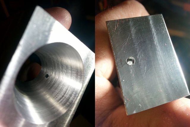 )
)
(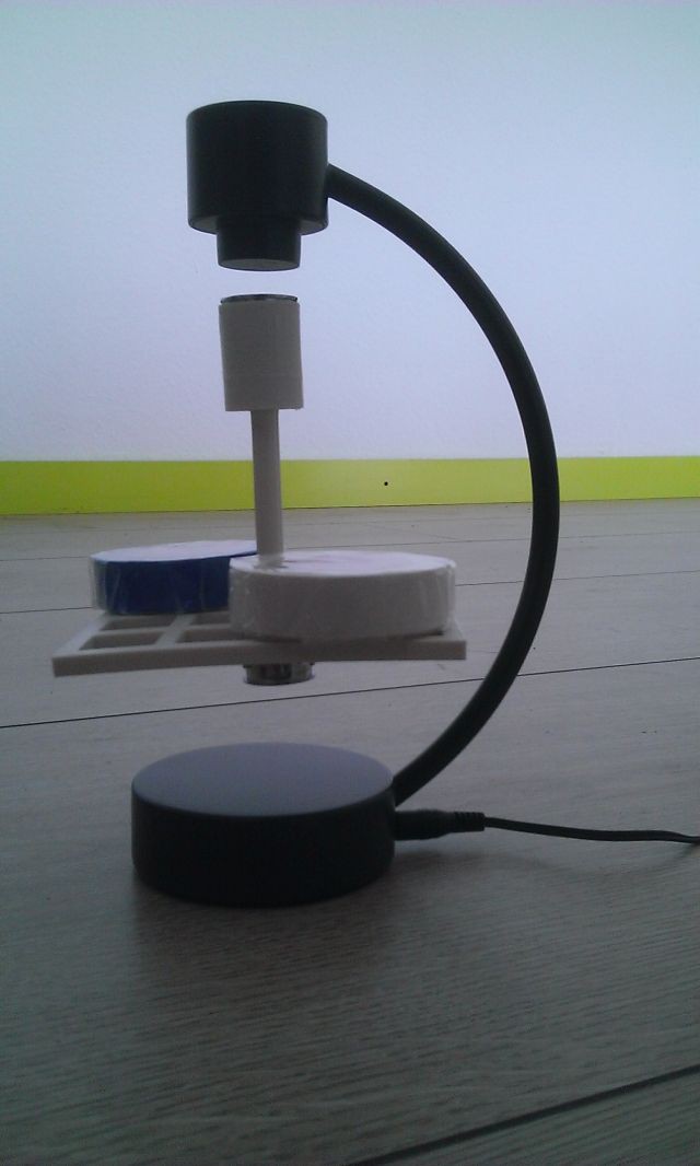 )
)
-
Title: Re: EM Drive Developments - related to space flight applications - Thread 3
Post by: Rodal on 06/02/2015 01:21 AM -
<a href="http://forum.nasaspaceflight.com/index.php?topic=37642.msg1382326#msg1382326">Quote from: WarpTech on 05/31/2015 03:42 AM</a>
I should know better than to post a 1st draft of anything, but here goes nothing...
What I've done is put together all of the pieces we have been working on, between Egan, Yang, De Aquino and Shawyer. What I ended up with didn't surprise me. What did is how much this "mimics" gravity in the PV Model is not even funny!
Let the show begin!
Todd
The show is not ready for prime-time yet, but working on it...
Continuing from here: http://forum.nasaspaceflight.com/index.php?topic=37642.msg1381966#msg1381966
An outstanding important question in developing this theory of EM Drive motion due to internal evanescent waves produced by geometrical attenuation (due to tapering of the walls of the truncated cone towards the small end) is whether the evanescent waves can couple to the enhanced energy density due to Q resonance standing waves. It is is very important to show this, because otherwise the EM Drive would not be able to be superior to a perfectly collimated photon rocket. The stored energy density from resonance is the key.
It is important to show whether there is coupling of the evanescent waves with the standing waves. That there is coupling between travelling waves and evanescent waves is shown in the paper of Zeng and Fan where one mode after another gets attenuated as it propagates towards the small end. However that's for an open waveguide, where travelling waves and evanescent waves can be easily shown to be in phase (particularly for phase constant equal to zero). Doubts were expressed in this thread as to whether this is possible for standing waves and evanescent waves.
The answer appears to be yes, at least in some qualified situations. There are a number of papers showing coupling between whispering -gallery modes and evanescent waves. It is far from clear whether whispering-gallery modes could be present in the EM Drive operation, (whispering-gallery modes would involve much higher frequencies -what is the highest frequency that a Magnetron puts out ?-).
This recent reference (2013) shows whispering-gallery modes in the microwave frequency at 10 GHz: http://arxiv.org/pdf/hep-ph/0506074
The fact that whispering-gallery modes can couple with evanescent waves is interesting enough.
Coupling between high Q cavities (of the ring type) and evanescent waves have also been shown.
Constructive interference.
It looks like the analysis may require numerical analysis, as all the papers I have seen so far have used the Finite Difference method to solve the problem numerically.
The problem is difficult, mathematically, but entirely within Standard Physics.
It is intriguing whether some of the gradient theories (Shawyer's gradient in group velocity, McCulloch's gradient of Unruh wavelengths, Notsosureofit gradient of dispersion, and this one geometrical attenuation gradient with coupling of standing and evanescent waves, are related somehow, rather than just superficially).
( )
)
( )
)
-
Title: Re: EM Drive Developments - related to space flight applications - Thread 3
Post by: Notsosureofit on 06/02/2015 01:38 AM -
Just worked out number of coupled cycles. Posting on emdrive.
works out to f*c/g where g is the accelerated frame...... -
Title: Re: EM Drive Developments - related to space flight applications - Thread 3
Post by: Rodal on 06/02/2015 01:44 AM -
<a href="http://forum.nasaspaceflight.com/index.php?topic=37642.msg1383233#msg1383233">Quote from: Notsosureofit on 06/02/2015 01:38 AM</a>
Just worked out number of coupled cycles. Posting on emdrive.
works out to f*c/g where g is the accelerated frame......
OK, I'll look for it. Incidentally why did you choose PQ = 2*10^6 watts for your example ? any particular reason, relating to one of the test cases? -
Title: Re: EM Drive Developments - related to space flight applications - Thread 3
Post by: Notsosureofit on 06/02/2015 01:53 AM - Just convenient
-
Title: Re: EM Drive Developments - related to space flight applications - Thread 3
Post by: Rodal on 06/02/2015 02:00 AM -
<a href="http://forum.nasaspaceflight.com/index.php?topic=37642.msg1383241#msg1383241">Quote from: Notsosureofit on 06/02/2015 01:53 AM</a>
Just convenient
Since PQ is arbitrary, wouldn't it be preferable to choose some power of 10, like 10^6 watts or 10^7 watts?
Then the vertical axis for force acts like a scaled force, and it is (a little) easier for the reader to find out the force based on a given PQ ?
Otherwise one could plot force/(PQ) but dimensionally force/(PQ) would be a really small number :) -
Title: Re: EM Drive Developments - related to space flight applications - Thread 3
Post by: Rodal on 06/02/2015 02:18 AM -
<a href="http://forum.nasaspaceflight.com/index.php?topic=37642.msg1383246#msg1383246">Quote from: Rodal on 06/02/2015 02:09 AM</a>
This is fantastic !
Do the three curves represent p=1, p=2 and p=3 ? (where p is the quantum number TMmnp or TEmnp in the longitudinal direction ?)
What made you think of that?
Great workQuote from: NotsosureofitAn interesting expression to examine is fc/g
It represents the number of cycles for the photons in the cavity to reach velocity c if they were free to do so at the acceleration g. In that respect it represents a degree of coupling between the standing waves in the cavity and a traveling wave. -
Title: Re: EM Drive Developments - related to space flight applications - Thread 3
Post by: Notsosureofit on 06/02/2015 02:20 AM -
Yes p = 1,2,3
Yes, I was looking at your request for couplings.
Notice that for a cylindrical cavity, it takes an infinite amount of time. -
Title: Re: EM Drive Developments - related to space flight applications - Thread 3
Post by: Rodal on 06/02/2015 02:21 AM -
<a href="http://forum.nasaspaceflight.com/index.php?topic=37642.msg1383254#msg1383254">Quote from: Notsosureofit on 06/02/2015 02:20 AM</a>
Yes p = 1,2,3
Are both TM and TE modes shown or did you consider just TM modes ?
Yes, I was looking at your request for couplings. -
Title: Re: EM Drive Developments - related to space flight applications - Thread 3
Post by: SeeShells on 06/02/2015 02:25 AM -
<a href="http://forum.nasaspaceflight.com/index.php?topic=37642.msg1383227#msg1383227">Quote from: Rodal on 06/02/2015 01:21 AM</a>
I honestly believe Todd has the tiger by the tail here and is on the right track. My math is just too rusty but not bad enough not to understand and see the connections. Feeling here is something that needs to be followed. Good work Todd and a great followup Rodal.<a href="http://forum.nasaspaceflight.com/index.php?topic=37642.msg1382326#msg1382326">Quote from: WarpTech on 05/31/2015 03:42 AM</a>I should know better than to post a 1st draft of anything, but here goes nothing...
What I've done is put together all of the pieces we have been working on, between Egan, Yang, De Aquino and Shawyer. What I ended up with didn't surprise me. What did is how much this "mimics" gravity in the PV Model is not even funny!
Let the show begin!
Todd
The show is not ready for prime-time yet, but working on it...
Continuing from here: http://forum.nasaspaceflight.com/index.php?topic=37642.msg1381966#msg1381966
An outstanding important question in developing this theory of EM Drive motion due to internal evanescent waves produced by geometrical attenuation (due to tapering of the walls of the truncated cone towards the small end) is whether the evanescent waves can couple to the enhanced energy density due to Q resonance standing waves. It is is very important to show this, because otherwise the EM Drive would not be able to be superior to a perfectly collimated photon rocket. The stored energy density from resonance is the key.
It is important to show whether there is coupling of the evanescent waves with the standing waves. That there is coupling between travelling waves and evanescent waves is shown in the paper of Zeng and Fan where one mode after another gets attenuated as it propagates towards the small end. However that's for an open waveguide, where travelling waves and evanescent waves can be easily shown to be in phase (particularly for phase constant equal to zero). Doubts were expressed in this thread as to whether this is possible for standing waves and evanescent waves.
The answer appears to be yes, at least in some qualified situations. There are a number of papers showing coupling between whispering -gallery modes and evanescent waves. It is far from clear whether whispering-gallery modes could be present in the EM Drive operation, (whispering-gallery modes would involve much higher frequencies -what is the highest frequency that a Magnetron puts out ?-).
This recent reference (2013) shows whispering-gallery modes in the microwave frequency at 10 GHz: http://arxiv.org/pdf/hep-ph/0506074
The fact that whispering-gallery modes can couple with evanescent waves is interesting enough.
Coupling between high Q cavities (of the ring type) and evanescent waves have also been shown.
Constructive interference.
It looks like the analysis may require numerical analysis, as all the papers I have seen so far have used the Finite Difference method to solve the problem numerically.
The problem is difficult, mathematically, but entirely within Standard Physics.
It is intriguing whether some of the gradient theories (Shawyer's gradient in group velocity, McCulloch's gradient of Unruh wavelengths, Notsosureofit gradient of dispersion, and this one geometrical attenuation gradient with coupling of standing and evanescent waves, are related somehow, rather than just superficially).
()
() -
Title: Re: EM Drive Developments - related to space flight applications - Thread 3
Post by: Notsosureofit on 06/02/2015 02:29 AM -
<a href="http://forum.nasaspaceflight.com/index.php?topic=37642.msg1383255#msg1383255">Quote from: Rodal on 06/02/2015 02:21 AM</a><a href="http://forum.nasaspaceflight.com/index.php?topic=37642.msg1383254#msg1383254">Quote from: Notsosureofit on 06/02/2015 02:20 AM</a>
Yes p = 1,2,3
Are both TM and TE modes shown or did you consider just TM modes ?
Yes, I was looking at your request for couplings.
All the modes are there. Same data table as above. -
Title: Re: EM Drive Developments - related to space flight applications - Thread 3
Post by: Quintaglio on 06/02/2015 02:42 AM -
This is my first post so I hope you forgive me if I make any mistakes
When the microwave is sent through the cavity is it passing through a vacum or is the chamber full with some sort of gas?
If there is a gas inside the cavity would the microwave heat this, and with the conical shape allow the heat to pass up the cones wall?
Stuart -
Title: Re: EM Drive Developments - related to space flight applications - Thread 3
Post by: Rodal on 06/02/2015 02:48 AM -
<a href="http://forum.nasaspaceflight.com/index.php?topic=37642.msg1383254#msg1383254">Quote from: Notsosureofit on 06/02/2015 02:20 AM</a>
...
Is that because for a cylindrical cavity delta f is zero (since the the diameters at both ends is the same, there is no gradient in that case), and therefore the acceleration g is zero for a cylindrical cavity, and therefore the number of cycles fc/g -> Infinity for a cylindrical cavity ?
Notice that for a cylindrical cavity, it takes an infinite amount of time.
This goes nicely with the fact that for a perfectly cylindrical cavity there is no geometrical attenuation, hence no travelling waves being cut-off and becoming evanescent waves. -
Title: Re: EM Drive Developments - related to space flight applications - Thread 3
Post by: Notsosureofit on 06/02/2015 02:51 AM - Yes
-
Title: Re: EM Drive Developments - related to space flight applications - Thread 3
Post by: Rodal on 06/02/2015 03:04 AM -
<a href="http://forum.nasaspaceflight.com/index.php?topic=37642.msg1383268#msg1383268">Quote from: Notsosureofit on 06/02/2015 02:51 AM</a>
Yes
Then, if the fellows in Aachen, Germany, have scaled all their cavity dimensions for Baby EM Drive such that
bigdiameterAACHEN = bigdiameterNASA / (frequencyAACHEN/frequencyNASA)
smalldiameterAACHEN =smalldiameterNASA / (frequencyAACHEN/frequencyNASA)
lengthAACHEN = lengthdiameterNASA / (frequencyAACHEN/frequencyNASA)
they don't have to worry about operating at frequencyAACHEN = 24 GHz, since the number of cycles needed for the photons in the cavity to accelerate to c (if they were free to do so), the coupling, would be what your curve shows at around frequencyNASA = 2 GHz, the NASA frequency ?
-
Title: Re: EM Drive Developments - related to space flight applications - Thread 3
Post by: deltaMass on 06/02/2015 05:08 AM - :o Are you guys seriously talking about accelerating photons? ???
-
Title: Re: EM Drive Developments - related to space flight applications - Thread 3
Post by: WarpTech on 06/02/2015 05:25 AM -
<a href="http://forum.nasaspaceflight.com/index.php?topic=37642.msg1383191#msg1383191">Quote from: smartcat on 06/01/2015 11:55 PM</a>
...
My feeling is that you are on the right track. For some reason I keep thinking that there is a rotational factor (about the cavity axis) and a related symmetry issue; as in perhaps needing to break the symmetry to reach a stable state.
Thanks. The geometry breaks the symmetry, but I've been playing with a coaxial frustum idea, fed from the small end so that I can start with a DC analysis and an AC, 1/4-wave stub analysis. What I'm learning is that as charge moves front to back, it "sees" it's reflection in the big end ground plane and is attracted to it, accelerating the wave. As charge moves from back to front, it sees less of a reflection, practically "none" if the frustum were a pointed cone. Instead, the charge density spikes.
Since I'm feeding it from the small end with an axial conductor down the middle, the magnetic field is circular around the axis. It's a 1-turn, air-core inductor. The Electric field is split, with the voltage gradient vector between the axis and the frustum, -Del(Phi) due to the applied voltage source, and a vector following each conductor, -dA/dt as it charges. The A field is parallel to the conductor surfaces.
The attenuation "relative" phase factor (k - Beta) can then be seen quite obviously I think, (still working on verifying that). What I see is inside a coax, the magnetic field is only dependent on the current on the inner conductor. So the phase of the magnetic wave is relative to the axis. Remember if we have positive charge oscillating on the axial conductor, we have negative charge on the inside of the outer conductor. Where the magnetic wave crosses the frustum, the relative phase is a variable depending on R(z). There is a forward-rectified Lorentz force acting on the frustum, but there is no opposing force on the inner conductor because the B field is perpendicular and very small at the center due to the circular symmetry. There is however, a strong opposing force at the back end plate that may or may not fully cancel it as it's charging.
I'll say more once I've worked it out for myself. I want to prove there are asymmetrical forces as it's charging and discharging. Once the principle is understood, we can do real engineering designs for kN of thrust.
Todd -
Title: Re: EM Drive Developments - related to space flight applications - Thread 3
Post by: WarpTech on 06/02/2015 05:38 AM -
<a href="http://forum.nasaspaceflight.com/index.php?topic=37642.msg1383233#msg1383233">Quote from: Notsosureofit on 06/02/2015 01:38 AM</a>
Just worked out number of coupled cycles. Posting on emdrive.
works out to f*c/g where g is the accelerated frame......
Where is it posted? -
Title: Re: EM Drive Developments - related to space flight applications - Thread 3
Post by: ThinkerX on 06/02/2015 06:18 AM -
Quote
Just worked out number of coupled cycles. Posting on emdrive.
works out to f*c/g where g is the accelerated frame......QuoteWhere is it posted?
The wiki linked to on post 1, page 1 of this thread.
-
Title: Re: EM Drive Developments - related to space flight applications - Thread 3
Post by: OttO on 06/02/2015 06:40 AM -
After Notsosurofit post, it would be interesting to know if the tapered cavity could work in purely optical mode (with a laser feeding it) :P
For DIY let's build areas of 10*10 blue ray diodes... -
Title: Re: EM Drive Developments - related to space flight applications - Thread 3
Post by: zen-in on 06/02/2015 07:03 AM -
<a href="http://forum.nasaspaceflight.com/index.php?topic=37642.msg1383227#msg1383227">Quote from: Rodal on 06/02/2015 01:21 AM</a>
The show is not ready for prime-time yet, but working on it...
Continuing from here: http://forum.nasaspaceflight.com/index.php?topic=37642.msg1381966#msg1381966
An outstanding important question in developing this theory of EM Drive motion due to internal evanescent waves produced by geometrical attenuation (due to tapering of the walls of the truncated cone towards the small end) is whether the evanescent waves can couple to the enhanced energy density due to Q resonance standing waves. It is is very important to show this, because otherwise the EM Drive would not be able to be superior to a perfectly collimated photon rocket. The stored energy density from resonance is the key.
It is important to show whether there is coupling of the evanescent waves with the standing waves. That there is coupling between travelling waves and evanescent waves is shown in the paper of Zeng and Fan where one mode after another gets attenuated as it propagates towards the small end. However that's for an open waveguide, where travelling waves and evanescent waves can be easily shown to be in phase (particularly for phase constant equal to zero). Doubts were expressed in this thread as to whether this is possible for standing waves and evanescent waves.
The answer appears to be yes, at least in some qualified situations. There are a number of papers showing coupling between whispering -gallery modes and evanescent waves. It is far from clear whether whispering-gallery modes could be present in the EM Drive operation, (whispering-gallery modes would involve much higher frequencies -what is the highest frequency that a Magnetron puts out ?-).
This recent reference (2013) shows whispering-gallery modes in the microwave frequency at 10 GHz: http://arxiv.org/pdf/hep-ph/0506074
The fact that whispering-gallery modes can couple with evanescent waves is interesting enough.
Coupling between high Q cavities (of the ring type) and evanescent waves have also been shown.
Constructive interference.
...
I have serious doubts this theory of thrust generated from evanescent waves interacting with the standing wave at the short end of the cavity has any basis in physics. Evanescent waves are synonomous with near field radiation in the RF world; at least this is what the Wikipedia page says:
"In electrical engineering, evanescent waves are found in the near-field region within one third of a wavelength of any radio antenna...."
http://en.wikipedia.org/wiki/Evanescent_wave
There are no evanescent waves inside the cavity because the Poynting vector = 0. An antenna or feed horn does have evanescent waves, although RF engineers refer to that as the near field radiation. There are also evanescent waves inside the copper but those are contained in a very small thickness due to the skin effect. There are no standing waves inside the copper to interact with those evanescent waves.
Even if evanescent waves and the standing wave did coexist in the same space there would be no magical effect as claimed. That superposition of RF voltages and currents is resolved as just another humdrum vector by the use of the Superpositioning Theorem. If it was any different our universe would be a very different place and we would likely not even be here.
In the last thread there were claims the em-drive cavity produced a warp field. The "evidence" presented for this claim was a rather ordinary interference pattern. Now there is another esoteric theory. The problem is there is no data to even support claims a thrust is being produced. No one has replicated this claimed em-drive and supplied data to prove there is any thrust. That would be the first step. The proof would be a 180° test that shows thrust above the error bars and is repeatable and with that experiment replicated in an open lab with all raw data being reported. -
Title: Re: EM Drive Developments - related to space flight applications - Thread 3
Post by: Mulletron on 06/02/2015 09:26 AM -
<a href="http://forum.nasaspaceflight.com/index.php?topic=37642.msg1383277#msg1383277">Quote from: Rodal on 06/02/2015 03:04 AM</a><a href="http://forum.nasaspaceflight.com/index.php?topic=37642.msg1383268#msg1383268">Quote from: Notsosureofit on 06/02/2015 02:51 AM</a>
Yes
Then, if the fellows in Aachen, Germany, have scaled all their cavity dimensions for Baby EM Drive such that
bigdiameterAACHEN = bigdiameterNASA / (frequencyAACHEN/frequencyNASA)
smalldiameterAACHEN =smalldiameterNASA / (frequencyAACHEN/frequencyNASA)
lengthAACHEN = lengthdiameterNASA / (frequencyAACHEN/frequencyNASA)
they don't have to worry about operating at frequencyAACHEN = 24 GHz, since the number of cycles needed for the photons in the cavity to accelerate to c (if they were free to do so), the coupling, would be what your curve shows at around frequencyNASA = 2 GHz, the NASA frequency ?
Photons don't accelerate. No reference required. It is basic. Any theory requiring such condition needs to go. -
Title: Re: EM Drive Developments - related to space flight applications - Thread 3
Post by: Flyby on 06/02/2015 10:20 AM -
<a href="http://forum.nasaspaceflight.com/index.php?topic=37642.msg1383105#msg1383105">Quote from: Rodal on 06/01/2015 08:15 PM</a>
I think it is great that people like you, Notsosureofit and Paul Kocyla/Jo Hinchliffe are looking/working on miniaturizing the EM Drive. There is higher risk that it won't work of course (as compared to a replication), but if it does you will have opened a very exciting future to this technology, and the next step (up in a CubeSat) will be all the much easier to accomplish! :)
Although I do agree that miniaturization is the end objective, I think it might be the wrong approach to help understand the engineering parameters of the EMdrive.
When looking at the current size of devices and how great an impact of differences of 10th of millimeters can have on frequency shifting, making it smaller will only make it a lot harder to keep the engineering aspects under control...(needing a manufacturing accuracy of a 100th or a 1000th of a millimeter)
I think we should do the opposite.. make the devices larger in size (and consequently also lower frequencies) so that tiny imperfections have less of an impact. Once we learn all about the needed engineering requirements, then you can focus on making it smaller...
apart from that, we still need evidence the EMdrive produce thrust... hopefully, soon...
-
Title: Re: EM Drive Developments - related to space flight applications - Thread 3
Post by: Stormbringer on 06/02/2015 11:06 AM -
<a href="http://forum.nasaspaceflight.com/index.php?topic=37642.msg1383350#msg1383350">Quote from: Mulletron on 06/02/2015 09:26 AM</a><a href="http://forum.nasaspaceflight.com/index.php?topic=37642.msg1383277#msg1383277">Quote from: Rodal on 06/02/2015 03:04 AM</a><a href="http://forum.nasaspaceflight.com/index.php?topic=37642.msg1383268#msg1383268">Quote from: Notsosureofit on 06/02/2015 02:51 AM</a>
Yes
Then, if the fellows in Aachen, Germany, have scaled all their cavity dimensions for Baby EM Drive such that
bigdiameterAACHEN = bigdiameterNASA / (frequencyAACHEN/frequencyNASA)
smalldiameterAACHEN =smalldiameterNASA / (frequencyAACHEN/frequencyNASA)
lengthAACHEN = lengthdiameterNASA / (frequencyAACHEN/frequencyNASA)
they don't have to worry about operating at frequencyAACHEN = 24 GHz, since the number of cycles needed for the photons in the cavity to accelerate to c (if they were free to do so), the coupling, would be what your curve shows at around frequencyNASA = 2 GHz, the NASA frequency ?
Photons don't accelerate. No reference required. It is basic. Any theory requiring such condition needs to go.
Eh- it might just be my peanut gallery prowess speaking here but... what happens when photons or other particles are in one medium and cross the boundary to another medium? Fer instance... particles in the water bath of a nuclear pile (they produce blue glowey stuff known as Cherenkov radiation) because they exceed the speed of light for that medium and shed energy. Bear with me...
So now they leave the water for open air or a vacuum. what happens then? The speed limit is now faster than they are traveling...could they ( here I mean photons not massive particles) accelerate to the new limit?
EDIT: And what of experiments with "slow light?" That's where photons are slowed down below their natural speed in recent high tech experiments. Does a slow or trapped photon mean a photon that can be accelerated? -
Title: Re: EM Drive Developments - related to space flight applications - Thread 3
Post by: dustinthewind on 06/02/2015 11:12 AM -
<a href="http://forum.nasaspaceflight.com/index.php?topic=37642.msg1383350#msg1383350">Quote from: Mulletron on 06/02/2015 09:26 AM</a><a href="http://forum.nasaspaceflight.com/index.php?topic=37642.msg1383277#msg1383277">Quote from: Rodal on 06/02/2015 03:04 AM</a><a href="http://forum.nasaspaceflight.com/index.php?topic=37642.msg1383268#msg1383268">Quote from: Notsosureofit on 06/02/2015 02:51 AM</a>
Yes
Then, if the fellows in Aachen, Germany, have scaled all their cavity dimensions for Baby EM Drive such that
bigdiameterAACHEN = bigdiameterNASA / (frequencyAACHEN/frequencyNASA)
smalldiameterAACHEN =smalldiameterNASA / (frequencyAACHEN/frequencyNASA)
lengthAACHEN = lengthdiameterNASA / (frequencyAACHEN/frequencyNASA)
they don't have to worry about operating at frequencyAACHEN = 24 GHz, since the number of cycles needed for the photons in the cavity to accelerate to c (if they were free to do so), the coupling, would be what your curve shows at around frequencyNASA = 2 GHz, the NASA frequency ?
Photons don't accelerate. No reference required. It is basic. Any theory requiring such condition needs to go.
I can't say I am exactly following them but there is this article here, http://www.nature.com/nphys/journal/v9/n12/full/nphys2777.html . They seem to suggest acceleration of the beam.
I always thought of photons more of as waves though considering the path followed by them from a double slit experiment has them emanating not from the holes but from between the holes and then they follow curved paths near the holes then straight paths later on. On the other hand there is quantum physics.
I also thought light slowed down when entering a gravitational well but one being in that gravitational well still measures speed c from inside due space time distortion but still I think light should slow down in the well with respect to the rest of space. I am not sure I would call the change in speed acceleration, though maybe it is.
I noticed their equation f*c/g is unit-less. Again, I can't say I understand it but I thought maybe it was in context of the article above? -
Title: Re: EM Drive Developments - related to space flight applications - Thread 3
Post by: Vix on 06/02/2015 11:16 AM -
Hi there! This is my first post here, so please excuse me for any mishaps :) Admins, feel free to delete if you consider it rubbish...
By the wsy, electronics is my hobby, albeit I've been mostly oriented toward audio applications (amplifiers and loudspeaker cabinets).
I don't have much to say here, except that I agree that an experiment should also be carried in other direction: i.e. very large EM drive with very high power input. Not DIY for sure. I just wonder what would happen if such a thing could be built in some lab, and powered by a very powerful Klystron?!
(As I like to read history of science, sometimes it appears to me that this may have been tried in the past. What if Nazi Secret weapon known as "the bell" was in fact a large conical device powered by a klystron? What if they observed a lift a called that "anti-gravity" :) )
Regards, Vix -
Title: Re: EM Drive Developments - related to space flight applications - Thread 3
Post by: Notsosureofit on 06/02/2015 11:47 AM -
<a href="http://forum.nasaspaceflight.com/index.php?topic=37642.msg1383303#msg1383303">Quote from: deltaMass on 06/02/2015 05:08 AM</a>
:o Are you guys seriously talking about accelerating photons? ???
No
That's a relation between inertial and accelerating frames of reference.
-
Title: Re: EM Drive Developments - related to space flight applications - Thread 3
Post by: Rodal on 06/02/2015 11:53 AM -
We are looking at the cavity's dispersion curve intersections of constant wave number instead of constant frequency.
-
Title: Re: EM Drive Developments - related to space flight applications - Thread 3
Post by: OttO on 06/02/2015 12:22 PM -
I think the following papers could be of interest:
"The mechanism responsible for the conversion of evanescent waves into propagating waves is explained and a general formula for the conversion of evanescent waves into propagating waves is derived."
http://rd.springer.com/article/10.1007/s00340-006-2220-3 (http://rd.springer.com/article/10.1007/s00340-006-2220-3)
"when the cavity gets closer to the horizon of a blackhole, square inverse law is recovered and the repulsive force due to negative energy/mass of the cavity now has an observable strength.
More importantly the force changes from being repulsive to attractive when the cavity crosses the event horizon"
http://arxiv.org/abs/1211.6068 (http://arxiv.org/abs/1211.6068)
Giant vacuum forces via transmission lines.
http://arxiv.org/abs/1304.2028 (http://arxiv.org/abs/1304.2028) -
Title: Re: EM Drive Developments - related to space flight applications - Thread 3
Post by: Rodal on 06/02/2015 12:33 PM -
<a href="http://forum.nasaspaceflight.com/index.php?topic=37642.msg1383329#msg1383329">Quote from: zen-in on 06/02/2015 07:03 AM</a>
...I have serious doubts this theory of thrust generated from evanescent waves interacting with the standing wave at the short end of the cavity has any basis in physics. Evanescent waves are synonomous with near field radiation in the RF world; at least this is what the Wikipedia page says:
"In electrical engineering, evanescent waves are found in the near-field region within one third of a wavelength of any radio antenna...."
http://en.wikipedia.org/wiki/Evanescent_wave
There are no evanescent waves inside the cavity because the Poynting vector = 0. An antenna or feed horn does have evanescent waves, although RF engineers refer to that as the near field radiation. There are also evanescent waves inside the copper but those are contained in a very small thickness due to the skin effect. There are no standing waves inside the copper to interact with those evanescent waves.
...
There is no law of physics that says that the Poynting vector inside a cavity is zero.
The Poynting vector (averaged over an integer number of periods) inside a cavity is zero when there are no sources or sinks in the cavity. Even in a cavity with no sinks or sources, the Poynting vector is not zero when averaged over any amount of time that is not an integer number of periods.
As long as the RF feed of microwaves is on, there is a source inside the cavity, therefore the Poynting vector (averaged over an integer number of periods) is not zero.
If there are losses (for example dielectric losses due to tan delta not being zero and resistive losses) then there is a sink inside the cavity and therefore the Poynting vector (averaged over an integer number of periods) is not zero.
As to the presence of evanescent waves inside a cavity, we are discussing Physics and not constitutional law. For constitutional law you go to the book of law, read what the law is and you have your answer.
To find out whether there are evanescent waves and other solutions of Maxwell's equations (besides standing waves) like whispering-gallery modes, etc. (any possible solution of Maxwell's equations), one doesn't go to Wikipedia. One has to solve Maxwell's equations. Greg Egan's solution does not take into account the source due to the RF feed, and only considered simple harmonic standing wave solutions to Maxwell's equations. Egan did not consider any other possible solution to Maxwell's equations. @aero took a cut by using MEEP and found evanescent waves inside the EM Drive. Cavities as used at CERN and other accelerators have standing waves inside them and travelling waves going through the open holes that go through the cavity. Here we have an open hole through which the RF field is fed to the cavity, so there are travelling waves coming into the cavity and there is a source (non-zero Poynting vector) as long as the RF Feed is on, with standing waves and travelling waves co-existing.
As you admit, there are evanescent waves due to the RF feed and there are evanescent waves at the walls. In addition it appears that there are evanescent waves due to geometrical attenuation. This geometrical attenuation is only present in cavities with a geometrical gradient. There is no geometrical attenuation and hence no evanescent waves due to geometrical attenuation in cylindrical cavities. But the EM Drive is a truncated conical cavity, not a cylindrical cavity. What happens inside the EM Drive is governed by all the solutions that are possible within Maxwell's equations, the boundary conditions and the RF feed.
_____QuoteEven if evanescent waves and the standing wave did coexist in the same space there would be no magical effect as claimed. That superposition of RF voltages and currents is resolved as just another humdrum vector by the use of the Superpositioning Theorem
The Superpositioning Theorem only applies to linear equations!
Even considering linear equations, not clear as to how you are applying superposition when you have asymmetric directionality: a source (the RF feed), dielectric and resistive losses, and a gradient imposed by the conical walls of the truncated cone.
_____
@notsosureofit hypothesis is here:
http://emdrive.wiki/@notsosureofit_Hypothesis
-
Title: Re: EM Drive Developments - related to space flight applications - Thread 3
Post by: OttO on 06/02/2015 01:04 PM -
I love this one ;D:
Shape-Preserving Accelerating Electromagnetic Wave Packets in Curved Space
http://arxiv.org/abs/1310.6153 (http://arxiv.org/abs/1310.6153) -
Title: Re: EM Drive Developments - related to space flight applications - Thread 3
Post by: SeeShells on 06/02/2015 01:10 PM -
<a href="http://forum.nasaspaceflight.com/index.php?topic=37642.msg1383393#msg1383393">Quote from: Rodal on 06/02/2015 11:53 AM</a>
We are looking at the cavity's dispersion curve intersections of constant wave number instead of constant frequency.
I found this representation of standing waves quite interesting.
http://en.wikipedia.org/wiki/Quantum_mechanics#/media/File:QuantumHarmonicOscillatorAnimation.gif -
Title: Re: EM Drive Developments - related to space flight applications - Thread 3
Post by: WarpTech on 06/02/2015 01:36 PM -
<a href="http://forum.nasaspaceflight.com/index.php?topic=37642.msg1383380#msg1383380">Quote from: dustinthewind on 06/02/2015 11:12 AM</a><a href="http://forum.nasaspaceflight.com/index.php?topic=37642.msg1383350#msg1383350">Quote from: Mulletron on 06/02/2015 09:26 AM</a>
...
Photons don't accelerate. No reference required. It is basic. Any theory requiring such condition needs to go.
....
I also thought light slowed down when entering a gravitational well but one being in that gravitational well still measures speed c from inside due space time distortion but still I think light should slow down in the well with respect to the rest of space. I am not sure I would call the change in speed acceleration, though maybe it is.
I noticed their equation f*c/g is unit-less. Again, I can't say I understand it but I thought maybe it was in context of the article above?
You are correct. Anyone who thinks photons do not accelerate needs to study General Relativity. A gravitational field "Is" an accelerated reference frame and photons in a g field "do" accelerate relative to a distant observer who is not in the g field. It is called the "coordinate speed of light". To someone observing from inside the g field, c appears to be constant on their relative tangent plane, but that is only because gravitational length contraction and time dilation conspire to make it so in that coordinate system. From the respective coordinate system of a distant observer, c/K in a gravitational field slower than c in free space!
This is a fact, if you don't believe it please study GR and the PV Model of GR. The speed of light is ONLY constant in an inertial reference frame. As soon as you introduce acceleration or gravity, it is not constant.
Thank you.
Todd
-
Title: Re: EM Drive Developments - related to space flight applications - Thread 3
Post by: Notsosureofit on 06/02/2015 01:48 PM -
<a href="http://forum.nasaspaceflight.com/index.php?topic=37642.msg1383429#msg1383429">Quote from: WarpTech on 06/02/2015 01:36 PM</a><a href="http://forum.nasaspaceflight.com/index.php?topic=37642.msg1383380#msg1383380">Quote from: dustinthewind on 06/02/2015 11:12 AM</a><a href="http://forum.nasaspaceflight.com/index.php?topic=37642.msg1383350#msg1383350">Quote from: Mulletron on 06/02/2015 09:26 AM</a>
...
Photons don't accelerate. No reference required. It is basic. Any theory requiring such condition needs to go.
....
I also thought light slowed down when entering a gravitational well but one being in that gravitational well still measures speed c from inside due space time distortion but still I think light should slow down in the well with respect to the rest of space. I am not sure I would call the change in speed acceleration, though maybe it is.
I noticed their equation f*c/g is unit-less. Again, I can't say I understand it but I thought maybe it was in context of the article above?
You are correct. Anyone who thinks photons do not accelerate needs to study General Relativity. A gravitational field "Is" an accelerated reference frame and photons in a g field "do" accelerate relative to a distant observer who is not in the g field. It is called the "coordinate speed of light". To someone observing from inside the g field, c appears to be constant on their relative tangent plane, but that is only because gravitational length contraction and time dilation conspire to make it so in that coordinate system. From the respective coordinate system of a distant observer, c/K in a gravitational field slower than c in free space!
This is a fact, if you don't believe it please study GR and the PV Model of GR. The speed of light is ONLY constant in an inertial reference frame. As soon as you introduce acceleration or gravity, it is not constant.
Thank you.
Todd
Right on Todd! The point taken here is that there exists an accelerated frame such that the variation due to dispersion in the cavity can be canceled by the "gravitational" variation. That's the g in my calculation.
Notice that this is only a "static" case, momentum still needs to be considered. -
Title: Re: EM Drive Developments - related to space flight applications - Thread 3
Post by: rfmwguy on 06/02/2015 01:51 PM -
<a href="http://forum.nasaspaceflight.com/index.php?topic=37642.msg1383362#msg1383362">Quote from: Flyby on 06/02/2015 10:20 AM</a><a href="http://forum.nasaspaceflight.com/index.php?topic=37642.msg1383105#msg1383105">Quote from: Rodal on 06/01/2015 08:15 PM</a>
I think it is great that people like you, Notsosureofit and Paul Kocyla/Jo Hinchliffe are looking/working on miniaturizing the EM Drive. There is higher risk that it won't work of course (as compared to a replication), but if it does you will have opened a very exciting future to this technology, and the next step (up in a CubeSat) will be all the much easier to accomplish! :)
Although I do agree that miniaturization is the end objective, I think it might be the wrong approach to help understand the engineering parameters of the EMdrive.
When looking at the current size of devices and how great an impact of differences of 10th of millimeters can have on frequency shifting, making it smaller will only make it a lot harder to keep the engineering aspects under control...(needing a manufacturing accuracy of a 100th or a 1000th of a millimeter)
I think we should do the opposite.. make the devices larger in size (and consequently also lower frequencies) so that tiny imperfections have less of an impact. Once we learn all about the needed engineering requirements, then you can focus on making it smaller...
apart from that, we still need evidence the EMdrive produce thrust... hopefully, soon...
Agreed...I plan on miniaturizing the rf source only, keeping the frustum @ 11.01 x 6.25 end dimensions with no dielectric to lower Q. When I get further along, will write up proposal and upload here for serious critique. Will keep it open source, have no commercial interests...kinda the way I am...if it works, all I ask is to mention my name....Dave :) -
Title: Re: EM Drive Developments - related to space flight applications - Thread 3
Post by: Rodal on 06/02/2015 01:51 PM -
<a href="http://forum.nasaspaceflight.com/index.php?topic=37642.msg1383429#msg1383429">Quote from: WarpTech on 06/02/2015 01:36 PM</a>
Perhaps the communication problem comes from being uncomfortable with the process of deriving macro equations and understanding how macro equations describe a micro reality. Instead, people can take the photon as a particle point of view, traveling at speed c. Then, they reconcile the fact that the speed of light is slower in different media than in the vacuum by saying that the photons travel at c in the vacuum between particles and when they meet a particle a new photon is produced. I am not clear as to how they resolve in their mind the issue that light can be slowed to practically a standstill at temperatures close to absolute zero.<a href="http://forum.nasaspaceflight.com/index.php?topic=37642.msg1383380#msg1383380">Quote from: dustinthewind on 06/02/2015 11:12 AM</a><a href="http://forum.nasaspaceflight.com/index.php?topic=37642.msg1383350#msg1383350">Quote from: Mulletron on 06/02/2015 09:26 AM</a>...
Photons don't accelerate. No reference required. It is basic. Any theory requiring such condition needs to go.
....
I also thought light slowed down when entering a gravitational well but one being in that gravitational well still measures speed c from inside due space time distortion but still I think light should slow down in the well with respect to the rest of space. I am not sure I would call the change in speed acceleration, though maybe it is.
I noticed their equation f*c/g is unit-less. Again, I can't say I understand it but I thought maybe it was in context of the article above?
You are correct. Anyone who thinks photons do not accelerate needs to study General Relativity. A gravitational field "Is" an accelerated reference frame and photons in a g field "do" accelerate relative to a distant observer who is not in the g field. It is called the "coordinate speed of light". To someone observing from inside the g field, c appears to be constant on their relative tangent plane, but that is only because gravitational length contraction and time dilation conspire to make it so in that coordinate system. From the respective coordinate system of a distant observer, c/K in a gravitational field slower than c in free space!
This is a fact, if you don't believe it please study GR and the PV Model of GR. The speed of light is ONLY constant in an inertial reference frame. As soon as you introduce acceleration or gravity, it is not constant.
Thank you.
Todd
They themselves (obviously) don't use quantum mechanics to solve any macro problem dealing with solid objects with dimensions that fit in your hands and weights that you can measure in a scale.
Engineers solve daily problems in solid and fluid mechanics using Continuum Mechanics (which is perfectly applicable) without having to consider the fact that solid matter and fluid is really not continuous.
Similarly here, there is a mathematical model which may be applicable without having to account in detail for all the photon interactions that take place at a quantum physics level.
Since very few macro problems can be dealt with using quantum mechanics, when it comes to solve actual macro problems, they use handbook equations that make the same approximations and much more. They use chemical equations, continuum mechanics equations, etc., without batting an eye. When they solve practical problems themselves they are not accounting for photon interactions on a one to one basis. They use macro properties like magnetic permeability of different media, electric permittivity of different media, tan delta, resistivity, etc.
I think that another big problem for people to understand intuitively what happens in an EM Drive is that the number of photons in a photon gas increases with the cube of the temperature. This, I think, is very counter-intuitive. This is very different from shooting billiard balls into a cavity.
If it is shown that the EM Drive experiments are not an artifact, and that they can be replicated, and there is a macro theory that accounts for the behavior observed in the experiments, people will become comfortable both with the theory and the reality of the EM Drive.
If the EM Drive experiments are an artifact, then all theoretical attempts to explain it are moot of course.
Hopefully we enjoyed the mental exercise of trying to explain it :) -
Title: Re: EM Drive Developments - related to space flight applications - Thread 3
Post by: deltaMass on 06/02/2015 02:42 PM -
Quote
From the respective coordinate system of a distant observer, c/K in a gravitational field slower than c in free space!
What does this mean? (you have not defined 'K' for your readers). c is a local invariant in any situation.
In the general relativistic sense, light rays do not accelerate in the absence of materials, because they always follow null geodesics. A distant observer may see these geodesics as curved, but nevertheless when a particle follows a null geodesic, it is not accelerating in the GR sense.
http://physics.stackexchange.com/questions/20289/do-photons-have-acceleration/20296#20296 -
Title: Re: EM Drive Developments - related to space flight applications - Thread 3
Post by: zen-in on 06/02/2015 02:43 PM -
<a href="http://forum.nasaspaceflight.com/index.php?topic=37642.msg1383405#msg1383405">Quote from: Rodal on 06/02/2015 12:33 PM</a>
I didn't say there was a law of physics that says that the Poynting vector inside a cavity is zero. You stated the Poynting vector inside a cavity is zero in thread 2. I don't have the time to search for your posts on that subject but this gentleman from Yale states the same thing:<a href="http://forum.nasaspaceflight.com/index.php?topic=37642.msg1383329#msg1383329">Quote from: zen-in on 06/02/2015 07:03 AM</a>
...I have serious doubts this theory of thrust generated from evanescent waves interacting with the standing wave at the short end of the cavity has any basis in physics. Evanescent waves are synonomous with near field radiation in the RF world; at least this is what the Wikipedia page says:
"In electrical engineering, evanescent waves are found in the near-field region within one third of a wavelength of any radio antenna...."
http://en.wikipedia.org/wiki/Evanescent_wave
There are no evanescent waves inside the cavity because the Poynting vector = 0. An antenna or feed horn does have evanescent waves, although RF engineers refer to that as the near field radiation. There are also evanescent waves inside the copper but those are contained in a very small thickness due to the skin effect. There are no standing waves inside the copper to interact with those evanescent waves.
...
There is no law of physics that says that the Poynting vector inside a cavity is zero.
http://www.researchgate.net/post/How_to_show_the_Poynting_vector_of_a_standing_electromagnetic_wave_integrated_over_the_volume_of_a_cavity_in_a_perfect_conductor_is_zero<a href="http://forum.nasaspaceflight.com/index.php?topic=37642.msg1383405#msg1383405">Quote from: Rodal on 06/02/2015 12:33 PM</a>
A cavity is not a feed horn. A cavity has standing waves inside it. It is you who is proclaiming a constitutional law for cavities.
The Poynting vector (averaged over an integer number of periods) inside a cavity is zero when there are no sources or sinks in the cavity. Even in a cavity with no sinks or sources, the Poynting vector is not zero when averaged over any amount of time that is not an integer number of periods.
As long as the RF feed of microwaves is on, there is a source inside the cavity, therefore the Poynting vector (averaged over an integer number of periods) is not zero.
If there are losses (for example dielectric losses due to tan delta not being zero and resistive losses) then there is a sink inside the cavity and therefore the Poynting vector (averaged over an integer number of periods) is not zero.
As to the presence of evanescent waves inside a cavity, we are discussing Physics and not constitutional law. For constitutional law you go to the book of law, read what the law is and you have your answer.<a href="http://forum.nasaspaceflight.com/index.php?topic=37642.msg1383405#msg1383405">Quote from: Rodal on 06/02/2015 12:33 PM</a>
There are no adjoining cavities inside the em-drive and therefore no travelling waves.
To find out whether there are evanescent waves and other solutions of Maxwell's equations (besides standing waves) like whispering-gallery modes, etc. (any possible solution of Maxwell's equations), one doesn't go to Wikipedia. One has to solve Maxwell's equations. Greg Egan's solution does not take into account the source due to the RF feed, and only considered simple harmonic standing wave solutions to Maxwell's equations. Egan did not consider any other possible solution to Maxwell's equations. @aero took a cut by using MEEP and found evanescent waves inside the EM Drive. Cavities as used at CERN and other accelerators have standing waves inside them and travelling waves going through the open holes that go through the cavity. Here we have an open hole through which the RF field is fed to the cavity, so there are travelling waves coming into the cavity and there is a source (non-zero Poynting vector) as long as the RF Feed is on, with standing waves and travelling waves co-existing.<a href="http://forum.nasaspaceflight.com/index.php?topic=37642.msg1383405#msg1383405">Quote from: Rodal on 06/02/2015 12:33 PM</a>
The failure of this theory of evanescent waves pushing against standing waves to produce thrust is that what you really have is just a standing wave inside the cavity. If you decide to call some parts of that standing wave evanescent waves you are stating that in this closed system one thing (RF power) is pushing against itself.
As you admit, there are evanescent waves due to the RF feed and there are evanescent waves at the walls. In addition it appears that there are evanescent waves due to geometrical attenuation. This geometrical attenuation is only present in cavities with a geometrical gradient. There is no geometrical attenuation and hence no evanescent waves due to geometrical attenuation in cylindrical cavities. But the EM Drive is a truncated conical cavity, not a cylindrical cavity. What happens inside the EM Drive is governed by all the solutions that are possible within Maxwell's equations, the boundary conditions and the RF feed.
_____QuoteEven if evanescent waves and the standing wave did coexist in the same space there would be no magical effect as claimed. That superposition of RF voltages and currents is resolved as just another humdrum vector by the use of the Superpositioning Theorem
The Superpositioning Theorem only applies to linear equations!
Even considering linear equations, not clear as to how you are applying superposition when you have asymmetric directionality: a source (the RF feed), dielectric and resistive losses, and a gradient imposed by the conical walls of the truncated cone.<a href="http://forum.nasaspaceflight.com/index.php?topic=37642.msg1383405#msg1383405">Quote from: Rodal on 06/02/2015 12:33 PM</a>
_____
@notsosureofit hypothesis is here:
http://emdrive.wiki/@notsosureofit_Hypothesis -
Title: Re: EM Drive Developments - related to space flight applications - Thread 3
Post by: Flyby on 06/02/2015 02:45 PM -
Isn't part of the problem also that we don't really know what an electromagnetic wave/photon is?
We try to understand it by partially describing it as a wave, whenever it is fitting, but also as a photon (particle) when ever it fits into the mathematical models we make.
I've learned to accept it as a given fact because we can observe both properties, but, i'll admit, I always found it extremely hard to visualize something to be a dualistic wave (composed electric/magnetic wave) and at the same time a particle.
The same thing applies for all the sub atomic particle models. They are mathematical entities that function within an established scientific model (the Standard Model), yet i have it difficult to visualize not less then 61 different elementary particles. Often described as a " particle zoo", it gives me an uncomfortable feeling that, although we have a working mathematical/scientific model, we're only observing the symptoms/manifestations of nature, rather then truly understand why those 61 elementary particles exist.
Isn't this the fundamental reason to why it is way more convenient to use those generalizing engineering approximations?
Because in the end, when we average all individual interactions, it does give us a "good enough" prediction, usable for science, engineering, architecture, etc...
-
Title: Re: EM Drive Developments - related to space flight applications - Thread 3
Post by: bprager on 06/02/2015 04:27 PM -
<a href="http://forum.nasaspaceflight.com/index.php?topic=37642.msg1383324#msg1383324">Quote from: OttO on 06/02/2015 06:40 AM</a>
After Notsosurofit post, it would be interesting to know if the tapered cavity could work in purely optical mode (with a laser feeding it) :P
For DIY let's build areas of 10*10 blue ray diodes...
That will pose some true challenges to tune into resonance, I believe. Microwave have about 10 mm wavelength, blue light has 500 nm. -
Title: Re: EM Drive Developments - related to space flight applications - Thread 3
Post by: X_RaY on 06/02/2015 04:59 PM -
quote author=WarpTech link=topic=37642.msg1383429#msg1383429 date=1433252162]<a href="http://forum.nasaspaceflight.com/index.php?topic=37642.msg1383380#msg1383380">Quote from: dustinthewind on 06/02/2015 11:12 AM</a><a href="http://forum.nasaspaceflight.com/index.php?topic=37642.msg1383350#msg1383350">Quote from: Mulletron on 06/02/2015 09:26 AM</a>
...
Photons don't accelerate. No reference required. It is basic. Any theory requiring such condition needs to go.
....
I also thought light slowed down when entering a gravitational well but one being in that gravitational well still measures speed c from inside due space time distortion but still I think light should slow down in the well with respect to the rest of space. I am not sure I would call the change in speed acceleration, though maybe it is.
I noticed their equation f*c/g is unit-less. Again, I can't say I understand it but I thought maybe it was in context of the article above?
You are correct. Anyone who thinks photons do not accelerate needs to study General Relativity. A gravitational field "Is" an accelerated reference frame and photons in a g field "do" accelerate relative to a distant observer who is not in the g field. It is called the "coordinate speed of light". To someone observing from inside the g field, c appears to be constant on their relative tangent plane, but that is only because gravitational length contraction and time dilation conspire to make it so in that coordinate system. From the respective coordinate system of a distant observer, c/K in a gravitational field slower than c in free space!
This is a fact, if you don't believe it please study GR and the PV Model of GR. The speed of light is ONLY constant in an inertial reference frame. As soon as you introduce acceleration or gravity, it is not constant.
Thank you.
Todd
[/quote]
Please restudy the GR! The planklenght is dependent on the strength of G The light have to travel a longer way. So it is not faster or slower! Inside a Material the permittivity and permabillity is higher than in vacuum
Got anybody a other universal meter in the toolbox?
http://en.wikipedia.org/wiki/Planck_units -
Title: Re: EM Drive Developments - related to space flight applications - Thread 3
Post by: aero on 06/02/2015 05:07 PM -
Quote
Isn't part of the problem also that we don't really know what an electromagnetic wave/photon is?
<a href="http://forum.nasaspaceflight.com/index.php?topic=37642.msg1383026#msg1383026">Quote from: aero on 06/01/2015 05:25 PM</a>A question about Dr. White's QV conjecture. Just a partially formed thought.
If his analogy of the electrons-positrons at a square dance with dancers changing partners by popping into and out of the QV, then wouldn't this same idea result in a particle electron idea of quantum tunneling? That is, electrons approach a barrier and dive into the QV. Another electron pops out of the QV nearby, but it has a probability of being on the wrong side of the barrier sence the barrier does not penetrate the QV.
This mechanism might be an excuse for the near instantaneous transit of the barrier, currently measured to be on the scale of attoseconds (10-18 seconds). In that short interval of time even light speed only moves a tenth of a nanometer and barriers are much thicker than that.
Of course I know that the wave theory of tunneling has the electron wave already partially on the other side of the barrier as it reaches the barrier so the wave tunnels through to fully re-form with the part that was already on the other side. That is reasonable for photons, but electrons have rest mass and that causes confusion to me.
I've been noodling this a little. If Dr. White's conjecture (and mine) were correct, shouldn't we be able to discover something about the QV by using the known probabilities of an electron tunneling through a barrier? The problem I run into immediately is modeling the shape of the QV. How many dimensions does it have? If it is only one dimension then the probability of an electron reaching the other side of the barrier is simply a matter of distance. If it is two dimensional that makes the probability curve look like the area of a segment of a circle which isn't the right curve to match the probability. Similarly for a 3 dimensional QV, probability becomes a segment of a sphere. That might fit.
Oh well, I guess pursuing this idea doesn't really belong on this thread although there is the connection to Dr. White's conjecture.
Edit Add: Rather than worry about the dimensions of the QV, I'm just going to guess it's a parallel universe and be done with it. Surely that's no further beyond my poor math/physics skills than most of this stuff we've been discussing. -
Title: Re: EM Drive Developments - related to space flight applications - Thread 3
Post by: Notsosureofit on 06/02/2015 05:45 PM -
<a href="http://forum.nasaspaceflight.com/index.php?topic=37642.msg1383535#msg1383535">Quote from: X_RaY on 06/02/2015 04:59 PM</a>
Please restudy the GR! The planklenght is dependent on the strength of G The light have to travel a longer way. So it is not faster or slower! Inside a Material the permittivity and permabillity is higher than in vacuum
or got anybody a other universal meter in the toolbox?
The Plank length is defined in terms of the Gravitational constant "G", not the frame acceleration "g". The only variable in that definition is the speed of light "c". -
Title: Re: EM Drive Developments - related to space flight applications - Thread 3
Post by: phaseshift on 06/02/2015 05:51 PM -
As many have said before the EW drive just can't work without violating CoM. The frustum is a closed cavity, at some level the forces must balance out. Unless, somehow, the frustum is being 'tricked' into thinking it's actually open.
Shawyer attempts to use Special Relativity to open the system, White uses the Quantum Vacuum, what is Yang proposing? Yang talks about charged particles but that doesn't fit the bill.
-
Title: Re: EM Drive Developments - related to space flight applications - Thread 3
Post by: WarpTech on 06/02/2015 05:57 PM -
<a href="http://forum.nasaspaceflight.com/index.php?topic=37642.msg1383470#msg1383470">Quote from: deltaMass on 06/02/2015 02:42 PM</a>
...A distant observer may see these geodesics as curved, but nevertheless when a particle follows a null geodesic, it is not accelerating in the GR sense.
http://physics.stackexchange.com/questions/20289/do-photons-have-acceleration/20296#20296
From our perspective as distant observers of what is happening inside the frustum, light propagating in an accelerated references frame is accelerated. If it were not so, gravitational lensing would not be possible. If you want to work in the "local" frame, light always travels at c, space-time is flat, Lorentz transformations apply and the speed of light is Lorentz Invariant. The coordinate speed I am talking about is not the invariant speed in the sense of Lorentz invariance. Lorentz invariance is not applicable in accelerated frames, and I am not talking about the "local" speed of light on a tangent plane. I am talking about comparing the speed of light at one gravitational potential with the speed at another.
Regarding K, it is the refractive index of the Polarizable Vacuum Model. I've posted this enough times already that I no longer feel obligated to define it again every time I use it.
EDIT:
ds^2 = -g_00*c^2*dt^2 + g_11*dx^2 = 0 Null line element
dx/dt = c*sqrt(-g_00/g11), coordinate speed of light = c/K
K = sqrt(-g11/g00)
K = 1/(1 - 2GM/r*c^2)
In a gravitational field according to Schwarzschild, where M is the mass of the planet, and r is the radius from the Center of Mass. This is approximated as;
K ~ exp[2GM/r*c^2]
Therefore: c/K depends on your altitude in a gravitational field such that the coordinate speed of light in a gravitational field OR an accelerated reference frame is NOT constant. In the case of the frustum,
c => w^2/(a^2 + k^2) = c/K, where w is frequency and "a" is the attenuation factor. In fact, I will go one step farther and claim that the refractive index due to gravity is "in fact" due to attenuation of the quantum wave functions of the harmonic oscillators that describe matter, all the way down to the Quarks! It's the same thing.
http://www.earthtech.org/publications/PV_Found_of_Physics.pdf
Todd -
Title: Re: EM Drive Developments - related to space flight applications - Thread 3
Post by: marbor222 on 06/02/2015 06:00 PM -
Good day all!
Please, a bit of leeway here. This is my first post on this forum, and considering the importance of what is being discussed I have absolutely no intention of wasting anyone's time. With that said, I will continue on to say that Mathematics is certainly not my strong point.
I do however have a good "Feel" for these things, and a base understanding to boot.
I would like to posit a question. And quite a difficult one at that. Please excuse my ignorance at the moment as I am quite rusty and have forgotten quite a few things.
Can a virtual particle impart information to it's surroundings within a vacuum? (within string theory?)
Now I know I probably phrased that incorrectly, but work with me here... I might have an idea what might be going on here. I think I see a problem with the way people are looking at the relative framework... -
Title: Re: EM Drive Developments - related to space flight applications - Thread 3
Post by: WarpTech on 06/02/2015 06:03 PM -
<a href="http://forum.nasaspaceflight.com/index.php?topic=37642.msg1383562#msg1383562">Quote from: phaseshift on 06/02/2015 05:51 PM</a>
As many have said before the EW drive just can't work without violating CoM. The frustum is a closed cavity, at some level the forces must balance out. Unless, somehow, the frustum is being 'tricked' into thinking it's actually open.
Shawyer attempts to use Special Relativity to open the system, White uses the Quantum Vacuum, what is Yang proposing? Yang talks about charged particles but that doesn't fit the bill.
It's not a closed cavity. It has a hole in it where microwave energy is being fed into it. This means there is positive Divergence. If you turn off the source and plug the hole, it is a closed cavity which has zero Divergence. If you turn it off, there is no thrust.
Todd
-
Title: Re: EM Drive Developments - related to space flight applications - Thread 3
Post by: Rodal on 06/02/2015 06:06 PM -
Nobel Prize winner Hans Bethe showed more than 70 years ago that the Poynting vector of the field through a hole in a cavity (the RF feed) is non-zero
Look at Equations 45 through 47 and also 54.
If RF power is being fed into a cavity, that constitutes a source into the cavity, power is being fed through the orifice and this must involve a non-zero Poynting vector.
Bethe's equation for power coupling of a waveguide to a cavity are of intrinsic value to the design of cavities at particle accelerators to this day.
-
Title: Re: EM Drive Developments - related to space flight applications - Thread 3
Post by: phaseshift on 06/02/2015 06:11 PM -
<a href="http://forum.nasaspaceflight.com/index.php?topic=37642.msg1383569#msg1383569">Quote from: Rodal on 06/02/2015 05:59 PM</a><a href="http://forum.nasaspaceflight.com/index.php?topic=37642.msg1383562#msg1383562">Quote from: phaseshift on 06/02/2015 05:51 PM</a>
As many have said before the EW drive just can't work without violating CoM. ...
Who has said that "the EM Drive drive just can't work without violating CoM"? I don't know of any author that has advocated that the EM Drive works by violating Conservation of Momentum. Every single theory I know of, Shawyer, McCulloch, Yang, White, you name it, postulates that the EM Drive does not violate conservation of momentum (they all have different explanations as to why momentum is conserved).
I think you can find the forum is full of extremely knowledgeable people who have said as such. Yes, the authors you listed have made claims but in each case have opened their system such that CoM appears to not be violated and that's how they make the 'claim' they are not violating basic physics.
Focusing on the question I asked might be more productive. How did Yang open her system such that CoM does not appear to be violated? Or do you really believe that the EM Drive, a closed cavity, is not violating CoM without a mechanism for opening it up and therefore in your opinion this line of questioning can lead no where?
-
Title: Re: EM Drive Developments - related to space flight applications - Thread 3
Post by: SeeShells on 06/02/2015 06:38 PM -
<a href="http://forum.nasaspaceflight.com/index.php?topic=37642.msg1383578#msg1383578">Quote from: phaseshift on 06/02/2015 06:11 PM</a><a href="http://forum.nasaspaceflight.com/index.php?topic=37642.msg1383569#msg1383569">Quote from: Rodal on 06/02/2015 05:59 PM</a>
I think you can find the forum is full of extremely knowledgeable people who have said as such. Yes, the authors you listed have made claims but in each case have opened their system such that CoM appears to not be violated and that's how they make the 'claim' they are not violating basic physics.<a href="http://forum.nasaspaceflight.com/index.php?topic=37642.msg1383562#msg1383562">Quote from: phaseshift on 06/02/2015 05:51 PM</a>As many have said before the EW drive just can't work without violating CoM. ...
Who has said that "the EM Drive drive just can't work without violating CoM"? I don't know of any author that has advocated that the EM Drive works by violating Conservation of Momentum. Every single theory I know of, Shawyer, McCulloch, Yang, White, you name it, postulates that the EM Drive does not violate conservation of momentum (they all have different explanations as to why momentum is conserved).
Focusing on the question I asked might be more productive. How did Yang open her system such that CoM does not appear to be violated? Or do you really believe that the EM Drive, a closed cavity, is not violating CoM without a mechanism for opening it up and therefore in your opinion this line of questioning can lead no where?
Even the most disruptive force in our known universe, a black hole, it has to play by the rules and not violate CoM and CoE, drop down to plank scale you might pull something from the quantum foam, but only for the briefest amount of time. Even SpaceTime when inflation ruled and everything accelerated away exponentially from everything else, still didn't violate CoE and CoM. To me a fundamental fact, is you can't do it. Just because it looks like the drive is a closed container it doesn't mean it really is, does it? Somehow that mix of RF bouncing around in the copper Frustum is making it to the outside world or an outside force is felt through the copper walls and the wave functions are acting on it.
Data, we need more Data, to be able to fill in the theories. -
Title: Re: EM Drive Developments - related to space flight applications - Thread 3
Post by: deltaMass on 06/02/2015 06:50 PM -
In conventional physics, it is clear that the momentum of the radiation injected into the cavity produces a back reaction upon the source of that radiation. Therefore if you put a box around [source + cavity], where the source includes a portable power supply (e.g. battery) - then the net momentum of the system is zero forever as viewed from outside the box.
If there is a radiation leak, thrust no greater than P/c ("equivalent photon rocket") may result from such a system, including thermal effects originating from the input power P.
Clearly here the claim being made is not conventional physics because:
1. The claim is made that the box as a whole will move
and
2. The claim is made that the magnitude of the thrust causing this movement exceeds the maximum expected thrust of the equivalent photon rocket by orders of magnitude.
Thus any successful attempt at explanation will not use conventional physics.
There is a corollary to all this:
If you attempt to explain this effect with conventional physics alone, you have made an error. -
Title: Re: EM Drive Developments - related to space flight applications - Thread 3
Post by: phaseshift on 06/02/2015 06:57 PM -
<a href="http://forum.nasaspaceflight.com/index.php?topic=37642.msg1383586#msg1383586">Quote from: Rodal on 06/02/2015 06:30 PM</a><a href="http://forum.nasaspaceflight.com/index.php?topic=37642.msg1383578#msg1383578">Quote from: phaseshift on 06/02/2015 06:11 PM</a>
Perhaps we are using different languages to express this.<a href="http://forum.nasaspaceflight.com/index.php?topic=37642.msg1383569#msg1383569">Quote from: Rodal on 06/02/2015 05:59 PM</a><a href="http://forum.nasaspaceflight.com/index.php?topic=37642.msg1383562#msg1383562">Quote from: phaseshift on 06/02/2015 05:51 PM</a>As many have said before the EW drive just can't work without violating CoM. ...
Who has said that "the EM Drive drive just can't work without violating CoM"? I don't know of any author that has advocated that the EM Drive works by violating Conservation of Momentum. Every single theory I know of, Shawyer, McCulloch, Yang, White, you name it, postulates that the EM Drive does not violate conservation of momentum (they all have different explanations as to why momentum is conserved).
I think you can find the forum is full of extremely knowledgeable people who have said as such. Yes, the authors you listed have made claims but in each case have opened their system such that CoM appears to not be violated and that's how they make the 'claim' they are not violating basic physics.
Focusing on the question I asked might be more productive. How did Yang open her system such that CoM does not appear to be violated? Or do you really believe that the EM Drive, a closed cavity, is not violating CoM without a mechanism for opening it up and therefore in your opinion this line of questioning can lead no where?
I use the following definition of an open system:
"A open system is a system that has external interactions. Such interactions can take the form of information, energy, or material transfers into or out of the system boundary, depending on the discipline which defines the concept. An open system is contrasted with the concept of an isolated system which exchanges neither energy, matter, nor information with its environment. An open system is also known as a constant volume system or a flow system."
According to that definition Dr. White's theory is opening the system by involving the Quantum Vacuum, if we take that the Quantum Vacuum was not part of the system being considered.
I think that neither Shawyer, McCulloch or Yang are "opening the system". I don't think that discussing a gradient of group velocity, or Unruh radiation, or considering current density J is opening the system. But I guess that it all depends on what one means by an open system.
As to what Prof. Yang is doing, I don't completely understand it, but my take (with a grain of salt) is that she maybe considering the case of a cavity coupled externally with a waveguide or a coaxial. Thus, the excitations of a mode in a cavity can be modeled by an equivalent electric ( J ) or magnetic ( Jm ) density current representing the sources of the modes. The equivalent magnetic sources are, for example, the magnetic field on a coupling slot between the waveguide and the cavity and the magnetic field generated by a loop coupled with a cavity, while the equivalent electric sources are the currents on a small antenna coupled with the cavity.
We are using the same definition of open system :)
I do think Shawyer attempted to "open" the cavity by invoking Special Relativity (incorrectly). White uses the QV (almost in an extra dimensional way) to open the system. Yang appears to make no attempt at doing so and thus the reason for my question.
Going extra dimensional, 4+1, also opens up the cavity. However, in looking over Randall/Sundrum I realized that their +1 is not on our D-Brane and is rather the bulk itself. According to string theory this means RF energy can not enter the +1 dimension,yet in the same breath Randall wonders if Standard Model particles are in the bulk. Of course there is the possibility of other dimensions outside of their theory.
I am hoping that given Yang's substantially higher thrust that the manner in which the cavity is opened up could be discerned helping theory move forward.
-
Title: Re: EM Drive Developments - related to space flight applications - Thread 3
Post by: Rodal on 06/02/2015 06:57 PM -
<a href="http://forum.nasaspaceflight.com/index.php?topic=37642.msg1383594#msg1383594">Quote from: deltaMass on 06/02/2015 06:50 PM</a>
In conventional physics, it is clear that the momentum of the radiation injected into the cavity produces a back reaction upon the source of that radiation. Therefore if you put a box around [source + cavity], where the source includes a portable power supply (e.g. battery) - then the net momentum of the system is zero forever as viewed from outside the box.
If there is a radiation leak, thrust no greater than P/c ("equivalent photon rocket") may result from such a system, including thermal effects originating from the input power P.
Clearly here the claim being made is not conventional physics because:
1. The claim is made that the box as a whole will move
and
2. The claim is made that the magnitude of the thrust causing this movement exceeds the maximum expected thrust of the equivalent photon rocket by orders of magnitude.
Thus any successful attempt at explanation will not use conventional physics.
I fully agree with you that this is the problem: whether the EM Drive will move. (The problem is not whether there is power flowing into the cavity, and it has a non-zero Poynting vector, or whether there are evanescent waves in the cavity, all those things are straightforward).
All these explanations posit a gradient:
Shawyer: a gradient of group velocity
Notsoureofit: a gradient of dispersion
McCulloch: a gradient of Unruh radiation wavelength
the hypothesis that the geometrical gradient produces geometrical attenuation that results in evanescent waves
and that in order to satisfy conservation of momentum, under that imposed gradient, the EM Drive has to move.
But none of these hypothesis have been mathematically proven. If they can be proven mathematically, and if they model the actual physical phenomena then they do not involve unconventional physics, it just an unintuitive result.
If, on the other hand, the EM Drive is an experimental artifact, or the hypotheses are not the right explanation, then they are plain wrong. Being wrong is not unconventional physics. Being wrong is just being wrong, conventionally speaking. ;) -
Title: Re: EM Drive Developments - related to space flight applications - Thread 3
Post by: phaseshift on 06/02/2015 06:59 PM -
<a href="http://forum.nasaspaceflight.com/index.php?topic=37642.msg1383589#msg1383589">Quote from: SeeShells on 06/02/2015 06:38 PM</a><a href="http://forum.nasaspaceflight.com/index.php?topic=37642.msg1383578#msg1383578">Quote from: phaseshift on 06/02/2015 06:11 PM</a><a href="http://forum.nasaspaceflight.com/index.php?topic=37642.msg1383569#msg1383569">Quote from: Rodal on 06/02/2015 05:59 PM</a>
I think you can find the forum is full of extremely knowledgeable people who have said as such. Yes, the authors you listed have made claims but in each case have opened their system such that CoM appears to not be violated and that's how they make the 'claim' they are not violating basic physics.<a href="http://forum.nasaspaceflight.com/index.php?topic=37642.msg1383562#msg1383562">Quote from: phaseshift on 06/02/2015 05:51 PM</a>As many have said before the EW drive just can't work without violating CoM. ...
Who has said that "the EM Drive drive just can't work without violating CoM"? I don't know of any author that has advocated that the EM Drive works by violating Conservation of Momentum. Every single theory I know of, Shawyer, McCulloch, Yang, White, you name it, postulates that the EM Drive does not violate conservation of momentum (they all have different explanations as to why momentum is conserved).
Focusing on the question I asked might be more productive. How did Yang open her system such that CoM does not appear to be violated? Or do you really believe that the EM Drive, a closed cavity, is not violating CoM without a mechanism for opening it up and therefore in your opinion this line of questioning can lead no where?
Even the most disruptive force in our known universe, a black hole, it has to play by the rules and not violate CoM and CoE, drop down to plank scale you might pull something from the quantum foam, but only for the briefest amount of time. Even SpaceTime when inflation ruled and everything accelerated away exponentially from everything else, still didn't violate CoE and CoM. To me a fundamental fact, is you can't do it. Just because it looks like the drive is a closed container it doesn't mean it really is, does it? Somehow that mix of RF bouncing around in the copper Frustum is making it to the outside world or an outside force is felt through the copper walls and the wave functions are acting on it.
Data, we need more Data, to be able to fill in the theories.
I 100% agree with you! Great way of putting it.
-
Title: Re: EM Drive Developments - related to space flight applications - Thread 3
Post by: phaseshift on 06/02/2015 07:00 PM -
<a href="http://forum.nasaspaceflight.com/index.php?topic=37642.msg1383594#msg1383594">Quote from: deltaMass on 06/02/2015 06:50 PM</a>
In conventional physics, it is clear that the momentum of the radiation injected into the cavity produces a back reaction upon the source of that radiation. Therefore if you put a box around [source + cavity], where the source includes a portable power supply (e.g. battery) - then the net momentum of the system is zero forever as viewed from outside the box.
If there is a radiation leak, thrust no greater than P/c ("equivalent photon rocket") may result from such a system, including thermal effects originating from the input power P.
Clearly here the claim being made is not conventional physics because:
1. The claim is made that the box as a whole will move
and
2. The claim is made that the magnitude of the thrust causing this movement exceeds the maximum expected thrust of the equivalent photon rocket by orders of magnitude.
Thus any successful attempt at explanation will not use conventional physics.
There is a corollary to all this:
If you attempt to explain this effect with conventional physics alone, you have made an error.
Thank you, thank you, thank you. Exactly. -
Title: Re: EM Drive Developments - related to space flight applications - Thread 3
Post by: deltaMass on 06/02/2015 07:07 PM -
Quote from: WarpTech
K ~ exp[2GM/r*c^2]
So K ~ 1. What use, then, is it? -
Title: Re: EM Drive Developments - related to space flight applications - Thread 3
Post by: CW on 06/02/2015 07:11 PM -
<a href="http://forum.nasaspaceflight.com/index.php?topic=37642.msg1383578#msg1383578">Quote from: phaseshift on 06/02/2015 06:11 PM</a><a href="http://forum.nasaspaceflight.com/index.php?topic=37642.msg1383569#msg1383569">Quote from: Rodal on 06/02/2015 05:59 PM</a><a href="http://forum.nasaspaceflight.com/index.php?topic=37642.msg1383562#msg1383562">Quote from: phaseshift on 06/02/2015 05:51 PM</a>
As many have said before the EW drive just can't work without violating CoM. ...
Who has said that "the EM Drive drive just can't work without violating CoM"? I don't know of any author that has advocated that the EM Drive works by violating Conservation of Momentum. Every single theory I know of, Shawyer, McCulloch, Yang, White, you name it, postulates that the EM Drive does not violate conservation of momentum (they all have different explanations as to why momentum is conserved).
I think you can find the forum is full of extremely knowledgeable people who have said as such. Yes, the authors you listed have made claims but in each case have opened their system such that CoM appears to not be violated and that's how they make the 'claim' they are not violating basic physics.
Focusing on the question I asked might be more productive. How did Yang open her system such that CoM does not appear to be violated? Or do you really believe that the EM Drive, a closed cavity, is not violating CoM without a mechanism for opening it up and therefore in your opinion this line of questioning can lead no where?
I think that the issue with closed systems is the reason that Paul March proposed a higher-dimensional space mechanism. What looks like a closed system in our 3+1 dimensional everyday reality, could easily be an open system in 5D+ spacetime. And this is why the experimentational factor is so vital. We need a demonstrator with high enough unidirectional force outout that can be reliably reproduced by any random, sufficiently technically skilled person on this planet. As string theories predict, reality is actually a lot higher-dimensional than what we can perceive and conceive with these little brains of ours.
:) -
Title: Re: EM Drive Developments - related to space flight applications - Thread 3
Post by: phaseshift on 06/02/2015 07:19 PM -
<a href="http://forum.nasaspaceflight.com/index.php?topic=37642.msg1383612#msg1383612">Quote from: CW on 06/02/2015 07:11 PM</a>
I think that the issue with closed systems is the reason that Paul March proposed a higher-dimensional space mechanism. What looks like a closed system in our 3+1 dimensional everyday reality, could easily be an open system in 5D+ spacetime. And this is why the experimentational factor is so vital. We need a demonstrator with high enough unidirectional force outout that can be reliably reproduced by any random, sufficiently technically skilled person on this planet. As string theories predict, reality is actually a lot higher-dimensional than what we can perceive and conceive with these little brains of ours.
:)
There just doesn't seem to be any way around it in my mind. Perhaps this is the first experimental evidence of a 5D spacetime (or interacting with the QV) - otherwise the thrust is an experimental artifact. I just don't see how it can be any other way. I do 'believe' there is thrust and it's not an experimental artifact - I also believe the theories proposed by Shawyer and Yang are wrong and perhaps White is on the right track - Shawyer's and Yang's drives just happen to work based on entirely different principles than they proposed.
-
Title: Re: EM Drive Developments - related to space flight applications - Thread 3
Post by: SeeShells on 06/02/2015 07:23 PM -
<a href="http://forum.nasaspaceflight.com/index.php?topic=37642.msg1383612#msg1383612">Quote from: CW on 06/02/2015 07:11 PM</a><a href="http://forum.nasaspaceflight.com/index.php?topic=37642.msg1383578#msg1383578">Quote from: phaseshift on 06/02/2015 06:11 PM</a><a href="http://forum.nasaspaceflight.com/index.php?topic=37642.msg1383569#msg1383569">Quote from: Rodal on 06/02/2015 05:59 PM</a><a href="http://forum.nasaspaceflight.com/index.php?topic=37642.msg1383562#msg1383562">Quote from: phaseshift on 06/02/2015 05:51 PM</a>
I think that the issue with closed systems is the reason that Paul March proposed a higher-dimensional space mechanism. What looks like a closed system in our 3+1 dimensional everyday reality, could easily be an open system in 5D+ spacetime. And this is why the experimentational factor is so vital. We need a demonstrator with high enough unidirectional force outout that can be reliably reproduced by any random, sufficiently technically skilled person on this planet. As string theories predict, reality is actually a lot higher-dimensional than what we can perceive and conceive with these little brains of ours.
Not so sure about that little brain, mine went through a period of exponential inflation, then I got onto this forum and then went through a longer period of deflation. Is there such a thing as negative mass? :o
:) -
Title: Re: EM Drive Developments - related to space flight applications - Thread 3
Post by: WarpTech on 06/02/2015 07:32 PM -
<a href="http://forum.nasaspaceflight.com/index.php?topic=37642.msg1383608#msg1383608">Quote from: deltaMass on 06/02/2015 07:07 PM</a>Quote from: WarpTech
K ~ exp[2GM/r*c^2]
So K ~ 1. What use, then, is it?
Uhmm.... (1/2)*Grad(K) = g/c^2 for example of using it to find the acceleration. What use is the metric tensor, g_uv?
It is an engineering tool because it is much easier working with K than it is working with g_uv and Einstein's equations, and it can be expressed in a frequency & bandwidth dependent way very easily. :)
I updated my previous post on this topic. Check it out.
http://forum.nasaspaceflight.com/index.php?topic=37642.msg1383566#msg1383566
-
Title: Re: EM Drive Developments - related to space flight applications - Thread 3
Post by: WarpTech on 06/02/2015 07:47 PM -
<a href="http://forum.nasaspaceflight.com/index.php?topic=37642.msg1383616#msg1383616">Quote from: phaseshift on 06/02/2015 07:19 PM</a><a href="http://forum.nasaspaceflight.com/index.php?topic=37642.msg1383612#msg1383612">Quote from: CW on 06/02/2015 07:11 PM</a>
I think that the issue with closed systems is the reason that Paul March proposed a higher-dimensional space mechanism. What looks like a closed system in our 3+1 dimensional everyday reality, could easily be an open system in 5D+ spacetime. And this is why the experimentational factor is so vital. We need a demonstrator with high enough unidirectional force outout that can be reliably reproduced by any random, sufficiently technically skilled person on this planet. As string theories predict, reality is actually a lot higher-dimensional than what we can perceive and conceive with these little brains of ours.
:)
There just doesn't seem to be any way around it in my mind. Perhaps this is the first experimental evidence of a 5D spacetime (or interacting with the QV) - otherwise the thrust is an experimental artifact. I just don't see how it can be any other way. I do 'believe' there is thrust and it's not an experimental artifact - I also believe the theories proposed by Shawyer and Yang are wrong and perhaps White is on the right track - Shawyer's and Yang's drives just happen to work based on entirely different principles than they proposed.
White is definitely NOT on the right track. Yang is closer than anyone and simply didn't disclose the details, and used a poorly constructed example to explain it, but her force equation is correct "IFF" you plug in the correct field amplitudes AND phases.
Simply put, it moves because inside there is an EM stress energy tensor that is skewed to one side by constructive and destructive interference with the source. It would have a lot more thrust if the balance were 50/50, but as it is, only a small percentage of the waves walk out of phase to cause the interference. So the standing waves dominate, and there is very little thrust. The percentage results in higher NET thrust for higher Q, but it would be a more efficient thruster if the percentage were higher and the Q were lower.
Todd -
Title: Re: EM Drive Developments - related to space flight applications - Thread 3
Post by: sghill on 06/02/2015 07:57 PM -
<a href="http://forum.nasaspaceflight.com/index.php?topic=37642.msg1383604#msg1383604">Quote from: phaseshift on 06/02/2015 07:00 PM</a><a href="http://forum.nasaspaceflight.com/index.php?topic=37642.msg1383594#msg1383594">Quote from: deltaMass on 06/02/2015 06:50 PM</a>
In conventional physics, it is clear that the momentum of the radiation injected into the cavity produces a back reaction upon the source of that radiation. Therefore if you put a box around [source + cavity], where the source includes a portable power supply (e.g. battery) - then the net momentum of the system is zero forever as viewed from outside the box.
If there is a radiation leak, thrust no greater than P/c ("equivalent photon rocket") may result from such a system, including thermal effects originating from the input power P.
Clearly here the claim being made is not conventional physics because:
1. The claim is made that the box as a whole will move
and
2. The claim is made that the magnitude of the thrust causing this movement exceeds the maximum expected thrust of the equivalent photon rocket by orders of magnitude.
Thus any successful attempt at explanation will not use conventional physics.
There is a corollary to all this:
If you attempt to explain this effect with conventional physics alone, you have made an error.
Thank you, thank you, thank you. Exactly.
But we've covered all of this literally dozens of times up thread. Pretty please, don't rehash what we've already covered ad nauseum, and instead focus on what we haven't covered so that the thread doesn't loose meaning or focus. Every few weeks this thread has a collective breather when someone yells "Unicorns don't exist!" then the lurkers ask a bunch of newbie questions, and then we go back to researching while the audience listens quietly. :) -
Title: Re: EM Drive Developments - related to space flight applications - Thread 3
Post by: wallofwolfstreet on 06/02/2015 07:58 PM -
<a href="http://forum.nasaspaceflight.com/index.php?topic=37642.msg1383630#msg1383630">Quote from: WarpTech on 06/02/2015 07:47 PM</a><a href="http://forum.nasaspaceflight.com/index.php?topic=37642.msg1383616#msg1383616">Quote from: phaseshift on 06/02/2015 07:19 PM</a><a href="http://forum.nasaspaceflight.com/index.php?topic=37642.msg1383612#msg1383612">Quote from: CW on 06/02/2015 07:11 PM</a>
I think that the issue with closed systems is the reason that Paul March proposed a higher-dimensional space mechanism. What looks like a closed system in our 3+1 dimensional everyday reality, could easily be an open system in 5D+ spacetime. And this is why the experimentational factor is so vital. We need a demonstrator with high enough unidirectional force outout that can be reliably reproduced by any random, sufficiently technically skilled person on this planet. As string theories predict, reality is actually a lot higher-dimensional than what we can perceive and conceive with these little brains of ours.
:)
There just doesn't seem to be any way around it in my mind. Perhaps this is the first experimental evidence of a 5D spacetime (or interacting with the QV) - otherwise the thrust is an experimental artifact. I just don't see how it can be any other way. I do 'believe' there is thrust and it's not an experimental artifact - I also believe the theories proposed by Shawyer and Yang are wrong and perhaps White is on the right track - Shawyer's and Yang's drives just happen to work based on entirely different principles than they proposed.
White is definitely NOT on the right track. Yang is closer than anyone and simply didn't disclose the details, and used a poorly constructed example to explain it, but her force equation is correct "IFF" you plug in the correct field amplitudes AND phases.
Simply put, it moves because inside there is an EM stress energy tensor that is skewed to one side by constructive and destructive interference with the source. It would have a lot more thrust if the balance were 50/50, but as it is, only a small percentage of the waves walk out of phase to cause the interference. So the standing waves dominate, and there is very little thrust. The percentage results in higher NET thrust for higher Q, but it would be a more efficient thruster if the percentage were higher and the Q were lower.
Todd
Todd, to maybe help with my understanding of your theory, is there anyway that you could succinctly say what is it within your theory that causes COM to be obeyed? We know that the EMdrive has a net force, and subsequent gain in physical momentum, in one direction.
What (matter, EM waves, etc.) is it that moves in the opposite direction such that COM holds?
Simply put, for me at least, talking about a "skewed EM stress energy tensor" and constructive vs destructive interference doesn't offer any insight into the conservation of momentum issue because those words don't have any meaning for me in terms of momentum. -
Title: Re: EM Drive Developments - related to space flight applications - Thread 3
Post by: Star One on 06/02/2015 08:12 PM -
<a href="http://forum.nasaspaceflight.com/index.php?topic=37642.msg1383636#msg1383636">Quote from: sghill on 06/02/2015 07:57 PM</a><a href="http://forum.nasaspaceflight.com/index.php?topic=37642.msg1383604#msg1383604">Quote from: phaseshift on 06/02/2015 07:00 PM</a><a href="http://forum.nasaspaceflight.com/index.php?topic=37642.msg1383594#msg1383594">Quote from: deltaMass on 06/02/2015 06:50 PM</a>
In conventional physics, it is clear that the momentum of the radiation injected into the cavity produces a back reaction upon the source of that radiation. Therefore if you put a box around [source + cavity], where the source includes a portable power supply (e.g. battery) - then the net momentum of the system is zero forever as viewed from outside the box.
If there is a radiation leak, thrust no greater than P/c ("equivalent photon rocket") may result from such a system, including thermal effects originating from the input power P.
Clearly here the claim being made is not conventional physics because:
1. The claim is made that the box as a whole will move
and
2. The claim is made that the magnitude of the thrust causing this movement exceeds the maximum expected thrust of the equivalent photon rocket by orders of magnitude.
Thus any successful attempt at explanation will not use conventional physics.
There is a corollary to all this:
If you attempt to explain this effect with conventional physics alone, you have made an error.
Thank you, thank you, thank you. Exactly.
But we've covered all of this literally dozens of times up thread. Pretty please, don't rehash what we've already covered ad nauseum, and instead focus on what we haven't covered so that the thread doesn't loose meaning or focus. Every few weeks this thread has a collective breather when someone yells "Unicorns don't exist!" then the lurkers ask a bunch of newbie questions, and then we go back to researching while the audience listens quietly. :)
But is that a closed or open system.
Face the unfortunate fact that until more data is received from experiments conducted at a high level this thread could be doomed to go in circles.:(
We'll just have to hope that maybe in the next six months fresh data of a qualitative standard is released. -
Title: Re: EM Drive Developments - related to space flight applications - Thread 3
Post by: sghill on 06/02/2015 08:14 PM -
<a href="http://forum.nasaspaceflight.com/index.php?topic=37642.msg1383647#msg1383647">Quote from: Star One on 06/02/2015 08:12 PM</a>
But is that a closed or open system.
Face the unfortunate fact that until more data is received from experiments conducted at a high level this thread could be doomed to go in circles.
Yes, that can be a consequence, or you can jump in with the experimenters and focus on the experiments in the hope that more experimental results will break the rhetoric cycle. -
Title: Re: EM Drive Developments - related to space flight applications - Thread 3
Post by: WarpTech on 06/02/2015 08:29 PM -
<a href="http://forum.nasaspaceflight.com/index.php?topic=37642.msg1383637#msg1383637">Quote from: wallofwolfstreet on 06/02/2015 07:58 PM</a><a href="http://forum.nasaspaceflight.com/index.php?topic=37642.msg1383630#msg1383630">Quote from: WarpTech on 06/02/2015 07:47 PM</a>
...
White is definitely NOT on the right track. Yang is closer than anyone and simply didn't disclose the details, and used a poorly constructed example to explain it, but her force equation is correct "IFF" you plug in the correct field amplitudes AND phases.
Simply put, it moves because inside there is an EM stress energy tensor that is skewed to one side by constructive and destructive interference with the source. It would have a lot more thrust if the balance were 50/50, but as it is, only a small percentage of the waves walk out of phase to cause the interference. So the standing waves dominate, and there is very little thrust. The percentage results in higher NET thrust for higher Q, but it would be a more efficient thruster if the percentage were higher and the Q were lower.
Todd
Todd, to maybe help with my understanding of your theory, is there anyway that you could succinctly say what is it within your theory that causes COM to be obeyed? We know that the EMdrive has a net force, and subsequent gain in physical momentum, in one direction.
What (matter, EM waves, etc.) is it that moves in the opposite direction such that COM holds?
Simply put, for me at least, talking about a "skewed EM stress energy tensor" and constructive vs destructive interference doesn't offer any insight into the conservation of momentum issue because those words don't have any meaning for me in terms of momentum.
Before I try to explain that, consider the following;
Two separated bar magnets will accelerate toward one another due to the magnetic force, if there is no friction to keep them apart. If you draw a circle around either magnet alone;
Where is an equal amount of momentum crossing that boundary, going in the "opposite" direction relative to the motion of each magnet?
The electromagnetic field is mediated by photons, so;
Why does this situation exert a force many orders of magnitude greater than a photon rocket?
The photons that are exchanged between the two magnets causes them to "attract" not repel, so conventional "logic" would say they are conveying the momentum in the wrong direction.
To understand this, you must consider not only the Amplitude of the field, but also the Phase, North vs South. This is where everyone is missing the mark, like Greg Egan using time averaged sin and cos, ignores the relative instantaneous phase and resulting interference pattern of the superposition.
Todd
-
Title: Re: EM Drive Developments - related to space flight applications - Thread 3
Post by: phaseshift on 06/02/2015 08:35 PM -
<a href="http://forum.nasaspaceflight.com/index.php?topic=37642.msg1383636#msg1383636">Quote from: sghill on 06/02/2015 07:57 PM</a><a href="http://forum.nasaspaceflight.com/index.php?topic=37642.msg1383604#msg1383604">Quote from: phaseshift on 06/02/2015 07:00 PM</a><a href="http://forum.nasaspaceflight.com/index.php?topic=37642.msg1383594#msg1383594">Quote from: deltaMass on 06/02/2015 06:50 PM</a>
In conventional physics, it is clear that the momentum of the radiation injected into the cavity produces a back reaction upon the source of that radiation. Therefore if you put a box around [source + cavity], where the source includes a portable power supply (e.g. battery) - then the net momentum of the system is zero forever as viewed from outside the box.
If there is a radiation leak, thrust no greater than P/c ("equivalent photon rocket") may result from such a system, including thermal effects originating from the input power P.
Clearly here the claim being made is not conventional physics because:
1. The claim is made that the box as a whole will move
and
2. The claim is made that the magnitude of the thrust causing this movement exceeds the maximum expected thrust of the equivalent photon rocket by orders of magnitude.
Thus any successful attempt at explanation will not use conventional physics.
There is a corollary to all this:
If you attempt to explain this effect with conventional physics alone, you have made an error.
Thank you, thank you, thank you. Exactly.
But we've covered all of this literally dozens of times up thread. Pretty please, don't rehash what we've already covered ad nauseum, and instead focus on what we haven't covered so that the thread doesn't loose meaning or focus. Every few weeks this thread has a collective breather when someone yells "Unicorns don't exist!" then the lurkers ask a bunch of newbie questions, and then we go back to researching while the audience listens quietly. :)
Agreed! Yes, we keep going in circles rehashing the same stuff over and over - and every time that an attempt is made to go outside of the dogmatic circle the thread is jerked back 'into place'. There are a few that manage to keep bringing their ideas up for discussion (thank you Todd and others) but the ideas get lost in all the 1/4 wavelength vs 1/2 wavelength kind of discussions. The answers lie outside the circle and it is certainly constructive to have such discussions. :)
We need a phase shift in thinking ;) -
Title: Re: EM Drive Developments - related to space flight applications - Thread 3
Post by: SeeShells on 06/02/2015 08:36 PM -
<a href="http://forum.nasaspaceflight.com/index.php?topic=37642.msg1383648#msg1383648">Quote from: sghill on 06/02/2015 08:14 PM</a>
I need to remind myself that this is a Tar Baby Frustum and really all anyone here wants is to see it work. I've read and understood more about one EM Frustum than about anything I've ever done. I try to understand everyones input no matter how off center it may be or simplistic (like. maybe. could. we fill it with jello?) questions.<a href="http://forum.nasaspaceflight.com/index.php?topic=37642.msg1383647#msg1383647">Quote from: Star One on 06/02/2015 08:12 PM</a>But is that a closed or open system.
Face the unfortunate fact that until more data is received from experiments conducted at a high level this thread could be doomed to go in circles.
Yes, that can be a consequence, or you can jump in with the experimenters and focus on the experiments in the hope that more experimental results will break the rhetoric cycle.
I love the passion and drive and creativity and so we rehash and rehash, explain a little differently. One day the light will go on and there will be an EUREKA moment "It works and we can make it better, or Damn it was just swamp gas all along".
-
Title: Re: EM Drive Developments - related to space flight applications - Thread 3
Post by: phaseshift on 06/02/2015 08:45 PM -
Is there anything that can be gained from looking at Shawyer's superconducting frustum experiment? That has hardly been mentioned at all. This is his 2nd generation thruster (TheTraveller correct me if its not) that he claims is far more powerful and he has gone to a squared off frustum. Is this simply for ease of doing some of the math? Is it because working with superconductors is too difficult in a conical frustum? I could come up with a dozen more questions.
Thoughts?
Any ideas about dimensions?
-
Title: Re: EM Drive Developments - related to space flight applications - Thread 3
Post by: FutureStormtrooper on 06/02/2015 08:58 PM -
<a href="http://forum.nasaspaceflight.com/index.php?topic=37642.msg1383663#msg1383663">Quote from: SeeShells on 06/02/2015 08:36 PM</a>
I need to remind myself that this is a Tar Baby Frustum and really all anyone here wants is to see it work. I've read and understood more about one EM Frustum than about anything I've ever done. I try to understand everyones input no matter how off center it may be or simplistic (like. maybe. could. we fill it with jello?) questions.
I love the passion and drive and creativity and so we rehash and rehash, explain a little differently. One day the light will go on and there will be an EUREKA moment "It works and we can make it better, or Damn it was just swamp gas all along".
Does anyone know, off the top of their head, the refractive index of jello? Perhaps this hypothesis is worth investigating... worst that happens is somebody gets scalded by molten sugar. -
Title: Re: EM Drive Developments - related to space flight applications - Thread 3
Post by: phaseshift on 06/02/2015 09:00 PM -
<a href="http://forum.nasaspaceflight.com/index.php?topic=37642.msg1383670#msg1383670">Quote from: FutureStormtrooper on 06/02/2015 08:58 PM</a>
Does anyone know, off the top of their head, the refractive index of jello? Perhaps this hypothesis is worth investigating... worst that happens is somebody gets scalded by molten sugar.
http://www.instructables.com/id/Jello-Refraction-Experiment/step5/Calculating-the-Refractive-Index-of-Jello/ -
Title: Re: EM Drive Developments - related to space flight applications - Thread 3
Post by: deltaMass on 06/02/2015 09:25 PM -
<a href="http://forum.nasaspaceflight.com/index.php?topic=37642.msg1383624#msg1383624">Quote from: WarpTech on 06/02/2015 07:32 PM</a>
I do believe you're missing my point, which is to point out that the magnitude of your 'K' is as close to unity as makes no difference.<a href="http://forum.nasaspaceflight.com/index.php?topic=37642.msg1383608#msg1383608">Quote from: deltaMass on 06/02/2015 07:07 PM</a>Quote from: WarpTechK ~ exp[2GM/r*c^2]
So K ~ 1. What use, then, is it?
Uhmm.... (1/2)*Grad(K) = g/c^2 for example of using it to find the acceleration. What use is the metric tensor, g_uv?
It is an engineering tool because it is much easier working with K than it is working with g_uv and Einstein's equations, and it can be expressed in a frequency & bandwidth dependent way very easily. :)
I updated my previous post on this topic. Check it out.
http://forum.nasaspaceflight.com/index.php?topic=37642.msg1383566#msg1383566 -
Title: Re: EM Drive Developments - related to space flight applications - Thread 3
Post by: Flyby on 06/02/2015 09:35 PM -
<a href="http://forum.nasaspaceflight.com/index.php?topic=37642.msg1383630#msg1383630">Quote from: WarpTech on 06/02/2015 07:47 PM</a>
Simply put, it moves because inside there is an EM stress energy tensor that is skewed to one side by constructive and destructive interference with the source. It would have a lot more thrust if the balance were 50/50, but as it is, only a small percentage of the waves walk out of phase to cause the interference. So the standing waves dominate, and there is very little thrust. The percentage results in higher NET thrust for higher Q, but it would be a more efficient thruster if the percentage were higher and the Q were lower.
Todd
Very interesting thesis there , Todd...
Assuming this is indeed the correct 50/50 proportion, wouldn't it be possible - for a mathematical skilled person - to calculated the frustum sidewall angle, for a given Q value?
Is there a way to calculate the amount of attenuation depending on the cone angle and then balance that against the energy stored, based upon the Q value?
It would be so great if there was a way to calculate the optimal cone angle in relation to the Q, in order to achieve optimal performance. That would be THE golden engineering tool for designing an EMdrive....
-
Title: Re: EM Drive Developments - related to space flight applications - Thread 3
Post by: WarpTech on 06/02/2015 09:37 PM -
<a href="http://forum.nasaspaceflight.com/index.php?topic=37642.msg1383680#msg1383680">Quote from: deltaMass on 06/02/2015 09:25 PM</a><a href="http://forum.nasaspaceflight.com/index.php?topic=37642.msg1383624#msg1383624">Quote from: WarpTech on 06/02/2015 07:32 PM</a>
I do believe you're missing my point, which is to point out that the magnitude of your 'K' is as close to unity as makes no difference.<a href="http://forum.nasaspaceflight.com/index.php?topic=37642.msg1383608#msg1383608">Quote from: deltaMass on 06/02/2015 07:07 PM</a>Quote from: WarpTechK ~ exp[2GM/r*c^2]
So K ~ 1. What use, then, is it?
Uhmm.... (1/2)*Grad(K) = g/c^2 for example of using it to find the acceleration. What use is the metric tensor, g_uv?
It is an engineering tool because it is much easier working with K than it is working with g_uv and Einstein's equations, and it can be expressed in a frequency & bandwidth dependent way very easily. :)
I updated my previous post on this topic. Check it out.
http://forum.nasaspaceflight.com/index.php?topic=37642.msg1383566#msg1383566
The value is irrelevant. The acceleration is determined by the gradient derivative, wrt the coordinates. As you said, K~1, but the derivative at the surface of the earth yields an acceleration of 9.8 m/s^2, which is not irrelevant. The accelerated reference frame is not generated by K, but buy its gradient derivative.
-
Title: Re: EM Drive Developments - related to space flight applications - Thread 3
Post by: deltaMass on 06/02/2015 09:47 PM -
You recall we were discussing whether c could change in the absence of a material medium. I came into this when you tossed a "c/K" out there. If K~1 (as we both agree), then this becomes a semantic null statement.
-
Title: Re: EM Drive Developments - related to space flight applications - Thread 3
Post by: wallofwolfstreet on 06/02/2015 09:48 PM -
Quote
Before I try to explain that, consider the following;
Two separated bar magnets will accelerate toward one another due to the magnetic force, if there is no friction to keep them apart. If you draw a circle around either magnet alone;
Where is an equal amount of momentum crossing that boundary, going in the "opposite" direction relative to the motion of each magnet?
There is none, nor should there be. Momentum doesn't have to be conserved locally. You simply chose the wrong boundary for you circle to differentiate between local and global.QuoteThe electromagnetic field is mediated by photons, so;
Why does this situation exert a force many orders of magnitude greater than a photon rocket?
Not all photons can contribute to force like a photon rocket, they must be radiative. The field emanating from a bar magnet is near field/reactive, there is no photon rocket effect whatsoever.QuoteThe photons that are exchanged between the two magnets causes them to "attract" not repel, so conventional "logic" would say they are conveying the momentum in the wrong direction.
To understand this, you must consider not only the Amplitude of the field, but also the Phase, North vs South. This is where everyone is missing the mark, like Greg Egan using time averaged sin and cos, ignores the relative instantaneous phase and resulting interference pattern of the superposition.
Todd
You see, this is where I still don't understand where you are coming from. To use your two magnets pulling towards one another analogy, the apparent gain in momentum from one magnet was exactly cancelled when we chose a larger, more inclusive boundary with which to perform our momentum accounting. So with the emdrive moving forward, what is it in your theory that moves back? Our is it that the whole universe is not a large enough circle with which to account for momentum, and thus momentum is gained in another dimension/exotic field?
At the end of the day, phase, superposition and interference are all classical effects. Nothing special there. So what circle do I need to draw around the EMdrive, and what fields do I need to consider, such that I end up with a momentum that is equal and opposite the physical momentum of the drive? -
Title: Re: EM Drive Developments - related to space flight applications - Thread 3
Post by: WarpTech on 06/02/2015 10:30 PM -
<a href="http://forum.nasaspaceflight.com/index.php?topic=37642.msg1383699#msg1383699">Quote from: deltaMass on 06/02/2015 09:47 PM</a>
You recall we were discussing whether c could change in the absence of a material medium. I came into this when you tossed a "c/K" out there. If K~1 (as we both agree), then this becomes a semantic null statement.
At the surface of the Earth, for the Earth's gravitational field;
K = 1/(1 - 2GM/r*c^2) ~ 1
Grad(K) = 2*g/c^2
Inside the frustum,
K_frustum = sqrt(1 + (a(z)/k)^2), where "a(z)" is the attenuation factor as a function of position along the "z" axis of the frustum, and "k" is the free space wave number. For the wavelength's inside the frustum;
K_frustum > 1, and
Grad(K_frustum) = (a/K)*(1/k^2)*da(z)/dz
It is only insignificant if the attenuation factor "a = 0" or if "a = constant". In a frustum it does not equal zero and it is not a constant.
I think you just like to antagonize! This is not THAT difficult to understand.
Todd
-
Title: Re: EM Drive Developments - related to space flight applications - Thread 3
Post by: Rodal on 06/02/2015 10:43 PM - Concerning superposiiton, unlike a particle, a wave is able to explore simultaneously multiple paths while undergoing chaotic diffusion. Typically after a characteristic time these multiple paths destructively interfere suppressing further diffusion.
-
Title: Re: EM Drive Developments - related to space flight applications - Thread 3
Post by: WarpTech on 06/02/2015 10:47 PM -
<a href="http://forum.nasaspaceflight.com/index.php?topic=37642.msg1383701#msg1383701">Quote from: wallofwolfstreet on 06/02/2015 09:48 PM</a>Quote
...
Where is an equal amount of momentum crossing that boundary, going in the "opposite" direction relative to the motion of each magnet?
There is none, nor should there be. Momentum doesn't have to be conserved locally. You simply chose the wrong boundary for you circle to differentiate between local and global.
So you're saying that a magnet interacting with a magnetic field does not conserve momentum? Of course it does!QuoteQuoteThe electromagnetic field is mediated by photons, so;
Why does this situation exert a force many orders of magnitude greater than a photon rocket?
Not all photons can contribute to force like a photon rocket, they must be radiative. The field emanating from a bar magnet is near field/reactive, there is no photon rocket effect whatsoever.
Correct! The frustum is on order of 1/2 wavelength in diameter and length. It is definitely a "near-field" and such things can and should be applicable!QuoteQuoteThe photons that are exchanged between the two magnets causes them to "attract" not repel, so conventional "logic" would say they are conveying the momentum in the wrong direction.
To understand this, you must consider not only the Amplitude of the field, but also the Phase, North vs South. This is where everyone is missing the mark, like Greg Egan using time averaged sin and cos, ignores the relative instantaneous phase and resulting interference pattern of the superposition.
Todd
You see, this is where I still don't understand where you are coming from. To use your two magnets pulling towards one another analogy, the apparent gain in momentum from one magnet was exactly cancelled when we chose a larger, more inclusive boundary with which to perform our momentum accounting. So with the emdrive moving forward, what is it in your theory that moves back? Our is it that the whole universe is not a large enough circle with which to account for momentum, and thus momentum is gained in another dimension/exotic field?
At the end of the day, phase, superposition and interference are all classical effects. Nothing special there. So what circle do I need to draw around the EMdrive, and what fields do I need to consider, such that I end up with a momentum that is equal and opposite the physical momentum of the drive?
Nothing is moving "backwards". Momentum is flowing INTO the boundary, NOT OUT of the boundary. It works both ways. Divergence is not zero when the source is turned on. The Poynting vector is not zero. The momentum put inside is then attenuated asymmetrically, and the resulting forces and amplitudes depend on the relative phase of the waves, not simply their time-averaged pressure. The conservation law says is that there must be divergence through the boundary, it can be in either direction, in or out. It isn't ONLY expelling something out that satisfies this condition.
Todd -
Title: Re: EM Drive Developments - related to space flight applications - Thread 3
Post by: SeeShells on 06/02/2015 10:58 PM -
<a href="http://forum.nasaspaceflight.com/index.php?topic=37642.msg1383719#msg1383719">Quote from: WarpTech on 06/02/2015 10:30 PM</a>
For whatever reason he is questioning it's doing one thing, it's helping me to see better where your coming from. Thanks<a href="http://forum.nasaspaceflight.com/index.php?topic=37642.msg1383699#msg1383699">Quote from: deltaMass on 06/02/2015 09:47 PM</a>You recall we were discussing whether c could change in the absence of a material medium. I came into this when you tossed a "c/K" out there. If K~1 (as we both agree), then this becomes a semantic null statement.
At the surface of the Earth, for the Earth's gravitational field;
K = 1/(1 - 2GM/r*c^2) ~ 1
Grad(K) = 2*g/c^2
Inside the frustum,
K_frustum = sqrt(1 + (a(z)/k)^2), where "a(z)" is the attenuation factor as a function of position along the "z" axis of the frustum, and "k" is the free space wave number. For the wavelength's inside the frustum;
K_frustum > 1, and
Grad(K_frustum) = (a/K)*(1/k^2)*da(z)/dz
It is only insignificant if the attenuation factor "a = 0" or if "a = constant". In a frustum it does not equal zero and it is not a constant.
I think you just like to antagonize! This is not THAT difficult to understand.
Todd -
Title: Re: EM Drive Developments - related to space flight applications - Thread 3
Post by: WarpTech on 06/02/2015 11:17 PM -
"Scientists have argued for more than a century about the momentum of light in materials," Leonhardt told Phys.org. "Is it Abraham's, is it Minkowski's? We discovered that momentum is not a fundamental quantity, but it is made in the interplay between light and matter, and it depends on the ability of the light to move the material. If the medium does not move, it is Minkowski's, and if it moves, Abraham's. This was not understood before."
Read more at: http://phys.org/news/2015-06-physicists-pressure.html#jCp
-
Title: Re: EM Drive Developments - related to space flight applications - Thread 3
Post by: RotoSequence on 06/02/2015 11:37 PM -
<a href="http://forum.nasaspaceflight.com/index.php?topic=37642.msg1383737#msg1383737">Quote from: WarpTech on 06/02/2015 11:17 PM</a>
"Scientists have argued for more than a century about the momentum of light in materials," Leonhardt told Phys.org. "Is it Abraham's, is it Minkowski's? We discovered that momentum is not a fundamental quantity, but it is made in the interplay between light and matter, and it depends on the ability of the light to move the material. If the medium does not move, it is Minkowski's, and if it moves, Abraham's. This was not understood before."
Read more at: http://phys.org/news/2015-06-physicists-pressure.html#jCp
This looks strikingly familiar... -
Title: Re: EM Drive Developments - related to space flight applications - Thread 3
Post by: wallofwolfstreet on 06/02/2015 11:52 PM -
Quote
So you're saying that a magnet interacting with a magnetic field does not conserve momentum? Of course it does!
I don't believe such a situation conserves momentum. Imagine a universe in which only a single charged particle and a single electric field, defined over the entire universe, exist. This particle will accelerate endlessly, gaining momentum, with no creation of any opposite momentum, either physical or EM. This is no different than a magnet in a magnetic field. Without a field source, there is no guarantee that the interaction of an arbitrary field and some object being acted upon conserve momentum. By drawing a boundary such that a field source is ignored, a net gain in momentum seems possible.Quote
Hahaha, well I'm sorry to hound you like this, but I suppose my immediate question is: From where does this momentum that flows into the boundary come from? There is still momentum that is not accounted for.QuoteQuote
The photons that are exchanged between the two magnets causes them to "attract" not repel, so conventional "logic" would say they are conveying the momentum in the wrong direction.
To understand this, you must consider not only the Amplitude of the field, but also the Phase, North vs South. This is where everyone is missing the mark, like Greg Egan using time averaged sin and cos, ignores the relative instantaneous phase and resulting interference pattern of the superposition.
Todd
You see, this is where I still don't understand where you are coming from. To use your two magnets pulling towards one another analogy, the apparent gain in momentum from one magnet was exactly cancelled when we chose a larger, more inclusive boundary with which to perform our momentum accounting. So with the emdrive moving forward, what is it in your theory that moves back? Our is it that the whole universe is not a large enough circle with which to account for momentum, and thus momentum is gained in another dimension/exotic field?
At the end of the day, phase, superposition and interference are all classical effects. Nothing special there. So what circle do I need to draw around the EMdrive, and what fields do I need to consider, such that I end up with a momentum that is equal and opposite the physical momentum of the drive?
Nothing is moving "backwards". Momentum is flowing INTO the boundary, NOT OUT of the boundary. It works both ways. Divergence is not zero when the source is turned on. The Poynting vector is not zero. The momentum put inside is then attenuated asymmetrically, and the resulting forces and amplitudes depend on the relative phase of the waves, not simply their time-averaged pressure. The conservation law says is that there must be divergence through the boundary, it can be in either direction, in or out. It isn't ONLY expelling something out that satisfies this condition.
Todd
Does it come from the microwaves? Then the force on the cavity is balanced by the force on the magnetron, so no net force for the entire device. A non-zero divergence to the poynting vector, when averaged over time, is correct, but the poynting vector is a flow of power (hence the non-zero divergence ought to be rather intuitive). When we divide the poynting vector by c2, we have the linear momentum of the EM field. For a constant force on the emdrive, it is not enough to have non-zero poynting vector. You must have a poynting vector that grows such that its time derivative is equal to and opposite the force on the emdrive. Without that, I do no understand how there is any sustained force from any EM field, no matter if it is radiative/reactive or constructive/destructive. -
Title: Re: EM Drive Developments - related to space flight applications - Thread 3
Post by: PaulF on 06/03/2015 01:05 AM -
<a href="http://forum.nasaspaceflight.com/index.php?topic=37642.msg1383662#msg1383662">Quote from: phaseshift on 06/02/2015 08:35 PM</a>
Thank you for pointing this out. I was wondering why nobody ever answers my question or replies to my suggestions. I had at one point suggested a pseudo-scientific thread for the EM drive in which out-of-the-box philosophies can be discussed. This way nobody get in eachother's way and the pure scientific thread can be clean as a whistle.<a href="http://forum.nasaspaceflight.com/index.php?topic=37642.msg1383636#msg1383636">Quote from: sghill on 06/02/2015 07:57 PM</a><a href="http://forum.nasaspaceflight.com/index.php?topic=37642.msg1383604#msg1383604">Quote from: phaseshift on 06/02/2015 07:00 PM</a><a href="http://forum.nasaspaceflight.com/index.php?topic=37642.msg1383594#msg1383594">Quote from: deltaMass on 06/02/2015 06:50 PM</a>In conventional physics, it is clear that the momentum of the radiation injected into the cavity produces a back reaction upon the source of that radiation. Therefore if you put a box around [source + cavity], where the source includes a portable power supply (e.g. battery) - then the net momentum of the system is zero forever as viewed from outside the box.
If there is a radiation leak, thrust no greater than P/c ("equivalent photon rocket") may result from such a system, including thermal effects originating from the input power P.
Clearly here the claim being made is not conventional physics because:
1. The claim is made that the box as a whole will move
and
2. The claim is made that the magnitude of the thrust causing this movement exceeds the maximum expected thrust of the equivalent photon rocket by orders of magnitude.
Thus any successful attempt at explanation will not use conventional physics.
There is a corollary to all this:
If you attempt to explain this effect with conventional physics alone, you have made an error.
Thank you, thank you, thank you. Exactly.
But we've covered all of this literally dozens of times up thread. Pretty please, don't rehash what we've already covered ad nauseum, and instead focus on what we haven't covered so that the thread doesn't loose meaning or focus. Every few weeks this thread has a collective breather when someone yells "Unicorns don't exist!" then the lurkers ask a bunch of newbie questions, and then we go back to researching while the audience listens quietly. :)
Agreed! Yes, we keep going in circles rehashing the same stuff over and over - and every time that an attempt is made to go outside of the dogmatic circle the thread is jerked back 'into place'. There are a few that manage to keep bringing their ideas up for discussion (thank you Todd and others) but the ideas get lost in all the 1/4 wavelength vs 1/2 wavelength kind of discussions. The answers lie outside the circle and it is certainly constructive to have such discussions. :)
We need a phase shift in thinking ;) -
Title: Re: EM Drive Developments - related to space flight applications - Thread 3
Post by: WarpTech on 06/03/2015 01:45 AM -
<a href="http://forum.nasaspaceflight.com/index.php?topic=37642.msg1383745#msg1383745">Quote from: wallofwolfstreet on 06/02/2015 11:52 PM</a>Quote
So you're saying that a magnet interacting with a magnetic field does not conserve momentum? Of course it does!
I don't believe such a situation conserves momentum. Imagine a universe in which only a single charged particle and a single electric field, defined over the entire universe, exist. This particle will accelerate endlessly, gaining momentum, with no creation of any opposite momentum, either physical or EM. This is no different than a magnet in a magnetic field. Without a field source, there is no guarantee that the interaction of an arbitrary field and some object being acted upon conserve momentum. By drawing a boundary such that a field source is ignored, a net gain in momentum seems possible.
Contrary to what you believe. QED tells us otherwise. A charged particle in it's ground state has a zero point energy. The vacuum EM field in it's ground state also has a zero point energy. Neither is "zero". They exist in equilibrium with a constant exchange of power. Power in = Power out. This is text book physics and it is true of every sub-atomic particle, even quarks "inside" a proton. That is CoM and CoE at the quantum scale. So yes, the interaction of a single particle obeys CoM and CoE with the field it is immersed in.Quote
Hahaha, well I'm sorry to hound you like this, but I suppose my immediate question is: From where does this momentum that flows into the boundary come from? There is still momentum that is not accounted for.
Does it come from the microwaves? Then the force on the cavity is balanced by the force on the magnetron, so no net force for the entire device. A non-zero divergence to the poynting vector, when averaged over time, is correct, but the poynting vector is a flow of power (hence the non-zero divergence ought to be rather intuitive). When we divide the poynting vector by c2, we have the linear momentum of the EM field. For a constant force on the emdrive, it is not enough to have non-zero poynting vector. You must have a poynting vector that grows such that its time derivative is equal to and opposite the force on the emdrive. Without that, I do no understand how there is any sustained force from any EM field, no matter if it is radiative/reactive or constructive/destructive.
So far, what I've come up with is the following. I'm still learning, but this makes sense to me;
Suppose we start with a perfect cylinder, that is perfectly conducting such that there are no losses at all. I then input microwaves at the resonant frequency, 50W for 100sec = 5000J of energy stored. I turn off the microwaves and since there are no losses and no attenuation in a cylinder, this 5000J of energy is stored like a perfectly tuned LC resonator. The linear momentum you are referring to, has been reflected bazillons of times over, resulting in a NET zero momentum. However, the standing wave that persists has a forward and a backward wave, each having momentum > 0, but in opposite directions.
So can we agree we have a cylinder that has 0 NET momentum but has 5000J of energy stored as an oscillating EM wave that does carry momentum? The momentum of this wave is much larger than the 50W input, but it's not doing any work because a standing wave has 90-deg phase shift between the E and B fields. The "power factor" is zero.
Now, suppose with the flick of a switch we can reduce the diameter of one end by 50%, turning the cylinder into a frustum. Suddenly the dimensions of the cavity have changed and the waves must phase shift to restore the boundary conditions. The phase shift of the forward wave is opposite the phase shift of the backward wave. This causes the power factor to shift away from zero, and causes an interference pattern that is required to do work on the boundary to equalize the pressure again.
This was an extreme example, but what I'm trying to illustrate is how the momentum of thrust is decoupled from the momentum input. The input energy is stored as a standing wave. The attenuation of that standing wave favors one side over the other and as the phase shifts, the field does work on the boundary to balance the pressure.
I'm working on the paper. What I posted the other day was a rough first draft. Thanks for helping me to attack the questions people will have.
Todd
-
Title: Re: EM Drive Developments - related to space flight applications - Thread 3
Post by: rfmwguy on 06/03/2015 01:53 AM -
A lot of the discussion here seems to focus on an individual's personal observation of the universe, using the filter of classical physics to interact with it. It doesn't matter...each observer has constructed their own filters. Quantum physics claims filters are irrelevant to other observers and to the universe as a whole. Chris Fields talks a lot about this at a conference on quantum entanglement, spooky action at a distance, per Albert. Take a break and watch his short vid: https://youtu.be/XGulRS2IyF8
If one gets nothing more than the message that one observer's interaction and filters cannot affect the whole, its worth the time. Take a short break and absorb a little spookiness...it could make future postings here a little more interesting. ;) -
Title: Re: EM Drive Developments - related to space flight applications - Thread 3
Post by: wallofwolfstreet on 06/03/2015 02:26 AM -
<a href="http://forum.nasaspaceflight.com/index.php?topic=37642.msg1383821#msg1383821">Quote from: WarpTech on 06/03/2015 01:45 AM</a><a href="http://forum.nasaspaceflight.com/index.php?topic=37642.msg1383745#msg1383745">Quote from: wallofwolfstreet on 06/02/2015 11:52 PM</a>Quote
So you're saying that a magnet interacting with a magnetic field does not conserve momentum? Of course it does!
I don't believe such a situation conserves momentum. Imagine a universe in which only a single charged particle and a single electric field, defined over the entire universe, exist. This particle will accelerate endlessly, gaining momentum, with no creation of any opposite momentum, either physical or EM. This is no different than a magnet in a magnetic field. Without a field source, there is no guarantee that the interaction of an arbitrary field and some object being acted upon conserve momentum. By drawing a boundary such that a field source is ignored, a net gain in momentum seems possible.
Contrary to what you believe. QED tells us otherwise. A charged particle in it's ground state has a zero point energy. The vacuum EM field in it's ground state also has a zero point energy. Neither is "zero". They exist in equilibrium with a constant exchange of power. Power in = Power out. This is text book physics and it is true of every sub-atomic particle, even quarks "inside" a proton. That is CoM and CoE at the quantum scale. So yes, the interaction of a single particle obeys CoM and CoE with the field it is immersed in.Quote
Hahaha, well I'm sorry to hound you like this, but I suppose my immediate question is: From where does this momentum that flows into the boundary come from? There is still momentum that is not accounted for.
Does it come from the microwaves? Then the force on the cavity is balanced by the force on the magnetron, so no net force for the entire device. A non-zero divergence to the poynting vector, when averaged over time, is correct, but the poynting vector is a flow of power (hence the non-zero divergence ought to be rather intuitive). When we divide the poynting vector by c2, we have the linear momentum of the EM field. For a constant force on the emdrive, it is not enough to have non-zero poynting vector. You must have a poynting vector that grows such that its time derivative is equal to and opposite the force on the emdrive. Without that, I do no understand how there is any sustained force from any EM field, no matter if it is radiative/reactive or constructive/destructive.
So far, what I've come up with is the following. I'm still learning, but this makes sense to me;
Suppose we start with a perfect cylinder, that is perfectly conducting such that there are no losses at all. I then input microwaves at the resonant frequency, 50W for 100sec = 5000J of energy stored. I turn off the microwaves and since there are no losses and no attenuation in a cylinder, this 5000J of energy is stored like a perfectly tuned LC resonator. The linear momentum you are referring to, has been reflected bazillons of times over, resulting in a NET zero momentum. However, the standing wave that persists has a forward and a backward wave, each having momentum > 0, but in opposite directions.
So can we agree we have a cylinder that has 0 NET momentum but has 5000J of energy stored as an oscillating EM wave that does carry momentum? The momentum of this wave is much larger than the 50W input, but it's not doing any work because a standing wave has 90-deg phase shift between the E and B fields. The "power factor" is zero.
Now, suppose with the flick of a switch we can reduce the diameter of one end by 50%, turning the cylinder into a frustum. Suddenly the dimensions of the cavity have changed and the waves must phase shift to restore the boundary conditions. The phase shift of the forward wave is opposite the phase shift of the backward wave. This causes the power factor to shift away from zero, and causes an interference pattern that is required to do work on the boundary to equalize the pressure again.
This was an extreme example, but what I'm trying to illustrate is how the momentum of thrust is decoupled from the momentum input. The input energy is stored as a standing wave. The attenuation of that standing wave favors one side over the other and as the phase shifts, the field does work on the boundary to balance the pressure.
I'm working on the paper. What I posted the other day was a rough first draft. Thanks for helping me to attack the questions people will have.
Todd
I simply don't know enough about QED to comment on your first point, so I'll trust you on that one :).
We can definitely agree that the cylinder has 0 NET momentum but has energy stored as an oscillating EM wave that carries momentum. And that this oscillating EM wave is made up of the superposition of waves, each containing more momentum than the single 50 W photon rocket equivalent, we can also agree. But at the end of the day, all of the momentum within the cavity can be accounted for as coming from an equal and opposite momentum that must have been imparted to the magnetron or feed cable/antenna, because everything stated is just classical EM, and classical EM obeys COM.
So when the end is shrunk, and the waves phase shift into a state with non-zero power factor and a subsequent non-zero poynting vector, surely you can realize no more force on the boundary from this attenuation than you originally supplied to those waves with your magnetron? In other words, averaged over some arbitrarily long time period, shouldn't your hypothesis result in a total thrust no greater than the equivalent photon rocket? If you had just opened one end of your cylindrical cavity, instead of flipping the switch of your diameter reduction device, wouldn't the result be the same? The sudden release of stored momentum gives a momentary thrust greater than a photon rocket, but time-averaged, nothing is gained. -
Title: Re: EM Drive Developments - related to space flight applications - Thread 3
Post by: dustinthewind on 06/03/2015 03:11 AM -
<a href="http://forum.nasaspaceflight.com/index.php?topic=37642.msg1383630#msg1383630">Quote from: WarpTech on 06/02/2015 07:47 PM</a>
...Yang is closer than anyone and simply didn't disclose the details, and used a poorly constructed example to explain it, but her force equation is correct "IFF" you plug in the correct field amplitudes AND phases.
Simply put, it moves because inside there is an EM stress energy tensor that is skewed to one side by constructive and destructive interference with the source. It would have a lot more thrust if the balance were 50/50, but as it is, only a small percentage of the waves walk out of phase to cause the interference. So the standing waves dominate, and there is very little thrust. The percentage results in higher NET thrust for higher Q, but it would be a more efficient thruster if the percentage were higher and the Q were lower.
Todd
Forgive me if I am wrong in assuming this but I suspect we are thinking in similar terms. I have been following and looked up the term for evanescent waves and it appears to be the same as the near field. It appears your suggesting that the evanescent waves are interacting with the light waves. However in reference to a later statement it appears the dimensions are small enough that we also have near field from the top possibly interacting with near field information at the bottom. Of course the light represents the speed of that information. The idea seems to be the geometry of the cavity is possibly causing the standing waves to be slightly out of phase with the currents in one of the plates (bottom/top) which leads to non-ideal Q but an imbalanced pressure for the near fields and light.
My hypothesis I think is similar as it is based on the idea that information from the near field can not travel faster than light. If we have two circular plates parallel to each other and separated 1/4 lambda then we first start by accelerating current in the top plate. Information begins traveling toward the bottom plate. The bottom plate begins rotating its current such that it is attracted to the "apparent" current in plate 1. Light and near field information from plate 1 is now traveling toward plate 2. Plate 2 has now reversed current and it appears the current in plate 1 is rotating counter to its current so it is repelled. That concludes 2 steps in the figure "Fig1 Simple.png".
You stated the EM drive may have trouble optimizing this imbalance in phase. What do you think of having two separate cavities near each other but out of phase such that the top cavity appears to be destructively interfering with the bottom while the bottom cavity appears to be constructively interfering with the top? See figure "EM propulse proposal.png" . Is this the same as your proposed separation of the (top and bottom) cavity for the EM drive or different?
In reference to http://emdrive.wiki/List_of_Suggested_Experiments
7. Separate resonance and attenuation chambers. Purpose: Proposed by WarpTech as a test of his theory.
9. Measure the force on two cylindrical resonant wave guides (lowest transverse electric mode) tuned to resonate at the same frequency (one is adjustable) with their flat plates separated by a quarter wavelength. The current in cavity one is out of phase with cavity two by 90 degrees. [6]
What do you think of this paper that suggests such EM propulsion may be possible using light speed delayed information of the near field? http://arxiv.org/abs/1502.06288
Another hypothesis of mine is that if we are pushing off the near field then if it works and is greater than light pressure then we may be instead some how pushing off space and time since we are taking advantage of the fact that information must travel at finite speed (space/time) to get such a push. As far as I knew space time waves are different from electromagnetic waves in that space time waves are related to gravitational objects but maybe there could be a connection. -
Title: Re: EM Drive Developments - related to space flight applications - Thread 3
Post by: WarpTech on 06/03/2015 04:46 AM -
<a href="http://forum.nasaspaceflight.com/index.php?topic=37642.msg1383841#msg1383841">Quote from: wallofwolfstreet on 06/03/2015 02:26 AM</a>
...
We can definitely agree that the cylinder has 0 NET momentum but has energy stored as an oscillating EM wave that carries momentum. And that this oscillating EM wave is made up of the superposition of waves, each containing more momentum than the single 50 W photon rocket equivalent, we can also agree. But at the end of the day, all of the momentum within the cavity can be accounted for as coming from an equal and opposite momentum that must have been imparted to the magnetron or feed cable/antenna, because everything stated is just classical EM, and classical EM obeys COM.
The input momentum is "irrelevant". Say I have the brakes on, it is clamped to the bench while the cylinder in my example is being charged to 5000J. Once it is charged, we start from 0 NET momentum. We have 2 (not 1) EM waves. One moving forward with momentum p, and one moving backwards with momentum -p. Their SUM is zero, but the individual magnitudes are not.Quote
So when the end is shrunk, and the waves phase shift into a state with non-zero power factor and a subsequent non-zero poynting vector, surely you can realize no more force on the boundary from this attenuation than you originally supplied to those waves with your magnetron? In other words, averaged over some arbitrarily long time period, shouldn't your hypothesis result in a total thrust no greater than the equivalent photon rocket?
No, not necessarily. I have a cylinder that is charged with 5000J of energy. How that energy is dispersed into the frustum has nothing to do with the input anymore. The "force" that can be exerted depends on the rate at which that 5000J can be attenuated, (Power spent) and the efficiency of the coupling between the 2 waves as they phase shift in opposite directions.Quote
If you had just opened one end of your cylindrical cavity, instead of flipping the switch of your diameter reduction device, wouldn't the result be the same? The sudden release of stored momentum gives a momentary thrust greater than a photon rocket, but time-averaged, nothing is gained.
Instead of the stored energy (5000J) being released out the back, it is attenuated and absorbed at the front. The result is the same, the frustum absorbs 5000J of energy as work done on it's mass, preferably all on one side.
Todd
-
Title: Re: EM Drive Developments - related to space flight applications - Thread 3
Post by: WarpTech on 06/03/2015 05:16 AM -
<a href="http://forum.nasaspaceflight.com/index.php?topic=37642.msg1383862#msg1383862">Quote from: dustinthewind on 06/03/2015 03:11 AM</a>
...
You stated the EM drive may have trouble optimizing this imbalance in phase. What do you think of having two separate cavities near each other but out of phase such that the top cavity appears to be destructively interfering with the bottom while the bottom cavity appears to be constructively interfering with the top? See figure "EM propulse proposal.png" . Is this the same as your proposed separation of the (top and bottom) cavity for the EM drive or different?
In reference to http://emdrive.wiki/List_of_Suggested_Experiments
7. Separate resonance and attenuation chambers. Purpose: Proposed by WarpTech as a test of his theory.
9. Measure the force on two cylindrical resonant wave guides (lowest transverse electric mode) tuned to resonate at the same frequency (one is adjustable) with their flat plates separated by a quarter wavelength. The current in cavity one is out of phase with cavity two by 90 degrees. [6]
What do you think of this paper that suggests such EM propulsion may be possible using light speed delayed information of the near field? http://arxiv.org/abs/1502.06288
Another hypothesis of mine is that if we are pushing off the near field then if it works and is greater than light pressure then we may be instead some how pushing off space and time since we are taking advantage of the fact that information must travel at finite speed (space/time) to get such a push. As far as I knew space time waves are different from electromagnetic waves in that space time waves are related to gravitational objects but maybe there could be a connection.
I had similar ideas nearly 20 years ago! The conclusion I came to back then was that there is always the "hidden momentum" creating an equal and opposite force. If you use a 1/4-wave coupling of the electric field and the charge, you will have an opposite force between the magnetic field and the current, and in the end you have a photon rocket resulting from the leakage inductance and capacitance.
The idea that is referenced to me in the Wiki is that we have 2 cavities, one where the Q is optimized to generate a very high power microwave source. The other cavity is a long tapered waveguide that will attenuate the high power microwave once the shutter is opened to the waveguide.
It will take me a while to read Dr. Pinheiro's paper. I usually agree with what he writes about, we've had correspondence in the past. I have not read this paper. Thank you.
Regarding space-time. Believe me when I tell you, what we are doing here with attenuation and superposition of EM waves "is" modifying space-time at this narrow bandwidth of the EM spectrum. It is NOT in any way going to generate a gravitational field where clocks, rulers, or lasers will be affected. What is going on at the microwave frequencies close to the cut-off is conceptually, and physically the same as-if space-time were curved at these frequencies. If you try to curve space-time at "all" the frequencies of the ZPF spectrum, such that it affects protons, etc.., the amount of energy required is enormous, as GR will tell you. Having a frequency dependent metric is something I predicted at least 15 years ago, when I first started modeling the PV as a quantum field theory. I had no idea how to do it back then. Now we do! :)
Todd -
Title: Re: EM Drive Developments - related to space flight applications - Thread 3
Post by: dustinthewind on 06/03/2015 06:51 AM -
<a href="http://forum.nasaspaceflight.com/index.php?topic=37642.msg1383912#msg1383912">Quote from: WarpTech on 06/03/2015 05:16 AM</a><a href="http://forum.nasaspaceflight.com/index.php?topic=37642.msg1383862#msg1383862">Quote from: dustinthewind on 06/03/2015 03:11 AM</a>
...
You stated the EM drive may have trouble optimizing this imbalance in phase. What do you think of having two separate cavities near each other but out of phase such that the top cavity appears to be destructively interfering with the bottom while the bottom cavity appears to be constructively interfering with the top? See figure "EM propulse proposal.png" . Is this the same as your proposed separation of the (top and bottom) cavity for the EM drive or different?
In reference to http://emdrive.wiki/List_of_Suggested_Experiments
7. Separate resonance and attenuation chambers. Purpose: Proposed by WarpTech as a test of his theory.
9. Measure the force on two cylindrical resonant wave guides (lowest transverse electric mode) tuned to resonate at the same frequency (one is adjustable) with their flat plates separated by a quarter wavelength. The current in cavity one is out of phase with cavity two by 90 degrees. [6]
What do you think of this paper that suggests such EM propulsion may be possible using light speed delayed information of the near field? http://arxiv.org/abs/1502.06288
...
I had similar ideas nearly 20 years ago! The conclusion I came to back then was that there is always the "hidden momentum" creating an equal and opposite force. If you use a 1/4-wave coupling of the electric field and the charge, you will have an opposite force between the magnetic field and the current, and in the end you have a photon rocket resulting from the leakage inductance and capacitance.
...
It will take me a while to read Dr. Pinheiro's paper. I usually agree with what he writes about, we've had correspondence in the past. I have not read this paper. Thank you.
...
Todd
In regards to the underlined statement. I know what you mean because static charge builds up and the force is counter to the magnetic. Concerning a cylindrical cavity in TE01 mode, does the charge build up so as to provide that counter force? It doesn't appear to me that there is a static charge build up in that mode.
Interesting that you have corresponded before. I kind of know him but indirectly through one of my teachers and online posts. I actually came across the paper by accident while searching for information.
Dustin -
Title: Re: EM Drive Developments - related to space flight applications - Thread 3
Post by: Ticktrip on 06/03/2015 07:21 AM -
Hello all. I have been following these threads for months but kept my silence, happy to watch the enthusiastic sharing of ideas brought forward. I just wanted to add my voice to phaseshift's post.<a href="http://forum.nasaspaceflight.com/index.php?topic=37642.msg1383665#msg1383665">Quote from: phaseshift on 06/02/2015 08:45 PM</a>
Is there anything that can be gained from looking at Shawyer's superconducting frustum experiment? That has hardly been mentioned at all. This is his 2nd generation thruster (TheTraveller correct me if its not) that he claims is far more powerful and he has gone to a squared off frustum. Is this simply for ease of doing some of the math? Is it because working with superconductors is too difficult in a conical frustum? I could come up with a dozen more questions.
My background is in electrical engineering so I have been mainly focused on the efforts of the experimenters in this thread. To me the Shawyer v2 superconducting frustum is vital in making or breaking this device. It's success would help settle concerns arising regarding experimental artifacts as well as help prove a direct relationship between the Q-factor and thrust. It would also help break some of the circular conversation by reframing the discussion from IF to HOW (and would help direct a LOT of the scientific community's attention to this phenomenon).
I had some questions:
What detective work has been done on this device? Any experimental data from Shawyer or others?
At least, has Shawyer said unequivocally that it works and is in line with his expected results?
How feasible is it for us to deduct it's construction and replicate one? I am assuming it is an order of magnitude more complicated to build.
The lack of results about this device is driving me crazy :D I assume that is intentional and at the very least we will hear a result maybe this year but maybe we can do something in between.
-
Title: Re: EM Drive Developments - related to space flight applications - Thread 3
Post by: Flyby on 06/03/2015 07:45 AM -
<a href="http://forum.nasaspaceflight.com/index.php?topic=37642.msg1383737#msg1383737">Quote from: WarpTech on 06/02/2015 11:17 PM</a>
"Scientists have argued for more than a century about the momentum of light in materials," Leonhardt told Phys.org. "Is it Abraham's, is it Minkowski's? We discovered that momentum is not a fundamental quantity, but it is made in the interplay between light and matter, and it depends on the ability of the light to move the material. If the medium does not move, it is Minkowski's, and if it moves, Abraham's. This was not understood before."
Read more at: http://phys.org/news/2015-06-physicists-pressure.html#jCp
Wow !
This really shook up my 40 year old "text book" concept of momentum....QuoteThe findings have both fundamental and practical significance. Fundamentally, the results help scientists gain a better understanding of the nature of light.
While it has long been known that light carries both energy and momentum, and that the energy of a photon is quantified by its frequency f times Planck's constant h, the momentum of light has not been so easy to describe.
Does the momentum increase or decrease as the refractive index of the medium increases?
The results here suggest that the answer depends on whether or not the light can put the fluid into motion: if it can, its momentum decreases and it exerts Abraham's pushing force; otherwise, its momentum increases and it exerts Minkowski's pulling force.
The behavior in bold learns me that momentum transfer is NOT a fixed set of rules (as most of us have been thought) but on the contrary is very contextual, depending on a certain set of rules, that only appear to be simple and straightforward, but which is not always the case.
It would strengthen the case for the EMdrive where many people confuse the "apparent violation of CoM" with the"violation of CoM". In the end, it may all be due to an incomplete understanding of CoM.
It is of course far to easy to simply say it doesn't violate CoM.. you also need to explain WHY it only appears to violate it. You're doing a far better job on that that Shawyer , fe...
In the case of the laser/fluid test it is not obvious to take the property of the fluid into account to determine the direction of momentum.
Must say, Todd, I liked your initial conjecture from the start and I'm starting to like it even more....
-
Title: Re: EM Drive Developments - related to space flight applications - Thread 3
Post by: OttO on 06/03/2015 08:49 AM -
Could be of interest:
Conical waves producing longitudinal power flows
http://rd.springer.com/article/10.1134%2F1.1307823 (http://rd.springer.com/article/10.1134%2F1.1307823)
"A conical electromagnetic wave converging to its axis is studied theoretically. It is demonstrated
that the wave produces an intense self-accelerating flow of energy (momentum)." -
Title: Re: EM Drive Developments - related to space flight applications - Thread 3
Post by: OttO on 06/03/2015 08:57 AM -
<a href="http://forum.nasaspaceflight.com/index.php?topic=37642.msg1383862#msg1383862">Quote from: dustinthewind on 06/03/2015 03:11 AM</a>
I have been following and looked up the term for evanescent waves and it appears to be the same as the near field.
Evanescent Fields Inside a Cut-off Waveguide as Near Fields
http://file.scirp.org/Html/34978.html (http://file.scirp.org/Html/34978.html)
"Usually, electromagnetic evanescent waves are some kinds of near fields (e.g., the ones in total internal reflec-tion). However, it looks as if the evanescent waves inside a cut-off waveguide had nothing to do with any near field. In this paper, by means of another way of looking at the guided waves, we will show that the evanescent fields inside a cut-off waveguide can be regarded as the near fields of an aerial array." -
Title: Re: EM Drive Developments - related to space flight applications - Thread 3
Post by: PaulF on 06/03/2015 10:18 AM -
<a href="http://forum.nasaspaceflight.com/index.php?topic=37642.msg1383959#msg1383959">Quote from: Ticktrip on 06/03/2015 07:21 AM</a>
Hello all. I have been following these threads for months but kept my silence, happy to watch the enthusiastic sharing of ideas brought forward. I just wanted to add my voice to phaseshift's post.
<a href="http://forum.nasaspaceflight.com/index.php?topic=37642.msg1383665#msg1383665">Quote from: phaseshift on 06/02/2015 08:45 PM</a>Is there anything that can be gained from looking at Shawyer's superconducting frustum experiment? That has hardly been mentioned at all. This is his 2nd generation thruster (TheTraveller correct me if its not) that he claims is far more powerful and he has gone to a squared off frustum. Is this simply for ease of doing some of the math? Is it because working with superconductors is too difficult in a conical frustum? I could come up with a dozen more questions.
My background is in electrical engineering so I have been mainly focused on the efforts of the experimenters in this thread. To me the Shawyer v2 superconducting frustum is vital in making or breaking this device. It's success would help settle concerns arising regarding experimental artifacts as well as help prove a direct relationship between the Q-factor and thrust. It would also help break some of the circular conversation by reframing the discussion from IF to HOW (and would help direct a LOT of the scientific community's attention to this phenomenon).
I had some questions:
What detective work has been done on this device? Any experimental data from Shawyer or others?
At least, has Shawyer said unequivocally that it works and is in line with his expected results?
How feasible is it for us to deduct it's construction and replicate one? I am assuming it is an order of magnitude more complicated to build.
The lack of results about this device is driving me crazy :D I assume that is intentional and at the very least we will hear a result maybe this year but maybe we can do something in between.
I think the peer-reviewed paper is set to come out, that explains a lot. -
Title: Re: EM Drive Developments - related to space flight applications - Thread 3
Post by: dustinthewind on 06/03/2015 11:12 AM -
<a href="http://forum.nasaspaceflight.com/index.php?topic=37642.msg1383989#msg1383989">Quote from: OttO on 06/03/2015 08:57 AM</a><a href="http://forum.nasaspaceflight.com/index.php?topic=37642.msg1383862#msg1383862">Quote from: dustinthewind on 06/03/2015 03:11 AM</a>
I have been following and looked up the term for evanescent waves and it appears to be the same as the near field.
Evanescent Fields Inside a Cut-off Waveguide as Near Fields
http://file.scirp.org/Html/34978.html (http://file.scirp.org/Html/34978.html)
"Usually, electromagnetic evanescent waves are some kinds of near fields (e.g., the ones in total internal reflec-tion). However, it looks as if the evanescent waves inside a cut-off waveguide had nothing to do with any near field. In this paper, by means of another way of looking at the guided waves, we will show that the evanescent fields inside a cut-off waveguide can be regarded as the near fields of an aerial array."
I guess I am a little bit confused by the abstract and the conclusion.
abstract, "it looks as if the evanescent waves inside a cut-off waveguide had nothing to do with any near field. In this paper, we will show that the evanescent waves inside a cut-off waveguide can also be regarded as the near fields of an aerial array. "
conclusion , "In this paper, we show that evanescent fields inside a cut-off waveguide are also identical with near fields, owing to which, in fact, many theoretical and experimental investigations have presented a conclusion that the eva-nescent fields of the electromagnetic field can superlu-minally propagate [4-9], which are also due to the super-luminal behaviors of near fields and does not violate causality."
Ok, so maybe in the conclusion they mean they are like evanescent waves of an aerial array but the near field propagates faster than light? I'm not sure I can bring myself to swallow that just yet. -
Title: Re: EM Drive Developments - related to space flight applications - Thread 3
Post by: OttO on 06/03/2015 11:38 AM -
<a href="http://forum.nasaspaceflight.com/index.php?topic=37642.msg1383862#msg1383862">Quote from: dustinthewind on 06/03/2015 03:11 AM</a>
the near field propagates faster than light? I'm not sure I can bring myself to swallow that just yet.
Superluminal Group Velocity of Electromagnetic Near-field
http://arxiv.org/abs/physics/0311061 (http://arxiv.org/abs/physics/0311061)
:) -
Title: Re: EM Drive Developments - related to space flight applications - Thread 3
Post by: rfmwguy on 06/03/2015 11:56 AM -
June 2, 2015 new buzzkill paper: http://arxiv.org/pdf/1506.00494.pdf FYI only
"IV. CONCLUSIONS
The fact that the EM drive, or any other reactionless drive that has a thrust-to-power
ratio greater than a photon-emitting device, would enable a perpetual motion machine of the
first kind suggests that such a device cannot exist. This objection is not as easily explained
away as the conservation of momentum objection to a reactionless drive, because this result
suggests than a source of free and infinite energy is already at our technological disposal.
Any conditions placed on the operation of the hypothetical “space drive” in order to make
is consistent with the First Law would also render it useless as a propulsion device; if it can
work as a propulsion device, it can also function as a perpetual motion machine of the first
kind. Further investment into investigating this concept should be tempered by the history
of attempts to realize perpetual motion machines."
One does wonder if much of the buzzkill is a thinly disguised funding suggestion ;)
-
Title: Re: EM Drive Developments - related to space flight applications - Thread 3
Post by: VAXHeadroom on 06/03/2015 12:07 PM -
<a href="http://forum.nasaspaceflight.com/index.php?topic=37642.msg1383987#msg1383987">Quote from: OttO on 06/03/2015 08:49 AM</a>
Could be of interest:
Conical waves producing longitudinal power flows
http://rd.springer.com/article/10.1134%2F1.1307823 (http://rd.springer.com/article/10.1134%2F1.1307823)
"A conical electromagnetic wave converging to its axis is studied theoretically. It is demonstrated
that the wave produces an intense self-accelerating flow of energy (momentum)."
"Could be" may be the understatement of the day. I may have access to this journal through work, I'll try to find out...
-
Title: Re: EM Drive Developments - related to space flight applications - Thread 3
Post by: Rodal on 06/03/2015 12:11 PM -
<a href="http://forum.nasaspaceflight.com/index.php?topic=37642.msg1384053#msg1384053">Quote from: rfmwguy on 06/03/2015 11:56 AM</a>
June 2, 2015 new buzzkill paper: http://arxiv.org/pdf/1506.00494.pdf FYI only
"IV. CONCLUSIONS
The fact that the EM drive, or any other reactionless drive that has a thrust-to-power
ratio greater than a photon-emitting device, would enable a perpetual motion machine of the
first kind suggests that such a device cannot exist. This objection is not as easily explained
away as the conservation of momentum objection to a reactionless drive, because this result
suggests than a source of free and infinite energy is already at our technological disposal.
Any conditions placed on the operation of the hypothetical “space drive” in order to make
is consistent with the First Law would also render it useless as a propulsion device; if it can
work as a propulsion device, it can also function as a perpetual motion machine of the first
kind. Further investment into investigating this concept should be tempered by the history
of attempts to realize perpetual motion machines."
One does wonder if much of the buzzkill is a thinly disguised funding suggestion ;)
It looks like an egregious repetition of the arguments previously published by @frobnicat's in discussions in these NSF EM Drive threads, but failing to give any credit to @frobnicat.
It is due @frobnicat's coherent and well formulated arguments that we decided to compare all EM Drive experimental force reports to the one of a perfectly collimated photon rocket, ever since we started to compile experimental records.
EDIT: The author of the above-mentioned article: http://arxiv.org/pdf/1506.00494.pdf is no @frobnicat
(http://forum.nasaspaceflight.com/index.php?action=dlattach;topic=29276.0;attach=619550;image) -
Title: Re: EM Drive Developments - related to space flight applications - Thread 3
Post by: rfmwguy on 06/03/2015 12:14 PM -
<a href="http://forum.nasaspaceflight.com/index.php?topic=37642.msg1384056#msg1384056">Quote from: Rodal on 06/03/2015 12:11 PM</a><a href="http://forum.nasaspaceflight.com/index.php?topic=37642.msg1384053#msg1384053">Quote from: rfmwguy on 06/03/2015 11:56 AM</a>
June 2, 2015 new buzzkill paper: http://arxiv.org/pdf/1506.00494.pdf FYI only
"IV. CONCLUSIONS
The fact that the EM drive, or any other reactionless drive that has a thrust-to-power
ratio greater than a photon-emitting device, would enable a perpetual motion machine of the
first kind suggests that such a device cannot exist. This objection is not as easily explained
away as the conservation of momentum objection to a reactionless drive, because this result
suggests than a source of free and infinite energy is already at our technological disposal.
Any conditions placed on the operation of the hypothetical “space drive” in order to make
is consistent with the First Law would also render it useless as a propulsion device; if it can
work as a propulsion device, it can also function as a perpetual motion machine of the first
kind. Further investment into investigating this concept should be tempered by the history
of attempts to realize perpetual motion machines."
One does wonder if much of the buzzkill is a thinly disguised funding suggestion ;)
It looks like a repetition of all the arguments already published by @frobnicat's in his discussions in these NSF EM Drive threads, but fails to give any credit to @frobnicat.
Unless frobnicat is Higgins which is unlikely ;). Good catch Doc. -
Title: Re: EM Drive Developments - related to space flight applications - Thread 3
Post by: Notsosureofit on 06/03/2015 12:20 PM - Perpetual motion is a "circular" argument. (pun intended)
-
Title: Re: EM Drive Developments - related to space flight applications - Thread 3
Post by: Paul Novy on 06/03/2015 12:27 PM - This reminds me of my physics professor at the university. He thought that the thermodynamics does not exist and we will omit that part of the course :P
-
Title: Re: EM Drive Developments - related to space flight applications - Thread 3
Post by: Star One on 06/03/2015 12:42 PM -
<a href="http://forum.nasaspaceflight.com/index.php?topic=37642.msg1384060#msg1384060">Quote from: rfmwguy on 06/03/2015 12:14 PM</a><a href="http://forum.nasaspaceflight.com/index.php?topic=37642.msg1384056#msg1384056">Quote from: Rodal on 06/03/2015 12:11 PM</a><a href="http://forum.nasaspaceflight.com/index.php?topic=37642.msg1384053#msg1384053">Quote from: rfmwguy on 06/03/2015 11:56 AM</a>
June 2, 2015 new buzzkill paper: http://arxiv.org/pdf/1506.00494.pdf FYI only
"IV. CONCLUSIONS
The fact that the EM drive, or any other reactionless drive that has a thrust-to-power
ratio greater than a photon-emitting device, would enable a perpetual motion machine of the
first kind suggests that such a device cannot exist. This objection is not as easily explained
away as the conservation of momentum objection to a reactionless drive, because this result
suggests than a source of free and infinite energy is already at our technological disposal.
Any conditions placed on the operation of the hypothetical “space drive” in order to make
is consistent with the First Law would also render it useless as a propulsion device; if it can
work as a propulsion device, it can also function as a perpetual motion machine of the first
kind. Further investment into investigating this concept should be tempered by the history
of attempts to realize perpetual motion machines."
One does wonder if much of the buzzkill is a thinly disguised funding suggestion ;)
It looks like a repetition of all the arguments already published by @frobnicat's in his discussions in these NSF EM Drive threads, but fails to give any credit to @frobnicat.
Unless frobnicat is Higgins which is unlikely ;). Good catch Doc.
Be interesting to see what the former has to say about this matter. -
Title: Re: EM Drive Developments - related to space flight applications - Thread 3
Post by: Rodal on 06/03/2015 01:46 PM -
<a href="http://forum.nasaspaceflight.com/index.php?topic=37642.msg1383903#msg1383903">Quote from: WarpTech on 06/03/2015 04:46 AM</a>
...
Instead of the stored energy (5000J) being released out the back, it is attenuated and absorbed at the front. The result is the same, the frustum absorbs 5000J of energy as work done on it's mass, preferably all on one side.
Todd
"Physical Audio Signal Processing'', by Julius O. Smith III, W3K Publishing, 2010, ISBN 978-0-9745607-2-4.
Copyright © 2015-05-22 by Julius O. Smith III (*)
Stanford University
https://ccrma.stanford.edu/~jos/pasp/Wave_Impedance_Cone.html
Bibliography: https://ccrma.stanford.edu/~jos/pasp/Bibliography.html#LevineAndSchwingerBothParts48
===>(Acoustic)<===
Wave Impedance in a Cone
The real part of the wave impedance corresponds to transportation of wave energy, the imaginary part is a so-called ``reactance'' and does not correspond to power transfer. Instead, it corresponds to a ``standing wave'' which is created by equal and opposite power flow, or an ``evanescent wave'' (§C.8.2), which is a non-propagating, exponentially decaying, limiting form of a traveling wave in which the ``propagation constant'' is purely imaginary due to being at a frequency above or below a ``cut off'' frequency for the waveguide[297,122].
Driving an ideal mass at the end of a waveguide results in total reflection of all incident wave energy along with a quarter-cycle phase shift. Another interpretation is that the traveling wave becomes a standing wave at the tip of the cone. This is one way to see how the resonances of a cone can be the same as those of a cylinder the same length which is open on both ends. (One might first expect the cone to behave like a cylinder which is open on one end and closed on the other.) Because the impedance approaches a purely imaginary zero at the tip, it looks like a mass. The ``piston of air'' at the open end similarly looks like a mass
===>(Acoustic)<===
Momentum Conservation in Nonuniform Tubes
Physical Audio Signal Processing'', by Julius O. Smith III, W3K Publishing, 2010, ISBN 978-0-9745607-2-4.
Copyright © 2015-05-22 by Julius O. Smith III
Newton's second law ``force equals mass times acceleration'' implies that the pressure gradient in a gas is proportional to the acceleration of a differential volume element in the gas.Quote from: NotsosureofitThe proposition that dispersion caused by an accelerating frame of reference implied an accelerating frame of reference caused by a dispersive cavity resonator. (to 1st order using massless, perfectly conducting cavity)
https://ccrma.stanford.edu/~jos/pasp/Momentum_Conservation_Nonuniform_Tubes.html
(*) This book describes signal-processing models and methods that are used in constructing virtual musical instruments and audio effects. Specific topics considered include delay effects such as phasing, flanging, the Leslie effect, and artificial reverberation; virtual acoustic musical instruments such as guitars, pianos, bowed strings, woodwinds, and brasses; and various component technologies such as digital waveguide modeling, wave digital modeling, commuted synthesis, resonator factoring, feedback delay networks, digital interpolation, Doppler simulation, nonlinear elements, finite difference schemes, passive signal processing, and associated software -
Title: Re: EM Drive Developments - related to space flight applications - Thread 3
Post by: aero on 06/03/2015 02:43 PM -
<a href="http://forum.nasaspaceflight.com/index.php?topic=37642.msg1384038#msg1384038">Quote from: OttO on 06/03/2015 11:38 AM</a><a href="http://forum.nasaspaceflight.com/index.php?topic=37642.msg1383862#msg1383862">Quote from: dustinthewind on 06/03/2015 03:11 AM</a>
the near field propagates faster than light? I'm not sure I can bring myself to swallow that just yet.
Superluminal Group Velocity of Electromagnetic Near-field
http://arxiv.org/abs/physics/0311061 (http://arxiv.org/abs/physics/0311061)
:)
There are dozens of papers reporting experiments measuring superluminal propigation of evanescent EM waves. Use Google to find your favorites.
It happens that the solution of the wave equations (Maxwell) are very similar, if not identical to the equations discribing the tunneling phenomona. I wonder if tunneling and superluminal propagation may be in fact the same phenomona? Does anyone know of any experimental measurements of momentum resulting from electron tunneling? -
Title: Re: EM Drive Developments - related to space flight applications - Thread 3
Post by: Rodal on 06/03/2015 02:58 PM -
<a href="http://forum.nasaspaceflight.com/index.php?topic=37642.msg1384150#msg1384150">Quote from: aero on 06/03/2015 02:43 PM</a>
I agree.<a href="http://forum.nasaspaceflight.com/index.php?topic=37642.msg1384038#msg1384038">Quote from: OttO on 06/03/2015 11:38 AM</a><a href="http://forum.nasaspaceflight.com/index.php?topic=37642.msg1383862#msg1383862">Quote from: dustinthewind on 06/03/2015 03:11 AM</a>the near field propagates faster than light? I'm not sure I can bring myself to swallow that just yet.
Superluminal Group Velocity of Electromagnetic Near-field
http://arxiv.org/abs/physics/0311061 (http://arxiv.org/abs/physics/0311061)
:)
There are dozens of papers reporting experiments measuring superluminal propigation of evanescent EM waves. Use Google to find your favorites.
It happens that the solution of the wave equations (Maxwell) are very similar, if not identical to the equations discribing the tunneling phenomona. I wonder if tunneling and superluminal propagation may be in fact the same phenomona? Does anyone know of any experimental measurements of momentum resulting from electron tunneling?
SUBJECTIVE OPINION: I much prefer the wording " tunneling phenomena" to "superluminal propagation" as it does not necessarily involve the need to invoke the existence of tachyons.
QUESTION 1: The group velocity is superluminal. Is the phase velocity subluminal ?
The number of photons in a photon gas is not a thermodynamic constant but it is proportional to the cube of the temperature of the photon gas. In the Photonic Laser Thruster, collimated photons are reused by mirrors, multiplying the force by the number of bounces. QUESTION 2: Under Q resonance can the number of photons able to achieve "tunneling phenomena", be greater than the number of photons emitted by a traditional photon rocket?
-
Title: Re: EM Drive Developments - related to space flight applications - Thread 3
Post by: MyronQG on 06/03/2015 03:07 PM -
<a href="http://forum.nasaspaceflight.com/index.php?topic=37642.msg1384071#msg1384071">Quote from: Star One on 06/03/2015 12:42 PM</a>
If it can help, here you find and old and "classical" demonstration of the impossibility of accelerating a closed system by converting the system internal energy into kinetic energy. Let's assimilate the spacecraft (including thruster, PPU, a.s.o.) to a particle having a rest mass m0 and 4-velocity V=(c/alpha, v/alpha) in an arbitrary Lorentzian frame. The 4-momentum of the particle, by definition is P=(mc, mv) with m=mo/alpha; if the particle is isolated (no interaction nor mass/energy exchange with the surrounding medium), then the relativistic conservation of momentum implies dP=(dm c, dm v)=0, i.e., dm=0 and d(m v)=0, so dv=0. Total energy is conserved and 3-momentum is also conserved, the former implying that according to the latter the system cannot accelerate.<a href="http://forum.nasaspaceflight.com/index.php?topic=37642.msg1384060#msg1384060">Quote from: rfmwguy on 06/03/2015 12:14 PM</a><a href="http://forum.nasaspaceflight.com/index.php?topic=37642.msg1384056#msg1384056">Quote from: Rodal on 06/03/2015 12:11 PM</a><a href="http://forum.nasaspaceflight.com/index.php?topic=37642.msg1384053#msg1384053">Quote from: rfmwguy on 06/03/2015 11:56 AM</a>June 2, 2015 new buzzkill paper: http://arxiv.org/pdf/1506.00494.pdf FYI only
"IV. CONCLUSIONS
The fact that the EM drive, or any other reactionless drive that has a thrust-to-power
ratio greater than a photon-emitting device, would enable a perpetual motion machine of the
first kind suggests that such a device cannot exist. This objection is not as easily explained
away as the conservation of momentum objection to a reactionless drive, because this result
suggests than a source of free and infinite energy is already at our technological disposal.
Any conditions placed on the operation of the hypothetical “space drive” in order to make
is consistent with the First Law would also render it useless as a propulsion device; if it can
work as a propulsion device, it can also function as a perpetual motion machine of the first
kind. Further investment into investigating this concept should be tempered by the history
of attempts to realize perpetual motion machines."
One does wonder if much of the buzzkill is a thinly disguised funding suggestion ;)
It looks like a repetition of all the arguments already published by @frobnicat's in his discussions in these NSF EM Drive threads, but fails to give any credit to @frobnicat.
Unless frobnicat is Higgins which is unlikely ;). Good catch Doc.
Be interesting to see what the former has to say about this matter. -
Title: Re: EM Drive Developments - related to space flight applications - Thread 3
Post by: PaulF on 06/03/2015 03:12 PM -
Quote
Nothing is moving "backwards". Momentum is flowing INTO the boundary, NOT OUT of the boundary. It works both ways. Divergence is not zero when the source is turned on. The Poynting vector is not zero. The momentum put inside is then attenuated asymmetrically, and the resulting forces and amplitudes depend on the relative phase of the waves, not simply their time-averaged pressure. The conservation law says is that there must be divergence through the boundary, it can be in either direction, in or out. It isn't ONLY expelling something out that satisfies this condition.
I can think of something that is moving backwards. Our whole universe, including you, me, the test stand, and whatever is beneath or above it dimensionally :)
Todd -
Title: Re: EM Drive Developments - related to space flight applications - Thread 3
Post by: WarpTech on 06/03/2015 03:27 PM -
<a href="http://forum.nasaspaceflight.com/index.php?topic=37642.msg1383950#msg1383950">Quote from: dustinthewind on 06/03/2015 06:51 AM</a><a href="http://forum.nasaspaceflight.com/index.php?topic=37642.msg1383912#msg1383912">Quote from: WarpTech on 06/03/2015 05:16 AM</a>
I had similar ideas nearly 20 years ago! The conclusion I came to back then was that there is always the "hidden momentum" creating an equal and opposite force. If you use a 1/4-wave coupling of the electric field and the charge, you will have an opposite force between the magnetic field and the current, and in the end you have a photon rocket resulting from the leakage inductance and capacitance.
...
In regards to the underlined statement. I know what you mean because static charge builds up and the force is counter to the magnetic. Concerning a cylindrical cavity in TE01 mode, does the charge build up so as to provide that counter force? It doesn't appear to me that there is a static charge build up in that mode.
...
Yeah, we're on the same page alright. I can't answer this right now, I'm working on the same puzzle but with the TM01 mode, because with an axial conductor down the middle, it's easier to calculate. For any mode, you need to solve the equation;
force density = dD/dt X B + D X dB/dt
Surface charge is one way to look at it, another is the magnetic moment. In free space, the "difference" between these 2 cross products is typically a photon rocket. Inside a cavity however, it becomes an "attenuation rocket". I'm not sure of the outcome yet, so I'm working on it....
-
Title: Re: EM Drive Developments - related to space flight applications - Thread 3
Post by: WarpTech on 06/03/2015 03:34 PM -
<a href="http://forum.nasaspaceflight.com/index.php?topic=37642.msg1384168#msg1384168">Quote from: MyronQG on 06/03/2015 03:07 PM</a>
...
If it can help, here you find and old and "classical" demonstration of the impossibility of accelerating a closed system by converting the system internal energy into kinetic energy. Let's assimilate the spacecraft (including thruster, PPU, a.s.o.) to a particle having a rest mass m0 and 4-velocity V=(c/alpha, v/alpha) in an arbitrary Lorentzian frame. The 4-momentum of the particle, by definition is P=(mc, mv) with m=mo/alpha; if the particle is isolated (no interaction nor mass/energy exchange with the surrounding medium), then the relativistic conservation of momentum implies dP=(dm c, dm v)=0, i.e., dm=0 and d(m v)=0, so dv=0. Total energy is conserved and 3-momentum is also conserved, the former implying that according to the latter the system cannot accelerate.
If you have a "Lorentzian frame", this is correct. However, in the frustum this is not true because you have a variable refractive index. It is no longer "Lorentzian" because there is an attenuation (acceleration) over a narrow bandwidth of the EM spectrum.
Todd
-
Title: Re: EM Drive Developments - related to space flight applications - Thread 3
Post by: X_RaY on 06/03/2015 03:39 PM -
Macroscopic and direct light propulsion of bulk graphene material
http://arxiv.org/abs/1505.04254
May be interesting... -
Title: Re: EM Drive Developments - related to space flight applications - Thread 3
Post by: MyronQG on 06/03/2015 04:52 PM -
<a href="http://forum.nasaspaceflight.com/index.php?topic=37642.msg1384185#msg1384185">Quote from: WarpTech on 06/03/2015 03:34 PM</a><a href="http://forum.nasaspaceflight.com/index.php?topic=37642.msg1384168#msg1384168">Quote from: MyronQG on 06/03/2015 03:07 PM</a>
...
If it can help, here you find and old and "classical" demonstration of the impossibility of accelerating a closed system by converting the system internal energy into kinetic energy. Let's assimilate the spacecraft (including thruster, PPU, a.s.o.) to a particle having a rest mass m0 and 4-velocity V=(c/alpha, v/alpha) in an arbitrary Lorentzian frame. The 4-momentum of the particle, by definition is P=(mc, mv) with m=mo/alpha; if the particle is isolated (no interaction nor mass/energy exchange with the surrounding medium), then the relativistic conservation of momentum implies dP=(dm c, dm v)=0, i.e., dm=0 and d(m v)=0, so dv=0. Total energy is conserved and 3-momentum is also conserved, the former implying that according to the latter the system cannot accelerate.
If you have a "Lorentzian frame", this is correct. However, in the frustum this is not true because you have a variable refractive index. It is no longer "Lorentzian" because there is an attenuation (acceleration) over a narrow bandwidth of the EM spectrum.
Todd
Just take a marker and draw a spot on the spacecraft hull. The theory works equally well for the motion of that spot, irrespective of what's happening inside, provided nothing is coming out of the enclosing control volume. I hate to say that this is basic theory of propulsion (Koëlle, Handbook of Astronautical Engineering, 1962). -
Title: Re: EM Drive Developments - related to space flight applications - Thread 3
Post by: WarpTech on 06/03/2015 05:20 PM -
<a href="http://forum.nasaspaceflight.com/index.php?topic=37642.msg1384245#msg1384245">Quote from: MyronQG on 06/03/2015 04:52 PM</a><a href="http://forum.nasaspaceflight.com/index.php?topic=37642.msg1384185#msg1384185">Quote from: WarpTech on 06/03/2015 03:34 PM</a><a href="http://forum.nasaspaceflight.com/index.php?topic=37642.msg1384168#msg1384168">Quote from: MyronQG on 06/03/2015 03:07 PM</a>
...
If it can help, here you find and old and "classical" demonstration of the impossibility of accelerating a closed system by converting the system internal energy into kinetic energy. Let's assimilate the spacecraft (including thruster, PPU, a.s.o.) to a particle having a rest mass m0 and 4-velocity V=(c/alpha, v/alpha) in an arbitrary Lorentzian frame. The 4-momentum of the particle, by definition is P=(mc, mv) with m=mo/alpha; if the particle is isolated (no interaction nor mass/energy exchange with the surrounding medium), then the relativistic conservation of momentum implies dP=(dm c, dm v)=0, i.e., dm=0 and d(m v)=0, so dv=0. Total energy is conserved and 3-momentum is also conserved, the former implying that according to the latter the system cannot accelerate.
If you have a "Lorentzian frame", this is correct. However, in the frustum this is not true because you have a variable refractive index. It is no longer "Lorentzian" because there is an attenuation (acceleration) over a narrow bandwidth of the EM spectrum.
Todd
Just take a marker and draw a spot on the spacecraft hull. The theory works equally well for the motion of that spot, irrespective of what's happening inside, provided nothing is coming out of the enclosing control volume. I hate to say that this is basic theory of propulsion (Koëlle, Handbook of Astronautical Engineering, 1962).
A mass in a gravitational field "falls" yet nothing is coming out of the enclosing control volume either. It falls precisely because the stress energy Tensor in that volume is skewed to one side. This is what is happening inside the frustum, but only over a narrow bandwidth of the EM spectrum. -
Title: Re: EM Drive Developments - related to space flight applications - Thread 3
Post by: aero on 06/03/2015 05:28 PM -
<a href="http://forum.nasaspaceflight.com/index.php?topic=37642.msg1384160#msg1384160">Quote from: Rodal on 06/03/2015 02:58 PM</a><a href="http://forum.nasaspaceflight.com/index.php?topic=37642.msg1384150#msg1384150">Quote from: aero on 06/03/2015 02:43 PM</a>
I agree.<a href="http://forum.nasaspaceflight.com/index.php?topic=37642.msg1384038#msg1384038">Quote from: OttO on 06/03/2015 11:38 AM</a><a href="http://forum.nasaspaceflight.com/index.php?topic=37642.msg1383862#msg1383862">Quote from: dustinthewind on 06/03/2015 03:11 AM</a>the near field propagates faster than light? I'm not sure I can bring myself to swallow that just yet.
Superluminal Group Velocity of Electromagnetic Near-field
http://arxiv.org/abs/physics/0311061 (http://arxiv.org/abs/physics/0311061)
:)
There are dozens of papers reporting experiments measuring superluminal propigation of evanescent EM waves. Use Google to find your favorites.
It happens that the solution of the wave equations (Maxwell) are very similar, if not identical to the equations discribing the tunneling phenomona. I wonder if tunneling and superluminal propagation may be in fact the same phenomona? Does anyone know of any experimental measurements of momentum resulting from electron tunneling?
SUBJECTIVE OPINION: I much prefer the wording " tunneling phenomena" to "superluminal propagation" as it does not necessarily involve the need to invoke the existence of tachyons.
QUESTION 1: The group velocity is superluminal. Is the phase velocity subluminal ?
The number of photons in a photon gas is not a thermodynamic constant but it is proportional to the cube of the temperature of the photon gas. In the Photonic Laser Thruster, collimated photons are reused by mirrors, multiplying the force by the number of bounces. QUESTION 2: Under Q resonance can the number of photons able to achieve "tunneling phenomena", be greater than the number of photons emitted by a traditional photon rocket?
Trying to find answer to your question, I find that we are not alone in preferring "tunneling phonomena" terminology.
I have posted this reference several times already, but http://wwwsis.lnf.infn.it/pub/INFN-FM-00-04.pdf (http://wwwsis.lnf.infn.it/pub/INFN-FM-00-04.pdf)QuoteWith regard to the same experiments, Guenter Nimitz claimed very recently [10] that those results with evanescent waves, or "tunnelling photons", do really imply Superluminal signal and impulse transmission.
pdf, can't copy/paste so quote is re-typed. Any errors in the quotation are mine.
Page 3, section 2
You will note that on page 15 of this paper, the evanescent wave equation is the same as the tunneling equation.
As for phase velocity and photon count, afraid I've struck out, so far. -
Title: Re: EM Drive Developments - related to space flight applications - Thread 3
Post by: frobnicat on 06/03/2015 05:52 PM -
<a href="http://forum.nasaspaceflight.com/index.php?topic=37642.msg1384056#msg1384056">Quote from: Rodal on 06/03/2015 12:11 PM</a><a href="http://forum.nasaspaceflight.com/index.php?topic=37642.msg1384053#msg1384053">Quote from: rfmwguy on 06/03/2015 11:56 AM</a>
June 2, 2015 new buzzkill paper: http://arxiv.org/pdf/1506.00494.pdf FYI only
"IV. CONCLUSIONS
The fact that the EM drive, or any other reactionless drive that has a thrust-to-power
ratio greater than a photon-emitting device, would enable a perpetual motion machine of the
first kind suggests that such a device cannot exist. This objection is not as easily explained
away as the conservation of momentum objection to a reactionless drive, because this result
suggests than a source of free and infinite energy is already at our technological disposal.
Any conditions placed on the operation of the hypothetical “space drive” in order to make
is consistent with the First Law would also render it useless as a propulsion device; if it can
work as a propulsion device, it can also function as a perpetual motion machine of the first
kind. Further investment into investigating this concept should be tempered by the history
of attempts to realize perpetual motion machines."
One does wonder if much of the buzzkill is a thinly disguised funding suggestion ;)
It looks like an egregious repetition of the arguments previously published by @frobnicat's in discussions in these NSF EM Drive threads, but failing to give any credit to @frobnicat.
It is due @frobnicat's coherent and well formulated arguments that we decided to compare all EM Drive experimental force reports to the one of a perfectly collimated photon rocket, ever since we started to compile experimental records.
EDIT: The author of the above-mentioned article: http://arxiv.org/pdf/1506.00494.pdf is no @frobnicat
(http://forum.nasaspaceflight.com/index.php?action=dlattach;topic=29276.0;attach=619550;image)
No I'm not the author of this paper, as dr Rodal who knows my "secret" identity can confirm. BTW it is secret not because of connection of my job with aerospace but complete lack thereof.
Anyway, I don't claim originality on this line of reasoning since it appears rather straightforward to me, and I think to a lot of people who haven't cared to write on that : silent dismissal of fringe science. Actually, I saw it made independently at other places, at least on talk polywell, by "believers" of propellantless ME scheme that dare go to the bold but consistent conclusions, and also by various sceptics on forums around. Neither more than me the author of this paper could really claim originality as I'm sure the objection is as old as the first claims of thrust/power>1/c... he is just putting it black on white, which has the merit of serving as a later reference. Though may be, as a reference, it would have benefited from a longer bibliography... and yes I would have appreciated a small citation (provided the author was aware of my communication efforts here).
My only original contribution on this line of refutation might be to illustrate how to put the break even velocity Vbe at 1/(thrust/power) rather than 2/(thrust/power) for Newtonian mechanics, i.e. low speeds, for instance with thrust/power=1N/kW yielding a Vbe of 1km/s instead of 2km/s, the CoE apparent breaking appears at more modest velocities when considering constant thrust/constant velocity rather than acquired velocity relative to starting frame. Even that I remember having seen elsewhere. This should appear in the paper, but maybe the author don't care about polishing the argument thus far, as from "this is breaking CoE" standpoint, Vbe=2/(thrust/power) is good enough.
Anyway, apart from Mach effect (Woodward) and QV plasma (White) contenders, both approaches being somehow compatible with tapping in a practically limitless energy source, and making possible a device such as the one depicted above (which is more or less publicly acknowledged by some followers), I saw none convincing argument that it could be possible to render compatible
1/ a working propellantless drive with averaged thrust/power>>1/c (useful for deep space flight)
2/ that don't act as a limitless energy source (for all practical purpose)
That is, for those wanting 1/ and 2/ : what would make the above depicted device fail (or equivalently, what would be the flaw in the cited paper) ? Obviously, just claiming that it does 1/ and still respects 2/ is not convincing by itself when those aspect are treated inconsistently.
It is to be expected as propellantless propulsion phenomenological claims gain in attention that more and more sceptics find the motivation to publish refutations that otherwise would have been kept in the realm of polite pass over. Unfortunately there is still not enough incentive right now for big labs to hunt for experimental null results. What is the point to confirm the inexistence of something that the overwhelming majority of establishment is knee jerkedly considering bogus ? When (if) apparent positives pile up, then this incentive will rise and maybe we will start to see more null results published. I'm convinced there are already a lot of null results out there, just not published/advertised.
ps. Thanks rfmwguy & dr Rodal, et al. :D
-
Title: Re: EM Drive Developments - related to space flight applications - Thread 3
Post by: Rodal on 06/03/2015 05:58 PM -
Please notice that the first worldwide replication test by a "Do it yourself", by Iulian Berca (in Romania), had a measured thrust force that when calculated as an average of runs in tests 3 and 3.1, subtracting out the likely "gas effect", as per @deltaMass calculated net thrust of 0.29gf effective thrust, which is 2.84mN, according to the EM Drive wiki page: http://emdrive.wiki/Experimental_Results
Also notice that Iulian Berca used the same geometrical dimensions as NASA's truncated cone
Also notice that a truncated cone with the same geometrical dimensions as NASA's truncated cone and without a dielectric, will experience resonance at the magnetron frequency ~ 2.45 GHz in mode shape TM212. Exactly the same mode shape that NASA Eagleworks has used for all the tests in Brady's a, Brady's b tests in ambient air and March's test in vacuum.
Now, notice that the thrust per InputPower measured by Iulian Berca, with a completely different experimental setup than NASA's, and with a completely different power (800 watts instead of 17 watts used at NASA) is
Researcher Mode shape Power (watts) Force / PowerInput (mN/kW) for
Iulian Berca TM212 800 3.55
NASA Brady a TM212 17 5.396
NASA Brady b TM212 17 3.00
Tha's really good agreement for Force/PowerInput, considering all the variables involved.
Notice that the Force/Power Input measured by NASA and by Iulian Berca are 6 to 27-80 times less than those reported by Shawyer for the Experimental and Demo respectively.
Notice that both NASA and Iulian Berca measured 1000 times greater thrust/PowerInput than a perfectly collimated photon rocket
The early test reported by Paul March in vacuum, giving 55 microNewtons at 50 watts gives Force / PowerInput (mN/kW) of only 1.1. If this was the result of Paul not quite tuning his system during that early test, indications are (using a multiplier factor of 3 to 5 times based on the above data) that he should be able to get 150 to 250 microNewtons with 50 watts when optimizing his test (if vacuum is not responsible for the smaller results) -
Title: Re: EM Drive Developments - related to space flight applications - Thread 3
Post by: Star One on 06/03/2015 06:00 PM -
<a href="http://forum.nasaspaceflight.com/index.php?topic=37642.msg1384277#msg1384277">Quote from: frobnicat on 06/03/2015 05:52 PM</a><a href="http://forum.nasaspaceflight.com/index.php?topic=37642.msg1384056#msg1384056">Quote from: Rodal on 06/03/2015 12:11 PM</a><a href="http://forum.nasaspaceflight.com/index.php?topic=37642.msg1384053#msg1384053">Quote from: rfmwguy on 06/03/2015 11:56 AM</a>
June 2, 2015 new buzzkill paper: http://arxiv.org/pdf/1506.00494.pdf FYI only
"IV. CONCLUSIONS
The fact that the EM drive, or any other reactionless drive that has a thrust-to-power
ratio greater than a photon-emitting device, would enable a perpetual motion machine of the
first kind suggests that such a device cannot exist. This objection is not as easily explained
away as the conservation of momentum objection to a reactionless drive, because this result
suggests than a source of free and infinite energy is already at our technological disposal.
Any conditions placed on the operation of the hypothetical “space drive” in order to make
is consistent with the First Law would also render it useless as a propulsion device; if it can
work as a propulsion device, it can also function as a perpetual motion machine of the first
kind. Further investment into investigating this concept should be tempered by the history
of attempts to realize perpetual motion machines."
One does wonder if much of the buzzkill is a thinly disguised funding suggestion ;)
It looks like an egregious repetition of the arguments previously published by @frobnicat's in discussions in these NSF EM Drive threads, but failing to give any credit to @frobnicat.
It is due @frobnicat's coherent and well formulated arguments that we decided to compare all EM Drive experimental force reports to the one of a perfectly collimated photon rocket, ever since we started to compile experimental records.
EDIT: The author of the above-mentioned article: http://arxiv.org/pdf/1506.00494.pdf is no @frobnicat
(http://forum.nasaspaceflight.com/index.php?action=dlattach;topic=29276.0;attach=619550;image)
No I'm not the author of this paper, as dr Rodal who knows my "secret" identity can confirm. BTW it is secret not because of connection of my job with aerospace but complete lack thereof.
Anyway, I don't claim originality on this line of reasoning since it appears rather straightforward to me, and I think to a lot of people who haven't cared to write on that : silent dismissal of fringe science. Actually, I saw it made independently at other places, at least on talk polywell, by "believers" of propellantless ME scheme that dare go to the bold but consistent conclusions, and also by various sceptics on forums around. Neither more than me the author of this paper could really claim originality as I'm sure the objection is as old as the first claims of thrust/power>1/c... he is just putting it black on white, which has the merit of serving as a later reference. Though may be, as a reference, it would have benefited from a longer bibliography... and yes I would have appreciated a small citation (provided the author was aware of my communication efforts here).
My only original contribution on this line of refutation might be to illustrate how to put the break even velocity Vbe at 1/(thrust/power) rather than 2/(thrust/power) for Newtonian mechanics, i.e. low speeds, for instance with thrust/power=1N/kW yielding a Vbe of 1km/s instead of 2km/s, the CoE apparent breaking appears at more modest velocities when considering constant thrust/constant velocity rather than acquired velocity relative to starting frame. Even that I remember having seen elsewhere. This should appear in the paper, but maybe the author don't care about polishing the argument thus far, as from "this is breaking CoE" standpoint, Vbe=2/(thrust/power) is good enough.
Anyway, apart from Mach effect (Woodward) and QV plasma (White) contenders, both approaches being somehow compatible with tapping in a practically limitless energy source, and making possible a device such as the one depicted above (which is more or less publicly acknowledged by some followers), I saw none convincing argument that it could be possible to render compatible
1/ a working propellantless drive with averaged thrust/power>>1/c (useful for deep space flight)
2/ that don't act as a limitless energy source (for all practical purpose)
That is, for those wanting 1/ and 2/ : what would make the above depicted device fail (or equivalently, what would be the flaw in the cited paper) ? Obviously, just claiming that it does 1/ and still respects 2/ is not convincing by itself when those aspect are treated inconsistently.
It is to be expected as propellantless propulsion phenomenological claims gain in attention that more and more sceptics find the motivation to publish refutations that otherwise would have been kept in the realm of polite pass over. Unfortunately there is still not enough incentive right now for big labs to hunt for experimental null results. What is the point to confirm the inexistence of something that the overwhelming majority of establishment is knee jerkedly considering bogus ? When (if) apparent positives pile up, then this incentive will rise and maybe we will start to see more null results published. I'm convinced there are already a lot of null results out there, just not published/advertised.
ps. Thanks rfmwguy & dr Rodal, et al. :D
So that's the end of that then? -
Title: Re: EM Drive Developments - related to space flight applications - Thread 3
Post by: zellerium on 06/03/2015 06:05 PM -
<a href="http://forum.nasaspaceflight.com/index.php?topic=37642.msg1383912#msg1383912">Quote from: WarpTech on 06/03/2015 05:16 AM</a>
...
Regarding space-time. Believe me when I tell you, what we are doing here with attenuation and superposition of EM waves "is" modifying space-time at this narrow bandwidth of the EM spectrum. It is NOT in any way going to generate a gravitational field where clocks, rulers, or lasers will be affected. What is going on at the microwave frequencies close to the cut-off is conceptually, and physically the same as-if space-time were curved at these frequencies. If you try to curve space-time at "all" the frequencies of the ZPF spectrum, such that it affects protons, etc.., the amount of energy required is enormous, as GR will tell you. Having a frequency dependent metric is something I predicted at least 15 years ago, when I first started modeling the PV as a quantum field theory. I had no idea how to do it back then. Now we do! :)
Todd
I like where you are going with this.
But what do you make of Eaglework's results, when they measured "space-time contractions" using a 632.8 nm laser? Isn't this far from bandwidth of the RF signal used?
http://forum.nasaspaceflight.com/index.php?topic=36313.msg1362403#msg1362403
http://forum.nasaspaceflight.com/index.php?topic=36313.msg1355764#msg1355764
Also Dr. Rodal:
Doesn't a TM mode require the RF feed from the end plates? Or does a magnetron antenna work differently?
-
Title: Re: EM Drive Developments - related to space flight applications - Thread 3
Post by: deltaMass on 06/03/2015 06:16 PM -
Apart from the F = P/v (trash Einstein) and F = constant (trash Noether) dynamic models, I did propose a third model which is probably best named "frustrated momentum". In this case, the static F persists until a certain momentum value has been established, equal to an initial impulse given to the system. This momentum having been fully established, F returns to zero Newton.
Shawyer's video seems to fit the "frustrated momentum" bill. McCullough's theory also predicts it IIRC. -
Title: Re: EM Drive Developments - related to space flight applications - Thread 3
Post by: rfmwguy on 06/03/2015 06:17 PM -
Well goup, I'm taking the plunge...right now. At the risk of being ridiculed by my wife, and maybe a couple on these threads ;), I have attached a Preliminary rev of my proposed emdrive experiment. I welcome any constructive comments, corrections and suggestions. I am putting it out in rough/prelim form to elicit feedback before I get underway in earnest this summer.
In addition, it might motivate others out there to get busy themselves!
p.s. Special thanks to Zellerium for "inspiration" on the experiment outline...
Note: My approach is not to replicate. I've decided on a lower power model for reasons stated in the paper. Nothing written yet has precluded the use of these lower power levels. Perhaps my humble efforts might help with that aspect.
Dave -
Title: Re: EM Drive Developments - related to space flight applications - Thread 3
Post by: Rodal on 06/03/2015 06:20 PM -
<a href="http://forum.nasaspaceflight.com/index.php?topic=37642.msg1384288#msg1384288">Quote from: zellerium on 06/03/2015 06:05 PM</a>
...
Also Dr. Rodal:
Doesn't a TM mode require the RF feed from the end plates? Or does a magnetron antenna work differently?
Great question.
First let me start by stating that I don't think :) that one can excite (in general, for higher modes where there are a lot of eigenfrequencies next to each other) this or that mode shape by simple positioning of the RF source, a lot depends on the spectrum of frequencies being excited and it depends on the eigenfrequencies of the modes that are nearby. A great source of good technical information for this is CERN that has very sophisticated cavities used for resonance. In general it is unavoidable that what one is going to get is a superposition of mode shape excitations at any frequency. So two points here:
1) one is never going to excite a single mode [particularly when using a magnetron that puts out quite a spectrum of frequencies], the most that one can aim for is maximizing the response for one mode and minimizing the response of other modes
2) to calculate the amount of participation of different modes in the resonance, one would have to conduct a spectrum analysis (this can be done with ANSYS, COMSOL, ADINA, and other finite element codes). All the COMSOL analysis I have seen reported from NASA (thanks to Star-Drive !!!) have been eigenvalue analyses. I have never seen (from NASA and much less from anyone else) a spectrum analysis response done for the EM Drive.
My understanding is that NASA uses their S21 plot and S11 plots to know when they are in resonance, and one assumes that the closest eigenvalues to the excitation frequency are the ones being excited.
Also, for their tests at frequencies lower than 2 GHz with a dielectric, NASA confirmed that they were exciting mainly TM212 mode with their thermal camera (that confirms that TM212 had the greatest participation in heating of the big end).
Having said that, I assumed (dangerously ) :) that TM212 is excited to a considerable extent because it is the closest eigenvalue at ~2.45GHz. There is another TM mode close to 2.45GHz: TM311, occurring at a little lower frequency. The TE modes eigenfrequencies are further away. I ( dangerously :) ) think that although the RF feed may not be optimal to excite TM modes, as you said, the possibility for exciting the TE modes (that are much significantly further away in frequency) at 2.45 GHz is even more remote (*)
To know exactly what modes are being excited and what is their participation in the response one needs, not only to take into account the geometrical location of the RF Feed, and the spectrum excited by the magnetron but also to conduct a spectrum analysis of the response taking into account all the eigenfrequencies nearby.
__________
(*) This will of course change with Iulian being able to change the length of his EM Drive with the gear mechanism he is working on that will allow variable length. However I have not calculated what he is going to be able to achieve with the length he has available to change. -
Title: Re: EM Drive Developments - related to space flight applications - Thread 3
Post by: WarpTech on 06/03/2015 06:35 PM -
<a href="http://forum.nasaspaceflight.com/index.php?topic=37642.msg1384288#msg1384288">Quote from: zellerium on 06/03/2015 06:05 PM</a><a href="http://forum.nasaspaceflight.com/index.php?topic=37642.msg1383912#msg1383912">Quote from: WarpTech on 06/03/2015 05:16 AM</a>
...
Regarding space-time. Believe me when I tell you, what we are doing here with attenuation and superposition of EM waves "is" modifying space-time at this narrow bandwidth of the EM spectrum. It is NOT in any way going to generate a gravitational field where clocks, rulers, or lasers will be affected. What is going on at the microwave frequencies close to the cut-off is conceptually, and physically the same as-if space-time were curved at these frequencies. If you try to curve space-time at "all" the frequencies of the ZPF spectrum, such that it affects protons, etc.., the amount of energy required is enormous, as GR will tell you. Having a frequency dependent metric is something I predicted at least 15 years ago, when I first started modeling the PV as a quantum field theory. I had no idea how to do it back then. Now we do! :)
Todd
I like where you are going with this.
But what do you make of Eaglework's results, when they measured "space-time contractions" using a 632.8 nm laser? Isn't this far from bandwidth of the RF signal used?
http://forum.nasaspaceflight.com/index.php?topic=36313.msg1362403#msg1362403
http://forum.nasaspaceflight.com/index.php?topic=36313.msg1355764#msg1355764
Also Dr. Rodal:
Doesn't a TM mode require the RF feed from the end plates? Or does a magnetron antenna work differently?
IMO, what they measured is most likely a change in the refractive index of the air inside the pillbox due to excitation of water vapor by the microwaves. Just like heat rising off a road distorts the reflected light, this would affect a laser beam. Dr. White really has no clue at this stage in the experiments. -
Title: Re: EM Drive Developments - related to space flight applications - Thread 3
Post by: Space Ghost 1962 on 06/03/2015 06:38 PM -
<a href="http://forum.nasaspaceflight.com/index.php?topic=37642.msg1384294#msg1384294">Quote from: Rodal on 06/03/2015 06:20 PM</a><a href="http://forum.nasaspaceflight.com/index.php?topic=37642.msg1384288#msg1384288">Quote from: zellerium on 06/03/2015 06:05 PM</a>
...
Also Dr. Rodal:
Doesn't a TM mode require the RF feed from the end plates? Or does a magnetron antenna work differently?
Great question.
First let me start by stating that I don't agree :) with posters in this thread that claim that they are going to be exciting this or that mode shape by simple positioning of the RF source. A great source of good technical information for this is CERN that has very sophisticated cavities used for resonance. In general it is unavoidable that what one is going to get is a superposition of mode shape excitations at any frequency. So two points here:
1) one is never going to excite a single mode, the most that one can aim for is maximizing the response for one mode and minimizing the response of other modes
2) to calculate the amount of participation of different modes in the resonance, one would have to conduct a spectrum analysis (this can be done with ANSYS, COMSOL, ADINA, and other finite element codes). All the COMSOL analysis I have seen reported from NASA (thanks to Star-Drive !!!) have been eigenvalue analyses. I have never seen (from NASA and much less from anyone else) an spectrum analysis response done for the EM Drive.
My understanding is that NASA uses their S21 plot and S11 plots to know when they are in resonance, and one assumes that the closest eigenvalues to the excitation frequency are the ones being excited.
Also, for their tests at frequencies lower than 2 GHz with a dielectric, NASA confirmed that they were exciting mainly TM212 mode with their thermal camera (that confirms that TM212 had the greatest participation in heating of the big end).
Having said that, I assumed (living dangereously) :) that TM212 is excited to a considerable extent because it is the closest eigenvalue at ~2.45GHz. There is another TM mode close to 2.45GHz: TM311, occurring at a little lower frequency. The TE modes eigenfrequencies are much further away. I (living dangereously :) ) think that although the RF feed may not be optimal to excite TM modes, as you said, the possibility for exciting the TE modes (that are much further away in frequency) at 2.45 GHz is even more remote (*)
To know exactly what modes are being excited and what is their participation in the response one needs, not only to take into account the geometrical location of the RF Feed, but also to conduct a spectrum analysis of the response taking into account all the eigenfrequencies nearby.
__________
(*) This will of course change with Iulian being able to change the length of his EM Drive with the gear mechanism he is working on that will allow variable length. However I have not calculated what he is going to be able to achieve with the length he has available to change.
Very, very important.
BTW, there should be a correlation between this and any theory of propulsion, because it's the "lever arm" so to speak for propulsion magnitude. If it doesn't correlate, it's not an EM effect.
So this allows you to get to the bottom of all of this. Once so, you can follow a chain of evidence to falsify theories convincingly, leaving a vastly reduced set to go thru. Goes back to an environment any microwave engineer (or propulsion engineer ;) ) can sort out. -
Title: Re: EM Drive Developments - related to space flight applications - Thread 3
Post by: MyronQG on 06/03/2015 06:49 PM -
<a href="http://forum.nasaspaceflight.com/index.php?topic=37642.msg1384260#msg1384260">Quote from: WarpTech on 06/03/2015 05:20 PM</a><a href="http://forum.nasaspaceflight.com/index.php?topic=37642.msg1384245#msg1384245">Quote from: MyronQG on 06/03/2015 04:52 PM</a><a href="http://forum.nasaspaceflight.com/index.php?topic=37642.msg1384185#msg1384185">Quote from: WarpTech on 06/03/2015 03:34 PM</a><a href="http://forum.nasaspaceflight.com/index.php?topic=37642.msg1384168#msg1384168">Quote from: MyronQG on 06/03/2015 03:07 PM</a>
...
If it can help, here you find and old and "classical" demonstration of the impossibility of accelerating a closed system by converting the system internal energy into kinetic energy. Let's assimilate the spacecraft (including thruster, PPU, a.s.o.) to a particle having a rest mass m0 and 4-velocity V=(c/alpha, v/alpha) in an arbitrary Lorentzian frame. The 4-momentum of the particle, by definition is P=(mc, mv) with m=mo/alpha; if the particle is isolated (no interaction nor mass/energy exchange with the surrounding medium), then the relativistic conservation of momentum implies dP=(dm c, dm v)=0, i.e., dm=0 and d(m v)=0, so dv=0. Total energy is conserved and 3-momentum is also conserved, the former implying that according to the latter the system cannot accelerate.
If you have a "Lorentzian frame", this is correct. However, in the frustum this is not true because you have a variable refractive index. It is no longer "Lorentzian" because there is an attenuation (acceleration) over a narrow bandwidth of the EM spectrum.
Todd
Just take a marker and draw a spot on the spacecraft hull. The theory works equally well for the motion of that spot, irrespective of what's happening inside, provided nothing is coming out of the enclosing control volume. I hate to say that this is basic theory of propulsion (Koëlle, Handbook of Astronautical Engineering, 1962).
A mass in a gravitational field "falls" yet nothing is coming out of the enclosing control volume either. It falls precisely because the stress energy Tensor in that volume is skewed to one side. This is what is happening inside the frustum, but only over a narrow bandwidth of the EM spectrum.
If I get it right, you are assuming that a gravitational field is induced by the electromagnetic fields within the frustrum, which I concede since EM fields are sources of the Einstein equations. However, back of the envelope calculations (looking for the gravity due to the mass of a huge EM field within a 1 m**3 volume) show that even in the best scenario the expected gravitational thrusts effects are orders of magnitude below what it has been observed (or claimed). I would like to have a look at a peer-reviewed reference where the amplification mechanism for narrow bandwith of the EM spectrum is duly explained. -
Title: Re: EM Drive Developments - related to space flight applications - Thread 3
Post by: deltaMass on 06/03/2015 06:54 PM -
<a href="http://forum.nasaspaceflight.com/index.php?topic=37642.msg1384292#msg1384292">Quote from: rfmwguy on 06/03/2015 06:17 PM</a>
Well goup, I'm taking the plunge...right now. At the risk of being ridiculed by my wife, and maybe a couple on these threads ;), I have attached a Preliminary rev of my proposed emdrive experiment. I welcome any constructive comments, corrections and suggestions. I am putting it out in rough/prelim form to elicit feedback before I get underway in earnest this summer.
Good luck with that! As regards the effect of heated air, you'll find (either by calculation or experiment) that if the device is able to let any air escape or enter, the change in weight due to lost air far exceeds the change in weight to due to buoyancy in air caused by ballooning.
In addition, it might motivate others out there to get busy themselves!
p.s. Special thanks to Zellerium for "inspiration" on the experiment outline...
Note: My approach is not to replicate. I've decided on a lower power model for reasons stated in the paper. Nothing written yet has precluded the use of these lower power levels. Perhaps my humble efforts might help with that aspect.
Dave
You can do a lot better than 100 mg rez on your weighing device for quite moderate bucks. I bought my used Mettler H20 for $80 online and it gets 10 ug.
I'd recommend a fully mechanical weighing device, so as to avoid e/m effects on its electronics. -
Title: Re: EM Drive Developments - related to space flight applications - Thread 3
Post by: rfmwguy on 06/03/2015 07:44 PM -
<a href="http://forum.nasaspaceflight.com/index.php?topic=37642.msg1384314#msg1384314">Quote from: deltaMass on 06/03/2015 06:54 PM</a><a href="http://forum.nasaspaceflight.com/index.php?topic=37642.msg1384292#msg1384292">Quote from: rfmwguy on 06/03/2015 06:17 PM</a>
Well goup, I'm taking the plunge...right now. At the risk of being ridiculed by my wife, and maybe a couple on these threads ;), I have attached a Preliminary rev of my proposed emdrive experiment. I welcome any constructive comments, corrections and suggestions. I am putting it out in rough/prelim form to elicit feedback before I get underway in earnest this summer.
Good luck with that! As regards the effect of heated air, you'll find (either by calculation or experiment) that if the device is able to let any air escape or enter, the change in weight due to lost air far exceeds the change in weight to due to buoyancy in air caused by ballooning.
In addition, it might motivate others out there to get busy themselves!
p.s. Special thanks to Zellerium for "inspiration" on the experiment outline...
Note: My approach is not to replicate. I've decided on a lower power model for reasons stated in the paper. Nothing written yet has precluded the use of these lower power levels. Perhaps my humble efforts might help with that aspect.
Dave
You can do a lot better than 100 mg rez on your weighing device for quite moderate bucks. I bought my used Mettler H20 for $80 online and it gets 10 ug.
I'd recommend a fully mechanical weighing device, so as to avoid e/m effects on its electronics.
Thks, One of the reasons I chose to use copper screen mesh for frustum side walls is to negate the ballooning.
Appreciate the scale input, really need a 2000g by 0.01g if I can find such a thing. Mechanical is probably the best, but at low RF levels, thought I'd try digital...cheers. -
Title: Re: EM Drive Developments - related to space flight applications - Thread 3
Post by: Rodal on 06/03/2015 07:58 PM -
<a href="http://forum.nasaspaceflight.com/index.php?topic=37642.msg1384265#msg1384265">Quote from: aero on 06/03/2015 05:28 PM</a><a href="http://forum.nasaspaceflight.com/index.php?topic=37642.msg1384160#msg1384160">Quote from: Rodal on 06/03/2015 02:58 PM</a><a href="http://forum.nasaspaceflight.com/index.php?topic=37642.msg1384150#msg1384150">Quote from: aero on 06/03/2015 02:43 PM</a>
I agree.<a href="http://forum.nasaspaceflight.com/index.php?topic=37642.msg1384038#msg1384038">Quote from: OttO on 06/03/2015 11:38 AM</a><a href="http://forum.nasaspaceflight.com/index.php?topic=37642.msg1383862#msg1383862">Quote from: dustinthewind on 06/03/2015 03:11 AM</a>the near field propagates faster than light? I'm not sure I can bring myself to swallow that just yet.
Superluminal Group Velocity of Electromagnetic Near-field
http://arxiv.org/abs/physics/0311061 (http://arxiv.org/abs/physics/0311061)
:)
There are dozens of papers reporting experiments measuring superluminal propigation of evanescent EM waves. Use Google to find your favorites.
It happens that the solution of the wave equations (Maxwell) are very similar, if not identical to the equations discribing the tunneling phenomona. I wonder if tunneling and superluminal propagation may be in fact the same phenomona? Does anyone know of any experimental measurements of momentum resulting from electron tunneling?
SUBJECTIVE OPINION: I much prefer the wording " tunneling phenomena" to "superluminal propagation" as it does not necessarily involve the need to invoke the existence of tachyons.
QUESTION 1: The group velocity is superluminal. Is the phase velocity subluminal ?
The number of photons in a photon gas is not a thermodynamic constant but it is proportional to the cube of the temperature of the photon gas. In the Photonic Laser Thruster, collimated photons are reused by mirrors, multiplying the force by the number of bounces. QUESTION 2: Under Q resonance can the number of photons able to achieve "tunneling phenomena", be greater than the number of photons emitted by a traditional photon rocket?
Trying to find answer to your question, I find that we are not alone in preferring "tunneling phonomena" terminology.
I have posted this reference several times already, but http://wwwsis.lnf.infn.it/pub/INFN-FM-00-04.pdf (http://wwwsis.lnf.infn.it/pub/INFN-FM-00-04.pdf)QuoteWith regard to the same experiments, Guenter Nimitz claimed very recently [10] that those results with evanescent waves, or "tunnelling photons", do really imply Superluminal signal and impulse transmission.
pdf, can't copy/paste so quote is re-typed. Any errors in the quotation are mine.
Page 3, section 2
You will note that on page 15 of this paper, the evanescent wave equation is the same as the tunneling equation.
As for phase velocity and photon count, afraid I've struck out, so far.
(I think that aero was one of the first ones to notice this, a long time ago on Thread 1), no researcher (with the possible exception of Shawyer (*)) has measured a Thrust/PowerInput superior to (the quality factor of resonance) "Q" times the Thrust/PowerInput of a perfectly collimated photon rocket.
NASA measured a Thrust/PowerInput significantly below Q times the Thrust/PowerInput of a perfectly collimated photon rocket.
Thus the possibility of quantum tunneling photons being responsible for EM Drive thrust is at play.
It involves no esoteric physics (no 5D branes, no gravitation, no dark energy or dark mass).
Also it neatly deals with conservation of momentum, as the thrust would be just due to the photons.
The thing that remains to be explained is whether quantum tunneling can take place and:
The number of photons in a photon gas is not a thermodynamic constant but it is proportional to the cube of the temperature of the photon gas. In the Photonic Laser Thruster, collimated photons are reused by mirrors, multiplying the force by the number of bounces. QUESTION : Under Q resonance can the number of photons able to achieve "tunneling phenomena", be greater than the number of photons emitted by a traditional photon rocket?
(*)
Shawyer Demonstration = 53% to 162% of the Q times the Thrust/PowerInput of a perfectly collimated photon rocket (can't be precise because the power reported varied from 421-1200 watts)
ShawyerExperimental 93 % of the Q times the Thrust/PowerInput of a perfectly collimated photon rocket
(NASA Brady a) 22% of the Q times the Thrust/PowerInput of a perfectly collimated photon rocket
(NASA Brady b) 5% of the Q times the Thrust/PowerInput of a perfectly collimated photon rocket
(NASA Brady a) 29% of the Q times the Thrust/PowerInput of a perfectly collimated photon rocket
(NASA March vacuum) 5% of the Q times the Thrust/PowerInput of a perfectly collimated photon rocket
(Cannae Superconducting) 0.02% to 0.03% of the Q x the Thrust/PowerInput of a perfectly collimated photon rocket
Iulian Berca Unknown Q
Notice the very low relative performance of Cannae's superconducting
(very difficult to stay at resonance with a Q > 10^9 -
Title: Re: EM Drive Developments - related to space flight applications - Thread 3
Post by: smartcat on 06/03/2015 08:27 PM -
<a href="http://forum.nasaspaceflight.com/index.php?topic=37642.msg1383977#msg1383977">Quote from: arc on 06/03/2015 08:21 AM</a>
At the moment it's like a bottle full of petrol looking for a live match.. unfortunately it lacks the legs to go looking.
Did you meanunfortunately? ;D -
Title: Re: EM Drive Developments - related to space flight applications - Thread 3
Post by: phaseshift on 06/03/2015 08:29 PM -
<a href="http://forum.nasaspaceflight.com/index.php?topic=37642.msg1384351#msg1384351">Quote from: Rodal on 06/03/2015 07:58 PM</a>
Thus the possibility of quantum tunneling photons being responsible for EM Drive thrust is at play.
I can buy that. The question then becomes how are the frustum's shape and modes responsible for making this happen? How can this be measured?
And if this is the case it sounds horribly dangerous to be behind the thing!
-
Title: Re: EM Drive Developments - related to space flight applications - Thread 3
Post by: Rodal on 06/03/2015 08:32 PM -
<a href="http://forum.nasaspaceflight.com/index.php?topic=37642.msg1384361#msg1384361">Quote from: phaseshift on 06/03/2015 08:29 PM</a>
You need the gradient shape to have photons coming out mainly at one end. Mode shapes have different amplitude response.<a href="http://forum.nasaspaceflight.com/index.php?topic=37642.msg1384351#msg1384351">Quote from: Rodal on 06/03/2015 07:58 PM</a>
Thus the possibility of quantum tunneling photons being responsible for EM Drive thrust is at play.
I can buy that. The question then becomes how are the frustum's shape and modes responsible for making this happen? How can this be measured?
And if this is the case it sounds horribly dangerous to be behind the thing!
-
Title: Re: EM Drive Developments - related to space flight applications - Thread 3
Post by: X_RaY on 06/03/2015 08:36 PM -
@ the case of geometrically attenuation
Is there a geometrically red- and blue- shift in the cavity causing by change the diameter along the z-axis (topological conditions of the Space Time boundary for the TEM- waves inside a tapered cavity)? The wave gets out of phase while phase velocity is increasing. Red Shifted waves does have a lower energy and therefore a lower momentum (again with respect to the available space). The equivalent space dependent frequency is just different at both endplates were the outer (measurable) frequency is a resultant of an integral over all possible r dependent frequencies by a given fixed length of the cone.
p=h_quer * k
http://en.wikipedia.org/wiki/Dispersion_relation
That brings us back to different impuse and Poynting vectors..
Dont sure if this is a way caused by well known physics. May be its a way to think about. But that's also confusing for normal brains :-\ -
Title: Re: EM Drive Developments - related to space flight applications - Thread 3
Post by: deltaMass on 06/03/2015 08:36 PM - As has been pointed out, getting Q*photon-rocket thrust might be OK so long as it isn't allowed to do work. Well, much work, anyway. We have equations for that, using the stored energy and the power input.
-
Title: Re: EM Drive Developments - related to space flight applications - Thread 3
Post by: phaseshift on 06/03/2015 08:38 PM -
<a href="http://forum.nasaspaceflight.com/index.php?topic=37642.msg1384362#msg1384362">Quote from: Rodal on 06/03/2015 08:32 PM</a><a href="http://forum.nasaspaceflight.com/index.php?topic=37642.msg1384361#msg1384361">Quote from: phaseshift on 06/03/2015 08:29 PM</a>
You need the gradient shape to have photons coming out mainly at one end. Mode shapes have different amplitude response.<a href="http://forum.nasaspaceflight.com/index.php?topic=37642.msg1384351#msg1384351">Quote from: Rodal on 06/03/2015 07:58 PM</a>
Thus the possibility of quantum tunneling photons being responsible for EM Drive thrust is at play.
I can buy that. The question then becomes how are the frustum's shape and modes responsible for making this happen? How can this be measured?
And if this is the case it sounds horribly dangerous to be behind the thing!
Right, but how can 93% of the photons tunnel? What about the shape or modes is causing that to happen?
Wouldn't Shawyer's 1,000,000+ Q superconducting thruster have pretty much melted his table top if photons were just tunneling out? -
Title: Re: EM Drive Developments - related to space flight applications - Thread 3
Post by: sneekmatrix on 06/03/2015 08:43 PM - Wouldn't the tunnelling effect also be constrained by conservation of momentum and therefore apply at both ends of the frustrum?
-
Title: Re: EM Drive Developments - related to space flight applications - Thread 3
Post by: Rodal on 06/03/2015 08:52 PM -
<a href="http://forum.nasaspaceflight.com/index.php?topic=37642.msg1384369#msg1384369">Quote from: phaseshift on 06/03/2015 08:38 PM</a>
Well, between NASA's results and a private company's reported results I prefer NASA's results, particularly NASA's vacuum result (5% of the Q times ...) but that is just me. You can choose the private company if you want :)<a href="http://forum.nasaspaceflight.com/index.php?topic=37642.msg1384362#msg1384362">Quote from: Rodal on 06/03/2015 08:32 PM</a><a href="http://forum.nasaspaceflight.com/index.php?topic=37642.msg1384361#msg1384361">Quote from: phaseshift on 06/03/2015 08:29 PM</a>
You need the gradient shape to have photons coming out mainly at one end. Mode shapes have different amplitude response.<a href="http://forum.nasaspaceflight.com/index.php?topic=37642.msg1384351#msg1384351">Quote from: Rodal on 06/03/2015 07:58 PM</a>
Thus the possibility of quantum tunneling photons being responsible for EM Drive thrust is at play.
I can buy that. The question then becomes how are the frustum's shape and modes responsible for making this happen? How can this be measured?
And if this is the case it sounds horribly dangerous to be behind the thing!
Right, but how can 93% of the photons tunnel? What about the shape or modes is causing that to happen?
Wouldn't Shawyer's 1,000,000+ Q superconducting thruster have pretty much melted his table top if photons were just tunneling out?
(NASA March vacuum) 5% of the Q times the Thrust/PowerInput of a perfectly collimated photon rocket
-
Title: Re: EM Drive Developments - related to space flight applications - Thread 3
Post by: Rodal on 06/03/2015 08:53 PM -
<a href="http://forum.nasaspaceflight.com/index.php?topic=37642.msg1384371#msg1384371">Quote from: sneekmatrix on 06/03/2015 08:43 PM</a>
Wouldn't the tunnelling effect also be constrained by conservation of momentum and therefore apply at both ends of the frustrum?
You have to look at the energy density regarding radiation pressure, and don't ignore the lateral conical walls.
Then perform a quantum tunneling analysis. Momentum will be favored to one side if there is a gradient of emission. -
Title: Re: EM Drive Developments - related to space flight applications - Thread 3
Post by: Rodal on 06/03/2015 08:58 PM -
<a href="http://forum.nasaspaceflight.com/index.php?topic=37642.msg1384367#msg1384367">Quote from: deltaMass on 06/03/2015 08:36 PM</a>
As has been pointed out, getting Q*photon-rocket thrust might be OK so long as it isn't allowed to do work. Well, much work, anyway. We have equations for that, using the stored energy and the power input.
Well, I never promised you a rose garden with constant acceleration for constant power. This thing has been tested at NASA for periods of what ? about 40 seconds ? and people are already extracting conclusions based on constant acceleration for constant power going to the stars, and forgetting about the 2nd Law ??? ;) -
Title: Re: EM Drive Developments - related to space flight applications - Thread 3
Post by: sneekmatrix on 06/03/2015 09:07 PM -
<a href="http://forum.nasaspaceflight.com/index.php?topic=37642.msg1383600#msg1383600">Quote from: phaseshift on 06/02/2015 06:57 PM</a><a href="http://forum.nasaspaceflight.com/index.php?topic=37642.msg1383586#msg1383586">Quote from: Rodal on 06/02/2015 06:30 PM</a><a href="http://forum.nasaspaceflight.com/index.php?topic=37642.msg1383578#msg1383578">Quote from: phaseshift on 06/02/2015 06:11 PM</a>
Perhaps we are using different languages to express this.<a href="http://forum.nasaspaceflight.com/index.php?topic=37642.msg1383569#msg1383569">Quote from: Rodal on 06/02/2015 05:59 PM</a>
Perhaps opening the cavity is akin to Schrodinger's cat and the observed thrust is negated. Best to leave the box closed until theory can come up with an answer.<a href="http://forum.nasaspaceflight.com/index.php?topic=37642.msg1383562#msg1383562">Quote from: phaseshift on 06/02/2015 05:51 PM</a>As many have said before the EW drive just can't work without violating CoM. ...
Who has said that "the EM Drive drive just can't work without violating CoM"? I don't know of any author that has advocated that the EM Drive works by violating Conservation of Momentum. Every single theory I know of, Shawyer, McCulloch, Yang's, White, you name it, postulates that the EM Drive does not violate conservation of momentum (they all have different explanations as to why momentum is conserved).
I think you can find the forum is full of extremely knowledgeable people who have said as such. Yes, the authors you listed have made claims but in each case have opened their system such that CoM appears to not be violated and that's how they make the 'claim' they are not violating basic physics.
Focusing on the question I asked might be more productive. How did Yang open her system such that CoM does not appear to be violated? Or do you really believe that the EM Drive, a closed cavity, is not violating CoM without a mechanism for opening it up and therefore in your opinion this line of questioning can lead no where?
I use the following definition of an open system:
"A open system is a system that has external interactions. Such interactions can take the form of information, energy, or material transfers into or out of the system boundary, depending on the discipline which defines the concept. An open system is contrasted with the concept of an isolated system which exchanges neither energy, matter, nor information with its environment. An open system is also known as a constant volume system or a flow system."
According to that definition Dr. White's theory is opening the system by involving the Quantum Vacuum, if we take that the Quantum Vacuum was not part of the system being considered.
I think that neither Shawyer, McCulloch or Yang are "opening the system". I don't think that discussing a gradient of group velocity, or Unruh radiation, or considering current density J is opening the system. But I guess that it all depends on what one means by an open system.
As to what Prof. Yang is doing, I don't completely understand it, but my take (with a grain of salt) is that she maybe considering the case of a cavity coupled externally with a waveguide or a coaxial. Thus, the excitations of a mode in a cavity can be modeled by an equivalent electric ( J ) or magnetic ( Jm ) density current representing the sources of the modes. The equivalent magnetic sources are, for example, the magnetic field on a coupling slot between the waveguide and the cavity and the magnetic field generated by a loop coupled with a cavity, while the equivalent electric sources are the currents on a small antenna coupled with the cavity.
We are using the same definition of open system :)
I do think Shawyer attempted to "open" the cavity by invoking Special Relativity (incorrectly). White uses the QV (almost in an extra dimensional way) to open the system. Yang appears to make no attempt at doing so and thus the reason for my question.
Going extra dimensional, 4+1, also opens up the cavity. However, in looking over Randall/Sundrum I realized that their +1 is not on our D-Brane and is rather the bulk itself. According to string theory this means RF energy can not enter the +1 dimension,yet in the same breath Randall wonders if Standard Model particles are in the bulk. Of course there is the possibility of other dimensions outside of their theory.
I am hoping that given Yang's substantially higher thrust that the manner in which the cavity is opened up could be discerned helping theory move forward.
From zeno effect wiki
It is easy to show using standard theory that if a system starts in an eigenstate of some observable, and measurements are made of that observable N times a second, then, even if the state is not a stationary one, the probability that the system will be in the same state after, say, one second, tends to one as N tends to infinity; that is, that continual observations will prevent motion …
— Alan Turing as quoted by A. Hodges in Alan Turing: Life and Legacy of a Great Thinker p. 54
-
Title: Re: EM Drive Developments - related to space flight applications - Thread 3
Post by: X_RaY on 06/03/2015 09:08 PM -
<a href="http://forum.nasaspaceflight.com/index.php?topic=37642.msg1384375#msg1384375">Quote from: Rodal on 06/03/2015 08:53 PM</a><a href="http://forum.nasaspaceflight.com/index.php?topic=37642.msg1384371#msg1384371">Quote from: sneekmatrix on 06/03/2015 08:43 PM</a>
Wouldn't the tunnelling effect also be constrained by conservation of momentum and therefore apply at both ends of the frustrum?
You have to look at the energy density regarding radiation pressure, and don't ignore the lateral conical walls.
Then perform a quantum tunneling analysis. Momentum will be favored to one side if there is a gradient of emission.
correct and
The tunneling effect acts instantaneous. At the moment a photon is tunneling it impulse acts, that's like its reflected in a wall <z (lower qua the real length of the cavity). There has to be a blue shift of the signal means higher frequency like calculated r and z dependent. -
Title: Re: EM Drive Developments - related to space flight applications - Thread 3
Post by: phaseshift on 06/03/2015 09:09 PM - Quantum tunneling also would imply a severe red-shifting from the transfer of energy to momentum. Seems that a quick calculation should get us in the ball park of the frequency to search for.
-
Title: Re: EM Drive Developments - related to space flight applications - Thread 3
Post by: rfmwguy on 06/03/2015 09:11 PM -
<a href="http://forum.nasaspaceflight.com/index.php?topic=37642.msg1384377#msg1384377">Quote from: Rodal on 06/03/2015 08:58 PM</a><a href="http://forum.nasaspaceflight.com/index.php?topic=37642.msg1384367#msg1384367">Quote from: deltaMass on 06/03/2015 08:36 PM</a>
As has been pointed out, getting Q*photon-rocket thrust might be OK so long as it isn't allowed to do work. Well, much work, anyway. We have equations for that, using the stored energy and the power input.
Well, I never promised you a rose garden with constant acceleration for constant power. This thing has been tested at NASA for periods of what ? about 40 seconds ? and people are already extracting conclusions based on constant acceleration for constant power going to the stars, and forgetting about the 2nd Law ??? ;)
Did forget to put in my test paper that I'll apply power for 5 minutes and longer if gram-force is registered 8) -
Title: Re: EM Drive Developments - related to space flight applications - Thread 3
Post by: phaseshift on 06/03/2015 09:12 PM -
<a href="http://forum.nasaspaceflight.com/index.php?topic=37642.msg1384382#msg1384382">Quote from: X_RaY on 06/03/2015 09:08 PM</a><a href="http://forum.nasaspaceflight.com/index.php?topic=37642.msg1384375#msg1384375">Quote from: Rodal on 06/03/2015 08:53 PM</a><a href="http://forum.nasaspaceflight.com/index.php?topic=37642.msg1384371#msg1384371">Quote from: sneekmatrix on 06/03/2015 08:43 PM</a>
Wouldn't the tunnelling effect also be constrained by conservation of momentum and therefore apply at both ends of the frustrum?
You have to look at the energy density regarding radiation pressure, and don't ignore the lateral conical walls.
Then perform a quantum tunneling analysis. Momentum will be favored to one side if there is a gradient of emission.
correct and
The tunneling effect acts instantaneous. At the moment a photon is tunneling it impulse acts, that's like its reflected in a wall <z (lower qua the real length of the cavity). There has to be a blue shift of the signal means higher frequency like calculated r and z dependent.
Are you sure that's a net blue shift? The frustum has to gain momentum which means the photon loses energy and red shifts. Is the blue shift something that photon's do when they tunnel? -
Title: Re: EM Drive Developments - related to space flight applications - Thread 3
Post by: SeeShells on 06/03/2015 09:16 PM -
<a href="http://forum.nasaspaceflight.com/index.php?topic=37642.msg1384375#msg1384375">Quote from: Rodal on 06/03/2015 08:53 PM</a>
When I first visited this blog and started to review the tons of papers and wonderful ideas here just to try to get up to speed I ran across this article. It got me to ask (not only for the thermal issues) but the tunneling effect, if anyone had used or considered using extruded metal. I'm not sure but wouldn't the tunneling effect be greater (correct selection of sized holes) with the extruded metal as the deformation of the waveforms impacting the holed areas would be less?<a href="http://forum.nasaspaceflight.com/index.php?topic=37642.msg1384371#msg1384371">Quote from: sneekmatrix on 06/03/2015 08:43 PM</a>Wouldn't the tunnelling effect also be constrained by conservation of momentum and therefore apply at both ends of the frustrum?
You have to look at the energy density regarding radiation pressure, and don't ignore the lateral conical walls.
Then perform a quantum tunneling analysis. Momentum will be favored to one side if there is a gradient of emission.
Crazy idea maybe and just thought I'd throw it out there. I'm still planning on using a solid copper construction
-
Title: Re: EM Drive Developments - related to space flight applications - Thread 3
Post by: sneekmatrix on 06/03/2015 09:24 PM -
<a href="http://forum.nasaspaceflight.com/index.php?topic=37642.msg1384389#msg1384389">Quote from: SeeShells on 06/03/2015 09:16 PM</a>
. Shawyer did mention reflective coating not silver or gold .. Perhaps titanium dioxide? May even help with reducing thermal problem.<a href="http://forum.nasaspaceflight.com/index.php?topic=37642.msg1384375#msg1384375">Quote from: Rodal on 06/03/2015 08:53 PM</a>
When I first visited this blog and started to review the tons of papers and wonderful ideas here just to try to get up to speed I ran across this article. It got me to ask (not only for the thermal issues) but the tunneling effect, if anyone had used or considered using extruded metal. I'm not sure but wouldn't the tunneling effect be greater (correct selection of sized holes) with the extruded metal as the deformation of the waveforms impacting the holed areas woconstructiony<a href="http://forum.nasaspaceflight.com/index.php?topic=37642.msg1384371#msg1384371">Quote from: sneekmatrix on 06/03/2015 08:43 PM</a>Wouldn't the tunnelling effect also be constrained by conservation of momentum and therefore apply at both ends of the frustrum?
You have to look at the energy density regarding radiation pressure, and don't ignore the lateral conical walls.
Then perform a quantum tunneling analysis. Momentum will be favored to one side if there is a gradient of emission.
Crazy idea maybe and just thought I'd throw it out there. I'm still planning on using a solid copper construction -
Title: Re: EM Drive Developments - related to space flight applications - Thread 3
Post by: ppnl on 06/03/2015 09:24 PM -
<a href="http://forum.nasaspaceflight.com/index.php?topic=37642.msg1384377#msg1384377">Quote from: Rodal on 06/03/2015 08:58 PM</a><a href="http://forum.nasaspaceflight.com/index.php?topic=37642.msg1384367#msg1384367">Quote from: deltaMass on 06/03/2015 08:36 PM</a>
As has been pointed out, getting Q*photon-rocket thrust might be OK so long as it isn't allowed to do work. Well, much work, anyway. We have equations for that, using the stored energy and the power input.
Well, I never promised you a rose garden with constant acceleration for constant power. This thing has been tested at NASA for periods of what ? about 40 seconds ? and people are already extracting conclusions based on constant acceleration for constant power going to the stars, and forgetting about the 2nd Law ??? ;)
It is interesting that the understanding of the problem has not progressed since I was last here.
If the thing does not give constant thrust but rather thrust that depends on its velocity then you have created a preferred or privileged frame.
Now if you understand that you are creating a privileged frame then you can theorize anything you want. You can even theorize violations of COE or COM as long as you understand that that is what you are doing. If you don't understand the obvious consequences of your own theory then you have little chance of doing anything useful. -
Title: Re: EM Drive Developments - related to space flight applications - Thread 3
Post by: X_RaY on 06/03/2015 09:31 PM -
<a href="http://forum.nasaspaceflight.com/index.php?topic=37642.msg1384385#msg1384385">Quote from: phaseshift on 06/03/2015 09:12 PM</a>
Yes, if there is a potential barrier (cutoff frequency, diameter )most of the photons would be reflected (may be at the sidewall may be at the energy barrier) but some photons able to tunneling that barrier in just zero time, i think than the cavity acts like shorter than it is.<a href="http://forum.nasaspaceflight.com/index.php?topic=37642.msg1384382#msg1384382">Quote from: X_RaY on 06/03/2015 09:08 PM</a><a href="http://forum.nasaspaceflight.com/index.php?topic=37642.msg1384375#msg1384375">Quote from: Rodal on 06/03/2015 08:53 PM</a><a href="http://forum.nasaspaceflight.com/index.php?topic=37642.msg1384371#msg1384371">Quote from: sneekmatrix on 06/03/2015 08:43 PM</a>Wouldn't the tunnelling effect also be constrained by conservation of momentum and therefore apply at both ends of the frustrum?
You have to look at the energy density regarding radiation pressure, and don't ignore the lateral conical walls.
Then perform a quantum tunneling analysis. Momentum will be favored to one side if there is a gradient of emission.
correct and
The tunneling effect acts instantaneous. At the moment a photon is tunneling it impulse acts, that's like its reflected in a wall <z (lower qua the real length of the cavity). There has to be a blue shift of the signal means higher frequency like calculated r and z dependent.
Are you sure that's a net blue shift? The frustum has to gain momentum which means the photon loses energy and red shifts. Is the blue shift something that photon's do when they tunnel?
The small end looks like it is narrow to the small end. Its more a intuitiv thing, i have the luck to work with conical cavities for special applications. Got network analyser, Spectrum Analyzer, circulator, load, tapered cavities all available and i am able to build conical cavities like a want but in K-Band area
8) -
Title: Re: EM Drive Developments - related to space flight applications - Thread 3
Post by: Rodal on 06/03/2015 09:44 PM -
<a href="http://forum.nasaspaceflight.com/index.php?topic=37642.msg1384392#msg1384392">Quote from: ppnl on 06/03/2015 09:24 PM</a>
...It is interesting that the understanding of the problem has not progressed since I was last here....
We have been having fun over here. Have you had any fun since you were last here? ;) -
Title: Re: EM Drive Developments - related to space flight applications - Thread 3
Post by: phaseshift on 06/03/2015 09:51 PM -
<a href="http://forum.nasaspaceflight.com/index.php?topic=37642.msg1384397#msg1384397">Quote from: X_RaY on 06/03/2015 09:31 PM</a><a href="http://forum.nasaspaceflight.com/index.php?topic=37642.msg1384385#msg1384385">Quote from: phaseshift on 06/03/2015 09:12 PM</a>
Yes, if there is a potential barrier (cutoff frequency, diameter )most of the photons would be reflected (may be at the sidewall may be at the energy barrier) but some photons able to tunneling that barrier in just zero time, i think than the cavity acts like shorter than it is.<a href="http://forum.nasaspaceflight.com/index.php?topic=37642.msg1384382#msg1384382">Quote from: X_RaY on 06/03/2015 09:08 PM</a><a href="http://forum.nasaspaceflight.com/index.php?topic=37642.msg1384375#msg1384375">Quote from: Rodal on 06/03/2015 08:53 PM</a><a href="http://forum.nasaspaceflight.com/index.php?topic=37642.msg1384371#msg1384371">Quote from: sneekmatrix on 06/03/2015 08:43 PM</a>Wouldn't the tunnelling effect also be constrained by conservation of momentum and therefore apply at both ends of the frustrum?
You have to look at the energy density regarding radiation pressure, and don't ignore the lateral conical walls.
Then perform a quantum tunneling analysis. Momentum will be favored to one side if there is a gradient of emission.
correct and
The tunneling effect acts instantaneous. At the moment a photon is tunneling it impulse acts, that's like its reflected in a wall <z (lower qua the real length of the cavity). There has to be a blue shift of the signal means higher frequency like calculated r and z dependent.
Are you sure that's a net blue shift? The frustum has to gain momentum which means the photon loses energy and red shifts. Is the blue shift something that photon's do when they tunnel?
The small end looks like it is narrow to the small end. Its more a intuitiv thing, i have the luck to work with conical cavities for special applications. Got network analyser, Spectrum Analyzer, circulator, load, tapered cavities all available and i am able to build conical cavities like a want but in K-Band area
8)
Just so I know we are saying the same thing - the tunneling itself produces a small blue shift, the transfer of momentum a large red shift - the net is a red shift. Without a transfer of momentum there would be only the blue shift.
The tunneling is what opens up the closed system to preserve CoM.
-
Title: Re: EM Drive Developments - related to space flight applications - Thread 3
Post by: frobnicat on 06/03/2015 09:56 PM -
<a href="http://forum.nasaspaceflight.com/index.php?topic=37642.msg1384291#msg1384291">Quote from: deltaMass on 06/03/2015 06:16 PM</a>
Apart from the F = P/v (trash Einstein) and F = constant (trash Noether) dynamic models, I did propose a third model which is probably best named "frustrated momentum". In this case, the static F persists until a certain momentum value has been established, equal to an initial impulse given to the system. This momentum having been fully established, F returns to zero Newton.
Shawyer's video seems to fit the "frustrated momentum" bill. McCullough's theory also predicts it IIRC.
Sorry if I may have skipped your model in previous posts. Is it supposed to trash neither ? Can you give a numerical example roughly consistent with current claimed observations (1 or 2 order of magnitude in the ballparks) for a short period (say, about 40s) modest deltaV gain in deep space ?
0/ classical action/reaction thrust(t) ( not sure I get that one, short initial impulse ? )
1/ em drive injected power(t)
2/ mass of spacecraft(t)
3/ acceleration(t)
from t=0- (initial conditions) to t=40+ (stationary coasting at the new velocity)
-
Title: Re: EM Drive Developments - related to space flight applications - Thread 3
Post by: PaulF on 06/03/2015 10:22 PM -
<a href="http://forum.nasaspaceflight.com/index.php?topic=37642.msg1384314#msg1384314">Quote from: deltaMass on 06/03/2015 06:54 PM</a><a href="http://forum.nasaspaceflight.com/index.php?topic=37642.msg1384292#msg1384292">Quote from: rfmwguy on 06/03/2015 06:17 PM</a>
Well goup, I'm taking the plunge...right now. At the risk of being ridiculed by my wife, and maybe a couple on these threads ;) , I have attached a Preliminary rev of my proposed emdrive experiment. I welcome any constructive comments, corrections and suggestions. I am putting it out in rough/prelim form to elicit feedback before I get underway in earnest this summer.
Good luck with that! As regards the effect of heated air, you'll find (either by calculation or experiment) that if the device is able to let any air escape or enter, the change in weight due to lost air far exceeds the change in weight to due to buoyancy in air caused by ballooning.
In addition, it might motivate others out there to get busy themselves!
p.s. Special thanks to Zellerium for "inspiration" on the experiment outline...
Note: My approach is not to replicate. I've decided on a lower power model for reasons stated in the paper. Nothing written yet has precluded the use of these lower power levels. Perhaps my humble efforts might help with that aspect.
Dave
You can do a lot better than 100 mg rez on your weighing device for quite moderate bucks. I bought my used Mettler H20 for $80 online and it gets 10 ug.
I'd recommend a fully mechanical weighing device, so as to avoid e/m effects on its electronics.
@rfmwguy: The loss of weight due to air escaping due to heating, can be solved by encasing the part of the experiment that has to be weighed, in an airtight container, preferably transparent :) i.e. perspex or plexiglass. Inexpensive and can be cut to size by the vendor on a standard table top saw. Use a good quality adhesive and you have an airtight container. Bonus: non-conducting. Be sure to ventilate between powerons :) plexiglass does deform at relatively low temps, i think from 60 C it will sag under its own weight. So maybe a somewhat stiffer frame is needed. -
Title: Re: EM Drive Developments - related to space flight applications - Thread 3
Post by: wallofwolfstreet on 06/03/2015 10:22 PM -
<a href="http://forum.nasaspaceflight.com/index.php?topic=37642.msg1384367#msg1384367">Quote from: deltaMass on 06/03/2015 08:36 PM</a>
As has been pointed out, getting Q*photon-rocket thrust might be OK so long as it isn't allowed to do work. Well, much work, anyway. We have equations for that, using the stored energy and the power input.
Would greatly appreciate a link to this discussion, or maybe a quick summary if it isn't too much trouble. -
Title: Re: EM Drive Developments - related to space flight applications - Thread 3
Post by: WarpTech on 06/03/2015 10:27 PM -
<a href="http://forum.nasaspaceflight.com/index.php?topic=37642.msg1384378#msg1384378">Quote from: arc on 06/03/2015 08:59 PM</a><a href="http://forum.nasaspaceflight.com/index.php?topic=37642.msg1384180#msg1384180">Quote from: WarpTech on 06/03/2015 03:27 PM</a>
{Yeah, we're on the same page alright. I can't answer this right now, I'm working on the same puzzle but with the TM01 mode, because with an axial conductor down the middle, it's easier to calculate. For any mode, you need to solve the equation;
force density = dD/dt X B + D X dB/dt
Surface charge is one way to look at it, another is the magnetic moment. In free space, the "difference" between these 2 cross products is typically a photon rocket. Inside a cavity however, it becomes an "attenuation rocket". I'm not sure of the outcome yet, so I'm working on it....}
Warptech
When you get some free time have a look at papers by Martin Tajmar.
I have not seen anything new in years, but his old stuff was "misguided". I struggled with his math for a while only to conclude he was doing it wrong and making bogus conclusions.
-
Title: Re: EM Drive Developments - related to space flight applications - Thread 3
Post by: WarpTech on 06/03/2015 10:59 PM -
<a href="http://forum.nasaspaceflight.com/index.php?topic=37642.msg1384310#msg1384310">Quote from: MyronQG on 06/03/2015 06:49 PM</a><a href="http://forum.nasaspaceflight.com/index.php?topic=37642.msg1384260#msg1384260">Quote from: WarpTech on 06/03/2015 05:20 PM</a>
...
A mass in a gravitational field "falls" yet nothing is coming out of the enclosing control volume either. It falls precisely because the stress energy Tensor in that volume is skewed to one side. This is what is happening inside the frustum, but only over a narrow bandwidth of the EM spectrum.
If I get it right, you are assuming that a gravitational field is induced by the electromagnetic fields within the frustrum, which I concede since EM fields are sources of the Einstein equations. However, back of the envelope calculations (looking for the gravity due to the mass of a huge EM field within a 1 m**3 volume) show that even in the best scenario the expected gravitational thrusts effects are orders of magnitude below what it has been observed (or claimed). I would like to have a look at a peer-reviewed reference where the amplification mechanism for narrow bandwith of the EM spectrum is duly explained.
You can look in "Gravity" by Misner, Thorne and Wheeler. I don't have it handy to look up the reference exactly, but if I recall correctly, it's in the section where they talk about gravitational red shift. It is shown that the effect of gravity on a wave function is simply to cause a phase shift that shifts the frequency of the light as it propagates "upward" in a gravitational field. The metric tensor is multiplied by the Energy-momentum 4-vector to transform it into the wave in curved space-time.
P^u*P_u = g_uv*P^u*P^v
or
P^u*P_u = g_uv*(w, k)*(w, k)
Where "w" is the angular frequency and "k" is the wave vector.
The ONLY difference is that gravity attenuates all frequencies and wavelengths identically, where the attenuation of the frustum cavity is ONLY affecting a very narrow bandwidth around the cut-off. The physical effect on those frequencies is identical to gravity. It takes an enormous amount of force, ~ G/c^4 to affect "all" the frequencies in the bandwidth of matter, down to quarks inside of protons. To affect only a narrow bandwidth of EM waves, the energy requirement it is far more reasonable.
What we have here is a frequency dependent metric. |g_uv| = 1, "except" in a narrow bandwidth near the cut-off, and there, -g_11/g_00 = 1 + (a/k)^2, where "a" is the attenuation factor and "k" is the wave number.
Is that clear enough now?
Todd -
Title: Re: EM Drive Developments - related to space flight applications - Thread 3
Post by: deltaMass on 06/03/2015 11:16 PM -
<a href="http://forum.nasaspaceflight.com/index.php?topic=37642.msg1384377#msg1384377">Quote from: Rodal on 06/03/2015 08:58 PM</a>
Yup, and yet other people tell you F = P/v because there's a preferred frame :):):)<a href="http://forum.nasaspaceflight.com/index.php?topic=37642.msg1384367#msg1384367">Quote from: deltaMass on 06/03/2015 08:36 PM</a>As has been pointed out, getting Q*photon-rocket thrust might be OK so long as it isn't allowed to do work. Well, much work, anyway. We have equations for that, using the stored energy and the power input.
Well, I never promised you a rose garden with constant acceleration for constant power. This thing has been tested at NASA for periods of what ? about 40 seconds ? and people are already extracting conclusions based on constant acceleration for constant power going to the stars, and forgetting about the 2nd Law ??? ;) -
Title: Re: EM Drive Developments - related to space flight applications - Thread 3
Post by: ppnl on 06/04/2015 12:29 AM -
<a href="http://forum.nasaspaceflight.com/index.php?topic=37642.msg1384401#msg1384401">Quote from: Rodal on 06/03/2015 09:44 PM</a><a href="http://forum.nasaspaceflight.com/index.php?topic=37642.msg1384392#msg1384392">Quote from: ppnl on 06/03/2015 09:24 PM</a>
...It is interesting that the understanding of the problem has not progressed since I was last here....
We have been having fun over here. Have you had any fun since you were last here? ;)
Well yes. In my spare time I play a zombie survival game. Thing is if I do not understand the rule set of the game then the zombies will eat my brains. Something similar will happen if you don't understand the rule set of the fantasy game you are playing. You may not have zombies but you will do the intellectual equivalent of playing chess with yourself... and cheating.
It is even worse if there is something to the emdrive. There is a marvelous invention out there that you will never understand because you refuse to understand the consequences of your own rule set.
Frame invariance was important long before Einstein. Since Einstein it has become exponentially more important. You can try to find some way to discard it or you can keep it and discard something else. You will make little progress while ignoring it and even less while not even understanding it. -
Title: Re: EM Drive Developments - related to space flight applications - Thread 3
Post by: deltaMass on 06/04/2015 12:49 AM -
<a href="http://forum.nasaspaceflight.com/index.php?topic=37642.msg1384428#msg1384428">Quote from: wallofwolfstreet on 06/03/2015 10:22 PM</a>
It's dead simple. There's a constant input power P and an initial stored energy E. In a time T the maximum energy that can be extracted is (P*T + E), which would deplete E entirely. This corresponds to an effective average power of (P + E/T). If we equate this to Q*P (true until E is depleted) then we get a determination of the max time we can get away with doing this, i.e. T = E / (P*(Q-1))<a href="http://forum.nasaspaceflight.com/index.php?topic=37642.msg1384367#msg1384367">Quote from: deltaMass on 06/03/2015 08:36 PM</a>As has been pointed out, getting Q*photon-rocket thrust might be OK so long as it isn't allowed to do work. Well, much work, anyway. We have equations for that, using the stored energy and the power input.
Would greatly appreciate a link to this discussion, or maybe a quick summary if it isn't too much trouble. -
Title: Re: EM Drive Developments - related to space flight applications - Thread 3
Post by: Mulletron on 06/04/2015 02:58 AM -
<a href="http://forum.nasaspaceflight.com/index.php?topic=37642.msg1383377#msg1383377">Quote from: Stormbringer on 06/02/2015 11:06 AM</a>
http://en.wikipedia.org/wiki/Cherenkov_radiation<a href="http://forum.nasaspaceflight.com/index.php?topic=37642.msg1383350#msg1383350">Quote from: Mulletron on 06/02/2015 09:26 AM</a><a href="http://forum.nasaspaceflight.com/index.php?topic=37642.msg1383277#msg1383277">Quote from: Rodal on 06/02/2015 03:04 AM</a><a href="http://forum.nasaspaceflight.com/index.php?topic=37642.msg1383268#msg1383268">Quote from: Notsosureofit on 06/02/2015 02:51 AM</a>Yes
Then, if the fellows in Aachen, Germany, have scaled all their cavity dimensions for Baby EM Drive such that
bigdiameterAACHEN = bigdiameterNASA / (frequencyAACHEN/frequencyNASA)
smalldiameterAACHEN =smalldiameterNASA / (frequencyAACHEN/frequencyNASA)
lengthAACHEN = lengthdiameterNASA / (frequencyAACHEN/frequencyNASA)
they don't have to worry about operating at frequencyAACHEN = 24 GHz, since the number of cycles needed for the photons in the cavity to accelerate to c (if they were free to do so), the coupling, would be what your curve shows at around frequencyNASA = 2 GHz, the NASA frequency ?
Photons don't accelerate. No reference required. It is basic. Any theory requiring such condition needs to go.
Eh- it might just be my peanut gallery prowess speaking here but... what happens when photons or other particles are in one medium and cross the boundary to another medium? Fer instance... particles in the water bath of a nuclear pile (they produce blue glowey stuff known as Cherenkov radiation) because they exceed the speed of light for that medium and shed energy. Bear with me...
So now they leave the water for open air or a vacuum. what happens then? The speed limit is now faster than they are traveling...could they ( here I mean photons not massive particles) accelerate to the new limit?
EDIT: And what of experiments with "slow light?" That's where photons are slowed down below their natural speed in recent high tech experiments. Does a slow or trapped photon mean a photon that can be accelerated?
Cherenkov radiation, also known as Vavilov-Cherenkov radiation,[a] is electromagnetic radiation emitted when a charged particle (such as an electron) passes through a dielectric medium at a speed greater than the phase velocity of light in that medium.
https://van.physics.illinois.edu/qa/listing.php?id=2026
https://sciencequestionswithchris.wordpress.com/2014/06/26/how-does-a-photon-accelerate-to-light-speed-so-quickly/
http://www.quora.com/Do-photons-of-light-ever-accelerate
http://www.abc.net.au/science/articles/2015/04/08/4192741.htm
Lastly, "slow light" is the reduction in group velocity, not phase velocity, and has nothing to do with accelerating photons. Also note that "slow light" isn't the same thing as light traveling slower in a medium. "Slow light" is a very particular situation. See below:
http://en.wikipedia.org/wiki/Slow_light
http://physicscentral.com/explore/action/light.cfmQuoteThe BEC is usually opaque, but the researchers made the material transparent by exposing it to a specific arrangement of laser beams. The lasers allowed incoming photons to combine with atoms to form a hybrid particle known as a polariton. Because polaritons get mass from the atoms, they move slower than c. In a BEC, many atoms condense to form one large, super atom. The super atoms are very heavy, and so are the polaritons formed with the incoming photons, and as a result they move much slower than c.
Once again, no photons being accelerated or decelerated.<a href="http://forum.nasaspaceflight.com/index.php?topic=37642.msg1383380#msg1383380">Quote from: dustinthewind on 06/02/2015 11:12 AM</a><a href="http://forum.nasaspaceflight.com/index.php?topic=37642.msg1383350#msg1383350">Quote from: Mulletron on 06/02/2015 09:26 AM</a><a href="http://forum.nasaspaceflight.com/index.php?topic=37642.msg1383277#msg1383277">Quote from: Rodal on 06/02/2015 03:04 AM</a><a href="http://forum.nasaspaceflight.com/index.php?topic=37642.msg1383268#msg1383268">Quote from: Notsosureofit on 06/02/2015 02:51 AM</a>Yes
Then, if the fellows in Aachen, Germany, have scaled all their cavity dimensions for Baby EM Drive such that
bigdiameterAACHEN = bigdiameterNASA / (frequencyAACHEN/frequencyNASA)
smalldiameterAACHEN =smalldiameterNASA / (frequencyAACHEN/frequencyNASA)
lengthAACHEN = lengthdiameterNASA / (frequencyAACHEN/frequencyNASA)
they don't have to worry about operating at frequencyAACHEN = 24 GHz, since the number of cycles needed for the photons in the cavity to accelerate to c (if they were free to do so), the coupling, would be what your curve shows at around frequencyNASA = 2 GHz, the NASA frequency ?
Photons don't accelerate. No reference required. It is basic. Any theory requiring such condition needs to go.
I can't say I am exactly following them but there is this article here, http://www.nature.com/nphys/journal/v9/n12/full/nphys2777.html . They seem to suggest acceleration of the beam.
I always thought of photons more of as waves though considering the path followed by them from a double slit experiment has them emanating not from the holes but from between the holes and then they follow curved paths near the holes then straight paths later on. On the other hand there is quantum physics.
I also thought light slowed down when entering a gravitational well but one being in that gravitational well still measures speed c from inside due space time distortion but still I think light should slow down in the well with respect to the rest of space. I am not sure I would call the change in speed acceleration, though maybe it is.
I noticed their equation f*c/g is unit-less. Again, I can't say I understand it but I thought maybe it was in context of the article above?
Okay, where to start...how about what addressing what I actually said, notice I said nothing about the speed of light, yet all the rebuttals were talking about the speed of light. I said acceleration, not speed. I'll entertain those other arguments too.QuotePhotons don't accelerate. No reference required. It is basic. Any theory requiring such condition needs to go.
http://www.creol.ucf.edu/Research/Publications/7155.pdf (The actual diametric drive paper)QuoteSimilarly, in photonic guiding structures, the effective photon mass can be positive or negative depending on the sign of the associated group velocity dispersion3,4
Photons in this situation have an "effective mass." In this context these particles are now known as polaritons. This is analogous to the BEC slow light situation in the paragraph above. They don't come out and say polaritons, but I'll provide proof of "photons with effective mass" are called polaritons. Polaritons (in this context) arise when photons interact with matter.
http://en.wikipedia.org/wiki/Effective_mass_%28solid-state_physics%29
http://en.wikipedia.org/wiki/Photon#Photons_in_matter
http://en.wikipedia.org/wiki/Polariton (nice hint here about Copper(I) oxide)
http://www.materialsviews.com/cuprous-oxide-a-new-super-material/
http://onlinelibrary.wiley.com/doi/10.1002/pssb.201147402/pdf
Maybe it would be a good exercise to stop treating photons as massive particles and referring to or giving them weight* or accelerating* them and start looking at how photons can gain effective mass???
*http://emdrive.wiki/@notsosureofit_Hypothesis
On light speed in a gravitational well:
http://en.wikipedia.org/wiki/Propagation_of_light_in_non-inertial_reference_frames
http://math.ucr.edu/home/baez/physics/Relativity/SpeedOfLight/speed_of_light.htmlQuotelight speeds up as it ascends from floor to ceiling, and it slows down as it descends from ceiling to floor; it's not like a ball that slows on the way up and goes faster on the way down. Light travels faster near the ceiling than near the floor. But where you are, you always measure it to travel at c; no matter where you place yourself, the mechanism that runs the clock you're using to measure the light's speed will speed up or slow down precisely in step with what the light is doing. If you're fixed to the ceiling, you measure light that is right next to you to travel at c. And if you're fixed to the floor, you measure light that is right next to you to travel at c. But if you are on the floor, you maintain that light travels faster than c near the ceiling. And if you're on the ceiling, you maintain that light travels slower than c near the floor.
<a href="http://forum.nasaspaceflight.com/index.php?topic=37642.msg1383429#msg1383429">Quote from: WarpTech on 06/02/2015 01:36 PM</a>
You are correct. Anyone who thinks photons do not accelerate needs to study General Relativity. A gravitational field "Is" an accelerated reference frame and photons in a g field "do" accelerate relative to a distant observer who is not in the g field. It is called the "coordinate speed of light". To someone observing from inside the g field, c appears to be constant on their relative tangent plane, but that is only because gravitational length contraction and time dilation conspire to make it so in that coordinate system. From the respective coordinate system of a distant observer, c/K in a gravitational field slower than c in free space!
This is a fact, if you don't believe it please study GR and the PV Model of GR. The speed of light is ONLY constant in an inertial reference frame. As soon as you introduce acceleration or gravity, it is not constant.
Thank you.
Todd
Okay, you're conflating the issue by talking about the speed of light. That isn't addressing the issue....the proposition of massless photons experiencing acceleration, which they cannot. What you are saying about the speed of light is true, but where you are going wrong is counting this as acceleration. This does not mean that photons accelerate or decelerate. Light does not get slowed or sped up. Light being affected by gravity is a geometric argument, light follows the null geodesic.
http://home.comcast.net/~peter.m.brown/gr/c_in_gfield.htm
http://www.physlink.com/Education/AskExperts/ae13.cfm
http://en.wikipedia.org/wiki/Geodesics_in_general_relativity
Once again, just because the speed of light appears to be different in or out of a gravity well as viewed by a distant observer, has nothing to do with photons being accelerated/decelerated.
Light entering a gravity well is blueshifted, light exiting a gravity well is red shifted. Light crossing a gravity well is curved. That is what really happens.
Now onto the PV model of GR...
Harold E. Puthoff has a lot of neat ideas (I've read his work too) and his PV model (his alternative approach to general relativity and quantum mechanics) certainly is interesting reading but none of it is accepted by the scientific community. I do find some merit in some of what he says (because the QED vacuum is a dielectric and vacuum polarization is a real thing) but there is no proof that it has anything to do with gravitation.
EmDrive is already on very shaky ground from a theoretical standpoint, and reports of thrust from them are also on shaky ground. Do we really need fringe science on the table right now? We're all screaming, "It ain't a warp drive!" and you're bringing taboo science to the table that isn't accepted by the scientific community, and proclaiming, it is a warp drive.
http://www.earthtech.org/publications/PV_Found_of_Physics.pdf
http://arxiv.org/find/physics/1/au:+Puthoff_H/0/1/0/all/0/1
-
Title: Re: EM Drive Developments - related to space flight applications - Thread 3
Post by: Mulletron on 06/04/2015 03:19 AM -
<a href="http://forum.nasaspaceflight.com/index.php?topic=37642.msg1383600#msg1383600">Quote from: phaseshift on 06/02/2015 06:57 PM</a><a href="http://forum.nasaspaceflight.com/index.php?topic=37642.msg1383586#msg1383586">Quote from: Rodal on 06/02/2015 06:30 PM</a><a href="http://forum.nasaspaceflight.com/index.php?topic=37642.msg1383578#msg1383578">Quote from: phaseshift on 06/02/2015 06:11 PM</a>
Perhaps we are using different languages to express this.<a href="http://forum.nasaspaceflight.com/index.php?topic=37642.msg1383569#msg1383569">Quote from: Rodal on 06/02/2015 05:59 PM</a><a href="http://forum.nasaspaceflight.com/index.php?topic=37642.msg1383562#msg1383562">Quote from: phaseshift on 06/02/2015 05:51 PM</a>As many have said before the EW drive just can't work without violating CoM. ...
Who has said that "the EM Drive drive just can't work without violating CoM"? I don't know of any author that has advocated that the EM Drive works by violating Conservation of Momentum. Every single theory I know of, Shawyer, McCulloch, Yang, White, you name it, postulates that the EM Drive does not violate conservation of momentum (they all have different explanations as to why momentum is conserved).
I think you can find the forum is full of extremely knowledgeable people who have said as such. Yes, the authors you listed have made claims but in each case have opened their system such that CoM appears to not be violated and that's how they make the 'claim' they are not violating basic physics.
Focusing on the question I asked might be more productive. How did Yang open her system such that CoM does not appear to be violated? Or do you really believe that the EM Drive, a closed cavity, is not violating CoM without a mechanism for opening it up and therefore in your opinion this line of questioning can lead no where?
I use the following definition of an open system:
"A open system is a system that has external interactions. Such interactions can take the form of information, energy, or material transfers into or out of the system boundary, depending on the discipline which defines the concept. An open system is contrasted with the concept of an isolated system which exchanges neither energy, matter, nor information with its environment. An open system is also known as a constant volume system or a flow system."
According to that definition Dr. White's theory is opening the system by involving the Quantum Vacuum, if we take that the Quantum Vacuum was not part of the system being considered.
I think that neither Shawyer, McCulloch or Yang are "opening the system". I don't think that discussing a gradient of group velocity, or Unruh radiation, or considering current density J is opening the system. But I guess that it all depends on what one means by an open system.
As to what Prof. Yang is doing, I don't completely understand it, but my take (with a grain of salt) is that she maybe considering the case of a cavity coupled externally with a waveguide or a coaxial. Thus, the excitations of a mode in a cavity can be modeled by an equivalent electric ( J ) or magnetic ( Jm ) density current representing the sources of the modes. The equivalent magnetic sources are, for example, the magnetic field on a coupling slot between the waveguide and the cavity and the magnetic field generated by a loop coupled with a cavity, while the equivalent electric sources are the currents on a small antenna coupled with the cavity.
We are using the same definition of open system :)
I do think Shawyer attempted to "open" the cavity by invoking Special Relativity (incorrectly). White uses the QV (almost in an extra dimensional way) to open the system. Yang appears to make no attempt at doing so and thus the reason for my question.
Going extra dimensional, 4+1, also opens up the cavity. However, in looking over Randall/Sundrum I realized that their +1 is not on our D-Brane and is rather the bulk itself. According to string theory this means RF energy can not enter the +1 dimension,yet in the same breath Randall wonders if Standard Model particles are in the bulk. Of course there is the possibility of other dimensions outside of their theory.
I am hoping that given Yang's substantially higher thrust that the manner in which the cavity is opened up could be discerned helping theory move forward.
A perfectly reasonable argument for calling it an open system is to acknowledge that vacuum fluctuations of the electromagnetic field are common to both inside and outside the cavity. They are everywhere.
-
Title: Re: EM Drive Developments - related to space flight applications - Thread 3
Post by: Notsosureofit on 06/04/2015 03:35 AM -
"Maybe it would be a good exercise to stop treating photons as massive particles and referring to or giving them weight* or accelerating* them and start looking at how photons can gain effective mass???
*http://emdrive.wiki/@notsosureofit_Hypothesis"
Yes, "gain effective mass" is the correct interpretation. -
Title: Re: EM Drive Developments - related to space flight applications - Thread 3
Post by: deltaMass on 06/04/2015 04:02 AM - Since a photon cannot be accelerated, no matter how powerful the means brought to bear to effect this, we can say that it possesses an equivalent inertia of infinity. You will note that the equivalence principle is in a bit of trouble as a consequence.
-
Title: Re: EM Drive Developments - related to space flight applications - Thread 3
Post by: zen-in on 06/04/2015 04:08 AM -
<a href="http://forum.nasaspaceflight.com/index.php?topic=37642.msg1384283#msg1384283">Quote from: Rodal on 06/03/2015 05:58 PM</a>
Please notice that the first worldwide replication test by a "Do it yourself", by Iulian Berca (in Romania), had a measured thrust force that when calculated as an average of runs in tests 3 and 3.1, subtracting out the likely "gas effect", as per @deltaMass calculated net thrust of 0.29gf effective thrust, which is 2.84mN, according to the EM Drive wiki page: http://emdrive.wiki/Experimental_Results
...
That is an overly optimistic analysis of Iulian's experiment. He did 3 tests. The first, which attempted to observe a horizontal deflection, was null. Test 3.0 (are there other tests that haven't been reported? That sounds familiar) attempted to measure an upward force on the cavity. His one measurement from that experiment was 0.508 gram force. If that force was entirely from the RF energy and not from air heating inside the cavity one would expect the first test to show a deflection since he did say that approximately a gram force was necessary to cause an observable horizontal deflection. Experiment 3.1 was a 180° change in orientation. Again, if the force was entirely from the RF energy one would expect an equal but opposite force. The fact that the measured force in the downward direction was 7X smaller nullifies both experiments. Another experiment that could be done would be to stick a lighted match inside the cavity and measure the "thrust" that produces.
This is not a criticism of Iulian. I think he showed a lot of ingenuity and craftsmanship. And if he has decided to move on to other projects, so much the better. -
Title: Re: EM Drive Developments - related to space flight applications - Thread 3
Post by: aero on 06/04/2015 04:16 AM -
The problem I wonder about with the tunneling photons conjecture is that the barrier height seems to be insurmountable. When I claculated the probability of a photon tunneling through the 35 micron copper, the answer was zero. Not just a very small number but something on the order of 1e-110 as I recall. That zero. Now, as I don't claim to have much skill in math/physics, there is a strong probability that I was off by a few orders of magnitude so maybe someone would take a closer look.
We could also look at the thickness of the big end of the various thrusters and see if there is a relationship between thickness (tunneling barrier height) and thrust. The big end because tunneling photons would cause thrust by an action-reaction mechanism and there likely would be more action at the larger area of the big end. Anyway, that would be the right direction for the EW experiments. -
Title: Re: EM Drive Developments - related to space flight applications - Thread 3
Post by: Rodal on 06/04/2015 04:26 AM -
<a href="http://forum.nasaspaceflight.com/index.php?topic=37642.msg1384525#msg1384525">Quote from: zen-in on 06/04/2015 04:08 AM</a><a href="http://forum.nasaspaceflight.com/index.php?topic=37642.msg1384283#msg1384283">Quote from: Rodal on 06/03/2015 05:58 PM</a>
Please notice that the first worldwide replication test by a "Do it yourself", by Iulian Berca (in Romania), had a measured thrust force that when calculated as an average of runs in tests 3 and 3.1, subtracting out the likely "gas effect", as per @deltaMass calculated net thrust of 0.29gf effective thrust, which is 2.84mN, according to the EM Drive wiki page: http://emdrive.wiki/Experimental_Results
...
That is an overly optimistic analysis of Iulian's experiment. He did 3 tests. The first, which attempted to observe a horizontal deflection, was null. Test 3.0 (are there other tests that haven't been reported? That sounds familiar) attempted to measure an upward force on the cavity. His one measurement from that experiment was 0.508 gram force. If that force was entirely from the RF energy and not from air heating inside the cavity one would expect the first test to show a deflection since he did say that approximately a gram force was necessary to cause an observable horizontal deflection. Experiment 3.1 was a 180° change in orientation. Again, if the force was entirely from the RF energy one would expect an equal but opposite force. The fact that the measured force in the downward direction was 7X smaller nullifies both experiments. Another experiment that could be done would be to stick a lighted match inside the cavity and measure the "thrust" that produces.
This is not a criticism of Iulian. I think he showed a lot of ingenuity and craftsmanship. And if he has decided to move on to other projects, so much the better.
I noticed that somebody put Iulian's test in the wiki http://emdrive.wiki/Experimental_Results with this message, quoting DeltaMass:QuoteBecause of the high profile nature of the tests, they are included here merely to give a rough comparison to the more scientifically rigorous tests. The measured thrust in this table is an average of multiple runs in tests 3 and 3.1, subtracting out the likely effects of hot air. @deltaMass calculated the net thrust for the EmDrive across both tests to be 0.29gf effective thrust, which is 2.84mN.
Which gives a thrust/InputPower similar to the one measured by NASA.
On the basis of your comment above, do you think that Iulian's test should be taken out of the comparison table?
Or, if you think that Iulian's test should remain in the comparison table, what numbers would you suggest to put in the table instead of the numbers in the table? -
Title: Re: EM Drive Developments - related to space flight applications - Thread 3
Post by: Rodal on 06/04/2015 04:55 AM -
<a href="http://forum.nasaspaceflight.com/index.php?topic=37642.msg1384469#msg1384469">Quote from: ppnl on 06/04/2015 12:29 AM</a>
...Well yes. In my spare time I play a zombie survival game. ....
;) -
Title: Re: EM Drive Developments - related to space flight applications - Thread 3
Post by: zellerium on 06/04/2015 05:04 AM -
<a href="http://forum.nasaspaceflight.com/index.php?topic=37642.msg1384525#msg1384525">Quote from: zen-in on 06/04/2015 04:08 AM</a>
...
The fact that the measured force in the downward direction was 7X smaller nullifies both experiments. Another experiment that could be done would be to stick a lighted match inside the cavity and measure the "thrust" that produces.
This is not a criticism of Iulian. I think he showed a lot of ingenuity and craftsmanship. And if he has decided to move on to other projects, so much the better.
I know it has already been discussed here, but I think it is important to note that Iulian's downward thrust test was working against hot air as well as the spring force, so we should expect the result to be less than the upward test.
If the magnetron was not producing the force, what other mechanism could have resulted in a positive change in the scale?
-
Title: Re: EM Drive Developments - related to space flight applications - Thread 3
Post by: aero on 06/04/2015 05:05 AM -
Quote
...do you think that Iulian's test should be taken out of the comparison table?
Absolutely not!
If anything is to be changed (and It might already be there) it would be to include each piece of raw measurement data, or max, min and mean for each case where the each case is for the same configuration, orientation power, etc. Of course this detail may be more appropriate to the tester's data page, and not the summary comparison. -
Title: Re: EM Drive Developments - related to space flight applications - Thread 3
Post by: WarpTech on 06/04/2015 05:11 AM -
<a href="http://forum.nasaspaceflight.com/index.php?topic=37642.msg1384508#msg1384508">Quote from: Mulletron on 06/04/2015 02:58 AM</a>
It is my experience and opinion that "curved space time" and "variable refractive index" are two interpretations of the same phenomenon. You can't say one is correct and the other is not, just because the opinion of main stream physicists "prefer" GR over PV. You are entitled to your own opinion however, please don't discredit me for having one of my own.<a href="http://forum.nasaspaceflight.com/index.php?topic=37642.msg1383429#msg1383429">Quote from: WarpTech on 06/02/2015 01:36 PM</a>...The speed of light is ONLY constant in an inertial reference frame. As soon as you introduce acceleration or gravity, it is not constant.
...What you are saying about the speed of light is true, but where you are going wrong is counting this as acceleration. This does not mean that photons accelerate or decelerate. Light does not get slowed or sped up. Light being affected by gravity is a geometric argument, light follows the null geodesic.
http://home.comcast.net/~peter.m.brown/gr/c_in_gfield.htm
http://www.physlink.com/Education/AskExperts/ae13.cfm
http://en.wikipedia.org/wiki/Geodesics_in_general_relativity
Once again, just because the speed of light appears to be different in or out of a gravity well as viewed by a distant observer, has nothing to do with photons being accelerated/decelerated.
Light entering a gravity well is blueshifted, light exiting a gravity well is red shifted. Light crossing a gravity well is curved. That is what really happens.
IMO, it is a matter of taste, both make the same predictions, including frame dragging which I've briefly shown in this thread in previous posts. As an engineer, if you tell me I need to curve space-time with planetary size masses, I may as well quit my job and go fishing. However, if you tell me space-time can be modeled as a variable refractive index medium that can be "engineered" within a narrow bandwidth of the EM spectrum, and it's up to me to find a way to do it, by George I'll accept the challenge!QuoteNow onto the PV model of GR...
I can refute this if you like. Every test of GR is a test of PV. They predict the exact same metric solutions. This was first published by Joe Depp, where he derived the Schwarzschild solution and the Reissner-Nordstrom solution from PV, by combining Hal's work and the paper I wrote on Event Horizons in the PV Model.
Harold E. Puthoff has a lot of neat ideas (I've read his work too) and his PV model (his alternative approach to general relativity and quantum mechanics) certainly is interesting reading but none of it is accepted by the scientific community. I do find some merit in some of what he says (because the QED vacuum is a dielectric and vacuum polarization is a real thing) but there is no proof that it has anything to do with gravitation.
https://www.researchgate.net/publication/251231445_Event_horizons_in_the_PV_Model
https://www.researchgate.net/publication/265522894_Polarizable_Vacuum_and_the_Reissner-Nordstrom_Solution
https://www.researchgate.net/publication/265111294_Polarizable_Vacuum_and_the_Schwarzschild_Solution
https://www.researchgate.net/publication/275336571_The_Electromagnetic_Quantum_Vacuum_Warp_Drive_%28Slides%29
I then took what he did and found a solution to the Kerr metric and frame dragging problem in my quest for warp drive. I then re-designed Alcubierre's warp drive equation into one that is potentially realistic. In that paper which I'm hoping will be published in JBIS, I describe precisely how PV and GR are related, Power in = Power out. I describe what exotic matter really is and how gravity "works" as an equilibrium between the vacuum ZPF and the ground state of matter. This equilibrium is governed by the stress energy tensor, at the quantum scale just as GR requires. When the equilibrium symmetry is broken, the system accelerates. Except PV is now BETTER than GR because I have a QFT compatible theory now that is not a simple scalar field anymore.QuoteEmDrive is already on very shaky ground from a theoretical standpoint, and reports of thrust from them are also on shaky ground. Do we really need fringe science on the table right now? We're all screaming, "It ain't a warp drive!" and you're bringing taboo science to the table that isn't accepted by the scientific community, and proclaiming, it is a warp drive.
http://www.earthtech.org/publications/PV_Found_of_Physics.pdf
http://arxiv.org/find/physics/1/au:+Puthoff_H/0/1/0/all/0/1
I never said the EM Drive can go FTL, it can't and I only said it mimics gravity, which it does. It is pretty well accepted around here that "conventional physics" is not going to explain it. I'm trying to show how conventional physics, when interpreted correctly, can explain it perfectly well. It's not my fault it works this way. 8)
Todd
-
Title: Re: EM Drive Developments - related to space flight applications - Thread 3
Post by: zen-in on 06/04/2015 05:15 AM -
<a href="http://forum.nasaspaceflight.com/index.php?topic=37642.msg1384535#msg1384535">Quote from: Rodal on 06/04/2015 04:26 AM</a><a href="http://forum.nasaspaceflight.com/index.php?topic=37642.msg1384525#msg1384525">Quote from: zen-in on 06/04/2015 04:08 AM</a>
That is an overly optimistic analysis of Iulian's experiment. He did 3 tests. The first, which attempted to observe a horizontal deflection, was null. Test 3.0 (are there other tests that haven't been reported? That sounds familiar) attempted to measure an upward force on the cavity. His one measurement from that experiment was 0.508 gram force. If that force was entirely from the RF energy and not from air heating inside the cavity one would expect the first test to show a deflection since he did say that approximately a gram force was necessary to cause an observable horizontal deflection. Experiment 3.1 was a 180° change in orientation. Again, if the force was entirely from the RF energy one would expect an equal but opposite force. The fact that the measured force in the downward direction was 7X smaller nullifies both experiments. Another experiment that could be done would be to stick a lighted match inside the cavity and measure the "thrust" that produces.
This is not a criticism of Iulian. I think he showed a lot of ingenuity and craftsmanship. And if he has decided to move on to other projects, so much the better.
I noticed that somebody put Iulian's test in the wiki http://emdrive.wiki/Experimental_Results with this message, quoting DeltaMass:QuoteBecause of the high profile nature of the tests, they are included here merely to give a rough comparison to the more scientifically rigorous tests. The measured thrust in this table is an average of multiple runs in tests 3 and 3.1, subtracting out the likely effects of hot air. @deltaMass calculated the net thrust for the EmDrive across both tests to be 0.29gf effective thrust, which is 2.84mN.
Which gives a thrust/InputPower similar to the one measured by NASA.
On the basis of your comment above, do you think that Iulian's test should be taken out of the comparison table?
Or, if you think that Iulian's test should remain in the comparison table, what numbers would you suggest to put in the table instead of the numbers in the table?
If it was up to me I would report his test verbatim. Just quote what he stated in his blog. Readers can form their own conclusions. -
Title: Re: EM Drive Developments - related to space flight applications - Thread 3
Post by: WarpTech on 06/04/2015 05:51 AM -
<a href="http://forum.nasaspaceflight.com/index.php?topic=37642.msg1384512#msg1384512">Quote from: Mulletron on 06/04/2015 03:19 AM</a><a href="http://forum.nasaspaceflight.com/index.php?topic=37642.msg1383600#msg1383600">Quote from: phaseshift on 06/02/2015 06:57 PM</a>
We are using the same definition of open system :)
I do think Shawyer attempted to "open" the cavity by invoking Special Relativity (incorrectly). White uses the QV (almost in an extra dimensional way) to open the system. Yang appears to make no attempt at doing so and thus the reason for my question.
Going extra dimensional, 4+1, also opens up the cavity. However, in looking over Randall/Sundrum I realized that their +1 is not on our D-Brane and is rather the bulk itself. According to string theory this means RF energy can not enter the +1 dimension,yet in the same breath Randall wonders if Standard Model particles are in the bulk. Of course there is the possibility of other dimensions outside of their theory.
I am hoping that given Yang's substantially higher thrust that the manner in which the cavity is opened up could be discerned helping theory move forward.
A perfectly reasonable argument for calling it an open system is to acknowledge that vacuum fluctuations of the electromagnetic field are common to both inside and outside the cavity. They are everywhere.
That just flipped on a light bulb! I was thinking about the magnetic gauge potential, vector field. It cannot be shielded by copper or any conductor, and results in the Aharonov-Bohm effect on moving electrons. The Aharonov-Bohm effect is basically a phase shift of the electron wave function, due to its interaction with the gauge field. As I was saying, interference patterns, blah, blah, blah...,
"This is the quantum-mechanical law, which replaces the Lorentz force!" (qv x B) (Felsager - Geometry Particles, and Fields, Ch. 2, sec. 2.6. GREAT book by the way!
In TM01 mode, there is a solenoidal magnetic field, B circulating around the axis of the frustum. In this configuration, the gauge vector field, A is toroidal and coaxial with the frustum, it exits through the copper end plates front and back and is by definition and "open" system.
In TE01 mode however, I think the magnetic field is toroidal inside the frustum, (correct?) trapping the A field inside. Hmmm.... I know Lorentz forces are what is making it move, so this is relevant. Just haven't decided how yet. :o
Todd
-
Title: Re: EM Drive Developments - related to space flight applications - Thread 3
Post by: Jared on 06/04/2015 05:58 AM -
<a href="http://forum.nasaspaceflight.com/index.php?topic=37642.msg1384525#msg1384525">Quote from: zen-in on 06/04/2015 04:08 AM</a>
This is not a criticism of Iulian. I think he showed a lot of ingenuity and craftsmanship. And if he has decided to move on to other projects, so much the better.
According to his last blog entry, he is currently preparing a new test setup (Test No.4) with manually adjusted cavity lengths to see which one produces the most thrust.
http://www.masinaelectrica.com/emdrive-independent-test/ (http://www.masinaelectrica.com/emdrive-independent-test/) -
Title: Re: EM Drive Developments - related to space flight applications - Thread 3
Post by: deltaMass on 06/04/2015 06:00 AM -
Hello Todd - it's me, the thorn in your side.Quote
It is my experience and opinion that "curved space time" and "variable refractive index" are two interpretations of the same phenomenon. You can't say one is correct and the other is not, just because the opinion of main stream physicists "prefer" GR over PV. You are entitled to your own opinion however, please don't discredit me for having one of my own.
But I can disagree with your opinion. So I shall.
In a curved space time, a photon travels its geodesic at c.
In a medium with a non-unity refractive index n, a photon is involved with continual interactions with atoms and molecules, and is continually absorbed and re-emitted, and part of the time it is expressed as a phonon or a polariton etc. Whenever it is actualised, which is part of the time, it travels at the vacuum value of c. As a result of this messy collection of processes, it appears as though the photon is travelling at c/n along its straight refracted path.
These two scenarios are not equivalent at all. -
Title: Re: EM Drive Developments - related to space flight applications - Thread 3
Post by: WarpTech on 06/04/2015 06:15 AM -
<a href="http://forum.nasaspaceflight.com/index.php?topic=37642.msg1384562#msg1384562">Quote from: deltaMass on 06/04/2015 06:00 AM</a>
Hello Todd - it's me, the thorn in your side.
QuoteIt is my experience and opinion that "curved space time" and "variable refractive index" are two interpretations of the same phenomenon. You can't say one is correct and the other is not, just because the opinion of main stream physicists "prefer" GR over PV. You are entitled to your own opinion however, please don't discredit me for having one of my own.
But I can disagree with your opinion. So I shall.
In a curved space time, a photon travels its geodesic at c.
In a medium with a non-unity refractive index n, a photon is involved with continual interactions with atoms and molecules, and is continually absorbed and re-emitted, and part of the time it is expressed as a phonon or a polariton etc. Whenever it is actualised, which is part of the time, it travels at the vacuum value of c. As a result of this messy collection of processes, it appears as though the photon is travelling at c/n along its straight refracted path.
These two scenarios are not equivalent at all.
So, in your opinion, the EM ZPF does not exist and has no interaction with light propagation? I think there are enough experiments to prove the existence of the EM ZPF. I think it is also fairly easy to show without invoking any other ZPF's, only the EM ZPF. By using the density of coherent Boson's in the ground state, it is simple to construct a space-time that has a variable refractive index due to relative energy density, polarization and flow of momentum of the EM field, i.e. the stress energy tensor of the EM field. The "zero" of zero point is the ground state, it is a "relative" measurement in a gravitational field. I can do the same for the gluon field as well!
Also, in QED, that's precisely how it works! A photon is annihilated at point "a" and created at point "b". "c" is just a statistic!
Todd
-
Title: Re: EM Drive Developments - related to space flight applications - Thread 3
Post by: deltaMass on 06/04/2015 07:01 AM -
To equate the smooth motion of a photon along a curved geodesic to the jumpy progress of a photon in a medium seems a stretch to me.
So to indulge this idea a little more: refractive index in the real world is a complex number, as are relative permeability and permittivity. What equivalent complex number describes gravity? What does the imaginary part mean? What is "imaginary gravity"? -
Title: Re: EM Drive Developments - related to space flight applications - Thread 3
Post by: OttO on 06/04/2015 07:30 AM -
It will be probably to light an effect but:
Evanescent Artificial Gauge Potentials for Neutral Atoms
http://arxiv.org/abs/1310.7106 (http://arxiv.org/abs/1310.7106)
and
Artificial magnetic field induced by an evanescent wave
http://www.nature.com/srep/2015/150108/srep07672/full/srep07672.html (http://www.nature.com/srep/2015/150108/srep07672/full/srep07672.html)
"The artificial magnetic field is able to reflect falling atoms that can be observed experimentally"
Is it a way to give momentum to the external atmosphere? With the copper thickness and the working frequency it is doubtful.
-
Title: Re: EM Drive Developments - related to space flight applications - Thread 3
Post by: OttO on 06/04/2015 09:27 AM -
<a href="http://forum.nasaspaceflight.com/index.php?topic=37642.msg1384582#msg1384582">Quote from: deltaMass on 06/04/2015 07:01 AM</a>
To equate the smooth motion of a photon along a curved geodesic to the jumpy progress of a photon in a medium seems a stretch to me.
It could be ;):
Quantum phenomena modelled by interactions between many classical worlds
http://arxiv.org/abs/1402.6144 (http://arxiv.org/abs/1402.6144)
"we perform numerical simulations using our approach. We demonstrate, first, that it can be used to calculate quantum ground states, and second, that it is capable of reproducing, at least qualitatively, the double-slit interference phenomenon" -
Title: Re: EM Drive Developments - related to space flight applications - Thread 3
Post by: deltaMass on 06/04/2015 12:19 PM -
Electromagnetic fields and transmission properties in tapered hollow metallic waveguides
https://www.osapublishing.org/oe/fulltext.cfm?uri=oe-17-1-34&id=175583
-
Title: Re: EM Drive Developments - related to space flight applications - Thread 3
Post by: Rodal on 06/04/2015 12:30 PM -
<a href="http://forum.nasaspaceflight.com/index.php?topic=37642.msg1384637#msg1384637">Quote from: deltaMass on 06/04/2015 12:19 PM</a>
Electromagnetic fields and transmission properties in tapered hollow metallic waveguides
https://www.osapublishing.org/oe/fulltext.cfm?uri=oe-17-1-34&id=175583
???
I don't understand your message after page after page of you disagreeing with Todd. In your previous message you even begin by stating: "Todd - it's me, the thorn in your side." ( http://forum.nasaspaceflight.com/index.php?topic=37642.msg1384562#msg1384562 ) Now in this message it appears as if you are pointing out a new article to the audience? This is exactly the same report on geometrical attenuation that WarpTech has used for the geometrical attenuation argument in the theory that you have been arguing against. -
Title: Re: EM Drive Developments - related to space flight applications - Thread 3
Post by: Rodal on 06/04/2015 12:42 PM -
<a href="http://forum.nasaspaceflight.com/index.php?topic=37642.msg1384546#msg1384546">Quote from: zen-in on 06/04/2015 05:15 AM</a>
That's not the way (to have verbatim descriptions) that the person that set up the wiki ( http://emdrive.wiki/Experimental_Results ), set-up that page. My understanding is that the page was set up by the creator of the wiki as a table of Experimental Results, so that the readers could quickly gather the data from the experiments, as engineers and scientists do, from a table with numbers, rather than using words. A table with numbers under a common format for all researchers.<a href="http://forum.nasaspaceflight.com/index.php?topic=37642.msg1384535#msg1384535">Quote from: Rodal on 06/04/2015 04:26 AM</a><a href="http://forum.nasaspaceflight.com/index.php?topic=37642.msg1384525#msg1384525">Quote from: zen-in on 06/04/2015 04:08 AM</a>
That is an overly optimistic analysis of Iulian's experiment. He did 3 tests. The first, which attempted to observe a horizontal deflection, was null. Test 3.0 (are there other tests that haven't been reported? That sounds familiar) attempted to measure an upward force on the cavity. His one measurement from that experiment was 0.508 gram force. If that force was entirely from the RF energy and not from air heating inside the cavity one would expect the first test to show a deflection since he did say that approximately a gram force was necessary to cause an observable horizontal deflection. Experiment 3.1 was a 180° change in orientation. Again, if the force was entirely from the RF energy one would expect an equal but opposite force. The fact that the measured force in the downward direction was 7X smaller nullifies both experiments. Another experiment that could be done would be to stick a lighted match inside the cavity and measure the "thrust" that produces.
This is not a criticism of Iulian. I think he showed a lot of ingenuity and craftsmanship. And if he has decided to move on to other projects, so much the better.
I noticed that somebody put Iulian's test in the wiki http://emdrive.wiki/Experimental_Results with this message, quoting DeltaMass:QuoteBecause of the high profile nature of the tests, they are included here merely to give a rough comparison to the more scientifically rigorous tests. The measured thrust in this table is an average of multiple runs in tests 3 and 3.1, subtracting out the likely effects of hot air. @deltaMass calculated the net thrust for the EmDrive across both tests to be 0.29gf effective thrust, which is 2.84mN.
Which gives a thrust/InputPower similar to the one measured by NASA.
On the basis of your comment above, do you think that Iulian's test should be taken out of the comparison table?
Or, if you think that Iulian's test should remain in the comparison table, what numbers would you suggest to put in the table instead of the numbers in the table?
If it was up to me I would report his test verbatim. Just quote what he stated in his blog. Readers can form their own conclusions.
I think that the person that set-up the wiki made a great choice in this respect, because a table of numbers has a hygienic effect: it forces the analyst to make a numerical choice, in a common format for all the experiments from different researchers, rather than just reproduce verbatim what was reported without a common format.
Putting the data in numbers, in the same format, forces all the researchers to speak the same language, so that the reader can then understand what is being reported, and the reader can extract conclusions from such a table.
The choice here is either not to include the experiments by Iulian (if you think that his tests self-nullify each other, and therefore you think that you cannot put any numbers in the common format) or, if to include them, to put a number for the experiments. @aero wrote, that Iulian's experiments should remain in the table. In that case, if you think that the quoted numbers from deltaMass are incorrect and misrepresent the true tests, what numbers for Iulian tests would you suggest to put in the table under the agreed format? -
Title: Re: EM Drive Developments - related to space flight applications - Thread 3
Post by: OttO on 06/04/2015 01:07 PM -
http://arxiv.org/abs/1506.01099 (http://arxiv.org/abs/1506.01099)
The presence of the dielectric in the central part of the resonance cavity shifts the magnetic fields maximum from regions close to the metallic wall towards the dielectric surface,
Is it another reason to use a dielectric or just why it has been proposed? -
Title: Re: EM Drive Developments - related to space flight applications - Thread 3
Post by: CW on 06/04/2015 01:13 PM -
<a href="http://forum.nasaspaceflight.com/index.php?topic=37642.msg1384397#msg1384397">Quote from: X_RaY on 06/03/2015 09:31 PM</a><a href="http://forum.nasaspaceflight.com/index.php?topic=37642.msg1384385#msg1384385">Quote from: phaseshift on 06/03/2015 09:12 PM</a>
Yes, if there is a potential barrier (cutoff frequency, diameter )most of the photons would be reflected (may be at the sidewall may be at the energy barrier) but some photons able to tunneling that barrier in just zero time, i think than the cavity acts like shorter than it is.<a href="http://forum.nasaspaceflight.com/index.php?topic=37642.msg1384382#msg1384382">Quote from: X_RaY on 06/03/2015 09:08 PM</a><a href="http://forum.nasaspaceflight.com/index.php?topic=37642.msg1384375#msg1384375">Quote from: Rodal on 06/03/2015 08:53 PM</a><a href="http://forum.nasaspaceflight.com/index.php?topic=37642.msg1384371#msg1384371">Quote from: sneekmatrix on 06/03/2015 08:43 PM</a>Wouldn't the tunnelling effect also be constrained by conservation of momentum and therefore apply at both ends of the frustrum?
You have to look at the energy density regarding radiation pressure, and don't ignore the lateral conical walls.
Then perform a quantum tunneling analysis. Momentum will be favored to one side if there is a gradient of emission.
correct and
The tunneling effect acts instantaneous. At the moment a photon is tunneling it impulse acts, that's like its reflected in a wall <z (lower qua the real length of the cavity). There has to be a blue shift of the signal means higher frequency like calculated r and z dependent.
Are you sure that's a net blue shift? The frustum has to gain momentum which means the photon loses energy and red shifts. Is the blue shift something that photon's do when they tunnel?
The small end looks like it is narrow to the small end. Its more a intuitiv thing, i have the luck to work with conical cavities for special applications. Got network analyser, Spectrum Analyzer, circulator, load, tapered cavities all available and i am able to build conical cavities like a want but in K-Band area
8)
I'm just wondering.. if tunneling happens instantaneously (in the literal sense), then there is no time to measure anything - it happens without any dt . Hence, I don't think it can be said that photons increase or decrease frequency during the transition through the barrier.. if there is null time passing, then logically no measurements can take place, from which we can derive a claim about how frequencies of photons might change during a null time transition.
;) -
Title: Re: EM Drive Developments - related to space flight applications - Thread 3
Post by: Rodal on 06/04/2015 01:21 PM -
<a href="http://forum.nasaspaceflight.com/index.php?topic=37642.msg1384556#msg1384556">Quote from: WarpTech on 06/04/2015 05:51 AM</a>
Both TMmnp and TEmnp modes for a cavity are (at least mathematically) known as solenoidal modes. All transverse electric modes are solenoidal as well, where by a solenoidal vector field I take the mathematical definition: a vector field with zero divergence. Also I think that the solenoidal word means being constrained as if in a pipe (a cylindrical shape). The difference is that in the TM01p modes the magnetic field is in the azimuthal direction while the electric field is in the transverse and axial directions. For TE01p modes the electric field is in the azimuthal direction while the magnetic field is in the transverse and axial directions.<a href="http://forum.nasaspaceflight.com/index.php?topic=37642.msg1384512#msg1384512">Quote from: Mulletron on 06/04/2015 03:19 AM</a><a href="http://forum.nasaspaceflight.com/index.php?topic=37642.msg1383600#msg1383600">Quote from: phaseshift on 06/02/2015 06:57 PM</a>We are using the same definition of open system :)
I do think Shawyer attempted to "open" the cavity by invoking Special Relativity (incorrectly). White uses the QV (almost in an extra dimensional way) to open the system. Yang appears to make no attempt at doing so and thus the reason for my question.
Going extra dimensional, 4+1, also opens up the cavity. However, in looking over Randall/Sundrum I realized that their +1 is not on our D-Brane and is rather the bulk itself. According to string theory this means RF energy can not enter the +1 dimension,yet in the same breath Randall wonders if Standard Model particles are in the bulk. Of course there is the possibility of other dimensions outside of their theory.
I am hoping that given Yang's substantially higher thrust that the manner in which the cavity is opened up could be discerned helping theory move forward.
A perfectly reasonable argument for calling it an open system is to acknowledge that vacuum fluctuations of the electromagnetic field are common to both inside and outside the cavity. They are everywhere.
That just flipped on a light bulb! I was thinking about the magnetic gauge potential, vector field. It cannot be shielded by copper or any conductor, and results in the Aharonov-Bohm effect on moving electrons. The Aharonov-Bohm effect is basically a phase shift of the electron wave function, due to its interaction with the gauge field. As I was saying, interference patterns, blah, blah, blah...,
"This is the quantum-mechanical law, which replaces the Lorentz force!" (qv x B) (Felsager - Geometry Particles, and Fields, Ch. 2, sec. 2.6. GREAT book by the way!
In TM01 mode, there is a solenoidal magnetic field, B circulating around the axis of the frustum. In this configuration, the gauge vector field, A is toroidal and coaxial with the frustum, it exits through the copper end plates front and back and is by definition and "open" system.
In TE01 mode however, I think the magnetic field is toroidal inside the frustum, (correct?) trapping the A field inside. Hmmm.... I know Lorentz forces are what is making it move, so this is relevant. Just haven't decided how yet. :o
Todd
Minkowski, in his relativity theory, interpreted magnetic fields as just a relativistic manifestation of the same electromagnetic field responsible for the electric field, and not as something fundamentally different. Also, in a cavity the energy density can be expressed just in terms of the electric field or the magnetic field because when one is maximum the other one is zero, so the energy goes from one field to the other field. The energy goes from the TM mode to the TE mode, back and forth. So, if you consider the system to be open for one mode, you should consider it open for the other mode as well, since the energy goes from one mode to the other mode.
There are also irrotational solutions for Maxwell's equations that satisfy the boundary conditions for a resonant cavity. Greg Egan considered only the solenoidal fields. Egan did not consider the irrotational solutions because they are static fields. Egan just considered the time-varying electromagnetic fields.
-
Title: Re: EM Drive Developments - related to space flight applications - Thread 3
Post by: CW on 06/04/2015 01:28 PM -
<a href="http://forum.nasaspaceflight.com/index.php?topic=37642.msg1384562#msg1384562">Quote from: deltaMass on 06/04/2015 06:00 AM</a>
Hello Todd - it's me, the thorn in your side.
QuoteIt is my experience and opinion that "curved space time" and "variable refractive index" are two interpretations of the same phenomenon. You can't say one is correct and the other is not, just because the opinion of main stream physicists "prefer" GR over PV. You are entitled to your own opinion however, please don't discredit me for having one of my own.
But I can disagree with your opinion. So I shall.
In a curved space time, a photon travels its geodesic at c.
In a medium with a non-unity refractive index n, a photon is involved with continual interactions with atoms and molecules, and is continually absorbed and re-emitted, and part of the time it is expressed as a phonon or a polariton etc. Whenever it is actualised, which is part of the time, it travels at the vacuum value of c. As a result of this messy collection of processes, it appears as though the photon is travelling at c/n along its straight refracted path.
These two scenarios are not equivalent at all.
I fully agree. If you look at atoms as little absorbers/emitters of photons and consider the fact that there is a temporal distribution of when exactly an absorbed photon will be emitted again, it's easy to liken a crystal lattice to an electronic shift register. A photon gets absorbed by one of the 'bits', stored for some time and then a new photon is emitted to a neighboring 'bit'. A photon always and invariably travels with lightspeed c = ~300'000km/s between 'bits'. From the outside, it looks like an effectively slowed down movement of photons through a material. But that's not changing light speed itself.. . I hope that much is obvious.
:) -
Title: Re: EM Drive Developments - related to space flight applications - Thread 3
Post by: WarpTech on 06/04/2015 02:03 PM -
<a href="http://forum.nasaspaceflight.com/index.php?topic=37642.msg1384582#msg1384582">Quote from: deltaMass on 06/04/2015 07:01 AM</a>
To equate the smooth motion of a photon along a curved geodesic to the jumpy progress of a photon in a medium seems a stretch to me.
So to indulge this idea a little more: refractive index in the real world is a complex number, as are relative permeability and permittivity. What equivalent complex number describes gravity? What does the imaginary part mean? What is "imaginary gravity"?
How about this instead;
G^uv = 8pi*G*T^uv, where T^uv = Stress-Energy Tensor of the EM field ONLY.
EM energy creates gravity and a metric. Therefore EM fields can also create a refractive index such that "light can bend light". Nice and smooth!
Regarding gravity in my QFT. The "Reactive" power is stored in matter as charged oscillators at resonance. The "Real" power is the attenuation of the particle resonators that makes them "fall", which results from the Radiation Reaction damping force, from the superposition of all matter & fields. Dead Simple actually... ;D
"Imaginary gravity" IMO is; Empty space with nothing in it, but it's "curved", LOL! 8) You need to have quite an imagination to accept that.
Todd
-
Title: Re: EM Drive Developments - related to space flight applications - Thread 3
Post by: deltaMass on 06/04/2015 02:10 PM -
<a href="http://forum.nasaspaceflight.com/index.php?topic=37642.msg1384675#msg1384675">Quote from: WarpTech on 06/04/2015 02:03 PM</a>
"Therefore EM fields can also create a refractive index". That's a funny way of describing the situation - normally we think of a medium acting on the field rather than the other way around. Be that as it may, it seems that this "refractive index" concoction does indeed have both real and imaginary parts. In ordinary refraction, it is the imaginary part that represents loss/dissipation. It seems that with this version, the real and imaginary components are swapped around, with your real part being the lossy one.<a href="http://forum.nasaspaceflight.com/index.php?topic=37642.msg1384582#msg1384582">Quote from: deltaMass on 06/04/2015 07:01 AM</a>To equate the smooth motion of a photon along a curved geodesic to the jumpy progress of a photon in a medium seems a stretch to me.
So to indulge this idea a little more: refractive index in the real world is a complex number, as are relative permeability and permittivity. What equivalent complex number describes gravity? What does the imaginary part mean? What is "imaginary gravity"?
How about this instead;
G^uv = 8pi*G*T^uv, where T^uv = Stress-Energy Tensor of the EM field ONLY.
EM energy creates gravity and a metric. Therefore EM fields can also create a refractive index such that "light can bend light". Nice a smooth!
Regarding gravity in my QFT. The "Reactive" power is stored in matter as charged oscillators at resonance. The "Real" power is the attenuation of the particle resonators that makes them "fall", which results from the Radiation Reaction damping force, from the superposition of all matter & fields. Dead Simple actually... ;D
"Imaginary gravity" IMO is; Empty space with nothing in it, but it's "curved", LOL! 8) You need to have quite an imagination to accept that.
Todd
Or do I misunderstand? -
Title: Re: EM Drive Developments - related to space flight applications - Thread 3
Post by: wallofwolfstreet on 06/04/2015 02:13 PM -
<a href="http://forum.nasaspaceflight.com/index.php?topic=37642.msg1384535#msg1384535">Quote from: Rodal on 06/04/2015 04:26 AM</a><a href="http://forum.nasaspaceflight.com/index.php?topic=37642.msg1384525#msg1384525">Quote from: zen-in on 06/04/2015 04:08 AM</a><a href="http://forum.nasaspaceflight.com/index.php?topic=37642.msg1384283#msg1384283">Quote from: Rodal on 06/03/2015 05:58 PM</a>
Please notice that the first worldwide replication test by a "Do it yourself", by Iulian Berca (in Romania), had a measured thrust force that when calculated as an average of runs in tests 3 and 3.1, subtracting out the likely "gas effect", as per @deltaMass calculated net thrust of 0.29gf effective thrust, which is 2.84mN, according to the EM Drive wiki page: http://emdrive.wiki/Experimental_Results
...
That is an overly optimistic analysis of Iulian's experiment. He did 3 tests. The first, which attempted to observe a horizontal deflection, was null. Test 3.0 (are there other tests that haven't been reported? That sounds familiar) attempted to measure an upward force on the cavity. His one measurement from that experiment was 0.508 gram force. If that force was entirely from the RF energy and not from air heating inside the cavity one would expect the first test to show a deflection since he did say that approximately a gram force was necessary to cause an observable horizontal deflection. Experiment 3.1 was a 180° change in orientation. Again, if the force was entirely from the RF energy one would expect an equal but opposite force. The fact that the measured force in the downward direction was 7X smaller nullifies both experiments. Another experiment that could be done would be to stick a lighted match inside the cavity and measure the "thrust" that produces.
This is not a criticism of Iulian. I think he showed a lot of ingenuity and craftsmanship. And if he has decided to move on to other projects, so much the better.
I noticed that somebody put Iulian's test in the wiki http://emdrive.wiki/Experimental_Results with this message, quoting DeltaMass:QuoteBecause of the high profile nature of the tests, they are included here merely to give a rough comparison to the more scientifically rigorous tests. The measured thrust in this table is an average of multiple runs in tests 3 and 3.1, subtracting out the likely effects of hot air. @deltaMass calculated the net thrust for the EmDrive across both tests to be 0.29gf effective thrust, which is 2.84mN.
Which gives a thrust/InputPower similar to the one measured by NASA.
On the basis of your comment above, do you think that Iulian's test should be taken out of the comparison table?
Or, if you think that Iulian's test should remain in the comparison table, what numbers would you suggest to put in the table instead of the numbers in the table?
I really admire what Iulian did, but I personally wouldn't feel confident enough in the result to keep it in the table. Without making a comment on the experimental setup, I have a single criticism that, to me, would be enough to omit the results until further work is done:
When employing the equation to normalize out the force of buoyancy, namely (Tup-Tdown)/2, there is a rather massive assumption that is, of yet, unfounded; that there is in fact emdrive thrust. In order to employ the above equation, you must first assume that the only two forces acting on the frustum are the force of buoyancy and this mysterious thrust force. But the purpose of Iulian's test was to determine if there was or wasn't any thrust, correct?
If proving thrust requires that you must first assume thrust exists, then of course you can prove thrust, by definition
How can we rule out any myriad of other forces that would have acted upon the cavity and played into the above equation?
I've done enough experiments (many of them in cellular biology, which is notorious for a lack of reproducibility) to confidently state that experimenting is hard. It can be tempting to take a trial run or two, throw an equation or a statistical method at it and report a result. This can get you in real trouble, real quickly. So while I admire what Iulian is doing, I think we need to be realistic. -
Title: Re: EM Drive Developments - related to space flight applications - Thread 3
Post by: deltaMass on 06/04/2015 02:18 PM -
Regarding the Wiki with my calculation of Iulian's force, I described it in a post here. The quoted verbiage above does not belong to me. I simply took the forward and reverse thrusts and accounted for a mass 'a' of air loss due to heating, assuming it was the same for both orientations. Same with the thrust 'T'. Thus
T + a = |F1|
-T + a = |F2|
where F1, F2 are the measured weight changes. These 2 equations were solved for T and a.
It's necessary to do this because it turns out that T,a are of the same order of magnitude. Accounting for 'a' explains the seemingly odd difference in the two weight changes for the two orientations. In other words, it would be a mistake not to account for air mass loss. -
Title: Re: EM Drive Developments - related to space flight applications - Thread 3
Post by: rfmwguy on 06/04/2015 02:29 PM -
<a href="http://forum.nasaspaceflight.com/index.php?topic=37642.msg1384679#msg1384679">Quote from: wallofwolfstreet on 06/04/2015 02:13 PM</a><a href="http://forum.nasaspaceflight.com/index.php?topic=37642.msg1384535#msg1384535">Quote from: Rodal on 06/04/2015 04:26 AM</a><a href="http://forum.nasaspaceflight.com/index.php?topic=37642.msg1384525#msg1384525">Quote from: zen-in on 06/04/2015 04:08 AM</a><a href="http://forum.nasaspaceflight.com/index.php?topic=37642.msg1384283#msg1384283">Quote from: Rodal on 06/03/2015 05:58 PM</a>
Please notice that the first worldwide replication test by a "Do it yourself", by Iulian Berca (in Romania), had a measured thrust force that when calculated as an average of runs in tests 3 and 3.1, subtracting out the likely "gas effect", as per @deltaMass calculated net thrust of 0.29gf effective thrust, which is 2.84mN, according to the EM Drive wiki page: http://emdrive.wiki/Experimental_Results
...
That is an overly optimistic analysis of Iulian's experiment. He did 3 tests. The first, which attempted to observe a horizontal deflection, was null. Test 3.0 (are there other tests that haven't been reported? That sounds familiar) attempted to measure an upward force on the cavity. His one measurement from that experiment was 0.508 gram force. If that force was entirely from the RF energy and not from air heating inside the cavity one would expect the first test to show a deflection since he did say that approximately a gram force was necessary to cause an observable horizontal deflection. Experiment 3.1 was a 180° change in orientation. Again, if the force was entirely from the RF energy one would expect an equal but opposite force. The fact that the measured force in the downward direction was 7X smaller nullifies both experiments. Another experiment that could be done would be to stick a lighted match inside the cavity and measure the "thrust" that produces.
This is not a criticism of Iulian. I think he showed a lot of ingenuity and craftsmanship. And if he has decided to move on to other projects, so much the better.
I noticed that somebody put Iulian's test in the wiki http://emdrive.wiki/Experimental_Results with this message, quoting DeltaMass:QuoteBecause of the high profile nature of the tests, they are included here merely to give a rough comparison to the more scientifically rigorous tests. The measured thrust in this table is an average of multiple runs in tests 3 and 3.1, subtracting out the likely effects of hot air. @deltaMass calculated the net thrust for the EmDrive across both tests to be 0.29gf effective thrust, which is 2.84mN.
Which gives a thrust/InputPower similar to the one measured by NASA.
On the basis of your comment above, do you think that Iulian's test should be taken out of the comparison table?
Or, if you think that Iulian's test should remain in the comparison table, what numbers would you suggest to put in the table instead of the numbers in the table?
I really admire what Iulian did, but I personally wouldn't feel confident enough in the result to keep it in the table. Without making a comment on the experimental setup, I have a single criticism that, to me, would be enough to omit the results until further work is done:
When employing the equation to normalize out the force of buoyancy, namely (Tup-Tdown)/2, there is a rather massive assumption that is, of yet, unfounded; that there is in fact emdrive thrust. In order to employ the above equation, you must first assume that the only two forces acting on the frustum are the force of buoyancy and this mysterious thrust force. But the purpose of Iulian's test was to determine if there was or wasn't any thrust, correct?
If proving thrust requires that you must first assume thrust exists, then of course you can prove thrust, by definition
How can we rule out any myriad of other forces that would have acted upon the cavity and played into the above equation?
I've done enough experiments (many of them in cellular biology, which is notorious for a lack of reproducibility) to confidently state that experimenting is hard. It can be tempting to take a trial run or two, throw an equation or a statistical method at it and report a result. This can get you in real trouble, real quickly. So while I admire what Iulian is doing, I think we need to be realistic.
2 cents, I would leave Iulians data there, especially at this early stage. As Shell said, we need Data, Data, Data and this is better that waiting for prior test beds to cough up more Data. To me its an "inspiration factor" that we really need to keep out there. -
Title: Re: EM Drive Developments - related to space flight applications - Thread 3
Post by: deltaMass on 06/04/2015 02:31 PM -
This is my final attempt with Iulian's data, posted to YouTube. The one posted above is cruder. Here I make a rudimentary attempt to deduce error bars.
The readings are fairly unstable and sometimes the "tared zero" at test start is not actually indicating zero. Also, air convection out of the cavity must be allowed to occur before a reading is taken. Bearing these points in mind, I put some limits on the indicated values for the 3.0 (thrust up) and 3.1 (thrust down) tests by carefully watching the videos. Roughly I found
Up: 0.80 -> 1.15 or 0.28 -> 0.40 gm-wt
Down: 0.16 -> 0.24 or 0.05 -> 0.08 gm-wt
from which we can deduce that
Thrust = (Up + Down)/2 = 0.16 -> 0.30 = 0.23 +/-0.07 gm-wt
DeltaAir = (Up - Down)/2 = 0.11 -> 0.21 = 0.16 +/-0.05 gm-wt
You can see that there's no point going beyond 2 decimal points of accuracy. -
Title: Re: EM Drive Developments - related to space flight applications - Thread 3
Post by: WarpTech on 06/04/2015 02:35 PM -
<a href="http://forum.nasaspaceflight.com/index.php?topic=37642.msg1384678#msg1384678">Quote from: deltaMass on 06/04/2015 02:10 PM</a><a href="http://forum.nasaspaceflight.com/index.php?topic=37642.msg1384675#msg1384675">Quote from: WarpTech on 06/04/2015 02:03 PM</a>
"Therefore EM fields can also create a refractive index". That's a funny way of describing the situation - normally we think of a medium acting on the field rather than the other way around. Be that as it may, it seems that this "refractive index" concoction does indeed have both real and imaginary parts. In ordinary refraction, it is the imaginary part that represents loss/dissipation. It seems that with this version, the real and imaginary components are swapped around, with your real part being the lossy one.<a href="http://forum.nasaspaceflight.com/index.php?topic=37642.msg1384582#msg1384582">Quote from: deltaMass on 06/04/2015 07:01 AM</a>To equate the smooth motion of a photon along a curved geodesic to the jumpy progress of a photon in a medium seems a stretch to me.
So to indulge this idea a little more: refractive index in the real world is a complex number, as are relative permeability and permittivity. What equivalent complex number describes gravity? What does the imaginary part mean? What is "imaginary gravity"?
How about this instead;
G^uv = 8pi*G*T^uv, where T^uv = Stress-Energy Tensor of the EM field ONLY.
EM energy creates gravity and a metric. Therefore EM fields can also create a refractive index such that "light can bend light". Nice a smooth!
Regarding gravity in my QFT. The "Reactive" power is stored in matter as charged oscillators at resonance. The "Real" power is the attenuation of the particle resonators that makes them "fall", which results from the Radiation Reaction damping force, from the superposition of all matter & fields. Dead Simple actually... ;D
"Imaginary gravity" IMO is; Empty space with nothing in it, but it's "curved", LOL! 8) You need to have quite an imagination to accept that.
Todd
Or do I misunderstand?
I think we have them swapped because you are referring to the real and imaginary parts of the refractive index and I'm referring to the real and imaginary parts of the Power. The real part of the index results in stored energy and reactive "Imaginary" power, where the imaginary part of the refractive index results in attenuation and "Real" power. In any case, the refractive index results from constructive and destructive interference, and if you really think about it, particles are also waves and it is the same process that affects particles. You can think of it as photons absorbed and emitted as particles, but you can also show the same thing as a superposition of waves.
-
Title: Re: EM Drive Developments - related to space flight applications - Thread 3
Post by: rfmwguy on 06/04/2015 02:43 PM -
<a href="http://forum.nasaspaceflight.com/index.php?topic=37642.msg1384695#msg1384695">Quote from: Rodal on 06/04/2015 02:32 PM</a><a href="http://forum.nasaspaceflight.com/index.php?topic=37642.msg1384691#msg1384691">Quote from: rfmwguy on 06/04/2015 02:29 PM</a>
...
Thanks for the clarification. Since you "liked" wallofwolfstreet post saying that Iulian's data should be taken out of the table, I thought you agreed with wallofwolfstreet that it should be taken out. Now I understand that you are in favor of leaving the present numbers.
2 cents, I would leave Iulians data there, especially at this early stage. As Shell said, we need Data, Data, Data and this is better that waiting for prior test beds to cough up more Data. To me its an "inspiration factor" that we really need to keep out there.
Yes, I liked his post...well stated position without rudeness...didn't agree, but thought he presented his position well. (I tend to like anyone's posts that rise above the typical hand-waving blog antics) :D -
Title: Re: EM Drive Developments - related to space flight applications - Thread 3
Post by: deltaMass on 06/04/2015 02:52 PM -
<a href="http://forum.nasaspaceflight.com/index.php?topic=37642.msg1384700#msg1384700">Quote from: Rodal on 06/04/2015 02:36 PM</a>
I favour the latter post because I took cognizance of the sloppy taring and the multiple weighing attempts. Therefore<a href="http://forum.nasaspaceflight.com/index.php?topic=37642.msg1384694#msg1384694">Quote from: deltaMass on 06/04/2015 02:31 PM</a>This is my final attempt with Iulian's data, posted to YouTube. The one posted above is cruder. Here I make a rudimentary attempt to deduce error bars.
So, are you in favor of not having Iulian's data in the table? Or, if you are in favor, what number [please choose #digits] for force (in milliNewtons, 1 gram force = 9.80665 milliNewtons) would you put in the table for thrust? Are you in favor of placing 0.23gf= 2.3 mN in the table?
The readings are fairly unstable and sometimes the "tared zero" at test start is not actually indicating zero. Also, air convection out of the cavity must be allowed to occur before a reading is taken. Bearing these points in mind, I put some limits on the indicated values for the 3.0 (thrust up) and 3.1 (thrust down) tests by carefully watching the videos. Roughly I found
Up: 0.80 -> 1.15 or 0.28 -> 0.40 gm-wt
Down: 0.16 -> 0.24 or 0.05 -> 0.08 gm-wt
from which we can deduce that
Thrust = (Up + Down)/2 = 0.16 -> 0.30 = 0.23 +/-0.07 gm-wt
DeltaAir = (Up - Down)/2 = 0.11 -> 0.21 = 0.16 +/-0.05 gm-wt
You can see that there's no point going beyond 2 decimal points of accuracy.
The numbers now, posted by:
06:56, 1 June 2015 Sfrank (Talk | contribs) . . (4,925 bytes) (+769) . . (Added Iulian tests 3/3.1 with caveat that thrust and input are extremely approximate. Will create a page dedicated to his tests to explain results in detaiil.) (undo)
came from your previous post showing, instead:
T = 0.290 gm-wt (thrust forward from small end)
T = 2.26 +/-0.69 mN
EDIT I think more honest would be to drop a digit, as you suggest:
T = 2.3 +/-0.7 mN -
Title: Re: EM Drive Developments - related to space flight applications - Thread 3
Post by: Rodal on 06/04/2015 03:03 PM -
<a href="http://forum.nasaspaceflight.com/index.php?topic=37642.msg1384709#msg1384709">Quote from: deltaMass on 06/04/2015 02:52 PM</a>
...
I favour the latter post because I took cognizance of the sloppy taring and the multiple weighing attempts. Therefore
T = 2.26 +/-0.69 mN
EDIT I think more honest would be to drop a digit, as you suggest:
T = 2.3 +/-0.7 mN
Fine, that doesn't change the original argument. Actually, the measured Force/PowerInput for Iulian Berca is now even closer to NASA's Brady b.
The force measured by Iulian is about 44 times smaller than the force reported by Shawyer for the Demonstrator.
As to the argument:QuoteIf proving thrust requires that you must first assume thrust exists, then of course you can prove thrust, by definition
that can be said about all the experimental measurements in the table (admittedly, to different degrees, nobody expects the tests from Iulian to have the same accuracy as the ones at NASA).
Who is to say that ALL experimental measurements are not experimental artifacts? As far as I am concerned the table just shows reported forces. Interpretations and arguments about whether the reported forces are "thrust" are unwarranted at this point in time, and lead to circular arguments, just like arguing about whether the EM Drive will take you to the stars or give you free energy, when right now the reported forces are very small and the measurements have taken place over small periods of time, and there is no accepted theoretical explanation as to how it could be producing "thrust".
-
Title: Re: EM Drive Developments - related to space flight applications - Thread 3
Post by: zen-in on 06/04/2015 03:05 PM -
<a href="http://forum.nasaspaceflight.com/index.php?topic=37642.msg1384645#msg1384645">Quote from: Rodal on 06/04/2015 12:42 PM</a>
...
The choice here is either not to include the experiments by Iulian (if you think that his tests self-nullify each other, and therefore you think that you cannot put any numbers in the common format) or, if to include them, to put a number for the experiments. @aero wrote, that Iulian's experiments should remain in the table. In that case, if you think that the quoted numbers from deltaMass are incorrect and misrepresent the true tests, what numbers for Iulian tests would you suggest to put in the table under the agreed format?
I don't believe any of the "results" listed in the table are valid thrust measurements. None of the experiments have been done with controls to eliminate thermal effects, spurious magnetic interactions, torque from fluid pumping, etc, etc. And the data presented in that table represents cherry-picked data where an unknown number of failed experiments have been quietly ignored. On that basis if I were to say that Iulian's experiments should not be listed I would have to say it for all the others as well. -
Title: Re: EM Drive Developments - related to space flight applications - Thread 3
Post by: wallofwolfstreet on 06/04/2015 03:07 PM -
<a href="http://forum.nasaspaceflight.com/index.php?topic=37642.msg1384694#msg1384694">Quote from: deltaMass on 06/04/2015 02:31 PM</a>
This is my final attempt with Iulian's data, posted to YouTube. The one posted above is cruder. Here I make a rudimentary attempt to deduce error bars.
The readings are fairly unstable and sometimes the "tared zero" at test start is not actually indicating zero. Also, air convection out of the cavity must be allowed to occur before a reading is taken. Bearing these points in mind, I put some limits on the indicated values for the 3.0 (thrust up) and 3.1 (thrust down) tests by carefully watching the videos. Roughly I found
Up: 0.80 -> 1.15 or 0.28 -> 0.40 gm-wt
Down: 0.16 -> 0.24 or 0.05 -> 0.08 gm-wt
from which we can deduce that
Thrust = (Up + Down)/2 = 0.16 -> 0.30 = 0.23 +/-0.07 gm-wt
DeltaAir = (Up - Down)/2 = 0.11 -> 0.21 = 0.16 +/-0.05 gm-wt
You can see that there's no point going beyond 2 decimal points of accuracy.
Appreciate the work you're doing getting this data more accessible, but maybe I could take this opportunity to just further flesh out what I was getting at with my previous post:
Do you feel that the only two (significant) forces acting on the frustum in Iulian's experiment are buoyancy (DeltaAir) and thrust?
What about:
Material ablation/ejection
Thermal convection outside of the cavity from heated walls
The force of the spring on Iulian's torque arm
Accumulating errors in the digital scale from rf exposure
Thermal buckling causing a shift in the COM
Forces between wires connected to the frustum and wires that are not
etc.
If these effects are on the same order of magnitude as thrust and DeltaAir, then the above equations don't actually apply, and we are unable to conclude any thrust, much less accurately calculate it.
Not trying to be a negative Nancy, just a skeptical Sammy. After all, if you go into the darker part of youtube, you can find literally hundreds of videos of free-energy machines, all apparently working without issue. Many, if not most of these, are not scams or hoaxes, but earnest experiments that just failed to account for all the confounding factors. -
Title: Re: EM Drive Developments - related to space flight applications - Thread 3
Post by: deltaMass on 06/04/2015 03:15 PM -
<a href="http://forum.nasaspaceflight.com/index.php?topic=37642.msg1384716#msg1384716">Quote from: wallofwolfstreet on 06/04/2015 03:07 PM</a>
Thanks, and I totally agree. Having precalculated the order of magnitude of the expected weight loss due to expelled air, and finding it comparable in magnitude to the reported weight changes he was seeing, I felt it had to be included. Indeed, without including it, the inverted weight change would be pretty much unexplainable using only thrust as a model.<a href="http://forum.nasaspaceflight.com/index.php?topic=37642.msg1384694#msg1384694">Quote from: deltaMass on 06/04/2015 02:31 PM</a>This is my final attempt with Iulian's data, posted to YouTube. The one posted above is cruder. Here I make a rudimentary attempt to deduce error bars.
The readings are fairly unstable and sometimes the "tared zero" at test start is not actually indicating zero. Also, air convection out of the cavity must be allowed to occur before a reading is taken. Bearing these points in mind, I put some limits on the indicated values for the 3.0 (thrust up) and 3.1 (thrust down) tests by carefully watching the videos. Roughly I found
Up: 0.80 -> 1.15 or 0.28 -> 0.40 gm-wt
Down: 0.16 -> 0.24 or 0.05 -> 0.08 gm-wt
from which we can deduce that
Thrust = (Up + Down)/2 = 0.16 -> 0.30 = 0.23 +/-0.07 gm-wt
DeltaAir = (Up - Down)/2 = 0.11 -> 0.21 = 0.16 +/-0.05 gm-wt
You can see that there's no point going beyond 2 decimal points of accuracy.
Appreciate the work you're doing getting this data more accessible, but maybe I could take this opportunity to just further flesh out what I was getting at with my previous post:
Do you feel that the only two (significant) forces acting on the frustum in Iulian's experiment are buoyancy (DeltaAir) and thrust?
What about:
Material ablation/ejection
Thermal convection outside of the cavity from heated walls
The force of the spring on Iulian's torque arm
Accumulating errors in the digital scale from rf exposure
Thermal buckling causing a shift in the COM
Forces between wires connected to the frustum and wires that are not
etc.
If these effects are on the same order of magnitude as thrust and DeltaAir, then the above equations don't actually apply, and we are unable to conclude any thrust, much less accurately calculate it.
Not trying to be a negative Nancy, just a skeptical Sammy. After all, if you go into the darker part of youtube, you can find literally hundreds of videos of free-energy machines, all apparently working without issue. Many, if not most of these, are not scams or hoaxes, but earnest experiments that just failed to account for all the confounding factors.
But point taken. These experiments vary in their professionalism, and your list is very germane. This is why I keep harking on about a totally enclosed system being the best way. -
Title: Re: EM Drive Developments - related to space flight applications - Thread 3
Post by: Flyby on 06/04/2015 03:16 PM -
<a href="http://forum.nasaspaceflight.com/index.php?topic=37642.msg1384694#msg1384694">Quote from: deltaMass on 06/04/2015 02:31 PM</a>
This is my final attempt with Iulian's data, posted to YouTube. The one posted above is cruder. Here I make a rudimentary attempt to deduce error bars.
The readings are fairly unstable and sometimes the "tared zero" at test start is not actually indicating zero. Also, air convection out of the cavity must be allowed to occur before a reading is taken. Bearing these points in mind, I put some limits on the indicated values for the 3.0 (thrust up) and 3.1 (thrust down) tests by carefully watching the videos. Roughly I found
Up: 0.80 -> 1.15 or 0.28 -> 0.40 gm-wt
Down: 0.16 -> 0.24 or 0.05 -> 0.08 gm-wt
from which we can deduce that
Thrust = (Up + Down)/2 = 0.16 -> 0.30 = 0.23 +/-0.07 gm-wt
DeltaAir = (Up - Down)/2 = 0.11 -> 0.21 = 0.16 +/-0.05 gm-wt
You can see that there's no point going beyond 2 decimal points of accuracy.
It has been mentioned before, but you forgot to include the spring tension working against the "thrust" force when the frustum small-end was down, and working with it when it was pointing upwards.
I'm not sure what the characteristics were of that spring, but they're usually progressive and not linear, meaning the absolute force to pull it down is greater then the absolute force to pull it up. So, although the spring forces are leveled out by gravity itself, there is a spring force delta between the forces up or down
due to the material resistance.
It means that the down force thrust (if we may call it like that) had a bigger counteracting force, so the supposedly thrust force will be greater then what you mentioned.
At the same time, the upward force thrust had some extra help, making it bigger then what it actually was.
With that difference that the extra help of the spring is a bit smaller then the spring stretching force, so that they do not entirely cancel each other out, and put the downward force in a disadvantage...
If you see the need to mention the delta_air, then it surely makes sense to include the spring forces as well. Problem there is that we do not know their force contribution or the springs properties... sadly.
I see Iullian's experiment as an potential indication, but the lack of data and accuracy prohibit to see it as evidence... It is an experiment that gives hope or promise, not proof...
EUhh.. nevermind, I see someone had already brought that up while typing... :)
-
Title: Re: EM Drive Developments - related to space flight applications - Thread 3
Post by: phaseshift on 06/04/2015 03:29 PM -
<a href="http://forum.nasaspaceflight.com/index.php?topic=37642.msg1384512#msg1384512">Quote from: Mulletron on 06/04/2015 03:19 AM</a>
A perfectly reasonable argument for calling it an open system is to acknowledge that vacuum fluctuations of the electromagnetic field are common to both inside and outside the cavity. They are everywhere.
Agreed. In addition I can think of a few other ways that the system could be open and I'm sure there are others. I was putting this list together on my walk yesterday morning
1. Earth's, Sun's, Galaxy's electromagnetic field,
2. Earth's, Sun's, Galaxy's gravitational field,
3. Unruh radiation,
4. Neutrinos, (doubtful)
5. Higgs Fields,
6. Quantum Vacuum,
7. 3 + Nth spatial dimension,
8. 3 + Nth spatial dimension + Plank Brane,
9. Quantum Tunneling (though this is unlikely due to thickness of the copper)
10. Others?
I would like to add to, and cross off of, this list :) -
Title: Re: EM Drive Developments - related to space flight applications - Thread 3
Post by: WarpTech on 06/04/2015 03:42 PM -
<a href="http://forum.nasaspaceflight.com/index.php?topic=37642.msg1384665#msg1384665">Quote from: Rodal on 06/04/2015 01:21 PM</a><a href="http://forum.nasaspaceflight.com/index.php?topic=37642.msg1384556#msg1384556">Quote from: WarpTech on 06/04/2015 05:51 AM</a>
Both TMmnp and TEmnp modes for a cavity are (at least mathematically) known as solenoidal modes. All transverse electric modes are solenoidal as well, where by a solenoidal vector field I take the mathematical definition: a vector field with zero divergence. Also I think that the solenoidal word means being constrained as if in a pipe (a cylindrical shape). The difference is that in the TM01p modes the magnetic field is in the azimuthal direction while the electric field is in the transverse and axial directions. For TE01p modes the electric field is in the azimuthal direction while the magnetic field is in the transverse and axial directions.
That just flipped on a light bulb! I was thinking about the magnetic gauge potential, vector field. It cannot be shielded by copper or any conductor, and results in the Aharonov-Bohm effect on moving electrons. The Aharonov-Bohm effect is basically a phase shift of the electron wave function, due to its interaction with the gauge field. As I was saying, interference patterns, blah, blah, blah...,
"This is the quantum-mechanical law, which replaces the Lorentz force!" (qv x B) (Felsager - Geometry Particles, and Fields, Ch. 2, sec. 2.6. GREAT book by the way!
In TM01 mode, there is a solenoidal magnetic field, B circulating around the axis of the frustum. In this configuration, the gauge vector field, A is toroidal and coaxial with the frustum, it exits through the copper end plates front and back and is by definition and "open" system.
In TE01 mode however, I think the magnetic field is toroidal inside the frustum, (correct?) trapping the A field inside. Hmmm.... I know Lorentz forces are what is making it move, so this is relevant. Just haven't decided how yet. :o
Todd
Minkowski, in his relativity theory, interpreted magnetic fields as just a relativistic manifestation of the same electromagnetic field responsible for the electric field, and not as something fundamentally different. Also, in a cavity the energy density can be expressed just in terms of the electric field or the magnetic field because when one is maximum the other one is zero, so the energy goes from one field to the other field. The energy goes from the TM mode to the TE mode, back and forth. So, if you consider the system to be open for one mode, you should consider it open for the other mode as well, since the energy goes from one mode to the other mode.
There are also irrotational solutions for Maxwell's equations that satisfy the boundary conditions for a resonant cavity. Greg Egan considered only the solenoidal fields. Egan did not consider the irrotational solutions because they are static fields. Egan just considered the time-varying electromagnetic fields.
I tried to define what I meant by solenoidal: circulating around the axis of the frustum The Maxwell Field has 4 potentials, A^u=(phi, A), u = 0,1,2,3, "A" is parallel to the axis of the frustum. I understand solenoidal refers to any vector field that does not have divergence, but I was trying to describe the field wrapping around the axis, not a torroidal "B" field wrapping around the minor circumference. In QFT, the best example is a superconductor, where "phi" simply represents the scalar phase of the field.
I understand oscillating from TE to TM, I'm just thinking out loud and you're correct it applies in both modes. A^u exists on both sides of the conductors, regardless of the mode.
Todd -
Title: Re: EM Drive Developments - related to space flight applications - Thread 3
Post by: phaseshift on 06/04/2015 03:46 PM -
<a href="http://forum.nasaspaceflight.com/index.php?topic=37642.msg1384716#msg1384716">Quote from: wallofwolfstreet on 06/04/2015 03:07 PM</a>
What about:
Material ablation/ejection
Thermal convection outside of the cavity from heated walls
The force of the spring on Iulian's torque arm
Accumulating errors in the digital scale from rf exposure
Thermal buckling causing a shift in the COM
Forces between wires connected to the frustum and wires that are not
etc.
I would like to see a comprehensive enumeration of every experimental artifact that should be compensated/accounted for and get it on the wiki or some place that the experimenters have immediate access to.
The emdrive wiki has a rudimentary list - can we work to flesh it out? :) -
Title: Re: EM Drive Developments - related to space flight applications - Thread 3
Post by: Star One on 06/04/2015 03:54 PM -
<a href="http://forum.nasaspaceflight.com/index.php?topic=37642.msg1384732#msg1384732">Quote from: phaseshift on 06/04/2015 03:46 PM</a><a href="http://forum.nasaspaceflight.com/index.php?topic=37642.msg1384716#msg1384716">Quote from: wallofwolfstreet on 06/04/2015 03:07 PM</a>
What about:
Material ablation/ejection
Thermal convection outside of the cavity from heated walls
The force of the spring on Iulian's torque arm
Accumulating errors in the digital scale from rf exposure
Thermal buckling causing a shift in the COM
Forces between wires connected to the frustum and wires that are not
etc.
I would like to see a comprehensive enumeration of every experimental artifact that should be compensated for and get it on the wiki or some place that the experimenters have immediate access to.
Some of these I would have thought would be eliminated by more power, so that if there is any thrust it becomes more apparent above the background noise. Surely this is one of the reasons that EW are looking to develop a higher powered experiment. -
Title: Re: EM Drive Developments - related to space flight applications - Thread 3
Post by: Rodal on 06/04/2015 03:55 PM -
<a href="http://forum.nasaspaceflight.com/index.php?topic=37642.msg1384731#msg1384731">Quote from: WarpTech on 06/04/2015 03:42 PM</a>
...
I tried to define what I meant by solenoidal: circulating around the axis of the frustum The Maxwell Field has 4 potentials, A^u=(phi, A), u = 0,1,2,3, "A" is parallel to the axis of the frustum. I understand solenoidal refers to any vector field that does not have divergence, but I was trying to describe the field wrapping around the axis, not a torroidal "B" field wrapping around the minor circumference. In QFT, the best example is a superconductor, where "phi" simply represents the scalar phase of the field.
I understand oscillating from TE to TM, I'm just thinking out loud and you're correct it applies in both modes. A^u exists on both sides of the conductors, regardless of the mode.
Todd
Thanks for the explanation.
My understanding is that A--Bohm effect takes place when the wave function of a charged particle passing around a long solenoid experiences a phase shift as a result of the enclosed magnetic field, despite the magnetic field being negligible in the region through which the particle passes and the particle's wavefunction being negligible inside the solenoid.
What charged particles would be involved here in this effect ?
or you are just thinking aloud how the EM Drive system can be inherently open, and you think that charged particles are not necessary. If so, then what is it open in relationship to ?
(This brings to mind again Prof. Yang inviting the reader to think about charged particles in reference to the EM Drive) -
Title: Re: EM Drive Developments - related to space flight applications - Thread 3
Post by: rfmwguy on 06/04/2015 04:02 PM -
<a href="http://forum.nasaspaceflight.com/index.php?topic=37642.msg1384725#msg1384725">Quote from: phaseshift on 06/04/2015 03:29 PM</a><a href="http://forum.nasaspaceflight.com/index.php?topic=37642.msg1384512#msg1384512">Quote from: Mulletron on 06/04/2015 03:19 AM</a>
A perfectly reasonable argument for calling it an open system is to acknowledge that vacuum fluctuations of the electromagnetic field are common to both inside and outside the cavity. They are everywhere.
Agreed. In addition I can think of a few other ways that the system could be open and I'm sure there are others. I was putting this list together on my walk yesterday morning
1. Earth's, Sun's, Galaxy's electromagnetic field,
2. Earth's, Sun's, Galaxy's gravitational field,
3. Unruh radiation,
4. Neutrinos, (doubtful)
5. Higgs Fields,
6. Quantum Vacuum,
7. 3 + Nth spatial dimension,
8. 3 + Nth spatial dimension + Plank Brane,
9. Quantum Tunneling (though this is unlikely due to thickness of the copper)
10. Others?
I would like to add to, and cross off of, this list :)
Possible add (?) ...Electrostatics
Guess I should state why...my experience with high voltage and their ability to generate static electric fields. -
Title: Re: EM Drive Developments - related to space flight applications - Thread 3
Post by: phaseshift on 06/04/2015 04:38 PM -
<a href="http://forum.nasaspaceflight.com/index.php?topic=37642.msg1384645#msg1384645">Quote from: Rodal on 06/04/2015 12:42 PM</a>
The choice here is either not to include the experiments by Iulian (if you think that his tests self-nullify each other, and therefore you think that you cannot put any numbers in the common format) or, if to include them, to put a number for the experiments. @aero wrote, that Iulian's experiments should remain in the table. In that case, if you think that the quoted numbers from deltaMass are incorrect and misrepresent the true tests, what numbers for Iulian tests would you suggest to put in the table under the agreed format?
My concern is a lot of noise in the data table. Iulian's first experiment, while important for him to do, probably isn't a data point that adds to our collective knowledge. It seems to me that there is a threshold above which the experiment needs to be in order for its data to be added.
Having the null tests and failed tests listed on the wiki is also important.
Maybe they are all failed tests so far ;) I don't know what the threshold would be, but putting every experiment's results in the table without any controls seems counterproductive.
Maybe its up to the experimenter. "I have ruled out every experimental artifact that I can, here's how I did this, and here are the results".
-
Title: Re: EM Drive Developments - related to space flight applications - Thread 3
Post by: phaseshift on 06/04/2015 04:40 PM -
<a href="http://forum.nasaspaceflight.com/index.php?topic=37642.msg1384660#msg1384660">Quote from: CW on 06/04/2015 01:13 PM</a><a href="http://forum.nasaspaceflight.com/index.php?topic=37642.msg1384397#msg1384397">Quote from: X_RaY on 06/03/2015 09:31 PM</a><a href="http://forum.nasaspaceflight.com/index.php?topic=37642.msg1384385#msg1384385">Quote from: phaseshift on 06/03/2015 09:12 PM</a>
Yes, if there is a potential barrier (cutoff frequency, diameter )most of the photons would be reflected (may be at the sidewall may be at the energy barrier) but some photons able to tunneling that barrier in just zero time, i think than the cavity acts like shorter than it is.<a href="http://forum.nasaspaceflight.com/index.php?topic=37642.msg1384382#msg1384382">Quote from: X_RaY on 06/03/2015 09:08 PM</a><a href="http://forum.nasaspaceflight.com/index.php?topic=37642.msg1384375#msg1384375">Quote from: Rodal on 06/03/2015 08:53 PM</a><a href="http://forum.nasaspaceflight.com/index.php?topic=37642.msg1384371#msg1384371">Quote from: sneekmatrix on 06/03/2015 08:43 PM</a>Wouldn't the tunnelling effect also be constrained by conservation of momentum and therefore apply at both ends of the frustrum?
You have to look at the energy density regarding radiation pressure, and don't ignore the lateral conical walls.
Then perform a quantum tunneling analysis. Momentum will be favored to one side if there is a gradient of emission.
correct and
The tunneling effect acts instantaneous. At the moment a photon is tunneling it impulse acts, that's like its reflected in a wall <z (lower qua the real length of the cavity). There has to be a blue shift of the signal means higher frequency like calculated r and z dependent.
Are you sure that's a net blue shift? The frustum has to gain momentum which means the photon loses energy and red shifts. Is the blue shift something that photon's do when they tunnel?
The small end looks like it is narrow to the small end. Its more a intuitiv thing, i have the luck to work with conical cavities for special applications. Got network analyser, Spectrum Analyzer, circulator, load, tapered cavities all available and i am able to build conical cavities like a want but in K-Band area
8)
I'm just wondering.. if tunneling happens instantaneously (in the literal sense), then there is no time to measure anything - it happens without any dt . Hence, I don't think it can be said that photons increase or decrease frequency during the transition through the barrier.. if there is null time passing, then logically no measurements can take place, from which we can derive a claim about how frequencies of photons might change during a null time transition.
;)
Then they don't change during the null transition. -
Title: Re: EM Drive Developments - related to space flight applications - Thread 3
Post by: saucyjack on 06/04/2015 04:55 PM -
<a href="http://forum.nasaspaceflight.com/index.php?topic=37642.msg1384732#msg1384732">Quote from: phaseshift on 06/04/2015 03:46 PM</a><a href="http://forum.nasaspaceflight.com/index.php?topic=37642.msg1384716#msg1384716">Quote from: wallofwolfstreet on 06/04/2015 03:07 PM</a>
What about:
Material ablation/ejection
Thermal convection outside of the cavity from heated walls
The force of the spring on Iulian's torque arm
Accumulating errors in the digital scale from rf exposure
Thermal buckling causing a shift in the COM
Forces between wires connected to the frustum and wires that are not
etc.
I would like to see a comprehensive enumeration of every experimental artifact that should be compensated/accounted for and get it on the wiki or some place that the experimenters have immediate access to.
I added this list to http://emdrive.wiki/Iulian_Berca as well as a link to the existing, more general discussion of error sources at http://emdrive.wiki/Possible_Error_Sources
For both, feel free to add/edit as you see fit. -
Title: Re: EM Drive Developments - related to space flight applications - Thread 3
Post by: Rodal on 06/04/2015 04:56 PM -
<a href="http://forum.nasaspaceflight.com/index.php?topic=37642.msg1384751#msg1384751">Quote from: phaseshift on 06/04/2015 04:38 PM</a>
...
Well, if anyone doesn't like to take Iulian's data (or any other data in the spreadsheet) into account they are free to do so. At this point none of the experimental data in the table has been scientifically validated by replication at various other scientific institutions.
My concern is a lot of noise in the data table. Iulian's first experiment, while important for him to do, probably isn't a data point that adds to our collective knowledge. It seems to me that there is a threshold above which the experiment needs to be in order for its data to be added.
Having the null tests and failed tests listed on the wiki is also important.
Until that happens, if anyone wants to draw differences, there is one test that stands far above the others: NASA's test in vacuum.
After more than 100 years of experimenters reporting radiation pressure measurements problems with tests run in ambient conditions, I don't see how anyone could consider the tests in ambient conditions to be on an equal footing with NASA's tests in vacuum.
Particularly when the researchers conducting tests in ambient conditions have not used a wired mesh for the end plates as done by the first researcher to successfully measure radiation pressure in microwave waveguides (Cullen in 1951).
So much for a list of issues, when the main known issue ("gas effect") is not addressed, either by testing in vacuum or by using a wire mesh. -
Title: Re: EM Drive Developments - related to space flight applications - Thread 3
Post by: WarpTech on 06/04/2015 05:00 PM -
<a href="http://forum.nasaspaceflight.com/index.php?topic=37642.msg1384737#msg1384737">Quote from: Rodal on 06/04/2015 03:55 PM</a>
Thanks for the explanation.
My understanding is that A--Bohm effect takes place when the wave function of a charged particle passing around a long solenoid experiences a phase shift as a result of the enclosed magnetic field, despite the magnetic field being negligible in the region through which the particle passes and the particle's wavefunction being negligible inside the solenoid.
What charged particles would be involved here in this effect ?
or you are just thinking aloud how the EM Drive system can be inherently open, and you think that charged particles are not necessary. If so, then what is it open in relationship to ?
(This brings to mind again Prof. Yang inviting the reader to think about charged particles in reference to the EM Drive)
The field, A intersects the copper frustum, so the charges are the current flowing in the copper. When using Maxwell's equations, reduced to density and pressure, all the relative phase information is hidden. Using the A-Bohm effect and the quantum mechanical path integral approach, the relative phases of the field and the currents are taken into consideration, at every point along the path.
Regarding the open system, y'all were talking about photon tunneling yesterday and that reminded me that the gauge field, A^u cannot be shielded. In QED, A^u is a probability distribution of photons, which can be expressed as both particles and waves.
Todd
-
Title: Re: EM Drive Developments - related to space flight applications - Thread 3
Post by: phaseshift on 06/04/2015 05:01 PM -
<a href="http://forum.nasaspaceflight.com/index.php?topic=37642.msg1384764#msg1384764">Quote from: Rodal on 06/04/2015 04:56 PM</a><a href="http://forum.nasaspaceflight.com/index.php?topic=37642.msg1384751#msg1384751">Quote from: phaseshift on 06/04/2015 04:38 PM</a>
...
Well, if anyone doesn't like to take Iulian's data (or any other data in the spreadsheet) into account they are free to do so. At this point none of the experimental data in the table has been scientifically validated by replication at various other scientific institutions.
My concern is a lot of noise in the data table. Iulian's first experiment, while important for him to do, probably isn't a data point that adds to our collective knowledge. It seems to me that there is a threshold above which the experiment needs to be in order for its data to be added.
Having the null tests and failed tests listed on the wiki is also important.
Until that happens, if anyone wants to draw differences, there is one test that stands far above the others: NASA's test in vacuum.
After more than 100 years of experimenters reporting radiation pressure measurements problems with tests run in ambient conditions, I don't see how anyone could consider the tests in ambient conditions to be on an equal footing with NASA's tests in vacuum.
Particularly when the researchers conducting tests in ambient conditions have not used a wired mesh as done by the first researcher to successfully measure radiation pressure in microwave waveguides (Cullen in 1951).
Absolutely agree. When that page has 100+ experimental results maybe then it will become clearer how to proceed.
-
Title: Re: EM Drive Developments - related to space flight applications - Thread 3
Post by: Jared on 06/04/2015 05:03 PM -
<a href="http://forum.nasaspaceflight.com/index.php?topic=37642.msg1384764#msg1384764">Quote from: Rodal on 06/04/2015 04:56 PM</a><a href="http://forum.nasaspaceflight.com/index.php?topic=37642.msg1384751#msg1384751">Quote from: phaseshift on 06/04/2015 04:38 PM</a>
...
Well, if anyone doesn't like to take Iulian's data (or any other data in the spreadsheet) into account they are free to do so. At this point none of the experimental data in the table has been scientifically validated by replication at various other scientific institutions.
My concern is a lot of noise in the data table. Iulian's first experiment, while important for him to do, probably isn't a data point that adds to our collective knowledge. It seems to me that there is a threshold above which the experiment needs to be in order for its data to be added.
Having the null tests and failed tests listed on the wiki is also important.
Until that happens, if anyone wants to draw differences, there is one test that stands far above the others: NASA's test in vacuum.
After more than 100 years of experimenters reporting radiation pressure measurements problems with tests run in ambient conditions, I don't see how anyone could consider the tests in ambient conditions to be on an equal footing with NASA's tests in vacuum.
Particularly when the researchers conducting tests in ambient conditions have not used a wired mesh for the end plates as done by the first researcher to successfully measure radiation pressure in microwave waveguides (Cullen in 1951). So much for a list of issues, when the main known issue ("gas effect") is not addressed, either by testing in vacuum or by using a wire mesh.
Maybe transparency could be increased if the "Experimental Results" table in the Wiki featured an additional column describing the basic ambient conditions of each test? E.g. "Vacuum", "Partial Vacuum", etc.
[EDIT] I see this is basically already there in the "Pressure" column ... -
Title: Re: EM Drive Developments - related to space flight applications - Thread 3
Post by: Rodal on 06/04/2015 05:13 PM -
<a href="http://forum.nasaspaceflight.com/index.php?topic=37642.msg1384772#msg1384772">Quote from: phaseshift on 06/04/2015 05:01 PM</a>
I don't particularly agree with the focus and wording (I see the word "amateur" is present in the wiki) for Iulian Berca's experiment, when the same degree of stringent rigor is not dedicated to the tests reported by very small private companies in the UK and the USA and a University in China for their tests in ambient conditions.<a href="http://forum.nasaspaceflight.com/index.php?topic=37642.msg1384764#msg1384764">Quote from: Rodal on 06/04/2015 04:56 PM</a><a href="http://forum.nasaspaceflight.com/index.php?topic=37642.msg1384751#msg1384751">Quote from: phaseshift on 06/04/2015 04:38 PM</a>...
Well, if anyone doesn't like to take Iulian's data (or any other data in the spreadsheet) into account they are free to do so. At this point none of the experimental data in the table has been scientifically validated by replication at various other scientific institutions.
My concern is a lot of noise in the data table. Iulian's first experiment, while important for him to do, probably isn't a data point that adds to our collective knowledge. It seems to me that there is a threshold above which the experiment needs to be in order for its data to be added.
Having the null tests and failed tests listed on the wiki is also important.
Until that happens, if anyone wants to draw differences, there is one test that stands far above the others: NASA's test in vacuum.
After more than 100 years of experimenters reporting radiation pressure measurements problems with tests run in ambient conditions, I don't see how anyone could consider the tests in ambient conditions to be on an equal footing with NASA's tests in vacuum.
Particularly when the researchers conducting tests in ambient conditions have not used a wired mesh as done by the first researcher to successfully measure radiation pressure in microwave waveguides (Cullen in 1951).
Absolutely agree. When that page has 100+ experimental results maybe then it will become clearer how to proceed.
The one test in vacuum (NASA) only shows ~300 times the Force/Power Multiple of Photon Rocket. If you take into account the measurement with the EM Drive rotated by 180 degrees, then the measurement is ~100 times the Force/Power Multiple of Photon Rocket.
The measurements giving 72,830 times the Force/Power Multiple of Photon Rocket were conducted in ambient conditions by a very, very small private company, and nothing much more has been disclosed about their experimental conditions.
Iulian Berca at least provided all the dimensions of his experimental EM Drive, while the private company in question has not provided all the dimensions of the EM Drive being featured in the spreadsheet. We were reduced at guessing the dimensions by looking at photographs ?
And none of the experiments by Prof. Yang are in the spreadsheet because so little has been disclosed about her experiments.
So, is the focus and wording on Berca fair, taking into account that we cannot even put Yang's experimental results in the spreadsheet and that the really small private company has not even released the cavity dimensions and other vital data ?
:(
ADDED:
Is it meaningful to draw a meaningful distinction between private individuals and really tiny "private companies" supplying results? Private individuals form their own "companies" for tax purposes.
How many researchers were involved in the tiny US private company that conducted the superconducting test featured in the spreadsheet? and in the tiny UK private company ?
Concerning the validity of the tests, how about an examination of the validity of the superconducting test at that tiny US company ? Is there a calculation for the superconducting test device being oriented in the pointing up and pointing down position? [Berca performed the test in both orientations]
Should the superconducting test also be removed ?
-
Title: Re: EM Drive Developments - related to space flight applications - Thread 3
Post by: tchernik on 06/04/2015 05:26 PM -
<a href="http://forum.nasaspaceflight.com/index.php?topic=37642.msg1384779#msg1384779">Quote from: Rodal on 06/04/2015 05:13 PM</a><a href="http://forum.nasaspaceflight.com/index.php?topic=37642.msg1384772#msg1384772">Quote from: phaseshift on 06/04/2015 05:01 PM</a>
I don't particularly agree with the focus and wording (I see the word "amateur" is present in the wiki) for Iulian Berca's experiment, when the same degree of stringent rigor is not dedicated to the tests reported by a private company in the UK and a University in China for their tests in ambient conditions.<a href="http://forum.nasaspaceflight.com/index.php?topic=37642.msg1384764#msg1384764">Quote from: Rodal on 06/04/2015 04:56 PM</a><a href="http://forum.nasaspaceflight.com/index.php?topic=37642.msg1384751#msg1384751">Quote from: phaseshift on 06/04/2015 04:38 PM</a>...
Well, if anyone doesn't like to take Iulian's data (or any other data in the spreadsheet) into account they are free to do so. At this point none of the experimental data in the table has been scientifically validated by replication at various other scientific institutions.
My concern is a lot of noise in the data table. Iulian's first experiment, while important for him to do, probably isn't a data point that adds to our collective knowledge. It seems to me that there is a threshold above which the experiment needs to be in order for its data to be added.
Having the null tests and failed tests listed on the wiki is also important.
Until that happens, if anyone wants to draw differences, there is one test that stands far above the others: NASA's test in vacuum.
After more than 100 years of experimenters reporting radiation pressure measurements problems with tests run in ambient conditions, I don't see how anyone could consider the tests in ambient conditions to be on an equal footing with NASA's tests in vacuum.
Particularly when the researchers conducting tests in ambient conditions have not used a wired mesh as done by the first researcher to successfully measure radiation pressure in microwave waveguides (Cullen in 1951).
Absolutely agree. When that page has 100+ experimental results maybe then it will become clearer how to proceed.
The one test in vacuum (NASA) only shows ~300 times the Force/Power Multiple of Photon Rocket. If you take into account the measurement with the EM Drive rotated by 180 degrees, then the measurement is ~100 times the Force/Power Multiple of Photon Rocket.
The measurements giving 72,830 times the Force/Power Multiple of Photon Rocket were conducted in ambient conditions by a private company, and nothing much more has been disclosed about their experimental conditions.
Iulian Berca at least provided all the dimensions of his experimental EM Drive, while the private company in question has not provided all the dimensions of the EM Drive being featured in the spreadsheet. We were reduced at guessing the dimensions by looking at photographs ?
And none of the experiments by Prof. Yang are in the spreadsheet because so little has been disclosed about her experiments.
So, is the focus and wording on Berca fair, taking into account that we cannot even put Yang's experimental results in the spreadsheet and that the UK private company has not even released the cavity dimensions and other vital data ?
:(
2 words: scientific elitism.
If they want to somewhat avoid the flagrant appearance of falling into it, the list of experiments should be divided between public, private and individually funded experimental setups.
Then people can take whatever interpretation they like about the quality of the experiment from those true and irrefutable facts. -
Title: Re: EM Drive Developments - related to space flight applications - Thread 3
Post by: kml on 06/04/2015 05:32 PM -
<a href="http://forum.nasaspaceflight.com/index.php?topic=37642.msg1384779#msg1384779">Quote from: Rodal on 06/04/2015 05:13 PM</a>
Iulian Berca at least provided all the dimensions of his experimental EM Drive, while the private company in question has not provided all the dimensions of the EM Drive being featured in the spreadsheet. We were reduced at guessing the dimensions by looking at photographs ?
This is an excellent point. Science (open source or not) only works with full disclosure. I encourage experimenters to publish/post detailed specifications of their experiment as built and operated. That includes designs, dimensions, materials, coatings, dielectrics, feedpoint and sampling interfaces, operating frequency, resonant mode(s), ambient conditions (temperature, pressure, humidity), and methods of measuring forces (including calibration). Tests should be performed in as many orientations as possible.
So many of the existing results leave open questions about the above details. This limits the usefulness of the results. I am still acquiring the equipment and parts for my experiment but I will publish the above details along with any results.
-
Title: Re: EM Drive Developments - related to space flight applications - Thread 3
Post by: phaseshift on 06/04/2015 05:33 PM -
<a href="http://forum.nasaspaceflight.com/index.php?topic=37642.msg1384779#msg1384779">Quote from: Rodal on 06/04/2015 05:13 PM</a><a href="http://forum.nasaspaceflight.com/index.php?topic=37642.msg1384772#msg1384772">Quote from: phaseshift on 06/04/2015 05:01 PM</a>
I don't particularly agree with the focus and wording (I see the word "amateur" is present in the wiki) for Iulian Berca's experiment, when the same degree of attention is not focused on the tests reported by a private company in the UK and a University in China for their tests in ambient conditions.<a href="http://forum.nasaspaceflight.com/index.php?topic=37642.msg1384764#msg1384764">Quote from: Rodal on 06/04/2015 04:56 PM</a><a href="http://forum.nasaspaceflight.com/index.php?topic=37642.msg1384751#msg1384751">Quote from: phaseshift on 06/04/2015 04:38 PM</a>...
Well, if anyone doesn't like to take Iulian's data (or any other data in the spreadsheet) into account they are free to do so. At this point none of the experimental data in the table has been scientifically validated by replication at various other scientific institutions.
My concern is a lot of noise in the data table. Iulian's first experiment, while important for him to do, probably isn't a data point that adds to our collective knowledge. It seems to me that there is a threshold above which the experiment needs to be in order for its data to be added.
Having the null tests and failed tests listed on the wiki is also important.
Until that happens, if anyone wants to draw differences, there is one test that stands far above the others: NASA's test in vacuum.
After more than 100 years of experimenters reporting radiation pressure measurements problems with tests run in ambient conditions, I don't see how anyone could consider the tests in ambient conditions to be on an equal footing with NASA's tests in vacuum.
Particularly when the researchers conducting tests in ambient conditions have not used a wired mesh as done by the first researcher to successfully measure radiation pressure in microwave waveguides (Cullen in 1951).
Absolutely agree. When that page has 100+ experimental results maybe then it will become clearer how to proceed.
The one test in vacuum (NASA) only shows ~300 times the Force/Power Multiple of Photon Rocket. If you take into account the measurement with the EM Drive rotated by 180 degrees, then the measurement is ~100 times the Force/Power Multiple of Photon Rocket.
The measurements giving 72,830 times the Force/Power Multiple of Photon Rocket were conducted in ambient conditions by a private company, and nothing much more has been disclosed about their experimental conditions.
Iulian Berca at least provided all the dimensions of his experimental EM Drive, while the private company in question has not provided all the dimensions of the EM Drive being featured in the spreadsheet. We were reduced at guessing the dimensions by looking at photographs ?
And none of the experiments by Prof. Yang are in the spreadsheet because so little has been disclosed about her experiments.
So, is the focus and wording on Berca fair, taking into account that we cannot even put Yang's experimental results in the spreadsheet and that the UK private company has not even released the cavity dimensions and other vital data ?
:(
Yes, its fair. His is the first experiment we are able to focus on given his accessibility. The focus itself is not a judgement by anyone here, its simply that we have the data from him and are able to communicate with him - unlike the rest of the experimenters (in general).
I think it is too soon for Iulian to be releasing results though. His first video was exciting for sure. To see someone take concrete steps like this is encouraging and amazing. However, I'm sure he knows that there are numerous artifacts that he needs to take into account before he can truly say, "I think I'm seeing thrust." Sharing the results of his experiment as he progresses gives us all insight into his process and how he is handling the artifacts - but adding 'data' to a table indicating the positive measurement of thrust seems premature. Dr. Rodal, you are absolutely right that the same criteria is not being applied to the other experimenters except that they reached that point in their experiment where they proclaimed "I think I'm seeing thrust" and 'published' their results. It's just unfortunate that they didn't adequately share all of the data that they could have.
So, while I would like to hear updates from Iulian on his progress I would rather not add his 'data' to the table until he says "I think I'm seeing thrust", but not just due to the excitement of the moment.
-
Title: Re: EM Drive Developments - related to space flight applications - Thread 3
Post by: wallofwolfstreet on 06/04/2015 05:40 PM -
<a href="http://forum.nasaspaceflight.com/index.php?topic=37642.msg1384732#msg1384732">Quote from: phaseshift on 06/04/2015 03:46 PM</a><a href="http://forum.nasaspaceflight.com/index.php?topic=37642.msg1384716#msg1384716">Quote from: wallofwolfstreet on 06/04/2015 03:07 PM</a>
What about:
Material ablation/ejection
Thermal convection outside of the cavity from heated walls
The force of the spring on Iulian's torque arm
Accumulating errors in the digital scale from rf exposure
Thermal buckling causing a shift in the COM
Forces between wires connected to the frustum and wires that are not
etc.
I would like to see a comprehensive enumeration of every experimental artifact that should be compensated/accounted for and get it on the wiki or some place that the experimenters have immediate access to.
The emdrive wiki has a rudimentary list - can we work to flesh it out? :)
I can try to get the ball rolling on that. If anyone is allowed to edit the wiki, I will try to do so later.
Thermal effects
1) Convection from unevenly heated frustum walls ==> net force.
2) Infrared radiation - limited to force of perfectly collimated photon rocket, so should be negligible.
3) Buoyancy - expanding air is expelled from the cavity, resulting in a lower air density inside than outside. Note that this only applies to a cavity that is not hermetically sealed if buckling is negligible.
4) Buckling - changing the COM of the cavity results in measured forces. This includes both thermal buckling of wall material caused by rising temperature, as well as pressure induced buckling from expanding interior air if the cavity is hermetically sealed.
EM effects
1) Interaction with Earth's magnetic field.
2) Electrostatic induction - charge buildup on certain sections of the frustum leads to charge induction with local matter, both conductors and insulators.
3) Magnetic induction - the interaction with local conductors.
4) Wire to Wire magnetic force - A net force should only be possible with DC, but vibrations will be caused by AC than can lead to ratcheting (see below).
5) Temporary force caused by changing poynting vector - this will affect experiments run for brief periods of time.
Propellant
1) Ablation/ejection of frustum material
2) Outgassing of sealants - where epoxy or other sealants are used to connect frustum sections, ablation and ejection will be more likely to occur.
3) Thermal jet - leak of heated air. Will occur in conjunction with buoyancy effects,
Measurement Error
1) Digital equipment is damaged by RF exposure
2) Equipment can't detect the "duty cycle" - If the EMdrive is a pulsed photon rocket, where time averaged net thrust is no better than a photon rocket but individual thrust measurements are, equipment with too low a sampling will not detect the difference.
3) Ratcheting - vibrations lead to a net force, just as a vibrating phone slides across a table.
Specific Setup Issues
1) Spring Force (Iulian)
2) Cooling Fans (Shawyer dynamic rig, Iulian(?))
3) Interaction with permanent magnets (Upcoming Hackday text, Brady et al.(?))
I know that many of these issues I actually read off this forum. Special thanks to whomever first mentioned the vibrating phone analogy for ratcheting, really helped me understand :). -
Title: Re: EM Drive Developments - related to space flight applications - Thread 3
Post by: kml on 06/04/2015 05:53 PM -
<a href="http://forum.nasaspaceflight.com/index.php?topic=37642.msg1384792#msg1384792">Quote from: wallofwolfstreet on 06/04/2015 05:40 PM</a>
Specific Setup Issues
1) Spring Force (Iulian)
2) Cooling Fans (Shawyer dynamic rig, Iulian(?))
3) Interaction with permanent magnets (Upcoming Hackday text, Brady et al.(?))
4) Mechanical forces transmitted through feedlines/sensors
5) Net EM forces transmitted through feedlines/power sources. -
Title: Re: EM Drive Developments - related to space flight applications - Thread 3
Post by: rfmwguy on 06/04/2015 06:01 PM -
2) Electrostatic induction - charge buildup on certain sections of the frustum leads to charge induction with local matter, both conductors and insulators.
Much better stated than my "Electrostatics"...if this is a possibility, it has to be matter "outside" the DUT, conductive or nonconductive...for CoM. At first I suspected Earth's local + or - charge, but the reported horizontal "thrust" measurements kicked that out the window.
Reminds me of a day in a meteorological lecture years ago where I commented "Cloud to ground lightning doesn't concern me, its the ground to human lightning that really freaks me out...." The professor was NOT amused ;) -
Title: Re: EM Drive Developments - related to space flight applications - Thread 3
Post by: wallofwolfstreet on 06/04/2015 06:24 PM -
<a href="http://forum.nasaspaceflight.com/index.php?topic=37642.msg1384806#msg1384806">Quote from: rfmwguy on 06/04/2015 06:01 PM</a>
2) Electrostatic induction - charge buildup on certain sections of the frustum leads to charge induction with local matter, both conductors and insulators.
Much better stated than my "Electrostatics"...if this is a possibility, it has to be matter "outside" the DUT, conductive or nonconductive...for CoM. At first I suspected Earth's local + or - charge, but the reported horizontal "thrust" measurements kicked that out the window.
Reminds me of a day in a meteorological lecture years ago where I commented "Cloud to ground lightning doesn't concern me, its the ground to human lightning that really freaks me out...." The professor was NOT amused ;)
I was thinking that the chamber walls in the Brady et al. tests are a good candidate for this, or the copper plate that Iulian had placed above his EMdrive. Can't comment on Shawyer or Yang results.
The force of electrostatic induction is always attractive, because charge on one object causes the opposite charge to move towards it in the second object, leading to force via Coulomb's Law. This means that so long as the charge buildup was in the same location on the frustum, and the distribution of matter around the frustum is at a relatively constant distance, the electrostatic force would always act in the same direction relative to the frustum (ie. out the large end or out the small end) regardless of orientation. Hard to differentiate from true thrust in that respect. -
Title: Re: EM Drive Developments - related to space flight applications - Thread 3
Post by: Rodal on 06/04/2015 06:26 PM -
What is the rationale for the "Spring Force" artifact?
I thought @frobnicat had disposed of that issue.
Please provide what spring materials you know of that have a substantially different modulus of elasticity E in compression than in tension (this would be useful to experimenters, I guess, to avoid), what is the difference in value for E between compression and tension, and why you think that the spring used by Berca would display a substantial difference in E between tension and compression.
The overwhelming number of materials commonly used as springs have practically the same modulus of Elasticity in tension than in compression.
With deformations large enough, the issue that comes up is not one of bilinearity between tension and compression, but it is one of nonlinearity. For large deformations spring materials behave with a cubic nonlinearity, but they are still elastic and have same properties in tension and compression.
You would have to reach plasticity (permanent deformation) of a metal to exhibit significant differences between tension and compression. Most polymers are elastic up to the point of breaking. If somebody uses a metal spring to the point that it suffers permanent deformation, this should be obvious upon unloading (permanent set). Since metals have extremely high modulus of elasticity, you would need to use very small cross-sectional area metal to measure these very small forces (but Berca apparently did not use a metal spring), which would mean that to reach plasticity you would have very large spring deformations. All very unlikely. -
Title: Re: EM Drive Developments - related to space flight applications - Thread 3
Post by: Rodal on 06/04/2015 06:27 PM -
"the chamber walls in the Brady et al. tests a" an issue ?
have we forgotten about the tests that Paul March reported with the EM Drive outside the chamber walls? -
Title: Re: EM Drive Developments - related to space flight applications - Thread 3
Post by: Star One on 06/04/2015 06:47 PM -
The Huffington Post gives the EM drive a spin around the photon drive block.
http://m.huffpost.com/us/entry/7489064
Update from hackaday about their EM drive.
https://hackaday.io/project/5596-em-drive/log/18994-cavity-finished -
Title: Re: EM Drive Developments - related to space flight applications - Thread 3
Post by: Rodal on 06/04/2015 06:50 PM -
<a href="http://forum.nasaspaceflight.com/index.php?topic=37642.msg1384818#msg1384818">Quote from: Star One on 06/04/2015 06:47 PM</a>
The Huffington Post gives the EM drive a spin around the photon drive block.
They test the Baby EM Drive next week !
http://m.huffpost.com/us/entry/7489064
Update from hackaday about their EM drive.
https://hackaday.io/project/5596-em-drive/log/18994-cavity-finished
Oh baby, baby ! :) -
Title: Re: EM Drive Developments - related to space flight applications - Thread 3
Post by: wallofwolfstreet on 06/04/2015 06:50 PM -
<a href="http://forum.nasaspaceflight.com/index.php?topic=37642.msg1384813#msg1384813">Quote from: Rodal on 06/04/2015 06:26 PM</a>
What is the rationale for the "Spring Force" artifact?
I thought @frobnicat had disposed of that issue.
Please provide what spring materials you know of that have a substantially different modulus of elasticity E in compression than in tension (this would be useful to experimenters, I guess, to avoid), what is the difference in value for E between compression and tension, and why you think that the spring used by Berca would display a substantial difference in E between tension and compression.
The overwhelming number of materials commonly used as springs have practically the same modulus of Elasticity in tension than in compression.
With deformations large enough, the issue that comes up is not one of bilinearity between tension and compression, but it is one of nonlinearity. For large deformations spring materials behave with a cubic nonlinearity, but they are still elastic and have same properties in tension and compression.
You would have to reach plasticity (permanent deformation) of a metal to exhibit significant differences between tension and compression.
I think you are overthinking the issue quite a bit here.
In Iulian's setup, the spring looked to be in tension. When the deflection of the cantilevered torque arm is downwards, the deflection of the spring increases and the tension would increase. When deflection is up, tension decreases. The force provided by the spring is not a constant in both instances, and is therefore a source of error.<a href="http://forum.nasaspaceflight.com/index.php?topic=37642.msg1384814#msg1384814">Quote from: Rodal on 06/04/2015 06:27 PM</a>"the chamber walls in the Brady et al. tests a" an issue ?
have we forgotten about the tests that Paul March reported with the EM Drive outside the chamber walls?
I don't claim that all of those confounding factors are an issue in all emdrive tests ever performed. I suppose we can rule out Electrostatic induction with chamber walls for that specific test run. We can't rule it out in general though, and so it's on the list. -
Title: Re: EM Drive Developments - related to space flight applications - Thread 3
Post by: Rodal on 06/04/2015 06:58 PM -
<a href="http://forum.nasaspaceflight.com/index.php?topic=37642.msg1384821#msg1384821">Quote from: wallofwolfstreet on 06/04/2015 06:50 PM</a><a href="http://forum.nasaspaceflight.com/index.php?topic=37642.msg1384813#msg1384813">Quote from: Rodal on 06/04/2015 06:26 PM</a>
What is the rationale for the "Spring Force" artifact?
I thought @frobnicat had disposed of that issue.
Please provide what spring materials you know of that have a substantially different modulus of elasticity E in compression than in tension (this would be useful to experimenters, I guess, to avoid), what is the difference in value for E between compression and tension, and why you think that the spring used by Berca would display a substantial difference in E between tension and compression.
The overwhelming number of materials commonly used as springs have practically the same modulus of Elasticity in tension than in compression.
With deformations large enough, the issue that comes up is not one of bilinearity between tension and compression, but it is one of nonlinearity. For large deformations spring materials behave with a cubic nonlinearity, but they are still elastic and have same properties in tension and compression.
You would have to reach plasticity (permanent deformation) of a metal to exhibit significant differences between tension and compression.
I think you are overthinking the issue quite a bit here.
In Iulian's setup, the spring looked to be in tension. When the deflection of the cantilevered torque arm is downwards, the deflection of the spring increases and the tension would increase. When deflection is up, tension decreases. The force provided by the spring is not a constant in both instances, and is therefore a source of error.
...
Overthinking, me ? Nahh ;)
DERIVATION OF SPRING STIFFNESS IN TERMS OF FORCE AND DISPLACEMENT
Formula from strength of materials
stress = Force /Area (uniform normal stress distribution on the cross-sectional area)
strain =displacement/(original length) (definition of strain)
stress = E strain (constitutive relationship = linear modulus of elasticity E)
Then it trivially follows that:
Force =( E * Area/ originalLength ) * displacement
Force = SpringStiffness * displacement (a linear stiffness relationship between force and displacement)
where
springStiffness = E Area/ originalLength
It doesn't matter whether it is tension or compression if the material has a unique E (which most materials do)
It doesn't matter the amount of tension if the material has a linear stress-strain relationship giving a linear E
In essence, if you are worrying about the "amount of tension" affecting the force, then you are positing a material with a nonlinear stress-strain relationship.
If we agree that the spring material has a constant modulus of elasticity E, then the SpringStiffness is constant as well:
Force = SpringStiffness * displacement (this is known as Hooke's law)
then
delta (Force) = SpringStiffness * delta (displacement)
EXAMPLE: SAME ABSOLUTE VALUE OF DISPLACEMENT IN UPWARDS AND DOWNWARDS DIRECTION
So let's say that the neutral position is for z (vertical coordinate) = 0
F = SpringStiffness z
(so z=0 means F=0)
for z = + positiveDisplacement
positive Force = SpringStiffness * positiveDisplacement
for z = - positiveDisplacement
negative Force = - SpringStiffness * positiveDisplacement
so
positive Force = - negative Force
Same displacements up or down translate into same absolute value of force up or down
EXAMPLE: DIFFERENT ABSOLUTE VALUE OF DISPLACEMENT IN UPWARDS THAN DOWNWARDS DIRECTION
for z = + positiveDisplacement
positive Force = SpringStiffness * positiveDisplacement
for z = - (1/7) * positiveDisplacement
negative Force = - (1/7) SpringStiffness * positiveDisplacement
so
positive Force = - 7 negative Force
or, equivalently,
negative Force = - (1/7) positive Force
That spring force is balanced by the force on the cantilever, which is being measured.
In essence, the spring is linear .
What is the source of error ? ???
-
Title: Re: EM Drive Developments - related to space flight applications - Thread 3
Post by: Star One on 06/04/2015 07:03 PM -
<a href="http://forum.nasaspaceflight.com/index.php?topic=37642.msg1384819#msg1384819">Quote from: Rodal on 06/04/2015 06:50 PM</a><a href="http://forum.nasaspaceflight.com/index.php?topic=37642.msg1384818#msg1384818">Quote from: Star One on 06/04/2015 06:47 PM</a>
The Huffington Post gives the EM drive a spin around the photon drive block.
They test the Baby EM Drive next week !
http://m.huffpost.com/us/entry/7489064
Update from hackaday about their EM drive.
https://hackaday.io/project/5596-em-drive/log/18994-cavity-finished
Oh baby, baby ! :)
Is such a dinky drive a good idea for testing? -
Title: Re: EM Drive Developments - related to space flight applications - Thread 3
Post by: phaseshift on 06/04/2015 07:14 PM -
Would it be helpful to subjectively assign a "possible impact on thrust" to each of the possible experimental artifacts as they go onto the wiki. Something like Thermal: high, Bouyancy: high, My Shoe Size: low (extremely). Three levels would be more than enough: High, Medium, Low. Seems this might help experimenters in prioritizing their efforts.
Then group the list by the potential impact on thrust. -
Title: Re: EM Drive Developments - related to space flight applications - Thread 3
Post by: SeeShells on 06/04/2015 07:50 PM -
<a href="http://forum.nasaspaceflight.com/index.php?topic=37642.msg1384788#msg1384788">Quote from: phaseshift on 06/04/2015 05:33 PM</a><a href="http://forum.nasaspaceflight.com/index.php?topic=37642.msg1384779#msg1384779">Quote from: Rodal on 06/04/2015 05:13 PM</a><a href="http://forum.nasaspaceflight.com/index.php?topic=37642.msg1384772#msg1384772">Quote from: phaseshift on 06/04/2015 05:01 PM</a><a href="http://forum.nasaspaceflight.com/index.php?topic=37642.msg1384764#msg1384764">Quote from: Rodal on 06/04/2015 04:56 PM</a><a href="http://forum.nasaspaceflight.com/index.php?topic=37642.msg1384751#msg1384751">Quote from: phaseshift on 06/04/2015 04:38 PM</a>
...
So, while I would like to hear updates from Iulian on his progress I would rather not add his 'data' to the table until he says "I think I'm seeing thrust", but not just due to the excitement of the moment.
It doesn't matter to me, data in any form is so rare right now. As as long as I realize where it came from, it's fine. Beggars can't be choosers. A couple of months or a year from now I will be picky. -
Title: Re: EM Drive Developments - related to space flight applications - Thread 3
Post by: Rodal on 06/04/2015 07:55 PM -
Beggars can't be choosers.
Love that ;)
We are beggars with a Tar Baby. -
Title: Re: EM Drive Developments - related to space flight applications - Thread 3
Post by: kencolangelo on 06/04/2015 07:55 PM -
As an onlooker I do often wonder about the possible magnitude of the artifacts.
Is it reasonable to think that any configuration of the system could interact with Earth's magnetic field enough to explain the resulting thrust?
Could even a dedicated electrostatic "air pusher" taking this basic frustrum form generate these sorts of figures with this kind of power input?
Basically, in the worst case scenarios, where the system is explicitly designed to generate the artifacts, what magnitude of artifacts would we see?
-
Title: Re: EM Drive Developments - related to space flight applications - Thread 3
Post by: X_RaY on 06/04/2015 08:18 PM -
<a href="http://forum.nasaspaceflight.com/index.php?topic=37642.msg1384660#msg1384660">Quote from: CW on 06/04/2015 01:13 PM</a><a href="http://forum.nasaspaceflight.com/index.php?topic=37642.msg1384397#msg1384397">Quote from: X_RaY on 06/03/2015 09:31 PM</a><a href="http://forum.nasaspaceflight.com/index.php?topic=37642.msg1384385#msg1384385">Quote from: phaseshift on 06/03/2015 09:12 PM</a>
Yes, if there is a potential barrier (cutoff frequency, diameter )most of the photons would be reflected (may be at the sidewall may be at the energy barrier) but some photons able to tunneling that barrier in just zero time, i think than the cavity acts like shorter than it is.<a href="http://forum.nasaspaceflight.com/index.php?topic=37642.msg1384382#msg1384382">Quote from: X_RaY on 06/03/2015 09:08 PM</a><a href="http://forum.nasaspaceflight.com/index.php?topic=37642.msg1384375#msg1384375">Quote from: Rodal on 06/03/2015 08:53 PM</a><a href="http://forum.nasaspaceflight.com/index.php?topic=37642.msg1384371#msg1384371">Quote from: sneekmatrix on 06/03/2015 08:43 PM</a>Wouldn't the tunnelling effect also be constrained by conservation of momentum and therefore apply at both ends of the frustrum?
You have to look at the energy density regarding radiation pressure, and don't ignore the lateral conical walls.
Then perform a quantum tunneling analysis. Momentum will be favored to one side if there is a gradient of emission.
correct and
The tunneling effect acts instantaneous. At the moment a photon is tunneling it impulse acts, that's like its reflected in a wall <z (lower qua the real length of the cavity). There has to be a blue shift of the signal means higher frequency like calculated r and z dependent.
Are you sure that's a net blue shift? The frustum has to gain momentum which means the photon loses energy and red shifts. Is the blue shift something that photon's do when they tunnel?
The small end looks like it is narrow to the small end. Its more a intuitiv thing, i have the luck to work with conical cavities for special applications. Got network analyser, Spectrum Analyzer, circulator, load, tapered cavities all available and i am able to build conical cavities like a want but in K-Band area
8)
I'm just wondering.. if tunneling happens instantaneously (in the literal sense), then there is no time to measure anything - it happens without any dt . Hence, I don't think it can be said that photons increase or decrease frequency during the transition through the barrier.. if there is null time passing, then logically no measurements can take place, from which we can derive a claim about how frequencies of photons might change during a null time transition.
;)
OK, i got a little bit tired yesterday. first i dont think about a redshift in the sense of lower energie. Of course the energie per cycle have to be constant if the cavity is superconducting, in the case of copper there is loss caused by eddy currents and therefore thermal heating, this leads to bigger bandwidth.
Inside a waveguide the wavenumber is different to free space. It's geometrically frustrated..
And i don't think about increase or decrease frequency during the transition through the cutoff barrier.
The frequency shift and phase shift at tunneling is of course equal to zero.
*note to myself, it's difficult for me to translate my mind into an english text. :-\
But bad english is one of the most spoken language of the world. ;D -
Title: Re: EM Drive Developments - related to space flight applications - Thread 3
Post by: SeeShells on 06/04/2015 08:31 PM -
<a href="http://forum.nasaspaceflight.com/index.php?topic=37642.msg1384850#msg1384850">Quote from: kencolangelo on 06/04/2015 07:55 PM</a>
As an onlooker I do often wonder about the possible magnitude of the artifacts.
So many things to consider when testing a EM Frustum and many have criticized EagleWorks for testing at such a low power level. Think of this, by designing the testing to be lower power they can look for effects that a higher power might mask out. I've said before you can't hear the music if you bang the drums loudly. Now they have a low power baseline they can ramp it up a little and compare the two and flag the differences. It's quite smart if you ask me.
Is it reasonable to think that any configuration of the system could interact with Earth's magnetic field enough to explain the resulting thrust?
Could even a dedicated electrostatic "air pusher" taking this basic frustrum form generate these sorts of figures with this kind of power input?
Basically, in the worst case scenarios, where the system is explicitly designed to generate the artifacts, what magnitude of artifacts would we see? -
Title: Re: EM Drive Developments - related to space flight applications - Thread 3
Post by: wallofwolfstreet on 06/04/2015 08:55 PM -
<a href="http://forum.nasaspaceflight.com/index.php?topic=37642.msg1384825#msg1384825">Quote from: Rodal on 06/04/2015 06:58 PM</a><a href="http://forum.nasaspaceflight.com/index.php?topic=37642.msg1384821#msg1384821">Quote from: wallofwolfstreet on 06/04/2015 06:50 PM</a><a href="http://forum.nasaspaceflight.com/index.php?topic=37642.msg1384813#msg1384813">Quote from: Rodal on 06/04/2015 06:26 PM</a>
What is the rationale for the "Spring Force" artifact?
I thought @frobnicat had disposed of that issue.
Please provide what spring materials you know of that have a substantially different modulus of elasticity E in compression than in tension (this would be useful to experimenters, I guess, to avoid), what is the difference in value for E between compression and tension, and why you think that the spring used by Berca would display a substantial difference in E between tension and compression.
The overwhelming number of materials commonly used as springs have practically the same modulus of Elasticity in tension than in compression.
With deformations large enough, the issue that comes up is not one of bilinearity between tension and compression, but it is one of nonlinearity. For large deformations spring materials behave with a cubic nonlinearity, but they are still elastic and have same properties in tension and compression.
You would have to reach plasticity (permanent deformation) of a metal to exhibit significant differences between tension and compression.
I think you are overthinking the issue quite a bit here.
In Iulian's setup, the spring looked to be in tension. When the deflection of the cantilevered torque arm is downwards, the deflection of the spring increases and the tension would increase. When deflection is up, tension decreases. The force provided by the spring is not a constant in both instances, and is therefore a source of error.
...
Overthinking, me ? Nahh ;)
DERIVATION OF SPRING STIFFNESS IN TERMS OF FORCE AND DISPLACEMENT
Formula from strength of materials
stress = Force /Area (uniform normal stress distribution on the cross-sectional area)
strain =displacement/(original length) (definition of strain)
stress = E strain (constitutive relationship = linear modulus of elasticity E)
Then it trivially follows that:
Force =( E * Area/ originalLength ) * displacement
Force = SpringStiffness * displacement (a linear stiffness relationship between force and displacement)
where
springStiffness = E Area/ originalLength
It doesn't matter whether it is tension or compression if the material has a unique E (which most materials do)
It doesn't matter the amount of tension if the material has a linear stress-strain relationship giving a linear E
In essence, if you are worrying about the "amount of tension" affecting the force, then you are positing a material with a nonlinear stress-strain relationship.
If we agree that the spring material has a constant modulus of elasticity E, then the SpringStiffness is constant as well:
Force = SpringStiffness * displacement (this is known as Hooke's law)
then
delta (Force) = SpringStiffness * delta (displacement)
EXAMPLE: SAME ABSOLUTE VALUE OF DISPLACEMENT IN UPWARDS AND DOWNWARDS DIRECTION
So let's say that the neutral position is for z (vertical coordinate) = 0
F = SpringStiffness z
(so z=0 means F=0)
for z = + positiveDisplacement
positive Force = SpringStiffness * positiveDisplacement
for z = - positiveDisplacement
negative Force = - SpringStiffness * positiveDisplacement
so
positive Force = - negative Force
Same displacements up or down translate into same absolute value of force up or down
EXAMPLE: DIFFERENT ABSOLUTE VALUE OF DISPLACEMENT IN UPWARDS THAN DOWNWARDS DIRECTION
for z = + positiveDisplacement
positive Force = SpringStiffness * positiveDisplacement
for z = - (1/7) * positiveDisplacement
negative Force = - (1/7) SpringStiffness * positiveDisplacement
so
positive Force = - 7 negative Force
or, equivalently,
negative Force = - (1/7) positive Force
That spring force is balanced by the force on the cantilever, which is being measured.
In essence, the spring is linear .
What is the source of error ? ???
I thought “overthinking” was the wrong phrase to use, but now I'm not so sure ;). You did a great job of accounting for linearities in the above post. You accounted for linearity of the spring force (no complaints here). The deflection of a cantilevered beam is also linear with respect to force applied (so good so far on the linearity front)http://en.wikipedia.org/wiki/Deflection_%28engineering%29 (http://en.wikipedia.org/wiki/Deflection_%28engineering%29).
However, there is a non-linearity in the analysis that you didn’t account for, and it ends up justifying my initial remarks. Sin(theta) is not a linear function.
The linearity of beam deflection implies that for a given Thrust magnitude, applied in the up and then the down direction, the deflections deltaup and deltadown must also be equal in magnitude and opposite in direction (See the terrible paint drawing). We then have that Ldown, the total length of the spring when thrust is applied in the down direction, is greater than Lup, total length of the spring when thrust is applied in the up direction. As you have so rigorously proven springs are linear. For linearity of the spring to matter though, we must have that the change in length going from Lnot to Lup is the same as Lnot to Ldown.
Let’s assume that to be true (In isn’t in my picture because I don’t account for deflection that occurs in the x direction, which may or may not be linear with respect to force applied. If it isn't true. then I could stop my comment here, because we would have failed to meet the condition above.)
Now is where we have the issue. Calculate the change in force in the y direction due to the change in length of the spring. It is after all the spring force in the y direction that matters for the balance reading (trivial to prove with just an FBD). You will immediately see that the change in y direction spring force is not a linear function of Thrust. This is the source of error. -
Title: Re: EM Drive Developments - related to space flight applications - Thread 3
Post by: Rodal on 06/04/2015 09:38 PM -
<a href="http://forum.nasaspaceflight.com/index.php?topic=37642.msg1384874#msg1384874">Quote from: wallofwolfstreet on 06/04/2015 08:55 PM</a>
...
Well, the conversation now has shifted from "Spring Error" to you claiming that there is a geometric nonlinearity in Berca's tests.
I thought “overthinking” was the wrong phrase to use, but now I'm not so sure ;). You did a great job of accounting for linearities in the above post. You accounted for linearity of the spring force (no complaints here). The deflection of a cantilevered beam is also linear with respect to force applied (so good so far on the linearity front)http://en.wikipedia.org/wiki/Deflection_%28engineering%29 (http://en.wikipedia.org/wiki/Deflection_%28engineering%29).
However, there is a non-linearity in the analysis that you didn’t account for, and it ends up justifying my initial remarks. Sin(theta) is not a linear function.
Whatever it is you are trying to represent by the angle theta, let's say that for Power OFF, you have an angle
theta= thetaInitial
and that for Power ON, pointing UP you have an angle
thetaOnUP = thetaInitial + deltaThetaUP
and that for Power ON, pointing DOWN you have an angle
thetaOnDOWN = thetaInitial + deltaThetaDOWN
(where deltaThetaDOWN is a negative number)
then the change going up is
changeUP = Sin[thetaInitial + deltaThetaUP] - Sin[thetaInitial ]
= Sin[thetaInitial]Cos[deltaThetaUP] + Cos[thetaInitial]Sin[deltaThetaUP] - Sin[thetaInitial ]
for small change in angle
deltaThetaUP ~ 0
the expansion of the Sin and Cos series give: (see http://en.wikipedia.org/wiki/Trigonometric_functions#Series_definitions )
Cos[deltaThetaUP] ~ 1
Sin[deltaThetaUP] ~ deltaThetaUP
changeUP = Sin[thetaInitial] + Cos[thetaInitial] deltaThetaUP - Sin[thetaInitial ]
= Cos[thetaInitial] deltaThetaUP
the change going down is
changeDOWN = Sin[thetaInitial + deltaThetaDOWN] - Sin[thetaInitial ]
= Sin[thetaInitial]Cos[deltaThetaDOWN] + Cos[thetaInitial]Sin[deltaThetaDOWN] - Sin[thetaInitial ]
for small change in angle
deltaThetaDOWN ~ 0
the expansion of the Sin and Cos series give: (see http://en.wikipedia.org/wiki/Trigonometric_functions#Series_definitions )
Cos[deltaThetaDOWN] ~ 1
Sin[deltaThetaDOWN] ~ deltaThetaDOWN
changeDOWN = Sin[thetaInitial] + Cos[thetaInitial] deltaThetaDOWN - Sin[thetaInitial ]
= Cos[thetaInitial] deltaThetaDOWN
So for small deflections of the EM Drive, the effect is also linear:
changeUP = Cos[thetaInitial] deltaThetaUP
changeDOWN = Cos[thetaInitial] deltaThetaDOWN
(where deltaThetaDOWN is a negative number)
In general we can write that the change in the Sin of theta is equal to a constant times the change in the angle
changeInSin[theta] = Constant * changeInAngle
where Constant = Cos[thetaInitial]
There is no geometric nonlinearity for small forces of the EM Drive, because the force produced by the EM Drive is tiny (fractions of a gram), which also involve tiny changes in displacement, and tiny changes in rotation
Again: we are talking here about very small forces produced by the EM Drive, and hence very small displacements, and very small rotations produced by the EM Drive.
Note1, what is involved here is called a perturbation analysis, which is quite common in Physics. Such perturbation is also involved in the analysis for beam bending or shell structures used by engineers when the design a rocket spaceship.
Note2, if you are interested in a nonlinearity, involving a thermal instability affecting the EM Drive, then this is an excellent paper that is highly recommended: ;)
https://www.researchgate.net/publication/268804028_NASA%27S_MICROWAVE_PROPELLANT-LESS_THRUSTER_ANOMALOUS_RESULTS_CONSIDERATION_OF_A_THERMO-MECHANICAL_EFFECT -
Title: Re: EM Drive Developments - related to space flight applications - Thread 3
Post by: frobnicat on 06/04/2015 10:01 PM -
<a href="http://forum.nasaspaceflight.com/index.php?topic=37642.msg1384825#msg1384825">Quote from: Rodal on 06/04/2015 06:58 PM</a><a href="http://forum.nasaspaceflight.com/index.php?topic=37642.msg1384821#msg1384821">Quote from: wallofwolfstreet on 06/04/2015 06:50 PM</a>
...<a href="http://forum.nasaspaceflight.com/index.php?topic=37642.msg1384813#msg1384813">Quote from: Rodal on 06/04/2015 06:26 PM</a>...
I think you are overthinking the issue quite a bit here.
In Iulian's setup, the spring looked to be in tension. When the deflection of the cantilevered torque arm is downwards, the deflection of the spring increases and the tension would increase. When deflection is up, tension decreases. The force provided by the spring is not a constant in both instances, and is therefore a source of error.
...
EXAMPLE: SAME ABSOLUTE VALUE OF DISPLACEMENT IN UPWARDS AND DOWNWARDS DIRECTION
So let's say that the neutral position is for z (vertical coordinate) = 0
F = SpringStiffness z
(so z=0 means F=0)
for z = + positiveDisplacement
positive Force = SpringStiffness * positiveDisplacement
for z = - positiveDisplacement
negative Force = - SpringStiffness * positiveDisplacement
so
positive Force = - negative Force
Same displacements up or down translate into same absolute value of force up or down
...
Agree. Maybe the misconception stems from the fact that the spring is "pre-tensioned" and variations occur around this tensioned equilibrium point. I don't see how to illustrate this specific situation more clearly than going with algebraic values (rather than absolute ones) to disambiguate signs.
With all axis going upward (force and position) and origin z=0 at natural rest length of spring (with no force on it at all) Hookes law goes as Fspring/frustum=-k*z, k being spring stiffness, lets say 1000N/m. Running around a pre-tensioned equilibrium means that we have a Weight (of the test article) pulling downward, W=-100N for instance, plus the Thrust T. At any equilibrium (no acceleration) Fspring/frustum opposes other forces (or pseudo-forces) acting on the frustum : Fspring/frustum=-(W+T). For T=0 the spring is resting at z=z0 such that W-k*z0=0. With the given values, z0=-10cm (that is, below origin, sorry for the inconvenience).
Now in general when T is not necessarily 0, noting displacement d (again positive upward) deviation from z0 : z=z0+d then we have
(W+T)=k*(z0+d) => W-k*z0+T=k*d => T=k*d
d=+.01mm => T=10mN
d=-.01mm => T=-10mN
Now this is a dismembered dead horse... ::)
Overthinking that a little more, in Iulian set-up this is likely not the stiffness of the "weight offset" pulling spring that dictates the displacement, but the likely higher stiffness (not "strength" as it is not kg rated) of the electronic scale that supports the residual weight left over from the pull-up spring. Divided by the lever ratio. And ignoring the compliance in flexion of the arm... oh well, isn't saying "all linear" sufficient, at least to discard up/down asymmetries in measurements ?
Ahem, too slow an answer...
-
Title: Re: EM Drive Developments - related to space flight applications - Thread 3
Post by: wallofwolfstreet on 06/04/2015 10:32 PM -
<a href="http://forum.nasaspaceflight.com/index.php?topic=37642.msg1384894#msg1384894">Quote from: Rodal on 06/04/2015 09:38 PM</a><a href="http://forum.nasaspaceflight.com/index.php?topic=37642.msg1384874#msg1384874">Quote from: wallofwolfstreet on 06/04/2015 08:55 PM</a>
...
Well, the conversation now has shifted from "Spring Error" to you claiming that there is a geometric nonlinearity in Berca's tests.
I thought “overthinking” was the wrong phrase to use, but now I'm not so sure ;). You did a great job of accounting for linearities in the above post. You accounted for linearity of the spring force (no complaints here). The deflection of a cantilevered beam is also linear with respect to force applied (so good so far on the linearity front)http://en.wikipedia.org/wiki/Deflection_%28engineering%29 (http://en.wikipedia.org/wiki/Deflection_%28engineering%29).
However, there is a non-linearity in the analysis that you didn’t account for, and it ends up justifying my initial remarks. Sin(theta) is not a linear function.
I don't understand your picture and how it may relate to Iulian's test.
Whatever it is you are trying to represent by the angle theta, let's say that for Power OFF, you have an angle
theta= thetaInitial
and that for Power ON, pointing UP you have an angle
thetaOnUP = thetaInitial + deltaThetaUP
and that for Power ON, pointing DOWN you have an angle
thetaOnDOWN = thetaInitial + deltaThetaDOWN
(where deltaThetaDOWN is a negative number)
then the change going up is
changeUP = Sin[thetaInitial + deltaThetaUP] - Sin[thetaInitial ]
=Sin[thetaInitial]Cos[deltaThetaUP] + Cos[thetaInitial]Sin[deltaThetaUP] - Sin[thetaInitial ]
for small change in angle
deltaThetaUP ~ 0
the expansion of the Sin and Cos series give: (see http://en.wikipedia.org/wiki/Trigonometric_functions#Series_definitions )
Cos[deltaThetaUP] ~0
Sin[deltaThetaUP] ~ deltaThetaUP
changeUP =Sin[thetaInitial] + Cos[thetaInitial] deltaThetaUP - Sin[thetaInitial ]
= Cos[thetaInitial] deltaThetaUP
the change going down is
changeDOWN = Sin[thetaInitial + deltaThetaDOWN] - Sin[thetaInitial ]
=Sin[thetaInitial]Cos[deltaThetaDOWN] + Cos[thetaInitial]Sin[deltaThetaDOWN] - Sin[thetaInitial ]
for small change in angle
deltaThetaDOWN ~ 0
the expansion of the Sin and Cos series give: (see http://en.wikipedia.org/wiki/Trigonometric_functions#Series_definitions )
Cos[deltaThetaDOWN] ~0
Sin[deltaThetaDOWN] ~ deltaThetaDOWN
changeDOWN =Sin[thetaInitial] + Cos[thetaInitial] deltaThetaDOWN - Sin[thetaInitial ]
= Cos[thetaInitial] deltaThetaDOWN
So for small deflections of the EM Drive, the effect is also linear:
changeUP = Cos[thetaInitial] deltaThetaUP
changeDOWN = Cos[thetaInitial] deltaThetaDOWN
(where deltaThetaDOWN is a negative number)
changeInSin[theta] = Constant * changeInAngle
where Constant = Cos[thetaInitial]
There is no geometric nonlinearity for small forces of the EM Drive, because the force produced by the EM Drive is tiny (fractions of a gram), which also involve tiny changes in displacement, and tiny changes in rotation
We are talking here about very small forces produced by the EM Drive, and hence very small displacements, and very small roatations produced by the EM Drive.
Note1, what is involved here is called a perturbation analysis, which is quite common in Physics. Such perturbation is also involved in the analysis for beam bending or shell structures used by engineers when the design a rocket spaceship.
Note2, if you are interested in a nonlinearity, involving a thermal instability affecting the EM Drive, then this is an excellent paper that is highly recommended: ;)
https://www.researchgate.net/publication/268804028_NASA%27S_MICROWAVE_PROPELLANT-LESS_THRUSTER_ANOMALOUS_RESULTS_CONSIDERATION_OF_A_THERMO-MECHANICAL_EFFECT
The "Spring Error" and the geometric non-linearity are one in the same. My initial wording of this issue was simply: Spring Force (Iulian). You are the one who brought up the linearly of the spring constant as though that was the issue, not me. I never claimed springs aren't linear, or anything to the sort (although I see how you could have come to that conclusion from my initial response, which is my fault for not being clear and fleshing it out right then and there).
The picture is of Iulian's cantilevered arm, where the right side half-circle indicates the fixed connection of one end of the spring, and the other half-circle represents the connection of the spring to the arm. The arm has been omitted. I colour coded three cases, black for the initial case (no thrust), red for the case were thrust is upwards (hence the upwards deflection) and green for the case where thrust is downwards. By "Theta", I mean the angle made between the horizontal and the spring, as I tried to denote with the three colored semi-circles in the top right (which I failed to label).
Now that we have that out of the way, we can actually address this issue. There is, unequivocally, a geometrical non-linearity with the spring arranged as such. If you don't believe me, and think the above statement is false, I urge you to get out the old pencil and paper and do the FBD yourself with the spring arranged as drawn, no small angle approximations. Sure, an angle arbitrarily close to zero brings this error arbitrarily close to zero. But deflection exists, and this error exists with it. You can argue that it is negligible for the case of experimentation because of the small thrust of the emdrive, and I would probably agree if I could be bothered to solve the equations and find out exactly how negligible. Negligible or not though, it does exist.
To be honest, the fact that you employed a linear approximation to sin for small angles ought to be enough to convince you that there is a geometrical non-linearity. -
Title: Re: EM Drive Developments - related to space flight applications - Thread 3
Post by: Rodal on 06/04/2015 10:35 PM -
<a href="http://forum.nasaspaceflight.com/index.php?topic=37642.msg1384917#msg1384917">Quote from: wallofwolfstreet on 06/04/2015 10:32 PM</a>
...
To be honest, the fact that you employed a linear approximation to sin for small angles ought to be enough to convince you that there is a geometrical non-linearity.
I'm sorry, you are simply wrong, there is no geometric nonlinearity involved in Berca's measurements because the forces of the EM Drive are extremely small. Higher order terms are negligible. Physicists and engineers are familiar with examples like this throughout nature. It is called perturbation analysis. For example, the small angle approximation is also involved in the formula for beam bending or for shell deformations that aerospace engineers routinely use. Good luck and goodbye -
Title: Re: EM Drive Developments - related to space flight applications - Thread 3
Post by: wallofwolfstreet on 06/04/2015 10:44 PM -
<a href="http://forum.nasaspaceflight.com/index.php?topic=37642.msg1384918#msg1384918">Quote from: Rodal on 06/04/2015 10:35 PM</a><a href="http://forum.nasaspaceflight.com/index.php?topic=37642.msg1384917#msg1384917">Quote from: wallofwolfstreet on 06/04/2015 10:32 PM</a>
...
To be honest, the fact that you employed a linear approximation to sin for small angles ought to be enough to convince you that there is a geometrical non-linearity.
You are simply wrong, there is no geometric nonlinearity involved in Berca's measurements because the forces of the EM Drive are extremely small. Good luck and goodbye
Well I guess there is no convincing you, and I'm sorry to hear that. Nature doesn't make approximations. For no non-zero value of theta, does sin(theta)=theta exactly . Ergo, there is a non-linearity in Iulian's setup with his spring arranged as is. Maybe you don't think it is big enough to warrant a mention on the sources of error page, and that's fine by me. Rest assured though, it is there. -
Title: Re: EM Drive Developments - related to space flight applications - Thread 3
Post by: frobnicat on 06/04/2015 11:29 PM -
<a href="http://forum.nasaspaceflight.com/index.php?topic=37642.msg1384922#msg1384922">Quote from: wallofwolfstreet on 06/04/2015 10:44 PM</a><a href="http://forum.nasaspaceflight.com/index.php?topic=37642.msg1384918#msg1384918">Quote from: Rodal on 06/04/2015 10:35 PM</a><a href="http://forum.nasaspaceflight.com/index.php?topic=37642.msg1384917#msg1384917">Quote from: wallofwolfstreet on 06/04/2015 10:32 PM</a>
...
To be honest, the fact that you employed a linear approximation to sin for small angles ought to be enough to convince you that there is a geometrical non-linearity.
You are simply wrong, there is no geometric nonlinearity involved in Berca's measurements because the forces of the EM Drive are extremely small. Good luck and goodbye
Well I guess there is no convincing you, and I'm sorry to hear that. Nature doesn't make approximations. For no non-zero value of theta, does sin(theta)=theta exactly . Ergo, there is a non-linearity in Iulian's setup with his spring arranged as is. Maybe you don't think it is big enough to warrant a mention on the sources of error page, and that's fine by me. Rest assured though, it is there.
Remember discussing a similar "relevance" issue with dr Rodal (inertial recoils from thermal expansions, yes it's 0, no it's not...). Do you think it is big enough to play a significant role in the apparent up/downward disparity ? What size roughly would have to be the arc span to make such non linearity relevant at, say, even only 1% ? Do you see the arm actually move to such extent ? Personally I had to run numbers before I was convinced that a "not 0" was close enough to 0 to be negligible in practice (and hence null, kind of, at least for the discussion).
-
Title: Re: EM Drive Developments - related to space flight applications - Thread 3
Post by: rfmwguy on 06/04/2015 11:33 PM -
<a href="http://forum.nasaspaceflight.com/index.php?topic=37642.msg1383160#msg1383160">Quote from: TheTraveller on 06/01/2015 10:27 PM</a><a href="http://forum.nasaspaceflight.com/index.php?topic=37642.msg1383150#msg1383150">Quote from: phaseshift on 06/01/2015 09:56 PM</a><a href="http://forum.nasaspaceflight.com/index.php?topic=37642.msg1383128#msg1383128">Quote from: TheTraveller on 06/01/2015 09:17 PM</a><a href="http://forum.nasaspaceflight.com/index.php?topic=37642.msg1383065#msg1383065">Quote from: phaseshift on 06/01/2015 06:35 PM</a>
Short snippet of Ruby code that computes the Shawyer Design Factor the way TheTraveller has in his spreadsheet.
def compute_design_factor( small_diameter_meters, large_diameter_meters, frequency_hz, jC)
cM = 299705000.0
cf = cM / frequency_hz
jCFPI = jC * cf / Math::PI
b = Math.sqrt( 1 - ( jCFPI / large_diameter_meters ) ** 2 )
s = Math.sqrt( 1 - ( jCFPI / small_diameter_meters ) ** 2 )
df = (b - s) / ( 1 - b * s )
return df
end
jC = BesselJ Cutoff
Before doing Df or resonance calc you need to know excitation mode TMm,n,p or TEm,n,p and the appropriate BesselJ value as per that mode. BesselJ value is driven by mode TE or TM and the associated m & n values. p refers to the number of 1/2 waves between the end plates.
There are 2 tables provided. One for TE mode and one for TM mode. Each is indexed by the selected m & n values.
As example to use TE013 mode, use the TE table and the value at the intersection of the m=0 & n=1. = 3.8318 Then adjust end plate spacing or frequency or Df, via altering either/both end plate diameters to fit the desired number of p 1/2 waves between the end plates.
Tables attached.
And what? The above method coming directly out of your spreadsheet and produces the same values - I had to bounce all over to pull all the cells together and then simplify all the duplicate references :) - not sure what you're trying to point out - other than for people to use the above tables to pick a value for jC?
Yes use the tables, for now, to select the appropriate BesselJ value for the excitation mode.
Next version will directly calc the BesselJ value for the selected mode.
Ay the heart of the Df equation is the cutoff wavelength, which is driven by the BesselJ value for the selected excitation mode.
TE11 has a different Df than TE01 and different again for TM01. There is no one value for BesselJ.
Once the mode is selected and resonance is obtained, the physical antenna placement, length & design must be correct to excite the frustum in the mode that the frustum has been designed for.
Further to obtain the highest Q possible, the frustum impedance must match that of the Rf generator. To do that will require the physical ability to adjust the antennas local enviroment by some physically adjustable means.
I'm working to bring those placement & length calculations and impedance tuning methods to the calculator.
As it exists now, there are several more stages to be added.
There are several ways to match to 50 ohms. My plans are to use a simple monopole antenna rather than a loop. Loops will affect the coupling energy directed along the axis of the frustum. In the pic below (bandpass filter) 2 coupling loops are adjusted (rotated) that effectively changes the 3dB BW of the cavity (more coupling, more BW).
So to avoid unknowns, it might be good to go with a simple 1/4 wave monopole. Eagleworks had a coupling loop on the small end (not the side) which polarized the RF perpendicular to the frustum axis. Again, not enough data released to determine if this is significant. FWIW...
-
Title: Re: EM Drive Developments - related to space flight applications - Thread 3
Post by: Rodal on 06/04/2015 11:47 PM -
<a href="http://forum.nasaspaceflight.com/index.php?topic=37642.msg1384779#msg1384779">Quote from: Rodal on 06/04/2015 05:13 PM</a>
...
I don't particularly agree with the focus and wording (I see the word "amateur" is present in the wiki) for Iulian Berca's experiment, when the same degree of stringent rigor is not dedicated to the tests reported by very small private companies in the UK and the USA and a University in China for their tests in ambient conditions.
Iulian Berca's real name (and not a monicker) is being used in the EM Drive wiki article and in discussions in this thread to refer to his experiments. I looked up Iulian Berca in the Internet, and I found out that Iulian has an Electrical Engineering degree from Politehnica University of Bucharest, and has won a Prize at the International robotic contest "Eurobot" August 2006 . Therefore I think it is wrong (in many ways) to characterize his experiments as those of an "amateur" (particularly when they are compared in the spreadsheet to the experiments by other engineers at really tiny companies in the UK and US). I have therefore taken the liberty to change the entry in the EM Drive wiki to the following:QuoteAfter the invention of the EM Drive by Roger Shawyer, Iulan Berca was the first independent electrical engineer to fabricate a working EmDrive and successfully record force from the device.
Which is a more equanimous description.Quote from: Iain D. SmithDo not underestimate the determination of a quiet man.
-
Title: Re: EM Drive Developments - related to space flight applications - Thread 3
Post by: wallofwolfstreet on 06/05/2015 12:06 AM -
<a href="http://forum.nasaspaceflight.com/index.php?topic=37642.msg1384938#msg1384938">Quote from: frobnicat on 06/04/2015 11:29 PM</a><a href="http://forum.nasaspaceflight.com/index.php?topic=37642.msg1384922#msg1384922">Quote from: wallofwolfstreet on 06/04/2015 10:44 PM</a><a href="http://forum.nasaspaceflight.com/index.php?topic=37642.msg1384918#msg1384918">Quote from: Rodal on 06/04/2015 10:35 PM</a><a href="http://forum.nasaspaceflight.com/index.php?topic=37642.msg1384917#msg1384917">Quote from: wallofwolfstreet on 06/04/2015 10:32 PM</a>
...
To be honest, the fact that you employed a linear approximation to sin for small angles ought to be enough to convince you that there is a geometrical non-linearity.
You are simply wrong, there is no geometric nonlinearity involved in Berca's measurements because the forces of the EM Drive are extremely small. Good luck and goodbye
Well I guess there is no convincing you, and I'm sorry to hear that. Nature doesn't make approximations. For no non-zero value of theta, does sin(theta)=theta exactly . Ergo, there is a non-linearity in Iulian's setup with his spring arranged as is. Maybe you don't think it is big enough to warrant a mention on the sources of error page, and that's fine by me. Rest assured though, it is there.
Remember discussing a similar "relevance" issue with dr Rodal (inertial recoils from thermal expansions, yes it's 0, no it's not...). Do you think it is big enough to play a significant role in the apparent up/downward disparity ? What size roughly would have to be the arc span to make such non linearity relevant at, say, even only 1% ? Do you see the arm actually move to such extent ? Personally I had to run numbers before I was convinced that a "not 0" was close enough to 0 to be negligible in practice (and hence null, kind of, at least for the discussion).
I see where Rodal is coming from. Believe it or not, I am also an engineer. Have an undergrad degree in mechanical engineering and math. It's not that I don't understand the small angle approximation, or how to derive it from cancelling higher order terms in the taylor expansion, or that I somehow don't believe it's used in engineering practice (I use it too!).
For me though, never in a million years would I feel comfortable saying that because you can approximate an error source to zero, it must in fact be zero, especially when I haven't done a single calculation to see just how approximate my approximation ends up being.
To answer your question, I would have do the maths. I might in the next few days, but it's hardly worth it.
This is basically a clash with theory and practice. In practice, maybe sin(theta)=theta is accurate to within the 10^(-50) decimal place, and I'm just being a pedant (but I wouldn't feel comfortable making that claim without having done the math). In the most accurate theoretical model, no approximations (ie. the real world), the spring will always constitute a source of error. Until the math conclusively indicates it is too small to matter, how can we justify ignoring it?
Anyways, this argument is largely off-topic for the EMdrive. Want to kiss and make up Rodal :) :-*? -
Title: Re: EM Drive Developments - related to space flight applications - Thread 3
Post by: Rodal on 06/05/2015 12:11 AM -
WallofWolfStreet,
Here is my hand stretched to you for a friendly handshake :)
( )
)
(Notice that I put on my WallStreet suit) ;) -
Title: Re: EM Drive Developments - related to space flight applications - Thread 3
Post by: SeeShells on 06/05/2015 12:15 AM - I'm going to be open to suggestions in what might be seen in differences between a solid copper sheet constructed frustum and a perforated copper sheet and how the perforated will effect the patterns of reflected microwaves? I decided to make both.
-
Title: Re: EM Drive Developments - related to space flight applications - Thread 3
Post by: wallofwolfstreet on 06/05/2015 12:27 AM -
And I'll meet you on that one ;D.
This thread is still the number one source of accessible, critical information on the EMdrive in existence. I'll be doing my best from here on out (no promises!) not to clog it up with side-shows related to minor math issues so we can all enjoy it to the fullest extent. -
Title: Re: EM Drive Developments - related to space flight applications - Thread 3
Post by: rfmwguy on 06/05/2015 12:30 AM -
<a href="http://forum.nasaspaceflight.com/index.php?topic=37642.msg1384955#msg1384955">Quote from: SeeShells on 06/05/2015 12:15 AM</a>
I'm going to be open to suggestions in what might be seen in differences between a solid copper sheet constructed frustum and a perforated copper sheet and how the perforated will effect the patterns of reflected microwaves? I decided to make both.
I'm definitely going w/mesh. Skin depth is sub-micron level @ 2.4 GHz, so that shouldn't be an issue. Holes in mesh will be transparent @ 2.4 GHz. Will be an interesting comparison to solid Cu. -
Title: Re: EM Drive Developments - related to space flight applications - Thread 3
Post by: TheTraveller on 06/05/2015 12:31 AM -
Driven mainly by the $4k cost of a 100W 3.85GHz Rf amp, versus $2k for a 100W 2.45GHz Rf amp and the help Roger Shawyer has provided in getting my EMDrive Calculator operational, I have decided to adopt the EW/Mulletron/Iulian copper frustum design but with a slightly altered length to get TE013 resonance at 2.45GHz.
Will shortly provide data on the TE012 & TE013 resonance frequencies of the EW frustum (calculated as per Shawyer) plus what needs to be changed to achieve resonance at Shawyer's suggested TE013.
As EWs has a variable narrow band Rf generator, would be interesting to see what they get exciting their frustum in TE013 mode at the frequency Shawyer claims will generate resonance. They may need to modify their antenna design and feedin point on the side wall. -
Title: Re: EM Drive Developments - related to space flight applications - Thread 3
Post by: rfmwguy on 06/05/2015 12:40 AM -
<a href="http://forum.nasaspaceflight.com/index.php?topic=37642.msg1384959#msg1384959">Quote from: TheTraveller on 06/05/2015 12:31 AM</a>
Driven mainly by the $4k cost of a 100W 3.85GHz Rf amp, versus $2k for a 100W 2.45GHz Rf amp and the help Roger Shawyer has provided in getting my EMDrive Calculator operational, I have decided to adopt the EW/Mulletron/Iulian copper frustum design but with a slightly altered length to get TE013 resonance at 2.45GHz.
Will shortly provide data on the TE012 & TE013 resonance frequencies of the EW frustum (calculated as per Shawyer) plus what needs to be changed to achieve resonance at Shawyer's suggested TE013.
As EWs has a variable narrow band Rf generator, would be interesting to see what they get exciting their frustum in TE013 mode at the frequency Shawyer claims will generate resonance. They may need to modify their antenna design and feedin point on the side wall.
Broken record: Careful of the 4KV bias voltage :P -
Title: Re: EM Drive Developments - related to space flight applications - Thread 3
Post by: SeeShells on 06/05/2015 12:45 AM - holes vs not
-
Title: Re: EM Drive Developments - related to space flight applications - Thread 3
Post by: deltaMass on 06/05/2015 12:54 AM -
Is this a Bombshell?
Or is this a Meh!?
At least have a look...
http://phys.org/news/2015-06-physicists-pressure.html
-
Title: Re: EM Drive Developments - related to space flight applications - Thread 3
Post by: TheTraveller on 06/05/2015 01:11 AM -
<a href="http://forum.nasaspaceflight.com/index.php?topic=37642.msg1384965#msg1384965">Quote from: SeeShells on 06/05/2015 12:45 AM</a>
holes vs not
Nice info. Is a keeper.
My issue would be getting a smooth & accurate roll of the frustum side walls if using other than a solid sheet. Not saying it can't be done but maybe not KISS. -
Title: Re: EM Drive Developments - related to space flight applications - Thread 3
Post by: TheTraveller on 06/05/2015 01:18 AM -
<a href="http://forum.nasaspaceflight.com/index.php?topic=37642.msg1384962#msg1384962">Quote from: rfmwguy on 06/05/2015 12:40 AM</a><a href="http://forum.nasaspaceflight.com/index.php?topic=37642.msg1384959#msg1384959">Quote from: TheTraveller on 06/05/2015 12:31 AM</a>
Driven mainly by the $4k cost of a 100W 3.85GHz Rf amp, versus $2k for a 100W 2.45GHz Rf amp and the help Roger Shawyer has provided in getting my EMDrive Calculator operational, I have decided to adopt the EW/Mulletron/Iulian copper frustum design but with a slightly altered length to get TE013 resonance at 2.45GHz.
Will shortly provide data on the TE012 & TE013 resonance frequencies of the EW frustum (calculated as per Shawyer) plus what needs to be changed to achieve resonance at Shawyer's suggested TE013.
As EWs has a variable narrow band Rf generator, would be interesting to see what they get exciting their frustum in TE013 mode at the frequency Shawyer claims will generate resonance. They may need to modify their antenna design and feedin point on the side wall.
Broken record: Careful of the 4KV bias voltage :P
Not using a magnetron. Instead using a variable frequently narrow band Rf gen with a 100W Rf amp. Similar setup to EW. -
Title: Re: EM Drive Developments - related to space flight applications - Thread 3
Post by: deltaMass on 06/05/2015 01:40 AM -
<a href="http://forum.nasaspaceflight.com/index.php?topic=37642.msg1384971#msg1384971">Quote from: Rodal on 06/05/2015 01:03 AM</a>
Yes, the EmDrive connection is, I agree, tenuous. However, what if a mechanism existed such that the narrow end experienced a push, and the wide end a pull? One has to throw the kitchen sink at this perhaps - evanescent waves, attenuation, partial transmission, you name it...<a href="http://forum.nasaspaceflight.com/index.php?topic=37642.msg1384969#msg1384969">Quote from: deltaMass on 06/05/2015 12:54 AM</a>Is this a Bombshell?
IMHO my take:
Or is this a Meh!?
At least have a look...
http://phys.org/news/2015-06-physicists-pressure.html
<<"There is no conceptual problem with the momentum of light if the light is reflected, for example from a mirror or the dust particles of a comet, because here the momentum balance is very simple: twice the incident momentum causes motion, the incident and the reflected one," Leonhardt said. "If, however, part of the light is transmitted, then the transmitted light in the material needs to be taken into account. There it matters whether the Abraham or Minkowski momentum is carried by the transmitted light, as it affects the net balance of momentum, whether it is positive or negative. In Abraham's case the net balance leads to a push, in Minkowski's to a pull."
Perhaps this effect (narrow push, wide pull, or vice versa) can be deliberately engineered. Is CoM violated? I suspect strongly that it is not. But the asymmetry is appealing. -
Title: Re: EM Drive Developments - related to space flight applications - Thread 3
Post by: aero on 06/05/2015 02:33 AM -
Been making a little progress in my understanding of Scheme and Meep programming. Attached find a big end view of a modified Brady cone. The big end is modeled as concentric metal rings, one 64th of an inch wide, separated by one 64th of an inch of vacuum. To get an idea of scale, recall that the big end diameter is about 11 inches.
The cavity resonates with very nearly the same frequency and Q value as does the cavity with a solid end. -
Title: Re: EM Drive Developments - related to space flight applications - Thread 3
Post by: Rodal on 06/05/2015 02:37 AM -
PHOTON ACCELERATION
A related microwave experiment by Joshi et al, in 1992 [95] was able to show
that the frequency of microwave radiation contained in a cavity can be up-shifted
to give a broadband spectrum, in the presence of an ionization front produced by
an ultraviolet laser pulse. These results provided the first clear indication that the
photon acceleration mechanism was possibly taking place
http://bit.ly/1FY2inV
This Russian website has this book on
Theory of Photon Acceleration
J T Mendonca
( )
)
http://bit.ly/1M9gPyy
by one of the original discoverers of what is known as photon acceleration.
This website version of the book is only shown here for research purposes, for researchers such as @Notsosureofit, conducting such research.
People are warned that this book is copyrighted and published by The Institute of Physics, and if interested, you are advised to purchase the book from an authorized bookseller, for example here is Amazon
http://amzn.to/1FxkrXd
instead of relying on the copy from the Russian website.
<<The concept of photon acceleration appeared quite recently in plasma physics. It
is a simple and general concept associated with electromagnetic wave propagation,
and can be used to describe a large number of effects occurring not only in
plasmas but also in other optical media. Photon acceleration is so simple that it
could be considered a trivial concept, if it were not a subtle one.
Let us first try to define the concept. The best way to do it is to establish a
comparison between this and a few other well-known concepts, such as with refraction.
For instance, photon acceleration can be seen as a space–time refraction.
Everybody knows that refraction is the change of direction suffered by a light
beam when it crosses the boundary between two optical media. In more technical
terms we can say that the wavevector associated with this light beam changes,
because the properties of the optical medium vary in space.
We can imagine a symmetric situation where the properties of the optical
medium are constant in space but vary in time. Now the light wavevector remains
constant (the usual refraction does not occur here) but the light frequency changes.
This effect, which is as universal as the usual refraction, can be called time
refraction. A more general situation can also occur, where the optical medium
changes in both space and time and the resulting space–time refraction effect
coincides with what is now commonly called photon acceleration.
Another natural comparison can be established with the nonlinear wave processes,
because photon acceleration is likewise responsible for the transfer of
energy from one region of the electromagnetic wave spectrum to another. The
main differences are that photon acceleration is a non-resonant wave process,
because it can allow for the transfer of electromagnetic energy from one region of
the spectrum to an arbitrarily different one, with no selection rules>>
-
Title: Re: EM Drive Developments - related to space flight applications - Thread 3
Post by: WarpTech on 06/05/2015 02:54 AM -
This is for those of you who believe the refractive index of the vacuum is simply a "scalar field". It is not, it is a tensor field and behaves like an anisotropic crystal.
https://www.researchgate.net/publication/1968721_Effective_refractive_index_tensor_for_weak_field_gravity
Effective refractive index tensor for weak-field gravity
Petarpa Boonserm †, Celine Cattoen ‡, Tristan Faber §, Matt Visser ∥, and Silke Weinfurtner ¶
School of Mathematics, Statistics, and Computer Science, Victoria University of Wellington,
P.O.Box 600, Wellington, New Zealand
Abstract.
Gravitational lensing in a weak but otherwise arbitrary gravitational field can be described in terms of a 3 × 3 tensor, the “effective refractive index”. If the sources generating the gravitational field all have small internal fluxes, stresses, and pressures, then this tensor is automatically isotropic and the “effective refractive index” is simply a scalar that can be determined in terms of a classic result involving the Newtonian gravitational potential. In contrast if anisotropic stresses are ever important then the gravitational field acts similarly to an anisotropic crystal. We derive simple formulae for the refractive index tensor, and indicate some situations in which this will be important.
gr-qc/0411034; 8 November 2004;
Revised 10 March 2005; LATEX-ed 7 February 2008
Enjoy!
-
Title: Re: EM Drive Developments - related to space flight applications - Thread 3
Post by: SeeShells on 06/05/2015 03:22 AM -
https://www.youtube.com/watch?v=snSIRJ2brEk
I'm sure most have seen this but it's great to visualize a pulse of photons traveling down a coke bottle. What I found interesting is when the pulse reaches the top of the bottle and the area that shrinks in dimension. The wave front traveling in the center remains at the same speed but look at the sidewall of the bottle shaped like the frustum the wave is still the same but the distance traveled on the surface of the sidewall is longer. Just found this an interesting visual. -
Title: Re: EM Drive Developments - related to space flight applications - Thread 3
Post by: Rodal on 06/05/2015 03:30 AM -
<a href="http://forum.nasaspaceflight.com/index.php?topic=37642.msg1385018#msg1385018">Quote from: SeeShells on 06/05/2015 03:22 AM</a>
....
I had never seen this before. Thanks a million for posting it !!!
I'm sure most have seen this but it's great to visualize a pulse of photons traveling down a coke bottle. What I found interesting is when the pulse reaches the top of the bottle and the area that shrinks in dimension. The wave front traveling in the center remains at the same speed but look at the sidewall of the bottle shaped like the frustum the wave is still the same but the distance traveled on the surface of the sidewall is longer. Just found this an interesting visual.
What caught my attention also was what I have been thinking about during the past few days: the incredible fact that photons are not constant inside the cavity but that a huge amount can be produced or destroyed. I find it fascinating to see the gradient of photon density within the cavity. -
Title: Re: EM Drive Developments - related to space flight applications - Thread 3
Post by: Rodal on 06/05/2015 03:38 AM -
On the reluctance of physicists to talk about photon acceleration and instead use other terminology
Theory of Photon Acceleration
J T Mendonca
<<This section contains a few concluding remarks. We have started with very simple
ideas concerning the processes of time refraction and time reflection, which correspond
to a natural extension of the familiar concepts of refraction and reflection
into the space–time domain.
The frequency shift resulting from these basic processes is what we call
photon acceleration. We have shown that it can occur in a large variety of physical
situations, in plasmas, in optical fibres or other optical media, and that it is more
effective when the space–time disturbance of the medium travels with a velocity
nearly equal to that of the photons.
Presently, a significant fraction of the physics community is still reluctant to
talk about photon acceleration and prefers to use other terms such as frequency
shift or phase modulation. This is not, in principle, a big problem, because what
is important in physics is to have an accurate view of the physical processes,
independent of the way they are known. However, the choice of the words is
never completely innocent or arbitrary, and reflects the ideas that we have about
the physical reality.
We have shown in this work that the photons in a medium are subjected to
a force, proportional to the time derivative of the refractive index. Furthermore,
their dynamical interaction with electrostatic waves in a plasma is very similar to
that of a charged particle (an electron or an ion) interacting with the same wave.
In particular, photons can oscillate and can be trapped in the wavefield. On
the other hand, the plasma waves can be damped by photon Landau damping, in
the same way as they are Landau damped by the electrons.
We have also found that an effective photon mass, and an equivalent electric
charge (or a dipole) for the photons in a medium, could be defined. This shows
that our familiar view of photons as particles with no rest mass, and with no
electric charge, can only apply to ‘bare’ photons moving in a vacuum and not to
‘dressed’ photons moving in a background medium. This means that we should
not deny for photons what we accept as true for other particles: that, by receiving
energy from the fields with which they interact, they are energized or, in other
words, they are accelerated.
We can still argue that photons correspond to a particle description of the
electromagnetic field, and that more generally, a wave description is necessary.
But the same is also true for the other fields and for the other particles.
This means that the use of photon acceleration as a genuine physical concept
can lead to a more global view of the physical processes and of the elementary
interactions between the various particles and the various fields. What, at first
sight, is seen as a more fashionable choice of terminology can lead us to ask new
questions and eventually to get a deeper understanding about physics.
As an example, we could say that the equivalent charge of a photon in a
plasma is nothing but a different way of describing the well-known ponderomotive
force, or radiation pressure effects. However, the fact that we were able to
isolate the new concept of an equivalent charge led us immediately to the problem
of secondary radiation emitted by accelerated photons, such as the photon
ondulator effects of the photon transition radiation. Other questions related to this
concept, but not considered here, are the possibility of photon bending in a static
magnetic field or the attraction between two parallel photon beams.
We can also explore the idea of photon acceleration as a particular example
of particle acceleration by a time-varying mean field. Such a mean field process
could operate not only with photons and the electromagnetic field, but also with
other particles and with other fields. We saw in this chapter that the ideas of
photon acceleration in an optical medium can be extrapolated to the case of
photons interacting in a vacuum with a gravitational field, or to neutrinos moving
in a dense plasma.
These different mean field processes involve the electromagnetic, the weak
and the gravitational interactions. Similar processes can also be found for the
strong interaction. In particular, the possibility of particle acceleration by the
non-stationary nuclear matter produced by relativistic heavy ion collisions [20] is
presently being explored >>
-
Title: Re: EM Drive Developments - related to space flight applications - Thread 3
Post by: SeeShells on 06/05/2015 03:52 AM -
<a href="http://forum.nasaspaceflight.com/index.php?topic=37642.msg1385020#msg1385020">Quote from: Rodal on 06/05/2015 03:30 AM</a>
Gladly it looks very much like I visualized but much better. We used some of the very same technology to image accelerating proton packets in the Super Conductor Collider. We used a Streak Camera from Hamamatsu Photonics to image the packet and detect any abnormalities in that packet, go/no go situation.<a href="http://forum.nasaspaceflight.com/index.php?topic=37642.msg1385018#msg1385018">Quote from: SeeShells on 06/05/2015 03:22 AM</a>....
I had never seen this before, particularly enjoyable coming from my alma mater. Thanks a million for posting it !!!
I'm sure most have seen this but it's great to visualize a pulse of photons traveling down a coke bottle. What I found interesting is when the pulse reaches the top of the bottle and the area that shrinks in dimension. The wave front traveling in the center remains at the same speed but look at the sidewall of the bottle shaped like the frustum the wave is still the same but the distance traveled on the surface of the sidewall is longer. Just found this an interesting visual.
What caught my attention also was what I have been thinking about during the past few days: the incredible fact that photons are not constant inside the cavity but that a huge amount can be produced or destroyed. I find it fascinating to see the gradient of photon density within the cavity.
It would be interesting to see a packet traveling down a beaker shaped like a Frustum with reflecting mirrors to just see the waveform interactions. -
Title: Re: EM Drive Developments - related to space flight applications - Thread 3
Post by: deltaMass on 06/05/2015 04:03 AM - While watching the light in the "plastic frustum" (nice find Shells!) I was thinking about what handles one has on the phase of the light as it bounces around inside. Although unthinkable a decade or so ago, now we can actually do mechanical movement up into the GHz domain using monolayer graphene sheets. These of course can be coated with a single atomic layer of anything you fancy. They can also be switched between transmitting and reflecting. So we can play all sorts of games with such a sheet inserted at right angles to the frustum axis. Just a crazy thought.
-
Title: Re: EM Drive Developments - related to space flight applications - Thread 3
Post by: SeeShells on 06/05/2015 04:21 AM -
<a href="http://forum.nasaspaceflight.com/index.php?topic=37642.msg1385030#msg1385030">Quote from: SeeShells on 06/05/2015 03:52 AM</a>
I saw this, oh, I don't know last year I guess. If you have any pull or contacts at MIT it would be a visual delight to see a pulse travel down a plastic/glass frustum with mirrors at each end.<a href="http://forum.nasaspaceflight.com/index.php?topic=37642.msg1385020#msg1385020">Quote from: Rodal on 06/05/2015 03:30 AM</a>
Gladly it looks very much like I visualized but much better. We used some of the very same technology to image accelerating proton packets in the Super Conductor Collider. We used a Streak Camera from Hamamatsu Photonics to image the packet and detect any abnormalities in that packet, go/no go situation.<a href="http://forum.nasaspaceflight.com/index.php?topic=37642.msg1385018#msg1385018">Quote from: SeeShells on 06/05/2015 03:22 AM</a>....
I had never seen this before, particularly enjoyable coming from my alma mater. Thanks a million for posting it !!!
I'm sure most have seen this but it's great to visualize a pulse of photons traveling down a coke bottle. What I found interesting is when the pulse reaches the top of the bottle and the area that shrinks in dimension. The wave front traveling in the center remains at the same speed but look at the sidewall of the bottle shaped like the frustum the wave is still the same but the distance traveled on the surface of the sidewall is longer. Just found this an interesting visual.
What caught my attention also was what I have been thinking about during the past few days: the incredible fact that photons are not constant inside the cavity but that a huge amount can be produced or destroyed. I find it fascinating to see the gradient of photon density within the cavity.
It would be interesting to see a packet traveling down a beaker shaped like a Frustum with reflecting mirrors to just see the waveform interactions.
This is frustrating and pushing our math to see what's happening in the frustum, maybe a visual would get two or more brain cells firing off...at the same time.
-
Title: Re: EM Drive Developments - related to space flight applications - Thread 3
Post by: WarpTech on 06/05/2015 04:26 AM -
<a href="http://forum.nasaspaceflight.com/index.php?topic=37642.msg1385007#msg1385007">Quote from: Rodal on 06/05/2015 02:37 AM</a>
...
This Russian website has this book on
Theory of Photon Acceleration
J T Mendonca
http://bit.ly/1M9gPyy
by one of the original discoverers of what is known as photon acceleration.
This website version of the book is only shown here for research purposes, for researchers such as @Notsosureofit, conducting such research.
People are warned that this book is copyrighted and published by The Institute of Physics, and if interested, you are advised to purchase the book from an authorized bookseller, for example here is Amazon
http://amzn.to/1FxkrXd
instead of relying on the copy from the Russian website.
...
This book is a goldmine! Thank you. -
Title: Re: EM Drive Developments - related to space flight applications - Thread 3
Post by: dustinthewind on 06/05/2015 06:33 AM -
I was thinking about the issue of neutralizing force from expanding gas in the cavity when it is heated. I was thinking we might put 2 nozzles on the sides. The idea being to place them at a set height so that the volume of air that leaves below is equal to the volume of air the leaves above. (Edit: The idea being to eliminate pressure gradients inside the cavity. The extreme being we place the nozzles at the far end. See link: http://forum.nasaspaceflight.com/index.php?topic=37642.msg1385537#msg1385537 ) I attached a diagram with problem worked out. The height to place the nozzles if my assumption is correct is height = hv1 .
I was thinking to neutralize the force from convection of air also. I think some one else already mentioned this but what about just putting the device in a box. Then the force of air pushed by heat from the cavity strikes the box and there should be cancellation.
measuring the temperature in the box and cavity we can calculate the buoyancy of the air to boot. That or just flip the thing over and take another measurement.
My only worries is that the side tubes for gas ejection might change the behavior of the currents in the cavity.
I tested the equations for the resulting height by substituting it into the volume equations and I get equal volumes for V1 and V2. -
Title: Re: EM Drive Developments - related to space flight applications - Thread 3
Post by: deltaMass on 06/05/2015 06:55 AM -
I see no point in equalising volumes like that. All that's necessary is the venting orthogonal to the thrust (you have that) and two nozzles, diametrically opposite one another (you have that too). I don't think the height placement is critical.
(I checked your maths and it's correct btw) -
Title: Re: EM Drive Developments - related to space flight applications - Thread 3
Post by: RotoSequence on 06/05/2015 09:03 AM -
<a href="http://forum.nasaspaceflight.com/index.php?topic=37642.msg1385018#msg1385018">Quote from: SeeShells on 06/05/2015 03:22 AM</a>
https://www.youtube.com/watch?v=snSIRJ2brEk
I'm sure most have seen this but it's great to visualize a pulse of photons traveling down a coke bottle. What I found interesting is when the pulse reaches the top of the bottle and the area that shrinks in dimension. The wave front traveling in the center remains at the same speed but look at the sidewall of the bottle shaped like the frustum the wave is still the same but the distance traveled on the surface of the sidewall is longer. Just found this an interesting visual.
Where do those flashes of light behind the advancing wave come from? They seem to appear (popping into existence, even) behind the initial pulse every time the lengthwise volume of the bottle stops shrinking (5:17 to 5:21, 5:25 to 5:29). What's more, why do those flashes look like they're stationary?
EDIT: Is the light wave compensating for the change in geometry by making a portion of the light orthogonal to the original direction of the collimated beam? Does the delay come from time of flight to the camera? -
Title: Re: EM Drive Developments - related to space flight applications - Thread 3
Post by: Davinator on 06/05/2015 09:18 AM - Be careful to stick to space flight elements. This is a space flight site and not a physics site...... or a poetry site. Yes, there was a poem discussed on here, which I've saved if that person wants it back (PM me if you didn't save it), but really no place for it on here. Small trim.
-
Title: Re: EM Drive Developments - related to space flight applications - Thread 3
Post by: Giovanni DS on 06/05/2015 09:36 AM - I can agree about poetry and any other off topic but Physics, Math and Space Flight are closely related IMHO. Everything is finalized to flyable thrusters, is there the need to mention that in each single post?
-
Title: Re: EM Drive Developments - related to space flight applications - Thread 3
Post by: OttO on 06/05/2015 09:45 AM -
I do not remember if the following paper has been dissected before.
Generating Net Forces from Backgrounds of Randomly Created Waves
http://file.scirp.org/Html/3-7501960_50603.htm (http://file.scirp.org/Html/3-7501960_50603.htm)
"We have shown that in a background of randomly created waves a structure with a rectangular concave interior embodying parallel reflecting plates can be subject to net forces.....
For the electromagnetic waves associated with the quantum vacuum, the energy extracted can be seen as originating from the curvature of space- time, which then would become less curved locally. In this perspective, an extended principle of conservation of energy-momentum could be applied to a delimited region of space-time"
It is the reverse I thought and seems shaky as hell...
EDIT: OK after research, I think he is a fraud... -
Title: Re: EM Drive Developments - related to space flight applications - Thread 3
Post by: SeeShells on 06/05/2015 11:21 AM -
<a href="http://forum.nasaspaceflight.com/index.php?topic=37642.msg1384973#msg1384973">Quote from: TheTraveller on 06/05/2015 01:11 AM</a>
Who said I'm going to do this one in a smooth and slick way? ;) You're right it is tough to take a perforated sheet and get it smooth. This one is my test bed, trying from the get go my different ideas, so it's not going to be a nice smooth curve. It's like when you and Rodal were tap dancing together today (and were doing a beautiful job BTW) a design factor becomes so close to zero why bother. This is going to be a little bent. I'm going to use a hexagonal funnel shape.<a href="http://forum.nasaspaceflight.com/index.php?topic=37642.msg1384965#msg1384965">Quote from: SeeShells on 06/05/2015 12:45 AM</a>holes vs not
Nice info. Is a keeper.
My issue would be getting a smooth & accurate roll of the frustum side walls if using other than a solid sheet. Not saying it can't be done but maybe not KISS. -
Title: Re: EM Drive Developments - related to space flight applications - Thread 3
Post by: SeeShells on 06/05/2015 11:42 AM -
<a href="http://forum.nasaspaceflight.com/index.php?topic=37642.msg1385014#msg1385014">Quote from: WarpTech on 06/05/2015 02:54 AM</a>
This is for those of you who believe the refractive index of the vacuum is simply a "scalar field". It is not, it is a tensor field and behaves like an anisotropic crystal.
Good find
https://www.researchgate.net/publication/1968721_Effective_refractive_index_tensor_for_weak_field_gravity
Effective refractive index tensor for weak-field gravity
Petarpa Boonserm †, Celine Cattoen ‡, Tristan Faber §, Matt Visser ∥, and Silke Weinfurtner ¶
School of Mathematics, Statistics, and Computer Science, Victoria University of Wellington,
P.O.Box 600, Wellington, New Zealand
Abstract.
Gravitational lensing in a weak but otherwise arbitrary gravitational field can be described in terms of a 3 × 3 tensor, the “effective refractive index”. If the sources generating the gravitational field all have small internal fluxes, stresses, and pressures, then this tensor is automatically isotropic and the “effective refractive index” is simply a scalar that can be determined in terms of a classic result involving the Newtonian gravitational potential. In contrast if anisotropic stresses are ever important then the gravitational field acts similarly to an anisotropic crystal. We derive simple formulae for the refractive index tensor, and indicate some situations in which this will be important.
gr-qc/0411034; 8 November 2004;
Revised 10 March 2005; LATEX-ed 7 February 2008
Enjoy!
http://edafologia.ugr.es/optmine/intro/doblerew.htm -
Title: Re: EM Drive Developments - related to space flight applications - Thread 3
Post by: rfmwguy on 06/05/2015 12:58 PM -
<a href="http://forum.nasaspaceflight.com/index.php?topic=37642.msg1384980#msg1384980">Quote from: TheTraveller on 06/05/2015 01:18 AM</a><a href="http://forum.nasaspaceflight.com/index.php?topic=37642.msg1384962#msg1384962">Quote from: rfmwguy on 06/05/2015 12:40 AM</a><a href="http://forum.nasaspaceflight.com/index.php?topic=37642.msg1384959#msg1384959">Quote from: TheTraveller on 06/05/2015 12:31 AM</a>
Driven mainly by the $4k cost of a 100W 3.85GHz Rf amp, versus $2k for a 100W 2.45GHz Rf amp and the help Roger Shawyer has provided in getting my EMDrive Calculator operational, I have decided to adopt the EW/Mulletron/Iulian copper frustum design but with a slightly altered length to get TE013 resonance at 2.45GHz.
Will shortly provide data on the TE012 & TE013 resonance frequencies of the EW frustum (calculated as per Shawyer) plus what needs to be changed to achieve resonance at Shawyer's suggested TE013.
As EWs has a variable narrow band Rf generator, would be interesting to see what they get exciting their frustum in TE013 mode at the frequency Shawyer claims will generate resonance. They may need to modify their antenna design and feedin point on the side wall.
Broken record: Careful of the 4KV bias voltage :P
Not using a magnetron. Instead using a variable frequently narrow band Rf gen with a 100W Rf amp. Similar setup to EW.
Very good! Solid state all the way. Depending on the sig gen, if "thrust" were measured, varying ctr freq would be interesting as well as amplitude and modulation; FM/AM/Phase or perhaps pulsing. This type of setup allows for nice variables for eval. A bit envious here ;)
p.s. 100 mW 2.4 GHz exciter board shipped and should be here this week for my project...only 8 ctr freqs available >:( -
Title: Re: EM Drive Developments - related to space flight applications - Thread 3
Post by: PaulF on 06/05/2015 01:29 PM -
<a href="http://forum.nasaspaceflight.com/index.php?topic=37642.msg1385081#msg1385081">Quote from: RotoSequence on 06/05/2015 09:03 AM</a><a href="http://forum.nasaspaceflight.com/index.php?topic=37642.msg1385018#msg1385018">Quote from: SeeShells on 06/05/2015 03:22 AM</a>
http://www.youtube.com/watch?v=snSIRJ2brEk
I'm sure most have seen this but it's great to visualize a pulse of photons traveling down a coke bottle. What I found interesting is when the pulse reaches the top of the bottle and the area that shrinks in dimension. The wave front traveling in the center remains at the same speed but look at the sidewall of the bottle shaped like the frustum the wave is still the same but the distance traveled on the surface of the sidewall is longer. Just found this an interesting visual.
Where do those flashes of light behind the advancing wave come from? They seem to appear (popping into existence, even) behind the initial pulse every time the lengthwise volume of the bottle stops shrinking (5:17 to 5:21, 5:25 to 5:29). What's more, why do those flashes look like they're stationary?
EDIT: Is the light wave compensating for the change in geometry by making a portion of the light orthogonal to the original direction of the collimated beam? Does the delay come from time of flight to the camera?
Cherenkov radiation perhaps? -
Title: Re: EM Drive Developments - related to space flight applications - Thread 3
Post by: SeeShells on 06/05/2015 01:38 PM -
<a href="http://forum.nasaspaceflight.com/index.php?topic=37642.msg1385081#msg1385081">Quote from: RotoSequence on 06/05/2015 09:03 AM</a>
BINGO! That's what intrigues me! The beam has not quite hit the end of the cap and here is all this beautiful action in the frustum area of the bottle right after the pulse has passed. I don't think there is a delay to the camera causing it.<a href="http://forum.nasaspaceflight.com/index.php?topic=37642.msg1385018#msg1385018">Quote from: SeeShells on 06/05/2015 03:22 AM</a>https://www.youtube.com/watch?v=snSIRJ2brEk
I'm sure most have seen this but it's great to visualize a pulse of photons traveling down a coke bottle. What I found interesting is when the pulse reaches the top of the bottle and the area that shrinks in dimension. The wave front traveling in the center remains at the same speed but look at the sidewall of the bottle shaped like the frustum the wave is still the same but the distance traveled on the surface of the sidewall is longer. Just found this an interesting visual.
Where do those flashes of light behind the advancing wave come from? They seem to appear (popping into existence, even) behind the initial pulse every time the lengthwise volume of the bottle stops shrinking (5:17 to 5:21, 5:25 to 5:29). What's more, why do those flashes look like they're stationary?
EDIT: Is the light wave compensating for the change in geometry by making a portion of the light orthogonal to the original direction of the collimated beam? Does the delay come from time of flight to the camera?
What is interesting as well is the wave at the junction of the frustum angle, it's traveling along the boundary of the angle like a wave on the sea shore, appearing to travel faster on the edge or is this just an optical illusion? -
Title: Re: EM Drive Developments - related to space flight applications - Thread 3
Post by: Left Field on 06/05/2015 01:40 PM -
<a href="http://forum.nasaspaceflight.com/index.php?topic=37642.msg1385157#msg1385157">Quote from: PaulF on 06/05/2015 01:29 PM</a>
If I understand the flashes meant... they are internal reflections. The incident light is traveling at an angle to the axis of the bottle, so the light gets refracted toward the normal by the near side of the bottle and then reflected off the far side of the bottle.<a href="http://forum.nasaspaceflight.com/index.php?topic=37642.msg1385081#msg1385081">Quote from: RotoSequence on 06/05/2015 09:03 AM</a><a href="http://forum.nasaspaceflight.com/index.php?topic=37642.msg1385018#msg1385018">Quote from: SeeShells on 06/05/2015 03:22 AM</a>http://www.youtube.com/watch?v=snSIRJ2brEk
I'm sure most have seen this but it's great to visualize a pulse of photons traveling down a coke bottle. What I found interesting is when the pulse reaches the top of the bottle and the area that shrinks in dimension. The wave front traveling in the center remains at the same speed but look at the sidewall of the bottle shaped like the frustum the wave is still the same but the distance traveled on the surface of the sidewall is longer. Just found this an interesting visual.
Where do those flashes of light behind the advancing wave come from? They seem to appear (popping into existence, even) behind the initial pulse every time the lengthwise volume of the bottle stops shrinking (5:17 to 5:21, 5:25 to 5:29). What's more, why do those flashes look like they're stationary?
EDIT: Is the light wave compensating for the change in geometry by making a portion of the light orthogonal to the original direction of the collimated beam? Does the delay come from time of flight to the camera?
Cherenkov radiation perhaps?
Just look at theappletomato example to see how the light propagates and hopefully it will become clearer. -
Title: Re: EM Drive Developments - related to space flight applications - Thread 3
Post by: SeeShells on 06/05/2015 01:43 PM -
<a href="http://forum.nasaspaceflight.com/index.php?topic=37642.msg1385111#msg1385111">Quote from: SeeShells on 06/05/2015 11:21 AM</a>
Started to do the layouts, have the stepper motor lead screw and carrier, drivers and controller, now getting ready to have the endplates water jet cut<a href="http://forum.nasaspaceflight.com/index.php?topic=37642.msg1384973#msg1384973">Quote from: TheTraveller on 06/05/2015 01:11 AM</a>
Who said I'm going to do this one in a smooth and slick way? ;) You're right it is tough to take a perforated sheet and get it smooth. This one is my test bed, trying from the get go my different ideas, so it's not going to be a nice smooth curve. It's like when you and Rodal were tap dancing together today (and were doing a beautiful job BTW) a design factor becomes so close to zero why bother. This is going to be a little bent. I'm going to use a hexagonal funnel shape.<a href="http://forum.nasaspaceflight.com/index.php?topic=37642.msg1384965#msg1384965">Quote from: SeeShells on 06/05/2015 12:45 AM</a>holes vs not
Nice info. Is a keeper.
My issue would be getting a smooth & accurate roll of the frustum side walls if using other than a solid sheet. Not saying it can't be done but maybe not KISS. -
Title: Re: EM Drive Developments - related to space flight applications - Thread 3
Post by: deltaMass on 06/05/2015 02:03 PM - I have an Italian coffee maker that looks like that :-[
-
Title: Re: EM Drive Developments - related to space flight applications - Thread 3
Post by: zen-in on 06/05/2015 02:46 PM -
<a href="http://forum.nasaspaceflight.com/index.php?topic=37642.msg1384973#msg1384973">Quote from: TheTraveller on 06/05/2015 01:11 AM</a><a href="http://forum.nasaspaceflight.com/index.php?topic=37642.msg1384965#msg1384965">Quote from: SeeShells on 06/05/2015 12:45 AM</a>
holes vs not
Nice info. Is a keeper.
My issue would be getting a smooth & accurate roll of the frustum side walls if using other than a solid sheet. Not saying it can't be done but maybe not KISS.
It's very easy if the Copper is completely soft. Sheet Copper comes work hardened from the rolling process. To soften it you have to heat it to a dull red and let it air dry. That will oxidize the surface. A sulphuric dip will dissolve all the oxide. You will have to polish it to get the surface bright again. If you have a softwood form made to bend the Copper on you can bend the cone by hand; using a rubber hammer for the ends. For the best RF performance join the seam with a strip of Copper on the outside riveted to both sides; using Copper rivets. -
Title: Re: EM Drive Developments - related to space flight applications - Thread 3
Post by: rfmwguy on 06/05/2015 02:55 PM -
<a href="http://forum.nasaspaceflight.com/index.php?topic=37642.msg1385163#msg1385163">Quote from: Left Field on 06/05/2015 01:40 PM</a><a href="http://forum.nasaspaceflight.com/index.php?topic=37642.msg1385157#msg1385157">Quote from: PaulF on 06/05/2015 01:29 PM</a>
If I understand the flashes meant... they are internal reflections. The incident light is traveling at an angle to the axis of the bottle, so the light gets refracted toward the normal by the near side of the bottle and then reflected off the far side of the bottle.<a href="http://forum.nasaspaceflight.com/index.php?topic=37642.msg1385081#msg1385081">Quote from: RotoSequence on 06/05/2015 09:03 AM</a><a href="http://forum.nasaspaceflight.com/index.php?topic=37642.msg1385018#msg1385018">Quote from: SeeShells on 06/05/2015 03:22 AM</a>http://www.youtube.com/watch?v=snSIRJ2brEk
I'm sure most have seen this but it's great to visualize a pulse of photons traveling down a coke bottle. What I found interesting is when the pulse reaches the top of the bottle and the area that shrinks in dimension. The wave front traveling in the center remains at the same speed but look at the sidewall of the bottle shaped like the frustum the wave is still the same but the distance traveled on the surface of the sidewall is longer. Just found this an interesting visual.
Where do those flashes of light behind the advancing wave come from? They seem to appear (popping into existence, even) behind the initial pulse every time the lengthwise volume of the bottle stops shrinking (5:17 to 5:21, 5:25 to 5:29). What's more, why do those flashes look like they're stationary?
EDIT: Is the light wave compensating for the change in geometry by making a portion of the light orthogonal to the original direction of the collimated beam? Does the delay come from time of flight to the camera?
Cherenkov radiation perhaps?
Just look at theappletomato example to see how the light propagates and hopefully it will become clearer.
I think this is a reflection of the packet of photon energy propogating in the frustum-like bottle (towards the large end). A near field effect...comparing this to MW freqs, wonder if the near-field attenuation would be as great? I'm thinking no, as the skin-effect of copper would have far less attenuation at MW than light does in the clear plastic... -
Title: Re: EM Drive Developments - related to space flight applications - Thread 3
Post by: hhexo on 06/05/2015 03:23 PM -
<a href="http://forum.nasaspaceflight.com/index.php?topic=37642.msg1385179#msg1385179">Quote from: deltaMass on 06/05/2015 02:03 PM</a>
I have an Italian coffee maker that looks like that :-[
Me too!
I wonder if one could manufacture an "Espresso EmDrive" that is between Iulian's and the Baby EmDrive in terms of dimensions. :) One could even re-use the hole where the safety valve is as the RF injection hole... And the cylindrical part where the filter is lodged could be used as the range for the variable plate... :D
Who wants to solve the resonance modes analysis for a coffee maker's tank? :P
Edit: I know, I'm joking, but have a look at the rather appropriate shape of the Venus's heating vessel (9):
( )
)
-
Title: Re: EM Drive Developments - related to space flight applications - Thread 3
Post by: SeeShells on 06/05/2015 03:49 PM -
<a href="http://forum.nasaspaceflight.com/index.php?topic=37642.msg1385211#msg1385211">Quote from: rfmwguy on 06/05/2015 02:55 PM</a>
As the packet enters just enters the neck and has passed the frustum area, the frustum area starts to increase dramatically in photonic activity even after the light pulse dissipates into the endcap and in one of the last frames you can see the end result.<a href="http://forum.nasaspaceflight.com/index.php?topic=37642.msg1385163#msg1385163">Quote from: Left Field on 06/05/2015 01:40 PM</a><a href="http://forum.nasaspaceflight.com/index.php?topic=37642.msg1385157#msg1385157">Quote from: PaulF on 06/05/2015 01:29 PM</a>
If I understand the flashes meant... they are internal reflections. The incident light is traveling at an angle to the axis of the bottle, so the light gets refracted toward the normal by the near side of the bottle and then reflected off the far side of the bottle.<a href="http://forum.nasaspaceflight.com/index.php?topic=37642.msg1385081#msg1385081">Quote from: RotoSequence on 06/05/2015 09:03 AM</a><a href="http://forum.nasaspaceflight.com/index.php?topic=37642.msg1385018#msg1385018">Quote from: SeeShells on 06/05/2015 03:22 AM</a>http://www.youtube.com/watch?v=snSIRJ2brEk
I'm sure most have seen this but it's great to visualize a pulse of photons traveling down a coke bottle. What I found interesting is when the pulse reaches the top of the bottle and the area that shrinks in dimension. The wave front traveling in the center remains at the same speed but look at the sidewall of the bottle shaped like the frustum the wave is still the same but the distance traveled on the surface of the sidewall is longer. Just found this an interesting visual.
Where do those flashes of light behind the advancing wave come from? They seem to appear (popping into existence, even) behind the initial pulse every time the lengthwise volume of the bottle stops shrinking (5:17 to 5:21, 5:25 to 5:29). What's more, why do those flashes look like they're stationary?
EDIT: Is the light wave compensating for the change in geometry by making a portion of the light orthogonal to the original direction of the collimated beam? Does the delay come from time of flight to the camera?
Cherenkov radiation perhaps?
Just look at theappletomato example to see how the light propagates and hopefully it will become clearer.
I think this is a reflection of the packet of photon energy propogating in the frustum-like bottle (towards the large end). A near field effect...comparing this to MW freqs, wonder if the near-field attenuation would be as great? I'm thinking no, as the skin-effect of copper would have far less attenuation at MW than light does in the clear plastic... -
Title: Re: EM Drive Developments - related to space flight applications - Thread 3
Post by: Rodal on 06/05/2015 04:13 PM -
<a href="http://forum.nasaspaceflight.com/index.php?topic=37642.msg1385249#msg1385249">Quote from: SeeShells on 06/05/2015 03:49 PM</a>
...
Shell, thanks again for posting this great video and for sharing your great insights. And thank you for the still photographs !
As the packet enters just enters the neck and has passed the frustum area, the frustum area starts to increase dramatically in photonic activity even after the light pulse dissipates into the endcap and in one of the last frames you can see the end result.
Your last comment brings to mind something that we have not discussed in enough detail before: the EM Drive shape used by Shawyer for the Demonstrator (and now by Iulian in his next series of tests) is a little like this soda bottle. The straight section after the taper is like the straight endcap in the soda bottle.
I think that assuming that the Demonstrator behaves like Shawyer's experimental or like NASA's frustum may be unwarranted because of this straight section after the taper. It is not a simple truncated cone anymore. The natural frequencies and mode shapes are different. The mode shapes are less similar to a cylinder. -
Title: Re: EM Drive Developments - related to space flight applications - Thread 3
Post by: Left Field on 06/05/2015 04:25 PM -
<a href="http://forum.nasaspaceflight.com/index.php?topic=37642.msg1385249#msg1385249">Quote from: SeeShells on 06/05/2015 03:49 PM</a>
As the packet enters just enters the neck and has passed the frustum area, the frustum area starts to increase dramatically in photonic activity even after the light pulse dissipates into the endcap and in one of the last frames you can see the end result.
The laser is not being fired along the axis of the bottle. Look at the arc of light on the table before it strikes the bottle; there is a sphere of light expanding into the scene. It is travelling from bottom left frame to top right into the screen, so the light will strike the cap at the same time as it reaches the far side of the bottle. It just so happens that the bottle is curved there and focuses the light back to the camera. If you watch the progress of the arc of light on the table you can see how it matches up with the shape of the bottle.
Also, the coke bottom cap probably has a reflective white plastic insert, which perhaps sustains that glow.
I just tried to simulate it at home, but all I have is a new bottle of Coke Zero and I ain't drinking that rubbish to demonstrate it :P -
Title: Re: EM Drive Developments - related to space flight applications - Thread 3
Post by: aero on 06/05/2015 04:32 PM - Yes, my thoughts are similar. The flash is reflected light from the opposite inside surface of the bottle. It happens to appear to the camera at a later time because it has traveled farther than the direct light from the photon pulse. That is, it travels (for a centered axial pulse line of flight) one-half bottle radius from the pulse to the other side, then one-half radius back to the center line where the pulse was, then on to the camera. But it is the light time of traveling a full diameter farther than light from the pulse, hence arrives later at the camera.
-
Title: Re: EM Drive Developments - related to space flight applications - Thread 3
Post by: Rodal on 06/05/2015 04:43 PM -
<a href="http://forum.nasaspaceflight.com/index.php?topic=37642.msg1385268#msg1385268">Quote from: Left Field on 06/05/2015 04:25 PM</a><a href="http://forum.nasaspaceflight.com/index.php?topic=37642.msg1385249#msg1385249">Quote from: SeeShells on 06/05/2015 03:49 PM</a>
As the packet enters just enters the neck and has passed the frustum area, the frustum area starts to increase dramatically in photonic activity even after the light pulse dissipates into the endcap and in one of the last frames you can see the end result.
The laser is not being fired along the axis of the bottle. Look at the arc of light on the table before it strikes the bottle; there is a sphere of light expanding into the scene. It is travelling from bottom left frame to top right into the screen, so the light will strike the cap at the same time as it reaches the far side of the bottle. It just so happens that the bottle is curved there and focuses the light back to the camera. If you watch the progress of the arc of light on the table you can see how it matches up with the shape of the bottle.
Also, the coke bottom cap probably has a reflective white plastic insert, which perhaps sustains that glow.
I just tried to simulate it at home, but all I have is a new bottle of Coke Zero and I ain't drinking that rubbish to demonstrate it :P
The information can be obtained from MIT's Media Lab.
Laser-produced bursts of light travel the length of a one-liter bottle, bouncing off the cap and reflecting back.
The aperture of the streak camera is a narrow slit. Photons enter the photocathode through a slit, which when hit by photons produces electrons via the photoelectric effect and pass through an electric field that deflects them in a direction perpendicular to the slit.
So: they first convert light into an electron stream, which is then easily deflected using an electromagnetic field.
Because the electric field is changing very rapidly, it deflects the electrons corresponding to late-arriving photons more than it does those corresponding to early arriving ones.
The image produced by the camera is one dimensional in space: one dimension corresponds to the space coordinate axis: the direction of the slit. The other dimension, corresponding to the degree of deflection, is time. The image thus represents the time of arrival of photons passing through a one-dimensional slice of space. corresponding to the direction of the slit.The image thus represents the time of arrival of photons passing through a one-dimensional slice of space.
The streak camera and the laser that generates the light pulses — both cutting-edge devices with a cumulative price tag of $250,000 — were provided by Bawendi, a pioneer in research on quantum dots: tiny, light-emitting clusters of semiconductor particles that have potential applications in quantum computing, video-display technology, biological imaging, solar cells and a host of other areas.
In order to get the two-dimensions of space, they must perform the same experiment — such as passing a light pulse through a bottle — over and over, continually repositioning the streak camera to gradually build up a two-dimensional image. Synchronizing the camera and the laser that generates the pulse, so that the timing of every exposure is the same, requires a battery of sophisticated optical equipment and exquisite mechanical control. It takes only a nanosecond — a billionth of a second — for light to scatter through a bottle, but it takes about an hour to collect all the data necessary for the final video.
It takes over an hour, after which the researchers accumulate hundreds of thousands of data sets, each of which plots the one-dimensional positions of photons against their times of arrival. Raskar, Velten and other members at MIT's Media Lab developed mathematical algorithms that can stitch that raw data into a set of sequential two-dimensional images. -
Title: Re: EM Drive Developments - related to space flight applications - Thread 3
Post by: Notsosureofit on 06/05/2015 04:46 PM -
(Ooops ! The "Firebug" jumped thru hyperspace...)
FYI
A FABLE FOR SOME OTHER TIME
Chapter 1.
In a quiet inertial frame between galaxies far, far away, Turtle and Rabbit (T&R Space Movers, LLC)
were floating in their space transport, "Firebug", a refurbished shipping container carrying recycled
bricks from the remains of (the now sunken) New York City.
Rabbit said, "Turtle, I want to to aim my Hubble telescope (bought cheap at the NASA bankrupcy
auction) at that pretty star over there. What say I throw some bricks from one corner of the
ship to get this thing rotating into position."
"Not so fast", said Turtle. (her favorite expression) "If you do that, you'll have to throw more
bricks in the opposite direction when you want it to stop. Besides, I don't want you to
throwing our cargo overboard whenever you feel like it."
"Then how else can I point my telescope ?" said Rabbit.
"Well, I have this little gadget...." said Turtle.
"That's your antique disk drive" said Rabbit, "How is that supposed to help me turn the ship?"
Turtle settled in for a bit, "I can use this thing to store energy in a spinning disk. It
doesn't lose very much and I can always input a certain amount of power to overcome those losses
and maintain a given angular frequency and by extension, a given angular momentum."
"Huh ?" said Rabbit, "I'm an oscillator guy, myself. You know, back and forth, fast!"
"Ok, ok" said Turtle, "Think of the atoms in the spinning disk as undergoing oscillation in each
of two dimensions, x and y, at the same frequency and 90 degrees apart in phase. Forget about z
and t for the moment."
Rabbit thinks for a moment and says, "Mmmm, well I guess the energy stored would be proportional to the amount
of power you have to be putting in times the Q of the oscillator."
"Right!" said Turtle, " And the amount of stored energy determines the rate at which the ship
will rotate in the opposite direction to the disk. When you stop the disk, you stop the ship.
You've changed your frame of reference to the "fixed" stars, all due to the Conservation of
Angular Momentum."
"Oh goody!" says Rabbit, "Now I can get a good look at that star."
Chapter 2.
Bye n' bye, as Turtle was trying to listen to her favorite recording, "A Window in Time", (Sergei
Rachmaninoff performs his solo piano works) she could not help but notice that Rabbit was
becoming increasingly frustrated over at his telescope.
"What seems to be the matter this time?", she asked.
"It's this star! It's too red! I really didn't want to ask, but can I throw some bricks out
the back and shorten those stellar wavelengths a bit?"
Turtle hated to repeat herself, "No! We've been over this. I don't want you wasting our bricks!"
"But I really want to be able to see more of that star." said Rabbit, "Isn't there anything else
I could do ?"
"Well, I have this little gadget...." said Turtle.
"Oh no, not this time." said Rabbit, "Your little trick with the disk worked to rotate the ship,
and frustratingly slow at that, but I need to make it move! You know, the whole displacement,
velocity, acceleration bit."
"Calm down." said Turtle, "It really isn't that much different. You already know that
acceleration is just a rotation that includes t as one of the two axes."
"But, but ...." stammered Rabbit.
"And, you already know that if we make an oscillator in those two dimensions we can store an
amount of energy proportional to power times Q."
"Yeah, but ...." continued Rabbit.
"And, you already know that the ship will continue to accelerate as long as we maintain that
stored energy in the oscillator." said Turtle.
"Now just a carrot pickin' minute here." said Rabbit, "That's just an old tin flowerpot from the
trash, a fryin' pan lid and parts from the cooker in the galley! It doesn't even have a disk!"
Turtle smiled, "We don't need the disk. We can use the standing electro-magnetic waves and the
charged particles in the walls as the pair of oscillators for the two axes."
"How's that again ?" said Rabbit "Don't we need that 90 degree phase shift as well?"
"Why do you think that's a flower pot rather than one of those big cans of veggies you're so
fond of ? The electrons and photons are doing a little dance together, so all we need to do is
get them a bit behind or ahead. We don't have to have exactly 90 degrees, but that would be
best"
"You really believe this will work ?" said Rabbit.
"I think it will." said Turtle, putting on her best smile, "but I'm not so sure of it." -
Title: Re: EM Drive Developments - related to space flight applications - Thread 3
Post by: SeeShells on 06/05/2015 04:47 PM -
<a href="http://forum.nasaspaceflight.com/index.php?topic=37642.msg1385261#msg1385261">Quote from: Rodal on 06/05/2015 04:13 PM</a>
You're correct it may not be warranted because of the dissimilarities, but it also can be looked at where the similarities match. My area of focus was the frustum angles just before the neck. It's representative of one packet of light and maybe that can be likened to one full waveform of Microwave pulsed into an EM cavity. We do not have any Q or real modes, only the reflective angled surfaces acting on the waveform.<a href="http://forum.nasaspaceflight.com/index.php?topic=37642.msg1385249#msg1385249">Quote from: SeeShells on 06/05/2015 03:49 PM</a>...
Shell, thanks again for posting this great video and for sharing your great insights. And thank you for the still photographs !
As the packet enters just enters the neck and has passed the frustum area, the frustum area starts to increase dramatically in photonic activity even after the light pulse dissipates into the endcap and in one of the last frames you can see the end result.
Your last comment brings to mind something that we have not discussed in enough detail before: the EM Drive shape used by Shawyer for the Demonstrator (and now by Iulian in his next series of tests) is a little like this soda bottle. The straight section after the taper is like the straight endcap in the soda bottle.
I think that assuming that the Demonstrator behaves like Shawyer's experimental or like NASA's frustum may be unwarranted because of this straight section after the taper. It is not a simple truncated cone anymore. The natural frequencies and mode shapes are different. The mode shapes are less similar to a cylinder.
With that packet of light within the frustum shaped area and after the packet has passed into the endcap and seen dissipating we still see what looks like an organized and intense display in the frustum area.
It's the closest real visual we can relate to and in my opinion strengthens the actions we see in a tapered cavity with microwaves.
-
Title: Re: EM Drive Developments - related to space flight applications - Thread 3
Post by: Rodal on 06/05/2015 04:53 PM -
<a href="http://forum.nasaspaceflight.com/index.php?topic=37642.msg1385282#msg1385282">Quote from: SeeShells on 06/05/2015 04:47 PM</a><a href="http://forum.nasaspaceflight.com/index.php?topic=37642.msg1385261#msg1385261">Quote from: Rodal on 06/05/2015 04:13 PM</a>
You're correct it may not be warranted because of the dissimilarities, but it also can be looked at where the similarities match. My area of focus was the frustum angles just before the neck. It's representative of one packet of light and maybe that can be likened to one full waveform of Microwave pulsed into an EM cavity. We do not have any Q or real modes, only the reflective angled surfaces acting on the waveform.<a href="http://forum.nasaspaceflight.com/index.php?topic=37642.msg1385249#msg1385249">Quote from: SeeShells on 06/05/2015 03:49 PM</a>...
Shell, thanks again for posting this great video and for sharing your great insights. And thank you for the still photographs !
As the packet enters just enters the neck and has passed the frustum area, the frustum area starts to increase dramatically in photonic activity even after the light pulse dissipates into the endcap and in one of the last frames you can see the end result.
Your last comment brings to mind something that we have not discussed in enough detail before: the EM Drive shape used by Shawyer for the Demonstrator (and now by Iulian in his next series of tests) is a little like this soda bottle. The straight section after the taper is like the straight endcap in the soda bottle.
I think that assuming that the Demonstrator behaves like Shawyer's experimental or like NASA's frustum may be unwarranted because of this straight section after the taper. It is not a simple truncated cone anymore. The natural frequencies and mode shapes are different. The mode shapes are less similar to a cylinder.
With that packet of light within the frustum shaped area and after the packet has passed into the endcap and seen dissipating we still see what looks like an organized and intense display in the frustum area.
It's the closest real visual we can relate to and in my opinion strengthens the actions we see in a tapered cavity with microwaves.
Sorry about my bad English. I didn't want to mean that anything you wrote was unwarranted. On the contrary, I find what you wrote to be very appropriate.
I meant to write that others (including me) should not assume that the Demonstrator from Shawyer (and now the new one from Iulian, where he added a straight section) will behave like the other EM Drives. In previous discussions we were treating the Demonstrator (and the new modified EM Drive by Iulian) as the same as the other EM Drives.
What you wrote is entirely appropriate for the Demonstrator, and who knows may also be for the other EM Drives. I personally have to give this some more thought :) -
Title: Re: EM Drive Developments - related to space flight applications - Thread 3
Post by: Notsosureofit on 06/05/2015 04:55 PM -
FYI
http://www.amazon.com/The-Theoretical-Minimum-Start-Physics/dp/0465075681
Still trying to find my copy....
-
Title: Re: EM Drive Developments - related to space flight applications - Thread 3
Post by: Rodal on 06/05/2015 05:01 PM -
<a href="http://forum.nasaspaceflight.com/index.php?topic=37642.msg1385280#msg1385280">Quote from: Notsosureofit on 06/05/2015 04:46 PM</a>
...A FABLE FOR SOME OTHER TIME...
Great poem about the EM Drive. Basically using the Socratic method to discuss the EM Drive Developments and how they relate to space flight applications. I love the analogies.
I knew you were a great Physicist, but I didn't know you also wrote technical poems.
Reminds me of something that Hemingway wrote, I have learned so much from these NSF threads:Quote from: Ernest Hemingway, For Whom The Bell TollsHow little we know of what there is to know. I wish that I were going to live a long time instead of going to die today because I have learned much about life in these four days; more, I think than in all other time. I'd like to be an old man to really know. I wonder if you keep on learning or if there is only a certain amount each man can understand. I thought I knew so many things that I know nothing of. I wish there was more time.
-
Title: Re: EM Drive Developments - related to space flight applications - Thread 3
Post by: SeeShells on 06/05/2015 05:42 PM -
<a href="http://forum.nasaspaceflight.com/index.php?topic=37642.msg1385268#msg1385268">Quote from: Left Field on 06/05/2015 04:25 PM</a>
From MIt's site.<a href="http://forum.nasaspaceflight.com/index.php?topic=37642.msg1385249#msg1385249">Quote from: SeeShells on 06/05/2015 03:49 PM</a>As the packet enters just enters the neck and has passed the frustum area, the frustum area starts to increase dramatically in photonic activity even after the light pulse dissipates into the endcap and in one of the last frames you can see the end result.
The laser is not being fired along the axis of the bottle. Look at the arc of light on the table before it strikes the bottle; there is a sphere of light expanding into the scene. It is travelling from bottom left frame to top right into the screen, so the light will strike the cap at the same time as it reaches the far side of the bottle. It just so happens that the bottle is curved there and focuses the light back to the camera. If you watch the progress of the arc of light on the table you can see how it matches up with the shape of the bottle.
Also, the coke bottom cap probably has a reflective white plastic insert, which perhaps sustains that glow.
I just tried to simulate it at home, but all I have is a new bottle of Coke Zero and I ain't drinking that rubbish to demonstrate it :P
Volumetric Propagation: The pulse of light is less than a millimeter long. Between each frame, the pulse travels less than half a millimeter. Light travels a foot in a nanosecond and the duration of travel through a one foot long bottle is barely one nanosecond (one billionth of a second).
http://web.media.mit.edu/~raskar/trillionfps/
Looks like it is traveling through the bottle and starts at the bottom progressing to the top. -
Title: Re: EM Drive Developments - related to space flight applications - Thread 3
Post by: SeeShells on 06/05/2015 05:49 PM -
<a href="http://forum.nasaspaceflight.com/index.php?topic=37642.msg1385286#msg1385286">Quote from: Rodal on 06/05/2015 04:53 PM</a>
Your english is fine and this is a place when discussions take place. I'm sorry I'm a highly visual person and not like you where your strength is in calculations and math. Just different is all and I welcome the different and varied views from everyone as what I see isn't what you or others see.<a href="http://forum.nasaspaceflight.com/index.php?topic=37642.msg1385282#msg1385282">Quote from: SeeShells on 06/05/2015 04:47 PM</a><a href="http://forum.nasaspaceflight.com/index.php?topic=37642.msg1385261#msg1385261">Quote from: Rodal on 06/05/2015 04:13 PM</a>
You're correct it may not be warranted because of the dissimilarities, but it also can be looked at where the similarities match. My area of focus was the frustum angles just before the neck. It's representative of one packet of light and maybe that can be likened to one full waveform of Microwave pulsed into an EM cavity. We do not have any Q or real modes, only the reflective angled surfaces acting on the waveform.<a href="http://forum.nasaspaceflight.com/index.php?topic=37642.msg1385249#msg1385249">Quote from: SeeShells on 06/05/2015 03:49 PM</a>...
Shell, thanks again for posting this great video and for sharing your great insights. And thank you for the still photographs !
As the packet enters just enters the neck and has passed the frustum area, the frustum area starts to increase dramatically in photonic activity even after the light pulse dissipates into the endcap and in one of the last frames you can see the end result.
Your last comment brings to mind something that we have not discussed in enough detail before: the EM Drive shape used by Shawyer for the Demonstrator (and now by Iulian in his next series of tests) is a little like this soda bottle. The straight section after the taper is like the straight endcap in the soda bottle.
I think that assuming that the Demonstrator behaves like Shawyer's experimental or like NASA's frustum may be unwarranted because of this straight section after the taper. It is not a simple truncated cone anymore. The natural frequencies and mode shapes are different. The mode shapes are less similar to a cylinder.
With that packet of light within the frustum shaped area and after the packet has passed into the endcap and seen dissipating we still see what looks like an organized and intense display in the frustum area.
It's the closest real visual we can relate to and in my opinion strengthens the actions we see in a tapered cavity with microwaves.
Sorry about my bad English. I didn't want to mean that anything you wrote was unwarranted. On the contrary, I find what you wrote to be very appropriate.
I meant to write that others (including me) should not assume that the Demonstrator from Shawyer (and now the new one from Iulian, where he added a straight section) will behave like the other EM Drives. In previous discussions we were treating the Demonstrator (and the new modified EM Drive by Iulian) as the same as the other EM Drives.
What you wrote is entirely appropriate for the Demonstrator, and who knows may also be for the other EM Drives. I personally have to give this some more thought :) -
Title: Re: EM Drive Developments - related to space flight applications - Thread 3
Post by: TheTraveller on 06/05/2015 05:52 PM -
<a href="http://forum.nasaspaceflight.com/index.php?topic=37642.msg1385229#msg1385229">Quote from: hhexo on 06/05/2015 03:23 PM</a><a href="http://forum.nasaspaceflight.com/index.php?topic=37642.msg1385179#msg1385179">Quote from: deltaMass on 06/05/2015 02:03 PM</a>
I have an Italian coffee maker that looks like that :-[
Me too!
I wonder if one could manufacture an "Espresso EmDrive" that is between Iulian's and the Baby EmDrive in terms of dimensions. :) One could even re-use the hole where the safety valve is as the RF injection hole... And the cylindrical part where the filter is lodged could be used as the range for the variable plate... :D
Who wants to solve the resonance modes analysis for a coffee maker's tank? :P
Edit: I know, I'm joking, but have a look at the rather appropriate shape of the Venus's heating vessel (9):
()
Smple to calc resonance. Just need dimensions. Hole is easy to fix. -
Title: Re: EM Drive Developments - related to space flight applications - Thread 3
Post by: Giovanni DS on 06/05/2015 06:41 PM - Try searching "bicchiere in rame", "caffettiera in rame" o "vaso in rame" on Google images, there are some very interesting results.
-
Title: Re: EM Drive Developments - related to space flight applications - Thread 3
Post by: rfmwguy on 06/05/2015 07:06 PM - Final or intermediate amp +39dBm (8 Watts) on its way!
-
Title: Re: EM Drive Developments - related to space flight applications - Thread 3
Post by: ZuluMoon99 on 06/05/2015 07:12 PM -
Hi all
Came across Thread after reading about EmDrive on NextBigFuture. It has been a enjoyable, exciting even to watch the Contributers try and make sense of what the initial test results have come up with.
With regards to the Search Option I have never tried it, but if one press the Print Button at the top of the page it will call up a single page of the entire Thread to date.
If anyone wants to search for a particular term then its easy to do within your web browser. It will not however replicate the mathematical terms as used by Dr Rodal et al. The date of the message will however be visible and you can backtrack to that particular one from there.
I have one question I would like to pitch out there if I may. Why doesnt anyone put together multiple emitters and see if that makes a difference to the detected, if I may call it force?
Kind Regards -
Title: Re: EM Drive Developments - related to space flight applications - Thread 3
Post by: SeeShells on 06/05/2015 07:18 PM -
<a href="http://forum.nasaspaceflight.com/index.php?topic=37642.msg1385346#msg1385346">Quote from: rfmwguy on 06/05/2015 07:06 PM</a>
Final or intermediate amp +39dBm (8 Watts) on its way!
Yes, good for you, but it kind of looks like a toaster. ;) -
Title: Re: EM Drive Developments - related to space flight applications - Thread 3
Post by: TheTraveller on 06/05/2015 07:19 PM -
<a href="http://forum.nasaspaceflight.com/index.php?topic=37642.msg1385346#msg1385346">Quote from: rfmwguy on 06/05/2015 07:06 PM</a>
Final or intermediate amp +39dBm (8 Watts) on its way!
20 Watts: http://sunhans.com/wifi-signal-booster-20w-2-4ghz-40dbm/
Got a link for your 8 Watt unit?
Found one link: http://www.amazon.com/EDUP-EP-AB003-Repeater-Wireless-Broadband/dp/B00OOSRVPQ
Good price.
Review here which questions 8 Watt output:
http://w5vwp.com/wifidevices.shtml -
Title: Re: EM Drive Developments - related to space flight applications - Thread 3
Post by: smartcat on 06/05/2015 07:44 PM -
<a href="http://forum.nasaspaceflight.com/index.php?topic=37642.msg1385288#msg1385288">Quote from: Notsosureofit on 06/05/2015 04:55 PM</a>
FYI
http://www.amazon.com/The-Theoretical-Minimum-Start-Physics/dp/0465075681
Still trying to find my copy....
I still have mine :) If that's indeed you, I would be right to have felt that the poem sounded like it was written by him :)) How cool! :) -
Title: Re: EM Drive Developments - related to space flight applications - Thread 3
Post by: Star One on 06/05/2015 07:47 PM - Be careful as people could end up getting this thread trimmed again.
-
Title: Re: EM Drive Developments - related to space flight applications - Thread 3
Post by: WarpTech on 06/05/2015 07:55 PM -
<a href="http://forum.nasaspaceflight.com/index.php?topic=37642.msg1384291#msg1384291">Quote from: deltaMass on 06/03/2015 06:16 PM</a>
Apart from the F = P/v (trash Einstein) and F = constant (trash Noether) dynamic models, I did propose a third model which is probably best named "frustrated momentum". In this case, the static F persists until a certain momentum value has been established, equal to an initial impulse given to the system. This momentum having been fully established, F returns to zero Newton.
Shawyer's video seems to fit the "frustrated momentum" bill. McCullough's theory also predicts it IIRC.
I think I found a solution to the Paradox:
The issue of a perpetual motion machine goes away when you accept that if the system has input power and no expulsion of mass, then mass is going to increase with time.
m(t) = m0 + Pin*t/c^2
Therefore, if F/Pin = N/kW is a constant, the acceleration will vary inversely to the mass as a function of time.
a(t) = a0/(1 + (Pin*t)/(m0*c^2))
F = m(t)*a(t) = m0*a0
v(t) = a0*t/(1 + (Pin*t)/(m0*c^2))
Now, the kinetic energy can never exceed the input energy.
Pin*t = m0*c^2 * (sqrt(m0*(a0*t)^2 / m(t)*v(t)^2) - 1)
It’s similar to special relativity, but for low velocity, taking relativistic mass into consideration. Even though the speed is far from c, mass is still increasing as energy is input to the system and is NOT expelled.
Comments?
Todd -
Title: Re: EM Drive Developments - related to space flight applications - Thread 3
Post by: aero on 06/05/2015 08:05 PM -
Well, Energy reaches a maximum, Pin *Q as Po reaches Pin, so mass reaches a maximum, what, like
mo + Pin*Q/c^2 ? -
Title: Re: EM Drive Developments - related to space flight applications - Thread 3
Post by: smartcat on 06/05/2015 08:16 PM -
<a href="http://forum.nasaspaceflight.com/index.php?topic=37642.msg1385364#msg1385364">Quote from: WarpTech on 06/05/2015 07:55 PM</a>
I think I found a solution to the Paradox:
The issue of a perpetual motion machine goes away when you accept that if the system has input power and no expulsion of mass, then mass is going to increase with time......
It’s similar to special relativity, but for low velocity, taking relativistic mass into consideration. Even though the speed is far from c, mass is still increasing as energy is input to the system and is NOT expelled.
Comments?
Todd
This would make it even more fun than it ever was. A constipated frustum... -
Title: Re: EM Drive Developments - related to space flight applications - Thread 3
Post by: X_RaY on 06/05/2015 08:28 PM -
<a href="http://forum.nasaspaceflight.com/index.php?topic=37642.msg1385372#msg1385372">Quote from: smartcat on 06/05/2015 08:16 PM</a><a href="http://forum.nasaspaceflight.com/index.php?topic=37642.msg1385364#msg1385364">Quote from: WarpTech on 06/05/2015 07:55 PM</a>
I think I found a solution to the Paradox:
The issue of a perpetual motion machine goes away when you accept that if the system has input power and no expulsion of mass, then mass is going to increase with time......
It’s similar to special relativity, but for low velocity, taking relativistic mass into consideration. Even though the speed is far from c, mass is still increasing as energy is input to the system and is NOT expelled.
Comments?
Todd
This would make it even more fun than it ever was. A constipated frustum...
splendiferous ;D -
Title: Re: EM Drive Developments - related to space flight applications - Thread 3
Post by: rfmwguy on 06/05/2015 08:33 PM -
<a href="http://forum.nasaspaceflight.com/index.php?topic=37642.msg1385351#msg1385351">Quote from: SeeShells on 06/05/2015 07:18 PM</a><a href="http://forum.nasaspaceflight.com/index.php?topic=37642.msg1385346#msg1385346">Quote from: rfmwguy on 06/05/2015 07:06 PM</a>
Final or intermediate amp +39dBm (8 Watts) on its way!
Yes, good for you, but it kind of looks like a toaster. ;)
I was almost going to nickname my experiment Project Lampshade :)
-
Title: Re: EM Drive Developments - related to space flight applications - Thread 3
Post by: foob on 06/05/2015 08:34 PM -
<a href="http://forum.nasaspaceflight.com/index.php?topic=37642.msg1385364#msg1385364">Quote from: WarpTech on 06/05/2015 07:55 PM</a>
Now, the kinetic energy can never exceed the input energy.
Pin*t = m0*c^2 * (sqrt(m0*(a0*t)^2 / m(t)*v(t)^2) - 1)
It’s similar to special relativity, but for low velocity, taking relativistic mass into consideration. Even though the speed is far from c, mass is still increasing as energy is input to the system and is NOT expelled.
Comments?
Still seems a little flaky. Assume an on-board power plant with 100% mass to RF conversion efficiency. The mass lost in the power plant would balance the mass gained in the thruster(aside from waste in the thruster). Thus all you have done is changed the center of mass of the spaceship while merrily jetting around the solar system.
-
Title: Re: EM Drive Developments - related to space flight applications - Thread 3
Post by: rfmwguy on 06/05/2015 08:37 PM -
<a href="http://forum.nasaspaceflight.com/index.php?topic=37642.msg1385352#msg1385352">Quote from: TheTraveller on 06/05/2015 07:19 PM</a><a href="http://forum.nasaspaceflight.com/index.php?topic=37642.msg1385346#msg1385346">Quote from: rfmwguy on 06/05/2015 07:06 PM</a>
Final or intermediate amp +39dBm (8 Watts) on its way!
20 Watts: http://sunhans.com/wifi-signal-booster-20w-2-4ghz-40dbm/
Got a link for your 8 Watt unit?
Found one link: http://www.amazon.com/EDUP-EP-AB003-Repeater-Wireless-Broadband/dp/B00OOSRVPQ
Good price.
Review here which questions 8 Watt output:
http://w5vwp.com/wifidevices.shtml
8 watt amp:
Generic EDUP 8W WiFi Wireless LAN Broadband Router Signal Booster Amplifier 39dBm 2.4Ghz TDD
by EDUP
Link: http://amzn.com/B00JVHDAPA
This increases my initial power plan about 5.8dB to about +38dBm. Still small, lightweight and battery operable. If I decide to ramp up final power even more, I can use this as an intermediate amp...probably be able to find or build a 100W final amp at reasonable costs. -
Title: Re: EM Drive Developments - related to space flight applications - Thread 3
Post by: X_RaY on 06/05/2015 09:02 PM -
<a href="http://forum.nasaspaceflight.com/index.php?topic=37642.msg1385364#msg1385364">Quote from: WarpTech on 06/05/2015 07:55 PM</a><a href="http://forum.nasaspaceflight.com/index.php?topic=37642.msg1384291#msg1384291">Quote from: deltaMass on 06/03/2015 06:16 PM</a>
Apart from the F = P/v (trash Einstein) and F = constant (trash Noether) dynamic models, I did propose a third model which is probably best named "frustrated momentum". In this case, the static F persists until a certain momentum value has been established, equal to an initial impulse given to the system. This momentum having been fully established, F returns to zero Newton.
Shawyer's video seems to fit the "frustrated momentum" bill. McCullough's theory also predicts it IIRC.
I think I found a solution to the Paradox:
The issue of a perpetual motion machine goes away when you accept that if the system has input power and no expulsion of mass, then mass is going to increase with time.
m(t) = m0 + Pin*t/c^2
Therefore, if F/Pin = N/kW is a constant, the acceleration will vary inversely to the mass as a function of time.
a(t) = a0/(1 + (Pin*t)/(m0*c^2))
F = m(t)*a(t) = m0*a0
v(t) = a0*t/(1 + (Pin*t)/(m0*c^2))
Now, the kinetic energy can never exceed the input energy.
Pin*t = m0*c^2 * (sqrt(m0*(a0*t)^2 / m(t)*v(t)^2) - 1)
It’s similar to special relativity, but for low velocity, taking relativistic mass into consideration. Even though the speed is far from c, mass is still increasing as energy is input to the system and is NOT expelled.
Comments?
Todd
@ m(t) = m0 + Pin*t/c^2
Problem with this equation is, even you got a superconducting cavity, the energy inside increase to infinity if you pump energie into an infinite time. It will be more and more heavy and ends in a black hole.. On the other hand may be do you like to create a new universe inside the frustum? ;)
Don't be worry :) work on and may be one day we have a fitting result. -
Title: Re: EM Drive Developments - related to space flight applications - Thread 3
Post by: SeeShells on 06/05/2015 09:10 PM -
<a href="http://forum.nasaspaceflight.com/index.php?topic=37642.msg1385383#msg1385383">Quote from: rfmwguy on 06/05/2015 08:33 PM</a>
You have to call it something I guess. ;) I was told mine looked like a kitchen microwave colander.<a href="http://forum.nasaspaceflight.com/index.php?topic=37642.msg1385351#msg1385351">Quote from: SeeShells on 06/05/2015 07:18 PM</a><a href="http://forum.nasaspaceflight.com/index.php?topic=37642.msg1385346#msg1385346">Quote from: rfmwguy on 06/05/2015 07:06 PM</a>Final or intermediate amp +39dBm (8 Watts) on its way!
Yes, good for you, but it kind of looks like a toaster. ;)
I was almost going to nickname my experiment Project Lampshade :) -
Title: Re: EM Drive Developments - related to space flight applications - Thread 3
Post by: deltaMass on 06/05/2015 09:35 PM -
<a href="http://forum.nasaspaceflight.com/index.php?topic=37642.msg1385351#msg1385351">Quote from: SeeShells on 06/05/2015 07:18 PM</a>
Now we have espresso and toast. I think we're set! ;D<a href="http://forum.nasaspaceflight.com/index.php?topic=37642.msg1385346#msg1385346">Quote from: rfmwguy on 06/05/2015 07:06 PM</a>Final or intermediate amp +39dBm (8 Watts) on its way!
Yes, good for you, but it kind of looks like a toaster. ;) -
Title: Re: EM Drive Developments - related to space flight applications - Thread 3
Post by: X_RaY on 06/05/2015 09:38 PM -
<a href="http://forum.nasaspaceflight.com/index.php?topic=37642.msg1385401#msg1385401">Quote from: SeeShells on 06/05/2015 09:10 PM</a><a href="http://forum.nasaspaceflight.com/index.php?topic=37642.msg1385383#msg1385383">Quote from: rfmwguy on 06/05/2015 08:33 PM</a>
You have to call it something I guess. ;) I was told mine looked like a kitchen microwave colander.<a href="http://forum.nasaspaceflight.com/index.php?topic=37642.msg1385351#msg1385351">Quote from: SeeShells on 06/05/2015 07:18 PM</a><a href="http://forum.nasaspaceflight.com/index.php?topic=37642.msg1385346#msg1385346">Quote from: rfmwguy on 06/05/2015 07:06 PM</a>Final or intermediate amp +39dBm (8 Watts) on its way!
Yes, good for you, but it kind of looks like a toaster. ;)
I was almost going to nickname my experiment Project Lampshade :)
Not this bad an amp. but be sure your cavity is really RF-tight if you dont want to got problems with the FCC or your healthiness. 39 Watt of @2.4GHz is a lot of RF-power... On the other hand people play with 400W or more :D that's quite dangerous even more. Seriously be sure you play safe with such equipment! Go a few meters away before put on the power. Only with spectrum analyzer and a little know how you are be sure about the emitted energy caused by self construction the cone and antenna.
There are people well-known by myself who burn a little hole into a RF sensitive foil with only 3W in a distance of a few cm!
Its like the case of the laser guys: Don't look with your left eye into the RF-beam! (in a distance of a few cm) ;) -
Title: Re: EM Drive Developments - related to space flight applications - Thread 3
Post by: WarpTech on 06/05/2015 09:56 PM -
<a href="http://forum.nasaspaceflight.com/index.php?topic=37642.msg1385368#msg1385368">Quote from: aero on 06/05/2015 08:05 PM</a>
Well, Energy reaches a maximum, Pin *Q as Po reaches Pin, so mass reaches a maximum, what, like
mo + Pin*Q/c^2 ?
No, the Q is not necessary in this calculation. It represents the accumulated "stored" energy, but the total input energy is still Pin*t. Now, I did not include heat losses, so all the energy input is either stored as EM standing waves, or stored as Kinetic energy of motion. You can't ignore the KE when calculating the total mass to be pushed.
Todd -
Title: Re: EM Drive Developments - related to space flight applications - Thread 3
Post by: X_RaY on 06/05/2015 10:05 PM -
<a href="http://forum.nasaspaceflight.com/index.php?topic=37642.msg1385419#msg1385419">Quote from: WarpTech on 06/05/2015 09:56 PM</a><a href="http://forum.nasaspaceflight.com/index.php?topic=37642.msg1385368#msg1385368">Quote from: aero on 06/05/2015 08:05 PM</a>
Well, Energy reaches a maximum, Pin *Q as Po reaches Pin, so mass reaches a maximum, what, like
mo + Pin*Q/c^2 ?
No, the Q is not necessary in this calculation. It represents the accumulated "stored" energy, but the total input energy is still Pin*t. Now, I did not include heat losses, so all the energy input is either stored as EM standing waves, or stored as Kinetic energy of motion. You can't ignore the KE when calculating the total mass to be pushed.
Todd
Congratulations you got build a super battery/capacitor. Sorry i don't believe in your equation :-\
edit:
Therefore you got the solution for the energy problems in all the world. Storage energie of solar- and wind- systems and geothermal energy in a little resonator and get out of it if you need energy for your TV or microwave-truster, really nice ;) -
Title: Re: EM Drive Developments - related to space flight applications - Thread 3
Post by: WarpTech on 06/05/2015 10:19 PM -
<a href="http://forum.nasaspaceflight.com/index.php?topic=37642.msg1385384#msg1385384">Quote from: foob on 06/05/2015 08:34 PM</a><a href="http://forum.nasaspaceflight.com/index.php?topic=37642.msg1385364#msg1385364">Quote from: WarpTech on 06/05/2015 07:55 PM</a>
Now, the kinetic energy can never exceed the input energy.
Pin*t = m0*c^2 * (sqrt(m0*(a0*t)^2 / m(t)*v(t)^2) - 1)
It’s similar to special relativity, but for low velocity, taking relativistic mass into consideration. Even though the speed is far from c, mass is still increasing as energy is input to the system and is NOT expelled.
Comments?
Still seems a little flaky. Assume an on-board power plant with 100% mass to RF conversion efficiency. The mass lost in the power plant would balance the mass gained in the thruster(aside from waste in the thruster). Thus all you have done is changed the center of mass of the spaceship while merrily jetting around the solar system.
You are proposing a NEW problem, not the one that was presented by Dr. White and by deltaMass here on this forum, or in the paper by A. Higgins. If everyone wants me to do their Math homework for them, I'm going to start charging for my services! ;)
Regardless, you are correct. The mass would remain constant if the on-board energy storage were 100% converted into stored RF energy and thrust. However, constant mass in this case still does not lead to free energy. The kinetic energy + stored RF energy can never exceed the initial stored energy of the on-board power plant.
Please, every engineer with half a brain knows there is no free-energy, not even from the QV. The thrust from a photon rocket is mistakenly taken to be F = P/c. This is wrong. The thrust of a photon rocket will depend on the change in frequency as the light leaves the material medium and enters vacuum. It's easy enough to show that inside a material, the momentum density D x B, depends on the properties of the medium.
D x B = eR*e0*E x uRxu0*H
where eR and uR are the relative permittivity and permeability in the material, and e0 and u0 are in vacuum.
eR >> u0, uR >> u0
When the light leaves the medium and enters the vacuum;
D x B = e0*E x u0*H
So where did the extra "relative" momentum go? This physics is being totally neglected in the equation F = P/c. That ratio is a back of the envelope calculation of the momentum of light in free space. It has nothing to do with how well light can push on a material as it exits.
Todd
-
Title: Re: EM Drive Developments - related to space flight applications - Thread 3
Post by: deltaMass on 06/05/2015 10:49 PM -
<a href="http://forum.nasaspaceflight.com/index.php?topic=37642.msg1385364#msg1385364">Quote from: WarpTech on 06/05/2015 07:55 PM</a>
I'm afraid you've made a mistake and so your conclusion is wrong. You have to integrate a(t) to derive v(t), which yields Eout(t). This in turn readily exceeds Ein(t) when t > t0. I'll just cut to the chase (not showing the entire derivation). Let<a href="http://forum.nasaspaceflight.com/index.php?topic=37642.msg1384291#msg1384291">Quote from: deltaMass on 06/03/2015 06:16 PM</a>Apart from the F = P/v (trash Einstein) and F = constant (trash Noether) dynamic models, I did propose a third model which is probably best named "frustrated momentum". In this case, the static F persists until a certain momentum value has been established, equal to an initial impulse given to the system. This momentum having been fully established, F returns to zero Newton.
Shawyer's video seems to fit the "frustrated momentum" bill. McCullough's theory also predicts it IIRC.
I think I found a solution to the Paradox:
The issue of a perpetual motion machine goes away when you accept that if the system has input power and no expulsion of mass, then mass is going to increase with time.
m(t) = m0 + Pin*t/c^2
Therefore, if F/Pin = N/kW is a constant, the acceleration will vary inversely to the mass as a function of time.
a(t) = a0/(1 + (Pin*t)/(m0*c^2))
F = m(t)*a(t) = m0*a0
v(t) = a0*t/(1 + (Pin*t)/(m0*c^2))
Now, the kinetic energy can never exceed the input energy.
Pin*t = m0*c^2 * (sqrt(m0*(a0*t)^2 / m(t)*v(t)^2) - 1)
It’s similar to special relativity, but for low velocity, taking relativistic mass into consideration. Even though the speed is far from c, mass is still increasing as energy is input to the system and is NOT expelled.
Comments?
Todd
Ein(t) := P t
a0 := k P / m0
T := m0c2/P
h := 2 m0 / (P k2)
then
m(t) = m0(1 + t/T)
v(t) = a0 T ln(1 + t/T)
so
Eout(t) / Ein(t) = (1/h)(ln(1 + t/T))2 / t , =1 when t = t0.
We need to solve this for t0:
(ln(1 + t0/T))2 = h t0
Mathematica v8 falls on its keester.
However we can plot the left and right side together and verify that a breakeven t0 indeed exists for certain values of h, T
So a brave and creative attempt, but it doesn't guarantee that overunity goes away.
-
Title: Re: EM Drive Developments - related to space flight applications - Thread 3
Post by: X_RaY on 06/05/2015 11:09 PM -
???<a href="http://forum.nasaspaceflight.com/index.php?topic=37642.msg1385430#msg1385430">Quote from: WarpTech on 06/05/2015 10:19 PM</a><a href="http://forum.nasaspaceflight.com/index.php?topic=37642.msg1385384#msg1385384">Quote from: foob on 06/05/2015 08:34 PM</a><a href="http://forum.nasaspaceflight.com/index.php?topic=37642.msg1385364#msg1385364">Quote from: WarpTech on 06/05/2015 07:55 PM</a>
Now, the kinetic energy can never exceed the input energy.
Pin*t = m0*c^2 * (sqrt(m0*(a0*t)^2 / m(t)*v(t)^2) - 1)
It’s similar to special relativity, but for low velocity, taking relativistic mass into consideration. Even though the speed is far from c, mass is still increasing as energy is input to the system and is NOT expelled.
Comments?
Still seems a little flaky. Assume an on-board power plant with 100% mass to RF conversion efficiency. The mass lost in the power plant would balance the mass gained in the thruster(aside from waste in the thruster). Thus all you have done is changed the center of mass of the spaceship while merrily jetting around the solar system.
You are proposing a NEW problem, not the one that was presented by Dr. White and by deltaMass here on this forum, or in the paper by A. Higgins. If everyone wants me to do their Math homework for them, I'm going to start charging for my services! ;)
Regardless, you are correct. The mass would remain constant if the on-board energy storage were 100% converted into stored RF energy and thrust. However, constant mass in this case still does not lead to free energy. The kinetic energy + stored RF energy can never exceed the initial stored energy of the on-board power plant.
Please, every engineer with half a brain knows there is no free-energy, not even from the QV. The thrust from a photon rocket is mistakenly taken to be F = P/c. This is wrong. The thrust of a photon rocket will depend on the change in frequency as the light leaves the material medium and enters vacuum. It's easy enough to show that inside a material, the momentum density D x B, depends on the properties of the medium.
D x B = eR*e0*E x uRxu0*H
where eR and uR are the relative permittivity and permeability in the material, and e0 and u0 are in vacuum.
eR >> u0, uR >> u0
When the light leaves the medium and enters the vacuum;
D x B = e0*E x u0*H
So where did the extra "relative" momentum go? This physics is being totally neglected in the equation F = P/c. That ratio is a back of the envelope calculation of the momentum of light in free space. It has nothing to do with how well light can push on a material as it exits.
Todd
I know about and i work with this stuff namely Epsilon_R (µ_R and tan_Delta) in dielectric materials in presence of conical cavities (NDT specific applications, i am not aloud to tell on what exactly i am working on) .
So first i need to understood or to try understand you, please tell me is big "P" the momentum at the (+/-z direction foreword small ends) of photon times n(photons)
or the total power in your equation? And k is the wavenumber? Right? OK, Let me think about it a short time please... -
Title: Re: EM Drive Developments - related to space flight applications - Thread 3
Post by: frobnicat on 06/05/2015 11:13 PM -
<a href="http://forum.nasaspaceflight.com/index.php?topic=37642.msg1385430#msg1385430">Quote from: WarpTech on 06/05/2015 10:19 PM</a><a href="http://forum.nasaspaceflight.com/index.php?topic=37642.msg1385384#msg1385384">Quote from: foob on 06/05/2015 08:34 PM</a><a href="http://forum.nasaspaceflight.com/index.php?topic=37642.msg1385364#msg1385364">Quote from: WarpTech on 06/05/2015 07:55 PM</a>
Now, the kinetic energy can never exceed the input energy.
Pin*t = m0*c^2 * (sqrt(m0*(a0*t)^2 / m(t)*v(t)^2) - 1)
It’s similar to special relativity, but for low velocity, taking relativistic mass into consideration. Even though the speed is far from c, mass is still increasing as energy is input to the system and is NOT expelled.
Comments?
Still seems a little flaky. Assume an on-board power plant with 100% mass to RF conversion efficiency. The mass lost in the power plant would balance the mass gained in the thruster(aside from waste in the thruster). Thus all you have done is changed the center of mass of the spaceship while merrily jetting around the solar system.
You are proposing a NEW problem, not the one that was presented by Dr. White and by deltaMass here on this forum, or in the paper by A. Higgins. If everyone wants me to do their Math homework for them, I'm going to start charging for my services! ;)
The phenomenology of an em drive effect used for space flight leads to apparent generation of more energy than was put in, not with a beamed scheme but for a spacecraft accelerating on its own mass_energy resources . You propose a solution to this paradox, and when asked to take into account that power (mass_energy flow) poured into the em drive must come from another part of the same rigid system that constitute the spacecraft you say this is another problem. I'm sorry but this remark by foob (welcome !) is spot on, and nullifies your later musings until you take it into account from start.
There is no point in saying that throwing bricks from a heavy planetoid A into free floating pudding B will both impart momentum to B with averaged force/power higher than 1/c and yet respect CoE. Yes it will. But note that A+B is not a rigid system, ever expanding geometry of a space system can't be qualified as a single spacecraft. Also A[edited] will suffer a recoil. So this is not making any advancement to the resolution of the paradox at hand (if em drive effect is really useful for spaceflight of single spacecrafts, as its claimed phenomenology implies).Quote
...
So where did the extra "relative" momentum go? This physics is being totally neglected in the equation F = P/c. That ratio is a back of the envelope calculation of the momentum of light in free space. It has nothing to do with how well light can push on a material as it exits.
Todd
Please, every engineer with a whole brain knows there is no free-momentum. Photon rocket is action reaction. Counting momentum leaving forever the spacecraft gets you the gained momentum for what's left of the spacecraft energy_mass. Photons are leaving in a vacuum, momentum is accounted in the vacuum. Bouncing history of the photons and emitting medium characteristics are utterly irrelevant once the photon exhaust profile is known. The accountancy of leaving momentum flow should be made at a safe distance of the spacecraft, ideally at infinity, for instance to take into account the redshift of photons due to spacecraft gravity making them "falling back" to it a little bit (irrelevant, just kidding).
If you were to emit photons into some medium, then yes, medium characteristics would matter. But we are not discussing photon driven submarines...
-
Title: Re: EM Drive Developments - related to space flight applications - Thread 3
Post by: rq3 on 06/05/2015 11:47 PM -
I suspect that your joke has been lost in translation over the years, continents, and languages. It actually goes: "Don't look at the laser with your remaining eye". The implication (joke here) is that the other eye is already useless due to carelessness or ignorance.
On another note, folks looking at 38 dBm amps should also look VERY carefully at the difference between gain and saturated power output. The advertised device seems to grossly conflate the two. It may have 38 dB of GAIN, but likely won't put out anything like 38 dBm of POWER.
-
Title: Re: EM Drive Developments - related to space flight applications - Thread 3
Post by: Rodal on 06/06/2015 12:44 AM -
Defining scaled velocities and times:
vp =Pin/(ao mo) (here vp =1/k where "k" is deltaMass variable)
tp = c2/(vp ao) (this is the same variable as deltaMass "T")(reference "deltaMass" is : http://forum.nasaspaceflight.com/index.php?topic=37642.msg1385441#msg1385441 )
then the speed is:
v =( c2 / vp) ln[(1+t/tp)/(1+to/tp)]
where to is the initial time
and the ratio of the kinetic energy to the input energy (assuming zero initial velocity) is
KE/(Pin t) = (1/2) (c/vp)2 (1+tp/t)(ln[(1+t/tp)/(1+to/tp)])2
It is obvious that this goes to Infinity with t going to Infinity, as the Log[t] goes to Infinity (very slowly)
Of course, time is arbitrary so we can take to =0
which gives
v =( c2 / vp) ln[1+t/tp] (this is the same result as deltaMass)
KE/(Pin t) = (1/2) (c/vp)2 (1+tp/t)(ln[1+t/tp])2 (this is different than deltaMass, who I think has an error)
Note that for t -> 0, this ratio goes to zero, because the square of the Log goes to zero much faster than the inverse of time.
Limit[ (1+tp/t)(ln[1+t/tp])2, t -> 0] = 0
So, a problem occurs when this ratio is greater than one ("overunity"). The time at which the problem occurs is the solution of this equation in terms of time "t" :
1= (1/2) (c/vp)2 (1+tp/t)(ln[1+t/tp])2 (this is different than deltaMass, who I think has an error)
This equation (solving for "t") has no closed-form solution in general.
However, a closed-form solution can readily be obtained for the case that overunity occurs at a time significantly smaller than tp, t<< tp, such that
(1+tp/t) ~ tp/t
and
(ln[1+t/tp])2 ~ (t/ tp)2
Substituting those expressions, we obtain:
1= (1/2) (c/vp)2 (tp/t) (t/ tp)2
and substituting:
t =2 tp(vp/c)2
=2 vp/ao
=2 Pin /((ao)2 mo)
that's the time at which the Kinetic Energy becomes greater than the InputEnergy=InputPower*time,
this solution is only valid when this calculated time is significantly smaller than tp, which obviously occurs when vp is signficantly smaller than the speed of light.
Since in general vp is signficantly smaller than the speed of light c, this solution
t =2 vp/ao
is of general applicabiltiy.
if we substitute this time in the expression for the velocity,
v =( c2 / vp) ln[1+t/tp]
=( c2 / vp)(t/tp) (for t/tp < <1 )
=ao t
we get
v = 2 vp
as the velocity at which the kinetic energy becomes greater than the input energy
Notice that this is twice the amount previously calculated by @frobnicat for the case of constant mass.
NOTE added a posteriori: please see @frobnicat's message http://forum.nasaspaceflight.com/index.php?topic=37642.msg1385588#msg1385588 explaining the origin of the factor of 2 difference. -
Title: Re: EM Drive Developments - related to space flight applications - Thread 3
Post by: WarpTech on 06/06/2015 12:56 AM -
<a href="http://forum.nasaspaceflight.com/index.php?topic=37642.msg1385441#msg1385441">Quote from: deltaMass on 06/05/2015 10:49 PM</a><a href="http://forum.nasaspaceflight.com/index.php?topic=37642.msg1385364#msg1385364">Quote from: WarpTech on 06/05/2015 07:55 PM</a>
...
I'm afraid you've made a mistake and so your conclusion is wrong. You have to integrate a(t) to derive v(t), which yields Eout(t). This in turn readily exceeds Ein(t) when t > t0. I'll just cut to the chase (not showing the entire derivation). Let
a(t) = a0/(1 + (Pin*t)/(m0*c^2))
F = m(t)*a(t) = m0*a0
...
Ein(t) := P t
a0 := k P / m0
T := m0c2/P
h := 2 m0 / (P k2)
then
m(t) = m0(1 + t/T)
v(t) = a0 T ln(1 + t/T)
so
Eout(t) / Ein(t) = (1/h)(ln(1 + t/T))2 / t , =1 when t = t0.
We need to solve this for t0:
(ln(1 + t0/T))2 = h t0
Mathematica v8 falls on its keester.
However we can plot the left and right side together and verify that a breakeven t0 indeed exists for certain values of h, T
So a brave and creative attempt, but it doesn't guarantee that overunity goes away.
Good catch thank you! That's what happens when I do Math on my lunch break. :-[
I gotta hand it to you @deltaMass, you're sharp! Well, let's try a totally different approach then, shall we?
For instance: Let y be the relativistic gamma factor,
y = 1/sqrt(1 - (v/c)^2)
We "know" the following must be true to conserve energy.
m*c^2*(y - 1) = Pin*t
If there are no other losses or stored energy, then there is 100% conversion of input power to kinetic energy, no more, no less. Take the time derivative of both sides, keeping Pin constant.
m*c^2*dy/dt = Pin
Plug in… (EDIT: lost the “a” below)
dy/dt = (a*v/c^2)*y^3
and solve!
Pin = m*a*v*y^3 or
F = (Pin/v)*(1 - (v/c)^2)^3/2 (Edit 3)
What this shows is that constant Power is proportional to a constant Limiting Velocity, not a constant force. You can't have a system where you have constant N/kW and it just keeps accelerating. If N/kW is held constant, then it will reach a limiting velocity. Therefore, the photon rocket equation F = P/c is wrong! No such equation can exist when you are accelerating a mass. Nature won't allow it. Given a constant input power, eventually the mass will reach a constant velocity < c.
Paradox solved!
EDIT: I find it similar to hovering in a gravitational field of acceleration “a". The gravitational potential has units of velocity squared, just like energy. But to stay at a constant potential (altitude) you must constantly run the engine to hover! (Funny, in my quantum PV warp drive theory, gravitational potentials are equivalent to different power spectrums of the ZPF.) Bingo!
Todd
-
Title: Re: EM Drive Developments - related to space flight applications - Thread 3
Post by: Rodal on 06/06/2015 01:25 AM -
<a href="http://forum.nasaspaceflight.com/index.php?topic=37642.msg1385441#msg1385441">Quote from: deltaMass on 06/05/2015 10:49 PM</a><a href="http://forum.nasaspaceflight.com/index.php?topic=37642.msg1385364#msg1385364">Quote from: WarpTech on 06/05/2015 07:55 PM</a>
I'm afraid you've made a mistake and so your conclusion is wrong. You have to integrate a(t) to derive v(t), which yields Eout(t). This in turn readily exceeds Ein(t) when t > t0. I'll just cut to the chase (not showing the entire derivation). Let<a href="http://forum.nasaspaceflight.com/index.php?topic=37642.msg1384291#msg1384291">Quote from: deltaMass on 06/03/2015 06:16 PM</a>Apart from the F = P/v (trash Einstein) and F = constant (trash Noether) dynamic models, I did propose a third model which is probably best named "frustrated momentum". In this case, the static F persists until a certain momentum value has been established, equal to an initial impulse given to the system. This momentum having been fully established, F returns to zero Newton.
Shawyer's video seems to fit the "frustrated momentum" bill. McCullough's theory also predicts it IIRC.
I think I found a solution to the Paradox:
The issue of a perpetual motion machine goes away when you accept that if the system has input power and no expulsion of mass, then mass is going to increase with time.
m(t) = m0 + Pin*t/c^2
Therefore, if F/Pin = N/kW is a constant, the acceleration will vary inversely to the mass as a function of time.
a(t) = a0/(1 + (Pin*t)/(m0*c^2))
F = m(t)*a(t) = m0*a0
v(t) = a0*t/(1 + (Pin*t)/(m0*c^2))
Now, the kinetic energy can never exceed the input energy.
Pin*t = m0*c^2 * (sqrt(m0*(a0*t)^2 / m(t)*v(t)^2) - 1)
It’s similar to special relativity, but for low velocity, taking relativistic mass into consideration. Even though the speed is far from c, mass is still increasing as energy is input to the system and is NOT expelled.
Comments?
Todd
Ein(t) := P t
a0 := k P / m0
T := m0c2/P
h := 2 m0 / (P k2)
then
m(t) = m0(1 + t/T)
v(t) = a0 T ln(1 + t/T)
so
Eout(t) / Ein(t) = (1/h)(ln(1 + t/T))2 / t , =1 when t = t0.
We need to solve this for t0:
(ln(1 + t0/T))2 = h t0
Mathematica v8 falls on its keester.
However we can plot the left and right side together and verify that a breakeven t0 indeed exists for certain values of h, T
So a brave and creative attempt, but it doesn't guarantee that overunity goes away.
deltaMass, let's mind about units ;) [since you were saying last night that Rabbit, (in Notsosureofit's poem) had the wrong units ;)]
a0 := k P / m0 here "k" has units of inverse velocity (time/length)
h := 2 m0 / (P k2) here "h" has units of time
therefore
(ln(1 + t0/T))2 = h t0
is not dimensionally correct, because the natural logarithm (ln) is dimensionless. The square of a dimensionless quantity is also dimensionless. Notice that t0 must have dimensions of time because deltaMass defined T with dimensions of time, and because( t0/T)2 must be dimensionless to be able to compute (ln(1 + t0/T))2.
now
(ln(1 + t0/T))2 = h t0
since h has dimensions of time, and t0 has dimensions of time, this is stating
dimensionless^2 = time^2
which is obviously incorrect.
See http://forum.nasaspaceflight.com/index.php?topic=37642.msg1385474#msg1385474 for a correct solution including the time at which the energy goes over unity
-
Title: Re: EM Drive Developments - related to space flight applications - Thread 3
Post by: sfrank on 06/06/2015 02:03 AM -
<a href="http://forum.nasaspaceflight.com/index.php?topic=37642.msg1385165#msg1385165">Quote from: SeeShells on 06/05/2015 01:43 PM</a>
Started to do the layouts, have the stepper motor lead screw and carrier, drivers and controller, now getting ready to have the endplates water jet cut
Its great to see so many new projects getting underway. I'm updating the Emdrive.wiki/Builders page with the details of your project and rmfwguy's. As each builder gets testing underway, we'll create specific pages for your tests.
I did have a question for the builders: Is anyone considering replicating the Cannae drive?
After reading back over the Brady et.al paper, they pretty much concluded the thrust was originating in the Rf feed tube, not in the pillbox cavity (COSMOL showed pretty much nothing going on in the cavity). But Fetta's 2011 superconducting test had a different input design and does not mention using a dielectric. ??? So to me there's still unresolved questions about the Cannae drive. I think it would be very interesting if someone planning to build an EmDrive also built a Cannae drive and tested them both on the same experimental setup. Just a thought for the builders to file away as a possible future experiment.
Link to Fetta's superconducting design if you want to compare to what's in the EW paper: http://web.archive.org/web/20121104025749/http://www.cannae.com/proof-of-concept/design -
Title: Re: EM Drive Developments - related to space flight applications - Thread 3
Post by: Rodal on 06/06/2015 02:38 AM -
<a href="http://forum.nasaspaceflight.com/index.php?topic=37642.msg1385487#msg1385487">Quote from: sfrank on 06/06/2015 02:03 AM</a><a href="http://forum.nasaspaceflight.com/index.php?topic=37642.msg1385165#msg1385165">Quote from: SeeShells on 06/05/2015 01:43 PM</a>
Started to do the layouts, have the stepper motor lead screw and carrier, drivers and controller, now getting ready to have the endplates water jet cut
Its great to see so many new projects getting underway. I'm updating the Emdrive.wiki/Builders page with the details of your project and rmfwguy's. As each builder gets testing underway, we'll create specific pages for your tests.
I did have a question for the builders: Is anyone considering replicating the Cannae drive?
After reading back over the Brady et.al paper, they pretty much concluded the thrust was originating in the Rf feed tube, not in the pillbox cavity (COSMOL showed pretty much nothing going on in the cavity). But Fetta's 2011 superconducting test had a different input design and does not mention using a dielectric. ??? So to me there's still unresolved questions about the Cannae drive. I think it would be very interesting if someone planning to build an EmDrive also built a Cannae drive and tested them both on the same experimental setup. Just a thought for the builders to file away as a possible future experiment.
Link to Fetta's superconducting design if you want to compare to what's in the EW paper: http://web.archive.org/web/20121104025749/http://www.cannae.com/proof-of-concept/design
For general info: a number of problems with the superconducting Cannae drive test were pointed out by @zen-in in previous threads. My recollection is that the consensus was that the results of this test (apparently only published in the Cannae webpage in 2012 but now no longer there according to Wikipedia) were questionable.
My recollection is that what was actually measured could very well have been an experimental artifact due to the way that the low superconducting temperature was attempted to be reached. Apparently the only way to get this information now is to access the web archive, as you point out.
"So, use the info in the web-archive at one's own peril" -
Title: Re: EM Drive Developments - related to space flight applications - Thread 3
Post by: kml on 06/06/2015 02:58 AM -
The first part has arrived, a surplus aluminum WR-650 waveguide section (6.5" x 3.25" x17"). Operating mode will be TE10 @1250MHz which can be driven by affordable 23cm Ham equipment (10w initially and later 160w). Various dielectric materials will be tested at one end. Used WR-650 waveguide parts do not seem to be very common so I am considering just drilling a hole for my coax transition. At least one of the end shorts will likely need to be an adjustable insert. Any net forces will be measured by an AND MC-10K 10.1kg/.001g mass comparator. The list of dielectrics to be tested includes HDPE (n=1.5), Alumina (n=3), and Strontium Titanate (n=17). Dielectrics will be drilled or notched at various depths for a low reflection transition. I'm still looking for information on the ideal pattern for the dielectric transition and how long it needs to be.
(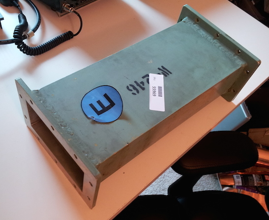 )
)
-
Title: Re: EM Drive Developments - related to space flight applications - Thread 3
Post by: SeeShells on 06/06/2015 03:04 AM -
<a href="http://forum.nasaspaceflight.com/index.php?topic=37642.msg1385412#msg1385412">Quote from: X_RaY on 06/05/2015 09:38 PM</a>
I know the dangers and yes I'll be careful. I'm even building an RF cage around them. I visibly cringed when I saw iulian turn his on.<a href="http://forum.nasaspaceflight.com/index.php?topic=37642.msg1385401#msg1385401">Quote from: SeeShells on 06/05/2015 09:10 PM</a><a href="http://forum.nasaspaceflight.com/index.php?topic=37642.msg1385383#msg1385383">Quote from: rfmwguy on 06/05/2015 08:33 PM</a>
You have to call it something I guess. ;) I was told mine looked like a kitchen microwave colander.<a href="http://forum.nasaspaceflight.com/index.php?topic=37642.msg1385351#msg1385351">Quote from: SeeShells on 06/05/2015 07:18 PM</a><a href="http://forum.nasaspaceflight.com/index.php?topic=37642.msg1385346#msg1385346">Quote from: rfmwguy on 06/05/2015 07:06 PM</a>Final or intermediate amp +39dBm (8 Watts) on its way!
Yes, good for you, but it kind of looks like a toaster. ;)
I was almost going to nickname my experiment Project Lampshade :)
Not this bad an amp. but be sure your cavity is really RF-tight if you dont want to got problems with the FCC or your healthiness. 39 Watt of @2.4GHz is a lot of RF-power... On the other hand people play with 400W or more :D that's quite dangerous even more. Seriously be sure you play safe with such equipment! Go a few meters away before put on the power. Only with spectrum analyzer and a little know how you are be sure about the emitted energy caused by self construction the cone and antenna.
There are people well-known by myself who burn a little hole into a RF sensitive foil with only 3W in a distance of a few cm!
Its like the case of the laser guys: Don't look with your left eye into the RF-beam! (in a distance of a few cm) ;) -
Title: Re: EM Drive Developments - related to space flight applications - Thread 3
Post by: not_a_physicist on 06/06/2015 03:15 AM -
<a href="http://forum.nasaspaceflight.com/index.php?topic=37642.msg1385478#msg1385478">Quote from: WarpTech on 06/06/2015 12:56 AM</a>
What this shows is that constant Power is proportional to a constant Limiting Velocity, not a constant force. ...(clipped)... Given a constant input power, eventually the mass will reach a constant velocity < c.
Paradox solved!
I may be misunderstanding, but doesn't this privilege a reference frame? If you watch a spaceship using 1 watt moving to the right limited to 1 m/s, and I am driving left at 9 m/s, then in my frame of reference the spaceship is travelling at 10 m/s. That's the same 1 watt of input power leading to a different speed limit depending on who's watching. -
Title: Re: EM Drive Developments - related to space flight applications - Thread 3
Post by: SeeShells on 06/06/2015 03:19 AM -
<a href="http://forum.nasaspaceflight.com/index.php?topic=37642.msg1385430#msg1385430">Quote from: WarpTech on 06/05/2015 10:19 PM</a><a href="http://forum.nasaspaceflight.com/index.php?topic=37642.msg1385384#msg1385384">Quote from: foob on 06/05/2015 08:34 PM</a><a href="http://forum.nasaspaceflight.com/index.php?topic=37642.msg1385364#msg1385364">Quote from: WarpTech on 06/05/2015 07:55 PM</a>
Well done. I'm in the middle of re-going through a refresher of all the hooks momentum has in physics, it's kind of fun. Such a simple equation p=mv.
So where did the extra "relative" momentum go? This physics is being totally neglected in the equation F = P/c. That ratio is a back of the envelope calculation of the momentum of light in free space. It has nothing to do with how well light can push on a material as it exits.
Todd -
Title: Re: EM Drive Developments - related to space flight applications - Thread 3
Post by: SeeShells on 06/06/2015 04:05 AM - http://arstechnica.com/science/2015/06/nasa-wants-to-cut-travel-time-to-mars-in-half-with-new-propulsion-tech/
-
Title: Re: EM Drive Developments - related to space flight applications - Thread 3
Post by: deltaMass on 06/06/2015 04:19 AM -
<a href="http://forum.nasaspaceflight.com/index.php?topic=37642.msg1385478#msg1385478">Quote from: WarpTech on 06/06/2015 12:56 AM</a>
Oops - you did it again.<a href="http://forum.nasaspaceflight.com/index.php?topic=37642.msg1385441#msg1385441">Quote from: deltaMass on 06/05/2015 10:49 PM</a><a href="http://forum.nasaspaceflight.com/index.php?topic=37642.msg1385364#msg1385364">Quote from: WarpTech on 06/05/2015 07:55 PM</a>...
I'm afraid you've made a mistake and so your conclusion is wrong. You have to integrate a(t) to derive v(t), which yields Eout(t). This in turn readily exceeds Ein(t) when t > t0. I'll just cut to the chase (not showing the entire derivation). Let
a(t) = a0/(1 + (Pin*t)/(m0*c^2))
F = m(t)*a(t) = m0*a0
...
Ein(t) := P t
a0 := k P / m0
T := m0c2/P
h := 2 m0 / (P k2)
then
m(t) = m0(1 + t/T)
v(t) = a0 T ln(1 + t/T)
so
Eout(t) / Ein(t) = (1/h)(ln(1 + t/T))2 / t , =1 when t = t0.
We need to solve this for t0:
(ln(1 + t0/T))2 = h t0
Mathematica v8 falls on its keester.
However we can plot the left and right side together and verify that a breakeven t0 indeed exists for certain values of h, T
So a brave and creative attempt, but it doesn't guarantee that overunity goes away.
Good catch thank you! That's what happens when I do Math on my lunch break. :-[
I gotta hand it to you @deltaMass, you're sharp! Well, let's try a totally different approach then, shall we?
For instance: Let y be the relativistic gamma factor,
y = 1/sqrt(1 - (v/c)^2)
We "know" the following must be true to conserve energy.
m*c^2*(y - 1) = Pin*t
If there are no other losses or stored energy, then there is 100% conversion of input power to kinetic energy, no more, no less. Take the time derivative of both sides, keeping Pin constant.
m*c^2*dy/dt = Pin
Plug in… (EDIT: lost the “a” below)
dy/dt = (a*v/c^2)*y^3
and solve!
Pin = m*a*v*y^3 or
F = (Pin/v)*(1 - (v/c)^2)^3/2 (Edit 3)
What this shows is that constant Power is proportional to a constant Limiting Velocity, not a constant force. You can't have a system where you have constant N/kW and it just keeps accelerating. If N/kW is held constant, then it will reach a limiting velocity. Therefore, the photon rocket equation F = P/c is wrong! No such equation can exist when you are accelerating a mass. Nature won't allow it. Given a constant input power, eventually the mass will reach a constant velocity < c.
Paradox solved!
EDIT: I find it similar to hovering in a gravitational field of acceleration “a". The gravitational potential has units of velocity squared, just like energy. But to stay at a constant potential (altitude) you must constantly run the engine to hover! (Funny, in my quantum PV warp drive theory, gravitational potentials are equivalent to different power spectrums of the ZPF.) Bingo!
ToddQuotem*c^2*dy/dt = Pin
isn't right. You ought to have the total differential because, recall, you have allowed a variable m(t). Thus
Pin = c2(y dm/dt + m dy/dt)
and so forth...
Yes, there's a reason I call myself deltaMass 8)
But quite frankly, you only muddy the waters by introducing Special Relativity. Your equations ought to work at all speeds.
-
Title: Re: EM Drive Developments - related to space flight applications - Thread 3
Post by: Dortex on 06/06/2015 04:25 AM -
<a href="http://forum.nasaspaceflight.com/index.php?topic=37642.msg1385510#msg1385510">Quote from: not_a_physicist on 06/06/2015 03:15 AM</a>
I may be misunderstanding, but doesn't this privilege a reference frame? If you watch a spaceship using 1 watt moving to the right limited to 1 m/s, and I am driving left at 9 m/s, then in my frame of reference the spaceship is travelling at 10 m/s. That's the same 1 watt of input power leading to a different speed limit depending on who's watching.
To make matters worse, if you're on the ship itself, the drive is stationary relative to you, so it never stops accelerating. It seems to me like we're making Einstein dig his own grave here by using relativity to refute relativity. :-\ -
Title: Re: EM Drive Developments - related to space flight applications - Thread 3
Post by: birchoff on 06/06/2015 04:27 AM -
<a href="http://forum.nasaspaceflight.com/index.php?topic=37642.msg1385521#msg1385521">Quote from: deltaMass on 06/06/2015 04:19 AM</a><a href="http://forum.nasaspaceflight.com/index.php?topic=37642.msg1385478#msg1385478">Quote from: WarpTech on 06/06/2015 12:56 AM</a>
Oops - you did it again.<a href="http://forum.nasaspaceflight.com/index.php?topic=37642.msg1385441#msg1385441">Quote from: deltaMass on 06/05/2015 10:49 PM</a><a href="http://forum.nasaspaceflight.com/index.php?topic=37642.msg1385364#msg1385364">Quote from: WarpTech on 06/05/2015 07:55 PM</a>...
I'm afraid you've made a mistake and so your conclusion is wrong. You have to integrate a(t) to derive v(t), which yields Eout(t). This in turn readily exceeds Ein(t) when t > t0. I'll just cut to the chase (not showing the entire derivation). Let
a(t) = a0/(1 + (Pin*t)/(m0*c^2))
F = m(t)*a(t) = m0*a0
...
Ein(t) := P t
a0 := k P / m0
T := m0c2/P
h := 2 m0 / (P k2)
then
m(t) = m0(1 + t/T)
v(t) = a0 T ln(1 + t/T)
so
Eout(t) / Ein(t) = (1/h)(ln(1 + t/T))2 / t , =1 when t = t0.
We need to solve this for t0:
(ln(1 + t0/T))2 = h t0
Mathematica v8 falls on its keester.
However we can plot the left and right side together and verify that a breakeven t0 indeed exists for certain values of h, T
So a brave and creative attempt, but it doesn't guarantee that overunity goes away.
Good catch thank you! That's what happens when I do Math on my lunch break. :-[
I gotta hand it to you @deltaMass, you're sharp! Well, let's try a totally different approach then, shall we?
For instance: Let y be the relativistic gamma factor,
y = 1/sqrt(1 - (v/c)^2)
We "know" the following must be true to conserve energy.
m*c^2*(y - 1) = Pin*t
If there are no other losses or stored energy, then there is 100% conversion of input power to kinetic energy, no more, no less. Take the time derivative of both sides, keeping Pin constant.
m*c^2*dy/dt = Pin
Plug in… (EDIT: lost the “a” below)
dy/dt = (a*v/c^2)*y^3
and solve!
Pin = m*a*v*y^3 or
F = (Pin/v)*(1 - (v/c)^2)^3/2 (Edit 3)
What this shows is that constant Power is proportional to a constant Limiting Velocity, not a constant force. You can't have a system where you have constant N/kW and it just keeps accelerating. If N/kW is held constant, then it will reach a limiting velocity. Therefore, the photon rocket equation F = P/c is wrong! No such equation can exist when you are accelerating a mass. Nature won't allow it. Given a constant input power, eventually the mass will reach a constant velocity < c.
Paradox solved!
EDIT: I find it similar to hovering in a gravitational field of acceleration “a". The gravitational potential has units of velocity squared, just like energy. But to stay at a constant potential (altitude) you must constantly run the engine to hover! (Funny, in my quantum PV warp drive theory, gravitational potentials are equivalent to different power spectrums of the ZPF.) Bingo!
ToddQuotem*c^2*dy/dt = Pin
isn't right. You ought to have the total differential because, recall, you have allowed a variable m(t). Thus
Pin = c2(y dm/dt + m dy/dt)
and so forth...
I gotta ask, Is there any catastrophic side effect from EmDrive leading to a perpetual motion machine?
P.S. I do not consider needing to go back and fix up or re-write whole theories catastrophic. -
Title: Re: EM Drive Developments - related to space flight applications - Thread 3
Post by: deltaMass on 06/06/2015 04:29 AM -
<a href="http://forum.nasaspaceflight.com/index.php?topic=37642.msg1385483#msg1385483">Quote from: Rodal on 06/06/2015 01:25 AM</a>
Sorry - you're right. That's because there was a typo; I dropped a constant. The definition of 'h' should have been<a href="http://forum.nasaspaceflight.com/index.php?topic=37642.msg1385441#msg1385441">Quote from: deltaMass on 06/05/2015 10:49 PM</a><a href="http://forum.nasaspaceflight.com/index.php?topic=37642.msg1385364#msg1385364">Quote from: WarpTech on 06/05/2015 07:55 PM</a>
I'm afraid you've made a mistake and so your conclusion is wrong. You have to integrate a(t) to derive v(t), which yields Eout(t). This in turn readily exceeds Ein(t) when t > t0. I'll just cut to the chase (not showing the entire derivation). Let<a href="http://forum.nasaspaceflight.com/index.php?topic=37642.msg1384291#msg1384291">Quote from: deltaMass on 06/03/2015 06:16 PM</a>Apart from the F = P/v (trash Einstein) and F = constant (trash Noether) dynamic models, I did propose a third model which is probably best named "frustrated momentum". In this case, the static F persists until a certain momentum value has been established, equal to an initial impulse given to the system. This momentum having been fully established, F returns to zero Newton.
Shawyer's video seems to fit the "frustrated momentum" bill. McCullough's theory also predicts it IIRC.
I think I found a solution to the Paradox:
The issue of a perpetual motion machine goes away when you accept that if the system has input power and no expulsion of mass, then mass is going to increase with time.
m(t) = m0 + Pin*t/c^2
Therefore, if F/Pin = N/kW is a constant, the acceleration will vary inversely to the mass as a function of time.
a(t) = a0/(1 + (Pin*t)/(m0*c^2))
F = m(t)*a(t) = m0*a0
v(t) = a0*t/(1 + (Pin*t)/(m0*c^2))
Now, the kinetic energy can never exceed the input energy.
Pin*t = m0*c^2 * (sqrt(m0*(a0*t)^2 / m(t)*v(t)^2) - 1)
It’s similar to special relativity, but for low velocity, taking relativistic mass into consideration. Even though the speed is far from c, mass is still increasing as energy is input to the system and is NOT expelled.
Comments?
Todd
Ein(t) := P t
a0 := k P / m0
T := m0c2/P
h := 2 m0 / (P k2)
then
m(t) = m0(1 + t/T)
v(t) = a0 T ln(1 + t/T)
so
Eout(t) / Ein(t) = (1/h)(ln(1 + t/T))2 / t , =1 when t = t0.
We need to solve this for t0:
(ln(1 + t0/T))2 = h t0
Mathematica v8 falls on its keester.
However we can plot the left and right side together and verify that a breakeven t0 indeed exists for certain values of h, T
So a brave and creative attempt, but it doesn't guarantee that overunity goes away.
deltaMass, let's mind about units ;) [since you were saying last night that Rabbit, (in Notsosureofit's poem) had the wrong units ;)]
a0 := k P / m0 here "k" has units of inverse velocity (time/length)
h := 2 m0 / (P k2) here "h" has units of time
therefore
(ln(1 + t0/T))2 = h t0
is not dimensionally correct, because the natural logarithm (ln) is dimensionless. The square of a dimensionless quantity is also dimensionless. Notice that t0 must have dimensions of time because deltaMass defined T with dimensions of time, and because( t0/T)2 must be dimensionless to be able to compute (ln(1 + t0/T))2.
now
(ln(1 + t0/T))2 = h t0
since h has dimensions of time, and t0 has dimensions of time, this is stating
dimensionless^2 = time^2
which is obviously incorrect.
See http://forum.nasaspaceflight.com/index.php?topic=37642.msg1385474#msg1385474 for a correct solution including the time at which the energy goes over unity
h := 2 m0 / (P (k T)2) here "h" has units of 1/time
-
Title: Re: EM Drive Developments - related to space flight applications - Thread 3
Post by: deltaMass on 06/06/2015 04:49 AM -
Our posts crossed in the time warp. We are agreeing. You can relax now.
Except the problem is with Mathematica. Since 'h' is a constant of the motion, it doesn't change the fact that M'ca v8 can't solve it.
You say so yourself - "there is no closed form solution"
However, FindInstance[..] will find the solution numerically, using n=2 in the arglist (you need 2 because t0=0 is trivially a solution)
The bottom line is that Todd's attempt to guarantee avoiding overunity with variable mass fails. -
Title: Re: EM Drive Developments - related to space flight applications - Thread 3
Post by: dustinthewind on 06/06/2015 04:57 AM -
<a href="http://forum.nasaspaceflight.com/index.php?topic=37642.msg1385067#msg1385067">Quote from: deltaMass on 06/05/2015 06:55 AM</a>
I see no point in equalising volumes like that. All that's necessary is the venting orthogonal to the thrust (you have that) and two nozzles, diametrically opposite one another (you have that too). I don't think the height placement is critical.
(I checked your maths and it's correct btw)
My reasoning for equalizing the volumes was because I was considering the extreme condition that we place the valves at one end or the other. As a volume of air is expelled that vacuum is then filled with new air. In the extreme placement of the valves at one end then air must travel towards the valves. The movement of the air towards the valves suggest a reaction on the cavity in the opposite direction. My aim was to eliminate that. -
Title: Re: EM Drive Developments - related to space flight applications - Thread 3
Post by: deltaMass on 06/06/2015 04:59 AM - I can sort of buy that. Certainly the problem (almost) goes away if we decide not to weigh the cavity in order to deduce thrust, but measure horizontal thrust instead, as EW is doing
-
Title: Re: EM Drive Developments - related to space flight applications - Thread 3
Post by: deltaMass on 06/06/2015 05:05 AM -
<a href="http://forum.nasaspaceflight.com/index.php?topic=37642.msg1385536#msg1385536">Quote from: Rodal on 06/06/2015 04:56 AM</a>
No idea why you continue to argue the toss with me and beat your breast about your expertise in perturbation theory. If I say "I'm very impressed, Rodal", will you quit?<a href="http://forum.nasaspaceflight.com/index.php?topic=37642.msg1385534#msg1385534">Quote from: deltaMass on 06/06/2015 04:49 AM</a>Our posts crossed in the time warp. We are agreeing. You can relax now.
I hope I'm not the only one that routinely uses perturbation analysis here?
Except the problem is with Mathematica. Since 'h' is a constant of the motion, it doesn't change the fact that M'ca v8 can't solve it.
You say so yourself - "there is no closed form solution"
However, FindInstance[..] will find the solution numerically, using n=2 in the arglist (you need 2 because t=0 is trivially a solution)
Whenever you see a nonlinear equation, one shouldn't just give up. There is usually a perturbation analysis one can perform.
Most problems in nature, including General Relativity (which is a nonlinear theory) are nonlinear. The solution to first order is perfectly fine, because as I show, the overunity speed is way below the speed of light.
It would be incongruous for you to say to WarpTech on one hand "why are you using the nonlinear Special Relativity equations" and then when you see a nonlinearity you stop, instead of pursuing the perturbation to first order, which should take you all the way back to standard theory.
We both had a go at deconstructing Todd's hypothesis. We both found (modulo my typo in a constant) the same result - namely, that postulating variable mass doesn't fix what it was supposed to fix. -
Title: Re: EM Drive Developments - related to space flight applications - Thread 3
Post by: deltaMass on 06/06/2015 05:11 AM -
Quote from: birchoff
I gotta ask, Is there any catastrophic side effect from EmDrive leading to a perpetual motion machine?
It depends what you mean by "catastrophic" of course. For example, Woodward does not think it catastrophic that his drive pulls apparently-unlimited energy and momentum from the distant stars. I would instead describe a device that provided unlimited local free energy as "miraculous". ::)
P.S. I do not consider needing to go back and fix up or re-write whole theories catastrophic. -
Title: Re: EM Drive Developments - related to space flight applications - Thread 3
Post by: dustinthewind on 06/06/2015 05:31 AM -
<a href="http://forum.nasaspaceflight.com/index.php?topic=37642.msg1385544#msg1385544">Quote from: deltaMass on 06/06/2015 05:11 AM</a>Quote from: birchoff
I gotta ask, Is there any catastrophic side effect from EmDrive leading to a perpetual motion machine?
It depends what you mean by "catastrophic" of course. For example, Woodward does not think it catastrophic that his drive pulls apparently-unlimited energy and momentum from the distant stars. I would instead describe a device that provided unlimited local free energy as "miraculous". ::)
P.S. I do not consider needing to go back and fix up or re-write whole theories catastrophic.
It is funny because they were suggesting at some speed the device reaches over-unity. My brain immediately jumped to Doc Brown in Back to the Future and his flux capacitor. His car needed to reach a certain velocity and then the flux capacitor would warp the car.
I know it doesn't seem right because you could say the car is already going fast enough relative to say Jupiter or Pluto. Same thing with respect to the cavity I would suspect.
It is also funny to think the cavity could be thought as a flux capacitor but in the sense that it stores EM energy. Then again a SMES (superconducting magnetic energy storage) unit or capacitor can also.
Edit: below @ deltamass Yeah, I saw the rotary illustration some time earlier in the threads. -
Title: Re: EM Drive Developments - related to space flight applications - Thread 3
Post by: deltaMass on 06/06/2015 05:35 AM - One way to pin down this velocity dependent stuff is to imagine a rotary implementation. frobincat has already provided all the details of that, and I've discussed it too, going back to 1996 with my first chat with Woodward.
-
Title: Re: EM Drive Developments - related to space flight applications - Thread 3
Post by: ThinkerX on 06/06/2015 06:10 AM -
I wonder...would it be valid to test the thrust of this device on a near frictionless surface?
I was at a lake a few days ago. Lots of kids splashing in the water with all sorts of boats and floating objects. What caught my eye was a toddler - maybe three or four years old - pushing around a small boat. On land, said toddler could not have budged the boat an inch. But, in the water, he gave it a little push and away it went. (said water wasn't more than knee deep for him, btw).
So, would a similar test be valid for the EM Drive? Put it on a tiny boat in a tub or pool and see if it could move itself? Or perhaps slick ice or something similar?
-
Title: Re: EM Drive Developments - related to space flight applications - Thread 3
Post by: deltaMass on 06/06/2015 06:18 AM - Yes indeed. Or an air table. Or on dry ice mounts.
-
Title: Re: EM Drive Developments - related to space flight applications - Thread 3
Post by: dustinthewind on 06/06/2015 07:04 AM -
<a href="http://forum.nasaspaceflight.com/index.php?topic=37642.msg1385551#msg1385551">Quote from: deltaMass on 06/06/2015 05:35 AM</a>
One way to pin down this velocity dependent stuff is to imagine a rotary implementation. frobincat has already provided all the details of that, and I've discussed it too, going back to 1996 with my first chat with Woodward.
I wanted to suggest a possible parallel to propellant-less propulsion in a rotary sense. Two examples come to mind that might qualify in this category. One is the device in this video. https://www.youtube.com/watch?v=j6hxhSX4RUk . The device regardless of how fast it rotates can still have energy added to it by torquing against the force of the pull on the weights that pull towards the larger radius. I think it qualifies as propellantless.
Another is a swing but we are going to make it a hard long rod that can rotate 360 degrees and have an object at the end that can do work. set it up like a swing so gravity pulls it down and now set it in motion. When the device reaches max velocity it does work against the circular force. When it reaches minimal velocity it contracts so it can do work again at max velocity.
Would these devices be in the same category as a propellantless thruster rotating in circles?
If so, what is to stop them from reaching overunity?
whoops I didn't realize this but it looks like some one has already attempted such a thing. I can't say it is valid or not. https://www.youtube.com/watch?v=U8v7ZQiGSgE It's possible energy could be being added externally. Anyways, I think it might relate to the discussion of a propellantless em drive and conservation of momentum issues some times discussed. -
Title: Re: EM Drive Developments - related to space flight applications - Thread 3
Post by: WarpTech on 06/06/2015 07:41 AM -
<a href="http://forum.nasaspaceflight.com/index.php?topic=37642.msg1385510#msg1385510">Quote from: not_a_physicist on 06/06/2015 03:15 AM</a><a href="http://forum.nasaspaceflight.com/index.php?topic=37642.msg1385478#msg1385478">Quote from: WarpTech on 06/06/2015 12:56 AM</a>
What this shows is that constant Power is proportional to a constant Limiting Velocity, not a constant force. ...(clipped)... Given a constant input power, eventually the mass will reach a constant velocity < c.
Paradox solved!
I may be misunderstanding, but doesn't this privilege a reference frame? If you watch a spaceship using 1 watt moving to the right limited to 1 m/s, and I am driving left at 9 m/s, then in my frame of reference the spaceship is travelling at 10 m/s. That's the same 1 watt of input power leading to a different speed limit depending on who's watching.
It is identical to hovering in a gravitational field. The potential energy per unit mass is ~v^2. It is identical to the difference in potential between 2 altitudes in a gravitational field. That's the width and breadth of the "preferred frame".
I just finished a paper, but I'm too tired to proof it tonight. Check back tomorrow!
-
Title: Re: EM Drive Developments - related to space flight applications - Thread 3
Post by: WarpTech on 06/06/2015 07:52 AM -
<a href="http://forum.nasaspaceflight.com/index.php?topic=37642.msg1385521#msg1385521">Quote from: deltaMass on 06/06/2015 04:19 AM</a>
...
Oops - you did it again.Quotem*c^2*dy/dt = Pin
isn't right. You ought to have the total differential because, recall, you have allowed a variable m(t). Thus
Pin = c2(y dm/dt + m dy/dt)
and so forth...
Yes, there's a reason I call myself deltaMass 8)
But quite frankly, you only muddy the waters by introducing Special Relativity. Your equations ought to work at all speeds.
No sir, m is the invariant rest mass, not m(t) in this equation.
No again sir, the behavior of a limiting velocity is identical to hovering in a gravitational field. I'll release the paper tomorrow. I'm tired. I told you it was related to General Relativity!
-
Title: Re: EM Drive Developments - related to space flight applications - Thread 3
Post by: deltaMass on 06/06/2015 08:10 AM - I suspected later that I'd misinterpreted your intent - apologies. Nevertheless, the dynamics "paradox" doesn't depend on relativistic speeds to manifest itself, and so I think this gamma relation is a red herring. It has to make correct predictions at a few metres/second also.
-
Title: Re: EM Drive Developments - related to space flight applications - Thread 3
Post by: frobnicat on 06/06/2015 10:44 AM -
<a href="http://forum.nasaspaceflight.com/index.php?topic=37642.msg1385474#msg1385474">Quote from: Rodal on 06/06/2015 12:44 AM</a>
...
we get
v = 2 vp
as the velocity at which the kinetic energy becomes greater than the input energy
Notice that this is twice the amount previously calculated by @frobnicat for the case of constant mass.
Not really, I mean, what you are arriving at after an approximation justified by the extremely low delta_m in subrelativistic case (mission profile with delta_v << c) is exactly the same Vbe=2*vp (with vp=1/(thrust/power), for thrust and power measured "at rest") as obtained in Higgins.
The 2* factor is not dependant on "added mass" relativistic effect, even if properly accounted for, it is dependant on the, somewhat arbitrary (ill defined) frame from which "velocity" is understood, and from the scheme considered to assess excess energy :
- Constant acceleration (or almost constant acceleration if mass is slightly increasing) at constant thrust/constant power, when is Ke accounted in the starting reference frame > Pin*t ? => Vbe=2*Vp
- Constant tangential velocity (around an arbitrarily large track, or even on a linear infinite track) at constant thrust/constant power, when is recoverable mechanical power in the frame of the track > Pin ? => Vbe=Vp.
This last scheme can easily discard away any "flow of added mass" due to Pin as IR waste heat, so we have a perfectly stationary situation. Those losses don't prevent the cycle to run over-unity (as has been taken into consideration in my numerical examples). Please note also that in this last scheme, the apparent CoE breaking is "instantaneous", it can be observed on arbitrarily small time intervals (comparing powers, not energies). Please note also that in this last scheme, the em drive is not accelerating (in the axis of its thrust, and no other acceleration at all with a linear track), so it is in the exact same conditions as when constant (or near constant) thrust was observed at constant Pin against a spring on balances. Unless frame invariance is broken and pushing 10mN on balance arm at constant "0 speed" relative to lab is different from pushing 10mN on some generator's arm at constant 200km/s relative to some arbitrary track.
-
Title: Re: EM Drive Developments - related to space flight applications - Thread 3
Post by: Rodal on 06/06/2015 12:00 PM -
<a href="http://forum.nasaspaceflight.com/index.php?topic=37642.msg1385588#msg1385588">Quote from: frobnicat on 06/06/2015 10:44 AM</a><a href="http://forum.nasaspaceflight.com/index.php?topic=37642.msg1385474#msg1385474">Quote from: Rodal on 06/06/2015 12:44 AM</a>
...
we get
v = 2 vp
as the velocity at which the kinetic energy becomes greater than the input energy
Notice that this is twice the amount previously calculated by @frobnicat for the case of constant mass.
Not really, I mean, what you are arriving at after an approximation justified by the extremely low delta_m in subrelativistic case (mission profile with delta_v << c) is exactly the same Vbe=2*vp (with vp=1/(thrust/power), for thrust and power measured "at rest") as obtained in Higgins.
The 2* factor is not dependant on "added mass" relativistic effect, even if properly accounted for, it is dependant on the, somewhat arbitrary (ill defined) frame from which "velocity" is understood, and from the scheme considered to assess excess energy :
- Constant acceleration (or almost constant acceleration if mass is slightly increasing) at constant thrust/constant power, when is Ke accounted in the starting reference frame > Pin*t ? => Vbe=2*Vp
- Constant tangential velocity (around an arbitrarily large track, or even on a linear infinite track) at constant thrust/constant power, when is recoverable mechanical power in the frame of the track > Pin ? => Vbe=Vp.
This last scheme can easily discard away any "flow of added mass" due to Pin as IR waste heat, so we have a perfectly stationary situation. Those losses don't prevent the cycle to run over-unity (as has been taken into consideration in my numerical examples). Please note also that in this last scheme, the apparent CoE breaking is "instantaneous", it can be observed on arbitrarily small time intervals (comparing powers, not energies). Please note also that in this last scheme, the em drive is not accelerating (in the axis of its thrust, and no other acceleration at all with a linear track), so it is in the exact same conditions as when constant (or near constant) thrust was observed at constant Pin against a spring on balances. Unless frame invariance is broken and pushing 10mN on balance arm at constant "0 speed" relative to lab is different from pushing 10mN on some generator's arm at constant 200km/s relative to some arbitrary track.
I thought it was better pointing out the factor of 2 that me claiming "I got a result basically the same as @frobnicat" . Thank you for stating it better :) : the factor of 2 <<is dependent on the, somewhat arbitrary (ill defined) frame from which "velocity" is understood, and from the scheme considered to assess excess energy :>>. I added a note to my proof http://forum.nasaspaceflight.com/index.php?topic=37642.msg1385474#msg1385474, directing the reader to your message ;).
Hat tip to deltaMass ;) for pointing that the solution with E=mc^2 also goes to Infinity.
In addition, we have also shown that the solution using E=mc^2 is identical, to first order We should not stop at a derivation and give up when the full equation is nonlinear and cannot be solved with a closed-from solution, as most problems in Nature are nonlinear. However, most problems in Nature can usually be linearized. We should seek a perturbation solution in terms of a parameter that is small in Nature. In this case, the small parameter is the ratio of the speed to the speed of light, which is extremely small, hence the final solution is perfectly fine to first order. This is much better than dealing with fully nonlinear equations and solving them numerically, because, if they contain small parameters, it is numerically more accurate to solve them by doing a perturbation to first order (since this eliminates differences of small numbers, which is an ill-conditioned problem), and the first order solution is always more intuitive. QED
And thank you to WarpTech :) for seeking out further solutions that clarify the issues associated with the EM Drive. -
Title: Re: EM Drive Developments - related to space flight applications - Thread 3
Post by: rfmwguy on 06/06/2015 01:18 PM -
Copper wire mesh shipped and on the way.
http://www.ebay.com/itm/190935667491 -
Title: Re: EM Drive Developments - related to space flight applications - Thread 3
Post by: WarpTech on 06/06/2015 01:35 PM -
<a href="http://forum.nasaspaceflight.com/index.php?topic=37642.msg1385580#msg1385580">Quote from: deltaMass on 06/06/2015 08:10 AM</a>
I suspected later that I'd misinterpreted your intent - apologies. Nevertheless, the dynamics "paradox" doesn't depend on relativistic speeds to manifest itself, and so I think this gamma relation is a red herring. It has to make correct predictions at a few metres/second also.
It does. It is not required to come close to the speed of light before it is necessary to "hover" in a gravitational field. Not any more than the notion that I am moving faster than I was 10 minutes ago because I'm in an accelerated reference frame whilst sitting in my chair. At "Any" thrust-to-power ratio, eventually there is a limiting speed. For 2 N/W, the limit is .5 m/s, which equates to a gravitational potential energy per unit mass of ~.125 J/kg. Once this speed is reached, regardless that the engine is running at constant thrust-to-power, it is simply "hovering" at at a constant velocity potential. It does not exceed this speed without first increasing the input power supplied. It does not start providing output power over and above what was supplied.
This is a prime example of Einstein's Equivalence Principle, where the gravitational potential energy per unit mass is v^2. When the maximum potential energy is reached, it hovers at constant speed.
Todd
-
Title: Re: EM Drive Developments - related to space flight applications - Thread 3
Post by: SeeShells on 06/06/2015 02:00 PM -
<a href="http://forum.nasaspaceflight.com/index.php?topic=37642.msg1385586#msg1385586">Quote from: arc on 06/06/2015 10:25 AM</a>
hmmmm . . . I read? :)<a href="http://forum.nasaspaceflight.com/index.php?topic=37642.msg1385519#msg1385519">Quote from: SeeShells on 06/06/2015 04:05 AM</a>http://arstechnica.com/science/2015/06/nasa-wants-to-cut-travel-time-to-mars-in-half-with-new-propulsion-tech/
SeeShells, You rock.
How do you manage to find such seriously interesting doc's? -
Title: Re: EM Drive Developments - related to space flight applications - Thread 3
Post by: Dortex on 06/06/2015 02:17 PM -
<a href="http://forum.nasaspaceflight.com/index.php?topic=37642.msg1385623#msg1385623">Quote from: WarpTech on 06/06/2015 01:35 PM</a>
For 2 N/W, the limit is .5 m/s, which equates to a gravitational potential energy per unit mass of ~.125 J/kg.
Why do I keep getting the feeling you're implying a preferred rest frame? And why is Einstein being involved in this excercise? If I'm sitting inside a ship with said drive, it'll never actually reach .5 m/s, thus continue to accelerate forever. In my reference frame, it will reach over-unity, no? -
Title: Re: EM Drive Developments - related to space flight applications - Thread 3
Post by: SeeShells on 06/06/2015 02:30 PM -
<a href="http://forum.nasaspaceflight.com/index.php?topic=37642.msg1385623#msg1385623">Quote from: WarpTech on 06/06/2015 01:35 PM</a>
You guys rock!!! All of you who skip the light fantastic in your ciphering, my hat is off to you.<a href="http://forum.nasaspaceflight.com/index.php?topic=37642.msg1385580#msg1385580">Quote from: deltaMass on 06/06/2015 08:10 AM</a>I suspected later that I'd misinterpreted your intent - apologies. Nevertheless, the dynamics "paradox" doesn't depend on relativistic speeds to manifest itself, and so I think this gamma relation is a red herring. It has to make correct predictions at a few metres/second also.
It does. It is not required to come close to the speed of light before it is necessary to "hover" in a gravitational field. Not any more than the notion that I am moving faster than I was 10 minutes ago because I'm in an accelerated reference frame whilst sitting in my chair. At "Any" thrust-to-power ratio, eventually there is a limiting speed. For 2 N/W, the limit is .5 m/s, which equates to a gravitational potential energy per unit mass of ~.125 J/kg. Once this speed is reached, regardless that the engine is running at constant thrust-to-power, it is simply "hovering" at at a constant velocity potential. It does not exceed this speed without first increasing the input power supplied. It does not start providing output power over and above what was supplied.
This is a prime example of Einstein's Equivalence Principle, where the gravitational potential energy per unit mass is v^2. When the maximum potential energy is reached, it hovers at constant speed.
Todd
I'm getting better, polishing up my rusty 40 yr old math as fast as can. Like I've said I never built anything until I truly understand the why, and here I am building an EMDrive. Excited? Yes, very and hopefully I can add that little stick of data to the fire we are making and in doing so understand the why.
I'm laying in my cozy bed half asleep this morning going over what I have learned and understand. I realized this isn't a thrusting Drive but more like an Mass-Effect device. Close here? I'm saying this for the thousands of lurkers and readers who can't tiptoe through the math like you can.
Opinions come from understanding (as does research dollars :) ) So who would like to take the leap and explain to the 99% of lurkers here better than I can? I'm on my first cup of coffee and still somewhat groggy.
Shell
-
Title: Re: EM Drive Developments - related to space flight applications - Thread 3
Post by: Rodal on 06/06/2015 02:32 PM -
<a href="http://forum.nasaspaceflight.com/index.php?topic=37642.msg1385623#msg1385623">Quote from: WarpTech on 06/06/2015 01:35 PM</a><a href="http://forum.nasaspaceflight.com/index.php?topic=37642.msg1385580#msg1385580">Quote from: deltaMass on 06/06/2015 08:10 AM</a>
I suspected later that I'd misinterpreted your intent - apologies. Nevertheless, the dynamics "paradox" doesn't depend on relativistic speeds to manifest itself, and so I think this gamma relation is a red herring. It has to make correct predictions at a few metres/second also.
It does. It is not required to come close to the speed of light before it is necessary to "hover" in a gravitational field. Not any more than the notion that I am moving faster than I was 10 minutes ago because I'm in an accelerated reference frame whilst sitting in my chair. At "Any" thrust-to-power ratio, eventually there is a limiting speed. For 2 N/W, the limit is .5 m/s, which equates to a gravitational potential energy per unit mass of ~.125 J/kg. Once this speed is reached, regardless that the engine is running at constant thrust-to-power, it is simply "hovering" at at a constant velocity potential. It does not exceed this speed without first increasing the input power supplied. It does not start providing output power over and above what was supplied.
This is a prime example of Einstein's Equivalence Principle, where the gravitational potential energy per unit mass is v^2. When the maximum potential energy is reached, it hovers at constant speed.
Todd
It seems to me that this "paradox" was never a paradox (a statement that apparently contradicts itself and yet might be true), but like most paradoxes in Physics it just addresses a possible misunderstanding. The misunderstanding of making the unwarranted assumptions that
1) one can have constant acceleration at constant power ad infinitum and
2) that one can ignore the 1st or the 2nd law of thermodynamics.
Initially this was not obvious. The fact that is is not obvious is that new people in the thread keep bringing it up and the fact that Higgins has now published an article about it.
However, @frobnicat did such a good job at addressing it that it now appears that constant acceleration at constant power is an unwarranted assumption.
Extending the paradox beyond that (that constant acceleration at constant power is impossible) can be viewed as a strawman. The so-called typical "attacking a straw man" argument creates the illusion of having completely refuted or defeated an opponent's proposition by replacing it with a different proposition (i.e., "stand up a straw man") and then to refute or defeat that false argument ("knock down a straw man") instead of the original proposition.
( )
)
The different proposition, advanced by this strawman, is that EM Drive necessarily means constant acceleration at constant power (WRONG) and that EM Drive means one can ignore the 1st and 2nd Law of Thermodynamics (WRONG).
As @Notsosureofit wrote, the arguments behind this "paradox" are circular ("pun intended"). They are based on unwarranted assumptions.
All that the "paradox" proves, again, is that one cannot have free energy. It certainly does not prove that there cannot be an EM Drive that respects the 1st and 2nd Law of Thermodynamics. The main argument against the EM Drive has always rested on conservation of momentum. That is what needs to be addressed: conservation of momentum. There is no author I know of that has proposed abandoning the law of conservation of momentum. All authors have come up with one way or another to satisfy conservation of momentum, but there is no convincing proof to this date. -
Title: Re: EM Drive Developments - related to space flight applications - Thread 3
Post by: frobnicat on 06/06/2015 03:49 PM -
@Rodal : regarding the straw man aspect of the argument I strongly object. It's not because the apparent CoE breaking is put forward again and again by sceptics (including some sceptics that haven't really gave the experiments and papers the minimum attention span they deserve) that it is less relevant. We don't care about words, paradoxical or not.
1/ If the em drive effect is a black box that gives an (averaged) constant thrust for constant power (regardless of constant speed or not constant speed) at better than 1/c ratio, then it can yield more energy than it uses. This is only paradoxical if one can't explain/measure where this excess energy is coming from (what is tapped).
2/ If the em drive effect is a black box that don't give a constant thrust for constant power, such that gained Ke<Pin*t, then it becomes not much more useful than, say, a Vasimr scheme where ejection speed is optimised to a given end deltaV goal. If you disagree please set-up a quick comparison with facts and order of magnitude figures. Paradox resolved, so to speak, but all papers that I know of that advocate both em drive for space flight and insisting on apparent respect of CoE (not requiring a mysterious excess energy being tapped) fail to apply the inequality Ke<Pin*t in proposed mission profiles. So, in those papers, it is not a problem of paradox but either unforgivable sloppiness at best, or a deliberate omission of an inconvenient inconsistency in the claims.
So, either case, CoE aspects around EM drive claims is not a red herring, it is at the core of why it won't work as claimed, as far as deep space flight is concerned. Proponents say explicitly 2/ and implicitly use 1/ ...
[added] BTW I don't see what second law as to do with that...
-
Title: Re: EM Drive Developments - related to space flight applications - Thread 3
Post by: Rodal on 06/06/2015 04:04 PM -
<a href="http://forum.nasaspaceflight.com/index.php?topic=37642.msg1385666#msg1385666">Quote from: frobnicat on 06/06/2015 03:49 PM</a>
@Rodal : regarding the straw man aspect of the argument I strongly object. It's not because the apparent CoE breaking is put forward again and again by sceptics (including some sceptics that haven't really gave the experiments and papers the minimum attention span they deserve) that it is less relevant. We don't care about words, paradoxical or not.
1/ If the em drive effect is a black box that gives an (averaged) constant thrust for constant power (regardless of constant speed or not constant speed) at better than 1/c ratio, then it can yield more energy than it uses. This is only paradoxical if one can't explain/measure where this excess energy is coming from (what is tapped).
2/ If the em drive effect is a black box that don't give a constant thrust for constant power, such that gained Ke<Pin*t, then it becomes not much more useful than, say, a Vasimr scheme where ejection speed is optimised to a given end deltaV goal. If you disagree please set-up a quick comparison with facts and order of magnitude figures. Paradox resolved, so to speak, but all papers that I know of that advocate both em drive for space flight and insisting on apparent respect of CoE (not requiring a mysterious excess energy being tapped) fail to apply the inequality Ke<Pin*t in proposed mission profiles. So, in those papers, it is not a problem of paradox but either unforgivable sloppiness at best, or a deliberate omission of an inconvenient inconsistency in the claims.
So, either case, CoE aspects around EM drive claims is not a red herring, it is at the core of why it won't work as claimed, as far as deep space flight is concerned. Proponents say explicitly 2/ and implicitly use 1/ ...
[added] BTW I don't see what second law as to do with that...
If the EM Drive is eventually proven to conserve momentum, then whether it will be commercially useful, and to what extent, will remain to be shown. There are plenty of devices that satisfy conservation of momentum and conservation of energy that "are not commercially useful". So the new argument that the EM Drive may not be as commercially useful as described by some authors is a non-sequitur.
When all that is being measured right now are a few microNewtons in vacuum, and when we are still debating whether the measurements are experimental artifacts, discussion and "proofs" of commercial usefulness are, Ahem :) , shall we say, a bit "premature" ? :)
-
Title: Re: EM Drive Developments - related to space flight applications - Thread 3
Post by: Prunesquallor on 06/06/2015 04:07 PM -
<a href="http://forum.nasaspaceflight.com/index.php?topic=37642.msg1385643#msg1385643">Quote from: Rodal on 06/06/2015 02:32 PM</a><a href="http://forum.nasaspaceflight.com/index.php?topic=37642.msg1385623#msg1385623">Quote from: WarpTech on 06/06/2015 01:35 PM</a>
Todd, what should we add to the section on energy conservation in the EM Drive wiki:<a href="http://forum.nasaspaceflight.com/index.php?topic=37642.msg1385580#msg1385580">Quote from: deltaMass on 06/06/2015 08:10 AM</a>I suspected later that I'd misinterpreted your intent - apologies. Nevertheless, the dynamics "paradox" doesn't depend on relativistic speeds to manifest itself, and so I think this gamma relation is a red herring. It has to make correct predictions at a few metres/second also.
It does. It is not required to come close to the speed of light before it is necessary to "hover" in a gravitational field. Not any more than the notion that I am moving faster than I was 10 minutes ago because I'm in an accelerated reference frame whilst sitting in my chair. At "Any" thrust-to-power ratio, eventually there is a limiting speed. For 2 N/W, the limit is .5 m/s, which equates to a gravitational potential energy per unit mass of ~.125 J/kg. Once this speed is reached, regardless that the engine is running at constant thrust-to-power, it is simply "hovering" at at a constant velocity potential. It does not exceed this speed without first increasing the input power supplied. It does not start providing output power over and above what was supplied.
This is a prime example of Einstein's Equivalence Principle, where the gravitational potential energy per unit mass is v^2. When the maximum potential energy is reached, it hovers at constant speed.
Todd
http://emdrive.wiki/Energy_Conservation
as per your latest thoughts (regarding the comparison with a photon rocket and regarding the gamma relationship) ?
Is this what you would like to have added?Quote from: WarpTechParadox solved!
Constant Power is proportional to a constant Limiting Velocity, not a constant force. You can't have a system where you have constant N/kW and it just keeps accelerating. If N/kW is held constant, then it will reach a limiting velocity. Therefore, the photon rocket equation F = P/c is wrong! No such equation can exist when you are accelerating a mass. Nature won't allow it. Given a constant input power, eventually the mass will reach a constant velocity < c.
Note: it seems to me that this "paradox" was never a paradox (a statement that apparently contradicts itself and yet might be true), but like most paradoxes in Physics it just addresses a possible misunderstanding. The misunderstanding of making the unwarranted assumptions that
1) one can have constant acceleration at constant power ad infinitum and
2) that one can ignore the 2nd law of thermodynamics.
The paradox can be viewed as a strawman. The so-called typical "attacking a straw man" argument creates the illusion of having completely refuted or defeated an opponent's proposition by replacing it with a different proposition (i.e., "stand up a straw man") and then to refute or defeat that false argument ("knock down a straw man") instead of the original proposition.
()
The different proposition, advanced by this strawman, is that EM Drive necessarily means constant acceleration at constant power (WRONG) and that EM Drive means one can ignore the 2nd Law of Thermodynamics (WRONG).
As @Notsosureofit wrote, the arguments behind this "paradox" are circular ("pun intended"). They are based on unwarranted assumptions.
All that the "paradox" proves, again, is that one cannot have free energy. It certainly does not prove that there cannot be an EM Drive that respects the 2nd Law of Thermodynamics. The main argument against the EM Drive has always rested on conservation of momentum. That is what needs to be addressed: conservation of momentum. There is no author I know of that has proposed abandoning the law of conservation of momentum. All authors have come up with one way or another to satisfy conservation of momentum, but there is no convincing proof to this date.
Call me slow, but I just see new paradoxes arising. Don't see that this resolves anything.
If I am on a spacecraft on a parallel course with the emdrive craft and I am coasting along at the "limiting velocity" (having reached that velocity by conventional means), I now see energy DISAPPEARING from the emdrive - it's power plant is producing power (in my reference frame), but kinetic energy is not changing (in my reference frame).
And, as has been asked many times many posts ago, what happens, having achieved "limiting velocity" if I turn the emdrive off? -
Title: Re: EM Drive Developments - related to space flight applications - Thread 3
Post by: Rodal on 06/06/2015 04:10 PM -
<a href="http://forum.nasaspaceflight.com/index.php?topic=37642.msg1385674#msg1385674">Quote from: Prunesquallor on 06/06/2015 04:07 PM</a>
...
I never supported the notion of a limiting velocity per se. I support the notion that every such limit is governed by the 2nd law of thermodynamics, not by a "limiting velocity" as such a velocity can always be attacked on the basis of frame dependence, obviously.
Call me slow, but I just see new paradoxes arising. Don't see that this resolves anything.
If I am on a spacecraft on a parallel course with the emdrive craft coasting along at the "limiting velocity" (having reached that velocity by conventional means), I now see energy DISAPPEARING from the emdrive - it's power plant is producing power (in my reference frame), but kinetic energy is not changing (in my reference frame).
And, as has been asked many times many posts ago, what happens, having achieved "limiting velocity" if I turn the emdrive off?
The notion of entropy is universal. The notion of velocity is frame-dependent. It sounds like another straw man argument.
Operational efficiency of vehicles is governed by thermodynamics (which is curiously not discussed much in this thread) and not by just by kinematics or by dynamics.
NOTE: in the interest of saving bandwidth could you please delete that strawman picture and other stuff being repeated again in the quote? [the quote is like 10 times longer than the message] thanks. It makes the thread easier to read (if people are interested in reading the original message they can always click on the quote that takes them to the original message) -
Title: Re: EM Drive Developments - related to space flight applications - Thread 3
Post by: frobnicat on 06/06/2015 04:25 PM -
@Rodal: I'm not really talking about commercial usefulness, but rather that a true effect (not a sum of local spurious forces) really implies 1/, as the position 2/ is not tenable. And 1/ needs a "secret" energy source. Of course there is also an other possibility :
3/ All reported "thrusts" are just local spurious forces (against local earth grounded agents). No CoE discussion then. The CoE argument directs us toward the natural conclusion because 3/ has no CoE issue while both 1/ and 2/ have. If you were presented with a particularly elaborate and fussy purely mechanical perpetual motion of the first kind, would you rather trust the author's integration of energy balance between all parts > 0 than just discard the claim on CoE alone ?
2/ is not tenable because apparent CoE breaking does not need integration of Pin over a long period of increasing Ke, it emerges "instantaneously" (on arbitrarily short time interval) as soon as you have 10µN of thrust for 50W power, even for 1s, as the case "pushing against constant velocity generator" clearly shows. Modest Eaglework's results are already apparently breaking CoE, seems obvious enough, can't be eluded. Why do you think those results raise such suspicion about their validity (as a "true" effect) ?
-
Title: Re: EM Drive Developments - related to space flight applications - Thread 3
Post by: frobnicat on 06/06/2015 04:35 PM -
<a href="http://forum.nasaspaceflight.com/index.php?topic=37642.msg1385681#msg1385681">Quote from: Rodal on 06/06/2015 04:28 PM</a><a href="http://forum.nasaspaceflight.com/index.php?topic=37642.msg1385680#msg1385680">Quote from: frobnicat on 06/06/2015 04:25 PM</a>
...Why do you think those results raise such suspicion about their validity (as a "true" effect) ?
I think that they raise suspicion because of conservation of momentum
CoE issues are as convincing as for CoM, but more difficult to get wrong.
http://arxiv.org/pdf/1506.00494.pdfQuote from: HigginsA number of elaborate explanations have been advanced, ranging from classical electromagnetics to interactions with virtual particles in the quantum vacuum, in order to explain this result and reconcile it with the conservation of momentum. This paper will not address these issues whatsoever, but rather will examine the consequences in relation to the First Law of Thermodynamics if such a device were to exist.
...
The fact that the EM drive, or any other reactionless drive that has a thrust-to-power ratio greater than a photon-emitting device, would enable a perpetual motion machine of the first kind suggests that such a device cannot exist. This objection is not as easily explained away as the conservation of momentum objection to a reactionless drive -
Title: Re: EM Drive Developments - related to space flight applications - Thread 3
Post by: Rodal on 06/06/2015 04:40 PM -
Let's discuss this on objective basis, not on what Higgins writes or having a poll on why people have suspicions. It doesn't matter really if most people are more familiar with conservation of energy than conservation of momentum.
Somebody already started a poll on people's beliefs on the EM Drive.
While one may use Bayesian Statistical Analysis (on things like the stock market, that are driven by people's beliefs) , the relevance of what people in this forum may or may not believe regarding something governed by Nature escapes me.
Nature has its own laws. -
Title: Re: EM Drive Developments - related to space flight applications - Thread 3
Post by: wallofwolfstreet on 06/06/2015 04:44 PM -
Regardless of whether or not the CoE issue is real or not, I think I can offer a quick example of this issue without falling back on any reference to relativity or use of difficult math, just for the sake of illustration. Shoutout to @frobnicat for working through this procedure earlier in the threads.
Assumptions:
1) The emdrive has a constant force to power ratio (this assumption is critical)
For this example, we will use the greatest predicted thrust to power ratio, coming from Shawyer's own website, of 30 kN/kW. http://emdrive.com/faq.html (scroll to the very bottom)
Then:
P: Power
T: Thrust
v: velocity
R: Thrust to Power ratio
Pout=T*v
Pout=(R*Pin)*v
Overunity (ie. free energy) is achieved when Pout=Pin
So the critical v is given by:
1=R*v
v=1/R
If we sub in Shawyer's claimed theoretical thrust to power ratio, we get that overunity occurs at just 0.033 m/s. No need for relativity. Mass increase is completely negligible. Put the device at the end of a 1 m wheel and spin it at 0.033 rad/s, attach a generator and you're golden. Holding this wheeled device at a constant angular velocity just slightly above 0.33 rad/s will result in more power out than power in. It is a continual process with no limiting factor. This works equally well on earth or between galaxies, no gravity well needed.
Obviously we can't just take the 30 kN/kW at face value, but it illustrates the issue perfectly. The CoE issue isn't complicated or hidden in advanced maths.
It is up to the reader to refute the critical assumption, which isn't necessarily so easy to do within Relativity. -
Title: Re: EM Drive Developments - related to space flight applications - Thread 3
Post by: frobnicat on 06/06/2015 05:04 PM -
<a href="http://forum.nasaspaceflight.com/index.php?topic=37642.msg1385684#msg1385684">Quote from: Rodal on 06/06/2015 04:40 PM</a>
Let's discuss this on objective basis, not on what Higgins writes or having a poll on why people have suspicions. It doesn't matter really if most people are more familiar with conservation of energy than conservation of momentum. Nature has its own laws.
You yourself said that a CoE issue is a CoM issue and reciprocally (if relativity is to hold). So how can you say that CoE is a red herring and straw man argument, when as far as em drive effect apparent impossibility is concerned, apparent CoE breaking fits the bill as much as apparent CoM breaking ?
(10mN corrected to 10µN, thanks, wanted to leave margin against uncertainties, don't change the argument, could be ever so slightly above photon rocket, .2µN for 50W for instance, already apparently breaking CoE...)
-
Title: Re: EM Drive Developments - related to space flight applications - Thread 3
Post by: frobnicat on 06/06/2015 05:17 PM -
<a href="http://forum.nasaspaceflight.com/index.php?topic=37642.msg1385689#msg1385689">Quote from: Rodal on 06/06/2015 05:08 PM</a><a href="http://forum.nasaspaceflight.com/index.php?topic=37642.msg1385688#msg1385688">Quote from: frobnicat on 06/06/2015 05:04 PM</a><a href="http://forum.nasaspaceflight.com/index.php?topic=37642.msg1385684#msg1385684">Quote from: Rodal on 06/06/2015 04:40 PM</a>
Let's discuss this on objective basis, not on what Higgins writes or having a poll on why people have suspicions. It doesn't matter really if most people are more familiar with conservation of energy than conservation of momentum. Nature has its own laws.
You yourself said that a CoE issue is a CoM issue and reciprocally (if relativity is to hold). So how can you say that CoE is a red herring and straw man argument, when as far as em drive effect apparent impossibility is concerned, apparent CoE breaking fits the bill as much as apparent CoM breaking ?
(10mN corrected to 10µN, thanks, wanted to leave margin against uncertainties, don't change the argument, could be ever so slightly above photon rocket, .2µN for 50W for instance, already apparently breaking CoE...)
What I wrote is that assuming constant acceleration at constant power is a straw man argument.
I also add to that now that assuming a limiting velocity as a constraint is another straw man argument.
Perhaps I should add a list of unwarranted assumptions to the EM Drive wiki ?
Efficiency of vehicles is governed by thermodynamics, and not just based on kinematics or dynamics or frame-indifference.
I still don't get your inclusion of second law in that.
Could you please explain what is your proposed phenomenology of not constant acceleration at constant power ? a(t) = function( power(t) + what else ) ? Have you a precise idea or is it just a hint ? Since you seem to discard completely a(t) = cst * power(t), do you see any consistent alternative ?
-
Title: Re: EM Drive Developments - related to space flight applications - Thread 3
Post by: SeeShells on 06/06/2015 05:24 PM -
<a href="http://forum.nasaspaceflight.com/index.php?topic=37642.msg1385684#msg1385684">Quote from: Rodal on 06/06/2015 04:40 PM</a>
Let's discuss this on objective basis, not on what Higgins writes or having a poll on why people have suspicions. It doesn't matter really if most people are more familiar with conservation of energy than conservation of momentum.
You're right Mother Nature has her own laws and some of them like Quantum Mechanics seem to violate them. When I first read about quantum entanglement I said no, no way can one particle effect another particle that is entangled instantaneously, but it happens. We have tried to comprehend these laws as best we can and as faulted as we are many a time we are simply dead wrong.
Somebody already started a poll on people's beliefs on the EM Drive.
While I use Bayesian Statistical Analysis (on things like the stock market, that are driven by people's beliefs) to make a living, this emphasis on what people in this forum believe regarding something governed by Nature escapes me.
Nature has its own laws.
Our views on violation's of any of natures is naive thinking don't get huffy and close your mind because an equation points to a violation of CoM, CoE or thermodynamics. Keep the door open, keep an open mind just because a road sign says One Way doesn't mean you can't drive down it and look at the sights. Even Einstein called entanglement spooky action, but accepted the data. I see very spooky actions in the EMdrive. We need more data from real tests, solid data, data we can plug in our mathematical models to see if they agree.
Ok, off the soap box and on to having fun in my shop, the iron is hot and I want to melt something. -
Title: Re: EM Drive Developments - related to space flight applications - Thread 3
Post by: frobnicat on 06/06/2015 06:13 PM -
<a href="http://forum.nasaspaceflight.com/index.php?topic=37642.msg1385694#msg1385694">Quote from: Rodal on 06/06/2015 05:21 PM</a><a href="http://forum.nasaspaceflight.com/index.php?topic=37642.msg1385693#msg1385693">Quote from: frobnicat on 06/06/2015 05:17 PM</a>
You can't break the first law. Agreed.
I still don't get your inclusion of second law in that.
Could you please explain what is your proposed phenomenology of not constant acceleration at constant power ? a(t) = function( power(t) + what else ) ? Have you a precise idea or is it just a hint ? Since you seem to discard completely a(t) = cst * power(t), do you see any consistent alternative ?
You cannot break the 2nd law either (most of the time at least ;) )
All you prove by assuming unwarranted assumptions (constant acceleration at constant power) is that, Ahem :), your assumption (constant acceleration at constant power) was unwarranted.
If you want to prove more, you can go for example, next to the 2nd Law, that should impose further restrictions on efficiency.
And constant thrust at constant velocity at constant power ? Is it unwarranted also ?
We have from Eagleworks reports 50µN at constant velocity for 50W, for 40s.
Hypothesis 1 : this is from forces that are spurious, in the sense : acting between moving assembly and local grounded agents (vacuum chamber walls, earth magnetic field, earth g ...). I guess you think this is a viable hypothesis. This would make the device not only commercially un-useful for space flight but the whole concept as utterly irrelevant to any space propulsion application (even a marginal one) and irrelevant on this forum. We might still learn interesting other aspects...
Hypothesis 2 : this is a "real" propulsive component. Should it dislike acceleration, it can be made to run in the same conditions as reported results, at constant velocity (with appropriate mounting on actuators on an accelerating spacecraft body) on 40s intervals and still be of propulsive use (and have apparent CoE breaking as consequence). If it's acting 40s then what fundamental limit would prevent it to act for 400s ? for 40000s ? Assuming this can#039;t act more than 40s continuous, what duration would it have to be "resting" before it's switched on again ? Or can it do only a 40s run only once in its all life, needing a complete remelt and rebuild, or fresh copper maybe ? Does it need a certain amount of energy to be "bootable" to a 40s run again ? Where exactly your second law fits in this picture ?
In my picture of a perpetuum movement of the first kind from constant thrust at constant velocity at constant power, second principle is respected as inefficiencies bleed (and radiate in space) waste heat at every step. Only if averaged thrust/power ratio don't exceed 1/c this schemes becomes impossible, from 1st law alone. Second law only brings a small margin above 1/c before we are in trouble, and with 50µN at constant velocity for 50W, for 40s, we are in trouble.
-
Title: Re: EM Drive Developments - related to space flight applications - Thread 3
Post by: Rodal on 06/06/2015 06:22 PM -
<a href="http://forum.nasaspaceflight.com/index.php?topic=37642.msg1385703#msg1385703">Quote from: frobnicat on 06/06/2015 06:13 PM</a>
...Where exactly your second law fits in this picture ?
Well, this will turn a lot of people off ;), because it gets technical, by I see the 2nd law useful in restricting constitutive equations. Through the Clauss-Duhem inequality. It would address the constitutive equations issues brought up by WarpTech.
In my picture of a perpetuum movement of the first kind from constant thrust at constant velocity at constant power, second principle is respected as inefficiencies bleed (and radiate in space) waste heat at every step. Only if averaged thrust/power ratio don't exceed 1/c this schemes becomes impossible, from 1st law alone. Second law only brings a small margin above 1/c before we are in trouble, and with 50µN at constant velocity for 50W, for 40s, we are in trouble.
See this, for example, from Prof. David Steigmann, Prof at Berkeley:
https://www.researchgate.net/publication/245381814_On_the_Formulation_of_Balance_Laws_for_Electromagnetic_Continua
I have not seen this having been done for the Quantum Vacuum yet (not just White's theory, but any theory, including chirality, for example, etc.)
I have not seen it done by Prof. Wooodward's group either, yet. -
Title: Re: EM Drive Developments - related to space flight applications - Thread 3
Post by: WarpTech on 06/06/2015 07:29 PM -
Rather than try to keep up with this conversation on preferred frames and CoM, CoE violations. Here is the solution. I've updated both of my recent papers and the solution to this Energy Paradox problem is simply Einstein's Equivalence Principle, and once you read it you will understand that it makes no difference if it is conventional propulsion, a photon rocket or an EM Drive, CoE and CoM are NOT violated.
Please read it and add them to the Wiki so this paradox can go away and the straw man can go back to scaring crows. (ha ha ha)
Regarding the preferred frame. Is the gravitational potential you are standing in now a preferred frame, relative to one at a different altitude? Granted, I prefer sea level with a cocktail myself. 8)
Thank you and enjoy!
Todd
-
Title: Re: EM Drive Developments - related to space flight applications - Thread 3
Post by: Tetrakis on 06/06/2015 07:54 PM -
<a href="http://forum.nasaspaceflight.com/index.php?topic=37642.msg1385719#msg1385719">Quote from: WarpTech on 06/06/2015 07:29 PM</a>
Rather than try to keep up with this conversation on preferred frames and CoM, CoE violations. Here is the solution. I've updated both of my recent papers and the solution to this Energy Paradox problem is simply Einstein's Equivalence Principle, and once you read it you will understand that it makes no difference if it is conventional propulsion, a photon rocket or an EM Drive, CoE and CoM are NOT violated.
Please read it and add them to the Wiki so this paradox can go away and the straw man can go back to scaring crows. (ha ha ha)
Regarding the preferred frame. Is the gravitational potential you are standing in now a preferred frame, relative to one at a different altitude? Granted, I prefer sea level with a cocktail myself. 8)
Thank you and enjoy!
Todd
Can you please explain to me, a lowly chemist, how this solves frame invariance? I dont think that there should ever be a limiting velocity aside from c. -
Title: Re: EM Drive Developments - related to space flight applications - Thread 3
Post by: WarpTech on 06/06/2015 08:03 PM -
<a href="http://forum.nasaspaceflight.com/index.php?topic=37642.msg1385728#msg1385728">Quote from: Tetrakis on 06/06/2015 07:54 PM</a>
Can you please explain to me, a lowly chemist, how this solves frame invariance? I dont think that there should ever be a limiting velocity aside from c.
Frame invariance, meaning "Lorentz Invariance" is not applicable in an accelerated reference fame. It is not even applicable when the acceleration value is small. In order for frame invariance to be applied correctly, it must be comparing two inertial reference frames where acceleration = 0. It does not equal 0 in a gravitational field or in a ship with a constant thrust-to-power ratio. -
Title: Re: EM Drive Developments - related to space flight applications - Thread 3
Post by: rfmwguy on 06/06/2015 08:14 PM -
Interesting 2012 article on the Pioneer Spacecraft...seems its been decelerating for several years. Its called the Pioneer Anomaly "The effect is something like when you're driving a car and the photons from your headlights are pushing you backward" Seems classical science types are all happy with the explanation: http://www.space.com/16648-pioneer-anomaly-spacecraft-mystery-solved.html
wiki link: http://en.wikipedia.org/wiki/Pioneer_anomaly
This dove-tails into a discussion of Anisotropy: http://en.wikipedia.org/wiki/Anisotropy see the "Physics" paragraph. Mechanically, the Frustum does have the potential (pun intended) of this property with the large and small diameters.
-
Title: Re: EM Drive Developments - related to space flight applications - Thread 3
Post by: deltaMass on 06/06/2015 08:32 PM -
<a href="http://forum.nasaspaceflight.com/index.php?topic=37642.msg1385729#msg1385729">Quote from: WarpTech on 06/06/2015 08:03 PM</a>
I'm a little behind the curve at the moment. Have to digest Higgins and these new papers of yours.<a href="http://forum.nasaspaceflight.com/index.php?topic=37642.msg1385728#msg1385728">Quote from: Tetrakis on 06/06/2015 07:54 PM</a>Can you please explain to me, a lowly chemist, how this solves frame invariance? I dont think that there should ever be a limiting velocity aside from c.
Frame invariance, meaning "Lorentz Invariance" is not applicable in an accelerated reference fame. It is not even applicable when the acceleration value is small. In order for frame invariance to be applied correctly, it must be comparing two inertial reference frames where acceleration = 0. It does not equal 0 in a gravitational field or in a ship with a constant thrust-to-power ratio.
Re. acceleration and SR, it's not so bad. The trick is to utilise an "instantaneous comoving inertial frame", which of course is continually refreshed. In SR, accelerations transform like gamma3 -
Title: Re: EM Drive Developments - related to space flight applications - Thread 3
Post by: Rodal on 06/06/2015 08:33 PM -
<a href="http://forum.nasaspaceflight.com/index.php?topic=37642.msg1385729#msg1385729">Quote from: WarpTech on 06/06/2015 08:03 PM</a><a href="http://forum.nasaspaceflight.com/index.php?topic=37642.msg1385728#msg1385728">Quote from: Tetrakis on 06/06/2015 07:54 PM</a>
Can you please explain to me, a lowly chemist, how this solves frame invariance? I dont think that there should ever be a limiting velocity aside from c.
Frame invariance, meaning "Lorentz Invariance" is not applicable in an accelerated reference fame. It is not even applicable when the acceleration value is small. In order for frame invariance to be applied correctly, it must be comparing two inertial reference frames where acceleration = 0. It does not equal 0 in a gravitational field or in a ship with a constant thrust-to-power ratio.
Not just that, but "frame-invariant" absolutists are not taking into account that frame-invariance only applies to isotropic constitutive material properties. Frame-invariance does not apply to chiral anisotropy and diverse kinds of anisotropy where there are preferred material frames. Blindly imposing absolute frame-invariance on the EM Drive is precluding anisotropic explanations based on chirality for example.
I will add imposition of frame-invariance aka "assumption of isotropy" to the list of assumptions that are often being made.
It is fine to make assumptions, but they should be stated. For example, the frame-invariance absolutists, should preface by "assuming isotropy" etc....
van Tiggelen has something to say about it (momentum from the QV).
Having said that, it is not clear to me that anisotropy (chirality, etc.) is involved here. Even in that case one should be able to distinguish a preferred frame of co-moving, embedded material coordinates, where the 1st and 2nd Law of Thermodynamics, as well as momentum conservation still apply. (But when there is anisotropy, sometimes there are non-intuitive things that can happen). -
Title: Re: EM Drive Developments - related to space flight applications - Thread 3
Post by: Prunesquallor on 06/06/2015 09:11 PM -
<a href="http://forum.nasaspaceflight.com/index.php?topic=37642.msg1385719#msg1385719">Quote from: WarpTech on 06/06/2015 07:29 PM</a>
Rather than try to keep up with this conversation on preferred frames and CoM, CoE violations. Here is the solution. I've updated both of my recent papers and the solution to this Energy Paradox problem is simply Einstein's Equivalence Principle, and once you read it you will understand that it makes no difference if it is conventional propulsion, a photon rocket or an EM Drive, CoE and CoM are NOT violated.
Please read it and add them to the Wiki so this paradox can go away and the straw man can go back to scaring crows. (ha ha ha)
Regarding the preferred frame. Is the gravitational potential you are standing in now a preferred frame, relative to one at a different altitude? Granted, I prefer sea level with a cocktail myself. 8)
Thank you and enjoy!
Todd
I am sorry to keep dragging this out. My feeble engineer's brain keeps dropping into thought experiments.
Given the conclusions reached in your "Resolution" paper, what would be the result of this scenario?
Assume two identical self-powered emdrive "stages" operating in series. Turn on Stage 1. According to your Resolution, it will attain some delta-v (with respect to the initial power-up?) that depends on its thrust-to-power ratio. Now physically detach Stage 2 and turn on the power.
What will happen? -
Title: Re: EM Drive Developments - related to space flight applications - Thread 3
Post by: birchoff on 06/06/2015 09:21 PM -
<a href="http://forum.nasaspaceflight.com/index.php?topic=37642.msg1385719#msg1385719">Quote from: WarpTech on 06/06/2015 07:29 PM</a>
Rather than try to keep up with this conversation on preferred frames and CoM, CoE violations. Here is the solution. I've updated both of my recent papers and the solution to this Energy Paradox problem is simply Einstein's Equivalence Principle, and once you read it you will understand that it makes no difference if it is conventional propulsion, a photon rocket or an EM Drive, CoE and CoM are NOT violated.
Please read it and add them to the Wiki so this paradox can go away and the straw man can go back to scaring crows. (ha ha ha)
Regarding the preferred frame. Is the gravitational potential you are standing in now a preferred frame, relative to one at a different altitude? Granted, I prefer sea level with a cocktail myself. 8)
Thank you and enjoy!
ToddQuoteCould the EM Drive create an artificial gravitational potential?
Gotta ask, given your analysis so far what would need to occur inside the EmDrive for it to create an artificial gravitational potential? -
Title: Re: EM Drive Developments - related to space flight applications - Thread 3
Post by: wallofwolfstreet on 06/06/2015 09:27 PM -
I have a question Todd on your Resolution of the Space-Drive Energy Paradox paper.
It pertains to the following section, so I include it here:
The correct interpretation is such that to exceed the limiting velocity, a higher
input power is required. It is incorrect to assume that because a force is being exerted, the
velocity will continue to accelerate beyond the limit at which the kinetic energy exceeds
the total input energy and the system becomes a perpetual motion machine of the first
kind. [1]
The physics is similar in nature to hovering in a gravitational field, where Special
Relativity does not apply. The Newtonian gravitational potential Φ has units of ( m / s)2,
such that the gradient derivative yields an acceleration vector. It represents the potential
energy per unit mass and may be treated identically to the velocity squared in Newtonian
kinetic energy, v2 = 2E / m.
In order to remain stationary at a given altitude in a gravitational field, a constant
force must be exerted, along with a constant acceleration and a constant input power.
There is no gain in altitude, no increase in the potential energy and no increase in
velocity. Although power and force are being expended constantly.
Question: When a conventional machine is hovering in a gravitational field, like a helicopter or a falcon 9, it is expending power constantly to generate a force equal to the force of gravity. There is no gain in kinetic energy of the machine. All of the power being expended is transferred to surrounding air in the case of the helicopter or propellant for the falcon 9. When an EMdrive has reached it's limiting speed, and is expending power with no gain in kinetic energy,where does this power go such that CoE is obeyed? -
Title: Re: EM Drive Developments - related to space flight applications - Thread 3
Post by: WarpTech on 06/06/2015 09:41 PM -
<a href="http://forum.nasaspaceflight.com/index.php?topic=37642.msg1385744#msg1385744">Quote from: Prunesquallor on 06/06/2015 09:11 PM</a>
....
I am sorry to keep dragging this out. My feeble engineer's brain keeps dropping into thought experiments.
Given the conclusions reached in your "Resolution" paper, what would be the result of this scenario?
Assume two identical self-powered emdrive "stages" operating in series. Turn on Stage 1. According to your Resolution, it will attain some delta-v (with respect to the initial power-up?) that depends on its thrust-to-power ratio. Now physically detach Stage 2 and turn on the power.
What will happen?
Assuming identical input power is available, when you detach Stage 2 from Stage 1, it now has half the mass, so it can accelerate up to ~ 2*delta-v.
-
Title: Re: EM Drive Developments - related to space flight applications - Thread 3
Post by: TheTraveller on 06/06/2015 09:44 PM -
Off the shelf, DIY Mini EMDrive case?:
Ebay: "Copper-Shot-Glass-Gift-Present-Shooter-Drinking-Party-Cups-Alcohol-Spirits"
Have bought a few to measure up and using the EMDrive Calculator to see what resonate frequencies and excitation modes it can work with, versus predicted Df and thrust. -
Title: Re: EM Drive Developments - related to space flight applications - Thread 3
Post by: WarpTech on 06/06/2015 09:47 PM -
<a href="http://forum.nasaspaceflight.com/index.php?topic=37642.msg1385747#msg1385747">Quote from: birchoff on 06/06/2015 09:21 PM</a><a href="http://forum.nasaspaceflight.com/index.php?topic=37642.msg1385719#msg1385719">Quote from: WarpTech on 06/06/2015 07:29 PM</a>
...
Could the EM Drive create an artificial gravitational potential?
Gotta ask, given your analysis so far what would need to occur inside the EmDrive for it to create an artificial gravitational potential?
As I've said, over a very narrow bandwidth near the cut-off wavelength, this is exactly what it's doing. The attenuation of the waves is identical to a frequency dependent metric, g_uv, where in this case;
-g_11/g00 = 1 + a^2/k^2, where "a" is attenuation function (Zeng & Fan's Hankel functions) and "k" is the wave number. It has no effect on atoms or lasers, but will strongly affect EM waves with a wavelength in the vicinity of the cut-off.
Todd
-
Title: Re: EM Drive Developments - related to space flight applications - Thread 3
Post by: WarpTech on 06/06/2015 10:01 PM -
<a href="http://forum.nasaspaceflight.com/index.php?topic=37642.msg1385749#msg1385749">Quote from: wallofwolfstreet on 06/06/2015 09:27 PM</a>
I have a question Todd on your Resolution of the Space-Drive Energy Paradox paper.
It pertains to the following section, so I include it here:
...
In order to remain stationary at a given altitude in a gravitational field, a constant
force must be exerted, along with a constant acceleration and a constant input power.
There is no gain in altitude, no increase in the potential energy and no increase in
velocity. Although power and force are being expended constantly.
Question: When a conventional machine is hovering in a gravitational field, like a helicopter or a falcon 9, it is expending power constantly to generate a force equal to the force of gravity. There is no gain in kinetic energy of the machine. All of the power being expended is transferred to surrounding air in the case of the helicopter or propellant for the falcon 9. When an EMdrive has reached it's limiting speed, and is expending power with no gain in kinetic energy,where does this power go such that CoE is obeyed?
It goes into maintaining a state of compressed, time dilated matter, just as in a gravitational field. In order to do so, it is pushing up-hill against a gravity well that is resisting the acceleration. There is constant force on your feet while standing on the ground. Power is being applied by the gravitational field, yet you're not moving or gaining energy. Where is the power going? It is going into maintaining your state of compression.
Therefore, the EM Drive, if it is creating and can maintain a gradient in (P/F)^2, then it it will accelerate until it reaches a gradient in the potential energy per unit mass that exerts an equal and opposite force. At which point, it is the same as standing on the ground just to maintain the relative compression. If you turn off the engine, it will no longer "feel" like an accelerated reference frame. It will become a weightless inertial reference frame, and so the feeling of compression to the floor would disappear.
I guess it would be correct to say, the power goes into maintaining a gravitational field, aka an accelerated reference frame, even though it's not gaining any relative velocity.
Todd
-
Title: Re: EM Drive Developments - related to space flight applications - Thread 3
Post by: wallofwolfstreet on 06/06/2015 10:05 PM -
<a href="http://forum.nasaspaceflight.com/index.php?topic=37642.msg1385750#msg1385750">Quote from: WarpTech on 06/06/2015 09:41 PM</a><a href="http://forum.nasaspaceflight.com/index.php?topic=37642.msg1385744#msg1385744">Quote from: Prunesquallor on 06/06/2015 09:11 PM</a>
....
I am sorry to keep dragging this out. My feeble engineer's brain keeps dropping into thought experiments.
Given the conclusions reached in your "Resolution" paper, what would be the result of this scenario?
Assume two identical self-powered emdrive "stages" operating in series. Turn on Stage 1. According to your Resolution, it will attain some delta-v (with respect to the initial power-up?) that depends on its thrust-to-power ratio. Now physically detach Stage 2 and turn on the power.
What will happen?
Assuming identical input power is available, when you detach Stage 2 from Stage 1, it now has half the mass, so it can accelerate up to ~ 2*delta-v.
Let's change the question up a bit. After Stage 1 has been powered for long enough that it's maximum delta-v has been achieved, turn it off. Don't detach it this time. Your spaceship, made of the two identical emdrive stages, is now floating through space at delta-v plus whatever initially velocity it had. Let's say that the spaceship is in deep space, negligible gravity. In this inertial frame, the spaceship has no way of "knowing" whether it is moving or standing still. How does Stage 2 "know" it is currently moving at it's limiting velocity, without invoking a preferred frame? If it is allowed to act as Stage 1 has, than kinetic energy will have gone up 4 times, even though power expended only doubles. -
Title: Re: EM Drive Developments - related to space flight applications - Thread 3
Post by: zen-in on 06/06/2015 10:31 PM -
<a href="http://forum.nasaspaceflight.com/index.php?topic=37642.msg1385751#msg1385751">Quote from: TheTraveller on 06/06/2015 09:44 PM</a>
...
Have bought a few to measure up and using the EMDrive Calculator to see what resonate frequencies and excitation modes it can work with, versus predicted Df and thrust.
It may be a Copper colored glaze on glass so the conductivity would not be very high. On thread 2 someone mentioned they had a machinist spin a cone for them. That's a good way to go, especially if they can put a straight section in at the thin end (closed) end. The only downside is the surface after metal spinning is not very smooth, because of the way the metal gets moved. -
Title: Re: EM Drive Developments - related to space flight applications - Thread 3
Post by: WarpTech on 06/06/2015 10:32 PM -
<a href="http://forum.nasaspaceflight.com/index.php?topic=37642.msg1385763#msg1385763">Quote from: wallofwolfstreet on 06/06/2015 10:05 PM</a><a href="http://forum.nasaspaceflight.com/index.php?topic=37642.msg1385750#msg1385750">Quote from: WarpTech on 06/06/2015 09:41 PM</a><a href="http://forum.nasaspaceflight.com/index.php?topic=37642.msg1385744#msg1385744">Quote from: Prunesquallor on 06/06/2015 09:11 PM</a>
....
I am sorry to keep dragging this out. My feeble engineer's brain keeps dropping into thought experiments.
Given the conclusions reached in your "Resolution" paper, what would be the result of this scenario?
Assume two identical self-powered emdrive "stages" operating in series. Turn on Stage 1. According to your Resolution, it will attain some delta-v (with respect to the initial power-up?) that depends on its thrust-to-power ratio. Now physically detach Stage 2 and turn on the power.
What will happen?
Assuming identical input power is available, when you detach Stage 2 from Stage 1, it now has half the mass, so it can accelerate up to ~ 2*delta-v.
Let's change the question up a bit. After Stage 1 has been powered for long enough that it's maximum delta-v has been achieved, turn it off. Don't detach it this time. Your spaceship, made of the two identical emdrive stages, is now floating through space at delta-v plus whatever initially velocity it had. Let's say that the spaceship is in deep space, negligible gravity. In this inertial frame, the spaceship has no way of "knowing" whether it is moving or standing still. How does Stage 2 "know" it is currently moving at it's limiting velocity, without invoking a preferred frame? ...
Because, when the engine was running, every sub-atomic particle of matter was accelerated and in dong so, their momentum increased. Relative to where it started from, the wavelength of every matter-wave has been reduced in size and this represents the real stored energy of inertia. Therefore, the matter that was accelerated "knows" it was accelerated because it possesses more inertia than when it started. In this regard, when the engine is turned off, it is equivalent to orbiting at a constant gravitational potential (v^2), in free-fall at a constant velocity, as opposed to hovering at this potential when the engine was running.
Einstein's Equivalence Principle still rocks! ::)
Todd -
Title: Re: EM Drive Developments - related to space flight applications - Thread 3
Post by: TheTraveller on 06/06/2015 10:47 PM -
<a href="http://forum.nasaspaceflight.com/index.php?topic=37642.msg1385773#msg1385773">Quote from: zen-in on 06/06/2015 10:31 PM</a><a href="http://forum.nasaspaceflight.com/index.php?topic=37642.msg1385751#msg1385751">Quote from: TheTraveller on 06/06/2015 09:44 PM</a>
...
Have bought a few to measure up and using the EMDrive Calculator to see what resonate frequencies and excitation modes it can work with, versus predicted Df and thrust.
It may be a Copper colored glaze on glass so the conductivity would not be very high. On thread 2 someone mentioned they had a machinist spin a cone for them. That's a good way to go, especially if they can put a straight section in at the thin end (closed) end. The only downside is the surface after metal spinning is not very smooth, because of the way the metal gets moved.
Seller said solid copper. Will know for sure when they arrive.
Spreadsheet is being modified to auto calc Df, thrust & resonance in many modes at once. Then easy to see where the sweet spots are. -
Title: Re: EM Drive Developments - related to space flight applications - Thread 3
Post by: wallofwolfstreet on 06/06/2015 10:54 PM -
<a href="http://forum.nasaspaceflight.com/index.php?topic=37642.msg1385762#msg1385762">Quote from: WarpTech on 06/06/2015 10:01 PM</a>
It goes into maintaining a state of compressed, time dilated matter, just as in a gravitational field. In order to do so, it is pushing up-hill against a gravity well that is resisting the acceleration. There is constant force on your feet while standing on the ground. Power is being applied by the gravitational field, yet you're not moving or gaining energy. Where is the power going? It is going into maintaining your state of compression.
Therefore, the EM Drive, if it is creating and can maintain a gradient in (P/F)^2, then it it will accelerate until it reaches a gradient in the potential energy per unit mass that exerts an equal and opposite force. At which point, it is the same as standing on the ground just to maintain the relative compression. If you turn off the engine, it will no longer "feel" like an accelerated reference frame. It will become a weightless inertial reference frame, and so the feeling of compression to the floor would disappear.
I guess it would be correct to say, the power goes into maintaining a gravitational field, aka an accelerated reference frame, even though it's not gaining any relative velocity.
Todd
Power is being applied by a gravitational field when I am standing on the ground? Power is necessary to maintain a state of "compression" or a gravitational field? This is news to me, and certainly goes against any classical model.
Thought experiment: Imagine a universe in which there is only a single rock, one single rock, floating in emptiness. The laws of physics apply in this world just as they do in ours. You say there is power expended in maintaining this rock's gravitational field. Is the total energy thus constantly increasing/decreasing in this theoretical universe? How is this reconciled with CoE?
I see I am asking you a lot of questions, but what you are saying is completely foreign to me. -
Title: Re: EM Drive Developments - related to space flight applications - Thread 3
Post by: TheTraveller on 06/06/2015 10:58 PM -
<a href="http://forum.nasaspaceflight.com/index.php?topic=37642.msg1385784#msg1385784">Quote from: wallofwolfstreet on 06/06/2015 10:54 PM</a><a href="http://forum.nasaspaceflight.com/index.php?topic=37642.msg1385762#msg1385762">Quote from: WarpTech on 06/06/2015 10:01 PM</a>
It goes into maintaining a state of compressed, time dilated matter, just as in a gravitational field. In order to do so, it is pushing up-hill against a gravity well that is resisting the acceleration. There is constant force on your feet while standing on the ground. Power is being applied by the gravitational field, yet you're not moving or gaining energy. Where is the power going? It is going into maintaining your state of compression.
Therefore, the EM Drive, if it is creating and can maintain a gradient in (P/F)^2, then it it will accelerate until it reaches a gradient in the potential energy per unit mass that exerts an equal and opposite force. At which point, it is the same as standing on the ground just to maintain the relative compression. If you turn off the engine, it will no longer "feel" like an accelerated reference frame. It will become a weightless inertial reference frame, and so the feeling of compression to the floor would disappear.
I guess it would be correct to say, the power goes into maintaining a gravitational field, aka an accelerated reference frame, even though it's not gaining any relative velocity.
Todd
Power is being applied by a gravitational field when I am standing on the ground? Power is necessary to maintain a state of "compression" or a gravitational field? This is news to me, and certainly goes against any classical model.
Thought experiment: Imagine a universe in which there is only a single rock, one single rock, floating in emptiness. The laws of physics apply in this world just as they do in ours. You say there is power expended in maintaining this rock's gravitational field. Is the total energy thus constantly increasing/decreasing in this theoretical universe? How is this reconciled with CoE?
I see I am asking you a lot of questions, but what you are saying is completely foreign to me.
From one engineer to another, you may enjoy reading this dumbed down version of the EMDrive Basic Theory. This presentation is not on the EMDrive site. Was sent by Roger Shawyer to Mulletron, who made it public. -
Title: Re: EM Drive Developments - related to space flight applications - Thread 3
Post by: Prunesquallor on 06/06/2015 11:13 PM -
<a href="http://forum.nasaspaceflight.com/index.php?topic=37642.msg1385774#msg1385774">Quote from: WarpTech on 06/06/2015 10:32 PM</a><a href="http://forum.nasaspaceflight.com/index.php?topic=37642.msg1385763#msg1385763">Quote from: wallofwolfstreet on 06/06/2015 10:05 PM</a><a href="http://forum.nasaspaceflight.com/index.php?topic=37642.msg1385750#msg1385750">Quote from: WarpTech on 06/06/2015 09:41 PM</a><a href="http://forum.nasaspaceflight.com/index.php?topic=37642.msg1385744#msg1385744">Quote from: Prunesquallor on 06/06/2015 09:11 PM</a>
....
I am sorry to keep dragging this out. My feeble engineer's brain keeps dropping into thought experiments.
Given the conclusions reached in your "Resolution" paper, what would be the result of this scenario?
Assume two identical self-powered emdrive "stages" operating in series. Turn on Stage 1. According to your Resolution, it will attain some delta-v (with respect to the initial power-up?) that depends on its thrust-to-power ratio. Now physically detach Stage 2 and turn on the power.
What will happen?
Assuming identical input power is available, when you detach Stage 2 from Stage 1, it now has half the mass, so it can accelerate up to ~ 2*delta-v.
Let's change the question up a bit. After Stage 1 has been powered for long enough that it's maximum delta-v has been achieved, turn it off. Don't detach it this time. Your spaceship, made of the two identical emdrive stages, is now floating through space at delta-v plus whatever initially velocity it had. Let's say that the spaceship is in deep space, negligible gravity. In this inertial frame, the spaceship has no way of "knowing" whether it is moving or standing still. How does Stage 2 "know" it is currently moving at it's limiting velocity, without invoking a preferred frame? ...
Because, when the engine was running, every sub-atomic particle of matter was accelerated and in dong so, their momentum increased. Relative to where it started from, the wavelength of every matter-wave has been reduced in size and this represents the real stored energy of inertia. Therefore, the matter that was accelerated "knows" it was accelerated because it possesses more inertia than when it started. In this regard, when the engine is turned off, it is equivalent to orbiting at a constant gravitational potential (v^2), in free-fall at a constant velocity, as opposed to hovering at this potential when the engine was running.
Einstein's Equivalence Principle still rocks! ::)
Todd
But...
Stage 2 has gone through the same acceleration and momentum change and should have experience the same subatomic effects as Stage 1. So why would it operate? In fact after reaching the first delta-v and turning off Stage 1, the two stages should be indistguishable. So why could Stage 2 accelerate and Stage 1 be "dead"? -
Title: Re: EM Drive Developments - related to space flight applications - Thread 3
Post by: TheTraveller on 06/06/2015 11:27 PM -
<a href="http://forum.nasaspaceflight.com/index.php?topic=37642.msg1385791#msg1385791">Quote from: Prunesquallor on 06/06/2015 11:13 PM</a><a href="http://forum.nasaspaceflight.com/index.php?topic=37642.msg1385774#msg1385774">Quote from: WarpTech on 06/06/2015 10:32 PM</a><a href="http://forum.nasaspaceflight.com/index.php?topic=37642.msg1385763#msg1385763">Quote from: wallofwolfstreet on 06/06/2015 10:05 PM</a><a href="http://forum.nasaspaceflight.com/index.php?topic=37642.msg1385750#msg1385750">Quote from: WarpTech on 06/06/2015 09:41 PM</a><a href="http://forum.nasaspaceflight.com/index.php?topic=37642.msg1385744#msg1385744">Quote from: Prunesquallor on 06/06/2015 09:11 PM</a>
....
I am sorry to keep dragging this out. My feeble engineer's brain keeps dropping into thought experiments.
Given the conclusions reached in your "Resolution" paper, what would be the result of this scenario?
Assume two identical self-powered emdrive "stages" operating in series. Turn on Stage 1. According to your Resolution, it will attain some delta-v (with respect to the initial power-up?) that depends on its thrust-to-power ratio. Now physically detach Stage 2 and turn on the power.
What will happen?
Assuming identical input power is available, when you detach Stage 2 from Stage 1, it now has half the mass, so it can accelerate up to ~ 2*delta-v.
Let's change the question up a bit. After Stage 1 has been powered for long enough that it's maximum delta-v has been achieved, turn it off. Don't detach it this time. Your spaceship, made of the two identical emdrive stages, is now floating through space at delta-v plus whatever initially velocity it had. Let's say that the spaceship is in deep space, negligible gravity. In this inertial frame, the spaceship has no way of "knowing" whether it is moving or standing still. How does Stage 2 "know" it is currently moving at it's limiting velocity, without invoking a preferred frame? ...
Because, when the engine was running, every sub-atomic particle of matter was accelerated and in dong so, their momentum increased. Relative to where it started from, the wavelength of every matter-wave has been reduced in size and this represents the real stored energy of inertia. Therefore, the matter that was accelerated "knows" it was accelerated because it possesses more inertia than when it started. In this regard, when the engine is turned off, it is equivalent to orbiting at a constant gravitational potential (v^2), in free-fall at a constant velocity, as opposed to hovering at this potential when the engine was running.
Einstein's Equivalence Principle still rocks! ::)
Todd
But...
Stage 2 has gone through the same acceleration and momentum change and should have experience the same subatomic effects as Stage 1. So why would it operate? In fact after reaching the first delta-v and turning off Stage 1, the two stages should be indistguishable. So why could Stage 2 accelerate and Stage 1 be "dead"?
Inside the EMDrive frustum all it knows of the world outside is when acceleration causes internal Doppler shift, dropping Q and stored energy, which converts into Kinetic. Reverse happens if something tries to move it small end to big end. Acts like a Kinetic energy sink.
Push big end toward small end and it is a Kinetic source, push it the other and it is a Kinetic sink. -
Title: Re: EM Drive Developments - related to space flight applications - Thread 3
Post by: ThinkerX on 06/06/2015 11:32 PM -
Quote
Let's change the question up a bit. After Stage 1 has been powered for long enough that it's maximum delta-v has been achieved, turn it off. Don't detach it this time. Your spaceship, made of the two identical emdrive stages, is now floating through space at delta-v plus whatever initially velocity it had. Let's say that the spaceship is in deep space, negligible gravity. In this inertial frame, the spaceship has no way of "knowing" whether it is moving or standing still. How does Stage 2 "know" it is currently moving at it's limiting velocity, without invoking a preferred frame? ...
For some reason I am reminded here of the examples given for relativistic spacecraft - the ones that go 'you are traveling at 99.99999% the speed of light, then you hit the boosters, so you should be going faster than light.'
To me, this...debate...appears to be of the same nature.
-
Title: Re: EM Drive Developments - related to space flight applications - Thread 3
Post by: TheTraveller on 06/06/2015 11:48 PM -
<a href="http://forum.nasaspaceflight.com/index.php?topic=37642.msg1385798#msg1385798">Quote from: ThinkerX on 06/06/2015 11:32 PM</a>Quote
Let's change the question up a bit. After Stage 1 has been powered for long enough that it's maximum delta-v has been achieved, turn it off. Don't detach it this time. Your spaceship, made of the two identical emdrive stages, is now floating through space at delta-v plus whatever initially velocity it had. Let's say that the spaceship is in deep space, negligible gravity. In this inertial frame, the spaceship has no way of "knowing" whether it is moving or standing still. How does Stage 2 "know" it is currently moving at it's limiting velocity, without invoking a preferred frame? ...
For some reason I am reminded here of the examples given for relativistic spacecraft - the ones that go 'you are traveling at 99.99999% the speed of light, then you hit the boosters, so you should be going faster than light.'
To me, this...debate...appears to be of the same nature.
Inside the EMDrive is an antenna, which is attached to the side wall and moves as the EMDrive moves. The internal wave propagation is more complex that there just being a standing wave. The small vertical line in the centre of the attached frustum drawing is a 1/4 wave stub antenna radiating Rf energy toward both end plates. -
Title: Re: EM Drive Developments - related to space flight applications - Thread 3
Post by: wallofwolfstreet on 06/06/2015 11:53 PM -
<a href="http://forum.nasaspaceflight.com/index.php?topic=37642.msg1385794#msg1385794">Quote from: TheTraveller on 06/06/2015 11:27 PM</a>
Inside the EMDrive frustum all it knows of the world outside is when acceleration causes internal Doppler shift, dropping Q and stored energy, which converts into Kinetic. Reverse happens if something tries to move it small end to big end. Acts like a Kinetic energy sink.
Push big end toward small end and it is a Kinetic source, push it the other and it is a Kinetic sink.
That doesn't resolve the energy paradox though. The EMdrive doesn't have to be accelerating at all to act as a free energy machine, so converting EM energy to kinetic energy when an acceleration occurs solves nothing. This has been fleshed out a few times now, so I'm just going to link to my previous post on the matter: http://forum.nasaspaceflight.com/index.php?topic=37642.msg1385685#msg1385685.
Free energy doesn't require acceleration, so CoE during acceleration just isn't enough. -
Title: Re: EM Drive Developments - related to space flight applications - Thread 3
Post by: Prunesquallor on 06/07/2015 12:00 AM -
<a href="http://forum.nasaspaceflight.com/index.php?topic=37642.msg1385798#msg1385798">Quote from: ThinkerX on 06/06/2015 11:32 PM</a>Quote
Let's change the question up a bit. After Stage 1 has been powered for long enough that it's maximum delta-v has been achieved, turn it off. Don't detach it this time. Your spaceship, made of the two identical emdrive stages, is now floating through space at delta-v plus whatever initially velocity it had. Let's say that the spaceship is in deep space, negligible gravity. In this inertial frame, the spaceship has no way of "knowing" whether it is moving or standing still. How does Stage 2 "know" it is currently moving at it's limiting velocity, without invoking a preferred frame? ...
For some reason I am reminded here of the examples given for relativistic spacecraft - the ones that go 'you are traveling at 99.99999% the speed of light, then you hit the boosters, so you should be going faster than light.'
To me, this...debate...appears to be of the same nature.
I really wasn't trying to start a debate with my thought experiment, I was testing to see if I understood the implications of Todd's Resolution. My thought experiment results in what appears to me to be a paradox (two identical vehicles experiencing identical momentum changes subsequently behave differently). It is almost surely a misunderstanding on my part, and I'm just trying to figure out where I am going astray. -
Title: Re: EM Drive Developments - related to space flight applications - Thread 3
Post by: TheTraveller on 06/07/2015 12:03 AM -
<a href="http://forum.nasaspaceflight.com/index.php?topic=37642.msg1385802#msg1385802">Quote from: wallofwolfstreet on 06/06/2015 11:53 PM</a><a href="http://forum.nasaspaceflight.com/index.php?topic=37642.msg1385794#msg1385794">Quote from: TheTraveller on 06/06/2015 11:27 PM</a>
Inside the EMDrive frustum all it knows of the world outside is when acceleration causes internal Doppler shift, dropping Q and stored energy, which converts into Kinetic. Reverse happens if something tries to move it small end to big end. Acts like a Kinetic energy sink.
Push big end toward small end and it is a Kinetic source, push it the other and it is a Kinetic sink.
That doesn't resolve the energy paradox though. The EMdrive doesn't have to be accelerating at all to act as a free energy machine, so converting EM energy to kinetic energy when an acceleration occurs solves nothing. This has been fleshed out a few times now, so I'm just going to link to my previous post on the matter: http://forum.nasaspaceflight.com/index.php?topic=37642.msg1385685#msg1385685.
Free energy doesn't require acceleration, so CoE during acceleration just isn't enough.
If the EMDrive is not acceleration (in motor mode) nor opposing acceleration (in generator mode), some small fraction of cavity energy does turn into thermal energy, assuming constant input, due to wall losses.
How is this a Free Energy Source? -
Title: Re: EM Drive Developments - related to space flight applications - Thread 3
Post by: SeeShells on 06/07/2015 12:06 AM -
Because, when the engine was running, every sub-atomic particle of matter was accelerated and in dong so, their momentum increased. Relative to where it started from, the wavelength of every matter-wave has been reduced in size and this represents the real stored energy of inertia. Therefore, the matter that was accelerated "knows" it was accelerated because it possesses more inertia than when it started. In this regard, when the engine is turned off, it is equivalent to orbiting at a constant gravitational potential (v^2), in free-fall at a constant velocity, as opposed to hovering at this potential when the engine was running.
Einstein's Equivalence Principle still rocks! ::)
Todd
[/quote]
So let me get this right. The real reference frame isn't the gravitational field but spacetime? Since that is how an object "knows" it's speed from the stored compression of the matter it's made of? So if we backwards think this and look at the Emdrive removing that spacetime compression while it's running... -
Title: Re: EM Drive Developments - related to space flight applications - Thread 3
Post by: frobnicat on 06/07/2015 12:26 AM -
<a href="http://forum.nasaspaceflight.com/index.php?topic=37642.msg1385802#msg1385802">Quote from: wallofwolfstreet on 06/06/2015 11:53 PM</a><a href="http://forum.nasaspaceflight.com/index.php?topic=37642.msg1385794#msg1385794">Quote from: TheTraveller on 06/06/2015 11:27 PM</a>
Inside the EMDrive frustum all it knows of the world outside is when acceleration causes internal Doppler shift, dropping Q and stored energy, which converts into Kinetic. Reverse happens if something tries to move it small end to big end. Acts like a Kinetic energy sink.
Push big end toward small end and it is a Kinetic source, push it the other and it is a Kinetic sink.
That doesn't resolve the energy paradox though. The EMdrive doesn't have to be accelerating at all to act as a free energy machine, so converting EM energy to kinetic energy when an acceleration occurs solves nothing. This has been fleshed out a few times now, so I'm just going to link to my previous post on the matter: http://forum.nasaspaceflight.com/index.php?topic=37642.msg1385685#msg1385685.
Free energy doesn't require acceleration, so CoE during acceleration just isn't enough.
Yes, and actually accelerating a spacecraft with an EM drive doesn't even require an EM drive accelerating when it's operated. It can be operated intermittently : when it is on it pushes on an actuator that lengthen in such a way as to cancel any acceleration of it, but the other side of the actuator communicate the gained momentum to rest of spacecraft that do accelerate. Switch off EM drive, pull it back to its original position, that will pull back the spacecraft, but not to the point of cancelling the gained thrust momentum. The EM drive is accelerated when it is off, it is not accelerated when it is on : the thrust is "buffered" through the intermediate actuator to mass of rest of spacecraft.
So, does that mean that an EM drive kind of records accelerations even when it is passively accelerated (by outside agent) while being off ? You must be kidding.
If EM drives like to be free to accelerate to thrust, so be it, if they don't like to be accelerated to thrust, so be it, either way, a buffering intermediate link can accommodate for those whims, at a very, very, very modest energetic cost. So, a 40s long thrust of 50µN for 50W at constant velocity, that is exactly the same conditions as claimed results at Eagleworks, if it is reproducible many times, can be used intermittently to reach break even velocities, in principle (if not in practice). What could possibly make it, in principle, not reproducible many times if it can genuinely work one time ? Growing distance with the lab, or cumulative disturbance of the Force ?
-
Title: Re: EM Drive Developments - related to space flight applications - Thread 3
Post by: WarpTech on 06/07/2015 12:27 AM -
<a href="http://forum.nasaspaceflight.com/index.php?topic=37642.msg1385784#msg1385784">Quote from: wallofwolfstreet on 06/06/2015 10:54 PM</a><a href="http://forum.nasaspaceflight.com/index.php?topic=37642.msg1385762#msg1385762">Quote from: WarpTech on 06/06/2015 10:01 PM</a>
....
I guess it would be correct to say, the power goes into maintaining a gravitational field, aka an accelerated reference frame, even though it's not gaining any relative velocity.
... (EDIT: This previous post could've been worded better..)
Power is being applied by a gravitational field when I am standing on the ground? Power is necessary to maintain a state of "compression" or a gravitational field? This is news to me, and certainly goes against any classical model.
Thought experiment: Imagine a universe in which there is only a single rock, one single rock, floating in emptiness. The laws of physics apply in this world just as they do in ours. You say there is power expended in maintaining this rock's gravitational field. Is the total energy thus constantly increasing/decreasing in this theoretical universe? How is this reconciled with CoE?
I see I am asking you a lot of questions, but what you are saying is completely foreign to me.
First of all, although you want there to be "only a single rock", matter is composed of particles which are constituents of fields. The EM field and Gravitational field span the entire universe. So it's not only a rock, it is a rock + its fields. The two are in constant equilibrium, Power-in = Power-out. The power an atom absorbs from the ZPF is equal to the power it radiates back into the ZPF. When this symmetry is broken the rock will accelerate and then you have an external gravitational field. Where as, if you drop in a 2nd object as a "test particle" it will also be in equilibrium with its surrounding ZPF, but when it comes near your "rock" it the symmetry of the interaction between the field and the objects will be broken, and they will attract each other. Just like to boats on a rough sea!
This is the crux of the preferred frame argument. "IFF" there were someplace in the universe that was free of influence from all fields and matter, no EM, no gravity, no nothing, that would be nice. However, since it can be shown that the fields must span the entire universe, no such preferred frame exists. Therefore, everything in GR is relative to everything else. You can change your gravitational potential, you can hover with the engine running or turn off the engine and continue in free-fall (inertial frame) at a higher constant inertia content than you started with. But your rulers and clocks are not absolute, they are ALWAYS relative to what you define them to be in your local space-time neighborhood. In other words, matter is not immutable, it inflates or contracts depending on its relative inertia content.
Todd
-
Title: Re: EM Drive Developments - related to space flight applications - Thread 3
Post by: kdhilliard on 06/07/2015 12:32 AM -
<a href="http://forum.nasaspaceflight.com/index.php?topic=37642.msg1385804#msg1385804">Quote from: TheTraveller on 06/07/2015 12:03 AM</a>
If the EMDrive is not acceleration (in motor mode) nor opposing acceleration (in generator mode), some small fraction of cavity energy does turn into thermal energy, assuming constant input, due to wall losses.
Are you invoking Shawyer's claim that an EMDrive will generate no measurable force if it is not free to accelerate, as described in his Measurement Paper (http://www.emdrive.com/EmDriveForceMeasurement.pdf)?Quote from: Pg 3.In each successful case, the EmDrive force data has been superimposed on an increasing or decreasing background force, generated by the test equipment itself. Indeed, in the UK when the background force changes were eliminated, in an effort to improve force measurement resolution, no EmDrive force was measured. This was clearly a result of attempting to measure the forces on a fully static thruster, where T and R cancel each other. UK flight thruster measurements employ this principle to calibrate the background noise on the force balance prior to carrying out force measurements.
~Kirk -
Title: Re: EM Drive Developments - related to space flight applications - Thread 3
Post by: ThinkerX on 06/07/2015 12:37 AM -
Been contemplating photons the past few days.
Weird little buggers. Particle or Wave? Entanglement? And when they hit something, they can transfer momentum despite not having any mass - repeatedly.
David Bae's laser driven two space ship concept involves 'recycling' photon's thousands of times, with a corresponding increase in the efficiency of photon rockets. This design produces around 5000 times the thrust of a photon rocket, but...
...about 14-15 times less than claimed for the EM Drive.
Still, photon's are durable little critters, and can transfer momentum for something on the order of 50,000 - 100,000 'bounces,' though if I understand such correctly, the kinetic energy drops a hair with each subsequent 'bounce.'
So, I have been wondering: suppose all the kinetic energy locked into a photon could be released all at once? One super hard bounce that unleashes 50,000 - 100,000 times the amount of kinetic energy that would be transferred during a 'normal bounce.' The photon's full potential converted to kinetic energy...or perhaps inertial energy. (Which for some reason makes me think of Doctor McCulloch's pet theory). -
Title: Re: EM Drive Developments - related to space flight applications - Thread 3
Post by: WarpTech on 06/07/2015 12:39 AM -
<a href="http://forum.nasaspaceflight.com/index.php?topic=37642.msg1385791#msg1385791">Quote from: Prunesquallor on 06/06/2015 11:13 PM</a><a href="http://forum.nasaspaceflight.com/index.php?topic=37642.msg1385774#msg1385774">Quote from: WarpTech on 06/06/2015 10:32 PM</a><a href="http://forum.nasaspaceflight.com/index.php?topic=37642.msg1385763#msg1385763">Quote from: wallofwolfstreet on 06/06/2015 10:05 PM</a>
Let's change the question up a bit. After Stage 1 has been powered for long enough that it's maximum delta-v has been achieved, turn it off. Don't detach it this time. Your spaceship, made of the two identical emdrive stages, is now floating through space at delta-v plus whatever initially velocity it had. Let's say that the spaceship is in deep space, negligible gravity. In this inertial frame, the spaceship has no way of "knowing" whether it is moving or standing still. How does Stage 2 "know" it is currently moving at it's limiting velocity, without invoking a preferred frame? ...
Because, when the engine was running, every sub-atomic particle of matter was accelerated and in dong so, their momentum increased. Relative to where it started from, the wavelength of every matter-wave has been reduced in size and this represents the real stored energy of inertia. Therefore, the matter that was accelerated "knows" it was accelerated because it possesses more inertia than when it started. In this regard, when the engine is turned off, it is equivalent to orbiting at a constant gravitational potential (v^2), in free-fall at a constant velocity, as opposed to hovering at this potential when the engine was running.
Einstein's Equivalence Principle still rocks! ::)
But...
Stage 2 has gone through the same acceleration and momentum change and should have experience the same subatomic effects as Stage 1. So why would it operate? In fact after reaching the first delta-v and turning off Stage 1, the two stages should be indistguishable. So why could Stage 2 accelerate and Stage 1 be "dead"?
I didn't say that. They would be indistinguishable. If after reaching delta-v with Stage-1, it is now "hovering" at a constant potential. Turning off Stage-1, it now continues with constant inertia in free-fall. If you turn on Stage-2, identical to Stage-1, it's now hovering again at the same potential. If you turn on both stages, you've doubled the Power so it will accelerate to 2*delta-v.
The difference will be in that when the engine is running, there is an acceleration toward the floor, when it's off, you're floating. The relative speed does not change, and just like pushing on a wall, no work is being done. So although the engine is running, it's is not increasing the inertia any higher. To increase the inertia further, a higher input power is required.
Todd
-
Title: Re: EM Drive Developments - related to space flight applications - Thread 3
Post by: wallofwolfstreet on 06/07/2015 12:46 AM -
<a href="http://forum.nasaspaceflight.com/index.php?topic=37642.msg1385804#msg1385804">Quote from: TheTraveller on 06/07/2015 12:03 AM</a><a href="http://forum.nasaspaceflight.com/index.php?topic=37642.msg1385802#msg1385802">Quote from: wallofwolfstreet on 06/06/2015 11:53 PM</a><a href="http://forum.nasaspaceflight.com/index.php?topic=37642.msg1385794#msg1385794">Quote from: TheTraveller on 06/06/2015 11:27 PM</a>
Inside the EMDrive frustum all it knows of the world outside is when acceleration causes internal Doppler shift, dropping Q and stored energy, which converts into Kinetic. Reverse happens if something tries to move it small end to big end. Acts like a Kinetic energy sink.
Push big end toward small end and it is a Kinetic source, push it the other and it is a Kinetic sink.
That doesn't resolve the energy paradox though. The EMdrive doesn't have to be accelerating at all to act as a free energy machine, so converting EM energy to kinetic energy when an acceleration occurs solves nothing. This has been fleshed out a few times now, so I'm just going to link to my previous post on the matter: http://forum.nasaspaceflight.com/index.php?topic=37642.msg1385685#msg1385685.
Free energy doesn't require acceleration, so CoE during acceleration just isn't enough.
If the EMDrive is not acceleration (in motor mode) nor opposing acceleration (in generator mode), some small fraction of cavity energy does turn into thermal energy, assuming constant input, due to wall losses.
How is this a Free Energy Source?
Did you read the post I linked? It doesn't require a perfectly efficient cavity, where no power is lost to resistive heating effects. Such power losses can be, and are free to be, quite large. All that matters for the analysis to hold is that the Thrust to Power ratio is greater than 1/c, which has been true for all EMdrives to date.
As long as the thrust to power ratio is greater than 1/c, there will be a break even velocity where, when held at constant velocity (so no "motor mode" effects), the emdrive creates more power than it takes in. It doesn't matter if the power it takes in is converted to heat or unicorn dust.
Please, read the link. You will see that thermal energy losses in the cavity don't play into this issue at all.
(note: I reserve the right for the preceding analysis, props to @frobnicat, to potentially be made irrelevant by theories like @warptech's.) -
Title: Re: EM Drive Developments - related to space flight applications - Thread 3
Post by: ThinkerX on 06/07/2015 12:49 AM -
Quote
I didn't say that. They would be indistinguishable. If after reaching delta-v with Stage-1, it is now "hovering" at a constant potential. Turning off Stage-1, it now continues with constant inertia in free-fall. If you turn on Stage-2, identical to Stage-1, it's now hovering again at the same potential. If you turn on both stages, you've doubled the Power so it will accelerate to 2*delta-v.
The difference will be in that when the engine is running, there is an acceleration toward the floor, when it's off, you're floating. The relative speed does not change, and just like pushing on a wall, no work is being done. So although the engine is running, it's is not increasing the inertia any higher. To increase the inertia further, a higher input power is required.
Hmmm...
Imagine a road climbing a hill with an ever steepening grade. At the bottom of the hill is a giant, heavy SUV...out of gas. Next to the SUV are two muscular men - Bill and Carl.
Bill starts pushing the car up the hill. He's tough, so at first no problem - one step at a time.
Then the grade gets steeper. Bill is tough, but not that tough - push though he might, the most he can do is keep the car in place...until Carl decides to help out. Together they can push the car.
Probably a pretty badly flawed analogy - but maybe close enough?
-
Title: Re: EM Drive Developments - related to space flight applications - Thread 3
Post by: WarpTech on 06/07/2015 12:52 AM -
<a href="http://forum.nasaspaceflight.com/index.php?topic=37642.msg1385806#msg1385806">Quote from: SeeShells on 06/07/2015 12:06 AM</a>Quote
Because, when the engine was running, every sub-atomic particle of matter was accelerated and in dong so, their momentum increased. Relative to where it started from, the wavelength of every matter-wave has been reduced in size and this represents the real stored energy of inertia. Therefore, the matter that was accelerated "knows" it was accelerated because it possesses more inertia than when it started. In this regard, when the engine is turned off, it is equivalent to orbiting at a constant gravitational potential (v^2), in free-fall at a constant velocity, as opposed to hovering at this potential when the engine was running.
Einstein's Equivalence Principle still rocks! ::)
Todd
So let me get this right. The real reference frame isn't the gravitational field but spacetime? Since that is how an object "knows" it's speed from the stored compression of the matter it's made of? So if we backwards think this and look at the Emdrive removing that spacetime compression while it's running...
The real reference frame is the rest frame the mass started from. As work is done to accelerate it, matter acquires inertia which is physically stored as a reduction of the wavelength of matter waves, leading to relativistic length contraction and time dilation as physical effects as v -> c. For v << c, the effect is still there, but we perceive it as inertial mass, or total energy content of the body. The inertial mass of an object moving at velocity v is greater than it was in the frame in which it started.
Again, this is not a Lorentz transformation anymore, this is GR not SR. This is that part of SR that they leave out when trying to explain the Twin Paradox. Then they say "it's because one of the twins was accelerated". You must integrate along the world-line of the matter being accelerated to get the right answer. It's not simply comparing 2 identical inertial frames, it is comparing 2 inertial frames at different gravitational potentials.
Todd -
Title: Re: EM Drive Developments - related to space flight applications - Thread 3
Post by: Prunesquallor on 06/07/2015 01:05 AM -
<a href="http://forum.nasaspaceflight.com/index.php?topic=37642.msg1385818#msg1385818">Quote from: WarpTech on 06/07/2015 12:39 AM</a><a href="http://forum.nasaspaceflight.com/index.php?topic=37642.msg1385791#msg1385791">Quote from: Prunesquallor on 06/06/2015 11:13 PM</a><a href="http://forum.nasaspaceflight.com/index.php?topic=37642.msg1385774#msg1385774">Quote from: WarpTech on 06/06/2015 10:32 PM</a><a href="http://forum.nasaspaceflight.com/index.php?topic=37642.msg1385763#msg1385763">Quote from: wallofwolfstreet on 06/06/2015 10:05 PM</a>
Let's change the question up a bit. After Stage 1 has been powered for long enough that it's maximum delta-v has been achieved, turn it off. Don't detach it this time. Your spaceship, made of the two identical emdrive stages, is now floating through space at delta-v plus whatever initially velocity it had. Let's say that the spaceship is in deep space, negligible gravity. In this inertial frame, the spaceship has no way of "knowing" whether it is moving or standing still. How does Stage 2 "know" it is currently moving at it's limiting velocity, without invoking a preferred frame? ...
Because, when the engine was running, every sub-atomic particle of matter was accelerated and in dong so, their momentum increased. Relative to where it started from, the wavelength of every matter-wave has been reduced in size and this represents the real stored energy of inertia. Therefore, the matter that was accelerated "knows" it was accelerated because it possesses more inertia than when it started. In this regard, when the engine is turned off, it is equivalent to orbiting at a constant gravitational potential (v^2), in free-fall at a constant velocity, as opposed to hovering at this potential when the engine was running.
Einstein's Equivalence Principle still rocks! ::)
But...
Stage 2 has gone through the same acceleration and momentum change and should have experience the same subatomic effects as Stage 1. So why would it operate? In fact after reaching the first delta-v and turning off Stage 1, the two stages should be indistguishable. So why could Stage 2 accelerate and Stage 1 be "dead"?
I didn't say that. They would be indistinguishable. If after reaching delta-v with Stage-1, it is now "hovering" at a constant potential. Turning off Stage-1, it now continues with constant inertia in free-fall. If you turn on Stage-2, identical to Stage-1, it's now hovering again at the same potential. If you turn on both stages, you've doubled the Power so it will accelerate to 2*delta-v.
The difference will be in that when the engine is running, there is an acceleration toward the floor, when it's off, you're floating. The relative speed does not change, and just like pushing on a wall, no work is being done. So although the engine is running, it's is not increasing the inertia any higher. To increase the inertia further, a higher input power is required.
Todd
Hmmm.. So t becomes an artificial gravity machine upon reaching delta-v? -
Title: Re: EM Drive Developments - related to space flight applications - Thread 3
Post by: WarpTech on 06/07/2015 01:12 AM -
<a href="http://forum.nasaspaceflight.com/index.php?topic=37642.msg1385822#msg1385822">Quote from: Prunesquallor on 06/07/2015 01:05 AM</a><a href="http://forum.nasaspaceflight.com/index.php?topic=37642.msg1385818#msg1385818">Quote from: WarpTech on 06/07/2015 12:39 AM</a><a href="http://forum.nasaspaceflight.com/index.php?topic=37642.msg1385791#msg1385791">Quote from: Prunesquallor on 06/06/2015 11:13 PM</a><a href="http://forum.nasaspaceflight.com/index.php?topic=37642.msg1385774#msg1385774">Quote from: WarpTech on 06/06/2015 10:32 PM</a>
...
Einstein's Equivalence Principle still rocks! ::)
But...
Stage 2 has gone through the same acceleration and momentum change and should have experience the same subatomic effects as Stage 1. So why would it operate? In fact after reaching the first delta-v and turning off Stage 1, the two stages should be indistguishable. So why could Stage 2 accelerate and Stage 1 be "dead"?
I didn't say that. They would be indistinguishable. If after reaching delta-v with Stage-1, it is now "hovering" at a constant potential. Turning off Stage-1, it now continues with constant inertia in free-fall. If you turn on Stage-2, identical to Stage-1, it's now hovering again at the same potential. If you turn on both stages, you've doubled the Power so it will accelerate to 2*delta-v.
The difference will be in that when the engine is running, there is an acceleration toward the floor, when it's off, you're floating. The relative speed does not change, and just like pushing on a wall, no work is being done. So although the engine is running, it's is not increasing the inertia any higher. To increase the inertia further, a higher input power is required.
Hmmm.. So t becomes an artificial gravity machine upon reaching delta-v?
More like it's being chased by a black hole, similar (?) to Dr. McCulloch's model. At constant acceleration, the faster you go the closer the black hole gets and eventually the ship reaches a limit to where it can't go any faster because all the power you have can only keep it hovering at this distance from the event horizon. :)
Didn't the Borg project a black hole in front of the cube to create their warp drive? 8)
Todd
-
Title: Re: EM Drive Developments - related to space flight applications - Thread 3
Post by: phaseshift on 06/07/2015 01:24 AM -
<a href="http://forum.nasaspaceflight.com/index.php?topic=37642.msg1385823#msg1385823">Quote from: WarpTech on 06/07/2015 01:12 AM</a><a href="http://forum.nasaspaceflight.com/index.php?topic=37642.msg1385822#msg1385822">Quote from: Prunesquallor on 06/07/2015 01:05 AM</a><a href="http://forum.nasaspaceflight.com/index.php?topic=37642.msg1385818#msg1385818">Quote from: WarpTech on 06/07/2015 12:39 AM</a><a href="http://forum.nasaspaceflight.com/index.php?topic=37642.msg1385791#msg1385791">Quote from: Prunesquallor on 06/06/2015 11:13 PM</a><a href="http://forum.nasaspaceflight.com/index.php?topic=37642.msg1385774#msg1385774">Quote from: WarpTech on 06/06/2015 10:32 PM</a>
...
Einstein's Equivalence Principle still rocks! ::)
But...
Stage 2 has gone through the same acceleration and momentum change and should have experience the same subatomic effects as Stage 1. So why would it operate? In fact after reaching the first delta-v and turning off Stage 1, the two stages should be indistguishable. So why could Stage 2 accelerate and Stage 1 be "dead"?
I didn't say that. They would be indistinguishable. If after reaching delta-v with Stage-1, it is now "hovering" at a constant potential. Turning off Stage-1, it now continues with constant inertia in free-fall. If you turn on Stage-2, identical to Stage-1, it's now hovering again at the same potential. If you turn on both stages, you've doubled the Power so it will accelerate to 2*delta-v.
The difference will be in that when the engine is running, there is an acceleration toward the floor, when it's off, you're floating. The relative speed does not change, and just like pushing on a wall, no work is being done. So although the engine is running, it's is not increasing the inertia any higher. To increase the inertia further, a higher input power is required.
Hmmm.. So t becomes an artificial gravity machine upon reaching delta-v?
More like it's being chased by a black hole, similar (?) to Dr. McCulloch's model. At constant acceleration, the faster you go the closer the black hole gets and eventually the ship reaches a limit to where it can't go any faster because all the power you have can only keep it hovering at this distance from the event horizon. :)
Didn't the Borg project a black hole in front of the cube to create their warp drive? 8)
Todd
No, they created a transwarp conduit enabling them to go Warp 10 - allowing them to be all places simultaneously and they then could exit the transwarp conduit at a location of their choosing - Suspend disbelief when everything else in the episodes said something else. If you collected all the 'data' from the episodes trying to figure out Borg propulsion technology you would stand zero chance of figuring anything out. LOL The Romulans did power their warp drive with a singularity though :)
Todd, you almost had me with where you were going with things but it is practically the opposite of everything I have learned about GR/SR. I get what you are saying and I've thought the same things years ago and was hammered on that I was absolutely wrong. I'm not a professional physicist so I accepted that I was wrong but I'm going to reexamine all of it and see where I end up. Having a conceptual cleanroom universe in which to do thought experiments seems to work in most situations - but when there are gravitational and EM fields everywhere it's a different story. :)
-
Title: Re: EM Drive Developments - related to space flight applications - Thread 3
Post by: Rodal on 06/07/2015 01:37 AM -
<a href="http://forum.nasaspaceflight.com/index.php?topic=37642.msg1385812#msg1385812">Quote from: frobnicat on 06/07/2015 12:26 AM</a>
...
The 40 second long thrust was not at constant velocity. Roughly speaking there was transient (let's say for discussion sake in the remaining of this post, that it was about 2 sec long) with constant velocity and after 2 sec it was (roughly speaking) zero velocity.
If EM drives like to be free to accelerate to thrust, so be it, if they don't like to be accelerated to thrust, so be it, either way, a buffering intermediate link can accommodate for those whims, at a very, very, very modest energetic cost. So, a 40s long thrust of 50µN for 50W at constant velocity, that is exactly the same conditions as claimed results at Eagleworks, if it is reproducible many times, can be used intermittently to reach break even velocities, in principle (if not in practice). What could possibly make it, in principle, not reproducible many times if it can genuinely work one time ? Growing distance with the lab, or cumulative disturbance of the Force ?
So40s2 sec long thrust of 0 to 50µN linear rise at constant velocity,
~40s long thrust of 50µN for 50W at zero velocity
During the 2 second rise, what you see is the damped harmonic oscillator response to a step force
It is not the response of an EM Drive free in space, of course. What would that be? We have no idea. If the EM Drive is an artifact, it won't do anything in space. If it isn't we have to choose a theory to model it (Shawyer, McCulloch, Notsosureofit, etc.)
What was measured at Eagleworks looks like a Force step response
Going from my memory now, I recall that what is being measured is the displacement, and that the displacement looks like a linear rise during the first 2 seconds, and then the displacement is constant for the remaining duration until the power is turned off.
So, we have, approximately, to first order (Ahem, not legally speaking ;) ):
Displacement = rises linearly from t=0 to t=2 sec, and it stays constant x=x0 after that
x = (xo/2)t 0 < t < 2
x = xo t> 2
Velocity
v = (xo/2) 0 < t < 2
v = 0 t>2
Force = k x , rises linearly from t=0 to t= 2 sec and it stays constant k=xo after that
F = k (xo/2)t 0 < t < 2
F = k xo t>2
ENERGY (Elastic Potential)
EE = (1/2) k ((xo/2)t)^2 0 < t < 2
EE = (1/2) k (xo)^2 t>2
WORK
W = k ((xo/2)t)^2 = 2 EE 0 < t < 2
W = k (xo)^2 =2 EE t>2
KINETIC ENERGY
KE= (1/2) m (xo/2)^2 0 < t < 2
KE = 0 t>2
elastic POWER (time rate of Potential Elastic Energy)
PE = k (xo/2)^2 t 0 < t < 2
PE = 0 t >2
Velocity and kinetic energy are constant during first 2 sec and then they are zero until power is turned off.
Displacement and force rise linearly during the first 2 sec and then they stay constant until power is turned off.
Elastic power rises linearly during first 2 sec and then it is zero until the end of the test until power is turned off.
Elastic energy and Work rise quadratically with time during first 2 sec and then they stay constant until power is turned off.
Note: the rise is really an exponentially damped harmonic function, so there is an acceleration as well, but the exponentially damped harmonic response has been linearized here as it looks linear to the eyeball, so this is a simplification to first order. After the first 2 sec, there are some small amplitude damped oscillations as well
In a damped oscillator, the force feeds energy into the system. The damping force always takes energy out,
because the damping force always points antiparallel to the velocity.
-
Title: Re: EM Drive Developments - related to space flight applications - Thread 3
Post by: birchoff on 06/07/2015 01:44 AM -
@WarpTech
So under the assumption that I accept your theory of operation. What experiments would need to be carried out to show that the EmDrive Frustum behaves as predicted. And for those of us who secretly harbor dreams of a much simpler way of getting into orbit, What is the predicted thrust scaling of the theory. -
Title: Re: EM Drive Developments - related to space flight applications - Thread 3
Post by: TheTraveller on 06/07/2015 01:45 AM -
<a href="http://forum.nasaspaceflight.com/index.php?topic=37642.msg1385819#msg1385819">Quote from: wallofwolfstreet on 06/07/2015 12:46 AM</a><a href="http://forum.nasaspaceflight.com/index.php?topic=37642.msg1385804#msg1385804">Quote from: TheTraveller on 06/07/2015 12:03 AM</a><a href="http://forum.nasaspaceflight.com/index.php?topic=37642.msg1385802#msg1385802">Quote from: wallofwolfstreet on 06/06/2015 11:53 PM</a><a href="http://forum.nasaspaceflight.com/index.php?topic=37642.msg1385794#msg1385794">Quote from: TheTraveller on 06/06/2015 11:27 PM</a>
Inside the EMDrive frustum all it knows of the world outside is when acceleration causes internal Doppler shift, dropping Q and stored energy, which converts into Kinetic. Reverse happens if something tries to move it small end to big end. Acts like a Kinetic energy sink.
Push big end toward small end and it is a Kinetic source, push it the other and it is a Kinetic sink.
That doesn't resolve the energy paradox though. The EMdrive doesn't have to be accelerating at all to act as a free energy machine, so converting EM energy to kinetic energy when an acceleration occurs solves nothing. This has been fleshed out a few times now, so I'm just going to link to my previous post on the matter: http://forum.nasaspaceflight.com/index.php?topic=37642.msg1385685#msg1385685.
Free energy doesn't require acceleration, so CoE during acceleration just isn't enough.
If the EMDrive is not acceleration (in motor mode) nor opposing acceleration (in generator mode), some small fraction of cavity energy does turn into thermal energy, assuming constant input, due to wall losses.
How is this a Free Energy Source?
Did you read the post I linked? It doesn't require a perfectly efficient cavity, where no power is lost to resistive heating effects. Such power losses can be, and are free to be, quite large. All that matters for the analysis to hold is that the Thrust to Power ratio is greater than 1/c, which has been true for all EMdrives to date.
As long as the thrust to power ratio is greater than 1/c, there will be a break even velocity where, when held at constant velocity (so no "motor mode" effects), the emdrive creates more power than it takes in. It doesn't matter if the power it takes in is converted to heat or unicorn dust.
Please, read the link. You will see that thermal energy losses in the cavity don't play into this issue at all.
(note: I reserve the right for the preceding analysis, props to @frobnicat, to potentially be made irrelevant by theories like @warptech's.)
My reply was in regard to your statement that a non accelerating EMDrive was still a source of Free Energy. Could you please resopnd to this quote:QuoteThe EMdrive doesn't have to be accelerating at all to act as a free energy machine,
I'll get to responding to your link shortly, which I'm sure you know Shawyer has already made comment on the severe acceleration limits which apply to a superconducting EMDrive. -
Title: Re: EM Drive Developments - related to space flight applications - Thread 3
Post by: SeeShells on 06/07/2015 01:52 AM -
<a href="http://forum.nasaspaceflight.com/index.php?topic=37642.msg1385821#msg1385821">Quote from: WarpTech on 06/07/2015 12:52 AM</a>
Hmmm. I find this interesting and I'm trying to wrap my brain around it. I thought the Higgs field gave mass to matter and part of the mass it has was as it traveled through the Higgs field.<a href="http://forum.nasaspaceflight.com/index.php?topic=37642.msg1385806#msg1385806">Quote from: SeeShells on 06/07/2015 12:06 AM</a>QuoteBecause, when the engine was running, every sub-atomic particle of matter was accelerated and in dong so, their momentum increased. Relative to where it started from, the wavelength of every matter-wave has been reduced in size and this represents the real stored energy of inertia. Therefore, the matter that was accelerated "knows" it was accelerated because it possesses more inertia than when it started. In this regard, when the engine is turned off, it is equivalent to orbiting at a constant gravitational potential (v^2), in free-fall at a constant velocity, as opposed to hovering at this potential when the engine was running.
Einstein's Equivalence Principle still rocks! ::)
Todd
So let me get this right. The real reference frame isn't the gravitational field but spacetime? Since that is how an object "knows" it's speed from the stored compression of the matter it's made of? So if we backwards think this and look at the Emdrive removing that spacetime compression while it's running...
The real reference frame is the rest frame the mass started from. As work is done to accelerate it, matter acquires inertia which is physically stored as a reduction of the wavelength of matter waves, leading to relativistic length contraction and time dilation as physical effects as v -> c. For v << c, the effect is still there, but we perceive it as inertial mass, or total energy content of the body. The inertial mass of an object moving at velocity v is greater than it was in the frame in which it started.
Again, this is not a Lorentz transformation anymore, this is GR not SR. This is that part of SR that they leave out when trying to explain the Twin Paradox. Then they say "it's because one of the twins was accelerated". You must integrate along the world-line of the matter being accelerated to get the right answer. It's not simply comparing 2 identical inertial frames, it is comparing 2 inertial frames at different gravitational potentials.
Todd
What your saying makes some sense, but if I have a object traveling at lets say near light speed, it's mass increases we know that, now does that increased mass warp spacetime like a star or a black hole? If it did pass close to lets say me floating in free space would I feel its gravitational effect in passing?
Sorry if I'm being silly here but you have a good way with words.
-
Title: Re: EM Drive Developments - related to space flight applications - Thread 3
Post by: rfmwguy on 06/07/2015 01:54 AM -
Really a pleasure to read posts on all sides of the em drive...wish I were in the 0.5% club like many here ;)
Since I tend to go macro...I am visualizing fields whose strength is inversely proportional to spacetime...iow...weak forces can span huge distances. Pehaps we are leaving our preoccupation with strong nuclear forces and heading towards the understanding and utilization of the opposite. As always, thanks for activating some of my dormant brain cells 8)
-
Title: Re: EM Drive Developments - related to space flight applications - Thread 3
Post by: WarpTech on 06/07/2015 02:10 AM -
<a href="http://forum.nasaspaceflight.com/index.php?topic=37642.msg1385833#msg1385833">Quote from: SeeShells on 06/07/2015 01:52 AM</a><a href="http://forum.nasaspaceflight.com/index.php?topic=37642.msg1385821#msg1385821">Quote from: WarpTech on 06/07/2015 12:52 AM</a>
...
Hmmm. I find this interesting and I'm trying to wrap my brain around it. I thought the Higgs field gave mass to matter and part of the mass it has was as it traveled through the Higgs field.
Again, this is not a Lorentz transformation anymore, this is GR not SR. This is that part of SR that they leave out when trying to explain the Twin Paradox. Then they say "it's because one of the twins was accelerated". You must integrate along the world-line of the matter being accelerated to get the right answer. It's not simply comparing 2 identical inertial frames, it is comparing 2 inertial frames at different gravitational potentials.
What your saying makes some sense, but if I have a object traveling at lets say near light speed, it's mass increases we know that, now does that increased mass warp spacetime like a star or a black hole? If it did pass close to lets say me floating in free space would I feel its gravitational effect in passing?
Sorry if I'm being silly here but you have a good way with words.
Thanks, no problem.
Yes, and yes. In an accelerated reference frame the total inertia of the mass warps spacetime and makes pushing it faster like going up-hill. The faster it goes, the steeper the grade. At some potential, there is not enough power available to push it to a higher inertia. The best you can do is "hover", and if you turn off the engine you "orbit" meaning free-fall at constant velocity. It shows an accelerated reference frame is identical to a gravitational field, as it should be.
Also, the Higgs field is a scalar field. Newtonian gravity is a simple gradient of a scalar field. Probably the same thing, IMO. I don't know enough about the Higgs field to say more than that. My understanding is, the equilibrium power exchanged between matter and the EM ZPF, works pretty much the same way for all ZPF's, including the weak and strong nuclear force fields, and the Dirac field. So my model of how gravity and inertia work is the same, all the way down to the smallest scales and highest energies. IMO however, I only care that it works. Where it's right or wrong will come out in the end, so far, it works better than any other engineering physics model I've seen.
Todd
-
Title: Re: EM Drive Developments - related to space flight applications - Thread 3
Post by: Notsosureofit on 06/07/2015 02:16 AM - A little awkward in statement, but the right idea.
-
Title: Re: EM Drive Developments - related to space flight applications - Thread 3
Post by: SeeShells on 06/07/2015 02:25 AM -
<a href="http://forum.nasaspaceflight.com/index.php?topic=37642.msg1385840#msg1385840">Quote from: WarpTech on 06/07/2015 02:10 AM</a>
Now your paper makes more sense and that is where I was struggling in how you saw the Higgs field and now I know you treat both gravity and inertia the same. And you're right we will see how it ends up in the wash.<a href="http://forum.nasaspaceflight.com/index.php?topic=37642.msg1385833#msg1385833">Quote from: SeeShells on 06/07/2015 01:52 AM</a><a href="http://forum.nasaspaceflight.com/index.php?topic=37642.msg1385821#msg1385821">Quote from: WarpTech on 06/07/2015 12:52 AM</a>...
Hmmm. I find this interesting and I'm trying to wrap my brain around it. I thought the Higgs field gave mass to matter and part of the mass it has was as it traveled through the Higgs field.
Again, this is not a Lorentz transformation anymore, this is GR not SR. This is that part of SR that they leave out when trying to explain the Twin Paradox. Then they say "it's because one of the twins was accelerated". You must integrate along the world-line of the matter being accelerated to get the right answer. It's not simply comparing 2 identical inertial frames, it is comparing 2 inertial frames at different gravitational potentials.
What your saying makes some sense, but if I have a object traveling at lets say near light speed, it's mass increases we know that, now does that increased mass warp spacetime like a star or a black hole? If it did pass close to lets say me floating in free space would I feel its gravitational effect in passing?
Sorry if I'm being silly here but you have a good way with words.
Thanks, no problem.
Yes, and yes. In an accelerated reference frame the total inertia of the mass warps spacetime and makes pushing it faster like going up-hill. The faster it goes, the steeper the grade. At some potential, there is not enough power available to push it to a higher inertia. The best you can do is "hover", and if you turn off the engine you "orbit" meaning free-fall at constant velocity. It shows an accelerated reference frame is identical to a gravitational field, as it should be.
Also, the Higgs field is a scalar field. Newtonian gravity is a simple gradient of a scalar field. Probably the same thing, IMO. I don't know enough about the Higgs field to say more than that. My understanding is, the equilibrium power exchanged between matter and the EM ZPF, works pretty much the same way for all ZPF's, including the weak and strong nuclear force fields, and the Dirac field. So my model of how gravity and inertia work is the same, all the way down to the smallest scales and highest energies. IMO however, I only care that it works. Where it's right or wrong will come out in the end, so far, it works better than any other engineering physics model I've seen.
Todd
Thanks bunches, this calls for a glass of something red and maybe a hot tub. ;)
Shell -
Title: Re: EM Drive Developments - related to space flight applications - Thread 3
Post by: aero on 06/07/2015 02:29 AM -
I've been following this discussion and one thing I wonder about. When you turn the engine off, what happens to the Inertia? Obviously if you are hovering in a gravity field, you fall, but in freespace what happens to it?
I see no reason for the ship to loose it's accumulated momentum but does it? The extra inertia of the engine particles must dissapate when the power is removed? -
Title: Re: EM Drive Developments - related to space flight applications - Thread 3
Post by: Notsosureofit on 06/07/2015 02:32 AM -
Just passing though, not really up to date, so take w/ pound of salt....
Free Energy: As I recall (maybe) , any Maxwellian device following a closed curve is subject to a retarding potential known in the trade as "back emf".
"Free Energy" in the remaining circumstance is meaningless from a practical point of view.
The best GR explanation of closed loops are written about "twin paradoxes", don't have a ref. w/ me, but they are out there.
Hopefully there is some sense in that.... -
Title: Re: EM Drive Developments - related to space flight applications - Thread 3
Post by: TheTraveller on 06/07/2015 03:27 AM -
<a href="http://forum.nasaspaceflight.com/index.php?topic=37642.msg1385850#msg1385850">Quote from: aero on 06/07/2015 02:29 AM</a>
I've been following this discussion and one thing I wonder about. When you turn the engine off, what happens to the Inertia? Obviously if you are hovering in a gravity field, you fall, but in freespace what happens to it?
I see no reason for the ship to loose it's accumulated momentum but does it? The extra inertia of the engine particles must dissapate when the power is removed?
When a mass is accelerated, it's velocity, in reference to an initial stationary reference frame, continually increases.
When the acceleration stops, the velocity stops increasing and remains constant. -
Title: Re: EM Drive Developments - related to space flight applications - Thread 3
Post by: deltaMass on 06/07/2015 03:30 AM -
<a href="http://forum.nasaspaceflight.com/index.php?topic=37642.msg1385866#msg1385866">Quote from: TheTraveller on 06/07/2015 03:27 AM</a>
What you describe is true for any inertial observer frame.<a href="http://forum.nasaspaceflight.com/index.php?topic=37642.msg1385850#msg1385850">Quote from: aero on 06/07/2015 02:29 AM</a>I've been following this discussion and one thing I wonder about. When you turn the engine off, what happens to the Inertia? Obviously if you are hovering in a gravity field, you fall, but in freespace what happens to it?
I see no reason for the ship to loose it's accumulated momentum but does it? The extra inertia of the engine particles must dissapate when the power is removed?
When a mass is accelerated, it's velocity, in reference to an initial stationary reference frame, continually increases.
When the acceleration stops, the velocity stops increasing and remains constant.
It's also instructive to see how changes in kinetic energy transform between inertial frames. Like this, in 1D:
dE1 = dE0 + V dv
where
V = relative velocity of frames
dv = change in velocity of object
Note: This relation is non-relativistic. -
Title: Re: EM Drive Developments - related to space flight applications - Thread 3
Post by: dustinthewind on 06/07/2015 05:11 AM -
<a href="http://forum.nasaspaceflight.com/index.php?topic=37642.msg1385866#msg1385866">Quote from: TheTraveller on 06/07/2015 03:27 AM</a><a href="http://forum.nasaspaceflight.com/index.php?topic=37642.msg1385850#msg1385850">Quote from: aero on 06/07/2015 02:29 AM</a>
I've been following this discussion and one thing I wonder about. When you turn the engine off, what happens to the Inertia? Obviously if you are hovering in a gravity field, you fall, but in freespace what happens to it?
I see no reason for the ship to loose it's accumulated momentum but does it? The extra inertia of the engine particles must dissapate when the power is removed?
When a mass is accelerated, it's velocity, in reference to an initial stationary reference frame, continually increases.
When the acceleration stops, the velocity stops increasing and remains constant.
One way I came to grips with accelerating inertial frames was I realized what happens in between two frames of special relativity. For there to be contraction of outside space, then, when when one is accelerating is when the contraction happens. I was thinking of how relativity seems to enhance classical effects like momentum, mass, and energy and I wondered if us living in an accelerated frame (gravity) means our frame is continuously contracting and relativity enhances this? That is, space continuously contracting into the earth suggests a flow into the earth. It sort of made sense that something was dragging us as it flows in.
In a sense a rocket ship accelerating is similar as it also experiences this dragging (artificial gravity) and it seems that local space wants to travel with the observer (via resistance). So when the observer stops accelerating then local space seems to have caught up.
I suppose one could think of the resistance to acceleration as a negative potential or pressure behind the observer and a positive potential in front. If that potential can be reversed electromagnetically then it might be possible to make space drag us along towards something similar to a gravity well. One would then instead generate a negative potential in front and a positive potential behind. Our problem is how to induce that potential.
My attempt at it was to use the time delay of information to make the current in front see the current behind appear to be traveling in the opposite direction and so experience repulsion. When the information approaches the rear current it appears the top current is in the same direction and it experiences attraction. One problem with this is that static charge (capacitance) works against this. However, I am wondering if a TE01 mode for a cylinder experiences that static charge build up thus bypassing the back reaction? Due to the flow of current it doesn't immediately appear to me to have charge build up and if it is purely magnetic I wonder if it would work.
It is quite interesting to see all the different theories of how we might accomplish a more efficient form of propulsion. I am sure it is a long held dream of many and I hope something can be found. -
Title: Re: EM Drive Developments - related to space flight applications - Thread 3
Post by: WarpTech on 06/07/2015 05:15 AM -
<a href="http://forum.nasaspaceflight.com/index.php?topic=37642.msg1385850#msg1385850">Quote from: aero on 06/07/2015 02:29 AM</a>
I've been following this discussion and one thing I wonder about. When you turn the engine off, what happens to the Inertia? Obviously if you are hovering in a gravity field, you fall, but in freespace what happens to it?
I see no reason for the ship to loose it's accumulated momentum but does it? The extra inertia of the engine particles must dissapate when the power is removed?
Nope, the inertia is stored as length contraction and time dilation, i.e, curved space-time, relative to where it started from. I just updated to v3 of the paper, because so many were asking about what happens when the engine is turned off and back on again. It's like pushing against a wall. You can feel the force, but no work is being done because the matter has reached an equilibrium state, for the available power. I deleted the part about the refractive index and replaced it with GR metric coefficients.
See attached revision. Hopefully, this should clear up all the misconceptions about a preferred frame too. I've also cleaned it up a bit thanks to everyone here, for your input and questions. It really helps to solidify what is going on and where more explanation and understanding is required.
Todd
-
Title: Re: EM Drive Developments - related to space flight applications - Thread 3
Post by: deltaMass on 06/07/2015 06:01 AM -
Equation 2) is making the assumption that there exists a preferred frame. Because for v << c, you are writing
P = F v
and we all know by now what that implies, I would hope. The entirety of the rest of your paper rests on this assumption. Throwing gammas around with abandon does not change this basic fact. -
Title: Re: EM Drive Developments - related to space flight applications - Thread 3
Post by: Tetrakis on 06/07/2015 06:14 AM -
<a href="http://forum.nasaspaceflight.com/index.php?topic=37642.msg1385821#msg1385821">Quote from: WarpTech on 06/07/2015 12:52 AM</a>
The real reference frame is the rest frame the mass started from. As work is done to accelerate it, matter acquires inertia which is physically stored as a reduction of the wavelength of matter waves, leading to relativistic length contraction and time dilation as physical effects as v -> c. For v << c, the effect is still there, but we perceive it as inertial mass, or total energy content of the body. The inertial mass of an object moving at velocity v is greater than it was in the frame in which it started.<a href="http://forum.nasaspaceflight.com/index.php?topic=37642.msg1385737#msg1385737">Quote from: Rodal on 06/06/2015 08:33 PM</a>
Not just that, but "frame-invariant" absolutists are not taking into account that frame-invariance only applies to isotropic constitutive material properties. Frame-invariance does not apply to chiral anisotropy and diverse kinds of anisotropy where there are preferred material frames. Blindly imposing absolute frame-invariance on the EM Drive is precluding anisotropic explanations based on chirality for example.
Absolutists? Count me among them. Conservation of energy and the isotropic universe are some of the founding principals of modern science. Sure, anisotropic explanations might be true, but as EMdrive proponents have largely conceded, the operation and design of the EMdrive crucially depends on the violation of one of these principals. Would you refer to >99% of physicists and other scientists dogmatic absolutists? They, and for that matter journal editors, R1 PIs, and governmental program managers in places like the NSF and DOE, aren't going to be convinced that there is a problem with those assumptions unless there is some really serious experimental evidence. -
Title: Re: EM Drive Developments - related to space flight applications - Thread 3
Post by: WarpTech on 06/07/2015 06:31 AM -
<a href="http://forum.nasaspaceflight.com/index.php?topic=37642.msg1385889#msg1385889">Quote from: deltaMass on 06/07/2015 06:01 AM</a>
Equation 2) is making the assumption that there exists a preferred frame. Because for v << c, you are writing
P = F v
and we all know by now what that implies, I would hope. The entirety of the rest of your paper rests on this assumption. Throwing gammas around with abandon does not change this basic fact.
In GR there is a gravitational field and it literally has a "scaling" affect on matter. In that regard, the initial rest frame of an object sets the initial scale. Not all rest frames are equal, though none are any more preferred than any other. They are just different, based on the relative inertia content of the object or its relative gravitational field potential.
Again, any ruler or clock we define as a tool is a relative comparison of one thing to another, neither of which has any absolute value or scale. 1 meter is what we define it to be and use this to compare to something else, but 1 meter is not the same on earth as it is on Jupiter, due to gravitational length contraction.
dx = dx'/|sqrt(g_11)|
dx is not the same if g_11 changes. You can say g_11 = 1 is a preferred frame, but it's not. It's simply what it is defined to be, based on the local scale. Scale is not invariant in a gravitational field, and the gravitational field spans the entire universe. Everything is relative to everything else. There is no way to get outside the Universe, at least not without undermining the definition of the word the way string theorists do. ;)
Here's one example. We define 1 meter here on Earth, orbiting Sol, in the Milky way galaxy. With this ruler, we measure light from distant galaxies that was emitted long ago, and the farther back we go with measuring wavelengths, we discover the faster the galaxies are receding away from us. The effect is nearly linear, so we propose the Big Bang Theory. What if, just for giggles, we're wrong. And over the course of billions of years since light left those far-off galaxies, our meter stick has been shrinking by just 6.8 nanometers/century? Well, when we use this ruler on a static universe that is not expanding, we would measure the Hubble constant. Just saying.... ;D
Todd
-
Title: Re: EM Drive Developments - related to space flight applications - Thread 3
Post by: deltaMass on 06/07/2015 07:19 AM -
Why are you veering off into abstractions about GR? You seem to be obsessed with it. You haven't addressed head-on my simple observation that you have presupposed that energy conservation obtains. In an early post to this thread
http://forum.nasaspaceflight.com/index.php?topic=36313.msg1369875#msg1369875
I showed that if you assume P = F v, then conservation automatically follows.
I am using Newton in a field-free flat spacetime at relative velocities severely smaller than c. There is no GR here. There is no SR here. There is classical mechanics and you have just made a postulate that guarantees that conservation obtains. The price you pay is to have selected a preferred frame.
The ghost of Einstein is going to hunt you down. -
Title: Re: EM Drive Developments - related to space flight applications - Thread 3
Post by: PaulF on 06/07/2015 10:15 AM -
<a href="http://forum.nasaspaceflight.com/index.php?topic=37642.msg1385882#msg1385882">Quote from: dustinthewind on 06/07/2015 05:11 AM</a>
One way I came to grips with accelerating inertial frames was I realized what happens in between two frames of special relativity. For there to be contraction of outside space, then, when when one is accelerating is when the contraction happens. I was thinking of how relativity seems to enhance classical effects like momentum, mass, and energy and I wondered if us living in an accelerated frame (gravity) means our frame is continuously contracting and relativity enhances this? That is, space continuously contracting into the earth suggests a flow into the earth. It sort of made sense that something was dragging us as it flows in.
I'd like to kick in on this a little. After reading this my brain went into auto-though experiment mode.
Let's say space is continuously contracting in the presence of gravity. Relatively speaking, that means it could also be the universe expanding around it. Now I am no expert on this subject, but I know that is what we are observing today, expansion of the universe. What if the expansion of the universe is not due to expansion, but due to contraction of the observers (us + observational equipment, i.e. hubble etc)? I can't think of a method to prove which of the two it is, or is there a way?
P.S. I just saw Warptech mentioned this very same thing. Maybe a discussion is in order :) -
Title: Re: EM Drive Developments - related to space flight applications - Thread 3
Post by: Rodal on 06/07/2015 12:32 PM -
<a href="http://forum.nasaspaceflight.com/index.php?topic=37642.msg1385891#msg1385891">Quote from: Tetrakis on 06/07/2015 06:14 AM</a>
...
Absolutists? Count me among them. Conservation of energy and the isotropic universe are some of the founding principals of modern science. Sure, anisotropic explanations might be true, but as EMdrive proponents have largely conceded, the operation and design of the EMdrive crucially depends on the violation of one of these principals. Would you refer to >99% of physicists and other scientists dogmatic absolutists? They, and for that matter journal editors, R1 PIs, and governmental program managers in places like the NSF and DOE, aren't going to be convinced that there is a problem with those assumptions unless there is some really serious experimental evidence.
As you are new in the thread (welcome :) ) and from your assertions it appears you are unfamiliar with the subject matter being discussed in my post that you quoted. Suggestion: search for the peer-reviewed papers of Bart van Tiggelen et.al. and read about chilarity. You may find them posted by @Mulletron, in the last hundreds of pages of this thread.
-
Title: Re: EM Drive Developments - related to space flight applications - Thread 3
Post by: SeeShells on 06/07/2015 02:09 PM -
<a href="http://forum.nasaspaceflight.com/index.php?topic=37642.msg1385835#msg1385835">Quote from: rfmwguy on 06/07/2015 01:54 AM</a>
Really a pleasure to read posts on all sides of the em drive...wish I were in the 0.5% club like many here ;)
Sometimes I think of the QV of space as one giant Quantum Entanglement. Big enough macro?
Since I tend to go macro...I am visualizing fields whose strength is inversely proportional to spacetime...iow...weak forces can span huge distances. Pehaps we are leaving our preoccupation with strong nuclear forces and heading towards the understanding and utilization of the opposite. As always, thanks for activating some of my dormant brain cells 8)
shell -
Title: Re: EM Drive Developments - related to space flight applications - Thread 3
Post by: WarpTech on 06/07/2015 02:22 PM -
<a href="http://forum.nasaspaceflight.com/index.php?topic=37642.msg1385903#msg1385903">Quote from: deltaMass on 06/07/2015 07:19 AM</a>
Why are you veering off into abstractions about GR? You seem to be obsessed with it. You haven't addressed head-on my simple observation that you have presupposed that energy conservation obtains. In an early post to this thread
http://forum.nasaspaceflight.com/index.php?topic=36313.msg1369875#msg1369875
I showed that if you assume P = F v, then conservation automatically follows.
I am using Newton in a field-free flat spacetime at relative velocities severely smaller than c. There is no GR here. There is no SR here. There is classical mechanics and you have just made a postulate that guarantees that conservation obtains. The price you pay is to have selected a preferred frame.
The ghost of Einstein is going to hunt you down.
Look, you were arguing with me about a preferred frame 10+ years ago. Yes, in Newtonian gravity v<<c it implies a preferred frame. You must use GR and "understand it" in order to eliminate that implication. You're not doing your homework to understand GR well enough, or as I've explained it, to get past this and it is not my job to convince you. I've found trying to convince absolutists of anything is not worth the effort. An object in an inertial frame is not equivalent to the same object with a higher inertia content in another inertial frame in GR. It is not a Lorentz Transformation anymore once matter is accelerated and it's inertial mass has changed. The inertial frames are "different", not "identical" because the inertial mass has changed and in so doing, space-time was affected.
Now, how do you define and measure such a preferred frame?
What do you use for an "absolute" length of a ruler & tick of a clock to establish such measurements?
Now it's your turn to define your preferred absolute frame so everyone can understand why you believe this.
Todd
-
Title: Re: EM Drive Developments - related to space flight applications - Thread 3
Post by: PaulF on 06/07/2015 02:26 PM -
<a href="http://forum.nasaspaceflight.com/index.php?topic=37642.msg1385953#msg1385953">Quote from: SeeShells on 06/07/2015 02:09 PM</a>
I'll continue on that note. I See the QV as being a singularity, but a special one. Black holes have their singularity rooted in our spacetime. Now open your mind a little for what i am now proposing. Most will agree QV is something underlying, and that possible extra dimension are probably outside our 4d spacetime, in effect enclosing our spacetime. Imagine the QV as being the 0th dimension( or if you take the other angle, the portal to our mirror anti-universe). The base of our existence. I also would then see a link between the QV and black holes as we know them. Black holes could in this case possibly be the drain for matter and energy in our universe, with the energy flowing back into the QV (assuming QV was responsible for what we now call the big bang/inflation). Thus energy is only being given back as it was given in the first place, and all energy must be given back as the universe reaches maximum entropy. result: no entropy coz thereaint no energy left. Makes me think that although our universe may expand indefinitely, the point at which all energy is depleted from our universe could be the point where there is a new big bang. Endless loop, problem solved as to what came before the big bang. For those who say that expansion within one particular universe could last for infinity even in the case mentioned above, I say no. You can't divide energy or time beyond the planck values. Furthermore X divided by infinity equals zero for all intents and purposes, way beyond planck scales. That division will result in 0, even in our universe. At that point : Big Bang! version 2, or 200, 2 quadrillion. So in fact there are even two mechanisms ensuring an endless Big Bang loop, even if our universe accelerates to oblivion. (probably some holes in that due to CoM or CoE, but please do go nuts on that! :) )<a href="http://forum.nasaspaceflight.com/index.php?topic=37642.msg1385835#msg1385835">Quote from: rfmwguy on 06/07/2015 01:54 AM</a>Really a pleasure to read posts on all sides of the em drive...wish I were in the 0.5% club like many here ;)
Sometimes I think of the QV of space as one giant Quantum Entanglement. Big enough macro?
Since I tend to go macro...I am visualizing fields whose strength is inversely proportional to spacetime...iow...weak forces can span huge distances. Pehaps we are leaving our preoccupation with strong nuclear forces and heading towards the understanding and utilization of the opposite. As always, thanks for activating some of my dormant brain cells 8)
shell
All this popped into my head, just thinking about the relationship between 0 and infinity. These two numbers boggle me more every day. How is it, that our universe which loves 0 and infinity, and in which these two numbers are widely presented and perfectly possible, how is it that these two numbers are the only two we humans with our brilliant minds cannot grasp?
Oh and yes, for some people who may ask the question: Yes, our universe is both expanding spatially and shrinking (in mass and energy) at the same time, if one uses above propositions. Maybe there's even a correllation. -
Title: Re: EM Drive Developments - related to space flight applications - Thread 3
Post by: Rodal on 06/07/2015 02:31 PM -
<a href="http://forum.nasaspaceflight.com/index.php?topic=37642.msg1385958#msg1385958">Quote from: WarpTech on 06/07/2015 02:22 PM</a>
and hopefully the answer will no longer contain "Einstein" (or other scientists) sprinkled around, intending to add some "gravitas" (pun intended :) ). Mentioning the name of Einstein does not really add to the substance of any comment.<a href="http://forum.nasaspaceflight.com/index.php?topic=37642.msg1385903#msg1385903">Quote from: deltaMass on 06/07/2015 07:19 AM</a>...
...Now, how do you define and measure such a preferred frame? What do you use for an "absolute" length of a ruler & tick of a clock to establish such measurements? Now it's your turn to define your preferred absolute frame so everyone can understand why you believe this. Todd
The ghost of Einstein is going to hunt you down.
From now on, points subtracted for any mention of Einstein, Newton, and other towering figures in an argument ;) . Points added for using mathematical and physical arguments. :)
[Examples of added points:
1) deltaMass showing that when acceleration is postulated, velocity has to be obtained from its integral;
2) Todd showing that the photon rocket equation being used represents the force exerted by the radiation pressure of light in free space, which is not the same as the forces and momentum imparted to a massive object]. -
Title: Re: EM Drive Developments - related to space flight applications - Thread 3
Post by: wallofwolfstreet on 06/07/2015 03:11 PM -
<a href="http://forum.nasaspaceflight.com/index.php?topic=37642.msg1385830#msg1385830">Quote from: TheTraveller on 06/07/2015 01:45 AM</a>
My reply was in regard to your statement that a non accelerating EMDrive was still a source of Free Energy. Could you please respond to this quote:
QuoteThe EMdrive doesn't have to be accelerating at all to act as a free energy machine,
I'll get to responding to your link shortly, which I'm sure you know Shawyer has already made comment on the severe acceleration limits which apply to a superconducting EMDrive.
This is my response to just that quote:
All you need to know for that is the equation Powerout=Thrust*velocity. If the emdrive goes fast enough, at some point, given it's constant thrust to power ratio, it will be able to produce more energy than it needs to run ==> free energy. None of Shawyer's constraints on acceleration matter to this issue, because the drive doesn't need to accelerate for the above equation to hold. If the drive conserves energy as it accelerates from rest up to the breakeven velocity where Pout>Pin, that is all well and good, but it simply isn't enough for CoE, because you don't need acceleration to produce more power than you put in. It happens completely instantaneously at constant velocity, if it is high enough. -
Title: Re: EM Drive Developments - related to space flight applications - Thread 3
Post by: frobnicat on 06/07/2015 03:54 PM -
<a href="http://forum.nasaspaceflight.com/index.php?topic=37642.msg1385826#msg1385826">Quote from: Rodal on 06/07/2015 01:37 AM</a><a href="http://forum.nasaspaceflight.com/index.php?topic=37642.msg1385812#msg1385812">Quote from: frobnicat on 06/07/2015 12:26 AM</a>
...
The 40 second long thrust was not at constant velocity. Roughly speaking there was transient (let's say for discussion sake in the remaining of this post, that it was about 2 sec long) with constant velocity and after 2 sec it was (roughly speaking) zero velocity.
If EM drives like to be free to accelerate to thrust, so be it, if they don't like to be accelerated to thrust, so be it, either way, a buffering intermediate link can accommodate for those whims, at a very, very, very modest energetic cost. So, a 40s long thrust of 50µN for 50W at constant velocity, that is exactly the same conditions as claimed results at Eagleworks, if it is reproducible many times, can be used intermittently to reach break even velocities, in principle (if not in practice). What could possibly make it, in principle, not reproducible many times if it can genuinely work one time ? Growing distance with the lab, or cumulative disturbance of the Force ?
So40s2 sec long thrust of 0 to 50µN linear rise at constant velocity,
~40s long thrust of 50µN for 50W at zero velocity
You make a distinction between constant velocity and constant zero velocity ? Do you consider frame of lab's ground as a privileged frame, or just a convenient frame ?Quote
During the 2 second rise, what you see is the damped harmonic oscillator response to a step force
It is not the response of an EM Drive free in space, of course. What would that be? We have no idea. If the EM Drive is an artifact, it won't do anything in space. If it isn't we have to choose a theory to model it (Shawyer, McCulloch, Notsosureofit, etc.)
What I said is that, whatever is position(t) (wrt the vacuum chamber) in the reported experiments, if it is not the consequence of forces or torques between frustum and ground (vacuum chamber and fixed apparatus, earth), that is if it is the consequence of what I think everybody would agree to call a real linear thrust (a real propulsive force useful in deep space, not just a push on the front window of the spacecraft compensated by my back pushing on the seat, or equivalent) it implies a net total momentum impulse of the drive on pendulum arms, on the flexure bearings, on the fixed apparatus, on the vacuum chamber, on earth globally, and earth globally is a body free falling on an inertial trajectory (neglecting solar wind pressure...). The reported position(t) results of Eagleworks would then (assuming a "real" effect, and trusting proportionality to calibration pulses) imply a net total momentum impulse of roughly 50e-6*40=2e-3 kg.m/s at an energetic cost of roughly 50*40=2000J.
So we already have quite a good idea of "the response of an EM Drive free in space", when the EM Drive is attached to a spacecraft the size and mass of earth. My point is that same position(t) wrt to an inertial frame can be simulated by an appropriate actuator between the EM drive and a much lighter spacecraft (than earth) in free space. The much lighter spacecraft in free space would have a much higher acceleration (and total deltaV during the 40s run) than earth does, but the EM drive assembly couldn't tell the difference from this situation and the one we already know about. Apart from the gravitational field, that is orthogonal to the "axis of operation" (for Eagleworks horizontal setup)... If we want a fully fledged replication of all conditions met in the lab, this is just a little bit more of engineering, use a rotating big enough carrousel to mount the drive at equivalent radial acceleration (everybody seems to agree that equivalence principle still applies).
In the end we have a light spacecraft in deep space, driven by successive 40s pulses of 2e-3 kg.m/s costing 2000J each, minus the energy needed to operate the actuator that makes the EM drive operate in the same apparent kinematic conditions as in the lab. This added cost is that of pushing for 40s a rod at 50µN for a distance that correspond to the relative displacement between the accelerating spacecraft and the non accelerating thrusting EM drive. For a 100kg spacecraft (not counting the mass of EM drive) accelerating at 50µN/100kg=5e-7m/s², upon 40s (while the thrusting EM drive is kept on inertial velocity, synchronised with that of rest of spacecraft at start of process), that gives 0.5*a*t²=0.4mm. So, ideally, it takes only 50µN*0.4mm=20nJ (nano Joules) to simulate the appropriate conditions. After the 40s power on period, the actuator has to put the EM drive back into the original position, please grant me that it's in the same ball park for that to be done in about the same 40s, and total is sufficiently many order of magnitudes below 2000J to accommodate for thermodynamical inefficiencies (+ electronic control...) so that it is not affecting the yield of, roughly, 2e-3 kg.m/s for 2000J, at each successive 40s pulse.
My conclusion is that, apart from the evident interest of ruling out for good any spurious forces with the environment (and validating or refuting the effect as a real linear thrust), we do already have a pretty good idea of how an EM drive like the one used at Eagleworks could work in free space, should it be a real linear thrust effect, and without needing custom theory or interpretation of SR or GR.
And a sequence of 2e-3 kg.m/s pulses for 2000J, even diluted to the extreme (1 month off between 40s runs for instance) could already, like it or not, apparently break CoE, if not in practice, at least in principle (2nd law included).Quote...
In a damped oscillator, the force feeds energy into the system. The damping force always takes energy out,
because the damping force always points antiparallel to the velocity.
This energy is negligible when compared to the electrical/RF input. Let's say it is 0 :)
-
Title: Re: EM Drive Developments - related to space flight applications - Thread 3
Post by: Tetrakis on 06/07/2015 04:00 PM -
To revisit the rocket staging thought experiment, consider two scenarios: EMdrive 1 accelerating itself to its "limiting velocity", say 100 km/s, and a chemical rocket carrying EMdrive 2 accelerating itself to 100 km/s by conventional means. The discussion upthread indicates that if COE is conserved, EMdrive 1, having brought itself up to 100 km/s will not be able to accelerate further. But if the rocket propelling EMdrive 2 "stages" away, releasing its EMdrive payload, would EMdrive 2 be able to accelerate to a higher velocity than EMdrive 1 relative to the "real" inertial reference frame EM1 obeys at their mutual starting point? Where you place the "real reference frame" matters.
This strikes me as a qualitative problem with Traveller's theory. How does EMdrive 1 "know" that if it continues to accelerate, it will violate COE? Your description of some sort of subatomic stress left me totally unconvinced, as it has no empirical backing. If you are going to rely on such a thing, please provide a reference to a peer reviewed journal with an impact factor greater than 1.Quote from: TravellerThis physical change in the properties of matter alters atomic and sub-atomic spacing,
and energies, identical to how gravity contracts matter falling into a gravity well. -
Title: Re: EM Drive Developments - related to space flight applications - Thread 3
Post by: Rodal on 06/07/2015 04:12 PM -
<a href="http://forum.nasaspaceflight.com/index.php?topic=37642.msg1385983#msg1385983">Quote from: frobnicat on 06/07/2015 03:54 PM</a>
More talk about frames cannot hide the facts that<a href="http://forum.nasaspaceflight.com/index.php?topic=37642.msg1385826#msg1385826">Quote from: Rodal on 06/07/2015 01:37 AM</a><a href="http://forum.nasaspaceflight.com/index.php?topic=37642.msg1385812#msg1385812">Quote from: frobnicat on 06/07/2015 12:26 AM</a>...
The 40 second long thrust was not at constant velocity. Roughly speaking there was transient (let's say for discussion sake in the remaining of this post, that it was about 2 sec long) with constant velocity and after 2 sec it was (roughly speaking) zero velocity.
If EM drives like to be free to accelerate to thrust, so be it, if they don't like to be accelerated to thrust, so be it, either way, a buffering intermediate link can accommodate for those whims, at a very, very, very modest energetic cost. So, a 40s long thrust of 50µN for 50W at constant velocity, that is exactly the same conditions as claimed results at Eagleworks, if it is reproducible many times, can be used intermittently to reach break even velocities, in principle (if not in practice). What could possibly make it, in principle, not reproducible many times if it can genuinely work one time ? Growing distance with the lab, or cumulative disturbance of the Force ?
So40s2 sec long thrust of 0 to 50µN linear rise at constant velocity,
~40s long thrust of 50µN for 50W at zero velocity
You make a distinction between constant velocity and constant zero velocity ? Do you consider frame of lab's ground as a privileged frame, or just a convenient frame ?
...
1) the velocity was not constant in the Eagleworks test from the time that the power was turned on.
2) same velocity (zero) with the power off for t<0 , than the velocity with power on for t > 2 s
The velocity changed from zero for t<0 to the (roughly constant non-zero) value during the first 2 sec to the (roughly) zero value in the next ~40 seconds.
Yes, I consider a change in velocity to mean that the velocity was not constant, starting from the time that the power was turned on (t=0 below).
We have, approximately, to first order (Ahem, not legally speaking ;) ):
Displacement = rises linearly from t=0 to t=2 sec, and it stays constant x=x0 after that
x = (xo/2 sec)t 0 < t < 2
x = xo t> 2
Velocity = roughly constant from t=0 to t=2 sec, and it becomes roughly zero after 2 sec until power is turned off
v = (xo/2 sec) 0 < t < 2
v = 0 t>2 Change in velocity: (xo/2 sec) - 0 = (xo/2 sec)
So, this is the history:
Power off t<0 => velocity = 0 (zero)
Power on 0<t<2 s => velocity =(xo/2 sec) for 2 seconds duration (it implies deltaV = (xo/2 sec) )
Power on t> 2 s => velocity = 0 (zero) (it implies deltaV = (xo/2 sec) )
Same velocity (zero) for power off t<0 , than the velocity (zero, again) with power on for t > 2 s -
Title: Re: EM Drive Developments - related to space flight applications - Thread 3
Post by: wallofwolfstreet on 06/07/2015 04:19 PM -
Todd -
I commend you on your efforts to develop a theory that can help to resolve the CoE issue of the emdrive. I have a comment and a question.
First, a comment:QuoteThe physics is similar in nature to hovering in a Newtonian gravitational field, where Special Relativity
does not apply. The Newtonian gravitational potential Φ has units of (m / s)2
, such that the gradient derivative yields an acceleration vector. It represents the potential energy per unit mass and may be treated identically to the velocity squared in Newtonian kinetic energy, v2 = 2E / m .
It appears to me that you have confused the gravitational potential, Φgravity=GM/r, with an actual evaluation of the gravitational potential energy. The gravitational potential is work done by gravity accelerating a unit mass from infinity to the point of evaluation (http://en.wikipedia.org/wiki/Gravitational_potential). If you actually wanted the gravitational potential energy, you are missing some mathematical mechanics. I don't think this changes too much, but it is necessary.
Now for the actual issue: This theory is a completely testable hypothesis with a trivial experiment.
Take a ball and hold it above the ground. It has gravitational potential energy equal to m*g*h. There is a force between the ball and the earth equal to m*g. At t =0 release this ball.
Then:
Thrust to power ratio = mg/(d/dt(mgh))
=mg/(mgv), dh/dt=v
=1/v
So at t=0 when we release the ball, the thrust to power ratio for the ball is given by: 1/v = 1/0 = inf.
Therefore, the limiting velocity of the ball is 0! This ball should not be able to move (by my understanding of your theory), but clearly balls do move. How can this be resolved?
-
Title: Re: EM Drive Developments - related to space flight applications - Thread 3
Post by: PaulF on 06/07/2015 04:24 PM - On a lighter side, should we one day get the bad news that the EMdrive is nothing more than a remodelled microwave oven, we could use that to our advantage. We could build a bad news drive. Bad news always travels faster than light 8)
-
Title: Re: EM Drive Developments - related to space flight applications - Thread 3
Post by: PaulF on 06/07/2015 04:39 PM -
OK I must let this out.
-thought experiment-
For all who keep going on about preferred frames:
I believe there is a preferred reference frame, it's just not in our reality. It's outside it. So for all intents and purposes, GR remains intact because it does not take into account extra dimensions in that way. In an earlier post I mentioned I liked to see the QV as a 0-dimensional singularity. What I did not mention was that in that respect I also visualised the QV as being directly linked to at least all our four spacetime dimensions. Let's say we could drill a hole in our spacetime to get to the QV. Because the QV is 0-dimensional you could never tap into a specific region of the QV, it's the same everywhere. the QV simply doesn't have dimensions (as we know it) although we seem to think it has because of our perception of dimensions.
Sorry I forgot to link QV and preferred frame in this explanation. I believe the QV can solely act as frame of reference. -
Title: Re: EM Drive Developments - related to space flight applications - Thread 3
Post by: frobnicat on 06/07/2015 05:11 PM -
<a href="http://forum.nasaspaceflight.com/index.php?topic=37642.msg1385988#msg1385988">Quote from: Rodal on 06/07/2015 04:12 PM</a><a href="http://forum.nasaspaceflight.com/index.php?topic=37642.msg1385983#msg1385983">Quote from: frobnicat on 06/07/2015 03:54 PM</a>
More talk about frames cannot hide the fact that the velocity was not constant in the Eagleworks test from the time that the power was turned on.<a href="http://forum.nasaspaceflight.com/index.php?topic=37642.msg1385826#msg1385826">Quote from: Rodal on 06/07/2015 01:37 AM</a><a href="http://forum.nasaspaceflight.com/index.php?topic=37642.msg1385812#msg1385812">Quote from: frobnicat on 06/07/2015 12:26 AM</a>...
The 40 second long thrust was not at constant velocity. Roughly speaking there was transient (let's say for discussion sake in the remaining of this post, that it was about 2 sec long) with constant velocity and after 2 sec it was (roughly speaking) zero velocity.
If EM drives like to be free to accelerate to thrust, so be it, if they don't like to be accelerated to thrust, so be it, either way, a buffering intermediate link can accommodate for those whims, at a very, very, very modest energetic cost. So, a 40s long thrust of 50µN for 50W at constant velocity, that is exactly the same conditions as claimed results at Eagleworks, if it is reproducible many times, can be used intermittently to reach break even velocities, in principle (if not in practice). What could possibly make it, in principle, not reproducible many times if it can genuinely work one time ? Growing distance with the lab, or cumulative disturbance of the Force ?
So40s2 sec long thrust of 0 to 50µN linear rise at constant velocity,
~40s long thrust of 50µN for 50W at zero velocity
You make a distinction between constant velocity and constant zero velocity ? Do you consider frame of lab's ground as a privileged frame, or just a convenient frame ?
...
The velocity changed from the (roughly constant non-zero) value during the first 2 sec to the (roughly) zero value in the next ~40 seconds.
Yes, I consider a change in velocity to mean that the velocity was not constant, starting from the time that the power was turned on (t=0 below).
We have, approximately, to first order (Ahem, not legally speaking ;) ):
Displacement = rises linearly from t=0 to t=2 sec, and it stays constant x=x0 after that
x = (xo/2 sec)t 0 < t < 2
x = xo t> 2
Velocity = roughly constant from t=0 to t=2 sec, and it becomes roughly zero after 2 sec until power is turned off
v = (xo/2 sec) 0 < t < 2
v = 0 t>2 Change in velocity: (xo/2 sec) - 0 = (xo/2 sec)
So, this is the history:
Power off t<0 => velocity = 0 (zero)
Power on 0<t<2 s => velocity =(xo/2 sec) for 2 seconds duration (it implies deltaV = (xo/2 sec) )
Power on t> 2 s => velocity = 0 (zero) (it implies deltaV = (xo/2 sec) )
Same velocity (zero) for power off t<0 , than the velocity with power on for t > 2 s
All right dr Rodal, this was a preliminary question, probably irrelevant that I shouldn't have made since it distracted us from what I wanted to say. Precisely, the rest of my post made no assumption about constant or non constant velocities. It just says that, given an any measured position(t) displacement of frustum wrt to inertial frame (vacuum chamber, for convenience), provided the integrated consequent momentum exchange through spring stiffness implied a net momentum of given magnitude overall (regardless of rising and falling details, hell, it could widely oscillate all the 40s, at average above 0 wouldn't change the argument) for a given energy. And that this same position(t) displacement of frustum wrt to inertial frame can be artificially recreated to get the same effect (same momentum pulse) to propel a free floating spacecraft, hence nullifying the argument that we don't know how a EM drive could behave in space (if it works at all) short of custom theories. Do you intend to comment on that ? Irrelevant ? Why ?
-
Title: Re: EM Drive Developments - related to space flight applications - Thread 3
Post by: SeeShells on 06/07/2015 05:29 PM -
<a href="http://forum.nasaspaceflight.com/index.php?topic=37642.msg1385988#msg1385988">Quote from: Rodal on 06/07/2015 04:12 PM</a><a href="http://forum.nasaspaceflight.com/index.php?topic=37642.msg1385983#msg1385983">Quote from: frobnicat on 06/07/2015 03:54 PM</a><a href="http://forum.nasaspaceflight.com/index.php?topic=37642.msg1385826#msg1385826">Quote from: Rodal on 06/07/2015 01:37 AM</a><a href="http://forum.nasaspaceflight.com/index.php?topic=37642.msg1385812#msg1385812">Quote from: frobnicat on 06/07/2015 12:26 AM</a>
Velocity = roughly constant from t=0 to t=2 sec, and it becomes roughly zero after 2 sec until power is turned off
v = (xo/2 sec) 0 < t < 2
v = 0 t>2 Change in velocity: (xo/2 sec) - 0 = (xo/2 sec)
So, this is the history:
Power off t<0 => velocity = 0 (zero)
Power on 0<t<2 s => velocity =(xo/2 sec) for 2 seconds duration (it implies deltaV = (xo/2 sec) )
Power on t> 2 s => velocity = 0 (zero) (it implies deltaV = (xo/2 sec) )
Same velocity (zero) for power off t<0 , than the velocity with power on for t > 2 s
Than I'm kind of confused at what I see here Dr.
http://emdrive.com/dynamictests.html -
Title: Re: EM Drive Developments - related to space flight applications - Thread 3
Post by: Rodal on 06/07/2015 05:39 PM -
<a href="http://forum.nasaspaceflight.com/index.php?topic=37642.msg1386011#msg1386011">Quote from: frobnicat on 06/07/2015 05:11 PM</a>
...
All right dr Rodal, this was a preliminary question, probably irrelevant that I shouldn't have made since it distracted us from what I wanted to say. Precisely, the rest of my post made no assumption about constant or non constant velocities. It just says that, given an any measured position(t) displacement of frustum wrt to inertial frame (vacuum chamber, for convenience), provided the integrated consequent momentum exchange through spring stiffness implied a net momentum of given magnitude overall (regardless of rising and falling details, hell, it could widely oscillate all the 40s, at average above 0 wouldn't change the argument) for a given energy. And that this same position(t) displacement of frustum wrt to inertial frame can be artificially recreated to get the same effect (same momentum pulse) to propel a free floating spacecraft, hence nullifying the argument that we don't know how a EM drive could behave in space (if it works at all) short of custom theories. Do you intend to comment on that ? Irrelevant ? Why ?
Concerning the argument that we don't know how an EM drive could behave in space, yes there are several possibilities: we don't know whether the experiment is an artifact, and if it is not an artifact there are several competing theories on how it would behave in Space. The several competing existing theories disagree as to how it would behave in space. I disagree with authors that write that it would result in constant steady acceleration for constant power input, and on that basis extrapolate space trips. I also disagree with authors that have ad-hoc "theories". IMHO if the experiments are not an artifact, how it would behave in Space would depend on what enables it to produce thrust, what is the physical process behind it and what is its long-term operation characteristics.
I don't think we can extrapolate now based on a few experiments in partial vacuum conducted at one research center. If it works, right now is a black box and we have only a few input-output experiments (particularly in partial vacuum) to be able to extrapolate its practical performance.
What can be done (and you have done an excellent job showing this :) ) is to show what an EM Drive cannot do in Space. (For example: it cannot provide constant acceleration at constant power) -
Title: Re: EM Drive Developments - related to space flight applications - Thread 3
Post by: Blaine on 06/07/2015 05:41 PM -
If anyone likes to mess around with the frustum calculator program here are dimensions you can input that scale very well. Lets see, here: big diameter - .2314
small diameter - .1180
cavity length - .2286
frequency - 3.3Ghz
Q - 8,000
Po - 26000 watts -
Title: Re: EM Drive Developments - related to space flight applications - Thread 3
Post by: dustinthewind on 06/07/2015 05:42 PM -
<a href="http://forum.nasaspaceflight.com/index.php?topic=37642.msg1385991#msg1385991">Quote from: wallofwolfstreet on 06/07/2015 04:19 PM</a>
Todd -
I commend you on your efforts to develop a theory that can help to resolve the CoE issue of the emdrive. I have a comment and a question.
First, a comment:QuoteThe physics is similar in nature to hovering in a Newtonian gravitational field, where Special Relativity
does not apply. The Newtonian gravitational potential Φ has units of (m / s)2
, such that the gradient derivative yields an acceleration vector. It represents the potential energy per unit mass and may be treated identically to the velocity squared in Newtonian kinetic energy, v2 = 2E / m .
It appears to me that you have confused the gravitational potential, Φgravity=GM/r, with an actual evaluation of the gravitational potential energy. The gravitational potential is work done by gravity accelerating a unit mass from infinity to the point of evaluation (http://en.wikipedia.org/wiki/Gravitational_potential). If you actually wanted the gravitational potential energy, you are missing some mathematical mechanics. I don't think this changes too much, but it is necessary.
Now for the actual issue: This theory is a completely testable hypothesis with a trivial experiment.
Take a ball and hold it above the ground. It has gravitational potential energy equal to m*g*h. There is a force between the ball and the earth equal to m*g. At t =0 release this ball.
Then:
Thrust to power ratio = mg/(d/dt(mgh))
=mg/(mgv), dh/dt=v
=1/v
So at t=0 when we release the ball, the thrust to power ratio for the ball is given by: 1/v = 1/0 = inf.
Therefore, the limiting velocity of the ball is 0! This ball should not be able to move (by my understanding of your theory), but clearly balls do move. How can this be resolved?
I guess I have a question myself. I was wondering what this velocity is with respect to. Normally when I see a velocity I think that V=V1-V2 where it is a comparison between two frames with different velocity. My question is if this velocity is a comparison with us and the accelerated frame of space time? That is we are stationary but the space flowing into the earth is not so we can assign it a relative velocity. This relative velocity dilates space and time. Lower to the surface of the earth clocks run slower and space is more contracted because space is flowing faster. Higher from the surface space is flowing slower with respect to us so clocks are running faster. So is this velocity a comparison between our frame and the flow of space time's frame? In that sense in a gravitational field the ball would move? Further away from gravitational fields where the relative velocity with respect to space time is zero the ball would not accelerate?
Hmm, be warned. I think my hypothesis about free space might be flawed. The reason being if you are falling faster than free space then its resistance would slow you down. This might make sense for momentum resisting acceleration and assuming free space catches up to you but in the sense of assuming a velocity for in falling space I am not sure it makes sense. Unless some ones local space moving towards the earth at near light speed could fall faster than the surrounding space. Do super fluids behave this way? -
Title: Re: EM Drive Developments - related to space flight applications - Thread 3
Post by: SeeShells on 06/07/2015 05:54 PM -
<a href="http://forum.nasaspaceflight.com/index.php?topic=37642.msg1386026#msg1386026">Quote from: Rodal on 06/07/2015 05:40 PM</a>
Correct me if I am wrong but wasn't the test flawed with a leaky cap?<a href="http://forum.nasaspaceflight.com/index.php?topic=37642.msg1386021#msg1386021">Quote from: SeeShells on 06/07/2015 05:29 PM</a>...Than I'm kind of confused at what I see here Dr.
Shell, @frobnicat and I were discussing the only EM Drive tests reported having been performed in a partial vacuum.
http://emdrive.com/dynamictests.html -
Title: Re: EM Drive Developments - related to space flight applications - Thread 3
Post by: SeeShells on 06/07/2015 05:59 PM -
What can be done (and you have done an excellent job showing this :) ) is to show what an EM Drive cannot do in Space. (For example: it cannot provide constant acceleration at constant power)
[/quote]
I'd never say cannot as we are not dealing with a black and white situation. It may not provide constant acceleration at constant power, we simply don't know.
-
Title: Re: EM Drive Developments - related to space flight applications - Thread 3
Post by: SeeShells on 06/07/2015 06:03 PM -
<a href="http://forum.nasaspaceflight.com/index.php?topic=37642.msg1386035#msg1386035">Quote from: Rodal on 06/07/2015 05:58 PM</a>
Somewhere I read or heard someone saying that the capacitors were failing and were even replaced once. No? Did I glean something else. I've read so much lately that it's kind of melding together. ;)<a href="http://forum.nasaspaceflight.com/index.php?topic=37642.msg1386033#msg1386033">Quote from: SeeShells on 06/07/2015 05:54 PM</a>
what test being flawed? are you referring to the NASA Eagleworks test in partial vacuum ?<a href="http://forum.nasaspaceflight.com/index.php?topic=37642.msg1386026#msg1386026">Quote from: Rodal on 06/07/2015 05:40 PM</a>
Correct me if I am wrong but wasn't the test flawed with a leaky cap?<a href="http://forum.nasaspaceflight.com/index.php?topic=37642.msg1386021#msg1386021">Quote from: SeeShells on 06/07/2015 05:29 PM</a>...Than I'm kind of confused at what I see here Dr.
Shell, @frobnicat and I were discussing the only EM Drive tests reported having been performed in a partial vacuum.
http://emdrive.com/dynamictests.html -
Title: Re: EM Drive Developments - related to space flight applications - Thread 3
Post by: SeeShells on 06/07/2015 06:04 PM -
<a href="http://forum.nasaspaceflight.com/index.php?topic=37642.msg1386038#msg1386038">Quote from: Rodal on 06/07/2015 06:02 PM</a>
It may provide nothing.<a href="http://forum.nasaspaceflight.com/index.php?topic=37642.msg1386036#msg1386036">Quote from: SeeShells on 06/07/2015 05:59 PM</a>
If it provides constant steady acceleration at constant power, then it can be used to provide free energy, I think that Todd agrees with that too.QuoteWhat can be done (and you have done an excellent job showing this :) ) is to show what an EM Drive cannot do in Space. (For example: it cannot provide constant acceleration at constant power)
I'd never say cannot as we are not dealing with a black and white situation. It may not provide constant acceleration at constant power, we simply don't know. -
Title: Re: EM Drive Developments - related to space flight applications - Thread 3
Post by: Rodal on 06/07/2015 06:07 PM -
<a href="http://forum.nasaspaceflight.com/index.php?topic=37642.msg1386040#msg1386040">Quote from: SeeShells on 06/07/2015 06:03 PM</a>
...Somewhere I read or heard someone saying that the capacitors were failing and were even replaced once. No? Did I glean something else. I've read so much lately that it's kind of melding together. ;)
In the initial Brady et.al report they couldn't perform any vacuum tests because of such capacitor problems.
Paul March addressed those issues (replaced capacitors with ones that can operate in the vacuum of Space, etc.) and since December 2014 he reported a number of tests in partial vacuum without those issues.
The issue it has however is that according to the reports the average thrust is significantly lower than what @frobnicat considers because when turned around 180 degrees the thrust was significantly smaller. -
Title: Re: EM Drive Developments - related to space flight applications - Thread 3
Post by: WarpTech on 06/07/2015 06:21 PM -
<a href="http://forum.nasaspaceflight.com/index.php?topic=37642.msg1385984#msg1385984">Quote from: Tetrakis on 06/07/2015 04:00 PM</a>
To revisit the rocket staging thought experiment, consider two scenarios: EMdrive 1 accelerating itself to its "limiting velocity", say 100 km/s, and a chemical rocket carrying EMdrive 2 accelerating itself to 100 km/s by conventional means. The discussion upthread indicates that if COE is conserved, EMdrive 1, having brought itself up to 100 km/s will not be able to accelerate further. But if the rocket propelling EMdrive 2 "stages" away, releasing its EMdrive payload, would EMdrive 2 be able to accelerate to a higher velocity than EMdrive 1 relative to the "real" inertial reference frame EM1 obeys at their mutual starting point? Where you place the "real reference frame" matters.
This strikes me as a qualitative problem with Traveller's theory. How does EMdrive 1 "know" that if it continues to accelerate, it will violate COE? Your description of some sort of subatomic stress left me totally unconvinced, as it has no empirical backing. If you are going to rely on such a thing, please provide a reference to a peer reviewed journal with an impact factor greater than 1.Quote from: TravellerThis physical change in the properties of matter alters atomic and sub-atomic spacing,
and energies, identical to how gravity contracts matter falling into a gravity well.
Why do I need a peer reviewed paper to prove that the momentum of a sub-atomic particle such as an electron is, p = h/lambda, relative to the rest frame? Where h is Planck's constant. This is basic QM. If a particle is accelerated to a higher momentum and h is a constant, the wavelength must be decreased. It's not rocket science.
The fact that the amount the wavelength contracts is equal to the amount predicted by Lorentz Contraction, is mere coincidence?
Matter stores inertia, simply put, the longitudinal mass will increase by gamma^3 and the transverse mass will increase by gamma. This shortens the wavelengths of matter waves, that is where the inertia is stored.
See: http://www.fourmilab.ch/etexts/einstein/specrel/www/
ON THE ELECTRODYNAMICS OF MOVING BODIES
By A. Einstein
June 30, 1905
To answer your question, if the rocket engine and the EM Drive have the same thrust-to-power ratio, then switching off the rocket and switching on the EM Drive will make no difference. Just because EM Drive 2 was only along for the ride makes no difference. Every particle of matter in both devices still absorbed the increased inertia when it was accelerated by the rocket engine to the new potential, (v - v0)^2. Note, this is the "change" in velocity, relative to where it started from, relative to its rest frame. The rest frame it started in is a preferred frame for that object, but it was not at rest in any "absolute" sense of the word.
Todd
-
Title: Re: EM Drive Developments - related to space flight applications - Thread 3
Post by: WarpTech on 06/07/2015 06:29 PM -
<a href="http://forum.nasaspaceflight.com/index.php?topic=37642.msg1385991#msg1385991">Quote from: wallofwolfstreet on 06/07/2015 04:19 PM</a>
Todd -
I commend you on your efforts to develop a theory that can help to resolve the CoE issue of the emdrive. I have a comment and a question.
First, a comment:QuoteThe physics is similar in nature to hovering in a Newtonian gravitational field, where Special Relativity
does not apply. The Newtonian gravitational potential Φ has units of (m / s)2
, such that the gradient derivative yields an acceleration vector. It represents the potential energy per unit mass and may be treated identically to the velocity squared in Newtonian kinetic energy, v2 = 2E / m .
It appears to me that you have confused the gravitational potential, Φgravity=GM/r, with an actual evaluation of the gravitational potential energy. The gravitational potential is work done by gravity accelerating a unit mass from infinity to the point of evaluation (http://en.wikipedia.org/wiki/Gravitational_potential). If you actually wanted the gravitational potential energy, you are missing some mathematical mechanics. I don't think this changes too much, but it is necessary.
Now for the actual issue: This theory is a completely testable hypothesis with a trivial experiment.
Take a ball and hold it above the ground. It has gravitational potential energy equal to m*g*h. There is a force between the ball and the earth equal to m*g. At t =0 release this ball.
Then:
Thrust to power ratio = mg/(d/dt(mgh))
=mg/(mgv), dh/dt=v
=1/v
So at t=0 when we release the ball, the thrust to power ratio for the ball is given by: 1/v = 1/0 = inf.
Therefore, the limiting velocity of the ball is 0! This ball should not be able to move (by my understanding of your theory), but clearly balls do move. How can this be resolved?
You're forgetting the gradient in the thrust-to-power ratio is required to get g. In your example, the power is the energy exchanged between the ball and the gravitational field. If it were stationary at height h, then there is a constant thrust-to-power ratio, but a force must be exerted on the ball to overcome the gradient in that ratio, wrt the center of mass. When you let go of the ball, the gradient is then free to act. Note, this is Newtonian mechanics, not GR. It's explained differently in GR, because the ball is now in geodesic motion, which is in fact described by the derivatives of the metric potentials.
-
Title: Re: EM Drive Developments - related to space flight applications - Thread 3
Post by: WarpTech on 06/07/2015 06:43 PM -
<a href="http://forum.nasaspaceflight.com/index.php?topic=37642.msg1386028#msg1386028">Quote from: dustinthewind on 06/07/2015 05:42 PM</a>
...
I guess I have a question myself. I was wondering what this velocity is with respect to. Normally when I see a velocity I think that V=V1-V2 where it is a comparison between two frames with different velocity. My question is if this velocity is a comparison with us and the accelerated frame of space time? That is we are stationary but the space flowing into the earth is not so we can assign it a relative velocity. This relative velocity dilates space and time. Lower to the surface of the earth clocks run slower and space is more contracted because space is flowing faster. Higher from the surface space is flowing slower with respect to us so clocks are running faster. So is this velocity a comparison between our frame and the flow of space time's frame? In that sense in a gravitational field the ball would move? Further away from gravitational fields where the relative velocity with respect to space time is zero the ball would not accelerate?
Hmm, be warned. I think my hypothesis about free space might be flawed. The reason being if you are falling faster than free space then its resistance would slow you down. This might make sense for momentum resisting acceleration and assuming free space catches up to you but in the sense of assuming a velocity for in falling space I am not sure it makes sense. Unless some ones local space moving towards the earth at near light speed could fall faster than the surrounding space. Do super fluids behave this way?
The problem with what you said is that, you can't measure "space moving". You can only measure objects in space moving. To answer your question, the velocity is wrt the rest-frame the object started from, just as in SR. This rest frame defines the initial inertial mass = m0*|g_11|^3/2, where g_11 is the gravitational potential at the location of the object. At this inertial mass, the object's speed is defined as v0=0. The speed defined in (P/F) = v, is the speed it was accelerated to, relative to the rest-frame it started from (v - v0) = v. Sorry if that was not obvious.
Todd -
Title: Re: EM Drive Developments - related to space flight applications - Thread 3
Post by: wallofwolfstreet on 06/07/2015 07:02 PM -
<a href="http://forum.nasaspaceflight.com/index.php?topic=37642.msg1386054#msg1386054">Quote from: WarpTech on 06/07/2015 06:29 PM</a><a href="http://forum.nasaspaceflight.com/index.php?topic=37642.msg1385991#msg1385991">Quote from: wallofwolfstreet on 06/07/2015 04:19 PM</a>
Todd -
I commend you on your efforts to develop a theory that can help to resolve the CoE issue of the emdrive. I have a comment and a question.
First, a comment:QuoteThe physics is similar in nature to hovering in a Newtonian gravitational field, where Special Relativity
does not apply. The Newtonian gravitational potential Φ has units of (m / s)2
, such that the gradient derivative yields an acceleration vector. It represents the potential energy per unit mass and may be treated identically to the velocity squared in Newtonian kinetic energy, v2 = 2E / m .
It appears to me that you have confused the gravitational potential, Φgravity=GM/r, with an actual evaluation of the gravitational potential energy. The gravitational potential is work done by gravity accelerating a unit mass from infinity to the point of evaluation (http://en.wikipedia.org/wiki/Gravitational_potential). If you actually wanted the gravitational potential energy, you are missing some mathematical mechanics. I don't think this changes too much, but it is necessary.
Now for the actual issue: This theory is a completely testable hypothesis with a trivial experiment.
Take a ball and hold it above the ground. It has gravitational potential energy equal to m*g*h. There is a force between the ball and the earth equal to m*g. At t =0 release this ball.
Then:
Thrust to power ratio = mg/(d/dt(mgh))
=mg/(mgv), dh/dt=v
=1/v
So at t=0 when we release the ball, the thrust to power ratio for the ball is given by: 1/v = 1/0 = inf.
Therefore, the limiting velocity of the ball is 0! This ball should not be able to move (by my understanding of your theory), but clearly balls do move. How can this be resolved?
You're forgetting the gradient in the thrust-to-power ratio is required to get g. In your example, the power is the energy exchanged between the ball and the gravitational field. If it were stationary at height h, then there is a constant thrust-to-power ratio, but a force must be exerted on the ball to overcome the gradient in that ratio, wrt the center of mass. When you let go of the ball, the gradient is then free to act. Note, this is Newtonian mechanics, not GR. It's explained differently in GR, because the ball is now in geodesic motion, which is in fact described by the derivatives of the metric potentials.
You know, I understand all those words you used, but in that arrangement they make absolutely no sense to me.
Also, I'm not unfamiliar with SR and GR, or physics and math in general. That is not where the issue in my understanding lies.QuoteYou're forgetting the gradient in the thrust-to-power ratio is required to get g.
What does this mean? What gradient in the thrust-to-power ratio? The thrust-to-power ratio is location-independent, it is a constant throughout space (in fact it isn't even uniquely defined through space, because it is velocity dependent.) It has zero gradient (more accurately, it's gradient is completely undefined. There is no such thing as the gradient in the thrust-to-power ratio). And how does g play into it?QuoteIf it were stationary at height h, then there is a constant thrust-to-power ratio, but a force must be exerted on the ball to overcome the gradient in that ratio, wrt the center of mass.
Once again, what does it mean for a force to overcome a gradient in a ratio? This "gradient" has units of s/m2 because the ratio of thrust-to-power is in s/m. What equation relates them such that one can "overcome" the other?QuoteWhen you let go of the ball, the gradient is then free to act.
The gradient (if we are still talking about the gradient in thrust-to-power) isn't a force. What do you mean by "the gradient is free to act"? Act on what?
I know I'm coming off here a little aggressive, but there is nothing for it. The majority of people reading aren't commenting. If they are to understand correctly, I suppose it is up to us commenters to ask the tough questions. -
Title: Re: EM Drive Developments - related to space flight applications - Thread 3
Post by: deltaMass on 06/07/2015 07:20 PM -
Consider the domain of the following to be a field-free region of flat spacetime in which all measured velocities in some arbitrary inertial observer frame are severely subrelativistic. Thus Galilean transformations and Newton's laws suffice for an analysis to first order in this domain. We also consider the motion to be confined to one dimension - i.e. there exist no transverse forces.
It is stated that "F = P/v" is an accurate description of the dynamics of a propellantless space drive, such as the EmDrive. What are the consequences of this assertion?
The measured acceleration of the drive will be the same in any inertial frame, since the measured value of deltaV is the same in any inertial frame.
[deltaV = v1 - v0 = (v1 + V) - (v0 + V), where V is the relative velocity of any two inertial frames]
In the limit of small deltas, the measured acceleration of the drive is directly deducible from deltaV
[a = deltaV/deltaT] and as shown is not dependent on which inertial frame is used to measure it.
Since the mass is an invariant of the motion, we can via observation therefore directly deduce the value of the thrust [F = m a, where acceleration is deduced as above].
The power input P to the device is taken to be a constant and is also known accurately. The device carries its own power supply on board, which delivers constant input power by design.
Putting all the above together, it is clear that we are able to directly test the validity of the assertion "F = P/v" from any inertial frame, and that the measured values of F and P will be identical in any and all of these frames. Clearly, however, the measured value of v will be different in different inertial frames.
This leads to a contradiction:
a) The measured value of F/P is the same in all different inertial frames
b) The measured value of v is different in all different inertial frames
The conclusion is that "F = P/v" cannot be true for an EmDrive in space.
Now, for a car accelerating along a flat road, we know that F = P/v is a true description of the situation. Given the above, how can that be?
The answer is that in the case of the car, there is indeed a preferred frame in respect of the car, and that is the road itself. The car's tyres are in physical contact with the road and thus 'v' has an absolute significance as far as the car's engine is concerned. It is doing work by pushing off against the road and the elementary mechanics of the situation shows that, for constant P, the thrust F will decrease with increasing v, and F = P/v will hold. Equal and opposite momentum is transferred to the road, which of course is not something we notice, given the mass of the Earth.
But for an EmDrive in space, there is no road, and there are no tyres. The drive is oblivious to the value 'v' because there is no preferred reference frame, because there is no solid connection to one.
Only if a preferred reference frame exists can "F = P/v" be true for an EmDrive in space.
But the existence of a preferred reference frame is a direct violation of a core principle of physics - that the physics is the same in all different inertial frames in a flat, field-free spacetime. Therefore, for an EmDrive in space, "F = P/v" can only be true if this core tenet is violated.
I rest my case.
-
Title: Re: EM Drive Developments - related to space flight applications - Thread 3
Post by: frobnicat on 06/07/2015 07:34 PM -
<a href="http://forum.nasaspaceflight.com/index.php?topic=37642.msg1386025#msg1386025">Quote from: Rodal on 06/07/2015 05:39 PM</a>
...
What can be done (and you have done an excellent job showing this :) ) is to show what an EM Drive cannot do in Space. (For example: it cannot provide constant acceleration at constant power)
Thank you for the sensible reply.
I must (you know I must) only add, for sake of precision, to the last remark, that what me and a number of sceptics are trying to show is that it cannot provide averaged stationary thrust (be it operated while free to accelerate, as per Shawyer ideas, or operated when not accelerating, as per what results on static balances roughly hint as being possible, should inertial frame invariance hold) at an averaged stationary power such that thrust/power (averaged as a limit of any stationary process, be it constant, periodic, or chaotic) > 1/c, unless in deep space vacuum a frame invariant proper source/reserve of energy exists and can be harnessed.
Trying to be concise but accurate.
If the effect as measured on lab balances is real (not a force exchanged with earthly surroundings), I find constant_thrust/constant_power + frame invariant proper source/reserve of energy in vacuum actually quite less unbelievable than other proposed schemes positing a span/duration/velocity limit so far. Just an opinion.
-
Title: Re: EM Drive Developments - related to space flight applications - Thread 3
Post by: birchoff on 06/07/2015 07:49 PM -
<a href="http://forum.nasaspaceflight.com/index.php?topic=37642.msg1386070#msg1386070">Quote from: deltaMass on 06/07/2015 07:20 PM</a>
Consider the domain of the following to be a field-free region of flat spacetime in which all measured velocities in some arbitrary inertial observer frame are severely subrelativistic. Thus Galilean transformations and Newton's laws suffice for an analysis to first order in this domain. We also consider the motion to be confined to one dimension - i.e. there exist no transverse forces.
...
Is this assumption true for the universe as we currently understand it?<a href="http://forum.nasaspaceflight.com/index.php?topic=37642.msg1386070#msg1386070">Quote from: deltaMass on 06/07/2015 07:20 PM</a>...
But for an EmDrive in space, there is no road, and there are no tyres. The drive is oblivious to the value 'v' because there is no preferred reference frame, because there is no solid connection to one.
Only if a preferred reference frame exists can "F = P/v" be true for an EmDrive in space.
But the existence of a preferred reference frame is a direct violation of a core principle of physics - that the physics is the same in all different inertial frames in a flat, field-free spacetime. Therefore, for an EmDrive in space, "F = P/v" can only be true if this core tenet is violated.
I rest my case.
How is this conclusion valid outside the constraints you initially defined; "Consider the domain of the following to be a field-free region of flat spacetime in which all measured velocities in some arbitrary inertial observer frame are severely subrelativistic." -
Title: Re: EM Drive Developments - related to space flight applications - Thread 3
Post by: deltaMass on 06/07/2015 07:58 PM -
If this spherical chicken was good enough for the physics greats to conduct their own thought experiments, then you can rest assured that it's good enough for me.
Try thinking less like an engineer and more like a physicist. There is such a thing as an acceptable approximation, and there is such a thing as "to first order". -
Title: Re: EM Drive Developments - related to space flight applications - Thread 3
Post by: WarpTech on 06/07/2015 08:01 PM -
<a href="http://forum.nasaspaceflight.com/index.php?topic=37642.msg1386064#msg1386064">Quote from: wallofwolfstreet on 06/07/2015 07:02 PM</a>
...
You know, I understand all those words you used, but in that arrangement they make absolutely no sense to me.
Also, I'm not unfamiliar with SR and GR, or physics and math in general. That is not where the issue in my understanding lies.QuoteYou're forgetting the gradient in the thrust-to-power ratio is required to get g.
What does this mean? What gradient in the thrust-to-power ratio? The thrust-to-power ratio is location-independent, it is a constant throughout space (in fact it isn't even uniquely defined through space, because it is velocity dependent.) It has zero gradient (more accurately, it's gradient is completely undefined. There is no such thing as the gradient in the thrust-to-power ratio). And how does g play into it?QuoteIf it were stationary at height h, then there is a constant thrust-to-power ratio, but a force must be exerted on the ball to overcome the gradient in that ratio, wrt the center of mass.
Once again, what does it mean for a force to overcome a gradient in a ratio? This "gradient" has units of s/m2 because the ratio of thrust-to-power is in s/m. What equation relates them such that one can "overcome" the other?QuoteWhen you let go of the ball, the gradient is then free to act.
The gradient (if we are still talking about the gradient in thrust-to-power) isn't a force. What do you mean by "the gradient is free to act"? Act on what?
I know I'm coming off here a little aggressive, but there is nothing for it. The majority of people reading aren't commenting. If they are to understand correctly, I suppose it is up to us commenters to ask the tough questions.
If you read the paper, please understand I'm referring to the gradient of equation (5);
(P/F)^2 = (v - v0)^2,
Sorry, I see now I was being sloppy. I hadn't finished my first cup of coffee yet this morning. :-[ It happens on forums, I'm not as formal with my language as I should be and my thoughts are not always as clearly stated as I think they are at the time. In haste, I may say things incorrectly or abbreviate my thoughts in ways that are not clear to others. Please, on this forum, taken what I say with a grain of salt. If I publish a paper, then that is what I have given thought to and where I attempted to express them clearly.
It is not the gradient of F/P, as I mistakenly said above. Equation 5 is correct in the paper we are discussing, refer to that for the Math please.
The gradient of (P/F)^2 = v^2 is not a force, it is an acceleration vector that opposes the force when you are accelerating an object, and results in the Newtonian force of gravity when it is the gravitational acceleration;
GM/r = (v - v0)^2
d/dr GM/r = -GM/r^2 = g m/s^2
d/dr (P/F)^2 = -a m/s^2,
Where the ratio P/F is only constant at a constant r, but is a variable wrt r. This gradient opposes the thrust. When the force of the thruster acting on the mass is offset by the gradient (-a), the object can no l longer increase its inertial mass, it has reached equilibrium with its own gravity, due to its increased inertial mass. Pushing on the ground at 1g will not move the earth.
Todd -
Title: Re: EM Drive Developments - related to space flight applications - Thread 3
Post by: WarpTech on 06/07/2015 08:11 PM -
<a href="http://forum.nasaspaceflight.com/index.php?topic=37642.msg1386070#msg1386070">Quote from: deltaMass on 06/07/2015 07:20 PM</a>
Consider the domain of the following to be a field-free region of flat spacetime...
No such domain exists. The EM and Gravitational fields span the entire universe. There is no way to "eliminate" them for convenience and have a meaningful discussion of this topic. Sorry!
Please read my paper and tell me where I made the mistake in the Math, rather than another long analogy in a nonexistent universe with no fields to interact with. The problem cannot be solved without them, not even at rest.
Thank you.
ToddQuote...
I rest my case. -
Title: Re: EM Drive Developments - related to space flight applications - Thread 3
Post by: vulture4 on 06/07/2015 08:17 PM -
If we accept frame invariance (and it is hard not to) then the reactionless thrust cannot vary with velocity. But that means that the engine power output increases without limit. So it's hard to avoid breaking conservation of energy.
As to the varying energy of the microwave photons as they pass through the waveguide, here is my question.
The energy of a photon is proportional to its frequency. E=hf where h is Planck's constant
So if photons approaching the small end of the waveguide have lower energy, they must have lower frequency. That should be easily measured to a precision of 1 in 10^6 or greater. There is nothing in the literature that I can find about frequency varying with waveguide diameter. In other words, the group velocity of a photon may vary with the medium through which it propogates (e,g, free space, waveguide, dielectric) but photon energy (and hence radiation pressure) does not vary with group velocity in the manner that the recoil force of a billiard ball varies with the velocity with which it propagates across a pool table.
https://en.wikipedia.org/wiki/Radiation_pressure#Radiation_pressure_by_particle_model:_photons -
Title: Re: EM Drive Developments - related to space flight applications - Thread 3
Post by: not_a_physicist on 06/07/2015 08:20 PM -
<a href="http://forum.nasaspaceflight.com/index.php?topic=37642.msg1386051#msg1386051">Quote from: WarpTech on 06/07/2015 06:21 PM</a>
Every particle of matter in both devices still absorbed the increased inertia when it was accelerated by the rocket engine to the new potential, (v - v0)^2. Note, this is the "change" in velocity, relative to where it started from, relative to its rest frame. The rest frame it started in is a preferred frame for that object, but it was not at rest in any "absolute" sense of the word.
If you and the EM drive were aboard the spaceship after the conventional rocket finished accelerating it, would you back able to take apart and inspect the EM drive to tell that it was "spent" (as in already at its maximum velocity)? Presumably (if I am understanding your predictions correctly), you could tell it was spent by running it and seeing if it accelerated your ship further, but could you tell by looking at its particles?
Thanks for all your patience with us! -
Title: Re: EM Drive Developments - related to space flight applications - Thread 3
Post by: Tetrakis on 06/07/2015 08:33 PM -
<a href="http://forum.nasaspaceflight.com/index.php?topic=37642.msg1386051#msg1386051">Quote from: WarpTech on 06/07/2015 06:21 PM</a><a href="http://forum.nasaspaceflight.com/index.php?topic=37642.msg1385984#msg1385984">Quote from: Tetrakis on 06/07/2015 04:00 PM</a>
To revisit the rocket staging thought experiment, consider two scenarios: EMdrive 1 accelerating itself to its "limiting velocity", say 100 km/s, and a chemical rocket carrying EMdrive 2 accelerating itself to 100 km/s by conventional means. The discussion upthread indicates that if COE is conserved, EMdrive 1, having brought itself up to 100 km/s will not be able to accelerate further. But if the rocket propelling EMdrive 2 "stages" away, releasing its EMdrive payload, would EMdrive 2 be able to accelerate to a higher velocity than EMdrive 1 relative to the "real" inertial reference frame EM1 obeys at their mutual starting point? Where you place the "real reference frame" matters.
This strikes me as a qualitative problem with Traveller's theory. How does EMdrive 1 "know" that if it continues to accelerate, it will violate COE? Your description of some sort of subatomic stress left me totally unconvinced, as it has no empirical backing. If you are going to rely on such a thing, please provide a reference to a peer reviewed journal with an impact factor greater than 1.
To answer your question, if the rocket engine and the EM Drive have the same thrust-to-power ratio, then switching off the rocket and switching on the EM Drive will make no difference. Just because EM Drive 2 was only along for the ride makes no difference. Every particle of matter in both devices still absorbed the increased inertia when it was accelerated by the rocket engine to the new potential, (v - v0)^2. Note, this is the "change" in velocity, relative to where it started from, relative to its rest frame. The rest frame it started in is a preferred frame for that object, but it was not at rest in any "absolute" sense of the word.
So to be absolutely clear, you agree and have yourself now stated that an absolute rest frame is required for your theory to work (when you postulate that COE is forbidden, but that the EMdrive may still create net thrust). Do you understand what this means? If the starting point for my thought experiment was at the surface of the moon, that point is in motion relative to Texas. That point is in motion relative to the center of the earth. That point is in motion relative to the sun, and so on and so on. Who decides where velocity is zero? You? Who is to say that the velocity of the frame at staging is or is not a valid rest frame? As was explained many pages ago, an EMdrive working according to your theory would also act as a universal spedometer anyone could use to determine their current velocity relative to the "universal preferred frame of reference".
I'm just glad that we agree on something: if the EMdrive works as advertised, there must be either a COE violation or there must be an absolute rest frame and therefore universal isotropy is broken. To me this indicates that the "principles" used to design the experimental EMdrives are baseless, and therefore any observed effect will be the result of luck. Might as well build a thousand EMdrives of different dimensions and specifications and test them all on spacecraft, that would give you more insight than the current regime. -
Title: Re: EM Drive Developments - related to space flight applications - Thread 3
Post by: wallofwolfstreet on 06/07/2015 08:40 PM -
<a href="http://forum.nasaspaceflight.com/index.php?topic=37642.msg1386091#msg1386091">Quote from: WarpTech on 06/07/2015 08:01 PM</a>
If you read the paper, please understand I'm referring to the gradient of equation (5);
(P/F)^2 = (v - v0)^2,
Sorry, I see now I was being sloppy. I hadn't finished my first cup of coffee yet this morning. :-[ It happens on forums, I'm not as formal with my language as I should be and my thoughts are not always as clearly stated as I think they are at the time. In haste, I may say things incorrectly or abbreviate my thoughts in ways that are not clear to others. Please, on this forum, taken what I say with a grain of salt. If I publish a paper, then that is what I have given thought to and where I attempted to express them clearly.
It is not the gradient of F/P, as I mistakenly said above. Equation 5 is correct in the paper we are discussing, refer to that for the Math please.
The gradient of (P/F)^2 = v^2 is not a force, it is an acceleration vector that opposes the force when you are accelerating an object, and results in the Newtonian force of gravity when it is the gravitational acceleration;
GM/r = (v - v0)^2
d/dr GM/r = -GM/r^2 = g m/s^2
d/dr (P/F)^2 = -a m/s^2,
Where the ratio P/F is only constant at a constant r, but is a variable wrt r. This gradient opposes the thrust. When the force of the thruster acting on the mass is offset by the gradient (-a), the object can no l longer increase its inertial mass, it has reached equilibrium with its own gravity, due to its increased inertial mass. Pushing on the ground at 1g will not move the earth.
Todd
Okay.... but how does that solve the problem? Instead of referring to the gradient of (F/P), you are referring to the gradient of (P/F)2, correct?
So in my example, wtih a ball just sitting in a gravitational field, the F/P ratio is just given by 1/v. There is no spatial dependence. It is not uniquely defined.
There is no such thing as the gradient of (P/F)^2 for this case.
So is there something special in my hypothetical case that causes you theory to be inapplicable? -
Title: Re: EM Drive Developments - related to space flight applications - Thread 3
Post by: vulture4 on 06/07/2015 08:47 PM -
<a href="http://forum.nasaspaceflight.com/index.php?topic=37642.msg1386110#msg1386110">Quote from: deltaMass on 06/07/2015 08:41 PM</a>
So what do you think about the momentum argument, i.e. that radiation pressure exerted by a photon depends only on frequency, and not on group velocity?Quote from: vulture4If we accept frame invariance (and it is hard not to) then the reactionless thrust cannot vary with velocity.
Precisely. That is all I am saying. Todd and Rodal, however, seem to think differently. -
Title: Re: EM Drive Developments - related to space flight applications - Thread 3
Post by: Rodal on 06/07/2015 08:55 PM -
<a href="http://forum.nasaspaceflight.com/index.php?topic=37642.msg1386070#msg1386070">Quote from: deltaMass on 06/07/2015 07:20 PM</a>
...
How can it be stated on one hand that
The power input P to the device is taken to be a constant and is also known accurately. The device carries its own power supply on board, which delivers constant input power by design.
Putting all the above together, it is clear that we are able to directly test the validity of the assertion "F = P/v" from any inertial frame, and that the measured values of F and P will be identical in any and all of these frames. Clearly, however, the measured value of v will be different in different inertial frames.
...QuoteThe power input P to the device is taken to be a constant and is also known accurately.
and that on the other handQuotethe measured value of v will be different in different inertial frames
Power is the time rate of energy, power is Force*velocity. If velocity is frame dependent, so is Power frame dependent, where Power = Force * velocity<a href="http://forum.nasaspaceflight.com/index.php?topic=37642.msg1386070#msg1386070">Quote from: deltaMass on 06/07/2015 07:20 PM</a>...
Now, for a car accelerating along a flat road, we know that F = P/v is a true description of the situation. Given the above, how can that be? The answer is that in the case of the car, there is indeed a preferred frame in respect of the car, and that is the road itself. The car's tyres are in physical contact with the road and thus 'v' has an absolute significance as far as the car's engine is concerned. It is doing work by pushing off against the road and the elementary mechanics of the situation shows that, for constant P, the thrust F will decrease with increasing v, and F = P/v will hold. Equal and opposite momentum is transferred to the road, which of course is not something we notice, given the mass of the Earth....
Since the distance covered while applying a force to an object depends on the inertial frame of reference, so does the work done. The amount of work is frame-dependent.
In order to resolve this one has to use Newton's third law ( http://en.wikipedia.org/wiki/Newton%27s_laws_of_motion ) , to find the reaction force that does work depending on the inertial frame of reference in an opposite way. Then, (when using Newton's reaction force dependent on the inertial frame) the total work done becomes independent of the inertial frame of reference.
The kinetic energy, and also the change in this energy due to a change in velocity, depends on the inertial frame of reference. The total kinetic energy of an isolated system also depends on the inertial frame of reference: it is the sum of the total kinetic energy in a center of momentum frame and the kinetic energy the total mass would have if it were concentrated in the center of mass. Due to the conservation of momentum the latter does not change with time, so changes with time of the total kinetic energy do not depend on the inertial frame of reference.
As an aside, furthermore, the relativistic energy is the addition of the rest energy plus the kinetic energy, where kinetic energy is dependent on velocity. A body having an inertial rest mass possesses a definite amount of energy proportional to its mass m, this amount being not small in comparison with its kinetic energy for v << c -
Title: Re: EM Drive Developments - related to space flight applications - Thread 3
Post by: deltaMass on 06/07/2015 09:03 PM -
<a href="http://forum.nasaspaceflight.com/index.php?topic=37642.msg1386119#msg1386119">Quote from: vulture4 on 06/07/2015 08:47 PM</a>
Radiation pressure from a beam of photons depends solely on P. When one is talking about beamed power like that, and when the relative velocity of source and mirror becomes relativistic, it gets complex. I have worked through the relativistic issues on StackExchange, but they are not relevant here, since the relative velocity of source and cavity is zero.<a href="http://forum.nasaspaceflight.com/index.php?topic=37642.msg1386110#msg1386110">Quote from: deltaMass on 06/07/2015 08:41 PM</a>
So what do you think about the momentum argument, i.e. that radiation pressure exerted by a photon depends only on frequency, and not on group velocity?Quote from: vulture4If we accept frame invariance (and it is hard not to) then the reactionless thrust cannot vary with velocity.
Precisely. That is all I am saying. Todd and Rodal, however, seem to think differently. -
Title: Re: EM Drive Developments - related to space flight applications - Thread 3
Post by: deltaMass on 06/07/2015 09:10 PM -
@Rodal: You want me to agree to the statement that the onboard battery, located one million LY distant from our galaxy and far away from any ponderable masses and where all fields are miniscule, depletes at a different rate when moving at 10 m/s relative to our galaxy than when it is moving at 1 m/s relative to our galaxy?
Why on earth would you expect me to agree to something as silly as that? -
Title: Re: EM Drive Developments - related to space flight applications - Thread 3
Post by: Rodal on 06/07/2015 09:16 PM -
<a href="http://forum.nasaspaceflight.com/index.php?topic=37642.msg1386135#msg1386135">Quote from: deltaMass on 06/07/2015 09:10 PM</a>
@Rodal: You want me to agree to the statement that the onboard battery, located one million LY distant from our galaxy and far away from any ponderable masses and where all fields are miniscule, depletes at a different rate when moving at 10 m/s relative to our galaxy than when it is moving at 1 m/s relative to our galaxy?
I have no idea what battery you are talking about. Where did I ever ask you to agree about a depletion of a battery one million light years away?
Why on earth would you expect me to agree to something as silly as that?
and why do you writeQuotePrecisely. That is all I am saying. Todd and Rodal, however, seem to think differently.
??? ? ? ?
What I wrote was this: http://forum.nasaspaceflight.com/index.php?topic=37642.msg1386124#msg1386124
-
Title: Re: EM Drive Developments - related to space flight applications - Thread 3
Post by: deltaMass on 06/07/2015 09:16 PM -
Quote from: Rodal
The kinetic energy, and also the change in this energy due to a change in velocity, depends on the inertial frame of reference. The total kinetic energy of an isolated system also depends on the inertial frame of reference
and immediately after:Quote from: Rodalchanges with time of the total kinetic energy do not depend on the inertial frame of reference.
Is it just me, or does this strike you also as a pair of inconsistent statements? -
Title: Re: EM Drive Developments - related to space flight applications - Thread 3
Post by: deltaMass on 06/07/2015 09:19 PM -
<a href="http://forum.nasaspaceflight.com/index.php?topic=37642.msg1386139#msg1386139">Quote from: Rodal on 06/07/2015 09:16 PM</a>
Because you assert that P is frame-dependent. For a long time now we have used P to denote input power Pin. This can be thought of as being supplied by a battery.<a href="http://forum.nasaspaceflight.com/index.php?topic=37642.msg1386135#msg1386135">Quote from: deltaMass on 06/07/2015 09:10 PM</a>@Rodal: You want me to agree to the statement that the onboard battery, located one million LY distant from our galaxy and far away from any ponderable masses and where all fields are miniscule, depletes at a different rate when moving at 10 m/s relative to our galaxy than when it is moving at 1 m/s relative to our galaxy?
I have no idea what battery you are talking about. Where did I ever ask you to agree about a depletion of a battery one million light years away?
Why on earth would you expect me to agree to something as silly as that?
and why do you writeQuotePrecisely. That is all I am saying. Todd and Rodal, however, seem to think differently.
??? ? ? ?
What I wrote was this: http://forum.nasaspaceflight.com/index.php?topic=37642.msg1386124#msg1386124 -
Title: Re: EM Drive Developments - related to space flight applications - Thread 3
Post by: deltaMass on 06/07/2015 09:25 PM -
<a href="http://forum.nasaspaceflight.com/index.php?topic=37642.msg1386095#msg1386095">Quote from: WarpTech on 06/07/2015 08:11 PM</a>
But I already have refuted your paper. I already posted that your equation 2), with gamma ~1, states as an assumption that F = P/v. And just now I discussed the consequences of F = P/v. Since the entirety of your paper is based on the assumption of the correctness of equation 2), your paper proposes a preferred frame. But I already said that to you twice.<a href="http://forum.nasaspaceflight.com/index.php?topic=37642.msg1386070#msg1386070">Quote from: deltaMass on 06/07/2015 07:20 PM</a>Consider the domain of the following to be a field-free region of flat spacetime...
No such domain exists. The EM and Gravitational fields span the entire universe. There is no way to "eliminate" them for convenience and have a meaningful discussion of this topic. Sorry!
Please read my paper and tell me where I made the mistake in the Math, rather than another long analogy in a nonexistent universe with no fields to interact with. The problem cannot be solved without them, not even at rest.
Thank you.
ToddQuote...
I rest my case. -
Title: Re: EM Drive Developments - related to space flight applications - Thread 3
Post by: X_RaY on 06/07/2015 09:26 PM -
Expressions in GR.
Seriously everything is relative. But if one accept the maximum speed of light in our state of Quantum vacuum valley, nothing with any rest mass can reach c in an inertial frame whatever. So (if) the frustum truster is able to accelerate over long time and it becomes relativistic the time it need to reach c goes to infinity. Because of its own rest mass.
By the way, the Energy inside the cavity is given from the relation of the inner and outer Q.
1/Q_eff= 1/Q_int+1/Q_ext
Thats because of the impedance of the cavity AND the HF source with respect to K=coupling factor. The stored energy enters an equilibrium state of internal energy.
If ther is a(near) constant transformation ratio P_eff to accelleration-->velocity it have to respect the aspects of GR such as known and accept in modern physics.
Let me ask a question:
Why the people here doesnt belive the Lorenz-Invariace is usabe in such a situation as accelleration? It describes the relative conditions of equal inertial systems, it can do this for at a given time t to make relative predications to any energy/velocity/wavelenght conditions of this systems each other.
And it has to give predictions to systems in a preferably homogeneous frame such as an accellerated system with respekt to a given time to compute the interessting realtions. At time t (i.e. planck time t(p)@inertialsystem1=relative_t(p)@inertialsystem2) the situation reduces to a constant relative velocity [v_t(p)1<--rel-->2] not an acceleration.
Please explain me in this last point why you think its not. :) -
Title: Re: EM Drive Developments - related to space flight applications - Thread 3
Post by: Rodal on 06/07/2015 09:26 PM -
<a href="http://forum.nasaspaceflight.com/index.php?topic=37642.msg1386140#msg1386140">Quote from: deltaMass on 06/07/2015 09:16 PM</a>Quote from: Rodal
The kinetic energy, and also the change in this energy due to a change in velocity, depends on the inertial frame of reference. The total kinetic energy of an isolated system also depends on the inertial frame of reference
and immediately after:Quote from: Rodalchanges with time of the total kinetic energy do not depend on the inertial frame of reference.
Is it just me, or does this strike you also as a pair of inconsistent statements?
They are correct statements. You have to read the different qualifiers.
http://en.wikipedia.org/wiki/Isolated_system
http://en.wikipedia.org/wiki/Oberth_effect -
Title: Re: EM Drive Developments - related to space flight applications - Thread 3
Post by: Prunesquallor on 06/07/2015 09:48 PM -
<a href="http://forum.nasaspaceflight.com/index.php?topic=37642.msg1386076#msg1386076">Quote from: frobnicat on 06/07/2015 07:34 PM</a>
If the effect as measured on lab balances is real (not a force exchanged with earthly surroundings), I find constant_thrust/constant_power + frame invariant proper source/reserve of energy in vacuum actually quite less unbelievable than other proposed schemes positing a span/duration/velocity limit so far. Just an opinion.
Well stated. I was trying to come up with a similar opinion. Mine would be something like - if the effect is not an artifact, we need to expand our thinking regarding the CoM and CoE control volumes. -
Title: Re: EM Drive Developments - related to space flight applications - Thread 3
Post by: Rodal on 06/07/2015 09:54 PM -
<a href="http://forum.nasaspaceflight.com/index.php?topic=37642.msg1386142#msg1386142">Quote from: deltaMass on 06/07/2015 09:19 PM</a>
...Because you assert that P is frame-dependent. For a long time now we have used P to denote input power Pin. This can be thought of as being supplied by a battery.
1) You are addressing Todd's paper
2) When Todd uses P in his equations 2 and 3, P depends on velocity
-
Title: Re: EM Drive Developments - related to space flight applications - Thread 3
Post by: WarpTech on 06/07/2015 09:54 PM -
<a href="http://forum.nasaspaceflight.com/index.php?topic=37642.msg1386100#msg1386100">Quote from: not_a_physicist on 06/07/2015 08:20 PM</a><a href="http://forum.nasaspaceflight.com/index.php?topic=37642.msg1386051#msg1386051">Quote from: WarpTech on 06/07/2015 06:21 PM</a>
Every particle of matter in both devices still absorbed the increased inertia when it was accelerated by the rocket engine to the new potential, (v - v0)^2. Note, this is the "change" in velocity, relative to where it started from, relative to its rest frame. The rest frame it started in is a preferred frame for that object, but it was not at rest in any "absolute" sense of the word.
If you and the EM drive were aboard the spaceship after the conventional rocket finished accelerating it, would you be able to take apart and inspect the EM drive to tell that it was "spent" (as in already at its maximum velocity)? Presumably (if I am understanding your predictions correctly), you could tell it was spent by running it and seeing if it accelerated your ship further, but could you tell by looking at its particles?
Thanks for all your patience with us!
No problem. If you are in the same inertial frame as the EM Drive, then you, and all your tools would be scaled as well, so no. On board the rocket however, you would've felt the acceleration when the rocket was running, so you "know" work was done to your body and to the EM Drive to get it there.
Taking it apart in this inertial frame, it would appear totally normal but if you compared your EM Drive to the one you left behind, using Lorentz Transformations between the two frames, you will see yours is different than that one left behind. This is because "you and your EM Drive" are the ones that were accelerated to a higher velocity potential. Work was done to get you there, and you could measure it happening by the physical forces acting on every sub-atomic particle. It is not symmetrical. Frame invariance implies symmetry, this is not symmetrical because only 1 EM Drive was accelerated by the rocket, to this new inertial frame.
Here's my take on what I'm seeing as the issue most people are having with understanding this.
1. The Twin Paradox is supposed to teach that two inertial frames are not identical, when they are not symmetrical. One twin was accelerated, the other was not.
2. Lorentz Invariance is supposed to teach that you can transform measurements between two identical inertial frames at constant relative velocity and you cannot distinguish between them, so the math works both ways. However....
3. Relativistic mass is supposed to teach that matter physically possesses more inertia, more mass after it has been accelerated. Where this is stored seems to be a bit of a mystery to most people, including main stream physicists, to my amazement. Hopefully my paper has cleared this up, it is stored as Lorentz contraction and time dilation, i.e., curved space-time.
4. The Equivalence Principle is supposed to teach you that anything you do in an accelerated reference frame will be identical to what happens in a gravitational field.
It seems to me that some people miss the point of 1 because it's not taught correctly. They grasp onto 2 like gospel because that's how to work problems in SR to pass the class. Then assume 3 doesn't matter at all until you reach relativistic speed so they ignore it when it comes to 4, and totally misunderstand GR altogether.
Does that about sum it up? I really do hope I'm helping to facilitate understanding of all these things.
Todd -
Title: Re: EM Drive Developments - related to space flight applications - Thread 3
Post by: deltaMass on 06/07/2015 09:57 PM -
<a href="http://forum.nasaspaceflight.com/index.php?topic=37642.msg1386156#msg1386156">Quote from: Rodal on 06/07/2015 09:54 PM</a>
Then I suggest to Todd that he explicitly differentiate between Pin and Pout in his paper.<a href="http://forum.nasaspaceflight.com/index.php?topic=37642.msg1386142#msg1386142">Quote from: deltaMass on 06/07/2015 09:19 PM</a>...Because you assert that P is frame-dependent. For a long time now we have used P to denote input power Pin. This can be thought of as being supplied by a battery.
1) You are addressing Todd's paper
2) When Todd uses P in his equations 2 and 3, P depends on velocity -
Title: Re: EM Drive Developments - related to space flight applications - Thread 3
Post by: WarpTech on 06/07/2015 10:16 PM -
<a href="http://forum.nasaspaceflight.com/index.php?topic=37642.msg1386107#msg1386107">Quote from: Tetrakis on 06/07/2015 08:33 PM</a><a href="http://forum.nasaspaceflight.com/index.php?topic=37642.msg1386051#msg1386051">Quote from: WarpTech on 06/07/2015 06:21 PM</a>
...
To answer your question, if the rocket engine and the EM Drive have the same thrust-to-power ratio, then switching off the rocket and switching on the EM Drive will make no difference. Just because EM Drive 2 was only along for the ride makes no difference. Every particle of matter in both devices still absorbed the increased inertia when it was accelerated by the rocket engine to the new potential, (v - v0)^2. Note, this is the "change" in velocity, relative to where it started from, relative to its rest frame. The rest frame it started in is a preferred frame for that object, but it was not at rest in any "absolute" sense of the word.
So to be absolutely clear, you agree and have yourself now stated that an absolute rest frame is required for your theory to work (when you postulate that COE is forbidden, but that the EMdrive may still create net thrust)....
No, I did not say that! I strongly disagree. You are totally misunderstanding what I wrote in the paper. Please don't put words in my mouth if you do not understand what I'm saying.
I'm saying, at the surface of the earth, the inertial mass is m0, this is what we define it to be. At the surface of the moon, it will be;
m = m0*|g_11|^3/2 < m0, because g_11 on the moon is less than it is on the earth, where I have defined it to be 1.
Its inertial mass in free space, far away from the earth and before it is accelerated is going to be;
m = m0*|g_11|^3/2 < m0, where now g_11 is the difference between the earth where g_11 at those coordinates was defined to be 1, and this distant location (coordinates) far from any planets. In other words, the inertial mass is slightly lower, away from the earth.
Now turn on the engine, and the inertial mass increases, m = m0*(gamma*sqrt|g_11|)^3. I have to carry the g_11 term with it because I "defined" it to be 1 at the surface of the earth. Had I defined it to be 1 in free space, I would not need that term. There is nothing absolute about this. My only preference is that it started on Earth, so I defined my initial inertial mass value there.
Also, when I say "free space", that kinda depends on where we're at in the universe too. Far from earth is still within the gravitational field of the sun, far from the sun is still within the gravitational field of the Milky Way, etc., etc.. So everything is relative to everything else. There is no absolute zero. Measurements can ONLY be made by comparing one thing to another, so the best ratio to use is 1, not 0.
Understand?
Thank you.
Todd -
Title: Re: EM Drive Developments - related to space flight applications - Thread 3
Post by: Carl G on 06/07/2015 10:19 PM -
Please remember posts that do not correctly quote another member will be removed.
Quoting is very easy. It cites the person you're quoting and links to the original post. Otherwise they are open to the quote being altered and not referenced. Such posts will be removed.
Please ensure your post is useful and worthwhile, or it will be removed. -
Title: Re: EM Drive Developments - related to space flight applications - Thread 3
Post by: zurael on 06/07/2015 11:02 PM -
Hi. New here.
I'm trying to make an analogue between a hypothetical non-CoE violating em-drive and a momentum wheel.
Is this a worthwhile analogy to make?
In a momentum wheel, how does the angular momentum (torque?) scale with the input power? It doesn't violate the conservation of energy. It's my understanding (please correct me if I'm wrong), that a preferred rotational reference frame is not completely confirmed to exist. If an absolute rotational reference frame isn't known to be certainly true, there must be some kind relationship between the difference in reference frames of both the small mass wheel and the big mass spaceship, and the kinetic energy of the whole system?
I can understand of course how a momentum wheel obeys the conservation of momentum and newton's third law, and I can understand that the rotational energy is limited by the strength of the wheel, but couldn't an analogy be drawn where the momentum wheel flywheel is represented by an em-drive's "working photons", and the spacecraft (or whatever the motor is attached to) of a momentum wheel is represented by an em-drive's frustum? -
Title: Re: EM Drive Developments - related to space flight applications - Thread 3
Post by: Notsosureofit on 06/07/2015 11:09 PM -
<a href="http://forum.nasaspaceflight.com/index.php?topic=37642.msg1386169#msg1386169">Quote from: zurael on 06/07/2015 11:02 PM</a>
Hi. New here.
I'm trying to make an analogue between a hypothetical non-CoE violating em-drive and a momentum wheel.
Is this a worthwhile analogy to make?
In a momentum wheel, how does the angular momentum (torque?) scale with the input power? It doesn't violate the conservation of energy. It's my understanding (please correct me if I'm wrong), that a preferred rotational reference frame is not completely confirmed to exist. If a non absolute rotational reference frame isn't known to be certainly true, there must be some kind relationship between the difference in reference frames of both the small mass wheel and the big mass spaceship, and the kinetic energy of the whole system?
I can understand of course how a momentum wheel obeys the conservation of momentum and newton's third law, and I can understand that the rotational energy is limited by the strength of the wheel, but couldn't an analogy be drawn where the momentum wheel flywheel is represented by an em-drive's "working photons", and the spacecraft (or whatever the motor is attached to) of a momentum wheel is represented by an em-drive's frustum?
see:
http://forum.nasaspaceflight.com/index.php?topic=37642.msg1385280#msg1385280
-
Title: Re: EM Drive Developments - related to space flight applications - Thread 3
Post by: SeeShells on 06/07/2015 11:32 PM -
<a href="http://forum.nasaspaceflight.com/index.php?topic=37642.msg1386157#msg1386157">Quote from: WarpTech on 06/07/2015 09:54 PM</a><a href="http://forum.nasaspaceflight.com/index.php?topic=37642.msg1386100#msg1386100">Quote from: not_a_physicist on 06/07/2015 08:20 PM</a><a href="http://forum.nasaspaceflight.com/index.php?topic=37642.msg1386051#msg1386051">Quote from: WarpTech on 06/07/2015 06:21 PM</a>
Well done...very well done.
Does that about sum it up? I really do hope I'm helping to facilitate understanding of all these things.
Todd
To everyone here very well done. I did and I hope others learned something.
All my life I was told you can't do that or that will not work and I never believed them. You can't like electronics, you're a girl. Didn't work. You can't do a degree in 2 years, didn't work. You can't, you can't, it will not work, gag me. Well the you can'ts gave me a couple dozen patents and proved to me that if you raise red flag of "you can't" in front of me I'll somehow prove you can.
You see when someone says you can't, it will not work. The first thing I do is look for ways it will work. (The hardest thing for me is to finally know and accept it just might not work and that's not often). This is not the case with the EMdrive as there is enough (barely) real test data to prove to me there is something there. Dozens of people have seriously worked on this and against those who have said it's not gonna work. Well, my hat is off to them for we are alike. Why is what drives you and for me the why is the reason you have pushed to know the world around you.
I was retired, but you know, I still like a good fight when someone says, you can't do that. So I'm building this newfangled EMdrive violation contraption and learning. And this is the other side to the equation as to why many are here and it's just as important as all the math and all the conjecture.
Shell -
Title: Re: EM Drive Developments - related to space flight applications - Thread 3
Post by: deltaMass on 06/07/2015 11:34 PM -
I'm fascinated in a way by WarpTech's insistence of including elements of metric tensors, and of the Lorentz boost gamma, in his calculations. It is surely clear that space is "almost flat" and that the relative velocities involved in foreseeable lab tests, or even in space in the mid-term, will have a gamma factor as close to unity as makes "no difference".
So Todd, can you quantify please by what kind of percentage your calculations would be affected if you dropped these SR and GR references? 0.000001%? 0.00000000001%? less?
And if you agree that they are so small, then why do you bother with them when they don't change the outcome in a materially significant way? That's a serious question. I just don't get why you would bother with them. -
Title: Re: EM Drive Developments - related to space flight applications - Thread 3
Post by: WarpTech on 06/07/2015 11:36 PM -
<a href="http://forum.nasaspaceflight.com/index.php?topic=37642.msg1386109#msg1386109">Quote from: wallofwolfstreet on 06/07/2015 08:40 PM</a>
Okay.... but how does that solve the problem? Instead of referring to the gradient of (F/P), you are referring to the gradient of (P/F)2, correct?
Yes, the gradient derivative of (P/F)^2 is an acceleration vector that opposes the thrust.QuoteSo in my example, wtih a ball just sitting in a gravitational field, the F/P ratio is just given by 1/v. There is no spatial dependence. It is not uniquely defined.
There is no such thing as the gradient of (P/F)^2 for this case.
So is there something special in my hypothetical case that causes you theory to be inapplicable?
(P/F)^2 = v2^2 - v1^2, the difference between two potentials, better?
Or if I define v1 at infinity to be 0, does that make it clearer? It differs only by a limit of integration and I am showing the indefinite integral solution. I guess it could be expressed clearer, but the meaning is there.
In a gravitational field this would be;
(P/F)^2 = g(h2 - h1), same thing.
(P/F)^2 is not a constant wrt the center of mass in a gravitational field, it depends on the relative distance from it and varies like 1/r, like a potential.
Todd
-
Title: Re: EM Drive Developments - related to space flight applications - Thread 3
Post by: rfmwguy on 06/07/2015 11:41 PM -
http://arxiv.org/pdf/1204.2507v1
Turychev's paper written to explain the pioneer spacecraft anomoly...its deceleration...breaks no laws of physics. Does not address its spin-down, however.
I could not gather how much thermal "thrust" the spacecraft was generating on its own. Perhaps a braintrust here can give us a micro or milinewton translation. Not sure I understand how thermal radiation could slow a spacecraft in interstellar space, regardless... :o -
Title: Re: EM Drive Developments - related to space flight applications - Thread 3
Post by: WarpTech on 06/08/2015 12:01 AM -
<a href="http://forum.nasaspaceflight.com/index.php?topic=37642.msg1386184#msg1386184">Quote from: deltaMass on 06/07/2015 11:34 PM</a>
I'm fascinated in a way by WarpTech's insistence of including elements of metric tensors, and of the Lorentz boost gamma, in his calculations. It is surely clear that space is "almost flat" and that the relative velocities involved in foreseeable lab tests, or even in space in the mid-term, will have a gamma factor as close to unity as makes "no difference".
So Todd, can you quantify please by what kind of percentage your calculations would be affected if you dropped these SR and GR references? 0.000001%? 0.00000000001%? less?
And if you agree that they are so small, then why do you bother with them when they don't change the outcome in a materially significant way? That's a serious question. I just don't get why you would bother with them.
Because, when mass is accelerated, it's inertia content increases. That inertia is stored as length contraction and time dilation of of every sub-atomic particle in the object. In other words, inertial mass curves space-time. Without that, the inertia seems to disappear! Leading to preposterous conclusions like "free energy" and perpetual motion machines. At the human scale of a meter stick moving at v << c, these factors may be imperceivable small, but for millions of sub-atomic particles spinning at nearly the speed of light, and whose tiny wavelength depends on its momentum,
lambda(t) = h/p(t), i.e., it's inertia content....
ANY warping of space-time is significant.
In the case of your battery scenario. In that situation, you are starting with a total inertial mass energy of;
E = ship(m) + charged battery(M(t)) = (m + M(t))*c^2. The limiting velocity will be determined by the equation;
E2 = ((m + M(t))c2)2 + (p(t)c)2
The thrust-to-power ratio will just tell you how fast you can get there. What happens is, the energy stored in the battery is discharged into accelerating all the particles to a new momentum. If no mass was ejected in the process, then once the ultimate momentum state is reached the battery is discharged and all the sub-atomic particles of mass that were accelerated will have been contracted. Work was done to curve space-time for the matter that was transported, relative to the rest-frame where it started. Without that, there is "hidden inertia", not accounted for, even at low speed.
Todd
-
Title: Re: EM Drive Developments - related to space flight applications - Thread 3
Post by: WarpTech on 06/08/2015 12:09 AM -
<a href="http://forum.nasaspaceflight.com/index.php?topic=37642.msg1386158#msg1386158">Quote from: deltaMass on 06/07/2015 09:57 PM</a><a href="http://forum.nasaspaceflight.com/index.php?topic=37642.msg1386156#msg1386156">Quote from: Rodal on 06/07/2015 09:54 PM</a>
Then I suggest to Todd that he explicitly differentiate between Pin and Pout in his paper.<a href="http://forum.nasaspaceflight.com/index.php?topic=37642.msg1386142#msg1386142">Quote from: deltaMass on 06/07/2015 09:19 PM</a>...Because you assert that P is frame-dependent. For a long time now we have used P to denote input power Pin. This can be thought of as being supplied by a battery.
1) You are addressing Todd's paper
2) When Todd uses P in his equations 2 and 3, P depends on velocity
How do you define which is which? The equation works both ways. Hydroelectric power for instance. ;D -
Title: Re: EM Drive Developments - related to space flight applications - Thread 3
Post by: deltaMass on 06/08/2015 12:12 AM -
<a href="http://forum.nasaspaceflight.com/index.php?topic=37642.msg1386195#msg1386195">Quote from: WarpTech on 06/08/2015 12:01 AM</a>
So Todd, can you quantify please by what kind of percentage your calculations would be affected if you dropped these SR and GR references? 0.000001%? 0.00000000001%? less?<a href="http://forum.nasaspaceflight.com/index.php?topic=37642.msg1386184#msg1386184">Quote from: deltaMass on 06/07/2015 11:34 PM</a>I'm fascinated in a way by WarpTech's insistence of including elements of metric tensors, and of the Lorentz boost gamma, in his calculations. It is surely clear that space is "almost flat" and that the relative velocities involved in foreseeable lab tests, or even in space in the mid-term, will have a gamma factor as close to unity as makes "no difference".
So Todd, can you quantify please by what kind of percentage your calculations would be affected if you dropped these SR and GR references? 0.000001%? 0.00000000001%? less?
And if you agree that they are so small, then why do you bother with them when they don't change the outcome in a materially significant way? That's a serious question. I just don't get why you would bother with them.
Because, when mass is accelerated, it's inertia content increases. That inertia is stored as length contraction and time dilation of of every sub-atomic particle in the object. In other words, inertial mass curves space-time. Without that, the inertia seems to disappear! Leading to preposterous conclusions like "free energy" and perpetual motion machines. At the human scale of a meter stick moving at v << c, these factors may be imperceivable small, but for millions of sub-atomic particles whose tiny wavelength depends on its momentum,
lambda(t) = h/p(t), i.e., it's inertia content....
ANY warping of space-time is significant.
In the case of your battery scenario. In that situation, you are starting with a total inertial mass energy of;
E = ship(m) + charged battery(M(t)) = (m + M(t))*c^2. The limiting velocity will be determined by the equation;
E2 = ((m + M(t))c2)2 + (p(t)c)2
The thrust-to-power ratio will just tell you how fast you can get there. What happens is, the energy stored in the battery is discharged into accelerating all the particles to a new momentum. If no mass was ejected in the process, then once the ultimate momentum state is reached the battery is discharged and all the sub-atomic particles of mass that were accelerated will have been contracted. Work was done to curve space-time for the matter that was transported, relative to the rest-frame where it started. Without that, there is "hidden inertia", not accounted for, even at low speed.
Todd
Take the case, for example of a 100 Kg EmDrive above GSO accelerating for a few minutes with an initial thrust of say 100 uN. Or whatever floats your boat really, so long as it is not totally beyond our expectations. -
Title: Re: EM Drive Developments - related to space flight applications - Thread 3
Post by: deltaMass on 06/08/2015 12:17 AM -
<a href="http://forum.nasaspaceflight.com/index.php?topic=37642.msg1386198#msg1386198">Quote from: WarpTech on 06/08/2015 12:09 AM</a>
I am surprised you would ask that, given the water under the bridge. It is self-evident what the answer is, so I can only assume there's some agenda behind that question. But to be neutral, clear and informative, here is the definition for something like EmDrive<a href="http://forum.nasaspaceflight.com/index.php?topic=37642.msg1386158#msg1386158">Quote from: deltaMass on 06/07/2015 09:57 PM</a><a href="http://forum.nasaspaceflight.com/index.php?topic=37642.msg1386156#msg1386156">Quote from: Rodal on 06/07/2015 09:54 PM</a>
Then I suggest to Todd that he explicitly differentiate between Pin and Pout in his paper.<a href="http://forum.nasaspaceflight.com/index.php?topic=37642.msg1386142#msg1386142">Quote from: deltaMass on 06/07/2015 09:19 PM</a>...Because you assert that P is frame-dependent. For a long time now we have used P to denote input power Pin. This can be thought of as being supplied by a battery.
1) You are addressing Todd's paper
2) When Todd uses P in his equations 2 and 3, P depends on velocity
How do you define which is which? The equation works both ways. Hydroelectric power for instance. ;D
Pin = battery power supplied
Pout = kinetic power of EmDrive
When I use P, you can take it to mean Pin because I rarely if ever talk about Pout explicitly. -
Title: Re: EM Drive Developments - related to space flight applications - Thread 3
Post by: Rodal on 06/08/2015 12:30 AM -
<a href="http://forum.nasaspaceflight.com/index.php?topic=37642.msg1386201#msg1386201">Quote from: deltaMass on 06/08/2015 12:17 AM</a>
...
Better to lead by example.
I am surprised you would ask that, given the water under the bridge. It is self-evident what the answer is, so I can only assume there's some agenda behind that question. But to be neutral, clear and informative, here is the definition for something like EmDrive
Pin = battery power supplied
Pout = kinetic power of EmDrive
When I use P, you can take it to mean Pin because I rarely if ever talk about Pout explicitly.
Meaning, you should use Pin, Pout explicitly from now on, and set the example , that you are telling others to follow. It would certainly have helped me in reading and interpreting your long post, using P, when addressing Todd's paper. ;) -
Title: Re: EM Drive Developments - related to space flight applications - Thread 3
Post by: WarpTech on 06/08/2015 12:38 AM -
<a href="http://forum.nasaspaceflight.com/index.php?topic=37642.msg1386201#msg1386201">Quote from: deltaMass on 06/08/2015 12:17 AM</a><a href="http://forum.nasaspaceflight.com/index.php?topic=37642.msg1386198#msg1386198">Quote from: WarpTech on 06/08/2015 12:09 AM</a>
How do you define which is which? The equation works both ways. Hydroelectric power for instance. ;D
I am surprised you would ask that, given the water under the bridge. It is self-evident what the answer is, so I can only assume there's some agenda behind that question. But to be neutral, clear and informative, here is the definition for something like EmDrive
Pin = battery power supplied
Pout = kinetic power of EmDrive
When I use P, you can take it to mean Pin because I rarely if ever talk about Pout explicitly.
It was a joke. I have a VERY sarcastic sense of humor. LOL! I do solar power, so Pout, Pin, Pout/Pin, Performance Ratio, Incentive factors, all that mumbo jumbo gets so ingrained into my common language that I take it for granted people will interpret it the way I do. I should know better, but hey, I'm faster than I am thorough. Character flaw? "I" know what I meant. 8) -
Title: Re: EM Drive Developments - related to space flight applications - Thread 3
Post by: not_a_physicist on 06/08/2015 12:41 AM -
<a href="http://forum.nasaspaceflight.com/index.php?topic=37642.msg1386157#msg1386157">Quote from: WarpTech on 06/07/2015 09:54 PM</a><a href="http://forum.nasaspaceflight.com/index.php?topic=37642.msg1386100#msg1386100">Quote from: not_a_physicist on 06/07/2015 08:20 PM</a><a href="http://forum.nasaspaceflight.com/index.php?topic=37642.msg1386051#msg1386051">Quote from: WarpTech on 06/07/2015 06:21 PM</a>
Every particle of matter in both devices still absorbed the increased inertia when it was accelerated by the rocket engine to the new potential, (v - v0)^2. Note, this is the "change" in velocity, relative to where it started from, relative to its rest frame. The rest frame it started in is a preferred frame for that object, but it was not at rest in any "absolute" sense of the word.
If you and the EM drive were aboard the spaceship after the conventional rocket finished accelerating it, would you be able to take apart and inspect the EM drive to tell that it was "spent" (as in already at its maximum velocity)? Presumably (if I am understanding your predictions correctly), you could tell it was spent by running it and seeing if it accelerated your ship further, but could you tell by looking at its particles?
Thanks for all your patience with us!
No problem. If you are in the same inertial frame as the EM Drive, then you, and all your tools would be scaled as well, so no. On board the rocket however, you would've felt the acceleration when the rocket was running, so you "know" work was done to your body and to the EM Drive to get it there.
Taking it apart in this inertial frame, it would appear totally normal but if you compared your EM Drive to the one you left behind, using Lorentz Transformations between the two frames, you will see yours is different than that one left behind. This is because "you and your EM Drive" are the ones that were accelerated to a higher velocity potential. Work was done to get you there, and you could measure it happening by the physical forces acting on every sub-atomic particle. It is not symmetrical. Frame invariance implies symmetry, this is not symmetrical because only 1 EM Drive was accelerated by the rocket, to this new inertial frame.
...(quote clipped)...
Does that about sum it up? I really do hope I'm helping to facilitate understanding of all these things.
Todd
Thanks for the detailed response! I think I follow your explanation. It is reassuring that the on-board EM drive would appear totally normal to the observer on the spaceship with it after being accelerated by the conventional rocket.
I have a question that this brings up, though: suppose this observer is intent on determining if the EM drive is in its starting rest frame. Taking it apart will do no good, as you say, because his particles and its particles have been equally affected by the acceleration they've felt so far. But, if he turns the EM drive on and tries to accelerate his spaceship with it, it will not cause any acceleration, because it is already at its maximum velocity relative to its rest frame. If he were to have turned it on before firing his conventional rocket, he would have gotten some acceleration out of the EM drive. In this way, he has a experiment to run to tell whether or not the drive is in its starting rest frame.
So, I have a hard time reconciling these two things:
- He can't inspect his EM drive to determine if it is in its rest frame (since it appears normal).
- He can activate his EM drive to determine if it is in its rest frame.
Can you explain that? How does the EM drive "remember" that it is out of its rest frame in a way that is immune to inspection, but accessible by running it? Or is my premise wrong?
Thanks again for all your patience! I have certainly learned a lot from yours and others' explanations in this thread. (I was personally confused about the twin paradox in the way you describe a few weeks ago, for example.) -
Title: Re: EM Drive Developments - related to space flight applications - Thread 3
Post by: wallofwolfstreet on 06/08/2015 12:45 AM -
<a href="http://forum.nasaspaceflight.com/index.php?topic=37642.msg1386185#msg1386185">Quote from: WarpTech on 06/07/2015 11:36 PM</a><a href="http://forum.nasaspaceflight.com/index.php?topic=37642.msg1386109#msg1386109">Quote from: wallofwolfstreet on 06/07/2015 08:40 PM</a>
Okay.... but how does that solve the problem? Instead of referring to the gradient of (F/P), you are referring to the gradient of (P/F)2, correct?
Yes, the gradient derivative of (P/F)^2 is an acceleration vector that opposes the thrust.QuoteSo in my example, wtih a ball just sitting in a gravitational field, the F/P ratio is just given by 1/v. There is no spatial dependence. It is not uniquely defined.
There is no such thing as the gradient of (P/F)^2 for this case.
So is there something special in my hypothetical case that causes you theory to be inapplicable?
(P/F)^2 = v2^2 - v1^2, the difference between two potentials, better?
Or if I define v1 at infinity to be 0, does that make it clearer? It differs only by a limit of integration and I am showing the indefinite integral solution. I guess it could be expressed clearer, but the meaning is there.
In a gravitational field this would be;
(P/F)^2 = g(h2 - h1), same thing.
(P/F)^2 is not a constant wrt the center of mass in a gravitational field, it depends on the relative distance from it and varies like 1/r, like a potential.
Todd
I really admire you for having the courage to get your ideas out there, especially when those ideas are under your real name.
That said, I have to be honest with you. I have tried my best to understand where you are coming from using what I was taught, and there is no having it. I will go on record as saying that I think your paper is very confused, incredibly hand-wavy and outright wrong. Harsh, but no more harsh than the comments I received when I was first subjected to peer review.
It is trivial to think of situations where the thrust to power ratio is infinite. A rock in a gravitational field (my original example given here: http://forum.nasaspaceflight.com/index.php?topic=37642.msg1385991#msg1385991). Two charges spaced apart. Two magnets spaced apart. Capacitor plates, solenoids, etc. Basic household stuff. By the logic of you paper, none of these objects should ever be able to move, because they have a limiting velocity of 0 (as per equation (5)). Perhaps foreseeing this issue, you use "constant" as a qualifier to the F/P ratio, yet nothing in your math indicates that a constant F/P should behave any differently than an instantaneous F/P ratio.
I have asked you about the CoE issue, when the drive is expending power while not gaining velocity (as would occur once it has achieved it's max delta-v for it's given F/P) , and I received this answer:
link for completeness: http://forum.nasaspaceflight.com/index.php?topic=37642.msg1385813#msg1385813QuoteFirst of all, although you want there to be "only a single rock", matter is composed of particles which are constituents of fields. The EM field and Gravitational field span the entire universe. So it's not only a rock, it is a rock + its fields. The two are in constant equilibrium, Power-in = Power-out. The power an atom absorbs from the ZPF is equal to the power it radiates back into the ZPF. When this symmetry is broken the rock will accelerate and then you have an external gravitational field. Where as, if you drop in a 2nd object as a "test particle" it will also be in equilibrium with its surrounding ZPF, but when it comes near your "rock" it the symmetry of the interaction between the field and the objects will be broken, and they will attract each other. Just like to boats on a rough sea!
I let this go at the time, but this statement is not grounded in any physics I ever learned. It honestly reads like a physics word ad lib.
Sorry to come at you like this, but that is peer review. People reading this forum might read your posts and think they are uncontroversial statements, generally accepted in the mainstream. That really isn't the case. Maybe you and I just share different mainstreams.
And to answer your question:Quote(P/F)^2 = v2^2 - v1^2, the difference between two potentials, better?
No, that's not at all better. For the gradient of a function to exist in any meaningful it must, at the bare minimum, be uniquely defined over the domain of interest. (P/F)2 is not uniquely defined over any domain. Maybe this is the place where your "constant" F/P caveat falls into place? Well, no, because the gradient of a constant is zero, and if the gradient is zero, what in the world is the point of the paper given:QuoteThe gradient of this potential is an acceleration vector that opposes the thrust
That alone would be enough for a a reviewer to send you back to the drawing board. You say F/P is constant. You say the gradient of (P/F)2 is an acceleration vector that opposes thrust. The gradient is obviously zero however. -
Title: Re: EM Drive Developments - related to space flight applications - Thread 3
Post by: WarpTech on 06/08/2015 01:02 AM -
<a href="http://forum.nasaspaceflight.com/index.php?topic=37642.msg1386199#msg1386199">Quote from: deltaMass on 06/08/2015 12:12 AM</a>
...
So Todd, can you quantify please by what kind of percentage your calculations would be affected if you dropped these SR and GR references? 0.000001%? 0.00000000001%? less?
Take the case, for example of a 100 Kg EmDrive above GSO accelerating for a few minutes with an initial thrust of say 100 uN. Or whatever floats your boat really, so long as it is not totally beyond our expectations.
In the paper, I said, "Where, for a constant thrust-to-power ratio of 1 N/W, the limiting velocity is 1 m/s.", I did not use gamma there, because as you imply, it is negligible. Later, I use Newtonian gravity and Newtonian kinetic energy to explain hovering, I didn't use GR metric terms there either. However, if I leave out the gamma's and g_uv in equations (5, 6, 7), then taking the gradient derivative will be incorrect and it will make a HUGE difference in understanding the model and the mechanism of how it works. Without those factors, what I'm saying will make no sense.
Todd
-
Title: Re: EM Drive Developments - related to space flight applications - Thread 3
Post by: deltaMass on 06/08/2015 01:06 AM -
<a href="http://forum.nasaspaceflight.com/index.php?topic=37642.msg1386214#msg1386214">Quote from: WarpTech on 06/08/2015 01:02 AM</a>
It would be churlish of me to ask you for a percentage estimate for a third time, since it appears clear that I will not receive one.<a href="http://forum.nasaspaceflight.com/index.php?topic=37642.msg1386199#msg1386199">Quote from: deltaMass on 06/08/2015 12:12 AM</a>...
So Todd, can you quantify please by what kind of percentage your calculations would be affected if you dropped these SR and GR references? 0.000001%? 0.00000000001%? less?
Take the case, for example of a 100 Kg EmDrive above GSO accelerating for a few minutes with an initial thrust of say 100 uN. Or whatever floats your boat really, so long as it is not totally beyond our expectations.
In the paper, I said, "Where, for a constant thrust-to-power ratio of 1 N/W, the limiting velocity is 1 m/s.", I did not use gamma there, because as you imply, it is negligible. Later, I use Newtonian gravity and Newtonian kinetic energy to explain hovering, I didn't use GR metric terms there either. However, if I leave out the gamma's and g_uv in equations (5, 6, 7), then taking the gradient derivative will be incorrect and it will make a HUGE difference in understanding the model and the mechanism of how it works. Without those factors, what I'm saying will make no sense.
Todd -
Title: Re: EM Drive Developments - related to space flight applications - Thread 3
Post by: Rodal on 06/08/2015 01:14 AM -
<a href="http://forum.nasaspaceflight.com/index.php?topic=37642.msg1386206#msg1386206">Quote from: wallofwolfstreet on 06/08/2015 12:45 AM</a><a href="http://forum.nasaspaceflight.com/index.php?topic=37642.msg1386185#msg1386185">Quote from: WarpTech on 06/07/2015 11:36 PM</a>
...
...
I really admire you for having the courage to get your ideas out there, especially when those ideas are under your real name.
That said, I have to be honest with you. I have tried my best to understand where you are coming from using what I was taught, and there is no having it. I will go on record as saying that I think your paper is very confused, incredibly hand-wavy and outright wrong. Harsh, but no more harsh than the comments I received when I was first subjected to peer review.
It is trivial to think of situations where the thrust to power ratio is infinite. A rock in a gravitational field (my original example given here: http://forum.nasaspaceflight.com/index.php?topic=37642.msg1385991#msg1385991). Two charges spaced apart. Two magnets spaced apart. Capacitor plates, solenoids, etc. Basic household stuff. By the logic of you paper, none of these objects should ever be able to move, because they have a limiting velocity of 0 (as per equation (5)). Perhaps foreseeing this issue, you use "constant" as a qualifier to the F/P ratio, yet nothing in your math indicates that a constant F/P should behave any differently than an instantaneous F/P ratio.
I have asked you about the CoE issue, when the drive is expending power while not gaining velocity (as would occur once it has achieved it's max delta-v for it's given F/P) , and I received this answer:
link for completeness: http://forum.nasaspaceflight.com/index.php?topic=37642.msg1385813#msg1385813
...
That alone would be enough for a a reviewer to send you back to the drawing board. You say F/P is constant. You say the gradient of (P/F)2 is an acceleration vector that opposes thrust. The gradient is obviously zero however.
Please moderate your statements and stick to the technical details.
You are not performing any peer review here, this is not a peer-review journal, and you are not one of the editors.
You are stating your own subjective opinions, anonymously, using a monicker, in an Internet forum. That's all.
And concerning peer-review, I have reviewed papers for peer-reviewed journals and I (and the Professors that directed the Lab at the University) never addressed errors in the papers I reviewed by making subjective general statements like "your paper is very confused, incredibly hand-wavy and outright wrong" . I always addressed what I thought were the technical errors specifically one by one, and concentrated on the mathematical aspects. -
Title: Re: EM Drive Developments - related to space flight applications - Thread 3
Post by: WarpTech on 06/08/2015 01:30 AM -
<a href="http://forum.nasaspaceflight.com/index.php?topic=37642.msg1386206#msg1386206">Quote from: wallofwolfstreet on 06/08/2015 12:45 AM</a>
...
I let this go at the time, but this statement is not grounded in any physics I ever learned. It honestly reads like a physics word ad lib.
Sorry to come at you like this, but that is peer review. People reading this forum might read your posts and think they are uncontroversial statements, generally accepted in the mainstream. That really isn't the case. Maybe you and I just share different mainstreams.
And to answer your question:Quote(P/F)^2 = v2^2 - v1^2, the difference between two potentials, better?
No, that's not at all better. For the gradient of a function to exist in any meaningful it must, at the bare minimum, be uniquely defined over the domain of interest. (P/F)2 is not uniquely defined over any domain. Maybe this is the place where your "constant" F/P caveat falls into place? Well, no, because the gradient of a constant is zero, and if the gradient is zero, what in the world is the point of the paper given:QuoteThe gradient of this potential is an acceleration vector that opposes the thrust
That alone would be enough for a a reviewer to send you back to the drawing board. You say F/P is constant. You say the gradient of (P/F)2 is an acceleration vector that opposes thrust. The gradient is obviously zero however.
Where to start? Please read a few things first please, so I don't have to explain it all. Thank you!
https://www.researchgate.net/publication/222942820_Quantum_Ground_States_as_Equilibrium_Particle-Vacuum_Interaction_States
https://www.researchgate.net/publication/24268956_Electromagnetic_Potentials_
Basis_for_Energy_Density_and_Power_Flux
https://www.researchgate.net/publication/223130116_Advanced_Space_Propulsion
_Based_on_Vacuum_%28Spacetime_Metric%29_Engineering
This is an excerpt from a paper I can't post here, regarding the interaction between a charged particle harmonic oscillator and the EM ZPF, that should explain it more clearly than I can...
Todd
-
Title: Re: EM Drive Developments - related to space flight applications - Thread 3
Post by: rfmwguy on 06/08/2015 01:40 AM - For those of us working @ 2.4 ghz, here is an academic paper on low cost mw leakage gear. Safety first, friends...
-
Title: Re: EM Drive Developments - related to space flight applications - Thread 3
Post by: Devilstower on 06/08/2015 01:44 AM -
While my skills are too rusty to be of much use in elaborating on the theory or design of the EM Drive, I've been following this thread and the previous threads closely. While unable to solve mysteries central to this discussion, it seems we may have inadvertently shed light on two other well-known puzzles—the limiting factor on the Drake Equation and the solution to the Fermi Paradox. To wit: at some point, technological civilizations learn it's possible to construct an over unity device from a common kitchen appliance.
(Apologies, I couldn't resist.) -
Title: Re: EM Drive Developments - related to space flight applications - Thread 3
Post by: wallofwolfstreet on 06/08/2015 01:52 AM -
<a href="http://forum.nasaspaceflight.com/index.php?topic=37642.msg1386220#msg1386220">Quote from: Rodal on 06/08/2015 01:14 AM</a><a href="http://forum.nasaspaceflight.com/index.php?topic=37642.msg1386206#msg1386206">Quote from: wallofwolfstreet on 06/08/2015 12:45 AM</a><a href="http://forum.nasaspaceflight.com/index.php?topic=37642.msg1386185#msg1386185">Quote from: WarpTech on 06/07/2015 11:36 PM</a>
...
...
I really admire you for having the courage to get your ideas out there, especially when those ideas are under your real name.
That said, I have to be honest with you. I have tried my best to understand where you are coming from using what I was taught, and there is no having it. I will go on record as saying that I think your paper is very confused, incredibly hand-wavy and outright wrong. Harsh, but no more harsh than the comments I received when I was first subjected to peer review.
It is trivial to think of situations where the thrust to power ratio is infinite. A rock in a gravitational field (my original example given here: http://forum.nasaspaceflight.com/index.php?topic=37642.msg1385991#msg1385991). Two charges spaced apart. Two magnets spaced apart. Capacitor plates, solenoids, etc. Basic household stuff. By the logic of you paper, none of these objects should ever be able to move, because they have a limiting velocity of 0 (as per equation (5)). Perhaps foreseeing this issue, you use "constant" as a qualifier to the F/P ratio, yet nothing in your math indicates that a constant F/P should behave any differently than an instantaneous F/P ratio.
I have asked you about the CoE issue, when the drive is expending power while not gaining velocity (as would occur once it has achieved it's max delta-v for it's given F/P) , and I received this answer:
link for completeness: http://forum.nasaspaceflight.com/index.php?topic=37642.msg1385813#msg1385813
...
That alone would be enough for a a reviewer to send you back to the drawing board. You say F/P is constant. You say the gradient of (P/F)2 is an acceleration vector that opposes thrust. The gradient is obviously zero however.
Please moderate your statements and stick to the technical details.
You are not performing any peer review here, this is not a peer-review journal, and you are not one of the editors.
You are stating your own subjective opinions, anonymously, using a monicker, in an Internet forum. That's all.
And concerning peer-review, I have reviewed papers for peer-reviewed journals and I (and the Professors that directed the Lab at the University) never addressed errors in the papers I reviewed by making subjective general statements like "your paper is very confused, incredibly hand-wavy and outright wrong" . I always addressed what I thought were the technical errors specifically one by one, and concentrated on the mathematical aspects.
There is a point where addressing every technical error, one by one, is pointless. If you have a problem with the technical issues I brought up, address them. I gave subjective analysis, but I brought up specific issues as well to validate that subjective opinion in the post. If you think those were made incorrectly, state why. Surely I can hold you to the same standard of criticism as you hold me? What are the technical issues with my critique of Todd's paper that make it incorrect?
Of course this isn't peer review. If I was asked to legitimately peer review Todd's paper, I would have responded back to the editor that I could make neither heads nor tails of it. I commend you on your peer review etiquette. I suppose you are a better person than the reviewers I have had.
As to:QuoteYou are stating your own subjective opinions, anonymously, using a monicker, in an Internet forum.
What in the world does that matter? If I doxxed myself would my criticism somehow become more meaningful? -
Title: Re: EM Drive Developments - related to space flight applications - Thread 3
Post by: wallofwolfstreet on 06/08/2015 02:00 AM -
<a href="http://forum.nasaspaceflight.com/index.php?topic=37642.msg1386226#msg1386226">Quote from: WarpTech on 06/08/2015 01:30 AM</a><a href="http://forum.nasaspaceflight.com/index.php?topic=37642.msg1386206#msg1386206">Quote from: wallofwolfstreet on 06/08/2015 12:45 AM</a>
...
I let this go at the time, but this statement is not grounded in any physics I ever learned. It honestly reads like a physics word ad lib.
Sorry to come at you like this, but that is peer review. People reading this forum might read your posts and think they are uncontroversial statements, generally accepted in the mainstream. That really isn't the case. Maybe you and I just share different mainstreams.
And to answer your question:Quote(P/F)^2 = v2^2 - v1^2, the difference between two potentials, better?
No, that's not at all better. For the gradient of a function to exist in any meaningful it must, at the bare minimum, be uniquely defined over the domain of interest. (P/F)2 is not uniquely defined over any domain. Maybe this is the place where your "constant" F/P caveat falls into place? Well, no, because the gradient of a constant is zero, and if the gradient is zero, what in the world is the point of the paper given:QuoteThe gradient of this potential is an acceleration vector that opposes the thrust
That alone would be enough for a a reviewer to send you back to the drawing board. You say F/P is constant. You say the gradient of (P/F)2 is an acceleration vector that opposes thrust. The gradient is obviously zero however.
Where to start? Please read a few things first please, so I don't have to explain it all. Thank you!
This is an excerpt from a paper I can't post here, regarding the interaction between a charged particle harmonic oscillator and the EM ZPF, that should explain it more clearly than I can...
Todd
Todd, if you address one issue in my post, please let it be this, because vector calc is not something I need shy away from: Immediately after introducing equation (5), you write:QuoteThe gradient of this potential is an acceleration vector that opposes the thrust.
If we assume F/P is constant, this gradient is zero (ignoring all the issues with the fact F/P is not unique in the first place). If the gradient is zero, there is no acceleration that opposes thrust. How am I to resolve this? -
Title: Re: EM Drive Developments - related to space flight applications - Thread 3
Post by: Rodal on 06/08/2015 02:13 AM -
<a href="http://forum.nasaspaceflight.com/index.php?topic=37642.msg1386231#msg1386231">Quote from: wallofwolfstreet on 06/08/2015 01:52 AM</a>
...
There is a point where addressing every technical error, one by one, is pointless. If you have a problem with the technical issues I brought up, address them. I gave subjective analysis, but I brought up specific issues as well to validate that subjective opinion in the post. If you think those were made incorrectly, state why. Surely I can hold you to the same standard of criticism as you hold me? Address the technical.
Of course this isn't peer review. If I was asked to legitimately peer review Todd's paper, I would have responded back to the editor that I could make neither heads nor tails of it. I commend you on your peer review etiquette. I suppose you are a better person than the reviewers I have had.
As to:QuoteYou are stating your own subjective opinions, anonymously, using a monicker, in an Internet forum.
What in the world does that matter? If I doxxed myself would my criticism somehow become more meaningful?
If you think it is pointless for you to address what you perceive as a technical error in a technical manner, then please refrain from writing. Don't use this thread to express your feelings. Don't write ""your paper is very confused, incredibly hand-wavy and outright wrong" in response to a busy engineering executive who took his precious time to explain his viewpoint in a more formal way. Just stick to the technical aspects. Please refer to the guidelines on page one of this thread.
Thank you. -
Title: Re: EM Drive Developments - related to space flight applications - Thread 3
Post by: wallofwolfstreet on 06/08/2015 02:23 AM -
<a href="http://forum.nasaspaceflight.com/index.php?topic=37642.msg1386236#msg1386236">Quote from: Rodal on 06/08/2015 02:13 AM</a><a href="http://forum.nasaspaceflight.com/index.php?topic=37642.msg1386231#msg1386231">Quote from: wallofwolfstreet on 06/08/2015 01:52 AM</a>
...
There is a point where addressing every technical error, one by one, is pointless. If you have a problem with the technical issues I brought up, address them. I gave subjective analysis, but I brought up specific issues as well to validate that subjective opinion in the post. If you think those were made incorrectly, state why. Surely I can hold you to the same standard of criticism as you hold me? Address the technical.
Of course this isn't peer review. If I was asked to legitimately peer review Todd's paper, I would have responded back to the editor that I could make neither heads nor tails of it. I commend you on your peer review etiquette. I suppose you are a better person than the reviewers I have had.
As to:QuoteYou are stating your own subjective opinions, anonymously, using a monicker, in an Internet forum.
What in the world does that matter? If I doxxed myself would my criticism somehow become more meaningful?
If you think it is pointless for you to address what you perceive as a technical error in a technical manner, then please refrain from writing. Don't use this thread to express your feelings. Don't write ""your paper is very confused, incredibly hand-wavy and outright wrong" in response to a busy engineering executive who took his precious time to explain his viewpoint in a more formal way. Just stick to the technical aspects. Please refer to the guidelines on page one of this thread.
Thank you.
I did address technical errors. Read my post again if you don't believe me. If those issues I raised aren't actually issues, then I have no problem admitting I was in the wrong. Once again, where are the technical issues in my post?QuoteDon't write ""your paper is very confused, incredibly hand-wavy and outright wrong" in response to a busy engineering executive who took his precious time to explain his viewpoint in a more formal way.
You must be playing a joke on me. If someone posts an opinion online, claiming a new theoretical basis, nobody who raises real objections to that post can be accused of taking up "precious time". That is the price of wanting to have other people listen to your ideas and try to understand them in earnest. -
Title: Re: EM Drive Developments - related to space flight applications - Thread 3
Post by: ThinkerX on 06/08/2015 03:12 AM -
'Warp Drive' - I am noticing a pattern with your posts. You explain things, but fail to clearly define key elements - most recently the whole P in / P out bit, leave other elements of your equations out. Other posters here seize on these missing bits, and the result is pages of back and forth bickering.
I strongly suggest you go back through your papers and
1) make certain all the elements of your formula are defined beforehand (no more shortcuts with P, for example), and
2) incorporate detailed step by step examples in those papers that account for the objections you KNOW will be raised - things like 'pushing on a wall' and the multistage spacecraft example.
I do find your idea interesting, but by NOT doing those things you are hurting your argument very badly. -
Title: Re: EM Drive Developments - related to space flight applications - Thread 3
Post by: TheTraveller on 06/08/2015 03:17 AM -
<a href="http://forum.nasaspaceflight.com/index.php?topic=37642.msg1386228#msg1386228">Quote from: rfmwguy on 06/08/2015 01:40 AM</a>
For those of us working @ 2.4 ghz, here is an academic paper on low cost mw leakage gear. Safety first, friends...
Thanks. Most appropriate for the magnetron builders.
Working with the EMDrive Calculator, I working to design the smallest TM011 flat end plate unit possible, that uses a simple Rf excitation in the middle of the small end and that is resonate at 2.45 GHz so can use the low cost 5-20W WiFi amps available.
Plan to keep total mass, including battery and USB IR (wireless data link) USB link to max 2.5kg and ALL to fit inside a clear sealable perspex cylinder that can easily be oriented as desired. Will then sit directly on a 5kg scale that has 0.001g resolution. Can pump down the perspex cylinder, using a small lab pump I have to very significantly reduce hot air effects. Electro caps will be replaced with solid tants.
Work In Progress. -
Title: Re: EM Drive Developments - related to space flight applications - Thread 3
Post by: WarpTech on 06/08/2015 03:19 AM -
<a href="http://forum.nasaspaceflight.com/index.php?topic=37642.msg1386220#msg1386220">Quote from: Rodal on 06/08/2015 01:14 AM</a><a href="http://forum.nasaspaceflight.com/index.php?topic=37642.msg1386206#msg1386206">Quote from: wallofwolfstreet on 06/08/2015 12:45 AM</a><a href="http://forum.nasaspaceflight.com/index.php?topic=37642.msg1386185#msg1386185">Quote from: WarpTech on 06/07/2015 11:36 PM</a>
...
...
That alone would be enough for a a reviewer to send you back to the drawing board. You say F/P is constant. You say the gradient of (P/F)2 is an acceleration vector that opposes thrust. The gradient is obviously zero however.
Please moderate your statements and stick to the technical details.
You are not performing any peer review here, this is not a peer-review journal, and you are not one of the editors.
You are stating your own subjective opinions, anonymously, using a monicker, in an Internet forum. That's all.
And concerning peer-review, I have reviewed papers for peer-reviewed journals and I (and the Professors that directed the Lab at the University) never addressed errors in the papers I reviewed by making subjective general statements like "your paper is very confused, incredibly hand-wavy and outright wrong" . I always addressed what I thought were the technical errors specifically one by one, and concentrated on the mathematical aspects.
I'm no newbie to forums. His comments are worthy of discussion and I am giving them due consideration. Honestly, I appreciate that someone is actually giving me criticism that makes me think! However, there are some gaps in our common knowledge base that confound a simple explanation. I hope @wallofwolfstreet will read up on the work I base my model on, and I will sort out where I went wrong in defining the potential.
I must agree and admit my mistake, the way equation (5) is written in my paper is informal, and it really does only mean something as an equilibrium condition at a relative change in velocity, (delta-v)2. When this potential is in equilibrium with the gravitational potential relative to the center of the increased inertial mass, there is no force. So he is correct when he's saying thrust-to-power is zero! Sorry, I didn't see that. At that point, it would be pressure-to-power rather than thrust, since no work is being done and therefore, the force is zero.
There is also a point confounding the issue. In this paper, like the energy paradox problem, the question of "where the power is coming from" was ignored. There is no battery, no fuel and no propellant. The total energy of the system is increasing as it goes, not decreasing like a rocket. Therefore, it must represent only what happens when an object gains inertia from an outside-source, such as radiation pressure. As soon as you put the battery on-board, the velocity is limited by the equation;
E2=(mc2)2 + (pc)2
I'm sure there will be a revision 5 coming soon. :-[
Todd
-
Title: Re: EM Drive Developments - related to space flight applications - Thread 3
Post by: deltaMass on 06/08/2015 03:26 AM -
<a href="http://forum.nasaspaceflight.com/index.php?topic=37642.msg1386255#msg1386255">Quote from: WarpTech on 06/08/2015 03:19 AM</a>
As soon as you put the battery on-board, the velocity is limited by the equation;
Could you please describe qualitatively - i.e. in plain English - the mechanism whereby this "natural brake" occurs, but iff that limiting velocity is << c? Or did you simply mean that c is the natural limit?
E2=(mc2)2 + (pc)2 -
Title: Re: EM Drive Developments - related to space flight applications - Thread 3
Post by: rfmwguy on 06/08/2015 03:36 AM -
<a href="http://forum.nasaspaceflight.com/index.php?topic=37642.msg1386253#msg1386253">Quote from: TheTraveller on 06/08/2015 03:17 AM</a><a href="http://forum.nasaspaceflight.com/index.php?topic=37642.msg1386228#msg1386228">Quote from: rfmwguy on 06/08/2015 01:40 AM</a>
For those of us working @ 2.4 ghz, here is an academic paper on low cost mw leakage gear. Safety first, friends...
Thanks. Most appropriate for the magnetron builders.
Working with the EMDrive Calculator, I working to design the smallest TM011 flat end plate unit possible, that uses a simple Rf excitation in the middle of the small end and that is resonate at 2.45 GHz so can use the low cost 5-20W WiFi amps available.
Plan to keep total mass, including battery and USB IR (wireless data link) USB link to max 2.5kg and ALL to fit inside a clear sealable perspex cylinder that can easily be oriented as desired. Will then sit directly on a 5kg scale that has 0.001g resolution. Can pump down the perspex cylinder, using a small lab pump I have to very significantly reduce hot air effects. Electro caps will be replaced with solid tants.
Work In Progress.
Nice! Exciter, amp, copper wire mesh and other goodies on their way. Will be fun to experiment with rf injection locale and radiator. Starting with simple monopole at first, then loop. Planning on side injection at center and close to big and small ends, about 15% off ends. Will have removeable end caps for another variable. Might be a stretch, but targeting 1.5 kg... -
Title: Re: EM Drive Developments - related to space flight applications - Thread 3
Post by: vulture4 on 06/08/2015 04:35 AM -
<a href="http://forum.nasaspaceflight.com/index.php?topic=37642.msg1386233#msg1386233">Quote from: wallofwolfstreet on 06/08/2015 02:00 AM</a>
*Links*
All these references are unpublished articles by Harold E. Puthoff https://en.wikipedia.org/wiki/Harold_E._Puthoff who has for decades insisted that electrons cannot "accelerate" in the atomic ground state without radiating. Now, I'm all for considering unorthodox views. The problem is that this view is sort of based on the Bohr model, in which electrons orbited the nucleus like planets orbiting the Sun. There are various ways of refuting the argument, but to me the simplest is to point out that if an electron in the ground state did radiate, it would have to fall to a lower energy level, and of course none exists. The rigor of a science is measured by its ability to predict, and the Standard Model makes quite a number of very accurate predictions. To deviate from accepted physics one has to present convincing evidence. -
Title: Re: EM Drive Developments - related to space flight applications - Thread 3
Post by: WarpTech on 06/08/2015 04:37 AM -
<a href="http://forum.nasaspaceflight.com/index.php?topic=37642.msg1386256#msg1386256">Quote from: deltaMass on 06/08/2015 03:26 AM</a><a href="http://forum.nasaspaceflight.com/index.php?topic=37642.msg1386255#msg1386255">Quote from: WarpTech on 06/08/2015 03:19 AM</a>
As soon as you put the battery on-board, the velocity is limited by the equation;
Could you please describe qualitatively - i.e. in plain English - the mechanism whereby this "natural brake" occurs, but iff that limiting velocity is << c? Or did you simply mean that c is the natural limit?
E2=(mc2)2 + (pc)2
You and @wallonwolfstreet have both helped me and I want to say, I am still learning and trying to cope with my own understanding. The point of the paper has not changed, however, my expression for the potential as (P/F)^2 is incorrect, except as v^2 equates to a gravitational potential. I think the meaning of what I want to say is there, but the equation is wrong.
It is a perplexing problem and obviously not a realistic one, once you consider the power source is external and mass will increase indefinitely.
Todd
-
Title: Re: EM Drive Developments - related to space flight applications - Thread 3
Post by: TheTraveller on 06/08/2015 04:42 AM -
<a href="http://forum.nasaspaceflight.com/index.php?topic=37642.msg1386258#msg1386258">Quote from: rfmwguy on 06/08/2015 03:36 AM</a><a href="http://forum.nasaspaceflight.com/index.php?topic=37642.msg1386253#msg1386253">Quote from: TheTraveller on 06/08/2015 03:17 AM</a><a href="http://forum.nasaspaceflight.com/index.php?topic=37642.msg1386228#msg1386228">Quote from: rfmwguy on 06/08/2015 01:40 AM</a>
For those of us working @ 2.4 ghz, here is an academic paper on low cost mw leakage gear. Safety first, friends...
Thanks. Most appropriate for the magnetron builders.
Working with the EMDrive Calculator, I working to design the smallest TM011 flat end plate unit possible, that uses a simple Rf excitation in the middle of the small end and that is resonate at 2.45 GHz so can use the low cost 5-20W WiFi amps available.
Plan to keep total mass, including battery and USB IR (wireless data link) USB link to max 2.5kg and ALL to fit inside a clear sealable perspex cylinder that can easily be oriented as desired. Will then sit directly on a 5kg scale that has 0.001g resolution. Can pump down the perspex cylinder, using a small lab pump I have to very significantly reduce hot air effects. Electro caps will be replaced with solid tants.
Work In Progress.
Nice! Exciter, amp, copper wire mesh and other goodies on their way. Will be fun to experiment with rf injection locale and radiator. Starting with simple monopole at first, then loop. Planning on side injection at center and close to big and small ends, about 15% off ends. Will have removeable end caps for another variable. Might be a stretch, but targeting 1.5 kg...
To aid mode hunting, the Calculator is bring modified to calc resonance closeness, from a selected external frequency. Will indicate how many +-Hz the selected frequency is away from being ideal at a dozen TM & TE modes.
One glance will reveal the closest mode/s to give resonance at your desired frustum dimensions & frequency.
Should make the job of getting it right enough / close enough to see mN level thrust. -
Title: Re: EM Drive Developments - related to space flight applications - Thread 3
Post by: A_M_Swallow on 06/08/2015 04:58 AM -
<a href="http://forum.nasaspaceflight.com/index.php?topic=37642.msg1386271#msg1386271">Quote from: WarpTech on 06/08/2015 04:37 AM</a>
{snip}
It is a perplexing problem and obviously not a realistic one, once you consider the power source is external and mass will increase indefinitely.
Todd
Does this amount to with a solar powered EM drive the speed will increase as long as energy is supplied? The energy is stored as mass.
This variable mass should reduce the acceleration for constant Pin as the velocity increases, giving the device a top speed. -
Title: Re: EM Drive Developments - related to space flight applications - Thread 3
Post by: deltaMass on 06/08/2015 05:26 AM -
<a href="http://forum.nasaspaceflight.com/index.php?topic=37642.msg1386276#msg1386276">Quote from: A_M_Swallow on 06/08/2015 04:58 AM</a>
I would draw your attention to my nick :D<a href="http://forum.nasaspaceflight.com/index.php?topic=37642.msg1386271#msg1386271">Quote from: WarpTech on 06/08/2015 04:37 AM</a>{snip}
Does this amount to with a solar powered EM drive the speed will increase as long as energy is supplied? The energy is stored as mass.
It is a perplexing problem and obviously not a realistic one, once you consider the power source is external and mass will increase indefinitely.
Todd
This variable mass should reduce the acceleration for constant Pin as the velocity increases, giving the device a top speed.
Were this to be true, then this is yet another way to build a perpetual motion machine of the 1st kind, with free energy to spare. Any system that can vary its mass at will can in principle be engineered into a free energy machine.
-
Title: Re: EM Drive Developments - related to space flight applications - Thread 3
Post by: deltaMass on 06/08/2015 05:30 AM -
<a href="http://forum.nasaspaceflight.com/index.php?topic=37642.msg1386271#msg1386271">Quote from: WarpTech on 06/08/2015 04:37 AM</a>
I wish you nothing but success in refining your theory into something wonderful. You have my respect for the attempt! But I cannot say in all honesty that your theory in its current form commands my respect. I'm pleased you see the criticisms for what they are intended to be. No hard feelings, I hope.<a href="http://forum.nasaspaceflight.com/index.php?topic=37642.msg1386256#msg1386256">Quote from: deltaMass on 06/08/2015 03:26 AM</a><a href="http://forum.nasaspaceflight.com/index.php?topic=37642.msg1386255#msg1386255">Quote from: WarpTech on 06/08/2015 03:19 AM</a>As soon as you put the battery on-board, the velocity is limited by the equation;
Could you please describe qualitatively - i.e. in plain English - the mechanism whereby this "natural brake" occurs, but iff that limiting velocity is << c? Or did you simply mean that c is the natural limit?
E2=(mc2)2 + (pc)2
You and @wallonwolfstreet have both helped me and I want to say, I am still learning and trying to cope with my own understanding. The point of the paper has not changed, however, my expression for the potential as (P/F)^2 is incorrect, except as v^2 equates to a gravitational potential. I think the meaning of what I want to say is there, but the equation is wrong.
It is a perplexing problem and obviously not a realistic one, once you consider the power source is external and mass will increase indefinitely.
Todd -
Title: Re: EM Drive Developments - related to space flight applications - Thread 3
Post by: frobnicat on 06/08/2015 09:32 AM -
<a href="http://forum.nasaspaceflight.com/index.php?topic=37642.msg1386195#msg1386195">Quote from: WarpTech on 06/08/2015 12:01 AM</a>
...
The thrust-to-power ratio will just tell you how fast you can get there. What happens is, the energy stored in the battery is discharged into accelerating all the particles to a new momentum. If no mass was ejected in the process, then once the ultimate momentum state is reached the battery is discharged and all the sub-atomic particles of mass that were accelerated will have been contracted. Work was done to curve space-time for the matter that was transported, relative to the rest-frame where it started. Without that, there is "hidden inertia", not accounted for, even at low speed.
Todd
Sorry to add to the heavy fire your ideas are already subjected to, one further question maybe you can answer to clarify your position. I can understand you point that if you relate inertia fundamentally to relativistic effects, even very very small delta_mass (relative to "initial" mass) must be taken into account to "equate" with mv² at low v (because of c²). Anyway, "all the sub-atomic particles of mass that were accelerated will have been contracted" seem to imply that when two objects A and B meet at some relative velocity, what A will see of B will not necessarily be symmetrical of what B sees of A, depending on the history of each, and that sounds contradicting to SR.
To put it more clearly : let's A and B be two similar spacecrafts initially resting (inertial trajectory) with no relative velocity at some distance from one another, in a local patch of flat space time (which is not the same as saying in a completely empty Universe). While B stay inert, let A thrust toward B, by conventional mean or with EM drive, or with beamed propulsion, should make no difference. Then A stops thrusting and continues coasting toward B on inertial trajectory. You said there is no way from A to tell the acceleration history of A by analysing its constitutive elements, since all is scaled likewise (both on board helium atom for instance and on board measuring yardsticks). Fine.
But when A and B (both now coasting on their respective inertial trajectories) meet at close distance, A releases an atom of helium that is measured against yardsticks on board B. B also releases an atom of helium that is measured likewise on board A. Seems, from what you are saying, that the 2 results would be different, so there would be a way from A and B to tell apart the acceleration history of A and B. While in academical interpretation of relativity, both would see some relativistic effects of the atom coming from the other, but those relativistic effects (scalings...) would be symmetrical, of same magnitude, ignoring the history that brought A and B at a given relative velocity at a given moment. How comes ?
-
Title: Re: EM Drive Developments - related to space flight applications - Thread 3
Post by: flux_capacitor on 06/08/2015 10:26 AM -
@Todd (WarpTech), I have another (!) question for you:
You use polarizable vacuum (PV), alternative to GR, to explain EmDrive thrust.
As PV is a scalar theory of gravity, and since Pr. Fernando Minotti (https://www.researchgate.net/profile/F_Minotti) from CONICET also uses a scalar theory of gravity (of the Brans-Dicke type, after Mbelek and Lachièze-Rey, with inclusion of a Bekenstein's direct interaction of scalar and Maxwell fields) to explain EmDrive thrust, is your model compatible, about the same, slightly or completely different compared to Minotti's?
For the record, here is Minotti's paper: Scalar-tensor theories and asymmetric resonant cavities (http://arxiv.org/pdf/1302.5690v3.pdf) -
Title: Re: EM Drive Developments - related to space flight applications - Thread 3
Post by: WarpTech on 06/08/2015 01:29 PM -
<a href="http://forum.nasaspaceflight.com/index.php?topic=37642.msg1386327#msg1386327">Quote from: frobnicat on 06/08/2015 09:32 AM</a><a href="http://forum.nasaspaceflight.com/index.php?topic=37642.msg1386195#msg1386195">Quote from: WarpTech on 06/08/2015 12:01 AM</a>
...
The thrust-to-power ratio will just tell you how fast you can get there. What happens is, the energy stored in the battery is discharged into accelerating all the particles to a new momentum. If no mass was ejected in the process, then once the ultimate momentum state is reached the battery is discharged and all the sub-atomic particles of mass that were accelerated will have been contracted. Work was done to curve space-time for the matter that was transported, relative to the rest-frame where it started. Without that, there is "hidden inertia", not accounted for, even at low speed.
Todd
Sorry to add to the heavy fire your ideas are already subjected to, one further question maybe you can answer to clarify your position. I can understand you point that if you relate inertia fundamentally to relativistic effects, even very very small delta_mass (relative to "initial" mass) must be taken into account to "equate" with mv² at low v (because of c²). Anyway, "all the sub-atomic particles of mass that were accelerated will have been contracted" seem to imply that when two objects A and B meet at some relative velocity, what A will see of B will not necessarily be symmetrical of what B sees of A, depending on the history of each, and that sounds contradicting to SR.
...
If you integrate the path along each objects world-line, you find they are not symmetrical. It is like the Twin Paradox. The two twins do not age identically because one was accelerated, the other was not. The situation is not symmetrical. What you are referring to as "SR" is a symmetrical comparison between two identical inertial frames, no history and constant relative velocity, therefore no way to distinguish between them. That's SR, this is GR. Accelerations are involved, therefore this is not a comparison of two identical inertial frames anymore. Total mass-energy was increased in one and not the other, when force was exerted to accelerate it.
-
Title: Re: EM Drive Developments - related to space flight applications - Thread 3
Post by: rfmwguy on 06/08/2015 01:55 PM -
To save time and avoid my rusty CAD skills, I will try and describe a simple system I will use to validate weight loss or gain on my EMDrive experiment in addition to a digital scale...which "may" be affected by RF radiation from the drive:
A simple horizontal balancing bar, hung at a height of 3 to 5 feet or about midway between a floor and ceiling (to avoid near-field interactions).
One end of balance bar has the emdrive (hanging) assembly (I'm targeting 1.5 kg). The opposite end of the horizontal bar should be further away from the near-centralized balancing point than the emdrive is (for greater range of movement).
At his opposite end away from the emdrive is a laser pointer (attached horizontally) shining on a wall about 3-5 feet (not critical) away. Simple weights on are used to balance the horizontal bar at equilibrium (perhaps lengths of tape attached to the laser side of bar).
On the wall nearest the laser pointer is a length of white paper. When at balance equilibrium, mark a point where laser light appears on the paper. Add a known weight (a US penny weighs about 2.5g) to the emdrive assembly and mark the new spot on the paper that the laser pointer appears (will be vertically above).
You get the idea, its a VERY simple system to validate digital scale measurements and not meant for absolute accuracy. Hope this helps. If anyone sees a problem with it, post it here as well as other ideas that might be useful for the growing number of experimenters out there.
The more vertical deflection you can get on the laser end, the better. Further away from a wall and also assymetry of the balancing bar in favor of the laser side.
Had to write this down before my memory failed me once again ;)
-
Title: Re: EM Drive Developments - related to space flight applications - Thread 3
Post by: Rodal on 06/08/2015 02:07 PM -
<a href="http://forum.nasaspaceflight.com/index.php?topic=37642.msg1386021#msg1386021">Quote from: SeeShells on 06/07/2015 05:29 PM</a>
Motivated by Shell's post, and the discussion with @frobnicat as to what NASA measured concerning velocity vs Input Power, I went back to Shawyer's report on this test, see http://www.emdrive.com/IAC-08-C4-4-7.pdf, to see what is reported concerning velocity vs. power<a href="http://forum.nasaspaceflight.com/index.php?topic=37642.msg1385988#msg1385988">Quote from: Rodal on 06/07/2015 04:12 PM</a>Velocity = roughly constant from t=0 to t=2 sec, and it becomes roughly zero after 2 sec until power is turned off
v = (xo/2 sec) 0 < t < 2
v = 0 t>2 Change in velocity: (xo/2 sec) - 0 = (xo/2 sec)
So, this is the history:
Power off t<0 => velocity = 0 (zero)
Power on 0<t<2 s => velocity =(xo/2 sec) for 2 seconds duration (it implies deltaV = (xo/2 sec) )
Power on t> 2 s => velocity = 0 (zero) (it implies deltaV = (xo/2 sec) )
Same velocity (zero) for power off t<0 , than the velocity with power on for t > 2 s
Than I'm kind of confused at what I see here Dr.
http://emdrive.com/dynamictests.html
See the Figure attached below
Shawyer writes:Quote from: MICROWAVE PROPULSION – PROGRESS IN THE EMDRIVE PROGRAMME Roger Shawyer
The engine was then mounted on a dynamic
test rig enabling it to be “flown” on a rotary air
bearing, as shown in fig 9.
The tests simulated the engine moving a
100Kg spacecraft in weightless conditions.
The test programme included acceleration and
deceleration runs in both directions, and
confirmed the thrust levels measured in the
static tests.
Fig 10 gives the result of a typical test run,
where the Demonstrator Engine produced a
thrust of 10.4 gm against a calibrated friction
torque of 7.1 gm. Input power was 421W,
giving a specific thrust of 243 mN/kW.
The frequency offset curve shows that initial
magnetron thermal drift ends with frequency
lock. At this point, 130 secs into the test run,
the velocity data shows the start of
acceleration under power. The prior thermal
drift period, with no acceleration, shows that
the thrust is not a result of spurious thermal
effects. When the power is turned off, at 210
secs, there is a coast period as the slosh effects
of 5kg of coolant maintain a reduced
acceleration. This is followed by the
deceleration due to the friction torque. A
maximum velocity of 2cm/s was achieved and
a total distance of 185cm was “flown”.
The direction of acceleration was opposite to
the direction of thrust, thus conclusively
proving that the engine obeys Newton’s laws,
and that although no reaction mass is ejected,
the engine is not a reactionless machine. An
electrical reaction occurs between the EM
wave and the reflector surfaces of the
resonator, resulting in an input impedance
change with acceleration. This is seen in the
power curve in fig 10
So, while NASA Eagleworks tests (with the EM Drive "force" acting against the stiffness of the torque pendulum and against the magnetic damping force) showed:
Power off t<0 => velocity = 0 (zero)
Power on 0<t<2 s => velocity =(xo/2 sec) for 2 seconds duration (it implies deltaV = (xo/2 sec) )
Power on t> 2 s => velocity = 0 (zero) (it implies deltaV = (xo/2 sec) )
Same velocity (zero) for power off t<0 , than the velocity (zero) with power on for t > 2 s
==> Explanation: due to damping, after the ~2 sec transient, the response under the "force" is practically the static response, F=k*x where k is the stiffness and x the displacement (acceleration and velocity effects become negligible). "Force" is resisted by the torque pendulum stiffness.
This Shawyer test (in an "air bearing" with calibrated friction torque of 7.1 gm, that the EM Drive had to overocme ) shows instead:
velocity increasing with constant (or slowly decreasing) Power Input
the velocity increase is nonlinear
acceleration is not constant, but it actually appears to increase with time in a bilnear fashion: approximately there is a first period of time with constant acceleration A and a following period of time with acceleration B, where B > A. After power is turned off, velocity continues to increase with time (Shaywer's explanation is in the quote above: " When the power is turned off, at 210 secs, there is a coast period as the slosh effects of 5kg of coolant maintain a reduced acceleration." ), at an acceleration rate roughly corresponding to acceleration A.
in other words, it shows acceleration under Power Input ON. first acceleration=A, then B>A
and it continues to show acceleration with Power Input OFF. at acceleration = A again
QUESTION: what do others make of the velocity vs. power shown for this test (the only test performed with the EM Drive on an air bearing) ?
Does it make sense that "coasting period" with NO power can translate into continued acceleration (albeit at a slower rate of acceleration ?)
-
Title: Re: EM Drive Developments - related to space flight applications - Thread 3
Post by: WarpTech on 06/08/2015 02:29 PM -
<a href="http://forum.nasaspaceflight.com/index.php?topic=37642.msg1386269#msg1386269">Quote from: vulture4 on 06/08/2015 04:35 AM</a><a href="http://forum.nasaspaceflight.com/index.php?topic=37642.msg1386233#msg1386233">Quote from: wallofwolfstreet on 06/08/2015 02:00 AM</a>
*Links*
All these references are unpublished articles by Harold E. Puthoff https://en.wikipedia.org/wiki/Harold_E._Puthoff who has for decades insisted that electrons cannot "accelerate" in the atomic ground state without radiating. Now, I'm all for considering unorthodox views. The problem is that this view is sort of based on the Bohr model, in which electrons orbited the nucleus like planets orbiting the Sun. There are various ways of refuting the argument, but to me the simplest is to point out that if an electron in the ground state did radiate, it would have to fall to a lower energy level, and of course none exists. The rigor of a science is measured by its ability to predict, and the Standard Model makes quite a number of very accurate predictions. To deviate from accepted physics one has to present convincing evidence.
The paper on quantum ground states by Hal Puthoff is available online and very easy to read, relatively speaking. He derives the equilibrium using Stochastic Electrodynamics and shows the result is identical to those obtained using Quantum Electrodyamics of the Standard Model. If you want peer reviewed publications, I will refer you to the book; "The Quantum Vacuum" by Peter W. Milonni, and the references there-in. The end result is the same, but it's more difficult to read. In the book,
In section 3.3 of The Quantum Vacuum, Milonni writes,
"The fact that an accelerating charge loses energy by radiating implies, according to classical ideas, that an electron should spiral into the nucleus and that atoms should not be stable. The balancing of the effects of radiation reaction and the vacuum field..., however, suggest that the stability of atoms might be attributable to the influence on the atom of the vacuum field.... We now know that the vacuum field is in fact formally necessary for the stability of atoms in quantum theory. As we saw..., radiation reaction will cause canonical commutators [x, px] to decay to zero unless the fluctuating vacuum field is included, in which case commutators are consistently preserved."
Puthoff has a very clear way of explaining things, so does Milonni. I believe this will help most of the people here to understand this, without getting too deep into the Standard Model physics.
Thank you.
Todd
-
Title: Re: EM Drive Developments - related to space flight applications - Thread 3
Post by: SeeShells on 06/08/2015 02:38 PM -
"chiral magnetic wave"
http://arxiv.org/abs/1504.02175
And the clickbait summary
http://phys.org/news/2015-06-scientists-ripples-particle-separating-primordial-plasma.html -
Title: Re: EM Drive Developments - related to space flight applications - Thread 3
Post by: WarpTech on 06/08/2015 02:39 PM -
<a href="http://forum.nasaspaceflight.com/index.php?topic=37642.msg1386394#msg1386394">Quote from: Rodal on 06/08/2015 02:07 PM</a>
So, while NASA Eagleworks tests (with the EM Drive "force" acting against the stiffness of the torque pendulum and against the magnetic damping force) showed:
Power off t<0 => velocity = 0 (zero)
Power on 0<t<2 s => velocity =(xo/2 sec) for 2 seconds duration (it implies deltaV = (xo/2 sec) )
Power on t> 2 s => velocity = 0 (zero) (it implies deltaV = (xo/2 sec) )
Same velocity (zero) for power off t<0 , than the velocity (zero) with power on for t > 2 s
This Shawyer test (in an "air bearing" ) shows instead:
velocity increasing with constant (or slowly decreasing) Power Input
the velocity increase is nonlinear
acceleration is not constant, but it actually appears to increase with time in a bilnear fashion: approximately there is a first period of time with constant acceleration A and a following period of time with acceleration B, where B > A. After power is turned off, velocity continues to increase with time (Shaywer's explanation is in the quote above: " When the power is turned off, at 210 secs, there is a coast period as the slosh effects of 5kg of coolant maintain a reduced acceleration." ), at an acceleration rate roughly corresponding to acceleration A.
in other words, it shows acceleration under Power Input ON. first acceleration=A, then B>A
and it continues to show acceleration with Power Input OFF. at acceleration = A again
QUESTION: what do others make of the velocity vs. power shown for this test (the only test performed with the EM Drive on an air bearing) ?
Does it make sense that "coasting period" with NO power can translate into continued acceleration (albeit at a slower rate of acceleration ?)
It looks to me after a brief period to charge the Q, as power is being attenuated, the frustum accelerates. As attenuation increases and power drops faster, the acceleration rises. When it's turned off, all the energy has to be attenuated and the asymmetry and acceleration persists until all the energy is dissipated into thrust & heat. Perfect IMO! (But I have not had my coffee yet. :-\)
Todd
-
Title: Re: EM Drive Developments - related to space flight applications - Thread 3
Post by: Rodal on 06/08/2015 02:46 PM -
<a href="http://forum.nasaspaceflight.com/index.php?topic=37642.msg1386403#msg1386403">Quote from: WarpTech on 06/08/2015 02:39 PM</a>
OK, but this experimental report presents even more problems for energy conservation, as it shows increasing acceleration (first A , and then B >A) under decreasing input power.<a href="http://forum.nasaspaceflight.com/index.php?topic=37642.msg1386394#msg1386394">Quote from: Rodal on 06/08/2015 02:07 PM</a>...
It looks to me after a brief period to charge the Q, as power is being attenuated, the frustum accelerates. As attenuation increases and power drops faster, the acceleration rises. When it's turned off, all the energy has to be attenuated and the asymmetry and acceleration persists until all the energy is dissipated into thrust & heat. Perfect IMO! (But I have not had my coffee yet. :-\)
Todd
Either the test is an artifact or if it is a real effect, it cannot go on like that (like a chemical reaction that consumes itself cannot go on indefinitely), as it would be a super free-energy machine.
The only actual test of the EM Drive in motion is even more disturbing than the worst that has been assumed here (constant acceleration at constant power input). -
Title: Re: EM Drive Developments - related to space flight applications - Thread 3
Post by: vulture4 on 06/08/2015 02:57 PM -
<a href="http://forum.nasaspaceflight.com/index.php?topic=37642.msg1386403#msg1386403">Quote from: WarpTech on 06/08/2015 02:39 PM</a>
When it's turned off, all the energy has to be attenuated and the asymmetry and acceleration persists until all the energy is dissipated into thrust & heat.
If the thrust is proportional to the intensity of the microwave energy in the resonator, then the latter could be easily measured and compared to thrust. But IMO the microwave energy level would have dropped to an undetectable level in a very small fraction of a second after power was terminated. OTOH if the acceleration measurement is the result of a thermal heating effect and not reactionless propulsion, it might well have shown the persistance that was recorded.
My reading of Shawyer's original paper is that he asserts that radiation pressure will vary with the group velocity of the incident photons. However it is well established that the momentum of a photon is proportional only to its frequency, and SFAICT there are no reports to indicate that microwave frequency is shifted by a change in waveguide diameter. So why would the radiation pressure on the two ends of the resonator be diferent?
https://en.wikipedia.org/wiki/Radiation_pressure#Radiation_pressure_by_particle_model:_photons -
Title: Re: EM Drive Developments - related to space flight applications - Thread 3
Post by: SeeShells on 06/08/2015 02:58 PM -
<a href="http://forum.nasaspaceflight.com/index.php?topic=37642.msg1386394#msg1386394">Quote from: Rodal on 06/08/2015 02:07 PM</a><a href="http://forum.nasaspaceflight.com/index.php?topic=37642.msg1386021#msg1386021">Quote from: SeeShells on 06/07/2015 05:29 PM</a><a href="http://forum.nasaspaceflight.com/index.php?topic=37642.msg1385988#msg1385988">Quote from: Rodal on 06/07/2015 04:12 PM</a>
Velocity = roughly constant from t=0 to t=2 sec, and it becomes roughly zero after 2 sec until power is turned off
Does it make sense that "coasting period" with NO power can translate into continued acceleration (albeit at a slower rate of acceleration ?)
It leads to looking at issues regarding the air bearing for a starter. We used air bearings on much of the equipment we designed in the semiconductor industry We once designed a flat disk rotational bearing and had issues with it. Once it started to move it tended to want to continue moving and sometimes accelerating. We finally related it to the way the pressure waves were traveling between the plates creating a pattern that imparted movement to the top floating plate. We also saw the same effect in air bearing spindles used in dicing saws where the internal air bearing wasn't mated correctly and would lead to rotation in the spindle with out power being applied.
It was hard to think of a way we could test these theories as air is hard to see until one of my techs decided to simply put his hand in front of the air flow from the rotational bearing and said he could feel the differences in pressure. The body is sometimes a great detector.
This is why I intend as one test to float my device, it's close to being frictionless and only the viscosity of the water needs to be overcome to see movement. No weird air bearing issues.
-
Title: Re: EM Drive Developments - related to space flight applications - Thread 3
Post by: rfmwguy on 06/08/2015 03:00 PM -
Thoughts for emdrive advanced experimenters: These threads have mentioned cubesat, which is a fixed form factor payload availability. Believe the Aachen group is planning to use it if success is achieved at 26 GHz.
An interesting article on a recent cubesat experiment via crowdfunding and The Planetary Society recently appeared. However, there are rumblings from contributors that its of a lot of money for a very limited duration:
"LightSail's days in orbit are now numbered. The cubesat launched to a relatively low orbit, and atmospheric drag will likely pull it back down to Earth in the next two to 10 days, Planetary Society representatives have said." -
http://www.space.com/29588-lightsail-spacecraft-deploys-solar-sail.html
FWIW, cubesats are low-earth orbit platforms with apparently short lives. Thought the Lightsail could overcome the low-orbit forces and get moving outward...apparently not. Could emdrive? Maybe...maybe not. -
Title: Re: EM Drive Developments - related to space flight applications - Thread 3
Post by: Rodal on 06/08/2015 03:50 PM -
<a href="http://forum.nasaspaceflight.com/index.php?topic=37642.msg1386416#msg1386416">Quote from: SeeShells on 06/08/2015 02:58 PM</a>
...It leads to looking at issues regarding the air bearing for a starter. We used air bearings on much of the equipment we designed in the semiconductor industry We once designed a flat disk rotational bearing and had issues with it. Once it started to move it tended to want to continue moving and sometimes accelerating. We finally related it to the way the pressure waves were traveling between the plates creating a pattern that imparted movement to the top floating plate. We also saw the same effect in air bearing spindles used in dicing saws where the internal air bearing wasn't mated correctly and would lead to rotation in the spindle with out power being applied.
This paper compares the air bearing with other methods to simulate weightlessness and concludes that the air bearing is the superior method: http://www.space-electronics.com/Literature/SAWE_Papers/Spherical_Gas_Bearing_Weightlessness.pdf
It was hard to think of a way we could test these theories as air is hard to see until one of my techs decided to simply put his hand in front of the air flow from the rotational bearing and said he could feel the differences in pressure. The body is sometimes a great detector.
This is why I intend as one test to float my device, it's close to being frictionless and only the viscosity of the water needs to be overcome to see movement. No weird air bearing issues.
I tried searching for air bearing problems , and disadvantages and I couldn't find much under acceleration problems.
Your experience with this case is very valuable:Quote from: SeeShellsOnce it started to move it tended to want to continue moving and sometimes accelerating. We finally related it to the way the pressure waves were traveling between the plates creating a pattern that imparted movement to the top floating plate
If this was going on with the Demonstrator test, it would be very difficult to tell what part of the response (if any) is real and what is an experimental artifact. -
Title: Re: EM Drive Developments - related to space flight applications - Thread 3
Post by: Rodal on 06/08/2015 04:06 PM -
We would need to know what method was used to balance the Demonstrator and what was the Center of Mass offset from the Center of Rotation in this test, the machining accuracy and the hydrodynamics of the air flow in the bearing.
There certainly appears to be an interaction with the power consumed by the EM Drive as when the power to the EM Drive is turned off, the acceleration rate decreases in conjunction with the time at which the power was turned off.
(http://forum.nasaspaceflight.com/index.php?action=dlattach;topic=37642.0;attach=839013;image)QuoteThere are significant drawbacks with the use of
air bearings. One drawback is the existence of
gravitational torques. The center of mass of the
simulator must be extremely close to the center of
rotation of the bearing to minimize the gravitational
torque about the center of rotation. Moving the center
of mass toward the center of rotation is referred to as
'balancing' the table. The goal of balancing the
SSACS is to increase the period of oscillation as far as
possible without causing system instability.
...
The common procedure used to balance airbearing
satellite simulators is known as manual
balancing. This is a time-consuming, iterative process
where lead weights of varying mass are placed on the
simulator at various locations in an attempt to balance
the table. The process is finalized by carefully
adjusting several strategically placed set screws to
• zero-in' the CM to the CR.
This manual method of balancing has advantages
and disadvantages. Manual balancing is relatively
simple to conceive and execute. It requires only
patience and a little skill in weight placement. On the
other hand, the amount of time required to balance the
SSACS is considerable, often several hours, and the
results can be disappointing. After considerable time
spent in the manual balancing process, the CM offset is
still large enough to create oscillations around the CR
with a period of approximately 20 seconds -
Title: Re: EM Drive Developments - related to space flight applications - Thread 3
Post by: vulture4 on 06/08/2015 04:10 PM -
<a href="http://forum.nasaspaceflight.com/index.php?topic=37642.msg1386399#msg1386399">Quote from: WarpTech on 06/08/2015 02:29 PM</a>
We now know that the vacuum field is in fact formally necessary for the stability of atoms in quantum theory.[/b] As we saw..., radiation reaction will cause canonical commutators [x, px] to decay to zero unless the fluctuating vacuum field is included, in which case commutators are consistently preserved."
Puthoff provides clear explanations, but not necessarily accurate ones. The rigor of a science is measured not by its ability to explain, but by its ability to predict. Puthoff utilized a theory he called stochastic electrodynamics to treat particles as Newtonian bodies with some allowances for relativity and the addition of concepts of energy exchange with a surrounding field.
Puthoff has a very clear way of explaining things, so does Milonni. I believe this will help most of the people here to understand this, without getting too deep into the Standard Model physics.
The difficulty is that these ideas have long since been superseded by quantum mechanics, which is why they aren't seen in current texts or used in current theories. An electron in ground state is not a canonical commutator. It might be more understandably described as a standing wave, or a probability density function. It exists at a much lower energy state than a free electron, which can indeed radiate if accelerated. An electron in the ground state cannot radiate because there is no lower energy state to which it can decay. -
Title: Re: EM Drive Developments - related to space flight applications - Thread 3
Post by: ZuluMoon99 on 06/08/2015 05:01 PM -
"Thought the Lightsail could overcome the low-orbit forces and get moving outward...apparently not. "
FYI, this particular iteration and the next are to test sail deployment, very low orbit to ensure it operates as planned in weightlessness. Only on the third iteration [Due for launch in late 2016, I believe] will they try for changing orbital circumference.
Regards -
Title: Re: EM Drive Developments - related to space flight applications - Thread 3
Post by: rfmwguy on 06/08/2015 05:10 PM -
<a href="http://forum.nasaspaceflight.com/index.php?topic=37642.msg1386415#msg1386415">Quote from: vulture4 on 06/08/2015 02:57 PM</a><a href="http://forum.nasaspaceflight.com/index.php?topic=37642.msg1386403#msg1386403">Quote from: WarpTech on 06/08/2015 02:39 PM</a>
When it's turned off, all the energy has to be attenuated and the asymmetry and acceleration persists until all the energy is dissipated into thrust & heat.
If the thrust is proportional to the intensity of the microwave energy in the resonator, then the latter could be easily measured and compared to thrust. But IMO the microwave energy level would have dropped to an undetectable level in a very small fraction of a second after power was terminated. OTOH if the acceleration measurement is the result of a thermal heating effect and not reactionless propulsion, it might well have shown the persistance that was recorded.
My reading of Shawyer's original paper is that he asserts that radiation pressure will vary with the group velocity of the incident photons. However it is well established that the momentum of a photon is proportional only to its frequency, and SFAICT there are no reports to indicate that microwave frequency is shifted by a change in waveguide diameter. So why would the radiation pressure on the two ends of the resonator be diferent?
https://en.wikipedia.org/wiki/Radiation_pressure#Radiation_pressure_by_particle_model:_photons
This has also interested me, a frequency transition not being due to shape, but what else can cause it? My experiment will only use copper as to not run the risk of intermodulation distortion (sum & difference frequencies) being created. http://en.wikipedia.org/wiki/Intermodulation
These unwanted signals are usually out of resonance in a transmission line or cavity, creating high standing waves, possible creating additional heating. Any ferromagnetic material, such as a nickle plating of a connector is another culprit for IMD.
Somewhere, I'd like to find a spectral display of Shawyer's frustum from the rf tap (sensor) he had on the frustum or a signal source and frustum spectrum comparison.
-
Title: Re: EM Drive Developments - related to space flight applications - Thread 3
Post by: jmossman on 06/08/2015 05:13 PM -
<a href="http://forum.nasaspaceflight.com/index.php?topic=37642.msg1386403#msg1386403">Quote from: WarpTech on 06/08/2015 02:39 PM</a><a href="http://forum.nasaspaceflight.com/index.php?topic=37642.msg1386394#msg1386394">Quote from: Rodal on 06/08/2015 02:07 PM</a>
(...)
QUESTION: what do others make of the velocity vs. power shown for this test (the only test performed with the EM Drive on an air bearing) ?
Does it make sense that "coasting period" with NO power can translate into continued acceleration (albeit at a slower rate of acceleration ?)
It looks to me after a brief period to charge the Q, as power is being attenuated, the frustum accelerates. As attenuation increases and power drops faster, the acceleration rises. When it's turned off, all the energy has to be attenuated and the asymmetry and acceleration persists until all the energy is dissipated into thrust & heat. Perfect IMO! (But I have not had my coffee yet. :-\)
Todd
Seems like there are undisclosed variables/dynamics within Shawyer's setup. :'(
My "kind" interpretation of t=210s to t=255s would be that the power supply and/or amplifier setup has some undisclosed time constants. A less friendly interpretation would be to wonder if non-EM drive factors are contributing to the acceleration (such as the discussed air bearings).
The Shawyer graph arbitrarily starts at t=100s, and power applied between t=100s and t=125s corresponds to a period of velocity=0. IMO, not enough information to confirm how much of the control/search/tracking algorithm is in play. My back-of-napkin says the Q=60000 @ 2.4GHz charge/discharge time should be bounded by ~100 microseconds. Only ~44.9999 seconds of uncertainty left to account for.... :P -
Title: Re: EM Drive Developments - related to space flight applications - Thread 3
Post by: Rodal on 06/08/2015 05:17 PM -
<a href="http://forum.nasaspaceflight.com/index.php?topic=37642.msg1386487#msg1386487">Quote from: jmossman on 06/08/2015 05:13 PM</a><a href="http://forum.nasaspaceflight.com/index.php?topic=37642.msg1386403#msg1386403">Quote from: WarpTech on 06/08/2015 02:39 PM</a><a href="http://forum.nasaspaceflight.com/index.php?topic=37642.msg1386394#msg1386394">Quote from: Rodal on 06/08/2015 02:07 PM</a>
(...)
QUESTION: what do others make of the velocity vs. power shown for this test (the only test performed with the EM Drive on an air bearing) ?
Does it make sense that "coasting period" with NO power can translate into continued acceleration (albeit at a slower rate of acceleration ?)
It looks to me after a brief period to charge the Q, as power is being attenuated, the frustum accelerates. As attenuation increases and power drops faster, the acceleration rises. When it's turned off, all the energy has to be attenuated and the asymmetry and acceleration persists until all the energy is dissipated into thrust & heat. Perfect IMO! (But I have not had my coffee yet. :-\)
Todd
Seems like there are undisclosed variables/dynamics within Shawyer's setup. :'(
My "kind" interpretation of t=210s to t=255s would be that the power supply and/or amplifier setup has some undisclosed time constants. A less friendly interpretation would be to wonder if non-EM drive factors are contributing to the acceleration (such as the discussed air bearings).
The Shawyer graph arbitrarily starts at t=100s, and power applied between t=100s and t=125s corresponds to a period of velocity=0. IMO, not enough information to confirm how much of the control/search/tracking algorithm is in play. My back-of-napkin says the Q=60000 @ 2.4GHz charge/discharge time should be bounded by ~100 microseconds. Only ~44.9999 seconds of uncertainty left to account for.... :P
Good point, neither the graph or the text clarify as to when was the power turned on (was it turned on at t=0 ? or at t=100s or at some time in-between ?) and why the graph starts at t=100s. -
Title: Re: EM Drive Developments - related to space flight applications - Thread 3
Post by: SeeShells on 06/08/2015 05:26 PM -
<a href="http://forum.nasaspaceflight.com/index.php?topic=37642.msg1386440#msg1386440">Quote from: Rodal on 06/08/2015 03:50 PM</a>
Yes, It could be tough to determine what was happening.<a href="http://forum.nasaspaceflight.com/index.php?topic=37642.msg1386416#msg1386416">Quote from: SeeShells on 06/08/2015 02:58 PM</a>...It leads to looking at issues regarding the air bearing for a starter. We used air bearings on much of the equipment we designed in the semiconductor industry We once designed a flat disk rotational bearing and had issues with it. Once it started to move it tended to want to continue moving and sometimes accelerating. We finally related it to the way the pressure waves were traveling between the plates creating a pattern that imparted movement to the top floating plate. We also saw the same effect in air bearing spindles used in dicing saws where the internal air bearing wasn't mated correctly and would lead to rotation in the spindle with out power being applied.
This paper compares the air bearing with other methods to simulate weightlessness and concludes that the air bearing is the superior method: http://www.space-electronics.com/Literature/SAWE_Papers/Spherical_Gas_Bearing_Weightlessness.pdf
It was hard to think of a way we could test these theories as air is hard to see until one of my techs decided to simply put his hand in front of the air flow from the rotational bearing and said he could feel the differences in pressure. The body is sometimes a great detector.
This is why I intend as one test to float my device, it's close to being frictionless and only the viscosity of the water needs to be overcome to see movement. No weird air bearing issues.
I tried searching for air bearing problems , and disadvantages and I couldn't find much under acceleration problems.
Your experience with this case is very valuable:Quote from: SeeShellsOnce it started to move it tended to want to continue moving and sometimes accelerating. We finally related it to the way the pressure waves were traveling between the plates creating a pattern that imparted movement to the top floating plate
If this was going on with the Demonstrator test, it would be very difficult to tell what part of the response (if any) is real and what is an experimental artifact.
It was a red flag because of the continued thrust even after the power was shut off. But... seeing other tests show thrust w/o air bearings I tend to put it on the maybe side if it indeed caused this. Simply I don't know what type of air bearing he used, size, or even the pressures. Did they build it, did they use one from an OEM?????
In the paper world of numbers air bearings are far superior providing a almost frictionless bearing surface. In the real world they can cause issues if not set up correctly, as jets become clogged and incorrect high/low pressures can cause stability problems. We would see it in repairs of equipment and even in new designs.
I would also note it was stable at first without power and something introduced enough thrust to overcome the mass of the table/equipment and this could very well be the EMdrive. The artifact after power was shut off was the residual action of the air bearing.
Shell -
Title: Re: EM Drive Developments - related to space flight applications - Thread 3
Post by: deltaMass on 06/08/2015 05:29 PM -
<a href="http://forum.nasaspaceflight.com/index.php?topic=37642.msg1386416#msg1386416">Quote from: SeeShells on 06/08/2015 02:58 PM</a>
Excellent points all and based on hard experience. It's also my view. Air bearings are notoriously finnicky and can produce spurious dynamic effects with just a little perturbation. For that reason I take these experimental results of Shawyer with a huge pinch of salt. I certainly wouldn't even begin to try and evince any physics from them.<a href="http://forum.nasaspaceflight.com/index.php?topic=37642.msg1386394#msg1386394">Quote from: Rodal on 06/08/2015 02:07 PM</a><a href="http://forum.nasaspaceflight.com/index.php?topic=37642.msg1386021#msg1386021">Quote from: SeeShells on 06/07/2015 05:29 PM</a><a href="http://forum.nasaspaceflight.com/index.php?topic=37642.msg1385988#msg1385988">Quote from: Rodal on 06/07/2015 04:12 PM</a>Velocity = roughly constant from t=0 to t=2 sec, and it becomes roughly zero after 2 sec until power is turned off
Does it make sense that "coasting period" with NO power can translate into continued acceleration (albeit at a slower rate of acceleration ?)
It leads to looking at issues regarding the air bearing for a starter. We used air bearings on much of the equipment we designed in the semiconductor industry We once designed a flat disk rotational bearing and had issues with it. Once it started to move it tended to want to continue moving and sometimes accelerating. We finally related it to the way the pressure waves were traveling between the plates creating a pattern that imparted movement to the top floating plate. We also saw the same effect in air bearing spindles used in dicing saws where the internal air bearing wasn't mated correctly and would lead to rotation in the spindle with out power being applied.
It was hard to think of a way we could test these theories as air is hard to see until one of my techs decided to simply put his hand in front of the air flow from the rotational bearing and said he could feel the differences in pressure. The body is sometimes a great detector.
This is why I intend as one test to float my device, it's close to being frictionless and only the viscosity of the water needs to be overcome to see movement. No weird air bearing issues.
-
Title: Re: EM Drive Developments - related to space flight applications - Thread 3
Post by: rfmwguy on 06/08/2015 05:34 PM -
<a href="http://forum.nasaspaceflight.com/index.php?topic=37642.msg1386507#msg1386507">Quote from: deltaMass on 06/08/2015 05:29 PM</a><a href="http://forum.nasaspaceflight.com/index.php?topic=37642.msg1386416#msg1386416">Quote from: SeeShells on 06/08/2015 02:58 PM</a>
Excellent points all and based on hard experience. It's also my view. Air bearings are notoriously finnicky and can produce spurious dynamic effects with just a little perturbation. For that reason I take these experimental results of Shawyer with a huge pinch of salt. I certainly wouldn't even begin to try and evince any physics from them.<a href="http://forum.nasaspaceflight.com/index.php?topic=37642.msg1386394#msg1386394">Quote from: Rodal on 06/08/2015 02:07 PM</a><a href="http://forum.nasaspaceflight.com/index.php?topic=37642.msg1386021#msg1386021">Quote from: SeeShells on 06/07/2015 05:29 PM</a><a href="http://forum.nasaspaceflight.com/index.php?topic=37642.msg1385988#msg1385988">Quote from: Rodal on 06/07/2015 04:12 PM</a>Velocity = roughly constant from t=0 to t=2 sec, and it becomes roughly zero after 2 sec until power is turned off
Does it make sense that "coasting period" with NO power can translate into continued acceleration (albeit at a slower rate of acceleration ?)
It leads to looking at issues regarding the air bearing for a starter. We used air bearings on much of the equipment we designed in the semiconductor industry We once designed a flat disk rotational bearing and had issues with it. Once it started to move it tended to want to continue moving and sometimes accelerating. We finally related it to the way the pressure waves were traveling between the plates creating a pattern that imparted movement to the top floating plate. We also saw the same effect in air bearing spindles used in dicing saws where the internal air bearing wasn't mated correctly and would lead to rotation in the spindle with out power being applied.
It was hard to think of a way we could test these theories as air is hard to see until one of my techs decided to simply put his hand in front of the air flow from the rotational bearing and said he could feel the differences in pressure. The body is sometimes a great detector.
This is why I intend as one test to float my device, it's close to being frictionless and only the viscosity of the water needs to be overcome to see movement. No weird air bearing issues.
All good points. Perhaps the system had velocity at T=0 and the power-on condition temporarily halted it. Too much chart snipping in the time domain IYAM. He left himself wide open for critique. -
Title: Re: EM Drive Developments - related to space flight applications - Thread 3
Post by: vulture4 on 06/08/2015 05:42 PM - It's my understanding that the goalis to measure force. Was there some reason for not using a spring mounting and just measuring displacement?
-
Title: Re: EM Drive Developments - related to space flight applications - Thread 3
Post by: deltaMass on 06/08/2015 05:44 PM -
Re. the recent flyby reference to the Aachen group's Baby EmDrive and CubeSats, I'm reminded that their team leader has already flown a couple of amateur space missions with an outfit called PoqetQub (from memory).
This is a NASA forum, so presumably packed to the brim with orbital mechanics specialists!! So... what value of k (N/W) is needed to get EmDrive up from LEO, O Experts?
ETA: On reflection that's a dumb question :-[
Any positive k value will do. -
Title: Re: EM Drive Developments - related to space flight applications - Thread 3
Post by: Rodal on 06/08/2015 05:47 PM -
<a href="http://forum.nasaspaceflight.com/index.php?topic=37642.msg1386521#msg1386521">Quote from: vulture4 on 06/08/2015 05:42 PM</a>
It's my understanding that the goalis to measure force. Was there some reason for not using a spring mounting and just measuring displacement?
Shawyer first tested it in a balance:QuoteThe engine was tested in a large static test rig
employing a calibrated composite balance to
measure thrust in both vertical and horizontal
directions. A total of 134 test runs were carried
out over the full performance envelope.
Fig 7 gives test results for 3 Vertical Thrust
test runs under the same input and tuner
conditions but for thrust vectors in the Up,
Down and Horizontal directions. This clearly
illustrates the loss of measured weight for the
Up vector, the increase in measured weight for
the Down vector, and a mean weight change
close to zero, for the horizontal vector. These
early comparative tests yielded specific thrusts
around 80mN/kW.
Notice that in the static test he also gets some force reading after power is off.
Engine in horizontal position still gives some thrust force reading -
Title: Re: EM Drive Developments - related to space flight applications - Thread 3
Post by: WarpTech on 06/08/2015 05:48 PM -
<a href="http://forum.nasaspaceflight.com/index.php?topic=37642.msg1386287#msg1386287">Quote from: deltaMass on 06/08/2015 05:30 AM</a><a href="http://forum.nasaspaceflight.com/index.php?topic=37642.msg1386271#msg1386271">Quote from: WarpTech on 06/08/2015 04:37 AM</a>
...
I wish you nothing but success in refining your theory into something wonderful. You have my respect for the attempt! But I cannot say in all honesty that your theory in its current form commands my respect. I'm pleased you see the criticisms for what they are intended to be. No hard feelings, I hope.
It is a perplexing problem and obviously not a realistic one, once you consider the power source is external and mass will increase indefinitely.
Here is what I've come up with for an expression where the force goes to zero and velocity is limited. See attached image. Keep in mind, in this context of GR, the coordinate speed of light is a variable, not a constant. So the speed limit shown here is a variable, that varies depending on the inertia content, inversely proportional to wavelength.
Comments?
Todd PS: The photo does not appear rotated on my phone or computer, only here.
-
Title: Re: EM Drive Developments - related to space flight applications - Thread 3
Post by: deltaMass on 06/08/2015 05:54 PM - My comment is that dv/dt = 0 for a photon
-
Title: Re: EM Drive Developments - related to space flight applications - Thread 3
Post by: WarpTech on 06/08/2015 05:59 PM -
<a href="http://forum.nasaspaceflight.com/index.php?topic=37642.msg1386537#msg1386537">Quote from: deltaMass on 06/08/2015 05:54 PM</a>
My comment is that dv/dt = 0 for a photon
It's not a photon, it's a Dirac particle. dv/dt is the acceleration of the group velocity of the particle. -
Title: Re: EM Drive Developments - related to space flight applications - Thread 3
Post by: SeeShells on 06/08/2015 06:01 PM -
<a href="http://forum.nasaspaceflight.com/index.php?topic=37642.msg1386512#msg1386512">Quote from: rfmwguy on 06/08/2015 05:34 PM</a><a href="http://forum.nasaspaceflight.com/index.php?topic=37642.msg1386507#msg1386507">Quote from: deltaMass on 06/08/2015 05:29 PM</a><a href="http://forum.nasaspaceflight.com/index.php?topic=37642.msg1386416#msg1386416">Quote from: SeeShells on 06/08/2015 02:58 PM</a><a href="http://forum.nasaspaceflight.com/index.php?topic=37642.msg1386394#msg1386394">Quote from: Rodal on 06/08/2015 02:07 PM</a><a href="http://forum.nasaspaceflight.com/index.php?topic=37642.msg1386021#msg1386021">Quote from: SeeShells on 06/07/2015 05:29 PM</a><a href="http://forum.nasaspaceflight.com/index.php?topic=37642.msg1385988#msg1385988">Quote from: Rodal on 06/07/2015 04:12 PM</a>
Velocity = roughly constant from t=0 to t=2 sec, and it becomes roughly zero after 2 sec until power is turned off
All good points. Perhaps the system had velocity at T=0 and the power-on condition temporarily halted it. Too much chart snipping in the time domain IYAM. He left himself wide open for critique.
I would have done the test differently. Instead of putting all the weight onto a air bearing I would have suspended from the ceiling from the center point of the test jig. As even a small air bearing would have provided enough air bearing surface and balancing it out. Eliminate a lot of potential errors. -
Title: Re: EM Drive Developments - related to space flight applications - Thread 3
Post by: Fugudaddy on 06/08/2015 06:05 PM -
Is this relevant?
Human version:http://motherboard.vice.com/read/physicists-carve-logrithmic-spirals-into-steel-with-laser-vortexes?trk_source=recommended
Science version: https://www.osapublishing.org/oe/abstract.cfm?uri=oe-23-10-12562
This part seemed relevant to the current conversation:QuoteWe show clearly also how the Orbital Angular Momentum(OAM) associated with a helical wavefront induces rotation of vector fields along the optic axis of a focusing lens and confirmed by the observed surface micro-structures
.
and this:QuoteThese results highlight the complexity of the focal electric fields and the remarkable effect of the presence of a vortex phase on the vector beams which leads to rotation of the vector fields around the focal plane and inversion of the spiral direction, which was quite unexpected.
This lead to a link to this:
http://arxiv.org/ftp/arxiv/papers/1108/1108.5722.pdf
which was related, but don't know if it's been brought up before in the forums. -
Title: Re: EM Drive Developments - related to space flight applications - Thread 3
Post by: deltaMass on 06/08/2015 06:32 PM -
{list type=lower-greek}l m n{/list}
That doesn't work with square brackets.
But I saw a post by A. N. Swallow (because of the god-awful search here I cannot locate his posts) which used Greek "mu".
So how do I shoehorn Greek into posts here? -
Title: Re: EM Drive Developments - related to space flight applications - Thread 3
Post by: deltaMass on 06/08/2015 06:45 PM -
<a href="http://forum.nasaspaceflight.com/index.php?topic=37642.msg1386541#msg1386541">Quote from: WarpTech on 06/08/2015 05:59 PM</a>
Be careful to formulate your variable mass piece correctly:<a href="http://forum.nasaspaceflight.com/index.php?topic=37642.msg1386537#msg1386537">Quote from: deltaMass on 06/08/2015 05:54 PM</a>My comment is that dv/dt = 0 for a photon
It's not a photon, it's a Dirac particle. dv/dt is the acceleration of the group velocity of the particle.
http://en.wikipedia.org/wiki/Momentum#Objects_of_variable_mass
Note the correct vs. incorrect forms. It's a matter of using the correct frames -
Title: Re: EM Drive Developments - related to space flight applications - Thread 3
Post by: zurael on 06/08/2015 06:48 PM -
<a href="http://forum.nasaspaceflight.com/index.php?topic=37642.msg1386565#msg1386565">Quote from: deltaMass on 06/08/2015 06:32 PM</a>
{list type=lower-greek}l m n{/list}
That doesn't work with square brackets.
But I saw a post by A. N. Swallow (because of the god-awful search here I cannot locate his posts) which used Greek "mu".
So how do I shoehorn Greek into posts here?
Its a bit manual, but you could just copy and paste unicode symbols, like from here http://tinyurl.com/2vrnz4q
μ
Edit: The math versions of Greek do not seem to show up on all browsers by default, the regular Greek unicode can be pasted from here; [ http://en.wikipedia.org/wiki/Greek_and_Coptic ] -
Title: Re: EM Drive Developments - related to space flight applications - Thread 3
Post by: rfmwguy on 06/08/2015 06:55 PM -
<a href="http://forum.nasaspaceflight.com/index.php?topic=37642.msg1386544#msg1386544">Quote from: SeeShells on 06/08/2015 06:01 PM</a><a href="http://forum.nasaspaceflight.com/index.php?topic=37642.msg1386512#msg1386512">Quote from: rfmwguy on 06/08/2015 05:34 PM</a><a href="http://forum.nasaspaceflight.com/index.php?topic=37642.msg1386507#msg1386507">Quote from: deltaMass on 06/08/2015 05:29 PM</a><a href="http://forum.nasaspaceflight.com/index.php?topic=37642.msg1386416#msg1386416">Quote from: SeeShells on 06/08/2015 02:58 PM</a><a href="http://forum.nasaspaceflight.com/index.php?topic=37642.msg1386394#msg1386394">Quote from: Rodal on 06/08/2015 02:07 PM</a><a href="http://forum.nasaspaceflight.com/index.php?topic=37642.msg1386021#msg1386021">Quote from: SeeShells on 06/07/2015 05:29 PM</a><a href="http://forum.nasaspaceflight.com/index.php?topic=37642.msg1385988#msg1385988">Quote from: Rodal on 06/07/2015 04:12 PM</a>
Velocity = roughly constant from t=0 to t=2 sec, and it becomes roughly zero after 2 sec until power is turned off
All good points. Perhaps the system had velocity at T=0 and the power-on condition temporarily halted it. Too much chart snipping in the time domain IYAM. He left himself wide open for critique.
I would have done the test differently. Instead of putting all the weight onto a air bearing I would have suspended from the ceiling from the center point of the test jig. As even a small air bearing would have provided enough air bearing surface and balancing it out. Eliminate a lot of potential errors.
Great minds...etc.,: I had a similar thought in my suggestion here: http://forum.nasaspaceflight.com/index.php?topic=37642.msg1386392#msg1386392
Didn't have a cool drawing, though ;) -
Title: Re: EM Drive Developments - related to space flight applications - Thread 3
Post by: deltaMass on 06/08/2015 07:03 PM -
<a href="http://forum.nasaspaceflight.com/index.php?topic=37642.msg1386570#msg1386570">Quote from: deltaMass on 06/08/2015 06:45 PM</a><a href="http://forum.nasaspaceflight.com/index.php?topic=37642.msg1386541#msg1386541">Quote from: WarpTech on 06/08/2015 05:59 PM</a>
Be careful to formulate your variable mass piece correctly:<a href="http://forum.nasaspaceflight.com/index.php?topic=37642.msg1386537#msg1386537">Quote from: deltaMass on 06/08/2015 05:54 PM</a>My comment is that dv/dt = 0 for a photon
It's not a photon, it's a Dirac particle. dv/dt is the acceleration of the group velocity of the particle.
http://en.wikipedia.org/wiki/Momentum#Objects_of_variable_mass
Note the correct vs. incorrect forms. It's a matter of using the correct frames
Nevertheless, solving your equation at F=0 one obtains after integration
1/2 (𝛾 v/c)2 = ln(𝜆)
and no, I don't know the correct limits. It appears to blow up as v->0, doesn't it? -
Title: Re: EM Drive Developments - related to space flight applications - Thread 3
Post by: rfmwguy on 06/08/2015 07:05 PM -
EMDYIers, seems a lot of the RF injection into the frustum has been monopole antenna (magnatron) or coupling loop (EW). Been trying to think past this...I'll start out with a unity gain 1/2 wave monopole, then the loop, then a colinear array which provides about gain up to about 10dB with series 1/2 wave elements. Since this would exceed a linear dimension in the frustum, was thinking perhaps of a spiral arrangement.
Gain is important in my design, since I'm only planing on about +37dbm to start...FWIW: http://www.nodomainname.co.uk/Omnicolinear/2-4collinear.htm
Oops, forgot the helical pic... -
Title: Re: EM Drive Developments - related to space flight applications - Thread 3
Post by: SeeShells on 06/08/2015 07:15 PM -
<a href="http://forum.nasaspaceflight.com/index.php?topic=37642.msg1386578#msg1386578">Quote from: rfmwguy on 06/08/2015 06:55 PM</a><a href="http://forum.nasaspaceflight.com/index.php?topic=37642.msg1386544#msg1386544">Quote from: SeeShells on 06/08/2015 06:01 PM</a><a href="http://forum.nasaspaceflight.com/index.php?topic=37642.msg1386512#msg1386512">Quote from: rfmwguy on 06/08/2015 05:34 PM</a><a href="http://forum.nasaspaceflight.com/index.php?topic=37642.msg1386507#msg1386507">Quote from: deltaMass on 06/08/2015 05:29 PM</a><a href="http://forum.nasaspaceflight.com/index.php?topic=37642.msg1386416#msg1386416">Quote from: SeeShells on 06/08/2015 02:58 PM</a><a href="http://forum.nasaspaceflight.com/index.php?topic=37642.msg1386394#msg1386394">Quote from: Rodal on 06/08/2015 02:07 PM</a>
I like the idea but don't use a white paper stock and a red laser as you'll get a fuzzy image from the fringing patterns from the laser. Use a darker paper. We used that same process to measure some new equipment.<a href="http://forum.nasaspaceflight.com/index.php?topic=37642.msg1386021#msg1386021">Quote from: SeeShells on 06/07/2015 05:29 PM</a><a href="http://forum.nasaspaceflight.com/index.php?topic=37642.msg1385988#msg1385988">Quote from: Rodal on 06/07/2015 04:12 PM</a>Velocity = roughly constant from t=0 to t=2 sec, and it becomes roughly zero after 2 sec until power is turned off
All good points. Perhaps the system had velocity at T=0 and the power-on condition temporarily halted it. Too much chart snipping in the time domain IYAM. He left himself wide open for critique.
I would have done the test differently. Instead of putting all the weight onto a air bearing I would have suspended from the ceiling from the center point of the test jig. As even a small air bearing would have provided enough air bearing surface and balancing it out. Eliminate a lot of potential errors.
Great minds...etc.,: I had a similar thought in my suggestion here: http://forum.nasaspaceflight.com/index.php?topic=37642.msg1386392#msg1386392
Didn't have a cool drawing, though ;) -
Title: Re: EM Drive Developments - related to space flight applications - Thread 3
Post by: deltaMass on 06/08/2015 07:19 PM - @SeeShells: FYI your quotes are usually messed up. Final /quote(s) is missing
-
Title: Re: EM Drive Developments - related to space flight applications - Thread 3
Post by: Prunesquallor on 06/08/2015 07:42 PM -
<a href="http://forum.nasaspaceflight.com/index.php?topic=37642.msg1386418#msg1386418">Quote from: rfmwguy on 06/08/2015 03:00 PM</a>
Thoughts for emdrive advanced experimenters: These threads have mentioned cubesat, which is a fixed form factor payload availability. Believe the Aachen group is planning to use it if success is achieved at 26 GHz.
An interesting article on a recent cubesat experiment via crowdfunding and The Planetary Society recently appeared. However, there are rumblings from contributors that its of a lot of money for a very limited duration:
"LightSail's days in orbit are now numbered. The cubesat launched to a relatively low orbit, and atmospheric drag will likely pull it back down to Earth in the next two to 10 days, Planetary Society representatives have said." -
http://www.space.com/29588-lightsail-spacecraft-deploys-solar-sail.html
FWIW, cubesats are low-earth orbit platforms with apparently short lives. Thought the Lightsail could overcome the low-orbit forces and get moving outward...apparently not. Could emdrive? Maybe...maybe not.
This illustrates why I'm not too enthusiastic about an early test flight. There are ALL kinds of effects in low earth orbit that would have to be accounted for if possibly small effects of a little understood device were trying to be detected. These include gravity gradients, radiation, atomic oxygen, atmospheric drag, orbital debris, thermal cycling, interference from spacecraft systems, etc. that cannot be shielded against. I think there would be a far better chance of figuring out what is going on in the lab. -
Title: Re: EM Drive Developments - related to space flight applications - Thread 3
Post by: mwvp on 06/08/2015 07:49 PM -
<a href="http://forum.nasaspaceflight.com/index.php?topic=37642.msg1386588#msg1386588">Quote from: rfmwguy on 06/08/2015 07:05 PM</a>
EMDYIers, seems a lot of the RF injection into the frustum has been monopole antenna (magnatron) or coupling loop (EW). Been trying to think past this...I'll start out with a unity gain 1/2 wave monopole, then the loop, then a colinear array which provides about gain up to about 10dB with series 1/2 wave elements. Since this would exceed a linear dimension in the frustum, was thinking perhaps of a spiral arrangement.
Not that I have experience designing waveguide couplers, but AFAIK the idea is to couple energy by matching impedance from source to sink.
An antenna is used to match impedance to free space. An E-field probe (or slot) or B-field loop is used to couple to waveguides, and very similarly, cavities.
And with high-Q cavities and filters, you'll want to match a pretty low impedance (~50 ohms) to a very high-Q and impedance. So a very short probe or link, away from the high-field area would be in order.
I don't think putting the magnetron output stub axially, on an end of the frustrum is a good idea, because the end regions may be "hot" (high E-field). Locating it near a node, or low-field, will match better.
Most important, it won't load the cavity which would kill the Q.
It has been noted previously, if you use a loop, you can rotate it to reduce the coupling/impedance/loading. -
Title: Re: EM Drive Developments - related to space flight applications - Thread 3
Post by: Prunesquallor on 06/08/2015 07:58 PM -
<a href="http://forum.nasaspaceflight.com/index.php?topic=37642.msg1386524#msg1386524">Quote from: deltaMass on 06/08/2015 05:44 PM</a>
Re. the recent flyby reference to the Aachen group's Baby EmDrive and CubeSats, I'm reminded that their team leader has already flown a couple of amateur space missions with an outfit called PoqetQub (from memory).
This is a NASA forum, so presumably packed to the brim with orbital mechanics specialists!! So... what value of k (N/W) is needed to get EmDrive up from LEO, O Experts?
ETA: On reflection that's a dumb question :-[
Any positive k value will do.
You would have to determine what constitutes an orbit change that is outside the natural decay forces. Cubesats don't have much power, so they may not get much thrust. Would a retardation of orbital decay convince anyone? That is a tricky deal, because orbit decay is sensitive to upper atmosphere expansion/contraction, which is affected by solar activity, etc.
If the thrust was significantly greater than the decay forces, you can use something like the Edelbaum approximation to determine the altitude change you should see with constant, tangential acceleration. If there is interest, I'll run some quick parametrics to see what that might be. -
Title: Re: EM Drive Developments - related to space flight applications - Thread 3
Post by: deltaMass on 06/08/2015 08:06 PM -
That would be good. Maybe assume 100 Kg all-up EmDrive weight and maybe 100 mN thrust?
p.s. Doctor or Irma? ;) -
Title: Re: EM Drive Developments - related to space flight applications - Thread 3
Post by: mwvp on 06/08/2015 08:11 PM -
<a href="http://forum.nasaspaceflight.com/index.php?topic=37642.msg1386399#msg1386399">Quote from: WarpTech on 06/08/2015 02:29 PM</a>
...The paper on quantum ground states by Hal Puthoff is available online and very easy to read, relatively speaking. He derives the equilibrium using Stochastic Electrodynamics
...
Puthoff has a very clear way of explaining things, so does Milonni. I believe this will help most of the people here to understand this, without getting too deep into the Standard Model physics.
...
I like PV and SED, I can kind of understand it and my skull doesn't swell as bad as other stuff.
It would be nice to have a soliton-like model of a particle, a simulation depicting energy oscillating between the trapped EM mode and a non-linear PV around it in rest, motion and acceleration. Then the idea of an EM drive wouldn't seem un-physical. A particle with point charge, wavelength and mass is un-physical and improbable. -
Title: Re: EM Drive Developments - related to space flight applications - Thread 3
Post by: Prunesquallor on 06/08/2015 08:15 PM -
<a href="http://forum.nasaspaceflight.com/index.php?topic=37642.msg1386621#msg1386621">Quote from: deltaMass on 06/08/2015 08:06 PM</a>
That would be good. Maybe assume 100 Kg all-up EmDrive weight and maybe 100 mN thrust?
Uhh, Cubesats mass about ONE kilogram, 10cmx10cmx10cm.
Edit: PocketQubes are even smaller: 180 grams, 5cmx5cmx5cm.
Dr. :) -
Title: Re: EM Drive Developments - related to space flight applications - Thread 3
Post by: deltaMass on 06/08/2015 08:27 PM - Oh duh. So a baby one. Say 1 Kg and k = 5*10-4 N/W ? So F for 10 W is 5 mN, and a ~5*10-3 m/s2
-
Title: Re: EM Drive Developments - related to space flight applications - Thread 3
Post by: aero on 06/08/2015 08:29 PM -
<a href="http://forum.nasaspaceflight.com/index.php?topic=37642.msg1386598#msg1386598">Quote from: deltaMass on 06/08/2015 07:19 PM</a>
@SeeShells: FYI your quotes are usually messed up. Final /quote(s) is missing
I've found that the final quotes are ususlly there, just scroll down to the end of the inserted quoted material. It is very easy to read the last sentence of the quoted post and overlook the fact that the author may have added some blank lines at the end, which are also quoted. So the closing quote comes after the quoted blank lines. Here, try to quote this post, I have added 4 blank lines.
-
Title: Re: EM Drive Developments - related to space flight applications - Thread 3
Post by: Paul Novy on 06/08/2015 08:35 PM -
<a href="http://forum.nasaspaceflight.com/index.php?topic=37642.msg1386588#msg1386588">Quote from: rfmwguy on 06/08/2015 07:05 PM</a>
EMDYIers, seems a lot of the RF injection into the frustum has been monopole antenna (magnatron) or coupling loop (EW). Been trying to think past this...I'll start out with a unity gain 1/2 wave monopole, then the loop, then a colinear array which provides about gain up to about 10dB with series 1/2 wave elements. Since this would exceed a linear dimension in the frustum, was thinking perhaps of a spiral arrangement.
Gain is important in my design, since I'm only planing on about +37dbm to start...FWIW: http://www.nodomainname.co.uk/Omnicolinear/2-4collinear.htm
Oops, forgot the helical pic...
I think that the antena length might have some influence if we consider near field (as an evanescent waves) distribution inside the frustum.
After wikipedia:
( )
)
http://en.wikipedia.org/wiki/Near_and_far_field
-
Title: Re: EM Drive Developments - related to space flight applications - Thread 3
Post by: hhexo on 06/08/2015 09:26 PM -
Sorry if I interject into @WarpTech's and @deltaMass's conversation...
As a humble engineer I'm trying to make sense of this GR discussion as I tried to do so for when @StrongGR hypothesised and proved a gravitational effect within the EmDrive (but that one turned to be too small by about 25 orders of magnitude).
I can sort of follow the math this time, but I'm struggling a bit with the physical meaning of it all. Let's see if I can write down my thoughts in somewhat layman terms.
We make an assumption which I could agree with. Technically, there is no inertial frame of reference in our universe. Every point in the universe is subject to a combination of fields/forces/actions so that everywhere and everything is in an accelerated frame, even if the acceleration is tiny. This is just because the universe exists ("sum ergo accelero"? :) ). Inertial frames are just an approximation which may be valid when accelerations are close to zero, but they don't really exist. So we must use GR for everything. Fine by me.
GR also tells us of the Equivalence Principle, which is basically that any cause of acceleration is indistinguishable from gravity. That's fine too.
So let's consider an entity which is subject to several "causes of acceleration": a gravity well, some force exerted by spending energy / expelling mass, other stuff (maybe an EM field?). Every one of these "causes of acceleration" can be seen as gravity if we want to, it doesn't matter where they come from. They could be magic for all we care.
If I understand correctly, what your model is saying is that there is continually a flow of energy from the whole universe (represented by the combination of all "causes of acceleration") into the entity (increasing its inertial mass, affecting the De Broglie wavelength of its particles, and possibly affecting the macro properties of the entity, including its motion) and a flow of energy from the entity back into the universe (presumably the entity affecting everything else in the universe with its own "cause of acceleration" due to its mere existence and properties).
At some point these two flows will reach an equilibrium when they are identical. Once that equilibrium is reached, the entity is in a certain state: its inertial mass has been altered, its properties (including motion) have been altered. At that equilibrium, in "visible", "macro" terms you are still pumping energy into it (power > 0) but you're just fighting its inertial mass and all other forces that contribute to spend that power. For example, hovering.
It's a system of interconnected "buckets" of energy where the pressure in each "bucket" has been equalised but there is still a current from one "bucket" to the next, to the next, in a circle; if you then want to change the properties of the entity you have to pump more power in, which causes an imbalance in the energy "buckets" and they all change to reach a new equilibrium.
I can sort of see where you're going with this... you're basically stating a different form of CoE. The two differences with our (my?) usual way of thinking are:
- this is similar to a "thermodynamic" equilibrium as opposed to the "static" one that we are used to considering (where we think "sum of energy in each bucket equals constant, no flow"), and
- the only closed system in existence, and the only one you can consider, is "the whole universe".
So, the way I see it, this theory isn't saying anything about frames of reference, a preferred frame, or measuring velocity and getting confused. This theory states that an equilibrium will be reached (or approached) subject to certain conditions. Then, every observer will probably measure properties of the entity differently, and there may not be any way of reconciling these measurements, and some of them might look wrong; the exact way in which they differ is for the rest of GR to determine (if it can).
But in the context of "the whole universe" it won't matter, the equilibrium is reached anyway by the universe and we can just be baffled about it. Maybe that "limiting velocity" will not be exactly what we predict in our frame of reference and we won't see why, because we don't know all the interactions of our test entity with the rest of the universe and we don't know what the situation of our initial frame of reference was. But the entity will be in equilibrium somehow, and we can't get free energy from the equilibrium.
@WarpTech, am I interpreting what you are saying correctly? :) -
Title: Re: EM Drive Developments - related to space flight applications - Thread 3
Post by: rfmwguy on 06/08/2015 09:41 PM -
<a href="http://forum.nasaspaceflight.com/index.php?topic=37642.msg1386609#msg1386609">Quote from: mwvp on 06/08/2015 07:49 PM</a><a href="http://forum.nasaspaceflight.com/index.php?topic=37642.msg1386588#msg1386588">Quote from: rfmwguy on 06/08/2015 07:05 PM</a>
EMDYIers, seems a lot of the RF injection into the frustum has been monopole antenna (magnatron) or coupling loop (EW). Been trying to think past this...I'll start out with a unity gain 1/2 wave monopole, then the loop, then a colinear array which provides about gain up to about 10dB with series 1/2 wave elements. Since this would exceed a linear dimension in the frustum, was thinking perhaps of a spiral arrangement.
Not that I have experience designing waveguide couplers, but AFAIK the idea is to couple energy by matching impedance from source to sink.
An antenna is used to match impedance to free space. An E-field probe (or slot) or B-field loop is used to couple to waveguides, and very similarly, cavities.
And with high-Q cavities and filters, you'll want to match a pretty low impedance (~50 ohms) to a very high-Q and impedance. So a very short probe or link, away from the high-field area would be in order.
I don't think putting the magnetron output stub axially, on an end of the frustrum is a good idea, because the end regions may be "hot" (high E-field). Locating it near a node, or low-field, will match better.
Most important, it won't load the cavity which would kill the Q.
It has been noted previously, if you use a loop, you can rotate it to reduce the coupling/impedance/loading.
Well said. I've been trying to visualize this. EW had their loop in the top of the frustum, off-center, but according to models, right on a "hot spot". Shawyer seems to have his on the side as well as Iulian. My first tests will be side injection per my paper, at 3 different points. If I go with a helical radiator, think I can avoid the 4 hotspots I believe Doc said were TM212 which highlights 4 E fields at the top and bottom sides. Thks for the inputs... -
Title: Re: EM Drive Developments - related to space flight applications - Thread 3
Post by: rfmwguy on 06/08/2015 09:43 PM -
<a href="http://forum.nasaspaceflight.com/index.php?topic=37642.msg1386636#msg1386636">Quote from: Paul Novy on 06/08/2015 08:35 PM</a><a href="http://forum.nasaspaceflight.com/index.php?topic=37642.msg1386588#msg1386588">Quote from: rfmwguy on 06/08/2015 07:05 PM</a>
EMDYIers, seems a lot of the RF injection into the frustum has been monopole antenna (magnatron) or coupling loop (EW). Been trying to think past this...I'll start out with a unity gain 1/2 wave monopole, then the loop, then a colinear array which provides about gain up to about 10dB with series 1/2 wave elements. Since this would exceed a linear dimension in the frustum, was thinking perhaps of a spiral arrangement.
Gain is important in my design, since I'm only planing on about +37dbm to start...FWIW: http://www.nodomainname.co.uk/Omnicolinear/2-4collinear.htm
Oops, forgot the helical pic...
I think that the antena length might have some influence if we consider near field (as an evanescent waves) distribution inside the frustum.
After wikipedia:
()
http://en.wikipedia.org/wiki/Near_and_far_field
Thanks. Would you recommend 1/2 wavelengths or loops to avoid far-field interactions? -
Title: Re: EM Drive Developments - related to space flight applications - Thread 3
Post by: rfmwguy on 06/08/2015 09:48 PM -
<a href="http://forum.nasaspaceflight.com/index.php?topic=37642.msg1386615#msg1386615">Quote from: Prunesquallor on 06/08/2015 07:58 PM</a><a href="http://forum.nasaspaceflight.com/index.php?topic=37642.msg1386524#msg1386524">Quote from: deltaMass on 06/08/2015 05:44 PM</a>
Re. the recent flyby reference to the Aachen group's Baby EmDrive and CubeSats, I'm reminded that their team leader has already flown a couple of amateur space missions with an outfit called PoqetQub (from memory).
This is a NASA forum, so presumably packed to the brim with orbital mechanics specialists!! So... what value of k (N/W) is needed to get EmDrive up from LEO, O Experts?
ETA: On reflection that's a dumb question :-[
Any positive k value will do.
You would have to determine what constitutes an orbit change that is outside the natural decay forces. Cubesats don't have much power, so they may not get much thrust. Would a retardation of orbital decay convince anyone? That is a tricky deal, because orbit decay is sensitive to upper atmosphere expansion/contraction, which is affected by solar activity, etc.
If the thrust was significantly greater than the decay forces, you can use something like the Edelbaum approximation to determine the altitude change you should see with constant, tangential acceleration. If there is interest, I'll run some quick parametrics to see what that might be.
This may mean that cubesat V 2.0 might be in order, although I thought I read somewhere there was a lunar orbit insertion...gotta check that.
Even cubesat's 3U size is difficult to work with unless you "unfurl the sails" of a 2.4 GHz frustum somehow. -
Title: Re: EM Drive Developments - related to space flight applications - Thread 3
Post by: WarpTech on 06/08/2015 10:04 PM -
<a href="http://forum.nasaspaceflight.com/index.php?topic=37642.msg1386585#msg1386585">Quote from: deltaMass on 06/08/2015 07:03 PM</a><a href="http://forum.nasaspaceflight.com/index.php?topic=37642.msg1386570#msg1386570">Quote from: deltaMass on 06/08/2015 06:45 PM</a><a href="http://forum.nasaspaceflight.com/index.php?topic=37642.msg1386541#msg1386541">Quote from: WarpTech on 06/08/2015 05:59 PM</a>
Be careful to formulate your variable mass piece correctly:<a href="http://forum.nasaspaceflight.com/index.php?topic=37642.msg1386537#msg1386537">Quote from: deltaMass on 06/08/2015 05:54 PM</a>My comment is that dv/dt = 0 for a photon
It's not a photon, it's a Dirac particle. dv/dt is the acceleration of the group velocity of the particle.
http://en.wikipedia.org/wiki/Momentum#Objects_of_variable_mass
Note the correct vs. incorrect forms. It's a matter of using the correct frames
Nevertheless, solving your equation at F=0 one obtains after integration
1/2 (𝛾 v/c)2 = ln(𝜆)
and no, I don't know the correct limits. It appears to blow up as v->0, doesn't it?
Thanks. It sort of makes sense to me if it's ln(𝜆/𝜆o). Then it goes to 0 at v=0. I'll give it some thought after work, if my brain isn't too scrambled when i get home. :o There's a lot rattling around in there at the moment.
Todd
-
Title: Re: EM Drive Developments - related to space flight applications - Thread 3
Post by: deltaMass on 06/08/2015 10:28 PM - That's the ticket. Bounded below by lambda0
-
Title: Re: EM Drive Developments - related to space flight applications - Thread 3
Post by: TheTraveller on 06/08/2015 10:28 PM -
<a href="http://forum.nasaspaceflight.com/index.php?topic=37642.msg1386636#msg1386636">Quote from: Paul Novy on 06/08/2015 08:35 PM</a><a href="http://forum.nasaspaceflight.com/index.php?topic=37642.msg1386588#msg1386588">Quote from: rfmwguy on 06/08/2015 07:05 PM</a>
EMDYIers, seems a lot of the RF injection into the frustum has been monopole antenna (magnatron) or coupling loop (EW). Been trying to think past this...I'll start out with a unity gain 1/2 wave monopole, then the loop, then a colinear array which provides about gain up to about 10dB with series 1/2 wave elements. Since this would exceed a linear dimension in the frustum, was thinking perhaps of a spiral arrangement.
Gain is important in my design, since I'm only planing on about +37dbm to start...FWIW: http://www.nodomainname.co.uk/Omnicolinear/2-4collinear.htm
Oops, forgot the helical pic...
I think that the antena length might have some influence if we consider near field (as an evanescent waves) distribution inside the frustum.
After wikipedia:
()
http://en.wikipedia.org/wiki/Near_and_far_field
Inside the frustum at say TEx,x,3 there are 3 halfwaves or 4 node points from end plate to end plate. However the guide wavelength is NOT the same along the 3 halfwaves. Wavelength is longest at the small end the shortest at the big end.
If you wish to excite & couple to that bundle of energy, your antenna, in a simple way, should be 1/4 the guide wavelength at the point of side wall insertion, which should be 90 deg (1/4 wave) away from the nodes. With 3 x 1/2 waves, there are 3 points which match this condition.The EMDrive calc can give you those values.
While the attached is not shown as a cavity, the rules are the same. Always remember to adjust for guide wavelength not being constant.
Note well the tuning screw. Roger Shawyer told me every successful EMDrive build had a way to tune for optimal impedance matching / lowest VSWR. -
Title: Re: EM Drive Developments - related to space flight applications - Thread 3
Post by: WarpTech on 06/08/2015 10:35 PM -
<a href="http://forum.nasaspaceflight.com/index.php?topic=37642.msg1386664#msg1386664">Quote from: hhexo on 06/08/2015 09:26 PM</a>
Sorry if I interject into @WarpTech's and @deltaMass's conversation...
...
@WarpTech, am I interpreting what you are saying correctly? :)
You summed it up quite well actually! What I'm trying to show is that the speed limit depends on the available power and when equilibrium's reached, that's as fast as it can go. To be clear, in GR, the coordinate speed of light is not constant. Therefore, there is a "mechanism" that sets the speed limit, depending on the space-time curvature. Space-time curvature is determined by Tuv, so calling it "flow of power from and to the Universe" is quite accurate, though the local field is good enough. :) I'm attempting to show it depends on the power available to push it.
My problem is, I'm much better at the physical conceptualization and explaining things, than I am at the Mathematics.
Todd
-
Title: Re: EM Drive Developments - related to space flight applications - Thread 3
Post by: vnbt4 on 06/08/2015 10:55 PM -
sorry to but in but i have a relatively novice question. i am trying to do diy emdrive with the hope of scaling to a drone eventually. But my question is if you use a smaller cavity with the same level of input power from a magnetron would it mean more thrust? Also is there any advice available for a really cheap version of Woodward's thrust pendulum? i already have plan but i figured asking would help.
sorry if this seems rude, just been reading the forum a while and decided to shoot my mouth off. Sorry for the intrusion -
Title: Re: EM Drive Developments - related to space flight applications - Thread 3
Post by: TheTraveller on 06/08/2015 11:03 PM -
<a href="http://forum.nasaspaceflight.com/index.php?topic=37642.msg1386733#msg1386733">Quote from: vnbt4 on 06/08/2015 10:55 PM</a>
sorry to but in but i have a relatively novice question. i am trying to do diy emdrive with the hope of scaling to a drone eventually. But my question is if you use a smaller cavity with the same level of input power from a magnetron would it mean more thrust? Also is there any advice available for a really cheap version of Woodward's thrust pendulum? i already have plan but i figured asking would help.
sorry if this seems rude, just been reading the forum a while and decided to shoot my mouth off. Sorry for the intrusion
In my opinion, a non superconducting EMDrive would NOT generate enough thrust or lift to keep your drone airborne. -
Title: Re: EM Drive Developments - related to space flight applications - Thread 3
Post by: vnbt4 on 06/08/2015 11:18 PM -
Oh i didn't mean right away. i intended to build a very small emdrive and attach it to a woodward like test bench. Then use a microwave magnetron to power it in a vacuum. I know i will have small trusts but playing around and testing might reveal something useful. That aside though. would a standard coaxial cable be able to transfer a microwave signal into the emdrive or would there need to be a different cable/technique to transfer the microwave energy to the drive?
Also if a small emdrive like the one being built to be used on the modified levitating globe mechanism but using the same power-supply as a larger test artificial change the thrust levels at all or just make the small emdrive nonfunctional? -
Title: Re: EM Drive Developments - related to space flight applications - Thread 3
Post by: Mulletron on 06/08/2015 11:39 PM -
<a href="http://forum.nasaspaceflight.com/index.php?topic=37642.msg1385007#msg1385007">Quote from: Rodal on 06/05/2015 02:37 AM</a>
PHOTON ACCELERATION
A related microwave experiment by Joshi et al, in 1992 [95] was able to show
that the frequency of microwave radiation contained in a cavity can be up-shifted
to give a broadband spectrum, in the presence of an ionization front produced by
an ultraviolet laser pulse. These results provided the first clear indication that the
photon acceleration mechanism was possibly taking place
http://bit.ly/1FY2inV
This Russian website has this book on
Theory of Photon Acceleration
J T Mendonca
()
http://bit.ly/1M9gPyy
by one of the original discoverers of what is known as photon acceleration.
This website version of the book is only shown here for research purposes, for researchers such as @Notsosureofit, conducting such research.
People are warned that this book is copyrighted and published by The Institute of Physics, and if interested, you are advised to purchase the book from an authorized bookseller, for example here is Amazon
http://amzn.to/1FxkrXd
instead of relying on the copy from the Russian website.
<<The concept of photon acceleration appeared quite recently in plasma physics. It
is a simple and general concept associated with electromagnetic wave propagation,
and can be used to describe a large number of effects occurring not only in
plasmas but also in other optical media. Photon acceleration is so simple that it
could be considered a trivial concept, if it were not a subtle one.
Let us first try to define the concept. The best way to do it is to establish a
comparison between this and a few other well-known concepts, such as with refraction.
For instance, photon acceleration can be seen as a space–time refraction.
Everybody knows that refraction is the change of direction suffered by a light
beam when it crosses the boundary between two optical media. In more technical
terms we can say that the wavevector associated with this light beam changes,
because the properties of the optical medium vary in space.
We can imagine a symmetric situation where the properties of the optical
medium are constant in space but vary in time. Now the light wavevector remains
constant (the usual refraction does not occur here) but the light frequency changes.
This effect, which is as universal as the usual refraction, can be called time
refraction. A more general situation can also occur, where the optical medium
changes in both space and time and the resulting space–time refraction effect
coincides with what is now commonly called photon acceleration.
Another natural comparison can be established with the nonlinear wave processes,
because photon acceleration is likewise responsible for the transfer of
energy from one region of the electromagnetic wave spectrum to another. The
main differences are that photon acceleration is a non-resonant wave process,
because it can allow for the transfer of electromagnetic energy from one region of
the spectrum to an arbitrarily different one, with no selection rules>>
Well this certainly is a revolutionary idea and later related work from him and others is published.
http://arxiv.org/abs/hep-ph/0607195
http://www.sciencedirect.com/science/article/pii/S0375960106011340
Given recent developments such as this:
http://arxiv.org/abs/1302.6165
http://link.springer.com/article/10.1140%2Fepjd%2Fe2013-30578-7
and this:
http://arxiv.org/abs/1101.0712 (and predictions of the same in vacuum within this paper)
http://journals.aps.org/prl/abstract/10.1103/PhysRevLett.106.193003
So the subject of "photon acceleration" remains a possibility (contrary to my original assumptions, based off the majority view), but I'd rather wait to embrace it until there is an experiment proving it in vacuum (which would make a real mess of currently accepted physics). In the meantime, it might be a good idea to challenge our other assumption too, which stem from this:
http://arxiv.org/abs/1405.6706
http://link.springer.com/chapter/10.1007%2F978-3-319-13045-3_5
If the EmDrive doesn't turn out to be bunk, it'll answer some the questions in the above reference.
-
Title: Re: EM Drive Developments - related to space flight applications - Thread 3
Post by: hhexo on 06/09/2015 12:00 AM -
<a href="http://forum.nasaspaceflight.com/index.php?topic=37642.msg1386725#msg1386725">Quote from: WarpTech on 06/08/2015 10:35 PM</a><a href="http://forum.nasaspaceflight.com/index.php?topic=37642.msg1386664#msg1386664">Quote from: hhexo on 06/08/2015 09:26 PM</a>
Sorry if I interject into @WarpTech's and @deltaMass's conversation...
...
@WarpTech, am I interpreting what you are saying correctly? :)
You summed it up quite well actually! What I'm trying to show is that the speed limit depends on the available power and when equilibrium's reached, that's as fast as it can go. To be clear, in GR, the coordinate speed of light is not constant. Therefore, there is a "mechanism" that sets the speed limit, depending on the space-time curvature. Space-time curvature is determined by Tuv, so calling it "flow of power from and to the Universe" is quite accurate, though the local field is good enough. :) I'm attempting to show it depends on the power available to push it.
My problem is, I'm much better at the physical conceptualization and explaining things, than I am at the Mathematics.
Todd
Ok, thanks!
Hm... is this speed limit in any way related to the "speed of light" speed limit that we all know? I can understand that one in SR. I know how it works. But GR is different, and that I don't know enough. Is what you're suggesting similar?
Would a possible interpretation be that in the weird accelerated reference frame the speed limit determined by the energy equilibrium with the universe is the same thing as the speed of light speed limit? Or am I going totally wrong now?
I guess what I'm asking is: in your accelerated frame of reference trying to reach equilibrium with the universe, is your speed limit actually still c, only we would perceive it in our different reference frame as a smaller limit v (which incidentally would be slightly different for different observers in different gravity wells)? Because if that were the case, I would sort of understand the whole "it's better than a photon rocket" issue as something like "it's really just a photon rocket in its own frame, but in our different reference frame we see it as appearing better than a photon rocket but with a lower limit speed, as an artefact of how accelerated frames work".
Maybe I have just veered in a totally different direction there. :)
Also, even if GR does predict variations in the speed of light for different accelerated reference frames, I would think that these variations can't transform it to the order of magnitude of everyday speeds unless there is a massively (pun intended) strong gravitational effect.
The kind of distortion you would need for something like your_c_in_my_frame = 1m/s boggles the mind.
[Edit] ...or maybe not! http://www.nature.com/nature/journal/v397/n6720/abs/397594a0.html
... wow. I think that's a bit too much to digest at 1am here. :) I'll go back to trying to make sense of this tomorrow. -
Title: Re: EM Drive Developments - related to space flight applications - Thread 3
Post by: TheTraveller on 06/09/2015 12:26 AM -
<a href="http://forum.nasaspaceflight.com/index.php?topic=37642.msg1386759#msg1386759">Quote from: arc on 06/08/2015 11:59 PM</a>
Either Im going slowly mad.. a possibility .. or reality is conspiring to keep this project front and center in my mind for a while
I feel hungry and decide its time for a rest and some food... sounds like a good excuse to go to the pub and get a pub meal.
I take some reading material along to keep my mind busy.. sort of a habit
I order some fries and some food, What do you think arrives ... #$%^ cavities are everywhere... triffids
( )
)
I've done Dfs on quite a few buckets & glasses. Not ideal but could work. Even better if already copper electroplated. -
Title: Re: EM Drive Developments - related to space flight applications - Thread 3
Post by: rfmwguy on 06/09/2015 12:33 AM -
Brief Intermission -
Wow, if nothing else, this thread is dusting off the cobwebs of vague memories regarding the nature of the universe. Which turns me to dark matter, which compromises most of the universe: "Dark matter neither emits nor absorbs light or any other electromagnetic radiation at any significant level. According to the Planck mission team, and based on the standard model of cosmology, the total mass–energy of the known universe contains 4.9% ordinary matter, 26.8% dark matter and 68.3% dark energy." - http://en.wikipedia.org/wiki/Dark_matter
As we try to wrap our heads around the 4.9%, lets consider the other 95.1% and how we may or may not be inadvertedly bumping into it...by mistake. I know dark energy/matter is sci-fi realm to some, but not to others.
Quantum Vacuum, Dark Energy or Aether? Who knows, not me :o
-
Title: Re: EM Drive Developments - related to space flight applications - Thread 3
Post by: WarpTech on 06/09/2015 12:41 AM -
<a href="http://forum.nasaspaceflight.com/index.php?topic=37642.msg1386718#msg1386718">Quote from: deltaMass on 06/08/2015 10:28 PM</a>
That's the ticket. Bounded below by lambda0
Wow, light bulb time! What I'm describing is almost exactly Mike McCulloch's theory, and it's "real" effects. Check this out. He writes on his blog; http://physicsfromtheedge.blogspot.co.uk/2014/01/mihsc-101.html
"I have suggested that the waves of Unruh radiation cause inertia as follows: the waves have to fit exactly between the rightwards-accelerating object and the Rindler horizon that forms on the left. This is similar in form to the Casimir effect, but I use logic instead: a non-fitting partial wave would allow us to infer what lies beyond the horizon, so it wouldn't be a horizon anymore. This logic disallows Unruh waves that don't fit on the left: they dissappear. As a result more Unruh radiation pressure hits the object coming from the right than from the left and this imbalance pushes it back against its acceleration, just like inertia. I have shown that this effect is the right size to provide a mechanism for inertia,...."
Now, imagine this Rindler horizon behind the accelerating object and consider it to be a real black hole event horizon. As the object gains speed, the black hole keeps getting closer until you reach a speed where the best you can do at this constant power is hover above the horizon.
Maybe if the engine has enough power, the horizon catches up and then the object falls through the event horizon, as observed by someone in the rest-frame??? It's far fetched, but almost plausible. McCulloch's theory I find is not too different from my own. The acceleration vector points toward where gravity is strongest. In his model, it points towards where there is are fewer allowed modes of the ZPF. Exactly as it should be and what I said in my warp drive paper. Interesting new way to look at it! He just got my attention. :)
Also, the equation for hovering above the horizon I believe, turns out to be this....
agreed? -
Title: Re: EM Drive Developments - related to space flight applications - Thread 3
Post by: deltaMass on 06/09/2015 01:22 AM -
Yes if
a) your g00 is unitless, and
b) it predicts sqrt(t) dynamics for 'a' -
Title: Re: EM Drive Developments - related to space flight applications - Thread 3
Post by: WarpTech on 06/09/2015 01:47 AM -
<a href="http://forum.nasaspaceflight.com/index.php?topic=37642.msg1386789#msg1386789">Quote from: deltaMass on 06/09/2015 01:22 AM</a>
Yes if
a) your g00 is unitless, and
b) it predicts sqrt(t) dynamics for 'a'
g00 = 1/sqrt(1 - 2GM/rc2),
There are two ways to interpret this.
a) M is the mass of the black hole chasing the object, and r is the distance between the thruster and the CM
b) M is the total inertia of the object at velocity (v), and r is the distance between the thruster and the CM.
Not sure which is right, but both result in the same thing. I think b is the more reasonable choice.
-
Title: Re: EM Drive Developments - related to space flight applications - Thread 3
Post by: Mulletron on 06/09/2015 01:56 AM -
<a href="http://forum.nasaspaceflight.com/index.php?topic=37642.msg1386685#msg1386685">Quote from: rfmwguy on 06/08/2015 09:41 PM</a><a href="http://forum.nasaspaceflight.com/index.php?topic=37642.msg1386609#msg1386609">Quote from: mwvp on 06/08/2015 07:49 PM</a><a href="http://forum.nasaspaceflight.com/index.php?topic=37642.msg1386588#msg1386588">Quote from: rfmwguy on 06/08/2015 07:05 PM</a>
EMDYIers, seems a lot of the RF injection into the frustum has been monopole antenna (magnatron) or coupling loop (EW). Been trying to think past this...I'll start out with a unity gain 1/2 wave monopole, then the loop, then a colinear array which provides about gain up to about 10dB with series 1/2 wave elements. Since this would exceed a linear dimension in the frustum, was thinking perhaps of a spiral arrangement.
Not that I have experience designing waveguide couplers, but AFAIK the idea is to couple energy by matching impedance from source to sink.
An antenna is used to match impedance to free space. An E-field probe (or slot) or B-field loop is used to couple to waveguides, and very similarly, cavities.
And with high-Q cavities and filters, you'll want to match a pretty low impedance (~50 ohms) to a very high-Q and impedance. So a very short probe or link, away from the high-field area would be in order.
I don't think putting the magnetron output stub axially, on an end of the frustrum is a good idea, because the end regions may be "hot" (high E-field). Locating it near a node, or low-field, will match better.
Most important, it won't load the cavity which would kill the Q.
It has been noted previously, if you use a loop, you can rotate it to reduce the coupling/impedance/loading.
Well said. I've been trying to visualize this. EW had their loop in the top of the frustum, off-center, but according to models, right on a "hot spot". Shawyer seems to have his on the side as well as Iulian. My first tests will be side injection per my paper, at 3 different points. If I go with a helical radiator, think I can avoid the 4 hotspots I believe Doc said were TM212 which highlights 4 E fields at the top and bottom sides. Thks for the inputs...
Eagleworks had their antennas on the side. See images from Eagleworks here:
http://forum.nasaspaceflight.com/index.php?topic=36313.msg1327467#msg1327467
http://forum.nasaspaceflight.com/index.php?topic=36313.msg1331854#msg1331854 (note copper tape showing old antenna location)
Also very good info if you read in detail:
http://forum.nasaspaceflight.com/index.php?topic=36313.msg1349225#msg1349225
http://forum.nasaspaceflight.com/index.php?topic=36313.msg1346380#msg1346380 (antenna placement) -
Title: Re: EM Drive Developments - related to space flight applications - Thread 3
Post by: WarpTech on 06/09/2015 02:00 AM -
<a href="http://forum.nasaspaceflight.com/index.php?topic=37642.msg1386760#msg1386760">Quote from: hhexo on 06/09/2015 12:00 AM</a>
The kind of distortion you would need for something like your_c_in_my_frame = 1m/s boggles the mind.
[Edit] ...or maybe not! http://www.nature.com/nature/journal/v397/n6720/abs/397594a0.html
... wow. I think that's a bit too much to digest at 1am here. :) I'll go back to trying to make sense of this tomorrow.
I'm doing my best to grapple with this thing. I think I am bridging to new understanding, right or wrong has yet to be determined. Please bare with me and thank you for your comments.
Just FYI: In GR, the coordinate speed of light is a variable;
ds2 = -g00c2dt2+g11dx2...
For light, ds = 0
So we get,
(dx/dt)2 = c2g00/g11
or simply, dx/dt = c/K
where K is the refractive index of the vacuum, i.e., the gravitational field. It amounts to the difference between how much space-time has been altered from what we define as |guv|=1, where c = 1, not 1/K.
-
Title: Re: EM Drive Developments - related to space flight applications - Thread 3
Post by: kml on 06/09/2015 02:26 AM -
I've been reading up on waveguide math and noticed a very important property of waveguides:
- As you approach cutoff frequency group velocity decreases but guided wavelength increases
- As EM waves enter a dielectric the group velocity decreases but guided wavelength decreases
- Dielectrics also take you further from cutoff frequency, additionally decreasing guided wavelength.
If Shawyer's formula 7 in theorypaper9-4.pdf is correct, this means that in a tapered resonator without dielectric, would accelerate large end forward while a resonator with dielectric at one end would accelerate dielectric end first (regardless of which end has the taper).
Isn't this exactly what happened in the the Eagleworks test where the dielectric disk fell off the small end?
Another consequence of this is that an EmDrive that does not use dielectric could never exceed Q * photon rocket thrust, while an EmDrive with dielectric does not have that limitation. This is because tapering only reduces momentum transfer at the small end while the large end transfers higher but still less than unguided reflection momentum. In a resonator with dielectric at one end, the reflections at the dielectric end transfer more momentum than normal (according to Shawyer's guided wavelength theory).
Shawyers formula 7 already incorporates the effect of a dielectric if guided wavelengths are calculated correctly including relative permittivity (which is not hard). I wonder why he opted to set Er=1 and mur=1 in formula 7 and add in dielectric terms in a very akward and confusing way in later formulas?
---
Progress update: I have installed the feedpoint connector at 1/4 guided wave from the end for f=1265mhz (8.5cm). Circulator has been ordered. I placed an order for 5kg of Strontium Titanate but the vendor needs to approve my account before it will ship.
(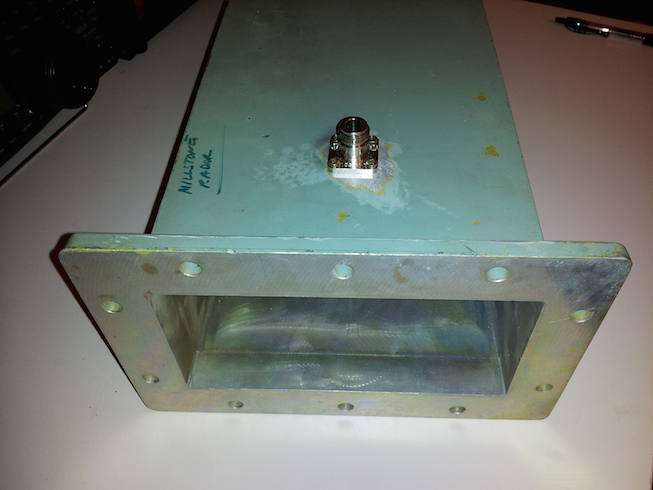 )
)
It looks like my surplus WR-650 waveguide section came from the famous Millstone Radar L-band system. That's pretty cool. -
Title: Re: EM Drive Developments - related to space flight applications - Thread 3
Post by: ThereIWas3 on 06/09/2015 03:18 AM -
<a href="http://forum.nasaspaceflight.com/index.php?topic=37642.msg1386760#msg1386760">Quote from: hhexo on 06/09/2015 12:00 AM</a>
But GR is different, and that I don't know enough.
I just remembered the name of first book I ever read on relativity, both Special and General. I read it (or tried to read it) in my High School lilbrary. Twice. At the start it only assumes you can understand High School math, and teaches you just enough of the rest to grasp General Relativity. Including terms like "Covariant tensors of rank three".
The title is "The Einstein Theory of Relativity, a trip to the fourth dimension (http://www.amazon.com/Einstein-Theory-Relativity-Fourth-Dimension/dp/1589880447)" and it is by Lillian R. Lieber (https://en.wikipedia.org/wiki/Lillian_Rosanoff_Lieber). It was written in the 1940's. It has been republished and Amazon has it. -
Title: Re: EM Drive Developments - related to space flight applications - Thread 3
Post by: SeeShells on 06/09/2015 03:58 AM -
<a href="http://forum.nasaspaceflight.com/index.php?topic=37642.msg1386809#msg1386809">Quote from: Rodal on 06/09/2015 02:12 AM</a>
6 inch diameter air bearing. Area of a circle = Pi x diameter 2/4 = 3.142 x 36/4 = 28.28 sq ins<a href="http://forum.nasaspaceflight.com/index.php?topic=37642.msg1386544#msg1386544">Quote from: SeeShells on 06/08/2015 06:01 PM</a>...
OK good idea to take care of for static stability but this will not eliminate (just by doing this) dynamic unbalance, unfortunately.
I would have done the test differently. Instead of putting all the weight onto a air bearing I would have suspended from the ceiling from the center point of the test jig. As even a small air bearing would have provided enough air bearing surface and balancing it out. Eliminate a lot of potential errors.
Think of ceiling fans: they are hang this way from the ceiling. Remember that even carefully placing lead weights it is difficult to take care of dynamic balancing problems of a ceiling fan, even more so when one has a light fixture under the fan. Here is a picture of me trying to balance a fan, I can never get right, and the noise keeps me up at night: :)
( )
)
The paper I attached in a prior post goes over the equations and shows that there is an inherent dynamic balancing problem with air bearings.
I think this problem is greater for the EM Drive than for usual electronics, due to the weight of Shawyer's EM Drive and the attendant equipment and the fact that the weight on air bearings is limited.
@ 100psi x 28.28 = 2,828 pounds
Support isn't a issue, but design is in making the bottom cavity cupped to keep the top disk in the center and that can be done with air jets in the bottom section and very small .020" groves connecting the jets dispersing the air flow over the bearing and eliminating high pressure areas.
I could put a small car on this bearing and spin it around without it loosing any centricity of rotation. -
Title: Re: EM Drive Developments - related to space flight applications - Thread 3
Post by: Rodal on 06/09/2015 04:41 AM -
<a href="http://forum.nasaspaceflight.com/index.php?topic=37642.msg1386832#msg1386832">Quote from: SeeShells on 06/09/2015 03:58 AM</a>
...
What is the minimum speed at which that air bearing (described above) can accurately operate?
6 inch diameter air bearing. Area of a circle = Pi x diameter 2/4 = 3.142 x 36/4 = 28.28 sq ins
@ 100psi x 28.28 = 2,828 pounds
Support isn't a issue, but design is in making the bottom cavity cupped to keep the top disk in the center and that can be done with air jets in the bottom section and very small .020" groves connecting the jets dispersing the air flow over the bearing and eliminating high pressure areas.
I could put a small car on this bearing and spin it around without it loosing any centricity of rotation.
Does it require precise manufacturing ?
Or can you give the manufacturer name (or link) to see its design parameters?
Thanks -
Title: Re: EM Drive Developments - related to space flight applications - Thread 3
Post by: WarpTech on 06/09/2015 05:35 AM -
I know this thread is regarding the EM Drive and we have been doing a lot of talking about physics. This post definitely belongs here because to my understanding, the EM Drive works by attenuating waves and I've said that it mimics gravity because of this. I would like to elaborate on this, because really understanding it is relevant to engineering such devices.
The average power and energy of a quantum mechanical oscillator in its ground state is;
E0 = h*w
P0 = h*w2/2
Here, P0 is both the power radiated by the oscillator, and the power absorbed from the vacuum. You can call it the ZPF, or you can call it a Thermal field with a gaussian distribution, since the vacuum has a minimum temperature above zero. It really doesn't matter, it is the energy of the vacuum that is relative to some other energy, someplace else.
In a gravitational field, Power is modified by the g00 term of the Schwarzschild metric. It co-varies with the coordinate speed of light, which is a variable as I showed in an earlier post today.
P(r) = P0*(1 - 2GM/rc2)
What this says is, the average power goes to zero as the oscillator approaches the event horizon of a black hole, as r -> Rs, the Schwarzschild radius. This makes sense, we know time stops there, so there can be no change with respect to time. Therefore, we can deduce that the radiation and absorption for this oscillator go to zero.
So what happened here? My understanding is this;
In free space, the oscillator is driven by the ZPF, and it is attenuated by Radiation Reaction. The two are in equilibrium. The oscillator in its ground state can't go any lower in energy because the ZPF prevents it. It sets the base-line, ground state energy level. Relative to what?
As the oscillator approaches the event horizon, it is losing power, P(r). No doubt here, the particle is in free fall and this is geodesic motion. There is no force acting on it so why is it losing power?
Because the ZPF that sustains it is being attenuated by the presence of the matter, by the presence of the black hole
The Damping factor for the damped harmonic oscillator, turns out to be.... yup, you guessed it right;
Damping factor = sqrt(2GM/rc2)
It causes the "loss" of power due to the term, 2GM/rc2, reducing the available power required to drive the oscillator. Why? Because the presence of the oscillator drives currents in nearby matter that are phase-shifted relative to the oscillator, causing work to be done and power to be spent. Again, superposition of waves leads to asymmetrical pressures, amplification or attenuation.
Unfortunately, the EM Drive is attempting to do both, amplify Q and attenuate for thrust. It's a great clue, but the design is like a push-me-pull-you. Anyway... the EM Drive has a cut-off frequency where the wave velocity goes to zero, due to attenuation of the waves caused by the relative phase shift. This mimics gravity. Once frequencies below the cut-off cross that line, it is like crossing the event horizon and they are not reflected. Stored energy is attenuated asymmetrically to provide thrust, dependent on the rate of attenuation.
Will that make it a good thruster someday? How do you move a black hole? ;)
Comments?
Good night NSF!
Todd
-
Title: Re: EM Drive Developments - related to space flight applications - Thread 3
Post by: kml on 06/09/2015 05:41 AM -
<a href="http://forum.nasaspaceflight.com/index.php?topic=37642.msg1386816#msg1386816">Quote from: kml on 06/09/2015 02:26 AM</a>
I've been reading up on waveguide math and noticed a very important property of waveguides:
- As you approach cutoff frequency group velocity decreases but guided wavelength increases
- As EM waves enter a dielectric the group velocity decreases but guided wavelength decreases
- Dielectrics also take you further from cutoff frequency, additionally decreasing guided wavelength.
If Shawyer's formula 7 in theorypaper9-4.pdf is correct, this means that in a tapered resonator without dielectric, would accelerate large end forward while a resonator with dielectric at one end would accelerate dielectric end first (regardless of which end has the taper).
Isn't this exactly what happened in the the Eagleworks test where the dielectric disk fell off the small end?
Another consequence of this is that an EmDrive that does not use dielectric could never exceed Q * photon rocket thrust, while an EmDrive with dielectric does not have that limitation. This is because tapering only reduces momentum transfer at the small end while the large end transfers higher but still less than unguided reflection momentum. In a resonator with dielectric at one end, the reflections at the dielectric end transfer more momentum than normal (according to Shawyer's guided wavelength theory).
Shawyers formula 7 already incorporates the effect of a dielectric if guided wavelengths are calculated correctly including relative permittivity (which is not hard). I wonder why he opted to set Er=1 and mur=1 in formula 7 and add in dielectric terms in a very akward and confusing way in later formulas?
Here's a quick spreadsheet I made for rectangular resonators. It lets you play with different geometry, media, Q, power and frequency. It calculates guided wavelengths with industry standard formulas. It calculates thrust using Shawyer's forumula 7 directly adapted for thrust with Q and by not ignoring the media (which then properly affects the guided wavelengths). You can see how tapered geometry isn't real interesting compared to dielectrics.
http://kl.net/emdrive/kml-emdrive-1.0.xls (http://kl.net/emdrive/kml-emdrive-1.0.xls)
It predicts I will get 1.63 milinewtons with my WR-650 waveguide, 3 watts net power, f=1265MHz, Q=5000 and SrTiO3 dielectric. Scale that up to 30w net and it's 16.2 milinewtons or 1.7 grams of force (!)
Here are the predicted figures with 3w net power, WR-650, f=1265, Q=5000:
HDPE (K=2.25): 72.6 micronewtons
Al2O3 (K=9): 230 micronewtons
SrTiO3 (K=289): 1632 micronewtons
Will I be able to get Q=5000 with those dielectrics? We'll find out but regardless of Q this will be a good test of the Shawyer Guided Wavelength theory. -
Title: Re: EM Drive Developments - related to space flight applications - Thread 3
Post by: SeeShells on 06/09/2015 05:56 AM -
<a href="http://forum.nasaspaceflight.com/index.php?topic=37642.msg1386840#msg1386840">Quote from: Rodal on 06/09/2015 04:41 AM</a><a href="http://forum.nasaspaceflight.com/index.php?topic=37642.msg1386832#msg1386832">Quote from: SeeShells on 06/09/2015 03:58 AM</a>
...
What is the minimum speed at which that air bearing (described above) can accurately operate?
6 inch diameter air bearing. Area of a circle = Pi x diameter 2/4 = 3.142 x 36/4 = 28.28 sq ins
@ 100psi x 28.28 = 2,828 pounds
Support isn't a issue, but design is in making the bottom cavity cupped to keep the top disk in the center and that can be done with air jets in the bottom section and very small .020" groves connecting the jets dispersing the air flow over the bearing and eliminating high pressure areas.
I could put a small car on this bearing and spin it around without it loosing any centricity of rotation.
Does it require precise manufacturing ?
Or can you give the manufacturer name (or link) to see its design parameters?
Thanks
0 hz static nadda. Yes, it does require good machining but nothing a good lathe can't do. I built one just like this after one of my guys told me it wouldn't work. Don't po the boss ... lmao. (lost the bet and he had to buy the pizza that week) I had an tool room Harrison manual lathe good to +-.00005 ( and had it turned out in about day with all the air channels and air jets machined in with a mill and drill press.
Because of the way the center bearing takes the load it can be sensitive to load and air pressure. It's is like one half of an air bearing spindle thrust bearing but much easier to make. http://www.westwind-airbearings.com/airBearing/documents/AirBearingTechnologybriefv2.pdf
I installed a small stop on the top of the outside bearing. You would put on the load, increase the pressure until the stop engaged and drop the air pressure with your regulator about 10 pounds. You then had all the specs of a thrust bearing without having to have the extreme machining. Cool huh?
Shell
I'll look and see if I still have the drawings and specs but that was 10 years ago and they would be on hard copy. -
Title: Re: EM Drive Developments - related to space flight applications - Thread 3
Post by: Rodal on 06/09/2015 12:29 PM -
<a href="http://forum.nasaspaceflight.com/index.php?topic=37642.msg1386850#msg1386850">Quote from: SeeShells on 06/09/2015 05:56 AM</a><a href="http://forum.nasaspaceflight.com/index.php?topic=37642.msg1386840#msg1386840">Quote from: Rodal on 06/09/2015 04:41 AM</a>
...
What is the minimum speed at which that air bearing (described above) can accurately operate?
Does it require precise manufacturing ?
Or can you give the manufacturer name (or link) to see its design parameters?
Thanks
0 hz static nadda. Yes, it does require good machining but nothing a good lathe can't do. I built one just like this after one of my guys told me it wouldn't work. Don't po the boss ... lmao. (lost the bet and he had to buy the pizza that week) I had an tool room Harrison manual lathe good to +-.00005 ( and had it turned out in about day with all the air channels and air jets machined in with a mill and drill press.
Because of the way the center bearing takes the load it can be sensitive to load and air pressure. It's is like one half of an air bearing spindle thrust bearing but much easier to make. http://www.westwind-airbearings.com/airBearing/documents/AirBearingTechnologybriefv2.pdf
I installed a small stop on the top of the outside bearing. You would put on the load, increase the pressure until the stop engaged and drop the air pressure with your regulator about 10 pounds. You then had all the specs of a thrust bearing without having to have the extreme machining. Cool huh?
Shell
I'll look and see if I still have the drawings and specs but that was 10 years ago and they would be on hard copy.
Focusing on Shawyer's EM Drive Demonstrator dynamic test on the air bearing (average speed: one revolution every 6 minutes):
Maximum speed = 2 cm/s (very slow) (from Shawyer's data)
Circumferential perimeter rig = (4*28 cm) Pi = 352 cm (using the known EM Drive diameter=28cm as a scale)
Maximum RPM =( (2 cm/s)/( (4*28 cm) Pi) )*(60 s/min) = 0.34 RPM (very slow, about 1 rev every 3 minutes)
Average RPM =(0 + 0.34)/2 RPM= 0.17 RPM (one revolution every 6 minutes) this video shows how slow is the motion of the EM Drive:
https://www.youtube.com/watch?v=57q3_aRiUXs
See attached the Fig. 7 asynchronous radial runout against shaft speed, on page 8 of the Westwind webpage you noted. It shows that component of the total error motion (that occurs at noninteger multiples of the rotation frequency, and that is not-periodic, and/or periodic at frequencies that are subharmonics of the rotation frequency) to increase hyperbolically from 20000 RPM to 2000 RPM (going from right to left on the lower axis). It shows that component of the radial runout to rise nonlinearly for rotational speeds less than 5000 RPM. Nothing is shown for less than 2000 RPM, but it is clearly rising. So the minimum rotational speed shown is ~6000 times greater than Shawyer's maximum RPM (only 0.34 RPM), and more than 10,000 times Shawyer's average RPM. I also see that Shawyer's moment of inertia and weight distribution seems to be inhomogenous around the perimeter. Admittedly the asynchronous component (the largest peak-to-valley number at each measured angular position) is small at the minimum reported value (2000 RPM) but that RPM (and its associated runout which appears to be rising hyperbolically) is so much larger than Shawyer's maximum 0.34 RPM that I cannot fail to be concerned about the air bearing used by Shawyer to be involved in the strange motion shown in Shawyer's report (the acceleration increasing under decreasing power from an initial acceleration A to a higher acceleration B where B>A, and then with the power off continuing to accelerate, albeit going back to the initial acceleration A (this time under no power).
At average rotational speeds of only 0.17 RPM it looks like the acceleration of the EM Drive would be governed to a significant degree by the peculiarities of the air bearing's air flow hydrodynamics, by the geometrical design (for example flow separation) and by the bearing's machining accuracy. -
Title: Re: EM Drive Developments - related to space flight applications - Thread 3
Post by: Paul Novy on 06/09/2015 12:49 PM -
<a href="http://forum.nasaspaceflight.com/index.php?topic=37642.msg1386686#msg1386686">Quote from: rfmwguy on 06/08/2015 09:43 PM</a><a href="http://forum.nasaspaceflight.com/index.php?topic=37642.msg1386636#msg1386636">Quote from: Paul Novy on 06/08/2015 08:35 PM</a><a href="http://forum.nasaspaceflight.com/index.php?topic=37642.msg1386588#msg1386588">Quote from: rfmwguy on 06/08/2015 07:05 PM</a>
EMDYIers, seems a lot of the RF injection into the frustum has been monopole antenna (magnatron) or coupling loop (EW). Been trying to think past this...I'll start out with a unity gain 1/2 wave monopole, then the loop, then a colinear array which provides about gain up to about 10dB with series 1/2 wave elements. Since this would exceed a linear dimension in the frustum, was thinking perhaps of a spiral arrangement.
Gain is important in my design, since I'm only planing on about +37dbm to start...FWIW: http://www.nodomainname.co.uk/Omnicolinear/2-4collinear.htm
Oops, forgot the helical pic...
I think that the antena length might have some influence if we consider near field (as an evanescent waves) distribution inside the frustum.
After wikipedia:
()
http://en.wikipedia.org/wiki/Near_and_far_field
Thanks. Would you recommend 1/2 wavelengths or loops to avoid far-field interactions?
I'm not sure. I have to once again go through all the theory behind this. However, my intuition tells me to try full wavelength antenna and try to somehow fit it inside the frustum (loops, dipole etc.).
I believe that TheTraveller provided better explanation. -
Title: Re: EM Drive Developments - related to space flight applications - Thread 3
Post by: A_M_Swallow on 06/09/2015 01:45 PM -
<a href="http://forum.nasaspaceflight.com/index.php?topic=37642.msg1386286#msg1386286">Quote from: deltaMass on 06/08/2015 05:26 AM</a><a href="http://forum.nasaspaceflight.com/index.php?topic=37642.msg1386276#msg1386276">Quote from: A_M_Swallow on 06/08/2015 04:58 AM</a>
I would draw your attention to my nick :D<a href="http://forum.nasaspaceflight.com/index.php?topic=37642.msg1386271#msg1386271">Quote from: WarpTech on 06/08/2015 04:37 AM</a>{snip}
Does this amount to with a solar powered EM drive the speed will increase as long as energy is supplied? The energy is stored as mass.
It is a perplexing problem and obviously not a realistic one, once you consider the power source is external and mass will increase indefinitely.
Todd
This variable mass should reduce the acceleration for constant Pin as the velocity increases, giving the device a top speed.
Were this to be true, then this is yet another way to build a perpetual motion machine of the 1st kind, with free energy to spare. Any system that can vary its mass at will can in principle be engineered into a free energy machine.
You would have to exceed the top speed to extract excess energy. As energy is removed the mass would go down.
You do not actually get to the top speed because that would produce infinite mass and zero acceleration. The system will have rest mass. -
Title: Re: EM Drive Developments - related to space flight applications - Thread 3
Post by: rfmwguy on 06/09/2015 03:22 PM -
Online conical frustum calculator fyi:
http://www.calculatorsoup.com/calculators/geometry-solids/conicalfrustum.php -
Title: Re: EM Drive Developments - related to space flight applications - Thread 3
Post by: deltaMass on 06/09/2015 03:53 PM -
<a href="http://forum.nasaspaceflight.com/index.php?topic=37642.msg1386955#msg1386955">Quote from: A_M_Swallow on 06/09/2015 01:45 PM</a>
I can show you a very simple machine utilising the hypothetical principle of variable mass that readily produces free energy forever. A version can be built for either linear motion in free space or, using a different approach, rotary motion in a gravitational field.<a href="http://forum.nasaspaceflight.com/index.php?topic=37642.msg1386286#msg1386286">Quote from: deltaMass on 06/08/2015 05:26 AM</a><a href="http://forum.nasaspaceflight.com/index.php?topic=37642.msg1386276#msg1386276">Quote from: A_M_Swallow on 06/08/2015 04:58 AM</a>
I would draw your attention to my nick :D<a href="http://forum.nasaspaceflight.com/index.php?topic=37642.msg1386271#msg1386271">Quote from: WarpTech on 06/08/2015 04:37 AM</a>{snip}
Does this amount to with a solar powered EM drive the speed will increase as long as energy is supplied? The energy is stored as mass.
It is a perplexing problem and obviously not a realistic one, once you consider the power source is external and mass will increase indefinitely.
Todd
This variable mass should reduce the acceleration for constant Pin as the velocity increases, giving the device a top speed.
Were this to be true, then this is yet another way to build a perpetual motion machine of the 1st kind, with free energy to spare. Any system that can vary its mass at will can in principle be engineered into a free energy machine.
You would have to exceed the top speed to extract excess energy. As energy is removed the mass would go down.
You do not actually get to the top speed because that would produce infinite mass and zero acceleration. The system will have rest mass.
The bottom line is that if you have variable mass then you have perpetual motion and free energy. -
Title: Re: EM Drive Developments - related to space flight applications - Thread 3
Post by: SeeShells on 06/09/2015 03:57 PM -
<a href="http://forum.nasaspaceflight.com/index.php?topic=37642.msg1386917#msg1386917">Quote from: Rodal on 06/09/2015 12:29 PM</a>
It could very well be governed some by the air bearing, but we also see the same effects of thrust after power shut off in other tests without an air bearing. I can't correlate the two observed actions and say it was a air bearing abnormality when the other tests had no air bearing.<a href="http://forum.nasaspaceflight.com/index.php?topic=37642.msg1386850#msg1386850">Quote from: SeeShells on 06/09/2015 05:56 AM</a><a href="http://forum.nasaspaceflight.com/index.php?topic=37642.msg1386840#msg1386840">Quote from: Rodal on 06/09/2015 04:41 AM</a>...
What is the minimum speed at which that air bearing (described above) can accurately operate?
Does it require precise manufacturing ?
Or can you give the manufacturer name (or link) to see its design parameters?
Thanks
0 hz static nadda. Yes, it does require good machining but nothing a good lathe can't do. I built one just like this after one of my guys told me it wouldn't work. Don't po the boss ... lmao. (lost the bet and he had to buy the pizza that week) I had an tool room Harrison manual lathe good to +-.00005 ( and had it turned out in about day with all the air channels and air jets machined in with a mill and drill press.
Because of the way the center bearing takes the load it can be sensitive to load and air pressure. It's is like one half of an air bearing spindle thrust bearing but much easier to make. http://www.westwind-airbearings.com/airBearing/documents/AirBearingTechnologybriefv2.pdf
I installed a small stop on the top of the outside bearing. You would put on the load, increase the pressure until the stop engaged and drop the air pressure with your regulator about 10 pounds. You then had all the specs of a thrust bearing without having to have the extreme machining. Cool huh?
Shell
I'll look and see if I still have the drawings and specs but that was 10 years ago and they would be on hard copy.
Focusing on Shawyer's EM Drive Demonstrator dynamic test on the air bearing (average speed: one revolution every 6 minutes):
Maximum speed = 2 cm/s (very slow) (from Shawyer's data)
Circumferential perimeter rig = (4*28 cm) Pi = 352 cm (using the known EM Drive diameter=28cm as a scale)
Maximum RPM =( (2 cm/s)/( (4*28 cm) Pi) )*(60 s/min) = 0.34 RPM (very slow, about 1 rev every 3 minutes)
Average RPM =(0 + 0.34)/2 RPM= 0.17 RPM (one revolution every 6 minutes) this video shows how slow is the motion of the EM Drive:
https://www.youtube.com/watch?v=57q3_aRiUXs
See attached the Fig. 7 asynchronous radial runout against shaft speed, on page 8 of the Westwind webpage you noted. It shows that component of the total error motion (that occurs at noninteger multiples of the rotation frequency, and that is not-periodic, and/or periodic at frequencies that are subharmonics of the rotation frequency) to increase hyperbolically from 20000 RPM to 2000 RPM (going from right to left on the lower axis). It shows that component of the radial runout to rise nonlinearly for rotational speeds less than 5000 RPM. Nothing is shown for less than 2000 RPM, but it is clearly rising. So the minimum rotational speed shown is ~6000 times greater than Shawyer's maximum RPM (only 0.34 RPM), and more than 10,000 times Shawyer's average RPM. I also see that Shawyer's moment of inertia and weight distribution seems to be inhomogenous around the perimeter. Admittedly the asynchronous component (the largest peak-to-valley number at each measured angular position) is small at the minimum reported value (2000 RPM) but that RPM (and its associated runout which appears to be rising hyperbolically) is so much larger than Shawyer's maximum 0.34 RPM that I cannot fail to be concerned about the air bearing used by Shawyer to be involved in the strange motion shown in Shawyer's report (the acceleration increasing under decreasing power from an initial acceleration A to a higher acceleration B where B>A, and then with the power off continuing to accelerate, albeit going back to the initial acceleration A (this time under no power).
At average rotational speeds of only 0.17 RPM it looks like the acceleration of the EM Drive would be governed to a significant degree by the peculiarities of the air bearing's air flow hydrodynamics, by the geometrical design (for example flow separation) and by the bearing's machining accuracy.
If you remember I said when we first did a air bearing like this where my tech said I feel the air flows coming out of the bearing? He was right and after some thought we figured out that the air pressures between the plates were nonuniform with high pressure gradients radiating out from the air jets down to low pressures where where were no jets. This nonuniformity in pressures would lead to the air swirling in vortexes (just like a tornado), these vortexes would impart momentum to the top plate causing it to rotate.
This is one reason why I put air guides (channels) between the air jets in a crisscross pattern to distribute the air pressure more uniformly and dampen any rotational actions involving air flow subharmonics that could impart movement to the top plate at 0 RPM.
By putting a high frequency microphone onto the metal casing we could see on a scope and coupled with a spectrum analyzer the acoustics of the air bearing and the harmonic frequencies of the air flows. It became a good tool for fine tuning a air bearing.
Shell -
Title: Re: EM Drive Developments - related to space flight applications - Thread 3
Post by: deltaMass on 06/09/2015 04:09 PM - In an attempt to be as pragmatic as possible, I'd say that Shawyer's results on that air bearing are highly questionable and that the experiment should be repeated with something more robust. The fact that rotating gizmos are present on that platform just adds to the farce of it.
-
Title: Re: EM Drive Developments - related to space flight applications - Thread 3
Post by: Rodal on 06/09/2015 04:14 PM -
<a href="http://forum.nasaspaceflight.com/index.php?topic=37642.msg1387030#msg1387030">Quote from: SeeShells on 06/09/2015 03:57 PM</a>
...
I'm sorry I don't understand in which other tests, in which
It could very well be governed some by the air bearing, but we also see the same effects of thrust after power shut off in other tests without an air bearing. I can't correlate the two observed actions and say it was a air bearing abnormality when the other tests had no air bearing.
...Quote from: SeeShellswe also see the same effects of thrust after power shut off in other tests without an air bearing
are you referring to other EM Drive tests (other than the Shawyer Demonstrator dynamic test we were discussing) ? -
Title: Re: EM Drive Developments - related to space flight applications - Thread 3
Post by: hhexo on 06/09/2015 04:32 PM -
<a href="http://forum.nasaspaceflight.com/index.php?topic=37642.msg1386805#msg1386805">Quote from: WarpTech on 06/09/2015 02:00 AM</a><a href="http://forum.nasaspaceflight.com/index.php?topic=37642.msg1386760#msg1386760">Quote from: hhexo on 06/09/2015 12:00 AM</a>
The kind of distortion you would need for something like your_c_in_my_frame = 1m/s boggles the mind.
[Edit] ...or maybe not! http://www.nature.com/nature/journal/v397/n6720/abs/397594a0.html
... wow. I think that's a bit too much to digest at 1am here. :) I'll go back to trying to make sense of this tomorrow.
I'm doing my best to grapple with this thing. I think I am bridging to new understanding, right or wrong has yet to be determined. Please bare with me and thank you for your comments.
Just FYI: In GR, the coordinate speed of light is a variable;
ds2 = -g00c2dt2+g11dx2...
For light, ds = 0
So we get,
(dx/dt)2 = c2g00/g11
or simply, dx/dt = c/K
where K is the refractive index of the vacuum, i.e., the gravitational field. It amounts to the difference between how much space-time has been altered from what we define as |guv|=1, where c = 1, not 1/K.
Ok... so, if I understand correctly...
In my "vacuum" reference frame I see the speed of light as c.
The radiation going through a material or waveguide or gravity field with refractive index K is moving, in my "vacuum" reference frame, at c/K. No question there.
If I were riding on one of the photons in the accelerated frame, or if I were living in the accelerated frame, would I still measure the speed of light as if it were c, or as c/K, with respect to the coordinates in the accelerated frame?
In the former case, the 1/K factor is simply the coordinate transformation for the value of the speed of light from measurements in the accelerated reference frame to measurements in the "vacuum" reference frame (or a frame with acceleration/gravity close to zero), right?
But then a consequence is that my measurement of the inertia of the "thing" in the accelerated reference frame and its measurement of its inertia disagree.
Suppose I have a box containing an accelerated reference frame, like you're supposing the EmDrive is. Suppose the EmDrive is running and it has achieved half its limit velocity in my frame of reference, let's say that is 0.5m/s.
Now, if try to accelerate the EmDrive with some effect within the EmDrive itself, I encounter an inertia as measured in the EmDrive's system, where it's believing that it's running at half c, so the gamma is significant.
If I instead accelerate it by picking it up and throwing it in my reference system, what happens?
Can I just push it past its limit velocity? (what happens to its insides?!)
Or is my acceleration then transformed in its system, and therefore does it resist being pushed exactly as if it had a significant gamma in my system? This doesn't seem to make sense, because with an arbitrarily powerful EmDrive I could create an almost "immovable object" in my reference frame. I'm confused. Not even black holes are immovable.
So it must be that entities in the accelerated reference frame do measure the speed of light as c/K within their coordinate system. Right?
I'm not sure what the consequence of that is... Basically, if I then accelerate a running EmDrive conventionally past c/K using stuff in my "vacuum" reference frame, do I create an event horizon within the EmDrive, and do I prevent anything from ever happening in there? Do I effectively stop light?
Another example question: if I take a chunk of material with a refractive index such that the speed of light is just 17m/s (like the ultracool gas of sodium atoms in the paper I referenced), can I pick it up and move it at 20m/s? If yes, do I create a black hole in the chunk of material? -
Title: Re: EM Drive Developments - related to space flight applications - Thread 3
Post by: SeeShells on 06/09/2015 04:41 PM -
<a href="http://forum.nasaspaceflight.com/index.php?topic=37642.msg1387043#msg1387043">Quote from: Rodal on 06/09/2015 04:14 PM</a>
http://forum.nasaspaceflight.com/index.php?topic=37642.msg1386529#msg1386529<a href="http://forum.nasaspaceflight.com/index.php?topic=37642.msg1387030#msg1387030">Quote from: SeeShells on 06/09/2015 03:57 PM</a>...
I'm sorry I don't understand in which other tests, in which
It could very well be governed some by the air bearing, but we also see the same effects of thrust after power shut off in other tests without an air bearing. I can't correlate the two observed actions and say it was a air bearing abnormality when the other tests had no air bearing.
...Quote from: SeeShellswe also see the same effects of thrust after power shut off in other tests without an air bearing
are you referring to other EM Drive tests (other than the Shawyer Demonstrator dynamic test we were discussing) ? -
Title: Re: EM Drive Developments - related to space flight applications - Thread 3
Post by: Rodal on 06/09/2015 04:46 PM -
I added a lot of information and references on the EM Drive Wiki for Experimental Results: http://emdrive.wiki/Experimental_Results
Please notice:
1) We still have some way to go to model the vacuum of LEO (low Earth orbit) in these EM Drive experiments. The only EM Drive experiments reported in a partial vacuum are the NASA experiments conducted since the end of December 2014. (R. Shawyer, Prof. Yang have not reported, to my knowledge, tests in partial vacuum). However, these NASA vacuum tests were conducted at an ambient pressure:
1.52*10^8 lower pressure than ambient pressure
100 to 50,000 times greater pressure than what is reported for LEO (low Earth orbit)
5*10^11 times greater than what is reported for outer space
2) We still have to include the data for the NASA test done in vacuum with the EM Drive rotated 180 degrees (which gave significantly lower reported thrust measurements). -
Title: Re: EM Drive Developments - related to space flight applications - Thread 3
Post by: Rodal on 06/09/2015 04:56 PM -
<a href="http://forum.nasaspaceflight.com/index.php?topic=37642.msg1387056#msg1387056">Quote from: SeeShells on 06/09/2015 04:41 PM</a><a href="http://forum.nasaspaceflight.com/index.php?topic=37642.msg1387043#msg1387043">Quote from: Rodal on 06/09/2015 04:14 PM</a>
http://forum.nasaspaceflight.com/index.php?topic=37642.msg1386529#msg1386529<a href="http://forum.nasaspaceflight.com/index.php?topic=37642.msg1387030#msg1387030">Quote from: SeeShells on 06/09/2015 03:57 PM</a>...
I'm sorry I don't understand in which other tests, in which
It could very well be governed some by the air bearing, but we also see the same effects of thrust after power shut off in other tests without an air bearing. I can't correlate the two observed actions and say it was a air bearing abnormality when the other tests had no air bearing.
...Quote from: SeeShellswe also see the same effects of thrust after power shut off in other tests without an air bearing
are you referring to other EM Drive tests (other than the Shawyer Demonstrator dynamic test we were discussing) ?
I see a huge difference between the continuing acceleration (speed increasing after power off) in the dynamic test for ~55 seconds after power off,
with the static test showing a continuing force for a few seconds after power off and then a big fall of the force (I did take into account that the dynamic test shows 200 second total time span while the static test shows 100 seconds total time span).
Same EM Drive (Demonstrator) tested under two different set-ups, here one on top of each other for comparison :
air bearing (upper figure, horizontal scale span= 200 seconds)
vs
balance (lower figure, horizontal scale span=100 seconds) -
Title: Re: EM Drive Developments - related to space flight applications - Thread 3
Post by: SeeShells on 06/09/2015 05:01 PM -
<a href="http://forum.nasaspaceflight.com/index.php?topic=37642.msg1387040#msg1387040">Quote from: deltaMass on 06/09/2015 04:09 PM</a>
In an attempt to be as pragmatic as possible, I'd say that Shawyer's results on that air bearing are highly questionable and that the experiment should be repeated with something more robust. The fact that rotating gizmos are present on that platform just adds to the farce of it.
I'm not standing up for him but I am trying to be highly objective. To understand what we are seeing in some of these abnormalities in the tests he was running is my goal. If they are artifacts of the air bearing we need to try and understand that they truly are from the bering and hopefully not repeat the same error producing component in another test.
Honestly you would be better off just hanging the device(s) from the ceiling with a thin cable that the characteristics are well known to input the variables into the final thrust values. A air bearing while offering good advantages in an almost frictionless surface it also can introduce variables that are almost impossible to know. This is why I asked did they build it or did they use a OEM's design and so far we don't know which it was so it's a total unknown variable and everything is up in the air. -
Title: Re: EM Drive Developments - related to space flight applications - Thread 3
Post by: SeeShells on 06/09/2015 05:23 PM -
<a href="http://forum.nasaspaceflight.com/index.php?topic=37642.msg1387063#msg1387063">Quote from: Rodal on 06/09/2015 04:56 PM</a>
The other thing we need to look at because of the commonality of thrust after power is turned off. It is there and even though they are different in some amount of time. Looking at everything I have to ask, even though it may be far fetched. (HA! here we are talking about a reactionless drive and i say far fetched). Are we seeing an artifact from the EMdrive itself? Are we somehow seeing the drive re-establish its frame reference to the outside world after thrust? I need to mull this one over for a bit as it going to require more than just figuring out the abnormalities of an air bearing.<a href="http://forum.nasaspaceflight.com/index.php?topic=37642.msg1387056#msg1387056">Quote from: SeeShells on 06/09/2015 04:41 PM</a><a href="http://forum.nasaspaceflight.com/index.php?topic=37642.msg1387043#msg1387043">Quote from: Rodal on 06/09/2015 04:14 PM</a>
http://forum.nasaspaceflight.com/index.php?topic=37642.msg1386529#msg1386529<a href="http://forum.nasaspaceflight.com/index.php?topic=37642.msg1387030#msg1387030">Quote from: SeeShells on 06/09/2015 03:57 PM</a>...
I'm sorry I don't understand in which other tests, in which
It could very well be governed some by the air bearing, but we also see the same effects of thrust after power shut off in other tests without an air bearing. I can't correlate the two observed actions and say it was a air bearing abnormality when the other tests had no air bearing.
...Quote from: SeeShellswe also see the same effects of thrust after power shut off in other tests without an air bearing
are you referring to other EM Drive tests (other than the Shawyer Demonstrator dynamic test we were discussing) ?
I see a huge difference between the continuing to acceleration (speed increasing after power off) in the dynamic test for ~55 seconds after power off,
with the static test showing a continuing force for a few seconds after power off and then a big fall of the force (I did take into account that the dynamic test shows 200 second total time span while the static test shows 100 seconds total time span).
Same EM Drive (Demonstrator) tested under two different set-ups, here one on top of each other for comparison :
air bearing (upper figure, horizontal scale span= 200 seconds)
vs
balance (lower figure, horizontal scale span=100 seconds) -
Title: Re: EM Drive Developments - related to space flight applications - Thread 3
Post by: deltaMass on 06/09/2015 05:26 PM - Once again, I must mention that there are spinning fans on the test rig. A HD drive also.
-
Title: Re: EM Drive Developments - related to space flight applications - Thread 3
Post by: WarpTech on 06/09/2015 05:30 PM -
<a href="http://forum.nasaspaceflight.com/index.php?topic=37642.msg1387024#msg1387024">Quote from: deltaMass on 06/09/2015 03:53 PM</a><a href="http://forum.nasaspaceflight.com/index.php?topic=37642.msg1386955#msg1386955">Quote from: A_M_Swallow on 06/09/2015 01:45 PM</a>
...
I can show you a very simple machine utilising the hypothetical principle of variable mass that readily produces free energy forever. A version can be built for either linear motion in free space or, using a different approach, rotary motion in a gravitational field.
You would have to exceed the top speed to extract excess energy. As energy is removed the mass would go down.
You do not actually get to the top speed because that would produce infinite mass and zero acceleration. The system will have rest mass.
The bottom line is that if you have variable mass then you have perpetual motion and free energy.
Really? How? Where does the extra free energy come from?
-
Title: Re: EM Drive Developments - related to space flight applications - Thread 3
Post by: rfmwguy on 06/09/2015 05:45 PM -
<a href="http://forum.nasaspaceflight.com/index.php?topic=37642.msg1387094#msg1387094">Quote from: deltaMass on 06/09/2015 05:26 PM</a>
Once again, I must mention that there are spinning fans on the test rig. A HD drive also.
Yep, good reason to make the DUT as low of a mass as possible...the less variables the better. KISS and lightweight. If the emdrive is scalable in power, we should be able to see results a few dozen dbm below Shawyers high power tests.
Helpful watts to dbm converter: http://www.everythingrf.com/rf-calculators/watt-to-dbm -
Title: Re: EM Drive Developments - related to space flight applications - Thread 3
Post by: deltaMass on 06/09/2015 05:59 PM -
<a href="http://forum.nasaspaceflight.com/index.php?topic=37642.msg1387097#msg1387097">Quote from: WarpTech on 06/09/2015 05:30 PM</a>
The rotary device is the simplest. A balanced wheel with two equal masses A,B diametrically placed, one of which (A) is alterable by means unspecified. When A is descending it is made heavier. Thus each half cycle the wheel undergoes acceleration.<a href="http://forum.nasaspaceflight.com/index.php?topic=37642.msg1387024#msg1387024">Quote from: deltaMass on 06/09/2015 03:53 PM</a><a href="http://forum.nasaspaceflight.com/index.php?topic=37642.msg1386955#msg1386955">Quote from: A_M_Swallow on 06/09/2015 01:45 PM</a>...
I can show you a very simple machine utilising the hypothetical principle of variable mass that readily produces free energy forever. A version can be built for either linear motion in free space or, using a different approach, rotary motion in a gravitational field.
You would have to exceed the top speed to extract excess energy. As energy is removed the mass would go down.
You do not actually get to the top speed because that would produce infinite mass and zero acceleration. The system will have rest mass.
The bottom line is that if you have variable mass then you have perpetual motion and free energy.
Really? How? Where does the extra free energy come from?
The linear version requires no gravity and can operate in free space. It consists of a variable mass "puck" losslesssly bouncing between two walls of a container. When it strikes the "front" wall it is made heavier. The container experiences a steady acceleration in the forward direction.
The full descriptions are attached
-
Title: Re: EM Drive Developments - related to space flight applications - Thread 3
Post by: Rodal on 06/09/2015 06:05 PM -
http://arxiv.org/pdf/hep-ph/0409292
Hydrodynamics of the Vacuum
P. M. Stevenson
T. W. Bonner Laboratory, Department of Physics and Astronomy
Rice University
“anti-Galilean” invariance
Although the flow velocity is nonrelativistic (v ≪ 1), disturbances tend to “propagate” superluminally, at 1/v.
page 9:Quote from: page 9 of Hydrodynamics of the Vacuum_0409292v2.pdfAlthough the flow velocity is nonrelativistic (v ≪ 1), disturbances tend to “propagate” superluminally, at 1/v. Hence, the NFA here is not a normal nonrelativistic reduction. The resulting equations are “anti-Galilean” invariant...This is certainly strange, and takes some getting used to, but one should simply view it
as an approximation to the full Lorentz transformations, valid in the stated context. One
is used to dealing with small objects that move slowly, so that their density distributions
vary rapidly in space, but slowly in time. In the present case one is dealing with large
objects, slowly varying in space, but relatively rapidly varying in time. This is related to
the fact that the Higgs vacuum, as a spontaneous Bose-Einstein condensate, has almost
all its particles in the same quantum state. Small disturbances of this state involve vast
numbers of particles, spread over long distances, all moving nearly in lockstep, so that
the disturbance varies only slowly with position while the whole collective has the same,
relatively rapid time dependence. -
Title: Re: EM Drive Developments - related to space flight applications - Thread 3
Post by: SeeShells on 06/09/2015 06:20 PM -
<a href="http://forum.nasaspaceflight.com/index.php?topic=37642.msg1387094#msg1387094">Quote from: deltaMass on 06/09/2015 05:26 PM</a>
Once again, I must mention that there are spinning fans on the test rig. A HD drive also.
Yep there are but we also see the abnormality in tests without fans and spinning drives. -
Title: Re: EM Drive Developments - related to space flight applications - Thread 3
Post by: vulture4 on 06/09/2015 06:26 PM -
Let us assume the incident radiation is perpendicular and is perfectly reflected from the large end of the frustrum, and that there is no pressure at all on the small end.
Measured scale force = 5 gm = .05N (from the Shawyer Demo file above)
Radiation pressure for perfect normal reflection:
P = 2E/c
where:
P=radiation pressure (N/m^2)
E=energy flux (W/m^2)
c= light speed in vacuum = 3E8 m/s
(see https://en.wikipedia.org/wiki/Radiation_pressure#Radiation_pressure_by_particle_model:_photons )
Multiplying by area,
F=2P/c
where
F=force (N)
P=power (W)
P=Fc/2
=.05N(3*10^8m/s)/2
=1.5*10^7 W
=15,000,000 watts incident power is required on the frustum endplate to produce a 5gm scale reading -
Title: Re: EM Drive Developments - related to space flight applications - Thread 3
Post by: deltaMass on 06/09/2015 06:33 PM -
<a href="http://forum.nasaspaceflight.com/index.php?topic=37642.msg1387124#msg1387124">Quote from: SeeShells on 06/09/2015 06:20 PM</a>
Just highlighting Shawyer's lack of experimental professionalism. YMMV<a href="http://forum.nasaspaceflight.com/index.php?topic=37642.msg1387094#msg1387094">Quote from: deltaMass on 06/09/2015 05:26 PM</a>Once again, I must mention that there are spinning fans on the test rig. A HD drive also.
Yep there are but we also see the abnormality in tests without fans and spinning drives. -
Title: Re: EM Drive Developments - related to space flight applications - Thread 3
Post by: ort on 06/09/2015 06:41 PM -
<a href="http://forum.nasaspaceflight.com/index.php?topic=37642.msg1387111#msg1387111">Quote from: deltaMass on 06/09/2015 05:59 PM</a>
This is my first time posting but it seems to me that this "free energy" machine only works if you assume that the device that alters the mass doesn't require energy input to work. (Or atleast less energy then whatever the break even point would work out to) Shutting up now.<a href="http://forum.nasaspaceflight.com/index.php?topic=37642.msg1387097#msg1387097">Quote from: WarpTech on 06/09/2015 05:30 PM</a>
The rotary device is the simplest. A balanced wheel with two equal masses A,B diametrically placed, one of which (A) is alterable by means unspecified. When A is descending it is made heavier. Thus each half cycle the wheel undergoes acceleration.<a href="http://forum.nasaspaceflight.com/index.php?topic=37642.msg1387024#msg1387024">Quote from: deltaMass on 06/09/2015 03:53 PM</a><a href="http://forum.nasaspaceflight.com/index.php?topic=37642.msg1386955#msg1386955">Quote from: A_M_Swallow on 06/09/2015 01:45 PM</a>...
I can show you a very simple machine utilising the hypothetical principle of variable mass that readily produces free energy forever. A version can be built for either linear motion in free space or, using a different approach, rotary motion in a gravitational field.
You would have to exceed the top speed to extract excess energy. As energy is removed the mass would go down.
You do not actually get to the top speed because that would produce infinite mass and zero acceleration. The system will have rest mass.
The bottom line is that if you have variable mass then you have perpetual motion and free energy.
Really? How? Where does the extra free energy come from?
The linear version requires no gravity and can operate in free space. It consists of a variable mass "puck" losslesssly bouncing between two walls of a container. When it strikes the "front" wall it is made heavier. The container experiences a steady acceleration in the forward direction.
The full descriptions are attached -
Title: Re: EM Drive Developments - related to space flight applications - Thread 3
Post by: Prunesquallor on 06/09/2015 06:51 PM -
<a href="http://forum.nasaspaceflight.com/index.php?topic=37642.msg1386615#msg1386615">Quote from: Prunesquallor on 06/08/2015 07:58 PM</a><a href="http://forum.nasaspaceflight.com/index.php?topic=37642.msg1386524#msg1386524">Quote from: deltaMass on 06/08/2015 05:44 PM</a>
Re. the recent flyby reference to the Aachen group's Baby EmDrive and CubeSats, I'm reminded that their team leader has already flown a couple of amateur space missions with an outfit called PoqetQub (from memory).
This is a NASA forum, so presumably packed to the brim with orbital mechanics specialists!! So... what value of k (N/W) is needed to get EmDrive up from LEO, O Experts?
ETA: On reflection that's a dumb question :-[
Any positive k value will do.
You would have to determine what constitutes an orbit change that is outside the natural decay forces. Cubesats don't have much power, so they may not get much thrust. Would a retardation of orbital decay convince anyone? That is a tricky deal, because orbit decay is sensitive to upper atmosphere expansion/contraction, which is affected by solar activity, etc.
If the thrust was significantly greater than the decay forces, you can use something like the Edelbaum approximation to determine the altitude change you should see with constant, tangential acceleration. If there is interest, I'll run some quick parametrics to see what that might be.
Here's some analysis of what kind of orbital raising one could expect given constant, tangential, in-plane orbit thrust acceleration starting from a 600 km circular orbit (an average CubeSat altitude). It is not dependent on the type of thruster.
Now if one wanted to apply this to a CubeSat with a little bitty EM Drive, here is how the numbers might stack up:
Typical CubeSat available power: 0.5 W
http://www.diyspaceexploration.com/power-system-budget-analysis/ (http://www.diyspaceexploration.com/power-system-budget-analysis/)
Typical CubeSat mass: 1.3 kg
http://en.wikipedia.org/wiki/CubeSat (http://en.wikipedia.org/wiki/CubeSat)
Now, choose your assumed EM Drive efficiency and compute acceleration. For example if you want to assume 0.1 N/kW, your acceleration would be (0.1 N/kW)*(0.5 W)*(0.001 kW/W)/(1.3 kg)/(9.81 m/s2/g) = around 4 micro-gs.
You can then look at the chart, find the 4 micro-g line and see the altitude gain as a function of thruster on-time. You can decide for yourself if you want it to have constant thrust at constant power or if you want compute the time you think the universe will let the thruster operate and see how high it will get. -
Title: Re: EM Drive Developments - related to space flight applications - Thread 3
Post by: deltaMass on 06/09/2015 06:53 PM -
<a href="http://forum.nasaspaceflight.com/index.php?topic=37642.msg1387140#msg1387140">Quote from: ort on 06/09/2015 06:41 PM</a>
Yes, of course. You get deltaMass for free. The whole idea is to show that if you can do that - even briefly, but repeatedly - then you get free energy and perpetual motion. Naturally nobody knows how to actually do this.<a href="http://forum.nasaspaceflight.com/index.php?topic=37642.msg1387111#msg1387111">Quote from: deltaMass on 06/09/2015 05:59 PM</a>
This is my first time posting but it seems to me that this "free energy" machine only works if you assume that the device that alters the mass doesn't require energy input to work. (Or atleast less energy then whatever the break even point would work out to) Shutting up now.<a href="http://forum.nasaspaceflight.com/index.php?topic=37642.msg1387097#msg1387097">Quote from: WarpTech on 06/09/2015 05:30 PM</a>
The rotary device is the simplest. A balanced wheel with two equal masses A,B diametrically placed, one of which (A) is alterable by means unspecified. When A is descending it is made heavier. Thus each half cycle the wheel undergoes acceleration.<a href="http://forum.nasaspaceflight.com/index.php?topic=37642.msg1387024#msg1387024">Quote from: deltaMass on 06/09/2015 03:53 PM</a><a href="http://forum.nasaspaceflight.com/index.php?topic=37642.msg1386955#msg1386955">Quote from: A_M_Swallow on 06/09/2015 01:45 PM</a>...
I can show you a very simple machine utilising the hypothetical principle of variable mass that readily produces free energy forever. A version can be built for either linear motion in free space or, using a different approach, rotary motion in a gravitational field.
You would have to exceed the top speed to extract excess energy. As energy is removed the mass would go down.
You do not actually get to the top speed because that would produce infinite mass and zero acceleration. The system will have rest mass.
The bottom line is that if you have variable mass then you have perpetual motion and free energy.
Really? How? Where does the extra free energy come from?
The linear version requires no gravity and can operate in free space. It consists of a variable mass "puck" losslesssly bouncing between two walls of a container. When it strikes the "front" wall it is made heavier. The container experiences a steady acceleration in the forward direction.
The full descriptions are attached
Now, if you think that you can do this, we should start a company :) -
Title: Re: EM Drive Developments - related to space flight applications - Thread 3
Post by: deltaMass on 06/09/2015 06:57 PM -
<a href="http://forum.nasaspaceflight.com/index.php?topic=37642.msg1387142#msg1387142">Quote from: Prunesquallor on 06/09/2015 06:51 PM</a>
Thanks for the analysis! Well, the performance is parlous, as expected.<a href="http://forum.nasaspaceflight.com/index.php?topic=37642.msg1386615#msg1386615">Quote from: Prunesquallor on 06/08/2015 07:58 PM</a><a href="http://forum.nasaspaceflight.com/index.php?topic=37642.msg1386524#msg1386524">Quote from: deltaMass on 06/08/2015 05:44 PM</a>Re. the recent flyby reference to the Aachen group's Baby EmDrive and CubeSats, I'm reminded that their team leader has already flown a couple of amateur space missions with an outfit called PoqetQub (from memory).
This is a NASA forum, so presumably packed to the brim with orbital mechanics specialists!! So... what value of k (N/W) is needed to get EmDrive up from LEO, O Experts?
ETA: On reflection that's a dumb question :-[
Any positive k value will do.
You would have to determine what constitutes an orbit change that is outside the natural decay forces. Cubesats don't have much power, so they may not get much thrust. Would a retardation of orbital decay convince anyone? That is a tricky deal, because orbit decay is sensitive to upper atmosphere expansion/contraction, which is affected by solar activity, etc.
If the thrust was significantly greater than the decay forces, you can use something like the Edelbaum approximation to determine the altitude change you should see with constant, tangential acceleration. If there is interest, I'll run some quick parametrics to see what that might be.
Here's some analysis of what kind of orbital raising one could expect given constant, tangential, in-plane orbit thrusting starting from a 600 km circular orbit (an average CubeSat altitude). It is not dependent on the type of thruster.
Now if one wanted to apply this to a CubeSat with a little bitty EM Drive, here is how the numbers might stack up:
Typical CubeSat available power: 0.5 W
http://www.diyspaceexploration.com/power-system-budget-analysis/ (http://www.diyspaceexploration.com/power-system-budget-analysis/)
Typical CubeSat mass: 1.3 kg
http://en.wikipedia.org/wiki/CubeSat (http://en.wikipedia.org/wiki/CubeSat)
Now, choose your assumed EM Drive efficiency and compute acceleration. For example if you want to assume 0.1 N/kW, your acceleration would be (0.1 N/kW)*(0.5 W)*(0.001 kW/W)/(1.3 kg)/(9.81 m/s2/g) = around 4 micro-gs.
You can then look at the chart, find the 4 micro-g line and see the altitude gain as a function of thruster on-time. You can decide for yourself if you want it to have constant thrust at constant power or if you want compute the time you think the universe will let the thruster operate and see how high it will get.
The idea here is to ask whether we can actually tell that the drive is working. It looks like this is not too hard. -
Title: Re: EM Drive Developments - related to space flight applications - Thread 3
Post by: Rodal on 06/09/2015 07:04 PM -
<a href="http://forum.nasaspaceflight.com/index.php?topic=37642.msg1387142#msg1387142">Quote from: Prunesquallor on 06/09/2015 06:51 PM</a>
The winner is Prof. Yang, reporting 1 N/kW (for ambient air) which gives 40 micro-gs
Here's some analysis of what kind of orbital raising one could expect given constant, tangential, in-plane orbit thrust acceleration starting from a 600 km circular orbit (an average CubeSat altitude). It is not dependent on the type of thruster.
Now if one wanted to apply this to a CubeSat with a little bitty EM Drive, here is how the numbers might stack up:
Typical CubeSat available power: 0.5 W
http://www.diyspaceexploration.com/power-system-budget-analysis/ (http://www.diyspaceexploration.com/power-system-budget-analysis/)
Typical CubeSat mass: 1.3 kg
http://en.wikipedia.org/wiki/CubeSat (http://en.wikipedia.org/wiki/CubeSat)
Now, choose your assumed EM Drive efficiency and compute acceleration. For example if you want to assume 0.1 N/kW, your acceleration would be (0.1 N/kW)*(0.5 W)*(0.001 kW/W)/(1.3 kg)/(9.81 m/s2/g) = around 4 micro-gs.
You can then look at the chart, find the 4 micro-g line and see the altitude gain as a function of thruster on-time. You can decide for yourself if you want it to have constant thrust at constant power or if you want compute the time you think the universe will let the thruster operate and see how high it will get.
The lowest reported value is NASA Eagleworks, in 5*10^(-4) Torr partial vacuum turned around 180 degrees, 0.000283 N/kW giving 0.01 micro-gs, which is lower than the lowest value reported in the chart (0.1 micro g)
(http://forum.nasaspaceflight.com/index.php?action=dlattach;topic=37642.0;attach=839395;image) -
Title: Re: EM Drive Developments - related to space flight applications - Thread 3
Post by: Prunesquallor on 06/09/2015 07:10 PM -
<a href="http://forum.nasaspaceflight.com/index.php?topic=37642.msg1387149#msg1387149">Quote from: Rodal on 06/09/2015 07:04 PM</a><a href="http://forum.nasaspaceflight.com/index.php?topic=37642.msg1387142#msg1387142">Quote from: Prunesquallor on 06/09/2015 06:51 PM</a>
The winner is Prof. Yang, reporting 1 N/kW (for ambient air)which gives 40 micro-gs<a href="http://forum.nasaspaceflight.com/index.php?topic=37642.msg1386615#msg1386615">Quote from: Prunesquallor on 06/08/2015 07:58 PM</a><a href="http://forum.nasaspaceflight.com/index.php?topic=37642.msg1386524#msg1386524">Quote from: deltaMass on 06/08/2015 05:44 PM</a>Re. the recent flyby reference to the Aachen group's Baby EmDrive and CubeSats, I'm reminded that their team leader has already flown a couple of amateur space missions with an outfit called PoqetQub (from memory).
This is a NASA forum, so presumably packed to the brim with orbital mechanics specialists!! So... what value of k (N/W) is needed to get EmDrive up from LEO, O Experts?
ETA: On reflection that's a dumb question :-[
Any positive k value will do.
You would have to determine what constitutes an orbit change that is outside the natural decay forces. Cubesats don't have much power, so they may not get much thrust. Would a retardation of orbital decay convince anyone? That is a tricky deal, because orbit decay is sensitive to upper atmosphere expansion/contraction, which is affected by solar activity, etc.
If the thrust was significantly greater than the decay forces, you can use something like the Edelbaum approximation to determine the altitude change you should see with constant, tangential acceleration. If there is interest, I'll run some quick parametrics to see what that might be.
Here's some analysis of what kind of orbital raising one could expect given constant, tangential, in-plane orbit thrust acceleration starting from a 600 km circular orbit (an average CubeSat altitude). It is not dependent on the type of thruster.
Now if one wanted to apply this to a CubeSat with a little bitty EM Drive, here is how the numbers might stack up:
Typical CubeSat available power: 0.5 W
http://www.diyspaceexploration.com/power-system-budget-analysis/ (http://www.diyspaceexploration.com/power-system-budget-analysis/)
Typical CubeSat mass: 1.3 kg
http://en.wikipedia.org/wiki/CubeSat (http://en.wikipedia.org/wiki/CubeSat)
Now, choose your assumed EM Drive efficiency and compute acceleration. For example if you want to assume 0.1 N/kW, your acceleration would be (0.1 N/kW)*(0.5 W)*(0.001 kW/W)/(1.3 kg)/(9.81 m/s2/g) = around 4 micro-gs.
You can then look at the chart, find the 4 micro-g line and see the altitude gain as a function of thruster on-time. You can decide for yourself if you want it to have constant thrust at constant power or if you want compute the time you think the universe will let the thruster operate and see how high it will get.
The lowest reported value is NASA Eagleworks, in 5*10^(-4) Torr turned around 180 degrees, 0.000283 N/kW giving 0.01 micro-gs
Hence the log-log plot ;) -
Title: Re: EM Drive Developments - related to space flight applications - Thread 3
Post by: Prunesquallor on 06/09/2015 07:13 PM -
<a href="http://forum.nasaspaceflight.com/index.php?topic=37642.msg1387145#msg1387145">Quote from: deltaMass on 06/09/2015 06:57 PM</a><a href="http://forum.nasaspaceflight.com/index.php?topic=37642.msg1387142#msg1387142">Quote from: Prunesquallor on 06/09/2015 06:51 PM</a>
Thanks for the analysis! Well, the performance is parlous, as expected.<a href="http://forum.nasaspaceflight.com/index.php?topic=37642.msg1386615#msg1386615">Quote from: Prunesquallor on 06/08/2015 07:58 PM</a><a href="http://forum.nasaspaceflight.com/index.php?topic=37642.msg1386524#msg1386524">Quote from: deltaMass on 06/08/2015 05:44 PM</a>Re. the recent flyby reference to the Aachen group's Baby EmDrive and CubeSats, I'm reminded that their team leader has already flown a couple of amateur space missions with an outfit called PoqetQub (from memory).
This is a NASA forum, so presumably packed to the brim with orbital mechanics specialists!! So... what value of k (N/W) is needed to get EmDrive up from LEO, O Experts?
ETA: On reflection that's a dumb question :-[
Any positive k value will do.
You would have to determine what constitutes an orbit change that is outside the natural decay forces. Cubesats don't have much power, so they may not get much thrust. Would a retardation of orbital decay convince anyone? That is a tricky deal, because orbit decay is sensitive to upper atmosphere expansion/contraction, which is affected by solar activity, etc.
If the thrust was significantly greater than the decay forces, you can use something like the Edelbaum approximation to determine the altitude change you should see with constant, tangential acceleration. If there is interest, I'll run some quick parametrics to see what that might be.
Here's some analysis of what kind of orbital raising one could expect given constant, tangential, in-plane orbit thrusting starting from a 600 km circular orbit (an average CubeSat altitude). It is not dependent on the type of thruster.
Now if one wanted to apply this to a CubeSat with a little bitty EM Drive, here is how the numbers might stack up:
Typical CubeSat available power: 0.5 W
http://www.diyspaceexploration.com/power-system-budget-analysis/ (http://www.diyspaceexploration.com/power-system-budget-analysis/)
Typical CubeSat mass: 1.3 kg
http://en.wikipedia.org/wiki/CubeSat (http://en.wikipedia.org/wiki/CubeSat)
Now, choose your assumed EM Drive efficiency and compute acceleration. For example if you want to assume 0.1 N/kW, your acceleration would be (0.1 N/kW)*(0.5 W)*(0.001 kW/W)/(1.3 kg)/(9.81 m/s2/g) = around 4 micro-gs.
You can then look at the chart, find the 4 micro-g line and see the altitude gain as a function of thruster on-time. You can decide for yourself if you want it to have constant thrust at constant power or if you want compute the time you think the universe will let the thruster operate and see how high it will get.
The idea here is to ask whether we can actually tell that the drive is working. It looks like this is not too hard.
The missing piece is the orbital decay. You would want have to (IMHO) stay at least an order of magnitude above the predicted drag deceleration, since that thing is quite variable and hard to predict. I'll try to dig up some info. -
Title: Re: EM Drive Developments - related to space flight applications - Thread 3
Post by: vulture4 on 06/09/2015 07:37 PM -
<a href="http://forum.nasaspaceflight.com/index.php?topic=37642.msg1387152#msg1387152">Quote from: Prunesquallor on 06/09/2015 07:10 PM</a>
The winner is Prof. Yang, reporting 1 N/kW (for ambient air)which gives 40 micro-gs
So thrust varies directly with atmospheric pressure, eh? Wait! I've got a theory...
The lowest reported value is NASA Eagleworks, in 5*10^(-4) Torr turned around 180 degrees, 0.000283 N/kW giving 0.01 micro-gs
Seriously, theory and verification must come first. All spacecraft are subject to perturbations, even the Pioneers in interstellar space. If the theory we are considering is the one proposed by Shawyer, that reactionless thrust is produced by unequal radiation pressures, then the measured thrusts would require unattainable energy densities in the resonator. If some other theory is to be considered and tested, it must first be defined. -
Title: Re: EM Drive Developments - related to space flight applications - Thread 3
Post by: WarpTech on 06/09/2015 07:37 PM -
<a href="http://forum.nasaspaceflight.com/index.php?topic=37642.msg1387111#msg1387111">Quote from: deltaMass on 06/09/2015 05:59 PM</a><a href="http://forum.nasaspaceflight.com/index.php?topic=37642.msg1387097#msg1387097">Quote from: WarpTech on 06/09/2015 05:30 PM</a>
...
The rotary device is the simplest. A balanced wheel with two equal masses A,B diametrically placed, one of which (A) is alterable by means unspecified. When A is descending it is made heavier. Thus each half cycle the wheel undergoes acceleration.
Really? How? Where does the extra free energy come from?
The linear version requires no gravity and can operate in free space. It consists of a variable mass "puck" losslesssly bouncing between two walls of a container. When it strikes the "front" wall it is made heavier. The container experiences a steady acceleration in the forward direction.
The full descriptions are attached
"...is alterable by means unspecified"
In the paper you wrote; "...by whatever means."
The "means" you are referring to, I refer to as a self-charging capacitor. If you have a device that can spontaneous gain mass, i.e., a self-charging capacitor, you don't need the cart or the wheel to extract it.
Good luck with that! I wouldn't buy Woodward's device either.
-
Title: Re: EM Drive Developments - related to space flight applications - Thread 3
Post by: SeeShells on 06/09/2015 07:55 PM -
<a href="http://forum.nasaspaceflight.com/index.php?topic=37642.msg1387116#msg1387116">Quote from: Rodal on 06/09/2015 06:05 PM</a>
http://arxiv.org/pdf/hep-ph/0409292
I LOVE this! Great find Dr. Rodal!
Hydrodynamics of the Vacuum
P. M. Stevenson
T. W. Bonner Laboratory, Department of Physics and Astronomy
Rice University
“anti-Galilean” invariance
Although the flow velocity is nonrelativistic (v ≪ 1), disturbances tend to “propagate” superluminally, at 1/v.
page 9:Quote from: page 9 of Hydrodynamics of the Vacuum_0409292v2.pdfAlthough the flow velocity is nonrelativistic (v ≪ 1), disturbances tend to “propagate” superluminally, at 1/v. Hence, the NFA here is not a normal nonrelativistic reduction. The resulting equations are “anti-Galilean” invariant...This is certainly strange, and takes some getting used to, but one should simply view it
as an approximation to the full Lorentz transformations, valid in the stated context. One
is used to dealing with small objects that move slowly, so that their density distributions
vary rapidly in space, but slowly in time. In the present case one is dealing with large
objects, slowly varying in space, but relatively rapidly varying in time. This is related to
the fact that the Higgs vacuum, as a spontaneous Bose-Einstein condensate, has almost
all its particles in the same quantum state. Small disturbances of this state involve vast
numbers of particles, spread over long distances, all moving nearly in lockstep, so that
the disturbance varies only slowly with position while the whole collective has the same,
relatively rapid time dependence.
I've always wondered before the inflationary period where there seemed to be no controls on the expansion of spacetime that the Higgs manifested itself into a state that was quantum entangled and then the Higgs interaction with matter and mass slowed the expansion to present day values we see. It would make sense that to be felt throughout the universe in a slow down the Higgs would need to be in a quantum entanglement lockstep.
I was just reading this before reading your post.
http://www.nature.com/news/higgs-data-could-spell-trouble-for-leading-big-bang-theory-1.12804
<edit>
More thoughts before I go out and clean the hot tub area. From superluminal thoughts to more mundane...such is life.
You know a particle in lockstep ie:entanglement means there is no spoon. Ok, it means that the walls of the EM Cavity are not there and any effect it has on the particles within the cavity effects those outside that are entangled. Seeing this correctly?
-
Title: Re: EM Drive Developments - related to space flight applications - Thread 3
Post by: SeeShells on 06/09/2015 08:21 PM -
https://hackaday.io/project/5596-em-drive/log/19253-emdrive-tests
Still not sure if they have thrust yet...looking at data. -
Title: Re: EM Drive Developments - related to space flight applications - Thread 3
Post by: Rodal on 06/09/2015 08:33 PM -
<a href="http://forum.nasaspaceflight.com/index.php?topic=37642.msg1387176#msg1387176">Quote from: SeeShells on 06/09/2015 08:21 PM</a>
https://hackaday.io/project/5596-em-drive/log/19253-emdrive-tests
What torque makes the device spin around then ?
Still not sure if they have thrust yet...looking at data.
It's a beautiful set-up, this baby EM Drive.
Neat!
https://www.youtube.com/watch?v=ZSZT5plA4a4 -
Title: Re: EM Drive Developments - related to space flight applications - Thread 3
Post by: SeeShells on 06/09/2015 08:37 PM -
<a href="http://forum.nasaspaceflight.com/index.php?topic=37642.msg1387181#msg1387181">Quote from: Rodal on 06/09/2015 08:33 PM</a>
I think they had to impart some spin before they switched it on. Just early in the testing and I'm sure they will refine it more.<a href="http://forum.nasaspaceflight.com/index.php?topic=37642.msg1387176#msg1387176">Quote from: SeeShells on 06/09/2015 08:21 PM</a>https://hackaday.io/project/5596-em-drive/log/19253-emdrive-tests
What torque makes the device spin around then ?
Still not sure if they have thrust yet...looking at data.
It's a beautiful set-up, this baby EM Drive.
Neat!
https://www.youtube.com/watch?v=ZSZT5plA4a4 -
Title: Re: EM Drive Developments - related to space flight applications - Thread 3
Post by: Rodal on 06/09/2015 08:41 PM -
<a href="http://forum.nasaspaceflight.com/index.php?topic=37642.msg1387185#msg1387185">Quote from: SeeShells on 06/09/2015 08:37 PM</a><a href="http://forum.nasaspaceflight.com/index.php?topic=37642.msg1387181#msg1387181">Quote from: Rodal on 06/09/2015 08:33 PM</a>
I think they had to impart some spin before they switched it on. Just early in the testing and I'm sure they will refine it more.<a href="http://forum.nasaspaceflight.com/index.php?topic=37642.msg1387176#msg1387176">Quote from: SeeShells on 06/09/2015 08:21 PM</a>https://hackaday.io/project/5596-em-drive/log/19253-emdrive-tests
What torque makes the device spin around then ?
Still not sure if they have thrust yet...looking at data.
It's a beautiful set-up, this baby EM Drive.
Neat!
They had to impart the spin in order to stabilize the set-up so that it would stay centered? (using the gyroscopic effect, conservation of rotational momentum)? -
Title: Re: EM Drive Developments - related to space flight applications - Thread 3
Post by: Prunesquallor on 06/09/2015 08:49 PM -
<a href="http://forum.nasaspaceflight.com/index.php?topic=37642.msg1387186#msg1387186">Quote from: Rodal on 06/09/2015 08:41 PM</a><a href="http://forum.nasaspaceflight.com/index.php?topic=37642.msg1387185#msg1387185">Quote from: SeeShells on 06/09/2015 08:37 PM</a><a href="http://forum.nasaspaceflight.com/index.php?topic=37642.msg1387181#msg1387181">Quote from: Rodal on 06/09/2015 08:33 PM</a>
I think they had to impart some spin before they switched it on. Just early in the testing and I'm sure they will refine it more.<a href="http://forum.nasaspaceflight.com/index.php?topic=37642.msg1387176#msg1387176">Quote from: SeeShells on 06/09/2015 08:21 PM</a>https://hackaday.io/project/5596-em-drive/log/19253-emdrive-tests
What torque makes the device spin around then ?
Still not sure if they have thrust yet...looking at data.
It's a beautiful set-up, this baby EM Drive.
Neat!
They had to impart the spin in order to stabilize the set-up so that it would stay centered? (using the gyroscopic effect, conservation of rotational momentum)?
This is their magnetically suspended rig? -
Title: Re: EM Drive Developments - related to space flight applications - Thread 3
Post by: sghill on 06/09/2015 08:50 PM -
At that power level and those small sizes, they could conceivably sell this thing as a kit to hobbyists who want to test their own EMDrives!
Kickstarter powers, Activate!!!
(P.S. we could all chip in and mail one to Paul March for Christmas). -
Title: Re: EM Drive Developments - related to space flight applications - Thread 3
Post by: zurael on 06/09/2015 09:22 PM -
Asked about it on youtube, apparently the rig was spun for 8 minutes before power was applied, and the rig was suspended magnetically.
He also said tests of other orientations have been run.
Edit: I also asked if they intended to try a tunable small end plate like the Shawyer designs, he said they did intend to do so, either as an improvement to the current test, or a complete redesign. -
Title: Re: EM Drive Developments - related to space flight applications - Thread 3
Post by: SeeShells on 06/09/2015 09:43 PM -
<a href="http://forum.nasaspaceflight.com/index.php?topic=37642.msg1387190#msg1387190">Quote from: arc on 06/09/2015 08:54 PM</a>
Good idea! One of the tests I'll be testing this. I plan to suspend the EMdrive almost submerged in a tank of water with a just a little of it out of the water. I'm thinking of using lasers angled off the top and sides to measure any displacements of the water. Placing the target about 25 foot away should give me enough deviation to calculate the displacement of the water and record the real time actions with the Drive on. Also the water will keep the frustum cooled and hopefully a little more stable.<a href="http://forum.nasaspaceflight.com/index.php?topic=37642.msg1387090#msg1387090">Quote from: SeeShells on 06/09/2015 05:23 PM</a>
Seeshells, Link that thought back to Todds G-mimic /horizon_event effect. You have an intuitive and very valid conjecture. A G-mimic/horizon_event takes time and energy to create, also to dissipate.
The other thing we need to look at because of the commonality of thrust after power is turned off. It is there and even though they are different in some amount of time. Looking at everything I have to ask, even though it may be far fetched. (HA! here we are talking about a reactionless drive and i say far fetched). Are we seeing an artifact from the EMdrive itself? Are we somehow seeing the drive re-establish its frame reference to the outside world after thrust? I need to mull this one over for a bit as it going to require more than just figuring out the abnormalities of an air bearing.
When you get your cavity up and running, can you please test its inertial reaction to an outside force temporarily acting on the device ( perhaps a coiled spring or a known mass on the end of a pendulum string as an impactor) ... the usual power on/power off phases and data log the distance, acceleration, velocity etc.
This will not be with the one with holes... lmao. It will be with the solid and sealed frustum. -
Title: Re: EM Drive Developments - related to space flight applications - Thread 3
Post by: Prunesquallor on 06/09/2015 10:16 PM -
<a href="http://forum.nasaspaceflight.com/index.php?topic=37642.msg1387199#msg1387199">Quote from: SeeShells on 06/09/2015 09:43 PM</a><a href="http://forum.nasaspaceflight.com/index.php?topic=37642.msg1387190#msg1387190">Quote from: arc on 06/09/2015 08:54 PM</a>
Good idea! One of the tests I'll be testing this. I plan to suspend the EMdrive almost submerged in a tank of water with a just a little of it out of the water. I'm thinking of using lasers angled off the top and sides to measure any displacements of the water. Placing the target about 25 foot away should give me enough deviation to calculate the displacement of the water and record the real time actions with the Drive on. Also the water will keep the frustum cooled and hopefully a little more stable.<a href="http://forum.nasaspaceflight.com/index.php?topic=37642.msg1387090#msg1387090">Quote from: SeeShells on 06/09/2015 05:23 PM</a>
Seeshells, Link that thought back to Todds G-mimic /horizon_event effect. You have an intuitive and very valid conjecture. A G-mimic/horizon_event takes time and energy to create, also to dissipate.
The other thing we need to look at because of the commonality of thrust after power is turned off. It is there and even though they are different in some amount of time. Looking at everything I have to ask, even though it may be far fetched. (HA! here we are talking about a reactionless drive and i say far fetched). Are we seeing an artifact from the EMdrive itself? Are we somehow seeing the drive re-establish its frame reference to the outside world after thrust? I need to mull this one over for a bit as it going to require more than just figuring out the abnormalities of an air bearing.
When you get your cavity up and running, can you please test its inertial reaction to an outside force temporarily acting on the device ( perhaps a coiled spring or a known mass on the end of a pendulum string as an impactor) ... the usual power on/power off phases and data log the distance, acceleration, velocity etc.
This will not be with the one with holes... lmao. It will be with the solid and sealed frustum.
Might want to keep the power low at first...
-
Title: Re: EM Drive Developments - related to space flight applications - Thread 3
Post by: deltaMass on 06/09/2015 10:19 PM -
<a href="http://forum.nasaspaceflight.com/index.php?topic=37642.msg1387162#msg1387162">Quote from: WarpTech on 06/09/2015 07:37 PM</a><a href="http://forum.nasaspaceflight.com/index.php?topic=37642.msg1387111#msg1387111">Quote from: deltaMass on 06/09/2015 05:59 PM</a><a href="http://forum.nasaspaceflight.com/index.php?topic=37642.msg1387097#msg1387097">Quote from: WarpTech on 06/09/2015 05:30 PM</a>
...
The rotary device is the simplest. A balanced wheel with two equal masses A,B diametrically placed, one of which (A) is alterable by means unspecified. When A is descending it is made heavier. Thus each half cycle the wheel undergoes acceleration.
Really? How? Where does the extra free energy come from?
The linear version requires no gravity and can operate in free space. It consists of a variable mass "puck" losslesssly bouncing between two walls of a container. When it strikes the "front" wall it is made heavier. The container experiences a steady acceleration in the forward direction.
The full descriptions are attached
"...is alterable by means unspecified"
In the paper you wrote; "...by whatever means."
The "means" you are referring to, I refer to as a self-charging capacitor. If you have a device that can spontaneous gain mass, i.e., a self-charging capacitor, you don't need the cart or the wheel to extract it.
Good luck with that! I wouldn't buy Woodward's device either.
I know you're looking to get a rise out of me, but I'm too old to fall for it. Next!
This is an informal paper that seeks to demonstrates a principle, and succeeds in doing so via a worked example. The fact that one cannot build this and therefore violate CoE is incidental.
In particular, I was answering your direct question to the best of my ability.
Why would I bother? - because (modulo my misunderstanding) I'm seeing hints of variable mass occurring in your mathematics. Therefore this little discussion shows you what you can do with it.
-
Title: Re: EM Drive Developments - related to space flight applications - Thread 3
Post by: A_M_Swallow on 06/09/2015 11:09 PM -
<a href="http://forum.nasaspaceflight.com/index.php?topic=37642.msg1387024#msg1387024">Quote from: deltaMass on 06/09/2015 03:53 PM</a><a href="http://forum.nasaspaceflight.com/index.php?topic=37642.msg1386955#msg1386955">Quote from: A_M_Swallow on 06/09/2015 01:45 PM</a>
I can show you a very simple machine utilising the hypothetical principle of variable mass that readily produces free energy forever. A version can be built for either linear motion in free space or, using a different approach, rotary motion in a gravitational field.<a href="http://forum.nasaspaceflight.com/index.php?topic=37642.msg1386286#msg1386286">Quote from: deltaMass on 06/08/2015 05:26 AM</a><a href="http://forum.nasaspaceflight.com/index.php?topic=37642.msg1386276#msg1386276">Quote from: A_M_Swallow on 06/08/2015 04:58 AM</a>
I would draw your attention to my nick :D<a href="http://forum.nasaspaceflight.com/index.php?topic=37642.msg1386271#msg1386271">Quote from: WarpTech on 06/08/2015 04:37 AM</a>{snip}
Does this amount to with a solar powered EM drive the speed will increase as long as energy is supplied? The energy is stored as mass.
It is a perplexing problem and obviously not a realistic one, once you consider the power source is external and mass will increase indefinitely.
Todd
This variable mass should reduce the acceleration for constant Pin as the velocity increases, giving the device a top speed.
Were this to be true, then this is yet another way to build a perpetual motion machine of the 1st kind, with free energy to spare. Any system that can vary its mass at will can in principle be engineered into a free energy machine.
You would have to exceed the top speed to extract excess energy. As energy is removed the mass would go down.
You do not actually get to the top speed because that would produce infinite mass and zero acceleration. The system will have rest mass.
The bottom line is that if you have variable mass then you have perpetual motion and free energy.
I am describing
E = mc2 / sqrt(1- (v2 / c2) )
The energy to increase the mass did not appear by magic, the machine is solar powered, it came from the sun. You cannot get more energy out than is put in (including starting energy). It is a battery not a perpetual motion machine. -
Title: Re: EM Drive Developments - related to space flight applications - Thread 3
Post by: SeeShells on 06/09/2015 11:14 PM -
<a href="http://forum.nasaspaceflight.com/index.php?topic=37642.msg1387218#msg1387218">Quote from: deltaMass on 06/09/2015 10:19 PM</a><a href="http://forum.nasaspaceflight.com/index.php?topic=37642.msg1387162#msg1387162">Quote from: WarpTech on 06/09/2015 07:37 PM</a><a href="http://forum.nasaspaceflight.com/index.php?topic=37642.msg1387111#msg1387111">Quote from: deltaMass on 06/09/2015 05:59 PM</a><a href="http://forum.nasaspaceflight.com/index.php?topic=37642.msg1387097#msg1387097">Quote from: WarpTech on 06/09/2015 05:30 PM</a>
...
The rotary device is the simplest. A balanced wheel with two equal masses A,B diametrically placed, one of which (A) is alterable by means unspecified. When A is descending it is made heavier. Thus each half cycle the wheel undergoes acceleration.
Really? How? Where does the extra free energy come from?
The linear version requires no gravity and can operate in free space. It consists of a variable mass "puck" losslesssly bouncing between two walls of a container. When it strikes the "front" wall it is made heavier. The container experiences a steady acceleration in the forward direction.
The full descriptions are attached
"...is alterable by means unspecified"
In the paper you wrote; "...by whatever means."
The "means" you are referring to, I refer to as a self-charging capacitor. If you have a device that can spontaneous gain mass, i.e., a self-charging capacitor, you don't need the cart or the wheel to extract it.
Good luck with that! I wouldn't buy Woodward's device either.
I know you're looking to get a rise out of me, but I'm too old to fall for it. Next!
This is an informal paper that seeks to demonstrates a principle, and succeeds in doing so via a worked example. The fact that one cannot build this and therefore violate CoE is incidental.
In particular, I was answering your direct question to the best of my ability.
Why would I bother? - because (modulo my misunderstanding) I'm seeing hints of variable mass occurring in your mathematics. Therefore this little discussion shows you what you can do with it.
Ok you two, It's not gonna work as I already have the patent on a Variable Mass Platform.
Shell -
Title: Re: EM Drive Developments - related to space flight applications - Thread 3
Post by: deltaMass on 06/09/2015 11:37 PM -
I have a car like that. As I'm driving along, I throw a biodegradable object out of the window :)
What I was talking about is some gizmo that allows mass to change and then change back to its rest mass value, with no expenditure of energy or momentum. Therefore Mr. Swallow's idea is not to be included, and I suspect, Shells, neither is yours.
Think of it as "a magic brick" -
Title: Re: EM Drive Developments - related to space flight applications - Thread 3
Post by: Rodal on 06/09/2015 11:46 PM -
I calculated the geometry of the NWPU Prof. Yang et.al.'s cavity. The length is given in Yang's paper. The small diameter is given by the cutoff frequency for mode TE010 and the big diameter comes from Fig. 3, knowing the previous data and the fact that the frequency was 2.45 GHz and the mode TE012 (which according to Prof. Yang's computer program should give the highest thrust force).
I also verified that these dimensions result in resonance of the cavity at 2.45 GHz in mode TE012 with my truncated cone exact solution (it checked fine).
Description Mode Shape Cavity Length (m) bigDiameter (m) smallDiameter (m) Shawyer Design Factor
NWPU Yang TE012 0.24 0.201 0.1492 0.664
http://emdrive.wiki/Experimental_Results
Where Shawyer's Design Factor is calculated with TE010 as the cutoff frequency, just as one has to do for Shawyer's Demonstrator to get a design factor of 0.844 -
Title: Re: EM Drive Developments - related to space flight applications - Thread 3
Post by: wallofwolfstreet on 06/10/2015 12:07 AM -
<a href="http://forum.nasaspaceflight.com/index.php?topic=37642.msg1386226#msg1386226">Quote from: WarpTech on 06/08/2015 01:30 AM</a>
Where to start? Please read a few things first please, so I don't have to explain it all. Thank you!
https://www.researchgate.net/publication/222942820_Quantum_Ground_States_as_Equilibrium_Particle-Vacuum_Interaction_States
https://www.researchgate.net/publication/24268956_Electromagnetic_Potentials_
Basis_for_Energy_Density_and_Power_Flux
https://www.researchgate.net/publication/223130116_Advanced_Space_Propulsion
_Based_on_Vacuum_%28Spacetime_Metric%29_Engineering
This is an excerpt from a paper I can't post here, regarding the interaction between a charged particle harmonic oscillator and the EM ZPF, that should explain it more clearly than I can...
Todd
Just got around to reading those links Todd.
To get the obvious out of the way, all those papers are from a single person, Harold Puthoff, and none of them have been subjected to peer review. Seeing as they were all from the same person, I figured I would give him a google and see what sort of background he had. It's an interesting background, to say the least. If anyone wants to know what I mean by that, they can check the link:
http://en.wikipedia.org/wiki/Harold_E._Puthoff (http://en.wikipedia.org/wiki/Harold_E._Puthoff)
After reading that, I thought I would read the wikis on stochastic electrodynamics (SED) and the polarisable vacuum (PV) model of GR to get a quick background. Links provided:
http://en.wikipedia.org/wiki/Stochastic_electrodynamics (http://en.wikipedia.org/wiki/Stochastic_electrodynamics)
http://en.wikipedia.org/wiki/Polarizable_vacuum (http://en.wikipedia.org/wiki/Polarizable_vacuum)
Okay. It looks like maybe this PV model is a little bit more contentious in the physics community than I was led to believe. Wikipedia is wikipedia however, so I'm not about to take their word on it.
Now I go to my school's databases. As best I can tell, a large chunk of everything written on the polarizable vacuum is written by Dr. Puthoff. There are only a handful of papers on the subject that aren't by him.
Finally, I read the papers, ordered in the way you linked them:
1) This is an attempt to reconcile the idea of a radiationless quantum ground state with the fact that accelerating charges ought to produce radiation from a classical viewpoint, correct? If so, I can reconcile that quite easily: the classical viewpoint is superseded by the quantum viewpoint at such scales, and therefore no reconciliation is actually needed. Experiments validate the accuracy of quantum theory in explaining away this apparent issue, so in what way does SED add to the discussion?
2) There isn't really anything to argue about in here. It's basically him arguing for different variables, but same math, in classical EM. However, there is absolutely nothing here than goes against anything I said in my original post. Not sure what his paper was supposed to convey in the context of your reply.
3) This starts out kind of innocuously, but then unexpectedly takes the whole PV approach. In order to "get " this paper, you have to already take the PV model as fact. I guess my question is, on what basis do we accept Dr. Puthoffs PV model? He introduces it as though it should be obvious to the reader, not even a citation. It's not obvious to me. Is there evidence for it?
I guess what I am saying is, while those citations offer insight into what Puthoff is thinking, they do literally nothing to validate his thoughts. All I know now is where you got your approach from. I can't honestly say that this new knowledge has put to bed any of my technical criticisms. -
Title: Re: EM Drive Developments - related to space flight applications - Thread 3
Post by: SeeShells on 06/10/2015 12:07 AM -
<a href="http://forum.nasaspaceflight.com/index.php?topic=37642.msg1387250#msg1387250">Quote from: deltaMass on 06/09/2015 11:37 PM</a>
I have a car like that. As I'm driving along, I throw a biodegradable object out of the window :)
:) Look it up.
What I was talking about is some gizmo that allows mass to change and then change back to its rest mass value, with no expenditure of energy or momentum. Therefore Mr. Swallow's idea is not to be included, and I suspect, Shells, neither is yours.
Think of it as "a magic brick"
I know and keep up as I've been following the debate between you two. I will say both of you are very good with very insightful ideas and thoughts. If anything in this paper thought experiment you have advanced what I understood and what others have.
At this point and since I love to look at problems a little differently. I'll pose a question that take things back to a fundamental level. I need to ask why when laser was shot through a frustum did they see a time differential in the frustum cavity? What in the world could cause this, a warpage of time, which is space? A effect that was many times more than any that could be calculated. It would seem like it was an artifact of something going on within the EMDrive.
I've always looked at things differently. We create the paper equations that define the laws but mother nature makes the laws and honestly we can't violate her laws. We have always we had a tough time defining them. So maybe if you two take it to the extreme and not worry about violating a law on paper it might give you insight into something quite different than you thought.
Just a thought from an old lady engineer. -
Title: Re: EM Drive Developments - related to space flight applications - Thread 3
Post by: Tetrakis on 06/10/2015 12:14 AM -
<a href="http://forum.nasaspaceflight.com/index.php?topic=37642.msg1387263#msg1387263">Quote from: SeeShells on 06/10/2015 12:07 AM</a>
At this point and since I love to look at problems a little differently. I'll pose a question that take things back to a fundamental level. I need to ask why when laser was shot through a frustum did they see a time differential in the frustum cavity? What in the world could cause this, a warpage of time, which is space? A effect that was many times more than any that could be calculated. It would seem like it was an artifact of something going on within the EMDrive.
Why do you discount the null hypothesis? It is highly likely, >99%, that the experimental conditions were insufficiently robust.
-
Title: Re: EM Drive Developments - related to space flight applications - Thread 3
Post by: deltaMass on 06/10/2015 12:26 AM -
<a href="http://forum.nasaspaceflight.com/index.php?topic=37642.msg1387257#msg1387257">Quote from: arc on 06/09/2015 11:47 PM</a>
Move a black hole using a large mass by means of gravity.QuoteTodd
How do you move a black hole?
You dont. You create and destroy it, cyclically
If it's charged, you may use a voltage or a magnetic field to move it.
And if it's spinning, you bolt it to the back forks of your bicycle. -
Title: Re: EM Drive Developments - related to space flight applications - Thread 3
Post by: Acryte on 06/10/2015 12:41 AM - I thought I read at one point that superfluid helium could work as a perpetual fountain because it expels itself by frictionlessly climbing surfaces and can create a pressure gradient that keeps it siphoning, provided you maintained the cooled state of it perpetually... Or maybe that's just old outdated babble.
-
Title: Re: EM Drive Developments - related to space flight applications - Thread 3
Post by: SeeShells on 06/10/2015 01:07 AM -
<a href="http://forum.nasaspaceflight.com/index.php?topic=37642.msg1387270#msg1387270">Quote from: Tetrakis on 06/10/2015 12:14 AM</a>
So you believe no statistical significance existed in this set of observations?<a href="http://forum.nasaspaceflight.com/index.php?topic=37642.msg1387263#msg1387263">Quote from: SeeShells on 06/10/2015 12:07 AM</a>
At this point and since I love to look at problems a little differently. I'll pose a question that take things back to a fundamental level. I need to ask why when laser was shot through a frustum did they see a time differential in the frustum cavity? What in the world could cause this, a warpage of time, which is space? A effect that was many times more than any that could be calculated. It would seem like it was an artifact of something going on within the EMDrive.
Why do you discount the null hypothesis? It is highly likely, >99%, that the experimental conditions were insufficiently robust. -
Title: Re: EM Drive Developments - related to space flight applications - Thread 3
Post by: rfmwguy on 06/10/2015 01:07 AM - Rough 11.01x6.25x9 frustum frame...I'll use this to shape the copper mesh or sheeting. And yes, I made use of an old lampshade :)
-
Title: Re: EM Drive Developments - related to space flight applications - Thread 3
Post by: SeeShells on 06/10/2015 01:13 AM -
<a href="http://forum.nasaspaceflight.com/index.php?topic=37642.msg1387250#msg1387250">Quote from: deltaMass on 06/09/2015 11:37 PM</a>
I have a car like that. As I'm driving along, I throw a biodegradable object out of the window :)
Mine has nothing to do with an EMdrive but it does work and work quite well. So happens it is called A Variable Mass Platform. So your suspicions and assumptions are wrong. Be open to things, you are too bright and dang smart not to be.
What I was talking about is some gizmo that allows mass to change and then change back to its rest mass value, with no expenditure of energy or momentum. Therefore Mr. Swallow's idea is not to be included, and I suspect, Shells, neither is yours.
Think of it as "a magic brick" -
Title: Re: EM Drive Developments - related to space flight applications - Thread 3
Post by: wallofwolfstreet on 06/10/2015 01:21 AM -
<a href="http://forum.nasaspaceflight.com/index.php?topic=37642.msg1387293#msg1387293">Quote from: SeeShells on 06/10/2015 01:13 AM</a><a href="http://forum.nasaspaceflight.com/index.php?topic=37642.msg1387250#msg1387250">Quote from: deltaMass on 06/09/2015 11:37 PM</a>
I have a car like that. As I'm driving along, I throw a biodegradable object out of the window :)
Mine has nothing to do with an EMdrive but it does work and work quite well. So happens it is called A Variable Mass Platform. So your suspicions and assumptions are wrong. Be open to things, you are too bright and dang smart not to be.
What I was talking about is some gizmo that allows mass to change and then change back to its rest mass value, with no expenditure of energy or momentum. Therefore Mr. Swallow's idea is not to be included, and I suspect, Shells, neither is yours.
Think of it as "a magic brick"
Maybe I am misunderstanding you Shell, but are you saying you have/know of something that is able to change its mass with no expenditure of energy? Like a black box that can gain mass at command, no power needed? A quick google of variable mass platform didn't satisfy my curiosity. -
Title: Re: EM Drive Developments - related to space flight applications - Thread 3
Post by: SeeShells on 06/10/2015 01:27 AM -
<a href="http://forum.nasaspaceflight.com/index.php?topic=37642.msg1387298#msg1387298">Quote from: deltaMass on 06/10/2015 01:24 AM</a>
https://www.google.com/patents/US6227515<a href="http://forum.nasaspaceflight.com/index.php?topic=37642.msg1387293#msg1387293">Quote from: SeeShells on 06/10/2015 01:13 AM</a>
Well, you didn't tell me what it was yet!<a href="http://forum.nasaspaceflight.com/index.php?topic=37642.msg1387250#msg1387250">Quote from: deltaMass on 06/09/2015 11:37 PM</a>I have a car like that. As I'm driving along, I throw a biodegradable object out of the window :)
Mine has nothing to do with an EMdrive but it does work and work quite well. So happens it is called A Variable Mass Platform. So your suspicions and assumptions are wrong. Be open to things, you are too bright and dang smart not to be.
What I was talking about is some gizmo that allows mass to change and then change back to its rest mass value, with no expenditure of energy or momentum. Therefore Mr. Swallow's idea is not to be included, and I suspect, Shells, neither is yours.
Think of it as "a magic brick" -
Title: Re: EM Drive Developments - related to space flight applications - Thread 3
Post by: zurael on 06/10/2015 01:47 AM -
<a href="http://forum.nasaspaceflight.com/index.php?topic=37642.msg1387299#msg1387299">Quote from: SeeShells on 06/10/2015 01:27 AM</a><a href="http://forum.nasaspaceflight.com/index.php?topic=37642.msg1387298#msg1387298">Quote from: deltaMass on 06/10/2015 01:24 AM</a>
https://www.google.com/patents/US6227515<a href="http://forum.nasaspaceflight.com/index.php?topic=37642.msg1387293#msg1387293">Quote from: SeeShells on 06/10/2015 01:13 AM</a>
Well, you didn't tell me what it was yet!<a href="http://forum.nasaspaceflight.com/index.php?topic=37642.msg1387250#msg1387250">Quote from: deltaMass on 06/09/2015 11:37 PM</a>I have a car like that. As I'm driving along, I throw a biodegradable object out of the window :)
Mine has nothing to do with an EMdrive but it does work and work quite well. So happens it is called A Variable Mass Platform. So your suspicions and assumptions are wrong. Be open to things, you are too bright and dang smart not to be.
What I was talking about is some gizmo that allows mass to change and then change back to its rest mass value, with no expenditure of energy or momentum. Therefore Mr. Swallow's idea is not to be included, and I suspect, Shells, neither is yours.
Think of it as "a magic brick"
Pardon me, I think deltaMass was referring to the modulation of the inertial and/or gravitational rest mass of a constant number of point particles by some means. (Like the proposed woodward effect?) (⌒_⌒;) -
Title: Re: EM Drive Developments - related to space flight applications - Thread 3
Post by: rfmwguy on 06/10/2015 01:57 AM -
<a href="http://forum.nasaspaceflight.com/index.php?topic=37642.msg1387299#msg1387299">Quote from: SeeShells on 06/10/2015 01:27 AM</a><a href="http://forum.nasaspaceflight.com/index.php?topic=37642.msg1387298#msg1387298">Quote from: deltaMass on 06/10/2015 01:24 AM</a>
https://www.google.com/patents/US6227515<a href="http://forum.nasaspaceflight.com/index.php?topic=37642.msg1387293#msg1387293">Quote from: SeeShells on 06/10/2015 01:13 AM</a>
Well, you didn't tell me what it was yet!<a href="http://forum.nasaspaceflight.com/index.php?topic=37642.msg1387250#msg1387250">Quote from: deltaMass on 06/09/2015 11:37 PM</a>I have a car like that. As I'm driving along, I throw a biodegradable object out of the window :)
Mine has nothing to do with an EMdrive but it does work and work quite well. So happens it is called A Variable Mass Platform. So your suspicions and assumptions are wrong. Be open to things, you are too bright and dang smart not to be.
What I was talking about is some gizmo that allows mass to change and then change back to its rest mass value, with no expenditure of energy or momentum. Therefore Mr. Swallow's idea is not to be included, and I suspect, Shells, neither is yours.
Think of it as "a magic brick"
Wow...nice shell, congrats -
Title: Re: EM Drive Developments - related to space flight applications - Thread 3
Post by: WarpTech on 06/10/2015 02:01 AM -
<a href="http://forum.nasaspaceflight.com/index.php?topic=37642.msg1387262#msg1387262">Quote from: wallofwolfstreet on 06/10/2015 12:07 AM</a><a href="http://forum.nasaspaceflight.com/index.php?topic=37642.msg1386226#msg1386226">Quote from: WarpTech on 06/08/2015 01:30 AM</a>
Where to start? Please read a few things first please, so I don't have to explain it all. Thank you!
https://www.researchgate.net/publication/222942820_Quantum_Ground_States_as_Equilibrium_Particle-Vacuum_Interaction_States
https://www.researchgate.net/publication/24268956_Electromagnetic_Potentials_
Basis_for_Energy_Density_and_Power_Flux
https://www.researchgate.net/publication/223130116_Advanced_Space_Propulsion
_Based_on_Vacuum_%28Spacetime_Metric%29_Engineering
This is an excerpt from a paper I can't post here, regarding the interaction between a charged particle harmonic oscillator and the EM ZPF, that should explain it more clearly than I can...
Todd
Just got around to reading those links Todd.
To get the obvious out of the way, all those papers are from a single person, Harold Puthoff, and none of them have been subjected to peer review. Seeing as they were all from the same person, I figured I would give him a google and see what sort of background he had. It's an interesting background, to say the least. If anyone wants to know what I mean by that, they can check the link:
http://en.wikipedia.org/wiki/Harold_E._Puthoff (http://en.wikipedia.org/wiki/Harold_E._Puthoff)
After reading that, I thought I would read the wikis on stochastic electrodynamics (SED) and the polarisable vacuum (PV) model of GR to get a quick background. Links provided:
http://en.wikipedia.org/wiki/Stochastic_electrodynamics (http://en.wikipedia.org/wiki/Stochastic_electrodynamics)
http://en.wikipedia.org/wiki/Polarizable_vacuum (http://en.wikipedia.org/wiki/Polarizable_vacuum)
Okay. It looks like maybe this PV model is a little bit more contentious in the physics community than I was led to believe. Wikipedia is wikipedia however, so I'm not about to take their word on it.
Now I go to my school's databases. As best I can tell, a large chunk of everything written on the polarizable vacuum is written by Dr. Puthoff. There are only a handful of papers on the subject that aren't by him.
Finally, I read the papers, ordered in the way you linked them:
1) This is an attempt to reconcile the idea of a radiationless quantum ground state with the fact that accelerating charges ought to produce radiation from a classical viewpoint, correct? If so, I can reconcile that quite easily: the classical viewpoint is superseded by the quantum viewpoint at such scales, and therefore no reconciliation is actually needed. Experiments validate the accuracy of quantum theory in explaining away this apparent issue, so in what way does SED add to the discussion?
2) There isn't really anything to argue about in here. It's basically him arguing for different variables, but same math, in classical EM. However, there is absolutely nothing here than goes against anything I said in my original post. Not sure what his paper was supposed to convey in the context of your reply.
3) This starts out kind of innocuously, but then unexpectedly takes the whole PV approach. In order to "get " this paper, you have to already take the PV model as fact. I guess my question is, on what basis do we accept Dr. Puthoffs PV model? He introduces it as though it should be obvious to the reader, not even a citation. It's not obvious to me. Is there evidence for it?
I guess what I am saying is, while those citations offer insight into what Puthoff is thinking, they do literally nothing to validate his thoughts. All I know now is where you got your approach from. I can't honestly say that this new knowledge has put to bed any of my technical criticisms.
Thank you for a very detailed post. I don't want to delete any of it. You are correct, these papers do not fix what I wrote in my paper. Over the past few days I've considered what you said, realized what you mean about the potential being undefined and realized the error in my equation. The "logic" I speak of is still there, but the equations are wrong. No argument.
In order to correct it however, it's going to be a lot more involved than a simple weekend paper. So, my thoughts are I should do my homework before releasing a paper. Unfortunately, there's no retracting on the internet, so it's out there, it is what it is. I think the explanation is a good one, even if it lacks the Math to back it up... (for the moment).
Regarding the PV Model, I posted #3 so you could see that since they predict the same metric solutions, between Puthoff, Depp and myself, we have shown that the PV Model is simply an alternative interpretation of GR. One that is more useful for engineering purposes, and easier for laymen to understand. All the evidence of GR also supports PV, there is no difference in their predictions anymore.
Todd -
Title: Re: EM Drive Developments - related to space flight applications - Thread 3
Post by: rfmwguy on 06/10/2015 02:22 AM -
<a href="http://forum.nasaspaceflight.com/index.php?topic=37642.msg1387296#msg1387296">Quote from: wallofwolfstreet on 06/10/2015 01:21 AM</a><a href="http://forum.nasaspaceflight.com/index.php?topic=37642.msg1387293#msg1387293">Quote from: SeeShells on 06/10/2015 01:13 AM</a><a href="http://forum.nasaspaceflight.com/index.php?topic=37642.msg1387250#msg1387250">Quote from: deltaMass on 06/09/2015 11:37 PM</a>
I have a car like that. As I'm driving along, I throw a biodegradable object out of the window :)
Mine has nothing to do with an EMdrive but it does work and work quite well. So happens it is called A Variable Mass Platform. So your suspicions and assumptions are wrong. Be open to things, you are too bright and dang smart not to be.
What I was talking about is some gizmo that allows mass to change and then change back to its rest mass value, with no expenditure of energy or momentum. Therefore Mr. Swallow's idea is not to be included, and I suspect, Shells, neither is yours.
Think of it as "a magic brick"
Maybe I am misunderstanding you Shell, but are you saying you have/know of something that is able to change its mass with no expenditure of energy? Like a black box that can gain mass at command, no power needed? A quick google of variable mass platform didn't satisfy my curiosity.
Actually a brick is a variable mass object. While expending no energy of its own, it can gain mass by being left out in the rain. ;) I think the question is, can object A increase mass with zero energy. If I understand layman physics, there is no such thing as zero energy and I believe, zero mass and zero velocity on any scale you wish to measure...micro or macro.
abt 95% of what we call the universe is dark mass (matter) and energy...we have yet to figure a way to measure/observe it directly. Until we do, I say keep the mind open to all the possibilities.../end rare soapbox post -
Title: Re: EM Drive Developments - related to space flight applications - Thread 3
Post by: birchoff on 06/10/2015 02:25 AM -
<a href="http://forum.nasaspaceflight.com/index.php?topic=37642.msg1387304#msg1387304">Quote from: WarpTech on 06/10/2015 02:01 AM</a><a href="http://forum.nasaspaceflight.com/index.php?topic=37642.msg1387262#msg1387262">Quote from: wallofwolfstreet on 06/10/2015 12:07 AM</a><a href="http://forum.nasaspaceflight.com/index.php?topic=37642.msg1386226#msg1386226">Quote from: WarpTech on 06/08/2015 01:30 AM</a>
Where to start? Please read a few things first please, so I don't have to explain it all. Thank you!
https://www.researchgate.net/publication/222942820_Quantum_Ground_States_as_Equilibrium_Particle-Vacuum_Interaction_States
https://www.researchgate.net/publication/24268956_Electromagnetic_Potentials_
Basis_for_Energy_Density_and_Power_Flux
https://www.researchgate.net/publication/223130116_Advanced_Space_Propulsion
_Based_on_Vacuum_%28Spacetime_Metric%29_Engineering
This is an excerpt from a paper I can't post here, regarding the interaction between a charged particle harmonic oscillator and the EM ZPF, that should explain it more clearly than I can...
Todd
Just got around to reading those links Todd.
To get the obvious out of the way, all those papers are from a single person, Harold Puthoff, and none of them have been subjected to peer review. Seeing as they were all from the same person, I figured I would give him a google and see what sort of background he had. It's an interesting background, to say the least. If anyone wants to know what I mean by that, they can check the link:
http://en.wikipedia.org/wiki/Harold_E._Puthoff (http://en.wikipedia.org/wiki/Harold_E._Puthoff)
After reading that, I thought I would read the wikis on stochastic electrodynamics (SED) and the polarisable vacuum (PV) model of GR to get a quick background. Links provided:
http://en.wikipedia.org/wiki/Stochastic_electrodynamics (http://en.wikipedia.org/wiki/Stochastic_electrodynamics)
http://en.wikipedia.org/wiki/Polarizable_vacuum (http://en.wikipedia.org/wiki/Polarizable_vacuum)
Okay. It looks like maybe this PV model is a little bit more contentious in the physics community than I was led to believe. Wikipedia is wikipedia however, so I'm not about to take their word on it.
Now I go to my school's databases. As best I can tell, a large chunk of everything written on the polarizable vacuum is written by Dr. Puthoff. There are only a handful of papers on the subject that aren't by him.
Finally, I read the papers, ordered in the way you linked them:
1) This is an attempt to reconcile the idea of a radiationless quantum ground state with the fact that accelerating charges ought to produce radiation from a classical viewpoint, correct? If so, I can reconcile that quite easily: the classical viewpoint is superseded by the quantum viewpoint at such scales, and therefore no reconciliation is actually needed. Experiments validate the accuracy of quantum theory in explaining away this apparent issue, so in what way does SED add to the discussion?
2) There isn't really anything to argue about in here. It's basically him arguing for different variables, but same math, in classical EM. However, there is absolutely nothing here than goes against anything I said in my original post. Not sure what his paper was supposed to convey in the context of your reply.
3) This starts out kind of innocuously, but then unexpectedly takes the whole PV approach. In order to "get " this paper, you have to already take the PV model as fact. I guess my question is, on what basis do we accept Dr. Puthoffs PV model? He introduces it as though it should be obvious to the reader, not even a citation. It's not obvious to me. Is there evidence for it?
I guess what I am saying is, while those citations offer insight into what Puthoff is thinking, they do literally nothing to validate his thoughts. All I know now is where you got your approach from. I can't honestly say that this new knowledge has put to bed any of my technical criticisms.
Thank you for a very detailed post. I don't want to delete any of it. You are correct, these papers do not fix what I wrote in my paper. Over the past few days I've considered what you said, realized what you mean about the potential being undefined and realized the error in my equation. The "logic" I speak of is still there, but the equations are wrong. No argument.
In order to correct it however, it's going to be a lot more involved than a simple weekend paper. So, my thoughts are I should do my homework before releasing a paper. Unfortunately, there's no retracting on the internet, so it's out there, it is what it is. I think the explanation is a good one, even if it lacks the Math to back it up... (for the moment).
Regarding the PV Model, I posted #3 so you could see that since they predict the same metric solutions, between Puthoff, Depp and myself, we have shown that the PV Model is simply an alternative interpretation of GR. One that is more useful for engineering purposes, and easier for laymen to understand. All the evidence of GR also supports PV, there is no difference in their predictions anymore.
Todd
If one accepts the PV Model as an alternative to GR. That should mean any prediction made by the PV Model should also exist in GR. Which means once you have put your math together in the PV Model I would assume your argument would be much stronger if you showed the GR Equivalent for the sake of completeness. -
Title: Re: EM Drive Developments - related to space flight applications - Thread 3
Post by: WarpTech on 06/10/2015 02:38 AM -
<a href="http://forum.nasaspaceflight.com/index.php?topic=37642.msg1387290#msg1387290">Quote from: SeeShells on 06/10/2015 01:07 AM</a><a href="http://forum.nasaspaceflight.com/index.php?topic=37642.msg1387270#msg1387270">Quote from: Tetrakis on 06/10/2015 12:14 AM</a>
So you believe no statistical significance existed in this set of observations?<a href="http://forum.nasaspaceflight.com/index.php?topic=37642.msg1387263#msg1387263">Quote from: SeeShells on 06/10/2015 12:07 AM</a>
At this point and since I love to look at problems a little differently. I'll pose a question that take things back to a fundamental level. I need to ask why when laser was shot through a frustum did they see a time differential in the frustum cavity? What in the world could cause this, a warpage of time, which is space? A effect that was many times more than any that could be calculated. It would seem like it was an artifact of something going on within the EMDrive.
Why do you discount the null hypothesis? It is highly likely, >99%, that the experimental conditions were insufficiently robust.
Me too.
-
Title: Re: EM Drive Developments - related to space flight applications - Thread 3
Post by: WarpTech on 06/10/2015 03:12 AM -
<a href="http://forum.nasaspaceflight.com/index.php?topic=37642.msg1387312#msg1387312">Quote from: birchoff on 06/10/2015 02:25 AM</a><a href="http://forum.nasaspaceflight.com/index.php?topic=37642.msg1387304#msg1387304">Quote from: WarpTech on 06/10/2015 02:01 AM</a>
...Regarding the PV Model, I posted #3 so you could see that since they predict the same metric solutions, between Puthoff, Depp and myself, we have shown that the PV Model is simply an alternative interpretation of GR. One that is more useful for engineering purposes, and easier for laymen to understand. All the evidence of GR also supports PV, there is no difference in their predictions anymore.
If one accepts the PV Model as an alternative to GR. That should mean any prediction made by the PV Model should also exist in GR. Which means once you have put your math together in the PV Model I would assume your argument would be much stronger if you showed the GR Equivalent for the sake of completeness.
It's already been done for Schwarzschild metric, Reissner-Nordstrom metric, Kerr Metric, Alcubierre Metric. I posed a paper earlier from Matt Visser and crew, that posed GR as a anisotropic crystal model with a variable refractive index. Witten also wrote about it as an analog model of GR.
As an Engineer, the proof is in the pudding. Right or wrong, if it works I'm good with it. The PV Model is far easier to understand than Covariant Tensor mathematics. It facilitates learning something about it without mind boggling Math. I'm told, though I have no reference for it, that most cosmologists use a refractive index model of GR to calculate gravitational lensing effects. So, just look at it as an Engineering Tool, not a theory. It works very well in the scope of where it is applicable.
https://www.researchgate.net/publication/251231445_Event_horizons_in_the_PV_Model
https://www.researchgate.net/publication/265111294_Polarizable_Vacuum_and_the_Schwarzschild_Solution
https://www.researchgate.net/publication/265522894_Polarizable_Vacuum_and_the_Reissner-Nordstrom_Solution
http://vixra.org/pdf/1203.0090v1.pdf
I don't have a reference for the Kerr solution. I worked it out like 10 years ago, but never wrote a paper. I only did it because I needed to work out frame dragging to make the Alcubierre metric work in PV. In the end, I don't even worry about it anymore. I just look at the GR Metric solution and call it a refractive index, where applicable. It's just an alternate interpretation and nobody has shown otherwise.
Todd
-
Title: Re: EM Drive Developments - related to space flight applications - Thread 3
Post by: SeeShells on 06/10/2015 03:23 AM -
<a href="http://forum.nasaspaceflight.com/index.php?topic=37642.msg1387302#msg1387302">Quote from: zurael on 06/10/2015 01:47 AM</a><a href="http://forum.nasaspaceflight.com/index.php?topic=37642.msg1387299#msg1387299">Quote from: SeeShells on 06/10/2015 01:27 AM</a><a href="http://forum.nasaspaceflight.com/index.php?topic=37642.msg1387298#msg1387298">Quote from: deltaMass on 06/10/2015 01:24 AM</a>
https://www.google.com/patents/US6227515<a href="http://forum.nasaspaceflight.com/index.php?topic=37642.msg1387293#msg1387293">Quote from: SeeShells on 06/10/2015 01:13 AM</a>
Well, you didn't tell me what it was yet!<a href="http://forum.nasaspaceflight.com/index.php?topic=37642.msg1387250#msg1387250">Quote from: deltaMass on 06/09/2015 11:37 PM</a>I have a car like that. As I'm driving along, I throw a biodegradable object out of the window :)
Mine has nothing to do with an EMdrive but it does work and work quite well. So happens it is called A Variable Mass Platform. So your suspicions and assumptions are wrong. Be open to things, you are too bright and dang smart not to be.
What I was talking about is some gizmo that allows mass to change and then change back to its rest mass value, with no expenditure of energy or momentum. Therefore Mr. Swallow's idea is not to be included, and I suspect, Shells, neither is yours.
Think of it as "a magic brick"
Pardon me, I think deltaMass was referring to the modulation of the inertial and/or gravitational rest mass of a constant number of point particles by some means. (Like the proposed woodward effect?) (⌒_⌒;)
You are correct zurael it's not quite the same as filling a hollow table up with water to vary its mass and acoustic dampening characteristics. It was based in solid classical math and physics.
I hope the EMdrive can be explained with a classical physics where nothing is violated but it does seem we have reached an impasse at explaining what's going on. We need more hard data and data that is solid with good lab work. Then hopefully classical can explain it. But what if it doesn't? What if the effect is still there with solid data? There are a few who are thinking beyond the classic physics and while the postulations lack hard data they might in the near future be able to plug good data into their theories to glean what is happening.
It is a good thing to see the debate between WarpTech and DeltaMass with others chipping in, it expands our understanding.
BTW welcome aboard.
Shell -
Title: Re: EM Drive Developments - related to space flight applications - Thread 3
Post by: zurael on 06/10/2015 03:35 AM -
<a href="http://forum.nasaspaceflight.com/index.php?topic=37642.msg1387327#msg1387327">Quote from: SeeShells on 06/10/2015 03:23 AM</a>
You are correct zurael it's not quite the same as filling a hollow table up with water to vary its mass and acoustic dampening characteristics. It was based in solid classical math and physics.
I hope the EMdrive can be explained with a classical physics where nothing is violated but it does seem we have reached an impasse at explaining what's going on. We need more hard data and data that is solid with good lab work. Then hopefully classical can explain it. But what if it doesn't? What if the effect is still there with solid data? There are a few who are thinking beyond the classic physics and while the postulations lack hard data they might in the near future be able to plug good data into their theories to glean what is happening.
It is a good thing to see the debate between WarpTech and DeltaMass with others chipping in, it expands our understanding.
BTW welcome aboard.
Shell
Thank you for the welcome SeeShells! (─‿‿─)
I think I could live with momentum being violated in some way, but violation of CoE gives me a panic attack!
I look forward to the revised version of Todd's paper when it is ready. -
Title: Re: EM Drive Developments - related to space flight applications - Thread 3
Post by: deltaMass on 06/10/2015 03:40 AM - What is with you and water, SeeShell? :) A variable mass table patent, a hot tub, and your suggestion that the device be floated. I think that, we having thrashed around with the air table anomalies, the water float idea is probably the best of all for seeing thrust directly - and its dynamics. I also recall "curling" a lump of dry ice down a long lab bench as a nipper, and that was extremely low friction.
-
Title: Re: EM Drive Developments - related to space flight applications - Thread 3
Post by: SeeShells on 06/10/2015 04:19 AM -
<a href="http://forum.nasaspaceflight.com/index.php?topic=37642.msg1387333#msg1387333">Quote from: deltaMass on 06/10/2015 03:40 AM</a>
What is with you and water, SeeShell? :) A variable mass table patent, a hot tub, and your suggestion that the device be floated. I think that, we having thrashed around with the air table anomalies, the water float idea is probably the best of all for seeing thrust directly - and its dynamics. I also recall "curling" a lump of dry ice down a long lab bench as a nipper, and that was extremely low friction.
Thanks!
Love water, it's the neatest molecule ever. Plus, in a hot tub on a clear moonless night I get recharged (might increase my mass too). Looking up I see what this effort is about and I hope our descendants can have even a better view.
I hope that the water idea floats (sorry :) ) and I'd welcome any thoughts on it. The thing i like about it is it will give me data in the XYZ and T axis all at the same time and it's the closest I could get to weightlessness with the EMDrive, plus act as a great heat sink and keep the thermal effects low. -
Title: Re: EM Drive Developments - related to space flight applications - Thread 3
Post by: WarpTech on 06/10/2015 04:20 AM -
<a href="http://forum.nasaspaceflight.com/index.php?topic=37642.msg1387250#msg1387250">Quote from: deltaMass on 06/09/2015 11:37 PM</a>
I have a car like that. As I'm driving along, I throw a biodegradable object out of the window :)
What I was talking about is some gizmo that allows mass to change and then change back to its rest mass value, with no expenditure of energy or momentum. Therefore Mr. Swallow's idea is not to be included, and I suspect, Shells, neither is yours.
Think of it as "a magic brick"
One "magic brick"... Delivered! This guy has a battery operating under load since 1999, that has "never" been charged.
http://www.waterconf.org/participants-materials/abstracts/MarcusReid.pdf
https://www.youtube.com/watch?v=aGT48R1_P8Y&index=19&list=UUhPrfhkHcmrCPXvGKsssAUw
No, it's not simply a galvanic cell. The dissimilar metals act as a diode so current will only flow one way, forming a self charging capacitor from clay and water. :) I actually made one, it works until it dries out, but I didn't seal it the way he seals it to where the water cannot escape. My take is, it converts thermal energy of oscillation between layers of silicate crystal, into a current of electrons similar to a solar panel, but different from a thermocouple in that it apparently doesn't need a temperature difference to operate. If it's hotter, it puts out more energy. He claimed to me that it was the ZPF, I disagree but... who knows. It's new! There are other videos on youtube as well.
How many of you are going to build one with your excess copper and aluminum? If you live in Jersey, just go grab a hand full of gray clay out of the lake. :)
Todd
-
Title: Re: EM Drive Developments - related to space flight applications - Thread 3
Post by: Tetrakis on 06/10/2015 05:05 AM -
<a href="http://forum.nasaspaceflight.com/index.php?topic=37642.msg1387344#msg1387344">Quote from: WarpTech on 06/10/2015 04:20 AM</a>
No, it's not simply a galvanic cell. The dissimilar metals act as a diode so current will only flow one way, forming a self charging capacitor from clay and water. :) I actually made one, it works until it dries out, but I didn't seal it the way he seals it to where the water cannot escape. My take is, it converts thermal energy of oscillation between layers of silicate crystal, into a current of electrons similar to a solar panel, but different from a thermocouple in that it apparently doesn't need a temperature difference to operate. If it's hotter, it puts out more energy. He claimed to me that it was the ZPF, I disagree but... who knows. It's new! There are other videos on youtube as well.
Todd
As someone who works with electrochemistry, this is just silly. Two dissimilar metals will always generate a net potential until one dissolves completely, and any kind of silicate can act as an electrolyte in water. This experimental setup is, from a chemical standpoint, only trivially different from zinc and copper stuck into a potato.
Sometimes I think physicists lose control of their pure science hubris and think they know better than the electrochemists. Practically speaking the physics behind electrochemistry has been completely known for about 100 years now. -
Title: Re: EM Drive Developments - related to space flight applications - Thread 3
Post by: dustinthewind on 06/10/2015 05:26 AM -
click quote to see video. <a href="http://forum.nasaspaceflight.com/index.php?topic=37642.msg1387344#msg1387344">Quote from: WarpTech on 06/10/2015 04:20 AM</a>
...
Todd
Thanks for sharing this video you linked. At 7:20 to 9:20 he is talking about two resonating systems but that there should be a phase difference between them and a way of possibly violating energy conservation? Makes me think about our talks about CoE and also the experiment I proposed about the two resonating cavities that are out of phase with each other ( http://forum.nasaspaceflight.com/index.php?topic=36313.msg1375365#msg1375365 ).
Not sure if the device he describes is just an electro-chemical battery or not. I would think if it were it should have a limited capacity and could be analyzed for such. he seems to indicate shorting it for long periods of time but then again I don't know all there is to know about his set up. -
Title: Re: EM Drive Developments - related to space flight applications - Thread 3
Post by: Rodal on 06/10/2015 12:02 PM -
<a href="http://forum.nasaspaceflight.com/index.php?topic=37642.msg1387343#msg1387343">Quote from: SeeShells on 06/10/2015 04:19 AM</a>
If the EM Drive is not an experimental artifact, the present experiments show extremely small forces and hence accelerations, and hence inertial forces. The only test with an EM Drive accelerating in an air bearing (Shawyer's) showed a very slow speed of 2 cm/s (it rotated at an average rotational speed of only 1 revolution every 6 minutes). So, likely the floater will experience Stokes flow http://en.wikipedia.org/wiki/Stokes_flow , the type of flow where inertial forces are smaller than viscous forces.<a href="http://forum.nasaspaceflight.com/index.php?topic=37642.msg1387333#msg1387333">Quote from: deltaMass on 06/10/2015 03:40 AM</a>What is with you and water, SeeShell? :) A variable mass table patent, a hot tub, and your suggestion that the device be floated. I think that, we having thrashed around with the air table anomalies, the water float idea is probably the best of all for seeing thrust directly - and its dynamics. I also recall "curling" a lump of dry ice down a long lab bench as a nipper, and that was extremely low friction.
Thanks!
Love water, it's the neatest molecule ever. Plus, in a hot tub on a clear moonless night I get recharged (might increase my mass too). Looking up I see what this effort is about and I hope our descendants can have even a better view.
I hope that the water idea floats (sorry :) ) and I'd welcome any thoughts on it. The thing i like about it is it will give me data in the XYZ and T axis all at the same time and it's the closest I could get to weightlessness with the EMDrive, plus act as a great heat sink and keep the thermal effects low.
( )
)
The Reynolds number goes like the mean velocity times the characteristic length divided by the kinematic viscosity. Water's dynamic viscosity is significantly higher than air's, however (due to the density ratio) the kinematic viscosity of water (1.00e-6 m^2/s at room temp.) is about 15.6 times smaller than that of air (1.51e-5 m^2/s at room temp.).
The floater will experience a drag coefficient at low Reynolds number. Tests show that, the drag coefficient under such conditions is not just related to the geometrical shape of the floater, but that your tank dimensions may play a significant effect (and the distance from the floater to the tank walls if it gets too close): http://onlinelibrary.wiley.com/doi/10.1002/aic.690070107/abstract
Drag coefficient increases at lower Reynolds number:
( )
)
tractor beam on water:
http://www.sciencedaily.com/releases/2014/08/140810214202.htm
http://www.nature.com/nphys/journal/v10/n9/full/nphys3041.html
( )Quote
The team also experimented with different shaped plungers to generate different swirling flow patterns.
As yet no mathematical theory can explain these experiments, Dr Punzmann said.
"It's one of the great unresolved problems, yet anyone in the bathtub can reproduce it. We were very surprised no one had described it before."
( )
)
-
Title: Re: EM Drive Developments - related to space flight applications - Thread 3
Post by: TMEubanks on 06/10/2015 01:23 PM -
<a href="http://forum.nasaspaceflight.com/index.php?topic=37642.msg1387142#msg1387142">Quote from: Prunesquallor on 06/09/2015 06:51 PM</a><a href="http://forum.nasaspaceflight.com/index.php?topic=37642.msg1386615#msg1386615">Quote from: Prunesquallor on 06/08/2015 07:58 PM</a><a href="http://forum.nasaspaceflight.com/index.php?topic=37642.msg1386524#msg1386524">Quote from: deltaMass on 06/08/2015 05:44 PM</a>
Re. the recent flyby reference to the Aachen group's Baby EmDrive and CubeSats, I'm reminded that their team leader has already flown a couple of amateur space missions with an outfit called PoqetQub (from memory).
This is a NASA forum, so presumably packed to the brim with orbital mechanics specialists!! So... what value of k (N/W) is needed to get EmDrive up from LEO, O Experts?
ETA: On reflection that's a dumb question :-[
Any positive k value will do.
You would have to determine what constitutes an orbit change that is outside the natural decay forces. Cubesats don't have much power, so they may not get much thrust. Would a retardation of orbital decay convince anyone? That is a tricky deal, because orbit decay is sensitive to upper atmosphere expansion/contraction, which is affected by solar activity, etc.
If the thrust was significantly greater than the decay forces, you can use something like the Edelbaum approximation to determine the altitude change you should see with constant, tangential acceleration. If there is interest, I'll run some quick parametrics to see what that might be.
Here's some analysis of what kind of orbital raising one could expect given constant, tangential, in-plane orbit thrust acceleration starting from a 600 km circular orbit (an average CubeSat altitude). It is not dependent on the type of thruster.
Now if one wanted to apply this to a CubeSat with a little bitty EM Drive, here is how the numbers might stack up:
Typical CubeSat available power: 0.5 W
http://www.diyspaceexploration.com/power-system-budget-analysis/ (http://www.diyspaceexploration.com/power-system-budget-analysis/)
Typical CubeSat mass: 1.3 kg
http://en.wikipedia.org/wiki/CubeSat (http://en.wikipedia.org/wiki/CubeSat)
Now, choose your assumed EM Drive efficiency and compute acceleration. For example if you want to assume 0.1 N/kW, your acceleration would be (0.1 N/kW)*(0.5 W)*(0.001 kW/W)/(1.3 kg)/(9.81 m/s2/g) = around 4 micro-gs.
You can then look at the chart, find the 4 micro-g line and see the altitude gain as a function of thruster on-time. You can decide for yourself if you want it to have constant thrust at constant power or if you want compute the time you think the universe will let the thruster operate and see how high it will get.
The chart posted above does NOT seem to include atmospheric drag (which dramatically changes orbital lifetimes etc. at low altitudes). Note that most cubesat launches are at 300 - 400 km - the ISS is 330 km, and that is probably the easiest platform to launch from.
A cubesat is 0.1x0.1 meter (1U), so its area is 10^-2 m^2. Its mass will be ~ 1 kg.
Assume 0.1 N/kW or 10^-4 N/W or ~ 5 x 10^-5 N for a 0.5 W drive. That means we want forcing to be
(ideally) << 5 x 10^-3 N/m^2 to be sure a thrust observed is actually from the thruster. (If drag is large, then you will never be able to model it well enough to say that <thrust - drag> is actually meaningful.)
Solar radiation pressure is 4.5 (absorption) to 9 (reflection) micro N / m^2, so radiation force will be
< 10^-7 N, which is fine and can be ignored. (For LEO, the radiation pressure from the Earth is also substantial, and hard to model as it depends on cloud albedo, but it will be < solar and so also can be ignored).
Drag at altitude depends heavily on the solar activity, and thus the solar cycle (which brought Skylab down). We are near peak right now, which is bad, but in 2 or 3 years or so things could be a lot better. See this prediction:
http://en.wikipedia.org/wiki/Solar_cycle_24#/media/File:Solar_cycle_24_sunspot_number_progression_and_prediction.gif
Looking at the old Harris-Preister model atmosphere (see Figure 2 of
http://stk.com/downloads/support/productSupport/literature/pdfs/whitePapers/A%20Critical%20Assessment%20of%20Satellite%20Drag%20.pdf ) we would want the altitude to be > 300 km. At 400 km, Harris-Preister drag prediction is 3 x 10^-4 N/m^2, which might be OK, but is a little too close for comfort for me.
That says to me that a CASIS launch of a test from Station would not be adequate, but a launch to 500 or 600 km circular orbit would be fine. Launches at that altitude still count as LEO, and are available as get-away specials. (For various reasons, get-away specials basically never seem to be available for launches to GEO and higher.)
Also note that a 600 km circular orbit is about as high as you can go with a reasonable expectation of a 25 year post mission lifetime for a cubesat, which is needed to meet IADC guidelines on limiting space debris :
http://mstl.atl.calpoly.edu/~bklofas/Presentations/DevelopersWorkshop2011/8_Leveque_Orbital_Decay.pdf -
Title: Re: EM Drive Developments - related to space flight applications - Thread 3
Post by: Rodal on 06/10/2015 01:31 PM -
<a href="http://forum.nasaspaceflight.com/index.php?topic=37642.msg1387427#msg1387427">Quote from: TMEubanks on 06/10/2015 01:23 PM</a>
...
The chart posted above does NOT seem to include atmospheric drag (which dramatically changes orbital lifetimes etc. at low altitudes). Note that most cubesat launches are at 300 - 400 km - the ISS is 330 km, and that is probably the easiest platform to launch from.
A cubesat is 0.1x0.1 meter (1U), so its area is 10^-2 m^2. Its mass will be ~ 1 kg.
Assume 0.1 N/kW or 10^-4 N/W or ~ 5 x 10^-5 N for a 0.5 W drive. That means we want forcing to be
(ideally) << 5 x 10^-3 N/m^2 to be sure a thrust observed is actually from the thruster. (If drag is large, then you will never be able to model it well enough to say that <thrust - drag> is actually meaningful.)
Solar radiation pressure is 4.5 (absorption) to 9 (reflection) micro N / m^2, so radiation force will be
< 10^-7 N, which is fine and can be ignored. (For LEO, the radiation pressure from the Earth is also substantial, and hard to model as it depends on cloud albedo, but it will be < solar and so also can be ignored).
Drag at altitude depends heavily on the solar activity, and thus the solar cycle (which brought Skylab down). We are near peak right now, which is bad, but in 2 or 3 years or so things could be a lot better. See this prediction:
http://en.wikipedia.org/wiki/Solar_cycle_24#/media/File:Solar_cycle_24_sunspot_number_progression_and_prediction.gif
Looking at the old Harris-Preister model atmosphere (see Figure 2 of
http://stk.com/downloads/support/productSupport/literature/pdfs/whitePapers/A%20Critical%20Assessment%20of%20Satellite%20Drag%20.pdf ) we would want the altitude to be > 300 km. At 400 km, Harris-Preister drag prediction is 3 x 10^-4 N/m^2, which might be OK, but is a little too close for comfort for me.
That says to me that a CASIS launch of a test from Station would not be adequate, but a launch to 500 or 600 km circular orbit would be fine. Launches at that altitude still count as LEO, and are available as get-away specials. (For various reasons, get-away specials basically never seem to be available for launches to GEO and higher.)
Also note that a 600 km circular orbit is about as high as you can go with a reasonable expectation of a 25 year post mission lifetime for a cubesat, which is needed to meet IADC guidelines on limiting space debris :
http://mstl.atl.calpoly.edu/~bklofas/Presentations/DevelopersWorkshop2011/8_Leveque_Orbital_Decay.pdf
Thank you Marshall, this is an excellent explanation as to why nobody has reported launching the EM Drive yet to the International Space Station or such a low Earth orbit. Launching it to a low orbit where it would be subject to air drag would just serve to continue the present state of uncertain experimental results at ground level, but at a low earth orbit would mean a much higher cost, where the experimental uncertainty of the ground tests with the EM Drives is such that there is no scientific demonstration that an EM Drive force that can be used for space propulsion is being measured, since the experimental variations and uncertainty overwhelm the present results.
It is still fortunate that one can rescue some positive news from this, that launching at >500km circular orbit would be fine and that still qualifies for relatively low rates [but this rules out the International Space Station is definitely out since its orbit is too low 417 km] :):Quotea launch to 500 or 600 km circular orbit would be fine. Launches at that altitude still count as LEO, and are available as get-away specials
That's about the orbit of the Hubble Telescope, isn't it ? (559 kilometers)
( )
)
( )
)
-
Title: Re: EM Drive Developments - related to space flight applications - Thread 3
Post by: SeeShells on 06/10/2015 02:03 PM -
<a href="http://forum.nasaspaceflight.com/index.php?topic=37642.msg1387410#msg1387410">Quote from: Rodal on 06/10/2015 12:02 PM</a>
Water rocks (only if frozen)<a href="http://forum.nasaspaceflight.com/index.php?topic=37642.msg1387343#msg1387343">Quote from: SeeShells on 06/10/2015 04:19 AM</a>
If the EM Drive is not an experimental artifact, the present experiments show extremely small forces and hence accelerations, and hence inertial forces. The only test with an EM Drive accelerating in an air bearing (Shawyer's) showed a very slow speed of 2 cm/s (it rotated at an average rotational speed of only 1 revolution every 6 minutes). So, likely the floater will experience Stokes flow http://en.wikipedia.org/wiki/Stokes_flow , the type of flow where inertial forces are smaller than viscous forces.<a href="http://forum.nasaspaceflight.com/index.php?topic=37642.msg1387333#msg1387333">Quote from: deltaMass on 06/10/2015 03:40 AM</a>
()
The Reynolds number goes like the mean velocity times the characteristic length divided by the kinematic viscosity. Water's dynamic viscosity is significantly higher than air's, however (due to the density ratio) the kinematic viscosity of water is about 15.6 times smaller than that of air.
The floater will experience a drag coefficient at low Reynolds number. Tests show that, the drag coefficient under such conditions is not just related to the geometrical shape of the floater, but that your tank dimensions may play a significant effect (and the distance from the floater to the tank walls if it gets too close): http://onlinelibrary.wiley.com/doi/10.1002/aic.690070107/abstract
Drag coefficient increases at lower Reynolds number:
()
tractor beam on water:
http://www.sciencedaily.com/releases/2014/08/140810214202.htm
http://www.nature.com/nphys/journal/v10/n9/full/nphys3041.html
()QuoteThe team also experimented with different shaped plungers to generate different swirling flow patterns.
As yet no mathematical theory can explain these experiments, Dr Punzmann said.
"It's one of the great unresolved problems, yet anyone in the bathtub can reproduce it. We were very surprised no one had described it before."
()
Thanks for the great info Dr Rodal it will help.
My first quickie drawing that lead me to the idea of a water test.
This is the way I think the test will bear results without the issues of trying to navigate in a horizontal position across the water. It can measure thrust by its vertical Z displacement up or down and any rotational components T along with X and Y at the same time, although I don't think T and X and Y should be a large factor but if it is then we need to rethink what is happening with the EMdrive.
Of course the unit will be water tight.
-
Title: Re: EM Drive Developments - related to space flight applications - Thread 3
Post by: OttO on 06/10/2015 02:13 PM -
<a href="http://forum.nasaspaceflight.com/index.php?topic=37642.msg1387435#msg1387435">Quote from: SeeShells on 06/10/2015 02:03 PM</a>
It can measure thrust by its vertical Z displacement up or down
Do you plan to put in it toaster resistors to measure the infrared influence :) -
Title: Re: EM Drive Developments - related to space flight applications - Thread 3
Post by: SeeShells on 06/10/2015 02:22 PM -
<a href="http://forum.nasaspaceflight.com/index.php?topic=37642.msg1387439#msg1387439">Quote from: OttO on 06/10/2015 02:13 PM</a><a href="http://forum.nasaspaceflight.com/index.php?topic=37642.msg1387435#msg1387435">Quote from: SeeShells on 06/10/2015 02:03 PM</a>
It can measure thrust by its vertical Z displacement up or down
Do you plan to put in it toaster resistors to measure the infrared influence :)
No, no toaster elements allowed.
I will be using a plastic container to keep any magnetic components from the EMdrive acting on the side walls. And don't laugh as this will work fine and it is inexpensive.
-
Title: Re: EM Drive Developments - related to space flight applications - Thread 3
Post by: Rodal on 06/10/2015 02:24 PM -
<a href="http://forum.nasaspaceflight.com/index.php?topic=37642.msg1387435#msg1387435">Quote from: SeeShells on 06/10/2015 02:03 PM</a>
...
Since you may want to test it small end pointing up and small end pointing down, one suggestion is to encase the truncated cone inside a cylinder with inner diameter the same outer diameter as the big base of the truncated cone so that the hydrodynamic profile is identical in both orientations (small end pointing down and small end pointing up) and hence there is the same drag coefficient in both orientations.
Water rocks (only if frozen)
Thanks for the great info Dr Rodal it will help.
My first quickie drawing that lead me to the idea of a water test.
This is the way I think the test will bear results without the issues of trying to navigate in a horizontal position across the water. It can measure thrust by its vertical Z displacement up or down and any rotational components T along with X and Y at the same time, although I don't think T and X and Y should be a large factor but if it is then we need to rethink what is happening with the EMdrive.
Of course the unit will be water tight.
Only the encasing cylinder's outer surface will be in contact with the water, rather than the EM Drive truncated cone's walls which will be inside the cylinder.
This will also take care of the fact that the displaced volume of water is a nonlinear function of truncated cone depth (because its cross-sectional area changes with depth). The cylinder's displaced volume of water will just be a linear function of its depth. -
Title: Re: EM Drive Developments - related to space flight applications - Thread 3
Post by: SeeShells on 06/10/2015 02:29 PM -
<a href="http://forum.nasaspaceflight.com/index.php?topic=37642.msg1387444#msg1387444">Quote from: Rodal on 06/10/2015 02:24 PM</a>
I understand (had to read twice) and it's a even better idea, as I don't have to worry as much in waterproofing the EMdrive as well. The endplates will cause more resistance to movement considering the viscosity of the water than the drag components of the water on the side walls. Thanks for the great idea!<a href="http://forum.nasaspaceflight.com/index.php?topic=37642.msg1387435#msg1387435">Quote from: SeeShells on 06/10/2015 02:03 PM</a>...
Since you may want to test it small end pointing up and small end pointing down, one suggestion is to encase the truncated cone inside a cylinder with inner diameter the same outer diameter as the big base of the truncated cone so that the hydrodynamic profile is identical in both orientations and hence there is the same drag coefficient in both orientations. The cylinder will be in contact with the water, rather than the EM Drive truncated cone's walls.
Water rocks (only if frozen)
Thanks for the great info Dr Rodal it will help.
My first quickie drawing that lead me to the idea of a water test.
This is the way I think the test will bear results without the issues of trying to navigate in a horizontal position across the water. It can measure thrust by its vertical Z displacement up or down and any rotational components T along with X and Y at the same time, although I don't think T and X and Y should be a large factor but if it is then we need to rethink what is happening with the EMdrive.
Of course the unit will be water tight.
Shell -
Title: Re: EM Drive Developments - related to space flight applications - Thread 3
Post by: OttO on 06/10/2015 02:34 PM -
It is funny how while hunting in the internet I found that our EM problems have analog in water, sound and light.
When you google about tapered cavity a lot of work about light is going out. And with or without dielectric. What some of you guys talk about with horizon, gravity seems to have been explored.
http://extremelight.eps.hw.ac.uk/publications/CQG-optical_BH_laser-Faccio(2012).pdf (http://extremelight.eps.hw.ac.uk/publications/CQG-optical_BH_laser-Faccio(2012).pdf)
http://relativity.livingreviews.org/Articles/lrr-2011-3/download/lrr-2011-3BW.pdf (http://relativity.livingreviews.org/Articles/lrr-2011-3/download/lrr-2011-3BW.pdf)
there was even an experience with light bullets preventing a violation of CoM.
-
Title: Re: EM Drive Developments - related to space flight applications - Thread 3
Post by: OttO on 06/10/2015 02:39 PM -
<a href="http://forum.nasaspaceflight.com/index.php?topic=37642.msg1387435#msg1387435">Quote from: SeeShells on 06/10/2015 02:03 PM</a>
No, no toaster elements allowed.
Silly as it seems I think it would be a cheap and strong way to prove that the thermal effects are not a problem.
Put on the resistors to red hot and measure. If the Z displacement is inferior that the one with EM... -
Title: Re: EM Drive Developments - related to space flight applications - Thread 3
Post by: Star One on 06/10/2015 02:57 PM -
<a href="http://forum.nasaspaceflight.com/index.php?topic=37642.msg1387442#msg1387442">Quote from: SeeShells on 06/10/2015 02:22 PM</a><a href="http://forum.nasaspaceflight.com/index.php?topic=37642.msg1387439#msg1387439">Quote from: OttO on 06/10/2015 02:13 PM</a><a href="http://forum.nasaspaceflight.com/index.php?topic=37642.msg1387435#msg1387435">Quote from: SeeShells on 06/10/2015 02:03 PM</a>
It can measure thrust by its vertical Z displacement up or down
Do you plan to put in it toaster resistors to measure the infrared influence :)
No, no toaster elements allowed.
I will be using a plastic container to keep any magnetic components from the EMdrive acting on the side walls. And don't laugh as this will work fine and it is inexpensive.
Are you making a comment there as you appear to be testing it in a dustbin.;) -
Title: Re: EM Drive Developments - related to space flight applications - Thread 3
Post by: TMEubanks on 06/10/2015 03:00 PM -
<a href="http://forum.nasaspaceflight.com/index.php?topic=37642.msg1387430#msg1387430">Quote from: Rodal on 06/10/2015 01:31 PM</a><a href="http://forum.nasaspaceflight.com/index.php?topic=37642.msg1387427#msg1387427">Quote from: TMEubanks on 06/10/2015 01:23 PM</a>
...
The chart posted above does NOT seem to include atmospheric drag (which dramatically changes orbital lifetimes etc. at low altitudes). Note that most cubesat launches are at 300 - 400 km - the ISS is 330 km, and that is probably the easiest platform to launch from.
A cubesat is 0.1x0.1 meter (1U), so its area is 10^-2 m^2. Its mass will be ~ 1 kg.
Assume 0.1 N/kW or 10^-4 N/W or ~ 5 x 10^-5 N for a 0.5 W drive. That means we want forcing to be
(ideally) << 5 x 10^-3 N/m^2 to be sure a thrust observed is actually from the thruster. (If drag is large, then you will never be able to model it well enough to say that <thrust - drag> is actually meaningful.)
Solar radiation pressure is 4.5 (absorption) to 9 (reflection) micro N / m^2, so radiation force will be
< 10^-7 N, which is fine and can be ignored. (For LEO, the radiation pressure from the Earth is also substantial, and hard to model as it depends on cloud albedo, but it will be < solar and so also can be ignored).
Drag at altitude depends heavily on the solar activity, and thus the solar cycle (which brought Skylab down). We are near peak right now, which is bad, but in 2 or 3 years or so things could be a lot better. See this prediction:
http://en.wikipedia.org/wiki/Solar_cycle_24#/media/File:Solar_cycle_24_sunspot_number_progression_and_prediction.gif
Looking at the old Harris-Preister model atmosphere (see Figure 2 of
http://stk.com/downloads/support/productSupport/literature/pdfs/whitePapers/A%20Critical%20Assessment%20of%20Satellite%20Drag%20.pdf ) we would want the altitude to be > 300 km. At 400 km, Harris-Preister drag prediction is 3 x 10^-4 N/m^2, which might be OK, but is a little too close for comfort for me.
That says to me that a CASIS launch of a test from Station would not be adequate, but a launch to 500 or 600 km circular orbit would be fine. Launches at that altitude still count as LEO, and are available as get-away specials. (For various reasons, get-away specials basically never seem to be available for launches to GEO and higher.)
Also note that a 600 km circular orbit is about as high as you can go with a reasonable expectation of a 25 year post mission lifetime for a cubesat, which is needed to meet IADC guidelines on limiting space debris :
http://mstl.atl.calpoly.edu/~bklofas/Presentations/DevelopersWorkshop2011/8_Leveque_Orbital_Decay.pdf
Thank you Marshall, this is an excellent explanation as to why nobody has reported launching the EM Drive yet to the International Space Station or such a low Earth orbit. Launching it to a low orbit where it would be subject to air drag would just serve to continue the present state of uncertain experimental results at ground level, but at a low earth orbit would mean a much higher cost, where the experimental uncertainty of the ground tests with the EM Drives is such that there is no scientific demonstration that an EM Drive force that can be used for space propulsion is being measured, since the experimental variations and uncertainty overwhelm the present results.
It is still fortunate that one can rescue some positive news from this, that launching at >500km circular orbit would be fine and that still qualifies for relatively low rates [but this rules out the International Space Station is definitely out since its orbit is too low 417 km] :):Quotea launch to 500 or 600 km circular orbit would be fine. Launches at that altitude still count as LEO, and are available as get-away specials
That's about the orbit of the Hubble Telescope, isn't it ? (559 kilometers)
()
()
I believe that's the altitude they raised the Hubble to in the last servicing mission (Wikipedia says ~ 550 km). If nothing is done, of course, it will eventually come down in a few decades.
Here is a plot of Station altitude versus time. You can see the various boosts and the altitude now is indeed more like 400 km. It needs frequent boosts to maintain its orbit, and there is a tendency for the mean height to decline some over time (even with boosting) requiring a big boost every few years to raise it again.
http://www.heavens-above.com/IssHeight.aspx
-
Title: Re: EM Drive Developments - related to space flight applications - Thread 3
Post by: SeeShells on 06/10/2015 03:04 PM -
<a href="http://forum.nasaspaceflight.com/index.php?topic=37642.msg1387453#msg1387453">Quote from: Star One on 06/10/2015 02:57 PM</a>
No comment here and I'm sorry it had to be a Trash can, but it is cheap, strong, non-ferrous plastic and the right size.<a href="http://forum.nasaspaceflight.com/index.php?topic=37642.msg1387442#msg1387442">Quote from: SeeShells on 06/10/2015 02:22 PM</a><a href="http://forum.nasaspaceflight.com/index.php?topic=37642.msg1387439#msg1387439">Quote from: OttO on 06/10/2015 02:13 PM</a><a href="http://forum.nasaspaceflight.com/index.php?topic=37642.msg1387435#msg1387435">Quote from: SeeShells on 06/10/2015 02:03 PM</a>It can measure thrust by its vertical Z displacement up or down
Do you plan to put in it toaster resistors to measure the infrared influence :)
No, no toaster elements allowed.
I will be using a plastic container to keep any magnetic components from the EMdrive acting on the side walls. And don't laugh as this will work fine and it is inexpensive.
Are you making a comment there as you appear to be testing it in a dustbin.;)
I know some here will say ... And if it doesn't work just put it out by the curb. -
Title: Re: EM Drive Developments - related to space flight applications - Thread 3
Post by: SeeShells on 06/10/2015 03:10 PM -
Why not just launch 2 in tandem? One without an EM thruster and get real baseline data comparing the two orbits? Eliminate a lot of unknowns in your test.
Shell -
Title: Re: EM Drive Developments - related to space flight applications - Thread 3
Post by: vulture4 on 06/10/2015 03:15 PM -
<a href="http://forum.nasaspaceflight.com/index.php?topic=37642.msg1387450#msg1387450">Quote from: OttO on 06/10/2015 02:39 PM</a><a href="http://forum.nasaspaceflight.com/index.php?topic=37642.msg1387435#msg1387435">Quote from: SeeShells on 06/10/2015 02:03 PM</a>
No, no toaster elements allowed.
Silly as it seems I think it would be a cheap and strong way to prove that the thermal effect are not a problem.
Put on the resistors to red hot and measure. If the Z displacement is inferior that the one with EM...
An excellent idea. Start with a simpler experimental setup (heating only) and measure generated forces.
As I noted before, the Shawyer data (based on the measured thrust) requires an incident flux of at least 15 megawatts on the end of the frustrum to produce the measured force through radiation pressure even if there is no counteracting forceat all on the opposite end. This level of power would have produced obvious thermal and electromagnetic leakage. The radiation flux can be (and apparently was) measured with a small dipole inserted into the resonator. This would be of interest, and would provide an upper limit to the force that could have been generated based on the total radation pressure on the large end of the resonator. Anything in excess of this must be the result of an experimental artifact.
There has been quite a bit of discussion suggesting that the measurement must be one of actual motion of the device in response to the force, using air bearings, flotation, or weightlessness, rather than measurement of the force under static test conditions. I cannot see any rationale for this, it appears to violate the equivalence principle. Nevertheless the most accurate way to measure thrust under dynamic conditions is simply to mechanically apply any desired movement profile to the device and measure the force it produces. Allowing the device to move freely permits any unanticipated force to remain unmeasured and produce unpredictable accelerations. -
Title: Re: EM Drive Developments - related to space flight applications - Thread 3
Post by: Rodal on 06/10/2015 03:20 PM -
<a href="http://forum.nasaspaceflight.com/index.php?topic=37642.msg1387458#msg1387458">Quote from: SeeShells on 06/10/2015 03:10 PM</a>
Why not just launch 2 in tandem? One without an EM thruster and get real baseline data comparing the two orbits? Eliminate a lot of unknowns in your test.
Because as Marshall said, " (If drag is large, then you will never be able to model it well enough to say that <thrust - drag> is actually meaningful.)" the atmospheric drag force at a particular location is too difficult to model and the thrust force of the EM Drive is too small to differentiate.
Shell
Similar situation we are facing now with the tests on the ground, as the skeptics, for very good scientific reasons point out that the experimental uncertainty overwhelms what is being claimed as having been measured.
Even with all the "do it yourself" experiments coming up, we will face pretty soon a situation similar to "cold fusion" which persists to this date with some claiming success and others not.
What is needed is to have scientific measurements that are repeatable and where the level of uncertainty is much lower than what is being claimed to be measured. -
Title: Re: EM Drive Developments - related to space flight applications - Thread 3
Post by: vulture4 on 06/10/2015 03:22 PM -
<a href="http://forum.nasaspaceflight.com/index.php?topic=37642.msg1387458#msg1387458">Quote from: SeeShells on 06/10/2015 03:10 PM</a>
Why not just launch 2 in tandem? One without an EM thruster and get real baseline data comparing the two orbits? Eliminate a lot of unknowns in your test.
The problem is that the thruster itself may produce unanticipated artifactual forces, e.g. interactions with the Earth's magnetic field, electrostatic interactions, vacuum arcing, variations in orbital drag acceleration due to differences in mass between the two spacecraft, etc. These forces are not huge but they can be comparable to the small force postulated for the EM thruster.
Shell -
Title: Re: EM Drive Developments - related to space flight applications - Thread 3
Post by: Rodal on 06/10/2015 03:26 PM -
Height of the International Space Station vs time, look at the effect of air drag at 416 to 398 km
(hat tip to TMEubanks )
(http://www.heavens-above.com/OrbitHeightPlot.aspx?Width=800&Height=600&satid=25544&cul=en) -
Title: Re: EM Drive Developments - related to space flight applications - Thread 3
Post by: foob on 06/10/2015 03:29 PM -
<a href="http://forum.nasaspaceflight.com/index.php?topic=37642.msg1387457#msg1387457">Quote from: SeeShells on 06/10/2015 03:04 PM</a><a href="http://forum.nasaspaceflight.com/index.php?topic=37642.msg1387453#msg1387453">Quote from: Star One on 06/10/2015 02:57 PM</a>
No comment here and I'm sorry it had to be a Trash can, but it is cheap, strong, non-ferrous plastic and the right size.<a href="http://forum.nasaspaceflight.com/index.php?topic=37642.msg1387442#msg1387442">Quote from: SeeShells on 06/10/2015 02:22 PM</a><a href="http://forum.nasaspaceflight.com/index.php?topic=37642.msg1387439#msg1387439">Quote from: OttO on 06/10/2015 02:13 PM</a><a href="http://forum.nasaspaceflight.com/index.php?topic=37642.msg1387435#msg1387435">Quote from: SeeShells on 06/10/2015 02:03 PM</a>It can measure thrust by its vertical Z displacement up or down
Do you plan to put in it toaster resistors to measure the infrared influence :)
No, no toaster elements allowed.
I will be using a plastic container to keep any magnetic components from the EMdrive acting on the side walls. And don't laugh as this will work fine and it is inexpensive.
Are you making a comment there as you appear to be testing it in a dustbin.;)
I know some here will say ... And if it doesn't work just put it out by the curb.
If the water is heated by the DUT, you must resist the urge to get in until the data is collected.
-
Title: Re: EM Drive Developments - related to space flight applications - Thread 3
Post by: Prunesquallor on 06/10/2015 03:37 PM -
<a href="http://forum.nasaspaceflight.com/index.php?topic=37642.msg1387427#msg1387427">Quote from: TMEubanks on 06/10/2015 01:23 PM</a><a href="http://forum.nasaspaceflight.com/index.php?topic=37642.msg1387142#msg1387142">Quote from: Prunesquallor on 06/09/2015 06:51 PM</a><a href="http://forum.nasaspaceflight.com/index.php?topic=37642.msg1386615#msg1386615">Quote from: Prunesquallor on 06/08/2015 07:58 PM</a><a href="http://forum.nasaspaceflight.com/index.php?topic=37642.msg1386524#msg1386524">Quote from: deltaMass on 06/08/2015 05:44 PM</a>
Re. the recent flyby reference to the Aachen group's Baby EmDrive and CubeSats, I'm reminded that their team leader has already flown a couple of amateur space missions with an outfit called PoqetQub (from memory).
This is a NASA forum, so presumably packed to the brim with orbital mechanics specialists!! So... what value of k (N/W) is needed to get EmDrive up from LEO, O Experts?
ETA: On reflection that's a dumb question :-[
Any positive k value will do.
You would have to determine what constitutes an orbit change that is outside the natural decay forces. Cubesats don't have much power, so they may not get much thrust. Would a retardation of orbital decay convince anyone? That is a tricky deal, because orbit decay is sensitive to upper atmosphere expansion/contraction, which is affected by solar activity, etc.
If the thrust was significantly greater than the decay forces, you can use something like the Edelbaum approximation to determine the altitude change you should see with constant, tangential acceleration. If there is interest, I'll run some quick parametrics to see what that might be.
Here's some analysis of what kind of orbital raising one could expect given constant, tangential, in-plane orbit thrust acceleration starting from a 600 km circular orbit (an average CubeSat altitude). It is not dependent on the type of thruster.
Now if one wanted to apply this to a CubeSat with a little bitty EM Drive, here is how the numbers might stack up:
Typical CubeSat available power: 0.5 W
http://www.diyspaceexploration.com/power-system-budget-analysis/ (http://www.diyspaceexploration.com/power-system-budget-analysis/)
Typical CubeSat mass: 1.3 kg
http://en.wikipedia.org/wiki/CubeSat (http://en.wikipedia.org/wiki/CubeSat)
Now, choose your assumed EM Drive efficiency and compute acceleration. For example if you want to assume 0.1 N/kW, your acceleration would be (0.1 N/kW)*(0.5 W)*(0.001 kW/W)/(1.3 kg)/(9.81 m/s2/g) = around 4 micro-gs.
You can then look at the chart, find the 4 micro-g line and see the altitude gain as a function of thruster on-time. You can decide for yourself if you want it to have constant thrust at constant power or if you want compute the time you think the universe will let the thruster operate and see how high it will get.
The chart posted above does NOT seem to include atmospheric drag (which dramatically changes orbital lifetimes etc. at low altitudes). Note that most cubesat launches are at 300 - 400 km - the ISS is 330 km, and that is probably the easiest platform to launch from.
A cubesat is 0.1x0.1 meter (1U), so its area is 10^-2 m^2. Its mass will be ~ 1 kg.
Assume 0.1 N/kW or 10^-4 N/W or ~ 5 x 10^-5 N for a 0.5 W drive. That means we want forcing to be
(ideally) << 5 x 10^-3 N/m^2 to be sure a thrust observed is actually from the thruster. (If drag is large, then you will never be able to model it well enough to say that <thrust - drag> is actually meaningful.)
Solar radiation pressure is 4.5 (absorption) to 9 (reflection) micro N / m^2, so radiation force will be
< 10^-7 N, which is fine and can be ignored. (For LEO, the radiation pressure from the Earth is also substantial, and hard to model as it depends on cloud albedo, but it will be < solar and so also can be ignored).
Drag at altitude depends heavily on the solar activity, and thus the solar cycle (which brought Skylab down). We are near peak right now, which is bad, but in 2 or 3 years or so things could be a lot better. See this prediction:
http://en.wikipedia.org/wiki/Solar_cycle_24#/media/File:Solar_cycle_24_sunspot_number_progression_and_prediction.gif
Looking at the old Harris-Preister model atmosphere (see Figure 2 of
http://stk.com/downloads/support/productSupport/literature/pdfs/whitePapers/A%20Critical%20Assessment%20of%20Satellite%20Drag%20.pdf ) we would want the altitude to be > 300 km. At 400 km, Harris-Preister drag prediction is 3 x 10^-4 N/m^2, which might be OK, but is a little too close for comfort for me.
That says to me that a CASIS launch of a test from Station would not be adequate, but a launch to 500 or 600 km circular orbit would be fine. Launches at that altitude still count as LEO, and are available as get-away specials. (For various reasons, get-away specials basically never seem to be available for launches to GEO and higher.)
Also note that a 600 km circular orbit is about as high as you can go with a reasonable expectation of a 25 year post mission lifetime for a cubesat, which is needed to meet IADC guidelines on limiting space debris :
http://mstl.atl.calpoly.edu/~bklofas/Presentations/DevelopersWorkshop2011/8_Leveque_Orbital_Decay.pdf
You are absolutely correct - there are no other forces accounted for in that plot other than spacecraft thrust acceleration. As I mentioned in the above quote, I think you need to be clearly above the region where predicted drag deceleration is within an order of magnitude of your expected thrust acceleration. As time permits, I was going to try to do some calculations and include them as a "keep out zone" in that plot.
I am actually NOT a big fan of a space test, especially CubeSat. I think the prospect of introducing error sources is much higher than in the lab. Drag is one, but for example most CubeSats do NOT have active attitude control - they just tumble. You have no ability, really to shield thruster electronics from spacecraft electronics and vice versa - you just don't have the space or mass available.
Somewhere I saw that the AVERAGE CubeSat deployment altitude was 600 km, which is why I used it in that example, but the analysis was just to answer the question of what kind of altitude change you could expect as a function of predicted thruster performance. I still maintain that an early CubeSat test at this stage that returns null results tells us nothing. -
Title: Re: EM Drive Developments - related to space flight applications - Thread 3
Post by: TMEubanks on 06/10/2015 03:55 PM -
<a href="http://forum.nasaspaceflight.com/index.php?topic=37642.msg1387465#msg1387465">Quote from: Rodal on 06/10/2015 03:26 PM</a>
Height of the International Space Station vs time, look at the effect of air drag at 416 to 398 km
(hat tip to TMEubanks )
(http://www.heavens-above.com/OrbitHeightPlot.aspx?Width=800&Height=600&satid=25544&cul=en)
Thanks, Jose, I should have done that :)
I should point out that a huge effort in basically every space faring country has gone into understanding orbital drag and relating it to solar activity and other parameters. Some very sophisticated models are available and you would definitely want to use them in analyzing any advanced propulsion test in Earth orbit. I just wanted to provide some back-of-the-envelope information that would be useful in deciding what sort of test to run.
Note, also, that any proposed EM-drive in a CubeSat test would be considerably smaller and would have a considerably higher resonance frequency than the drives I am aware of. Any space test would need first a "CubeSat sized" thruster that had gone through a series of ground tests in vacuum first, and been shown to be producing (or possibly producing) anomalous thrust on the ground. "It would be bad" to actually fly something and then find it didn't even appear to work on the ground. Do that once, and you'll find it very hard to get resources for a second attempt. -
Title: Re: EM Drive Developments - related to space flight applications - Thread 3
Post by: Giovanni DS on 06/10/2015 04:55 PM -
<a href="http://forum.nasaspaceflight.com/index.php?topic=37642.msg1387469#msg1387469">Quote from: Rodal on 06/10/2015 03:32 PM</a>
19 hours after posting their YouTube video, they still don´t know (or haven't reported) if there is thrust yet...
https://www.youtube.com/watch?v=ZSZT5plA4a4
The cavity does not look in the right orientation in this video, is it? -
Title: Re: EM Drive Developments - related to space flight applications - Thread 3
Post by: SeeShells on 06/10/2015 04:56 PM -
<a href="http://forum.nasaspaceflight.com/index.php?topic=37642.msg1387463#msg1387463">Quote from: Rodal on 06/10/2015 03:20 PM</a>
That makes sense.<a href="http://forum.nasaspaceflight.com/index.php?topic=37642.msg1387458#msg1387458">Quote from: SeeShells on 06/10/2015 03:10 PM</a>Why not just launch 2 in tandem? One without an EM thruster and get real baseline data comparing the two orbits? Eliminate a lot of unknowns in your test.
Because as Marshall said, " (If drag is large, then you will never be able to model it well enough to say that <thrust - drag> is actually meaningful.)" the atmospheric drag force at a particular location is too difficult to model and the thrust force of the EM Drive is too small to differentiate.
Shell
Similar situation we are facing now with the tests on the ground, as the skeptics, for very good scientific reasons point out that the experimental uncertainty overwhelms what is being claimed as having been measured.
Even with all the "do it yourself" experiments coming up, we will face pretty soon a situation similar to "cold fusion" which persists to this date with some claiming success and others not.
What is needed is to have scientific measurements that are repeatable and where the level of uncertainty is much lower than what is being claimed to be measured.
Seems like so many are building an EMdrive, even me. I still have my doubts as to how any of the data I get will be accepted. I'll share but, because I'm just an old gal engineer and not an accredited lab I know the data will be under question like the cold fusion fiasco. That's to be expected and I knew this going in. So I'm going about this as a personal project.
I still have some ideas as to the why it does what it does and those ideas come from an anomaly I saw 35 years ago doing sonar buoy research with a shape very similar to the Frustum. Funny, I never understood why and that has always bothered me.
Maybe the container has thrown some people off in my test but if the other one I wanted (simply a barrel) wasn't so much more I would have gone with it. Honestly I did laugh at my solution but honestly it's just a container. -
Title: Re: EM Drive Developments - related to space flight applications - Thread 3
Post by: TMEubanks on 06/10/2015 04:58 PM -
<a href="http://forum.nasaspaceflight.com/index.php?topic=37642.msg1387470#msg1387470">Quote from: Prunesquallor on 06/10/2015 03:37 PM</a><a href="http://forum.nasaspaceflight.com/index.php?topic=37642.msg1387427#msg1387427">Quote from: TMEubanks on 06/10/2015 01:23 PM</a><a href="http://forum.nasaspaceflight.com/index.php?topic=37642.msg1387142#msg1387142">Quote from: Prunesquallor on 06/09/2015 06:51 PM</a><a href="http://forum.nasaspaceflight.com/index.php?topic=37642.msg1386615#msg1386615">Quote from: Prunesquallor on 06/08/2015 07:58 PM</a><a href="http://forum.nasaspaceflight.com/index.php?topic=37642.msg1386524#msg1386524">Quote from: deltaMass on 06/08/2015 05:44 PM</a>
Re. the recent flyby reference to the Aachen group's Baby EmDrive and CubeSats, I'm reminded that their team leader has already flown a couple of amateur space missions with an outfit called PoqetQub (from memory).
This is a NASA forum, so presumably packed to the brim with orbital mechanics specialists!! So... what value of k (N/W) is needed to get EmDrive up from LEO, O Experts?
ETA: On reflection that's a dumb question :-[
Any positive k value will do.
You would have to determine what constitutes an orbit change that is outside the natural decay forces. Cubesats don't have much power, so they may not get much thrust. Would a retardation of orbital decay convince anyone? That is a tricky deal, because orbit decay is sensitive to upper atmosphere expansion/contraction, which is affected by solar activity, etc.
If the thrust was significantly greater than the decay forces, you can use something like the Edelbaum approximation to determine the altitude change you should see with constant, tangential acceleration. If there is interest, I'll run some quick parametrics to see what that might be.
Here's some analysis of what kind of orbital raising one could expect given constant, tangential, in-plane orbit thrust acceleration starting from a 600 km circular orbit (an average CubeSat altitude). It is not dependent on the type of thruster.
Now if one wanted to apply this to a CubeSat with a little bitty EM Drive, here is how the numbers might stack up:
Typical CubeSat available power: 0.5 W
http://www.diyspaceexploration.com/power-system-budget-analysis/ (http://www.diyspaceexploration.com/power-system-budget-analysis/)
Typical CubeSat mass: 1.3 kg
http://en.wikipedia.org/wiki/CubeSat (http://en.wikipedia.org/wiki/CubeSat)
Now, choose your assumed EM Drive efficiency and compute acceleration. For example if you want to assume 0.1 N/kW, your acceleration would be (0.1 N/kW)*(0.5 W)*(0.001 kW/W)/(1.3 kg)/(9.81 m/s2/g) = around 4 micro-gs.
You can then look at the chart, find the 4 micro-g line and see the altitude gain as a function of thruster on-time. You can decide for yourself if you want it to have constant thrust at constant power or if you want compute the time you think the universe will let the thruster operate and see how high it will get.
The chart posted above does NOT seem to include atmospheric drag (which dramatically changes orbital lifetimes etc. at low altitudes). Note that most cubesat launches are at 300 - 400 km - the ISS is 330 km, and that is probably the easiest platform to launch from.
A cubesat is 0.1x0.1 meter (1U), so its area is 10^-2 m^2. Its mass will be ~ 1 kg.
Assume 0.1 N/kW or 10^-4 N/W or ~ 5 x 10^-5 N for a 0.5 W drive. That means we want forcing to be
(ideally) << 5 x 10^-3 N/m^2 to be sure a thrust observed is actually from the thruster. (If drag is large, then you will never be able to model it well enough to say that <thrust - drag> is actually meaningful.)
Solar radiation pressure is 4.5 (absorption) to 9 (reflection) micro N / m^2, so radiation force will be
< 10^-7 N, which is fine and can be ignored. (For LEO, the radiation pressure from the Earth is also substantial, and hard to model as it depends on cloud albedo, but it will be < solar and so also can be ignored).
Drag at altitude depends heavily on the solar activity, and thus the solar cycle (which brought Skylab down). We are near peak right now, which is bad, but in 2 or 3 years or so things could be a lot better. See this prediction:
http://en.wikipedia.org/wiki/Solar_cycle_24#/media/File:Solar_cycle_24_sunspot_number_progression_and_prediction.gif
Looking at the old Harris-Preister model atmosphere (see Figure 2 of
http://stk.com/downloads/support/productSupport/literature/pdfs/whitePapers/A%20Critical%20Assessment%20of%20Satellite%20Drag%20.pdf ) we would want the altitude to be > 300 km. At 400 km, Harris-Preister drag prediction is 3 x 10^-4 N/m^2, which might be OK, but is a little too close for comfort for me.
That says to me that a CASIS launch of a test from Station would not be adequate, but a launch to 500 or 600 km circular orbit would be fine. Launches at that altitude still count as LEO, and are available as get-away specials. (For various reasons, get-away specials basically never seem to be available for launches to GEO and higher.)
Also note that a 600 km circular orbit is about as high as you can go with a reasonable expectation of a 25 year post mission lifetime for a cubesat, which is needed to meet IADC guidelines on limiting space debris :
http://mstl.atl.calpoly.edu/~bklofas/Presentations/DevelopersWorkshop2011/8_Leveque_Orbital_Decay.pdf
You are absolutely correct - there are no other forces accounted for in that plot other than spacecraft thrust acceleration. As I mentioned in the above quote, I think you need to be clearly above the region where predicted drag deceleration is within an order of magnitude of your expected thrust acceleration. As time permits, I was going to try to do some calculations and include them as a "keep out zone" in that plot.
I am actually NOT a big fan of a space test, especially CubeSat. I think the prospect of introducing error sources is much higher than in the lab. Drag is one, but for example most CubeSats do NOT have active attitude control - they just tumble. You have no ability, really to shield thruster electronics from spacecraft electronic and vice versa - you just don't have the space or mass available.
Somewhere I saw that the AVERAGE CubeSat deployment altitude was 600 km, which is why I used it in that example, but the analysis was just to answer the question of what kind of altitude change you could expect as a function of predicted thruster performance. I still maintain that an early CubeSat test at this stage that returns a null results tells us nothing.
That is indeed a worry. Note, however, that reaction wheels (and, for that matter, micro thrusters) are now available for CubeSats. See
http://www.cubesatkit.com/docs/datasheet/DS_CSK_ADACS_634-00412-A.pdf (for example).
However, my thoughts have been moving in a different direction, and I would like to present that here. I would suggest that a CubeSat test should be 3U, not 1 U, and should have two thrusters, to enable a spin test, not a thrust test.
The proposed test would have two drives, oriented in opposing direction (i.e., 180 deg relative to each other), to enable the drives to spin the satellite up (i.e., in a "pin-wheel" mode). That way, drag becomes much less important. In Ascii Art mode, the directions of thrust would look (from above the long axis) like
>|
|
+
|
|<
where + denotes the center of Mass and <,> the directions of thrust.
A 3U CubeSat is 30 cm long (L = 0.3 m) and 10 cm high and wide (h = 0.1 m). Assume the thrust is 2.5 x 10^-5 N per drive, they are separated by 25 cm, are each 12.5 cm from the center of mass , and the total mass is 3 kg.
The moment of inertia, I, of a spin perpendicular to the L axis is ~ M * (L^2 + h^2) / 12, or 0.025 kg m^2 (a non-uniform distribution of mass might change that by up to a factor of two, which doesn't matter now but would have to be measured before launch). The torque, T, from two drives would be 2 x 2.5 x 10^-5 N x 0.125 m = 0.625 x 10^-5 N m = 6.25 x 10^-6 kg m^2 / sec^2. The spin up (or down), d Omega / dt = T / I = 6.25 x 10^-6 / 0.025 = 2.5 x 10^-4 radians sec^-2
A d Omega / dt = 2.5 x 10^-4 radians sec^-2 means that in 1 day (86,400 seconds, assuming the orbit was in continual sunlight), the spin rate would be 21.6 radians / second, or a spin period of 0.29 seconds (or 206 rpms).
With two transmitters on either end of the CubeSat, you could easily see the 3 m/sec relative Doppler shift that 21.6 radians represents, and of course gyroscopes, accelerometers and sun-sensors (all for measuring rotation) are available and routinely used on CubeSats.
Even in 8 hours of Sun, the spin would be 68 RPM or 0.87 seconds.
I, personally, think that spinning a test satellite up to 200 rpms or even 68 RPMS in a day would be pretty conclusive. (Of course, you would need a "null mode," with power but no expected thrust, as a control.) And, note, this could be done at ISS altitude (or on a "next available" orbit, which is cheapest on commercial flights) - drag at those altitudes does not spin satellites up like that. If these thrusts are at all realistic, then the test would succeed or fail in a very short period of time (2 or 3 days), which is also a plus.
Also, the first such test you run, if successful (a big if in my opinion) would establish a market for EM drives for attitude control.
-
Title: Re: EM Drive Developments - related to space flight applications - Thread 3
Post by: Rodal on 06/10/2015 04:59 PM -
<a href="http://forum.nasaspaceflight.com/index.php?topic=37642.msg1387509#msg1387509">Quote from: TMEubanks on 06/10/2015 04:58 PM</a>
...
Marshall, we might as well take advantage of having an Astrophysicist in our thread to learn even more from you. I recall you telling me how the Cosmos is a great laboratory where a lot (all ?) of the processes that govern Nature have or can be observed. This is relevant to a lot of the theories being considered here as they may already be denied (or confirmed ?) by astronomical observations. One of the least controversial theories (least controversial because it does not involve extra dimensions or unknown particles, fields or forces) is the transfer of linear momentum from the quantum vacuum to a magnetochiral molecule, posited by Bart van Tiggelen and Manuel Donaire. They have lots of papers, see this for example: http://arxiv.org/abs/1404.5990 and http://qvg2013.sciencesconf.org/conference/qvg2013/program/Donaire_qvg2013.pdf. They claim to have shown that the simultaneous breakdown of Time & Parity symmetries allows for the transfer of net momentum from the quantum vacuum to matter. The breakdown of time and parity symmetry should be associated (in my view) with the weak force (although I do not recall their papers invoking the weak force). They claim that this effect is similar to the Casimir effect of the Lamb-shift effect.
For common chiral compounds they estimate a deltaV Δv~ 1 nanometer/second for a magnetic field B=10 Tesla.
QUESTION: Are there chiral (polymer ?) compounds floating in the Cosmos that astronomers have already observed (for example through spectroscopy)? If so, is a deltaV Δv~ 1nm/s (admittedly extremely small (*) ) in the presence of 10 T magnetic field, a change in velocity that would observable, and if so do you know whether it has been observed ?
________
(*) For comparison Shawyer reported a maximum speed of 2 cm/s in his EM Drive on an air bearing test, that is twenty million (20*10^6) times greater deltaV, using an axial magnetic field (in TE012 mode) much smaller than 10 Tesla
-
Title: Re: EM Drive Developments - related to space flight applications - Thread 3
Post by: deltaMass on 06/10/2015 05:10 PM -
About that spinning idea. T = I dw/dt is the rotational equivalent of F = m a. T = F r and I is the moment of inertia of the thing being accelerated. So for a given F, what r maximises dw/dt?
dw/dt = F r / I, so naively maximum r results in maximum dw/dt
But I itself depends on r; I = m r2, the result of some integral and averaging, so
dw/dt = F / (m r), so here minimum r results in maximum dw/dt.
Which is it?
EDIT: If we assume the arm is massless in comparison to the device at the end of it, then I is constant and we need maximum r. -
Title: Re: EM Drive Developments - related to space flight applications - Thread 3
Post by: SeeShells on 06/10/2015 05:11 PM -
<a href="http://forum.nasaspaceflight.com/index.php?topic=37642.msg1387461#msg1387461">Quote from: vulture4 on 06/10/2015 03:15 PM</a><a href="http://forum.nasaspaceflight.com/index.php?topic=37642.msg1387450#msg1387450">Quote from: OttO on 06/10/2015 02:39 PM</a><a href="http://forum.nasaspaceflight.com/index.php?topic=37642.msg1387435#msg1387435">Quote from: SeeShells on 06/10/2015 02:03 PM</a>
No, no toaster elements allowed.
Allowing the device to move freely permits any unanticipated force to remain unmeasured and produce unpredictable accelerations.
By placing one of my tests in water, any and all abnormalities can show up and I'm looking to address any of them. Things you'll not see on a bench strapped down to a air bearing or simply pushing on a force gauge or hanging in free air with a wire. Being submerged with the device water cooled I can reduce the issues with the thermal expansion coefficients of the case. See any unknown effects and log them, measuring in real time the EmDrive to move freely in XYZ & T. It's all about the data and getting data in 3D is better than in 2D.
Shell -
Title: Re: EM Drive Developments - related to space flight applications - Thread 3
Post by: Rodal on 06/10/2015 05:14 PM -
<a href="http://forum.nasaspaceflight.com/index.php?topic=37642.msg1387517#msg1387517">Quote from: SeeShells on 06/10/2015 05:11 PM</a>
It will be very interesting. My prediction is that you will see a random walk
By placing one of my tests in water, any and all abnormalities can show up and I'm looking to address any of them. Things you'll not see on a bench strapped down to a air bearing or simply pushing on a force gauge or hanging in free air with a wire. Being submerged with the device water cooled I can reduce the issues with the thermal expansion coefficients of the case. See any unknown effects and log them, measuring in real time the EmDrive to move freely in XYZ & T. It's all about the data and getting data in 3D is better than in 2D.
Shell
(http://www.doc.ic.ac.uk/~nd/surprise_95/journal/vol4/ykl/report.br1) -
Title: Re: EM Drive Developments - related to space flight applications - Thread 3
Post by: TMEubanks on 06/10/2015 05:17 PM -
I am not a chemist, but I do know that PAH (Polycyclic Aromatic Hydrocarbons) are common in space, and that these are (or some are) chiral. See
http://www.astrochem.org/sci/Cosmic_Complexity_PAHs.php for more.
I also know that chiral molecules like amino acids have been found in meteorites, but with more or less equal amounts of the two senses of chirality. See
http://en.wikipedia.org/wiki/Murchison_meteorite for an example.
Now, the question you are asking can be converted to are the PAH sorted by chirality in space?, and I do not know the answer to that. Note that magnetic fields in cosmos are typically << 1 Tesla, except near stars, planets, neutron stars, etc. But still, a small motion over a billion years could add up to a lot, and so even a microTelsa field (such as was common in the early solar system) might cause an observable effect. -
Title: Re: EM Drive Developments - related to space flight applications - Thread 3
Post by: Prunesquallor on 06/10/2015 05:18 PM -
<a href="http://forum.nasaspaceflight.com/index.php?topic=37642.msg1387509#msg1387509">Quote from: TMEubanks on 06/10/2015 04:58 PM</a><a href="http://forum.nasaspaceflight.com/index.php?topic=37642.msg1387470#msg1387470">Quote from: Prunesquallor on 06/10/2015 03:37 PM</a>
You are absolutely correct - there are no other forces accounted for in that plot other than spacecraft thrust acceleration. As I mentioned in the above quote, I think you need to be clearly above the region where predicted drag deceleration is within an order of magnitude of your expected thrust acceleration. As time permits, I was going to try to do some calculations and include them as a "keep out zone" in that plot.
I am actually NOT a big fan of a space test, especially CubeSat. I think the prospect of introducing error sources is much higher than in the lab. Drag is one, but for example most CubeSats do NOT have active attitude control - they just tumble. You have no ability, really to shield thruster electronics from spacecraft electronic and vice versa - you just don't have the space or mass available.
Somewhere I saw that the AVERAGE CubeSat deployment altitude was 600 km, which is why I used it in that example, but the analysis was just to answer the question of what kind of altitude change you could expect as a function of predicted thruster performance. I still maintain that an early CubeSat test at this stage that returns a null results tells us nothing.
That is indeed a worry. Note, however, that reaction wheels (and, for that matter, micro thrusters) are now available for CubeSats. See
http://www.cubesatkit.com/docs/datasheet/DS_CSK_ADACS_634-00412-A.pdf (for example).
However, my thoughts have been moving in a different direction, and I would like to present that here. I would suggest that a CubeSat test should be 3U, not 1 U, and should have two thrusters, to enable a spin test, not a thrust test.
The proposed test would have two drives, oriented in opposing direction (i.e., 180 deg relative to each other), to enable the drives to spin the satellite up (i.e., in a "pin-wheel" mode). That way, drag becomes much less important. In Ascii Art mode, the directions of thrust would look (from above the long axis) like
>|
|
+
|
|<
where + denotes the center of Mass and <,> the directions of thrust.
A 3U CubeSat is 30 cm long (L = 0.3 m) and 10 cm high and wide (h = 0.1 m). Assume the thrust is 2.5 x 10^-5 N per drive, they are separated by 25 cm, are each 12.5 cm from the center of mass , and the total mass is 3 kg.
The moment of inertia, I, of a spin perpendicular to the L axis is ~ M * (L^2 + h^2) / 12, or 0.025 kg m^2 (a non-uniform distribution of mass might change that by up to a factor of two, which doesn't matter now but would have to be measured before launch). The torque, T, from two drives would be 2 x 2.5 x 10^-5 N x 0.125 m = 0.625 x 10^-5 N m = 6.25 x 10^-6 kg m^2 / sec^2. The spin up (or down), d Omega / dt = T / I = 6.25 x 10^-6 / 0.025 = 2.5 x 10^-4 radians sec^-2
A d Omega / dt = 2.5 x 10^-4 radians sec^-2 means that in 1 day (86,400 seconds, assuming the orbit was in continual sunlight), the spin rate would be 21.6 radians / second, or a spin period of 0.29 seconds (or 206 rpms).
With two transmitters on either end of the CubeSat, you could easily see the 3 m/sec relative Doppler shift that 21.6 radians represents, and of course gyroscopes, accelerometers and sun-sensors (all for measuring rotation) are available and routinely used on CubeSats.
Even in 8 hours of Sun, the spin would be 68 RPM or 0.87 seconds.
I, personally, think that spinning a test satellite up to 200 rpms or even 68 RPMS in a day would be pretty conclusive. (Of course, you would need a "null mode," with power but no expected thrust, as a control.) And, note, this could be done at ISS altitude (or on a "next available" orbit, which is cheapest on commercial flights) - drag at those altitudes does not spin satellites up like that. If these thrusts are at all realistic, then the test would succeed or fail in a very short period of time (2 or 3 days), which is also a plus.
Also, the first such test you run, if successful (a big if in my opinion) would establish a market for EM drives for attitude control.
I think that would be a much better test. Another you could do is to thrust out-of plane during half an orbit (e.g., the sunlit half) and measure orbital inclination change/node shift - that should be independent of drag also. You could initially spin up (by conventional means) the CubeSat so it pointed in the direction you wanted (along the thrust axis) and then not worry about attitude control after that. -
Title: Re: EM Drive Developments - related to space flight applications - Thread 3
Post by: TMEubanks on 06/10/2015 05:31 PM -
<a href="http://forum.nasaspaceflight.com/index.php?topic=37642.msg1387516#msg1387516">Quote from: deltaMass on 06/10/2015 05:10 PM</a>
About that spinning idea. T = I dw/dt is the rotational equivalent of F = m a. T = F r and I is the moment of inertia of the thing being accelerated. So for a given F, what r maximises dw/dt?
dw/dt = F r / I, so naively maximum r results in maximum dw/dt
But I itself depends on r; I = m r2, the result of some integral and averaging, so
dw/dt = F / (m r), so here minimum r results in maximum dw/dt.
Which is it?
Suppose you had a uniform (very thin) rod, of (linear!) density rho, so that M = rho L and I = M L^2 / 12 = rho L^3 / 12
dw/dt = F L / I = 12 F L / rho L^3 = 12 F / (rho L^2) so you are correct, a large lever arm will have a smaller d Omega / dt. However, if your structure's size is fixed, then you want the separation of the thrusters to be as large as possible, as then I is fixed (to first order) and T depends linearly on the separation.
A 1U test would be better in terms of a smaller I, maybe, but I don't think all of this would fit in 1U, and I worry about doing a rotation test on a small cube (the thrusters would not be symmetrically placed with respect to the face of the cube they were pointing at). (I would have the same response to a rotational test _about_ the long axis of a 3-U CubeSat.)
But, these are all implementation details, and FWIW I could certainly be convinced differently if there was a good reason for it. -
Title: Re: EM Drive Developments - related to space flight applications - Thread 3
Post by: Prunesquallor on 06/10/2015 05:39 PM -
<a href="http://forum.nasaspaceflight.com/index.php?topic=37642.msg1387527#msg1387527">Quote from: TMEubanks on 06/10/2015 05:31 PM</a><a href="http://forum.nasaspaceflight.com/index.php?topic=37642.msg1387516#msg1387516">Quote from: deltaMass on 06/10/2015 05:10 PM</a>
About that spinning idea. T = I dw/dt is the rotational equivalent of F = m a. T = F r and I is the moment of inertia of the thing being accelerated. So for a given F, what r maximises dw/dt?
dw/dt = F r / I, so naively maximum r results in maximum dw/dt
But I itself depends on r; I = m r2, the result of some integral and averaging, so
dw/dt = F / (m r), so here minimum r results in maximum dw/dt.
Which is it?
Suppose you had a uniform (very thin) rod, of (linear!) density rho, so that M = rho L and I = M L^2 / 12 = rho L^3 / 12
dw/dt = F L / I = 12 F L / rho L^3 = 12 F / (rho L^2) so you are correct, a large lever arm will have a smaller d Omega / dt. However, if your structure's size is fixed, then you want the separation of the thrusters to be as large as possible, as then I is fixed (to first order) and T depends linearly on the separation.
A 1U test would be better in terms of a smaller I, maybe, but I don't think all of this would fit in 1U, and I worry about doing a rotation test on a small cube (the thrusters would not be symmetrically placed with respect to the face of the cube they were pointing at). (I would have the same response to a rotational test _about_ the long axis of a 3-U CubeSat.)
But, these are all implementation details, and FWIW I could certainly be convinced differently if there was a good reason for it.
And it still begs the question, why not just do it in the lab on a low friction turntable or magnetic suspension? -
Title: Re: EM Drive Developments - related to space flight applications - Thread 3
Post by: TMEubanks on 06/10/2015 05:51 PM -
<a href="http://forum.nasaspaceflight.com/index.php?topic=37642.msg1387530#msg1387530">Quote from: Prunesquallor on 06/10/2015 05:39 PM</a><a href="http://forum.nasaspaceflight.com/index.php?topic=37642.msg1387527#msg1387527">Quote from: TMEubanks on 06/10/2015 05:31 PM</a><a href="http://forum.nasaspaceflight.com/index.php?topic=37642.msg1387516#msg1387516">Quote from: deltaMass on 06/10/2015 05:10 PM</a>
About that spinning idea. T = I dw/dt is the rotational equivalent of F = m a. T = F r and I is the moment of inertia of the thing being accelerated. So for a given F, what r maximises dw/dt?
dw/dt = F r / I, so naively maximum r results in maximum dw/dt
But I itself depends on r; I = m r2, the result of some integral and averaging, so
dw/dt = F / (m r), so here minimum r results in maximum dw/dt.
Which is it?
Suppose you had a uniform (very thin) rod, of (linear!) density rho, so that M = rho L and I = M L^2 / 12 = rho L^3 / 12
dw/dt = F L / I = 12 F L / rho L^3 = 12 F / (rho L^2) so you are correct, a large lever arm will have a smaller d Omega / dt. However, if your structure's size is fixed, then you want the separation of the thrusters to be as large as possible, as then I is fixed (to first order) and T depends linearly on the separation.
A 1U test would be better in terms of a smaller I, maybe, but I don't think all of this would fit in 1U, and I worry about doing a rotation test on a small cube (the thrusters would not be symmetrically placed with respect to the face of the cube they were pointing at). (I would have the same response to a rotational test _about_ the long axis of a 3-U CubeSat.)
But, these are all implementation details, and FWIW I could certainly be convinced differently if there was a good reason for it.
And it still begs the question, why not just do it in the lab on a low friction turntable or magnetic suspension?
Well, that should be done first, ideally in vacuum. Any idea what the torque drag is on a good low friction turntable? I was thinking of a torsion pendulum for ground tests, which I think can be made very low drag,
Even on the ground, I would think rotation tests would have the great advantage that static perturbations (of the "the drive is attracted to that hunk of metal over there" type) will average out in a rotational test. And, if this was ever flown, the actual flight hardware should be tested this way too.
-
Title: Re: EM Drive Developments - related to space flight applications - Thread 3
Post by: Rodal on 06/10/2015 06:08 PM -
<a href="http://forum.nasaspaceflight.com/index.php?topic=37642.msg1387534#msg1387534">Quote from: TMEubanks on 06/10/2015 05:51 PM</a>
...
NASA has been using a low torsional stiffness torque pendulum for their measurements. The forces they are reporting are extremely small (from a few microNewtons to 100 microNewtons). They have an inclination problem, discussed up by @frobnicat in very detailed posts.
Well, that should be done first, ideally in vacuum. Any idea what the torque drag is on a good low friction turntable? I was thinking of a torsion pendulum for ground tests, which I think can be made very low drag,
Even on the ground, I would think rotation tests would have the great advantage that static perturbations (of the "the drive is attracted to that hunk of metal over there" type) will average out in a rotational test. And, if this was ever flown, the actual flight hardware should be tested this way too.
The main issue has been that they have measured in vacuum chamber a 5*10^-6 Torr partial vacuum, forces of 55 microNewtons with 50 watts power input, but when they turn it around by 180 degrees pointing in the opposite direction, they only measured 9.9 microNewtons under an input power of 35 watts.
See:
http://emdrive.wiki/Experimental_Results
NASA Glenn has offered to do measurements but they have a minimum threshold of 100 microNewtons for their measuring equipment, so they need NASA Johnson (Eagleworks) to up their thrust to over 100 microNewtons to repliate the experiments. -
Title: Re: EM Drive Developments - related to space flight applications - Thread 3
Post by: wallofwolfstreet on 06/10/2015 06:17 PM -
<a href="http://forum.nasaspaceflight.com/index.php?topic=37642.msg1387352#msg1387352">Quote from: arc on 06/10/2015 04:49 AM</a>
Wallofwolfstreet
Would you care to tell us about Your theory on the em-drive...
Sure @arc. Unfortunately, it's pretty mundane and a little/lot pessimistic. I wonder what that says about me as a person ;).
First things first, I feel it is very unlikely the emdrive is producing a thrust that would be useable for space propulsion. I want this to work as much as anyone, but it's a scientific long shot. I am fully supportive of all the DIY experimenters here who are trying to get real data and validation on this thing, but I don't hold out much hope.
Now, there is definitely measured thrust in the experiments we have seen. I basically listed out all of the experimental error possibilities that could have led to this thrust in an earlier post, but (embarrassingly) I can't figure out how to quote your own posts without having to just search the thread for it.
I used to favour this explanation, but not so sure anymore:
The emdrive actually produces a net thrust that has been correctly measured, but there is also an equal and opposite net force that appears on the magnetron/radio frequency source. As far as I know, the only setup so far where the source and the emdrive were on the same measuring platform is Shawyer's dynamic rig. Personally, I have no faith in the validity of that setup, so I wouldn't say it invalidates this hypothesis. Exactly how the force is felt on the magnetron(and how the force was transmitted electromagnetically through the feed antenna/feed lines) is hard to say, but doesn't seem impossible.
Like I said, it's not a very good theory, and I would love to find myself needing to change it. It falls on the backs of all the experiments coming online in the next few months to do just that!
Also, I feel like I just need to get this out there. If this thing works, it will have been discovered completely by accident (it won't have been the first time in science). I have read everything graciously supplied by @TheTraveller on Shawyer's work, and I have to say it really is nonsensical. It contradicts itself constantly, ex: The net radiation pressure is greater on the big end, which causes thrust, but then it actually moves in the direction of the little end because of Newton's 2nd law??? Either he doesn't know how F=ma works, or he is hiding something. What's more, in 2001 his company was given a UK SMART grant of 45,000 pounds to build and test a drive. 15 years later, and we still can't say if this works or not with any certainty!
Iulian was able to build a model in what, a few weeks, and with a maybe a few hundred dollars? A bit more time and money and he might have quite a nice setup. How can Shawyer justify 15 years and exponentially more money to produce a worse result? All we have is a few confused papers and a 30 second youtube video! Strange, very strange. (By now you should realize I'm a cynical person, so I acknowledge that those Shaywer criticisms might be unfounded) -
Title: Re: EM Drive Developments - related to space flight applications - Thread 3
Post by: deltaMass on 06/10/2015 06:30 PM - 15 years? I had no idea that Shawyer had been fiddling about for so long with this.
-
Title: Re: EM Drive Developments - related to space flight applications - Thread 3
Post by: TMEubanks on 06/10/2015 06:33 PM -
<a href="http://forum.nasaspaceflight.com/index.php?topic=37642.msg1387536#msg1387536">Quote from: Rodal on 06/10/2015 06:08 PM</a><a href="http://forum.nasaspaceflight.com/index.php?topic=37642.msg1387534#msg1387534">Quote from: TMEubanks on 06/10/2015 05:51 PM</a>
...
NASA has been using a low torsional stiffness torque pendulum for their measurements. The forces they are reporting are extremely small (from a few microNewtons to 100 microNewtons). They have an inclination problem, discussed up by @frobnicat in very detailed posts.
Well, that should be done first, ideally in vacuum. Any idea what the torque drag is on a good low friction turntable? I was thinking of a torsion pendulum for ground tests, which I think can be made very low drag,
Even on the ground, I would think rotation tests would have the great advantage that static perturbations (of the "the drive is attracted to that hunk of metal over there" type) will average out in a rotational test. And, if this was ever flown, the actual flight hardware should be tested this way too.
The main issue has been that they have measured in vacuum chamber a 5*10^-6 Torr partial vacuum, forces of 55 microNewtons with 50 watts power input, but when they turn it around by 180 degrees pointing in the opposite direction, they only measured 9.9 microNewtons under an input power of 35 watts.
See:
http://emdrive.wiki/Experimental_Results
NASA Glenn has offered to do measurements but they have a minimum threshold of 100 microNewtons for their measuring equipment, so they need NASA Johnson (Eagleworks) to up their thrust to over 100 microNewtons to repliate the experiments.
Note the difference between a torsional pendulum test and a true rotational test. A torsional pendulum is basically a null test (motions are small, and any thrust is opposed by the torsion of the pendulum). A torsional test will _not_ cancel out external environmental effects on the test equipment. A rotational test (think a turntable) will, if there is thrust, start rotating, and _will_ cancel out (some) external effects and also can build up to a decent rotation period over time. Rotating at (say) 1 RPM would be a lot further on the road to being convincing IMHO than moving a torsion pendulum by some fraction of a mm.
FWIW, my take on this is the same as @wallofwolfstreet. I assume these results are due to errors of some sort, and is highly unlikely to be real, much less useful in spacecraft propulsion. However, that needs to be shown, not just asserted. -
Title: Re: EM Drive Developments - related to space flight applications - Thread 3
Post by: SeeShells on 06/10/2015 06:35 PM -
<a href="http://forum.nasaspaceflight.com/index.php?topic=37642.msg1387519#msg1387519">Quote from: Rodal on 06/10/2015 05:14 PM</a>
I'm looking for a vertical moment that means a displacement of any water, not so much a over zealous partier on St Patrick's Day. But it is something to keep in mind. :P<a href="http://forum.nasaspaceflight.com/index.php?topic=37642.msg1387517#msg1387517">Quote from: SeeShells on 06/10/2015 05:11 PM</a>
It will be very interesting. My prediction is that you will see a random walk
By placing one of my tests in water, any and all abnormalities can show up and I'm looking to address any of them. Things you'll not see on a bench strapped down to a air bearing or simply pushing on a force gauge or hanging in free air with a wire. Being submerged with the device water cooled I can reduce the issues with the thermal expansion coefficients of the case. See any unknown effects and log them, measuring in real time the EmDrive to move freely in XYZ & T. It's all about the data and getting data in 3D is better than in 2D.
Shell
(http://www.doc.ic.ac.uk/~nd/surprise_95/journal/vol4/ykl/report.br1) -
Title: Re: EM Drive Developments - related to space flight applications - Thread 3
Post by: Rodal on 06/10/2015 06:36 PM -
<a href="http://forum.nasaspaceflight.com/index.php?topic=37642.msg1387541#msg1387541">Quote from: wallofwolfstreet on 06/10/2015 06:17 PM</a>
...
I share your skepticism.
Iulian was able to build a model in what, a few weeks, and with a maybe a few hundred dollars? A bit more time and money and he might have quite a nice setup. How can Shawyer justify 15 years and exponentially more money to produce a worse result? All we have is a few confused papers and a 30 second youtube video! Strange, very strange. (By now you should realize I'm a cynical person, so I acknowledge that those Shaywer criticisms might be unfounded)
What compounds the issue is that Prof. Yang and her team at a Chinese University publishes in a Chinese peer-reviewed journal her results that exceed Shawyer's claims, achieving 1 N/Kw.
Her Force/InputPower results are thousands of times greater than the one reported by NASA Eagleworks.
(http://forum.nasaspaceflight.com/index.php?action=dlattach;topic=36313.0;attach=876514;image)
And her papers claim low errors between the tests (look at the curves in the figure above). Very difficult to reconcile all of this disparate data...
See:
http://emdrive.wiki/Experimental_Results#cite_note-design_factor-3 -
Title: Re: EM Drive Developments - related to space flight applications - Thread 3
Post by: SeeShells on 06/10/2015 06:53 PM -
<a href="http://forum.nasaspaceflight.com/index.php?topic=37642.msg1387550#msg1387550">Quote from: Rodal on 06/10/2015 06:36 PM</a>
It may seem like a question that has been asked before and tried to find it using the search function (right... good luck) but why 2.45 GHZ? Considering you can make a cavity in any size with a new set of harmonics at a different input frequency.<a href="http://forum.nasaspaceflight.com/index.php?topic=37642.msg1387541#msg1387541">Quote from: wallofwolfstreet on 06/10/2015 06:17 PM</a>...
I share your skepticism.
Iulian was able to build a model in what, a few weeks, and with a maybe a few hundred dollars? A bit more time and money and he might have quite a nice setup. How can Shawyer justify 15 years and exponentially more money to produce a worse result? All we have is a few confused papers and a 30 second youtube video! Strange, very strange. (By now you should realize I'm a cynical person, so I acknowledge that those Shaywer criticisms might be unfounded)
What compounds the issue is that Prof. Yang and her team at a Chinese University publishes in a Chinese peer-reviewed journal her results that exceed Shawyer's claims, achieving 1 N/Kw.
Her Force/InputPower results are thousands of times greater than the one reported by NASA Eagleworks.
(http://forum.nasaspaceflight.com/index.php?action=dlattach;topic=36313.0;attach=876514;image)
And her papers claim low errors between the tests (look at the curves in the figure above). Very difficult to reconcile all of this disparate data...
See:
http://emdrive.wiki/Experimental_Results#cite_note-design_factor-3
Sorry to ask but I've tried to dig it out on my own and nadda.
Shell -
Title: Re: EM Drive Developments - related to space flight applications - Thread 3
Post by: Rodal on 06/10/2015 06:55 PM -
<a href="http://forum.nasaspaceflight.com/index.php?topic=37642.msg1387555#msg1387555">Quote from: SeeShells on 06/10/2015 06:53 PM</a>
...
Because (2.45 GHz) that's the standard frequency for Magnetrons used in home microwave cooking ovens.
It may seem like a question that has been asked before and tried to find it using the search function (right... good luck) but why 2.45 GHZ? Considering you can make a cavity in any size with a new set of harmonics at a different input frequency.
Sorry to ask but I've tried to dig it out on my own and nadda.
Shell
The same reason why it was easy for Iulian to get a magnetron at that frequency at a reasonable price. -
Title: Re: EM Drive Developments - related to space flight applications - Thread 3
Post by: Rodal on 06/10/2015 07:01 PM -
<a href="http://forum.nasaspaceflight.com/index.php?topic=37642.msg1387549#msg1387549">Quote from: SeeShells on 06/10/2015 06:35 PM</a>
...
I'm looking for a vertical moment that means a displacement of any water, not so much a over zealous partier on St Patrick's Day. But it is something to keep in mind. :P
md2z/dt2 + ρgAz = 0
if you use an encasing cylinder, it will have a constant cross-section A, and it will act like a spring with stiffness ρgA
http://www.codecogs.com/library/engineering/fluid_mechanics/floating_bodies/the-oscillation-of-floating-bodies.php
http://physics.stackexchange.com/questions/64154/shm-of-floating-objects
http://www.okphysics.com/1-oscillations-of-a-body-floating-in-a-liquid/ -
Title: Re: EM Drive Developments - related to space flight applications - Thread 3
Post by: SeeShells on 06/10/2015 07:05 PM -
<a href="http://forum.nasaspaceflight.com/index.php?topic=37642.msg1387561#msg1387561">Quote from: Rodal on 06/10/2015 07:01 PM</a><a href="http://forum.nasaspaceflight.com/index.php?topic=37642.msg1387549#msg1387549">Quote from: SeeShells on 06/10/2015 06:35 PM</a>
...
I'm looking for a vertical moment that means a displacement of any water, not so much a over zealous partier on St Patrick's Day. But it is something to keep in mind. :P
md2z/dt2 + ρgAz = 0
if you use an encasing cylinder, it will have a constant cross-section A, and it will act like a spring with stiffness ρgA
http://www.codecogs.com/library/engineering/fluid_mechanics/floating_bodies/the-oscillation-of-floating-bodies.php
http://physics.stackexchange.com/questions/64154/shm-of-floating-objects
http://www.okphysics.com/1-oscillations-of-a-body-floating-in-a-liquid/
Perfect! Thnaks!!!! ;D
-
Title: Re: EM Drive Developments - related to space flight applications - Thread 3
Post by: Rodal on 06/10/2015 07:07 PM -
<a href="http://forum.nasaspaceflight.com/index.php?topic=37642.msg1387566#msg1387566">Quote from: SeeShells on 06/10/2015 07:05 PM</a><a href="http://forum.nasaspaceflight.com/index.php?topic=37642.msg1387561#msg1387561">Quote from: Rodal on 06/10/2015 07:01 PM</a><a href="http://forum.nasaspaceflight.com/index.php?topic=37642.msg1387549#msg1387549">Quote from: SeeShells on 06/10/2015 06:35 PM</a>
...
I'm looking for a vertical moment that means a displacement of any water, not so much a over zealous partier on St Patrick's Day. But it is something to keep in mind. :P
md2z/dt2 + ρgAz = 0
if you use an encasing cylinder, it will have a constant cross-section A, and it will act like a spring with stiffness ρgA
http://www.codecogs.com/library/engineering/fluid_mechanics/floating_bodies/the-oscillation-of-floating-bodies.php
http://physics.stackexchange.com/questions/64154/shm-of-floating-objects
http://www.okphysics.com/1-oscillations-of-a-body-floating-in-a-liquid/
Perfect! Thnaks!!!! ;D
md2z/dt2 + ρgAz = F
md2z/dt2 + k z = F
k = ρgA
F= force from the EM Drive
ρg is a constant (equal to the weight density of the liquid, water in this case ρg= 9.81kN/m3) you can't do much about (unless you change the density of the liquid). All you have as a variable is A and it is determined by the size of your EM Drive, which for Shawyer's., Yang and Eagleworks is fairly large.
The steady state displacement will be
z = F / k
You can calculate the effective stiffness k = ρgA (of your "water buoyancy pendulum") due to bouyancy in water and compare it with the stiffness you would get in other set-ups, for example in a Cavendish pendulum, or compare it with Iulian's set-up
Plug in F ~ 50 microNewtons to a few hundred milliNewtons, divide by k = ρgA and that's your expected steady-state displacement
for NASA Eagleworks A= 0.0613 m2
k= 9.81kN/m3 * 0.0613 m2 = 601 N/m
z = F / (601 N/m) = 1.664*10^(-3) micrometer/microNewtons
for 50 microNewtons , z = 0.08 micrometers
for 601 microNewtons z = 1 micrometers
for 300 milliNewtons z= 500 micrometers -
Title: Re: EM Drive Developments - related to space flight applications - Thread 3
Post by: SeeShells on 06/10/2015 07:17 PM -
<a href="http://forum.nasaspaceflight.com/index.php?topic=37642.msg1387557#msg1387557">Quote from: Rodal on 06/10/2015 06:55 PM</a>
And that's it? Thanks. I thought it might be it but I could never know if I missed something.<a href="http://forum.nasaspaceflight.com/index.php?topic=37642.msg1387555#msg1387555">Quote from: SeeShells on 06/10/2015 06:53 PM</a>...
Because (2.45 GHz) that's the standard frequency for Magnetrons used in home microwave cooking ovens.
It may seem like a question that has been asked before and tried to find it using the search function (right... good luck) but why 2.45 GHZ? Considering you can make a cavity in any size with a new set of harmonics at a different input frequency.
Sorry to ask but I've tried to dig it out on my own and nadda.
Shell
The same reason why it was easy for Iulian to get a magnetron at that frequency at a reasonable price.
-
Title: Re: EM Drive Developments - related to space flight applications - Thread 3
Post by: Rodal on 06/10/2015 07:19 PM -
<a href="http://forum.nasaspaceflight.com/index.php?topic=37642.msg1387569#msg1387569">Quote from: SeeShells on 06/10/2015 07:17 PM</a>
This may be one of the very few things with the EM Drive that has a simple answer ;)<a href="http://forum.nasaspaceflight.com/index.php?topic=37642.msg1387557#msg1387557">Quote from: Rodal on 06/10/2015 06:55 PM</a>
And that's it? Thanks. I thought it might be it but I could never know if I missed something.<a href="http://forum.nasaspaceflight.com/index.php?topic=37642.msg1387555#msg1387555">Quote from: SeeShells on 06/10/2015 06:53 PM</a>...
Because (2.45 GHz) that's the standard frequency for Magnetrons used in home microwave cooking ovens.
It may seem like a question that has been asked before and tried to find it using the search function (right... good luck) but why 2.45 GHZ? Considering you can make a cavity in any size with a new set of harmonics at a different input frequency.
Sorry to ask but I've tried to dig it out on my own and nadda.
Shell
The same reason why it was easy for Iulian to get a magnetron at that frequency at a reasonable price. -
Title: Re: EM Drive Developments - related to space flight applications - Thread 3
Post by: wallofwolfstreet on 06/10/2015 07:31 PM -
<a href="http://forum.nasaspaceflight.com/index.php?topic=37642.msg1387569#msg1387569">Quote from: SeeShells on 06/10/2015 07:17 PM</a><a href="http://forum.nasaspaceflight.com/index.php?topic=37642.msg1387557#msg1387557">Quote from: Rodal on 06/10/2015 06:55 PM</a>
And that's it? Thanks. I thought it might be it but I could never know if I missed something.<a href="http://forum.nasaspaceflight.com/index.php?topic=37642.msg1387555#msg1387555">Quote from: SeeShells on 06/10/2015 06:53 PM</a>...
Because (2.45 GHz) that's the standard frequency for Magnetrons used in home microwave cooking ovens.
It may seem like a question that has been asked before and tried to find it using the search function (right... good luck) but why 2.45 GHZ? Considering you can make a cavity in any size with a new set of harmonics at a different input frequency.
Sorry to ask but I've tried to dig it out on my own and nadda.
Shell
The same reason why it was easy for Iulian to get a magnetron at that frequency at a reasonable price.
Minor thing to remember is that when this cylinder is being submerged, your z-coordinate, if measured from the water level, is not a constant. When the cylinder goes down some incremental step dz, it will actually raise the water level in your container by:
dwaterlevel= (A*dz)/AreaGarbageCan)
The changing of the water level will mean more of your cylinder is submerged that just a simple calculation would indicate, which is something you need to include into the math. Easy to do the iterative calculation. There is also a closed form solution if you are into that sort of thing :P.
You can see just from the above equation that one way to eliminate this issue is to choose a large area container, so the change in water height becomes negligible. -
Title: Re: EM Drive Developments - related to space flight applications - Thread 3
Post by: deltaMass on 06/10/2015 07:39 PM -
<a href="http://forum.nasaspaceflight.com/index.php?topic=37642.msg1387557#msg1387557">Quote from: Rodal on 06/10/2015 06:55 PM</a>
Because (2.45 GHz) that's the standard frequency for Magnetrons used in home microwave cooking ovens.
You can get microwaves from Freecycle for nothing.
The same reason why it was easy for Iulian to get a magnetron at that frequency at a reasonable price. -
Title: Re: EM Drive Developments - related to space flight applications - Thread 3
Post by: Vix on 06/10/2015 07:49 PM -
What is perplexing to me is the fact that the Chinese seem to be experimenting with some technologies that are still deemed as junk in the west, like EM drive or Lenr:
http://nextbigfuture.com/2015/06/chinas-lenr-is-getting-excess-600-watts.html?m=1
But, as they say, one man's junk is another's treasure :)
Now I wish to believe that everything is true, but I am still not convinced, at least not without going into some conspiracy theories. Yet, I still believe that google doesn't have all the answers, simply because we still don't know what we don't know :) , and the truth is out there :). Hence I wish you good luck and happy building, even if that mean that the truth may be hidden in a trash bin :) -
Title: Re: EM Drive Developments - related to space flight applications - Thread 3
Post by: Blaine on 06/10/2015 07:52 PM - Everyone check out Hackaday.io! Results are up and data is looking good.
-
Title: Re: EM Drive Developments - related to space flight applications - Thread 3
Post by: Prunesquallor on 06/10/2015 08:00 PM -
<a href="http://forum.nasaspaceflight.com/index.php?topic=37642.msg1387582#msg1387582">Quote from: Rodal on 06/10/2015 07:54 PM</a>
https://hackaday.io/project/5596-em-drive
I'm just looking at the plots. They say he decelerated from 500 spin units to 100 spin units 3000 time units sooner when he was thrusting against the spin as opposed to thrusting with the spin? -
Title: Re: EM Drive Developments - related to space flight applications - Thread 3
Post by: DIYFAN on 06/10/2015 08:11 PM -
<a href="http://forum.nasaspaceflight.com/index.php?topic=37642.msg1387585#msg1387585">Quote from: Prunesquallor on 06/10/2015 08:00 PM</a><a href="http://forum.nasaspaceflight.com/index.php?topic=37642.msg1387582#msg1387582">Quote from: Rodal on 06/10/2015 07:54 PM</a>
https://hackaday.io/project/5596-em-drive
I'm just looking at the plots. They say he decelerated from 500 spin units to 100 spin units 3000 time units sooner when he was thrusting against the spin as opposed to thrusting with the spin?
That is my interpretation of the initial plots posted today. I'm looking forward to seeing more test runs and more plots. -
Title: Re: EM Drive Developments - related to space flight applications - Thread 3
Post by: Prunesquallor on 06/10/2015 08:21 PM -
<a href="http://forum.nasaspaceflight.com/index.php?topic=37642.msg1387587#msg1387587">Quote from: DIYFAN on 06/10/2015 08:11 PM</a><a href="http://forum.nasaspaceflight.com/index.php?topic=37642.msg1387585#msg1387585">Quote from: Prunesquallor on 06/10/2015 08:00 PM</a><a href="http://forum.nasaspaceflight.com/index.php?topic=37642.msg1387582#msg1387582">Quote from: Rodal on 06/10/2015 07:54 PM</a>
https://hackaday.io/project/5596-em-drive
I'm just looking at the plots. They say he decelerated from 500 spin units to 100 spin units 3000 time units sooner when he was thrusting against the spin as opposed to thrusting with the spin?
That is my interpretation of the initial plots posted today. I'm looking forward to seeing more test runs and more plots.
What is the vertical red hack? Is that the thruster "on" point? -
Title: Re: EM Drive Developments - related to space flight applications - Thread 3
Post by: supryin on 06/10/2015 08:21 PM -
<a href="http://forum.nasaspaceflight.com/index.php?topic=37642.msg1387587#msg1387587">Quote from: DIYFAN on 06/10/2015 08:11 PM</a><a href="http://forum.nasaspaceflight.com/index.php?topic=37642.msg1387585#msg1387585">Quote from: Prunesquallor on 06/10/2015 08:00 PM</a><a href="http://forum.nasaspaceflight.com/index.php?topic=37642.msg1387582#msg1387582">Quote from: Rodal on 06/10/2015 07:54 PM</a>
https://hackaday.io/project/5596-em-drive
I'm just looking at the plots. They say he decelerated from 500 spin units to 100 spin units 3000 time units sooner when he was thrusting against the spin as opposed to thrusting with the spin?
That is my interpretation of the initial plots posted today. I'm looking forward to seeing more test runs and more plots.
Yes, this is my understanging as well. The difference in the decreasing of the rotation rates in the plots indicates that smth is going on when the thruster is switched on.
As far as I understand, with this test setup it can't be due to the air buoyancy or air heating up in general. -
Title: Re: EM Drive Developments - related to space flight applications - Thread 3
Post by: RERT on 06/10/2015 08:32 PM -
I was quite taken by the comment some time back - ?by DeltaMass? - implying no explanation from Maxwell's equations. Right now I expect that the results are an artefact, but if not, we need another theory.
I'm reluctant to drop in an idea that I have absolutely no idea how to calculate, but the recent reference to the weak force ability to transfer momentum to the vacuum reminded me that, at least when I was in school, the weak force was part of the electro-weak force.
Does some cross coupling exist between EM and Weak interactions which would facilitate the above momentum transfer in the fields seen in the frustrum? -
Title: Re: EM Drive Developments - related to space flight applications - Thread 3
Post by: Rodal on 06/10/2015 08:37 PM -
First the Chinese lead in force/Input power (1 N/kW)
Now the Germans lead in miniaturization (Baby EM Drive)
( )
)
https://www.youtube.com/watch?t=10&v=ZSZT5plA4a4
If this works they already announced they were going to send it into Space... -
Title: Re: EM Drive Developments - related to space flight applications - Thread 3
Post by: tchernik on 06/10/2015 08:38 PM -
<a href="http://forum.nasaspaceflight.com/index.php?topic=37642.msg1387599#msg1387599">Quote from: Rodal on 06/10/2015 08:37 PM</a>
First the Chinese lead in force/Input power (1 N/kW)
Now the Germans lead in miniaturization (Baby EM Drive)
()
If this works they already announced they were going to send it into Space...
Sputnik moment, here it comes. -
Title: Re: EM Drive Developments - related to space flight applications - Thread 3
Post by: birchoff on 06/10/2015 08:49 PM -
<a href="http://forum.nasaspaceflight.com/index.php?topic=37642.msg1387599#msg1387599">Quote from: Rodal on 06/10/2015 08:37 PM</a>
First the Chinese lead in force/Input power (1 N/kW)
Now the Germans lead in miniaturization (Baby EM Drive)
...
If this works they already announced they were going to send it into Space...
I would hope they would attempt a null configuration test with a cylinder geometry test. -
Title: Re: EM Drive Developments - related to space flight applications - Thread 3
Post by: Star One on 06/10/2015 08:50 PM -
As to their test I see people are asking for a null chart where the device wasn't powered on.
They are also wondering about the effect air resistance would have. -
Title: Re: EM Drive Developments - related to space flight applications - Thread 3
Post by: deltaMass on 06/10/2015 08:53 PM -
They need to take a lot more data. That includes repetitions and null tests and side-by-side comparisons and difference plots and statistical analyses and and...
If finite thrust is found, the key parameters are N/W and N/Kg. It is likely that the latter one blows the doors off anything heretofore tried, due to the small dimensions.
A composite Figure of Merit (FoM) might be better - i.e. N / (W Kg).
Would make a good column for the Wiki? -
Title: Re: EM Drive Developments - related to space flight applications - Thread 3
Post by: zurael on 06/10/2015 08:58 PM - They mentioned (in the Node interview (http://n-o-d-e.net/post/119343131451/building-a-diy-emdrive)) that they will also be doing vacuum tests. Excited for the results of that.
-
Title: Re: EM Drive Developments - related to space flight applications - Thread 3
Post by: deltaMass on 06/10/2015 09:01 PM - I wish they'd kept the plotting going past zero velocity, in both cases.
-
Title: Re: EM Drive Developments - related to space flight applications - Thread 3
Post by: Star One on 06/10/2015 09:03 PM -
<a href="http://forum.nasaspaceflight.com/index.php?topic=37642.msg1387609#msg1387609">Quote from: deltaMass on 06/10/2015 08:53 PM</a>
They need to take a lot more data. That includes repetitions and null tests and side-by-side comparisons and difference plots and statistical analyses and and...
If finite thrust is found, the key parameters are N/W and N/Kg. It is likely that the latter one blows the doors off anything heretofore tried, due to the small dimensions.
A composite Figure of Merit (FoM) might be better - i.e. N / (W Kg).
Would make a good column for the Wiki?
Many, many, many, many replications TBH. :-\ -
Title: Re: EM Drive Developments - related to space flight applications - Thread 3
Post by: Prunesquallor on 06/10/2015 09:17 PM -
<a href="http://forum.nasaspaceflight.com/index.php?topic=37642.msg1387607#msg1387607">Quote from: birchoff on 06/10/2015 08:49 PM</a><a href="http://forum.nasaspaceflight.com/index.php?topic=37642.msg1387599#msg1387599">Quote from: Rodal on 06/10/2015 08:37 PM</a>
First the Chinese lead in force/Input power (1 N/kW)
Now the Germans lead in miniaturization (Baby EM Drive)
...
If this works they already announced they were going to send it into Space...
I would hope they would attempt a null configuration test with a cylinder geometry test.
I hope they are not just looking for an excuse to fly just for the sake of flying. Null results could actually cause more damage than benefit. -
Title: Re: EM Drive Developments - related to space flight applications - Thread 3
Post by: Prunesquallor on 06/10/2015 09:27 PM -
<a href="http://forum.nasaspaceflight.com/index.php?topic=37642.msg1387609#msg1387609">Quote from: deltaMass on 06/10/2015 08:53 PM</a>
They need to take a lot more data. That includes repetitions and null tests and side-by-side comparisons and difference plots and statistical analyses and and...
If finite thrust is found, the key parameters are N/W and N/Kg. It is likely that the latter one blows the doors off anything heretofore tried, due to the small dimensions.
A composite Figure of Merit (FoM) might be better - i.e. N / (W Kg).
Would make a good column for the Wiki?
I would keep them separate. In a vehicle systems context, the mass/cost of the power plant may be dominant, hence a higher importance of N/W. Or, it may not. We don't know, so I would keep them distinct. -
Title: Re: EM Drive Developments - related to space flight applications - Thread 3
Post by: aero on 06/10/2015 09:54 PM -
<a href="http://forum.nasaspaceflight.com/index.php?topic=37642.msg1387582#msg1387582">Quote from: Rodal on 06/10/2015 07:54 PM</a>
https://hackaday.io/project/5596-em-drive
So how are we going to pull N/W out of that data? Or mN/mW? -
Title: Re: EM Drive Developments - related to space flight applications - Thread 3
Post by: SeeShells on 06/10/2015 09:55 PM -
<a href="http://forum.nasaspaceflight.com/index.php?topic=37642.msg1387574#msg1387574">Quote from: wallofwolfstreet on 06/10/2015 07:31 PM</a>
Thanks for your input, it means a lot.<a href="http://forum.nasaspaceflight.com/index.php?topic=37642.msg1387569#msg1387569">Quote from: SeeShells on 06/10/2015 07:17 PM</a><a href="http://forum.nasaspaceflight.com/index.php?topic=37642.msg1387557#msg1387557">Quote from: Rodal on 06/10/2015 06:55 PM</a>
And that's it? Thanks. I thought it might be it but I could never know if I missed something.<a href="http://forum.nasaspaceflight.com/index.php?topic=37642.msg1387555#msg1387555">Quote from: SeeShells on 06/10/2015 06:53 PM</a>...
Because (2.45 GHz) that's the standard frequency for Magnetrons used in home microwave cooking ovens.
It may seem like a question that has been asked before and tried to find it using the search function (right... good luck) but why 2.45 GHZ? Considering you can make a cavity in any size with a new set of harmonics at a different input frequency.
Sorry to ask but I've tried to dig it out on my own and nadda.
Shell
The same reason why it was easy for Iulian to get a magnetron at that frequency at a reasonable price.
Minor thing to remember is that when this cylinder is being submerged, your z-coordinate, if measured from the water level, is not a constant. When the cylinder goes down some incremental step dz, it will actually raise the water level in your container by:
dwaterlevel= (A*dz)/AreaGarbageCan)
The changing of the water level will mean more of your cylinder is submerged that just a simple calculation would indicate, which is something you need to include into the math. Easy to do the iterative calculation. There is also a closed form solution if you are into that sort of thing :P.
You can see just from the above equation that one way to eliminate this issue is to choose a large area container, so the change in water height becomes negligible.
I plan to keep to keep one end of the frustum exposed about 10 mill above the water and I'll be happy to get a max of 1 mill of Z deviation.
-
Title: Re: EM Drive Developments - related to space flight applications - Thread 3
Post by: kml on 06/10/2015 09:58 PM -
<a href="http://forum.nasaspaceflight.com/index.php?topic=37642.msg1387582#msg1387582">Quote from: Rodal on 06/10/2015 07:54 PM</a>
https://hackaday.io/project/5596-em-drive
Is there any indication of which end (large or small) is forward? If it has no dielectric inside it should be accelerating large end forward, I'd love to know if that's the case. -
Title: Re: EM Drive Developments - related to space flight applications - Thread 3
Post by: rfmwguy on 06/10/2015 10:05 PM -
<a href="http://forum.nasaspaceflight.com/index.php?topic=37642.msg1387547#msg1387547">Quote from: deltaMass on 06/10/2015 06:30 PM</a>
15 years? I had no idea that Shawyer had been fiddling about for so long with this.
I have been suspect of several research projects that seem to be extended for dubious reasons. Trouble with emdrive, its simplicity puts it into a broad realm of experimentors...no exotic componentry.
Question I have is why it took so long for experimentors to focus on it. I know electronics is now plug and play, but 15 years to get general intention? Curious... -
Title: Re: EM Drive Developments - related to space flight applications - Thread 3
Post by: Rodal on 06/10/2015 10:05 PM -
<a href="http://forum.nasaspaceflight.com/index.php?topic=37642.msg1387657#msg1387657">Quote from: SeeShells on 06/10/2015 09:55 PM</a>
..
Thanks for your input, it means a lot.
I plan to keep to keep one end of the frustum exposed about 10 mill above the water and I'll be happy to get a max of 1 mill of Z deviation.
I calculated (http://forum.nasaspaceflight.com/index.php?topic=37642.msg1387567#msg1387567) (where z is the deviation from the level of the water)
for 50 microNewtons , z = 0.08 micrometers
for 600 microNewtons z = 1 micrometers
for 300 milliNewtons z= 500 micrometers
-
Title: Re: EM Drive Developments - related to space flight applications - Thread 3
Post by: Prunesquallor on 06/10/2015 10:09 PM -
<a href="http://forum.nasaspaceflight.com/index.php?topic=37642.msg1387656#msg1387656">Quote from: aero on 06/10/2015 09:54 PM</a><a href="http://forum.nasaspaceflight.com/index.php?topic=37642.msg1387582#msg1387582">Quote from: Rodal on 06/10/2015 07:54 PM</a>
https://hackaday.io/project/5596-em-drive
So how are we going to pull N/W out of that data? Or mN/mW?
Without a non-thrusting baseline or knowing when the thrusters were turned on, I don't know how one would pull any data out of this. -
Title: Re: EM Drive Developments - related to space flight applications - Thread 3
Post by: deltaMass on 06/10/2015 10:15 PM -
<a href="http://forum.nasaspaceflight.com/index.php?topic=37642.msg1387669#msg1387669">Quote from: Prunesquallor on 06/10/2015 10:09 PM</a>
The legend tells you when the thrusters turn on. Vertical red line<a href="http://forum.nasaspaceflight.com/index.php?topic=37642.msg1387656#msg1387656">Quote from: aero on 06/10/2015 09:54 PM</a><a href="http://forum.nasaspaceflight.com/index.php?topic=37642.msg1387582#msg1387582">Quote from: Rodal on 06/10/2015 07:54 PM</a>https://hackaday.io/project/5596-em-drive
So how are we going to pull N/W out of that data? Or mN/mW?
Without a non-thrusting baseline or knowing when the thrusters were turned on, I don't know how one would pull any data out of this. -
Title: Re: EM Drive Developments - related to space flight applications - Thread 3
Post by: aero on 06/10/2015 10:18 PM -
<a href="http://forum.nasaspaceflight.com/index.php?topic=37642.msg1387670#msg1387670">Quote from: deltaMass on 06/10/2015 10:15 PM</a><a href="http://forum.nasaspaceflight.com/index.php?topic=37642.msg1387669#msg1387669">Quote from: Prunesquallor on 06/10/2015 10:09 PM</a>
The legend tells you when the thrusters turn on. Vertical red line<a href="http://forum.nasaspaceflight.com/index.php?topic=37642.msg1387656#msg1387656">Quote from: aero on 06/10/2015 09:54 PM</a><a href="http://forum.nasaspaceflight.com/index.php?topic=37642.msg1387582#msg1387582">Quote from: Rodal on 06/10/2015 07:54 PM</a>https://hackaday.io/project/5596-em-drive
So how are we going to pull N/W out of that data? Or mN/mW?
Without a non-thrusting baseline or knowing when the thrusters were turned on, I don't know how one would pull any data out of this.
It also says that it was initially spun countercloskwise - so which end was leading, big or small? -
Title: Re: EM Drive Developments - related to space flight applications - Thread 3
Post by: SeeShells on 06/10/2015 10:19 PM -
<a href="http://forum.nasaspaceflight.com/index.php?topic=37642.msg1387669#msg1387669">Quote from: Prunesquallor on 06/10/2015 10:09 PM</a>
The data? It was the big data they were after and it seemed to work. Looks like they are doing things to eliminate errors and seem to be doing it to gain solid data upon further testing.<a href="http://forum.nasaspaceflight.com/index.php?topic=37642.msg1387656#msg1387656">Quote from: aero on 06/10/2015 09:54 PM</a><a href="http://forum.nasaspaceflight.com/index.php?topic=37642.msg1387582#msg1387582">Quote from: Rodal on 06/10/2015 07:54 PM</a>https://hackaday.io/project/5596-em-drive
So how are we going to pull N/W out of that data? Or mN/mW?
Without a non-thrusting baseline or knowing when the thrusters were turned on, I don't know how one would pull any data out of this.
My hat's off to them and they just stirred the big ant pile. ;) -
Title: Re: EM Drive Developments - related to space flight applications - Thread 3
Post by: wallofwolfstreet on 06/10/2015 10:29 PM -
Here is a google doc that reddit user /u/TortugaTerritory put together that overlaps the figures and draws some trendlines (posted with his/her permission). Helps to make some of differences clearer.
https://docs.google.com/presentation/d/11TVN9vE_ZB7NjdB05UzJDJjjoQsGCNWWyQl5L70jAF4/edit?pli=1#slide=id.gb342f84ab_0_61 (https://docs.google.com/presentation/d/11TVN9vE_ZB7NjdB05UzJDJjjoQsGCNWWyQl5L70jAF4/edit?pli=1#slide=id.gb342f84ab_0_61) -
Title: Re: EM Drive Developments - related to space flight applications - Thread 3
Post by: RareSaturn on 06/10/2015 10:50 PM - I assume small end was leading as thrust comes out the back(large end)
-
Title: Re: EM Drive Developments - related to space flight applications - Thread 3
Post by: fasmax on 06/10/2015 10:58 PM - Hopefully they rotate the drive 180 deg and run the experiment again.
-
Title: Re: EM Drive Developments - related to space flight applications - Thread 3
Post by: TMEubanks on 06/10/2015 11:04 PM -
<a href="http://forum.nasaspaceflight.com/index.php?topic=37642.msg1387581#msg1387581">Quote from: Blaine on 06/10/2015 07:52 PM</a>
Everyone check out Hackaday.io! Results are up and data is looking good.
Maybe I am missing something, but what is exciting about having the device spin slower in both prograde and retrograde configuration? Are we sure that's not just friction? Have they tried to spin it up? -
Title: Re: EM Drive Developments - related to space flight applications - Thread 3
Post by: rfmwguy on 06/10/2015 11:19 PM -
<a href="http://forum.nasaspaceflight.com/index.php?topic=37642.msg1387689#msg1387689">Quote from: TMEubanks on 06/10/2015 11:04 PM</a><a href="http://forum.nasaspaceflight.com/index.php?topic=37642.msg1387581#msg1387581">Quote from: Blaine on 06/10/2015 07:52 PM</a>
Everyone check out Hackaday.io! Results are up and data is looking good.
Maybe I am missing something, but what is exciting about having the device spin slower in both prograde and retrograde configuration? Are we sure that's not just friction? Have they tried to spin it up?
Hard to tell, if they simply reversed frustum, perhaps the relative angle of it could have been slightly different creating more air drag as it spun down. No idea at this point. -
Title: Re: EM Drive Developments - related to space flight applications - Thread 3
Post by: fasmax on 06/10/2015 11:31 PM -
It would have been nice to see a more pronounced effect at activation.
I think I see a slight change at activation. Prograde seem to aid the rotation and retrograde seems to reduce it.
I would not draw any conclusion until a lot more tests were run.
If the drive was rotated 180 deg and the experiment ran again it would be nice to see what happens.
-
Title: Re: EM Drive Developments - related to space flight applications - Thread 3
Post by: frobnicat on 06/10/2015 11:51 PM -
<a href="http://forum.nasaspaceflight.com/index.php?topic=37642.msg1387689#msg1387689">Quote from: TMEubanks on 06/10/2015 11:04 PM</a><a href="http://forum.nasaspaceflight.com/index.php?topic=37642.msg1387581#msg1387581">Quote from: Blaine on 06/10/2015 07:52 PM</a>
Everyone check out Hackaday.io! Results are up and data is looking good.
Maybe I am missing something, but what is exciting about having the device spin slower in both prograde and retrograde configuration? Are we sure that's not just friction? Have they tried to spin it up?
There clearly isn't enough "thrust" (if there is thrust) to compensate friction, at least at those speeds. Actually there isn't even prograde thrust at all that would limit the decay, or if there is it appears very unconclusive to my eye, as the decay seems to continue at same rate, within margins of noise. Only in retrograde mounting there is maybe slightly more speed loss rate at activation (maybe adepts of Shawyer's theories will be delighted to see here an illustration of the distinction between motor mode and generator mode ?).
Which begs the question of what kind of friction there is ? Aerodynamic drag would tend to fall with speed, while the curves show a near linear decay in speed, constant deceleration, constant drag force... it looks more like a (very low) dry friction, until it falls below 150 and drag gets even higher. That looks contradictory to aerodynamic drag being the main contributor to the dissipative factor. This is to be characterised properly, especially if thrust effects are to be evaluated against this drag.
I wonder, they do use one of those magnetic globe levitators system, don't they ? Those toys use an active electromagnet feedback system to stabilize altitude and vertical oscillations, on top of the stronger permanent magnet that does the heavy lifting. Couldn't the periods of this feedback enter in resonance or just happen to synchronise with the rotation period, leading to net torque being communicated from the electromagnet to the levitated rig (taking into account small deviations of magnetic materials wrt perfectly axisymmetric geometry) ?
-
Title: Re: EM Drive Developments - related to space flight applications - Thread 3
Post by: Prunesquallor on 06/11/2015 12:13 AM -
<a href="http://forum.nasaspaceflight.com/index.php?topic=37642.msg1387675#msg1387675">Quote from: SeeShells on 06/10/2015 10:19 PM</a><a href="http://forum.nasaspaceflight.com/index.php?topic=37642.msg1387669#msg1387669">Quote from: Prunesquallor on 06/10/2015 10:09 PM</a>
The data? It was the big data they were after and it seemed to work. Looks like they are doing things to eliminate errors and seem to be doing it to gain solid data upon further testing.<a href="http://forum.nasaspaceflight.com/index.php?topic=37642.msg1387656#msg1387656">Quote from: aero on 06/10/2015 09:54 PM</a><a href="http://forum.nasaspaceflight.com/index.php?topic=37642.msg1387582#msg1387582">Quote from: Rodal on 06/10/2015 07:54 PM</a>https://hackaday.io/project/5596-em-drive
So how are we going to pull N/W out of that data? Or mN/mW?
Without a non-thrusting baseline or knowing when the thrusters were turned on, I don't know how one would pull any data out of this.
My hat's off to them and they just stirred the big ant pile. ;)
Hmmm.. you're extracting more information that I can see.
What do "retrograde" and "prograde" actually mean? Does that mean they spun the rig in the same direction and reversed thruster orientation? Or did they leave the thruster orientation the same and reverse spin?
Why did they start the thruster at different times relative to 500 spin units?
What does a "no thrust" case look like in both directions? How does the rig naturally despin? That is the FIRST thing I would want to understand.
I think this just raises more confusion.
-
Title: Re: EM Drive Developments - related to space flight applications - Thread 3
Post by: Prunesquallor on 06/11/2015 12:18 AM -
<a href="http://forum.nasaspaceflight.com/index.php?topic=37642.msg1387679#msg1387679">Quote from: wallofwolfstreet on 06/10/2015 10:29 PM</a>
Here is a google doc that reddit user /u/TortugaTerritory put together that overlaps the figures and draws some trendlines (posted with his/her permission). Helps to make some of differences clearer.
https://docs.google.com/presentation/d/11TVN9vE_ZB7NjdB05UzJDJjjoQsGCNWWyQl5L70jAF4/edit?pli=1#slide=id.gb342f84ab_0_61 (https://docs.google.com/presentation/d/11TVN9vE_ZB7NjdB05UzJDJjjoQsGCNWWyQl5L70jAF4/edit?pli=1#slide=id.gb342f84ab_0_61)
See, take the last chart. If there was a "no thrust" curve that was right between the two, I might get excited. But for some reason, they didn't look at that? -
Title: Re: EM Drive Developments - related to space flight applications - Thread 3
Post by: cej on 06/11/2015 12:37 AM -
Here's a slightly clearer picture of the Hackaday.io graph.
Warning: This is not the original data; I overlaid an Excel graph over the original graph and added data points by hand. I also don't know what the units are. -
Title: Re: EM Drive Developments - related to space flight applications - Thread 3
Post by: DIYFAN on 06/11/2015 12:39 AM -
<a href="http://forum.nasaspaceflight.com/index.php?topic=37642.msg1387663#msg1387663">Quote from: rfmwguy on 06/10/2015 10:05 PM</a><a href="http://forum.nasaspaceflight.com/index.php?topic=37642.msg1387547#msg1387547">Quote from: deltaMass on 06/10/2015 06:30 PM</a>
15 years? I had no idea that Shawyer had been fiddling about for so long with this.
I have been suspect of several research projects that seem to be extended for dubious reasons. Trouble with emdrive, its simplicity puts it into a broad realm of experimentors...no exotic componentry.
Question I have is why it took so long for experimentors to focus on it. I know electronics is now plug and play, but 15 years to get general intention? Curious...
There might be a confluence of factors. However, my primary theory on this is that we live in an age of extreme skepticism. Extreme skepticism dismisses out of hand. Healthy skepticism considers the possibility, looks closely at the evidence, and follows the data. -
Title: Re: EM Drive Developments - related to space flight applications - Thread 3
Post by: Prunesquallor on 06/11/2015 12:56 AM -
<a href="http://forum.nasaspaceflight.com/index.php?topic=37642.msg1387717#msg1387717">Quote from: cej on 06/11/2015 12:37 AM</a>
Here's a slightly clearer picture of the Hackaday.io graph.
OK, so in each case I see a change in slope during thrusting that is about an order of magnitude bigger than the difference in non-thrusting slope between the two runs. Interesting.
<edit> and in opposite directions. Even more interesting -
Title: Re: EM Drive Developments - related to space flight applications - Thread 3
Post by: Rodal on 06/11/2015 01:13 AM -
<a href="http://forum.nasaspaceflight.com/index.php?topic=37642.msg1387689#msg1387689">Quote from: TMEubanks on 06/10/2015 11:04 PM</a>
Excited that, instead of copying the same dimensions used by Shawyer, Yang and NASA, Aachen fellows miniaturized it, and instead of running at 2.45 GHz they went 10 times higher to 24 GHz in unexplored territory, and that after taking these big risks they are reporting seeing a thrust signal. :)<a href="http://forum.nasaspaceflight.com/index.php?topic=37642.msg1387581#msg1387581">Quote from: Blaine on 06/10/2015 07:52 PM</a>Everyone check out Hackaday.io! Results are up and data is looking good.
Maybe I am missing something, but what is exciting about having the device spin slower in both prograde and retrograde configuration? Are we sure that's not just friction? Have they tried to spin it up?
Having said that, the signal-to-noise ratio is, shall we say, Ahem, unexciting ? :)
Disturbing to se the EM Drive's strange preference of one direction vs. another (reminds me of the issue with NASA turning it around by 180 degrees).
Hope that they continue, that they check whether they are in resonance (? never heard anything about Q, what mode shape they have, etc.) that they show null curves and they do lots more testing, and perhaps they can also try filling it with Ammonia gas (it emits at 24 GHz) ? and looking forward to vacuum testing as well... -
Title: Re: EM Drive Developments - related to space flight applications - Thread 3
Post by: dustinthewind on 06/11/2015 01:45 AM -
<a href="http://forum.nasaspaceflight.com/index.php?topic=37642.msg1387732#msg1387732">Quote from: Rodal on 06/11/2015 01:13 AM</a>
Disturbing to se the EM Drive's strange preference of one direction vs. another (reminds me of the issue with NASA turning it around by 180 degrees).
I have been wondering if a preferred frame means that there is a specific velocity at which it appears one should be at rest. I would suspect that this might be so. Far away from a gravity well, maybe we can assume space is stationary, and light speed is about the same in any direction from a 3rd observer displaced from all gravity. Inside a gravity well however, lets assume space time is moving into the gravity well. With a black hole, at the event horizon lets say, space is moving in at the speed of light. At that point light cant escape because space is moving in at the same speed it propagates. Maybe we are not at rest in our own frame inside earths gravity well with respect to space.
I once during an experiment encountered some non-symmetry that also baffled me. We had a high resistance volt meter connected to a capacitor that was outside and concentric around a large solenoid. It had, I think around 180 picofarads and was aluminum. I could apply DC current through the solenoid in one direction and the voltage would rise on the capacitor and stay that way but decay as charge flowed off slowly. If I discharged it then reversed the voltage wires so current flowed the other way through the Edit:(solenoid) then give it current the magnitude of increase in the voltage on the capacitor was about an order less. -
Title: Re: EM Drive Developments - related to space flight applications - Thread 3
Post by: kml on 06/11/2015 01:51 AM -
<a href="http://forum.nasaspaceflight.com/index.php?topic=37642.msg1387686#msg1387686">Quote from: RareSaturn on 06/10/2015 10:50 PM</a>
I assume small end was leading as thrust comes out the back(large end)
In the youtube video the large end is leading. The spacing of the screws is different on each end and the feedline is closest to the small end. It's not clear whether that video represented the "prograde" direction or not.
If the guided wavelength model is correct then the large end should lead when there is no dielectric present, as appears to be the case with this design. If there was a thin dielectric on the small end the curves would reverse and the small end would lead, and with higher thrust. Move the (resized) dielectric to the large end and the large end would again lead and with the highest thrust of the three configurations, adjusting for net power and Q. -
Title: Re: EM Drive Developments - related to space flight applications - Thread 3
Post by: Prunesquallor on 06/11/2015 02:13 AM -
<a href="http://forum.nasaspaceflight.com/index.php?topic=37642.msg1387717#msg1387717">Quote from: cej on 06/11/2015 12:37 AM</a>
Here's a slightly clearer picture of the Hackaday.io graph.
I downloaded their spreadsheet. For those interested, it looks like their sample rate was 16 Hz. The ordinate axis is rpm.
<edit> The ordinate axis data is LABELED as RPM which is probably not right, unless this was spinning VERY fast. -
Title: Re: EM Drive Developments - related to space flight applications - Thread 3
Post by: Rodal on 06/11/2015 02:18 AM -
<a href="http://forum.nasaspaceflight.com/index.php?topic=37642.msg1387738#msg1387738">Quote from: kml on 06/11/2015 01:51 AM</a>
...If the guided wavelength model is correct then the large end should lead when there is no dielectric present, as appears to be the case with this design. If there was a thin dielectric on the small end the curves would reverse and the small end would lead, and with higher thrust. ...
1) What is the guided wavelength model? Is that Shawyer's model?
I have found Shawyer's diagrams of thrust force pointing towards the big end and the reaction movement pointing towards the small end confusing (because the "thrust force" is not something ever measured but appears to be something conceived to try to explain conservation of momentum) but:
2) My recollection is that in Shawyer's tests the frustum moves pointing towards the small end (instead of the large end) for the Demonstrator (no dielectric present).
3) My recollection is that in NASA's tests, the truncated cone moves in the direction of the small end (same as in Shawyer's Demonstrator). NASA' truncated cone has a dielectric insert at the small end.
So my recollection is that the movement is always towards the small end.
-
Title: Re: EM Drive Developments - related to space flight applications - Thread 3
Post by: cej on 06/11/2015 02:37 AM -
<a href="http://forum.nasaspaceflight.com/index.php?topic=37642.msg1387748#msg1387748">Quote from: Prunesquallor on 06/11/2015 02:13 AM</a><a href="http://forum.nasaspaceflight.com/index.php?topic=37642.msg1387717#msg1387717">Quote from: cej on 06/11/2015 12:37 AM</a>
Here's a slightly clearer picture of the Hackaday.io graph.
I downloaded their spreadsheet. For those interested, it looks like their sample rate was 16 Hz. The ordinate axis is rpm.
<edit> The ordinate axis data is LABELED as RPM which is probably not right, unless this was spinning VERY fast.
Sorry! I failed to mention in my initial post that it is NOT the original data. I attached the spreadsheet so that anyone can adjust the data points and play with the trend lines. Also, the units in the spreadsheet are complete guesses (based on the experimenter saying, "to get the proper time, devide X by 16," which seems like it could be in seconds). -
Title: Re: EM Drive Developments - related to space flight applications - Thread 3
Post by: vulture4 on 06/11/2015 02:37 AM -
If the theory is that the thrust is due to radiation pressure, then it cannot exceed the total radiation pressure on the large end of the frustrum. It is essential to record the microwave power level in the resonator.This would provide a clear indication of the maximum possible force that could be generated from photon momentum. It is essential to measure the frequency at both ends of the resonator as well. If the frequency is different, then we need to figure out why. If the frequency is the same, then the momentum of incident photons will also be the same, regardless of their group velocity, and differential radiation pressure will not occur.
Getting more accurate laboratory data would at least provide some opportunity to determine what forces the device is producing and whether they actually result from electromagnetic interactions or from artifactual (probably air/thermal) processes. Tests under more complex conditions, with the device in motion, floating on air or water, or in space introduce additional complexities which make any meaningful analysis even more difficult. Experiments in space will be so much more expensive that the amount of actual data that can be collected will be vastly reduced. -
Title: Re: EM Drive Developments - related to space flight applications - Thread 3
Post by: bprager on 06/11/2015 02:44 AM -
<a href="http://forum.nasaspaceflight.com/index.php?topic=37642.msg1387736#msg1387736">Quote from: dustinthewind on 06/11/2015 01:45 AM</a>
Maybe we are not at rest in our own frame inside earths gravity well with respect to space.
Are you suspecting the microwave resonance behaves like a gyroscope which interacts with a moving spacetime around us? -
Title: Re: EM Drive Developments - related to space flight applications - Thread 3
Post by: vulture4 on 06/11/2015 03:19 AM -
<a href="http://forum.nasaspaceflight.com/index.php?topic=37642.msg1387761#msg1387761">Quote from: arc on 06/11/2015 02:56 AM</a>
Shades of the Michelson-Morley experiments for Aether.
The experiments were very precise and performed in the simplest, most stable, and most carefully controlled environment possible. They showed no evidence of a preferred frame of reference. There is no moving spacetime. The speed of light was exactly the same to the limit of measurement regardless of its direction with respect to the Earth's motion.
We should strive to be equally precise. -
Title: Re: EM Drive Developments - related to space flight applications - Thread 3
Post by: dustinthewind on 06/11/2015 03:32 AM -
<a href="http://forum.nasaspaceflight.com/index.php?topic=37642.msg1387760#msg1387760">Quote from: bprager on 06/11/2015 02:44 AM</a><a href="http://forum.nasaspaceflight.com/index.php?topic=37642.msg1387736#msg1387736">Quote from: dustinthewind on 06/11/2015 01:45 AM</a>
Maybe we are not at rest in our own frame inside earths gravity well with respect to space.
Are you suspecting the microwave resonance behaves like a gyroscope which interacts with a moving spacetime around us?
I am not sure how you are suggesting a gyroscope interacts with moving space-time. What I was thinking is that if you eliminate buoyancy, thermal convection, and and pressure gradients from expanding heated air and what you get is a thrust that appears to behave differently with respect to direction and that thrust was dependent on pushing off a moving medium then maybe thrust would be less one way compared to another.
On the other hand the speed of light measured "locally" should not be influenced by the motion of this medium (via the Lorentz contraction of rulers) except for the perception of a 3rd person removed from the gravitational well. The way to measure something non-locally is to send it in (maybe to a black hole), let its path be bent and come back and I would guess you should observer the difference in the passage of time. Am I wrong here? (E.g. this goes back to the engineers use of a varying k = dielectric constant of space to explain relativity near gravitational wells.) This paper seems to suggests a possibility of flowing space time, "http://arxiv.org/abs/physics/9902029".
Of course maybe there is some other reason for this non-symetry and is why I made reference to the unusual measurement of the capacitor in my last post. ( http://forum.nasaspaceflight.com/index.php?topic=37642.msg1387736#msg1387736 ) The question being why in that case I would observe non-symetric emf in the capacitor by reversing the polarity of the magnetic field of the solenoid and also why the voltage would be constant as long as the DC magnetic field was there. That is I would have thought it would be -dB/dt that would push the electrons away from the solenoid not a constant magnetic field. The EMF was always in the same direction regardless of the magnetic field and maybe it was the para-magnetism of aluminum but still the non-symmetry of that. -
Title: Re: EM Drive Developments - related to space flight applications - Thread 3
Post by: TMEubanks on 06/11/2015 04:05 AM -
<a href="http://forum.nasaspaceflight.com/index.php?topic=37642.msg1387732#msg1387732">Quote from: Rodal on 06/11/2015 01:13 AM</a><a href="http://forum.nasaspaceflight.com/index.php?topic=37642.msg1387689#msg1387689">Quote from: TMEubanks on 06/10/2015 11:04 PM</a>
Excited that, instead of copying the same dimensions used by Shawyer, Yang and NASA, Aachen fellows miniaturized it, and instead of running at 2.45 GHz they went 10 times higher to 24 GHz in unexplored territory, and that after taking these big risks they are reporting seeing a thrust signal. :)<a href="http://forum.nasaspaceflight.com/index.php?topic=37642.msg1387581#msg1387581">Quote from: Blaine on 06/10/2015 07:52 PM</a>Everyone check out Hackaday.io! Results are up and data is looking good.
Maybe I am missing something, but what is exciting about having the device spin slower in both prograde and retrograde configuration? Are we sure that's not just friction? Have they tried to spin it up?
Having said that, the signal-to-noise ratio is, shall we say, Ahem, unexciting ? :)
Disturbing to se the EM Drive's strange preference of one direction vs. another (reminds me of the issue with NASA turning it around by 180 degrees).
Hope that they continue, that they check whether they are in resonance (? never heard anything about Q, what mode shape they have, etc.) that they show null curves and they do lots more testing, and perhaps they can also try filling it with Ammonia gas (it emits at 24 GHz) ? and looking forward to vacuum testing as well...
I agree fully - while the SNR is unimpressive, these drives are just the size needed for a test in space. -
Title: Re: EM Drive Developments - related to space flight applications - Thread 3
Post by: WarpTech on 06/11/2015 04:44 AM -
I've been working on the EM Drive attenuation factor, and the design equations for a "better" thruster. I'm not quite there yet, but what I have just found is interesting, I think.
Shawyer's design criteria calls for the small end to be (half?) the cut-off wavelength, equal to (half?) the wavelength in free space, such that "his" wave velocity goes to zero. I've coined the analogy that this is like falling into a black hole, the energy is attenuated asymmetrically.
What I've determined is, with this design it's more like the waves are reflecting off the event horizon, not falling through it where they are attenuated. In order for the waves to be attenuated, there is a time constant on the order of;
tau = lambda0/c,
Where, lambda0 is the free space wavelength, and c is light speed in free space. In an exponentially decaying function, 1 time constant will only allow 2/3 of the energy to be attenuated. The other 1/3 can take several more time constants. The frustum is not even 1 wavelength long, so the attenuation is severely limited.
Based on this it would seem to me that, to maximize thrust one would want to extend the frustum out another 1/2 wavelength or more, until the small end is 1/2 it's current value. Why?
Well, the damping factor is the attenuation/frequency, and this is lambda0/lambdacutoff. The current design sets this to 1. It should be set to 2, the Q will be relatively low, but that is because more of the stored-energy is being attenuated as thrust.
It has nothing to do with what is flowing in on the wires, that is just charging the LC oscillator, and nothing is required to thrust out the back. AFTER the energy is stored, the rate of attenuation is asymmetrical and that is what generates the thrust. The faster the rate, the more force will be exerted, due to phase cancellation inside. With a low Q, less energy will be stored, but more thrust will be achieved. I'd be willing to wager!
We are "guessing" what Yang did with her design and @Rodal suggested she followed Shawyer's DF making the small end equal to (half?) the input wavelength. I'd be surprised if it wasn't 50% smaller than that, given her thrust measurements and low Q values.
Todd
-
Title: Re: EM Drive Developments - related to space flight applications - Thread 3
Post by: deltaMass on 06/11/2015 04:45 AM - I thought I might try to deduce the N/W figure from the data, and the first issue is modelling the friction. It looks like the simplest model would work quite well - a constant frictional force opposed to the motion, independent of the angular velocity. Anything more complex produces an exponential decay, and we don't see that.
-
Title: Re: EM Drive Developments - related to space flight applications - Thread 3
Post by: kml on 06/11/2015 05:13 AM -
<a href="http://forum.nasaspaceflight.com/index.php?topic=37642.msg1387751#msg1387751">Quote from: Rodal on 06/11/2015 02:18 AM</a><a href="http://forum.nasaspaceflight.com/index.php?topic=37642.msg1387738#msg1387738">Quote from: kml on 06/11/2015 01:51 AM</a>
...If the guided wavelength model is correct then the large end should lead when there is no dielectric present, as appears to be the case with this design. If there was a thin dielectric on the small end the curves would reverse and the small end would lead, and with higher thrust. ...
1) What is the guided wavelength model? Is that Shawyer's model?
I have found Shawyer's diagrams of thrust force pointing towards the big end and the reaction movement pointing towards the small end confusing (because the "thrust force" is not something ever measured but appears to be something conceived to try to explain conservation of momentum) but:
2) My recollection is that in Shawyer's tests the frustum moves pointing towards the small end (instead of the large end) for the Demonstrator (no dielectric present).
3) My recollection is that in NASA's tests, the truncated cone moves in the direction of the small end (same as in Shawyer's Demonstrator). NASA' truncated cone has a dielectric insert at the small end.
So my recollection is that the movement is always towards the small end.
1) It is Shawyer's model (at least the part of it I understand), but derived and explained in a more straightforward way.
In the "guided wavelength" model photon momentum transfer is proportional to Lambda0 / Lambdag. Which is equation 7 in Shawyer's theory paper but not ignoring permittivity and permeability of media in calculating guided wavelength. I haven't tried to make sense of his later formulas where he adds back the previously ignored dielectric effects in an unnecessarily confusing way. If you calculate guided wavelength at each end using industry standard formulas that include permittivity and permeability then Shawyer's equation 7 (plus Q) equals this model.
the simplest explanation of the model is that the energy of a photon is always based on it's frequency:
E = h c / Lambda0
but the momentum of a photon, at least for these interactions, depends on it's actual in media wavelength:
p = h / Lambdag.
So:
P0 = n h c / Lambda0 (Power = number of photons per second * energy per photon)
n = P0 Lambda0 / h c (rearranging for n)
F = 2 n h / Lambdag (Force = 2 * number of photons per second * momentum per photon)
Thus the force transferred in a perfect reflection is:
F = 2 P0 Lambda0 / c Lambdag
And thrust equals:
T = (2 P0 Q / c) * (Lambda0 / Lambdag1 - Lambda0 / Lambdag2) (Shawyer's formula 7 with Q)
Since the guided wavelength of a tapered resonator without dielectric is longer at the small end, there should be less force on the small end and the large end should lead. The presence of a dielectric usually overrides the effect tapering so the dielectric end (large or small) should lead when present. This is of course very different from a group velocity model which would have the small end lead in an empty tapered resonator.
2) The demonstrator in the video is leading small end forward which would contradict this model if there is no dielectric or high permeability media in the small end and the rotation is due to emdrive thrust and not mechanical effects.
3) In one of the Eagleworks tests the thrust did decrease and reverse towards the large end when the dielectric separated which is in agreement with this model. The other tests all accelerated dielectric end first in agreement with the model.
I like the simplicity of this model as it says momentum transfer only depends on actual wavelength. A photon with a 1m wavelength in air transfers the same momentum as a lower freqency photon in media with a guided wavelength of 1m. Whether or not the change in momentum in media is offset elsewhere is not addressed here :)
I have a spreadsheet that models this for rectangular resonators like the one I'm building. It handles tapering in a very crude way. For straight resonators with dielectrics of the correct size/shape for the mode used (TE vs TM) it should be good. It could easily be adapted for specific circular modes.
http://kl.net/emdrive/kml-emdrive-latest.xls (http://kl.net/emdrive/kml-emdrive-latest.xls) -
Title: Re: EM Drive Developments - related to space flight applications - Thread 3
Post by: PaulF on 06/11/2015 05:41 AM -
<a href="http://forum.nasaspaceflight.com/index.php?topic=37642.msg1387736#msg1387736">Quote from: dustinthewind on 06/11/2015 01:45 AM</a>
While reading this, I asked myself the following:<a href="http://forum.nasaspaceflight.com/index.php?topic=37642.msg1387732#msg1387732">Quote from: Rodal on 06/11/2015 01:13 AM</a>
Disturbing to se the EM Drive's strange preference of one direction vs. another (reminds me of the issue with NASA turning it around by 180 degrees).
I have been wondering if a preferred frame means that there is a specific velocity at which it appears one should be at rest. I would suspect that this might be so. Far away from a gravity well, maybe we can assume space is stationary, and light speed is about the same in any direction from a 3rd observer displaced from all gravity. Inside a gravity well however, lets assume space time is moving into the gravity well. With a black hole, at the event horizon lets say, space is moving in at the speed of light. At that point light cant escape because space is moving in at the same speed it propagates. Maybe we are not at rest in our own frame inside earths gravity well with respect to space.
I once during an experiment encountered some non-symmetry that also baffled me. We had a high resistance volt meter connected to a capacitor that was outside and concentric around a large solenoid. It had, I think around 180 picofarads and was aluminum. I could apply DC current through the solenoid in one direction and the voltage would rise on the capacitor and stay that way but decay as charge flowed off slowly. If I discharged it then reversed the voltage wires so current flowed the other way through the Edit:(solenoid) then give it current the magnitude of increase in the voltage on the capacitor was about an order less.
How is that, as spacetime expands, the matter in our universe is dragged outward along with it (or is this my misconception?) and that the invisible part is receding from us at greater than the speed of light (Vgalaxies + Vspacetime), while with a black hole spacetime is dragged in, and acceleration toward the black hole is solely due to gravity. Vmax = c, not c + speed of dragged spacetime. Why is that? Due to time dilation / length compression? Is this a proprietary property of a black hole, being able to stretch spacetime into itself without dragging in matter at V > c ?
Can anyone clear this up for me with a good explanation?
-PS maybe a better question is: Why can expanding spacetime without gravity well expell matter from "us"at V>c while a blackhole with it's monster gravity can suck in spacetime so brutally but fail to suck in matter at V>c ? -
Title: Re: EM Drive Developments - related to space flight applications - Thread 3
Post by: deltaMass on 06/11/2015 06:00 AM -
I'm trying to deduce the thrust from the Baby Emdrive data, and failing.
Let q represent dw/dt or the angular acceleration (always < 0), where
q0 is the acceleration with the drive off = -29.408
q+ is the acceleration with the drive prograde (impeding decay) = -24.987
q- is the acceleration with the drive retrograde (assisting decay) = -35.007
where the numbers have been read off from the interpolated graphical slopes.
Let b = the constant frictional force acting against the motion (Newtons)
Let F = the drive force (Newtons)
Let a = I/R, so that a*q is also in Newtons (torque = moment of inertia * dw/dt)
Then we have 3 equations in 3 unknowns:
1. a q0 = -b
2. a q+ = -b + F
3. a q- = -b - F
For consistency we are forced to have
2 q0 = q+ + q-
and from the interpolated graphical slopes, this is quite nicely the case (58.82 vs. 59.99).
However, we cannot solve for F independently of a or b.
Bummer. Or am I being stupid?
-
Title: Re: EM Drive Developments - related to space flight applications - Thread 3
Post by: TheTraveller on 06/11/2015 06:05 AM -
<a href="http://forum.nasaspaceflight.com/index.php?topic=37642.msg1387781#msg1387781">Quote from: WarpTech on 06/11/2015 04:44 AM</a>
I've been working on the EM Drive attenuation factor, and the design equations for a "better" thruster. I'm not quite there yet, but what I have just found is interesting, I think.
Shawyer's design criteria calls for the small end to be (half?) the cut-off wavelength, equal to (half?) the wavelength in free space, such that "his" wave velocity goes to zero. I've coined the analogy that this is like falling into a black hole, the energy is attenuated asymmetrically.
What I've determined is, with this design it's more like the waves are reflecting off the event horizon, not falling through it where they are attenuated. In order for the waves to be attenuated, there is a time constant on the order of;
tau = lambda0/c,
Where, lambda0 is the free space wavelength, and c is light speed in free space. In an exponentially decaying function, 1 time constant will only allow 2/3 of the energy to be attenuated. The other 1/3 can take several more time constants. The frustum is not even 1 wavelength long, so the attenuation is severely limited.
Based on this it would seem to me that, to maximize thrust one would want to extend the frustum out another 1/2 wavelength or more, until the small end is 1/2 it's current value. Why?
Well, the damping factor is the attenuation/frequency, and this is lambda0/lambdacutoff. The current design sets this to 1. It should be set to 2, the Q will be relatively low, but that is because more of the stored-energy is being attenuated as thrust.
It has nothing to do with what is flowing in on the wires, that is just charging the LC oscillator, and nothing is required to thrust out the back. AFTER the energy is stored, the rate of attenuation is asymmetrical and that is what generates the thrust. The faster the rate, the more force will be exerted, due to phase cancellation inside. With a low Q, less energy will be stored, but more thrust will be achieved. I'd be willing to wager!
We are "guessing" what Yang did with her design and @Rodal suggested she followed Shawyer's DF making the small end equal to (half?) the input wavelength. I'd be surprised if it wasn't 50% smaller than that, given her thrust measurements and low Q values.
Todd
What Shawyer suggest for the small end is it should operate just ABOVE cutoff, defined as Guide Wavelength at small end still above zero. That way there is an EM wave to bounce back off the small end plate
That gives max Df as either small end diameter, excitation mode or input frequency will need to be adjusted / chosen to obtain that result.
Next he suggests getting big end as big as possible while obtaining desired internal 1/2 wave multiples of the effective overall guide wavelength to fit inside end plate spacing. -
Title: Re: EM Drive Developments - related to space flight applications - Thread 3
Post by: deltaMass on 06/11/2015 07:21 AM -
<a href="http://forum.nasaspaceflight.com/index.php?topic=37642.msg1387796#msg1387796">Quote from: deltaMass on 06/11/2015 06:00 AM</a>
I'm trying to deduce the thrust from the Baby Emdrive data, and failing.
I think that's quite sensible so I'm not dropping the ball.
Let q represent dw/dt or the angular acceleration (always < 0), where
q0 is the acceleration with the drive off = -29.408
q+ is the acceleration with the drive prograde (impeding decay) = -24.987
q- is the acceleration with the drive retrograde (assisting decay) = -35.007
where the numbers have been read off from the interpolated graphical slopes.
Let b = the constant frictional force acting against the motion (Newtons)
Let F = the drive force (Newtons)
Let a = I/R, so that a*q is also in Newtons (torque = moment of inertia * dw/dt)
Then we have 3 equations in 3 unknowns:
1. a q0 = -b
2. a q+ = -b + F
3. a q- = -b - F
For consistency we are forced to have
2 q0 = q+ + q-
and from the interpolated graphical slopes, this is quite nicely the case (58.82 vs. 59.99).
However, we cannot solve for F independently of a or b.
Bummer. Or am I being stupid?
In order to get the value of F, either the friction needs be known (which is the value 'b'), or the moment of inertia of the cavity and its lever arm needs be known (which yields the value 'a').
Note that the numerical values used for q are not yet in the correct (SI) units at this point. -
Title: Re: EM Drive Developments - related to space flight applications - Thread 3
Post by: dustinthewind on 06/11/2015 08:05 AM -
<a href="http://forum.nasaspaceflight.com/index.php?topic=37642.msg1387793#msg1387793">Quote from: PaulF on 06/11/2015 05:41 AM</a><a href="http://forum.nasaspaceflight.com/index.php?topic=37642.msg1387736#msg1387736">Quote from: dustinthewind on 06/11/2015 01:45 AM</a>
While reading this, I asked myself the following:<a href="http://forum.nasaspaceflight.com/index.php?topic=37642.msg1387732#msg1387732">Quote from: Rodal on 06/11/2015 01:13 AM</a>
Disturbing to se the EM Drive's strange preference of one direction vs. another (reminds me of the issue with NASA turning it around by 180 degrees).
I have been wondering if a preferred frame means that there is a specific velocity at which it appears one should be at rest. I would suspect that this might be so. Far away from a gravity well, maybe we can assume space is stationary, and light speed is about the same in any direction from a 3rd observer displaced from all gravity. Inside a gravity well however, lets assume space time is moving into the gravity well. With a black hole, at the event horizon lets say, space is moving in at the speed of light. At that point light cant escape because space is moving in at the same speed it propagates. Maybe we are not at rest in our own frame inside earths gravity well with respect to space.
...
How is that, as spacetime expands, the matter in our universe is dragged outward along with it (or is this my misconception?) and that the invisible part is receding from us at greater than the speed of light (Vgalaxies + Vspacetime), while with a black hole spacetime is dragged in, and acceleration toward the black hole is solely due to gravity. Vmax = c, not c + speed of dragged spacetime. Why is that? Due to time dilation / length compression? Is this a proprietary property of a black hole, being able to stretch spacetime into itself without dragging in matter at V > c ?
Can anyone clear this up for me with a good explanation?
-PS maybe a better question is: Why can expanding spacetime without gravity well expell matter from "us"at V>c while a blackhole with it's monster gravity can suck in spacetime so brutally but fail to suck in matter at V>c ?
This article kind of helped me with your question. Here is a quote, "how we could possibly see a galaxy that is moving away from us faster than the speed of light! The answer is that the motion of the galaxy now has no effect whatsoever on the light that it emitted billions of years ago. The light doesn't care what the galaxy is doing; it just cares about the stretching of space between its current location and us. So we can easily imagine a situation where the galaxy was not moving faster than the speed of light at the moment the light was emitted; therefore, the light was able to "outrun" the expansion of space and move towards us, "
http://curious.astro.cornell.edu/about-us/104-the-universe/cosmology-and-the-big-bang/expansion-of-the-universe/616-is-the-universe-expanding-faster-than-the-speed-of-light-intermediate
So in a sense I think that when the light was emitted the velocity of the space it passed through never went above the speed of light so it made it to us but was still stretched due to the expansion (red shifted). This seems to imply that if the space light passes through does go above the speed of light then the light doesn't reach us and may be similar to a black hole but with an event horizon that surrounds us. In a sense everything freezes at the event horizon and time stops so it doesn't go above light speed but then maybe the universe does that to hide anything that does go above c.
It is an interesting subject in that it seems to suggest space is moving and dragging us with it.
-
Title: Re: EM Drive Developments - related to space flight applications - Thread 3
Post by: Flyby on 06/11/2015 08:13 AM -
The observation that the supposedly generated forces are unable to overcome the deceleration, due to air resistance, when oriented with the rotation direction, ....well.... i find that very worrying and not something to be overly ecstatic about... Or is that just me?
we'll be talking about µN here instead of mN...
And with such minute forces at play, then the same dreadful monster emerges :...doubt....
"wasn't it due to other residual forces?"
This test does not solve the question whether or not the EMdrive produces thrust.
It still splits people into believers or not believers (and a few skeptics).
However, science isn't about believing or not believing, but about reproducible experiments and data validation...
We really need 720mN (or something alike) to validate the EMdrive or else the discussions/debate will never draw to a conclusion... -
Title: Re: EM Drive Developments - related to space flight applications - Thread 3
Post by: deltaMass on 06/11/2015 08:22 AM - That 720 mN came from about 1 KW of power. The Baby EmDrive uses not kilowatts, not Watts, but milliwatts. You need to adjust your expectations accordingly.
-
Title: Re: EM Drive Developments - related to space flight applications - Thread 3
Post by: Vix on 06/11/2015 08:24 AM -
<a href="http://forum.nasaspaceflight.com/index.php?topic=37642.msg1387829#msg1387829">Quote from: Flyby on 06/11/2015 08:13 AM</a>
We really need 720mN (or something alike) to validate the EMdrive or else the discussions/debate will never draw to a conclusion...
That's why I consider that Baby EM drives are not the way to go. We should build a "Monster EM" instead. Not trivial, I know.... -
Title: Re: EM Drive Developments - related to space flight applications - Thread 3
Post by: Paul Novy on 06/11/2015 08:40 AM -
<a href="http://forum.nasaspaceflight.com/index.php?topic=37642.msg1387333#msg1387333">Quote from: deltaMass on 06/10/2015 03:40 AM</a>
(...) the water float idea is probably the best of all for seeing thrust directly - and its dynamics. (...)
1. Place the device on the old fashioned Foucault test bench.
2. See the air currents around.
3. ??
4. PROFIT
https://www.youtube.com/watch?v=mLp_rSBzteI -
Title: Re: EM Drive Developments - related to space flight applications - Thread 3
Post by: Paul Novy on 06/11/2015 08:59 AM -
<a href="http://forum.nasaspaceflight.com/index.php?topic=37642.msg1387590#msg1387590">Quote from: supryin on 06/10/2015 08:21 PM</a>
As far as I understand, with this test setup it can't be due to the air buoyancy or air heating up in general.
I think that it is rather due to the fact that their built an electric motor, where emdrive assembly is a rotor. -
Title: Re: EM Drive Developments - related to space flight applications - Thread 3
Post by: Flyby on 06/11/2015 09:17 AM -
<a href="http://forum.nasaspaceflight.com/index.php?topic=37642.msg1387831#msg1387831">Quote from: deltaMass on 06/11/2015 08:22 AM</a>
That 720 mN came from about 1 KW of power. The Baby EmDrive uses not kilowatts, not Watts, but milliwatts. You need to adjust your expectations accordingly.
2.5kW IIRC...
But you misunderstood my motivation: it's not that i want 720mN out of a handful of milliwatts.
But what's needed is hardcore evidence that there is indeed a force developing withing an RF flooded frustum.
Al we have now are questionable results where it is way to difficult to detect real thrust data from static noise.
Although all those tests give - let me reword it carefully here - an "indication" there might be something going on, the water is still too murky to see clearly...
That's why I in favor for drastically increasing power (even if that means increasing thermal issues) so that thrust signals clearly separate themselves from all the noise...
Unless the baby EMdrive is able to generate a clear spin on its own, well above other effects, it is of little use except for providing another "indication".
In courtrooms they make a distinction between "evidence" and "an indication of evidence".
On the science level, we've had plenty of indications by now, time to fork out the evidence this time...
It doesn't need to float 1 ton of force for me... no need for floating cars as evidence...just a few hundreds of mN , not to be attributed to any already (thermal, magnetic, etc) known effect, would be enough, i think...
Although i do want to believe it and I am supportive to the cause/quest, I do remain a skeptic, until a more tangible result is produced....
And i suspect I'm not the only one... :) -
Title: Re: EM Drive Developments - related to space flight applications - Thread 3
Post by: Paul Novy on 06/11/2015 09:31 AM -
<a href="http://forum.nasaspaceflight.com/index.php?topic=37642.msg1387840#msg1387840">Quote from: Flyby on 06/11/2015 09:17 AM</a><a href="http://forum.nasaspaceflight.com/index.php?topic=37642.msg1387831#msg1387831">Quote from: deltaMass on 06/11/2015 08:22 AM</a>
That 720 mN came from about 1 KW of power. The Baby EmDrive uses not kilowatts, not Watts, but milliwatts. You need to adjust your expectations accordingly.
It doesn't need to float 1 ton of force for me... no need for floating cars as evidence...just a few hundreds of mN , not to be attributed to any already (thermal, magnetic, etc) known effect, would be enough, i think...
Well, someone might built a one meter frustum and connect it to a couple megawatts (continuous power) klystron at 300 Mhz but no one will spend such amount of money without clear evidence. -
Title: Re: EM Drive Developments - related to space flight applications - Thread 3
Post by: rfmwguy on 06/11/2015 09:32 AM - The skeptic in me is alive and well but curiosity is also. I will test it for myself, half mythbuster half believer. Think this balance is important as the experiments begin. Still awaiting exciter board and amp. Frustum shaper done and working out endplate mounting schemes. Simple balance beam for first test with laser pointer. Full size 2.4 Ghz frustum with about 8 watts and hoping for 1.5 kg mass. Pushing the power to weight ratio, but hey, been there done that. project update for nsf complete ;)
-
Title: Re: EM Drive Developments - related to space flight applications - Thread 3
Post by: Paul_A on 06/11/2015 10:10 AM -
The guys from hackaday.io posted an update with some raw data graphs: https://hackaday.io/project/5596-em-drive/log/19330-original-recordings
I am greatly enjoying the discussion here on NSF, its a great learning experience and should be used in lessons at schools and universities as an example of the scientific method (which many scientists are forgetting nowadays). -
Title: Re: EM Drive Developments - related to space flight applications - Thread 3
Post by: PaulF on 06/11/2015 10:32 AM -
<a href="http://forum.nasaspaceflight.com/index.php?topic=37642.msg1387824#msg1387824">Quote from: dustinthewind on 06/11/2015 08:05 AM</a><a href="http://forum.nasaspaceflight.com/index.php?topic=37642.msg1387793#msg1387793">Quote from: PaulF on 06/11/2015 05:41 AM</a><a href="http://forum.nasaspaceflight.com/index.php?topic=37642.msg1387736#msg1387736">Quote from: dustinthewind on 06/11/2015 01:45 AM</a>
While reading this, I asked myself the following:<a href="http://forum.nasaspaceflight.com/index.php?topic=37642.msg1387732#msg1387732">Quote from: Rodal on 06/11/2015 01:13 AM</a>
Disturbing to se the EM Drive's strange preference of one direction vs. another (reminds me of the issue with NASA turning it around by 180 degrees).
I have been wondering if a preferred frame means that there is a specific velocity at which it appears one should be at rest. I would suspect that this might be so. Far away from a gravity well, maybe we can assume space is stationary, and light speed is about the same in any direction from a 3rd observer displaced from all gravity. Inside a gravity well however, lets assume space time is moving into the gravity well. With a black hole, at the event horizon lets say, space is moving in at the speed of light. At that point light cant escape because space is moving in at the same speed it propagates. Maybe we are not at rest in our own frame inside earths gravity well with respect to space.
...
How is that, as spacetime expands, the matter in our universe is dragged outward along with it (or is this my misconception?) and that the invisible part is receding from us at greater than the speed of light (Vgalaxies + Vspacetime), while with a black hole spacetime is dragged in, and acceleration toward the black hole is solely due to gravity. Vmax = c, not c + speed of dragged spacetime. Why is that? Due to time dilation / length compression? Is this a proprietary property of a black hole, being able to stretch spacetime into itself without dragging in matter at V > c ?
Can anyone clear this up for me with a good explanation?
-PS maybe a better question is: Why can expanding spacetime without gravity well expell matter from "us"at V>c while a blackhole with it's monster gravity can suck in spacetime so brutally but fail to suck in matter at V>c ?
This article kind of helped me with your question. Here is a quote, "how we could possibly see a galaxy that is moving away from us faster than the speed of light! The answer is that the motion of the galaxy now has no effect whatsoever on the light that it emitted billions of years ago. The light doesn't care what the galaxy is doing; it just cares about the stretching of space between its current location and us. So we can easily imagine a situation where the galaxy was not moving faster than the speed of light at the moment the light was emitted; therefore, the light was able to "outrun" the expansion of space and move towards us, "
http://curious.astro.cornell.edu/about-us/104-the-universe/cosmology-and-the-big-bang/expansion-of-the-universe/616-is-the-universe-expanding-faster-than-the-speed-of-light-intermediate (http://curious.astro.cornell.edu/about-us/104-the-universe/cosmology-and-the-big-bang/expansion-of-the-universe/616-is-the-universe-expanding-faster-than-the-speed-of-light-intermediate)
So in a sense I think that when the light was emitted the velocity of the space it passed through never went above the speed of light so it made it to us but was still stretched due to the expansion (red shifted). This seems to imply that if the space light passes through does go above the speed of light then the light doesn't reach us and may be similar to a black hole but with an event horizon that surrounds us. In a sense everything freezes at the event horizon and time stops so it doesn't go above light speed but then maybe the universe does that to hide anything that does go above c.
It is an interesting subject in that it seems to suggest space is moving and dragging us with it.
Actually what I inferred was Galaxies receding from us at V>c, not the light in any respect. I know that galaxies that are now to far for us too see (> 13.6 Gigalightyears), but their light will reach us eventually. I know all this. We know fairly certain the universe is much larger. The fact is that these galaxies ARE receding from us at V>c. Which means spacetime expansion MUST drag matter along. -
Title: Re: EM Drive Developments - related to space flight applications - Thread 3
Post by: Prunesquallor on 06/11/2015 10:52 AM -
<a href="http://forum.nasaspaceflight.com/index.php?topic=37642.msg1387859#msg1387859">Quote from: Paul_A on 06/11/2015 10:10 AM</a>
The guys from hackaday.io posted an update with some raw data graphs: https://hackaday.io/project/5596-em-drive/log/19330-original-recordings
I am greatly enjoying the discussion here on NSF, its a great learning experience and should be used in lessons at schools and universities as an example of the scientific method (which many scientists are forgetting nowadays).
OK excellent, they defined "prograde" and "retrograde" - same spin direction, with a reversal in thruster orientation. Now if we just had data on a non-thrusting run so we could see the natural spin damping effects. -
Title: Re: EM Drive Developments - related to space flight applications - Thread 3
Post by: Prunesquallor on 06/11/2015 11:05 AM -
<a href="http://forum.nasaspaceflight.com/index.php?topic=37642.msg1387796#msg1387796">Quote from: deltaMass on 06/11/2015 06:00 AM</a>
I'm trying to deduce the thrust from the Baby Emdrive data, and failing.
Let q represent dw/dt or the angular acceleration (always < 0), where
q0 is the acceleration with the drive off = -29.408
q+ is the acceleration with the drive prograde (impeding decay) = -24.987
q- is the acceleration with the drive retrograde (assisting decay) = -35.007
where the numbers have been read off from the interpolated graphical slopes.
Let b = the constant frictional force acting against the motion (Newtons)
Let F = the drive force (Newtons)
Let a = I/R, so that a*q is also in Newtons (torque = moment of inertia * dw/dt)
Then we have 3 equations in 3 unknowns:
1. a q0 = -b
2. a q+ = -b + F
3. a q- = -b - F
For consistency we are forced to have
2 q0 = q+ + q-
and from the interpolated graphical slopes, this is quite nicely the case (58.82 vs. 59.99).
However, we cannot solve for F independently of a or b.
Bummer. Or am I being stupid?
Its difficult for me to wrap my head around what the natural anguiar deceleration should be, which is why I would like to see more of the non-thrusting behavior. On the one hand, if it were due primarily to "smooth" aerodynamics, the decelerating torque should be proportional to the square of the angular rate. On the other hand, the airflow in the jar may be completely chaotic or vortical making prediction impossible. On the third hand, is there a magnetic dampening torque? -
Title: Re: EM Drive Developments - related to space flight applications - Thread 3
Post by: Vix on 06/11/2015 11:27 AM -
<a href="http://forum.nasaspaceflight.com/index.php?topic=37642.msg1387842#msg1387842">Quote from: Paul Novy on 06/11/2015 09:31 AM</a>
Well, someone might built a one meter frustum and connect it to a couple megawatts (continuous power) klystron at 300 Mhz but no one will spend such amount of money without clear evidence.
Chicken and egg thing. Well, this is what I advocate too. It should be built by some lab. They must accept the risk that it will prove nothing, or it may be a breakthrough. It is expensive for a Diy-er, but it's a peanut for the Defense industry...
-
Title: Re: EM Drive Developments - related to space flight applications - Thread 3
Post by: Flyby on 06/11/2015 12:31 PM -
<a href="http://forum.nasaspaceflight.com/index.php?topic=37642.msg1387903#msg1387903">Quote from: Vix on 06/11/2015 11:27 AM</a><a href="http://forum.nasaspaceflight.com/index.php?topic=37642.msg1387842#msg1387842">Quote from: Paul Novy on 06/11/2015 09:31 AM</a>
Well, someone might built a one meter frustum and connect it to a couple megawatts (continuous power) klystron at 300 Mhz but no one will spend such amount of money without clear evidence.
Chicken and egg thing. Well, this is what I advocate too. It should be built by some lab. They must accept the risk that it will prove nothing, or it may be a breakthrough. It is expensive for a Diy-er, but it's a peanut for the Defense industry...
But first you need to persuade skeptics that it actually works. And for that you need thrust signals that go well beyond possible side effects and measurement artifacts.
Before research and development of the EMdrive goes any further it will have to build up some credibility first. None of the established institutes wants to participate in what could turn out the biggest hoax of this decade... -
Title: Re: EM Drive Developments - related to space flight applications - Thread 3
Post by: Vix on 06/11/2015 01:00 PM -
History repeats itself. Which reminds me of Leo Szilard in the 1930'es. Skeptics need a proof first. :(
As it looks now, it could easily happen that the Chinese will provide it...
-
Title: Re: EM Drive Developments - related to space flight applications - Thread 3
Post by: rfmwguy on 06/11/2015 01:23 PM -
<a href="http://forum.nasaspaceflight.com/index.php?topic=37642.msg1387912#msg1387912">Quote from: Flyby on 06/11/2015 12:31 PM</a><a href="http://forum.nasaspaceflight.com/index.php?topic=37642.msg1387903#msg1387903">Quote from: Vix on 06/11/2015 11:27 AM</a><a href="http://forum.nasaspaceflight.com/index.php?topic=37642.msg1387842#msg1387842">Quote from: Paul Novy on 06/11/2015 09:31 AM</a>
Well, someone might built a one meter frustum and connect it to a couple megawatts (continuous power) klystron at 300 Mhz but no one will spend such amount of money without clear evidence.
Chicken and egg thing. Well, this is what I advocate too. It should be built by some lab. They must accept the risk that it will prove nothing, or it may be a breakthrough. It is expensive for a Diy-er, but it's a peanut for the Defense industry...
(...)
Before research and development of the EMdrive goes any further it will have to build up some credibility first. None of the established institutes wants to participate in what could turn out the biggest hoax of this decade...
Its a shame many R&D outfits may be taking a political view like this. There is no shame in disproving anything, although I'm not sure awards are given for this; unlike the opposite. If I help disprove the EMDrive contentions, I'll personally be pleased to contribute to the body of research without the need of a rewards plaque...but thats just me... -
Title: Re: EM Drive Developments - related to space flight applications - Thread 3
Post by: Rodal on 06/11/2015 02:53 PM -
<a href="http://forum.nasaspaceflight.com/index.php?topic=37642.msg1381241#msg1381241">Quote from: TheTraveller on 05/28/2015 04:43 PM</a>
Flight Thruster build update:
From the best photo of the Flight Thruster I could find and allowing for 2mm thick walls, to add thermal mass and reduce the rate of thermal expansion, the following internal Flight Thruster dimensions were obtained:
Length: 138.6mm
Small diameter: 125.7mm
Big diameter: 231.4mm
Applying those to my spreadsheet generated:
Df: 0.638
Frequency: 3.85GHz
Mode: TE013
I then asked Roger Shawyer did I get close? His reply:
Df: 0.635
Frequency: 3.9003GHz
Mode: TE013
I'm VERY happy with that as my Rf gen can easily go to that frequency. Time now to finalise drawings and get some copper sheet laser cut.
Roger also mentioned it is best to give the internal frustum surfaces a nice bright shinny polish. No need for Silver or Gold overcoats.
I was reviewing the data for the Flight Thruster to include in the EM Drive wiki, and I noticed the following differences:
Length(m) BigDiameter(m)
TheTraveller: 0.1386 0.2314
Shawyer's paper: 0.164 0.265
Difference: 18% 15%
Where Shawyer's paper reference means this paper:
page 9 of IAC- 08 – C4.4.7, MICROWAVE PROPULSION – PROGRESS IN THE EMDRIVE PROGRAMME, Roger Shawyer (http://www.emdrive.com/IAC-08-C4-4-7.pdf)
QUESTION: What is the reason for the 18% difference ? (If this was previously discussed in other posts, I forgot)
and how do we know which one is correct?
If the difference is due to using external dimensions (Shawyer's paper) or internal dimensions (TheTraveller) then this would imply that the wall thicknesses (assuming given by the difference in radii) are:
lateral walls=((265-231.4)/2) mm= 16.8 mm (0.661 inches)
which are much, much thicker than what NASA Eagleworks used
-
Title: Re: EM Drive Developments - related to space flight applications - Thread 3
Post by: TheTraveller on 06/11/2015 03:06 PM -
<a href="http://forum.nasaspaceflight.com/index.php?topic=37642.msg1388007#msg1388007">Quote from: Rodal on 06/11/2015 02:53 PM</a><a href="http://forum.nasaspaceflight.com/index.php?topic=37642.msg1381241#msg1381241">Quote from: TheTraveller on 05/28/2015 04:43 PM</a>
Flight Thruster build update:
From the best photo of the Flight Thruster I could find and allowing for 2mm thick walls, to add thermal mass and reduce the rate of thermal expansion, the following internal Flight Thruster dimensions were obtained:
Length: 138.6mm
Small diameter: 125.7mm
Big diameter: 231.4mm
Applying those to my spreadsheet generated:
Df: 0.638
Frequency: 3.85GHz
Mode: TE013
I then asked Roger Shawyer did I get close? His reply:
Df: 0.635
Frequency: 3.9003GHz
Mode: TE013
I'm VERY happy with that as my Rf gen can easily go to that frequency. Time now to finalise drawings and get some copper sheet laser cut.
Roger also mentioned it is best to give the internal frustum surfaces a nice bright shinny polish. No need for Silver or Gold overcoats.
I was reviewing the data for the Flight Thruster to include in the EM Drive wiki, and I noticed the following differences:
Length(m) BigDiameter(m)
TheTraveller: 0.1386 0.2314
Shawyer's paper: 0.164 0.265
Difference: 18% 15%
Where Shawyer's paper reference means this paper:
page 9 of IAC- 08 – C4.4.7, MICROWAVE PROPULSION – PROGRESS IN THE EMDRIVE PROGRAMME, Roger Shawyer (http://www.emdrive.com/IAC-08-C4-4-7.pdf)
QUESTION: What is the reason for the 18% difference ? (If this was previously discussed in other posts, I forgot)
and how do we know which one is correct?
If the difference is due to using external dimensions (Shawyer's paper) or internal dimensions (TheTraveller) then this would imply that the wall thicknesses (assuming given by the difference in radii) are:
lateral walls=((265-231.4)/2) mm= 16.8 mm (0.661 inches)
which are much, much thicker than what NASA Eagleworks used
Any dimensional data Shawyer provides is always external overall dimensions. Then you use photos to estimate internal dimensions. I used 2mm thick walls for the Flight Thruster to give more thermal mass & less dimensional movement during thrust pulses. -
Title: Re: EM Drive Developments - related to space flight applications - Thread 3
Post by: SeeShells on 06/11/2015 03:09 PM -
<a href="http://forum.nasaspaceflight.com/index.php?topic=37642.msg1387834#msg1387834">Quote from: Paul Novy on 06/11/2015 08:40 AM</a>
True It's going to have thermal currents around the Frustum container but not quite like the hair drier we see. ;) They should be relatively uniform around the Frustum. I should look at the error that these can have in thrust measurements from an almost randomized flow of pressure differentials around the Frustum container and if it's going to lead in significantly skewing the data.<a href="http://forum.nasaspaceflight.com/index.php?topic=37642.msg1387333#msg1387333">Quote from: deltaMass on 06/10/2015 03:40 AM</a>(...) the water float idea is probably the best of all for seeing thrust directly - and its dynamics. (...)
1. Place the device on the old fashioned Foucault test bench.
2. See the air currents around.
3. ??
4. PROFIT
https://www.youtube.com/watch?v=mLp_rSBzteI -
Title: Re: EM Drive Developments - related to space flight applications - Thread 3
Post by: TheTraveller on 06/11/2015 03:12 PM -
<a href="http://forum.nasaspaceflight.com/index.php?topic=37642.msg1387925#msg1387925">Quote from: Vix on 06/11/2015 01:00 PM</a>
History repeats itself. Which reminds me of Leo Szilard in the 1930'es. Skeptics need a proof first. :(
As it looks now, it could easily happen that the Chinese will provide it...
Shawyer has stated he will release a new peer reviewed Superconducting EMDrive in 2015, created with the assistance of other companies SPR works with. He normally releases at IAC meetings. Next is mid Oct 2015. -
Title: Re: EM Drive Developments - related to space flight applications - Thread 3
Post by: Rodal on 06/11/2015 03:14 PM -
<a href="http://forum.nasaspaceflight.com/index.php?topic=37642.msg1388012#msg1388012">Quote from: TheTraveller on 06/11/2015 03:06 PM</a>
OK, I understand you are saying that the dimensions given by Shawyer are external dimensions, but I don't understand the difference between the dimensions and your saying that you used 2mm walls.<a href="http://forum.nasaspaceflight.com/index.php?topic=37642.msg1388007#msg1388007">Quote from: Rodal on 06/11/2015 02:53 PM</a>...
I was reviewing the data for the Flight Thruster to include in the EM Drive wiki, and I noticed the following differences:
Length(m) BigDiameter(m)
TheTraveller: 0.1386 0.2314
Shawyer's paper: 0.164 0.265
Difference: 18% 15%
Where Shawyer's paper reference means this paper:
page 9 of IAC- 08 – C4.4.7, MICROWAVE PROPULSION – PROGRESS IN THE EMDRIVE PROGRAMME, Roger Shawyer (http://www.emdrive.com/IAC-08-C4-4-7.pdf)
QUESTION: What is the reason for the 18% difference ? (If this was previously discussed in other posts, I forgot)
and how do we know which one is correct?
If the difference is due to using external dimensions (Shawyer's paper) or internal dimensions (TheTraveller) then this would imply that the wall thicknesses (assuming given by the difference in radii) are:
lateral walls=((265-231.4)/2) mm= 16.8 mm (0.661 inches)
which are much, much thicker than what NASA Eagleworks used
Any dimensional data Shawyer provides is always external overall dimensions. Then you use photos to estimate internal dimensions. I used 2mm thick walls for the Flight Thruster to give more thermal mass & less dimensional movement during thrust pulses.
Please take a gander at my message again, I calculate the walls to be 16.8mm based on the discrepancy between the data, while you give 2 mm. Those are off by a huge factor of eight (8x). (2mm*8= 16mm)
Any further comments as to why there is this huge discrepancy (a factor of 8 times in the wall thickness)? -
Title: Re: EM Drive Developments - related to space flight applications - Thread 3
Post by: TheTraveller on 06/11/2015 03:23 PM -
<a href="http://forum.nasaspaceflight.com/index.php?topic=37642.msg1388015#msg1388015">Quote from: Rodal on 06/11/2015 03:14 PM</a><a href="http://forum.nasaspaceflight.com/index.php?topic=37642.msg1388012#msg1388012">Quote from: TheTraveller on 06/11/2015 03:06 PM</a>
OK, I understand you are saying that the dimensions given by Shawyer are external dimensions, but I don't understand the difference between the dimensions and your saying that you used 2mm walls.<a href="http://forum.nasaspaceflight.com/index.php?topic=37642.msg1388007#msg1388007">Quote from: Rodal on 06/11/2015 02:53 PM</a>...
I was reviewing the data for the Flight Thruster to include in the EM Drive wiki, and I noticed the following differences:
Length(m) BigDiameter(m)
TheTraveller: 0.1386 0.2314
Shawyer's paper: 0.164 0.265
Difference: 18% 15%
Where Shawyer's paper reference means this paper:
page 9 of IAC- 08 – C4.4.7, MICROWAVE PROPULSION – PROGRESS IN THE EMDRIVE PROGRAMME, Roger Shawyer (http://www.emdrive.com/IAC-08-C4-4-7.pdf)
QUESTION: What is the reason for the 18% difference ? (If this was previously discussed in other posts, I forgot)
and how do we know which one is correct?
If the difference is due to using external dimensions (Shawyer's paper) or internal dimensions (TheTraveller) then this would imply that the wall thicknesses (assuming given by the difference in radii) are:
lateral walls=((265-231.4)/2) mm= 16.8 mm (0.661 inches)
which are much, much thicker than what NASA Eagleworks used
Any dimensional data Shawyer provides is always external overall dimensions. Then you use photos to estimate internal dimensions. I used 2mm thick walls for the Flight Thruster to give more thermal mass & less dimensional movement during thrust pulses.
Please take a gander at my message again, I calculate the walls to be 16.8mm based on the discrepancy between the data, while you give 2 mm. Those are off by a huge factor of 8. (2*8= 16)
Any further comments as to why there is this discrepancy?
Maybe LOOK at the photos. Notice the really wide & thick flanges on the ends. Need to subtrace 2x the flange width, then 2mm for wall thickness from the 265mm overall width to get big end internal diameters. -
Title: Re: EM Drive Developments - related to space flight applications - Thread 3
Post by: Rodal on 06/11/2015 03:46 PM -
<a href="http://forum.nasaspaceflight.com/index.php?topic=37642.msg1388018#msg1388018">Quote from: TheTraveller on 06/11/2015 03:23 PM</a>
...
OK, but Shawyer never reported the flange widths in his papers, to my knowledge.
Maybe LOOK at the photos. Notice the really wide & thick flanges on the ends. Need to subtrace 2x the flange width, then 2mm for wall thickness from the 265mm overall width to get big end internal diameters.
So, what should I put in the wiki, that:
1) You guesstimated the flange widths from the photographs
or that
2) You got the internal dimensions from Shawyer?
How do you know that Shawyer used 2 mm wall thickness?
Thanks -
Title: Re: EM Drive Developments - related to space flight applications - Thread 3
Post by: Flyby on 06/11/2015 03:57 PM -
Didn't someone bring up a technical datasheet from the company that sells these premade aluminium cones?
That's the very reason I stopped trying to find the right dimensions based upon the photograph, because it was all there...
it was about.. 200 - 250 pages ago?
I also recall we established that the flanges were so thick because there is a high possibility Shawyer started to experiment with convex and concave surfaces.
Also, note that in that later photo, where he's standing next to a later (dummy?) setup with the Flight Thruster, the thruster itself has a different color then the bottom/top plates.
Either the body has undergone some color changes due to heat, with the top/bottom plates being replaced by different "models" or it has been copper plated. -
Title: Re: EM Drive Developments - related to space flight applications - Thread 3
Post by: aceshigh on 06/11/2015 03:58 PM -
<a href="http://forum.nasaspaceflight.com/index.php?topic=37642.msg1387842#msg1387842">Quote from: Paul Novy on 06/11/2015 09:31 AM</a><a href="http://forum.nasaspaceflight.com/index.php?topic=37642.msg1387840#msg1387840">Quote from: Flyby on 06/11/2015 09:17 AM</a><a href="http://forum.nasaspaceflight.com/index.php?topic=37642.msg1387831#msg1387831">Quote from: deltaMass on 06/11/2015 08:22 AM</a>
That 720 mN came from about 1 KW of power. The Baby EmDrive uses not kilowatts, not Watts, but milliwatts. You need to adjust your expectations accordingly.
It doesn't need to float 1 ton of force for me... no need for floating cars as evidence...just a few hundreds of mN , not to be attributed to any already (thermal, magnetic, etc) known effect, would be enough, i think...
Well, someone might built a one meter frustum and connect it to a couple megawatts (continuous power) klystron at 300 Mhz but no one will spend such amount of money without clear evidence.
what would be the theorized (so far) thrust of such experimented device? -
Title: Re: EM Drive Developments - related to space flight applications - Thread 3
Post by: WarpTech on 06/11/2015 04:11 PM -
<a href="http://forum.nasaspaceflight.com/index.php?topic=37642.msg1388038#msg1388038">Quote from: aceshigh on 06/11/2015 03:58 PM</a><a href="http://forum.nasaspaceflight.com/index.php?topic=37642.msg1387842#msg1387842">Quote from: Paul Novy on 06/11/2015 09:31 AM</a><a href="http://forum.nasaspaceflight.com/index.php?topic=37642.msg1387840#msg1387840">Quote from: Flyby on 06/11/2015 09:17 AM</a><a href="http://forum.nasaspaceflight.com/index.php?topic=37642.msg1387831#msg1387831">Quote from: deltaMass on 06/11/2015 08:22 AM</a>
That 720 mN came from about 1 KW of power. The Baby EmDrive uses not kilowatts, not Watts, but milliwatts. You need to adjust your expectations accordingly.
It doesn't need to float 1 ton of force for me... no need for floating cars as evidence...just a few hundreds of mN , not to be attributed to any already (thermal, magnetic, etc) known effect, would be enough, i think...
Well, someone might built a one meter frustum and connect it to a couple megawatts (continuous power) klystron at 300 Mhz but no one will spend such amount of money without clear evidence.
what would be the theorized (so far) thrust of such experimented device?
If my Theory of Operation is correct, damping factor = attenuation/frequency. So a lower frequency should have a lower Q but a higher thrust output, due to higher damping on one side. The greater the differential of phase between the forward and backward standing waves, the higher the power factor, the more work that can be done as thrust.
Todd
-
Title: Re: EM Drive Developments - related to space flight applications - Thread 3
Post by: RotoSequence on 06/11/2015 04:16 PM -
<a href="http://forum.nasaspaceflight.com/index.php?topic=37642.msg1387732#msg1387732">Quote from: Rodal on 06/11/2015 01:13 AM</a>
Disturbing to se the EM Drive's strange preference of one direction vs. another (reminds me of the issue with NASA turning it around by 180 degrees).
Has anyone checked for a North/South/East/West orientation dependency in the measured thrust? If the quantum vacuum conjectures are correct (or at least on the right track), could it be that the EM drive's measured thrust is affected by frame dragging from the rotation of the Earth? -
Title: Re: EM Drive Developments - related to space flight applications - Thread 3
Post by: Rodal on 06/11/2015 04:17 PM -
<a href="http://forum.nasaspaceflight.com/index.php?topic=37642.msg1388044#msg1388044">Quote from: WarpTech on 06/11/2015 04:11 PM</a><a href="http://forum.nasaspaceflight.com/index.php?topic=37642.msg1388038#msg1388038">Quote from: aceshigh on 06/11/2015 03:58 PM</a><a href="http://forum.nasaspaceflight.com/index.php?topic=37642.msg1387842#msg1387842">Quote from: Paul Novy on 06/11/2015 09:31 AM</a><a href="http://forum.nasaspaceflight.com/index.php?topic=37642.msg1387840#msg1387840">Quote from: Flyby on 06/11/2015 09:17 AM</a><a href="http://forum.nasaspaceflight.com/index.php?topic=37642.msg1387831#msg1387831">Quote from: deltaMass on 06/11/2015 08:22 AM</a>
That 720 mN came from about 1 KW of power. The Baby EmDrive uses not kilowatts, not Watts, but milliwatts. You need to adjust your expectations accordingly.
It doesn't need to float 1 ton of force for me... no need for floating cars as evidence...just a few hundreds of mN , not to be attributed to any already (thermal, magnetic, etc) known effect, would be enough, i think...
Well, someone might built a one meter frustum and connect it to a couple megawatts (continuous power) klystron at 300 Mhz but no one will spend such amount of money without clear evidence.
what would be the theorized (so far) thrust of such experimented device?
If my Theory of Operation is correct, damping factor = attenuation/frequency. So a lower frequency should have a lower Q but a higher thrust output, due to higher damping on one side. The greater the differential of phase between the forward and backward standing waves, the higher the power factor, the more work that can be done as thrust.
Todd
It has been characterized that Prof. Yang was advised by Shawyer, but it looks that she greatly improved on his results:
Force/InputPower (N/kW) Q ModeShape Frequency (GHz)
Shawyer Demonstrator 0.080 to 0.243 45,000 TE012 2.45
Prof. Yang 0.9 to 1.07 1,531 TE012 2.45
Same frequency, same mode shape, but Yang achieved 5 to 10 times greater Force/PowerInput using a Q that was 29 times smaller than Shawyer's
Yang's Q calculated from Fig.5 "frustum microwave cavity actual resonance curve"of "Net thrust measurement of propellantless microwave thrusters", 2011, where Frequency Bandwidth=0.0016GHz, Frequency=2.45 GHz, hence Q=2.45/0.0016=1531. This is the value of Q calculated according to the convention in the West. See definition of quality factor Q . Notice that Prof. Yang reports different values in her tables because of her different convention. -
Title: Re: EM Drive Developments - related to space flight applications - Thread 3
Post by: Rodal on 06/11/2015 04:19 PM -
<a href="http://forum.nasaspaceflight.com/index.php?topic=37642.msg1388047#msg1388047">Quote from: RotoSequence on 06/11/2015 04:16 PM</a>
Nobody has checked this, to my knowledge.<a href="http://forum.nasaspaceflight.com/index.php?topic=37642.msg1387732#msg1387732">Quote from: Rodal on 06/11/2015 01:13 AM</a>Disturbing to se the EM Drive's strange preference of one direction vs. another (reminds me of the issue with NASA turning it around by 180 degrees).
Has anyone checked for a North/South/East/West orientation dependency in the measured thrust? If the quantum vacuum conjectures are correct (or at least on the right track), could it be that the EM drive's measured thrust is affected by frame dragging from the rotation of the Earth? -
Title: Re: EM Drive Developments - related to space flight applications - Thread 3
Post by: WarpTech on 06/11/2015 04:24 PM -
<a href="http://forum.nasaspaceflight.com/index.php?topic=37642.msg1387797#msg1387797">Quote from: TheTraveller on 06/11/2015 06:05 AM</a><a href="http://forum.nasaspaceflight.com/index.php?topic=37642.msg1387781#msg1387781">Quote from: WarpTech on 06/11/2015 04:44 AM</a>
...
We are "guessing" what Yang did with her design and @Rodal suggested she followed Shawyer's DF making the small end equal to (half?) the input wavelength. I'd be surprised if it wasn't 50% smaller than that, given her thrust measurements and low Q values.
What Shawyer suggest for the small end is it should operate just ABOVE cutoff, defined as Guide Wavelength at small end still above zero. That way there is an EM wave to bounce back off the small end plate
That gives max Df as either small end diameter, excitation mode or input frequency will need to be adjusted / chosen to obtain that result.
Next he suggests getting big end as big as possible while obtaining desired internal 1/2 wave multiples of the effective overall guide wavelength to fit inside end plate spacing.
I know, but Shawyer's mathematics is definitively wrong. Yang's is definitively correct, using Maxwell's equations. The difference is, Yang is getting orders of magnitude greater thrust, but she did not disclose the details of her designs. I'm suggesting it is because she made the small end smaller to increase the attenuation due to phase shift. Shawyer's design is not much better than a straight cylinder. It's intended to maximize Q, based on his incorrect theory. Yang's equation "proves", just as Egan's does, that standing waves alone will not produce thrust. I agree with this 100% since they have 0 Power Factor, they can't do "work" to create thrust. All the power is stored energy, like an LC circuit. Yang's equation has only 1 obvious way to create thrust, and that is through evanescent waves that are phase shifted relative to the standing waves. The stored energy can either generate heat or thrust. Asymmetrical attenuation will cause thrust. Copper losses will cause heat. Reduce the losses, but increase the attenuation by making the small end smaller and the frustum longer, "should" result in much higher thrust.
I'll publish this when it's ready, but for now I'm just offering this info to help where I can.
Todd
-
Title: Re: EM Drive Developments - related to space flight applications - Thread 3
Post by: rfmwguy on 06/11/2015 04:31 PM - Updated Preliminary project page with bill of materials.
-
Title: Re: EM Drive Developments - related to space flight applications - Thread 3
Post by: Flyby on 06/11/2015 04:39 PM -
<a href="http://forum.nasaspaceflight.com/index.php?topic=37642.msg1388056#msg1388056">Quote from: WarpTech on 06/11/2015 04:24 PM</a>
...... Asymmetrical attenuation will cause thrust. Copper losses will cause heat. Reduce the losses, but increase the attenuation by making the small end smaller and the frustum longer, "should" result in much higher thrust.
If you continue on that mental path - by making the small end smaller and smaller - you end up with a simple cone shape, no?
Todd
Or do the front and back plates have a role to play? -
Title: Re: EM Drive Developments - related to space flight applications - Thread 3
Post by: Rodal on 06/11/2015 04:41 PM -
<a href="http://forum.nasaspaceflight.com/index.php?topic=37642.msg1388014#msg1388014">Quote from: TheTraveller on 06/11/2015 03:12 PM</a><a href="http://forum.nasaspaceflight.com/index.php?topic=37642.msg1387925#msg1387925">Quote from: Vix on 06/11/2015 01:00 PM</a>
History repeats itself. Which reminds me of Leo Szilard in the 1930'es. Skeptics need a proof first. :(
As it looks now, it could easily happen that the Chinese will provide it...
Shawyer has stated he will release a new peer reviewed Superconducting EMDrive in 2015, created with the assistance of other companies SPR works with. He normally releases at IAC meetings. Next is mid Oct 2015.
Perhaps yes, perhaps not ?
Presentations at conferences like the IAC meetings are not what is usually meant by "peer reviewed publications". [ http://en.wikipedia.org/wiki/Peer_review ] -
Title: Re: EM Drive Developments - related to space flight applications - Thread 3
Post by: Rodal on 06/11/2015 05:06 PM -
<a href="http://forum.nasaspaceflight.com/index.php?topic=37642.msg1388063#msg1388063">Quote from: Flyby on 06/11/2015 04:39 PM</a>
All frequencies (up to infinity) are cut-off in a perfect cone ending at a point.<a href="http://forum.nasaspaceflight.com/index.php?topic=37642.msg1388056#msg1388056">Quote from: WarpTech on 06/11/2015 04:24 PM</a>...... Asymmetrical attenuation will cause thrust. Copper losses will cause heat. Reduce the losses, but increase the attenuation by making the small end smaller and the frustum longer, "should" result in much higher thrust.
If you continue on that mental path - by making the small end smaller and smaller - you end up with a simple cone shape, no?
Todd
Or do the front and back plates have a role to play? -
Title: Re: EM Drive Developments - related to space flight applications - Thread 3
Post by: deltaMass on 06/11/2015 05:14 PM -
<a href="http://forum.nasaspaceflight.com/index.php?topic=37642.msg1388056#msg1388056">Quote from: WarpTech on 06/11/2015 04:24 PM</a>
I know, but Shawyer's mathematics is definitively wrong. Yang's is definitively correct, using Maxwell's equations.
I dispute that Yang's maths is correct.
Maxwell predicts zero thrust. Maxwell doesn't predict that group velocity differences contribute to thrust. -
Title: Re: EM Drive Developments - related to space flight applications - Thread 3
Post by: Rodal on 06/11/2015 05:26 PM -
<a href="http://forum.nasaspaceflight.com/index.php?topic=37642.msg1388077#msg1388077">Quote from: deltaMass on 06/11/2015 05:14 PM</a>
Prof. Yang did not publish the actual equations she (may have?) used to model thrust. How she can get thrust from the equations she shows in her paper is a mystery...<a href="http://forum.nasaspaceflight.com/index.php?topic=37642.msg1388056#msg1388056">Quote from: WarpTech on 06/11/2015 04:24 PM</a>I know, but Shawyer's mathematics is definitively wrong. Yang's is definitively correct, using Maxwell's equations.
I dispute that Yang's maths is correct.
Maxwell predicts zero thrust. Maxwell doesn't predict that group velocity differences contribute to thrust.
Therefore: no basis to tell whether her equations for thrust are correct or incorrect ...
She invites the reader to think about ions inside the cavity and she displays equations including J terms. Then she switches the story saying that there are no ions inside the cavity but that the conclusions still apply...
I would have expected the journal referees in her "peer reviewed paper" to further inquire as to where the thrust comes from. The word "evanescent waves" or geometrical attenuation are not found in her paper, to my recollection. -
Title: Re: EM Drive Developments - related to space flight applications - Thread 3
Post by: deltaMass on 06/11/2015 05:27 PM -
<a href="http://forum.nasaspaceflight.com/index.php?topic=37642.msg1387893#msg1387893">Quote from: Prunesquallor on 06/11/2015 11:05 AM</a>
We seem to be the only two so far discussing the Baby EmDrive data - thanks for the valuable feedback.<a href="http://forum.nasaspaceflight.com/index.php?topic=37642.msg1387796#msg1387796">Quote from: deltaMass on 06/11/2015 06:00 AM</a>I'm trying to deduce the thrust from the Baby Emdrive data, and failing.
Let q represent dw/dt or the angular acceleration (always < 0), where
q0 is the acceleration with the drive off = -29.408
q+ is the acceleration with the drive prograde (impeding decay) = -24.987
q- is the acceleration with the drive retrograde (assisting decay) = -35.007
where the numbers have been read off from the interpolated graphical slopes.
Let b = the constant frictional force acting against the motion (Newtons)
Let F = the drive force (Newtons)
Let a = I/R, so that a*q is also in Newtons (torque = moment of inertia * dw/dt)
Then we have 3 equations in 3 unknowns:
1. a q0 = -b
2. a q+ = -b + F
3. a q- = -b - F
For consistency we are forced to have
2 q0 = q+ + q-
and from the interpolated graphical slopes, this is quite nicely the case (58.82 vs. 59.99).
However, we cannot solve for F independently of a or b.
In order to get the value of F, either the friction needs be known (which is the value 'b'), or the moment of inertia of the cavity and its lever arm needs be known (which yields the value 'a').
Note that the numerical values used for q are not yet in the correct (SI) units at this point.
Its difficult for me to wrap my head around what the natural anguiar deceleration should be, which is why I would like to see more of the non-thrusting behavior. On the one hand, if it were due primarily to "smooth" aerodynamics, the decelerating torque should be proportional to the square of the angular rate. On the other hand, the airflow in the jar may be completely chaotic or vortical making prediction impossible. On the third hand, is there a magnetic dampening torque?
If I take your suggestion that "the decelerating torque should be proportional to the square of the angular rate", then we solve by integration to end up with
w(t) = w0 / (b w0 t + 1)
where b is a frictional constant of the motion. Two comments:
1. The test was done in vacuum, so I don't think this applies. That's why I adopted a friction model that was independent of w.
2. We see to 1st order a constant negative slope of w(t) in all 3 cases (drive off, drive on prograde, drive on retrograde), which is the observation that leads to my equations.
Still, I have provided an w(t) based on your hypothesis. Do you think you can fit it to the data? -
Title: Re: EM Drive Developments - related to space flight applications - Thread 3
Post by: Rodal on 06/11/2015 05:31 PM -
<a href="http://forum.nasaspaceflight.com/index.php?topic=37642.msg1388085#msg1388085">Quote from: deltaMass on 06/11/2015 05:27 PM</a>
...
I was not participating since so little is known at this point.
We seem to be the only two so far discussing the Baby EmDrive data - thanks for the valuable feedback.
If I take your suggestion that "the decelerating torque should be proportional to the square of the angular rate", then we solve by integration to end up with
w(t) = w0 / (b w0 t + 1)
where b is a frictional constant of the motion. Two comments:
1. The test was done in vacuum, so I don't think this applies. That's why I adopted a friction model that was independent of w.
2. We see to 1st order a constant negative slope of w(t) in all 3 cases (drive off, drive on prograde, drive on retrograde), which is the observation that leads to my equations.
Still, I have provided an w(t) based on your hypothesis. Do you think you can fit it to the data?
In this message you state "The test was done in vacuum" yet in prior messages others state that it was not done in vacuum. How do you know it was done in vacuum ? What was the partial vacuum pressure?
You state you use a friction model. I thought they had the Baby EM Drive levitated with magnets, so if there is no air, where is the friction coming from in your model ? -
Title: Re: EM Drive Developments - related to space flight applications - Thread 3
Post by: deltaMass on 06/11/2015 05:33 PM -
<a href="http://forum.nasaspaceflight.com/index.php?topic=37642.msg1388089#msg1388089">Quote from: Rodal on 06/11/2015 05:31 PM</a>
That's not a vacuum chamber? Are you saying that it was not evacuated?<a href="http://forum.nasaspaceflight.com/index.php?topic=37642.msg1388085#msg1388085">Quote from: deltaMass on 06/11/2015 05:27 PM</a>...
I was not participating since so little is known at this point.
We seem to be the only two so far discussing the Baby EmDrive data - thanks for the valuable feedback.
If I take your suggestion that "the decelerating torque should be proportional to the square of the angular rate", then we solve by integration to end up with
w(t) = w0 / (b w0 t + 1)
where b is a frictional constant of the motion. Two comments:
1. The test was done in vacuum, so I don't think this applies. That's why I adopted a friction model that was independent of w.
2. We see to 1st order a constant negative slope of w(t) in all 3 cases (drive off, drive on prograde, drive on retrograde), which is the observation that leads to my equations.
Still, I have provided an w(t) based on your hypothesis. Do you think you can fit it to the data?
In this message you state "The test was done in vacuum" yet in prior messages others state that it was not done in vacuum. How do you know it was done in vacuum ? What was the partial vacuum pressure?
You state you use a friction model. I thought they had the Baby EM Drive levitated with magnets, so if there is no air, where is the friction coming from in your model ? -
Title: Re: EM Drive Developments - related to space flight applications - Thread 3
Post by: Rodal on 06/11/2015 05:34 PM -
<a href="http://forum.nasaspaceflight.com/index.php?topic=37642.msg1388092#msg1388092">Quote from: deltaMass on 06/11/2015 05:33 PM</a>
...
That's not a vacuum chamber? Are you saying that it was not evacuated?
I'm saying that it appears that there is no basis to assume that there was a partial vacuum inside the transparent container. Others wrote that it was an enclosure to prevent drafts affecting the experiment. Ambient pressure.
Notice that the transparent jar is sitting on top of tapes, and there are big air gaps between its bottom and the table' surface:
https://www.youtube.com/watch?v=ZSZT5plA4a4Quote from: K wrote 9 hours agoWould be nice to create enclosure from which you'd be able to remove most of the air. Next, initiate spin using external electromagnet pulses. Record the curve of the decay (chart #1). Next, Restart the spinning, this time in the middle of recording (chart #2), turn on the EMD via laser beam (you probably would have to install sensor and indicator for that). Comparison of curve #1 and #2 would be great!
Great work!
The Aachen fellow answered:Quote from: movax wrote 9 hours agoThanx. We got a vacuum chamber, but the levitator is too high, so we need to modify it.
The thruster can be turned on by radio. -
Title: Re: EM Drive Developments - related to space flight applications - Thread 3
Post by: MyronQG on 06/11/2015 06:00 PM -
<a href="http://forum.nasaspaceflight.com/index.php?topic=37642.msg1388083#msg1388083">Quote from: Rodal on 06/11/2015 05:26 PM</a><a href="http://forum.nasaspaceflight.com/index.php?topic=37642.msg1388077#msg1388077">Quote from: deltaMass on 06/11/2015 05:14 PM</a>
Prof. Yang did not publish the actual equations she (may have?) used to model thrust. How she can get thrust from the equations she shows in her paper is a mystery...<a href="http://forum.nasaspaceflight.com/index.php?topic=37642.msg1388056#msg1388056">Quote from: WarpTech on 06/11/2015 04:24 PM</a>I know, but Shawyer's mathematics is definitively wrong. Yang's is definitively correct, using Maxwell's equations.
I dispute that Yang's maths is correct.
Maxwell predicts zero thrust. Maxwell doesn't predict that group velocity differences contribute to thrust.
Therefore: no basis to tell whether her equations for thrust are correct or incorrect ...
She invites the reader to think about ions inside the cavity and she displays equations including J terms. Then she switches the story saying that there are no ions inside the cavity but that the conclusions still apply...
I would have expected the journal referees in her "peer reviewed paper" to further inquire as to where the thrust comes from. The word "evanescent waves" or geometrical attenuation are not found in her paper, to my recollection.
In the attached paper Prof. Yang get thrust from Eq. 13, i.e., by integrating the Maxwell's tensor over the thruster's boundary.
-
Title: Re: EM Drive Developments - related to space flight applications - Thread 3
Post by: Rodal on 06/11/2015 06:17 PM -
<a href="http://forum.nasaspaceflight.com/index.php?topic=37642.msg1388103#msg1388103">Quote from: MyronQG on 06/11/2015 06:00 PM</a>
Eq. 13 is just an integration (over the surfaces) of the energy densities (for the electric and magnetic fields).<a href="http://forum.nasaspaceflight.com/index.php?topic=37642.msg1388083#msg1388083">Quote from: Rodal on 06/11/2015 05:26 PM</a><a href="http://forum.nasaspaceflight.com/index.php?topic=37642.msg1388077#msg1388077">Quote from: deltaMass on 06/11/2015 05:14 PM</a>
Prof. Yang did not publish the actual equations she (may have?) used to model thrust. How she can get thrust from the equations she shows in her paper is a mystery...<a href="http://forum.nasaspaceflight.com/index.php?topic=37642.msg1388056#msg1388056">Quote from: WarpTech on 06/11/2015 04:24 PM</a>I know, but Shawyer's mathematics is definitively wrong. Yang's is definitively correct, using Maxwell's equations.
I dispute that Yang's maths is correct.
Maxwell predicts zero thrust. Maxwell doesn't predict that group velocity differences contribute to thrust.
Therefore: no basis to tell whether her equations for thrust are correct or incorrect ...
She invites the reader to think about ions inside the cavity and she displays equations including J terms. Then she switches the story saying that there are no ions inside the cavity but that the conclusions still apply...
I would have expected the journal referees in her "peer reviewed paper" to further inquire as to where the thrust comes from. The word "evanescent waves" or geometrical attenuation are not found in her paper, to my recollection.
In the attached paper Prof. Yang get thrust from Eq. 13, i.e., by integrating the Maxwell's tensor over the thruster's boundary.
How does she calculate the energy density? If she calculates the energy densities based on the standing waves solution, then the net force results should be zero.
So either:
1. She made an elementary mistake, which would be hard to understand that the referees would let go by
or
2. She calculates the energy density including terms that are not based on standing waves harmonic solutions). If that is so, she does not disclose what those terms could be. -
Title: Re: EM Drive Developments - related to space flight applications - Thread 3
Post by: WarpTech on 06/11/2015 06:24 PM -
<a href="http://forum.nasaspaceflight.com/index.php?topic=37642.msg1388077#msg1388077">Quote from: deltaMass on 06/11/2015 05:14 PM</a><a href="http://forum.nasaspaceflight.com/index.php?topic=37642.msg1388056#msg1388056">Quote from: WarpTech on 06/11/2015 04:24 PM</a>
I know, but Shawyer's mathematics is definitively wrong. Yang's is definitively correct, using Maxwell's equations.
I dispute that Yang's maths is correct.
Maxwell predicts zero thrust. Maxwell doesn't predict that group velocity differences contribute to thrust.
Maxwell's equations predict zero thrust with "standing waves". If you integrate evanescent waves instead of standing waves, Maxwell's equations absolutely do predict thrust. Yang just didn't show what she was plugging in for E and H fields. She is concealing her design details.
Didn't you read that paper I wrote?
Todd
-
Title: Re: EM Drive Developments - related to space flight applications - Thread 3
Post by: WarpTech on 06/11/2015 06:27 PM -
<a href="http://forum.nasaspaceflight.com/index.php?topic=37642.msg1388092#msg1388092">Quote from: deltaMass on 06/11/2015 05:33 PM</a><a href="http://forum.nasaspaceflight.com/index.php?topic=37642.msg1388089#msg1388089">Quote from: Rodal on 06/11/2015 05:31 PM</a>
That's not a vacuum chamber? Are you saying that it was not evacuated?<a href="http://forum.nasaspaceflight.com/index.php?topic=37642.msg1388085#msg1388085">Quote from: deltaMass on 06/11/2015 05:27 PM</a>...
I was not participating since so little is known at this point.
We seem to be the only two so far discussing the Baby EmDrive data - thanks for the valuable feedback.
If I take your suggestion that "the decelerating torque should be proportional to the square of the angular rate", then we solve by integration to end up with
w(t) = w0 / (b w0 t + 1)
where b is a frictional constant of the motion. Two comments:
1. The test was done in vacuum, so I don't think this applies. That's why I adopted a friction model that was independent of w.
2. We see to 1st order a constant negative slope of w(t) in all 3 cases (drive off, drive on prograde, drive on retrograde), which is the observation that leads to my equations.
Still, I have provided an w(t) based on your hypothesis. Do you think you can fit it to the data?
In this message you state "The test was done in vacuum" yet in prior messages others state that it was not done in vacuum. How do you know it was done in vacuum ? What was the partial vacuum pressure?
You state you use a friction model. I thought they had the Baby EM Drive levitated with magnets, so if there is no air, where is the friction coming from in your model ?
It doesn't look like a vacuum chamber. It looks like a bell jar resting on two rolls of electrical tape. -
Title: Re: EM Drive Developments - related to space flight applications - Thread 3
Post by: Prunesquallor on 06/11/2015 06:32 PM -
<a href="http://forum.nasaspaceflight.com/index.php?topic=37642.msg1388085#msg1388085">Quote from: deltaMass on 06/11/2015 05:27 PM</a><a href="http://forum.nasaspaceflight.com/index.php?topic=37642.msg1387893#msg1387893">Quote from: Prunesquallor on 06/11/2015 11:05 AM</a>
We seem to be the only two so far discussing the Baby EmDrive data - thanks for the valuable feedback.<a href="http://forum.nasaspaceflight.com/index.php?topic=37642.msg1387796#msg1387796">Quote from: deltaMass on 06/11/2015 06:00 AM</a>I'm trying to deduce the thrust from the Baby Emdrive data, and failing.
Let q represent dw/dt or the angular acceleration (always < 0), where
q0 is the acceleration with the drive off = -29.408
q+ is the acceleration with the drive prograde (impeding decay) = -24.987
q- is the acceleration with the drive retrograde (assisting decay) = -35.007
where the numbers have been read off from the interpolated graphical slopes.
Let b = the constant frictional force acting against the motion (Newtons)
Let F = the drive force (Newtons)
Let a = I/R, so that a*q is also in Newtons (torque = moment of inertia * dw/dt)
Then we have 3 equations in 3 unknowns:
1. a q0 = -b
2. a q+ = -b + F
3. a q- = -b - F
For consistency we are forced to have
2 q0 = q+ + q-
and from the interpolated graphical slopes, this is quite nicely the case (58.82 vs. 59.99).
However, we cannot solve for F independently of a or b.
In order to get the value of F, either the friction needs be known (which is the value 'b'), or the moment of inertia of the cavity and its lever arm needs be known (which yields the value 'a').
Note that the numerical values used for q are not yet in the correct (SI) units at this point.
Its difficult for me to wrap my head around what the natural anguiar deceleration should be, which is why I would like to see more of the non-thrusting behavior. On the one hand, if it were due primarily to "smooth" aerodynamics, the decelerating torque should be proportional to the square of the angular rate. On the other hand, the airflow in the jar may be completely chaotic or vortical making prediction impossible. On the third hand, is there a magnetic dampening torque?
If I take your suggestion that "the decelerating torque should be proportional to the square of the angular rate", then we solve by integration to end up with
w(t) = w0 / (b w0 t + 1)
where b is a frictional constant of the motion. Two comments:
1. The test was done in vacuum, so I don't think this applies. That's why I adopted a friction model that was independent of w.
2. We see to 1st order a constant negative slope of w(t) in all 3 cases (drive off, drive on prograde, drive on retrograde), which is the observation that leads to my equations.
Still, I have provided an w(t) based on your hypothesis. Do you think you can fit it to the data?
As others have noted, the test was in a bell jar to (I assume) isolate it from room currents, but I don't think they have pumped it down yet.
My comment about deceleration was just based on that fact that in free stream, drag is proportional to velocity squared, so the drag of each of the components should have caused a decelerating torque (drag x radius) proportional to the square of the angular rate (angular rate2 = v2/r2). But I doubt the air flow in the jar is anywhere close to free stream, it has probably been propelled into a vortex that is transmitting losses to the boundary layer with the sides of the jar. It has been too long since aerodynamics courses for me to figure out how to compute the drag in that situation.
So, I can't figure out a way to apply any analytics to the deceleration. What I would like to see is the experimenters run their system unpowered for about a dozen trials and determine the angular rate vs. time envelope that they are seeing. THEN power up the thruster at a consistent angular rate and do a dozen runs with it on and determine THAT envelope. Then copilot everything normalizing start time to the thruster-on angular velocity. THEN we would be able to see if the variability in the powered and unpowered cases are overlapping, or whether there clearly a distinct deceleration time history envelope with the thruster turned on. -
Title: Re: EM Drive Developments - related to space flight applications - Thread 3
Post by: Rodal on 06/11/2015 06:43 PM -
<a href="http://forum.nasaspaceflight.com/index.php?topic=37642.msg1388124#msg1388124">Quote from: Prunesquallor on 06/11/2015 06:32 PM</a>
...
So, I can't figure out a way to apply any analytics to the deceleration. What I would like to see is the experimenters run their system unpowered for about a dozen trials and determine the angular rate vs. time envelope that they are seeing. THEN power up the thruster at a consistent angular rate and do a dozen runs with it on and determine THAT envelope. Then copilot everything normalizing start time to the thruster-on angular velocity. THEN we would be able to see if the variability in the powered and unpowered cases are overlapping, or whether there clearly a distinct deceleration time history envelope with the thruster turned on.
Disk drag power goes (empirically) like the RPM to the 2.8 power (almost cube): http://arxiv.org/pdf/1201.6402
Drag power losses on helicopter blades goes like the cube of the RPM (or angular speed), see Eq. 3.4
http://www.aerostudents.com/files/aircraftPerformance2/helicopters.pdf
or Eq. 13 here http://www.dtic.mil/dtic/tr/fulltext/u2/a365512.pdf
-
Title: Re: EM Drive Developments - related to space flight applications - Thread 3
Post by: deltaMass on 06/11/2015 06:56 PM -
<a href="http://forum.nasaspaceflight.com/index.php?topic=37642.msg1388130#msg1388130">Quote from: Rodal on 06/11/2015 06:43 PM</a>
Power = Torque * w<a href="http://forum.nasaspaceflight.com/index.php?topic=37642.msg1388124#msg1388124">Quote from: Prunesquallor on 06/11/2015 06:32 PM</a>...
So, I can't figure out a way to apply any analytics to the deceleration. What I would like to see is the experimenters run their system unpowered for about a dozen trials and determine the angular rate vs. time envelope that they are seeing. THEN power up the thruster at a consistent angular rate and do a dozen runs with it on and determine THAT envelope. Then copilot everything normalizing start time to the thruster-on angular velocity. THEN we would be able to see if the variability in the powered and unpowered cases are overlapping, or whether there clearly a distinct deceleration time history envelope with the thruster turned on.
Disk drag power goes (empirically) like the RPM to the 2.8 power (almost cube): http://arxiv.org/pdf/1201.6402
Drag power losses on helicopter blades goes like the cube of the RPM (or angular speed), see Eq. 3.4
http://www.aerostudents.com/files/aircraftPerformance2/helicopters.pdf
So if P = k1 w3, then
F = k2 w2
using constants k.
This is what Prunesquallor also suggests as a model.
But I agree with him that much more experimental data is even better.
-
Title: Re: EM Drive Developments - related to space flight applications - Thread 3
Post by: Rodal on 06/11/2015 07:03 PM -
<a href="http://forum.nasaspaceflight.com/index.php?topic=37642.msg1388135#msg1388135">Quote from: deltaMass on 06/11/2015 06:56 PM</a><a href="http://forum.nasaspaceflight.com/index.php?topic=37642.msg1388130#msg1388130">Quote from: Rodal on 06/11/2015 06:43 PM</a>
Power = Torque * w<a href="http://forum.nasaspaceflight.com/index.php?topic=37642.msg1388124#msg1388124">Quote from: Prunesquallor on 06/11/2015 06:32 PM</a>...
So, I can't figure out a way to apply any analytics to the deceleration. What I would like to see is the experimenters run their system unpowered for about a dozen trials and determine the angular rate vs. time envelope that they are seeing. THEN power up the thruster at a consistent angular rate and do a dozen runs with it on and determine THAT envelope. Then copilot everything normalizing start time to the thruster-on angular velocity. THEN we would be able to see if the variability in the powered and unpowered cases are overlapping, or whether there clearly a distinct deceleration time history envelope with the thruster turned on.
Disk drag power goes (empirically) like the RPM to the 2.8 power (almost cube): http://arxiv.org/pdf/1201.6402
Drag power losses on helicopter blades goes like the cube of the RPM (or angular speed), see Eq. 3.4
http://www.aerostudents.com/files/aircraftPerformance2/helicopters.pdf
So if P = k1 w3, then
F = k2 w2
using constants k.
Yes for a the blades in a helicopter. A little less for the empirical relationship for a disk (since it is 2.8 power instead of 3).
F = k2 w1.8 (for a disk, empirically)
So at this point, to do rough calculations one might as well assume square of velocity (as originally assumed by @prunesquallor). It will be affected by the walls of the jar, but it is better than assuming a linear relationship with velocity -
Title: Re: EM Drive Developments - related to space flight applications - Thread 3
Post by: Rodal on 06/11/2015 07:06 PM -
<a href="http://forum.nasaspaceflight.com/index.php?topic=37642.msg1388139#msg1388139">Quote from: Prunesquallor on 06/11/2015 07:05 PM</a>
I agree. Perhaps it should be power of 1.8 (2.8 for the power, then 1.8=2.8-1 for the drag force dependence on velocity) but 2 is a better model than assuming a linear coefficient of friction (power of 1).<a href="http://forum.nasaspaceflight.com/index.php?topic=37642.msg1388130#msg1388130">Quote from: Rodal on 06/11/2015 06:43 PM</a>
Disk drag power goes (empirically) like the RPM to the 2.8 power (almost cube): http://arxiv.org/pdf/1201.6402 (http://arxiv.org/pdf/1201.6402)
Drag power losses on helicopter blades goes like the cube of the RPM (or angular speed), see Eq. 3.4
http://www.aerostudents.com/files/aircraftPerformance2/helicopters.pdf (http://www.aerostudents.com/files/aircraftPerformance2/helicopters.pdf)
or Eq. 13 here http://www.dtic.mil/dtic/tr/fulltext/u2/a365512.pdf (http://www.dtic.mil/dtic/tr/fulltext/u2/a365512.pdf)
The "drag power" is typically D x V IIRC. Since D is proportional to V2, that makes sense. I still think the change in angular acceleration is driven by drag (at least, dimensional analysis would say so). -
Title: Re: EM Drive Developments - related to space flight applications - Thread 3
Post by: Fugudaddy on 06/11/2015 07:19 PM -
<a href="http://forum.nasaspaceflight.com/index.php?topic=37642.msg1388063#msg1388063">Quote from: Flyby on 06/11/2015 04:39 PM</a><a href="http://forum.nasaspaceflight.com/index.php?topic=37642.msg1388056#msg1388056">Quote from: WarpTech on 06/11/2015 04:24 PM</a>
...... Asymmetrical attenuation will cause thrust. Copper losses will cause heat. Reduce the losses, but increase the attenuation by making the small end smaller and the frustum longer, "should" result in much higher thrust.
If you continue on that mental path - by making the small end smaller and smaller - you end up with a simple cone shape, no?
Todd
Or do the front and back plates have a role to play?
It matters *where* the wave is cut off, if I am understanding Todd's conjecture correctly.
Shawyer cut his waves off too early resulting in higher 'Q', but lower thrust.
Yang cut her waves off a bit later, resulting in lower 'Q', but (reportedly) higher thrust.
If the shape goes all the way to a cone, all the waves just get chopped up and there's none of that transfer of energy when the wave goes from one form to another.
The idea then of tuning is to find that 'sweet spot' exactly where the waves are cut in just the right way to produce the 'thrust' effect.
Todd- please correct me if I'm wrong, but the idea in even more basic terms is that a wave that moves down this fustrum gains (mass/energy). When the wave is cut off, it 'changes form' (standing vs. evenescent). Normally, the (mass/energy) that the wave gains is then converted right back in whatever scattered direction when a wave is cut or bounced or changed. But if it's done in the right place/time of wave cycle, where the two wave-forms sort of 'meet' and change over, the mass/energy that's given to the new wave does so in a specific direction. So CoM and CoE are conserved, it's just that the EM Drive is 'taking advantage' of that conversion at a point where that energy exchange 'pushes' in a single direction.
Am I even in the ballpark? :D
-
Title: Re: EM Drive Developments - related to space flight applications - Thread 3
Post by: Rodal on 06/11/2015 07:37 PM -
<a href="http://forum.nasaspaceflight.com/index.php?topic=37642.msg1388140#msg1388140">Quote from: Rodal on 06/11/2015 07:06 PM</a><a href="http://forum.nasaspaceflight.com/index.php?topic=37642.msg1388139#msg1388139">Quote from: Prunesquallor on 06/11/2015 07:05 PM</a>
I agree. Perhaps it should be power of 1.8 (2.8 for the power, then 1.8=2.8-1 for the drag force dependence on velocity) but 2 is a better model than assuming a linear coefficient of friction (power of 1).<a href="http://forum.nasaspaceflight.com/index.php?topic=37642.msg1388130#msg1388130">Quote from: Rodal on 06/11/2015 06:43 PM</a>
Disk drag power goes (empirically) like the RPM to the 2.8 power (almost cube): http://arxiv.org/pdf/1201.6402 (http://arxiv.org/pdf/1201.6402)
Drag power losses on helicopter blades goes like the cube of the RPM (or angular speed), see Eq. 3.4
http://www.aerostudents.com/files/aircraftPerformance2/helicopters.pdf (http://www.aerostudents.com/files/aircraftPerformance2/helicopters.pdf)
or Eq. 13 here http://www.dtic.mil/dtic/tr/fulltext/u2/a365512.pdf (http://www.dtic.mil/dtic/tr/fulltext/u2/a365512.pdf)
The "drag power" is typically D x V IIRC. Since D is proportional to V2, that makes sense. I still think the change in angular acceleration is driven by drag (at least, dimensional analysis would say so).
This paper: http://physics.wooster.edu/JrIS/Files/grugel.pdf has data going over the whole range:
from a power of 1 for Stokes flow (very low Reynolds number) F= k omega.
So deltaMass relationship applies for Stokes flow (very low Reynolds number, very slow velocity).
it goes to a power of 2 for Newtonian F= k omega2
The empirical relationship for the disk falls in between
F= k omega1.8
closer to the Newtonian
This is still missing the effects of the transparent jar inner walls (no slip boundary condition) -
Title: Re: EM Drive Developments - related to space flight applications - Thread 3
Post by: deltaMass on 06/11/2015 07:37 PM -
<a href="http://forum.nasaspaceflight.com/index.php?topic=37642.msg1388112#msg1388112">Quote from: Rodal on 06/11/2015 06:17 PM</a>
How does she calculate the energy density? If she calculates the energy densities based on the standing waves solution, then the results (over an integer number of periods) should be zero.
How can Integral[E2] = 0 under any circumstances? (for nonzero E) -
Title: Re: EM Drive Developments - related to space flight applications - Thread 3
Post by: Rodal on 06/11/2015 07:51 PM -
<a href="http://forum.nasaspaceflight.com/index.php?topic=37642.msg1388159#msg1388159">Quote from: deltaMass on 06/11/2015 07:37 PM</a>
Look at the section Energy, pressure and forces<a href="http://forum.nasaspaceflight.com/index.php?topic=37642.msg1388112#msg1388112">Quote from: Rodal on 06/11/2015 06:17 PM</a>How does she calculate the energy density? If she calculates the energy densities based on the standing waves solution, then the results (over an integer number of periods) should be zero.
How can Integral[E2] = 0 under any circumstances? (for nonzero E)
http://gregegan.customer.netspace.net.au/SCIENCE/Cavity/Cavity.html
The reason is because the Maxwell stress tensor is a 2nd order rank tensor, when you integrate the stress components over the surface you get the vector forces The net sum of the vector forces are zero because the cavity is a closed surface.
If you think of the energy density as a scalar (which it is, since the components of tensors are scalars) then think of the inner surfaces as having a unit vector normal to the surface, this unit vector appears in the differential of the Integral (it is a surface integral) which gives the directionality of the vector resulting from the integration.
Yang's cavity has a big hole for the waveguide feed, but it leads to another closed chamber, so if the system is not open to the outside, it should form a closed system.
I should have written "then the net force results should be zero" in my message (what I wrote before was referring to the Poynting vector instead). -
Title: Re: EM Drive Developments - related to space flight applications - Thread 3
Post by: deltaMass on 06/11/2015 08:07 PM -
This means Egan, who showed his work, integrated the Maxwell stress-energy tensor correctly, and it therefore means that Yang, also using the Maxwell stress-energy tensor, but not showing her work, did it wrong.
Which is kinda what I said to WarpTech. -
Title: Re: EM Drive Developments - related to space flight applications - Thread 3
Post by: Rodal on 06/11/2015 08:17 PM -
<a href="http://forum.nasaspaceflight.com/index.php?topic=37642.msg1388173#msg1388173">Quote from: deltaMass on 06/11/2015 08:07 PM</a>
This means Egan, who showed his work, integrated the Maxwell stress-energy tensor correctly, and it therefore means that Yang, also using the Maxwell stress-energy tensor, but not showing her work, did it wrong.
And if she would have modeled the cavity as having an open hole to the outside (where the waveguide feeds the RF to the cavity), and she ends up with a non-zero net force (let's say because she neglected to model the waveguide), shouldn't the net force be directed opposite to the hole ? (it would be like a balloon with an open hole). But this is not a symmetrical balloon, it is a tapered balloon...
Which is kinda what I said to WarpTech.
It is Greek to me (as to how she ends with a non-zero net force). -
Title: Re: EM Drive Developments - related to space flight applications - Thread 3
Post by: JasonAW3 on 06/11/2015 08:22 PM -
Crazy thought here;
Is it not possible that some sort of inverted gravity force, similar to that that is causing expansion in the universe, may have been accidentally produced in these experiments? I would imagine that the shape of the EM device itself could act as a sort of focus, projecting the majority of the force in one direction rather than a spherical direction.
Such a force has been theorized in current physics and could produce such results, pretty much violating Newton's Laws, by simply expanding space in one direction, or conversely, compressing it in the opposite direction. We pretty much think that that is what happened shortly after the initial Event that produced the universe, so why couldn't this be an extension, by other means, of that same phenomena? -
Title: Re: EM Drive Developments - related to space flight applications - Thread 3
Post by: deltaMass on 06/11/2015 08:31 PM -
Von Daeniken, author of more crazy thoughts than you can shake a stick at, was fond of starting his sentences like that too.
"Could it be that <insert preposterous hypothesis here>... ?" -
Title: Re: EM Drive Developments - related to space flight applications - Thread 3
Post by: WarpTech on 06/11/2015 08:45 PM -
<a href="http://forum.nasaspaceflight.com/index.php?topic=37642.msg1388173#msg1388173">Quote from: deltaMass on 06/11/2015 08:07 PM</a>
This means Egan, who showed his work, integrated the Maxwell stress-energy tensor correctly, and it therefore means that Yang, also using the Maxwell stress-energy tensor, but not showing her work, did it wrong.
Which is kinda what I said to WarpTech.
There is nothing "wrong" about integrating over evanescent waves instead of standing waves. With standing waves, the time-average energy density is a constant, that results in NET-zero force. Where, evanescent waves are exponentially decaying, Zeng & Fan have shown the attenuation is asymmetrical. Therefore, the NET force when integrated over the surface area will be asymmetrical and not NET-zero. It is the same Force equation used by Egan and Yang, but the functions input for E and H are not standing wave sin(wt), cos(wt), the are e-t/T. Where T ~ lambda0/c. If the frustum does not provide at least 1 wavelength past the cut-off diameter, then the wave will be reflected rather than attenuated. That's why Shawyer's design has such a low thrust. His theory is wrong and he's optimizing it for the wrong variable, Q rather than F.
Todd
-
Title: Re: EM Drive Developments - related to space flight applications - Thread 3
Post by: deltaMass on 06/11/2015 09:02 PM - Assuming you're right, can you write down your equation for thrust as a function of parameters that can be engineered?
-
Title: Re: EM Drive Developments - related to space flight applications - Thread 3
Post by: WarpTech on 06/11/2015 09:25 PM -
<a href="http://forum.nasaspaceflight.com/index.php?topic=37642.msg1388195#msg1388195">Quote from: deltaMass on 06/11/2015 09:02 PM</a>
Assuming you're right, can you write down your equation for thrust as a function of parameters that can be engineered?
The equation is already written by Egan and by Yang. What I don't have is the expressions for E and H, that are dependent on the design of the frustum. I can only say, the function will be of the form E0*e-t/T, where T will be a function dependent on the direction of the unit Normal vectors and the shape of the frustum. If you have software that can crunch Hankel functions, we could determine what they are.
Todd
-
Title: Re: EM Drive Developments - related to space flight applications - Thread 3
Post by: Rodal on 06/11/2015 09:42 PM -
<a href="http://forum.nasaspaceflight.com/index.php?topic=37642.msg1388205#msg1388205">Quote from: WarpTech on 06/11/2015 09:25 PM</a><a href="http://forum.nasaspaceflight.com/index.php?topic=37642.msg1388195#msg1388195">Quote from: deltaMass on 06/11/2015 09:02 PM</a>
Assuming you're right, can you write down your equation for thrust as a function of parameters that can be engineered?
The equation is already written by Egan and by Yang. What I don't have is the expressions for E and H, that are dependent on the design of the frustum. I can only say, the function will be of the form E0*e-t/T, where T will be a function dependent on the direction of the unit Normal vectors and the shape of the frustum. If you have software that can crunch Hankel functions, we could determine what they are.
Todd
Well I can crunch Hankel functions all day long. What I don't get is how one is going to satisfy the boundary conditions for the cavity.
The geometrical attenuation equation derived by the Chinese authors is for an open waveguide, which has no standing waves. To get standing waves one has to impose Boundary Conditions, as done for example by Egan.
What is the solution (if there is one) that has simultaneous standing waves and evanescent waves and yet it respects the boundary conditions of the problem?
Zeng and Fan obtain the attenuation γ as Hankel functions from the derivative of the Log of the Electric field for a travelling wave
If we take the derivative of the Log of the Electric field standing waves we will not get a correct expression for an evanescent wave.
Are we supposed to assume that some of the travelling waves (with a particular frequency) traveling towards the apex become evanescent waves? and other ones (at another frequency) become standing waves?
I can do that, but then how do you impose a condition that restricts what travelling waves become evanescent waves and which ones form standing waves?
I have not seen an exact solution for this problem, I'm not sure there is one.
I have only seen solutions for whispering gallery modes coupling with evanescent waves, and some of those solutions show chaos (which is interesting because the Finite Difference numerical solutions obtained by aero did look like chaotic fractal patterns)
(http://forum.nasaspaceflight.com/index.php?action=dlattach;topic=36313.0;attach=956723;image)(http://forum.nasaspaceflight.com/index.php?action=dlattach;topic=36313.0;attach=956724;image)
It may have to be solved numerically -
Title: Re: EM Drive Developments - related to space flight applications - Thread 3
Post by: deltaMass on 06/11/2015 10:10 PM - Evanescent waves are a wholly natural phenomenon - for example, the skin depth calculation for e/m waves incident upon a conductor shows a negative exponential decay of field strength inside the conductor. So as such, they cannot violate CoM. How then are they supposed to explain the EmDrive's violation of CoM?
-
Title: Re: EM Drive Developments - related to space flight applications - Thread 3
Post by: Rodal on 06/11/2015 10:14 PM -
<a href="http://forum.nasaspaceflight.com/index.php?topic=37642.msg1388218#msg1388218">Quote from: deltaMass on 06/11/2015 10:10 PM</a>
Evanescent waves are a wholly natural phenomenon - for example, the skin depth calculation for e/m waves incident upon a conductor shows a negative exponential decay of field strength inside the conductor. So as such, they cannot violate CoM. How then are they supposed to explain the EmDrive's violation of CoM?
Todd is not saying that the evanescent waves violate conservation of momentum (CoM) on the contrary he says that to satisfy CoM the cavity has to move.
Evanescent waves carry momentum. Evanescent waves outside the cavity, emitted from another object, directed at the cavity, can make the cavity move.
But the problem here is that the evanescent waves are produced inside the cavity: how can internal evanescent waves make the cavity move?
I can make a space object move by throwing balls at the object (with whatever coefficient of restitution, from 0 to 1) from the outside.
I cannot make a space vehicle get a deltaV by throwing balls inside the vehicle at its walls (with whatever coefficient of restitution, from 0 to 1) -
Title: Re: EM Drive Developments - related to space flight applications - Thread 3
Post by: WarpTech on 06/11/2015 10:18 PM -
<a href="http://forum.nasaspaceflight.com/index.php?topic=37642.msg1388207#msg1388207">Quote from: Rodal on 06/11/2015 09:42 PM</a><a href="http://forum.nasaspaceflight.com/index.php?topic=37642.msg1388205#msg1388205">Quote from: WarpTech on 06/11/2015 09:25 PM</a><a href="http://forum.nasaspaceflight.com/index.php?topic=37642.msg1388195#msg1388195">Quote from: deltaMass on 06/11/2015 09:02 PM</a>
Assuming you're right, can you write down your equation for thrust as a function of parameters that can be engineered?
The equation is already written by Egan and by Yang. What I don't have is the expressions for E and H, that are dependent on the design of the frustum. I can only say, the function will be of the form E0*e-t/T, where T will be a function dependent on the direction of the unit Normal vectors and the shape of the frustum. If you have software that can crunch Hankel functions, we could determine what they are.
Todd
Well I can crunch Hankel functions all day long. What I don't get is how one is going to satisfy the boundary conditions for the cavity.
The geometrical attenuation equation derived by the Chinese authors is for an open waveguide, which has no standing waves. To get standing waves one has to impose Boundary Conditions, as done for example by Egan.
What is the solution (if there is one) that has simultaneous standing waves and evanescent waves and yet it respects the boundary conditions of the problem?
Zeng and Fan obtain the attenuation γ as Hankel functions from the derivative of the Log of the Electric field for a travelling wave
If we take the derivative of the Log of the Electric field standing waves we will not get a correct expression for an evanescent wave.
Are we supposed to assume that some of the travelling waves (with a particular frequency) traveling towards the apex become evanescent waves? and other ones (at another frequency) become standing waves?
I can do that, but then how do you impose a condition that restricts what travelling waves become evanescent waves and which ones form standing waves?
I have not seen an exact solution for this problem, I'm not sure there is one.
I have only seen solutions for whispering gallery modes coupling with evanescent waves, and some of those solutions show chaos (which is interesting because the Finite Difference numerical solutions obtained by aero did look like chaotic fractal patterns)
(http://forum.nasaspaceflight.com/index.php?action=dlattach;topic=36313.0;attach=956723;image)
It may have to be solved numerically
Hence, why I said the frustum needs to be longer, so we can have something "closer" to Zeng & Fan's waveguide for traveling waves. If we are confined to 0-length past the cut-off diameter, attenuation is minimized, reflection and Q are higher. If we extend it out a full wavelength, we may attenuate 66% of the energy. The other 33% will be reflected with a larger phase shift than what Shawyer's design allows.
Also, the standing waves in a damped cavity will also frequency shift due to the damping. That's what gives Shawyer's design "some" thrust, but as I said, it is the rate of attenuation that will exert a higher force. So a longer front end to give the waves some traveling room to be attenuated faster, is what I believe is needed.
In other words, "design" the thruster more like Zeng and Fan and less like Shawyer.
Todd -
Title: Re: EM Drive Developments - related to space flight applications - Thread 3
Post by: TheTraveller on 06/11/2015 10:21 PM -
<a href="http://forum.nasaspaceflight.com/index.php?topic=37642.msg1388065#msg1388065">Quote from: Rodal on 06/11/2015 04:41 PM</a><a href="http://forum.nasaspaceflight.com/index.php?topic=37642.msg1388014#msg1388014">Quote from: TheTraveller on 06/11/2015 03:12 PM</a><a href="http://forum.nasaspaceflight.com/index.php?topic=37642.msg1387925#msg1387925">Quote from: Vix on 06/11/2015 01:00 PM</a>
History repeats itself. Which reminds me of Leo Szilard in the 1930'es. Skeptics need a proof first. :(
As it looks now, it could easily happen that the Chinese will provide it...
Shawyer has stated he will release a new peer reviewed Superconducting EMDrive in 2015, created with the assistance of other companies SPR works with. He normally releases at IAC meetings. Next is mid Oct 2015.
Perhaps yes, perhaps not ?
Presentations at conferences like the IAC meetings are not what is usually meant by "peer reviewed publications". [ http://en.wikipedia.org/wiki/Peer_review ]
I suggest Shawyer knows what peer review means. My point was if the paper is ready for release he may decide to do so at IAC 2015. -
Title: Re: EM Drive Developments - related to space flight applications - Thread 3
Post by: TheTraveller on 06/11/2015 10:36 PM -
<a href="http://forum.nasaspaceflight.com/index.php?topic=37642.msg1388030#msg1388030">Quote from: Rodal on 06/11/2015 03:46 PM</a><a href="http://forum.nasaspaceflight.com/index.php?topic=37642.msg1388018#msg1388018">Quote from: TheTraveller on 06/11/2015 03:23 PM</a>
...
OK, but Shawyer never reported the flange widths in his papers, to my knowledge.
Maybe LOOK at the photos. Notice the really wide & thick flanges on the ends. Need to subtrace 2x the flange width, then 2mm for wall thickness from the 265mm overall width to get big end internal diameters.
So, what should I put in the wiki, that:
1) You guesstimated the flange widths from the photographs
or that
2) You got the internal dimensions from Shawyer?
How do you know that Shawyer used 2 mm wall thickness?
Thanks
1. Measured from latest non distorted Flight Thruster photo pixel data, knowing overall width & height.
Dont know wall thickness. Guessed at 2mm to give more thermal mass, to reduce thermally induced dimension changes.
Nothing changes much if you enter my dimensions in my spreadsheet and try various wall and flange thickness. Df stays around 0.64-0.65.
Biggie is getting end plate spacing to give TE013 resonance and know that frequency. Shawyer's 3.9003GHz was vital to check my calculator did resonance same as SPR software. Adding 0.6mm to length / spacing then give resonance at the desired 3.85GHz, which is a good back test that my dimensions are close enough. Which is what Shawyer said to me. -
Title: Re: EM Drive Developments - related to space flight applications - Thread 3
Post by: Rodal on 06/11/2015 10:39 PM -
<a href="http://forum.nasaspaceflight.com/index.php?topic=37642.msg1388238#msg1388238">Quote from: TheTraveller on 06/11/2015 10:36 PM</a>
Thanks, that's useful. I did put your dimensions in the EM Drive wiki. I will also link to your response for people interested in the reasons for the numbers.<a href="http://forum.nasaspaceflight.com/index.php?topic=37642.msg1388030#msg1388030">Quote from: Rodal on 06/11/2015 03:46 PM</a><a href="http://forum.nasaspaceflight.com/index.php?topic=37642.msg1388018#msg1388018">Quote from: TheTraveller on 06/11/2015 03:23 PM</a>...
OK, but Shawyer never reported the flange widths in his papers, to my knowledge.
Maybe LOOK at the photos. Notice the really wide & thick flanges on the ends. Need to subtrace 2x the flange width, then 2mm for wall thickness from the 265mm overall width to get big end internal diameters.
So, what should I put in the wiki, that:
1) You guesstimated the flange widths from the photographs
or that
2) You got the internal dimensions from Shawyer?
How do you know that Shawyer used 2 mm wall thickness?
Thanks
1. Measured from latest non distorted Flight Thruster photo pixel data, knowing overall width & height.
Dont know wall thickness. Guessed at 2mm to give more thermal mass, to reduce thermally induced dimension changes.
Nothing changes much if you enter my dimensions in my spreadsheet and try various wall and flange thickness. Df stays around 0.64-0.65.
Biggie is getting end plate spacing to give TE013 resonance and know that frequency. Shawyer's 3.9003GHz was vital to check my calculator did resonance same as SPR software. Adding 0.6mm to length / spacing then give resonance at the desired 3.85GHz, which is a good back test that my dimensions are close enough. Which is what Shawyer said to me. -
Title: Re: EM Drive Developments - related to space flight applications - Thread 3
Post by: rfmwguy on 06/11/2015 10:40 PM -
Thought experiment time...2 minute time-out:
Grazing on the massive amount of theories and equations here brought me to a brick wall. Then I read this paper:
Entropic Accelerating Universe: http://arxiv.org/pdf/1002.4278v3
"...Dark energy is thereby obviated and the acceleration is due to an entropic force naturally arising from the information storage on the horizon surface screen."
I am becoming convinced that our lack of understanding of the other 95% of the universe is what is causing our difficulties. If the EM Drive is real, I am proposing it is being pushed by natural force we call entropy. How the frustum is resonating/responding to it is beyond me. Perhaps the photonic energy is projected on the small end of the frustum and natural entropy, alone is responsible for movement.
It is "sailing on entropy", radiating naturally from any reference frame we choose in space-time...Only when it somehow becomes "opaque" to it. No CoE/M difficulties. Its not a violation, but an expansion of what we consider "normal" forces...the other 70%.
We now return you to our previously scheduled discussion. ;)
-
Title: Re: EM Drive Developments - related to space flight applications - Thread 3
Post by: rfmwguy on 06/11/2015 10:53 PM -
<a href="http://forum.nasaspaceflight.com/index.php?topic=37642.msg1388245#msg1388245">Quote from: Rodal on 06/11/2015 10:43 PM</a><a href="http://forum.nasaspaceflight.com/index.php?topic=37642.msg1388243#msg1388243">Quote from: rfmwguy on 06/11/2015 10:40 PM</a>
Thought experiment time...2 minute time-out:
Grazing on the massive amount of theories and equations here brought me to a brick wall. Then I read this paper:
Entropic Accelerating Universe: http://arxiv.org/pdf/1002.4278v3
"...Dark energy is thereby obviated and the acceleration is due to an entropic force naturally arising from the information storage on the horizon surface screen."
I am becoming convinced that our lack of understanding of the other 95% of the universe is what is causing our difficulties. If the EM Drive is real, I am proposing it is being pushed by natural force we call entropy. How the frustum is resonating/responding to it is beyond me. Perhaps the photonic energy is projected on the small end of the frustum and natural entropy, alone is responsible for movement.
It is "sailing on entropy", radiating naturally from any reference frame we choose in space-time...Only when it somehow becomes "opaque" to it. No CoE/M difficulties. Its not a violation, but an expansion of what we consider "normal" forces...the other 70%.
We now return you to our previously scheduled discussion. ;)
OK, and how do we explain that we have not seen other microwave cavities being pushed before?
Are these forces also present in asymmetric mobile phones ?
What is particular about the EM Drive?
Of the hundreds of cavities, I've been around, tuned and generally treated like a rented mule ;) I've never seen anything like a Frustum in use. Even if I've had, most resonant cavities top out at 500 watts max input below 1 GHz and any force would be miniscule and unnoticed...because no one is looking for it.
I think the Frustum is the key, not the frequency, and not (directly) the power. If the special propogation of EM against the small end is creating something that the force of Entropy recognizes, I am not certain, but believe it is possible.
All I know is we cannot measure entropy directly, only the distant objects in the universe speeding up. A sort of antithesis to a gravitational force which collects around matter. Entropy does not seem to care about mass either on the micro or macro scale. Entropy acts on everything. Generally speaking the larger the mass is, the faster entropy works. -
Title: Re: EM Drive Developments - related to space flight applications - Thread 3
Post by: TheTraveller on 06/11/2015 10:56 PM -
I'm currently in bed, dealing with a few long term health issues. Not much EMDrive build work will happen by me for 4 weeks or so.
Will try to check the forum at least twice a day.
Wish the other EMDrive replicators and experimenters all the best results in working out how to get us off this rock, using other thrust generation methods than long, controlled & directed explosions. -
Title: Re: EM Drive Developments - related to space flight applications - Thread 3
Post by: deltaMass on 06/11/2015 11:05 PM - @TheTraveller: get well soon!
-
Title: Re: EM Drive Developments - related to space flight applications - Thread 3
Post by: Rodal on 06/11/2015 11:08 PM -
<a href="http://forum.nasaspaceflight.com/index.php?topic=37642.msg1388254#msg1388254">Quote from: TheTraveller on 06/11/2015 10:56 PM</a>
I'm currently in bed, dealing with a few long term health issues. Not much EMDrive build work will happen by me for 4 weeks or so.
Wishing you all the best and that you can use this time to re-charge. Hope your recovery is a speedy one
Will try to check the forum at least twice a day.
Wish the other EMDrive replicators and experimenters all the best results in working out how to get us off this rock, using other thrust generation methods than long, controlled & directed explosions. -
Title: Re: EM Drive Developments - related to space flight applications - Thread 3
Post by: deltaMass on 06/11/2015 11:08 PM - @rfmwguy: If it's that esoteric, then perhaps a frustum is not an optimal shape. Perhaps the sidewalls need to follow some esoteric functional profile, as perhaps also do the end plates. But there's no way to get a handle on that sort of speculation without some hard mathematics behind your idea.
-
Title: Re: EM Drive Developments - related to space flight applications - Thread 3
Post by: Star One on 06/11/2015 11:10 PM -
<a href="http://forum.nasaspaceflight.com/index.php?topic=37642.msg1388254#msg1388254">Quote from: TheTraveller on 06/11/2015 10:56 PM</a>
I'm currently in bed, dealing with a few long term health issues. Not much EMDrive build work will happen by me for 4 weeks or so.
Will try to check the forum at least twice a day.
Wish the other EMDrive replicators and experimenters all the best results in working out how to get us off this rock, using other thrust generation methods than long, controlled & directed explosions.
Sorry to hear that get well soon. -
Title: Re: EM Drive Developments - related to space flight applications - Thread 3
Post by: SeeShells on 06/11/2015 11:36 PM -
<a href="http://forum.nasaspaceflight.com/index.php?topic=37642.msg1388254#msg1388254">Quote from: TheTraveller on 06/11/2015 10:56 PM</a>
I'm currently in bed, dealing with a few long term health issues. Not much EMDrive build work will happen by me for 4 weeks or so.
Please get well soon. Really miss our chats!!!
Will try to check the forum at least twice a day.
Wish the other EMDrive replicators and experimenters all the best results in working out how to get us off this rock, using other thrust generation methods than long, controlled & directed explosions.
Shell -
Title: Re: EM Drive Developments - related to space flight applications - Thread 3
Post by: Rodal on 06/11/2015 11:38 PM -
Also Iulian Berca had to leave his equipment behind while he goes to another country. Quote
Unfortunately i can not continue tests for the moment because i moved from original location (another country) and i left the frustum, magnetrons, transformer, there. I was not able to carry all my stuff.
http://www.masinaelectrica.com/emdrive-independent-test/
I will continue tests, but i do not know when. :(
It is obviously a conspiracy, like in the X files. -
Title: Re: EM Drive Developments - related to space flight applications - Thread 3
Post by: SeeShells on 06/11/2015 11:56 PM -
<a href="http://forum.nasaspaceflight.com/index.php?topic=37642.msg1388270#msg1388270">Quote from: Rodal on 06/11/2015 11:38 PM</a>
Also Iulian Berca had to leave his equipment behind while he goes to another country.
That's weird. I should almost feel afraid.QuoteUnfortunately i can not continue tests for the moment because i moved from original location (another country) and i left the frustum, magnetrons, transformer, there. I was not able to carry all my stuff.
http://www.masinaelectrica.com/emdrive-independent-test/
I will continue tests, but i do not know when. :(
It is obviously a conspiracy, like in the X files. -
Title: Re: EM Drive Developments - related to space flight applications - Thread 3
Post by: rfmwguy on 06/12/2015 12:33 AM -
<a href="http://forum.nasaspaceflight.com/index.php?topic=37642.msg1388264#msg1388264">Quote from: deltaMass on 06/11/2015 11:08 PM</a>
@rfmwguy: If it's that esoteric, then perhaps a frustum is not an optimal shape. Perhaps the sidewalls need to follow some esoteric functional profile, as perhaps also do the end plates. But there's no way to get a handle on that sort of speculation without some hard mathematics behind your idea.
You are 100% correct. Trouble is, I cannot find sources that quantify entropy. Its certainly post-newtonian physics, which was solely focused on the 5% of "regular" matter and energy. I also agree that a Frustum may be happenstance, but an "opaque effect" may be focused there. The reason I say opaque is that if it was "solid" the Frustum would literally blow apart. :o
Its similar to gravity. We have yet to determine how to make something "opaque" to it, something it affects less than normal matter. -
Title: Re: EM Drive Developments - related to space flight applications - Thread 3
Post by: Rodal on 06/12/2015 12:44 AM -
<a href="http://forum.nasaspaceflight.com/index.php?topic=37642.msg1388224#msg1388224">Quote from: WarpTech on 06/11/2015 10:18 PM</a>
...
Hence, why I said the frustum needs to be longer, so we can have something "closer" to Zeng & Fan's waveguide for traveling waves. If we are confined to 0-length past the cut-off diameter, attenuation is minimized, reflection and Q are higher. If we extend it out a full wavelength, we may attenuate 66% of the energy. The other 33% will be reflected with a larger phase shift than what Shawyer's design allows.
Also, the standing waves in a damped cavity will also frequency shift due to the damping. That's what gives Shawyer's design "some" thrust, but as I said, it is the rate of attenuation that will exert a higher force. So a longer front end to give the waves some traveling room to be attenuated faster, is what I believe is needed.
In other words, "design" the thruster more like Zeng and Fan and less like Shawyer.
Todd
Prof. Yang's EM Drive is significantly longer than Shawyer's
Description Mode Shape Length (m) Db (m) Ds (m) Frequency (GHz) Q Force / PowerInput (mN/kW)
Shawyer Demo TE012 0.187 0.28 0.14921 2.45 45000 80-243
Yang TE012 0.24 0.201 0.1492 2.45 1531 1070
Both have the same frequency, same mode shape, same Small Diameter
Yang achieves 10 to 5 times greater force/input power by operating with 29 times lower Q with a 28% longer EM Drive and 39% smaller big diameter. All the opposite of what Shawyer recommends.
The wavelength is 299700000 m/s /(2.45*10^9 1/s) = 0.122 m
So Yang's EM Drive (which has the same small diameter as Shawyer's Demo) has a length (0.24 - 0.187) = 0.053 m
Yang's EM Drive is therefore about 1/2 wavelength longer than Shawyer's EM Drive truncated cone length -
Title: Re: EM Drive Developments - related to space flight applications - Thread 3
Post by: ZuluMoon99 on 06/12/2015 01:07 AM -
Gentle Suggestion to those with the knowledge & skills to do this.
It would it not be possible to do both via the "Baby" route as done elsewhere, but with the dimensions changed to match both types of device?
Not sure of the costings of such an endeavour however.
-
Title: Re: EM Drive Developments - related to space flight applications - Thread 3
Post by: Rodal on 06/12/2015 01:20 AM -
<a href="http://forum.nasaspaceflight.com/index.php?topic=37642.msg1388285#msg1388285">Quote from: Rodal on 06/12/2015 12:44 AM</a><a href="http://forum.nasaspaceflight.com/index.php?topic=37642.msg1388224#msg1388224">Quote from: WarpTech on 06/11/2015 10:18 PM</a>
...
Hence, why I said the frustum needs to be longer, so we can have something "closer" to Zeng & Fan's waveguide for traveling waves. If we are confined to 0-length past the cut-off diameter, attenuation is minimized, reflection and Q are higher. If we extend it out a full wavelength, we may attenuate 66% of the energy. The other 33% will be reflected with a larger phase shift than what Shawyer's design allows.
Also, the standing waves in a damped cavity will also frequency shift due to the damping. That's what gives Shawyer's design "some" thrust, but as I said, it is the rate of attenuation that will exert a higher force. So a longer front end to give the waves some traveling room to be attenuated faster, is what I believe is needed.
In other words, "design" the thruster more like Zeng and Fan and less like Shawyer.
Todd
Prof. Yang's EM Drive is significantly longer than Shawyer's
Description Mode Shape Length (m) Db (m) Ds (m) Frequency (GHz) Q Force / PowerInput (mN/kW)
Shawyer Demo TE012 0.187 0.28 0.14921 2.45 45000 80-243
Yang TE012 0.24 0.201 0.1492 2.45 1531 1070
Both have the same frequency, same mode shape, same Small Diameter
Yang achieves 10 to 5 times greater force/input power by operating with 29 times lower Q with a 28% longer EM Drive and 39% smaller big diameter. All the opposite of what Shawyer recommends.
The wavelength is 299700000 m/s /(2.45*10^9 1/s) = 0.122 m
So Yang's EM Drive (which has the same small diameter as Shawyer's Demo) has a length (0.24 - 0.187) = 0.053 m
Yang's EM Drive is therefore about 1/2 wavelength longer than Shawyer's EM Drive truncated cone length
The most important parameter to Zeng & Fan is the cone half-angle. It is drastically different between them:
Shawyer (180/Pi) ArcTan[(0.28 - 0.14921)/(2*0.187)] = 19.275 degrees
Yang (180/Pi) ArcTan[(0.201 - 0.1492)/(2*0.24)] = 6.159 degrees
Shawyer's EM Drive has a cone half-angle more than 3 times greater.
Yang's EM Drive is closer to a cylinder, which according to Zeng & Fan results in much greater attenuation. -
Title: Re: EM Drive Developments - related to space flight applications - Thread 3
Post by: ThinkerX on 06/12/2015 01:26 AM -
At this point I am wondering if there is enough publically available or deducible data for one of the DIY types here to build a copycat version of Yeng and Fan's EM Drive device.
Also...would 'scaling down' the Yeng/Fan design to 'baby EM Drive' dimensions be feasible? Seems to me a compact Yeng/Fan design producing anywhere near the amount of thrust as the original would put the EM Drive that much closer to cube sat testing. -
Title: Re: EM Drive Developments - related to space flight applications - Thread 3
Post by: rq3 on 06/12/2015 01:33 AM -
<a href="http://forum.nasaspaceflight.com/index.php?topic=37642.msg1388264#msg1388264">Quote from: deltaMass on 06/11/2015 11:08 PM</a>
@rfmwguy: If it's that esoteric, then perhaps a frustum is not an optimal shape. Perhaps the sidewalls need to follow some esoteric functional profile, as perhaps also do the end plates. But there's no way to get a handle on that sort of speculation without some hard mathematics behind your idea.
Exactly. The frustum should be a 3D printed superconductor (for max Q, min bandwidth) in a fractal form so that the small end has zero real dimension, and infinite surface area. This would have the added benefit of snuffing cutoff evanescent modes, while enhancing 1/2 wave resonance.
Rip -
Title: Re: EM Drive Developments - related to space flight applications - Thread 3
Post by: meberbs on 06/12/2015 01:50 AM -
<a href="http://forum.nasaspaceflight.com/index.php?topic=37642.msg1388284#msg1388284">Quote from: rfmwguy on 06/12/2015 12:33 AM</a><a href="http://forum.nasaspaceflight.com/index.php?topic=37642.msg1388264#msg1388264">Quote from: deltaMass on 06/11/2015 11:08 PM</a>
@rfmwguy: If it's that esoteric, then perhaps a frustum is not an optimal shape. Perhaps the sidewalls need to follow some esoteric functional profile, as perhaps also do the end plates. But there's no way to get a handle on that sort of speculation without some hard mathematics behind your idea.
You are 100% correct. Trouble is, I cannot find sources that quantify entropy. Its certainly post-newtonian physics, which was solely focused on the 5% of "regular" matter and energy. I also agree that a Frustum may be happenstance, but an "opaque effect" may be focused there. The reason I say opaque is that if it was "solid" the Frustum would literally blow apart. :o
Its similar to gravity. We have yet to determine how to make something "opaque" to it, something it affects less than normal matter.
I think you are very confused by what you are referring to. Entropy is not a weird, unknown or mysterious force (at least to scientists who regularly work with thermodynamics).
I'd like to clarify this a little since one of the biggest differences I've noticed between pseudo science and good science is precise definitions of terms.
You referred to entropy as a force a couple times. Entropy is not a force (It has units of energy per temperature.) This doesn't mean that it can't produce an effective force, but this would be the same way that a density gradient in a gas would cause an effective force (The higher density causes a higher pressure, which is force normalized by area)
Entropy per mass or entropy per mole can be considered comparable to the density in the example I just made (In fact, if someone wanted to go through the math, they could calculate the entropy changes for a density gradient situation and show how the resulting gas flow would be driven from an entropy perspective).
As I said before entropy is well understood. Boltzmann worked in the late 1800s and his gavestone has a version of the formula for absolute entropy of a system The formula is here: http://en.wikipedia.org/wiki/Entropy#Statistical_mechanics (http://en.wikipedia.org/wiki/Entropy#Statistical_mechanics) This requires a complete description of the system to calculate, so it is not used much. Generally entropy deltas are easier to deal with, and are more relevant, but we do have a precise definition for absolute entropy and zero entropy (a perfect crystal at temperature absolute 0).
While entropy is post newtonian in the sense that it was developed after Newton died, it is definitely a part of classical physics, and I know of nothing in relativity or quantum that changes the concept of entropy. (although they provide interesting new systems to apply entropy calculations to and the divide-by-zero nature of black holes causes complications they haven't fully resolved)
I only have had time to read the conclusion section of the paper you referenced, but it appears they are not proposing a revolutionary way for entropy to result in a force. They seem to be using entropy as a tool to show how some of the acceleration attributed to dark energy may actually just be classical forces that weren't fully accounted for. It does not seem like they are claiming anything that would count as "new physics" or explain EM drive thrust.
I can't keep up with this thread all the time, but I try to stop by once in a while. -
Title: Re: EM Drive Developments - related to space flight applications - Thread 3
Post by: WarpTech on 06/12/2015 01:53 AM -
<a href="http://forum.nasaspaceflight.com/index.php?topic=37642.msg1388300#msg1388300">Quote from: Rodal on 06/12/2015 01:20 AM</a><a href="http://forum.nasaspaceflight.com/index.php?topic=37642.msg1388285#msg1388285">Quote from: Rodal on 06/12/2015 12:44 AM</a><a href="http://forum.nasaspaceflight.com/index.php?topic=37642.msg1388224#msg1388224">Quote from: WarpTech on 06/11/2015 10:18 PM</a>
...
Hence, why I said the frustum needs to be longer, so we can have something "closer" to Zeng & Fan's waveguide for traveling waves. If we are confined to 0-length past the cut-off diameter, attenuation is minimized, reflection and Q are higher. If we extend it out a full wavelength, we may attenuate 66% of the energy. The other 33% will be reflected with a larger phase shift than what Shawyer's design allows.
Also, the standing waves in a damped cavity will also frequency shift due to the damping. That's what gives Shawyer's design "some" thrust, but as I said, it is the rate of attenuation that will exert a higher force. So a longer front end to give the waves some traveling room to be attenuated faster, is what I believe is needed.
In other words, "design" the thruster more like Zeng and Fan and less like Shawyer.
Todd
Prof. Yang's EM Drive is significantly longer than Shawyer's
Description Mode Shape Length (m) Db (m) Ds (m) Frequency (GHz) Q Force / PowerInput (mN/kW)
Shawyer Demo TE012 0.187 0.28 0.14921 2.45 45000 80-243
Yang TE012 0.24 0.201 0.1492 2.45 1531 1070
Both have the same frequency, same mode shape, same Small Diameter
Yang achieves 10 to 5 times greater force/input power by operating with 29 times lower Q with a 28% longer EM Drive and 39% smaller big diameter. All the opposite of what Shawyer recommends.
The wavelength is 299700000 m/s /(2.45*10^9 1/s) = 0.122 m
So Yang's EM Drive (which has the same small diameter as Shawyer's Demo) has a length (0.24 - 0.187) = 0.053 m
Yang's EM Drive is therefore about 1/2 wavelength longer than Shawyer's EM Drive truncated cone length
The most important parameter to Zeng & Fan is the cone half-angle. It is drastically different between them:
Shawyer (180/Pi) ArcTan[(0.28 - 0.14921)/(2*0.187)] = 19.275 degrees
Yang (180/Pi) ArcTan[(0.201 - 0.1492)/(2*0.24)] = 6.159 degrees
Shawyer's EM Drive has a cone half-angle more than 3 times greater.
Yang's EM Drive is closer to a cylinder, which according to Zeng & Fan results in much greater attenuation.
Thank you for validating everything I just said! 8) -
Title: Re: EM Drive Developments - related to space flight applications - Thread 3
Post by: Rodal on 06/12/2015 02:13 AM -
<a href="http://forum.nasaspaceflight.com/index.php?topic=37642.msg1388305#msg1388305">Quote from: WarpTech on 06/12/2015 01:53 AM</a>
It is amazing that Yang achieves record thrust force and record thrust force/powerInput by doing the complete opposite of common wisdom:<a href="http://forum.nasaspaceflight.com/index.php?topic=37642.msg1388300#msg1388300">Quote from: Rodal on 06/12/2015 01:20 AM</a><a href="http://forum.nasaspaceflight.com/index.php?topic=37642.msg1388285#msg1388285">Quote from: Rodal on 06/12/2015 12:44 AM</a><a href="http://forum.nasaspaceflight.com/index.php?topic=37642.msg1388224#msg1388224">Quote from: WarpTech on 06/11/2015 10:18 PM</a>...
Hence, why I said the frustum needs to be longer, so we can have something "closer" to Zeng & Fan's waveguide for traveling waves. If we are confined to 0-length past the cut-off diameter, attenuation is minimized, reflection and Q are higher. If we extend it out a full wavelength, we may attenuate 66% of the energy. The other 33% will be reflected with a larger phase shift than what Shawyer's design allows.
Also, the standing waves in a damped cavity will also frequency shift due to the damping. That's what gives Shawyer's design "some" thrust, but as I said, it is the rate of attenuation that will exert a higher force. So a longer front end to give the waves some traveling room to be attenuated faster, is what I believe is needed.
In other words, "design" the thruster more like Zeng and Fan and less like Shawyer.
Todd
Prof. Yang's EM Drive is significantly longer than Shawyer's
Description Mode Shape Length (m) Db (m) Ds (m) Frequency (GHz) Q Force / PowerInput (mN/kW)
Shawyer Demo TE012 0.187 0.28 0.14921 2.45 45000 80-243
Yang TE012 0.24 0.201 0.1492 2.45 1531 1070
Both have the same frequency, same mode shape, same Small Diameter
Yang achieves 10 to 5 times greater force/input power by operating with 29 times lower Q with a 28% longer EM Drive and 39% smaller big diameter. All the opposite of what Shawyer recommends.
The wavelength is 299700000 m/s /(2.45*10^9 1/s) = 0.122 m
So Yang's EM Drive (which has the same small diameter as Shawyer's Demo) has a length (0.24 - 0.187) = 0.053 m
Yang's EM Drive is therefore about 1/2 wavelength longer than Shawyer's EM Drive truncated cone length
The most important parameter to Zeng & Fan is the cone half-angle. It is drastically different between them:
Shawyer (180/Pi) ArcTan[(0.28 - 0.14921)/(2*0.187)] = 19.275 degrees
Yang (180/Pi) ArcTan[(0.201 - 0.1492)/(2*0.24)] = 6.159 degrees
Shawyer's EM Drive has a cone half-angle more than 3 times greater.
Yang's EM Drive is closer to a cylinder, which according to Zeng & Fan results in much greater attenuation.
Thank you for validating everything I just said! 8)
* lowest Q of any recorded test (common wisdom: highest Q the better)
* smallest cone angle, closest to cylinder (common wisdom: highest cone angle the better)
* longer cavity than Shawyer's Demo at same small diameter
* smaller big diameter than Shawyer's Demo at same small diameter (common wisdom: the larger the big diameter the better)
It is also noteworthy that both Shawyer and Yang (who achieve much larger forces):
* do not use dielectric inserts
* use TE012 mode with magnetic axial field
instead of NASA Eagleworks, who uses a dielectric insert and uses a higher transverse magnetic mode (TM212) with an electric axial field -
Title: Re: EM Drive Developments - related to space flight applications - Thread 3
Post by: rfmwguy on 06/12/2015 02:17 AM -
<a href="http://forum.nasaspaceflight.com/index.php?topic=37642.msg1388304#msg1388304">Quote from: meberbs on 06/12/2015 01:50 AM</a><a href="http://forum.nasaspaceflight.com/index.php?topic=37642.msg1388284#msg1388284">Quote from: rfmwguy on 06/12/2015 12:33 AM</a><a href="http://forum.nasaspaceflight.com/index.php?topic=37642.msg1388264#msg1388264">Quote from: deltaMass on 06/11/2015 11:08 PM</a>
@rfmwguy: If it's that esoteric, then perhaps a frustum is not an optimal shape. Perhaps the sidewalls need to follow some esoteric functional profile, as perhaps also do the end plates. But there's no way to get a handle on that sort of speculation without some hard mathematics behind your idea.
You are 100% correct. Trouble is, I cannot find sources that quantify entropy. Its certainly post-newtonian physics, which was solely focused on the 5% of "regular" matter and energy. I also agree that a Frustum may be happenstance, but an "opaque effect" may be focused there. The reason I say opaque is that if it was "solid" the Frustum would literally blow apart. :o
Its similar to gravity. We have yet to determine how to make something "opaque" to it, something it affects less than normal matter.
I think you are very confused by what you are referring to. Entropy is not a weird, unknown or mysterious force (at least to scientists who regularly work with thermodynamics).
I'd like to clarify this a little since one of the biggest differences I've noticed between pseudo science and good science is precise definitions of terms.
You referred to entropy as a force a couple times. Entropy is not a force (It has units of energy per temperature.) This doesn't mean that it can't produce an effective force, but this would be the same way that a density gradient in a gas would cause an effective force (The higher density causes a higher pressure, which is force normalized by area)
(...)
its the nature of entropy that interests me and there are knowns due to classic thermodynamics. from a plain language standpoint, we measure and discuss 5% of the known universe, despite the majority of it being dark mass & energy. Some knowns could crossover, but odds are that cosmic expansion occurs because of a force/energy/mass we know little about. Therein lies a more than reasonable chance of significant discoveries, emdrive or otherwise. maybe we can agree that expansion due to dark energy is a natural force we do not fully comprehend yet.
Edit
Perhaps I should have said entropic force: https://en.m.wikipedia.org/wiki/Entropic_force
One final edit: Unification of Dark Matter and Dark Energy in a Modified Entropic Force Model - http://arxiv.org/pdf/1009.1506v3
Guess I am a couple of years behind ;) -
Title: Re: EM Drive Developments - related to space flight applications - Thread 3
Post by: SeeShells on 06/12/2015 04:32 AM -
<a href="http://forum.nasaspaceflight.com/index.php?topic=37642.msg1388314#msg1388314">Quote from: rfmwguy on 06/12/2015 02:17 AM</a>
And I keep on re-reading this.<a href="http://forum.nasaspaceflight.com/index.php?topic=37642.msg1388304#msg1388304">Quote from: meberbs on 06/12/2015 01:50 AM</a><a href="http://forum.nasaspaceflight.com/index.php?topic=37642.msg1388284#msg1388284">Quote from: rfmwguy on 06/12/2015 12:33 AM</a><a href="http://forum.nasaspaceflight.com/index.php?topic=37642.msg1388264#msg1388264">Quote from: deltaMass on 06/11/2015 11:08 PM</a>@rfmwguy: If it's that esoteric, then perhaps a frustum is not an optimal shape. Perhaps the sidewalls need to follow some esoteric functional profile, as perhaps also do the end plates. But there's no way to get a handle on that sort of speculation without some hard mathematics behind your idea.
You are 100% correct. Trouble is, I cannot find sources that quantify entropy. Its certainly post-newtonian physics, which was solely focused on the 5% of "regular" matter and energy. I also agree that a Frustum may be happenstance, but an "opaque effect" may be focused there. The reason I say opaque is that if it was "solid" the Frustum would literally blow apart. :o
Its similar to gravity. We have yet to determine how to make something "opaque" to it, something it affects less than normal matter.
I think you are very confused by what you are referring to. Entropy is not a weird, unknown or mysterious force (at least to scientists who regularly work with thermodynamics).
I'd like to clarify this a little since one of the biggest differences I've noticed between pseudo science and good science is precise definitions of terms.
You referred to entropy as a force a couple times. Entropy is not a force (It has units of energy per temperature.) This doesn't mean that it can't produce an effective force, but this would be the same way that a density gradient in a gas would cause an effective force (The higher density causes a higher pressure, which is force normalized by area)
(...)
its the nature of entropy that interests me and there are knowns due to classic thermodynamics. from a plain language standpoint, we measure and discuss 5% of the known universe, despite the majority of it being dark mass & energy. Some knowns could crossover, but odds are that cosmic expansion occurs because of a force/energy/mass we know little about. Therein lies a more than reasonable chance of significant discoveries, emdrive or otherwise. maybe we can agree that expansion due to dark energy is a natural force we do not fully comprehend yet.
Edit
Perhaps I should have said entropic force: https://en.m.wikipedia.org/wiki/Entropic_force
One final edit: Unification of Dark Matter and Dark Energy in a Modified Entropic Force Model - http://arxiv.org/pdf/1009.1506v3
Guess I am a couple of years behind ;)
http://www.sciencedaily.com/releases/2015/05/150527112953.htm -
Title: Re: EM Drive Developments - related to space flight applications - Thread 3
Post by: SeeShells on 06/12/2015 04:57 AM -
Intermission
For expanding your mind.
https://vimeo.com/66641648# -
Title: Re: EM Drive Developments - related to space flight applications - Thread 3
Post by: zen-in on 06/12/2015 06:28 AM -
<a href="http://forum.nasaspaceflight.com/index.php?topic=37642.msg1387698#msg1387698">Quote from: frobnicat on 06/10/2015 11:51 PM</a>
...
There clearly isn't enough "thrust" (if there is thrust) to compensate friction, at least at those speeds. Actually there isn't even prograde thrust at all that would limit the decay, or if there is it appears very unconclusive to my eye, as the decay seems to continue at same rate, within margins of noise. Only in retrograde mounting there is maybe slightly more speed loss rate at activation (maybe adepts of Shawyer's theories will be delighted to see here an illustration of the distinction between motor mode and generator mode ?).
Which begs the question of what kind of friction there is ? Aerodynamic drag would tend to fall with speed, while the curves show a near linear decay in speed, constant deceleration, constant drag force... it looks more like a (very low) dry friction, until it falls below 150 and drag gets even higher. That looks contradictory to aerodynamic drag being the main contributor to the dissipative factor. This is to be characterised properly, especially if thrust effects are to be evaluated against this drag.
I wonder, they do use one of those magnetic globe levitators system, don't they ? Those toys use an active electromagnet feedback system to stabilize altitude and vertical oscillations, on top of the stronger permanent magnet that does the heavy lifting. Couldn't the periods of this feedback enter in resonance or just happen to synchronise with the rotation period, leading to net torque being communicated from the electromagnet to the levitated rig (taking into account small deviations of magnetic materials wrt perfectly axisymmetric geometry) ?
One possible source of drag is eddy currents. As the Aluminum cavity sweeps through the magnetic field created by the levitator any change in the field strength will induce currents in the Aluminum. This can happen because of the wobbles seen in the rotation vs time curves. The Aluminum block moves out of center slightly and the magnetic field strength around it is slightly weaker. That will introduce Ohmic losses and the rotation rate will decrease faster than it would if there was no metal.
It's an interesting apparatus; very crafty construction. I hope they collect lots of data from it and see what averages out. -
Title: Re: EM Drive Developments - related to space flight applications - Thread 3
Post by: WarpTech on 06/12/2015 06:35 AM -
<a href="http://forum.nasaspaceflight.com/index.php?topic=37642.msg1388343#msg1388343">Quote from: arc on 06/12/2015 04:33 AM</a><a href="http://forum.nasaspaceflight.com/index.php?topic=37642.msg1388305#msg1388305">Quote from: WarpTech on 06/12/2015 01:53 AM</a>
...
Thank you for validating everything I just said!
Do you think this model will still require a separate resonance chamber as per your original plan?
Yes, that's still a very valid design concept. I'm working on something else right now, the DC analysis of a coaxial cone. Why? Because, it's easier to model and understand what's what, with a pencil and paper. What I found is that the amount of energy stored inside, depends on the length. So a longer cone can store more energy as a magnetic field. It's a 1-turn inductor, with the B-field trapped inside. I just finished integrating the B-field pressure over the surface areas. Of course, Maxwell is always right and the SUM of the DC pressures balances, exactly as they should. No thrust. (With the bottom closed anyway.)
Later, I can see what happens when I integrate this with waves and a damping factor.
Todd
-
Title: Re: EM Drive Developments - related to space flight applications - Thread 3
Post by: WarpTech on 06/12/2015 06:50 AM -
<a href="http://forum.nasaspaceflight.com/index.php?topic=37642.msg1388311#msg1388311">Quote from: Rodal on 06/12/2015 02:13 AM</a>
...
It is amazing that Yang achieves record thrust force and record thrust force/powerInput by doing the complete opposite of common wisdom:
* lowest Q of any recorded test (common wisdom: highest Q the better)
* smallest cone angle, closest to cylinder (common wisdom: highest cone angle the better)
* longer cavity than Shawyer's Demo at same small diameter
* smaller big diameter than Shawyer's Demo at same small diameter (common wisdom: the larger the big diameter the better)
...
1. Q represents energy stored. If ALL the energy is stored, it doesn't do any "work". A lower Q does not imply more waste, it implies more work is being done. It can be due to thrust or heat.
2. Smaller cone angle has faster attenuation at higher energy modes = more thrust, lower Q.
3. Longer cavity means more stored energy, so she makes up for a lower Q by adding length. (conjecture)
4. Thought about this a little more today and the comment from @TheTraveler. (Get well soon!) The wavelength inside the cavity at the small end will be ~half what it is in free space, so the small end is actually probably the right size. It is still important to have a longer frustum to allow the stored energy to be attenuated faster, with fewer bounces.
I'm thinking the input port should be 1/4 wavelength from the large end. So resonance happens between the Feed and the large surface. The small end should be far away and designed to attenuate all the possible waves in the spectrum.
Todd
-
Title: Re: EM Drive Developments - related to space flight applications - Thread 3
Post by: Chrochne on 06/12/2015 07:52 AM -
I am glad to see that this debate is now starting to explore the idea of increasing the thrust in this device. As a member of the general public, I see this as the only way now to really prove that this is something science community should look into.
Also thanks goes to Dr. Rodal that managed to return this debate into science again (and of course to editors as well).
And I am really looking forward to see some ideas on how to increase the thrust. Lets see what Eagleworks will come up with. I hope you are still follwing us Mr. Paul March! Its your turn now.
I am also glad to see, that another team managed to see the thrust. Congratulations to baby EmDrive team. I am looking forward for additional data they will send our way.
-
Title: Re: EM Drive Developments - related to space flight applications - Thread 3
Post by: dustinthewind on 06/12/2015 08:46 AM -
<a href="http://forum.nasaspaceflight.com/index.php?topic=37642.msg1388361#msg1388361">Quote from: zen-in on 06/12/2015 06:28 AM</a><a href="http://forum.nasaspaceflight.com/index.php?topic=37642.msg1387698#msg1387698">Quote from: frobnicat on 06/10/2015 11:51 PM</a>
...
There clearly isn't enough "thrust" (if there is thrust) to compensate friction, at least at those speeds. Actually there isn't even prograde thrust at all that would limit the decay, or if there is it appears very unconclusive to my eye, as the decay seems to continue at same rate, within margins of noise. Only in retrograde mounting there is maybe slightly more speed loss rate at activation (maybe adepts of Shawyer's theories will be delighted to see here an illustration of the distinction between motor mode and generator mode ?).
Which begs the question of what kind of friction there is ? Aerodynamic drag would tend to fall with speed, while the curves show a near linear decay in speed, constant deceleration, constant drag force... it looks more like a (very low) dry friction, until it falls below 150 and drag gets even higher. That looks contradictory to aerodynamic drag being the main contributor to the dissipative factor. This is to be characterised properly, especially if thrust effects are to be evaluated against this drag.
I wonder, they do use one of those magnetic globe levitators system, don't they ? Those toys use an active electromagnet feedback system to stabilize altitude and vertical oscillations, on top of the stronger permanent magnet that does the heavy lifting. Couldn't the periods of this feedback enter in resonance or just happen to synchronise with the rotation period, leading to net torque being communicated from the electromagnet to the levitated rig (taking into account small deviations of magnetic materials wrt perfectly axisymmetric geometry) ?
One possible source of drag is eddy currents. As the Aluminum cavity sweeps through the magnetic field created by the levitator any change in the field strength will induce currents in the Aluminum. This can happen because of the wobbles seen in the rotation vs time curves. The Aluminum block moves out of center slightly and the magnetic field strength around it is slightly weaker. That will introduce Ohmic losses and the rotation rate will decrease faster than it would if there was no metal.
It's an interesting apparatus; very crafty construction. I hope they collect lots of data from it and see what averages out.
Hmm this gets me thinking about the standing or non-standing waves in the cavity. Let us say, that for some reason attenuation of light is happening at the top end so reflected light is weaker than light from the bottom. As a result the wave is no longer a standing wave and is instead a traveling wave or semi (standing-traveling wave). We all know if you hold a magnet near an aluminum plate and move it it will drag the plate because of the resistance to change in magnetic field. So maybe the semi-traveling waves could do the same to the cavity and drag it along? Does that sound like a possibility? -
Title: Re: EM Drive Developments - related to space flight applications - Thread 3
Post by: Rodal on 06/12/2015 11:10 AM -
<a href="http://forum.nasaspaceflight.com/index.php?topic=37642.msg1388387#msg1388387">Quote from: dustinthewind on 06/12/2015 08:46 AM</a>
...Hmm this gets me thinking about the standing or non-standing waves in the cavity. Let us say, that for some reason attenuation of light is happening at the top end so reflected light is weaker than light from the bottom. As a result the wave is no longer a standing wave and is instead a traveling wave or semi (standing-traveling wave). We all know if you hold a magnet near an aluminum plate and move it it will drag the plate because of the resistance to change in magnetic field. So maybe the semi-traveling waves could do the same to the cavity and drag it along? Does that sound like a possibility?
You can move an object by using a magnet from the outside.
However you cannot accelerate the center of mass of an object by moving a magnet inside it.
An Astronaut with a powerful magnet inside the ISS can move the magnet all she/he wants, and still will not be able to accelerate the center of mass of the ISS. -
Title: Re: EM Drive Developments - related to space flight applications - Thread 3
Post by: Rodal on 06/12/2015 11:46 AM -
<a href="http://forum.nasaspaceflight.com/index.php?topic=37642.msg1388365#msg1388365">Quote from: WarpTech on 06/12/2015 06:50 AM</a>
...
1. Q represents energy stored. If ALL the energy is stored, it doesn't do any "work". A lower Q does not imply more waste, it implies more work is being done. It can be due to thrust or heat.
2. Smaller cone angle has faster attenuation at higher energy modes = more thrust, lower Q.
3. Longer cavity means more stored energy, so she makes up for a lower Q by adding length. (conjecture)
4. Thought about this a little more today and the comment from @TheTraveler. (Get well soon!) The wavelength inside the cavity at the small end will be ~half what it is in free space, so the small end is actually probably the right size. It is still important to have a longer frustum to allow the stored energy to be attenuated faster, with fewer bounces.
I'm thinking the input port should be 1/4 wavelength from the large end. So resonance happens between the Feed and the large surface. The small end should be far away and designed to attenuate all the possible waves in the spectrum.
Todd
Shawyer criticizes the use of dielectric inserts inside the EM Drive because they lower the Q (because they have a tan delta > 0 and hence they introduce further losses). However, notice that the use of a dielectric insert can also be criticized from the point of view of lowering the amount of geometrical attenuation.
Keeping the geometry of the truncated cone constant, inserting a dielectric has the effect of significantly lowering the natural frequency of the truncated cone. Lowering the natural frequency has the effect of allowing mode shapes to occur that otherwise would have been cut-off without the dielectric. The common practice of inserting the dielectric at the small end, next to the small end base (as done by NASA Eagleworks) has the effect of preventing the cut-off of mode shapes that would have been otherwise cut-off at the small end.
Notice that NASA Eagleworks reported thrust force is orders of magnitude smaller than the reported thrust force by the UK and Chinese researchers who don't use dielectric inserts. The effect of the dielectric in lowering the natural frequency and preventing cut-off of modes can be more important than the effect of lowering the Q because the tan delta of these dielectric inserts is very small (for example, for the dielectric used by NASA Eagleworks, HDPE), the tan delta (responsible for lowering Q) is small: only 0.00031 @ 3 GHz while the relative permittivity (responsible for lowering the natural frequency) is not small: 2.26 @ 3 GHz .(http://www.rfcafe.com/references/electrical/dielectric-constants-strengths.htm)
So, the geometrical attenuation theory of thrust also says that it is a bad idea to use dielectric inserts, because they prevent cut-off, they prevent evanescent waves that would otherwise occur. Thus, the geometrical attenuation theory is in accord with experiments also in this respect, as the experiments show that the highest thrust forces have been produced without dielectric inserts.
-
Title: Re: EM Drive Developments - related to space flight applications - Thread 3
Post by: rfmwguy on 06/12/2015 12:26 PM -
<a href="http://forum.nasaspaceflight.com/index.php?topic=37642.msg1388414#msg1388414">Quote from: Rodal on 06/12/2015 11:46 AM</a><a href="http://forum.nasaspaceflight.com/index.php?topic=37642.msg1388365#msg1388365">Quote from: WarpTech on 06/12/2015 06:50 AM</a>
...
1. Q represents energy stored. If ALL the energy is stored, it doesn't do any "work". A lower Q does not imply more waste, it implies more work is being done. It can be due to thrust or heat.
2. Smaller cone angle has faster attenuation at higher energy modes = more thrust, lower Q.
3. Longer cavity means more stored energy, so she makes up for a lower Q by adding length. (conjecture)
4. Thought about this a little more today and the comment from @TheTraveler. (Get well soon!) The wavelength inside the cavity at the small end will be ~half what it is in free space, so the small end is actually probably the right size. It is still important to have a longer frustum to allow the stored energy to be attenuated faster, with fewer bounces.
I'm thinking the input port should be 1/4 wavelength from the large end. So resonance happens between the Feed and the large surface. The small end should be far away and designed to attenuate all the possible waves in the spectrum.
Todd
Shawyer criticizes the use of dielectric inserts inside the EM Drive because they lower the Q (because they have a tan delta > 0 and hence they introduce further losses). However, notice that the use of a dielectric insert can also be criticized from the point of view of lowering the amount of geometrical attenuation.
Keeping the geometry of the truncated cone constant, inserting a dielectric has the effect of significantly lowering the natural frequency of the truncated cone. Lowering the natural frequency has the effect of allowing mode shapes to occur that otherwise would have been cut-off without the dielectric. The common practice of inserting the dielectric at the small end, next to the small end base (as done by NASA Eagleworks) has the effect of preventing the cut-off of mode shapes that would have been otherwise cut-off at the small end.
Notice that NASA Eagleworks reported thrust force is orders of magnitude smaller than the reported thrust force by the UK and Chinese researchers who don't use dielectric inserts. The effect of the dielectric in lowering the natural frequency and preventing cut-off of modes can be more important than the effect of lowering the Q because the tan delta of these dielectric inserts is very small (for example, for the dielectric used by NASA Eagleworks, HDPE), the tan delta (responsible for lowering Q) is small: only 0.00031 @ 3 GHz while the relative permittivity (responsible for lowering the natural frequency) is not small: 2.26 @ 3 GHz .(http://www.rfcafe.com/references/electrical/dielectric-constants-strengths.htm)
So, the geometrical attenuation theory theory of thrust also says that it is a bad idea to use dielectric inserts, because they prevent cut-off, they prevent evanescent waves that would otherwise occur. Thus, the geometrical attenuation theory is in accord with experiments also in this respect, as the experiments show that the highest thrust forces have been produced without dielectric inserts.
I agree, dielectrics add a needless loss variable if you are not concerned with overall size. They "warp" space for em in a way. We only used them for cavity designs where miniaturization was required. They had higher losses and added mass (no free lunch). Always a balance for flight hardware...performance vs size, doc. -
Title: Re: EM Drive Developments - related to space flight applications - Thread 3
Post by: Notsosureofit on 06/12/2015 01:46 PM -
FYI
Thanks to @rfmwguy for the term "Entropic Force". Much more descriptive than "false force" I've been using.
Still post-it-noting away on the entropy solution to see if it agrees.
The reasoning here is that if it can be explicitly shown to be the same "Entropic" force, then there is no problem with CoM.
-
Title: Re: EM Drive Developments - related to space flight applications - Thread 3
Post by: Rodal on 06/12/2015 02:04 PM -
<a href="http://forum.nasaspaceflight.com/index.php?topic=37642.msg1388443#msg1388443">Quote from: Notsosureofit on 06/12/2015 01:46 PM</a>
FYI
There is some possible confusion (as per a prior post discussing the concept of Entropy in Chemistry and Thermodynamics) with the concept of Entropy that I would like to clarify here.
Thanks to @rfmwguy for the term "Entropic Force". Much more descriptive than "false force" I've been using.
Still post-it-noting away on the entropy solution to see if it agrees.
The reason here is that if it can be explicitly shown to be the same "Entropic" force, then there is no problem with CoM.
The paper (Entropic Accelerating Universe: http://arxiv.org/pdf/1002.4278v3) discusses the concept of Entropy as information content, as defined by Shannon at MIT after WWII, that has had a huge impact in Science.
Shannon defined the entropy Η of a discrete random variable X and probability mass function P(X) as the Expectation of the negative of the natural log of the probability mass function P:
H = E[- ln[P(X)]]
This definition uses Information Theory. It can be extended to the continuous case by integration of a random variable with probability density function f(x).
Making a link between information entropy and thermodynamic entropy is not self evident, and has been the cause of arguments in the Physics and in the Information Theory community.
For example, Chemists are more interested in changes in entropy as a system spontaneously evolves away from its initial conditions, in accordance with the second law of thermodynamics, rather than an unchanging probability distribution. In classical thermodynamics the entropy is defined in terms of macroscopic measurements and makes no reference to any probability distribution, which is central to the definition of information entropy used in this paper. -
Title: Re: EM Drive Developments - related to space flight applications - Thread 3
Post by: Notsosureofit on 06/12/2015 02:13 PM -
Yes, there is considerable confusion centered about the inclusion of temperature vs information.
None the less, unlike the cylindrical cavity where the absolute entropy is maximized in an inertial frame, the tapered cavity distribution is maximized in an accelerated frame of reference.
Working from there. Kantor not a big help. -
Title: Re: EM Drive Developments - related to space flight applications - Thread 3
Post by: Rodal on 06/12/2015 02:21 PM -
<a href="http://forum.nasaspaceflight.com/index.php?topic=37642.msg1388456#msg1388456">Quote from: Notsosureofit on 06/12/2015 02:13 PM</a>
Yes, there is considerable confusion centered about the inclusion of temperature vs information.
None the less, unlike the cylindrical cavity where the absolute entropy is maximized in an inertial frame, the tapered cavity distribution is maximized in an accelerated frame of reference.
Working from there. Kantor not a big help.
How do we know that the truncated cone entropy distribution is maximized in an accelerated frame or reference?
This has been the cause of much discussions in these threads, for example @frobnicat, @deltaMass and @wallofwolfstreet insisting that there is no preferred frame of reference, that the photons don't accelerate, and that everything should be based on frame-indifference. They insist on applying frame-indifference to the cavity.
Furthermore, @deltaMass insists on using just simple Galilean frame-indifference as he maintains the velocity, and change of velocity of the cavity is much below the speed of light. Given Shawyer's experiment on an air bearing showing a delta V of only 2 cm/s it is difficult to argue against the fact that the metal cavity itself should be governed by Newtonian mechanics. So the issue is the photons and how to describe their momentum, and the gradient imposed by the geometrical gradient in the cavity. -
Title: Re: EM Drive Developments - related to space flight applications - Thread 3
Post by: RotoSequence on 06/12/2015 02:27 PM -
<a href="http://forum.nasaspaceflight.com/index.php?topic=37642.msg1388463#msg1388463">Quote from: Rodal on 06/12/2015 02:21 PM</a>
How do we know that the truncated cone entropy distribution is maximized in an accelerated frame or reference?
This has been the cause of much discussions in these threads, for example @frobnicat, @deltaMass and @wallofwolfstreet insisting that there is no preferred frame of reference, that the photons don't accelerate, and that everything should be based on frame-indifference. They insist on applying frame-indifference to the cavity.
To be fair, doesn't the bulk of experimental evidence outside the realm of EM Drives support frame indifference? -
Title: Re: EM Drive Developments - related to space flight applications - Thread 3
Post by: Rodal on 06/12/2015 02:32 PM -
<a href="http://forum.nasaspaceflight.com/index.php?topic=37642.msg1388464#msg1388464">Quote from: RotoSequence on 06/12/2015 02:27 PM</a><a href="http://forum.nasaspaceflight.com/index.php?topic=37642.msg1388463#msg1388463">Quote from: Rodal on 06/12/2015 02:21 PM</a>
How do we know that the truncated cone entropy distribution is maximized in an accelerated frame or reference?
This has been the cause of much discussions in these threads, for example @frobnicat, @deltaMass and @wallofwolfstreet insisting that there is no preferred frame of reference, that the photons don't accelerate, and that everything should be based on frame-indifference. They insist on applying frame-indifference to the cavity.
To be fair, doesn't the bulk of experimental evidence outside the realm of EM Drives support frame indifference?
No, you cannot apply frame-indifference to anisotropic materials, for example. They have preferential embedded material coordinates. One cannot apply frame-indifference to large strain deformations of anisotropic metals for example, or to anisotropic fluids.
Frame indifference in general only applies to a conceptual, idealized isotropic world.
A lot of the discussion in this thread treats materials very simplistically as if one could just use rigid body dynamics. That may also be fine for the EM Drive. I certainly support using rigid body dynamics and isotropy until it can be shown otherwise. (*)
The only anisotropic theory I have seen so far is van Tiggelen's extraction of momentum from the QV through chiral anisotropy.
I am just pointing out that one cannot be a frame-indifferent absolutist in general as it prevents characterization and analysis of anisotropic fluids for example.
There is no absolutist frame-indifference principle in Nature. However, applying Occam's razor, astronomical observations show an isotropic universe at large scales and we might as well use the simplest models unless required otherwise.
The experimental observation that rotating NASA's EM Drive by 180 degrees significantly changes the reported forces sounds more like an experimental artifact, so also the differences between prograde and retrograde in the the Baby EM Drive experiments, need to be assumed as artifacts until proven otherwise.
_________
(*) In the discussion with notsosureofit we are discussing, something else: the need for an accelerated frame of reference. -
Title: Re: EM Drive Developments - related to space flight applications - Thread 3
Post by: birchoff on 06/12/2015 02:36 PM -
<a href="http://forum.nasaspaceflight.com/index.php?topic=37642.msg1388365#msg1388365">Quote from: WarpTech on 06/12/2015 06:50 AM</a><a href="http://forum.nasaspaceflight.com/index.php?topic=37642.msg1388311#msg1388311">Quote from: Rodal on 06/12/2015 02:13 AM</a>
...
It is amazing that Yang achieves record thrust force and record thrust force/powerInput by doing the complete opposite of common wisdom:
* lowest Q of any recorded test (common wisdom: highest Q the better)
* smallest cone angle, closest to cylinder (common wisdom: highest cone angle the better)
* longer cavity than Shawyer's Demo at same small diameter
* smaller big diameter than Shawyer's Demo at same small diameter (common wisdom: the larger the big diameter the better)
...
1. Q represents energy stored. If ALL the energy is stored, it doesn't do any "work". A lower Q does not imply more waste, it implies more work is being done. It can be due to thrust or heat.
...
Todd
Assuming your perspective on Q, wouldn't you eventually want to build a cavity where the energy lots it heat is drastically reduced. So that there is more energy to do work via attenuation? If so would simply building a super conducting frustum do the trick, Or would super-conduction also reduce attenuation? -
Title: Re: EM Drive Developments - related to space flight applications - Thread 3
Post by: WarpTech on 06/12/2015 03:44 PM -
<a href="http://forum.nasaspaceflight.com/index.php?topic=37642.msg1388468#msg1388468">Quote from: birchoff on 06/12/2015 02:36 PM</a><a href="http://forum.nasaspaceflight.com/index.php?topic=37642.msg1388365#msg1388365">Quote from: WarpTech on 06/12/2015 06:50 AM</a>
1. Q represents energy stored. If ALL the energy is stored, it doesn't do any "work". A lower Q does not imply more waste, it implies more work is being done. It can be due to thrust or heat.
...
Todd
Assuming your perspective on Q, wouldn't you eventually want to build a cavity where the energy lots it heat is drastically reduced. So that there is more energy to do work via attenuation? If so would simply building a super conducting frustum do the trick, Or would super-conduction also reduce attenuation?
IMO a superconducting frustum, that is longer with a much lower cone angle should exhibit more thrust and less loss to heat. The attenuation, I've learned is caused by the phase differences causing pressure imbalance, not resistive "heat" losses.
Consider this a game of tug-of-war. Both teams (pressures) are pushing equally in both directions, but when one team lets go of the rope, the other team experiences "thrust". In this case, the team that lets go, is the destructive interference at one end, and constructive interference at the other end gets to hold onto the rope, er, I mean frustum. :)
Todd
-
Title: Re: EM Drive Developments - related to space flight applications - Thread 3
Post by: aero on 06/12/2015 04:01 PM -
I'm still fooling with meep, trying to get some 3D images and yesterday I had an interesting accident with the code. Using what I thought was a sealed "Bradycone" cavity in 3D, I continued to see extensive RF energy outside the cone. Of course that can not be as we understand things. I made a Force/Power run and meep measured 10+ times ideal photon rocket.
On further investigation i discovered that I had modeled the dielectric shifted in the Y direction - sideways - instead of axially. (Meep uses different coordinates in 3D that in 2D, it seems) So with the dielectric penetrating the center of one of the sidewalls of the cone (still oriented with dielectric and cavity ends parallel) F/P was 10 times higher than typical. OH, and this model won't resonate, that's where my investigation started.
I don't know if the above is meaningful but I found it interesting. I wish someone else would do some FDTD runs so I would have someone to discuss wierd resiults with. -
Title: Re: EM Drive Developments - related to space flight applications - Thread 3
Post by: Dortex on 06/12/2015 04:05 PM -
<a href="http://forum.nasaspaceflight.com/index.php?topic=37642.msg1388414#msg1388414">Quote from: Rodal on 06/12/2015 11:46 AM</a>
Thus, the geometrical attenuation theory is in accord with experiments also in this respect, as the experiments show that the highest thrust forces have been produced without dielectric inserts.
I'm starting to get the impression EW did everything possible not to get thrust. -
Title: Re: EM Drive Developments - related to space flight applications - Thread 3
Post by: dustinthewind on 06/12/2015 04:17 PM -
<a href="http://forum.nasaspaceflight.com/index.php?topic=37642.msg1388407#msg1388407">Quote from: Rodal on 06/12/2015 11:10 AM</a><a href="http://forum.nasaspaceflight.com/index.php?topic=37642.msg1388387#msg1388387">Quote from: dustinthewind on 06/12/2015 08:46 AM</a>
...Hmm this gets me thinking about the standing or non-standing waves in the cavity. Let us say, that for some reason attenuation of light is happening at the top end so reflected light is weaker than light from the bottom. As a result the wave is no longer a standing wave and is instead a traveling wave or semi (standing-traveling wave). We all know if you hold a magnet near an aluminum plate and move it it will drag the plate because of the resistance to change in magnetic field. So maybe the semi-traveling waves could do the same to the cavity and drag it along? Does that sound like a possibility?
You can move an object by using a magnet from the outside.
However you cannot accelerate the center of mass of an object by moving a magnet inside it.
An Astronaut with a powerful magnet inside the ISS can move the magnet all she/he wants, and still will not be able to accelerate the center of mass of the ISS.
The traveling waves appear at the injection port then travel to the attenuated end then disappear I would think. Isn't that sort of like a magnet just appears at the big end and then travels towards the narrow end then just suddenly disappears? I'm not sure where the back reaction would come from to counter the drag from the changing magnetic field. In the ISS, it would be the astronaut pushing against the hull to move the magnet, I would suspect. Pressure from a changing magnetic field should be much larger than the pressure from light. -
Title: Re: EM Drive Developments - related to space flight applications - Thread 3
Post by: Star One on 06/12/2015 04:18 PM -
<a href="http://forum.nasaspaceflight.com/index.php?topic=37642.msg1388499#msg1388499">Quote from: Dortex on 06/12/2015 04:05 PM</a><a href="http://forum.nasaspaceflight.com/index.php?topic=37642.msg1388414#msg1388414">Quote from: Rodal on 06/12/2015 11:46 AM</a>
Thus, the geometrical attenuation theory is in accord with experiments also in this respect, as the experiments show that the highest thrust forces have been produced without dielectric inserts.
I'm starting to get the impression EW did everything possible not to get thrust.
Curious statement, why would they move in that direction? -
Title: Re: EM Drive Developments - related to space flight applications - Thread 3
Post by: aero on 06/12/2015 04:28 PM -
<a href="http://forum.nasaspaceflight.com/index.php?topic=37642.msg1388505#msg1388505">Quote from: Star One on 06/12/2015 04:18 PM</a><a href="http://forum.nasaspaceflight.com/index.php?topic=37642.msg1388499#msg1388499">Quote from: Dortex on 06/12/2015 04:05 PM</a><a href="http://forum.nasaspaceflight.com/index.php?topic=37642.msg1388414#msg1388414">Quote from: Rodal on 06/12/2015 11:46 AM</a>
Thus, the geometrical attenuation theory is in accord with experiments also in this respect, as the experiments show that the highest thrust forces have been produced without dielectric inserts.
I'm starting to get the impression EW did everything possible not to get thrust.
Curious statement, why would they move in that direction?
If you look back at what we knew or even suspected when we started thread 1, you'll see that EW was in an almost totally unknown world at the time they started their work. That's why. -
Title: Re: EM Drive Developments - related to space flight applications - Thread 3
Post by: Rodal on 06/12/2015 05:08 PM -
<a href="http://forum.nasaspaceflight.com/index.php?topic=37642.msg1388505#msg1388505">Quote from: Star One on 06/12/2015 04:18 PM</a><a href="http://forum.nasaspaceflight.com/index.php?topic=37642.msg1388499#msg1388499">Quote from: Dortex on 06/12/2015 04:05 PM</a><a href="http://forum.nasaspaceflight.com/index.php?topic=37642.msg1388414#msg1388414">Quote from: Rodal on 06/12/2015 11:46 AM</a>
Thus, the geometrical attenuation theory is in accord with experiments also in this respect, as the experiments show that the highest thrust forces have been produced without dielectric inserts.
I'm starting to get the impression EW did everything possible not to get thrust.
Curious statement, why would they move in that direction?
I doubt the comment was meant literally, but instead as how funny it is that things sometime turn out different than one imagined.
Now, concerning NASA Eagleworks, we have posts in these threads (and in the media) stating that perhaps the researchers wanted "too much" to believe there is real thrust going on. If now the feeling is that they did everything to diminish thrust, it is probable that the truth is somewhere in the middle, that the NASA team conducted the tests in an objective manner and sometimes the complexity and the unknown nature of the experiment makes it look like they are trying too hard to get thrust and sometimes makes it look like they are trying not to get thrust, while the truth is that the experimenter is doing its human best to be objective.
The real reason is that scientifically, one doesn't expect to get thrust out of a microwave cavity, and therefore one is in a situation similar to von Braun's description of R&D:
" Basic research is what I'm doing when I don't know what I'm doing. "
-- Wernher von Braun -
Title: Re: EM Drive Developments - related to space flight applications - Thread 3
Post by: SeeShells on 06/12/2015 05:19 PM -
<a href="http://forum.nasaspaceflight.com/index.php?topic=37642.msg1388488#msg1388488">Quote from: WarpTech on 06/12/2015 03:44 PM</a>
The harmonic wave collapse is towards the small end if I'm gleaning this right? Visualizing on the fly here so forgive me if I muck it up. If I consider the internal Frustum structures of a stabilized harmonic wave pattern, it makes sense that the small end would collapse and decay first (simply less harmonic wave support) into effervescent waves and the large end would "rush" in to fill the void where the EM pattern lost structure in the small end. Whereas they also would also decay into effervescent waves. It seems to tie in with the Chinese using the TM mode as the collapsing harmonics at the large end of the Fructum structure would travel down the center of the Frustum towards the small end?<a href="http://forum.nasaspaceflight.com/index.php?topic=37642.msg1388468#msg1388468">Quote from: birchoff on 06/12/2015 02:36 PM</a><a href="http://forum.nasaspaceflight.com/index.php?topic=37642.msg1388365#msg1388365">Quote from: WarpTech on 06/12/2015 06:50 AM</a>1. Q represents energy stored. If ALL the energy is stored, it doesn't do any "work". A lower Q does not imply more waste, it implies more work is being done. It can be due to thrust or heat.
...
Todd
Assuming your perspective on Q, wouldn't you eventually want to build a cavity where the energy lots it heat is drastically reduced. So that there is more energy to do work via attenuation? If so would simply building a super conducting frustum do the trick, Or would super-conduction also reduce attenuation?
IMO a superconducting frustum, that is longer with a much lower cone angle should exhibit more thrust and less loss to heat. The attenuation, I've learned is caused by the phase differences causing pressure imbalance, not resistive "heat" losses.
Consider this a game of tug-of-war. Both teams (pressures) are pushing equally in both directions, but when one team lets go of the rope, the other team experiences "thrust". In this case, the team that lets go, is the destructive interference at one end, and constructive interference at the other end gets to hold onto the rope, er, I mean frustum. :)
Todd -
Title: Re: EM Drive Developments - related to space flight applications - Thread 3
Post by: SeeShells on 06/12/2015 05:21 PM -
<a href="http://forum.nasaspaceflight.com/index.php?topic=37642.msg1388496#msg1388496">Quote from: aero on 06/12/2015 04:01 PM</a>
I'm still fooling with meep, trying to get some 3D images and yesterday I had an interesting accident with the code. Using what I thought was a sealed "Bradycone" cavity in 3D, I continued to see extensive RF energy outside the cone. Of course that can not be as we understand things. I made a Force/Power run and meep measured 10+ times ideal photon rocket.
I'm just digging into it so I need some more time, it's not easy to learn. When I feel I can offer some intelligent bread crumbs I'll speak up.
On further investigation i discovered that I had modeled the dielectric shifted in the Y direction - sideways - instead of axially. (Meep uses different coordinates in 3D that in 2D, it seems) So with the dielectric penetrating the center of one of the sidewalls of the cone (still oriented with dielectric and cavity ends parallel) F/P was 10 times higher than typical. OH, and this model won't resonate, that's where my investigation started.
I don't know if the above is meaningful but I found it interesting. I wish someone else would do some FDTD runs so I would have someone to discuss wierd resiults with.
But your right that is a weird result.
Shell -
Title: Re: EM Drive Developments - related to space flight applications - Thread 3
Post by: aero on 06/12/2015 05:37 PM -
<a href="http://forum.nasaspaceflight.com/index.php?topic=37642.msg1388528#msg1388528">Quote from: SeeShells on 06/12/2015 05:21 PM</a><a href="http://forum.nasaspaceflight.com/index.php?topic=37642.msg1388496#msg1388496">Quote from: aero on 06/12/2015 04:01 PM</a>
I'm still fooling with meep, trying to get some 3D images and yesterday I had an interesting accident with the code. Using what I thought was a sealed "Bradycone" cavity in 3D, I continued to see extensive RF energy outside the cone. Of course that can not be as we understand things. I made a Force/Power run and meep measured 10+ times ideal photon rocket.
I'm just digging into it so I need some more time, it's not easy to learn. When I feel I can offer some intelligent bread crumbs I'll speak up.
On further investigation i discovered that I had modeled the dielectric shifted in the Y direction - sideways - instead of axially. (Meep uses different coordinates in 3D that in 2D, it seems) So with the dielectric penetrating the center of one of the sidewalls of the cone (still oriented with dielectric and cavity ends parallel) F/P was 10 times higher than typical. OH, and this model won't resonate, that's where my investigation started.
I don't know if the above is meaningful but I found it interesting. I wish someone else would do some FDTD runs so I would have someone to discuss wierd resiults with.
But your right that is a weird result.
Shell
Oh thank you, thank you!
It took me about 2 months in a vacuum to get my first valid Force/Power run working, but then I've had more time to forget my education than you have. About 5 years more, if my gleaning from your remarks is correct. That, and side trips into Maxima and ParaView made my progress a little slow.
I hope you won't need to study Meep in a vacuum though. Ask, or PM me if you have questions about Meep that you'd rather not share with the forum. -
Title: Re: EM Drive Developments - related to space flight applications - Thread 3
Post by: SeeShells on 06/12/2015 05:43 PM -
<a href="http://forum.nasaspaceflight.com/index.php?topic=37642.msg1388527#msg1388527">Quote from: SeeShells on 06/12/2015 05:19 PM</a>
Also the longer length of the Chinese Frustum makes sense with the sidewalls of the Frustum not attenuating as it (less angle) collapses into the smaller end. Longer distance traveled = higher Momentum gained and speed through less loss, a more focused effervescent wave collapse?<a href="http://forum.nasaspaceflight.com/index.php?topic=37642.msg1388488#msg1388488">Quote from: WarpTech on 06/12/2015 03:44 PM</a>
The harmonic wave collapse is towards the small end if I'm gleaning this right? Visualizing on the fly here so forgive me if I muck it up. If I consider the internal Frustum structures of a stabilized harmonic wave pattern, it makes sense that the small end would collapse and decay first (simply less harmonic wave support) into effervescent waves and the large end would "rush" in to fill the void where the EM pattern lost structure in the small end. Whereas they also would also decay into effervescent waves. It seems to tie in with the Chinese using the TM mode as the collapsing harmonics at the large end of the Fructum structure would travel down the center of the Frustum towards the small end?<a href="http://forum.nasaspaceflight.com/index.php?topic=37642.msg1388468#msg1388468">Quote from: birchoff on 06/12/2015 02:36 PM</a><a href="http://forum.nasaspaceflight.com/index.php?topic=37642.msg1388365#msg1388365">Quote from: WarpTech on 06/12/2015 06:50 AM</a>1. Q represents energy stored. If ALL the energy is stored, it doesn't do any "work". A lower Q does not imply more waste, it implies more work is being done. It can be due to thrust or heat.
...
Todd
Assuming your perspective on Q, wouldn't you eventually want to build a cavity where the energy lots it heat is drastically reduced. So that there is more energy to do work via attenuation? If so would simply building a super conducting frustum do the trick, Or would super-conduction also reduce attenuation?
IMO a superconducting frustum, that is longer with a much lower cone angle should exhibit more thrust and less loss to heat. The attenuation, I've learned is caused by the phase differences causing pressure imbalance, not resistive "heat" losses.
Consider this a game of tug-of-war. Both teams (pressures) are pushing equally in both directions, but when one team lets go of the rope, the other team experiences "thrust". In this case, the team that lets go, is the destructive interference at one end, and constructive interference at the other end gets to hold onto the rope, er, I mean frustum. :)
Todd
-
Title: Re: EM Drive Developments - related to space flight applications - Thread 3
Post by: Rodal on 06/12/2015 05:47 PM -
<a href="http://forum.nasaspaceflight.com/index.php?topic=37642.msg1388305#msg1388305">Quote from: WarpTech on 06/12/2015 01:53 AM</a><a href="http://forum.nasaspaceflight.com/index.php?topic=37642.msg1388300#msg1388300">Quote from: Rodal on 06/12/2015 01:20 AM</a><a href="http://forum.nasaspaceflight.com/index.php?topic=37642.msg1388285#msg1388285">Quote from: Rodal on 06/12/2015 12:44 AM</a><a href="http://forum.nasaspaceflight.com/index.php?topic=37642.msg1388224#msg1388224">Quote from: WarpTech on 06/11/2015 10:18 PM</a>
...
Hence, why I said the frustum needs to be longer, so we can have something "closer" to Zeng & Fan's waveguide for traveling waves. If we are confined to 0-length past the cut-off diameter, attenuation is minimized, reflection and Q are higher. If we extend it out a full wavelength, we may attenuate 66% of the energy. The other 33% will be reflected with a larger phase shift than what Shawyer's design allows.
Also, the standing waves in a damped cavity will also frequency shift due to the damping. That's what gives Shawyer's design "some" thrust, but as I said, it is the rate of attenuation that will exert a higher force. So a longer front end to give the waves some traveling room to be attenuated faster, is what I believe is needed.
In other words, "design" the thruster more like Zeng and Fan and less like Shawyer.
Todd
Prof. Yang's EM Drive is significantly longer than Shawyer's
Description Mode Shape Length (m) Db (m) Ds (m) Frequency (GHz) Q Force / PowerInput (mN/kW)
Shawyer Demo TE012 0.187 0.28 0.14921 2.45 45000 80-243
Yang TE012 0.24 0.201 0.1492 2.45 1531 1070
Both have the same frequency, same mode shape, same Small Diameter
Yang achieves 10 to 5 times greater force/input power by operating with 29 times lower Q with a 28% longer EM Drive and 39% smaller big diameter. All the opposite of what Shawyer recommends.
The wavelength is 299700000 m/s /(2.45*10^9 1/s) = 0.122 m
So Yang's EM Drive (which has the same small diameter as Shawyer's Demo) has a length (0.24 - 0.187) = 0.053 m
Yang's EM Drive is therefore about 1/2 wavelength longer than Shawyer's EM Drive truncated cone length
The most important parameter to Zeng & Fan is the cone half-angle. It is drastically different between them:
Shawyer (180/Pi) ArcTan[(0.28 - 0.14921)/(2*0.187)] = 19.275 degrees
Yang (180/Pi) ArcTan[(0.201 - 0.1492)/(2*0.24)] = 6.159 degrees
Shawyer's EM Drive has a cone half-angle more than 3 times greater.
Yang's EM Drive is closer to a cylinder, which according to Zeng & Fan results in much greater attenuation.
Thank you for validating everything I just said! 8)
I have now added the dimensions of the EM Drive cavities used in experiments, figured out in spherical coordinates, which is the natural system to use for the microwaves inside the cavity (they are spherical waves), to the wiki page for Experimental Results:
http://emdrive.wiki/Experimental_Results
Of these spherical geometry parameters, Zeng and Fan single out the cone half angle as the most important, as the geometrical attenuation is a very strong function of the cone half angle.
Zeng and Fan show data for 7.5 degrees, 15 degrees, up to 90 degrees in 7.5 degree increments.
They show that the largest attenuation by far occurs at 7.5 degrees.
It is fascinating, again that Yang achieves 10 to 5 times greater force/input power by operating with 29 times lower Q with a cone half angle of 6 degrees, while Shawyer's EM Drive has a cone half-angle more than 3 times greater.
-
Title: Re: EM Drive Developments - related to space flight applications - Thread 3
Post by: SeeShells on 06/12/2015 05:49 PM -
<a href="http://forum.nasaspaceflight.com/index.php?topic=37642.msg1388536#msg1388536">Quote from: aero on 06/12/2015 05:37 PM</a>
I started to just play around with it and my first thought was from Star Trek as Scotty said "They be whales Capt'n". You're right it's not for the light of heart. Thanks for the help as I have somethings I really want to model and see if what I "see" using my mind's eye agrees. When I get stuck or have a dumb question that stumps me I'll pm you. Thanks again.<a href="http://forum.nasaspaceflight.com/index.php?topic=37642.msg1388528#msg1388528">Quote from: SeeShells on 06/12/2015 05:21 PM</a><a href="http://forum.nasaspaceflight.com/index.php?topic=37642.msg1388496#msg1388496">Quote from: aero on 06/12/2015 04:01 PM</a>I'm still fooling with meep, trying to get some 3D images and yesterday I had an interesting accident with the code. Using what I thought was a sealed "Bradycone" cavity in 3D, I continued to see extensive RF energy outside the cone. Of course that can not be as we understand things. I made a Force/Power run and meep measured 10+ times ideal photon rocket.
I'm just digging into it so I need some more time, it's not easy to learn. When I feel I can offer some intelligent bread crumbs I'll speak up.
On further investigation i discovered that I had modeled the dielectric shifted in the Y direction - sideways - instead of axially. (Meep uses different coordinates in 3D that in 2D, it seems) So with the dielectric penetrating the center of one of the sidewalls of the cone (still oriented with dielectric and cavity ends parallel) F/P was 10 times higher than typical. OH, and this model won't resonate, that's where my investigation started.
I don't know if the above is meaningful but I found it interesting. I wish someone else would do some FDTD runs so I would have someone to discuss wierd resiults with.
But your right that is a weird result.
Shell
Oh thank you, thank you!
It took me about 2 months in a vacuum to get my first valid Force/Power run working, but then I've had more time to forget my education than you have. About 5 years more, if my gleaning from your remarks is correct. That, and side trips into Maxima and ParaView made my progress a little slow.
I hope you won't need to study Meep in a vacuum though. Ask, or PM me if you have questions about Meep that you'd rather not share with the forum.
Shell -
Title: Re: EM Drive Developments - related to space flight applications - Thread 3
Post by: Rodal on 06/12/2015 05:54 PM -
<a href="http://forum.nasaspaceflight.com/index.php?topic=37642.msg1388540#msg1388540">Quote from: SeeShells on 06/12/2015 05:43 PM</a>
...
OK, I need your help here Shell.
Also the longer length of the Chinese Frustum makes sense with the sidewalls of the Frustum not attenuating as it (less angle) collapses into the smaller end. Longer distance traveled = higher Momentum gained and speed through less loss, a more focused effervescent wave collapse?
I understand Zeng and Fan's paper analytically, that the smaller the half-angle the greater the attenuation, but I don't have a physical understanding of this to explain it in simple terms. Which means that when it comes down to it, I don't understand really understand it :) .
This is my problem in understanding this:
1) A perfect cylinder has no geometrical attenuation: it has no evanescent waves, no progressive cut-off of modes. The modes that are cut-off are the ones that have a bigger diameter than the cylinder, that's it.
2) So, how can it be that the biggest geometrical attenuation occurs for the smallest half-angle ? in other words for the geometry that is closest to a cylinder?
3) What happens in the limit with the geometrical attenuation as the cone becomes a cylinder (as the half angle becomes zero)? How does one go from the largest geometrical attenuation for a cone to NO geometrical attenuation for a cylinder? -
Title: Re: EM Drive Developments - related to space flight applications - Thread 3
Post by: SeeShells on 06/12/2015 05:56 PM -
<a href="http://forum.nasaspaceflight.com/index.php?topic=37642.msg1388544#msg1388544">Quote from: Rodal on 06/12/2015 05:47 PM</a>
It makes sense unless I'm off my meds. ;) I think the Frustum is a lot like the charging of a capacitor and pushing up the Q can lead to not that much more stored energy to release. See graph.<a href="http://forum.nasaspaceflight.com/index.php?topic=37642.msg1388305#msg1388305">Quote from: WarpTech on 06/12/2015 01:53 AM</a><a href="http://forum.nasaspaceflight.com/index.php?topic=37642.msg1388300#msg1388300">Quote from: Rodal on 06/12/2015 01:20 AM</a><a href="http://forum.nasaspaceflight.com/index.php?topic=37642.msg1388285#msg1388285">Quote from: Rodal on 06/12/2015 12:44 AM</a><a href="http://forum.nasaspaceflight.com/index.php?topic=37642.msg1388224#msg1388224">Quote from: WarpTech on 06/11/2015 10:18 PM</a>...
Hence, why I said the frustum needs to be longer, so we can have something "closer" to Zeng & Fan's waveguide for traveling waves. If we are confined to 0-length past the cut-off diameter, attenuation is minimized, reflection and Q are higher. If we extend it out a full wavelength, we may attenuate 66% of the energy. The other 33% will be reflected with a larger phase shift than what Shawyer's design allows.
Also, the standing waves in a damped cavity will also frequency shift due to the damping. That's what gives Shawyer's design "some" thrust, but as I said, it is the rate of attenuation that will exert a higher force. So a longer front end to give the waves some traveling room to be attenuated faster, is what I believe is needed.
In other words, "design" the thruster more like Zeng and Fan and less like Shawyer.
Todd
Prof. Yang's EM Drive is significantly longer than Shawyer's
Description Mode Shape Length (m) Db (m) Ds (m) Frequency (GHz) Q Force / PowerInput (mN/kW)
Shawyer Demo TE012 0.187 0.28 0.14921 2.45 45000 80-243
Yang TE012 0.24 0.201 0.1492 2.45 1531 1070
Both have the same frequency, same mode shape, same Small Diameter
Yang achieves 10 to 5 times greater force/input power by operating with 29 times lower Q with a 28% longer EM Drive and 39% smaller big diameter. All the opposite of what Shawyer recommends.
The wavelength is 299700000 m/s /(2.45*10^9 1/s) = 0.122 m
So Yang's EM Drive (which has the same small diameter as Shawyer's Demo) has a length (0.24 - 0.187) = 0.053 m
Yang's EM Drive is therefore about 1/2 wavelength longer than Shawyer's EM Drive truncated cone length
The most important parameter to Zeng & Fan is the cone half-angle. It is drastically different between them:
Shawyer (180/Pi) ArcTan[(0.28 - 0.14921)/(2*0.187)] = 19.275 degrees
Yang (180/Pi) ArcTan[(0.201 - 0.1492)/(2*0.24)] = 6.159 degrees
Shawyer's EM Drive has a cone half-angle more than 3 times greater.
Yang's EM Drive is closer to a cylinder, which according to Zeng & Fan results in much greater attenuation.
Thank you for validating everything I just said! 8)
I have now added the dimensions of the EM Drive cavities used in experiments, figured out in spherical coordinates, which is the natural system to use for the microwaves inside the cavity (they are spherical waves), to the wiki page for Experimental Results:
http://emdrive.wiki/Experimental_Results
Of these spherical geometry parameters, Zeng and Fan single out the cone half angle as the most important, as the geometrical attenuation is a very strong function of the cone half angle.
Zeng and Fan show data for 7.5 degrees, 15 degrees, up to 90 degrees in 7.5 degree increments.
They show that the largest attenuation by far occurs at 7.5 degrees.
It is fascinating, again that Yang achieves 10 to 5 times greater force/input power by operating with 29 times lower Q with a cone half angle of 6 degrees, while Shawyer's EM Drive has a cone half-angle more than 3 times greater. -
Title: Re: EM Drive Developments - related to space flight applications - Thread 3
Post by: Dortex on 06/12/2015 06:01 PM -
<a href="http://forum.nasaspaceflight.com/index.php?topic=37642.msg1388505#msg1388505">Quote from: Star One on 06/12/2015 04:18 PM</a>
Curious statement, why would they move in that direction?
To clarify: I wasn't implying they deliberately fudged results to arrive at an answer. I meant to say that now it seems that everything they did (dielectric, wall angles, high Q, etc.) just so happens to reduce thrust if the new guesses happen to be right.
-
Title: Re: EM Drive Developments - related to space flight applications - Thread 3
Post by: WarpTech on 06/12/2015 06:02 PM -
<a href="http://forum.nasaspaceflight.com/index.php?topic=37642.msg1388464#msg1388464">Quote from: RotoSequence on 06/12/2015 02:27 PM</a><a href="http://forum.nasaspaceflight.com/index.php?topic=37642.msg1388463#msg1388463">Quote from: Rodal on 06/12/2015 02:21 PM</a>
How do we know that the truncated cone entropy distribution is maximized in an accelerated frame or reference?
This has been the cause of much discussions in these threads, for example @frobnicat, @deltaMass and @wallofwolfstreet insisting that there is no preferred frame of reference, that the photons don't accelerate, and that everything should be based on frame-indifference. They insist on applying frame-indifference to the cavity.
To be fair, doesn't the bulk of experimental evidence outside the realm of EM Drives support frame indifference?
Here's the issue with frame invariance or "indifference" as you put it. In QED, the force on an atom in the quantum vacuum, EM field is proportional to (Milonni Appendix B);
F = R*v ~ [Rho(w) - (w/3)*d(Rho(w))/dw]
Where Rho(w) is the spectral energy density of the vacuum EM field. We know that in the ZPF;
Rho(w) = (hbar*w3)/(2pi2*c3)
So when Rho(w) is plugged into the above equation, we get F = 0. THIS is the QM equivalent of an "Inertial Reference Frame". The force on the atom goes to zero, at "any" velocity.
This equation however is degenerate. Rho, being a quantized by hbar and because photons are Bosons, Bose-Einstein statistics apply, then Rho(w) can be modified to be Rho(n*w), where n is an integer called the "photon number"
This NEW vacuum is also an Inertial frame, yet there are n X more photons in the field. In other words, the ZPF is a thermal field with a Gaussian distribution. There are variations in the thermal field that modify "n", to behave as a variable intensity of the ZPF. A higher "n" value, means a higher ZPF spectral energy density value, as a function of the general coordinates;
Rho(n*w) = (hbar*(n*w)3)/(2pi2*c3)
Current theories Normalize n=1 in the vacuum, because it cannot be measured directly.
This "PROVES" that all inertial reference frames are NOT alike. There exist an infinite number of inertial reference frames, each differs from the other by the density of photons in the spectrum of the thermal field. This is true for ANY spectral energy density proportional to w3!
THIS is why frame invariance is treated differently in SR than it is in GR, where the differences represent different gravitational potentials or different inertial mass content.
Todd -
Title: Re: EM Drive Developments - related to space flight applications - Thread 3
Post by: WarpTech on 06/12/2015 06:13 PM -
<a href="http://forum.nasaspaceflight.com/index.php?topic=37642.msg1388548#msg1388548">Quote from: Rodal on 06/12/2015 05:54 PM</a><a href="http://forum.nasaspaceflight.com/index.php?topic=37642.msg1388540#msg1388540">Quote from: SeeShells on 06/12/2015 05:43 PM</a>
...
OK, I need your help here Shell.
Also the longer length of the Chinese Frustum makes sense with the sidewalls of the Frustum not attenuating as it (less angle) collapses into the smaller end. Longer distance traveled = higher Momentum gained and speed through less loss, a more focused effervescent wave collapse?
I understand Zeng and Fan's paper analytically, that the smaller the half-angle the greater the attenuation, but I don't have a physical understanding of this to explain it in simple terms. Which means that when it comes down to it, I don't understand really understand it :) .
This is my problem in understanding this:
1) A perfect cylinder has no geometrical attenuation: it has no evanescent waves, no progressive cut-off of modes. The modes that are cut-off are the ones that have a bigger diameter than the cylinder, that's it.
2) So, how can it be that the biggest geometrical attenuation occurs for the smallest half-angle ? in other words for the geometry that is closest to a cylinder?
3) What happens in the limit with the geometrical attenuation as the cone becomes a cylinder (as the half angle becomes zero)? How does one go from the largest geometrical attenuation for a cone to NO geometrical attenuation for a cylinder?
In Zeng & Fan, the waves are propagating down a cylinder with little or no attenuation, and little or no phase shift. When they come to a tapered waveguide, then the waves are attenuated because the cut-off wavelength is getting shorter, and shorter. The wave is partially reflected as it contacts the walls at different phases in the cycle, and these reflections propagate backwards causing an interference with the incoming wave. That is what causes the attenuation;
alpha = j(k - Beta), Beta is the phase of the reflected wave, k is the phase of the forward wave. if k - Beta=0, there is no attenuation, that's a cylinder.
If the wavelength of the incoming wave is much shorter than the cut-off of the guide, the taper will have very little effect.... until the cut-off and the wavelength are close to the same value.
Todd -
Title: Re: EM Drive Developments - related to space flight applications - Thread 3
Post by: SeeShells on 06/12/2015 06:15 PM -
<a href="http://forum.nasaspaceflight.com/index.php?topic=37642.msg1388548#msg1388548">Quote from: Rodal on 06/12/2015 05:54 PM</a><a href="http://forum.nasaspaceflight.com/index.php?topic=37642.msg1388540#msg1388540">Quote from: SeeShells on 06/12/2015 05:43 PM</a>
...
OK, I need your help here Shell.
Also the longer length of the Chinese Frustum makes sense with the sidewalls of the Frustum not attenuating as it (less angle) collapses into the smaller end. Longer distance traveled = higher Momentum gained and speed through less loss, a more focused effervescent wave collapse?
I understand Zeng and Fan's paper analytically, that the smaller the half-angle the greater the attenuation, but I don't have a physical understanding of this to explain it in simple terms. Which it comes down to,it means that I don't understand it really :) .
This is my problem in understanding this:
1) A perfect cylinder has no geometrical attenuation: it has no evanescent waves, no progressive cut-off of modes. The modes that are cut-off are the ones that have a bigger diameter than the cylinder, that's it.
Yep, that's about it and very well said.
2) So, how can it be that the biggest geometrical attenuation occurs for the smallest half-angle ? in other words for the geometry that is closest to a cylinder?
The way I see it it it really doesn't matter after the harmonic pattern starts its collapse at the small end. The collapse of the wave functions is part of the Quantum collapse into effervescent waves and where the discussions of any harmonic actions are mute as there aren't any harmonic cavities to support a Quantum environment. All we are left with are the quantum force vectors... I think.
http://rationalwiki.org/wiki/Quantum_collapse
3) What happens in the limit with the geometrical attenuation as the cone becomes a cylinder (as the half angle becomes zero)? How does one go from the largest geometrical attenuation for a cone to NO geometrical attenuation for a cylinder?
I think number 2 answers that. -
Title: Re: EM Drive Developments - related to space flight applications - Thread 3
Post by: Rodal on 06/12/2015 06:25 PM -
<a href="http://forum.nasaspaceflight.com/index.php?topic=37642.msg1388562#msg1388562">Quote from: WarpTech on 06/12/2015 06:13 PM</a><a href="http://forum.nasaspaceflight.com/index.php?topic=37642.msg1388548#msg1388548">Quote from: Rodal on 06/12/2015 05:54 PM</a><a href="http://forum.nasaspaceflight.com/index.php?topic=37642.msg1388540#msg1388540">Quote from: SeeShells on 06/12/2015 05:43 PM</a>
...
OK, I need your help here Shell.
Also the longer length of the Chinese Frustum makes sense with the sidewalls of the Frustum not attenuating as it (less angle) collapses into the smaller end. Longer distance traveled = higher Momentum gained and speed through less loss, a more focused effervescent wave collapse?
I understand Zeng and Fan's paper analytically, that the smaller the half-angle the greater the attenuation, but I don't have a physical understanding of this to explain it in simple terms. Which means that when it comes down to it, I don't understand really understand it :) .
This is my problem in understanding this:
1) A perfect cylinder has no geometrical attenuation: it has no evanescent waves, no progressive cut-off of modes. The modes that are cut-off are the ones that have a bigger diameter than the cylinder, that's it.
2) So, how can it be that the biggest geometrical attenuation occurs for the smallest half-angle ? in other words for the geometry that is closest to a cylinder?
3) What happens in the limit with the geometrical attenuation as the cone becomes a cylinder (as the half angle becomes zero)? How does one go from the largest geometrical attenuation for a cone to NO geometrical attenuation for a cylinder?
In Zeng & Fan, the waves are propagating down a cylinder with little or no attenuation, and little or no phase shift. When they come to a tapered waveguide, then the waves are attenuated because the cut-off wavelength is getting shorter, and shorter. The wave is partially reflected as it contacts the walls at different phases in the cycle, and these reflections propagate backwards causing an interference with the incoming wave. That is what causes the attenuation;
alpha = j(k - Beta), Beta is the phase of the reflected wave, k is the phase of the forward wave. if k - Beta, there is no attenuation, that's a cylinder.
If the wavelength of the incoming wave is much shorter than the cut-off of the guide, the taper will have very little effect.... until the cut-off and the wavelength are close to the same value.
Todd
So, your answer boils down to that the explanation is that maximum attenuation occurs when " the cut-off and the wavelength are close to the same value."
But what's the problem with a larger cone angle? as I see it the difference is that for a larger cone angle there are extra modes that get cut-off.
EXAMPLE:
Imagine two different truncated cones, both having the same length and the same small diameter.
The only difference is that truncated cone A has a much larger big diameter than truncated cone B. Therefore cone A has a significantly larger cone angle than cone B.
In cone A, you have other modes that get cut off. All the modes that get cut off in cone B also get cut of in cone A.
So, why is the geometrical attenuation of cone A worse than the geometrical attenuation of cone B? -
Title: Re: EM Drive Developments - related to space flight applications - Thread 3
Post by: mwvp on 06/12/2015 07:13 PM -
<a href="http://forum.nasaspaceflight.com/index.php?topic=37642.msg1388361#msg1388361">Quote from: zen-in on 06/12/2015 06:28 AM</a>
One possible source of drag is eddy currents. As the Aluminum cavity sweeps through the magnetic field created by the levitator any change in the field strength will induce currents in the Aluminum. This can happen because of the wobbles seen in the rotation vs time curves. The Aluminum block moves out of center slightly and the magnetic field strength around it is slightly weaker. That will introduce Ohmic losses and the rotation rate will decrease faster than it would if there was no metal.
It's an interesting apparatus; very crafty construction. I hope they collect lots of data from it and see what averages out.
I thought of eddy currents too, though not in the Aluminum block far away from the magnet in a weak field, but in the electromagnet core itself.
There was chat about variable mass and CoE, which brings to mind parametric resonance and pumping. I suspect it would be possible for an unscrupulous hacker to oscillate the magnetic field, such that a ball bearing in a viscous pool in the axis of the device could induce rotation.
-
Title: Re: EM Drive Developments - related to space flight applications - Thread 3
Post by: mwvp on 06/12/2015 07:19 PM -
<a href="http://forum.nasaspaceflight.com/index.php?topic=37642.msg1388254#msg1388254">Quote from: TheTraveller on 06/11/2015 10:56 PM</a>
I'm currently in bed, dealing with a few long term health issues. Not much EMDrive build work will happen by me for 4 weeks or so.
Very sorry to hear that, I'm especially looking forward to your results, since you've got such (IMHO) a proficient grasp of the hardware and knowledge. Get well soon! -
Title: Re: EM Drive Developments - related to space flight applications - Thread 3
Post by: WarpTech on 06/12/2015 07:19 PM -
<a href="http://forum.nasaspaceflight.com/index.php?topic=37642.msg1388566#msg1388566">Quote from: Rodal on 06/12/2015 06:25 PM</a><a href="http://forum.nasaspaceflight.com/index.php?topic=37642.msg1388562#msg1388562">Quote from: WarpTech on 06/12/2015 06:13 PM</a>
In Zeng & Fan, the waves are propagating down a cylinder with little or no attenuation, and little or no phase shift. When they come to a tapered waveguide, then the waves are attenuated because the cut-off wavelength is getting shorter, and shorter. The wave is partially reflected as it contacts the walls at different phases in the cycle, and these reflections propagate backwards causing an interference with the incoming wave. That is what causes the attenuation;
alpha = j(k - Beta), Beta is the phase of the reflected wave, k is the phase of the forward wave. if k - Beta, there is no attenuation, that's a cylinder.
If the wavelength of the incoming wave is much shorter than the cut-off of the guide, the taper will have very little effect.... until the cut-off and the wavelength are close to the same value.
Todd
So, your answer boils down to that the explanation is that maximum attenuation occurs when " the cut-off and the wavelength are close to the same value."
But what's the problem with a larger cone angle? as I see it the difference is that for a larger cone angle there are extra modes that get cut-off.
EXAMPLE:
Imagine two different truncated cones, both having the same length and the same small diameter.
The only difference is that truncated cone A has a much larger big diameter than truncated cone B. Therefore cone A has a significantly larger cone angle than cone B.
In cone A, you have other modes that get cut off. All the modes that get cut off in cone B also get cut of in cone A.
So, why is the geometrical attenuation of cone A worse than the geometrical attenuation of cone B?
I think you are misinterpreting Zeng & Fan, when you think the half-angle of a cylinder is zero. My interpretation would be that the half-angle of a cylinder = pi/2. It has a "Flat" end. As you reduce the cone angle, the "end" of the cylinder becomes pointed, and the permitter of the conical end shifts back toward the large end to become a cone. Then the longer the the cone, the smaller the half-angle. A half-angle of zero is not a cylinder, it's a solid rod.
Now, for a cylinder of length L, with resonant modes, of N*lambda/2 = L, the allowed wavelengths will be;
lambda = 2L/N
Reflections in this case will have phase Beta = k, and will form standing waves.
Attenuation = j(k - Beta) = 0.
In the case of a cone at the end of a cylinder, there will be partial reflections from the side walls that are shorter than L. So the allowed wavelengths will be;
lamda2 = 2(L-dL)/N,
Where, dL is a variable depending on where the wave was reflected along the length of the conical section.
Beta =/= k anymore, so now there will be attenuation. Do you see how that causes a phase shift in Beta, of the reflected wave?
A larger dL value, coming from a smaller half-angle, will generate larger phase shifts on the returning wave, causing destructive interference moving backwards toward the large end. This relieves the pressure on the big end, allowing the small end to feel a force forward.
I'm still working on the hard core mathematics of all this, but you should have a better understanding now, I hope.
Todd
-
Title: Re: EM Drive Developments - related to space flight applications - Thread 3
Post by: Rodal on 06/12/2015 07:31 PM -
<a href="http://forum.nasaspaceflight.com/index.php?topic=37642.msg1388577#msg1388577">Quote from: WarpTech on 06/12/2015 07:19 PM</a><a href="http://forum.nasaspaceflight.com/index.php?topic=37642.msg1388566#msg1388566">Quote from: Rodal on 06/12/2015 06:25 PM</a><a href="http://forum.nasaspaceflight.com/index.php?topic=37642.msg1388562#msg1388562">Quote from: WarpTech on 06/12/2015 06:13 PM</a>
In Zeng & Fan, the waves are propagating down a cylinder with little or no attenuation, and little or no phase shift. When they come to a tapered waveguide, then the waves are attenuated because the cut-off wavelength is getting shorter, and shorter. The wave is partially reflected as it contacts the walls at different phases in the cycle, and these reflections propagate backwards causing an interference with the incoming wave. That is what causes the attenuation;
alpha = j(k - Beta), Beta is the phase of the reflected wave, k is the phase of the forward wave. if k - Beta, there is no attenuation, that's a cylinder.
If the wavelength of the incoming wave is much shorter than the cut-off of the guide, the taper will have very little effect.... until the cut-off and the wavelength are close to the same value.
Todd
So, your answer boils down to that the explanation is that maximum attenuation occurs when " the cut-off and the wavelength are close to the same value."
But what's the problem with a larger cone angle? as I see it the difference is that for a larger cone angle there are extra modes that get cut-off.
EXAMPLE:
Imagine two different truncated cones, both having the same length and the same small diameter.
The only difference is that truncated cone A has a much larger big diameter than truncated cone B. Therefore cone A has a significantly larger cone angle than cone B.
In cone A, you have other modes that get cut off. All the modes that get cut off in cone B also get cut of in cone A.
So, why is the geometrical attenuation of cone A worse than the geometrical attenuation of cone B?
I think you are misinterpreting Zeng & Fan, when you think the half-angle of a cylinder is zero. My interpretation would be that the half-angle of a cylinder = pi/2. It has a "Flat" end. As you reduce the cone angle, the "end" of the cylinder becomes pointed, and the permitter of the conical end shifts back toward the large end to become a cone. Then the longer the the cone, the smaller the half-angle. A half-angle of zero is not a cylinder, it's a solid rod.
Now, for a cylinder of length L, with resonant modes, of N*lambda/2 = L, the allowed wavelengths will be;
lambda = 2L/N
Reflections in this case will have phase Beta = k, and will form standing waves.
Attenuation = j(k - Beta) = 0.
In the case of a cone at the end of a cylinder, there will be partial reflections from the side walls that are shorter than L. So the allowed wavelengths will be;
lamda2 = 2(L-dL)/N,
Where, dL is a variable depending on where the wave was reflected along the length of the conical section.
Beta =/= k anymore, so now there will be attenuation. Do you see how that causes a phase shift in Beta, of the reflected wave?
A larger dL value, coming from a smaller half-angle, will generate larger phase shifts on the returning wave, causing destructive interference moving backwards toward the large end. This relieves the pressure on the big end, allowing the small end to feel a force forward.
I'm still working on the hard core mathematics of all this, but you should have a better understanding now, I hope.
Todd
This is the geometry defined by Zeng and Fan:
(http://forum.nasaspaceflight.com/index.php?action=dlattach;topic=37642.0;attach=870967)
here the angle θo is the cone half-angle
it is exactly the same definition as in Egan for θw :
()
and elsewhere in the literature.
A cylinder is the limit for radius r1 approaching radius r2, both going to infinity
A cylinder has cone half-angle θo =0 and r1-> r2 ->Infinity
A cylinder is not at all the limit for θo =90 degrees . That limit gives you a line. It only defines one line, instead of the two walls of a cylinder.
Instead think of what the geometry looks like just before the limit:
1) for the cone angle going to zero the lateral walls of the cone approach two parallel lines, a cylinder has parallel lines. However as the cone half angle goes to zero, the diameters of the bases become smaller, going to zero.
2) Therefore you need to increase both r1 and r2 as the cone angle becomes smaller, in order to get closer to a cylinder. You need r1 and r2 both going to infinity as the cone angle goes to zero.
As the cone angle goes to zero, the lines become closer to parallel (like in a cylinder).
As r1 and r2 go to Infinity, the end caps become flat, as the end caps of a cylinder are flat.
As the cone angle goes to zero, you need r1 and r2 go to Infinity, so that the base diameters remain finite. As they go to Infinity, they become the same diameter. And the figure becomes a cylinder.
I think that the resolution of the problem is that one has to consider the fact that r1 and r2 go to Infinity for a cylinder, one cannot ignore r1 and r2 in the solution. The description of geometrical attenuation solely on the basis of the cone half angle, only works for moderate size r1 and r2. A cylinder has infinite spherical radius r1 and r2, and this has to be taken into account.
Take a gander at what happens for large r (in the horizontal axis) in the pictures below: the geometrical attenuation goes to zero.
-
Title: Re: EM Drive Developments - related to space flight applications - Thread 3
Post by: deuteragenie on 06/12/2015 07:33 PM -
<a href="http://forum.nasaspaceflight.com/index.php?topic=37642.msg1388311#msg1388311">Quote from: Rodal on 06/12/2015 02:13 AM</a>
It is amazing that Yang achieves record thrust force and record thrust force/powerInput by doing the complete opposite of common wisdom:
Maybe this should read "by doing the complete opposite of what I expect" or ".. of what would be expected".
Wisdom, on the other hand, would commend doing exactly the opposite of what you would expect... once in a while.
This is what Yang did: applying wisdom by doing the complete opposite of what yould be expected. This is how discoveries are made. -
Title: Re: EM Drive Developments - related to space flight applications - Thread 3
Post by: mwvp on 06/12/2015 07:34 PM -
<a href="http://forum.nasaspaceflight.com/index.php?topic=37642.msg1388496#msg1388496">Quote from: aero on 06/12/2015 04:01 PM</a>
...I wish someone else would do some FDTD runs so I would have someone to discuss wierd resiults with.
Since I went to a bit of trouble installing it, I'll run through the tutorial and the try loading the file you posted. Hopefully I can figure it out.
A question (perhaps the first of many); I assume Meep is solving Maxwell's 4 equations, two static equations (Gauss' law for E and B) and two for electrodynamics.
Do the near-field/evanescent waves result from the contributions of the two static equations?
Does the fine-structure constant have anything to do with the near-field/evanescent waves and Maxwell's equations?
I read some paper posted here about (4-wave mixing?) and photon-photon scattering/acceleration.
Obviously, I don't even understand enough to ask the right question the right way. -
Title: Re: EM Drive Developments - related to space flight applications - Thread 3
Post by: deuteragenie on 06/12/2015 07:45 PM -
<a href="http://forum.nasaspaceflight.com/index.php?topic=37642.msg1388496#msg1388496">Quote from: aero on 06/12/2015 04:01 PM</a>
I'm still fooling with meep, trying to get some 3D images and yesterday I had an interesting accident with the code. Using what I thought was a sealed "Bradycone" cavity in 3D, I continued to see extensive RF energy outside the cone. Of course that can not be as we understand things. I made a Force/Power run and meep measured 10+ times ideal photon rocket.
On further investigation i discovered that I had modeled the dielectric shifted in the Y direction - sideways - instead of axially. (Meep uses different coordinates in 3D that in 2D, it seems) So with the dielectric penetrating the center of one of the sidewalls of the cone (still oriented with dielectric and cavity ends parallel) F/P was 10 times higher than typical. OH, and this model won't resonate, that's where my investigation started.
I don't know if the above is meaningful but I found it interesting. I wish someone else would do some FDTD runs so I would have someone to discuss wierd resiults with.
I have Meep up and running on Ubuntu 15.04 and have been posting on thread 2 an image and video of a 2d simulation with a dielectric. If you point to the latest version of your model I can try to run it. -
Title: Re: EM Drive Developments - related to space flight applications - Thread 3
Post by: SeeShells on 06/12/2015 08:10 PM -
As a thought experiment. I've thought of making a Frustum cone collapsing to a point without the small end end plate, but in place of the plate inserting a wire grid where endcap would be. I'm sure it would work just like a normal Frustum until the waveform collapses into the wire grid and effervescent waves. That's where my thought experiment falls apart.
On another note I think my water tank idea for the frustum is trashed. I would need to increase the power to be able to measure above the noise and at the threshold of my home brew laser detector. Than the water turbulence overcomes any meaningful measurement. It was a good idea though.
-
Title: Re: EM Drive Developments - related to space flight applications - Thread 3
Post by: Rodal on 06/12/2015 08:15 PM -
<a href="http://forum.nasaspaceflight.com/index.php?topic=37642.msg1388590#msg1388590">Quote from: SeeShells on 06/12/2015 08:10 PM</a>
...On another note I think my water tank idea for the frustum is trashed. I would need to increase the power to be able to measure above the noise and at the threshold of my home brew laser detector. Than the water turbulence overcomes any meaningful measurement. It was a good idea though.
Yes, displacing water acts like a spring that is much stiffer than the torsion of a thin wire for example. Effectively, you would need a liquid with orders of magnitude smaller density than water to have a spring constant small enough such that the displacement for these small forces would be significant.
Still, water will work if you do get the magnitude of forces obtained by Prof. Yang (0.3 Newtons).
It won't work if you get the forces measured by NASA. -
Title: Re: EM Drive Developments - related to space flight applications - Thread 3
Post by: rfmwguy on 06/12/2015 08:19 PM -
<a href="http://forum.nasaspaceflight.com/index.php?topic=37642.msg1388590#msg1388590">Quote from: SeeShells on 06/12/2015 08:10 PM</a>
As a thought experiment. I've thought of making a Frustum cone collapsing to a point without the small end end plate, but in place of the plate inserting a wire grid where endcap would be. I'm sure it would work just like a normal Frustum until the waveform collapses into the wire grid and effervescent waves. That's where my thought experiment falls apart.
On another note I think my water tank idea for the frustum is trashed. I would need to increase the power to be able to measure above the noise and at the threshold of my home brew laser detector. Than the water turbulence overcomes any meaningful measurement. It was a good idea though.
I'll let you know how it turns out, both my endcaps are mesh, swappable with solid copper plated boards. Expect first test after July 4th holiday weekend.
Note: spelling police will get you "Evanescent Waves" ;) -
Title: Re: EM Drive Developments - related to space flight applications - Thread 3
Post by: SeeShells on 06/12/2015 08:29 PM -
<a href="http://forum.nasaspaceflight.com/index.php?topic=37642.msg1388595#msg1388595">Quote from: rfmwguy on 06/12/2015 08:19 PM</a>
Silly spelling program, flew right by be, so sorry. Dr. Rodal sent me an email telling me the same. I had to laugh at my mistake and tell him it did sound like Mr. Bubble in a hot tub.<a href="http://forum.nasaspaceflight.com/index.php?topic=37642.msg1388590#msg1388590">Quote from: SeeShells on 06/12/2015 08:10 PM</a>As a thought experiment. I've thought of making a Frustum cone collapsing to a point without the small end end plate, but in place of the plate inserting a wire grid where endcap would be. I'm sure it would work just like a normal Frustum until the waveform collapses into the wire grid and effervescent waves. That's where my thought experiment falls apart.
On another note I think my water tank idea for the frustum is trashed. I would need to increase the power to be able to measure above the noise and at the threshold of my home brew laser detector. Than the water turbulence overcomes any meaningful measurement. It was a good idea though.
I'll let you know how it turns out, both my endcaps are mesh, swappable with solid copper plated boards. Expect first test after July 4th holiday weekend.
Note: spelling police will get you "Evanescent Waves" ;)
I am very interested in just what you'll find! I expect sometime in July I should have everything together to do my test but no set date yet. -
Title: Re: EM Drive Developments - related to space flight applications - Thread 3
Post by: SeeShells on 06/12/2015 08:31 PM -
<a href="http://forum.nasaspaceflight.com/index.php?topic=37642.msg1388592#msg1388592">Quote from: Rodal on 06/12/2015 08:15 PM</a><a href="http://forum.nasaspaceflight.com/index.php?topic=37642.msg1388590#msg1388590">Quote from: SeeShells on 06/12/2015 08:10 PM</a>
...On another note I think my water tank idea for the frustum is trashed. I would need to increase the power to be able to measure above the noise and at the threshold of my home brew laser detector. Than the water turbulence overcomes any meaningful measurement. It was a good idea though.
Yes, displacing water acts like a spring that is much stiffer than the torsion of a thin wire for example. Effectively, you would need a liquid with orders of magnitude smaller density than water to have a spring constant small enough such that the displacement for these small forces would be significant.
Still, water will work if you do get the magnitude of forces obtained by Prof. Yang (0.3 Newtons).
It won't work if you get the forces measured by NASA.
True but I need to get some measurement first and if it's within Prof. Yang's scale then I'll do the water.
Shell -
Title: Re: EM Drive Developments - related to space flight applications - Thread 3
Post by: WarpTech on 06/12/2015 08:32 PM -
<a href="http://forum.nasaspaceflight.com/index.php?topic=37642.msg1388581#msg1388581">Quote from: Rodal on 06/12/2015 07:31 PM</a>
...
A cylinder is not at all the limit for θo =90 degrees . That limit gives you a line. It only defines one line, instead of the two walls of a cylinder.
Instead think of what the geometry looks like just before the limit:
1) for the cone angle going to zero the lateral walls of the cone approach two parallel lines, a cylinder has parallel lines. However as the cone half angle goes to zero, the diameters of the bases become smaller, going to zero.
...
No, you are completely misinterpreting the angle theta. Theta is measured at the "Vertex" of the cone, not the difference between the cone wall and a cylinder wall.
See attached....
Todd
-
Title: Re: EM Drive Developments - related to space flight applications - Thread 3
Post by: Rodal on 06/12/2015 08:42 PM -
<a href="http://forum.nasaspaceflight.com/index.php?topic=37642.msg1388601#msg1388601">Quote from: WarpTech on 06/12/2015 08:32 PM</a><a href="http://forum.nasaspaceflight.com/index.php?topic=37642.msg1388581#msg1388581">Quote from: Rodal on 06/12/2015 07:31 PM</a>
...
A cylinder is not at all the limit for θo =90 degrees . That limit gives you a line. It only defines one line, instead of the two walls of a cylinder.
Instead think of what the geometry looks like just before the limit:
1) for the cone angle going to zero the lateral walls of the cone approach two parallel lines, a cylinder has parallel lines. However as the cone half angle goes to zero, the diameters of the bases become smaller, going to zero.
...
No, you are completely misinterpreting the angle theta. Theta is measured at the "Vertex" of the cone, not the difference between the cone wall and a cylinder wall.
See attached....
Todd
Gee, we are not in a good mood today are we :) (I am completely misrepresenting ?)
I never defined the angle θ as "the difference between the cone wall and a cylinder wall. " :)
I even included the figures.
This is their figure for θ
(http://forum.nasaspaceflight.com/index.php?action=dlattach;topic=37642.0;attach=870967)
As θ -> 0 the lines of the cone become parallel, that's what I said. Look at the figure to see what happens as θ -> 0,
To describe what happens in the limit you need to consider the spherical radius r.
Look at the fact that attenuation is a function of both θ and r in Zeng and Fan's paper, and that for r -> Infinity, the attenuation goes to zero in their figures.
Also look at their equations, and what happens for r -> Infinity.
You cannot ignore the fact that attenuation is a function of r for large r going to Infinity.
-
Title: Re: EM Drive Developments - related to space flight applications - Thread 3
Post by: WarpTech on 06/12/2015 09:06 PM -
<a href="http://forum.nasaspaceflight.com/index.php?topic=37642.msg1388606#msg1388606">Quote from: Rodal on 06/12/2015 08:42 PM</a><a href="http://forum.nasaspaceflight.com/index.php?topic=37642.msg1388601#msg1388601">Quote from: WarpTech on 06/12/2015 08:32 PM</a><a href="http://forum.nasaspaceflight.com/index.php?topic=37642.msg1388581#msg1388581">Quote from: Rodal on 06/12/2015 07:31 PM</a>
...
A cylinder is not at all the limit for θo =90 degrees . That limit gives you a line. It only defines one line, instead of the two walls of a cylinder.
Instead think of what the geometry looks like just before the limit:
1) for the cone angle going to zero the lateral walls of the cone approach two parallel lines, a cylinder has parallel lines. However as the cone half angle goes to zero, the diameters of the bases become smaller, going to zero.
...
No, you are completely misinterpreting the angle theta. Theta is measured at the "Vertex" of the cone, not the difference between the cone wall and a cylinder wall.
See attached....
Todd
Gee, we are not in a good mood today are we :) (I am completely misrepresenting ?)
I never defined the angle θ as "the difference between the cone wall and a cylinder wall. " :)
I even included the figures.
This is their figure for θ
(http://forum.nasaspaceflight.com/index.php?action=dlattach;topic=37642.0;attach=870967)
As θ -> 0 the lines of the cone become parallel, that's what I said. Look at the figure to see what happens as θ -> 0,
To describe what happens in the limit you need to consider the spherical radius r.
Look at the fact that attenuation is a function of both θ and r in Zeng and Fan's paper, and that for r -> Infinity, the attenuation goes to zero in their figures.
Also look at their equations, and what happens for r -> Infinity.
You cannot ignore the fact that attenuation is a function of r for large r going to Infinity.
I apologize if I appear to be rude, it wasn't intended that way. Just trying to squeeze this in "fast" while I'm working.
When I look at the diagram above, I see the following:
As theta => 0, R => 0, there is no waveguide anymore, the opening closes and it becomes a solid bar.
What you are saying is:
As theta => 0, R(zin) = R(z0)
To me, that's not what the diagram shows. To me, as R(z0) => R(zin), theta => pi/2. The vertex of the cone doesn't just "disappear" it gets pulled inward toward the center of the end plate of the cylinder and the angle 2*theta => pi.
Large values of r, are located at the big end. The bigger it is, the less effect the waveguide has on the free-space wavelength.
Todd
EDIT: The difference is, in your interpretation, the end result of theta => 0 is an "infinitely long" cylinder. Where in my interpretation, we have a cylinder of finite length L at theta = pi/2.
-
Title: Re: EM Drive Developments - related to space flight applications - Thread 3
Post by: madsci on 06/12/2015 09:59 PM -
<a href="http://forum.nasaspaceflight.com/index.php?topic=37642.msg1387736#msg1387736">Quote from: dustinthewind on 06/11/2015 01:45 AM</a>
I once during an experiment encountered some non-symmetry that also baffled me. We had a high resistance volt meter connected to a capacitor that was outside and concentric around a large solenoid. It had, I think around 180 picofarads and was aluminum. I could apply DC current through the solenoid in one direction and the voltage would rise on the capacitor and stay that way but decay as charge flowed off slowly. If I discharged it then reversed the voltage wires so current flowed the other way through the Edit:(solenoid) then give it current the magnitude of increase in the voltage on the capacitor was about an order less.
That's interesting.
Do you think that you could reproduce that experiment today ?
If you can, that might open another promising line of (experimental) research. -
Title: Re: EM Drive Developments - related to space flight applications - Thread 3
Post by: Rodal on 06/12/2015 10:02 PM -
<a href="http://forum.nasaspaceflight.com/index.php?topic=37642.msg1388620#msg1388620">Quote from: WarpTech on 06/12/2015 09:06 PM</a>
...I apologize if I appear to be rude, it wasn't intended that way. Just trying to squeeze this in "fast" while I'm working.
When I look at the diagram above, I see the following:
As theta => 0, R => 0, there is no waveguide anymore, the opening closes and it becomes a solid bar.
What you are saying is:
As theta => 0, R(zin) = R(z0)
To me, that's not what the diagram shows. To me, as R(z0) => R(zin), theta => pi/2. The vertex of the cone doesn't just "disappear" it gets pulled inward toward the center of the end plate of the cylinder and the angle 2It *theta => pi.
Large values of r, are located at the big end. The bigger it is, the less effect the waveguide has on the free-space wavelength.
Todd
PROOF dedicated to Todd.
SPHERICAL GEOMETRY DEFINITIONS
In spherical coordinates, such as used by Zeng and Fan, and by Egan, defined as follows in the following figures:
(http://forum.nasaspaceflight.com/index.php?action=dlattach;topic=37642.0;attach=870967;image)
()
In the figures above, the following quantities are defined:
θ = cone's half angle
r1 = spherical radius of small base of truncated cone
r2 = spherical radius of large base of truncated cone
It is trivial to show that:
Tan[θ] =(Db - Ds)/ (2 h)
where
Db= big diameter of the truncated cone
Ds= small diameter of the truncated cone
h = height (length distance between the flat bases of the truncated cone
In the following, " ->" is standard notation for "approaching in the Limit"
PROOF THAT IF THE CONE'S HALF ANGLE APPROACHES 90 DEGREES, THE LENGTH OF THE TRUNCATED CONE APPROACHES ZERO
Then, for:
θ -> Pi/2 (the cone half-angle approaching a right angle, as proposed by Todd)
Tan[θ] -> Infinity,
(tangent of 90 degrees is Infinite) so that the following expression approaches Infinity
(Db - Ds)/ (2 h) -> Infinity
For finite Db and Ds this is only possible for h -> 0
So that θ -> Pi/2 (as proposed by Todd) means a truncated cone with zero height, in other words a line (which is obvious from construction or inspection). Obviously θ -> Pi/2 does not represent the limit of the truncated cone going to a cylinder (*)
TO APPROACH A LIMIT CYLINDER, THE SPHERICAL RADIUS MUST APPROACH INFINITY AS THE CONE ANGLE APPROACHES ZERO
On the other hand, for the cone angle going to zero, :
θ -> 0 we have
Tan[θ] -> 0,
(the tangent of zero degrees is zero) so that the following expression approaches zero:
(Db - Ds)/ (2 h) -> 0
Now, for a cylinder, Db = Ds, the diameters of both ends of a cylinder are equal: the diameter of the cylinder, so that the difference is zero (Db - Ds) =0, therefore
0/ (2 h) -> 0
which is satisfied for any h greater than zero.
In other words, θ -> 0 will satisfy Db = Ds, the diameter of the cylinder for any h greater than zero
It is also trivial to show that
2 Sin[θ] r1 = Ds in general
which for θ -> 0, and therefore Sin[θ] ->θ becomes
2 θ r1 = Ds (which is a trivial re-statement that the arc length becomes equal to the subtended secant)
or
θ r1 = Ds/2
So, in order to converge to a cylinder of diameter Ds all we need is to keep this ratio constant,
therefore
θ -> 0 means
Ds/(2θ) -> Infinity or r1 -> Infinity (for finite diameter Ds )
To approach a cylinder, having the cone half angle approach zero is tantamount to the spherical radius of the truncated cone approach Infinity
NECESSARY LIMIT CONSTRAINT FOR THE LIMIT CYLINDER TO HAVE A SPECIFIED LENGTH (or "height") "h"
It is also trivial to show that
r2 - r1 = (Db - Ds) /(2Sin[θ])
Now, recall that for θ -> 0, it follows that Sin[θ] ~ Tan[θ] ~ θ, therefore for θ -> 0
r2 - r1 = h
Now, we put the above results together, to gather that indeed, for
θ -> 0
in order to converge to a cylinder of diameter Db ~ Ds
what is needed is to also simultaneously have r1 approach Infinity such that
θ r1 = Ds/2
and such that
r2 = r1 + h
QED
In words: a cylinder is the limit of a truncated cone, in spherical coordinates such that the cone half angle approaches zero, and simultaneously that the spherical radii r1 and r2 both go to Infinity such that
the product of the cone half-angle and the spherical small radius
θ r1 = Ds/2
is kept constant, equal to half the diameter of the cylinder, and such that r2 is kept larger than r1 by a distance h as both r1 and r2 go to Infinity as follows:
r2 = r1 + h
This is a general result, for any truncated cone defined in spherical coordinates, r1, r2 and θ.
(*) This is also obvious in Todd's picture:
(http://forum.nasaspaceflight.com/index.php?action=dlattach;topic=37642.0;attach=1001854;image)
where it is obvious that as θ -> Pi/2, or 2θ -> Pi, the cone angle becomes 180 degrees, the walls of the truncated cone (denoted as "tapered waveguide" in Todd's drawing) become a line, and the "truncated cone" height goes to zero, such that the truncated cone becomes the base in Todd's picture. The cylinder drawn by Todd to the right of the cone (denoted as "straight waveguide" in Todd's drawing) is a completely different structure that is not present in Zeng and Fan's discussion. Zeng and Fan only discuss the cone (there is no cylinder next to it). Keep your focus on the cone in Todd's picture and you will see the cone flatten out to a line as θ -> Pi/2, or 2θ -> Pi. -
Title: Re: EM Drive Developments - related to space flight applications - Thread 3
Post by: frobnicat on 06/12/2015 11:45 PM -
<a href="http://forum.nasaspaceflight.com/index.php?topic=37642.msg1388592#msg1388592">Quote from: Rodal on 06/12/2015 08:15 PM</a><a href="http://forum.nasaspaceflight.com/index.php?topic=37642.msg1388590#msg1388590">Quote from: SeeShells on 06/12/2015 08:10 PM</a>
...On another note I think my water tank idea for the frustum is trashed. I would need to increase the power to be able to measure above the noise and at the threshold of my home brew laser detector. Than the water turbulence overcomes any meaningful measurement. It was a good idea though.
Yes, displacing water acts like a spring that is much stiffer than the torsion of a thin wire for example. Effectively, you would need a liquid with orders of magnitude smaller density than water to have a spring constant small enough such that the displacement for these small forces would be significant.
Still, water will work if you do get the magnitude of forces obtained by Prof. Yang (0.3 Newtons).
It won't work if you get the forces measured by NASA.
It is easy to lower the apparent "stiffness" of a floating object by immersing the main body and letting emerge just a thin cylinder, as in an alcoholmeter :
( )
)
( )
)
Compared to your previous apparent stiffness calculations, there is a gain in sensitivity as the ratio of section of the main cylinder by the section of the small emerging cylinder.
Obviously, the more sensitive it gets (the thinner the emerging cylinder) the more stringent gets the requirement to balance the overall weight so that it floats midwater (or mid alcohol). Needs tuning with leads or other ballast. The sensitivity could in principle be made arbitrarily high (within the limits of surface tension effects), but at some point it will require precise temperature control of water bath to avoid change of density and, ahem, thermal drift of baseline (again) ...
Also the move of a large volume underwater will not only add apparent inertia to the mass of the tested rig, but it will stir the whole bath, with hard to predict delayed currents bouncing back from the container walls. High thermal inertia of the bath is a good point to mitigate high temperature at cavities wall (good dissipation), but higher density and viscosity of water means also stronger convection currents. Maybe using a thermal blanket around ? Could be wet, like open cell foam (neoprene for diving...) so that it's heavy enough not to float like cork.
So I would say, this could be made sensitive enough as far as static displacement/force at equilibrium goes, but I'm afraid this is going to have poor dynamics, high mass (thing has to have same density as water) so high inertia => slow to reach equilibrium, which for an EM drive means running the power for long time, so lots of heat, with a lot of potential spurious delayed effects hard to foretell. Unless explicitly dealing with liquids from the start (characterisation of surface tension...), precision force measurement are usually done in dry set-ups, vacuum ideally, don't they ? Let's stay sober.
-
Title: Re: EM Drive Developments - related to space flight applications - Thread 3
Post by: SeeShells on 06/13/2015 12:16 AM -
<a href="http://forum.nasaspaceflight.com/index.php?topic=37642.msg1388688#msg1388688">Quote from: frobnicat on 06/12/2015 11:45 PM</a>
@frobnicat, thank you for taking the time to write up a very nice reply and you have some great ideas as well as some nasty problems. You're right on with the thinking that I could increase sensitivity by submerging the whole drive and the problems that would occur because of it. Heating as in a hot tub environment isn't going to happen, sorry that's just for me and... ;)<a href="http://forum.nasaspaceflight.com/index.php?topic=37642.msg1388592#msg1388592">Quote from: Rodal on 06/12/2015 08:15 PM</a><a href="http://forum.nasaspaceflight.com/index.php?topic=37642.msg1388590#msg1388590">Quote from: SeeShells on 06/12/2015 08:10 PM</a>...On another note I think my water tank idea for the frustum is trashed. I would need to increase the power to be able to measure above the noise and at the threshold of my home brew laser detector. Than the water turbulence overcomes any meaningful measurement. It was a good idea though.
Yes, displacing water acts like a spring that is much stiffer than the torsion of a thin wire for example. Effectively, you would need a liquid with orders of magnitude smaller density than water to have a spring constant small enough such that the displacement for these small forces would be significant.
Still, water will work if you do get the magnitude of forces obtained by Prof. Yang (0.3 Newtons).
It won't work if you get the forces measured by NASA.
It is easy to lower the apparent "stiffness" of a floating object by immersing the main body and letting emerge just a thin cylinder, as in an alcoholmeter :
()
()
Compared to your previous apparent stiffness calculations, there is a gain in sensitivity as the ratio of section of the main cylinder by the section of the small emerging cylinder.
Obviously, the more sensitive it gets (the thinner the emerging cylinder) the more stringent gets the requirement to balance the overall weight so that it floats midwater (or mid alcohol). Needs tuning with leads or other ballast. The sensitivity could in principle be made arbitrarily high (within the limits of surface tension effects), but at some point it will require precise temperature control of water bath to avoid change of density and, ahem, thermal drift of baseline (again) ...
Also the move of a large volume underwater will not only add apparent inertia to the mass of the tested rig, but it will stir the whole bath, with hard to predict delayed currents bouncing back from the container walls. High thermal inertia of the bath is a good point to mitigate high temperature at cavities wall (good dissipation), but higher density and viscosity of water means also stronger convection currents. Maybe using a thermal blanket around ? Could be wet, like open cell foam (neoprene for diving...) so that it's heavy enough not to float like cork.
So I would say, this could be made sensitive enough as far as static displacement/force at equilibrium goes, but I'm afraid this is going to have poor dynamics, high mass (thing has to have same density as water) so high inertia => slow to reach equilibrium, which for an EM drive means running the power for long time, so lots of heat, with a lot of potential spurious delayed effects hard to foretell. Unless explicitly dealing with liquids from the start (characterisation of surface tension...), precision force measurement are usually done in dry set-ups, vacuum ideally, don't they ? Let's stay sober.
This was the thing we saw in ASW when we did a frustum shape cavity and submerged it with a little antenna popping out of the water. Power it on and the length on the antenna would change. Totally baffled everyone.
I'm going to think some more on this and I might have an idea but let me bounce it around between my ears for a bit.
And thanks again,
Shell -
Title: Re: EM Drive Developments - related to space flight applications - Thread 3
Post by: rfmwguy on 06/13/2015 12:26 AM - Video alert: A couple of weeks ago, NY hosted the world science festival. One of the panel discussions was about our friend, dark energy and the expanding universe. It remains a little understood force, but progress has been made since 1998. Video is long, but panel commentary is very interesting imo. http://pdvod.new.livestream.com/events/00000000003e0055/a7e1cbca-faa0-4b68-8689-6096c858a39e_678.mp4?start=1298&end=6900&__gda__=1434172981_c0fafb8efe0110980ff2e55b4730aa11
-
Title: Re: EM Drive Developments - related to space flight applications - Thread 3
Post by: Rodal on 06/13/2015 12:27 AM -
<a href="http://forum.nasaspaceflight.com/index.php?topic=37642.msg1388696#msg1388696">Quote from: SeeShells on 06/13/2015 12:16 AM</a>
...
@frobnicat's idea has merit: it increases sensitivity.
@frobnicat, thank you for taking the time to write up a very nice reply and you have some great ideas as well as some nasty problems. You're right on with the thinking that I could increase sensitivity by submerging the whole drive and the problems that would occur because of it. Heating as in a hot tub environment isn't going to happen, sorry that's just for me and... ;)
This was the thing we saw in ASW when we did a frustum shape cavity and submerged it with a little antenna popping out of the water. Power it on and the length on the antenna would change. Totally baffled everyone.
I'm going to think some more on this and I might have an idea but let me bounce it around between my ears for a bit.
And thanks again,
Shell
Keeping it afloat like a submarine midwater is an issue.
The length on the antenna changing is an issue.
Stronger convection currents are an issue.
Stirring the whole bath, with hard to predict delayed currents bouncing back from the container walls, is an issue.
I don't see inertial effects as an issue, given what we know about the extremely small acceleration (if any) expected from the EM Drive. (And my understanding is that @frobnicat expects the EM Drive acceleration to be zero, as an artifact :) )
I looked at the inertia effects and considered the added mass as well. If (and only if) we consider Shawyer's experiment on an air bearing to be representative of the expected inertial effects, we know that the Delta V was a maximum of 2 centimeters/second, and that the RPM of his rig was as slow as watching paint dry: one revolution every 6 minutes
As such, the inertial effects are very small (due to the very low acceleration) -if any- imparted by the EM Drive. The Reynolds number is very small, so that most likely one will have Stokes flow (flow dominated by viscosity and not by the inertial effects).
Once you know the mass of the drive set-up in your experiment, then the maximum acceleration expected would be
acceleration = 2* F/mass
Where F is the expected force from the EM Drive. The factor of "2" is the inertial overshoot from steady state.
The forces measured in experiments range from 0.0099 milliNewtons (NASA Eagleworks vacuum, with drive turned around 180 degrees) to 0.27 Newtons (Prof. Yang's maximum).
-
Title: Re: EM Drive Developments - related to space flight applications - Thread 3
Post by: WarpTech on 06/13/2015 12:57 AM -
<a href="http://forum.nasaspaceflight.com/index.php?topic=37642.msg1388641#msg1388641">Quote from: Rodal on 06/12/2015 10:02 PM</a>
...
(*) This is also obvious in Todd's picture:
(http://forum.nasaspaceflight.com/index.php?action=dlattach;topic=37642.0;attach=1001854;image)
where it is obvious that as θ -> Pi/2, or 2θ -> Pi, the cone angle becomes 180 degrees, the walls of the truncated cone (denoted as "tapered waveguide" in Todd's drawing) become a line, and the "truncated cone" height goes to zero, such that the truncated cone becomes the base in Todd's picture. The cylinder drawn by Todd to the right of the cone (denoted as "straight waveguide" in Todd's drawing) is a completely different structure that is not present in Zeng and Fan's discussion. Zeng and Fan only discuss the cone (there is no cylinder next to it). Keep your focus on the cone in Todd's picture and you will see the cone flatten out to a line as θ -> Pi/2, or 2θ -> Pi.
Jose,
We are talking around each other. Thank you for going through all that. I understand what you are saying about spherical coordinates and r => infinity as theta => 0, gives a cylinder now. However, my drawing represents a traveling wave propagating down a cylindrical hollow waveguide, that is terminated by either a plate, cone, frustum or coupler. This interpretation comes from what Zeng and Fan wrote;
"In recent years, hollow metallic waveguides with a conical taper have been investigated in view of their applicability as couplers."
They are talking about traveling waves in a waveguide, so I drew the diagram as such... In this application, the cylinder is terminated with a conical section called an "attenuator". The half-angle theta of that section goes from a cylinder at theta=0, just as you said above, to a flat plate at theta=pi/2. At any angle in between, you can truncate the cone with another cylindrical wave guide, plate, sphere, cone or whatever, which is what I attempted to show, that the end section could be "anything".
I hope we are on the same page now. :)
The smaller the angle, the greater the phase shift of the reflected wave relative to the standing waves. If the angle is large, the phase difference between a flat-ended cylinder and a truncated cone will be negligible, where a small angle will have a large phase difference between a flat-ended cylinder and a longer truncated cone.
Todd -
Title: Re: EM Drive Developments - related to space flight applications - Thread 3
Post by: Rodal on 06/13/2015 01:03 AM -
<a href="http://forum.nasaspaceflight.com/index.php?topic=37642.msg1388707#msg1388707">Quote from: WarpTech on 06/13/2015 12:57 AM</a><a href="http://forum.nasaspaceflight.com/index.php?topic=37642.msg1388641#msg1388641">Quote from: Rodal on 06/12/2015 10:02 PM</a>
...
(*) This is also obvious in Todd's picture:
(http://forum.nasaspaceflight.com/index.php?action=dlattach;topic=37642.0;attach=1001854;image)
where it is obvious that as θ -> Pi/2, or 2θ -> Pi, the cone angle becomes 180 degrees, the walls of the truncated cone (denoted as "tapered waveguide" in Todd's drawing) become a line, and the "truncated cone" height goes to zero, such that the truncated cone becomes the base in Todd's picture. The cylinder drawn by Todd to the right of the cone (denoted as "straight waveguide" in Todd's drawing) is a completely different structure that is not present in Zeng and Fan's discussion. Zeng and Fan only discuss the cone (there is no cylinder next to it). Keep your focus on the cone in Todd's picture and you will see the cone flatten out to a line as θ -> Pi/2, or 2θ -> Pi.
Jose,
We are talking around each other. Thank you for going through all that. I understand what you are saying about spherical coordinates and r => infinity as theta => 0, gives a cylinder now. However, my drawing represents a traveling wave propagating down a cylindrical hollow waveguide, that is terminated by either a plate, cone, frustum or coupler. This interpretation comes from what Zeng and Fan wrote;
"In recent years, hollow metallic waveguides with a conical taper have been investigated in view of their applicability as couplers."
They are talking about traveling waves in a waveguide, so I drew the diagram as such... In this application, the cylinder is terminated with a conical section called an "attenuator". The half-angle theta of that section goes from a cylinder at theta=0, just as you said above, to a flat plate at theta=pi/2. At any angle in between, you can truncate the cone with another cylindrical wave guide, plate, sphere, cone or whatever, which is what I attempted to show, that the end section could be "anything".
I hope we are on the same page now. :)
The smaller the angle, the greater the phase shift of the reflected wave relative to the standing waves. If the angle is large, the phase difference between a flat-ended cylinder and a truncated cone will be negligible, where a small angle will have a large phase difference between a flat-ended cylinder and a longer truncated cone.
Todd
OK, these conclusions apply :) :
1) A cylinder is the limit for both cone angle going to zero and the spherical radii r1 and r2 going to Infinity.
2) The attenuation (at a location specified by a given cone angle θ and a given spherical radius r) is a function of both the cone angle and the spherical radius r as shown by Zeng and Fan.
3) For spherical radius going to Infinity (which means a cylinder) the attenuation goes to zero.
4) Maximum attenuation occurs for small cone angles and small r1
:)
Practical example:
Description r1(m) r2(m) Cone Half Angle (degrees)
Shawyer Demo 0.2260 0.4241 19.28
Yang 0.6953 0.9367 6.159
Observe how Yang's geometry (closer to a cylinder) has the half angle 3 times smaller, and the spherical radius r1 about 3 times longer
Attachment: Zeng and Fan's figures showing that attenuation goes to zero for radius r (horizontal axis) going to Infinity (notice that the vertical and horizontal scales are both non-dimensionalized by the wavenumber k )
Vertical axis: attenuation divided by k
Horizontal axis: spherical radius r multiplied by k
k = 2 Pi /wavelength = 2 Pi f / c
f= frequency (Hz)
c = speed of light
For large attenuation we want both small k * r and small cone half-angle θ
()
(http://forum.nasaspaceflight.com/index.php?action=dlattach;topic=37642.0;attach=1001675;image) -
Title: Re: EM Drive Developments - related to space flight applications - Thread 3
Post by: WarpTech on 06/13/2015 01:50 AM -
My interpretation of kr on these diagrams is, 2pi x number of wavelengths. So these diagrams show 5, 10, 15 wavelengths. You can understand that a frustum that is 1/2 wavelength long, does not have enough length to absorb much energy, and it should be several wavelengths long I think. It makes a good resonator, but a very poor thruster.
Todd -
Title: Re: EM Drive Developments - related to space flight applications - Thread 3
Post by: aero on 06/13/2015 01:53 AM - I don't mean to stick my nose into your discussions, but doesn't the half angle also go to zero when height goes to infinity?
-
Title: Re: EM Drive Developments - related to space flight applications - Thread 3
Post by: Rodal on 06/13/2015 02:04 AM -
<a href="http://forum.nasaspaceflight.com/index.php?topic=37642.msg1388722#msg1388722">Quote from: WarpTech on 06/13/2015 01:50 AM</a>
My interpretation of kr on these diagrams is, 2pi x number of wavelengths. So these diagrams show 5, 10, 15 wavelengths. You can understand that a frustum that is 1/2 wavelength long, does not have enough length to absorb much energy, and it should be several wavelengths long I think. It makes a good resonator, but a very poor thruster.
Todd
r is the spherical radial distance from the apex of the cone as defined here:
()
Don't forget the factor of 2 Pi in the definition of k
k r = 2 Pi r /wavelength
in the horizontal axis is a dimensionless expression of spherical radial distance, so that it can be applied for any size fustrum.
For example, k r = 5 means
2 Pi r /wavelength = 5
so that it means a spherical radial distance of
r = 5 wavelength / ( 2 Pi )
= 0.80 wavelength
so:
kr 5 10 15
r (wavelengths) 0.80 1.59 2.39
You have to get very close to the apex of the cone to get geometrical attenuation (unless θ is small)
-
Title: Re: EM Drive Developments - related to space flight applications - Thread 3
Post by: Rodal on 06/13/2015 02:15 AM -
<a href="http://forum.nasaspaceflight.com/index.php?topic=37642.msg1388723#msg1388723">Quote from: aero on 06/13/2015 01:53 AM</a>
I don't mean to stick my nose into your discussions, but doesn't the half angle also go to zero when height goes to infinity?
Yes, for non-zero difference between the diameters. Take a gander at my proof in this message:
http://forum.nasaspaceflight.com/index.php?topic=37642.msg1388641#msg1388641
No for the case approaching a cylinder, where one imposes the conditions of the diameters being equal.
The Limit of a mathematical expression depends on what assumptions are made on the behavior of the parameters in the expression in the limit.
For example, the case of 0/0 (zero over zero) is Indeterminate in general. To find out one has to specify the behavior of the numerator and the denominator in the Limit.
From geometry it follows:
Tan[θ] =(Db - Ds)/ (2 h)
where
Db= big diameter of the truncated cone
Ds= small diameter of the truncated cone
h = height (length distance between the flat bases of the truncated cone
For the cone angle going to zero, :
θ -> 0 we have
Tan[θ] -> 0,
(the tangent of zero degrees is zero) so that the following expression approaches zero:
(Db - Ds)/ (2 h) -> 0
Now, for the limit case approaching a cylinder, we specify the diameters approaching each other at constant longitudinal distance h between them,: Db = Ds, approaching the diameter of the cylinder, so that the difference is zero (Db - Ds) =0, therefore
0/ (2 h) -> 0
which is satisfied for any h greater than zero.
In other words, θ -> 0 will satisfy Db = Ds, the diameter of the cylinder for any h greater than zero.
We are perfectly free to contemplate that Limit behavior.
What comes out of the analysis is that a cylinder is the Limit not just for the cone angle going to zero, but also for the radii going to infinity keeping a distance h between them.
-
Title: Re: EM Drive Developments - related to space flight applications - Thread 3
Post by: aero on 06/13/2015 02:30 AM -
<a href="http://forum.nasaspaceflight.com/index.php?topic=37642.msg1388583#msg1388583">Quote from: mwvp on 06/12/2015 07:34 PM</a><a href="http://forum.nasaspaceflight.com/index.php?topic=37642.msg1388496#msg1388496">Quote from: aero on 06/12/2015 04:01 PM</a>
...I wish someone else would do some FDTD runs so I would have someone to discuss wierd resiults with.
Since I went to a bit of trouble installing it, I'll run through the tutorial and the try loading the file you posted. Hopefully I can figure it out.
A question (perhaps the first of many); I assume Meep is solving Maxwell's 4 equations, two static equations (Gauss' law for E and B) and two for electrodynamics.
Do the near-field/evanescent waves result from the contributions of the two static equations?
Does the fine-structure constant have anything to do with the near-field/evanescent waves and Maxwell's equations?
I read some paper posted here about (4-wave mixing?) and photon-photon scattering/acceleration.
Obviously, I don't even understand enough to ask the right question the right way.
I'm sorry, but I'm no expert on the internal operation of Meep. I've found a few background papers but not one that describes FDTD and Meep in the same context.
Here is one paper that may interest you but doesn't answer your specific questions.
http://web.ics.purdue.edu/~pbermel/pdf/Farjadpour09.pdf (http://web.ics.purdue.edu/~pbermel/pdf/Farjadpour09.pdf)
And if you have problems operating meep, ask and I'll try to answer . -
Title: Re: EM Drive Developments - related to space flight applications - Thread 3
Post by: Rodal on 06/13/2015 02:51 AM -
<a href="http://forum.nasaspaceflight.com/index.php?topic=37642.msg1388742#msg1388742">Quote from: aero on 06/13/2015 02:30 AM</a><a href="http://forum.nasaspaceflight.com/index.php?topic=37642.msg1388583#msg1388583">Quote from: mwvp on 06/12/2015 07:34 PM</a><a href="http://forum.nasaspaceflight.com/index.php?topic=37642.msg1388496#msg1388496">Quote from: aero on 06/12/2015 04:01 PM</a>
...I wish someone else would do some FDTD runs so I would have someone to discuss wierd resiults with.
Since I went to a bit of trouble installing it, I'll run through the tutorial and the try loading the file you posted. Hopefully I can figure it out.
A question (perhaps the first of many); I assume Meep is solving Maxwell's 4 equations, two static equations (Gauss' law for E and B) and two for electrodynamics.
Do the near-field/evanescent waves result from the contributions of the two static equations?
Does the fine-structure constant have anything to do with the near-field/evanescent waves and Maxwell's equations?
I read some paper posted here about (4-wave mixing?) and photon-photon scattering/acceleration.
Obviously, I don't even understand enough to ask the right question the right way.
I'm sorry, but I'm no expert on the internal operation of Meep. I've found a few background papers but not one that describes FDTD and Meep in the same context.
Here is one paper that may interest you but doesn't answer your specific questions.
http://web.ics.purdue.edu/~pbermel/pdf/Farjadpour09.pdf (http://web.ics.purdue.edu/~pbermel/pdf/Farjadpour09.pdf)
And if you have problems operating meep, ask and I'll try to answer .
It is a very flexible code, one can do a lot of things with it.
1) In Meep one can write your own constitutive equations ( http://ab-initio.mit.edu/~meep/meep.pdf )
2) Meep uses the Finite Difference method in the time domain in order to allow the solution of nonlinear constitutive equations, which is the particular attraction for using Meep in optics, particularly.
I have not used it up to now because:
A) the FD scheme is extremely demanding of computer resources. It can be mainly justified for nonlinear constitutive equations, that need small time incrementation in the time domain.
B) I haven't seen enough information yet on what one would be modelling with Meep for the EM Drive. What constitutive equations? where do we get the constitutive parameters from ? imaginary values of susceptibility? coupling coefficients? nonlinear constitutive parameters? (not available in the Internet)
@aero discussed the issues associated with the Drude model, etc.
We are still debating how we can have any thrust.
I can move a spacecraft by hitting it with tennis balls from the outside. Or by using a magnet on it from the outside.
I cannot move a spacecraft by using a magnet on the inside or hitting its internal walls with tennis balls.
I can move something by using evanescent waves from the outside.
I cannot see how to move something by using internal evanescent waves.
Unless you emit something to the outside: one needs to either emit mass or energy to the outside to have propulsion.
-
Title: Re: EM Drive Developments - related to space flight applications - Thread 3
Post by: Dortex on 06/13/2015 03:15 AM -
<a href="http://forum.nasaspaceflight.com/index.php?topic=37642.msg1388726#msg1388726">Quote from: Rodal on 06/13/2015 02:04 AM</a>
2 Pi r /wavelength = 5
I feel compelled to plug Tau in here: http://netalyzr.icsi.berkeley.edu/ -
Title: Re: EM Drive Developments - related to space flight applications - Thread 3
Post by: aero on 06/13/2015 04:51 AM -
<a href="http://forum.nasaspaceflight.com/index.php?topic=37642.msg1388585#msg1388585">Quote from: deuteragenie on 06/12/2015 07:45 PM</a><a href="http://forum.nasaspaceflight.com/index.php?topic=37642.msg1388496#msg1388496">Quote from: aero on 06/12/2015 04:01 PM</a>
I'm still fooling with meep, trying to get some 3D images and yesterday I had an interesting accident with the code. Using what I thought was a sealed "Bradycone" cavity in 3D, I continued to see extensive RF energy outside the cone. Of course that can not be as we understand things. I made a Force/Power run and meep measured 10+ times ideal photon rocket.
On further investigation i discovered that I had modeled the dielectric shifted in the Y direction - sideways - instead of axially. (Meep uses different coordinates in 3D that in 2D, it seems) So with the dielectric penetrating the center of one of the sidewalls of the cone (still oriented with dielectric and cavity ends parallel) F/P was 10 times higher than typical. OH, and this model won't resonate, that's where my investigation started.
I don't know if the above is meaningful but I found it interesting. I wish someone else would do some FDTD runs so I would have someone to discuss wierd resiults with.
I have Meep up and running on Ubuntu 15.04 and have been posting on thread 2 an image and video of a 2d simulation with a dielectric. If you point to the latest version of your model I can try to run it.
I centered the dielectric and got meep to calculate zero forces, then increased the dielectric radius to equal the big end radius, so the dielectric penetrated the cone sides all around, (see the attached image). Also attached is an image of the center slice of the 3D cavity showing field patterns after 16 cycles. I ran resonances and did reliably get a low value of Q ~= 100. I then ran forces and meep calculated Force/Flux ~=5 times a photon rocket. I haven't experimented further but my control file is attached (as .txt because NSF doesn't allow .ctl extensions). If you find things you wonder about, ask or PM me and ask, I'll try to explain. And of course, tell me when you find errors.
Oh, I am also running under Ubuntu 15.04 so I expect the attached control file will run on your system.
And would you post a link to "thread 2" as I have no idea where to view your meep posts. -
Title: Re: EM Drive Developments - related to space flight applications - Thread 3
Post by: mwvp on 06/13/2015 05:09 AM -
<a href="http://forum.nasaspaceflight.com/index.php?topic=37642.msg1388742#msg1388742">Quote from: aero on 06/13/2015 02:30 AM</a>
And if you have problems operating meep, ask and I'll try to answer .
Thanks. I ran a couple examples & looked up your Bradycone.txt file from your recent 5/31 post. Any reason you're using the Harminv rather than the frequency domain solver? It would seem to be a better choice for speed, if all that's desired is the steady-state mode pattern. -
Title: Re: EM Drive Developments - related to space flight applications - Thread 3
Post by: apoc2021 on 06/13/2015 05:09 AM -
Just a note about DIY professional experiments..
There are several theories of operation and a dearth of experimental data. EW is constrained by a shoestring budget, but collectively our community is not so constrained. If we want to test a new theory or a higher power implementation, we can! One credible DIYer carefully does the build, experiments and data, and the rest of us simply pool our financial resources via Patreon or GoFundMe (or bitcoin for that matter).
I don't know about you guys, but given the importance of this work, I think a few thousand dollars should be seen as a drop in the bucket. I would be eager to directly contribute resources to an experimental setup that would otherwise not be possible, given the chance and a given a credible community member who was willing and able to carry it out.
WarpTech, Rodal and DeltaMass dream team?? ;) -
Title: Re: EM Drive Developments - related to space flight applications - Thread 3
Post by: mwvp on 06/13/2015 06:00 AM -
<a href="http://forum.nasaspaceflight.com/index.php?topic=37642.msg1388749#msg1388749">Quote from: Rodal on 06/13/2015 02:51 AM</a>
...
A) the FD scheme is extremely demanding of computer resources. It can be mainly justified for nonlinear constitutive equations, that need small time incrementation in the time domain.
I've noticed the difference between time and frequency domain in Spice. I went to a Comsol seminar last November. Very nice software and user friendly, but was disappointed with the few modes it could handle FDTD, IIRC. But that, AFAIK is true of any code running on a PC with normal resources.<a href="http://forum.nasaspaceflight.com/index.php?topic=37642.msg1388749#msg1388749">Quote from: Rodal on 06/13/2015 02:51 AM</a>...
B) I haven't seen enough information yet on what one would be modelling with Meep for the EM Drive. What constitutive equations? where do we get the constitutive parameters from ? imaginary values of susceptibility? coupling coefficients? nonlinear constitutive parameters? (not available in the Internet)
Yes, you can hardly simulate a design based on unknown operating principles.
I would find a simulation useful to determine feed placement, type and loading. To predict Q. To map fields and phase, for comparison with a prototype, to know if there is something unexpected going on.<a href="http://forum.nasaspaceflight.com/index.php?topic=37642.msg1388749#msg1388749">Quote from: Rodal on 06/13/2015 02:51 AM</a>...Unless you emit something to the outside: one needs to either emit mass or energy to the outside to have propulsion.
That's the question. Is the system open or closed, and how. It open to infrared heat, x-rays and up, gravity.
I had a nasty thought few days back; what if its heating up, detuning, automatic frequency control chirps at it until it limits, and then repeats in a sawtooth cycle, resulting in acoustic vibrations that interact with the scale bearings and environment. This could be one of those flaky phenomena, like LENR, that you could make a career out of getting marginal and intermittent results.
-
Title: Re: EM Drive Developments - related to space flight applications - Thread 3
Post by: ElizabethGreene on 06/13/2015 06:04 AM -
I now suspect there are two discrete phenomenon at work inside the emDrive.
The first effect is very close to that described in Mr. Sawyer's theory paper. By ray tracing the paths of photons in a continuously tapered asymmetric waveguide you can see a small force is generated.
The second effect is that discovered by the Nasa team, that a dielectric placed in an otherwise non-thrusting cavity will cause it to generate a force. I no longer believe this is due to the Sawyer effect. I believe this second effect is due to a very non-intuitive behavior of radiation pressure.
My physics textbook (Serway) says that Radiation pressure P is equal to the Plank constant times the frequency of light divided by C. (1)
The speed of light in a medium is equal to the speed of light in a vacuum divided by the index of refraction (n) (2)
Substituting 2 into 1 yields:
P= hf/(c/n)
or, to make it more obvious...
(3) P = hfn/c
Radiation Pressure is increased by the index of refraction of the material surrounding the bounce.
This effect has been confirmed experimentally (Jones, 1978) Radiation pressure is greater if the target mirror is immersed in a material with a higher index of refraction.
(citation)
The Measurement of Optical Radiation Pressure in Dispersive Media
R. V. Jones and B. Leslie
Proceedings of the Royal Society of London. Series A, Mathematical and Physical Sciences
Vol. 360, No. 1702 (Apr. 4, 1978) , pp. 347-363
Published by: The Royal Society
http://www.jstor.org/stable/79586
(/citation)
Serway also says that radiation pressure P is valid for emission or absorption, but is actually 2P for reflection. The cause for this is obvious. A reflection is actually an absorption followed by an emission. (4)
The combined effect of (3) and (4) is, I suspect, the cause for the Nasa/dielectric effect.
Consider a one-dimensional system where a photon is trapped in the vacuum space between two loss-less front-surface mirrors. it will bounce back and forth practically forever, generating no net thrust.
At the left mirror impact the mirror receives a left push of -1 on absorption, and a left push of -1 on emission. The acceleration on the left mirror is -2. When the photons strike the right mirror, +1 for absorption, +1 for emission. The net thrust is zero.
Now consider the case where the left mirror is immersed in another lossy material with the index of refraction of 1.5.Action Thrust from Action Net thrust (start) 0 Transition v-d Absorption at vacuum-fluid boundary. -1 -1 Transition v-d Emission at vac/fluid boundary. 1.5 0.5 Dielectric Reflection Absorption at left mirror -1.5 -1 Dielectric Reflection Emission at left mirror. -1.5 -2.5 Transition d-v Absorption at the fluid-vacuum boundary 1.5 -1 Transition d-v Emission at the fluid-vacuum boundary -1 -2 Vacuum Reflection Absorption at the right Mirror 1 -1 Vacuum Reflection Emission at the right Mirror 1 0 (return to start condition)
The radiation pressure is greater during the phase where the photons are in the lossy dielectric. Loss of one of these these photons during that phase results in a asymmetric force. This asymmetry is, I propose, the cause of the Nasa effect. The index of refraction of PTFE at microwave frequencies is complex, so this absorption and loss can occur.
I propose to confirm the second effect experimentally by creating a traditional round symmetrical microwave resonator and operating it with and without a PTFE endplate inside the existing metal plate. If I am correct, this circular-non-tapered resonator will generate thrust when the PTFE endplate is in place.
Do I fundamentally misunderstand any concepts here?
Elizabeth Greene
elizabeth.a.greene@gmail.com
Edited: copy and pasted the wrong theory, added table. -
Title: Re: EM Drive Developments - related to space flight applications - Thread 3
Post by: deltaMass on 06/13/2015 07:45 AM -
<a href="http://forum.nasaspaceflight.com/index.php?topic=37642.msg1388698#msg1388698">Quote from: rfmwguy on 06/13/2015 12:26 AM</a>
Video alert: A couple of weeks ago, NY hosted the world science festival. One of the panel discussions was about our friend, dark energy and the expanding universe. It remains a little understood force, but progress has been made since 1998. Video is long, but panel commentary is very interesting imo. http://pdvod.new.livestream.com/events/00000000003e0055/a7e1cbca-faa0-4b68-8689-6096c858a39e_678.mp4?start=1298&end=6900&__gda__=1434172981_c0fafb8efe0110980ff2e55b4730aa11
Great link - but it's gone bad for reasons unknown. Do you have a replacement? -
Title: Re: EM Drive Developments - related to space flight applications - Thread 3
Post by: deuteragenie on 06/13/2015 08:11 AM -
Quote from: aero
And would you post a link to "thread 2" as I have no idea where to view your meep posts.
Here is the video: http://forum.nasaspaceflight.com/index.php?action=dlattach;topic=36313.0;attach=830280 -
Title: Re: EM Drive Developments - related to space flight applications - Thread 3
Post by: deltaMass on 06/13/2015 08:25 AM -
Re. the Baby EmDrive data: if friction be modelled going as w2, then in the absence of a driving force
w(t) -> e-t
Unfortunately, the shape of that does not fit the shape of the undriven data, which is roughly a straight line of negative slope.
Therefore the friction model isn't right.
Neither does friction going as w fit: it yields
w(t) -> 1/(1 + t)
The friction model which fits the data is constant frictional force, independent of the rotational velocity.
I've already analysed that and shown that the driving force cannot be determined without more data about the experiment. Specifically we need to know either
a) the frictional torque, or
b) the moment of inertia of the cavity platform (I) AND the lever arm (R) of the cavity
In any case, I am abandoning the w2 friction model. -
Title: Re: EM Drive Developments - related to space flight applications - Thread 3
Post by: Prunesquallor on 06/13/2015 11:53 AM -
<a href="http://forum.nasaspaceflight.com/index.php?topic=37642.msg1388797#msg1388797">Quote from: deltaMass on 06/13/2015 08:25 AM</a>
Re. the Baby EmDrive data: if friction be modelled going as w2, then in the absence of a driving force
w(t) -> e-t
Unfortunately, the shape of that does not fit the shape of the undriven data, which is roughly a straight line of negative slope.
Therefore the friction model isn't right.
Neither does friction going as w fit: it yields
w(t) -> 1/(1 + t)
The friction model which fits the data is constant frictional force, independent of the rotational velocity.
I've already analysed that and shown that the driving force cannot be determined without more data about the experiment. Specifically we need to know either
a) the frictional torque, or
b) the moment of inertia of the cavity platform (I) AND the lever arm (R) of the cavity
In any case, I am abandoning the w2 friction model.
Too bad it's a dead end, but I'm not surprised. Like I speculated on an earlier post, after the rig has been spinning for a time, the air in that bell jar is probably in some kind of "steady state" vortex losing energy through boundary layer interactions with the jar walls. Maybe an analogy is a ducted fan. -
Title: Re: EM Drive Developments - related to space flight applications - Thread 3
Post by: Rodal on 06/13/2015 12:52 PM -
<a href="http://forum.nasaspaceflight.com/index.php?topic=37642.msg1388787#msg1388787">Quote from: ElizabethGreene on 06/13/2015 06:04 AM</a>
I now suspect there are two discrete phenomenon at work inside the emDrive.
Hi Elizabeth,
The first effect is very close to that described in Mr. Sawyer's theory paper. By ray tracing the paths of photons in a continuously tapered asymmetric waveguide you can see a small force is generated.
The second effect is that discovered by the Nasa team, that a dielectric placed in an otherwise non-thrusting cavity will cause it to generate a force. I no longer believe this is due to the Sawyer effect. I believe this second effect is due to a very non-intuitive behavior of radiation pressure.
My physics textbook (Serway) says that Radiation pressure P is equal to the Plank constant times the frequency of light divided by C. (1)
The speed of light in a medium is equal to the speed of light in a vacuum divided by the index of refraction (n) (2)
Substituting 2 into 1 yields:
P= hf/(c/n)
or, to make it more obvious...
(3) P = hfn/c
Radiation Pressure is increased by the index of refraction of the material surrounding the bounce.
This effect has been confirmed experimentally (Jones, 1978) Radiation pressure is greater if the target mirror is immersed in a material with a higher index of refraction.
(citation)
The Measurement of Optical Radiation Pressure in Dispersive Media
R. V. Jones and B. Leslie
Proceedings of the Royal Society of London. Series A, Mathematical and Physical Sciences
Vol. 360, No. 1702 (Apr. 4, 1978) , pp. 347-363
Published by: The Royal Society
http://www.jstor.org/stable/79586
(/citation)
Serway also says that radiation pressure P is valid for emission or absorption, but is actually 2P for reflection. The cause for this is obvious. A reflection is actually an absorption followed by an emission. (4)
The combined effect of (3) and (4) is, I suspect, the cause for the Nasa/dielectric effect.
Consider a one-dimensional system where a photon is trapped in the vacuum space between two loss-less front-surface mirrors. it will bounce back and forth practically forever, generating no net thrust.
At the left mirror impact the mirror receives a left push of -1 on absorption, and a left push of -1 on emission. The acceleration on the left mirror is -2. When the photons strike the right mirror, +1 for absorption, +1 for emission. The net thrust is zero.
Now consider the case where the left mirror is immersed in another lossy material with the index of refraction of 1.5.Action Thrust from Action Net thrust (start) 0 Transition v-d Absorption at vacuum-fluid boundary. -1 -1 Transition v-d Emission at vac/fluid boundary. 1.5 0.5 Dielectric Reflection Absorption at left mirror -1.5 -1 Dielectric Reflection Emission at left mirror. -1.5 -2.5 Transition d-v Absorption at the fluid-vacuum boundary 1.5 -1 Transition d-v Emission at the fluid-vacuum boundary -1 -2 Vacuum Reflection Absorption at the right Mirror 1 -1 Vacuum Reflection Emission at the right Mirror 1 0 (return to start condition)
The radiation pressure is greater during the phase where the photons are in the lossy dielectric. Loss of one of these these photons during that phase results in a asymmetric force. This asymmetry is, I propose, the cause of the Nasa effect. The index of refraction of PTFE at microwave frequencies is complex, so this absorption and loss can occur.
I propose to confirm the second effect experimentally by creating a traditional round symmetrical microwave resonator and operating it with and without a PTFE endplate inside the existing metal plate. If I am correct, this circular-non-tapered resonator will generate thrust when the PTFE endplate is in place.
Do I fundamentally misunderstand any concepts here?
Elizabeth Greene
elizabeth.a.greene@gmail.com
Edited: copy and pasted the wrong theory, added table.
Welcome to the EM Drive thread !!! :)
Thank you for a great post. Thank you for the reference to the classic paper by Jones and Leslie.
Yes, the effect of the index of diffraction has been pointed out by Fran de Aquino, for example, see his paper "How the Thrust of Shawyer’s Thruster can be Strongly Increased" http://bit.ly/1f8zJLV
But the issue we are struggling with is that if there is no mass or no energy being emitted outside the device, how can anything done inside it accelerate its center of mass? Doing so would run counter to the law of conservation of momentum, one of our most cherished laws in Physics.
I can move a spacecraft by hitting it with tennis balls from the outside. Or by using a magnet on it from the outside. I cannot move the center of mass of a spacecraft by asymmetrically using a magnet on the inside or asymmetrically hitting its internal walls with tennis balls. One needs to either emit mass or energy to the outside to have propulsion.
How do you satisfy conservation of momentum ?.
Besides the issue of conservation of momentum, there appear to be issues with conservation of energy as well, because if this effect can produce acceleration in response to input power, then the kinetic energy can increase as the square of the velocity without bounds, quickly overtaking the input power leading to an apparent paradox. As @frobnicat pointed out one could use 2 or more EM Drives internally, rotating in order to produce power as a generator, and it looks like the EM Drive itself would be able to power itself and produce free energy, breaking conservation of energy.
Another issue with explaining this in terms of asymmetric index of refraction by the use of dielectrics, is that Shawyer claims that it is better not to use dielectrics, as he abandoned their use, and the highest force per InputPower has been reported by teams (Shawyer's in the UK and Prof. Yang in China) using no dielectric inserts inside the EM Drive. See this table of experimental results that we put together: http://emdrive.wiki/Experimental_Results. A comparison is made in this table to an ideal, perfectly collimated photon rocket, because it is another intriguing feature of the EM Drive that its claimed force/Input Power is orders of magnitude greater than the one of a photon rocket.
-
Title: Re: EM Drive Developments - related to space flight applications - Thread 3
Post by: ElizabethGreene on 06/13/2015 02:11 PM - Rodal, thank you for the kind reply. I am giddy to see the Aquino paper. It means I'm on the right path. That the paper is only 8 months old is even more encouraging. I simply need to run faster and catch up.
-
Title: Re: EM Drive Developments - related to space flight applications - Thread 3
Post by: rfmwguy on 06/13/2015 02:12 PM -
<a href="http://forum.nasaspaceflight.com/index.php?topic=37642.msg1388835#msg1388835">Quote from: Prunesquallor on 06/13/2015 11:53 AM</a><a href="http://forum.nasaspaceflight.com/index.php?topic=37642.msg1388797#msg1388797">Quote from: deltaMass on 06/13/2015 08:25 AM</a>
Re. the Baby EmDrive data: if friction be modelled going as w2, then in the absence of a driving force
w(t) -> e-t
Unfortunately, the shape of that does not fit the shape of the undriven data, which is roughly a straight line of negative slope.
Therefore the friction model isn't right.
Neither does friction going as w fit: it yields
w(t) -> 1/(1 + t)
The friction model which fits the data is constant frictional force, independent of the rotational velocity.
I've already analysed that and shown that the driving force cannot be determined without more data about the experiment. Specifically we need to know either
a) the frictional torque, or
b) the moment of inertia of the cavity platform (I) AND the lever arm (R) of the cavity
In any case, I am abandoning the w2 friction model.
Too bad it's a dead end, but I'm not surprised. Like I speculated on an earlier post, after the rig has been spinning for a time, the air in that bell jar is probably in some kind of "steady state" vortex losing energy through boundary layer interactions with the jar walls. Maybe an analogy is a ducted fan.
Still must give a hats-off the Aachen team for their novel approach. Perhaps it will lead to something more.
Nice Job Germany! (meine Heimat vom Darmstadt) -
Title: Re: EM Drive Developments - related to space flight applications - Thread 3
Post by: SeeShells on 06/13/2015 02:29 PM -
<a href="http://forum.nasaspaceflight.com/index.php?topic=37642.msg1388864#msg1388864">Quote from: ElizabethGreene on 06/13/2015 02:11 PM</a>
Rodal, thank you for the kind reply. I am giddy to see the Aquino paper. It means I'm on the right path. That the paper is only 8 months old is even more encouraging. I simply need to run faster and catch up.
Welcome aboard Elizabeth! It was nice to read your ideas and you will find the people here from interested lurkers, DYIers, techs, engineers and phds all hoping to see the next generation in propulsion become real. It's a truly great group.
I see where your leading with your ideas and I find them quite insightful, you seem to violate CoM but don't let that be a brick wall just because someone tells you it does. We're working with human laws based on understanding of mother nature and if your ideas seem to violate a law take it to the next step and prove it doesn't or glory be it does (and that is another story)!
Shell
-
Title: Re: EM Drive Developments - related to space flight applications - Thread 3
Post by: Star One on 06/13/2015 02:36 PM -
Second test of the baby EM drive and problems with oscillation. I think they are looking for suggestions to resolve this?
https://www.youtube.com/watch?v=Y8uyIgzdzS4&feature=youtu.be
More info.
https://hackaday.io/project/5596-em-drive/log/19417-torsion-test-no-data-due-to-oscillations -
Title: Re: EM Drive Developments - related to space flight applications - Thread 3
Post by: Rodal on 06/13/2015 02:43 PM -
Oscillations of the Baby EM Drive in a torsional pendulum: struggling with the same problem that has plagued these measurements since Maxwell: what has been known as the "gas effect". For 30 years in the 19th century they struggled with this until a Russian succeeded at eliminating it in the year 1900...by using a vacuum chamber to perform the measurements.
They are talking about using water to dampen the oscillations. Experience with torsional pendulums show that they would be better off using oil to dampen the oscillations. They should also eliminate the heat sources in the chamber: the lights in the chamber, as they cause natural convection currents in the air. Best thing at the moment is to use a vacuum chamber, otherwise they will just dampen oscillations but still have a steady-state effect of convection.
////////////////
Note on the prograde and retrograde measurements (particularly to deltaMass): the response clearly exhibits nutation released from rest (which they describe with Electrical Engineering language: "looking like a rectified sine curve" ? , perhaps Movax is an EE student at Aachen University ? ). The gyroscopic equations have to be taken into account. Unfortunately the full form of the gyroscopic equations are nonlinear differential equations so one may have to perform a numerical analysis (depending on the amplitude of the motion).
I am not inclined to analyze this at the moment because I am skeptical of not taking taking into account the effect of the magnetic forces being applied to it to levitate it as well, and what role they may play in the experiment. Also, they have not performed enough experiments yet. They need to perform more experiments,, including null configuration.
It is frustrating that they have not yet disclosed the internal dimensions of the Baby EM Drive, (last time I checked), although people have asked them in their blog. NASA (Paul March) and Iulian Berca promptly disclosed their geometry, etc. Need the internal dimensions to find out what are the nearby natural frequencies and mode shapes, to know what mode shapes are being excited, and their participation. -
Title: Re: EM Drive Developments - related to space flight applications - Thread 3
Post by: Flyby on 06/13/2015 03:37 PM -
<a href="http://forum.nasaspaceflight.com/index.php?topic=37642.msg1388854#msg1388854">Quote from: Rodal on 06/13/2015 12:52 PM</a>
I can move a spacecraft by hitting it with tennis balls from the outside. Or by using a magnet on it from the outside. I cannot move the center of mass of a spacecraft by asymmetrically using a magnet on the inside or asymmetrically hitting its internal walls with tennis balls. One needs to either emit mass or energy to the outside to have propulsion.
A risky step I'm taking here, but I do not agree with the magnet or tennis ball analogy...
I know moment is depending on mass and velocity. When masses are not equal, velocity has to be proportional at the inverse ratio of the mass.
When the ball hits the interior wall, it looses a part of its momentum due to speed (energy) loss. Energy loss comes from the elastic deformation of both wall (very little) and the tennis ball.
Some energy will also be lost due to air resistance when traveling back to the other side, where another impact will generate a slightly smaller , but opposite momentum, after which the ball travels back, etc...
The amount of times it bounces back and forth, is basically an indirect representation our Q value. Normally, as we all learned, it should equalize out in the end, giving a nul result...
But what happens if that ball suddenly changes from an elastic object into a non elastic object, like clay?
when all the kinetic energy is absorbed and all of its momentum is transferred to one side?
Isn't that what happens when an electromagnetic wave is attenuated?
Do not forget that the tennis ball is actually coming from outside the space station, just as the electromagnetic waves are pumped from the outside into the frustum. (as Todd previously said).
Do not be fooled by the illusion that it ricochets inside the space station.
The starting energy of the ball has not been created inside the space station, hence seen from within the space station, there was no action(ball throwing) prior to the reaction (ball moving).
The ball entered the space station at full kinetic energy level through a small portal, never to get out again.
It also means, as has been identified (probably correctly) that the lower your Q and the faster you can convert you tennis ball into a clay ball, the bigger the remaining momentum will be...
The error in the analogy is that you describe the tennis ball to have started its action within the space station, were in reality, it didn't.
now.. i'll throw myself for the lions... :-X
-
Title: Re: EM Drive Developments - related to space flight applications - Thread 3
Post by: Rodal on 06/13/2015 04:00 PM -
<a href="http://forum.nasaspaceflight.com/index.php?topic=37642.msg1388883#msg1388883">Quote from: Flyby on 06/13/2015 03:37 PM</a>
...But what happens if that ball suddenly changes from an elastic object into a non elastic object, like clay?
(*)
when all the kinetic energy is absorbed and all of its momentum is transferred to one side?
Isn't that what happens when an electromagnetic wave is attenuated?...
No difference whatsoever in that case.
I have actually modeled this effect successfully vs. experiments. When a high speed impact takes place, the impacting object constitutive behavior changes from perfectly elastic, to plastic strain-hardening, to perfectly plastic. At high enough velocities, it even changes to a fluid behavior. This can and has been analyzed to take into account material anisotropy and strain-rate effects on the constitutive equations. Even change of phase has been taken into account.
All of that respects conservation of momentum and conservation of energy.
In a few words: change of constitutive behavior from elastic to plastic, as well as change of phase, or even chemical or nuclear reactions still satisfy conservation of momentum and conservation of energy. This has been verified to great accuracy and precision.
So, if the analogy fails (all analogies are imperfect) it must be on another basis (other than change in constitutive behavior). I think it has to do more with the nature of a photon gas (photons can be created and eliminated, and they are not continuum particles, but display Quantum behavior). If the EM Drive is not an artifact, I think that energy is getting out somehow (as for example @aero is finding out in his analysis).
__________
(*) Sorry, no, that's not what happens in the attenuation we are discussing. The attenuation we are discussing is geometrical attenuation that does not result in heat losses, but rather change of phase. -
Title: Re: EM Drive Developments - related to space flight applications - Thread 3
Post by: kdhilliard on 06/13/2015 04:22 PM -
<a href="http://forum.nasaspaceflight.com/index.php?topic=37642.msg1388883#msg1388883">Quote from: Flyby on 06/13/2015 03:37 PM</a>
Do not forget that the tennis ball is actually coming from outside the space station, just as the electromagnetic waves are pumped from the outside into the frustum. (as Todd previously said).
Do not be fooled by the illusion that it ricochets inside the space station.
The starting energy of the ball has not been created inside the space station, hence seen from within the space station, there was no action(ball throwing) prior to the reaction (ball moving).
The ball entered the space station at full kinetic energy level through a small portal, never to get out again.
It also means, as has been identified (probably correctly) that the lower your Q and the faster you can convert you tennis ball into a clay ball, the bigger the remaining momentum will be...
The error in the analogy is that you describe the tennis ball to have started its action within the space station, were in reality, it didn't.
Your example with the balls fired into the station from the ground (or from a different, unattached space station) certainly will yield a thrust. It's analogous to a dark, non-reflective solar sail, which is half as efficient as a shiny, reflective solar sail. But an EmDrive's magnetron is attached to the frustum and both parts accelerate (or don't) as a unit, so you need to modify your example so that the balls are fired from a tennis ball cannon which is attached to the station. Do that and the action of initially accelerating the balls must be taken into consideration.
~Kirk -
Title: Re: EM Drive Developments - related to space flight applications - Thread 3
Post by: Flyby on 06/13/2015 04:58 PM -
<a href="http://forum.nasaspaceflight.com/index.php?topic=37642.msg1388891#msg1388891">Quote from: Rodal on 06/13/2015 04:00 PM</a>
(*) Sorry, no, that's not what happens in the attenuation we are discussing. The attenuation we are discussing is geometrical attenuation that does not result in heat losses, but rather change of phase.
Hmmm... isn't "attenuation" the opposite of "amplification" , consequently meaning a decrease in amplitude and the elongation of the frequency till in the end, it becomes zero?
A change of phase is just linear shift.
Although I understand that, when the wave hits the endplate, the effect of both situations means the wave no longer resonates between the plates , because frequency and distance have to match, I do not understand where the phase shift comes from....
I can understand that the waves change amplitude and frequency as they're dragged along the frustum side walls, because they loose some of their energy and consequently have to change in frequency/amplitude. At least that's how I understood (maybe wrongly?) Todd's idea.
I don't see why a wave would just shift it's phase, but keep amplitude and frequency the same?
I'm just trying to visualize what's happening and how a momentum transfer in a frustum could happen...
euh.. Do I have the wrong idea about this whole thing then...?
ah well, until we got some serious proof it actually works all theories mean nothing. Sad to see we got 2 DIY that have to postpone their builds, due to circumstances. All hopes are now on the EagleWorks setup.. that's, if they're ever allowed to report back to us in the future... :-\ -
Title: Re: EM Drive Developments - related to space flight applications - Thread 3
Post by: vulture4 on 06/13/2015 05:02 PM -
All the RF fed into the resonator is ultimately attenuated. The primary mode of attenuation is the induction of eddy currents in the enclosure, which are in turn radiated as em energy (was this measured externally?) which might produce inductive repulsion against other conductors in the area, or as heat which may produce force even at low pressures through thermal recoil of air molecules. A microwave oven magnetron can easily put out a kilowatt of RF power, it has to go somewhere.
My goal experimentally would be to buid a small metal box with a heating element and a thermistor on one surface, mounted on a load cell to measure the change in force when the box is heated. -
Title: Re: EM Drive Developments - related to space flight applications - Thread 3
Post by: aero on 06/13/2015 05:14 PM -
<a href="http://forum.nasaspaceflight.com/index.php?topic=37642.msg1388776#msg1388776">Quote from: mwvp on 06/13/2015 05:09 AM</a><a href="http://forum.nasaspaceflight.com/index.php?topic=37642.msg1388742#msg1388742">Quote from: aero on 06/13/2015 02:30 AM</a>
And if you have problems operating meep, ask and I'll try to answer .
Thanks. I ran a couple examples & looked up your Bradycone.txt file from your recent 5/31 post. Any reason you're using the Harminv rather than the frequency domain solver? It would seem to be a better choice for speed, if all that's desired is the steady-state mode pattern.
No reason, just haven't looked into the solver. If you're running it, I would appreciate a code snippet that does it. -
Title: Re: EM Drive Developments - related to space flight applications - Thread 3
Post by: Rodal on 06/13/2015 05:26 PM -
<a href="http://forum.nasaspaceflight.com/index.php?topic=37642.msg1388726#msg1388726">Quote from: Rodal on 06/13/2015 02:04 AM</a><a href="http://forum.nasaspaceflight.com/index.php?topic=37642.msg1388722#msg1388722">Quote from: WarpTech on 06/13/2015 01:50 AM</a>
My interpretation of kr on these diagrams is, 2pi x number of wavelengths. So these diagrams show 5, 10, 15 wavelengths. You can understand that a frustum that is 1/2 wavelength long, does not have enough length to absorb much energy, and it should be several wavelengths long I think. It makes a good resonator, but a very poor thruster.
Todd
r is the spherical radial distance from the apex of the cone as defined here:
()
Don't forget the factor of 2 Pi in the definition of k
k r = 2 Pi r /wavelength
in the horizontal axis is a dimensionless expression of spherical radial distance, so that it can be applied for any size fustrum.
For example, k r = 5 means
2 Pi r /wavelength = 5
so that it means a spherical radial distance of
r = 5 wavelength / ( 2 Pi )
= 0.80 wavelength
so:
kr 5 10 15
r (wavelengths) 0.80 1.59 2.39
You have to get very close to the apex of the cone to get geometrical attenuation (unless θ is small)
Now that we have populated with data the Experimental Data Table in the wiki: http://emdrive.wiki/Experimental_Results , particularly the mode shapes used for different experiments and the geometrical data in spherical coordinates, we can use this information (mining this powerful database) to compare vis-a-vis Zeng and Fan's paper ( https://www.osapublishing.org/oe/fulltext.cfm?uri=oe-17-1-34&id=175583 ) on geometrical attenuation of waveguides to critically examine whether it applies to the EM Drive experiments.
Synopsis of the "geometrical theory of attenuation" for EM Drive thrust: it is proposed that momentum is transferred from energy stored in the cavity through standing waves in resonance with a quality factor Q, to evanescent waves. Evanescent waves are created due to the tapering geometry of the cone, which cuts-off modes at the small end of the truncated cone. Standing waves cannot transfer momentum but evanescent waves can transfer momentum. Hence it is posited that an ideal EM Drive design is one that maximizes evanescent waves at the small end of the cone and yet it allows enough standing waves at the big end to store energy that can be transferred to the small end of the EM Drive.
I have calculated the following data:
Description k r1 θ f (GHz) Force/InptPwr (N/kW) Dielectric
Shawyer Demo 11.61 Pi/9.3 2.45 0.080-0.243 none
Shawyer Flight 14.24 Pi/8.6 3.85 0.235-0.408 none
NASA Brady c 12.26 Pi/12 1.88 0.021 HDPE
Yang 35.71 Pi/29 2.45 1.070 none
Here k r1 is the product of the wavenumber (k = 2 Pi f / c , where f is the excitation frequency and c is the speed of light in the medium) times the smaller spherical radius r1. k r is the dimensionless unit of distance from the cone's apex used by Zeng and Fan in Figures 2 and 3 below.
θ is the cone half-angle expressed in Radians as Pi/n where n is a number, for easy comparison with the charts of Zeng and Fan shown below.
All of these experiments were conducted in TE01p mode (transverse electric with a magnetic axial field), therefore they have to be compared with the TE01 charts from Zeng and Fan shown below.
Notice:
1) It is incorrect to focus solely on the cone half-angle θ to characterize the dependence of attenuation and phase shift on the geometry of the truncated cone. The attenuation and the phase shifts are a function of both the cone half-angle and the spherical radial distance from the apex of the cone. Observe that while Yang has a cone half angle 3 times smaller than Shawyer, her EM Drive has a small spherical radius that is 3 times longer than Shawyer's. So, Yang uses a much smaller cone angle, but the distance from the small base to the apex of the cone is 3 times longer, so she ends up with practically the same small diameter that Shaywer uses.
2) Both the cone half-angle and the small spherical radius are important to describe attenuation and phase. If one has to use only one parameter one might as well use the small base diameter. What the designers need is to use small base diameters that are somewhat smaller than the cut-off wavelength, in order to enhance attenuation and phase shift. This is consistent with the formulas of Shawyer's Design Factor, McCulloch's formula and @Notsosureofit's formula. All these formulas prescribe the use of the smallest diameter possible at the small end.
3) Concerning attenuation (α/k in Fig. 2 attached): The value of kr in the EM Drive TE01 experiments ranges from 12 to 36 which is way to the right in the horizontal axis of Zeng and Fan, in the region of small attenuation. Although Yang uses a small cone half-angle (Pi/29) her value of the spherical radius is large (36), it lies outside the range shown by Zeng and Fan. Shawyer's value of α/k in Fig. 2 is somewhere between 0.5 and 1.0, based on his k r of 12 to 14 and his θ of Pi/9.
4) The important chart is the phase constant (Fig. 3 attached for phase constant β ), which we want as small as possible, in order to transfer momentum. In that respect, it appears that Shawyer's design gets the smallest phase constant, about β/k= 0 compared to Yang's β/k = - 0.5, which should translate into greater transfer of momentum for Shawyer. Since Yang achieved the greatest Force/InputPower it appears that this data presents a challenge to the geometrical attenuation theory (unless "something got lost in translation" from Yang's paper). NASA's geometry is also pretty good but it does not present a challenge to the theory, because NASA is using a dielectric insert at the small end that lowers the natural frequency and prevents cut-off of modes, hence the geometrical attenuation theory correctly predicts that NASA should get lower thrust forces -
Title: Re: EM Drive Developments - related to space flight applications - Thread 3
Post by: Possibles on 06/13/2015 05:50 PM -
<a href="http://forum.nasaspaceflight.com/index.php?topic=37642.msg1388883#msg1388883">Quote from: Flyby on 06/13/2015 03:37 PM</a><a href="http://forum.nasaspaceflight.com/index.php?topic=37642.msg1388854#msg1388854">Quote from: Rodal on 06/13/2015 12:52 PM</a>
I can move a spacecraft by hitting it with tennis balls from the outside. Or by using a magnet on it from the outside. I cannot move the center of mass of a spacecraft by asymmetrically using a magnet on the inside or asymmetrically hitting its internal walls with tennis balls. One needs to either emit mass or energy to the outside to have propulsion.
A risky step I'm taking here, but I do not agree with the magnet or tennis ball analogy...
I know moment is depending on mass and velocity. When masses are not equal, velocity has to be proportional at the inverse ratio of the mass.
When the ball hits the interior wall, it looses a part of its momentum due to speed (energy) loss. Energy loss comes from the elastic deformation of both wall (very little) and the tennis ball.
Some energy will also be lost due to air resistance when traveling back to the other side, where another impact will generate a slightly smaller , but opposite momentum, after which the ball travels back, etc...
The amount of times it bounces back and forth, is basically an indirect representation our Q value. Normally, as we all learned, it should equalize out in the end, giving a nul result...
But what happens if that ball suddenly changes from an elastic object into a non elastic object, like clay?
when all the kinetic energy is absorbed and all of its momentum is transferred to one side?
Isn't that what happens when an electromagnetic wave is attenuated?
Do not forget that the tennis ball is actually coming from outside the space station, just as the electromagnetic waves are pumped from the outside into the frustum. (as Todd previously said).
Do not be fooled by the illusion that it ricochets inside the space station.
The starting energy of the ball has not been created inside the space station, hence seen from within the space station, there was no action(ball throwing) prior to the reaction (ball moving).
The ball entered the space station at full kinetic energy level through a small portal, never to get out again.
It also means, as has been identified (probably correctly) that the lower your Q and the faster you can convert you tennis ball into a clay ball, the bigger the remaining momentum will be...
The error in the analogy is that you describe the tennis ball to have started its action within the space station, were in reality, it didn't.
now.. i'll throw myself for the lions... :-X
Hi there! - nice to be here. Lovely to see people coming together to work on a worthwhile subject for a change. And I hope I can be of service.
I will point out that in this case, even though the energy comes from the outside, the core problem remains. You are imparting energy to a sealed framework that "should" have no influence on the separate framework outside of said space station.
The only chance for this to work is for the machine itself to somehow be enabling information and energy transfer "Through" the space station at a quantum connected level that quite frankly, we don't understand (as yet). I understand this does not help very much, but it is a gentle reminder of where our efforts should be concentrated. -
Title: Re: EM Drive Developments - related to space flight applications - Thread 3
Post by: deltaMass on 06/13/2015 06:08 PM -
<a href="http://forum.nasaspaceflight.com/index.php?topic=37642.msg1388874#msg1388874">Quote from: Star One on 06/13/2015 02:36 PM</a>
Second test of the baby EM drive and problems with oscillation. I think they are looking for suggestions to resolve this?
I find this quite bizarre. The motion seems to have little to do with the natural frequency or its friction, and little to do with whether the drive is on or off. It seems instead to be showing a chaotic time series of air circulation flows local to the apparatus.
https://www.youtube.com/watch?v=Y8uyIgzdzS4&feature=youtu.be
More info.
https://hackaday.io/project/5596-em-drive/log/19417-torsion-test-no-data-due-to-oscillations
A vacuum chamber is called for! -
Title: Re: EM Drive Developments - related to space flight applications - Thread 3
Post by: Star One on 06/13/2015 06:22 PM - Hopefully the vacuum chamber will be communicated successfully to them as the solution.
-
Title: Re: EM Drive Developments - related to space flight applications - Thread 3
Post by: Blaine on 06/13/2015 07:04 PM - Simple solution to the lighting problem - LED lighting. tada!
-
Title: Re: EM Drive Developments - related to space flight applications - Thread 3
Post by: deltaMass on 06/13/2015 07:05 PM - I just wish I could deduce the absolute thrust. That would let us get a N/W and a N/Kg figure for the wiki.
-
Title: Re: EM Drive Developments - related to space flight applications - Thread 3
Post by: deltaMass on 06/13/2015 07:07 PM -
Baby EmDrive dimensions now released.
Height 24.37mm
diameter1 29.64mm
diameter2 16.12mm
small dameter top edge to centre of injector 5.60mm. -
Title: Re: EM Drive Developments - related to space flight applications - Thread 3
Post by: aceshigh on 06/13/2015 07:37 PM -
<a href="http://forum.nasaspaceflight.com/index.php?topic=37642.msg1388854#msg1388854">Quote from: Rodal on 06/13/2015 12:52 PM</a>
But the issue we are struggling with is that if there is no mass or no energy being emitted outside the device, how can anything done inside it accelerate its center of mass? Doing so would run counter to the law of conservation of momentum, one of our most cherished laws in Physics.
I can move a spacecraft by hitting it with tennis balls from the outside. Or by using a magnet on it from the outside. I cannot move the center of mass of a spacecraft by asymmetrically using a magnet on the inside or asymmetrically hitting its internal walls with tennis balls. One needs to either emit mass or energy to the outside to have propulsion.
this is where you need Dr White's explanation right? In that case, the virtual particles are everywhere and I guess they move through the device too. Like if it was water and the device a propeller. Somehow it would be interacting with particles that go through the matter of the device?
maybe they just found a way to interact with neutrinos... instead of virtual particles...
depending of the case, IF the measurements are real, EVEN if this can never be used for a space drive, it would still be very interesting from a pure scientific standpoint depending on what is causing the effect. -
Title: Re: EM Drive Developments - related to space flight applications - Thread 3
Post by: vulture4 on 06/13/2015 08:19 PM -
For the truncated spherical cone and indeed any closed surface Greg Egan demonstrates that there is no net force due to radiation pressure:
http://gregegan.customer.netspace.net.au/SCIENCE/Cavity/Cavity.htmlQuotemaybe they just found a way to interact with neutrinos... instead of virtual particles...
Neutrinos do not have much mass. It would take a massive (sorry) flux of neutrinos to produce a detectable reaction force. -
Title: Re: EM Drive Developments - related to space flight applications - Thread 3
Post by: WarpTech on 06/13/2015 08:25 PM -
<a href="http://forum.nasaspaceflight.com/index.php?topic=37642.msg1388910#msg1388910">Quote from: Flyby on 06/13/2015 04:58 PM</a><a href="http://forum.nasaspaceflight.com/index.php?topic=37642.msg1388891#msg1388891">Quote from: Rodal on 06/13/2015 04:00 PM</a>
(*) Sorry, no, that's not what happens in the attenuation we are discussing. The attenuation we are discussing is geometrical attenuation that does not result in heat losses, but rather change of phase.
Hmmm... isn't "attenuation" the opposite of "amplification" , consequently meaning a decrease in amplitude and the elongation of the frequency till in the end, it becomes zero?
A change of phase is just linear shift.
Although I understand that, when the wave hits the endplate, the effect of both situations means the wave no longer resonates between the plates , because frequency and distance have to match, I do not understand where the phase shift comes from....
I can understand that the waves change amplitude and frequency as they're dragged along the frustum side walls, because they loose some of their energy and consequently have to change in frequency/amplitude. At least that's how I understood (maybe wrongly?) Todd's idea.
I don't see why a wave would just shift it's phase, but keep amplitude and frequency the same?
I'm just trying to visualize what's happening and how a momentum transfer in a frustum could happen...
euh.. Do I have the wrong idea about this whole thing then...?
ah well, until we got some serious proof it actually works all theories mean nothing. Sad to see we got 2 DIY that have to postpone their builds, due to circumstances. All hopes are now on the EagleWorks setup.. that's, if they're ever allowed to report back to us in the future... :-\
When the wave is reflected from the sidewall and not from the small end plate, the phase is advanced relative to waves reflected from the small end plate. That induces a relative phase shift, which causes interference.
What you said is perfectly true. The resonant wave loses energy on each bounce, and as it's amplitude "exponentially decays", the amount of momentum transferred on each bounce is less. This results in a NET thrust that is the difference between 2 exponentially decaying forces separated by a time delay or phase shift.
F1 ~ I2 * exp(-2t/T)
F2 ~ -I2 * exp(-2(t + dt)/T
The two are not equal, because the wave decays in the time longer time t + dt, before it can transfer its momentum to the other side.
Technically, microwaves are not even required to do this. It will work with any exponentially decaying pressures, that differ in rate (T1 =/= T2)or by a phase shift, t+dt.
I had worked out such a design many years ago. It can generate thrust, but not much. The trick is then to accelerate when charging and decelerate when discharging. Even Greg Egan's "proof" requires time-average of sin(wt) and cos(wt) result in 0-NET thrust. But if that time-average is NOT zero because the waves are decaying steadily throughout each cycle, then his equation will predict thrust, just as Yang's did.
Todd -
Title: Re: EM Drive Developments - related to space flight applications - Thread 3
Post by: kml on 06/13/2015 08:37 PM -
<a href="http://forum.nasaspaceflight.com/index.php?topic=37642.msg1388978#msg1388978">Quote from: vulture4 on 06/13/2015 08:19 PM</a>
For the truncated spherical cone and indeed any closed surface there is no net force due to radiation pressure:
http://gregegan.customer.netspace.net.au/SCIENCE/Cavity/Cavity.htmlQuotemaybe they just found a way to interact with neutrinos... instead of virtual particles...
Neutrinos do not have much mass. It would take a massive (sorry) flux of neutrinos to produce a detectable reaction force.
The Solar neutrino flux seems pretty massive at 7E10/cm2 with 400keV typical energy. That's almost an electorn's mass worth of energy each. How much would it take to explain the forces observed? -
Title: Re: EM Drive Developments - related to space flight applications - Thread 3
Post by: WarpTech on 06/13/2015 08:42 PM -
<a href="http://forum.nasaspaceflight.com/index.php?topic=37642.msg1388978#msg1388978">Quote from: vulture4 on 06/13/2015 08:19 PM</a>
For the truncated spherical cone and indeed any closed surface there is no net force due to radiation pressure:
http://gregegan.customer.netspace.net.au/SCIENCE/Cavity/Cavity.htmlQuotemaybe they just found a way to interact with neutrinos... instead of virtual particles...
Neutrinos do not have much mass. It would take a massive (sorry) flux of neutrinos to produce a detectable reaction force.
Greg Egan also said; "If the cavity contains a standing wave, then the fields will have a harmonic time dependence of the form sin(ωt) or cos(ωt), and over one complete cycle of the mode, a period of 2π/ω, all the fields will return to their origin values. So at each point in the interior of the cavity, we will have:
∫cycle (∂Si / ∂t) dt = Si(t0+2π/ω) – Si(t0) = 0
So, averaged over a complete cycle in the same way, each component of the net force on the wall will sum to zero."
When the sin(wt) or cos(wt) functions are multiplied by an exponential decay factor, their time average is not zero. So when Q is increasing or Q is decreasing, there should be thrust. If Q is steady, there will be no thrust.
Todd
-
Title: Re: EM Drive Developments - related to space flight applications - Thread 3
Post by: Rodal on 06/13/2015 08:56 PM -
<a href="http://forum.nasaspaceflight.com/index.php?topic=37642.msg1388989#msg1388989">Quote from: WarpTech on 06/13/2015 08:42 PM</a><a href="http://forum.nasaspaceflight.com/index.php?topic=37642.msg1388978#msg1388978">Quote from: vulture4 on 06/13/2015 08:19 PM</a>
For the truncated spherical cone and indeed any closed surface there is no net force due to radiation pressure:
http://gregegan.customer.netspace.net.au/SCIENCE/Cavity/Cavity.htmlQuotemaybe they just found a way to interact with neutrinos... instead of virtual particles...
Neutrinos do not have much mass. It would take a massive (sorry) flux of neutrinos to produce a detectable reaction force.
Greg Egan also said; "If the cavity contains a standing wave, then the fields will have a harmonic time dependence of the form sin(ωt) or cos(ωt), and over one complete cycle of the mode, a period of 2π/ω, all the fields will return to their origin values. So at each point in the interior of the cavity, we will have:
∫cycle (∂Si / ∂t) dt = Si(t0+2π/ω) – Si(t0) = 0
So, averaged over a complete cycle in the same way, each component of the net force on the wall will sum to zero."
When the sin(wt) or cos(wt) functions are multiplied by an exponential decay factor, their time average is not zero. So when Q is increasing or Q is decreasing, there should be thrust. If Q is steady, there will be no thrust.
Todd
I agree that there will be a non-zero Poynting vector in the gedankenmodell you propose above. I don't follow that a non-zero Poynting vector must mean acceleration of the center of mass of the whole drive system, which is what is at stake.
Even when the Poynting vector average is zero, it fluctuates harmonically, yet that harmonic fluctuation around zero does not translate into a harmonic variation of position of the center of mass. Moreover, for a cavity with gradient losses, the time-average of the Poynting vector will be non-zero, yet the center of mass will not accelerate as the flux of the Poynting vector in that case is related to the gradient energy losses.
The problem here is that the Poynting vector is internal to the cavity and even if there is a non-zero time-averaged Poynting vector that does not necessarily mean that the center of mass will accelerate. That remains to be proven, as in all the cases we know of in Nature nothing accelerates the center of mass if the forces or energy are applied internally. All the cases we know of in propulsion (including a photon rocket) involve either a loss of mass or energy to the exterior or the action of external fields on the object whose center of mass accelerates.
If the evanescent waves leak to the outside, that may produce acceleration of the center of mass. -
Title: Re: EM Drive Developments - related to space flight applications - Thread 3
Post by: Rodal on 06/13/2015 09:22 PM -
I found this keyboard for Math Symbols:
http://math.typeit.org/
It also has Greek letters, everything ;)
I'm putting this link in the first page of this thread, for easy reference. -
Title: Re: EM Drive Developments - related to space flight applications - Thread 3
Post by: jmossman on 06/13/2015 09:31 PM -
<a href="http://forum.nasaspaceflight.com/index.php?topic=37642.msg1388936#msg1388936">Quote from: Rodal on 06/13/2015 06:22 PM</a><a href="http://forum.nasaspaceflight.com/index.php?topic=37642.msg1388928#msg1388928">Quote from: deltaMass on 06/13/2015 06:08 PM</a>
Probably due to the heat from the light fixture creating natural thermal convection currents. The power from this Baby EM Drive is so small that its effect on the environment is overwhelmed by the light fixture. It is common in Germany to use this kind of light (particularly annoying in hotel rooms ).<a href="http://forum.nasaspaceflight.com/index.php?topic=37642.msg1388874#msg1388874">Quote from: Star One on 06/13/2015 02:36 PM</a>Second test of the baby EM drive and problems with oscillation. I think they are looking for suggestions to resolve this?
I find this quite bizarre. The motion seems to have little to do with the natural frequency or its friction, and little to do with whether the drive is on or off. It seems instead to be showing a chaotic time series of air circulation flows local to the apparatus.
...
More info.
https://hackaday.io/project/5596-em-drive/log/19417-torsion-test-no-data-due-to-oscillations
A vacuum chamber is called for!
Short of using a vacuum chamber they should explore lighting that produces a minimum of heat.
Here are a couple of other suggestions that come to mind:
1) move the light source (and any other potential heat sources) above apparatus; hot air rises, so placing light nearer to the ceiling will help with any thermal currents from the lighting. Shadows in the video suggest the lighting source was below the apparatus (which would likely maximum thermal currents from lighting)
2) to further reduce thermal effects from lighting, I'd recommend turning the light on once per second to enable the time lapse video (that should reduce heating by a factor of ~60)
3) using a couple of crude LED's for lighting that provide just enough lighting to determine if oscillations are reduced
4) measuring temperature of different areas of the room might help identify other possible sources of thermal effects; (i.e. what type of floor is in the room?, etc); hanging blankets/sheets on the walls and the door might help, as might placing a blanket on the floor
5) enclosing the lower portion of the pendulum in a "jar" or box; maybe use a large cardboard box with the top open?
6) vibrations might be contributing to the oscillations; choosing a different linkage between string and ceiling might help. A true "spring" might not help; perhaps a large block of rubber would be better to provide some isolation? choice of string material might also unintentional amplify the oscillations/vibrations
-
Title: Re: EM Drive Developments - related to space flight applications - Thread 3
Post by: SeeShells on 06/13/2015 09:33 PM -
<a href="http://forum.nasaspaceflight.com/index.php?topic=37642.msg1388993#msg1388993">Quote from: Rodal on 06/13/2015 08:56 PM</a><a href="http://forum.nasaspaceflight.com/index.php?topic=37642.msg1388989#msg1388989">Quote from: WarpTech on 06/13/2015 08:42 PM</a><a href="http://forum.nasaspaceflight.com/index.php?topic=37642.msg1388978#msg1388978">Quote from: vulture4 on 06/13/2015 08:19 PM</a>
If the evanescent waves leak to the outside, that may produce acceleration of the center of mass.
This is why I'm somewhat quiet. It seems that evanescent waves might be the key to this thing and I'm digging.
It's interesting a evanescent wave is a standing wave, and could be considered a static stress-energy pressure gradient, only if static and not acting like the off tuned harmonics of a frustum. Evanescent waves are found in near-field regions out to 1/3 wavelength of any RF antenna.
So what happens when the Frustum T-mode harmonics collapse creating in the small end decaying evanescent waves?
http://en.wikipedia.org/wiki/Evanescent_wave
Then this crops up
http://iopscience.iop.org/0295-5075/76/2/189;jsessionid=B5C4696705DCDDFC9F814A979EDDF64E.c3
EPL (Europhysics Letters) Volume 76 Number 2
A. A. Stahlhofen and G. Nimtz 2006 Europhys. Lett. 76 189 doi:10.1209/epl/i2006-10271-9
Former QED-based studies of evanescent modes identified these with virtual photons. Recent experimental studies confirmed the resulting predictions about non-locality, non-observability, violation of the Einstein relation and the existence of a commutator of field operators between two space-like separated points. Relativistic causality thus is violated by the near-field phenomenon evanescent modes while primitive causality is untouched.
Back to digging...
Shell -
Title: Re: EM Drive Developments - related to space flight applications - Thread 3
Post by: vulture4 on 06/13/2015 09:41 PM -
<a href="http://forum.nasaspaceflight.com/index.php?topic=37642.msg1388981#msg1388981">Quote from: WarpTech on 06/13/2015 08:25 PM</a>
The two are not equal, because the wave decays in the time longer time t + dt, before it can transfer its momentum to the other side.
In the most extreme case, where the photon is completely absorbed, all its momentum is transferred to the endplate on the first contact. But even in this case, the momentum applied to the endplate will be equal and opposite to the momentum applied to the power source when the photon was generated, so there would be no net thrust.
The most efficient way to achieve thrust from photon momentum is to remove the resonator entirely and simply emit the photons away from the spacecraft in a coherent beam. -
Title: Re: EM Drive Developments - related to space flight applications - Thread 3
Post by: deltaMass on 06/13/2015 10:07 PM -
That's all well and good, except that thrusts are being recorded by different teams at a level 100x - 1000x bigger than a photon rocket could provide using the same power. I think that's what keeps us here:
a) there should be no thrust, but apparently there is
b) it's much bigger than a photon rocket's, apparently -
Title: Re: EM Drive Developments - related to space flight applications - Thread 3
Post by: rfmwguy on 06/13/2015 10:13 PM - Humble suggestion to Aachen team. Focus first on vertical displacement. Simple 4:1 moment arm fulcrum (teeter totter). Longer moment arms the better. Small frustum plate end facing down. Look for movement against gravity and thermal ballooning (lift). Large open room. All air and lights off, better yet, no electricity. Activate outside of room. Shoot a video :)
-
Title: Re: EM Drive Developments - related to space flight applications - Thread 3
Post by: snoozdoc on 06/13/2015 10:15 PM -
Quote from: Rodal
... No virtual particles. No 5 D Branes. No Woodward instant-action from afar hypothesis. No neutrinos. No breaking of CoM. No dark energy. No dark mass. No fifth force.
What? You mean I have been sweating over Maxwell's Equations, General Relativity, and all my tensor calculus books for nothing? You really mean I won't be able to discover new physics with my $300 of parts that I have strewn (to my wife's disgust) across the kitchen table? I had really hoped I wouldn't need a $20 billion Large (or preferably smaller) Hadron Collider (the one in Geneva won't fit in my back yard :( )and that my hack of a kitchen appliance would net me the next Nobel prize!
Oh well ... maybe I can get a job at the local community college teaching all the math I have so recently learned. ;) -
Title: Re: EM Drive Developments - related to space flight applications - Thread 3
Post by: aero on 06/13/2015 10:20 PM -
<a href="http://forum.nasaspaceflight.com/index.php?topic=37642.msg1388972#msg1388972">Quote from: Rodal on 06/13/2015 07:58 PM</a><a href="http://forum.nasaspaceflight.com/index.php?topic=37642.msg1388964#msg1388964">Quote from: aceshigh on 06/13/2015 07:37 PM</a><a href="http://forum.nasaspaceflight.com/index.php?topic=37642.msg1388854#msg1388854">Quote from: Rodal on 06/13/2015 12:52 PM</a>
But the issue we are struggling with is that if there is no mass or no energy being emitted outside the device, how can anything done inside it accelerate its center of mass? Doing so would run counter to the law of conservation of momentum, one of our most cherished laws in Physics.
I can move a spacecraft by hitting it with tennis balls from the outside. Or by using a magnet on it from the outside. I cannot move the center of mass of a spacecraft by asymmetrically using a magnet on the inside or asymmetrically hitting its internal walls with tennis balls. One needs to either emit mass or energy to the outside to have propulsion.
this is where you need Dr White's explanation right? In that case, the virtual particles are everywhere and I guess they move through the device too. Like if it was water and the device a propeller. Somehow it would be interacting with particles that go through the matter of the device?
maybe they just found a way to interact with neutrinos... instead of virtual particles...
depending of the case, IF the measurements are real, EVEN if this can never be used for a space drive, it would still be very interesting from a pure scientific standpoint depending on what is causing the effect.
@aero in his MEEP FDTD computations gets the evanescent waves to emanate to the outside and outperform a photon rocket. No virtual particles. No 5 D Branes. No Woodward instant-action from afar hypothesis. No neutrinos. No breaking of CoM. No dark energy. No dark mass. No fifth force.
Just not nearly enough force. Better than a Photon rocket though, that's true. -
Title: Re: EM Drive Developments - related to space flight applications - Thread 3
Post by: deltaMass on 06/13/2015 10:32 PM -
<a href="http://forum.nasaspaceflight.com/index.php?topic=37642.msg1389030#msg1389030">Quote from: Rodal on 06/13/2015 10:26 PM</a>
This is known as "The Edison Phase"<a href="http://forum.nasaspaceflight.com/index.php?topic=37642.msg1389028#msg1389028">Quote from: aero on 06/13/2015 10:20 PM</a>...
Well, it is only 2-D at the moment, and we don't fully understand why the force is greater than a photon rocket, so perhaps if we understand it better, we could construct a better model (3-D ?), perhaps with better constitutive properties (imaginary susceptibility? coupling coefficients? nonlinear coefficients?) that would show even greater response.
Just not nearly enough force. Better than a Photon rocket though, that's true. -
Title: Re: EM Drive Developments - related to space flight applications - Thread 3
Post by: flux_capacitor on 06/13/2015 10:36 PM -
<a href="http://forum.nasaspaceflight.com/index.php?topic=37642.msg1388875#msg1388875">Quote from: Rodal on 06/13/2015 02:43 PM</a>
It is frustrating that they have not yet disclosed the internal dimensions of the Baby EM Drive, (last time I checked), although people have asked them in their blog. NASA (Paul March) and Iulian Berca promptly disclosed their geometry, etc. Need the internal dimensions to find out what are the nearby natural frequencies and mode shapes, to know what mode shapes are being excited, and their participation.
I asked them again today in the comments on their web site, and they finally revealed the cavity parameters (https://hackaday.io/project/5596-em-drive/log/19437-cavity-parameters):
Height 24.37mm
Diameter 1: 29.64mm
Diameter 2: 16.12mm
+ Small dameter top edge to centre of injector: 5.60mm -
Title: Re: EM Drive Developments - related to space flight applications - Thread 3
Post by: aero on 06/13/2015 10:40 PM -
<a href="http://forum.nasaspaceflight.com/index.php?topic=37642.msg1389030#msg1389030">Quote from: Rodal on 06/13/2015 10:26 PM</a><a href="http://forum.nasaspaceflight.com/index.php?topic=37642.msg1389028#msg1389028">Quote from: aero on 06/13/2015 10:20 PM</a>
...
Well, it is only 2-D at the moment, and we don't fully understand why the force is greater than a photon rocket, so perhaps if we understand it better, we could construct a better model (3-D ?), perhaps with better constitutive properties (imaginary susceptibility? coupling coefficients? nonlinear coefficients?) that would show even greater response. Then, again, the force may really be less than a photon rocket in the final analysis.
Just not nearly enough force. Better than a Photon rocket though, that's true.
No, the last image I posted was from a 3-D run and for that 3-D Brady cavity run, Meep did calculate Force/Power about 5/c, or 5 times greater than a Photon rocket. (that was the image with the dielectric through the sides.) Of course the image is in 2-D but it was of an axiel slice through the center of the 3D cavity.
And here are some more cavities. All modeled in 3D, with the image showing the central slice of the cavities. I used Dr. Rodal's posted dimensions and the cavities are Brady, Shawyer Demo and Yang. They do certainly look different. -
Title: Re: EM Drive Developments - related to space flight applications - Thread 3
Post by: TheTraveller on 06/13/2015 10:49 PM -
<a href="http://forum.nasaspaceflight.com/index.php?topic=37642.msg1388953#msg1388953">Quote from: deltaMass on 06/13/2015 07:07 PM</a>
Baby EmDrive dimensions now released.
Height 24.37mm
diameter1 29.64mm
diameter2 16.12mm
small dameter top edge to centre of injector 5.60mm.
To confirm what is the excitation frequency and input power? Can then work out the excitation mode and expected thrust.
The attached suggests ,that at 24GHz, it is not excited in TE01x as none of the possible end plate spacing match the actual -
Title: Re: EM Drive Developments - related to space flight applications - Thread 3
Post by: ThinkerX on 06/13/2015 10:52 PM - So...at this point, we have both MEEP modeling AND a number of shaky (sometimes literally) experiments indicating these devices somehow violate CoE and CoM. Or at least appear to do so. To radically different extents. I can't help but wonder if we aren't somehow missing something very basic that would permit this results.
-
Title: Re: EM Drive Developments - related to space flight applications - Thread 3
Post by: flux_capacitor on 06/13/2015 10:59 PM - Wait a minute, I missed something… and I can't find it searching the thread. Where did we obtain Yang's frustum dimensions from? A few pages ago we complained she didn't published them.
-
Title: Re: EM Drive Developments - related to space flight applications - Thread 3
Post by: ElizabethGreene on 06/13/2015 11:07 PM -
<a href="http://forum.nasaspaceflight.com/index.php?topic=37642.msg1388871#msg1388871">Quote from: SeeShells on 06/13/2015 02:29 PM</a>
... you seem to violate CoM but don't let that be a brick wall just because someone tells you it does ...
As it relates to the EmDrive I've put Conservation of momentum on a shelf for later examination. Candidly, I have quietly wondered if it might have a loophole or two for someone who was clever enough to find them. I seriously doubt I'm that clever.
Playing in that vein, I have a related thought experiment.
Imagine the space shuttle in orbit. The cargo bay doors are open. An astronaut equipped with an MMU fires his gas jets, accelerates from space outside the shuttle, and smacks into the back wall of the cargo bay. The astronaut transfers his momentum to the shuttle, and recieves a concussion for his trouble.
The momentum flow is Gas from the Jets go left, shuttle goes right. CoM is satisfied.
Two asprin later the astronaut+mmu is in the cargo bay with the bay doors closed and sealed. The bay is a hard vacuum. The astronaut reluctantly fires the MMU jets and smacks into the back wall again. A small amount of momentum is transferred to the shuttle, and the astronaut rethinks his "glamorous" career with Nasa.
For conservation of momentum to be satisfied the force of the gas striking the inside of the cargo bay must exactly balance the force of the shuttle to the right for there to be no net momentum change. This exact balance of gas pressure does not match my understanding of gas behavior at all. I expect instead to see the all kinds of non-Newtonian action in the gas as it expands randomly into the bay in all directions. Turbulence and brownian motion will rob energy out of the gas literally left and right.
I also don't see what would prevent the astronaut from pulling out a vacuum pump and compressing it back into the MMU's cylinders for another shot.
I have an idea about how to test this here on earth, but the EmDrive work seems much more urgent and promising.
Could someone point out the obvious flaw in my thought experiment? Despite having it drawn on my bathroom mirror since October, I've still not managed to see it. -
Title: Re: EM Drive Developments - related to space flight applications - Thread 3
Post by: ElizabethGreene on 06/13/2015 11:30 PM -
I love Mr. Feynman, and I would love to have time with him. I _did_ the sprinkler experiment. :) It spins backwards a smidgen, then stops. If you get the flow rate just right, the flow spirals into the nozzles like the swirl of a toilet or drain.
I will, one day, have a go at the charged top and collapsing B field paradox. One day. -
Title: Re: EM Drive Developments - related to space flight applications - Thread 3
Post by: WarpTech on 06/13/2015 11:41 PM -
<a href="http://forum.nasaspaceflight.com/index.php?topic=37642.msg1389010#msg1389010">Quote from: vulture4 on 06/13/2015 09:41 PM</a><a href="http://forum.nasaspaceflight.com/index.php?topic=37642.msg1388981#msg1388981">Quote from: WarpTech on 06/13/2015 08:25 PM</a>
The two are not equal, because the wave decays in the time longer time t + dt, before it can transfer its momentum to the other side.
In the most extreme case, where the photon is completely absorbed, all its momentum is transferred to the endplate on the first contact. But even in this case, the momentum applied to the endplate will be equal and opposite to the momentum applied to the power source when the photon was generated, so there would be no net thrust.
The most efficient way to achieve thrust from photon momentum is to remove the resonator entirely and simply emit the photons away from the spacecraft in a coherent beam.
Your last statement is not news to me. However, what you said above is not what I've proposed. I've decoupled the thrust from the magnetron. The magnetron simply charges the resonator to an enormous energy level Q and is then turned off. Simultaneously, release the docking clamps that held the frustum in place while charging.
Now, which way will it move as the energy stored inside decays to zero, considering that the attenuation is not symmetrical?
It started from 0-NET momentum but inside it has a stored oscillation that is rapidly decaying. The time-average of these decaying waves exert unequal pressures on the walls due to constructive and destructive interference. Thrust will depend on rate of decay of the pressures in both directions, and which one decays faster, like a game of tug-of-war. Whoever can hold out the longest wins.
I'm thinking that the pressure will decay faster at the big end because destructive interference will starve it of the return feedback. Where the small end receives the reflections from the big end and converts that energy into "work", F = qv x B, depending on the phase angle between the field and the eddy currents, which determines the relative Power Factor. The tapered cavity allows there to be phase angles other than pi/2, which exist for reflection from a flat end plate.
Todd -
Title: Re: EM Drive Developments - related to space flight applications - Thread 3
Post by: TheTraveller on 06/13/2015 11:43 PM -
<a href="http://forum.nasaspaceflight.com/index.php?topic=37642.msg1389049#msg1389049">Quote from: flux_capacitor on 06/13/2015 10:59 PM</a>
Wait a minute, I missed something… and I can't find it searching the thread. Where did we obtain Yang's frustum dimensions from? A few pages ago we complained she didn't published them.
Try here:
http://www.emdrive.com/NWPU2010translation.pdf
Dimensions and modes all over the original paper. -
Title: Re: EM Drive Developments - related to space flight applications - Thread 3
Post by: WarpTech on 06/14/2015 12:01 AM -
<a href="http://forum.nasaspaceflight.com/index.php?topic=37642.msg1389052#msg1389052">Quote from: ElizabethGreene on 06/13/2015 11:07 PM</a><a href="http://forum.nasaspaceflight.com/index.php?topic=37642.msg1388871#msg1388871">Quote from: SeeShells on 06/13/2015 02:29 PM</a>
... you seem to violate CoM but don't let that be a brick wall just because someone tells you it does ...
As it relates to the EmDrive I've put Conservation of momentum on a shelf for later examination. Candidly, I have quietly wondered if it might have a loophole or two for someone who was clever enough to find them. I seriously doubt I'm that clever.
Playing in that vein, I have a related thought experiment.
Imagine the space shuttle in orbit. The cargo bay doors are open. An astronaut equipped with an MMU fires his gas jets, accelerates from space outside the shuttle, and smacks into the back wall of the cargo bay. The astronaut transfers his momentum to the shuttle, and recieves a concussion for his trouble.
The momentum flow is Gas from the Jets go left, shuttle goes right. CoM is satisfied.
Two asprin later the astronaut+mmu is in the cargo bay with the bay doors closed and sealed. The bay is a hard vacuum. The astronaut reluctantly fires the MMU jets and smacks into the back wall again. A small amount of momentum is transferred to the shuttle, and the astronaut rethinks his "glamorous" career with Nasa.
For conservation of momentum to be satisfied the force of the gas striking the inside of the cargo bay must exactly balance the force of the shuttle to the right for there to be no net momentum change. This exact balance of gas pressure does not match my understanding of gas behavior at all. I expect instead to see the all kinds of non-Newtonian action in the gas as it expands randomly into the bay in all directions. Turbulence and brownian motion will rob energy out of the gas literally left and right.
I also don't see what would prevent the astronaut from pulling out a vacuum pump and compressing it back into the MMU's cylinders for another shot.
I have an idea about how to test this here on earth, but the EmDrive work seems much more urgent and promising.
Could someone point out the obvious flaw in my thought experiment? Despite having it drawn on my bathroom mirror since October, I've still not managed to see it.
I had the same idea! If the astronaut were smart, he would close the bay doors and put his back up against the wall before firing his MMU. The shuttle would start moving instantly, before the gas could reach the other side. When it finally reaches the other side, turbulence and heat will have dissipated much of it's energy and nothing needs to leave the shuttle. I can't imagine why it would not work.
Now if we had 2 astronauts, one on either side. Each with his own MMU device opposing each other, and one of them has a longer burst than the other.... -
Title: Re: EM Drive Developments - related to space flight applications - Thread 3
Post by: Prunesquallor on 06/14/2015 12:35 AM -
<a href="http://forum.nasaspaceflight.com/index.php?topic=37642.msg1389066#msg1389066">Quote from: WarpTech on 06/14/2015 12:01 AM</a>
I had the same idea! If the astronaut were smart, he would close the bay doors and put his back up against the wall before firing his MMU. The shuttle would start moving instantly, before the gas could reach the other side. When it finally reaches the other side, turbulence and heat will have dissipated much of it's energy and nothing needs to leave the shuttle. I can't imagine why it would not work.
And then run a vacuum pump to harvest the gas, compress it and put it back in the backpack. Repeat as needed. -
Title: Re: EM Drive Developments - related to space flight applications - Thread 3
Post by: rfmwguy on 06/14/2015 12:45 AM - DIY Challenge...lost in theories? Skeptical? Go retro and construct something yourself. Hewlett and packard did. Jobs did. Wright brothers, etc. Many others started small and dreamed big. Theoriticians need practical data. Braintrusts here at nsf need data...just do it. You are hereby challenged in the spirit of innovation. Who's in? Succeed or fail, u can help....I am and will be happy to prove or disprove, for all that is important is the effort...snarky comments have zero value, imo.
-
Title: Re: EM Drive Developments - related to space flight applications - Thread 3
Post by: SeeShells on 06/14/2015 12:59 AM -
<a href="http://forum.nasaspaceflight.com/index.php?topic=37642.msg1389052#msg1389052">Quote from: ElizabethGreene on 06/13/2015 11:07 PM</a>
I love your thought experiment. Nobel prize winner Ernest Rutherford said: "If you can't explain your physics simply, it's probably not very good physics." I've lived by this and I believe our visual imaginary is so much more powerful than just cranking out and solving formulas, they should be a tool for our imagination.<a href="http://forum.nasaspaceflight.com/index.php?topic=37642.msg1388871#msg1388871">Quote from: SeeShells on 06/13/2015 02:29 PM</a>... you seem to violate CoM but don't let that be a brick wall just because someone tells you it does ...
As it relates to the EmDrive I've put Conservation of momentum on a shelf for later examination. Candidly, I have quietly wondered if it might have a loophole or two for someone who was clever enough to find them. I seriously doubt I'm that clever.
Playing in that vein, I have a related thought experiment.
Imagine the space shuttle in orbit. The cargo bay doors are open. An astronaut equipped with an MMU fires his gas jets, accelerates from space outside the shuttle, and smacks into the back wall of the cargo bay. The astronaut transfers his momentum to the shuttle, and recieves a concussion for his trouble.
The momentum flow is Gas from the Jets go left, shuttle goes right. CoM is satisfied.
Two asprin later the astronaut+mmu is in the cargo bay with the bay doors closed and sealed. The bay is a hard vacuum. The astronaut reluctantly fires the MMU jets and smacks into the back wall again. A small amount of momentum is transferred to the shuttle, and the astronaut rethinks his "glamorous" career with Nasa.
For conservation of momentum to be satisfied the force of the gas striking the inside of the cargo bay must exactly balance the force of the shuttle to the right for there to be no net momentum change. This exact balance of gas pressure does not match my understanding of gas behavior at all. I expect instead to see the all kinds of non-Newtonian action in the gas as it expands randomly into the bay in all directions. Turbulence and brownian motion will rob energy out of the gas literally left and right.
I also don't see what would prevent the astronaut from pulling out a vacuum pump and compressing it back into the MMU's cylinders for another shot.
I have an idea about how to test this here on earth, but the EmDrive work seems much more urgent and promising.
Could someone point out the obvious flaw in my thought experiment? Despite having it drawn on my bathroom mirror since October, I've still not managed to see it.
Simple to solve your MMU problem as you go from a open entropy environment with your doors open to a closed entropy with the doors closed. No matter how you disperse your MMU jets and no matter how or what conversion to another form of energy, the thrust is contained within the Shuttles bay and your momentum banging into a wall will not equate to the outside.
I have this air tank I use to fill up tires if they go flat on my cars (and don't ask I have too many ;) ). Lets say I put a set of speakers in the tank with my Ipod with 0 PSI, then call my Ipad and it starts playing some Led Zeppelin ... full volume. The tank sits there, not moving. I pressurize the tank to 200 psi and do the same, make a call and Led Zeppelin plays again. Nothing happens, the tank will not move.
Opening the tank to get my Ipad and speakers I forget to depressurize the tank. Zoowie off it goes and I hope it doesn't hit my 36 Pontiac!
Someone is playing Led Zeppelin in the Em Frustum and it's moving.
I also shelved CoE and CoE (for now) and I'm embracing quantum effects as standard physics is butting heads with it and will not give us answers we need.
Good to see you here.
Shell
-
Title: Re: EM Drive Developments - related to space flight applications - Thread 3
Post by: Rodal on 06/14/2015 01:18 AM -
I had previously posted a mathematical proof that one cannot define the attenuation and phase constant solely on the basis of the cone angle. Here is a geometrical proof that Zeng and Fan are misleading in their text (their equations and figures are correct, though). If one uses the cone angle, one also needs to define what is the distance from the small base to the apex of the cone.
Imagine two different truncated cones, one blue and one red, both having the same length and the same small diameter.
(http://forum.nasaspaceflight.com/index.php?action=dlattach;topic=37642.0;attach=1013149;image)
The only difference is that the blue truncated cone has a larger big diameter than the red truncated cone. Therefore the blue cone has a significantly larger cone angle than the red cone.
In the blue cone, one hase other modes that get cut off. All the modes that get cut off in the red cone also get cut of in the bluecone.
So, why should the geometrical attenuation of the blue cone be worse than the geometrical attenuation of the red cone?
That's the question I posed in a previous message. The answer is that it is incorrect to state that the blue cone has worse attenuation than the red cone, solely on the basis of the cone angle. One has to also take into account the distance between the small base and the apex of the cones (which is given by their spherical radii r1) in order to determine their attenuation. This is evident when showing the distance to the apex as in the following picture:
(http://forum.nasaspaceflight.com/index.php?action=dlattach;topic=37642.0;attach=1013150;image)
which shows that the blue cone has the small base much closer to the apex of the cone than it is the case for the red cone. The distance to the apex of the cone is critical for attenuation and the phase constant and disregarding it leads to absurd conclusions.
In the figures of Zeng and Fan, when comparing different cone angles at the same spherical radial distance r, one is really considering a truncated cone with a much smaller small base, like this green truncated cone that has the small base at the same distance to the apex as the blue cone:
(http://forum.nasaspaceflight.com/index.php?action=dlattach;topic=37642.0;attach=1013151;image)
Looking at that green cone it becomes now apparent the benefit of a small cone angle and small distance to the apex: it leads to a very pointy geometry with a lot of attenuation.
Here is a comparison showing the blue and the green truncated cones by themselves:
(http://forum.nasaspaceflight.com/index.php?action=dlattach;topic=37642.0;attach=1013152;image)
Observe that this green truncated cone looks very different from the EM Drive geometries that have been tried up to now.
So, in a few words: to put what Zeng and Fan write about "geometrical attenuation" in the language that people familiar with the EM Drive are familiar with:
the ideal geometrical attenuation is achieved by an EM Drive geometry that has BOTH a minimum distance from the small base to the apex of the cone and a small cone angle, what this means, effectively is that the small diameter of the truncated cone should be as small as possible
This is nothing new to people already familiar with the following formulas:
*Shawyer's Design Factor
*McCulloch's formula
*@Notsosureofit's fomula
All these formulas show that the best geometry is the one that maximizes the difference between the small base and the large base of the truncated cone.
Zeng and Fan show precisely the same: the best geometry is the one that maximizes the difference between the bases.
Also observe that the General Relativity theory of Marco Frasca also shows the same
There is a singularity at the apex of the cone. Attenuation is maximized the closer the small base is to the apex of the cone. The General Relativity effect is maximized the closer one gets to the apex of the cone. Unruh wave effect is maximized the closer the small base is to the apex of the cone. Notsosureofit's dispersion gets maximized the closer the small base is to the apex of the cone. Shawyer's group velocity difference is maximized the closer the small base is to the apex of the cone. All these theories agree.
So why hasn't this been tried? It has to do with what Todd calls "the tug of war" between energy storage Q and evanescent waves. Up to now researchers have been concerned with maximizing Q and concerned that if they make the small base too small, they will not have a high Q cavity. But it should be tried, because indications are (i.e. the low effective Q used by the Chinese to achieve high thrust) that the optimal design may enjoy a smaller small diameter than the ones tried up to now. -
Title: Re: EM Drive Developments - related to space flight applications - Thread 3
Post by: deltaMass on 06/14/2015 01:58 AM - So what's the big picture wrap up of 2D vs 3D?
-
Title: Re: EM Drive Developments - related to space flight applications - Thread 3
Post by: aero on 06/14/2015 02:50 AM -
<a href="http://forum.nasaspaceflight.com/index.php?topic=37642.msg1389081#msg1389081">Quote from: Rodal on 06/14/2015 02:01 AM</a><a href="http://forum.nasaspaceflight.com/index.php?topic=37642.msg1389079#msg1389079">Quote from: aero on 06/14/2015 01:56 AM</a>
...
Three dimensions
flux1: 2.25E+000 7.13E-009 -4.8601123862
force1: 2.25E+000 -3.46E-008
Two dimensions
flux1: 2.25E+000 2.24E-010 -4.4050439326
force1: 2.25E+000 -9.85E-010
Check the file names to determine what was a 2D run and what is a slice of a 3D run. Note the files ending in 02.png show the antenna location. That is, 2 time steps after start<a href="http://forum.nasaspaceflight.com/index.php?topic=37642.msg1389080#msg1389080">Quote from: deltaMass on 06/14/2015 01:58 AM</a>So what's the big picture wrap up of 2D vs 3D?
the distribution of the electromagnetic field inside and outside look very different
and the calculated values look quite different too
Which way is the force ? is it pointing towards the small end forward? or is the opposite way?
In the attached, the small circle is at the 0, 0 orign, and the large circle is at +1, 0. There are two detectors located at +1.5, 0 and -1.5, 0. The Flux at the detectors is summed (its expended energy), the forces at the detectors are the differenced. Perhaps I have the subtraction backwards. Using EW test results, the force is commonly in the minus direction. But then, no body has ever ran an experiment that is anything like this with a dielectric penetrating the frustum side walls. At least the external wave pattern agrees with the force direction, I think. If necessary, I could make runs detecting the forces individually so that we could add them by hand, or I could replace the frustum with a planewave source, then detect the forces individually. In that case we would know what the force signs and magnitudes should be analytically.
As for the difference in the field patterns, ?? don't know. I know that the resonant frequency is commonly different in meep between 2D and 3D but in this case I did not check resonance, but just used the identical Gaussian center drive frequency and bandwidth. Maybe one of the other meep users could provide insight?
Edit Add 06/14/15
After sleeping on it I realize than I'm going to need to do this all over again, checking the boundary layers and sign conventions as a minimum.
This control file started out as a new file, structured to be a simple, closed, fast running cavity model suitable for posting. Opening it with the dielectric out the sides violates more than one of my original assumptions. I'll get a new set of data today or this week, depends on the challenges. -
Title: Re: EM Drive Developments - related to space flight applications - Thread 3
Post by: ThinkerX on 06/14/2015 03:11 AM - Ok...it be way past time for one of the DIY types here to take a shot at duplicating the Yeng / Fan EM Drive design.
-
Title: Re: EM Drive Developments - related to space flight applications - Thread 3
Post by: Wetmelon on 06/14/2015 03:28 AM -
<a href="http://forum.nasaspaceflight.com/index.php?topic=37642.msg1389052#msg1389052">Quote from: ElizabethGreene on 06/13/2015 11:07 PM</a>
Could someone point out the obvious flaw in my thought experiment? Despite having it drawn on my bathroom mirror since October, I've still not managed to see it.
I think that as soon as the container (shuttle) starts to move, it creates a slight pressure gradient within the container which creates forces that oppose that motion, even in a situation with a rarefied gas. It might take a long time for everything to go back to "zero", but it eventually would. That's my prediction, anyway. -
Title: Re: EM Drive Developments - related to space flight applications - Thread 3
Post by: WarpTech on 06/14/2015 04:10 AM -
<a href="http://forum.nasaspaceflight.com/index.php?topic=37642.msg1389097#msg1389097">Quote from: Wetmelon on 06/14/2015 03:28 AM</a><a href="http://forum.nasaspaceflight.com/index.php?topic=37642.msg1389052#msg1389052">Quote from: ElizabethGreene on 06/13/2015 11:07 PM</a>
Could someone point out the obvious flaw in my thought experiment? Despite having it drawn on my bathroom mirror since October, I've still not managed to see it.
I think that as soon as the container (shuttle) starts to move, it creates a slight pressure gradient within the container which creates forces that oppose that motion, even in a situation with a rarefied gas. It might take a long time for everything to go back to "zero", but it eventually would. That's my prediction, anyway.
Yup, that's why we put the vacuum pump on the "other" side of the shuttle. :)
-
Title: Re: EM Drive Developments - related to space flight applications - Thread 3
Post by: ThinkerX on 06/14/2015 05:27 AM -
Quote
I think that as soon as the container (shuttle) starts to move, it creates a slight pressure gradient within the container which creates forces that oppose that motion, even in a situation with a rarefied gas. It might take a long time for everything to go back to "zero", but it eventually would. That's my prediction, anyway.
Yet, at least initially, it should move the shuttle, right? -
Title: Re: EM Drive Developments - related to space flight applications - Thread 3
Post by: RareSaturn on 06/14/2015 10:24 AM -
Data from second Baby EmDrive test
https://hackaday.io/project/5596-em-drive/log/19468-torsion-test-2-data
-
Title: Re: EM Drive Developments - related to space flight applications - Thread 3
Post by: Star One on 06/14/2015 10:42 AM -
<a href="http://forum.nasaspaceflight.com/index.php?topic=37642.msg1389148#msg1389148">Quote from: RareSaturn on 06/14/2015 10:24 AM</a>
Data from second Baby EmDrive test
https://hackaday.io/project/5596-em-drive/log/19468-torsion-test-2-data
Oh so they did use water damping. -
Title: Re: EM Drive Developments - related to space flight applications - Thread 3
Post by: SeeShells on 06/14/2015 11:56 AM -
<a href="http://forum.nasaspaceflight.com/index.php?topic=37642.msg1389093#msg1389093">Quote from: ThinkerX on 06/14/2015 03:11 AM</a>
Ok...it be way past time for one of the DIY types here to take a shot at duplicating the Yeng / Fan EM Drive design.
I am and have been working on it.
Shell -
Title: Re: EM Drive Developments - related to space flight applications - Thread 3
Post by: madsci on 06/14/2015 12:17 PM -
<a href="http://forum.nasaspaceflight.com/index.php?topic=37642.msg1389148#msg1389148">Quote from: RareSaturn on 06/14/2015 10:24 AM</a>
Data from second Baby EmDrive test
https://hackaday.io/project/5596-em-drive/log/19468-torsion-test-2-data
It seems that they no longer use the magnetic suspension as in their first test.
That's good since the magnetic field could have coupled with the rest of the assembly and transmit momentum to it.
Did they explain their reasons for abandoning the magnetic suspension ? I can't find anything on their web site. -
Title: Re: EM Drive Developments - related to space flight applications - Thread 3
Post by: TMEubanks on 06/14/2015 01:05 PM -
<a href="http://forum.nasaspaceflight.com/index.php?topic=37642.msg1389052#msg1389052">Quote from: ElizabethGreene on 06/13/2015 11:07 PM</a><a href="http://forum.nasaspaceflight.com/index.php?topic=37642.msg1388871#msg1388871">Quote from: SeeShells on 06/13/2015 02:29 PM</a>
... you seem to violate CoM but don't let that be a brick wall just because someone tells you it does ...
As it relates to the EmDrive I've put Conservation of momentum on a shelf for later examination. Candidly, I have quietly wondered if it might have a loophole or two for someone who was clever enough to find them. I seriously doubt I'm that clever.
Playing in that vein, I have a related thought experiment.
Imagine the space shuttle in orbit. The cargo bay doors are open. An astronaut equipped with an MMU fires his gas jets, accelerates from space outside the shuttle, and smacks into the back wall of the cargo bay. The astronaut transfers his momentum to the shuttle, and recieves a concussion for his trouble.
The momentum flow is Gas from the Jets go left, shuttle goes right. CoM is satisfied.
Two asprin later the astronaut+mmu is in the cargo bay with the bay doors closed and sealed. The bay is a hard vacuum. The astronaut reluctantly fires the MMU jets and smacks into the back wall again. A small amount of momentum is transferred to the shuttle, and the astronaut rethinks his "glamorous" career with Nasa.
For conservation of momentum to be satisfied the force of the gas striking the inside of the cargo bay must exactly balance the force of the shuttle to the right for there to be no net momentum change. This exact balance of gas pressure does not match my understanding of gas behavior at all. I expect instead to see the all kinds of non-Newtonian action in the gas as it expands randomly into the bay in all directions. Turbulence and brownian motion will rob energy out of the gas literally left and right.
I also don't see what would prevent the astronaut from pulling out a vacuum pump and compressing it back into the MMU's cylinders for another shot.
I have an idea about how to test this here on earth, but the EmDrive work seems much more urgent and promising.
Could someone point out the obvious flaw in my thought experiment? Despite having it drawn on my bathroom mirror since October, I've still not managed to see it.
This is really pretty simple. Gas in a vacuum behaves ballistically (i.e., the molecules travel in straight lines until they hit something, or some other force bends their trajectory). When you say, "Turbulence and brownian motion will rob energy out of the gas literally left and right," you are thinking of a dense gas, not a vacuum. Note also that turbulence does not "rob" energy - the kinetic energy (in a thick gas) gets converted to random motions of the gas, and eventually to random motions of the atoms (i.e., the gas gets a higher temperature). The energy is still there, it's just disordered. Any net momentum is conserved, just transferred between gas molecules.* But, if you agree that sending molecules out a nozzle impart momentum, you should be able to see that molecules impacting somewhere also imparts momentum. At a molecular level, the processes are the same.
Suppose there is 1 kg of gas expelled at 100 m/sec, the shuttle bay is 20 meters end to end, the astronaut starts in the middle, the astronaut + suit weighs 100 kg, and the Shuttle weighs 10 tons (10^4kg). When the astronaut fires the MMU, the gas molecules go left at 100 m / sec, and the astronaut goes right at 1 m / sec. For order 100 milliseconds, the shuttle does not respond, and then gas molecules start hitting the far (left) end. Some are absorbed, some reflected, and the shuttle starts moving left at 1 cm / sec (or thereabouts, depending on just how the molecules inside the bay are bouncing around). This continues for about 10 seconds, until the astronaut hits the right wall. The astronaut is just another particle here, more massive than the gas molecules, but following the same dynamics. In your model (assuming the astronaut goes to sleep, and doesn't do anything else) it could take a good while for the system to settle down - the astronaut could keep bouncing from wall to wall, with the shuttle moving about 20 cm in the opposite direction in the 20 seconds or so between each such collision.
Also note that if the Shuttle bay was open, say facing the Earth, firing the MMU would impart a thrust to the shuttle in the direction opposite the bay direction (in this case, away from the Earth), even if all of the gas momentum was originally perpendicular to that direction - this is really just a (very inefficient) rocket engine. In a rocket engine reaction chamber, molecules are heated and move every which way, bouncing off each other and the walls of the chamber. Only the ones moving in the direction of the nozzle escape, and so the net momentum imparted to the chamber is in the opposite direction. (Generally rocket exhaust has a high enough pressure - i.e., enough gas molecule collisions - that the momentum transfer on the walls of the nozzle is also significant, but this doesn't change any of the principles here.) In your example, the molecule move originally one way, but are randomized in collisions by the walls (and the astronaut!) and the ones that have velocity vectors pointing out the bay escape, leaving the momentum transfer of their last collision with the bay walls, and thus moving the shuttle in the opposite direction.
*All of this continues to work in denser air, but the motions are more complicated. Suppose you blow up a balloon, and hold it with the throat pinched off. The gas molecule motions inside the balloon are complicated, but they all balance, and the balloon has no thrust. Once you let go, the throat opens, molecules start pouring out of the throat, and the balloon goes zooming in the opposite direction. Think about what's going on at a molecular level. Molecule 1 hits molecule 2, sending 1 towards the throat while 2 goes in the opposite direction (with no net momentum for the sum of the two molecules). Molecule 1 then escapes, leaving a net momentum (in molecule 2's velocity). It will not strike the wall of the balloon, but other molecules, until that net momentum is imparted to the far wall of the balloon and it starts moving in the direction opposite the throat. The mean free path in air is about 70 nanometers, so it takes millions of gas molecule collisions for this to happen, and we prefer (are forced) to take an averaged viewpoint, and say that there is pressure on the far wall which is imbalanced and thrusts the balloon, but it's really just billions and billions of molecule collisions that do this, the same physics as in your example.
-
Title: Re: EM Drive Developments - related to space flight applications - Thread 3
Post by: Rodal on 06/14/2015 02:01 PM -
I added the TE012 NASA test without dielectric insert that registered no thrust force to the EM Drive Experimental Results wiki:
http://emdrive.wiki/Experimental_Results
including a note reading: "@TheTraveller made an argument that the test may have been conducted at the wrong (too low) frequency for resonance"
QUESTION: does anybody have a link to TheTraveller's message where he points out that the test may have been conducted at the wrong frequency, so that the note can link to the message? Thanks -
Title: Re: EM Drive Developments - related to space flight applications - Thread 3
Post by: SeeShells on 06/14/2015 02:34 PM -
<a href="http://forum.nasaspaceflight.com/index.php?topic=37642.msg1389168#msg1389168">Quote from: madsci on 06/14/2015 12:17 PM</a>
This maybe of use as to why they might be seeing oscillations on the pendulum. Living in California we had suspended a string with a weight on it about 4 foot long. It would start to move and oscillate on its own. The reason was minor tremors and earthquakes would cause the pendulum to move (P and S waves) as the waves from the quakes would travel under it. The rest of the earth would move but the end with the weight would not until it recentered itself to earth's gravity. I was surprised at the number of minor quakes.<a href="http://forum.nasaspaceflight.com/index.php?topic=37642.msg1389148#msg1389148">Quote from: RareSaturn on 06/14/2015 10:24 AM</a>Data from second Baby EmDrive test
https://hackaday.io/project/5596-em-drive/log/19468-torsion-test-2-data
It seems that they no longer use the magnetic suspension as in their first test.
That's good since the magnetic field could have coupled with the rest of the assembly and transmit momentum to it.
Did they explain their reasons for abandoning the magnetic suspension ? I can't find anything on their web site. -
Title: Re: EM Drive Developments - related to space flight applications - Thread 3
Post by: Prunesquallor on 06/14/2015 04:28 PM -
<a href="http://forum.nasaspaceflight.com/index.php?topic=37642.msg1389148#msg1389148">Quote from: RareSaturn on 06/14/2015 10:24 AM</a>
Data from second Baby EmDrive test
https://hackaday.io/project/5596-em-drive/log/19468-torsion-test-2-data
Using their data, I plotted maxima and minima, then averaged: ave(t) = [min(t)+max(t-1)]/2. Thruster on/off times were interpreted from hackaday plot. -
Title: Re: EM Drive Developments - related to space flight applications - Thread 3
Post by: Rodal on 06/14/2015 05:06 PM -
<a href="http://forum.nasaspaceflight.com/index.php?topic=37642.msg1389258#msg1389258">Quote from: Prunesquallor on 06/14/2015 04:28 PM</a><a href="http://forum.nasaspaceflight.com/index.php?topic=37642.msg1389148#msg1389148">Quote from: RareSaturn on 06/14/2015 10:24 AM</a>
Data from second Baby EmDrive test
https://hackaday.io/project/5596-em-drive/log/19468-torsion-test-2-data
Using their data, I plotted maxima and minima, then averaged: ave(t) = [min(t)+max(t-1)]/2. Thruster on/off times were interpreted from hackaday plot.
Thank you for taking the time to do that.
What information do you gather from this exercise? Do you get information here pointing towards the EM Drive displaying what has been claimed as thrust by other researchers ?
To me it seems like a null test, with a lot of noise and no thrust signal. -
Title: Re: EM Drive Developments - related to space flight applications - Thread 3
Post by: zen-in on 06/14/2015 05:12 PM -
<a href="http://forum.nasaspaceflight.com/index.php?topic=37642.msg1388874#msg1388874">Quote from: Star One on 06/13/2015 02:36 PM</a>
Second test of the baby EM drive and problems with oscillation. I think they are looking for suggestions to resolve this?
https://www.youtube.com/watch?v=Y8uyIgzdzS4&feature=youtu.be
More info.
https://hackaday.io/project/5596-em-drive/log/19417-torsion-test-no-data-due-to-oscillations
My guess is the pendulum is being excited by vibrations. Even the smallest vibration or movement of the whole apparatus will make the pendulum swing back and forth at its natural frequency. This effect is much more noticeable than any possible thrust from the RF. A method used by holography experimenters is to use a container filled with sand as the base, and have that container situated on a concrete floor. The apparatus has legs that are sunk into the sand. Any table or floor of a wood frame house will be swaying from vibrations, wind outside, etc. This movement is coupled to the whole apparatus, making the pendulum swing. But the effect of seismic activity, waves crashing on a distant shoreline, heavy trucks passing, construction activity, etc, etc, will still affect the measurement. Any thrust from the RF will always be too far below the noise level to even be measured, no matter what methods are used to analyze the "data". -
Title: Re: EM Drive Developments - related to space flight applications - Thread 3
Post by: Prunesquallor on 06/14/2015 05:12 PM -
<a href="http://forum.nasaspaceflight.com/index.php?topic=37642.msg1389292#msg1389292">Quote from: Rodal on 06/14/2015 05:06 PM</a><a href="http://forum.nasaspaceflight.com/index.php?topic=37642.msg1389258#msg1389258">Quote from: Prunesquallor on 06/14/2015 04:28 PM</a><a href="http://forum.nasaspaceflight.com/index.php?topic=37642.msg1389148#msg1389148">Quote from: RareSaturn on 06/14/2015 10:24 AM</a>
Data from second Baby EmDrive test
https://hackaday.io/project/5596-em-drive/log/19468-torsion-test-2-data
Using their data, I plotted maxima and minima, then averaged: ave(t) = [min(t)+max(t-1)]/2. Thruster on/off times were interpreted from hackaday plot.
Thank you for taking the time to do that.
What information do you gather from this exercise? Do you get information here pointing towards the EM Drive displaying what has been claimed as thrust by other researchers ?
To me it seems like a null test, with a lot of noise and no thrust signal.
It's pretty noisy. I might believe that I see depression of the mean during the first long thruster on-time. But I would have to want to believe.
If anyone knows of a better technique of extracting S/N that Excel could handle, I'd be will to try. -
Title: Re: EM Drive Developments - related to space flight applications - Thread 3
Post by: SeeShells on 06/14/2015 05:16 PM -
<a href="http://forum.nasaspaceflight.com/index.php?topic=37642.msg1389302#msg1389302">Quote from: Prunesquallor on 06/14/2015 05:12 PM</a>
this help any?<a href="http://forum.nasaspaceflight.com/index.php?topic=37642.msg1389292#msg1389292">Quote from: Rodal on 06/14/2015 05:06 PM</a><a href="http://forum.nasaspaceflight.com/index.php?topic=37642.msg1389258#msg1389258">Quote from: Prunesquallor on 06/14/2015 04:28 PM</a><a href="http://forum.nasaspaceflight.com/index.php?topic=37642.msg1389148#msg1389148">Quote from: RareSaturn on 06/14/2015 10:24 AM</a>Data from second Baby EmDrive test
https://hackaday.io/project/5596-em-drive/log/19468-torsion-test-2-data
Using their data, I plotted maxima and minima, then averaged: ave(t) = [min(t)+max(t-1)]/2. Thruster on/off times were interpreted from hackaday plot.
Thank you for taking the time to do that.
What information do you gather from this exercise? Do you get information here pointing towards the EM Drive displaying what has been claimed as thrust by other researchers ?
To me it seems like a null test, with a lot of noise and no thrust signal.
It's pretty noisy. I might believe that I see depression of the mean during the first long thruster on-time. But I would have to want to believe.
If anyone knows of a better technique of extracting S/N that Excel could handle, I'd be will to try.
http://www.bostonaudiosociety.org/articles/extracting_data_from_excel.htm -
Title: Re: EM Drive Developments - related to space flight applications - Thread 3
Post by: Rodal on 06/14/2015 05:18 PM -
<a href="http://forum.nasaspaceflight.com/index.php?topic=37642.msg1389302#msg1389302">Quote from: Prunesquallor on 06/14/2015 05:12 PM</a><a href="http://forum.nasaspaceflight.com/index.php?topic=37642.msg1389292#msg1389292">Quote from: Rodal on 06/14/2015 05:06 PM</a><a href="http://forum.nasaspaceflight.com/index.php?topic=37642.msg1389258#msg1389258">Quote from: Prunesquallor on 06/14/2015 04:28 PM</a><a href="http://forum.nasaspaceflight.com/index.php?topic=37642.msg1389148#msg1389148">Quote from: RareSaturn on 06/14/2015 10:24 AM</a>
Data from second Baby EmDrive test
https://hackaday.io/project/5596-em-drive/log/19468-torsion-test-2-data
Using their data, I plotted maxima and minima, then averaged: ave(t) = [min(t)+max(t-1)]/2. Thruster on/off times were interpreted from hackaday plot.
Thank you for taking the time to do that.
What information do you gather from this exercise? Do you get information here pointing towards the EM Drive displaying what has been claimed as thrust by other researchers ?
To me it seems like a null test, with a lot of noise and no thrust signal.
It's pretty noisy. I might believe that I see depression of the mean during the first long thruster on-time. But I would have to want to believe.
If anyone knows of a better technique of extracting S/N that Excel could handle, I'd be will to try.
I have dozens of tools that I use for processes governed by non-stationary randomness, from simple Autocorrelation, and Power Spectral Density computations, to non-parametric statistical methods and more complicated stuff, but what I see in this output is that there is no useful recoverable signal here. Even in the stock market one sees "signals" that are not really there (they are constructs of the mind). This output is even worse.
The human mind is built by Nature to see patterns. Often, humans see patterns where there is just noise (the face on Mars, the face on the Moon, trees on Mars, canals on Mars, artificial patterns in the stock market, etc. etc.)
Here, even the human mind cannot even see a pattern, and much less a trend. And the amount of data is really not massive enough to do much statistical analysis either.
I don't understand why they are using water instead of oil to dampen the oscillations. -
Title: Re: EM Drive Developments - related to space flight applications - Thread 3
Post by: Prunesquallor on 06/14/2015 05:23 PM -
<a href="http://forum.nasaspaceflight.com/index.php?topic=37642.msg1389305#msg1389305">Quote from: SeeShells on 06/14/2015 05:16 PM</a><a href="http://forum.nasaspaceflight.com/index.php?topic=37642.msg1389302#msg1389302">Quote from: Prunesquallor on 06/14/2015 05:12 PM</a>
this help any?<a href="http://forum.nasaspaceflight.com/index.php?topic=37642.msg1389292#msg1389292">Quote from: Rodal on 06/14/2015 05:06 PM</a><a href="http://forum.nasaspaceflight.com/index.php?topic=37642.msg1389258#msg1389258">Quote from: Prunesquallor on 06/14/2015 04:28 PM</a><a href="http://forum.nasaspaceflight.com/index.php?topic=37642.msg1389148#msg1389148">Quote from: RareSaturn on 06/14/2015 10:24 AM</a>Data from second Baby EmDrive test
https://hackaday.io/project/5596-em-drive/log/19468-torsion-test-2-data
Using their data, I plotted maxima and minima, then averaged: ave(t) = [min(t)+max(t-1)]/2. Thruster on/off times were interpreted from hackaday plot.
Thank you for taking the time to do that.
What information do you gather from this exercise? Do you get information here pointing towards the EM Drive displaying what has been claimed as thrust by other researchers ?
To me it seems like a null test, with a lot of noise and no thrust signal.
It's pretty noisy. I might believe that I see depression of the mean during the first long thruster on-time. But I would have to want to believe.
If anyone knows of a better technique of extracting S/N that Excel could handle, I'd be will to try.
http://www.bostonaudiosociety.org/articles/extracting_data_from_excel.htm
Yeah,I was thinking about trend lines, but didn't know what they would mean with (potential) step functions in the input. Maybe just an average value of the data during each of the thruster on/off periods.
Will have to come later - being take to "Jurassic World" for Father's Day. Dinosaurs for Father's Day! How cool is that? -
Title: Re: EM Drive Developments - related to space flight applications - Thread 3
Post by: SeeShells on 06/14/2015 05:33 PM - And a Happy Fathers Day to all the Fathers!
-
Title: Re: EM Drive Developments - related to space flight applications - Thread 3
Post by: RotoSequence on 06/14/2015 05:39 PM -
Isn't Father's Day on the 21st? ???
That second set of Baby-EM drive data doesn't look like much more than noise, to me. :-\ -
Title: Re: EM Drive Developments - related to space flight applications - Thread 3
Post by: deltaMass on 06/14/2015 05:42 PM -
<a href="http://forum.nasaspaceflight.com/index.php?topic=37642.msg1389292#msg1389292">Quote from: Rodal on 06/14/2015 05:06 PM</a>
Concur.<a href="http://forum.nasaspaceflight.com/index.php?topic=37642.msg1389258#msg1389258">Quote from: Prunesquallor on 06/14/2015 04:28 PM</a><a href="http://forum.nasaspaceflight.com/index.php?topic=37642.msg1389148#msg1389148">Quote from: RareSaturn on 06/14/2015 10:24 AM</a>Data from second Baby EmDrive test
https://hackaday.io/project/5596-em-drive/log/19468-torsion-test-2-data
Using their data, I plotted maxima and minima, then averaged: ave(t) = [min(t)+max(t-1)]/2. Thruster on/off times were interpreted from hackaday plot.
Thank you for taking the time to do that.
What information do you gather from this exercise? Do you get information here pointing towards the EM Drive displaying what has been claimed as thrust by other researchers ?
To me it seems like a null test, with a lot of noise and no thrust signal.
I see pretty much zero correlation between drive on/off and the data itself.
Said otherwise, a high confidence level in the null hypothesis.
Said otherwise, there is no "there" there in this test.
Test #1 is a lot more convincing. -
Title: Re: EM Drive Developments - related to space flight applications - Thread 3
Post by: Star One on 06/14/2015 05:57 PM -
<a href="http://forum.nasaspaceflight.com/index.php?topic=37642.msg1389332#msg1389332">Quote from: Rodal on 06/14/2015 05:39 PM</a><a href="http://forum.nasaspaceflight.com/index.php?topic=37642.msg1389326#msg1389326">Quote from: SeeShells on 06/14/2015 05:33 PM</a>
And a Happy Fathers Day to all the Fathers!
Father's day is Sunday, June 21 in the USA ;)
(I just asked my children ;) )
And the UK. -
Title: Re: EM Drive Developments - related to space flight applications - Thread 3
Post by: SeeShells on 06/14/2015 05:58 PM -
<a href="http://forum.nasaspaceflight.com/index.php?topic=37642.msg1389332#msg1389332">Quote from: Rodal on 06/14/2015 05:39 PM</a>
Wanted to be the first?<a href="http://forum.nasaspaceflight.com/index.php?topic=37642.msg1389326#msg1389326">Quote from: SeeShells on 06/14/2015 05:33 PM</a>And a Happy Fathers Day to all the Fathers!
Father's day is Sunday, June 21 in the USA ;)
(I just asked my children ;) )
I'm off to a 50th birthday and Fathers Day cookout. So poo I'm confused. ;) -
Title: Re: EM Drive Developments - related to space flight applications - Thread 3
Post by: deuteragenie on 06/14/2015 06:51 PM -
<a href="http://forum.nasaspaceflight.com/index.php?topic=37642.msg1389258#msg1389258">Quote from: Prunesquallor on 06/14/2015 04:28 PM</a><a href="http://forum.nasaspaceflight.com/index.php?topic=37642.msg1389148#msg1389148">Quote from: RareSaturn on 06/14/2015 10:24 AM</a>
Data from second Baby EmDrive test
https://hackaday.io/project/5596-em-drive/log/19468-torsion-test-2-data
Using their data, I plotted maxima and minima, then averaged: ave(t) = [min(t)+max(t-1)]/2. Thruster on/off times were interpreted from hackaday plot.
As others have said you would need to perform proper signal / time series analysis on this to be sure.
Maybe something that could be useful for a start is if to compute the average the Ys for the periods where the drive is "off" and then for the period where the drive is "on". Is there any noticeable pattern ?
-
Title: Re: EM Drive Developments - related to space flight applications - Thread 3
Post by: rfmwguy on 06/14/2015 07:03 PM - Any signal that cannot escape noise is likely zero. Null test is my vote for our Aachen friends.
-
Title: Re: EM Drive Developments - related to space flight applications - Thread 3
Post by: deltaMass on 06/14/2015 07:05 PM -
My advice is "give it up" for this test #2. The "signal" is so small and the amount of data taken so small that "it doesn't work in this configuration" pretty much covers it.
What's needed now is a repeat of Test #1 in vacuum. -
Title: Re: EM Drive Developments - related to space flight applications - Thread 3
Post by: snoozdoc on 06/14/2015 07:39 PM -
<a href="http://forum.nasaspaceflight.com/index.php?topic=37642.msg1389052#msg1389052">Quote from: ElizabethGreene on 06/13/2015 11:07 PM</a>
... Imagine the space shuttle in orbit. The cargo bay doors are open. An astronaut equipped with an MMU fires his gas jets, accelerates from space outside the shuttle, and smacks into the back wall of the cargo bay. The astronaut transfers his momentum to the shuttle, and recieves a concussion for his trouble.
The momentum flow is Gas from the Jets go left, shuttle goes right. CoM is satisfied.
Two asprin later the astronaut+mmu is in the cargo bay with the bay doors closed and sealed. The bay is a hard vacuum. The astronaut reluctantly fires the MMU jets and smacks into the back wall again. A small amount of momentum is transferred to the shuttle, and the astronaut rethinks his "glamorous" career with Nasa.
For conservation of momentum to be satisfied the force of the gas striking the inside of the cargo bay must exactly balance the force of the shuttle to the right for there to be no net momentum change. This exact balance of gas pressure does not match my understanding of gas behavior at all. I expect instead to see the all kinds of non-Newtonian action in the gas as it expands randomly into the bay in all directions. Turbulence and brownian motion will rob energy out of the gas literally left and right.
I also don't see what would prevent the astronaut from pulling out a vacuum pump and compressing it back into the MMU's cylinders for another shot.
...
When we were taught CoM at school, our physics teacher encouraged us to think of the centre of mass of our systems. The trick he was trying to get us to understand was what exactly comprises “the system”.
He suggested we think about rockets (the Gemini test flights had just ended as I recall). He explained that even with rockets, the centre of mass also remains either stationary or in it’s original path (before its engine is lit) when you consider the entire system. Thus when a rocket fires its engine, the rocket moves in one direction and gains a lot of momentum. But when you consider all the exhaust it throws out of the back, the centre of mass of all that exhaust and the rocket combined remains either stationary or continues in its original path. (At that age we hadn’t yet discussed reference frames).
At first this might not seem true because the rockets mass is (generally) much larger than the exhaust and of course it moves. But the exhaust travels at a much higher velocity and thus in a given time has moves a lot further than the rocket, so the centre of mass remains un-accelerated, continuing in whatever path it originally was in. The only thing that has changed is the geometry that encloses the system ... it takes up a lot more space!
When one of us asked in class if that was the case when the rocket was launched from earth, I remember our teacher fascinating us by explaining that when you consider all the rockets that had ever been launched from earth, including those that had headed to the moon, mars and those that had missed the moon and got lost in space etc, then the centre of mass of all the atoms in the system which included earth, the rockets and their exhaust material, the moon and mars etc was still continuing in its exact same path it always had. Its just that the geometry of the system had changed.
That was a pretty powerful notion we had of CoM at age 15 … but a useful one.
When thinking of the astronaut in the cargo bay of the shuttle with his/her gas powered MMU the same thought about what happens to the centre of mass of the system including the exhaust atoms of the MMU should help keep the picture straight. The geometry of the mass changes but the centre of mass will continue in the same path it always was. Even with the astronaut bouncing back and fort inside the cargo bay the center of mass will remain in its original path.
The gut feeling I still have is that this is true even with the EM drive and that the thrust that has been measured in these EM drive experiments is either accumulation of measurement errors caused by inadequate understanding of noise sources in the experimental set-up or … and much more interestingly (if extremely unlikely) ... we haven’t yet figured out what the entire system consists of. This would mean extending the system into fringe physics such as quantum vacuums and the like. The engineer and space enthusiast in me would love to believe the latter which is why I too am trying to cobble together an experiment. The gambler in me however is giving astronomical (pun intended) odds against it.
But if nothing else it is a great learning opportunity for many of us to brush up on our math and physics. 8)
-
Title: Re: EM Drive Developments - related to space flight applications - Thread 3
Post by: TheTraveller on 06/14/2015 07:45 PM -
<a href="http://forum.nasaspaceflight.com/index.php?topic=37642.msg1389192#msg1389192">Quote from: Rodal on 06/14/2015 02:01 PM</a>
I added the TE012 NASA test without dielectric insert that registered no thrust force to the EM Drive Experimental Results wiki:
http://emdrive.wiki/Experimental_Results
including a note reading: "@TheTraveller made an argument that the test may have been conducted at the wrong (too low) frequency for resonance"
QUESTION: does anybody have a link to TheTraveller's message where he points out that the test may have been conducted at the wrong frequency, so that the note can link to the message? Thanks
My spreadsheet can now quickly test 40 x TEm,n,p and 40 x TMm,n,p combos at a set input frequency and find the closest match in terms of physical to theoretical end plate spacing.
Once the best mode is found, Excel Goal Fit can then find the exact frequency to match the physical end plate spacing.
With the EW test of their frustum without a dielectric, my evaluation is showing the excitation at 2.168GHz operates the frustum below cutoff for most common modes.
Will shortly post the results. -
Title: Re: EM Drive Developments - related to space flight applications - Thread 3
Post by: flux_capacitor on 06/14/2015 08:03 PM -
<a href="http://forum.nasaspaceflight.com/index.php?topic=37642.msg1389192#msg1389192">Quote from: Rodal on 06/14/2015 02:01 PM</a>
QUESTION: does anybody have a link to TheTraveller's message where he points out that the test may have been conducted at the wrong frequency, so that the note can link to the message? Thanks
In this post and the following:
http://forum.nasaspaceflight.com/index.php?topic=37642.msg1382477#msg1382477 -
Title: Re: EM Drive Developments - related to space flight applications - Thread 3
Post by: Rodal on 06/14/2015 08:29 PM -
<a href="http://forum.nasaspaceflight.com/index.php?topic=37642.msg1389438#msg1389438">Quote from: flux_capacitor on 06/14/2015 08:03 PM</a><a href="http://forum.nasaspaceflight.com/index.php?topic=37642.msg1389192#msg1389192">Quote from: Rodal on 06/14/2015 02:01 PM</a>
QUESTION: does anybody have a link to TheTraveller's message where he points out that the test may have been conducted at the wrong frequency, so that the note can link to the message? Thanks
In this post and the following:
http://forum.nasaspaceflight.com/index.php?topic=37642.msg1382477#msg1382477
Thank you !!!!
Much appreciated. :) -
Title: Re: EM Drive Developments - related to space flight applications - Thread 3
Post by: deltaMass on 06/14/2015 08:39 PM -
A result from Test #1 of the Baby EmDrive
Some rather elementary algebra using the experimental data yields:
The apparent thrust is 15% of the frictional force and drag to an accuracy of about 2%
The frictional force is assumed constant at all rotational velocities plotted.
-
Title: Re: EM Drive Developments - related to space flight applications - Thread 3
Post by: Prunesquallor on 06/14/2015 08:42 PM -
<a href="http://forum.nasaspaceflight.com/index.php?topic=37642.msg1389413#msg1389413">Quote from: deuteragenie on 06/14/2015 06:51 PM</a><a href="http://forum.nasaspaceflight.com/index.php?topic=37642.msg1389258#msg1389258">Quote from: Prunesquallor on 06/14/2015 04:28 PM</a><a href="http://forum.nasaspaceflight.com/index.php?topic=37642.msg1389148#msg1389148">Quote from: RareSaturn on 06/14/2015 10:24 AM</a>
Data from second Baby EmDrive test
https://hackaday.io/project/5596-em-drive/log/19468-torsion-test-2-data
Using their data, I plotted maxima and minima, then averaged: ave(t) = [min(t)+max(t-1)]/2. Thruster on/off times were interpreted from hackaday plot.
As others have said you would need to perform proper signal / time series analysis on this to be sure.
Maybe something that could be useful for a start is if to compute the average the Ys for the periods where the drive is "off" and then for the period where the drive is "on". Is there any noticeable pattern ?
Since I already had this plotted, it was pretty easy. And more interesting, especially the second half of the test. Comments? -
Title: Re: EM Drive Developments - related to space flight applications - Thread 3
Post by: deltaMass on 06/14/2015 08:45 PM -
I do see a half-decent anticorrelation now, on the 2nd half.
But I won't eat my hat until I see a similar set of data with the cavity reversed. -
Title: Re: EM Drive Developments - related to space flight applications - Thread 3
Post by: Rodal on 06/14/2015 08:54 PM -
<a href="http://forum.nasaspaceflight.com/index.php?topic=37642.msg1389446#msg1389446">Quote from: deltaMass on 06/14/2015 08:45 PM</a>
I do see a half-decent anticorrelation now, on the 2nd half.
But I won't eat my hat until I see a similar set of data with the cavity reversed.
I see here a stock market that is looking pretty good right now, with a great trend, it looks like great momentum for trading:
(http://i2.wp.com/jbmarwood.com/wp-content/uploads/2014/07/equity-curve-coin-toss.jpg?resize=356%2C194)
Oh , no sorry, that's a random walk of 10,000 coin tosses ;) -
Title: Re: EM Drive Developments - related to space flight applications - Thread 3
Post by: deuteragenie on 06/14/2015 09:05 PM -
<a href="http://forum.nasaspaceflight.com/index.php?topic=37642.msg1389445#msg1389445">Quote from: Prunesquallor on 06/14/2015 08:42 PM</a><a href="http://forum.nasaspaceflight.com/index.php?topic=37642.msg1389413#msg1389413">Quote from: deuteragenie on 06/14/2015 06:51 PM</a><a href="http://forum.nasaspaceflight.com/index.php?topic=37642.msg1389258#msg1389258">Quote from: Prunesquallor on 06/14/2015 04:28 PM</a><a href="http://forum.nasaspaceflight.com/index.php?topic=37642.msg1389148#msg1389148">Quote from: RareSaturn on 06/14/2015 10:24 AM</a>
Data from second Baby EmDrive test
https://hackaday.io/project/5596-em-drive/log/19468-torsion-test-2-data
Using their data, I plotted maxima and minima, then averaged: ave(t) = [min(t)+max(t-1)]/2. Thruster on/off times were interpreted from hackaday plot.
As others have said you would need to perform proper signal / time series analysis on this to be sure.
Maybe something that could be useful for a start is if to compute the average the Ys for the periods where the drive is "off" and then for the period where the drive is "on". Is there any noticeable pattern ?
Since I already had this plotted, it was pretty easy. And more interesting, especially the second half of the test. Comments?
Thank you. Here you have now a more difficult case to reject without proper data analysis, as it looks like in almost all case the average drops when the engine is "on". I have said before that I am not a physicist nor an electrician. Unfortunately, I am neither a statistician, so I cannot tell whether this is significant. I would try to establish a correlation with "on", "off" and the average values for a start, but you do not have enough "on" "off" events I am afraid. Another thing is to do some autocorrelation analysis on the TS. R has what you need. -
Title: Re: EM Drive Developments - related to space flight applications - Thread 3
Post by: ThinkerX on 06/14/2015 09:13 PM -
So....
...would 'borderline net thrust' be a fair assessment for test 1 of the Baby EM drive?
...and would 'null' or 'signal lost in noise' be a fair assessment for test 2 of the Baby EM drive?
I wonder if the Yang / Fan EM Drive would produce stronger results if scaled down to Baby EM drive scale? (longer, shallower frustum) -
Title: Re: EM Drive Developments - related to space flight applications - Thread 3
Post by: deuteragenie on 06/14/2015 09:13 PM -
<a href="http://forum.nasaspaceflight.com/index.php?topic=37642.msg1389450#msg1389450">Quote from: Rodal on 06/14/2015 08:54 PM</a><a href="http://forum.nasaspaceflight.com/index.php?topic=37642.msg1389446#msg1389446">Quote from: deltaMass on 06/14/2015 08:45 PM</a>
I do see a half-decent anticorrelation now, on the 2nd half.
But I won't eat my hat until I see a similar set of data with the cavity reversed.
I see here a stock market that is looking pretty good right now, with a great trend, it looks like great momentum for trading:
(http://i2.wp.com/jbmarwood.com/wp-content/uploads/2014/07/equity-curve-coin-toss.jpg?resize=356%2C194)
Oh , no sorry, that's a random walk of 10,000 coin tosses ;)
We know that B. Mandelbrot has shown "deeply" fractal markets behave (which do not fit your coin tossing example), and why the Black-Scholes model for determining option price is broken as it relies on incorrect assumptions. But what has that to do with demonstrating that this TS is random. The simple averaging I suggested above shows it is not so simple... -
Title: Re: EM Drive Developments - related to space flight applications - Thread 3
Post by: zen-in on 06/14/2015 09:32 PM -
<a href="http://forum.nasaspaceflight.com/index.php?topic=37642.msg1389445#msg1389445">Quote from: Prunesquallor on 06/14/2015 08:42 PM</a>
Since I already had this plotted, it was pretty easy. And more interesting, especially the second half of the test. Comments?
The only reason why it there appears to be a correlation with the RF on time is because your averages are synchronized with it. This is called wishful thinking or biased data. If you used a sample period that was not in synch with the RF switch when you calculated the average, they would not have the appearance of being related. However you would still be ignoring the error limits, which are many times more than any possible signal. This data is just background noise, nothing more.
https://en.wikipedia.org/wiki/Bias_%28statistics%29
-
Title: Re: EM Drive Developments - related to space flight applications - Thread 3
Post by: Rodal on 06/14/2015 09:38 PM -
<a href="http://forum.nasaspaceflight.com/index.php?topic=37642.msg1389454#msg1389454">Quote from: deuteragenie on 06/14/2015 09:05 PM</a>
...Another thing is to do some autocorrelation analysis on the TS. R has what you need.
I was showing that the human mind is built by Nature to see patterns, many times where there may not be any patterns. (The face on Mars, trees on Mars, etc.)
( )
)
( )
)
Focusing on the Movax experiment, they should try to use oil (instead of water) to dampen the vibrations.
If calculate we must, calculate we will. We can also do autocorrelation and power spectral density with Mathematica:
(I guess we could also try to do a cross-correlation with the on/off signal later on...) -
Title: Re: EM Drive Developments - related to space flight applications - Thread 3
Post by: jmossman on 06/14/2015 09:57 PM -
<a href="http://forum.nasaspaceflight.com/index.php?topic=37642.msg1389301#msg1389301">Quote from: zen-in on 06/14/2015 05:12 PM</a><a href="http://forum.nasaspaceflight.com/index.php?topic=37642.msg1388874#msg1388874">Quote from: Star One on 06/13/2015 02:36 PM</a>
Second test of the baby EM drive and problems with oscillation. I think they are looking for suggestions to resolve this?
https://www.youtube.com/watch?v=Y8uyIgzdzS4&feature=youtu.be
More info.
https://hackaday.io/project/5596-em-drive/log/19417-torsion-test-no-data-due-to-oscillations
My guess is the pendulum is being excited by vibrations. Even the smallest vibration or movement of the whole apparatus will make the pendulum swing back and forth at its natural frequency. This effect is much more noticeable than any possible thrust from the RF. A method used by holography experimenters is to use a container filled with sand as the base, and have that container situated on a concrete floor. The apparatus has legs that are sunk into the sand. Any table or floor of a wood frame house will be swaying from vibrations, wind outside, etc. This movement is coupled to the whole apparatus, making the pendulum swing. But the effect of seismic activity, waves crashing on a distant shoreline, heavy trucks passing, construction activity, etc, etc, will still affect the measurement. Any thrust from the RF will always be too far below the noise level to even be measured, no matter what methods are used to analyze the "data".
Another option might be to approach this in a manner similar to noise canceling microphones: construct a second "null" apparatus (with identical design, mass distribution, etc) and then collect simultaneous data from both the "null" apparatus and the "baby EM drive" apparatus. Unfortunately the DIY nature of their current torsion apparatus probably precludes such a technique. If the apparatus was redesigned, running a simultaneous twin "null" for noise correlation might enable recovery of some signal-to-noise ratio.
However, I suspect there are also chaotic air currents in play, which probably won't correlate in a twin "null" configuration. A bit more control over their testing environment is probably worthwhile. (i.e. attempts to isolate apparatus from vibrations, air currents, etc)
I imagine Paul March could give us a few stories about noise sources in his pursuit of EM drive SNR. :) -
Title: Re: EM Drive Developments - related to space flight applications - Thread 3
Post by: vulture4 on 06/14/2015 09:59 PM - The possible statistical manipulations are limitless and some analyses such as power spectra will produce what appears to be systematic results from random input. In this case no systematic effect is present, and the hypothesis (a continuous force produced by the device) is not consistent with an effect that can only be detected statistically.
-
Title: Re: EM Drive Developments - related to space flight applications - Thread 3
Post by: PaulF on 06/14/2015 10:18 PM -
<a href="http://forum.nasaspaceflight.com/index.php?topic=37642.msg1389465#msg1389465">Quote from: Rodal on 06/14/2015 09:38 PM</a><a href="http://forum.nasaspaceflight.com/index.php?topic=37642.msg1389454#msg1389454">Quote from: deuteragenie on 06/14/2015 09:05 PM</a>
...Another thing is to do some autocorrelation analysis on the TS. R has what you need.
I was showing that the human mind is built by Nature to see patterns, many times where there may not be any patterns. (The face on Mars, trees on Mars, etc.)
I believe the term for that, from the top of my head, is Pareidolia.
Quite the coincidence, two days ago I rewatched Mission to mars from 2000 for the first time since it was released on VHS at the time, lol. -
Title: Re: EM Drive Developments - related to space flight applications - Thread 3
Post by: PaulF on 06/14/2015 10:23 PM -
<a href="http://forum.nasaspaceflight.com/index.php?topic=37642.msg1389465#msg1389465">Quote from: Rodal on 06/14/2015 09:38 PM</a>
If I may, maybe the best vibration dampener could be corn starch, as it becomes liquid when there is no force on it, but becomes stiffer when moved. I can see this is a boone especially for very small forces as it will dampen large force practically logarithmically compared to small forces.<a href="http://forum.nasaspaceflight.com/index.php?topic=37642.msg1389454#msg1389454">Quote from: deuteragenie on 06/14/2015 09:05 PM</a>...Another thing is to do some autocorrelation analysis on the TS. R has what you need.
Focusing on the Movax experiment, they should try to use oil (instead of water) to dampen the vibrations. -
Title: Re: EM Drive Developments - related to space flight applications - Thread 3
Post by: Flyby on 06/14/2015 10:23 PM -
That second test suffers heavily from the "black cat in a dark room" syndrome...
Me... I can't see anything....either I'm blind or there is nothing to see... 8) -
Title: Re: EM Drive Developments - related to space flight applications - Thread 3
Post by: TMEubanks on 06/14/2015 10:58 PM -
<a href="http://forum.nasaspaceflight.com/index.php?topic=37642.msg1389472#msg1389472">Quote from: jmossman on 06/14/2015 09:57 PM</a><a href="http://forum.nasaspaceflight.com/index.php?topic=37642.msg1389301#msg1389301">Quote from: zen-in on 06/14/2015 05:12 PM</a><a href="http://forum.nasaspaceflight.com/index.php?topic=37642.msg1388874#msg1388874">Quote from: Star One on 06/13/2015 02:36 PM</a>
Second test of the baby EM drive and problems with oscillation. I think they are looking for suggestions to resolve this?
https://www.youtube.com/watch?v=Y8uyIgzdzS4&feature=youtu.be
More info.
https://hackaday.io/project/5596-em-drive/log/19417-torsion-test-no-data-due-to-oscillations
My guess is the pendulum is being excited by vibrations. Even the smallest vibration or movement of the whole apparatus will make the pendulum swing back and forth at its natural frequency. This effect is much more noticeable than any possible thrust from the RF. A method used by holography experimenters is to use a container filled with sand as the base, and have that container situated on a concrete floor. The apparatus has legs that are sunk into the sand. Any table or floor of a wood frame house will be swaying from vibrations, wind outside, etc. This movement is coupled to the whole apparatus, making the pendulum swing. But the effect of seismic activity, waves crashing on a distant shoreline, heavy trucks passing, construction activity, etc, etc, will still affect the measurement. Any thrust from the RF will always be too far below the noise level to even be measured, no matter what methods are used to analyze the "data".
Another option might be to approach this in a manner similar to noise canceling microphones: construct a second "null" apparatus (with identical design, mass distribution, etc) and then collect simultaneous data from both the "null" apparatus and the "baby EM drive" apparatus. Unfortunately the DIY nature of their current torsion apparatus probably precludes such a technique. If the apparatus was redesigned, running a simultaneous twin "null" for noise correlation might enable recovery of some signal-to-noise ratio.
However, I suspect there are also chaotic air currents in play, which probably won't correlate in a twin "null" configuration. A bit more control over their testing environment is probably worthwhile. (i.e. attempts to isolate apparatus from vibrations, air currents, etc)
I imagine Paul March could give us a few stories about noise sources in his pursuit of EM drive SNR. :)
May I suggest that the first thing someone with a new experimental setup should do is run tests with the drive off, and work on vibration isolation etc. until they understand what the null experiment is doing, and only then try things with the power on. If the drive could be run with the power on but no thrust being generated, I would do the sequence power off, power on, drive on, in that order. If you cannot understand the motions you are seeing in the null case, it makes no sense to try and understand the full-up test.
I know that goes against people's desire for results (and I could understand an initial test to see if the drive was so strong it's thrust was beyond doubt), but I strongly think that's the way to proceed. -
Title: Re: EM Drive Developments - related to space flight applications - Thread 3
Post by: vulture4 on 06/14/2015 11:03 PM - If the thruster is powerful enough to cause the device to rocket out of sight in seconds, then the noise may not be a factor. If the goal is to minimize noise and record a small signal, the best strategy is to rigidly mount to device on a load cell anchored to a vibration-isolated table. A device that is free to move will be subject to motion due to noise, air currents, both already present and thermally induced, thermal recoil, power line induced magnetic fields, vibrations from air conditioners, traffic, and distant earthquakes, and a host of other factors. The investigator's statement that the device has to be free to move or there would be no thrust is unfortunately a misinterpretation of Newton's laws.
-
Title: Re: EM Drive Developments - related to space flight applications - Thread 3
Post by: Rodal on 06/14/2015 11:03 PM -
This was plotted by KevinJPluck
https://www.dropbox.com/s/t2syuuj8mtw2h04/emdrive.xlsx?dl=0
https://hackaday.io/project/5596-em-drive/log/19468-torsion-test-2-data
who wrote:Quote from: kevinjpluck wrote 5 minutes agoHere's some shabby analysis. If I saw anything I would've gone deeper!
-
Title: Re: EM Drive Developments - related to space flight applications - Thread 3
Post by: kml on 06/14/2015 11:20 PM -
Build update:
Picked up a new Bird RF power meter today at a Hamfest and started trying to tune the cavity. No dielectrics have been installed yet. After some tinkering I was able to get Q=1600, Pforward=8W, Preverse=200mW @1281.825MHz, TE102. Power was measured after isolator and before feedpoint, Q was measured using 3db bandwidth from sampling port. The pictures show the Q measuring configuration.
Dimensions: x=6.5", y=3.25", z=13", Feedpoint=3.375" from closest short, feed probe = .625".
I started with a feed probe of about 1.5" and incrementally trimmed while checking Q. I stopped at .625". One end short is an adjustable plunger covered with copper foil. The dielectirc will likely be mounted to the fixed end plate, which currently has copper foil sandwiched between an aluminum plate and the flange.
I have a 4"x4"x0.25" Al2O3 ceramic that needs to be cut to fit. Looks like it's time to order the A&D MC-10K balance.
(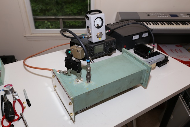 )
)
(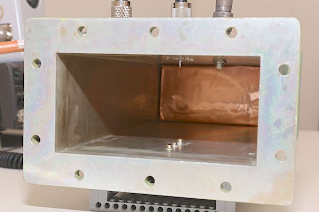 )
)
-
Title: Re: EM Drive Developments - related to space flight applications - Thread 3
Post by: TMEubanks on 06/15/2015 12:00 AM -
<a href="http://forum.nasaspaceflight.com/index.php?topic=37642.msg1389502#msg1389502">Quote from: vulture4 on 06/14/2015 11:03 PM</a>
If the thruster is powerful enough to cause the device to rocket out of sight in seconds, then the noise may not be a factor. If the goal is to minimize noise and record a small signal, the best strategy is to rigidly mount to device on a load cell anchored to a vibration-isolated table. A device that is free to move will be subject to motion due to noise, air currents, both already present and thermally induced, thermal recoil, power line induced magnetic fields, vibrations from air conditioners, traffic, and distant earthquakes, and a host of other factors. The investigator's statement that the device has to be free to move or there would be no thrust is unfortunately a misinterpretation of Newton's laws.
Yes, if the thrust > 1 g, we would not be having these discussions. Given that it is not, we have to worry about noise. Note that to measure thrust, something has to move or bend or deform - there has to be a pendulum or a spring or something with an opposing force. However, measurements at this level of accuracy can certainly be done.*
*You can go out and buy absolute gravimeters : http://www.microglacoste.com/pdf/Brochure-FG5-X.pdf (http://www.microglacoste.com/pdf/Brochure-FG5-X.pdf) that are good to ~ 10 microGals = 10^-7 m/sec^2, based on dropping a retroreflector weighing about 1 kg (thus the force accuracy is ~ 0.1 micro Newtons). This, note, is a field instrument, intended to be used in a tent. -
Title: Re: EM Drive Developments - related to space flight applications - Thread 3
Post by: frobnicat on 06/15/2015 12:18 AM -
<a href="http://forum.nasaspaceflight.com/index.php?topic=37642.msg1389465#msg1389465">Quote from: Rodal on 06/14/2015 09:38 PM</a><a href="http://forum.nasaspaceflight.com/index.php?topic=37642.msg1389454#msg1389454">Quote from: deuteragenie on 06/14/2015 09:05 PM</a>
...Another thing is to do some autocorrelation analysis on the TS. R has what you need.
I was showing that the human mind is built by Nature to see patterns, many times where there may not be any patterns. (The face on Mars, trees on Mars, etc.)
...
Focusing on the Movax experiment, they should try to use oil (instead of water) to dampen the vibrations.
If calculate we must, calculate we will. We can also do autocorrelation and power spectral density with Mathematica:
(I guess we could also try to do a cross-correlation with the on/off signal later on...)
Actually the cross-correlation looks interesting, there is a relatively clear max (magnitude) centered around 0. Interestingly this absolute max is found at a lag of 3 frames (is it 3 minutes ?). Not rock solid statistics but lucky if it was only a coincidence in the absence of any actual correlation.
So Prunesquallor's activation periods averaged cuts seem not that much misleading, there may have a thing going on.
Attached plot :
Horizontal = lag
Vertical = sum (averaged) on all t of activation(t)*data(t+lag) with normalized data and activation +1(on)/-1(off) (0 outside)
This is using the discrete formula for cross-correlation (https://en.wikipedia.org/wiki/Cross-correlation), what I call lag is n in the formula, excitation (on/off) is f and data is g.
-
Title: Re: EM Drive Developments - related to space flight applications - Thread 3
Post by: aero on 06/15/2015 12:20 AM -
You may recall that yesterday I posted some meep generated data including the first attached image. I claimed force/power ~ 5/c based on the model run as the model existed at that time. That was all wrong.
I let myself get in a hurry and didn't do enough debugging. The image from the corrected model is attached, followed by an image of the cavity debug mark-up. This corrected model gives force/power ~ 0.85/c, which is not spectacular at all but interesting none the less. Interesting, because one would expect the force on the plus and minus ends of the cavity to cancel out. Meep does calculate the sum of forces in the positive and negative direction from a plane wave source as exactly zero. (Using the control file attached.)
Now, for those who are interested, I have attached my corrected control file. The problem with the version I was using yesterday (and I have posted here on NSF) was that the computational lattice was not large enough. The corner of the big end of the frustum was very near or within the PML boundary layer. This damped RF energy moving in that direction so the wave paterns looked as they did and the force/power was dominated by only one end. Hopefully none of you will ever make such a mistake. Making the computational lattice smaller will result in faster runs, but it's hardly worth the embarrassment. -
Title: Re: EM Drive Developments - related to space flight applications - Thread 3
Post by: TheTraveller on 06/15/2015 01:22 AM -
WE HAVE RESONANCE!
Attached is TE01x analysis for the Baby EM Drive.
With flat end plates, length resonance can occur anywhere from
the min spacing of:
1) centre of big end plate to centre of small end plate
to max spacing of :
2) outer edge big end plate to outer edge small end plate.
As you can see TE013 generates a length resonance ring just inside the maximal outer edge spacing.
For the Baby EM Drive, there are several resonance modes. Which is driven depends on excitation method, antenna placement and antenna design.
Spreadsheet attached.
-
Title: Re: EM Drive Developments - related to space flight applications - Thread 3
Post by: PaulF on 06/15/2015 01:26 AM -
BabyEM is small enough to have the whole contraption enclosed in a relatively small vacuum chamber. Going on the fact that BabyEM is only a few cm long, the whole contraption seems between 25 and 30 cm long to me. With a bit of redesign it could easily fit in a small chamber which is easier to get than a large one.
Ding tests in a vacuum was proposed during the period BabyEM was being built. In my opinion vacuum is the only way to get rid of thermal currents and other atmospheric noise in a relatively simple, and probably the only convincing way.
Even if the electronics contain elco's it's possible to nullify the thermal and atmospheric disturbances by measuring apparent thrust in steps of different pressures, like at 1, 0.95, 0.90, 0.85 bar and so on down to a pressure that can still be handled by any pressurised component.
-
Title: Re: EM Drive Developments - related to space flight applications - Thread 3
Post by: TheTraveller on 06/15/2015 01:31 AM -
<a href="http://forum.nasaspaceflight.com/index.php?topic=37642.msg1389533#msg1389533">Quote from: PaulF on 06/15/2015 01:26 AM</a>
BabyEM is small enough to have the whole contraption enclosed in a relatively small vacuum chamber. Going on the fact that BabyEM is only a few cm long, the whole contraption seems between 25 and 30 cm long to me. With a bit of redesign it could easily fit in a small chamber which is easier to get than a large one.
Ding tests in a vacuum was proposed during the period BabyEM was being built. In my opinion vacuum is the only way to get rid of thermal currents and other atmospheric noise in a relatively simple, and probably the only convincing way.
Even if the electronics contain elco's it's possible to nullify the thermal and atmospheric disturbances by measuring apparent thrust in steps of different pressures, like at 1, 0.95, 0.90, 0.85 bar and so on down to a pressure that can still be handled by any pressurised component.
Can also change the elco to tants. -
Title: Re: EM Drive Developments - related to space flight applications - Thread 3
Post by: Rodal on 06/15/2015 02:05 AM -
<a href="http://forum.nasaspaceflight.com/index.php?topic=37642.msg1389531#msg1389531">Quote from: TheTraveller on 06/15/2015 01:22 AM</a>
WE HAVE RESONANCE!
Attached is TE01x analysis for the Baby EM Drive.
With flat end plates, length resonance can occur anywhere from
the min spacing of:
1) centre of big end plate to centre of small end plate
to max spacing of :
2) outer edge big end plate to outer edge small end plate.
As you can see TE013 generates a length resonance ring just inside the maximal outer edge spacing.
For the Baby EM Drive, there are several resonance modes. Which is driven depends on excitation method, antenna placement and antenna design.
Spreadsheet attached.
I get TE013 for Baby EM Drive with my exact solution at a frequency of 24.34 GHz. There are many other natural frequencies close by though, so there will be participation from other modes as well.
TE013 is a transverse electric mode shape, therefore the field in the circumferential direction of the Baby EM Drive is electric, while the transverse and the longitudinal fields are magnetic. It has 3 half-wave patterns along the longitudinal direction, with the strongest fields near the small end of the Baby EM Drive. Shown below is the Poynting vector field for the Baby EM Drive.
I imagine that it is not a coincidence that TE013 is the natural frequency that matches their excitation frequency. TE01p has been the preferred mode of excitation of both Shawyer for the Demo and the Flight Thruster, and by Prof. Yang, and it was also the mode shape that gave the highest Force/InputPower for NASA Eagleworks (see http://emdrive.wiki/Experimental_Results ), so it looks to me that the fellows at Aachen calculated this before they machined Baby EM Drive. These guys did their homework ;) -
Title: Re: EM Drive Developments - related to space flight applications - Thread 3
Post by: rfmwguy on 06/15/2015 02:21 AM -
EMDIY project update. Exciter and 8W amp are here. Small bits on their way such as lipo batt pack and rf switch. Planning ahead, I expect the build completed just after july 4th.
Something different, I will try and set up a live broadcast on ustream. Already have 4 live broadcasts now, 24/7, set up for my wife's animal shelter. The live webcams raise awareness for neglected and abused felines. Check them out here: http://carolines-kids.org (I volunteer my time and electronics know-how).
Regardless, I will try and set up a live stream event for test #1. There is a chat mode on the event so I can read questions with abt 1 min delay. Will use ustream rather than youtube which is loaded with trolls.
Thought this might be fun. Will share the private url on nsf for the broadcast as I get closer to test date. -
Title: Re: EM Drive Developments - related to space flight applications - Thread 3
Post by: TheTraveller on 06/15/2015 02:30 AM -
<a href="http://forum.nasaspaceflight.com/index.php?topic=37642.msg1389539#msg1389539">Quote from: Rodal on 06/15/2015 02:05 AM</a><a href="http://forum.nasaspaceflight.com/index.php?topic=37642.msg1389531#msg1389531">Quote from: TheTraveller on 06/15/2015 01:22 AM</a>
WE HAVE RESONANCE!
Attached is TE01x analysis for the Baby EM Drive.
With flat end plates, length resonance can occur anywhere from
the min spacing of:
1) centre of big end plate to centre of small end plate
to max spacing of :
2) outer edge big end plate to outer edge small end plate.
As you can see TE013 generates a length resonance ring just inside the maximal outer edge spacing.
For the Baby EM Drive, there are several resonance modes. Which is driven depends on excitation method, antenna placement and antenna design.
Spreadsheet attached.
I get TE013 for Baby EM Drive with my exact solution at a frequency of 24.34 GHz. There are many other natural frequencies close by though, so there will be participation from other modes as well.
I imagine that it is not a coincidence that TE013 is the natural frequency that matches their excitation frequency. TE01p has been the preferred mode of excitation of both Shawyer for the Demo and the Flight Thruster, and by Prof. Yang, and it was also the mode shape that gave the highest Force/InputPower for NASA Eagleworks (see http://emdrive.wiki/Experimental_Results ), so it looks to me that the fellows at Aachen calculated this before they machined Baby EM Drive. These guys did their homework ;)
The end plates of the Baby EM Drive are flat, so a lot of close frequencies should obtain resonance. For your 24.34GHz spherical end plate case, the results are attached, which show resonance a bit further away from the side wall but not at the minimal centre to centre end plate spacing.
Would expect thrust to be MUCH greater with spherical and plates as much more (should be all of it) end plate surface area is working at resonance as against a thin ring (very small area) at each end plate. -
Title: Re: EM Drive Developments - related to space flight applications - Thread 3
Post by: Rodal on 06/15/2015 03:10 AM -
<a href="http://forum.nasaspaceflight.com/index.php?topic=37642.msg1389531#msg1389531">Quote from: TheTraveller on 06/15/2015 01:22 AM</a>
WE HAVE RESONANCE!
What is the numerical value of Shaywer's Design Factor you calculate for the Baby EM Drive, following Shawyer's procedure?
Attached is TE01x analysis for the Baby EM Drive.... -
Title: Re: EM Drive Developments - related to space flight applications - Thread 3
Post by: aero on 06/15/2015 03:23 AM -
With all the fooling I've done with meep recently, I discovered a new trick. I can show different views of slices of a 4-D data set. Here is the closed cavity with the Gaussian drive frequency centered at 2.253 GHz though Meep/Harminv says it resonates at 2.343 GHz. These are all at timestep 1420. What mode is this illustrated.
Shown are big end, center and small end slices "x", and y and z axial slices. -
Title: Re: EM Drive Developments - related to space flight applications - Thread 3
Post by: TheTraveller on 06/15/2015 03:25 AM -
<a href="http://forum.nasaspaceflight.com/index.php?topic=37642.msg1389551#msg1389551">Quote from: Rodal on 06/15/2015 03:10 AM</a><a href="http://forum.nasaspaceflight.com/index.php?topic=37642.msg1389531#msg1389531">Quote from: TheTraveller on 06/15/2015 01:22 AM</a>
WE HAVE RESONANCE!
What is the numerical value of Shaywer's Design Factor you calculate for the Baby EM Drive, following Shawyer's procedure?
Attached is TE01x analysis for the Baby EM Drive....
Df = 0.7311 @ 24,100,700,000Hz (from their freq meter) @ TE01x as per attached
-
Title: Re: EM Drive Developments - related to space flight applications - Thread 3
Post by: Abyss on 06/15/2015 04:43 AM -
Here is an analysis using Fourier transform filtering.

All time domain signals can be represented in terms of their component frequencies. In their experiment we aren't interested in the high frequency components because the experimental perturbation isn't rapidly switched, so we can filter them out, which is what I've done. This leaves the low frequency signal completely intact. The smallest 'on' range is from frames 18-39, a range of 21. Thus the cutoff frequency was chosen to be 0.047 (1/21).
The Y axis is displacement because I subtracted the mean. -
Title: Re: EM Drive Developments - related to space flight applications - Thread 3
Post by: deltaMass on 06/15/2015 05:41 AM -
Well, you're Murrikan so I suppose you have to use Imperial units. One day this will change. One centimetre at a time. Except you won't spell it right
:( -
Title: Re: EM Drive Developments - related to space flight applications - Thread 3
Post by: deltaMass on 06/15/2015 05:44 AM -
<a href="http://forum.nasaspaceflight.com/index.php?topic=37642.msg1389531#msg1389531">Quote from: TheTraveller on 06/15/2015 01:22 AM</a>
WE HAVE RESONANCE!
Pretty good for a guy who is being sick for 4 weeks, after less than a week. Congrats!
Attached is TE01x analysis for the Baby EM Drive.
With flat end plates, length resonance can occur anywhere from
the min spacing of:
1) centre of big end plate to centre of small end plate
to max spacing of :
2) outer edge big end plate to outer edge small end plate.
As you can see TE013 generates a length resonance ring just inside the maximal outer edge spacing.
For the Baby EM Drive, there are several resonance modes. Which is driven depends on excitation method, antenna placement and antenna design.
Spreadsheet attached. -
Title: Re: EM Drive Developments - related to space flight applications - Thread 3
Post by: TheTraveller on 06/15/2015 05:51 AM -
<a href="http://forum.nasaspaceflight.com/index.php?topic=37642.msg1389587#msg1389587">Quote from: deltaMass on 06/15/2015 05:44 AM</a><a href="http://forum.nasaspaceflight.com/index.php?topic=37642.msg1389531#msg1389531">Quote from: TheTraveller on 06/15/2015 01:22 AM</a>
WE HAVE RESONANCE!
Pretty good for a guy who is being sick for 4 weeks, after less than a week. Congrats!
Attached is TE01x analysis for the Baby EM Drive.
With flat end plates, length resonance can occur anywhere from
the min spacing of:
1) centre of big end plate to centre of small end plate
to max spacing of :
2) outer edge big end plate to outer edge small end plate.
As you can see TE013 generates a length resonance ring just inside the maximal outer edge spacing.
For the Baby EM Drive, there are several resonance modes. Which is driven depends on excitation method, antenna placement and antenna design.
Spreadsheet attached.
I'm not sick as such. Recovering from surgery. Can still use a laptop for a few hours a day. Did say would post the multi mode version of my EM Drive Calculator. Is good to be able to quickly test 80 modes for resonance. -
Title: Re: EM Drive Developments - related to space flight applications - Thread 3
Post by: deltaMass on 06/15/2015 05:52 AM - Anyone going to confirm my 15% figure?
-
Title: Re: EM Drive Developments - related to space flight applications - Thread 3
Post by: Abyss on 06/15/2015 05:55 AM -
<a href="http://forum.nasaspaceflight.com/index.php?topic=37642.msg1389516#msg1389516">Quote from: frobnicat on 06/15/2015 12:18 AM</a><a href="http://forum.nasaspaceflight.com/index.php?topic=37642.msg1389465#msg1389465">Quote from: Rodal on 06/14/2015 09:38 PM</a><a href="http://forum.nasaspaceflight.com/index.php?topic=37642.msg1389454#msg1389454">Quote from: deuteragenie on 06/14/2015 09:05 PM</a>
...Another thing is to do some autocorrelation analysis on the TS. R has what you need.
I was showing that the human mind is built by Nature to see patterns, many times where there may not be any patterns. (The face on Mars, trees on Mars, etc.)
...
Focusing on the Movax experiment, they should try to use oil (instead of water) to dampen the vibrations.
If calculate we must, calculate we will. We can also do autocorrelation and power spectral density with Mathematica:
(I guess we could also try to do a cross-correlation with the on/off signal later on...)
Actually the cross-correlation looks interesting, there is a relatively clear max (magnitude) centered around 0. Interestingly this absolute max is found at a lag of 3 frames (is it 3 minutes ?). Not rock solid statistics but lucky if it was only a coincidence in the absence of any actual correlation.
So Prunesquallor's activation periods averaged cuts seem not that much misleading, there may have a thing going on.
Attached plot :
Horizontal = lag
Vertical = sum (averaged) on all t of activation(t)*data(t+lag) with normalized data and activation +1(on)/-1(off) (0 outside)
This is using the discrete formula for cross-correlation (https://en.wikipedia.org/wiki/Cross-correlation), what I call lag is n in the formula, excitation (on/off) is f and data is g.
Was just going to post this when I saw you did it, I saw a delay of 5 frames though, with a magnitude of -0.167 (normalized) on a 5 frame offset, which is meaningful. There must have been some kind of measurement error that offset the switching of the device on and off, because there is no way that delay is chance. -
Title: Re: EM Drive Developments - related to space flight applications - Thread 3
Post by: TheTraveller on 06/15/2015 06:27 AM -
Have found the freq range for the Baby Em Drive operating at TE013
Upper: 25.327GHz - Centre
Lower: 23.927GHz - Outer edge
As the Rf source is narrow band, very little of either end plate area will be in resonance and able to exchange momentum, so thrust will be a very small traction of that predicted by the SPR thrust equation.
Design rule seems to be, if your Rf source has a wide bandwidth and you are using flat end plates, design the frustum so the Rf range runs from resonance at the centre at highest frequency to resonance at the outer edges at the lowest frequency as then you may have a hope to capture more of the mixed frequency energy in the cavity.
For a narrow band Rf source, using flat end plates may be a waste of time as very little of the cavity end plate area will be in resonance. Much better to use spherical end plates as then the entire surface area of the end plates will be in length resonance and able to contribute to thrust generation.
Does anybody know the output bandwidth of a microwave magnetron? If so I will do an analysis of that as against the EW frustum. Yes I do know the energy distribution versus frequency will not be flat, which just adds another element to the analysis task.
-
Title: Re: EM Drive Developments - related to space flight applications - Thread 3
Post by: TheTraveller on 06/15/2015 06:58 AM -
Here is the data for the EW, non dielectric, frustum operating at 2.168GHz as attached.
The only mode with resonance is TM013, in a thin length resonance ring about 40% of the way between the centre and the outer edge. See new chart that plots where a narrow band Rf would resonant between centre and the outer edge. No way to tell if EW excited that mode but even so thrust would be very weak as very little end plate area would be in resonance. -
Title: Re: EM Drive Developments - related to space flight applications - Thread 3
Post by: OttO on 06/15/2015 07:42 AM -
For people wanting to look at it another way (in a liquid way :P) :
General Navier-Stokes-like Momentum and Mass-Energy Equations
We have shown that by starting with general forms of momentum, mass and energy hydrodynamic conservation equations we can arrive at analogous general forms
of momentum and mass-energy equations applicable to electromagnetic flow
http://arxiv.org/abs/1410.6794 (http://arxiv.org/abs/1410.6794)
Optics of Nonuniformly Moving Media
A moving dielectric appears to light as an effective gravitational field. At low flow velocities the
dielectric acts on light in the same way as a magnetic field acts on a charged matter wave.
http://arxiv.org/abs/physics/9906038 (http://arxiv.org/abs/physics/9906038)
It is another way (by similarity) to obtain the various mechanisms that has been discussed here. -
Title: Re: EM Drive Developments - related to space flight applications - Thread 3
Post by: flux_capacitor on 06/15/2015 09:30 AM -
I have a more general question about the evolution of all this research.
According to Shawyer, we have to increase the Q factor up to billions in order to scale the thrust (with the help of superconducting cavities). Hence Shawyer envisioned not only thrusters for spaceprobes and spaceships, but also "lift engines" here on Earth, with -literally speaking- flyings cars and the like around the corner.
If Shawyer is wrong regarding the scale law of thrust vs Q (and the lack of published experimental results of superconducting EmDrives up to now would bolster this pessimistic view), but the EmDrive is still real, would the thrust stay very low even with high power, restricting the applications to space-based thrusters only?
If an alternate model is right, for example Todd's: wavelength attenuation produces thrust in a refractive index gradient, due to an energy density unevenly distributed thanks to a proper asymmetric geometry aka the frustum: the thrust is then maximized while increasing the attenuation, and not increasing the energy stored into the cavity via the Q factor (the "tug of war" between attenuated energy and stored energy).
If this model is right, according to you WarpTech, would the max. thrust be caped well below one gee, or do you think your model could enable lift-engines in Earth gravity field, with enough power on board? (powerful still cheap and light energy source, I'm not speaking of fitting a nuclear power plant in a car…) -
Title: Re: EM Drive Developments - related to space flight applications - Thread 3
Post by: Rodal on 06/15/2015 09:43 AM -
<a href="http://forum.nasaspaceflight.com/index.php?topic=37642.msg1389554#msg1389554">Quote from: aero on 06/15/2015 03:23 AM</a>
With all the fooling I've done with meep recently, I discovered a new trick. I can show different views of slices of a 4-D data set. Here is the closed cavity with the Gaussian drive frequency centered at 2.253 GHz though Meep/Harminv says it resonates at 2.343 GHz. These are all at timestep 1420. What mode is this illustrated.
What is the reason for the elliptical shape of the electromagnetic field in the circular cross-section views?
Shown are big end, center and small end slices "x", and y and z axial slices.
(http://forum.nasaspaceflight.com/index.php?action=dlattach;topic=37642.0;attach=1018289;image)
The boundary conditions should be perfectly circular for a truncated cone.
Therefore one expects a circularly symmetric electromagnetic field instead of this surprising elliptical electromagnetic field.
There appears to be an asymmetry in the circular cross section of your model responsible for this ellipse.
What feature of the model does the major and minor axes of the ellipse align with?
They seem to align with the cut-outs your model has at 0 , 90, 180 and 270 degrees.
What is the asymmetry responsible for the major axis of the ellipse aligning itself with the cut-outs at 0 and 180 degrees instead of 90 and 270 degrees ?
Or, in other words, why should there be an ellipse instead of a rhombus-like shape with symmetry every 90 degrees (the angle between the cut-outs) instead of every 180 degrees? -
Title: Re: EM Drive Developments - related to space flight applications - Thread 3
Post by: TheTraveller on 06/15/2015 09:57 AM -
<a href="http://forum.nasaspaceflight.com/index.php?topic=37642.msg1389638#msg1389638">Quote from: flux_capacitor on 06/15/2015 09:30 AM</a>
I have a more general question about the evolution of all this research.
According to Shawyer, we have to increase the Q factor up to billions in order to scale the thrust (with the help of superconducting cavities). Hence Shawyer envisioned not only thrusters for spaceprobes and spaceships, but also "lift engines" here on Earth, with -literally speaking- flyings cars and the like around the corner.
If Shawyer is wrong regarding the scale law of thrust vs Q (and the lack of published experimental results of superconducting EmDrives up to now would bolster this pessimistic view), but the EmDrive is still real, would the thrust stay very low even with high power, restricting the applications to space-based thrusters only?
If an alternate model is right, for example Todd's: wavelength attenuation produces thrust in a refractive index gradient, due to an energy density unevenly distributed thanks to a proper asymmetric geometry aka the frustum: the thrust is then maximized while increasing the attenuation, and not increasing the energy stored into the cavity via the Q factor (the "tug of war" between attenuated energy and stored energy).
If this model is right, according to you WarpTech, would the max. thrust be caped well below one gee, or do you think your model could enable lift-engines in Earth gravity field, with enough power on board? (powerful still cheap and light energy source, I'm not speaking of fitting a nuclear power plant in a car…)
May I suggest dealing with really high Q cavities is REALLY hard. Narrow band Rf needs to spot on, massive cavity detune with the slightest acceleration or the slightest temp change. Shawyer has revealed enough publically, that to me, he knows the issues and is working them.
His next peer reviewed paper on the SC EM Drive that has been developed with partners is due to be released in 2015. Expect there will be performance data in the paper. I keep watching the IAC 2015 site for his paper to be listed for the mid Oct 2015 event.
https://iafastro.directory/iac/browse/IAC-15/catalog-technical-programme#sec.C4 subsection (C4.8. Advanced and Combined Propulsion Systems) -
Title: Re: EM Drive Developments - related to space flight applications - Thread 3
Post by: Chris Bergin on 06/15/2015 10:31 AM -
Remember to "attach" images, not embed them.
Only use the embed [img ] code when the image is small. Anything wider than the width of the thread makes the page unreadable as it stretches it (we're working on auto reduction, but different browsers work different ways, etc.)
Sounds like you're having interesting fun on here, so as you were..... -
Title: Re: EM Drive Developments - related to space flight applications - Thread 3
Post by: francesco nicoli on 06/15/2015 10:33 AM - we profanes are in need of an update in a while! :) I see lots of work is going on and I am impressed on the role this forum is having, but unfortunately I can't follow much of developments...how the new experiments are going?
-
Title: Re: EM Drive Developments - related to space flight applications - Thread 3
Post by: Rodal on 06/15/2015 12:38 PM -
<a href="http://forum.nasaspaceflight.com/index.php?topic=37642.msg1389542#msg1389542">Quote from: TheTraveller on 06/15/2015 02:30 AM</a><a href="http://forum.nasaspaceflight.com/index.php?topic=37642.msg1389539#msg1389539">Quote from: Rodal on 06/15/2015 02:05 AM</a><a href="http://forum.nasaspaceflight.com/index.php?topic=37642.msg1389531#msg1389531">Quote from: TheTraveller on 06/15/2015 01:22 AM</a>
WE HAVE RESONANCE!
Attached is TE01x analysis for the Baby EM Drive.
With flat end plates, length resonance can occur anywhere from
the min spacing of:
1) centre of big end plate to centre of small end plate
to max spacing of :
2) outer edge big end plate to outer edge small end plate.
As you can see TE013 generates a length resonance ring just inside the maximal outer edge spacing.
For the Baby EM Drive, there are several resonance modes. Which is driven depends on excitation method, antenna placement and antenna design.
Spreadsheet attached.
I get TE013 for Baby EM Drive with my exact solution at a frequency of 24.34 GHz. There are many other natural frequencies close by though, so there will be participation from other modes as well.
I imagine that it is not a coincidence that TE013 is the natural frequency that matches their excitation frequency. TE01p has been the preferred mode of excitation of both Shawyer for the Demo and the Flight Thruster, and by Prof. Yang, and it was also the mode shape that gave the highest Force/InputPower for NASA Eagleworks (see http://emdrive.wiki/Experimental_Results ), so it looks to me that the fellows at Aachen calculated this before they machined Baby EM Drive. These guys did their homework ;)
The end plates of the Baby EM Drive are flat, so a lot of close frequencies should obtain resonance. For your 24.34GHz spherical end plate case, the results are attached, which show resonance a bit further away from the side wall but not at the minimal centre to centre end plate spacing.
Would expect thrust to be MUCH greater with spherical and plates as much more (should be all of it) end plate surface area is working at resonance as against a thin ring (very small area) at each end plate.
I calculated the natural frequency of the EM Drive based on the formula for a perfect cylinder ( https://en.wikipedia.org/wiki/Microwave_cavity#Cylindrical_cavity ) (using the cylindrical Bessel functions that you use in your spreadsheet), based on the Mean diameter (the average of the small and big diameters of the Baby EM Drive), I obtained the following frequency for TE013 for perfectly flat ends:
24.41 GHz
which compares to the value I obtained using my exact solution:
24.34 GHz
The difference between these values is only
0.29%
Suggestion: this difference (0.29%) is very small, particularly compared with the uncertainties of:
--precision of the dimensional measurements of the Baby EM Drive
--precision in machining the Baby EM Drive: precision in radial runout, precision in concentricity, precision in longitudinal runout
--precision in excitation frequencies of the Baby EM Drive by the radar they are using
Therefore undue emphasis on such small differences and undue emphasis on a large number of digits for precision may be unwarranted at this point in time, particularly when using a spreadsheet based on using cylindrical Bessel functions that are known to apply only for cylinders and that are not able to satisfy the boundary conditions of a truncated cone.
The most that can be confidently said is that the Baby EM Drive if excited at 24 to 25 GHz will experience a number of mode shapes with different participation factors, and that TE013 is one of the main mode shapes expected to participate. To be more precise would require a spectrum analysis of the truncated cone, taking into account all the frequencies excited by the radar used in the Baby EM Drive as well as knowing more about the precision of their geometrical measurement and the precision of their machining the Baby EM Drive.
-
Title: Re: EM Drive Developments - related to space flight applications - Thread 3
Post by: Rodal on 06/15/2015 12:54 PM -
<a href="http://forum.nasaspaceflight.com/index.php?topic=37642.msg1389647#msg1389647">Quote from: francesco nicoli on 06/15/2015 10:33 AM</a>
we profanes are in need of an update in a while! :) I see lots of work is going on and I am impressed on the role this forum is having, but unfortunately I can't follow much of developments...how the new experiments are going?
Hi :)
IMHO the main topics of discussion at the moment are:
EXPERIMENTAL: the breakthrough in miniaturization: the Baby EM Drive with 1/10 the geometrical dimensions of other EM Drives, running at 10 times higher frequency: 24 GHz, by two fellows in Aachen, Germany. See: https://hackaday.io/project/5596-em-drive
The test inside the transparent jar (NOT a vacuum chamber) displays gyroscopic oscillations ("nutation") and decay with time that almost mask the response of the EM Drive (still, a small effect on the rotation speed appears to be there). A subsequent test of the EM Drive in a torsional hanging pendulum was the subject of even more uncertainty as the magnitude of spurious oscillations completely overwhelm any possible signal response.
https://www.youtube.com/watch?v=ZSZT5plA4a4
THEORETICAL: Todd "WarpTech" theory based on geometrical attenuation: that due to the tapering geometry of the EM Drive, standing waves are cut-off and become evanescent waves near the small base of the truncated cone. Evanescent waves are known to carry momentum (unlike standing waves). The problem is that the evanescent waves are inside the EM Drive and this still appears to break conservation of momentum unless they are able to leak out somehow (in which case it has to be shown how can they leak out in such a way as to exceed the performance of a photon rocket).
This discussion has also been useful concerning optimization of the shape of an EM Drive to maximize thrust output.
It points (pun intended ;) ) towards a more pointy cone, with a smaller diameter base (compared to the big base) than used up to now. All the theories (Todd's attenuation theory, Shawyer's, McCulloch's, Yang's, Notsosureofit) point in the same geometrical direction.
EDIT: Todd's attenuation theory differs in one very important aspect: while all the other theories predict thrust to linearly increase with quality factor of resonance ("Q"), Todd's attenuation theory shows a "tug of war" between Q and attenuation (cut-off of natural frequencies), and maximum thrust should take place at a yet unknown compromise between the two.
(http://forum.nasaspaceflight.com/index.php?action=dlattach;topic=37642.0;attach=1011076;image)
DATABASE: EM DRIVE wiki. The information in the EM Drive wiki continues to expand. We now have a very extensive and useful table of EM Drive experiments with lots of annotated information: http://emdrive.wiki/Experimental_Results
and a page for independent replications and building of new EM Drives:
http://emdrive.wiki/Building -
Title: Re: EM Drive Developments - related to space flight applications - Thread 3
Post by: WarpTech on 06/15/2015 02:14 PM -
<a href="http://forum.nasaspaceflight.com/index.php?topic=37642.msg1389638#msg1389638">Quote from: flux_capacitor on 06/15/2015 09:30 AM</a>
I have a more general question about the evolution of all this research.
According to Shawyer, we have to increase the Q factor up to billions in order to scale the thrust (with the help of superconducting cavities). Hence Shawyer envisioned not only thrusters for spaceprobes and spaceships, but also "lift engines" here on Earth, with -literally speaking- flyings cars and the like around the corner.
If Shawyer is wrong regarding the scale law of thrust vs Q (and the lack of published experimental results of superconducting EmDrives up to now would bolster this pessimistic view), but the EmDrive is still real, would the thrust stay very low even with high power, restricting the applications to space-based thrusters only?
If an alternate model is right, for example Todd's: wavelength attenuation produces thrust in a refractive index gradient, due to an energy density unevenly distributed thanks to a proper asymmetric geometry aka the frustum: the thrust is then maximized while increasing the attenuation, and not increasing the energy stored into the cavity via the Q factor (the "tug of war" between attenuated energy and stored energy).
If this model is right, according to you WarpTech, would the max. thrust be caped well below one gee, or do you think your model could enable lift-engines in Earth gravity field, with enough power on board? (powerful still cheap and light energy source, I'm not speaking of fitting a nuclear power plant in a car…)
It's difficult to answer. Going by Shawyer's and Nasa's data, I'd say it's a very long shot of scaling it, but going by Yang's it seems more likely.
The Power input is the rate of change in work "W". It results in doing work on the field via the Poynting vector, and also -J*E, which is the current density flowing in the frustum conductors. So look at E and look at J and see where it can be maximized.
IMO, the frustum "should" exert thrust ONLY when charging or discharging. It's should not work when it's at equilibrium with a constant Q value, no matter how high it is.
One question on my mind is, if the Center of Mass (CM) could be moving because the mass of the field dissipates or is attenuated. One or the other or both, it's equivalent to expelling the field out the back. The CM may move forward, then loose mass, before it can oscillate and cause a back reaction, back to where it started. So it "walks" forward, either gaining or losing mass on each step. If the CM is held at constant mass, nothing should happen.
Todd
-
Title: Re: EM Drive Developments - related to space flight applications - Thread 3
Post by: Rodal on 06/15/2015 02:26 PM -
I have added Baby EM Drive to the list of experiments. http://emdrive.wiki/Experimental_Results
The geometry of Baby EM Drive is essentially the geometry of NASA's truncated cone, scaled down by 1/10 so that it can resonate at 10 times higher frequency in a fundamental mode. The cone angle is very close to NASA's truncated cone. Small differences in geometry were carried out (apparently not by chance but by judicious choice based on numerical analysis) so that Baby EM Drive would resonate in mode shape TE013, instead of mode TM212 chosen by NASA for most of their experiments. TE01p is a transverse electric mode shape with a magnetic axial field that is known to produce a large amplitude or response, and this has been confirmed by the fact that all researchers: Shawyer, Yang and NASA have reported the largest force/InputPower when using this mode shape.
The force entries in the experimental chart remain to be filled until they report a meaningful force measurement for Baby EM Drive. -
Title: Re: EM Drive Developments - related to space flight applications - Thread 3
Post by: TheTraveller on 06/15/2015 02:28 PM -
<a href="http://forum.nasaspaceflight.com/index.php?topic=37642.msg1389684#msg1389684">Quote from: Rodal on 06/15/2015 12:38 PM</a>
.....
I calculated the natural frequency of the EM Drive based on the formula for a perfect cylinder ( https://en.wikipedia.org/wiki/Microwave_cavity#Cylindrical_cavity ) (using the cylindrical Bessel functions that you use in your spreadsheet), based on the Mean diameter (the average of the small and big diameters of the Baby EM Drive), I obtained the following frequency for TE013 for perfectly flat ends:
24.41 GHz
which compares to the value I obtained using my exact solution:
24.34 GHz
......
With respect that is not now effective guide wavelength is calculated. Roger Shawyer told me how to do it and I shared this here several times. It is in my SS.
The effective guide wavelength is not based on the average of the 2 end plate diameter. It is the numerically integrated value of 10,000 diameters (well I use 10,000, could be more, could be less) including and in between the plates.
For the Baby EMD the guide wavelength for the mean/average diameter is = 0.016501. The numerically integrated effective guide wavelength is = 0.018224, which is why your resonance is too high as your effective guide wavelength is too small.
Have attached the latest version of the SS, which has a new feature.
-
Title: Re: EM Drive Developments - related to space flight applications - Thread 3
Post by: Rodal on 06/15/2015 02:37 PM -
<a href="http://forum.nasaspaceflight.com/index.php?topic=37642.msg1389724#msg1389724">Quote from: TheTraveller on 06/15/2015 02:28 PM</a><a href="http://forum.nasaspaceflight.com/index.php?topic=37642.msg1389684#msg1389684">Quote from: Rodal on 06/15/2015 12:38 PM</a>
.....
I calculated the natural frequency of the EM Drive based on the formula for a perfect cylinder ( https://en.wikipedia.org/wiki/Microwave_cavity#Cylindrical_cavity ) (using the cylindrical Bessel functions that you use in your spreadsheet), based on the Mean diameter (the average of the small and big diameters of the Baby EM Drive), I obtained the following frequency for TE013 for perfectly flat ends:
24.41 GHz
which compares to the value I obtained using my exact solution:
24.34 GHz
......
With respect that is not now effective guide wavelength is calculated. Roger Shawyer told me how to do it and I shared this here several times. It is in my SS.
The effective guide wavelength is not based on the average of the 2 end plate diameter. It is the numerically integrated value of 10,000 diameters (well I use 10,000, could be more, could be less) including and in between the plates.
For the Baby EMD the guide wavelength for the mean/average diameter is = 0.016501. The numerically integrated effective guide wavelength is = 0.018224, which is why your resonance is too high as your effective guide wavelength is too small.
Have attached the latest version of the SS, which has a new feature.
Let's agree to disagree on this point otherwise this is going to run for ever. You calculate the effective guide wavelength and the cut-off based on Bessel cylinder functions that do not satisfy the boundary conditions of the problem. It is an ad-hoc solution that agrees with Shawyer's formulation (not an exact solution to Maxwell's equations for a truncated cone with flat ends) . You think it is better to proceed that way than using Finite Element analysis or using the exact solution for a truncated cone with spherical ends.
In this case (Baby EM Drive natural frequency 24 GHz TE013) it makes very little difference.
My point was that we cannot justify to include so many digits of numerical precision with geometrical dimensions (runout, concentricity) of unknown precision, and without performing a spectrum solution, as the participation of other modes in the response is not taken into account (the response of any system will not be the response of a single mode, but will include other mode shapes as well). -
Title: Re: EM Drive Developments - related to space flight applications - Thread 3
Post by: TheTraveller on 06/15/2015 02:45 PM -
<a href="http://forum.nasaspaceflight.com/index.php?topic=37642.msg1389727#msg1389727">Quote from: Rodal on 06/15/2015 02:37 PM</a><a href="http://forum.nasaspaceflight.com/index.php?topic=37642.msg1389724#msg1389724">Quote from: TheTraveller on 06/15/2015 02:28 PM</a><a href="http://forum.nasaspaceflight.com/index.php?topic=37642.msg1389684#msg1389684">Quote from: Rodal on 06/15/2015 12:38 PM</a>
.....
I calculated the natural frequency of the EM Drive based on the formula for a perfect cylinder ( https://en.wikipedia.org/wiki/Microwave_cavity#Cylindrical_cavity ) (using the cylindrical Bessel functions that you use in your spreadsheet), based on the Mean diameter (the average of the small and big diameters of the Baby EM Drive), I obtained the following frequency for TE013 for perfectly flat ends:
24.41 GHz
which compares to the value I obtained using my exact solution:
24.34 GHz
......
With respect that is not now effective guide wavelength is calculated. Roger Shawyer told me how to do it and I shared this here several times. It is in my SS.
The effective guide wavelength is not based on the average of the 2 end plate diameter. It is the numerically integrated value of 10,000 diameters (well I use 10,000, could be more, could be less) including and in between the plates.
For the Baby EMD the guide wavelength for the mean/average diameter is = 0.016501. The numerically integrated effective guide wavelength is = 0.018224, which is why your resonance is too high as your effective guide wavelength is too small.
Have attached the latest version of the SS, which has a new feature.
Let's agree to disagree on this point otherwise this is going to run for ever. You calculate the effective guide wavelength and the cut-off based on Bessel cylinder functions that do not satisfy the boundary conditions of the problem. It is an ad-hoc solution that you like because it agrees with Shawyer's formulation .
My point was that there is no justification to include so many digits of numerical precision based on an ad-hoc formula based on cylinder functions and geometrical dimensions (runout, concentricity) of unknown precision, and not performing a spectrum solution, as the participation of other modes in the response is not taken into account (the response of any system will not be the response of a single mode, but will include other mode shapes as well).
It is not what I like or not. It is now Roger Shawyer instructed me to calculate the effective guide wavelength.
It is your method which does not agree with how Roger Shawyer and SPR do the effective guide wavelength calculation. -
Title: Re: EM Drive Developments - related to space flight applications - Thread 3
Post by: inquisitive-j on 06/15/2015 02:51 PM -
I have been following the emDrive for sometime now. I've had a google alert on it for over a year, and I kept up with thread 2 up until around page 140. That thread has now been ended at page 209, and this thread is at now at page 91. I have to admit that I am not anxious to read through the roughly 160 pages that have been posted in my absence but would still love to know what's going on with the emDrive in Eagleworks. I have a suggestion/request that I think could help streamline this discussion a bit. I think that there should be a separate thread that can be commented on ONLY by the people at Eagleworks for the purpose of information dissemination. This way a person wouldn't have to sift through hundreds of pages to find the results of the latest emDrive experiments or the plans for the next experiment. If a thread in this forum couldn't be created with that restriction, perhaps a post on another site that was linked on this thread would do. This would help people like me, who want to catch up after an absence and would give everyone in this thread an easy go-to reference for their thoughts and discussions.
This would be a nice follow up to the great "Evaluating NASA’s Futuristic EM Drive" article which gives a nice broad introduction to the emdrive (http://www.nasaspaceflight.com/2015/04/evaluating-nasas-futuristic-em-drive/). My suggested thread would give people a more detailed, up to date view of what has happened with the emDrive and what eagleworks is planning next. This wouldn't need to be a lot of work either. For everything up to the present, simply copying and pasting the Eagleworks teams posts scattered through the 3 main threads into one place would do. -
Title: Re: EM Drive Developments - related to space flight applications - Thread 3
Post by: RotoSequence on 06/15/2015 02:52 PM -
<a href="http://forum.nasaspaceflight.com/index.php?topic=37642.msg1389731#msg1389731">Quote from: TheTraveller on 06/15/2015 02:45 PM</a>
It is not what I like or not. It is now Roger Shawyer instructed me to calculate the effective guide wavelength.
It is your method which does not agree with how Roger Shawyer and SPR do the effective guide wavelength calculation.
Is there a numerical reason to believe that the SPR method delivers superior results to Rodal's? -
Title: Re: EM Drive Developments - related to space flight applications - Thread 3
Post by: TheTraveller on 06/15/2015 02:59 PM -
<a href="http://forum.nasaspaceflight.com/index.php?topic=37642.msg1389735#msg1389735">Quote from: RotoSequence on 06/15/2015 02:52 PM</a><a href="http://forum.nasaspaceflight.com/index.php?topic=37642.msg1389731#msg1389731">Quote from: TheTraveller on 06/15/2015 02:45 PM</a>
It is not what I like or not. It is now Roger Shawyer instructed me to calculate the effective guide wavelength.
It is your method which does not agree with how Roger Shawyer and SPR do the effective guide wavelength calculation.
Is there a numerical reason to believe that the SPR method delivers superior results to Rodal's?
SPR design EM Drives and use this method (embodied in their in house software) to calculate resonance. -
Title: Re: EM Drive Developments - related to space flight applications - Thread 3
Post by: kdhilliard on 06/15/2015 03:02 PM -
<a href="http://forum.nasaspaceflight.com/index.php?topic=37642.msg1389733#msg1389733">Quote from: inquisitive-j on 06/15/2015 02:51 PM</a>
I think that there should be a separate thread that can be commented on ONLY by the people at Eagleworks for the purpose of information dissemination.
Has anyone from Eagleworks other than Paul March (NSF user Star-Drive) posted here?
All his posts can be seen here (http://forum.nasaspaceflight.com/index.php?action=profile;u=2074;area=showposts;start=0). His last post (http://forum.nasaspaceflight.com/index.php?topic=36313.msg1366772#msg1366772) was on 2015-04-30, the day after NSF's Evaluating NASA’s Futuristic EM Drive (http://www.nasaspaceflight.com/2015/04/evaluating-nasas-futuristic-em-drive/) feature article was published.
~Kirk
Edit: Typo -
Title: Re: EM Drive Developments - related to space flight applications - Thread 3
Post by: TheTraveller on 06/15/2015 03:04 PM -
<a href="http://forum.nasaspaceflight.com/index.php?topic=37642.msg1389740#msg1389740">Quote from: kdhilliard on 06/15/2015 03:02 PM</a><a href="http://forum.nasaspaceflight.com/index.php?topic=37642.msg1389733#msg1389733">Quote from: inquisitive-j on 06/15/2015 02:51 PM</a>
I think that there should be a separate thread that can be commented on ONLY by the people at Eagleworks for the purpose of information dissemination.
Has anyone from Eagleworks other than Paul March (NSF user Star-Drive) posted here?
All his posts an be seen here (http://forum.nasaspaceflight.com/index.php?action=profile;u=2074;area=showposts;start=0). His last post (http://forum.nasaspaceflight.com/index.php?topic=36313.msg1366772#msg1366772) was on 2015-04-30, the day after NSF's Evaluating NASA’s Futuristic EM Drive (http://www.nasaspaceflight.com/2015/04/evaluating-nasas-futuristic-em-drive/) feature article was published.
~Kirk
Paul March was told to stop posting to NSF or he would lose his job. -
Title: Re: EM Drive Developments - related to space flight applications - Thread 3
Post by: Star One on 06/15/2015 03:06 PM -
<a href="http://forum.nasaspaceflight.com/index.php?topic=37642.msg1389740#msg1389740">Quote from: kdhilliard on 06/15/2015 03:02 PM</a><a href="http://forum.nasaspaceflight.com/index.php?topic=37642.msg1389733#msg1389733">Quote from: inquisitive-j on 06/15/2015 02:51 PM</a>
I think that there should be a separate thread that can be commented on ONLY by the people at Eagleworks for the purpose of information dissemination.
Has anyone from Eagleworks other than Paul March (NSF user Star-Drive) posted here?
All his posts can be seen here (http://forum.nasaspaceflight.com/index.php?action=profile;u=2074;area=showposts;start=0). His last post (http://forum.nasaspaceflight.com/index.php?topic=36313.msg1366772#msg1366772) was on 2015-04-30, the day after NSF's Evaluating NASA’s Futuristic EM Drive (http://www.nasaspaceflight.com/2015/04/evaluating-nasas-futuristic-em-drive/) feature article was published.
~Kirk
Edit: Typo
All that can be said is that for the moment there is no posts from that direction, and not likely to be for the time being so the OP's suggestion is something of a non-starter.
@TheTraveller first I've heard of that.:eek: -
Title: Re: EM Drive Developments - related to space flight applications - Thread 3
Post by: TheTraveller on 06/15/2015 03:08 PM -
<a href="http://forum.nasaspaceflight.com/index.php?topic=37642.msg1389742#msg1389742">Quote from: Star One on 06/15/2015 03:06 PM</a><a href="http://forum.nasaspaceflight.com/index.php?topic=37642.msg1389740#msg1389740">Quote from: kdhilliard on 06/15/2015 03:02 PM</a><a href="http://forum.nasaspaceflight.com/index.php?topic=37642.msg1389733#msg1389733">Quote from: inquisitive-j on 06/15/2015 02:51 PM</a>
I think that there should be a separate thread that can be commented on ONLY by the people at Eagleworks for the purpose of information dissemination.
Has anyone from Eagleworks other than Paul March (NSF user Star-Drive) posted here?
All his posts can be seen here (http://forum.nasaspaceflight.com/index.php?action=profile;u=2074;area=showposts;start=0). His last post (http://forum.nasaspaceflight.com/index.php?topic=36313.msg1366772#msg1366772) was on 2015-04-30, the day after NSF's Evaluating NASA’s Futuristic EM Drive (http://www.nasaspaceflight.com/2015/04/evaluating-nasas-futuristic-em-drive/) feature article was published.
~Kirk
Edit: Typo
All that can be said is that for the moment there is no posts from that direction, and not likely to be for the time being so the OP's suggestion is something of a non-starter.
@TheTraveller first I've heard of that.:eek:
Several others have confirmed as did Paul in a email to me. -
Title: Re: EM Drive Developments - related to space flight applications - Thread 3
Post by: inquisitive-j on 06/15/2015 03:10 PM -
<a href="http://forum.nasaspaceflight.com/index.php?topic=37642.msg1389740#msg1389740">Quote from: kdhilliard on 06/15/2015 03:02 PM</a>
Has anyone from Eagleworks other than Paul March (NSF user Star-Drive) posted here?
All his posts can be seen here (http://forum.nasaspaceflight.com/index.php?action=profile;u=2074;area=showposts;start=0). His last post (http://forum.nasaspaceflight.com/index.php?topic=36313.msg1366772#msg1366772) was on 2015-04-30, the day after NSF's Evaluating NASA’s Futuristic EM Drive (http://www.nasaspaceflight.com/2015/04/evaluating-nasas-futuristic-em-drive/) feature article was published.
~Kirk
Edit: Typo
I'm not sure. Paul March was the person I had in mind the most when I was posting that. I didn't think to look at his profile for a complete list of posts. I also didn't realize that he posted so little outside of emDrive discussion. I was hoping that he had posted in the 2-3 months that I'd been away from the threads, but I suppose not.
Edit- This is the first I'm hearing that Paul March was instructed not to post anymore, and if true, it is very disappointing. I was looking forward to updates on experiments run future plans. -
Title: Re: EM Drive Developments - related to space flight applications - Thread 3
Post by: TheTraveller on 06/15/2015 03:12 PM -
<a href="http://forum.nasaspaceflight.com/index.php?topic=37642.msg1389746#msg1389746">Quote from: inquisitive-j on 06/15/2015 03:10 PM</a><a href="http://forum.nasaspaceflight.com/index.php?topic=37642.msg1389740#msg1389740">Quote from: kdhilliard on 06/15/2015 03:02 PM</a>
Has anyone from Eagleworks other than Paul March (NSF user Star-Drive) posted here?
All his posts can be seen here (http://forum.nasaspaceflight.com/index.php?action=profile;u=2074;area=showposts;start=0). His last post (http://forum.nasaspaceflight.com/index.php?topic=36313.msg1366772#msg1366772) was on 2015-04-30, the day after NSF's Evaluating NASA’s Futuristic EM Drive (http://www.nasaspaceflight.com/2015/04/evaluating-nasas-futuristic-em-drive/) feature article was published.
~Kirk
Edit: Typo
I'm not sure. Paul March was the person I had in mind the most when I was posting that. I didn't think to look at his profile for a complete list of posts. I also didn't realize that he posted so little outside of emDrive discussion. I was hoping that he had posted in the 2-3 months that I'd been away from the threads, but I suppose not.
Can check his stats here:
http://forum.nasaspaceflight.com/index.php?action=profile;area=summary;u=2074
Was last loggged on 15 June, so he does read forum posts. -
Title: Re: EM Drive Developments - related to space flight applications - Thread 3
Post by: Star One on 06/15/2015 03:22 PM -
<a href="http://forum.nasaspaceflight.com/index.php?topic=37642.msg1389747#msg1389747">Quote from: TheTraveller on 06/15/2015 03:12 PM</a><a href="http://forum.nasaspaceflight.com/index.php?topic=37642.msg1389746#msg1389746">Quote from: inquisitive-j on 06/15/2015 03:10 PM</a><a href="http://forum.nasaspaceflight.com/index.php?topic=37642.msg1389740#msg1389740">Quote from: kdhilliard on 06/15/2015 03:02 PM</a>
Has anyone from Eagleworks other than Paul March (NSF user Star-Drive) posted here?
All his posts can be seen here (http://forum.nasaspaceflight.com/index.php?action=profile;u=2074;area=showposts;start=0). His last post (http://forum.nasaspaceflight.com/index.php?topic=36313.msg1366772#msg1366772) was on 2015-04-30, the day after NSF's Evaluating NASA’s Futuristic EM Drive (http://www.nasaspaceflight.com/2015/04/evaluating-nasas-futuristic-em-drive/) feature article was published.
~Kirk
Edit: Typo
I'm not sure. Paul March was the person I had in mind the most when I was posting that. I didn't think to look at his profile for a complete list of posts. I also didn't realize that he posted so little outside of emDrive discussion. I was hoping that he had posted in the 2-3 months that I'd been away from the threads, but I suppose not.
Can check his stats here:
http://forum.nasaspaceflight.com/index.php?action=profile;area=summary;u=2074
Was last loggged on 15 June, so he does read forum posts.
I assuming any further communications will be through formal channels for EW such as at conferences etc? -
Title: Re: EM Drive Developments - related to space flight applications - Thread 3
Post by: aero on 06/15/2015 03:29 PM -
<a href="http://forum.nasaspaceflight.com/index.php?topic=37642.msg1389641#msg1389641">Quote from: Rodal on 06/15/2015 09:43 AM</a><a href="http://forum.nasaspaceflight.com/index.php?topic=37642.msg1389554#msg1389554">Quote from: aero on 06/15/2015 03:23 AM</a>
With all the fooling I've done with meep recently, I discovered a new trick. I can show different views of slices of a 4-D data set. Here is the closed cavity with the Gaussian drive frequency centered at 2.253 GHz though Meep/Harminv says it resonates at 2.343 GHz. These are all at timestep 1420. What mode is this illustrated.
What is the reason for the elliptical shape of the electromagnetic field in the circular cross-section views?
Shown are big end, center and small end slices "x", and y and z axial slices.
(http://forum.nasaspaceflight.com/index.php?action=dlattach;topic=37642.0;attach=1018289;image)
The boundary conditions should be perfectly circular for a truncated cone.
Therefore one expects a circularly symmetric electromagnetic field instead of this surprising elliptical electromagnetic field.
There appears to be an asymmetry in the circular cross section of your model responsible for this ellipse.
What feature of the model does the major and minor axes of the ellipse align with?
They seem to align with the cut-outs your model has at 0 , 90, 180 and 270 degrees.
What is the asymmetry responsible for the major axis of the ellipse aligning itself with the cut-outs at 0 and 180 degrees instead of 90 and 270 degrees ?
Or, in other words, why should there be an ellipse instead of a rhombus-like shape with symmetry every 90 degrees (the angle between the cut-outs) instead of every 180 degrees?
The cut-outs are an artifact of the display software, they don't exist in the model.
As for the elliptical shape, probably due to the antenna being a line, like this. -
Title: Re: EM Drive Developments - related to space flight applications - Thread 3
Post by: rfcavity on 06/15/2015 03:39 PM -
<a href="http://forum.nasaspaceflight.com/index.php?topic=37642.msg1389731#msg1389731">Quote from: TheTraveller on 06/15/2015 02:45 PM</a><a href="http://forum.nasaspaceflight.com/index.php?topic=37642.msg1389727#msg1389727">Quote from: Rodal on 06/15/2015 02:37 PM</a><a href="http://forum.nasaspaceflight.com/index.php?topic=37642.msg1389724#msg1389724">Quote from: TheTraveller on 06/15/2015 02:28 PM</a><a href="http://forum.nasaspaceflight.com/index.php?topic=37642.msg1389684#msg1389684">Quote from: Rodal on 06/15/2015 12:38 PM</a>
.....
I calculated the natural frequency of the EM Drive based on the formula for a perfect cylinder ( https://en.wikipedia.org/wiki/Microwave_cavity#Cylindrical_cavity ) (using the cylindrical Bessel functions that you use in your spreadsheet), based on the Mean diameter (the average of the small and big diameters of the Baby EM Drive), I obtained the following frequency for TE013 for perfectly flat ends:
24.41 GHz
which compares to the value I obtained using my exact solution:
24.34 GHz
......
With respect that is not now effective guide wavelength is calculated. Roger Shawyer told me how to do it and I shared this here several times. It is in my SS.
The effective guide wavelength is not based on the average of the 2 end plate diameter. It is the numerically integrated value of 10,000 diameters (well I use 10,000, could be more, could be less) including and in between the plates.
For the Baby EMD the guide wavelength for the mean/average diameter is = 0.016501. The numerically integrated effective guide wavelength is = 0.018224, which is why your resonance is too high as your effective guide wavelength is too small.
Have attached the latest version of the SS, which has a new feature.
Let's agree to disagree on this point otherwise this is going to run for ever. You calculate the effective guide wavelength and the cut-off based on Bessel cylinder functions that do not satisfy the boundary conditions of the problem. It is an ad-hoc solution that you like because it agrees with Shawyer's formulation .
My point was that there is no justification to include so many digits of numerical precision based on an ad-hoc formula based on cylinder functions and geometrical dimensions (runout, concentricity) of unknown precision, and not performing a spectrum solution, as the participation of other modes in the response is not taken into account (the response of any system will not be the response of a single mode, but will include other mode shapes as well).
It is not what I like or not. It is now Roger Shawyer instructed me to calculate the effective guide wavelength.
It is your method which does not agree with how Roger Shawyer and SPR do the effective guide wavelength calculation.
So if Roger said 5+5=9 you would believe him? He's not setting up the problem correctly. It's plain wrong. -
Title: Re: EM Drive Developments - related to space flight applications - Thread 3
Post by: D_Dom on 06/15/2015 03:50 PM -
<a href="http://forum.nasaspaceflight.com/index.php?topic=37642.msg1389762#msg1389762">Quote from: aero on 06/15/2015 03:29 PM</a>
As for the elliptical shape, probably due to the antenna being a line, like this.
Is this antenna shape correct? When I first read the @Rodal post showing those elliptical lines of force I thought immediately of antenna. -
Title: Re: EM Drive Developments - related to space flight applications - Thread 3
Post by: aero on 06/15/2015 04:17 PM -
<a href="http://forum.nasaspaceflight.com/index.php?topic=37642.msg1389766#msg1389766">Quote from: D_Dom on 06/15/2015 03:50 PM</a><a href="http://forum.nasaspaceflight.com/index.php?topic=37642.msg1389762#msg1389762">Quote from: aero on 06/15/2015 03:29 PM</a>
As for the elliptical shape, probably due to the antenna being a line, like this.
Is this antenna shape correct? When I first read the @Rodal post showing those elliptical lines of force I thought immediately of antenna.
No. EW uses a loop antenna as best I know. I don't yet know how to model a loop antenna so I use a line source placed for Meep to calculate the highest resonance. Of course antenna length, location and direction make a difference. -
Title: Re: EM Drive Developments - related to space flight applications - Thread 3
Post by: deltaMass on 06/15/2015 04:21 PM -
The 24 GHz Baby EmDrive
http://www.youtube.com/watch?v=ZSZT5plA4a4
Tough to get the moment of inertia. Any suggestions?
Were the platform disk-shaped, it'd be easier. Put the axis horizontal and wind a string around the disk a few times with a weight attached. Attach a shaft encoder to the axle and log the position against time as the string runs out when the weight is released and falls. Then use a little AlgebraTM and presto! you have the moment of inertia.
Has anyone else noticed that the cavity axis is not aligned exactly tangentially? -
Title: Re: EM Drive Developments - related to space flight applications - Thread 3
Post by: rmem on 06/15/2015 04:23 PM -
Hello,
I'm new to this forum and want to add to the discussion:
Thrust can be achieved by various error sources interacting with the environment as many out here already pointed out. eagleworks and many others used only small input power therefore i propose a test theory which is built on a pressure gradient caused by thermal effects.
Explanation:
The measured forces are tiny but divided by the projected area in thrust direction it becomes an even smaller pressure needed for thrust.
Example for eagleworks tests:
Area: 0.0613116 m²
Force~0.05mN
=> Pressure needed=0.815mPa =0.00000008% of ambient pressure.
Note that this is such a tiny pressure change that it could still be produced in near vacuum. My theory now is that this tiny pressure difference is caused by uneven heating in near wall regions (p=RTrho). Other reasons could be vibrations and magnetic fields. This effect should fairly quickly reach a constant thrust. If this theory holds up we should see a correlation between mode shape and thrust. The node shape dictates where heating occurs. All needed to test this is therefore to integrate heat production over the surfaces and add these up with respect to the orientation of said surface since the pressure gradient should be linear to this. It would probably suffice to use the B field on the boundary as an estimate for the heat production. My prediction is that certain frequencies will produce a heating pattern that is more uneven and hence produces more thrust. With all the reference geometries we have we might see a correlation to the data. If the math has already been done i'd like to apologize.
-
Title: Re: EM Drive Developments - related to space flight applications - Thread 3
Post by: deltaMass on 06/15/2015 04:33 PM -
<a href="http://forum.nasaspaceflight.com/index.php?topic=37642.msg1389775#msg1389775">Quote from: rmem on 06/15/2015 04:23 PM</a>
Hello,
Can you describe in more detail how the B-field will help to determine heat production?
I'm new to this forum and want to add to the discussion:
Thrust can be achieved by various error sources interacting with the environment as many out here already pointed out. eagleworks and many others used only small input power therefore i propose a test theory which is built on a pressure gradient caused by thermal effects.
Explanation:
The measured forces are tiny but divided by the projected area in thrust direction it becomes an even smaller pressure needed for thrust.
Example for eagleworks tests:
Area: 0.0613116 m²
Force~0.05mN
=> Pressure needed=0.815mPa =0.00000008% of ambient pressure.
Note that these is such a tiny pressure change that it could still be produced in near vacuum. My theory now is that this tiny pressure difference is caused by uneven heating in near wall regions (p=RT/rho). Other reasons could be vibrations and magnetic fields. This effect should fairly quickly reach a constant thrust. If this theory holds up we should see a correlation between mode shape and thrust. The node shape dictates where heating occurs. All needed to test this is therefore to integrate heat production over the surfaces and add these up with respect to the orientation of said surface since the pressure gradient should be linear to this. It would probably suffice to use the B field on the boundary as an estimate for the heat production. My prediction is that certain frequencies will produce a heating pattern that is more uneven and hence produces more thrust. With all the reference geometries we have we might see a correlation to the data. If the math has already been done i'd like to apologize.
Also, I believe it should be p= R T rho, because p V = n R T -
Title: Re: EM Drive Developments - related to space flight applications - Thread 3
Post by: rmem on 06/15/2015 04:51 PM -
@deltaMass yes ofcourse.
Greg Egan showed this correlation near the end of the page
http://gregegan.customer.netspace.net.au/SCIENCE/Cavity/Cavity.html (http://gregegan.customer.netspace.net.au/SCIENCE/Cavity/Cavity.html)
"For the TM modes, the rate of heat production per unit area is not proportional to any quantity we’ve previously considered, so we compute it directly from the magnetic field strength:"
The Nasa thermal images also showed a correlation to mode shape as one would expect. If the heating power is small enough air movements on the outside can be neglected and only a pressure change remains which will cause a thrust. I was therefore wondering if this correlates with the observed thrust magnitudes. -
Title: Re: EM Drive Developments - related to space flight applications - Thread 3
Post by: deltaMass on 06/15/2015 05:03 PM -
I suggest starting with the EagleWorks data, both in air and in vacuum. Somewhere the vacuum pressure has been recorded. Probably on the wiki page. This should be enough information to work backwards and determine what temperature would suffice to produce a given amount of thrust due to a pressure differential.
I believe that Paul March has also posted temperature plots of the cavity faces.
-
Title: Re: EM Drive Developments - related to space flight applications - Thread 3
Post by: Abyss on 06/15/2015 05:38 PM -
<a href="http://forum.nasaspaceflight.com/index.php?topic=37642.msg1389516#msg1389516">Quote from: frobnicat on 06/15/2015 12:18 AM</a>
Actually the cross-correlation looks interesting, there is a relatively clear max (magnitude) centered around 0. Interestingly this absolute max is found at a lag of 3 frames (is it 3 minutes ?).
I've been thinking more about this, we expect the em drive to produce thrust instantly, if there is a delay that means the thrust producing mechanism is most likely related to heat or another means.
Because of this lag I'm leaning towards the thrust not being from a novel mechanism. We'll need more data to be sure. -
Title: Re: EM Drive Developments - related to space flight applications - Thread 3
Post by: rfmwguy on 06/15/2015 05:52 PM -
<a href="http://forum.nasaspaceflight.com/index.php?topic=37642.msg1389773#msg1389773">Quote from: aero on 06/15/2015 04:17 PM</a><a href="http://forum.nasaspaceflight.com/index.php?topic=37642.msg1389766#msg1389766">Quote from: D_Dom on 06/15/2015 03:50 PM</a><a href="http://forum.nasaspaceflight.com/index.php?topic=37642.msg1389762#msg1389762">Quote from: aero on 06/15/2015 03:29 PM</a>
As for the elliptical shape, probably due to the antenna being a line, like this.
Is this antenna shape correct? When I first read the @Rodal post showing those elliptical lines of force I thought immediately of antenna.
No. EW uses a loop antenna as best I know. I don't yet know how to model a loop antenna so I use a line source placed for Meep to calculate the highest resonance. Of course antenna length, location and direction make a difference.
Yes, the loop EW seemed to use was a quarter-wavelength loop, horizontal polarization w/the top and bottom frustum plates. This is different from Shawyer, whom I believe used a monopole design at one time, possibly aligned with frustum side walls. Decent loop page here: http://www.robkalmeijer.nl/techniek/electronica/radiotechniek/hambladen/qst/1986/06/page33/index.html
Julian's was a monopole perpendicular to frustum sidewalls, so no one seems to have settled on one particular style. Not sure about our Aachen friends, but might be the same as Julian's.
If I seen any effects w/my test, the radiator (antenna) is the first thing I will vary. Starting out w/a Julian style monopole, not an EW loop on the small plate. -
Title: Re: EM Drive Developments - related to space flight applications - Thread 3
Post by: PaulF on 06/15/2015 06:18 PM -
I just had another thought experiment but I need a couple of solid answers before I can draw conclusions. I am hoping some of you could fill in on this. No weirdo untestable stuff this time.
If I understand correctly, there is massive energy flowing through the "nodes" of the standing waves. Now let's say, we could focus those nodes to maybe the diameter of a proton. We then pump one KiloWatt of power into the cavity. The energy density at the nodes would become high.
What I don't know is, could the energy density in the nodes become so high that a singularity could form? And in this case because the mass is the result of energy flux (like a lightbulb, switch off power and instantaneously there's darkness, in case of the nodes they fade extremely quickly in energy density), would it be a an actual virtual singularity suitable as a tabletop black hole for experimenting on?
Anybody with a view on that? -
Title: Re: EM Drive Developments - related to space flight applications - Thread 3
Post by: deltaMass on 06/15/2015 06:45 PM -
<a href="http://forum.nasaspaceflight.com/index.php?topic=37642.msg1389849#msg1389849">Quote from: PaulF on 06/15/2015 06:18 PM</a>
I just had another thought experiment but I need a couple of solid answers before I can draw conclusions. I am hoping some of you could fill in on this. No weirdo untestable stuff this time.
No.
If I understand correctly, there is massive energy flowing through the "nodes" of the standing waves. Now let's say, we could focus those nodes to maybe the diameter of a proton. We then pump one KiloWatt of power into the cavity. The energy density at the nodes would become high.
What I don't know is, could the energy density in the nodes become so high that a singularity could form? And in this case because the mass is the result of energy flux (like a lightbulb, switch off power and instantaneously there's darkness, in case of the nodes they fade extremely quickly in energy density), would it be a an actual virtual singularity suitable as a tabletop black hole for experimenting on? -
Title: Re: EM Drive Developments - related to space flight applications - Thread 3
Post by: PaulF on 06/15/2015 06:52 PM -
<a href="http://forum.nasaspaceflight.com/index.php?topic=37642.msg1389881#msg1389881">Quote from: deltaMass on 06/15/2015 06:45 PM</a>
Short 'n sweet. Thank you :)<a href="http://forum.nasaspaceflight.com/index.php?topic=37642.msg1389849#msg1389849">Quote from: PaulF on 06/15/2015 06:18 PM</a>I just had another thought experiment but I need a couple of solid answers before I can draw conclusions. I am hoping some of you could fill in on this. No weirdo untestable stuff this time.
No.
If I understand correctly, there is massive energy flowing through the "nodes" of the standing waves. Now let's say, we could focus those nodes to maybe the diameter of a proton. We then pump one KiloWatt of power into the cavity. The energy density at the nodes would become high.
What I don't know is, could the energy density in the nodes become so high that a singularity could form? And in this case because the mass is the result of energy flux (like a lightbulb, switch off power and instantaneously there's darkness, in case of the nodes they fade extremely quickly in energy density), would it be a an actual virtual singularity suitable as a tabletop black hole for experimenting on? -
Title: Re: EM Drive Developments - related to space flight applications - Thread 3
Post by: aero on 06/15/2015 06:54 PM -
<a href="http://forum.nasaspaceflight.com/index.php?topic=37642.msg1389821#msg1389821">Quote from: rfmwguy on 06/15/2015 05:52 PM</a><a href="http://forum.nasaspaceflight.com/index.php?topic=37642.msg1389773#msg1389773">Quote from: aero on 06/15/2015 04:17 PM</a><a href="http://forum.nasaspaceflight.com/index.php?topic=37642.msg1389766#msg1389766">Quote from: D_Dom on 06/15/2015 03:50 PM</a><a href="http://forum.nasaspaceflight.com/index.php?topic=37642.msg1389762#msg1389762">Quote from: aero on 06/15/2015 03:29 PM</a>
As for the elliptical shape, probably due to the antenna being a line, like this.
Is this antenna shape correct? When I first read the @Rodal post showing those elliptical lines of force I thought immediately of antenna.
No. EW uses a loop antenna as best I know. I don't yet know how to model a loop antenna so I use a line source placed for Meep to calculate the highest resonance. Of course antenna length, location and direction make a difference.
Yes, the loop EW seemed to use was a quarter-wavelength loop, horizontal polarization w/the top and bottom frustum plates. This is different from Shawyer, whom I believe used a monopole design at one time, possibly aligned with frustum side walls. Decent loop page here: http://www.robkalmeijer.nl/techniek/electronica/radiotechniek/hambladen/qst/1986/06/page33/index.html
Julian's was a monopole perpendicular to frustum sidewalls, so no one seems to have settled on one particular style. Not sure about our Aachen friends, but might be the same as Julian's.
If I seen any effects w/my test, the radiator (antenna) is the first thing I will vary. Starting out w/a Julian style monopole, not an EW loop on the small plate.
Right now, I'm moving the dipole antenna around and exciting it with Ez and Hy sources. If you have a configuration you'd like to see, let me know what it is. I have not modeled your cavity but I could take the time to do that if you can wait a few days to see the field patterns.
In order to model any antenna other than a point source or a dipole, I'd need to write an antenna model in Scheme which I'm not up to. That's more of a task than I want to bite off. -
Title: Re: EM Drive Developments - related to space flight applications - Thread 3
Post by: WarpTech on 06/15/2015 07:40 PM -
<a href="http://forum.nasaspaceflight.com/index.php?topic=37642.msg1389812#msg1389812">Quote from: Abyss on 06/15/2015 05:38 PM</a><a href="http://forum.nasaspaceflight.com/index.php?topic=37642.msg1389516#msg1389516">Quote from: frobnicat on 06/15/2015 12:18 AM</a>
Actually the cross-correlation looks interesting, there is a relatively clear max (magnitude) centered around 0. Interestingly this absolute max is found at a lag of 3 frames (is it 3 minutes ?).
I've been thinking more about this, we expect the em drive to produce thrust instantly, if there is a delay that means the thrust producing mechanism is most likely related to heat or another means.
Because of this lag I'm leaning towards the thrust not being from a novel mechanism. We'll need more data to be sure.
Don't forget, there was a time delay in previous experiments too, at much higher power levels. If it requires a certain stored-energy threshold before any thrust can be achieved, these guys are playing with only mW where others were using Watts. It could take this Baby EM Drive 1000X longer to ramp up to speed, so to speak.
Todd
-
Title: Re: EM Drive Developments - related to space flight applications - Thread 3
Post by: deuteragenie on 06/15/2015 09:16 PM -
<a href="http://forum.nasaspaceflight.com/index.php?topic=37642.msg1389915#msg1389915">Quote from: WarpTech on 06/15/2015 07:40 PM</a><a href="http://forum.nasaspaceflight.com/index.php?topic=37642.msg1389812#msg1389812">Quote from: Abyss on 06/15/2015 05:38 PM</a><a href="http://forum.nasaspaceflight.com/index.php?topic=37642.msg1389516#msg1389516">Quote from: frobnicat on 06/15/2015 12:18 AM</a>
Actually the cross-correlation looks interesting, there is a relatively clear max (magnitude) centered around 0. Interestingly this absolute max is found at a lag of 3 frames (is it 3 minutes ?).
I've been thinking more about this, we expect the em drive to produce thrust instantly, if there is a delay that means the thrust producing mechanism is most likely related to heat or another means.
Because of this lag I'm leaning towards the thrust not being from a novel mechanism. We'll need more data to be sure.
Don't forget, there was a time delay in previous experiments too, at much higher power levels. If it requires a certain stored-energy threshold before any thrust can be achieved, these guys are playing with only mW where others were using Watts. It could take this Baby EM Drive 1000X longer to ramp up to speed, so to speak.
Todd
Even though there is a lot of noise in the data, it would be interesting if the Baby EM drive experimentors could generate a longer time series with much more on / off cycles, preferrably of the same duration. This would provide a better basis for the TS analysis. From what I have seen, there are some hints that something is going on, but it is inconclusive. -
Title: Re: EM Drive Developments - related to space flight applications - Thread 3
Post by: flux_capacitor on 06/15/2015 09:26 PM -
<a href="http://forum.nasaspaceflight.com/index.php?topic=37642.msg1389719#msg1389719">Quote from: WarpTech on 06/15/2015 02:14 PM</a>
The Power input is the rate of change in work "W". It results in doing work on the field via the Poynting vector, and also -J*E, which is the current density flowing in the frustum conductors. So look at E and look at J and see where it can be maximized.
That Poynting vector is analogous to the Lorentz force when electric charges are able to freely flow within the electric field, right?
In more conventional (although leading edge and still in R&D) magnetohydrodynamic (MHD) thrusters using a plasma as a working fluid (magnetoplasmadynamic thrusters) the flow of charged particles q along the electric field E produced by a voltage between electrodes gives rise to an electric current density J which, combined to the induced magnetic field B, creates Lorentz forces which accelerate the plasma in one direction (the output nozzle). If a magnetic coil wraps that kind of MPD thruster, the ambient B-field is no longer mainly induced by the flow of charged particles, but is externally applied to the plasma. This is known as an "applied-field" (VS "self-field") MPD thruster. The purpose of an applied field is to increase the magnetic field, hence the Lorentz force, hence the thrust.
( )
)
A self-field MPD thruster.
In dark purple: the electric field lines. In red: the induced toroidal magnetic field.
The magnetic field is stronger where J is more focused, i.e. where the E-field lines are gathered, on the axis.
Arrow: direction of the Lorentz force.
An EmDrive is also a "self-field" thruster. It induces its own E-field and B-field within, which combine together.
Following this idea, could we imagine an "applied-field EmDrive" with an external belt coil that would produce a more powerful magnetic field inside the cavity, tuned to combine with the E-field (axial B-field in the case of TE modes, and toroidal B-field for TM modes) in order to enhance the Poynting vector in a preferred direction? Or is my idea coming from magnetohydrodynamics a complete nonsense when applied to standing waves in a resonant cavity? -
Title: Re: EM Drive Developments - related to space flight applications - Thread 3
Post by: X_RaY on 06/15/2015 09:30 PM -
<a href="http://forum.nasaspaceflight.com/index.php?topic=37642.msg1389724#msg1389724">Quote from: TheTraveller on 06/15/2015 02:28 PM</a><a href="http://forum.nasaspaceflight.com/index.php?topic=37642.msg1389684#msg1389684">Quote from: Rodal on 06/15/2015 12:38 PM</a>
.....
I calculated the natural frequency of the EM Drive based on the formula for a perfect cylinder ( https://en.wikipedia.org/wiki/Microwave_cavity#Cylindrical_cavity ) (using the cylindrical Bessel functions that you use in your spreadsheet), based on the Mean diameter (the average of the small and big diameters of the Baby EM Drive), I obtained the following frequency for TE013 for perfectly flat ends:
24.41 GHz
which compares to the value I obtained using my exact solution:
24.34 GHz
......
With respect that is not now effective guide wavelength is calculated. Roger Shawyer told me how to do it and I shared this here several times. It is in my SS.
The effective guide wavelength is not based on the average of the 2 end plate diameter. It is the numerically integrated value of 10,000 diameters (well I use 10,000, could be more, could be less) including and in between the plates.
For the Baby EMD the guide wavelength for the mean/average diameter is = 0.016501. The numerically integrated effective guide wavelength is = 0.018224, which is why your resonance is too high as your effective guide wavelength is too small.
Have attached the latest version of the SS, which has a new feature.
What is that mean? The length between the two end plates is 0.02437m. Mode index p=3 means 3 notes of the field(2 inside the cavity and 1! for the boundary conditions at the metallic end plates). The guide wavelength is always larger inside some waveguide such as a cavity than in free space. The effective wavelength have to be larger as the ~0.0125m. Based on your relation it is :) . But is this a average over the 3 half wavelengths? Is that what you want to tell with this number(0.018224m)? The wavelength is dependent on the actual diameter and its not linear, its quadratic with the diameter over the length { (2r/l)² }. So is it deceptive to talk about an effective wavelength inside the cone with p=3?
Or does it mean the relation between the freespace wavelength and that inside in cavity at whole?
An effective wavelength (µm/wavelength) is only direct usefull if you have a mode with index p=1 (one half wavelength). All other is still average. ;) -
Title: Re: EM Drive Developments - related to space flight applications - Thread 3
Post by: WarpTech on 06/15/2015 10:39 PM -
<a href="http://forum.nasaspaceflight.com/index.php?topic=37642.msg1389988#msg1389988">Quote from: flux_capacitor on 06/15/2015 09:26 PM</a>
... Following this idea, could we imagine an "applied-field EmDrive" with an external belt coil that would produce a more powerful magnetic field inside the cavity, tuned to combine with the E-field (axial B-field in the case of TE modes, and toroidal B-field for TM modes) in order to enhance the Poynting vector in a preferred direction? Or is my idea coming from magnetohydrodynamics a complete nonsense when applied to standing waves in a resonant cavity?
But how would the external field get "inside" the frustum to enhance the B field? The interior is completely shielded all the way around. If the field can't get out, then it can't get in either. I had a similar thought, but I don't think it will work.
I'm working on an alternative that does not require microwaves, can use iron or ferrite to amplify the B field and is not a closed system. I think it will give more thrust than a simple photon rocket, but I have yet to prove it. :-\
Todd -
Title: Re: EM Drive Developments - related to space flight applications - Thread 3
Post by: frobnicat on 06/15/2015 11:15 PM -
<a href="http://forum.nasaspaceflight.com/index.php?topic=37642.msg1389812#msg1389812">Quote from: Abyss on 06/15/2015 05:38 PM</a><a href="http://forum.nasaspaceflight.com/index.php?topic=37642.msg1389516#msg1389516">Quote from: frobnicat on 06/15/2015 12:18 AM</a>
Actually the cross-correlation looks interesting, there is a relatively clear max (magnitude) centered around 0. Interestingly this absolute max is found at a lag of 3 frames (is it 3 minutes ?).
I've been thinking more about this, we expect the em drive to produce thrust instantly, if there is a delay that means the thrust producing mechanism is most likely related to heat or another means.
Because of this lag I'm leaning towards the thrust not being from a novel mechanism. We'll need more data to be sure.
Not everybody expects the em drive to produce thrust "instantly". On the (hopefully) uncontroversial ground of standing waves alone, the time constant to reach stationary regime is of order Q/freq, so that give us a maximum of a few µs. And contrary to what @WarpTech suggests (http://forum.nasaspaceflight.com/index.php?topic=37642.msg1389915#msg1389915), this is not about power. Magnitude of power is irrelevant for this charging time constant, same situation for instance that time constant of charging of a RC circuit doesn't depend on tension (applied as a step). This is first order.
Starting from a few µs and then talking about retarded em induced thrusting effects for seconds or here even minutes (I fail to find again the time per frame for torsion test 2, can anyone confirm this is a minute per frame ?) is nonsense IMO. But then, all theories developed here so far to explain real thrust at all (not spurious couplings with environment) seem nonsense to me...
I do think from the cross-correlation that we do see a correlation between em power applied vs angular position, maybe at 1 or 2 Sigmas. Even if this is the case that the spike of max magnitude of cross-correlation being very close to 0 lag is due to a real correlation, the data is clearly insufficient to be exploited and give indications as to the origin of such correlation. Assuming a lag of between 3 and 5 minutes (which is risky even if there indeed is a real correlation, since the data is sparse and noise so high) doesn't necessarily preclude an instantaneous or much faster force effect : we would need to take into account the natural time constant of the system (stiffness and inertia), or the integrating rate (inertia and thrust magnitude). The near horizontal pendulum at Eagleworks have quite a high stiffness, despite its high sensitivity, because it discriminates very small displacements on the order of µm, and its time constant is a few seconds. Even the square calibration pulse results in some delayed response. I wouldn't be surprised that the torsion pendulum on baby test 2 would exhibit a lag (sloped rise) of a few minutes against a very small magnitude instantaneous excitation. This integration time for small magnitude effects would make it difficult to discriminate between an effect that takes 1µs or 10µs to reach plateau, from one that takes 1s or 1 minute. So, at this level of noise, without much more data and a proper characterisation of the system the argument of lag can't neither infirm nor confirm the rate of the effect.
I wonder if the mechanical system is sensitive enough that it behaves like an electromagnetic compass, tending to align DC current loops (axis) of the electronic system with local magnetic field ? That would need a null test (on dummy load) to be checked.
-
Title: Re: EM Drive Developments - related to space flight applications - Thread 3
Post by: Rodal on 06/15/2015 11:33 PM -
<a href="http://forum.nasaspaceflight.com/index.php?topic=37642.msg1389774#msg1389774">Quote from: deltaMass on 06/15/2015 04:21 PM</a>
...Has anyone else noticed that the cavity axis is not aligned exactly tangentially?
The Baby EM Drive should have been aligned with its axis of axisymmetry perpendicular to the radius of gyration.
Yes, the fact that the cavity axis is misaligned is a contributing problem: any axial force it generates can be resolved along two components:
1) a Tangential component that will accelerate or decelerate the rotational speed of the rig
2) a Radial component that will contribute to the nutation: is a rocking, swaying, motion of the axis of rotation of the rig.
The nutation of the Baby EM Drive rig is very noticeable in the output data. Curiously, the Aachen researcher uses Electrical Engineer parlance as he descibes the nutation as looking as "a rectified sine" (although he recognizes it has nothing to do with a rectified sine). The nutation is an outcome of the gyroscope equations of motion, as the Baby EM Drive rig behaves like a gyroscope in the magnetic levitation set-up inside the jar.
(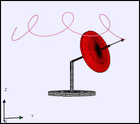 )
)
(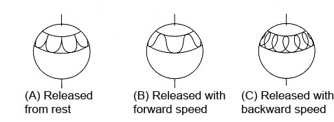 )
)
( )
)
(https://elkement.files.wordpress.com/2012/09/spinning-top-precession.jpg?w=300&h=199)
In general, for large enough motion, the gyroscopic equations are nonlinear differential equations that require numerical solution. If Baby EM Drive is thrusting in this misaligned position, it not only is accelerating or decelerating the rotational speed, but it is also changing the nutation. The nutation also contributes to the air drag, and you have a complicated experimental situation.
Sheila Widnall's lecture on gyroscopic equations: http://ocw.mit.edu/courses/aeronautics-and-astronautics/16-07-dynamics-fall-2009/lecture-notes/MIT16_07F09_Lec30.pdf
Look at the fact that as the rate of rotation decreases, the nutation increases:
-
Title: Re: EM Drive Developments - related to space flight applications - Thread 3
Post by: frobnicat on 06/15/2015 11:56 PM -
<a href="http://forum.nasaspaceflight.com/index.php?topic=37642.msg1389775#msg1389775">Quote from: rmem on 06/15/2015 04:23 PM</a>
Hello,
I'm new to this forum and want to add to the discussion:
Thrust can be achieved by various error sources interacting with the environment as many out here already pointed out. eagleworks and many others used only small input power therefore i propose a test theory which is built on a pressure gradient caused by thermal effects.
Explanation:
The measured forces are tiny but divided by the projected area in thrust direction it becomes an even smaller pressure needed for thrust.
Example for eagleworks tests:
Area: 0.0613116 m²
Force~0.05mN
=> Pressure needed=0.815mPa =0.00000008% of ambient pressure.
Note that this is such a tiny pressure change that it could still be produced in near vacuum. My theory now is that this tiny pressure difference is caused by uneven heating in near wall regions (p=RTrho). Other reasons could be vibrations and magnetic fields. This effect should fairly quickly reach a constant thrust. If this theory holds up we should see a correlation between mode shape and thrust. The node shape dictates where heating occurs. All needed to test this is therefore to integrate heat production over the surfaces and add these up with respect to the orientation of said surface since the pressure gradient should be linear to this. It would probably suffice to use the B field on the boundary as an estimate for the heat production. My prediction is that certain frequencies will produce a heating pattern that is more uneven and hence produces more thrust. With all the reference geometries we have we might see a correlation to the data. If the math has already been done i'd like to apologize.
Uneven heating can't thrust directly like that, left and right part of the frustum are not like a piston in a cylinder, they share the same volume of air (I'm speaking of the volume outside the frustum). Assuming right end heats and left one not at all. The rise of temperature of air near the right end will lower its density but will not raise its pressure, pressure equalises "instantly" (well, at speed of sound). Depending on the rate of heating, there will be a small recoil of air expanding to reach a new equilibrium at lower density but same pressure as the volume overall. This is a transient of very very low magnitude, negligible (at heating rates considered), followed by an equilibrium that gives 0 unbalance of forces. Indirectly, the lower density of heated air near right end will make it rise as convection occurs. This convection can make dynamic pressures on the order of the recorded thrusts. Paul March explained the lower magnitude of thrusts measurements in vacuum as the disappearance of such convection effects. Notice that convection magnitude depends on gravity, so g should appear somewhere in equations dealing with that.
What you are describing as direct pressure differences due to walls of uneven temperatures is valid when the gas around (the shared volume) can't equalize pressure because it is too thin. It requires pressures low enough that the mean free path of molecules is on the same order as the size of walls and container, this is the operating conditions of the Crookes radiometer. I vaguely recall someone calculated the mean free path for the (not perfect) vacuum used at Eagleworks, was it above or below what is needed for such rarefied gas effect to occur ? -
Title: Re: EM Drive Developments - related to space flight applications - Thread 3
Post by: snoozdoc on 06/16/2015 02:28 AM -
<a href="http://forum.nasaspaceflight.com/index.php?topic=37642.msg1389719#msg1389719">Quote from: WarpTech on 06/15/2015 02:14 PM</a>
... IMO, the frustum "should" exert thrust ONLY when charging or discharging. It's should not work when it's at equilibrium with a constant Q value, no matter how high it is. ...
Iulian Berca used the magnetron from a microwave oven to source the microwaves for his test article. His videos suggest that he also used the oven’s power supply with minimal changes. Now a YouTube video posted on this thread a few days ago titled "Measuring the voltage and current of a microwave oven magnetron" seems to show that the duty cycle for a typical microwave oven is about 50%. This means that if his test article performed in this way, his frustum was going through an approximately 60 Hz charge and discharge cycle (depending I suppose on the AC frequency of his home country's power supply grid).
Disappointing then that his thrust data was also in the mud of noise. But how many of the other reported tests used a relatively high charge/discharge cycle rate? ???
-
Title: Re: EM Drive Developments - related to space flight applications - Thread 3
Post by: WarpTech on 06/16/2015 03:43 AM -
I've updated my Theory on the Wiki.
http://emdrive.wiki/Todd_Desiato_(@WarpTech)%27s_Evanescent_Wave_Theory#Application_of_Theory_to_the_EmDrive
The EM Drive is intentionally designed to have asymmetrical attenuation. As such, energy is reflected from the large end to be stored at the small end as induced currents. Standing waves store energy and as such, store mass. As the EM drive charges and the Q ramps up, energy from the input source is reflected from the large end and stored in the small end on each successive reflection cycle. This energy is stored as induction currents caused by the near-field effects of evanescent waves. Due to the phase shift, the Power Factor is not zero as it is with standing waves. Therefore, work can be done to move the EM Drive. This dynamic action of storing mass-energy toward the front causes the center of mass to walk forward. The increasing pressure on the small end causes the EM Drive to accelerate forward due to the internal pressure gradient, until the pressure is equalized. Then the cycle builds again. This dynamic implies that a high Q value is not required, but rather how quickly can energy be ramped up under extreme attenuation conditions.
Todd -
Title: Re: EM Drive Developments - related to space flight applications - Thread 3
Post by: demofsky on 06/16/2015 04:08 AM -
<a href="http://forum.nasaspaceflight.com/index.php?topic=37642.msg1390096#msg1390096">Quote from: WarpTech on 06/16/2015 03:43 AM</a>
I've updated my Theory on the Wiki.
http://emdrive.wiki/Todd_Desiato_(@WarpTech)%27s_Evanescent_Wave_Theory#Application_of_Theory_to_the_EmDrive
The EM Drive is intentionally designed to have asymmetrical attenuation. As such, energy is reflected from the large end to be stored at the small end as induced currents. Standing waves store energy and as such, store mass. As the EM drive charges and the Q ramps up, energy from the input source is reflected from the large end and stored in the small end on each successive reflection cycle. This energy is stored as induction currents caused by the near-field effects of evanescent waves. Due to the phase shift, the Power Factor is not zero as it is with standing waves. Therefore, work can be done to move the EM Drive. This dynamic action of storing mass-energy toward the front causes the center of mass to walk forward. The increasing pressure on the small end causes the EM Drive to accelerate forward due to the internal pressure gradient, until the pressure is equalized. Then the cycle builds again. This dynamic implies that a high Q value is not required, but rather how quickly can energy be ramped up under extreme attenuation conditions.
Todd
Todd, to help unpack this a bit, when I read "energy stored as induction currents" I think of heating the fustrum - which would be inefficient since we want kinetic not thermal effects. So effectively a high Q system would be more inefficient because there would be more opportunity for the stored energy to leak out as heat. A high attenuation system like Yang's would be more efficient since the energy is not sitting around as long. Is this synopsis accurate from your perspective? Thanks! -
Title: Re: EM Drive Developments - related to space flight applications - Thread 3
Post by: WarpTech on 06/16/2015 04:50 AM -
<a href="http://forum.nasaspaceflight.com/index.php?topic=37642.msg1390098#msg1390098">Quote from: demofsky on 06/16/2015 04:08 AM</a><a href="http://forum.nasaspaceflight.com/index.php?topic=37642.msg1390096#msg1390096">Quote from: WarpTech on 06/16/2015 03:43 AM</a>
I've updated my Theory on the Wiki.
http://emdrive.wiki/Todd_Desiato_(@WarpTech)%27s_Evanescent_Wave_Theory#Application_of_Theory_to_the_EmDrive
...
Todd, to help unpack this a bit, when I read "energy stored as induction currents" I think of heating the fustrum - which would be inefficient since we want kinetic not thermal effects....
Correct...QuoteSo effectively a high Q system would be more inefficient because there would be more opportunity for the stored energy to leak out as heat. A high attenuation system like Yang's would be more efficient since the energy is not sitting around as long. Is this synopsis accurate from your perspective? Thanks!
Sounds about right. If it were superconducting, it would be more efficient and the "loss per cycle" of the Q would be lost as thrust rather than heat. It's not necessary to have a high Q, it is necessary to have a high rate of charging and discharging, F = v*dm/dt, rather than m*dv/dt.
My conjecture is that because it is the charging that walks the center of mass forward, microwaves and standing waves are not even needed. Just exponentially increasing or decreasing current densities, i.e., near field effects.
Todd
-
Title: Re: EM Drive Developments - related to space flight applications - Thread 3
Post by: demofsky on 06/16/2015 06:37 AM -
<a href="http://forum.nasaspaceflight.com/index.php?topic=37642.msg1390103#msg1390103">Quote from: WarpTech on 06/16/2015 04:50 AM</a><a href="http://forum.nasaspaceflight.com/index.php?topic=37642.msg1390098#msg1390098">Quote from: demofsky on 06/16/2015 04:08 AM</a><a href="http://forum.nasaspaceflight.com/index.php?topic=37642.msg1390096#msg1390096">Quote from: WarpTech on 06/16/2015 03:43 AM</a>
I've updated my Theory on the Wiki.
http://emdrive.wiki/Todd_Desiato_(@WarpTech)%27s_Evanescent_Wave_Theory#Application_of_Theory_to_the_EmDrive
...
Todd, to help unpack this a bit, when I read "energy stored as induction currents" I think of heating the fustrum - which would be inefficient since we want kinetic not thermal effects....
Correct...QuoteSo effectively a high Q system would be more inefficient because there would be more opportunity for the stored energy to leak out as heat. A high attenuation system like Yang's would be more efficient since the energy is not sitting around as long. Is this synopsis accurate from your perspective? Thanks!
Sounds about right. If it were superconducting, it would be more efficient and the "loss per cycle" of the Q would be lost as thrust rather than heat. It's not necessary to have a high Q, it is necessary to have a high rate of charging and discharging, F = v*dm/dt, rather than m*dv/dt.
My conjecture is that because it is the charging that walks the center of mass forward, microwaves and standing waves are not even needed. Just exponentially increasing or decreasing current densities, i.e., near field effects.
Todd
I have wondered about this as well, in the sense of tapered optical waveguides or the equivalent for a strip line on a printed circuit - especially for higher frequencies. Taking this one step forward there are also meta materials.
But how would you create those exponentially increasing/decreasing current densities without, say, microwaves? -
Title: Re: EM Drive Developments - related to space flight applications - Thread 3
Post by: Rodal on 06/16/2015 11:38 AM -
It looks like CHAOTIC motion to me. The Chaotic Baby EM Drive.
( )
)
By comparison, Iulian Berca's test was a beautiful symphony (of course it took 800 Watts to do that).
Another day, another Baby EM Drive experiment, cavity direction is inverted compared to the previous test.
I wonder why they are still using water instead of oil to dampen the motion. How difficult is it to get oil in Germany?
And most of all, I wonder why don't they instead go back to their first experiment in magnetic levitation but do it under a partial vacuum this time.
https://www.youtube.com/watch?t=110&v=t04i2l4jcd0
https://hackaday.io/project/5596-em-drive/log/19598-torsion-test-3-8-hours -
Title: Re: EM Drive Developments - related to space flight applications - Thread 3
Post by: Prunesquallor on 06/16/2015 11:49 AM -
<a href="http://forum.nasaspaceflight.com/index.php?topic=37642.msg1390178#msg1390178">Quote from: Rodal on 06/16/2015 11:38 AM</a>
It looks like CHAOTIC motion to me
Another day, another Baby EM Drive experiment, cavity direction is inverted compared to the previous test.
I wonder why they are still using water instead of oil to dampen the motion. How difficult is it to get oil in Germany?
I wonder why don't they instead go back to their first experiment in magnetic levitation but do it under a partial vacuum this time
https://hackaday.io/project/5596-em-drive/log/19598-torsion-test-3-8-hours
I could convince myself I see a lower frequency oscillation that is weakly driven by the thruster on-times.
-
Title: Re: EM Drive Developments - related to space flight applications - Thread 3
Post by: supryin on 06/16/2015 12:17 PM -
<a href="http://forum.nasaspaceflight.com/index.php?topic=37642.msg1390183#msg1390183">Quote from: Rodal on 06/16/2015 12:09 PM</a>
Where are the thruster ON times indicated ?
"Pink: thruster ON" ;) -
Title: Re: EM Drive Developments - related to space flight applications - Thread 3
Post by: hhexo on 06/16/2015 01:55 PM -
<a href="http://forum.nasaspaceflight.com/index.php?topic=37642.msg1390178#msg1390178">Quote from: Rodal on 06/16/2015 11:38 AM</a>
And most of all, I wonder why don't they instead go back to their first experiment in magnetic levitation but do it under a partial vacuum this time.
From an engineering point of view, I'd say components would be damaged due to internal pressure, maybe not to the point of blowing up, but definitely in a significant way. I'm thinking mostly of the batteries, but it could also be that the radar module they're using has non-vacuum-resistant capacitors.
This is the problem EW had too, if I remember correctly; they had to purchase new vacuum-resistant components.
Still, I concur that the floating setup seems more controllable and precise compared to this:Quotehttps://hackaday.io/project/5596-em-drive/log/19598-torsion-test-3-8-hours
Looking at the photos I'm not entirely surprised about the resulting noise levels.
It's a pity the noise level completely dwarfs any signal that might or might not be there. They ran it for 8 hours straight and the resulting data is not really usable. :( -
Title: Re: EM Drive Developments - related to space flight applications - Thread 3
Post by: Rodal on 06/16/2015 02:07 PM -
<a href="http://forum.nasaspaceflight.com/index.php?topic=37642.msg1390210#msg1390210">Quote from: hhexo on 06/16/2015 01:55 PM</a>
Atmospheric pressure in low Earth orbit ("LEO") = 5x10^(-8) to 10^(-10) Torr.<a href="http://forum.nasaspaceflight.com/index.php?topic=37642.msg1390178#msg1390178">Quote from: Rodal on 06/16/2015 11:38 AM</a>And most of all, I wonder why don't they instead go back to their first experiment in magnetic levitation but do it under a partial vacuum this time.
From an engineering point of view, I'd say components would be damaged due to internal pressure, maybe not to the point of blowing up, but definitely in a significant way. I'm thinking mostly of the batteries, but it could also be that the radar module they're using has non-vacuum-resistant capacitors.
This is the problem EW had too, if I remember correctly; they had to purchase new vacuum-resistant components.
Still, I concur that the floating setup seems more controllable and precise compared to this:Quotehttps://hackaday.io/project/5596-em-drive/log/19598-torsion-test-3-8-hours
Looking at the photos I'm not entirely surprised about the resulting noise levels.
1 Torr = 1/760 of a standard atmosphere = 1.3*10^(-3) of a standard atmosphere
Initially, Eagleworks had problems due to their capacitors. NASA Eagleworks performed experiments at 5*10^(-6) Torr, about 100 times higher pressure than the highest pressure one finds in the lowest LEO. On the other hand, one standard atmosphere is 152 million times greater pressure than the partial vacuum used by NASA Eagleworks. So we have a huge range of partial vacuums in between standard atmosphere and the partial vacuum used by NASA.
For the Baby EM Drive experiment they don't need to go immediately to 5*10^(-6) Torr or better partial vacuum, to significantly reduce the problem with air drag.
They could explore higher pressure partial vacuums, for example start
Now: 760 Torr = 1 standard atmosphere
move to
250 Torr= 33% of a standard atmosphere (pressure at the top of Mt. Everest)
move to
100 Torr = 13% of a standard atmosphere
move to
10 Torr =1% of a standard atmosphere
move to
1 Torr = 0.1 % of a standard atmosphere
move to
1*10^(-1) Torr = 0.01% of a standard atmosphere
move to
1*10^(-2) Torr
move to
1*10^(-3) Torr
move to
1*10^(-4) Torr ,
move to
1*10^(-5) Torr,
move to
5*10^(-6) Torr = 6.6*10^(-9) standard atmosphere, NASA's Partial Vacuum.
Many lower levels of partial vacuum that may evacuate a significant amount of air, reduce air drag, without much affecting the electronics.
There is a big difference in air drag that an aircraft encounters when flying at ground level vs. flying at normal altitude. Similarly, all that the Aachen team needs to explore initially is reduced level of pressure as the ones found in the upper atmosphere (no need to explore the vacuum of space at this point in time) to reduce air drag.
-
Title: Re: EM Drive Developments - related to space flight applications - Thread 3
Post by: SeeShells on 06/16/2015 02:19 PM -
<a href="http://forum.nasaspaceflight.com/index.php?topic=37642.msg1390096#msg1390096">Quote from: WarpTech on 06/16/2015 03:43 AM</a>
I've updated my Theory on the Wiki.
I look at it this way and correct me if I'm wrong. The EM Drive could be thought of like this. You are trapped in an enclosed tank with a fire extinguisher and you turn on the fire extinguisher expecting it to move the tank, it doesn't because it's a enclosed system, but if you run up the side of the tank changing the local enclosed gravity profile of the tank, then you can move it in the direction you are running. And you haven't violated any laws just changed the local enclosed profile.
http://emdrive.wiki/Todd_Desiato_(@WarpTech)%27s_Evanescent_Wave_Theory#Application_of_Theory_to_the_EmDrive
The EM Drive is intentionally designed to have asymmetrical attenuation. As such, energy is reflected from the large end to be stored at the small end as induced currents. Standing waves store energy and as such, store mass. As the EM drive charges and the Q ramps up, energy from the input source is reflected from the large end and stored in the small end on each successive reflection cycle. This energy is stored as induction currents caused by the near-field effects of evanescent waves. Due to the phase shift, the Power Factor is not zero as it is with standing waves. Therefore, work can be done to move the EM Drive. This dynamic action of storing mass-energy toward the front causes the center of mass to walk forward. The increasing pressure on the small end causes the EM Drive to accelerate forward due to the internal pressure gradient, until the pressure is equalized. Then the cycle builds again. This dynamic implies that a high Q value is not required, but rather how quickly can energy be ramped up under extreme attenuation conditions.
Todd
Shell -
Title: Re: EM Drive Developments - related to space flight applications - Thread 3
Post by: rfmwguy on 06/16/2015 02:37 PM -
You might want to bookmark this link: http://www.ustream.tv/channel/em-drive-experiment
This is my ustream video channel where I will try and broadcast a live 1st test of my humble DIYDrive experiment in July. I may upload some videos in the meantime as I get further into the build.
I have set chat up as well, but only plan to use it after a video upload or live event. I won't be routinely monitoring it. I'll hang here for most interactions.
For now, you can log on to ustream for free, preferably creating the same username as you have on NSF, so I will know who I'm chatting with.
Oh, forgot to mention. Click FOLLOW once your account is created, then you'll receive notices when uploads occur. -
Title: Re: EM Drive Developments - related to space flight applications - Thread 3
Post by: foob on 06/16/2015 02:43 PM -
<a href="http://forum.nasaspaceflight.com/index.php?topic=37642.msg1390218#msg1390218">Quote from: SeeShells on 06/16/2015 02:19 PM</a>
I look at it this way and correct me if I'm wrong. The EM Drive could be thought of like this. You are trapped in an enclosed tank with a fire extinguisher and you turn on the fire extinguisher expecting it to move the tank, it doesn't because it's a enclosed system, but if you run up the side of the tank changing the local enclosed gravity profile of the tank, then you can move it in the direction you are running. And you haven't violated any laws just changed the local enclosed profile.
Shell
It's an interesting idea, but the flaw is the concept of an enclosed system. In moving up the tank wall you are working against the local gravity which is part of the working system. If your tank was in orbit, you could run around the inside all day and you'd get the tank spinning, but not change your orbit, as opposed to rolling across the ground, constantly applying a torque and lifting yourself against gravity. -
Title: Re: EM Drive Developments - related to space flight applications - Thread 3
Post by: Rodal on 06/16/2015 02:51 PM -
<a href="http://forum.nasaspaceflight.com/index.php?topic=37642.msg1390096#msg1390096">Quote from: WarpTech on 06/16/2015 03:43 AM</a>
I've updated my Theory on the Wiki.
Got to find some way that enough mass (or energy) leaks out (somehow) asymmetrically of the EM Drive to justify the claimed self-acceleration of its center of mass without breaking Conservation of Momentum.
http://emdrive.wiki/Todd_Desiato_(@WarpTech)%27s_Evanescent_Wave_Theory#Application_of_Theory_to_the_EmDrive
The EM Drive is intentionally designed to have asymmetrical attenuation. As such, energy is reflected from the large end to be stored at the small end as induced currents. Standing waves store energy and as such, store mass. As the EM drive charges and the Q ramps up, energy from the input source is reflected from the large end and stored in the small end on each successive reflection cycle. This energy is stored as induction currents caused by the near-field effects of evanescent waves. Due to the phase shift, the Power Factor is not zero as it is with standing waves. Therefore, work can be done to move the EM Drive. This dynamic action of storing mass-energy toward the front causes the center of mass to walk forward. The increasing pressure on the small end causes the EM Drive to accelerate forward due to the internal pressure gradient, until the pressure is equalized. Then the cycle builds again. This dynamic implies that a high Q value is not required, but rather how quickly can energy be ramped up under extreme attenuation conditions.
Todd
Either that, or you have to couple to an external directional field. -
Title: Re: EM Drive Developments - related to space flight applications - Thread 3
Post by: WarpTech on 06/16/2015 03:13 PM -
<a href="http://forum.nasaspaceflight.com/index.php?topic=37642.msg1390218#msg1390218">Quote from: SeeShells on 06/16/2015 02:19 PM</a><a href="http://forum.nasaspaceflight.com/index.php?topic=37642.msg1390096#msg1390096">Quote from: WarpTech on 06/16/2015 03:43 AM</a>
I've updated my Theory on the Wiki.
I look at it this way and correct me if I'm wrong. The EM Drive could be thought of like this. You are trapped in an enclosed tank with a fire extinguisher and you turn on the fire extinguisher expecting it to move the tank, it doesn't because it's a enclosed system, but if you run up the side of the tank changing the local enclosed gravity profile of the tank, then you can move it in the direction you are running. And you haven't violated any laws just changed the local enclosed profile.
http://emdrive.wiki/Todd_Desiato_(@WarpTech)%27s_Evanescent_Wave_Theory#Application_of_Theory_to_the_EmDrive
The EM Drive is intentionally designed to have asymmetrical attenuation. As such, energy is reflected from the large end to be stored at the small end as induced currents. Standing waves store energy and as such, store mass. As the EM drive charges and the Q ramps up, energy from the input source is reflected from the large end and stored in the small end on each successive reflection cycle. This energy is stored as induction currents caused by the near-field effects of evanescent waves. Due to the phase shift, the Power Factor is not zero as it is with standing waves. Therefore, work can be done to move the EM Drive. This dynamic action of storing mass-energy toward the front causes the center of mass to walk forward. The increasing pressure on the small end causes the EM Drive to accelerate forward due to the internal pressure gradient, until the pressure is equalized. Then the cycle builds again. This dynamic implies that a high Q value is not required, but rather how quickly can energy be ramped up under extreme attenuation conditions.
Todd
Shell
I think it's more like milk sloshing around in a 1/4 filled container. ;D
Or someone outside is throwing tennis balls in through the side, and someone on the inside is whacking them at the front wall where they stick. -
Title: Re: EM Drive Developments - related to space flight applications - Thread 3
Post by: WarpTech on 06/16/2015 03:17 PM -
<a href="http://forum.nasaspaceflight.com/index.php?topic=37642.msg1390227#msg1390227">Quote from: Rodal on 06/16/2015 02:51 PM</a><a href="http://forum.nasaspaceflight.com/index.php?topic=37642.msg1390096#msg1390096">Quote from: WarpTech on 06/16/2015 03:43 AM</a>
I've updated my Theory on the Wiki.
Got to find some way that enough mass (or energy) leaks out (somehow) asymmetrically of the EM Drive to justify the claimed self-acceleration of its center of mass without breaking Conservation of Momentum.
http://emdrive.wiki/Todd_Desiato_(@WarpTech)%27s_Evanescent_Wave_Theory#Application_of_Theory_to_the_EmDrive
The EM Drive is intentionally designed to have asymmetrical attenuation. As such, energy is reflected from the large end to be stored at the small end as induced currents. Standing waves store energy and as such, store mass. As the EM drive charges and the Q ramps up, energy from the input source is reflected from the large end and stored in the small end on each successive reflection cycle. This energy is stored as induction currents caused by the near-field effects of evanescent waves. Due to the phase shift, the Power Factor is not zero as it is with standing waves. Therefore, work can be done to move the EM Drive. This dynamic action of storing mass-energy toward the front causes the center of mass to walk forward. The increasing pressure on the small end causes the EM Drive to accelerate forward due to the internal pressure gradient, until the pressure is equalized. Then the cycle builds again. This dynamic implies that a high Q value is not required, but rather how quickly can energy be ramped up under extreme attenuation conditions.
Todd
Either that, or you have to couple to an external directional field.
(delete)
EDIT: I'm confused as to why putting energy "in" does not result in the same physics as letting energy "out". If the system is gaining energy from the outside, +dm/dt, why is that not the same as expelling it to the outside as -dm/dt in the opposite direction?
-
Title: Re: EM Drive Developments - related to space flight applications - Thread 3
Post by: sghill on 06/16/2015 03:26 PM -
Quick question.
In my physics education. "Q" stood for heat energy, or charge, or resonance efficiency, depending on what you are talking about.
In most of these EMDrive conversations, the distinction hasn't been particularly worrisome, but I find myself asking what does "Q" mean in the context of these latest conversations. Relatedly, is the definition of "Q" interchangeable in this context?
Thanks. -
Title: Re: EM Drive Developments - related to space flight applications - Thread 3
Post by: Rodal on 06/16/2015 03:31 PM -
<a href="http://forum.nasaspaceflight.com/index.php?topic=37642.msg1390246#msg1390246">Quote from: sghill on 06/16/2015 03:26 PM</a>
Quick question.
In my physics education. "Q" stood for heat energy, or charge, or resonance efficiency, depending on what you are talking about.
In most of these EMDrive conversations, the distinction hasn't been particularly worrisome, but I find myself asking what does "Q" mean in the context of these latest conversations. Relatedly, is the definition of "Q" interchangeable in this context?
Thanks.
Take Q to stand for "quality of resonance factor", a dimensionless quantity, which is inverse to damping: see https://en.wikipedia.org/wiki/Q_factor in this thread, unless otherwise defined.
Q= 1 / (2 DampingRatio) (where https://en.wikipedia.org/wiki/Damping_ratio )
( )
)
Black spring= high Q, low damping
Blue spring= low Q, high damping
____
(*) In general, Q it is not directly interchangeable with heat in this context (remember, Q is inverse to damping), except that energy dissipated by damping goes into heat -
Title: Re: EM Drive Developments - related to space flight applications - Thread 3
Post by: madsci on 06/16/2015 04:15 PM - Haha, cute gif :)
-
Title: Re: EM Drive Developments - related to space flight applications - Thread 3
Post by: Rodal on 06/16/2015 04:26 PM -
<a href="http://forum.nasaspaceflight.com/index.php?topic=37642.msg1390243#msg1390243">Quote from: WarpTech on 06/16/2015 03:17 PM</a><a href="http://forum.nasaspaceflight.com/index.php?topic=37642.msg1390227#msg1390227">Quote from: Rodal on 06/16/2015 02:51 PM</a><a href="http://forum.nasaspaceflight.com/index.php?topic=37642.msg1390096#msg1390096">Quote from: WarpTech on 06/16/2015 03:43 AM</a>
I've updated my Theory on the Wiki.
Got to find some way that enough mass (or energy) leaks out (somehow) asymmetrically of the EM Drive to justify the claimed self-acceleration of its center of mass without breaking Conservation of Momentum.
http://emdrive.wiki/Todd_Desiato_(@WarpTech)%27s_Evanescent_Wave_Theory#Application_of_Theory_to_the_EmDrive
The EM Drive is intentionally designed to have asymmetrical attenuation. As such, energy is reflected from the large end to be stored at the small end as induced currents. Standing waves store energy and as such, store mass. As the EM drive charges and the Q ramps up, energy from the input source is reflected from the large end and stored in the small end on each successive reflection cycle. This energy is stored as induction currents caused by the near-field effects of evanescent waves. Due to the phase shift, the Power Factor is not zero as it is with standing waves. Therefore, work can be done to move the EM Drive. This dynamic action of storing mass-energy toward the front causes the center of mass to walk forward. The increasing pressure on the small end causes the EM Drive to accelerate forward due to the internal pressure gradient, until the pressure is equalized. Then the cycle builds again. This dynamic implies that a high Q value is not required, but rather how quickly can energy be ramped up under extreme attenuation conditions.
Todd
Either that, or you have to couple to an external directional field.
(delete)
EDIT: I'm confused as to why putting energy "in" does not result in the same physics as letting energy "out". If the system is gaining energy from the outside, +dm/dt, why is that not the same as expelling it to the outside as -dm/dt in the opposite direction?
If you draw a boundary around the exterior boundary of the spaceship, the energy powering the EM Drive is internally produced (say by a nuclear powerplant inside the spaceship ;) ). The EM Drive proponents propose that there is no need of external energy coming in. They also propose that there is no mass or energy coming out to enable the propulsion.
Something's got to give.
Otherwise it breaks Conservation of Momentum and Conservation of Energy.
Either there is enough mass (or energy) leaking out (somehow) asymmetrically of the EM Drive to justify the claimed self-acceleration of its center of mass, or you have to couple to an external directional field. -
Title: Re: EM Drive Developments - related to space flight applications - Thread 3
Post by: rfmwguy on 06/16/2015 04:27 PM -
<a href="http://forum.nasaspaceflight.com/index.php?topic=37642.msg1390227#msg1390227">Quote from: Rodal on 06/16/2015 02:51 PM</a><a href="http://forum.nasaspaceflight.com/index.php?topic=37642.msg1390096#msg1390096">Quote from: WarpTech on 06/16/2015 03:43 AM</a>
I've updated my Theory on the Wiki.
Got to find some way that enough mass (or energy) leaks out (somehow) asymmetrically of the EM Drive to justify the claimed self-acceleration of its center of mass without breaking Conservation of Momentum.
http://emdrive.wiki/Todd_Desiato_(@WarpTech)%27s_Evanescent_Wave_Theory#Application_of_Theory_to_the_EmDrive
The EM Drive is intentionally designed to have asymmetrical attenuation. As such, energy is reflected from the large end to be stored at the small end as induced currents. Standing waves store energy and as such, store mass. As the EM drive charges and the Q ramps up, energy from the input source is reflected from the large end and stored in the small end on each successive reflection cycle. This energy is stored as induction currents caused by the near-field effects of evanescent waves. Due to the phase shift, the Power Factor is not zero as it is with standing waves. Therefore, work can be done to move the EM Drive. This dynamic action of storing mass-energy toward the front causes the center of mass to walk forward. The increasing pressure on the small end causes the EM Drive to accelerate forward due to the internal pressure gradient, until the pressure is equalized. Then the cycle builds again. This dynamic implies that a high Q value is not required, but rather how quickly can energy be ramped up under extreme attenuation conditions.
Todd
Either that, or you have to couple to an external directional field.
This has been my thought experiment...a point or points coupling to a natural entropic force. Surfing the wave so to speak or riding the wind. Sorry for the basic description...I cannot visualize particle or wave ejection/leakage thrusting forward nor thermal radiation of some sort. If emdrive works I'm convinced (without the math to prove it yet) that its being coupled to an elemental, natural force we have yet to measure directly. I'll leave it as an entropic force for the time being...the natural tendency for all energy and matter to disperse. -
Title: Re: EM Drive Developments - related to space flight applications - Thread 3
Post by: sghill on 06/16/2015 04:51 PM -
Jose,
Thanks for the explanation of "Q"! :)
One more quick sophomoric question for anyone if I may: Could the EM Drive be creating an energy allegory to mass (for this narrow slice of frequency)? And it's the allegorical mass that is reacting to the directional field. In other words, E=mc2, so the more "E" we feed into the device, the more our allegorical mass grows until we can detect the space-time distortion with a laser (as Eagleworks did). That then begs the question of whether our allegorical mass is preferential in its formation due to the frustum shape shaping field lines, resulting "falling" in a preferential direction (viewed as thrust to an external viewer). -
Title: Re: EM Drive Developments - related to space flight applications - Thread 3
Post by: Rodal on 06/16/2015 05:18 PM -
<a href="http://forum.nasaspaceflight.com/index.php?topic=37642.msg1390279#msg1390279">Quote from: sghill on 06/16/2015 04:51 PM</a>
Jose,
Thanks for the explanation of "Q"! :)
One more quick sophomoric question for anyone if I may: Could the EM Drive be creating an energy allegory to mass (for this narrow slice of frequency)? And it's the allegorical mass that is reacting to the directional field. In other words, E=mc2, so the more "E" we feed into the device, the more our allegorical mass grows until we can detect the space-time distortion with a laser (as Eagleworks did). That then begs the question of whether our allegorical mass is preferential in its formation due to the frustum shape, resulting in perceived thrust to an external viewer, when really it's just "falling" in a preferential direction.
We had physicist Marco Frasca "StrongGR" in the EM Drive thread 2, discuss his recent paper "Einstein-Maxwell equations for asymmetric resonant cavities" ( https://www.researchgate.net/publication/277334213_Einstein-Maxwell_equations_for_asymmetric_resonant_cavities ) where he shows that none of the present researchers have tested EM Drive geometries that would allow any significant coupling with General Relativity to produce the claimed measured thrust forces. The measured thrust forces are a huge number of orders of magnitude much greater than any such interaction. His calculations ruled out, with a very high degree of confidence, a General Relativity gravitational effect affecting the EM Drive. However, he shows that a proper choice of the geometrical parameters of the cavity (a pointy cone) can make the gravitational effects significant for an interferometric setup. This could make possible to realize table-top experiments involving gravitational effects.
-
Title: Re: EM Drive Developments - related to space flight applications - Thread 3
Post by: deltaMass on 06/16/2015 05:26 PM -
All of known physics is based on CoM. All of it.
Therefore, you are not going to get anywhere with known physics as an explanatory method for EmDrive.
Therefore, either EmDrive is an artifact of poor experimental technique, or new physics is required.
There is no third way.
-
Title: Re: EM Drive Developments - related to space flight applications - Thread 3
Post by: MyronQG on 06/16/2015 05:43 PM -
<a href="http://forum.nasaspaceflight.com/index.php?topic=37642.msg1390297#msg1390297">Quote from: deltaMass on 06/16/2015 05:26 PM</a>
All of known physics is based on CoM. All of it.
I wouldn't say it better.
Therefore, you are not going to get anywhere with known physics as an explanatory method for EmDrive.
Therefore, either EmDrive is an artifact of poor experimental technique, or new physics is required.
There is no third way. -
Title: Re: EM Drive Developments - related to space flight applications - Thread 3
Post by: SeeShells on 06/16/2015 06:07 PM -
<a href="http://forum.nasaspaceflight.com/index.php?topic=37642.msg1390222#msg1390222">Quote from: foob on 06/16/2015 02:43 PM</a><a href="http://forum.nasaspaceflight.com/index.php?topic=37642.msg1390218#msg1390218">Quote from: SeeShells on 06/16/2015 02:19 PM</a>
I look at it this way and correct me if I'm wrong. The EM Drive could be thought of like this. You are trapped in an enclosed tank with a fire extinguisher and you turn on the fire extinguisher expecting it to move the tank, it doesn't because it's a enclosed system, but if you run up the side of the tank changing the local enclosed gravity profile of the tank, then you can move it in the direction you are running. And you haven't violated any laws just changed the local enclosed profile.
Shell
It's an interesting idea, but the flaw is the concept of an enclosed system. In moving up the tank wall you are working against the local gravity which is part of the working system. If your tank was in orbit, you could run around the inside all day and you'd get the tank spinning, but not change your orbit, as opposed to rolling across the ground, constantly applying a torque and lifting yourself against gravity.
Thanks for answering and you are very correct in classical physics there is no way, but maybe I need to take it up one notch as there is something happening.
It's not so much as it rolling the tank against local gravity on dirt I'm talking about. It's creating a small localized gravity differential on the side of the tank and a corresponding one is created on the other side. Yes and space is warped in the vicinity where I'm running (or the end of the EM Thruster in buildup of energy with Q), just a little as it will not take very much.
In my thought experiment I'm simply trying to logically define what is happening, using Occam's Razor. I asked what must be happening to get to the outside or the outside getting in? I thought being in the hypothetical tank the walls are going to protect you from the crushing gravity of a let's say black hole? Unless you were orbiting the hole and then you feel effectively 0 g, and if I'm right orbiting is acceleration (a slow spiral into the object) (Einstein said this). In orbiting you create your own localized warpage of space time and that is why we can orbit.
What else can leak out of the metal Frustum to mimic an effect like thrust, a potential to want to move to another position in spacetime? Tunneling quantum particles normally will only travel through 3-5um of material, a problem showing up in microelectronics and maybe a boon for quantum computing but that's another story. Evanescent waves or virtual particles (like those that form at 1/3 of a wavelength of an antenna) a big maybe and if they do I think they could be also responsible for the other half of the spacetime warpage in front of the Frustum. It seems not much could escape those walls but this.
WarpTech (thanks) says that speed while relative you still need to "keep track" of your speed and this is done by your apparent mass and your apparent space timeframe. We know this is true because a long time ago two watches were used to prove it. One stayed put while the other flew around the world and when they landed there was a difference in time. Moving in spacetime keeps track by increasing your mass and changing time, the quarks and gluons and atoms squeeze just a little more together get a little more dense and gain mass. Increase the mass and time slows down. The EM Frustum seems to match this and if someone was smart they would put a clock into a Frustum and one outside and measure after just to see if there was a time differential. I suspect a clock in the smaller end of the Frustum will beat a little slower.
I know we're not supposed to talk to much about warp drive here but this is more like a gravity drive and geez this Occam's Razor is cutting deep.
Shell
-
Title: Re: EM Drive Developments - related to space flight applications - Thread 3
Post by: WarpTech on 06/16/2015 06:19 PM -
<a href="http://forum.nasaspaceflight.com/index.php?topic=37642.msg1390297#msg1390297">Quote from: deltaMass on 06/16/2015 05:26 PM</a>
All of known physics is based on CoM. All of it.
Therefore, you are not going to get anywhere with known physics as an explanatory method for EmDrive.
Therefore, either EmDrive is an artifact of poor experimental technique, or new physics is required.
There is no third way.
Here's a proposal I've been contemplating, but I'm sure it will raise some controversy and I’m not sure I’ve worded it absolutely perfectly. I'm trying to convey the concept at this point, rather than the Math. It is the QM version of the Lorentz Force and gauge potentials, as applied to a frustum.
Newtonian gravity is simply the gradient of a scalar potential. We have such a scalar potential inside the frustum, it is the gradient in magnetic flux, Φ. Consider a constant azimuthal B-field circulating around the axis of the frustum. There will be less flux at the small end than at the large end. This is a "difference in potential", and as such it contributes to the Lorentz force through the Bohm-Aharanonov effect.
In this magnetic field configuration, current flows from the big end toward the small end along the walls. The current density J is increasing as it approaches the small end. Force density is increasing;
f = J x B,
The drift velocity of the electrons in the copper is accelerating;
vd = J/n*e,
Where n is the density of electrons in copper, and e is the electron's charge. For constant current, the acceleration depends on the cross sectional area, "A";
ad = (I/n*e)(1/A2)*dA/dt,
Which is negative since A is decreasing toward the front. This can be cast in the form;
φ = (q/hbar)*(Φ(small end) - Φ(big end)),
where φ is the Phase, Φ is the Magnetic flux and q is the total charge. This represents a phase shift of the electron wave functions as they accelerate. Due to this potential difference, current flowing in the walls should feel a force toward the small end. In the CM frame, the copper atoms are moving in the opposite direction and feel a force in the same direction. So the system "falls" forward, or one can think of it as the CM drags it forward, as in Frame Dragging. This is just another way in which the frustum mimics gravity.
As the energy builds up inside the frustum, the CM walks forward increasing this gradient until the frustum moves forward to compensate. At which time the CM falls backwards to begin the cycle again. Inside, the CM is oscillating back and forth, gaining mass as it moves forward, losing it as it moves backwards as it would "in an accelerated reference frame". IMO, this should cause thrust as the frustum moves to compensate it.
Todd -
Title: Re: EM Drive Developments - related to space flight applications - Thread 3
Post by: deltaMass on 06/16/2015 06:29 PM -
If I understand correctly your intent to attribute cavity momentum to a field property, then the field will carry off equal and opposite momentum. So are you describing radiation reaction?
If you are, then because the system is closed, there is net zero momentum expressed externally.
You also need to account for forces that are 1000x greater than that expected of a photon rocket, and you seem intent on doing that using electromagnetism. Known physics says that this is impossible. -
Title: Re: EM Drive Developments - related to space flight applications - Thread 3
Post by: Paul Novy on 06/16/2015 06:30 PM -
Quote from: rfmwguy
This has been my thought experiment...a point or points coupling to a natural entropic force. Surfing the wave so to speak or riding the wind. Sorry for the basic description...I cannot visualize particle or wave ejection/leakage thrusting forward nor thermal radiation of some sort. If emdrive works I'm convinced (without the math to prove it yet) that its being coupled to an elemental, natural force we have yet to measure directly. I'll leave it as an entropic force for the time being...the natural tendency for all energy and matter to disperse.
So how do you explain life? Self organizing, becoming more and more complex, Fibonacci patterned from micro to macro scale. Apparently it is defying this mighty force. -
Title: Re: EM Drive Developments - related to space flight applications - Thread 3
Post by: deltaMass on 06/16/2015 06:42 PM - Life does not violate thermodynamics.
-
Title: Re: EM Drive Developments - related to space flight applications - Thread 3
Post by: WarpTech on 06/16/2015 06:59 PM -
<a href="http://forum.nasaspaceflight.com/index.php?topic=37642.msg1390321#msg1390321">Quote from: deltaMass on 06/16/2015 06:29 PM</a>
If I understand correctly your intent to attribute cavity momentum to a field property, then the field will carry off equal and opposite momentum. So are you describing radiation reaction?
If you are, then because the system is closed, there is net zero momentum expressed externally.
You also need to account for forces that are 1000x greater than that expected of a photon rocket, and you seem intent on doing that using electromagnetism. Known physics says that this is impossible.
"Known" does not mean "understand", since I "know" that gravity can be mimicked by an EM effect, and this is not well understood by others. So this response does not surprise me. :)
In a Newtonian gravitational field, an object falls to lower its potential energy. It loses energy and gains mass in the process. It does not eject mass to conserve momentum;
E => E/sqrt(K)
m => m*K^3/2
In what I've proposed, the frustum "falls" forward to lower it's potential energy as it gains mass. The frustum is charged by a magnetron to raise it's potential energy and input more mass. It doesn't lose mass if it gains velocity.
The "New Physics" you want is right in front of you! I'm showing you how to mimic gravity using magnetic flux as a gauge-gravity potential. This is about as NEW as it gets! Gauge potentials are simply the potential for a phase shift. The phase shift caused by magnetic flux is indistinguishable from the phase shift caused by a gravitational field, acting on the identical wave function. Most people do not understand this clearly.
Todd
-
Title: Re: EM Drive Developments - related to space flight applications - Thread 3
Post by: Rodal on 06/16/2015 07:05 PM -
<a href="http://forum.nasaspaceflight.com/index.php?topic=37642.msg1390332#msg1390332">Quote from: WarpTech on 06/16/2015 06:59 PM</a><a href="http://forum.nasaspaceflight.com/index.php?topic=37642.msg1390321#msg1390321">Quote from: deltaMass on 06/16/2015 06:29 PM</a>
If I understand correctly your intent to attribute cavity momentum to a field property, then the field will carry off equal and opposite momentum. So are you describing radiation reaction?
If you are, then because the system is closed, there is net zero momentum expressed externally.
You also need to account for forces that are 1000x greater than that expected of a photon rocket, and you seem intent on doing that using electromagnetism. Known physics says that this is impossible.
"Known" does not mean "understand", since I "know" that gravity can be mimicked by an EM effect, and this is not well understood by others. So this response does not surprise me. :)
In a Newtonian gravitational field, an object falls to lower its potential energy. It loses energy and gains mass in the process. It does not eject mass to conserve momentum;
E => E/sqrt(K)
m => m*K^3/2
In what I've proposed, the frustum "falls" forward to lower it's potential energy as it gains mass. The frustum is charged by a magnetron to raise it's potential energy and input more mass. It doesn't lose mass if it gains velocity.
The "New Physics" you want is right in front of you! I'm showing you how to mimic gravity using magnetic flux as a gauge-gravity potential. This is about as NEW as it gets! Gauge potentials are simply the potential for a phase shift. The phase shift caused by magnetic flux is indistinguishable from the phase shift caused by a gravitational field, acting on the identical wave function. Most people do not understand this clearly.
Todd
There is no problem in visualizing moving an object with an external electromagnetic field, external to the object.
But in the EM Drive the electromagnetic field is inside the cavity, instead of the cavity being inside an external electromagnetic field.
The example you give is of an object falling, with a gravity field that is all around, external to the object as well.
-
Title: Re: EM Drive Developments - related to space flight applications - Thread 3
Post by: demofsky on 06/16/2015 07:15 PM -
Is it really correct to view an EM drive as a closed system? For instance, as far as I know, no one has measured the external magnetic fields these things throw off. Most experiments use copper fustrums and so they must be coupled electromagnetically to the outside world.
-
Title: Re: EM Drive Developments - related to space flight applications - Thread 3
Post by: madsci on 06/16/2015 07:21 PM -
<a href="http://forum.nasaspaceflight.com/index.php?topic=37642.msg1389557#msg1389557">Quote from: TheTraveller on 06/15/2015 03:25 AM</a>
Df = 0.7311 @ 24,100,700,000Hz (from their freq meter) @ TE01x as per attached
I think it would be useful to estimate the expected thrust for the Baby Em Drive according to various models.
To get the ball rolling, let's start with the calculation posted by TheTraveller.
He used:
PIn=1W
Q=50e3
and got
Thrust=0.244mN
However, the power for the radar module is much smaller than 1W, probably 3-10mW.
For example this module
http://www.alibaba.com/product-detail/360degree-radar-24ghz-K-Band-Bistatic_60028127891.html (http://www.alibaba.com/product-detail/360degree-radar-24ghz-K-Band-Bistatic_60028127891.html)
has the following specifications:
Frequency Setting: 24.050~24.250 GHz
Radiated Power (EIRP): 2.0~3.0mW
Settling Time: 5~20μSec
Received Signal Strength: 150~250μVp-p
Noise: 4.0~5.0mVrms
Supply Voltage: 4.75~5.25 VDC
Current Consumption: 25~45mA
Pulse Repetition Frequency: 1.8~3.0 KHz
Pulse Width: 10~30μSec
Operating Temperature: -20~60°C
Weight: 2.5~4.0g
Moreover, the Q=50e3 seems high for the cavity given its rough walls, big hole for the microwave cable, etc..
Let's say that Q is in the range 5e3-10e3.
Maybe other people with microwave experience can give better estimations.
So the new data is:
PIn=3 - 10mW
Q=5e3 - 10e3
therefore
Thrust=0.073uN - 0.488uN
I assumed that the thrust scales linearly with power and Q.
So, even in the best case the thrust is half of a micro Newton, which is very small. The NASA lab experiments were looking for thrusts of 10-50uN, if I'm not mistaken, and even they found difficult to discern the signal from the noise. -
Title: Re: EM Drive Developments - related to space flight applications - Thread 3
Post by: ElizabethGreene on 06/16/2015 07:23 PM -
I have the following design equation for a box resonator.
L,M,N being the number of half wavelengths for the box dimensions d,b,a respectively.
( )
)
Is there a similar equation for truncated cone shaped resonators? I do not trust my ability to derive it.
Thanks. -
Title: Re: EM Drive Developments - related to space flight applications - Thread 3
Post by: madsci on 06/16/2015 07:32 PM -
This is TheTraveler's model thrust prediction for the Baby EmDrive:<a href="http://forum.nasaspaceflight.com/index.php?topic=37642.msg1390341#msg1390341">Quote from: madsci on 06/16/2015 07:21 PM</a>
PIn=3 - 10mW
Q=5e3 - 10e3
therefore
Thrust=0.073uN - 0.488uN
Can someone calculate the thrust predictions given by the other models, using the same data ?
-
Title: Re: EM Drive Developments - related to space flight applications - Thread 3
Post by: Rodal on 06/16/2015 07:38 PM -
<a href="http://forum.nasaspaceflight.com/index.php?topic=37642.msg1390342#msg1390342">Quote from: ElizabethGreene on 06/16/2015 07:23 PM</a>
I have the following design equation for a box resonator.
L,M,N being the number of half wavelengths for the box dimensions d,b,a respectively.
()
Is there a similar equation for truncated cone shaped resonators? I do not trust my ability to derive it.
Thanks.
Here is a closed-form solution for a cylindrical cavity: https://en.wikipedia.org/wiki/Microwave_cavity#Cylindrical_cavity
You need a table of values for the zeros Xmn of Bessel Cylindrical function and the zeros X'mn of its derivative, here you have such a table, to 15 digits:
http://wwwal.kuicr.kyoto-u.ac.jp/www/accelerator/a4/besselroot.htmlx
You also have to separately calculate the cut-off frequency (https://en.wikipedia.org/?title=Cutoff_frequency#Waveguides) for different modes to verify that they are not cut-off, when using the closed-form solution and the table of values.
There is no closed-form solution for a truncated cone cavity.
There are exact solutions for the truncated cone, but you have to solve two separate eigenvalue problems, one eigenvalue problem in terms of Legendre Associated functions and another eigenvalue problem in terms of spherical Bessel functions.
Greg Egan shows an exact solution for modes that are constant in the azimuthal direction: TE0np and TM0np, here: http://gregegan.customer.netspace.net.au/SCIENCE/Cavity/Cavity.html
TheTraveller has constructed an Excel spreadsheet solution based on Shawyer's ad-hoc approximation which approximates the truncated cone as large number of small cylindrical waveguides. The problem is that he still uses equations that are based on a cylinder. The electromagnetic field inside a cylinder has a longitudinal variation described by harmonic functions (sines and cosines, depending on the longitudinal mode number "p"). Instead, the electromagnetic field inside a truncated cone varies according to spherical Bessel functions.
For an approximate solution you might as well use the cylindrical cavity exact solution: https://en.wikipedia.org/wiki/Microwave_cavity#Cylindrical_cavity
and use the Mean of the Big and Small diameters as the diameter of the cylinder. -
Title: Re: EM Drive Developments - related to space flight applications - Thread 3
Post by: WarpTech on 06/16/2015 07:41 PM -
<a href="http://forum.nasaspaceflight.com/index.php?topic=37642.msg1390337#msg1390337">Quote from: Rodal on 06/16/2015 07:05 PM</a><a href="http://forum.nasaspaceflight.com/index.php?topic=37642.msg1390332#msg1390332">Quote from: WarpTech on 06/16/2015 06:59 PM</a><a href="http://forum.nasaspaceflight.com/index.php?topic=37642.msg1390321#msg1390321">Quote from: deltaMass on 06/16/2015 06:29 PM</a>
If I understand correctly your intent to attribute cavity momentum to a field property, then the field will carry off equal and opposite momentum. So are you describing radiation reaction?
If you are, then because the system is closed, there is net zero momentum expressed externally.
You also need to account for forces that are 1000x greater than that expected of a photon rocket, and you seem intent on doing that using electromagnetism. Known physics says that this is impossible.
"Known" does not mean "understand", since I "know" that gravity can be mimicked by an EM effect, and this is not well understood by others. So this response does not surprise me. :)
In a Newtonian gravitational field, an object falls to lower its potential energy. It loses energy and gains mass in the process. It does not eject mass to conserve momentum;
E => E/sqrt(K)
m => m*K^3/2
In what I've proposed, the frustum "falls" forward to lower it's potential energy as it gains mass. The frustum is charged by a magnetron to raise it's potential energy and input more mass. It doesn't lose mass if it gains velocity.
The "New Physics" you want is right in front of you! I'm showing you how to mimic gravity using magnetic flux as a gauge-gravity potential. This is about as NEW as it gets! Gauge potentials are simply the potential for a phase shift. The phase shift caused by magnetic flux is indistinguishable from the phase shift caused by a gravitational field, acting on the identical wave function. Most people do not understand this clearly.
Todd
There is no problem in visualizing moving an object with an external electromagnetic field, external to the object.
But in the EM Drive the electromagnetic field is inside the cavity, instead of the cavity being inside an external electromagnetic field.
The example you give is of an object falling, with a gravity field that is all around, external to the object as well.
In my model, the gravitational field external to the particle plays no role. Only the field that intersects the particle plays a role by attenuating the natural frequency of the harmonic oscillators. That is what is going on inside the frustum. IMO, it's the same thing.
Inside a proton, it's natural oscillations are attenuated more if it moves in one direction (increasing K) vs the other (decreasing K). Attenuation lowers its frequency and energy;
f => f/sqrt(K)
E => E/sqrt(K)
The Energy of its internal oscillation in a gravitational field is equivalent to it's Potential energy. As it falls, it's frequency is shifted lower due to the increasing phase shift, i.e. gravitational red-shift of matter waves.
I see no difference between this and how the EM Drive works. If there is nothing expelled, not even heat, then as the EM Drive falls forward it retains the added mass from the power source, which is converted into kinetic energy. The power source is losing mass of course in the process, unless it happens to be powered from solar panels. :)
Todd
-
Title: Re: EM Drive Developments - related to space flight applications - Thread 3
Post by: Rodal on 06/16/2015 07:44 PM -
<a href="http://forum.nasaspaceflight.com/index.php?topic=37642.msg1390348#msg1390348">Quote from: WarpTech on 06/16/2015 07:41 PM</a>
In my model, the gravitational field external to the particle plays no role. Only the field that intersects the particle plays a role by attenuating the natural frequency of the harmonic oscillators. That is what is going on inside the frustum. IMO, it's the same thing.
The point was that in your example (and all known examples), you can accelerate the center of mass of an object using external fields (fields that are external to the object being moved).
Inside a proton, it's natural oscillations are attenuated more if it moves in one direction (increasing K) vs the other (decreasing K). Attenuation lowers its frequency and energy;
f => f/sqrt(K)
E => E/sqrt(K)
The Energy of its internal oscillation in a gravitational field is equivalent to it's Potential energy. As it falls, it's frequency is shifted lower due to the increasing phase shift, i.e. gravitational red-shift of matter waves.
I see no difference between this and how the EM Drive works. If there is nothing expelled, not even heat, then as the EM Drive falls forward it retains the added mass from the power source, which is converted into kinetic energy. The power source is losing mass of course in the process, unless it happens to be powered from solar panels. :)
Todd
There is no example in Physics that I know of, where one can accelerate the center of mass of an object by solely using an internal field, or an internal force.
For example, an astronaut cannot accelerate a spacecraft's center of mass by moving, inside the spacecraft, a magnet.
Can you provide an example where the center of mass of an object has been accelerated using a field or force internal to the object being accelerated? -
Title: Re: EM Drive Developments - related to space flight applications - Thread 3
Post by: deltaMass on 06/16/2015 07:44 PM -
<a href="http://forum.nasaspaceflight.com/index.php?topic=37642.msg1390332#msg1390332">Quote from: WarpTech on 06/16/2015 06:59 PM</a>
In a Newtonian gravitational field, an object falls to lower its potential energy. It loses energy and gains mass in the process. It does not eject mass to conserve momentum
Say what?? It gains mass?? And the complementary motion of the Earth towards it plays no role in CoM??? This is nonsense.
The Newtonian energetics (i.e. 1st order) dictates no such thing. Energy lost via potential energy decrease is exactly compensated by energy gained via kinetic energy increase.
What you are suggesting is
m g dh + dm c2 = 0
which ignores the kinetic energy term completely.
Here we take dh < 0 and dm >0.
Were that crazy equation true, then a 1000 ton mass elevated 100 Km in 1 gee would gain 10 mg.
I am forced to admit that this experiment would be very hard to do, so I can't rebut your theory on two fronts instead of just the one. -
Title: Re: EM Drive Developments - related to space flight applications - Thread 3
Post by: Cryogenic on 06/16/2015 07:46 PM -
I didn't see this covered here yet, but I think this is worthy of front page news:
China’s Interstellar Probe May Be Propelled by Electric Thruster
http://en.yibada.com/articles/37587/20150610/china-interstellar-probe-electric-thruster.htmQuoteAccording to the report, five deep space probes, propelled by electric thrusters, have explored the moon, asteroids and a comet. Japan-made "Hayabusa" was the first to bring samples from an asteroid back to earth, while US spacecraft "Dawn" was the first to probe on two asteroids in one mission
China aims to send craft to Mars in 200 days with electric thrusters
http://www.wantchinatimes.com/news-subclass-cnt.aspx?cid=1101&MainCatID=11&id=20150614000021QuoteExperts believe that, given the significant weight reduction offered by electric propulsion, an array of 40 electric thrusters of 50 kilowatts would be able to send a 300-ton spacecraft to Mars in just 200 days.
Electric thruster propels China's interstellar ambitions
http://www.china.org.cn/china/2015-06/08/content_35768904.htmQuoteChina also plans to launch a hybrid propulsion communication satellite at the end of 2016. The electric propulsion system would be used in China's space station in the future, Wang says.
-
Title: Re: EM Drive Developments - related to space flight applications - Thread 3
Post by: deltaMass on 06/16/2015 07:48 PM - This is wretchedly unscientific pseudo-journalism. The appellation "interstellar" is wholly inappropriate.
-
Title: Re: EM Drive Developments - related to space flight applications - Thread 3
Post by: Rodal on 06/16/2015 07:50 PM -
<a href="http://forum.nasaspaceflight.com/index.php?topic=37642.msg1390351#msg1390351">Quote from: Cryogenic on 06/16/2015 07:46 PM</a>
I didn't see this covered here yet, but I think this is worthy of front page news:
China’s Interstellar Probe May Be Propelled by Electric Thruster
http://en.yibada.com/articles/37587/20150610/china-interstellar-probe-electric-thruster.htmQuoteAccording to the report, five deep space probes, propelled by electric thrusters, have explored the moon, asteroids and a comet. Japan-made "Hayabusa" was the first to bring samples from an asteroid back to earth, while US spacecraft "Dawn" was the first to probe on two asteroids in one mission
China aims to send craft to Mars in 200 days with electric thrusters
http://www.wantchinatimes.com/news-subclass-cnt.aspx?cid=1101&MainCatID=11&id=20150614000021QuoteExperts believe that, given the significant weight reduction offered by electric propulsion, an array of 40 electric thrusters of 50 kilowatts would be able to send a 300-ton spacecraft to Mars in just 200 days.
Electric thruster propels China's interstellar ambitions
http://www.china.org.cn/china/2015-06/08/content_35768904.htmQuoteChina also plans to launch a hybrid propulsion communication satellite at the end of 2016. The electric propulsion system would be used in China's space station in the future, Wang says.
Electric thrusters have been used since at least the 1960's. See ion thrusters, etc. (https://en.wikipedia.org/wiki/Ion_thruster )
This is what the article refers to, not the EM Drive.
The difference is that they work like any other conventional rocket, by expelling mass, while the EM Drive researchers claim that nothing is being expelled. -
Title: Re: EM Drive Developments - related to space flight applications - Thread 3
Post by: Notsosureofit on 06/16/2015 08:06 PM -
FYI
http://www.nature.com/nphys/journal/vaop/ncurrent/full/nphys3366.html
"Here we consider low-energy quantum mechanics in the presence of gravitational time dilation and show that the latter leads to the decoherence of quantum superpositions. Time dilation induces a universal coupling between the internal degrees of freedom and the centre of mass of a composite particle. The resulting correlations lead to decoherence in the particle position, even without any external environment." -
Title: Re: EM Drive Developments - related to space flight applications - Thread 3
Post by: Rodal on 06/16/2015 08:13 PM -
<a href="http://forum.nasaspaceflight.com/index.php?topic=37642.msg1390355#msg1390355">Quote from: Notsosureofit on 06/16/2015 08:06 PM</a>
FYI
http://www.nature.com/nphys/journal/vaop/ncurrent/full/nphys3366.html
"Here we consider low-energy quantum mechanics in the presence of gravitational time dilation and show that the latter leads to the decoherence of quantum superpositions. Time dilation induces a universal coupling between the internal degrees of freedom and the centre of mass of a composite particle. The resulting correlations lead to decoherence in the particle position, even without any external environment."
The main author, Igor, is a Postdoctoral Fellow at the Harvard-Smithsonian Center for Astrophysics at Harvard University in Cambridge Mass
I attach his (March 2015 update) article (with a huge number of co-authors) on Macroscopic Quantum Resonators
<<We have presented an updated version of the proposal for a medium-sized space mission, MAQRO, originally
proposed in 2010. This proposal was submitted in response to the ESA M4 call for a mission opportunity for a
medium-size space mission. The main scienti�c objective of the mission is testing quantum theory using high-mass
matter-wave interferometry in combination with novel techniques from quantum optomechanics. The update includes
several signi�cant changes with respect to the original proposal in order to address novel developments as well as critical
issues in the original mission proposal. In particular, we presented an update of the thermal shield design allowing
36
to perform high-mass matter-wave interference on a separate platform outside the spacecraft in order to ful�l the
strict temperature and vacuum requirements of MAQRO. We introduced a novel type of matter-wave interferometer
adapted for a microgravity setting as well as novel schemes for loading test particles into the central optical trap to
meet the stringent requirements of MAQRO.
This novel approach promises to overcome principal limitations of ground-based experiments and to resolve technical
limitations of the earlier proposal by harnessing state-of-the-art space technology, well-established techniques
of matter-wave interferometry and recent developments in quantum optomechanics using optically trapped dielectric
particles. MAQRO will o�er the unique opportunity to investigate a yet untested parameter regime allowing to probe
for a quantum-to-classical transition and for possible novel e�ects at the interface between quantum and gravitational
physics. Moreover, the high sensitivity of the MAQRO instrument might even allow testing a speci�c type of
low-energy dark-matter models[13, 14].
The present proposal highlights the rapid progress in recent years to achieve quantum control over macroscopic
optomechanical systems and to harness space as an intriguing new environment for tests on the foundations of physics.
MAQRO may prove a path�nder for quantum technology in space, opening the door for a range of future applications
in high-sensitivity measurements using techniques from quantum optomechanics and matter-wave interferometry.>>
as well as his article on Universal decoherence
<<Phenomena inherent to quantum theory on curved space-time, such as Hawking radiation [1],
are typically assumed to be only relevant at extreme physical conditions: at high energies and
in strong gravitational �elds. Here we consider low-energy quantum mechanics in the presence of
weak gravitational time dilation and show that the latter leads to universal decoherence of quantum
superpositions. Time dilation induces a universal coupling between internal degrees-of-freedom and
the centre-of-mass of a composite particle and we show that the resulting entanglement causes the
particle's position to decohere. We derive the decoherence timescale and show that the weak time
dilation on Earth is already su�cient to decohere micro-scale objects. No coupling to an external
environment is necessary, thus even completely isolated composite systems will decohere on curved
space-time. In contrast to gravitational collapse models [2, 3], no modi�cation of quantum theory
is assumed. General relativity therefore can account for the emergence of classicality and the e�ect
can in principle be tested in future matter wave experiments with large molecules [4, 5] or with
trapped microspheres [>>
as well as his article on Optomechanical Quantum State Reconstruction
-
Title: Re: EM Drive Developments - related to space flight applications - Thread 3
Post by: deltaMass on 06/16/2015 08:47 PM - Best place to station your quantum computer is in space, then, since it will decohere more slowly.
-
Title: Re: EM Drive Developments - related to space flight applications - Thread 3
Post by: SeeShells on 06/16/2015 08:52 PM -
<a href="http://forum.nasaspaceflight.com/index.php?topic=37642.msg1390351#msg1390351">Quote from: Cryogenic on 06/16/2015 07:46 PM</a>
I didn't see this covered here yet, but I think this is worthy of front page news:
China also plans to launch a hybrid propulsion communication satellite at the end of 2016. The electric propulsion system would be used in China's space station in the future, Wang says.
China’s Interstellar Probe May Be Propelled by Electric Thruster
http://en.yibada.com/articles/37587/20150610/china-interstellar-probe-electric-thruster.htmQuoteAccording to the report, five deep space probes, propelled by electric thrusters, have explored the moon, asteroids and a comet. Japan-made "Hayabusa" was the first to bring samples from an asteroid back to earth, while US spacecraft "Dawn" was the first to probe on two asteroids in one mission
China aims to send craft to Mars in 200 days with electric thrusters
http://www.wantchinatimes.com/news-subclass-cnt.aspx?cid=1101&MainCatID=11&id=20150614000021QuoteExperts believe that, given the significant weight reduction offered by electric propulsion, an array of 40 electric thrusters of 50 kilowatts would be able to send a 300-ton spacecraft to Mars in just 200 days.
Electric thruster propels China's interstellar ambitions
http://www.china.org.cn/china/2015-06/08/content_35768904.htmQuoteChina also plans to launch a hybrid propulsion communication satellite at the end of 2016. The electric propulsion system would be used in China's space station in the future, Wang says.
Electric propulsion systems are mainly of the ion thruster or Hall thruster types. They are essentially similar, using electricity to ionize the propellant, usually xenon, and accelerating the ions to produce thrust.
The biggest advantage of electric propulsion is that it uses a tenth of the amount of propellant required by traditional chemical propulsion systems. A typical 5-tonne chemical propulsion communication satellite contains three tonnes of fuel. With an electric propulsion system, it would only need 300 kg of propellant, Wang says. -
Title: Re: EM Drive Developments - related to space flight applications - Thread 3
Post by: SeeShells on 06/16/2015 09:00 PM -
<a href="http://forum.nasaspaceflight.com/index.php?topic=37642.msg1390355#msg1390355">Quote from: Notsosureofit on 06/16/2015 08:06 PM</a>
FYI
Say's alot in the last paragraph, I agree.
http://www.nature.com/nphys/journal/vaop/ncurrent/full/nphys3366.html
"Here we consider low-energy quantum mechanics in the presence of gravitational time dilation and show that the latter leads to the decoherence of quantum superpositions. Time dilation induces a universal coupling between the internal degrees of freedom and the centre of mass of a composite particle. The resulting correlations lead to decoherence in the particle position, even without any external environment."
"As a final remark, we note that the presented estimate
for the time-dilation-induced decoherence is likely to be
an underestimation of the actual effect. The internal
structure of the constituents is not taken into account
and additional mechanisms, such as nuclear processes,
may contribute to the decoherence effect. Additionally,
special relativistic time dilation and the decoherence during
the build-up of the superposition were neglected. We
therefore expect that the actual decoherence due to time
dilation is even stronger than predicted here."
-
Title: Re: EM Drive Developments - related to space flight applications - Thread 3
Post by: Stormbringer on 06/16/2015 09:06 PM -
http://phys.org/news/2015-06-theory-reality-nonlinear-optical-metamaterials.html
Synopsis: metamaterials with negative index of refraction created in testable quantities for the first time.
Question: Jack Sarfati claims such materials would of necessity be interchangeable with negative mass/energy which can then be used in space drives related to the topic at hand. Does that article make his claim testable now? -
Title: Re: EM Drive Developments - related to space flight applications - Thread 3
Post by: WarpTech on 06/16/2015 10:35 PM -
<a href="http://forum.nasaspaceflight.com/index.php?topic=37642.msg1390349#msg1390349">Quote from: Rodal on 06/16/2015 07:44 PM</a><a href="http://forum.nasaspaceflight.com/index.php?topic=37642.msg1390348#msg1390348">Quote from: WarpTech on 06/16/2015 07:41 PM</a>
In my model, the gravitational field external to the particle plays no role. Only the field that intersects the particle plays a role by attenuating the natural frequency of the harmonic oscillators. That is what is going on inside the frustum. IMO, it's the same thing.
The point was that in your example (and all known examples), you can accelerate the center of mass of an object using external fields (fields that are external to the object being moved).
Inside a proton, it's natural oscillations are attenuated more if it moves in one direction (increasing K) vs the other (decreasing K). Attenuation lowers its frequency and energy;
f => f/sqrt(K)
E => E/sqrt(K)
The Energy of its internal oscillation in a gravitational field is equivalent to it's Potential energy. As it falls, it's frequency is shifted lower due to the increasing phase shift, i.e. gravitational red-shift of matter waves.
I see no difference between this and how the EM Drive works. If there is nothing expelled, not even heat, then as the EM Drive falls forward it retains the added mass from the power source, which is converted into kinetic energy. The power source is losing mass of course in the process, unless it happens to be powered from solar panels. :)
Todd
There is no example in Physics that I know of, where one can accelerate the center of mass of an object by solely using an internal field, or an internal force.
For example, an astronaut cannot accelerate a spacecraft's center of mass by moving, inside the spacecraft, a magnet.
Can you provide an example where the center of mass of an object has been accelerated using a field or force internal to the object being accelerated?
Well, apparently I am arguing for something that I do not even believe is true, and I've mentioned it before. The magnetic gauge field "A" cannot be shielded by the conductors, it can even penetrate superconductors. (See Felsager, "Geometry, Particles and Fields") So it's not a closed system in this interpretation. It does not change anything regarding what I said however. There is still a gradient in magnetic flux, where it intersects the copper that induces a phase shift in the moving current densities, that mimics gravity.
My hypothesis follows below. Before anyone says "Gauge transformations have no effect on Maxwell's equations or the fields E and B", I will remind you that neither do gravitational fields. However, both influence the wave functions through a relative phase shift in the Action of the Lagrangian system.
Todd
How's that for new physics? :)
EDIT: The terms ∅1/r and ∅2/r2, are "Damping Factors", caused by attenuation of the waves. This is why they depend on frequency, phase and bandwidth of the coupling. I believe that a sub-atomic particle has a mass proportional to its resonant frequency and a size inversely proportional to its bandwidth. It is in this bandwidth that the interaction with gravity takes place, for each particle. -
Title: Re: EM Drive Developments - related to space flight applications - Thread 3
Post by: WarpTech on 06/16/2015 10:51 PM -
<a href="http://forum.nasaspaceflight.com/index.php?topic=37642.msg1390350#msg1390350">Quote from: deltaMass on 06/16/2015 07:44 PM</a>
...
Were that crazy equation true, then a 1000 ton mass elevated 100 Km in 1 gee would gain 10 mg.
I am forced to admit that this experiment would be very hard to do, so I can't rebut your theory on two fronts instead of just the one.
You have it upside down and backwards. An object gains mass as it moves downward in a gravitational field. It loses mass as it moves upward.
m => m*K^3/2
K = 1/(1 - 2GM/rc^2)
As r increases, K decreases and so does m.
I wrote up my hypothesis in an earlier post.
Todd
-
Title: Re: EM Drive Developments - related to space flight applications - Thread 3
Post by: deltaMass on 06/16/2015 10:58 PM -
<a href="http://forum.nasaspaceflight.com/index.php?topic=37642.msg1390399#msg1390399">Quote from: WarpTech on 06/16/2015 10:51 PM</a>
Please re-read what I wrote. dh < 0 (falling) and dm > 0 (when lower).<a href="http://forum.nasaspaceflight.com/index.php?topic=37642.msg1390350#msg1390350">Quote from: deltaMass on 06/16/2015 07:44 PM</a>...
Were that crazy equation true, then a 1000 ton mass elevated 100 Km in 1 gee would gain 10 mg.
I am forced to admit that this experiment would be very hard to do, so I can't rebut your theory on two fronts instead of just the one.
You have it upside down and backwards. An object gains mass as it moves downward in a gravitational field. It loses mass as it moves upward.
m => m*K^3/2
K = 1/(1 - 2GM/rc^2)
As r increases, K decreases and so does m.
I wrote up my hypothesis in an earlier post.
Todd
The elevated mass, according to your crazy physics, should be smaller than what the mass was below.
But yes, I should have said that the elevated mass is lighter according to you. Slip o' the kbd. -
Title: Re: EM Drive Developments - related to space flight applications - Thread 3
Post by: rfmwguy on 06/16/2015 11:03 PM -
<a href="http://forum.nasaspaceflight.com/index.php?topic=37642.msg1390323#msg1390323">Quote from: Paul Novy on 06/16/2015 06:30 PM</a>Quote from: rfmwguy
This has been my thought experiment...a point or points coupling to a natural entropic force. Surfing the wave so to speak or riding the wind. Sorry for the basic description...I cannot visualize particle or wave ejection/leakage thrusting forward nor thermal radiation of some sort. If emdrive works I'm convinced (without the math to prove it yet) that its being coupled to an elemental, natural force we have yet to measure directly. I'll leave it as an entropic force for the time being...the natural tendency for all energy and matter to disperse.
So how do you explain life? Self organizing, becoming more and more complex, Fibonacci patterned from micro to macro scale. Apparently it is defying this mighty force.
That's a good point, however all life is transitory; extremely short-lived on a cosmic scale. I have not come to grips with complexity versus time although my gut feel is the more complex the shorter lived a system is within an Entropic Force...if one exists.
Classic chemistry envokes thermodynamics of the system as the source of entropy...reaction, not a force. I'm veering into a controversial field, but am not entirely alone. -
Title: Re: EM Drive Developments - related to space flight applications - Thread 3
Post by: deltaMass on 06/16/2015 11:05 PM -
<a href="http://forum.nasaspaceflight.com/index.php?topic=37642.msg1390373#msg1390373">Quote from: Stormbringer on 06/16/2015 09:06 PM</a>
http://phys.org/news/2015-06-theory-reality-nonlinear-optical-metamaterials.html
Why don't you ask him and report back?
Synopsis: metamaterials with negative index of refraction created in testable quantities for the first time.
Question: Jack Sarfati claims such materials would of necessity be interchangeable with negative mass/energy which can then be used in space drives related to the topic at hand. Does that article make his claim testable now? -
Title: Re: EM Drive Developments - related to space flight applications - Thread 3
Post by: TheTraveller on 06/16/2015 11:07 PM -
<a href="http://forum.nasaspaceflight.com/index.php?topic=37642.msg1390220#msg1390220">Quote from: rfmwguy on 06/16/2015 02:37 PM</a>
You might want to bookmark this link: http://www.ustream.tv/channel/em-drive-experiment
This is my ustream video channel where I will try and broadcast a live 1st test of my humble DIYDrive experiment in July. I may upload some videos in the meantime as I get further into the build.
I have set chat up as well, but only plan to use it after a video upload or live event. I won't be routinely monitoring it. I'll hang here for most interactions.
For now, you can log on to ustream for free, preferably creating the same username as you have on NSF, so I will know who I'm chatting with.
Oh, forgot to mention. Click FOLLOW once your account is created, then you'll receive notices when uploads occur.
If you share your dimensions,, flat or spherical end plates, Rf source (bandwidth if known) & excitation mode, I'll create a ss for your project. -
Title: Re: EM Drive Developments - related to space flight applications - Thread 3
Post by: WarpTech on 06/16/2015 11:13 PM -
<a href="http://forum.nasaspaceflight.com/index.php?topic=37642.msg1390401#msg1390401">Quote from: deltaMass on 06/16/2015 10:58 PM</a><a href="http://forum.nasaspaceflight.com/index.php?topic=37642.msg1390399#msg1390399">Quote from: WarpTech on 06/16/2015 10:51 PM</a>
...
Please re-read what I wrote. dh < 0 (falling) and dm > 0 (when lower).
As r increases, K decreases and so does m.
I wrote up my hypothesis in an earlier post.
Todd
The elevated mass, according to your crazy physics, should be smaller than what the mass was below.
But yes, I should have said that the elevated mass is lighter according to you. Slip o' the kbd.
You're equal to... I mean,
Δm = m0*(1/(1 - Rs/r2)^3/2 - 1/(1 - Rs/r1)^3/2)
if r2 > r1, the mass will be less. Rs = 2GM/c^2.
Todd
-
Title: Re: EM Drive Developments - related to space flight applications - Thread 3
Post by: apoc2021 on 06/16/2015 11:35 PM -
Let me get this straight. Many acknowledge that properly explaining EMdrive thrust may require new physics. Here, Todd has boldly proposed some pretty new physics. And a paper published by Nature just yesterday supports this new framework?
I have to say - this is pretty damn amazing. Keep up the great work guys, and please let's all keep an open mind! It takes courage to publicly state and defend one's own views and if there's one thing EVERYONE can agree on, its that the truth is out there.
If we support each other, we just might find it! -
Title: Re: EM Drive Developments - related to space flight applications - Thread 3
Post by: Rodal on 06/16/2015 11:51 PM -
<a href="http://forum.nasaspaceflight.com/index.php?topic=37642.msg1390414#msg1390414">Quote from: apoc2021 on 06/16/2015 11:35 PM</a>
Let me get this straight. Many acknowledge that properly explaining EMdrive thrust may require new physics. Here, Todd has boldly proposed some pretty new physics. And a paper published by Nature just yesterday supports this new framework?
I agree that Todd deserves praise for attempting to explain with Physics how can something like the EM Drive work for space propulsion. It is quite a challenge to come up with a reasonable explanation.
I have to say - this is pretty damn amazing. Keep up the great work guys, and please let's all keep an open mind! It takes courage to publicly state and defend one's own views and if there's one thing EVERYONE can agree on, its that the truth is out there.
If we support each other, we just might find it!
However, I do not see a direct connection yet between the article in Nature and the work of Igor Pikovski, about quantum decoherence to what Todd has been proposing.
The microwave electromagnetic fields inside the EM Drive are carried by photons, which are quantum particles. Photons are capable of displaying quantum coherence and decoherence. The laser, superconductivity and superfluidity are examples of highly coherent quantum systems whose effects are evident at the macroscopic scale.
I know of nothing in the EM Drive experiments that has shown a state of quantum coherence, and therefore nothing that has shown that decoherence takes place in the EM Drive. So where is the connection to the EM Drive?
Regarding Todd's papers, if he posited quantum coherence, I missed that in his papers. My understanding is the contrary, that his emphasis is on geometric attenuation producing evanescent waves that can carry momentum. Todd is not even looking for a super-high Q, but portrays the tug-of-war between Q storage and attenuation and evanescent waves as what could enable the EM Drive to work.
-
Title: Re: EM Drive Developments - related to space flight applications - Thread 3
Post by: TheTraveller on 06/16/2015 11:55 PM -
<a href="http://forum.nasaspaceflight.com/index.php?topic=37642.msg1390345#msg1390345">Quote from: Rodal on 06/16/2015 07:38 PM</a><a href="http://forum.nasaspaceflight.com/index.php?topic=37642.msg1390342#msg1390342">Quote from: ElizabethGreene on 06/16/2015 07:23 PM</a>
I have the following design equation for a box resonator.
L,M,N being the number of half wavelengths for the box dimensions d,b,a respectively.
()
Is there a similar equation for truncated cone shaped resonators? I do not trust my ability to derive it.
Thanks.
Here is a closed-form solution for a cylindrical cavity: https://en.wikipedia.org/wiki/Microwave_cavity#Cylindrical_cavity
You need a table of values for the zeros Xmn of Bessel Cylindrical function and the zeros X'mn of its derivative, here you have such a table, to 15 digits:
http://wwwal.kuicr.kyoto-u.ac.jp/www/accelerator/a4/besselroot.htmlx
You also have to separately calculate the cut-off frequency (https://en.wikipedia.org/?title=Cutoff_frequency#Waveguides) for different modes to verify that they are not cut-off, when using the closed-form solution and the table of values.
There is no closed-form solution for a truncated cone cavity.
There are exact solutions for the truncated cone, but you have to solve two separate eigenvalue problems, one eigenvalue problem in terms of Legendre Associated functions and another eigenvalue problem in terms of spherical Bessel functions.
Greg Egan shows an exact solution for modes that are constant in the azimuthal direction: TE0np and TM0np, here: http://gregegan.customer.netspace.net.au/SCIENCE/Cavity/Cavity.html
TheTraveller has constructed an Excel spreadsheet solution based on Shawyer's ad-hoc approximation which approximates the truncated cone as large number of small cylindrical waveguides. The problem is that he still uses equations that are based on a cylinder. The electromagnetic field inside a cylinder has a longitudinal variation described by harmonic functions (sines and cosines, depending on the longitudinal mode number "p"). Instead, the electromagnetic field inside a truncated cone varies according to spherical Bessel functions.
For an approximate solution you might as well use the cylindrical cavity exact solution: https://en.wikipedia.org/wiki/Microwave_cavity#Cylindrical_cavity
and use the Mean of the Big and Small diameters as the diameter of the cylinder.
Attached is what you fail to accept:
I deduced the internal dimensions of the Flight Thruster and set them to Roger Shawyer. He put them through the SPR inhouse EM Drive software package and reported back to me that the dimensions would achieve TE013 resonance at 3.9003 GHz. If a added 0.6mm to the length, then resonance was at 3.85GHz, which is the frequency used by the Flight Thruster.
SPR's software predicted the correct resonance for my derived Flight Thruster dimensions.
My EM Drive Calculator SS now matches, with Roger Shawyer's help, the SPR software results.
Would be really interested to see what TE013 resonance your solution generates from these values?
My values:
Frustum big diameter m 0.2314000
Frustum small diameter m 0.1257000
Frustum centre length m 0.1386000
External Rf Hz 3,900,300,000
Adjusted length:
Frustum big diameter m 0.2314000
Frustum small diameter m 0.1257000
Frustum centre length m 0.1413000
External Rf Hz 3,850,000,000
Await your data. -
Title: Re: EM Drive Developments - related to space flight applications - Thread 3
Post by: deltaMass on 06/16/2015 11:58 PM - Are you going to be able to manufacture to sub-mm tolerances?
-
Title: Re: EM Drive Developments - related to space flight applications - Thread 3
Post by: ThinkerX on 06/16/2015 11:58 PM -
This is probably easily debunked, but it does pertain to Conservation of Momentum.
Couple days ago, I was at a lake. Glass calm, no waves, no current.
I loaded myself into a canoe for a little spin. Got out into the water. Drifted to a complete or near complete halt. Then...
while remaining seated AND hands holding on tight to the side of the canoe, I 'threw' my torso forward. I never actually left the seat. But the canoe did move in that direction. I then straightened myself up (slowly) and repeated the process a few times. Each time, the canoe would shoot forward (ok move forward at less than paddle speed) for about two yards or so...but there was never any corresponding 'back motion' when I straightened.
So...violation of CoM or something else? And could what I was doing be used as an analogy for whatever is going on with the EM Drive? -
Title: Re: EM Drive Developments - related to space flight applications - Thread 3
Post by: Rodal on 06/17/2015 12:00 AM -
<a href="http://forum.nasaspaceflight.com/index.php?topic=37642.msg1390420#msg1390420">Quote from: TheTraveller on 06/16/2015 11:55 PM</a>
..Await your data.
I am writing a paper showing why it is wrong to use for truncated cones the cut-off frequency equations based on cylinders, as you are doing in your spreadsheet.
The paper will show how can EM Drive researchers exploit the fact that cut-off frequencies for truncated cones do not work the way you are modeling it.
The results are very interesting as they support some of the stuff that Todd has been writing about :-) . -
Title: Re: EM Drive Developments - related to space flight applications - Thread 3
Post by: SeeShells on 06/17/2015 12:02 AM -
<a href="http://forum.nasaspaceflight.com/index.php?topic=37642.msg1390339#msg1390339">Quote from: demofsky on 06/16/2015 07:15 PM</a>
Is it really correct to view an EM drive as a closed system? For instance, as far as I know, no one has measured the external magnetic fields these things throw off. Most experiments use copper fustrums and so they must be coupled electromagnetically to the outside world.
True, there is no real magnetic insulator and the best you can do is reroute the fields with a metal like iron or steel, but copper no. Copper will allow you in a moving electric field to induce another field within it (like the old trick of a magnet dropped through a copper pipe. http://video.mit.edu/watch/physics-demo-lenzs-law-with-copper-pipe-10268/) and corresponding eddy currents that in effect create their own magnetic field.
Shell -
Title: Re: EM Drive Developments - related to space flight applications - Thread 3
Post by: TheTraveller on 06/17/2015 12:06 AM -
<a href="http://forum.nasaspaceflight.com/index.php?topic=37642.msg1390423#msg1390423">Quote from: Rodal on 06/17/2015 12:00 AM</a><a href="http://forum.nasaspaceflight.com/index.php?topic=37642.msg1390420#msg1390420">Quote from: TheTraveller on 06/16/2015 11:55 PM</a>
..Await your data.
I am writing a paper showing why it is wrong to use for truncated cones the cut-off frequency equations based on cylinders, as you are doing in your spreadsheet.
The paper will show how can EM Drive researchers exploit the fact that cut-off frequencies for truncated cones do not work the way you are modeling it.
The results are very interesting as they support some of the stuff that Todd has been writing about :-) .
You seem to be trying to void my question.
The SPR software predicts the frequency used in the Flight Thruster tests. My ss version of the SPR software reports the same frequence. The Flight Thruster is a real device that has reported thrust while operating at 3.85GHz.
Please share the resonant frequency your method reports using my dimensions. I suggest that if it does not report 3.85GHz, then it is wrong.
As for Todd's theory, it may well be correct but like the use of dielectrics, only produce weak thrust. Roger Shawyer has made a very clear comment about dielectrics and cutoff.
1) Dielectrics should not be used as they reduce Q, thrust and increase losses.
2) Run the small end plate just ABOVE cutoff. To get Todd's condition, the small end needs to run BELOW cutoff, which is opposite to the advise of Roger Shawyer. -
Title: Re: EM Drive Developments - related to space flight applications - Thread 3
Post by: rfmwguy on 06/17/2015 12:28 AM -
<a href="http://forum.nasaspaceflight.com/index.php?topic=37642.msg1390407#msg1390407">Quote from: TheTraveller on 06/16/2015 11:07 PM</a><a href="http://forum.nasaspaceflight.com/index.php?topic=37642.msg1390220#msg1390220">Quote from: rfmwguy on 06/16/2015 02:37 PM</a>
You might want to bookmark this link: http://www.ustream.tv/channel/em-drive-experiment
This is my eustream video channel where I will try and broadcast a live 1st test of my humble DIYDrive experiment in July. I may upload some videos in the meantime as I get further into the build.
I have set chat up as well, but only plan to use it after a video upload or live event. I won't be routinely monitoring it. I'll hang here for most interactions.
For now, you can log on to ustream for free, preferably creating the same username as you have on NSF, so I will know who I'm chatting with.
Oh, forgot to mention. Click FOLLOW once your account is created, then you'll receive notices when uploads occur.
If you share your dimensions,, flat or spherical end plates, Rf source (bandwidth if known) & excitation mode, I'll create a ss for your project.
Sure, flat endplates, 11.01 x 6.25 x 9 inch (dia big x dia small x ht), 8W CW source (no am/fm/phase modulation @ 2.450 Ghz. More info here: http://forum.nasaspaceflight.com/index.php?action=dlattach;topic=37642.0;attach=978733 -
Title: Re: EM Drive Developments - related to space flight applications - Thread 3
Post by: Rodal on 06/17/2015 12:36 AM -
<a href="http://forum.nasaspaceflight.com/index.php?topic=37642.msg1390427#msg1390427">Quote from: TheTraveller on 06/17/2015 12:06 AM</a><a href="http://forum.nasaspaceflight.com/index.php?topic=37642.msg1390423#msg1390423">Quote from: Rodal on 06/17/2015 12:00 AM</a><a href="http://forum.nasaspaceflight.com/index.php?topic=37642.msg1390420#msg1390420">Quote from: TheTraveller on 06/16/2015 11:55 PM</a>
..Await your data.
I am writing a paper showing why it is wrong to use for truncated cones the cut-off frequency equations based on cylinders, as you are doing in your spreadsheet.
The paper will show how can EM Drive researchers exploit the fact that cut-off frequencies for truncated cones do not work the way you are modeling it.
The results are very interesting as they support some of the stuff that Todd has been writing about :-) .
You seem to be trying to void my question.
The SPR software predicts the frequency used in the Flight Thruster tests. My ss version of the SPR software reports the same frequence. The Flight Thruster is a real device that has reported thrust while operating at 3.85GHz.
Please share the resonant frequency your method reports using my dimensions. I suggest that if it does not report 3.85GHz, then it is wrong.
As for Todd's theory, it may well be correct but like the use of dielectrics only produce weak thrust. Roger Shawyer has made a very clear comment about dielectrics and cutoff.
1) Dielectrics should not be used as they reduce Q and increase losses.
2) Run the small end plate just ABOVE cutoff. To get Todd's condition, the small end needs to run BELOW cutoff, which is opposite to the advise of Roger Shawyer.
As far as I know the only EM Drive researcher that has verified a mode shape in operation has been Paul March at NASA.
How does Shawyer know what mode(s) where resonant at 3.85GHz?
Unless you show experimental proof (as Paul March at NASA presented) that Roger Shawyer experimentally verified the mode shape, I suggest to you that all that Roger Shawyer knew (for example by looking at S21 and S11) was that the EM Drive was at resonant at some unknown mode shape(s), and could measure the Q, but did not precisely know what were the resonant modes, and their participation in resonance.
If you can present experimental proof from Roger Shawyer that the Flight Thruster was resonating in mode TE013 at 3.85 GHz, it would be great, as it would be the second EM Drive researcher to prove what mode was the EM Drive operating at.
If Roger Shawyer cannot provide experimental proof of what mode shape he was operating at, the proper verification of a code should be based on mode shape TM212 with the NASA truncated cone, since that is the only one for which we have experimental verification.
______________________________________________
Actually, since you are working on this, to my knowledge, Shawyer did not provide (in his publications) the experimentally measured Q for the Flight Thruster, either. Do you know of a publication from Shawyer giving the Q, so that we can put this information in the wiki Experimental Data table ?
-
Title: Re: EM Drive Developments - related to space flight applications - Thread 3
Post by: SeeShells on 06/17/2015 12:58 AM -
http://www.reddit.com/r/EmDrive/comments/3a3rce/had_an_informal_interview_with_movax_baby_emdrive/
Interview with one of the MiniDrive ppl. -
Title: Re: EM Drive Developments - related to space flight applications - Thread 3
Post by: TheTraveller on 06/17/2015 12:58 AM -
<a href="http://forum.nasaspaceflight.com/index.php?topic=37642.msg1390430#msg1390430">Quote from: rfmwguy on 06/17/2015 12:28 AM</a><a href="http://forum.nasaspaceflight.com/index.php?topic=37642.msg1390407#msg1390407">Quote from: TheTraveller on 06/16/2015 11:07 PM</a><a href="http://forum.nasaspaceflight.com/index.php?topic=37642.msg1390220#msg1390220">Quote from: rfmwguy on 06/16/2015 02:37 PM</a>
You might want to bookmark this link: http://www.ustream.tv/channel/em-drive-experiment
This is my eustream video channel where I will try and broadcast a live 1st test of my humble DIYDrive experiment in July. I may upload some videos in the meantime as I get further into the build.
I have set chat up as well, but only plan to use it after a video upload or live event. I won't be routinely monitoring it. I'll hang here for most interactions.
For now, you can log on to ustream for free, preferably creating the same username as you have on NSF, so I will know who I'm chatting with.
Oh, forgot to mention. Click FOLLOW once your account is created, then you'll receive notices when uploads occur.
If you share your dimensions,, flat or spherical end plates, Rf source (bandwidth if known) & excitation mode, I'll create a ss for your project.
Sure, flat endplates, 11.01 x 6.25 x 9 inch (dia big x dia small x ht), 8W CW source (no am/fm/phase modulation @ 2.450 Ghz. More info here: http://forum.nasaspaceflight.com/index.php?action=dlattach;topic=37642.0;attach=978733
Your SS attached.
A quick scan through 80 modes failed to find any resonance at 2.45GHz. 2.507GHz (outer end plate edge) thru 2.654GHz (centre of end plates) should get you TE013 resonance. -
Title: Re: EM Drive Developments - related to space flight applications - Thread 3
Post by: TheTraveller on 06/17/2015 01:07 AM -
<a href="http://forum.nasaspaceflight.com/index.php?topic=37642.msg1390431#msg1390431">Quote from: Rodal on 06/17/2015 12:36 AM</a>
If Roger Shawyer cannot provide experimental proof of what mode shape he was operating at, the proper verification of a code should be based on mode shape TM212 with the NASA truncated cone, since that is the only one for which we have experimental verification.
______________________________________________
Actually, since you are working on this, to my knowledge, Shawyer did not provide (in his publications) the experimentally measured Q for the Flight Thruster, either. Do you know of a publication from Shawyer giving the Q, so that we can put this information in the wiki Experimental Data table ?
Shawyer has stated, several times, the Flight Thruster Q as 50 to 60,000 and he told me the mode was TE013.
As for proof, I gave him my dimensions and desired mode (TE013), he gave me the frequency, which matched what I got using the SPR method in my SS, which matches what he used to excite the Flight Thruster. As far as I'm concerned, Game Over. His method correctly predicts the resonant TE013 frequency as 3.85GHz.
When can I expect YOUR resonance date for the dimensions and frequency I provided? -
Title: Re: EM Drive Developments - related to space flight applications - Thread 3
Post by: rfmwguy on 06/17/2015 01:14 AM -
<a href="http://forum.nasaspaceflight.com/index.php?topic=37642.msg1390422#msg1390422">Quote from: ThinkerX on 06/16/2015 11:58 PM</a>
This is probably easily debunked, but it does pertain to Conservation of Momentum.
Couple days ago, I was at a lake. Glass calm, no waves, no current.
I loaded myself into a canoe for a little spin. Got out into the water. Drifted to a complete or near complete halt. Then...
while remaining seated AND hands holding on tight to the side of the canoe, I 'threw' my torso forward. I never actually left the seat. But the canoe did move in that direction. I then straightened myself up (slowly) and repeated the process a few times. Each time, the canoe would shoot forward (ok move forward at less than paddle speed) for about two yards or so...but there was never any corresponding 'back motion' when I straightened.
So...violation of CoM or something else? And could what I was doing be used as an analogy for whatever is going on with the EM Drive?
Quick thought, there could be an equal and opposite kinetic force transmitted to the lake in the form of water displacement. -
Title: Re: EM Drive Developments - related to space flight applications - Thread 3
Post by: WarpTech on 06/17/2015 01:17 AM -
<a href="http://forum.nasaspaceflight.com/index.php?topic=37642.msg1390424#msg1390424">Quote from: SeeShells on 06/17/2015 12:02 AM</a><a href="http://forum.nasaspaceflight.com/index.php?topic=37642.msg1390339#msg1390339">Quote from: demofsky on 06/16/2015 07:15 PM</a>
Is it really correct to view an EM drive as a closed system? For instance, as far as I know, no one has measured the external magnetic fields these things throw off. Most experiments use copper fustrums and so they must be coupled electromagnetically to the outside world.
True, there is no real magnetic insulator and the best you can do is reroute the fields with a metal like iron or steel, but copper no. Copper will allow you in a moving electric field to induce another field within it (like the old trick of a magnet dropped through a copper pipe. http://video.mit.edu/watch/physics-demo-lenzs-law-with-copper-pipe-10268/) and corresponding eddy currents that in effect create their own magnetic field.
Shell
Thanks Shell! Lenz's Law is the perfect example. As the magnet passes through the pipe, it does work to induce Eddy currents in the copper. Those currents "oppose" the change in magnetic flux. The magnet is attempting to drag the copper pipe with it by transferring momentum to the pipe. The magnet feels the back-reaction which opposes gravity in this example.
In the EM Drive, I believe the Eddy currents in the copper are being dragged forward by the gradient in the B-flux, which establishes a relative potential in the frustum. When it moves forward, a new induction field is generated that opposes the decrease in flux. The stored energy is dissipated as work. At least, that's how I see it "today". :)
Todd
-
Title: Re: EM Drive Developments - related to space flight applications - Thread 3
Post by: Rodal on 06/17/2015 01:20 AM -
<a href="http://forum.nasaspaceflight.com/index.php?topic=37642.msg1390437#msg1390437">Quote from: TheTraveller on 06/17/2015 01:07 AM</a><a href="http://forum.nasaspaceflight.com/index.php?topic=37642.msg1390431#msg1390431">Quote from: Rodal on 06/17/2015 12:36 AM</a>
If Roger Shawyer cannot provide experimental proof of what mode shape he was operating at, the proper verification of a code should be based on mode shape TM212 with the NASA truncated cone, since that is the only one for which we have experimental verification.
______________________________________________
Actually, since you are working on this, to my knowledge, Shawyer did not provide (in his publications) the experimentally measured Q for the Flight Thruster, either. Do you know of a publication from Shawyer giving the Q, so that we can put this information in the wiki Experimental Data table ?
Shawyer has stated, several times, the Flight Thruster Q as 50 to 60,000 and he told me the mode was TE013.
As for proof, I gave him my dimensions and desired mode (TE013), he gave me the frequency, which matched what I got using the SPR method in my SS, which matches what he used to excite the Flight Thruster. As far as I'm concerned, Game Over. His method correctly predicts the resonant TE013 frequency as 3.85GHz.
When can I expect YOUR resonance date for the dimensions and frequency I provided?
In other words, Shawyer never experimentally verified that the mode shape of resonance was TE013, all he knew was that the EM Drive was resonating and he apparently just assumed that it must have been TE013 because his calculations told him to be so? No experimental mode shape verification?
If so, the only valid data point for code verification remains TM212 from NASA Eagleworks. We cannot verify codes based on second-hand information from Shawyer (he has not published those values) and where there has not even been experimental verification of the mode shape.
Concerning the Q value for the Flight Thruser all the other Q's in the wiki have been reported directly by the researchers. For consistency, we need a publication from Shawyer where he directly reports the Q for the flight. thruster -
Title: Re: EM Drive Developments - related to space flight applications - Thread 3
Post by: demofsky on 06/17/2015 01:21 AM -
<a href="http://forum.nasaspaceflight.com/index.php?topic=37642.msg1390422#msg1390422">Quote from: ThinkerX on 06/16/2015 11:58 PM</a>
This is probably easily debunked, but it does pertain to Conservation of Momentum.
Couple days ago, I was at a lake. Glass calm, no waves, no current.
I loaded myself into a canoe for a little spin. Got out into the water. Drifted to a complete or near complete halt. Then...
while remaining seated AND hands holding on tight to the side of the canoe, I 'threw' my torso forward. I never actually left the seat. But the canoe did move in that direction. I then straightened myself up (slowly) and repeated the process a few times. Each time, the canoe would shoot forward (ok move forward at less than paddle speed) for about two yards or so...but there was never any corresponding 'back motion' when I straightened.
So...violation of CoM or something else? And could what I was doing be used as an analogy for whatever is going on with the EM Drive?
Essentially, you are in an open system (the lake) and are relying on the friction (viscosity) of the water to hold the canoe as you come back to a full sitting position.
That said, I am gradually starting to wonder whether EM drives are operating in a similar fashion. The issue is whether EM drives really are closed or are in fact doing something like your experiment. The question here is what is the friction that the EM drives are using. It could be magnetism or something related to the quantum vacuum (aka the propeller theory). It could even be something like columbic potential..
My money, rightly or wrongly, is on something simple that is surprising. -
Title: Re: EM Drive Developments - related to space flight applications - Thread 3
Post by: TheTraveller on 06/17/2015 01:26 AM -
<a href="http://forum.nasaspaceflight.com/index.php?topic=37642.msg1390441#msg1390441">Quote from: Rodal on 06/17/2015 01:20 AM</a><a href="http://forum.nasaspaceflight.com/index.php?topic=37642.msg1390437#msg1390437">Quote from: TheTraveller on 06/17/2015 01:07 AM</a><a href="http://forum.nasaspaceflight.com/index.php?topic=37642.msg1390431#msg1390431">Quote from: Rodal on 06/17/2015 12:36 AM</a>
If Roger Shawyer cannot provide experimental proof of what mode shape he was operating at, the proper verification of a code should be based on mode shape TM212 with the NASA truncated cone, since that is the only one for which we have experimental verification.
______________________________________________
Actually, since you are working on this, to my knowledge, Shawyer did not provide (in his publications) the experimentally measured Q for the Flight Thruster, either. Do you know of a publication from Shawyer giving the Q, so that we can put this information in the wiki Experimental Data table ?
Shawyer has stated, several times, the Flight Thruster Q as 50 to 60,000 and he told me the mode was TE013.
As for proof, I gave him my dimensions and desired mode (TE013), he gave me the frequency, which matched what I got using the SPR method in my SS, which matches what he used to excite the Flight Thruster. As far as I'm concerned, Game Over. His method correctly predicts the resonant TE013 frequency as 3.85GHz.
When can I expect YOUR resonance date for the dimensions and frequency I provided?
In other words, Shawyer never experimentally verified that the mode shape of resonance was TE013, all he knew was that the EM Drive was resonating and he apparently just assumed that it must have been TE013 because his calculations told him to be so? No experimental mode shape verification?
If so, the only valid data point for code verification remains TM212 from NASA Eagleworks. We cannot verify codes based on second-hand information from Shawyer (he has not published those values) and where there has not even been experimental verification of the mode shape.
Concerning the Q value for the Flight Thruser all the other Q's in the wiki have been reported directly by the researchers. For consistency, we need a publication from Shawyer where directly reports the Q for the flight. thruster
Please stop diverting away from my question.
What is YOUR TE013 resonance frequency for the 2 sets of dimensions I provided?
-
Title: Re: EM Drive Developments - related to space flight applications - Thread 3
Post by: rfmwguy on 06/17/2015 01:32 AM -
<a href="http://forum.nasaspaceflight.com/index.php?topic=37642.msg1390435#msg1390435">Quote from: TheTraveller on 06/17/2015 12:58 AM</a><a href="http://forum.nasaspaceflight.com/index.php?topic=37642.msg1390430#msg1390430">Quote from: rfmwguy on 06/17/2015 12:28 AM</a><a href="http://forum.nasaspaceflight.com/index.php?topic=37642.msg1390407#msg1390407">Quote from: TheTraveller on 06/16/2015 11:07 PM</a><a href="http://forum.nasaspaceflight.com/index.php?topic=37642.msg1390220#msg1390220">Quote from: rfmwguy on 06/16/2015 02:37 PM</a>
You might want to bookmark this link: http://www.ustream.tv/channel/em-drive-experiment
This is my eustream video channel where I will try and broadcast a live 1st test of my humble DIYDrive experiment in July. I may upload some videos in the meantime as I get further into the build.
I have set chat up as well, but only plan to use it after a video upload or live event. I won't be routinely monitoring it. I'll hang here for most interactions.
For now, you can log on to ustream for free, preferably creating the same username as you have on NSF, so I will know who I'm chatting with.
Oh, forgot to mention. Click FOLLOW once your account is created, then you'll receive notices when uploads occur.
If you share your dimensions,, flat or spherical end plates, Rf source (bandwidth if known) & excitation mode, I'll create a ss for your project.
Sure, flat endplates, 11.01 x 6.25 x 9 inch (dia big x dia small x ht), 8W CW source (no am/fm/phase modulation @ 2.450 Ghz. More info here: http://forum.nasaspaceflight.com/index.php?action=dlattach;topic=37642.0;attach=978733
Your SS attached.
A quick scan through 80 modes failed to find any resonance at 2.45GHz. 2.507GHz (outer end plate edge) thru 2.654GHz (centre of end plates) should get you TE013 resonance.
Thks...since it early in my build, can you suggest measurements for 2.450 ghz resonance? Can change mechanicals not freq as easily... -
Title: Re: EM Drive Developments - related to space flight applications - Thread 3
Post by: WarpTech on 06/17/2015 01:38 AM -
<a href="http://forum.nasaspaceflight.com/index.php?topic=37642.msg1390419#msg1390419">Quote from: Rodal on 06/16/2015 11:51 PM</a>
...
However, I do not see a direct connection yet between the article in Nature and the work of Igor Pikovski, about quantum decoherence to what Todd has been proposing.
The microwave electromagnetic fields inside the EM Drive are carried by photons, which are quantum particles. Photons are capable of displaying quantum coherence and decoherence. The laser, superconductivity and superfluidity are examples of highly coherent quantum systems whose effects are evident at the macroscopic scale.
I know of nothing in the EM Drive experiments that has shown a state of quantum coherence, and therefore nothing that has shown that decoherence takes place in the EM Drive. So where is the connection to the EM Drive?
Regarding Todd's papers, if he posited quantum coherence, I missed that in his papers. My understanding is the contrary, that his emphasis is on geometric attenuation producing evanescent waves that can carry momentum. Todd is not even looking for a super-high Q, but portrays the tug-of-war between Q storage and attenuation and evanescent waves as what could enable the EM Drive to work.
Jose,
If I were talking about gravity in atoms, their paper would be a a spot-on way to look at it. Equation's (5) & (6) are similar in form to the Zitterbewegung motion of the electron in the Dirac equation that I typically refer to. When 2 particles are coupled, they have coherent states. In a gravitational field, we have asymmetry in time.
In the case of the frustum, it is not "quantum" but the standing waves are still a coherent state, just as they are in a laser or a maser. We have 2 waves, "forward" and "backward" that are phase shifted due to the asymmetrical attenuation, i.e., asymmetrical wave velocity, guide wavelength, geometry, whatever. The two waves are out of phase and you can see in their Fig. 1c, that the phase shifted superposition has a component along the "real" Power axis, i.e, the Power Factor is not 0.
This action causes the center of mass between the two to shift. The "decoherence" they are referring to, is what I've been referring to as "constructive and destructive interference". This is the information contained in the Matrix terms they are referring to. I'm just saying it in my own Engineering-speak. If the frustum were replaced by a cylinder, this phase interference would not happen. The frustum is a nice conical-section representation of a spherically symmetric gravitational field, that only exists over a very narrow bandwidth. :)
Todd -
Title: Re: EM Drive Developments - related to space flight applications - Thread 3
Post by: TheTraveller on 06/17/2015 01:51 AM -
<a href="http://forum.nasaspaceflight.com/index.php?topic=37642.msg1390445#msg1390445">Quote from: rfmwguy on 06/17/2015 01:32 AM</a>
Thks...since it early in my build, can you suggest measurements for 2.450 ghz resonance? Can change mechanicals not freq as easily...
TE013 with your big and small end diameters:
2.50GHz = length: 0.2603m
2.45GHz = length: 0.2739m
2.40GHz = length: 0.2906m
I would use 0.2603 as that puts the 2.45GHz length resonance point as being 1/2 way between the centre and the outside of the end plates. See the lower right chart (attached) which shows where the length resonance occurs (green vertical bar). That allows your frequency to wander around a bit but still stay in cavity length resonance. This is a nice feature of using flat end plates. -
Title: Re: EM Drive Developments - related to space flight applications - Thread 3
Post by: rfmwguy on 06/17/2015 01:53 AM -
<a href="http://forum.nasaspaceflight.com/index.php?topic=37642.msg1390448#msg1390448">Quote from: TheTraveller on 06/17/2015 01:51 AM</a><a href="http://forum.nasaspaceflight.com/index.php?topic=37642.msg1390445#msg1390445">Quote from: rfmwguy on 06/17/2015 01:32 AM</a>
Thks...since it early in my build, can you suggest measurements for 2.450 ghz resonance? Can change mechanicals not freq as easily...
TE013 with your big and small end diameters:
2.50GHz = length: 0.2603m
2.45GHz = length: 0.2739m
2.40GHz = length: 0.2906m
Nice example of collaboration...many thanks! -
Title: Re: EM Drive Developments - related to space flight applications - Thread 3
Post by: deltaMass on 06/17/2015 01:58 AM -
<a href="http://forum.nasaspaceflight.com/index.php?topic=37642.msg1390442#msg1390442">Quote from: demofsky on 06/17/2015 01:21 AM</a>
Two words: Dean drive.<a href="http://forum.nasaspaceflight.com/index.php?topic=37642.msg1390422#msg1390422">Quote from: ThinkerX on 06/16/2015 11:58 PM</a>This is probably easily debunked, but it does pertain to Conservation of Momentum.
Couple days ago, I was at a lake. Glass calm, no waves, no current.
I loaded myself into a canoe for a little spin. Got out into the water. Drifted to a complete or near complete halt. Then...
while remaining seated AND hands holding on tight to the side of the canoe, I 'threw' my torso forward. I never actually left the seat. But the canoe did move in that direction. I then straightened myself up (slowly) and repeated the process a few times. Each time, the canoe would shoot forward (ok move forward at less than paddle speed) for about two yards or so...but there was never any corresponding 'back motion' when I straightened.
So...violation of CoM or something else? And could what I was doing be used as an analogy for whatever is going on with the EM Drive?
Essentially, you are in an open system (the lake) and are relying on the friction (viscosity) of the water to hold the canoe as you come back to a full sitting position.
That said, I am gradually starting to wonder whether EM drives are operating in a similar fashion. The issue is whether EM drives really are closed or are in fact doing something like your experiment. The question here is what is the friction that the EM drives are using. It could be magnetism or something related to the quantum vacuum (aka the propeller theory). It could even be something like columbic potential..
My money, rightly or wrongly, is on something simple that is surprising.
-
Title: Re: EM Drive Developments - related to space flight applications - Thread 3
Post by: TheTraveller on 06/17/2015 02:04 AM -
<a href="http://forum.nasaspaceflight.com/index.php?topic=37642.msg1390449#msg1390449">Quote from: rfmwguy on 06/17/2015 01:53 AM</a><a href="http://forum.nasaspaceflight.com/index.php?topic=37642.msg1390448#msg1390448">Quote from: TheTraveller on 06/17/2015 01:51 AM</a><a href="http://forum.nasaspaceflight.com/index.php?topic=37642.msg1390445#msg1390445">Quote from: rfmwguy on 06/17/2015 01:32 AM</a>
Thks...since it early in my build, can you suggest measurements for 2.450 ghz resonance? Can change mechanicals not freq as easily...
TE013 with your big and small end diameters:
2.50GHz = length: 0.2603m
2.45GHz = length: 0.2739m
2.40GHz = length: 0.2906m
Nice example of collaboration...many thanks!
Please review additions to that post. -
Title: Re: EM Drive Developments - related to space flight applications - Thread 3
Post by: Rodal on 06/17/2015 02:19 AM -
<a href="http://forum.nasaspaceflight.com/index.php?topic=37642.msg1390446#msg1390446">Quote from: WarpTech on 06/17/2015 01:38 AM</a>
Thank you for your explanation. What I read in the paper by Igor Pikovski et.al. is an argument for the quantum decoherence problem: why is it that we don't see quantum behavior in macroscopic objects? What is responsible for decoherence? They show that classical general relativity can account for the suppression of quantum behavior for macroscopic objects without introducing modi�cations to quantum mechanics or to general relativity.<a href="http://forum.nasaspaceflight.com/index.php?topic=37642.msg1390419#msg1390419">Quote from: Rodal on 06/16/2015 11:51 PM</a>...
However, I do not see a direct connection yet between the article in Nature and the work of Igor Pikovski, about quantum decoherence to what Todd has been proposing.
The microwave electromagnetic fields inside the EM Drive are carried by photons, which are quantum particles. Photons are capable of displaying quantum coherence and decoherence. The laser, superconductivity and superfluidity are examples of highly coherent quantum systems whose effects are evident at the macroscopic scale.
I know of nothing in the EM Drive experiments that has shown a state of quantum coherence, and therefore nothing that has shown that decoherence takes place in the EM Drive. So where is the connection to the EM Drive?
Regarding Todd's papers, if he posited quantum coherence, I missed that in his papers. My understanding is the contrary, that his emphasis is on geometric attenuation producing evanescent waves that can carry momentum. Todd is not even looking for a super-high Q, but portrays the tug-of-war between Q storage and attenuation and evanescent waves as what could enable the EM Drive to work.
Jose,
If I were talking about gravity in atoms, their paper would be a a spot-on way to look at it. Equation's (5) & (6) are similar in form to the Zitterbewegung motion of the electron in the Dirac equation that I typically refer to. When 2 particles are coupled, they have coherent states. In a gravitational field, we have asymmetry in time.
In the case of the frustum, it is not "quantum" but the standing waves are still a coherent state, just as they are in a laser or a maser. We have 2 waves, "forward" and "backward" that are phase shifted due to the asymmetrical attenuation, i.e., asymmetrical wave velocity, guide wavelength, geometry, whatever. The two waves are out of phase and you can see in their Fig. 1c, that the phase shifted superposition has a component along the "real" Power axis, i.e, the Power Factor is not 0.
This action causes the center of mass between the two to shift. The "decoherence" they are referring to, is what I've been referring to as "constructive and destructive interference". This is the information contained in the Matrix terms they are referring to. I'm just saying it in my own Engineering-speak. If the frustum were replaced by a cylinder, this phase interference would not happen. The frustum is a nice conical-section representation of a spherically symmetric gravitational field, that only exists over a very narrow bandwidth. :)
Todd
It is nice to have an explanation for quantum decoherence that resolves the correlation paradoxes of quantum theory, such as the Einstein Podolsky Rosen paradox and Schrödinger's cat. It is nice to know that decoherence can be resolved by general relativity, particular for people like me that don't like Everett's many world interpretation.
Having said that, as to how this relates to the EM Drive conservation of momentum problem, I don't yet see it. The EM Drive could be a Maser, but none of the researchers have built it like a Maser. So to me the EM Drive as a macroscopic body, never achieves coherence. Maybe I have to think some more about it :-)
-
Title: Re: EM Drive Developments - related to space flight applications - Thread 3
Post by: WarpTech on 06/17/2015 03:16 AM -
<a href="http://forum.nasaspaceflight.com/index.php?topic=37642.msg1390454#msg1390454">Quote from: Rodal on 06/17/2015 02:19 AM</a>
....
It is nice to have an explanation for quantum decoherence that resolves the correlation paradoxes of quantum theory, such as the Einstein Podolsky Rosen paradox and Schrödinger's cat. It is nice to know that decoherence can be resolved by general relativity, particular for people like me that don't like Everett's many world interpretation.
Having said that, as to how this relates to the EM Drive conservation of momentum problem, I don't yet see it. The EM Drive could be a Maser, but none of the researchers have built it like a Maser. So to me the EM Drive as a macroscopic body, never achieves coherence. Maybe I have to think some more about it :-)
Ahh.... What you seek is a theory of Quantum Gravity. None exists. I'm offering my engineering version of it as a way of bridging the classical and quantum behavior of electron "matter" waves. The "easiest" bridge I have found is through the Action of the wave functions. The EM field modifies the phase of the wave. The gravitational field is input through the metric tensor, when taking the product of the 4-vectors, <pu guv xv>. In a weak field approximation, it's simply adding a little bit more or less to the phase shift! There is no distinguishable way to know if the phase shift occurs due to gravity, or the EM potentials. Gauge transformations are also gravitational potential transformations. They have no effect on the local values of E or B because they differ only by a phase shift and a different coordinate speed of light of c/K.
Also, as Shell said, copper will not shield a magnetic field. I can emphasize that, by this she means a DC magnetic field. The AC field can't penetrate much beyond the skin depth. Correct? However, a DC magnetic field can pass right through it.
How about this proposal, conjecture.... that the evanescent waves are inducing persistent DC currents, precisely because their time average is not zero. The Volt-Seconds (magnetic flux) do not cancel! This allows mass to be stored as a DC offset in the current and the magnetic field. That DC offset can escape through the copper.
In fact, I know from experience when attempting to design DC to AC Inverters, it is very difficult to PREVENT DC offset from accumulating in a low impedance transformer. One must design special circuitry to control the reference and keep the oscillation in the flux density centered in the B/H curve of the transformer core. I was struggling to understand how the mass was increasing so significantly, now I understand that the stored current may be DC and the associated magnetic field, stored in the small end of the frustum and caused by the time-asymmetry of the evanescent wave's near-field induction effects. Along the walls of the frustum, the gauge potential has a divergence, offset by a change in the refractive index. This divergent field can escape and away we go!
Damn! I hope I said that right. Happy birthday to me!
Todd
EDIT: This supports my previous conjecture, that we don't need microwaves at all. -
Title: Re: EM Drive Developments - related to space flight applications - Thread 3
Post by: Abyss on 06/17/2015 03:32 AM -
<a href="http://forum.nasaspaceflight.com/index.php?topic=37642.msg1390373#msg1390373">Quote from: Stormbringer on 06/16/2015 09:06 PM</a>
http://phys.org/news/2015-06-theory-reality-nonlinear-optical-metamaterials.html
Synopsis: metamaterials with negative index of refraction created in testable quantities for the first time.
Well metamaterials have been experimentally studied with negative index for more than a decade (See: http://www.sciencemag.org/content/292/5514/77) these materials are very resonant in nature so they only function in a narrow frequency region, and often for only a single polarization of light. If something really wierd was going to happen they'd have seen it already.
It looks like in that paper they finally scaled the meta material down to optical frequencies, but negative index materials have been studied before.
For the frequencies we use with em drive we'd want the lower frequencies that have already been studied in the past.
Metamaterials are my area of research, although I don't work on negative index variants. -
Title: Re: EM Drive Developments - related to space flight applications - Thread 3
Post by: ThinkerX on 06/17/2015 03:57 AM -
Quote
Two words: Dean drive.
So you are arguing the EM Drive is a weird artifact then? Or that there may actually be the proverbial 'grain of salt' to Dean's theory?
Here is another thought I had upon reading Miss Greene's initial post here a few pages back.
We have a space suited astronaut in the cargo bay of a orbiting shuttle craft. Cargo bay is in vacuum, but also sealed - a closed system. Midpoint in the cargo bay walls are a series of powerful fans. Astronaut is braced against forward bulkhead.
Astronaut fires gas gun back down center axis of the shuttle bay. Normally, in those circumstances (weightlessness, vacuum), this would propel the shuttle craft forward...until the gas hit the far wall of the cargo bay, canceling the effect. Except, this time, the fans in the side of the cargo bay kick to life, dispersing the gas jet at the midpoint. The gas doesn't loose momentum, but the bulk of it strikes the sides of the cargo bay instead of the end. In that situation, the shuttle should move forward.
Next thought I had, connected with the above:
A 'gun' firing hollow metal pellets down a long tube set inside the cargo bay. Interior of the tube is lined with sequenced electromagnets - making it a sort of 'rail gun.' Hence, pellets inside tube are greatly accelerated, striking the far wall with great force - outside the tube, transferring momentum. AFTER this bounce, more powerful magnets yank the pellets sideways in different directions, while also slowing them down. Hence, when they strike the sides, their momentum is likewise dispersed. Yes, its fanciful.
With the EM Drive proper, though, I have another thought that keeps bugging me. We keep talking about 'photons' - particles. Sometimes 'waves' get mentioned, and get treated as something entirely different. But 'light' (EM Energy) is BOTH at the same time. -
Title: Re: EM Drive Developments - related to space flight applications - Thread 3
Post by: demofsky on 06/17/2015 04:09 AM -
<a href="http://forum.nasaspaceflight.com/index.php?topic=37642.msg1390450#msg1390450">Quote from: deltaMass on 06/17/2015 01:58 AM</a>
Three words: Open or Closed?<a href="http://forum.nasaspaceflight.com/index.php?topic=37642.msg1390442#msg1390442">Quote from: demofsky on 06/17/2015 01:21 AM</a>
Two words: Dean drive.<a href="http://forum.nasaspaceflight.com/index.php?topic=37642.msg1390422#msg1390422">Quote from: ThinkerX on 06/16/2015 11:58 PM</a>This is probably easily debunked, but it does pertain to Conservation of Momentum.
Couple days ago, I was at a lake. Glass calm, no waves, no current.
I loaded myself into a canoe for a little spin. Got out into the water. Drifted to a complete or near complete halt. Then...
while remaining seated AND hands holding on tight to the side of the canoe, I 'threw' my torso forward. I never actually left the seat. But the canoe did move in that direction. I then straightened myself up (slowly) and repeated the process a few times. Each time, the canoe would shoot forward (ok move forward at less than paddle speed) for about two yards or so...but there was never any corresponding 'back motion' when I straightened.
So...violation of CoM or something else? And could what I was doing be used as an analogy for whatever is going on with the EM Drive?
Essentially, you are in an open system (the lake) and are relying on the friction (viscosity) of the water to hold the canoe as you come back to a full sitting position.
That said, I am gradually starting to wonder whether EM drives are operating in a similar fashion. The issue is whether EM drives really are closed or are in fact doing something like your experiment. The question here is what is the friction that the EM drives are using. It could be magnetism or something related to the quantum vacuum (aka the propeller theory). It could even be something like columbic potential..
My money, rightly or wrongly, is on something simple that is surprising. -
Title: Re: EM Drive Developments - related to space flight applications - Thread 3
Post by: SeeShells on 06/17/2015 04:12 AM -
<a href="http://forum.nasaspaceflight.com/index.php?topic=37642.msg1390463#msg1390463">Quote from: WarpTech on 06/17/2015 03:16 AM</a><a href="http://forum.nasaspaceflight.com/index.php?topic=37642.msg1390454#msg1390454">Quote from: Rodal on 06/17/2015 02:19 AM</a>
....
It is nice to have an explanation for quantum decoherence that resolves the correlation paradoxes of quantum theory, such as the Einstein Podolsky Rosen paradox and Schrödinger's cat. It is nice to know that decoherence can be resolved by general relativity, particular for people like me that don't like Everett's many world interpretation.
Having said that, as to how this relates to the EM Drive conservation of momentum problem, I don't yet see it. The EM Drive could be a Maser, but none of the researchers have built it like a Maser. So to me the EM Drive as a macroscopic body, never achieves coherence. Maybe I have to think some more about it :-)
Ahh.... What you seek is a theory of Quantum Gravity. None exists. I'm offering my engineering version of it as a way of bridging the classical and quantum behavior of electron "matter" waves. The "easiest" bridge I have found is through the Action of the wave functions. The EM field modifies the phase of the wave. The gravitational field is input through the metric tensor, when taking the product of the 4-vectors, <pu guv xv>. In a weak field approximation, it's simply adding a little bit more or less to the phase shift! There is no distinguishable way to know if the phase shift occurs due to gravity, or the EM potentials. Gauge transformations are also gravitational potential transformations. They have no effect on the local values of E or B because they differ only by a phase shift and a different coordinate speed of light of c/K.
Also, as Shell said, copper will not shield a magnetic field. I can emphasize that, by this she means a DC magnetic field. The AC field can't penetrate much beyond the skin depth. Correct? However, a DC magnetic field can pass right through it.
How about this proposal, conjecture.... that the evanescent waves are inducing persistent DC currents, precisely because their time average is not zero. The Volt-Seconds (magnetic flux) do not cancel! This allows mass to be stored as a DC offset in the current and the magnetic field. That DC offset can escape through the copper.
In fact, I know from experience when attempting to design DC to AC Inverters, it is very difficult to PREVENT DC offset from accumulating in a low impedance transformer. One must design special circuitry to control the reference and keep the oscillation in the flux density centered in the B/H curve of the transformer core. I was struggling to understand how the mass was increasing so significantly, now I understand that the stored current may be DC and the associated magnetic field, stored in the small end of the frustum and caused by the time-asymmetry of the evanescent wave's near-field induction effects. Along the walls of the frustum, the gauge potential has a divergence, offset by a change in the refractive index. This divergent field can escape and away we go!
Damn! I hope I said that right. Happy birthday to me!
Todd
I like this alot! You have said it much better than I could and it's what I've been thinking but still not up to the maths level you are. Nice work.
Honestly this is mostly why I'm doing the small endplate for 2.45ghz at 6.1cm using bars and spacing to allow evanescent waves to dissipate though it. I'm also doing a solid if I'm wrong.
This is why I got to thinking about this.
When the Frustum T-mode harmonics collapse creating in the small end decaying evanescent waves. It's interesting a evanescent wave is a standing wave, and could be considered a static stress-energy pressure gradient. Evanescent waves are found in near-field regions out to 1/3 wavelength of any RF antenna. http://en.wikipedia.org/wiki/Evanescent_wave -
Title: Re: EM Drive Developments - related to space flight applications - Thread 3
Post by: deltaMass on 06/17/2015 04:25 AM -
<a href="http://forum.nasaspaceflight.com/index.php?topic=37642.msg1390474#msg1390474">Quote from: ThinkerX on 06/17/2015 03:57 AM</a>
"Dean drive" is what happened in that canoe. It's a stick/slip method of propulsion. I'm not addressing the EmDrive, because I don't see how that could apply to it.QuoteTwo words: Dean drive.
So you are arguing the EM Drive is a weird artifact then? Or that there may actually be the proverbial 'grain of salt' to Dean's theory? -
Title: Re: EM Drive Developments - related to space flight applications - Thread 3
Post by: OttO on 06/17/2015 08:10 AM -
Universe does not like CoM violation!
I find some papers about creation of "negative mass" in tapered cavity but the universe managed to cancel any move by equalizing momentum in one way or other.
On another point, I find an interesting book:
Modelling of Mechanical Systems: Fluid-Structure Interaction : Fluid-Structure Interaction
You can find an extract attached with conical things, Schrodinger, momentum and evanescent waves ;) -
Title: Re: EM Drive Developments - related to space flight applications - Thread 3
Post by: flux_capacitor on 06/17/2015 09:01 AM -
Some people (like Shawyer, TheTraveller) state we should build cavities with a length just ABOVE cut-off frequency.
Some others (like Rodal, WarpTech) state the opposite: that we should build cavities with a small end putshorterlonger, just BELOW cut-off (shorter length = higher frequency).
We have also seen, in the literature from Shawyer, after experiments reported by Paul March, and by TheTraveller's spreadsheet, that at those dimensions the cavities easily detune quickly. The cavity detunes while its length is modified by less than one millimeter. So we need to precisely build solid cavities otherwise we will find ourselves below or above the cutoff frequency, although we could think we are not according to our calculation and how we designed the cavity initially.
And most importantly, let's keep in our open minds that every researcher pursuing an experimental DIY EmDrive should build several cavities, or design a special small end plate adjustable by a stepper motor, to test those statements and see which one (just below or above cutoff) works. Falsifiability is important since we don't theoretically know how the EmDrive operates.
TheTraveller finds the cut-off frequency of a frustum cavity after Shawyer, through a calculation using a series of very thin cylindrical cavities of decreasing diameters. Rodal finds the cut-off frequency of a frustum cavity through an exact solution (finite elements analysis using spherical Bessel functions). With those two independent methods, they do not find the same cut-off frequency for the same cavity length, thus for some frequency they do find a different optimal cavity length… That means we have to test FOUR cavity lengths for each cavity and each testing frequency (TheTraveller's below and above cut-off, and Rodal's below and above cut-off).
That's why it is very important for you guys to publish your theoretical numbers, to confront them with real-world experiments. -
Title: Re: EM Drive Developments - related to space flight applications - Thread 3
Post by: TheTraveller on 06/17/2015 09:35 AM -
<a href="http://forum.nasaspaceflight.com/index.php?topic=37642.msg1390530#msg1390530">Quote from: flux_capacitor on 06/17/2015 09:01 AM</a>
Some people (like Shawyer, TheTraveller) state we should build cavities with a length just ABOVE cut-off frequency.
Some others (like Rodal, WarpTech) state the opposite: that we should build cavities with a small end putshorterlonger, just BELOW cut-off (shorter length = higher frequency).
We have also seen, in the literature from Shawyer, after experiments reported by Paul March, and by TheTraveller's spreadsheet, that at those dimensions the cavities easily detune quickly. The cavity detunes while its length is modified by less than one millimeter. So we need to precisely build solid cavities otherwise we will find ourselves below or above the cutoff frequency, although we could think we are not according to our calculation and how we designed the cavity initially.
And most importantly, let's keep in our open minds that every researcher pursuing an experimental DIY EmDrive should build several cavities, or design a special small end plate adjustable by a stepper motor, to test those statements and see which one (just below or above cutoff) works. Falsifiability is important since we don't theoretically know how the EmDrive operates.
Length is not involved in cutoff.
It is small end plate diameter, frequency and excitation mode that determines cutoff frequency.
I would point out that the only person, who has built at least 3 successful EM Drives, Roger Shawyer, in an effort to see many more EM Drives replicated all over the planet, has shared how to do all the necessary calcs to make an operational EM Drive based on the SPR in house software.
Roger Shawyer has stated 2 No, Nos when building EM Drives.
1) Don't use a dielectric.
2) Don't operate the small end at or below cutoff.
While doing so may indeed produce some small level of thrust, to generate larger levels of thrust requires operation at cavity resonance and a high Q, which implies there is a wave to bounce off the small end plate. If the small end plate is set to operate below cutoff, then there will be little or no EM wave to bounce off the small end plate and no Q amplified thrust generation.
Todd and others seems to think the Chinese data supports lower Q = higher thrust. Well it does not. Read the attached data, which clearly shows higher Q results in higher thrust. Also note there are plenty of dimensions provided by the Chinese, which is also not what others have reported.
Bottom line if you want to try Blue Sky stuff, please do so but if you want to build a working EM Drive, then Roger Shawyer and SPR have given us all we need to do the calcs, cut metal, get resonance and thrust.
For some strange reason, even though all this SPR guidance was available to EW, they seemingly decided to go for Blue Sky stuff and got no thrust without a dielectric, using frequencies that are not, according to the SPR calc method, resonant. So no wonder they saw no thrust. Even using dielectrics, the best they got was SnowFlake thrust levels.
So you decide. Go with the SPR calc methods or go chasing SnowFlakes.
As for the calc methods, the SPR method calcs the 3.85GHz that the Flight Thruster operates at. I'm still waiting on Dr Rodal to post the freq his method generates for the Flight Thruster dimensions. You see if his method doesn't produce 3.85GHz then it is wrong as that is the frequency the Flight Thruster operates at.
Have attached the latest version of the EMDriveCalculator if anybody wants to confirm it is small end plate diameter that drives CUTOFF -
Title: Re: EM Drive Developments - related to space flight applications - Thread 3
Post by: Rodal on 06/17/2015 11:48 AM -
<a href="http://forum.nasaspaceflight.com/index.php?topic=37642.msg1390535#msg1390535">Quote from: TheTraveller on 06/17/2015 09:35 AM</a>
...
So you decide. Go with the SPR calc methods or go chasing SnowFlakes.
As for the calc methods, the SPR method calcs the 3.85GHz that the Flight Thruster operates at. I'm still waiting on Dr Rodal to post the freq his method generates for the Flight Thruster dimensions. You see if his method doesn't produce 3.85GHz then it is wrong as that is the frequency the Flight Thruster operates at.
...
I already replied that I am not going to participate in a rigged game, based on second-hand information. Roger Shawyer never published the mode shape that the Flight Thruster has at 3.85GHz. It would be a game based on hearsay. Moreover, it appears that Shawyer never obtained experimental verification that the mode shape was TE013 at 3.85 GHz, so it would be a rigged game based on Shawyer's beliefs rather than experimental information. The fact that the rules of the game are based on hearsay without experimental verification make the game you insist on proposing a rigged game.
Up to this point, the only experimental information on a mode shaped has been provided by NASA Eagleworks, for mode TM212, see this experimental information provided by Paul March:
(http://forum.nasaspaceflight.com/index.php?action=dlattach;topic=36313.0;attach=846719;image)
Shawyer has not provided any such experimental verification for the Flight Thruster or for any other test he has written about.
Therefore, the only way to verify a code based on EM Drive truncated cone experimental information, up to now, is this TM212 information provided by NASA, and certainly not based on hearsay from Shawyer without any experimental basis provided.
The more you push for people to accept Shawyer's prescriptions, the less credible Shawyer's claims appear.
Pushing for people to engage in a rigged game where there is no experimental report of the mode shape to be calculated does not serve Shawyer well.
Suggestion: a better way to campaign for Shawyer's prescriptions is to independently replicate his claims, so that the EM Drive can be accepted by the technical community.
-
Title: Re: EM Drive Developments - related to space flight applications - Thread 3
Post by: rfmwguy on 06/17/2015 12:01 PM -
<a href="http://forum.nasaspaceflight.com/index.php?topic=37642.msg1390551#msg1390551">Quote from: Rodal on 06/17/2015 11:48 AM</a><a href="http://forum.nasaspaceflight.com/index.php?topic=37642.msg1390535#msg1390535">Quote from: TheTraveller on 06/17/2015 09:35 AM</a>
...
So you decide. Go with the SPR calc methods or go chasing SnowFlakes.
As for the calc methods, the SPR method calcs the 3.85GHz that the Flight Thruster operates at. I'm still waiting on Dr Rodal to post the freq his method generates for the Flight Thruster dimensions. You see if his method doesn't produce 3.85GHz then it is wrong as that is the frequency the Flight Thruster operates at.
...
I already replied that I am not going to participate in a rigged game, based on second-hand information. Roger Shawyer never published the mode shape that the Flight Thruster has at 3.85GHz. It would be a game based on hearsay. Moreover, it appears that Shawyer never obtained experimental verification that the mode shape was TE013 at 3.85 GHz, so it would be a rigged game based on Shawyer's beliefs rather than experimental information.
Up to this point, the only experimental information on a mode shaped has been provided by NASA Eagleworks, for mode TM212, see this experimental information provided by Paul March:
(http://forum.nasaspaceflight.com/index.php?action=dlattach;topic=36313.0;attach=846719;image)
Shawyer has not provided any such experimental verification for the Flight Thruster or for any other test he has written about.
Therefore, the only way to verify a code based on EM Drive truncated cone experimental information, up to now, is this TM212 information provided by NASA, and certainly not based on hearsay from Shawyer without any experimental basis provided.
The more you push for people to accept Shawyer's prescriptions, the less that credible Shaywer appears. Suggestion: a better way to campaign for Shaywer's prescriptions is to independently replicate his claims, so that the EM Drive can be accepted by the technical community.
Soooo...appears the descrepancy I am finding is length calc. with end plates of 6.25 and 11.01, you (ew) suggest 9.0 traveller (spr) suggest abt 10.8 in.
Care to discuss the differences doc?
This is a significant disparity. -
Title: Re: EM Drive Developments - related to space flight applications - Thread 3
Post by: Rodal on 06/17/2015 12:07 PM -
<a href="http://forum.nasaspaceflight.com/index.php?topic=37642.msg1390553#msg1390553">Quote from: rfmwguy on 06/17/2015 12:01 PM</a>
...
Sorry, I have not been following the discussion.
Soooo...appears the descrepancy I am finding is length calc. with end plates of 6.25 and 11.01, you (ew) suggest 9.0 traveller (spr) suggest abt 10.8 in.
Care to discuss the differences doc?
This is a significant disparity.
In a truncated cone everything (the mode shape, the natural frequency and the cut-off frequency) depend on all the geometrical dimensions: the diameters of both bases and the length.
Could you please re-state the problem? what is the disparity? What are the dimensions of your cavity? -
Title: Re: EM Drive Developments - related to space flight applications - Thread 3
Post by: rfmwguy on 06/17/2015 12:12 PM -
<a href="http://forum.nasaspaceflight.com/index.php?topic=37642.msg1390554#msg1390554">Quote from: Rodal on 06/17/2015 12:07 PM</a><a href="http://forum.nasaspaceflight.com/index.php?topic=37642.msg1390553#msg1390553">Quote from: rfmwguy on 06/17/2015 12:01 PM</a>
...
Soooo...appears the descrepancy I am finding is length calc. with end plates of 6.25 and 11.01, you (ew) suggest 9.0 traveller (spr) suggest abt 10.8 in.
Care to discuss the differences doc?
This is a significant disparity.
Sorry, I have not been following the discussion.
In a truncated cone everything (the mode shape, the natural frequency and the cut-off frequency) depend on all the geometrical dimensions: the diameters of both bases and the length.
Could you please re-state the problem? what is the disparity? What are the dimensions of your cavity?
11.01 x 6.25 endplates.
U (ew) suggest 9 in length, traveller suggests abt 10.78.
Why the diff?
Is shorter ew length due to dielectric insertion? -
Title: Re: EM Drive Developments - related to space flight applications - Thread 3
Post by: TheTraveller on 06/17/2015 12:16 PM -
<a href="http://forum.nasaspaceflight.com/index.php?topic=37642.msg1390551#msg1390551">Quote from: Rodal on 06/17/2015 11:48 AM</a>
I already replied that I am not going to participate in a rigged game, based on second-hand information. Roger Shawyer never published the mode shape that the Flight Thruster has at 3.85GHz. It would be a game based on hearsay. Moreover, it appears that Shawyer never obtained experimental verification that the mode shape was TE013 at 3.85 GHz, so it would be a rigged game based on Shawyer's beliefs rather than experimental information.
Up to this point, the only experimental information on a mode shaped has been provided by NASA Eagleworks, for mode TM212, see this experimental information provided by Paul March:
Shawyer has not provided any such experimental verification for the Flight Thruster or for any other test he has written about.
Therefore, the only way to verify a code based on EM Drive truncated cone experimental information, up to now, is this TM212 information provided by NASA, and certainly not based on hearsay from Shawyer without any experimental basis provided.
The more you push for people to accept Shawyer's prescriptions, the less credible Shaywer claims appear. Suggestion: a better way to campaign for Shaywer's prescriptions is to independently replicate his claims, so that the EM Drive can be accepted by the technical community.
Long winded way to say your method can't predict the Flight Thruster resonant frequency nor mode from known dimensions and known excitation frequency.
Despite your hand waving, you don't need to know the mode. Try 80 modes as I do and find the one that gives resonance at the desired 3.85GHz and the Flight Thruster dimensions. It just happens to be TE013 as Shawyer shared with me.
You claim what Roger Shawyer has shared and I have shared with this forum is hearsay. Well it is NOT. It is what the man has said and I have provided copies of his emails. If you feel I have embellished or distorted his emails to me and Mulletron in some way, please feel free to contact Roger and verify their originality.
End result is you can't currently predict the Flight Thruster mode as TE013 nor can you currently predict the resonant frequency as 3.85GHz. As such just maybe you need to revisit your theory on how to do these calcs and realise the data you have been providing just may not be correct and may be why EW found nothing more that SnowFlake level thrust, if that.
BTW his name is Roger Shawyer and not Shaywer as you sometime use.
How is the game rigged and who did the rigging? I send the following Flight Thruster dimensions to Roger Shawyer:
Frustum big diameter m 0.2314000
Frustum small diameter m 0.1257000
Frustum centre length m 0.1386000
and asked him for the resonate frequency. He sent me the following:
External Rf Hz 3,900,300,000
What is rigged here? Why do you refuse to do the same? As I have now asked 4 times, I suspect your solution can't predict the same resonant frequency and so you do hand waving exercises to divert attention away.
-
Title: Re: EM Drive Developments - related to space flight applications - Thread 3
Post by: rfmwguy on 06/17/2015 01:08 PM -
<a href="http://forum.nasaspaceflight.com/index.php?topic=37642.msg1390562#msg1390562">Quote from: Rodal on 06/17/2015 12:29 PM</a><a href="http://forum.nasaspaceflight.com/index.php?topic=37642.msg1390556#msg1390556">Quote from: rfmwguy on 06/17/2015 12:12 PM</a><a href="http://forum.nasaspaceflight.com/index.php?topic=37642.msg1390554#msg1390554">Quote from: Rodal on 06/17/2015 12:07 PM</a><a href="http://forum.nasaspaceflight.com/index.php?topic=37642.msg1390553#msg1390553">Quote from: rfmwguy on 06/17/2015 12:01 PM</a>
...
Soooo...appears the descrepancy I am finding is length calc. with end plates of 6.25 and 11.01, you (ew) suggest 9.0 traveller (spr) suggest abt 10.8 in.
Care to discuss the differences doc?
This is a significant disparity.
Sorry, I have not been following the discussion.
In a truncated cone everything (the mode shape, the natural frequency and the cut-off frequency) depend on all the geometrical dimensions: the diameters of both bases and the length.
Could you please re-state the problem? what is the disparity? What are the dimensions of your cavity?
11.01 x 6.25 endplates.
U (ew) suggest 9 in length, traveller suggests abt 10.78.
Why the diff?
Is shorter ew length due to dielectric insertion?
11.01 x 6.25 endplates.
Does that mean endplates having rectangular dimensions of 11.01 x 6.25 ?
Do you have a rectangular cavity with rectangular end plates having internal dimensions of
End Plate internal length= 11.01 inches
End Plate internal width = 6.25 inches
and you want to know the natural frequencies and mode shapes for internal longitudinal distances of 9 inches and 10.78 inches ?
This is the exact solution for a rectangular boxed resonator:
( )
)
See: https://en.wikipedia.org/wiki/Microwave_cavity#Rectangular_cavity
Do you have a dielectric insert inside the cavity?
Do you have an excitation frequency for your experiment?
Circular cavity.
Internal longitudinal axis.
No dielectric.
2.45 GHz exicitation. -
Title: Re: EM Drive Developments - related to space flight applications - Thread 3
Post by: Rodal on 06/17/2015 01:18 PM -
<a href="http://forum.nasaspaceflight.com/index.php?topic=37642.msg1390580#msg1390580">Quote from: rfmwguy on 06/17/2015 01:08 PM</a>
...
Circular cavity.
Internal longitudinal axis.
No dielectric.
2.45 GHz exicitation.
For internal dimensions as follows:
End Plate internal big diameter= 11.01 inches
End Plate internal small diameter= 6.25 inches
My exact solution for the truncated cone gives, for mode shape TE013:
Length (inches) Natural Frequency TE013 (GHz) Maximum Relative Amplitude
9.00 2.566 0.15
10.00 2.440 0.30
10.75 2.363 0.38
-
Title: Re: EM Drive Developments - related to space flight applications - Thread 3
Post by: rfmwguy on 06/17/2015 01:29 PM -
<a href="http://forum.nasaspaceflight.com/index.php?topic=37642.msg1390581#msg1390581">Quote from: Rodal on 06/17/2015 01:18 PM</a><a href="http://forum.nasaspaceflight.com/index.php?topic=37642.msg1390580#msg1390580">Quote from: rfmwguy on 06/17/2015 01:08 PM</a>
...
Circular cavity.
Internal longitudinal axis.
No dielectric.
2.45 GHz exicitation.
For internal dimensions as follows:
End Plate internal big diameter= 11.01 inches
End Plate internal small diameter= 6.25 inches
My exact solution for the truncated cone gives, for mode shape TE013:
Length (inches) Natural Frequency TE013 (GHz) Maximum Relative Amplitude
9.00 2.566 0.15
10.00 2.440 0.30
10.75 2.363 0.38
Thanks, so excitation freq of 2.45, what is your suggestion for length? -
Title: Re: EM Drive Developments - related to space flight applications - Thread 3
Post by: Rodal on 06/17/2015 01:50 PM -
<a href="http://forum.nasaspaceflight.com/index.php?topic=37642.msg1390582#msg1390582">Quote from: rfmwguy on 06/17/2015 01:29 PM</a><a href="http://forum.nasaspaceflight.com/index.php?topic=37642.msg1390581#msg1390581">Quote from: Rodal on 06/17/2015 01:18 PM</a><a href="http://forum.nasaspaceflight.com/index.php?topic=37642.msg1390580#msg1390580">Quote from: rfmwguy on 06/17/2015 01:08 PM</a>
...
Circular cavity.
Internal longitudinal axis.
No dielectric.
2.45 GHz exicitation.
For internal dimensions as follows:
End Plate internal big diameter= 11.01 inches
End Plate internal small diameter= 6.25 inches
My exact solution for the truncated cone gives, for mode shape TE013:
Length (inches) Natural Frequency TE013 (GHz) Maximum Relative Amplitude
9.00 2.566 0.15
10.00 2.440 0.30
10.75 2.363 0.38
Thanks, so excitation freq of 2.45, what is your suggestion for length?
My exact solution calculates that a length of 9.91 inches gives a natural frequency of 2.45 GHz for mode TE013
Length (inches) Natural Frequency TE013 (GHz) Maximum Relative Amplitude
9.00 2.566 0.15
9.91 2.450 0.21
10.00 2.440 0.30
10.75 2.363 0.38
But note:
1) The relative maximum amplitude for mode TE013 undergoes a nonlinear transition just about this length dimension on its way to more than double in intensity (with respect to its intensity at 9 inches). The amplitude of TE013 considerably increases at lengths closer to 11 inches (and correspondingly lower natural frequency).
2) I am in the process of writing a paper about this interesting behavior, that only happens with cones (it is not present in cylindrical cavities). It has to do with geometrical attenuation (and perhaps related to evanescent waves). The relative amplitude of TE013 is very dependent on length.
3) If you can excite at lower frequencies it would be better for example to make the cone 10.75 inches long and excite it at a lower frequency around 2.36 GHz. If you can only excite at 2.45 GHz then make it around 9.91 inches.
4) Do not place too much confidence on the difference between these dimensions (between 9.91 inches and 10 inches, for example) as a lot depends on the accuracy of the internal dimensions of your final cone: circular runout, concentricity, longitudinal runout, and the participation of other modes nearby (which would need a spectrum analysis). @Mulletron reported some time ago that he could move the natural frequency just by putting pressure on the cone with his hands. A small deformation of the cone moves the natural frequency.
-
Title: Re: EM Drive Developments - related to space flight applications - Thread 3
Post by: ElizabethGreene on 06/17/2015 02:04 PM -
In an resonator, light is trapped as standing waves of oscillating Electrical and Magnetic fields moving back and forth in the resonator. Those fields have to move at the speed of light. If a non-optical magnetic or electrical charge is introduced a short distance from an antinode....
1. Is there a force generated on the point of charge?
2. If the point is mechanically coupled to the resonator, does it push against the light to move the resonator?
3. If 2, understanding that light's electrical and magnetic fields propagate more slowly within materials as a function of the dielectric constant/index of refraction, could this explain why the dielectric blocks make a difference in some resonators?
4. If 2, could specific mechanical configurations induce an out-of-phase charge on the small plate causing force to be exerted in that direction?
<expletive insomnia>
Elizabeth
(Based on a completely undocumented, single, poorly controlled and grossly underinstrumented experiment, I no longer accept radiation pressure as an explanation for the Emdrive's thrust. I'll write about it when I rerun it with more rigor.) -
Title: Re: EM Drive Developments - related to space flight applications - Thread 3
Post by: Rodal on 06/17/2015 02:10 PM -
<a href="http://forum.nasaspaceflight.com/index.php?topic=37642.msg1390594#msg1390594">Quote from: ElizabethGreene on 06/17/2015 02:04 PM</a>
In an resonator, light is trapped as standing waves of oscillating Electrical and Magnetic fields moving back and forth in the resonator. Those fields have to move at the speed of light. If a non-optical magnetic or electrical charge is introduced a short distance from an antinode....
1. Is there a force generated on the point of charge?
2. If the point is mechanically coupled to the resonator, does it push against the light to move the resonator?
3. If 2, understanding that light's electrical and magnetic fields propagate more slowly within materials as a function of the dielectric constant/index of refraction, could this explain why the dielectric blocks make a difference in some resonators?
4. If 2, could specific mechanical configurations induce an out-of-phase charge on the small plate causing force to be exerted in that direction?
<expletive insomnia>
Elizabeth
(Based on a completely undocumented, single, poorly controlled and grossly underinstrumented experiment, I no longer accept radiation pressure as an explanation for the Emdrive's thrust. I'll write about it when I rerun it with more rigor.)
Your mentioning of a point charge immediately catches my attention, because:
1) This is the section of Prof. Yang's paper where she discusses charge particles inside the EM Drive cavity:
Pages 4 and 5 of http://www.emdrive.com/NWPU2010translation.pdf
"Applying Method of Reference 2 to Effectively Calculating Performance of Microwave Radiation Thruster"
Yang Juan,Yang Le,Zhu Yu,Ma Nan
Journal of Northwestern Polytechnical University Vol 28 No 6 Dec 2010
Section 2 Electrodynamics theory of the microwave thrust without propellant
<<If the microwave electromagnetic field consists of charge particles, due to the electromagnetic force, the charge particles can travel within the electromagnetic field, so the charge particles can acquire energy and momentum from the electromagnetic field. This indicates that electromagnetic field have energy and momentum. Charge particle energy and momentum fulfil the following
relationship:
Dgp/dt=pE+JB dwp/dt=J.E (3)
Where J is current density of the moving particles, from the equation of Maxwell, the following is obtained:
V.(ExH)=-J.E-d/dt(1/2E.D+1/2H.B) (4)
where S=ExH represents the flux density vector of electromagnetic field or Poynting vector, wf=1/2E.D+1/2H.B represents the density of electromagnetic.
D/dt(wp+wf)+V.S=0
∫S.nds=-d/dt∫(wp+wf)dv=0 (5)
so
∫ wpdv+∫ wfdv=const (6)
Differentiate the Poynting vector and consider the Maxwell equation, the following equation can be derived:
D/dt(uoeo+gp)=-V
((1/2eoE2 +1/2 uoH2
)I-eoEE-uoHH) (7)
Because gp is the density of the charge particles, compare the term, uoeoS=uoeoExH , in the equation above, it represents the density of momentum of the electromagnetic field gf. The right hand side of the above equation can be define as the momentum flux density tensor of electromagnetic field
Ф=1/2(eoE2+uoH2
)I=eoEE+uoHH (8)
Introducing a new symbol T=- Ф, used for the tension tensor of electromagnetic field per unit area, this is first proposed by Maxwell, so it is also called Maxwell tension tensor. Integrating Equation 6 to:
D/dt∫ (gf+gp)dV=∫ n.TdS (9)
compare with the classical conservation of momentumdG/dt=F , the right hand side of Equation 9 represents the electromagnetic force produced by the electromagnetic tensor acting on the surface V, regardless whether charge particles are presented within the volume, the surface electromagnetic force can change the momentum within the volume V.>>
2) A NASA engineer at NASA Goddard (Joseph Knuble) has written about the possible influence of charged ions inside the microwave cavity.
These are his messages about Corona Discharge, etc.:
http://forum.nasaspaceflight.com/index.php?topic=36313.msg1371195#msg1371195
http://forum.nasaspaceflight.com/index.php?topic=37438.msg1367778#msg1367778
http://forum.nasaspaceflight.com/index.php?topic=37438.msg1367727#msg1367727
http://forum.nasaspaceflight.com/index.php?topic=37438.msg1367683#msg1367683
http://forum.nasaspaceflight.com/index.php?topic=36313.msg1367676#msg1367676
http://forum.nasaspaceflight.com/index.php?topic=36313.msg1367663#msg1367663
3) The fact that microwave ovens can producing ionization (plasma) is evident to anyone that owns a home cooking microwave oven
https://www.youtube.com/watch?v=QMdweDWGCM4
https://www.youtube.com/watch?v=49cij-Bq_s8
-
Title: Re: EM Drive Developments - related to space flight applications - Thread 3
Post by: rfmwguy on 06/17/2015 02:12 PM -
<a href="http://forum.nasaspaceflight.com/index.php?topic=37642.msg1390590#msg1390590">Quote from: Rodal on 06/17/2015 01:50 PM</a><a href="http://forum.nasaspaceflight.com/index.php?topic=37642.msg1390582#msg1390582">Quote from: rfmwguy on 06/17/2015 01:29 PM</a><a href="http://forum.nasaspaceflight.com/index.php?topic=37642.msg1390581#msg1390581">Quote from: Rodal on 06/17/2015 01:18 PM</a><a href="http://forum.nasaspaceflight.com/index.php?topic=37642.msg1390580#msg1390580">Quote from: rfmwguy on 06/17/2015 01:08 PM</a>
...
Circular cavity.
Internal longitudinal axis.
No dielectric.
2.45 GHz exicitation.
For internal dimensions as follows:
End Plate internal big diameter= 11.01 inches
End Plate internal small diameter= 6.25 inches
My exact solution for the truncated cone gives, for mode shape TE013:
Length (inches) Natural Frequency TE013 (GHz) Maximum Relative Amplitude
9.00 2.566 0.15
10.00 2.440 0.30
10.75 2.363 0.38
Thanks, so excitation freq of 2.45, what is your suggestion for length?
My exact solution calculates that a length of 9.91 inches gives a natural frequency of 2.45 GHz for mode TE013
Length (inches) Natural Frequency TE013 (GHz) Maximum Relative Amplitude
9.00 2.566 0.15
9.91 2.450 0.21
10.00 2.440 0.30
10.75 2.363 0.38
But note:
1) The relative maximum amplitude for mode TE013 undergoes a nonlinear transition just about this length dimension on its way to more than double in intensity (with respect to its intensity at 9 inches). The amplitude of TE013 stabilizes at a larger amplitude at lengths closer to 11 inches (and correspondingly lower natural frequency).
2) I am in the process of writing a paper about this interesting behavior, that only happens with cones (it is not present in cylindrical cavities). It has to do with geometrical attenuation (and perhaps related to evanescent waves).
3) If you can excite at lower frequencies it would be better for example to make the cone 10.75 inches long and excite it at a lower frequency around 2.36 GHz. If you can only excite at 2.45 GHz then make it around 9.91 inches.
4) Do not place too much confidence on the difference between these dimensions as a lot depends on the accuracy of the internal dimensions of your final cone: circular runout, concentricity, longitudinal runout, and the participation of other modes nearby (which would need a spectrum analysis).
Thanks doc,
Spectrum analysis will not be a problem, as well as precise power measurement...am still friendly with my old company: http://bird-technologies.com
You and others are welcome to connect with me (real names only) on linkedin:
https://www.linkedin.com/pub/a-david-distler/8/814/578
<edit correct url>
Note, in the last 7 years, I've been in semi-retirement mode and a high degree of multi-tasking (wife calls it adhd) ;) -
Title: Re: EM Drive Developments - related to space flight applications - Thread 3
Post by: Rodal on 06/17/2015 02:23 PM -
<a href="http://forum.nasaspaceflight.com/index.php?topic=37642.msg1390600#msg1390600">Quote from: rfmwguy on 06/17/2015 02:12 PM</a>
...
Thanks doc,
Spectrum analysis will not be a problem, as well as precise power measurement...am still friendly with my old company: http://bird-technologies.com
You and others are welcome to connect with me (real names only) on linkedin: https://www.linkedin.com/pub/a-david-distler/8/814/578
Note, in the last 7 years, I've been in semi-retirement mode and a high degree of multi-tasking (wife calls it adhd) ;)
I was referring also to the issue that there are a lot of mode shapes bunched next to each other, and that it is not practical to have a cavity resonate such that only one mode gets excited, but in general many mode shapes are excited with different degrees of participation in the response. To model the degree of participation of different modes one has to conduct a Spectrum Analysis of the response spectra (which to my knowledge nobody has yet reported for the EM Drive -- the NASA COMSOL FEA reported analyses are eigenvalue analysis instead of spectra response analyses-).
-
Title: Re: EM Drive Developments - related to space flight applications - Thread 3
Post by: rfmwguy on 06/17/2015 02:35 PM -
<a href="http://forum.nasaspaceflight.com/index.php?topic=37642.msg1390603#msg1390603">Quote from: Rodal on 06/17/2015 02:23 PM</a><a href="http://forum.nasaspaceflight.com/index.php?topic=37642.msg1390600#msg1390600">Quote from: rfmwguy on 06/17/2015 02:12 PM</a>
...
I was referring also to the issue that there are a lot of mode shapes bunched next to each other, and that it is not practical to have a cavity resonate such that only one mode gets excited, but in general many mode shapes are excited with different degrees of participation in the response. To model the degree of participation of different modes one has to conduct a Spectrum Analysis of the response spectra (which to my knowledge nobody has yet reported for the EM Drive -- the NASA COMSOL FEA reported analyses are eigenvalue analysis instead of spectra response analyses-
In my previous world, spectrum analysis was wide and narrow bandwidth FFT around ctr freq for spurious emmissions, mainly due to IMD distortion often caused by magnetic or dissimilar metals in the transmission line and radiator.
Perhaps we are speaking different languages...Spectra Response analysis is different, no? -
Title: Re: EM Drive Developments - related to space flight applications - Thread 3
Post by: Rodal on 06/17/2015 02:40 PM -
<a href="http://forum.nasaspaceflight.com/index.php?topic=37642.msg1390607#msg1390607">Quote from: rfmwguy on 06/17/2015 02:35 PM</a>
Yes, you are referring to hardware spectral analysis and I was referring to modeling analysis of the spectral response using software to make a prediction of the actual mode participation of different modes<a href="http://forum.nasaspaceflight.com/index.php?topic=37642.msg1390603#msg1390603">Quote from: Rodal on 06/17/2015 02:23 PM</a><a href="http://forum.nasaspaceflight.com/index.php?topic=37642.msg1390600#msg1390600">Quote from: rfmwguy on 06/17/2015 02:12 PM</a>...
I was referring also to the issue that there are a lot of mode shapes bunched next to each other, and that it is not practical to have a cavity resonate such that only one mode gets excited, but in general many mode shapes are excited with different degrees of participation in the response. To model the degree of participation of different modes one has to conduct a Spectrum Analysis of the response spectra (which to my knowledge nobody has yet reported for the EM Drive -- the NASA COMSOL FEA reported analyses are eigenvalue analysis instead of spectra response analyses-
In my previous world, spectrum analysis was wide and narrow bandwidth FFT around ctr freq for spurious emmissions, mainly due to IMD distortion often caused by magnetic or dissimilar metals in the transmission line and radiator.
Perhaps we are speaking different languages...Spectra Response analysis is different, no? -
Title: Re: EM Drive Developments - related to space flight applications - Thread 3
Post by: sghill on 06/17/2015 02:43 PM -
<a href="http://forum.nasaspaceflight.com/index.php?topic=37642.msg1390463#msg1390463">Quote from: WarpTech on 06/17/2015 03:16 AM</a>
... now I understand that the stored current may be DC and the associated magnetic field, stored in the small end of the frustum and caused by the time-asymmetry of the evanescent wave's near-field induction effects. Along the walls of the frustum, the gauge potential has a divergence, offset by a change in the refractive index. This divergent field can escape and away we go!
What is the best way to measure (or model) this field that's escaping the frustum and correlate it to measured thrust?
And how would the "DC" EMDrive be setup so as not to use microwaves? -
Title: Re: EM Drive Developments - related to space flight applications - Thread 3
Post by: rfmwguy on 06/17/2015 02:49 PM -
<a href="http://forum.nasaspaceflight.com/index.php?topic=37642.msg1390609#msg1390609">Quote from: Rodal on 06/17/2015 02:40 PM</a><a href="http://forum.nasaspaceflight.com/index.php?topic=37642.msg1390607#msg1390607">Quote from: rfmwguy on 06/17/2015 02:35 PM</a>
Yes, you are referring to hardware spectral analysis and I was referring to modeling analysis of the spectral response using software to make a prediction of the actual mode participation of different modes<a href="http://forum.nasaspaceflight.com/index.php?topic=37642.msg1390603#msg1390603">Quote from: Rodal on 06/17/2015 02:23 PM</a>
...<a href="http://forum.nasaspaceflight.com/index.php?topic=37642.msg1390600#msg1390600">Quote from: rfmwguy on 06/17/2015 02:12 PM</a>...
I was referring also to the issue that there are a lot of mode shapes bunched next to each other, and that it is not practical to have a cavity resonate such that only one mode gets excited, but in general many mode shapes are excited with different degrees of participation in the response. To model the degree of participation of different modes one has to conduct a Spectrum Analysis of the response spectra (which to my knowledge nobody has yet reported for the EM Drive -- the NASA COMSOL FEA reported analyses are eigenvalue analysis instead of spectra response analyses-
Perhaps we are speaking different languages...Spectra Response analysis is different, no?
Got it. Best I can do is a thermal image, not sure if 8W will be enough to generate much heat however. I am considering a test I read about on this thread somewhere in which a "fog" seemed to have been attracted along magnetic lines of influence.
BTW like the IUPUI 50s pic. -
Title: Re: EM Drive Developments - related to space flight applications - Thread 3
Post by: TheTraveller on 06/17/2015 03:08 PM -
<a href="http://forum.nasaspaceflight.com/index.php?topic=37642.msg1390600#msg1390600">Quote from: rfmwguy on 06/17/2015 02:12 PM</a>
....If you can only excite at 2.45 GHz then make it around 9.91 inches....
With a length of 251.72mm (9.91") you should get the following modes to resonate at 2.45GHz
1) TE013
2) TE114
3) TM014
4) TM113
Which one you will excite depends on antenna placement position, antenna design and orientation.
At least Dr Rodal and I agree the standard EW frustum
Frustum big diameter m 0.2794000
Frustum small diameter m 0.1588000
Frustum centre length m 0.2286000
External Rf Hz 2,450,000,000
will not resonate at 2.45GHz.
Which does call Iulian's results into question. Just maybe his magnetron output frequency distribution was wide enough to get a weak resonance or maybe all we saw was the effect of rapidly heated microwaved moisture in the air.
-
Title: Re: EM Drive Developments - related to space flight applications - Thread 3
Post by: kml on 06/17/2015 03:11 PM -
<a href="http://forum.nasaspaceflight.com/index.php?topic=37642.msg1390535#msg1390535">Quote from: TheTraveller on 06/17/2015 09:35 AM</a>
So you decide. Go with the SPR calc methods or go chasing SnowFlakes.
Testing different design methods and models should be strongly encouraged. We still don't know how this effect works. We will only get a better understanding of this through a diversity of experiments that test different aspects and designs. Attempting to scale up the existing design would be helpful too, but certainly not the only thing.
Updates on my build:
- My 10kg x 1mg scale is on it's way!
- I was able to cut the 4"x4" alumina plate to fit within the waveguide using a diamond blade on an 11k rpm angle grinder. Alumina really does laugh at any tool without diamond in it. The system's Q was still ~1600 after inserting the alumina but it did lower the resonant frequency by by 30MHz (without adjusting the z dimension). I am going to test with the existing flat face on the alumina plate first, though that should have 25% reflectivity. After those tests I will cut some grooves to attempt to reduce reflection. I also have some larger alumina plates on the way that can be cut to completely fill the waveguide aperture.
- SrTiO3 powder has been ordered, though that will need to be compressed and sintered to be most effective.
- I ordered a 30W power amp kit from Down East Microwave which will triple my existing power level without adding too much weight. I want to keep the entire apparatus including battery within the 10kg scale capacity. It is currently at ~6kg not including the additional PA and battery.
- I'm going to do initial tests with the current Q ~ 1600, then attempt to increase Q for further tests. The sample ports is pulling out 10% of the input power so reconfiguring that should be an easy way to increase Q. Having that high take off does make it easy to tune with just a meter since I don't have a spectrum analyzer yet.
The Scale is scheduled to arrive Thursday so I should have some data by this weekend. -
Title: Re: EM Drive Developments - related to space flight applications - Thread 3
Post by: Rodal on 06/17/2015 03:19 PM -
<a href="http://forum.nasaspaceflight.com/index.php?topic=37642.msg1390607#msg1390607">Quote from: rfmwguy on 06/17/2015 02:35 PM</a>
A magnetron, for example, emits photons at different frequencies, as well as producing modulation (frequency, amplitude and phase modulation). This results in feeding a complex spectrum to the truncated cone.<a href="http://forum.nasaspaceflight.com/index.php?topic=37642.msg1390603#msg1390603">Quote from: Rodal on 06/17/2015 02:23 PM</a><a href="http://forum.nasaspaceflight.com/index.php?topic=37642.msg1390600#msg1390600">Quote from: rfmwguy on 06/17/2015 02:12 PM</a>...
I was referring also to the issue that there are a lot of mode shapes bunched next to each other, and that it is not practical to have a cavity resonate such that only one mode gets excited, but in general many mode shapes are excited with different degrees of participation in the response. To model the degree of participation of different modes one has to conduct a Spectrum Analysis of the response spectra (which to my knowledge nobody has yet reported for the EM Drive -- the NASA COMSOL FEA reported analyses are eigenvalue analysis instead of spectra response analyses-
In my previous world, spectrum analysis was wide and narrow bandwidth FFT around ctr freq for spurious emmissions, mainly due to IMD distortion often caused by magnetic or dissimilar metals in the transmission line and radiator.
Perhaps we are speaking different languages...Spectra Response analysis is different, no?
The truncated cone response will contain different modes shapes with different participation. (This is also a function of RF feed placement and choice of RF feed, of course).
I spent a short amount of time looking for images for electromagnetic spectral analysis: I could not readily find spectrum analyses (modelled with software) for a magnetron exciting a cavity: it looks that it is not usual for Electrical Engineer researchers to conduct such analysis (*), but it is very usual for example to model earthquakes acceleration, (for obvious reasons, as an earthquake contains a rich spectrum),or to model the response of a bridge,or to model the response of a rocket to a vibration spectrum, for example coming from a chemical propulsion rocket engine, here is earthquake spectrum response analysis;
(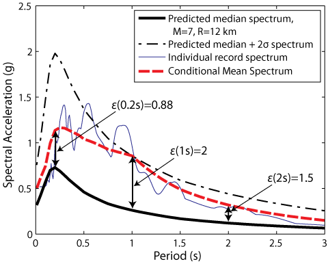 )
)
To model the response of the EM Drive, a spectral analysis would also be needed.
_____
(*) It is noteworthy that the Finite Element method was developed at MIT and other places during and after WWII to model aircraft aeroelastic response and that it was only used by Electrical Engineers to solve Maxwell's equations decades later. The Finite Difference method, though was used prior to WWII and continues to be used to this date (in MEEP for example) to solve Maxwell's equations. -
Title: Re: EM Drive Developments - related to space flight applications - Thread 3
Post by: Rodal on 06/17/2015 03:35 PM -
<a href="http://forum.nasaspaceflight.com/index.php?topic=37642.msg1390621#msg1390621">Quote from: TheTraveller on 06/17/2015 03:08 PM</a><a href="http://forum.nasaspaceflight.com/index.php?topic=37642.msg1390600#msg1390600">Quote from: rfmwguy on 06/17/2015 02:12 PM</a>
....If you can only excite at 2.45 GHz then make it around 9.91 inches....
With a length of 251.72mm (9.91") you should get the following modes to resonate at 2.45GHz
1) TE013
2) TE114
3) TM014
4) TM113
Which one you will excite depends on antenna placement position, antenna design and orientation.
At least Dr Rodal and I agree the standard EW frustum
Frustum big diameter m 0.2794000
Frustum small diameter m 0.1588000
Frustum centre length m 0.2286000
External Rf Hz 2,450,000,000
will not resonate at 2.45GHz.
Which does call Iulian's results into question. Just maybe his magnetron output frequency distribution was wide enough to get a weak resonance or maybe all we saw was the effect of rapidly heated microwaved moisture in the air.
Sorry, I don't agree with the word "will not resonate" in absolute terms. You probably mean "will not resonate at the highest Q". There is always a spectral response of resonance, which will contains peaks with different amplitude at different frequencies.
The natural frequencies at which maximum Q occurs changes with temperature, as the EM Drive heats up and the EM Drive expands, for example.
In the case of the EM Drive, we have the separate issues of at what frequencies maximum Q occurs, and at what frequencies maximum acceleration response occurs (if the EM Drive "acceleration" is not an artifact) -at a given input power-. -
Title: Re: EM Drive Developments - related to space flight applications - Thread 3
Post by: SeeShells on 06/17/2015 03:41 PM -
<a href="http://forum.nasaspaceflight.com/index.php?topic=37642.msg1390624#msg1390624">Quote from: Rodal on 06/17/2015 03:19 PM</a><a href="http://forum.nasaspaceflight.com/index.php?topic=37642.msg1390607#msg1390607">Quote from: rfmwguy on 06/17/2015 02:35 PM</a>
A magnetron, for example, emits photons at different frequencies, as well as producing modulation (frequency, amplitude and phase modulation). This results in feeding a complex spectrum to the truncated cone.<a href="http://forum.nasaspaceflight.com/index.php?topic=37642.msg1390603#msg1390603">Quote from: Rodal on 06/17/2015 02:23 PM</a><a href="http://forum.nasaspaceflight.com/index.php?topic=37642.msg1390600#msg1390600">Quote from: rfmwguy on 06/17/2015 02:12 PM</a>...
I was referring also to the issue that there are a lot of mode shapes bunched next to each other, and that it is not practical to have a cavity resonate such that only one mode gets excited, but in general many mode shapes are excited with different degrees of participation in the response. To model the degree of participation of different modes one has to conduct a Spectrum Analysis of the response spectra (which to my knowledge nobody has yet reported for the EM Drive -- the NASA COMSOL FEA reported analyses are eigenvalue analysis instead of spectra response analyses-
In my previous world, spectrum analysis was wide and narrow bandwidth FFT around ctr freq for spurious emmissions, mainly due to IMD distortion often caused by magnetic or dissimilar metals in the transmission line and radiator.
Perhaps we are speaking different languages...Spectra Response analysis is different, no?
The truncated cone response will contain different modes shapes with different participation. (This is also a function of RF feed placement and choice of RF feed, of course).
I spent a short amount of time looking for images for electromagnetic spectral analysis: I could not readily find spectrum analyses (modelled with software) for a magnetron exciting a cavity: it looks that it is not usual for Electrical Engineer researchers to conduct such analysis (*), but it is very usual for example to model earthquakes acceleration, (for obvious reasons, as an earthquake contains a rich spectrum),or to model the response of a bridge,or to model the response of a rocket to a vibration spectrum, for example coming from a chemical propulsion rocket engine, here is earthquake spectrum response analysis;
()
To model the response of the EM Drive, a spectral analysis would also be needed.
_____
(*) It is noteworthy that the Finite Element method was developed at MIT and other places during and after WWII to model aircraft aeroelastic response and that it was only used by Electrical Engineers to solve Maxwell's equations decades later. The Finite Difference method, though was used prior to WWII and continues to be used to this date (in MEEP for example) to solve Maxwell's equations.
This help I don't have time to read it as I've got to leave. but...
http://link.springer.com/article/10.1134%2FS1063784210110150 -
Title: Re: EM Drive Developments - related to space flight applications - Thread 3
Post by: rfmwguy on 06/17/2015 03:47 PM -
<a href="http://forum.nasaspaceflight.com/index.php?topic=37642.msg1390621#msg1390621">Quote from: TheTraveller on 06/17/2015 03:08 PM</a><a href="http://forum.nasaspaceflight.com/index.php?topic=37642.msg1390600#msg1390600">Quote from: rfmwguy on 06/17/2015 02:12 PM</a>
....If you can only excite at 2.45 GHz then make it around 9.91 inches....
With a length of 251.72mm (9.91") you should get the following modes to resonate at 2.45GHz
1) TE013
2) TE114
3) TM014
4) TM113
Which one you will excite depends on antenna placement position, antenna design and orientation.
At least Dr Rodal and I agree the standard EW frustum
Frustum big diameter m 0.2794000
Frustum small diameter m 0.1588000
Frustum centre length m 0.2286000
External Rf Hz 2,450,000,000
will not resonate at 2.45GHz.
Which does call Iulian's results into question. Just maybe his magnetron output frequency distribution was wide enough to get a weak resonance or maybe all we saw was the effect of rapidly heated microwaved moisture in the air.
9.91L it is then...thanks. I do have the ability to phase modulate the signal, but that experimentation will be for later. The variables I will use are the insertion points and antenna.
Playing it safe, I will go with midway side and simple omdirectional monopole. Was then going to adjust polarity 90 degrees. Afterwards, pick a new insertion point 15% towards small end and then large end, both polarities.
If null results, will move to collinear rather than monopole; basically increase gain (ERP) withing the frustum. This method doesn't need a tuning stub as the source is 50 ohm and so is the semirigid cable and antenna design. -
Title: Re: EM Drive Developments - related to space flight applications - Thread 3
Post by: TheTraveller on 06/17/2015 03:58 PM -
<a href="http://forum.nasaspaceflight.com/index.php?topic=37642.msg1390632#msg1390632">Quote from: Rodal on 06/17/2015 03:35 PM</a><a href="http://forum.nasaspaceflight.com/index.php?topic=37642.msg1390621#msg1390621">Quote from: TheTraveller on 06/17/2015 03:08 PM</a><a href="http://forum.nasaspaceflight.com/index.php?topic=37642.msg1390600#msg1390600">Quote from: rfmwguy on 06/17/2015 02:12 PM</a>
....If you can only excite at 2.45 GHz then make it around 9.91 inches....
With a length of 251.72mm (9.91") you should get the following modes to resonate at 2.45GHz
1) TE013
2) TE114
3) TM014
4) TM113
Which one you will excite depends on antenna placement position, antenna design and orientation.
At least Dr Rodal and I agree the standard EW frustum
Frustum big diameter m 0.2794000
Frustum small diameter m 0.1588000
Frustum centre length m 0.2286000
External Rf Hz 2,450,000,000
will not resonate at 2.45GHz.
Which does call Iulian's results into question. Just maybe his magnetron output frequency distribution was wide enough to get a weak resonance or maybe all we saw was the effect of rapidly heated microwaved moisture in the air.
Sorry, I don't agree with the word "will not resonate" in absolute terms. You probably mean "will not resonate at a high Q". There is always a spectral response of resonance, which will contains peaks with different amplitude at different frequencies.
The natural frequencies at which maximum Q occurs changes with temperature, as the EM Drive heats up and the EM Drive expands, for example.
In the case of the EM Drive, we have the separate issues of at what frequencies maximum Q occurs, and at what frequencies maximum acceleration response occurs (if the EM Drive "acceleration" is not an artifact) -at a given input power-.
We are talking about EM Drives that deliver significant thrust and not SnowFlake thrust. At 2.45GHz there is no mode that will generate significant thrust using the EW frustum. In other words, exiting the EW frustum at 2.45GHz to look for thrust is a waste of time and resources.
If you make it a bit longer then things get interesting.
I suspect this is what Shawyer did with the Demonstrator as while the neck is a constant diameter section, it can expand the length beyond the point where the frustum taper stops and tune it to a longer effective electrical frustum length than the distance between the taper start and end points.
Is clear Shawyer knew what he was doing and why when he built the constant diameter section and the small end plate tuning system. Anyone who replicated that frustum and installed a end plate where the small end taper finished will never get it working at 2.45GHz as you need the extra length resonance provided by the constant diameter section having the sliding end plate about 1/2 way down. -
Title: Re: EM Drive Developments - related to space flight applications - Thread 3
Post by: TheTraveller on 06/17/2015 04:07 PM -
<a href="http://forum.nasaspaceflight.com/index.php?topic=37642.msg1390636#msg1390636">Quote from: rfmwguy on 06/17/2015 03:47 PM</a><a href="http://forum.nasaspaceflight.com/index.php?topic=37642.msg1390621#msg1390621">Quote from: TheTraveller on 06/17/2015 03:08 PM</a><a href="http://forum.nasaspaceflight.com/index.php?topic=37642.msg1390600#msg1390600">Quote from: rfmwguy on 06/17/2015 02:12 PM</a>
....If you can only excite at 2.45 GHz then make it around 9.91 inches....
With a length of 251.72mm (9.91") you should get the following modes to resonate at 2.45GHz
1) TE013
2) TE114
3) TM014
4) TM113
Which one you will excite depends on antenna placement position, antenna design and orientation.
At least Dr Rodal and I agree the standard EW frustum
Frustum big diameter m 0.2794000
Frustum small diameter m 0.1588000
Frustum centre length m 0.2286000
External Rf Hz 2,450,000,000
will not resonate at 2.45GHz.
Which does call Iulian's results into question. Just maybe his magnetron output frequency distribution was wide enough to get a weak resonance or maybe all we saw was the effect of rapidly heated microwaved moisture in the air.
9.91L it is then...thanks. I do have the ability to phase modulate the signal, but that experimentation will be for later. The variables I will use are the insertion points and antenna.
Playing it safe, I will go with midway side and simple omdirectional monopole. Was then going to adjust polarity 90 degrees. Afterwards, pick a new insertion point 15% towards small end and then large end, both polarities.
If null results, will move to collinear rather than monopole; basically increase gain (ERP) withing the frustum. This method doesn't need a tuning stub as the source is 50 ohm and so is the semirigid cable and antenna design.
My understanding is you need to insert the antenna at the internal diameter point where the effective guide wavelength is equal to the actual guide wavelength and the antenna should be a 1/4 wave stub at the effective guide wavelength.
In my EMDrive Calc, the lower left chart shows a red vertical line where that condition is satisfied. -
Title: Re: EM Drive Developments - related to space flight applications - Thread 3
Post by: Rodal on 06/17/2015 04:28 PM -
<a href="http://forum.nasaspaceflight.com/index.php?topic=37642.msg1390634#msg1390634">Quote from: SeeShells on 06/17/2015 03:41 PM</a>
...
Thank you, I attach a copy of the full paper in case you want to use it for your Research purposes
This help I don't have time to read it as I've got to leave. but...
http://link.springer.com/article/10.1134%2FS1063784210110150
<<Conclusion
Thus, the introduction of an external coupling channel
between cavities of a relativistic magnetron provides
an additional effective tool for controlling the oscillatory
processes in this device. At an optimum adjustment
of the coupling channel, a strong interaction between
oscillatory subsystems of the coupled cavities
evidently ensures a deeper stabilization of primary
processes in the magnetron, which are related to the
formation of an electron flow in the oscillating electromagnetic
field. The proposed external coupling
provides a strong selective mechanism of keeping
preset phase relationships in the system, which increases
the modal and spectral stability of radiation.
This ensures stable operation of the magnetron with a
complex load in the form of a system of radiators incorporated
into the coupling channel and makes possible
the effective extraction of power and the spatial
formation of microwave pulses. The obtained results
are supplementary to those reported previously [3–5,
7] for a six cavity relativistic magnetron with a coupling
waveguide channel.>> -
Title: Re: EM Drive Developments - related to space flight applications - Thread 3
Post by: aero on 06/17/2015 04:30 PM -
An observation and a question.
As you may know, I have made a large number of Meep runs to detect forces from evanescent waves. One thing that I have noticed is that the quality factor, Q, is strongly related to the magnitude of the imaginary component of the resonant frequency and that the force/power of the evanescent waves seems to be related to this component also. Difference being that force/power is related to the signed value of the imaginary component of the complex resonant frequency. That is, the imaginary component is typically a small negative value but when it goes near zero, the Q goes way up, almost like 1/fi where fi is the imaginary coefficient of the complex frequency. Then, when fi goes positive, force/power detected from the external evanescent waves goes up.
Question. Does the described behavior relate to any theory we have thought about?
-
Title: Re: EM Drive Developments - related to space flight applications - Thread 3
Post by: Rodal on 06/17/2015 04:54 PM -
John Costella (PhD, Relativistic Electrodynamics ??) is on record about his views about Shawyer's analysis of the EM Drive but I didn't know that he had also written about Prof. Yang's papers.
This pertains to our discussions (with Todd and others) of what exactly is Prof. Yang alluding to in her paper.
See: https://johncostella.wordpress.com/2013/06/16/the-emdrive-the-cold-fusion-of-the-21st-century/Quote from: Dr.CostellaThe Yang Juan et al. paper, however, is more akin to that haystack. They quote many valid equations of electrodynamics, but then stitch them together with numerous assumptions, and then use numerical simulation to compute a result. Without having a spare year to dig through their calculations and simulations, it’s impossible to know where they made their mistake. (Now you know why the Patent Office refuses to accept any more applications for perpetual motion machines.) I recommend that they submit their paper, and simulation code, to a reputable physics journal like the Physical Review, who might be able to find a graduate student with nothing better to do than debunk their submission.
A possible source of their error is their Fig. 1. In diagram (a) they show an open system, where microwaves are thrust into outer space. Such a system would indeed show a tiny amount of thrust: the microwave photons are the propellant. But they reject diagram (a) because the microwaves leak out (obviously), which prevents a standing wave (Shawyer’s claimed mechanism for getting amplification of the tiny thrust) from being maintained. They then replace this with diagram (b), which has placed on the exhaust a “matched load used to absorb the heat transferred from reflected microwaves”. This statement makes no sense at all: reflected microwaves would not transfer heat—only momentum, namely, the force that would prevent the system from getting any net thrust. If something more sophisticated is meant, then it is not explained, and certainly not modeled in their equations. It is possible that neglect of the momentum transfer to this “matched load” is the missing force in their calculations.
I don't know what paper by Juan Yang contains this Fig 1 showing microwaves thrusting into space, and where is diagram b which has placed on the exhaust a “matched load used to absorb the heat transferred from reflected microwaves”. Does anybody know ?
That there is heat produced by induction heating from the magnetic field inside the cavity has been proven by NASA's experiments (for mode TM212):
(http://forum.nasaspaceflight.com/xindex.php,qaction=dlattach,3Btopic=36313.0,3Battach=846719,3Bimage.pagespeed.ic.KVIUQGgNKt.webp) -
Title: Re: EM Drive Developments - related to space flight applications - Thread 3
Post by: aero on 06/17/2015 04:56 PM -
I just finished some Meep runs calculating resonance and Q for the Yang and Shawyer Demo devices using measurements posted.
frequency imag. freq. Q
Yang 2.5387557535 -3.84E-005 33,024.11
Shawyer 2.5058375192 -9.72E-008 12,889,869.03
(To convert frequencies to SI units, multiply by c/0.3)
The frequencies are a little high it seems, and so are the Q values. I really could use that Drude model for copper, but all I really need is an accurate number for complex permittivity of copper at 2 GHz, er = e' + ie".
Experience with Meep with and without the imaginary component of the dielectric constant in the Brady cavity model shows that e" strongly affects both resonance and Q. -
Title: Re: EM Drive Developments - related to space flight applications - Thread 3
Post by: WarpTech on 06/17/2015 05:41 PM -
<a href="http://forum.nasaspaceflight.com/index.php?topic=37642.msg1390611#msg1390611">Quote from: sghill on 06/17/2015 02:43 PM</a><a href="http://forum.nasaspaceflight.com/index.php?topic=37642.msg1390463#msg1390463">Quote from: WarpTech on 06/17/2015 03:16 AM</a>
... now I understand that the stored current may be DC and the associated magnetic field, stored in the small end of the frustum and caused by the time-asymmetry of the evanescent wave's near-field induction effects. Along the walls of the frustum, the gauge potential has a divergence, offset by a change in the refractive index. This divergent field can escape and away we go!
What is the best way to measure (or model) this field that's escaping the frustum and correlate it to measured thrust?
And how would the "DC" EMDrive be setup so as not to use microwaves?
I did the following calculation by hand.
Consider a Coaxial section, where the outer conductor is tapered wrt the inner conductor. At one end, they are connected at a point. At the other end, they are separated by a radial gap. Apply current, "in" through the inner connector and "out" though the outer conductor. This forms a 1-turn Inductor, with an azimuthal B-field.
The B-field between the two conductors is solely due to the inner conductor. The outer conductor does not contribute to the field inside. Outside, the 2 fields cancel, but penetrate the copper right up to the outer boundary.
I used Maxwell's equations and calculated the integral of the pressure x surface area for the conical outer conductor, the cylindrical inner conductor and a flat disk at the input end. The forces are as follows;
Inner conductor: F = 0 The only contribution is radial from it's own B-field, and by symmetry it is cancelled completely.
Outer conductor: F = (u0/2*sin(θ))*I2 x ln(rb/ra)
In the "z" direction, multiply by sin(θ) to get;
Fz = (u0/2)*I2 x ln(rb/ra)
At the bottom disk, at the input end: F = -Fz
Now, remove the bottom disk, or remove it from the path of current flow such that J = 0 in the disk. The cone will be propelled by leakage inductance out the bottom. As it charges, there will be a force pushing toward the small end. It will be a photon rocket, proportional to u0*I*dI/dt.
I'm working on this as part of a paper, but it's not going quickly.
Todd
-
Title: Re: EM Drive Developments - related to space flight applications - Thread 3
Post by: DIYFAN on 06/17/2015 06:02 PM -
Quote
(From Dr. Costella)
(Now you know why the Patent Office refuses to accept any more applications for perpetual motion machines.)
Actually, this is not entirely accurate. While highly skeptical as they should be, there is no prohibition against filing an application for a perpetual motion machine--at least in the U.S. There is a requirement that such a machine be physically presented at the Patent Office for verification before any patent would be granted. -
Title: Re: EM Drive Developments - related to space flight applications - Thread 3
Post by: flux_capacitor on 06/17/2015 07:00 PM -
<a href="http://forum.nasaspaceflight.com/index.php?topic=37642.msg1390661#msg1390661">Quote from: Rodal on 06/17/2015 04:54 PM</a>
I don't know what paper by Juan Yang contains this Fig 1 showing microwaves thrusting into space, and where is diagram b which has placed on the exhaust a “matched load used to absorb the heat transferred from reflected microwaves”. Does anybody know ?
Yes, I found the paper:
Yang, Juan; Wang, Yu-Quan; Ma, Yan-Jie; Li, Peng-Fei; Yang, Le; Wang, Yang; He, Guo-Qiang (May 2013). "Prediction and experimental measurement of the electromagnetic thrust generated by a microwave thruster system" (http://cpb.iphy.ac.cn/EN/article/downloadArticleFile.do?attachType=PDF&id=53411) (PDF). Chinese Physics B (IOP Publishing) 22 (5): 050301. doi:10.1088/1674-1056/22/5/050301
Figure 1 a) and b) from that paper attached below. -
Title: Re: EM Drive Developments - related to space flight applications - Thread 3
Post by: Rodal on 06/17/2015 07:12 PM -
<a href="http://forum.nasaspaceflight.com/index.php?topic=37642.msg1390745#msg1390745">Quote from: flux_capacitor on 06/17/2015 07:00 PM</a><a href="http://forum.nasaspaceflight.com/index.php?topic=37642.msg1390661#msg1390661">Quote from: Rodal on 06/17/2015 04:54 PM</a>
I don't know what paper by Juan Yang contains this Fig 1 showing microwaves thrusting into space, and where is diagram b which has placed on the exhaust a “matched load used to absorb the heat transferred from reflected microwaves”. Does anybody know ?
Yes, I found the paper:
Yang, Juan; Wang, Yu-Quan; Ma, Yan-Jie; Li, Peng-Fei; Yang, Le; Wang, Yang; He, Guo-Qiang (May 2013). "Prediction and experimental measurement of the electromagnetic thrust generated by a microwave thruster system" (http://cpb.iphy.ac.cn/EN/article/downloadArticleFile.do?attachType=PDF&id=53411) (PDF). Chinese Physics B (IOP Publishing) 22 (5): 050301. doi:10.1088/1674-1056/22/5/050301
Figure 1 a) and b) from that paper attached below.
Excellent thank you so much.
-
Title: Re: EM Drive Developments - related to space flight applications - Thread 3
Post by: Rodal on 06/17/2015 07:18 PM -
<a href="http://forum.nasaspaceflight.com/index.php?topic=37642.msg1390712#msg1390712">Quote from: DIYFAN on 06/17/2015 06:02 PM</a>
1) The quote comes from Dr. Costella. In his paper: http://johncostella.webs.com/shawyerfraud.pdfQuote(From Dr. Costella)
(Now you know why the Patent Office refuses to accept any more applications for perpetual motion machines.)
Actually, this is not entirely accurate. While highly skeptical as they should be, there is no prohibition against filing an application for a perpetual motion machine--at least in the U.S. There is a requirement that such a machine be physically presented at the Patent Office for verification before any patent would be granted.
he lists his residence as being in Australia, so perhaps what he means is that the Australian Patent Office refuses to accept any more applications for perpetual motion machines.
This article http://blog.patentology.com.au/2015/04/patenting-perpetual-motion.html concludes: <<So, alleged perpetual motion machines certainly used to be patentable in Australia, and now they probably are not.>>
2) For people interested in sending their perpetual motion machines to the US Patent Office, their rules on models is here: http://www.uspto.gov/web/offices/pac/mpep/s608.html#d0e50532. I'm told by a friend Patent Attorney that used to work for them that they run out of room to store perpetual motion machine models a long time ago :)
3) I leave further discussion on perpetual motion machines on the capable hands of Messrs. @frobnicat and @deltaMass :) -
Title: Re: EM Drive Developments - related to space flight applications - Thread 3
Post by: rfmwguy on 06/17/2015 07:25 PM -
<a href="http://forum.nasaspaceflight.com/index.php?topic=37642.msg1390643#msg1390643">Quote from: TheTraveller on 06/17/2015 04:07 PM</a><a href="http://forum.nasaspaceflight.com/index.php?topic=37642.msg1390636#msg1390636">Quote from: rfmwguy on 06/17/2015 03:47 PM</a><a href="http://forum.nasaspaceflight.com/index.php?topic=37642.msg1390621#msg1390621">Quote from: TheTraveller on 06/17/2015 03:08 PM</a><a href="http://forum.nasaspaceflight.com/index.php?topic=37642.msg1390600#msg1390600">Quote from: rfmwguy on 06/17/2015 02:12 PM</a>
....If you can only excite at 2.45 GHz then make it around 9.91 inches....
...
My understanding is you need to insert the antenna at the internal diameter point where the effective guide wavelength is equal to the actual guide wavelength and the antenna should be a 1/4 wave stub at the effective guide wavelength.
In my EMDrive Calc, the lower left chart shows a red vertical line where that condition is satisfied.
Had a question on the chart below (my apologies in advance):
Not sure I understand the X and Y axis definitions. Know I'm looking for vertical transition, how does this define locale of rf injection? Thanks in advance... -
Title: Re: EM Drive Developments - related to space flight applications - Thread 3
Post by: flux_capacitor on 06/17/2015 07:28 PM -
<a href="http://forum.nasaspaceflight.com/index.php?topic=37642.msg1390754#msg1390754">Quote from: Rodal on 06/17/2015 07:18 PM</a>
The quote comes from Dr. Costella. In his paper: http://johncostella.webs.com/shawyerfraud.pdf
[…]
BTW you should know when citing Costella, that after the man criticized publicly Shawyer's EmDrive as being "a fraud" (not an "experimental error" but a "fraud" which can be considered as defamation according to the English law) that a question about the validly of SPR ltd research was raised in the UK House of Commons (logged (http://www.publications.parliament.uk/pa/cm200607/cmhansrd/cm061205/text/61205w0031.htm) on UK Parliament Publications and Records, Hansard Commons Debates, 5 Dec 2006, Column 340W, Electromagnetic Relativity Drive) caused in part by this claim of fraud.
Questioned on that investigation, Shawyer answered a background check was carried out by the UK authorities about Costella. This inquiry showed that he was not an electrodynamics expert working for the Australian Department of Defence, but had been briefly employed as a junior reliability engineer. He was however known to the Australian authorities as a persistent conspiracy theorist, as demonstrated by various comments he wrote on many blogs.
Not to play devil's advocate here, but sometimes things are not exactly what they seem to be. So everything on that matter that is not true facts (like falsifiable replicable experimental setups) should be taken with a grain of salt. -
Title: Re: EM Drive Developments - related to space flight applications - Thread 3
Post by: Rodal on 06/17/2015 07:31 PM -
<a href="http://forum.nasaspaceflight.com/index.php?topic=37642.msg1390764#msg1390764">Quote from: flux_capacitor on 06/17/2015 07:28 PM</a>
....
Thank you for the clarification. The link you provide (http://www.publications.parliament.uk/pa/cm200607/cmhansrd/cm061205/text/61205w0031.htm) reads:
BTW you should know when citing Costella, that after the man criticized publicly Shawyer's EmDrive as being "a fraud" (not an "experimental error" but a "fraud" which can be considered as defamation according to the English law) that a question about the validly of SPR ltd research was raised in the UK House of Commons (logged (http://www.publications.parliament.uk/pa/cm200607/cmhansrd/cm061205/text/61205w0031.htm) on UK Parliament Publications and Records, Hansard Commons Debates, 5 Dec 2006, Column 340W, Electromagnetic Relativity Drive) caused in part by this claim of fraud.
Questioned on that investigation, Shawyer answered a background check was carried out by the UK authorities about Costella. This inquiry showed that he was not an electrodynamics expert working for the Australian Department of Defence, but had been briefly employed as a junior reliability engineer. He was however known to the Australian authorities as a persistent conspiracy theorist, as demonstrated by various comments he wrote on many blogs.
Not to play devil's advocate here, but sometimes things are not exactly what they seem to be. So everything on that matter that is not true facts (like falsifiable replicable experimental setups) should be taken with a grain of salt.Quote from: UK ParliamentElectromagnetic Relativity Drive
Alan Duncan: To ask the Secretary of State for Trade and Industry how much his Department has provided to the electromagnetic relativity drive design proposed by Roger Shawyer; and from what budget funding has been drawn. [103254]
Margaret Hodge [holding answer 27 November 2006]: Awards have been made to Satellite Propulsion Research Ltd from the DTI’s Small Firms and Enterprise budget.
July 2001—£43,809 paid.
A feasibility study into the application of innovative microwave thruster technology for satellite propulsion. The study involved development of an experimental thruster followed by independent tests and evaluation.
August 2003—£81,291 total grant awarded, £68,399 paid to date.
A follow-on from the above project, to design and develop a demonstration model engine. To be tested on a dynamic test rig, to demonstrate continuous thrust and the conversion of thrust into kinetic energy.
Both grants were awarded against the criteria of the DTI’s Smart scheme that was designed to help fund pioneering and risky R and D projects in small and medium enterprises. Highly qualified technical experts and academics carried out an assessment on behalf of the Department. -
Title: Re: EM Drive Developments - related to space flight applications - Thread 3
Post by: rfmwguy on 06/17/2015 07:41 PM -
<a href="http://forum.nasaspaceflight.com/index.php?topic=37642.msg1390754#msg1390754">Quote from: Rodal on 06/17/2015 07:18 PM</a><a href="http://forum.nasaspaceflight.com/index.php?topic=37642.msg1390712#msg1390712">Quote from: DIYFAN on 06/17/2015 06:02 PM</a>
1) The quote comes from Dr. Costella. In his paper: http://johncostella.webs.com/shawyerfraud.pdfQuote(From Dr. Costella)
(Now you know why the Patent Office refuses to accept any more applications for perpetual motion machines.)
Actually, this is not entirely accurate. While highly skeptical as they should be, there is no prohibition against filing an application for a perpetual motion machine--at least in the U.S. There is a requirement that such a machine be physically presented at the Patent Office for verification before any patent would be granted.
he lists his residence as being in Australia, so perhaps what he means is that the Australian Patent Office refuses to accept any more applications for perpetual motion machines.
This article http://blog.patentology.com.au/2015/04/patenting-perpetual-motion.html concludes: <<So, alleged perpetual motion machines certainly used to be patentable in Australia, and now they probably are not.>>
2) For people interested in sending their perpetual motion machines to the US Patent Office, their rules on models is here: http://www.uspto.gov/web/offices/pac/mpep/s608.html#d0e50532. I'm told by a friend Patent Attorney that used to work for them that they run out of room to store perpetual motion machine models a long time ago :)
3) Further discussion on perpetual motion machines will be handled by Messrs. @frobnicat and @deltaMass :)
Interesting that an agency would block an application based on "common beliefs"...While reading this forum, I know there are opposing viewpoints, but think others should not try and discourage DIY attempts.
I am fully aware that this could be a "hoax of the century", something remarkable or somewhere in-between. To me it does not matter. Its the art of the build and the positive or negative results that may occur. It will be contributed to the knowledge-base, regardless.
What confounds me is criticism outside this forum based on theories and equations someone else came up with, not the posters or pdf writers...as if the posters had the skill or knowledge to prove it or disprove it themselves. Newton, Einstein and other can speak for themselves...negative handwavers need not parrot ;)
Speaking of parrot...be careful with Magnetron Voltages!
-
Title: Re: EM Drive Developments - related to space flight applications - Thread 3
Post by: dustinthewind on 06/17/2015 08:01 PM -
<a href="http://forum.nasaspaceflight.com/index.php?topic=37642.msg1390446#msg1390446">Quote from: WarpTech on 06/17/2015 01:38 AM</a><a href="http://forum.nasaspaceflight.com/index.php?topic=37642.msg1390419#msg1390419">Quote from: Rodal on 06/16/2015 11:51 PM</a>
...
However, I do not see a direct connection yet between the article in Nature and the work of Igor Pikovski, about quantum decoherence to what Todd has been proposing.
The microwave electromagnetic fields inside the EM Drive are carried by photons, which are quantum particles. Photons are capable of displaying quantum coherence and decoherence. The laser, superconductivity and superfluidity are examples of highly coherent quantum systems whose effects are evident at the macroscopic scale.
I know of nothing in the EM Drive experiments that has shown a state of quantum coherence, and therefore nothing that has shown that decoherence takes place in the EM Drive. So where is the connection to the EM Drive?
Regarding Todd's papers, if he posited quantum coherence, I missed that in his papers. My understanding is the contrary, that his emphasis is on geometric attenuation producing evanescent waves that can carry momentum. Todd is not even looking for a super-high Q, but portrays the tug-of-war between Q storage and attenuation and evanescent waves as what could enable the EM Drive to work.
Jose,
If I were talking about gravity in atoms, their paper would be a a spot-on way to look at it. Equation's (5) & (6) are similar in form to the Zitterbewegung motion of the electron in the Dirac equation that I typically refer to. When 2 particles are coupled, they have coherent states. In a gravitational field, we have asymmetry in time.
In the case of the frustum, it is not "quantum" but the standing waves are still a coherent state, just as they are in a laser or a maser. We have 2 waves, "forward" and "backward" that are phase shifted due to the asymmetrical attenuation, i.e., asymmetrical wave velocity, guide wavelength, geometry, whatever. The two waves are out of phase and you can see in their Fig. 1c, that the phase shifted superposition has a component along the "real" Power axis, i.e, the Power Factor is not 0.
This action causes the center of mass between the two to shift. The "decoherence" they are referring to, is what I've been referring to as "constructive and destructive interference". This is the information contained in the Matrix terms they are referring to. I'm just saying it in my own Engineering-speak. If the frustum were replaced by a cylinder, this phase interference would not happen. The frustum is a nice conical-section representation of a spherically symmetric gravitational field, that only exists over a very narrow bandwidth. :)
Todd
What about two cylindrical resonators that are at a set distance and close together but out of phase? Doesn't this re-introduce the phase shifted asymmetrical attenuation? -
Title: Re: EM Drive Developments - related to space flight applications - Thread 3
Post by: rfmwguy on 06/17/2015 08:04 PM -
<a href="http://forum.nasaspaceflight.com/index.php?topic=37642.msg1390764#msg1390764">Quote from: flux_capacitor on 06/17/2015 07:28 PM</a><a href="http://forum.nasaspaceflight.com/index.php?topic=37642.msg1390754#msg1390754">Quote from: Rodal on 06/17/2015 07:18 PM</a>
The quote comes from Dr. Costella. In his paper: http://johncostella.webs.com/shawyerfraud.pdf
[…]
BTW you should know when citing Costella, that after the man criticized publicly Shawyer's EmDrive as being "a fraud" (not an "experimental error" but a "fraud" which can be considered as defamation according to the English law) that a question about the validly of SPR ltd research was raised in the UK House of Commons (logged (http://www.publications.parliament.uk/pa/cm200607/cmhansrd/cm061205/text/61205w0031.htm) on UK Parliament Publications and Records, Hansard Commons Debates, 5 Dec 2006, Column 340W, Electromagnetic Relativity Drive) caused in part by this claim of fraud.
Questioned on that investigation, Shawyer answered a background check was carried out by the UK authorities about Costella. This inquiry showed that he was not an electrodynamics expert working for the Australian Department of Defence, but had been briefly employed as a junior reliability engineer. He was however known to the Australian authorities as a persistent conspiracy theorist, as demonstrated by various comments he wrote on many blogs.
Not to play devil's advocate here, but sometimes things are not exactly what they seem to be. So everything on that matter that is not true facts (like falsifiable replicable experimental setups) should be taken with a grain of salt.
Hmmmm...meet Mr Costella, now a Facebook software engineer: https://www.linkedin.com/in/johncostella -
Title: Re: EM Drive Developments - related to space flight applications - Thread 3
Post by: deltaMass on 06/17/2015 08:12 PM -
<a href="http://forum.nasaspaceflight.com/index.php?topic=37642.msg1390787#msg1390787">Quote from: rfmwguy on 06/17/2015 08:04 PM</a>
Wrong guy. Try this<a href="http://forum.nasaspaceflight.com/index.php?topic=37642.msg1390764#msg1390764">Quote from: flux_capacitor on 06/17/2015 07:28 PM</a><a href="http://forum.nasaspaceflight.com/index.php?topic=37642.msg1390754#msg1390754">Quote from: Rodal on 06/17/2015 07:18 PM</a>The quote comes from Dr. Costella. In his paper: http://johncostella.webs.com/shawyerfraud.pdf
[…]
BTW you should know when citing Costella, that after the man criticized publicly Shawyer's EmDrive as being "a fraud" (not an "experimental error" but a "fraud" which can be considered as defamation according to the English law) that a question about the validly of SPR ltd research was raised in the UK House of Commons (logged (http://www.publications.parliament.uk/pa/cm200607/cmhansrd/cm061205/text/61205w0031.htm) on UK Parliament Publications and Records, Hansard Commons Debates, 5 Dec 2006, Column 340W, Electromagnetic Relativity Drive) caused in part by this claim of fraud.
Questioned on that investigation, Shawyer answered a background check was carried out by the UK authorities about Costella. This inquiry showed that he was not an electrodynamics expert working for the Australian Department of Defence, but had been briefly employed as a junior reliability engineer. He was however known to the Australian authorities as a persistent conspiracy theorist, as demonstrated by various comments he wrote on many blogs.
Not to play devil's advocate here, but sometimes things are not exactly what they seem to be. So everything on that matter that is not true facts (like falsifiable replicable experimental setups) should be taken with a grain of salt.
Hmmmm...meet Mr Costella, now a Facebook software engineer: https://www.linkedin.com/in/johncostella
http://spartacus-educational.com/JFKcostella.htm
Two degrees plus 3 years postdoc physics is a little different to the picture painted by Shawyer of a "junior engineer".
I first encountered Shawyer via Costella's paper. I am grateful to Costella for pointing out that not only does Shawyer not understand Newton's laws (or if he does, is unable to communicate them clearly), but also seems incapable of correctly drawing force vectors at the sidewall. This in Shawyer's mind gave a finite net thrust, based purely on the summation of his incorrect reflected force vectors over the complete surface of the frustum. A childish error unworthy of even a junior reliability engineer, one might say? -
Title: Re: EM Drive Developments - related to space flight applications - Thread 3
Post by: rfmwguy on 06/17/2015 08:22 PM -
<a href="http://forum.nasaspaceflight.com/index.php?topic=37642.msg1390790#msg1390790">Quote from: deltaMass on 06/17/2015 08:12 PM</a><a href="http://forum.nasaspaceflight.com/index.php?topic=37642.msg1390787#msg1390787">Quote from: rfmwguy on 06/17/2015 08:04 PM</a>
Wrong guy. Try this<a href="http://forum.nasaspaceflight.com/index.php?topic=37642.msg1390764#msg1390764">Quote from: flux_capacitor on 06/17/2015 07:28 PM</a><a href="http://forum.nasaspaceflight.com/index.php?topic=37642.msg1390754#msg1390754">Quote from: Rodal on 06/17/2015 07:18 PM</a>The quote comes from Dr. Costella. In his paper: http://johncostella.webs.com/shawyerfraud.pdf
[…]
BTW you should know when citing Costella, that after the man criticized publicly Shawyer's EmDrive as being "a fraud" (not an "experimental error" but a "fraud" which can be considered as defamation according to the English law) that a question about the validly of SPR ltd research was raised in the UK House of Commons (logged (http://www.publications.parliament.uk/pa/cm200607/cmhansrd/cm061205/text/61205w0031.htm) on UK Parliament Publications and Records, Hansard Commons Debates, 5 Dec 2006, Column 340W, Electromagnetic Relativity Drive) caused in part by this claim of fraud.
Questioned on that investigation, Shawyer answered a background check was carried out by the UK authorities about Costella. This inquiry showed that he was not an electrodynamics expert working for the Australian Department of Defence, but had been briefly employed as a junior reliability engineer. He was however known to the Australian authorities as a persistent conspiracy theorist, as demonstrated by various comments he wrote on many blogs.
Not to play devil's advocate here, but sometimes things are not exactly what they seem to be. So everything on that matter that is not true facts (like falsifiable replicable experimental setups) should be taken with a grain of salt.
Hmmmm...meet Mr Costella, now a Facebook software engineer: https://www.linkedin.com/in/johncostella
http://spartacus-educational.com/JFKcostella.htm
Two physics degrees is a little different to the picture painted by Shawyer of a "junior engineer".
I first encountered Shawyer via Costella's paper. I am grateful to Costella for pointing out that not only does Shawyer not understand Newton's laws (or if he does, is unable to communicate them clearly), but also seems incapable of correctly drawing force vectors at the sidewall. This in Shawyer's mind gave a finite net thrust, based purely on the summation of his incorrect reflected force vectors over the complete surface of the frustum. A childish error unworthy of even a junior reliability engineer, one might say?
Same dude...
Your guy: "John Costella was born in Australia. After graduating with honors degrees in both electrical engineering and the sciences from the University of Melbourne, he completed a Ph.D. in theoretical physics. After three years of postdoctoral research and lecturing at the University of Melbourne he was appointed as a teacher of Mathematics, Physics and Information Technology at Mentone Grammar.
Costella has researched the assassination of John F. Kennedy and has undertaken a sophisticated analyses of the Zapruder Film. Two of his articles, A Scientist's Verdict: The Film is a Fabrication and Mary Moorman and Her Polaroids appeared in The Great Zapruder Film Hoax (edited by James H. Fetzer)."
My guy, Linkedin Experience summary:
"Experience
Software Engineer
Facebook
October 2012 – Present (2 years 9 months)|San Francisco Bay Area
Data science infrastructure; sentiment analysis; statistics; image processing
Senior Data Scientist
Intelematics Australia
September 2011 – October 2012 (1 year 2 months)|Richmond, Victoria, Australia
Live vehicular traffic measurement, prediction, and broadcast
Physics Research Developer
Peter MacCallum Cancer Centre
July 2010 – September 2011 (1 year 3 months)|East Melbourne, Australia
Cancer research: volumetric radiation dose and radiobiological model analysis
Product Consultant
Thomson Reuters
March 2011 – July 2011 (5 months)|Greater New York City Area
Financial markets database systems: Enterprise Platform for Velocity Analytics (Vhayu Velocity)
Data Analyst
Bourse Data Pty Ltd
June 2010 – July 2010 (2 months)|Melbourne Area, Australia
Financial markets data systems and analysis
Data Manager and Senior Research Scientist
Portland House Research Group
April 2007 – May 2010 (3 years 2 months)|Melbourne Area, Australia
Black-box quantitative financial market research and operations
Reliability Engineer
Department of Defence, Australia
February 2006 – April 2007 (1 year 3 months)|Melbourne, Australia
Reliability, Availability, Maintainability; statistical analysis
Teacher
The Peninsula School
January 2005 – February 2006 (1 year 2 months)|Melbourne Area, Australia
High school mathematics
Teacher
Mentone Grammar
July 1997 – December 2004 (7 years 6 months)|Melbourne Area, Australia
High school mathematics
Postdoctoral Research Physicist
The University of Melbourne
July 1994 – December 1996 (2 years 6 months)|Melbourne, Australia
Theoretical particle physics"
-
Title: Re: EM Drive Developments - related to space flight applications - Thread 3
Post by: deltaMass on 06/17/2015 08:27 PM - I stand corrected. Apparently he is all of the above and more. I was also misled by the great apparent difference between the portrait photos.
-
Title: Re: EM Drive Developments - related to space flight applications - Thread 3
Post by: flux_capacitor on 06/17/2015 08:31 PM - Yes this is the same person. He has many interests and you can see some of them on his personal web page that will reconcile what you found about him: http://johncostella.webs.com
-
Title: Re: EM Drive Developments - related to space flight applications - Thread 3
Post by: flux_capacitor on 06/17/2015 08:35 PM -
<a href="http://forum.nasaspaceflight.com/index.php?topic=37642.msg1390790#msg1390790">Quote from: deltaMass on 06/17/2015 08:12 PM</a>
I am grateful to Costella for pointing out that not only does Shawyer not understand Newton's laws (or if he does, is unable to communicate them clearly), but also seems incapable of correctly drawing force vectors at the sidewall. This in Shawyer's mind gave a finite net thrust, based purely on the summation of his incorrect reflected force vectors over the complete surface of the frustum. A childish error unworthy of even a junior reliability engineer, one might say?
Are you seriously considering Roger Shawyer predicted the forces produced by his EmDrive using… arrows on a drawing, instead of equations? -
Title: Re: EM Drive Developments - related to space flight applications - Thread 3
Post by: rfmwguy on 06/17/2015 08:37 PM -
<a href="http://forum.nasaspaceflight.com/index.php?topic=37642.msg1390801#msg1390801">Quote from: deltaMass on 06/17/2015 08:27 PM</a>
I stand corrected. Apparently he is all of the above and more. I was also misled by the great apparent difference between the portrait photos.
I did a double-take on the pics as well...big difference for sure. -
Title: Re: EM Drive Developments - related to space flight applications - Thread 3
Post by: VAXHeadroom on 06/17/2015 08:37 PM -
<a href="http://forum.nasaspaceflight.com/index.php?topic=37642.msg1390422#msg1390422">Quote from: ThinkerX on 06/16/2015 11:58 PM</a>
This is probably easily debunked, but it does pertain to Conservation of Momentum.
Couple days ago, I was at a lake. Glass calm, no waves, no current.
I loaded myself into a canoe for a little spin. Got out into the water. Drifted to a complete or near complete halt. Then...
while remaining seated AND hands holding on tight to the side of the canoe, I 'threw' my torso forward. I never actually left the seat. But the canoe did move in that direction. I then straightened myself up (slowly) and repeated the process a few times. Each time, the canoe would shoot forward (ok move forward at less than paddle speed) for about two yards or so...but there was never any corresponding 'back motion' when I straightened.
So...violation of CoM or something else? And could what I was doing be used as an analogy for whatever is going on with the EM Drive?
No violation. F=MA If A is different in the two different directions, force is also different. CoE is also conserved since more energy was expended to accelerate your mass in one direction than the other. You were asymmetrically converting energy into force.
(somebody here is probably going to bite my head of for some boneheaded error :) )
-
Title: Re: EM Drive Developments - related to space flight applications - Thread 3
Post by: deltaMass on 06/17/2015 08:48 PM -
<a href="http://forum.nasaspaceflight.com/index.php?topic=37642.msg1390802#msg1390802">Quote from: flux_capacitor on 06/17/2015 08:31 PM</a>
Yes this is the same person. He has many interests and you can see some of them on his personal web page that will reconcile what you found about him: http://johncostella.webs.com
There I find:
PhD thesis : Single-particle electrodynamics
And Shawyer states "This inquiry showed that he was not an electrodynamics expert" -
Title: Re: EM Drive Developments - related to space flight applications - Thread 3
Post by: aero on 06/17/2015 08:55 PM -
@TravelerQuote
Frustum big diameter m 0.2314000
Frustum small diameter m 0.1257000
Frustum centre length m 0.1386000
and asked him for the resonate frequency. He sent me the following:
External Rf Hz 3,900,300,000
I would prefer not to make an assumption, so I will ask. "Are those internal dimensions?" And, "Are the end plates flat or curved?" -
Title: Re: EM Drive Developments - related to space flight applications - Thread 3
Post by: deltaMass on 06/17/2015 08:57 PM -
<a href="http://forum.nasaspaceflight.com/index.php?topic=37642.msg1390805#msg1390805">Quote from: flux_capacitor on 06/17/2015 08:35 PM</a>
Yes, seriously. Like several other people noticed. But don't go putting words in people's mouths. There is no "instead of" as you state. There is instead "in addition to". To quote from the attached PDF:<a href="http://forum.nasaspaceflight.com/index.php?topic=37642.msg1390790#msg1390790">Quote from: deltaMass on 06/17/2015 08:12 PM</a>I am grateful to Costella for pointing out that not only does Shawyer not understand Newton's laws (or if he does, is unable to communicate them clearly), but also seems incapable of correctly drawing force vectors at the sidewall. This in Shawyer's mind gave a finite net thrust, based purely on the summation of his incorrect reflected force vectors over the complete surface of the frustum. A childish error unworthy of even a junior reliability engineer, one might say?
Are you seriously considering Roger Shawyer predicted the forces produced by his EmDrive using… arrows on a drawing, instead of equations?
What’s wrong in Shawyer’s paper
Now we get to the point that a number of people have already made, but perhaps not confidently enough. Look at the arrows that Shawyer labels ‘Fs1’ and ‘Fs2’ on his Figure 2.4. These are sup-posed to be the forces that the particle imparts to the wall of the conical part of his contraption.
But hang on a minute! When a particle bounces elastically off a wall, doesn’t the wall feel a force that is perpendicular to the wall? Of course it does: if you remember your high school physics, you subtract the initial momentum vector from the final momentum vector, and the resultant force points into the wall.
etc... -
Title: Re: EM Drive Developments - related to space flight applications - Thread 3
Post by: kml on 06/17/2015 09:02 PM -
<a href="http://forum.nasaspaceflight.com/index.php?topic=37642.msg1390643#msg1390643">Quote from: TheTraveller on 06/17/2015 04:07 PM</a>
My understanding is you need to insert the antenna at the internal diameter point where the effective guide wavelength is equal to the actual guide wavelength and the antenna should be a 1/4 wave stub at the effective guide wavelength.
In my EMDrive Calc, the lower left chart shows a red vertical line where that condition is satisfied.
You generally want a TE feedpoint to be 1/4 guided wave away from one of the shorted ends. This is so the reflections off that end are in phase with the probe. The ideal length of the probe will probably be much shorter than you would use for a non-enclosed waveguide as you don't want too much coupling to pull power out of the resonator. In my rectangular waveguide resonator I started with the standard 1/8 wave probe which resulted in a TE101 Q of 35. Incrementally shortening it increased Q until I stopped at about 1/20 wave and TE101 Q=400. Increasing the length to TE102 further increased the Q from 400 to 1600. I have a separate monitor probe which is off center and about half the length of the feed probe. It pulls out about 10% of the power in it's current location. I suspect moving it to a side wall will dramatically reduce that and increase Q further.
I don't know if any of that translates to tapered cylinders but be prepared to try different lengths and positions. -
Title: Re: EM Drive Developments - related to space flight applications - Thread 3
Post by: deltaMass on 06/17/2015 09:04 PM -
While I'm happily cruising along in debunk mode, I might as well toss out the fact that photon momentum goes as the phase velocity and not as the group velocity. This renders the purported thrust mechanism of "differential group velocity" incorrect.
https://en.wikipedia.org/wiki/EmDrive#Theory -
Title: Re: EM Drive Developments - related to space flight applications - Thread 3
Post by: flux_capacitor on 06/17/2015 09:04 PM -
@deltamass:
Sometimes when you want anybody to understand quickly the basis of a theory, instead of using complicated equations, you simplify the concepts with what is know as popularization, through drawings and analogies. Those drawings and analogies are only that: approximations. And because they are only approximations, sometimes they are well found and clever, sometimes they are more or less misleading. Shawyer, in the drawing you refer to, was just trying to show the force imbalance exerted on the two end plates. The drawing was not good enough since it didn't show the forces on the walls. It wasn't the drawing upon which Shawyer built his theory! But what Costella did, was to throw the baby out with the bath water, on the sole basis of a not so clever popularization drawing. When I read that "refutation paper" at that time, I thought it was incredible being so rude (slandering Shawyer as a fraud) while at the same time never bothering to go into the maths. Costella's paper was very poor from both a human and a scientific viewpoint, and for that reason I think it was a shame that paper was so widely publicized. Gred Egan's work on frustum resonant cavities was much better for example.
I think too that Shawyer does not have the good theory to explain the thrust produced by the EmDrive. But don't think the man once began to wrote some incomplete arrows on a tablecloth before thinking about calculations or experiments. That's completely an upside-down reasoning. -
Title: Re: EM Drive Developments - related to space flight applications - Thread 3
Post by: flux_capacitor on 06/17/2015 09:14 PM -
<a href="http://forum.nasaspaceflight.com/index.php?topic=37642.msg1390823#msg1390823">Quote from: deltaMass on 06/17/2015 09:04 PM</a>
While I'm happily cruising along in debunk mode, I might as well toss out the fact that photon momentum goes as the phase velocity and not as the group velocity. This renders the purported thrust mechanism of "differential group velocity" incorrect.
https://en.wikipedia.org/wiki/EmDrive#Theory
I used to found exactly the opposite searching that information, so we should ask someone specialized in microwaves to clarify this phase velocity vs group velocity thing. Perhaps we should open a good specialized microwave engineering text book IRL (please, no Wikipedia for such specialized stuff) and search about that.
What I found is: it is group velocity (not phase velocity) which contributes to the radiation pressure at the end plates. The group velocity (sometimes referred to as the guide velocity) carries the energy and momentum of the EM wave along a waveguide. The equations for group velocity are well defined and show that the velocity decreases as the guide dimensions decrease until cut off where propagation stops.
But I'm not an expert, so any expert should clarify :) -
Title: Re: EM Drive Developments - related to space flight applications - Thread 3
Post by: deltaMass on 06/17/2015 09:15 PM -
<a href="http://forum.nasaspaceflight.com/index.php?topic=37642.msg1390824#msg1390824">Quote from: flux_capacitor on 06/17/2015 09:04 PM</a>
@deltamass:
I agree with you that Shawyer "does not have a good theory". And I also think that by no means should Shawyer be singled out in this respect. That's because I don't think anybody has a good theory :)
Sometimes when you want anybody to understand quickly the basis of a theory, instead of using complicated equations, you simplify the concepts with what is know as popularization, through drawings and analogies. Those drawings and analogies are only that: approximations. And because they are only approximations, sometimes they are well found and clever, sometimes they are more or less misleading. Shawyer, in the drawing you refer to, was just trying to show the force imbalance exerted on the two end plates. The drawing was not good enough since it didn't show the forces on the walls. It wasn't the drawing upon which Shawyer built his theory! But what Costella did, was to throw the baby out with the bath water, on the sole basis of a not so clever popularization drawing. When I read that "refutation paper" at that time, I thought it was incredible being so rude (slandering Shawyer as a fraud) while at the same time never bothering to go into the maths. Costella's paper was very poor from both a human and a scientific viewpoint, and for that reason I think it was a shame that paper was so widely publicized. Gred Egan's work on frustum resonant cavities was much better for example.
I think too that Shawyer does not have the good theory to explain the thrust produced by the EmDrive. But don't think the man once began to wrote some incomplete arrows on a tablecloth before thinking about calculations or experiments. That's completely an upside-down reasoning. -
Title: Re: EM Drive Developments - related to space flight applications - Thread 3
Post by: Rodal on 06/17/2015 09:20 PM -
<a href="http://forum.nasaspaceflight.com/index.php?topic=37642.msg1390823#msg1390823">Quote from: deltaMass on 06/17/2015 09:04 PM</a>
While I'm happily cruising along in debunk mode, I might as well toss out the fact that photon momentum goes as the phase velocity and not as the group velocity. This renders the purported thrust mechanism of "differential group velocity" incorrect.
Not so fast moving along...
https://en.wikipedia.org/wiki/EmDrive#Theory
The group velocity of a simple plane wave is:
vg=∂ω/∂k=∂E/∂p=p/m=v
which is exactly the velocity of the particle.
If a wave packet is localized, the group velocity measures how the "center of mass" of this packet is moving
( )
)
The red dot moves with the phase velocity, and the green dots propagate with the group velocity. In this deep-water case, the phase velocity is twice the group velocity. The red dot [the phase velocity] overtakes two green dots [the group velocity] when moving from the left to the right of the figure. -
Title: Re: EM Drive Developments - related to space flight applications - Thread 3
Post by: flux_capacitor on 06/17/2015 09:25 PM - So Rodal, which carries information and momentum: the phase or the group velocity?
-
Title: Re: EM Drive Developments - related to space flight applications - Thread 3
Post by: rfmwguy on 06/17/2015 09:26 PM -
<a href="http://forum.nasaspaceflight.com/index.php?topic=37642.msg1390826#msg1390826">Quote from: deltaMass on 06/17/2015 09:15 PM</a><a href="http://forum.nasaspaceflight.com/index.php?topic=37642.msg1390824#msg1390824">Quote from: flux_capacitor on 06/17/2015 09:04 PM</a>
@deltamass:
I agree with you that Shawyer "does not have a good theory". And I also think that by no means should Shawyer be singled out in this respect. That's because I don't think anybody has a good theory :)
(..)
I'm workin' on it, I'm working on it! ;) Just procrastinating on slapping together (shiver) formulas after years of abstinence...I know, I swore off them, went to Formulas Anonymous meetings and everything...
Seriously, have not studied it long enough to spew out anything with scientific formulae...but I will eventually, IF I see something other than Null results on my project. If its there, it'll be discected and exposed eventually. Boom! -
Title: Re: EM Drive Developments - related to space flight applications - Thread 3
Post by: Rodal on 06/17/2015 09:27 PM -
<a href="http://forum.nasaspaceflight.com/index.php?topic=37642.msg1390828#msg1390828">Quote from: flux_capacitor on 06/17/2015 09:25 PM</a>
So Rodal, which carries information and momentum: the phase or the group velocity?
In most cases, it is the group velocity that carries information and energy -
Title: Re: EM Drive Developments - related to space flight applications - Thread 3
Post by: deltaMass on 06/17/2015 09:29 PM -
http://www.quora.com/Is-there-a-relationship-between-refractive-index-and-radiation-pressureQuote
The new experiment confirms, to a precision of about 0.05%, that the momentum associated with electromagnetic radiation increases directly with the refractive index of the medium into which it passes, discriminating substantially in favour of the phase velocity ratio and against the group velocity ratio.
-
Title: Re: EM Drive Developments - related to space flight applications - Thread 3
Post by: WarpTech on 06/17/2015 09:34 PM -
<a href="http://forum.nasaspaceflight.com/index.php?topic=37642.msg1390784#msg1390784">Quote from: dustinthewind on 06/17/2015 08:01 PM</a><a href="http://forum.nasaspaceflight.com/index.php?topic=37642.msg1390446#msg1390446">Quote from: WarpTech on 06/17/2015 01:38 AM</a>
... If the frustum were replaced by a cylinder, this phase interference would not happen. The frustum is a nice conical-section representation of a spherically symmetric gravitational field, that only exists over a very narrow bandwidth. :)
Todd
What about two cylindrical resonators that are at a set distance and close together but out of phase? Doesn't this re-introduce the phase shifted asymmetrical attenuation?
If I had software like COMSOL, I could answer that. It's not so easy to do by hand and I find that;
D x dB/dt + dD/dt x B = 0,
with every other scenario I've tried. I think the DC cone idea I posted this morning is uniquely possible due to the axial symmetry and radial asymmetry of the cone shape.
Todd
-
Title: Re: EM Drive Developments - related to space flight applications - Thread 3
Post by: flux_capacitor on 06/17/2015 09:34 PM -
<a href="http://forum.nasaspaceflight.com/index.php?topic=37642.msg1390830#msg1390830">Quote from: Rodal on 06/17/2015 09:27 PM</a><a href="http://forum.nasaspaceflight.com/index.php?topic=37642.msg1390828#msg1390828">Quote from: flux_capacitor on 06/17/2015 09:25 PM</a>
So Rodal, which carries information and momentum: the phase or the group velocity?
In most cases, it is the group velocity that carries information and energy
Ok thanks, that confirm what I thought, as the phase velocity in certain conditions can sometimes exceed the speed of light, but the group velocity can never exceed c. -
Title: Re: EM Drive Developments - related to space flight applications - Thread 3
Post by: Rodal on 06/17/2015 09:41 PM -
<a href="http://forum.nasaspaceflight.com/index.php?topic=37642.msg1390832#msg1390832">Quote from: deltaMass on 06/17/2015 09:29 PM</a>
http://www.quora.com/Is-there-a-relationship-between-refractive-index-and-radiation-pressure
QuoteThe new experiment confirms, to a precision of about 0.05%, that the momentum associated with electromagnetic radiation increases directly with the refractive index of the medium into which it passes, discriminating substantially in favour of the phase velocity ratio and against the group velocity ratio.
See this that addresses this conundrum: http://arxiv.org/ftp/physics/papers/0607/0607094.pdf
(much easier than for me having to type it)
The phase velocity is E/p while the group velocity is ∂E/∂p
Unfortunately quantum mechanics means characteristics of both wave and particle so the question is ill-posed. In situations that we can intuitively relate to the group velocity is associated with momentum since the group velocity is associated with the particle, but in other situations (absorptive media) the wave plays a more important role -
Title: Re: EM Drive Developments - related to space flight applications - Thread 3
Post by: deltaMass on 06/17/2015 10:16 PM -
"So even if it resonates, it won't push. QED"
http://physics.stackexchange.com/questions/130662/emdrive-cavity-modes
Some maths, probably similar to Egan.
-
Title: Re: EM Drive Developments - related to space flight applications - Thread 3
Post by: dustinthewind on 06/17/2015 10:27 PM -
<a href="http://forum.nasaspaceflight.com/index.php?topic=37642.msg1390833#msg1390833">Quote from: WarpTech on 06/17/2015 09:34 PM</a><a href="http://forum.nasaspaceflight.com/index.php?topic=37642.msg1390784#msg1390784">Quote from: dustinthewind on 06/17/2015 08:01 PM</a><a href="http://forum.nasaspaceflight.com/index.php?topic=37642.msg1390446#msg1390446">Quote from: WarpTech on 06/17/2015 01:38 AM</a>
... If the frustum were replaced by a cylinder, this phase interference would not happen. The frustum is a nice conical-section representation of a spherically symmetric gravitational field, that only exists over a very narrow bandwidth. :)
Todd
What about two cylindrical resonators that are at a set distance and close together but out of phase? Doesn't this re-introduce the phase shifted asymmetrical attenuation?
If I had software like COMSOL, I could answer that. It's not so easy to do by hand and I find that;
D x dB/dt + dD/dt x B = 0,
with every other scenario I've tried. I think the DC cone idea I posted this morning is uniquely possible due to the axial symmetry and radial asymmetry of the cone shape.
Todd
I was saying that because the evanescent waves (or the currents) in the two cavities walls being out of phase by pi/2 and 1/4 lambda apart interact. One cavities evanescent waves appear to be working against the other so it is attenuated at one end. The other is constructively interfering and working with its partner cavity evanescent waves (due to time retardation). As a result energy is attenuated from one cavity and transported (tunneled) to the other creating a non-standing wave as a result. It appears to be asymmetric attenuation in one cavity and asymmetric amplification in the other but with opposite wall orientation w.r.t. each cavity. Hopefully I am not too far off in this but I think I am right. -
Title: Re: EM Drive Developments - related to space flight applications - Thread 3
Post by: Rodal on 06/17/2015 10:49 PM -
<a href="http://forum.nasaspaceflight.com/index.php?topic=37642.msg1390837#msg1390837">Quote from: Rodal on 06/17/2015 09:41 PM</a><a href="http://forum.nasaspaceflight.com/index.php?topic=37642.msg1390832#msg1390832">Quote from: deltaMass on 06/17/2015 09:29 PM</a>
http://www.quora.com/Is-there-a-relationship-between-refractive-index-and-radiation-pressure
QuoteThe new experiment confirms, to a precision of about 0.05%, that the momentum associated with electromagnetic radiation increases directly with the refractive index of the medium into which it passes, discriminating substantially in favour of the phase velocity ratio and against the group velocity ratio.
See this that addresses this conundrum: http://arxiv.org/ftp/physics/papers/0607/0607094.pdf
(much easier than for me having to type it)
The phase velocity is E/p while the group velocity is ∂E/∂p
Unfortunately quantum mechanics means characteristics of both wave and particle so the question is ill-posed. In situations that we can intuitively relate to the group velocity is associated with momentum since the group velocity is associated with the particle, but in other situations (absorptive media) the wave plays a more important role
So, perhaps we can put it this charitable way: Shawyer's ad-hoc approximation is closer to the truth for the case in which there is no dielectric insert inside the cavity (in which case the photons may behave more like particles with a group velocity vg for reflective boundary conditions) and it is further away from the truth for the case of the cavity containing a dielectric insert (since the momentum associated with electromagnetic radiation increases directly with the refractive index of the medium into which it passes through) -
Title: Re: EM Drive Developments - related to space flight applications - Thread 3
Post by: ElizabethGreene on 06/17/2015 11:06 PM -
<a href="http://forum.nasaspaceflight.com/index.php?topic=37642.msg1390784#msg1390784">Quote from: dustinthewind on 06/17/2015 08:01 PM</a>
...
What about two cylindrical resonators that are at a set distance and close together but out of phase? Doesn't this re-introduce the phase shifted asymmetrical attenuation?
Wouldn't the fields you are trying to attenuate be trapped in the respective resonators?
I was considering the question this morning: "How could I generate an electrical field out of phase but of the same frequency as that within the resonator?" What I've come up with so far, disclaiming that I am grossly uneducated in the topic, is
1. Electrically split the signal between the magnetron and the waveguide coupling probe.
or.
2. Insert a small probe, < 1/4 wave, into the resonator at some arbitrarily selected point, preferably near an antinode to gather the required charge from the resonator itself.
In the case of 2, you can control the collected power by the length of the probe. You can control how out-of phase it is by altering the length of the intervening bit of cable keeping in mind that the wavelength in copper will be longer than the wavelength in air.
My application is to insert the other end of the now oscillating-out-of-phase probe into an electrically insulated tube, and insert that perpendicular to the E field in the ... (I lack the correct term to describe this, help appreciated) E-field-is-moving in-and-out end of my shiny new non-tapered resonator to see if something interesting happens.
It is my intention to work on this Saturday*.
*One hopes that a related memorial service will not be held soon after. -
Title: Re: EM Drive Developments - related to space flight applications - Thread 3
Post by: rfmwguy on 06/17/2015 11:44 PM -
<a href="http://forum.nasaspaceflight.com/index.php?topic=37642.msg1390866#msg1390866">Quote from: ElizabethGreene on 06/17/2015 11:06 PM</a><a href="http://forum.nasaspaceflight.com/index.php?topic=37642.msg1390784#msg1390784">Quote from: dustinthewind on 06/17/2015 08:01 PM</a>
...
What about two cylindrical resonators that are at a set distance and close together but out of phase? Doesn't this re-introduce the phase shifted asymmetrical attenuation?
Wouldn't the fields you are trying to attenuate be trapped in the respective resonators?
(...)
Ergo, the ultimate attenuation one would think.
Here's why I chose not to start w/dielectrics.
1. shawyer and yang had none and claimed results.
2. It adds a layer of complexity when the effect is hard to prove all by itself.
3. Suspicious of reflow/outgassing/etc.
4. Added mass, increasing need for more sensitive weight measurement gear.
5. Q reduction
Only reason to use them in my experience was miniaturization for flight hardware. Not saying dielectrics will not work, but not ideal for EMDIYers imho.
-
Title: Re: EM Drive Developments - related to space flight applications - Thread 3
Post by: Acryte on 06/18/2015 12:07 AM -
<a href="http://forum.nasaspaceflight.com/index.php?topic=37642.msg1390443#msg1390443">Quote from: TheTraveller on 06/17/2015 01:26 AM</a>
Please stop diverting away from my question.
What is YOUR TE013 resonance frequency for the 2 sets of dimensions I provided?
(Correct me if I'm wrong here)
TheTraveller, you're being a bit thick. He is saying that unless Shawyer has experimentally verified what mode he was in by taking measurements or making observations to PROVE that specific mode was in effect, that he is simply (and inaccurately) making a postulation as to what mode he BELIEVES that it is operating in, when in reality he does NOT know. Rodal is arguing that the wrong mode is being used to explain how it works, not that your work does not accurately approximate the resonant frequency and design factor etc of his devices... The formula you use coincides very well with Shawyer's own formula to calculate it, which is impressive, and we thank you for that... Yes, you are able to predict the appropriate resonant frequency that Shawyer also uses for his device, but it still doesn't prove his declaration of what mode it's operating in is an accurate statement. That mode is important to Shawyer because that's the one he uses to explain his data with inaccurate theory about open cylindrical waveguides and other things that fly in the face of common sense understanding and mathematical application regarding the system under experimentation. -
Title: Re: EM Drive Developments - related to space flight applications - Thread 3
Post by: kml on 06/18/2015 01:21 AM -
<a href="http://forum.nasaspaceflight.com/index.php?topic=37642.msg1390745#msg1390745">Quote from: flux_capacitor on 06/17/2015 07:00 PM</a><a href="http://forum.nasaspaceflight.com/index.php?topic=37642.msg1390661#msg1390661">Quote from: Rodal on 06/17/2015 04:54 PM</a>
I don't know what paper by Juan Yang contains this Fig 1 showing microwaves thrusting into space, and where is diagram b which has placed on the exhaust a “matched load used to absorb the heat transferred from reflected microwaves”. Does anybody know ?
Yes, I found the paper:
Yang, Juan; Wang, Yu-Quan; Ma, Yan-Jie; Li, Peng-Fei; Yang, Le; Wang, Yang; He, Guo-Qiang (May 2013). "Prediction and experimental measurement of the electromagnetic thrust generated by a microwave thruster system" (http://cpb.iphy.ac.cn/EN/article/downloadArticleFile.do?attachType=PDF&id=53411) (PDF). Chinese Physics B (IOP Publishing) 22 (5): 050301. doi:10.1088/1674-1056/22/5/050301
Figure 1 a) and b) from that paper attached below.
Since there is a circulator in there, the exhaust or dummy load radiation would be minimal in a well tuned system. -
Title: Re: EM Drive Developments - related to space flight applications - Thread 3
Post by: WarpTech on 06/18/2015 01:34 AM -
<a href="http://forum.nasaspaceflight.com/index.php?topic=37642.msg1390852#msg1390852">Quote from: dustinthewind on 06/17/2015 10:27 PM</a><a href="http://forum.nasaspaceflight.com/index.php?topic=37642.msg1390833#msg1390833">Quote from: WarpTech on 06/17/2015 09:34 PM</a><a href="http://forum.nasaspaceflight.com/index.php?topic=37642.msg1390784#msg1390784">Quote from: dustinthewind on 06/17/2015 08:01 PM</a>
What about two cylindrical resonators that are at a set distance and close together but out of phase? Doesn't this re-introduce the phase shifted asymmetrical attenuation?
If I had software like COMSOL, I could answer that. It's not so easy to do by hand and I find that;
D x dB/dt + dD/dt x B = 0,
with every other scenario I've tried. I think the DC cone idea I posted this morning is uniquely possible due to the axial symmetry and radial asymmetry of the cone shape.
Todd
I was saying that because the evanescent waves (or the currents) in the two cavities walls being out of phase by pi/2 and 1/4 lambda apart interact. One cavities evanescent waves appear to be working against the other so it is attenuated at one end. The other is constructively interfering and working with its partner cavity evanescent waves (due to time retardation). As a result energy is attenuated from one cavity and transported (tunneled) to the other creating a non-standing wave as a result. It appears to be asymmetric attenuation in one cavity and asymmetric amplification in the other but with opposite wall orientation w.r.t. each cavity. Hopefully I am not too far off in this but I think I am right.
Are "both" the E and B fields phased the same, or are they 90 deg out of phase? In the near-field, they are typically 90 deg out of phase, and the 1/4 wave separation will make them 0 and 180 deg. So one force will be forward, the other will be backwards. So you need to look at both E and B, and forces for both. As I said, it's not an easy thing to solve by hand but for harmonic oscillations, they typically cancel. For evanescent waves, the result may generate thrust since the time average is not zero, so you could be right.
-
Title: Re: EM Drive Developments - related to space flight applications - Thread 3
Post by: rfmwguy on 06/18/2015 02:23 AM -
https://www.aiaa-propulsionenergy.org
Welcome to the big leagues...the propulsion industry. Mega players and special interests. The conference where nasa emdrive was presented. Where boeing, rolls royce and GE listened carefully. Where they are openly talking about electric propulsion but not in the way you may think. Where you can search papers for "microwave".
And the 2015 conference occurs next month in florida.
A website where anyone interested in emdrive should visit and explore.
Where emdrive does not seem to be on the agenda.
Welcome to the playground where conventional technology titans might feel threatened...or not.
-
Title: Re: EM Drive Developments - related to space flight applications - Thread 3
Post by: RotoSequence on 06/18/2015 02:36 AM -
<a href="http://forum.nasaspaceflight.com/index.php?topic=37642.msg1390932#msg1390932">Quote from: rfmwguy on 06/18/2015 02:23 AM</a>
Welcome to the playground where conventional technology titans might feel threatened...or not.
They're probably not feeling threatened. EM Drives are interesting at best, but the experimental evidence thus far isn't particularly compelling. :-\ -
Title: Re: EM Drive Developments - related to space flight applications - Thread 3
Post by: aero on 06/18/2015 02:48 AM -
<a href="http://forum.nasaspaceflight.com/index.php?topic=37642.msg1390902#msg1390902">Quote from: Acryte on 06/18/2015 12:07 AM</a><a href="http://forum.nasaspaceflight.com/index.php?topic=37642.msg1390443#msg1390443">Quote from: TheTraveller on 06/17/2015 01:26 AM</a>
Please stop diverting away from my question.
What is YOUR TE013 resonance frequency for the 2 sets of dimensions I provided?
(Correct me if I'm wrong here)
TheTraveller, you're being a bit thick. He is saying that unless Shawyer has experimentally verified what mode he was in by taking measurements or making observations to PROVE that specific mode was in effect, that he is simply (and inaccurately) making a postulation as to what mode he BELIEVES that it is operating in, when in reality he does NOT know. Rodal is arguing that the wrong mode is being used to explain how it works, not that your work does not accurately approximate the resonant frequency and design factor etc of his devices... The formula you use coincides very well with Shawyer's own formula to calculate it, which is impressive, and we thank you for that... Yes, you are able to predict the appropriate resonant frequency that Shawyer also uses for his device, but it still doesn't prove his declaration of what mode it's operating in is an accurate statement. That mode is important to Shawyer because that's the one he uses to explain his data with inaccurate theory about open cylindrical waveguides and other things that fly in the face of common sense understanding and mathematical application regarding the system under experimentation.
You didn't answer my question so this is only my guess of what the RF wave pattern looks like. I leave it to you to decide what mode it is. -
Title: Re: EM Drive Developments - related to space flight applications - Thread 3
Post by: rfmwguy on 06/18/2015 02:49 AM -
<a href="http://forum.nasaspaceflight.com/index.php?topic=37642.msg1390935#msg1390935">Quote from: RotoSequence on 06/18/2015 02:36 AM</a><a href="http://forum.nasaspaceflight.com/index.php?topic=37642.msg1390932#msg1390932">Quote from: rfmwguy on 06/18/2015 02:23 AM</a>
Welcome to the playground where conventional technology titans might feel threatened...or not.
They're probably not feeling threatened. EM Drives are interesting at best, but the experimental evidence thus far isn't particularly compelling. :-\
Maybe you are right...maybe you are wrong. Opinions can differ. But you have heard the term disruptive technologies...its a real thing...and a real concern in board rooms...been there.
Edit
Forgot the link https://en.m.wikipedia.org/wiki/Disruptive_innovation#Disruptive_technology
and
https://youtu.be/qDrMAzCHFUU -
Title: Re: EM Drive Developments - related to space flight applications - Thread 3
Post by: WarpTech on 06/18/2015 02:49 AM -
It would be interesting if one of the experimenters would hang a magnet in front and behind their frustum. Since the frustum is copper, there should not be any movement of the magnet unless DC magnetic fields are passing through it. It should be fairly easy to see if the magnets start swinging when the magnetron is turned ON.
Of course a Gauss meter sensitive to 2.5 GHz would be better for collecting data. A magnet will at least tell us if "something" is coupling through to the outside world.
Todd
-
Title: Re: EM Drive Developments - related to space flight applications - Thread 3
Post by: SeeShells on 06/18/2015 03:24 AM -
<a href="http://forum.nasaspaceflight.com/index.php?topic=37642.msg1390938#msg1390938">Quote from: WarpTech on 06/18/2015 02:49 AM</a>
It would be interesting if one of the experimenters would hang a magnet in front and behind their frustum. Since the frustum is copper, there should not be any movement of the magnet unless DC magnetic fields are passing through it. It should be fairly easy to see if the magnets start swinging when the magnetron is turned ON.
And I thought I was going to surprise everyone with my magnet idea. You're just too sharp! It is a great idea for a simple test isn't it?
Of course a Gauss meter sensitive to 2.5 GHz would be better for collecting data. A magnet will at least tell us if "something" is coupling through to the outside world.
Todd -
Title: Re: EM Drive Developments - related to space flight applications - Thread 3
Post by: deltaMass on 06/18/2015 03:59 AM - An AC magnetic field at GHz with zero bias will show squat on a bar magnet.
-
Title: Re: EM Drive Developments - related to space flight applications - Thread 3
Post by: aero on 06/18/2015 04:04 AM -
<a href="http://forum.nasaspaceflight.com/index.php?topic=37642.msg1390972#msg1390972">Quote from: deltaMass on 06/18/2015 03:59 AM</a>
An AC magnetic field at GHz with zero bias will show squat on a bar magnet.
Yes, but as I understand the thought, there may be a DC bias. In which case it should show more than squat. How much more? That is the question. -
Title: Re: EM Drive Developments - related to space flight applications - Thread 3
Post by: WarpTech on 06/18/2015 04:07 AM -
<a href="http://forum.nasaspaceflight.com/index.php?topic=37642.msg1390950#msg1390950">Quote from: SeeShells on 06/18/2015 03:24 AM</a><a href="http://forum.nasaspaceflight.com/index.php?topic=37642.msg1390938#msg1390938">Quote from: WarpTech on 06/18/2015 02:49 AM</a>
It would be interesting if one of the experimenters would hang a magnet in front and behind their frustum. Since the frustum is copper, there should not be any movement of the magnet unless DC magnetic fields are passing through it. It should be fairly easy to see if the magnets start swinging when the magnetron is turned ON.
And I thought I was going to surprise everyone with my magnet idea. You're just too sharp! It is a great idea for a simple test isn't it?
Of course a Gauss meter sensitive to 2.5 GHz would be better for collecting data. A magnet will at least tell us if "something" is coupling through to the outside world.
Todd
I think so. Yesterday when I offered my conjecture that the currents are DC, I hadn't realized that a microwave magnetron is said to operate on a 50% duty cycle. The easiest way to do that is a 1/2 wave rectifier. That got me thinking that maybe the waves are driven with a DC offset from the transformer, and exponentially decay right out of the magnetron. -
Title: Re: EM Drive Developments - related to space flight applications - Thread 3
Post by: rfmwguy on 06/18/2015 04:20 AM -
<a href="http://forum.nasaspaceflight.com/index.php?topic=37642.msg1390976#msg1390976">Quote from: WarpTech on 06/18/2015 04:07 AM</a><a href="http://forum.nasaspaceflight.com/index.php?topic=37642.msg1390950#msg1390950">Quote from: SeeShells on 06/18/2015 03:24 AM</a><a href="http://forum.nasaspaceflight.com/index.php?topic=37642.msg1390938#msg1390938">Quote from: WarpTech on 06/18/2015 02:49 AM</a>
It would be interesting if one of the experimenters would hang a magnet in front and behind their frustum. Since the frustum is copper, there should not be any movement of the magnet unless DC magnetic fields are passing through it. It should be fairly easy to see if the magnets start swinging when the magnetron is turned ON.
And I thought I was going to surprise everyone with my magnet idea. You're just too sharp! It is a great idea for a simple test isn't it?
Of course a Gauss meter sensitive to 2.5 GHz would be better for collecting data. A magnet will at least tell us if "something" is coupling through to the outside world.
Todd
I think so. Yesterday when I offered my conjecture that the currents are DC, I hadn't realized that a microwave magnetron is said to operate on a 50% duty cycle. The easiest way to do that is a 1/2 wave rectifier. That got me thinking that maybe the waves are driven with a DC offset from the transformer, and exponentially decay right out of the magnetron.
Hmmm, methinks the voltage doubler cap and diode circuit generating 4kv bias from a 2kv transformer on everyday microwave power supplies does indeed cause the 50% duty cycle. Its pulsed, as in radar...rapidly expanding and collapsing fields...the buzzing noise julian commented on...tilt :o -
Title: Re: EM Drive Developments - related to space flight applications - Thread 3
Post by: WarpTech on 06/18/2015 04:22 AM -
<a href="http://forum.nasaspaceflight.com/index.php?topic=37642.msg1390972#msg1390972">Quote from: deltaMass on 06/18/2015 03:59 AM</a>
An AC magnetic field at GHz with zero bias will show squat on a bar magnet.
Correcto! But a DC magnetic field is not shielded by copper and evanescent waves do not have time averages equal to zero. Therefore, the volt-seconds product applied to the conductors by the E field is not 100% canceled on each cycle. A DC bias can (and probably does) exist, and that is what can escape outside the copper walls because the skin effect does not apply.
I'm working on the paper now to show a DC field will exert thrust on a conical section, without microwaves. As it moves forward, B-field escapes, lowering the potential energy and impedance, allowing it to draw more power from the battery. Watt goes in is Watt comes out! :) It is a near-field photon rocket that works due to inefficient coupling and leakage inductance. It may not work, but I'm going to write it up anyway.
Since gravity in the PV Model is basically a gradient in the inductance and capacitance, it is simply another expression of how it mimics gravity. It has a DC bias in one direction and this is unique to a cone!
Todd
-
Title: Re: EM Drive Developments - related to space flight applications - Thread 3
Post by: WarpTech on 06/18/2015 05:09 AM -
<a href="http://forum.nasaspaceflight.com/index.php?topic=37642.msg1390978#msg1390978">Quote from: rfmwguy on 06/18/2015 04:20 AM</a><a href="http://forum.nasaspaceflight.com/index.php?topic=37642.msg1390976#msg1390976">Quote from: WarpTech on 06/18/2015 04:07 AM</a><a href="http://forum.nasaspaceflight.com/index.php?topic=37642.msg1390950#msg1390950">Quote from: SeeShells on 06/18/2015 03:24 AM</a><a href="http://forum.nasaspaceflight.com/index.php?topic=37642.msg1390938#msg1390938">Quote from: WarpTech on 06/18/2015 02:49 AM</a>
It would be interesting if one of the experimenters would hang a magnet in front and behind their frustum. Since the frustum is copper, there should not be any movement of the magnet unless DC magnetic fields are passing through it. It should be fairly easy to see if the magnets start swinging when the magnetron is turned ON.
And I thought I was going to surprise everyone with my magnet idea. You're just too sharp! It is a great idea for a simple test isn't it?
Of course a Gauss meter sensitive to 2.5 GHz would be better for collecting data. A magnet will at least tell us if "something" is coupling through to the outside world.
Todd
I think so. Yesterday when I offered my conjecture that the currents are DC, I hadn't realized that a microwave magnetron is said to operate on a 50% duty cycle. The easiest way to do that is a 1/2 wave rectifier. That got me thinking that maybe the waves are driven with a DC offset from the transformer, and exponentially decay right out of the magnetron.
Hmmm, methinks the voltage doubler cap and diode circuit generating 4kv bias from a 2kv transformer on everyday microwave power supplies does indeed cause the 50% duty cycle. Its pulsed, as in radar...rapidly expanding and collapsing fields...the buzzing noise julian commented on...tilt :o
I found some schematics for microwave ovens. Yup... that's exactly how it works. The magnetron sees only a 0.7V diode-drop on it's input during the positive half-cycle at 60Hz, and -4kV with an exponential decaying voltage on the negative half-cycle, with a time constant set by the capacitor and the power consumption of the Magnetron. Such a source is probably 99.999% guaranteed to produce an accumulated DC offset in a low-impedance short-circuit such as a frustum.
Therefore, rather conclusively then, exponentially decaying evanescent waves are not only caused by the geometry, they are being input by the source!
That could be a key difference then between those who used Magnetrons, and Brady who used an RF amplifier. I recall Star Drive saying that "dithering the input" seemed to have the best results.
Todd
-
Title: Re: EM Drive Developments - related to space flight applications - Thread 3
Post by: dustinthewind on 06/18/2015 10:20 AM -
<a href="http://forum.nasaspaceflight.com/index.php?topic=37642.msg1390925#msg1390925">Quote from: WarpTech on 06/18/2015 01:34 AM</a><a href="http://forum.nasaspaceflight.com/index.php?topic=37642.msg1390852#msg1390852">Quote from: dustinthewind on 06/17/2015 10:27 PM</a><a href="http://forum.nasaspaceflight.com/index.php?topic=37642.msg1390833#msg1390833">Quote from: WarpTech on 06/17/2015 09:34 PM</a><a href="http://forum.nasaspaceflight.com/index.php?topic=37642.msg1390784#msg1390784">Quote from: dustinthewind on 06/17/2015 08:01 PM</a>
What about two cylindrical resonators that are at a set distance and close together but out of phase? Doesn't this re-introduce the phase shifted asymmetrical attenuation?
If I had software like COMSOL, I could answer that. It's not so easy to do by hand and I find that;
D x dB/dt + dD/dt x B = 0,
with every other scenario I've tried. I think the DC cone idea I posted this morning is uniquely possible due to the axial symmetry and radial asymmetry of the cone shape.
Todd
I was saying that because the evanescent waves (or the currents) in the two cavities walls being out of phase by pi/2 and 1/4 lambda apart interact. One cavities evanescent waves appear to be working against the other so it is attenuated at one end. The other is constructively interfering and working with its partner cavity evanescent waves (due to time retardation). As a result energy is attenuated from one cavity and transported (tunneled) to the other creating a non-standing wave as a result. It appears to be asymmetric attenuation in one cavity and asymmetric amplification in the other but with opposite wall orientation w.r.t. each cavity. ...
Are "both" the E and B fields phased the same, or are they 90 deg out of phase? In the near-field, they are typically 90 deg out of phase, and the 1/4 wave separation will make them 0 and 180 deg. So one force will be forward, the other will be backwards. So you need to look at both E and B, and forces for both. As I said, it's not an easy thing to solve by hand but for harmonic oscillations, they typically cancel. For evanescent waves, the result may generate thrust since the time average is not zero, so you could be right.
Initially the E and B fields (light and evanescent waves) in the cavities are in phase till you bring them close and they interfere. I would assume the evanescent waves of cavity one interacts with the evanescent waves of cavity two which are not in phase. This interaction then should cause the phase of the evanescent waves in the two separate cavities to drift closer together and as a result light should start to tunnel through from cavity one to two or visa versa depending on the phase relationship. This new light introduced into the cavity by the interaction is a bit out of phase with even the bottom plate I would assume. By manipulating the phase and amplitude of light coming into the two cavities I was thinking we could keep the evanescent waves in this phase relationship.
Yes exactly with time delay one cavity sees 0 degrees out of phase E field evanescent wave and the other cavity sees 180 degrees out of phase evanescent wave. The resulting interaction produces forces in the same direction and is similar to how a phase array antenna works to focus radiation with out any moving parts.
Your right that the capacitance seems to work against the magnetic field and almost appears to be the relativistic working against the static. I was looking at the TE01 mode for a cylindrical cavity and the E-field circles the axis and appears to be induced by the light. In a wire I can see how by capacitance charge builds up from current flow in the wire and so we have evanescent waves shifting from magnetic to static E-field. One issue is I am not seeing how the TE01 mode in a cylindrical cavity can build up that static E-field. The currents are symmetric with the plate and just circle around the axis so am I wrong in thinking the evanescent waves in the TE01 mode are magnetic but seem to be lacking static charge build up? -
Title: Re: EM Drive Developments - related to space flight applications - Thread 3
Post by: TheTraveller on 06/18/2015 11:12 AM -
IXS Clark. Powered by 20 EMDrives from a stern mounted nuclear reactor. Same guy who designed the EagleWorks Warp Ship.
https://m.flickr.com/#/photos/123021064@N05/
Can see the microwave feed into the big end of the frustum and small end thrusting the ship forward.
Told me he was commissioned to do this work by same source that commissioned him to do the Warp Ship work. -
Title: Re: EM Drive Developments - related to space flight applications - Thread 3
Post by: Rodal on 06/18/2015 11:43 AM -
<a href="http://forum.nasaspaceflight.com/index.php?topic=37642.msg1390936#msg1390936">Quote from: aero on 06/18/2015 02:48 AM</a><a href="http://forum.nasaspaceflight.com/index.php?topic=37642.msg1390902#msg1390902">Quote from: Acryte on 06/18/2015 12:07 AM</a><a href="http://forum.nasaspaceflight.com/index.php?topic=37642.msg1390443#msg1390443">Quote from: TheTraveller on 06/17/2015 01:26 AM</a>
Please stop diverting away from my question.
What is YOUR TE013 resonance frequency for the 2 sets of dimensions I provided?
(Correct me if I'm wrong here)
TheTraveller, you're being a bit thick. He is saying that unless Shawyer has experimentally verified what mode he was in by taking measurements or making observations to PROVE that specific mode was in effect, that he is simply (and inaccurately) making a postulation as to what mode he BELIEVES that it is operating in, when in reality he does NOT know. Rodal is arguing that the wrong mode is being used to explain how it works, not that your work does not accurately approximate the resonant frequency and design factor etc of his devices... The formula you use coincides very well with Shawyer's own formula to calculate it, which is impressive, and we thank you for that... Yes, you are able to predict the appropriate resonant frequency that Shawyer also uses for his device, but it still doesn't prove his declaration of what mode it's operating in is an accurate statement. That mode is important to Shawyer because that's the one he uses to explain his data with inaccurate theory about open cylindrical waveguides and other things that fly in the face of common sense understanding and mathematical application regarding the system under experimentation.
You didn't answer my question so this is only my guess of what the RF wave pattern looks like. I leave it to you to decide what mode it is.
@aero
Is that the electromagnetic field that MEEP 3D predicts for the Flight Thruster?
(http://forum.nasaspaceflight.com/231x231xindex.php,qaction=dlattach,3Btopic=37642.0,3Battach=1026035,3Bimage.pagespeed.ic.uE0LjkBMEe.webp)
The field variation in the azimuthal (circumferential) direction "m" looks definitely like having a value of m=1 instead of the value of m=0 for TE013 (m=0,n=1,p=3).
See this chart:
(http://forum.nasaspaceflight.com/xindex.php,qaction=dlattach,3Btopic=36313.0,3Battach=854378,3Bimage.pagespeed.ic.r_hNYiAEVu.webp)
It doesn't look like the mode shape TE013 that TheTraveller says that Shawyer believes the Flight Thruster should have experienced, based on Shawyer's calculations. Unfortunately I understand that Shawyer did not perform any experimental verification of what the actual mode shape actually was, so it doesn't look like we can ever be sure what mode shape the Flight Thruster actually experienced.
The only researcher that has experimentally verified a mode shape, to my knowledge, has been Paul March at NASA, who experimentally verified mode shape TM212 for NASA's truncated cone cavity.<a href="http://forum.nasaspaceflight.com/index.php?topic=37642.msg1390819#msg1390819">Quote from: aero on 06/17/2015 08:55 PM</a>@Traveler
QuoteFrustum big diameter m 0.2314000
Frustum small diameter m 0.1257000
Frustum centre length m 0.1386000
and asked him for the resonate frequency. He sent me the following:
External Rf Hz 3,900,300,000
I would prefer not to make an assumption, so I will ask. "Are those internal dimensions?" And, "Are the end plates flat or curved?"
Regarding lack of response on dimensions for the Flight Thruster, yes these are the dimensions that I recall were given by TheTraveller at some point in time (I lost track whether these are the latest or why would they have changed):
Cavity Length (m) big diameter (m) small diameter (m)
0.1386 0.2314 0.1257
Congratulations on making such great progress with MEEP where you can now run 3D models.
Additionally, there is the issue of what the excitation RF frequency was. In Shaywer's publications, Shawyer gives 3.85 GHz for the Flight Thruster, but in that quotation TheTraveller is saying that External Rf was instead 3.90 GHz?
What excitation frequency did you use for your MEEP 3 D analysis ? (3.85 GHz or 3.90 GHz ?)
How much computer time do these MEEP 3D runs take ?
Are you running them on the same computer that you were using to run the MEEP 2D models ? -
Title: Re: EM Drive Developments - related to space flight applications - Thread 3
Post by: SeeShells on 06/18/2015 11:54 AM -
So much has been talked about on evanescent waves I felt I needed a refresher and found this of youtube and I think it help me understand and refresh my understanding of evanescent waves.
https://www.youtube.com/watch?v=MNvM1Rc01Pc
Interesting that this looks like the angles of a Frustum.
https://www.youtube.com/watch?v=xO6T1JCdJOQ
Reading and watching videos this morning.
Shell
-
Title: Re: EM Drive Developments - related to space flight applications - Thread 3
Post by: rfmwguy on 06/18/2015 12:06 PM -
<a href="http://forum.nasaspaceflight.com/index.php?topic=37642.msg1390989#msg1390989">Quote from: WarpTech on 06/18/2015 05:09 AM</a><a href="http://forum.nasaspaceflight.com/index.php?topic=37642.msg1390978#msg1390978">Quote from: rfmwguy on 06/18/2015 04:20 AM</a><a href="http://forum.nasaspaceflight.com/index.php?topic=37642.msg1390976#msg1390976">Quote from: WarpTech on 06/18/2015 04:07 AM</a><a href="http://forum.nasaspaceflight.com/index.php?topic=37642.msg1390950#msg1390950">Quote from: SeeShells on 06/18/2015 03:24 AM</a><a href="http://forum.nasaspaceflight.com/index.php?topic=37642.msg1390938#msg1390938">Quote from: WarpTech on 06/18/2015 02:49 AM</a>
It would be interesting if one of the experimenters would hang a magnet in front and behind their frustum. Since the frustum is copper, there should not be any movement of the magnet unless DC magnetic fields are passing through it. It should be fairly easy to see if the magnets start swinging when the magnetron is turned ON.
And I thought I was going to surprise everyone with my magnet idea. You're just too sharp! It is a great idea for a simple test isn't it?
Of course a Gauss meter sensitive to 2.5 GHz would be better for collecting data. A magnet will at least tell us if "something" is coupling through to the outside world.
Todd
I think so. Yesterday when I offered my conjecture that the currents are DC, I hadn't realized that a microwave magnetron is said to operate on a 50% duty cycle. The easiest way to do that is a 1/2 wave rectifier. That got me thinking that maybe the waves are driven with a DC offset from the transformer, and exponentially decay right out of the magnetron.
Hmmm, methinks the voltage doubler cap and diode circuit generating 4kv bias from a 2kv transformer on everyday microwave power supplies does indeed cause the 50% duty cycle. Its pulsed, as in radar...rapidly expanding and collapsing fields...the buzzing noise julian commented on...tilt :o
I found some schematics for microwave ovens. Yup... that's exactly how it works. The magnetron sees only a 0.7V diode-drop on it's input during the positive half-cycle at 60Hz, and -4kV with an exponential decaying voltage on the negative half-cycle, with a time constant set by the capacitor and the power consumption of the Magnetron. Such a source is probably 99.999% guaranteed to produce an accumulated DC offset in a low-impedance short-circuit such as a frustum.
Therefore, rather conclusively then, exponentially decaying evanescent waves are not only caused by the geometry, they are being input by the source!
That could be a key difference then between those who used Magnetrons, and Brady who used an RF amplifier. I recall Star Drive saying that "dithering the input" seemed to have the best results.
Todd
I agree @warptech, this could be a key in understanding the effect. Bad news for CW experimenters like me, BUT there is an old friend, the pulse modulator:
http://www.gtmicrowave.com/SPST_PIN_Diode_Pulse_Modulator_Model_S1P_69_3JH.php
Methinks this is why this forum exists, to question assumptions and to take previous low-budget testing to the next level of thought, then experimentation.
Why have we not seen (variable) pulse modulated testing of the RF source? While many are focused on mechanicals and continuous wave models (like me), it might have been worthy to have pulse width and rep rate variables on the RF source...maybe. -
Title: Re: EM Drive Developments - related to space flight applications - Thread 3
Post by: Rodal on 06/18/2015 12:56 PM -
<a href="http://forum.nasaspaceflight.com/index.php?topic=37642.msg1390979#msg1390979">Quote from: WarpTech on 06/18/2015 04:22 AM</a><a href="http://forum.nasaspaceflight.com/index.php?topic=37642.msg1390972#msg1390972">Quote from: deltaMass on 06/18/2015 03:59 AM</a>
An AC magnetic field at GHz with zero bias will show squat on a bar magnet.
Correcto! But a DC magnetic field is not shielded by copper and evanescent waves do not have time averages equal to zero. Therefore, the volt-seconds product applied to the conductors by the E field is not 100% canceled on each cycle. A DC bias can (and probably does) exist, and that is what can escape outside the copper walls because the skin effect does not apply.
I'm working on the paper now to show a DC field will exert thrust on a conical section, without microwaves. As it moves forward, B-field escapes, lowering the potential energy and impedance, allowing it to draw more power from the battery. Watt goes in is Watt comes out! :) It is a near-field photon rocket that works due to inefficient coupling and leakage inductance. It may not work, but I'm going to write it up anyway.
Since gravity in the PV Model is basically a gradient in the inductance and capacitance, it is simply another expression of how it mimics gravity. It has a DC bias in one direction and this is unique to a cone!
Todd
It is noteworthy that Greg Egan (in his analysis of the EM Drive http://gregegan.customer.netspace.net.au/SCIENCE/Cavity/Cavity.html ) discards the static (DC) solution of Maxwell's equations:Quote from: Greg Egan(Note that although [8] also gives the vector field L = grad f as a further solution, the curl of a gradient is zero, and if either curl E = 0 or curl B = 0 that would imply, via Maxwell’s equations, a completely static solution.)
So, Greg Egan does not take into consideration the following solutions of Maxwell's equations:
1) the static (DC) solution L = grad f (he admits this in his paper)
2) evanescent waves (he does not state explicitly that he does not consider this solution)
Greg Egan only considers the standing wave solution. -
Title: Re: EM Drive Developments - related to space flight applications - Thread 3
Post by: VAXHeadroom on 06/18/2015 01:00 PM -
For any interested: I found this book on the shelves at work yesterday. It's an unabridged 1955 reprint of a 1912 work by H.Bateman, exhaustively referenced, but to stuff that's probably unobtanium. It still refers to the aether and references GR as a 'recent theory' :)
Note the stamp on the front "Litton Library". This was in the library of Litton's AMECOM division which was purchased by Northrop Grumman in 2001 (I came along with the purchase!). The last time it was checked out of the library was 1970 :)
If anyone cares I can scan any portions of this which might be of interest. -
Title: Re: EM Drive Developments - related to space flight applications - Thread 3
Post by: Rodal on 06/18/2015 01:08 PM -
More null data from the Baby EM Drive. They increased the damping by further immersion in water (why don't they use oil instead ?). The researchers admit that it is difficult to extract a meaningful signal from these data, as the noise from the data gets damped, it is evident that the signal is null:
https://hackaday.io/project/5596-em-drive/log/19695-torsion-test-4-inversed
-
Title: Re: EM Drive Developments - related to space flight applications - Thread 3
Post by: kdhilliard on 06/18/2015 01:42 PM -
<a href="http://forum.nasaspaceflight.com/index.php?topic=37642.msg1390805#msg1390805">Quote from: flux_capacitor on 06/17/2015 08:35 PM</a><a href="http://forum.nasaspaceflight.com/index.php?topic=37642.msg1390790#msg1390790">Quote from: deltaMass on 06/17/2015 08:12 PM</a>
I am grateful to Costella for pointing out that not only does Shawyer not understand Newton's laws (or if he does, is unable to communicate them clearly), but also seems incapable of correctly drawing force vectors at the sidewall. This in Shawyer's mind gave a finite net thrust, based purely on the summation of his incorrect reflected force vectors over the complete surface of the frustum. A childish error unworthy of even a junior reliability engineer, one might say?
Are you seriously considering Roger Shawyer predicted the forces produced by his EmDrive using… arrows on a drawing, instead of equations?
Do we even know the history of Shawyer's theory vs. experimentation?
Without knowing better, I'm left wondering if some of his more egregious misapplications of Newton's laws were attempts to align his theory with experimental results. The two most obvious are:
1. In his Theory Paper (http://www.emdrive.com/theorypaper9-4.pdf) he claims that there is a greater radiation pressure (times Q) on the interior face of the large end of the frustum than on the small end. He does not mention the direction of acceleration, leaving everyone to understand that the EmDrive should accelerate large end first. But in his IAC-08 paper (http://www.emdrive.com/IAC-08-C4-4-7.pdf) he adds, "Note that to maintain the principle of the conservation of momentum, the acceleration of the waveguide due to thrust is opposite to the actual thrust direction." This is a bizarre statement, as his thrust is a net force on the frustum itself, not on any exhaust propellant. Did he initially expect the EmDrive to accelerate large end first, and only mis-invoked Newton's third law of motion (where's the second body?) after initial experimental evidence suggested that it would accelerate small end first. (V 9.4 of his Theory Paper is dated 2006, but it is possible that he addressed direction of acceleration earlier but never got around to rolling it into his Theory Paper.)
2. In his Measurement Paper (http://www.emdrive.com/EmDriveForceMeasurement.pdf) he claims that when an EmDrive is "at rest, no force can be measured."(Pg. 2) As has been pointed out in this forum, some displacement is necessary to measure any force, via compression of a load cell, for instance, but with a constant application of force the system is at rest following that initial displacement. Shawyer explicitly states that such a measurement will not work for the EmDrive. "Because the thruster is at rest, no force will be measured on the load cell."(Pg. 3) He goes on to say:Quote from: Measurement Paper, Pg. 3A number of methods have been used in the UK, the US and China to measure the forces produced by an EmDrive thruster. In each successful case, the EmDrive force data has been superimposed on an increasing or decreasing background force, generated by the test equipment itself.
This sounds as if he initially expected to receive better results from a less noisy test rig, but when he ran his refined experiment he measured no force, and instead of concluding that his earlier measurements were artifacts of the more noisy rig, he expanded on his "T vs. R opposing forces generated by the same body" ideas to explain away the results.
Indeed, in the UK when the background force changes were eliminated, in an effort to improve force measurement resolution, no EmDrive force was measured. This was clearly a result of attempting to measure the forces on a fully static thruster, where T and R cancel each other.
It would be interesting to hear Shaywer describe how his theory evolved as a result of his experimentation.
~Kirk -
Title: Re: EM Drive Developments - related to space flight applications - Thread 3
Post by: PaulF on 06/18/2015 01:44 PM -
<a href="http://forum.nasaspaceflight.com/index.php?topic=37642.msg1391046#msg1391046">Quote from: rfmwguy on 06/18/2015 12:06 PM</a>
Why have we not seen (variable) pulse modulated testing of the RF source? While many are focused on mechanicals and continuous wave models (like me), it might have been worthy to have pulse width and rep rate variables on the RF source...maybe.
I asked this same question in thread 2 a while back. There was no reply, so I too am curious about this.
-
Title: Re: EM Drive Developments - related to space flight applications - Thread 3
Post by: Rodal on 06/18/2015 01:47 PM -
<a href="http://forum.nasaspaceflight.com/index.php?topic=37642.msg1391073#msg1391073">Quote from: PaulF on 06/18/2015 01:44 PM</a>
Paul March (NASA, "Star-Drive") has extensive discussions on Frequency Modulation, Amplitude Modulation and Phase Modulation on Thread 2 of the EM Drive, including Dr. White's computer analysis of the effect of such modulations on the thrust force, and their plans to investigate this this summer. So he may be running such modulation tests right now at NASA, for all we know.<a href="http://forum.nasaspaceflight.com/index.php?topic=37642.msg1391046#msg1391046">Quote from: rfmwguy on 06/18/2015 12:06 PM</a>Why have we not seen (variable) pulse modulated testing of the RF source? While many are focused on mechanicals and continuous wave models (like me), it might have been worthy to have pulse width and rep rate variables on the RF source...maybe.
I asked this same question in thread 2 a while back. There was no reply, so I too am curious about this. -
Title: Re: EM Drive Developments - related to space flight applications - Thread 3
Post by: rfmwguy on 06/18/2015 01:48 PM -
<a href="http://forum.nasaspaceflight.com/index.php?topic=37642.msg1391067#msg1391067">Quote from: Rodal on 06/18/2015 01:08 PM</a>
More null data from the Baby EM Drive. They increased the damping by further immersion in water (why don't they use oil instead ?). The researchers admit that it is difficult to extract a meaningful signal from these data, as the noise from the data gets damped, it is evident that the signal is null:
https://hackaday.io/project/5596-em-drive/log/19695-torsion-test-4-inversed
Doc, what is your educated guess as to null results? Input power? Scaling errors? Non-scaleable? -
Title: Re: EM Drive Developments - related to space flight applications - Thread 3
Post by: Rodal on 06/18/2015 01:54 PM -
<a href="http://forum.nasaspaceflight.com/index.php?topic=37642.msg1391076#msg1391076">Quote from: rfmwguy on 06/18/2015 01:48 PM</a>
There was an excellent post a few pages ago where somebody calculated the predicted thrust force for Baby EM Drive and it came out to be less than 1 microNewton, (from what I recall).<a href="http://forum.nasaspaceflight.com/index.php?topic=37642.msg1391067#msg1391067">Quote from: Rodal on 06/18/2015 01:08 PM</a>More null data from the Baby EM Drive. They increased the damping by further immersion in water (why don't they use oil instead ?). The researchers admit that it is difficult to extract a meaningful signal from these data, as the noise from the data gets damped, it is evident that the signal is null:
https://hackaday.io/project/5596-em-drive/log/19695-torsion-test-4-inversed
Doc, what is your educated guess as to null results? Input power? Scaling errors? Non-scaleable?
The poster has asked others to run similar calculations using other formulas (McCulloch?, Notsosureofit?, Shawyer?) but I have not seen anybody else attempting such prediction.
So, so far it looks like the predicted force, even when considering a Q of ~10,000 to ~20,000 is extremely small. Furthermore the researchers have not (to my knowledge) even measured resonance Q, so they don't know whether they are operating at resonance or not.
The response of the Baby EM Drive always looked to be drowned by noise to me (and I do a lot of my work in the area of extracting signals from noise). The best signal they got IMHO was from the magnetic levitation experiment and they have abandoned that test. This latest test (#4) definitely looks like a null test IMHO. -
Title: Re: EM Drive Developments - related to space flight applications - Thread 3
Post by: TheTraveller on 06/18/2015 01:56 PM -
<a href="http://forum.nasaspaceflight.com/index.php?topic=37642.msg1391067#msg1391067">Quote from: Rodal on 06/18/2015 01:08 PM</a>
More null data from the Baby EM Drive. They increased the damping by further immersion in water (why don't they use oil instead ?). The researchers admit that it is difficult to extract a meaningful signal from these data, as the noise from the data gets damped, it is evident that the signal is null:
https://hackaday.io/project/5596-em-drive/log/19695-torsion-test-4-inversed
Assuming a Q of 10,000 and Rf power at 0.1W, my SS shows 4.9uN or 0.0005gf. SnowFlake is 6x more at 0.003g. -
Title: Re: EM Drive Developments - related to space flight applications - Thread 3
Post by: Rodal on 06/18/2015 02:01 PM -
<a href="http://forum.nasaspaceflight.com/index.php?topic=37642.msg1391071#msg1391071">Quote from: kdhilliard on 06/18/2015 01:42 PM</a><a href="http://forum.nasaspaceflight.com/index.php?topic=37642.msg1390805#msg1390805">Quote from: flux_capacitor on 06/17/2015 08:35 PM</a><a href="http://forum.nasaspaceflight.com/index.php?topic=37642.msg1390790#msg1390790">Quote from: deltaMass on 06/17/2015 08:12 PM</a>
I am grateful to Costella for pointing out that not only does Shawyer not understand Newton's laws (or if he does, is unable to communicate them clearly), but also seems incapable of correctly drawing force vectors at the sidewall. This in Shawyer's mind gave a finite net thrust, based purely on the summation of his incorrect reflected force vectors over the complete surface of the frustum. A childish error unworthy of even a junior reliability engineer, one might say?
Are you seriously considering Roger Shawyer predicted the forces produced by his EmDrive using… arrows on a drawing, instead of equations?
Do we even know the history of Shawyer's theory vs. experimentation?
Without knowing better, I'm left wondering if some of his more egregious misapplications of Newton's laws were attempts to align his theory with experimental results. The two most obvious are:
1. In his Theory Paper (http://www.emdrive.com/theorypaper9-4.pdf) he claims that there is a greater radiation pressure (times Q) on the interior face of the large end of the frustum than on the small end. He does not mention the direction of acceleration, leaving everyone to understand that the EmDrive should accelerate large end first. But in his IAC-08 paper (http://www.emdrive.com/IAC-08-C4-4-7.pdf) he adds, "Note that to maintain the principle of the conservation of momentum, the acceleration of the waveguide due to thrust is opposite to the actual thrust direction." This is a bizarre statement, as his thrust is a net force on the frustum itself, not on any exhaust propellant. Did he initially expect the EmDrive to accelerate large end first, and only mis-invoked Newton's third law of motion (where's the second body?) after initial experimental evidence suggested that it would accelerate small end first. (V 9.4 of his Theory Paper is dated 2006, but it is possible that he addressed direction of acceleration earlier but never got around to rolling it into his Theory Paper.)
2. In his Measurement Paper (http://www.emdrive.com/EmDriveForceMeasurement.pdf) he claims that when an EmDrive is "at rest, no force can be measured."(Pg. 2) As has been pointed out in this forum, some displacement is necessary to measure any force, via compression of a load cell, for instance, but with a constant application of force the system is at rest following that initial displacement. Shawyer explicitly states that such a measurement will not work for the EmDrive. "Because the thruster is at rest, no force will be measured on the load cell."(Pg. 3) He goes on to say:Quote from: Measurement Paper, Pg. 3A number of methods have been used in the UK, the US and China to measure the forces produced by an EmDrive thruster. In each successful case, the EmDrive force data has been superimposed on an increasing or decreasing background force, generated by the test equipment itself.
This sounds as if he initially expected to receive better results from a less noisy test rig, but when he ran his refined experiment he measured no force, and instead of concluding that his earlier measurements were artifacts of the more noisy rig, he expanded on his "T vs. R opposing forces generated by the same body" ideas to explain away the results.
Indeed, in the UK when the background force changes were eliminated, in an effort to improve force measurement resolution, no EmDrive force was measured. This was clearly a result of attempting to measure the forces on a fully static thruster, where T and R cancel each other.
It would be interesting to hear Shaywer describe how his theory evolved as a result of his experimentation.
~Kirk
This is an excellent description of Shawyer's reports, much better than what I could have written.
Add to this that Prof. Yang, as shown in the following paper (hat tip to @Flux Capacitor):
Yang, Juan; Wang, Yu-Quan; Ma, Yan-Jie; Li, Peng-Fei; Yang, Le; Wang, Yang; He, Guo-Qiang (May 2013). "Prediction and experimental measurement of the electromagnetic thrust generated by a microwave thruster system" (PDF). Chinese Physics B (IOP Publishing) 22 (5): 050301. doi:10.1088/1674-1056/22/5/050301
explicitly, clearly writes that the thrust force is directed towards the small end, instead of Shawyer's statement that the thrust force is directed towards the big end (Shawyer posits an internal thrust force in the opposite direction than the acceleration of the EM Drive).
So, how can some people state that Prof. Yang has been following Shawyer's prescriptions? (when Prof.Yang herself abandons Shaywer's statement that thrust force of the EM Drive is towards the big end, while it accelerates towards the small end?)
To my knowledge, Shawyer is the only person that maintains that the thrust force on the EM Drive is in the opposite direction than its acceleration. No wonder his latest paper in his blog attempts to address this once again, as apparently many of his readers have asked him to explain what he means.
-
Title: Re: EM Drive Developments - related to space flight applications - Thread 3
Post by: TheTraveller on 06/18/2015 02:18 PM -
<a href="http://forum.nasaspaceflight.com/index.php?topic=37642.msg1390902#msg1390902">Quote from: Acryte on 06/18/2015 12:07 AM</a><a href="http://forum.nasaspaceflight.com/index.php?topic=37642.msg1390443#msg1390443">Quote from: TheTraveller on 06/17/2015 01:26 AM</a>
Please stop diverting away from my question.
What is YOUR TE013 resonance frequency for the 2 sets of dimensions I provided?
(Correct me if I'm wrong here)
TheTraveller, you're being a bit thick. He is saying that unless Shawyer has experimentally verified what mode he was in by taking measurements or making observations to PROVE that specific mode was in effect, that he is simply (and inaccurately) making a postulation as to what mode he BELIEVES that it is operating in, when in reality he does NOT know. Rodal is arguing that the wrong mode is being used to explain how it works, not that your work does not accurately approximate the resonant frequency and design factor etc of his devices... The formula you use coincides very well with Shawyer's own formula to calculate it, which is impressive, and we thank you for that... Yes, you are able to predict the appropriate resonant frequency that Shawyer also uses for his device, but it still doesn't prove his declaration of what mode it's operating in is an accurate statement. That mode is important to Shawyer because that's the one he uses to explain his data with inaccurate theory about open cylindrical waveguides and other things that fly in the face of common sense understanding and mathematical application regarding the system under experimentation.
I sent Shawyer the 3 internal Flight Thruster dimensions I had derived and asked for the resonance frequency:
Frustum big diameter m 0.2314000
Frustum small diameter m 0.1257000
Frustum centre length m 0.1386000
Spherical end plates
He sent back 3.9003GHz.
When I plugged that data into my SS I see the mode is TE013, which is what he told me SPR used.
When I ask Dr Rodal the same question all I get is hand waving, which tells me his solution does not produce 3.9003GHz at any mode.
We know the Flight Thruster external big end overall width is 256mm and overall height 154mm, Q 50,000 and excitation frequency 3.85GHz. We also have his experimental data of power versus thrust.
I really do not care what mode it is operating in as long as I get thrust. However the spreadsheet I use, which is based on how SPR does the calc, shows me the mode as TE013 based on equivalent guide wavelength at TE01 mode and 3 x 1/2 guide wavelengths fitting between the end plates.
I would also point out that Dr, Rodals nice images are all using spherical end plates and very few builders are going that pathway. Would love to see Dr. Rodal's images and resonance data for frustums with flat end plates. -
Title: Re: EM Drive Developments - related to space flight applications - Thread 3
Post by: Rodal on 06/18/2015 02:24 PM -
<a href="http://forum.nasaspaceflight.com/index.php?topic=37642.msg1391086#msg1391086">Quote from: TheTraveller on 06/18/2015 02:18 PM</a><a href="http://forum.nasaspaceflight.com/index.php?topic=37642.msg1390902#msg1390902">Quote from: Acryte on 06/18/2015 12:07 AM</a><a href="http://forum.nasaspaceflight.com/index.php?topic=37642.msg1390443#msg1390443">Quote from: TheTraveller on 06/17/2015 01:26 AM</a>
Please stop diverting away from my question.
What is YOUR TE013 resonance frequency for the 2 sets of dimensions I provided?
(Correct me if I'm wrong here)
TheTraveller, you're being a bit thick. He is saying that unless Shawyer has experimentally verified what mode he was in by taking measurements or making observations to PROVE that specific mode was in effect, that he is simply (and inaccurately) making a postulation as to what mode he BELIEVES that it is operating in, when in reality he does NOT know. Rodal is arguing that the wrong mode is being used to explain how it works, not that your work does not accurately approximate the resonant frequency and design factor etc of his devices... The formula you use coincides very well with Shawyer's own formula to calculate it, which is impressive, and we thank you for that... Yes, you are able to predict the appropriate resonant frequency that Shawyer also uses for his device, but it still doesn't prove his declaration of what mode it's operating in is an accurate statement. That mode is important to Shawyer because that's the one he uses to explain his data with inaccurate theory about open cylindrical waveguides and other things that fly in the face of common sense understanding and mathematical application regarding the system under experimentation.
I sent Shawyer the 3 internal Flight Thruster dimensions I had derived and asked for the resonance frequency:
Frustum big diameter m 0.2314000
Frustum small diameter m 0.1257000
Frustum centre length m 0.1386000
Spherical end plates
He sent back 3.9003GHz.
When I plugged that data into my SS I see the mode is TE013, which is what he told me SPR used.
When I ask Dr Rodal the same question all I get is hand waving, which tells me his solution does not produce 3.9003GHz at any mode.
We know the Flight Thruster external big end overall width is 256mm and overall height 154mm, Q 50,000 and excitation frequency 3.85GHz. We also have his experimental data of power versus thrust.
I really do not care what mode it is operating in as long as I get thrust. However the spreadsheet I use, which is based on how SPR does the calc, shows me the mode as TE013 based on equivalent guide wavelength at TE01 mode and 3 x 1/2 guide wavelengths fitting between the end plates.
I would also point out that Dr, Rodals nice images are all using spherical end plates and very few builders are going that pathway. Would love to see Dr. Rodal's images and resonance data for frustums with flat end plates.
It is interesting to get confirmation, that after all:<a href="http://forum.nasaspaceflight.com/index.php?topic=37642.msg1391086#msg1391086">Quote from: TheTraveller on 06/18/2015 02:18 PM</a>I really do not care what mode it is operating in as long as I get thrust
The only researcher that I know that has explicitly shown an equation relating thrust to mode shapes is @Notsosureofit. I have not seen anything by Shawyer explicitly relating thrust to mode shape.
It is trivial to calculate the difference in arc length between the spherical ends and flat ends for these truncated cones. The difference in arc length between the spherical ends and flat ends for NASA's truncated cone is only 1% (one per cent), while for Shawyer's Flight Thruster is 2%.
To accurately model the effect of flat ends one has to use numerical methods like MEEP's (Finite Difference Method) or COMSOL FEA (Finite Element Analysis). The ad-hoc spreadsheet method used by TheTraveller/ Shawyer does not satisfy the boundary conditions of the problem and definitely cannot accurately account for these effects. The exact solution I am using, exactly satisfies all boundary conditions for a truncated cone with spherical ends.
This can be seen in the MEEP and in the COMSOL analysis: as the field conforms to a spherical wave field inside the truncated cone and accommodates the flat boundary condition of the flat ends only at the very end (like a boundary layer effect). This effect is very small for the NASA truncated cone, as shown by the excellent comparison between COMSOL's FEA analysis by NASA and by the exact solution for the only mode shape that has been experimentally confirmed up to now: TM212. -
Title: Re: EM Drive Developments - related to space flight applications - Thread 3
Post by: space_britannia on 06/18/2015 02:33 PM -
Apologies if this has already been raised, but this paper on propulsion of a graphene sponge by electron ejection (excited by a laser) has been doing the rounds: http://nextbigfuture.com/2015/05/graphene-sponge-can-absorb-light-and.html
Have any attempts been made to measure an electron plume from the EmDrive? Are the devices building up a charge? -
Title: Re: EM Drive Developments - related to space flight applications - Thread 3
Post by: Rodal on 06/18/2015 02:39 PM -
<a href="http://forum.nasaspaceflight.com/index.php?topic=37642.msg1391094#msg1391094">Quote from: space_britannia on 06/18/2015 02:33 PM</a>
Apologies if this has already been raised, but this paper on propulsion of a graphene sponge by electron ejection (excited by a laser) has been doing the rounds: http://nextbigfuture.com/2015/05/graphene-sponge-can-absorb-light-and.html
Have any attempts been made to measure an electron plume from the EmDrive? Are the devices building up a charge?
Concerning charge, see this : http://forum.nasaspaceflight.com/index.php?topic=37642.msg1390599#msg1390599 -
Title: Re: EM Drive Developments - related to space flight applications - Thread 3
Post by: TheTraveller on 06/18/2015 02:41 PM -
<a href="http://forum.nasaspaceflight.com/index.php?topic=37642.msg1391089#msg1391089">Quote from: Rodal on 06/18/2015 02:24 PM</a>
It is interesting to get confirmation, that after all:
I have said that many times. Guess you don't read what I post.
Now to ask again, can you obtain resonance at 3.9003GHz, using any mode, for the quoted dimensions? If not what is the closest frequency and mode? Please no hand waving or excuses. just post what your method produces? -
Title: Re: EM Drive Developments - related to space flight applications - Thread 3
Post by: Rodal on 06/18/2015 02:48 PM -
<a href="http://forum.nasaspaceflight.com/index.php?topic=37642.msg1391099#msg1391099">Quote from: TheTraveller on 06/18/2015 02:41 PM</a><a href="http://forum.nasaspaceflight.com/index.php?topic=37642.msg1391089#msg1391089">Quote from: Rodal on 06/18/2015 02:24 PM</a>
It is interesting to get confirmation, that after all:
I have said that many times. Guess you don't read what I post.
Now to ask again, can you obtain resonance at 3.9003GHz, using any mode, for the quoted dimensions? If not what is the closest frequency and mode? Please no hand waving or excuses. just post what your method produces?
I had posted my results for the Flight Thruster (I think it was in Thread 2 when you first started calculating frequencies for it) for an excitation frequency of 3.85 GHz (which is the frequency reported by Shawyer in his publications). That's the frequency we have in the EM Drive wiki for the flight thruster: http://emdrive.wiki/Experimental_Results
I still don't understand why you are now insisting on looking at an excitation frequency of 3.9003 GHz, when Shawyer has written in his publications that the excitation frequency is 3.85 GHz. What is the need to re-run calculations for 3.9003 GHz ? Why is that accuracy in frequency needed -down to 5 digits precision-?
In what publication of Shawyer does he ever say that the excitation frequency of the Flight Thruster was 3.9003GHz? What difference does it make? I thought you were not going to conduct experiments at that high frequency and that you were going to do it at 2.45 GHz (because, as I recall, the expense for the hardware needed to run at the Flight Thruster frequencies)...
The exercise looks all the more pointless to me when Shawyer has never published that the frequency was 3.9003 GHz, Shawyer never verified the mode shape and you yourself state that you don't care what the mode shape is, and moreover you stated that you were not planning to do your experiment at that high a frequency. -
Title: Re: EM Drive Developments - related to space flight applications - Thread 3
Post by: TheTraveller on 06/18/2015 03:00 PM -
<a href="http://forum.nasaspaceflight.com/index.php?topic=37642.msg1391102#msg1391102">Quote from: Rodal on 06/18/2015 02:48 PM</a><a href="http://forum.nasaspaceflight.com/index.php?topic=37642.msg1391099#msg1391099">Quote from: TheTraveller on 06/18/2015 02:41 PM</a><a href="http://forum.nasaspaceflight.com/index.php?topic=37642.msg1391089#msg1391089">Quote from: Rodal on 06/18/2015 02:24 PM</a>
It is interesting to get confirmation, that after all:
I have said that many times. Guess you don't read what I post.
Now to ask again, can you obtain resonance at 3.9003GHz, using any mode, for the quoted dimensions? If not what is the closest frequency and mode? Please no hand waving or excuses. just post what your method produces?
I had posted my results for the Flight Thruster (I think it was in Thread 2 when you first started calculating frequencies for it) for an excitation frequency of 3.85 GHz (which is the frequency reported by Shawyer in his publications).
I still don't understand why you are now insisting on looking at an excitation frequency of 3.9003 GHz, when Shawyer has written in his publications that the excitation frequency is 3.85 GHz. What is the need to re-run calculations for 3.9003 GHz ? Why is that accuracy in frequency needed -down to 5 digits precision-?
In what publication of Shawyer does he ever say that the excitation frequency of the Flight Thruster was 3.9003GHz? What difference does it make? I thought you were not going to conduct experiments at that high frequency and that you were going to do it at 2.45 GHz...
We have now 6 locked down data points from SPR: Small dia, Big dia, Length, Df, resonant frequency & mode. There is no other set of those data provided by SPR. They are unique.
If your method is accurate and you used the dimensions I sent to Shawyer (which is not what you used before), you should get the same 3.9003GHz he got using my supplied dimensions. What do you get? -
Title: Re: EM Drive Developments - related to space flight applications - Thread 3
Post by: aero on 06/18/2015 03:12 PM -
<a href="http://forum.nasaspaceflight.com/index.php?topic=37642.msg1391038#msg1391038">Quote from: Rodal on 06/18/2015 11:43 AM</a>
yes
... snip ...
... snip...
@aero
Is that the electromagnetic field that MEEP 3D predicts for the Flight Thruster?Quote(http://forum.nasaspaceflight.com/231x231xindex.php,qaction=dlattach,3Btopic=37642.0,3Battach=1026035,3Bimage.pagespeed.ic.uE0LjkBMEe.webp)
(set! fsi 3.87295489E+009) ; Drive frequency
The field variation in the azimuthal (circumferential) direction "m" looks definitely like having a value of m=1 instead of the value of m=0 for TE013 (m=0,n=1,p=3).
See this chart:
(http://forum.nasaspaceflight.com/xindex.php,qaction=dlattach,3Btopic=36313.0,3Battach=854378,3Bimage.pagespeed.ic.r_hNYiAEVu.webp)
It doesn't look like the mode shape TE013 that TheTraveller says that Shawyer believes the Flight Thruster should have experienced, based on Shawyer's calculations. Unfortunately I understand that Shawyer did not perform any experimental verification of what the actual mode shape actually was, so it doesn't look like we can ever be sure what mode shape the Flight Thruster actually experienced.
The only researcher that has experimentally verified a mode shape, to my knowledge, has been Paul March at NASA, who experimentally verified mode shape TM212 for NASA's truncated cone cavity.
... snip...
Regarding lack of response on dimensions for the Flight Thruster, yes these are the dimensions that I recall were given by TheTraveller at some point in time (I lost track whether these are the latest or why would they have changed):
Cavity Length (m) big diameter (m) small diameter (m)
0.1386 0.2314 0.1257
Congratulations on making such great progress with MEEP where you can now run 3D models.
Additionally, there is the issue of what the excitation RF frequency was. In Shaywer's publications, Shawyer gives 3.85 GHz for the Flight Thruster, but in that quotation TheTraveller is saying that External Rf was instead 3.90 GHz?
What excitation frequency did you use for your MEEP 3 D analysis ? (3.85 GHz or 3.90 GHz ?)
How much computer time do these MEEP 3D runs take ?
Are you running them on the same computer that you were using to run the MEEP 2D models ?
Not a lot of CPU time at all. Two to 5 minutes, depending on noise BW.
I've given up on trying to model thin copper, the walls of this model are 1/4 inch thick so the model will run at much lower resolution. I also changed the meep scale factor, scaling the cavity to about 1x1, and have totally eliminated any volume external to the cavity. That works when looking at cavity internal field patterns but will need to add the volume back in if I look at anything outside the cavity. That will slow it back down.
Yes, its the same machine.
There's also the question of where the antenna should be located and should it be excited by Ez (currently) or by Hy components? -
Title: Re: EM Drive Developments - related to space flight applications - Thread 3
Post by: space_britannia on 06/18/2015 03:16 PM -
<a href="http://forum.nasaspaceflight.com/index.php?topic=37642.msg1391096#msg1391096">Quote from: Rodal on 06/18/2015 02:39 PM</a><a href="http://forum.nasaspaceflight.com/index.php?topic=37642.msg1391094#msg1391094">Quote from: space_britannia on 06/18/2015 02:33 PM</a>
Apologies if this has already been raised, but this paper on propulsion of a graphene sponge by electron ejection (excited by a laser) has been doing the rounds: http://nextbigfuture.com/2015/05/graphene-sponge-can-absorb-light-and.html
Have any attempts been made to measure an electron plume from the EmDrive? Are the devices building up a charge?
Concerning charge, see this : http://forum.nasaspaceflight.com/index.php?topic=37642.msg1390599#msg1390599
Yang in the quoted section: "regardless whether charge particles are presented within the volume, the surface electromagnetic force can change the momentum within the volume V.>>"
Is there a layman's explanation why this is the case? The graphene foam experiment required electrons emitted into the vacuum to provide the momentum change -
Title: Re: EM Drive Developments - related to space flight applications - Thread 3
Post by: Rodal on 06/18/2015 03:42 PM -
<a href="http://forum.nasaspaceflight.com/index.php?topic=37642.msg1391110#msg1391110">Quote from: aero on 06/18/2015 03:12 PM</a>
...
That's fantastic, I recall when people where suggesting using a more powerful machine or to do your calculations in the cloud !!!
(set! fsi 3.87295489E+009) ; Drive frequency
Not a lot of CPU time at all. Two to 5 minutes, depending on noise BW.
...
Yes, its the same machine.
There's also the question of where the antenna should be located and should it be excited by Ez (currently) or by Hy components?
QUESTION1: Is your solution an eigenvalue (frequency) solution (using the MEEP frequency solver)?
QUESTION2: Can you attempt to also perform a time -marching solution, to see the time-decaying effect of evanescent waves and other effects that Warp-Tech, Shell and myself are interested in? (Such a solution will take much more computer time of course, and you will have to use a time step small enough to satisfy stability of the central difference scheme)
I still don't see the motivation for me to re-run calculations for slightly different dimensions and slightly different frequencies for the Flight Thruster, based on unpublished numbers that contradict what Shawyer published (3.85 GHz for the Flight Thruster) but you if you are interested in further exercising MEEP, you could try what TheTraveller is suggesting. I'm not clear as to what are the dimensions that go with the 3.90.......GHz frequency, you may have to obtain that directly from him. And I am still not clear as to whether the Flight Thruster has spherical ends or flat ends, and all the other questions regarding antenna placement, etc.
-
Title: Re: EM Drive Developments - related to space flight applications - Thread 3
Post by: TheTraveller on 06/18/2015 03:46 PM -
<a href="http://forum.nasaspaceflight.com/index.php?topic=37642.msg1391110#msg1391110">Quote from: aero on 06/18/2015 03:12 PM</a>
Cavity Length (m) big diameter (m) small diameter (m)
0.1386 0.2314 0.1257
Congratulations on making such great progress with MEEP where you can now run 3D models.
Additionally, there is the issue of what the excitation RF frequency was. In Shaywer's publications, Shawyer gives 3.85 GHz for the Flight Thruster, but in that quotation TheTraveller is saying that External Rf was instead 3.90 GHz?
What excitation frequency did you use for your MEEP 3 D analysis ? (3.85 GHz or 3.90 GHz ?)
How much computer time do these MEEP 3D runs take ?
Are you running them on the same computer that you were using to run the MEEP 2D models ?
There's also the question of where the antenna should be located and should it be excited by Ez (currently) or by Hy components?
According to my SS, your freq is 1.47mm too long in length resonance at TE013, but close enough to work with a variable Rf gen.
As we don't know the Flight Thruster internal dimensions. I calculated a set from the known externals and the latest photo. Emailed them to Shawyer and asked if they were close. He responded by giving me the 3.9003GHz resonance frequency for those supplied dimensions. Had I set the length to 141.3mm instead of 138.6mm, the resonant frequency would have been 3.85GHz as attached.
As for the antenna placement by thought is it should be placed at the side wall point where the equivalent guide wavelength is equal to the actual guide wavelength and be a 1/2 stub antenna at the effective guide wavelength. That way when it radiates, it's wavelength is equal to that at it's insertion point.
Shawyer did a drawing which shows this. -
Title: Re: EM Drive Developments - related to space flight applications - Thread 3
Post by: TheTraveller on 06/18/2015 03:59 PM -
<a href="http://forum.nasaspaceflight.com/index.php?topic=37642.msg1391126#msg1391126">Quote from: Rodal on 06/18/2015 03:42 PM</a><a href="http://forum.nasaspaceflight.com/index.php?topic=37642.msg1391110#msg1391110">Quote from: aero on 06/18/2015 03:12 PM</a>
...
That's fantastic, I recall when people where suggesting using a more powerful machine or to do your calculations in the cloud !!!
(set! fsi 3.87295489E+009) ; Drive frequency
Not a lot of CPU time at all. Two to 5 minutes, depending on noise BW.
...
Yes, its the same machine.
There's also the question of where the antenna should be located and should it be excited by Ez (currently) or by Hy components?
QUESTION1: Is your solution an eigenvalue (frequency) solution (using the MEEP frequency solver)?
QUESTION2: Can you attempt to also perform a time -marching solution, to see the time-decaying effect of evanescent waves and other effects that Warp-Tech, Shell and myself are interested in? (Such a solution will take much more computer time of course, and you will have to use a time step small enough to satisfy stability of the central difference scheme)
I still don't see the motivation for me to re-run calculations for slightly different dimensions and slightly different frequencies for the Flight Thruster, based on unpublished numbers that contradict what Shawyer published (3.85 GHz for the Flight Thruster) but you if you are interested in further exercising MEEP, you could try what TheTraveller is suggesting. I'm not clear as to what are the dimensions that go with the 3.90.......GHz frequency, you may have to obtain that directly from him. And I am still not clear as to whether the Flight Thruster has spherical ends or flat ends, and all the other questions regarding antenna placement, etc.
I guess you are having a bad day as you seem to be getting confused.
I supplied my estimated Flight Thruster dimensions to Shawyer and asked him what would be the resonant frequency. He replied 3.9003GHz. So my estimated dimensions were close to those of the Flight Thruster's 3.85GHz but not spot on.
How can you NOT be clear as I have stated this now many times??? It would seem you do not read what I post???
Shawyer has stated the Flight Thruster has Spherical ends and a Q of 50,000. Do you read any of what he has published?
All I see is more hand waving as you seem to be determined to NOT post what your method produces for resonance at my estimated dimensions. -
Title: Re: EM Drive Developments - related to space flight applications - Thread 3
Post by: Rodal on 06/18/2015 04:15 PM -
<a href="http://forum.nasaspaceflight.com/index.php?topic=37642.msg1391140#msg1391140">Quote from: TheTraveller on 06/18/2015 03:59 PM</a>
...
It is a great day in the stock market and I'm multitasking. No, I have not read everything that Shawyer has published. Can you please link to Shawyer's publications where he states that the Q is 50,000, that the Flight Thruster has spherical ends ? [I would like to add those links to the EM Drive wiki] Thank you in advance for the links to such publications.
I guess you are having a bad day as you seem to be getting confused.
I supplied my estimated Flight Thruster dimensions to Shawyer and asked him what would be the resonant frequency. He replied 3.9003GHz. So my estimated dimensions were close to those of the Flight Thruster's 3.85GHz but not spot on.
How can you NOT be clear as I have stated this now many times??? It would seem you do not read what I post???
Shawyer has stated the Flight Thruster has Spherical ends and a Q of 50,000. Do you read any of what he has published?
All I see is more hand waving as you seem to be determined to NOT post what your method produces for resonance at my estimated dimensions.
I understand that you are saying that Shawyer told you that the frequency was really 3.90 GHz instead of what he wrote in his publications (3.85GHz). That is a difference of only 1 % in frequency. Why is a 1% difference so important? -
Title: Re: EM Drive Developments - related to space flight applications - Thread 3
Post by: rfcavity on 06/18/2015 04:17 PM -
<a href="http://forum.nasaspaceflight.com/index.php?topic=37642.msg1391140#msg1391140">Quote from: TheTraveller on 06/18/2015 03:59 PM</a><a href="http://forum.nasaspaceflight.com/index.php?topic=37642.msg1391126#msg1391126">Quote from: Rodal on 06/18/2015 03:42 PM</a><a href="http://forum.nasaspaceflight.com/index.php?topic=37642.msg1391110#msg1391110">Quote from: aero on 06/18/2015 03:12 PM</a>
...
That's fantastic, I recall when people where suggesting using a more powerful machine or to do your calculations in the cloud !!!
(set! fsi 3.87295489E+009) ; Drive frequency
Not a lot of CPU time at all. Two to 5 minutes, depending on noise BW.
...
Yes, its the same machine.
There's also the question of where the antenna should be located and should it be excited by Ez (currently) or by Hy components?
QUESTION1: Is your solution an eigenvalue (frequency) solution (using the MEEP frequency solver)?
QUESTION2: Can you attempt to also perform a time -marching solution, to see the time-decaying effect of evanescent waves and other effects that Warp-Tech, Shell and myself are interested in? (Such a solution will take much more computer time of course, and you will have to use a time step small enough to satisfy stability of the central difference scheme)
I still don't see the motivation for me to re-run calculations for slightly different dimensions and slightly different frequencies for the Flight Thruster, based on unpublished numbers that contradict what Shawyer published (3.85 GHz for the Flight Thruster) but you if you are interested in further exercising MEEP, you could try what TheTraveller is suggesting. I'm not clear as to what are the dimensions that go with the 3.90.......GHz frequency, you may have to obtain that directly from him. And I am still not clear as to whether the Flight Thruster has spherical ends or flat ends, and all the other questions regarding antenna placement, etc.
I guess you are having a bad day as you seem to be getting confused.
I supplied my estimated Flight Thruster dimensions to Shawyer and asked him what would be the resonant frequency. He replied 3.9003GHz. So my estimated dimensions were close to those of the Flight Thruster's 3.85GHz but not spot on.
How can you NOT be clear as I have stated this now many times??? It would seem you do not read what I post???
Shawyer has stated the Flight Thruster has Spherical ends and a Q of 50,000. Do you read any of what he has published?
All I see is more hand waving as you seem to be determined to NOT post what your method produces for resonance at my estimated dimensions.
He's not replying to you with the full solution because doing this calculation properly takes time. Both the thinking time and the compute time. You should try to solve some problems with a FEM solver instead of walking out some kludgy guided wavelength thing.
You should be extremely content with the fact that Rodal has continued to reply and be civil with you as 99.9% of the people in the EM measurement industry would have just given up and disappeared once you started pushing clearly wrong computation so aggressively. -
Title: Re: EM Drive Developments - related to space flight applications - Thread 3
Post by: TheTraveller on 06/18/2015 04:50 PM -
<a href="http://forum.nasaspaceflight.com/index.php?topic=37642.msg1391148#msg1391148">Quote from: rfcavity on 06/18/2015 04:17 PM</a>
He's not replying to you with the full solution because doing this calculation properly takes time. Both the thinking time and the compute time. You should try to solve some problems with a FEM solver instead of walking out some kludgy guided wavelength thing.
You should be extremely content with the fact that Rodal has continued to reply and be civil with you as 99.9% of the people in the EM measurement industry would have just given up and disappeared once you started pushing clearly wrong computation so aggressively.
Dr Rodal has had several weeks to answer my question. Never realised COMSOL was so CPU intensive.
The "kludgy guided wavelength thing" is not my invention. It is how I was taught to do it and how SPR does it.
Wrong computations? SPR seems to do ok with them. 3 working EM Drives with measured thrust data.
Here is the state of play.
1) My SS, openly available, based on the method SPR uses correctly predicts Flight Thruster resonance.
2) SPRs data to me, based on me estimations, correctly predicts a higher resonance of 3.9003GHz and when I lengthen the cavity a few mm, I get 3.85GHz.
3) Dr Rodal has yet to reply to my measurements, yet does so quickly to others, well to others when there is no known resonant frequency to be measured against. Easy to pop out a number when there is no reference.
4) Now it appears to be tag team effort and others are running interference for Dr Rodals unwillingness to do a simple calc.
Here is what we know:
1) The SPR Flight Thruster is driven by 3.85GHz and produces a range of measured thrust versus power.
2) We don't have it's internal dimensions.
3) We do have 2 external dimensions.
4) We do had a set of estimated internal dimensions I calculated based on the external dimensions and the most recent photo.
5) When I sent those estimated internal dimensions to SPR and asked for the resonant frequency, I was told 3.9003GHz
6) When I put that frequency and estimated dimensions in my SS, it said there was resonance.
7) If I increased the length by a few mms, resonance dropped to 3.85GHz.
I would have thought Dr Rodal would welcome the opportunity to test his method against the SPR method but it would seem he is not eager to do so.
Here is the bottom line. What value is Dr. Rodal's or any other method if it does not generate resonance at the 3.85GHz used by the Flight Thruster?
But of course if you don't believe the Flight Thruster produces the claimed thrust, then all this is just noise to you and trying to work out why classic solutions do not produce the right resonance is also not of any interest as it is a waste of time. -
Title: Re: EM Drive Developments - related to space flight applications - Thread 3
Post by: aero on 06/18/2015 04:54 PM -
<a href="http://forum.nasaspaceflight.com/index.php?topic=37642.msg1391126#msg1391126">Quote from: Rodal on 06/18/2015 03:42 PM</a><a href="http://forum.nasaspaceflight.com/index.php?topic=37642.msg1391110#msg1391110">Quote from: aero on 06/18/2015 03:12 PM</a>
...
That's fantastic, I recall when people where suggesting using a more powerful machine or to do your calculations in the cloud !!!
(set! fsi 3.87295489E+009) ; Drive frequency
Not a lot of CPU time at all. Two to 5 minutes, depending on noise BW.
...
Yes, its the same machine.
There's also the question of where the antenna should be located and should it be excited by Ez (currently) or by Hy components?
QUESTION1: Is your solution an eigenvalue (frequency) solution (using the MEEP frequency solver)?
QUESTION2: Can you attempt to also perform a time -marching solution, to see the time-decaying effect of evanescent waves and other effects that Warp-Tech, Shell and myself are interested in? (Such a solution will take much more computer time of course, and you will have to use a time step small enough to satisfy stability of the central difference scheme)
... snip ...
I would be back to the need for a more powerful machine as soon as I increased the computational lattice looking for any RF energy outside of the cavity. (like modeling a screen end, instead of a solid plate) By using a totally enclosed cavity with quarter inch perfect metal skin, I'm not concerned with Meep detecting anything external to the cavity.
My solution is still the same Harminv generated answers. Harminv does seem to work a little better in 3D, at least it is easier to find resonance in my current setup. In order to use the frequency solver, I think I would need to recompile and install meep from source. I'm still running the binary downloaded from the Debian web site. This is an older version and I don't think it includes the frequency solver, unless you are referming to MPB, then I know that requires a compile from source in order to install it.
I generate the time solution with every run. It only adds the time needed to output the data files which is not much. My problem is converting the 4D data set then piecing it together. In particular the colors usually come out very weak and faded so there is not a lot to see. That is because the field strength near the antenna is high, while it is low in the areas of interest. This becomes a scaling problem for the color map. If I get a good set of images I will send them off to Tom Ligon who is good enough to convert them to a movie, then I will post the movie. But don't hold your breath. -
Title: Re: EM Drive Developments - related to space flight applications - Thread 3
Post by: Chrochne on 06/18/2015 05:01 PM - Please Mr. Traveller be more civil. I love this debate, but there is no need for this kind of attitude. Dr. Rodal means no harm. In fact this debate has such high standard thanks to him and other scientist. Let get back to the civil side of debate, where we respect each others ideas. Your ideas are great too.With kind regards. Your EmDrive followers.
-
Title: Re: EM Drive Developments - related to space flight applications - Thread 3
Post by: TheTraveller on 06/18/2015 05:14 PM -
<a href="http://forum.nasaspaceflight.com/index.php?topic=37642.msg1391181#msg1391181">Quote from: Chrochne on 06/18/2015 05:01 PM</a>
Please Mr. Traveller be more civil. I love this debate, but there is no need for this kind of attitude. Dr. Rodal means no harm. In fact this debate has such high standard thanks to him and other scientist. Let get back to the civil side of debate, where we respect each others ideas. Your ideas are great too.With kind regards. Your EmDrive followers.
I have asked many times for the calcs. We need to establish if Dr Rodal's method can actually compute the resonate frequency for the real life Flight Thruster. People are starting to build EM Drives. They need to know their dimensions will achieve resonance or they will see NO THRUST.
Knowing a DIYers dimensions will get resonance with their Rf gen is critical as most have very little ability to change frequency.
We have ONE real world example of internal dimension to resonance frequency, yet no one seems to understand the significance of those SPR supplied numbers. Having Dr Rodal verify his method gives the same value is critical to anyone using his numbers.
If you use dimensions that do not produce resonance you will get NO thrust, then you will stop and the EM Drive will get a bad name.
Of everything you can do, in building a EM Drive, getting dimensions that will produce resonance with your Rf gen is the most critical step. That is why I was SO HAPPY when SPR give me the resonance of my estimated Flight Thruster dimensions, cause I could then verify my SS generated the same result.
I really can't understand why Dr Rodal is not revealing his Flight Thruster resonance frequency. Surely he wants to generate good data, so DIYers can go forward, with faith their Rf generators and frustum dimensions will achieve the resonance he has predicted? -
Title: Re: EM Drive Developments - related to space flight applications - Thread 3
Post by: Blaine on 06/18/2015 05:16 PM -
Blaine wrote an hour ago
Okay, this is clearly not working as a reliable method of testing for you guys. But, do you have another plan? Use oil if you continue with this method. Apparently, that would help a lot according to Rodal.
movax wrote 7 minutes ago
Yes. We will put it on a swimming platform, stabilized by a ring magnet on the ground an another one under the platform.
What does anyone think of the teams idea? Of his idea? -
Title: Re: EM Drive Developments - related to space flight applications - Thread 3
Post by: Flyby on 06/18/2015 05:57 PM -
I do not think the baby EMdrive will produce any noticeable results...regardless any damping fluid.
- the input power is way too weak, consequently the output forces are impossible to distinguish from any background noise.
-By reducing the size and going from 2.4 to 24ghz, you also make it very, very sensitive to dimensional imperfections and thermal deformations that can de-tune the cavity
If anything can be learned from prof. Yang experimental (and Shawyer's) results then it is that you need to feed the device with a lot of power to obtain a clear noticeable result...
You also need a way to tune the waves to the dimensional properties of the cavity...
I really hope ir. P.Marchal get's green light to informing us on their test results....
For me , it will be a "make or break" event...
IF EagleWorks can't produce "something" credible, then I'll have a hard time to keep hoping it might work... Without noticeable force results, the dream for easier Human interplanetary travel is over...(well, at least with the EMdrive...)
If the experiments can't be validated soon (let's say, this year), then all the theories about the EMdrive are nothing more then brain gymnastics... -
Title: Re: EM Drive Developments - related to space flight applications - Thread 3
Post by: Rodal on 06/18/2015 06:05 PM -
<a href="http://forum.nasaspaceflight.com/index.php?topic=37642.msg1391196#msg1391196">Quote from: Blaine on 06/18/2015 05:16 PM</a>
Blaine wrote an hour ago
Thank you for taking the time to point out using oil instead of water. He doesn't appear to answer regarding oil. Perhaps they have some environmental regulations on getting rid of oil in Germany, but I doubt it would be a big problem as everybody loves cars in Germany. He may also be concerned that the damping factor with oil will be too large and negate any measurement, as just immersing the bracket further in water was enough to considerably dampen the response in this latest test.
Okay, this is clearly not working as a reliable method of testing for you guys. But, do you have another plan? Use oil if you continue with this method. Apparently, that would help a lot according to Rodal.
movax wrote 7 minutes ago
Yes. We will put it on a swimming platform, stabilized by a ring magnet on the ground an another one under the platform.
What does anyone think of the teams idea? Of his idea?
Concerning the use of magnets, it is noteworthy that NASA Eagleworks has used magnetic damping exclusively, and they have succeeded in getting much better force vs. time signals (at less than 10 microNewtons in several experiments).
I am not hopeful that they are going to get a clear signal because we have two separate people that have conducted calculations of the force that the EM Drive could produce at a Q of 10,000 or 20,000 and it is less than 5 microNewtons in one calculation and 1 microNewton in the other calculation. Using magnets for stabilization, and/or oil is going to increase the damping coefficient compared to this latest test in water, which will make it less noticeable.
At this point I would suggest:
1) They should measure the Q of the EM Drive when excited with the RF frequency (they don't need to measure any thrust force to measure the Q). If they don't have the instruments themselves, they could use the one at the University (of Aachen). At this point it looks like they are testing without knowing what the quality factor of resonance (Q) is.
2) They should examine the internal surface of the Baby EM Drive (was it sufficiently smooth ?, if not, they should smooth the surface)
3) They should try to conduct an experiment in a partial vacuum to reduce air drag (they don't need to simulate the vacuum of space, all they need is to simulate the much smaller pressure that a jet airplane or an high altitude balloon experiences)
4) They are testing near 24 GHz. This is the frequency at which ammonia emits (which enabled the first Maser) . They should read about ammonia MASERS, learn the principles behind it, learn safety procedures for handling ammonia and then they might fill the interior of the cavity with ammonia to see whether ammonia emission makes any difference in their thrust measurements. -
Title: Re: EM Drive Developments - related to space flight applications - Thread 3
Post by: SeeShells on 06/18/2015 06:18 PM -
<a href="http://forum.nasaspaceflight.com/index.php?topic=37642.msg1391126#msg1391126">Quote from: Rodal on 06/18/2015 03:42 PM</a>
That's a great idea Rodal! Please please please. Thanks so much @Aero for what you have added to getting this Genie out of the bottle!<a href="http://forum.nasaspaceflight.com/index.php?topic=37642.msg1391110#msg1391110">Quote from: aero on 06/18/2015 03:12 PM</a>...
That's fantastic, I recall when people where suggesting using a more powerful machine or to do your calculations in the cloud !!!
(set! fsi 3.87295489E+009) ; Drive frequency
Not a lot of CPU time at all. Two to 5 minutes, depending on noise BW.
...
Yes, its the same machine.
There's also the question of where the antenna should be located and should it be excited by Ez (currently) or by Hy components?
QUESTION1: Is your solution an eigenvalue (frequency) solution (using the MEEP frequency solver)?
QUESTION2: Can you attempt to also perform a time -marching solution, to see the time-decaying effect of evanescent waves and other effects that Warp-Tech, Shell and myself are interested in? (Such a solution will take much more computer time of course, and you will have to use a time step small enough to satisfy stability of the central difference scheme)
snip
Shell -
Title: Re: EM Drive Developments - related to space flight applications - Thread 3
Post by: Rodal on 06/18/2015 06:44 PM -
<a href="http://forum.nasaspaceflight.com/index.php?topic=37642.msg1391175#msg1391175">Quote from: aero on 06/18/2015 04:54 PM</a>
...I would be back to the need for a more powerful machine as soon as I increased the computational lattice looking for any RF energy outside of the cavity. (like modeling a screen end, instead of a solid plate) By using a totally enclosed cavity with quarter inch perfect metal skin, I'm not concerned with Meep detecting anything external to the cavity....
While including a finite difference mesh outside the EM Drive would be the scientific thing to do (as any propulsion in space that we know of either relies on expulsion of mass/energy from the rocket or the use of external fields (like electrodynamic tethers or the use of solar sails)), in this case, for this thread it would suffice to just model the interior cavity to begin with.
The purpose of such an exercise would be more fundamental in nature. We would be interested in a number of things aside from assessing whether there is any thrust or not at this point from such a model.
It has to do with the ideas that Todd has been pursuing, that there may be evanescent waves inside the cavity. I think that several other people in this thread (like me and Shell, for example) would be very interested in you running MEEP with a finite difference discretization just inside the cavity, to ascertain the following:
1) Following the time-marching history of the traveling waves from the RF feed going into the cavity and forming standing waves. The transient should be very short-lived, as you already showed with a MEEP movie early on. After the transient is over and you get standing waves in the cavity, what do the waves from the RF feed (with the RF feed ON) look like and where and how do they merge with the standing waves?
2) Are there evanescent waves inside the cavity, mainly near the small end? or just standing waves?
3) If there are evanescent waves, what is their time history?
4) If there are evanescent waves existing simultaneously with standing waves inside the cavity, is there any momentum transfer happening (probably changing with time) between the standing waves and the evanescent waves?
5) Is a distinction between standing waves and evanescent waves determinate or is it diffuse, as Zeng and Fan in their paper maintain that travelling waves in a cone becomes evanescent waves continuously and not abruptly?
6) Can you model the time-varying effect of a magnetron feeding the cavity, as suggested by Todd?
7) Are there DC components on the metal cavity as suggested by Todd? What does the DC field look like?
8) At a later point in time, once we have answers to the above questions, we could pursue opening the outside to the cavity, to explore leaking of evanescent waves to the exterior, etc.
-
Title: Re: EM Drive Developments - related to space flight applications - Thread 3
Post by: SeeShells on 06/18/2015 06:47 PM -
<a href="http://forum.nasaspaceflight.com/index.php?topic=37642.msg1391190#msg1391190">Quote from: TheTraveller on 06/18/2015 05:14 PM</a>
Simply I dislike conflict, I like well meant criticism and honestly I'm doing my own calculations and I'll not post here for fear of coming under attack. This is silly IMHO.<a href="http://forum.nasaspaceflight.com/index.php?topic=37642.msg1391181#msg1391181">Quote from: Chrochne on 06/18/2015 05:01 PM</a>Please Mr. Traveller be more civil. I love this debate, but there is no need for this kind of attitude. Dr. Rodal means no harm. In fact this debate has such high standard thanks to him and other scientist. Let get back to the civil side of debate, where we respect each others ideas. Your ideas are great too.With kind regards. Your EmDrive followers.
I have asked many times for the calcs. We need to establish if Dr Rodal's method can actually compute the resonate frequency for the real life Flight Thruster. People are starting to build EM Drives. They need to know their dimensions will achieve resonance or they will see NO THRUST.
Knowing a DIYers dimensions will get resonance with their Rf gen is critical as most have very little ability to change frequency.
We have ONE real world example of internal dimension to resonance frequency, yet no one seems to understand the significance of those SPR supplied numbers. Having Dr Rodal verify his method gives the same value is critical to anyone using his numbers.
If you use dimensions that do not produce resonance you will get NO thrust, then you will stop and the EM Drive will get a bad name.
Of everything you can do, in building a EM Drive, getting dimensions that will produce resonance with your Rf gen is the most critical step. That is why I was SO HAPPY when SPR give me the resonance of my estimated Flight Thruster dimensions, cause I could then verify my SS generated the same result.
I really can't understand why Dr Rodal is not revealing his Flight Thruster resonance frequency. Surely he wants to generate good data, so DIYers can go forward, with faith their Rf generators and frustum dimensions will achieve the resonance he has predicted?
There is so much happening that is unknown at this time within the Fructum that I don't think you or anyone else have the perfect answers to produce the best thrust, period! It's that simple. Is it the highest Q? Is it the RF source? Is it the thickness of the walls? Is it the shape of the Frustum? Is it, is it, is it...??? And the biggie, what method causes the thrust? Until that is defined all this blustering is for naught.
Considering these simple facts I've decided to make my Frustum(s) so that it will be able to change the internal dimensions to fine tune from my own best estimate and this is why I plan on building 3 different frustums and all will be adjustable. I stated designing the flexibility in my first one when I joined this group. This isn't my first merry go around working with very brilliant people.
I thank you for your passion and everyone else here who has a dream and are stuck to this Tar Baby.
Shell -
Title: Re: EM Drive Developments - related to space flight applications - Thread 3
Post by: ZuluMoon99 on 06/18/2015 06:48 PM -
I would be back to the need for a more powerful machine as soon as I increased the computational lattice looking for any RF energy outside of the cavity. (like modeling a screen end, instead of a solid plate) By using a totally enclosed cavity with quarter inch perfect metal skin, I'm not concerned with Meep detecting anything external to the cavity.
My solution is still the same Harminv generated answers. Harminv does seem to work a little better in 3D, at least it is easier to find resonance in my current setup. In order to use the frequency solver, I think I would need to recompile and install meep from source. I'm still running the binary downloaded from the Debian web site. This is an older version and I don't think it includes the frequency solver, unless you are referming to MPB, then I know that requires a compile from source in order to install it.
I generate the time solution with every run. It only adds the time needed to output the data files which is not much. My problem is converting the 4D data set then piecing it together. In particular the colors usually come out very weak and faded so there is not a lot to see. That is because the field strength near the antenna is high, while it is low in the areas of interest. This becomes a scaling problem for the color map. If I get a good set of images I will send them off to Tom Ligon who is good enough to convert them to a movie, then I will post the movie. But don't hold your breath.
[/quote]
Aero,
May I make a suggestion that might help out your efforts?
If you made out instructions on how to use MEEP, and supplied the source file which is to be run, would it possible do you think to distribute it and get others to run particular parts of the Time Run - then have the people running it send you the finished parts and you can then stitch together?
-
Title: Re: EM Drive Developments - related to space flight applications - Thread 3
Post by: Rodal on 06/18/2015 06:54 PM -
<a href="http://forum.nasaspaceflight.com/index.php?topic=37642.msg1391231#msg1391231">Quote from: SeeShells on 06/18/2015 06:47 PM</a>
...Considering these simple facts I've decided to make my Frustum(s) so that it will be able to change the internal dimensions to fine tune from my own best estimate and this is why I plan on building 3 different frustums and all will be adjustable. I stated designing the flexibility in my first one when I joined this group. ...
That's a fantastic idea :)
I'm working on a paper that shows what happens if you extend the cone into much smaller small diameters than what have been tried up to now. While extending the truncated cone into a cylinder is easy and has been done (using the cylinder to change the variable length) extending the cone, keeping the same cone angle , going to smaller and smaller bases and exploring what happens with Q, and the thrust, is one thing we need to explore. -
Title: Re: EM Drive Developments - related to space flight applications - Thread 3
Post by: SeeShells on 06/18/2015 06:58 PM -
<a href="http://forum.nasaspaceflight.com/index.php?topic=37642.msg1391175#msg1391175">Quote from: aero on 06/18/2015 04:54 PM</a><a href="http://forum.nasaspaceflight.com/index.php?topic=37642.msg1391126#msg1391126">Quote from: Rodal on 06/18/2015 03:42 PM</a><a href="http://forum.nasaspaceflight.com/index.php?topic=37642.msg1391110#msg1391110">Quote from: aero on 06/18/2015 03:12 PM</a>
...
I would be back to the need for a more powerful machine as soon as I increased the computational lattice looking for any RF energy outside of the cavity. (like modeling a screen end, instead of a solid plate) By using a totally enclosed cavity with quarter inch perfect metal skin, I'm not concerned with Meep detecting anything external to the cavity.
My solution is still the same Harminv generated answers. Harminv does seem to work a little better in 3D, at least it is easier to find resonance in my current setup. In order to use the frequency solver, I think I would need to recompile and install meep from source. I'm still running the binary downloaded from the Debian web site. This is an older version and I don't think it includes the frequency solver, unless you are referming to MPB, then I know that requires a compile from source in order to install it.
I generate the time solution with every run. It only adds the time needed to output the data files which is not much. My problem is converting the 4D data set then piecing it together. In particular the colors usually come out very weak and faded so there is not a lot to see. That is because the field strength near the antenna is high, while it is low in the areas of interest. This becomes a scaling problem for the color map. If I get a good set of images I will send them off to Tom Ligon who is good enough to convert them to a movie, then I will post the movie. But don't hold your breath.
Enclose your model with a larger model and thereby limiting the number of calculations and keep the this walls?
Just a thought.
Shell -
Title: Re: EM Drive Developments - related to space flight applications - Thread 3
Post by: SeeShells on 06/18/2015 07:15 PM -
<a href="http://forum.nasaspaceflight.com/index.php?topic=37642.msg1391238#msg1391238">Quote from: Rodal on 06/18/2015 06:54 PM</a><a href="http://forum.nasaspaceflight.com/index.php?topic=37642.msg1391231#msg1391231">Quote from: SeeShells on 06/18/2015 06:47 PM</a>
...Considering these simple facts I've decided to make my Frustum(s) so that it will be able to change the internal dimensions to fine tune from my own best estimate and this is why I plan on building 3 different frustums and all will be adjustable. I stated designing the flexibility in my first one when I joined this group. ...
That's a fantastic idea :)
I'm working on a paper that shows what happens if you extend the cone into much smaller small diameters than what have been tried up to now. While extending the truncated cone into a cylinder is easy and has been done (using the cylinder to change the variable length) extending the cone, keeping the same cone angle , going to smaller and smaller bases and exploring what happens with Q, and the thrust, is one thing we need to explore.
Remember the one I'm doing in a Hexagonal shape? I've been designing to taking it to a point and making the small end plate section detachable so I can insert different sizes as I go down to smaller and a longer Frustum. Plus the octagonal shape is stronger and less prone to thermal effects and add the holes allowing heat and pressure to escape I'l remove some of the worries of a totally enclosed Frustum. The biggie and the most interesting to me is I should be able to "see" inside through the holes like a microwave oven's mesh front at higher powers I expect to see plasma discharges.
Good enough? ;)
Shell -
Title: Re: EM Drive Developments - related to space flight applications - Thread 3
Post by: Rodal on 06/18/2015 07:29 PM -
<a href="http://forum.nasaspaceflight.com/index.php?topic=37642.msg1391258#msg1391258">Quote from: SeeShells on 06/18/2015 07:15 PM</a><a href="http://forum.nasaspaceflight.com/index.php?topic=37642.msg1391238#msg1391238">Quote from: Rodal on 06/18/2015 06:54 PM</a><a href="http://forum.nasaspaceflight.com/index.php?topic=37642.msg1391231#msg1391231">Quote from: SeeShells on 06/18/2015 06:47 PM</a>
...Considering these simple facts I've decided to make my Frustum(s) so that it will be able to change the internal dimensions to fine tune from my own best estimate and this is why I plan on building 3 different frustums and all will be adjustable. I stated designing the flexibility in my first one when I joined this group. ...
That's a fantastic idea :)
I'm working on a paper that shows what happens if you extend the cone into much smaller small diameters than what have been tried up to now. While extending the truncated cone into a cylinder is easy and has been done (using the cylinder to change the variable length) extending the cone, keeping the same cone angle , going to smaller and smaller bases and exploring what happens with Q, and the thrust, is one thing we need to explore.
Remember the one I'm doing in a Hexagonal shape? I've been designing to taking it to a point and making the small end plate section detachable so I can insert different sizes as I go down to smaller and a longer Frustum. Plus the octagonal shape is stronger and less prone to thermal effects and add the holes allowing heat and pressure to escape I'l remove some of the worries of a totally enclosed Frustum. The biggie and the most interesting to me is I should be able to "see" inside through the holes like a microwave oven's mesh front at higher powers I expect to see plasma discharges.
Good enough? ;)
Shell
I think that's fantastically clever, inventive, imaginative and very original !!!!
-
Title: Re: EM Drive Developments - related to space flight applications - Thread 3
Post by: Flyby on 06/18/2015 07:41 PM -
Could you make the frustum in such a way that it is modular, with ring sections that can be added. It is more work to build, but the modularity would allow easier research.
I recon, it might be easier to first have proof that this thing works, before investing more time and dedication into improving the EMdrive... -
Title: Re: EM Drive Developments - related to space flight applications - Thread 3
Post by: flux_capacitor on 06/18/2015 07:41 PM -
<a href="http://forum.nasaspaceflight.com/index.php?topic=37642.msg1391064#msg1391064">Quote from: VAXHeadroom on 06/18/2015 01:00 PM</a>
For any interested: I found this book on the shelves at work yesterday. It's an unabridged 1955 reprint of a 1912 work by H.Bateman, exhaustively referenced, but to stuff that's probably unobtanium. It still refers to the aether and references GR as a 'recent theory' :)
Note the stamp on the front "Litton Library". This was in the library of Litton's AMECOM division which was purchased by Northrop Grumman in 2001 (I came along with the purchase!). The last time it was checked out of the library was 1970 :)
If anyone cares I can scan any portions of this which might be of interest.
The book is available as an online viewable PDF (https://archive.org/details/mathematicalanal00baterich) (alas not searchable, pages are images). EDIT: whole PDF (1915 version!) attached below.
For those who would be interested to purchase the book, some more recent copies (2010) are available on Amazon (http://www.amazon.com/Mathematical-Analysis-Electrical-Wave-Motion-Equations/dp/1164245279). -
Title: Re: EM Drive Developments - related to space flight applications - Thread 3
Post by: SeeShells on 06/18/2015 07:45 PM -
<a href="http://forum.nasaspaceflight.com/index.php?topic=37642.msg1391265#msg1391265">Quote from: Rodal on 06/18/2015 07:29 PM</a><a href="http://forum.nasaspaceflight.com/index.php?topic=37642.msg1391258#msg1391258">Quote from: SeeShells on 06/18/2015 07:15 PM</a><a href="http://forum.nasaspaceflight.com/index.php?topic=37642.msg1391238#msg1391238">Quote from: Rodal on 06/18/2015 06:54 PM</a><a href="http://forum.nasaspaceflight.com/index.php?topic=37642.msg1391231#msg1391231">Quote from: SeeShells on 06/18/2015 06:47 PM</a>
...Considering these simple facts I've decided to make my Frustum(s) so that it will be able to change the internal dimensions to fine tune from my own best estimate and this is why I plan on building 3 different frustums and all will be adjustable. I stated designing the flexibility in my first one when I joined this group. ...
That's a fantastic idea :)
I'm working on a paper that shows what happens if you extend the cone into much smaller small diameters than what have been tried up to now. While extending the truncated cone into a cylinder is easy and has been done (using the cylinder to change the variable length) extending the cone, keeping the same cone angle , going to smaller and smaller bases and exploring what happens with Q, and the thrust, is one thing we need to explore.
Remember the one I'm doing in a Hexagonal shape? I've been designing to taking it to a point and making the small end plate section detachable so I can insert different sizes as I go down to smaller and a longer Frustum. Plus the octagonal shape is stronger and less prone to thermal effects and add the holes allowing heat and pressure to escape I'l remove some of the worries of a totally enclosed Frustum. The biggie and the most interesting to me is I should be able to "see" inside through the holes like a microwave oven's mesh front at higher powers I expect to see plasma discharges.
Good enough? ;)
Shell
I think that's fantastically clever, inventive, imaginative and very original !!!!
Thanks. Let's hope it's all of that. Right now I need to get out to the shop so I can play and have fun. And it is FUN!!! -
Title: Re: EM Drive Developments - related to space flight applications - Thread 3
Post by: ElizabethGreene on 06/18/2015 07:45 PM -
<a href="http://forum.nasaspaceflight.com/index.php?topic=37642.msg1391238#msg1391238">Quote from: Rodal on 06/18/2015 06:54 PM</a>
I'm working on a paper that shows what happens if you extend the cone into much smaller small diameters than what have been tried up to now. While extending the truncated cone into a cylinder is easy and has been done (using the cylinder to change the variable length) extending the cone, keeping the same cone angle , going to smaller and smaller bases and exploring what happens with Q, and the thrust, is one thing we need to explore.
It should not be terribly difficult to make a resonator where you can change the small-end plate diameter. Make a pointed cone. Then change the frustrum small end diameter by sticking circular end plates of various sizes into it. To make it mechanically robust the end plates can be held in place by nylon bolts.
This presupposes that our desired phenomenon wouldn't be suppressed by the overhanging bits of copper extending beyond the end plate.
I have an idea about how to make an adjustable angle cone too, but it needs more thought.
Something like this:
( )
)
... and the iris from StarGate
(...and now I see someone else posted my idea within the last 4 hours. <expletive/>)
-
Title: Re: EM Drive Developments - related to space flight applications - Thread 3
Post by: deuteragenie on 06/18/2015 07:48 PM -
<a href="http://forum.nasaspaceflight.com/index.php?topic=37642.msg1391232#msg1391232">Quote from: ZuluMoon99 on 06/18/2015 06:48 PM</a>
I would be back to the need for a more powerful machine as soon as I increased the computational lattice looking for any RF energy outside of the cavity. (like modeling a screen end, instead of a solid plate) By using a totally enclosed cavity with quarter inch perfect metal skin, I'm not concerned with Meep detecting anything external to the cavity.
My solution is still the same Harminv generated answers. Harminv does seem to work a little better in 3D, at least it is easier to find resonance in my current setup. In order to use the frequency solver, I think I would need to recompile and install meep from source. I'm still running the binary downloaded from the Debian web site. This is an older version and I don't think it includes the frequency solver, unless you are referming to MPB, then I know that requires a compile from source in order to install it.
I generate the time solution with every run. It only adds the time needed to output the data files which is not much. My problem is converting the 4D data set then piecing it together. In particular the colors usually come out very weak and faded so there is not a lot to see. That is because the field strength near the antenna is high, while it is low in the areas of interest. This becomes a scaling problem for the color map. If I get a good set of images I will send them off to Tom Ligon who is good enough to convert them to a movie, then I will post the movie. But don't hold your breath.
Aero,
May I make a suggestion that might help out your efforts?
If you made out instructions on how to use MEEP, and supplied the source file which is to be run, would it possible do you think to distribute it and get others to run particular parts of the Time Run - then have the people running it send you the finished parts and you can then stitch together?
[/quote]
Don't bother aero with this: they are good tutorials on how to RUN meep on the Internet. Unfortunately, the documentation on how to set up a model is badly lacking. -
Title: Re: EM Drive Developments - related to space flight applications - Thread 3
Post by: deuteragenie on 06/18/2015 07:52 PM -
<a href="http://forum.nasaspaceflight.com/index.php?topic=37642.msg1391175#msg1391175">Quote from: aero on 06/18/2015 04:54 PM</a>
I generate the time solution with every run. It only adds the time needed to output the data files which is not much. My problem is converting the 4D data set then piecing it together. In particular the colors usually come out very weak and faded so there is not a lot to see. That is because the field strength near the antenna is high, while it is low in the areas of interest. This becomes a scaling problem for the color map. If I get a good set of images I will send them off to Tom Ligon who is good enough to convert them to a movie, then I will post the movie. But don't hold your breath.
I used this tutorial to make the animation I posted before: http://ab-initio.mit.edu/wiki/index.php/Meep_Tutorial
It is straightforward.
For your color map, you should use an exponential or log map, that will intensify the "weak" colors. -
Title: Re: EM Drive Developments - related to space flight applications - Thread 3
Post by: WarpTech on 06/18/2015 08:08 PM -
Just came across a very interesting paper;
http://arxiv.org/pdf/0708.3519.pdf
Photons inside a waveguide as massive particles
Zhi-Yong Wang1, Cai-Dong Xiong
"In the paper, we show that there exists a close analogy between the behavior of de
Broglie matter waves and that of electromagnetic waves inside a hollow waveguide, such that the guided photons can be treated as free massive particles subject to a relativistic quantum-mechanical equation. Inspired by the effective rest mass of guided photons and the zitterbewegung phenomenon of the Dirac electron, at variance with the well-known Higgs mechanism we present some different heuristic ideas on the origin of mass."
-
Title: Re: EM Drive Developments - related to space flight applications - Thread 3
Post by: aero on 06/18/2015 08:11 PM -
<a href="http://forum.nasaspaceflight.com/index.php?topic=37642.msg1391232#msg1391232">Quote from: ZuluMoon99 on 06/18/2015 06:48 PM</a>
I would be back to the need for a more powerful machine as soon as I increased the computational lattice looking for any RF energy outside of the cavity. (like modeling a screen end, instead of a solid plate) By using a totally enclosed cavity with quarter inch perfect metal skin, I'm not concerned with Meep detecting anything external to the cavity.
My solution is still the same Harminv generated answers. Harminv does seem to work a little better in 3D, at least it is easier to find resonance in my current setup. In order to use the frequency solver, I think I would need to recompile and install meep from source. I'm still running the binary downloaded from the Debian web site. This is an older version and I don't think it includes the frequency solver, unless you are referming to MPB, then I know that requires a compile from source in order to install it.
I generate the time solution with every run. It only adds the time needed to output the data files which is not much. My problem is converting the 4D data set then piecing it together. In particular the colors usually come out very weak and faded so there is not a lot to see. That is because the field strength near the antenna is high, while it is low in the areas of interest. This becomes a scaling problem for the color map. If I get a good set of images I will send them off to Tom Ligon who is good enough to convert them to a movie, then I will post the movie. But don't hold your breath.
Aero,
May I make a suggestion that might help out your efforts?
If you made out instructions on how to use MEEP, and supplied the source file which is to be run, would it possible do you think to distribute it and get others to run particular parts of the Time Run - then have the people running it send you the finished parts and you can then stitch together?
[/quote]
That's a nice thought, but it wouldn't help. Meep runs the whole problem end to end, storing the Yee lattice in memory until the end, then writing the data files. Meep can write the data files at intermediate time points but forwarding that data to a different computer wouldn't help the wall clock time problem.
What would help would be for an expert in the use of ParaView (or someone who wants to try it) to volunteer to reduce the 4-D data set to something visual. I could upload the data set to Google drive to be downloaded from there. -
Title: Re: EM Drive Developments - related to space flight applications - Thread 3
Post by: rfmwguy on 06/18/2015 08:31 PM -
<a href="http://forum.nasaspaceflight.com/index.php?topic=37642.msg1391258#msg1391258">Quote from: SeeShells on 06/18/2015 07:15 PM</a><a href="http://forum.nasaspaceflight.com/index.php?topic=37642.msg1391238#msg1391238">Quote from: Rodal on 06/18/2015 06:54 PM</a><a href="http://forum.nasaspaceflight.com/index.php?topic=37642.msg1391231#msg1391231">Quote from: SeeShells on 06/18/2015 06:47 PM</a>
...Considering these simple facts I've decided to make my Frustum(s) so that it will be able to change the internal dimensions to fine tune from my own best estimate and this is why I plan on building 3 different frustums and all will be adjustable. I stated designing the flexibility in my first one when I joined this group. ...
That's a fantastic idea :)
I'm working on a paper that shows what happens if you extend the cone into much smaller small diameters than what have been tried up to now. While extending the truncated cone into a cylinder is easy and has been done (using the cylinder to change the variable length) extending the cone, keeping the same cone angle , going to smaller and smaller bases and exploring what happens with Q, and the thrust, is one thing we need to explore.
Remember the one I'm doing in a Hexagonal shape? I've been designing to taking it to a point and making the small end plate section detachable so I can insert different sizes as I go down to smaller and a longer Frustum. Plus the octagonal shape is stronger and less prone to thermal effects and add the holes allowing heat and pressure to escape I'l remove some of the worries of a totally enclosed Frustum. The biggie and the most interesting to me is I should be able to "see" inside through the holes like a microwave oven's mesh front at higher powers I expect to see plasma discharges.
Good enough? ;)
Shell
Hey, no fair Shell, "stealing my mesh idea" ;)
I agree, it will be interesting. Also, break out the patchouli incense stick...I plan to place a "smoke stick" under the frustum to watch for convective air currents as they pass around and THRU the frustum. Also, I will post a video by this weekend (on my ustream page), demo-ing my balance scale (a simple mechanical balance to augment the more sensitive digital scale). Validation...since digital scales could be influenced by even low RF power. -
Title: Re: EM Drive Developments - related to space flight applications - Thread 3
Post by: WarpTech on 06/18/2015 09:42 PM -
<a href="http://forum.nasaspaceflight.com/index.php?topic=37642.msg1391294#msg1391294">Quote from: WarpTech on 06/18/2015 08:08 PM</a>
Just came across a very interesting paper;
http://arxiv.org/pdf/0708.3519.pdf
Photons inside a waveguide as massive particles
Zhi-Yong Wang1, Cai-Dong Xiong
"In the paper, we show that there exists a close analogy between the behavior of de
Broglie matter waves and that of electromagnetic waves inside a hollow waveguide, such that the guided photons can be treated as free massive particles subject to a relativistic quantum-mechanical equation. Inspired by the effective rest mass of guided photons and the zitterbewegung phenomenon of the Dirac electron, at variance with the well-known Higgs mechanism we present some different heuristic ideas on the origin of mass."
So, apparently photons in a waveguide may be treated identically to De Broglie waves of massive particles. The photons have a rest mass determined by the waveguide cut-off where vg => 0;
mphoton = h/cλc
and have relativistic momentum;
p = mphoton*vg/√(1 - (vg/c)2)
As the waves reach the cut-off end of the waveguide, their momentum goes to zero and the frustum must gain that amount of rest mass. This process should happen with a magnetron, because the output is a Negative E-field, pulsed at 60Hz (or 50Hz) and this negative value exponentially decays to zero. The magnetron's microwaves have a negative DC bias, right out of the gun.
http://www.cpii.com/docs/related/2/Mag%20tech%20art.pdf
I believe that this process stores mass at the front of the frustum that builds over time, walking the CM forward until there is enough pressure to push it. The resonant microwaves, IMO like Greg Egan, have nothing to do with the thrust. The Q when using a magnetron however, may be proportional the stored DC current level as well as the resonance since both will grow together until heat losses overcome the addition of more current. It is essentially, charging up an inductor, L,
dI(t) = (V/L)dt
In this case, f = 60Hz, not GHz.
The force dF = B.H*dS (S for area), is due to the B-field pressure, which escapes through the copper because it is DC. The AC skin effect does not apply so the field cannot be shielded by copper.
Todd
-
Title: Re: EM Drive Developments - related to space flight applications - Thread 3
Post by: Rodal on 06/18/2015 10:32 PM -
<a href="http://forum.nasaspaceflight.com/index.php?topic=37642.msg1391359#msg1391359">Quote from: WarpTech on 06/18/2015 09:42 PM</a><a href="http://forum.nasaspaceflight.com/index.php?topic=37642.msg1391294#msg1391294">Quote from: WarpTech on 06/18/2015 08:08 PM</a>
Just came across a very interesting paper;
http://arxiv.org/pdf/0708.3519.pdf
Photons inside a waveguide as massive particles
Zhi-Yong Wang1, Cai-Dong Xiong
"In the paper, we show that there exists a close analogy between the behavior of de
Broglie matter waves and that of electromagnetic waves inside a hollow waveguide, such that the guided photons can be treated as free massive particles subject to a relativistic quantum-mechanical equation. Inspired by the effective rest mass of guided photons and the zitterbewegung phenomenon of the Dirac electron, at variance with the well-known Higgs mechanism we present some different heuristic ideas on the origin of mass."
So, apparently photons in a waveguide may be treated identically to De Broglie waves of massive particles. The photons have a rest mass determined by the waveguide cut-off where vg => 0;
mphoton = h/cλc
and have relativistic momentum;
p = mphoton*vg/√(1 - (vg/c)2)
As the waves reach the cut-off end of the waveguide, their momentum goes to zero and the frustum must gain that amount of rest mass. This process should happen with a magnetron, because the output is a Negative E-field, pulsed at 60Hz (or 50Hz) and this negative value exponentially decays to zero. The magnetron's microwaves have a negative DC bias, right out of the gun.
http://www.cpii.com/docs/related/2/Mag%20tech%20art.pdf
I believe that this process stores mass at the front of the frustum that builds over time, walking the CM forward until there is enough pressure to push it. The resonant microwaves, IMO like Greg Egan, have nothing to do with the thrust. The Q when using a magnetron however, may be proportional the stored DC current level as well as the resonance since both will grow together until heat losses overcome the addition of more current. It is essentially, charging up an inductor, L,
dI(t) = (V/L)dt
In this case, f = 60Hz, not GHz.
The force dF = B.H*dS (S for area), is due to the B-field pressure, which escapes through the copper because it is DC. The AC skin effect does not apply so the field cannot be shielded by copper.
Todd
1) This theory should be subject to nullification easily then, by measuring the DC component for example, is that right? Measuring the DC component should be an important part of any researcher's report
2) Next remains to show how can this exceed the force/InputPower of a perfectly collimated photon rocket by several orders of magnitude (from a factor of 84 for the reverse NASA test in vacuum to a factor of 320,000 in Yang's case)
3) Next, can one show that the effective "mass" thereby lost is consonant with the claimed acceleration?
4) Next, what are the consequences of this theory with respect to the "energy paradox" put forth by frobnicat and deltaMass? -
Title: Re: EM Drive Developments - related to space flight applications - Thread 3
Post by: aero on 06/18/2015 11:30 PM -
Quote
Enclose your model with a larger model and thereby limiting the number of calculations and keep the this walls?
Just a thought.
Shell
No, the problem is resolution. Meep requires a minimum of 8 to 10 lattice (pixels) points per wavelength in order to accurately calculate the fields. That converts to ~ 0.01 meter pixel spacing at 3GHz. 1/32 inch skin thickness is like 0.0008 m so to resolve the skin, meep needs pixel density like 100 times what is needed to calculate the fields. If the model of the skin passes between pixels, meep doesn't see the skin at all. While meep provides averaging techniques which help ameliorate this problem, those techniques can only go so far. And the clincher is that the CPU time goes up as 28 power with doubling the resolution while the memory requirements go up as 216, at least that is the way I recall it. Bottom line is that if meep doesn't abort for lack of memory, then my wife makes me kill it for lack of sleep. (My computer is in her bedroom and I'd like to keep sharing it.)
I think, as far as Meep results go, our weakness is in reducing the data that I can generate, not so much in generating more data. And I have h5topng installed, so I can view the timelapse animations almost at will at least for 2-D runs. If others have h5topng they could easily do so too, by downloading data files that I'm quite willing to upload.
Speaking of that, I now have several conic frustum models put together in one program, (If-then-elseif-elseif ...) and can easily add more so if you could agree on what frustum model you would like to see the raw data for, I only need to add 4 data points within an "elseif" to incorporate it. Internal dimensions - length, big diameter, small diameter - and frequency - and of course a model name to identify it by. That's for flat plate ends. I can do the rounded ends but would need to verify the geometry. -
Title: Re: EM Drive Developments - related to space flight applications - Thread 3
Post by: deltaMass on 06/18/2015 11:32 PM - Perhaps an ASIC accelerator card exists for MEEP?
-
Title: Re: EM Drive Developments - related to space flight applications - Thread 3
Post by: Rodal on 06/19/2015 12:21 AM -
<a href="http://forum.nasaspaceflight.com/index.php?topic=37642.msg1391392#msg1391392">Quote from: deltaMass on 06/18/2015 11:32 PM</a>
Perhaps an ASIC accelerator card exists for MEEP?
There is not much one can find on that for MEEP because it has such a small user's community (big companies can afford commercial codes). However, Time-Domain Finite-Element methods have been accelerated using the Graphics Processing Unit, see for example this:
http://ieeexplore.ieee.org/xpl/login.jsp?tp=&arnumber=4168264&url=http%3A%2F%2Fieeexplore.ieee.org%2Fxpls%2Fabs_all.jsp%3Farnumber%3D4168264, and the acceleration of a finite difference method like MEEP would be simpler than the one for a Finite Element method.
However, the authors only claim an improvement of <<a factor of close to two yet, relative to an Intel CPU of similar technology generation.>> so it doesn't come even close to the factors that @aero is talking about.
I think that the best approach is to use a similar finite difference mesh as @aero is using now (just modeling the interior of the cavity and modeling the boundary with boundary conditions) and perform a time-marching finite-difference for the Time-Domain instead of solving the eigenvalue problem.
This would enable us to answer what is the nature of the evanescent waves, and the other questions we have posed.
-
Title: Re: EM Drive Developments - related to space flight applications - Thread 3
Post by: aero on 06/19/2015 12:46 AM -
<a href="http://forum.nasaspaceflight.com/index.php?topic=37642.msg1391406#msg1391406">Quote from: arc on 06/19/2015 12:29 AM</a>
Meep sets up the computational lattice as a cuboid which it slices up to run quite well on parallel processor machines. The way it does that is by forming an interface layer between slices which is owned by all adjacent slices. Each processor owns a slice and shares ownership of the adjacent slices which it uses and updates in propagating the fields. Unfortunately, if the interface is not updated the adjacent processors must wait. That works well on multicore machines but as far as I know, there is no way implemented to share an interface with a remote machine.QuoteAERO:
I would be back to the need for a more powerful machine as soon as I increased the computational lattice looking for any RF energy outside of the cavity. (like modeling a screen end, instead of a solid plate) By using a totally enclosed cavity with quarter inch perfect metal skin, I'm not concerned with Meep detecting anything external to the cavity.
snip...
Do you know if MEEP can run under a parallel processing environment, eg will it allow multiple sub processes (multiple parts of itself) to be run concurrently in different locations.
If so I may be able to help you out with the processing load. -
Title: Re: EM Drive Developments - related to space flight applications - Thread 3
Post by: Rodal on 06/19/2015 01:01 AM -
<a href="http://forum.nasaspaceflight.com/index.php?topic=37642.msg1391359#msg1391359">Quote from: WarpTech on 06/18/2015 09:42 PM</a>
...The magnetron's microwaves have a negative DC bias, right out of the gun.
http://www.cpii.com/docs/related/2/Mag%20tech%20art.pdf
...
Todd
Numerical Study of Relativistic Magnetrons (Attached below)
H.W. Chen, C. Chen
December, 1992
Plasma Fusion Center
Massachusetts Institute of Technology
Cambridge, MA 02139 USAQuote from: H.W. Chen, C. ChenAlthough magnetrons are widely used as microwave sources, a fundamental understanding
of the underlying interaction physics is still being developed [7],[9], particularly
in the nonlinear regime. Much of the theoretical challenge in describing multiresonator
magnetron operation arises from the fact that the electrons emitted from the cathode interact
in a highly nonlinear way with the electromagnetic waves in the anode-cathode gap.
This is manifest through strong azimuthal bunching of the electrons and the formation
of large-amplitude "spokes" in the circulating electron density. In this regard, computer
simulation studies provide a particularly valuable approach to analyze the interaction
physics and nonlinear electrodynamics in magnetrons
Also
A Multiphysics Approach to Magnetron and Microwave Oven Design
https://www.cst.com/Content/Articles/article679/CST_Whitepaper_Magnetron_CST_web.pdf
More on really high power magnetrons and their modeling:
Theoretical Modeling of an A6 Relativistic Magnetron
http://math.cos.ucf.edu//~kaup/kaup_files/RelMag05.pdf -
Title: Re: EM Drive Developments - related to space flight applications - Thread 3
Post by: aero on 06/19/2015 01:02 AM -
<a href="http://forum.nasaspaceflight.com/index.php?topic=37642.msg1391402#msg1391402">Quote from: Rodal on 06/19/2015 12:21 AM</a><a href="http://forum.nasaspaceflight.com/index.php?topic=37642.msg1391392#msg1391392">Quote from: deltaMass on 06/18/2015 11:32 PM</a>
Perhaps an ASIC accelerator card exists for MEEP?
There is not much one can find on that for MEEP because it has such a small user's community (big companies can afford commercial codes). However, Time-Domain Finite-Element methods have been accelerated using the Graphics Processing Unit, see for example this:
http://ieeexplore.ieee.org/xpl/login.jsp?tp=&arnumber=4168264&url=http%3A%2F%2Fieeexplore.ieee.org%2Fxpls%2Fabs_all.jsp%3Farnumber%3D4168264, and the acceleration of a finite difference method like MEEP would be simpler than the one for a Finite Element method.
However, the authors only claim an improvement of <<a factor of close to two yet, relative to an Intel CPU of similar technology generation.>> so it doesn't come even close to the factors that @aero is talking about.
I think that the best approach is to use a similar finite difference mesh as @aero is using now (just modeling the interior of the cavity and modeling the boundary with boundary conditions) and perform a time-marching finite-difference for the Time-Domain instead of solving the eigenvalue problem.
This would enable us to answer what is the nature of the evanescent waves, and the other questions we have posed.
(just modeling the interior of the cavity and modeling the boundary with boundary conditions)
In that regard, I really really need the complex permittivity of copper at ~2 - 3 GHz. We want to look for evanescent waves which are likely created at the boundaries. But perfect metal may not provide the right "stimulus." -
Title: Re: EM Drive Developments - related to space flight applications - Thread 3
Post by: aero on 06/19/2015 01:06 AM -
<a href="http://forum.nasaspaceflight.com/index.php?topic=37642.msg1391413#msg1391413">Quote from: arc on 06/19/2015 12:56 AM</a>
I run a test and prototype environment for different parallel processing programs. I have a small 24 core cluster (6 machines) here beside me but can take over 3 labs to provide 336 cores if required. I will load meep and have a play.
it will all hinge on task sharing, not thread sharing
You'll likely need to compile from source so get the latest from
https://github.com/stevengj/meep/blob/master/src/meep.hpp#L169-L172 (https://github.com/stevengj/meep/blob/master/src/meep.hpp#L169-L172)
That way your software will be current with the latest documentation. -
Title: Re: EM Drive Developments - related to space flight applications - Thread 3
Post by: Rodal on 06/19/2015 01:08 AM -
<a href="http://forum.nasaspaceflight.com/index.php?topic=37642.msg1391415#msg1391415">Quote from: aero on 06/19/2015 01:02 AM</a><a href="http://forum.nasaspaceflight.com/index.php?topic=37642.msg1391402#msg1391402">Quote from: Rodal on 06/19/2015 12:21 AM</a><a href="http://forum.nasaspaceflight.com/index.php?topic=37642.msg1391392#msg1391392">Quote from: deltaMass on 06/18/2015 11:32 PM</a>
Perhaps an ASIC accelerator card exists for MEEP?
There is not much one can find on that for MEEP because it has such a small user's community (big companies can afford commercial codes). However, Time-Domain Finite-Element methods have been accelerated using the Graphics Processing Unit, see for example this:
http://ieeexplore.ieee.org/xpl/login.jsp?tp=&arnumber=4168264&url=http%3A%2F%2Fieeexplore.ieee.org%2Fxpls%2Fabs_all.jsp%3Farnumber%3D4168264, and the acceleration of a finite difference method like MEEP would be simpler than the one for a Finite Element method.
However, the authors only claim an improvement of <<a factor of close to two yet, relative to an Intel CPU of similar technology generation.>> so it doesn't come even close to the factors that @aero is talking about.
I think that the best approach is to use a similar finite difference mesh as @aero is using now (just modeling the interior of the cavity and modeling the boundary with boundary conditions) and perform a time-marching finite-difference for the Time-Domain instead of solving the eigenvalue problem.
This would enable us to answer what is the nature of the evanescent waves, and the other questions we have posed.
(just modeling the interior of the cavity and modeling the boundary with boundary conditions)
In that regard, I really really need the complex permittivity of copper at ~2 - 3 GHz. We want to look for evanescent waves which are likely created at the boundaries. But perfect metal may not provide the right "stimulus."
Why not just start by seeing whether geometrical attenuation is enough to produce them?
Suggestion: take the NASA truncated cone (or any other cone used by the researchers) and using exactly the same cone angle, continue the cone up to the point where the small diameter is 50% of the small diameter used by the researcher (at that point the length of the truncated cone would be extended by approximately the same proportion). Excite this longer cone at the same frequency as used by the researchers.
Compare the above geometry (in the Time-Domain) with the interior behavior of the truncated cone used by the researchers.
It will be interesting to see -
Title: Re: EM Drive Developments - related to space flight applications - Thread 3
Post by: deltaMass on 06/19/2015 01:57 AM -
https://en.wikipedia.org/wiki/Relative_permittivity#cite_ref-23
Permittivity is typically associated with dielectric materials, however metals are described as having an effective permittivity, with real relative permittivity equal to one.[22] In the low-frequency region, which extends from radio frequencies to the far infrared and terahertz region, the plasma frequency of the electron gas is much greater than the electromagnetic propagation frequency, so the complex index n of a metal is practically a purely imaginary number, expressed in terms of effective relative permittivity it has a low imaginary value (loss) and a negative real-value (high conductivity).[23]
A model for the dielectric function of metals is the Lindhard or random phase dielectric constant.
http://adsabs.harvard.edu/abs/2006ApPhL..89u3106W (Drude-Lindhard)
http://link.springer.com/article/10.1007%2FBF01115730
31 refs listed too
http://www.wave-scattering.com/drudefit.html
-
Title: Re: EM Drive Developments - related to space flight applications - Thread 3
Post by: aero on 06/19/2015 03:16 AM -
<a href="http://forum.nasaspaceflight.com/index.php?topic=37642.msg1391425#msg1391425">Quote from: deltaMass on 06/19/2015 01:57 AM</a>
https://en.wikipedia.org/wiki/Relative_permittivity#cite_ref-23
Permittivity is typically associated with dielectric materials, however metals are described as having an effective permittivity, with real relative permittivity equal to one.[22] In the low-frequency region, which extends from radio frequencies to the far infrared and terahertz region, the plasma frequency of the electron gas is much greater than the electromagnetic propagation frequency, so the complex index n of a metal is practically a purely imaginary number, expressed in terms of effective relative permittivity it has a low imaginary value (loss) and a negative real-value (high conductivity).[23]
A model for the dielectric function of metals is the Lindhard or random phase dielectric constant.
http://adsabs.harvard.edu/abs/2006ApPhL..89u3106W (Drude-Lindhard)
http://link.springer.com/article/10.1007%2FBF01115730
31 refs listed too
http://www.wave-scattering.com/drudefit.html
Thanks for trying. Unfortunately those data are in the wrong frequency regime, eg. "between the near visible and soft x-ray regions" I'll keep looking on occation, in the mean time I'll see what we find by relying on geometry as Dr. Rodal suggests. -
Title: Re: EM Drive Developments - related to space flight applications - Thread 3
Post by: aero on 06/19/2015 03:24 AM -
<a href="http://forum.nasaspaceflight.com/index.php?topic=37642.msg1391419#msg1391419">Quote from: Rodal on 06/19/2015 01:08 AM</a><a href="http://forum.nasaspaceflight.com/index.php?topic=37642.msg1391415#msg1391415">Quote from: aero on 06/19/2015 01:02 AM</a><a href="http://forum.nasaspaceflight.com/index.php?topic=37642.msg1391402#msg1391402">Quote from: Rodal on 06/19/2015 12:21 AM</a><a href="http://forum.nasaspaceflight.com/index.php?topic=37642.msg1391392#msg1391392">Quote from: deltaMass on 06/18/2015 11:32 PM</a>
Perhaps an ASIC accelerator card exists for MEEP?
There is not much one can find on that for MEEP because it has such a small user's community (big companies can afford commercial codes). However, Time-Domain Finite-Element methods have been accelerated using the Graphics Processing Unit, see for example this:
http://ieeexplore.ieee.org/xpl/login.jsp?tp=&arnumber=4168264&url=http%3A%2F%2Fieeexplore.ieee.org%2Fxpls%2Fabs_all.jsp%3Farnumber%3D4168264, and the acceleration of a finite difference method like MEEP would be simpler than the one for a Finite Element method.
However, the authors only claim an improvement of <<a factor of close to two yet, relative to an Intel CPU of similar technology generation.>> so it doesn't come even close to the factors that @aero is talking about.
I think that the best approach is to use a similar finite difference mesh as @aero is using now (just modeling the interior of the cavity and modeling the boundary with boundary conditions) and perform a time-marching finite-difference for the Time-Domain instead of solving the eigenvalue problem.
This would enable us to answer what is the nature of the evanescent waves, and the other questions we have posed.
(just modeling the interior of the cavity and modeling the boundary with boundary conditions)
In that regard, I really really need the complex permittivity of copper at ~2 - 3 GHz. We want to look for evanescent waves which are likely created at the boundaries. But perfect metal may not provide the right "stimulus."
Why not just start by seeing whether geometrical attenuation is enough to produce them?
Suggestion: take the NASA truncated cone (or any other cone used by the researchers) and using exactly the same cone angle, continue the cone up to the point where the small diameter is 50% of the small diameter used by the researcher (at that point the length of the truncated cone would be extended by approximately the same proportion). Excite this longer cone at the same frequency as used by the researchers.
Compare the above geometry (in the Time-Domain) with the interior behavior of the truncated cone used by the researchers.
It will be interesting to see
I thought I would start with the Yaun model because it did give the highest thrust/power and my model does resonate very close to 2.45 GHz. The down-side is that my model calculates Q ~12-18 million. -
Title: Re: EM Drive Developments - related to space flight applications - Thread 3
Post by: deltaMass on 06/19/2015 03:30 AM -
After more research & analysis, I get the permittivity of copper at 2.4 GHz to be i0.0032 F/m .
I used the Drude model. Here, we can get a good approximation because at microwave frequencies we are well below the plasma frequency of copper fp = 2.61*1015 Hz
Here the imaginary part swamps the real part by many orders, so the permittivity is almost pure imaginary.
I found the damping time Tau to be 2*10-14 sec (but note only to 1 digit of accuracy).
This is the average time between collisions of the electron gas.
Maybe you can find a more accurate value at the links I provided.
The Drude-derived formula is
Epsilon(w) ~= i Epsilon0 wp2 Tau (1/w)
and you can use my given values to check my answer.
Remember w = 2 Pi f
NOTE THIS HAS BEEN UPDATED
-
Title: Re: EM Drive Developments - related to space flight applications - Thread 3
Post by: Mulletron on 06/19/2015 03:32 AM -
In search of other effects, found this. Page 12 is interesting too.
On Newton's third law and its symmetry-breaking effects
Mario J Pinheiro
http://iopscience.iop.org/1402-4896/84/5/055004
http://arxiv.org/pdf/1104.5011.pdf
Also pulled from references:
http://www.sciencedirect.com/science/article/pii/S0375960102001883
http://arxiv.org/pdf/nlin/0007034v1.pdf
Some useful info in here:
http://arxiv.org/ftp/arxiv/papers/1308/1308.2755.pdf
-
Title: Re: EM Drive Developments - related to space flight applications - Thread 3
Post by: deltaMass on 06/19/2015 03:58 AM -
<a href="http://forum.nasaspaceflight.com/index.php?topic=37642.msg1391446#msg1391446">Quote from: aero on 06/19/2015 03:16 AM</a>
Please check my updated post<a href="http://forum.nasaspaceflight.com/index.php?topic=37642.msg1391425#msg1391425">Quote from: deltaMass on 06/19/2015 01:57 AM</a>https://en.wikipedia.org/wiki/Relative_permittivity#cite_ref-23
Permittivity is typically associated with dielectric materials, however metals are described as having an effective permittivity, with real relative permittivity equal to one.[22] In the low-frequency region, which extends from radio frequencies to the far infrared and terahertz region, the plasma frequency of the electron gas is much greater than the electromagnetic propagation frequency, so the complex index n of a metal is practically a purely imaginary number, expressed in terms of effective relative permittivity it has a low imaginary value (loss) and a negative real-value (high conductivity).[23]
A model for the dielectric function of metals is the Lindhard or random phase dielectric constant.
http://adsabs.harvard.edu/abs/2006ApPhL..89u3106W (Drude-Lindhard)
http://link.springer.com/article/10.1007%2FBF01115730
31 refs listed too
http://www.wave-scattering.com/drudefit.html
Thanks for trying. Unfortunately those data are in the wrong frequency regime, eg. "between the near visible and soft x-ray regions" I'll keep looking on occation, in the mean time I'll see what we find by relying on geometry as Dr. Rodal suggests.
I get i0.0032 -
Title: Re: EM Drive Developments - related to space flight applications - Thread 3
Post by: deltaMass on 06/19/2015 04:23 AM -
It turns out that (details available on request :) ) expressions used for the plasma frequency and for the relaxation time Tau can be combined and largely cancelled. These expressions use fundamental constants of the electron and the electron gas. We are left with an extremely simple expression for the permittivity:
Epsilon = i / (Rho * w)
Now Rho, the resistivity of copper at 20oC, is 1.678*10-8 Ohm.m
and w at 2.4 GHz is 1.508*1010 rad/s
so this yields
Epsilon = i0.00397 F/m
This is much more accurate.
-
Title: Re: EM Drive Developments - related to space flight applications - Thread 3
Post by: rfmwguy on 06/19/2015 04:38 AM - FYI only. So I search around for competing theories on dark matter and dark energy and stumble across a belief system called the Electronic Universe. Seemed like a reasonable theory and maybe emdrives were interacting with it somehow...but wait...there's more...the EU movement is fringe, very fringe imho. Not gonna go any deeper. Too many easy answers and too little hard data. Slick videos, however. ;)
-
Title: Re: EM Drive Developments - related to space flight applications - Thread 3
Post by: deltaMass on 06/19/2015 04:52 AM -
<a href="http://forum.nasaspaceflight.com/index.php?topic=37642.msg1391455#msg1391455">Quote from: rfmwguy on 06/19/2015 04:38 AM</a>
FYI only. So I search around for competing theories on dark matter and dark energy and stumble across a belief system called the Electronic Universe. Seemed like a reasonable theory and maybe emdrives were interacting with it somehow...but wait...there's more...the EU movement is fringe, very fringe imho. Not gonna go any deeper. Too many easy answers and too little hard data. Slick videos, however. ;)
My advice - stay away. cf. Brain Damage by Pink Floyd. "Got to keep the loonies on the path" -
Title: Re: EM Drive Developments - related to space flight applications - Thread 3
Post by: Mulletron on 06/19/2015 04:56 AM -
@dustinthewind has linked to this paper many times but it didn't get discussed much. It has lots of good pertinent info in there including some surprising info for you near field fans:
http://arxiv.org/pdf/1502.06288v1.pdf (note that ref 6 is our favorite anomalous thrust production...paper)
Also pulled out reference 15 as it is of interest:
http://www.asps.it/article2.pdf
Edit:
I was thinking, instead of spending thousands of man hours reading, researching, building stuff and generating hundreds of pages of thread content....how bout we just ask Watson?
http://www.ibm.com/smarterplanet/us/en/ibmwatson/what-is-watson.html
He better not say 42. -
Title: Re: EM Drive Developments - related to space flight applications - Thread 3
Post by: deltaMass on 06/19/2015 04:59 AM -
I need to tweak that value for the permittivity of copper. I had not used the effective mass of the electron. For copper, this turns out to be 1.38*me, and so the permittivity is correspondingly reduced.
So from
Epsilon = i / (Rho (meff/me) w)
we get at 2.4 GHz
Epsilon = i0.00288
-
Title: Re: EM Drive Developments - related to space flight applications - Thread 3
Post by: aero on 06/19/2015 06:07 AM -
<a href="http://forum.nasaspaceflight.com/index.php?topic=37642.msg1391460#msg1391460">Quote from: deltaMass on 06/19/2015 04:59 AM</a>
I need to tweak that value for the permittivity of copper. I had not used the effective mass of the electron. For copper, this turns out to be 1.38*me, and so the permittivity is correspondingly reduced.
So from
Epsilon = i / (Rho (meff/me) w)
we get at 2.4 GHz
Epsilon = i0.00288
Thanks so much for all your work, but since now I don't have a real part of permittivity, how will I impliment this model?
http://ab-initio.mit.edu/wiki/index.php/Material_dispersion_in_Meep#Conductivity_and_complex_.CE.B5 (http://ab-initio.mit.edu/wiki/index.php/Material_dispersion_in_Meep#Conductivity_and_complex_.CE.B5)
Sorry to send you down a link, but that provides a much better explaination of the model than I could. But just in case you miss it, the example model is given in italics in Scheme code as:(make medium (epsilon 3.4) (D-conductivity (/ (* 2 pi 0.42 0.101) 3.4))
-
Title: Re: EM Drive Developments - related to space flight applications - Thread 3
Post by: WarpTech on 06/19/2015 07:23 AM -
<a href="http://forum.nasaspaceflight.com/index.php?topic=37642.msg1391466#msg1391466">Quote from: aero on 06/19/2015 06:07 AM</a><a href="http://forum.nasaspaceflight.com/index.php?topic=37642.msg1391460#msg1391460">Quote from: deltaMass on 06/19/2015 04:59 AM</a>
I need to tweak that value for the permittivity of copper. I had not used the effective mass of the electron. For copper, this turns out to be 1.38*me, and so the permittivity is correspondingly reduced.
So from
Epsilon = i / (Rho (meff/me) w)
we get at 2.4 GHz
Epsilon = i0.00288
Thanks so much for all your work, but since now I don't have a real part of permittivity, how will I impliment this model?
http://ab-initio.mit.edu/wiki/index.php/Material_dispersion_in_Meep#Conductivity_and_complex_.CE.B5 (http://ab-initio.mit.edu/wiki/index.php/Material_dispersion_in_Meep#Conductivity_and_complex_.CE.B5)
Sorry to send you down a link, but that provides a much better explaination of the model than I could. But just in case you miss it, the example model is given in italics in Scheme code as:(make medium (epsilon 3.4) (D-conductivity (/ (* 2 pi 0.42 0.101) 3.4))
The real part is practically zero, so use a really small number. :)
Todd
-
Title: Re: EM Drive Developments - related to space flight applications - Thread 3
Post by: deltaMass on 06/19/2015 08:03 AM -
What he said!
If you need to use another frequency, just ratio it off the value I gave for 2.4 GHz.
e.g. at 3 GHz, use i0.00288 * (2.4/3) = i0.00230 -
Title: Re: EM Drive Developments - related to space flight applications - Thread 3
Post by: deltaMass on 06/19/2015 08:23 AM -
<a href="http://forum.nasaspaceflight.com/index.php?topic=37642.msg1391466#msg1391466">Quote from: aero on 06/19/2015 06:07 AM</a>
If you are concerned with expressing the relative permittivity only, then use<a href="http://forum.nasaspaceflight.com/index.php?topic=37642.msg1391460#msg1391460">Quote from: deltaMass on 06/19/2015 04:59 AM</a>I need to tweak that value for the permittivity of copper. I had not used the effective mass of the electron. For copper, this turns out to be 1.38*me, and so the permittivity is correspondingly reduced.
So from
Epsilon = i / (Rho (meff/me) w)
we get at 2.4 GHz
Epsilon = i0.00288
Thanks so much for all your work, but since now I don't have a real part of permittivity, how will I impliment this model?
http://ab-initio.mit.edu/wiki/index.php/Material_dispersion_in_Meep#Conductivity_and_complex_.CE.B5 (http://ab-initio.mit.edu/wiki/index.php/Material_dispersion_in_Meep#Conductivity_and_complex_.CE.B5)
Sorry to send you down a link, but that provides a much better explaination of the model than I could. But just in case you miss it, the example model is given in italics in Scheme code as:(make medium (epsilon 3.4) (D-conductivity (/ (* 2 pi 0.42 0.101) 3.4))
Epsilonr = 1 + i0.00288/Epsilon0
from which you can see how much bigger is the imaginary part - about a billion times larger than the real part, since Epsilon0 = 8.85*10-12. The real part of the relative permittivity is almost exactly = 1 at these frequencies, for copper.
From that you can verify the expression for absolute permittivity that I've been using:
Epsilon = Epsilon0 * Epsilonr ~= 10-11 + i0.00288
-
Title: Re: EM Drive Developments - related to space flight applications - Thread 3
Post by: Rodal on 06/19/2015 12:12 PM -
<a href="http://forum.nasaspaceflight.com/index.php?topic=37642.msg1391484#msg1391484">Quote from: deltaMass on 06/19/2015 08:23 AM</a>
This result is essentially correct, the known result for a conductive metal like copper that:<a href="http://forum.nasaspaceflight.com/index.php?topic=37642.msg1391466#msg1391466">Quote from: aero on 06/19/2015 06:07 AM</a>
If you are concerned with expressing the relative permittivity only, then use<a href="http://forum.nasaspaceflight.com/index.php?topic=37642.msg1391460#msg1391460">Quote from: deltaMass on 06/19/2015 04:59 AM</a>I need to tweak that value for the permittivity of copper. I had not used the effective mass of the electron. For copper, this turns out to be 1.38*me, and so the permittivity is correspondingly reduced.
So from
Epsilon = i / (Rho (meff/me) w)
we get at 2.4 GHz
Epsilon = i0.00288
Thanks so much for all your work, but since now I don't have a real part of permittivity, how will I impliment this model?
http://ab-initio.mit.edu/wiki/index.php/Material_dispersion_in_Meep#Conductivity_and_complex_.CE.B5 (http://ab-initio.mit.edu/wiki/index.php/Material_dispersion_in_Meep#Conductivity_and_complex_.CE.B5)
Sorry to send you down a link, but that provides a much better explaination of the model than I could. But just in case you miss it, the example model is given in italics in Scheme code as:(make medium (epsilon 3.4) (D-conductivity (/ (* 2 pi 0.42 0.101) 3.4))
Epsilonr = 1 + i0.00288/Epsilon0
from which you can see how much bigger is the imaginary part - about a billion times larger than the real part, since Epsilon0 = 8.85*10-12. The real part of the relative permittivity is almost exactly = 1 at these frequencies, for copper.
From that you can verify the expression for absolute permittivity that I've been using:
Epsilon = Epsilon0 * Epsilonr ~= 10-11 + i0.00288
The Real part of the relative permittivity is one
The Imaginary part of the relative permittivity approaches + Infinity
(+3.25*10^8)
-
Title: Re: EM Drive Developments - related to space flight applications - Thread 3
Post by: deuteragenie on 06/19/2015 12:15 PM -
<a href="http://forum.nasaspaceflight.com/index.php?topic=37642.msg1391446#msg1391446">Quote from: aero on 06/19/2015 03:16 AM</a><a href="http://forum.nasaspaceflight.com/index.php?topic=37642.msg1391425#msg1391425">Quote from: deltaMass on 06/19/2015 01:57 AM</a>
https://en.wikipedia.org/wiki/Relative_permittivity#cite_ref-23
Permittivity is typically associated with dielectric materials, however metals are described as having an effective permittivity, with real relative permittivity equal to one.[22] In the low-frequency region, which extends from radio frequencies to the far infrared and terahertz region, the plasma frequency of the electron gas is much greater than the electromagnetic propagation frequency, so the complex index n of a metal is practically a purely imaginary number, expressed in terms of effective relative permittivity it has a low imaginary value (loss) and a negative real-value (high conductivity).[23]
A model for the dielectric function of metals is the Lindhard or random phase dielectric constant.
http://adsabs.harvard.edu/abs/2006ApPhL..89u3106W (Drude-Lindhard)
http://link.springer.com/article/10.1007%2FBF01115730
31 refs listed too
http://www.wave-scattering.com/drudefit.html
Thanks for trying. Unfortunately those data are in the wrong frequency regime, eg. "between the near visible and soft x-ray regions" I'll keep looking on occation, in the mean time I'll see what we find by relying on geometry as Dr. Rodal suggests.
A Meep Drude-Lorentz model of copper is available in section 1.1.6 of "Notes on metals in Meep", Aaron Webster:
http://www.fzu.cz/~dominecf/meep/data/meep-metals.pdf
-
Title: Re: EM Drive Developments - related to space flight applications - Thread 3
Post by: Rodal on 06/19/2015 12:44 PM -
<a href="http://forum.nasaspaceflight.com/index.php?topic=37642.msg1391528#msg1391528">Quote from: deuteragenie on 06/19/2015 12:15 PM</a><a href="http://forum.nasaspaceflight.com/index.php?topic=37642.msg1391446#msg1391446">Quote from: aero on 06/19/2015 03:16 AM</a><a href="http://forum.nasaspaceflight.com/index.php?topic=37642.msg1391425#msg1391425">Quote from: deltaMass on 06/19/2015 01:57 AM</a>
https://en.wikipedia.org/wiki/Relative_permittivity#cite_ref-23
Permittivity is typically associated with dielectric materials, however metals are described as having an effective permittivity, with real relative permittivity equal to one.[22] In the low-frequency region, which extends from radio frequencies to the far infrared and terahertz region, the plasma frequency of the electron gas is much greater than the electromagnetic propagation frequency, so the complex index n of a metal is practically a purely imaginary number, expressed in terms of effective relative permittivity it has a low imaginary value (loss) and a negative real-value (high conductivity).[23]
A model for the dielectric function of metals is the Lindhard or random phase dielectric constant.
http://adsabs.harvard.edu/abs/2006ApPhL..89u3106W (Drude-Lindhard)
http://link.springer.com/article/10.1007%2FBF01115730
31 refs listed too
http://www.wave-scattering.com/drudefit.html
Thanks for trying. Unfortunately those data are in the wrong frequency regime, eg. "between the near visible and soft x-ray regions" I'll keep looking on occation, in the mean time I'll see what we find by relying on geometry as Dr. Rodal suggests.
A Meep Drude-Lorentz model of copper is available in section 1.1.6 of "Notes on metals in Meep", Aaron Webster:
http://www.fzu.cz/~dominecf/meep/data/meep-metals.pdf
Excellent reference for optical range (which constitutes the lion share of MEEP users)
Please notice that:
Maximum wavelength for copper ( in section 1.1.6 of "Notes on metals in Meep", Aaron Webster:
http://www.fzu.cz/~dominecf/meep/data/meep-metals.pdf)
is only 2 micrometers
Maximum wavelength in their reference (see their Fig. 3):
Optical properties of metallic films for vertical-cavity optoelectronic devices
Aleksandar D. Rakic´ , Aleksandra B. Djurisˇ ic´ , Jovan M. Elazar, and Marian L. Majewski
http://faculty.kfupm.edu.sa/ee/msunaidi/EE635%20stuff/Rakic%20paper%20on%20metal%20models%201998.pdf
http://www.academia.edu/3606049/Optical_properties_of_metallic_films_for_vertical-cavity_optoelectronic_devices
https://www.osapublishing.org/ao/viewmedia.cfm?uri=ao-37-22-5271&seq=0
is only 10 micrometers
In other words, their data is for the Optical range, much higher frequency than Microwave frequency.
One GHz corresponds to 30 cm wavelength (and to 4 μeV photon energy). -
Title: Re: EM Drive Developments - related to space flight applications - Thread 3
Post by: deuteragenie on 06/19/2015 01:41 PM -
[quote
In other words, their data is for the Optical range, much higher frequency than Microwave frequency.
[/quote]
Ok. Do we have experimental results for copper at microwave frequency range ?
We could try to build a multi-coefficient model from the experimental data.
See here: https://www.lumerical.com/support/whitepaper/fdtd_multicoefficient_material_modeling.html
I do not know if this is supported by Meep though.
-
Title: Re: EM Drive Developments - related to space flight applications - Thread 3
Post by: Rodal on 06/19/2015 02:21 PM -
<a href="http://forum.nasaspaceflight.com/index.php?topic=37642.msg1391527#msg1391527">Quote from: Rodal on 06/19/2015 12:12 PM</a><a href="http://forum.nasaspaceflight.com/index.php?topic=37642.msg1391484#msg1391484">Quote from: deltaMass on 06/19/2015 08:23 AM</a>
This result is essentially correct, the known result for a conductive metal like copper that:<a href="http://forum.nasaspaceflight.com/index.php?topic=37642.msg1391466#msg1391466">Quote from: aero on 06/19/2015 06:07 AM</a>
If you are concerned with expressing the relative permittivity only, then use<a href="http://forum.nasaspaceflight.com/index.php?topic=37642.msg1391460#msg1391460">Quote from: deltaMass on 06/19/2015 04:59 AM</a>I need to tweak that value for the permittivity of copper. I had not used the effective mass of the electron. For copper, this turns out to be 1.38*me, and so the permittivity is correspondingly reduced.
So from
Epsilon = i / (Rho (meff/me) w)
we get at 2.4 GHz
Epsilon = i0.00288
Thanks so much for all your work, but since now I don't have a real part of permittivity, how will I impliment this model?
http://ab-initio.mit.edu/wiki/index.php/Material_dispersion_in_Meep#Conductivity_and_complex_.CE.B5 (http://ab-initio.mit.edu/wiki/index.php/Material_dispersion_in_Meep#Conductivity_and_complex_.CE.B5)
Sorry to send you down a link, but that provides a much better explaination of the model than I could. But just in case you miss it, the example model is given in italics in Scheme code as:(make medium (epsilon 3.4) (D-conductivity (/ (* 2 pi 0.42 0.101) 3.4))
Epsilonr = 1 + i0.00288/Epsilon0
from which you can see how much bigger is the imaginary part - about a billion times larger than the real part, since Epsilon0 = 8.85*10-12. The real part of the relative permittivity is almost exactly = 1 at these frequencies, for copper.
From that you can verify the expression for absolute permittivity that I've been using:
Epsilon = Epsilon0 * Epsilonr ~= 10-11 + i0.00288
The Real part of the relative permittivity is one
The Imaginary part of the relative permittivity approaches + Infinity
(+3.25*10^8)
p. 29 and 30 of:
http://www.phys.ufl.edu/~tanner/notes.pdf
One GHz corresponds to 0.033 1/cm frequency, or 30 cm wavelength (and to 4 μeV photon energy), which is way off to the left outside the range of the image below (observe how the Imaginary part of permittivity goes to +Infinity for low frequencies, and what a huge difference in the value of the imaginary permittivity frequency makes ), since the Imaginary part of permittivity goes to Infinity as 1/ω , this behavior makes the Imaginary permittivity of a metal a not a very useful function for conducting materials at microwave frequencies, also notice that the (much smaller) real part is negative:
(*IMHO The Drude model is NOT a useful model to model Copper in the GHz range*) -
Title: Re: EM Drive Developments - related to space flight applications - Thread 3
Post by: deuteragenie on 06/19/2015 02:22 PM -
<a href="http://forum.nasaspaceflight.com/index.php?topic=37642.msg1391464#msg1391464">Quote from: arc on 06/19/2015 05:38 AM</a><a href="http://forum.nasaspaceflight.com/index.php?topic=37642.msg1391418#msg1391418">Quote from: aero on 06/19/2015 01:06 AM</a>
You'll likely need to compile from source so get the latest from
https://github.com/stevengj/meep/blob/master/src/meep.hpp#L169-L172 (https://github.com/stevengj/meep/blob/master/src/meep.hpp#L169-L172)
That way your software will be current with the latest documentation.
Have found meep-mpich2 ! MPI Message Passing Interface, almost a standard parallel processing tool in large installations. It even has a installer for Ubuntu and .deb systems if anyone else out there is interested.
(if you are running more than one box with linux/ubuntu/?, you can use all the machines as one single larger Virtual Machine, eg a quad desktop and a laptop work together to use all 8 cores for the single program)
Need to sort out a few library, driver and complie conflicts and attempt to install alongside the present system.
http://ftp.univ-nantes.fr/ubuntu/pool/universe/m/meep-mpich2/ (http://ftp.univ-nantes.fr/ubuntu/pool/universe/m/meep-mpich2/)
Instructions on how to build the latest Meep version:
http://geektimes.ru/post/248514/
Would be good to share the binaries...
Does Meep uses GPUs ? -
Title: Re: EM Drive Developments - related to space flight applications - Thread 3
Post by: aero on 06/19/2015 02:44 PM -
That looks like useful information, unfortunately it's Greek to me. :)
Need to use a translator I guess.
No, Meep doesn't use GPUs, but of course the source language code is available, written in C++, so someone really, really motivated could make it so.
Same answer re. writing new functions for material characteristics, except Meep does already provide hooks for new user supplied functions in some instances and I think material characteristics is one place where it does. -
Title: Re: EM Drive Developments - related to space flight applications - Thread 3
Post by: rfmwguy on 06/19/2015 03:05 PM -
15 second break:
"In my opinion, all previous advances in the various lines of invention will appear totally insignificant when compared with those which the present century will witness. I almost wish that I might live my life over again to see the wonders which are at the threshold." - Charles Holland Duell, Commissioner of the US Patent Office in 1899 (His misquote was "Everything that can be invented has been invented") -
Title: Re: EM Drive Developments - related to space flight applications - Thread 3
Post by: JasonAW3 on 06/19/2015 04:56 PM -
This may have been answered before, but, has anyone checked if there had been any mass lost from the device being tested?
It occured to me that just because we can't SEE and apparent thrust being produced, doesn't mean that there IS no thrust being produced.
Could there be material erosion going on with these devices on the molecular scale that we aren't seeing? -
Title: Re: EM Drive Developments - related to space flight applications - Thread 3
Post by: rfmwguy on 06/19/2015 04:58 PM - Found my emdrive "napkin sketch" from last month. 1 cubic foot and 1.5 kg will be a challenge...
-
Title: Re: EM Drive Developments - related to space flight applications - Thread 3
Post by: deuteragenie on 06/19/2015 05:21 PM -
<a href="http://forum.nasaspaceflight.com/index.php?topic=37642.msg1391546#msg1391546">Quote from: deuteragenie on 06/19/2015 01:41 PM</a>
[quote
In other words, their data is for the Optical range, much higher frequency than Microwave frequency.
Would this be more useful ?
http://www.mathworks.com/matlabcentral/fileexchange/18040-drude-lorentz-and-debye-lorentz-models-for-the-dielectric-constant-of-metals-and-water
I still cannot find experimental data on copper in that range though. -
Title: Re: EM Drive Developments - related to space flight applications - Thread 3
Post by: deltaMass on 06/19/2015 05:49 PM -
I did a lot of checking around about the permittivity (or dielectric constant or "dielectric function" as it's called because it's complex) of copper and its domain of applicability. I stand by the value I calculated.
Well below the plasma frequency the model is said to be quite reliable. Note that the operating frequencies that interest us here are six orders of magnitude down on the plasma frequency. Down at these lower frequencies, which is the case here, several sources have told me that the free electron gas model is perfectly fine for copper. The free electron model is what I used.
Indeed matters become much more complex at optical frequencies, because the plasma frequency is being approached and indeed exceeded. But we need not worry about that.
If it helps you to trust me on this, I should perhaps mention that I have a Masters in Physics with Honours from Oxford University, and that I gained my place there at age 16. Although that degree is now long in the tooth, I did actually study the physics of free electron gasses back then as it was part of the curriculum. -
Title: Re: EM Drive Developments - related to space flight applications - Thread 3
Post by: dustinthewind on 06/19/2015 06:09 PM -
<a href="http://forum.nasaspaceflight.com/index.php?topic=37642.msg1391459#msg1391459">Quote from: Mulletron on 06/19/2015 04:56 AM</a>
@dustinthewind has linked to this paper many times but it didn't get discussed much. It has lots of good pertinent info in there including some surprising info for you near field fans:
http://arxiv.org/pdf/1502.06288v1.pdf (note that ref 6 is our favorite anomalous thrust production...paper)
Also pulled out reference 15 as it is of interest:
http://www.asps.it/article2.pdf
Edit:
I was thinking, instead of spending thousands of man hours reading, researching, building stuff and generating hundreds of pages of thread content....how bout we just ask Watson?
http://www.ibm.com/smarterplanet/us/en/ibmwatson/what-is-watson.html
He better not say 42.
The paper in bold and underlined, at the end they are also stating that it appears the static part of the current is working against the magnetic part in electromagnetic propulsion. "The origin of the propulsion is related to the nearfields, such as the static electric field and the inductive electromagnetic field.". It appears they are talking here about the same thing WarpTech and I were discussing how the static field opposes the magnetic but still leads to some propulsion. Here they imply that the near fields are a part of the propulsion and they are using two dipole antennas.
Something interesting to note is that in dipole antennas the current alternates between kinetic energy (magnetic) and potential energy (separation of charge) and these two fields are what oppose each other (w.r.t. propulsion) but also provide some propulsion (they don't balance out). I also suspect the current passing through the magnetic fields of radiation also provide some propulsion and I think they mention this also.
Now in the case of two circular cavities in TE011 mode but with one cavity out of phase by 90 degrees and taking into account time retardation we notice the current around the axis of the cavity doesn't allow for this charge separation and so we don't have the opposing static fields. This is because the energy alternates from (kinetic current) to being stored in the light (also kinetic). In the case that cavities are brought close to each other we only get magnetic interaction I think... but there may/may-not be a draw back.
Remember those traveling modes I suggested may exist as energy starts flowing from one cavity to the next? I am a little divided as to which way these modes should be traveling (if they oppose propulsion or work with it).
In figure "Fig1 Simple.png" if the force is up as in the depiction of the cavities then the top cavity appears to be working with the force of the evanescent electric field from the lower cavity.I would think this amplifies the energy in the top cavity and the reverse for the lower cavity. If this is true then the modes are traveling up and so they are working with the propulsion from the evanescent currents.If I am wrong please correct me.
I highly suspect I was wrong and that the modes are actually traveling down.
If we have eliminated the opposing static E-field opposition and only the magnetic provides propulsion and the traveling modes are also dragging the two cavities in the same direction then I suspect this could provide some effective propulsion. However, if I am wrong and the traveling modes of light are opposing the force from the plates then I am not sure if we would get propulsion at all. suspect modes are opposing propulsion
One thing I was suspecting was what if the traveling modes are providing propulsion in the frustum. Figure "Moving mode push.png"
Warning Edited Moving mode push.png and changed to imply I think the modes are opposing propulsion
-
Title: Re: EM Drive Developments - related to space flight applications - Thread 3
Post by: deltaMass on 06/19/2015 06:10 PM -
<a href="http://forum.nasaspaceflight.com/index.php?topic=37642.msg1391557#msg1391557">Quote from: Rodal on 06/19/2015 02:21 PM</a><a href="http://forum.nasaspaceflight.com/index.php?topic=37642.msg1391527#msg1391527">Quote from: Rodal on 06/19/2015 12:12 PM</a><a href="http://forum.nasaspaceflight.com/index.php?topic=37642.msg1391484#msg1391484">Quote from: deltaMass on 06/19/2015 08:23 AM</a>
This result is essentially correct, the known result for a conductive metal like copper that:<a href="http://forum.nasaspaceflight.com/index.php?topic=37642.msg1391466#msg1391466">Quote from: aero on 06/19/2015 06:07 AM</a>
If you are concerned with expressing the relative permittivity only, then use<a href="http://forum.nasaspaceflight.com/index.php?topic=37642.msg1391460#msg1391460">Quote from: deltaMass on 06/19/2015 04:59 AM</a>I need to tweak that value for the permittivity of copper. I had not used the effective mass of the electron. For copper, this turns out to be 1.38*me, and so the permittivity is correspondingly reduced.
So from
Epsilon = i / (Rho (meff/me) w)
we get at 2.4 GHz
Epsilon = i0.00288
Thanks so much for all your work, but since now I don't have a real part of permittivity, how will I impliment this model?
http://ab-initio.mit.edu/wiki/index.php/Material_dispersion_in_Meep#Conductivity_and_complex_.CE.B5 (http://ab-initio.mit.edu/wiki/index.php/Material_dispersion_in_Meep#Conductivity_and_complex_.CE.B5)
Sorry to send you down a link, but that provides a much better explaination of the model than I could. But just in case you miss it, the example model is given in italics in Scheme code as:(make medium (epsilon 3.4) (D-conductivity (/ (* 2 pi 0.42 0.101) 3.4))
Epsilonr = 1 + i0.00288/Epsilon0
from which you can see how much bigger is the imaginary part - about a billion times larger than the real part, since Epsilon0 = 8.85*10-12. The real part of the relative permittivity is almost exactly = 1 at these frequencies, for copper.
From that you can verify the expression for absolute permittivity that I've been using:
Epsilon = Epsilon0 * Epsilonr ~= 10-11 + i0.00288
The Real part of the relative permittivity is one
The Imaginary part of the relative permittivity approaches + Infinity
(+3.25*10^8)
p. 29 and 30 of:
http://www.phys.ufl.edu/~tanner/notes.pdf
One GHz corresponds to 0.033 1/cm frequency, or 30 cm wavelength (and to 4 μeV photon energy), which is way off to the left outside the range of the image below (observe how the Imaginary part of permittivity goes to +Infinity for low frequencies, and what a huge difference in the value of the imaginary permittivity frequency makes ), since the Imaginary part of permittivity goes to Infinity as 1/ω , this behavior makes the Imaginary permittivity of a metal a not a very useful function for conducting materials at microwave frequencies, also notice that the (much smaller) real part is negative:
(*IMHO The Drude model is NOT a useful model to model Copper in the GHz range*)
The Tanner notes PDF you reference states on page 1 that it applies to optical frequencies.
So not what we want. -
Title: Re: EM Drive Developments - related to space flight applications - Thread 3
Post by: Rodal on 06/19/2015 06:14 PM -
<a href="http://forum.nasaspaceflight.com/index.php?topic=37642.msg1391617#msg1391617">Quote from: deltaMass on 06/19/2015 05:49 PM</a>
I did a lot of checking around about the permittivity (or dielectric constant or "dielectric function" as it's called because it's complex) of copper and its domain of applicability. I stand by the value I calculated.
Well below the plasma frequency the model is said to be quite reliable. Note that the operating frequencies that interest us here are six orders of magnitude down on the plasma frequency. Down at these lower frequencies, which is the case here, several sources have told me that the free electron gas model is perfectly fine for copper. The free electron model is what I used.
Indeed matters become much more complex at optical frequencies, because the plasma frequency is being approached and indeed exceeded. But we need not worry about that.
If it helps you to trust me on this, I should perhaps mention that I have a Masters in Physics with Honours from Oxford University, and that I gained my place there at age 16. Although that degree is now long in the tooth, I did actually study the physics of free electron gasses back then as it was part of the curriculum.
As I wrote here: http://forum.nasaspaceflight.com/index.php?topic=37642.msg1391527#msg1391527
I agree with you that the value is essentially theoretically correct.
However the issue in inputting these values in MEEP is one of numerical correctness due to numerical implementation in the code.
As the Imaginary part of the relative permittivity approaches + Infinity as 1/ω, the value of (+3.25*10^8) being so large may result in numerical issues in MEEP's numerical implementation of the Drude model, if so it would not be a useful numerical model. There is no harm in trying these values in MEEP and seeing how MEEP handles it numerically...
The Drude model in MEEP was written and used mainly for optical applications, in which range the value of the Imaginary part of pemittivity is much lower.
The issue is how will MEEP handle these values (that's why the numbers used in machine precision are important in numerical implementations).
Just because the value is theoretically correct, does not necessarily mean that MEEP will handle it correctly, particularly if the people that wrote the MEEP code had in mind people using the model for optical applications and not for GHz applications.
I will also be interested in finding out how MEEP handles this input for the microwave range. -
Title: Re: EM Drive Developments - related to space flight applications - Thread 3
Post by: SeeShells on 06/19/2015 06:35 PM -
<a href="http://forum.nasaspaceflight.com/index.php?topic=37642.msg1391560#msg1391560">Quote from: aero on 06/19/2015 02:44 PM</a>
That looks like useful information, unfortunately it's Greek to me. :)
Digging I found this.
Need to use a translator I guess.
No, Meep doesn't use GPUs, but of course the source language code is available, written in C++, so someone really, really motivated could make it so.
Same answer re. writing new functions for material characteristics, except Meep does already provide hooks for new user supplied functions in some instances and I think material characteristics is one place where it does.
http://www.ajol.info/index.php/ijest/article/viewFile/83885/73892
Simulation and analysis of microwave heating while joining bulk copper
M. S. Srinath 1*, P. Suryanarayana Murthy2
, Apurbba Kumar Sharma3
,
Pradeep Kumar4
, M. V. Kartikeyan5
1*Department of Mechanical Engineering, Malnad College of Engineering, Hassan-573201, INDIA
2,3,4Department of Mechanical and Industrial Engineering, Indian Institute of Technology Roorkee, Roorkee – 247 667, INDIA.
5Department of Electronics and Computer Science Engineering, Indian Institute of Technology Roorkee, Roorkee
I believe you will find what you're looking for here.
Shell -
Title: Re: EM Drive Developments - related to space flight applications - Thread 3
Post by: deuteragenie on 06/19/2015 06:37 PM -
<a href="http://forum.nasaspaceflight.com/index.php?topic=37642.msg1391623#msg1391623">Quote from: Rodal on 06/19/2015 06:14 PM</a><a href="http://forum.nasaspaceflight.com/index.php?topic=37642.msg1391617#msg1391617">Quote from: deltaMass on 06/19/2015 05:49 PM</a>
I did a lot of checking around about the permittivity (or dielectric constant or "dielectric function" as it's called because it's complex) of copper and its domain of applicability. I stand by the value I calculated.
Well below the plasma frequency the model is said to be quite reliable. Note that the operating frequencies that interest us here are six orders of magnitude down on the plasma frequency. Down at these lower frequencies, which is the case here, several sources have told me that the free electron gas model is perfectly fine for copper. The free electron model is what I used.
Indeed matters become much more complex at optical frequencies, because the plasma frequency is being approached and indeed exceeded. But we need not worry about that.
If it helps you to trust me on this, I should perhaps mention that I have a Masters in Physics with Honours from Oxford University, and that I gained my place there at age 16. Although that degree is now long in the tooth, I did actually study the physics of free electron gasses back then as it was part of the curriculum.
As I wrote here: http://forum.nasaspaceflight.com/index.php?topic=37642.msg1391527#msg1391527
I agree with you that the value is essentially theoretically correct.
However the issue in inputting these values in MEEP is one of numerical correctness due to numerical implementation in the code.
As the Imaginary part of the relative permittivity approaches + Infinity as 1/ω, the value of (+3.25*10^8) being so large may result in numerical issues in MEEP's numerical implementation of the Drude model, if so it would not be a useful numerical model. There is no harm in trying these values in MEEP and seeing how MEEP handles it numerically...
The Drude model in MEEP was written and used mainly for optical applications, in which range the value of the Imaginary part of pemittivity is much lower.
The issue is how will MEEP handle these values (that's why the numbers used in machine precision are important in numerical implementations).
Just because the value is theoretically correct, does not necessarily mean that MEEP will handle it correctly, if the person that wrote the MEEP code had in mind people using the model for optical applications and not for GHz applications.
I will also be interested in finding out how MEEP handles this input for the microwave range.
Well... if it all boils to the fact that copper in these ranges behaves very closely to a perfect metal, than Meep has a predefined material type for this: "perfect-metal".
A predefined material type corresponding to a perfect electric conductor (at the boundary of which the parallel electric field is zero), technically epsilon = -infinity.
That will simplify things and prevent numerical issues. -
Title: Re: EM Drive Developments - related to space flight applications - Thread 3
Post by: deltaMass on 06/19/2015 06:39 PM -
<a href="http://forum.nasaspaceflight.com/index.php?topic=37642.msg1391623#msg1391623">Quote from: Rodal on 06/19/2015 06:14 PM</a>
Good points. I did not look at the MEEP side of things. As a software engineer with 5 decades of experience, I can share your concerns. But 10^8 is not a terribly big number, and MEEP certainly uses floating point. I'm not about to go study MEEP though. I suggest aero tries it out and reports back.<a href="http://forum.nasaspaceflight.com/index.php?topic=37642.msg1391617#msg1391617">Quote from: deltaMass on 06/19/2015 05:49 PM</a>I did a lot of checking around about the permittivity (or dielectric constant or "dielectric function" as it's called because it's complex) of copper and its domain of applicability. I stand by the value I calculated.
Well below the plasma frequency the model is said to be quite reliable. Note that the operating frequencies that interest us here are six orders of magnitude down on the plasma frequency. Down at these lower frequencies, which is the case here, several sources have told me that the free electron gas model is perfectly fine for copper. The free electron model is what I used.
Indeed matters become much more complex at optical frequencies, because the plasma frequency is being approached and indeed exceeded. But we need not worry about that.
If it helps you to trust me on this, I should perhaps mention that I have a Masters in Physics with Honours from Oxford University, and that I gained my place there at age 16. Although that degree is now long in the tooth, I did actually study the physics of free electron gasses back then as it was part of the curriculum.
As I wrote here: http://forum.nasaspaceflight.com/index.php?topic=37642.msg1391527#msg1391527
I agree with you that the value is essentially theoretically correct.
However the issue in inputting these values in MEEP is one of numerical correctness due to numerical implementation in the code.
As the Imaginary part of the relative permittivity approaches + Infinity as 1/ω, the value of (+3.25*10^8) being so large may result in numerical issues in MEEP's numerical implementation of the Drude model, if so it would not be a useful numerical model. There is no harm in trying these values in MEEP and seeing how MEEP handles it numerically...
The Drude model in MEEP was written and used mainly for optical applications, in which range the value of the Imaginary part of pemittivity is much lower.
The issue is how will MEEP handle these values (that's why the numbers used in machine precision are important in numerical implementations).
Just because the value is theoretically correct, does not necessarily mean that MEEP will handle it correctly, if the person that wrote the MEEP code had in mind people using the model for optical applications and not for GHz applications.
I will also be interested in finding out how MEEP handles this input for the microwave range. -
Title: Re: EM Drive Developments - related to space flight applications - Thread 3
Post by: deltaMass on 06/19/2015 06:51 PM -
<a href="http://forum.nasaspaceflight.com/index.php?topic=37642.msg1391629#msg1391629">Quote from: deuteragenie on 06/19/2015 06:37 PM</a><a href="http://forum.nasaspaceflight.com/index.php?topic=37642.msg1391623#msg1391623">Quote from: Rodal on 06/19/2015 06:14 PM</a><a href="http://forum.nasaspaceflight.com/index.php?topic=37642.msg1391617#msg1391617">Quote from: deltaMass on 06/19/2015 05:49 PM</a>
I did a lot of checking around about the permittivity (or dielectric constant or "dielectric function" as it's called because it's complex) of copper and its domain of applicability. I stand by the value I calculated.
Well below the plasma frequency the model is said to be quite reliable. Note that the operating frequencies that interest us here are six orders of magnitude down on the plasma frequency. Down at these lower frequencies, which is the case here, several sources have told me that the free electron gas model is perfectly fine for copper. The free electron model is what I used.
Indeed matters become much more complex at optical frequencies, because the plasma frequency is being approached and indeed exceeded. But we need not worry about that.
If it helps you to trust me on this, I should perhaps mention that I have a Masters in Physics with Honours from Oxford University, and that I gained my place there at age 16. Although that degree is now long in the tooth, I did actually study the physics of free electron gasses back then as it was part of the curriculum.
As I wrote here: http://forum.nasaspaceflight.com/index.php?topic=37642.msg1391527#msg1391527
I agree with you that the value is essentially theoretically correct.
However the issue in inputting these values in MEEP is one of numerical correctness due to numerical implementation in the code.
As the Imaginary part of the relative permittivity approaches + Infinity as 1/ω, the value of (+3.25*10^8) being so large may result in numerical issues in MEEP's numerical implementation of the Drude model, if so it would not be a useful numerical model. There is no harm in trying these values in MEEP and seeing how MEEP handles it numerically...
The Drude model in MEEP was written and used mainly for optical applications, in which range the value of the Imaginary part of pemittivity is much lower.
The issue is how will MEEP handle these values (that's why the numbers used in machine precision are important in numerical implementations).
Just because the value is theoretically correct, does not necessarily mean that MEEP will handle it correctly, if the person that wrote the MEEP code had in mind people using the model for optical applications and not for GHz applications.
I will also be interested in finding out how MEEP handles this input for the microwave range.
Well... if it all boils to the fact that copper in these ranges behaves very closely to a perfect metal, than Meep has a predefined material type for this: "perfect-metal".
A predefined material type corresponding to a perfect electric conductor (at the boundary of which the parallel electric field is zero), technically epsilon = -infinity.
That will simplify things and prevent numerical issues.
I think you solved the problem. At least well enough for aero to do useful work. -
Title: Re: EM Drive Developments - related to space flight applications - Thread 3
Post by: SeeShells on 06/19/2015 06:54 PM -
https://hal.archives-ouvertes.fr/jpa-00246781/document
On the other hand, the 60 mm length of this region corresponds to a delay time of 0.2 nsec of light in vacuum, this is clearly longer than the measured delay in the first 5 nsec duration of the pulse superluminal conditions are present both for the center of gravity and the maximum value of the electromagnetic packet. Furthermore this confirmes the correctness of the frequency domain data and the corresponding Fourier evaluation [2, 3]. The zerc-time traversal described in references [2] and [3] proves to be correct, I-e- there is no additional time delay caused by an additional length of the evanescent region.
<end quote> -
Title: Re: EM Drive Developments - related to space flight applications - Thread 3
Post by: Rodal on 06/19/2015 06:54 PM -
<a href="http://forum.nasaspaceflight.com/index.php?topic=37642.msg1391629#msg1391629">Quote from: deuteragenie on 06/19/2015 06:37 PM</a><a href="http://forum.nasaspaceflight.com/index.php?topic=37642.msg1391623#msg1391623">Quote from: Rodal on 06/19/2015 06:14 PM</a><a href="http://forum.nasaspaceflight.com/index.php?topic=37642.msg1391617#msg1391617">Quote from: deltaMass on 06/19/2015 05:49 PM</a>
I did a lot of checking around about the permittivity (or dielectric constant or "dielectric function" as it's called because it's complex) of copper and its domain of applicability. I stand by the value I calculated.
Well below the plasma frequency the model is said to be quite reliable. Note that the operating frequencies that interest us here are six orders of magnitude down on the plasma frequency. Down at these lower frequencies, which is the case here, several sources have told me that the free electron gas model is perfectly fine for copper. The free electron model is what I used.
Indeed matters become much more complex at optical frequencies, because the plasma frequency is being approached and indeed exceeded. But we need not worry about that.
If it helps you to trust me on this, I should perhaps mention that I have a Masters in Physics with Honours from Oxford University, and that I gained my place there at age 16. Although that degree is now long in the tooth, I did actually study the physics of free electron gasses back then as it was part of the curriculum.
As I wrote here: http://forum.nasaspaceflight.com/index.php?topic=37642.msg1391527#msg1391527
I agree with you that the value is essentially theoretically correct.
However the issue in inputting these values in MEEP is one of numerical correctness due to numerical implementation in the code.
As the Imaginary part of the relative permittivity approaches + Infinity as 1/ω, the value of (+3.25*10^8) being so large may result in numerical issues in MEEP's numerical implementation of the Drude model, if so it would not be a useful numerical model. There is no harm in trying these values in MEEP and seeing how MEEP handles it numerically...
The Drude model in MEEP was written and used mainly for optical applications, in which range the value of the Imaginary part of pemittivity is much lower.
The issue is how will MEEP handle these values (that's why the numbers used in machine precision are important in numerical implementations).
Just because the value is theoretically correct, does not necessarily mean that MEEP will handle it correctly, if the person that wrote the MEEP code had in mind people using the model for optical applications and not for GHz applications.
I will also be interested in finding out how MEEP handles this input for the microwave range.
Well... if it all boils to the fact that copper in these ranges behaves very closely to a perfect metal, than Meep has a predefined material type for this: "perfect-metal".
A predefined material type corresponding to a perfect electric conductor (at the boundary of which the parallel electric field is zero), technically epsilon = -infinity.
That will simplify things and prevent numerical issues.
Yes, this is what I advocate:
1) That @aero uses the "perfect metal" or other such boundary condition (perhaps somebody wrote a skin effect BC?). The issue of finite Q can be handled as done for example by Greg Egan and in textbooks using the skin effect. Actually, perhaps somebody wrote such a condition (to obtain a finite Q based on a simple formula based on skin effect) for MEEP?
2) That @aero only meshes the interior of the cavity with a Finite Difference grid (not the outside)
3) That @aero conducts a Time-Marching Finite-Difference TIme-Domain scheme to study the possible presence of evanescent waves and time-domain effects that have been brought up in this thread
4) After that we could examine the issues of evanescent wave leaking, the non-perfect metal, etc. -
Title: Re: EM Drive Developments - related to space flight applications - Thread 3
Post by: rfmwguy on 06/19/2015 06:55 PM -
Future considerations:
Should the emdrive become a reality, I can envision a next-generation of high-power, miniaturized frustums (from my old filter days - when these were the newest disruptive innovation/technology introduced)
Below is a miniature rectangular bandpass cavity resonator and an old round air cavity. Its outer walls and inner conductor (hole) are silver plated. Underneath the ceramic is a somewhat proprietary ceramic material. Simply think of this as a straight-sided frustum, a common rectangular cavity filter. Ceramic dielectric is used to miniaturize the assembly, replacing the air dielectric (K=1). Power handling is somewhat less than an air cavity.
Now, shape the frustum with ceramic and it will significantly shrink the form factor at any frequency chosen. Another benefit would be a molded (repeatable) design that is lower cost to manufacture. The weight will be much less another befit.
The ceramic material is a powder, thermally cured and typically not milled. -
Title: Re: EM Drive Developments - related to space flight applications - Thread 3
Post by: aero on 06/19/2015 06:56 PM -
So the consensus is that I should use e = 1 +i 3.25E+8, correct?
I'll try that, first to see what effect it has on the resonant frequency. I'll let you know.
I don't anticipate that this will introduce numerical problems in meep but we will see. -
Title: Re: EM Drive Developments - related to space flight applications - Thread 3
Post by: jmossman on 06/19/2015 07:00 PM -
<a href="http://forum.nasaspaceflight.com/index.php?topic=37642.msg1391560#msg1391560">Quote from: aero on 06/19/2015 02:44 PM</a>
...
No, Meep doesn't use GPUs, but of course the source language code is available, written in C++, so someone really, really motivated could make it so.
...
Meep utilizes BLAS and LAPACK libraries, which can be optionally replaced (at compile time) with GPU optimized versions. How much speedup would be available is tough to say given that both Nvidia and AMD/ATI like to play marketing games. (and exact performance will depend upon GPU version; consumer GPUs won't provide nearly the boost of a $$$ professional-level GPU product)
http://ab-initio.mit.edu/wiki/index.php/Meep_Installation#BLAS_and_LAPACK_.28recommended.29
https://developer.nvidia.com/cublas
https://developer.nvidia.com/magma
http://developer.amd.com/tools-and-sdks/cpu-development/amd-core-math-library-acml/
http://developer.amd.com/tools-and-sdks/opencl-zone/amd-accelerated-parallel-processing-math-libraries/ -
Title: Re: EM Drive Developments - related to space flight applications - Thread 3
Post by: Rodal on 06/19/2015 07:10 PM -
<a href="http://forum.nasaspaceflight.com/index.php?topic=37642.msg1391639#msg1391639">Quote from: aero on 06/19/2015 06:56 PM</a>
So the consensus is that I should use e = 1 +i 3.25E+8, correct?
By numerical problems I don't mean that the code will halt, I meant the accuracy of the solution due to finite precision. It depends on how the MEEP coder handled the numerical operations (whether they took into account that the input can differ by so many orders of magnitude and how these impacts numerical handling).
I'll try that, first to see what effect it has on the resonant frequency. I'll let you know.
I don't anticipate that this will introduce numerical problems in meep but we will see.
To look at the accuracy of this, two runs will be needed:
1) one run with the boundary condition set as "perfect metal"
2) another run with the Drude mode as per input from deltaMass, including the Imaginary part = +i 3.25E+8
The Finite Difference Mesh for the interior of the cavity should be exactly the same for both runs.
This will be interesting ! -
Title: Re: EM Drive Developments - related to space flight applications - Thread 3
Post by: aero on 06/19/2015 08:10 PM -
<a href="http://forum.nasaspaceflight.com/index.php?topic=37642.msg1391628#msg1391628">Quote from: SeeShells on 06/19/2015 06:35 PM</a><a href="http://forum.nasaspaceflight.com/index.php?topic=37642.msg1391560#msg1391560">Quote from: aero on 06/19/2015 02:44 PM</a>
That looks like useful information, unfortunately it's Greek to me. :)
Digging I found this.
Need to use a translator I guess.
No, Meep doesn't use GPUs, but of course the source language code is available, written in C++, so someone really, really motivated could make it so.
Same answer re. writing new functions for material characteristics, except Meep does already provide hooks for new user supplied functions in some instances and I think material characteristics is one place where it does.
http://www.ajol.info/index.php/ijest/article/viewFile/83885/73892
Simulation and analysis of microwave heating while joining bulk copper
M. S. Srinath 1*, P. Suryanarayana Murthy2
, Apurbba Kumar Sharma3
,
Pradeep Kumar4
, M. V. Kartikeyan5
1*Department of Mechanical Engineering, Malnad College of Engineering, Hassan-573201, INDIA
2,3,4Department of Mechanical and Industrial Engineering, Indian Institute of Technology Roorkee, Roorkee – 247 667, INDIA.
5Department of Electronics and Computer Science Engineering, Indian Institute of Technology Roorkee, Roorkee
I believe you will find what you're looking for here.
Shell
That's an interesting paper, Thanks. -
Title: Re: EM Drive Developments - related to space flight applications - Thread 3
Post by: Rodal on 06/19/2015 08:17 PM -
<a href="http://forum.nasaspaceflight.com/index.php?topic=37642.msg1391654#msg1391654">Quote from: aero on 06/19/2015 08:10 PM</a><a href="http://forum.nasaspaceflight.com/index.php?topic=37642.msg1391628#msg1391628">Quote from: SeeShells on 06/19/2015 06:35 PM</a><a href="http://forum.nasaspaceflight.com/index.php?topic=37642.msg1391560#msg1391560">Quote from: aero on 06/19/2015 02:44 PM</a>
That looks like useful information, unfortunately it's Greek to me. :)
Digging I found this.
Need to use a translator I guess.
No, Meep doesn't use GPUs, but of course the source language code is available, written in C++, so someone really, really motivated could make it so.
Same answer re. writing new functions for material characteristics, except Meep does already provide hooks for new user supplied functions in some instances and I think material characteristics is one place where it does.
http://www.ajol.info/index.php/ijest/article/viewFile/83885/73892
Simulation and analysis of microwave heating while joining bulk copper
M. S. Srinath 1*, P. Suryanarayana Murthy2
, Apurbba Kumar Sharma3
,
Pradeep Kumar4
, M. V. Kartikeyan5
1*Department of Mechanical Engineering, Malnad College of Engineering, Hassan-573201, INDIA
2,3,4Department of Mechanical and Industrial Engineering, Indian Institute of Technology Roorkee, Roorkee – 247 667, INDIA.
5Department of Electronics and Computer Science Engineering, Indian Institute of Technology Roorkee, Roorkee
I believe you will find what you're looking for here.
Shell
That's an interesting paper, Thanks.
Note"QuoteDue to the unavailability of permeability values, only the effect of permittivity (εr) is taken in this model. In the heat transfer module only the effect of conduction is taken into account. For the
future study, the other modes of heat transfer can be included. -
Title: Re: EM Drive Developments - related to space flight applications - Thread 3
Post by: aero on 06/19/2015 09:01 PM -
This is what Meep calculates. (Yang model)
Permittivity frequency imag. freq. Q |amp|
Perfect Metal 2.4834659343 -3.79E-007 3,273,813 0.8598093348
amplitude : -0.5636892860372409+0.6492507073419053i error : 3.663515085704893e-10+0.0i
copper model 2.4834659343 -4.26E-007 2,914,661 0.8598042117
amplitude : -0.5636862008658441+0.6492466013378828i error : 3.663577500401384e-10+0.0i
Note that the only difference of any significance is the quality factor which was reduced a little over 10% only. So not much difference but that is what we expected.
-
Title: Re: EM Drive Developments - related to space flight applications - Thread 3
Post by: deltaMass on 06/19/2015 09:04 PM -
<a href="http://forum.nasaspaceflight.com/index.php?topic=37642.msg1391671#msg1391671">Quote from: aero on 06/19/2015 09:01 PM</a>
This is what Meep calculates. (Yang model)
This is gobbledygook to me. What is it that you are calculating and what does "imag. freq." mean, for example? And is it truly the case that the calculated Q value is up in the millions?
Permittivity frequency imag. freq. Q |amp| amplitude
Perfect Metal 2.4834659343 -3.79E-007 3,273,813 0.8598093348 -0.5636892860372409+0.6492507073419053i
error : 3.663515085704893e-10+0.0i
copper model 2.4834659343 -4.26E-007 2,914,661 0.8598042117 -0.5636862008658441+0.6492466013378828i
error : 3.663577500401384e-10+0.0i
Note that the only difference of any significance is the quality factor which was reduced a little over 10% only. So not much difference but that is what we expected. -
Title: Re: EM Drive Developments - related to space flight applications - Thread 3
Post by: Rodal on 06/19/2015 09:38 PM -
<a href="http://forum.nasaspaceflight.com/index.php?topic=37642.msg1391671#msg1391671">Quote from: aero on 06/19/2015 09:01 PM</a>
This is what Meep calculates. (Yang model)
Permittivity frequency imag. freq. Q |amp|
Perfect Metal 2.4834659343 -3.79E-007 3,273,813 0.8598093348
amplitude : -0.5636892860372409+0.6492507073419053i error : 3.663515085704893e-10+0.0i
copper model 2.4834659343 -4.26E-007 2,914,661 0.8598042117
amplitude : -0.5636862008658441+0.6492466013378828i error : 3.663577500401384e-10+0.0i
Note that the only difference of any significance is the quality factor which was reduced a little over 10% only. So not much difference but that is what we expected.
What are the computer times for both cases? (is there any advantage in computer time to run the perfect metal case?) [it matters for a time-marching scheme, as every time step is another set of calculations] -
Title: Re: EM Drive Developments - related to space flight applications - Thread 3
Post by: aero on 06/19/2015 09:38 PM -
<a href="http://forum.nasaspaceflight.com/index.php?topic=37642.msg1391674#msg1391674">Quote from: deltaMass on 06/19/2015 09:04 PM</a><a href="http://forum.nasaspaceflight.com/index.php?topic=37642.msg1391671#msg1391671">Quote from: aero on 06/19/2015 09:01 PM</a>
This is what Meep calculates. (Yang model)
This is gobbledygook to me. What is it that you are calculating and what does "imag. freq." mean, for example? And is it truly the case that the calculated Q value is up in the millions?
Permittivity frequency imag. freq. Q |amp| amplitude
Perfect Metal 2.4834659343 -3.79E-007 3,273,813 0.8598093348 -0.5636892860372409+0.6492507073419053i
error : 3.663515085704893e-10+0.0i
copper model 2.4834659343 -4.26E-007 2,914,661 0.8598042117 -0.5636862008658441+0.6492466013378828i
error : 3.663577500401384e-10+0.0i
Note that the only difference of any significance is the quality factor which was reduced a little over 10% only. So not much difference but that is what we expected.
It isn't formatted very well but I dislike taking digets off to fit it onto one line. This data is in Meep units. The first number is the real component of frequency, the second is the imaginary frequency component. Scale to SI units by multiplying by c and dividing by my scale factor, 0.3. (Or approximatly 1x10⁹) Yes, for the Yang model, Meep calculates very high Q values. Following Q is the magnitude of the signal amplitude in meep units followed by the complex amplitude, then an Meep internal error calculation. Small value means "good." -
Title: Re: EM Drive Developments - related to space flight applications - Thread 3
Post by: aero on 06/19/2015 09:46 PM -
Quote
What are the computer times for both cases? (is there any advantage in computer time to run the perfect metal case?) [it matters for a time-marching scheme, as every time step is another set of calculations]
100.0% done in 4343.1s I really didn't keep track of run time, but they were about the same. As it happens, the resonance calculations take significantly more time than calculating the field evolution. Here I used resolution of 200 which is higher than needed but I wanted to be sure that resolution was not a factor in this evaluation. I normally run at resolution of 100 and only go higher to verify an unexpected result. -
Title: Re: EM Drive Developments - related to space flight applications - Thread 3
Post by: aero on 06/19/2015 10:20 PM -
<a href="http://forum.nasaspaceflight.com/index.php?topic=37642.msg1391694#msg1391694">Quote from: Rodal on 06/19/2015 10:05 PM</a>
I doubt it. While I didn't expect significant changes, I was thinking that Q would be more strongly affected. The Yang model is the nearest to a cylinder that we have so perhaps we could expect higher Q values with Perfect metal.<a href="http://forum.nasaspaceflight.com/index.php?topic=37642.msg1391671#msg1391671">Quote from: aero on 06/19/2015 09:01 PM</a>This is what Meep calculates. (Yang model)
Permittivity frequency imag. freq. Q |amp| amplitude
Perfect Metal 2.4834659343 -3.79E-007 3,273,813 0.8598093348 -0.5636892860372409+0.6492507073419053i
error : 3.663515085704893e-10+0.0i
copper model 2.4834659343 -4.26E-007 2,914,661 0.8598042117 -0.5636862008658441+0.6492466013378828i
error : 3.663577500401384e-10+0.0i
Note that the only difference of any significance is the quality factor which was reduced a little over 10% only. So not much difference but that is what we expected.<a href="http://forum.nasaspaceflight.com/index.php?topic=37642.msg1391674#msg1391674">Quote from: deltaMass on 06/19/2015 09:04 PM</a>....This is gobbledygook to me. What is it that you are calculating and what does "imag. freq." mean, for example? And is it truly the case that the calculated Q value is up in the millions?
So, those values for the Drude model gave you a Q in the superconducting range ?
If so, either the values are not a good representation of the metal conditions, or there is something wrong with the model, or MEEP does not handle well those values numerically
Am I missing something ?
Here's what I emplimented, feel free to check it.
(define f2_4GHzmeep (/ (* 2.4E+9 asi) csi)) - asi is scale factor, 0.3, and csi is speed of light, m and m/s.
(define CU-D-conduct (/ (* 2 pi f2_4GHzmeep 3.25E+8) 1))
(material (make medium (epsilon 1) (D-conductivity CU-D-conduct)))
-
Title: Re: EM Drive Developments - related to space flight applications - Thread 3
Post by: WarpTech on 06/19/2015 10:34 PM -
<a href="http://forum.nasaspaceflight.com/index.php?topic=37642.msg1391620#msg1391620">Quote from: dustinthewind on 06/19/2015 06:09 PM</a><a href="http://forum.nasaspaceflight.com/index.php?topic=37642.msg1391459#msg1391459">Quote from: Mulletron on 06/19/2015 04:56 AM</a>
...
Also pulled out reference 15 as it is of interest:
http://www.asps.it/article2.pdf
...
The paper in bold and underlined, at the end they are also stating that it appears the static part of the current is working against the magnetic part in electromagnetic propulsion. "The origin of the propulsion is related to the nearfields, such as the static electric field and the inductive electromagnetic field.". It appears they are talking here about the same thing WarpTech and I were discussing how the static field opposes the magnetic but still leads to some propulsion. Here they imply that the near fields are a part of the propulsion and they are using two dipole antennas.
Something interesting to note is that in dipole antennas the current alternates between kinetic energy (magnetic) and potential energy (separation of charge) and these two fields are what oppose each other (w.r.t. propulsion) but also provide some propulsion (they don't balance out). I also suspect the current passing through the magnetic fields of radiation also provide some propulsion and I think they mention this also.
Now in the case of two circular cavities in TE011 mode but with one cavity out of phase by 90 degrees and taking into account time retardation we notice the current around the axis of the cavity doesn't allow for this charge separation and so we don't have the opposing static fields. This is because the energy alternates from (kinetic current) to being stored in the light (also kinetic). In the case that cavities are brought close to each other we only get magnetic interaction I think... but there may/may-not be a draw back.
...
Warning Edited Moving mode push.png and changed to imply I think the modes are opposing propulsion
I think the current will have a charge distribution on the surface because the perimeter of the antenna is not small compared to a wavelength. In other words, the charge density is not uniform, so there will be both magnetic and static forces at work between them.
I'm familiar with this uni-directional antenna stuff as I've modeled it before on MathCAD 7, like 15 years ago. My end result was that it is possible to get propulsion. However, it is simply due to leakage flux and is essentially a well focused antenna radiation lobe. It will never give more thrust than an equivalent photon rocket with an equal power output. So I gave up on the idea, lasers are more efficient. ;)
Todd
-
Title: Re: EM Drive Developments - related to space flight applications - Thread 3
Post by: Rodal on 06/19/2015 10:39 PM -
<a href="http://forum.nasaspaceflight.com/index.php?topic=37642.msg1391698#msg1391698">Quote from: aero on 06/19/2015 10:20 PM</a><a href="http://forum.nasaspaceflight.com/index.php?topic=37642.msg1391694#msg1391694">Quote from: Rodal on 06/19/2015 10:05 PM</a>
I doubt it. While I didn't expect significant changes, I was thinking that Q would be more strongly affected. The Yang model is the nearest to a cylinder that we have so perhaps we could expect higher Q values with Perfect metal.<a href="http://forum.nasaspaceflight.com/index.php?topic=37642.msg1391671#msg1391671">Quote from: aero on 06/19/2015 09:01 PM</a>This is what Meep calculates. (Yang model)
Permittivity frequency imag. freq. Q |amp| amplitude
Perfect Metal 2.4834659343 -3.79E-007 3,273,813 0.8598093348 -0.5636892860372409+0.6492507073419053i
error : 3.663515085704893e-10+0.0i
copper model 2.4834659343 -4.26E-007 2,914,661 0.8598042117 -0.5636862008658441+0.6492466013378828i
error : 3.663577500401384e-10+0.0i
Note that the only difference of any significance is the quality factor which was reduced a little over 10% only. So not much difference but that is what we expected.<a href="http://forum.nasaspaceflight.com/index.php?topic=37642.msg1391674#msg1391674">Quote from: deltaMass on 06/19/2015 09:04 PM</a>....This is gobbledygook to me. What is it that you are calculating and what does "imag. freq." mean, for example? And is it truly the case that the calculated Q value is up in the millions?
So, those values for the Drude model gave you a Q in the superconducting range ?
If so, either the values are not a good representation of the metal conditions, or there is something wrong with the model, or MEEP does not handle well those values numerically
Am I missing something ?
Here's what I emplimented, feel free to check it.
(define f2_4GHzmeep (/ (* 2.4E+9 asi) csi)) - asi is scale factor, 0.3, and csi is speed of light, m and m/s.
(define CU-D-conduct (/ (* 2 pi f2_4GHzmeep 3.25E+8) 1))
(material (make medium (epsilon 1) (D-conductivity CU-D-conduct)))
I don't think that Q's in the millions are realistic, so if there is nothing wrong with the model, either the Drude model values are not a good representation of the metal conditions (either because the values are unrepresentative or there is something wrong with the Drude model in the microwave range), or MEEP does not handle well numerically those Drude model values . We have to agree that the cavity is not going to resonate with a Q in the millions. -
Title: Re: EM Drive Developments - related to space flight applications - Thread 3
Post by: aero on 06/19/2015 10:56 PM -
Million's seems excessive, but Perfect metal cavity also resonates in the millions, even 10% higher so ....
I guess I'll run the other models just to see what happens with them. -
Title: Re: EM Drive Developments - related to space flight applications - Thread 3
Post by: deltaMass on 06/19/2015 11:03 PM -
What is the meaning of "imaginary frequency"?
-
Title: Re: EM Drive Developments - related to space flight applications - Thread 3
Post by: aero on 06/19/2015 11:10 PM -
<a href="http://forum.nasaspaceflight.com/index.php?topic=37642.msg1391709#msg1391709">Quote from: deltaMass on 06/19/2015 11:03 PM</a>
What is the meaning of "imaginary frequency"?
Here's one answer.
http://www.researchgate.net/post/What_does_imaginary_frequency_mean_while_optimizing_dimer_geometry_by_DFT_approach (http://www.researchgate.net/post/What_does_imaginary_frequency_mean_while_optimizing_dimer_geometry_by_DFT_approach)
These frequencies are obtained through calculating second derivatives of energy, which constitute the hessian matrix. Diagonalization of hessian matrix gives its eigenvalues and eigenvectors. Eigenvalues are squared harmonic frequencies of 3N-6 normal vibrations, while eigenvectors are 3N-6 normal coordinates. A negative eigenvalue means that one of its square roots (i.e harmonic frequency) contains imaginary number as a factor, and hence the term imaginary frequency. Physically, a negative eigenvalue corresponds to negative curvature of corresponding normal coordinate. In other wrds, the geometry on which this second derivative is yieled is passing through a energy maximum (and geometry corresponds to a saddle point) along this particular normal coordinate. Very low, and close to zero negative frequency means that geometry is already converged to an energy minimum, but the accuracy of energy gradient, and/or electronic scf gradient is not sufficient to eliminate negative frequencies correctly. -
Title: Re: EM Drive Developments - related to space flight applications - Thread 3
Post by: deltaMass on 06/20/2015 12:13 AM - Thanks. In other words, it's an artifact of an optimisation process, and as such has no physical significance. Moreover, if it's nonzero it signifies that the solution process is broken in some way and that its results are not to be trusted.
-
Title: Re: EM Drive Developments - related to space flight applications - Thread 3
Post by: deltaMass on 06/20/2015 12:17 AM -
<a href="http://forum.nasaspaceflight.com/index.php?topic=37642.msg1391706#msg1391706">Quote from: aero on 06/19/2015 10:56 PM</a>
Million's seems excessive, but Perfect metal cavity also resonates in the millions, even 10% higher so ....
"Millions" is not just excessive - it's nonsense. Something isn't right with your simulator. Either the Q will appear to be infinite when the resistivity is identically zero, or the Q will have a physically reasonable value. Does MEEP know the resistivity of copper and is it using it?
I guess I'll run the other models just to see what happens with them. -
Title: Re: EM Drive Developments - related to space flight applications - Thread 3
Post by: dustinthewind on 06/20/2015 01:01 AM -
<a href="http://forum.nasaspaceflight.com/index.php?topic=37642.msg1391702#msg1391702">Quote from: WarpTech on 06/19/2015 10:34 PM</a><a href="http://forum.nasaspaceflight.com/index.php?topic=37642.msg1391620#msg1391620">Quote from: dustinthewind on 06/19/2015 06:09 PM</a><a href="http://forum.nasaspaceflight.com/index.php?topic=37642.msg1391459#msg1391459">Quote from: Mulletron on 06/19/2015 04:56 AM</a>
...
Also pulled out reference 15 as it is of interest:
http://www.asps.it/article2.pdf
...
The paper in bold and underlined, at the end they are also stating that it appears the static part of the current is working against the magnetic part in electromagnetic propulsion. "The origin of the propulsion is related to the nearfields, such as the static electric field and the inductive electromagnetic field.". It appears they are talking here about the same thing WarpTech and I were discussing how the static field opposes the magnetic but still leads to some propulsion. Here they imply that the near fields are a part of the propulsion and they are using two dipole antennas.
Something interesting to note is that in dipole antennas the current alternates between kinetic energy (magnetic) and potential energy (separation of charge) and these two fields are what oppose each other (w.r.t. propulsion) but also provide some propulsion (they don't balance out). I also suspect the current passing through the magnetic fields of radiation also provide some propulsion and I think they mention this also.
Now in the case of two circular cavities in TE011 mode but with one cavity out of phase by 90 degrees and taking into account time retardation we notice the current around the axis of the cavity doesn't allow for this charge separation and so we don't have the opposing static fields. This is because the energy alternates from (kinetic current) to being stored in the light (also kinetic). In the case that cavities are brought close to each other we only get magnetic interaction I think... but there may/may-not be a draw back.
...
Warning Edited Moving mode push.png and changed to imply I think the modes are opposing propulsion
I think the current will have a charge distribution on the surface because the perimeter of the antenna is not small compared to a wavelength. In other words, the charge density is not uniform, so there will be both magnetic and static forces at work between them.
I'm familiar with this uni-directional antenna stuff as I've modeled it before on MathCAD 7, like 15 years ago. My end result was that it is possible to get propulsion. However, it is simply due to leakage flux and is essentially a well focused antenna radiation lobe. It will never give more thrust than an equivalent photon rocket with an equal power output. So I gave up on the idea, lasers are more efficient. ;)
Todd
http://www.ncbi.nlm.nih.gov/pmc/articles/PMC2736591/ quote: "where the TE011 mode power loss normalized to the peak rf magnetic field is given by (6). The self-inductance and capacitance of cylindrical cavity modes are derived from the stored electric and magnetic energies" (light) "and the cavity wall currents" (magnetic) "at resonance." They don't mention charge separation.
Also here "http://arxiv.org/ftp/physics/papers/0603/0603154.pdf", "Intrinsically, the TE011 mode has closed E and H loops..." Closed E field loops indicate no separation of charge unless I am miss understanding things. -
Title: Re: EM Drive Developments - related to space flight applications - Thread 3
Post by: ThinkerX on 06/20/2015 01:19 AM -
Doctor McCulloch has a new blog post up.
http://physicsfromtheedge.blogspot.com/
Seems he is looking into combining his theory with the Zero Point Field (ZPF), which to me seems to be aiming into Doctor White territory.
While disagreements abound, to me it almost seems like the different EM Drive theories are sort of...converging, or attempting to describe the same...force???...from different perspectives in different terminology. -
Title: Re: EM Drive Developments - related to space flight applications - Thread 3
Post by: RareSaturn on 06/20/2015 01:48 AM -
<a href="http://forum.nasaspaceflight.com/index.php?topic=37642.msg1391734#msg1391734">Quote from: ThinkerX on 06/20/2015 01:19 AM</a>
Doctor McCulloch has a new blog post up.
http://physicsfromtheedge.blogspot.com/
Seems he is looking into combining his theory with the Zero Point Field (ZPF), which to me seems to be aiming into Doctor White territory.
While disagreements abound, to me it almost seems like the different EM Drive theories are sort of...converging, or attempting to describe the same...force???...from different perspectives in different terminology.
He is also posting on Reddit with the username memcculloch
http://www.reddit.com/r/EmDrive/comments/3acayb/mihsc_lets_talk_about_this/ -
Title: Re: EM Drive Developments - related to space flight applications - Thread 3
Post by: Fugudaddy on 06/20/2015 02:13 AM -
<a href="http://forum.nasaspaceflight.com/index.php?topic=37642.msg1391638#msg1391638">Quote from: rfmwguy on 06/19/2015 06:55 PM</a>
Future considerations:
Should the emdrive become a reality, I can envision a next-generation of high-power, miniaturized frustums (from my old filter days - when these were the newest disruptive innovation/technology introduced)
Speaking of disruptive technologies; this was from back in April, hard to tell if this was discussed or not as an option but:
http://www.nasa.gov/marshall/news/nasa-3-D-prints-first-full-scale-copper-rocket-engine-part.html
small frustum models should be easier and faster to 'print' than a whole engine part. -
Title: Re: EM Drive Developments - related to space flight applications - Thread 3
Post by: deltaMass on 06/20/2015 03:08 AM -
Baby's twitching again.
https://www.youtube.com/watch?v=t04i2l4jcd0
That's the good news.
The bad news is that she's twitching when turned off, too.
Oh, Well.
-
Title: Re: EM Drive Developments - related to space flight applications - Thread 3
Post by: deltaMass on 06/20/2015 03:17 AM -
Inverted. Spot the difference
https://www.youtube.com/watch?v=CqT7TW0TZoc
I can't. -
Title: Re: EM Drive Developments - related to space flight applications - Thread 3
Post by: Dortex on 06/20/2015 03:40 AM -
<a href="http://forum.nasaspaceflight.com/index.php?topic=37642.msg1391753#msg1391753">Quote from: deltaMass on 06/20/2015 03:17 AM</a>
Inverted. Spot the difference
I can't.
These torsion tests are disappointing. Spinning articles and duplicate drives seem to be the best option for spotting thrust, artifact or otherwise. -
Title: Re: EM Drive Developments - related to space flight applications - Thread 3
Post by: Rodal on 06/20/2015 12:57 PM -
<a href="http://forum.nasaspaceflight.com/index.php?topic=37642.msg1391753#msg1391753">Quote from: deltaMass on 06/20/2015 03:17 AM</a>
Inverted. Spot the difference
I can't.
Looks like NULL results. But we don't know whether the cavity was in resonance and what is the Q.
Why don't they use a Network Analyzer in transmission (S21) or reflection (S11) measurement to find out what is the quality factor of resonance (Q) of the Baby EM Drive under this excitation frequency instead of "flying blind" now for so many tests without knowing (or reporting) whether they are in resonance and what is the quality factor of resonance (Q) ?
There must be a Network Analyzer somewhere in Aachen... -
Title: Re: EM Drive Developments - related to space flight applications - Thread 3
Post by: graybeardsyseng on 06/20/2015 01:05 PM -
<a href="http://forum.nasaspaceflight.com/index.php?topic=37642.msg1391740#msg1391740">Quote from: Fugudaddy on 06/20/2015 02:13 AM</a><a href="http://forum.nasaspaceflight.com/index.php?topic=37642.msg1391638#msg1391638">Quote from: rfmwguy on 06/19/2015 06:55 PM</a>
Future considerations:
Should the emdrive become a reality, I can envision a next-generation of high-power, miniaturized frustums (from my old filter days - when these were the newest disruptive innovation/technology introduced)
Speaking of disruptive technologies; this was from back in April, hard to tell if this was discussed or not as an option but:
http://www.nasa.gov/marshall/news/nasa-3-D-prints-first-full-scale-copper-rocket-engine-part.html
small frustum models should be easier and faster to 'print' than a whole engine part.
Hello - first time poster - long time reader - trying to refresh my 40 year ago physics and math heh heh.
I have been looking into 3d printing with some of the new filament types (filled filament ceramics, conductives) with the intent of seeing if printing frustums for testing is starting to be both practical and affordable and where variations in geometry and operating point can be tested more easily.
Ceramics can be worked to desired smoothness and accuracy at the bisque stage and then fired, followed by deposition plating of desired material - all within some DIY capabilities. Conductive filaments may not quite be there yet but we are getting close.
In terms of size, printing something like the Baby EMDrive wouldn't be hard but larger (Yang et al) would likely require printing in parts and assembling, with associated mechanical challenges. I am particularly looking at how to do this and maintain the interior qualitative and quantitative requirements, in particular as I want to do some experiments at lower frequencies - perhaps as low as ham radio 30cm band - spectrally pure rf sources with significant power are fairly common - although the frustum gets pretty big.
I think there is a real need for more data points (positive and/or negative results - they are all meaningful as long as experimental setup is well documented) in effects of frequency and geometry. This seems to be to be an area where DIYers can add valuable data.
BTW - Has anyone looked at filtering the output of wideband sources (Magnetron) before injecting to the frustum? Don't recall seeing in the thread(s) but I haven't read all yet.
-
Title: Re: EM Drive Developments - related to space flight applications - Thread 3
Post by: Rodal on 06/20/2015 01:27 PM -
<a href="http://forum.nasaspaceflight.com/index.php?topic=37642.msg1391819#msg1391819">Quote from: graybeardsyseng on 06/20/2015 01:05 PM</a>
...
Welcome to the thread.
BTW - Has anyone looked at filtering the output of wideband sources (Magnetron) before injecting to the frustum? Don't recall seeing in the thread(s) but I haven't read all yet.
Filtering wideband RF sources (Magnetron) may be counter-productive as:
1) The highest reported thrust/InputPower by far has been obtained by Prof. Yang in China using Magnetrons. Her reported thrust/InputPower is much larger than Shawyer's and way more than NASA's. NASA had the lowest thrust/InputPower and they did not use a Magnetron.
2) Due to induction heating from the magnetic field the EM Drive heats up, and therefore it expands due to thermal expansion. Filtering the wideband source would be counterproductive, as it would be even more difficult to stay within resonance, particularly at high Q.
3) There are indications that the frequency, phase and amplitude modulation from the Magnetron may also be beneficial. NASA was planning to conduct tests this summer to test this.
4) Todd "WarpTech" has posted that magnetrons give a DC component that may be crucial to the EM Drive providing any significant thrust. -
Title: Re: EM Drive Developments - related to space flight applications - Thread 3
Post by: rfmwguy on 06/20/2015 01:45 PM -
<a href="http://forum.nasaspaceflight.com/index.php?topic=37642.msg1391819#msg1391819">Quote from: graybeardsyseng on 06/20/2015 01:05 PM</a><a href="http://forum.nasaspaceflight.com/index.php?topic=37642.msg1391740#msg1391740">Quote from: Fugudaddy on 06/20/2015 02:13 AM</a><a href="http://forum.nasaspaceflight.com/index.php?topic=37642.msg1391638#msg1391638">Quote from: rfmwguy on 06/19/2015 06:55 PM</a>
Future considerations:
Should the emdrive become a reality, I can envision a next-generation of high-power, miniaturized frustums (from my old filter days - when these were the newest disruptive innovation/technology introduced)
Speaking of disruptive technologies; this was from back in April, hard to tell if this was discussed or not as an option but:
http://www.nasa.gov/marshall/news/nasa-3-D-prints-first-full-scale-copper-rocket-engine-part.html
small frustum models should be easier and faster to 'print' than a whole engine part.
Hello - first time poster - long time reader - trying to refresh my 40 year ago physics and math heh heh.
I have been looking into 3d printing with some of the new filament types (filled filament ceramics, conductives) with the intent of seeing if printing frustums for testing is starting to be both practical and affordable and where variations in geometry and operating point can be tested more easily.
Ceramics can be worked to desired smoothness and accuracy at the bisque stage and then fired, followed by deposition plating of desired material - all within some DIY capabilities. Conductive filaments may not quite be there yet but we are getting close.
In terms of size, printing something like the Baby EMDrive wouldn't be hard but larger (Yang et al) would likely require printing in parts and assembling, with associated mechanical challenges. I am particularly looking at how to do this and maintain the interior qualitative and quantitative requirements, in particular as I want to do some experiments at lower frequencies - perhaps as low as ham radio 30cm band - spectrally pure rf sources with significant power are fairly common - although the frustum gets pretty big.
I think there is a real need for more data points (positive and/or negative results - they are all meaningful as long as experimental setup is well documented) in effects of frequency and geometry. This seems to be to be an area where DIYers can add valuable data.
BTW - Has anyone looked at filtering the output of wideband sources (Magnetron) before injecting to the frustum? Don't recall seeing in the thread(s) but I haven't read all yet.
Hello...must say, your first post was light-years ahead of mine many pages ago ;). I'm putting together a DUT using Yang dimensions and copper mesh w/8W to try and obtain some lower Q, lower power data points. Think its about 1 month away.
Doc Rodal is right, the "spray" from the magnetron may indeed yield better results. I'm going CW for initial testing then may have to pulse mod it. I don't have a lab to back me up, so there are limits.
You sound like an RF guy, so one of the things of interest down the road is taking what is effectively an air cavity and reduce size with ceramic dielectric...just futurethought at this point.
I will have trouble measing Q at home without a network analyzer at my fingertips. I'll use the Q=F0/3db BW -
Title: Re: EM Drive Developments - related to space flight applications - Thread 3
Post by: Rodal on 06/20/2015 02:40 PM -
<a href="http://forum.nasaspaceflight.com/index.php?topic=37642.msg1391828#msg1391828">Quote from: rfmwguy on 06/20/2015 01:45 PM</a>
...Hello...must say, your first post was light-years ahead of mine many pages ago ;). I'm putting together a DUT using Yang dimensions and copper mesh w/8W to try and obtain some lower Q, lower power data points. Think its about 1 month away...
A reminder to all that the only EM Drive researchers that have provided all dimensions of a tested truncated cone EM Drive have been Paul March at NASA, Iulian Berca and @Movax (Baby EM Drive). Everybody else has failed to provide all required dimensions, hence the dimensions for Shawyer's and Yang's EM Drive's are best estimates based on their data. Prof. Yang only provided the length of the truncated cone. The other dimensions had to be estimated (interpolated) from her geometrical ratio charts and frequency. -
Title: Re: EM Drive Developments - related to space flight applications - Thread 3
Post by: rfmwguy on 06/20/2015 03:39 PM -
<a href="http://forum.nasaspaceflight.com/index.php?topic=37642.msg1391845#msg1391845">Quote from: Rodal on 06/20/2015 02:40 PM</a><a href="http://forum.nasaspaceflight.com/index.php?topic=37642.msg1391828#msg1391828">Quote from: rfmwguy on 06/20/2015 01:45 PM</a>
...Hello...must say, your first post was light-years ahead of mine many pages ago ;). I'm putting together a DUT using Yang dimensions and copper mesh w/8W to try and obtain some lower Q, lower power data points. Think its about 1 month away...
A reminder to all that the only EM Drive researchers that have provided all dimensions of a tested truncated cone EM Drive have been Paul March at NASA, Iulian Berca and @Movax (Baby EM Drive). Everybody else has failed to provide all required dimensions, hence the dimensions for Shawyer's and Yang's EM Drive's are best estimates based on their data. Prof. Yang only provided the length of the truncated cone. The other dimensions had to be estimated (interpolated) from her geometrical ratio charts and frequency.
OK, you've got mine at 11.01 x 6.25 x 9.91"L as discussed with you and Traveller. -
Title: Re: EM Drive Developments - related to space flight applications - Thread 3
Post by: Rodal on 06/20/2015 03:58 PM -
<a href="http://forum.nasaspaceflight.com/index.php?topic=37642.msg1391865#msg1391865">Quote from: rfmwguy on 06/20/2015 03:39 PM</a>
...OK, you've got mine at 11.01 x 6.25 x 9.91"L as discussed with you and Traveller.
OK, those dimensions are actually closer to NASA's and Iulian Berca's truncated cone geometry, and significantly different from Prof. Yang's dimensions (when taking into consideration the cone angle and the distance to the vertex of the cone). The big and the small diameters are same as NASA's, the length is closest to Yang's.
(NASA has the following internal copper surface dimensions.Large OD : 11.00 " (0.2794m), Small OD: 6.25" (0.1588 m) & Length : 9.00 " (0.2286m) )
rfmwguy Dimensions
axial length = 0.252 meters = 9.91 inches
big diameter = 0.280 meters = 11.01 inches [same as NASA]
small diameter = 0.159 meters = 6.25 inches [same as NASA]
gives
r1= 0.340 meters
r2=0.599 meters
half cone angle = 13.5 degrees
See the dimensions of the other EM Drives here: http://emdrive.wiki/Experimental_Results -
Title: Re: EM Drive Developments - related to space flight applications - Thread 3
Post by: WarpTech on 06/20/2015 04:11 PM -
<a href="http://forum.nasaspaceflight.com/index.php?topic=37642.msg1391825#msg1391825">Quote from: Rodal on 06/20/2015 01:27 PM</a>
...
4) Todd "WarpTech" has posted that magnetrons give a DC component that may be crucial to the EM Drive providing any significant thrust.
I'll tell you, I spent the past few days trying to find a solution using AC, GHz resonance. I've tried Maxwell's equations, Lorentz transformations, treating photons like massive particles per that paper I found the other day, and even a case where conservation of energy was blatantly violated. Every calculation results in 0-NET Momentum transfer to the frustum. I've done so much number crunching, my notebook is running low on paper!
I've even re-wrtitten SPR's Relativistic derivation correctly. The result was surprising, that regardless if waves are traveling forward or backward inside the frustum, the frustum always feels a push "forward" toward the small end. However, what reaches the big end ALWAYS cancels what was gained. Attenuation (velocity), cone angle, Q, make no difference at all to these results.
1. Remove the big end cover and it would thrust like an antenna.
2. Add losses that take away some of the energy reaching the big end, or let some leak out and then there will be thrust.
3. Add exponentially increasing or decreasing (DC) currents and allow DC fields to escape through the big end, then there will be thrust.
None of which result in thrust greater than a photon rocket, though if we have a 1000's of Amps DC stored when AC is at highest Q, then a photon rocket is in the ball park, just not continuously.
Todd
-
Title: Re: EM Drive Developments - related to space flight applications - Thread 3
Post by: Rodal on 06/20/2015 05:59 PM -
<a href="http://forum.nasaspaceflight.com/index.php?topic=37642.msg1391875#msg1391875">Quote from: WarpTech on 06/20/2015 04:11 PM</a>
Mass/Energy needs to escape and amplification is needed as well.<a href="http://forum.nasaspaceflight.com/index.php?topic=37642.msg1391825#msg1391825">Quote from: Rodal on 06/20/2015 01:27 PM</a>...
4) Todd "WarpTech" has posted that magnetrons give a DC component that may be crucial to the EM Drive providing any significant thrust.
I'll tell you, I spent the past few days trying to find a solution using AC, GHz resonance. I've tried Maxwell's equations, Lorentz transformations, treating photons like massive particles per that paper I found the other day, and even a case where conservation of energy was blatantly violated. Every calculation results in 0-NET Momentum transfer to the frustum. I've done so much number crunching, my notebook is running low on paper!
I've even re-wrtitten SPR's Relativistic derivation correctly. The result was surprising, that regardless if waves are traveling forward or backward inside the frustum, the frustum always feels a push "forward" toward the small end. However, what reaches the big end ALWAYS cancels what was gained. Attenuation (velocity), cone angle, Q, make no difference at all to these results.
1. Remove the big end cover and it would thrust like an antenna.
2. Add losses that take away some of the energy reaching the big end, or let some leak out and then there will be thrust.
3. Add exponentially increasing or decreasing (DC) currents and allow DC fields to escape through the big end, then there will be thrust.
None of which result in thrust greater than a photon rocket, though if we have a 1000's of Amps DC stored when AC is at highest Q, then a photon rocket is in the ball park, just not continuously.
Todd
The amplification factor reported over a photon rocket is
80 to 6,000 times for NASA's experiments
850 times for Iulian Berca's experiments
5,000 to 100,000 times for Shawyer's experiments
300,000 times for Prof. Yang's experiments -
Title: Re: EM Drive Developments - related to space flight applications - Thread 3
Post by: RonM on 06/20/2015 06:28 PM -
<a href="http://forum.nasaspaceflight.com/index.php?topic=37642.msg1391875#msg1391875">Quote from: WarpTech on 06/20/2015 04:11 PM</a>
I've even re-wrtitten SPR's Relativistic derivation correctly. The result was surprising, that regardless if waves are traveling forward or backward inside the frustum, the frustum always feels a push "forward" toward the small end. However, what reaches the big end ALWAYS cancels what was gained. Attenuation (velocity), cone angle, Q, make no difference at all to these results.
While the details are interesting, there is nothing surprising about your final results. The forces cancelling out is what conventional wisdom expects.
I'm impressed by the mathematical skills and scientific knowledge shown by the people in this thread. Your research is way above my pay grade. Keep up the good work, but don't be surprised if you don't find anything. There are firm scientific reasons why many outright dismiss EM drives.
If these devices are producing thrust and the results are not experimental error, there must be new physics at work. Taught by experimentalists, I believe the data, but it has to be good and irrefutable data for a claim of this magnitude. Once we reach that state, then let the theorists sort it out. -
Title: Re: EM Drive Developments - related to space flight applications - Thread 3
Post by: Rodal on 06/20/2015 06:40 PM -
<a href="http://forum.nasaspaceflight.com/index.php?topic=37642.msg1391875#msg1391875">Quote from: WarpTech on 06/20/2015 04:11 PM</a><a href="http://forum.nasaspaceflight.com/index.php?topic=37642.msg1391825#msg1391825">Quote from: Rodal on 06/20/2015 01:27 PM</a>
...
4) Todd "WarpTech" has posted that magnetrons give a DC component that may be crucial to the EM Drive providing any significant thrust.
I'll tell you, I spent the past few days trying to find a solution using AC, GHz resonance. I've tried Maxwell's equations, Lorentz transformations, treating photons like massive particles per that paper I found the other day, and even a case where conservation of energy was blatantly violated. Every calculation results in 0-NET Momentum transfer to the frustum. I've done so much number crunching, my notebook is running low on paper!
I've even re-wrtitten SPR's Relativistic derivation correctly. The result was surprising, that regardless if waves are traveling forward or backward inside the frustum, the frustum always feels a push "forward" toward the small end. However, what reaches the big end ALWAYS cancels what was gained. Attenuation (velocity), cone angle, Q, make no difference at all to these results.
1. Remove the big end cover and it would thrust like an antenna.
2. Add losses that take away some of the energy reaching the big end, or let some leak out and then there will be thrust.
3. Add exponentially increasing or decreasing (DC) currents and allow DC fields to escape through the big end, then there will be thrust.
None of which result in thrust greater than a photon rocket, though if we have a 1000's of Amps DC stored when AC is at highest Q, then a photon rocket is in the ball park, just not continuously.
Todd
What you find is useful in showing once again that neither Shawyer's or Yang's explanations make scientific sense (that a completely enclosed microwave cavity, without mass/energy escaping from it, can outperform a perfectly collimated photon rocket by a factor of 10^5, and that, according to Shawyer, nothing outside Classical Physics is needed to explain it). -
Title: Re: EM Drive Developments - related to space flight applications - Thread 3
Post by: SeeShells on 06/20/2015 06:55 PM -
<a href="http://forum.nasaspaceflight.com/index.php?topic=37642.msg1391901#msg1391901">Quote from: Rodal on 06/20/2015 05:59 PM</a>
When you hit a Frustum with a spewing magnetron @2.45Ghz radiating across the harmonics of four modes, TE011, TE012, TE111 and coupled with a heavy DC component popping on and off at 6ohz how can you calculate anything with that small slice of action in your calculations?<a href="http://forum.nasaspaceflight.com/index.php?topic=37642.msg1391875#msg1391875">Quote from: WarpTech on 06/20/2015 04:11 PM</a>
Mass/Energy needs to escape and amplification is needed as well.<a href="http://forum.nasaspaceflight.com/index.php?topic=37642.msg1391825#msg1391825">Quote from: Rodal on 06/20/2015 01:27 PM</a>...
4) Todd "WarpTech" has posted that magnetrons give a DC component that may be crucial to the EM Drive providing any significant thrust.
I'll tell you, I spent the past few days trying to find a solution using AC, GHz resonance. I've tried Maxwell's equations, Lorentz transformations, treating photons like massive particles per that paper I found the other day, and even a case where conservation of energy was blatantly violated. Every calculation results in 0-NET Momentum transfer to the frustum. I've done so much number crunching, my notebook is running low on paper!
I've even re-wrtitten SPR's Relativistic derivation correctly. The result was surprising, that regardless if waves are traveling forward or backward inside the frustum, the frustum always feels a push "forward" toward the small end. However, what reaches the big end ALWAYS cancels what was gained. Attenuation (velocity), cone angle, Q, make no difference at all to these results.
1. Remove the big end cover and it would thrust like an antenna.
2. Add losses that take away some of the energy reaching the big end, or let some leak out and then there will be thrust.
3. Add exponentially increasing or decreasing (DC) currents and allow DC fields to escape through the big end, then there will be thrust.
None of which result in thrust greater than a photon rocket, though if we have a 1000's of Amps DC stored when AC is at highest Q, then a photon rocket is in the ball park, just not continuously.
Todd
The amplification factor reported over a photon rocket is
80 to 6,000 times for NASA's experiments
850 times for Iulian Berca's experiments
5,000 to 100,000 times for Shawyer's experiments
300,000 times for Prof. Yang's experiments
Anyone take those three TE modes and digitally combine them into 1?
Shell -
Title: Re: EM Drive Developments - related to space flight applications - Thread 3
Post by: dustinthewind on 06/20/2015 07:01 PM -
<a href="http://forum.nasaspaceflight.com/index.php?topic=37642.msg1391636#msg1391636">Quote from: SeeShells on 06/19/2015 06:54 PM</a>
https://hal.archives-ouvertes.fr/jpa-00246781/document
On the other hand, the 60 mm length of this region corresponds to a delay time of 0.2 nsec of light in vacuum, this is clearly longer than the measured delay in the first 5 nsec duration of the pulse superluminal conditions are present both for the center of gravity and the maximum value of the electromagnetic packet. Furthermore this confirmes the correctness of the frequency domain data and the corresponding Fourier evaluation [2, 3]. The zerc-time traversal described in references [2] and [3] proves to be correct, I-e- there is no additional time delay caused by an additional length of the evanescent region.
<end quote>
I know group velocities can appear greater than the speed of light but because the wave form information was previously propagated at light speed. I suspect that may be what is happening and maybe this is what this paper is also suggesting.
https://scholar.google.com/scholar?cluster=3707515693059191286&hl=en&as_sdt=5,48&sciodt=0,48
It is an interesting question.
hmm on a second maybe they are implying that group velocity can't explain the results? "Finally, we discussed a pos-sible interpretation of the results, favoring the argument that the group velocity cannot be interpreted as a tunneling ve-locity." Fascinating. -
Title: Re: EM Drive Developments - related to space flight applications - Thread 3
Post by: Rodal on 06/20/2015 07:05 PM -
<a href="http://forum.nasaspaceflight.com/index.php?topic=37642.msg1391921#msg1391921">Quote from: SeeShells on 06/20/2015 06:55 PM</a>
The amplification could be due to a nonlinear effect that Todd has not taken into account. Masers (and Lasers) involve amplification. A solid state room-temperature Maser was invented during the last two decades but it is one meter long and it involves a special material to help amplification through emmission.<a href="http://forum.nasaspaceflight.com/index.php?topic=37642.msg1391901#msg1391901">Quote from: Rodal on 06/20/2015 05:59 PM</a>
When you hit a Frustum with a spewing magnetron @2.45Ghz radiating across the harmonics of four modes, TE011, TE012, TE111 and coupled with a heavy DC component popping on and off at 6ohz how can you calculate anything with that small slice of action in your calculations?<a href="http://forum.nasaspaceflight.com/index.php?topic=37642.msg1391875#msg1391875">Quote from: WarpTech on 06/20/2015 04:11 PM</a>
Mass/Energy needs to escape and amplification is needed as well.<a href="http://forum.nasaspaceflight.com/index.php?topic=37642.msg1391825#msg1391825">Quote from: Rodal on 06/20/2015 01:27 PM</a>...
4) Todd "WarpTech" has posted that magnetrons give a DC component that may be crucial to the EM Drive providing any significant thrust.
I'll tell you, I spent the past few days trying to find a solution using AC, GHz resonance. I've tried Maxwell's equations, Lorentz transformations, treating photons like massive particles per that paper I found the other day, and even a case where conservation of energy was blatantly violated. Every calculation results in 0-NET Momentum transfer to the frustum. I've done so much number crunching, my notebook is running low on paper!
I've even re-wrtitten SPR's Relativistic derivation correctly. The result was surprising, that regardless if waves are traveling forward or backward inside the frustum, the frustum always feels a push "forward" toward the small end. However, what reaches the big end ALWAYS cancels what was gained. Attenuation (velocity), cone angle, Q, make no difference at all to these results.
1. Remove the big end cover and it would thrust like an antenna.
2. Add losses that take away some of the energy reaching the big end, or let some leak out and then there will be thrust.
3. Add exponentially increasing or decreasing (DC) currents and allow DC fields to escape through the big end, then there will be thrust.
None of which result in thrust greater than a photon rocket, though if we have a 1000's of Amps DC stored when AC is at highest Q, then a photon rocket is in the ball park, just not continuously.
Todd
The amplification factor reported over a photon rocket is
80 to 6,000 times for NASA's experiments
850 times for Iulian Berca's experiments
5,000 to 100,000 times for Shawyer's experiments
300,000 times for Prof. Yang's experiments
Anyone take those three TE modes and digitally combine them into 1?
Shell
I have not calculated the combined effects of TE011, TE012 and TE111, and/or the effects of coupling with a DC component.
I can't calculate any thrust without mass/energy escaping the frustum somehow. That's what bothers me the most. I can't see how can the center of mass of an object be accelerated purely from the inside without expelling mass/energy to produce the thrust.
-
Title: Re: EM Drive Developments - related to space flight applications - Thread 3
Post by: SeeShells on 06/20/2015 07:10 PM -
<a href="http://forum.nasaspaceflight.com/index.php?topic=37642.msg1391926#msg1391926">Quote from: dustinthewind on 06/20/2015 07:01 PM</a>
It is a very interesting question. I've been mulling over this the last few days.<a href="http://forum.nasaspaceflight.com/index.php?topic=37642.msg1391636#msg1391636">Quote from: SeeShells on 06/19/2015 06:54 PM</a>https://hal.archives-ouvertes.fr/jpa-00246781/document
On the other hand, the 60 mm length of this region corresponds to a delay time of 0.2 nsec of light in vacuum, this is clearly longer than the measured delay in the first 5 nsec duration of the pulse superluminal conditions are present both for the center of gravity and the maximum value of the electromagnetic packet. Furthermore this confirmes the correctness of the frequency domain data and the corresponding Fourier evaluation [2, 3]. The zerc-time traversal described in references [2] and [3] proves to be correct, I-e- there is no additional time delay caused by an additional length of the evanescent region.
<end quote>
I know group velocities can appear greater than the speed of light but because the wave form information was previously propagated at light speed. I suspect that may be what is happening and maybe this is what this paper is also suggesting.
https://scholar.google.com/scholar?cluster=3707515693059191286&hl=en&as_sdt=5,48&sciodt=0,48
It is an interesting question.
Shell -
Title: Re: EM Drive Developments - related to space flight applications - Thread 3
Post by: SeeShells on 06/20/2015 07:25 PM -
<a href="http://forum.nasaspaceflight.com/index.php?topic=37642.msg1391928#msg1391928">Quote from: Rodal on 06/20/2015 07:05 PM</a><a href="http://forum.nasaspaceflight.com/index.php?topic=37642.msg1391921#msg1391921">Quote from: SeeShells on 06/20/2015 06:55 PM</a><a href="http://forum.nasaspaceflight.com/index.php?topic=37642.msg1391901#msg1391901">Quote from: Rodal on 06/20/2015 05:59 PM</a><a href="http://forum.nasaspaceflight.com/index.php?topic=37642.msg1391875#msg1391875">Quote from: WarpTech on 06/20/2015 04:11 PM</a><a href="http://forum.nasaspaceflight.com/index.php?topic=37642.msg1391825#msg1391825">Quote from: Rodal on 06/20/2015 01:27 PM</a>
...
I can't calculate any thrust without mass/energy escaping the frustum somehow. That's what bothers me the most. I can't see how can the center of mass of an object be accelerated purely from the inside without expelling mass/energy to produce the thrust.
Evanescent waves can escape using the DC component of the magnetron to "ride" on through the copper. We know they will appear upto a 1/3 wavelength from an antenna.
Also what has bothered me how can a evanescent wave that travels in a superluminal fashion even see normal vectors in matter and other waveforms? Where is the coupling mechanism that can effect a 2 vectored superluminal wave?
Whether these questions point you into another direction is unknown but these are the ones I'm puzzling over right now.
Out to a steak cookout and a effervescent beverage. Have a good one all!!!
Shell -
Title: Re: EM Drive Developments - related to space flight applications - Thread 3
Post by: apoc2021 on 06/20/2015 07:26 PM -
<a href="http://forum.nasaspaceflight.com/index.php?topic=37642.msg1391035#msg1391035">Quote from: TheTraveller on 06/18/2015 11:12 AM</a>
Same guy who designed the EagleWorks Warp Ship...
Told me he was commissioned to do this work by same source that commissioned him to do the Warp Ship work.
My understanding is that the warp ship images were commissioned to illustrate a vision for FLT travel, in concert with a conference presentation by Dr. White on recent research. Note that the title of this image contains "Q-Thruster," a term used almost exclusively by White/March/EW to describe EMDrives and related experimental propulsion devices.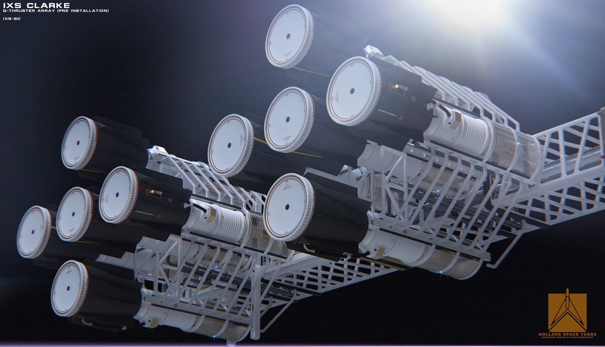
Perhaps EW is preparing to present their latest findings? Here's hoping! -
Title: Re: EM Drive Developments - related to space flight applications - Thread 3
Post by: aero on 06/20/2015 07:48 PM -
<a href="http://forum.nasaspaceflight.com/index.php?topic=37642.msg1391870#msg1391870">Quote from: Rodal on 06/20/2015 03:58 PM</a>
Re. NASA dimensions. I am confused. You state that the measurements are internal dimensions then in the same breath say that they are OD. OD normally stands for Outer Diameter. I know that the dielectric disks used are 6.25 inches, OD, which makes the small diameter of the cavity >= 6.25 inches, ID. The others, I'm not sure as I'm not sure where you are coming up with the numbers, but I think it is the origonal Brady cavity. The dimensions of the NASA copper kettle cavity are a little different, given in the attached, as provided by Paul March.<a href="http://forum.nasaspaceflight.com/index.php?topic=37642.msg1391865#msg1391865">Quote from: rfmwguy on 06/20/2015 03:39 PM</a>...OK, you've got mine at 11.01 x 6.25 x 9.91"L as discussed with you and Traveller.
OK, those dimensions are actually closer to NASA's and Iulian Berca's truncated cone geometry, and significantly different from Prof. Yang's dimensions (when taking into consideration the cone angle and the distance to the vertex of the cone). The big and the small diameters are same as NASA's, the length is closest to Yang's.
(NASA has the following internal copper surface dimensions.Large OD : 11.00 " (0.2794m), Small OD: 6.25" (0.1588 m) & Length : 9.00 " (0.2286m) )
rfmwguy Dimensions
axial length = 0.251714 meters = 9.91 inches
big diameter = 0.279654 meters = 11.01 inches [same as NASA]
small diameter = 0.15875 meters = 6.25 inches [same as NASA]
gives
r1= 0.339905 meters
r2=0.598776 meters
half cone angle = 13.5045 degrees
See the dimensions of the other EM Drives here: http://emdrive.wiki/Experimental_Results
-
Title: Re: EM Drive Developments - related to space flight applications - Thread 3
Post by: Rodal on 06/20/2015 07:58 PM -
<a href="http://forum.nasaspaceflight.com/index.php?topic=37642.msg1391948#msg1391948">Quote from: aero on 06/20/2015 07:48 PM</a><a href="http://forum.nasaspaceflight.com/index.php?topic=37642.msg1391870#msg1391870">Quote from: Rodal on 06/20/2015 03:58 PM</a>
Re. NASA dimensions. I am confused. You state that the measurements are internal dimensions then in the same breath say that they are OD. OD normally stands for Outer Diameter. I know that the dielectric disks used are 6.25 inches, OD, which makes the small diameter of the cavity >= 6.25 inches, ID. The others, I'm not sure as I'm not sure where you are coming up with the numbers, but I think it is the origonal Brady cavity. The dimensions of the NASA copper kettle cavity are a little different, given in the attached, as provided by Paul March.<a href="http://forum.nasaspaceflight.com/index.php?topic=37642.msg1391865#msg1391865">Quote from: rfmwguy on 06/20/2015 03:39 PM</a>...OK, you've got mine at 11.01 x 6.25 x 9.91"L as discussed with you and Traveller.
OK, those dimensions are actually closer to NASA's and Iulian Berca's truncated cone geometry, and significantly different from Prof. Yang's dimensions (when taking into consideration the cone angle and the distance to the vertex of the cone). The big and the small diameters are same as NASA's, the length is closest to Yang's.
(NASA has the following internal copper surface dimensions.Large OD : 11.00 " (0.2794m), Small OD: 6.25" (0.1588 m) & Length : 9.00 " (0.2286m) )
rfmwguy Dimensions
axial length = 0.252 meters = 9.91 inches
big diameter = 0.280 meters = 11.01 inches [same as NASA]
small diameter = 0.159 meters = 6.25 inches [same as NASA]
gives
r1= 0.340 meters
r2=0.599 meters
half cone angle = 13.5 degrees
See the dimensions of the other EM Drives here: http://emdrive.wiki/Experimental_Results
The quote is direct from @Star-Drive (March, NASA Eagleworks) in the following message:
http://forum.nasaspaceflight.com/index.php?topic=36313.msg1326997#msg1326997
where he wrote:Quote from: Star-DriveThe copper frustum we built and now are using has the following internal copper surface dimensions.
Large OD: 11.00" (0.2794m), Small OD: 6.25" (0.1588m) & Length: 9.00" (0.2286m)
Notice that he writes <<internal copper surface dimensions>> as well as <<OD>>.
This may have been a mistake, or this may be telling us that the differences between ID and OD and the differences between 11.00" and 11.01" are entirely within the roundness and concentricity tolerances of their cavity because it was homemade in his living room, and not accurately machined.
That's why I don't agree with seeking super accuracy in frequency determination, providing numbers with many digits beyond geometrical tolerances.
I previously copied and pasted the number of output digits in my file, I'll go back and change them to 3 digits to reflect this. -
Title: Re: EM Drive Developments - related to space flight applications - Thread 3
Post by: WarpTech on 06/20/2015 08:09 PM -
<a href="http://forum.nasaspaceflight.com/index.php?topic=37642.msg1391928#msg1391928">Quote from: Rodal on 06/20/2015 07:05 PM</a>
<snip>
The amplification could be due to a nonlinear effect that Todd has not taken into account. Masers (and Lasers) involve amplification. A solid state room-temperature Maser was invented during the last two decades but it is one meter long and it involves a special material to help amplification through emmission.
I have not calculated the combined effects of TE011, TE012 and TE111, and/or the effects of coupling with a DC component.
I can't calculate any thrust without mass/energy escaping the frustum somehow. That's what bothers me the most. I can't see how can the center of mass of an object be accelerated purely from the inside without expelling mass/energy to produce the thrust.
One thing I did find that "could" serve as an unexpected amplifier. Inside the frustum, the guide frequency is given by;
ωg = ω0*√(1 - (ωc / ω0)2)
Similarly for kg
if energy stored inside is ~ωg and if ωc / ω0 ~ 1,
Then when that energy is released to the outside environment, it will receive a "boost" from;
1/√(1 - (ωc / ω0)2), as ωg -> ω0.
which can be substantial. It means, we are underestimating the Q inside at the guide frequency.
On the other hand, if all the energy is trapped inside and nothing gets out, this does nothing to boost 0-thrust.
Todd -
Title: Re: EM Drive Developments - related to space flight applications - Thread 3
Post by: kitsuac on 06/20/2015 08:37 PM - Isn't group "velocity" sort of a misnomer, like waving a laser beam across the surface of the moon and saying that it's physically moving at a superluminal velocity? Just seems like a level of abstraction which is only meaningful in particular constrained situations, basing calculations on it seems very prone to yielding illegitimate conclusions.
-
Title: Re: EM Drive Developments - related to space flight applications - Thread 3
Post by: sghill on 06/20/2015 08:52 PM - Seems to me that if the thicknesses of the copper walls are varied, but the other dimensions remain the same, and thrust also differs between the models, then we know the drive is interacting with the outside environment somehow. If thrust does not vary between models of different wall thickness, then the thrust is occurring in-house- so to speak.
-
Title: Re: EM Drive Developments - related to space flight applications - Thread 3
Post by: deltaMass on 06/20/2015 09:30 PM -
<a href="http://forum.nasaspaceflight.com/index.php?topic=37642.msg1391973#msg1391973">Quote from: sghill on 06/20/2015 08:52 PM</a>
Seems to me that if the thicknesses of the copper walls are varied, but the other dimensions remain the same, and thrust also differs between the models, then we know the drive is interacting with the outside environment somehow. If thrust does not vary between models of different wall thickness, then the thrust is occurring in-house- so to speak.
Cart before the horse? - if you will excuse me saying so.
To date we do not even have at least two independent laboratories using identical devices producing identical thrust to within experimental tolerances.
That for me is a prerequisite for declaring that there is any thrust at all. -
Title: Re: EM Drive Developments - related to space flight applications - Thread 3
Post by: X_RaY on 06/20/2015 09:52 PM -
Would it be useful to generate a geometrie like this in the pictures to multiply the effects of the force? I know its difficult without the definitiv correct math for the trust but i think it can help to maximize the effects of the frustrated cone...
In the 24GHz case one can make easily :) -
Title: Re: EM Drive Developments - related to space flight applications - Thread 3
Post by: Rodal on 06/20/2015 10:03 PM -
<a href="http://forum.nasaspaceflight.com/index.php?topic=37642.msg1391987#msg1391987">Quote from: deltaMass on 06/20/2015 09:30 PM</a><a href="http://forum.nasaspaceflight.com/index.php?topic=37642.msg1391973#msg1391973">Quote from: sghill on 06/20/2015 08:52 PM</a>
Seems to me that if the thicknesses of the copper walls are varied, but the other dimensions remain the same, and thrust also differs between the models, then we know the drive is interacting with the outside environment somehow. If thrust does not vary between models of different wall thickness, then the thrust is occurring in-house- so to speak.
Cart before the horse? - if you will excuse me saying so.
To date we do not even have at least two independent laboratories using identical devices producing identical thrust to within experimental tolerances.
That for me is a prerequisite for declaring that there is any thrust at all.
The geometrical dimensions of these two independent devices are identical.
Identical mode shape.
The force/PowerInput not rigorously the same (extreme rigor leads to "rigor mortis") but these two are very comparable [considering that reported Force/InputPower ranges from 0 to 1000 for other researcher tests]:
Description Mode Pressure Length (m) Db (m) Ds(m) mN/kW
NASA Eagleworks TM212 Ambient 0.2286 0.2794 0.15875 3.00
Iulian Berca TM212 Ambient 0.2286 0.2794 0.1588 2.80
Berca Tests 3 & 3.1 (averaged w/up/down directional effects subtracted as per you, deltaMass -so you can't object to those numbers :) )
Iulian's Berca Lab is very independent from NASA.
NASA Brady, White, March, Lawrence, and Davies, b
Pretty good agreement between these two (certainly within experimental tolerance).
Iulian Berca did not make noise, but he quietly humbly went about his business, the first independent researcher to produce results and his results (in force/PowerInput) are very close to NASA's.
-
Title: Re: EM Drive Developments - related to space flight applications - Thread 3
Post by: aero on 06/20/2015 11:35 PM -
In my Meep runs with Q in the millions, I was making a fundemental error. I was chasing resonance at a frequency near 2.45GHz, and ended up at (set! fsi 2.46316014E+009). In doing this I continually narrowed the noise bandwidth, getting as low as 73.5 MHz and finally settling on a bandwidth of 246 MHz and a length of 0.232 meters (not .24 meters; To keep resonance close to 2.45 GHz). Of course I forgot to mention this in my post. So this is not really Yang's model although I don't know what the bandwidth of Yang's magnetron source should be.
I've made some more runs and with the bandwidth set somewhere between 500 MHz and 540 MHz, the Q value should be what we expect. (5,000, isn't it?)
But that's not what I want to post! Something interesting happened when I decided to quit fooling with resonance and look at the field patterns! The attached image is generated using the new copper model that we developed here on NSF in the last few days. There is energy outside of the frustum! Now we need to be very careful and certain the the copper model is correct for 2.4 GHz frequency.
If the copper model is correct, this image becomes a significant piece of data. -
Title: Re: EM Drive Developments - related to space flight applications - Thread 3
Post by: Rodal on 06/20/2015 11:40 PM -
<a href="http://forum.nasaspaceflight.com/index.php?topic=37642.msg1392015#msg1392015">Quote from: aero on 06/20/2015 11:35 PM</a>
In my Meep runs with Q in the millions, I was making a fundemental error. I was chasing resonance at a frequency near 2.45GHz, and ended up at (set! fsi 2.46316014E+009). In doing this I continually narrowed the noise bandwidth, getting as low as 73.5 MHz and finally settling on a bandwidth of 246 MHz and a length of 0.232 meters (not .24 meters; To keep resonance close to 2.45 GHz). Of course I forgot to mention this in my post. So this is not really Yang's model although I don't know what the bandwidth of Yang's magnetron source should be.
Yes, Q=5000 is a reasonable value
I've made some more runs and with the bandwidth set somewhere between 500 MHz and 540 MHz, the Q value should be what we expect. (5,000, isn't it?)
But that's not what I want to post! Something interesting happened when I decided to quit fooling with resonance and look at the field patterns! The attached image is generated using the new copper model that we developed here on NSF in the last few days. There is energy outside of the frustum! Now we need to be very careful and certain the the copper model is correct for 2.4 GHz frequency.
If the copper model is correct, this image becomes a significant piece of data.
Thanks for the update.
Please tell us more info as to how you find that there is energy outside the frustum. First of all, do you have a Finite Difference mesh outside the frustum? (I thought you didn't)
If you don't have a mesh outside the frustum, how can you tell there is energy outside the frustum?
How does the energy leak to the outside?
Is your model still using HarmInv (basically only solving for frequencies) or is it a Time-Marching solution that enables you to monitor the time variation of the fields? -
Title: Re: EM Drive Developments - related to space flight applications - Thread 3
Post by: aero on 06/21/2015 12:26 AM - Its a Time-Marching solution. The image shows the center slice of computational lattice at the end of the run, 16 peroids of the drive frequency, (2.45 GHz). The outer boundary of the .jpg image is the outer boundary of the computational lattice, or mesh, which is a cuboid. You can see the frustum boundaries within the mesh. The color represents the energy at that point within the mesh. It looks like there is color outside the frustum boundaries. I will make more runs and attempt to get some color discrimination within the frustum.
-
Title: Re: EM Drive Developments - related to space flight applications - Thread 3
Post by: KittyMoo on 06/21/2015 12:47 AM -
Have lost hope.
IMHO what was promising has turned into dust.
-
Title: Re: EM Drive Developments - related to space flight applications - Thread 3
Post by: Rodal on 06/21/2015 01:23 AM -
<a href="http://forum.nasaspaceflight.com/index.php?topic=37642.msg1392031#msg1392031">Quote from: KittyMoo on 06/21/2015 12:47 AM</a>
Have lost hope.
IMHO what was promising has turned into dust.Quote from: Albert EinsteinLearn from yesterday, live for today, hope for tomorrow. The important thing is not to stop questioning.
-
Title: Re: EM Drive Developments - related to space flight applications - Thread 3
Post by: rfmwguy on 06/21/2015 01:26 AM -
<a href="http://forum.nasaspaceflight.com/index.php?topic=37642.msg1392031#msg1392031">Quote from: KittyMoo on 06/21/2015 12:47 AM</a>
Have lost hope.
IMHO what was promising has turned into dust.
With so little test data, way too early for that opinion...lots of unfunded experiments going on...patience is paramount. -
Title: Re: EM Drive Developments - related to space flight applications - Thread 3
Post by: rfmwguy on 06/21/2015 02:38 AM - weight budget is 1.5 kg. amp below is not half that. exciter only 1.2 g.
-
Title: Re: EM Drive Developments - related to space flight applications - Thread 3
Post by: KittyMoo on 06/21/2015 02:40 AM -
You say there is little test data...
I say there is NONE past EW.
To this point we have EW...
Shaywer and the Chinese are mistaken. This is what Occam says and after much ado appears to be correct.
I see the hint from old timers here that I may be correct. -
Title: Re: EM Drive Developments - related to space flight applications - Thread 3
Post by: rfmwguy on 06/21/2015 02:51 AM -
<a href="http://forum.nasaspaceflight.com/index.php?topic=37642.msg1392047#msg1392047">Quote from: KittyMoo on 06/21/2015 02:40 AM</a>
You say there is little test data...
I say there is NONE past EW.
To this point we have EW...
Shaywer and the Chinese are mistaken. This is what Occam says and after much ado appears to be correct.
I see the hint from old timers here that I may be correct.
You'd have to claim julian had null data. I'm not in a position to dismiss his results. Maybe u know something we do not. Regardless, my build goes on with an open mind, as others do. If mine are null, will have zero reservations in stating so.
We need data and math theories. Your contributions would be welcomed...the group here is apolitical for the most part.
-
Title: Re: EM Drive Developments - related to space flight applications - Thread 3
Post by: KittyMoo on 06/21/2015 03:01 AM -
What solid data did Julien garner? None.
Where is he now?
I disagree (agree?) we need more controlled experimental results, not more theory. -
Title: Re: EM Drive Developments - related to space flight applications - Thread 3
Post by: rfmwguy on 06/21/2015 03:14 AM -
<a href="http://forum.nasaspaceflight.com/index.php?topic=37642.msg1392052#msg1392052">Quote from: KittyMoo on 06/21/2015 03:01 AM</a>
What solid data did Julien garner? None.
Where is he now?
I disagree (agree?) we need more controlled experimental results, not more theory.
Julian Berca on fb...new job in china. I also agree more experimental data needed. Was skeptical of julians data until downward momentum measured. Upwards could have been ballooning, downward is something very different. Did not appear to be falsified. May not have had lab standard accuracies...think relative accuracy shows something. What exactly...am not sure, so my curiosity remains. -
Title: Re: EM Drive Developments - related to space flight applications - Thread 3
Post by: deltaMass on 06/21/2015 03:21 AM - Not so much "ballooning" as a change in the contained mass of air via a temperature increase at constant volume.
-
Title: Re: EM Drive Developments - related to space flight applications - Thread 3
Post by: KittyMoo on 06/21/2015 03:45 AM -
Re New job in China
That right there should flash red lights. It is simple to end a fake FB account with that explanation.
I wonder how many other people will produce videos and then disappear?
EDIT: I include Shawyer in that -
Title: Re: EM Drive Developments - related to space flight applications - Thread 3
Post by: Dortex on 06/21/2015 04:22 AM -
<a href="http://forum.nasaspaceflight.com/index.php?topic=37642.msg1392047#msg1392047">Quote from: KittyMoo on 06/21/2015 02:40 AM</a>
You say there is little test data...
I say there is NONE past EW.
To this point we have EW...
Shaywer and the Chinese are mistaken. This is what Occam says and after much ado appears to be correct.
I see the hint from old timers here that I may be correct.
Dismissing data is easy. Refutation takes work. -
Title: Re: EM Drive Developments - related to space flight applications - Thread 3
Post by: RareSaturn on 06/21/2015 04:43 AM -
<a href="http://forum.nasaspaceflight.com/index.php?topic=37642.msg1392031#msg1392031">Quote from: KittyMoo on 06/21/2015 12:47 AM</a>
Have lost hope.
IMHO what was promising has turned into dust.
Why do you say that? (What have I missed?) -
Title: Re: EM Drive Developments - related to space flight applications - Thread 3
Post by: FutureStormtrooper on 06/21/2015 05:11 AM -
Time and further experiments will tell. Frankly, our personal feelings about this mean bugger all in the short run, as others are going to keep running experiments whether we like it or not.
Shawyer will be presenting this year, EW will have new experimental data this year. Those are the big reveals I'm looking forward to, and to my mind, will say how to gauge my hope going forward. -
Title: Re: EM Drive Developments - related to space flight applications - Thread 3
Post by: ThinkerX on 06/21/2015 06:19 AM -
Quote
Have lost hope.
IMHO what was promising has turned into dust.
I have been going back and forth on this for almost a year now...and I cannot agree.
As pointed out, we are still awaiting EW's results.
Shawyer, for all his theory issues, has a great deal of 'hands on' experience with these devices, which give at least the appearance of producing thrust. Replication is the key here. Identical items in different labs producing or not producing identical amounts of thrust under identical conditions. This hasn't happened yet. Same for the Chinese versions.
Theory wise, to me, it looks like at least some of the more disparate theories of operation are starting to converge. Warp-Tech has mentioned Doctor McCulloch's theory more than once. McCulloch, for his part, is starting to contemplate interaction of some sort with the Zero Point Field, which is what Doctor White's theory is centered on. And Notsosureofits theory seems similar (?) compatible (?) with Warp-Tech's and maybe others. -
Title: Re: EM Drive Developments - related to space flight applications - Thread 3
Post by: Flyby on 06/21/2015 07:22 AM -
<a href="http://forum.nasaspaceflight.com/index.php?topic=37642.msg1392031#msg1392031">Quote from: KittyMoo on 06/21/2015 12:47 AM</a>
Have lost hope.
IMHO what was promising has turned into dust.
I think you rather lost patience then hope...hence the need to vent your frustration. :)
It is true there is not enough real experimental evidence. I agree with you on that.
But all the test done so far do provide "indication of proof" that something is might be happening we have not yet understood very well.
We're all eagerly waiting for that one specific test that provides "pure evidence" and not just an "indication"....
That the baby EMdrive wouldn't yield any noticeable result was not a surprise to me. I had my doubts from the start : too small (hence too dimensional sensitive) and not enough power.
If I were you, i'd try to stay away of the conspiracy theories regarding Iulian's lack of activities. It is not uncommon for an active engineer to move around the world...
We still have 4 tests on the shelf to look out for : Eagleworks, TheTraveler's (when he gets better), rfmwguy(in the works) and our hot-tubbing Seeshell (planning stage) ;D
Then there is also a promised announcement/peer review from Shawyer, now his EMdrive got the spotlights thanks to press-hysteria about EW test and the article published here on the nasaspaceflight forums. I can only hope it is loaded with data on his supercooled EMdrive experiment..but i kinda fear it will be disappointing...we'll see..
patience, my dear Watson.. patience... -
Title: Re: EM Drive Developments - related to space flight applications - Thread 3
Post by: Star One on 06/21/2015 07:50 AM -
<a href="http://forum.nasaspaceflight.com/index.php?topic=37642.msg1392071#msg1392071">Quote from: FutureStormtrooper on 06/21/2015 05:11 AM</a>
Time and further experiments will tell. Frankly, our personal feelings about this mean bugger all in the short run, as others are going to keep running experiments whether we like it or not.
Shawyer will be presenting this year, EW will have new experimental data this year. Those are the big reveals I'm looking forward to, and to my mind, will say how to gauge my hope going forward.
Hopefully things maybe clearer one way or the other by September/October, as have a feeling we should hear more from both EW & Shawyer by then.
Would be helpful if people stayed away from any expectations either way on any of these experiments and their results. -
Title: Re: EM Drive Developments - related to space flight applications - Thread 3
Post by: rfmwguy on 06/21/2015 02:45 PM - Simple mechanical fulcrum built and settling in on balance as I type. Will upload video in a little while.
-
Title: Re: EM Drive Developments - related to space flight applications - Thread 3
Post by: Rodal on 06/21/2015 03:10 PM -
<a href="http://forum.nasaspaceflight.com/index.php?topic=37642.msg1392142#msg1392142">Quote from: rfmwguy on 06/21/2015 02:45 PM</a>
Simple mechanical fulcrum built and settling in on balance as I type. Will upload video in a little while.
It's great to have you "live" here to comment on your built.
One thing that previous researchers have not commented on is the geometrical tolerances of their tested EM Drives. Would you be able to give us some assessment of the circular runout and concentricity of your truncated cone? And what is the accuracy of your measurements (are you using a caliper, for example?)
The reason I'm asking is because calculations of frequency and mode shapes are dependent on actual internal geometrical dimensions. NASA's truncated cone was built in a researcher's living room, therefore it is my assessment that one cannot seek too much precision, perhaps not more that 1%, perhaps less.
I also wonder about the stability of the geometrical dimensions, as the coper sheets used are very thin, hence the geometry can change with time as the EM Drives are stressed under handling and thermal stresses. -
Title: Re: EM Drive Developments - related to space flight applications - Thread 3
Post by: Rodal on 06/21/2015 03:21 PM -
<a href="http://forum.nasaspaceflight.com/index.php?topic=37642.msg1392023#msg1392023">Quote from: aero on 06/21/2015 12:26 AM</a>
Its a Time-Marching solution. The image shows the center slice of computational lattice at the end of the run, 16 peroids of the drive frequency, (2.45 GHz). The outer boundary of the .jpg image is the outer boundary of the computational lattice, or mesh, which is a cuboid. You can see the frustum boundaries within the mesh. The color represents the energy at that point within the mesh. It looks like there is color outside the frustum boundaries. I will make more runs and attempt to get some color discrimination within the frustum.
Can you show a plot of something (for example max amplitude, or amplitude at a given location) vs. time to assess the time variation and the progress from transient to steady-state?
Also to see whether the variation is harmonic with time or not... -
Title: Re: EM Drive Developments - related to space flight applications - Thread 3
Post by: aero on 06/21/2015 04:00 PM -
<a href="http://forum.nasaspaceflight.com/index.php?topic=37642.msg1392149#msg1392149">Quote from: Rodal on 06/21/2015 03:21 PM</a><a href="http://forum.nasaspaceflight.com/index.php?topic=37642.msg1392023#msg1392023">Quote from: aero on 06/21/2015 12:26 AM</a>
Its a Time-Marching solution. The image shows the center slice of computational lattice at the end of the run, 16 peroids of the drive frequency, (2.45 GHz). The outer boundary of the .jpg image is the outer boundary of the computational lattice, or mesh, which is a cuboid. You can see the frustum boundaries within the mesh. The color represents the energy at that point within the mesh. It looks like there is color outside the frustum boundaries. I will make more runs and attempt to get some color discrimination within the frustum.
Can you show a plot of something (for example max amplitude, or amplitude at a given location) vs. time to assess the time variation and the progress from transient to steady-state?
Also to see whether the variation is harmonic with time or not...
I've attached some images. This run was 2-D so the images are, well, from a 2-D run + time, not 3-D. I went back to 2-D runs to to save time while exploring general area. These images use the "lines" color map and were snapped at 5.8, 6 and 6.2 Periods into the run so they are what, about 70 degrees apart? I think you can see much of my difficulty. How do I get the information we want or need from the data at hand?
I don't mind taking the time to make long, 3-D runs, but information extraction is another skill that is needed.
As for generating the plots you asked for, I think, I'm not sure but I think that is a MATLAB task, or Octave of course, and hence new code of a different kind. I'll happily provide the data files via Google Drive, just tell me what model you'd like run. We know the most about the EW models, but Yang claimed the largest F/P, hence that may be the choice. -
Title: Re: EM Drive Developments - related to space flight applications - Thread 3
Post by: Rodal on 06/21/2015 04:07 PM -
<a href="http://forum.nasaspaceflight.com/index.php?topic=37642.msg1392156#msg1392156">Quote from: aero on 06/21/2015 04:00 PM</a><a href="http://forum.nasaspaceflight.com/index.php?topic=37642.msg1392149#msg1392149">Quote from: Rodal on 06/21/2015 03:21 PM</a><a href="http://forum.nasaspaceflight.com/index.php?topic=37642.msg1392023#msg1392023">Quote from: aero on 06/21/2015 12:26 AM</a>
Its a Time-Marching solution. The image shows the center slice of computational lattice at the end of the run, 16 peroids of the drive frequency, (2.45 GHz). The outer boundary of the .jpg image is the outer boundary of the computational lattice, or mesh, which is a cuboid. You can see the frustum boundaries within the mesh. The color represents the energy at that point within the mesh. It looks like there is color outside the frustum boundaries. I will make more runs and attempt to get some color discrimination within the frustum.
Can you show a plot of something (for example max amplitude, or amplitude at a given location) vs. time to assess the time variation and the progress from transient to steady-state?
Also to see whether the variation is harmonic with time or not...
I've attached some images. This run was 2-D so the images are, well, from a 2-D run + time, not 3-D. I went back to 2-D runs to to save time while exploring general area. These images use the "lines" color map and were snapped at 5.8, 6 and 6.2 Periods into the run so they are what, about 70 degrees apart? I think you can see much of my difficulty. How do I get the information we want or need from the data at hand?
I don't mind taking the time to make long, 3-D runs, but information extraction is another skill that is needed.
As for generating the plots you asked for, I think, I'm not sure but I think that is a MATLAB task, or Octave of course, and hence new code of a different kind. I'll happily provide the data files via Google Drive, just tell me what model you'd like run. We know the most about the EW models, but Yang claimed the largest F/P, hence that may be the choice.
This is very interesting as it shows p=4 instead of p=3. What geometry is this for? Is it for the Flight Thruster geometry or for the Yang geometry?
Boundary Layer adaptation of the natural spherical standing wave to the flat ends occurs most noticeably at the Big End.
(http://forum.nasaspaceflight.com/xindex.php,qaction=dlattach,3Btopic=37642.0,3Battach=1030808,3Bimage.pagespeed.ic.NzToiYPWIl.webp)
Can you show images for the end of your time marching solution (16 periods)? -
Title: Re: EM Drive Developments - related to space flight applications - Thread 3
Post by: aero on 06/21/2015 04:46 PM -
I'm re-running it now, just to reset my focus.
It is the Yang model, dimensions exactly as posted.
I'll post some more images once the run completes and they are generated. -
Title: Re: EM Drive Developments - related to space flight applications - Thread 3
Post by: zen-in on 06/21/2015 04:52 PM -
<a href="http://forum.nasaspaceflight.com/index.php?topic=37642.msg1392054#msg1392054">Quote from: rfmwguy on 06/21/2015 03:14 AM</a><a href="http://forum.nasaspaceflight.com/index.php?topic=37642.msg1392052#msg1392052">Quote from: KittyMoo on 06/21/2015 03:01 AM</a>
What solid data did Julien garner? None.
Where is he now?
I disagree (agree?) we need more controlled experimental results, not more theory.
Julian Berca on fb...new job in china. I also agree more experimental data needed. Was skeptical of julians data until downward momentum measured. Upwards could have been ballooning, downward is something very different. Did not appear to be falsified. May not have had lab standard accuracies...think relative accuracy shows something. What exactly...am not sure, so my curiosity remains.
My theory on his downward thrust experiment is the reaction was caused by electromagnetic interaction of the supply wires. The same effect would have been seen with his upward thrust experiment except bouyancy effects dominated. Videos always look more impressive than witnessing the actual experiment firsthand. It's possible Julian Berca has realized, after performing several experiments, that there is nothing to the em-drive. After all he seems to be smart and honest. -
Title: Re: EM Drive Developments - related to space flight applications - Thread 3
Post by: aero on 06/21/2015 05:35 PM -
<a href="http://forum.nasaspaceflight.com/index.php?topic=37642.msg1392170#msg1392170">Quote from: aero on 06/21/2015 04:46 PM</a>
I'm re-running it now, just to reset my focus.
It is the Yang model, dimensions exactly as posted.
I'll post some more images once the run completes and they are generated.
Here are some images from the end of the run.
I have uploaded the complete set of images to my Google Drive but am unsure how to share them without a colaborator's email address. PM me with your email address if you'd like to look at the complete set.
I did not upload the source data file as it is 1.37 GB and so takes time even with my relatively fast cable internet connection. (Relatively fast when the cable's not dropping out, that is.)
My output is a .png every 0.2 periods of the drive frequency with the first file labled hy.t00.png output at time 0.2 periods. The color intensity is set by each file individually, rather than normalized over the data set. When normalized over the complete data set, only the last few files show any discrimination. That is, everything seems to wash out.QuoteThis is very interesting as it shows p=4 instead of p=3. What geometry is this for? Is it for the Flight Thruster geometry or for the Yang geometry?
It could be due to antenna orientation. And I'm exciting the cavity with a magnetic component. Should I rotate the antenna and excite the electric modes? -
Title: Re: EM Drive Developments - related to space flight applications - Thread 3
Post by: Blaine on 06/21/2015 05:47 PM -
<a href="http://forum.nasaspaceflight.com/index.php?topic=37642.msg1392173#msg1392173">Quote from: zen-in on 06/21/2015 04:52 PM</a><a href="http://forum.nasaspaceflight.com/index.php?topic=37642.msg1392054#msg1392054">Quote from: rfmwguy on 06/21/2015 03:14 AM</a><a href="http://forum.nasaspaceflight.com/index.php?topic=37642.msg1392052#msg1392052">Quote from: KittyMoo on 06/21/2015 03:01 AM</a>
What solid data did Julien garner? None.
Where is he now?
I disagree (agree?) we need more controlled experimental results, not more theory.
Julian Berca on fb...new job in china. I also agree more experimental data needed. Was skeptical of julians data until downward momentum measured. Upwards could have been ballooning, downward is something very different. Did not appear to be falsified. May not have had lab standard accuracies...think relative accuracy shows something. What exactly...am not sure, so my curiosity remains.
My theory on his downward thrust experiment is the reaction was caused by electromagnetic interaction of the supply wires. The same effect would have been seen with his upward thrust experiment except bouyancy effects dominated. Videos always look more impressive than witnessing the actual experiment firsthand. It's possible Julian Berca has realized, after performing several experiments, that there is nothing to the em-drive. After all he seems to be smart and honest.
electromagnetic interaction of the supply wires? I wasn't aware copper was that magnetic. I mean, unless I don't understand what you are saying. Interaction with what? -
Title: Re: EM Drive Developments - related to space flight applications - Thread 3
Post by: Rodal on 06/21/2015 06:13 PM -
<a href="http://forum.nasaspaceflight.com/index.php?topic=37642.msg1392178#msg1392178">Quote from: aero on 06/21/2015 05:35 PM</a>
p=4 makes sense for some of the TM modes.<a href="http://forum.nasaspaceflight.com/index.php?topic=37642.msg1392170#msg1392170">Quote from: aero on 06/21/2015 04:46 PM</a>I'm re-running it now, just to reset my focus.
It is the Yang model, dimensions exactly as posted.
I'll post some more images once the run completes and they are generated.
Here are some images from the end of the run.
I have uploaded the complete set of images to my Google Drive but am unsure how to share them without a colaborator's email address. PM me with your email address if you'd like to look at the complete set.
I did not upload the source data file as it is 1.37 GB and so takes time even with my relatively fast cable internet connection. (Relatively fast when the cable's not dropping out, that is.)
My output is a .png every 0.2 periods of the drive frequency with the first file labled hy.t00.png output at time 0.2 periods. The color intensity is set by each file individually, rather than normalized over the data set. When normalized over the complete data set, only the last few files show any discrimination. That is, everything seems to wash out.QuoteThis is very interesting as it shows p=4 instead of p=3. What geometry is this for? Is it for the Flight Thruster geometry or for the Yang geometry?
It could be due to antenna orientation. And I'm exciting the cavity with a magnetic component. Should I rotate the antenna and excite the electric modes?
Definitely.
Could could you please rotate the antenna and excite the electric modes? -
Title: Re: EM Drive Developments - related to space flight applications - Thread 3
Post by: rfmwguy on 06/21/2015 06:44 PM -
As promised, here is my video of the first test of my mechanical fulcrum. It will be used to show relative weight change in addition to a digital scale. Had some concerns about the digital scale alone, possibly being affected by the RF. The fulcrum is simply designed to be an alternate test method.
https://youtu.be/lVXhynPYj6E -
Title: Re: EM Drive Developments - related to space flight applications - Thread 3
Post by: aero on 06/21/2015 07:02 PM -
Ok - I've rotated the antenna and am running electric mode excitation now. Be a few minutes.
I note that Harminv detected 3 resonant frequencies for this cavity, 2.23495377E+009, 2.48317048E+009 and 2.67105206E+009 Hz for this cavity when run in this configuration but at much lower resolution. Q's all about the same 1000 < Q < 1500.
-
Title: Re: EM Drive Developments - related to space flight applications - Thread 3
Post by: Rodal on 06/21/2015 07:10 PM -
<a href="http://forum.nasaspaceflight.com/index.php?topic=37642.msg1392205#msg1392205">Quote from: aero on 06/21/2015 07:02 PM</a>
Ok - I've rotated the antenna and am running electric mode excitation now. Be a few minutes.
I note that Harminv detected 3 resonant frequencies for this cavity, 2.23495377E+009, 2.48317048E+009 and 2.67105206E+009 Hz for this cavity when run in this configuration but at much lower resolution. Q's all about the same 1000 < Q < 1500.
Yang also reported that his Q was about 1500, so that's pretty good, much better than the millions you were getting before ! -
Title: Re: EM Drive Developments - related to space flight applications - Thread 3
Post by: Rodal on 06/21/2015 07:18 PM -
<a href="http://forum.nasaspaceflight.com/index.php?topic=37642.msg1392196#msg1392196">Quote from: rfmwguy on 06/21/2015 06:44 PM</a>
As promised, here is my video of the first test of my mechanical fulcrum. It will be used to show relative weight change in addition to a digital scale. Had some concerns about the digital scale alone, possibly being affected by the RF. The fulcrum is simply designed to be an alternate test method.
...
Thank you for posting this !
Great work.
1) I don't know whether it is parallax due to the camera (I would like your feedback) but I saw bending of the wooden beam. Is the wooden beam compliant enought that the two water bottles are producing visible bending of the beam simply-supported by the knife edge? If so, you may have two sources of oscillation:
a) lowest frequency oscillation: rigid body rotation of the beam around the knife edge
b) higher frequency oscillation: beam bending oscillations (there are an infinite number, but unless it was parallax I clearly saw beam bending : the first mode)
Couldn't see whether the oscillations were due mainly to rigid body rotation or to bending, but based on the very long period of oscillation, it must be mainly due to rigid body rotation of the beam.
2) If you cannot wait for the oscillations to dampen (>30 minutes ?) in the future, you may have to also include (oil or water) damping.
-
Title: Re: EM Drive Developments - related to space flight applications - Thread 3
Post by: X_RaY on 06/21/2015 07:26 PM -
<a href="http://forum.nasaspaceflight.com/index.php?topic=37642.msg1392196#msg1392196">Quote from: rfmwguy on 06/21/2015 06:44 PM</a>
As promised, here is my video of the first test of my mechanical fulcrum. It will be used to show relative weight change in addition to a digital scale. Had some concerns about the digital scale alone, possibly being affected by the RF. The fulcrum is simply designed to be an alternate test method.
Nice idea and verry cheap but its tricky intricate and it cost a lot of time with such setup. I wonder ??? why nobody come up with the idea to use realy good laboratory scales, for example up to 10kg( for cone and magnetron) and a precision of ~50mg.
https://www.pce-instruments.com/english/?id=55870f0216498200&_baseurl=%2Fenglish&action=ShowItem&_list=qr.art&_listpos=1&_artnr=345622 -
Title: Re: EM Drive Developments - related to space flight applications - Thread 3
Post by: SeeShells on 06/21/2015 07:28 PM -
Need to go visit today, but before I did I thought you would like to see the first draft of the segmented, multi end plate, perforated copper frustum. Using clasps to hold the to parts together and they should be quite secure and sturdy. The large endplate will be cupped out with an english wheel the small top plates will be flat.
Shell
Waiting to see the patterns from Aero to finally decide on the antenna orientation. BTW Aero great work!!!
Edit: forgot pic... ;) -
Title: Re: EM Drive Developments - related to space flight applications - Thread 3
Post by: Rodal on 06/21/2015 07:39 PM -
<a href="http://forum.nasaspaceflight.com/index.php?topic=37642.msg1392213#msg1392213">Quote from: SeeShells on 06/21/2015 07:28 PM</a>
Need to go visit today, but before I did I thought you would like to see the first draft of the segmented, multi end plate, perforated copper frustum. Using clasps to hold the to parts together and they should be quite secure and sturdy. The large endplate will be cupped out with an english wheel the small top plates will be flat.
Shell
Waiting to see the patterns from Aero to finally decide on the antenna orientation. BTW Aero great work!!!
Edit: forgot pic... ;)
It looks great !!! :)
Please wait until you read my paper (coming out soon, today) as that cone maybe too pointy, you want to be able to terminate it a little further from the vertex of the cone. -
Title: Re: EM Drive Developments - related to space flight applications - Thread 3
Post by: DaCunha on 06/21/2015 07:41 PM -
Dear all,
In 2012 the first solid state maser based on a pentacene doped t-terphenyl crystal was invented at the Imperial College London after 60 years of unsuccessful attempts to build a maser that is capable of emitting at ambient conditions with considerable output powers.
It's maximal output power in Continous mode is 0.1 mW and approx. 1 W in a microsecond pulsed mode.
Now what do you think about the following?
What if we manage to amplify such a 1 W peak power pulse with a pulse duration of a microsecond and amplify it with a klystron to much higher peak powers?
If the effect that shortened the optical path length of the laser pulse (as measured from laboratory frame), is dependent on the electric field strength, then we could amplify this effect for the duration of the pulse.
Now IF, the laser pulse is just triggered to pass through the frustum just when the pulse is being reflected, we should see a much stronger effect of path length shortening... well at least IF the assumption that the effect is dependent on electric and magnetic field strength is correct...
I have the feeling that spatial coherence of the microwave input of the EMDrive plays an important role that has not been taken into account until now. Thus the maser could help a lot..
Do you think that beside the electric field amplitude also the phase of the field is playing a role for the EMDrive effect? -
Title: Re: EM Drive Developments - related to space flight applications - Thread 3
Post by: Rodal on 06/21/2015 07:47 PM -
<a href="http://forum.nasaspaceflight.com/index.php?topic=37642.msg1392216#msg1392216">Quote from: DaCunha on 06/21/2015 07:41 PM</a>
Dear all,
In 2012 the first solid state maser based on a pentacene doped t-terphenyl crystal was invented at the Imperial College London after 60 years of unsuccessful attempts to build a maser that is capable of emitting at ambient conditions with considerable output powers.
It's maximal output power in Continous mode is 0.1 mW and approx. 1 W in a microsecond pulsed mode.
Now what do you think about the following?
What if we manage to amplify such a 1 W peak power pulse with a pulse duration of a microsecond and amplify it with a klystron to much higher peak powers?
If the effect that shortened the optical path length of the laser pulse (as measured from laboratory frame), is dependent on the electric field strength, then we could amplify this effect for the duration of the pulse.
Now IF, the laser pulse is just triggered to pass through the frustum just when the pulse is being reflected, we should see a much stronger effect of path length shortening... well at least IF the assumption that the effect is dependent on electric and magnetic field strength is correct...
Welcome to the forum and thank you for a fantastic contribution.
I think that your proposal is a great idea ! :)
I have been campaigning for the Aachen fellow to fill the Baby EM Drive with Ammonia so that it can emit at the 24 GHz frequency they are operating at, to see whether that results in any detectable thrust force -
Title: Re: EM Drive Developments - related to space flight applications - Thread 3
Post by: aero on 06/21/2015 07:49 PM -
The final 8 .pngs, Yang cavity electric excitation, antenna length = 0.2 wavelengths, total run 16 periods with .png output every 0.2 periods.
This set of images is much better behaved than the magnetic excited cavity images. Don't know why. Unfortunately, with the background changing color as it does, a movie wouldn't be very viewable. IMO
I'll go ahead and upload this complete set to my Google Drive in case anyone is interested in looking at them all together. I point out that there are patterns that appear across the whole set that don't pop out at you when looking at only a small subset of the images. -
Title: Re: EM Drive Developments - related to space flight applications - Thread 3
Post by: Rodal on 06/21/2015 07:58 PM -
<a href="http://forum.nasaspaceflight.com/index.php?topic=37642.msg1392218#msg1392218">Quote from: aero on 06/21/2015 07:49 PM</a>
The final 8 .pngs, Yang cavity electric excitation, antenna length = 0.2 wavelengths, total run 16 periods with .png output every 0.2 periods.
This set of images is much better behaved than the magnetic excited cavity images. Don't know why. Unfortunately, with the background changing color as it does, a movie wouldn't be very viewable. IMO
I'll go ahead and upload this complete set to my Google Drive in case anyone is interested in looking at them all together. I point out that there are patterns that appear across the whole set that don't pop out at you when looking at only a small subset of the images.
This is great !!!
It predicts mode shape TE012, same mode that my exact solution predicts :) -
Title: Re: EM Drive Developments - related to space flight applications - Thread 3
Post by: aero on 06/21/2015 08:04 PM -
<a href="http://forum.nasaspaceflight.com/index.php?topic=37642.msg1392220#msg1392220">Quote from: Rodal on 06/21/2015 07:58 PM</a><a href="http://forum.nasaspaceflight.com/index.php?topic=37642.msg1392218#msg1392218">Quote from: aero on 06/21/2015 07:49 PM</a>
The final 8 .pngs, Yang cavity electric excitation, antenna length = 0.2 wavelengths, total run 16 periods with .png output every 0.2 periods.
This set of images is much better behaved than the magnetic excited cavity images. Don't know why. Unfortunately, with the background changing color as it does, a movie wouldn't be very viewable. IMO
I'll go ahead and upload this complete set to my Google Drive in case anyone is interested in looking at them all together. I point out that there are patterns that appear across the whole set that don't pop out at you when looking at only a small subset of the images.
This is great !!!
It predicts mode shape TE012, same mode that my exact solution predicts :)
It predicts mode shape TE012, same mode that my exact solution predicts
I am glad to hear that! Emphatically GLAD to hear that. -
Title: Re: EM Drive Developments - related to space flight applications - Thread 3
Post by: Rodal on 06/21/2015 08:07 PM -
I attach my report
first attachment below, titled:
Cut-off of Resonant Modes in Truncated Conical Cavities
Conclusions
1) It is nonsense to use a cylindrical waveguide cut-off formula to predict cut-off of mode shapes in a truncated cone. Truncated cones cannot have constant electromagnetic fields in the longitudinal direction, thus the use of cylindrical waveguide formulas (which assume constant cross-sections) for truncated cone cavities is nonsense.
2) Truncated cones show an absence of sharp cut-off frequencies. Cut-off occurs at geometries that are close to a pointy cone, at small base dimensions that are much smaller than what is predicted by cylindrical waveguide cut-off formulas.
3) On the contrary, continuing the cone beyond the small diameter at which cut-off would occur (according to the cylindrical formula which is inapplicable to the cone) leads to significantly higher amplitudes of the electromagnetic fields. The amplitude of mode TE013 actually increases by a factor greater than 2.5 from its original amplitude. While mode shape TE013 has the smallest amplitude compared to TE011 and TE012 at the initial dimensions, as we reduce the small base it becomes the mode with the highest amplitude
4) The “half-wavelength” nearest the apex gets longer as it approaches the apex.
5) For the particular geometry in the examples in this report, cut-off of mode shape TE011 occurs when the small base is reduced to only ¼ of its original dimension. The cut-off condition based on a cylindrical waveguide incorrectly shows that TE011 should have been cut-off at a much larger base diameter (at 0.90 the original dimension instead of 0.25 the original dimension).
6) Cut-off of mode shape TE012 and TE013 occurs when the small base is reduced to only 1/5 of its original dimension. The cut-off condition based on a cylindrical waveguide incorrectly shows that TE012 and TE013 should have been cut-off at a much larger base diameter (at 0.90 the original dimension instead of 0.20 the original dimension).
7) Continuing the cone up to distances much closer to the apex also results in lower phase shift and higher geometrical attenuation of the electromagnetic field in the longitudinal direction. When the small base is reduced to ½ the original size: a) the (dimensionless) geometrical attenuation is increased by a factor of 28 times from 0.1 to 2.8, and b) the phase constant is increased by a factor of 2 from 0.5 to 1. Hence it looks like very large changes can be accomplished by simply reducing a truncated cone’s small base so that it is much closer to the cone’s apex, and this can be done without incurring cut-off, and achieving a higher amplitude to boot. Thus continuing the cone beyond the cylindrical cut-off frequency may result in very interesting behavior.
8) All the EM Drive formulas (McCulloch’s, @Notsosureofit’s, and Shawyer’s) predict greater thrust with a larger difference between the diameters of the big and the small bases of the truncated cone. Therefore these formulas point towards the direction that the ideal geometry would be one with a small base diameter. Yet such a geometry has not been explored up to now, apparently due to Shawyer’s constraining the small base diameter to be larger than the diameter that results in cut-off according to the cylindrical waveguide formula. This report shows that this constraint is nonsensical, as truncated cones resonate (and at higher amplitude) with significantly smaller base diameters. This report shows that the small based diameter could be reduced to at least ½ of its present size, and perhaps to 1/5 of its present size.
-
Title: Re: EM Drive Developments - related to space flight applications - Thread 3
Post by: Rodal on 06/21/2015 08:16 PM -
<a href="http://forum.nasaspaceflight.com/index.php?topic=37642.msg1392222#msg1392222">Quote from: aero on 06/21/2015 08:04 PM</a>
...
I am glad to hear that! Emphatically GLAD to hear that.
At what frequency is your cone being excited in those images? -
Title: Re: EM Drive Developments - related to space flight applications - Thread 3
Post by: SeeShells on 06/21/2015 08:39 PM -
<a href="http://forum.nasaspaceflight.com/index.php?topic=37642.msg1392223#msg1392223">Quote from: Rodal on 06/21/2015 08:07 PM</a>
I attach my report
first attachment below, titled:
Cut-off of Resonant Modes in Truncated Conical Cavities
Conclusions
1) It is nonsense to use a cylindrical waveguide cut-off formula to predict cut-off of mode shapes in a truncated cone. Truncated cones cannot have constant electromagnetic fields in the longitudinal direction, thus the use of cylindrical waveguide formulas (which assume constant cross-sections) for truncated cone cavities is nonsense.
2) Truncated cones show an absence of sharp cut-off frequencies. Cut-off occurs at geometries that are close to a pointy cone, at small base dimensions that are much smaller than what is predicted by cylindrical waveguide cut-off formulas.
3) On the contrary, continuing the cone beyond the small diameter at which cut-off would occur (according to the cylindrical formula which is inapplicable to the cone) leads to significantly higher amplitudes of the electromagnetic fields. The amplitude of mode TE013 actually increases by a factor greater than 2.5 from its original amplitude. While mode shape TE013 has the smallest amplitude compared to TE011 and TE012 at the initial dimensions, as we reduce the small base it becomes the mode with the highest amplitude
4) The “half-wavelength” nearest the apex gets longer as it approaches the apex.
5) For the particular geometry in the examples in this report, cut-off of mode shape TE011 occurs when the small base is reduced to only ¼ of its original dimension. The cut-off condition based on a cylindrical waveguide incorrectly shows that TE011 should have been cut-off at a much larger base diameter (at 0.90 the original dimension instead of 0.25 the original dimension).
6) Cut-off of mode shape TE012 and TE013 occurs when the small base is reduced to only 1/5 of its original dimension. The cut-off condition based on a cylindrical waveguide incorrectly shows that TE012 and TE013 should have been cut-off at a much larger base diameter (at 0.90 the original dimension instead of 0.20 the original dimension).
7) Continuing the cone up to distances much closer to the apex also results in lower phase shift and higher geometrical attenuation of the electromagnetic field in the longitudinal direction. When the small base is reduced to ½ the original size: a) the (dimensionless) geometrical attenuation is increased by a factor of 28 times from 0.1 to 2.8, and b) the phase constant is increased by a factor of 2 from 0.5 to 1. Hence it looks like very large changes can be accomplished by simply reducing a truncated cone’s small base so that it is much closer to the cone’s apex, and this can be done without incurring cut-off, and achieving a higher amplitude to boot. Thus continuing the cone beyond the cylindrical cut-off frequency may result in very interesting behavior.
8) All the EM Drive formulas (McCulloch’s, @Notsosureofit’s, and Shawyer’s) predict greater thrust with a larger difference between the diameters of the big and the small bases of the truncated cone. Therefore these formulas point towards the direction that the ideal geometry would be one with a small base diameter. Yet such a geometry has not been explored up to now, apparently due to Shawyer’s constraining the small base diameter to be larger than the diameter that results in cut-off according to the cylindrical waveguide formula. This report shows that this constraint is nonsensical, as truncated cones resonate (and at higher amplitude) with significantly smaller base diameters. This report shows that the small based diameter could be reduced to at least ½ of its present size, and perhaps to 1/5 of its present size.
If you notice that I have setting beside my design several small end cone inserts. Even though the cone goes to a small 1" opening. I believe what is beyond the small endplate should have no effect to the harmonics between the endplates.
I've moved the lead screw to the back of the large plate for fine tuning.
Shell -
Title: Re: EM Drive Developments - related to space flight applications - Thread 3
Post by: aero on 06/21/2015 08:39 PM -
<a href="http://forum.nasaspaceflight.com/index.php?topic=37642.msg1392225#msg1392225">Quote from: Rodal on 06/21/2015 08:16 PM</a><a href="http://forum.nasaspaceflight.com/index.php?topic=37642.msg1392222#msg1392222">Quote from: aero on 06/21/2015 08:04 PM</a>
...
I am glad to hear that! Emphatically GLAD to hear that.
At what frequency is your cone being excited in those images?
Drive is set at 2.45 GHz. I haven't made any resonance runs in this excitation/antenna configuration. I could do that.
I could, but I'd like to take the time to digest your paper and perhaps model a cavity designed as you suggest. For flat end plates, making a model would be very simple. For "spherical section" end plates I'd need to write a new control file but that wouldn't be so difficult as I've done it before. Do need to know the radii though, and the best half angle. -
Title: Re: EM Drive Developments - related to space flight applications - Thread 3
Post by: Rodal on 06/21/2015 09:52 PM -
<a href="http://forum.nasaspaceflight.com/index.php?topic=37642.msg1392229#msg1392229">Quote from: aero on 06/21/2015 08:39 PM</a><a href="http://forum.nasaspaceflight.com/index.php?topic=37642.msg1392225#msg1392225">Quote from: Rodal on 06/21/2015 08:16 PM</a><a href="http://forum.nasaspaceflight.com/index.php?topic=37642.msg1392222#msg1392222">Quote from: aero on 06/21/2015 08:04 PM</a>
...
I am glad to hear that! Emphatically GLAD to hear that.
At what frequency is your cone being excited in those images?
Drive is set at 2.45 GHz. I haven't made any resonance runs in this excitation/antenna configuration. I could do that.
I could, but I'd like to take the time to digest your paper and perhaps model a cavity designed as you suggest. For flat end plates, making a model would be very simple. For "spherical section" end plates I'd need to write a new control file but that wouldn't be so difficult as I've done it before. Do need to know the radii though, and the best half angle.
You don't need to have spherical ends, the difference between spherical and flat is only like 1% for NASA truncated cone.
I advise you use flat ends.
In my paper I think I have the dimensions of flat bases, both small and big diameter, as well as the length between them. If something is missing please just ask :) -
Title: Re: EM Drive Developments - related to space flight applications - Thread 3
Post by: zen-in on 06/21/2015 10:03 PM -
<a href="http://forum.nasaspaceflight.com/index.php?topic=37642.msg1392180#msg1392180">Quote from: Blaine on 06/21/2015 05:47 PM</a>
...
electromagnetic interaction of the supply wires? I wasn't aware copper was that magnetic. I mean, unless I don't understand what you are saying. Interaction with what?
Any conductor that has a current in it produces a magnetic field that can interact with permanent magnets or other current-carrying wires. This was discovered by Hans Christian Ørsted almost 200 years ago and was later studied by Michael Faraday. Two parallel wires that carry current in the same direction will attract each other. In the case of wires used to supply power to an apparatus, the currents would always be in opposite directions so the wires would repel each other. This repelling force produces a secondary force due to the decreased length of the two conductors as a result of the bending. I have observed all of this. When an apparatus is suspended from a balance and wires are used to power said apparatus it is not always apparent what the effects of these forces will be. But these forces will be there and they are almost impossible to null them out. It doesn't matter if the wire is carrying AC or DC; the same force is produced. Also a dual conductor cable (like an AC zipline) is not immune to these effects. Heat generated in the wires has the opposite effect. The effective wire length increase when it is heated because of expansion of the Copper and softening of the insulation.
http://hyperphysics.phy-astr.gsu.edu/hbase/magnetic/wirfor.html -
Title: Re: EM Drive Developments - related to space flight applications - Thread 3
Post by: rfmwguy on 06/21/2015 10:15 PM -
<a href="http://forum.nasaspaceflight.com/index.php?topic=37642.msg1392210#msg1392210">Quote from: Rodal on 06/21/2015 07:18 PM</a><a href="http://forum.nasaspaceflight.com/index.php?topic=37642.msg1392196#msg1392196">Quote from: rfmwguy on 06/21/2015 06:44 PM</a>
As promised, here is my video of the first test of my mechanical fulcrum. It will be used to show relative weight change in addition to a digital scale. Had some concerns about the digital scale alone, possibly being affected by the RF. The fulcrum is simply designed to be an alternate test method.
...
Thank you for posting this !
Great work.
1) I don't know whether it is parallax due to the camera (I would like your feedback) but I saw bending of the wooden beam. Is the wooden beam compliant enought that the two water bottles are producing visible bending of the beam simply-supported by the knife edge? If so, you may have two sources of oscillation:
a) lowest frequency oscillation: rigid body rotation of the beam around the knife edge
b) higher frequency oscillation: beam bending oscillations (there are an infinite number, but unless it was parallax I clearly saw beam bending : the first mode)
Couldn't see whether the oscillations were due mainly to rigid body rotation or to bending, but based on the very long period of oscillation, it must be mainly due to rigid body rotation of the beam.
2) If you cannot wait for the oscillations to dampen (>30 minutes ?) in the future, you may have to also include (oil or water) damping.
Yes, the wood is bending and is a source of oscillation besides air currents and end weight rotation. It all becomes stable in abt 30 min, which is fine as my emdrive has abt 6 hour battery life.
On the fulcrum, I cannot perform fast rep-rate testing, simply cw for long duration. The digital scale will be used for that. -
Title: Re: EM Drive Developments - related to space flight applications - Thread 3
Post by: A_M_Swallow on 06/21/2015 10:36 PM -
Dear rfmwguy,
a table to put the camera down on may make adjusting things easier as it will allow you to use both hands. -
Title: Re: EM Drive Developments - related to space flight applications - Thread 3
Post by: aero on 06/21/2015 11:03 PM -
<a href="http://forum.nasaspaceflight.com/index.php?topic=37642.msg1392255#msg1392255">Quote from: A_M_Swallow on 06/21/2015 10:36 PM</a>
Dear rfmwguy,
a table to put the camera down on may make adjusting things easier as it will allow you to use both hands.
A table or a tripod. Unless you are filming with your cell phone :) -
Title: Re: EM Drive Developments - related to space flight applications - Thread 3
Post by: rfmwguy on 06/21/2015 11:12 PM -
<a href="http://forum.nasaspaceflight.com/index.php?topic=37642.msg1392262#msg1392262">Quote from: aero on 06/21/2015 11:03 PM</a><a href="http://forum.nasaspaceflight.com/index.php?topic=37642.msg1392255#msg1392255">Quote from: A_M_Swallow on 06/21/2015 10:36 PM</a>
Dear rfmwguy,
a table to put the camera down on may make adjusting things easier as it will allow you to use both hands.
A table or a tripod. Unless you are filming with your cell phone :)
Yes, just a cellphone. I plan on using a tripod and webcam for the live video stream in july. Test today was simply to discover if I could get deflection in milligram range. Thanks for advice. -
Title: Re: EM Drive Developments - related to space flight applications - Thread 3
Post by: aero on 06/21/2015 11:49 PM -
Dr. Rodal,
What drive frequency do you propose? Shown is ~ 1.95 GHz. It's an extended Brady cone, with small end = 0.25*big end. That is, sf= 0.25, small = sf * big, and new_height = height*big*(1-sf)/(big-small). I guess I'll make a resonance run to see if something comes up. -
Title: Re: EM Drive Developments - related to space flight applications - Thread 3
Post by: Rodal on 06/21/2015 11:59 PM -
<a href="http://forum.nasaspaceflight.com/index.php?topic=37642.msg1392276#msg1392276">Quote from: aero on 06/21/2015 11:49 PM</a>
Dr. Rodal,
For the extended Baby EM Drive I have a spreadsheet with dimensions and corresponding frequencies on page 10 of my report "Cut-Off of resonant..."
What drive frequency do you propose? Shown is ~ 1.95 GHz. It's an extended Brady cone, with small end = 0.25*big end. That is, sf= 0.25, small = sf * big, and new_height = height*big*(1-sf)/(big-small). I guess I'll make a resonance run to see if something comes up.
For other dimensions, I need you to give&nnbsp; me:
(please specify inches or meters, or whatever dimension you use)
BIG DIAMETER =
SMALL DIAMETER =
LENGTH =
and I'll run the calculations.
(I rather don't assume what you mean by Brady cone, as even Paul used slightly different numbers).
Roughly speaking, keeping the same cone angle and extending the cone the frequency goes down just a little, for the same mode.
It looks like you are exciting another mode there with a high "p"
The antenna seems to be too far towards the apex into the cone. It should be much closer to the big end.
Keep the antenna in the original Brady location. Do NOT move the antenna as you extend the cone -
Title: Re: EM Drive Developments - related to space flight applications - Thread 3
Post by: frobnicat on 06/22/2015 12:17 AM -
<a href="http://forum.nasaspaceflight.com/index.php?topic=37642.msg1392254#msg1392254">Quote from: rfmwguy on 06/21/2015 10:15 PM</a><a href="http://forum.nasaspaceflight.com/index.php?topic=37642.msg1392210#msg1392210">Quote from: Rodal on 06/21/2015 07:18 PM</a><a href="http://forum.nasaspaceflight.com/index.php?topic=37642.msg1392196#msg1392196">Quote from: rfmwguy on 06/21/2015 06:44 PM</a>
As promised, here is my video of the first test of my mechanical fulcrum. It will be used to show relative weight change in addition to a digital scale. Had some concerns about the digital scale alone, possibly being affected by the RF. The fulcrum is simply designed to be an alternate test method.
...
Thank you for posting this !
Great work.
1) I don't know whether it is parallax due to the camera (I would like your feedback) but I saw bending of the wooden beam. Is the wooden beam compliant enought that the two water bottles are producing visible bending of the beam simply-supported by the knife edge? If so, you may have two sources of oscillation:
a) lowest frequency oscillation: rigid body rotation of the beam around the knife edge
b) higher frequency oscillation: beam bending oscillations (there are an infinite number, but unless it was parallax I clearly saw beam bending : the first mode)
Couldn't see whether the oscillations were due mainly to rigid body rotation or to bending, but based on the very long period of oscillation, it must be mainly due to rigid body rotation of the beam.
2) If you cannot wait for the oscillations to dampen (>30 minutes ?) in the future, you may have to also include (oil or water) damping.
Yes, the wood is bending and is a source of oscillation besides air currents and end weight rotation. It all becomes stable in abt 30 min, which is fine as my emdrive has abt 6 hour battery life.
On the fulcrum, I cannot perform fast rep-rate testing, simply cw for long duration. The digital scale will be used for that.
Both the main rigid body rotation oscillation period and sensitivity (deviation/force) will depend on the height of centre of mass below the axis. It is below, otherwise the arm wouldn't be stable. The length of strings from which the water bottles hang don't count, since the strings are vertical (same torque around axis whether short or long). The position (height) at which the strings are attached just below the beam + bending downward of the beam are geometric factors that govern the main dynamic and static equilibrium (sensitivity).
Since the beam seems very compliant, the periodic variation of bending (mode b, as per Rodal) will significantly alter the parameters of mode a) : there will be coupling between the two modes a) and b). Maybe it's possible at small cost and small added weight to use a stiffer beam, or make this one stiffer, for instance by triangulating (vertical "mast" fixed orthogonal at centre, two cables slanting from top of it toward both ends of beam).
-
Title: Re: EM Drive Developments - related to space flight applications - Thread 3
Post by: rfmwguy on 06/22/2015 12:31 AM -
<a href="http://forum.nasaspaceflight.com/index.php?topic=37642.msg1392283#msg1392283">Quote from: frobnicat on 06/22/2015 12:17 AM</a><a href="http://forum.nasaspaceflight.com/index.php?topic=37642.msg1392254#msg1392254">Quote from: rfmwguy on 06/21/2015 10:15 PM</a><a href="http://forum.nasaspaceflight.com/index.php?topic=37642.msg1392210#msg1392210">Quote from: Rodal on 06/21/2015 07:18 PM</a><a href="http://forum.nasaspaceflight.com/index.php?topic=37642.msg1392196#msg1392196">Quote from: rfmwguy on 06/21/2015 06:44 PM</a>
As promised, here is my video of the first test of my mechanical fulcrum. It will be used to show relative weight change in addition to a digital scale. Had some concerns about the digital scale alone, possibly being affected by the RF. The fulcrum is simply designed to be an alternate test method.
...
Thank you for posting this !
Great work.
1) I don't know whether it is parallax due to the camera (I would like your feedback) but I saw bending of the wooden beam. Is the wooden beam compliant enought that the two water bottles are producing visible bending of the beam simply-supported by the knife edge? If so, you may have two sources of oscillation:
a) lowest frequency oscillation: rigid body rotation of the beam around the knife edge
b) higher frequency oscillation: beam bending oscillations (there are an infinite number, but unless it was parallax I clearly saw beam bending : the first mode)
Couldn't see whether the oscillations were due mainly to rigid body rotation or to bending, but based on the very long period of oscillation, it must be mainly due to rigid body rotation of the beam.
2) If you cannot wait for the oscillations to dampen (>30 minutes ?) in the future, you may have to also include (oil or water) damping.
Yes, the wood is bending and is a source of oscillation besides air currents and end weight rotation. It all becomes stable in abt 30 min, which is fine as my emdrive has abt 6 hour battery life.
On the fulcrum, I cannot perform fast rep-rate testing, simply cw for long duration. The digital scale will be used for that.
Both the main rigid body rotation oscillation period and sensitivity (deviation/force) will depend on the height of centre of mass below the axis. It is below, otherwise the arm wouldn't be stable. The length of strings from which the water bottles hang don't count, since the strings are vertical (same torque around axis whether short or long). The position (height) at which the strings are attached just below the beam + bending downward of the beam are geometric factors that govern the main dynamic and static equilibrium (sensitivity).
Since the beam seems very compliant, the periodic variation of bending (mode b, as per Rodal) will significantly alter the parameters of mode a) : there will be coupling between the two modes a) and b). Maybe it's possible at small cost and small added weight to use a stiffer beam, or make this one stiffer, for instance by triangulating (vertical "mast" fixed orthogonal at centre, two cables slanting from top of it toward both ends of beam).
I like the vertical mast idea to dampen oscillations. Like Doc says, I could also suspend a flat plate in oil at ground level to help. Long moment arms do have their quirks :o -
Title: Re: EM Drive Developments - related to space flight applications - Thread 3
Post by: aero on 06/22/2015 12:47 AM -
@Rodal - I have:
BIG DIAMETER = 0.27246 m
SMALL DIAMETER = 0.068115 m
LENGTH = 0.4890240258390259 m
Pardon the extra digits from the calculation.
Running in 3-D with bandwidth opened up to 0.5 * drive frequency (drive = ~1.95GHz), Meep finds 4 frequencies:
1.58530024E+009
1.83409637E+009
2.08402579E+009
2.33698507E+009 Hz
Q - in order
620.675008923
133.4147313913
1211.3296422825
141.0133154386
This is electric excitation with antenna = 0.2 * wavelength, perpendicular to and centered on the central axis of rotation.
OK - I just read the rest of your post. I'll look for the location of the antenna in the Brady cone, and put it there. But as I recall, that was for exciting a TM mode? -
Title: Re: EM Drive Developments - related to space flight applications - Thread 3
Post by: SeeShells on 06/22/2015 01:11 AM -
<a href="http://forum.nasaspaceflight.com/index.php?topic=37642.msg1392283#msg1392283">Quote from: frobnicat on 06/22/2015 12:17 AM</a><a href="http://forum.nasaspaceflight.com/index.php?topic=37642.msg1392254#msg1392254">Quote from: rfmwguy on 06/21/2015 10:15 PM</a><a href="http://forum.nasaspaceflight.com/index.php?topic=37642.msg1392210#msg1392210">Quote from: Rodal on 06/21/2015 07:18 PM</a>
PERFECT!!! I was trying to play catch up asI was away and was just thinking of ways you could stiffen it. I think the cable idea is perfect. Nice.<a href="http://forum.nasaspaceflight.com/index.php?topic=37642.msg1392196#msg1392196">Quote from: rfmwguy on 06/21/2015 06:44 PM</a>As promised, here is my video of the first test of my mechanical fulcrum. It will be used to show relative weight change in addition to a digital scale. Had some concerns about the digital scale alone, possibly being affected by the RF. The fulcrum is simply designed to be an alternate test method.
...
Thank you for posting this !
Great work.
Since the beam seems very compliant, the periodic variation of bending (mode b, as per Rodal) will significantly alter the parameters of mode a) : there will be coupling between the two modes a) and b). Maybe it's possible at small cost and small added weight to use a stiffer beam, or make this one stiffer, for instance by triangulating (vertical "mast" fixed orthogonal at centre, two cables slanting from top of it toward both ends of beam).
Shell -
Title: Re: EM Drive Developments - related to space flight applications - Thread 3
Post by: Rodal on 06/22/2015 01:18 AM -
<a href="http://forum.nasaspaceflight.com/index.php?topic=37642.msg1392289#msg1392289">Quote from: aero on 06/22/2015 12:47 AM</a>
@Rodal - I have:
I can't run this now, as I'm working on a project. My two Mathematica machines are running other calculations at the moment. Will try to run it tomorrow.
BIG DIAMETER = 0.27246 m
SMALL DIAMETER = 0.068115 m
LENGTH = 0.4890240258390259 m
Pardon the extra digits from the calculation.
Running in 3-D with bandwidth opened up to 0.5 * drive frequency (drive = ~1.95GHz), Meep finds 4 frequencies:
1.58530024E+009
1.83409637E+009
2.08402579E+009
2.33698507E+009 Hz
Q - in order
620.675008923
133.4147313913
1211.3296422825
141.0133154386
This is electric excitation with antenna = 0.2 * wavelength, perpendicular to and centered on the central axis of rotation.
OK - I just read the rest of your post. I'll look for the location of the antenna in the Brady cone, and put it there. But as I recall, that was for exciting a TM mode?
Either the 2.08402579E+009 or 2.33698507E+009 Hz may be the TE012 mode I think (from my memory, remember the case where they run without dielectric and they could not get a measurable thrust ?)
<<We performed some very early evaluations without the dielectric resonator (TE012 mode at 2168 MHz, with power levels up to ~30 watts) and measured no significant net thrust.>>
Whether you excite a TE mode or a TM mode, I would NOT move the antenna as you extend the cone towards the vertex. If you look at my report, the electric fields do NOT move into the pointy side of the cone. Thus the antenna will be ineffective there.
The antenna location should be kept in the original Brady position in fixed position, whether in the TE orientation or the TM orientation. Do not move the antenna as you extend the cone. -
Title: Re: EM Drive Developments - related to space flight applications - Thread 3
Post by: Rodal on 06/22/2015 01:27 AM -
splad posted this great video on Reddit:
https://www.youtube.com/watch?v=L5fVFA2sWt4&feature=youtu.be
Acoustic Propulsion
Notice that you must have an open end for this to work. Prof. Uno Ingard showed this in his classic book with puffs of smoke coming out of the bottle. I remember Uno Ingard at MIT, Professor in both the Physics and the Aero and Astro departments. Great teacher .
Look at 3:20 into the film for the puffs of smoke to come out
You must have mass/energy coming out of the EM Drive to have any propulsion, as well.
This is a great test to show that Shawyer is wrong (justifying the EM Drive on resonance, and claiming that no esoteric physics is needed to have propulsion without anything coming out): if you put a cap on the bottles, they will not spin, as there is no air coming out, it is an ASYMMETRIC RESONATOR. It needs to have an open end for it to work.
EDIT: Acoustic propulsion works because the exhaust of gas (due to compression of the plastic bottle during acoustic vibration) occurs in well-directed vortices while the intake of gas (due to the expansion phase of the plastic bottle during acoustic vibration) is not as axially directed but instead it sucks air from a large range of directions, including the direction perpendicular to the axis of axisymmetry of the bottle. In other words, acoustic propulsion works due to the difference between ejection flow and intake flow.
More on acoustic propulsion:
https://www.youtube.com/watch?v=je7eLZS6GG0
https://www.youtube.com/watch?v=uJ8B8k1ISQg -
Title: Re: EM Drive Developments - related to space flight applications - Thread 3
Post by: deltaMass on 06/22/2015 02:10 AM -
<a href="http://forum.nasaspaceflight.com/index.php?topic=37642.msg1392262#msg1392262">Quote from: aero on 06/21/2015 11:03 PM</a>
@rfmwguy: How many kilos did you plan hanging off that splendid piece of wood? ???<a href="http://forum.nasaspaceflight.com/index.php?topic=37642.msg1392255#msg1392255">Quote from: A_M_Swallow on 06/21/2015 10:36 PM</a>Dear rfmwguy,
a table to put the camera down on may make adjusting things easier as it will allow you to use both hands.
A table or a tripod. Unless you are filming with your cell phone :)
I seem to recall you wanted to make this self-contained and battery operated (or was that TheTraveller?).
How much RF power will you use?
For what sort of thrust magnitude are you planning? -
Title: Re: EM Drive Developments - related to space flight applications - Thread 3
Post by: WarpTech on 06/22/2015 03:00 AM -
<a href="http://forum.nasaspaceflight.com/index.php?topic=37642.msg1392223#msg1392223">Quote from: Rodal on 06/21/2015 08:07 PM</a>
I attach my report
first attachment below, titled:
Cut-off of Resonant Modes in Truncated Conical Cavities
Conclusions
...
This is a great piece of work Jose. It shows what can be learned when a problem thoroughly tackled and we don't just copy and paste what someone else did. I've got to analyze this myself some more. I'm working on my DC analysis and I've made significant progress. It's not ready yet, but I think it will be interesting.
Todd -
Title: Re: EM Drive Developments - related to space flight applications - Thread 3
Post by: WarpTech on 06/22/2015 03:03 AM -
<a href="http://forum.nasaspaceflight.com/index.php?topic=37642.msg1392254#msg1392254">Quote from: rfmwguy on 06/21/2015 10:15 PM</a><a href="http://forum.nasaspaceflight.com/index.php?topic=37642.msg1392210#msg1392210">Quote from: Rodal on 06/21/2015 07:18 PM</a><a href="http://forum.nasaspaceflight.com/index.php?topic=37642.msg1392196#msg1392196">Quote from: rfmwguy on 06/21/2015 06:44 PM</a>
As promised, here is my video of the first test of my mechanical fulcrum. It will be used to show relative weight change in addition to a digital scale. Had some concerns about the digital scale alone, possibly being affected by the RF. The fulcrum is simply designed to be an alternate test method.
...
Thank you for posting this !
Great work.
1) I don't know whether it is parallax due to the camera (I would like your feedback) but I saw bending of the wooden beam. Is the wooden beam compliant enought that the two water bottles are producing visible bending of the beam simply-supported by the knife edge? If so, you may have two sources of oscillation:
a) lowest frequency oscillation: rigid body rotation of the beam around the knife edge
b) higher frequency oscillation: beam bending oscillations (there are an infinite number, but unless it was parallax I clearly saw beam bending : the first mode)
Couldn't see whether the oscillations were due mainly to rigid body rotation or to bending, but based on the very long period of oscillation, it must be mainly due to rigid body rotation of the beam.
2) If you cannot wait for the oscillations to dampen (>30 minutes ?) in the future, you may have to also include (oil or water) damping.
Yes, the wood is bending and is a source of oscillation besides air currents and end weight rotation. It all becomes stable in abt 30 min, which is fine as my emdrive has abt 6 hour battery life.
On the fulcrum, I cannot perform fast rep-rate testing, simply cw for long duration. The digital scale will be used for that.
A plunger and a bucket of oil will really help damp those oscillations, and it should not affect any displacement if there is real thrust, and proper counterbalance.
Todd
-
Title: Re: EM Drive Developments - related to space flight applications - Thread 3
Post by: Rodal on 06/22/2015 03:13 AM -
<a href="http://forum.nasaspaceflight.com/index.php?topic=37642.msg1392328#msg1392328">Quote from: WarpTech on 06/22/2015 03:00 AM</a><a href="http://forum.nasaspaceflight.com/index.php?topic=37642.msg1392223#msg1392223">Quote from: Rodal on 06/21/2015 08:07 PM</a>
I attach my report
first attachment below, titled:
Cut-off of Resonant Modes in Truncated Conical Cavities
Conclusions
...
This is a great piece of work Jose. It shows what can be learned when a problem thoroughly tackled and we don't just copy and paste what someone else did. I've got to analyze this myself some more. I'm working on my DC analysis and I've made significant progress. It's not ready yet, but I think it will be interesting.
Todd
Thank you, much appreciated :) -
Title: Re: EM Drive Developments - related to space flight applications - Thread 3
Post by: rfmwguy on 06/22/2015 03:28 AM -
<a href="http://forum.nasaspaceflight.com/index.php?topic=37642.msg1392319#msg1392319">Quote from: deltaMass on 06/22/2015 02:10 AM</a><a href="http://forum.nasaspaceflight.com/index.php?topic=37642.msg1392262#msg1392262">Quote from: aero on 06/21/2015 11:03 PM</a>
@rfmwguy: How many kilos did you plan hanging off that splendid piece of wood? ???<a href="http://forum.nasaspaceflight.com/index.php?topic=37642.msg1392255#msg1392255">Quote from: A_M_Swallow on 06/21/2015 10:36 PM</a>Dear rfmwguy,
a table to put the camera down on may make adjusting things easier as it will allow you to use both hands.
A table or a tripod. Unless you are filming with your cell phone :)
I seem to recall you wanted to make this self-contained and battery operated (or was that TheTraveller?).
How much RF power will you use?
For what sort of thrust magnitude are you planning?
Budget is 1.5 kg 8 watts and 12 cubic inches -
Title: Re: EM Drive Developments - related to space flight applications - Thread 3
Post by: Acryte on 06/22/2015 03:54 AM -
Dr. Rodal very cool videos.
I'm sure it' a dumb idea but it comes to mind for a low cost setup for the baby EM drive... Can we use sound waves to lock them into a controlled spin? Could they possibly Have 2 setups contained in 2 separate large plastic or glass containments (to reduce problems with drafts), then use sound to control the initial starting conditions of each setup... cheaply, you could probably use a magnet to hold them at an identical starting position then remove it and then start to spin it with sound... I think you could control the setup with decent precision and have them operating synchronously... We use some setup for the base that damps vibrations or possibly have both setups hang from the ceiling? With both devices synced up we kill the sound and then we turn one of the baby EM Drives on and measure any significant deviation between the two setups.
We could also capture video of both setups and analyze the difference with video software... all you'd need for a basic setup are 2 displays both provided the same video source that has a clock counting up at idk 120hz and then you can have 2 individual cameras take the video and syncing up and comparing them later would be simple.
Would the expelled air from the bottle or whatever open container is used as a thruster be too chaotic to have in a closed environment? Would it overwhelm the possibility of making any significant measurements or would each setup operate in a relatively controlled manner? -
Title: Re: EM Drive Developments - related to space flight applications - Thread 3
Post by: deltaMass on 06/22/2015 03:59 AM -
<a href="http://forum.nasaspaceflight.com/index.php?topic=37642.msg1392335#msg1392335">Quote from: rfmwguy on 06/22/2015 03:28 AM</a>
12 cubic inches of thrust should be readily detectable with your set-up I think.<a href="http://forum.nasaspaceflight.com/index.php?topic=37642.msg1392319#msg1392319">Quote from: deltaMass on 06/22/2015 02:10 AM</a><a href="http://forum.nasaspaceflight.com/index.php?topic=37642.msg1392262#msg1392262">Quote from: aero on 06/21/2015 11:03 PM</a>
@rfmwguy: How many kilos did you plan hanging off that splendid piece of wood? ???<a href="http://forum.nasaspaceflight.com/index.php?topic=37642.msg1392255#msg1392255">Quote from: A_M_Swallow on 06/21/2015 10:36 PM</a>Dear rfmwguy,
a table to put the camera down on may make adjusting things easier as it will allow you to use both hands.
A table or a tripod. Unless you are filming with your cell phone :)
I seem to recall you wanted to make this self-contained and battery operated (or was that TheTraveller?).
How much RF power will you use?
For what sort of thrust magnitude are you planning?
Budget is 1.5 kg 8 watts and 12 cubic inches -
Title: Re: EM Drive Developments - related to space flight applications - Thread 3
Post by: demofsky on 06/22/2015 06:45 AM -
<a href="http://forum.nasaspaceflight.com/index.php?topic=37642.msg1391359#msg1391359">Quote from: WarpTech on 06/18/2015 09:42 PM</a><a href="http://forum.nasaspaceflight.com/index.php?topic=37642.msg1391294#msg1391294">Quote from: WarpTech on 06/18/2015 08:08 PM</a>
Just came across a very interesting paper;
http://arxiv.org/pdf/0708.3519.pdf
Photons inside a waveguide as massive particles
Zhi-Yong Wang1, Cai-Dong Xiong
"In the paper, we show that there exists a close analogy between the behavior of de
Broglie matter waves and that of electromagnetic waves inside a hollow waveguide, such that the guided photons can be treated as free massive particles subject to a relativistic quantum-mechanical equation. Inspired by the effective rest mass of guided photons and the zitterbewegung phenomenon of the Dirac electron, at variance with the well-known Higgs mechanism we present some different heuristic ideas on the origin of mass."
So, apparently photons in a waveguide may be treated identically to De Broglie waves of massive particles. The photons have a rest mass determined by the waveguide cut-off where vg => 0;
mphoton = h/cλc
and have relativistic momentum;
p = mphoton*vg/√(1 - (vg/c)2)
As the waves reach the cut-off end of the waveguide, their momentum goes to zero and the frustum must gain that amount of rest mass. This process should happen with a magnetron, because the output is a Negative E-field, pulsed at 60Hz (or 50Hz) and this negative value exponentially decays to zero. The magnetron's microwaves have a negative DC bias, right out of the gun.
http://www.cpii.com/docs/related/2/Mag%20tech%20art.pdf
I believe that this process stores mass at the front of the frustum that builds over time, walking the CM forward until there is enough pressure to push it. The resonant microwaves, IMO like Greg Egan, have nothing to do with the thrust. The Q when using a magnetron however, may be proportional the stored DC current level as well as the resonance since both will grow together until heat losses overcome the addition of more current. It is essentially, charging up an inductor, L,
dI(t) = (V/L)dt
In this case, f = 60Hz, not GHz.
The force dF = B.H*dS (S for area), is due to the B-field pressure, which escapes through the copper because it is DC. The AC skin effect does not apply so the field cannot be shielded by copper.
ToddQuoteAs the waves reach the cut-off end of the waveguide, their momentum goes to zero and the frustum must gain that amount of rest mass. This process should happen with a magnetron, because the output is a Negative E-field, pulsed at 60Hz (or 50Hz) and this negative value exponentially decays to zero.
So could this be reinterpreted to say that the duty cycle of the magnetron is an important factor?
I ask this specific question to highlight the fact that the duty cycle "comes out of the box" with magnetrons and could be a factor vs. the nice continuous CW experiments that don't produce much thrust.
I can't recall anyone doing any deliberate modulation/pulsing of the power input so I want to highlight this for everyone's consideration.
(I am catching up on this thread so apologies for the late question for this post.) -
Title: Re: EM Drive Developments - related to space flight applications - Thread 3
Post by: Rodal on 06/22/2015 12:29 PM -
<a href="http://forum.nasaspaceflight.com/index.php?topic=37642.msg1392328#msg1392328">Quote from: WarpTech on 06/22/2015 03:00 AM</a>
.. I'm working on my DC analysis and I've made significant progress. It's not ready yet, but I think it will be interesting.
Todd
Have you seen this papers by Pinheiro?
http://arxiv.org/abs/1502.06288
http://arxiv.org/pdf/1502.01917.pdf
http://arxiv.org/abs/1208.3458
http://arxiv.org/abs/1104.5011
http://arxiv.org/abs/0901.3726
http://arxiv.org/abs/0802.0284
http://arxiv.org/abs/physics/0511103
-
Title: Re: EM Drive Developments - related to space flight applications - Thread 3
Post by: Rodal on 06/22/2015 01:30 PM -
<a href="http://forum.nasaspaceflight.com/index.php?topic=37642.msg1392337#msg1392337">Quote from: Acryte on 06/22/2015 03:54 AM</a>
Dr. Rodal very cool videos.
An external bottle containing the EM Drive inside it, could indeed be used to impart a velocity, but so could other means be used to impart a velocity to the EM Drive. The expelled air from the bottle has been shown by Prof. Uno Ingar to feature nice looking vortices that are pulsed as per acoustic frequency of the bottle. In this case the EM Drive inside the bottle would change the acoustics of the bottle so that the acoustic natural frequency of the bottle with the EM Drive inside it would be different from the acoustic frequency of an empty bottle.
I'm sure it' a dumb idea but it comes to mind for a low cost setup for the baby EM drive... Can we use sound waves to lock them into a controlled spin? Could they possibly Have 2 setups contained in 2 separate large plastic or glass containments (to reduce problems with drafts), then use sound to control the initial starting conditions of each setup... cheaply, you could probably use a magnet to hold them at an identical starting position then remove it and then start to spin it with sound... I think you could control the setup with decent precision and have them operating synchronously... We use some setup for the base that damps vibrations or possibly have both setups hang from the ceiling? With both devices synced up we kill the sound and then we turn one of the baby EM Drives on and measure any significant deviation between the two setups.
We could also capture video of both setups and analyze the difference with video software... all you'd need for a basic setup are 2 displays both provided the same video source that has a clock counting up at idk 120hz and then you can have 2 individual cameras take the video and syncing up and comparing them later would be simple.
Would the expelled air from the bottle or whatever open container is used as a thruster be too chaotic to have in a closed environment? Would it overwhelm the possibility of making any significant measurements or would each setup operate in a relatively controlled manner?
NOTE: Acoustic propulsion works because the exhaust of gas (due to compression of the plastic bottle during acoustic vibration) occurs in well-directed vortices while the intake of gas (due to the expansion phase of the plastic bottle during acoustic vibration) is not as axially directed but instead it sucks air from a large range of directions, including the direction perpendicular to the axis of axisymmetry of the bottle. In other words, acoustic propulsion works due to the asymmetry between the ejection flow (well directed in axial flow) and intake flow (practically omnidirectional) phases of the bottle's oscillation.
-
Title: Re: EM Drive Developments - related to space flight applications - Thread 3
Post by: Rodal on 06/22/2015 01:49 PM -
<a href="http://forum.nasaspaceflight.com/index.php?topic=37642.msg1392353#msg1392353">Quote from: demofsky on 06/22/2015 06:45 AM</a>
...
Paul March from NASA discussed frequency, amplitude and phase modulation produced by the Magnetron in NSF EM Drive Thread 2. He showed the results of Dr. White's computer analysis (based on his QV theory) to the effect that the modulation provided by the Magnetron should result in much greater thrust as per White's theory. Therefore they designed a series of tests to be run with Magnetron providing modulation, that are scheduled to be run this Summer.
I can't recall anyone doing any deliberate modulation/pulsing of the power input so I want to highlight this for everyone's consideration.
(I am catching up on this thread so apologies for the late question for this post.) -
Title: Re: EM Drive Developments - related to space flight applications - Thread 3
Post by: OttO on 06/22/2015 02:39 PM -
An article that could be interesting:
http://arxiv.org/abs/1410.1445
Position and Spin Operators, Wigner Rotation and the Origin of Hidden Momentum Forces
in special relativity, there are two rest systems for the particle, zero velocity and zero
momentum,........If the magnetic moment is interacting with a pointlike electric charge e, then the electric field ~E created gives rise to a force e~ -
Title: Re: EM Drive Developments - related to space flight applications - Thread 3
Post by: rfmwguy on 06/22/2015 02:54 PM -
<a href="http://forum.nasaspaceflight.com/index.php?topic=37642.msg1392338#msg1392338">Quote from: deltaMass on 06/22/2015 03:59 AM</a><a href="http://forum.nasaspaceflight.com/index.php?topic=37642.msg1392335#msg1392335">Quote from: rfmwguy on 06/22/2015 03:28 AM</a>
12 cubic inches of thrust should be readily detectable with your set-up I think.<a href="http://forum.nasaspaceflight.com/index.php?topic=37642.msg1392319#msg1392319">Quote from: deltaMass on 06/22/2015 02:10 AM</a><a href="http://forum.nasaspaceflight.com/index.php?topic=37642.msg1392262#msg1392262">Quote from: aero on 06/21/2015 11:03 PM</a>
@rfmwguy: How many kilos did you plan hanging off that splendid piece of wood? ???<a href="http://forum.nasaspaceflight.com/index.php?topic=37642.msg1392255#msg1392255">Quote from: A_M_Swallow on 06/21/2015 10:36 PM</a>Dear rfmwguy,
a table to put the camera down on may make adjusting things easier as it will allow you to use both hands.
A table or a tripod. Unless you are filming with your cell phone :)
I seem to recall you wanted to make this self-contained and battery operated (or was that TheTraveller?).
How much RF power will you use?
For what sort of thrust magnitude are you planning?
Budget is 1.5 kg 8 watts and 12 cubic inches
Sorry, thrust estimate in the 185 mg range I believe is what the spreadsheet said...snarky comment accepted ;) -
Title: Re: EM Drive Developments - related to space flight applications - Thread 3
Post by: Rodal on 06/22/2015 02:58 PM -
<a href="http://forum.nasaspaceflight.com/index.php?topic=37642.msg1392450#msg1392450">Quote from: rfmwguy on 06/22/2015 02:54 PM</a>
...Sorry, thrust estimate in the 185 mg range I believe is what the spreadsheet said...snarky comment accepted ;)
What formula are you using to estimate the thrust force as 185 mg and what were the input parameters you used for the formula? -
Title: Re: EM Drive Developments - related to space flight applications - Thread 3
Post by: rfmwguy on 06/22/2015 03:10 PM -
<a href="http://forum.nasaspaceflight.com/index.php?topic=37642.msg1392429#msg1392429">Quote from: Rodal on 06/22/2015 01:49 PM</a><a href="http://forum.nasaspaceflight.com/index.php?topic=37642.msg1392353#msg1392353">Quote from: demofsky on 06/22/2015 06:45 AM</a>
...
Paul March from NASA discussed frequency, amplitude and phase modulation produced by the Magnetron in NSF EM Drive Thread 2. He showed the results of Dr. White's computer analysis (based on his QV theory) to the effect that the modulation provided by the Magnetron should result in much greater thrust as per White's theory. Therefore they designed a series of tests to be run with Magnetron providing modulation, that are scheduled to be run this Summer.
I can't recall anyone doing any deliberate modulation/pulsing of the power input so I want to highlight this for everyone's consideration.
(I am catching up on this thread so apologies for the late question for this post.)
Thought experiment continues (in my mind only :P)
I watched White's Ames presentation again, this time paying much closer attention. Seems he is hanging his hat exclusively on QV to avoid the CoM fight. His submarine analogy makes sense IF he can demonstrate how the EM fields interacts with it. This is the gap I have struggled with as my own general theories shift about. It seems it would have to be more than simple standing wave interactions as that implies static displacement (suspended items in acoustic wave tests). I can only visualize the drive working in a corkscrew fashion, twisting into the QV, i.e. pulling itself. The leap of faith here is the physics of the QV. EM I can visualize fairly well, QV is largely over my head and the EM-QV coupling is way beyond me. However, am curious enough to keep plugging away. Perhaps the mode modeling, which I have enjoyed viewing, can be converted into moving fields or resonances...seems this has to be the mechanism IF the drive is to become a reality. /end ramble. -
Title: Re: EM Drive Developments - related to space flight applications - Thread 3
Post by: rfmwguy on 06/22/2015 03:11 PM -
<a href="http://forum.nasaspaceflight.com/index.php?topic=37642.msg1392453#msg1392453">Quote from: Rodal on 06/22/2015 02:58 PM</a>
I'll have to go back and look at home, believe its travellers spreadsheet.<a href="http://forum.nasaspaceflight.com/index.php?topic=37642.msg1392450#msg1392450">Quote from: rfmwguy on 06/22/2015 02:54 PM</a>...Sorry, thrust estimate in the 185 mg range I believe is what the spreadsheet said...snarky comment accepted ;)
What formula are you using to estimate the thrust force as 185 mg and what were the input parameters you used for the formula?
edit...here it is:
N thrust calculator derived from T = 2DfPoQ/c
Q 50,000 Cavity Q 1.884 mN thrust
Po 8 Watts input 1.884 mN thrust
Df 0.7059 Design Factor 0.19 gf
-
Title: Re: EM Drive Developments - related to space flight applications - Thread 3
Post by: Rodal on 06/22/2015 03:19 PM -
<a href="http://forum.nasaspaceflight.com/index.php?topic=37642.msg1392460#msg1392460">Quote from: rfmwguy on 06/22/2015 03:11 PM</a>
...
I'll have to go back and look at home, believe its travellers spreadsheet.
edit...here it is:
N thrust calculator derived from T = 2DfPoQ/c
Q 50,000 Cavity Q 1.884 mN thrust
Po 8 Watts input 1.884 mN thrust
Df 0.7059 Design Factor 0.19 gf
A lot depends on the Q and the validity of the formula, of course. If Q=5,000, the force is 1/10 of the calculated value. If Q=1,000 then it is 1/50 of the calculated value. -
Title: Re: EM Drive Developments - related to space flight applications - Thread 3
Post by: SeeShells on 06/22/2015 03:38 PM -
Time to start my build.
I think I have most of the info to be sure I can get something viable from a first test. Thanks to all of you! You're all Supermen (women too) in my mind!
I'm basing the cavity on Yang's sizes @2.45 Ghz, keeping the Frustum angle shallow like theirs but extending it to only 1 inch in diameter at the small end. I'm allowing the Cavity to be able to be flexible so as to remove and replace the small endplates to test different harmonics and modes while only changing the small endplate. I think Dr. Rodal's ideas mirror my thoughts here (Loved the write up BTW Jose) and the smaller endplates will lead to greater forces being exhibited. The fine tuning is going to be done through a lead screw in the large endplate, which is concave. Note: I've a English wheel and have put a very nice curve into a piece of soft sheet metal just to test if it could be done.
The material is going to be ~ 18 Gauge Perforated Copper sheet. I found some at a surplus metal company but it's a 150 mile RT drive to get it and he said he has others I need to look at also. Just got a 32" sheet metal break to make my bends.
I'm going to use a Microwave Magnetron rated at 800w and 2.45 Ghz as it's cheap and should give me a DC component as well as a broad frequency spread enough to get any forces above the noise level. Important! ... a fine mesh Chicken wire cage to enclose the entire thing as we need WiFi and to keep the FCC happy. ;)
I like being able to get into the cavity to change the Microwave antenna and the endplates plus being able see inside the maelstrom of microwave cavity activity might prove to be a plus.
I have some thoughts on the testing rig and still working those out. I like the fulcrum with the oil damping idea and I'll post a drawing of my thoughts later, but I want to get the Frustum built first.
Shell -
Title: Re: EM Drive Developments - related to space flight applications - Thread 3
Post by: rfmwguy on 06/22/2015 03:46 PM -
<a href="http://forum.nasaspaceflight.com/index.php?topic=37642.msg1392465#msg1392465">Quote from: Rodal on 06/22/2015 03:19 PM</a><a href="http://forum.nasaspaceflight.com/index.php?topic=37642.msg1392460#msg1392460">Quote from: rfmwguy on 06/22/2015 03:11 PM</a>
...
I'll have to go back and look at home, believe its travellers spreadsheet.
edit...here it is:
N thrust calculator derived from T = 2DfPoQ/c
Q 50,000 Cavity Q 1.884 mN thrust
Po 8 Watts input 1.884 mN thrust
Df 0.7059 Design Factor 0.19 gf
A lot depends on the Q and the validity of the formula, of course. If Q=5,000, the force is 1/10 of the calculated value. If Q=1,000 then it is 1/50 of the calculated value.
Very true. 50K is a tall order. I've always calculated Q as Ctr Freq/3dB Bandwidth in the filter world. Q determination in a closed cavity is another story. The sample ports on previous frustums would provide the necessary BW performance. I cannot imagine the frustum is a narrow band device. S11 and S21 charts would be nice to see. Probably need to refresh myself on other Q determinates. Skin depth @ 2.45 GHz is sub-micron, so eddy losses are low, especially on a copper screen mesh, so in my world, thats a major factor in frustum construction; EM containment with minimal eddy current losses. I could be way off on this way of thinking...prelim test results will let me know... -
Title: Re: EM Drive Developments - related to space flight applications - Thread 3
Post by: Rodal on 06/22/2015 03:53 PM -
<a href="http://forum.nasaspaceflight.com/index.php?topic=37642.msg1392467#msg1392467">Quote from: SeeShells on 06/22/2015 03:38 PM</a>
...
I like being able to get into the cavity to change the Microwave antenna and the endplates plus being able see inside the maelstrom of microwave cavity activity might prove to be a plus.
..
This is looking like it is going to be the best designed EM Drive test ever performed !
I will not be surprised if you see plasma inside the EM Drive, I look forward to seeing the experiment !
The RF feed location looks very important, based on aero's MEEP analysis.
Am I reading you correctly that you will have the ability to change the RF feed location at will by being able to get into the cavity? -
Title: Re: EM Drive Developments - related to space flight applications - Thread 3
Post by: aero on 06/22/2015 04:02 PM -
@ Dr. Rodal -
Attached are images of the Brady cavity and the Rodal cavity showing antenna location. Are you sure you want to place the antenna where EW had theirs placed? Before you answer that, take a look at the field patterns here:
Brady_corner_ant
https://drive.google.com/folderview?id=0B1XizxEfB23tfjBKSFF2dFp4WVV2MEZzNUtOU3NmdTZrQWd0dVo4WFIxcll0NDZEUjFXeEk&usp=sharing (https://drive.google.com/folderview?id=0B1XizxEfB23tfjBKSFF2dFp4WVV2MEZzNUtOU3NmdTZrQWd0dVo4WFIxcll0NDZEUjFXeEk&usp=sharing)
and here:
Rodal_corner_ant
https://drive.google.com/folderview?id=0B1XizxEfB23tfjkxdTdaWjdxMmdLZ0syUktiaU9hSklYQmFGbzdkZGVtc09GRFB4ZzJTZ1k&usp=sharing (https://drive.google.com/folderview?id=0B1XizxEfB23tfjkxdTdaWjdxMmdLZ0syUktiaU9hSklYQmFGbzdkZGVtc09GRFB4ZzJTZ1k&usp=sharing)
Add: Anyone interested in the EM thruster, feel free to check them out. -aero -
Title: Re: EM Drive Developments - related to space flight applications - Thread 3
Post by: SeeShells on 06/22/2015 04:12 PM -
<a href="http://forum.nasaspaceflight.com/index.php?topic=37642.msg1392469#msg1392469">Quote from: Rodal on 06/22/2015 03:53 PM</a><a href="http://forum.nasaspaceflight.com/index.php?topic=37642.msg1392467#msg1392467">Quote from: SeeShells on 06/22/2015 03:38 PM</a>
...
I like being able to get into the cavity to change the Microwave antenna and the endplates plus being able see inside the maelstrom of microwave cavity activity might prove to be a plus.
..
This is looking like it is going to be the best designed EM Drive test ever performed !
I will not be surprised if you see plasma inside the EM Drive, I look forward to seeing the experiment !
The RF feed location looks very important, based on aero's MEEP analysis.
Am I reading you correctly that you will have the ability to change the RF feed location at will by being able to get into the cavity?
Yep. That's a affirmative. I think this might be one of the lesser looked at and talked about aspects of the EMDrive. I have a dear friend who is a ham and my ex was as well (and had so many different antenna designs, smart man. I'm sorry he has passed on as he would have Loved this!) so by tech osmosis I'm a little up on antennas, have a local brain to pick, as on here. I think it would be critical to be able to change the position as well as the shape.
With so much up in the air as to the why it does what it does I didn't want to lock myself into having no or little flexibility in the testing in cavity shape and antenna designs.
Shell -
Title: Re: EM Drive Developments - related to space flight applications - Thread 3
Post by: aero on 06/22/2015 04:16 PM -
<a href="http://forum.nasaspaceflight.com/index.php?topic=37642.msg1392472#msg1392472">Quote from: SeeShells on 06/22/2015 04:12 PM</a><a href="http://forum.nasaspaceflight.com/index.php?topic=37642.msg1392469#msg1392469">Quote from: Rodal on 06/22/2015 03:53 PM</a><a href="http://forum.nasaspaceflight.com/index.php?topic=37642.msg1392467#msg1392467">Quote from: SeeShells on 06/22/2015 03:38 PM</a>
...
I like being able to get into the cavity to change the Microwave antenna and the endplates plus being able see inside the maelstrom of microwave cavity activity might prove to be a plus.
..
This is looking like it is going to be the best designed EM Drive test ever performed !
I will not be surprised if you see plasma inside the EM Drive, I look forward to seeing the experiment !
The RF feed location looks very important, based on aero's MEEP analysis.
Am I reading you correctly that you will have the ability to change the RF feed location at will by being able to get into the cavity?
Yep. That's a affirmative. I think this might be one of the lesser looked at and talked about aspects of the EMDrive. I have a dear friend who is a ham and my ex was as well (and had so many different antenna designs, smart man. I'm sorry he has passed on as he would have Loved this!) so by tech osmosis I'm a little up on antennas, have a local brain to pick, as on here. I think it would be critical to be able to change the position as well as the shape.
With so much up in the air as to the why it does what it does I didn't want to lock myself into having no or little flexibility in the testing in cavity shape and antenna designs.
Shell
You may also find the field patterns I linked above, interesting. I was surprised to see that the antenna location had such a dramatic effect, but on thinking about it I wonder why I didn't realize that would happen. -
Title: Re: EM Drive Developments - related to space flight applications - Thread 3
Post by: Rodal on 06/22/2015 04:21 PM -
<a href="http://forum.nasaspaceflight.com/index.php?topic=37642.msg1392471#msg1392471">Quote from: aero on 06/22/2015 04:02 PM</a>
@ Dr. Rodal -
Attached are images of the Brady cavity and the Rodal cavity showing antenna location. Are you sure you want to place the antenna where EW had theirs placed? Before you answer that, take a look at the field patterns here:
Brady_corner_ant
https://drive.google.com/folderview?id=0B1XizxEfB23tfjBKSFF2dFp4WVV2MEZzNUtOU3NmdTZrQWd0dVo4WFIxcll0NDZEUjFXeEk&usp=sharing (https://drive.google.com/folderview?id=0B1XizxEfB23tfjBKSFF2dFp4WVV2MEZzNUtOU3NmdTZrQWd0dVo4WFIxcll0NDZEUjFXeEk&usp=sharing)
and here:
Rodal_corner_ant
https://drive.google.com/folderview?id=0B1XizxEfB23tfjkxdTdaWjdxMmdLZ0syUktiaU9hSklYQmFGbzdkZGVtc09GRFB4ZzJTZ1k&usp=sharing (https://drive.google.com/folderview?id=0B1XizxEfB23tfjkxdTdaWjdxMmdLZ0syUktiaU9hSklYQmFGbzdkZGVtc09GRFB4ZzJTZ1k&usp=sharing)
Add: Anyone interested in the EM thruster, feel free to check them out. -aero
I cannot access the links in your above message. I get a screen stating "Permission required"
I could access the link you sent me previously in a personal message for the other runs.
What is the "Rodal cavity" ? -
Title: Re: EM Drive Developments - related to space flight applications - Thread 3
Post by: Prunesquallor on 06/22/2015 04:25 PM -
<a href="http://forum.nasaspaceflight.com/index.php?topic=37642.msg1392472#msg1392472">Quote from: SeeShells on 06/22/2015 04:12 PM</a><a href="http://forum.nasaspaceflight.com/index.php?topic=37642.msg1392469#msg1392469">Quote from: Rodal on 06/22/2015 03:53 PM</a><a href="http://forum.nasaspaceflight.com/index.php?topic=37642.msg1392467#msg1392467">Quote from: SeeShells on 06/22/2015 03:38 PM</a>
...
I like being able to get into the cavity to change the Microwave antenna and the endplates plus being able see inside the maelstrom of microwave cavity activity might prove to be a plus.
..
This is looking like it is going to be the best designed EM Drive test ever performed !
I will not be surprised if you see plasma inside the EM Drive, I look forward to seeing the experiment !
The RF feed location looks very important, based on aero's MEEP analysis.
Am I reading you correctly that you will have the ability to change the RF feed location at will by being able to get into the cavity?
Yep. That's a affirmative. I think this might be one of the lesser looked at and talked about aspects of the EMDrive. I have a dear friend who is a ham and my ex was as well (and had so many different antenna designs, smart man. I'm sorry he has passed on as he would have Loved this!) so by tech osmosis I'm a little up on antennas, have a local brain to pick, as on here. I think it would be critical to be able to change the position as well as the shape.
With so much up in the air as to the why it does what it does I didn't want to lock myself into having no or little flexibility in the testing in cavity shape and antenna designs.
Shell
So for all the microwave gurus, what is the expected effect of a hexagonal as opposed to circular cross-section? -
Title: Re: EM Drive Developments - related to space flight applications - Thread 3
Post by: aero on 06/22/2015 04:28 PM -
<a href="http://forum.nasaspaceflight.com/index.php?topic=37642.msg1392476#msg1392476">Quote from: Rodal on 06/22/2015 04:21 PM</a><a href="http://forum.nasaspaceflight.com/index.php?topic=37642.msg1392471#msg1392471">Quote from: aero on 06/22/2015 04:02 PM</a>
@ Dr. Rodal -
Attached are images of the Brady cavity and the Rodal cavity showing antenna location. Are you sure you want to place the antenna where EW had theirs placed? Before you answer that, take a look at the field patterns here:
Brady_corner_ant
https://drive.google.com/folderview?id=0B1XizxEfB23tfjBKSFF2dFp4WVV2MEZzNUtOU3NmdTZrQWd0dVo4WFIxcll0NDZEUjFXeEk&usp=sharing (https://drive.google.com/folderview?id=0B1XizxEfB23tfjBKSFF2dFp4WVV2MEZzNUtOU3NmdTZrQWd0dVo4WFIxcll0NDZEUjFXeEk&usp=sharing)
and here:
Rodal_corner_ant
https://drive.google.com/folderview?id=0B1XizxEfB23tfjkxdTdaWjdxMmdLZ0syUktiaU9hSklYQmFGbzdkZGVtc09GRFB4ZzJTZ1k&usp=sharing (https://drive.google.com/folderview?id=0B1XizxEfB23tfjkxdTdaWjdxMmdLZ0syUktiaU9hSklYQmFGbzdkZGVtc09GRFB4ZzJTZ1k&usp=sharing)
Add: Anyone interested in the EM thruster, feel free to check them out. -aero
I cannot access the links in your above message. I get a screen stating "Permission required"
I could access the link you sent me previously in a personal message for the other runs.
What is the "Rodal cavity" ?
Its the Brady cavity extended (same taper) to small end diameter of 25% of the big end diameter. The long one in the images attached above.
I don't know why you can't click the links - I can. But then maybe Google remembers my computer. Does anyone else have a problem getting access to my Google drive data linked?
The linked folders contain complete sets of images, 16 cycles every 0.2 cycles. Here is one.
-
Title: Re: EM Drive Developments - related to space flight applications - Thread 3
Post by: SeeShells on 06/22/2015 04:32 PM -
<a href="http://forum.nasaspaceflight.com/index.php?topic=37642.msg1392473#msg1392473">Quote from: aero on 06/22/2015 04:16 PM</a>
I tried to look at them but need access and sent you a request from my google account just a bit ago.<a href="http://forum.nasaspaceflight.com/index.php?topic=37642.msg1392472#msg1392472">Quote from: SeeShells on 06/22/2015 04:12 PM</a><a href="http://forum.nasaspaceflight.com/index.php?topic=37642.msg1392469#msg1392469">Quote from: Rodal on 06/22/2015 03:53 PM</a><a href="http://forum.nasaspaceflight.com/index.php?topic=37642.msg1392467#msg1392467">Quote from: SeeShells on 06/22/2015 03:38 PM</a>...
I like being able to get into the cavity to change the Microwave antenna and the endplates plus being able see inside the maelstrom of microwave cavity activity might prove to be a plus.
..
This is looking like it is going to be the best designed EM Drive test ever performed !
I will not be surprised if you see plasma inside the EM Drive, I look forward to seeing the experiment !
The RF feed location looks very important, based on aero's MEEP analysis.
Am I reading you correctly that you will have the ability to change the RF feed location at will by being able to get into the cavity?
Yep. That's a affirmative. I think this might be one of the lesser looked at and talked about aspects of the EMDrive. I have a dear friend who is a ham and my ex was as well (and had so many different antenna designs, smart man. I'm sorry he has passed on as he would have Loved this!) so by tech osmosis I'm a little up on antennas, have a local brain to pick, as on here. I think it would be critical to be able to change the position as well as the shape.
With so much up in the air as to the why it does what it does I didn't want to lock myself into having no or little flexibility in the testing in cavity shape and antenna designs.
Shell
You may also find the field patterns I linked above, interesting. I was surprised to see that the antenna location had such a dramatic effect, but on thinking about it I wonder why I didn't realize that would happen.
Shell -
Title: Re: EM Drive Developments - related to space flight applications - Thread 3
Post by: rfmwguy on 06/22/2015 04:34 PM -
<a href="http://forum.nasaspaceflight.com/index.php?topic=37642.msg1392478#msg1392478">Quote from: Prunesquallor on 06/22/2015 04:25 PM</a><a href="http://forum.nasaspaceflight.com/index.php?topic=37642.msg1392472#msg1392472">Quote from: SeeShells on 06/22/2015 04:12 PM</a><a href="http://forum.nasaspaceflight.com/index.php?topic=37642.msg1392469#msg1392469">Quote from: Rodal on 06/22/2015 03:53 PM</a><a href="http://forum.nasaspaceflight.com/index.php?topic=37642.msg1392467#msg1392467">Quote from: SeeShells on 06/22/2015 03:38 PM</a>
...
..
...
Yep. That's a affirmative. I think this might be one of the lesser looked at and talked about aspects of the EMDrive. I have a dear friend who is a ham and my ex was as well (and had so many different antenna designs, smart man. I'm sorry he has passed on as he would have Loved this!) so by tech osmosis I'm a little up on antennas, have a local brain to pick, as on here. I think it would be critical to be able to change the position as well as the shape.
With so much up in the air as to the why it does what it does I didn't want to lock myself into having no or little flexibility in the testing in cavity shape and antenna designs.
Shell
So for all the microwave gurus, what is the expected effect of a hexagonal as opposed to circular cross-section?
Field wise, I do not know, thermal wise, a potential for some thermal focus along the seams, but this is going to be way interesting! Nice call Shell... -
Title: Re: EM Drive Developments - related to space flight applications - Thread 3
Post by: SeeShells on 06/22/2015 04:36 PM -
<a href="http://forum.nasaspaceflight.com/index.php?topic=37642.msg1392478#msg1392478">Quote from: Prunesquallor on 06/22/2015 04:25 PM</a><a href="http://forum.nasaspaceflight.com/index.php?topic=37642.msg1392472#msg1392472">Quote from: SeeShells on 06/22/2015 04:12 PM</a><a href="http://forum.nasaspaceflight.com/index.php?topic=37642.msg1392469#msg1392469">Quote from: Rodal on 06/22/2015 03:53 PM</a><a href="http://forum.nasaspaceflight.com/index.php?topic=37642.msg1392467#msg1392467">Quote from: SeeShells on 06/22/2015 03:38 PM</a>
...
I like being able to get into the cavity to change the Microwave antenna and the endplates plus being able see inside the maelstrom of microwave cavity activity might prove to be a plus.
..
This is looking like it is going to be the best designed EM Drive test ever performed !
I will not be surprised if you see plasma inside the EM Drive, I look forward to seeing the experiment !
The RF feed location looks very important, based on aero's MEEP analysis.
Am I reading you correctly that you will have the ability to change the RF feed location at will by being able to get into the cavity?
Yep. That's a affirmative. I think this might be one of the lesser looked at and talked about aspects of the EMDrive. I have a dear friend who is a ham and my ex was as well (and had so many different antenna designs, smart man. I'm sorry he has passed on as he would have Loved this!) so by tech osmosis I'm a little up on antennas, have a local brain to pick, as on here. I think it would be critical to be able to change the position as well as the shape.
With so much up in the air as to the why it does what it does I didn't want to lock myself into having no or little flexibility in the testing in cavity shape and antenna designs.
Shell
So for all the microwave gurus, what is the expected effect of a hexagonal as opposed to circular cross-section?
Yes, please speak up, I'd love to hear your thoughts.
Shell -
Title: Re: EM Drive Developments - related to space flight applications - Thread 3
Post by: Rodal on 06/22/2015 04:44 PM -
<a href="http://forum.nasaspaceflight.com/index.php?topic=37642.msg1392479#msg1392479">Quote from: aero on 06/22/2015 04:28 PM</a>
...
Its the Brady cavity extended (same taper) to small end diameter of 25% of the big end diameter. The long one in the images attached above.
I don't know why you can't click the links - I can. But then maybe Google remembers my computer. Does anyone else have a problem getting access to my Google drive data linked?
The linked folders contain complete sets of images, 16 cycles every 0.2 cycles. Here is one.
On the Google Drive: it looks like you need to set it so that anybody can look at it without receiving permission.
///////////////////
On the antenna placement, it looks awfully unsymmetric.
Is it a TM or a TE mode?
If it is from the early period transient before it settled into a symmetric steady state pattern , no problem.
Otherwise, it looks like what is needed is to have a MEEP study of optimal antenna placements :)
-
Title: Re: EM Drive Developments - related to space flight applications - Thread 3
Post by: SeeShells on 06/22/2015 04:49 PM -
<a href="http://forum.nasaspaceflight.com/index.php?topic=37642.msg1392483#msg1392483">Quote from: rfmwguy on 06/22/2015 04:34 PM</a><a href="http://forum.nasaspaceflight.com/index.php?topic=37642.msg1392478#msg1392478">Quote from: Prunesquallor on 06/22/2015 04:25 PM</a><a href="http://forum.nasaspaceflight.com/index.php?topic=37642.msg1392472#msg1392472">Quote from: SeeShells on 06/22/2015 04:12 PM</a><a href="http://forum.nasaspaceflight.com/index.php?topic=37642.msg1392469#msg1392469">Quote from: Rodal on 06/22/2015 03:53 PM</a><a href="http://forum.nasaspaceflight.com/index.php?topic=37642.msg1392467#msg1392467">Quote from: SeeShells on 06/22/2015 03:38 PM</a>
...
..
...
So for all the microwave gurus, what is the expected effect of a hexagonal as opposed to circular cross-section?
Field wise, I do not know, thermal wise, a potential for some thermal focus along the seams, but this is going to be way interesting! Nice call Shell...
I was thinking that the antenna placement and design if a rubber duckie stick type, loop (got interesting thoughts here, my ex came up with the loop antenna used in the astronauts helmets after the first problems with the whips hitting the side walls of the first LEM landing and blanking out. The loop has a nice null in the center so the astronauts wouldn't get fried with microwaves). And even thought on a highly modified loopstick antenna with a ferrite iron core and to place in the center of the cavity. Sounds cool doesn't it as this has to do with what WarpTech was thinking about on the Magnetic actions within the Cavity.
I hope the heating with the slight bend in the sides is minimal. I'm thinking it might not interact at all but we will see.
Shell -
Title: Re: EM Drive Developments - related to space flight applications - Thread 3
Post by: rfmwguy on 06/22/2015 04:56 PM - Cavity Q refresher: http://www.allaboutcircuits.com/textbook/alternating-current/chpt-6/q-and-bandwidth-resonant-circuit/
-
Title: Re: EM Drive Developments - related to space flight applications - Thread 3
Post by: Rodal on 06/22/2015 05:15 PM -
<a href="http://forum.nasaspaceflight.com/index.php?topic=37642.msg1392479#msg1392479">Quote from: aero on 06/22/2015 04:28 PM</a>
OK, now I can access your pictures on Google Drive (don't know what you changed).<a href="http://forum.nasaspaceflight.com/index.php?topic=37642.msg1392476#msg1392476">Quote from: Rodal on 06/22/2015 04:21 PM</a><a href="http://forum.nasaspaceflight.com/index.php?topic=37642.msg1392471#msg1392471">Quote from: aero on 06/22/2015 04:02 PM</a>@ Dr. Rodal -
Attached are images of the Brady cavity and the Rodal cavity showing antenna location. Are you sure you want to place the antenna where EW had theirs placed? Before you answer that, take a look at the field patterns here:
Brady_corner_ant
https://drive.google.com/folderview?id=0B1XizxEfB23tfjBKSFF2dFp4WVV2MEZzNUtOU3NmdTZrQWd0dVo4WFIxcll0NDZEUjFXeEk&usp=sharing (https://drive.google.com/folderview?id=0B1XizxEfB23tfjBKSFF2dFp4WVV2MEZzNUtOU3NmdTZrQWd0dVo4WFIxcll0NDZEUjFXeEk&usp=sharing)
and here:
Rodal_corner_ant
https://drive.google.com/folderview?id=0B1XizxEfB23tfjkxdTdaWjdxMmdLZ0syUktiaU9hSklYQmFGbzdkZGVtc09GRFB4ZzJTZ1k&usp=sharing (https://drive.google.com/folderview?id=0B1XizxEfB23tfjkxdTdaWjdxMmdLZ0syUktiaU9hSklYQmFGbzdkZGVtc09GRFB4ZzJTZ1k&usp=sharing)
Add: Anyone interested in the EM thruster, feel free to check them out. -aero
I cannot access the links in your above message. I get a screen stating "Permission required"
I could access the link you sent me previously in a personal message for the other runs.
What is the "Rodal cavity" ?
Its the Brady cavity extended (same taper) to small end diameter of 25% of the big end diameter. The long one in the images attached above.
I don't know why you can't click the links - I can. But then maybe Google remembers my computer. Does anyone else have a problem getting access to my Google drive data linked?
The linked folders contain complete sets of images, 16 cycles every 0.2 cycles. Here is one.
(https://lh4.googleusercontent.com/44b-SdZDlMssSpNduX2vlPAnA6olYN5tu2CaKQTikgsDmC1Xc-ZB5VZDccK0lqJ1geQHnw=w1875-h799)
It looks to me that this is a 2-D model, and that this field cannot occur in the 3-D axisymmetric EM Drive
Please let me know whether these are 2-D models. If so they are unrepresentative, as those patterns cannot occur in a rotationally symmetric EM Drive. They can only occur on a trapezium box (which is the 2-D model)
This is an interesting exercise to show the problem with 2-D modeling. -
Title: Re: EM Drive Developments - related to space flight applications - Thread 3
Post by: sghill on 06/22/2015 05:17 PM -
<a href="http://forum.nasaspaceflight.com/index.php?topic=37642.msg1392467#msg1392467">Quote from: SeeShells on 06/22/2015 03:38 PM</a>
Time to start my build.
Godspeed John Glenn! -
Title: Re: EM Drive Developments - related to space flight applications - Thread 3
Post by: sghill on 06/22/2015 05:22 PM -
<a href="http://forum.nasaspaceflight.com/index.php?topic=37642.msg1391993#msg1391993">Quote from: Rodal on 06/20/2015 10:03 PM</a><a href="http://forum.nasaspaceflight.com/index.php?topic=37642.msg1391987#msg1391987">Quote from: deltaMass on 06/20/2015 09:30 PM</a><a href="http://forum.nasaspaceflight.com/index.php?topic=37642.msg1391973#msg1391973">Quote from: sghill on 06/20/2015 08:52 PM</a>
Seems to me that if the thicknesses of the copper walls are varied, but the other dimensions remain the same, and thrust also differs between the models, then we know the drive is interacting with the outside environment somehow. If thrust does not vary between models of different wall thickness, then the thrust is occurring in-house- so to speak.
Cart before the horse? - if you will excuse me saying so.
To date we do not even have at least two independent laboratories using identical devices producing identical thrust to within experimental tolerances.
That for me is a prerequisite for declaring that there is any thrust at all.
The geometrical dimensions of these two independent devices are identical.
Identical mode shape.
The force/PowerInput not rigorously the same (extreme rigor leads to "rigor mortis") but these two are very comparable [considering that reported Force/InputPower ranges from 0 to 1000 for other researcher tests]:
Description Mode Pressure Length (m) Db (m) Ds(m) mN/kW
NASA Eagleworks TM212 Ambient 0.2286 0.2794 0.15875 3.00
Iulian Berca TM212 Ambient 0.2286 0.2794 0.1588 2.80
Berca Tests 3 & 3.1 (averaged w/up/down directional effects subtracted as per you, deltaMass -so you can't object to those numbers :) )
Iulian's Berca Lab is very independent from NASA.
NASA Brady, White, March, Lawrence, and Davies, b
Pretty good agreement between these two (certainly within experimental tolerance).
Iulian Berca did not make noise, but he quietly humbly went about his business, the first independent researcher to produce results and his results (in force/PowerInput) are very close to NASA's.
Thanks Jose,
But do we know the thicknesses of these two drives? Were they very different in thickness, but achieved approximately the same thrust? Is the signal to noise even high enough to distinguish (perhaps not yet)? -
Title: Re: EM Drive Developments - related to space flight applications - Thread 3
Post by: SeeShells on 06/22/2015 05:31 PM -
<a href="http://forum.nasaspaceflight.com/index.php?topic=37642.msg1392494#msg1392494">Quote from: rfmwguy on 06/22/2015 04:56 PM</a>
Cavity Q refresher: http://www.allaboutcircuits.com/textbook/alternating-current/chpt-6/q-and-bandwidth-resonant-circuit/
Thanks, that was refreshing. Honestly I really needed a the link to some of those old school formulas, helps me stay on base.
Don't get me wrong on thinking that the high Q of the device is important but what I think is as or more important is the tradeoff between a smaller Q and the stored release of that buildup of Q. I think it has a direct relationship to thrust.
I was looking for a good Q in this design but more importantly a very stable mechanical and small thermal expansion environment. I know heat can play havoc with a smooth cone shape as the modes through time change warpage in the walls occur leading to a non-stable environment. What drives this thought is this... I built a machine to dice IC wafers. The Z axis was so good you could touch the stainless steel chuck for less than one second and then measure doing a height test. And see expansion from that brief touch and just from the heat of your finger. It was only a micron or so but that was on a 1 inch thick piece of stainless steel!
I've looked for six sided hexagon horn antennas and found very little info but nothing bad. So I am open to thoughts and ideas. You guys are way smarter than this silly girl.
Shell -
Title: Re: EM Drive Developments - related to space flight applications - Thread 3
Post by: aero on 06/22/2015 05:35 PM -
Yes, they are 2-D perfect metal cavities, Ez excitation. I'll make a 3-D run for comparison.
Meep tells me that for the best Q values, the antenna should be place on the axis of rotation. Parallel for Hy (magnetic) excitation and perpendicular for Ez (electric) excitation. The distance from the end is an open question for me but for Ez excitation I've used 1/4 and 1/2 wavelength and don't remember which worked best. For Hy, it seems to depend on the mode I'm trying to excite. Note that I've settled on a dipole antenna, 0.2 wavelengths long for lack of better information. Of course for the Brady antenna, I use 14 mm which is the diameter of the loop antenna he is now using. Unfortunately I don't know how to model a loop antenna in meep, it is not one of the defaults that I can find. -
Title: Re: EM Drive Developments - related to space flight applications - Thread 3
Post by: Rodal on 06/22/2015 05:37 PM -
<a href="http://forum.nasaspaceflight.com/index.php?topic=37642.msg1392499#msg1392499">Quote from: sghill on 06/22/2015 05:22 PM</a>
...
We know that both drives were built at their homes, using thin copper sheet. Therefore we know that the thickness of the copper sheet (compared to the geometrical dimensions) is small. We can also ascertain that any difference in copper sheet thickness between NASA and Iulian is negligible, regarding conical frequency and mode shape, and Q (since we know that the skin depth is much smaller than the copper thickness).
Thanks Jose,
But do we know the thicknesses of these two drives? Were they very different in thickness, but achieved approximately the same thrust? Is the signal to noise even high enough to distinguish (perhaps not yet)?
From an examination of the experimental results in the wiki EM Drive table it can be statistically affirmed that Bercan and NASA have statistically similar results (take a look at the range of force/InputPower for different researchers). -
Title: Re: EM Drive Developments - related to space flight applications - Thread 3
Post by: Rodal on 06/22/2015 05:41 PM -
<a href="http://forum.nasaspaceflight.com/index.php?topic=37642.msg1392508#msg1392508">Quote from: aero on 06/22/2015 05:35 PM</a>
Yes, they are 2-D perfect metal cavities, Ez excitation. I'll make a 3-D run for comparison.
Meep tells me that for the best Q values, the antenna should be place on the axis of rotation. Parallel for Hy (magnetic) excitation and perpendicular for Ez (electric) excitation. The distance from the end is an open question for me but for Ez excitation I've used 1/4 and 1/2 wavelength and don't remember which worked best. For Hy, it seems to depend on the mode I'm trying to excite. Note that I've settled on a dipole antenna, 0.2 wavelengths long for lack of better information. Of course for the Brady antenna, I use 14 mm which is the diameter of the loop antenna he is now using. Unfortunately I don't know how to model a loop antenna in meep, it is not one of the defaults that I can find.
For a 2-D model you MUST place the antenna in the axis of axisymmetry, otherwise you are going to converge to the wrong solution: a trapezium box, where the boundaries are straight walls perpendicular to the plane.
The interesting thing will be what you may find from the 3D model of a CONE, which has inherent geometrical axi-symmetry. Will an offset RF feed (as most researchers have, entering one of the side conical walls) lead to an unsymmetric solution? Or will the axisymmetry of the cone prevail and you will still have a symmetric solution? -
Title: Re: EM Drive Developments - related to space flight applications - Thread 3
Post by: SeeShells on 06/22/2015 05:56 PM -
<a href="http://forum.nasaspaceflight.com/index.php?topic=37642.msg1392513#msg1392513">Quote from: Rodal on 06/22/2015 05:41 PM</a><a href="http://forum.nasaspaceflight.com/index.php?topic=37642.msg1392508#msg1392508">Quote from: aero on 06/22/2015 05:35 PM</a>
Yes, they are 2-D perfect metal cavities, Ez excitation. I'll make a 3-D run for comparison.
Meep tells me that for the best Q values, the antenna should be place on the axis of rotation. Parallel for Hy (magnetic) excitation and perpendicular for Ez (electric) excitation. The distance from the end is an open question for me but for Ez excitation I've used 1/4 and 1/2 wavelength and don't remember which worked best. For Hy, it seems to depend on the mode I'm trying to excite. Note that I've settled on a dipole antenna, 0.2 wavelengths long for lack of better information. Of course for the Brady antenna, I use 14 mm which is the diameter of the loop antenna he is now using. Unfortunately I don't know how to model a loop antenna in meep, it is not one of the defaults that I can find.
For a 2-D model you MUST place the antenna in the axis of axisymmetry, otherwise you are going to converge to the wrong solution: a trapezium box, where the boundaries are straight walls perpendicular to the plane.
The interesting thing will be what you may find from the 3D model of a CONE, which has inherent geometrical axi-symmetry. Will an offset RF feed (as most researchers have, entering one of the side conical walls) lead to an unsymmetric solution? Or will the axisymmetry of the cone prevail and you will still have a symmetric solution?
This is why you didn't see my placement of the RF feed into the EMDrive and why it's important to make it flexible. It will be very interesting to see Aero's results, I'm so glad he is here and after I tried my hand at Meep I know, it's not easy... at all.
Shell -
Title: Re: EM Drive Developments - related to space flight applications - Thread 3
Post by: rfmwguy on 06/22/2015 06:01 PM -
<a href="http://forum.nasaspaceflight.com/index.php?topic=37642.msg1392506#msg1392506">Quote from: SeeShells on 06/22/2015 05:31 PM</a><a href="http://forum.nasaspaceflight.com/index.php?topic=37642.msg1392494#msg1392494">Quote from: rfmwguy on 06/22/2015 04:56 PM</a>
Cavity Q refresher: http://www.allaboutcircuits.com/textbook/alternating-current/chpt-6/q-and-bandwidth-resonant-circuit/
Thanks, that was refreshing. Honestly I really needed a the link to some of those old school formulas, helps me stay on base.
Don't get me wrong on thinking that the high Q of the device is important but what I think is as or more important is the tradeoff between a smaller Q and the stored release of that buildup of Q. I think it has a direct relationship to thrust.
I was looking for a good Q in this design but more importantly a very stable mechanical and small thermal expansion environment. I know heat can play havoc with a smooth cone shape as the modes through time change warpage in the walls occur leading to a non-stable environment. What drives this thought is this... I built a machine to dice IC wafers. The Z axis was so good you could touch the stainless steel chuck for less than one second and then measure doing a height test. And see expansion from that brief touch and just from the heat of your finger. It was only a micron or so but that was on a 1 inch thick piece of stainless steel!
I've looked for six sided hexagon horn antennas and found very little info but nothing bad. So I am open to thoughts and ideas. You guys are way smarter than this silly girl.
Shell
Shell, think you are just fine with a hex cone. Besides, the variety of designs is what makes this appealing. No entity has come out and said they have the only solution that will work. Hex on! -
Title: Re: EM Drive Developments - related to space flight applications - Thread 3
Post by: SeeShells on 06/22/2015 06:04 PM -
<a href="http://forum.nasaspaceflight.com/index.php?topic=37642.msg1392498#msg1392498">Quote from: sghill on 06/22/2015 05:17 PM</a><a href="http://forum.nasaspaceflight.com/index.php?topic=37642.msg1392467#msg1392467">Quote from: SeeShells on 06/22/2015 03:38 PM</a>
Time to start my build.
Godspeed John Glenn!
Thanks... oh so much, you just choked me up sghill.
shell -
Title: Re: EM Drive Developments - related to space flight applications - Thread 3
Post by: WarpTech on 06/22/2015 06:04 PM -
<a href="http://forum.nasaspaceflight.com/index.php?topic=37642.msg1392467#msg1392467">Quote from: SeeShells on 06/22/2015 03:38 PM</a>
Time to start my build.
I think I have most of the info to be sure I can get something viable from a first test. Thanks to all of you! You're all Supermen (women too) in my mind!
I'm basing the cavity on Yang's sizes @2.45 Ghz, keeping the Frustum angle shallow like theirs but extending it to only 1 inch in diameter at the small end. I'm allowing the Cavity to be able to be flexible so as to remove and replace the small endplates to test different harmonics and modes while only changing the small endplate. I think Dr. Rodal's ideas mirror my thoughts here (Loved the write up BTW Jose) and the smaller endplates will lead to greater forces being exhibited. The fine tuning is going to be done through a lead screw in the large endplate, which is concave. Note: I've a English wheel and have put a very nice curve into a piece of soft sheet metal just to test if it could be done.
The material is going to be ~ 18 Gauge Perforated Copper sheet. I found some at a surplus metal company but it's a 150 mile RT drive to get it and he said he has others I need to look at also. Just got a 32" sheet metal break to make my bends.
I'm going to use a Microwave Magnetron rated at 800w and 2.45 Ghz as it's cheap and should give me a DC component as well as a broad frequency spread enough to get any forces above the noise level. Important! ... a fine mesh Chicken wire cage to enclose the entire thing as we need WiFi and to keep the FCC happy. ;)
I like being able to get into the cavity to change the Microwave antenna and the endplates plus being able see inside the maelstrom of microwave cavity activity might prove to be a plus.
I have some thoughts on the testing rig and still working those out. I like the fulcrum with the oil damping idea and I'll post a drawing of my thoughts later, but I want to get the Frustum built first.
Shell
Just a thought. At the center of the big end plate, if you cut some radial slots there, maybe 20% of the diameter in length, to prevent circulating current around the axis near the center, that is where a majority of opposing forces are generated. This will prevent those currents, and will probably allow some energy to leak out. This should give "significant" increase in thrust, IMO. Just don't stand behind it. :)
Todd
-
Title: Re: EM Drive Developments - related to space flight applications - Thread 3
Post by: SeeShells on 06/22/2015 06:13 PM -
<a href="http://forum.nasaspaceflight.com/index.php?topic=37642.msg1392525#msg1392525">Quote from: WarpTech on 06/22/2015 06:04 PM</a>
Good idea! I like how you think. That goes into the "to do" #1 pile! Thanks!<a href="http://forum.nasaspaceflight.com/index.php?topic=37642.msg1392467#msg1392467">Quote from: SeeShells on 06/22/2015 03:38 PM</a>Time to start my build.
I think I have most of the info to be sure I can get something viable from a first test. Thanks to all of you! You're all Supermen (women too) in my mind!
I'm basing the cavity on Yang's sizes @2.45 Ghz, keeping the Frustum angle shallow like theirs but extending it to only 1 inch in diameter at the small end. I'm allowing the Cavity to be able to be flexible so as to remove and replace the small endplates to test different harmonics and modes while only changing the small endplate. I think Dr. Rodal's ideas mirror my thoughts here (Loved the write up BTW Jose) and the smaller endplates will lead to greater forces being exhibited. The fine tuning is going to be done through a lead screw in the large endplate, which is concave. Note: I've a English wheel and have put a very nice curve into a piece of soft sheet metal just to test if it could be done.
The material is going to be ~ 18 Gauge Perforated Copper sheet. I found some at a surplus metal company but it's a 150 mile RT drive to get it and he said he has others I need to look at also. Just got a 32" sheet metal break to make my bends.
I'm going to use a Microwave Magnetron rated at 800w and 2.45 Ghz as it's cheap and should give me a DC component as well as a broad frequency spread enough to get any forces above the noise level. Important! ... a fine mesh Chicken wire cage to enclose the entire thing as we need WiFi and to keep the FCC happy. ;)
I like being able to get into the cavity to change the Microwave antenna and the endplates plus being able see inside the maelstrom of microwave cavity activity might prove to be a plus.
I have some thoughts on the testing rig and still working those out. I like the fulcrum with the oil damping idea and I'll post a drawing of my thoughts later, but I want to get the Frustum built first.
Shell
Just a thought. At the center of the big end plate, if you cut some radial slots there, maybe 20% of the diameter in length, to prevent circulating current around the axis near the center, that is where a majority of opposing forces are generated. This will prevent those currents, and will probably allow some energy to leak out. This should give "significant" increase in thrust, IMO. Just don't stand behind it. :)
Todd
I'm open to different ideas if someone has a pet thought that I can put into testing, I am trying to be like the Drive... flexible.
Shell -
Title: Re: EM Drive Developments - related to space flight applications - Thread 3
Post by: WarpTech on 06/22/2015 06:14 PM -
<a href="http://forum.nasaspaceflight.com/index.php?topic=37642.msg1392471#msg1392471">Quote from: aero on 06/22/2015 04:02 PM</a>
@ Dr. Rodal -
Attached are images of the Brady cavity and the Rodal cavity showing antenna location. Are you sure you want to place the antenna where EW had theirs placed? Before you answer that, take a look at the field patterns here:
Brady_corner_ant
https://drive.google.com/folderview?id=0B1XizxEfB23tfjBKSFF2dFp4WVV2MEZzNUtOU3NmdTZrQWd0dVo4WFIxcll0NDZEUjFXeEk&usp=sharing (https://drive.google.com/folderview?id=0B1XizxEfB23tfjBKSFF2dFp4WVV2MEZzNUtOU3NmdTZrQWd0dVo4WFIxcll0NDZEUjFXeEk&usp=sharing)
and here:
Rodal_corner_ant
https://drive.google.com/folderview?id=0B1XizxEfB23tfjkxdTdaWjdxMmdLZ0syUktiaU9hSklYQmFGbzdkZGVtc09GRFB4ZzJTZ1k&usp=sharing (https://drive.google.com/folderview?id=0B1XizxEfB23tfjkxdTdaWjdxMmdLZ0syUktiaU9hSklYQmFGbzdkZGVtc09GRFB4ZzJTZ1k&usp=sharing)
Add: Anyone interested in the EM thruster, feel free to check them out. -aero
Based on what I've calculated, and what Shawyer says, the antenna should be located at the diameter where it is Sqrt(2) x cutoff diameter. So, if you know the diameter at the cutoff frequency, then the antenna should be located at 1.414X that diameter.
The reason is, at this diameter the free-space frequency matches the guide frequency, so the impedance should be matched at this location.
(1/2)/sqrt(1 - 1/2) =1/sqrt(2)
Todd -
Title: Re: EM Drive Developments - related to space flight applications - Thread 3
Post by: ZuluMoon99 on 06/22/2015 06:56 PM -
<a href="http://forum.nasaspaceflight.com/index.php?topic=37642.msg1392506#msg1392506">Quote from: SeeShells on 06/22/2015 05:31 PM</a><a href="http://forum.nasaspaceflight.com/index.php?topic=37642.msg1392494#msg1392494">Quote from: rfmwguy on 06/22/2015 04:56 PM</a>
Cavity Q refresher: http://www.allaboutcircuits.com/textbook/alternating-current/chpt-6/q-and-bandwidth-resonant-circuit/
Thanks, that was refreshing. Honestly I really needed a the link to some of those old school formulas, helps me stay on base.
Don't get me wrong on thinking that the high Q of the device is important but what I think is as or more important is the tradeoff between a smaller Q and the stored release of that buildup of Q. I think it has a direct relationship to thrust.
I was looking for a good Q in this design but more importantly a very stable mechanical and small thermal expansion environment. I know heat can play havoc with a smooth cone shape as the modes through time change warpage in the walls occur leading to a non-stable environment. What drives this thought is this... I built a machine to dice IC wafers. The Z axis was so good you could touch the stainless steel chuck for less than one second and then measure doing a height test. And see expansion from that brief touch and just from the heat of your finger. It was only a micron or so but that was on a 1 inch thick piece of stainless steel!
I've looked for six sided hexagon horn antennas and found very little info but nothing bad. So I am open to thoughts and ideas. You guys are way smarter than this silly girl.
Shell
Not sure if this will be of use Shell but if you look at :
http://www.ece.rutgers.edu/~orfanidi/ewa/ch19.pdf
You will find details on the calcs for Aperture Antenna radiation
The Maths is way over my head but maybe you and others might find it of use. -
Title: Re: EM Drive Developments - related to space flight applications - Thread 3
Post by: aceshigh on 06/22/2015 07:44 PM -
did a search and did not find this... hope it was not posted yetQuote
AIAA Propulsion and Energy Forum and Exposition
27–29 July 2015
Hilton Orlando, Orlando, Florida
...
TUESDAY, JULY 28, 2015
NFF-04. Future Flight Propulsion Systems
Chair(s): Gregory Meholic (The Aerospace Corporation)
Co-Chair(s): Heidi Fearn (California State University, Fullerton)
2:30 PM - 5:30 PM; Lake Nona A
...
3:30 PM - 4:00 PM
Design and First Measurements of a Superconducting Gravity-Impulse-Generator
Istvan Lörincz; Martin Tajmar
4:00 PM - 4:30 PM
Replication and Experimental Characterization of the Wallace Dynamic Force Field Generator
Martin Tajmar
4:30 PM - 5:00 PM
New Theoretical Results for the Mach Effect Thruster
Heidi Fearn
5:00 PM - 5:30 PM
Direct Thrust Measurements of an EMDrive and Evaluation of Possible Side-Effects
Martin Tajmar
I wonder if someone from this thread could attend the conference and if there is a following Q/A, even mention some of the experiments discussed here, ask questions, etc. -
Title: Re: EM Drive Developments - related to space flight applications - Thread 3
Post by: Rodal on 06/22/2015 08:05 PM -
<a href="http://forum.nasaspaceflight.com/index.php?topic=37642.msg1392553#msg1392553">Quote from: aceshigh on 06/22/2015 07:44 PM</a>
...
5:00 PM - 5:30 PM
Direct Thrust Measurements of an EMDrive and Evaluation of Possible Side-Effects
Martin Tajmar
I wonder if someone from this thread could attend the conference and if there is a following Q/A, even mention some of the experiments discussed here, ask questions, etc.
Martin Tajmar is the same guy who has claimed to have measured a gravitomagnetic version of the frame-dragging effect caused by a superconductor with an accelerating or decelerating spin, that nobody else, to my knowledge has observed independently (actually hasn't it been falsified ?). Now, he is going to present results on the EM Drive, and moreover on side effects ?
Didn't Tajmar suggest gravity-EM coupling billions of times stronger than predicted by General Relativity, but his own experiments showed a much smaller effect than what he was predicting?.
If I recall correctly he later attributed his results to air currents caused by his cryo-coolant sublimating and retracted his paper.
Wasn't Tajmar's general design also used by Ning Li and Podkletnov ? with different details of cooling and method of obtaining rotation and materials for the disks?.
Now Tajmar is going to present results on the EM Drive ? The story of the EM Drive gets stranger all the time... -
Title: Re: EM Drive Developments - related to space flight applications - Thread 3
Post by: tchernik on 06/22/2015 08:21 PM -
<a href="http://forum.nasaspaceflight.com/index.php?topic=37642.msg1392560#msg1392560">Quote from: Rodal on 06/22/2015 08:05 PM</a><a href="http://forum.nasaspaceflight.com/index.php?topic=37642.msg1392553#msg1392553">Quote from: aceshigh on 06/22/2015 07:44 PM</a>
...
5:00 PM - 5:30 PM
Direct Thrust Measurements of an EMDrive and Evaluation of Possible Side-Effects
Martin Tajmar
I wonder if someone from this thread could attend the conference and if there is a following Q/A, even mention some of the experiments discussed here, ask questions, etc.
Martin Tajmar is the same guy who has claimed to have measured a gravitomagnetic version of the frame-dragging effect caused by a superconductor with an accelerating or decelerating spin, that nobody else, to my knowledge has observed independently (actually hasn't it been falsified ?). Now, he is going to present results on the EM Drive, and moreover on side effects ?
The story of the EM Drive gets stranger all the time...
I understand he recanted his own results, admitting they were probably due to measurement error (the dreaded atmospheric/thermal effects).
Edit: the article below goes into much more details. Personally, I think it speaks leagues about this guy's integrity that he actually made a paper to recant himself. Quite a rare sight.
http://lanl.arxiv.org/ftp/arxiv/papers/0806/0806.2271.pdf -
Title: Re: EM Drive Developments - related to space flight applications - Thread 3
Post by: deltaMass on 06/22/2015 08:36 PM -
Heidi Fearn is Woodward's collaborator.
It is noteworthy that she's reporting on theoretical developments rather than on experimental progress. -
Title: Re: EM Drive Developments - related to space flight applications - Thread 3
Post by: graybeardsyseng on 06/22/2015 08:43 PM -
<a href="http://forum.nasaspaceflight.com/index.php?topic=37642.msg1392494#msg1392494">Quote from: rfmwguy on 06/22/2015 04:56 PM</a>
Cavity Q refresher: http://www.allaboutcircuits.com/textbook/alternating-current/chpt-6/q-and-bandwidth-resonant-circuit/
Excellent Link!! Thanks.
Have you developed an approach for measuring Q in you DUT? I tend to think in of "Q as Ctr Freq/3dB Bandwidth" from the filter world as well and have been pondering this. VNA?
BTW - thanks for the earlier welcome and yes I am (mostly) an old RF guy.
Herman
-
Title: Re: EM Drive Developments - related to space flight applications - Thread 3
Post by: graybeardsyseng on 06/22/2015 08:55 PM -
<a href="http://forum.nasaspaceflight.com/index.php?topic=37642.msg1392506#msg1392506">Quote from: SeeShells on 06/22/2015 05:31 PM</a><a href="http://forum.nasaspaceflight.com/index.php?topic=37642.msg1392494#msg1392494">Quote from: rfmwguy on 06/22/2015 04:56 PM</a>
Cavity Q refresher: http://www.allaboutcircuits.com/textbook/alternating-current/chpt-6/q-and-bandwidth-resonant-circuit/
Thanks, that was refreshing. Honestly I really needed a the link to some of those old school formulas, helps me stay on base.
Don't get me wrong on thinking that the high Q of the device is important but what I think is as or more important is the tradeoff between a smaller Q and the stored release of that buildup of Q. I think it has a direct relationship to thrust.
I was looking for a good Q in this design but more importantly a very stable mechanical and small thermal expansion environment. I know heat can play havoc with a smooth cone shape as the modes through time change warpage in the walls occur leading to a non-stable environment. What drives this thought is this... I built a machine to dice IC wafers. The Z axis was so good you could touch the stainless steel chuck for less than one second and then measure doing a height test. And see expansion from that brief touch and just from the heat of your finger. It was only a micron or so but that was on a 1 inch thick piece of stainless steel!
I've looked for six sided hexagon horn antennas and found very little info but nothing bad. So I am open to thoughts and ideas. You guys are way smarter than this silly girl.
Shell
Shell -
From a short discussion with some waveguide colleagues I get the impression that hexagonal should work pretty well - I didn't go into what I was asking for, just discussions of circular vs rectangular vs hexagonal wg. mode calculations are somewhat different of course but hex or octagonal etc are just closer approximations to circular (insert spherical chicken in a vacuum joke here).
I think matching the horn geometry to frustum geometry is likely a good idea but thats just because it "feels right". I will try playing with it tonight if I can.
Love all the different experimental setups - the more the merrier.
Herman -
Title: Re: EM Drive Developments - related to space flight applications - Thread 3
Post by: aero on 06/22/2015 09:05 PM - Ok - here is what the Brady cavity looks like in 3D. x, y, and z views. The y view looks pretty good as it should because that is the symetric view of both cavity and antenna. The end view and the other side view, not so much as the antenna is not symetric with those view directions.
-
Title: Re: EM Drive Developments - related to space flight applications - Thread 3
Post by: kml on 06/22/2015 09:10 PM -
I have started conducting tests on my linear EmDrive. The test assembly is fully untethered using a battery power source and IR remote control for RF on/off. Forces are measured using an AND MC-10K 10.1kg x 0.001g scale. The initial tests are using a 4"x3"x0.25" Al2O3 ceramic dielectric. During tests the scale and unit are enclosed within a cardboard breeze break. The rectangular non-tapered resonator internal dimensions are 6.5"x3.25"x13", mode TE102. "Up Orientation" means the fixed end with the feedpoint and the dielectric plate is on top, the adjustable end is on bottom closest to the scale. In all orientations the RF PA, battery, and sample port heat sink are on top of the unit, furthest from the scale.
The initial tests with dielectric were promising, with forces very close to the 15mg predicted: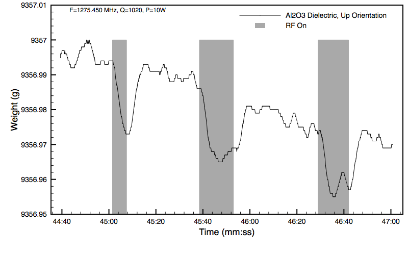 ()
()
()
Unfortunately, I also saw similar forces in most of the control experiments, such as with no dielectric installed: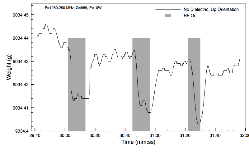 ()
()
()
And even with the unit suspended by a wood stand just above the scale (to prevent contact), with ceramic flooring tiles placed on the scale tray for similar loading: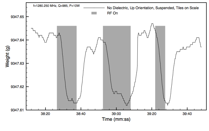 ()
()
()
Only the dummy load test did I not see any change in scale output. The output of the isolator is directly connected to the dummy load that normally takes the output of the sampling port, thus bypassing the RF cavity: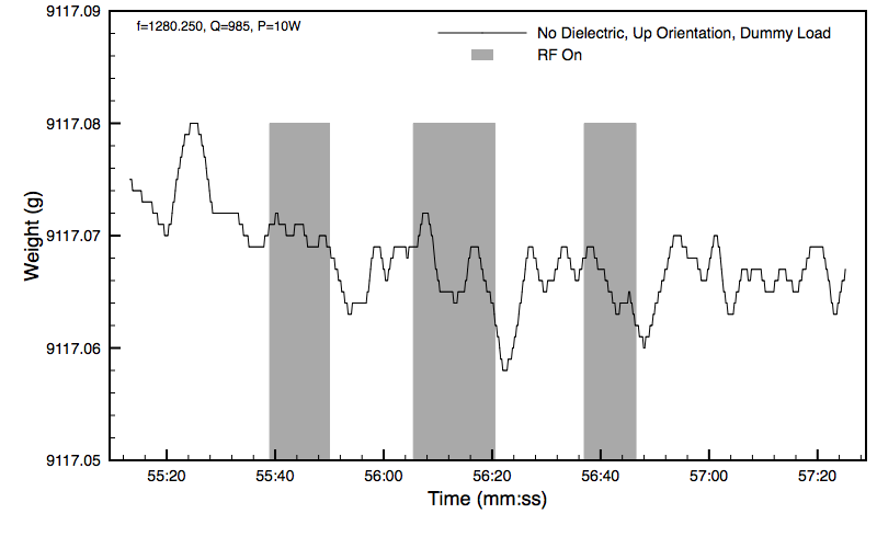 ()
()
()
Most likely there is an RFI problem with the scale. I'm going to attempt to shield the scale with the unit suspended above it to prove that it is RFI. -
Title: Re: EM Drive Developments - related to space flight applications - Thread 3
Post by: SeeShells on 06/22/2015 09:17 PM -
<a href="http://forum.nasaspaceflight.com/index.php?topic=37642.msg1392411#msg1392411">Quote from: Rodal on 06/22/2015 12:29 PM</a>
You have been a busy little bee and it looks like I'm going to be taking some time today to dig into this very nice collection of theories, thoughts and speculations. Dang, it looks like fun. I'll be back on later a little more brain fried. Thanks for the brain cramp ahead of time.<a href="http://forum.nasaspaceflight.com/index.php?topic=37642.msg1392328#msg1392328">Quote from: WarpTech on 06/22/2015 03:00 AM</a>.. I'm working on my DC analysis and I've made significant progress. It's not ready yet, but I think it will be interesting.
Todd
Have you seen this papers by Pinheiro?
http://arxiv.org/abs/1502.06288
http://arxiv.org/pdf/1502.01917.pdf
http://arxiv.org/abs/1208.3458
http://arxiv.org/abs/1104.5011
http://arxiv.org/abs/0901.3726
http://arxiv.org/abs/0802.0284
http://arxiv.org/abs/physics/0511103
Shell -
Title: Re: EM Drive Developments - related to space flight applications - Thread 3
Post by: Rodal on 06/22/2015 09:23 PM -
<a href="http://forum.nasaspaceflight.com/index.php?topic=37642.msg1392583#msg1392583">Quote from: aero on 06/22/2015 09:05 PM</a>
Ok - here is what the Brady cavity looks like in 3D. x, y, and z views. The y view looks pretty good as it should because that is the symetric view of both cavity and antenna. The end view and the other side view, not so much as the antenna is not symetric with those view directions.
As they are shown, the fields do not appear to be compatible, continuous if one envisions what happens around the circumference.
How can the field look like this
(http://forum.nasaspaceflight.com/xindex.php,qaction=dlattach,3Btopic=37642.0,3Battach=1031659,3Bimage.pagespeed.ic.YgBH9K2eJa.webp)
and when looked at a 90 angle look like this:
(http://forum.nasaspaceflight.com/xindex.php,qaction=dlattach,3Btopic=37642.0,3Battach=1031661,3Bimage.pagespeed.ic._q8bDOIzOD.webp)
Is MEEP performing the calculations in a global x, y, z Cartesian coordinate system?
If so, is the package doing the post-processing plots a MEEP package? or is it an external package? If it is an external package, have MEEP users used this same package to plot electromagnetic fields in conical cavities ?
I think we have to take a look at how:
1) MEEP outputs the vector electromagnetic fields. Does MEEP output the vector components in all 3 directions Ex Ey and Ez, and Bx By and Bz?
2) How does the Postprocessing package take the data for Ex Ey and Ez, and Bx By and Bz and produce a contour plot?
3) Can the postprocessing package produce a vector field plot instead of a contour plot?
Either that, or we need 3-D plots to understand what is going on -
Title: Re: EM Drive Developments - related to space flight applications - Thread 3
Post by: SeeShells on 06/22/2015 09:34 PM -
<a href="http://forum.nasaspaceflight.com/index.php?topic=37642.msg1392579#msg1392579">Quote from: graybeardsyseng on 06/22/2015 08:55 PM</a><a href="http://forum.nasaspaceflight.com/index.php?topic=37642.msg1392506#msg1392506">Quote from: SeeShells on 06/22/2015 05:31 PM</a><a href="http://forum.nasaspaceflight.com/index.php?topic=37642.msg1392494#msg1392494">Quote from: rfmwguy on 06/22/2015 04:56 PM</a>
Cavity Q refresher: http://www.allaboutcircuits.com/textbook/alternating-current/chpt-6/q-and-bandwidth-resonant-circuit/
CLIP
I've looked for six sided hexagon horn antennas and found very little info but nothing bad. So I am open to thoughts and ideas. You guys are way smarter than this silly girl.
Shell
Shell -
From a short discussion with some waveguide colleagues I get the impression that hexagonal should work pretty well - I didn't go into what I was asking for, just discussions of circular vs rectangular vs hexagonal wg. mode calculations are somewhat different of course but hex or octagonal etc are just closer approximations to circular (insert spherical chicken in a vacuum joke here).
I think matching the horn geometry to frustum geometry is likely a good idea but thats just because it "feels right". I will try playing with it tonight if I can.
Love all the different experimental setups - the more the merrier.
Herman
What did the chicken say in space? Nothing, cuz they can't hear you cluck in space.
We also need to realize I'm shoving RF into this thing from what I consider a very dirty almost uncontrolled RF device and it will probably range over 3 harmonic modes, plus the kicking on and off of the magnetron's power supply. It looks like a witch's brew where anyone is going to be hard pressed to write down a clean formula. I thank you for your thumbs up good gut feeling, it means alot.
What do you call a chicken in a blender? A Frustum?
Enough of being silly, I don't want to be slapped by the moderator, I have some serious reading to get into. Welcome Aboard the Tar Baby Chicken Frustum.
Shell -
Title: Re: EM Drive Developments - related to space flight applications - Thread 3
Post by: rfmwguy on 06/22/2015 09:41 PM -
<a href="http://forum.nasaspaceflight.com/index.php?topic=37642.msg1392553#msg1392553">Quote from: aceshigh on 06/22/2015 07:44 PM</a>
did a search and did not find this... hope it was not posted yet
QuoteAIAA Propulsion and Energy Forum and Exposition
27–29 July 2015
Hilton Orlando, Orlando, Florida
...
TUESDAY, JULY 28, 2015
NFF-04. Future Flight Propulsion Systems
Chair(s): Gregory Meholic (The Aerospace Corporation)
Co-Chair(s): Heidi Fearn (California State University, Fullerton)
2:30 PM - 5:30 PM; Lake Nona A
...
3:30 PM - 4:00 PM
Design and First Measurements of a Superconducting Gravity-Impulse-Generator
Istvan Lörincz; Martin Tajmar
4:00 PM - 4:30 PM
Replication and Experimental Characterization of the Wallace Dynamic Force Field Generator
Martin Tajmar
4:30 PM - 5:00 PM
New Theoretical Results for the Mach Effect Thruster
Heidi Fearn
5:00 PM - 5:30 PM
Direct Thrust Measurements of an EMDrive and Evaluation of Possible Side-Effects
Martin Tajmar
I wonder if someone from this thread could attend the conference and if there is a following Q/A, even mention some of the experiments discussed here, ask questions, etc.
I did post a link but none of the sessions, thanks. Note on the Mach Effect Thruster...a competing technology also presented last year at the Ohio conference. Seems we might have a horse race ;) -
Title: Re: EM Drive Developments - related to space flight applications - Thread 3
Post by: aero on 06/22/2015 09:46 PM -
<a href="http://forum.nasaspaceflight.com/index.php?topic=37642.msg1392591#msg1392591">Quote from: Rodal on 06/22/2015 09:23 PM</a><a href="http://forum.nasaspaceflight.com/index.php?topic=37642.msg1392583#msg1392583">Quote from: aero on 06/22/2015 09:05 PM</a>
Ok - here is what the Brady cavity looks like in 3D. x, y, and z views. The y view looks pretty good as it should because that is the symetric view of both cavity and antenna. The end view and the other side view, not so much as the antenna is not symetric with those view directions.
As they are shown, the fields do not appear to be compatible, continuous if one envisions what happens around the circumference.
Is MEEP performing the calculations in a global x, y, z Cartesian coordinate system?
If so, is the package doing the post-processing plots a MEEP package? or is it an external package? If it is an external package, have MEEP users used this same package to plot electromagnetic fields in conical cavities ?
I think we have to take a look at how:
1) MEEP outputs the vector electromagnetic fields. Does MEEP output the vector components in all 3 directions Ex Ey and Ez, and Bx By and Bz?
2) How does the Postprocessing package take the data for Ex Ey and Ez, and Bx By and Bz and produce a contour plot?
3) Can the postprocessing package produce a vector field plot instead of a contour plot?
Perhaps -
x, y, z cartesian coordinates as I understand it.
h5topng - It is the program packaged with Meep, prepared at MIT for use with Meep. As far as I know it is commonly used with Meep data.
The components - Ex, Ey, Ez and Hx, Hy, Hz are available for output. The user must ask for them to output them. They go into seperate files. Each file comes with real and imaginary data sets each giving x, y, z components of field strength, and ofcourse there is a time dimension available.
How does h5topng work? I have no idea.
Vector field instead of contour? I don't think so. http://ab-initio.mit.edu/h5utils/h5topng-man.html (http://ab-initio.mit.edu/h5utils/h5topng-man.html)
If someone really wanted to look at the details of the data then IMO ParaView is the package to use. But I find it difficult to use and ParaView is a CPU and memory hog on the same order as Meep. And why not? The Ez file alone for these 3D runs is over 4GB. Pulling that file into memory and manipulating it is bound to take some resources. OF course, ParaView is designed for parallel processing on supercomputers much as is Meep so if anyone has one handy ...
I'll see about making a time stationary output file to look at. That would be a lot smaller file to work with but have no evolving information. -
Title: Re: EM Drive Developments - related to space flight applications - Thread 3
Post by: rfmwguy on 06/22/2015 09:49 PM -
<a href="http://forum.nasaspaceflight.com/index.php?topic=37642.msg1392574#msg1392574">Quote from: graybeardsyseng on 06/22/2015 08:43 PM</a><a href="http://forum.nasaspaceflight.com/index.php?topic=37642.msg1392494#msg1392494">Quote from: rfmwguy on 06/22/2015 04:56 PM</a>
Cavity Q refresher: http://www.allaboutcircuits.com/textbook/alternating-current/chpt-6/q-and-bandwidth-resonant-circuit/
Excellent Link!! Thanks.
Have you developed an approach for measuring Q in you DUT? I tend to think in of "Q as Ctr Freq/3dB Bandwidth" from the filter world as well and have been pondering this. VNA?
BTW - thanks for the earlier welcome and yes I am (mostly) an old RF guy.
Herman
Thats the big question in my mind...what the F the Q is ;). I can take my DUT and have S11 and S22 run which will get me close. The spreadsheet Traveller made for me was a 50K Q, which is what, 49 MHz 3dB BW? Highly suspicious by nevertheless I'll give it a whirl. -
Title: Re: EM Drive Developments - related to space flight applications - Thread 3
Post by: aceshigh on 06/22/2015 09:54 PM -
<a href="http://forum.nasaspaceflight.com/index.php?topic=37642.msg1392600#msg1392600">Quote from: rfmwguy on 06/22/2015 09:41 PM</a>
I did post a link but none of the sessions, thanks. Note on the Mach Effect Thruster...a competing technology also presented last year at the Ohio conference. Seems we might have a horse race ;)
well, Paul March, from Eagleworks Lab, based his Q-Thruster on his previous work with Woodward's Mach Effect. He said here at NSF that he thinks Q-Thrusters/EM-Drives and Mach Effect Thrusters are two sides of the same coin.
I said "q-thrusters/em-drives", but I am not sure they are the same thing or how they relate... (well, Dr White probably thinks both work based on Quantum Vacuum Fluctuations) -
Title: Re: EM Drive Developments - related to space flight applications - Thread 3
Post by: rfmwguy on 06/22/2015 10:13 PM -
<a href="http://forum.nasaspaceflight.com/index.php?topic=37642.msg1392606#msg1392606">Quote from: aceshigh on 06/22/2015 09:54 PM</a><a href="http://forum.nasaspaceflight.com/index.php?topic=37642.msg1392600#msg1392600">Quote from: rfmwguy on 06/22/2015 09:41 PM</a>
I did post a link but none of the sessions, thanks. Note on the Mach Effect Thruster...a competing technology also presented last year at the Ohio conference. Seems we might have a horse race ;)
well, Paul March, from Eagleworks Lab, based his Q-Thruster on his previous work with Woodward's Mach Effect. He said here at NSF that he thinks Q-Thrusters/EM-Drives and Mach Effect Thrusters are two sides of the same coin.
I said "q-thrusters/em-drives", but I am not sure they are the same thing or how they relate... (well, Dr White probably thinks both work based on Quantum Vacuum Fluctuations)
Tell you what, KML here might be presenting a paper soon...very interesting results in a classic rectangular waveguide with & without dielectrics. I would not have predicted that. The plot thickens ;) -
Title: Re: EM Drive Developments - related to space flight applications - Thread 3
Post by: Rodal on 06/22/2015 10:32 PM -
<a href="http://forum.nasaspaceflight.com/index.php?topic=37642.msg1392604#msg1392604">Quote from: aero on 06/22/2015 09:46 PM</a><a href="http://forum.nasaspaceflight.com/index.php?topic=37642.msg1392591#msg1392591">Quote from: Rodal on 06/22/2015 09:23 PM</a><a href="http://forum.nasaspaceflight.com/index.php?topic=37642.msg1392583#msg1392583">Quote from: aero on 06/22/2015 09:05 PM</a>
Ok - here is what the Brady cavity looks like in 3D. x, y, and z views. The y view looks pretty good as it should because that is the symetric view of both cavity and antenna. The end view and the other side view, not so much as the antenna is not symetric with those view directions.
As they are shown, the fields do not appear to be compatible, continuous if one envisions what happens around the circumference.
Is MEEP performing the calculations in a global x, y, z Cartesian coordinate system?
If so, is the package doing the post-processing plots a MEEP package? or is it an external package? If it is an external package, have MEEP users used this same package to plot electromagnetic fields in conical cavities ?
I think we have to take a look at how:
1) MEEP outputs the vector electromagnetic fields. Does MEEP output the vector components in all 3 directions Ex Ey and Ez, and Bx By and Bz?
2) How does the Postprocessing package take the data for Ex Ey and Ez, and Bx By and Bz and produce a contour plot?
3) Can the postprocessing package produce a vector field plot instead of a contour plot?
Perhaps -
x, y, z cartesian coordinates as I understand it.
h5topng - It is the program packaged with Meep, prepared at MIT for use with Meep. As far as I know it is commonly used with Meep data.
The components - Ex, Ey, Ez and Hx, Hy, Hz are available for output. The user must ask for them to output them. They go into seperate files. Each file comes with real and imaginary data sets each giving x, y, z components of field strength, and ofcourse there is a time dimension available.
How does h5topng work? I have no idea.
Vector field instead of contour? I don't think so. http://ab-initio.mit.edu/h5utils/h5topng-man.html (http://ab-initio.mit.edu/h5utils/h5topng-man.html)
If someone really wanted to look at the details of the data then IMO ParaView is the package to use. But I find it difficult to use and ParaView is a CPU and memory hog on the same order as Meep. And why not? The Ez file alone for these 3D runs is over 4GB. Pulling that file into memory and manipulating it is bound to take some resources. OF course, ParaView is designed for parallel processing on supercomputers much as is Meep so if anyone has one handy ...
I'll see about making a time stationary output file to look at. That would be a lot smaller file to work with but have no evolving information.
Let's try to work through this. The standard convention is to take z as the axis of symmetry (the longitudinal axis of the cone) but the way you labeled them, it looks like x is your axis of symmetry, is that correct?
If x is the axis of symmetry, then y and z are perpendicular to it.
On the trapezium-looking cross section with axis y perpendicular to it, the axis of the trapezium are x and z, is that correct?
OK, if the answer is yes, on your y plot, what are you plotting:
Ex ?
Ez?
Hx?
Hz? -
Title: Re: EM Drive Developments - related to space flight applications - Thread 3
Post by: deltaMass on 06/22/2015 10:53 PM - After more than 20 years of almost continuous experimentation, Woodward still has nothing that has been independently verified by at least two other labs. This is a heads-up that you might be in this for the long haul.
-
Title: Re: EM Drive Developments - related to space flight applications - Thread 3
Post by: demofsky on 06/22/2015 11:21 PM -
<a href="http://forum.nasaspaceflight.com/index.php?topic=37642.msg1392584#msg1392584">Quote from: kml on 06/22/2015 09:10 PM</a>
I have started conducting tests on my linear EmDrive. The test assembly is fully untethered using a battery power source and IR remote control for RF on/off. Forces are measured using an AND MC-10K 10.1kg x 0.001g scale. The initial tests are using a 4"x3"x0.25" Al2O3 ceramic dielectric. During tests the scale and unit are enclosed within a cardboard breeze break. The rectangular non-tapered resonator internal dimensions are 6.5"x3.25"x13", mode TE102. "Up Orientation" means the fixed end with the feedpoint and the dielectric plate is on top, the adjustable end is on bottom closest to the scale. In all orientations the RF PA, battery, and sample port heat sink are on top of the unit, furthest from the scale.
The initial tests with dielectric were promising, with forces very close to the 15mg predicted: ()
()
Unfortunately, I also saw similar forces in most of the control experiments, such as with no dielectric installed: ()
()
And even with the unit suspended by a wood stand just above the scale (to prevent contact), with ceramic flooring tiles placed on the scale tray for similar loading: ()
()
Only the dummy load test did I not see any change in scale output. The output of the isolator is directly connected to the dummy load that normally takes the output of the sampling port, thus bypassing the RF cavity: ()
()
Most likely there is an RFI problem with the scale. I'm going to attempt to shield the scale with the unit suspended above it to prove that it is RFI.
I have to say that these are very intriguing results! While we are all waiting to see if you can eliminate RFI interference on your scale as the cause for these results, I would like to point out a couple of notable things:
1). The performance with and without dielectrics reflects Shawyer's and Yang's experience.
2). Much more interesting from my perspective are the declining lows in your first experiment with the dielectrics. This is a very similar pattern to the Eagleworks tests With a dielectric insert. It was speculated at the time that this might have been due to out gassing but I can't see that happening with a ceramic dielectric!!
So what the heck is happening with the dielectrics?
There is a more subtle pattern of declining lows without the dielectrics, but it is more pronounced with them present.
So either there is some type of ongoing electrical (electrostatic?) interference with the digital scale once the power is off, significant out gassing from somewhere, or we are looking some very interesting theoretical issues here folks - and evanescent waves are just not going to cut it...
Edit: After checking the scale, it is apparent that the unit is getting lighter and so we have to add ballooning to the possible effects, with the dielectrics thermal mass sustaining the effect.
-
Title: Re: EM Drive Developments - related to space flight applications - Thread 3
Post by: WarpTech on 06/22/2015 11:40 PM -
<a href="http://forum.nasaspaceflight.com/index.php?topic=37642.msg1392643#msg1392643">Quote from: demofsky on 06/22/2015 11:21 PM</a>
...
So what the heck is happening with the dielectrics?
There is a more subtle pattern of declining lows without the dielectrics, but it is more pronounced with them present.
So either there is some type of ongoing electrical (electrostatic?) interference with the digital scale once the power is off, significant out gassing from somewhere, or we are looking some very interesting theoretical issues here folks - and evanescent waves are just not going to cut it...
I would recommend keeping it "OFF" until the Rig thermally stabilizes. The decrease in weight when it is off could be due to heating of the air inside, "balloon" effect with air-mass leaking out.
Todd
-
Title: Re: EM Drive Developments - related to space flight applications - Thread 3
Post by: TheTraveller on 06/22/2015 11:44 PM -
Roger Shawyer kindly sent me a copy of his EMDrive paper that is currently under peer review. All I can say is WOW. All doubt will be removed. Apologises but can't yet share it.
Would make one comment.
The EMDrives on the IXS Clark are old tech, working at only 4N/kW. If you think the voyage times here
http://emdrive.wiki/Potential_EMDrive_solar_system_explorer_ship
look good, well lets just say they need to be revised downward quite a bit.
Still in bed, recovering slower than desired, damn old age, but getting there. My build start still looks like 4 to 6 weeks away but the design steadly improves. Force measurement system will follow what Shawyer did in the Flight Thruster demo setup as attached. Hang it from a spring and measure the generated forces on a digital scale. Typical KISS enginerring. -
Title: Re: EM Drive Developments - related to space flight applications - Thread 3
Post by: demofsky on 06/22/2015 11:48 PM -
<a href="http://forum.nasaspaceflight.com/index.php?topic=37642.msg1392654#msg1392654">Quote from: WarpTech on 06/22/2015 11:40 PM</a><a href="http://forum.nasaspaceflight.com/index.php?topic=37642.msg1392643#msg1392643">Quote from: demofsky on 06/22/2015 11:21 PM</a>
...
So what the heck is happening with the dielectrics?
There is a more subtle pattern of declining lows without the dielectrics, but it is more pronounced with them present.
So either there is some type of ongoing electrical (electrostatic?) interference with the digital scale once the power is off, significant out gassing from somewhere, or we are looking some very interesting theoretical issues here folks - and evanescent waves are just not going to cut it...
I would recommend keeping it "OFF" until the Rig thermally stabilizes. The decrease in weight when it is off could be due to heating of the air inside, "balloon" effect with air-mass leaking out.
Todd
Agreed. This is the most likely effect and not interference with the scale. Happily this is easy to rectify by flipping the fustrum and seeing what happens. -
Title: Re: EM Drive Developments - related to space flight applications - Thread 3
Post by: rfmwguy on 06/23/2015 12:08 AM -
<a href="http://forum.nasaspaceflight.com/index.php?topic=37642.msg1392654#msg1392654">Quote from: WarpTech on 06/22/2015 11:40 PM</a><a href="http://forum.nasaspaceflight.com/index.php?topic=37642.msg1392643#msg1392643">Quote from: demofsky on 06/22/2015 11:21 PM</a>
...
So what the heck is happening with the dielectrics?
There is a more subtle pattern of declining lows without the dielectrics, but it is more pronounced with them present.
So either there is some type of ongoing electrical (electrostatic?) interference with the digital scale once the power is off, significant out gassing from somewhere, or we are looking some very interesting theoretical issues here folks - and evanescent waves are just not going to cut it...
I would recommend keeping it "OFF" until the Rig thermally stabilizes. The decrease in weight when it is off could be due to heating of the air inside, "balloon" effect with air-mass leaking out.
Todd
I like the way you think...my own plans are for 30 minutes on, 30 minutes off. I understand the need for short term pulses at much higher power levels than what I am operating at. Guess that comes with my burn-in mentality from days past. -
Title: Re: EM Drive Developments - related to space flight applications - Thread 3
Post by: Prunesquallor on 06/23/2015 12:32 AM -
<a href="http://forum.nasaspaceflight.com/index.php?topic=37642.msg1392669#msg1392669">Quote from: TheTraveller on 06/23/2015 12:19 AM</a>
In reference to:
http://emdrive.wiki/Potential_EMDrive_solar_system_explorer_shipQuoteTodd "WarpTech" and deltaMass have shown in NSF EM Drive Thread 2 that Dr. White's derivation contains an error in the integration. frobnicat has discussed in NSF EM Drive Threads 1 and 2 other flaws in this analysis. For the ion rocket consideration, the kinetic energy of the propellant needs to be properly taken into account.
Added 23 June 2015. As far as I (TheTraveller) know, none of the NSF members above has contacted Dr. White to discuss their concerns with his calculations. Until they do that and publish their corro showing Dr. White has agreed with their concerns and published a modified results paper, Dr. White's current published results stand and trumps arm chair critics.
Didnt realise comments made in NSF trump those made by the head of NASA's JSC Eagleworks, especially if Dr. White was never contacted.
If you guys have an issue with what Dr. White has published, you should 1st take it up with him directly and resolve your differences. You don't do what you did, on a public forum, without giving him the right to respond and defend the statements he made in the papers Appendix A.
So has any of the 3 mentioned NSF forum members contacted Dr. White to discuss their counter claims?
BTW, the Ion drive ship accelerates, inside it's inertial reference frame, and follows A = F/M. Don't see where a distant observers measurement of starting velocity & KE comes into that equation?
Well someone made an error in that write up. 8000 N/90,000 kg is 0.088 m/s2 NOT 0.088 g's. -
Title: Re: EM Drive Developments - related to space flight applications - Thread 3
Post by: aero on 06/23/2015 12:56 AM -
X is the axis of symmetry. The antenna is to the +Y edge of the cavity. Z completes the coordinate system.
I am plotting a snap shot of the x, y and z corrdinate values of the Ez field. More than that you'd have to ask a physicist. -
Title: Re: EM Drive Developments - related to space flight applications - Thread 3
Post by: Chris Bergin on 06/23/2015 01:07 AM -
I know you are all clever people, but I'm sure a lot of you have never been on an internet forum before ;)
1) Read the site rules. There are rules on how to conduct yourself here.
2) Don't embed massive images. Attach them. It kills the thread if you have a massive image messing up the width.
3) Quote someone correctly. It's very easy and self explanatory. Badly quoting (no name and link to post) is open to changing the quote and that's a bad day if that happens.
4) I'm not being an arse, I'm just trying to keep some order on this crazy thread I don't understand ;) -
Title: Re: EM Drive Developments - related to space flight applications - Thread 3
Post by: zen-in on 06/23/2015 01:13 AM -
<a href="http://forum.nasaspaceflight.com/index.php?topic=37642.msg1392584#msg1392584">Quote from: kml on 06/22/2015 09:10 PM</a>
I have started conducting tests on my linear EmDrive. The test assembly is fully untethered using a battery power source and IR remote control for RF on/off. Forces are measured using an AND MC-10K 10.1kg x 0.001g scale.
...
Only the dummy load test did I not see any change in scale output. The output of the isolator is directly connected to the dummy load that normally takes the output of the sampling port, thus bypassing the RF cavity:
Most likely there is an RFI problem with the scale.[/b] I'm going to attempt to shield the scale with the unit suspended above it to prove that it is RFI.
That is very interesting. Can I make a constructive suggestion? Why don't you put the dummy load (or a suitably sized resistor for DC power) inside the cavity and collect data with that configuration? This was my criticism of the Eagleworks lab tests going back to thread 1. Have you posted a picture of your apparatus? videos? Good work! -
Title: Re: EM Drive Developments - related to space flight applications - Thread 3
Post by: SeeShells on 06/23/2015 01:15 AM -
<a href="http://forum.nasaspaceflight.com/index.php?topic=37642.msg1392663#msg1392663">Quote from: arc on 06/22/2015 11:57 PM</a><a href="http://forum.nasaspaceflight.com/index.php?topic=37642.msg1392467#msg1392467">Quote from: SeeShells on 06/22/2015 03:38 PM</a>
Time to start my build...
Remember to use a smoke source (or Dry Ice if you can get it ) and if possible try inputs in multiple different locations spaced along the length of the cavity. You "might" see different results from different locations?.
I like being able to get into the cavity to change the Microwave antenna and the endplates plus being able see inside the maelstrom of microwave cavity activity might prove to be a plus.
I have some thoughts on the testing rig and still working those out. I like the fulcrum with the oil damping idea and I'll post a drawing of my thoughts later, but I want to get the Frustum built first.
Shell
I'll remember to do a smoke test (no, not the old tech test either, ;) ). I did design the thing to try different locations and I'm sure there will be surprises during this testing.
Thanks,
Shell -
Title: Re: EM Drive Developments - related to space flight applications - Thread 3
Post by: kml on 06/23/2015 01:35 AM -
<a href="http://forum.nasaspaceflight.com/index.php?topic=37642.msg1392691#msg1392691">Quote from: zen-in on 06/23/2015 01:13 AM</a><a href="http://forum.nasaspaceflight.com/index.php?topic=37642.msg1392584#msg1392584">Quote from: kml on 06/22/2015 09:10 PM</a>
I have started conducting tests on my linear EmDrive. The test assembly is fully untethered using a battery power source and IR remote control for RF on/off. Forces are measured using an AND MC-10K 10.1kg x 0.001g scale.
...
Only the dummy load test did I not see any change in scale output. The output of the isolator is directly connected to the dummy load that normally takes the output of the sampling port, thus bypassing the RF cavity:
Most likely there is an RFI problem with the scale.[/b] I'm going to attempt to shield the scale with the unit suspended above it to prove that it is RFI.
That is very interesting. Can I make a constructive suggestion? Why don't you put the dummy load (or a suitably sized resistor for DC power) inside the cavity and collect data with that configuration? This was my criticism of the Eagleworks lab tests going back to thread 1. Have you posted a picture of your apparatus? videos? Good work!
The feed ports are removable so I can find a way to test with a dummy load inside.
Here is a picture of the setup: (
(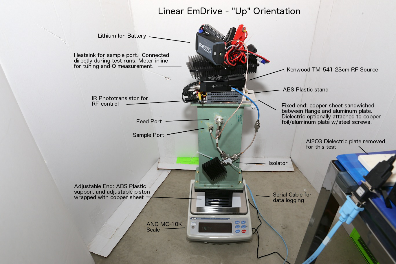 )
)
(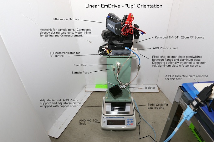 )
)
-
Title: Re: EM Drive Developments - related to space flight applications - Thread 3
Post by: SeeShells on 06/23/2015 01:35 AM -
I have a 7 ton car lift in my shop that is buried in over 3 feet of bedrock and concrete so I figured I would use that as it's stable.
The fulcrum is a laminated plywood beam with a SS cable attached to the ends with a turnbuckle to keep it taunt and straight.
The critical issue I've seen id getting power cables to the Drive without having to worry about the power cable causing issues. I have the power box under the fulcrum in a shielded cage. The power line from it goes up to connect to a point above the center of the beam. *see drawing and never touches the beam which could cause deflection.
The damper is a small 1 gal can filled with 30 weight oil and is connected to the end of the fulcrum and should provide damping in the X and Z directions.
The end of the beam opposite of the drive is a laser pointer to monitor any disturbances. (thrust hopefully) Still looking at scales so I've not put one into my layout.
Thoughts? Questions?
Shell
-
Title: Re: EM Drive Developments - related to space flight applications - Thread 3
Post by: SeeShells on 06/23/2015 01:51 AM -
<a href="http://forum.nasaspaceflight.com/index.php?topic=37642.msg1392657#msg1392657">Quote from: TheTraveller on 06/22/2015 11:44 PM</a>
Roger Shawyer kindly sent me a copy of his EMDrive paper that is currently under peer review. All I can say is WOW. All doubt will be removed. Apologises but can't yet share it.
SNIP
Still in bed, recovering slower than desired, damn old age, but getting there. My build start still looks like 4 to 6 weeks away but the design steadly improves. Force measurement system will follow what Shawyer did in the Flight Thruster demo setup as attached. Hang it from a spring and measure the generated forces on a digital scale. Typical KISS enginerring.
Please get well soon, getting old is not for wimps.
Honestly I hope he shakes up the community and the world with earth shattering news better than discovering fire. He has been like a dog with a bone stubborn working on this and sometimes that is what it takes.
Get better, ok?
Shell -
Title: Re: EM Drive Developments - related to space flight applications - Thread 3
Post by: zen-in on 06/23/2015 01:52 AM -
<a href="http://forum.nasaspaceflight.com/index.php?topic=37642.msg1392699#msg1392699">Quote from: kml on 06/23/2015 01:35 AM</a>
The feed ports are removable so I can find a way to test with a dummy load inside.
...
Here is a picture of the setup:
Very good! I remember seeing that waveguide earlier. I don't think the dummy load would fit inside it so you would have to use a power resistor. Maybe one with a lightweight Aluminum heatsink suspended near the bottom of the cavity and not touching the walls would do. Another similar test would be to heat the outside of the cavity with a heat lamp. If the metal inside the cavity is heating up uniformly the heat transfer to the air inside would happen quickly; hence the underdamped response you are seeing on the longer RF on times. How well sealed is the cavity? Are there o-rings at each end or just metal to metal seals? Some air may be escaping from one end. From a theoretical perspective what determines the directivity of this cavity? -
Title: Re: EM Drive Developments - related to space flight applications - Thread 3
Post by: Prunesquallor on 06/23/2015 01:53 AM -
<a href="http://forum.nasaspaceflight.com/index.php?topic=37642.msg1392584#msg1392584">Quote from: kml on 06/22/2015 09:10 PM</a>
And even with the unit suspended by a wood stand just above the scale (to prevent contact), with ceramic flooring tiles placed on the scale tray for similar loading:
So let me understand. The rig wasn't even ON THE SCALE and the scale regestered a weight change? -
Title: Re: EM Drive Developments - related to space flight applications - Thread 3
Post by: Rodal on 06/23/2015 01:56 AM -
<a href="http://forum.nasaspaceflight.com/index.php?topic=37642.msg1392657#msg1392657">Quote from: TheTraveller on 06/22/2015 11:44 PM</a>
...Still in bed, recovering slower than desired, damn old age, but getting there. ..
Take all the time you need to build up your strength and spirits. Your job right now is to relax and recover. Wishing you a prompt recovery. -
Title: Re: EM Drive Developments - related to space flight applications - Thread 3
Post by: Rodal on 06/23/2015 01:59 AM -
<a href="http://forum.nasaspaceflight.com/index.php?topic=37642.msg1392289#msg1392289">Quote from: aero on 06/22/2015 12:47 AM</a>
@Rodal - I have:
BIG DIAMETER = 0.27246 m
SMALL DIAMETER = 0.068115 m
LENGTH = 0.4890240258390259 m
Pardon the extra digits from the calculation.
Running in 3-D with bandwidth opened up to 0.5 * drive frequency (drive = ~1.95GHz), Meep finds 4 frequencies:
1.58530024E+009
1.83409637E+009
2.08402579E+009
2.33698507E+009 Hz
Q - in order
620.675008923
133.4147313913
1211.3296422825
141.0133154386
This is electric excitation with antenna = 0.2 * wavelength, perpendicular to and centered on the central axis of rotation.
OK - I just read the rest of your post. I'll look for the location of the antenna in the Brady cone, and put it there. But as I recall, that was for exciting a TM mode?
Those dimensions
BIG DIAMETER = 0.27246 m
SMALL DIAMETER = 0.068115 m
LENGTH = 0.4890240258390259 m
have lots of natural frequencies around that range. Here are just a few, for flat ends:
Mode frequency (GHz)
TE011 1.73146
TE012 2.0553
TE013 2.3431
TM211 1.9874
TM212 2.40296
TM213 2.72512
TE111 0.965122
TE112 1.24641
TE113 1.50459
TM111 1.51277
TM112 1.89759
TM113 2.20088
-
Title: Re: EM Drive Developments - related to space flight applications - Thread 3
Post by: Prunesquallor on 06/23/2015 02:09 AM -
<a href="http://forum.nasaspaceflight.com/index.php?topic=37642.msg1392701#msg1392701">Quote from: SeeShells on 06/23/2015 01:35 AM</a>
I have a 7 ton car lift in my shop that is buried in over 3 feet of bedrock and concrete so I figured I would use that as it's stable.
The fulcrum is a laminated plywood beam with a SS cable attached to the ends with a turnbuckle to keep it taunt and straight.
The critical issue I've seen id getting power cables to the Drive without having to worry about the power cable causing issues. I have the power box under the fulcrum in a shielded cage. The power line from it goes up to connect to a point above the center of the beam. *see drawing and never touches the beam which could cause deflection.
The damper is a small 1 gal can filled with 30 weight oil and is connected to the end of the fulcrum and should provide damping in the X and Z directions.
The end of the beam opposite of the drive is a laser pointer to monitor any disturbances. (thrust hopefully) Still looking at scales so I've not put one into my layout.
Thoughts? Questions?
Shell
My thoughts? I lust after your shop. -
Title: Re: EM Drive Developments - related to space flight applications - Thread 3
Post by: TheTraveller on 06/23/2015 02:19 AM -
<a href="http://forum.nasaspaceflight.com/index.php?topic=37642.msg1392745#msg1392745">Quote from: Rodal on 06/23/2015 01:56 AM</a><a href="http://forum.nasaspaceflight.com/index.php?topic=37642.msg1392657#msg1392657">Quote from: TheTraveller on 06/22/2015 11:44 PM</a>
...Still in bed, recovering slower than desired, damn old age, but getting there. ..
Take all the time you need to build up your strength and spirits. Your job right now is to relax and recover. Wishing you a prompt recovery.
Thanks.
My wife ensures I stick to doctors orders. Does allow me to do fat finger typing on my phone. :)
Bonus is I get to mentally build my 3 frustums and go through the testing process at least once a day. -
Title: Re: EM Drive Developments - related to space flight applications - Thread 3
Post by: RareSaturn on 06/23/2015 02:34 AM -
<a href="http://forum.nasaspaceflight.com/index.php?topic=37642.msg1392736#msg1392736">Quote from: Prunesquallor on 06/23/2015 01:53 AM</a><a href="http://forum.nasaspaceflight.com/index.php?topic=37642.msg1392584#msg1392584">Quote from: kml on 06/22/2015 09:10 PM</a>
And even with the unit suspended by a wood stand just above the scale (to prevent contact), with ceramic flooring tiles placed on the scale tray for similar loading:
So let me understand. The rig wasn't even ON THE SCALE and the scale regestered a weight change?
Something shooting out the back perhaps? Would love to see this setup inversed -
Title: Re: EM Drive Developments - related to space flight applications - Thread 3
Post by: demofsky on 06/23/2015 02:34 AM -
<a href="http://forum.nasaspaceflight.com/index.php?topic=37642.msg1392701#msg1392701">Quote from: SeeShells on 06/23/2015 01:35 AM</a>
I have a 7 ton car lift in my shop that is buried in over 3 feet of bedrock and concrete so I figured I would use that as it's stable.
The fulcrum is a laminated plywood beam with a SS cable attached to the ends with a turnbuckle to keep it taunt and straight.
The critical issue I've seen id getting power cables to the Drive without having to worry about the power cable causing issues. I have the power box under the fulcrum in a shielded cage. The power line from it goes up to connect to a point above the center of the beam. *see drawing and never touches the beam which could cause deflection.
The damper is a small 1 gal can filled with 30 weight oil and is connected to the end of the fulcrum and should provide damping in the X and Z directions.
The end of the beam opposite of the drive is a laser pointer to monitor any disturbances. (thrust hopefully) Still looking at scales so I've not put one into my layout.
Thoughts? Questions?
Shell
In my own speculative experimental design I also have thought about using a very large beam with a laser pointer.
Question. Does something as massive as that beam really need any additional dampening? Without doing the math, I envisaged that any changes would happen slowly, the mass of the beam dampening most artifacts.
Also, because it will be slow, you need to be mindful of cooling since everything will need to run for long periods of time. -
Title: Re: EM Drive Developments - related to space flight applications - Thread 3
Post by: Rodal on 06/23/2015 02:35 AM -
<a href="http://forum.nasaspaceflight.com/index.php?topic=37642.msg1392626#msg1392626">Quote from: Rodal on 06/22/2015 10:32 PM</a>
....
Let's try to work through this. The standard convention is to take z as the axis of symmetry (the longitudinal axis of the cone) but the way you labeled them, it looks like x is your axis of symmetry, is that correct?
If x is the axis of symmetry, then y and z are perpendicular to it.
On the trapezium-looking cross section with axis y perpendicular to it, the axis of the trapezium are x and z, is that correct?
OK, if the answer is yes, on your y plot, what are you plotting:
Ex ?
Ez?
Hx?
Hz?<a href="http://forum.nasaspaceflight.com/index.php?topic=37642.msg1392679#msg1392679">Quote from: aero on 06/23/2015 12:56 AM</a>X is the axis of symmetry. The antenna is to the +Y edge of the cavity. Z completes the coordinate system.
Can you plot the Absolute Value of the E field:
I am plotting a snap shot of the x, y and z corrdinate values of the Ez field. More than that you'd have to ask a physicist.
for example, for the cross-section with normal y
instead of Ez, can you have contour plot Sqrt[(Ex)^2 + (Ez)^2] -
Title: Re: EM Drive Developments - related to space flight applications - Thread 3
Post by: aero on 06/23/2015 02:44 AM -
<a href="http://forum.nasaspaceflight.com/index.php?topic=37642.msg1392701#msg1392701">Quote from: SeeShells on 06/23/2015 01:35 AM</a>
I have a 7 ton car lift in my shop that is buried in over 3 feet of bedrock and concrete so I figured I would use that as it's stable.
The fulcrum is a laminated plywood beam with a SS cable attached to the ends with a turnbuckle to keep it taunt and straight.
The critical issue I've seen id getting power cables to the Drive without having to worry about the power cable causing issues. I have the power box under the fulcrum in a shielded cage. The power line from it goes up to connect to a point above the center of the beam. *see drawing and never touches the beam which could cause deflection.
The damper is a small 1 gal can filled with 30 weight oil and is connected to the end of the fulcrum and should provide damping in the X and Z directions.
The end of the beam opposite of the drive is a laser pointer to monitor any disturbances. (thrust hopefully) Still looking at scales so I've not put one into my layout.
Thoughts? Questions?
Shell
How massive is that beam? I see a lot of inertia but maybe it's not as massive as it looks.
Still, you can measure the response time using weights as rfmwguy did. -
Title: Re: EM Drive Developments - related to space flight applications - Thread 3
Post by: aero on 06/23/2015 02:53 AM -
<a href="http://forum.nasaspaceflight.com/index.php?topic=37642.msg1392784#msg1392784">Quote from: Rodal on 06/23/2015 02:35 AM</a><a href="http://forum.nasaspaceflight.com/index.php?topic=37642.msg1392626#msg1392626">Quote from: Rodal on 06/22/2015 10:32 PM</a>
....
Let's try to work through this. The standard convention is to take z as the axis of symmetry (the longitudinal axis of the cone) but the way you labeled them, it looks like x is your axis of symmetry, is that correct?
If x is the axis of symmetry, then y and z are perpendicular to it.
On the trapezium-looking cross section with axis y perpendicular to it, the axis of the trapezium are x and z, is that correct?
OK, if the answer is yes, on your y plot, what are you plotting:
Ex ?
Ez?
Hx?
Hz?<a href="http://forum.nasaspaceflight.com/index.php?topic=37642.msg1392679#msg1392679">Quote from: aero on 06/23/2015 12:56 AM</a>X is the axis of symmetry. The antenna is to the +Y edge of the cavity. Z completes the coordinate system.
Can you plot the Absolute Value of the E field:
I am plotting a snap shot of the x, y and z corrdinate values of the Ez field. More than that you'd have to ask a physicist.
for example, for the cross-section with normal y
instead of Ez, can you have contour plot Sqrt[(Ex)^2 + (Ez)^2]
That is not an option that I see in the h5topng manual. Maybe HDFview has that option but I think you're asking for some MatLab data processing. If so, then no, I can't, maybe someone else would like to accept the challenge. I know that Meep users commonly reduce data using MatLab programs so it's likely possible. -
Title: Re: EM Drive Developments - related to space flight applications - Thread 3
Post by: kml on 06/23/2015 03:09 AM -
<a href="http://forum.nasaspaceflight.com/index.php?topic=37642.msg1392643#msg1392643">Quote from: demofsky on 06/22/2015 11:21 PM</a><a href="http://forum.nasaspaceflight.com/index.php?topic=37642.msg1392584#msg1392584">Quote from: kml on 06/22/2015 09:10 PM</a>
Most likely there is an RFI problem with the scale. I'm going to attempt to shield the scale with the unit suspended above it to prove that it is RFI.
I have to say that these are very intriguing results! While we are all waiting to see if you can eliminate RFI interference on your scale as the cause for these results, I would like to point out a couple of notable things:
1). The performance with and without dielectrics reflects Shawyer's and Yang's experience.
2). Much more interesting from my perspective are the declining lows in your first experiment with the dielectrics. This is a very similar pattern to the Eagleworks tests With a dielectric insert. It was speculated at the time that this might have been due to out gassing but I can't see that happening with a ceramic dielectric!!
So what the heck is happening with the dielectrics?
There is a more subtle pattern of declining lows without the dielectrics, but it is more pronounced with them present.
So either there is some type of ongoing electrical (electrostatic?) interference with the digital scale once the power is off, significant out gassing from somewhere, or we are looking some very interesting theoretical issues here folks - and evanescent waves are just not going to cut it...
Edit: After checking the scale, it is apparent that the unit is getting lighter and so we have to add ballooning to the possible effects, with the dielectrics thermal mass sustaining the effect.
Don't read too much into the overall declining slope. It takes a while for the scale to fully stabilize after placing the unit on it. The faster I start the test the steeper the slope is, usually. I have learned to wait longer before starting as you can see from the later test #'s.
Keep in mind the "suspended" test is without any contact between the test unit and the scale. There should be absolutely no force registered in this configuration. The weight on the scale is from several ceramic flooring tiles used to simulate the weight of the unit. I did test with very little weight on the scale with the unit suspended above it and there was no change in weight indicated:
20150621-test-42-nod-up-suspended-paper.png (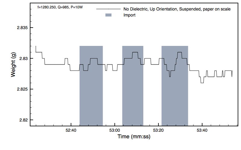 )
)
()
This indicates that the RFI induced error may be related to the dynamic correction system used to offset heavy loads.:
http://www.scalenet.com/and/gx/sensor.html (http://www.scalenet.com/and/gx/sensor.html)
Also, the tests done in the "down" orientation show much less force, though still in the "weighs less" direction. This may be due to the better RF sealing on the fixed end which is down in the "down" orientation. -
Title: Re: EM Drive Developments - related to space flight applications - Thread 3
Post by: rfmwguy on 06/23/2015 03:10 AM -
<a href="http://forum.nasaspaceflight.com/index.php?topic=37642.msg1392701#msg1392701">Quote from: SeeShells on 06/23/2015 01:35 AM</a>
I have a 7 ton car lift in my shop that is buried in over 3 feet of bedrock and concrete so I figured I would use that as it's stable.
The fulcrum is a laminated plywood beam with a SS cable attached to the ends with a turnbuckle to keep it taunt and straight.
The critical issue I've seen id getting power cables to the Drive without having to worry about the power cable causing issues. I have the power box under the fulcrum in a shielded cage. The power line from it goes up to connect to a point above the center of the beam. *see drawing and never touches the beam which could cause deflection.
The damper is a small 1 gal can filled with 30 weight oil and is connected to the end of the fulcrum and should provide damping in the X and Z directions.
The end of the beam opposite of the drive is a laser pointer to monitor any disturbances. (thrust hopefully) Still looking at scales so I've not put one into my layout.
Thoughts? Questions?
Shell
there will be 4 wires needed for magnetron, 2 bias and 2 filament. Make a liquid "wire splice" for the 4 wires. Basically 4 test tubes of conductive mercury. An electrode from power supply wire goes in at bottom of tube. Another electrode from fulcrum drops down into mercury. The mercury conducts the voltage regardless of the depth of the fulcrum side electrode, it simply swims in it. Depth of mercury and length of electrode should allow Moment arm displacement without breaking contact (fulcrum side electrode rising out of mercury).
A non scientific description of a near frictionless wire splice...hope I explained it well enough. -
Title: Re: EM Drive Developments - related to space flight applications - Thread 3
Post by: SeeShells on 06/23/2015 03:14 AM -
<a href="http://forum.nasaspaceflight.com/index.php?topic=37642.msg1392783#msg1392783">Quote from: demofsky on 06/23/2015 02:34 AM</a>
Good points. I worried about the pendulum effect that I've seen on other tests and the slow movement of other outside forces is a concern. I remember setting up anti-vibration tables in a lab and watching cars and trucks drive by a 100 foot away. Even when we would set up our semiconductor equipment in a lab with a concrete floor we could detect the bending movement of the floor and into our machines by someone walking next to it. Very small movements, but a issue when they were expecting submicron accuracies.<a href="http://forum.nasaspaceflight.com/index.php?topic=37642.msg1392701#msg1392701">Quote from: SeeShells on 06/23/2015 01:35 AM</a>I have a 7 ton car lift in my shop that is buried in over 3 feet of bedrock and concrete so I figured I would use that as it's stable.
Thoughts? Questions?
Shell
In my own speculative experimental design I also have thought about using a very large beam with a laser pointer.
Question. Does something as massive as that beam really need any additional dampening? Without doing the math, I envisaged that any changes would happen slowly, the mass of the beam dampening most artifacts.
Also, because it will be slow, you need to be mindful of cooling since everything will need to run for long periods of time.
Cooling is a issue and I hope the holes in the Copper Frustum help, free hanging with holes I should get away from a hot air balloon effect but still need to worry about hot air eddie currents from the frustum. Turning the drive around should give me subtracting data for the total deviations.
The lasers are great to monitor deflections and vibrations of the beam, plus they are very cheap.
I hope by putting the beam between the 2 stainless steel cables I can reduce movement in one direction and the oil damper should help with any others... hope.
Thanks for your input, I don't feel so alone in doing this.
Shell -
Title: Re: EM Drive Developments - related to space flight applications - Thread 3
Post by: kml on 06/23/2015 03:17 AM -
<a href="http://forum.nasaspaceflight.com/index.php?topic=37642.msg1392736#msg1392736">Quote from: Prunesquallor on 06/23/2015 01:53 AM</a><a href="http://forum.nasaspaceflight.com/index.php?topic=37642.msg1392584#msg1392584">Quote from: kml on 06/22/2015 09:10 PM</a>
And even with the unit suspended by a wood stand just above the scale (to prevent contact), with ceramic flooring tiles placed on the scale tray for similar loading:
So let me understand. The rig wasn't even ON THE SCALE and the scale regestered a weight change?
Yes! which is why I susped RFI of the "hybrid super sensor" in the scale:
http://www.scalenet.com/and/gx/sensor.html (http://www.scalenet.com/and/gx/sensor.html)
Though my experience with RFI is that it is usually much more dramatic/noisy/unpredictable. This is a remarkably consistent and reproducable effect. -
Title: Re: EM Drive Developments - related to space flight applications - Thread 3
Post by: maciejzi on 06/23/2015 03:19 AM -
<a href="http://forum.nasaspaceflight.com/index.php?topic=37642.msg1392302#msg1392302">Quote from: Rodal on 06/22/2015 01:27 AM</a>
splad posted this great video on Reddit:
https://www.youtube.com/watch?v=L5fVFA2sWt4&feature=youtu.be
Acoustic Propulsion
[...]
You must have mass/energy coming out of the EM Drive to have any propulsion, as well.
This is a great test to show that Shawyer is wrong (justifying the EM Drive on resonance, and claiming that no esoteric physics is needed to have propulsion without anything coming out): if you put a cap on the bottles, they will not spin, as there is no air coming out, it is an ASYMMETRIC RESONATOR. It needs to have an open end for it to work.
EDIT: Acoustic propulsion works because the exhaust of gas (due to compression of the plastic bottle during acoustic vibration) occurs in well-directed vortices while the intake of gas (due to the expansion phase of the plastic bottle during acoustic vibration) is not as axially directed but instead it sucks air from a large range of directions, including the direction perpendicular to the axis of axisymmetry of the bottle. In other words, acoustic propulsion works due to the difference between ejection flow and intake flow.
I think that EmDrive is in many aspects similar to such acoustic propulsion, only tuned for microwaves and energized by electromagnetic wave (not sound wave).
There is no sound in vacuum, but the microwaves may still work and generate thrust in vacuum as well. No end needs to be open, microwaves can escape with the whole resonator closed.
-
Title: Re: EM Drive Developments - related to space flight applications - Thread 3
Post by: SeeShells on 06/23/2015 03:21 AM -
<a href="http://forum.nasaspaceflight.com/index.php?topic=37642.msg1392812#msg1392812">Quote from: rfmwguy on 06/23/2015 03:10 AM</a>
Very well indeed! I'll look into it. I think I have some old home thermostats that used mercury. I need to be very careful of it.<a href="http://forum.nasaspaceflight.com/index.php?topic=37642.msg1392701#msg1392701">Quote from: SeeShells on 06/23/2015 01:35 AM</a>
The critical issue I've seen id getting power cables to the Drive without having to worry about the power cable causing issues. I have the power box under the fulcrum in a shielded cage. The power line from it goes up to connect to a point above the center of the beam. *see drawing and never touches the beam which could cause deflection.
Thoughts? Questions?
Shell
there will be 4 wires needed for magnetron, 2 bias and 2 filament. Make a liquid "wire splice" for the 4 wires. Basically 4 test tubes of conductive mercury. An electrode from power supply wire goes in at bottom of tube. Another electrode from fulcrum drops down into mercury. The mercury conducts the voltage regardless of the depth of the fulcrum side electrode, it simply swims in it. Depth of mercury and length of electrode should allow Moment arm displacement without breaking contact (fulcrum side electrode rising out of mercury).
A non scientific description of a near frictionless wire splice...hope I explained it well enough.
Shell -
Title: Re: EM Drive Developments - related to space flight applications - Thread 3
Post by: zellerium on 06/23/2015 03:29 AM -
<a href="http://forum.nasaspaceflight.com/index.php?topic=37642.msg1392804#msg1392804">Quote from: aero on 06/23/2015 02:53 AM</a>
...
That is not an option that I see in the h5topng manual. Maybe HDFview has that option but I think you're asking for some MatLab data processing. If so, then no, I can't, maybe someone else would like to accept the challenge. I know that Meep users commonly reduce data using MatLab programs so it's likely possible.
aero,
I am very comfortable with Matlab data processing, if you want to send me the data I'd happily do some contours, plot3 or anything else you all are looking for. My email is kwzeller@calpoly.edu
However it might take me a day or two, I'm back home visiting family.
Kurt -
Title: Re: EM Drive Developments - related to space flight applications - Thread 3
Post by: Rodal on 06/23/2015 03:40 AM -
<a href="http://forum.nasaspaceflight.com/index.php?topic=37642.msg1392817#msg1392817">Quote from: maciejzi on 06/23/2015 03:19 AM</a>
...
Microwaves can penetrate a sheet of copper?
. No end needs to be open, microwaves can escape with the whole resonator closed.
What happened to the safety of home-cooking microwaves ? -
Title: Re: EM Drive Developments - related to space flight applications - Thread 3
Post by: Rodal on 06/23/2015 03:44 AM -
<a href="http://forum.nasaspaceflight.com/index.php?topic=37642.msg1392804#msg1392804">Quote from: aero on 06/23/2015 02:53 AM</a><a href="http://forum.nasaspaceflight.com/index.php?topic=37642.msg1392784#msg1392784">Quote from: Rodal on 06/23/2015 02:35 AM</a><a href="http://forum.nasaspaceflight.com/index.php?topic=37642.msg1392626#msg1392626">Quote from: Rodal on 06/22/2015 10:32 PM</a>
....
Let's try to work through this. The standard convention is to take z as the axis of symmetry (the longitudinal axis of the cone) but the way you labeled them, it looks like x is your axis of symmetry, is that correct?
If x is the axis of symmetry, then y and z are perpendicular to it.
On the trapezium-looking cross section with axis y perpendicular to it, the axis of the trapezium are x and z, is that correct?
OK, if the answer is yes, on your y plot, what are you plotting:
Ex ?
Ez?
Hx?
Hz?<a href="http://forum.nasaspaceflight.com/index.php?topic=37642.msg1392679#msg1392679">Quote from: aero on 06/23/2015 12:56 AM</a>X is the axis of symmetry. The antenna is to the +Y edge of the cavity. Z completes the coordinate system.
Can you plot the Absolute Value of the E field:
I am plotting a snap shot of the x, y and z corrdinate values of the Ez field. More than that you'd have to ask a physicist.
for example, for the cross-section with normal y
instead of Ez, can you have contour plot Sqrt[(Ex)^2 + (Ez)^2]
That is not an option that I see in the h5topng manual. Maybe HDFview has that option but I think you're asking for some MatLab data processing. If so, then no, I can't, maybe someone else would like to accept the challenge. I know that Meep users commonly reduce data using MatLab programs so it's likely possible.
Your Ex component should be zero (I keep forgetting that you are using x for the longitudinal axis)
There should only be a magnetic field Hx component in the longitudinal direction for x for TE modes.
That's why it is called Transverse Electric: there should not be an electric field in the longitudinal direction
It is for a circular cross section with normal x you need to plot Sqrt[Ez^2+Ey^2]
Can you please verify that your Ex is zero ?
Can you give us a plot of the Hx field for the TE mode?
-
Title: Re: EM Drive Developments - related to space flight applications - Thread 3
Post by: aero on 06/23/2015 04:15 AM -
<a href="http://forum.nasaspaceflight.com/index.php?topic=37642.msg1392826#msg1392826">Quote from: Rodal on 06/23/2015 03:44 AM</a><a href="http://forum.nasaspaceflight.com/index.php?topic=37642.msg1392804#msg1392804">Quote from: aero on 06/23/2015 02:53 AM</a><a href="http://forum.nasaspaceflight.com/index.php?topic=37642.msg1392784#msg1392784">Quote from: Rodal on 06/23/2015 02:35 AM</a><a href="http://forum.nasaspaceflight.com/index.php?topic=37642.msg1392626#msg1392626">Quote from: Rodal on 06/22/2015 10:32 PM</a>
....
Let's try to work through this. The standard convention is to take z as the axis of symmetry (the longitudinal axis of the cone) but the way you labeled them, it looks like x is your axis of symmetry, is that correct?
If x is the axis of symmetry, then y and z are perpendicular to it.
On the trapezium-looking cross section with axis y perpendicular to it, the axis of the trapezium are x and z, is that correct?
OK, if the answer is yes, on your y plot, what are you plotting:
Ex ?
Ez?
Hx?
Hz?<a href="http://forum.nasaspaceflight.com/index.php?topic=37642.msg1392679#msg1392679">Quote from: aero on 06/23/2015 12:56 AM</a>X is the axis of symmetry. The antenna is to the +Y edge of the cavity. Z completes the coordinate system.
Can you plot the Absolute Value of the E field:
I am plotting a snap shot of the x, y and z corrdinate values of the Ez field. More than that you'd have to ask a physicist.
for example, for the cross-section with normal y
instead of Ez, can you have contour plot Sqrt[(Ex)^2 + (Ez)^2]
That is not an option that I see in the h5topng manual. Maybe HDFview has that option but I think you're asking for some MatLab data processing. If so, then no, I can't, maybe someone else would like to accept the challenge. I know that Meep users commonly reduce data using MatLab programs so it's likely possible.
Your Ex component should be zero (I keep forgetting that you are using x for the longitudinal axis)
There should only be a magnetic field Hx component in the longitudinal direction for x for TE modes.
That's why it is called Transverse Electric: there should not be an electric field in the longitudinal direction
It is for a circular cross section with normal x you need to plot Sqrt[Ez^2+Ey^2]
Can you please verify that your Ex is zero ?
Can you give us a plot of the Hx field for the TE mode?
I'm thinking that we need to consider the coordinate systems in a little more detail. The origon of the of the EM fields is the location of the antenna. The x, y, and z coordinates of the EM fields start at that origin. The fields do pass through the origon of the cavity which is on the central axis of rotation equidistant from the ends.
Meep calculates from the origin of the cavity but the field patterns are at an angle to that origin, maybe by as much as 45 degrees. The antenna center is offset from the big end by 1.35 inches and the central axis by the radius of the cavity minus 7 mm in the Y edge direction of the cavity. So the field pattern coordinate values detected by meep are a vector combination of the field patterns generated by the antenna.
To me the implication seems to be that patterns detected by meep will not coincide with the theorecal patterns except when the antenna is centered within the cavity. -
Title: Re: EM Drive Developments - related to space flight applications - Thread 3
Post by: WarpTech on 06/23/2015 04:40 AM -
<a href="http://forum.nasaspaceflight.com/index.php?topic=37642.msg1392753#msg1392753">Quote from: Rodal on 06/23/2015 01:59 AM</a>
Those dimensions
BIG DIAMETER = 0.27246 m
SMALL DIAMETER = 0.068115 m
LENGTH = 0.4890240258390259 m
have lots of natural frequencies around that range. Here are just a few, for flat ends:
Mode frequency (GHz)
TE011 1.73146
TE012 2.0553
TE013 2.3431
TM211 1.9874
TM212 2.40296
TM213 2.72512
TE111 0.965122
TE112 1.24641
TE113 1.50459
TM111 1.51277
TM112 1.89759
TM113 2.20088
Looking at TE111 and assuming field strength = color, you can actually see how the strength of the field pushing on 3-sides of the triangle is symmetrical and nearly identical. Indicating, there should NOT be any thrust due to this mode.
Todd
-
Title: Re: EM Drive Developments - related to space flight applications - Thread 3
Post by: demofsky on 06/23/2015 05:01 AM -
<a href="http://forum.nasaspaceflight.com/index.php?topic=37642.msg1392814#msg1392814">Quote from: SeeShells on 06/23/2015 03:14 AM</a>
...
Good points. I worried about the pendulum effect that I've seen on other tests and the slow movement of other outside forces is a concern. I remember setting up anti-vibration tables in a lab and watching cars and trucks drive by a 100 foot away. Even when we would set up our semiconductor equipment in a lab with a concrete floor we could detect the bending movement of the floor and into our machines by someone walking next to it. Very small movements, but a issue when they were expecting submicron accuracies.
....
Thanks! I completely forgot about external forces like trucks. A relative of mine was a spectroscopist. His lab was in the lowest sub basement and had special foundations. Even so, he had to have additional dampening for his lasers. So rather than spend money on very expensive air tables he used a couple of layers of inner tubes sandwiched between sheets of plywood! Worked extremely well I was told!!
Can't wait to see what results you get! -
Title: Re: EM Drive Developments - related to space flight applications - Thread 3
Post by: WarpTech on 06/23/2015 05:07 AM -
MOMENTUM ENHANCEMENT
I think I just solved the momentum enhancement problem, and learned something new in the process. I'm working on my DC analysis, since now I'm 99% convinced microwaves are not causing thrust. In the course of my day, I was trying to figure out how much momentum is carried away by a quantum of magnetic flux. Very interesting answer, probably best described quantum mechanically, though that is not how I came to this conclusion.
In a superconductor, the momentum of the cooper pair is given by; p = h/λ
A quantum of magnetic flux is given by: Φ=h/2e
Therefore, momentum/volt-sec = p/Φ = 2e/λ
In macroscopic terms, the momentum carried away by the magnetic flux, depends on the recoil momentum of the charge per unit length of the electrons flowing in the copper. This value is an intrinsic property of the copper based on the free electron density, which is only slightly altered by collisions, heat and relativistic effects (velocity).
So far, I have shown that due to the inductance gradient of the cone geometry, there is a force acting on the current and magnetic flux, pushing it toward the big end. I've also shown that the drift velocity at the small end is much larger than at the big end, so as the current is pushed toward the big end, it is losing momentum in the form of magnetic flux. The amount of momentum gained by the frustum will depend on the difference in drift velocity, the momentum stored as magnetic flux AND, on how much of it can escape.
Todd
-
Title: Re: EM Drive Developments - related to space flight applications - Thread 3
Post by: aero on 06/23/2015 05:08 AM -
<a href="http://forum.nasaspaceflight.com/index.php?topic=37642.msg1392818#msg1392818">Quote from: SeeShells on 06/23/2015 03:21 AM</a><a href="http://forum.nasaspaceflight.com/index.php?topic=37642.msg1392812#msg1392812">Quote from: rfmwguy on 06/23/2015 03:10 AM</a>
Very well indeed! I'll look into it. I think I have some old home thermostats that used mercury. I need to be very careful of it.<a href="http://forum.nasaspaceflight.com/index.php?topic=37642.msg1392701#msg1392701">Quote from: SeeShells on 06/23/2015 01:35 AM</a>
The critical issue I've seen id getting power cables to the Drive without having to worry about the power cable causing issues. I have the power box under the fulcrum in a shielded cage. The power line from it goes up to connect to a point above the center of the beam. *see drawing and never touches the beam which could cause deflection.
Thoughts? Questions?
Shell
there will be 4 wires needed for magnetron, 2 bias and 2 filament. Make a liquid "wire splice" for the 4 wires. Basically 4 test tubes of conductive mercury. An electrode from power supply wire goes in at bottom of tube. Another electrode from fulcrum drops down into mercury. The mercury conducts the voltage regardless of the depth of the fulcrum side electrode, it simply swims in it. Depth of mercury and length of electrode should allow Moment arm displacement without breaking contact (fulcrum side electrode rising out of mercury).
A non scientific description of a near frictionless wire splice...hope I explained it well enough.
Shell
You might check with Mulleton. As I recall he bought some liquid metal not involving mercury specially sold for completing electrical contacts on his DYI device. I don't know how far his project has progressed but I'm sure he could give you a name of the material and maybe a source contact.
I had a thought while taking out the trash that I'd like to share. How large is your garage? If you need the extra sensitive with your laser detecter system could you use a couple (or more pairs) of mirrors to reflect the beam across your garage so that any movement will be amplified by the extra distance the light beam travels. You might even be able to see vibration noise this way.
This also applies to rfmwguy's setup.
-
Title: Re: EM Drive Developments - related to space flight applications - Thread 3
Post by: demofsky on 06/23/2015 05:16 AM -
<a href="http://forum.nasaspaceflight.com/index.php?topic=37642.msg1392811#msg1392811">Quote from: kml on 06/23/2015 03:09 AM</a><a href="http://forum.nasaspaceflight.com/index.php?topic=37642.msg1392643#msg1392643">Quote from: demofsky on 06/22/2015 11:21 PM</a><a href="http://forum.nasaspaceflight.com/index.php?topic=37642.msg1392584#msg1392584">Quote from: kml on 06/22/2015 09:10 PM</a>
Most likely there is an RFI problem with the scale. I'm going to attempt to shield the scale with the unit suspended above it to prove that it is RFI.
I have to say that these are very intriguing results! While we are all waiting to see if you can eliminate RFI interference on your scale as the cause for these results, I would like to point out a couple of notable things:
1). The performance with and without dielectrics reflects Shawyer's and Yang's experience.
2). Much more interesting from my perspective are the declining lows in your first experiment with the dielectrics. This is a very similar pattern to the Eagleworks tests With a dielectric insert. It was speculated at the time that this might have been due to out gassing but I can't see that happening with a ceramic dielectric!!
So what the heck is happening with the dielectrics?
There is a more subtle pattern of declining lows without the dielectrics, but it is more pronounced with them present.
So either there is some type of ongoing electrical (electrostatic?) interference with the digital scale once the power is off, significant out gassing from somewhere, or we are looking some very interesting theoretical issues here folks - and evanescent waves are just not going to cut it...
Edit: After checking the scale, it is apparent that the unit is getting lighter and so we have to add ballooning to the possible effects, with the dielectrics thermal mass sustaining the effect.
Don't read too much into the overall declining slope. It takes a while for the scale to fully stabilize after placing the unit on it. The faster I start the test the steeper the slope is, usually. I have learned to wait longer before starting as you can see from the later test #'s.
Keep in mind the "suspended" test is without any contact between the test unit and the scale. There should be absolutely no force registered in this configuration. The weight on the scale is from several ceramic flooring tiles used to simulate the weight of the unit. I did test with very little weight on the scale with the unit suspended above it and there was no change in weight indicated:
20150621-test-42-nod-up-suspended-paper.png ()
()
This indicates that the RFI induced error may be related to the dynamic correction system used to offset heavy loads.:
http://www.scalenet.com/and/gx/sensor.html (http://www.scalenet.com/and/gx/sensor.html)
Also, the tests done in the "down" orientation show much less force, though still in the "weighs less" direction. This may be due to the better RF sealing on the fixed end which is down in the "down" orientation.
One thing to bear in mind here is that the error may not be RF induced but rather Magnetically or Electrostatically. We really don't know how EM drives couple to the external environment. That said, eliminating possible sources of interference would be very enlightening for everyone building one of these.
Just wrapping the scale with well grounded aluminum foil might be a quick and dirty solution for RF and electrostatic interference...
-
Title: Re: EM Drive Developments - related to space flight applications - Thread 3
Post by: demofsky on 06/23/2015 05:37 AM -
<a href="http://forum.nasaspaceflight.com/index.php?topic=37642.msg1392838#msg1392838">Quote from: WarpTech on 06/23/2015 05:07 AM</a>
MOMENTUM ENHANCEMENT
I think I just solved the momentum enhancement problem, and learned something new in the process. I'm working on my DC analysis, since now I'm 99% convinced microwaves are not causing thrust. In the course of my day, I was trying to figure out how much momentum is carried away by a quantum of magnetic flux. Very interesting answer, probably best described quantum mechanically, though that is not how I came to this conclusion.
In a superconductor, the momentum of the cooper pair is given by; p = h/λ
A quantum of magnetic flux is given by: Φ=h/2e
Therefore, momentum/volt-sec = p/Φ = 2e/λ
In macroscopic terms, the momentum carried away by the magnetic flux, depends on the recoil momentum of the charge per unit length of the electrons flowing in the copper. This value is an intrinsic property of the copper based on the free electron density, which is only slightly altered by collisions, heat and relativistic effects (velocity).
So far, I have shown that due to the inductance gradient of the cone geometry, there is a force acting on the current and magnetic flux, pushing it toward the big end. I've also shown that the drift velocity at the small end is much larger than at the big end, so as the current is pushed toward the big end, it is losing momentum in the form of magnetic flux. The amount of momentum gained by the frustum will depend on the difference in drift velocity, the momentum stored as magnetic flux AND, on how much of it can escape.
Todd
WOW!!! This is VERY interesting!! When you say "AND, on how much of it can escape." are you referring to the magnetic flux that is storing the momentum? If so what is the mechanism that it uses to escape in your view? Thanks!
-
Title: Re: EM Drive Developments - related to space flight applications - Thread 3
Post by: SeeShells on 06/23/2015 05:47 AM -
<a href="http://forum.nasaspaceflight.com/index.php?topic=37642.msg1392838#msg1392838">Quote from: WarpTech on 06/23/2015 05:07 AM</a>
MOMENTUM ENHANCEMENT
Any bearing? Too many things are clicking again and again.
I think I just solved the momentum enhancement problem, and learned something new in the process. I'm working on my DC analysis, since now I'm 99% convinced microwaves are not causing thrust. In the course of my day, I was trying to figure out how much momentum is carried away by a quantum of magnetic flux. Very interesting answer, probably best described quantum mechanically, though that is not how I came to this conclusion.
In a superconductor, the momentum of the cooper pair is given by; p = h/λ
A quantum of magnetic flux is given by: Φ=h/2e
Therefore, momentum/volt-sec = p/Φ = 2e/λ
In macroscopic terms, the momentum carried away by the magnetic flux, depends on the recoil momentum of the charge per unit length of the electrons flowing in the copper. This value is an intrinsic property of the copper based on the free electron density, which is only slightly altered by collisions, heat and relativistic effects (velocity).
So far, I have shown that due to the inductance gradient of the cone geometry, there is a force acting on the current and magnetic flux, pushing it toward the big end. I've also shown that the drift velocity at the small end is much larger than at the big end, so as the current is pushed toward the big end, it is losing momentum in the form of magnetic flux. The amount of momentum gained by the frustum will depend on the difference in drift velocity, the momentum stored as magnetic flux AND, on how much of it can escape.
Todd
<paste>"In view of the fact that the evanescent waves actually correspond to the near fields of electromagnetic sources, in this article, we shall show that the group velocities of electromagnetic near-fields can be superluminal, which may provide a heuristic interpretation for the superluminal behaviors reported in many experiments of evanescent wave propagation."
My question to you is how well can a evanescent wave from the cycling and moving near magnetic fields off the frustum couple to the QV? This has been bugging me and sorry if it's a silly question.
Shell
-
Title: Re: EM Drive Developments - related to space flight applications - Thread 3
Post by: SeeShells on 06/23/2015 05:52 AM -
<a href="http://forum.nasaspaceflight.com/index.php?topic=37642.msg1392839#msg1392839">Quote from: aero on 06/23/2015 05:08 AM</a><a href="http://forum.nasaspaceflight.com/index.php?topic=37642.msg1392818#msg1392818">Quote from: SeeShells on 06/23/2015 03:21 AM</a><a href="http://forum.nasaspaceflight.com/index.php?topic=37642.msg1392812#msg1392812">Quote from: rfmwguy on 06/23/2015 03:10 AM</a><a href="http://forum.nasaspaceflight.com/index.php?topic=37642.msg1392701#msg1392701">Quote from: SeeShells on 06/23/2015 01:35 AM</a>
You might check with Mulleton. As I recall he bought some liquid metal not involving mercury specially sold for completing electrical contacts on his DYI device. I don't know how far his project has progressed but I'm sure he could give you a name of the material and maybe a source contact.
I had a thought while taking out the trash that I'd like to share. How large is your garage? If you need the extra sensitive with your laser detecter system could you use a couple (or more pairs) of mirrors to reflect the beam across your garage so that any movement will be amplified by the extra distance the light beam travels. You might even be able to see vibration noise this way.
This also applies to rfmwguy's setup.
It is a good idea. more angles and lengths to calculate, I hate crunching numbers but if need be I will hack away with a smile. ;)
Shell
PS: Nite all. I've just too many things swirling between my ears. -
Title: Re: EM Drive Developments - related to space flight applications - Thread 3
Post by: WarpTech on 06/23/2015 06:05 AM -
<a href="http://forum.nasaspaceflight.com/index.php?topic=37642.msg1392842#msg1392842">Quote from: demofsky on 06/23/2015 05:37 AM</a><a href="http://forum.nasaspaceflight.com/index.php?topic=37642.msg1392838#msg1392838">Quote from: WarpTech on 06/23/2015 05:07 AM</a>
MOMENTUM ENHANCEMENT
I think I just solved the momentum enhancement problem, and learned something new in the process. I'm working on my DC analysis, since now I'm 99% convinced microwaves are not causing thrust. In the course of my day, I was trying to figure out how much momentum is carried away by a quantum of magnetic flux. Very interesting answer, probably best described quantum mechanically, though that is not how I came to this conclusion.
In a superconductor, the momentum of the cooper pair is given by; p = h/λ
A quantum of magnetic flux is given by: Φ=h/2e
Therefore, momentum/volt-sec = p/Φ = 2e/λ
In macroscopic terms, the momentum carried away by the magnetic flux, depends on the recoil momentum of the charge per unit length of the electrons flowing in the copper. This value is an intrinsic property of the copper based on the free electron density, which is only slightly altered by collisions, heat and relativistic effects (velocity).
So far, I have shown that due to the inductance gradient of the cone geometry, there is a force acting on the current and magnetic flux, pushing it toward the big end. I've also shown that the drift velocity at the small end is much larger than at the big end, so as the current is pushed toward the big end, it is losing momentum in the form of magnetic flux. The amount of momentum gained by the frustum will depend on the difference in drift velocity, the momentum stored as magnetic flux AND, on how much of it can escape.
Todd
WOW!!! This is VERY interesting!! When you say "AND, on how much of it can escape." are you referring to the magnetic flux that is storing the momentum? If so what is the mechanism that it uses to escape in your view? Thanks!
Yes, but I'm still working on it. It's partially due to resistance of the copper. When there is a voltage drop, it means flux is escaping the loop. For DC it's no problem, but for microwaves, the only thing that might explain it would be excessive heat causing the skin effect to degrade. IMO, thrust is more likely due to the DC offset from the half-wave 60Hz rectification driving the magnetron, than it is from the microwaves.
Todd -
Title: Re: EM Drive Developments - related to space flight applications - Thread 3
Post by: aero on 06/23/2015 06:12 AM -
<a href="http://forum.nasaspaceflight.com/index.php?topic=37642.msg1392845#msg1392845">Quote from: SeeShells on 06/23/2015 05:52 AM</a><a href="http://forum.nasaspaceflight.com/index.php?topic=37642.msg1392839#msg1392839">Quote from: aero on 06/23/2015 05:08 AM</a><a href="http://forum.nasaspaceflight.com/index.php?topic=37642.msg1392818#msg1392818">Quote from: SeeShells on 06/23/2015 03:21 AM</a><a href="http://forum.nasaspaceflight.com/index.php?topic=37642.msg1392812#msg1392812">Quote from: rfmwguy on 06/23/2015 03:10 AM</a><a href="http://forum.nasaspaceflight.com/index.php?topic=37642.msg1392701#msg1392701">Quote from: SeeShells on 06/23/2015 01:35 AM</a>
You might check with Mulleton. As I recall he bought some liquid metal not involving mercury specially sold for completing electrical contacts on his DYI device. I don't know how far his project has progressed but I'm sure he could give you a name of the material and maybe a source contact.
I had a thought while taking out the trash that I'd like to share. How large is your garage? If you need the extra sensitive with your laser detecter system could you use a couple (or more pairs) of mirrors to reflect the beam across your garage so that any movement will be amplified by the extra distance the light beam travels. You might even be able to see vibration noise this way.
This also applies to rfmwguy's setup.
It is a good idea. more angles and lengths to calculate, I hate crunching numbers but if need be I will hack away with a smile. ;)
Shell
PS: Nite all. I've just too many things swirling between my ears.
Ah, don't worry about the calculations until you have some data to reduce. Just get all your mirrors aligned (and secured) then drop a few miligrams of weight on the end of the beam at the cavity location. Calibrate like rfmwguy showed in his video. The only problem I see is to keep the mirrors from vibrating excessively, and of course movement would really hose your results. -
Title: Re: EM Drive Developments - related to space flight applications - Thread 3
Post by: aero on 06/23/2015 06:22 AM -
<a href="http://forum.nasaspaceflight.com/index.php?topic=37642.msg1392846#msg1392846">Quote from: WarpTech on 06/23/2015 06:05 AM</a><a href="http://forum.nasaspaceflight.com/index.php?topic=37642.msg1392842#msg1392842">Quote from: demofsky on 06/23/2015 05:37 AM</a><a href="http://forum.nasaspaceflight.com/index.php?topic=37642.msg1392838#msg1392838">Quote from: WarpTech on 06/23/2015 05:07 AM</a>
MOMENTUM ENHANCEMENT
I think I just solved the momentum enhancement problem, and learned something new in the process. I'm working on my DC analysis, since now I'm 99% convinced microwaves are not causing thrust. In the course of my day, I was trying to figure out how much momentum is carried away by a quantum of magnetic flux. Very interesting answer, probably best described quantum mechanically, though that is not how I came to this conclusion.
In a superconductor, the momentum of the cooper pair is given by; p = h/λ
A quantum of magnetic flux is given by: Φ=h/2e
Therefore, momentum/volt-sec = p/Φ = 2e/λ
In macroscopic terms, the momentum carried away by the magnetic flux, depends on the recoil momentum of the charge per unit length of the electrons flowing in the copper. This value is an intrinsic property of the copper based on the free electron density, which is only slightly altered by collisions, heat and relativistic effects (velocity).
So far, I have shown that due to the inductance gradient of the cone geometry, there is a force acting on the current and magnetic flux, pushing it toward the big end. I've also shown that the drift velocity at the small end is much larger than at the big end, so as the current is pushed toward the big end, it is losing momentum in the form of magnetic flux. The amount of momentum gained by the frustum will depend on the difference in drift velocity, the momentum stored as magnetic flux AND, on how much of it can escape.
Todd
WOW!!! This is VERY interesting!! When you say "AND, on how much of it can escape." are you referring to the magnetic flux that is storing the momentum? If so what is the mechanism that it uses to escape in your view? Thanks!
Yes, but I'm still working on it. It's partially due to resistance of the copper. When there is a voltage drop, it means flux is escaping the loop. For DC it's no problem, but for microwaves, the only thing that might explain it would be excessive heat causing the skin effect to degrade. IMO, thrust is more likely due to the DC offset from the half-wave 60Hz rectification driving the magnetron, than it is from the microwaves.
Todd
That says thrust is proportional to frequency. Laser cavities here we come. Or maybe just very high frequency driven magnatrons. The reason they switch at 60 Hz is because 60 Hz is at the wall socket but there isn't any good reason not to use a 400 Hz generator or go even much higher. Might need to re-design the magnatron but that's no biggie compared to the payoff, if the thruster works that way. -
Title: Re: EM Drive Developments - related to space flight applications - Thread 3
Post by: demofsky on 06/23/2015 06:36 AM -
<a href="http://forum.nasaspaceflight.com/index.php?topic=37642.msg1392848#msg1392848">Quote from: aero on 06/23/2015 06:22 AM</a><a href="http://forum.nasaspaceflight.com/index.php?topic=37642.msg1392846#msg1392846">Quote from: WarpTech on 06/23/2015 06:05 AM</a><a href="http://forum.nasaspaceflight.com/index.php?topic=37642.msg1392842#msg1392842">Quote from: demofsky on 06/23/2015 05:37 AM</a><a href="http://forum.nasaspaceflight.com/index.php?topic=37642.msg1392838#msg1392838">Quote from: WarpTech on 06/23/2015 05:07 AM</a>
MOMENTUM ENHANCEMENT
I think I just solved the momentum enhancement problem, and learned something new in the process. I'm working on my DC analysis, since now I'm 99% convinced microwaves are not causing thrust. In the course of my day, I was trying to figure out how much momentum is carried away by a quantum of magnetic flux. Very interesting answer, probably best described quantum mechanically, though that is not how I came to this conclusion.
In a superconductor, the momentum of the cooper pair is given by; p = h/λ
A quantum of magnetic flux is given by: Φ=h/2e
Therefore, momentum/volt-sec = p/Φ = 2e/λ
In macroscopic terms, the momentum carried away by the magnetic flux, depends on the recoil momentum of the charge per unit length of the electrons flowing in the copper. This value is an intrinsic property of the copper based on the free electron density, which is only slightly altered by collisions, heat and relativistic effects (velocity).
So far, I have shown that due to the inductance gradient of the cone geometry, there is a force acting on the current and magnetic flux, pushing it toward the big end. I've also shown that the drift velocity at the small end is much larger than at the big end, so as the current is pushed toward the big end, it is losing momentum in the form of magnetic flux. The amount of momentum gained by the frustum will depend on the difference in drift velocity, the momentum stored as magnetic flux AND, on how much of it can escape.
Todd
WOW!!! This is VERY interesting!! When you say "AND, on how much of it can escape." are you referring to the magnetic flux that is storing the momentum? If so what is the mechanism that it uses to escape in your view? Thanks!
Yes, but I'm still working on it. It's partially due to resistance of the copper. When there is a voltage drop, it means flux is escaping the loop. For DC it's no problem, but for microwaves, the only thing that might explain it would be excessive heat causing the skin effect to degrade. IMO, thrust is more likely due to the DC offset from the half-wave 60Hz rectification driving the magnetron, than it is from the microwaves.
Todd
That says thrust is proportional to frequency. Laser cavities here we come. Or maybe just very high frequency driven magnatrons. The reason they switch at 60 Hz is because 60 Hz is at the wall socket but there isn't any good reason not to use a 400 Hz generator or go even much higher. Might need to re-design the magnatron but that's no biggie compared to the payoff, if the thruster works that way.
Does it have to be a magnetron? Would a simple RF source switched on/off 400+Hz work just as well?? -
Title: Re: EM Drive Developments - related to space flight applications - Thread 3
Post by: aero on 06/23/2015 06:45 AM - Would a simple switched RF source work as well? Don't know.
-
Title: Re: EM Drive Developments - related to space flight applications - Thread 3
Post by: demofsky on 06/23/2015 06:48 AM -
<a href="http://forum.nasaspaceflight.com/index.php?topic=37642.msg1392855#msg1392855">Quote from: aero on 06/23/2015 06:45 AM</a>
Would a simple switched RF source work as well? Don't know.
Todd, what are your thoughts? Should be easy enough to test experimentally given the large number of simple RF source experiments that are coming on line... -
Title: Re: EM Drive Developments - related to space flight applications - Thread 3
Post by: TheTraveller on 06/23/2015 07:44 AM -
An email to Dr. White head, Eagleworks, JSC, NASA:Quote
Hi Dr. White,
I'm an active member of the NSF EMDrive discussion forum and of the Reddit EMDrive group and an engineer by training.
On both forums your Appendix A titled
"Analysis of Conservation of Energy for Interplanetary Space Missions using Electric Propulsion"
http://ntrs.nasa.gov/archive/nasa/casi.ntrs.nasa.gov/20140013174.pdf
has been claimed to be in error, being
1) The calculations for the start-final KE analysis is negative but is shown as positive.
2) The analysis fails to use the Oberth effect on the KE of the ships fuel.
Your comments are most welcome as possible CofE violation for long term thrusting spacecraft needs to be understood, especially if applicable to non propellantless drive technology.
I would also like to further understand this statement of yours:
"When this situation occurs, in order to ensure that the input energy is equal to the change in kinetic energy, the thrust to power performance will have to decrease over time."
How will this happen? How will the ship know when to stop obeying A = F/M and start reducing force generation to not break CofE? What will happen if the ship continually accelerates?
I actively support your work at Eagleworks and believe those that say your Q Thruster / EMDrive can't work as claimed because then CofE will be violated are incorrect.
Hopefully your reply will help others to understand apparent CofE violation with propellantless thrusters is not the show stopper they think it is.
Best regards
I didn't mention the NSF members
deltaMass,
WarpTech,
frobnicat
who appatently have claimed Dr. White is wrong.
Do hope they come forward once Dr. White responds and take up their claims directly with Dr. White.
Getting the CofE issue clearly resolved one way or the other is so important so we can move forward and leave an incorrect assumption (one or the orher) behind.
When I initially had issues with Roger Shawyer, I didn't call him out in a public forum, making comments behind his back that he was incorrect. I gave him the courtesy of answering my concerns, which he did. -
Title: Re: EM Drive Developments - related to space flight applications - Thread 3
Post by: deltaMass on 06/23/2015 07:47 AM -
<a href="http://forum.nasaspaceflight.com/index.php?topic=37642.msg1392818#msg1392818">Quote from: SeeShells on 06/23/2015 03:21 AM</a>
The liquid connection of choice here is something called Galinstan. Do check it out. It's far safer than mercury.<a href="http://forum.nasaspaceflight.com/index.php?topic=37642.msg1392812#msg1392812">Quote from: rfmwguy on 06/23/2015 03:10 AM</a>
Very well indeed! I'll look into it. I think I have some old home thermostats that used mercury. I need to be very careful of it.<a href="http://forum.nasaspaceflight.com/index.php?topic=37642.msg1392701#msg1392701">Quote from: SeeShells on 06/23/2015 01:35 AM</a>
The critical issue I've seen id getting power cables to the Drive without having to worry about the power cable causing issues. I have the power box under the fulcrum in a shielded cage. The power line from it goes up to connect to a point above the center of the beam. *see drawing and never touches the beam which could cause deflection.
Thoughts? Questions?
Shell
there will be 4 wires needed for magnetron, 2 bias and 2 filament. Make a liquid "wire splice" for the 4 wires. Basically 4 test tubes of conductive mercury. An electrode from power supply wire goes in at bottom of tube. Another electrode from fulcrum drops down into mercury. The mercury conducts the voltage regardless of the depth of the fulcrum side electrode, it simply swims in it. Depth of mercury and length of electrode should allow Moment arm displacement without breaking contact (fulcrum side electrode rising out of mercury).
A non scientific description of a near frictionless wire splice...hope I explained it well enough.
Shell -
Title: Re: EM Drive Developments - related to space flight applications - Thread 3
Post by: deltaMass on 06/23/2015 07:49 AM -
<a href="http://forum.nasaspaceflight.com/index.php?topic=37642.msg1392870#msg1392870">Quote from: TheTraveller on 06/23/2015 07:44 AM</a>
An email to Dr. White head, Eagleworks, JSC, NASA:
Add Rodal to that list too. I remember because of "imprimatur(a)"QuoteHi Dr. White,
I'm an active member of the NSF EMDrive discussion forum and of the Reddit EMDrive group and an engineer by training.
On both forums your Appendix A titled
"Analysis of Conservation of Energy for Interplanetary Space Missions using Electric Propulsion"
http://ntrs.nasa.gov/archive/nasa/casi.ntrs.nasa.gov/20140013174.pdf
has been claimed to be in error, being
1) The calculations for the start-final KE analysis is negative but is shown as positive.
2) The analysis fails to use the Oberth effect on the KE of the ships fuel.
Your comments are most welcome as possible CofE violation for long term thrusting spacecraft needs to be understood, especially if applicable to non propellantless drive technology.
I would also like to further understand this statement of yours:
"When this situation occurs, in order to ensure that the input energy is equal to the change in kinetic energy, the thrust to power performance will have to decrease over time."
How will this happen? How will the ship know when to stop obeying A = F/M and start reducing force generation to not break CofE? What will happen if the ship continually accelerates?
I actively support your work at Eagleworks and believe those that say your Q Thruster / EMDrive can't work as claimed because then CofE will be violated are incorrect.
Hopefully your reply will help others to understand apparent CofE violation with propellantless thrusters is not the show stopper they think it is.
Best regards
I didn't mention the NSF members
deltaMass,
WarpTech,
frobnicat
who appatently have claimed Dr. White is wrong.
Do hope they come forward once Dr. White responds and take up their claims directly with Dr. White.
Getting the CofE issue clearly resolved one way or the other is so important so we can move forward and leave an incorrect assumption (one or the orher) behind.
When I initially had issues with Roger Shawyer, I didn't call him out in a public forum, making comments behind his back that he was incorrect. I gave him the courtesy of answering my concerns, which he did. -
Title: Re: EM Drive Developments - related to space flight applications - Thread 3
Post by: Rodal on 06/23/2015 09:36 AM -
<a href="http://forum.nasaspaceflight.com/index.php?topic=37642.msg1392875#msg1392875">Quote from: deltaMass on 06/23/2015 07:49 AM</a>
deltaMass, I certainly don't mind to be added to a list with WarpTech, frobnicat and you :) , but I wondered what did I really write and upon searching I found that what I wrote about "imprimatur(a)" was in reference to Hawking: I wrote that White and Woodward deserve the same consideration as Hawking. The purpose of my post was to ask you <<How do you address Woodward's conjecture ? (he claims that it is perfectly compatible with GR)>><a href="http://forum.nasaspaceflight.com/index.php?topic=37642.msg1392870#msg1392870">Quote from: TheTraveller on 06/23/2015 07:44 AM</a>An email to Dr. White head, Eagleworks, JSC, NASA:
Add Rodal to that list too. I remember because of "imprimatur(a)"QuoteHi Dr. White,
I'm an active member of the NSF EMDrive discussion forum and of the Reddit EMDrive group and an engineer by training.
On both forums your Appendix A titled
"Analysis of Conservation of Energy for Interplanetary Space Missions using Electric Propulsion"
http://ntrs.nasa.gov/archive/nasa/casi.ntrs.nasa.gov/20140013174.pdf
has been claimed to be in error, being
1) The calculations for the start-final KE analysis is negative but is shown as positive.
2) The analysis fails to use the Oberth effect on the KE of the ships fuel.
Your comments are most welcome as possible CofE violation for long term thrusting spacecraft needs to be understood, especially if applicable to non propellantless drive technology.
I would also like to further understand this statement of yours:
"When this situation occurs, in order to ensure that the input energy is equal to the change in kinetic energy, the thrust to power performance will have to decrease over time."
How will this happen? How will the ship know when to stop obeying A = F/M and start reducing force generation to not break CofE? What will happen if the ship continually accelerates?
I actively support your work at Eagleworks and believe those that say your Q Thruster / EMDrive can't work as claimed because then CofE will be violated are incorrect.
Hopefully your reply will help others to understand apparent CofE violation with propellantless thrusters is not the show stopper they think it is.
Best regards
I didn't mention the NSF members
deltaMass,
WarpTech,
frobnicat
who appatently have claimed Dr. White is wrong.
Do hope they come forward once Dr. White responds and take up their claims directly with Dr. White.
Getting the CofE issue clearly resolved one way or the other is so important so we can move forward and leave an incorrect assumption (one or the orher) behind.
When I initially had issues with Roger Shawyer, I didn't call him out in a public forum, making comments behind his back that he was incorrect. I gave him the courtesy of answering my concerns, which he did.
This is what I wrote about ""imprimatur(a)":Quote from: deltaMass on 05/07/2015 12:28 AM
Well, when somebody like Hawkings proposes chronology protection to prevent time travel:
I must reject the analysis by J & W in Appendix A, but thanks for the link.
I have already mentioned in my preamble that not only is any propellantless propulsion craft capable of perpetuum mobile operation, but that free energy is available on top of that to boot.
This causes many people to break out in hives, or to resort to chewing their towels. ::)
https://en.wikipedia.org/wiki/Chronology_protection_conjecture
it is invested with the imprimatura of somebody serious. So White and Woodward deserve the same attention and respect.
How do you address Woodward's conjecture ? (he claims that it is perfectly compatible with GR)
to which deltaMass answered:Quote from: deltaMassHaving been raised in the sixties, I am kinda allergic to
imprimaturaimprimaturs. A pox on them, say I.
Having said that, I think that it was proper for you (deltaMass) to address the Energy Paradox, and that the more light that is shed on this paradox, the better. -
Title: Re: EM Drive Developments - related to space flight applications - Thread 3
Post by: deltaMass on 06/23/2015 10:00 AM - It's Hawking and imprimatur btw. Fair enough if you wish to place Woodward and White together with Hawking. It is certain, at least, that all three are serious. I do recall a slightly previous remark you made about White's paper that expressed rather greater surprise. I'd go find it except for the so-called "search function" here.
-
Title: Re: EM Drive Developments - related to space flight applications - Thread 3
Post by: graybeardsyseng on 06/23/2015 10:25 AM -
<a href="http://forum.nasaspaceflight.com/index.php?topic=37642.msg1392814#msg1392814">Quote from: SeeShells on 06/23/2015 03:14 AM</a><a href="http://forum.nasaspaceflight.com/index.php?topic=37642.msg1392783#msg1392783">Quote from: demofsky on 06/23/2015 02:34 AM</a>
Good points. I worried about the pendulum effect that I've seen on other tests and the slow movement of other outside forces is a concern. I remember setting up anti-vibration tables in a lab and watching cars and trucks drive by a 100 foot away. Even when we would set up our semiconductor equipment in a lab with a concrete floor we could detect the bending movement of the floor and into our machines by someone walking next to it. Very small movements, but a issue when they were expecting submicron accuracies.<a href="http://forum.nasaspaceflight.com/index.php?topic=37642.msg1392701#msg1392701">Quote from: SeeShells on 06/23/2015 01:35 AM</a>I have a 7 ton car lift in my shop that is buried in over 3 feet of bedrock and concrete so I figured I would use that as it's stable.
Thoughts? Questions?
Shell
In my own speculative experimental design I also have thought about using a very large beam with a laser pointer.
Question. Does something as massive as that beam really need any additional dampening? Without doing the math, I envisaged that any changes would happen slowly, the mass of the beam dampening most artifacts.
Also, because it will be slow, you need to be mindful of cooling since everything will need to run for long periods of time.
Cooling is a issue and I hope the holes in the Copper Frustum help, free hanging with holes I should get away from a hot air balloon effect but still need to worry about hot air eddie currents from the frustum. Turning the drive around should give me subtracting data for the total deviations.
The lasers are great to monitor deflections and vibrations of the beam, plus they are very cheap.
I hope by putting the beam between the 2 stainless steel cables I can reduce movement in one direction and the oil damper should help with any others... hope.
Thanks for your input, I don't feel so alone in doing this.
Shell
Very impressive setup. I too lust for your shop!!
One comment though - very glad to see you are using laminate for your beam. That should eliminate a lot of issues but one thing I would add (and you may have and I just missed it - keeping up with amount of data on this thread taxes my reading speed - getting old is tough work) is a way of watching out for twist along the long axis. The laminate SHOULD limit or hopefully eliminate this but I have seen long thin laminate columns experience experimentally significant twist; not necessarily visible to naked eye.
The EMDRIVE shouldn't add enough force to cause a problem here but anomalous inputs might (temp./humidity etc). Reflected laser to spot on wall might be able to be rigged up but would of course need to eliminate normal motion.
This is a SMALL effect, but then again we are looking for small signals.
Herman -
Title: Re: EM Drive Developments - related to space flight applications - Thread 3
Post by: Chrochne on 06/23/2015 11:00 AM -
<a href="http://forum.nasaspaceflight.com/index.php?topic=37642.msg1392657#msg1392657">Quote from: TheTraveller on 06/22/2015 11:44 PM</a>
Roger Shawyer kindly sent me a copy of his EMDrive paper that is currently under peer review. All I can say is WOW. All doubt will be removed. Apologises but can't yet share it.
Would make one comment.
The EMDrives on the IXS Clark are old tech, working at only 4N/kW. If you think the voyage times here
http://emdrive.wiki/Potential_EMDrive_solar_system_explorer_ship
look good, well lets just say they need to be revised downward quite a bit.
Still in bed, recovering slower than desired, damn old age, but getting there. My build start still looks like 4 to 6 weeks away but the design steadly improves. Force measurement system will follow what Shawyer did in the Flight Thruster demo setup as attached. Hang it from a spring and measure the generated forces on a digital scale. Typical KISS enginerring.
This is quite a WOW post Mr. Traveller. I try to speculate that second generation EmDrive (prototype) is operational? I can not wait to read that paper you speak about. I also can not imagine what storm it will start here on the forum (and not only here). I already feel sorry for the moderators.
Anyway thank you for interesting post. -
Title: Re: EM Drive Developments - related to space flight applications - Thread 3
Post by: Star One on 06/23/2015 11:10 AM -
<a href="http://forum.nasaspaceflight.com/index.php?topic=37642.msg1392907#msg1392907">Quote from: Chrochne on 06/23/2015 11:00 AM</a><a href="http://forum.nasaspaceflight.com/index.php?topic=37642.msg1392657#msg1392657">Quote from: TheTraveller on 06/22/2015 11:44 PM</a>
Roger Shawyer kindly sent me a copy of his EMDrive paper that is currently under peer review. All I can say is WOW. All doubt will be removed. Apologises but can't yet share it.
Would make one comment.
The EMDrives on the IXS Clark are old tech, working at only 4N/kW. If you think the voyage times here
http://emdrive.wiki/Potential_EMDrive_solar_system_explorer_ship
look good, well lets just say they need to be revised downward quite a bit.
Still in bed, recovering slower than desired, damn old age, but getting there. My build start still looks like 4 to 6 weeks away but the design steadly improves. Force measurement system will follow what Shawyer did in the Flight Thruster demo setup as attached. Hang it from a spring and measure the generated forces on a digital scale. Typical KISS enginerring.
This is quite a WOW post Mr. Traveller. I try to speculate that second generation EmDrive (prototype) is operational? I can not wait to read that paper you speak about. I also can not imagine what storm it will start here on the forum (and not only here). I already feel sorry for the moderators.
Anyway thank you for interesting post.
If he's going to make any headway in persuading his many detractors he's going to need more than a peer reviewed paper. He's going to need a functioning 2nd generation drive at the very least. -
Title: Re: EM Drive Developments - related to space flight applications - Thread 3
Post by: Stormbringer on 06/23/2015 11:18 AM -
<a href="http://forum.nasaspaceflight.com/index.php?topic=37642.msg1392873#msg1392873">Quote from: deltaMass on 06/23/2015 07:47 AM</a>
The liquid connection of choice here is something called Galinstan. Do check it out. It's far safer than mercury.
I am *not* going to test this out personally; but I have read that elemental mercury isn't too dangerous or even biologically active. It's methyl-mercury and dimethyl mercury that are biologically active and very toxic.
http://www.epa.gov/mercury/exposure.htm
-
Title: Re: EM Drive Developments - related to space flight applications - Thread 3
Post by: TheTraveller on 06/23/2015 11:55 AM -
<a href="http://forum.nasaspaceflight.com/index.php?topic=37642.msg1392912#msg1392912">Quote from: Star One on 06/23/2015 11:10 AM</a>
If he's going to make any headway in persuading his many detractors he's going to need more than a peer reviewed paper. He's going to need a functioning 2nd generation drive at the very least.
Don't believe he cares what his many detractors think. Do believe many here may have undisclosed reasons behind their deep seated dislike of him.
So yes I agree the peer review paper will have little effect on changing deep rooted opinions.
It is a pitty to see intelligent people invest so much intellectual capital in opposing Roger Shawyer and his EMDrive invention that there is no way for them to later alter their position and still be credible. -
Title: Re: EM Drive Developments - related to space flight applications - Thread 3
Post by: Rodal on 06/23/2015 12:23 PM -
<a href="http://forum.nasaspaceflight.com/index.php?topic=37642.msg1392831#msg1392831">Quote from: aero on 06/23/2015 04:15 AM</a><a href="http://forum.nasaspaceflight.com/index.php?topic=37642.msg1392826#msg1392826">Quote from: Rodal on 06/23/2015 03:44 AM</a><a href="http://forum.nasaspaceflight.com/index.php?topic=37642.msg1392804#msg1392804">Quote from: aero on 06/23/2015 02:53 AM</a><a href="http://forum.nasaspaceflight.com/index.php?topic=37642.msg1392784#msg1392784">Quote from: Rodal on 06/23/2015 02:35 AM</a><a href="http://forum.nasaspaceflight.com/index.php?topic=37642.msg1392626#msg1392626">Quote from: Rodal on 06/22/2015 10:32 PM</a>
....
Let's try to work through this. The standard convention is to take z as the axis of symmetry (the longitudinal axis of the cone) but the way you labeled them, it looks like x is your axis of symmetry, is that correct?
If x is the axis of symmetry, then y and z are perpendicular to it.
On the trapezium-looking cross section with axis y perpendicular to it, the axis of the trapezium are x and z, is that correct?
OK, if the answer is yes, on your y plot, what are you plotting:
Ex ?
Ez?
Hx?
Hz?<a href="http://forum.nasaspaceflight.com/index.php?topic=37642.msg1392679#msg1392679">Quote from: aero on 06/23/2015 12:56 AM</a>X is the axis of symmetry. The antenna is to the +Y edge of the cavity. Z completes the coordinate system.
Can you plot the Absolute Value of the E field:
I am plotting a snap shot of the x, y and z corrdinate values of the Ez field. More than that you'd have to ask a physicist.
for example, for the cross-section with normal y
instead of Ez, can you have contour plot Sqrt[(Ex)^2 + (Ez)^2]
That is not an option that I see in the h5topng manual. Maybe HDFview has that option but I think you're asking for some MatLab data processing. If so, then no, I can't, maybe someone else would like to accept the challenge. I know that Meep users commonly reduce data using MatLab programs so it's likely possible.
Your Ex component should be zero (I keep forgetting that you are using x for the longitudinal axis)
There should only be a magnetic field Hx component in the longitudinal direction for x for TE modes.
That's why it is called Transverse Electric: there should not be an electric field in the longitudinal direction
It is for a circular cross section with normal x you need to plot Sqrt[Ez^2+Ey^2]
Can you please verify that your Ex is zero ?
Can you give us a plot of the Hx field for the TE mode?
I'm thinking that we need to consider the coordinate systems in a little more detail. The origon of the of the EM fields is the location of the antenna. The x, y, and z coordinates of the EM fields start at that origin. The fields do pass through the origon of the cavity which is on the central axis of rotation equidistant from the ends.
Meep calculates from the origin of the cavity but the field patterns are at an angle to that origin, maybe by as much as 45 degrees. The antenna center is offset from the big end by 1.35 inches and the central axis by the radius of the cavity minus 7 mm in the Y edge direction of the cavity. So the field pattern coordinate values detected by meep are a vector combination of the field patterns generated by the antenna.
To me the implication seems to be that patterns detected by meep will not coincide with the theorecal patterns except when the antenna is centered within the cavity.
The electric field must satisfy the boundary conditions of the problem. The boundary conditions are dictated by copper metal in circular cross-sections, not in Cartesian square cross-sections.
To hope to answer the questions you raise we have to start by understanding what is it that you are plotting.
So far I have understood that:
1) You chose a coordinate Cartesian system that has its origin x=0,y=0,z=0 at the antenna location
2) You chose the x axis to be aligned parallel to the longitudinal axis of symmetry of the cone
3) You chose to plot the component of the Electric field vector in the z direction (Ez), in one of the perpendicular directions to the longitudinal axis of the cone.
4) To further understand what you are plotting we need you to answer, for the TE mode:
a) is the component of the electric field in the longitudinal direction Ex, zero in your analysis? If not, what is the magnitude of Ex compared to Ey and Ez ?
b) can you produce plots of the electric field in the longitudinal direction Ex in the different cross sections so we see what Ex looks like ?
c) can you plot the magnetic field in the longitudinal direction Hx, so we can see what it looks like?
It will probably take even more plots to understand what you are plotting: Hx, Hy and Ey in the different cross sections. That's the price one has to pay for using cartesian coordinates (the intrinsic coordinates are spherical because the cone has a circular cross section, rather than a square cross section, and the boundary conditions have to be specified on a circular cross section) and for plotting cartesian components rather than the absolute value of the vector.
Cartesian coordinates are alien, extrinsic to the cone, regardless of the complications of the antenna.
If the Ez field looks symmetric in one cross sectional view, but it looks very unsymmetric at a cross-section rotated by 90 degrees from the symmetric view, somehow the electric field still has to satisfy the boundary conditions along the circumference, and the electric field has to be continuous.
With the present information it is difficult to see how the electric field goes continuously from this:
(http://forum.nasaspaceflight.com/xindex.php,qaction=dlattach,3Btopic=37642.0,3Battach=1031661,3Bimage.pagespeed.ic._q8bDOIzOD.webp)
to this:
(http://forum.nasaspaceflight.com/xindex.php,qaction=dlattach,3Btopic=37642.0,3Battach=1031659,3Bimage.pagespeed.ic.YgBH9K2eJa.webp)
by rotating the cross-section by 90 degrees around the longitudinal x axis of symmetry of the cone, and simultaneously being continuous and satisfying the boundary conditions around the circumference.
-
Title: Re: EM Drive Developments - related to space flight applications - Thread 3
Post by: Rodal on 06/23/2015 01:14 PM -
NOTE: in private messages with Rotosequence it looks like Google Chrome is necessary to be able to see these pictures below.
//////////////////////////////////////////////////
One interpretation is that this picture:
(http://forum.nasaspaceflight.com/xindex.php,qaction=dlattach,3Btopic=37642.0,3Battach=1031661,3Bimage.pagespeed.ic._q8bDOIzOD.webp)
does not conform to the expected symmetric pattern of standing waves, simply because this is not a standing wave pattern.
This is a travelling wave pattern set-up by the RF feed. As long as the RF feed is on, these travelling waves keep travelling away from the RF feed (at the upper left hand end of the image). At the narrow right-hand end of the cone these travelling waves may become evanescent waves.
If so, the force would not only be towards the narrow end, but also it would be preferentially oriented away from the RF feed, towards the narrow end corner that is opposite to the RF feed.
/////////////////////////////
On the other hand, the section at 90 degrees from it shows the standing wave pattern:
(http://forum.nasaspaceflight.com/xindex.php,qaction=dlattach,3Btopic=37642.0,3Battach=1031659,3Bimage.pagespeed.ic.YgBH9K2eJa.webp)
So the continuity problem may be resolved by the fact that the standing wave may be symmetric and continuous while the travelling wave is not.
Both the travelling wave and the standing waves co-exist inside the truncated cone. One view shows the travelling wave dominating and the other cross-section shows the standing wave dominating. It will take more effort to sort out what is going.
We need to know the magnitude of these fields in these images to make progress in understanding them. We need numbers associated with these images.
-
Title: Re: EM Drive Developments - related to space flight applications - Thread 3
Post by: rfmwguy on 06/23/2015 01:26 PM -
<a href="http://forum.nasaspaceflight.com/index.php?topic=37642.msg1392923#msg1392923">Quote from: TheTraveller on 06/23/2015 11:55 AM</a><a href="http://forum.nasaspaceflight.com/index.php?topic=37642.msg1392912#msg1392912">Quote from: Star One on 06/23/2015 11:10 AM</a>
If he's going to make any headway in persuading his many detractors he's going to need more than a peer reviewed paper. He's going to need a functioning 2nd generation drive at the very least.
Don't believe he cares what his many detractors think. Do believe many here may have undisclosed reasons behind their deep seated dislike of him.
So yes I agree the peer review paper will have little effect on changing deep rooted opinions.
It is a pitty to see intelligent people invest so much intellectual capital in opposing Roger Shawyer and his EMDrive invention that there is no way for them to later alter their position and still be credible.
I've read countless back and forths about shawyer with dismay, for this solves nothing. People naturally pick sides. we should get past it and not spend intellectual capital on what I call a p*ssing contest. forum should focus on experiments, personal theories and methods, not opinions of who's right and wrong...its boring imho. -
Title: Re: EM Drive Developments - related to space flight applications - Thread 3
Post by: WarpTech on 06/23/2015 01:31 PM -
<a href="http://forum.nasaspaceflight.com/index.php?topic=37642.msg1392923#msg1392923">Quote from: TheTraveller on 06/23/2015 11:55 AM</a><a href="http://forum.nasaspaceflight.com/index.php?topic=37642.msg1392912#msg1392912">Quote from: Star One on 06/23/2015 11:10 AM</a>
If he's going to make any headway in persuading his many detractors he's going to need more than a peer reviewed paper. He's going to need a functioning 2nd generation drive at the very least.
Don't believe he cares what his many detractors think. Do believe many here may have undisclosed reasons behind their deep seated dislike of him.
So yes I agree the peer review paper will have little effect on changing deep rooted opinions.
It is a pitty to see intelligent people invest so much intellectual capital in opposing Roger Shawyer and his EMDrive invention that there is no way for them to later alter their position and still be credible.
Just FYI, I notified Paul March regarding the integration error as soon as I found it. I have nothing personal against Roger Shawyer. His relativistic mathematics is blatantly wrong, anyone can do the math and know it's wrong. There are significant forces on the side walls that cannot be neglected. It appears to me that SPR ignores the correct way to do the math with Maxwell's equations, because it doesn't give him the answer he wants. To me, that is the sign of someone who is either uninterested in understanding it thoroughly, or is trying to hide something or deceive someone. Rather than simply say, "I don't know why it works, but you can see that it does." He's been trying to develop it for over a decade, yet has not made much progress due to his incorrect theory.
Todd -
Title: Re: EM Drive Developments - related to space flight applications - Thread 3
Post by: Fugudaddy on 06/23/2015 01:32 PM -
<a href="http://forum.nasaspaceflight.com/index.php?topic=37642.msg1392701#msg1392701">Quote from: SeeShells on 06/23/2015 01:35 AM</a>
The end of the beam opposite of the drive is a laser pointer to monitor any disturbances. (thrust hopefully) Still looking at scales so I've not put one into my layout.
Thoughts? Questions?
The other beam that Rfmwguy showed had a lot of problem with ambient air currents from even him moving around the room. Is there isolation from air/drafts besides the oil can? Since heating seems to be a factor, is it important to have a reading on the air temp when the testing is run?
Side note: I am totally amazed and impressed at the work that people are putting into this project. It's a blessing to get to be a wee tiny part and I am quite confident that the (literally) thousands of others who are watching this thread carefully feel that way as well.
There's a lot of different approaches to this problem, there's a lot of very worthy skepticism, and it appears that there's going to be a *lot* of data to start pouring through in the coming months. Exciting times. :D -
Title: Re: EM Drive Developments - related to space flight applications - Thread 3
Post by: TheTraveller on 06/23/2015 01:38 PM -
A much longer video of the EmDrive Demonstrator engine on the rotary air bearing test rig has just been released:
http://emdrive.com/dynamictests.html -
Title: Re: EM Drive Developments - related to space flight applications - Thread 3
Post by: Rodal on 06/23/2015 01:41 PM -
<a href="http://forum.nasaspaceflight.com/index.php?topic=37642.msg1392961#msg1392961">Quote from: TheTraveller on 06/23/2015 01:38 PM</a>
A much longer video of the EmDrive Demonstrator engine on the rotary air bearing test rig has just been released:
http://emdrive.com/dynamictests.html
Also interesting notes (I don't recall whether this information is new or not):Quote from: ShawyerNotes on Test video:
The field strengths within the thruster equate to a power level of 17MW. Signal leakage causes EMC effects within the fixed video camera. This leads to the apparent vertical movements.
The engine only starts to accelerate when the magnetron frequency locks to the resonant frequency of the thruster, following an initial warm up period. This test operation eliminates possible spurious forces.
The rotary air bearing supports a total load of 100kg, with a friction torque resulting in a calibrated resistance force of 8.2 gm at the engine centre of thrust.
For this test a thrust of 96 mN was recorded for an input power of 334 W.
I don't know how he claims to have measured the 96 mN on the air-bearing -
Title: Re: EM Drive Developments - related to space flight applications - Thread 3
Post by: rfmwguy on 06/23/2015 02:01 PM -
<a href="http://forum.nasaspaceflight.com/index.php?topic=37642.msg1392848#msg1392848">Quote from: aero on 06/23/2015 06:22 AM</a><a href="http://forum.nasaspaceflight.com/index.php?topic=37642.msg1392846#msg1392846">Quote from: WarpTech on 06/23/2015 06:05 AM</a><a href="http://forum.nasaspaceflight.com/index.php?topic=37642.msg1392842#msg1392842">Quote from: demofsky on 06/23/2015 05:37 AM</a><a href="http://forum.nasaspaceflight.com/index.php?topic=37642.msg1392838#msg1392838">Quote from: WarpTech on 06/23/2015 05:07 AM</a>
MOMENTUM ENHANCEMENT
I think I just solved the momentum enhancement problem, and learned something new in the process. I'm working on my DC analysis, since now I'm 99% convinced microwaves are not causing thrust. In the course of my day, I was trying to figure out how much momentum is carried away by a quantum of magnetic flux. Very interesting answer, probably best described quantum mechanically, though that is not how I came to this conclusion.
In a superconductor, the momentum of the cooper pair is given by; p = h/λ
A quantum of magnetic flux is given by: Φ=h/2e
Therefore, momentum/volt-sec = p/Φ = 2e/λ
In macroscopic terms, the momentum carried away by the magnetic flux, depends on the recoil momentum of the charge per unit length of the electrons flowing in the copper. This value is an intrinsic property of the copper based on the free electron density, which is only slightly altered by collisions, heat and relativistic effects (velocity).
So far, I have shown that due to the inductance gradient of the cone geometry, there is a force acting on the current and magnetic flux, pushing it toward the big end. I've also shown that the drift velocity at the small end is much larger than at the big end, so as the current is pushed toward the big end, it is losing momentum in the form of magnetic flux. The amount of momentum gained by the frustum will depend on the difference in drift velocity, the momentum stored as magnetic flux AND, on how much of it can escape.
Todd
WOW!!! This is VERY interesting!! When you say "AND, on how much of it can escape." are you referring to the magnetic flux that is storing the momentum? If so what is the mechanism that it uses to escape in your view? Thanks!
Yes, but I'm still working on it. It's partially due to resistance of the copper. When there is a voltage drop, it means flux is escaping the loop. For DC it's no problem, but for microwaves, the only thing that might explain it would be excessive heat causing the skin effect to degrade. IMO, thrust is more likely due to the DC offset from the half-wave 60Hz rectification driving the magnetron, than it is from the microwaves.
Todd
That says thrust is proportional to frequency. Laser cavities here we come. Or maybe just very high frequency driven magnatrons. The reason they switch at 60 Hz is because 60 Hz is at the wall socket but there isn't any good reason not to use a 400 Hz generator or go even much higher. Might need to re-design the magnatron but that's no biggie compared to the payoff, if the thruster works that way.
Well now, seems like an interesting theory to pursue. Let's break this down in picoseconds...walk me thru a burst of em into the fulcrum, making initial contact with the nearest wall...what happens next if I might ask? -
Title: Re: EM Drive Developments - related to space flight applications - Thread 3
Post by: TheTraveller on 06/23/2015 02:06 PM -
<a href="http://forum.nasaspaceflight.com/index.php?topic=37642.msg1392965#msg1392965">Quote from: Rodal on 06/23/2015 01:41 PM</a><a href="http://forum.nasaspaceflight.com/index.php?topic=37642.msg1392961#msg1392961">Quote from: TheTraveller on 06/23/2015 01:38 PM</a>
A much longer video of the EmDrive Demonstrator engine on the rotary air bearing test rig has just been released:
http://emdrive.com/dynamictests.html
Also interesting notes (I don't recall whether this information is new or not):Quote from: ShawyerNotes on Test video:
The field strengths within the thruster equate to a power level of 17MW. Signal leakage causes EMC effects within the fixed video camera. This leads to the apparent vertical movements.
The engine only starts to accelerate when the magnetron frequency locks to the resonant frequency of the thruster, following an initial warm up period. This test operation eliminates possible spurious forces.
The rotary air bearing supports a total load of 100kg, with a friction torque resulting in a calibrated resistance force of 8.2 gm at the engine centre of thrust.
For this test a thrust of 96 mN was recorded for an input power of 334 W.
I don't know how he claims to have measured the 96 mN on the air-bearing
The thrust is generated by the EMDrive being 9.8g at the centre of thrust, working against a load of 8.2g at the centre of thrust.
Note the frequency call outs. -
Title: Re: EM Drive Developments - related to space flight applications - Thread 3
Post by: TheTraveller on 06/23/2015 02:10 PM -
<a href="http://forum.nasaspaceflight.com/index.php?topic=37642.msg1392955#msg1392955">Quote from: WarpTech on 06/23/2015 01:31 PM</a>
Just FYI, I notified Paul March regarding the integration error as soon as I found it. I have nothing personal against Roger Shawyer. His relativistic mathematics is blatantly wrong, anyone can do the math and know it's wrong. There are significant forces on the side walls that cannot be neglected. It appears to me that SPR ignores the correct way to do the math with Maxwell's equations, because it doesn't give him the answer he wants. To me, that is the sign of someone who is either uninterested in understanding it thoroughly, or is trying to hide something or deceive someone. Rather than simply say, "I don't know why it works, but you can see that it does." He's been trying to develop it for over a decade, yet has not made much progress due to his incorrect theory.
Todd
What reply did you receive? -
Title: Re: EM Drive Developments - related to space flight applications - Thread 3
Post by: Flyby on 06/23/2015 02:27 PM -
<a href="http://forum.nasaspaceflight.com/index.php?topic=37642.msg1392923#msg1392923">Quote from: TheTraveller on 06/23/2015 11:55 AM</a><a href="http://forum.nasaspaceflight.com/index.php?topic=37642.msg1392912#msg1392912">Quote from: Star One on 06/23/2015 11:10 AM</a>
If he's going to make any headway in persuading his many detractors he's going to need more than a peer reviewed paper. He's going to need a functioning 2nd generation drive at the very least.
Don't believe he cares what his many detractors think. Do believe many here may have undisclosed reasons behind their deep seated dislike of him.
So yes I agree the peer review paper will have little effect on changing deep rooted opinions.
It is a pitty to see intelligent people invest so much intellectual capital in opposing Roger Shawyer and his EMDrive invention that there is no way for them to later alter their position and still be credible.
It' s important to make a distinction between detractors, skeptics and critics.
Science has only got this far thanks to critical thinking. It is what drives researchers further to more indepth research and produce even more compelling evidence of their theories.
Not that you need to be skilled in marketing (you're not selling toothpaste here), but knowing how to communicate with the "outside world" is absolutely crucial. And it is in that respect that Shawyer himself seems to be his worst enemy....
I'd gladly see Shawyer's name next to all the great inventors and researchers of the 20th/21th century. IF this really turns out to be real, he more then deserves it.... But as so many said before , exceptional claims need exceptional proof.
so...I'm looking forward to what his paper(s) will present? I only hope , for his own reputations sake, it has some serious content, because the poor man had to endure a lot of FLAK already...
He needs something that brings more then esoteric projections of flying cars in 50 year time...
Let's start with a few kilograms of force, then I'll be on the front row applauding his achievement...
And really, my attitude has nothing to do with being a detractor, but of healthy skepticism...
I do believe there is something interesting going on, but "believing" just doesn't cut it when it comes down to doing science and engineering... -
Title: Re: EM Drive Developments - related to space flight applications - Thread 3
Post by: TheTraveller on 06/23/2015 02:46 PM -
More rotary test data is released:
http://www.emdrive.com/testnotes.pdf -
Title: Re: EM Drive Developments - related to space flight applications - Thread 3
Post by: Rodal on 06/23/2015 03:07 PM -
Hard to understand why he continues to write ( http://www.emdrive.com/testnotes.pdf ):Quote from: Shawyer
The dynamic tests therefore conclusively proved that the engine obeys all Newton’s laws, and that although no reaction mass is required, the engine is not a reactionless machine. Reaction occurs between the EM wave and the reflector surfaces of the resonator, and the law of conservation of momentum is maintained with the transfer of the momentum of the EM wave to the engine
I don't understand why doesn't he get together with someone at a University in the UK to come up with a valid explanation for conservation of momentum, and to explain his experimental results. We have more than a decade of the scientific community not agreeing with this explanation. -
Title: Re: EM Drive Developments - related to space flight applications - Thread 3
Post by: TheTraveller on 06/23/2015 03:24 PM -
<a href="http://forum.nasaspaceflight.com/index.php?topic=37642.msg1392991#msg1392991">Quote from: Rodal on 06/23/2015 03:07 PM</a>
Hard to understand why he continues to write ( http://www.emdrive.com/testnotes.pdf ):
Quote from: ShawyerThe dynamic tests therefore conclusively proved that the engine obeys all Newton’s laws, and that although no reaction mass is required, the engine is not a reactionless machine. Reaction occurs between the EM wave and the reflector surfaces of the resonator, and the law of conservation of momentum is maintained with the transfer of the momentum of the EM wave to the engine
I don't understand why doesn't he get together with someone at a University in the UK to come up with a valid explanation for conservation of momentum, and to explain his experimental results. We have more than a decade of the scientific community not agreeing with this explanation.
Nick seems to agree with Shawyer:
EM momentum moves to the big end, device moves to the small end.
http://physicsfromtheedge.blogspot.com.au/2015/05/emdrive-whence-motion.html?m=1QuoteSo the photons at the wide end have more inertia, and photons gain mass going from the narrow to the wide end. You'll note that mass-energy is not conserved in the usual way here because the horizon causes the zero point field to become real: just as black hole horizons cause virtual particles to become real (Hawking radiation). To conserve momentum the cavity has to move towards the narrow end.
-
Title: Re: EM Drive Developments - related to space flight applications - Thread 3
Post by: BL on 06/23/2015 03:28 PM -
I have been reading about several folks building their own 'EmDrives' and trying to figure out how to get power to the drive through a variety of low drag slip rings etc. and wondered what ever happened to Mulletron's idea, way back in the beginning of the original thread, of simply TRANSMITTING the power from a fixed antenna to another antenna on the force measuring apparatus and hooking the output of the receiving antenna to the EmDrive frustum.
Mulletron reported that his kluged up test link coupled power with a loss on the order of a dB. Standard gain horns at the frequencies of interest are readily available and a pair of them could certainly couple energy as efficiently as Mulletron's home made rig.
This plan would have the advantage of not needing any fancy liquid metal slip rings and would remove ALL high current DC, and its attendant potential for introducing spurious thrust, from the vicinity of the test apparatus. There would be no need for ANY active electronics on the test balance, only the passive receive half of the RF link and the EmDrive frustum.
If the argument is that thrust would rotate the test rig, misalign the RF link, and reduce the drive to the thruster, that would in itself provide 'proof of principle'.
If the thruster is being tested by using the thrust to load (thrust down) or unload (thrust up) scales, having the thruster sitting on the scales with no physical connection to the off-scale world to worry about would also remove several potential sources of test error.
Another advantage of Mullletron's idea is that if testing is to be done in a vacuum, ALL electronics can be situated outside the vacuum chamber and the RF coupled into the chamber via hermetically sealed feedthroughs.
Yet another advantage is that conventional lab signal sources and amplifiers can be used instead of magnetrons salvaged from microwave ovens, allowing the frequency, power, and spectral content to be tailored to the thruster, and varied as the thruster heats, rather than trying to tweak the frequency response of the thruster mechanically.
At any rate, it seemed to me like a good idea at the time and I wondered why it died so quickly. -
Title: Re: EM Drive Developments - related to space flight applications - Thread 3
Post by: TheTraveller on 06/23/2015 03:29 PM -
<a href="http://forum.nasaspaceflight.com/index.php?topic=37642.msg1392991#msg1392991">Quote from: Rodal on 06/23/2015 03:07 PM</a>
Hard to understand why he continues to write ( http://www.emdrive.com/testnotes.pdf ):
Quote from: ShawyerThe dynamic tests therefore conclusively proved that the engine obeys all Newton’s laws, and that although no reaction mass is required, the engine is not a reactionless machine. Reaction occurs between the EM wave and the reflector surfaces of the resonator, and the law of conservation of momentum is maintained with the transfer of the momentum of the EM wave to the engine
I don't understand why doesn't he get together with someone at a University in the UK to come up with a valid explanation for conservation of momentum, and to explain his experimental results. We have more than a decade of the scientific community not agreeing with this explanation.
Should add the scientific community ignored his and the Chinese results. Not good to ignore real world experimental results because the theory was not accepted. -
Title: Re: EM Drive Developments - related to space flight applications - Thread 3
Post by: deltaMass on 06/23/2015 03:37 PM - Why did Shawyer's rig stop accelerating while under continuous power input?
-
Title: Re: EM Drive Developments - related to space flight applications - Thread 3
Post by: TheTraveller on 06/23/2015 03:51 PM -
<a href="http://forum.nasaspaceflight.com/index.php?topic=37642.msg1393005#msg1393005">Quote from: deltaMass on 06/23/2015 03:37 PM</a>
Why did Shawyer's rig stop accelerating while under continuous power input?
You need to enable the sound and listen to what was said.
It stopped accelerating because the magnetron power supply was switched off. -
Title: Re: EM Drive Developments - related to space flight applications - Thread 3
Post by: Rodal on 06/23/2015 04:22 PM -
<a href="http://forum.nasaspaceflight.com/index.php?topic=37642.msg1392753#msg1392753">Quote from: Rodal on 06/23/2015 01:59 AM</a>
Some more frequencies (TE114, TE115 and TE116)<a href="http://forum.nasaspaceflight.com/index.php?topic=37642.msg1392289#msg1392289">Quote from: aero on 06/22/2015 12:47 AM</a>@Rodal - I have:
BIG DIAMETER = 0.27246 m
SMALL DIAMETER = 0.068115 m
LENGTH = 0.4890240258390259 m
Pardon the extra digits from the calculation.
Running in 3-D with bandwidth opened up to 0.5 * drive frequency (drive = ~1.95GHz), Meep finds 4 frequencies:
1.58530024E+009
1.83409637E+009
2.08402579E+009
2.33698507E+009 Hz
Q - in order
620.675008923
133.4147313913
1211.3296422825
141.0133154386
This is electric excitation with antenna = 0.2 * wavelength, perpendicular to and centered on the central axis of rotation.
OK - I just read the rest of your post. I'll look for the location of the antenna in the Brady cone, and put it there. But as I recall, that was for exciting a TM mode?
Those dimensions
BIG DIAMETER = 0.27246 m
SMALL DIAMETER = 0.068115 m
LENGTH = 0.4890240258390259 m
have lots of natural frequencies around that range. Here are just a few, for flat ends:
Mode frequency (GHz)
TE011 1.73146
TE012 2.0553
TE013 2.3431
TM211 1.9874
TM212 2.40296
TM213 2.72512
TE111 0.965122
TE112 1.24641
TE113 1.50459
TM111 1.51277
TM112 1.89759
TM113 2.20088
Mode frequency (GHz)
TE011 1.73146
TE012 2.0553
TE013 2.3431
TM211 1.9874
TM212 2.40296
TM213 2.72512
TE111 0.965122
TE112 1.24641
TE113 1.50459
TE114 1.75336
TE115 1.999
TE116 2.24676
TM111 1.51277
TM112 1.89759
TM113 2.20088
It looks like in this image:
(http://forum.nasaspaceflight.com/xindex.php,qaction=dlattach,3Btopic=37642.0,3Battach=1030978,3Bimage.pagespeed.ic.AnobEhov5P.webp)
you are exciting mode shape TE115.
Is that the Yang of the Brady extended cone geometry? My results below are for the extended Brady cone geometry
It would be helpful if you could plot the magnetic fields in the cross-direction Hz and the longitudinal direction Hx -
Title: Re: EM Drive Developments - related to space flight applications - Thread 3
Post by: deltaMass on 06/23/2015 05:06 PM -
<a href="http://forum.nasaspaceflight.com/index.php?topic=37642.msg1393017#msg1393017">Quote from: TheTraveller on 06/23/2015 03:51 PM</a>
Do you have the raw data?<a href="http://forum.nasaspaceflight.com/index.php?topic=37642.msg1393005#msg1393005">Quote from: deltaMass on 06/23/2015 03:37 PM</a>Why did Shawyer's rig stop accelerating while under continuous power input?
You need to enable the sound and listen to what was said.
It stopped accelerating because the magnetron power supply was switched off.
Why did the drive frequency keep being changed?
Can we see the time series data for all rotating objects on the cart (on/off/speed)? -
Title: Re: EM Drive Developments - related to space flight applications - Thread 3
Post by: TheTraveller on 06/23/2015 05:20 PM -
<a href="http://forum.nasaspaceflight.com/index.php?topic=37642.msg1393056#msg1393056">Quote from: deltaMass on 06/23/2015 05:06 PM</a><a href="http://forum.nasaspaceflight.com/index.php?topic=37642.msg1393017#msg1393017">Quote from: TheTraveller on 06/23/2015 03:51 PM</a>
Do you have the raw data?<a href="http://forum.nasaspaceflight.com/index.php?topic=37642.msg1393005#msg1393005">Quote from: deltaMass on 06/23/2015 03:37 PM</a>Why did Shawyer's rig stop accelerating while under continuous power input?
You need to enable the sound and listen to what was said.
It stopped accelerating because the magnetron power supply was switched off.
Why did the drive frequency keep being changed?
Can we see the time series data for all rotating objects on the cart (on/off/speed)?
What we have is what we have. Which is more than we had a few hours ago.
As I understand it, the frequency was varied to find rough cavity resonance, then the small end plate length adjuster went to work getting the best possible resonance and highest Q combo.
Seemed to work. -
Title: Re: EM Drive Developments - related to space flight applications - Thread 3
Post by: kdhilliard on 06/23/2015 05:35 PM -
<a href="http://forum.nasaspaceflight.com/index.php?topic=37642.msg1392657#msg1392657">Quote from: TheTraveller on 06/22/2015 11:44 PM</a>
Roger Shawyer kindly sent me a copy of his EMDrive paper that is currently under peer review. All I can say is WOW. All doubt will be removed. Apologises but can't yet share it.
Would make one comment.
The EMDrives on the IXS Clark are old tech, working at only 4N/kW. If you think the voyage times here
http://emdrive.wiki/Potential_EMDrive_solar_system_explorer_ship
look good, well lets just say they need to be revised downward quite a bit.
Shawyer claims that acceleration causes a decrease in Q which limits the specific thrust to the reciprocal of the velocity: T/P < 1/v. If he sticks by this, then the specific thrust of any EmDrive will fall below 4N/kW as it accelerates past 250 m/s, so this newer generation drive should not make much of a difference in his calculation of transit times. IXS Clark transit times, however, come from Eagleworks Lab's (or just Paul March's?) expectation of constant thrust without acceleration-induced degradation of Q. Under that assumption, every improvement in specific thrust will help.
The only place where I know that Shawyer has specifically addressed spaceship transit times is last month's Daily Mail article (http://www.dailymail.co.uk/sciencetech/article-3080846/Fly-moon-FOUR-hours-British-scientist-says-s-secret-Star-Trek-s-wrap-speed.html): "Its inventor calculates that an interstellar probe would take ten years to reach two-thirds the speed of light, which he sees as pretty much the limit of how fast we could practically travel." I analyzed that claim here (http://forum.nasaspaceflight.com/index.php?topic=37438.msg1375490#msg1375490) (over on the Feature Article thread) and showed that with T/P < 1/v specific thrust limitation his zero to 2/3 c in 10 years craft would require a power plant which generates at least 97.3 MW/kg. That is a massive power density and is five orders of magnitude greater than the astounding 1 kW/kg which VASIMR needs for its 39 day trips to Mars.
It is also possible that Shawyer simply forgot to apply his T/P < 1/v when he calculated his interstellar probe acceleration.
It bears repeating here that the T/P < 1/v specific thrust limitation leads only to the appearance of Conservation of Energy in the reference frame from which the EmDrive started accelerating, but that CoE is supposed to be conserved in any inertial reference frame and T/P < 1/v doesn't pull that off.
~Kirk -
Title: Re: EM Drive Developments - related to space flight applications - Thread 3
Post by: deltaMass on 06/23/2015 05:44 PM -
Correct. One can write T = P/v until the cows come home, but there's nobody able to say how something disconnected from everything in an asymptotically field-free flat spacetime can know its v-value. If it could, then Einstein's postulate of there being no preferred inertial reference frame is gainsayed, and the jig is up.
However, this does work splendidly for a car tyre on a road. -
Title: Re: EM Drive Developments - related to space flight applications - Thread 3
Post by: Possibles on 06/23/2015 06:06 PM -
Greetings everyone.
You are all probably going to think I'm a bit mad here...
I had the idea today when I was fed up with thinking about thermal problems and various other artifacts. Also with reversing the experiment to check for thrust. Unfortunately I will also add that actually building what I have in mind is simply going to be too expensive for the hobbyist. So this is going to be more of a thought experiment. I hope that is clear.
What I am proposing is that a spherical capacitor is built. The first, and most desired configuration is that within the first shell, the battery, magnetron, etc... is housed. Heat build up will be a major problem as the inner shell is surrounded by a vacuum so coolant and O2 intake and outtake pipes from the exterior will be needed. The problem here is that the connection to the outside world has to be considered, plus interior interference from the coolant flow etc... The alternative is a one shot system with the interior shell contents supercooled and sealed.
The main purpose of this thought experiment is to ask you guys, and myself included...
How important are the frustum measurements? Can we produce similar effects within two concentric spherical shells containing a vacuum? What will happen?
I know from experience that pointing your eyes and mind somewhere else from time to time can help you realize what you have and haven't got. It can only help.
Mark. -
Title: Re: EM Drive Developments - related to space flight applications - Thread 3
Post by: TheTraveller on 06/23/2015 06:11 PM -
<a href="http://forum.nasaspaceflight.com/index.php?topic=37642.msg1393075#msg1393075">Quote from: deltaMass on 06/23/2015 05:44 PM</a>
Correct. One can write T = P/v until the cows come home, but there's nobody able to say how something disconnected from everything in an asymptotically field-free flat spacetime can know its v-value. If it could, then Einstein's postulate of there being no preferred inertial reference frame is gainsayed, and the jig is up.
However, this does work splendidly for a car tyre on a road.
An EMDrive powered ship only knows
A = F/M.
The ship's EMDrive generates the Force, which does Work Accelerating the Mass of the ship over a distance The Energy use to do the work comes from the ship's electrical power supply via the Rf generator.
The ship knows nothing of velocity or KE or distant observers in different reference planes.
As long as the EMDrive can generate the Force and the power supply can deliver the Energy for the Force to do Work on the ship's Mass over a distance, the ship will Accelerate. -
Title: Re: EM Drive Developments - related to space flight applications - Thread 3
Post by: WarpTech on 06/23/2015 06:11 PM -
<a href="http://forum.nasaspaceflight.com/index.php?topic=37642.msg1392975#msg1392975">Quote from: TheTraveller on 06/23/2015 02:10 PM</a><a href="http://forum.nasaspaceflight.com/index.php?topic=37642.msg1392955#msg1392955">Quote from: WarpTech on 06/23/2015 01:31 PM</a>
Just FYI, I notified Paul March regarding the integration error as soon as I found it. I have nothing personal against Roger Shawyer. His relativistic mathematics is blatantly wrong, anyone can do the math and know it's wrong. There are significant forces on the side walls that cannot be neglected. It appears to me that SPR ignores the correct way to do the math with Maxwell's equations, because it doesn't give him the answer he wants. To me, that is the sign of someone who is either uninterested in understanding it thoroughly, or is trying to hide something or deceive someone. Rather than simply say, "I don't know why it works, but you can see that it does." He's been trying to develop it for over a decade, yet has not made much progress due to his incorrect theory.
Todd
What reply did you receive?
None. We have conversed on other topics but not that one. All in all, as I said the integration was embarrassing but the discrepancy does not effect their conclusions or data. Just their theory.
Todd
-
Title: Re: EM Drive Developments - related to space flight applications - Thread 3
Post by: TheTraveller on 06/23/2015 06:14 PM -
<a href="http://forum.nasaspaceflight.com/index.php?topic=37642.msg1393090#msg1393090">Quote from: WarpTech on 06/23/2015 06:11 PM</a><a href="http://forum.nasaspaceflight.com/index.php?topic=37642.msg1392975#msg1392975">Quote from: TheTraveller on 06/23/2015 02:10 PM</a><a href="http://forum.nasaspaceflight.com/index.php?topic=37642.msg1392955#msg1392955">Quote from: WarpTech on 06/23/2015 01:31 PM</a>
Just FYI, I notified Paul March regarding the integration error as soon as I found it. I have nothing personal against Roger Shawyer. His relativistic mathematics is blatantly wrong, anyone can do the math and know it's wrong. There are significant forces on the side walls that cannot be neglected. It appears to me that SPR ignores the correct way to do the math with Maxwell's equations, because it doesn't give him the answer he wants. To me, that is the sign of someone who is either uninterested in understanding it thoroughly, or is trying to hide something or deceive someone. Rather than simply say, "I don't know why it works, but you can see that it does." He's been trying to develop it for over a decade, yet has not made much progress due to his incorrect theory.
Todd
What reply did you receive?
None. We have conversed on other topics but not that one. All in all, as I said the integration was embarrassing but the discrepancy does not effect their conclusions or data. Just their theory.
Todd
Have a link? -
Title: Re: EM Drive Developments - related to space flight applications - Thread 3
Post by: SeeShells on 06/23/2015 06:26 PM -
I like your Chamber and I think your idea may show something of interest once you get your scales stabilized.
On your Resonance chamber have you thought of inserting 2 thin copper sheets down your cavity walls forming a capped off horn as another test? Just a thought.
Shell
Edit.... this was for kml. -
Title: Re: EM Drive Developments - related to space flight applications - Thread 3
Post by: WarpTech on 06/23/2015 06:32 PM -
<a href="http://forum.nasaspaceflight.com/index.php?topic=37642.msg1393093#msg1393093">Quote from: TheTraveller on 06/23/2015 06:14 PM</a><a href="http://forum.nasaspaceflight.com/index.php?topic=37642.msg1393090#msg1393090">Quote from: WarpTech on 06/23/2015 06:11 PM</a><a href="http://forum.nasaspaceflight.com/index.php?topic=37642.msg1392975#msg1392975">Quote from: TheTraveller on 06/23/2015 02:10 PM</a><a href="http://forum.nasaspaceflight.com/index.php?topic=37642.msg1392955#msg1392955">Quote from: WarpTech on 06/23/2015 01:31 PM</a>
Just FYI, I notified Paul March regarding the integration error as soon as I found it. I have nothing personal against Roger Shawyer. His relativistic mathematics is blatantly wrong, anyone can do the math and know it's wrong. There are significant forces on the side walls that cannot be neglected. It appears to me that SPR ignores the correct way to do the math with Maxwell's equations, because it doesn't give him the answer he wants. To me, that is the sign of someone who is either uninterested in understanding it thoroughly, or is trying to hide something or deceive someone. Rather than simply say, "I don't know why it works, but you can see that it does." He's been trying to develop it for over a decade, yet has not made much progress due to his incorrect theory.
Todd
What reply did you receive?
None. We have conversed on other topics but not that one. All in all, as I said the integration was embarrassing but the discrepancy does not effect their conclusions or data. Just their theory.
Todd
Have a link?
No. This was a private conversation regarding my warp drive paper and background, not related to the EM Drive.
Regarding F/P = 1/v, I have "just yesterday" found a variation of this equation that requires I consider the 3rd derivative of the magnetic flux, which opposes 1/v. When I have more info, I'll post it but I think I'm onto the equation I tried to derive last month to resolve the paradox. It's just as I said, mc^2/length and length contraction even at relatively low velocity, work to inhibit a higher v and reduce force to zero at constant power. Like pushing on a wall.
Todd
-
Title: Re: EM Drive Developments - related to space flight applications - Thread 3
Post by: Rodal on 06/23/2015 06:37 PM -
<a href="http://forum.nasaspaceflight.com/index.php?topic=37642.msg1393027#msg1393027">Quote from: Rodal on 06/23/2015 04:22 PM</a>
OK, now that I know that you are exciting mode shape TE115, I think I know why one of your cross-views shows the very asymmetric view of the antenna travelling waves, instead of the standing wave field.<a href="http://forum.nasaspaceflight.com/index.php?topic=37642.msg1392753#msg1392753">Quote from: Rodal on 06/23/2015 01:59 AM</a>
Some more frequencies (TE114, TE115 and TE116)<a href="http://forum.nasaspaceflight.com/index.php?topic=37642.msg1392289#msg1392289">Quote from: aero on 06/22/2015 12:47 AM</a>@Rodal - I have:
BIG DIAMETER = 0.27246 m
SMALL DIAMETER = 0.068115 m
LENGTH = 0.4890240258390259 m
Pardon the extra digits from the calculation.
Running in 3-D with bandwidth opened up to 0.5 * drive frequency (drive = ~1.95GHz), Meep finds 4 frequencies:
1.58530024E+009
1.83409637E+009
2.08402579E+009
2.33698507E+009 Hz
Q - in order
620.675008923
133.4147313913
1211.3296422825
141.0133154386
This is electric excitation with antenna = 0.2 * wavelength, perpendicular to and centered on the central axis of rotation.
OK - I just read the rest of your post. I'll look for the location of the antenna in the Brady cone, and put it there. But as I recall, that was for exciting a TM mode?
Those dimensions
BIG DIAMETER = 0.27246 m
SMALL DIAMETER = 0.068115 m
LENGTH = 0.4890240258390259 m
have lots of natural frequencies around that range. Here are just a few, for flat ends:
Mode frequency (GHz)
TE011 1.73146
TE012 2.0553
TE013 2.3431
TM211 1.9874
TM212 2.40296
TM213 2.72512
TE111 0.965122
TE112 1.24641
TE113 1.50459
TM111 1.51277
TM112 1.89759
TM113 2.20088
Mode frequency (GHz)
TE011 1.73146
TE012 2.0553
TE013 2.3431
TM211 1.9874
TM212 2.40296
TM213 2.72512
TE111 0.965122
TE112 1.24641
TE113 1.50459
TE114 1.75336
TE115 1.999
TE116 2.24676
TM111 1.51277
TM112 1.89759
TM113 2.20088
It looks like in this image:
(http://forum.nasaspaceflight.com/xindex.php,qaction=dlattach,3Btopic=37642.0,3Battach=1030978,3Bimage.pagespeed.ic.AnobEhov5P.webp)
you are exciting mode shape TE115.
Is that the Yang of the Brady extended cone geometry? My results below are for the extended Brady cone geometry
It would be helpful if you could plot the magnetic fields in the cross-direction Hz and the longitudinal direction Hx
Mode shape TE115 is not circumferentially symmetric, but it shows two lobes, see the picture below for the electric vector field
The electric vector field along the horizontal axis going through the center of the cone is zero everywhere, while it is maximum along the vertical axis, at 90 degrees to the horizontal.
Your standing wave plot must be oriented corresponding to my vertical line below, where the standing wave electric field component in the vertical direction is maximum.
Your travelling wave plot for the antenna must be oriented corresponding to my horizontal line below, where the standing wave electric field component in the horizontal direction is zero. Since the standing wave field is zero, the travelling wave field due to the antenna will show up (however small in magnitude). Now it would be nice if you could pull up some numbers for both views, to confirm this -
Title: Re: EM Drive Developments - related to space flight applications - Thread 3
Post by: aero on 06/23/2015 06:39 PM -
Quoting from
http://forum.nasaspaceflight.com/index.php?topic=37642.msg1392935#msg1392935
Rodal wrote:QuoteThe electric field must satisfy the boundary conditions of the problem. The boundary conditions are dictated by copper metal in circular cross-sections, not in Cartesian square cross-sections.
No. The coordinate system originates at the center of the cavity, midway between the big and small ends on the axis of rotation of the frustum. The x axis is the axis of rotation, y and z are orthogonal radials. The antenna is centered at (-0.2038, +0.1148, 0) in meters, and lies on y radial, 0.014 meters long.
To hope to answer the questions you raise we have to start by understanding what is it that you are plotting.
So far I have understood that:
1) You chose a coordinate Cartesian system that has its origin x=0,y=0,z=0 at the antenna locationQuote
The x axis is on the axis of symmetry of the cone.
2) You chose the x axis to be aligned parallel to the longitudinal axis of symmetry of the coneQuote3) You chose to plot the component of the Electric field vector in the z direction (Ez), in one of the perpendicular directions to the longitudinal axis of the cone.
I chose to calculate the component of the Electric field vector in the z direction (Ez), z is perpendicular to the longitudinal axis of the cone.Quote
I don't know about you but I just hate it when a co-worker chooses to filter the data before showing it to me. It usually is OK but sometimes it causes all sorts of confusion. guilty :-[
4) To further understand what you are plotting we need you to answer, for the TE mode:
a) is the component of the electric field in the longitudinal direction Ex, zero in your analysis? If not, what is the magnitude of Ex compared to Ey and Ez ?
I have now uploaded the complete set of all of the data slices in the 3 coordinate directions for the ez run. The link is here and I think I've solved the sharing problem so that all you should need is this link.
https://drive.google.com/folderview?id=0B1XizxEfB23tfjVmb1RiZXpaajd6WGpGQmpSWDkxRlV3cG10TEJmWVVEbTd2U0t4MC1aa1E&usp=sharingQuote
Done
b) can you produce plots of the electric field in the longitudinal direction Ex in the different cross sections so we see what Ex looks like ?Quote
Yes, I can to that - it will likely take the rest of the day.
c) can you plot the magnetic field in the longitudinal direction Hx, so we can see what it looks like?QuoteIt will probably take even more plots to understand what you are plotting: Hx, Hy and Ey in the different cross sections. That's the price one has to pay for using cartesian coordinates (the intrinsic coordinates are spherical because the cone has a circular cross section, rather than a square cross section, and the boundary conditions have to be specified on a circular cross section) and for plotting cartesian components rather than the absolute value of the vector.
Cartesian coordinates are alien, extrinsic to the cone, regardless of the complications of the antenna.
If the Ez field looks symmetric in one cross sectional view, but it looks very unsymmetric at a cross-section rotated by 90 degrees from the symmetric view, somehow the electric field still has to satisfy the boundary conditions along the circumference, and the electric field has to be continuous.
With the present information it is difficult to see how the electric field goes continuously from this:
to this:
by rotating the cross-section by 90 degrees around the longitudinal x axis of symmetry of the cone, and simultaneously being continuous and satisfying the boundary conditions around the circumference.
I hope the additional data will help answer your concerns and apologize for not posting it earlier. I thought that I had an error somewhere so withheld it.
Unfortunately Meep does not provide spherical coordinates.
-
Title: Re: EM Drive Developments - related to space flight applications - Thread 3
Post by: wallofwolfstreet on 06/23/2015 06:45 PM -
I remember there being some conversation earlier in this thread about whether or not Boeing was conducting Emdrive research in secret. This aviation week article, from Nov 5th 2012, has a direct quote from a Boeig representative: http://aviationweek.com/awin/propellentless-space-propulsion-research-continues (http://aviationweek.com/awin/propellentless-space-propulsion-research-continues)Quote
There has been little interest in the EmDrive in the West so far, and Shawyer's government funding has ended. Boeing's Phantom Works, which has previously explored exotic forms of space propulsion, was said to be looking into it some years ago. Such work has evidently ceased. “Phantom Works is not working with Mr. Shawyer,” a Boeing representative says, adding that the company is no longer pursuing this avenue.
So I think it is safe to put to bed the idea that Boeing is working on the Emdrive. Sorry if this has been posted before. -
Title: Re: EM Drive Developments - related to space flight applications - Thread 3
Post by: Rodal on 06/23/2015 06:51 PM -
<a href="http://forum.nasaspaceflight.com/index.php?topic=37642.msg1393111#msg1393111">Quote from: wallofwolfstreet on 06/23/2015 06:45 PM</a>
I remember there being some conversation earlier in this thread about whether or not Boeing was conducting Emdrive research in secret. This aviation week article, from Nov 5th 2012, has a direct quote from a Boeig representative: http://aviationweek.com/awin/propellentless-space-propulsion-research-continues (http://aviationweek.com/awin/propellentless-space-propulsion-research-continues)
QuoteThere has been little interest in the EmDrive in the West so far, and Shawyer's government funding has ended. Boeing's Phantom Works, which has previously explored exotic forms of space propulsion, was said to be looking into it some years ago. Such work has evidently ceased. “Phantom Works is not working with Mr. Shawyer,” a Boeing representative says, adding that the company is no longer pursuing this avenue.
So I think it is safe to put to bed the idea that Boeing is working on the Emdrive. Sorry if this has been posted before.
Thank you for putting this issue to bed, as it keeps coming back and some people talk about "Boeing going dark" while the news you just disclosed actually sound like Boeing just turned off the lights on the project and they clearly state that such works has ceased. From the article it sounds like Boeing was disappointed with the Flight Thruster, as they stopped working with Shawyer. Furthermore they add that "they are not longer pursuing this avenue."
Who knows more about what Boeing is doing or not doing, and can speak more authoritatively on this subject than Boeing themselves? If they would have gone dark, all they had to do is refuse to speak to Aviation Week, and keep silent on the subject. -
Title: Re: EM Drive Developments - related to space flight applications - Thread 3
Post by: Rodal on 06/23/2015 06:57 PM -
<a href="http://forum.nasaspaceflight.com/index.php?topic=37642.msg1393110#msg1393110">Quote from: aero on 06/23/2015 06:39 PM</a>
...
I have now uploaded the complete set of all of the data slices in the 3 coordinate directions for the ez run. The link is here and I think I've solved the sharing problem so that all you should need is this link.
https://drive.google.com/folderview?id=0B1XizxEfB23tfjVmb1RiZXpaajd6WGpGQmpSWDkxRlV3cG10TEJmWVVEbTd2U0t4MC1aa1E&usp=sharing
...
I hope the additional data will help answer your concerns and apologize for not posting it earlier. I thought that I had an error somewhere so withheld it.
Unfortunately Meep does not provide spherical coordinates.
The data most interesting to me is Ez on the plane perpendicular to the z axis, the plane with x and y Cartesian coordinates. It is evident from the pictures that the electric field is very low (zero a lot of the time in most of the area). Although low, these pictures may hold the key to the measured thrust, because, as we know, standing waves cannot produce thrust, but the images on Ez / z show the travelling waves from the antenna, that perhaps become evanescent waves towards the small end of the cone., or perhaps it has to do with the DC fields that are being discussed by Todd. The circular cross section views of the Ez / x field are also interesting because they show that the standing wave field is heavily perturbed by the antenna traveling waves. Perhaps there is indeed interaction from the energy stored in standing waves and the traveling waves from the RF feed. -
Title: Re: EM Drive Developments - related to space flight applications - Thread 3
Post by: Star One on 06/23/2015 06:59 PM -
<a href="http://forum.nasaspaceflight.com/index.php?topic=37642.msg1393112#msg1393112">Quote from: Rodal on 06/23/2015 06:51 PM</a><a href="http://forum.nasaspaceflight.com/index.php?topic=37642.msg1393111#msg1393111">Quote from: wallofwolfstreet on 06/23/2015 06:45 PM</a>
I remember there being some conversation earlier in this thread about whether or not Boeing was conducting Emdrive research in secret. This aviation week article, from Nov 5th 2012, has a direct quote from a Boeig representative: http://aviationweek.com/awin/propellentless-space-propulsion-research-continues (http://aviationweek.com/awin/propellentless-space-propulsion-research-continues)
QuoteThere has been little interest in the EmDrive in the West so far, and Shawyer's government funding has ended. Boeing's Phantom Works, which has previously explored exotic forms of space propulsion, was said to be looking into it some years ago. Such work has evidently ceased. “Phantom Works is not working with Mr. Shawyer,” a Boeing representative says, adding that the company is no longer pursuing this avenue.
So I think it is safe to put to bed the idea that Boeing is working on the Emdrive. Sorry if this has been posted before.
Thank you for putting this issue to bed, as it keeps coming back and some people talk about "Boeing going dark" while the news you just disclosed actually sound like Boeing just turned off the lights on the project and they clearly state that such works has ceased. From the article it sounds like Boeing was disappointed with the Flight Thruster, as they stopped working with Shawyer.
It was Shawyer who said it went dark and I'd give his word more weight than most on the topic. And no people don't keep dragging this up as they've taken his word on it. -
Title: Re: EM Drive Developments - related to space flight applications - Thread 3
Post by: kml on 06/23/2015 07:18 PM -
<a href="http://forum.nasaspaceflight.com/index.php?topic=37642.msg1393100#msg1393100">Quote from: SeeShells on 06/23/2015 06:26 PM</a>
I like your Chamber and I think your idea may show something of interest once you get your scales stabilized.
On your Resonance chamber have you thought of inserting 2 thin copper sheets down your cavity walls forming a capped off horn as another test? Just a thought.
Shell
Edit.... this was for kml.
Yes, I have considered making the inside tapered in a later series of tests. Right now I'm not even concerned with the dielectric tests until I figure out what is going on with the scale. -
Title: Re: EM Drive Developments - related to space flight applications - Thread 3
Post by: deltaMass on 06/23/2015 07:22 PM -
Boeing says they're no longer working on it. One assumes because they found no meat on the bone. The alternative is that they found the biggest breakthrough in physics since QCD, for that's what it represents if it were to work. Only a fool would reject something like that, and Boeing are no fools.
Shawyer says it went black inside Boeing. Can you see him admitting that they rejected it based on their disappointment with it?
-
Title: Re: EM Drive Developments - related to space flight applications - Thread 3
Post by: rfmwguy on 06/23/2015 07:28 PM - Boeing thought experiment - I think we would be fooling ourselves if we said there are no black projects or hidden investigations on emdrive. Anything with potential, no matter how far-fetched, will be explored if the potential is great. The nuts and bolts of this project are rather simple, test tools are readily available. Also, there are theory refutiations, but no legit experimental refutiations proving the idea is bunk...that I could find anyway. I find this extremely curious, not one aerospace or energy company has published null test results. Are they asleep at the switch? They usually aren't imho.
-
Title: Re: EM Drive Developments - related to space flight applications - Thread 3
Post by: deltaMass on 06/23/2015 07:29 PM -
<a href="http://forum.nasaspaceflight.com/index.php?topic=37642.msg1393088#msg1393088">Quote from: TheTraveller on 06/23/2015 06:11 PM</a>
@frobnicat: Is he ready to be shown The Wheel Of Fortune?<a href="http://forum.nasaspaceflight.com/index.php?topic=37642.msg1393075#msg1393075">Quote from: deltaMass on 06/23/2015 05:44 PM</a>Correct. One can write T = P/v until the cows come home, but there's nobody able to say how something disconnected from everything in an asymptotically field-free flat spacetime can know its v-value. If it could, then Einstein's postulate of there being no preferred inertial reference frame is gainsayed, and the jig is up.
However, this does work splendidly for a car tyre on a road.
An EMDrive powered ship only knows
A = F/M.
The ship's EMDrive generates the Force, which does Work Accelerating the Mass of the ship over a distance The Energy use to do the work comes from the ship's electrical power supply via the Rf generator.
The ship knows nothing of velocity or KE or distant observers in different reference planes.
As long as the EMDrive can generate the Force and the power supply can deliver the Energy for the Force to do Work on the ship's Mass over a distance, the ship will Accelerate. -
Title: Re: EM Drive Developments - related to space flight applications - Thread 3
Post by: rfmwguy on 06/23/2015 07:45 PM -
<a href="http://forum.nasaspaceflight.com/index.php?topic=37642.msg1393121#msg1393121">Quote from: kml on 06/23/2015 07:18 PM</a><a href="http://forum.nasaspaceflight.com/index.php?topic=37642.msg1393100#msg1393100">Quote from: SeeShells on 06/23/2015 06:26 PM</a>
I like your Chamber and I think your idea may show something of interest once you get your scales stabilized.
On your Resonance chamber have you thought of inserting 2 thin copper sheets down your cavity walls forming a capped off horn as another test? Just a thought.
Shell
Edit.... this was for kml.
Yes, I have considered making the inside tapered in a later series of tests. Right now I'm not even concerned with the dielectric tests until I figure out what is going on with the scale.
Kevin, simple isolation idea. Get some wire and a couple of pulleys. move scale and all its cables several feet away. Put a weight on scale and fire up ur emdrive. If no weight change on scale at distance X, attach one end of wire to scale weight, run vertically up tp pulley. Run wire horizontally to another pulley directly above emdrive. Attach wire to emdrive. Fire it up. There will be losses, but its a quick way to isolate scale and check if there's any emdrive weight change. use solid wire to minimize stretching. -
Title: Re: EM Drive Developments - related to space flight applications - Thread 3
Post by: wallofwolfstreet on 06/23/2015 07:55 PM -
<a href="http://forum.nasaspaceflight.com/index.php?topic=37642.msg1393115#msg1393115">Quote from: Star One on 06/23/2015 06:59 PM</a><a href="http://forum.nasaspaceflight.com/index.php?topic=37642.msg1393112#msg1393112">Quote from: Rodal on 06/23/2015 06:51 PM</a><a href="http://forum.nasaspaceflight.com/index.php?topic=37642.msg1393111#msg1393111">Quote from: wallofwolfstreet on 06/23/2015 06:45 PM</a>
I remember there being some conversation earlier in this thread about whether or not Boeing was conducting Emdrive research in secret. This aviation week article, from Nov 5th 2012, has a direct quote from a Boeig representative: http://aviationweek.com/awin/propellentless-space-propulsion-research-continues (http://aviationweek.com/awin/propellentless-space-propulsion-research-continues)
QuoteThere has been little interest in the EmDrive in the West so far, and Shawyer's government funding has ended. Boeing's Phantom Works, which has previously explored exotic forms of space propulsion, was said to be looking into it some years ago. Such work has evidently ceased. “Phantom Works is not working with Mr. Shawyer,” a Boeing representative says, adding that the company is no longer pursuing this avenue.
So I think it is safe to put to bed the idea that Boeing is working on the Emdrive. Sorry if this has been posted before.
Thank you for putting this issue to bed, as it keeps coming back and some people talk about "Boeing going dark" while the news you just disclosed actually sound like Boeing just turned off the lights on the project and they clearly state that such works has ceased. From the article it sounds like Boeing was disappointed with the Flight Thruster, as they stopped working with Shawyer.
It was Shawyer who said it went dark and I'd give his word more weight than most on the topic. And no people don't keep dragging this up as they've taken his word on it.
This might be a nitpicky comment, but it didn't go dark. That implies that Boeing is still working on it, but not disclosing any information. A representative of Boeing expressly said they are not working on the emdrive. It's not dark, it's just done.
Boeing is a publicly traded company. If they are working on the drive secretly, then they are beholden to simply say "no comment" if they receive enquires about it. To expressly say they are not working on it would constitute a lie, and as a publicly traded corporation, they have a legal right to be honest with the shareholders (which is different than the legal right they have to pick and choose what they disclose). Lying by commission would be legitimate grounds for a legal suit by a shareholder should they prove that they were financially impacted by trading on this false information. -
Title: Re: EM Drive Developments - related to space flight applications - Thread 3
Post by: aero on 06/23/2015 08:06 PM -
<a href="http://forum.nasaspaceflight.com/index.php?topic=37642.msg1393114#msg1393114">Quote from: Rodal on 06/23/2015 06:57 PM</a><a href="http://forum.nasaspaceflight.com/index.php?topic=37642.msg1393110#msg1393110">Quote from: aero on 06/23/2015 06:39 PM</a>
...
I have now uploaded the complete set of all of the data slices in the 3 coordinate directions for the ez run. The link is here and I think I've solved the sharing problem so that all you should need is this link.
https://drive.google.com/folderview?id=0B1XizxEfB23tfjVmb1RiZXpaajd6WGpGQmpSWDkxRlV3cG10TEJmWVVEbTd2U0t4MC1aa1E&usp=sharing
...
I hope the additional data will help answer your concerns and apologize for not posting it earlier. I thought that I had an error somewhere so withheld it.
Unfortunately Meep does not provide spherical coordinates.
The data most interesting to me is Ez on the plane perpendicular to the z axis, the plane with x and y Cartesian coordinates. It is evident from the pictures that the electric field is very low (zero a lot of the time in most of the area). Although low, these pictures may hold the key to the measured thrust, because, as we know, standing waves cannot produce thrust, but the images on Ez / z show the travelling waves from the antenna, that perhaps become evanescent waves towards the small end of the cone., or perhaps it has to do with the DC fields that are being discussed by Todd. The circular cross section views of the Ez / x field are also interesting because they show that the standing wave field is heavily perturbed by the antenna traveling waves. Perhaps there is indeed interaction from the energy stored in standing waves and the traveling waves from the RF feed.
It occurs to me that looking at some images Ez/x nearer to the small end of the frustum might be interesting. But making and looking at data sets of all of the possibilities becomes a burden. What do you think? I think I could scan the final time step (I save those fields) end to end, though. Maybe I'll just look. -
Title: Re: EM Drive Developments - related to space flight applications - Thread 3
Post by: Star One on 06/23/2015 08:10 PM -
<a href="http://forum.nasaspaceflight.com/index.php?topic=37642.msg1393138#msg1393138">Quote from: wallofwolfstreet on 06/23/2015 07:55 PM</a><a href="http://forum.nasaspaceflight.com/index.php?topic=37642.msg1393115#msg1393115">Quote from: Star One on 06/23/2015 06:59 PM</a><a href="http://forum.nasaspaceflight.com/index.php?topic=37642.msg1393112#msg1393112">Quote from: Rodal on 06/23/2015 06:51 PM</a><a href="http://forum.nasaspaceflight.com/index.php?topic=37642.msg1393111#msg1393111">Quote from: wallofwolfstreet on 06/23/2015 06:45 PM</a>
I remember there being some conversation earlier in this thread about whether or not Boeing was conducting Emdrive research in secret. This aviation week article, from Nov 5th 2012, has a direct quote from a Boeig representative: http://aviationweek.com/awin/propellentless-space-propulsion-research-continues (http://aviationweek.com/awin/propellentless-space-propulsion-research-continues)
QuoteThere has been little interest in the EmDrive in the West so far, and Shawyer's government funding has ended. Boeing's Phantom Works, which has previously explored exotic forms of space propulsion, was said to be looking into it some years ago. Such work has evidently ceased. “Phantom Works is not working with Mr. Shawyer,” a Boeing representative says, adding that the company is no longer pursuing this avenue.
So I think it is safe to put to bed the idea that Boeing is working on the Emdrive. Sorry if this has been posted before.
Thank you for putting this issue to bed, as it keeps coming back and some people talk about "Boeing going dark" while the news you just disclosed actually sound like Boeing just turned off the lights on the project and they clearly state that such works has ceased. From the article it sounds like Boeing was disappointed with the Flight Thruster, as they stopped working with Shawyer.
It was Shawyer who said it went dark and I'd give his word more weight than most on the topic. And no people don't keep dragging this up as they've taken his word on it.
This might be a nitpicky comment, but it didn't go dark. That implies that Boeing is still working on it, but not disclosing any information. A representative of Boeing expressly said they are not working on the emdrive. It's not dark, it's just done.
Boeing is a publicly traded company. If they are working on the drive secretly, then they are beholden to simply say "no comment" if they receive enquires about it. To expressly say they are not working on it would constitute a lie, and as a publicly traded corporation, they have a legal right to be honest with the shareholders (which is different than the legal right they have to pick and choose what they disclose). Lying by commission would be legitimate grounds for a legal suit by a shareholder should they prove that they were financially impacted by trading on this false information.
Things do just disappear from public view, that are still worked on. Anyway the statement that was made was constructed in such that it was effectively ambiguous, no lying required. -
Title: Re: EM Drive Developments - related to space flight applications - Thread 3
Post by: Star One on 06/23/2015 08:13 PM -
<a href="http://forum.nasaspaceflight.com/index.php?topic=37642.msg1393144#msg1393144">Quote from: Star One on 06/23/2015 08:10 PM</a><a href="http://forum.nasaspaceflight.com/index.php?topic=37642.msg1393138#msg1393138">Quote from: wallofwolfstreet on 06/23/2015 07:55 PM</a><a href="http://forum.nasaspaceflight.com/index.php?topic=37642.msg1393115#msg1393115">Quote from: Star One on 06/23/2015 06:59 PM</a><a href="http://forum.nasaspaceflight.com/index.php?topic=37642.msg1393112#msg1393112">Quote from: Rodal on 06/23/2015 06:51 PM</a><a href="http://forum.nasaspaceflight.com/index.php?topic=37642.msg1393111#msg1393111">Quote from: wallofwolfstreet on 06/23/2015 06:45 PM</a>
I remember there being some conversation earlier in this thread about whether or not Boeing was conducting Emdrive research in secret. This aviation week article, from Nov 5th 2012, has a direct quote from a Boeig representative: http://aviationweek.com/awin/propellentless-space-propulsion-research-continues (http://aviationweek.com/awin/propellentless-space-propulsion-research-continues)
QuoteThere has been little interest in the EmDrive in the West so far, and Shawyer's government funding has ended. Boeing's Phantom Works, which has previously explored exotic forms of space propulsion, was said to be looking into it some years ago. Such work has evidently ceased. “Phantom Works is not working with Mr. Shawyer,” a Boeing representative says, adding that the company is no longer pursuing this avenue.
So I think it is safe to put to bed the idea that Boeing is working on the Emdrive. Sorry if this has been posted before.
Thank you for putting this issue to bed, as it keeps coming back and some people talk about &quoquot;Boeing going dark" while the news you just disclosed actually sound like Boeing just turned off the lights on the project and they clearly state that such works has ceased. From the article it sounds like Boeing was disappointed with the Flight Thruster, as they stopped working with Shawyer.
It was Shawyer who said it went dark and I'd give his word more weight than most on the topic. And no people don't keep dragging this up as they've taken his word on it.
This might be a nitpicky comment, but it didn't go dark. That implies that Boeing is still working on it, but not disclosing any information. A representative of Boeing expressly said they are not working on the emdrive. It's not dark, it's just done.
Boeing is a publicly traded company. If they are working on the drive secretly, then they are beholden to simply say "no comment" if they receive enquires about it. To expressly say they are not working on it would constitute a lie, and as a publicly traded corporation, they have a legal right to be honest with the shareholders (which is different than the legal right they have to pick and choose what they disclose). Lying by commission would be legitimate grounds for a legal suit by a shareholder should they prove that they were financially impacted by trading on this false information.
Things do just disappear from public view, that are still worked on. Share holders understand very well the way the classified world works and what can be said and cannot be said, what can be left vague and what can be denied. Saying no comment is still a comment, some things require a non-comment. Anyway the statement that was made was constructed in such that it was effectively ambiguous, no lying required.
All I'm trying to say are things are often not as black and white in this area as you seem to believe they are. -
Title: Re: EM Drive Developments - related to space flight applications - Thread 3
Post by: Rodal on 06/23/2015 08:16 PM -
<a href="http://forum.nasaspaceflight.com/index.php?topic=37642.msg1393141#msg1393141">Quote from: aero on 06/23/2015 08:06 PM</a>
Yes, unless you output all the field variables, we are not going to fully understand what's going. Just to know what mode shape is being excited one needs to have multiple views (because the fields are a function of three variables). For the MEEP analysis the need for views is compounded by the fact that the results not only show standing waves but also the travelling waves from the antenna.<a href="http://forum.nasaspaceflight.com/index.php?topic=37642.msg1393114#msg1393114">Quote from: Rodal on 06/23/2015 06:57 PM</a><a href="http://forum.nasaspaceflight.com/index.php?topic=37642.msg1393110#msg1393110">Quote from: aero on 06/23/2015 06:39 PM</a>...
I have now uploaded the complete set of all of the data slices in the 3 coordinate directions for the ez run. The link is here and I think I've solved the sharing problem so that all you should need is this link.
https://drive.google.com/folderview?id=0B1XizxEfB23tfjVmb1RiZXpaajd6WGpGQmpSWDkxRlV3cG10TEJmWVVEbTd2U0t4MC1aa1E&usp=sharing
...
I hope the additional data will help answer your concerns and apologize for not posting it earlier. I thought that I had an error somewhere so withheld it.
Unfortunately Meep does not provide spherical coordinates.
The data most interesting to me is Ez on the plane perpendicular to the z axis, the plane with x and y Cartesian coordinates. It is evident from the pictures that the electric field is very low (zero a lot of the time in most of the area). Although low, these pictures may hold the key to the measured thrust, because, as we know, standing waves cannot produce thrust, but the images on Ez / z show the travelling waves from the antenna, that perhaps become evanescent waves towards the small end of the cone., or perhaps it has to do with the DC fields that are being discussed by Todd. The circular cross section views of the Ez / x field are also interesting because they show that the standing wave field is heavily perturbed by the antenna traveling waves. Perhaps there is indeed interaction from the energy stored in standing waves and the traveling waves from the RF feed.
It occurs to me that looking at some images Ez/x nearer to the small end of the frustum might be interesting. But making and looking at data sets of all of the possibilities becomes a burden. What do you think? I think I could scan the final time step (I save those fields) end to end, though. Maybe I'll just look.Quote from: John F. KennedyLet every nation know, whether it wishes us well or ill, that we shall pay any price, bear any burden, meet any hardship, support any friend, oppose any foe to assure the survival and the success of liberty.
-
Title: Re: EM Drive Developments - related to space flight applications - Thread 3
Post by: deltaMass on 06/23/2015 08:22 PM - "We are not working on it" is unambiguous.
-
Title: Re: EM Drive Developments - related to space flight applications - Thread 3
Post by: zurael on 06/23/2015 08:27 PM -
Hi, sorry to interject.
I've uploaded the longer version of the SPR 2006 air bearing test to YouTube that TheTraveller mentioned was recently uploaded to emdrive.com .
https://youtu.be/5P3pzbEnwuA
I've emailed the SPR contact e-mail to ask if it's ok to put it on YouTube. If not I will remove the video. -
Title: Re: EM Drive Developments - related to space flight applications - Thread 3
Post by: Dortex on 06/23/2015 08:28 PM -
<a href="http://forum.nasaspaceflight.com/index.php?topic=37642.msg1393152#msg1393152">Quote from: deltaMass on 06/23/2015 08:22 PM</a>
"We are not working on it" is unambiguous.
It might just be true from a certain point of view (http://tvtropes.org/pmwiki/pmwiki.php/Main/MetaphoricallyTrue?from=Main.FromACertainPointOfView). Not to say they're still working on it, but it's easy to just rename the drive and project then say you're not working on an "EMDrive" specifically. -
Title: Re: EM Drive Developments - related to space flight applications - Thread 3
Post by: aero on 06/23/2015 08:47 PM -
Speaking to the possibilities of low friction supports, I recall a case from college days where I was testing a rotating flat plane in a wind tunnel. My advisor and I designed a shaft with very sharply pointed ends. The machine shop turned it out in stainless along with a matching set of supporting conical cavities. The two cavity supports were mounted in the wind tunnel with the points of the rotating shaft inserted. I was amazed at how deep and sharp the cavity support turned out to be. That thing had almost no friction. It was sort of like rfmwguy's razor support, only for rotation.
I'm thinking that a single sharp point in stainless steel support pin inserted into a matching machined cavity mounted on the bottom of the beam would allow beam end motion up/down, sideways and twist if all of those degrees of freedom were to be measured.
My pins were about 4 inches long and 1 inch in diameter at the big end, uniformly tapering to a point on the other end. -
Title: Re: EM Drive Developments - related to space flight applications - Thread 3
Post by: Possibles on 06/23/2015 09:14 PM -
Greetings everyone.
You are all probably going to think I'm a bit mad here...
I had the idea today when I was fed up with thinking about thermal problems and various other artifacts. Also with reversing the experiment to check for thrust. Unfortunately I will also add that actually building what I have in mind is simply going to be too expensive for the hobbyist. So this is going to be more of a thought experiment. I hope that is clear.
What I am proposing is that a spherical capacitor is built. The first, and most desired configuration is that within the first shell, the battery, magnetron, etc... is housed. Heat build up will be a major problem as the inner shell is surrounded by a vacuum so coolant and O2 intake and outtake pipes from the exterior will be needed. The problem here is that the connection to the outside world has to be considered, plus interior interference from the coolant flow etc... The alternative is a one shot system with the interior shell contents supercooled and sealed.
The main purpose of this thought experiment is to ask you guys, and myself included...
How important are the frustum measurements? Can we produce similar effects within two concentric spherical shells containing a vacuum? What will happen?
I know from experience that pointing your eyes and mind somewhere else from time to time can help you realize what you have and haven't got. It can only help.
Mark.
Reposted. Can everyone please pay attention to the subject at hand. Whether or not Boeing drew the line is irrelevant. Boeing has very few people expert in the relevant field - I would imagine this as they are mainly concerned with getting people from A to B using conventional systems.
Our job is to disprove or improve our understanding of the current topic that we are dealing with. It's about time that various people here realized what a rare thread this is. It is for absolute professionals in their field. Of which we are gifted by many. There is a Reddit site available for procrastination. Please feel free to use it.
Sorry for my tone. I do apologize, and I know I'm an untested stone in the water. Again, I have a lot of respect for everyone here. Please get on with it. -
Title: Re: EM Drive Developments - related to space flight applications - Thread 3
Post by: flux_capacitor on 06/23/2015 09:15 PM -
<a href="http://forum.nasaspaceflight.com/index.php?topic=37642.msg1393158#msg1393158">Quote from: Dortex on 06/23/2015 08:28 PM</a><a href="http://forum.nasaspaceflight.com/index.php?topic=37642.msg1393152#msg1393152">Quote from: deltaMass on 06/23/2015 08:22 PM</a>
"We are not working on it" is unambiguous.
It might just be true from a certain point of view (http://tvtropes.org/pmwiki/pmwiki.php/Main/MetaphoricallyTrue?from=Main.FromACertainPointOfView). Not to say they're still working on it, but it's easy to just rename the drive and project then say you're not working on an "EMDrive" specifically.
No need to rename anything. This sentence "We are not working on it" is just wrong: it is not present in the Aviation Week article (http://aviationweek.com/awin/propellentless-space-propulsion-research-continues). It is your (EDIT: @deltamass) own conclusion, which is based ona biasan assumption and not facts (and the "facts" are quite thin, as we only have some reported comments of an unknown Boeing representative told by a journalist).
The exact quote from the Boeing representative is:QuotePhantom Works is not working with Mr. Shawyer
followed by:Quotethe company is no longer pursuing this avenue.
Which has a completely different meaning, the purpose of such statements proclaimed by professional non-commenters is to remain vague and ambiguous. Basically, the Boeing representative told they are not working with Shawyer anymore, they never said they were not working on a drive anymore. Very classical for PR to respond in a way that misses the point. All the rest besides those two sentences is only interpretation.
The only truth about this is: we don't know. So don't infer wrong conclusions from twisted quotes. -
Title: Re: EM Drive Developments - related to space flight applications - Thread 3
Post by: Dortex on 06/23/2015 09:25 PM -
<a href="http://forum.nasaspaceflight.com/index.php?topic=37642.msg1393178#msg1393178">Quote from: flux_capacitor on 06/23/2015 09:15 PM</a>
It is your own conclusion
No it's not.<a href="http://forum.nasaspaceflight.com/index.php?topic=37642.msg1393178#msg1393178">Quote from: flux_capacitor on 06/23/2015 09:15 PM</a>and because it is not even in the original text,I call it bias and not facts
Your English needs work, then. (https://www.google.com.pr/search?q=bias&rlz=1C1CHWA_enPR644PR645&oq=bias&aqs=chrome..69i57.1055j0j7&sourceid=chrome&es_sm=122&ie=UTF-8)<a href="http://forum.nasaspaceflight.com/index.php?topic=37642.msg1393178#msg1393178">Quote from: flux_capacitor on 06/23/2015 09:15 PM</a>The only truth about this is: we don't know. So don't infer wrong conclusions from twisted quotes.
I'm not inferring anything. -
Title: Re: EM Drive Developments - related to space flight applications - Thread 3
Post by: flux_capacitor on 06/23/2015 09:32 PM -
<a href="http://forum.nasaspaceflight.com/index.php?topic=37642.msg1393182#msg1393182">Quote from: Dortex on 06/23/2015 09:25 PM</a>
I only quoted what the Boeing spokesman said…<a href="http://forum.nasaspaceflight.com/index.php?topic=37642.msg1393178#msg1393178">Quote from: flux_capacitor on 06/23/2015 09:15 PM</a>It is your own conclusion
No it's not.<a href="http://forum.nasaspaceflight.com/index.php?topic=37642.msg1393182#msg1393182">Quote from: Dortex on 06/23/2015 09:25 PM</a>
Always, as it's not my primary language. But I think "bias" is the correct meaning I wanted to communicate. Would "a priori" or "prejudice" be a better term?<a href="http://forum.nasaspaceflight.com/index.php?topic=37642.msg1393178#msg1393178">Quote from: flux_capacitor on 06/23/2015 09:15 PM</a>and because it is not even in the original text,I call it bias and not facts
Your English needs work, then. (https://www.google.com.pr/search?q=bias&rlz=1C1CHWA_enPR644PR645&oq=bias&aqs=chrome..69i57.1055j0j7&sourceid=chrome&es_sm=122&ie=UTF-8)
Again, I carefully read the original article to separate the journalist's conclusions from the two sentences made by the Boeing spokesman.<a href="http://forum.nasaspaceflight.com/index.php?topic=37642.msg1393182#msg1393182">Quote from: Dortex on 06/23/2015 09:25 PM</a>
Indeed. I was answering deltamass all along. Apologies if you though I was answering you. The way I quoted was my fault so I edited my previous post to clarify.<a href="http://forum.nasaspaceflight.com/index.php?topic=37642.msg1393178#msg1393178">Quote from: flux_capacitor on 06/23/2015 09:15 PM</a>The only truth about this is: we don't know. So don't infer wrong conclusions from twisted quotes.
I'm not inferring anything. -
Title: Re: EM Drive Developments - related to space flight applications - Thread 3
Post by: SeeShells on 06/23/2015 09:40 PM -
Before I have to get out to my envied shop to play some more I thought I'd at least post what the last test configuration on my RFChicken in a Blender EMDrive and what I want to do. I'll write more later but I have a few projects I got to get done today.
Aero, Love the way your Meeps is starting to work. I swear in image and a few others I looked at (and I'll pick one) EZ.T168.png, zooming in to the angled sidewalls I could see small fractals all up and down the wall. Interesting indeed.
Shell
Edit: writing to fast... booboos
PS Edit: Hint... Look at the variable dimensions across the bottom plate that the hexagon provides. Really GTG this time. -
Title: Re: EM Drive Developments - related to space flight applications - Thread 3
Post by: flux_capacitor on 06/23/2015 09:48 PM -
<a href="http://forum.nasaspaceflight.com/index.php?topic=37642.msg1393177#msg1393177">Quote from: Possibles on 06/23/2015 09:14 PM</a>
Greetings everyone.
Greetings Mark, welcome to the forum!<a href="http://forum.nasaspaceflight.com/index.php?topic=37642.msg1393177#msg1393177">Quote from: Possibles on 06/23/2015 09:14 PM</a>How important are the frustum measurements? Can we produce similar effects within two concentric spherical shells containing a vacuum? What will happen?
I'm not sure to understand what you are proposing. The EmDrive, because it is a frustum (truncated cone) has an asymmetric shape. It is believed this asymmetry is the key for the anomalous thrust. Hence there is no thrust possible with a symmetric cavity, for example cylindrical (unless having a dielectric inside, which produces a gradient and restore an asymmetry). So two concentric spheres, which is also a symmetrical shape, would not produce any thrust. -
Title: Re: EM Drive Developments - related to space flight applications - Thread 3
Post by: Dortex on 06/23/2015 09:56 PM -
<a href="http://forum.nasaspaceflight.com/index.php?topic=37642.msg1393185#msg1393185">Quote from: flux_capacitor on 06/23/2015 09:32 PM</a>
I only quoted what the Boeing spokesman said…
To be clear, I'm just saying they could still work on the thing even if they literally said they aren't anymore. I don't care whether they actually are or not.<a href="http://forum.nasaspaceflight.com/index.php?topic=37642.msg1393178#msg1393178">Quote from: flux_capacitor on 06/23/2015 09:15 PM</a>Always, as it's not my primary language. But I think "bias" is the correct meaning I wanted to communicate. Would "a priori" or "prejudice" be a better term?
Again, I carefully read the original article to separate the journalist's conclusions from the two sentences made by the Boeing spokesman.
"Assumption" or "misunderstanding" seem to fit better. Unless you're honestly trying to say he's got some kind of ideological problem with Boeing working on the EMDrive. In that case, it's exactly the word for it, though I'd be baffled by your trying to make it so personal.<a href="http://forum.nasaspaceflight.com/index.php?topic=37642.msg1393178#msg1393178">Quote from: flux_capacitor on 06/23/2015 09:15 PM</a>Indeed. I was answering deltamass all along. Apologies if you though I was answering you. The way I quoted was my fault so I edited my previous post to clarify.
I understand. Sorry for getting a little harsh myself. -
Title: Re: EM Drive Developments - related to space flight applications - Thread 3
Post by: Rodal on 06/23/2015 10:03 PM -
<a href="http://forum.nasaspaceflight.com/index.php?topic=37642.msg1393189#msg1393189">Quote from: SeeShells on 06/23/2015 09:40 PM</a>
...EZ.T168.png, zooming in to the angled sidewalls I could see small fractals all up and down the wall. ...
An artifact of the Finite Difference scheme in Cartesian coordinates.
The boundary conditions along the side walls are difficult for the Finite Difference scheme to satisfy. (Satisfaction of boundary conditions along complex boundaries is one of the many reasons why Finite Elements are preferred to Finite Differences).
The side walls are not oriented along any of the Cartesian axes. The side walls are at an angle to the Cartesian axes.
The boundary conditions for the Finite Difference scheme can only be imposed (and only satisfied) at the finite difference mesh points. Suitable boundary conditions have to be imposed at every Finite Difference mesh point on the Cartesian components of the Electric field such that, the Electric Field (for example) component parallel to the wall is zero. Since the walls are not aligned along the Cartesian axes, the finite mesh discretization leads to a fractal pattern that arises as an artifact of the mesh discretization and the Cartesian coordinates. -
Title: Re: EM Drive Developments - related to space flight applications - Thread 3
Post by: SeeShells on 06/23/2015 10:16 PM -
<a href="http://forum.nasaspaceflight.com/index.php?topic=37642.msg1393200#msg1393200">Quote from: Rodal on 06/23/2015 10:03 PM</a>
Thanks for the detailed write up, that makes sense how it breaks down.<a href="http://forum.nasaspaceflight.com/index.php?topic=37642.msg1393189#msg1393189">Quote from: SeeShells on 06/23/2015 09:40 PM</a>...EZ.T168.png, zooming in to the angled sidewalls I could see small fractals all up and down the wall. ...
An artifact of the Finite Difference scheme in Cartesian coordinates.
The boundary conditions along the side walls are difficult for the Finite Difference scheme to satisfy. (Satisfaction of boundary conditions along complex boundaries is one of the many reasons why Finite Elements are preferred to Finite Differences).
The side walls are not oriented along any of the Cartesian axes. The side walls are at an angle to the Cartesian axes.
The boundary conditions for the Finite Difference scheme can only be imposed (and only satisfied) at the finite difference mesh points. Suitable boundary conditions have to be imposed at every Finite Difference mesh point on the Cartesian components of the Electric field such that, the Electric Field (for example) component parallel to the wall is zero. Since the walls are not aligned along the Cartesian axes, the finite mesh discretization leads to a fractal pattern that arises as an artifact of the mesh discretization and the Cartesian coordinates.
Shell -
Title: Re: EM Drive Developments - related to space flight applications - Thread 3
Post by: rfmwguy on 06/23/2015 10:30 PM -
<a href="http://forum.nasaspaceflight.com/index.php?topic=37642.msg1393158#msg1393158">Quote from: Dortex on 06/23/2015 08:28 PM</a><a href="http://forum.nasaspaceflight.com/index.php?topic=37642.msg1393152#msg1393152">Quote from: deltaMass on 06/23/2015 08:22 PM</a>
"We are not working on it" is unambiguous.
It might just be true from a certain point of view (http://tvtropes.org/pmwiki/pmwiki.php/Main/MetaphoricallyTrue?from=Main.FromACertainPointOfView). Not to say they're still working on it, but it's easy to just rename the drive and project then say you're not working on an "EMDrive" specifically.
Hint...boeing has thousands of suppliers and contractors.
Edit - this is meant to remind all to keep working on their theories and projects. Don't assume its been shelved or doesn't work just because one company rep says something. drive on troops.
-
Title: Re: EM Drive Developments - related to space flight applications - Thread 3
Post by: aero on 06/23/2015 10:37 PM -
@Rodal - I hope you won't be upset that I have re-named the cavity model, formerly named "Rodel" to the new name, "Brady-Rodal." That way, if I want to make "Yang-Rodal," I can do so without naming confusion. :)
Meep, Harminv calculates resonant frequency = 2.33737192E+009 for the Brady-Rodal cavity excited by Hy magnetic source. Does that frequency seem reasonable to you. I note that Q ~100 which is very similar to the Q obtained when excited by the Ez electric source.
Note that since Meep sucks up over 99.7% of all 4 of my CPUs, I can't run other batch jobs in parallel. They don't get resources. (Happily the user interface is higher priority.) -
Title: Re: EM Drive Developments - related to space flight applications - Thread 3
Post by: rfmwguy on 06/23/2015 11:17 PM - weight budget 1.5 kg, total so far 750.2 g. includes exciter, power amp, rf switch, exciter box, sma connector, 4 copper support rods and 6800 mah lipo battery. whats left is 5vdc rectifier, copper wire mesh and pc boards. should come in right around 1.5 kg as planned. assembly begins sunday.
-
Title: Re: EM Drive Developments - related to space flight applications - Thread 3
Post by: Rodal on 06/24/2015 12:07 AM -
<a href="http://forum.nasaspaceflight.com/index.php?topic=37642.msg1393217#msg1393217">Quote from: aero on 06/23/2015 10:37 PM</a>
@Rodal - I hope you won't be upset that I have re-named the cavity model, formerly named "Rodel" to the new name, "Brady-Rodal." That way, if I want to make "Yang-Rodal," I can do so without naming confusion. :)
Meep, Harminv calculates resonant frequency = 2.33737192E+009 for the Brady-Rodal cavity excited by Hy magnetic source. Does that frequency seem reasonable to you. I note that Q ~100 which is very similar to the Q obtained when excited by the Ez electric source.
Note that since Meep sucks up over 99.7% of all 4 of my CPUs, I can't run other batch jobs in parallel. They don't get resources. (Happily the user interface is higher priority.)
Concerning names, I think that "Pointy Brady" and "Pointy Yang" would be more descriptive :) and I strongly suggest their use. We can discriminate to different degrees of pointyness by two figures after the name Pointy Brady ##
For example, Pointy Brady 50 means: a Brady cavity, that has been extended, keeping the same cone angle, to the point where the small base diameter is now 50% of the original diameter of the small base of Brady's cavity.
////////////////////////////////////
Concerning frequency if the cavity resonates at 2.33737192E+009 for the Pointy-Brady cavity excited by Hy magnetic source, this could be mode TM212, the same mode used by NASA and by Iulian Berca's in their tests
///////////////////////////////////
Regarding the excitation of the Pointy Brady cavity excited by Hy magnetic source, I imagine that this is a different computer run you are running in addition to the request of running the cavity excited with Ez electric RF feed, where we need to see the Hx field (in the flat trapezium cross-sections that have y or z axis perpendicular to the cross sections) of the Ez electric field. We need to see this in order to fully understand what is going on, to verify what mode shape is being excited, and what is the effect of the electric RF feed in that case. -
Title: Re: EM Drive Developments - related to space flight applications - Thread 3
Post by: aero on 06/24/2015 12:10 AM -
https://drive.google.com/folderview?id=0B1XizxEfB23tfjVmb1RiZXpaajd6WGpGQmpSWDkxRlV3cG10TEJmWVVEbTd2U0t4MC1aa1E&usp=sharing
Dr. Rodal, this is the same link as before so I hope it will give you access to the new x slices data set. The cavity sliced 276 times across the axis of rotation. Only thing I see is that the influence of the antenna diminishes markedly toward the upper half of the cavity. That and it seems very little energy actully reaches the small end. That may be simply an artefact of the time slice I chose. -
Title: Re: EM Drive Developments - related to space flight applications - Thread 3
Post by: Rodal on 06/24/2015 12:22 AM -
<a href="http://forum.nasaspaceflight.com/index.php?topic=37642.msg1393243#msg1393243">Quote from: aero on 06/24/2015 12:10 AM</a>
https://drive.google.com/folderview?id=0B1XizxEfB23tfjVmb1RiZXpaajd6WGpGQmpSWDkxRlV3cG10TEJmWVVEbTd2U0t4MC1aa1E&usp=sharing
Dr. Rodal, this is the same link as before so I hope it will give you access to the new x slices data set. The cavity sliced 276 times across the axis of rotation. Only thing I see is that the influence of the antenna diminishes markedly toward the upper half of the cavity. That and it seems very little energy actully reaches the small end. That may be simply an artefact of the time slice I chose.
Is x=0 near the small base and higher x means closer to the big base of the truncated cone?
If so , it is amazing that we can represent the cavity as a standing wave ignoring the antenna only for x>194
for lower values of x the antenna effect is extremely important.
Clearly, the problem, incorporating the antenna effect, is much more complicated than what Greg Egan considered
It looks like there are lots of runs that could be run with MEEP to learn about the effect of the antenna.
Unfortunately at the moment we don't have a theory of thrust force, so how do we know what is a good effect and what is not?
I look forward to everybody in the thread to comment on the antenna and its effect on thrust force -
Title: Re: EM Drive Developments - related to space flight applications - Thread 3
Post by: frobnicat on 06/24/2015 12:28 AM -
<a href="http://forum.nasaspaceflight.com/index.php?topic=37642.msg1393130#msg1393130">Quote from: deltaMass on 06/23/2015 07:29 PM</a><a href="http://forum.nasaspaceflight.com/index.php?topic=37642.msg1393088#msg1393088">Quote from: TheTraveller on 06/23/2015 06:11 PM</a>
@frobnicat: Is he ready to be shown The Wheel Of Fortune?<a href="http://forum.nasaspaceflight.com/index.php?topic=37642.msg1393075#msg1393075">Quote from: deltaMass on 06/23/2015 05:44 PM</a>Correct. One can write T = P/v until the cows come home, but there's nobody able to say how something disconnected from everything in an asymptotically field-free flat spacetime can know its v-value. If it could, then Einstein's postulate of there being no preferred inertial reference frame is gainsayed, and the jig is up.
However, this does work splendidly for a car tyre on a road.
An EMDrive powered ship only knows
A = F/M.
The ship's EMDrive generates the Force, which does Work Accelerating the Mass of the ship over a distance The Energy use to do the work comes from the ship's electrical power supply via the Rf generator.
The ship knows nothing of velocity or KE or distant observers in different reference planes.
As long as the EMDrive can generate the Force and the power supply can deliver the Energy for the Force to do Work on the ship's Mass over a distance, the ship will Accelerate.
I think TheTraveller saw my drawing about that, already posted and reposted quite a few times.
@TheTraveller, why deltaMass and me don't buy the "Q is degraded by acceleration" is that there is a scheme where force is put to work without any acceleration, and yield apparent CoE breaking nonetheless, so this should by itself be sufficient to show the problem : apparent CoE breaking doesn't imply integration for some interval of time of a power, i.e. requiring a certain amount of energy, it is "instantaneous" in that it is manifest for an arbitrarily small time interval. If not viable from an engineering point of view, at least in principle, if it is indeed a real thrust that don't depend on a preferred rest frame, the 50µN for 50W for 40s or so (with nearly null acceleration, just pushing statically) of Eagleworks is already apparently breaking CoE, in principle.
I haven't seen any argument so far to explain how an (inertial frame agnostic) propellantless thrust device exhibiting stationary thrust/power better than 1/c (averaged) wouldn't be amenable to such over break-even feed back system. No need to accelerate, no need to talk about kinetic energy, let's concentrate on this case alone, as I summarized for instance here (http://forum.nasaspaceflight.com/index.php?topic=37438.msg1370818#msg1370818).
All known forms of "emitting" propulsion (chemical, electric ionic, photon rocket) are "inertial frame agnostic" : the thrust (as measured from the spacecraft itself, i.e. with an accelerometer and/or load cells between drive unit and hull) won't depend on some absolute velocity, at a given moment, this is an "instantaneous" parameter. Non emitting propulsion, so far, requires an interaction with a field or medium that naturally defines a preferred rest frame (earth magnetic field for electrodynamic tethers, solar wind for sailing, source of beam rest frame for beamed propulsion, asphalt road for a car, air for a plane...). Non of those categories is amenable to such apparent CoE breaking schemes, even if some are indeed "harvesting" energy (sailing for instance).
The only way I see to have an inertial frame invariant effect, as is the case for emitting propulsion, and better than photon rocket thrust/power (accounting in the power term the flow of energy equivalent content of the exhaust, which makes thrusting on massive particles worse than thrusting on photons), and not apparently breaking CoE, is by emitting tachyons. Hence, it's not surprising that the theoretical musings here bring on the table candidate FTL or "slower c" phenomenons such as quantum tunnelling or pseudo refraction indices, this is the natural outcome of any attempt to extract more momentum for a given mass_energy budget than from a massless particle. I remain quite sceptical of the interpretations made to fit those kind of virtual FTL or slow c effects with the claimed propulsive efficiency of EM drive, as I think they are "bound" effects (and if it ain't leavin' it ain't thrustin') but the frameworks are way beyond my comfort zone.
If EM drive effect is not emitting tachyons or exhausting a kind of frame invariant energy deficit (lower than zero point field wake...), then there is a coupling with a field with a local preferred rest frame, to be determined.
-
Title: Re: EM Drive Developments - related to space flight applications - Thread 3
Post by: aero on 06/24/2015 12:41 AM -
I think so. The small base appears as 25% the diameter of the big base, so check the number in the file name. It is actually the computational lattice that is sliced up, the first 10 and last 10 images are outside of the cavity so show nothing. ez.x10.png looks like the first image inside of the big base of the cavity and ez.x126.png looks to be the last image inside the small end.
Oh, and I can't name a model "pointy" that doesn't contain any source information. "Rodal" conveys the "why" of the model. Where would we be if Einstein or Maxwell or even Mach hadn't allowed their name to be attached to their theories? And you don't hear notsosureofit or warptech object to your use of their handles to discuss their theory. -
Title: Re: EM Drive Developments - related to space flight applications - Thread 3
Post by: Rodal on 06/24/2015 01:21 AM -
<a href="http://forum.nasaspaceflight.com/index.php?topic=37642.msg1393257#msg1393257">Quote from: aero on 06/24/2015 12:41 AM</a>
I think so. The small base appears as 25% the diameter of the big base, so check the number in the file name. It is actually the computational lattice that is sliced up, the first 10 and last 10 images are outside of the cavity so show nothing. ez.x10.png looks like the first image inside of the big base of the cavity and ez.x126.png looks to be the last image inside the small end.
Oh, and I can't name a model "pointy" that doesn't contain any source information. "Rodal" conveys the "why" of the model. Where would we be if Einstein or Maxwell or even Mach hadn't allowed their name to be attached to their theories? And you don't hear notsosureofit or warptech object to your use of their handles to discuss their theory.
<<ez.x10.png looks like the first image inside of the big base of the cavity and ez.x126.png looks to be the last image inside the small end.>>
Did you mean to write that exactly that way, it seems to contradict your earlier statement <<I think so. >>
to my question whether x=0 is near the small base, not the big base, so my understanding is that
ez.x10.png looks like the first image inside of the small base of the cavity and ez.x126.png looks to be the last image inside the big end. -
Title: Re: EM Drive Developments - related to space flight applications - Thread 3
Post by: Rodal on 06/24/2015 01:33 AM -
<a href="http://forum.nasaspaceflight.com/index.php?topic=37642.msg1393189#msg1393189">Quote from: SeeShells on 06/23/2015 09:40 PM</a>
Before I have to get out to my envied shop to play some more I thought I'd at least post what the last test configuration on my RFChicken in a Blender EMDrive and what I want to do. I'll write more later but I have a few projects I got to get done today.
Aero, Love the way your Meeps is starting to work. I swear in image and a few others I looked at (and I'll pick one) EZ.T168.png, zooming in to the angled sidewalls I could see small fractals all up and down the wall. Interesting indeed.
Shell
Edit: writing to fast... booboos
PS Edit: Hint... Look at the variable dimensions across the bottom plate that the hexagon provides. Really GTG this time.
OK, I see some dimensions there in order to model the frequencies and mode shapes in your EM Drive:
Inscribed Diameter = 7 inches
Circumscribed Diameter = 8 inches
There is also a length of 9 9/16 but I don't know the cone half angle or the small base diameters.
If you are planning to use the same cone half-angle calculated for Prof. Yang, 6.159 degrees, this is going to be a long pointy cone (from big base to the apex)
-
Title: Re: EM Drive Developments - related to space flight applications - Thread 3
Post by: TheTraveller on 06/24/2015 02:36 AM -
<a href="http://forum.nasaspaceflight.com/index.php?topic=37642.msg1393250#msg1393250">Quote from: frobnicat on 06/24/2015 12:28 AM</a><a href="http://forum.nasaspaceflight.com/index.php?topic=37642.msg1393130#msg1393130">Quote from: deltaMass on 06/23/2015 07:29 PM</a><a href="http://forum.nasaspaceflight.com/index.php?topic=37642.msg1393088#msg1393088">Quote from: TheTraveller on 06/23/2015 06:11 PM</a>
@frobnicat: Is he ready to be shown The Wheel Of Fortune?<a href="http://forum.nasaspaceflight.com/index.php?topic=37642.msg1393075#msg1393075">Quote from: deltaMass on 06/23/2015 05:44 PM</a>Correct. One can write T = P/v until the cows come home, but there's nobody able to say how something disconnected from everything in an asymptotically field-free flat spacetime can know its v-value. If it could, then Einstein's postulate of there being no preferred inertial reference frame is gainsayed, and the jig is up.
However, this does work splendidly for a car tyre on a road.
An EMDrive powered ship only knows
A = F/M.
The ship's EMDrive generates the Force, which does Work Accelerating the Mass of the ship over a distance The Energy use to do the work comes from the ship's electrical power supply via the Rf generator.
The ship knows nothing of velocity or KE or distant observers in different reference planes.
As long as the EMDrive can generate the Force and the power supply can deliver the Energy for the Force to do Work on the ship's Mass over a distance, the ship will Accelerate.
I think TheTraveller saw my drawing about that, already posted and reposted quite a few times.
@TheTraveller, why deltaMass and me don't buy the "Q is degraded by acceleration" is that there is a scheme where force is put to work without any acceleration, and yield apparent CoE breaking nonetheless, so this should by itself be sufficient to show the problem : apparent CoE breaking doesn't imply integration for some interval of time of a power, i.e. requiring a certain amount of energy, it is "instantaneous" in that it is manifest for an arbitrarily small time interval. If not viable from an engineering point of view, at least in principle, if it is indeed a real thrust that don't depend on a preferred rest frame, the 50µN for 50W for 40s or so (with nearly null acceleration, just pushing statically) of Eagleworks is already apparently breaking CoE, in principle.
I haven't seen any argument so far to explain how an (inertial frame agnostic) propellantless thrust device exhibiting stationary thrust/power better than 1/c (averaged) wouldn't be amenable to such over break-even feed back system. No need to accelerate, no need to talk about kinetic energy, let's concentrate on this case alone, as I summarized for instance here (http://forum.nasaspaceflight.com/index.php?topic=37438.msg1370818#msg1370818).
All known forms of "emitting" propulsion (chemical, electric ionic, photon rocket) are "inertial frame agnostic" : the thrust (as measured from the spacecraft itself, i.e. with an accelerometer and/or load cells between drive unit and hull) won't depend on some absolute velocity, at a given moment, this is an "instantaneous" parameter. Non emitting propulsion, so far, requires an interaction with a field or medium that naturally defines a preferred rest frame (earth magnetic field for electrodynamic tethers, solar wind for sailing, source of beam rest frame for beamed propulsion, asphalt road for a car, air for a plane...). Non of those categories is amenable to such apparent CoE breaking schemes, even if some are indeed "harvesting" energy (sailing for instance).
The only way I see to have an inertial frame invariant effect, as is the case for emitting propulsion, and better than photon rocket thrust/power (accounting in the power term the flow of energy equivalent content of the exhaust, which makes thrusting on massive particles worse than thrusting on photons), and not apparently breaking CoE, is by emitting tachyons. Hence, it's not surprising that the theoretical musings here bring on the table candidate FTL or "slower c" phenomenons such as quantum tunnelling or pseudo refraction indices, this is the natural outcome of any attempt to extract more momentum for a given mass_energy budget than from a massless particle. I remain quite sceptical of the interpretations made to fit those kind of virtual FTL or slow c effects with the claimed propulsive efficiency of EM drive, as I think they are "bound" effects (and if it ain't leavin' it ain't thrustin') but the frameworks are way beyond my comfort zone.
If EM drive effect is not emitting tachyons or exhausting a kind of frame invariant energy deficit (lower than zero point field wake...), then there is a coupling with a field with a local preferred rest frame, to be determined.
You do understand that for a truly static EMDrive it will NOT move?
Shawyer in his Force measurement document makes that very clear.
The EMDrive operates in 1 of 3 mode:
1) Do Nothing - no externally applied forces
2) Motor Mode - externally applied force moving the cavity big end toward small end.
3) Generator Mode - externally applied force trying to move the cavity small end toward big end.
The Energy for the Motor Mode generated Force to do Work over Distance comes from newly created microwave energy, powered by increased energy draw on the power supply.
Hook an EMDrive to a rotary wheel and feed it to a generator is not a source of free energy as the energy necessary to turn the generator under load comes from the EMDrives primary electrical power supply.
-
Title: Re: EM Drive Developments - related to space flight applications - Thread 3
Post by: dustinthewind on 06/24/2015 02:45 AM -
<a href="http://forum.nasaspaceflight.com/index.php?topic=37642.msg1393277#msg1393277">Quote from: TheTraveller on 06/24/2015 02:36 AM</a>
You do understand that for a truly static EMDrive it will NOT move?
Shawyer in his Force measurement document makes that very clear.
The EMDrive operates in 1 of 3 mode:
1) Do Nothing - no externally applied forces
2) Motor Mode - externally applied force moving the cavity big end toward small end.
3) Generator Mode - externally applied force trying to move the cavity small end toward big end.
The Energy for the Motor Mode generated Force to do Work over Distance comes from newly created microwave energy, powered by increased energy draw on the power supply.
Hook an EMDrive to a rotary wheel and feed it to a generator is not a source of free energy as the energy necessary to turn the generator under load comes from the EMDrives primary electrical power supply.
Pardon me if I am not understanding but I would like to clarify what seems to be a conceptual problem. Are you saying an em drive can be truly static? That doesn't make sense to me because take a car for instance moving down the street. The EM drive is not static to the car. In the case of the car the EM drive can do work and has force but for the lab frame observer no force is observed? In one case the Em drive could gain kinetic energy and the other frame would observe no gain in kinetic energy. That just doesn't seem right to me and almost seems like traveling into alternate dimensions where different things happen with respect to frames, or am I misunderstanding things. -
Title: Re: EM Drive Developments - related to space flight applications - Thread 3
Post by: SeeShells on 06/24/2015 02:51 AM -
<a href="http://forum.nasaspaceflight.com/index.php?topic=37642.msg1393264#msg1393264">Quote from: Rodal on 06/24/2015 01:33 AM</a>
The numbers were from another cone I was doing and they really are not relative to Prof Yang's layout. I just wanted to show the grid arrangement on the bottom being open.<a href="http://forum.nasaspaceflight.com/index.php?topic=37642.msg1393189#msg1393189">Quote from: SeeShells on 06/23/2015 09:40 PM</a>Before I have to get out to my envied shop to play some more I thought I'd at least post what the last test configuration on my RFChicken in a Blender EMDrive and what I want to do. I'll write more later but I have a few projects I got to get done today.
Aero, Love the way your Meeps is starting to work. I swear in image and a few others I looked at (and I'll pick one) EZ.T168.png, zooming in to the angled sidewalls I could see small fractals all up and down the wall. Interesting indeed.
Shell
Edit: writing to fast... booboos
PS Edit: Hint... Look at the variable dimensions across the bottom plate that the hexagon provides. Really GTG this time.
OK, I see some dimensions there in order to model the frequencies and mode shapes in your EM Drive:
Inscribed Diameter = 7 inches
Circumscribed Diameter = 8 inches
There is also a length of 9 9/16 but I don't know the cone half angle or the small base diameters.
If you are planning to use the same cone half-angle calculated for Prof. Yang, 6.159 degrees, this is going to be a long pointy cone (from big base to the apex)
Shell -
Title: Re: EM Drive Developments - related to space flight applications - Thread 3
Post by: aero on 06/24/2015 02:56 AM -
<a href="http://forum.nasaspaceflight.com/index.php?topic=37642.msg1393261#msg1393261">Quote from: Rodal on 06/24/2015 01:21 AM</a>
Are we looking at the same data set? I did somehow err, the image file named ez.x265.png is the last image inside the small end. Now that does contradict the sign convention in the model which is small end +, big end -, but these coordinate labels for the images are the image coordinates. It is confusing so perhaps I should switch directions for the x axis in the model, but the image coordinates and the model coordinates are quite different things once they are filtered through the h5topng program. The lattice coordinates and the model coordinates are the same, but h5toping seems to reverse x. Just judge by the diameter of the circles, knowing that all images in the set have the same width and height, in pixels. Then image ez.x10.png is clearly larger diameter circle than ez.x265.png<a href="http://forum.nasaspaceflight.com/index.php?topic=37642.msg1393257#msg1393257">Quote from: aero on 06/24/2015 12:41 AM</a>I think so. The small base appears as 25% the diameter of the big base, so check the number in the file name. It is actually the computational lattice that is sliced up, the first 10 and last 10 images are outside of the cavity so show nothing. ez.x10.png looks like the first image inside of the big base of the cavity and ez.x126.png looks to be the last image inside the small end.
Oh, and I can't name a model "pointy" that doesn't contain any source information. "Rodal" conveys the "why" of the model. Where would we be if Einstein or Maxwell or even Mach hadn't allowed their name to be attached to their theories? And you don't hear notsosureofit or warptech object to your use of their handles to discuss their theory.
<<ez.x10.png looks like the first image inside of the big base of the cavity and ez.x126.png looks to be the last image inside the small end.>>
Did you mean to write that exactly that way, it seems to contradict your earlier statement <<I think so. >>
to my question whether x=0 is near the small base, not the big base, so my understanding is that
ez.x10.png looks like the first image inside of the small base of the cavity and ez.x126.png looks to be the last image inside the big end.
I checked this with the data on Google drive which is the correct set of data. I don't know what data set I was looking at when I typed 126.
-
Title: Re: EM Drive Developments - related to space flight applications - Thread 3
Post by: TheTraveller on 06/24/2015 02:57 AM -
<a href="http://forum.nasaspaceflight.com/index.php?topic=37642.msg1393279#msg1393279">Quote from: dustinthewind on 06/24/2015 02:45 AM</a><a href="http://forum.nasaspaceflight.com/index.php?topic=37642.msg1393277#msg1393277">Quote from: TheTraveller on 06/24/2015 02:36 AM</a>
You do understand that for a truly static EMDrive it will NOT move?
Shawyer in his Force measurement document makes that very clear.
The EMDrive operates in 1 of 3 mode:
1) Do Nothing - no externally applied forces
2) Motor Mode - externally applied force moving the cavity big end toward small end.
3) Generator Mode - externally applied force trying to move the cavity small end toward big end.
The Energy for the Motor Mode generated Force to do Work over Distance comes from newly created microwave energy, powered by increased energy draw on the power supply.
Hook an EMDrive to a rotary wheel and feed it to a generator is not a source of free energy as the energy necessary to turn the generator under load comes from the EMDrives primary electrical power supply.
Pardon me if I am not understanding but I would like to clarify what seems to be a conceptual problem. Are you saying an em drive can be truly static? That doesn't make sense to me because take a car for instance moving down the street. The EM drive is not static to the car. In the case of the car the EM drive can do work and has force but for the lab frame observer no force is observed? In one case the Em drive could gain kinetic energy and the other frame would observe no gain in kinetic energy. That just doesn't seem right to me or am I misunderstanding things.
With no externally applied forces, the EMDrive will not generate force to support movement nor generate a force to oppose accekeration.
Please read these 2 documents.
Understanding this comment is very importantQuoteA number of methods have been used in the UK, the US and China to measure the forces produced by an EmDrive thruster. In each successful case, the EmDrive force data has been superimposed on an increasing or decreasing background force, generated by the test equipment itself. Indeed, in the UK when the background force changes were eliminated, in an effort to improve force measurement resolution, no EmDrive force was measured. This was clearly a result of attempting to measure the forces on a fully static thruster, where T and R cancel each other. UK flight thruster measurements employ this principle to calibrate the background noise on the force balance prior to carrying out force measurements.
Have attached pages 6 & 7 of the basic theory presentation to explain the 3 modes of operation -
Title: Re: EM Drive Developments - related to space flight applications - Thread 3
Post by: Prunesquallor on 06/24/2015 03:20 AM -
<a href="http://forum.nasaspaceflight.com/index.php?topic=37642.msg1393277#msg1393277">Quote from: TheTraveller on 06/24/2015 02:36 AM</a>
You do understand that for a truly static EMDrive it will NOT move?
Shawyer in his Force measurement document makes that very clear.
The EMDrive operates in 1 of 3 mode:
1) Do Nothing - no externally applied forces
2) Motor Mode - externally applied force moving the cavity big end toward small end.
3) Generator Mode - externally applied force trying to move the cavity small end toward big end.
So I always had trouble understanding this. Take "Motor Mode". Suppose the EMDrive has an externally applied force, say applied horizontally toward the small end that would accelerate the EMDrive at 1 g. When does the EMDrive start thrusting? As soon as the velocity is greater than zero? How does it "know" when that happens? -
Title: Re: EM Drive Developments - related to space flight applications - Thread 3
Post by: zero123 on 06/24/2015 03:24 AM -
<a href="http://forum.nasaspaceflight.com/index.php?topic=37642.msg1393071#msg1393071">Quote from: kdhilliard on 06/23/2015 05:35 PM</a>
The only place where I know that Shawyer has specifically addressed spaceship transit times is last month's Daily Mail article (http://www.dailymail.co.uk/sciencetech/article-3080846/Fly-moon-FOUR-hours-British-scientist-says-s-secret-Star-Trek-s-wrap-speed.html): "Its inventor calculates that an interstellar probe would take ten years to reach two-thirds the speed of light, which he sees as pretty much the limit of how fast we could practically travel." I analyzed that claim here (http://forum.nasaspaceflight.com/index.php?topic=37438.msg1375490#msg1375490) (over on the Feature Article thread) and showed that with T/P < 1/v specific thrust limitation his zero to 2/3 c in 10 years craft would require a power plant which generates at least 97.3 MW/kg. That is a massive power density and is five orders of magnitude greater than the astounding 1 kW/kg which VASIMR needs for its 39 day trips to Mars.
It is also possible that Shawyer simply forgot to apply his T/P < 1/v when he calculated his interstellar probe acceleration.
These figures for the interstellar probe can be seen in this presentation of Shawyer's: http://www.emdrive.com/iac2014presentation.pdf, specifically slides 9 and 10. He says 304 N/KW and 1m/s^2 and it looks like he means these to be constant. He also says that his power source is a 200KW nuclear generator. Even if you ignore the thrust-to-power ratio, it is obvious that the kinetic energy at the end is many many many times more than what this generator could possibly provide in the amount of time specified.
Interestingly, on slide 11 he somehow claims to be calculating efficiency (based on energy input and final kinetic energy), to be less than 1 but this is clearly wrong given the figures in the previous two slides.
-
Title: Re: EM Drive Developments - related to space flight applications - Thread 3
Post by: Dortex on 06/24/2015 03:41 AM -
<a href="http://forum.nasaspaceflight.com/index.php?topic=37642.msg1393295#msg1393295">Quote from: zero123 on 06/24/2015 03:24 AM</a>
He says 304 N/KW and 1m/s^2 and it looks like he means these to be constant.
340 mN/kw is the closest I could find there. If we got 340 N/kw, there wouldn't be any question as to whether the drive worked, we'd have put it on literally anything that moves by this point and solved the energy problems of the world. -
Title: Re: EM Drive Developments - related to space flight applications - Thread 3
Post by: TheTraveller on 06/24/2015 03:53 AM -
<a href="http://forum.nasaspaceflight.com/index.php?topic=37642.msg1393301#msg1393301">Quote from: Dortex on 06/24/2015 03:41 AM</a><a href="http://forum.nasaspaceflight.com/index.php?topic=37642.msg1393295#msg1393295">Quote from: zero123 on 06/24/2015 03:24 AM</a>
He says 304 N/KW and 1m/s^2 and it looks like he means these to be constant.
340 mN/kw is the closest I could find there. If we got 340 N/kw, there wouldn't be any question as to whether the drive worked, we'd have put it on literally anything that moves by this point and solved the energy problems of the world.
The EMDrive is NOT an energy source.
EMDrive generated Force is not Work or Energy.
The power supply provides the Energy for the Force to do Work. -
Title: Re: EM Drive Developments - related to space flight applications - Thread 3
Post by: TheTraveller on 06/24/2015 04:00 AM -
<a href="http://forum.nasaspaceflight.com/index.php?topic=37642.msg1393295#msg1393295">Quote from: zero123 on 06/24/2015 03:24 AM</a><a href="http://forum.nasaspaceflight.com/index.php?topic=37642.msg1393071#msg1393071">Quote from: kdhilliard on 06/23/2015 05:35 PM</a>
The only place where I know that Shawyer has specifically addressed spaceship transit times is last month's Daily Mail article (http://www.dailymail.co.uk/sciencetech/article-3080846/Fly-moon-FOUR-hours-British-scientist-says-s-secret-Star-Trek-s-wrap-speed.html): "Its inventor calculates that an interstellar probe would take ten years to reach two-thirds the speed of light, which he sees as pretty much the limit of how fast we could practically travel." I analyzed that claim here (http://forum.nasaspaceflight.com/index.php?topic=37438.msg1375490#msg1375490) (over on the Feature Article thread) and showed that with T/P < 1/v specific thrust limitation his zero to 2/3 c in 10 years craft would require a power plant which generates at least 97.3 MW/kg. That is a massive power density and is five orders of magnitude greater than the astounding 1 kW/kg which VASIMR needs for its 39 day trips to Mars.
It is also possible that Shawyer simply forgot to apply his T/P < 1/v when he calculated his interstellar probe acceleration.
These figures for the interstellar probe can be seen in this presentation of Shawyer's: http://www.emdrive.com/iac2014presentation.pdf, specifically slides 9 and 10. He says 304 N/KW and 1m/s^2 and it looks like he means these to be constant. He also says that his power source is a 200KW nuclear generator. Even if you ignore the thrust-to-power ratio, it is obvious that the kinetic energy at the end is many many many times more than what this generator could possibly provide in the amount of time specified.
Interestingly, on slide 11 he somehow claims to be calculating efficiency (based on energy input and final kinetic energy), to be less than 1 but this is clearly wrong given the figures in the previous two slides.
The ship obeys A = F/M. It cares not about accumulated KE or velocity.
The EMDrive generates a constant Force. The power supply generates constant energy to enable the Force to do Work on the ship's Mass and Accelerate it according to A = F/M.
Violation of CofE by a constantly accelerating ship is just an unproven theory. -
Title: Re: EM Drive Developments - related to space flight applications - Thread 3
Post by: zero123 on 06/24/2015 04:04 AM -
<a href="http://forum.nasaspaceflight.com/index.php?topic=37642.msg1393301#msg1393301">Quote from: Dortex on 06/24/2015 03:41 AM</a><a href="http://forum.nasaspaceflight.com/index.php?topic=37642.msg1393295#msg1393295">Quote from: zero123 on 06/24/2015 03:24 AM</a>
He says 304 N/KW and 1m/s^2 and it looks like he means these to be constant.
340 mN/kw is the closest I could find there. If we got 340 N/kw, there wouldn't be any question as to whether the drive worked, we'd have put it on literally anything that moves by this point and solved the energy problems of the world.
Slide 9 says "304N/KW". That's what I am referring to. -
Title: Re: EM Drive Developments - related to space flight applications - Thread 3
Post by: Dortex on 06/24/2015 04:06 AM -
<a href="http://forum.nasaspaceflight.com/index.php?topic=37642.msg1393305#msg1393305">Quote from: TheTraveller on 06/24/2015 03:53 AM</a>
The power supply provides the Energy for the Force to do Work.
And that Force will do Work with the Energy from the power supply as long as we can keep it powered. I'm confused by your interjection. We have a thing that moves around when we turn on the power. Do you have some objection I'm missing here, or are you just in Delta's side of the fence?<a href="http://forum.nasaspaceflight.com/index.php?topic=37642.msg1393310#msg1393310">Quote from: zero123 on 06/24/2015 04:04 AM</a>Slide 9 says "304N/KW". That's what I am referring to.
Bowing out, then. -
Title: Re: EM Drive Developments - related to space flight applications - Thread 3
Post by: TheTraveller on 06/24/2015 04:14 AM -
<a href="http://forum.nasaspaceflight.com/index.php?topic=37642.msg1393311#msg1393311">Quote from: Dortex on 06/24/2015 04:06 AM</a><a href="http://forum.nasaspaceflight.com/index.php?topic=37642.msg1393305#msg1393305">Quote from: TheTraveller on 06/24/2015 03:53 AM</a>
The power supply provides the Energy for the Force to do Work.
And that Force will do Work with the Energy from the power supply as long as we can keep it powered. I'm confused by your interjection. We have a thing that moves around when we turn on the power. Do you have some objection I'm missing here, or are you just in Delta's side of the fence?<a href="http://forum.nasaspaceflight.com/index.php?topic=37642.msg1393310#msg1393310">Quote from: zero123 on 06/24/2015 04:04 AM</a>Slide 9 says "304N/KW". That's what I am referring to.
Bowing out, then.
Strictly speaking the EMDrive will NOT move unless an outside force is applied, moving it big end to small end.
Vibration caused that to initially occur.
So just switching it on will not necessarily cause it to move. -
Title: Re: EM Drive Developments - related to space flight applications - Thread 3
Post by: Dortex on 06/24/2015 04:21 AM -
<a href="http://forum.nasaspaceflight.com/index.php?topic=37642.msg1393314#msg1393314">Quote from: TheTraveller on 06/24/2015 04:14 AM</a>
Strictly speaking the EMDrive will NOT move unless an outside force is applied, moving it big end to small end.
Vibration caused that to initially occur.
So just switching it on will not necessarily cause it to move.
You're the only one I've seen saying this. Even Warp, with his cannibalization of GR, acknowledges that it moves with just power. At the absolute least he hasn't said anything like what you've said. I'm no genius, but I think you're alone on this one. -
Title: Re: EM Drive Developments - related to space flight applications - Thread 3
Post by: zero123 on 06/24/2015 04:24 AM -
<a href="http://forum.nasaspaceflight.com/index.php?topic=37642.msg1393308#msg1393308">Quote from: TheTraveller on 06/24/2015 04:00 AM</a><a href="http://forum.nasaspaceflight.com/index.php?topic=37642.msg1393295#msg1393295">Quote from: zero123 on 06/24/2015 03:24 AM</a><a href="http://forum.nasaspaceflight.com/index.php?topic=37642.msg1393071#msg1393071">Quote from: kdhilliard on 06/23/2015 05:35 PM</a>
The only place where I know that Shawyer has specifically addressed spaceship transit times is last month's Daily Mail article (http://www.dailymail.co.uk/sciencetech/article-3080846/Fly-moon-FOUR-hours-British-scientist-says-s-secret-Star-Trek-s-wrap-speed.html): "Its inventor calculates that an interstellar probe would take ten years to reach two-thirds the speed of light, which he sees as pretty much the limit of how fast we could practically travel." I analyzed that claim here (http://forum.nasaspaceflight.com/index.php?topic=37438.msg1375490#msg1375490) (over on the Feature Article thread) and showed that with T/P < 1/v specific thrust limitation his zero to 2/3 c in 10 years craft would require a power plant which generates at least 97.3 MW/kg. That is a massive power density and is five orders of magnitude greater than the astounding 1 kW/kg which VASIMR needs for its 39 day trips to Mars.
It is also possible that Shawyer simply forgot to apply his T/P < 1/v when he calculated his interstellar probe acceleration.
These figures for the interstellar probe can be seen in this presentation of Shawyer's: http://www.emdrive.com/iac2014presentation.pdf, specifically slides 9 and 10. He says 304 N/KW and 1m/s^2 and it looks like he means these to be constant. He also says that his power source is a 200KW nuclear generator. Even if you ignore the thrust-to-power ratio, it is obvious that the kinetic energy at the end is many many many times more than what this generator could possibly provide in the amount of time specified.
Interestingly, on slide 11 he somehow claims to be calculating efficiency (based on energy input and final kinetic energy), to be less than 1 but this is clearly wrong given the figures in the previous two slides.
The ship obeys A = F/M. It cares not about accumulated KE or velocity.
The EMDrive generates a constant Force. The power supply generates constant energy to enable the Force to do Work on the ship's Mass and Accelerate it according to A = F/M.
Violation of CofE by a constantly accelerating ship is just an unproven theory.
Forget about the constantly accelerating part for just a moment. Just look at Shawyer's probe strictly from a Energy Input vs Kinetic Energy standpoint.
It has a 200KW power source and accelerates for 9.86 years. Total energy that can be produced is 200KW * 9.86 years = 62.2 TJ.
It has a final velocity of 204,429 km/s or 204,429,000 m/s. It's not clear how much the total spacecraft mass is at the end but he does say payload is 1000 kg, so let's just calculate the kinetic energy of the payload only (the total spacecraft will be even more obviously). Classical KE is 0.5*m*v^2 = 0.5(1000kg)(204,429,000 m/s)^2 = 20,895,608 TJ.
Relativistic gamma at that speed is about 1.34, so its contribution to any of these calculation is negligible, compared to the difference in energy.
So, you put in 62.2 TJ using your power source and you got out at least 20,895,608 TJ of kinetic energy (and even more for the whole spacecraft). Do you see the problem now? If not, then where would you say is all of that extra energy coming from? -
Title: Re: EM Drive Developments - related to space flight applications - Thread 3
Post by: RareSaturn on 06/24/2015 04:28 AM -
<a href="http://forum.nasaspaceflight.com/index.php?topic=37642.msg1393314#msg1393314">Quote from: TheTraveller on 06/24/2015 04:14 AM</a><a href="http://forum.nasaspaceflight.com/index.php?topic=37642.msg1393311#msg1393311">Quote from: Dortex on 06/24/2015 04:06 AM</a><a href="http://forum.nasaspaceflight.com/index.php?topic=37642.msg1393305#msg1393305">Quote from: TheTraveller on 06/24/2015 03:53 AM</a>
The power supply provides the Energy for the Force to do Work.
And that Force will do Work with the Energy from the power supply as long as we can keep it powered. I'm confused by your interjection. We have a thing that moves around when we turn on the power. Do you have some objection I'm missing here, or are you just in Delta's side of the fence?<a href="http://forum.nasaspaceflight.com/index.php?topic=37642.msg1393310#msg1393310">Quote from: zero123 on 06/24/2015 04:04 AM</a>Slide 9 says "304N/KW". That's what I am referring to.
Bowing out, then.
Strictly speaking the EMDrive will NOT move unless an outside force is applied, moving it big end to small end.
Vibration caused that to initially occur.
So just switching it on will not necessarily cause it to move.
I hate to be the one saying this but you appear to be claiming that no force will be measured unless there is "interference" ie. other forces at play... When all other forces are removed it does nothing. I seriously hope this is not the case. -
Title: Re: EM Drive Developments - related to space flight applications - Thread 3
Post by: kdhilliard on 06/24/2015 04:31 AM -
<a href="http://forum.nasaspaceflight.com/index.php?topic=37642.msg1393308#msg1393308">Quote from: TheTraveller on 06/24/2015 04:00 AM</a>
The ship obeys A = F/M. It cares not about accumulated KE or velocity.
The EMDrive generates a constant Force. ...
Hey Traveller,
I don't believe that anyone is agruing against A = F/M, but what Shawyer does it to limit F (or more specifically the specific thrust -- the amount of F obtainable for a given amount of power fed the EmDrive).
Nowhere in his Theory Paper (http://www.emdrive.com/theorypaper9-4.pdf) does he explicitly state T/P < 1/v, but that is what you get by taking equation (16), combining it with his definition of thrust, and taking the limit on Q. He also gives an example on pg. 8-9 where an EmDrive which has accelerated to 3 km/s is limited to a specific thrust of 333 mN/kW. (Note that 333 mN/kW = 0.333 (kg m / s^2) / (10^3 kg m^2 / s^3) = 1 / (3 km/s) = 1/v.)
However this is not an emergent property of his theory, but is instead explicitly added on pg. 7-8 where he declares that the output power from the device which is transferred into the device's kinetic energy is equal to the change of the kinetic energy of the device (as measured in the reference frame from which the drive first started accelerating from v=0), and thus P_k = M v a = v T. With total power equal to the sum P_k and the electrical losses P_e, we automatically have P < v T.
Are you suggesting that his Theory Paper is out of date in this regard, and that he no longer imposes a specific thrust limitation of T/P < 1/v?
Best wishes on your continued recuperation!
Kirk -
Title: Re: EM Drive Developments - related to space flight applications - Thread 3
Post by: TheTraveller on 06/24/2015 04:37 AM -
<a href="http://forum.nasaspaceflight.com/index.php?topic=37642.msg1393320#msg1393320">Quote from: RareSaturn on 06/24/2015 04:28 AM</a><a href="http://forum.nasaspaceflight.com/index.php?topic=37642.msg1393314#msg1393314">Quote from: TheTraveller on 06/24/2015 04:14 AM</a><a href="http://forum.nasaspaceflight.com/index.php?topic=37642.msg1393311#msg1393311">Quote from: Dortex on 06/24/2015 04:06 AM</a><a href="http://forum.nasaspaceflight.com/index.php?topic=37642.msg1393305#msg1393305">Quote from: TheTraveller on 06/24/2015 03:53 AM</a>
The power supply provides the Energy for the Force to do Work.
And that Force will do Work with the Energy from the power supply as long as we can keep it powered. I'm confused by your interjection. We have a thing that moves around when we turn on the power. Do you have some objection I'm missing here, or are you just in Delta's side of the fence?<a href="http://forum.nasaspaceflight.com/index.php?topic=37642.msg1393310#msg1393310">Quote from: zero123 on 06/24/2015 04:04 AM</a>Slide 9 says "304N/KW". That's what I am referring to.
Bowing out, then.
Strictly speaking the EMDrive will NOT move unless an outside force is applied, moving it big end to small end.
Vibration caused that to initially occur.
So just switching it on will not necessarily cause it to move.
I hate to be the one saying this but you appear to be claiming that no force will be measured unless there is "interference" ie. other forces at play... When all other forces are removed it does nothing. I seriously hope this is not the case.
If you read what Roger Shawyer is saying in the 2 attached documents that is how the EMDrive functions.
As per attached:
QuoteA number of methods have been used in the UK, the US and China to measure the forces produced by an EmDrive thruster. In each successful case, the EmDrive force data has been superimposed on an increasing or decreasing background force, generated by the test equipment itself. Indeed, in the UK when the background force changes were eliminated, in an effort to improve force measurement resolution, no EmDrive force was measured. This was clearly a result of attempting to measure the forces on a fully static thruster, where T and R cancel each other. UK flight thruster measurements employ this principle to calibrate the background noise on the force balance prior to carrying out force measurements.
Clear?
The EMDrive is trigger out of DoNothing mode and into Motor or Generator mode by externally applied forces (could be just vibration), upsetting the resonate EM waves in the cavity as per slide 7 attached.
Interesting point is that when SPR did what EWs did, eliminated vibration, measured EMDrive generated Force went to zero. -
Title: Re: EM Drive Developments - related to space flight applications - Thread 3
Post by: SeeShells on 06/24/2015 04:52 AM -
<a href="http://forum.nasaspaceflight.com/index.php?topic=37642.msg1393314#msg1393314">Quote from: TheTraveller on 06/24/2015 04:14 AM</a>
Honestly it could happen either way, move on its own or need to be pushed. The fulcrum I'm building will detect both ways as it can be free to move or push on scales.<a href="http://forum.nasaspaceflight.com/index.php?topic=37642.msg1393311#msg1393311">Quote from: Dortex on 06/24/2015 04:06 AM</a><a href="http://forum.nasaspaceflight.com/index.php?topic=37642.msg1393305#msg1393305">Quote from: TheTraveller on 06/24/2015 03:53 AM</a>The power supply provides the Energy for the Force to do Work.
And that Force will do Work with the Energy from the power supply as long as we can keep it powered. I'm confused by your interjection. We have a thing that moves around when we turn on the power. Do you have some objection I'm missing here, or are you just in Delta's side of the fence?<a href="http://forum.nasaspaceflight.com/index.php?topic=37642.msg1393310#msg1393310">Quote from: zero123 on 06/24/2015 04:04 AM</a>Slide 9 says "304N/KW". That's what I am referring to.
Bowing out, then.
Strictly speaking the EMDrive will NOT move unless an outside force is applied, moving it big end to small end.
Vibration caused that to initially occur.
So just switching it on will not necessarily cause it to move.
But, wait a minute, if I move just a few microns to deflect a scale, it's moving, right? Just doesn't make sense. Or do you really want to say its mass changes to show deflection on the scale?
Shell -
Title: Re: EM Drive Developments - related to space flight applications - Thread 3
Post by: TheTraveller on 06/24/2015 05:05 AM -
<a href="http://forum.nasaspaceflight.com/index.php?topic=37642.msg1393324#msg1393324">Quote from: SeeShells on 06/24/2015 04:52 AM</a><a href="http://forum.nasaspaceflight.com/index.php?topic=37642.msg1393314#msg1393314">Quote from: TheTraveller on 06/24/2015 04:14 AM</a>
Honestly it could happen either way, move on its own or need to be pushed. The fulcrum I'm building will detect both ways as it can be free to move or push on scales.<a href="http://forum.nasaspaceflight.com/index.php?topic=37642.msg1393311#msg1393311">Quote from: Dortex on 06/24/2015 04:06 AM</a><a href="http://forum.nasaspaceflight.com/index.php?topic=37642.msg1393305#msg1393305">Quote from: TheTraveller on 06/24/2015 03:53 AM</a>The power supply provides the Energy for the Force to do Work.
And that Force will do Work with the Energy from the power supply as long as we can keep it powered. I'm confused by your interjection. We have a thing that moves around when we turn on the power. Do you have some objection I'm missing here, or are you just in Delta's side of the fence?<a href="http://forum.nasaspaceflight.com/index.php?topic=37642.msg1393310#msg1393310">Quote from: zero123 on 06/24/2015 04:04 AM</a>Slide 9 says "304N/KW". That's what I am referring to.
Bowing out, then.
Strictly speaking the EMDrive will NOT move unless an outside force is applied, moving it big end to small end.
Vibration caused that to initially occur.
So just switching it on will not necessarily cause it to move.
But, wait a minute, if I move just a few microns to deflect a scale, it's moving, right? Just doesn't make sense. Or do you really want to say its mass changes to show deflection on the scale?
Shell
Just needs some vibration.
The EMDrive is an inertial ratchet. Push it on the small end and it will oppose that push, moving into Generator mode. Push it on the big end and it will support that push, moving into Motor mode.
It may be that EW cooked its own goose then they worked so hard to eliminate vibration, without which the EMDrive will just sit there and get hot. -
Title: Re: EM Drive Developments - related to space flight applications - Thread 3
Post by: Econocritic on 06/24/2015 05:20 AM -
<a href="http://forum.nasaspaceflight.com/index.php?topic=37642.msg1393323#msg1393323">Quote from: TheTraveller on 06/24/2015 04:37 AM</a>
The EMDrive is trigger out of DoNothing mode and into Motor or Generator mode by externally applied forces (could be just vibration), upsetting the resonate EM waves in the cavity as per slide 7 attached.
Interesting point is that when SPR did what EWs did, eliminated vibration, measured EMDrive generated Force went to zero.
I appreciate TheTraveler's rather uphill defense of Shawyer. If there is something to all of this the inventor should have considerable insight. Would it be possible to incorporate an external force per Shawyer into the Rodal and Aero models to analyze the effects on the EM waves? Is it possible to model the "upsetting of the resonate EM waves" indicated by TheTraveler? Maybe movement makes the cavity "pointer" or has another interesting effect from the perspective of the EM waves and maybe I'm completely off base.
Side Note: There was a lengthy discussion a while ago about crowd sourced funding mechanisms for NASA Eagleworks. Although this is not a legal option for a government entity it would be interesting to see a professional private replicator explore this avenue. -
Title: Re: EM Drive Developments - related to space flight applications - Thread 3
Post by: SeeShells on 06/24/2015 06:04 AM -
<a href="http://forum.nasaspaceflight.com/index.php?topic=37642.msg1393326#msg1393326">Quote from: TheTraveller on 06/24/2015 05:05 AM</a>
Everything vibrates, well maybe a bose condensate chilled just a bit above absolute 0c doesn't. So as a motor where does it get the EMF to push against being a closed box that nothing (Shawyer said so) escapes? The internal QV of the device?<a href="http://forum.nasaspaceflight.com/index.php?topic=37642.msg1393324#msg1393324">Quote from: SeeShells on 06/24/2015 04:52 AM</a><a href="http://forum.nasaspaceflight.com/index.php?topic=37642.msg1393314#msg1393314">Quote from: TheTraveller on 06/24/2015 04:14 AM</a>
Honestly it could happen either way, move on its own or need to be pushed. The fulcrum I'm building will detect both ways as it can be free to move or push on scales.<a href="http://forum.nasaspaceflight.com/index.php?topic=37642.msg1393311#msg1393311">Quote from: Dortex on 06/24/2015 04:06 AM</a><a href="http://forum.nasaspaceflight.com/index.php?topic=37642.msg1393305#msg1393305">Quote from: TheTraveller on 06/24/2015 03:53 AM</a>The power supply provides the Energy for the Force to do Work.
And that Force will do Work with the Energy from the power supply as long as we can keep it powered. I'm confused by your interjection. We have a thing that moves around when we turn on the power. Do you have some objection I'm missing here, or are you just in Delta's side of the fence?<a href="http://forum.nasaspaceflight.com/index.php?topic=37642.msg1393310#msg1393310">Quote from: zero123 on 06/24/2015 04:04 AM</a>Slide 9 says "304N/KW". That's what I am referring to.
Bowing out, then.
Strictly speaking the EMDrive will NOT move unless an outside force is applied, moving it big end to small end.
Vibration caused that to initially occur.
So just switching it on will not necessarily cause it to move.
But, wait a minute, if I move just a few microns to deflect a scale, it's moving, right? Just doesn't make sense. Or do you really want to say its mass changes to show deflection on the scale?
Shell
Just needs some vibration.
The EMDrive is an inertial ratchet. Push it on the small end and it will oppose that push, moving into Generator mode. Push it on the big end and it will support that push, moving into Motor mode.
It may be that EW cooked its own goose then they worked so hard to eliminate vibration, without which the EMDrive will just sit there and get hot.
Honestly the generator and motor explanation goes against everything that makes sense even quantum theory make more sense to me.
Shell -
Title: Re: EM Drive Developments - related to space flight applications - Thread 3
Post by: WarpTech on 06/24/2015 06:31 AM -
I think I just proved my hypothesis, with an open ended cone anyway. Very simply put, the cone shape has an inductance gradient that acts as a particle accelerator. A constant DC Current flowing around the cone perimeter at the big end will feel a force toward the small end. The current will "fall" in that direction, losing energy (and mass) in the process. At the same time, an equal and opposite force is acting on the magnetic flux contained in the current loop, pushing the flux out the back of the cone.
Write up soon!
Todd
-
Title: Re: EM Drive Developments - related to space flight applications - Thread 3
Post by: demofsky on 06/24/2015 06:42 AM -
<a href="http://forum.nasaspaceflight.com/index.php?topic=37642.msg1393347#msg1393347">Quote from: WarpTech on 06/24/2015 06:31 AM</a>
I think I just proved my hypothesis, with an open ended cone anyway. Very simply put, the cone shape has an inductance gradient that acts as a particle accelerator. A constant DC Current flowing around the cone perimeter at the big end will feel a force toward the small end. The current will "fall" in that direction, losing energy (and mass) in the process. At the same time, an equal and opposite force is acting on the magnetic flux contained in the current loop, pushing the flux out the back of the cone.
Write up soon!
Todd
Excellent! Does this require the duty cycle like that seen in magnetrons? Would increasing the duty cycle increase thrust? Thanks! -
Title: Re: EM Drive Developments - related to space flight applications - Thread 3
Post by: WarpTech on 06/24/2015 06:50 AM -
<a href="http://forum.nasaspaceflight.com/index.php?topic=37642.msg1393351#msg1393351">Quote from: demofsky on 06/24/2015 06:42 AM</a><a href="http://forum.nasaspaceflight.com/index.php?topic=37642.msg1393347#msg1393347">Quote from: WarpTech on 06/24/2015 06:31 AM</a>
I think I just proved my hypothesis, with an open ended cone anyway....
Excellent! Does this require the duty cycle like that seen in magnetrons? Would increasing the duty cycle increase thrust? Thanks!
Sorry, I'm not ready to think about design parameters yet, but at least I balanced the rocket equation! :)
Todd
-
Title: Re: EM Drive Developments - related to space flight applications - Thread 3
Post by: dustinthewind on 06/24/2015 06:50 AM -
<a href="http://forum.nasaspaceflight.com/index.php?topic=37642.msg1393347#msg1393347">Quote from: WarpTech on 06/24/2015 06:31 AM</a>
I think I just proved my hypothesis, with an open ended cone anyway. Very simply put, the cone shape has an inductance gradient that acts as a particle accelerator. A constant DC Current flowing around the cone perimeter at the big end will feel a force toward the small end. The current will "fall" in that direction, losing energy (and mass) in the process. At the same time, an equal and opposite force is acting on the magnetic flux contained in the current loop, pushing the flux out the back of the cone.
Write up soon!
Todd
This is the same thing I was thinking would happen with the dual resonating cylinders in TE01 (circular currents on the plates) [tuned to resonate at same freq and one can adjust freq. a bit to cause phase shift momentarily]. Both cylinders appear to be pushed by time retarded magnetism like an antenna array which focuses radiation in a direction. The radiation as a result travels in the opposite direction of the force. I think there should be the appearance of modes moving from one cylinder to the next and possibly passing outside also. The big question being if the traveling modes canceled out the currents force.
One question that comes to mind is that the modes appear to be traveling towards the narrow end in the images provided by "aero"<a href="http://forum.nasaspaceflight.com/index.php?topic=37642.msg1393243#msg1393243">Quote from: aero on 06/24/2015 12:10 AM</a>https://drive.google.com/folderview?id=0B1XizxEfB23tfjVmb1RiZXpaajd6WGpGQmpSWDkxRlV3cG10TEJmWVVEbTd2U0t4MC1aa1E&usp=sharing
Dr. Rodal, this is the same link as before so I hope it will give you access to the new x slices data set. The cavity sliced 276 times across the axis of rotation. Only thing I see is that the influence of the antenna diminishes markedly toward the upper half of the cavity. That and it seems very little energy actually reaches the small end. That may be simply an artefact of the time slice I chose.
but it sounds like your stating that they are moving towards the big end. Maybe it had to do with his antenna placement though.
The other question would be if you get any large (greater than photons) force from it or not? -
Title: Re: EM Drive Developments - related to space flight applications - Thread 3
Post by: CW on 06/24/2015 06:55 AM -
<a href="http://forum.nasaspaceflight.com/index.php?topic=37642.msg1393342#msg1393342">Quote from: SeeShells on 06/24/2015 06:04 AM</a>
(...)
Everything vibrates, well maybe a bose condensate chilled just a bit above absolute 0c doesn't. So as a motor where does it get the EMF to push against being a closed box that nothing (Shawyer said so) escapes? The internal QV of the device?
Honestly the generator and motor explanation goes against everything that makes sense even quantum theory make more sense to me.
Shell
So it seems to boil down to this: If it is moved, it moves. If it isn't moved, it doesn't move. What an insight! Others call it inertia. Even if we assumed that the QV somehow imparted microscopic vibrations.. since all QV vibrations time-average to Zero, the device would spend half the time in 'generator mode' and half the time in 'propulsion mode'. Nothing gained from it. Whatever Mr. Shawyer came up with to explain movement or acceleration, doesn't make any logical sense. I'm more than willing to look at experimental data that shows signals well above SNR. But I'm not willing to throw logic out of the window just for argument's sake. -
Title: Re: EM Drive Developments - related to space flight applications - Thread 3
Post by: WarpTech on 06/24/2015 07:08 AM -
<a href="http://forum.nasaspaceflight.com/index.php?topic=37642.msg1393326#msg1393326">Quote from: TheTraveller on 06/24/2015 05:05 AM</a>
Just needs some vibration.
The EMDrive is an inertial ratchet. Push it on the small end and it will oppose that push, moving into Generator mode. Push it on the big end and it will support that push, moving into Motor mode.
It may be that EW cooked its own goose then they worked so hard to eliminate vibration, without which the EMDrive will just sit there and get hot.
Ha! I've been trying to keep my nose out of this controversy, but I just figured out what's going on. It's like a spinning bicycle wheel. It will just sit there and do nothing until you try to tip it one way or the other, and then the torque acts to rotate it in one direction and oppose rotation it in the other direction. It doesn't exert any thrust due to the microwaves because Maxwell's equations say it can't. But it does store energy and that energy will have a back-reaction when you push it, which will be just as asymmetrical as the cavity attenuation.
Todd
-
Title: Re: EM Drive Developments - related to space flight applications - Thread 3
Post by: TheTraveller on 06/24/2015 07:14 AM -
<a href="http://forum.nasaspaceflight.com/index.php?topic=37642.msg1393359#msg1393359">Quote from: WarpTech on 06/24/2015 07:08 AM</a><a href="http://forum.nasaspaceflight.com/index.php?topic=37642.msg1393326#msg1393326">Quote from: TheTraveller on 06/24/2015 05:05 AM</a>
Just needs some vibration.
The EMDrive is an inertial ratchet. Push it on the small end and it will oppose that push, moving into Generator mode. Push it on the big end and it will support that push, moving into Motor mode.
It may be that EW cooked its own goose then they worked so hard to eliminate vibration, without which the EMDrive will just sit there and get hot.
Ha! I've been trying to keep my nose out of this controversy, but I just figured out what's going on. It's like a spinning bicycle wheel. It will just sit there and do nothing until you try to tip it one way or the other, and then the torque acts to rotate it in one direction and oppose rotation it in the other direction. It doesn't exert any thrust due to the microwaves because Maxwell's equations say it can't. But it does store energy and that energy will have a back-reaction when you push it, which will be just as asymmetrical as the cavity attenuation.
Todd
Well done. I'll accept that.
Like your bike wheel example, once you flip it into Motor or Generator mode, it will stay there as long as there is an external force, which can be just simple vibration.
If you look at this slide, Shawyer clearly shows the momentum generates no external Force. -
Title: Re: EM Drive Developments - related to space flight applications - Thread 3
Post by: A_M_Swallow on 06/24/2015 07:27 AM - If the drive is moved whilst a radio photon is travelling down the cone the distance and time taken to get to the end will change. The Δh and Δt are tiny but may not be zero.
-
Title: Re: EM Drive Developments - related to space flight applications - Thread 3
Post by: TheTraveller on 06/24/2015 07:30 AM -
<a href="http://forum.nasaspaceflight.com/index.php?topic=37642.msg1393358#msg1393358">Quote from: CW on 06/24/2015 06:55 AM</a><a href="http://forum.nasaspaceflight.com/index.php?topic=37642.msg1393342#msg1393342">Quote from: SeeShells on 06/24/2015 06:04 AM</a>
(...)
Everything vibrates, well maybe a bose condensate chilled just a bit above absolute 0c doesn't. So as a motor where does it get the EMF to push against being a closed box that nothing (Shawyer said so) escapes? The internal QV of the device?
Honestly the generator and motor explanation goes against everything that makes sense even quantum theory make more sense to me.
Shell
So it seems to boil down to this: If it is moved, it moves. If it isn't moved, it doesn't move. What an insight! Others call it inertia. Even if we assumed that the QV somehow imparted microscopic vibrations.. since all QV vibrations time-average to Zero, the device would spend half the time in 'generator mode' and half the time in 'propulsion mode'. Nothing gained from it. Whatever Mr. Shawyer came up with to explain movement or acceleration, doesn't make any logical sense. I'm more than willing to look at experimental data that shows signals well above SNR. But I'm not willing to throw logic out of the window just for argument's sake.
Sorry not about linear inertia but about an inertial ratchet like effect.
Is about the shift in the waves inside the cavity and what happens to them then they do and no not experience an external force being +ve or -ve or nothing as per the attached.
Have attached the referenced presentation.
When placed into Generator mode, it will resist being moved small end to big end and when placed in Motor mode will support being moved big end to small end. In both movement cases, the EMDrive generates a Force which either acts to resist movement (Generator mode) or causes acceleration (Motor mode). -
Title: Re: EM Drive Developments - related to space flight applications - Thread 3
Post by: pogsquog on 06/24/2015 07:42 AM -
Here's my understanding, if it helps to clarify anything:
Consider a vertical tube with mirrors on each end, and light bouncing between them, under the influence of acceleration i.e. the Earth's gravitational field. The light will gain energy while moving down, hitting the bottom of the tube with more momentum, and will lose energy while moving up, hitting the top of the tube with less momentum. This can happen repeatedly, due to the mirrors. One might imagine therefore that there will be a net force pushing in the direction of acceleration force i.e. down. (I'd be interested to know what the flaw in this reasoning is, at it would appear to allow an EM drive like functionality fairly straightforwardly in the presence of a strong gravitational well.)
If we now consider the tube not in a gravitational well, but rather experiencing acceleration from an external force, then the same thing will happen. The problem is that the net force will oppose the acceleration (i.e. it will add to the inertia).
For the EM drive to be working as Shawyer suggests, the net force is in some way arranged to be asymetric, such that the drive opposes acceleration in one direction, and enhances it in the other (which in turn gives rise to more acceleration). -
Title: Re: EM Drive Developments - related to space flight applications - Thread 3
Post by: OttO on 06/24/2015 08:51 AM -
I am not a Shawyer fan but the Traveller defense could be not so crazy, look at the following paper:
Motion induced radiation from a vibrating cavity
http://arxiv.org/abs/quant-ph/9606029
We study the radiation emitted by a cavity moving in vacuum. We give a quantitative estimate of the photon production inside the cavity as well as of the photon flux radiated from the cavity. A resonance enhancement occurs not only when the cavity length is modulated but also for a global oscillation of the cavity. For a high finesse cavity the emitted radiation surpasses radiation from a single mirror by orders of magnitude. -
Title: Re: EM Drive Developments - related to space flight applications - Thread 3
Post by: frobnicat on 06/24/2015 09:33 AM -
<a href="http://forum.nasaspaceflight.com/index.php?topic=37642.msg1393370#msg1393370">Quote from: pogsquog on 06/24/2015 07:42 AM</a>
Here's my understanding, if it helps to clarify anything:
Consider a vertical tube with mirrors on each end, and light bouncing between them, under the influence of acceleration i.e. the Earth's gravitational field. The light will gain energy while moving down, hitting the bottom of the tube with more momentum, and will lose energy while moving up, hitting the top of the tube with less momentum. This can happen repeatedly, due to the mirrors. One might imagine therefore that there will be a net force pushing in the direction of acceleration force i.e. down. (I'd be interested to know what the flaw in this reasoning is, at it would appear to allow an EM drive like functionality fairly straightforwardly in the presence of a strong gravitational well.)
If we now consider the tube not in a gravitational well, but rather experiencing acceleration from an external force, then the same thing will happen. The problem is that the net force will oppose the acceleration (i.e. it will add to the inertia).
For the EM drive to be working as Shawyer suggests, the net force is in some way arranged to be asymetric, such that the drive opposes acceleration in one direction, and enhances it in the other (which in turn gives rise to more acceleration).
Emphasized statement : classically this added inertia term is exactly the mass equivalent of the bound energy content (em wave bouncing inside cavity). Taking 1kW at Q=10000 for 2.45GHz yields 4mJ (milli-Joule), (I recall other way to calculate push that up to 1J ??) equivalently about 4.5*10^-20 kg ... this is so minuscule as to make no possible measurable difference on anything. For reasonable accelerations (compatible with a rigid body) this will be a much weaker effect than any asymmetry in exhaust photon thrust from waste IR alone. And even if it did a difference, this apparent added mass to the inertia is in fact exactly the same that was lost by the battery operating the system in the first place : taken as a whole, a spacecraft system with battery + frustum will see no change at all in apparent inertia, this is just a transfer of mass_energy from battery to frustum, this will change the x position of the hull (for a vanishingly small amount) as to conserve centre of mass overall, but will not yield any deltaV at all (until some of the energy_mass is radiated away as waste heat, at photon rocket thrust yield at best). -
Title: Re: EM Drive Developments - related to space flight applications - Thread 3
Post by: cej on 06/24/2015 10:22 AM -
<a href="http://forum.nasaspaceflight.com/index.php?topic=37642.msg1393389#msg1393389">Quote from: frobnicat on 06/24/2015 09:33 AM</a><a href="http://forum.nasaspaceflight.com/index.php?topic=37642.msg1393370#msg1393370">Quote from: pogsquog on 06/24/2015 07:42 AM</a>
If we now consider the tube not in a gravitational well, but rather experiencing acceleration from an external force, then the same thing will happen. The problem is that the net force will oppose the acceleration (i.e. it will add to the inertia).
Emphasized statement : classically this added inertia term is exactly the mass equivalent of the bound energy content (em wave bouncing inside cavity). Taking 1kW at Q=10000 for 2.45GHz yields 4mJ (milli-Joule), (I recall other way to calculate push that up to 1J ??) equivalently about 4.5*10^-20 kg ... this is so minuscule as to make no possible measurable difference on anything.
That is for a cylinder, and if there is indeed meaningful resistance to changes in momentum in such a cavity due to photons bouncing between the two endplates, then the EM drive should also resist changes in momentum symmetrically (i.e. it would not prefer moving toward the small end or large end).
But in a frustum, would moving the cavity from the small end toward the large end "squeeze" the standing waves radially, effecting a change in frequency and thus momentum -- and would this change be significant as to resist movement? Whereas, in the other direction, the standing waves would not be squeezed, so there would not be a significant resistance to a change in momentum?
In other words, does accelerating the frustum in one direction change the resonance mode, while accelerating in the other does not? And will the resonance mode significantly resist being changed? -
Title: Re: EM Drive Developments - related to space flight applications - Thread 3
Post by: Rodal on 06/24/2015 12:14 PM -
<a href="http://forum.nasaspaceflight.com/index.php?topic=37642.msg1393383#msg1393383">Quote from: OttO on 06/24/2015 08:51 AM</a>
I am not a Shawyer fan but the Traveller defense could be not so crazy, look at the following paper:
Motion induced radiation from a vibrating cavity
http://arxiv.org/abs/quant-ph/9606029
We study the radiation emitted by a cavity moving in vacuum. We give a quantitative estimate of the photon production inside the cavity as well as of the photon flux radiated from the cavity. A resonance enhancement occurs not only when the cavity length is modulated but also for a global oscillation of the cavity. For a high finesse cavity the emitted radiation surpasses radiation from a single mirror by orders of magnitude.
In this paper, the speed of the mirror needs to begin to match the the speed of the photons: relativistic speeds.
It’s hard to get an ordinary mirror moving at anything like relativistic speeds. No EM Drive experienced that kind of vibration.
In experiments to verify what is discussed in the paper, instead of a conventional mirror, they’ve used a transmission line connected to a superconducting quantum interference device (SQUID). The SQUID changes the effective electrical length of the line and this change is equivalent to the movement of an electromagnetic mirror. By modulating the SQUID at GHz rates, the mirror moves back and forth. The transmission line is only 100 micrometres long and the mirror moves over a distance of about a nanometre. But the rate at which it does this means it achieves speeds approaching 5 per cent light speed.
I can't see anything like this happening in the EM Drive, the EM Drive does not experience mechanical vibration in the GHz or MHz range, so I'm afraid that this kind of vibration and effect does not apply to the EM Drive -
Title: Re: EM Drive Developments - related to space flight applications - Thread 3
Post by: Rodal on 06/24/2015 12:22 PM -
<a href="http://forum.nasaspaceflight.com/index.php?topic=37642.msg1393396#msg1393396">Quote from: cej on 06/24/2015 10:22 AM</a>
...
For that to happen, the mechanical acceleration would have to be huge, since the electromagnetic field frequency is in the GHz range. But, on the contrary, the reported EM Drive accelerations instead of being huge, it is extremely tiny: in the only EM Drive experiment that experienced significant rigid body motion: Shawyer's Demo on an air bearing, it takes several minutes for the EM Drive to complete a circumference, Extremely small acceleration.
In other words, does accelerating the frustum in one direction change the resonance mode, while accelerating in the other does not? And will the resonance mode significantly resist being changed? -
Title: Re: EM Drive Developments - related to space flight applications - Thread 3
Post by: Notsosureofit on 06/24/2015 12:25 PM -
<a href="http://forum.nasaspaceflight.com/index.php?topic=37642.msg1393420#msg1393420">Quote from: Rodal on 06/24/2015 12:22 PM</a><a href="http://forum.nasaspaceflight.com/index.php?topic=37642.msg1393396#msg1393396">Quote from: cej on 06/24/2015 10:22 AM</a>
...
For that to happen, the mechanical acceleration would have to be huge, since the electromagnetic field frequency is in the GHz range. But, on the contrary, the reported EM Drive accelerations instead of being huge, it is extremely tiny: in the only EM Drive experiment that experienced significant rigid body motion: Shawyer's Demo on an air bearing, it takes several minutes for the EM Drive to complete a circumference, Extremely small acceleration.
In other words, does accelerating the frustum in one direction change the resonance mode, while accelerating in the other does not? And will the resonance mode significantly resist being changed?
The interesting part is the multiplication factor of a high Q cavity. -
Title: Re: EM Drive Developments - related to space flight applications - Thread 3
Post by: Rodal on 06/24/2015 12:34 PM -
<a href="http://forum.nasaspaceflight.com/index.php?topic=37642.msg1393421#msg1393421">Quote from: Notsosureofit on 06/24/2015 12:25 PM</a>
It shows that the finesse of an optical cavity (the equivalent of the Q of an electromagnetic cavity) has a multiplier effect on the number of produced photons.<a href="http://forum.nasaspaceflight.com/index.php?topic=37642.msg1393420#msg1393420">Quote from: Rodal on 06/24/2015 12:22 PM</a><a href="http://forum.nasaspaceflight.com/index.php?topic=37642.msg1393396#msg1393396">Quote from: cej on 06/24/2015 10:22 AM</a>...
For that to happen, the mechanical acceleration would have to be huge, since the electromagnetic field frequency is in the GHz range. But, on the contrary, the reported EM Drive accelerations instead of being huge, it is extremely tiny: in the only EM Drive experiment that experienced significant rigid body motion: Shawyer's Demo on an air bearing, it takes several minutes for the EM Drive to complete a circumference, Extremely small acceleration.
In other words, does accelerating the frustum in one direction change the resonance mode, while accelerating in the other does not? And will the resonance mode significantly resist being changed?
The interesting part is the multiplication factor of a high Q cavity.
The other interesting thing is that the number of photons to be expected on the outside of the cavity has a probability proportional to the finesse, in other words the probability of encountering these photons outside the EM Drive is proportional to the Q of the cavity. So quantum tunneling of photons is at play.
<<Each photon has a probability 4ρ of escaping from the cavity during each roundtrip time 2τ>>
where ρ is the finesse (the equivalent of the Q)
so that the probability of photons escaping from the cavity is 4Q
////////////////
EDIT: I wonder whether Tajmar has done some emission measurements on the outside of the EM Drive, and that's what he means by side effects in his upcoming talk:
5:00 PM - 5:30 PM
Direct Thrust Measurements of an EMDrive and Evaluation of Possible Side-Effects
Martin Tajmar
http://arxiv.org/pdf/1505.02755.pdf
-
Title: Re: EM Drive Developments - related to space flight applications - Thread 3
Post by: Rodal on 06/24/2015 12:55 PM -
A warnning on the detrimental effect of vibrations on scales, for people using scales to measure the EM Drive force, (as done for example by Shawyer), on Tajmar's paper:Quote
we have demonstrated that periodical vibrations, in our case generated
by a spinning body, can significantly influence the readout of the scale, which probably
operates based on an active feedback loop. The majority of electronic scales would fall into
this category, since they use an electromagnetic feedback loop in order to determine the force
necessary to counter the weight of a test mass. This feedback loop has a defined frequency
(which is mostly a trade secret of the production companies) for any specific state. Thus the
interaction of these two frequencies can lead to measurement errors. In case this situation
cannot be avoided in a measurement, we advise that proper precautions should be taken in
order to decouple the vibration sources. Finally we conclude that the reason for the conflicting
reports of the mass measurements of spinning gyroscopes was due to the error sources
presented in this paper.
http://arxiv.org/ftp/arxiv/papers/1506/1506.02689.pdf
The discussion in the previous pages that "the EM Drive" needs some vibration to operate, makes one wonder about the EM Drive measurements that relied on scales. -
Title: Re: EM Drive Developments - related to space flight applications - Thread 3
Post by: TheTraveller on 06/24/2015 12:56 PM -
<a href="http://forum.nasaspaceflight.com/index.php?topic=37642.msg1393420#msg1393420">Quote from: Rodal on 06/24/2015 12:22 PM</a><a href="http://forum.nasaspaceflight.com/index.php?topic=37642.msg1393396#msg1393396">Quote from: cej on 06/24/2015 10:22 AM</a>
...
For that to happen, the mechanical acceleration would have to be huge, since the electromagnetic field frequency is in the GHz range. But, on the contrary, the reported EM Drive accelerations instead of being huge, it is extremely tiny: in the only EM Drive experiment that experienced significant rigid body motion: Shawyer's Demo on an air bearing, it takes several minutes for the EM Drive to complete a circumference, Extremely small acceleration.
In other words, does accelerating the frustum in one direction change the resonance mode, while accelerating in the other does not? And will the resonance mode significantly resist being changed?
The published video had a 8.2g resistance to rotation centre line of the EMDrive and the EMDrive generating 9.8g of force along the centre line. Effective Force was 1.6g which did a good job spinning the EMDrive.
Have heard with no load, the Demonstrator EMDrive can do a rev in 3 sec on that rig.
The 9.8g Force was generated with 334W. Magnetron can go to 1.2kW. -
Title: Re: EM Drive Developments - related to space flight applications - Thread 3
Post by: Rodal on 06/24/2015 01:00 PM -
<a href="http://forum.nasaspaceflight.com/index.php?topic=37642.msg1393431#msg1393431">Quote from: TheTraveller on 06/24/2015 12:56 PM</a>
A rotation in 3 sec in that rig is a huge orders of magnitude smaller than required for a Dynamic Casimir effect. You need to move at relativistic velocities in order to experience a Dynamic Casimir effect (which is essentially what the paper discusses, that's why the only way to do it is with a SQUID).<a href="http://forum.nasaspaceflight.com/index.php?topic=37642.msg1393420#msg1393420">Quote from: Rodal on 06/24/2015 12:22 PM</a><a href="http://forum.nasaspaceflight.com/index.php?topic=37642.msg1393396#msg1393396">Quote from: cej on 06/24/2015 10:22 AM</a>...
For that to happen, the mechanical acceleration would have to be huge, since the electromagnetic field frequency is in the GHz range. But, on the contrary, the reported EM Drive accelerations instead of being huge, it is extremely tiny: in the only EM Drive experiment that experienced significant rigid body motion: Shawyer's Demo on an air bearing, it takes several minutes for the EM Drive to complete a circumference, Extremely small acceleration.
In other words, does accelerating the frustum in one direction change the resonance mode, while accelerating in the other does not? And will the resonance mode significantly resist being changed?
The published video had a 8.2g resistance to rotation centre line of the EMDrive and the EMDrive generating 9.8g of force along the centre line.
Have heard with no load, the Demonstrator EMDrive can do a rev in 3 sec on that rig. -
Title: Re: EM Drive Developments - related to space flight applications - Thread 3
Post by: Fugudaddy on 06/24/2015 01:08 PM -
<a href="http://forum.nasaspaceflight.com/index.php?topic=37642.msg1393430#msg1393430">Quote from: Rodal on 06/24/2015 12:55 PM</a>
A warnning on the detrimental effect of vibrations on scales, for people using scales to measure the EM Drive force, (as done for example by Shawyer), on Tajmar's paper:
Quotewe have demonstrated that periodical vibrations...
http://arxiv.org/ftp/arxiv/papers/1506/1506.02689.pdf
The discussion in the previous pages that "the EM Drive" needs some vibration to operate, makes one wonder about the EM Drive measurements that relied on scales.
Which is why the purely mechanical scales that Rfm and Shells are proposing are a much better mechanism for this sort of thing, at least in so far as to answer the basic question: does the EMDrive actually do something?
And there are no RF interference issues with a chunk of wood. ;)
-
Title: Re: EM Drive Developments - related to space flight applications - Thread 3
Post by: TheTraveller on 06/24/2015 01:14 PM -
<a href="http://forum.nasaspaceflight.com/index.php?topic=37642.msg1393430#msg1393430">Quote from: Rodal on 06/24/2015 12:55 PM</a>
A warnning on the detrimental effect of vibrations on scales, for people using scales to measure the EM Drive force, (as done for example by Shawyer), on Tajmar's paper:
Quotewe have demonstrated that periodical vibrations, in our case generated
by a spinning body, can significantly influence the readout of the scale, which probably
operates based on an active feedback loop. The majority of electronic scales would fall into
this category, since they use an electromagnetic feedback loop in order to determine the force
necessary to counter the weight of a test mass. This feedback loop has a defined frequency
(which is mostly a trade secret of the production companies) for any specific state. Thus the
interaction of these two frequencies can lead to measurement errors. In case this situation
cannot be avoided in a measurement, we advise that proper precautions should be taken in
order to decouple the vibration sources. Finally we conclude that the reason for the conflicting
reports of the mass measurements of spinning gyroscopes was due to the error sources
presented in this paper.
http://arxiv.org/ftp/arxiv/papers/1506/1506.02689.pdf
The discussion in the previous pages that "the EM Drive" needs some vibration to operate, makes one wonder about the EM Drive measurements that relied on scales.
Eh?
There is always vibration until a lot of effort is spent to eliminate it but then as Shawyer says in the Force Measurement document, the end result for the vibration elimination is the EMDrive Force goes to zero.
"A number of methods have been used in the UK, the US and China to measure the
forces produced by an EmDrive thruster. In each successful case, the EmDrive force
data has been superimposed on an increasing or decreasing background force,
generated by the test equipment itself.
Indeed, in the UK when the background force changes were eliminated, in an effort
to improve force measurement resolution, no EmDrive force was measured. This
was clearly a result of attempting to measure the forces on a fully static thruster,
where T and R cancel each other.
UK flight thruster measurements employ this principle to calibrate the background
noise on the force balance prior to carrying out force measurements."
Shawyer uses scales in 4 ways:
http://emdrive.wiki/Useful_EMDrive_Design_and_Test_Tools
Just maybe EWs efforts to eliminate vibration for their Warp Interferometer tests may have doomed them to very low or nothing EMDrive Force measurements. -
Title: Re: EM Drive Developments - related to space flight applications - Thread 3
Post by: Rodal on 06/24/2015 01:29 PM -
<a href="http://forum.nasaspaceflight.com/index.php?topic=37642.msg1393436#msg1393436">Quote from: TheTraveller on 06/24/2015 01:14 PM</a>
[...
Indeed, in the UK when the background force changes were eliminated, in an effort
to improve force measurement resolution, no EmDrive force was measured. This
was clearly a result of attempting to measure the forces on a fully static thruster,
where T and R cancel each other.
...
So, with the EM Drive in deep space, or at a Lagrangian point, where there are no external background forces, the EM Drive would be unable to exert a force on the spaceship and it would just sit still? -
Title: Re: EM Drive Developments - related to space flight applications - Thread 3
Post by: TheTraveller on 06/24/2015 01:33 PM -
<a href="http://forum.nasaspaceflight.com/index.php?topic=37642.msg1393441#msg1393441">Quote from: Rodal on 06/24/2015 01:29 PM</a><a href="http://forum.nasaspaceflight.com/index.php?topic=37642.msg1393436#msg1393436">Quote from: TheTraveller on 06/24/2015 01:14 PM</a>
[...
Indeed, in the UK when the background force changes were eliminated, in an effort
to improve force measurement resolution, no EmDrive force was measured. This
was clearly a result of attempting to measure the forces on a fully static thruster,
where T and R cancel each other.
...
So, with the EM Drive in deep space, or at a Lagrangian point, where there are no external background forces, the EM Drive would be unable to exert a force on the spaceship and it would just sit still?
Why do you always go to the extreme point?
There is ALWAYS vibration in any ship. Pumps, motors, compressors, etc. If needed simple to rig up a vibrator to kick things off.
If you tell the design engineer it needs an external vibrators source at switch on, no problems. Gets designed into the EMDrive support systems. -
Title: Re: EM Drive Developments - related to space flight applications - Thread 3
Post by: rfmwguy on 06/24/2015 01:35 PM -
<a href="http://forum.nasaspaceflight.com/index.php?topic=37642.msg1393430#msg1393430">Quote from: Rodal on 06/24/2015 12:55 PM</a>
A warnning on the detrimental effect of vibrations on scales, for people using scales to measure the EM Drive force, (as done for example by Shawyer), on Tajmar's paper:
Quotewe have demonstrated that periodical vibrations, in our case generated
by a spinning body, can significantly influence the readout of the scale, which probably
operates based on an active feedback loop. The majority of electronic scales would fall into
this category, since they use an electromagnetic feedback loop in order to determine the force
necessary to counter the weight of a test mass. This feedback loop has a defined frequency
(which is mostly a trade secret of the production companies) for any specific state. Thus the
interaction of these two frequencies can lead to measurement errors. In case this situation
cannot be avoided in a measurement, we advise that proper precautions should be taken in
order to decouple the vibration sources. Finally we conclude that the reason for the conflicting
reports of the mass measurements of spinning gyroscopes was due to the error sources
presented in this paper.
http://arxiv.org/ftp/arxiv/papers/1506/1506.02689.pdf
The discussion in the previous pages that "the EM Drive" needs some vibration to operate, makes one wonder about the EM Drive measurements that relied on scales.
I agree Doc, which is why I will start with a fulcrum balance first then move to a digital scale. Think Shell is going to do the same thing as a cross-check. Torsion testing not in my plans, IOW, no induced mechanical force...I'm looking for momentum from a static, cold-start up. There may be none, which could be very telling. -
Title: Re: EM Drive Developments - related to space flight applications - Thread 3
Post by: Rodal on 06/24/2015 01:39 PM -
<a href="http://forum.nasaspaceflight.com/index.php?topic=37642.msg1393444#msg1393444">Quote from: TheTraveller on 06/24/2015 01:33 PM</a>
So, internal to the Spaceship vibration forces from Pumps, motors, compressors, or a vibrator in the spaceship are, according to you, what Shawyer means to be "background" forces that will enable an EM Drive to exert its force on the center of mass of the spaceship?<a href="http://forum.nasaspaceflight.com/index.php?topic=37642.msg1393441#msg1393441">Quote from: Rodal on 06/24/2015 01:29 PM</a><a href="http://forum.nasaspaceflight.com/index.php?topic=37642.msg1393436#msg1393436">Quote from: TheTraveller on 06/24/2015 01:14 PM</a>[...
Indeed, in the UK when the background force changes were eliminated, in an effort
to improve force measurement resolution, no EmDrive force was measured. This
was clearly a result of attempting to measure the forces on a fully static thruster,
where T and R cancel each other.
...
So, with the EM Drive in deep space, or at a Lagrangian point, where there are no external background forces, the EM Drive would be unable to exert a force on the spaceship and it would just sit still?
Why do you always go to the extreme point?
There is ALWAYS vibration in any ship. Pumps, motors, compressors, etc. If needed simple to rig up a vibrator to kick things off.
Easy fix.
I thought that Shawyer was referring to external forces as "background forces" (forces external to the spaceship) -
Title: Re: EM Drive Developments - related to space flight applications - Thread 3
Post by: SeeShells on 06/24/2015 01:40 PM -
<a href="http://forum.nasaspaceflight.com/index.php?topic=37642.msg1393430#msg1393430">Quote from: Rodal on 06/24/2015 12:55 PM</a>
A warnning on the detrimental effect of vibrations on scales, for people using scales to measure the EM Drive force, (as done for example by Shawyer), on Tajmar's paper:
I could not agree more on that! I'm glad that my scales will be at the other end of the fulcrum, have to worry about a slight bending moment of the beam but for the forces trying to be measured it's very small, plus there still will be the laser on the beam.Quotewe have demonstrated that periodical vibrations, in our case generated
by a spinning body, can significantly influence the readout of the scale, which probably
operates based on an active feedback loop. The majority of electronic scales would fall into
this category, since they use an electromagnetic feedback loop in order to determine the force
necessary to counter the weight of a test mass. This feedback loop has a defined frequency
(which is mostly a trade secret of the production companies) for any specific state. Thus the
interaction of these two frequencies can lead to measurement errors. In case this situation
cannot be avoided in a measurement, we advise that proper precautions should be taken in
order to decouple the vibration sources. Finally we conclude that the reason for the conflicting
reports of the mass measurements of spinning gyroscopes was due to the error sources
presented in this paper.
http://arxiv.org/ftp/arxiv/papers/1506/1506.02689.pdf
The discussion in the previous pages that "the EM Drive" needs some vibration to operate, makes one wonder about the EM Drive measurements that relied on scales.
Shell -
Title: Re: EM Drive Developments - related to space flight applications - Thread 3
Post by: TheTraveller on 06/24/2015 01:44 PM -
<a href="http://forum.nasaspaceflight.com/index.php?topic=37642.msg1393447#msg1393447">Quote from: rfmwguy on 06/24/2015 01:35 PM</a><a href="http://forum.nasaspaceflight.com/index.php?topic=37642.msg1393430#msg1393430">Quote from: Rodal on 06/24/2015 12:55 PM</a>
A warnning on the detrimental effect of vibrations on scales, for people using scales to measure the EM Drive force, (as done for example by Shawyer), on Tajmar's paper:
Quotewe have demonstrated that periodical vibrations, in our case generated
by a spinning body, can significantly influence the readout of the scale, which probably
operates based on an active feedback loop. The majority of electronic scales would fall into
this category, since they use an electromagnetic feedback loop in order to determine the force
necessary to counter the weight of a test mass. This feedback loop has a defined frequency
(which is mostly a trade secret of the production companies) for any specific state. Thus the
interaction of these two frequencies can lead to measurement errors. In case this situation
cannot be avoided in a measurement, we advise that proper precautions should be taken in
order to decouple the vibration sources. Finally we conclude that the reason for the conflicting
reports of the mass measurements of spinning gyroscopes was due to the error sources
presented in this paper.
http://arxiv.org/ftp/arxiv/papers/1506/1506.02689.pdf
The discussion in the previous pages that "the EM Drive" needs some vibration to operate, makes one wonder about the EM Drive measurements that relied on scales.
I agree Doc, which is why I will start with a fulcrum balance first then move to a digital scale. Think Shell is going to do the same thing as a cross-check. Torsion testing not in my plans, IOW, no induced mechanical force...I'm looking for momentum from a static, cold-start up. Their may be none, which could be very telling.
You can always lightly tap the big end. -
Title: Re: EM Drive Developments - related to space flight applications - Thread 3
Post by: TheTraveller on 06/24/2015 01:47 PM -
<a href="http://forum.nasaspaceflight.com/index.php?topic=37642.msg1393449#msg1393449">Quote from: SeeShells on 06/24/2015 01:40 PM</a><a href="http://forum.nasaspaceflight.com/index.php?topic=37642.msg1393430#msg1393430">Quote from: Rodal on 06/24/2015 12:55 PM</a>
A warnning on the detrimental effect of vibrations on scales, for people using scales to measure the EM Drive force, (as done for example by Shawyer), on Tajmar's paper:
I could not agree more on that! I'm glad that my scales will be at the other end of the fulcrum, have to worry about a slight bending moment of the beam but for the forces trying to be measured it's very small, plus there still will be the laser on the beam.Quotewe have demonstrated that periodical vibrations, in our case generated
by a spinning body, can significantly influence the readout of the scale, which probably
operates based on an active feedback loop. The majority of electronic scales would fall into
this category, since they use an electromagnetic feedback loop in order to determine the force
necessary to counter the weight of a test mass. This feedback loop has a defined frequency
(which is mostly a trade secret of the production companies) for any specific state. Thus the
interaction of these two frequencies can lead to measurement errors. In case this situation
cannot be avoided in a measurement, we advise that proper precautions should be taken in
order to decouple the vibration sources. Finally we conclude that the reason for the conflicting
reports of the mass measurements of spinning gyroscopes was due to the error sources
presented in this paper.
http://arxiv.org/ftp/arxiv/papers/1506/1506.02689.pdf
The discussion in the previous pages that "the EM Drive" needs some vibration to operate, makes one wonder about the EM Drive measurements that relied on scales.
Shell
People,
Micro vibration is everywhere. Need to do very special isolation builds to try to eliminate it. Now that you know what SPR experienced, there should not be an issue. Vibration is your friend.
Of course you need to put the EMDrive in a Faraday Cage. Here is one Roger Shawyer used with his 1st Experimental EMDrive. Nice balance beam.
He did test this EMDrive pointing up, down and sideways to test for EMC interference. -
Title: Re: EM Drive Developments - related to space flight applications - Thread 3
Post by: Rodal on 06/24/2015 01:54 PM -
<a href="http://forum.nasaspaceflight.com/index.php?topic=37642.msg1393453#msg1393453">Quote from: TheTraveller on 06/24/2015 01:47 PM</a>
Does the amplitude and frequency of this mechanical vibration make any difference in how friendly it is to the EM Drive?<a href="http://forum.nasaspaceflight.com/index.php?topic=37642.msg1393449#msg1393449">Quote from: SeeShells on 06/24/2015 01:40 PM</a><a href="http://forum.nasaspaceflight.com/index.php?topic=37642.msg1393430#msg1393430">Quote from: Rodal on 06/24/2015 12:55 PM</a>A warnning on the detrimental effect of vibrations on scales, for people using scales to measure the EM Drive force, (as done for example by Shawyer), on Tajmar's paper:
I could not agree more on that! I'm glad that my scales will be at the other end of the fulcrum, have to worry about a slight bending moment of the beam but for the forces trying to be measured it's very small, plus there still will be the laser on the beam.Quotewe have demonstrated that periodical vibrations, in our case generated
by a spinning body, can significantly influence the readout of the scale, which probably
operates based on an active feedback loop. The majority of electronic scales would fall into
this category, since they use an electromagnetic feedback loop in order to determine the force
necessary to counter the weight of a test mass. This feedback loop has a defined frequency
(which is mostly a trade secret of the production companies) for any specific state. Thus the
interaction of these two frequencies can lead to measurement errors. In case this situation
cannot be avoided in a measurement, we advise that proper precautions should be taken in
order to decouple the vibration sources. Finally we conclude that the reason for the conflicting
reports of the mass measurements of spinning gyroscopes was due to the error sources
presented in this paper.
http://arxiv.org/ftp/arxiv/papers/1506/1506.02689.pdf
The discussion in the previous pages that "the EM Drive" needs some vibration to operate, makes one wonder about the EM Drive measurements that relied on scales.
Shell
People,
Micro vibration is everywhere. Need to do very special isolation builds to try to eliminate it. Now that you know what SPR experienced, there should not be an issue. Vibration is your friend.
Is a particular amplitude and frequency of mechanical vibration more friendly to the EM Drive?
Is a particular amplitude and frequency of mechanical vibration the foe of the EM Drive?
Or is the EM Drive an equal opportunity friend to all magnitudes of amplitude and frequency of mechanical vibration? -
Title: Re: EM Drive Developments - related to space flight applications - Thread 3
Post by: TiagoFreitas on 06/24/2015 01:54 PM -
All this talk of vibration increasing the effects reminded me of the Podkletnov experiment.
"when the disc was accelerating due to the AC field, but not spinning, objects above the disc lost 0.05%-0.06% of their weight. When they spun the disc at 5000 rpm they noticed a larger weight loss of 0.6-2%. The greatest weight loss occured when they slowed the disc to 3000-3300 rpm and it visibly vibrated."
http://physicsfromtheedge.blogspot.co.uk/2013/05/the-podkletnov-effect.html
Another thing is, in the KML build it seemed to affect gravity around it, just like in the Podkletnov experiment.
Could it be that the emdrive is firing Unruh waves and making matter around it less responsive to gravity, similar to what Mike McCulloch suggested? -
Title: Re: EM Drive Developments - related to space flight applications - Thread 3
Post by: TheTraveller on 06/24/2015 01:57 PM -
<a href="http://forum.nasaspaceflight.com/index.php?topic=37642.msg1393448#msg1393448">Quote from: Rodal on 06/24/2015 01:39 PM</a><a href="http://forum.nasaspaceflight.com/index.php?topic=37642.msg1393444#msg1393444">Quote from: TheTraveller on 06/24/2015 01:33 PM</a>
So, internal to the Spaceship vibration forces from Pumps, motors, compressors, or a vibrator in the spaceship are, according to you, what Shawyer means to be "background" forces that will enable an EM Drive to exert its force on the center of mass of the spaceship?<a href="http://forum.nasaspaceflight.com/index.php?topic=37642.msg1393441#msg1393441">Quote from: Rodal on 06/24/2015 01:29 PM</a><a href="http://forum.nasaspaceflight.com/index.php?topic=37642.msg1393436#msg1393436">Quote from: TheTraveller on 06/24/2015 01:14 PM</a>[...
Indeed, in the UK when the background force changes were eliminated, in an effort
to improve force measurement resolution, no EmDrive force was measured. This
was clearly a result of attempting to measure the forces on a fully static thruster,
where T and R cancel each other.
...
So, with the EM Drive in deep space, or at a Lagrangian point, where there are no external background forces, the EM Drive would be unable to exert a force on the spaceship and it would just sit still?
Why do you always go to the extreme point?
There is ALWAYS vibration in any ship. Pumps, motors, compressors, etc. If needed simple to rig up a vibrator to kick things off.
Easy fix.
I thought that Shawyer was referring to external forces as "background forces" (forces external to the spaceship)
In deep space, what external forces outside the ship would cause the equipment to have vibratory / background movements?
Also refer to his statement about their effort to reduce noise / improve resolutionQuoteIndeed, in the UK when the background force changes were eliminated, in an effort to improve force measurement resolution, no EmDrive force was measured. This was clearly a result of attempting to measure the forces on a fully static thruster, where T and R cancel each other.
UK flight thruster measurements employ this principle to calibrate the background noise on the force balance prior to carrying out force measurements.
Just maybe EW will get better Force generation if they add a bit of background vibration? -
Title: Re: EM Drive Developments - related to space flight applications - Thread 3
Post by: SeeShells on 06/24/2015 01:57 PM -
Areo's images in a B/W gif and color. For your viewing pleasure.
Shell -
Title: Re: EM Drive Developments - related to space flight applications - Thread 3
Post by: Rodal on 06/24/2015 01:59 PM -
<a href="http://forum.nasaspaceflight.com/index.php?topic=37642.msg1393457#msg1393457">Quote from: TiagoFreitas on 06/24/2015 01:54 PM</a>
All this talk of vibration increasing the effects reminded me of the Podkletnov experiment.
Occam's razor: the mechanical vibration affects the experimental readings, which are experimental artifacts, rather than these vibrations being responsible for Black Hole Unruh radiation or making matter less responsive to gravity.
"when the disc was accelerating due to the AC field, but not spinning, objects above the disc lost 0.05%-0.06% of their weight. When they spun the disc at 5000 rpm they noticed a larger weight loss of 0.6-2%. The greatest weight loss occured when they slowed the disc to 3000-3300 rpm and it visibly vibrated."
http://physicsfromtheedge.blogspot.co.uk/2013/05/the-podkletnov-effect.html
Another thing is, in the KML build it seemed to affect gravity around it, just like in the Podkletnov experiment.
Could it be that the emdrive is firing Unruh waves and making matter around it less responsive to gravity, similar to what Mike McCulloch suggested? -
Title: Re: EM Drive Developments - related to space flight applications - Thread 3
Post by: Rodal on 06/24/2015 02:01 PM -
<a href="http://forum.nasaspaceflight.com/index.php?topic=37642.msg1393459#msg1393459">Quote from: SeeShells on 06/24/2015 01:57 PM</a>
Areo's images in a B/W gif and color. For your viewing pleasure.
Shell
That's fantastic !!!!!!!!!!!!!!
There is something interesting happening at the small end of the cone
Could you please do that for the other views as well ?
Thanks so much -
Title: Re: EM Drive Developments - related to space flight applications - Thread 3
Post by: rfmwguy on 06/24/2015 02:01 PM -
<a href="http://forum.nasaspaceflight.com/index.php?topic=37642.msg1393451#msg1393451">Quote from: TheTraveller on 06/24/2015 01:44 PM</a><a href="http://forum.nasaspaceflight.com/index.php?topic=37642.msg1393447#msg1393447">Quote from: rfmwguy on 06/24/2015 01:35 PM</a><a href="http://forum.nasaspaceflight.com/index.php?topic=37642.msg1393430#msg1393430">Quote from: Rodal on 06/24/2015 12:55 PM</a>
A warnning on the detrimental effect of vibrations on scales, for people using scales to measure the EM Drive force, (as done for example by Shawyer), on Tajmar's paper:
Quote(...)
I agree Doc, which is why I will start with a fulcrum balance first then move to a digital scale. Think Shell is going to do the same thing as a cross-check. Torsion testing not in my plans, IOW, no induced mechanical force...I'm looking for momentum from a static, cold-start up. Their may be none, which could be very telling.
You can always lightly tap the big end.
No induced inertia is my plan. If this engine is really an engine, it won't need any. Minimize variables, Mr T, is the approach I'm taking. It may fail...I can deal with that. -
Title: Re: EM Drive Developments - related to space flight applications - Thread 3
Post by: TheTraveller on 06/24/2015 02:02 PM -
<a href="http://forum.nasaspaceflight.com/index.php?topic=37642.msg1393459#msg1393459">Quote from: SeeShells on 06/24/2015 01:57 PM</a>
Areo's images in a B/W gif and color. For your viewing pleasure.
Shell
Care to share your frustum dimensions and Rf frequency so I can run a few tests?
From my experience working with the Calculator your small diameter is way too small to support resonance but I would like to run the numbers. Will give you the data. -
Title: Re: EM Drive Developments - related to space flight applications - Thread 3
Post by: Mike-F on 06/24/2015 02:04 PM -
<a href="http://forum.nasaspaceflight.com/index.php?topic=37642.msg1393451#msg1393451">Quote from: TheTraveller on 06/24/2015 01:44 PM</a><a href="http://forum.nasaspaceflight.com/index.php?topic=37642.msg1393447#msg1393447">Quote from: rfmwguy on 06/24/2015 01:35 PM</a><a href="http://forum.nasaspaceflight.com/index.php?topic=37642.msg1393430#msg1393430">Quote from: Rodal on 06/24/2015 12:55 PM</a>
A warnning on the detrimental effect of vibrations on scales, for people using scales to measure the EM Drive force, (as done for example by Shawyer), on Tajmar's paper:
Quotewe have demonstrated that periodical vibrations, in our case generated
by a spinning body, can significantly influence the readout of the scale, which probably
operates based on an active feedback loop. The majority of electronic scales would fall into
this category, since they use an electromagnetic feedback loop in order to determine the force
necessary to counter the weight of a test mass. This feedback loop has a defined frequency
(which is mostly a trade secret of the production companies) for any specific state. Thus the
interaction of these two frequencies can lead to measurement errors. In case this situation
cannot be avoided in a measurement, we advise that proper precautions should be taken in
order to decouple the vibration sources. Finally we conclude that the reason for the conflicting
reports of the mass measurements of spinning gyroscopes was due to the error sources
presented in this paper.
http://arxiv.org/ftp/arxiv/papers/1506/1506.02689.pdf
The discussion in the previous pages that "the EM Drive" needs some vibration to operate, makes one wonder about the EM Drive measurements that relied on scales.
I agree Doc, which is why I will start with a fulcrum balance first then move to a digital scale. Think Shell is going to do the same thing as a cross-check. Torsion testing not in my plans, IOW, no induced mechanical force...I'm looking for momentum from a static, cold-start up. Their may be none, which could be very telling.
You can always lightly tap the big end.
Ring laser gyros use and ultrasonic transducer to avoid phase locking, this vibrates the cavity at around 400Hz
(https://en.wikipedia.org/wiki/Ring_laser_gyroscope)
-
Title: Re: EM Drive Developments - related to space flight applications - Thread 3
Post by: TheTraveller on 06/24/2015 02:06 PM -
<a href="http://forum.nasaspaceflight.com/index.php?topic=37642.msg1393465#msg1393465">Quote from: rfmwguy on 06/24/2015 02:01 PM</a><a href="http://forum.nasaspaceflight.com/index.php?topic=37642.msg1393451#msg1393451">Quote from: TheTraveller on 06/24/2015 01:44 PM</a><a href="http://forum.nasaspaceflight.com/index.php?topic=37642.msg1393447#msg1393447">Quote from: rfmwguy on 06/24/2015 01:35 PM</a><a href="http://forum.nasaspaceflight.com/index.php?topic=37642.msg1393430#msg1393430">Quote from: Rodal on 06/24/2015 12:55 PM</a>
A warnning on the detrimental effect of vibrations on scales, for people using scales to measure the EM Drive force, (as done for example by Shawyer), on Tajmar's paper:
Quote(...)
I agree Doc, which is why I will start with a fulcrum balance first then move to a digital scale. Think Shell is going to do the same thing as a cross-check. Torsion testing not in my plans, IOW, no induced mechanical force...I'm looking for momentum from a static, cold-start up. Their may be none, which could be very telling.
You can always lightly tap the big end.
No induced inertia is my plan. If this engine is really an engine, it won't need any. Minimize variables, Mr T, is the approach I'm taking. It may fail...I can deal with that.
Shawyer is very clear the EMDrive has 3 modes.
1) Do nothing as no external forces.
2) Go into Motor mode is tapped on the big end.
3) Go into Generator mode if tapped on the small end.
But you may have enough micro vibrations to trigger Force generation all by itself. Point being is a good idea to lightly tap it on the big end to ensure the EMDrive is in Motor mode. -
Title: Re: EM Drive Developments - related to space flight applications - Thread 3
Post by: SeeShells on 06/24/2015 02:10 PM -
<a href="http://forum.nasaspaceflight.com/index.php?topic=37642.msg1393464#msg1393464">Quote from: Rodal on 06/24/2015 02:01 PM</a>
Sure can do them all, it will take some time. BW or Color?<a href="http://forum.nasaspaceflight.com/index.php?topic=37642.msg1393459#msg1393459">Quote from: SeeShells on 06/24/2015 01:57 PM</a>Areo's images in a B/W gif and color. For your viewing pleasure.
Shell
That's fantastic !!!!!!!!!!!!!!
There is something interesting happening at the small end of the cone
Could you please do that for the other views as well ?
Thanks so much
See anything interesting? I see two things.
One is right after the cavity fills you see all this very interesting activity in the small end. Not sure if that's an artifact or not.
The other is the mode shape in the large end seems to ratchet as the mode shapes from the front bounce into it.
Shell -
Title: Re: EM Drive Developments - related to space flight applications - Thread 3
Post by: TiagoFreitas on 06/24/2015 02:12 PM -
Agree, but in both the Podkletnov experiment's with objects above the disc and KML build ceramic tiles, the disc/emdrive was physically separated from the scale and the objects on it, and the effects were greater when there was vibration.
How is the vibration affecting the scale in these 2 cases if it's isolated?
It can be increasing some asymmetry in the disc/emdrive and not the scale, just a possibility.<a href="http://forum.nasaspaceflight.com/index.php?topic=37642.msg1393461#msg1393461">Quote from: Rodal on 06/24/2015 01:59 PM</a>Occam's razor: the mechanical vibration affects the experimental readings, which are experimental artifacts, rather than these vibrations being responsible for Black Hole Unruh radiation or making matter less responsive to gravity.
-
Title: Re: EM Drive Developments - related to space flight applications - Thread 3
Post by: sghill on 06/24/2015 02:13 PM -
<a href="http://forum.nasaspaceflight.com/index.php?topic=37642.msg1393444#msg1393444">Quote from: TheTraveller on 06/24/2015 01:33 PM</a><a href="http://forum.nasaspaceflight.com/index.php?topic=37642.msg1393441#msg1393441">Quote from: Rodal on 06/24/2015 01:29 PM</a><a href="http://forum.nasaspaceflight.com/index.php?topic=37642.msg1393436#msg1393436">Quote from: TheTraveller on 06/24/2015 01:14 PM</a>
[...
Indeed, in the UK when the background force changes were eliminated, in an effort
to improve force measurement resolution, no EmDrive force was measured. This
was clearly a result of attempting to measure the forces on a fully static thruster,
where T and R cancel each other.
...
So, with the EM Drive in deep space, or at a Lagrangian point, where there are no external background forces, the EM Drive would be unable to exert a force on the spaceship and it would just sit still?
Why do you always go to the extreme point?
There is ALWAYS vibration in any ship. Pumps, motors, compressors, etc. If needed simple to rig up a vibrator to kick things off.
If you tell the design engineer it needs an external vibrators source at switch on, no problems. Gets designed into the EMDrive support systems.
Wait. Did you just say that they have to smack it with a hammer to get it to work?
-
Title: Re: EM Drive Developments - related to space flight applications - Thread 3
Post by: Rodal on 06/24/2015 02:14 PM -
<a href="http://forum.nasaspaceflight.com/index.php?topic=37642.msg1393470#msg1393470">Quote from: SeeShells on 06/24/2015 02:10 PM</a><a href="http://forum.nasaspaceflight.com/index.php?topic=37642.msg1393464#msg1393464">Quote from: Rodal on 06/24/2015 02:01 PM</a>
Sure can do them all, it will take some time. BW or Color?<a href="http://forum.nasaspaceflight.com/index.php?topic=37642.msg1393459#msg1393459">Quote from: SeeShells on 06/24/2015 01:57 PM</a>Areo's images in a B/W gif and color. For your viewing pleasure.
Shell
That's fantastic !!!!!!!!!!!!!!
There is something interesting happening at the small end of the cone
Could you please do that for the other views as well ?
Thanks so much
See anything interesting? I see two things.
One is right after the cavity fills you see all this very interesting activity in the small end. Not sure if that's an artifact or not.
The other is the mode shape in the large end seems to ratchet as the mode shapes from the front bounce into it.
Shell
I prefer the Black and White gif movies, since we have no idea what the colors represent, they are distracting. Even the background changes color: which doesn't make sense.
(http://forum.nasaspaceflight.com/index.php?action=dlattach;topic=37642.0;attach=1033032;image)
But, I also like to watch classic Black and White movies on TCM, so I maybe biased :)
////////////////////////////////////////////
@aero:
1) The most helpful thing at the moment is to get NUMBERS for what you are plotting.
What is the relative magnitude of the Ez/ z and Ez / y contour plots?
In other words, what is the relative magnitude of the asymmetric travelling wave from the antenna compared to the standing wave contour plot magnitude?
2) Need to have longer time runs, as it is not clear whether steady state has been reached or we are still looking at a transient effect
-
Title: Re: EM Drive Developments - related to space flight applications - Thread 3
Post by: TheTraveller on 06/24/2015 02:19 PM -
<a href="http://forum.nasaspaceflight.com/index.php?topic=37642.msg1393473#msg1393473">Quote from: sghill on 06/24/2015 02:13 PM</a><a href="http://forum.nasaspaceflight.com/index.php?topic=37642.msg1393444#msg1393444">Quote from: TheTraveller on 06/24/2015 01:33 PM</a><a href="http://forum.nasaspaceflight.com/index.php?topic=37642.msg1393441#msg1393441">Quote from: Rodal on 06/24/2015 01:29 PM</a><a href="http://forum.nasaspaceflight.com/index.php?topic=37642.msg1393436#msg1393436">Quote from: TheTraveller on 06/24/2015 01:14 PM</a>
[...
Indeed, in the UK when the background force changes were eliminated, in an effort
to improve force measurement resolution, no EmDrive force was measured. This
was clearly a result of attempting to measure the forces on a fully static thruster,
where T and R cancel each other.
...
So, with the EM Drive in deep space, or at a Lagrangian point, where there are no external background forces, the EM Drive would be unable to exert a force on the spaceship and it would just sit still?
Why do you always go to the extreme point?
There is ALWAYS vibration in any ship. Pumps, motors, compressors, etc. If needed simple to rig up a vibrator to kick things off.
If you tell the design engineer it needs an external vibrators source at switch on, no problems. Gets designed into the EMDrive support systems.
Wait. Did you just say that they have to smack it with a hammer to get it to work?
Maybe fit it with it's own personal vibrator?
Just to get things going?
Buzzzzz..........
ENGAGE -
Title: Re: EM Drive Developments - related to space flight applications - Thread 3
Post by: rfmwguy on 06/24/2015 02:26 PM - I must say, I enjoy the infrequent, random attacks of humor...keeps us from taking things too seriously all the time 8)
-
Title: Re: EM Drive Developments - related to space flight applications - Thread 3
Post by: SeeShells on 06/24/2015 02:34 PM -
T animation in Color.
Shell -
Title: Re: EM Drive Developments - related to space flight applications - Thread 3
Post by: Rodal on 06/24/2015 02:51 PM -
On Google Chrome the T animation works fine in color (if one clicks the image). I cannot get the B&W T animation to work on Google Chrome. It freezes.
The pattern (for the color animation) never settles down to the symmetric standing wave TE11 pattern (it wants to, but the peak that should be at the center, is instead to the left):
(http://forum.nasaspaceflight.com/xindex.php,qaction=dlattach,3Btopic=37642.0,3Battach=1032616,3Bimage.pagespeed.ic.tQBh39bypz.webp)
wonder whether this is due to not reaching steady-state yet (not enough finite difference time steps have been marched) or whether it is the asymmetric effect of the antenna that is never going to dissapear
////////////////
One can see the fractal artifact due to the discrete Finite Difference mesh: the fractal artifact is all over at the beginning but it disappears after a while and the fractal artifact only persists at the circular boundary (due to the difficulty of the finite difference mesh to satisfy the boundary conditions on a circular boundary using a Cartesian coordinate system: the Boundary Conditions are only satisfied at the finite difference mesh gridpoints) -
Title: Re: EM Drive Developments - related to space flight applications - Thread 3
Post by: aero on 06/24/2015 03:08 PM -
<a href="http://forum.nasaspaceflight.com/index.php?topic=37642.msg1393466#msg1393466">Quote from: TheTraveller on 06/24/2015 02:02 PM</a><a href="http://forum.nasaspaceflight.com/index.php?topic=37642.msg1393459#msg1393459">Quote from: SeeShells on 06/24/2015 01:57 PM</a>
Areo's images in a B/W gif and color. For your viewing pleasure.
Shell
Care to share your frustum dimensions and Rf frequency so I can run a few tests?
From my experience working with the Calculator your small diameter is way too small to support resonance but I would like to run the numbers. Will give you the data.
Big Dia. 0.27246 m
small dia 0.068115 m
length 0.4890240258
freq. 2.14497829E+009 Hz
Pardon all the digits. Big dia. was measured, the other two calculated from big dia and 0.25. -
Title: Re: EM Drive Developments - related to space flight applications - Thread 3
Post by: Rodal on 06/24/2015 03:14 PM -
<a href="http://forum.nasaspaceflight.com/index.php?topic=37642.msg1393501#msg1393501">Quote from: aero on 06/24/2015 03:08 PM</a><a href="http://forum.nasaspaceflight.com/index.php?topic=37642.msg1393466#msg1393466">Quote from: TheTraveller on 06/24/2015 02:02 PM</a><a href="http://forum.nasaspaceflight.com/index.php?topic=37642.msg1393459#msg1393459">Quote from: SeeShells on 06/24/2015 01:57 PM</a>
Areo's images in a B/W gif and color. For your viewing pleasure.
Shell
Care to share your frustum dimensions and Rf frequency so I can run a few tests?
From my experience working with the Calculator your small diameter is way too small to support resonance but I would like to run the numbers. Will give you the data.
Big Dia. 0.27246 m
small dia 0.068115 m
length 0.4890240258
freq. 2.14497829E+009 Hz
Pardon all the digits. Big dia. was measured, the other two calculated from big dia and 0.25.
I thought that the excitation frequency was 1.95 GHz., and that this was the electric excitation case shown in your message below. Did something else change from the 1.95 GHz case, and if so why?
The freq. 2.14497829E+009 Hz frequency was not mentioned in your message below.
If MEEP finds a frequency at 2.08402579E+009 Hz, why don't you mention that one?<a href="http://forum.nasaspaceflight.com/index.php?topic=37642.msg1392289#msg1392289">Quote from: aero on 06/22/2015 12:47 AM</a>@Rodal - I have:
BIG DIAMETER = 0.27246 m
SMALL DIAMETER = 0.068115 m
LENGTH = 0.4890240258390259 m
Pardon the extra digits from the calculation.
Running in 3-D with bandwidth opened up to 0.5 * drive frequency (drive = ~1.95GHz), Meep finds 4 frequencies:
1.58530024E+009
1.83409637E+009
2.08402579E+009
2.33698507E+009 Hz
Q - in order
620.675008923
133.4147313913
1211.3296422825
141.0133154386
This is electric excitation with antenna = 0.2 * wavelength, perpendicular to and centered on the central axis of rotation.
OK - I just read the rest of your post. I'll look for the location of the antenna in the Brady cone, and put it there. But as I recall, that was for exciting a TM mode?
-
Title: Re: EM Drive Developments - related to space flight applications - Thread 3
Post by: SeeShells on 06/24/2015 03:33 PM -
<a href="http://forum.nasaspaceflight.com/index.php?topic=37642.msg1393493#msg1393493">Quote from: Rodal on 06/24/2015 02:51 PM</a>
On Google Chrome the T animation works fine in color (if one clicks the image). I cannot get the B&W T animation to work on Google Chrome. It freezes.
It looks like the mode tries to stabilize in the center but the wave energy from the antenna migrating from the side antenna mount pushes and deforms it into the side walls.
The pattern (for the color animation) never settles down to the symmetric standing wave TE11 pattern (it wants to, but the peak that should be at the center, is instead to the left):
(http://forum.nasaspaceflight.com/xindex.php,qaction=dlattach,3Btopic=37642.0,3Battach=1032616,3Bimage.pagespeed.ic.tQBh39bypz.webp)
wonder whether this is due to not reaching steady-state yet (not enough finite difference time steps have been marched) or whether it is the asymmetric effect of the antenna that is never going to dissapear
////////////////
One can see the fractal artifact due to the discrete Finite Difference mesh: the fractal artifact is all over at the beginning but it disappears after a while and the fractal artifact only persists at the circular boundary (due to the difficulty of the finite difference mesh to satisfy the boundary conditions on a circular boundary using a Cartesian coordinate system: the Boundary Conditions are only satisfied at the finite difference mesh gridpoints)
I can only watch this a couple of times before I want to get my hip huggers, tie dye t-shirts and platform shoes out again. :) -
Title: Re: EM Drive Developments - related to space flight applications - Thread 3
Post by: rfmwguy on 06/24/2015 03:41 PM -
<a href="http://forum.nasaspaceflight.com/index.php?topic=37642.msg1393509#msg1393509">Quote from: SeeShells on 06/24/2015 03:33 PM</a><a href="http://forum.nasaspaceflight.com/index.php?topic=37642.msg1393493#msg1393493">Quote from: Rodal on 06/24/2015 02:51 PM</a>
On Google Chrome the T animation works fine in color (if one clicks the image). I cannot get the B&W T animation to work on Google Chrome. It freezes.
It looks like the mode tries to stabilize in the center but the wave energy from the antenna migrating from the side antenna mount pushes and deforms it into the side walls.
The pattern (for the color animation) never settles down to the symmetric standing wave TE11 pattern (it wants to, but the peak that should be at the center, is instead to the left):
(http://forum.nasaspaceflight.com/xindex.php,qaction=dlattach,3Btopic=37642.0,3Battach=1032616,3Bimage.pagespeed.ic.tQBh39bypz.webp)
wonder whether this is due to not reaching steady-state yet (not enough finite difference time steps have been marched) or whether it is the asymmetric effect of the antenna that is never going to dissapear
////////////////
One can see the fractal artifact due to the discrete Finite Difference mesh: the fractal artifact is all over at the beginning but it disappears after a while and the fractal artifact only persists at the circular boundary (due to the difficulty of the finite difference mesh to satisfy the boundary conditions on a circular boundary using a Cartesian coordinate system: the Boundary Conditions are only satisfied at the finite difference mesh gridpoints)
I can only watch this a couple of times before I want to get my hip huggers, tie dye t-shirts and platform shoes out again. :)
Shell, what is your guess at the best antenna placement, centralized along longitudinal axis? 1/4 up from big end? 1/4 up from small? midway? Polarity perpendicular to longitudinal axis?
I can locate my antenna anywhere, just thought I'd ask you and others opinion about 1st locale. -
Title: Re: EM Drive Developments - related to space flight applications - Thread 3
Post by: Rodal on 06/24/2015 03:47 PM -
<a href="http://forum.nasaspaceflight.com/index.php?topic=37642.msg1393511#msg1393511">Quote from: rfmwguy on 06/24/2015 03:41 PM</a><a href="http://forum.nasaspaceflight.com/index.php?topic=37642.msg1393509#msg1393509">Quote from: SeeShells on 06/24/2015 03:33 PM</a><a href="http://forum.nasaspaceflight.com/index.php?topic=37642.msg1393493#msg1393493">Quote from: Rodal on 06/24/2015 02:51 PM</a>
On Google Chrome the T animation works fine in color (if one clicks the image). I cannot get the B&W T animation to work on Google Chrome. It freezes.
It looks like the mode tries to stabilize in the center but the wave energy from the antenna migrating from the side antenna mount pushes and deforms it into the side walls.
The pattern (for the color animation) never settles down to the symmetric standing wave TE11 pattern (it wants to, but the peak that should be at the center, is instead to the left):
(http://forum.nasaspaceflight.com/xindex.php,qaction=dlattach,3Btopic=37642.0,3Battach=1032616,3Bimage.pagespeed.ic.tQBh39bypz.webp)
wonder whether this is due to not reaching steady-state yet (not enough finite difference time steps have been marched) or whether it is the asymmetric effect of the antenna that is never going to dissapear
////////////////
One can see the fractal artifact due to the discrete Finite Difference mesh: the fractal artifact is all over at the beginning but it disappears after a while and the fractal artifact only persists at the circular boundary (due to the difficulty of the finite difference mesh to satisfy the boundary conditions on a circular boundary using a Cartesian coordinate system: the Boundary Conditions are only satisfied at the finite difference mesh gridpoints)
I can only watch this a couple of times before I want to get my hip huggers, tie dye t-shirts and platform shoes out again. :)
Shell, what is your guess at the best antenna placement, centralized along longitudinal axis? 1/4 up from big end? 1/4 up from small? midway? Polarity perpendicular to longitudinal axis?
I can locate my antenna anywhere, just thought I'd ask you and others opinion about 1st locale.
It seems like placing the antenna along the longitudinal axis of symmetry would ensure transverse symmetry. I don't see why doing this would harm any thrust force (if there is any), and being off axis would be detrimental.
As to the optimal location on the longitudinal axis (how close to the big base) that depends on the mode shape excited, which depends on the frequency and the geometrical shape of the frustum. One would have to run separate MEEP runs with the antenna in different locations for your geometry, to see where it maximizes the amplitude of the mode shape.
The mode shapes do NOT have equi-wavelength along the axis (take a gander at my report, the wave pattern is NOT sinusoidal), the half-wavelength increases towards the small base, hence optimal placement of the antenna is not trivial. -
Title: Re: EM Drive Developments - related to space flight applications - Thread 3
Post by: rfmwguy on 06/24/2015 03:55 PM -
<a href="http://forum.nasaspaceflight.com/index.php?topic=37642.msg1393513#msg1393513">Quote from: Rodal on 06/24/2015 03:47 PM</a><a href="http://forum.nasaspaceflight.com/index.php?topic=37642.msg1393511#msg1393511">Quote from: rfmwguy on 06/24/2015 03:41 PM</a><a href="http://forum.nasaspaceflight.com/index.php?topic=37642.msg1393509#msg1393509">Quote from: SeeShells on 06/24/2015 03:33 PM</a><a href="http://forum.nasaspaceflight.com/index.php?topic=37642.msg1393493#msg1393493">Quote from: Rodal on 06/24/2015 02:51 PM</a>
On Google Chrome the T animation works fine in color (if one clicks the image). I cannot get the B&W T animation to work on Google Chrome. It freezes.
It looks like the mode tries to stabilize in the center but the wave energy from the antenna migrating from the side antenna mount pushes and deforms it into the side walls.
The pattern (for the color animation) never settles down to the symmetric standing wave TE11 pattern (it wants to, but the peak that should be at the center, is instead to the left):
(http://forum.nasaspaceflight.com/xindex.php,qaction=dlattach,3Btopic=37642.0,3Battach=1032616,3Bimage.pagespeed.ic.tQBh39bypz.webp)
wonder whether this is due to not reaching steady-state yet (not enough finite difference time steps have been marched) or whether it is the asymmetric effect of the antenna that is never going to dissapear
////////////////
One can see the fractal artifact due to the discrete Finite Difference mesh: the fractal artifact is all over at the beginning but it disappears after a while and the fractal artifact only persists at the circular boundary (due to the difficulty of the finite difference mesh to satisfy the boundary conditions on a circular boundary using a Cartesian coordinate system: the Boundary Conditions are only satisfied at the finite difference mesh gridpoints)
I can only watch this a couple of times before I want to get my hip huggers, tie dye t-shirts and platform shoes out again. :)
Shell, what is your guess at the best antenna placement, centralized along longitudinal axis? 1/4 up from big end? 1/4 up from small? midway? Polarity perpendicular to longitudinal axis?
I can locate my antenna anywhere, just thought I'd ask you and others opinion about 1st locale.
It seems like placing the antenna along the longitudinal axis of symmetry would ensure transverse symmetry. I don't see why doing this would harm any thrust force (if there is any), and being off axis would be detrimental.
As to the optimal location on the longitudinal axis (how close to the big base) that depends on the mode shape excited, which depends on the frequency and the geometrical shape of the frustum. One would have to run separate MEEP runs with the antenna in different locations for your geometry, to see where it maximizes the amplitude of the mode shape.
The mode shapes do NOT have equi-wavelength along the axis (take a gander at my report, the wave pattern is NOT sinusoidal), the half-wavelength increases towards the small base, hence optimal placement of the antenna is not trivial.
0.158750 sd
0.279654 bd
0.251714 L
2.450 ghz
if anyone would be so kind as to meep me... -
Title: Re: EM Drive Developments - related to space flight applications - Thread 3
Post by: Notsosureofit on 06/24/2015 04:04 PM -
<a href="http://forum.nasaspaceflight.com/index.php?topic=37642.msg1393493#msg1393493">Quote from: Rodal on 06/24/2015 02:51 PM</a>
On Google Chrome the T animation works fine in color (if one clicks the image). I cannot get the B&W T animation to work on Google Chrome. It freezes.
The pattern (for the color animation) never settles down to the symmetric standing wave TE11 pattern (it wants to, but the peak that should be at the center, is instead to the left):
(http://forum.nasaspaceflight.com/xindex.php,qaction=dlattach,3Btopic=37642.0,3Battach=1032616,3Bimage.pagespeed.ic.tQBh39bypz.webp)
wonder whether this is due to not reaching steady-state yet (not enough finite difference time steps have been marched) or whether it is the asymmetric effect of the antenna that is never going to dissapear
////////////////
One can see the fractal artifact due to the discrete Finite Difference mesh: the fractal artifact is all over at the beginning but it disappears after a while and the fractal artifact only persists at the circular boundary (due to the difficulty of the finite difference mesh to satisfy the boundary conditions on a circular boundary using a Cartesian coordinate system: the Boundary Conditions are only satisfied at the finite difference mesh gridpoints)
Unless Meep includes a finite Q value, my guess is it will never reach equilibrium. That happens when the antenna field matches the cavity field. -
Title: Re: EM Drive Developments - related to space flight applications - Thread 3
Post by: SeeShells on 06/24/2015 04:06 PM -
<a href="http://forum.nasaspaceflight.com/index.php?topic=37642.msg1393511#msg1393511">Quote from: rfmwguy on 06/24/2015 03:41 PM</a>
Center axis, 1/4 wave from small end and perpendicular. I wish you could model a loop but I know meep doesn't have that option. grrr ;) This is the first placement in my testing I'm going to try with extended Rodal's dimensions and shallow angle.<a href="http://forum.nasaspaceflight.com/index.php?topic=37642.msg1393509#msg1393509">Quote from: SeeShells on 06/24/2015 03:33 PM</a><a href="http://forum.nasaspaceflight.com/index.php?topic=37642.msg1393493#msg1393493">Quote from: Rodal on 06/24/2015 02:51 PM</a>
Shell, what is your guess at the best antenna placement, centralized along longitudinal axis? 1/4 up from big end? 1/4 up from small? midway? Polarity perpendicular to longitudinal axis?
I can locate my antenna anywhere, just thought I'd ask you and others opinion about 1st locale.
Shell -
Title: Re: EM Drive Developments - related to space flight applications - Thread 3
Post by: Rodal on 06/24/2015 04:14 PM -
<a href="http://forum.nasaspaceflight.com/index.php?topic=37642.msg1393521#msg1393521">Quote from: SeeShells on 06/24/2015 04:06 PM</a><a href="http://forum.nasaspaceflight.com/index.php?topic=37642.msg1393511#msg1393511">Quote from: rfmwguy on 06/24/2015 03:41 PM</a>
Center axis, 1/4 wave from small end and perpendicular. I wish you could model a loop but I know meep doesn't have that option. grrr ;) This is the first placement in my testing I'm going to try with extended Rodal's dimensions and shallow angle.<a href="http://forum.nasaspaceflight.com/index.php?topic=37642.msg1393509#msg1393509">Quote from: SeeShells on 06/24/2015 03:33 PM</a><a href="http://forum.nasaspaceflight.com/index.php?topic=37642.msg1393493#msg1393493">Quote from: Rodal on 06/24/2015 02:51 PM</a>
Shell, what is your guess at the best antenna placement, centralized along longitudinal axis? 1/4 up from big end? 1/4 up from small? midway? Polarity perpendicular to longitudinal axis?
I can locate my antenna anywhere, just thought I'd ask you and others opinion about 1st locale.
Shell
Shell, I don't know what Rodal's dimensions are :) , as Rodal is a dimensionless variable.
Suggest you provide us with temptative dimensions so that we can analyze your frustum:
Inscribed Big Hexagon Diameter=
Circumscribed Big Hexagon Diameter=
Inscribed Smallest Hexagon Diameter=
Circumscribed Smallest Hexagon Diameter=
Longitudinal distance between flat hexagonal faces =
(measured perpendicular to the flat faces) -
Title: Re: EM Drive Developments - related to space flight applications - Thread 3
Post by: deuteragenie on 06/24/2015 04:26 PM -
<a href="http://forum.nasaspaceflight.com/index.php?topic=37642.msg1393501#msg1393501">Quote from: aero on 06/24/2015 03:08 PM</a><a href="http://forum.nasaspaceflight.com/index.php?topic=37642.msg1393466#msg1393466">Quote from: TheTraveller on 06/24/2015 02:02 PM</a><a href="http://forum.nasaspaceflight.com/index.php?topic=37642.msg1393459#msg1393459">Quote from: SeeShells on 06/24/2015 01:57 PM</a>
Areo's images in a B/W gif and color. For your viewing pleasure.
Shell
Care to share your frustum dimensions and Rf frequency so I can run a few tests?
From my experience working with the Calculator your small diameter is way too small to support resonance but I would like to run the numbers. Will give you the data.
Big Dia. 0.27246 m
small dia 0.068115 m
length 0.4890240258
freq. 2.14497829E+009 Hz
Pardon all the digits. Big dia. was measured, the other two calculated from big dia and 0.25.
Would be good to have the fluxes near the small end computed and charted.
The Meep tutorial has a section on that topic.
Also:
- ffmpeg is your friend to create nice mp4s
- It looks like the timestep is a bit to big, as the frames "jump" too fast to the next state
- It would be good if you could post the .ctl file on google drive together with the images/videos. This way we will know what was the basis for creating the result.
Sorry to ask so much :) -
Title: Re: EM Drive Developments - related to space flight applications - Thread 3
Post by: SeeShells on 06/24/2015 04:30 PM -
<a href="http://forum.nasaspaceflight.com/index.php?topic=37642.msg1393523#msg1393523">Quote from: Rodal on 06/24/2015 04:14 PM</a>
I've no problem with it give me a little time to pull it from the cad, as I have company coming over in a few mins.<a href="http://forum.nasaspaceflight.com/index.php?topic=37642.msg1393521#msg1393521">Quote from: SeeShells on 06/24/2015 04:06 PM</a><a href="http://forum.nasaspaceflight.com/index.php?topic=37642.msg1393511#msg1393511">Quote from: rfmwguy on 06/24/2015 03:41 PM</a>
Center axis, 1/4 wave from small end and perpendicular. I wish you could model a loop but I know meep doesn't have that option. grrr ;) This is the first placement in my testing I'm going to try with extended Rodal's dimensions and shallow angle.<a href="http://forum.nasaspaceflight.com/index.php?topic=37642.msg1393509#msg1393509">Quote from: SeeShells on 06/24/2015 03:33 PM</a><a href="http://forum.nasaspaceflight.com/index.php?topic=37642.msg1393493#msg1393493">Quote from: Rodal on 06/24/2015 02:51 PM</a>
Shell, what is your guess at the best antenna placement, centralized along longitudinal axis? 1/4 up from big end? 1/4 up from small? midway? Polarity perpendicular to longitudinal axis?
I can locate my antenna anywhere, just thought I'd ask you and others opinion about 1st locale.
Shell
Shell, I don't know what Rodal's dimensions are :) , as Rodal is a dimensionless variable.
Suggest you provide us with temptative dimensions so that we can analyze your frustum:
Inscribed Big Hexagon Diameter=
Circumscribed Big Hexagon Diameter=
Inscribed Smallest Hexagon Diameter=
Circumscribed Smallest Hexagon Diameter=
Longitudinal distance between flat hexagonal faces =
(measured perpendicular to the flat faces)
And I wonder what does Dr. Rodal think... 2.45Ghz magnetron, hint need the widest part of the bottom hexagon to be a multiple of that and...
gotta go bbl
Shell -
Title: Re: EM Drive Developments - related to space flight applications - Thread 3
Post by: aero on 06/24/2015 05:11 PM -
<a href="http://forum.nasaspaceflight.com/index.php?topic=37642.msg1393517#msg1393517">Quote from: rfmwguy on 06/24/2015 03:55 PM</a><a href="http://forum.nasaspaceflight.com/index.php?topic=37642.msg1393513#msg1393513">Quote from: Rodal on 06/24/2015 03:47 PM</a><a href="http://forum.nasaspaceflight.com/index.php?topic=37642.msg1393511#msg1393511">Quote from: rfmwguy on 06/24/2015 03:41 PM</a><a href="http://forum.nasaspaceflight.com/index.php?topic=37642.msg1393509#msg1393509">Quote from: SeeShells on 06/24/2015 03:33 PM</a><a href="http://forum.nasaspaceflight.com/index.php?topic=37642.msg1393493#msg1393493">Quote from: Rodal on 06/24/2015 02:51 PM</a>
On Google Chrome the T animation works fine in color (if one clicks the image). I cannot get the B&W T animation to work on Google Chrome. It freezes.
It looks like the mode tries to stabilize in the center but the wave energy from the antenna migrating from the side antenna mount pushes and deforms it into the side walls.
The pattern (for the color animation) never settles down to the symmetric standing wave TE11 pattern (it wants to, but the peak that should be at the center, is instead to the left):
(http://forum.nasaspaceflight.com/xindex.php,qaction=dlattach,3Btopic=37642.0,3Battach=1032616,3Bimage.pagespeed.ic.tQBh39bypz.webp)
wonder whether this is due to not reaching steady-state yet (not enough finite difference time steps have been marched) or whether it is the asymmetric effect of the antenna that is never going to dissapear
////////////////
One can see the fractal artifact due to the discrete Finite Difference mesh: the fractal artifact is all over at the beginning but it disappears after a while and the fractal artifact only persists at the circular boundary (due to the difficulty of the finite difference mesh to satisfy the boundary conditions on a circular boundary using a Cartesian coordinate system: the Boundary Conditions are only satisfied at the finite difference mesh gridpoints)
I can only watch this a couple of times before I want to get my hip huggers, tie dye t-shirts and platform shoes out again. :)
Shell, what is your guess at the best antenna placement, centralized along longitudinal axis? 1/4 up from big end? 1/4 up from small? midway? Polarity perpendicular to longitudinal axis?
I can locate my antenna anywhere, just thought I'd ask you and others opinion about 1st locale.
It seems like placing the antenna along the longitudinal axis of symmetry would ensure transverse symmetry. I don't see why doing this would harm any thrust force (if there is any), and being off axis would be detrimental.
As to the optimal location on the longitudinal axis (how close to the big base) that depends on the mode shape excited, which depends on the frequency and the geometrical shape of the frustum. One would have to run separate MEEP runs with the antenna in different locations for your geometry, to see where it maximizes the amplitude of the mode shape.
The mode shapes do NOT have equi-wavelength along the axis (take a gander at my report, the wave pattern is NOT sinusoidal), the half-wavelength increases towards the small base, hence optimal placement of the antenna is not trivial.
0.158750 sd
0.279654 bd
0.251714 L
2.450 ghz
if anyone would be so kind as to meep me...
Does this look like your cavity? -
Title: Re: EM Drive Developments - related to space flight applications - Thread 3
Post by: rfmwguy on 06/24/2015 05:21 PM -
<a href="http://forum.nasaspaceflight.com/index.php?topic=37642.msg1393540#msg1393540">Quote from: aero on 06/24/2015 05:11 PM</a><a href="http://forum.nasaspaceflight.com/index.php?topic=37642.msg1393517#msg1393517">Quote from: rfmwguy on 06/24/2015 03:55 PM</a><a href="http://forum.nasaspaceflight.com/index.php?topic=37642.msg1393513#msg1393513">Quote from: Rodal on 06/24/2015 03:47 PM</a><a href="http://forum.nasaspaceflight.com/index.php?topic=37642.msg1393511#msg1393511">Quote from: rfmwguy on 06/24/2015 03:41 PM</a><a href="http://forum.nasaspaceflight.com/index.php?topic=37642.msg1393509#msg1393509">Quote from: SeeShells on 06/24/2015 03:33 PM</a><a href="http://forum.nasaspaceflight.com/index.php?topic=37642.msg1393493#msg1393493">Quote from: Rodal on 06/24/2015 02:51 PM</a>
On Google Chrome the T animation works fine in color (if one clicks the image). I cannot get the B&W T animation to work on Google Chrome. It freezes.
It looks like the mode tries to stabilize in the center but the wave energy from the antenna migrating from the side antenna mount pushes and deforms it into the side walls.
The pattern (for the color animation) never settles down to the symmetric standing wave TE11 pattern (it wants to, but the peak that should be at the center, is instead to the left):
(http://forum.nasaspaceflight.com/xindex.php,qaction=dlattach,3Btopic=37642.0,3Battach=1032616,3Bimage.pagespeed.ic.tQBh39bypz.webp)
wonder whether this is due to not reaching steady-state yet (not enough finite difference time steps have been marched) or whether it is the asymmetric effect of the antenna that is never going to dissapear
////////////////
One can see the fractal artifact due to the discrete Finite Difference mesh: the fractal artifact is all over at the beginning but it disappears after a while and the fractal artifact only persists at the circular boundary (due to the difficulty of the finite difference mesh to satisfy the boundary conditions on a circular boundary using a Cartesian coordinate system: the Boundary Conditions are only satisfied at the finite difference mesh gridpoints)
I can only watch this a couple of times before I want to get my hip huggers, tie dye t-shirts and platform shoes out again. :)
Shell, what is your guess at the best antenna placement, centralized along longitudinal axis? 1/4 up from big end? 1/4 up from small? midway? Polarity perpendicular to longitudinal axis?
I can locate my antenna anywhere, just thought I'd ask you and others opinion about 1st locale.
It seems like placing the antenna along the longitudinal axis of symmetry would ensure transverse symmetry. I don't see why doing this would harm any thrust force (if there is any), and being off axis would be detrimental.
As to the optimal location on the longitudinal axis (how close to the big base) that depends on the mode shape excited, which depends on the frequency and the geometrical shape of the frustum. One would have to run separate MEEP runs with the antenna in different locations for your geometry, to see where it maximizes the amplitude of the mode shape.
The mode shapes do NOT have equi-wavelength along the axis (take a gander at my report, the wave pattern is NOT sinusoidal), the half-wavelength increases towards the small base, hence optimal placement of the antenna is not trivial.
0.158750 sd
0.279654 bd
0.251714 L
2.450 ghz
if anyone would be so kind as to meep me...
Does this look like your cavity?
Bingo! Thanks! -
Title: Re: EM Drive Developments - related to space flight applications - Thread 3
Post by: aero on 06/24/2015 05:35 PM -
@Rodal
1- The frequency for the Brady-Rodal cavity, 2.14 GHz, was set for resonance. It resonates at a different frequency than does the Brady cavity, 1.95 GHz.
2- The output from the Meep runs depends on what I ask for in the control file. I have been asking for Ez, the z component of the electromagnetic field within the cavity. What the images show is the Ez component of the electromagnetic field as viewed from the x, y, and z directions. At any given time step you are viewing exactly the same field, just from a different angle.
The complete electromagnetic field, EMF = Ex + Ey + Ez + Hx + Hy + Hz as I understand it. These field components are output in Meep (Natural) units which assumes the speed lf light equals 1, and the distance scale factor equals 0.3 meters. Converting to SI units is not so meaningful in absolute terms as Meep automatically controls the drive power by some unknown means and the manuals don't clarify how. The Manuals do suggest that the Amplitude can be changed to calculate relative field strengths. That is two runs with MatLab data reduction.
If you want to see the complete E field, Ex + Ey + Ez, I believe I could output all of them from the same run, (same for H). They would be in their own individual files so again that would require some MatLab data combining and reduction in order to see viable results.
In any case you need to describe in detail what you want to see, then put it somewhere so that it won't get lost in the back thread as pages of posts are added here. Requests for information scattered throughout this very long thread just get lost as I don't have the time, skills or motivation to consolidate them into something meaningful. -
Title: Re: EM Drive Developments - related to space flight applications - Thread 3
Post by: SeeShells on 06/24/2015 05:41 PM -
I'd like to try this right or wrong. (still have company and they think I'm and little driven and somewhat nuts.) :)
THANKS!!!
d = a * √ 4 + 2 * √2
e = a * ( 1 + √ 2 )
f = a * √ 2 + √2
p = 8 * a
A = 2 * a² * ( 1 + √2 )
re = a / 2 * √ 4 + 2 * √2
ri = a / 2 * ( 1 + √2 )
Large End
Edge length (a):0.094
Long diagonal (d):0.2446
Medium diagonal (e):0.226
Short diagonal (f):0.173
Perimeter (p):0.749
Area (A):0.042
Excircle radius (re):0.122
Incircle radius (ri):0.113
Small End
Edge length (a):0.047
Long diagonal (d):0.1223
Medium diagonal (e):0.113
Short diagonal (f):0.086
Perimeter (p):0.374
Area (A):0.011
Excircle radius (re):0.061
Incircle radius (ri):0.056
Longitudinal distance between plates
0.4892 -
Title: Re: EM Drive Developments - related to space flight applications - Thread 3
Post by: WarpTech on 06/24/2015 05:41 PM -
<a href="http://forum.nasaspaceflight.com/index.php?topic=37642.msg1393362#msg1393362">Quote from: TheTraveller on 06/24/2015 07:14 AM</a><a href="http://forum.nasaspaceflight.com/index.php?topic=37642.msg1393359#msg1393359">Quote from: WarpTech on 06/24/2015 07:08 AM</a><a href="http://forum.nasaspaceflight.com/index.php?topic=37642.msg1393326#msg1393326">Quote from: TheTraveller on 06/24/2015 05:05 AM</a>
Just needs some vibration.
The EMDrive is an inertial ratchet. Push it on the small end and it will oppose that push, moving into Generator mode. Push it on the big end and it will support that push, moving into Motor mode.
...
Ha!... It doesn't exert any thrust due to the microwaves because Maxwell's equations say it can't. But it does store energy and that energy will have a back-reaction when you push it, which will be just as asymmetrical as the cavity attenuation.
Well done. I'll accept that.
Like your bike wheel example, once you flip it into Motor or Generator mode, it will stay there as long as there is an external force, which can be just simple vibration.
If you look at this slide, Shawyer clearly shows the momentum generates no external Force.
This diagram "slide" you keep showing is wrong, period. I spent a lot of time crunching numbers over the past week and I did a proper relativistic analysis of this diagram, 3 different ways! Using SR velocity addition/subtraction, using Lorentz Transformations and using Maxwell's equations. I took the walls into consideration as well as the 2 end plates.
In all 3 instances, pw = 0. There is no residual momentum transfer to the frustum with microwaves. Sorry, it just doesn't work this way. The "proof" it doesn't work this way is in this strange behavior you are aware of, that it will not thrust unless you give it a push. If it actually worked the way this diagram says it does, it would not require a push to get rolling.
It is possible that pushing it backwards offers resistance such that it appears more massive, where pushing it forward it appears less massive and tends to accelerate easier. But who's going to give a satellite a "push" in space?
Todd -
Title: Re: EM Drive Developments - related to space flight applications - Thread 3
Post by: rfmwguy on 06/24/2015 05:48 PM -
Rumors from the Mill: https://www.linkedin.com/grp/post/104738-6014615150470979585?trk=groups-post-b-title
https://en.wikipedia.org/wiki/Synchrotron_light_source
-
Title: Re: EM Drive Developments - related to space flight applications - Thread 3
Post by: wallofwolfstreet on 06/24/2015 06:09 PM -
I have some interesting information to report that will be a bit of an interlude from the rigors of coding and FEM analysis. This is purely background info that may or may not be interesting to some, and may or may not have been posted before.
The oldest patent that Roger Shawyer has on emdrives is GB 2,229,865 (Electrical propulsion for spacecraft), which was filed on November 1st 1988, and is specifically for the design of a cylindrical cavity in which a dielectric is inserted at one end. What interests me about this patent is that I always believed that Shawyer had only been thinking about these drives since around 2000. This patent moves the beginnings of the emdrive all the way back to 1988. Also intriguing is that failure to pay maintenance fees resulted in the patent becoming ineffective as of 1997, only one year before Shawyer filed for a second patent (for a conical frustum with dielectric insert). Perhaps he found that the cylinder with dielectric insert wasn't effective?
Source: https://www.ipo.gov.uk/p-ipsum/Case/PublicationNumber/GB2229865 (https://www.ipo.gov.uk/p-ipsum/Case/PublicationNumber/GB2229865)
Patent: http://worldwide.espacenet.com/publicationDetails/originalDocument?CC=GB&NR=2229865A&KC=A&FT=D&ND=3&date=19901003&DB=EPODOC&locale=en_ES (http://worldwide.espacenet.com/publicationDetails/originalDocument?CC=GB&NR=2229865A&KC=A&FT=D&ND=3&date=19901003&DB=EPODOC&locale=en_ES)
In total, Shawyer seems to have applied for four emdrive related patents, including this 1988 one. Three were granted, whilst one that was filed in 2011 has not yet been subjected to a first examination. This last patent verifies that Shawyer believes curved endplates are the way to go, and I believe it has been posted here before. If not, here is the link: http://worldwide.espacenet.com/publicationDetails/originalDocument?CC=GB&NR=2493361A&KC=A&FT=D&ND=3&date=20130206&DB=EPODOC&locale=en_ES (http://worldwide.espacenet.com/publicationDetails/originalDocument?CC=GB&NR=2493361A&KC=A&FT=D&ND=3&date=20130206&DB=EPODOC&locale=en_ES)
After examining the patents, I did some digging specifically on SPR ltd to see if there was anything interesting there. Using the Companies house database, we find the following:
1) The company was originally incorporated on 27/10/2000.
2) The corporate secretary is a Mr. Michael Kenneth Sheridan, who is a director of many (>15) companies that share the same headquarters address. This is not uncommon for small companies.
3) From the 2014 annual return, we see that Mr. Shawyer was born in 30/07/1947. Just interesting to note it will be his 68th birthday next month. If he reads this sub, it might be nice to wish him a happy birthday.
4) Also from the 2014 annual return, we see that there are a total of 10 investors. Mr. Shawyer has control with 62% of the shares, and Mr. Sheridan has the next greatest portion at 12%. Each one of these shares was sold for a pound (at 62%, Shawyer only has 700 share himself).
5) From the 2014 total exemption small company accounts (also under filing history tab), we get to see some of the financials. SPR is in debt to the tune of 240 thousand pounds. With total assets valued at only 5 thousand pounds, SPR is on the hook for 235 thousand pounds with an almost non-existent cash position. This financial picture might explain why Shawyer has so few patents, no employees and a very slow development path.
Source: https://beta.companieshouse.gov.uk/company/04097991 (https://beta.companieshouse.gov.uk/company/04097991)
Source for 2014 returns: https://beta.companieshouse.gov.uk/company/04097991/filing-history (https://beta.companieshouse.gov.uk/company/04097991/filing-history) -
Title: Re: EM Drive Developments - related to space flight applications - Thread 3
Post by: Rodal on 06/24/2015 06:24 PM -
<a href="http://forum.nasaspaceflight.com/index.php?topic=37642.msg1393562#msg1393562">Quote from: wallofwolfstreet on 06/24/2015 06:09 PM</a>
...
4) Also from the 2014 annual return, we see that there are a total of 10 investors. Mr. Shawyer has control with 62% of the shares, and Mr. Sheridan has the next greatest portion at 12%. Each one of these shares was sold for a pound (at 62%, Shawyer only has 700 share himself).
5) From the 2014 total exemption small company accounts (also under filing history tab), we get to see some of the financials. SPR is in debt to the tune of 240 thousand pounds. With total assets valued at only 5 thousand pounds, SPR is on the hook for [/b]235 thousand pounds[/b] with an almost non-existent cash position. This financial picture might explain why Shawyer has so few patents, no employees and a very slow development path.
Source: https://beta.companieshouse.gov.uk/company/04097991 (https://beta.companieshouse.gov.uk/company/04097991)
Source for 2014 returns: https://beta.companieshouse.gov.uk/company/04097991/filing-history (https://beta.companieshouse.gov.uk/company/04097991/filing-history)
Very interesting information. According to the above information, Shawyer's company appears to be in a very weak financial position: the almost non-existent cash position, and total assets valued at only 5 thousand pounds is particularly alarming to investors.
What would be of value to investors to compensate for your reported "235 thousand pounds" in debt would be his patents and technology, but his 3 granted patents appear to be Great Britain patents, instead of European patents or US patents. GB patents are only enforceable in the UK, is that right?
Don't you need a US patent to enforce a patent in the US?
It looks like he has a lot riding in his later paper that TheTraveller says is under peer-review, and to demonstrate the practical success of this technology. -
Title: Re: EM Drive Developments - related to space flight applications - Thread 3
Post by: graybeardsyseng on 06/24/2015 06:33 PM -
<a href="http://forum.nasaspaceflight.com/index.php?topic=37642.msg1393473#msg1393473">Quote from: sghill on 06/24/2015 02:13 PM</a><a href="http://forum.nasaspaceflight.com/index.php?topic=37642.msg1393444#msg1393444">Quote from: TheTraveller on 06/24/2015 01:33 PM</a><a href="http://forum.nasaspaceflight.com/index.php?topic=37642.msg1393441#msg1393441">Quote from: Rodal on 06/24/2015 01:29 PM</a><a href="http://forum.nasaspaceflight.com/index.php?topic=37642.msg1393436#msg1393436">Quote from: TheTraveller on 06/24/2015 01:14 PM</a>
[...
Indeed, in the UK when the background force changes were eliminated, in an effort
to improve force measurement resolution, no EmDrive force was measured. This
was clearly a result of attempting to measure the forces on a fully static thruster,
where T and R cancel each other.
...
So, with the EM Drive in deep space, or at a Lagrangian point, where there are no external background forces, the EM Drive would be unable to exert a force on the spaceship and it would just sit still?
Why do you always go to the extreme point?
There is ALWAYS vibration in any ship. Pumps, motors, compressors, etc. If needed simple to rig up a vibrator to kick things off.
If you tell the design engineer it needs an external vibrators source at switch on, no problems. Gets designed into the EMDrive support systems.
Wait. Did you just say that they have to smack it with a hammer to get it to work?
I was thinking of something similar to the Coffman starters used on large piston engines in aircraft in WW2 (aka Shotgun Starter) - good example in movie "Flight of the Phoenix".
So for our spaceship it would be something like - A) Insert new cartridge in the "impulse engine" - small tube heading aft, B) Engage EMDRIVE, C) Fire Cartridge and nudge ship, D) Ahead Warp One.
Seriously though - there are a lot of devices that need a nudge to start or move them out of a metastable state.
Herman
-
Title: Re: EM Drive Developments - related to space flight applications - Thread 3
Post by: flux_capacitor on 06/24/2015 06:36 PM -
@wallofwolfstreet, your link to the last patent returns a blank screen, so I repost all the links for the four Shawyer's patents below:
• GB application 2229865 (http://worldwide.espacenet.com/textdoc?DB=EPODOC&IDX=GB2229865), Shawyer, Roger John, "Electrical propulsion unit for spacecraft", filed 1988-11-01, published 1990-10-03
• GB application 2334761 (http://worldwide.espacenet.com/textdoc?DB=EPODOC&IDX=GB2334761), Shawyer, Roger John, "Microwave thruster for spacecraft", filed 1998-04-29, published 1999-09-01
• GB application 2399601 (http://worldwide.espacenet.com/textdoc?DB=EPODOC&IDX=GB2399601), Shawyer, Roger John, "Thrust producing device using microwaves", filed 2003-03-13, published 2004-09-22
• GB application 2493361 (http://worldwide.espacenet.com/textdoc?DB=EPODOC&IDX=GB2493361), Shawyer, Roger John, "A high Q microwave radiation thruster", filed 2011-08-01, published 2013-02-06
And since the original web site for patents is not really user-friendly, I attached the PDF versions to this message, much easier to read :)
The shape of the EmDrive in the last patent, no longer a truncated cone, is interesting. Note also that the second patent (a truncated conical cavity with a dielectric inside) was filed ten years after the first (a cylindrical cavity with a dielectric inside) but was published slightly before! That could explain why Shawyer didn't bother to pay the fee to maintain a patent for an obsolete design (the cylinder) in favor of a more effective one (the frustum). -
Title: Re: EM Drive Developments - related to space flight applications - Thread 3
Post by: deltaMass on 06/24/2015 06:37 PM - Is there any actual physics behind this "get out and push to select a Mode" business? 8)
-
Title: Re: EM Drive Developments - related to space flight applications - Thread 3
Post by: wallofwolfstreet on 06/24/2015 06:39 PM -
<a href="http://forum.nasaspaceflight.com/index.php?topic=37642.msg1393570#msg1393570">Quote from: Rodal on 06/24/2015 06:24 PM</a><a href="http://forum.nasaspaceflight.com/index.php?topic=37642.msg1393562#msg1393562">Quote from: wallofwolfstreet on 06/24/2015 06:09 PM</a>
...
4) Also from the 2014 annual return, we see that there are a total of 10 investors. Mr. Shawyer has control with 62% of the shares, and Mr. Sheridan has the next greatest portion at 12%. Each one of these shares was sold for a pound (at 62%, Shawyer only has 700 share himself).
5) From the 2014 total exemption small company accounts (also under filing history tab), we get to see some of the financials. SPR is in debt to the tune of 240 thousand pounds. With total assets valued at only 5 thousand pounds, SPR is on the hook for [/b]235 thousand pounds[/b] with an almost non-existent cash position. This financial picture might explain why Shawyer has so few patents, no employees and a very slow development path.
Source: https://beta.companieshouse.gov.uk/company/04097991 (https://beta.companieshouse.gov.uk/company/04097991)
Source for 2014 returns: https://beta.companieshouse.gov.uk/company/04097991/filing-history (https://beta.companieshouse.gov.uk/company/04097991/filing-history)
Very interesting information. According to the above information, Shawyer's company appears to be in a very weak financial position: the almost non-existent cash position, and total assets valued at only 5 thousand pounds is particularly alarming to investors.
What would be of value to investors to compensate for your reported "235 thousand pounds" in debt would be his patents and technology, but his 3 granted patents appear to be Great Britain patents, instead of European patents or US patents. GB patents are only enforceable in the UK, is that right?
Don't you need a US patent to enforce a patent in the US?
It looks like he has a lot riding in his later paper that TheTraveller says is under peer-review, and to demonstrate the practical success of this technology.
Yes, Patents are only enforceable in the country in which you have them. Specifically, they give you the right to exclude others from:
1) Selling
2) Offering for sale
3) Manufacturing
4) Importing
within the country you have the patent. Effectively, a company in the US can do whatever they want with the emdrive.
Getting an aerospace patent only in the UK is a very strange practice, especially if you really believed you were sitting on a billion dollar opportunity. A strong patent will have been filed in many countries, and the US is usually first on that list for any sort of high tech equipment. -
Title: Re: EM Drive Developments - related to space flight applications - Thread 3
Post by: aero on 06/24/2015 06:48 PM - Somewhere I picked up the idea that international patents are an option.
-
Title: Re: EM Drive Developments - related to space flight applications - Thread 3
Post by: Rodal on 06/24/2015 06:49 PM -
<a href="http://forum.nasaspaceflight.com/index.php?topic=37642.msg1393549#msg1393549">Quote from: aero on 06/24/2015 05:35 PM</a>
@Rodal
1- The frequency for the Brady-Rodal cavity, 2.14 GHz, was set for resonance. It resonates at a different frequency than does the Brady cavity, 1.95 GHz.
2- The output from the Meep runs depends on what I ask for in the control file. I have been asking for Ez, the z component of the electromagnetic field within the cavity. What the images show is the Ez component of the electromagnetic field as viewed from the x, y, and z directions. At any given time step you are viewing exactly the same field, just from a different angle.
The complete electromagnetic field, EMF = Ex + Ey + Ez + Hx + Hy + Hz as I understand it. These field components are output in Meep (Natural) units which assumes the speed lf light equals 1, and the distance scale factor equals 0.3 meters. Converting to SI units is not so meaningful in absolute terms as Meep automatically controls the drive power by some unknown means and the manuals don't clarify how. The Manuals do suggest that the Amplitude can be changed to calculate relative field strengths. That is two runs with MatLab data reduction.
If you want to see the complete E field, Ex + Ey + Ez, I believe I could output all of them from the same run, (same for H). They would be in their own individual files so again that would require some MatLab data combining and reduction in order to see viable results.
In any case you need to describe in detail what you want to see, then put it somewhere so that it won't get lost in the back thread as pages of posts are added here. Requests for information scattered throughout this very long thread just get lost as I don't have the time, skills or motivation to consolidate them into something meaningful.
1) Don't understand <<1- The frequency for the Brady-Rodal cavity, 2.14 GHz, was set for resonance. It resonates at a different frequency than does the Brady cavity, 1.95 GHz. >> QUESTION: are you exciting the pointy Brady cavity at 2.14 GHz? or are you saying that it resonates at 2.14 GHz ? (and if so, what is this resonance based on?)
2) I would better re-state your statement <<At any given time step you are viewing exactly the same field, just from a different angle.>> [it should say instead "exactly the same field component]" because what you are plotting is not the Electric Field as an invariant force vector object, what you are plotting is the Ez component which is based on the arbitrary orientation of your Cartesian coordinate system and the arbitrary choice of Cartesian coordinates. Plotting Sqrt[[Ex^2+Ey^2+Ez^2] would be plotting the Electric Field, it would be the absolute value of the electric field independent of arbitrary choices of coordinate systems.
3) I would prefer to see the electric field vectors, in a vector field plot. Otherwise to plot contour plots of the absolute value of the electric and magnetic vectors: for the electric field vector: Sqrt[[Ex^2+Ey^2+Ez^2] and the magnetic field vector Sqrt[[Hx^2+Hy^2+Hz^2] separately.
4) Not interested in the electromagnetic Energy Density for the time being.
5) If it is unwieldly to output and plot the electric field Sqrt[[Ex^2+Ey^2+Ez^2] and the magnetic field Sqrt[[Hx^2+Hy^2+Hz^2] separately, I would settle for seeing the Cartesian component Hx for the time being (the magnetic field in the longitudinal section, for a TE mode)
6) The most important thing at this point in time is to get NUMBERS, because at the moment we have no idea of the magnitude of Ez in the z view vs the x view. One shows a very asymmetric contour plot from the antenna, and the other one shows a plot that looks more like what one expects the standing waves to look like. Unless we get numbers we have no idea of whether one field is negligible in comparison to the other.
Viewers may incorrectly assume that you are plotting all the contour plots to the same range, while it is very likely that you are not plotting the same range, but instead you are plotting different magnitude ranges, betwen minimum and maximum in every case, so that a contour plot with very small numerical values may be misconstrued to be significant by an observer not aware of this fact. -
Title: Re: EM Drive Developments - related to space flight applications - Thread 3
Post by: wallofwolfstreet on 06/24/2015 07:00 PM -
<a href="http://forum.nasaspaceflight.com/index.php?topic=37642.msg1393582#msg1393582">Quote from: aero on 06/24/2015 06:48 PM</a>
Somewhere I picked up the idea that international patents are an option.
Kind of, but not really. As of right now, there is no such thing as a patent that gives you protection in the entire world (while there is a system specific to some european countries). The Patent Cooperation Treaty (PCT) creates a standardized filing option that allows you to define a single priority date for your application that then applies to all of your national filings. It also decreases the cost of going from the PCT stage to the national stage compared to filing in each individual country.
In essence you file a single patent application with the PCT, and they give you 18 months to decide all the different countries you wish to individually file in. You then pay national fees to get these nation specific patents, but it costs less because you paid some costs upfront when you applied through the PCT.
If you only want your patent in one country, the PCT route would likely cost more. If you want many patents in many countries, the PCT route saves time, money and streamlines the process. It still requires you to obtain nation specific patents however. -
Title: Re: EM Drive Developments - related to space flight applications - Thread 3
Post by: SeeShells on 06/24/2015 07:02 PM -
<a href="http://forum.nasaspaceflight.com/index.php?topic=37642.msg1393582#msg1393582">Quote from: aero on 06/24/2015 06:48 PM</a>
Somewhere I picked up the idea that international patents are an option.
You can spend tons on global patents and then trying to protect them becomes another money pit. Even if you do all of that you'll see a knockoff pop up in Singapore of somewhere else where it's almost impossible to stop.
If you're smart you'll bury your IP behind a picket fence and not disclose the gory tell all tech details on how and why it works. If money is tight and you're trying to grow with debt and have little or no revenue stream, you publish (and even apply for a patent) a simplistic model of your idea, leaving out really what makes it work.
What RS needs is a little revenue stream to show a positive cash flow. I would not want to try what he is doing with so little.
Shell
-
Title: Re: EM Drive Developments - related to space flight applications - Thread 3
Post by: rfmwguy on 06/24/2015 07:03 PM -
<a href="http://forum.nasaspaceflight.com/index.php?topic=37642.msg1393570#msg1393570">Quote from: Rodal on 06/24/2015 06:24 PM</a><a href="http://forum.nasaspaceflight.com/index.php?topic=37642.msg1393562#msg1393562">Quote from: wallofwolfstreet on 06/24/2015 06:09 PM</a>
...
4) Also from the 2014 annual return, we see that there are a total of 10 investors. Mr. Shawyer has control with 62% of the shares, and Mr. Sheridan has the next greatest portion at 12%. Each one of these shares was sold for a pound (at 62%, Shawyer only has 700 share himself).
5) From the 2014 total exemption small company accounts (also under filing history tab), we get to see some of the financials. SPR is in debt to the tune of 240 thousand pounds. With total assets valued at only 5 thousand pounds, SPR is on the hook for [/b]235 thousand pounds[/b] with an almost non-existent cash position. This financial picture might explain why Shawyer has so few patents, no employees and a very slow development path.
Source: https://beta.companieshouse.gov.uk/company/04097991 (https://beta.companieshouse.gov.uk/company/04097991)
Source for 2014 returns: https://beta.companieshouse.gov.uk/company/04097991/filing-history (https://beta.companieshouse.gov.uk/company/04097991/filing-history)
Very interesting information. According to the above information, Shawyer's company appears to be in a very weak financial position: the almost non-existent cash position, and total assets valued at only 5 thousand pounds is particularly alarming to investors.
What would be of value to investors to compensate for your reported "235 thousand pounds" in debt would be his patents and technology, but his 3 granted patents appear to be Great Britain patents, instead of European patents or US patents. GB patents are only enforceable in the UK, is that right?
Don't you need a US patent to enforce a patent in the US?
It looks like he has a lot riding in his later paper that TheTraveller says is under peer-review, and to demonstrate the practical success of this technology.
Well worth updating main wiki pages with prior patent/design information from 1988:
https://en.wikipedia.org/wiki/Roger_Shawyer and https://en.wikipedia.org/wiki/EmDrive -
Title: Re: EM Drive Developments - related to space flight applications - Thread 3
Post by: SeeShells on 06/24/2015 07:06 PM -
Slower version of Y plot by Aero.
Will try a BW version. -
Title: Re: EM Drive Developments - related to space flight applications - Thread 3
Post by: aero on 06/24/2015 07:13 PM - @Rodal - Resonance is as detected by Harminv. While the frequency may not be the exactly correct value from the real world, or the analytical solutions, it is the frequency that gives "strong" field images. IF you want to see a cavity without a resonant drive frequency, well, it looks like a candle flame. Just hold a lighted candle in a slight breeze and watch it flicker.
-
Title: Re: EM Drive Developments - related to space flight applications - Thread 3
Post by: aero on 06/24/2015 07:16 PM -
<a href="http://forum.nasaspaceflight.com/index.php?topic=37642.msg1393593#msg1393593">Quote from: SeeShells on 06/24/2015 07:06 PM</a>
Slower version of Y plot by Aero.
Will try a BW version.
When I get a couple of hours to spare, I'll upload a set of .png files with finer time resolution. It's not difficult, just time consuming. -
Title: Re: EM Drive Developments - related to space flight applications - Thread 3
Post by: dustinthewind on 06/24/2015 07:24 PM -
<a href="http://forum.nasaspaceflight.com/index.php?topic=37642.msg1393420#msg1393420">Quote from: Rodal on 06/24/2015 12:22 PM</a><a href="http://forum.nasaspaceflight.com/index.php?topic=37642.msg1393396#msg1393396">Quote from: cej on 06/24/2015 10:22 AM</a>
...
For that to happen, the mechanical acceleration would have to be huge, since the electromagnetic field frequency is in the GHz range. But, on the contrary, the reported EM Drive accelerations instead of being huge, it is extremely tiny: in the only EM Drive experiment that experienced significant rigid body motion: Shawyer's Demo on an air bearing, it takes several minutes for the EM Drive to complete a circumference, Extremely small acceleration.
In other words, does accelerating the frustum in one direction change the resonance mode, while accelerating in the other does not? And will the resonance mode significantly resist being changed?
Maybe it is possible there could be vibrations in the GHz range. There is radiation pressure and microwaves are in the GHz range. We also have that pressure amplified by the Q of the cavity and possibly phase relationships inducing vibrations. -
Title: Re: EM Drive Developments - related to space flight applications - Thread 3
Post by: Rodal on 06/24/2015 07:26 PM -
<a href="http://forum.nasaspaceflight.com/index.php?topic=37642.msg1393596#msg1393596">Quote from: aero on 06/24/2015 07:13 PM</a>
@Rodal - Resonance is as detected by Harminv. While the frequency may not be the exactly correct value from the real world, or the analytical solutions, it is the frequency that gives "strong" field images. IF you want to see a cavity without a resonant drive frequency, well, it looks like a candle flame. Just hold a lighted candle in a slight breeze and watch it flicker.
I don't understand why you write << IF you want to see a cavity without a resonant drive frequency, well, it looks like a candle flame. Just hold a lighted candle in a slight breeze and watch it flicker.>>
I am not a mind reader :) . Previously you were referring to the excitation frequency, and you listed several frequencies at which it could resonate.
This time you are not saying what the excitation frequency from the antenna is. This time instead of listing a number of resonant frequencies you are referring to a resonant frequency based on HarmInv. -
Title: Re: EM Drive Developments - related to space flight applications - Thread 3
Post by: flux_capacitor on 06/24/2015 07:28 PM -
<a href="http://forum.nasaspaceflight.com/index.php?topic=37642.msg1393592#msg1393592">Quote from: rfmwguy on 06/24/2015 07:03 PM</a>
Well worth updating main wiki pages with prior patent/design information from 1988:
https://en.wikipedia.org/wiki/Roger_Shawyer and https://en.wikipedia.org/wiki/EmDrive
Side note on this topic and my own advice: don't waste your time on Wikipedia. I tried to point to those patents once on the main EmDrive wikipedia page, but the links were immediately deleted because being "irrelevant". Actually any source from Shawyer (web page or PDF paper) is withdrawn from Wikipedia by people monitoring the page 24/7, as Shawyer's documents are considered orignal research (https://en.wikipedia.org/?title=Wikipedia:No_original_research) and a primary source (https://en.wikipedia.org/wiki/Wikipedia:No_original_research#Primary.2C_secondary_and_tertiary_sources).
Even peer-reviewed papers published by secondary sources (Fernando Minotti, Mike McCulloch…) are immediately withdrawn because also being "irrelevant" (but not Dr White's papers or negative comments by John Baez or Sean M. Carroll, although not peer reviewed…). This has resulted in a very poor "Theory" section in the article. Wikipedia is not a place for groundbreaking science. It is a place for well established facts.
This forum is a place for groundbreaking science! -
Title: Re: EM Drive Developments - related to space flight applications - Thread 3
Post by: rfmwguy on 06/24/2015 07:29 PM -
<a href="http://forum.nasaspaceflight.com/index.php?topic=37642.msg1393593#msg1393593">Quote from: SeeShells on 06/24/2015 07:06 PM</a>
Slower version of Y plot by Aero.
Will try a BW version.
Nice work shell, somewhere I had used a free movie program that "morphed" slides (pics) in sequential transition rather than hard jumping. I'll look for it at home, think it might make a good movie. -
Title: Re: EM Drive Developments - related to space flight applications - Thread 3
Post by: Rodal on 06/24/2015 07:32 PM -
<a href="http://forum.nasaspaceflight.com/index.php?topic=37642.msg1393601#msg1393601">Quote from: dustinthewind on 06/24/2015 07:24 PM</a><a href="http://forum.nasaspaceflight.com/index.php?topic=37642.msg1393420#msg1393420">Quote from: Rodal on 06/24/2015 12:22 PM</a><a href="http://forum.nasaspaceflight.com/index.php?topic=37642.msg1393396#msg1393396">Quote from: cej on 06/24/2015 10:22 AM</a>
...
For that to happen, the mechanical acceleration would have to be huge, since the electromagnetic field frequency is in the GHz range. But, on the contrary, the reported EM Drive accelerations instead of being huge, it is extremely tiny: in the only EM Drive experiment that experienced significant rigid body motion: Shawyer's Demo on an air bearing, it takes several minutes for the EM Drive to complete a circumference, Extremely small acceleration.
In other words, does accelerating the frustum in one direction change the resonance mode, while accelerating in the other does not? And will the resonance mode significantly resist being changed?
Maybe it is possible there could be vibrations in the GHz range. There is radiation pressure and microwaves are in the GHz range. We also have that pressure amplified by the Q of the cavity and possibly phase relationships inducing vibrations.
The amplitude of mechanical vibrations on the EM Drive copper in the GHz range must be extremely, extremely small.
The natural frequencies in the GHz range of the copper sheets used in these EM Drives are extremely high frequencies (as one can calculate using shell vibration theory).
We have to have some sense of proportion here, between someone saying just tap the end of the EM Drive and on the other hand GHz mechanical vibrations, otherwise the discussion is unfocused.
That's why I asked whether the EM Drive was an equal opportunity friend of all kinds of vibrations, regardless of amplitude and frequency.
Otherwise what is being proposed here, that nanometer amplitude vibrations are enough to get the EM Drive moving?
If nanometer amplitude vibrations are enough to set the EM Drive in motion, what prevents the EM Drive in any of the experimental studies from having experienced nanometer amplitude vibrations?
Frankly, between the proposal that the EM Drive somehow "knows" its velocity so that it cannot become a free-energy machine and this proposal that the EM Drive has to have an unspecified level of vibration amplitude and frequency to exert a force... well I better stop here. :) -
Title: Re: EM Drive Developments - related to space flight applications - Thread 3
Post by: ZuluMoon99 on 06/24/2015 07:45 PM -
<a href="http://forum.nasaspaceflight.com/index.php?topic=37642.msg1393582#msg1393582">Quote from: aero on 06/24/2015 06:48 PM</a>
Somewhere I picked up the idea that international patents are an option.
Worked at UK Patent office back in the 80s, if memory serves me right you can file a patent in the UK and later file one at Geneva to cover Europe [WIPO] and the rest of the world.
Cannot remember if there are any restrictions on time from first filing though - things undoubtedly have changed since then.
Do not read following if not eaten yet...
As for the observation of very strange perpetual motion patents the 'best', if one can call it that, one that I saw, involved thumb and bending over. Suspect not granted... I wonder why not....
-
Title: Re: EM Drive Developments - related to space flight applications - Thread 3
Post by: rfmwguy on 06/24/2015 07:52 PM -
<a href="http://forum.nasaspaceflight.com/index.php?topic=37642.msg1393612#msg1393612">Quote from: Rodal on 06/24/2015 07:49 PM</a><a href="http://forum.nasaspaceflight.com/index.php?topic=37642.msg1393608#msg1393608">Quote from: ZuluMoon99 on 06/24/2015 07:45 PM</a><a href="http://forum.nasaspaceflight.com/index.php?topic=37642.msg1393582#msg1393582">Quote from: aero on 06/24/2015 06:48 PM</a>
Somewhere I picked up the idea that international patents are an option.
Worked at UK Patent office back in the 80s, if memory serves me right you can file a patent in the UK and later file one at Geneva to cover Europe [WIPO] and the rest of the world.
Cannot remember if there are any restrictions on time from first filing though - things undoubtedly have changed since then.
...
WIPO has 31 months from priority date for UK patents, Time Limits for Entering National/Regional Phase under PCT Chapters I and II:
More info here:
http://www.wipo.int/pct/en/texts/time_limits.html
WIPO patent search: https://patentscope.wipo.int/search/en/search.jsf
Shawyer does have beam-former patents from the 90's registered there, Applicant: Marconi -
Title: Re: EM Drive Developments - related to space flight applications - Thread 3
Post by: SeeShells on 06/24/2015 08:08 PM -
<a href="http://forum.nasaspaceflight.com/index.php?topic=37642.msg1393553#msg1393553">Quote from: WarpTech on 06/24/2015 05:41 PM</a><a href="http://forum.nasaspaceflight.com/index.php?topic=37642.msg1393362#msg1393362">Quote from: TheTraveller on 06/24/2015 07:14 AM</a><a href="http://forum.nasaspaceflight.com/index.php?topic=37642.msg1393359#msg1393359">Quote from: WarpTech on 06/24/2015 07:08 AM</a><a href="http://forum.nasaspaceflight.com/index.php?topic=37642.msg1393326#msg1393326">Quote from: TheTraveller on 06/24/2015 05:05 AM</a>
Just needs some vibration.
The EMDrive is an inertial ratchet. Push it on the small end and it will oppose that push, moving into Generator mode. Push it on the big end and it will support that push, moving into Motor mode.
...
Ha!... It doesn't exert any thrust due to the microwaves because Maxwell's equations say it can't. But it does store energy and that energy will have a back-reaction when you push it, which will be just as asymmetrical as the cavity attenuation.
Well done. I'll accept that.
Like your bike wheel example, once you flip it into Motor or Generator mode, it will stay there as long as there is an external force, which can be just simple vibration.
If you look at this slide, Shawyer clearly shows the momentum generates no external Force.
This diagram "slide" you keep showing is wrong, period. I spent a lot of time crunching numbers over the past week and I did a proper relativistic analysis of this diagram, 3 different ways! Using SR velocity addition/subtraction, using Lorentz Transformations and using Maxwell's equations. I took the walls into consideration as well as the 2 end plates.
In all 3 instances, pw = 0. There is no residual momentum transfer to the frustum with microwaves. Sorry, it just doesn't work this way. The "proof" it doesn't work this way is in this strange behavior you are aware of, that it will not thrust unless you give it a push. If it actually worked the way this diagram says it does, it would not require a push to get rolling.
It is possible that pushing it backwards offers resistance such that it appears more massive, where pushing it forward it appears less massive and tends to accelerate easier. But who's going to give a satellite a "push" in space?
Todd
Ok, here goes. My love hate relationship with air bearings.
It was done on a air bearing, frictionless with known issues close to 0 rpm. I touch something on the stand... I breathe on it with a air bearing it starts moving and if the air bearing loading isn't uniform across the axis it will vortex the air between the plates and begin to move on its own... with acceleration. Push it the other way and because of the same rotating air vortexes pre-loading it will resist.
Do it on a pendulum or beam fulcrum or a pin bearing.
Shell -
Title: Re: EM Drive Developments - related to space flight applications - Thread 3
Post by: deltaMass on 06/24/2015 08:16 PM -
Air bearings are the best way to make a zero effect into something that looks like it does something.
You could put a dead ant on an air bearing and declare that you have thrust.
Of course, you have to lightly tap the ant first. :'( -
Title: Re: EM Drive Developments - related to space flight applications - Thread 3
Post by: SeeShells on 06/24/2015 08:38 PM -
<a href="http://forum.nasaspaceflight.com/index.php?topic=37642.msg1393624#msg1393624">Quote from: deltaMass on 06/24/2015 08:16 PM</a>
Air bearings are the best way to make a zero effect into something that looks like it does something.
It can be a tough test fixture to make work properly. Even though I had years of working with them and I could have done one I choose not. BTW if it was a spider on the air bearing? It be dead spider!
You could put a dead ant on an air bearing and declare that you have thrust.
Of course, you have to lightly tap the ant first. :'(
Shell -
Title: Re: EM Drive Developments - related to space flight applications - Thread 3
Post by: SeeShells on 06/24/2015 08:40 PM -
Aero, did you get those numbers I sent a few posts ago? Can you use them?
Shell -
Title: Re: EM Drive Developments - related to space flight applications - Thread 3
Post by: rfmwguy on 06/24/2015 08:48 PM -
<a href="http://forum.nasaspaceflight.com/index.php?topic=37642.msg1393633#msg1393633">Quote from: SeeShells on 06/24/2015 08:38 PM</a>
Methinks we are in agreement that air bearings, digital scales (exclusively) and perhaps torsional twists are not the way to proceed with this thing. Its not only the cost, but the Occam's Razor deal (added complexity), K.I.S.S.<a href="http://forum.nasaspaceflight.com/index.php?topic=37642.msg1393624#msg1393624">Quote from: deltaMass on 06/24/2015 08:16 PM</a>Air bearings are the best way to make a zero effect into something that looks like it does something.
It can be a tough test fixture to make work properly. Even though I had years of working with them and I could have done one I choose not. BTW if it was a spider on the air bearing? It be dead spider!
You could put a dead ant on an air bearing and declare that you have thrust.
Of course, you have to lightly tap the ant first. :'(
Shell
-
Title: Re: EM Drive Developments - related to space flight applications - Thread 3
Post by: SeeShells on 06/24/2015 08:53 PM -
<a href="http://forum.nasaspaceflight.com/index.php?topic=37642.msg1393640#msg1393640">Quote from: rfmwguy on 06/24/2015 08:48 PM</a>
KISS rocks. BTW I'm going to put a digital scale at the other end of my beam about 12 foot away from the EMdrive and shield the drive with copper screen supported by a chicken wire and wood framed. Should do it.<a href="http://forum.nasaspaceflight.com/index.php?topic=37642.msg1393633#msg1393633">Quote from: SeeShells on 06/24/2015 08:38 PM</a>
Methinks we are in agreement that air bearings, digital scales (exclusively) and perhaps torsional twists are not the way to proceed with this thing. Its not only the cost, but the Occam's Razor deal (added complexity), K.I.S.S.<a href="http://forum.nasaspaceflight.com/index.php?topic=37642.msg1393624#msg1393624">Quote from: deltaMass on 06/24/2015 08:16 PM</a>Air bearings are the best way to make a zero effect into something that looks like it does something.
It can be a tough test fixture to make work properly. Even though I had years of working with them and I could have done one I choose not. BTW if it was a spider on the air bearing? It be dead spider!
You could put a dead ant on an air bearing and declare that you have thrust.
Of course, you have to lightly tap the ant first. :'(
Shell
Shell -
Title: Re: EM Drive Developments - related to space flight applications - Thread 3
Post by: rfmwguy on 06/24/2015 09:05 PM -
<a href="http://forum.nasaspaceflight.com/index.php?topic=37642.msg1393641#msg1393641">Quote from: SeeShells on 06/24/2015 08:53 PM</a><a href="http://forum.nasaspaceflight.com/index.php?topic=37642.msg1393640#msg1393640">Quote from: rfmwguy on 06/24/2015 08:48 PM</a>
KISS rocks. BTW I'm going to put a digital scale at the other end of my beam about 12 foot away from the EMdrive and shield the drive with copper screen supported by a chicken wire and wood framed. Should do it.<a href="http://forum.nasaspaceflight.com/index.php?topic=37642.msg1393633#msg1393633">Quote from: SeeShells on 06/24/2015 08:38 PM</a>
Methinks we are in agreement that air bearings, digital scales (exclusively) and perhaps torsional twists are not the way to proceed with this thing. Its not only the cost, but the Occam's Razor deal (added complexity), K.I.S.S.<a href="http://forum.nasaspaceflight.com/index.php?topic=37642.msg1393624#msg1393624">Quote from: deltaMass on 06/24/2015 08:16 PM</a>Air bearings are the best way to make a zero effect into something that looks like it does something.
It can be a tough test fixture to make work properly. Even though I had years of working with them and I could have done one I choose not. BTW if it was a spider on the air bearing? It be dead spider!
You could put a dead ant on an air bearing and declare that you have thrust.
Of course, you have to lightly tap the ant first. :'(
Shell
Shell
Good plan, I cringed at the exposed cables to/from scale in kmls setup. Digital cables are notorious "EMF antennas" unless you get the expensive shielded types. Best just to keep at a distance imo. I designed a RF power meter with a DAC several years ago and found out first hand. -
Title: Re: EM Drive Developments - related to space flight applications - Thread 3
Post by: WarpTech on 06/24/2015 09:18 PM -
<a href="http://forum.nasaspaceflight.com/index.php?topic=37642.msg1393641#msg1393641">Quote from: SeeShells on 06/24/2015 08:53 PM</a><a href="http://forum.nasaspaceflight.com/index.php?topic=37642.msg1393640#msg1393640">Quote from: rfmwguy on 06/24/2015 08:48 PM</a>
KISS rocks. BTW I'm going to put a digital scale at the other end of my beam about 12 foot away from the EMdrive and shield the drive with copper screen supported by a chicken wire and wood framed. Should do it.<a href="http://forum.nasaspaceflight.com/index.php?topic=37642.msg1393633#msg1393633">Quote from: SeeShells on 06/24/2015 08:38 PM</a>
Methinks we are in agreement that air bearings, digital scales (exclusively) and perhaps torsional twists are not the way to proceed with this thing. Its not only the cost, but the Occam's Razor deal (added complexity), K.I.S.S.<a href="http://forum.nasaspaceflight.com/index.php?topic=37642.msg1393624#msg1393624">Quote from: deltaMass on 06/24/2015 08:16 PM</a>Air bearings are the best way to make a zero effect into something that looks like it does something.
It can be a tough test fixture to make work properly. Even though I had years of working with them and I could have done one I choose not. BTW if it was a spider on the air bearing? It be dead spider!
You could put a dead ant on an air bearing and declare that you have thrust.
Of course, you have to lightly tap the ant first. :'(
Shell
Shell
I'm sorry, but I've lost all hope that the microwave design can generate any significant thrust, now or in the future. The MOST that it could do is, given equal pressures front and rear, since there are higher losses on the big end, it will make the pressure "dissipate" (not attenuate) faster. Then it will move forward in the opposite direction. But rapid heat losses are equivalent to poking a hole in it and letting the pressure leak out. High resistance and voltage drop allows magnetic flux to escape through the copper. It's not rocket science.
Todd
-
Title: Re: EM Drive Developments - related to space flight applications - Thread 3
Post by: deltaMass on 06/24/2015 09:26 PM - Are you implying that the fault is not systemic but lies purely with the choice of frequency (microwave being "bad")?
-
Title: Re: EM Drive Developments - related to space flight applications - Thread 3
Post by: RonM on 06/24/2015 09:31 PM -
<a href="http://forum.nasaspaceflight.com/index.php?topic=37642.msg1393655#msg1393655">Quote from: WarpTech on 06/24/2015 09:18 PM</a><a href="http://forum.nasaspaceflight.com/index.php?topic=37642.msg1393641#msg1393641">Quote from: SeeShells on 06/24/2015 08:53 PM</a><a href="http://forum.nasaspaceflight.com/index.php?topic=37642.msg1393640#msg1393640">Quote from: rfmwguy on 06/24/2015 08:48 PM</a>
KISS rocks. BTW I'm going to put a digital scale at the other end of my beam about 12 foot away from the EMdrive and shield the drive with copper screen supported by a chicken wire and wood framed. Should do it.<a href="http://forum.nasaspaceflight.com/index.php?topic=37642.msg1393633#msg1393633">Quote from: SeeShells on 06/24/2015 08:38 PM</a>
Methinks we are in agreement that air bearings, digital scales (exclusively) and perhaps torsional twists are not the way to proceed with this thing. Its not only the cost, but the Occam's Razor deal (added complexity), K.I.S.S.<a href="http://forum.nasaspaceflight.com/index.php?topic=37642.msg1393624#msg1393624">Quote from: deltaMass on 06/24/2015 08:16 PM</a>Air bearings are the best way to make a zero effect into something that looks like it does something.
It can be a tough test fixture to make work properly. Even though I had years of working with them and I could have done one I choose not. BTW if it was a spider on the air bearing? It be dead spider!
You could put a dead ant on an air bearing and declare that you have thrust.
Of course, you have to lightly tap the ant first. :'(
Shell
Shell
I'm sorry, but I've lost all hope that the microwave design can generate any significant thrust, now or in the future. The MOST that it could do is, given equal pressures front and rear, since there are higher losses on the big end, it will make the pressure "dissipate" (not attenuate) faster. Then it will move forward in the opposite direction. But rapid heat losses are equivalent to poking a hole in it and letting the pressure leak out. High resistance and voltage drop allows magnetic flux to escape through the copper. It's not rocket science.
Todd
Don't give up until you see the data. There are very strong theoretical reasons why this won't work, but the issue remains that there is unexplained thrust. We should know soon from various experiments if the thrust is merely experimental error or if there is something going on. -
Title: Re: EM Drive Developments - related to space flight applications - Thread 3
Post by: aero on 06/24/2015 09:35 PM -
<a href="http://forum.nasaspaceflight.com/index.php?topic=37642.msg1393636#msg1393636">Quote from: SeeShells on 06/24/2015 08:40 PM</a>
Aero, did you get those numbers I sent a few posts ago? Can you use them?
Shell
Are you referring to the dimensions of your 6 sided cavity? If so, I saw them but as meep does not support arbitrary shapes, I would need to piece your cavity together with square plates angled properly, then cut the excess material with the "nothing" property. Those would be a bunch of commands like:
(make block (center 0 0 0) (size 1 1 0) (material metal) (axis 1 0 0)) )
where the center gives the x, y, z coordinate of the center of each face, Size is simple, just make height of the cavity and the width of a side at the base and thickness of the material. The trick is to align the axis so that the plate is angled like it should be. After that is done, to trim the corners just make a thick block of (material nothing) adjacent to the outer face of each plate, a little bit larger to trim all of the overhang. Else you won't see the shape of the model through all the extra pieces. Top and bottom can be modelled/capped with a disk, ie, a very short solid cylinder of the correct radius. Shortening the cavity would just involve moving the small end cap down, and the overhang cropped with a cylinder of nothing.
That would take me significant time, probably a full day or two to debug it even if you give me all the numbers. I'll model it if I get an inspiration and the time. I would like to see the fields that meep calculates for that shape.
I'm trying to get some pretty pictures for rfmwguy right now but locating the antenna is a challenge. Do we have some antenna guys reading this who can tell me how long (in wavelengths) the dipole antenna should be, and how far from the back plate it should be placed (again, in wavelengths)? I'd appreciate your input. -
Title: Re: EM Drive Developments - related to space flight applications - Thread 3
Post by: dustinthewind on 06/24/2015 10:01 PM -
<a href="http://forum.nasaspaceflight.com/index.php?topic=37642.msg1393605#msg1393605">Quote from: Rodal on 06/24/2015 07:32 PM</a><a href="http://forum.nasaspaceflight.com/index.php?topic=37642.msg1393601#msg1393601">Quote from: dustinthewind on 06/24/2015 07:24 PM</a><a href="http://forum.nasaspaceflight.com/index.php?topic=37642.msg1393420#msg1393420">Quote from: Rodal on 06/24/2015 12:22 PM</a>
For that to happen, the mechanical acceleration would have to be huge, since the electromagnetic field frequency is in the GHz range. But, on the contrary, the reported EM Drive accelerations instead of being huge, it is extremely tiny: in the only EM Drive experiment that experienced significant rigid body motion: Shawyer's Demo on an air bearing, it takes several minutes for the EM Drive to complete a circumference, Extremely small acceleration.
Maybe it is possible there could be vibrations in the GHz range. There is radiation pressure and microwaves are in the GHz range. We also have that pressure amplified by the Q of the cavity and possibly phase relationships inducing vibrations.
The amplitude of mechanical vibrations on the EM Drive copper in the GHz range must be extremely, extremely small.
The natural frequencies in the GHz range of the copper sheets used in these EM Drives are extremely high frequencies (as one can calculate using shell vibration theory).
We have to have some sense of proportion here, between someone saying just tap the end of the EM Drive and on the other hand GHz mechanical vibrations, otherwise the discussion is unfocused.
That's why I asked whether the EM Drive was an equal opportunity friend of all kinds of vibrations, regardless of amplitude and frequency.
Otherwise what is being proposed here, that nanometer amplitude vibrations are enough to get the EM Drive moving?
If nanometer amplitude vibrations are enough to set the EM Drive in motion, what prevents the EM Drive in any of the experimental studies from having experienced nanometer amplitude vibrations?
Frankly, between the proposal that the EM Drive somehow "knows" its velocity so that it cannot become a free-energy machine and this proposal that the EM Drive has to have an unspecified level of vibration amplitude and frequency to exert a force... well I better stop here. :)
Some good points. I was referring in particular to the paper below,<a href="http://forum.nasaspaceflight.com/index.php?topic=37642.msg1393383#msg1393383">Quote from: OttO on 06/24/2015 08:51 AM</a>I am not a Shawyer fan but the Traveller defense could be not so crazy, look at the following paper:
Motion induced radiation from a vibrating cavity
http://arxiv.org/abs/quant-ph/9606029
We study the radiation emitted by a cavity moving in vacuum. We give a quantitative estimate of the photon production inside the cavity as well as of the photon flux radiated from the cavity. A resonance enhancement occurs not only when the cavity length is modulated but also for a global oscillation of the cavity. For a high finesse cavity the emitted radiation surpasses radiation from a single mirror by orders of magnitude.
I understand where your coming from as I really can't identify with a cavity not having any force because it is at rest, though the paper got me thinking.
Edited:
I would like first to see better experimental verification by elimination of buoyancy (eliminated by turning upside down [already done]), convection currents (not solved yet but I was thinking put in a small insulated box), and pressure from heating (exhaust through small holes - maybe make holes so air velocity is slower when exhausted). -
Title: Re: EM Drive Developments - related to space flight applications - Thread 3
Post by: SeeShells on 06/24/2015 10:01 PM -
<a href="http://forum.nasaspaceflight.com/index.php?topic=37642.msg1393662#msg1393662">Quote from: aero on 06/24/2015 09:35 PM</a>
Please please please it will be fine, don't go to all the trouble, that's a crazy amount of time.<a href="http://forum.nasaspaceflight.com/index.php?topic=37642.msg1393636#msg1393636">Quote from: SeeShells on 06/24/2015 08:40 PM</a>Aero, did you get those numbers I sent a few posts ago? Can you use them?
Shell
Are you referring to the dimensions of your 6 sided cavity? If so, I saw them but as meep does not support arbitrary shapes, I would need to piece your cavity together with square plates angled properly, then cut the excess material with the "nothing" property. Those would be a bunch of commands like:
(make block (center 0 0 0) (size 1 1 0) (material metal) (axis 1 0 0)) )
where the center gives the x, y, z coordinate of the center of each face, Size is simple, just make height of the cavity and the width of a side at the base and thickness of the material. The trick is to align the axis so that the plate is angled like it should be. After that is done, to trim the corners just make a thick block of (material nothing) adjacent to the outer face of each plate, a little bit larger to trim all of the overhang. Else you won't see the shape of the model through all the extra pieces. Top and bottom can be modelled/capped with a disk, ie, a very short solid cylinder of the correct radius. Shortening the cavity would just involve moving the small end cap down, and the overhang cropped with a cylinder of nothing.
That would take me significant time, probably a full day or two to debug it even if you give me all the numbers. I'll model it if I get an inspiration and the time. I would like to see the fields that meep calculates for that shape.
I'm trying to get some pretty pictures for rfmwguy right now but locating the antenna is a challenge. Do we have some antenna guys reading this who can tell me how long (in wavelengths) the dipole antenna should be, and how far from the back plate it should be placed (again, in wavelengths)? I'd appreciate your input.
If you want to run with it just do a quickie.
Just pick the maxD for the big and small plate.
Excircle radius (re):0.122
Excircle radius (re):0.061
Longitudinal between plates 0.4892
Simple dipole calculator I've used before...
http://www.csgnetwork.com/antennaedcalc.html -
Title: Re: EM Drive Developments - related to space flight applications - Thread 3
Post by: WarpTech on 06/24/2015 10:11 PM -
<a href="http://forum.nasaspaceflight.com/index.php?topic=37642.msg1393660#msg1393660">Quote from: deltaMass on 06/24/2015 09:26 PM</a>
Are you implying that the fault is not systemic but lies purely with the choice of frequency (microwave being "bad")?
No, I'm saying that the fault is because the big end is closed! If you had resonance on the cone without closing the big end, like rubbing your finger on the rim of a champagne glass, it would be a thruster. As it is now, it's just an energy storage device and possibly an inertial-damper.
Todd
-
Title: Re: EM Drive Developments - related to space flight applications - Thread 3
Post by: aero on 06/24/2015 10:34 PM -
Simple dipole calculator I've used before...
http://www.csgnetwork.com/antennaedcalc.html
Thanks shell. -
Title: Re: EM Drive Developments - related to space flight applications - Thread 3
Post by: rfmwguy on 06/24/2015 11:05 PM -
<a href="http://forum.nasaspaceflight.com/index.php?topic=37642.msg1393655#msg1393655">Quote from: WarpTech on 06/24/2015 09:18 PM</a><a href="http://forum.nasaspaceflight.com/index.php?topic=37642.msg1393641#msg1393641">Quote from: SeeShells on 06/24/2015 08:53 PM</a><a href="http://forum.nasaspaceflight.com/index.php?topic=37642.msg1393640#msg1393640">Quote from: rfmwguy on 06/24/2015 08:48 PM</a>
KISS rocks. BTW I'm going to put a digital scale at the other end of my beam about 12 foot away from the EMdrive and shield the drive with copper screen supported by a chicken wire and wood framed. Should do it.<a href="http://forum.nasaspaceflight.com/index.php?topic=37642.msg1393633#msg1393633">Quote from: SeeShells on 06/24/2015 08:38 PM</a>
Methinks we are in agreement that air bearings, digital scales (exclusively) and perhaps torsional twists are not the way to proceed with this thing. Its not only the cost, but the Occam's Razor deal (added complexity), K.I.S.S.<a href="http://forum.nasaspaceflight.com/index.php?topic=37642.msg1393624#msg1393624">Quote from: deltaMass on 06/24/2015 08:16 PM</a>Air bearings are the best way to make a zero effect into something that looks like it does something.
It can be a tough test fixture to make work properly. Even though I had years of working with them and I could have done one I choose not. BTW if it was a spider on the air bearing? It be dead spider!
You could put a dead ant on an air bearing and declare that you have thrust.
Of course, you have to lightly tap the ant first. :'(
Shell
Shell
I'm sorry, but I've lost all hope that the microwave design can generate any significant thrust, now or in the future. The MOST that it could do is, given equal pressures front and rear, since there are higher losses on the big end, it will make the pressure "dissipate" (not attenuate) faster. Then it will move forward in the opposite direction. But rapid heat losses are equivalent to poking a hole in it and letting the pressure leak out. High resistance and voltage drop allows magnetic flux to escape through the copper. It's not rocket science.
Todd
I hear you...my test runs should either confirm or refute your position, at least it will be part of the body of data...which is sorely lacking right now. As doc says, don't give up the ship until more data arrives. Hope for the best, prepare for the worst. -
Title: Re: EM Drive Developments - related to space flight applications - Thread 3
Post by: SeeShells on 06/24/2015 11:09 PM -
<a href="http://forum.nasaspaceflight.com/index.php?topic=37642.msg1393677#msg1393677">Quote from: WarpTech on 06/24/2015 10:11 PM</a>
Take a break, read a book, go for a walk, a swim, anything but think, get stupid. ;) You have been buried in crunching numbers. Time to take a breather. I still think you have some great ideas that deserve more attention but your frustration needs you now.<a href="http://forum.nasaspaceflight.com/index.php?topic=37642.msg1393660#msg1393660">Quote from: deltaMass on 06/24/2015 09:26 PM</a>Are you implying that the fault is not systemic but lies purely with the choice of frequency (microwave being "bad")?
No, I'm saying that the fault is because the big end is closed! If you had resonance on the cone without closing the big end, like rubbing your finger on the rim of a champagne glass, it would be a thruster. As it is now, it's just an energy storage device and possibly an inertial-damper.
Todd
I've been worried about the closed off back cavity too and I allowed for it to be opened up in my final tests with a grate. For I believe there is a difference between a solid metal barrier, a off tuned grate in the ways related to maxwell's equations, QV, evanescent waves and force vectors tunneling through that barrier and the interactions that can occur on the outside. I'm still digging into this and haven't got all the facts and figures in place but It looks promising.
Shell
-
Title: Re: EM Drive Developments - related to space flight applications - Thread 3
Post by: JonnyMahony on 06/24/2015 11:19 PM - Hi guys. The people who are working on the warp theory should look at this paper: http://arxiv.org/pdf/1505.06917v1.pdf
-
Title: Re: EM Drive Developments - related to space flight applications - Thread 3
Post by: Rodal on 06/24/2015 11:32 PM -
<a href="http://forum.nasaspaceflight.com/index.php?topic=37642.msg1393704#msg1393704">Quote from: JonnyMahony on 06/24/2015 11:19 PM</a>
Hi guys. The people who are working on the warp theory should look at this paper: http://arxiv.org/pdf/1505.06917v1.pdf
Welcome to the thread. Marco Frasca posted this paper initially in these EM Drive threads and engaged in discussions with us, You can look at his postings by searching for users under User named: "StrongGR", -
Title: Re: EM Drive Developments - related to space flight applications - Thread 3
Post by: hhexo on 06/24/2015 11:41 PM -
<a href="http://forum.nasaspaceflight.com/index.php?topic=37642.msg1393677#msg1393677">Quote from: WarpTech on 06/24/2015 10:11 PM</a>
No, I'm saying that the fault is because the big end is closed! If you had resonance on the cone without closing the big end, like rubbing your finger on the rim of a champagne glass, it would be a thruster. As it is now, it's just an energy storage device and possibly an inertial-damper.
Todd
The space between two infinite parallel conductive plates is "closed"... and yet the imbalance of the vacuum expectation value of the EM field inside and outside them causes the Casimir force on the plates.
This is not an attempt at a theory, but just an example to suggest that something that is "closed" isn't necessarily "dead", and maybe to pique and prod your curiosity again. :)
That said, I have toyed with the idea that the forces at play may be Casimirean in nature. An asymmetry in the static Casimir force on the surface area of a cavity (maybe different points on the surface "see" different sets of allowed QV oscillations due to a variable refractive index?) might push it. Problem is, in our macroscopic case the Casimir force would probably be of the order of 10^-36. Very unlikely to have an effect.
[Edit: tried to be more rigorous with terminology] -
Title: Re: EM Drive Developments - related to space flight applications - Thread 3
Post by: aero on 06/25/2015 12:45 AM -
@rfmwguy - some images
https://drive.google.com/folderview?id=0B1XizxEfB23tfmcxbUxsM0lVTGVkemVTX1RaMlZJb001NHVaUDRvYUtjS0lIbjdIcUNkX0k&usp=sharing
anyone who has the link can view?
I had trouble finding resonance and basically failed. My excuse is that I ran out of daylight.
Driving at 2.45 GHz I got Q's of 145 at both 2.40189260E+009 and 2.64320588E+009 Hz.
Driving at the 2.40 GHz I got a Q of 100 and no other resonances
Driving at 2.64 GHz I got Q = 2000 at 2.40 GHz so I switched back to that number but the resonance went away.
So these images are from the cavity driven at 2.64 Ghz and so perhaps not meaningful. I did use the full 15 digits computed, not the 3 digits used here. I probably need to play some more and decrease the bandwidth of the search for resonance. Maybe I'll try that ... later.
These images are twice as dense as before. Ten images per cycle instead of five. -
Title: Re: EM Drive Developments - related to space flight applications - Thread 3
Post by: frobnicat on 06/25/2015 12:47 AM -
<a href="http://forum.nasaspaceflight.com/index.php?topic=37642.msg1393277#msg1393277">Quote from: TheTraveller on 06/24/2015 02:36 AM</a><a href="http://forum.nasaspaceflight.com/index.php?topic=37642.msg1393250#msg1393250">Quote from: frobnicat on 06/24/2015 12:28 AM</a>
... em drive on a wheel at stationary tangential speed and stationary thrust (for stationary power) ...
You do understand that for a truly static EMDrive it will NOT move?
No, as others here I don't understand that. But I can admit that as a phenomenological requisite, so OK, let's say EMdrive begins thrusting after some initial nudge, and/or then requires freedom to be constantly accelerating : are they sufficient conditions of operation ?QuoteShawyer in his Force measurement document makes that very clear.
The EMDrive operates in 1 of 3 mode:
1) Do Nothing - no externally applied forces
2) Motor Mode - externally applied force moving the cavity big end toward small end.
3) Generator Mode - externally applied force trying to move the cavity small end toward big end.
The Energy for the Motor Mode generated Force to do Work over Distance comes from newly created microwave energy, powered by increased energy draw on the power supply.
Makes no sense to me. Let's stick to the phenomenology : what can be observed. The points raised seem to be irrelevant (about free energy arguments) when considering stationary mode of operation. For instance if we have a single piston thermal engine, when the piston is at top or bottom position it can't impart any torque to the crank shaft. When the piston is rising it is in what you would call "generator mode" : piston receive works from the crank shaft, not the other way around. But the alternation of energy receiving ups and energy giving downs makes for a stationary operation where the piston is, averaged over one or more periods, giving a net work flow to the crank shaft (of course in this case we know where the net energy the piston is giving comes from).
Sorry for the crash course on thermal engines, just trying to illustrate my point : connect an EM drive through a spring to a Ballast (a passive block of similar mass as the EM drive, a bit heavier), and let's consider this system free floating in vacuum, in a patch of space-time of negligible curvature (i.e. deep space). Small end of EM drive to the right.
EMdrive ---spring--- Ballast
Let's start the process at t=0 with the spring elongated (it wants to pull), with 0 relative velocity. The two parts will start to accelerate toward each others. Please be clear on this point : the way you understand the phenomenology described by Shawyer, I think you would say that the EMdrive is in the right conditions to engage in motor mode, since it is accelerated toward right by the force imparted by the spring. You don't see any objection that this force "rests" on the inertia of Ballast, do you ? So, at t=0, we power EMdrive and it starts to thrust (motor mode) : this thrust will help the mass of EMdrive to accelerate to the right at a faster pace than it would on the pull of the spring alone, agree ? At some point the spring crosses it's rest length and it starts to push instead of pulling. Switch off EMdrive power at this stage. An off EMdrive is just a chunk of passive mass, it respects the usual F=m*a dynamics, agree ? So it will continue on its acquired (relative) velocity toward the Ballast, but slowing down (relatively), while the Ballast will continue to move to the left (relatively) and also slow down. At some point, EMdrive and Ballast will find themselves in 0 relative velocity, and the spring is compressed. The spring then starts to accelerate EMdrive away from Ballast (and reciprocally). When crossing again the rest length position EMdrive and Ballast have acquired a relative velocity, going on this inertia they continue to move and start to stretch the spring again, until the restoring force of spring (now pulling) slow them down, and they reach 0 relative velocity, the spring being elongated. By tuning the parameters (stiffness, initial elongation...) relative to the performances (thrust) of the EMdrive it is not hard to see how this final position can be made to be identical (relatively) to the one at t=0. In other words we have a periodic (=> stationary) process.
Questions :
- do you say, according to Shawyer's ideas, this would work (should this system be built) ?
- do you agree that if this is working then the system overall has an average acceleration toward the right ?
- do you think that this average acceleration could be such that the average_thrust=average_acceleration/(mass_EMdrive+mass_Ballast) can be greater that averaged_power/c ?
- assuming the (periodic intermittent) power for the EMdrive is not from a battery on board but is beamed from afar, for how long do you think this process can occur (assuming you say it can occur) ?QuoteHook an EMDrive to a rotary wheel and feed it to a generator is not a source of free energy as the energy necessary to turn the generator under load comes from the EMDrives primary electrical power supply.
Maybe we can discuss that after you clarify the points above.
Haven't say yet : wish you best recovery.
-
Title: Re: EM Drive Developments - related to space flight applications - Thread 3
Post by: cej on 06/25/2015 12:57 AM -
<a href="http://forum.nasaspaceflight.com/index.php?topic=37642.msg1393553#msg1393553">Quote from: WarpTech on 06/24/2015 05:41 PM</a>
It is possible that pushing it backwards offers resistance such that it appears more massive, where pushing it forward it appears less massive and tends to accelerate easier. But who's going to give a satellite a "push" in space?
Todd
If that is the case, then just combine it with a traditional rocket (e.g. a photon rocket or ion thruster); the drive should lower the cost of escaping a gravity well. QV fluctuations alone might even accelerate it in its preferred direction.
This also means that some of the experiments we've seen could be flawed by only testing it at ~9.8m/s2 versus momentum imparted by vibrations and atmosphere. Rather than look for the drive to start moving on a rotor, for example, we should start it at a constant velocity and see how/whether it resists various magnitudes of braking and/or acceleration. Then try it in the other direction to make sure it does not resist as much.<a href="http://forum.nasaspaceflight.com/index.php?topic=37642.msg1393605#msg1393605">Quote from: Rodal on 06/24/2015 07:32 PM</a>Frankly, between the proposal that the EM Drive somehow "knows" its velocity so that it cannot become a free-energy machine and this proposal that the EM Drive has to have an unspecified level of vibration amplitude and frequency to exert a force... well I better stop here. :)
The point is that it would not exert any force at all -- no more than a balloon does to rise in the air. In an atmosphere, it will be buoyant because it only resists change in momentum in one direction. Maybe even with QV fluctuations, although not as dramatically.
That said, a device with constant mass that can resist a change in momentum in one direction but not as much in the other, assuming that the resistance is greater than a photon rocket, sounds quite exotic. I'd love to hear someone familiar with the equations chime in as to whether this is remotely reasonable. -
Title: Re: EM Drive Developments - related to space flight applications - Thread 3
Post by: Dortex on 06/25/2015 01:16 AM -
<a href="http://forum.nasaspaceflight.com/index.php?topic=37642.msg1393677#msg1393677">Quote from: WarpTech on 06/24/2015 10:11 PM</a>
No, I'm saying that the fault is because the big end is closed! If you had resonance on the cone without closing the big end, like rubbing your finger on the rim of a champagne glass, it would be a thruster. As it is now, it's just an energy storage device and possibly an inertial-damper.
Todd
Open big end? That sounds a surprising bit like a certain other propulsion device (https://en.wikipedia.org/wiki/Photon_rocket). -
Title: Re: EM Drive Developments - related to space flight applications - Thread 3
Post by: arc on 06/25/2015 01:20 AM -
This sounds like the cavity is another version of the Woodward , Mach-Lorentz effect, a ratchet
http://www.centauri-dreams.org/?p=1324 (http://www.centauri-dreams.org/?p=1324)
http://nextbigfuture.com/2012/07/latest-woodward-mach-effect-propulsion.html (http://nextbigfuture.com/2012/07/latest-woodward-mach-effect-propulsion.html)
http://nextbigfuture.com/2014/12/significant-resources-to-make-mach.html (http://nextbigfuture.com/2014/12/significant-resources-to-make-mach.html) -
Title: Re: EM Drive Developments - related to space flight applications - Thread 3
Post by: Rodal on 06/25/2015 01:49 AM -
<a href="http://forum.nasaspaceflight.com/index.php?topic=37642.msg1393759#msg1393759">Quote from: arc on 06/25/2015 01:20 AM</a>
This sounds like the cavity is another version of the Woodward , Mach-Lorentz effect
http://www.centauri-dreams.org/?p=1324 (http://www.centauri-dreams.org/?p=1324)
http://nextbigfuture.com/2012/07/latest-woodward-mach-effect-propulsion.html (http://nextbigfuture.com/2012/07/latest-woodward-mach-effect-propulsion.html)
http://nextbigfuture.com/2014/12/significant-resources-to-make-mach.html (http://nextbigfuture.com/2014/12/significant-resources-to-make-mach.html)
Welcome.
___________
Shawyer has made a point that he doesn't want to use dielectric inserts because they reduce the thrust force and Yang has not ever used any dielectric inserts in her reported experiments. So, those who claim the highest thrust forces use no dielectric insert whatsoever.
How does a microwave cavity with no dielectric insert "sound like ... another version of the Woodward , Mach-Lorentz effect" ???
Where is the Woodward-Mach effect coming from in such a cavity with no dielectric insert ??? -
Title: Re: EM Drive Developments - related to space flight applications - Thread 3
Post by: smartcat on 06/25/2015 01:55 AM -
<a href="http://forum.nasaspaceflight.com/index.php?topic=37642.msg1393383#msg1393383">Quote from: OttO on 06/24/2015 08:51 AM</a>
I am not a Shawyer fan but the Traveller defense could be not so crazy, look at the following paper:
Motion induced radiation from a vibrating cavity
http://arxiv.org/abs/quant-ph/9606029
We study the radiation emitted by a cavity moving in vacuum. We give a quantitative estimate of the photon production inside the cavity as well as of the photon flux radiated from the cavity. A resonance enhancement occurs not only when the cavity length is modulated but also for a global oscillation of the cavity. For a high finesse cavity the emitted radiation surpasses radiation from a single mirror by orders of magnitude.
Amazing!.. Is this IT then?! -
Title: Re: EM Drive Developments - related to space flight applications - Thread 3
Post by: arc on 06/25/2015 02:19 AM -
<a href="http://forum.nasaspaceflight.com/index.php?topic=37642.msg1393766#msg1393766">Quote from: Rodal on 06/25/2015 01:49 AM</a>
Shawyer has made a point that he doesn't want to use dielectric inserts because they reduce the thrust force and Yang has not ever used any dielectric inserts in her reported experiments. So, those who claim the highest thrust forces use no dielectric insert whatsoever.
How does a microwave cavity with no dielectric insert "sound like ... another version of the Woodward , Mach-Lorentz effect" ???
Where is the Woodward-Mach effect coming from in such a cavity with no dielectric insert ???
No not the dielectrics, thats been covered before. Im refering to the "push-against-inertia"(generator mode) / "pull-when-assisted (motor) concept. If it realy operates with the ratchet like effect as stated then it is "similar" to Woodward's concept, just different in elementary design. STAIF 2006 states# "What if you can make the mass of a capacitor fluctuating and act on it in a direction when it is heavier and in the opposite direction when it is lighter?". Thats ratcheting, the statements made here about the cavity imply a similar fundamental mode. As far as I know Woodward started with (or later on tested) capacitor based systems, looking for inertial responses.
Woodward:
StairSteps1.pdf (http://bcs.net.nz/infinitas_systems/asdg/woodward/StairSteps1.pdf) , StairSteps2.pdf (http://bcs.net.nz/infinitas_systems/asdg/woodward/StairSteps2.pdf) ,StairSteps3.pdf (http://bcs.net.nz/infinitas_systems/asdg/woodward/StairSteps3.pdf) ,StairSteps4.pdf (http://bcs.net.nz/infinitas_systems/asdg/woodward/StairSteps4.pdf) ,StairSteps5.pdf (http://bcs.net.nz/infinitas_systems/asdg/woodward/StairSteps5.pdf) , StairSteps6.pdf (http://bcs.net.nz/infinitas_systems/asdg/woodward/StairSteps6.pdf) .
AIAA:
AIAA2006.pdf (http://bcs.net.nz/infinitas_systems/asdg/woodward/AIAA2006.pdf)
es.pdf (http://bcs.net.nz/infinitas_systems/asdg/woodward/es.pdf)
STAIF:
STAIF2006.pdf (http://bcs.net.nz/infinitas_systems/asdg/woodward/STAIF2006.pdf)
Eagle Works:
EagleWorks Warp-Physics.pdf (http://bcs.net.nz/infinitas_systems/asdg/EagleWorks/20140000851.pdf)
As responsible researchers/investigators we need to examine all fundamental aspects for possible previously unnoticed relationships
1- Shawyer; EM-Cavity theory
2- Woodward; EM-Mass fluctuation theory
3- Podkletnov; His range of superconductor experiments & beam-force devices.
4- ESA; Superconduction Energetic Momentum & Flux Emissions
5- NASA; Eagle Works
6- White; Warp field metrics
There are known and demonstrated relationships between Supercondustors: High energy short duration discharges around 600Joules : 2*10-4s: and g-flux reactions, with significant momentum generation. But not using this em-cavity method. -
Title: Re: EM Drive Developments - related to space flight applications - Thread 3
Post by: Rodal on 06/25/2015 02:34 AM -
<a href="http://forum.nasaspaceflight.com/index.php?topic=37642.msg1393769#msg1393769">Quote from: smartcat on 06/25/2015 01:55 AM</a><a href="http://forum.nasaspaceflight.com/index.php?topic=37642.msg1393383#msg1393383">Quote from: OttO on 06/24/2015 08:51 AM</a>
I am not a Shawyer fan but the Traveller defense could be not so crazy, look at the following paper:
Amazing!.. Is this IT then?!
Motion induced radiation from a vibrating cavity
http://arxiv.org/abs/quant-ph/9606029
We study the radiation emitted by a cavity moving in vacuum. We give a quantitative estimate of the photon production inside the cavity as well as of the photon flux radiated from the cavity. A resonance enhancement occurs not only when the cavity length is modulated but also for a global oscillation of the cavity. For a high finesse cavity the emitted radiation surpasses radiation from a single mirror by orders of magnitude.
The paper is referring to the Dynamic Casimir effect, which has required a SQUID to produce the effect experimentally. The copper walls of the EM Drive are not moving anywhere close to the required speed.
Here is a mechanical device with high Q that has mechanical vibration in the GHz range: http://citeseerx.ist.psu.edu/viewdoc/download?doi=10.1.1.152.4917&rep=rep1&type=pdf
see how much smaller than the EM Drive's tested by researchers it is:
20µm-diameter = 14,000 times smaller diameter than the EM Drive
2µm-stem
stem offset from the center by only 1µm -
Title: Re: EM Drive Developments - related to space flight applications - Thread 3
Post by: rfmwguy on 06/25/2015 02:34 AM -
<a href="http://forum.nasaspaceflight.com/index.php?topic=37642.msg1393741#msg1393741">Quote from: aero on 06/25/2015 12:45 AM</a>
@rfmwguy - some images
https://drive.google.com/folderview?id=0B1XizxEfB23tfmcxbUxsM0lVTGVkemVTX1RaMlZJb001NHVaUDRvYUtjS0lIbjdIcUNkX0k&usp=sharing
anyone who has the link can view?
I had trouble finding resonance and basically failed. My excuse is that I ran out of daylight.
Driving at 2.45 GHz I got Q's of 145 at both 2.40189260E+009 and 2.64320588E+009 Hz.
Driving at the 2.40 GHz I got a Q of 100 and no other resonances
Driving at 2.64 GHz I got Q = 2000 at 2.40 GHz so I switched back to that number but the resonance went away.
So these images are from the cavity driven at 2.64 Ghz and so perhaps not meaningful. I did use the full 15 digits computed, not the 3 digits used here. I probably need to play some more and decrease the bandwidth of the search for resonance. Maybe I'll try that ... later.
These images are twice as dense as before. Ten images per cycle instead of five.
Thanks aero, well done. Unfortunately I am stuck at driving at 2.45 ghz and not 2.64...fortunately I have yet to cut the frustum, meaning I can tweak the small and big diameters from 6.25 and 11.01. Is it easy to plug in the slightly larger diameters for 2.45 ghz resonance?. Not wanting to load u down, but 2k Q is better than 100. 6.735 in small diameter and 11.864 in large diameter, length can stay the same. Just wanting to know if resonance occurs...no pics needed. Thanks in advance...last favor to ask as I am meepless ;)
-
Title: Re: EM Drive Developments - related to space flight applications - Thread 3
Post by: Rodal on 06/25/2015 02:49 AM -
<a href="http://forum.nasaspaceflight.com/index.php?topic=37642.msg1393778#msg1393778">Quote from: rfmwguy on 06/25/2015 02:34 AM</a>
A clarification on my previous suggestion: I had suggested to use MEEP to look at optimal antenna placement, but not to make a decision at what frequency there is resonance. Not until the MEEP finite difference model has been verified vs. experimentally measured frequencies.<a href="http://forum.nasaspaceflight.com/index.php?topic=37642.msg1393741#msg1393741">Quote from: aero on 06/25/2015 12:45 AM</a>@rfmwguy - some images
https://drive.google.com/folderview?id=0B1XizxEfB23tfmcxbUxsM0lVTGVkemVTX1RaMlZJb001NHVaUDRvYUtjS0lIbjdIcUNkX0k&usp=sharing
anyone who has the link can view?
I had trouble finding resonance and basically failed. My excuse is that I ran out of daylight.
Driving at 2.45 GHz I got Q's of 145 at both 2.40189260E+009 and 2.64320588E+009 Hz.
Driving at the 2.40 GHz I got a Q of 100 and no other resonances
Driving at 2.64 GHz I got Q = 2000 at 2.40 GHz so I switched back to that number but the resonance went away.
So these images are from the cavity driven at 2.64 Ghz and so perhaps not meaningful. I did use the full 15 digits computed, not the 3 digits used here. I probably need to play some more and decrease the bandwidth of the search for resonance. Maybe I'll try that ... later.
These images are twice as dense as before. Ten images per cycle instead of five.
Thanks aero, well done. Unfortunately I am stuck at driving at 2.45 ghz and not 2.64...fortunately I have yet to cut the frustum, meaning I can tweak the small and big diameters from 6.25 and 11.01. Is it easy to plug in the slightly larger diameters for 2.45 ghz resonance?. Not wanting to load u down, but 2k Q is better than 100. 6.735 in small diameter and 11.864 in large diameter, length can stay the same. Just wanting to know if resonance occurs...no pics needed. Thanks in advance...last favor to ask as I am meepless ;)
Is the MEEP model's finite difference grid fine enough and the MEEP eigensolution HarmInv well-conditioned enough to successfully predict the frequencies measured by NASA and other experimenters, using their geometrical dimensions? -
Title: Re: EM Drive Developments - related to space flight applications - Thread 3
Post by: aero on 06/25/2015 04:41 AM -
Is the MEEP model's finite difference grid fine enough and the MEEP eigensolution HarmInv well-conditioned enough to successfully predict the frequencies measured by NASA and other experimenters, using their geometrical dimensions?
@ Rodal
Don't you mean, "The frequencies that COMSOL indicated that they should use? And the answer is that Harminv only comes close. And would you care to give an error bound on the measured (stated) dimensions of the cavities and the sensitivity of resonance to those measurements? I don't expect Harminv to reproduce the COMSOL numbers even if I do input the same numbers and precision used but we don't know what was used, do we. As for the experimental data, we have the same problems in spades. So if you could tell me what the resonance frequency sensitivities to small diameter and length are, that would be very helpful. Then we could estimate probable measurement errors and see if they are realistic. And if you can't tell me what the sensitivities are, then I can tell you, by using numerical data.
I doubt that Paul made a measurement error by as much as a tenth of an inch but unless he used a large micrometer to measure the height, he could have. And even with a micrometer, unless he was very very careful he could have introduced a slight angle to his measurement.
My point is that you know as well as I that my computer is not up to running high resolution in 3D but Harminv does do much better in 3D than it ever did in 2D or cylindrical coordinates.
And just so you will know, over the last nearly 10 years, meep has been downloaded over 10,000 times. Some, if not most of the downloaders used meep, and many of them conducted and published peer reviewed research papers based on meep results. Meep is still widely used and does not have a reputation for frequency errors. The one thing those users may have had access to that I don't yet have is a powerful computer. Mine is a good home desk-top but at 5 years old, it is not a supercomputer. Go ahead and knock my computer all you want but please lay off of meep.
And to answer your question as asked, "Yes, Meep absolutely does have the capability to measure resonance frequencies as well or better than other tools. I just do not have the needed tools installed. Harminv, not so much."
To install MPB and recent meep upgrades, I need to compile, link and load from C++ source code. That code is available but I am not a computer systems administrator or a professional C++ programmer and I do not want to stop producing some helpful results to produce nothing for the time it will take me to become knowledgeable enough to do that. Then take the time to learn to use the newly installed and upgraded program features. And then only to have my results flawed my my own modelling errors with many more potential sources of error. My system does what it does and if someone doesn't like it they can choose not to consider it.
And to the other 1,499,999 readers of this thread, I apologize for my rant. -
Title: Re: EM Drive Developments - related to space flight applications - Thread 3
Post by: kml on 06/25/2015 05:13 AM - I was able to confirm that it is RFI affecting the scale causing the apparent changes in force. I used a rubber duck antenna suspended above the scale and was able to reproduce the ~30mg change with 30mw of net power, which seems like a plausible leakage value from the adjustable end which is not well sealed. That end is closest to the scale in the "Up" orientation that produced the largest force changes.
-
Title: Re: EM Drive Developments - related to space flight applications - Thread 3
Post by: WarpTech on 06/25/2015 05:32 AM -
<a href="http://forum.nasaspaceflight.com/index.php?topic=37642.msg1393751#msg1393751">Quote from: cej on 06/25/2015 12:57 AM</a><a href="http://forum.nasaspaceflight.com/index.php?topic=37642.msg1393553#msg1393553">Quote from: WarpTech on 06/24/2015 05:41 PM</a>
It is possible that pushing it backwards offers resistance such that it appears more massive, where pushing it forward it appears less massive and tends to accelerate easier. But who's going to give a satellite a "push" in space?
Todd
If that is the case, then just combine it with a traditional rocket (e.g. a photon rocket or ion thruster); the drive should lower the cost of escaping a gravity well. QV fluctuations alone might even accelerate it in its preferred direction.
This also means that some of the experiments we've seen could be flawed by only testing it at ~9.8m/s2 versus momentum imparted by vibrations and atmosphere. Rather than look for the drive to start moving on a rotor, for example, we should start it at a constant velocity and see how/whether it resists various magnitudes of braking and/or acceleration. Then try it in the other direction to make sure it does not resist as much.<a href="http://forum.nasaspaceflight.com/index.php?topic=37642.msg1393605#msg1393605">Quote from: Rodal on 06/24/2015 07:32 PM</a>Frankly, between the proposal that the EM Drive somehow "knows" its velocity so that it cannot become a free-energy machine and this proposal that the EM Drive has to have an unspecified level of vibration amplitude and frequency to exert a force... well I better stop here. :)
The point is that it would not exert any force at all -- no more than a balloon does to rise in the air. In an atmosphere, it will be buoyant because it only resists change in momentum in one direction. Maybe even with QV fluctuations, although not as dramatically.
That said, a device with constant mass that can resist a change in momentum in one direction but not as much in the other, assuming that the resistance is greater than a photon rocket, sounds quite exotic. I'd love to hear someone familiar with the equations chime in as to whether this is remotely reasonable.
Not remotely, extremley possible. It's simply the Doppler Shift.
Say you have a TE01x standing wave mode inside, as shown on one of @Rodal's images. These waves have a specific energy and wavelength "at that specific location" in the frustum. When the frustum is pushed backwards, from the small end toward the big end, The accelerated reference frame causes a time delay in the momentum transfer to the standing wave. The wave shifts toward the small end and must increase in frequency. This means it gains mass, from the force exerted on it rather than kinetic energy. It resists the acceleration.
In the other direction, when the frustum is pushed forward, the standing wave shifts towards the big end and loses energy in the process, losing mass and making it lighter. It should continue to lose mass and move toward the big end until it gets there, and then it gives up 2X that momentum when it is reflected and slows the frustum to a stop, until it can charge up again.
So TheTraveler's explanation that it is a "ratchet" makes sense. It's just not a very good thruster. It would make a great Inertial Damper for a star ship though. :)
As for your idea, it would not make getting into orbit any easier because you still need to carry the mass of the stored energy needed to power it. With losses and inefficiency, it's just extra weight.
Todd
-
Title: Re: EM Drive Developments - related to space flight applications - Thread 3
Post by: SeeShells on 06/25/2015 05:36 AM -
<a href="http://forum.nasaspaceflight.com/index.php?topic=37642.msg1393810#msg1393810">Quote from: aero on 06/25/2015 04:41 AM</a>
Is the MEEP model's finite difference grid fine enough and the MEEP eigensolution HarmInv well-conditioned enough to successfully predict the frequencies measured by NASA and other experimenters, using their geometrical dimensions?
@ Rodal
Don't you mean, "The frequencies that COMSOL indicated that they should use? And the answer is that Harminv only comes close.
And to the other 1,499,999 readers of this thread, I apologize for my rant.
You're allowed to rant, I said so.
Shell -
Title: Re: EM Drive Developments - related to space flight applications - Thread 3
Post by: SeeShells on 06/25/2015 05:39 AM -
<a href="http://forum.nasaspaceflight.com/index.php?topic=37642.msg1393812#msg1393812">Quote from: kml on 06/25/2015 05:13 AM</a>
I was able to confirm that it is RFI affecting the scale causing the apparent changes in force. I used a rubber duck antenna suspended above the scale and was able to reproduce the ~30mg change with 30mw of net power, which seems like a plausible leakage value from the adjustable end which is not well sealed. That end is closest to the scale in the "Up" orientation that produced the largest force changes.
Are you going to try a screen between the two? I found some copper screen from the hardware very cheap that's used on screen doors that works quite well.
Shell -
Title: Re: EM Drive Developments - related to space flight applications - Thread 3
Post by: WarpTech on 06/25/2015 05:42 AM -
<a href="http://forum.nasaspaceflight.com/index.php?topic=37642.msg1393774#msg1393774">Quote from: arc on 06/25/2015 02:19 AM</a><a href="http://forum.nasaspaceflight.com/index.php?topic=37642.msg1393766#msg1393766">Quote from: Rodal on 06/25/2015 01:49 AM</a>
Shawyer has made a point that he doesn't want to use dielectric inserts because they reduce the thrust force and Yang has not ever used any dielectric inserts in her reported experiments. So, those who claim the highest thrust forces use no dielectric insert whatsoever.
How does a microwave cavity with no dielectric insert "sound like ... another version of the Woodward , Mach-Lorentz effect" ???
Where is the Woodward-Mach effect coming from in such a cavity with no dielectric insert ???
No not the dielectrics, thats been covered before. Im refering to the "push-against-inertia"(generator mode) / "pull-when-assisted (motor) concept. If it realy operates with the ratchet like effect as stated then it is "similar" to Woodward's concept, just different in elementary design. STAIF 2006 doc says "What if you can make the mass of a capacitor fluctuating and act on it in a direction when it is heavier and in the opposite direction when it is lighter?"
As far as I know Woodward started with (or later on created a test rig) based on capacitors, looking for inertial responses.
LOL! @arc you nailed it buddy! That's exactly what it does!!!! If you put the EM Drive on a shaker table in space, the system as a whole would accelerate, provided you allow sufficient time for it to recharge after each half-cycle.
When you pull it forward, it's lighter. When you push it backwards, it's heavier. An external sin(wt) oscillation will have a NET DC offset. LOL! That's hilarious!
Oxonian cart?
Amazing!
Todd
"I could tell how fast we were moving by the vibration on the bulkheads..." or something like that -- Scotty
-
Title: Re: EM Drive Developments - related to space flight applications - Thread 3
Post by: deltaMass on 06/25/2015 05:55 AM -
<a href="http://forum.nasaspaceflight.com/index.php?topic=37642.msg1393812#msg1393812">Quote from: kml on 06/25/2015 05:13 AM</a>
I was able to confirm that it is RFI affecting the scale causing the apparent changes in force. I used a rubber duck antenna suspended above the scale and was able to reproduce the ~30mg change with 30mw of net power, which seems like a plausible leakage value from the adjustable end which is not well sealed. That end is closest to the scale in the "Up" orientation that produced the largest force changes.
Based on your data, this was the expected conclusion. I have made the same mistake myself with other experiments. If one insists on using an electronic balance, put it in a Faraday cage. Fo those without access to a good machine shop, this can be as simple as a lidded plastic box internally lined with copper tape that forms a closed conductor when closed. But in any case follow the mantra "calibrate, calibrate, calibrate".
Good to see that you've done that. But never rest on your laurels - when you re-invent your thrust-measuring apparatus to take care of this problem, never stop recalibrating with a null device.
As I've mentioned here before, one of the best devices for measurement is the Mettler H20, a miracle of Swiss engineering, fully mechanical, available from time to time on eBay for a not unreasonable sum, and gets you 0.1 microNewton force resolution (10 microgram-weight). A friend of mine has automated it using a laser position measuring device, and gets even better resolution plus electronic data logging capability.
The downside of the Mettler is that it takes a maximum of 200 gm. This limitation can be finessed by judicious use of a mechanical arrangement to balance out the dead weight without sacrificing resolution.
-
Title: Re: EM Drive Developments - related to space flight applications - Thread 3
Post by: OttO on 06/25/2015 06:13 AM -
@aero
I would be a lot interested in a run with two additional equal sources of microwaves OUTSIDE the frustum. One toward the big side and one toward the small side. All the other parameters the same as your previous runs.
If I am correct and if MEEP is able to simulate Wood anomalies (plasmons), we could end with one OUTSIDE end surface of the frustum less reflective than the other to microwaves.
http://cpb.iphy.ac.cn/EN/article/downloadArticleFile.do?attachType=PDF&id=26571
What do you think of that?
PS: If it is not a silly idea, and if the DIY lab is near a TV transmitter or an airport radar we could have funny results :P
http://juluribk.com/tag/free-software/
-
Title: Re: EM Drive Developments - related to space flight applications - Thread 3
Post by: TheTraveller on 06/25/2015 06:34 AM -
<a href="http://forum.nasaspaceflight.com/index.php?topic=37642.msg1393821#msg1393821">Quote from: deltaMass on 06/25/2015 05:55 AM</a>
As I've mentioned here before, one of the best devices for measurement is the Mettler H20, a miracle of Swiss engineering, fully mechanical, available from time to time on eBay for a not unreasonable sum, and gets you 0.1 microNewton force resolution (10 microgram-weight). A friend of mine has automated it using a laser position measuring device, and gets even better resolution plus electronic data logging capability.
The downside of the Mettler is that it takes a maximum of 200 gm.
This one got away:
http://m.ebay.com/itm/250916276083?_mwBanner=1
Like it:
http://vi.raptor.ebaydesc.com/ws/eBayISAPI.dll?ViewItemDescV4&item=250916276083&category=11814&pm=1&ds=0&t=1435213901184 -
Title: Re: EM Drive Developments - related to space flight applications - Thread 3
Post by: deuteragenie on 06/25/2015 07:56 AM -
<a href="http://forum.nasaspaceflight.com/index.php?topic=37642.msg1393810#msg1393810">Quote from: aero on 06/25/2015 04:41 AM</a>
Is the MEEP model's finite difference grid fine enough and the MEEP eigensolution HarmInv well-conditioned enough to successfully predict the frequencies measured by NASA and other experimenters, using their geometrical dimensions?
@ Rodal
Don't you mean, "The frequencies that COMSOL indicated that they should use? And the answer is that Harminv only comes close. And would you care to give an error bound on the measured (stated) dimensions of the cavities and the sensitivity of resonance to those measurements? I don't expect Harminv to reproduce the COMSOL numbers even if I do input the same numbers and precision used but we don't know what was used, do we. As for the experimental data, we have the same problems in spades. So if you could tell me what the resonance frequency sensitivities to small diameter and length are, that would be very helpful. Then we could estimate probable measurement errors and see if they are realistic. And if you can't tell me what the sensitivities are, then I can tell you, by using numerical data.
I doubt that Paul made a measurement error by as much as a tenth of an inch but unless he used a large micrometer to measure the height, he could have. And even with a micrometer, unless he was very very careful he could have introduced a slight angle to his measurement.
My point is that you know as well as I that my computer is not up to running high resolution in 3D but Harminv does do much better in 3D than it ever did in 2D or cylindrical coordinates.
And just so you will know, over the last nearly 10 years, meep has been downloaded over 10,000 times. Some, if not most of the downloaders used meep, and many of them conducted and published peer reviewed research papers based on meep results. Meep is still widely used and does not have a reputation for frequency errors. The one thing those users may have had access to that I don't yet have is a powerful computer. Mine is a good home desk-top but at 5 years old, it is not a supercomputer. Go ahead and knock my computer all you want but please lay off of meep.
And to answer your question as asked, "Yes, Meep absolutely does have the capability to measure resonance frequencies as well or better than other tools. I just do not have the needed tools installed. Harminv, not so much."
To install MPB and recent meep upgrades, I need to compile, link and load from C++ source code. That code is available but I am not a computer systems administrator or a professional C++ programmer and I do not want to stop producing some helpful results to produce nothing for the time it will take me to become knowledgeable enough to do that. Then take the time to learn to use the newly installed and upgraded program features. And then only to have my results flawed my my own modelling errors with many more potential sources of error. My system does what it does and if someone doesn't like it they can choose not to consider it.
And to the other 1,499,999 readers of this thread, I apologize for my rant.
Dear aero,
Thank you so much for all your efforts in this project ! I guess what is happening is that we all get very excited with the rapid "turnover" that simulation allows to achieve, as you have demonstrated time and over again. So we ask, and ask more and keep asking more... I guess it boils down to this: we need more people running simulations, as we need more people running experiments, we need the latest version of the source code compiled and packaged properly (something the Meep project should have done...), we also need a link to the Meep folks @ Meep forum, for knowledge sharing and harvesting their experience, and finally, we need an online Meep submission site with a distributed computing backend (BOINC based ?). Am I asking too much ? Yes ! Do I have time to help ? No ! -
Title: Re: EM Drive Developments - related to space flight applications - Thread 3
Post by: KittyMoo on 06/25/2015 08:23 AM -
This is a good guide for installation of MEEP on Windows.
http://novelresearch.weebly.com/installing-meep-in-windows-8-via-cygwin.html (http://novelresearch.weebly.com/installing-meep-in-windows-8-via-cygwin.html) -
Title: Re: EM Drive Developments - related to space flight applications - Thread 3
Post by: OttO on 06/25/2015 08:31 AM -
Simulation of optical resonators using DGTD and FDTD
http://tinyurl.com/of3uh5w
It is found that FDTD suffers from phase errors and is limited by the
staircasing approximation. A further restriction stems from only second-order accuracy which
limits the geometrical problem size that can be analysed with given computational hardware.
Particularly for simulations of high-Q optical resonators, those problems prevent sufficient
convergence with reasonable grid spacing. The DGTD method, on the other hand, allows for
the approximation of curved surfaces with high accuracy using triangular elements.
:) -
Title: Re: EM Drive Developments - related to space flight applications - Thread 3
Post by: deltaMass on 06/25/2015 09:04 AM - I find this fascination with simulation rather curious, given the fact that all simulators seek to follow Maxwell's equations as accurately as their computational methods allow, and that Maxwell's equations predict zero thrust for the EmDrive. So what is it precisely that's so interesting about simulating the fields inside the cavity?
-
Title: Re: EM Drive Developments - related to space flight applications - Thread 3
Post by: deuteragenie on 06/25/2015 09:13 AM -
<a href="http://forum.nasaspaceflight.com/index.php?topic=37642.msg1393852#msg1393852">Quote from: deltaMass on 06/25/2015 09:04 AM</a>
I find this fascination with simulation rather curious, given the fact that all simulators seek to follow Maxwell's equations as accurately as their computational methods allow, and that Maxwell's equations predict zero thrust for the EmDrive. So what is it precisely that's so interesting about simulating the fields inside the cavity?
The patterns and colors are nice :)
What I find puzzling in @aero's simulations is the change of colors (field strength?) outside the cavity. What can explain such change ? Or is this an artifact of the colorization algorithms ? Or am I missing something obvious ?
-
Title: Re: EM Drive Developments - related to space flight applications - Thread 3
Post by: OttO on 06/25/2015 11:21 AM -
<a href="http://forum.nasaspaceflight.com/index.php?topic=37642.msg1393605#msg1393605">Quote from: Rodal on 06/24/2015 07:32 PM</a>
Frankly, between the proposal that the EM Drive somehow "knows" its velocity so that it cannot become a free-energy machine and this proposal that the EM Drive has to have an unspecified level of vibration amplitude and frequency to exert a force... well I better stop here. :)
I found that (I know, I know it is not a frustum :D):
Microwave frequency electromagnetic coupling to a thin membrane as one end of a cylindrical cavity
http://adsabs.harvard.edu/abs/2015APS..MARB35006C
This experiment shows that the TE011 mode gives rise to radiation pressure on the ends of a cylindrical cavity and demonstrates the feasibility of future work using high Q superconducting RF cavities to realize a dynamical Casimir effect (DCE) due to the membrane's motion at GHz frequencies.
EDIT And
Parametric Oscillation and Microwave Optomechanics with cm-sized SRF Cylindrical Cavities
https://escholarship.org/uc/item/0qz3w91j#page-77
And no I do not think that is what is happening here... -
Title: Re: EM Drive Developments - related to space flight applications - Thread 3
Post by: Rodal on 06/25/2015 11:32 AM -
<a href="http://forum.nasaspaceflight.com/index.php?topic=37642.msg1393784#msg1393784">Quote from: Rodal on 06/25/2015 02:49 AM</a><a href="http://forum.nasaspaceflight.com/index.php?topic=37642.msg1393778#msg1393778">Quote from: rfmwguy on 06/25/2015 02:34 AM</a>
A clarification on my previous suggestion: I had suggested to use MEEP to look at optimal antenna placement, but not to make a decision at what frequency there is resonance. Not until the MEEP finite difference model has been verified vs. experimentally measured frequencies.<a href="http://forum.nasaspaceflight.com/index.php?topic=37642.msg1393741#msg1393741">Quote from: aero on 06/25/2015 12:45 AM</a>@rfmwguy - some images
https://drive.google.com/folderview?id=0B1XizxEfB23tfmcxbUxsM0lVTGVkemVTX1RaMlZJb001NHVaUDRvYUtjS0lIbjdIcUNkX0k&usp=sharing
anyone who has the link can view?
I had trouble finding resonance and basically failed. My excuse is that I ran out of daylight.
Driving at 2.45 GHz I got Q's of 145 at both 2.40189260E+009 and 2.64320588E+009 Hz.
Driving at the 2.40 GHz I got a Q of 100 and no other resonances
Driving at 2.64 GHz I got Q = 2000 at 2.40 GHz so I switched back to that number but the resonance went away.
So these images are from the cavity driven at 2.64 Ghz and so perhaps not meaningful. I did use the full 15 digits computed, not the 3 digits used here. I probably need to play some more and decrease the bandwidth of the search for resonance. Maybe I'll try that ... later.
These images are twice as dense as before. Ten images per cycle instead of five.
Thanks aero, well done. Unfortunately I am stuck at driving at 2.45 ghz and not 2.64...fortunately I have yet to cut the frustum, meaning I can tweak the small and big diameters from 6.25 and 11.01. Is it easy to plug in the slightly larger diameters for 2.45 ghz resonance?. Not wanting to load u down, but 2k Q is better than 100. 6.735 in small diameter and 11.864 in large diameter, length can stay the same. Just wanting to know if resonance occurs...no pics needed. Thanks in advance...last favor to ask as I am meepless ;)
Is the MEEP model's finite difference grid fine enough and the MEEP eigensolution HarmInv well-conditioned enough to successfully predict the frequencies measured by NASA and other experimenters, using their geometrical dimensions?<a href="http://forum.nasaspaceflight.com/index.php?topic=37642.msg1393810#msg1393810">Quote from: aero on 06/25/2015 04:41 AM</a>Is the MEEP model's finite difference grid fine enough and the MEEP eigensolution HarmInv well-conditioned enough to successfully predict the frequencies measured by NASA and other experimenters, using their geometrical dimensions?
@ Rodal
Don't you mean, "The frequencies that COMSOL indicated that they should use? And the answer is that Harminv only comes close. And would you care to give an error bound on the measured (stated) dimensions of the cavities and the sensitivity of resonance to those measurements? I don't expect Harminv to reproduce the COMSOL numbers even if I do input the same numbers and precision used but we don't know what was used, do we. As for the experimental data, we have the same problems in spades. So if you could tell me what the resonance frequency sensitivities to small diameter and length are, that would be very helpful. Then we could estimate probable measurement errors and see if they are realistic. And if you can't tell me what the sensitivities are, then I can tell you, by using numerical data.
I doubt that Paul made a measurement error by as much as a tenth of an inch but unless he used a large micrometer to measure the height, he could have. And even with a micrometer, unless he was very very careful he could have introduced a slight angle to his measurement.
My point is that you know as well as I that my computer is not up to running high resolution in 3D but Harminv does do much better in 3D than it ever did in 2D or cylindrical coordinates.
And just so you will know, over the last nearly 10 years, meep has been downloaded over 10,000 times. Some, if not most of the downloaders used meep, and many of them conducted and published peer reviewed research papers based on meep results. Meep is still widely used and does not have a reputation for frequency errors. The one thing those users may have had access to that I don't yet have is a powerful computer. Mine is a good home desk-top but at 5 years old, it is not a supercomputer. Go ahead and knock my computer all you want but please lay off of meep.
And to answer your question as asked, "Yes, Meep absolutely does have the capability to measure resonance frequencies as well or better than other tools. I just do not have the needed tools installed. Harminv, not so much."
To install MPB and recent meep upgrades, I need to compile, link and load from C++ source code. That code is available but I am not a computer systems administrator or a professional C++ programmer and I do not want to stop producing some helpful results to produce nothing for the time it will take me to become knowledgeable enough to do that. Then take the time to learn to use the newly installed and upgraded program features. And then only to have my results flawed my my own modelling errors with many more potential sources of error. My system does what it does and if someone doesn't like it they can choose not to consider it.
And to the other 1,499,999 readers of this thread, I apologize for my rant.
@aero: my purpose was to warn @rfmwguy (who said was going to be cutting metal) on the accuracy of prediction of natural frequency and mode shape for truncated cone cavities. I will respond here to your message asking for comparisons, present a spreadsheet comparison and comments based on my experience on numerical methods on what is going on. I will abstain from making further comments about your Meep model in the future, as they seem to be unwelcome (judging from the tone of your response to my message to @rfmwguy).
______________________________________________________________
Here is a comparison of twenty one (21) natural frequencies calculated by Frank Davis at NASA for the Brady et.al frustum, between COMSOL Finite Element Analysis solution by Frank Davis and my exact solution. As it is evident from the spreadsheet, the Mean difference in natural frequency is only 0.177% and the Median difference is only 0.0898%. The standard deviation (of the 21 frequencies % difference) is 1.04%. That's an acceptable difference based on my experience with numerical models. In my estimation, Frank Davis model was a very good model, with sufficient finite element discretization to have converged close to a solution.
The mean difference in GHz is only 0.0023 GHz and the median difference in GHz is only 0.0016 GHz.
The dimensions of the cavity analyzed by Frank Davis are given in the second page of Davis' report attached below:
Height: 9.00 inch (228.6 mm)
Top diam.: 6.25 inch (0.1588 mm)
Bottom diam.: 11.01 inch (279.7 mm)
Material: 101 Copper Alloy
From what I have observed, the difference between your finite difference model and the NASA FEA model is much larger (it is an unacceptable difference, based on my long experience with Finite Element and Finite Difference analysis). From my education (S.B., S.M and Ph.D. degrees at MIT all using numerical analysis including FEA and FD) and experience (using and writing computer programs FEA) the problem is likely to be with your model and nothing to do with Meep (which is indeed an excellent program written by people at MIT). Initially the problem was due to your use of a flat 2-D model instead of a 3-D model. I don't know what the problem with your model is now (impossible to know when we lack a lot of the specifics of your particular model, starting with numerical values of the fields), but I have suggested that you should start by giving numerical values of your output to ascertain what's going on. The first thing that I would do (with a FD or FEA analysis) is to conduct a convergence analysis to ascertain whether your model is converging to a natural frequency solution (and to find out what is its asymptotic behavior).
Another suggestion is for you to compare your Meep model (at similar discretization of the FD mesh) to a problem for which an exact closed-form solution is available: a cylinder. This will help in assessing the accuracy of your Meep discretization to obtain natural frequencies, for people ready to cut metal to make their own models based on those predictions.
Attachments:
A) Frequency comparison table
B) NASA's Frank Davis FEA frequency and mode shape analysis
___________________________________________________
Note:
1) Brady et.al.'s frustum uses flat ends. For my exact solution I used spherical ends that have a spherical radius equal to the mean radius, where the mean is calculated from 1) the spherical radii that intersect the corners between the flat ends and the cone lateral walls and 2) the spherical radii that are tangential to the center of the flat ends. This mean results in a good approximation to flat ends, taking into account the boundary layer effect of the spherical wave trying to accommodate the flat ends.
2) Notice that the differences in the spreadsheet have different signs:
a) for the frequency difference: exact - FEA
b) for the % difference: (FEA - exact)/exact -
Title: Re: EM Drive Developments - related to space flight applications - Thread 3
Post by: TheTraveller on 06/25/2015 11:37 AM -
<a href="http://forum.nasaspaceflight.com/index.php?topic=37642.msg1393605#msg1393605">Quote from: Rodal on 06/24/2015 07:32 PM</a>
Frankly, between the proposal that the EM Drive somehow "knows" its velocity so that it cannot become a free-energy machine and this proposal that the EM Drive has to have an unspecified level of vibration amplitude and frequency to exert a force... well I better stop here. :)
What Free Energy?
The Work done by the EMDrive generated Force moving a Mass, is powered by Energy from the power supply.
Electrical energy to
Microwave energy to
Mechanical energy to
Acceleration to
Kinetic energy
An EMDrive powered ship obeys A = F/M.
Accumulated ships Velocity or Kinetic Energy is not part of A = F/M.
As for getting an EMDrive to generate an external Force, there 1st needs to be an external Force that moves the EMDrive and causes an internal Doppler shift of the resonant standing waves.
With no external Force, there is no internal Doppler shift and no EMDrive generated Force. -
Title: Re: EM Drive Developments - related to space flight applications - Thread 3
Post by: Vix on 06/25/2015 11:38 AM -
Hi!
I would like to throw some thoughts about EM drive and to suspicions whether its effects are real or not.
I think they are, despite the fact that some of our common attempts aren't showing it yet. Why? Without going into conspiracy theories, just ask yourself a couple of simple questions:
Q: 1. If you were an inventor, and invented something with a great potential, would you reveal all the details in the public?
A. No. Most probably you would reveal it to the goverment of your country, and/or the military you trust (hint: USA/Nasa)
Q2. If you were a government/military which was presented with an invention of a great potential, would you reveal all of its details to the public?
A: No. Most probably, you would say that you did a thorough research and found nothing, or at least nothing significant, and that it's not worthy pursuing further. In the meantine, you rename the project and work secretly toward its advancement. Moreover, in order to protect the invention and keep it for yourself, you may be inclined to provide fake info to the public, so a DIY model won't work, so afer an initial euphoria has subsided, it will be effectively forgotten. (Because it would appear that it doesn't work).
So, to summarize: EM drive works, but I am affraid that we won't be able to replicate it, simply because we lack some important (undisclosed) bits of information (the devil is in the details), and we may never find them, except if someone else discovers it by accident and make public (unlikely).
In the best case we may find out that our diy EM drive provides thrust but at funny low levels, rendering it useless, while the real (undisclosed) model really works!
This doesn't mean that we should give up, quite the contrary: Go and build EM drives, but don't stick to the disclosed info. Experiment, change things, be creative. Discover.
At the end, one of my favorite Eintein quotes:
"In theory, theory and practice are the same. In practice, they are not." :)
Regards,
Vix -
Title: Re: EM Drive Developments - related to space flight applications - Thread 3
Post by: Rodal on 06/25/2015 12:17 PM -
<a href="http://forum.nasaspaceflight.com/index.php?topic=37642.msg1393852#msg1393852">Quote from: deltaMass on 06/25/2015 09:04 AM</a>
I find this fascination with simulation rather curious, given the fact that all simulators seek to follow Maxwell's equations as accurately as their computational methods allow, and that Maxwell's equations predict zero thrust for the EmDrive. So what is it precisely that's so interesting about simulating the fields inside the cavity?
The main interest lies in precisely predicting the natural frequency and mode shape of a resonating cavity.
A secondary interest is in finding the optimal location for the RF Feed, for resonance.
Here is a comparison of natural frequencies and mode shapes for truncated cone cavities: http://forum.nasaspaceflight.com/index.php?topic=37642.msg1393872#msg1393872
The people in this thread that are interested in making their own cavities are interested in knowing at what frequency and mode shape will their cavities resonate. The solution of Maxwell's equations for a conical frustum are non-trivial. If you know of other ways to solve Maxwell's equations to predict the natural frequency and modes shapes of a truncated cone cavity (other than by using numerical methods or by using exact solutions) please let us know. -
Title: Re: EM Drive Developments - related to space flight applications - Thread 3
Post by: Chrochne on 06/25/2015 12:53 PM -
I found this article from May 2015. Roger Shawyer answers there on some interesting questions. I did not see the link to the article so far on the forum, so here it is.
It seems his cooperation with the private companies and development of the second generation EmDrive is alive and well. It fact, he is very sure about the progress.
So, make a coffee, tea or your favourite poison and read it :)
http://www.ibtimes.co.uk/nasa-validates-emdrive-roger-shawyer-says-aerospace-industry-needs-watch-out-1499141
I really can not wait to see the coming paper from him. I also noticed that media are starting to pay more attention to him.
-
Title: Re: EM Drive Developments - related to space flight applications - Thread 3
Post by: Fugudaddy on 06/25/2015 01:14 PM -
<a href="http://forum.nasaspaceflight.com/index.php?topic=37642.msg1393877#msg1393877">Quote from: Vix on 06/25/2015 11:38 AM</a>
So, to summarize: EM drive works, but I am afraid that we won't be able to replicate it, simply because we lack some important (undisclosed) bits of information (the devil is in the details), and we may never find them, except if someone else discovers it by accident and make public (unlikely).
Sorry, but pfft.
Between the math-heads trying to get a wrap around this in one direction, and the builders who are actually making these things, the amount of knowledge regarding how EMDrives function has gone up tremendously in just the last few months.
The biggest problem isn't that somebody else has a 'special sauce' that the people here can't figure out the recipe to. I don't think that *anybody* yet has a solid grasp on why an EMDrive appears to do what it does.
There's nothing accidental going on here; lots of theory and serious science is. And yes, the skeptics are as much a part of that process as the DIYers, the people developing software models, etc. I wonder how many papers have been written now as a result of this exploration/experimentation ;)
In the end it could be nothing more than an interesting artifact that can be used to make thrust that is better than photons, but not as effective as something else. Or it could open up new avenues in understanding the dual nature of wave/particles and their interaction with 'regular' matter.
Either way; patience. Data is coming. :)
-
Title: Re: EM Drive Developments - related to space flight applications - Thread 3
Post by: Rodal on 06/25/2015 01:15 PM -
<a href="http://forum.nasaspaceflight.com/index.php?topic=37642.msg1393896#msg1393896">Quote from: Chrochne on 06/25/2015 12:53 PM</a>
I found this article from May 2015. Roger Shawyer answers there on some interesting questions. I did not see the link to the article so far on the forum, so here it is.
TheTravellerEMD posted the abstract on reddit: (bold added for emphasis)
It seems his cooperation with the private companies and development of the second generation EmDrive is alive and well. It fact, he is very sure about the progress.
So, make a coffee, tea or your favourite poison and read it :)
http://www.ibtimes.co.uk/nasa-validates-emdrive-roger-shawyer-says-aerospace-industry-needs-watch-out-1499141
I really can not wait to see the coming paper from him. I also noticed that media are starting to pay more attention to him.Quote from: TheTravellerEMDSECOND GENERATION EMDRIVE PROPULSION APPLIED TO SSTO LAUNCHER AND INTERSTELLAR PROBE
Roger Shawyer C.Eng.MIET.FRAeS
SPR Ltd, United Kingdom
sprltd@emdrive.com
ABSTRACT
In an IAC13 paper the dynamic operation of a second generation superconducting EmDrive thruster was described.
A mathematical model was developed, and in this paper, that model is used to extend the performance envelope of the technology.
Three engine designs are evaluated. One is used as a lift engine for a launch vehicle, another as an orbital engine for the launcher, and a third as the main engine for an interstellar probe.
The engines are based on YBCO superconducting cavities, and performance is predicted on the basis of the test data obtained in earlier experimental programmes.
The Q values range from 8 x 10^7 to 2 x 10^8 and provide high specific thrusts over a range of accelerations from 0.4 m/s^2 to 6 m/s^2.
The launch vehicle is an “all-electric” single stage to orbit (SSTO) spaceplane, using a 900 MHz, eight cavity, fully gimballed lift engine.
A 1.5 GHz fixed orbital engine provides the horizontal velocity component.
Both engines use total loss liquid hydrogen cooling.
Electrical power is provided by fuel cells, fed with gaseous hydrogen from the cooling system and liquid oxygen.
A 2 Tonne payload, externally mounted, can be flown to Low Earth Orbit in a time of 27 minutes.
The total launch mass is 10 Tonnes, with an airframe styled on the X37B, which allows aerobraking and a glide approach and landing.
The full potential of EmDrive propulsion for deep space missions is illustrated by the performance of the interstellar probe.
A multi-cavity, fixed 500 MHz engine is cooled by a closed cycle liquid nitrogen system.
The refrigeration is carried out in a two stage reverse Brayton Cycle. Electrical power is provided by a 200 kWe nuclear generator.
The 9 Tonne spacecraft, which includes a 1 Tonne science payload, will achieve a terminal velocity of 0.67c and cover a distance of 4 light years, over the 10 year propulsion period.
The work reported in this paper has resulted in design studies for two Demonstrator spacecraft.
The launcher will demonstrate the long-sought-for, low cost access to space, and also meet the mission requirements of the proposed DARPA XS-1 Spaceplane.
The probe will enable the dream of an interstellar mission to be achieved within the next 20 years.
It will be interesting (from a public's expectation study point of view) to hear whether this abstract meets what readers here were expecting from what was said about the paper. -
Title: Re: EM Drive Developments - related to space flight applications - Thread 3
Post by: TheTraveller on 06/25/2015 01:43 PM -
<a href="http://forum.nasaspaceflight.com/index.php?topic=37642.msg1393903#msg1393903">Quote from: Fugudaddy on 06/25/2015 01:14 PM</a><a href="http://forum.nasaspaceflight.com/index.php?topic=37642.msg1393877#msg1393877">Quote from: Vix on 06/25/2015 11:38 AM</a>
So, to summarize: EM drive works, but I am afraid that we won't be able to replicate it, simply because we lack some important (undisclosed) bits of information (the devil is in the details), and we may never find them, except if someone else discovers it by accident and make public (unlikely).
Sorry, but pfft.
Between the math-heads trying to get a wrap around this in one direction, and the builders who are actually making these things, the amount of knowledge regarding how EMDrives function has gone up tremendously in just the last few months.
The biggest problem isn't that somebody else has a 'special sauce' that the people here can't figure out the recipe to. I don't think that *anybody* yet has a solid grasp on why an EMDrive appears to do what it does.
There's nothing accidental going on here; lots of theory and serious science is. And yes, the skeptics are as much a part of that process as the DIYers, the people developing software models, etc. I wonder how many papers have been written now as a result of this exploration/experimentation ;)
In the end it could be nothing more than an interesting artifact that can be used to make thrust that is better than photons, but not as effective as something else. Or it could open up new avenues in understanding the dual nature of wave/particles and their interaction with 'regular' matter.
Either way; patience. Data is coming. :)
There was missing info but Roger Shawyer helped me to put together my calculator, which pushes out the same data, for the same frustum dimensions as SPR's in house software does.
The resonate frequency it generates agrees with known SPR EMDrive dimensions such as the Boeing Flight Thruster.
As far as I know, no other model can generate the same resonant frequencies as this software does. -
Title: Re: EM Drive Developments - related to space flight applications - Thread 3
Post by: SeeShells on 06/25/2015 01:45 PM -
<a href="http://forum.nasaspaceflight.com/index.php?topic=37642.msg1393852#msg1393852">Quote from: deltaMass on 06/25/2015 09:04 AM</a>
I find this fascination with simulation rather curious, given the fact that all simulators seek to follow Maxwell's equations as accurately as their computational methods allow, and that Maxwell's equations predict zero thrust for the EmDrive. So what is it precisely that's so interesting about simulating the fields inside the cavity?
Patterns! EM harmonic mode patterns and yes Maxwell's equations are written not to be violated by the software code. The simulations will not magically show us a new effect violating any fundamental laws. The actions within the cavity follow those laws, but the thrust effect I believe lays it foundation from those laws. When I was 14 a old ham that I'd babysit his kids helped me get stuck on this tar baby technology. When I showed an interest in how his ham set worked he started showing me Maxwell's and Coulomb and ohms laws by drawing pictures and then writing the formulas. I could grasp the pictures as to what was happening and then the formulas made sense, latter I could see the images in my head by reading the formulas. Now it's impossible for me to separate the two. That is why I like them.
Einstein was good at what he did not only because of being able to write formulas but even more his visual thought experiments.
Shell -
Title: Re: EM Drive Developments - related to space flight applications - Thread 3
Post by: SeeShells on 06/25/2015 02:08 PM -
<a href="http://forum.nasaspaceflight.com/index.php?topic=37642.msg1393889#msg1393889">Quote from: Rodal on 06/25/2015 12:17 PM</a>
Several hundred quotes ago you, Thetraveler and a host of others joined in to do some not so simple calculations for a truncated cone. they all kind of worked and you all agreed to disagree, and now we have meep telling us something else. I even tried pen and paper and because I didn't feel good about my numbers I decided to make the diameters of the endplates express variable width dimensions using a polygon shape and be able to adjust the endplates to a harmonic that formulas refuse to do.<a href="http://forum.nasaspaceflight.com/index.php?topic=37642.msg1393852#msg1393852">Quote from: deltaMass on 06/25/2015 09:04 AM</a>I find this fascination with simulation rather curious, given the fact that all simulators seek to follow Maxwell's equations as accurately as their computational methods allow, and that Maxwell's equations predict zero thrust for the EmDrive. So what is it precisely that's so interesting about simulating the fields inside the cavity?
The main interest lies in precisely predicting the natural frequency and mode shape of a resonating cavity.
A secondary interest is in finding the optimal location for the RF Feed, for resonance.
Here is a comparison of natural frequencies and mode shapes for truncated cone cavities: http://forum.nasaspaceflight.com/index.php?topic=37642.msg1393872#msg1393872
The people in this thread that are interested in making their own cavities are interested in knowing at what frequency and mode shape will their cavities resonate. The solution of Maxwell's equations for a conical frustum are non-trivial. If you know of other ways to solve Maxwell's equations to predict the natural frequency and modes shapes of a truncated cone cavity (other than by using numerical methods or by using exact solutions) please let us know.
And don't feel bad about spread sheets or formulas calculating the variable geometries giving you exact harmonic frequencies, look at it as a clue. Something is going on within the cavity to cause a deviation from those formulas and that to me is a large waving flag.
Shell -
Title: Re: EM Drive Developments - related to space flight applications - Thread 3
Post by: Rodal on 06/25/2015 02:16 PM -
<a href="http://forum.nasaspaceflight.com/index.php?topic=37642.msg1393932#msg1393932">Quote from: SeeShells on 06/25/2015 02:08 PM</a>
...Several hundred quotes ago you, Thetraveler and a host of others joined in to do some not so simple calculations for a truncated cone. they all kind of worked and you all agreed to disagree, and now we have meep telling us something else...
Concerning the predicted natural frequency and mode shape, based on my experience with Finite Difference methods at MIT (where Meep was written) the difference may be due to the discretization model and not due to a physical difference or due to a difference with Meep from other codes. It is known that Finite Elements have much better convergence properties than Finite Difference methods (for the same number of grid points), since FE are based on variational principles and use polynomial interpolation in between. It simply appears that the FD mesh discretization is far from being sufficient to provide convergence. @aero writes that it is due to his computer memory and time limitations.
And don't feel bad about spread sheets or formulas calculating the variable geometries giving you exact harmonic frequencies, look at it as a clue. ...
This issue is well known to people familiar with FD methods, for example in fluid mechanics, where finite difference methods were prevalent (due to the fact that one has to solve nonlinear partial differential equations of Navier Stokes). Whenever undertaking a numerical solution, the user should:
1) conduct comparisons between the meshed solution and a known closed-form solution (in this case a comparison with a cylinder's natural frequencies)
2) conduct a convergence study of finer and finer meshes to ascertain the rate of convergence, and whether there is any monotonic convergence to a solution.
Part of the problem is due to the enforcement of boundary conditions based on Cartesian coordinates for a problem that has circular axi-symmetry (this is evident from the fractal artifact on the FD solution showing the fact that the FD mesh is not fine enough). The problem of FD methods with boundary conditions is well-known and it is one of the reasons that FE and other methods were developed. Yet, the FD's advantage is due to the simplicity in coding Finite Difference codes (much simpler than coding Finite Element methods), and the fact that one does not have to deal with a more fully populated huge matrix that has to be inverted (as in the FE method). The inversion of the FE matrix is very onerous for nonlinear transient problems (Meep was written for optical applications where nonlinear transient solutions are required).
-
Title: Re: EM Drive Developments - related to space flight applications - Thread 3
Post by: wallofwolfstreet on 06/25/2015 02:18 PM -
@TheTraveller
In regards to the abstract of Shawyer's paper, which you posted to reddit and Rodal has posted to this forum, I have a specific question:
When Shawyer says:QuoteThe engines are based on YBCO superconducting cavities, and performance is predicted on the basis of the test data obtained in earlier experimental programmes.
Are those new experimental programme results (ie. data we haven't seen before), or eariler in the sense that they have already been released?
I sincerely hope the former. Otherwise this paper is just more blue sky dreaming, and would really constitute more of a sales pitch than an actual scientific paper. -
Title: Re: EM Drive Developments - related to space flight applications - Thread 3
Post by: rfmwguy on 06/25/2015 02:21 PM -
EMDIYers Word O' the Day: Apophenia
"is the experience of perceiving patterns or connections in random or meaningless data." - https://en.wikipedia.org/wiki/Apophenia
Moral of the day? Get your test results up out of the noise to show clear trends. 8) -
Title: Re: EM Drive Developments - related to space flight applications - Thread 3
Post by: TheTraveller on 06/25/2015 02:23 PM -
<a href="http://forum.nasaspaceflight.com/index.php?topic=37642.msg1393939#msg1393939">Quote from: wallofwolfstreet on 06/25/2015 02:18 PM</a>
@TheTraveller
In regards to the abstract of Shawyer's paper, which you posted to reddit and Rodal has posted to this forum, I have a specific question:
When Shawyer says:QuoteThe engines are based on YBCO superconducting cavities, and performance is predicted on the basis of the test data obtained in earlier experimental programmes.
Are those new experimental programme results (ie. data we haven't seen before), or eariler in the sense that they have already been released?
I sincerely hope the former. Otherwise this paper is just more blue sky dreaming, and would really constitute more of a sales pitch than an actual scientific paper.
More info when full paper is published. -
Title: Re: EM Drive Developments - related to space flight applications - Thread 3
Post by: matthewpapa on 06/25/2015 02:27 PM -
So is that a no?
Or a no comment :)
-
Title: Re: EM Drive Developments - related to space flight applications - Thread 3
Post by: TheTraveller on 06/25/2015 02:35 PM -
<a href="http://forum.nasaspaceflight.com/index.php?topic=37642.msg1393944#msg1393944">Quote from: matthewpapa on 06/25/2015 02:27 PM</a>
So is that a no?
Or a no comment :)
You need to wait for the peer reviewed paper to be released. -
Title: Re: EM Drive Developments - related to space flight applications - Thread 3
Post by: francesco nicoli on 06/25/2015 02:42 PM - honestly I don't get it @Traveller. He is not asking you the results. He is not asking info about setups, contents, models. He is simply asking whether is new experiments or not. For the sake of this discussion and nothing else. You would certainly not violate any copyright norm if you tell us whether there are new experiments or not- actually, this is a normal information that should be stated in the abstract.
-
Title: Re: EM Drive Developments - related to space flight applications - Thread 3
Post by: wallofwolfstreet on 06/25/2015 02:44 PM -
<a href="http://forum.nasaspaceflight.com/index.php?topic=37642.msg1393948#msg1393948">Quote from: TheTraveller on 06/25/2015 02:35 PM</a><a href="http://forum.nasaspaceflight.com/index.php?topic=37642.msg1393944#msg1393944">Quote from: matthewpapa on 06/25/2015 02:27 PM</a>
So is that a no?
Or a no comment :)
You need to wait for the peer reviewed paper to be released.
But you have read the paper, correct?
I understand we have to wait for the paper to be released to see the data. I just want to know if the data in the paper has or has not been released before. It's just a yes or no question. No need to link any data, because I know you have to respect Roger's wishes and any deals you two have. -
Title: Re: EM Drive Developments - related to space flight applications - Thread 3
Post by: TheTraveller on 06/25/2015 02:57 PM -
<a href="http://forum.nasaspaceflight.com/index.php?topic=37642.msg1393958#msg1393958">Quote from: wallofwolfstreet on 06/25/2015 02:44 PM</a><a href="http://forum.nasaspaceflight.com/index.php?topic=37642.msg1393948#msg1393948">Quote from: TheTraveller on 06/25/2015 02:35 PM</a><a href="http://forum.nasaspaceflight.com/index.php?topic=37642.msg1393944#msg1393944">Quote from: matthewpapa on 06/25/2015 02:27 PM</a>
So is that a no?
Or a no comment :)
You need to wait for the peer reviewed paper to be released.
But you have read the paper, correct?
I understand we have to wait for the paper to be released to see the data. I just want to know if the data in the paper has or has not been released before. It's just a yes or no question. No need to link any data, because I know you have to respect Roger's wishes and any deals you two have.
The paper SPR submitted for peer review has not been publicly released. It is not available on the SPR web site. It has new information to that available on the SPR website. -
Title: Re: EM Drive Developments - related to space flight applications - Thread 3
Post by: SeeShells on 06/25/2015 03:02 PM -
<a href="http://forum.nasaspaceflight.com/index.php?topic=37642.msg1393937#msg1393937">Quote from: Rodal on 06/25/2015 02:16 PM</a>
Thank you for detailing it out I very much appreciate it.<a href="http://forum.nasaspaceflight.com/index.php?topic=37642.msg1393932#msg1393932">Quote from: SeeShells on 06/25/2015 02:08 PM</a>...Several hundred quotes ago you, Thetraveler and a host of others joined in to do some not so simple calculations for a truncated cone. they all kind of worked and you all agreed to disagree, and now we have meep telling us something else...
Concerning the predicted natural frequency and mode shape, based on my experience with Finite Difference methods at MIT (where Meep was written) the difference may be due to the discretization model and not due to a physical difference or due to a difference with Meep from other codes. It is known that Finite Elements have much better convergence properties than Finite Difference methods (for the same number of grid points), since FE are based on variational principles and use polynomial interpolation in between. It simply appears that the FD mesh discretization is far from being sufficient to provide convergence. @aero writes that it is due to his computer memory and time limitations.
This issue is well known to people familiar with FD methods, for example in fluid mechanics, where finite difference methods were prevalent. Whenever undertaking a numerical solution, the user should:
1) conduct comparisons between the meshed solution and a known closed-form solution (in this case a comparison with a cylinder's natural frequencies)
2) conduct a convergence study of finer and finer meshes to ascertain the rate of convergence, and whether there is any monotonic convergence to a solution.
Part of the problem is due to the enforcement of boundary conditions based on Cartesian coordinates for a problem that has circular axi-symmetry (this is evident from the fractal artifact on the FD solution showing the fact that the FD mesh is not fine enough). The problem of FD methods with boundary conditions is well-known and it is one of the reasons that FE and other methods were developed. Yet, FD's advantage is due to the simplicity in coding FE codes, and the fact that one does not have to deal with a more fully populated huge matrix that has to be inverted (as in the FE method).
On models... it's true Jose and if we were better at our models we would have had a operational fusion reactor long ago. ;) But, they are good enough to give us CERN aren't they? We're not dealing with a particle accelerator cavity are we (or maybe we are)? It's just a copper capped off cone shaped enclosure, just a slight deviation from a symmetrical resonating cavity and it should as easy as ringing a bell, it's not. HA!... like striking a large bell and hearing Johann Strauss's "The Blue Danube" over the ringing and that would be a good analogy.
-
Title: Re: EM Drive Developments - related to space flight applications - Thread 3
Post by: JasonAW3 on 06/25/2015 03:12 PM -
It may be possible that we may be missing some fundemental principle or function that cannot be fully observed in a gravity well. While parabolic arc flights and microgravity experiments on the ISS may provide more information, I suspect that if there is some fundemental, quantum level phenomena occuring that is enabling the results that we are currently observing with the EM drive tests, then we likely won't really uncover the full extent of this until we test this system in an area of spece wher gravity is largely canceled out, like EML-4 or EML-5.
Yes, getting a test syystem to that location would be hidiously expensive, but if there are results that seem to be very promising, I don't really think we'll fully understand what is going on until gravity can be effectively eliminated as a factor. -
Title: Re: EM Drive Developments - related to space flight applications - Thread 3
Post by: Rodal on 06/25/2015 03:14 PM -
<a href="http://forum.nasaspaceflight.com/index.php?topic=37642.msg1393966#msg1393966">Quote from: SeeShells on 06/25/2015 03:02 PM</a>
...
Thank you for detailing it out I very much appreciate it.
On models... it's true Jose and if we were better at our models we would have had a operational fusion reactor long ago. ;) But, they are good enough to give us CERN aren't they? We're not dealing with a particle accelerator cavity are we (or maybe we are)? It's just a copper capped off cone shaped enclosure, just a slight deviation from a symmetrical resonating cavity and it should as easy as ringing a bell, it's not. HA!... like striking a large bell and hearing Johann Strauss's "The Blue Danube" over the ringing and that would be a good analogy.
We should not conflate the claims about "thrust" from the EM Drive to whether we can accurately model the natural frequency and mode shapes. Is this being conflated because of deltaMass question?
We know for a fact that the natural frequency and mode shapes of these truncated cones can be accurately predicted with Finite Element, Finite Difference and exact solutions. There is no doubt whatsoever about it. Any difference in predictions is due to issues with people's models.
There is no room here for misinterpretation: the natural frequencies and mode shapes that have been accurately predicted for complicated-geometry resonators at CERN, and other cases, including asymmetric cavities, based on Finite Element Analysis are correct.
There is absolutely nothing in the EM Drive experimental reports pointing towards any inadequacy of Maxwell's equations to predict natural frequencies and mode shapes. On the contrary, NASA experiments confirm the accuracy of the FEA solutions
There are plenty of articles that have been written about resonance of truncated cones (please take a look at the references in my paper of extended pointy cone geometries). They all agree concerning resonance. Nobody I know of claims that Maxwell's equations are incorrect to predict resonance of a truncated cone cavity excited with at microwave frequencies.
If there is thrust from these cavities is a different question that should not be conflated with cavity resonance based on a solution to Maxwell's equations. I would be surprised if deltaMass was trying to infer that the natural frequency and mode shape calculations performed at CERN for complicated geometry cavities are wrong.
I think that deltaMass was addressing the thrust claims, and not the natural frequency or mode shape calculations. I think that deltaMass was questioning whether numerical analysis of Maxwell's equations can throw any light on the claimed "thrust".
_______
As per your example, if somebody would claim that they can use a plastic Coke bottle for propulsion (which can be done: acoustic propulsion) that doesn't change the accuracy of predicting the acoustic frequency of a Coke bottle. On the contrary, the accuracy of predicting acoustic frequency of Coke bottles is intact:
https://www.youtube.com/watch?v=L5fVFA2sWt4
-
Title: Re: EM Drive Developments - related to space flight applications - Thread 3
Post by: SeeShells on 06/25/2015 03:15 PM -
<a href="http://forum.nasaspaceflight.com/index.php?topic=37642.msg1393941#msg1393941">Quote from: rfmwguy on 06/25/2015 02:21 PM</a>
EMDIYers Word O' the Day: Apophenia
Yep and if my 800 watts won't do it I might react like the Myth Busters and get a high power surplus klystron from ebay and run it till it slags.
"is the experience of perceiving patterns or connections in random or meaningless data." - https://en.wikipedia.org/wiki/Apophenia
Moral of the day? Get your test results up out of the noise to show clear trends. 8)
-
Title: Re: EM Drive Developments - related to space flight applications - Thread 3
Post by: wallofwolfstreet on 06/25/2015 03:18 PM -
<a href="http://forum.nasaspaceflight.com/index.php?topic=37642.msg1393962#msg1393962">Quote from: TheTraveller on 06/25/2015 02:57 PM</a><a href="http://forum.nasaspaceflight.com/index.php?topic=37642.msg1393958#msg1393958">Quote from: wallofwolfstreet on 06/25/2015 02:44 PM</a><a href="http://forum.nasaspaceflight.com/index.php?topic=37642.msg1393948#msg1393948">Quote from: TheTraveller on 06/25/2015 02:35 PM</a><a href="http://forum.nasaspaceflight.com/index.php?topic=37642.msg1393944#msg1393944">Quote from: matthewpapa on 06/25/2015 02:27 PM</a>
So is that a no?
Or a no comment :)
You need to wait for the peer reviewed paper to be released.
But you have read the paper, correct?
I understand we have to wait for the paper to be released to see the data. I just want to know if the data in the paper has or has not been released before. It's just a yes or no question. No need to link any data, because I know you have to respect Roger's wishes and any deals you two have.
The paper SPR submitted for peer review has not been publicly released. It is not available on the SPR web site. It has new information to that available on the SPR website.
Sorry to pester you, but that was a non-answer on the level of any talented marketing agent.
I have no doubt it contains new information, as anything I don't already know is new information to me. I didn't know what the acronym SSTO meant until just now, for example.
I am asking: Are the projections in that paper based on new, not released, experimental data? Yes or no. -
Title: Re: EM Drive Developments - related to space flight applications - Thread 3
Post by: rfmwguy on 06/25/2015 03:24 PM -
<a href="http://forum.nasaspaceflight.com/index.php?topic=37642.msg1393977#msg1393977">Quote from: SeeShells on 06/25/2015 03:15 PM</a><a href="http://forum.nasaspaceflight.com/index.php?topic=37642.msg1393941#msg1393941">Quote from: rfmwguy on 06/25/2015 02:21 PM</a>
EMDIYers Word O' the Day: Apophenia
Yep and if my 800 watts won't do it I might react like the Myth Busters and get a high power surplus klystron from ebay and run it till it slags.
"is the experience of perceiving patterns or connections in random or meaningless data." - https://en.wikipedia.org/wiki/Apophenia
Moral of the day? Get your test results up out of the noise to show clear trends. 8)
Shell, you might be surprised about the resolution of the fulcrum test methodology. For example, I am tweaking mine for much higher resolution, increasing laser path length, oil dampening, stiffening, etc. Reason I did this is that the Q of my cavity may be much less than spreadsheet land...IOW, I'm planning for 1/10 the resolution I started out with @ 8W. So at 800W, you might launch that puppy ;) -
Title: Re: EM Drive Developments - related to space flight applications - Thread 3
Post by: TheTraveller on 06/25/2015 03:33 PM -
<a href="http://forum.nasaspaceflight.com/index.php?topic=37642.msg1393975#msg1393975">Quote from: Rodal on 06/25/2015 03:14 PM</a><a href="http://forum.nasaspaceflight.com/index.php?topic=37642.msg1393966#msg1393966">Quote from: SeeShells on 06/25/2015 03:02 PM</a>
...
Thank you for detailing it out I very much appreciate it.
On models... it's true Jose and if we were better at our models we would have had a operational fusion reactor long ago. ;) But, they are good enough to give us CERN aren't they? We're not dealing with a particle accelerator cavity are we (or maybe we are)? It's just a copper capped off cone shaped enclosure, just a slight deviation from a symmetrical resonating cavity and it should as easy as ringing a bell, it's not. HA!... like striking a large bell and hearing Johann Strauss's "The Blue Danube" over the ringing and that would be a good analogy.
We should not conflate the claims about "thrust" from the EM Drive to whether we can accurately model the natural frequency and mode shapes. Is this being conflated because of deltaMass question?
We know for a fact that the natural frequency and mode shapes of these truncated cones can be accurately predicted with Finite Element, Finite Difference and exact solutions. There is no doubt whatsoever about it. Any difference in predictions is due to issues with people's models.
There is no room here for misinterpretation: the natural frequencies and mode shapes that have been accurately predicted for complicated-geometry resonators at CERN, and other cases, including asymmetric cavities, based on Finite Element Analysis are correct.
There is absolutely nothing in the EM Drive experimental reports pointing towards any inadequacy of Maxwell's equations to predict natural frequencies and mode shapes. On the contrary, NASA experiments confirm the accuracy of the FEA solutions
There are plenty of articles that have been written about resonance of truncated cones (please take a look at the references in my paper of extended pointy cone geometries). They all agree concerning resonance. Nobody I know of claims that Maxwell's equations are incorrect to predict resonance of a truncated cone cavity excited with at microwave frequencies.
If there is thrust from these cavities is a different question that should not be conflated with cavity resonance based on a solution to Maxwell's equations. I would be surprised if deltaMass was trying to infer that the natural frequency and mode shape calculations performed at CERN for complicated geometry cavities are wrong.
I think that deltaMass was addressing the thrust claims, and not the natural frequency or mode shape calculations. I think that deltaMass was questioning whether numerical analysis of Maxwell's equations can throw any light on the claimed "thrust".
_______
As per your example, if somebody would claim that they can use a plastic Coke bottle for propulsion (which can be done: acoustic propulsion) that doesn't change the accuracy of predicting the acoustic frequency of a Coke bottle. On the contrary, the accuracy of predicting acoustic frequency of Coke bottles is intact:
https://www.youtube.com/watch?v=L5fVFA2sWt4
Still waiting for your TE013 mode resonant frequency for my Flight Thruster dimensions? -
Title: Re: EM Drive Developments - related to space flight applications - Thread 3
Post by: Rodal on 06/25/2015 03:41 PM -
<a href="http://forum.nasaspaceflight.com/index.php?topic=37642.msg1393994#msg1393994">Quote from: TheTraveller on 06/25/2015 03:33 PM</a>
...Still waiting for your TE013 mode resonant frequency for my Flight Thruster dimensions?
please provide (there are multiple dimensions, and I need you to clearly specify them again):
BIG DIAMETER = meters
SMALL DIAMETER = meters
AXIAL Length = meters
where axial length is measured in the longitudinal direction perpendicular to the bases.
When provided I'll give you an answer within a couple of days.
If interested in the accuracy of your spreadsheet, you can compare with the 21 frequencies predicted by COMSOL FEA, as I have done here http://forum.nasaspaceflight.com/index.php?topic=37642.msg1393872#msg1393872
and to my calculations on my report on cut-off frequencies of truncated cones.
___________
EDIT: Thanks to kdhilliard for catching the mistake I made with a redundant "DIAMETER" word where it did not belong :) -
Title: Re: EM Drive Developments - related to space flight applications - Thread 3
Post by: hhexo on 06/25/2015 03:43 PM -
<a href="http://forum.nasaspaceflight.com/index.php?topic=37642.msg1393818#msg1393818">Quote from: WarpTech on 06/25/2015 05:42 AM</a>
When you pull it forward, it's lighter. When you push it backwards, it's heavier. An external sin(wt) oscillation will have a NET DC offset. LOL! That's hilarious!
The engineer in me still doesn't see this cruising among the stars...
If I understand correctly, this is equivalent to saying that the inertial mass of the device appears different in different directions. We can visualize it with a surface which normally is a sphere of radius m0, but which is distorted when the resonant microwaves are on, to a surface that is still radially symmetrical around the z axis but asymmetrical with respect to the xy plane. The modulus of the points on the surface determines the effective inertial mass mv (with v being the vector to the point - for each interaction you have to take the vector that's aligned with the force).
Am I correct in saying that this theory then intentionally breaks the equivalence principle? That gravitation (like any other force) would use the standard mass m0 but inertia would use an mv on the distorted surface?
I'm not inherently opposed to it, I'm just checking, is this what the theory implies?
If this theory was correct, then:
- When the device is on a scale and powered on, it would weigh more or less depending on how it's oriented, because gravitational mass would be different from inertial mass. This would explain the static results on scales, which would not be the result of thrust, but only of a perceived mass difference.
- When the device is free to move and powered on, it would resist accelerations differently in different directions. Given a vibration pattern, there would be a net movement in one direction.
- The device would not be a thruster on its own, but only an inertial dampener/booster.
The energy required for this inertial dampening would come from the power supply; I would wager that for CoE the energy that you spend for the inertia change is at least equal (but likely higher) to what you would have spent propelling the reaction mass that you didn't need to propel. So it basically saves reaction mass but doesn't save energy, it just allows you to use electric energy directly without reaction mass.
Even if we roll with it though, the engineer in me says that it still does not make space propulsion much easier. As far as I can see the device can only change the inertial mass of the device itself, not of the ship around it. Even supposing we power it with an insane amount of energy and reduce the EmDrive inertial mass to zero in one direction... it doesn't reduce the total inertial mass of the spaceship by much.
Unless it can reduce its inertial mass to negative values, but that's even more exotic and definitely in the realm of spacetime warp. -
Title: Re: EM Drive Developments - related to space flight applications - Thread 3
Post by: Star One on 06/25/2015 03:47 PM -
<a href="http://forum.nasaspaceflight.com/index.php?topic=37642.msg1393980#msg1393980">Quote from: wallofwolfstreet on 06/25/2015 03:18 PM</a><a href="http://forum.nasaspaceflight.com/index.php?topic=37642.msg1393962#msg1393962">Quote from: TheTraveller on 06/25/2015 02:57 PM</a><a href="http://forum.nasaspaceflight.com/index.php?topic=37642.msg1393958#msg1393958">Quote from: wallofwolfstreet on 06/25/2015 02:44 PM</a><a href="http://forum.nasaspaceflight.com/index.php?topic=37642.msg1393948#msg1393948">Quote from: TheTraveller on 06/25/2015 02:35 PM</a><a href="http://forum.nasaspaceflight.com/index.php?topic=37642.msg1393944#msg1393944">Quote from: matthewpapa on 06/25/2015 02:27 PM</a>
So is that a no?
Or a no comment :)
You need to wait for the peer reviewed paper to be released.
But you have read the paper, correct?
I understand we have to wait for the paper to be released to see the data. I just want to know if the data in the paper has or has not been released before. It's just a yes or no question. No need to link any data, because I know you have to respect Roger's wishes and any deals you two have.
The paper SPR submitted for peer review has not been publicly released. It is not available on the SPR web site. It has new information to that available on the SPR website.
Sorry to pester you, but that was a non-answer on the level of any talented marketing agent.
I have no doubt it contains new information, as anything I don't already know is new information to me. I didn't know what the acronym SSTO meant until just now, for example.
I am asking: Are the projections in that paper based on new, not released, experimental data? Yes or no.
Not to fight his battles for him, but he is not obligated to answer that question on something like this and you should know better than to be even asking. -
Title: Re: EM Drive Developments - related to space flight applications - Thread 3
Post by: TheTraveller on 06/25/2015 03:59 PM -
<a href="http://forum.nasaspaceflight.com/index.php?topic=37642.msg1394005#msg1394005">Quote from: hhexo on 06/25/2015 03:43 PM</a><a href="http://forum.nasaspaceflight.com/index.php?topic=37642.msg1393818#msg1393818">Quote from: WarpTech on 06/25/2015 05:42 AM</a>
When you pull it forward, it's lighter. When you push it backwards, it's heavier. An external sin(wt) oscillation will have a NET DC offset. LOL! That's hilarious!
The engineer in me still doesn't see this cruising among the stars...
If I understand correctly, this is equivalent to saying that the inertial mass of the device appears different in different directions. We can visualize it with a surface which normally is a sphere of radius m0, but which is distorted when the resonant microwaves are on, to a surface that is still radially symmetrical around the z axis but asymmetrical with respect to the xy plane. The modulus of the points on the surface determines the effective inertial mass mv (with v being the vector to the point - for each interaction you have to take the vector that's aligned with the force).
Am I correct in saying that this theory then intentionally breaks the equivalence principle? That gravitation (like any other force) would use the standard mass m0 but inertia would use an mv on the distorted surface?
I'm not inherently opposed to it, I'm just checking, is this what the theory implies?
If this theory was correct, then:
- When the device is on a scale and powered on, it would weigh more or less depending on how it's oriented, because gravitational mass would be different from inertial mass. This would explain the static results on scales, which would not be the result of thrust, but only of a perceived mass difference.
- When the device is free to move and powered on, it would resist accelerations differently in different directions. Given a vibration pattern, there would be a net movement in one direction.
- The device would not be a thruster on its own, but only an inertial dampener/booster.
The energy required for this inertial dampening would come from the power supply; I would wager that for CoE the energy that you spend for the inertia change is at least equal (but likely higher) to what you would have spent propelling the reaction mass that you didn't need to propel. So it basically saves reaction mass but doesn't save energy, it just allows you to use electric energy directly without reaction mass.
Even if we roll with it though, the engineer in me says that it still does not make space propulsion much easier. As far as I can see the device can only change the inertial mass of the device itself, not of the ship around it. Even supposing we power it with an insane amount of energy and reduce the EmDrive inertial mass to zero in one direction... it doesn't reduce the total inertial mass of the spaceship by much.
Unless it can reduce its inertial mass to negative values, but that's even more exotic and definitely in the realm of spacetime warp.
A PM motor has 3 modes.
No power applied and no movement.
Apply power & it rotates.
Non shorted & non powered input and motor shaft rotates freely.
Short the input and shaft rotation is resisted.
The EMDrive is a different breed of dog but has the same leg action.
Non powered EMDrive can move either direction.
Powered it resists movement in one direction but not the other due to differential internal Doppler shifts of the resonant standing wave inside the cavity.
-
Title: Re: EM Drive Developments - related to space flight applications - Thread 3
Post by: Rodal on 06/25/2015 04:09 PM -
<a href="http://forum.nasaspaceflight.com/index.php?topic=37642.msg1394006#msg1394006">Quote from: Star One on 06/25/2015 03:47 PM</a>
I strongly disagree. TheTraveller started this by posting in this thread that Shawyer was going to publish an article in a peer-reviewed journal, and made a number of statements based on his privileged status of having the unique opportunity of having read the article ahead of publication. Nobody asked or forced TheTraveller to post about Shawyer's future article. Now TheTravellerEMD publishes the abstract of the paper.
..
Not to fight his battles for him, but he is not obligated to answer that question on something like this and you should know better than to be even asking.
WallofWolfStreet is entirely correct to ask TheTraveller about this abstract vis-a-vis TheTraveller's previous posts on this thread concerning the article he claims to have read ahead of publication.
As stated on page 1 of this thread, this thread is not a site for public advertising or promotions.
If TheTraveller does not want to discuss this or respond to WallofWolfStreet question, what was the purpose of TheTraveller's posting the fact that he had read Shawyer's upcoming article ? -
Title: Re: EM Drive Developments - related to space flight applications - Thread 3
Post by: TheTraveller on 06/25/2015 04:14 PM -
<a href="http://forum.nasaspaceflight.com/index.php?topic=37642.msg1394020#msg1394020">Quote from: Rodal on 06/25/2015 04:09 PM</a><a href="http://forum.nasaspaceflight.com/index.php?topic=37642.msg1394006#msg1394006">Quote from: Star One on 06/25/2015 03:47 PM</a>
I strongly disagree. TheTraveller started this by posting in this thread that Shawyer was going to publish an article in a peer-reviewed journal, and made a number of statements based on his privileged status of having the unique opportunity of having read the article ahead of publication. Nobody asked or forced TheTraveller to post about Shawyer's future article. Now TheTravellerEMD publishes the abstract of the paper.
..
Not to fight his battles for him, but he is not obligated to answer that question on something like this and you should know better than to be even asking.
WallofWolfStreet is entirely correct to ask TheTraveller about this abstract vis-a-vis TheTraveller's previous posts on this thread concerning the article he claims to have read ahead of publication.
As stated on page 1 of this thread, this thread is not a site for public advertising or promotions.
What was the purpose of TheTraveller's posting the fact that he had read Shawyer's upcoming article ?
I'm not the only active NSF member who has the paper. -
Title: Re: EM Drive Developments - related to space flight applications - Thread 3
Post by: SeeShells on 06/25/2015 04:21 PM -
<a href="http://forum.nasaspaceflight.com/index.php?topic=37642.msg1393986#msg1393986">Quote from: rfmwguy on 06/25/2015 03:24 PM</a>
Thank's for your vote of confidence!<a href="http://forum.nasaspaceflight.com/index.php?topic=37642.msg1393977#msg1393977">Quote from: SeeShells on 06/25/2015 03:15 PM</a><a href="http://forum.nasaspaceflight.com/index.php?topic=37642.msg1393941#msg1393941">Quote from: rfmwguy on 06/25/2015 02:21 PM</a>EMDIYers Word O' the Day: Apophenia
Yep and if my 800 watts won't do it I might react like the Myth Busters and get a high power surplus klystron from ebay and run it till it slags.
"is the experience of perceiving patterns or connections in random or meaningless data." - https://en.wikipedia.org/wiki/Apophenia
Moral of the day? Get your test results up out of the noise to show clear trends. 8)
Shell, you might be surprised about the resolution of the fulcrum test methodology. For example, I am tweaking mine for much higher resolution, increasing laser path length, oil dampening, stiffening, etc. Reason I did this is that the Q of my cavity may be much less than spreadsheet land...IOW, I'm planning for 1/10 the resolution I started out with @ 8W. So at 800W, you might launch that puppy ;)
In some ways I'm still trying to get my head around it.
I have a 800 w magnetron putting out microwaves all up and down the spectrum ~2.45 Ghz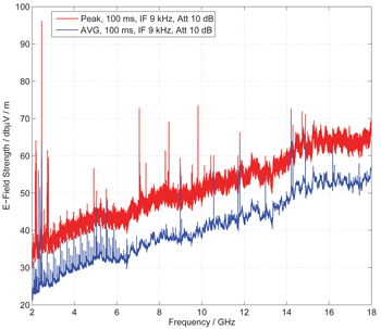
and a little dipole antenna that that will insert them into my cavity that I have designed a variable endplate geometry with a polygon shape.
How many modes will it run simultaneously at? Most of the models I see deal with one resonate mode frequency. Am I missing a duh moment here?
Time for a morning hot tub, cup of coffee and listen to the birds in the pines.
Shell
-
Title: Re: EM Drive Developments - related to space flight applications - Thread 3
Post by: aero on 06/25/2015 04:24 PM -
<a href="http://forum.nasaspaceflight.com/index.php?topic=37642.msg1393822#msg1393822">Quote from: OttO on 06/25/2015 06:13 AM</a>
@aero
I would be a lot interested in a run with two additional equal sources of microwaves OUTSIDE the frustum. One toward the big side and one toward the small side. All the other parameters the same as your previous runs.
If I am correct and if MEEP is able to simulate Wood anomalies (plasmons), we could end with one OUTSIDE end surface of the frustum less reflective than the other to microwaves.
http://cpb.iphy.ac.cn/EN/article/downloadArticleFile.do?attachType=PDF&id=26571
What do you think of that?
PS: If it is not a silly idea, and if the DIY lab is near a TV transmitter or an airport radar we could have funny results :P
http://juluribk.com/tag/free-software/
Probably something for much later. Meep models don't move and nothing on the inside affects the outside unless gaps are modelled or the skin is very thin. But if the skin is that thin then there is general degradation of meaningful results. -
Title: Re: EM Drive Developments - related to space flight applications - Thread 3
Post by: VAXHeadroom on 06/25/2015 04:32 PM -
<a href="http://forum.nasaspaceflight.com/index.php?topic=37642.msg1393973#msg1393973">Quote from: JasonAW3 on 06/25/2015 03:12 PM</a>
...
Yes, getting a test syystem to that location would be hidiously expensive, but if there are results that seem to be very promising, I don't really think we'll fully understand what is going on until gravity can be effectively eliminated as a factor.
A 10cm cube science device is $65K (IIRC) to the ISS from NanoRacks, and you can possibly get it flown by the NASA Flight Opportunities Office. So 'hideously' is a bit of an overstatement :)
-
Title: Re: EM Drive Developments - related to space flight applications - Thread 3
Post by: VAXHeadroom on 06/25/2015 04:33 PM -
<a href="http://forum.nasaspaceflight.com/index.php?topic=37642.msg1393977#msg1393977">Quote from: SeeShells on 06/25/2015 03:15 PM</a>
Yep and if my 800 watts won't do it I might react like the Myth Busters and get a high power surplus klystron from ebay and run it till it slags.
"Anything worth doing is worth overdoing." -- Adam Savage :) -
Title: Re: EM Drive Developments - related to space flight applications - Thread 3
Post by: hhexo on 06/25/2015 04:34 PM -
<a href="http://forum.nasaspaceflight.com/index.php?topic=37642.msg1394013#msg1394013">Quote from: TheTraveller on 06/25/2015 03:59 PM</a>
The EMDrive is a different breed of dog but has the same leg action.
Non powered EMDrive can move either direction.
Powered it resists movement in one direction but not the other due to differential internal Doppler shifts of the resonant standing wave inside the cavity.
I understand that. My description related to inertial mass is just another fancy way to model this behaviour.
My doubts are related to the fact that yes, the EmDrive does not resist its movement in one direction, but it does not make the whole spaceship not resist movement in that direction unless the effect is so great that it becomes equivalent to a lot of exotic negative mass.
Do you see what I mean? It will be easier to push the EmDrive in one direction, and in a limit, it will be so easy to push the EmDrive that it will seem so lighter that you would need almost zero force to do so. But what about the rest of the spaceship attached to the frustum? That is still hard to push. So you need to make the EmDrive "so easy to push that it does not just stop resisting, it encourages pushing", i.e. in my description the device has acquired apparent negative inertial mass greater in modulus than its own rest (unpowered) mass in one direction.
This makes me doubtful and sceptical, but I'm not inherently opposed to this, maybe we're just on the verge of finding something (I mean, just having a method of generating a tiny apparent negative mass would be an awesome discovery).
I just think for now that the effect will probably be smaller than what we dream of. But hey, if there is experimental data contradicting my doubts, I'll welcome it. -
Title: Re: EM Drive Developments - related to space flight applications - Thread 3
Post by: SeeShells on 06/25/2015 04:34 PM -
<a href="http://forum.nasaspaceflight.com/index.php?topic=37642.msg1393975#msg1393975">Quote from: Rodal on 06/25/2015 03:14 PM</a><a href="http://forum.nasaspaceflight.com/index.php?topic=37642.msg1393966#msg1393966">Quote from: SeeShells on 06/25/2015 03:02 PM</a>
...
Thank you for detailing it out I very much appreciate it.
On models... it's true Jose and if we were better at our models we would have had a operational fusion reactor long ago. ;) But, they are good enough to give us CERN aren't they? We're not dealing with a particle accelerator cavity are we (or maybe we are)? It's just a copper capped off cone shaped enclosure, just a slight deviation from a symmetrical resonating cavity and it should as easy as ringing a bell, it's not. HA!... like striking a large bell and hearing Johann Strauss's "The Blue Danube" over the ringing and that would be a good analogy.
We should not conflate the claims about "thrust" from the EM Drive to whether we can accurately model the natural frequency and mode shapes. Is this being conflated because of deltaMass question?
I think that deltaMass was addressing the thrust claims, and not the natural frequency or mode shape calculations. I think that deltaMass was questioning whether numerical analysis of Maxwell's equations can throw any light on the claimed "thrust".
_______
In regards to Q or natural frequencies of a cone or a hexagon shape of a given dimension we can come close to calculating those harmonics using Maxwell's equations but like I just wrote to @Rfmwguy those are just a slice of the total action that can be expected within the Frustum. And it leads heavy math papers like this one just posted. http://arxiv.org/pdf/1505.06917v1.pdf
Tub time, the effervescent waves are calling me.
Shell -
Title: Re: EM Drive Developments - related to space flight applications - Thread 3
Post by: aero on 06/25/2015 04:36 PM -
<a href="http://forum.nasaspaceflight.com/index.php?topic=37642.msg1393846#msg1393846">Quote from: KittyMoo on 06/25/2015 08:23 AM</a>
This is a good guide for installation of MEEP on Windows.
http://novelresearch.weebly.com/installing-meep-in-windows-8-via-cygwin.html (http://novelresearch.weebly.com/installing-meep-in-windows-8-via-cygwin.html)
Thanks,
I run Linux on Ubuntu but it would be great if someone else or more people tried meep.
As for support, I haven't found much online support for the rather mundane problem of simulating a resonant cavity. Professional meep users are busy inventing improved optical tweezers or evanescent microscopes or some such. -
Title: Re: EM Drive Developments - related to space flight applications - Thread 3
Post by: WarpTech on 06/25/2015 04:37 PM -
<a href="http://forum.nasaspaceflight.com/index.php?topic=37642.msg1394005#msg1394005">Quote from: hhexo on 06/25/2015 03:43 PM</a><a href="http://forum.nasaspaceflight.com/index.php?topic=37642.msg1393818#msg1393818">Quote from: WarpTech on 06/25/2015 05:42 AM</a>
When you pull it forward, it's lighter. When you push it backwards, it's heavier. An external sin(wt) oscillation will have a NET DC offset. LOL! That's hilarious!
The engineer in me still doesn't see this cruising among the stars...
If I understand correctly, this is equivalent to saying that the inertial mass of the device appears different in different directions. We can visualize it with a surface which normally is a sphere of radius m0, but which is distorted when the resonant microwaves are on, to a surface that is still radially symmetrical around the z axis but asymmetrical with respect to the xy plane. The modulus of the points on the surface determines the effective inertial mass mv (with v being the vector to the point - for each interaction you have to take the vector that's aligned with the force).
Am I correct in saying that this theory then intentionally breaks the equivalence principle? That gravitation (like any other force) would use the standard mass m0 but inertia would use an mv on the distorted surface?
I'm not inherently opposed to it, I'm just checking, is this what the theory implies?
If this theory was correct, then:
- When the device is on a scale and powered on, it would weigh more or less depending on how it's oriented, because gravitational mass would be different from inertial mass. This would explain the static results on scales, which would not be the result of thrust, but only of a perceived mass difference.
- When the device is free to move and powered on, it would resist accelerations differently in different directions. Given a vibration pattern, there would be a net movement in one direction.
- The device would not be a thruster on its own, but only an inertial dampener/booster.
The energy required for this inertial dampening would come from the power supply; I would wager that for CoE the energy that you spend for the inertia change is at least equal (but likely higher) to what you would have spent propelling the reaction mass that you didn't need to propel. So it basically saves reaction mass but doesn't save energy, it just allows you to use electric energy directly without reaction mass.
Even if we roll with it though, the engineer in me says that it still does not make space propulsion much easier. As far as I can see the device can only change the inertial mass of the device itself, not of the ship around it. Even supposing we power it with an insane amount of energy and reduce the EmDrive inertial mass to zero in one direction... it doesn't reduce the total inertial mass of the spaceship by much.
Unless it can reduce its inertial mass to negative values, but that's even more exotic and definitely in the realm of spacetime warp.
It doesn't violate the equivalence principle at all. In fact, it takes advantage of it. Think of a piston and valve in water. You pull the piston forward when the valve is open, letting water pass through it. You push the piston backwards and the valve closes, pushing the mass of water away and pushing you the other way.
In this case, the "water" is the energy stored inside at frequency "f" and energy "Q". When the frustum is pulled forward the mode moves to a lower frequency and lower energy, making the internal mass lighter. It gives up its energy as thrust, (applied energy - internal energy shift) When it is pushed backwards, it adds its energy as resistance, meaning as extra mass. (energy applied + internal energy shift) to cause resistance.
This is very important! Because this is the how it can work as a sealed cavity AND act as a thruster. What needs to be calculated using Maxwell's equations and @Rodal's solution, is how those modes and Q are affected when in an accelerated frame of reference. Maxwell's equations can certainly tell us the energy shift due to the Doppler shift and change in position inside the frustum. This difference between energy shift forward vs energy shift backwards gives us the Delta-Mass! i.e, we solved Woodward's dilemma of how to amplify the effect. :)
Todd
-
Title: Re: EM Drive Developments - related to space flight applications - Thread 3
Post by: rfmwguy on 06/25/2015 04:39 PM -
<a href="http://forum.nasaspaceflight.com/index.php?topic=37642.msg1394027#msg1394027">Quote from: SeeShells on 06/25/2015 04:21 PM</a><a href="http://forum.nasaspaceflight.com/index.php?topic=37642.msg1393986#msg1393986">Quote from: rfmwguy on 06/25/2015 03:24 PM</a>
Thank's for your vote of confidence!<a href="http://forum.nasaspaceflight.com/index.php?topic=37642.msg1393977#msg1393977">Quote from: SeeShells on 06/25/2015 03:15 PM</a><a href="http://forum.nasaspaceflight.com/index.php?topic=37642.msg1393941#msg1393941">Quote from: rfmwguy on 06/25/2015 02:21 PM</a>EMDIYers Word O' the Day: Apophenia
Yep and if my 800 watts won't do it I might react like the Myth Busters and get a high power surplus klystron from ebay and run it till it slags.
"is the experience of perceiving patterns or connections in random or meaningless data." - https://en.wikipedia.org/wiki/Apophenia
Moral of the day? Get your test results up out of the noise to show clear trends. 8)
Shell, you might be surprised about the resolution of the fulcrum test methodology. For example, I am tweaking mine for much higher resolution, increasing laser path length, oil dampening, stiffening, etc. Reason I did this is that the Q of my cavity may be much less than spreadsheet land...IOW, I'm planning for 1/10 the resolution I started out with @ 8W. So at 800W, you might launch that puppy ;)
In some ways I'm still trying to get my head around it.
I have a 800 w magnetron putting out microwaves all up and down the spectrum ~2.45 Ghz
and a little dipole antenna that that will insert them into my cavity that I have designed a variable endplate geometry with a polygon shape.
How many modes will it run simultaneously at? Most of the models I see deal with one resonate mode frequency. Am I missing a duh moment here?
Time for a morning hot tub, cup of coffee and listen to the birds in the pines.
Shell
I've been thinking about the spectral impurity of a magnetron and could it work in the emdrive's favor. There seems to be a theory floating about that the frustum needs to undergo a "discharge" or reset state, therefore, a 60% duty cycle might help accomplish this. Who knows what the reset state duration is at this point...not enough test data.
Riddle me this, does the magnetron's natural frequency drift, pulse rate and spurious sidebands actually enable this reset? Maybe...maybe not. Yours will be pulsed at higher power, mine a CW with 100% duty cycle and low spurious (a requirement for WIFI gear). So...we're covering some boundaries here...CW, pulse, input power, frustum dimensions all at 2.45 GHz...should be interesting. -
Title: Re: EM Drive Developments - related to space flight applications - Thread 3
Post by: Rodal on 06/25/2015 04:42 PM -
<a href="http://forum.nasaspaceflight.com/index.php?topic=37642.msg1394037#msg1394037">Quote from: SeeShells on 06/25/2015 04:34 PM</a>
The natural frequency and the mode shape predictions based on Maxwell's equations is all that I was referring to in previous discussions regarding numerical modeling. The natural frequency and mode shape calculations should not be conflated with whether there is thrust or no thrust. Marco Frasca paper (quoted above) is entirely consistent with that assertion.<a href="http://forum.nasaspaceflight.com/index.php?topic=37642.msg1393975#msg1393975">Quote from: Rodal on 06/25/2015 03:14 PM</a><a href="http://forum.nasaspaceflight.com/index.php?topic=37642.msg1393966#msg1393966">Quote from: SeeShells on 06/25/2015 03:02 PM</a>...
Thank you for detailing it out I very much appreciate it.
On models... it's true Jose and if we were better at our models we would have had a operational fusion reactor long ago. ;) But, they are good enough to give us CERN aren't they? We're not dealing with a particle accelerator cavity are we (or maybe we are)? It's just a copper capped off cone shaped enclosure, just a slight deviation from a symmetrical resonating cavity and it should as easy as ringing a bell, it's not. HA!... like striking a large bell and hearing Johann Strauss's "The Blue Danube" over the ringing and that would be a good analogy.
We should not conflate the claims about "thrust" from the EM Drive to whether we can accurately model the natural frequency and mode shapes. Is this being conflated because of deltaMass question?
I think that deltaMass was addressing the thrust claims, and not the natural frequency or mode shape calculations. I think that deltaMass was questioning whether numerical analysis of Maxwell's equations can throw any light on the claimed "thrust".
_______
In regards to Q or natural frequencies of a cone or a hexagon shape of a given dimension we can come close to calculating those harmonics using Maxwell's equations but like I just wrote to @Rfmwguy those are just a slice of the total action that can be expected within the Frustum. And it leads heavy math papers like this one just posted. http://arxiv.org/pdf/1505.06917v1.pdf
Tub time, the effervescent waves are calling me.
Shell -
Title: Re: EM Drive Developments - related to space flight applications - Thread 3
Post by: Rodal on 06/25/2015 04:48 PM -
<a href="http://forum.nasaspaceflight.com/index.php?topic=37642.msg1394039#msg1394039">Quote from: WarpTech on 06/25/2015 04:37 PM</a>
[...What needs to be calculated using Maxwell's equations and @Rodal's solution, is how those modes and Q are affected when in an accelerated frame of reference. Maxwell's equations can certainly tell us the energy shift due to the Doppler shift and change in position inside the frustum. This difference between energy shift forward vs energy shift backwards gives us the Delta-Mass! i.e, we solved Woodward's dilemma of how to amplify the effect. :)
Todd
Isn't that what Notsosureofit calculated ? (an accelerated frame of reference...the energy shift due to the Doppler shift and change in position inside the frustum. )
http://emdrive.wiki/@notsosureofit_Hypothesis -
Title: Re: EM Drive Developments - related to space flight applications - Thread 3
Post by: Star One on 06/25/2015 04:52 PM -
<a href="http://forum.nasaspaceflight.com/index.php?topic=37642.msg1394021#msg1394021">Quote from: TheTraveller on 06/25/2015 04:14 PM</a><a href="http://forum.nasaspaceflight.com/index.php?topic=37642.msg1394020#msg1394020">Quote from: Rodal on 06/25/2015 04:09 PM</a><a href="http://forum.nasaspaceflight.com/index.php?topic=37642.msg1394006#msg1394006">Quote from: Star One on 06/25/2015 03:47 PM</a>
I strongly disagree. TheTraveller started this by posting in this thread that Shawyer was going to publish an article in a peer-reviewed journal, and made a number of statements based on his privileged status of having the unique opportunity of having read the article ahead of publication. Nobody asked or forced TheTraveller to post about Shawyer's future article. Now TheTravellerEMD publishes the abstract of the paper.
..
Not to fight his battles for him, but he is not obligated to answer that question on something like this and you should know better than to be even asking.
WallofWolfStreet is entirely correct to ask TheTraveller about this abstract vis-a-vis TheTraveller's previous posts on this thread concerning the article he claims to have read ahead of publication.
As stated on page 1 of this thread, this thread is not a site for public advertising or promotions.
What was the purpose of TheTraveller's posting the fact that he had read Shawyer's upcoming article ?
I'm not the only active NSF member who has the paper.
Interesting and I think that answers the matter for now. -
Title: Re: EM Drive Developments - related to space flight applications - Thread 3
Post by: Dortex on 06/25/2015 04:54 PM -
<a href="http://forum.nasaspaceflight.com/index.php?topic=37642.msg1394013#msg1394013">Quote from: TheTraveller on 06/25/2015 03:59 PM</a>
Powered it resists movement in one direction but not the other due to differential internal Doppler shifts of the resonant standing wave inside the cavity.
That doesn't make sense to me at all. I'm probably misunderstanding something here, but if the drive itself is our reference frame, it doesn't move at all. Meanwhile, if I, a car, or some passing bird were used as such, it moves quite easily without any resistance. -
Title: Re: EM Drive Developments - related to space flight applications - Thread 3
Post by: Rodal on 06/25/2015 04:56 PM -
<a href="http://forum.nasaspaceflight.com/index.php?topic=37642.msg1394046#msg1394046">Quote from: Star One on 06/25/2015 04:52 PM</a>
It certainly doesn't answer the question raised by WallofWolfStreet. If anything it raises further questions. What other NSF member has access to the paper and why is that relevant to this thread?<a href="http://forum.nasaspaceflight.com/index.php?topic=37642.msg1394021#msg1394021">Quote from: TheTraveller on 06/25/2015 04:14 PM</a>...
I'm not the only active NSF member who has the paper.
Interesting and I think that answers the matter for now.
There is only one NSF member (to my knowledge) that disclosed his/her access to Shawyer's paper.
What is the purpose of posting (unasked by anyone) that she/he had privileged access to Shawyer's upcoming paper and boasting about its contents "it will remove all doubt" and now posting that another unnamed NSF member also has access?
Why give that irrelevant hearsay information (that somebody else has access to an unpublished paper) instead of providing substantive technical information on what is the subject matter of the paper?
This is not a thread to disclose who has access to unpublished papers. This is a thread to discuss the EM Drive developments - related to space flight applications - -
Title: Re: EM Drive Developments - related to space flight applications - Thread 3
Post by: hhexo on 06/25/2015 05:03 PM -
<a href="http://forum.nasaspaceflight.com/index.php?topic=37642.msg1394039#msg1394039">Quote from: WarpTech on 06/25/2015 04:37 PM</a>
It doesn't violate the equivalence principle at all. In fact, it takes advantage of it. Think of a piston and valve in water. You pull the piston forward when the valve is open, letting water pass through it. You push the piston backwards and the valve closes, pushing the mass of water away and pushing you the other way.
...
This is very important! Because this is the how it can work as a sealed cavity AND act as a thruster.
...
This difference between energy shift forward vs energy shift backwards gives us the Delta-Mass! i.e, we solved Woodward's dilemma of how to amplify the effect. :)
Todd
Ok, I see. The apparent Delta-Mass is already negative in one direction. That would be already awesome then. :)
I'm just doubtful of the following: can the Delta-Mass be so negative that it surpasses (in absolute value) the rest mass of the drive? Or any arbitrary amount of mass, for that matter. If you have a big ship attached to the drive, you need a very large negative Delta-Mass to have a visible effect.
Continuing your analogy, your piston in water will make a ship move, but of course the inertia of the rest of the ship matters. It will move significantly if it's a fishboat, and it will not move much if it's an aircraft carrier.
The Delta-Mass must be something like DeltaEnergyShift / c2. You need a LOT of stored energy to reduce the mass of a big ship!
I guess I'm just a bit of a pessimist. Only real experimental results will break my pessimism. :)
-
Title: Re: EM Drive Developments - related to space flight applications - Thread 3
Post by: WarpTech on 06/25/2015 05:12 PM -
<a href="http://forum.nasaspaceflight.com/index.php?topic=37642.msg1394056#msg1394056">Quote from: hhexo on 06/25/2015 05:03 PM</a><a href="http://forum.nasaspaceflight.com/index.php?topic=37642.msg1394039#msg1394039">Quote from: WarpTech on 06/25/2015 04:37 PM</a>
It doesn't violate the equivalence principle at all. In fact, it takes advantage of it. Think of a piston and valve in water. You pull the piston forward when the valve is open, letting water pass through it. You push the piston backwards and the valve closes, pushing the mass of water away and pushing you the other way.
...
This is very important! Because this is the how it can work as a sealed cavity AND act as a thruster.
...
This difference between energy shift forward vs energy shift backwards gives us the Delta-Mass! i.e, we solved Woodward's dilemma of how to amplify the effect. :)
Todd
Ok, I see. The apparent Delta-Mass is already negative in one direction. That would be already awesome then. :)
I'm just doubtful of the following: can the Delta-Mass be so negative that it surpasses (in absolute value) the rest mass of the drive? Or any arbitrary amount of mass, for that matter. If you have a big ship attached to the drive, you need a very large negative Delta-Mass to have a visible effect.
Continuing your analogy, your piston in water will make a ship move, but of course the inertia of the rest of the ship matters. It will move significantly if it's a fishboat, and it will not move much if it's an aircraft carrier.
The Delta-Mass must be something like DeltaEnergyShift / c2. You need a LOT of stored energy to reduce the mass of a big ship!
I guess I'm just a bit of a pessimist. Only real experimental results will break my pessimism. :)
The only differential is between frequency f1 when it's pushed forward and frequency f2 when it's pushed backwards. It can never give up more mass than that energy, Delta_E/c^2. But at high Q, that energy can be quite large.
I need to go back and look at @Notsosureofit's theory again. Now that might make more sense to me too.
Todd
-
Title: Re: EM Drive Developments - related to space flight applications - Thread 3
Post by: cej on 06/25/2015 05:21 PM -
<a href="http://forum.nasaspaceflight.com/index.php?topic=37642.msg1394039#msg1394039">Quote from: WarpTech on 06/25/2015 04:37 PM</a>
In this case, the "water" is the energy stored inside at frequency "f" and energy "Q". When the frustum is pulled forward the mode moves to a lower frequency and lower energy, making the internal mass lighter. It gives up its energy as thrust, (applied energy - internal energy shift) When it is pushed backwards, it adds its energy as resistance, meaning as extra mass. (energy applied + internal energy shift) to cause resistance.
This is very important! Because this is the how it can work as a sealed cavity AND act as a thruster. What needs to be calculated using Maxwell's equations and @Rodal's solution, is how those modes and Q are affected when in an accelerated frame of reference. Maxwell's equations can certainly tell us the energy shift due to the Doppler shift and change in position inside the frustum. This difference between energy shift forward vs energy shift backwards gives us the Delta-Mass! i.e, we solved Woodward's dilemma of how to amplify the effect. :)
Todd
Is the following another way to explain it?
Looking at the TE mode for a cylindrical cavity (https://en.wikipedia.org/wiki/Microwave_cavity (https://en.wikipedia.org/wiki/Microwave_cavity)), the frequency is (roughly) inversely proportional to the radius of the cavity. Decreasing the radius will increase the frequency, which in turn increases the momentum of light in the cavity. To satisfy conservation of momentum, the cavity has to push back against decreasing the radius. In the other direction, increasing the radius will lower the frequency and momentum of light stored in the cavity. To satisfy conservation of momentum, the lost momentum goes towards encouraging the radius to increase. If the radius is fixed, then the momentum inside the cavity will remain constant.
By having light resonate in a frustum, the change of radius is tied to acceleration along the axis of the frustum. The frustum will thus encourage pushing against its large end (increasing the cavity's radius) and resist pushing its small end (decreasing the cavity's radius). If the frustum does not accelerate along its axis, the radius will not change and no force will be observed.
-
Title: Re: EM Drive Developments - related to space flight applications - Thread 3
Post by: Rodal on 06/25/2015 05:22 PM -
<a href="http://forum.nasaspaceflight.com/index.php?topic=37642.msg1394064#msg1394064">Quote from: cej on 06/25/2015 05:21 PM</a><a href="http://forum.nasaspaceflight.com/index.php?topic=37642.msg1394039#msg1394039">Quote from: WarpTech on 06/25/2015 04:37 PM</a>
In this case, the "water" is the energy stored inside at frequency "f" and energy "Q". When the frustum is pulled forward the mode moves to a lower frequency and lower energy, making the internal mass lighter. It gives up its energy as thrust, (applied energy - internal energy shift) When it is pushed backwards, it adds its energy as resistance, meaning as extra mass. (energy applied + internal energy shift) to cause resistance.
This is very important! Because this is the how it can work as a sealed cavity AND act as a thruster. What needs to be calculated using Maxwell's equations and @Rodal's solution, is how those modes and Q are affected when in an accelerated frame of reference. Maxwell's equations can certainly tell us the energy shift due to the Doppler shift and change in position inside the frustum. This difference between energy shift forward vs energy shift backwards gives us the Delta-Mass! i.e, we solved Woodward's dilemma of how to amplify the effect. :)
Todd
Is the following another way to explain it?
Looking at the TE mode for a cylindrical cavity (https://en.wikipedia.org/wiki/Microwave_cavity (https://en.wikipedia.org/wiki/Microwave_cavity)), the frequency is (roughly) inversely proportional to the radius of the cavity. Decreasing the radius will increase the frequency, which in turn increases the momentum of light in the cavity. To satisfy conservation of momentum, the cavity has to push back against decreasing the radius. In the other direction, increasing the radius will lower the frequency and momentum of light stored in the cavity. To satisfy conservation of momentum, the lost momentum goes towards encouraging the radius to increase. If the radius is fixed, then the momentum inside the cavity will remain constant.
By having light resonate in a frustum, the change of radius is tied to acceleration along the axis of the frustum. The frustum will thus encourage pushing against its large end (increasing the cavity's radius) and resist pushing its small end (decreasing the cavity's radius). If the frustum does not accelerate along its axis, the radius will not change and no force will be observed.
Here is Notsosureofit's analysis:
http://emdrive.wiki/@notsosureofit_Hypothesis -
Title: Re: EM Drive Developments - related to space flight applications - Thread 3
Post by: Rodal on 06/25/2015 05:28 PM -
<a href="http://forum.nasaspaceflight.com/index.php?topic=37642.msg1394049#msg1394049">Quote from: Rodal on 06/25/2015 04:56 PM</a><a href="http://forum.nasaspaceflight.com/index.php?topic=37642.msg1394046#msg1394046">Quote from: Star One on 06/25/2015 04:52 PM</a>
It certainly doesn't answer the question raised by WallofWolfStreet. If anything it raises further questions. What other NSF member has access to the paper and why is that relevant to this thread?<a href="http://forum.nasaspaceflight.com/index.php?topic=37642.msg1394021#msg1394021">Quote from: TheTraveller on 06/25/2015 04:14 PM</a>...
I'm not the only active NSF member who has the paper.
Interesting and I think that answers the matter for now.
There is only one NSF member (to my knowledge) that disclosed his/her access to Shawyer's paper.
What is the purpose of posting (unasked by anyone) that she/he had privileged access to Shawyer's upcoming paper and boasting about its contents "it will remove all doubt" and now posting that another unnamed NSF member also has access?
Why give that irrelevant hearsay information (that somebody else has access to an unpublished paper) instead of providing substantive technical information on what is the subject matter of the paper?
This is not a thread to disclose who has access to unpublished papers. This is a thread to discuss the EM Drive developments - related to space flight applications -
For some substantive discussion (instead of this nonsense about "I'm not the only active NSF member who has the paper", this is the 2013 paper on Shawyer's superconducting thruster that the abstract of the new paper [that was claimed to "remove all doubts"] discusses:
http://www.emdrive.com/IAC13paper17254.v2.pdf
IAC-13,C4,P,44.p1,x17254
THE DYNAMIC OPERATON OF A HIGH Q EMDRIVE MICROWAVE THRUSTER
Roger Shawyer C.Eng. MIET. FRAeS
SPR Ltd UK sprltd@emdrive.com
Notice the emphasis on "designed" and "modelled" and the lack of discussion on experiments and experimental details.Quote from: ShawyerSuperconducting second generation thrusters were
then modelled, cooled first with liquid nitrogen and
then with liquid hydrogen. The thruster designs
were based on the results obtained from the
experimental YBCO thin film thruster described in
REF 3. With the thruster cooled to 77deg K using
liquid nitrogen, a Q of 6.8x10⁶ was measured.
Fig 3 shows the model results with the modified 2G
thruster cooled with liquid nitrogen, giving a static
specific thrust of 16.5 N/kW for an unloaded Q
factor of 3.7x10⁶
. With this modest value of Q it
requires high acceleration to cause significant
reduction of specific thrust. In this case an
acceleration of 1000m/s/s ((100g) gives a specific
thrust reduced to 4 N/kW.
Fig 4 gives the results for a lower frequency cavity,
cooled by liquid Hydrogen, thus operating at a
temperature of 20deg K, and achieving a static
specific thrust of 173 N/kW, with an unloaded Q
factor of 3.9x10⁷
. For an uncompensated thruster,
the loss of Q, and hence reduction of specific thrust
with acceleration is more pronounced. The model
results show a specific thrust of 11 N/kW for an
acceleration of 20m/s/s (2g).
A compensated cavity was designed and modelled,
where the axial length of the cavity is modified
according to the acceleration experienced by the
thruster. The cavity extension for a positive
acceleration of 20 m/s/s is illustrated in Fig 5. The
extension results from a pulsed voltage being
applied to piezoelectric elements in the sidewall of
the cavity. The pulse length is determined by the
time constant of the resonant cavity. A description
of such a thruster design is given in REF 4.
Clearly this simple form of compensation cannot
completely compensate for the Doppler shift
throughout a full pulse cycle, but fig 4 shows that
the specific thrust at 20m/s/s can be improved to 92
N/kW.Quote from: ShawyerA large high power thruster was designed,
operating at 900 MHz. This thruster again used a
YBCO superconducting coating, and was cooled
with liquid Hydrogen. The compensation technique
included both cavity length extension and
frequency offset, with a lower duty cycle than the
3.85 GHz thruster. A specific thrust of 9.92 kN/kW
was predicted with an acceleration limit of
0.5m/s/s.
This L-Band thruster was part of a design study for
a radically new approach to launch vehicles. A
Hybrid Spaceplane was proposed, using 2G LBand
EmDrive thrusters as lift engines, with
conventional low thrust jet engines and rocket
engines for auxilary propulsion. These secondary
propulsion units are fuelled by the gaseous
Hydrogen, boiled off during the cooling of the
EmDrive thrusters. The fuel cells used to provide
DC power to the microwave power sources would
also be fuelled in the same way. The initial
spaceplane design was described in REF 5. -
Title: Re: EM Drive Developments - related to space flight applications - Thread 3
Post by: aero on 06/25/2015 05:43 PM -
@Rodal - I was looking for antenna placement. But without having a proper resonant frequency for the cavity it doesn't matter where the antenna is, it won't resonate. So my thought was to find a resonant frequency then move the antenna to produce the highest Q for that frequency. Iterate.
So would you like to provide the correct resonant frequency for rfmwguy's cavity? Note that the drive frequency must be 2.45 GHz but that does not constrain the resonant frequency of the cavity. If the cavity resonant frequency is not 2.45 GHz then, as rfmwguy writes, he must modify his cavity dimensions until it does resonate at 2.45 GHz.
So you tell me what the resonant frequency actually is, change the dimensions as needed to reach 2.45 GHz resonance, then I can place the antenna to achieve the best Q.
I point out that if we don't support the DIY efforts (such as rfmwguy's) to the best of our ability then the experimental results that are achieved can not be definitive considering all the other limitations that DIYers must work under.
-
Title: Re: EM Drive Developments - related to space flight applications - Thread 3
Post by: zen-in on 06/25/2015 05:44 PM -
<a href="http://forum.nasaspaceflight.com/index.php?topic=37642.msg1394049#msg1394049">Quote from: Rodal on 06/25/2015 04:56 PM</a><a href="http://forum.nasaspaceflight.com/index.php?topic=37642.msg1394046#msg1394046">Quote from: Star One on 06/25/2015 04:52 PM</a>
It certainly doesn't answer the question raised by WallofWolfStreet. If anything it raises further questions. What other NSF member has access to the paper and why is that relevant to this thread?<a href="http://forum.nasaspaceflight.com/index.php?topic=37642.msg1394021#msg1394021">Quote from: TheTraveller on 06/25/2015 04:14 PM</a>...
I'm not the only active NSF member who has the paper.
Interesting and I think that answers the matter for now.
There is only one NSF member (to my knowledge) that disclosed his/her access to Shawyer's paper.
What is the purpose of posting (unasked by anyone) that she/he had privileged access to Shawyer's upcoming paper and boasting about its contents "it will remove all doubt" and now posting that another unnamed NSF member also has access?
Why give that irrelevant hearsay information (that somebody else has access to an unpublished paper) instead of providing substantive technical information on what is the subject matter of the paper?
This is not a thread to disclose who has access to unpublished papers. This is a thread to discuss the EM Drive developments - related to space flight applications -
This is another example of the disruptive thread-hijacking of the Travellers' posts. Earlier I complained about his persistent spam posts and empty promotion of Shawyers' dubious experiments. Whenever he has been asked to clarify one of his claims we just get the run-around. This really reflects poorly on Shawyer and has further impugned his credibility. I don't know if Shawyer is paying this guy but I would venture to say he is not getting his money's worth if that is the case. -
Title: Re: EM Drive Developments - related to space flight applications - Thread 3
Post by: flux_capacitor on 06/25/2015 05:49 PM -
<a href="http://forum.nasaspaceflight.com/index.php?topic=37642.msg1393904#msg1393904">Quote from: Rodal on 06/25/2015 01:15 PM</a>
TheTravellerEMD posted the abstract on reddit: (bold added for emphasis)
Quote from: TheTravellerEMDSECOND GENERATION EMDRIVE PROPULSION APPLIED TO SSTO LAUNCHER AND INTERSTELLAR PROBE
Roger Shawyer C.Eng.MIET.FRAeS
SPR Ltd, United Kingdom
sprltd@emdrive.com
ABSTRACT
In an IAC13 paper the dynamic operation of a second generation superconducting EmDrive thruster was described.
A mathematical model was developed, and in this paper, that model is used to extend the performance envelope of the technology.
Three engine designs are evaluated. One is used as a lift engine for a launch vehicle, another as an orbital engine for the launcher, and a third as the main engine for an interstellar probe.
The engines are based on YBCO superconducting cavities, and performance is predicted on the basis of the test data obtained in earlier experimental programmes.
The Q values range from 8 x 10^7 to 2 x 10^8 and provide high specific thrusts over a range of accelerations from 0.4 m/s^2 to 6 m/s^2.
The launch vehicle is an “all-electric” single stage to orbit (SSTO) spaceplane, using a 900 MHz, eight cavity, fully gimballed lift engine.
A 1.5 GHz fixed orbital engine provides the horizontal velocity component.
Both engines use total loss liquid hydrogen cooling.
Electrical power is provided by fuel cells, fed with gaseous hydrogen from the cooling system and liquid oxygen.
A 2 Tonne payload, externally mounted, can be flown to Low Earth Orbit in a time of 27 minutes.
The total launch mass is 10 Tonnes, with an airframe styled on the X37B, which allows aerobraking and a glide approach and landing.
The full potential of EmDrive propulsion for deep space missions is illustrated by the performance of the interstellar probe.
A multi-cavity, fixed 500 MHz engine is cooled by a closed cycle liquid nitrogen system.
The refrigeration is carried out in a two stage reverse Brayton Cycle. Electrical power is provided by a 200 kWe nuclear generator.
The 9 Tonne spacecraft, which includes a 1 Tonne science payload, will achieve a terminal velocity of 0.67c and cover a distance of 4 light years, over the 10 year propulsion period.
The work reported in this paper has resulted in design studies for two Demonstrator spacecraft.
The launcher will demonstrate the long-sought-for, low cost access to space, and also meet the mission requirements of the proposed DARPA XS-1 Spaceplane.
The probe will enable the dream of an interstellar mission to be achieved within the next 20 years.
It will be interesting (from a public's expectation study point of view) to hear whether this abstract meets what readers here were expecting from what was said about the paper.
Sorry but this is nothing new, sadly. The text of this upcoming abstract is the exact same as in the non peer-reviewed paper presented by Shawyer at the IAC conference, Toronto, Canada, in October 2014. The title was exactly the same BTW. More important, the text was the same. On the SPR web site, only the more vague presentation paper (http://www.emdrive.com/iac2014presentation.pdf) is available, but the full IAC 2014 paper has been posted in the NSF EmDrive thread 2 by Mulletron in this post (http://forum.nasaspaceflight.com/index.php?topic=36313.msg1369051#msg1369051).
Shawyer, Roger (29 September–3 October 2014). "Second Generation EmDrive Propulsion Applied to SSTO Launcher and Interstellar Probe", 65th International Astronautical Congress (IAC 2014). Toronto, Canada: International Astronautical Federation.
So it appears TheTravellerEMD on Reddit posted the abstract of the 2014 IAC paper??? Or the peer-review 2015 paper is based entirely on the 2014 conference paper? I'm confused.
If the abstract is the same, we should not hold our breath. That conference paper was all about projective study showing theoretical features of a conceptual superconducting EmDrive. No real data or new experimental results from any superconducting test article. I really hope I'm wrong and the 2015 peer-reviewed paper is completely different :(
I don't think many of you has ever read it, so I attach the full IAC 2014 paper below.
[EDIT]: @TheTraveller, can you tell us, just if the upcoming 2015 paper is written on the same grounds as the IAC 2014 paper? -
Title: Re: EM Drive Developments - related to space flight applications - Thread 3
Post by: Rodal on 06/25/2015 05:50 PM -
<a href="http://forum.nasaspaceflight.com/index.php?topic=37642.msg1394078#msg1394078">Quote from: aero on 06/25/2015 05:43 PM</a>
@Rodal - I was looking for antenna placement. But without having a proper resonant frequency for the cavity it doesn't matter where the antenna is, it won't resonate. So my thought was to find a resonant frequency then move the antenna to produce the highest Q for that frequency. Iterate.
So would you like to provide the correct resonant frequency for rfmwguy's cavity? Note that the drive frequency must be 2.45 GHz but that does not constrain the resonant frequency of the cavity. If the cavity resonant frequency is not 2.45 GHz then, as rfmwguy writes, he must modify his cavity dimensions until it does resonate at 2.45 GHz.
So you tell me what the resonant frequency actually is, change the dimensions as needed to reach 2.45 GHz resonance, then I can place the antenna to achieve the best Q.
I point out that if we don't support the DIY efforts (such as rfmwguy's) to the best of our ability then the experimental results that are achieved can not be definitive considering all the other limitations that DIYers must work under.
From what I recall, @rfmwguy provided some dimensions to TheTraveller, who gave him answers regarding resonance.
Then @rfmwguy asked why was there so much difference between @rfmwguy calculation for natural frequency and TheTraveller's calculation, to resonate at 2.45 GHz. So I calculated and gave @rfmwguy the length required to resonate at 2.45GHz. So my understanding is that @rfmwguy now has at least 3 answers (@rfmwguy's calculation, TheTraveller's calculation and my calculation) on the length at which it will resonate at 2.45 GHz.
Also, as I wrote in the prior pages, if your Meep code does not show resonance I think that this is probably due to your particular Meep model (and no fault of Meep). Have you compared a similar discretization FD mesh from your model, adapted to a cylindrical cavity and compare how close to the exact solution for a cylinder it is?
Model a cylinder with Meep with the Mean diameter where Mean= (BigDiameter+SmallDiameter)/2 and see how close is your Meep model to the exact solution for a cylinder. Here is the exact, closed-form solution: https://en.wikipedia.org/wiki/Microwave_cavity#Cylindrical_cavity
If your Meep model cannot accurately predict the natural frequency of a cylinder, it would be hopeless to predict the natural frequency of a truncated cone. So my advice is that you should start with that comparison, if you want to predict natural frequencies of a truncated cone. -
Title: Re: EM Drive Developments - related to space flight applications - Thread 3
Post by: SeeShells on 06/25/2015 05:51 PM -
<a href="http://forum.nasaspaceflight.com/index.php?topic=37642.msg1394041#msg1394041">Quote from: Rodal on 06/25/2015 04:42 PM</a><a href="http://forum.nasaspaceflight.com/index.php?topic=37642.msg1394037#msg1394037">Quote from: SeeShells on 06/25/2015 04:34 PM</a><a href="http://forum.nasaspaceflight.com/index.php?topic=37642.msg1393975#msg1393975">Quote from: Rodal on 06/25/2015 03:14 PM</a><a href="http://forum.nasaspaceflight.com/index.php?topic=37642.msg1393966#msg1393966">Quote from: SeeShells on 06/25/2015 03:02 PM</a>
...
The natural frequency and the mode shape predictions based on Maxwell's equations is all that I was referring to in previous discussions regarding numerical modeling. The natural frequency and mode shape calculations should not be conflated with whether there is thrust or no thrust. Marco Frasca paper (quoted above) is entirely consistent with that assertion.
Shell
Your right, I got off on a tangent just was getting frustrated at the limits of modeling. I'm more of a hands on kind of gal.
I read Frasca's paper (you were mentioned as well) and I think its done very well and I've added it to my substantial list of papers theorizing the hows and whys of thrust. Not discing anyone but this is like "The Price Is Right".
The how and why intrigues me, but Jose the rubber hits the road in building it. I know the task I've set out for myself is daunting and I've had to pull from decades of in the trenches engineering, hoping to add a little something to a discovery that might be as game changing as the taming of fire. The Higgs took Billions to discover and just from a theory. I'm trying to do about the same with a couple hundred bucks, scrap parts and staggered with multiple ideas and theories to "The Dam* Thing Won't Work". So I'm picking brains for any scraps to help and thanks to all for the atta girl.
Shell
PS: Hot tub was GREAT! -
Title: Re: EM Drive Developments - related to space flight applications - Thread 3
Post by: SeeShells on 06/25/2015 05:54 PM -
<a href="http://forum.nasaspaceflight.com/index.php?topic=37642.msg1394038#msg1394038">Quote from: aero on 06/25/2015 04:36 PM</a>
Maybe after my build I look more into it as it seems to be a time hog and the build is my first priority.<a href="http://forum.nasaspaceflight.com/index.php?topic=37642.msg1393846#msg1393846">Quote from: KittyMoo on 06/25/2015 08:23 AM</a>This is a good guide for installation of MEEP on Windows.
http://novelresearch.weebly.com/installing-meep-in-windows-8-via-cygwin.html (http://novelresearch.weebly.com/installing-meep-in-windows-8-via-cygwin.html)
Thanks,
I run Linux on Ubuntu but it would be great if someone else or more people tried meep.
As for support, I haven't found much online support for the rather mundane problem of simulating a resonant cavity. Professional meep users are busy inventing improved optical tweezers or evanescent microscopes or some such.
Shell -
Title: Re: EM Drive Developments - related to space flight applications - Thread 3
Post by: Star One on 06/25/2015 05:57 PM -
<a href="http://forum.nasaspaceflight.com/index.php?topic=37642.msg1394079#msg1394079">Quote from: zen-in on 06/25/2015 05:44 PM</a><a href="http://forum.nasaspaceflight.com/index.php?topic=37642.msg1394049#msg1394049">Quote from: Rodal on 06/25/2015 04:56 PM</a><a href="http://forum.nasaspaceflight.com/index.php?topic=37642.msg1394046#msg1394046">Quote from: Star One on 06/25/2015 04:52 PM</a>
It certainly doesn't answer the question raised by WallofWolfStreet. If anything it raises further questions. What other NSF member has access to the paper and why is that relevant to this thread?<a href="http://forum.nasaspaceflight.com/index.php?topic=37642.msg1394021#msg1394021">Quote from: TheTraveller on 06/25/2015 04:14 PM</a>...
I'm not the only active NSF member who has the paper.
Interesting and I think that answers the matter for now.
There is only one NSF member (to my knowledge) that disclosed his/her access to Shawyer's paper.
What is the purpose of posting (unasked by anyone) that she/he had privileged access to Shawyer's upcoming paper and boasting about its contents "it will remove all doubt" and now posting that another unnamed NSF member also has access?
Why give that irrelevant hearsay information (that somebody else has access to an unpublished paper) instead of providing substantive technical information on what is the subject matter of the paper?
This is not a thread to disclose who has access to unpublished papers. This is a thread to discuss the EM Drive developments - related to space flight applications -
This is another example of the disruptive thread-hijacking of the Travellers' posts. Earlier I complained about his persistent spam posts and empty promotion of Shawyers' dubious experiments. Whenever he has been asked to clarify one of his claims we just get the run-around. This really reflects poorly on Shawyer and has further impugned his credibility. I don't know if Shawyer is paying this guy but I would venture to say he is not getting his money's worth if that is the case.
And how is resorting to so far baseless accusations against another poster helping the thread?
All you're going to achieve is the possibility of getting the thread locked or your posts removed. -
Title: Re: EM Drive Developments - related to space flight applications - Thread 3
Post by: Rodal on 06/25/2015 06:11 PM -
<a href="http://forum.nasaspaceflight.com/index.php?topic=37642.msg1394081#msg1394081">Quote from: flux_capacitor on 06/25/2015 05:49 PM</a><a href="http://forum.nasaspaceflight.com/index.php?topic=37642.msg1393904#msg1393904">Quote from: Rodal on 06/25/2015 01:15 PM</a>
TheTravellerEMD posted the abstract on reddit: (bold added for emphasis)
Quote from: TheTravellerEMDSECOND GENERATION EMDRIVE PROPULSION APPLIED TO SSTO LAUNCHER AND INTERSTELLAR PROBE
Roger Shawyer C.Eng.MIET.FRAeS
SPR Ltd, United Kingdom
sprltd@emdrive.com
ABSTRACT
In an IAC13 paper the dynamic operation of a second generation superconducting EmDrive thruster was described.
A mathematical model was developed, and in this paper, that model is used to extend the performance envelope of the technology.
Three engine designs are evaluated. One is used as a lift engine for a launch vehicle, another as an orbital engine for the launcher, and a third as the main engine for an interstellar probe.
The engines are based on YBCO superconducting cavities, and performance is predicted on the basis of the test data obtained in earlier experimental programmes.
The Q values range from 8 x 10^7 to 2 x 10^8 and provide high specific thrusts over a range of accelerations from 0.4 m/s^2 to 6 m/s^2.
The launch vehicle is an “all-electric” single stage to orbit (SSTO) spaceplane, using a 900 MHz, eight cavity, fully gimballed lift engine.
A 1.5 GHz fixed orbital engine provides the horizontal velocity component.
Both engines use total loss liquid hydrogen cooling.
Electrical power is provided by fuel cells, fed with gaseous hydrogen from the cooling system and liquid oxygen.
A 2 Tonne payload, externally mounted, can be flown to Low Earth Orbit in a time of 27 minutes.
The total launch mass is 10 Tonnes, with an airframe styled on the X37B, which allows aerobraking and a glide approach and landing.
The full potential of EmDrive propulsion for deep space missions is illustrated by the performance of the interstellar probe.
A multi-cavity, fixed 500 MHz engine is cooled by a closed cycle liquid nitrogen system.
The refrigeration is carried out in a two stage reverse Brayton Cycle. Electrical power is provided by a 200 kWe nuclear generator.
The 9 Tonne spacecraft, which includes a 1 Tonne science payload, will achieve a terminal velocity of 0.67c and cover a distance of 4 light years, over the 10 year propulsion period.
The work reported in this paper has resulted in design studies for two Demonstrator spacecraft.
The launcher will demonstrate the long-sought-for, low cost access to space, and also meet the mission requirements of the proposed DARPA XS-1 Spaceplane.
The probe will enable the dream of an interstellar mission to be achieved within the next 20 years.
It will be interesting (from a public's expectation study point of view) to hear whether this abstract meets what readers here were expecting from what was said about the paper.
Sorry but this is nothing new, sadly. The text of this upcoming abstract is the exact same as in the non peer-reviewed paper presented by Shawyer at the IAC conference, Toronto, Canada, in October 2014. The title was exactly the same BTW. More important, the text was the same. On the SPR web site, only the more vague presentation paper (http://www.emdrive.com/iac2014presentation.pdf) is available, but the full IAC 2014 paper has been posted in the NSF EmDrive thread 2 by Mulletron in this post (http://forum.nasaspaceflight.com/index.php?topic=36313.msg1369051#msg1369051).
Shawyer, Roger (29 September–3 October 2014). "Second Generation EmDrive Propulsion Applied to SSTO Launcher and Interstellar Probe", 65th International Astronautical Congress (IAC 2014). Toronto, Canada: International Astronautical Federation.
So it appears TheTravellerEMD on Reddit posted the abstract of the 2014 IAC paper??? Or the peer-review 2015 paper is based entirely on the 2014 conference paper? I'm confused.
If the abstract is the same, we should not hold our breath. That conference paper was all about projective study showing theoretical features of a conceptual superconducting EmDrive. No real data or new experimental results from any superconducting test article. I really hope I'm wrong and the 2015 peer-reviewed paper is completely different :(
I don't think many of you has ever read it, so I attach the full IAC 2014 paper below.
[EDIT]: @TheTraveller, can you tell us, just if the upcoming 2015 paper is written on the same grounds as the IAC 2014 paper?
<<The text of this upcoming abstract is the exact same as in the non peer-reviewed paper presented by Shawyer at the IAC conference, Toronto, Canada, in October 2014.>>
You mean, the abstract of the "peer-reviewed paper" that is going "to remove all doubt" is the exact same as the 2014 paper???
Either TheTravellerEMD made a mistake or this is extremely disappointing news to anyone that believed the report that new upcoming results "to remove all doubts" would appear in the upcoming ''peer-reviewed" paper.
I sincerely hope that TheTravellerEMD made an innocent human mistake here and confused the 2014 and 2015 abstracts.
But if it is true that TheTraveller had read the upcoming peer-reviewed paper by Shawyer, he/she should certainly be able to tell us whether a mistake was made, or whether the peer-reviewed paper has the same abstract as the 2014 conference paper (this would be very strange as most peer-reviewed reputable journals do NOT accept papers that have been presented at old conferences). -
Title: Re: EM Drive Developments - related to space flight applications - Thread 3
Post by: kdhilliard on 06/25/2015 06:22 PM -
<a href="http://forum.nasaspaceflight.com/index.php?topic=37642.msg1393904#msg1393904">Quote from: Rodal on 06/25/2015 01:15 PM</a>
TheTravellerEMD posted the abstract on reddit:
Thanks Dr. Rodal,
...
I didn't see a link to the reddit post, so here it is:
https://www.reddit.com/r/EmDrive/comments/3b2gxc/abstract_from_the_soon_to_be_released_emdrive/
~Kirk -
Title: Re: EM Drive Developments - related to space flight applications - Thread 3
Post by: rfmwguy on 06/25/2015 06:25 PM -
<a href="http://forum.nasaspaceflight.com/index.php?topic=37642.msg1394084#msg1394084">Quote from: Rodal on 06/25/2015 05:50 PM</a><a href="http://forum.nasaspaceflight.com/index.php?topic=37642.msg1394078#msg1394078">Quote from: aero on 06/25/2015 05:43 PM</a>
@Rodal - I was looking for antenna placement. But without having a proper resonant frequency for the cavity it doesn't matter where the antenna is, it won't resonate. So my thought was to find a resonant frequency then move the antenna to produce the highest Q for that frequency. Iterate.
So would you like to provide the correct resonant frequency for rfmwguy's cavity? Note that the drive frequency must be 2.45 GHz but that does not constrain the resonant frequency of the cavity. If the cavity resonant frequency is not 2.45 GHz then, as rfmwguy writes, he must modify his cavity dimensions until it does resonate at 2.45 GHz.
So you tell me what the resonant frequency actually is, change the dimensions as needed to reach 2.45 GHz resonance, then I can place the antenna to achieve the best Q.
I point out that if we don't support the DIY efforts (such as rfmwguy's) to the best of our ability then the experimental results that are achieved can not be definitive considering all the other limitations that DIYers must work under.
I really don't understand what you are discussing above and I'll wait for @rfmwguy to explain it.
From what I recall, @rfmwguy provided some dimensions to TheTraveller, who gave him answers regarding resonance.
Then @rfmwguy asked why was there so much difference between @rfmwguy calculation for natural frequency and TheTraveller's calculation, to resonate at 2.45 GHz. So I calculated and gave @rfmwguy the length required to resonate at 2.45GHz. So my understanding is that @rfmwguy now has at least 3 answers (@rfmwguy's calculation, TheTraveller's calculation and my calculation) on the length at which it will resonate at 2.45 GHz.
Also, as I wrote in the prior pages, if your Meep code does not show resonance I think that this is probably due to your particular Meep model (and no fault of Meep). Have you compared a similar discretization FD mesh from your model, adapted to a cylindrical cavity and compare how close to the exact solution for a cylinder it is?
Model a cylinder with Meep with the Mean diameter where Mean= (BigDiameter+SmallDiameter)/2 and see how close is your Meep model to the exact solution for a cylinder. Here is the exact, closed-form solution: https://en.wikipedia.org/wiki/Microwave_cavity#Cylindrical_cavity
If your Meep model cannot accurately predict the natural frequency of a cylinder, it would be hopeless to predict the natural frequency of a truncated cone. So my advice is that you should start with that comparison, if you want to predict natural frequencies of a truncated cone.
Yes, I now have conflicting dimensions, however, am not even sure that "resonance" is key to the success of the thing. One would have to assume that max Q = max resonance to a large degree...some think Q may not be an overiding factor. So little real data from industry is being shared right now, we're on this path with a single flashlight. So be it in the initial stages of development...( )it happens.
I'd venture to say that this "project" does not have billion-dollar implications, it has trillion-dollar implications IF the device can be scaled and replicated. What we have here is what the brit papers are saying...potential for revolutionizing the aerospace/transport industry. Naturally, anything being done by capitalists eager on getting a slice of the pie will be hidden BEHIND CLOSED DOORS...been there.
Here's one thing my aerospace marketing instincts tell me...if this "effect" was bogus, many companies would have officially said so...with test results. All we have now is theoretical naysayers claiming such, but not one, to my knowledge has completed nor commissioned a build, so sure of their own belief system.
I'll go with 6.25 x 11.01 x 9.91L and let the chips fall where they may. I appreciate all the help at getting to this decision stage.
-
Title: Re: EM Drive Developments - related to space flight applications - Thread 3
Post by: Blaine on 06/25/2015 06:25 PM - Well, it looks like we can only look for current DIYers and NASA to give us the data we want. I am eagerly awaiting new results form the Baby EM Drive experiments.
-
Title: Re: EM Drive Developments - related to space flight applications - Thread 3
Post by: Rodal on 06/25/2015 06:33 PM -
<a href="http://forum.nasaspaceflight.com/index.php?topic=37642.msg1394100#msg1394100">Quote from: rfmwguy on 06/25/2015 06:25 PM</a>
...
Yes, I now have conflicting dimensions, however, am not even sure that "resonance" is key to the success of the thing. One would have to assume that max Q = max resonance to a large degree...some think Q may not be an overiding factor. So little real data from industry is being shared right now, we're on this path with a single flashlight. So be it in the initial stages of development...( )it happens.
I'd venture to say that this "project" does not have billion-dollar implications, it has trillion-dollar implications IF the device can be scaled and replicated. What we have here is what the brit papers are saying...potential for revolutionizing the aerospace/transport industry. Naturally, anything being done by capitalists eager on getting a slice of the pie will be hidden BEHIND CLOSED DOORS...been there.
Here's one thing my aerospace marketing instincts tell me...if this "effect" was bogus, many companies would have officially said so...with test results. All we have now is theoretical naysayers claiming such, but not one, to my knowledge has completed nor commissioned a build, so sure of their own belief system.
I'll go with 6.25 x 11.01 x 9.91L and let the chips fall where they may. I appreciate all the help at getting to this decision stage.
bigDiameter = 11.01 inches;
smallDiameter = 6.25 inches;
axialLength = 9 inches; NOTICE 9 inches -- in this case
with FLAT ENDs with a TRANSVERSE MAGNETIC MODE. It resonates at 2.45032 GHz with TM212
////////////////////////////////
bigDiameter = 11.01 inches;
smallDiameter = 6.25 inches;
axialLength = 10.2 inches; NOTICE 10.2 inches -- in this case
with FLAT ENDs with a TRANSVERSE ELECTRIC MODE. It resonates at 2.45044 GHz with TE013
////////////////////////////////
(Note: my previous calculation for 9.91 inches for TE013 resonance was using SPHERICAL ENDS)
L = 9.91 inches with spherical ends will resonate at TE013 at 2.45 GHz
L = 9.91 inches with flat ends will resonate at TE013 at 2.48468 GHz -
Title: Re: EM Drive Developments - related to space flight applications - Thread 3
Post by: Star One on 06/25/2015 06:42 PM -
<a href="http://forum.nasaspaceflight.com/index.php?topic=37642.msg1394096#msg1394096">Quote from: kdhilliard on 06/25/2015 06:22 PM</a><a href="http://forum.nasaspaceflight.com/index.php?topic=37642.msg1393904#msg1393904">Quote from: Rodal on 06/25/2015 01:15 PM</a>
TheTravellerEMD posted the abstract on reddit:
Thanks Dr. Rodal,
...
I didn't see a link to the reddit post, so here it is:
https://www.reddit.com/r/EmDrive/comments/3b2gxc/abstract_from_the_soon_to_be_released_emdrive/
~Kirk
Thanks wasn't aware of that as it was posted there and not here. -
Title: Re: EM Drive Developments - related to space flight applications - Thread 3
Post by: tchernik on 06/25/2015 06:48 PM -
<a href="http://forum.nasaspaceflight.com/index.php?topic=37642.msg1394092#msg1394092">Quote from: Rodal on 06/25/2015 06:11 PM</a><a href="http://forum.nasaspaceflight.com/index.php?topic=37642.msg1394081#msg1394081">Quote from: flux_capacitor on 06/25/2015 05:49 PM</a><a href="http://forum.nasaspaceflight.com/index.php?topic=37642.msg1393904#msg1393904">Quote from: Rodal on 06/25/2015 01:15 PM</a>
TheTravellerEMD posted the abstract on reddit: (bold added for emphasis)
Sorry but this is nothing new, sadly. The text of this upcoming abstract is the exact same as in the non peer-reviewed paper presented by Shawyer at the IAC conference, Toronto, Canada, in October 2014. The title was exactly the same BTW. More important, the text was the same. On the SPR web site, only the more vague presentation paper (http://www.emdrive.com/iac2014presentation.pdf) is available, but the full IAC 2014 paper has been posted in the NSF EmDrive thread 2 by Mulletron in this post (http://forum.nasaspaceflight.com/index.php?topic=36313.msg1369051#msg1369051).
Shawyer, Roger (29 September–3 October 2014). "Second Generation EmDrive Propulsion Applied to SSTO Launcher and Interstellar Probe", 65th International Astronautical Congress (IAC 2014). Toronto, Canada: International Astronautical Federation.
So it appears TheTravellerEMD on Reddit posted the abstract of the 2014 IAC paper??? Or the peer-review 2015 paper is based entirely on the 2014 conference paper? I'm confused.
If the abstract is the same, we should not hold our breath. That conference paper was all about projective study showing theoretical features of a conceptual superconducting EmDrive. No real data or new experimental results from any superconducting test article. I really hope I'm wrong and the 2015 peer-reviewed paper is completely different :(
I don't think many of you has ever read it, so I attach the full IAC 2014 paper below.
[EDIT]: @TheTraveller, can you tell us, just if the upcoming 2015 paper is written on the same grounds as the IAC 2014 paper?
<<The text of this upcoming abstract is the exact same as in the non peer-reviewed paper presented by Shawyer at the IAC conference, Toronto, Canada, in October 2014.>>
You mean, the abstract of the "peer-reviewed paper" that is going "to remove all doubt" is the exact same as the 2014 paper???
Either TheTravellerEMD made a mistake or this is extremely disappointing news to anyone that believed the report that new upcoming results "to remove all doubts" would appear in the upcoming ''peer-reviewed" paper.
I sincerely hope that TheTravellerEMD made an innocent human mistake here and confused the 2014 and 2015 abstracts.
But if it is true that TheTraveller had read the upcoming peer-reviewed paper by Shawyer, he/she should certainly be able to tell us whether a mistake was made, or whether the peer-reviewed paper has the same abstract as the 2014 conference paper (this would be very strange as most peer-reviewed reputable journals do NOT accept papers that have been presented at old conferences).
My hunch on this is that Mr. Shawyer simply has failed to produce a workable superconductor Emdrive demonstrator. Ergo, no new results to show.
Either because the superconductor material he is using is too frail, or flimsy or unwieldy and it doesn't result in a stable shape producing the expected Q values for enough time to conduct tests, and therefore, no measurements and no significant thrust increase is evidenced.
Or maybe he doesn't actually have the financial resources to do it on his own.
Note that all of these unforeseen challenges don't say zilch about the validity of the phenomenon. They are the mere vicissitudes of life and experimental physics.
What is bad PR is to oversell upcoming results and just copy-paste and slightly edit previous results. If he has nothing new, he shouldn't publish the same things as if they were new. -
Title: Re: EM Drive Developments - related to space flight applications - Thread 3
Post by: rfmwguy on 06/25/2015 06:56 PM -
<a href="http://forum.nasaspaceflight.com/index.php?topic=37642.msg1394104#msg1394104">Quote from: Rodal on 06/25/2015 06:33 PM</a><a href="http://forum.nasaspaceflight.com/index.php?topic=37642.msg1394100#msg1394100">Quote from: rfmwguy on 06/25/2015 06:25 PM</a>
...
Yes, I now have conflicting dimensions, however, am not even sure that "resonance" is key to the success of the thing. One would have to assume that max Q = max resonance to a large degree...some think Q may not be an overiding factor. So little real data from industry is being shared right now, we're on this path with a single flashlight. So be it in the initial stages of development...( )it happens.
I'd venture to say that this "project" does not have billion-dollar implications, it has trillion-dollar implications IF the device can be scaled and replicated. What we have here is what the brit papers are saying...potential for revolutionizing the aerospace/transport industry. Naturally, anything being done by capitalists eager on getting a slice of the pie will be hidden BEHIND CLOSED DOORS...been there.
Here's one thing my aerospace marketing instincts tell me...if this "effect" was bogus, many companies would have officially said so...with test results. All we have now is theoretical naysayers claiming such, but not one, to my knowledge has completed nor commissioned a build, so sure of their own belief system.
I'll go with 6.25 x 11.01 x 9.91L and let the chips fall where they may. I appreciate all the help at getting to this decision stage.
bigDiameter = 11.01 inches;
smallDiameter = 6.25 inches;
axialLength = 9 inches; NOTICE 9 inches -- in this case
with FLAT ENDs with a TRANSVERSE MAGNETIC MODE. It resonates at 2.45032 GHz with TM212
////////////////////////////////
bigDiameter = 11.01 inches;
smallDiameter = 6.25 inches;
axialLength = 10.2 inches; NOTICE 10.2 inches -- in this case
with FLAT ENDs with a TRANSVERSE ELECTRIC MODE. It resonates at 2.45044 GHz with TE013
////////////////////////////////
(Note: my previous calculation for 9.91 inches for TE013 resonance was using SPHERICAL ENDS)
L = 9.91 inches with spherical ends will resonate at TE013 at 2.45 GHz
L = 9.91 inches with flat ends will resonate at TE013 at 2.48468 GHz
Doc, you have stated TM212 as EW's success, am I correct? -
Title: Re: EM Drive Developments - related to space flight applications - Thread 3
Post by: Tetrakis on 06/25/2015 07:16 PM -
It seems that a consensus has emerged, even among EMdrive proponents, that Shawyer's math is wrong and his experiments suspect. Yang's results are suspect because of the poor testing environment and the generally atrocious quality of scientific institutions in China. NASA's results, under the highest quality testing environment of the three significant experimental efforts, also show the smallest measured force (probably within their experimental error, as shown by the test with different device orientation). DIY EMDrivers' results are, so far, all suspect and lack rigor; they will not exceed the standards set by NASA.
So the inventor of this device has little credibility, the positive results from other labs are suspect, null, or insignificant with respect to error, and yet there is still enormous enthusiasm in its development. Herculean efforts are put forth to provide a theoretical basis for data that is too weak to publish in a reputable journal. Why? -
Title: Re: EM Drive Developments - related to space flight applications - Thread 3
Post by: rfmwguy on 06/25/2015 07:16 PM -
<a href="http://forum.nasaspaceflight.com/index.php?topic=37642.msg1394121#msg1394121">Quote from: Rodal on 06/25/2015 07:05 PM</a><a href="http://forum.nasaspaceflight.com/index.php?topic=37642.msg1394117#msg1394117">Quote from: rfmwguy on 06/25/2015 06:56 PM</a>
...
I don't understand the question << you have stated TM212 as EW's success, am I correct?>> please elaborate further
Doc, you have stated TM212 as EW's success, am I correct?
From memory, not from search, I recall you mentioning TM212 mode in regards to EW. Is this the case and did this mode result in "thrust". Otherwise, where did you pick up on this...seems I recall some thermal and modeling images with this mode...many, many pages ago. -
Title: Re: EM Drive Developments - related to space flight applications - Thread 3
Post by: Star One on 06/25/2015 07:17 PM -
<a href="http://forum.nasaspaceflight.com/index.php?topic=37642.msg1394114#msg1394114">Quote from: tchernik on 06/25/2015 06:48 PM</a><a href="http://forum.nasaspaceflight.com/index.php?topic=37642.msg1394092#msg1394092">Quote from: Rodal on 06/25/2015 06:11 PM</a><a href="http://forum.nasaspaceflight.com/index.php?topic=37642.msg1394081#msg1394081">Quote from: flux_capacitor on 06/25/2015 05:49 PM</a><a href="http://forum.nasaspaceflight.com/index.php?topic=37642.msg1393904#msg1393904">Quote from: Rodal on 06/25/2015 01:15 PM</a>
TheTravellerEMD posted the abstract on reddit: (bold added for emphasis)
Sorry but this is nothing new, sadly. The text of this upcoming abstract is the exact same as in the non peer-reviewed paper presented by Shawyer at the IAC conference, Toronto, Canada, in October 2014. The title was exactly the same BTW. More important, the text was the same. On the SPR web site, only the more vague presentation paper (http://www.emdrive.com/iac2014presentation.pdf) is available, but the full IAC 2014 paper has been posted in the NSF EmDrive thread 2 by Mulletron in this post (http://forum.nasaspaceflight.com/index.php?topic=36313.msg1369051#msg1369051).
Shawyer, Roger (29 September–3 October 2014). "Second Generation EmDrive Propulsion Applied to SSTO Launcher and Interstellar Probe", 65th International Astronautical Congress (IAC 2014). Toronto, Canada: International Astronautical Federation.
So it appears TheTravellerEMD on Reddit posted the abstract of the 2014 IAC paper??? Or the peer-review 2015 paper is based entirely on the 2014 conference paper? I'm confused.
If the abstract is the same, we should not hold our breath. That conference paper was all about projective study showing theoretical features of a conceptual superconducting EmDrive. No real data or new experimental results from any superconducting test article. I really hope I'm wrong and the 2015 peer-reviewed paper is completely different :(
I don't think many of you has ever read it, so I attach the full IAC 2014 paper below.
[EDIT]: @TheTraveller, can you tell us, just if the upcoming 2015 paper is written on the same grounds as the IAC 2014 paper?
<<The text of this upcoming abstract is the exact same as in the non peer-reviewed paper presented by Shawyer at the IAC conference, Toronto, Canada, in October 2014.>>
You mean, the abstract of the "peer-reviewed paper" that is going "to remove all doubt" is the exact same as the 2014 paper???
Either TheTravellerEMD made a mistake or this is extremely disappointing news to anyone that believed the report that new upcoming results "to remove all doubts" would appear in the upcoming ''peer-reviewed" paper.
I sincerely hope that TheTravellerEMD made an innocent human mistake here and confused the 2014 and 2015 abstracts.
But if it is true that TheTraveller had read the upcoming peer-reviewed paper by Shawyer, he/she should certainly be able to tell us whether a mistake was made, or whether the peer-reviewed paper has the same abstract as the 2014 conference paper (this would be very strange as most peer-reviewed reputable journals do NOT accept papers that have been presented at old conferences).
My hunch on this is that Mr. Shawyer simply has failed to produce a workable superconductor Emdrive demonstrator. Ergo, no new results to show.
Either because the superconductor material he is using is too frail, or flimsy or unwieldy and it doesn't result in a stable shape producing the expected Q values for enough time to conduct tests, and therefore, no measurements and no significant thrust increase is evidenced.
Or maybe he doesn't actually have the financial resources to do it on his own.
Note that all of these unforeseen challenges don't say zilch about the validity of the phenomenon. They are the mere vicissitudes of life and experimental physics.
What is bad PR is to oversell upcoming results and just copy-paste and slightly edit previous results. If he has nothing new, he shouldn't publish the same things as if they were new.
So we should wait on EW & others then? -
Title: Re: EM Drive Developments - related to space flight applications - Thread 3
Post by: Rodal on 06/25/2015 07:20 PM -
<a href="http://forum.nasaspaceflight.com/index.php?topic=37642.msg1394125#msg1394125">Quote from: rfmwguy on 06/25/2015 07:16 PM</a><a href="http://forum.nasaspaceflight.com/index.php?topic=37642.msg1394121#msg1394121">Quote from: Rodal on 06/25/2015 07:05 PM</a><a href="http://forum.nasaspaceflight.com/index.php?topic=37642.msg1394117#msg1394117">Quote from: rfmwguy on 06/25/2015 06:56 PM</a>
...
I don't understand the question << you have stated TM212 as EW's success, am I correct?>> please elaborate further
Doc, you have stated TM212 as EW's success, am I correct?
From memory, not from search, I recall you mentioning TM212 mode in regards to EW. Is this the case and did this mode result in "thrust". Otherwise, where did you pick up on this...seems I recall some thermal and modeling images with this mode...many, many pages ago.
OK your memory is perfect.
NASA Eagleworks reported thrust with a HDPE dielectric insert, with mode TM212 at a lower frequency (1.94 GHz instead of 2.45 GHz).
Please notice that they used a dielectric insert, while you are not planning to use a dielectric insert.
The problem is that NASA also reported thrust with mode TE012 with a dielectric insert (at 1.8804 GHz), but they reported zero, nada, zilch, with TE012 without a dielectric insert (at 2.168 GHz).
Look here:
http://emdrive.wiki/Experimental_Results -
Title: Re: EM Drive Developments - related to space flight applications - Thread 3
Post by: zen-in on 06/25/2015 07:24 PM -
<a href="http://forum.nasaspaceflight.com/index.php?topic=37642.msg1394114#msg1394114">Quote from: tchernik on 06/25/2015 06:48 PM</a>
...
My hunch on this is that Mr. Shawyer simply has failed to produce a workable superconductor Emdrive demonstrator. Ergo, no new results to show.
Either because the superconductor material he is using is too frail, or flimsy or unwieldy and it doesn't result in a stable shape producing the expected Q values for enough time to conduct tests, and therefore, no measurements and no significant thrust increase is evidenced.
Or maybe he doesn't actually have the financial resources to do it on his own.
Note that all of these unforeseen challenges don't say zilch about the validity of the phenomenon. They are the mere vicissitudes of life and experimental physics.
What is bad PR is to oversell upcoming results and just copy-paste and slightly edit previous results. If he has nothing new, he shouldn't publish the same things as if they were new.
Like you I can only speculate on what Mr. Shawyer has actually accomplished. I have done many experiments with high temperature superconductors (HTS) and have earlier expressed my doubts that HTS can be used to create high Q waveguides, especially at high power. The vortex state in HTS results in high resistive losses at very low AC frequencies (> 60 Hz). I have seen this effect myself. As the magnetic field frequency goes up more power is dissipated and the liquid Nitrogen starts boiling away. Companies that make HTS power cables for electrical utilities have developed proprietary methods of limiting this loss at 60 Hz. I doubt there is much difference if the cavity is cooled to 70 K or is at room temperature and microwave power is injected into it. The HTS is just a high resistance dielectric, not considering any metal layers it may contain. My guess is that it was just an expensive experiment that failed but still has the potential to prime the pump for more funding. -
Title: Re: EM Drive Developments - related to space flight applications - Thread 3
Post by: VAXHeadroom on 06/25/2015 07:27 PM -
<a href="http://forum.nasaspaceflight.com/index.php?topic=37642.msg1394124#msg1394124">Quote from: Tetrakis on 06/25/2015 07:16 PM</a>
It seems that a consensus has emerged, even among EMdrive proponents, that Shawyer's math is wrong and his experiments suspect. Yang's results are suspect because of the poor testing environment and the generally atrocious quality of scientific institutions in China. NASA's results, under the highest quality testing environment of the three significant experimental efforts, also show the smallest measured force (probably within their experimental error, as shown by the test with different device orientation). DIY EMDrivers' results are, so far, all suspect and lack rigor; they will not exceed the standards set by NASA.
So the inventor of this device has little credibility, the positive results from other labs are suspect, null, or insignificant with respect to error, and yet there is still enormous enthusiasm in its development. Herculean efforts are put forth to provide a theoretical basis for data that is too weak to publish in a reputable journal. Why?
Because in the 1/10^9 chance that this effect is real - even to a small degree - it makes spaceflight into a 'whole new ballgame'. Being able to propel spacecraft without having to carry fuel which is depleted when thrusting is such a HUGE deal that this is worth running to ground.
Example: The LCROSS satellite which found water on the moon in 2009 (full disclosure: I was Lead Flight Software Engineer) had a tank with 330KG of hydrazine. The whole spacecraft only weighed 600KG fully loaded, so >half the mass was fuel. So even if we added 100KG for EM thrusters and more solar array and more batteries, we would have been able to save ~200KG of mass. At a cost of about $20K/KG to launch to low earth orbit, the launch costs would go down $4M. LCROSS was lunar, so the costs are just about double that - $8M. The whole program only cost ~$200M including hardware, software, launch and ops - a super cheap satellite. AND we almost lost the mission because a system design error spewed out most of our fuel when we were out of contact one night. So, OK, this is a super long shot. The tantalizing possibility that this just might be a real effect? TOTALLY WORTH EVERY BIT of time and money.
-- Emory Stagmer (aka VAXHeadroom) -
Title: Re: EM Drive Developments - related to space flight applications - Thread 3
Post by: Rodal on 06/25/2015 07:28 PM -
<a href="http://forum.nasaspaceflight.com/index.php?topic=37642.msg1394124#msg1394124">Quote from: Tetrakis on 06/25/2015 07:16 PM</a>
It seems that a consensus has emerged, even among EMdrive proponents, that Shawyer's math is wrong and his experiments suspect. Yang's results are suspect because of the poor testing environment and the generally atrocious quality of scientific institutions in China. NASA's results, under the highest quality testing environment of the three significant experimental efforts, also show the smallest measured force (probably within their experimental error, as shown by the test with different device orientation). DIY EMDrivers' results are, so far, all suspect and lack rigor; they will not exceed the standards set by NASA.
So the inventor of this device has little credibility, the positive results from other labs are suspect, null, or insignificant with respect to error, and yet there is still enormous enthusiasm in its development. Herculean efforts are put forth to provide a theoretical basis for data that is too weak to publish in a reputable journal. Why?
Why bother?
The answer is obvious. Because of the huge promise for more affordable and timely space travel if the claims would be true. Why do people reach for the stars? Because it is what separates humankind from all other known creatures: the search for knowledge and understanding of the Universe.
“All the universe or nothingness? Which shall it be, Passworthy, which shall it be?
https://www.youtube.com/watch?v=KRRXtymX50U
If the EM Drive is an artifact, other people will try (as many are doing now) other means of reaching affordable space travel. I have faith in humanity and our ability to transcend our world :) -
Title: Re: EM Drive Developments - related to space flight applications - Thread 3
Post by: wallofwolfstreet on 06/25/2015 07:33 PM -
<a href="http://forum.nasaspaceflight.com/index.php?topic=37642.msg1394114#msg1394114">Quote from: tchernik on 06/25/2015 06:48 PM</a>
Note that all of these unforeseen challenges don't say zilch about the validity of the phenomenon. They are the mere vicissitudes of life and experimental physics.
I have to disagree with that. If there was a strong theoretical basis that predicted the EMdrive, then I would agree that experimental failure means little in terms of whether or not the phenomenon is real. There is no strong theoretical basis for the Emdrive right now, so the idea that it even exists in the first place is questionable.
Analogy:
Let's say I thought I could jump ten metres high. I try, and fail. Maybe the wind direction wasn't right, or I didn't get enough sleep the night before, or I wasn't wearing the right shoes, or I didn't have enough money, or the moon was in the wrong phase, or.....
Or maybe, it is in fact impossible for me to jump ten metres. It wasn't an issue with my experimental setup. It's just impossible.
Maybe the reason that Shawyer, after 15 years and 250,000 pounds (https://s3-eu-west-1.amazonaws.com/document-api-images-prod/docs/9GEO37FWyZSDUT033f_bi_ou7LAilFtp0neUUrE8-a4/application-pdf?AWSAccessKeyId=ASIAJVARRABVKQTVIFLA&Expires=1435260619&Signature=N09hz9fkus%2Bg%2F8KbiuquPuZEGvk%3D&x-amz-security-token=AQoDYXdzEPP%2F%2F%2F%2F%2F%2F%2F%2F%2F%2FwEa0AORWFa55Eqx%2BR88uji8RaTxYwKj8aBTKI4oNVM8W4fI3%2BnxtiVFAdWjpUPn6q6T8yw9BYkEjpQSb0yviKTUtL7cniIfA%2FMKPdE9sBh%2FVkq%2BSyOgiZOoVKzLUp3X7dR3lolr0W6IR6EYolxwc22F9g6UQgtYNBz0R%2FC7nQER9aVm2Go51mThLCiRhAFAoKEr2rB%2F%2F3F83cMYx1NpiCcRDKDvJvk4TqsnJbwhIzjZuTqh1YytyuozYln1OaKhwUEOdkejBXkqgRyus1NutSBkaDzqWqAoVMvgynivLC5i%2BG15cgRpoT7owCcbzTAbVlkEoDjMOk77xl58OP3shR4p%2FP0pAiMfcxpQlGSJEmU9NgyGFgrkBpYbkmr%2F%2BljQUCySuJ%2BlPbAjzQltfCfJBhUD6LisRGWfquMJ6BJsMiA0NyHcUBnX3LsBKMq%2BpeqaNCeUUXEZkwg8YZogRRAo%2BnLiA5euodF2LGoTmcdFfqESjUzbNoBvCNsKq%2BPQLaC0Z2X8mTXdnSJlgNiiozsn7AZvDpjpeBCe7c%2B0o1tO5Ovj1M2hSwIUO20UMaNOLo1jtaX16QWilhRmjrx684hAHmFnzvb6vBgJGPqLL8wwcAsvMzYp%2FSCigLGsBQ%3D%3D), hasn't actually presented definite results isn't because of some issue with his method. Maybe there just isn't anything there?
It's an Occams razor thing. If I fail to jump ten metres despite all my best efforts, is it because I'm just not doing it right, or because it's just not possible? -
Title: Re: EM Drive Developments - related to space flight applications - Thread 3
Post by: matthewpapa on 06/25/2015 07:36 PM -
<a href="http://forum.nasaspaceflight.com/index.php?topic=37642.msg1394126#msg1394126">Quote from: Star One on 06/25/2015 07:17 PM</a><a href="http://forum.nasaspaceflight.com/index.php?topic=37642.msg1394114#msg1394114">Quote from: tchernik on 06/25/2015 06:48 PM</a><a href="http://forum.nasaspaceflight.com/index.php?topic=37642.msg1394092#msg1394092">Quote from: Rodal on 06/25/2015 06:11 PM</a><a href="http://forum.nasaspaceflight.com/index.php?topic=37642.msg1394081#msg1394081">Quote from: flux_capacitor on 06/25/2015 05:49 PM</a><a href="http://forum.nasaspaceflight.com/index.php?topic=37642.msg1393904#msg1393904">Quote from: Rodal on 06/25/2015 01:15 PM</a>
TheTravellerEMD posted the abstract on reddit: (bold added for emphasis)
Sorry but this is nothing new, sadly. The text of this upcoming abstract is the exact same as in the non peer-reviewed paper presented by Shawyer at the IAC conference, Toronto, Canada, in October 2014. The title was exactly the same BTW. More important, the text was the same. On the SPR web site, only the more vague presentation paper (http://www.emdrive.com/iac2014presentation.pdf) is available, but the full IAC 2014 paper has been posted in the NSF EmDrive thread 2 by Mulletron in this post (http://forum.nasaspaceflight.com/index.php?topic=36313.msg1369051#msg1369051).
Shawyer, Roger (29 September–3 October 2014). "Second Generation EmDrive Propulsion Applied to SSTO Launcher and Interstellar Probe", 65th International Astronautical Congress (IAC 2014). Toronto, Canada: International Astronautical Federation.
So it appears TheTravellerEMD on Reddit posted the abstract of the 2014 IAC paper??? Or the peer-review 2015 paper is based entirely on the 2014 conference paper? I'm confused.
If the abstract is the same, we should not hold our breath. That conference paper was all about projective study showing theoretical features of a conceptual superconducting EmDrive. No real data or new experimental results from any superconducting test article. I really hope I'm wrong and the 2015 peer-reviewed paper is completely different :(
I don't think many of you has ever read it, so I attach the full IAC 2014 paper below.
[EDIT]: @TheTraveller, can you tell us, just if the upcoming 2015 paper is written on the same grounds as the IAC 2014 paper?
<<The text of this upcoming abstract is the exact same as in the non peer-reviewed paper presented by Shawyer at the IAC conference, Toronto, Canada, in October 2014.>>
You mean, the abstract of the "peer-reviewed paper" that is going "to remove all doubt" is the exact same as the 2014 paper???
Either TheTravellerEMD made a mistake or this is extremely disappointing news to anyone that believed the report that new upcoming results "to remove all doubts" would appear in the upcoming ''peer-reviewed" paper.
I sincerely hope that TheTravellerEMD made an innocent human mistake here and confused the 2014 and 2015 abstracts.
But if it is true that TheTraveller had read the upcoming peer-reviewed paper by Shawyer, he/she should certainly be able to tell us whether a mistake was made, or whether the peer-reviewed paper has the same abstract as the 2014 conference paper (this would be very strange as most peer-reviewed reputable journals do NOT accept papers that have been presented at old conferences).
My hunch on this is that Mr. Shawyer simply has failed to produce a workable superconductor Emdrive demonstrator. Ergo, no new results to show.
Either because the superconductor material he is using is too frail, or flimsy or unwieldy and it doesn't result in a stable shape producing the expected Q values for enough time to conduct tests, and therefore, no measurements and no significant thrust increase is evidenced.
Or maybe he doesn't actually have the financial resources to do it on his own.
Note that all of these unforeseen challenges don't say zilch about the validity of the phenomenon. They are the mere vicissitudes of life and experimental physics.
What is bad PR is to oversell upcoming results and just copy-paste and slightly edit previous results. If he has nothing new, he shouldn't publish the same things as if they were new.
So we should wait on EW & others then?
Unless some DIYer can make their test drive hover or something our best bet is the NASA experiments IMO.
Seems like Eagleworks has produced the highest quality science, with this thread in second place :) . And Eagleworks has every reason to admit that they were wrong if they discover the thrust was an experimental mistake. Still they persist so there is definitely hope
As for all the talk that this is some black project at certain aerospace companies, it was all started by the Traveller so I would take it with a grain of salt given what has happened today. -
Title: Re: EM Drive Developments - related to space flight applications - Thread 3
Post by: rfmwguy on 06/25/2015 07:37 PM -
<a href="http://forum.nasaspaceflight.com/index.php?topic=37642.msg1394130#msg1394130">Quote from: Rodal on 06/25/2015 07:20 PM</a><a href="http://forum.nasaspaceflight.com/index.php?topic=37642.msg1394125#msg1394125">Quote from: rfmwguy on 06/25/2015 07:16 PM</a><a href="http://forum.nasaspaceflight.com/index.php?topic=37642.msg1394121#msg1394121">Quote from: Rodal on 06/25/2015 07:05 PM</a><a href="http://forum.nasaspaceflight.com/index.php?topic=37642.msg1394117#msg1394117">Quote from: rfmwguy on 06/25/2015 06:56 PM</a>
...
I don't understand the question << you have stated TM212 as EW's success, am I correct?>> please elaborate further
Doc, you have stated TM212 as EW's success, am I correct?
From memory, not from search, I recall you mentioning TM212 mode in regards to EW. Is this the case and did this mode result in "thrust". Otherwise, where did you pick up on this...seems I recall some thermal and modeling images with this mode...many, many pages ago.
OK your memory is perfect.
NASA Eagleworks reported thrust with a HDPE dielectric insert, with mode TM212 at a lower frequency (1.94 GHz instead of 2.45 GHz).
Please notice that they used a dielectric insert, while you are not planning to use a dielectric insert.
The problem is that NASA also reported thrust with mode TE012 with a dielectric insert (at 1.8804 GHz), but they reported zero, nada, zilch, with TE012 without a dielectric insert (at 2.168 GHz).
Look here:
http://emdrive.wiki/Experimental_Results
Thanks, now we're getting somewhere. Julian had a TM212, 6.25 x 11 x 9.0L without resonance and measured an "effect" both vertical and horizontal...which is what I will do. His experiments are on hold at the "tuner" plate stage designed to increase L.
So, what I will do is vary the rf injection points at midway, 1/4 wave to top and 1/4 to bottom plate. If null results, I may consider a "top hat" tuner...or I might go back to writing another book...its been 3.5 years now ;^) -
Title: Re: EM Drive Developments - related to space flight applications - Thread 3
Post by: deltaMass on 06/25/2015 07:48 PM -
Shawyer's abstract talks about SSTO (single stage to orbit) tech from a collection of EmDrives of new design. Let's pick that apart.
The key spec is the ability for an EmDrive to lift itself and all its support (power, electronics, etc.) off the ground. Specifically F/m > g, or the thrust-to-mass ratio must exceed 9.81 m/s2.
If one EmDrive cannot lift itself, then any greater number of them in constellation cannot do it either, unless substantial weight savings accrue from sharing the electronics and RF delivery system.
What I'm interested in here is the "blockbusterishness" of this new paper - i.e. how much better does it have to be than the already-published performances he has reported?
Shawyer mentions a small number (<10) so let's cut him some slack and say he uses 10 to implement a SSTO. Let's roughly handwave to say each drive of his already-published data produces 1 Newton (it's actually less than that) from a 5 Kg cavity (generously light) and that the ancillaries weigh 50 Kg, considered shared. Then the all-up weight is 100 Kg and the total thrust is 10 N. Thus this already-published guesstimate yields 0.1 N/Kg, and that is extremely generous. The lift-off requirement is at least 10 N/Kg.
Thus the blockbuster factor that Shawyer is claiming in this new paper is at least a factor 100x improvement over already-published designs.
Please, for the record, register my blank disbelief. Please register also my opinion that this is a pack of lies.
-
Title: Re: EM Drive Developments - related to space flight applications - Thread 3
Post by: SeeShells on 06/25/2015 07:55 PM -
<a href="http://forum.nasaspaceflight.com/index.php?topic=37642.msg1394124#msg1394124">Quote from: Tetrakis on 06/25/2015 07:16 PM</a>
It seems that a consensus has emerged, even among EMdrive proponents, that Shawyer's math is wrong and his experiments suspect. Yang's results are suspect because of the poor testing environment and the generally atrocious quality of scientific institutions in China. NASA's results, under the highest quality testing environment of the three significant experimental efforts, also show the smallest measured force (probably within their experimental error, as shown by the test with different device orientation). DIY EMDrivers' results are, so far, all suspect and lack rigor; they will not exceed the standards set by NASA.
So the inventor of this device has little credibility, the positive results from other labs are suspect, null, or insignificant with respect to error, and yet there is still enormous enthusiasm in its development. Herculean efforts are put forth to provide a theoretical basis for data that is too weak to publish in a reputable journal. Why?
Because I choose to dream.
I believe we are at a cusp of our growth on this ball of mud and if we don't evolve from this tiny seed called earth we may perish and never know the glorious heights that await us, or the true challenges of a universe that has no bounds. Yes, I dream, for humanity.
Shell -
Title: Re: EM Drive Developments - related to space flight applications - Thread 3
Post by: tchernik on 06/25/2015 08:15 PM -
<a href="http://forum.nasaspaceflight.com/index.php?topic=37642.msg1394140#msg1394140">Quote from: wallofwolfstreet on 06/25/2015 07:33 PM</a><a href="http://forum.nasaspaceflight.com/index.php?topic=37642.msg1394114#msg1394114">Quote from: tchernik on 06/25/2015 06:48 PM</a>
Note that all of these unforeseen challenges don't say zilch about the validity of the phenomenon. They are the mere vicissitudes of life and experimental physics.
I have to disagree with that. If there was a strong theoretical basis that predicted the EMdrive, then I would agree that experimental failure means little in terms of whether or not the phenomenon is real. There is no strong theoretical basis for the Emdrive right now, so the idea that it even exists in the first place is questionable.
Analogy:
Let's say I thought I could jump ten metres high. I try, and fail. Maybe the wind direction wasn't right, or I didn't get enough sleep the night before, or I wasn't wearing the right shoes, or I didn't have enough money, or the moon was in the wrong phase, or.....
Or maybe, it is in fact impossible for me to jump ten metres. It wasn't an issue with my experimental setup. It's just impossible.
Maybe the reason that Shawyer, after 15 years and 250,000 pounds (https://s3-eu-west-1.amazonaws.com/document-api-images-prod/docs/9GEO37FWyZSDUT033f_bi_ou7LAilFtp0neUUrE8-a4/application-pdf?AWSAccessKeyId=ASIAJVARRABVKQTVIFLA&Expires=1435260619&Signature=N09hz9fkus%2Bg%2F8KbiuquPuZEGvk%3D&x-amz-security-token=AQoDYXdzEPP%2F%2F%2F%2F%2F%2F%2F%2F%2F%2FwEa0AORWFa55Eqx%2BR88uji8RaTxYwKj8aBTKI4oNVM8W4fI3%2BnxtiVFAdWjpUPn6q6T8yw9BYkEjpQSb0yviKTUtL7cniIfA%2FMKPdE9sBh%2FVkq%2BSyOgiZOoVKzLUp3X7dR3lolr0W6IR6EYolxwc22F9g6UQgtYNBz0R%2FC7nQER9aVm2Go51mThLCiRhAFAoKEr2rB%2F%2F3F83cMYx1NpiCcRDKDvJvk4TqsnJbwhIzjZuTqh1YytyuozYln1OaKhwUEOdkejBXkqgRyus1NutSBkaDzqWqAoVMvgynivLC5i%2BG15cgRpoT7owCcbzTAbVlkEoDjMOk77xl58OP3shR4p%2FP0pAiMfcxpQlGSJEmU9NgyGFgrkBpYbkmr%2F%2BljQUCySuJ%2BlPbAjzQltfCfJBhUD6LisRGWfquMJ6BJsMiA0NyHcUBnX3LsBKMq%2BpeqaNCeUUXEZkwg8YZogRRAo%2BnLiA5euodF2LGoTmcdFfqESjUzbNoBvCNsKq%2BPQLaC0Z2X8mTXdnSJlgNiiozsn7AZvDpjpeBCe7c%2B0o1tO5Ovj1M2hSwIUO20UMaNOLo1jtaX16QWilhRmjrx684hAHmFnzvb6vBgJGPqLL8wwcAsvMzYp%2FSCigLGsBQ%3D%3D), hasn't actually presented definite results isn't because of some issue with his method. Maybe there just isn't anything there?
It's an Occams razor thing. If I fail to jump ten metres despite all my best efforts, is it because I'm just not doing it right, or because it's just not possible?
While I agree MR. Shawyer's behavior is suspect, I won't reject all the other experimental results just because the potential discoverer of the phenomenon has failed to deliver on his grandiose promises. By experimental replication, the other results suggest there is a real phenomenon behind them. Even if we are not sure that phenomenon is what we think it is.
For all we know, the phenomenon could be just a really awesome artifact of measurement due to thermal/electromagnetic interaction effects. It has to be awesome, because it has defied lots of explanations from very smart people around here and elsewhere.
Or it could exist but Shawyer could be wrong in his (rather self-serving) projections of strong force scalability, and it could only work at very low thrust levels (yet orders of magnitude bigger than a photon rocket). Most people agree his maths are bollocks anyway.
But the fact remains he could have found something worthy of investigation, even if his theoretical understanding of it is completely wrong.
People here have suggested several other parameters to explore as potential ways to increase thrust. Until the experiments are done, we can't know if such things could take this into other potential directions. -
Title: Re: EM Drive Developments - related to space flight applications - Thread 3
Post by: Rodal on 06/25/2015 08:21 PM -
<a href="http://forum.nasaspaceflight.com/index.php?topic=37642.msg1394079#msg1394079">Quote from: zen-in on 06/25/2015 05:44 PM</a>
This whole clumsy episode (if indeed he/she has not made an innocent mistake and confused the 2014 abstract with the 2015 paper -- which is hard to believe if one accepts the claim that she/he had access to the paper prior to peer-review and publication) is actually quite damaging to the credibility of the EM Drive.<a href="http://forum.nasaspaceflight.com/index.php?topic=37642.msg1394049#msg1394049">Quote from: Rodal on 06/25/2015 04:56 PM</a><a href="http://forum.nasaspaceflight.com/index.php?topic=37642.msg1394046#msg1394046">Quote from: Star One on 06/25/2015 04:52 PM</a>
It certainly doesn't answer the question raised by WallofWolfStreet. If anything it raises further questions. What other NSF member has access to the paper and why is that relevant to this thread?<a href="http://forum.nasaspaceflight.com/index.php?topic=37642.msg1394021#msg1394021">Quote from: TheTraveller on 06/25/2015 04:14 PM</a>...
I'm not the only active NSF member who has the paper.
Interesting and I think that answers the matter for now.
There is only one NSF member (to my knowledge) that disclosed his/her access to Shawyer's paper.
What is the purpose of posting (unasked by anyone) that she/he had privileged access to Shawyer's upcoming paper and boasting about its contents "it will remove all doubt" and now posting that another unnamed NSF member also has access?
Why give that irrelevant hearsay information (that somebody else has access to an unpublished paper) instead of providing substantive technical information on what is the subject matter of the paper?
This is not a thread to disclose who has access to unpublished papers. This is a thread to discuss the EM Drive developments - related to space flight applications -
This is another example of the disruptive thread-hijacking of the Travellers' posts. Earlier I complained about his persistent spam posts and empty promotion of Shawyers' dubious experiments. Whenever he has been asked to clarify one of his claims we just get the run-around. This really reflects poorly on Shawyer and has further impugned his credibility. I don't know if Shawyer is paying this guy but I would venture to say he is not getting his money's worth if that is the case.
So, the chasm between what is purported as the 2015 abstract (identical to the 2014 conference) and what was claimed was going to be revealed "removing all doubts" is unfathomable and difficult to understand. -
Title: Re: EM Drive Developments - related to space flight applications - Thread 3
Post by: tchernik on 06/25/2015 08:26 PM -
<a href="http://forum.nasaspaceflight.com/index.php?topic=37642.msg1394173#msg1394173">Quote from: Rodal on 06/25/2015 08:21 PM</a><a href="http://forum.nasaspaceflight.com/index.php?topic=37642.msg1394079#msg1394079">Quote from: zen-in on 06/25/2015 05:44 PM</a>
This whole clumsy episode (if indeed he/she has not made an innocent mistake and confused the 2014 abstract with the 2015 paper -- which is hard to believe if one accepts the claim that she/he had access to the paper prior to peer-review and publication) is actually quite damaging to the credibility of the EM Drive.<a href="http://forum.nasaspaceflight.com/index.php?topic=37642.msg1394049#msg1394049">Quote from: Rodal on 06/25/2015 04:56 PM</a><a href="http://forum.nasaspaceflight.com/index.php?topic=37642.msg1394046#msg1394046">Quote from: Star One on 06/25/2015 04:52 PM</a>
It certainly doesn't answer the question raised by WallofWolfStreet. If anything it raises further questions. What other NSF member has access to the paper and why is that relevant to this thread?<a href="http://forum.nasaspaceflight.com/index.php?topic=37642.msg1394021#msg1394021">Quote from: TheTraveller on 06/25/2015 04:14 PM</a>...
I'm not the only active NSF member who has the paper.
Interesting and I think that answers the matter for now.
There is only one NSF member (to my knowledge) that disclosed his/her access to Shawyer's paper.
What is the purpose of posting (unasked by anyone) that she/he had privileged access to Shawyer's upcoming paper and boasting about its contents "it will remove all doubt" and now posting that another unnamed NSF member also has access?
Why give that irrelevant hearsay information (that somebody else has access to an unpublished paper) instead of providing substantive technical information on what is the subject matter of the paper?
This is not a thread to disclose who has access to unpublished papers. This is a thread to discuss the EM Drive developments - related to space flight applications -
This is another example of the disruptive thread-hijacking of the Travellers' posts. Earlier I complained about his persistent spam posts and empty promotion of Shawyers' dubious experiments. Whenever he has been asked to clarify one of his claims we just get the run-around. This really reflects poorly on Shawyer and has further impugned his credibility. I don't know if Shawyer is paying this guy but I would venture to say he is not getting his money's worth if that is the case.
So, the chasm between what is purported as the 2015 abstract (identical to the 2014 conference) and what was claimed was going to be revealed "removing all doubts" is unfathomable and difficult to understand.
I have to say that if he wanted to throw the Emdrive's interest community into disarray, he has pretty much succeeded (look at reddit's /r/Emdrive reaction).
Weird how over-enthusiasm sometimes achieves quite the contrary of its apparent intentions. -
Title: Re: EM Drive Developments - related to space flight applications - Thread 3
Post by: CraigPichach on 06/25/2015 08:50 PM -
New questions -
If one wants to attempt a Q-thruster/EM-Drive at 100kW most commercial units are ~915MHz as opposed to the 2.45Gz of the current experiments. Can one just design for TE012 at 915MHz and expect thrust or is there something inherent to the 2.45Gz? There was a slide on-line from Eagleworks with a 17" OD (long side) and 28" length; is that designed for TE012 at 2.45GHz or 915MHz?
Why is everyone going 2.45Gz, does that have something to do with the resonance frequency of the copper, in which case 915MHz would not work? Or would going 915MHz make it simply too difficult to tune?
-
Title: Re: EM Drive Developments - related to space flight applications - Thread 3
Post by: deltaMass on 06/25/2015 09:15 PM -
Something that at least @frobnicat will appreciate - can we build an overunity device (free energy, perpetual motion, you know the drill) with the current crop of EmDrives?
The answer is - maybe, but not on Earth; only in space.
A generous k-value looks like about 2*10-4 N/W.
That corresponds to a breakeven velocity of 10 Km/s.
That's a problem for a terrestrial rotator, I think. No - actually I know it is 8)
But in space we can make the radius arm as big as we like.
Let's say that we can engineer a complete EmDrive system to withstand 100 gee.
Then the breakeven radius is 100 Km.
That's pushing it, but not completely beyond the bounds of possibility.
The hub would be anchored at a mountain top on the Moon and the plane of rotation would be horizontal. -
Title: Re: EM Drive Developments - related to space flight applications - Thread 3
Post by: WarpTech on 06/25/2015 09:21 PM -
<a href="http://forum.nasaspaceflight.com/index.php?topic=37642.msg1394065#msg1394065">Quote from: Rodal on 06/25/2015 05:22 PM</a><a href="http://forum.nasaspaceflight.com/index.php?topic=37642.msg1394064#msg1394064">Quote from: cej on 06/25/2015 05:21 PM</a><a href="http://forum.nasaspaceflight.com/index.php?topic=37642.msg1394039#msg1394039">Quote from: WarpTech on 06/25/2015 04:37 PM</a>
In this case, the "water" is the energy stored inside at frequency "f" and energy "Q". When the frustum is pulled forward the mode moves to a lower frequency and lower energy, making the internal mass lighter. It gives up its energy as thrust, (applied energy - internal energy shift) When it is pushed backwards, it adds its energy as resistance, meaning as extra mass. (energy applied + internal energy shift) to cause resistance.
This is very important! Because this is the how it can work as a sealed cavity AND act as a thruster. What needs to be calculated using Maxwell's equations and @Rodal's solution, is how those modes and Q are affected when in an accelerated frame of reference. Maxwell's equations can certainly tell us the energy shift due to the Doppler shift and change in position inside the frustum. This difference between energy shift forward vs energy shift backwards gives us the Delta-Mass! i.e, we solved Woodward's dilemma of how to amplify the effect. :)
Todd
Is the following another way to explain it?
Looking at the TE mode for a cylindrical cavity (https://en.wikipedia.org/wiki/Microwave_cavity (https://en.wikipedia.org/wiki/Microwave_cavity)), the frequency is (roughly) inversely proportional to the radius of the cavity. Decreasing the radius will increase the frequency, which in turn increases the momentum of light in the cavity. To satisfy conservation of momentum, the cavity has to push back against decreasing the radius. In the other direction, increasing the radius will lower the frequency and momentum of light stored in the cavity. To satisfy conservation of momentum, the lost momentum goes towards encouraging the radius to increase. If the radius is fixed, then the momentum inside the cavity will remain constant.
By having light resonate in a frustum, the change of radius is tied to acceleration along the axis of the frustum. The frustum will thus encourage pushing against its large end (increasing the cavity's radius) and resist pushing its small end (decreasing the cavity's radius). If the frustum does not accelerate along its axis, the radius will not change and no force will be observed.
Here is Notsosureofit's analysis:
http://emdrive.wiki/@notsosureofit_Hypothesis
I've been looking at it. He has the right idea, but his Math procedure is not correct. The force IS dependent on Q/R^2, but his equation is written as a difference in force rather than a difference in potential energy. I think he subtracted where he should've integrated.
Todd
-
Title: Re: EM Drive Developments - related to space flight applications - Thread 3
Post by: graybeardsyseng on 06/25/2015 09:48 PM -
<a href="http://forum.nasaspaceflight.com/index.php?topic=37642.msg1394184#msg1394184">Quote from: CraigPichach on 06/25/2015 08:50 PM</a>
New questions -
If one wants to attempt a Q-thruster/EM-Drive at 100kW most commercial units are ~915MHz as opposed to the 2.45Gz of the current experiments. Can one just design for TE012 at 915MHz and expect thrust or is there something inherent to the 2.45Gz? There was a slide on-line from Eagleworks with a 17" OD (long side) and 28" length; is that designed for TE012 at 2.45GHz or 915MHz?
Why is everyone going 2.45Gz, does that have something to do with the resonance frequency of the copper, in which case 915MHz would not work? Or would going 915MHz make it simply too difficult to tune?
I believe the focus on the 2.45 Ghz area comes from the availability of resonably priced i.e. cheap magnetrons from microwave oven designs. I have been thinking about the 915 Mhz range myself. Either that or go the other way and jump to IR and run it on a 10.6 um C02 laser (100w laser tubes with power supply are available on Ebay etc for under $1K - they are from the plethora of laser engraver/cutters now available so that is an area which might be useful to check.
However, I would not feel responsible if I didnt add the following:
WARNING - High Power CO2 LASERS (or any high power LASER) are at least as dangerous and often MUCH MORE dangerous than high power RF. It is a collimated coherent beam of energy. 100ws into a narrow spot will remove body parts before you know it. I have worked with high power RF and Lasers quite a bit over the years and basically all the warnings on these threads are real and not to be taken lightly. Laser safety involves series interlocks on main power and careful attention to spectral reflections. We once burned out a $500K sensor with the reflection of a carelessly discarded soda can (the bottom of them are very nice reflectors). That was with a 10 watt CO2 laser. Just be very very careful.
Herman -
Title: Re: EM Drive Developments - related to space flight applications - Thread 3
Post by: arc on 06/25/2015 09:52 PM -
<a href="http://forum.nasaspaceflight.com/index.php?topic=37642.msg1393904#msg1393904">Quote from: Rodal on 06/25/2015 01:15 PM</a>
TheTravellerEMD posted the abstract on reddit: (bold added for emphasis)
AND INTERSTELLAR PROBE
Roger Shawyer C.Eng.MIET.FRAeS
SPR Ltd, United Kingdom
sprltd@emdrive.com
ABSTRACT
In an IAC13 paper the dynamic operation of a second generation superconducting EmDrive thruster was described.
... snip
Thats not new! Has traveller got the wrong info?.
Thats an old paper fom 2014 {_IAC-14-C4,8.5_} iacpresentation.pdf (http://bcs.net.nz/infinitas_systems/asdg/shawyer/iacpresentation.pdf)
-
Title: Re: EM Drive Developments - related to space flight applications - Thread 3
Post by: RonM on 06/25/2015 10:17 PM -
A functioning EM drive would be a big technological advance and is worth the effort. Especially since there really isn't a lot of effort compared to most cutting edge physics experiments. As several of you know, it's a table top experiment that skilled hobbyists can do. We're not talking CERN and the LHC.
Now I'm a skeptic, but I'll believe good data. That's what experimentation is all about. If it's a null result, so be it. If there is thrust, let the theorists try to figure it out while we're building EM drives.
To everyone out there building an EM drive to test, good luck, be safe, and get results above the SNR. Let's get some data to settle this issue. -
Title: Re: EM Drive Developments - related to space flight applications - Thread 3
Post by: Rodal on 06/25/2015 10:19 PM -
<a href="http://forum.nasaspaceflight.com/index.php?topic=37642.msg1394104#msg1394104">Quote from: Rodal on 06/25/2015 06:33 PM</a><a href="http://forum.nasaspaceflight.com/index.php?topic=37642.msg1394100#msg1394100">Quote from: rfmwguy on 06/25/2015 06:25 PM</a>
...
Yes, I now have conflicting dimensions, however, am not even sure that "resonance" is key to the success of the thing. One would have to assume that max Q = max resonance to a large degree...some think Q may not be an overiding factor. So little real data from industry is being shared right now, we're on this path with a single flashlight. So be it in the initial stages of development...( )it happens.
I'd venture to say that this "project" does not have billion-dollar implications, it has trillion-dollar implications IF the device can be scaled and replicated. What we have here is what the brit papers are saying...potential for revolutionizing the aerospace/transport industry. Naturally, anything being done by capitalists eager on getting a slice of the pie will be hidden BEHIND CLOSED DOORS...been there.
Here's one thing my aerospace marketing instincts tell me...if this "effect" was bogus, many companies would have officially said so...with test results. All we have now is theoretical naysayers claiming such, but not one, to my knowledge has completed nor commissioned a build, so sure of their own belief system.
I'll go with 6.25 x 11.01 x 9.91L and let the chips fall where they may. I appreciate all the help at getting to this decision stage.
bigDiameter = 11.01 inches;
smallDiameter = 6.25 inches;
axialLength = 9 inches; NOTICE 9 inches -- in this case
with FLAT ENDs with a TRANSVERSE MAGNETIC MODE. It resonates at 2.45032 GHz with TM212
////////////////////////////////
bigDiameter = 11.01 inches;
smallDiameter = 6.25 inches;
axialLength = 10.2 inches; NOTICE 10.2 inches -- in this case
with FLAT ENDs with a TRANSVERSE ELECTRIC MODE. It resonates at 2.45044 GHz with TE013
////////////////////////////////
(Note: my previous calculation for 9.91 inches for TE013 resonance was using SPHERICAL ENDS)
L = 9.91 inches with spherical ends will resonate at TE013 at 2.45 GHz
L = 9.91 inches with flat ends will resonate at TE013 at 2.48468 GHz
So that you have a better idea of where to locate the RF feed, here are the shapes of the non-uniform waves and the locations of the maxima of the wave for the TE013 case with the cavity resonating at 2.45 GHz.
If you want to excite the free-free bending vibrations of a beam in space, where is best to hang it from? from the nodes or from the maxima? (answer: from the nodes, but the following video shows that even when hanging it at non-optimal locations, it still resonates -albeit at a lower amplitude-)
https://www.youtube.com/watch?v=XkmgMkDKAyU
I think you want to locate the RF Feed antenna close to the maxima, similar to the excitation being placed near the maxima at the ends in the above video. It would be foolish to place the RF feed antenna at a node of the wave.
The wave pattern in a truncated cone is not a sinusoidal curve, therefore it is not governed by equi-distant half-wavelengths as sines are in cylindrical cavities. People should not assume that the internal nodes in a truncated cone are spaced equidistant from each other. They are not. -
Title: Re: EM Drive Developments - related to space flight applications - Thread 3
Post by: vulture4 on 06/25/2015 10:56 PM -
Quote
All we have now is theoretical naysayers claiming such, but not one, to my knowledge has completed nor commissioned a build, so sure of their own belief system.
I am all for testing and trying out this idea. But I think it is unfair to say doubt is based only on a belief system. I've carefully reviewed the available papers, with or without peer review, and discussed the ideas with physicists who would dearly love to have a reactionless drive. The difficulty is that there are errors in the theoretical rationale and in the experimental procedures. I am trying to get the money together for a simple test of the thermal recoil effect, i.e. the apparent thrust produced by unequal heating, using resistance heating only (no RF) at various pressures between atmospheric and vaccuum. Test results are useless unless errors are carefully measured.
Really though, theory must come first. An experiment is only useful in physics when a solid theoretical foundation is developed first. That doesn't mean the exact results of the experiment can be predicted, i.e. no one knew exactly what mass the Higgs boson would have. But the theory underlying it was so solid there was almost no doubt the particle existed. Similarly, the first demonstration of the Casimir effect was considered almost routine, since its existence was so well based in physical theory. -
Title: Re: EM Drive Developments - related to space flight applications - Thread 3
Post by: tchernik on 06/25/2015 11:08 PM -
<a href="http://forum.nasaspaceflight.com/index.php?topic=37642.msg1394244#msg1394244">Quote from: vulture4 on 06/25/2015 10:56 PM</a><a href="http://forum.nasaspaceflight.com/index.php?topic=37642.msg1394232#msg1394232">Quote from: Rodal on 06/25/2015 10:19 PM</a>
All we have now is theoretical naysayers claiming such, but not one, to my knowledge has completed nor commissioned a build, so sure of their own belief system.
I am all for testing and trying out this idea. But I think it is unfair to say doubt is based only on a belief system. I've carefully reviewed the available papers, with or without peer review, and discussed the ideas with physicists who would dearly love to have a reactionless drive. The difficulty is that there are errors in the theoretical rationale and in the experimental procedures. I am trying to get the money together for a simple test of the thermal recoil effect, i.e. the apparent thrust produced by unequal heating, using resistance heating only (no RF) at various pressures between atmospheric and vaccuum. Test results are useless unless errors are carefully measured.
Really though, theory must come first. An experiment is only useful in physics when a solid theoretical foundation is developed first. That doesn't mean the exact results of the experiment can be predicted, i.e. no one knew exactly what mass the Higgs boson would have. But the theory underlying it was so solid there was almost no doubt the particle existed. Similarly, the first demonstration of the Casimir effect was considered almost routine, since its existence was so well based in physical theory.
IANAP, but isn't all of physics based on empiricism and falsifiability of theories? theory, when it's mature, can produce predictions that can be tested against reality in the way you say. But some times, phenomena are just found out or stumbled upon.
It's like fire. Primitive humans saw it, figured out how to start it (replicate it), keep it alive (for proving its existence and their dominion upon it to others), and used it for millennia before we had the slightest idea what oxygen and combustion were.
That bit of "theory must come first" smacks me as a snobbish and fundamentally wrong philosophical position; one unfriendly towards new phenomena and discoveries that don't follow the protocol. -
Title: Re: EM Drive Developments - related to space flight applications - Thread 3
Post by: rfmwguy on 06/25/2015 11:09 PM -
<a href="http://forum.nasaspaceflight.com/index.php?topic=37642.msg1394247#msg1394247">Quote from: Rodal on 06/25/2015 11:01 PM</a><a href="http://forum.nasaspaceflight.com/index.php?topic=37642.msg1394244#msg1394244">Quote from: vulture4 on 06/25/2015 10:56 PM</a><a href="http://forum.nasaspaceflight.com/index.php?topic=37642.msg1394232#msg1394232">Quote from: Rodal on 06/25/2015 10:19 PM</a>
INCORRECT QUOTATION, QUOTING ME INSTEAD OF THE AUTHOR OF WHAT IS BEING QUOTED
I am all for testing and trying out this idea. But I think it is unfair to say doubt is based only on a belief system. I've carefully reviewed the available papers, with or without peer review, and discussed the ideas with physicists who would dearly love to have a reactionless drive. The difficulty is that there are errors in the theoretical rationale and in the experimental procedures. I am trying to get the money together for a simple test of the thermal recoil effect, i.e. the apparent thrust produced by unequal heating, using resistance heating only (no RF) at various pressures between atmospheric and vaccuum. Test results are useless unless errors are carefully measured.
Really though, theory must come first. An experiment is only useful in physics when a solid theoretical foundation is developed first. That doesn't mean the exact results of the experiment can be predicted, i.e. no one knew exactly what mass the Higgs boson would have. But the theory underlying it was so solid there was almost no doubt the particle existed. Similarly, the first demonstration of the Casimir effect was considered almost routine, since its existence was so well based in physical theory.
Why are you quoting me for something I did not state ? Please correct your quotation
Yes, this is my commentary. I think the push to experiment has been to challenge questionable theories on BOTH sides. Best I can tell is these theories/counter theories have been going on for decades and some of us are impatient. As someone else said, if null, so be it. The results of every experiment will undoubtedly dissapoint someone...Funny, I have no emotional attachment to the results, only the curiosity to experiment...weird, I know. -
Title: Re: EM Drive Developments - related to space flight applications - Thread 3
Post by: vulture4 on 06/25/2015 11:17 PM -
If you discover fire (i.e. you come zipping overhead in a reactionless vehicle, or that electrons cannot be ejected from a cathode by photons below a specific energy) then yes, I grant that theory will have to follow. But in this case the detected results have all been well withing the range that can easily be produced by spurious gas-thermal or electromagnetic force induction effects, since the principal mode of attenuation in a resonator is the induction of eddy currents in the conductive shell. Occam's Razor applies; the simplest explanation is generally the most likely.
And this is not an accidental discovery of a dramatic but unexpected phenomenon. It is an attempt to observe a postulated phenomenon that has never been observed and is contrary to current theory. This requires a new theory, otherwise it is impossible to design an effective test.
-
Title: Re: EM Drive Developments - related to space flight applications - Thread 3
Post by: rfmwguy on 06/25/2015 11:57 PM -
<a href="http://forum.nasaspaceflight.com/index.php?topic=37642.msg1394257#msg1394257">Quote from: vulture4 on 06/25/2015 11:17 PM</a>
If you discover fire (i.e. you come zipping overhead in a reactionless vehicle, or that electrons cannot be ejected from a cathode by photons below a specific energy) then yes, I grant that theory will have to follow. But in this case the detected results have all been well withing the range that can easily be produced by spurious gas-thermal or electromagnetic force induction effects, since the principal mode of attenuation in a resonator is the induction of eddy currents in the conductive shell. Occam's Razor applies; the simplest explanation is generally the most likely.
And this is not an accidental discovery of a dramatic but unexpected phenomenon. It is an attempt to observe a postulated phenomenon that has never been observed and is contrary to current theory. This requires a new theory, otherwise it is impossible to design an effective test.
What you say is true about resolution or dynamic range in test equipment/platforms. Results have to be "out of the noise" and monitored for natural causes. Where many differ from your academic/classic approach is that discoveries are not always predicted on paper first.
Speaking solely for myself, where science has stumbled lately is a too heavy reliance on theory first. Its conservative and followed by most business entities to satisfy accountants and egos (fear of failure). If you look at breakthrough discovery trends, we have very little in the way of game-changing technologies...miniaturization of existing design, more computing power? Yes...Propulsion? No way, Jose (sorry Doc).
This field has been stuck in the goddard days, scaled up, yes, but name a breakthrough...ion engines aside. There have been none. Everything in propulsion is simple retooling of past discoveries. So my advice is to go to grass-roots, independent experimentation and serendipity*. Discouragement of that is not helpful IMO. We have enough accepted theories without solid experimental evidence, lets get some proof and let the theories catch up.../end ramble
* https://en.wikipedia.org/wiki/Role_of_chance_in_scientific_discoveries -
Title: Re: EM Drive Developments - related to space flight applications - Thread 3
Post by: zero123 on 06/26/2015 12:06 AM -
<a href="http://forum.nasaspaceflight.com/index.php?topic=37642.msg1393876#msg1393876">Quote from: TheTraveller on 06/25/2015 11:37 AM</a><a href="http://forum.nasaspaceflight.com/index.php?topic=37642.msg1393605#msg1393605">Quote from: Rodal on 06/24/2015 07:32 PM</a>
Frankly, between the proposal that the EM Drive somehow "knows" its velocity so that it cannot become a free-energy machine and this proposal that the EM Drive has to have an unspecified level of vibration amplitude and frequency to exert a force... well I better stop here. :)
What Free Energy?
The Work done by the EMDrive generated Force moving a Mass, is powered by Energy from the power supply.
Electrical energy to
Microwave energy to
Mechanical energy to
Acceleration to
Kinetic energy
An EMDrive powered ship obeys A = F/M.
Accumulated ships Velocity or Kinetic Energy is not part of A = F/M.
As for getting an EMDrive to generate an external Force, there 1st needs to be an external Force that moves the EMDrive and causes an internal Doppler shift of the resonant standing waves.
With no external Force, there is no internal Doppler shift and no EMDrive generated Force.
I already showed you here (https://forum.nasaspaceflight.com/index.php?topic=37642.msg1393317#msg1393317) how Shawyer's own proposed interstellar probe gains much more kinetic energy than the energy its power source can produce and yet you still claim that it just converts electrical energy to kinetic energy and that all is good. Why is that? Where does all of that extra kinetic energy come from? -
Title: Re: EM Drive Developments - related to space flight applications - Thread 3
Post by: Tetrakis on 06/26/2015 12:09 AM -
<a href="http://forum.nasaspaceflight.com/index.php?topic=37642.msg1394257#msg1394257">Quote from: vulture4 on 06/25/2015 11:17 PM</a>
This field has been stuck in the goddard days, scaled up, yes, but name a breakthrough...ion engines aside. There have been none. Everything in propulsion is simple retooling of past discoveries. So my advice is to go to grass-roots, independent experimentation and serendipity*. Discouragement of that is not helpful IMO. We have enough accepted theories without solid experimental evidence, lets get some proof and let the theories catch up.../end ramble
* https://en.wikipedia.org/wiki/Role_of_chance_in_scientific_discoveries
I completely agree with your sentiment. In my own scientific work, keeping my eyes open for unexpected, serendipitous results has given me many insights. This is why I think that a more rational approach is to focus on theories that rely on effects that have an experimental basis (not things like QV, below-ZPE energies, etc.). Its fine to keep an eye out for fire, but I think that focusing on theories that are known to be senseless narrows "search by chance" too much.
I don't think its too much to ask that if you want to do something that would require new physics, the rational place to start is with making new physics. Be a physicist, come up with a sound model that has a testable hypothesis, and test it in a rigorous way. What we have here are unsound models being tested without due rigor (in most cases).
-
Title: Re: EM Drive Developments - related to space flight applications - Thread 3
Post by: aero on 06/26/2015 12:18 AM -
Am I reading right?
Everything there is to know is already known?
Don't bother with education.
Everything there is to discover has already been discovered?
So quit looking.
Every word there is to speak has already been spoken?
So why doesn't everyone just close their mouths? -
Title: Re: EM Drive Developments - related to space flight applications - Thread 3
Post by: DrBagelBites on 06/26/2015 12:19 AM -
rfmwguy,
First time posting, so take it easy on me. :) I have been reviewing your build, and I am building a very similar one as well. The problem I have been finding when doing some preliminary calculations is measuring the very small differences due to the thrust.
You described your setup as a balanced fulcrum with a laser pointer on one end to measure the deflection. While, I am not sure what you will be using to measure the distance traveled by the laser, it is still a very small amount.
I was thinking of the same setup, but decided to go a difference route after doing some calculations.
I have attached an explanation of my thinking. Could definitely be wrong and not at all what you are doing, but I thought I would share.
-I -
Title: Re: EM Drive Developments - related to space flight applications - Thread 3
Post by: Rodal on 06/26/2015 12:37 AM -
<a href="http://forum.nasaspaceflight.com/index.php?topic=37642.msg1394291#msg1394291">Quote from: DrBagelBites on 06/26/2015 12:36 AM</a><a href="http://forum.nasaspaceflight.com/index.php?topic=37642.msg1394289#msg1394289">Quote from: Rodal on 06/26/2015 12:35 AM</a>
Welcome to our forum !
Have you seen rfmwguy's video ?
Thank you for the welcome!
I have not seen the video, no.
Here it is:
https://www.youtube.com/watch?v=lVXhynPYj6E -
Title: Re: EM Drive Developments - related to space flight applications - Thread 3
Post by: rfmwguy on 06/26/2015 12:42 AM -
<a href="http://forum.nasaspaceflight.com/index.php?topic=37642.msg1394282#msg1394282">Quote from: DrBagelBites on 06/26/2015 12:19 AM</a>
rfmwguy,
First time posting, so take it easy on me. :) I have been reviewing your build, and I am building a very similar one as well. The problem I have been finding when doing some preliminary calculations is measuring the very small differences due to the thrust.
You described your setup as a balanced fulcrum with a laser pointer on one end to measure the deflection. While, I am not sure what you will be using to measure the distance traveled by the laser, it is still a very small amount.
I was thinking of the same setup, but decided to go a difference route after doing some calculations.
I have attached an explanation of my thinking. Could definitely be wrong and not at all what you are doing, but I thought I would share.
-I
I remember helping you with the 8W amp selection...cool. After you watch my 1st fulcrum video here, I'll give you some updates below that:
EDIT - Ooops, Doc already posted video
Based on NSF inputs (thanks) I will enhance the simple fulcrum in a few ways; add oil dampening system to minimize oscillations and settling time; stiffen the beam with a wire and mast configuration. Increase the laser path length. I hope to play around with it this weekend and take another video. I want it settled before I start on the frustum assembly.
There is no laser distance measurement, only deflection of the laser terminus (spot). The video shows about a 2.5 inch deflection of 200 mg. I plan on trying to get this deflection distance down to about 40 mg, well above what I think the "noise" will be. Regardless, I'll only be convinced of "thrust" if the results are repeatable and at least twice the displacement of "noise" or random oscillations of the assembly. No digital scales until it passes the basic mechanical-only testing. -
Title: Re: EM Drive Developments - related to space flight applications - Thread 3
Post by: Prunesquallor on 06/26/2015 12:51 AM -
<a href="http://forum.nasaspaceflight.com/index.php?topic=37642.msg1394124#msg1394124">Quote from: Tetrakis on 06/25/2015 07:16 PM</a>
It seems that a consensus has emerged, even among EMdrive proponents, that Shawyer's math is wrong and his experiments suspect. Yang's results are suspect because of the poor testing environment and the generally atrocious quality of scientific institutions in China. NASA's results, under the highest quality testing environment of the three significant experimental efforts, also show the smallest measured force (probably within their experimental error, as shown by the test with different device orientation). DIY EMDrivers' results are, so far, all suspect and lack rigor; they will not exceed the standards set by NASA.
So the inventor of this device has little credibility, the positive results from other labs are suspect, null, or insignificant with respect to error, and yet there is still enormous enthusiasm in its development. Herculean efforts are put forth to provide a theoretical basis for data that is too weak to publish in a reputable journal. Why?
Because the implications, if true are complete game-changers comparable to the invention of the internal combustion engine.
That's why. -
Title: Re: EM Drive Developments - related to space flight applications - Thread 3
Post by: DrBagelBites on 06/26/2015 12:52 AM -
<a href="http://forum.nasaspaceflight.com/index.php?topic=37642.msg1394293#msg1394293">Quote from: rfmwguy on 06/26/2015 12:42 AM</a>
I remember helping you with the 8W amp selection...cool. After you watch my 1st fulcrum video here, I'll give you some updates below that:
https://www.youtube.com/watch?v=lVXhynPYj6E
Based on NSF inputs (thanks) I will enhance the simple fulcrum in a few ways; add oil dampening system to minimize oscillations and settling time; stiffen the beam with a wire and mast configuration. Increase the laser path length. I hope to play around with it this weekend and take another video. I want it settled before I start on the frustum assembly.
There is no laser distance measurement, only deflection of the laser terminus (spot). The video shows about a 2.5 inch deflection of 200 mg. I plan on trying to get this deflection distance down to about 40 mg, well above what I think the "noise" will be. Regardless, I'll only be convinced of "thrust" if the results are repeatable and at least twice the displacement of "noise" or random oscillations of the assembly. No digital scales until it passes the basic mechanical-only testing.
Alright, I have watched the video and your setup looks great!
I must have typed it incorrectly, but I was referring to the laser terminus, not actual laser measurement. So, my fault on that.
Have you checked for linearity of distance to weight?
The NASA test around our power input of 8W is 0.05 mN which is roughly 0.005 mg. So, assuming you have a linear relationship of 2.5 in/40 mg, the hypothetical thrust will cause a rise of about 0.000318 inches.
Is that correct?
-I
edit: changed 200mg to 40 mg -
Title: Re: EM Drive Developments - related to space flight applications - Thread 3
Post by: rfmwguy on 06/26/2015 01:04 AM -
<a href="http://forum.nasaspaceflight.com/index.php?topic=37642.msg1394299#msg1394299">Quote from: DrBagelBites on 06/26/2015 12:52 AM</a><a href="http://forum.nasaspaceflight.com/index.php?topic=37642.msg1394293#msg1394293">Quote from: rfmwguy on 06/26/2015 12:42 AM</a>
(...)
Alright, I have watched the video and your setup looks great!
I must have typed it incorrectly, but I was referring to the laser terminus, not actual laser measurement. So, my fault on that.
Have you checked for linearity of distance to weight?
The NASA test around our power input of 8W is 0.05 mN which is roughly 0.005 mg. So, assuming you have a linear relationship of 2.5 in/200 mg, the hypothetical thrust will cause a rise of about 0.0000625 inches.
Is that correct?
-I
I saw that in your information. I used traveller's spreadsheet, which is the only working spreadsheet publicly released, (many thanks Mr T.) and it came up with 185 mg of gram-force with a Q of 50K. Not expecting to see that type of Q, I scaled it back to 10K. Plug some numbers into the spreadsheet and see where gram force comes out. Your numbers would be far too small for EMDIYers to validate. Let me know. -
Title: Re: EM Drive Developments - related to space flight applications - Thread 3
Post by: Prunesquallor on 06/26/2015 01:08 AM -
<a href="http://forum.nasaspaceflight.com/index.php?topic=37642.msg1394244#msg1394244">Quote from: vulture4 on 06/25/2015 10:56 PM</a>Quote
All we have now is theoretical naysayers claiming such, but not one, to my knowledge has completed nor commissioned a build, so sure of their own belief system.
I am all for testing and trying out this idea. But I think it is unfair to say doubt is based only on a belief system. I've carefully reviewed the available papers, with or without peer review, and discussed the ideas with physicists who would dearly love to have a reactionless drive. The difficulty is that there are errors in the theoretical rationale and in the experimental procedures. I am trying to get the money together for a simple test of the thermal recoil effect, i.e. the apparent thrust produced by unequal heating, using resistance heating only (no RF) at various pressures between atmospheric and vaccuum. Test results are useless unless errors are carefully measured.
Really though, theory must come first. An experiment is only useful in physics when a solid theoretical foundation is developed first. That doesn't mean the exact results of the experiment can be predicted, i.e. no one knew exactly what mass the Higgs boson would have. But the theory underlying it was so solid there was almost no doubt the particle existed. Similarly, the first demonstration of the Casimir effect was considered almost routine, since its existence was so well based in physical theory.
Disagree. See Rutherford, Curie, Penzias, et. al. -
Title: Re: EM Drive Developments - related to space flight applications - Thread 3
Post by: Rodal on 06/26/2015 01:12 AM -
<a href="http://forum.nasaspaceflight.com/index.php?topic=37642.msg1394304#msg1394304">Quote from: rfmwguy on 06/26/2015 01:04 AM</a>
Hey Dave,<a href="http://forum.nasaspaceflight.com/index.php?topic=37642.msg1394299#msg1394299">Quote from: DrBagelBites on 06/26/2015 12:52 AM</a><a href="http://forum.nasaspaceflight.com/index.php?topic=37642.msg1394293#msg1394293">Quote from: rfmwguy on 06/26/2015 12:42 AM</a>
(...)
Alright, I have watched the video and your setup looks great!
I must have typed it incorrectly, but I was referring to the laser terminus, not actual laser measurement. So, my fault on that.
Have you checked for linearity of distance to weight?
The NASA test around our power input of 8W is 0.05 mN which is roughly 0.005 mg. So, assuming you have a linear relationship of 2.5 in/200 mg, the hypothetical thrust will cause a rise of about 0.0000625 inches.
Is that correct?
-I
I saw that in your information. I used traveller's spreadsheet, which is the only working spreadsheet publicly released, (many thanks Mr T.) and it came up with 185 mg of gram-force with a Q of 50K. Not expecting to see that type of Q, I scaled it back to 10K. Plug some numbers into the spreadsheet and see where gram force comes out. Your numbers would be far too small for EMDIYers to validate. Let me know.
take a gander at this table: http://emdrive.wiki/Experimental_Results
in the rightmost columns labeled Force/PowerInput
the numbers from TheTraveller are based on Shawyer's formula: they are (rounding off) 100 to 1,000 times greater than NASA' findings with mode TM212.
So, if your Q is 5,000 instead of 50,000 and your force/PowerInput agrees with NASA (as Iulian Berca's did) then your force could be 10,000 (ten thousand times) smaller than what TheTraveller calculated.
Such is the disparity between what NASA and Shawyer have reported. That's why many people in this forum have stated that NASA effectively nullified Shawyer's measurements (actually NASA got zero force without a dielectric).
-
Title: Re: EM Drive Developments - related to space flight applications - Thread 3
Post by: DrBagelBites on 06/26/2015 01:16 AM -
<a href="http://forum.nasaspaceflight.com/index.php?topic=37642.msg1394304#msg1394304">Quote from: rfmwguy on 06/26/2015 01:04 AM</a>
I saw that in your information. I used traveller's spreadsheet, which is the only working spreadsheet publicly released, (many thanks Mr T.) and it came up with 185 mg of gram-force with a Q of 50K. Not expecting to see that type of Q, I scaled it back to 10K. Plug some numbers into the spreadsheet and see where gram force comes out. Your numbers would be far too small for EMDIYers to validate. Let me know.
That is the problem I have been having. My calculated values, by using experimental data found on the emdrive wiki, are far to small to be measured by the EMDIYer. So, I am a bit stuck on what to expect.
I don't have that kind of space to create what you have, so I have to figure out a smaller way of testing this thing.
-
Title: Re: EM Drive Developments - related to space flight applications - Thread 3
Post by: frobnicat on 06/26/2015 01:24 AM -
<a href="http://forum.nasaspaceflight.com/index.php?topic=37642.msg1394232#msg1394232">Quote from: Rodal on 06/25/2015 10:19 PM</a>
...
If you have to play a guitar string, where should you strike the string ? at a maxima of the string vibration? or at a node of the string vibration, where nothing will move?
...
Not so fast doc, exciting a resonance with a single hit (strike a string) and then the resonating body is free from interaction with the excitation agent (thumb away from string after strike) may not have the same constraints as increasing and maintaining a resonance in a constant way, period after period, with excitation agent always interacting with resonating body. For instance when I want to make a street post wiggle in resonance at ever increasing amplitude, I will give a periodic nudge near the base (close to the node) and not at top of post as it would be hard not to dampen oscillation at wide amplitudes (rather than add energy). This is just ... arm waving, maybe I'm wrong on this one and the mechanical analogy doesn't hold for RF resonant cavity (not my domain). Trying to be more precise : when coupling a periodic active action (drive) with a passive (driven) resonant system, impedance must match otherwise power bounces back from driven system to the drive, no ? Exciting at a node is clearly sterile, but when manually wiggling a (solidly grounded elastic) post, the anti-node at top is not the best place, at least for an arm waver...
-
Title: Re: EM Drive Developments - related to space flight applications - Thread 3
Post by: Rodal on 06/26/2015 01:49 AM -
<a href="http://forum.nasaspaceflight.com/index.php?topic=37642.msg1394312#msg1394312">Quote from: frobnicat on 06/26/2015 01:24 AM</a>
Yeap, the guitar string is a bad example of a resonating cavity. Thanks, I'm editing my post.<a href="http://forum.nasaspaceflight.com/index.php?topic=37642.msg1394232#msg1394232">Quote from: Rodal on 06/25/2015 10:19 PM</a>...
If you have to play a guitar string, where should you strike the string ? at a maxima of the string vibration? or at a node of the string vibration, where nothing will move?
...
Not so fast doc, exciting a resonance with a single hit (strike a string) and then the resonating body is free from interaction with the excitation agent (thumb away from string after strike) may not have the same constraints as increasing and maintaining a resonance in a constant way, period after period, with excitation agent always interacting with resonating body. For instance when I want to make a street post wiggle in resonance at ever increasing amplitude, I will give a periodic nudge near the base (close to the node) and not at top of post as it would be hard not to dampen oscillation at wide amplitudes (rather than add energy). This is just ... arm waving, maybe I'm wrong on this one and the mechanical analogy doesn't hold for RF resonant cavity (not my domain). Trying to be more precise : when coupling a periodic active action (drive) with a passive (driven) resonant system, impedance must match otherwise power bounces back from driven system to the drive, no ? Exciting at a node is clearly sterile, but when manually wiggling a (solidly grounded elastic) post, the anti-node at top is not the best place, at least for an arm waver... -
Title: Re: EM Drive Developments - related to space flight applications - Thread 3
Post by: SeeShells on 06/26/2015 01:51 AM -
<a href="http://forum.nasaspaceflight.com/index.php?topic=37642.msg1394293#msg1394293">Quote from: rfmwguy on 06/26/2015 12:42 AM</a>
Good information and some sweet basic engineering. I also am going with the fulcrum. I've started to laminate the beam I'm going to use.<a href="http://forum.nasaspaceflight.com/index.php?topic=37642.msg1394282#msg1394282">Quote from: DrBagelBites on 06/26/2015 12:19 AM</a>rfmwguy,
First time posting, so take it easy on me. :) I have been reviewing your build, and I am building a very similar one as well. The problem I have been finding when doing some preliminary calculations is measuring the very small differences due to the thrust.
You described your setup as a balanced fulcrum with a laser pointer on one end to measure the deflection. While, I am not sure what you will be using to measure the distance traveled by the laser, it is still a very small amount.
I was thinking of the same setup, but decided to go a difference route after doing some calculations.
I have attached an explanation of my thinking. Could definitely be wrong and not at all what you are doing, but I thought I would share.
-I
I remember helping you with the 8W amp selection...cool. After you watch my 1st fulcrum video here, I'll give you some updates below that:
EDIT - Ooops, Doc already posted video
Based on NSF inputs (thanks) I will enhance the simple fulcrum in a few ways; add oil dampening system to minimize oscillations and settling time; stiffen the beam with a wire and mast configuration. Increase the laser path length. I hope to play around with it this weekend and take another video. I want it settled before I start on the frustum assembly.
There is no laser distance measurement, only deflection of the laser terminus (spot). The video shows about a 2.5 inch deflection of 200 mg. I plan on trying to get this deflection distance down to about 40 mg, well above what I think the "noise" will be. Regardless, I'll only be convinced of "thrust" if the results are repeatable and at least twice the displacement of "noise" or random oscillations of the assembly. No digital scales until it passes the basic mechanical-only testing.
Took a 100 mile RT today only to find that the very nice piece of copper with perforations sold this morning, they we supposed to hold it for me. grrrr. So I will be finding another supplier.
Shell -
Title: Re: EM Drive Developments - related to space flight applications - Thread 3
Post by: DrBagelBites on 06/26/2015 01:57 AM -
<a href="http://forum.nasaspaceflight.com/index.php?topic=37642.msg1394319#msg1394319">Quote from: SeeShells on 06/26/2015 01:51 AM</a>
Good information and some sweet basic engineering. I also am going with the fulcrum. I've started to laminate the beam I'm going to use.
Took a 100 mile RT today only to find that the very nice piece of copper with perforations sold this morning, they we supposed to hold it for me. grrrr. So I will be finding another supplier.
Shell
Wow! What a build! :D
How long of a beam are you using?
-I
-
Title: Re: EM Drive Developments - related to space flight applications - Thread 3
Post by: Rodal on 06/26/2015 02:00 AM -
<a href="http://forum.nasaspaceflight.com/index.php?topic=37642.msg1394319#msg1394319">Quote from: SeeShells on 06/26/2015 01:51 AM</a>
...
To those that see this for the first time: notice that Shell's EM Drive would be subject to buoyancy problems if it would be made with homogeneous copper sheet (like all other EM Drive testers up to now). Shell's will be made with a perforated sheet so she will eliminate buoyancy and other gas effects.
Good information and some sweet basic engineering. I also am going with the fulcrum. I've started to laminate the beam I'm going to use.
Took a 100 mile RT today only to find that the very nice piece of copper with perforations sold this morning, they we supposed to hold it for me. grrrr. So I will be finding another supplier.
Shell -
Title: Re: EM Drive Developments - related to space flight applications - Thread 3
Post by: rfmwguy on 06/26/2015 02:05 AM -
<a href="http://forum.nasaspaceflight.com/index.php?topic=37642.msg1394310#msg1394310">Quote from: DrBagelBites on 06/26/2015 01:16 AM</a><a href="http://forum.nasaspaceflight.com/index.php?topic=37642.msg1394304#msg1394304">Quote from: rfmwguy on 06/26/2015 01:04 AM</a>
I saw that in your information. I used traveller's spreadsheet, which is the only working spreadsheet publicly released, (many thanks Mr T.) and it came up with 185 mg of gram-force with a Q of 50K. Not expecting to see that type of Q, I scaled it back to 10K. Plug some numbers into the spreadsheet and see where gram force comes out. Your numbers would be far too small for EMDIYers to validate. Let me know.
That is the problem I have been having. My calculated values, by using experimental data found on the emdrive wiki, are far to small to be measured by the EMDIYer. So, I am a bit stuck on what to expect.
I don't have that kind of space to create what you have, so I have to figure out a smaller way of testing this thing.
If I achieve null results using the shawer inspired spreadsheet, then I would conclude his position is irrelevant. Reason I chose to follow it was its the only public tool I am aware of and its within a diyers measurement capability. Should nasa cough up a designers tool, which I highly doubt, I would consider it provided it doesn't require NIST to test the results.
-
Title: Re: EM Drive Developments - related to space flight applications - Thread 3
Post by: Rodal on 06/26/2015 02:08 AM -
<a href="http://forum.nasaspaceflight.com/index.php?topic=37642.msg1394325#msg1394325">Quote from: rfmwguy on 06/26/2015 02:05 AM</a>
But then, to be consistent with Shawyer, you have to use his mode shapes, Shawyer uses transverse ELECTRIC TE01 modes, just like Yang. So you should choose the dimensions that give TE013 at 2.45GHz instead of the dimensions that give the transverse magnetic TM212 mode (used by NASA) at 2.45 GHz.<a href="http://forum.nasaspaceflight.com/index.php?topic=37642.msg1394310#msg1394310">Quote from: DrBagelBites on 06/26/2015 01:16 AM</a><a href="http://forum.nasaspaceflight.com/index.php?topic=37642.msg1394304#msg1394304">Quote from: rfmwguy on 06/26/2015 01:04 AM</a>
I saw that in your information. I used traveller's spreadsheet, which is the only working spreadsheet publicly released, (many thanks Mr T.) and it came up with 185 mg of gram-force with a Q of 50K. Not expecting to see that type of Q, I scaled it back to 10K. Plug some numbers into the spreadsheet and see where gram force comes out. Your numbers would be far too small for EMDIYers to validate. Let me know.
That is the problem I have been having. My calculated values, by using experimental data found on the emdrive wiki, are far to small to be measured by the EMDIYer. So, I am a bit stuck on what to expect.
I don't have that kind of space to create what you have, so I have to figure out a smaller way of testing this thing.
If I achieve null results using the shawer inspired spreadsheet, then I would conclude his position is irrelevant. Reason I chose to follow it was its the only public tool I am aware of and its within a diyers measurement capability. Should nasa cough up a designers tool, which I highly doubt, I would consider it provided it doesn't require NIST to test the results.
////////////////////////////////
bigDiameter = 11.01 inches;
smallDiameter = 6.25 inches;
axialLength = 10.2 inches; NOTICE 10.2 inches -- in this case
with FLAT ENDs with a TRANSVERSE ELECTRIC MODE. It resonates at 2.45044 GHz with TE013
(http://forum.nasaspaceflight.com/xindex.php,qaction=dlattach,3Btopic=37642.0,3Battach=1033529,3Bimage.pagespeed.ic.I-1KURLUNn.webp)
////////////////////////////////
It would be inconsistent for you to use the dimensions that give the transverse magnetic TM212 mode (used by NASA) at 2.45 GHz -
Title: Re: EM Drive Developments - related to space flight applications - Thread 3
Post by: rfmwguy on 06/26/2015 02:15 AM -
<a href="http://forum.nasaspaceflight.com/index.php?topic=37642.msg1394308#msg1394308">Quote from: Rodal on 06/26/2015 01:12 AM</a><a href="http://forum.nasaspaceflight.com/index.php?topic=37642.msg1394304#msg1394304">Quote from: rfmwguy on 06/26/2015 01:04 AM</a>
Hey Dave,<a href="http://forum.nasaspaceflight.com/index.php?topic=37642.msg1394299#msg1394299">Quote from: DrBagelBites on 06/26/2015 12:52 AM</a><a href="http://forum.nasaspaceflight.com/index.php?topic=37642.msg1394293#msg1394293">Quote from: rfmwguy on 06/26/2015 12:42 AM</a>
(...)
Alright, I have watched the video and your setup looks great!
I must have typed it incorrectly, but I was referring to the laser terminus, not actual laser measurement. So, my fault on that.
Have you checked for linearity of distance to weight?
The NASA test around our power input of 8W is 0.05 mN which is roughly 0.005 mg. So, assuming you have a linear relationship of 2.5 in/200 mg, the hypothetical thrust will cause a rise of about 0.0000625 inches.
Is that correct?
-I
I saw that in your information. I used traveller's spreadsheet, which is the only working spreadsheet publicly released, (many thanks Mr T.) and it came up with 185 mg of gram-force with a Q of 50K. Not expecting to see that type of Q, I scaled it back to 10K. Plug some numbers into the spreadsheet and see where gram force comes out. Your numbers would be far too small for EMDIYers to validate. Let me know.
take a gander at this table: http://emdrive.wiki/Experimental_Results
in the rightmost columns labeled Force/PowerInput
the numbers from TheTraveller are based on Shawyer's formula: they are (rounding off) 100 to 1,000 times greater than NASA' findings with mode TM212.
So, if your Q is 5,000 instead of 50,000 and your force/PowerInput agrees with NASA (as Iulian Berca's did) then your force could be 10,000 (ten thousand times) smaller than what TheTraveller calculated.
Such is the disparity between what NASA and Shawyer have reported. That's why many people in this forum have stated that NASA effectively nullified Shawyer's measurements (actually NASA got zero force without a dielectric).
See my reply to drbagelbites. Shawyers reported results were within reasonable measurement range. ew is working too near measurement noise levels for homeboy here. Consider my build a possible shawyer refutation, not an ew validation. if null, my expense has been low and I had a little build fun in the process...been a few years. -
Title: Re: EM Drive Developments - related to space flight applications - Thread 3
Post by: DrBagelBites on 06/26/2015 02:18 AM -
<a href="http://forum.nasaspaceflight.com/index.php?topic=37642.msg1394328#msg1394328">Quote from: rfmwguy on 06/26/2015 02:15 AM</a>
...
See my reply to drbagelbites. Shawyers reported results were within reasonable measurement range. ew is working too near measurement noise levels for homeboy here. Consider my build a possible shawyer refutation, not an ew validation. if null, my expense has been low and I had a little build fun in the process...been a few years.
You have plans for a different setup if null?
And agreed, building is the best part regardless if it works. -
Title: Re: EM Drive Developments - related to space flight applications - Thread 3
Post by: SeeShells on 06/26/2015 02:20 AM -
<a href="http://forum.nasaspaceflight.com/index.php?topic=37642.msg1394321#msg1394321">Quote from: DrBagelBites on 06/26/2015 01:57 AM</a>
Thanks. 12 foot.<a href="http://forum.nasaspaceflight.com/index.php?topic=37642.msg1394319#msg1394319">Quote from: SeeShells on 06/26/2015 01:51 AM</a>
Good information and some sweet basic engineering. I also am going with the fulcrum. I've started to laminate the beam I'm going to use.
Took a 100 mile RT today only to find that the very nice piece of copper with perforations sold this morning, they we supposed to hold it for me. grrrr. So I will be finding another supplier.
Shell
Wow! What a build! :D
How long of a beam are you using?
-I -
Title: Re: EM Drive Developments - related to space flight applications - Thread 3
Post by: rfmwguy on 06/26/2015 02:31 AM -
<a href="http://forum.nasaspaceflight.com/index.php?topic=37642.msg1394329#msg1394329">Quote from: DrBagelBites on 06/26/2015 02:18 AM</a><a href="http://forum.nasaspaceflight.com/index.php?topic=37642.msg1394328#msg1394328">Quote from: rfmwguy on 06/26/2015 02:15 AM</a>
...
See my reply to drbagelbites. Shawyers reported results were within reasonable measurement range. ew is working too near measurement noise levels for homeboy here. Consider my build a possible shawyer refutation, not an ew validation. if null, my expense has been low and I had a little build fun in the process...been a few years.
You have plans for a different setup if null?
And agreed, building is the best part regardless if it works.
I will experiment with antennas, placement and possibly dielectrics or frustum tweaks, but not with power input. Others are doing that. -
Title: Re: EM Drive Developments - related to space flight applications - Thread 3
Post by: frobnicat on 06/26/2015 02:43 AM -
<a href="http://forum.nasaspaceflight.com/index.php?topic=37642.msg1394199#msg1394199">Quote from: deltaMass on 06/25/2015 09:15 PM</a>
Something that at least @frobnicat will appreciate - can we build an overunity device (free energy, perpetual motion, you know the drill) with the current crop of EmDrives?
The answer is - maybe, but not on Earth; only in space.
A generous k-value looks like about 2*10-4 N/W.
That corresponds to a breakeven velocity of 10 Km/s.
That's a problem for a terrestrial rotator, I think. No - actually I know it is 8)
But in space we can make the radius arm as big as we like.
Let's say that we can engineer a complete EmDrive system to withstand 100 gee.
Then the breakeven radius is 100 Km.
That's pushing it, but not completely beyond the bounds of possibility.
The hub would be anchored at a mountain top on the Moon and the plane of rotation would be horizontal.
Isn't it necessary to have the same kind of stuff that would make a space elevator possible to reach tangential velocities at 10km/s ? Tangential velocity is limited by specific strength of materials... limit is around 2km/s tangential velocity for energy storage flywheels, regardless of radius. Might be extended a little bit with tapered schemes but this quickly becomes impractical.
Without unobtainium materials, I would go with two contra-rotating satellites sharing the same orbit. They both carry a coil (big loop) and a permanent magnet. Each time they cross at 2*7.8km/s = 15.6km/s relative velocity, the induced current (energy) is recovered. This slows the two satellite a little bit, but they use part of this energy to power an EMdrive to restore velocity, with a net excess to dispose of.
Assuming unleashed budget, make two contra-rotating orbital rings, filled with emdrives and inductor and induced coils (basically a gigantic generator). Spacing one EMdrive every metre makes for about 42 millions EM drives on each ring. Each one consumes 1kW(electric) and thrusts at 0.2 N : total consumption 84GW (for the two rings), total tangential thrust 8.4MN (Mega Newtons, for each ring). Recoverable mechanical power at constant velocity : P=Fv=131GW. Generators efficiencies of 95% are common, but maintaining small gaps at 15.6km/s relative velocities may be challenging, lets say 70% efficiency seems achievable : we have recovered about 92GW(electric), enough to feed the EM drives + a small net benefit of a few spare GW.
Nice point with this design is that it allows the EM drives to operate at 0g (off axis), unlike a wheel, and also that it suffices to have a massive and dense enough body to orbit to make any thrust/power EM drive slightly above photon rocket to generate net power benefit, without requiring solid materials of impossible specific strength. About 50µN for 50W as per Eagleworks results needs a relative velocity above 1000km/s. A body with a low orbit velocity of 1000km/s will allow 2000km/s relative speed, ample margin for limited efficiency in the feedback + net surplus. Just requires orbiting a white dwarf for instance...
-
Title: Re: EM Drive Developments - related to space flight applications - Thread 3
Post by: aero on 06/26/2015 03:03 AM -
@Rodal,
Thanks for the correct dimensions. Using the 9.00 inch length, and narrowing the search bandwidth, Harminv calculates the resonant frequency to be 2.45163893E+009 which seems pretty close. Of course it helps to start with the solution.
I started with the search bandwidth = 0.1*drive frequency (your exact solution, 2.45032 GHz), got resonance at 2.45475327E+009, plugged that frequency back in with BW = 0.05, got 2.45163969E+009 Hz, then BW=0.04 gives 2.45163893E+009 Hz. This was with the "magnetic" antenna configured and located half wavelength from the small end.
I tried increasing the resolution but that doesn't seem to be the way to use Harminv. After 5 hr. 20 min at double the resolution, Harminv returned nothing. Counter intuitively, reducing the bandwidth increases the run time almost as much as increasing the resolution.
Anyway, if I'm reading your data correctly, that is a kind of verification of Harminv's capability to locate resonant frequency accurately in 3D. Now all I need to know is the answer and Harminv will converge to it. ???
Oh, and the Q was extremely high, in the millions using the copper model for the cavity,
Now do I understand you that rfmwguy will use 10.2 inch length (TE013) instead of the 9 inch length (TM212)? That does seem like a good choice IMO.
-
Title: Re: EM Drive Developments - related to space flight applications - Thread 3
Post by: SeeShells on 06/26/2015 06:25 AM -
I've read as many theories for the why this cannot work as for the theories of why it does, makes one dizzy. And it matters not to me as I will build it and Damn the Theories Full Speed Ahead.
I believe something is happening within the cavity that we just can't grasp ... yet. I will be open when the time comes to show all, bear my failure, or shout my success and just maybe we can whittle down the theories. I'm tired of being dizzy.
Shell
-
Title: Re: EM Drive Developments - related to space flight applications - Thread 3
Post by: SeeShells on 06/26/2015 06:29 AM -
@Aero,
Been doing some numbers and I'll post new ones in the morning for you if you wouldn't mind and are still interested.
Shell -
Title: Re: EM Drive Developments - related to space flight applications - Thread 3
Post by: SeeShells on 06/26/2015 07:17 AM -
http://phys.org/news/2015-06-quantum-hall-effect-fundamental-property.html
"We had previously done work looking at evanescent electromagnetic waves," says Konstantin Bliokh, who led the research, "and we realized the remarkable properties we found, an unusual transverse spin—was a manifestation of the fact that free-space light exhibits an intrinsic quantum spin Hall effect, meaning that evanescent waves with opposite spins will travel in opposite directions along an interface between two media."
Evanescent waves propagate along the surface of materials, such as metals, at the interface with a vacuum, in the same way that ocean waves emerge at the interface between the air and the water, and they decay exponentially as they move away from the interface.
The quantum spin Hall effect for electrons allows for the existence of an unusual type of material—called a topological insulator—which conducts electricity on the surface but not through the bulk of the material. The team was intrigued to learn that an analogy for these can be found for photons. Though light does not propagate through metals, it is known that it can propagate along interfaces between a metal and vacuum, in the form of so-called surface plasmons involving evanescent light waves. The group was able to show that the unusual transverse spin they found in evanescent waves was actually caused by the intrinsic quantum Hall effect of photons, and their findings also explain recent experiments that have shown spin-controlled unidirectional propagation of surface optical modes.
Read more at: http://phys.org/news/2015-06-quantum-hall-effect-fundamental-property.html#jCp -
Title: Re: EM Drive Developments - related to space flight applications - Thread 3
Post by: Rodal on 06/26/2015 07:17 AM -
<a href="http://forum.nasaspaceflight.com/index.php?topic=37642.msg1394339#msg1394339">Quote from: aero on 06/26/2015 03:03 AM</a>
@Rodal,
Thanks for the correct dimensions. Using the 9.00 inch length, and narrowing the search bandwidth, Harminv calculates the resonant frequency to be 2.45163893E+009 which seems pretty close. Of course it helps to start with the solution.
I started with the search bandwidth = 0.1*drive frequency (your exact solution, 2.45032 GHz), got resonance at 2.45475327E+009, plugged that frequency back in with BW = 0.05, got 2.45163969E+009 Hz, then BW=0.04 gives 2.45163893E+009 Hz. This was with the "magnetic" antenna configured and located half wavelength from the small end.
I tried increasing the resolution but that doesn't seem to be the way to use Harminv. After 5 hr. 20 min at double the resolution, Harminv returned nothing. Counter intuitively, reducing the bandwidth increases the run time almost as much as increasing the resolution.
Anyway, if I'm reading your data correctly, that is a kind of verification of Harminv's capability to locate resonant frequency accurately in 3D. Now all I need to know is the answer and Harminv will converge to it. ???
Oh, and the Q was extremely high, in the millions using the copper model for the cavity,
Now do I understand you that rfmwguy will use 10.2 inch length (TE013) instead of the 9 inch length (TM212)? That does seem like a good choice IMO.
That's excellent !!!!
Recall that the cavity with L=9 inches is the Brady cavity.
Recall that NASA's Frank Davis calculated that the Brady cavity L=9 inches, resonates at 2.4575 GHz with mode TM212.
So your Meep model with flat ends frequency 2.4516 GHz is very close to COMSOL's FEA frequency.
Both COMSOL's FEA and MEEP's FD frequencies are a little higher than what I calculate with the exact solution (2.45032 GHz).
COMSOL FEA = 2.4575 GHz Mode TM212
MEEP FD = 2.4516 GHz Mode Shape ???
Exact = 2.4503 GHz (but with flat ends modeled with approximate equation) Mode TM212
The small discrepancy could be due to the fact that both FEA and FD analysis are stiffer (higher frequency) than the exact solution because it would take an infinite number of finite elements, or an infinite number of finite difference grid points to converge to the solution, so a finite mesh is always stiffer (higher frequency) than the exact solution. It could also be because my exact solution uses spherical ends, and to approximate a flat end I derived a formula to calculate the equivalent radius of a spherical end that mimics a flat end. That formula is an approximation.
Anyway, my exact solution, COMSOL's FEA and MEEP's FD are in agreement to within less than 1%, which I think is very good. It is interesting that MEEP is actually a little closer to the exact solution than to COMSOL FEA's but that may be within numerical noise.
The problem is that it appears that you need to give to HarmInv an initial value to search that is pretty close to the solution. So, like you say, you have to "know the solution to converge to it".
This is typical of iterative solutions to problems that are difficult to converge to.
As to why it is difficult to converge to, we have to think about it. My understanding is that your MEEP formulation uses linear equations (no nonlinear constitutive equations in your model).
So the difficulty in converging has something to do with the inversion performed by HarmInv, it looks like the MEEP problem is numerically ill-conditioned.
HarmInv: given a discrete-time, finite-length signal that consists of a sum of finitely-many sinusoids (possibly exponentially decaying) in a given bandwidth, it determines the frequencies, decay constants, amplitudes, and phases of those sinusoids.
( )
)
It can, in principle, provide much better accuracy than straightforwardly extracting FFT peaks, essentially because it assumes a specific form for the signal. (Fourier transforms, in contrast, attempt to represent any data as a sum of sinusoidal components, and are thus limited by the uncertainty principle.) It is also often more robust than directly least-squares fitting the data (which can have problematic convergence), since it re-expresses the problem in terms of simply finding the eigenvalues of a small matrix.
In order to do this it has to invert a matrix. It looks like the matrix is ill-conditioned. It means that the diagonal eigenvalues in the matrix are small, in comparison to the magnitude of the off-diagonal components.
Why is it numerically ill-conditioned? We will need to think more about it.
It can be due to:
a) the discretization model
b) the boundary conditions
c) something inherent to the problem: evanescent waves? or the RF feed? , something that is "fighting against" the standing wave resonance. We see this 'fighting" in the movie frames. Most likely the RF feed "fights with the standing wave"
Both the exact solution and COMSOL's FEA do not have this problem because they are not solving the problem that way. They are not using an excitation frequency, instead they are solving the eigenvalue problem of a cavity to find the natural frequencies. This is not what MEEP is doing, in MEEP you are placing an antenna and finding the response. HarmInv's eigenvalue problem is related to inverting the output signal from the FD analysis with a known excitation (instead of zero excitation).
Where did you place the antenna for the L=9 inch model to get resonance at 2.4516 GHz ??
Or is it simply due to the high Q, which doesn't allow you to get these solutions unless your initial guess is within the bandwidth frequency/Q ? -
Title: Re: EM Drive Developments - related to space flight applications - Thread 3
Post by: A_M_Swallow on 06/26/2015 07:39 AM -
<a href="http://forum.nasaspaceflight.com/index.php?topic=37642.msg1394310#msg1394310">Quote from: DrBagelBites on 06/26/2015 01:16 AM</a><a href="http://forum.nasaspaceflight.com/index.php?topic=37642.msg1394304#msg1394304">Quote from: rfmwguy on 06/26/2015 01:04 AM</a>
I saw that in your information. I used traveller's spreadsheet, which is the only working spreadsheet publicly released, (many thanks Mr T.) and it came up with 185 mg of gram-force with a Q of 50K. Not expecting to see that type of Q, I scaled it back to 10K. Plug some numbers into the spreadsheet and see where gram force comes out. Your numbers would be far too small for EMDIYers to validate. Let me know.
That is the problem I have been having. My calculated values, by using experimental data found on the emdrive wiki, are far to small to be measured by the EMDIYer. So, I am a bit stuck on what to expect.
I don't have that kind of space to create what you have, so I have to figure out a smaller way of testing this thing.
The laser pointer does not have to be aimed directly at a white wall, you can bounce the light off a mirror or 3. -
Title: Re: EM Drive Developments - related to space flight applications - Thread 3
Post by: DrBagelBites on 06/26/2015 08:46 AM -
<a href="http://forum.nasaspaceflight.com/index.php?topic=37642.msg1394390#msg1394390">Quote from: A_M_Swallow on 06/26/2015 07:39 AM</a>
The laser pointer does not have to be aimed directly at a white wall, you can bounce the light off a mirror or 3.
Right, and I have definitely considered that as well as using convex mirrors to sort of "amplify" the effect of a shift. I might be changing my plan to use a fulcrum as well, mostly because it is cheap and easy to make. -
Title: Re: EM Drive Developments - related to space flight applications - Thread 3
Post by: OttO on 06/26/2015 11:34 AM -
For the DIY
Take a look at the following paper, it seems to me that you could improve the Q factor by cooling the ends of the cone.
A high quality, efficiently coupled microwave cavity for trapping cold molecules
http://iopscience.iop.org/0953-4075/48/4/045001/article
"The Q-factor was measured as the cavity warmed up from 77 K to room temperature" -
Title: Re: EM Drive Developments - related to space flight applications - Thread 3
Post by: Rodal on 06/26/2015 11:55 AM -
<a href="http://forum.nasaspaceflight.com/index.php?topic=37642.msg1394436#msg1394436">Quote from: OttO on 06/26/2015 11:34 AM</a>
For the DIY
Take a look at the following paper, it seems to me that you could improve the Q factor by cooling the end of the cone.
A high quality, efficiently coupled microwave cavity for trapping cold molecules
http://iopscience.iop.org/0953-4075/48/4/045001/article
"The Q-factor was measured as the cavity warmed up from 77 K to room temperature"
Great paper. They also find the hole size that maximizes the intra-cavity electric field. And they develop an analytical theory of the aperture-coupled cavity that agrees well with their measurements, with small deviations due to enhanced diffraction losses due to the opening.
In other words, this paper addresses a lot of what we are discussing: what is the best location for the RF feed? and for a coupled waveguide feed (like in Yang's experiments), what is the optimal aperture size for the RF feed?
For the modes to resonate, the wavefront at the mirror must match the mirror curvature, and this determines the Rayleigh parameter.
They find that the ideal location, for mode n=3, for this symmetric cavity, is the middle location along the length. Which coincides with the location of maximum amplitude, as proposed here http://forum.nasaspaceflight.com/index.php?topic=37642.msg1394232#msg1394232 and here http://forum.nasaspaceflight.com/index.php?topic=37642.msg1394326#msg1394326 , and without any "arm waving", frobnicat ;) -
Title: Re: EM Drive Developments - related to space flight applications - Thread 3
Post by: francesco nicoli on 06/26/2015 11:55 AM - it is sad that @thetraveller has disappeared. I would have much appreciated some clarifications on the nature of the "new" paper. If there are no replies, it seems to me that he/she will lose any credibility left.
-
Title: Re: EM Drive Developments - related to space flight applications - Thread 3
Post by: Rodal on 06/26/2015 12:03 PM -
<a href="http://forum.nasaspaceflight.com/index.php?topic=37642.msg1394439#msg1394439">Quote from: francesco nicoli on 06/26/2015 11:55 AM</a>
it is sad that @thetraveller has disappeared. I would have much appreciated some clarifications on the nature of the "new" paper. If there are no replies, it seems to me that he/she will lose any credibility left.
Francesco,
This is the problem with communications when people that don't use their real names indulge in promotion, claiming that they have special connections, that they are "in the know", "they know more and have better information", that they have special access to unpublished reports and unaccessible information and special influence, discussing "programs that went dark", access to "proprietary secret information", claiming that they are "not the only active NSF member who has the paper": they can always come back under another monicker, since nobody knows who they really are.
There is no real credibility issue, because credibility is attached to a monicker instead of to a real name. All they have to do is to change their monicker. This is a great difference between communications in real life and communications in a forum.
JR -
Title: Re: EM Drive Developments - related to space flight applications - Thread 3
Post by: Notsosureofit on 06/26/2015 12:18 PM -
<a href="http://forum.nasaspaceflight.com/index.php?topic=37642.msg1394436#msg1394436">Quote from: OttO on 06/26/2015 11:34 AM</a>
For the DIY
Take a look at the following paper, it seems to me that you could improve the Q factor by cooling the end of the cone.
A high quality, efficiently coupled microwave cavity for trapping cold molecules
http://iopscience.iop.org/0953-4075/48/4/045001/article
"The Q-factor was measured as the cavity warmed up from 77 K to room temperature"
It looks like that cavity solution can be "split" into two with the center division being a planar surface. The walls in this case are not conical. It would be interesting to see the rest of the mode structure in that case. -
Title: Re: EM Drive Developments - related to space flight applications - Thread 3
Post by: Rodal on 06/26/2015 12:25 PM -
<a href="http://forum.nasaspaceflight.com/index.php?topic=37642.msg1394444#msg1394444">Quote from: Notsosureofit on 06/26/2015 12:18 PM</a><a href="http://forum.nasaspaceflight.com/index.php?topic=37642.msg1394436#msg1394436">Quote from: OttO on 06/26/2015 11:34 AM</a>
For the DIY
Take a look at the following paper, it seems to me that you could improve the Q factor by cooling the end of the cone.
A high quality, efficiently coupled microwave cavity for trapping cold molecules
http://iopscience.iop.org/0953-4075/48/4/045001/article
"The Q-factor was measured as the cavity warmed up from 77 K to room temperature"
It looks like that cavity solution can be "split" into two with the center division being a planar surface. The walls in this case are not conical. It would be interesting to see the rest of the mode structure in that case.
I wonder whether a closed-form solution would be available for the non-symmetric case. When no closed-form solutions are available, much less is known about the nature of the solution, as numerical solutions only allow very limited exploration of the whole state of affairs.
A lot is known for linear solutions of symmetric problems. Much less is known for nonlinear problems.
That chaos and randomness is possible to arise from simple systems of coupled nonlinear differential equations was only learnt relatively recently (mainly due to Poincare) and mainly after WWII: issues of parametric amplification, etc. Chaotic solutions that are non-intuitive that arise in mundane systems leading to self-excited oscillations and chaotic motion. -
Title: Re: EM Drive Developments - related to space flight applications - Thread 3
Post by: rfmwguy on 06/26/2015 12:36 PM -
<a href="http://forum.nasaspaceflight.com/index.php?topic=37642.msg1394441#msg1394441">Quote from: Rodal on 06/26/2015 12:03 PM</a><a href="http://forum.nasaspaceflight.com/index.php?topic=37642.msg1394439#msg1394439">Quote from: francesco nicoli on 06/26/2015 11:55 AM</a>
it is sad that @thetraveller has disappeared. I would have much appreciated some clarifications on the nature of the "new" paper. If there are no replies, it seems to me that he/she will lose any credibility left.
Francesco,
This is the problem with communications when people don't use their real names to indulge in promotion, claiming that they have special connections, that they are "in the know", "they know more and have better information", that they have special access to unpublished reports and unaccessible information and special influence, discussing "dark programs" and behavior in an Internet forum that they would be more careful to indulge in if they were using their real names: they can always come back under another monicker, since nobody knows who they really are when using monickers.
There is no real credibility issue, because credibility is attached to a monicker instead of to a real name. All they have to do is to change their monicker. This is a great difference between communications in real life and communications in a forum.
JR
While I enjoyed Mr Ts infectious enthusiasm, many posts were repeats and reminded me of advocacy posts. There is a growing marketing industry out there that pays people for position statements on social media; sponsored advertising in the 21st century if you will. Not saying Mr T is one, but posters should avoid these traps...it is transparent to many. And yes, nicknames are fine but real names on formal papers is a must. -
Title: Re: EM Drive Developments - related to space flight applications - Thread 3
Post by: francesco nicoli on 06/26/2015 01:40 PM -
<a href="http://forum.nasaspaceflight.com/index.php?topic=37642.msg1394441#msg1394441">Quote from: Rodal on 06/26/2015 12:03 PM</a><a href="http://forum.nasaspaceflight.com/index.php?topic=37642.msg1394439#msg1394439">Quote from: francesco nicoli on 06/26/2015 11:55 AM</a>
it is sad that @thetraveller has disappeared. I would have much appreciated some clarifications on the nature of the "new" paper. If there are no replies, it seems to me that he/she will lose any credibility left.
Francesco,
This is the problem with communications when people that don't use their real names indulge in promotion, claiming that they have special connections, that they are "in the know", "they know more and have better information", that they have special access to unpublished reports and unaccessible information and special influence, discussing "programs that went dark", access to "proprietary secret information" : they can always come back under another monicker, since nobody knows who they really are.
There is no real credibility issue, because credibility is attached to a monicker instead of to a real name. All they have to do is to change their monicker. This is a great difference between communications in real life and communications in a forum.
JR
Agreed; but, as such, I expect from people discussing in this particular forum a level of professionalism in handling human relations close to the one shown in dealing with equations :) -
Title: Re: EM Drive Developments - related to space flight applications - Thread 3
Post by: rfmwguy on 06/26/2015 01:44 PM -
Move along...nothing to see here: https://www.jannaf.org/mtgs/June2015/pages/sps.html
Actually, there is... ;)
-
Title: Re: EM Drive Developments - related to space flight applications - Thread 3
Post by: Rodal on 06/26/2015 01:53 PM -
<a href="http://forum.nasaspaceflight.com/index.php?topic=37642.msg1394449#msg1394449">Quote from: rfmwguy on 06/26/2015 12:36 PM</a><a href="http://forum.nasaspaceflight.com/index.php?topic=37642.msg1394441#msg1394441">Quote from: Rodal on 06/26/2015 12:03 PM</a><a href="http://forum.nasaspaceflight.com/index.php?topic=37642.msg1394439#msg1394439">Quote from: francesco nicoli on 06/26/2015 11:55 AM</a>
it is sad that @thetraveller has disappeared. I would have much appreciated some clarifications on the nature of the "new" paper. If there are no replies, it seems to me that he/she will lose any credibility left.
Francesco,
This is the problem with communications when people don't use their real names to indulge in promotion, claiming that they have special connections, that they are "in the know", "they know more and have better information", that they have special access to unpublished reports and unaccessible information and special influence, discussing "dark programs" and behavior in an Internet forum that they would be more careful to indulge in if they were using their real names: they can always come back under another monicker, since nobody knows who they really are when using monickers.
There is no real credibility issue, because credibility is attached to a monicker instead of to a real name. All they have to do is to change their monicker. This is a great difference between communications in real life and communications in a forum.
JR
While I enjoyed Mr Ts infectious enthusiasm, many posts were repeats and reminded me of advocacy posts. There is a growing marketing industry out there that pays people for position statements on social media; sponsored advertising in the 21st century if you will. Not saying Mr T is one, but posters should avoid these traps...it is transparent to many. And yes, nicknames are fine but real names on formal papers is a must.
Not just a "new paper" was promised but what was much more outlandish (and completely unneeded), it was claimed that the paper was going to appear in a "peer-reviewed journal" (apparently addressing the poster's self-perceived problem that none of Shawyer's prior publications ever appeared in peer-reviewed journals), that the paper "was under peer-review", and that, upon having the rare privilege of being able to read the paper before publication (a privilege that people usually keep in confidence and never disclose in a public forum), it was (again, without any need) claimed that the paper would "end all doubt" about the EM Drive.
Instead, rather than "ending all doubt" about the EM Drive, the recently posted (what is claimed to be) abstract of the paper is in the process of becoming the sum total of all doubts about Shawyer's superconducting EM Drive claims: (notice the claim right in the title that this is the abstract from the soon to be released EMDrive peer reviewed paper):
"Abstract from the soon to be released EMDrive peer reviewed paper (self.EmDrive)" https://www.reddit.com/r/EmDrive/comments/3b2gxc/abstract_from_the_soon_to_be_released_emdrive/
Thus, rather than acting as an advocacy group, it ultimately, and unfortunately, acts as a demolition of credibility. So something doesn't make rational sense here.
I wonder whether Mr. Shawyer is reading this and perhaps he can clarify in his blog http://emdrive.com/, under "Recent News" whether it was true that other people (it is claimed at least "two active NSF active members") had been given access to a paper of his that was being peer-reviewed, and whether the abstract that was published (as purportedly being the peer-reviewed paper) is correct or is it just a verbatim reproduction of his old 2014 conference paper. -
Title: Re: EM Drive Developments - related to space flight applications - Thread 3
Post by: Star One on 06/26/2015 02:11 PM -
<a href="http://forum.nasaspaceflight.com/index.php?topic=37642.msg1394469#msg1394469">Quote from: Rodal on 06/26/2015 01:53 PM</a><a href="http://forum.nasaspaceflight.com/index.php?topic=37642.msg1394449#msg1394449">Quote from: rfmwguy on 06/26/2015 12:36 PM</a><a href="http://forum.nasaspaceflight.com/index.php?topic=37642.msg1394441#msg1394441">Quote from: Rodal on 06/26/2015 12:03 PM</a><a href="http://forum.nasaspaceflight.com/index.php?topic=37642.msg1394439#msg1394439">Quote from: francesco nicoli on 06/26/2015 11:55 AM</a>
it is sad that @thetraveller has disappeared. I would have much appreciated some clarifications on the nature of the "new" paper. If there are no replies, it seems to me that he/she will lose any credibility left.
Francesco,
This is the problem with communications when people don't use their real names to indulge in promotion, claiming that they have special connections, that they are "in the know", "they know more and have better information", that they have special access to unpublished reports and unaccessible information and special influence, discussing "dark programs" and behavior in an Internet forum that they would be more careful to indulge in if they were using their real names: they can always come back under another monicker, since nobody knows who they really are when using monickers.
There is no real credibility issue, because credibility is attached to a monicker instead of to a real name. All they have to do is to change their monicker. This is a great difference between communications in real life and communications in a forum.
JR
While I enjoyed Mr Ts infectious enthusiasm, many posts were repeats and reminded me of advocacy posts. There is a growing marketing industry out there that pays people for position statements on social media; sponsored advertising in the 21st century if you will. Not saying Mr T is one, but posters should avoid these traps...it is transparent to many. And yes, nicknames are fine but real names on formal papers is a must.
Not just a "new paper" was promised but what was much more outlandish (and completely unneeded), it was claimed that the paper was going to appear in a "peer-reviewed journal" (apparently addressing the poster's self-perceived problem that none of Shawyer's prior publications ever appeared in peer-reviewed journals), that the paper "was under peer-review", and that, upon having the rare privilege of being able to read the paper before publication (a privilege that people usually keep in confidence and never disclose in a public forum), it was (again, without any need) claimed that the paper would "end all doubt" about the EM Drive.
Instead, rather than "ending all doubt" about the EM Drive, the recently posted (what is claimed to be) abstract of the paper is in the process of becoming the sum total of all doubts about the EM Drive. Rather than acting as an advocacy group, it ultimately acts as a demolition of credibility.
I wonder whether Mr. Shawyer is reading this and perhaps he can clarify in his blog whether it was true that other people had been given access to a paper of his that was being peer-reviewed, and whether the abstract that was published (as purportedly being the peer-reviewed paper) is correct or is it a verbatim reproduction of his old 2014 conference paper.
If these posts were meant to assist his cause they've actually done the opposite and rather damaged it. If this poster was a fan of his he has done the subject of his support no favours at all.
Add to that the sudden disappearance of DIY experimenters looking into this no wonder EM drive has a credibility problem.
As a general point it is all stuff like the above that adds to the general air of distrust around this topic and only aids its very swift dismissal by many, many people. -
Title: Re: EM Drive Developments - related to space flight applications - Thread 3
Post by: francesco nicoli on 06/26/2015 02:41 PM -
precisely.
I would add, in my discipline (social sciences & economics) it is praxis to circulate papers prior to peer review for comments by fellow academics. It is even normal to put your draft paper available for download on websites such as www.ssrn.com or ideas.repec.org. I have done it myself quite a few times. There is absolutely no point in protecting a perspective journal article from disclosure because -if it is serious research- nobody will be able to replicate it fast enough and attribution is never an issue, ESPECIALLY when the paper has been formally uploaded on a working papers repository. There no problem with protection of industrial secrecy either, because all peer-reviewed journals are accessible to most academicians: f you want to keep industrial secrecy the last thing you want is double-blind peer review & journals' publication. So such secrecy around a draft paper sounds extremely, extremely weird to me. But then again,. maybe there is some disciplinary culture at work which I am not acquainted with.
-
Title: Re: EM Drive Developments - related to space flight applications - Thread 3
Post by: aero on 06/26/2015 02:43 PM -
@Rodal
"Where did you place the antenna for the L=9 inch model to get resonance at 2.4516 GHz ??
Or is it simply due to the high Q, which doesn't allow you to get these solutions unless your initial guess is within the bandwidth frequency/Q ?"
The antenna is 0.5 wavelengths of the drive from the small end. The antenna is 0.2556868 wavelengths long, (that's0.029 m) centered in the cavity. It was configured laterally to excite a TE mode but evidently it excited the TM mode. I will upload field patterns today to verify the mode excited. If it's not TM 212 then, back to the drawing board.
Regarding the second question, I need to study the Harminv theory of operation a little bit, maybe that will shed some light.
-
Title: Re: EM Drive Developments - related to space flight applications - Thread 3
Post by: Flyby on 06/26/2015 02:48 PM -
At this stage there is only one way to boost up credibility : to have a WORKING device, able to produce hundreds of mN's of thrust... best of all would be a self lifting device ofc...
In spite of all theoretical contemplations made so far, nothing can be concluded from it and the experimental tests done so far either lack credibility (due to missing data) or are unable to produce clear signals that exceed various background noises...
Fancy papers on how it could be in the future will not help boost credibility, but will only deepen the skepticism. Until experimentally proven, no body seriously believes in the straight linear scalability. There isn't a single device on this world that scales up linearly with a factor 1000 or more. Such claims have their perception against them and make people believe they're just hot-air balloons.
The time of big words and grand gestures of what could become is long over....
just show off the damn thing...
Perception is a hard thing to fight and even harder to correct.... -
Title: Re: EM Drive Developments - related to space flight applications - Thread 3
Post by: zaphod_vi on 06/26/2015 02:50 PM - One is almost tempted to wonder whether @thetraveller is currently experiencing a phase shift.
-
Title: Re: EM Drive Developments - related to space flight applications - Thread 3
Post by: saucyjack on 06/26/2015 02:57 PM -
I would like to say, that I appreciate @TheTraveller's enthusiasm for Mr. Shawyer's work (not to mention the value of his personal relationship to him) and hope he returns to the discussion. He has for sure, provided unique data points to this forum, Reddit, and in particular the wiki (I'm the guy who set it up).
We can probably all agree that Mr. Shawyer appears to be in a difficult position, where any desire he may have to announce details (theoretical or experimental) would be at odds with any existing licensing agreements. The various DIY'ers here thankfully don't have that problem (yet!).
Any crumbs dropped in the meantime (see: @TheTraveller, Paul March, etc.) will continue to be insufficient to satisfy the audience in one way or another, no matter what they were. Perhaps we could crowdsource some marketing consultants for SPR Ltd. to help manage the public expectations better? :)
If the phenomenon is real, the huge possibilities here, mean this vacuum is filled with speculation; unfortunately some of this drifts into personal attacks. I do hope @TheTraveller disregards these and rejoins the conversation.
-Rolf -
Title: Re: EM Drive Developments - related to space flight applications - Thread 3
Post by: rfmwguy on 06/26/2015 03:09 PM -
This author ( https://iseti.wordpress.com) commented on the emdrive earlier this month:
http://www.huffingtonpost.com/benjamin-t-solomon/photon-based-propulsion_b_7489064.html
Also note his book, which may be getting more attention now. Book preview here:
https://books.google.com/books?id=1Lmk1MtX-aUC&printsec=frontcover#v=onepage&q&f=false
"An Introduction to Gravity Modification: A Guide to Using Laithwaite's and Podkletnov's Experiments and the Physics of Forces for Empirical Results
Benjamin T. Solomon
Universal-Publishers, 2012 - Science - 532 pages
An Introduction to Gravity Modification, Second Edition is the result of a 12-year (1999-2011) study into the theoretical and technological feasibility of gravity modification, that presents the new physics of forces by replacing relativistic, quantum and string theories with process models. Gravity, electromagnetism and mechanical forces are unified by Ni fields, and obey a common equation g = (tau)c DEGREES2. Gravity modification is defined as the modification of the strength and direction of the gravitational acceleration without the use of mass as the primary source of this modification, in local space time. It consists of field modulation and field vectoring. Field modulation is the ability to attenuate or amplify a force field. Field vectoring is the ability to change the direction of this force field . This book reaches out to a wider audience, and not just to the theoretical physicist; to engineers and technologist who have the funding to experiment; just as Arno Penzias and Robert Woodrow Wilson experimented with the Holmdel Horn Antenna and discovered the microwave background radiation. The mathematics is easier than that taught in theoretical physics and therefore accessible to a wider audience such as these engineers..." -
Title: Re: EM Drive Developments - related to space flight applications - Thread 3
Post by: OttO on 06/26/2015 03:14 PM -
In the following paper:
A Gravitational Aharonov-Bohm Effect, and its Connection to Parametric Oscillators and Gravitational Radiation
http://arxiv.org/abs/1301.4270
"If such SC mirrors for GR waves were indeed to exist in Nature, then moving SC mirrors would not
only be able to do work like a piston on these waves, but would also simultaneously lead to a Doppler
effect that leads to the exponential amplification of these waves above the threshold for parametric oscillation,
as explained above. Thus, a laser-like generation of coherent GR waves starting from vacuum
fluctuations should become possible. If so, a Hertz-like experiment for GR radiation at microwave frequencies
[15] would become feasible to perform."
http://arxiv.org/abs/1301.4270
-
Title: Re: EM Drive Developments - related to space flight applications - Thread 3
Post by: Rodal on 06/26/2015 03:18 PM -
<a href="http://forum.nasaspaceflight.com/index.php?topic=37642.msg1394491#msg1394491">Quote from: rfmwguy on 06/26/2015 03:09 PM</a>
This author commented on the emdrive earlier this month:
http://www.huffingtonpost.com/benjamin-t-solomon/photon-based-propulsion_b_7489064.html
Also note his book, which may be getting more attention now. Book preview here:
https://books.google.com/books?id=1Lmk1MtX-aUC&printsec=frontcover#v=onepage&q&f=false
"An Introduction to Gravity Modification: A Guide to Using Laithwaite's and Podkletnov's Experiments and the Physics of Forces for Empirical Results
Benjamin T. Solomon
Universal-Publishers, 2012 - Science - 532 pages
An Introduction to Gravity Modification, Second Edition is the result of a 12-year (1999-2011) study into the theoretical and technological feasibility of gravity modification, that presents the new physics of forces by replacing relativistic, quantum and string theories with process models. Gravity, electromagnetism and mechanical forces are unified by Ni fields, and obey a common equation g = (tau)c DEGREES2. Gravity modification is defined as the modification of the strength and direction of the gravitational acceleration without the use of mass as the primary source of this modification, in local space time. It consists of field modulation and field vectoring. Field modulation is the ability to attenuate or amplify a force field. Field vectoring is the ability to change the direction of this force field . This book reaches out to a wider audience, and not just to the theoretical physicist; to engineers and technologist who have the funding to experiment; just as Arno Penzias and Robert Woodrow Wilson experimented with the Holmdel Horn Antenna and discovered the microwave background radiation. The mathematics is easier than that taught in theoretical physics and therefore accessible to a wider audience such as these engineers..."
"Author Of 'Introduction To Gravity Modification' Has No Plans For A Time Machine" article in Forbes:
http://www.forbes.com/sites/briancaulfield/2012/06/01/author-of-introduction-to-gravity-modification-answers-some-questions/ -
Title: Re: EM Drive Developments - related to space flight applications - Thread 3
Post by: Rodal on 06/26/2015 03:24 PM -
<a href="http://forum.nasaspaceflight.com/index.php?topic=37642.msg1394492#msg1394492">Quote from: OttO on 06/26/2015 03:14 PM</a>
In the following paper:
A Gravitational Aharonov-Bohm Effect, and its Connection to Parametric Oscillators and Gravitational Radiation
http://arxiv.org/abs/1301.4270
"If such SC mirrors for GR waves were indeed to exist in Nature, then moving SC mirrors would not
only be able to do work like a piston on these waves, but would also simultaneously lead to a Doppler
effect that leads to the exponential amplification of these waves above the threshold for parametric oscillation,
as explained above. Thus, a laser-like generation of coherent GR waves starting from vacuum
fluctuations should become possible. If so, a Hertz-like experiment for GR radiation at microwave frequencies
[15] would become feasible to perform."
http://arxiv.org/abs/1301.4270
Need something like this SC vibrating wire inside the microwave cavity for this parametric amplification to take place: -
Title: Re: EM Drive Developments - related to space flight applications - Thread 3
Post by: Rodal on 06/26/2015 03:29 PM -
<a href="http://forum.nasaspaceflight.com/index.php?topic=37642.msg1394488#msg1394488">Quote from: saucyjack on 06/26/2015 02:57 PM</a>
...
Licensing agreements?
We can probably all agree that Mr. Shawyer appears to be in a difficult position, where any desire he may have to announce details (theoretical or experimental) would be at odds with any existing licensing agreements. ...
-Rolf
What evidence do you have of Shawyer having any licensing agreements? This is in conflict with the information that was published by WallofWolfStreet in this thread a few pages ago. Did you see the publicly available information he posted? There are only 3 patents that are only enforceable in Great Britain.
It would be interesting if you could disclose what information you have on Licensing agreements that Shawyer has, as this is the first time I hear of Licensing Agreements. Licensing Agreements allude to something real that is there to license and for the licensees to pay periodic Royalty fees for such License Agreements.
I have been involved in Licensing Agreements and Intellectual Property in my professional life, and I'm surprised at the mention of Licensing Agreements for something as controversial as the EM Drive. It would be like talking about Licensing Agreements for Cold Fusion, for example.
In this NSF thread we should strive to challenge information like this (is this speculation ??? ), these are not personal attacks, there is nothing personal about it, it is important to separate fact from fiction. Dealing with outlandish claims of "having access to unpublished papers under peer-review that will end all doubts" is not a personal attack.
-
Title: Re: EM Drive Developments - related to space flight applications - Thread 3
Post by: wallofwolfstreet on 06/26/2015 03:30 PM -
<a href="http://forum.nasaspaceflight.com/index.php?topic=37642.msg1394488#msg1394488">Quote from: saucyjack on 06/26/2015 02:57 PM</a>
I would like to say, that I appreciate @TheTraveller's enthusiasm for Mr. Shawyer's work (not to mention the value of his personal relationship to him) and hope he returns to the discussion. He has for sure, provided unique data points to this forum, Reddit, and in particular the wiki (I'm the guy who set it up).
We can probably all agree that Mr. Shawyer appears to be in a difficult position, where any desire he may have to announce details (theoretical or experimental) would be at odds with any existing licensing agreements. The various DIY'ers here thankfully don't have that problem (yet!).
Any crumbs dropped in the meantime (see: @TheTraveller, Paul March, etc.) will continue to be insufficient to satisfy the audience in one way or another, no matter what they were. Perhaps we could crowdsource some marketing consultants for SPR Ltd. to help manage the public expectations better? :)
If the phenomenon is real, the huge possibilities here, mean this vacuum is filled with speculation; unfortunately some of this drifts into personal attacks. I do hope @TheTraveller disregards these and rejoins the conversation.
-Rolf
Rolf, I just wanted to address a specific part of your quote, namely:QuoteWe can probably all agree that Mr. Shawyer appears to be in a difficult position, where any desire he may have to announce details (theoretical or experimental) would be at odds with any existing licensing agreements.
I have commented a few times, at least with my reddit posts, that I am very skeptical that any such licensing agreements actually exist. I am also skeptical that there are many, if any at all, private companies working on this tech. I know this goes against what we have heard from Shawyer, but I have reason to doubt what he says.
Simply put, All of Shawyer's patents are in the UK alone. He claims that the west is not developing technology, and that "we need to think about the developing countries that don't have a vested interest in the long-haul aircraft market" (paraphrasing). He claims that these mysterious countries/companies have licensing agreements, and this is the cause of his silence. (At least thetraveller was of this opinion, which he may have heard directly from Shawyer).
Here is the kicker though: A foreign country/company, outside of the UK, has zero obligation to have an sort of licensing deal with SPR whatsoever.
SPR's patents are only in the UK. China or India, or any organization therein, has zero need to license anything. He has nothing they need. They can go online and read his patents, or look at his papers, just like we can. I see absolutely no reason why a private company would have a licensing agreement with SPR, it has no patents outside of the UK to license!
Edit: Rodal already covered this above.
-
Title: Re: EM Drive Developments - related to space flight applications - Thread 3
Post by: hhexo on 06/26/2015 03:41 PM -
@WarpTech, @notsosureofit, and others...
I think I have found an acoustic analogue of this "doppler shift causing inertial mass difference" theory, but I'm not sure if it makes sense. I'd like to run it past you as an idea.
If I'm completely wrong, please tell me so.
Suppose we have a resonating metal string like a guitar string (I play guitar, I like it).
We know that the frequencies of the waves on the string satisfy:
fn = nv / 2L
Where v is the speed of the wave in the string. This is however assuming that the speed of the wave is constant in the string, and equal to:
v = sqrt( T / rho )
where T is the tension and rho is the density of the string.
If the speed of the wave were variable in the string (i.e. the string had a "variable refractive index", so to speak), then the wave would be frequency-shifted along the string, and we would have:
fn(x) = nv(x) / 2L
(this is just refraction, similar to what happens to sea waves when they approach the shore and the depth changes)
At this point for any given n the frequency "seen" on one side of the string f0 is different from the one "seen" on the other side fL.
From now on I will omit the n as the following analysis should hold for each n similarly.
If we pushed on the system on one side of the string and compressed it, we would cause the string to temporarily shorten. Shortening the string means shortening L, which means increasing the frequency.
I think this effect travels along the system with the same speed of the wave if it is mechanical pressure (it is sound). If we time this correctly, we can push for a short enough time that we don't affect the whole string while pushing.
What your theory is saying, applied to this case, is that if we tapped the system on the f0 side, then when we are applying the force we would be "seeing" a DeltaFrequency based on f0, whereas if we tapped the system on the fL side we would be "seeing" a DeltaFrequency based on fL.
In other words a dL applied to one side causes f0 to become nv(0)/2(L-dL), whereas on the other side it causes fL to become nv(L)/2(L-dL).
(note that the tension T also decreases, but T is under a square root so I'm assuming dv is less significant than dL and that's why I'm keeping v(0) and v(L) constant - we could double-check numbers if needed).
The two doppler shifts are different and they cause a different resistance to movement (by absorbing energy from the string vibrations?), causing an apparent difference in inertial mass.
So. Can we test this theory by building an "acoustic EmDrive"?
How do we manufacture this? I'm not entirely sure.
First, we have to vary the speed of the wave along the string. We could use a variable density material; for example we could heat up a steel string on one side and the temperature gradient would cause a density gradient. We would get:
v(x) = sqrt( T / rho(x) )
Does this work? Or would T also change with rho and balance out?
Secondly, we need to be able to compress/expand the string at will on either side. We could mount the string on a beam and have moveable endpoints?
The duty cycle would be:
- Pluck the string and give it some energy.
- Compress it on the side that "exposes less inertial mass".
- Re-expand it on the side that "exposes more inertial mass".
- Measure net velocity imparted to the system, and the energy of the wave in the string.
- Hopefully for CoE the kinetic energy gained will be related to the energy lost by the wave in the string.
Does this make sense as a thought experiment, or even as a physical experiment?
Or am I going completely off track and totally missed something? -
Title: Re: EM Drive Developments - related to space flight applications - Thread 3
Post by: deltaMass on 06/26/2015 03:45 PM -
<a href="http://forum.nasaspaceflight.com/index.php?topic=37642.msg1394466#msg1394466">Quote from: rfmwguy on 06/26/2015 01:44 PM</a>
Move along...nothing to see here: https://www.jannaf.org/mtgs/June2015/pages/sps.html
Or to put it another way - no EmDrive, anywhere
Actually, there is... ;) -
Title: Re: EM Drive Developments - related to space flight applications - Thread 3
Post by: Mike-F on 06/26/2015 03:47 PM -
<a href="http://forum.nasaspaceflight.com/index.php?topic=37642.msg1394500#msg1394500">Quote from: wallofwolfstreet on 06/26/2015 03:30 PM</a><a href="http://forum.nasaspaceflight.com/index.php?topic=37642.msg1394488#msg1394488">Quote from: saucyjack on 06/26/2015 02:57 PM</a>
I would like to say, that I appreciate @TheTraveller's enthusiasm for Mr. Shawyer's work (not to mention the value of his personal relationship to him) and hope he returns to the discussion. He has for sure, provided unique data points to this forum, Reddit, and in particular the wiki (I'm the guy who set it up).
We can probably all agree that Mr. Shawyer appears to be in a difficult position, where any desire he may have to announce details (theoretical or experimental) would be at odds with any existing licensing agreements. The various DIY'ers here thankfully don't have that problem (yet!).
Any crumbs dropped in the meantime (see: @TheTraveller, Paul March, etc.) will continue to be insufficient to satisfy the audience in one way or another, no matter what they were. Perhaps we could crowdsource some marketing consultants for SPR Ltd. to help manage the public expectations better? :)
If the phenomenon is real, the huge possibilities here, mean this vacuum is filled with speculation; unfortunately some of this drifts into personal attacks. I do hope @TheTraveller disregards these and rejoins the conversation.
-Rolf
Rolf, I just wanted to address a specific part of your quote, namely:QuoteWe can probably all agree that Mr. Shawyer appears to be in a difficult position, where any desire he may have to announce details (theoretical or experimental) would be at odds with any existing licensing agreements.
I have commented a few times, at least with my reddit posts, that I am very skeptical that any such licensing agreements actually exist. I am also skeptical that there are many, if any at all, private companies working on this tech. I know this goes against what we have heard from Shawyer, but I have reason to doubt what he says.
Simply put, All of Shawyer's patents are in the UK alone. He claims that the west is not developing technology, and that "we need to think about the developing countries that don't have a vested interest in the long-haul aircraft market" (paraphrasing). He claims that these mysterious countries/companies have licensing agreements, and this is the cause of his silence. (At least thetraveller was of this opinion, which he may have heard directly from Shawyer).
Here is the kicker though: A foreign country/company, outside of the UK, has zero obligation to have an sort of licensing deal with SPR whatsoever.
SPR's patents are only in the UK. China or India, or any organization therein, has zero need to license anything. He has nothing they need. They can go online and read his patents, or look at his papers, just like we can. I see absolutely no reason why a private company would have a licensing agreement with SPR, it has no patents outside of the UK to license!
Edit: Rodal already covered this above.
I am not sure if the attached has been covered on here before but it states "EmDrive Licence: 10 year exclusive master licence £100,000,000 comprised of
2 years development to Flight Qualified status @ £10m per year pro rata, plus
consultancy from Roger Shawyer to divest expertise.
Break clause at 2 years, if project fails to achieve FQ status all rights revert to SPR.
A further 3 year exclusive use of EmDrive @ £10m per annum.
After 3 years of exclusive use, master licensee is required to sub licence technology on
similar terms, if requested, to third parties.
For 10 years, royalties of £150k per space vehicle using EmDrive (equivalent to 10% of
the saving on build cost).
After 10 years, master licensee has first right of refusal on renewing master licence"
I know this possibly quite old but may be of interest.
Mike. -
Title: Re: EM Drive Developments - related to space flight applications - Thread 3
Post by: Star One on 06/26/2015 03:51 PM -
I'd argue without hearing anything from credible sources such as EW, who have now understandable shied off from further public disclosure, there is nothing that can really be said more on the matter that carries any weight with the wider scientific community or the public as a whole. In fact I would opinion EM drive has far more of a credibility issue now than say a year ago.
I freely admit I was almost convinced but I'm now highly sceptical because of the way things have panned out. Maybe there is something in it but there is so much nonsense in the way how would you tell. -
Title: Re: EM Drive Developments - related to space flight applications - Thread 3
Post by: saucyjack on 06/26/2015 04:03 PM -
@Rodal and @wolfofwallstreet-
I apologize, I didn't mean to imply I had any knowledge of any licensing agreements between Mr. Shawyer and other entities (and the "personal attacks" I was referring to were in comments on the Reddit sub). What I should have said, was:Quote... where any desire he may have to announce details (theoretical or experimental) would be at odds with any licensing agreements *that may exist* ...
I was merely trying to provide a rationale for Mr. Shawyer's actions, and hopefully encourage @TheTraveller to keep delivering the crumbs, such as they are. The irony is not lost on me, that by doing so I fell into the same exact speculation trap I warned of!
Sorry for the diversion. If you need any wiki help you know where to find me. :) -
Title: Re: EM Drive Developments - related to space flight applications - Thread 3
Post by: rfmwguy on 06/26/2015 04:04 PM -
<a href="http://forum.nasaspaceflight.com/index.php?topic=37642.msg1394508#msg1394508">Quote from: deltaMass on 06/26/2015 03:45 PM</a>
Think the name emdrive is a no-no with this crowd (don't acknowledge shawyer's device?). Q thruster is the word o' the day which also doesn't appear. However, there are several other specific and several "foggy" Propellantless topics. Battle of the solar sail advocates (like Bill Nye) versus the world it appears.<a href="http://forum.nasaspaceflight.com/index.php?topic=37642.msg1394466#msg1394466">Quote from: rfmwguy on 06/26/2015 01:44 PM</a>Move along...nothing to see here: https://www.jannaf.org/mtgs/June2015/pages/sps.html
Or to put it another way - no EmDrive, anywhere
Actually, there is... ;)
Key here is jannaf exists and is a VERY high level org. Secondly, they have "propellantless" on their agenda. Thirdly, it is highly restrictive to attend and present. Fourthly (is that a word ;) ), nothing will be made public on presentations, some are classified. Its a dark-dark world we live in.
Takes no conspiracy theorist to acknowledge propellantless propulsion is in a buzz role right now and rocket men must be taking note. I would if I ran a company active in propulsion technology. -
Title: Re: EM Drive Developments - related to space flight applications - Thread 3
Post by: Star One on 06/26/2015 04:04 PM - He might well be leaving bread crumbs but who is going to bother following them now?
-
Title: Re: EM Drive Developments - related to space flight applications - Thread 3
Post by: Rodal on 06/26/2015 04:07 PM -
<a href="http://forum.nasaspaceflight.com/index.php?topic=37642.msg1394511#msg1394511">Quote from: Mike-F on 06/26/2015 03:47 PM</a><a href="http://forum.nasaspaceflight.com/index.php?topic=37642.msg1394500#msg1394500">Quote from: wallofwolfstreet on 06/26/2015 03:30 PM</a><a href="http://forum.nasaspaceflight.com/index.php?topic=37642.msg1394488#msg1394488">Quote from: saucyjack on 06/26/2015 02:57 PM</a>
I would like to say, that I appreciate @TheTraveller's enthusiasm for Mr. Shawyer's work (not to mention the value of his personal relationship to him) and hope he returns to the discussion. He has for sure, provided unique data points to this forum, Reddit, and in particular the wiki (I'm the guy who set it up).
We can probably all agree that Mr. Shawyer appears to be in a difficult position, where any desire he may have to announce details (theoretical or experimental) would be at odds with any existing licensing agreements. The various DIY'ers here thankfully don't have that problem (yet!).
Any crumbs dropped in the meantime (see: @TheTraveller, Paul March, etc.) will continue to be insufficient to satisfy the audience in one way or another, no matter what they were. Perhaps we could crowdsource some marketing consultants for SPR Ltd. to help manage the public expectations better? :)
If the phenomenon is real, the huge possibilities here, mean this vacuum is filled with speculation; unfortunately some of this drifts into personal attacks. I do hope @TheTraveller disregards these and rejoins the conversation.
-Rolf
Rolf, I just wanted to address a specific part of your quote, namely:QuoteWe can probably all agree that Mr. Shawyer appears to be in a difficult position, where any desire he may have to announce details (theoretical or experimental) would be at odds with any existing licensing agreements.
I have commented a few times, at least with my reddit posts, that I am very skeptical that any such licensing agreements actually exist. I am also skeptical that there are many, if any at all, private companies working on this tech. I know this goes against what we have heard from Shawyer, but I have reason to doubt what he says.
Simply put, All of Shawyer's patents are in the UK alone. He claims that the west is not developing technology, and that "we need to think about the developing countries that don't have a vested interest in the long-haul aircraft market" (paraphrasing). He claims that these mysterious countries/companies have licensing agreements, and this is the cause of his silence. (At least thetraveller was of this opinion, which he may have heard directly from Shawyer).
Here is the kicker though: A foreign country/company, outside of the UK, has zero obligation to have an sort of licensing deal with SPR whatsoever.
SPR's patents are only in the UK. China or India, or any organization therein, has zero need to license anything. He has nothing they need. They can go online and read his patents, or look at his papers, just like we can. I see absolutely no reason why a private company would have a licensing agreement with SPR, it has no patents outside of the UK to license!
Edit: Rodal already covered this above.
I am not sure if the attached has been covered on here before but it states "EmDrive Licence: 10 year exclusive master licence £100,000,000 comprised of
2 years development to Flight Qualified status @ £10m per year pro rata, plus
consultancy from Roger Shawyer to divest expertise.
Break clause at 2 years, if project fails to achieve FQ status all rights revert to SPR.
A further 3 year exclusive use of EmDrive @ £10m per annum.
After 3 years of exclusive use, master licensee is required to sub licence technology on
similar terms, if requested, to third parties.
For 10 years, royalties of £150k per space vehicle using EmDrive (equivalent to 10% of
the saving on build cost).
After 10 years, master licensee has first right of refusal on renewing master licence"
I know this possibly quite old but may be of interest.
Mike.
The injection of 250,000 British Pounds equals the same old 250,000 pounds that WallofWolfStreet disclosed SPR presently owes. So, unless this is a coincidence, it looks like the "injection" was really a LOAN, that SPR owes. On the other side of the ledger WallofWolfStreet disclosed that capital at the moment is only 5,000 pounds.
So nothing resembling the proposed Licensing agreement seems to have materialized.
Please note (bold for emphasis):QuoteIt is proposed to licence the technology on an exclusive
basis to an initial partner to take the product to a flight
qualification stage (18 – 24 months), to have them build and operate satellites using the
technology, and later to offer the technology on a sub-licence basis.
The minimum value of such a licence over 10 years would be in the region of £100,000,000
plus royalties.
This was a proposal. If it would have materialized, SPR would have £100,000,000 instead of owing £250,000 according to what WallofWolfStreet has uncovered.
Certainly a HUGE gap from what was proposed to be the Licensing agreement, and the reality, as uncovered by WallofWolfStreet.
From the writing one has to wonder whether the << initial partner to take the product to a flight
qualification stage (18 – 24 months), to have them build and operate satellites using the
technology, and later to offer the technology on a sub-licence basis>> was supposed to be Boeing, as this could very well be a description for the Flight Thruster project.
-
Title: Re: EM Drive Developments - related to space flight applications - Thread 3
Post by: kdhilliard on 06/26/2015 04:10 PM -
<a href="http://forum.nasaspaceflight.com/index.php?topic=37642.msg1394511#msg1394511">Quote from: Mike-F on 06/26/2015 03:47 PM</a>
I am not sure if the attached has been covered on here before but it states
"EmDrive Licence: 10 year exclusive master licence £100,000,000 comprised of
2 years development to Flight Qualified status @ £10m per year pro rata, plus
consultancy from Roger Shawyer to divest expertise.
Break clause at 2 years, if project fails to achieve FQ status all rights revert to SPR.
A further 3 year exclusive use of EmDrive @ £10m per annum.
After 3 years of exclusive use, master licensee is required to sub licence technology on
similar terms, if requested, to third parties.
For 10 years, royalties of £150k per space vehicle using EmDrive (equivalent to 10% of
the saving on build cost).
After 10 years, master licensee has first right of refusal on renewing master licence"
I know this possibly quite old but may be of interest.
Mike.
Source: http://ind-tech.com/wp-content/uploads/2014/11/Investment-Memorandum-final.pdf
This is an Investment Memorandum. The quote comes from section six "Financial Information", and is preceded by, "The company believes that in the next 9 months it can negotiate an exclusive licence and royalty structured in the following way."
~Kirk -
Title: Re: EM Drive Developments - related to space flight applications - Thread 3
Post by: WarpTech on 06/26/2015 04:59 PM -
<a href="http://forum.nasaspaceflight.com/index.php?topic=37642.msg1394505#msg1394505">Quote from: hhexo on 06/26/2015 03:41 PM</a>
@WarpTech, @notsosureofit, and others...
....<snip>
The duty cycle would be:
- Pluck the string and give it some energy.
- Compress it on the side that "exposes less inertial mass".
- Re-expand it on the side that "exposes more inertial mass".
- Measure net velocity imparted to the system, and the energy of the wave in the string.
- Hopefully for CoE the kinetic energy gained will be related to the energy lost by the wave in the string.
Does this make sense as a thought experiment, or even as a physical experiment?
Or am I going completely off track and totally missed something?
I play guitar too, so I had the same idea! :) Vary the linear mass density by making the string gradually thicker. Waves will have different velocity on each end. As such, it does model the frustum. My conclusion is the same as well. When the standing wave reaches the ends of the string, at one end, the string has more mass and less velocity, at the other end it has less mass and higher velocity. The momentum striking each end, plus the change in momentum along the length of the string, results in a NET-0 momentum transfer to the string supports (bridge & nut).
If you push it from either end, it will do as you said, resist in one direction gain in the other. But since I was just schooled on this, I will school everyone here too. :-/ The issue is, when you push and it resists, the energy put in is then reflected toward the big end and when it is reflected at that end, whatever momentum was gained from the push is lost. Same thing happens in the other direction. NET momentum gained is zero!
The only way these things will work is to interact with an outside environment. I believe I've figured out that this mechanism is the finite conductivity of copper + heat, allowing voltage drop to form on the conductor, AKA "Ohm's Law". Where there is voltage and current there are volt-seconds, or magnetic flux that is passing through that open window. So heat and poor conductivity allow flux to escape (tunnel) through the copper. I've also found a mechanism to boost the force many times over that of a photon rocket, such that this little bit of energy that escapes may in fact be enough to cause the observed thrust.
More when I finish the paper...
Todd
-
Title: Re: EM Drive Developments - related to space flight applications - Thread 3
Post by: dustinthewind on 06/26/2015 05:01 PM -
<a href="http://forum.nasaspaceflight.com/index.php?topic=37642.msg1391926#msg1391926">Quote from: dustinthewind on 06/20/2015 07:01 PM</a><a href="http://forum.nasaspaceflight.com/index.php?topic=37642.msg1391636#msg1391636">Quote from: SeeShells on 06/19/2015 06:54 PM</a>
https://hal.archives-ouvertes.fr/jpa-00246781/document
On the other hand, the 60 mm length of this region corresponds to a delay time of 0.2 nsec of light in vacuum, this is clearly longer than the measured delay in the first 5 nsec duration of the pulse superluminal conditions are present both for the center of gravity and the maximum value of the electromagnetic packet. Furthermore this confirmes the correctness of the frequency domain data and the corresponding Fourier evaluation [2, 3]. The zerc-time traversal described in references [2] and [3] proves to be correct, I-e- there is no additional time delay caused by an additional length of the evanescent region.
<end quote>
I know group velocities can appear greater than the speed of light but because the wave form information was previously propagated at light speed. I suspect that may be what is happening and maybe this is what this paper is also suggesting.
https://scholar.google.com/scholar?cluster=3707515693059191286&hl=en&as_sdt=5,48&sciodt=0,48
It is an interesting question.
hmm on a second maybe they are implying that group velocity can't explain the results? "Finally, we discussed a pos-sible interpretation of the results, favoring the argument that the group velocity cannot be interpreted as a tunneling ve-locity." Fascinating.
I guess I am still skeptical that near field's can travel faster than light. If that were so I don't know what would stop us from building a circular array and sending messages back in time. That is actual signals that move faster than light would travel back in time like tachyons. -
Title: Re: EM Drive Developments - related to space flight applications - Thread 3
Post by: dustinthewind on 06/26/2015 05:07 PM -
<a href="http://forum.nasaspaceflight.com/index.php?topic=37642.msg1394558#msg1394558">Quote from: WarpTech on 06/26/2015 04:59 PM</a>
...I've also found a mechanism to boost the force many times over that of a photon rocket, such that this little bit of energy that escapes may in fact be enough to cause the observed thrust.
More when I finish the paper...
Todd
I would be interested to hear what component it could be that would multiply the thrust. Would there be that much more radiation emitted? -
Title: Re: EM Drive Developments - related to space flight applications - Thread 3
Post by: aero on 06/26/2015 05:07 PM -
I found information about the original paper for Harminv, unfortuantely it is still behind a paywall. Here is the abstract.Quote
Article
Harmonic inversion of time signals and its applications
Vladimir A. Mandelshtam
Vladimir A. Mandelshtam
Howard S Taylor
Howard S Taylor
Department of Chemistry and Biochemistry, University of California, Los Angeles, Los Ángeles, California, United States
The Journal of Chemical Physics (Impact Factor: 3.12). 11/1997; 107(17):6756-6769. DOI: 10.1063/1.475324
ABSTRACT New methods of high resolution spectral analysis of short time signals are presented. These methods utilize the filter-diagonalization approach of Wall and Neuhauser [J. Chem. Phys. 102, 8011 (1995)] that extracts the complex frequencies ωk and amplitudes dk from a signal C(t) = ∑kdke−itωk in a small frequency interval by recasting the harmonic inversion problem as the one of a small matrix diagonalization. The present methods are rigorously adapted to the conventional case of the signal available on a sparse equidistant time grid and use a more efficient boxlike filter. Various applications are discussed, such as iterative diagonalization of large Hamiltonian matrices for calculating bound and resonance states, scattering calculations in the presence of narrow resonances, etc. For the scattering problem the harmonic inversion is directly applied to the signal cn = (χf,Tn(Ĥ)χi), generated by the dynamical system governed by a modified Chebyshev recursion, avoiding the usual recasting the problem to the time domain. Some challenging numerical examples are presented. The general filter-diagonalization method is shown to be stable and efficient for the extraction of thousands of complex frequencies ωk and amplitudes dk from a signal. When the model signal is “spoiled” by a moderate amount of an additive Gaussian noise the obtained spectral estimate is still superior to the conventional Fourier spectrum.
Of course for my purposes within Meep, Gaussian noise is added. Harminv runs for an infinite time when I try to use it without noise. And as mentioned previously the narrower the noise bandwidth the longer the run time.
It does appear, not suprisingly, as though the authors are quite proud of the technique. -
Title: Re: EM Drive Developments - related to space flight applications - Thread 3
Post by: D_Dom on 06/26/2015 05:10 PM -
I like thinking about standing waves. Whitewater kayakers can extract energy from the standing wave a rock causes midstream. Maybe not engineering "work" but certainly adrenaline pumping fun. No capability to model the turbulent flow I am more a hands-on type of guy. For many years I have been trying to learn enough to attempt my own build of a propellantless propulsion device.
back to lurk mode -
Title: Re: EM Drive Developments - related to space flight applications - Thread 3
Post by: jmossman on 06/26/2015 05:16 PM -
<a href="http://forum.nasaspaceflight.com/index.php?topic=37642.msg1394326#msg1394326">Quote from: Rodal on 06/26/2015 02:08 AM</a><a href="http://forum.nasaspaceflight.com/index.php?topic=37642.msg1394325#msg1394325">Quote from: rfmwguy on 06/26/2015 02:05 AM</a>
But then, to be consistent with Shawyer, you have to use his mode shapes, Shawyer uses transverse ELECTRIC TE01 modes, just like Yang. So you should choose the dimensions that give TE013 at 2.45GHz instead of the dimensions that give the transverse magnetic TM212 mode (used by NASA) at 2.45 GHz.<a href="http://forum.nasaspaceflight.com/index.php?topic=37642.msg1394310#msg1394310">Quote from: DrBagelBites on 06/26/2015 01:16 AM</a><a href="http://forum.nasaspaceflight.com/index.php?topic=37642.msg1394304#msg1394304">Quote from: rfmwguy on 06/26/2015 01:04 AM</a>
I saw that in your information. I used traveller's spreadsheet, which is the only working spreadsheet publicly released, (many thanks Mr T.) and it came up with 185 mg of gram-force with a Q of 50K. Not expecting to see that type of Q, I scaled it back to 10K. Plug some numbers into the spreadsheet and see where gram force comes out. Your numbers would be far too small for EMDIYers to validate. Let me know.
That is the problem I have been having. My calculated values, by using experimental data found on the emdrive wiki, are far to small to be measured by the EMDIYer. So, I am a bit stuck on what to expect.
I don't have that kind of space to create what you have, so I have to figure out a smaller way of testing this thing.
If I achieve null results using the shawer inspired spreadsheet, then I would conclude his position is irrelevant. Reason I chose to follow it was its the only public tool I am aware of and its within a diyers measurement capability. Should nasa cough up a designers tool, which I highly doubt, I would consider it provided it doesn't require NIST to test the results.
////////////////////////////////
bigDiameter = 11.01 inches;
smallDiameter = 6.25 inches;
axialLength = 10.2 inches; NOTICE 10.2 inches -- in this case
with FLAT ENDs with a TRANSVERSE ELECTRIC MODE. It resonates at 2.45044 GHz with TE013
(http://forum.nasaspaceflight.com/xindex.php,qaction=dlattach,3Btopic=37642.0,3Battach=1033529,3Bimage.pagespeed.ic.I-1KURLUNn.webp)
////////////////////////////////
It would be inconsistent for you to use the dimensions that give the transverse magnetic TM212 mode (used by NASA) at 2.45 GHz
@rfmwguy,
Please also keep in mind that to achieve the projected Q=50000 would likely require the use of spherically curved end plates. (unless I misunderstood TheTraveller's description)
The use of flat end plates will result in a much smaller Q. If I'm reading the emdrive.wiki correctly, I believe Shawyer's early attempt using flat end plates had a reported Q=5900. I can't remember if the Q=5900 was with a tunable end plate, or if Q=45000 was the tunable end plate.
http://emdrive.wiki/Experimental_Results#cite_ref-Shawyer_Demonstrator_7-0
http://emdrive.wiki/Experimental_Results#cite_note-Shawyer_Demonstrator-7
In either case, I would suggest that anticipating a Q=10000 for your build is a bit.... optimistic. :-[ -
Title: Re: EM Drive Developments - related to space flight applications - Thread 3
Post by: Rodal on 06/26/2015 05:20 PM -
<a href="http://forum.nasaspaceflight.com/index.php?topic=37642.msg1394560#msg1394560">Quote from: dustinthewind on 06/26/2015 05:01 PM</a>
I used to be not just skeptical, but, Ahem, hostile, to this idea of superluminal transmission, because of violation of causality, and the appearance that a tachyonic telephone could be constructed.<a href="http://forum.nasaspaceflight.com/index.php?topic=37642.msg1391926#msg1391926">Quote from: dustinthewind on 06/20/2015 07:01 PM</a><a href="http://forum.nasaspaceflight.com/index.php?topic=37642.msg1391636#msg1391636">Quote from: SeeShells on 06/19/2015 06:54 PM</a>https://hal.archives-ouvertes.fr/jpa-00246781/document
On the other hand, the 60 mm length of this region corresponds to a delay time of 0.2 nsec of light in vacuum, this is clearly longer than the measured delay in the first 5 nsec duration of the pulse superluminal conditions are present both for the center of gravity and the maximum value of the electromagnetic packet. Furthermore this confirmes the correctness of the frequency domain data and the corresponding Fourier evaluation [2, 3]. The zerc-time traversal described in references [2] and [3] proves to be correct, I-e- there is no additional time delay caused by an additional length of the evanescent region.
<end quote>
I know group velocities can appear greater than the speed of light but because the wave form information was previously propagated at light speed. I suspect that may be what is happening and maybe this is what this paper is also suggesting.
https://scholar.google.com/scholar?cluster=3707515693059191286&hl=en&as_sdt=5,48&sciodt=0,48
It is an interesting question.
hmm on a second maybe they are implying that group velocity can't explain the results? "Finally, we discussed a pos-sible interpretation of the results, favoring the argument that the group velocity cannot be interpreted as a tunneling ve-locity." Fascinating.
I guess I am still skeptical that near field's can travel faster than light. If that were so I don't know what would stop us from building a circular array and sending messages back in time. That is actual signals that move faster than light would travel back in time like tachyons.
However, upon examining the papers in detail, there is no doubt in my mind that it is impossible to send information using this superluminal transmission. It has been shown a number of times, by different authors that this is impossible, just as it is impossible to use the coherence phenomenon of instantaneous action at a distance to send information. This is precluded by quantum mechanics, in both cases. There is nothing deterministic about the superluminal evanescent wave transmission that can be used to send any information superluminally, as what will be received superluminally will be scrambled up randomly in a non-deterministic way. The signal received at the other end would be incomprehensible and contain no information.
Hence I no longer have any problem with this type of superluminal action. Besides the impossibility to use it to send information, the superluminal aspect is restricted to the group velocity and not to the phase velocity, so one has to be careful about the physical interpretation of this superluminal effect. -
Title: Re: EM Drive Developments - related to space flight applications - Thread 3
Post by: vulture4 on 06/26/2015 05:20 PM -
<a href="http://forum.nasaspaceflight.com/index.php?topic=37642.msg1394276#msg1394276">Quote from: rfmwguy on 06/25/2015 11:57 PM</a>
but name a breakthrough...ion engines aside. There have been none.
Giant magnetoresistance, which multiplied hard drive capacity from a megabyte to a terabyte? If you mean spacecraft propulsion, the physics is somehat understood but the engineering and economics are changing radically.QuoteWe have enough accepted theories without solid experimental evidence, lets get some proof and let the theories catch up.../end ramble
The primary point of the Wikipedia article is that rigourous observation may yield unexpected information. In this case an unexpected effect has been postulated without observation.
* https://en.wikipedia.org/wiki/Role_of_chance_in_scientific_discoveries -
Title: Re: EM Drive Developments - related to space flight applications - Thread 3
Post by: hhexo on 06/26/2015 05:27 PM -
<a href="http://forum.nasaspaceflight.com/index.php?topic=37642.msg1394558#msg1394558">Quote from: WarpTech on 06/26/2015 04:59 PM</a>
I play guitar too, so I had the same idea! :) Vary the linear mass density by making the string gradually thicker. Waves will have different velocity on each end. As such, it does model the frustum. My conclusion is the same as well.
<snip>
But since I was just schooled on this, I will school everyone here too. :-/ The issue is, when you push and it resists, the energy put in is then reflected toward the big end and when it is reflected at that end, whatever momentum was gained from the push is lost. Same thing happens in the other direction. NET momentum gained is zero!
I see!
Thanks a lot Todd! Even if the theory has then been schooled as you say, and there is no net gained momentum at the end, at least now I have in my mind a visualization of how this theory worked, which I previously found hard due to the complexity of EM waves versus acoustic waves. The acoustic case is easier to understand, at least for me.
And in fact... since such a string (great idea about the variable thickness!) models the frustum, at least for the waves at resonance... Could we use it as a physical experiment to prove whether the EmDrive effect can be due to the waves at resonance or to the waves NOT at resonance?
I.e. if the effect is due to the standing waves, then it must hold for the acoustic case as well, right?
We'd have a semi-decidable situation: if the string shows NO effect, then we do know that standing waves aren't involved (because they must behave the same in the frustum). If the string does show an effect however, we don't know if the experimental result would be valid for the frustum because the string does not really fully model the frustum.
It strikes me that a string with variable thickness is easier to manufacture and much safer to use than DIY cavities and magnetrons...
... unless one manages to strangle themselves with the string, but I think it's unlikely. :DQuoteThe only way these things will work is to interact with an outside environment.
...
So heat and poor conductivity allow flux to escape (tunnel) through the copper. I've also found a mechanism to boost the force many times over that of a photon rocket, such that this little bit of energy that escapes may in fact be enough to cause the observed thrust.
More when I finish the paper...
Todd
Looking forward to it. -
Title: Re: EM Drive Developments - related to space flight applications - Thread 3
Post by: wallofwolfstreet on 06/26/2015 05:30 PM -
<a href="http://forum.nasaspaceflight.com/index.php?topic=37642.msg1394511#msg1394511">Quote from: Mike-F on 06/26/2015 03:47 PM</a>
I am not sure if the attached has been covered on here before but it states "EmDrive Licence: 10 year exclusive master licence £100,000,000 comprised of
2 years development to Flight Qualified status @ £10m per year pro rata, plus
consultancy from Roger Shawyer to divest expertise.
Break clause at 2 years, if project fails to achieve FQ status all rights revert to SPR.
A further 3 year exclusive use of EmDrive @ £10m per annum.
After 3 years of exclusive use, master licensee is required to sub licence technology on
similar terms, if requested, to third parties.
For 10 years, royalties of £150k per space vehicle using EmDrive (equivalent to 10% of
the saving on build cost).
After 10 years, master licensee has first right of refusal on renewing master licence"
I know this possibly quite old but may be of interest.
Mike.
Wow Mike, great find. How did you come across this if you don't mind me asking? Do you know what year was this made so we can verify the accuracy of the financial statements?
I want to address this quote first:QuotePhilip Owen and Brian Milnes have been retained to negotiate the sale of a licence to
develop and use EmDrive technology. They are approaching the European and American
markets and the Chinese and Oceanic markets respectively.
As has been discussed by Rodal and myself, this statement makes no sense. If SPR truly has only UK patents, then they have no license to sell in any market outside of the UK. Very strange.
Now we come to this quote:QuoteThe company has been funded with the following:
Funds Pounds
Director's Loans 132,000
DTI awards 126,000
External Investor 250,000
Total 508,000
The current remaining working capital is around 100,000 pounds and the current cash burn rate is 7,000 per month.
Hmmmm. It looks likes this document must have been made before the demonstrator engine was completed, because they also write:
Quote...a Demonstration Model which is on schedule.
Suffice to say, their financial picture is not so rosy anymore. I have attached the last three years of financial returns (2012-2014). I am interested in examining all of the returns since SPR was founded in 2000, and see if their balance sheet ever looked like what they claim it is in this document. I will report the results here. To summarize some recent annual returns, where brackets imply negative net assets (ie. they owe more than they own):
Year 2011 2012 2013 2014
Net Assets (liabilities) (222,634) (237,035) (236,247) (234,768)
Here is the link (https://beta.companieshouse.gov.uk/company/04097991/filing-history) to all the filing history if anyone else is interested. -
Title: Re: EM Drive Developments - related to space flight applications - Thread 3
Post by: Rodal on 06/26/2015 05:36 PM -
<a href="http://forum.nasaspaceflight.com/index.php?topic=37642.msg1394563#msg1394563">Quote from: aero on 06/26/2015 05:07 PM</a>
I found information about the original paper for Harminv, unfortuantely it is still behind a paywall. Here is the abstract.
QuoteArticle
Harmonic inversion of time signals and its applications
Vladimir A. Mandelshtam
Vladimir A. Mandelshtam
Howard S Taylor
Howard S Taylor
Department of Chemistry and Biochemistry, University of California, Los Angeles, Los Ángeles, California, United States
The Journal of Chemical Physics (Impact Factor: 3.12). 11/1997; 107(17):6756-6769. DOI: 10.1063/1.475324
ABSTRACT New methods of high resolution spectral analysis of short time signals are presented. These methods utilize the filter-diagonalization approach of Wall and Neuhauser [J. Chem. Phys. 102, 8011 (1995)] that extracts the complex frequencies ωk and amplitudes dk from a signal C(t) = ∑kdke−itωk in a small frequency interval by recasting the harmonic inversion problem as the one of a small matrix diagonalization. The present methods are rigorously adapted to the conventional case of the signal available on a sparse equidistant time grid and use a more efficient boxlike filter. Various applications are discussed, such as iterative diagonalization of large Hamiltonian matrices for calculating bound and resonance states, scattering calculations in the presence of narrow resonances, etc. For the scattering problem the harmonic inversion is directly applied to the signal cn = (χf,Tn(Ĥ)χi), generated by the dynamical system governed by a modified Chebyshev recursion, avoiding the usual recasting the problem to the time domain. Some challenging numerical examples are presented. The general filter-diagonalization method is shown to be stable and efficient for the extraction of thousands of complex frequencies ωk and amplitudes dk from a signal. When the model signal is “spoiled” by a moderate amount of an additive Gaussian noise the obtained spectral estimate is still superior to the conventional Fourier spectrum.
Of course for my purposes within Meep, Gaussian noise is added. Harminv runs for an infinite time when I try to use it without noise. And as mentioned previously the narrower the noise bandwidth the longer the run time.
It does appear, not suprisingly, as though the authors are quite proud of the technique.
Instead of using a frequency domain solver, you can simply run an equivalent time domain simulation with a continuous wave source, time-stepping until all transient effects from the RF source turn-on have disappeared, and you have reached steady state oscillation. Then, to find out the frequency, just plot the electromagnetic fields vs. time and determine the period of the resulting time variation. Alternatively, you could run a FFT of the response to determine the frequency of the response. -
Title: Re: EM Drive Developments - related to space flight applications - Thread 3
Post by: rfmwguy on 06/26/2015 05:47 PM -
<a href="http://forum.nasaspaceflight.com/index.php?topic=37642.msg1394568#msg1394568">Quote from: jmossman on 06/26/2015 05:16 PM</a><a href="http://forum.nasaspaceflight.com/index.php?topic=37642.msg1394326#msg1394326">Quote from: Rodal on 06/26/2015 02:08 AM</a><a href="http://forum.nasaspaceflight.com/index.php?topic=37642.msg1394325#msg1394325">Quote from: rfmwguy on 06/26/2015 02:05 AM</a>
But then, to be consistent with Shawyer, you have to use his mode shapes, Shawyer uses transverse ELECTRIC TE01 modes, just like Yang. So you should choose the dimensions that give TE013 at 2.45GHz instead of the dimensions that give the transverse magnetic TM212 mode (used by NASA) at 2.45 GHz.<a href="http://forum.nasaspaceflight.com/index.php?topic=37642.msg1394310#msg1394310">Quote from: DrBagelBites on 06/26/2015 01:16 AM</a><a href="http://forum.nasaspaceflight.com/index.php?topic=37642.msg1394304#msg1394304">Quote from: rfmwguy on 06/26/2015 01:04 AM</a>
I saw that in your information. I used traveller's spreadsheet, which is the only working spreadsheet publicly released, (many thanks Mr T.) and it came up with 185 mg of gram-force with a Q of 50K. Not expecting to see that type of Q, I scaled it back to 10K. Plug some numbers into the spreadsheet and see where gram force comes out. Your numbers would be far too small for EMDIYers to validate. Let me know.
That is the problem I have been having. My calculated values, by using experimental data found on the emdrive wiki, are far to small to be measured by the EMDIYer. So, I am a bit stuck on what to expect.
I don't have that kind of space to create what you have, so I have to figure out a smaller way of testing this thing.
If I achieve null results using the shawer inspired spreadsheet, then I would conclude his position is irrelevant. Reason I chose to follow it was its the only public tool I am aware of and its within a diyers measurement capability. Should nasa cough up a designers tool, which I highly doubt, I would consider it provided it doesn't require NIST to test the results.
////////////////////////////////
bigDiameter = 11.01 inches;
smallDiameter = 6.25 inches;
axialLength = 10.2 inches; NOTICE 10.2 inches -- in this case
with FLAT ENDs with a TRANSVERSE ELECTRIC MODE. It resonates at 2.45044 GHz with TE013
(http://forum.nasaspaceflight.com/xindex.php,qaction=dlattach,3Btopic=37642.0,3Battach=1033529,3Bimage.pagespeed.ic.I-1KURLUNn.webp)
////////////////////////////////
It would be inconsistent for you to use the dimensions that give the transverse magnetic TM212 mode (used by NASA) at 2.45 GHz
@rfmwguy,
Please also keep in mind that to achieve the projected Q=50000 would likely require the use of spherically curved end plates. (unless I misunderstood TheTraveller's description)
The use of flat end plates will result in a much smaller Q. If I'm reading the emdrive.wiki correctly, I believe Shawyer's early attempt using flat end plates had a reported Q=5900. I can't remember if the Q=5900 was with a tunable end plate, or if Q=45000 was the tunable end plate.
http://emdrive.wiki/Experimental_Results#cite_ref-Shawyer_Demonstrator_7-0
http://emdrive.wiki/Experimental_Results#cite_note-Shawyer_Demonstrator-7
In either case, I would suggest that anticipating a Q=10000 for your build is a bit.... optimistic. :-[
Thanks...quite confusing, I must admit in the early stages of this project...9.0 vs 10.2"L. Suppose the logical way to go is 10.2 since it will be far easier to reduce length than to add it. Rodal says 10.2, Aero sees resonance at 9.0. Dielectric or no dielectric? My instincts tell me 9.0L with dielectric is equal to 10.2L without, or thereabouts.
Dielectrics decrease size and lower Q in my experience, which I want to keep as high as possible to avoid wasted energy in the forms of standing waves and heat (small as it may be @8W). Dielectrics add another variable, potential contamination in the form of outgassing at higher temperatures.
One variable I am interested in besides the copper is graphene film on endplates: http://arxiv.org/ftp/arxiv/papers/1210/1210.3444.pdf
-
Title: Re: EM Drive Developments - related to space flight applications - Thread 3
Post by: Rodal on 06/26/2015 05:48 PM -
<a href="http://forum.nasaspaceflight.com/index.php?topic=37642.msg1394575#msg1394575">Quote from: wallofwolfstreet on 06/26/2015 05:30 PM</a>
...
I have been involved in License Negotiation and License Renewal for technologies were NO patents are involved, but instead what is involved are trade secrets. This would not be unusual, and it is actually quite prevalent for technology involving manufacturing technology (as opposed to design technology). While for design technology it is always a better idea to patent (because obviously a design is apparent and obvious to anybody buying or seeing the product), that is not the case for manufacturing technology. Manufacturing is only known to people involved in manufacturing and not to the customer. Hence it is often better to keep such manufacturing technology as a trade secret, because although Patents expire, trade secrets have no expiration. Also it is very difficult, onerous, expensive, almost impossible to police violation of manufacturing patents. So it would be difficult to enforce such manufacturing patents.QuotePhilip Owen and Brian Milnes have been retained to negotiate the sale of a licence to
develop and use EmDrive technology. They are approaching the European and American
markets and the Chinese and Oceanic markets respectively.
As has been discussed by Rodal and myself, this statement makes no sense. If SPR truly has only UK patents, then they have no license to sell in any market outside of the UK. Very strange. ...
However, a conscious effort has to be made to keep such trade secret know-how truly secret. If the "secret" gets out due to lack of proper care, one has lost all recourse (unless the trade secret was misappropriated).
The problem with contemplating such a license for the EM Drive, is that to my knowledge, there is no "there" there. The licensing agreements involving royalties I was familiar with, involved successful products in the marketplace that were bringing in reall $$$ in sales and profits. Here with the EM Drive we have no sales, no markets, and it is very controversial whether there is even thrust produced by the EM Drive.
-
Title: Re: EM Drive Developments - related to space flight applications - Thread 3
Post by: Rodal on 06/26/2015 05:53 PM -
<a href="http://forum.nasaspaceflight.com/index.php?topic=37642.msg1394580#msg1394580">Quote from: rfmwguy on 06/26/2015 05:47 PM</a>
...
Well, my reading is that @aero is not confused on this, as he (apparently, from his last message) understood that I had showed you that there is resonance at 9.0 inches and there is resonance at 10.2 inches. So I don't understand why you state <<Rodal says 10.2, Aero sees resonance at 9.0>> ???
Thanks...quite confusing, I must admit in the early stages of this project...9.0 vs 10.2"L. Suppose the logical way to go is 10.2 since it will be far easier to reduce length than to add it. Rodal says 10.2, Aero sees resonance at 9.0. ...
The correct statement should read instead:
<<Rodal states resonance at L=9.0 inches and at L=10.2 inches, Aero sees resonance at L=9.0 inches and aero has not yet run L=10.2 inches>>
As far as I know @aero HarmInv has big issues with convergence, he has to add noise to get convergence in a finite time, and has to input a frequency very close to the answer to get an answer. So he has to know the answer in order to get an answer. And as far as I know he hasn't tried 10.2 inches yet, and he doesn't know what mode shape was his resonance at 9.0 inches. And to get resonance at 9.0 inches length, he had to input the same frequency and dimensions that I used to get resonance at 9.0 inches. So where is the confusion?
To clarify @aero's result we must wait until he runs some more runs, so that he can see what mode shape he converged to, and to see what he gets with L=10.2 inches. -
Title: Re: EM Drive Developments - related to space flight applications - Thread 3
Post by: Star One on 06/26/2015 06:03 PM -
<a href="http://forum.nasaspaceflight.com/index.php?topic=37642.msg1394582#msg1394582">Quote from: Rodal on 06/26/2015 05:48 PM</a><a href="http://forum.nasaspaceflight.com/index.php?topic=37642.msg1394575#msg1394575">Quote from: wallofwolfstreet on 06/26/2015 05:30 PM</a>
...
I have been involved in License Negotiation and License Renewal for technologies were NO patents are involved, but instead what is involved are trade secrets. This would not be unusual, and it is actually quite prevalent for technology involving manufacturing technology (as opposed to design technology). While for design technology it is always a better idea to patent (because obviously a design is apparent and obvious to anybody buying or seeing the product), that is not the case for manufacturing technology. Manufacturing is only known to people involved in manufacturing and not to the customer. Hence it is often better to keep such manufacturing technology as a trade secret, because although Patents expire, trade secrets have no expiration. Also it is very difficult, onerous, expensive, almost impossible to police violation of manufacturing patents. So it would be difficult to enforce such manufacturing patents.QuotePhilip Owen and Brian Milnes have been retained to negotiate the sale of a licence to
develop and use EmDrive technology. They are approaching the European and American
markets and the Chinese and Oceanic markets respectively.
As has been discussed by Rodal and myself, this statement makes no sense. If SPR truly has only UK patents, then they have no license to sell in any market outside of the UK. Very strange. ...
However, a conscious effort has to be made to keep such trade secret know-how truly secret. If the "secret" gets out due to lack of proper care, one has lost all recourse (unless the trade secret was misappropriated).
The problem with contemplating such a license for the EM Drive, is that to my knowledge, there is no "there" there. The licensing agreements involving royalties I was familiar with, involved successful products in the marketplace that were bringing in reall $$$ in sales and profits. Here with the EM Drive we have no sales, no markets, and it is very controversial whether there is even thrust produced by the EM Drive.
Actually, some scientists, engineers and managers in aerospace have interpreted the NASA results as an outright nullification of Shawyer's and Yang's claims, because NASA obtained zero, nada, zilch thrust response when using no dielectric inserts, and because when using dielectric inserts (which Shawyer claims is not using any longer), NASA obtained force/PowerInput orders of magnitude smaller than what Shawyer is claiming.
Does it really matter how others have interpreted their results at this stage, surly all that matters is what EW make of them. Of which you, me and no one else outside of EW know the current position so I don't see that as a relevant point at this time. -
Title: Re: EM Drive Developments - related to space flight applications - Thread 3
Post by: Rodal on 06/26/2015 06:06 PM -
<a href="http://forum.nasaspaceflight.com/index.php?topic=37642.msg1394589#msg1394589">Quote from: Star One on 06/26/2015 06:03 PM</a>
...Does it really matter how others have interpreted their results at this stage, surly all that matters is what EW make of them. Of which you, me and no one else outside of EW know the current position so I don't see that as a relevant point at this time.
It most certainly matters, for what we are discussing here: Licensing Agreements. Who is going to pay 100 million British Pounds Licensing Agreement for a technology that has only 3 British Patents, no Patents awarded outside the UK, and for which it now may be interpreted that NASA has nullified with their experiments???
The issue regarding Licensing Royalties is not how "we" interpret anything, the issue is who is going to be willing to pay Royalties for something that is even controversial whether it works or not at this point in time, much less as to whether one is paying Royalties for something that has no sales yet and has not been demonstrated in the marketplace.
Licensing agreements and Royalties certainly don't easily work that way in the business world I live in. It is much tougher than that.
-
Title: Re: EM Drive Developments - related to space flight applications - Thread 3
Post by: aero on 06/26/2015 06:11 PM -
<a href="http://forum.nasaspaceflight.com/index.php?topic=37642.msg1394585#msg1394585">Quote from: Rodal on 06/26/2015 05:53 PM</a><a href="http://forum.nasaspaceflight.com/index.php?topic=37642.msg1394580#msg1394580">Quote from: rfmwguy on 06/26/2015 05:47 PM</a>
...
Well, my reading is that @aero is not confused on this, as he (apparently, from his last message) understood that I had showed you that there is resonance at 9.0 inches and there is resonance at 10.2 inches. So I don't understand why you state <<Rodal says 10.2, Aero sees resonance at 9.0>> ???
Thanks...quite confusing, I must admit in the early stages of this project...9.0 vs 10.2"L. Suppose the logical way to go is 10.2 since it will be far easier to reduce length than to add it. Rodal says 10.2, Aero sees resonance at 9.0. ...
The correct statement should read instead:
<<Rodal states resonance at L=9.0 inches and at L=10.2 inches, Aero sees resonance at L=9.0 inches and aero has not yet run L=10.2 inches>>
As far as I know @aero HarmInv has big issues with convergence, he has to add noise to get convergence in a finite time, and has to input a frequency very close to the answer to get an answer. So he has to know the answer in order to get an answer. And as far as I know he hasn't tried 10.2 inches yet, and he doesn't know what mode shape was his resonance at 9.0 inches. And to get resonance at 9.0 inches length, he had to input the same frequency and dimensions that I used to get resonance at 9.0 inches. So where is the confusion?
To clarify @aero's result we must wait until he runs some more runs, so that he can see what mode shape he converged to, and to see what he gets with L=10.2 inches.
More data is forthcoming. First, field patterns at 9.0 inch length then resonance runs in 10.2 inch cavity followed by field patterns.
-
Title: Re: EM Drive Developments - related to space flight applications - Thread 3
Post by: rfmwguy on 06/26/2015 06:20 PM -
<a href="http://forum.nasaspaceflight.com/index.php?topic=37642.msg1394585#msg1394585">Quote from: Rodal on 06/26/2015 05:53 PM</a><a href="http://forum.nasaspaceflight.com/index.php?topic=37642.msg1394580#msg1394580">Quote from: rfmwguy on 06/26/2015 05:47 PM</a>
...
Well, my reading is that @aero is not confused on this, as he (apparently, from his last message) understood that I had showed you that there is resonance at 9.0 inches and there is resonance at 10.2 inches. So I don't understand why you state <<Rodal says 10.2, Aero sees resonance at 9.0>> ???
Thanks...quite confusing, I must admit in the early stages of this project...9.0 vs 10.2"L. Suppose the logical way to go is 10.2 since it will be far easier to reduce length than to add it. Rodal says 10.2, Aero sees resonance at 9.0. ...
The correct statement should read instead:
<<Rodal states resonance at L=9.0 inches and at L=10.2 inches, Aero sees resonance at L=9.0 inches and aero has not yet run L=10.2 inches>>
As far as I know @aero HarmInv has big issues with convergence, he has to add noise to get convergence in a finite time, and has to input a frequency very close to the answer to get an answer. So he has to know the answer in order to get an answer. And as far as I know he hasn't tried 10.2 inches yet, and he doesn't know what mode shape was his resonance at 9.0 inches. And to get resonance at 9.0 inches length, he had to input the same frequency and dimensions that I used to get resonance at 9.0 inches. So where is the confusion?
To clarify @aero's result we must wait until he runs some more runs, so that he can see what mode shape he converged to, and to see what he gets with L=10.2 inches.
Thanks Doc, a 10.2 run would be much appreciated. -
Title: Re: EM Drive Developments - related to space flight applications - Thread 3
Post by: WarpTech on 06/26/2015 06:21 PM -
<a href="http://forum.nasaspaceflight.com/index.php?topic=37642.msg1394562#msg1394562">Quote from: dustinthewind on 06/26/2015 05:07 PM</a><a href="http://forum.nasaspaceflight.com/index.php?topic=37642.msg1394558#msg1394558">Quote from: WarpTech on 06/26/2015 04:59 PM</a>
...I've also found a mechanism to boost the force many times over that of a photon rocket, such that this little bit of energy that escapes may in fact be enough to cause the observed thrust.
More when I finish the paper...
Todd
I would be interested to hear what component it could be that would multiply the thrust. Would there be that much more radiation emitted?
When I've checked, rechecked, and validated my equations, I'll let you know. :) I ran a spreadsheet last night to determine the required stored energy for a given force. The numbers seem reasonable given the available data, "IFF" there were no plate on the big end and the flux could get out. With the big end sealed, the force is there, but it's cancelled at the big end. It's not going to do anything unless the flux can get out.
One of the key issues I've tried to answer is, what is the drift velocity of an Xnm mode in a tapered cylinder cavity? In a straight cylindrical cavity, a resonant TExx mode at position "x" along the cylinder doesn't move down the pipe, it's velocity is zero and it's frequency doesn't shift due to it's position. In a cone it does.
Todd
-
Title: Re: EM Drive Developments - related to space flight applications - Thread 3
Post by: Rodal on 06/26/2015 06:30 PM -
<a href="http://forum.nasaspaceflight.com/index.php?topic=37642.msg1394603#msg1394603">Quote from: WarpTech on 06/26/2015 06:21 PM</a><a href="http://forum.nasaspaceflight.com/index.php?topic=37642.msg1394562#msg1394562">Quote from: dustinthewind on 06/26/2015 05:07 PM</a><a href="http://forum.nasaspaceflight.com/index.php?topic=37642.msg1394558#msg1394558">Quote from: WarpTech on 06/26/2015 04:59 PM</a>
...I've also found a mechanism to boost the force many times over that of a photon rocket, such that this little bit of energy that escapes may in fact be enough to cause the observed thrust.
More when I finish the paper...
Todd
I would be interested to hear what component it could be that would multiply the thrust. Would there be that much more radiation emitted?
When I've checked, rechecked, and validated my equations, I'll let you know. :) I ran a spreadsheet last night to determine the required stored energy for a given force. The numbers seem reasonable given the available data, "IFF" there were no plate on the big end and the flux could get out. With the big end sealed, the force is there, but it's cancelled at the big end. It's not going to do anything unless the flux can get out.
One of the key issues I've tried to answer is, what is the drift velocity of an Xnm mode in a tapered cylinder cavity? In a straight cylindrical cavity, a resonant TExx mode at position "x" along the cylinder doesn't move down the pipe, it's velocity is zero and it's frequency doesn't shift due to it's position. In a cone it does.
Todd
Please elaborate as to why you think that the velocity of a resonant TEmn is not zero, that it moves down, and that the frequency shifts. Are you talking about phase shift due to geometrical attenuation? And what do you mean by the TEmn moving down? -
Title: Re: EM Drive Developments - related to space flight applications - Thread 3
Post by: rfmwguy on 06/26/2015 06:32 PM -
<a href="http://forum.nasaspaceflight.com/index.php?topic=37642.msg1394603#msg1394603">Quote from: WarpTech on 06/26/2015 06:21 PM</a><a href="http://forum.nasaspaceflight.com/index.php?topic=37642.msg1394562#msg1394562">Quote from: dustinthewind on 06/26/2015 05:07 PM</a><a href="http://forum.nasaspaceflight.com/index.php?topic=37642.msg1394558#msg1394558">Quote from: WarpTech on 06/26/2015 04:59 PM</a>
...I've also found a mechanism to boost the force many times over that of a photon rocket, such that this little bit of energy that escapes may in fact be enough to cause the observed thrust.
More when I finish the paper...
Todd
I would be interested to hear what component it could be that would multiply the thrust. Would there be that much more radiation emitted?
When I've checked, rechecked, and validated my equations, I'll let you know. :) I ran a spreadsheet last night to determine the required stored energy for a given force. The numbers seem reasonable given the available data, "IFF" there were no plate on the big end and the flux could get out. With the big end sealed, the force is there, but it's cancelled at the big end. It's not going to do anything unless the flux can get out.
One of the key issues I've tried to answer is, what is the drift velocity of an Xnm mode in a tapered cylinder cavity? In a straight cylindrical cavity, a resonant TExx mode at position "x" along the cylinder doesn't move down the pipe, it's velocity is zero and it's frequency doesn't shift due to it's position. In a cone it does.
Todd
Strange you should say that, the circular gasket/insulator on the bottom of one of the early emdrive test articles in the UK has what appears to be a NON-conductive gasket, or perhaps partially conductive:
https://encrypted-tbn0.gstatic.com/images?q=tbn:ANd9GcSPXOLt96QKQLkKeDssNd4R656gcbuL02UP0doK84LE8NSZgmU
This could be an area of flux egress. Not sure why its even needed unless the machining tolerances were so poor the fit couldn't be guananteed. -
Title: Re: EM Drive Developments - related to space flight applications - Thread 3
Post by: aero on 06/26/2015 06:35 PM -
I don't recall whether or not I've posted this video, so here it is. I was fooling around back in April trying to create evanescent waves when I came across this very unusual pattern. I don't know that evanescent waves are involved at all but something unusual is showing up. You tell me?
Superluminal velocity? Well, strange things do happen. -
Title: Re: EM Drive Developments - related to space flight applications - Thread 3
Post by: Rodal on 06/26/2015 06:44 PM -
<a href="http://forum.nasaspaceflight.com/index.php?topic=37642.msg1394611#msg1394611">Quote from: aero on 06/26/2015 06:35 PM</a>
I don't recall whether or not I've posted this video, so here it is. I was fooling around back in April trying to create evanescent waves when I came across this very unusual pattern. I don't know that evanescent waves are involved at all but something unusual is showing up. You tell me?
Yes, in the acoustic analogue, this would be tantamount to shock waves due to exit speeds faster than the speed of sound. The shock waves would look like that.
Superluminal velocity? Well, strange things do happen. -
Title: Re: EM Drive Developments - related to space flight applications - Thread 3
Post by: sghill on 06/26/2015 06:47 PM -
<a href="http://forum.nasaspaceflight.com/index.php?topic=37642.msg1394558#msg1394558">Quote from: WarpTech on 06/26/2015 04:59 PM</a>
The only way these things will work is to interact with an outside environment. I believe I've figured out that this mechanism is the finite conductivity of copper + heat, allowing voltage drop to form on the conductor, AKA "Ohm's Law". Where there is voltage and current there are volt-seconds, or magnetic flux that is passing through that open window. So heat and poor conductivity allow flux to escape (tunnel) through the copper.
So, with the increased wall thickness of the baby EMDrive with respect to the cone size and power input, should we expect no meaningfully significant thrust measurements, or is the copper "transparent" to the tunneling flux?
P.S. A corollary thought is: if the material matters (it interacts) with respect to the flux escape, then should SeeShells' copper mesh EMDrive show increased performance in with respect to cone size and power input compared with a sheet copper EMDrive? -
Title: Re: EM Drive Developments - related to space flight applications - Thread 3
Post by: rfmwguy on 06/26/2015 06:47 PM -
<a href="http://forum.nasaspaceflight.com/index.php?topic=37642.msg1394611#msg1394611">Quote from: aero on 06/26/2015 06:35 PM</a>
I don't recall whether or not I've posted this video, so here it is. I was fooling around back in April trying to create evanescent waves when I came across this very unusual pattern. I don't know that evanescent waves are involved at all but something unusual is showing up. You tell me?
Before you posted this, I was imagining a gasket material (O-ring) that "insulated" the big diameter plate from the inner wall of the frustum. Thought experiment was backwards flux flow very similar to the 2D movie you presented.
Superluminal velocity? Well, strange things do happen.
Trick here would be storage and release of magnetic flux...hold on...flux capacitor...I think I just shot myself in the foot. :o
-
Title: Re: EM Drive Developments - related to space flight applications - Thread 3
Post by: Rodal on 06/26/2015 06:54 PM -
<a href="http://forum.nasaspaceflight.com/index.php?topic=37642.msg1394615#msg1394615">Quote from: rfmwguy on 06/26/2015 06:47 PM</a>
Looking forward to what Martin Tajmar is going to present regarding "side effects" of EM Drive measurements :)<a href="http://forum.nasaspaceflight.com/index.php?topic=37642.msg1394611#msg1394611">Quote from: aero on 06/26/2015 06:35 PM</a>I don't recall whether or not I've posted this video, so here it is. I was fooling around back in April trying to create evanescent waves when I came across this very unusual pattern. I don't know that evanescent waves are involved at all but something unusual is showing up. You tell me?
Before you posted this, I was imagining a gasket material (O-ring) that "insulated" the big diameter plate from the inner wall of the frustum. Thought experiment was backwards flux flow very similar to the 2D movie you presented.
Superluminal velocity? Well, strange things do happen.
Trick here would be storage and release of magnetic flux...hold on...flux capacitor...I think I just shot myself in the foot. :o -
Title: Re: EM Drive Developments - related to space flight applications - Thread 3
Post by: sghill on 06/26/2015 06:57 PM -
<a href="http://forum.nasaspaceflight.com/index.php?topic=37642.msg1394469#msg1394469">Quote from: Rodal on 06/26/2015 01:53 PM</a>Quote
While I enjoyed Mr Ts infectious enthusiasm, many posts were repeats and reminded me of advocacy posts. There is a growing marketing industry out there that pays people for position statements on social media; sponsored advertising in the 21st century if you will. Not saying Mr T is one, but posters should avoid these traps...it is transparent to many. And yes, nicknames are fine but real names on formal papers is a must.
Not just a "new paper" was promised but what was much more outlandish (and completely unneeded), it was claimed that the paper was going to appear in a "peer-reviewed journal" (apparently addressing the poster's self-perceived problem that none of Shawyer's prior publications ever appeared in peer-reviewed journals), that the paper "was under peer-review", and that, upon having the rare privilege of being able to read the paper before publication (a privilege that people usually keep in confidence and never disclose in a public forum), it was (again, without any need) claimed that the paper would "end all doubt" about the EM Drive.
Perhaps @TheTraveller is really Andrea Rossi! Certainly sounds like him.... :) -
Title: Re: EM Drive Developments - related to space flight applications - Thread 3
Post by: rfmwguy on 06/26/2015 07:03 PM -
<a href="http://forum.nasaspaceflight.com/index.php?topic=37642.msg1394618#msg1394618">Quote from: Rodal on 06/26/2015 06:54 PM</a>
This is certainly a big surprise. Lets hope its not about safe handling and exposure to high voltages and currents in bias/supply wires...worse yet, some theoretical causality between emdrive leakage and climate change...Yep, will be looking forward to that vid stream.<a href="http://forum.nasaspaceflight.com/index.php?topic=37642.msg1394615#msg1394615">Quote from: rfmwguy on 06/26/2015 06:47 PM</a>
Looking forward to what Martin Tajmar is going to present regarding "side effects" of EM Drive measurements :)<a href="http://forum.nasaspaceflight.com/index.php?topic=37642.msg1394611#msg1394611">Quote from: aero on 06/26/2015 06:35 PM</a>I don't recall whether or not I've posted this video, so here it is. I was fooling around back in April trying to create evanescent waves when I came across this very unusual pattern. I don't know that evanescent waves are involved at all but something unusual is showing up. You tell me?
Before you posted this, I was imagining a gasket material (O-ring) that "insulated" the big diameter plate from the inner wall of the frustum. Thought experiment was backwards flux flow very similar to the 2D movie you presented.
Superluminal velocity? Well, strange things do happen.
Trick here would be storage and release of magnetic flux...hold on...flux capacitor...I think I just shot myself in the foot. :o -
Title: Re: EM Drive Developments - related to space flight applications - Thread 3
Post by: SeeShells on 06/26/2015 07:22 PM -
<a href="http://forum.nasaspaceflight.com/index.php?topic=37642.msg1394614#msg1394614">Quote from: sghill on 06/26/2015 06:47 PM</a>
Was out in my highly envied "shop" ;) today and haven't been able to follow post to post and I'll catch up to where I left off reading in a bit. You're right in thinking I feel that the copper has the magic squirrel sauce that makes it work and one reason I shelved the other two (for now) designs to push on the perforated copper design and testing.<a href="http://forum.nasaspaceflight.com/index.php?topic=37642.msg1394558#msg1394558">Quote from: WarpTech on 06/26/2015 04:59 PM</a>The only way these things will work is to interact with an outside environment. I believe I've figured out that this mechanism is the finite conductivity of copper + heat, allowing voltage drop to form on the conductor, AKA "Ohm's Law". Where there is voltage and current there are volt-seconds, or magnetic flux that is passing through that open window. So heat and poor conductivity allow flux to escape (tunnel) through the copper.
So, with the increased wall thickness of the baby EMDrive with respect to the cone size and power input, should we expect no meaningfully significant thrust measurements, or is the copper "transparent" to the tunneling flux?
P.S. A corollary thought is: if the material matters to the flux escape, then should SeaShells' copper mesh EMDrive show increased performance in with respect to cone size and power input?
One time I had access to a very sharp staff and we were contemplating on using "light Tweezers" to move very small gold wires on a semiconductor chip, it was a viable project, but because of things that were not related to "it's not a good idea" it had to be shelved.
The things that intrigued us was the ability of an evanescent wave to manipulate an object, a wave that couldn't carry information or couldn't do work with it, hmmmm, it seemed to do. It still does intrigue me and I believe it can be a clue of why this cavity works the way it does.
Nice clue, thanks Dr. Rodal!
http://arxiv.org/ftp/arxiv/papers/1308/1308.0547.pdf
I'm still digging into it and I know they are much smarter people here than me that have a more detailed knowledge in depth and breadth and right now I'm trying to be a one girl band and finding it hard.
Love for you all to beat this idea up and kick it around. I think the evanescent waves due to their extraordinary nature and spooky weird actions can impart a directional momentum and thrust to the EMdrive.
Back to reading a little and then into my playground.
Shell -
Title: Re: EM Drive Developments - related to space flight applications - Thread 3
Post by: Devilstower on 06/26/2015 07:29 PM -
In the future, "Section Four" will have the same resonance as "Area 51."
-
Title: Re: EM Drive Developments - related to space flight applications - Thread 3
Post by: hhexo on 06/26/2015 07:32 PM -
<a href="http://forum.nasaspaceflight.com/index.php?topic=37642.msg1394574#msg1394574">Quote from: hhexo on 06/26/2015 05:27 PM</a>
It strikes me that a string with variable thickness is easier to manufacture and much safer to use than DIY cavities and magnetrons...
Proposal for an acoustic (imperfect) analogue of the EmDrive
(defined as "an acoustic system storing energy in standing waves and with a variable refraction index along an axis")
0. The basic idea is to take a string manufactured with a thickness following a linear gradient, and excite it until it resonates.
1. How do we manufacture a string with variable thickness?
- Take a steel E or B guitar string (non-wound) and set it on something that keeps it straight.
- Take a spray can of transparent paint (the one used for fixing artwork).
- Repeat:
--- Spray the string with paint from start to end, but increasing traversal speed as you do so.
--- Rotate the string slightly.
After enough spraying, you'll get a thicker coating of paint on one side due to the gradient in the speed of spraying.
2. One string doesn't store much energy, how do we optimize the setup to get more energy?
Have a lot of strings, arranged parallel to each other in an array, with the same orientation.
(this should be equivalent to a lot of EmDrives parallel to each other)
3. How do we excite the strings?
Blast white noise at them (the analogue of a magnetron?).
Alternatively use magnetic fields, i.e. the inverse of what electric guitar pickups do.
4. How do we NOT get lynched by an angry mob of neighbours due to all the noise?
Do the experiments in an abandoned airfield or the desert.
SAFETY ADVICE: Wear noise-cancelling headphones. In order to get a few Watts into the strings, you will produce a lot of noise.
I don't know if an acoustic analogue of the EmDrive would move... but it would rock! :D :D -
Title: Re: EM Drive Developments - related to space flight applications - Thread 3
Post by: mrwiffler on 06/26/2015 07:38 PM -
Quote from hhexo:Quote
. How do we excite the strings?
http://www.ebow.com/home.php -
Title: Re: EM Drive Developments - related to space flight applications - Thread 3
Post by: Devilstower on 06/26/2015 07:40 PM - Apologies. My Area 52 = Section 4 remark was concerning the JANNAF conference in which Section IV covered propellentless systems. Not only did I make a weak joke, I made poor assumptions about how quotes worked within the forum.
-
Title: Re: EM Drive Developments - related to space flight applications - Thread 3
Post by: hhexo on 06/26/2015 07:40 PM -
<a href="http://forum.nasaspaceflight.com/index.php?topic=37642.msg1394641#msg1394641">Quote from: mrwiffler on 06/26/2015 07:38 PM</a>Quote
. How do we excite the strings?
http://www.ebow.com/home.php
Yes!
I think that is exactly an implementation of what I was saying with "Alternatively use magnetic fields, i.e. the inverse of what electric guitar pickups do." :) -
Title: Re: EM Drive Developments - related to space flight applications - Thread 3
Post by: Rodal on 06/26/2015 07:46 PM -
<a href="http://forum.nasaspaceflight.com/index.php?topic=37642.msg1394638#msg1394638">Quote from: hhexo on 06/26/2015 07:32 PM</a><a href="http://forum.nasaspaceflight.com/index.php?topic=37642.msg1394574#msg1394574">Quote from: hhexo on 06/26/2015 05:27 PM</a>
It strikes me that a string with variable thickness is easier to manufacture and much safer to use than DIY cavities and magnetrons...
Proposal for an acoustic (imperfect) analogue of the EmDrive
(defined as "an acoustic system storing energy in standing waves and with a variable refraction index along an axis")
0. The basic idea is to take a string manufactured with a thickness following a linear gradient, and excite it until it resonates.
1. How do we manufacture a string with variable thickness?
- Take a steel E or B guitar string (non-wound) and set it on something that keeps it straight.
- Take a spray can of transparent paint (the one used for fixing artwork).
- Repeat:
--- Spray the string with paint from start to end, but increasing traversal speed as you do so.
--- Rotate the string slightly.
After enough spraying, you'll get a thicker coating of paint on one side due to the gradient in the speed of spraying.
2. One string doesn't store much energy, how do we optimize the setup to get more energy?
Have a lot of strings, arranged parallel to each other in an array, with the same orientation.
(this should be equivalent to a lot of EmDrives parallel to each other)
3. How do we excite the strings?
Blast white noise at them (the analogue of a magnetron?).
Alternatively use magnetic fields, i.e. the inverse of what electric guitar pickups do.
4. How do we NOT get lynched by an angry mob of neighbours due to all the noise?
Do the experiments in an abandoned airfield or the desert.
SAFETY ADVICE: Wear noise-cancelling headphones. In order to get a few Watts into the strings, you will produce a lot of noise.
I don't know if an acoustic analogue of the EmDrive would move... but it would rock! :D :D
Wouln't the acoustic propulsion (hat tip to Prof Uno Ingard at MIT) of a tapered bottle be a better acoustic analogue to the EM Drive than a string?
https://www.youtube.com/watch?v=L5fVFA2sWt4 -
Title: Re: EM Drive Developments - related to space flight applications - Thread 3
Post by: rfmwguy on 06/26/2015 07:57 PM -
<a href="http://forum.nasaspaceflight.com/index.php?topic=37642.msg1394642#msg1394642">Quote from: Devilstower on 06/26/2015 07:40 PM</a>
Apologies. My Area 52 = Section 4 remark was concerning the JANNAF conference in which Section IV covered propellentless systems. Not only did I make a weak joke, I made poor assumptions about how quotes worked within the forum.
Just click the Quote button and post away...I was wondering what it refered to...as it is now, not a bad joke, I've made worse. -
Title: Re: EM Drive Developments - related to space flight applications - Thread 3
Post by: hhexo on 06/26/2015 07:57 PM -
<a href="http://forum.nasaspaceflight.com/index.php?topic=37642.msg1394649#msg1394649">Quote from: Rodal on 06/26/2015 07:46 PM</a>
Wouln't the acoustic propulsion (hat tip to Prof Uno Ingard at MIT) of a tapered bottle be a better acoustic analogue to the EM Drive than a string?
Hm... Not really, because we know the bottle is open-ended and there is air emission/influx in an asymmetric pattern (as I think somebody pointed out a number of posts ago).
The EmDrive is allegedly a closed cavity. Similarly, the wave in a string does not "escape".
Rocking jokes aside, I'm semi-serious with this.
If the effect is only due to standing waves in a variable refraction medium, it should exist with confined acoustic waves.
Of course, the EmDrive is a much more complex beast. But, if we prove that there is no effect with a string, then we can exclude the effect comes from just the standing waves and we can focus our effort elsewhere (e.g. evanescent waves). -
Title: Re: EM Drive Developments - related to space flight applications - Thread 3
Post by: Rodal on 06/26/2015 07:58 PM -
<a href="http://forum.nasaspaceflight.com/index.php?topic=37642.msg1394614#msg1394614">Quote from: sghill on 06/26/2015 06:47 PM</a>
...
Not necessarily if the mesh opening is homogeneous throughout. It may show increased peformance if:
P.S. A corollary thought is: if the material matters (it interacts) with respect to the flux escape, then should SeeShells' copper mesh EMDrive show increased performance in with respect to cone size and power input compared with a sheet copper EMDrive?
a) no mesh opening or much smaller mesh opening on all surfaces except the small end
b) specially designed nozzle like openings at the small end in a whispering-gallery mode (which is known to enhance evanescent wave coupling) as shown in aero's movie:
http://forum.nasaspaceflight.com/index.php?action=dlattach;topic=37642.0;attach=1033772
(did aero know about whispering-gallery modes enhancement of evanescent wave coupling or did he independently think of it ?) -
Title: Re: EM Drive Developments - related to space flight applications - Thread 3
Post by: Rodal on 06/26/2015 08:01 PM -
<a href="http://forum.nasaspaceflight.com/index.php?topic=37642.msg1394653#msg1394653">Quote from: hhexo on 06/26/2015 07:57 PM</a>
I was the one that originally pointed out that the EM Drive has end caps, unlike the bottles in the video.<a href="http://forum.nasaspaceflight.com/index.php?topic=37642.msg1394649#msg1394649">Quote from: Rodal on 06/26/2015 07:46 PM</a>Wouln't the acoustic propulsion (hat tip to Prof Uno Ingard at MIT) of a tapered bottle be a better acoustic analogue to the EM Drive than a string?
Hm... Not really, because we know the bottle is open-ended and there is air emission/influx in an asymmetric pattern (as I think somebody pointed out a number of posts ago).
The EmDrive is allegedly a closed cavity. Similarly, the wave in a string does not "escape".
Rocking jokes aside, I'm semi-serious with this.
If the effect is only due to standing waves in a variable refraction medium, it should exist with confined acoustic waves.
Of course, the EmDrive is a much more complex beast. But, if we prove that there is no effect with a string, then we can exclude the effect comes from just the standing waves and we can focus our effort elsewhere (e.g. evanescent waves).
But, .. look closer: take a gander at aero's movie http://forum.nasaspaceflight.com/index.php?action=dlattach;topic=37642.0;attach=1033772 and rfmwguy's comments. There is a non-metallic sealant at the end, and a whispering-gallery mode can take place to enhance evanescent-wave coupling and hence exit of photons at superluminal group-velocities. This is analogous to a supersonic jet exit from a nozzle. Moreover the acoustic Helmholtz resonance is the exact acoustic analogue of the microwave cavity Helmholtz resonance (except for the fact that the number of gas molecules is constant while the number of photons is not constant, and the fact that the photon gas has different temperature dependence).
The guitar string is not as good an analogue of the the microwave cavity Helmholtz resonance. -
Title: Re: EM Drive Developments - related to space flight applications - Thread 3
Post by: sghill on 06/26/2015 08:03 PM -
<a href="http://forum.nasaspaceflight.com/index.php?topic=37642.msg1394649#msg1394649">Quote from: Rodal on 06/26/2015 07:46 PM</a>
Wouln't the acoustic propulsion (hat tip to Prof Uno Ingard at MIT) of a tapered bottle be a better acoustic analogue to the EM Drive than a string?
https://www.youtube.com/watch?v=L5fVFA2sWt4
I don't see how. Put a bottlecap on those bottles, and if they still work, then it could be called an analog. Those bottles are spinning because the compression wave created by the speaker is forcing the bottles shape to change, and puff air out the openings in a preferential direction.
-
Title: Re: EM Drive Developments - related to space flight applications - Thread 3
Post by: SeeShells on 06/26/2015 08:04 PM -
<a href="http://forum.nasaspaceflight.com/index.php?topic=37642.msg1394571#msg1394571">Quote from: Rodal on 06/26/2015 05:20 PM</a>
Just read this and you're right no information can be transmitted FTL but I'm not ready to throw the baby out with the bath water because and quote " To summarize, we have found that a single evanescent electromagnetic wave offers a rich and highly non-trivial structure of the local momentum and spin distributions. In sharp contrast to standard photon properties, evanescent waves carry helicity-independent transverse spin and<a href="http://forum.nasaspaceflight.com/index.php?topic=37642.msg1394560#msg1394560">Quote from: dustinthewind on 06/26/2015 05:01 PM</a>
I used to be not just skeptical, but, Ahem, hostile, to this idea of superluminal transmission, because of violation of causality, and the appearance that a tachyonic telephone could be constructed.<a href="http://forum.nasaspaceflight.com/index.php?topic=37642.msg1391926#msg1391926">Quote from: dustinthewind on 06/20/2015 07:01 PM</a><a href="http://forum.nasaspaceflight.com/index.php?topic=37642.msg1391636#msg1391636">Quote from: SeeShells on 06/19/2015 06:54 PM</a>https://hal.archives-ouvertes.fr/jpa-00246781/document
On the other hand, the 60 mm length of this region corresponds to a delay time of 0.2 nsec of light in vacuum, this is clearly longer than the measured delay in the first 5 nsec duration of the pulse superluminal conditions are present both for the center of gravity and the maximum value of the electromagnetic packet. Furthermore this confirmes the correctness of the frequency domain data and the corresponding Fourier evaluation [2, 3]. The zerc-time traversal described in references [2] and [3] proves to be correct, I-e- there is no additional time delay caused by an additional length of the evanescent region.
<end quote>
I know group velocities can appear greater than the speed of light but because the wave form information was previously propagated at light speed. I suspect that may be what is happening and maybe this is what this paper is also suggesting.
https://scholar.google.com/scholar?cluster=3707515693059191286&hl=en&as_sdt=5,48&sciodt=0,48
It is an interesting question.
hmm on a second maybe they are implying that group velocity can't explain the results? "Finally, we discussed a pos-sible interpretation of the results, favoring the argument that the group velocity cannot be interpreted as a tunneling ve-locity." Fascinating.
I guess I am still skeptical that near field's can travel faster than light. If that were so I don't know what would stop us from building a circular array and sending messages back in time. That is actual signals that move faster than light would travel back in time like tachyons.
However, upon examining the papers in detail, there is no doubt in my mind that it is impossible to send information using this superluminal transmission. It has been shown a number of times, by different authors that this is impossible, just as it is impossible to use the coherence phenomenon of instantaneous action at a distance to send information. This is precluded by quantum mechanics, in both cases. There is nothing deterministic about the superluminal evanescent wave transmission that can be used to send any information superluminally, as what will be received superluminally will be scrambled up randomly in a non-deterministic way. The signal received at the other end would be incomprehensible and contain no information.
Hence I no longer have any problem with this type of superluminal action. Besides the impossibility to use it to send information, the superluminal aspect is restricted to the group velocity and not to the phase velocity, so one has to be careful about the physical interpretation of this superluminal effect.
helicity-dependent transverse momentum. Moreover, the transverse momentum turns out to be a fundamental spin momentum introduced by Belinfante in field theory and first remarked in optics (as an unusual Poynting vector) by Fedorov. We have examined the measurements of the extraordinary spin and momentum in the evanescent field by analysing its interaction with a probe particle. Analytical evaluations and exact numerical simulations based on parameters of typical optical-manipulation experiments show that the transverse helicity-independent spin (and also the vertical electric spin for diagonal polarizations) can be detected straightforwardly via the radiation torque exerted on an absorbing small particle. At the same time, the Belinfante–Fedorov’s spin momentum does not exert the standard optical pressure in the dipole approximation, which confirms its ‘virtual’ character (in contrast to Fedorov’s interpretation).
Nonetheless, it appears detectable (in contrast to the field-theory interpretation) via a helicity dependent transverse optical force from the higher-order non-weak interaction with Mie 11 particles. Thus, an exceptional evanescent-wave structure with pure spin transverse momentum offers a unique opportunity for the direct observation of this fundamental field-theory quantity, which was previously considered as ‘virtual’.
http://arxiv.org/ftp/arxiv/papers/1308/1308.0547.pdf
Shell -
Title: Re: EM Drive Developments - related to space flight applications - Thread 3
Post by: Rodal on 06/26/2015 08:05 PM -
<a href="http://forum.nasaspaceflight.com/index.php?topic=37642.msg1394663#msg1394663">Quote from: sghill on 06/26/2015 08:03 PM</a><a href="http://forum.nasaspaceflight.com/index.php?topic=37642.msg1394649#msg1394649">Quote from: Rodal on 06/26/2015 07:46 PM</a>
Wouln't the acoustic propulsion (hat tip to Prof Uno Ingard at MIT) of a tapered bottle be a better acoustic analogue to the EM Drive than a string?
https://www.youtube.com/watch?v=L5fVFA2sWt4
I don't see how. Put a bottlecap on those bottles, and if they still work, then it could be called an analog. Those bottles are spinning because the compression wave created by the speaker is forcing the bottles shape to change, and puff air out the openings in a preferential direction.
Answered here: http://forum.nasaspaceflight.com/index.php?topic=37642.msg1394660#msg1394660 -
Title: Re: EM Drive Developments - related to space flight applications - Thread 3
Post by: Rodal on 06/26/2015 08:09 PM -
<a href="http://forum.nasaspaceflight.com/index.php?topic=37642.msg1394665#msg1394665">Quote from: SeeShells on 06/26/2015 08:04 PM</a>
...
Just read this and you're right no information can be transmitted FTL but I'm not ready to throw the baby out with the bath water ...
On the contrary, the fact that information cannnot be transmitted FTL is a plus for the theory and not a reason to feel like throwing babys out the windows :)
There is no need whatsoever for the evanescent waves to carry information anymore than there is a need for the isentropic supersonic exit from a rocket nozzle needing to carry information and convey messages out of the nozzle. All that is needed is to have enough momentum (not information) exit the spaceship in one direction asymmetrically, for the spaceship to accelerate.
https://www.grc.nasa.gov/www/k-12/airplane/isentrop.html
I like babies :) -
Title: Re: EM Drive Developments - related to space flight applications - Thread 3
Post by: SeeShells on 06/26/2015 08:17 PM -
<a href="http://forum.nasaspaceflight.com/index.php?topic=37642.msg1394629#msg1394629">Quote from: SeeShells on 06/26/2015 07:22 PM</a>
So the question arises what could it be interacting with and I'm stuck here as it going to take some time to mix and match the two together. It's the QV and I think the two link bigtime.<a href="http://forum.nasaspaceflight.com/index.php?topic=37642.msg1394614#msg1394614">Quote from: sghill on 06/26/2015 06:47 PM</a>
Was out in my highly envied "shop" ;) today and haven't been able to follow post to post and I'll catch up to where I left off reading in a bit. You're right in thinking I feel that the copper has the magic squirrel sauce that makes it work and one reason I shelved the other two (for now) designs to push on the perforated copper design and testing.<a href="http://forum.nasaspaceflight.com/index.php?topic=37642.msg1394558#msg1394558">Quote from: WarpTech on 06/26/2015 04:59 PM</a>The only way these things will work is to interact with an outside environment. I believe I've figured out that this mechanism is the finite conductivity of copper + heat, allowing voltage drop to form on the conductor, AKA "Ohm's Law". Where there is voltage and current there are volt-seconds, or magnetic flux that is passing through that open window. So heat and poor conductivity allow flux to escape (tunnel) through the copper.
So, with the increased wall thickness of the baby EMDrive with respect to the cone size and power input, should we expect no meaningfully significant thrust measurements, or is the copper "transparent" to the tunneling flux?
P.S. A corollary thought is: if the material matters to the flux escape, then should SeaShells' copper mesh EMDrive show increased performance in with respect to cone size and power input?
One time I had access to a very sharp staff and we were contemplating on using "light Tweezers" to move very small gold wires on a semiconductor chip, it was a viable project, but because of things that were not related to "it's not a good idea" it had to be shelved.
The things that intrigued us was the ability of an evanescent wave to manipulate an object, a wave that couldn't carry information or couldn't do work with it, hmmmm, it seemed to do. It still does intrigue me and I believe it can be a clue of why this cavity works the way it does.
Nice clue, thanks Dr. Rodal!
http://arxiv.org/ftp/arxiv/papers/1308/1308.0547.pdf
I'm still digging into it and I know they are much smarter people here than me that have a more detailed knowledge in depth and breadth and right now I'm trying to be a one girl band and finding it hard.
Love for you all to beat this idea up and kick it around. I think the evanescent waves due to their extraordinary nature and spooky weird actions can impart a directional momentum and thrust to the EMdrive.
Back to reading a little and then into my playground.
Shell
http://calphysics.org/inertiamath.html
Just had a brick fall on my pointing vector finger big time in my play shop and it's a bugger to type with it throbbing and a big band aid.
Shell -
Title: Re: EM Drive Developments - related to space flight applications - Thread 3
Post by: Rodal on 06/26/2015 08:18 PM -
<a href="http://forum.nasaspaceflight.com/index.php?topic=37642.msg1394663#msg1394663">Quote from: sghill on 06/26/2015 08:03 PM</a>
...Those bottles are spinning because the compression wave created by the speaker is forcing the bottles shape to change, and puff air out the openings in a preferential direction.
I would not word it that way. There is air coming in and out in the same vector orientation, but in different directions because when coming out it is in the form of a jet, while when going in it is a suction effect that instead of being well directed it pulls air from all directions like the suction from a vacuum cleaner.
It is the difference in air flow between suction and jet-nozzle effect that is responsible for the propulsion. In the EM Drive, there may be a similar effect, as shown by aero, at the circumferential gaps of the bases with the cone.
Both the acoustic and the electromagnetic resonance equation solutions were solved by Helmholtz and both still bear his name. SAME EQUATION, the Helmholtz equation
https://en.wikipedia.org/wiki/Helmholtz_equation
Here is young Helmholtz looking at us, 150 years ago :) :
( )
)
Yes, it is not exactly the same as in the movie (although Todd is proposing that an even opening like in the movie may be better... he maybe right)
Right now, for the tiny forces of the EM Drive one maybe relying on evanescent wave leakage and a whispering-gallery mode forming around the exit circle, as shown by aero's movie.
And in an EM Drive there may be only photons coming out, and not coming in. The magnetron feeds the photons inside it. -
Title: Re: EM Drive Developments - related to space flight applications - Thread 3
Post by: SeeShells on 06/26/2015 08:26 PM -
<a href="http://forum.nasaspaceflight.com/index.php?topic=37642.msg1394667#msg1394667">Quote from: Rodal on 06/26/2015 08:09 PM</a>
Yep, love all babies here.<a href="http://forum.nasaspaceflight.com/index.php?topic=37642.msg1394665#msg1394665">Quote from: SeeShells on 06/26/2015 08:04 PM</a>...
Just read this and you're right no information can be transmitted FTL but I'm not ready to throw the baby out with the bath water ...
On the contrary, the fact that information cannnot be transmitted FTL is a plus for the theory and not a reason to feel like throwing babys out the windows :)
There is no need whatsoever for the evanescent waves to carry information anymore than there is a need for the isentropic supersonic exit from a rocket nozzle needing to carry information and convey messages out of the nozzle. All that is needed is to have enough momentum (not information) exit the spaceship in one direction asymmetrically, for the spaceship to accelerate.
https://www.grc.nasa.gov/www/k-12/airplane/isentrop.html
I like babies :)
Anyway, the reason I posted this a few pages ago was that it was leading up to work can be done with a evanescent wave, not so much it was spooky action although that may come into play further down the line when the QV is taken into consideration. -
Title: Re: EM Drive Developments - related to space flight applications - Thread 3
Post by: WarpTech on 06/26/2015 08:31 PM -
<a href="http://forum.nasaspaceflight.com/index.php?topic=37642.msg1394606#msg1394606">Quote from: Rodal on 06/26/2015 06:30 PM</a><a href="http://forum.nasaspaceflight.com/index.php?topic=37642.msg1394603#msg1394603">Quote from: WarpTech on 06/26/2015 06:21 PM</a>
When I've checked, rechecked, and validated my equations, I'll let you know. :) I ran a spreadsheet last night to determine the required stored energy for a given force. The numbers seem reasonable given the available data, "IFF" there were no plate on the big end and the flux could get out. With the big end sealed, the force is there, but it's cancelled at the big end. It's not going to do anything unless the flux can get out.
One of the key issues I've tried to answer is, what is the drift velocity of an Xnm mode in a tapered cylinder cavity? In a straight cylindrical cavity, a resonant TExx mode at position "x" along the cylinder doesn't move down the pipe, it's velocity is zero and it's frequency doesn't shift due to it's position. In a cone it does.
Todd
Please elaborate as to why you think that the velocity of a resonant TEmn is not zero, that it moves down, and that the frequency shifts. Are you talking about phase shift due to geometrical attenuation? And what do you mean by the TEmn moving down?
In due time, I don't want to give away the farm just yet. 8) In a few days maybe, when I finish re-re-rewriting my paper, I'll let everyone in on the Tech. No secrets! I just don't want to totally embarrass myself (again) if I'm wrong. My DC solution works for a closed cavity, it's just easier to explain using an Xnm cylindrical harmonic mode and photons in an open ended cavity, rather than current density, flux density and heat in a closed cavity. It's also easier to explain using a TE mode than a TM mode.
magnetic flux = photons
Thanks for waiting...
Todd
-
Title: Re: EM Drive Developments - related to space flight applications - Thread 3
Post by: WarpTech on 06/26/2015 08:35 PM -
<a href="http://forum.nasaspaceflight.com/index.php?topic=37642.msg1394613#msg1394613">Quote from: Rodal on 06/26/2015 06:44 PM</a><a href="http://forum.nasaspaceflight.com/index.php?topic=37642.msg1394611#msg1394611">Quote from: aero on 06/26/2015 06:35 PM</a>
I don't recall whether or not I've posted this video, so here it is. I was fooling around back in April trying to create evanescent waves when I came across this very unusual pattern. I don't know that evanescent waves are involved at all but something unusual is showing up. You tell me?
Yes, in the acoustic analogue, this would be tantamount to shock waves due to exit speeds faster than the speed of sound. The shock waves would look like that.
Superluminal velocity? Well, strange things do happen.
Wow! That's cool and relevant. One of the issues I've been having is the phase velocity > c inside the cone, so what happens when it exists the big end? I think this video just showed me what happens.
Thank you.
Todd
-
Title: Re: EM Drive Developments - related to space flight applications - Thread 3
Post by: mittelhauser on 06/26/2015 08:41 PM -
<a href="http://forum.nasaspaceflight.com/index.php?topic=37642.msg1394535#msg1394535">Quote from: kdhilliard on 06/26/2015 04:10 PM</a><a href="http://forum.nasaspaceflight.com/index.php?topic=37642.msg1394511#msg1394511">Quote from: Mike-F on 06/26/2015 03:47 PM</a>
I am not sure if the attached has been covered on here before but it states
"EmDrive Licence: 10 year exclusive master licence £100,000,000 comprised of
2 years development to Flight Qualified status @ £10m per year pro rata, plus
consultancy from Roger Shawyer to divest expertise.
Break clause at 2 years, if project fails to achieve FQ status all rights revert to SPR.
A further 3 year exclusive use of EmDrive @ £10m per annum.
After 3 years of exclusive use, master licensee is required to sub licence technology on
similar terms, if requested, to third parties.
For 10 years, royalties of £150k per space vehicle using EmDrive (equivalent to 10% of
the saving on build cost).
After 10 years, master licensee has first right of refusal on renewing master licence"
I know this possibly quite old but may be of interest.
Mike.
Source: http://ind-tech.com/wp-content/uploads/2014/11/Investment-Memorandum-final.pdf
This is an Investment Memorandum. The quote comes from section six "Financial Information", and is preceded by, "The company believes that in the next 9 months it can negotiate an exclusive licence and royalty structured in the following way."
~Kirk
I've been an active lurker for months but this prospectus was finally too much. I hate the side debates that take away from the interesting exploration of whether or not there might be a true phenomenon here but I worry that somebody inexperienced will read that document and thing it means something worthwhile.
FWIW, I look at a *lot* of startup investments on a daily/weekly basis. If that document had passed my desk, it would have hit the trash can with enough force than nobody would have any difficulty measuring it. :) There are so many red flags to an investor I don't know if I can even delineate them all.
Let's be clear, if you are asking for an investment in a company like this, you need to demonstrate some combination of:
A) Evidence that you have created something unique AND you have IP protection around it
B) Real customers, revenues and pipeline
We all know that the rubber meets the road with (A) and there is not even a hint of real evidence (e.g. "documentation will be provided to back up these claims once an NDA is in place"). Even worse there is no coverage of IP protection or anything which would lead to a valuation in the tens of millions IF the claims turned out to be true.
In terms of B, OMFG. Where do I start? The statement "The company believes that in the next 9 months it can negotiate an exclusive licence ... for £100,000,000". LOL. Uh huh. I wouldn't think you could make a more outrageous claim than the drive itself without ANY supporting material but they succeeded.
Do you have an LOI with anyone? There are maybe 10 companies in the world that could do a deal like the one suggested. They all have plenty of venture capital ties (either in house or out of house). If any of them were "likely" to be doing a deal in the next 9 months for £100M, you certainly would not be putting out blind memorandums trying to raise a paltry £1.5M in £20k chunks.
Specific HUGE red flags if I was a prospective investor:
* "Three of the company’s existing minority shareholders are looking to divest some of their shares" - right as you are about to "prove" it works and sign a £100M deal, you have folks looking to bail? Uh huh.
* Cash in hand is £100k but your burn is only £7k per month?!? I'm all for start-ups being cash conservative but that's insane if you are on the edge of a £100M deal.
* The £250k investment was in 2005! Um. Show me WTF has happened with that investment money in 10 years.
God, I could go on and on but I'll stop just because I'm getting annoyed.
I truly hope that it turns out that there is something interesting happening with the EMDrive but from my (very experienced investment) seat, Sawyer is feeling a LOT like Andrea Rossi's e-CAT.
Both technologies still *could* be proven interesting but their main proponents are doing a LOT more to hurt the credibility than help it. -
Title: Re: EM Drive Developments - related to space flight applications - Thread 3
Post by: rfmwguy on 06/26/2015 08:44 PM -
Shell?

-
Title: Re: EM Drive Developments - related to space flight applications - Thread 3
Post by: Allogonist on 06/26/2015 08:52 PM -
<a href="http://forum.nasaspaceflight.com/index.php?topic=37642.msg1394663#msg1394663">Quote from: sghill on 06/26/2015 08:03 PM</a><a href="http://forum.nasaspaceflight.com/index.php?topic=37642.msg1394649#msg1394649">Quote from: Rodal on 06/26/2015 07:46 PM</a>
Wouln't the acoustic propulsion (hat tip to Prof Uno Ingard at MIT) of a tapered bottle be a better acoustic analogue to the EM Drive than a string?
https://www.youtube.com/watch?v=L5fVFA2sWt4
I don't see how. Put a bottlecap on those bottles, and if they still work, then it could be called an analog. Those bottles are spinning because the compression wave created by the speaker is forcing the bottles shape to change, and puff air out the openings in a preferential direction.
Except sound moves through a medium which has mass and can flow. More importantly, the flowing of air can be blocked by plastic barriers.
If electromagnetic waves are moving through a medium capable of flowing, I don't imagine copper would necessarily impede the flow of that medium. If it did, we would put copper propellers onto our space ships and fly them like airplanes to other planets.
I think it is better to imagine the above video as if the bottle could change the propagation of sound waves without blocking the flow of air.[Edit] That is if we intend to try and use it as an analogue for the EM drive. Obviously the question then is: would it still move? How would you optimize it? -
Title: Re: EM Drive Developments - related to space flight applications - Thread 3
Post by: rfmwguy on 06/26/2015 09:16 PM -
<a href="http://forum.nasaspaceflight.com/index.php?topic=37642.msg1394688#msg1394688">Quote from: Allogonist on 06/26/2015 08:52 PM</a>
Perhaps what is being demonstrated here is despite just one inlet/outlet, thrust is provided without breaking any conventional laws of physics. If you think of space as an electromagnetic/partical soup, it is not empty nor unmodulate-able (otherwise EM waves could not radiate, as sound does in air perhaps). So the resonance/standing waves of an EM cavity with a single outlet should theoretically do the same in space, unless you think the vacuum of space is nil. Air molecules are massive, granted, but EM concentrations in a resonant cavity should far EXCEED their near-space ambient surroundings and should hit it with some force...theoretically, that is. It sounds like a photon rocket, but perhaps persistence or elasticity of microwave radiation differs from light photons...above my head at the present time...tilt.<a href="http://forum.nasaspaceflight.com/index.php?topic=37642.msg1394663#msg1394663">Quote from: sghill on 06/26/2015 08:03 PM</a><a href="http://forum.nasaspaceflight.com/index.php?topic=37642.msg1394649#msg1394649">Quote from: Rodal on 06/26/2015 07:46 PM</a>Wouln't the acoustic propulsion (hat tip to Prof Uno Ingard at MIT) of a tapered bottle be a better acoustic analogue to the EM Drive than a string?
I don't see how. Put a bottlecap on those bottles, and if they still work, then it could be called an analog. Those bottles are spinning because the compression wave created by the speaker is forcing the bottles shape to change, and puff air out the openings in a preferential direction.
Except sound moves through a medium which has mass and can flow. More importantly, the flowing of air can be blocked by plastic barriers.
If electromagnetic waves are moving through a medium capable of flowing, I don't imagine copper would necessarily impede the flow of that medium. If it did, we would put copper propellers onto our space ships and fly them like airplanes to other planets.
I think it is better to imagine the above video as if the bottle could change the propagation of sound waves without blocking the flow of air. -
Title: Re: EM Drive Developments - related to space flight applications - Thread 3
Post by: aero on 06/26/2015 09:51 PM -
<a href="http://forum.nasaspaceflight.com/index.php?topic=37642.msg1394370#msg1394370">Quote from: SeeShells on 06/26/2015 06:29 AM</a>
@Aero,
Been doing some numbers and I'll post new ones in the morning for you if you wouldn't mind and are still interested.
Shell
Sure, I'd like to look more closely. Can't promise immediate response but the more I noodle it ahead of time the less time it will actually take to code the software. -
Title: Re: EM Drive Developments - related to space flight applications - Thread 3
Post by: WarpTech on 06/26/2015 09:53 PM -
Regarding resonant modes in the frustum. Would there still be resonant modes if;
1. the frustum were open on the big end only?
2. the frustum were open on both ends?
IF I understand these modes correctly, the TExx0 modes resonate with the pointing vector radial in/out-ward from the axis to the walls. It seems to me, that a cone that is open on both ends would still support the same TEnm modes, just not the p modes. Correct?
If it's closed at the small end, it should still support odd harmonics of p modes. Correct?
Thank you!
Todd -
Title: Re: EM Drive Developments - related to space flight applications - Thread 3
Post by: Allogonist on 06/26/2015 10:05 PM -
It's interesting to think that in both the plastic bottles resonating with sound, and in our copper frustum resonating with microwaves, the wavelength is much longer than the size of the resonating device. A traditional microwave plane-wave doesn't exactly fit inside the wave guide (assuming resonant frequency), yet it resonates based on the properties of the device just like the air does inside a bottle. In the case of air, the resonant frequency of the plastic is important because it acts like a spring converting external perturbation into internal pressure changes by expanding and contracting with the same period as the sound waves.
In the case of our frustum, the energy going in is not a longitudinal wave like it is with sound(right?), however waveguides do some strange stuff with wave propagation. is there even such a thing as electromagnetic compression waves?
Maxwell would certainly seem to argue that electric field lines are always under constant tension and thus can't experience compression waves, however as a hobby armchair hand-waving expert myself I have spent a very long time trying to rectify that in my head with the fact that energy density warps the path of a photon (gravity) the same way a dielectric would warp the path of a photon and the same way that non-constant tension of electric field lines would warp the path of any wave. How can we say that energy distorts a field (gravity) but also say that the field has constant tension (Maxwell), when we know gravity distorts the path of a wave?
Add onto that the fact that waveguide wavelength is considerably longer than input wavelength, and the possibility that maybe photon path length changes were measured by an interferometer and it all starts to feel very much like electromagnet compression waves to me.
I'd love for someone to explain to me exactly why this is crazy. -
Title: Re: EM Drive Developments - related to space flight applications - Thread 3
Post by: aero on 06/26/2015 10:08 PM -
<a href="http://forum.nasaspaceflight.com/index.php?topic=37642.msg1394709#msg1394709">Quote from: WarpTech on 06/26/2015 09:53 PM</a>
Regarding resonant modes in the frustum. Would there still be resonant modes if;
1. the frustum were open on the big end only?
2. the frustum were open on both ends?
IF I understand these modes correctly, the TExx0 modes resonate with the pointing vector radial in/out-ward from the axis to the walls. It seems to me, that a cone that is open on both ends would still support the same TEnm modes, just not the p modes. Correct?
If it's closed at the small end, it should still support odd harmonics of p modes. Correct?
Thank you!
Todd
I don't know if a resonant mode can be found with both ends totally open but I do know that the Brady cavity will resonate nicely with the big end cap radius ~ 20% shorter than the big end cavity radius. That is, with a huge gap around the rim in the big end. -
Title: Re: EM Drive Developments - related to space flight applications - Thread 3
Post by: SeeShells on 06/26/2015 10:10 PM -
<a href="http://forum.nasaspaceflight.com/index.php?topic=37642.msg1394709#msg1394709">Quote from: WarpTech on 06/26/2015 09:53 PM</a>
Regarding resonant modes in the frustum. Would there still be resonant modes if;
Like this?
1. the frustum were open on the big end only?
2. the frustum were open on both ends?
IF I understand these modes correctly, the TExx0 modes resonate with the pointing vector radial in/out-ward from the axis to the walls. It seems to me, that a cone that is open on both ends would still support the same TEnm modes, just not the p modes. Correct?
If it's closed at the small end, it should still support odd harmonics of p modes. Correct?
Thank you!
Todd
Shell -
Title: Re: EM Drive Developments - related to space flight applications - Thread 3
Post by: rfcavity on 06/26/2015 10:14 PM -
<a href="http://forum.nasaspaceflight.com/index.php?topic=37642.msg1394709#msg1394709">Quote from: WarpTech on 06/26/2015 09:53 PM</a>
Regarding resonant modes in the frustum. Would there still be resonant modes if;
1. the frustum were open on the big end only?
2. the frustum were open on both ends?
IF I understand these modes correctly, the TExx0 modes resonate with the pointing vector radial in/out-ward from the axis to the walls. It seems to me, that a cone that is open on both ends would still support the same TEnm modes, just not the p modes. Correct?
If it's closed at the small end, it should still support odd harmonics of p modes. Correct?
Thank you!
Todd
It would support TExx modes but they would be travelling, out the end of the device. It wouldn't be a energy store like normal closed cavities, but simply an antenna.
https://en.wikipedia.org/wiki/Horn_antenna -
Title: Re: EM Drive Developments - related to space flight applications - Thread 3
Post by: SeeShells on 06/26/2015 10:28 PM -
<a href="http://forum.nasaspaceflight.com/index.php?topic=37642.msg1394720#msg1394720">Quote from: rfcavity on 06/26/2015 10:14 PM</a>
So even though the rectagon wire dimensions are a multiple of the 2.45 ghz wavelength the waves would still pass? I know since the magnetron is such a wide band emitter you're probably right.<a href="http://forum.nasaspaceflight.com/index.php?topic=37642.msg1394709#msg1394709">Quote from: WarpTech on 06/26/2015 09:53 PM</a>Regarding resonant modes in the frustum. Would there still be resonant modes if;
1. the frustum were open on the big end only?
2. the frustum were open on both ends?
IF I understand these modes correctly, the TExx0 modes resonate with the pointing vector radial in/out-ward from the axis to the walls. It seems to me, that a cone that is open on both ends would still support the same TEnm modes, just not the p modes. Correct?
If it's closed at the small end, it should still support odd harmonics of p modes. Correct?
Thank you!
Todd
It would support TExx modes but they would be travelling, out the end of the device. It wouldn't be a energy store like normal closed cavities, but simply an antenna.
https://en.wikipedia.org/wiki/Horn_antenna
Shell -
Title: Re: EM Drive Developments - related to space flight applications - Thread 3
Post by: WarpTech on 06/26/2015 11:13 PM -
<a href="http://forum.nasaspaceflight.com/index.php?topic=37642.msg1394720#msg1394720">Quote from: rfcavity on 06/26/2015 10:14 PM</a><a href="http://forum.nasaspaceflight.com/index.php?topic=37642.msg1394709#msg1394709">Quote from: WarpTech on 06/26/2015 09:53 PM</a>
Regarding resonant modes in the frustum. Would there still be resonant modes if;
1. the frustum were open on the big end only?
2. the frustum were open on both ends?
IF I understand these modes correctly, the TExx0 modes resonate with the pointing vector radial in/out-ward from the axis to the walls. It seems to me, that a cone that is open on both ends would still support the same TEnm modes, just not the p modes. Correct?
If it's closed at the small end, it should still support odd harmonics of p modes. Correct?
Thank you!
Todd
It would support TExx modes but they would be travelling, out the end of the device. It wouldn't be a energy store like normal closed cavities, but simply an antenna.
https://en.wikipedia.org/wiki/Horn_antenna
Is it possible in a cylinder (not a cone) to have a TExx mode that does not travel? It just resonates at one particular spot in the cylinder? Since this resonant mode is radial, not axial, I don't see why it would have any reason to move in either direction. c is in the radial direction. v in the axial direction should be 0.
Todd
-
Title: Re: EM Drive Developments - related to space flight applications - Thread 3
Post by: cej on 06/26/2015 11:15 PM -
Here's a summary of how I interpret TheTraveller's explanation of Shawyer's claims, as I have gathered from roughly the last 15 pages of this thread by comments made by TheTraveller, WarpTech, hhexo, frobnicat, and others.
There has been much confusion over the EM Drive, and I believe a large factor contributing to this is Shawyer's tendency to lump what are actually three separate claims together. It makes sense for a sales pitch, but it leads to bad science.
Claim 1. The EM Drive is an inertial ratchet; it creates NO THRUST on its own.
It opposes change in momentum in one direction and does not oppose change in momentum in the opposite direction (it might even "encourage" this by making the drive's mass appear to be smaller in this direction). Unlike claiming that the drive alone creates thrust, this claim seems more likely to satisfy conservation of momentum.
Inertial ratchets are already studied in other contexts, e.g. to separate microscopic particles of varying mass. The novelty of this claim is that the EM Drive is magnitudes larger in size and seems to operate in a fundamentally different way.
Claim 2. An inertial ratchet can be made to do work: net thrust.
We already know that microscopic inertial ratchets can do work: see Brownian motors (https://en.wikipedia.org/wiki/Brownian_motor). The question here is how a macroscopic inertial ratchet can do work. Here are some possibilities I can think of:
1. Small vibrations (heat) that are external to the drive's frustum: like a Brownian motor. An inertial ratchet could become buoyant by inducing its own pressure gradient: particles would impart more momentum on the large end than the small end.
2. Attaching the EM Drive to an oscillating spring with a mass at the other end (see frobnicat's comment (http://forum.nasaspaceflight.com/index.php?topic=37642.msg1393745#msg1393745)).
3. QV fluctuations / Casimir effect? Unlike the Q-Thruster, an inertial ratchet would not expel a virtual plasma, but it could become buoyant among virtual particles.
4. By opposing gravity to some degree, it might make traditional forms of propulsion more efficient?
To my knowledge, TheTraveller has only proposed #1 and WarpTech has argued against #4 being viable. The Wikipedia entry for Brownian ratchets (https://en.wikipedia.org/wiki/Brownian_ratchet) also discusses why such devices are not free energy machines. It is not yet clear to me what the corresponding argument would be for the EM Drive.
Claim 3. The net thrust that can be generated by an inertial ratchet like the EM Drive (via Claim 2) leads to more efficient space travel than a photon rocket.
The reason why I am emphasizing three different claims is that I think this has a significant impact on how the experiments to validate or refute Shawyer's work should be conducted: these claims need to be tested individually. If this inertial ratchet interpretation is true, then it means that vibrations/noise have to be carefully understood and accounted for, but not necessarily eliminated. It would be no surprise that the experiments up to now have had inconsistent results because they attempt test claims 1 & 2 together by measuring thrust directly, but do not correctly distinguish between Claim 2 and noise.
Even if the EM Drive fails to pan out as a means of space travel, succeeding in any one of these 3 claims would be a useful scientific contribution. -
Title: Re: EM Drive Developments - related to space flight applications - Thread 3
Post by: rfmwguy on 06/26/2015 11:32 PM -
The em spectrum in space, ignore atmospheric line, galactic and quantum freqs have exponentially higher values...measured in temp K. The is much less to manipulate from 1-50 ghz...so cosmic soup is radio waves or near 1 thz. This chart is for seti types...dip is called the hydrogen hole. If I were scaling up the coke bottle experiment, would select nothing in the 1-50 ghz spectrum...interesting thought experiment.
-
Title: Re: EM Drive Developments - related to space flight applications - Thread 3
Post by: smartcat on 06/26/2015 11:33 PM -
<a href="http://forum.nasaspaceflight.com/index.php?topic=37642.msg1394571#msg1394571">Quote from: Rodal on 06/26/2015 05:20 PM</a>
I used to be not just skeptical, but, Ahem, hostile, to this idea of superluminal transmission, because of violation of causality, and the appearance that a tachyonic telephone could be constructed.
However, upon examining the papers in detail, there is no doubt in my mind that it is impossible to send information using this superluminal transmission. It has been shown a number of times, by different authors that this is impossible, just as it is impossible to use the coherence phenomenon of instantaneous action at a distance to send information. This is precluded by quantum mechanics, in both cases. There is nothing deterministic about the superluminal evanescent wave transmission that can be used to send any information superluminally, as what will be received superluminally will be scrambled up randomly in a non-deterministic way. The signal received at the other end would be incomprehensible and contain no information.
Hence I no longer have any problem with this type of superluminal action. Besides the impossibility to use it to send information, the superluminal aspect is restricted to the group velocity and not to the phase velocity, so one has to be careful about the physical interpretation of this superluminal effect.
I share the same feelings about "backwards in time", so I appreciate your soothing commentary :) -
Title: Re: EM Drive Developments - related to space flight applications - Thread 3
Post by: TheTraveller on 06/26/2015 11:43 PM -
I have advance & very agressive prostate cancer. Prostate has been removed along with a 9cm dia cancer mass. Seems they didnt get it all, so I'm back in hospital.
Haven't read the forum for days & likely will not for 3-5 more days. -
Title: Re: EM Drive Developments - related to space flight applications - Thread 3
Post by: deltaMass on 06/26/2015 11:45 PM - That's awful. Get well soon!
-
Title: Re: EM Drive Developments - related to space flight applications - Thread 3
Post by: Rodal on 06/26/2015 11:46 PM -
<a href="http://forum.nasaspaceflight.com/index.php?topic=37642.msg1394709#msg1394709">Quote from: WarpTech on 06/26/2015 09:53 PM</a>
Regarding resonant modes in the frustum. Would there still be resonant modes if;
Todd,
1. the frustum were open on the big end only?
2. the frustum were open on both ends?
IF I understand these modes correctly, the TExx0 modes resonate with the pointing vector radial in/out-ward from the axis to the walls. It seems to me, that a cone that is open on both ends would still support the same TEnm modes, just not the p modes. Correct?
If it's closed at the small end, it should still support odd harmonics of p modes. Correct?
Thank you!
Todd
This is another case where both size, and frequency do matter.
Even without any hole, both in a cylinder and in a truncated cone, modes that are high in azimuthal quantum number "m": for TEmnp with high m have no central field. The higher m, the more they start to look like a whispering-gallery mode.
Pictures of whispering-gallery modes:
( )
)
This is a picture of London's St.Paul's cathedral, which is associated with the whispering-gallery phenomenon. Climb 259 steps inside the dome, stand on one side of the circular gallery and talk very quietly and your speech can be heard quite clearly on the other side some 30m away. You can see deltaMass at the Cathedral whispering something about conservation of energy to frobnicat who is at the opposite end of the Cathedral listening to deltaMass musings:
( )
)
(https://encrypted-tbn2.gstatic.com/images?q=tbn:ANd9GcRrEbGvgeB6RaIzDP11GIUSF2t5erfeK4nVeDG4FSn6i5eyIEii)
you will notice that there is a hole in the center of the whispering gallery.
This picture shows the quadrapole for mode TM212 used by NASA Eagleworks, for the electric field:
(http://forum.nasaspaceflight.com/index.php?action=dlattach;topic=36313.0;attach=846721;image)
and for the magnetic field:
(http://forum.nasaspaceflight.com/index.php?action=dlattach;topic=36313.0;attach=846720;image)
You can see that even this low mode will support a small hole through the middle of the big base without affecting it.
See for example the octopole TE411 for NASA's Brady cavity in the attachment below, which will support a much larger hole.
As "m" increases, the hole supported in the middle can be bigger and bigger.
For these modes, you can actually make a hole through the central portion where there is no field, and it won't make a difference.
As "m" increases the mode looks more and more like a ring. In the limit you can still have resonance with very high "m" and a very thin ring.
When the hole is such that it is flash with the internal surface of the cylinder, "m" is infinite and you have no resonance.
Ditto for the big diameter in a truncated cone: you can have resonance at ever increasing "m" until the hole is flash with the interior surface, at which point m is infinite and you have no more resonance.
////////////////
You can also have resonance with holes on both ends, as long as they are not flash with interior surface. The resonance will be at a higher frequency as "m" increases. The big diameter hole size is what matters most. When the big diameter hole is flash with the interior surface "m" is infinite, the natural frequency is infinite and you no longer have resonance.
//////////////
To answer your unnumbered question requires more wording and I don't have a picture to explain it at the moment. So maybe tomorrow.
-
Title: Re: EM Drive Developments - related to space flight applications - Thread 3
Post by: hhexo on 06/27/2015 12:05 AM -
<a href="http://forum.nasaspaceflight.com/index.php?topic=37642.msg1394660#msg1394660">Quote from: Rodal on 06/26/2015 08:01 PM</a>
Moreover the acoustic Helmholtz resonance is the exact acoustic analogue of the microwave cavity Helmholtz resonance (except for the fact that the number of gas molecules is constant while the number of photons is not constant, and the fact that the photon gas has different temperature dependence).
The guitar string is not as good an analogue of the the microwave cavity Helmholtz resonance.
Hm... so you're suggesting we model the cavity as a Helmholtz resonator because the EmDrive cavity may not be totally sealed after all.
That's fine, but it changes the problem from what we've been working on so far. The initial claim was that the cavity is sealed.
Meanwhile I've been looking for data about variable thickness resonating string, and it turns out a lot of people researched the matter starting with Krein in the 1950s. If anyone's interested, this paper has an extensive bibliography with a lot of references:
http://arxiv.org/pdf/1006.2730v1.pdf
Also this book seems very useful for a lot of situations with acoustic waves:
https://books.google.co.uk/books?id=hmPSBQAAQBAJ -
Title: Re: EM Drive Developments - related to space flight applications - Thread 3
Post by: Rodal on 06/27/2015 12:13 AM -
<a href="http://forum.nasaspaceflight.com/index.php?topic=37642.msg1394748#msg1394748">Quote from: TheTraveller on 06/26/2015 11:43 PM</a>
I have advance & very agressive prostate cancer. Prostate has been removed along with a 9cm dia cancer mass. Seems they didnt get it all, so I'm back in hospital.
Haven't read the forum for days & likely will not for 3-5 more days.
Life after cancer: Eat, travel, read, laugh, have fun, dance, exercise, work, run, a Scotch on the rocks, play, write, swim, run, sleep, ride, flirt, celebrate, love, smile, hottub, cook, a fine cigar, hug, a working EM Drive, – yes, it is all worth fighting for.
Keep walking and let cancer be the shadow behind you that will disappear and be forgotten as time goes by. -
Title: Re: EM Drive Developments - related to space flight applications - Thread 3
Post by: SeeShells on 06/27/2015 12:23 AM -
<a href="http://forum.nasaspaceflight.com/index.php?topic=37642.msg1394748#msg1394748">Quote from: TheTraveller on 06/26/2015 11:43 PM</a>
I have advance & very agressive prostate cancer. Prostate has been removed along with a 9cm dia cancer mass. Seems they didnt get it all, so I'm back in hospital.
Haven't read the forum for days & likely will not for 3-5 more days.
MY thoughts and prayers to a quick recovery.
Shell -
Title: Re: EM Drive Developments - related to space flight applications - Thread 3
Post by: WarpTech on 06/27/2015 01:00 AM -
<a href="http://forum.nasaspaceflight.com/index.php?topic=37642.msg1394736#msg1394736">Quote from: cej on 06/26/2015 11:15 PM</a>
...
1. Small vibrations (heat) that are external to the drive's frustum: like a Brownian motor. An inertial ratchet could become buoyant by inducing its own pressure gradient: particles would impart more momentum on the large end than the small end.
...
Could you elaborate on this "buoyant" effect and provide some references?
It is interesting because in my model of QG, a particle like a proton behaves like a "bag" of zero point fluctuations that act as the "driving" function for the harmonic oscillations. Radiation reaction acts as a damping function and the two are in equilibrium. Gravity arises as a broken symmetry. If you amplify the ZPF in the correct bandwidth, it will inflate the bag, making it buoyant in a gravitational field. It's very counter-intuitive that adding energy reduces the energy density, but that is exactly what happens, just like a hot air balloon. Gravity obeys PV~T. Adding energy to the ZPF inflates the oscillator by dx and the volume of the probability density increases by dx^3, lowering the total Energy density. This is "Exotic Matter", it is the opposite effect of gravitational time dilation and length contraction.
Energy => E/sqrt(K)
Length => L/sqrt(K)
Where K is the refractive index of the vacuum in a gravitational field. If K < 1, Energy goes up, while Energy density goes down, which is "equivalent to" adding negative energy density to a positive energy density.
Todd -
Title: Re: EM Drive Developments - related to space flight applications - Thread 3
Post by: aero on 06/27/2015 01:09 AM -
Ok guys and gals, I hate to admit it but I'm confused again. I just re-ran rfmwguy's cavity and saved the ex, ey, and ez field components as well as the hy component. (It only took about 10 minutes so no time wasted) But now I am confused about what you all want to see. Had I output the hx and hz components also, (would have been no/little additional time penalty) then there would be 18 possible sets of 312 time slices. x, y, z view of each of 6 components of the EM field as follows.
1 - x, y, and z view of the Ex component
2 - x, y, and z view of the Ey component
3 - x, y, and z view of the Ez component
4 - x, y, and z view of the Hx component
5 - x, y, and z view of the Hy component
6 - x, y, and z view of the Hz component
Its not a big deal to make these data sets but uploading them takes time and can you make sense of that large number of files? I'll make them all and upload them all, as long as Google will give me the storage space but will all that data be useful?
I guess I'll just take the time to upload all 18 views, at least this once. That way we'll have something to look at to see if we really need them all. That seems to me to be the best answer to my confusion. Especially because I really want to know what resonance mode this is. -
Title: Re: EM Drive Developments - related to space flight applications - Thread 3
Post by: rfmwguy on 06/27/2015 01:16 AM -
<a href="http://forum.nasaspaceflight.com/index.php?topic=37642.msg1394782#msg1394782">Quote from: aero on 06/27/2015 01:09 AM</a>
Ok guys and gals, I hate to admit it but I'm confused again. I just re-ran rfmwguy's cavity and saved the ex, ey, and ez field components as well as the hy component. (It only took about 10 minutes so no time wasted) But now I am confused about what you all want to see. Had I output the hx and hz components also, (would have been no/little additional time penalty) then there would be 18 possible sets of 312 time slices. x, y, z view of each of 6 components of the EM field as follows.
Aero I really appreciate ur efforts. At this point nothing else needs to be done. We have resonance at both lengths, I have a 100% chance of picking the right one. Thanks again buddy...
1 - x, y, and z view of the Ex component
2 - x, y, and z view of the Ey component
3 - x, y, and z view of the Ez component
4 - x, y, and z view of the Hx component
5 - x, y, and z view of the Hy component
6 - x, y, and z view of the Hz component
Its not a big deal to make these data sets but uploading them takes time and can you make sense of that large number of files? I'll make them all and upload them all, as long as Google will give me the storage space but will all that data be useful? -
Title: Re: EM Drive Developments - related to space flight applications - Thread 3
Post by: Rodal on 06/27/2015 01:25 AM -
<a href="http://forum.nasaspaceflight.com/index.php?topic=37642.msg1394782#msg1394782">Quote from: aero on 06/27/2015 01:09 AM</a>
Ok guys and gals, I hate to admit it but I'm confused again. I just re-ran rfmwguy's cavity and saved the ex, ey, and ez field components as well as the hy component. (It only took about 10 minutes so no time wasted) But now I am confused about what you all want to see. Had I output the hx and hz components also, (would have been no/little additional time penalty) then there would be 18 possible sets of 312 time slices. x, y, z view of each of 6 components of the EM field as follows.
I have routinely outputted all those components for my own purposes, in addition to the Sqrt of their sums for E and B, as well as the Poynting vector fields, and I have ocassionally also plotted the energy densities and the divergence of the Poynting vector field. It is a 3D problem with both electric and magnetic fields. It is only by looking at all the components that I gained an understanding of what is going on: first in my model and once I accomplished that, to understand what is going on physically. To me, geometrical, visual understanding is fundamental in understanding the behavior of electromagnetic 3D fields.
1 - x, y, and z view of the Ex component
2 - x, y, and z view of the Ey component
3 - x, y, and z view of the Ez component
4 - x, y, and z view of the Hx component
5 - x, y, and z view of the Hy component
6 - x, y, and z view of the Hz component
Its not a big deal to make these data sets but uploading them takes time and can you make sense of that large number of files? I'll make them all and upload them all, as long as Google will give me the storage space but will all that data be useful?
Such understanding has come useful a number of times, not just for the EM Drive, for example this last time in answering Todd's question about the effect of openings at both ends. And it has also been useful for other problems that have nothing at all to do with the EM Drive.
As to whether it is worthwhile for you to use your time to download them in the Google Drive, only you can be a judge of that :)
If you do download them. Thanks for your efforts. A few of the people in the thread, including me, will appreciate them.
Those that do not care, are not forced to look at them, any more than they are forced to read any messages on these threads :) -
Title: Re: EM Drive Developments - related to space flight applications - Thread 3
Post by: aero on 06/27/2015 02:40 AM - Yes, there in lies the problem. Without looking at what I'm doing how can I learn from it?
-
Title: Re: EM Drive Developments - related to space flight applications - Thread 3
Post by: Rodal on 06/27/2015 02:50 AM -
<a href="http://forum.nasaspaceflight.com/index.php?topic=37642.msg1394800#msg1394800">Quote from: aero on 06/27/2015 02:40 AM</a>
Yes, there in lies the problem. Without looking at what I'm doing how can I learn from it?
Electromagnetic cavities have been used to measure, very accurately, the speed of light, they are used routinely at particle accelerators like CERN, they are used to look for Dark Matter (axions), they are used for optical, quantum mechanics, nanotechnology (nanocavities) and many other purposes.
So no matter what other people may think of this endeavor, our time modeling these electromagnetic modes in these cavities, has not been wasted, there are much worst ways to use one's time. It will be useful for other things, like everything in life, as Feynman said the amazing usefulness of math to describe our Universe....There are countless other problems you can use Meep for :) -
Title: Re: EM Drive Developments - related to space flight applications - Thread 3
Post by: Notsosureofit on 06/27/2015 03:04 AM -
Yup! Old dog learns new tricks on almost every page !
-
Title: Re: EM Drive Developments - related to space flight applications - Thread 3
Post by: zurael on 06/27/2015 03:16 AM -
<a href="http://forum.nasaspaceflight.com/index.php?topic=37642.msg1394748#msg1394748">Quote from: TheTraveller on 06/26/2015 11:43 PM</a>
I have advance & very agressive prostate cancer. Prostate has been removed along with a 9cm dia cancer mass. Seems they didnt get it all, so I'm back in hospital.
Haven't read the forum for days & likely will not for 3-5 more days.
Sorry to hear that, cancer took my mother. I'm sure you'll beat it soon, and look forward to your future posts! -
Title: Re: EM Drive Developments - related to space flight applications - Thread 3
Post by: DrBagelBites on 06/27/2015 04:23 AM -
@TheTraveller
Have a swift recovery. We'll be here when you get back. :)
-I -
Title: Re: EM Drive Developments - related to space flight applications - Thread 3
Post by: cej on 06/27/2015 05:06 AM -
<a href="http://forum.nasaspaceflight.com/index.php?topic=37642.msg1394778#msg1394778">Quote from: WarpTech on 06/27/2015 01:00 AM</a><a href="http://forum.nasaspaceflight.com/index.php?topic=37642.msg1394736#msg1394736">Quote from: cej on 06/26/2015 11:15 PM</a>
...
Could you elaborate on this "buoyant" effect and provide some references?
1. Small vibrations (heat) that are external to the drive's frustum: like a Brownian motor. An inertial ratchet could become buoyant by inducing its own pressure gradient: particles would impart more momentum on the large end than the small end.
...
(...)
I'm not referring to any "deep" concept of physics: https://en.wikipedia.org/wiki/Buoyancy (https://en.wikipedia.org/wiki/Buoyancy). But I will explain why I have chosen to use this term.
Buoyancy affects all objects in a gas or fluid when in an accelerated reference frame. One particular example is a hot air balloon rising against gravity because its density is smaller than the surrounding air.
But the underlying cause of this effect is due to the pressure gradient that acceleration creates in the particles of the surrounding medium. Under a pressure gradient, the vibration of individual particles exert more force on the "bottom" (w.r.t. acceleration) of an object than on its top because the pressure, i.e. momentum of the particles, is higher at the bottom. If the net force of acceleration on the object's mass (i.e. its weight) is less than the net force of acceleration on an equal volume of the surrounding medium, then the object will be pushed "up" w.r.t. acceleration. If greater, it will sink; and if equal, it will hover.
What is unique about an inertial ratchet is that it creates its own "pressure gradient"; not in the surrounding medium, but on itself. So when there is no pressure gradient in the surrounding medium, vibrating particles will still impart more momentum on one side of the ratchet than on the other. I am calling this effect "buoyancy" because there is a differential in how surrounding particles transfer momentum to an object and I expect it to behave similarly to traditional buoyancy. Unlike a balloon, however, an inertial ratchet will experience buoyancy in whichever direction you point it.
In the EM Drive experiments we've seen so far, this was not nearly enough to overcome gravity, but it might have been enough to lower its measured weight. (Of course, we also need to distinguish this from buoyancy caused by a change of air density inside its cavity). But if you put it on its side, then an inertial ratchet's own gradient will dominate and the surrounding air will cause it to move sideways.
In the experiments that weighed the EM Drive, the measured "thrust" has been a combination of the drive's resistance to the acceleration of gravity*, buoyancy in air, buoyancy of its cavity (e.g. hot air), and momentum imparted by vibrations in the scale. EW also tested the drive in a partial vacuum, which would predictably show much less buoyancy.
In the rotation experiments, the measured "thrust" would have been the result of horizontal buoyancy, vibrations in the rotating arm, and the drive's resistance to acceleration (or lack of, depending on orientation) as the rotation slows down due to friction.
Better experiments would either isolate each of these effects or show that the effect is negligible (in addition to eliminating measurement errors). Note that vibrations have a unique effect on an inertial ratchet that cannot be controlled for in the traditional way because they will not cancel themselves out.
This is all assuming the EM Drive is actually an inertial ratchet.<a href="http://forum.nasaspaceflight.com/index.php?topic=37642.msg1394778#msg1394778">Quote from: WarpTech on 06/27/2015 01:00 AM</a>It is interesting because in my model of QG (...)
Sorry, I do not know how or if this fits in with your theory. :-\
* Resisting gravity is another effect of this type of** inertial ratchet that is separate from buoyancy. If you were to stand on the moon and drop a hammer, feather, and inertial ratchet (oriented against gravity), then the feather and hammer will hit the ground at the same time, and before the inertial ratchet. An ideal/perfect inertial ratchet, if free of vibrations, will simply hover in place... or move tangentially away from the surface of the moon at a constant velocity? Crazy.
** My limited understanding is that existing inertial ratchets, unlike the hypothesized EM Drive, are based off interactions with other objects and don't actually resist gravity/acceleration itself.
-
Title: Re: EM Drive Developments - related to space flight applications - Thread 3
Post by: WarpTech on 06/27/2015 07:02 AM -
<a href="http://forum.nasaspaceflight.com/index.php?topic=37642.msg1394725#msg1394725">Quote from: SeeShells on 06/26/2015 10:28 PM</a><a href="http://forum.nasaspaceflight.com/index.php?topic=37642.msg1394720#msg1394720">Quote from: rfcavity on 06/26/2015 10:14 PM</a>
So even though the rectagon wire dimensions are a multiple of the 2.45 ghz wavelength the waves would still pass? I know since the magnetron is such a wide band emitter you're probably right.<a href="http://forum.nasaspaceflight.com/index.php?topic=37642.msg1394709#msg1394709">Quote from: WarpTech on 06/26/2015 09:53 PM</a>Regarding resonant modes in the frustum. Would there still be resonant modes if;
1. the frustum were open on the big end only?
2. the frustum were open on both ends?
IF I understand these modes correctly, the TExx0 modes resonate with the pointing vector radial in/out-ward from the axis to the walls. It seems to me, that a cone that is open on both ends would still support the same TEnm modes, just not the p modes. Correct?
If it's closed at the small end, it should still support odd harmonics of p modes. Correct?
Thank you!
Todd
It would support TExx modes but they would be travelling, out the end of the device. It wouldn't be a energy store like normal closed cavities, but simply an antenna.
https://en.wikipedia.org/wiki/Horn_antenna
Shell
No Shell, what he's saying is if the end were open, no mesh at all, it would pass through to space (air). I'm still curious to know if there is say, a stable TE010 mode in a cylinder, when the ends are open rather than closed. One that is not traveling out the end.
Probably the tolerance for such stability in a cylinder is too tight? I think if you had a cylinder with a bulge in the middle, it could trap the mode there, but otherwise there is nothing to stabilize it without both ends in place.
Todd
-
Title: Re: EM Drive Developments - related to space flight applications - Thread 3
Post by: ZuluMoon99 on 06/27/2015 01:42 PM -
<a href="http://forum.nasaspaceflight.com/index.php?topic=37642.msg1394829#msg1394829">Quote from: DrBagelBites on 06/27/2015 04:23 AM</a>
@TheTraveller
Have a swift recovery. We'll be here when you get back. :)
@TheTraveller
May I second that as well.
Been there done that - [a 1 in a million cancer that should have killed me], Ignore what is irrelevant, be thankful for the support of your family and the continued gift of life. Be positive of outlook, though these days are dark and come out stronger at the end.
Look forward to more sparkling conversations in the future.
Take care
-I -
Title: Re: EM Drive Developments - related to space flight applications - Thread 3
Post by: rfmwguy on 06/27/2015 01:45 PM -
<a href="http://forum.nasaspaceflight.com/index.php?topic=37642.msg1394859#msg1394859">Quote from: WarpTech on 06/27/2015 07:02 AM</a><a href="http://forum.nasaspaceflight.com/index.php?topic=37642.msg1394725#msg1394725">Quote from: SeeShells on 06/26/2015 10:28 PM</a><a href="http://forum.nasaspaceflight.com/index.php?topic=37642.msg1394720#msg1394720">Quote from: rfcavity on 06/26/2015 10:14 PM</a>
So even though the rectagon wire dimensions are a multiple of the 2.45 ghz wavelength the waves would still pass? I know since the magnetron is such a wide band emitter you're probably right.<a href="http://forum.nasaspaceflight.com/index.php?topic=37642.msg1394709#msg1394709">Quote from: WarpTech on 06/26/2015 09:53 PM</a>Regarding resonant modes in the frustum. Would there still be resonant modes if;
1. the frustum were open on the big end only?
2. the frustum were open on both ends?
IF I understand these modes correctly, the TExx0 modes resonate with the pointing vector radial in/out-ward from the axis to the walls. It seems to me, that a cone that is open on both ends would still support the same TEnm modes, just not the p modes. Correct?
If it's closed at the small end, it should still support odd harmonics of p modes. Correct?
Thank you!
Todd
It would support TExx modes but they would be travelling, out the end of the device. It wouldn't be a energy store like normal closed cavities, but simply an antenna.
https://en.wikipedia.org/wiki/Horn_antenna
Shell
No Shell, what he's saying is if the end were open, no mesh at all, it would pass through to space (air). I'm still curious to know if there is say, a stable TE010 mode in a cylinder, when the ends are open rather than closed. One that is not traveling out the end.
Probably the tolerance for such stability in a cylinder is too tight? I think if you had a cylinder with a bulge in the middle, it could trap the mode there, but otherwise there is nothing to stabilize it without both ends in place.
Todd
Warp and Shell,
Pardon the plain language, its the way my brain works, math and precision language will follow (way behind I might add). There are converging ideas here I have been trying to assimilate into a theorem in my rusty scientific mind, so I'll give you my 2c (pun intended) FWIW before I start my assembly tonight.
CoM must remain in effect. Anything leaving the frustum must "push" against something (TE standing waves or TM magnetic repulsion) or be "attracted" to something (TM magnetic attraction). My vote is pushing against something, the TE component of EM.
An open cavity is a horn, a simple MW antenna, is akin to turning on the garden hose and letting it run. A cavity is a garden hose nozzle, backing up water pressure then releasing with "thrust". So I envision the frustum cavity as a nozzle, building up em back pressure.
A mechanical device resonating MW energy that pulses or leaks out under pressure, is pushing against the electromagnetic soup surrounding us...call it aether, call it what you will. In the soup, there a complex mix of EM radiation. It is thin, and whatever hits it, setting up chaotic, random standing waves, resulting in a force (see Doc's acoustic video).
So we have a vapor thin EM soup here and in the cosmos...interacting with it is no minor challenge. The frustum must generate enough kinetic energy that it disrupts the soup and pushes off if it. A montrous amount of eV energy in comparison to the background eV. Call it delta eV.
I believe the frustum is trying to to this, ratchet, burp or leak will depend on the design. Looks like the UK boys had a simple gasket, which I would call a leak method. Guess it could be a ratchet release if the "gasket" had some properties that allowed energy to build up before it was burped (flux capacitor aside ;^) )...so peaked my interest in graphene.
Regardless, as you are finalizing your paper, thought I would spew out my half-baked ideas after spending much time reading everyone's great posts here and more than a few paper on the interwebs. Good luck on the paper and sorry for the stream of consciousness... -
Title: Re: EM Drive Developments - related to space flight applications - Thread 3
Post by: SeeShells on 06/27/2015 01:59 PM -
<a href="http://forum.nasaspaceflight.com/index.php?topic=37642.msg1394859#msg1394859">Quote from: WarpTech on 06/27/2015 07:02 AM</a>
Your right, without anything to stop the propagation of the waves and the harmonic patterns they would just shoot out the large end. I thought he meant something like this thought experiment I drew up.<a href="http://forum.nasaspaceflight.com/index.php?topic=37642.msg1394725#msg1394725">Quote from: SeeShells on 06/26/2015 10:28 PM</a><a href="http://forum.nasaspaceflight.com/index.php?topic=37642.msg1394720#msg1394720">Quote from: rfcavity on 06/26/2015 10:14 PM</a>
So even though the rectagon wire dimensions are a multiple of the 2.45 ghz wavelength the waves would still pass? I know since the magnetron is such a wide band emitter you're probably right.<a href="http://forum.nasaspaceflight.com/index.php?topic=37642.msg1394709#msg1394709">Quote from: WarpTech on 06/26/2015 09:53 PM</a>Regarding resonant modes in the frustum. Would there still be resonant modes if;
1. the frustum were open on the big end only?
2. the frustum were open on both ends?
IF I understand these modes correctly, the TExx0 modes resonate with the pointing vector radial in/out-ward from the axis to the walls. It seems to me, that a cone that is open on both ends would still support the same TEnm modes, just not the p modes. Correct?
If it's closed at the small end, it should still support odd harmonics of p modes. Correct?
Thank you!
Todd
It would support TExx modes but they would be travelling, out the end of the device. It wouldn't be a energy store like normal closed cavities, but simply an antenna.
https://en.wikipedia.org/wiki/Horn_antenna
Shell
No Shell, what he's saying is if the end were open, no mesh at all, it would pass through to space (air). I'm still curious to know if there is say, a stable TE010 mode in a cylinder, when the ends are open rather than closed. One that is not traveling out the end.
Probably the tolerance for such stability in a cylinder is too tight? I think if you had a cylinder with a bulge in the middle, it could trap the mode there, but otherwise there is nothing to stabilize it without both ends in place.
Todd
-
Title: Re: EM Drive Developments - related to space flight applications - Thread 3
Post by: teitur on 06/27/2015 02:17 PM -
<a href="http://forum.nasaspaceflight.com/index.php?topic=37642.msg1394652#msg1394652">Quote from: rfmwguy on 06/26/2015 07:57 PM</a><a href="http://forum.nasaspaceflight.com/index.php?topic=37642.msg1394642#msg1394642">Quote from: Devilstower on 06/26/2015 07:40 PM</a>
Apologies. My Area 52 = Section 4 remark was concerning the JANNAF conference in which Section IV covered propellentless systems. Not only did I make a weak joke, I made poor assumptions about how quotes worked within the forum.
Just click the Quote button and post away...I was wondering what it refered to...as it is now, not a bad joke, I've made worse.
I made a joke here and got banned for life with the message I was a troll, so I think I hold the record a a bad joke maker :)
Probably will be banned again now.
Teitur
-
Title: Re: EM Drive Developments - related to space flight applications - Thread 3
Post by: rfmwguy on 06/27/2015 02:47 PM -
<a href="http://forum.nasaspaceflight.com/index.php?topic=37642.msg1394934#msg1394934">Quote from: teitur on 06/27/2015 02:17 PM</a><a href="http://forum.nasaspaceflight.com/index.php?topic=37642.msg1394652#msg1394652">Quote from: rfmwguy on 06/26/2015 07:57 PM</a><a href="http://forum.nasaspaceflight.com/index.php?topic=37642.msg1394642#msg1394642">Quote from: Devilstower on 06/26/2015 07:40 PM</a>
Apologies. My Area 52 = Section 4 remark was concerning the JANNAF conference in which Section IV covered propellentless systems. Not only did I make a weak joke, I made poor assumptions about how quotes worked within the forum.
Just click the Quote button and post away...I was wondering what it refered to...as it is now, not a bad joke, I've made worse.
I made a joke here and got banned for life with the message I was a troll, so I think I hold the record a a bad joke maker :)
Probably will be banned again now.
Teitur
I think the forum gurus will forgive your joke, I think witout my quotes, they simply thought you were trolling and made a random statement. Welcome to the forum and use the Quote Icon, not just the Reply button. Tscheuss... -
Title: Re: EM Drive Developments - related to space flight applications - Thread 3
Post by: Rodal on 06/27/2015 02:52 PM -
<a href="http://forum.nasaspaceflight.com/index.php?topic=37642.msg1394943#msg1394943">Quote from: rfmwguy on 06/27/2015 02:47 PM</a><a href="http://forum.nasaspaceflight.com/index.php?topic=37642.msg1394934#msg1394934">Quote from: teitur on 06/27/2015 02:17 PM</a><a href="http://forum.nasaspaceflight.com/index.php?topic=37642.msg1394652#msg1394652">Quote from: rfmwguy on 06/26/2015 07:57 PM</a>
I made a joke here and got banned for life with the message I was a troll, so I think I hold the record a a bad joke maker :)<a href="http://forum.nasaspaceflight.com/index.php?topic=37642.msg1394642#msg1394642">Quote from: Devilstower on 06/26/2015 07:40 PM</a>Apologies. My Area 52 = Section 4 remark was concerning the JANNAF conference in which Section IV covered propellentless systems. Not only did I make a weak joke, I made poor assumptions about how quotes worked within the forum.
Just click the Quote button and post away...I was wondering what it refered to...as it is now, not a bad joke, I've made worse.
Probably will be banned again now.
Teitur
I think the forum gurus will forgive your joke, I think witout my quotes, they simply thought you were trolling and made a random statement. Welcome to the forum and use the Quote Icon, not just the Reply button. Tscheuss...
We all enjoy humor, and I'm guilty as well of posting humor in Thread 1 of the EM Drive. The problem is that it is difficult for the moderators to moderate the Advanced Concepts threads like the EM Drive because they are not dealing with existing spaceflight applications. Thread 1 of the EM Drive had to be halted and Chris Bergin explained the reasons, with a warning that we had to keep our focus on serious posts dealing with the subject matter.
http://forum.nasaspaceflight.com/index.php?topic=29276.msg1301657#msg1301657Quote from: Chris BerginI honestly couldn't read back further than that without my brain turning to mush.
Pointless posts (including one post that was basically "LOL") removed. Personal attack posts removed - member removed. Stupid posts removed - member asked not to post on here again.
However, nothing that I read (at least over the pages I looked at) feels like this site's subject matter, so I'm locking it (but putting it back on view) and we'll start a new thread in an attempt to make it relevant to this site. That's the best solution, better than leaving this in moderation.
Notice: "Pointless posts (including one post that was basically "LOL") removed. Personal attack posts removed - member removed. Stupid posts removed - member asked not to post on here again". If we deviate from this, we make the job of the moderators at NSF all the more difficult and, unfortunately, we threaten the ability to keep these threads alive.
http://forum.nasaspaceflight.com/index.php?topic=37610.0Quote from: Chris BerginYou may be new to this site and seeing only the EM Drive threads and advanced section via external links - and may think that's what we're all about here. That's not actually what we're about. This advanced section is a relief valve to allow the more "exotic" subjects to steer clear of the infringing on the main forum sections.
However, given we're not really one of "those sites", our advanced topics tend to be only up to cool - but realistic items - such as Reaction Engines, advanced propulsion and future space telescopes. EM Drive is a rare one (and was even aborted the first time around), but is great because it became an interesting thread and can be applied to what we cover.
Sure, to me - a "chemical propulsion hugger" as I was once described (and I like that) - this all seems like someone put a copper jug on a test stand and said "Ta dah!" - and I've cringed when I've seen the site liked with mass media shouting "WARP DRIVE!!!", but it's hard to argue with a thread that's going north of a million views - and so many very clever people seem excited, I'm hardly qualified to stick my nose up at it - which is why we catered to the community and published an article. We are a site that serves the community, but I just don't want it to turn into a section where I even can start a thread called "Yorkshire Drive! A light speed engine fuelled by Tetley Tea and mild insults!" (I wish ;D )
So EM Drive is the *top end* of what we can really have here. If you're a guy from Ghana who's looking for funding for your invisibility cloak, you're probably on the wrong site. -
Title: Re: EM Drive Developments - related to space flight applications - Thread 3
Post by: rfmwguy on 06/27/2015 02:54 PM -
<a href="http://forum.nasaspaceflight.com/index.php?topic=37642.msg1394928#msg1394928">Quote from: SeeShells on 06/27/2015 01:59 PM</a><a href="http://forum.nasaspaceflight.com/index.php?topic=37642.msg1394859#msg1394859">Quote from: WarpTech on 06/27/2015 07:02 AM</a>
Your right, without anything to stop the propagation of the waves and the harmonic patterns they would just shoot out the large end. I thought he meant something like this thought experiment I drew up.<a href="http://forum.nasaspaceflight.com/index.php?topic=37642.msg1394725#msg1394725">Quote from: SeeShells on 06/26/2015 10:28 PM</a><a href="http://forum.nasaspaceflight.com/index.php?topic=37642.msg1394720#msg1394720">Quote from: rfcavity on 06/26/2015 10:14 PM</a>
So even though the rectagon wire dimensions are a multiple of the 2.45 ghz wavelength the waves would still pass? I know since the magnetron is such a wide band emitter you're probably right.<a href="http://forum.nasaspaceflight.com/index.php?topic=37642.msg1394709#msg1394709">Quote from: WarpTech on 06/26/2015 09:53 PM</a>Regarding resonant modes in the frustum. Would there still be resonant modes if;
1. the frustum were open on the big end only?
2. the frustum were open on both ends?
IF I understand these modes correctly, the TExx0 modes resonate with the pointing vector radial in/out-ward from the axis to the walls. It seems to me, that a cone that is open on both ends would still support the same TEnm modes, just not the p modes. Correct?
If it's closed at the small end, it should still support odd harmonics of p modes. Correct?
Thank you!
Todd
It would support TExx modes but they would be travelling, out the end of the device. It wouldn't be a energy store like normal closed cavities, but simply an antenna.
https://en.wikipedia.org/wiki/Horn_antenna
Shell
No Shell, what he's saying is if the end were open, no mesh at all, it would pass through to space (air). I'm still curious to know if there is say, a stable TE010 mode in a cylinder, when the ends are open rather than closed. One that is not traveling out the end.
Probably the tolerance for such stability in a cylinder is too tight? I think if you had a cylinder with a bulge in the middle, it could trap the mode there, but otherwise there is nothing to stabilize it without both ends in place.
Todd
Nice drwg, shell...perhaps a mesh at the large end may allow a release of EM after a buildup...so little info on mesh, such as is there a "flashpoint" that radiates at a certain eV potential or does it all simply get converted to heat. Technically, mesh holes are invisible @ 2.45 GHz and you could theoretically apply infinite energy and the holes would remain invisible...melted perhaps, but invisible ;) -
Title: Re: EM Drive Developments - related to space flight applications - Thread 3
Post by: SeeShells on 06/27/2015 03:10 PM -
<a href="http://forum.nasaspaceflight.com/index.php?topic=37642.msg1394926#msg1394926">Quote from: rfmwguy on 06/27/2015 01:45 PM</a>
You are right in the laws of CoM and CoE and Maxwell and... have to be observed but within those laws is a key that can unlock this issue of thrust. I was up till 3am last night reading and trying to work out this idea I have like a old dog with a bone and it's a tough bone.<a href="http://forum.nasaspaceflight.com/index.php?topic=37642.msg1394859#msg1394859">Quote from: WarpTech on 06/27/2015 07:02 AM</a><a href="http://forum.nasaspaceflight.com/index.php?topic=37642.msg1394725#msg1394725">Quote from: SeeShells on 06/26/2015 10:28 PM</a><a href="http://forum.nasaspaceflight.com/index.php?topic=37642.msg1394720#msg1394720">Quote from: rfcavity on 06/26/2015 10:14 PM</a><a href="http://forum.nasaspaceflight.com/index.php?topic=37642.msg1394709#msg1394709">Quote from: WarpTech on 06/26/2015 09:53 PM</a>
Warp and Shell,
Pardon the plain language, its the way my brain works, math and precision language will follow (way behind I might add). There are converging ideas here I have been trying to assimilate into a theorem in my rusty scientific mind, so I'll give you my 2c (pun intended) FWIW before I start my assembly tonight.
CoM must remain in effect. Anything leaving the frustum must "push" against something (TE standing waves or TM magnetic repulsion) or be "attracted" to something (TM magnetic attraction). My vote is pushing against something, the TE component of EM.
An open cavity is a horn, a simple MW antenna, is akin to turning on the garden hose and letting it run. A cavity is a garden hose nozzle, backing up water pressure then releasing with "thrust". So I envision the frustum cavity as a nozzle, building up em back pressure.
A mechanical device resonating MW energy that pulses or leaks out under pressure, is pushing against the electromagnetic soup surrounding us...call it aether, call it what you will. In the soup, there a complex mix of EM radiation. It is thin, and whatever hits it, setting up chaotic, random standing waves, resulting in a force (see Doc's acoustic video).
So we have a vapor thin EM soup here and in the cosmos...interacting with it is no minor challenge. The frustum must generate enough kinetic energy that it disrupts the soup and pushes off if it. A montrous amount of eV energy in comparison to the background eV. Call it delta eV.
I believe the frustum is trying to to this, ratchet, burp or leak will depend on the design. Looks like the UK boys had a simple gasket, which I would call a leak method. Guess it could be a ratchet release if the "gasket" had some properties that allowed energy to build up before it was burped (flux capacitor aside ;^) )...so peaked my interest in graphene.
Regardless, as you are finalizing your paper, thought I would spew out my half-baked ideas after spending much time reading everyone's great posts here and more than a few paper on the interwebs. Good luck on the paper and sorry for the stream of consciousness...
In the transmission of evanescent waves (and they are around all antennas) there exists a high order force in the evanescent wave structure that carries momentum and longitudinal spin determined by the wave vector and circular polarization, respectively it is proven that these waves are not virtual and I think they can present a high order hook into the quantum vacuum providing thrust by pushing against those virtual particles.
A virtual particle in the Quantum Vacuum is a disturbance in a field that is something that is caused by the presence of other particles and their associated fields and an evanescent wave with it's high order actions can create a virtual particle and interact with it.
This is similar to Dr. Whites EMDrive generating a virtual particle jet within the cavity but not the same, as I think the effects arise from the evanescent waves and the first order forces they carry of momentum and spin in a virtual particle.
Hot tub time!
Shell
-
Title: Re: EM Drive Developments - related to space flight applications - Thread 3
Post by: SeeShells on 06/27/2015 03:22 PM -
<a href="http://forum.nasaspaceflight.com/index.php?topic=37642.msg1394947#msg1394947">Quote from: rfmwguy on 06/27/2015 02:54 PM</a>
Ahhh this isn't Myth Busters melt the end cavity antenna cap with a klystron beam. I set the spacing to be as close to the frequencies that are radiated out of the magnetron. In the hopes to make a more defined and stronger evanescent wave shape out the back. If it melts than I mucked up.<a href="http://forum.nasaspaceflight.com/index.php?topic=37642.msg1394928#msg1394928">Quote from: SeeShells on 06/27/2015 01:59 PM</a><a href="http://forum.nasaspaceflight.com/index.php?topic=37642.msg1394859#msg1394859">Quote from: WarpTech on 06/27/2015 07:02 AM</a>
Your right, without anything to stop the propagation of the waves and the harmonic patterns they would just shoot out the large end. I thought he meant something like this thought experiment I drew up.<a href="http://forum.nasaspaceflight.com/index.php?topic=37642.msg1394725#msg1394725">Quote from: SeeShells on 06/26/2015 10:28 PM</a><a href="http://forum.nasaspaceflight.com/index.php?topic=37642.msg1394720#msg1394720">Quote from: rfcavity on 06/26/2015 10:14 PM</a><a href="http://forum.nasaspaceflight.com/index.php?topic=37642.msg1394709#msg1394709">Quote from: WarpTech on 06/26/2015 09:53 PM</a>
Nice drwg, shell...perhaps a mesh at the large end may allow a release of EM after a buildup...so little info on mesh, such as is there a "flashpoint" that radiates at a certain eV potential or does it all simply get converted to heat. Technically, mesh holes are invisible @ 2.45 GHz and you could theoretically apply infinite energy and the holes would remain invisible...melted perhaps, but invisible ;)
Shell -
Title: Re: EM Drive Developments - related to space flight applications - Thread 3
Post by: rfmwguy on 06/27/2015 03:35 PM -
<a href="http://forum.nasaspaceflight.com/index.php?topic=37642.msg1394951#msg1394951">Quote from: SeeShells on 06/27/2015 03:10 PM</a><a href="http://forum.nasaspaceflight.com/index.php?topic=37642.msg1394926#msg1394926">Quote from: rfmwguy on 06/27/2015 01:45 PM</a>
You are right in the laws of CoM and CoE and Maxwell and... have to be observed but within those laws is a key that can unlock this issue of thrust. I was up till 3am last night reading and trying to work out this idea I have like a old dog with a bone and it's a tough bone.<a href="http://forum.nasaspaceflight.com/index.php?topic=37642.msg1394859#msg1394859">Quote from: WarpTech on 06/27/2015 07:02 AM</a><a href="http://forum.nasaspaceflight.com/index.php?topic=37642.msg1394725#msg1394725">Quote from: SeeShells on 06/26/2015 10:28 PM</a><a href="http://forum.nasaspaceflight.com/index.php?topic=37642.msg1394720#msg1394720">Quote from: rfcavity on 06/26/2015 10:14 PM</a><a href="http://forum.nasaspaceflight.com/index.php?topic=37642.msg1394709#msg1394709">Quote from: WarpTech on 06/26/2015 09:53 PM</a>
...
In the transmission of evanescent waves (and they are around all antennas) there exists a high order force in the evanescent wave structure that carries momentum and longitudinal spin determined by the wave vector and circular polarization, respectively it is proven that these waves are not virtual and I think they can present a high order hook into the quantum vacuum providing thrust by pushing against those virtual particles.
A virtual particle in the Quantum Vacuum is a disturbance in a field that is something that is caused by the presence of other particles and their associated fields and an evanescent wave with it's high order actions can create a virtual particle and interact with it.
This is similar to Dr. Whites EMDrive generating a virtual particle jet within the cavity but not the same, as I think the effects arise from the evanescent waves and the first order forces they carry of momentum and spin in a virtual particle.
Hot tub time!
Shell
I am hoping you do not have a "virtual" hot tub...just sayin' ;D
Circular evanescent waves, huh? Perhaps you should look at one of my options down the road, a 2.45 GHz helix antenna:
Compact, circular polarization and 9.5dB of gain...will be a challenge at 800W to design so it won't melt, but a magnetron mounted on top, attached directly to plate and coil was going to be my fallback if I chose to continue my project at higher power levels. Since you are already at hi power, have at it!
-
Title: Re: EM Drive Developments - related to space flight applications - Thread 3
Post by: Rodal on 06/27/2015 03:37 PM -
<a href="http://forum.nasaspaceflight.com/index.php?topic=37642.msg1394709#msg1394709">Quote from: WarpTech on 06/26/2015 09:53 PM</a>
...IF I understand these modes correctly, the TExx0 modes resonate with the pointing vector radial in/out-ward from the axis to the walls...
TE= transverse electric mode, having an axial magnetic field
TM=transverse magnetic mode, having an axial electric field
TEmnp =
m = for a cylinder, it refers to the circumferential direction of the wave pattern
n = for a cylinder, it refers to the polar radial direction of the wave pattern
p = it refers to the longitudinal direction of the wave pattern
There is no such thing as a TEmn0 resonant standing wave mode in a cylinder (and much less in a truncated cone, where TMmn0, p=0 is not allowed even for the transverse magnetic modes, while for a cylinder TMmn0 is allowed). TEmn0 implies p=0, which means that the field is constant in the axial, longitudinal direction.
Even for a cylinder, one must satisfy the boundary conditions for the electric and magnetic fields.
The boundary condition for the electric field is that the component of the electric field parallel to a boundary must be zero. Therefore TEmn0 means that the circumferential component of the electric field must be zero at the end caps, and since p=0 means that the electric field must be constant, it means that the circumferential component of the electric field is zero everywhere for TEmn0.
Moreover, the boundary condition for the magnetic field is that the component of the magnetic field perpendicular to a boundary must be zero. Therefore TEmn0 means that the longitudinal axial component of the magnetic field must be zero at the end caps, and since p=0 means that the magnetic field must be constant, it means that the longitudinal axial component of the magnetic field is zero everywhere for TEmn0.
The lowest frequency TEmnp (non-zero-field) mode allowed in a cylinder is TE011 , which has p=1, meaning one half-wave pattern in the longitudinal (axial) direction, such that the electric field in the circumferential direction vanishes at the end caps, and thus satisfies the boundary conditions for the electric field. (Notice that the lowest value of n allowed is n=1, similarly to satisfy the boundary conditions on the lateral, circular walls of the cavity, and that n=0 is not allowed).
____________
Notice that the cut-off condition for a waveguide for the transverse electric mode TEmn is equivalent to setting either p=0, or the cavity length (distance between end plates) equal to infinity, in the standing wave solution TEmnp for a cylindrical cavity. Therefore talk about cut-off frequency TEmn for a cylindrical cavity (with a finite distance between end plates) standing wave TEmnp is nonsense (since a cavity is not a waveguide, and moreover TEmn0 is not allowed as shown above).
-
Title: Re: EM Drive Developments - related to space flight applications - Thread 3
Post by: SeeShells on 06/27/2015 04:19 PM -
<a href="http://forum.nasaspaceflight.com/index.php?topic=37642.msg1394958#msg1394958">Quote from: rfmwguy on 06/27/2015 03:35 PM</a>
You know, I thought about it, but every time I looked at the potential power levels I'd have to deal with I cringed. It's just not one frequency from that malstrom from the magnetron acting on the circular polarizing antenna! Plus it needs more theory to see if it will give me anything useful.<a href="http://forum.nasaspaceflight.com/index.php?topic=37642.msg1394951#msg1394951">Quote from: SeeShells on 06/27/2015 03:10 PM</a><a href="http://forum.nasaspaceflight.com/index.php?topic=37642.msg1394926#msg1394926">Quote from: rfmwguy on 06/27/2015 01:45 PM</a>
You are right in the laws of CoM and CoE and Maxwell and... have to be observed but within those laws is a key that can unlock this issue of thrust. I was up till 3am last night reading and trying to work out this idea I have like a old dog with a bone and it's a tough bone.<a href="http://forum.nasaspaceflight.com/index.php?topic=37642.msg1394859#msg1394859">Quote from: WarpTech on 06/27/2015 07:02 AM</a><a href="http://forum.nasaspaceflight.com/index.php?topic=37642.msg1394725#msg1394725">Quote from: SeeShells on 06/26/2015 10:28 PM</a><a href="http://forum.nasaspaceflight.com/index.php?topic=37642.msg1394720#msg1394720">Quote from: rfcavity on 06/26/2015 10:14 PM</a><a href="http://forum.nasaspaceflight.com/index.php?topic=37642.msg1394709#msg1394709">Quote from: WarpTech on 06/26/2015 09:53 PM</a>
...
In the transmission of evanescent waves (and they are around all antennas) there exists a high order force in the evanescent wave structure that carries momentum and longitudinal spin determined by the wave vector and circular polarization, respectively it is proven that these waves are not virtual and I think they can present a high order hook into the quantum vacuum providing thrust by pushing against those virtual particles.
A virtual particle in the Quantum Vacuum is a disturbance in a field that is something that is caused by the presence of other particles and their associated fields and an evanescent wave with it's high order actions can create a virtual particle and interact with it.
This is similar to Dr. Whites EMDrive generating a virtual particle jet within the cavity but not the same, as I think the effects arise from the evanescent waves and the first order forces they carry of momentum and spin in a virtual particle.
Hot tub time!
Shell
I am hoping you do not have a "virtual" hot tub...just sayin' ;D
Circular evanescent waves, huh? Perhaps you should look at one of my options down the road, a 2.45 GHz helix antenna:
Compact, circular polarization and 9.5dB of gain...will be a challenge at 800W to design so it won't melt, but a magnetron mounted on top, attached directly to plate and coil was going to be my fallback if I chose to continue my project at higher power levels. Since you are already at hi power, have at it!
My throwback is a simple waveguide into the side of the frustum, well maybe not that simple. ;) Not quite there yet as it's still bouncing around in hot tub thoughts.
http://mwrf.com/components/extract-petroleum-microwaves -
Title: Re: EM Drive Developments - related to space flight applications - Thread 3
Post by: WarpTech on 06/27/2015 04:48 PM -
This is the Normalized thrust-to-power curve in the range of t < 1 period, i.e., in the Evanescent wave range, and it's inverse, which is the effective refractive index. It looks like the Permeability, B/H curve of a transformer core!
Todd
-
Title: Re: EM Drive Developments - related to space flight applications - Thread 3
Post by: Rodal on 06/27/2015 04:53 PM -
<a href="http://forum.nasaspaceflight.com/index.php?topic=37642.msg1394975#msg1394975">Quote from: WarpTech on 06/27/2015 04:48 PM</a>
This is the Normalized thrust-to-power curve in the range of t < 1 period, i.e., in the Evanescent wave range, and it's inverse, which is the effective refractive index. It looks like the Permeability, B/H curve of a transformer core!
That's also fairly consistent with Prof. Yang's reported thrust to power values !
Todd -
Title: Re: EM Drive Developments - related to space flight applications - Thread 3
Post by: aero on 06/27/2015 05:14 PM -
<a href="http://forum.nasaspaceflight.com/index.php?topic=37642.msg1394654#msg1394654">Quote from: Rodal on 06/26/2015 07:58 PM</a><a href="http://forum.nasaspaceflight.com/index.php?topic=37642.msg1394614#msg1394614">Quote from: sghill on 06/26/2015 06:47 PM</a>
...
Not necessarily if the mesh opening is homogeneous throughout. It may show increased peformance if:
P.S. A corollary thought is: if the material matters (it interacts) with respect to the flux escape, then should SeeShells' copper mesh EMDrive show increased performance in with respect to cone size and power input compared with a sheet copper EMDrive?
a) no mesh opening or much smaller mesh opening on all surfaces except the small end
b) specially designed nozzle like openings at the small end in a whispering-gallery mode (which is known to enhance evanescent wave coupling) as shown in aero's movie:
http://forum.nasaspaceflight.com/index.php?action=dlattach;topic=37642.0;attach=1033772
(did aero know about whispering-gallery modes enhancement of evanescent wave coupling or did he independently think of it ?)
No, I didn't know what I was doing, just that the small model ran so quickly that I tried out dozens of possibilities, finding this result in the process. Paul March suggestedQuoteThe motor boat wave interference pattern looks sort of like the wakes seen in the Feynman QM double slit experiment as found here: https://www.iop.org/news/13/mar/page_59670.html
I myself have no real explaination. -
Title: Re: EM Drive Developments - related to space flight applications - Thread 3
Post by: SeeShells on 06/27/2015 05:25 PM -
<a href="http://forum.nasaspaceflight.com/index.php?topic=37642.msg1394976#msg1394976">Quote from: Rodal on 06/27/2015 04:53 PM</a>
One other thought that keeps popping in and out and how the evanescent momentum and spin vectors of the wave interacting with the Quantum Vacuum virtually homogeneous ZPF is it will no longer be homogeneous due to the everanscent's wave actions on it. It will literally warp the area of space 1/3 of the wavelength (where evanescent waves form) of the microwave harmonics from the frustum and in doing so space itself warps. Will it be like the images I see with the alcubierre warp drive? Will I see a corresponding opposite effect in front of the frustum?<a href="http://forum.nasaspaceflight.com/index.php?topic=37642.msg1394975#msg1394975">Quote from: WarpTech on 06/27/2015 04:48 PM</a>This is the Normalized thrust-to-power curve in the range of t < 1 period, i.e., in the Evanescent wave range, and it's inverse, which is the effective refractive index. It looks like the Permeability, B/H curve of a transformer core!
That's also fairly consistent with Prof. Yang's reported thrust to power values !
Todd
Shell
PS: Or am I off in left field here guys and gals and have a run away imagination?
edit: writting booboos :) -
Title: Re: EM Drive Developments - related to space flight applications - Thread 3
Post by: aero on 06/27/2015 06:06 PM -
<a href="http://forum.nasaspaceflight.com/index.php?topic=37642.msg1394975#msg1394975">Quote from: WarpTech on 06/27/2015 04:48 PM</a>
This is the Normalized thrust-to-power curve in the range of t < 1 period, i.e., in the Evanescent wave range, and it's inverse, which is the effective refractive index. It looks like the Permeability, B/H curve of a transformer core!
Todd
I have seen that first plot, or something very similar, showing evanescent superluminal momentum in a paper somewhere. Saw it months ago, even before I started my meep activities and although I've searched, I have been unable to find it again. Sorry about that, but at least I believe your plot! -
Title: Re: EM Drive Developments - related to space flight applications - Thread 3
Post by: smartcat on 06/27/2015 06:37 PM -
<a href="http://forum.nasaspaceflight.com/index.php?topic=37642.msg1394983#msg1394983">Quote from: SeeShells on 06/27/2015 05:25 PM</a>
One other thought that keeps popping in and out and how the evanescent momentum and spin vectors of the wave interacting with the Quantum Vacuum virtually homogeneous ZPF is it will no longer be homogeneous due to the everanscent's wave actions on it. It will literally warp the area of space 1/3 of the wavelength (where evanescent waves form) of the microwave harmonics from the frustum and...
This corresponds to my "feeling/imagination" actually, but unfortunately I cannot form a theory either. I also feel that if nothing is spewing out then there must some kind of rotation, so I keep thinking of a helical disturbance to the truncated cone; in your design that would be like giving your pyramid a twist perhaps. :) -
Title: Re: EM Drive Developments - related to space flight applications - Thread 3
Post by: SeeShells on 06/27/2015 06:41 PM -
<a href="http://forum.nasaspaceflight.com/index.php?topic=37642.msg1394983#msg1394983">Quote from: SeeShells on 06/27/2015 05:25 PM</a><a href="http://forum.nasaspaceflight.com/index.php?topic=37642.msg1394976#msg1394976">Quote from: Rodal on 06/27/2015 04:53 PM</a>
One other thought that keeps popping in and out and how the evanescent momentum and spin vectors of the wave interacting with the Quantum Vacuum virtually homogeneous ZPF is it will no longer be homogeneous due to the everanscent's wave actions on it. It will literally warp the area of space 1/3 of the wavelength (where evanescent waves form) of the microwave harmonics from the frustum and in doing so space itself warps. Will it be like the images I see with the alcubierre warp drive? Will I see a corresponding opposite effect in front of the frustum?<a href="http://forum.nasaspaceflight.com/index.php?topic=37642.msg1394975#msg1394975">Quote from: WarpTech on 06/27/2015 04:48 PM</a>This is the Normalized thrust-to-power curve in the range of t < 1 period, i.e., in the Evanescent wave range, and it's inverse, which is the effective refractive index. It looks like the Permeability, B/H curve of a transformer core!
That's also fairly consistent with Prof. Yang's reported thrust to power values !
Todd
Shell
PS: Or am I off in left field here guys and gals and have a run away imagination?
edit: writting booboos :)
One more thing to think about and I need to go to a garden party (oh joy).
When the EmDrive Frustum is building up its energy in the Q and from what Aero's meep videos show it tends to be localized denser within the small end. Then it collapses all that stored microwave energy towards the large end putting out increased evanescent waves with their strange momentum and spin creating virtual particles and then pushing against them. You were looking for a "burp" and how about this one?
Kind of like a WWII Buzz bomb where the engine's shutters flash open and closed?
Shell
BTW ... I keep on hearing https://www.youtube.com/watch?v=rFugRFKqjFg -
Title: Re: EM Drive Developments - related to space flight applications - Thread 3
Post by: SeeShells on 06/27/2015 06:49 PM -
<a href="http://forum.nasaspaceflight.com/index.php?topic=37642.msg1395010#msg1395010">Quote from: smartcat on 06/27/2015 06:37 PM</a>
Like this?<a href="http://forum.nasaspaceflight.com/index.php?topic=37642.msg1394983#msg1394983">Quote from: SeeShells on 06/27/2015 05:25 PM</a>One other thought that keeps popping in and out and how the evanescent momentum and spin vectors of the wave interacting with the Quantum Vacuum virtually homogeneous ZPF is it will no longer be homogeneous due to the everanscent's wave actions on it. It will literally warp the area of space 1/3 of the wavelength (where evanescent waves form) of the microwave harmonics from the frustum and...
This corresponds to my "feeling/imagination" actually, but unfortunately I cannot form a theory either. I also feel that if nothing is spewing out then there must some kind of rotation, so I keep thinking of a helical disturbance to the truncated cone; in your design that would be like giving your pyramid a twist perhaps. :)
https://www.youtube.com/watch?v=BAKCGJ9rSi0
And I gottasa go.
Shell -
Title: Re: EM Drive Developments - related to space flight applications - Thread 3
Post by: Fugudaddy on 06/27/2015 07:12 PM -
So it's not the length of your frustum, but rather the resonance it generates in the cavity... ;)
There's a lot of fractal in the data and in the pictures that Aero's produced. If whatever makes this happen is more 'ratchety' instead of linear, then that makes a lot of sense.
It also makes it harder to separate noise from signal, since there's no nice straight lines anywhere.
The debate between Dr. Rodal and TheTraveller (get well soon) feels like a debate on how long a coastline is; it depends on if you use a meter stick or micrometer.
Data will tell which is the better way to measure. :) -
Title: Re: EM Drive Developments - related to space flight applications - Thread 3
Post by: Rodal on 06/27/2015 07:38 PM -
<a href="http://forum.nasaspaceflight.com/index.php?topic=37642.msg1395020#msg1395020">Quote from: Fugudaddy on 06/27/2015 07:12 PM</a>
The fractal nature is known to be an artifact (to those of us who have written and used Finite Difference computer codes) a result of a not sufficiently-fine finite-difference mesh (due to computer time and memory constraints) coupled with the use of Cartesian coordinates to enforce the boundary conditions for a circular geometry.
There's a lot of fractal in the data and in the pictures that Aero's produced. If whatever makes this happen is more 'ratchety' instead of linear, then that makes a lot of sense.
...
The debate between Dr. Rodal and TheTraveller (get well soon) feels like a debate on how long a coastline is; it depends on if you use a meter stick or micrometer.
...
The finite-difference method enforces the boundary conditions only at the grid points of the finite-difference mesh. That's the origin of this fractality. It is a complete artifact of the numerical discretization, and not a physical effect.
The interested readers can verify this by looking at the circumferential boundaries and noticing that the fractality has its origin at the boundaries, and even when the fractality mostly dissappears in the interior, it persists at the boundaries.
To give you an analogy, it would be like representing a circumference with an hexagon (6 gridpoints), then outputting the geometry, noticing that the boundaries are lines instead of circles and wrongly inferring from that there is some intrinsic hexagon geometry in the problem.
To infer from this artificial fractality artifact that this is like a coastline fractality is a sure way to get lost in the waves of numerical artifacts and missing the physical aspect of the problem.
I hope that people are not inferring the idea of a ratchet from this numerical artifact...and this fractal artifact (due to a relatively coarse FD mesh) has nothing to do with the debate with TheTraveller concerning the incorrect use of waveguide cut-off modes for cylinders to represent cavity resonance of truncated cones either. TheTraveller is not using a Finite-Difference mesh and neither am I, in our solutions. -
Title: Re: EM Drive Developments - related to space flight applications - Thread 3
Post by: sghill on 06/27/2015 07:49 PM -
<a href="http://forum.nasaspaceflight.com/index.php?topic=37642.msg1394679#msg1394679">Quote from: WarpTech on 06/26/2015 08:35 PM</a><a href="http://forum.nasaspaceflight.com/index.php?topic=37642.msg1394613#msg1394613">Quote from: Rodal on 06/26/2015 06:44 PM</a><a href="http://forum.nasaspaceflight.com/index.php?topic=37642.msg1394611#msg1394611">Quote from: aero on 06/26/2015 06:35 PM</a>
I don't recall whether or not I've posted this video, so here it is. I was fooling around back in April trying to create evanescent waves when I came across this very unusual pattern. I don't know that evanescent waves are involved at all but something unusual is showing up. You tell me?
Yes, in the acoustic analogue, this would be tantamount to shock waves due to exit speeds faster than the speed of sound. The shock waves would look like that.
Superluminal velocity? Well, strange things do happen.
Wow! That's cool and relevant. One of the issues I've been having is the phase velocity > c inside the cone, so what happens when it exists the big end? I think this video just showed me what happens.
Thank you.
Todd
Forgive the awkwardness of this question, but don't I recall that phase velocity can be >c, and we don't care about any information about it, we just want the momentum that's carried by the phase shift, and that the phase shift is set up by the waves in the EMDrive as the magnetron feeds into it? -
Title: Re: EM Drive Developments - related to space flight applications - Thread 3
Post by: Rodal on 06/27/2015 07:53 PM -
<a href="http://forum.nasaspaceflight.com/index.php?topic=37642.msg1395036#msg1395036">Quote from: sghill on 06/27/2015 07:49 PM</a>
...Forgive the awkwardness of this question, but don't I recall that phase velocity can be >c,...
Todd is correct, the phase velocity is greater than c (and the group velocity is less than c) for electromagnetic fields inside a cylindrical waveguide. It is called the dispersion relation between frequency and the wavenumber k, known as the Brillouin diagram.
References:
1. Introduction to Solid State Physics - Kittel et. al.
2. Wave Propagation in Period Structures - Brillouin
in the diagram below, the straight line represents the velocity of light, the dispersion curve shows that the phase velocity is greater than c. The group velocity is the tangent derivative of the dispersion curve, you can see that the group velocity is very low (near zero) near the origin and then increases asymptotically approaching c, but always being lower than c.
Introductory Physics MIT course (8.03) Fall 2004 by Prof. Walter Lewin:
https://www.youtube.com/watch?v=CtFSovvN19g
-
Title: Re: EM Drive Developments - related to space flight applications - Thread 3
Post by: sghill on 06/27/2015 08:01 PM -
<a href="http://forum.nasaspaceflight.com/index.php?topic=37642.msg1395038#msg1395038">Quote from: Rodal on 06/27/2015 07:53 PM</a><a href="http://forum.nasaspaceflight.com/index.php?topic=37642.msg1395036#msg1395036">Quote from: sghill on 06/27/2015 07:49 PM</a>
...Forgive the awkwardness of this question, but don't I recall that phase velocity can be >c,...
Todd is correct, the phase velocity is greater than c for electromagnetic fields
That's what I said. I think you reversed the order of "don't I..." which would change my meaning. :)
So, with that in mind, to reiterate again for a few of the naysayers that have popped up from time to time, we're not getting ANY information out of the >c phase velocity- just momentum. Therefore we are NOT talking about a time machine or "window into the past" as some have snorted about derisively on the thread. -
Title: Re: EM Drive Developments - related to space flight applications - Thread 3
Post by: Rodal on 06/27/2015 08:03 PM -
<a href="http://forum.nasaspaceflight.com/index.php?topic=37642.msg1395042#msg1395042">Quote from: sghill on 06/27/2015 08:01 PM</a><a href="http://forum.nasaspaceflight.com/index.php?topic=37642.msg1395038#msg1395038">Quote from: Rodal on 06/27/2015 07:53 PM</a><a href="http://forum.nasaspaceflight.com/index.php?topic=37642.msg1395036#msg1395036">Quote from: sghill on 06/27/2015 07:49 PM</a>
...Forgive the awkwardness of this question, but don't I recall that phase velocity can be >c,...
Todd is correct, the phase velocity is greater than c for electromagnetic fields
That's what I said. I think you reversed the order of "don't I..." which would change my meaning. :)
So, with that in mind, to reiterate again for a few of the naysayers that have popped up from time to time, we're not getting ANY information out of the >c phase velocity- just momentum. Therefore we are NOT talking about a time machine or "window into the past" as some have snorted about derisively on the thread.
No, the discussion about the group velocity > c is also correct. The FTL effect for the group velocity is associated with the quantum tunneling effect of the evanescent waves.
Electromagnetic fields inside a hollow cylindrical waveguide: phase velocity > c and group velocity < 0
Evanescent waves quantum tunneling: phase velocity < c and group velocity > 0
See the big change that occurs from inside the cavity to the outside of the cavity, this is what Todd is addressing.
As I previously discussed, there is NO way to transmit information using the FTL group velocity tunneling of evanescent waves.
We also have:
phase velocity = vp = c / n
group velocity = vp + k ∂vp/∂k = c / (n + ∂n/∂ω)
where n is the refractive index , ω = 2 * Pi * frequency and k is the wavenumber
As I previously discussed the associations of information and momentum with group or phase velocity always have a context.
Sorry ladies and gents, one is not going to make sense out of this without going through equations.Quote from: John Baez http://math.ucr.edu/home/baez/physics/Relativity/SpeedOfLight/FTL.html#5Phase velocity is the velocity of waves that have well-defined wavelengths, and it often varies as a function of the wavelength. One can combine ("superpose") waves of different wavelengths to build a wave packet, a blob of some specified extent over which the wave disturbance is not small. This packet does not have a well-defined wavelength, and because it usually spreads out as it travels, it doesn't have a well-defined velocity either; but it does have representative velocity, and this is called its group velocity, which will usually be less than c.
Each of the packet's constituent wave trains travels with its own individual phase velocity, which in some instances will be greater than c. But it is only possible to send information with such a wave packet at the group velocity (the velocity of the blob), so the phase velocity is yet another example of a speed faster than light that cannot carry a message.
In some situations, we can build a fairly exotic wave packet whose group velocity is greater than c. Does this then constitute an example of information being sent at a speed faster than light? It turns out that for these packets, information does not travel at the group velocity; instead, it travels at the signal velocity, which has to do with the time of arrival of the initial rise of the wave front as it reaches its destination. You might not now be surprised to learn that the signal velocity turns out always to be less than c.
()
Wikipedia: Frequency dispersion in groups of gravity waves on the surface of deep water. The red dot moves with the phase velocity, and the green dots propagate with the group velocity. In this deep-water case, the phase velocity is twice the group velocity. The red dot overtakes two green dots when moving from the left to the right of the figure.
New waves seem to emerge at the back of a wave group, grow in amplitude until they are at the center of the group, and vanish at the wave group front.
For surface gravity waves, the water particle velocities are much smaller than the phase velocity, in most cases.
-
Title: Re: EM Drive Developments - related to space flight applications - Thread 3
Post by: X_RaY on 06/27/2015 08:23 PM -
Momentum vs. Wavevector in QM
http://www.pa.msu.edu/~mmoore/Lect12_Wavepacket.pdf
"Phase and Group Velocities
•
We can see that the phase velocity is
•
What does the
probability density
look like?
•
We see that the center of the wavepacket
moves at the velocity
–
We call this the
`group velocity’
•
We can see that the group velocity correlates
with the velocity of a classical particle having
the same momentum"
note: for a photon m0=0 but E_photon=pc=hv
E=mc² --> m=E/c² with E=hbar*omega -
Title: Re: EM Drive Developments - related to space flight applications - Thread 3
Post by: SeeShells on 06/27/2015 08:34 PM -
<a href="http://forum.nasaspaceflight.com/index.php?topic=37642.msg1395043#msg1395043">Quote from: Rodal on 06/27/2015 08:03 PM</a>
Just dropped back to get some Effervescent waves for the party and saw your post. YES! she says Jose is very right. I see the equations as pictures, moving in 3d... but not in that order.<a href="http://forum.nasaspaceflight.com/index.php?topic=37642.msg1395042#msg1395042">Quote from: sghill on 06/27/2015 08:01 PM</a><a href="http://forum.nasaspaceflight.com/index.php?topic=37642.msg1395038#msg1395038">Quote from: Rodal on 06/27/2015 07:53 PM</a><a href="http://forum.nasaspaceflight.com/index.php?topic=37642.msg1395036#msg1395036">Quote from: sghill on 06/27/2015 07:49 PM</a>...Forgive the awkwardness of this question, but don't I recall that phase velocity can be >c,...
Todd is correct, the phase velocity is greater than c for electromagnetic fields
That's what I said. I think you reversed the order of "don't I..." which would change my meaning. :)
So, with that in mind, to reiterate again for a few of the naysayers that have popped up from time to time, we're not getting ANY information out of the >c phase velocity- just momentum. Therefore we are NOT talking about a time machine or "window into the past" as some have snorted about derisively on the thread.
No, the discussion about the group velocity > c is also correct. The FTL effect for the group velocity is associated with the quantum tunneling effect of the evanescent waves.
Electromagnetic fields inside a hollow cylindrical waveguide: phase velocity > c and group velocity < 0
Evanescent waves quantum tunneling: phase velocity < c and group velocity > 0
See the big change that occurs from inside the cavity to the outside of the cavity, this is what Todd is addressing.
As I previously discussed, there is NO way to transmit information using the FTL group velocity tunneling of evanescent waves.
We also have:
phase velocity = c / n
group velocity = c / (n + ∂n/∂ω)
where n is the refractive index and ω = 2 * Pi * frequency .
As I previously discussed the associations of information and momentum with group or phase velocity always have a context.
Sorry ladies and gents, one is not going to make sense out of this without going through equations.
Have fun with it Jose. I will bore the gals at the garden party when they ask... "whacha been doing"?
Shell -
Title: Re: EM Drive Developments - related to space flight applications - Thread 3
Post by: aero on 06/27/2015 08:50 PM -
Uploading of 18x312 views of 9 inch cavity complete. Top level folder dated June 26, link is:
https://drive.google.com/folderview?id=0B1XizxEfB23tfmcxbUxsM0lVTGVkemVTX1RaMlZJb001NHVaUDRvYUtjS0lIbjdIcUNkX0k&usp=sharing
Enjoy. -
Title: Re: EM Drive Developments - related to space flight applications - Thread 3
Post by: Rodal on 06/27/2015 09:09 PM -
<a href="http://forum.nasaspaceflight.com/index.php?topic=37642.msg1395062#msg1395062">Quote from: aero on 06/27/2015 08:50 PM</a>
Uploading of 18x312 views of 9 inch cavity complete. Top level folder dated June 26, link is:
https://drive.google.com/folderview?id=0B1XizxEfB23tfmcxbUxsM0lVTGVkemVTX1RaMlZJb001NHVaUDRvYUtjS0lIbjdIcUNkX0k&usp=sharing
Enjoy.
CONGRATULATIONS. You are getting there.
Yes, now we can see that you clearly excited a quadrapole. Now the only thing left to understand this is to get the Max Min numerical values for the ranges plotted. You have excited a TX21p mode (where X is either E or M). It is supposed to be TM212 but I'm not sure.
Since no field is obviously zero, and they all show colors and contours obviously what is being plotted is the Max Min range in each case.
For example, some of the plots may be plotting +10,000 to -10,000 while other plots may be plotting +0.00000001 to -0.00000001. They all look the same because there is no telling what is the numerical values.
Particularly the "crazy looking" "fractal ones" are suspected to be very small values.
But the Max Min range is different from image to image, so that one cannot distinguish what is a large magnitude and what is not. I'll look at it again later to see whether I can tell something further. -
Title: Re: EM Drive Developments - related to space flight applications - Thread 3
Post by: WarpTech on 06/27/2015 09:51 PM -
<a href="http://forum.nasaspaceflight.com/index.php?topic=37642.msg1394734#msg1394734">Quote from: WarpTech on 06/26/2015 11:13 PM</a><a href="http://forum.nasaspaceflight.com/index.php?topic=37642.msg1394720#msg1394720">Quote from: rfcavity on 06/26/2015 10:14 PM</a><a href="http://forum.nasaspaceflight.com/index.php?topic=37642.msg1394709#msg1394709">Quote from: WarpTech on 06/26/2015 09:53 PM</a>
Regarding resonant modes in the frustum. Would there still be resonant modes if;
1. the frustum were open on the big end only?
2. the frustum were open on both ends?
IF I understand these modes correctly, the TExx0 modes resonate with the pointing vector radial in/out-ward from the axis to the walls. It seems to me, that a cone that is open on both ends would still support the same TEnm modes, just not the p modes. Correct?
If it's closed at the small end, it should still support odd harmonics of p modes. Correct?
Thank you!
Todd
It would support TExx modes but they would be travelling, out the end of the device. It wouldn't be a energy store like normal closed cavities, but simply an antenna.
https://en.wikipedia.org/wiki/Horn_antenna
Is it possible in a cylinder (not a cone) to have a TExx mode that does not travel? It just resonates at one particular spot in the cylinder? Since this resonant mode is radial, not axial, I don't see why it would have any reason to move in either direction. c is in the radial direction. v in the axial direction should be 0.
Todd
So, what happens when you have a short Horn antenna with a really bad impedance mismatch at the open end? Waves are reflected at the opening, but there is no material there to absorb the recoil. Correct? So could we still be able to establish resonance at the TE011 mode, using the VSWR as the p-mode? In other words, the reflecting surface is the vacuum. Or am I missing something again?
Todd
-
Title: Re: EM Drive Developments - related to space flight applications - Thread 3
Post by: aero on 06/27/2015 10:10 PM -
@Rodal
Thanks.
I have considered the issue of max/min changing from image to image with and across the views. h5topng does have a switch to use the same max/min value within a data set but that leaves two problems.
1 - The Max/Min values automatically chosen are invariably from the later cycles, because the power increases as the cavity starts to resonate strongly. That means the first 100 - 200 images within a view are nearly always featureless with perhaps the antenna showing. Not very useful for showing start-up transients.
2 - As there are 18 data sets, there would still be 18 max/min ranges, so we still couldn't compare values between data sets anyway.
Still, if we didn't need to see the complete evolution, I could run and plot only the final 1 or 2 cycles (10 - 20 images). This would reduce the upload time to a reasonable value and make the Max/Min range across the data set sufficiently uniform to justify plotting with fixed Max/Min values, per data set. That would also make the task of reducing the data with MatLab to show the RSS of the E and H field components a lot less unwieldy.
The above doesn't consider the transfer of the raw data across the Internet. That is intractable with the full set of raw data as it requires 8 hours to upload one raw data field component as it stands now. That's 48 hours to upload all of the raw data, not to mention the time required to download same. Using only one full cycle should reduce that time to below 2 hours which becomes workable. Of course using only a single time point from each field component would make it quick. The question becomes, "Which time point?" so it seems that, "Use one full cycle," is the best answer.
Question: Does the data need to be so dense as 10 images per cycle, or would 8/cycle or even 4/cycle be sufficient? -
Title: Re: EM Drive Developments - related to space flight applications - Thread 3
Post by: Rodal on 06/27/2015 10:17 PM -
<a href="http://forum.nasaspaceflight.com/index.php?topic=37642.msg1395084#msg1395084">Quote from: aero on 06/27/2015 10:10 PM</a>
Thanks.
I have considered the issue of max/min changing from image to image with and across the views. h5topng does have a switch to use the same max/min value within a data set but that leaves two problems.
1 - The Max/Min values automatically chosen are invariably from the later cycles, because the power increases as the cavity starts to resonate strongly. That means the first 100 - 200 images within a view are nearly always featureless with perhaps the antenna showing. Not very useful for showing start-up transients.
2 - As there are 18 data sets, there would still be 18 max/min ranges, so we still couldn't compare values between data sets anyway.
Still, if we didn't need to see the complete evolution, I could run and plot only the final 1 or 2 cycles (10 - 20 images). This would reduce the upload time to a reasonable value and make the Max/Min range across the data set sufficiently uniform to justify plotting with fixed Max/Min values, per data set. That would also make the task of reducing the data with MatLab to show the RSS of the E and H field components a lot less unwieldy.
The above doesn't consider the transfer of the raw data across the Internet. That is intractable with the full set of raw data as it requires 8 hours to upload one raw data field component as it stands now. That's 48 hours to upload all of the raw data, not to mention the time required to download same. Using only one full cycle should reduce that time to below 2 hours which becomes workable. Of course using only a single time point from each field component would make it quick. The question becomes, "Which time point?" so it seems that, "Use one full cycle," is the best answer.
I definitely (No doubt about it) prefer to use the feature that: <<h5topng does have a switch to use the same max/min value within a data set but that leaves two problems.
1 - The Max/Min values automatically chosen are invariably from the later cycles, because the power increases as the cavity starts to resonate strongly. That means the first 100 - 200 images within a view are nearly always featureless with perhaps the antenna showing. Not very useful for showing start-up transients.>>
That's PERFECT.
A number of readers of this thread unfamilar with FD methods are getting the WRONG impression that the field is fractal and that the transient is important.
If the transient is negligible (as expected) and the fractal nature is an artifact of the FD method plotting very small values that are physically zero, so much the better.
The FD method cannot exactly satisfy the boundary conditions so you never get a perfect zero, you get a very small value. Much better to plot it as a zero, particularly when people in this thread are getting confused.
Yes no doubt about it, from now on: << switch to use the same max/min value within a data >>
Concerning comparing values between different data sets, MEEP allows you to output NUMERICAL values (the old fashioned way). You could output some numerical values for the very LAST time step at one of the particular data sets, to ascertain the numerical relationship between the data sets.
-
Title: Re: EM Drive Developments - related to space flight applications - Thread 3
Post by: Rodal on 06/27/2015 10:56 PM -
<a href="http://forum.nasaspaceflight.com/index.php?topic=37642.msg1395079#msg1395079">Quote from: WarpTech on 06/27/2015 09:51 PM</a>
...
The classical issue of SWR is due to mismatch between a load impedance (the antenna) and the transmission line. The standing wave takes place in the feed line and not in the antenna (as part of the forward wave sent toward the load (the antenna) is reflected back along the transmission line towards the source). The antenna acts a a resistive load. The impedance mismatch is between the antenna and the feed line, instead of between the antenna and the vacuum. The standing wave is formed in the feed line instead of getting formed in the antenna.
So, what happens when you have a short Horn antenna with a really bad impedance mismatch at the open end? Waves are reflected at the opening, but there is no material there to absorb the recoil. Correct? So could we still be able to establish resonance at the TE011 mode, using the VSWR as the p-mode? In other words, the reflecting surface is the vacuum. Or am I missing something again?
Todd
My understanding is that there's no mismatch with the vacuum or with air because the vacuum or air are not resistive loads and therefore there is no need to match their impedance. Impedance mismatch implies that energy is reflected somehow. But if you hook your 50 Ohm source up to a 50 Ohm antenna (that is sitting in air) you will see a VSWR=1, or no reflection. The power radiates away, and there is no spot for reflection (or impedance mismatch) to occur.
JR calling Notsosureofit: ring, ring, ring. ( )
)
Notsosureofit knows much more about this than I do, so I look forward to Notsosureofit's comments regarding impedance mismatch between a microwave antenna and the vacuum and standing waves produced in the antenna as a result of this impedance mismatch.
-
Title: Re: EM Drive Developments - related to space flight applications - Thread 3
Post by: Notsosureofit on 06/27/2015 11:35 PM -
<a href="http://forum.nasaspaceflight.com/index.php?topic=37642.msg1395093#msg1395093">Quote from: Rodal on 06/27/2015 10:56 PM</a><a href="http://forum.nasaspaceflight.com/index.php?topic=37642.msg1395079#msg1395079">Quote from: WarpTech on 06/27/2015 09:51 PM</a>
...
The classical issue of SWR is due to mismatch between a load impedance (the antenna) and the transmission line. The standing wave takes place in the feed line and not in the antenna (as part of the forward wave sent toward the load (the antenna) is reflected back along the transmission line towards the source). The antenna acts a a resistive load. The impedance mismatch is between the antenna and the feed line, instead of between the antenna and the vacuum. The standing wave is formed in the feed line instead of getting formed in the antenna.
So, what happens when you have a short Horn antenna with a really bad impedance mismatch at the open end? Waves are reflected at the opening, but there is no material there to absorb the recoil. Correct? So could we still be able to establish resonance at the TE011 mode, using the VSWR as the p-mode? In other words, the reflecting surface is the vacuum. Or am I missing something again?
Todd
My understanding is that there's no mismatch with the vacuum or with air because the vacuum or air are not resistive loads and therefore there is no need to match their impedance. Impedance mismatch implies that energy is reflected somehow. But if you hook your 50 Ohm source up to a 50 Ohm antenna (that is sitting in air) you will see a VSWR=1, or no reflection. The power radiates away, and there is no spot for reflection (or impedance mismatch) to occur.
JR calling Notsosureofit: ring, ring, ring. ()
Notsosureofit knows much more about this than I do, so I look forward to Notsosureofit's comments regarding impedance mismatch between a microwave antenna and the vacuum and standing waves produced in the antenna as a result of this impedance mismatch.
Boy, that's going way back. Seems we always looked at an antenna as a matching transformer between the line and the impedance of free space. (the antennas on sounding rockets, we would try to match or measure the ionosphere) Anyway, the reaction momentum would be to the last free carrier that acted as the radiation oscillator. Goes back to Plank, I believe. -
Title: Re: EM Drive Developments - related to space flight applications - Thread 3
Post by: aero on 06/28/2015 12:00 AM -
<a href="http://forum.nasaspaceflight.com/index.php?topic=37642.msg1395086#msg1395086">Quote from: Rodal on 06/27/2015 10:17 PM</a><a href="http://forum.nasaspaceflight.com/index.php?topic=37642.msg1395084#msg1395084">Quote from: aero on 06/27/2015 10:10 PM</a>
Thanks.
I have considered the issue of max/min changing from image to image with and across the views. h5topng does have a switch to use the same max/min value within a data set but that leaves two problems.
1 - The Max/Min values automatically chosen are invariably from the later cycles, because the power increases as the cavity starts to resonate strongly. That means the first 100 - 200 images within a view are nearly always featureless with perhaps the antenna showing. Not very useful for showing start-up transients.
2 - As there are 18 data sets, there would still be 18 max/min ranges, so we still couldn't compare values between data sets anyway.
Still, if we didn't need to see the complete evolution, I could run and plot only the final 1 or 2 cycles (10 - 20 images). This would reduce the upload time to a reasonable value and make the Max/Min range across the data set sufficiently uniform to justify plotting with fixed Max/Min values, per data set. That would also make the task of reducing the data with MatLab to show the RSS of the E and H field components a lot less unwieldy.
The above doesn't consider the transfer of the raw data across the Internet. That is intractable with the full set of raw data as it requires 8 hours to upload one raw data field component as it stands now. That's 48 hours to upload all of the raw data, not to mention the time required to download same. Using only one full cycle should reduce that time to below 2 hours which becomes workable. Of course using only a single time point from each field component would make it quick. The question becomes, "Which time point?" so it seems that, "Use one full cycle," is the best answer.
I definitely (No doubt about it) prefer to use the feature that: <<h5topng does have a switch to use the same max/min value within a data set but that leaves two problems.
1 - The Max/Min values automatically chosen are invariably from the later cycles, because the power increases as the cavity starts to resonate strongly. That means the first 100 - 200 images within a view are nearly always featureless with perhaps the antenna showing. Not very useful for showing start-up transients.>>
That's PERFECT.
A number of readers of this thread unfamilar with FD methods are getting the WRONG impression that the field is fractal and that the transient is important.
If the transient is negligible (as expected) and the fractal nature is an artifact of the FD method plotting very small values that are physically zero, so much the better.
The FD method cannot exactly satisfy the boundary conditions so you never get a perfect zero, you get a very small value. Much better to plot it as a zero, particularly when people in this thread are getting confused.
Yes no doubt about it, from now on: << switch to use the same max/min value within a data >>
Concerning comparing values between different data sets, MEEP allows you to output NUMERICAL values (the old fashioned way). You could output some numerical values for the very LAST time step at one of the particular data sets, to ascertain the numerical relationship between the data sets.
Would thisQuoteGiven a direction constant, and a meep::volume*, returns the flux (the integral of \Re [\mathbf{E}^* \times \mathbf{H}]) in that volume.
be a useful data point? I believe it is saying Real {E* x H}
here: http://ab-initio.mit.edu/wiki/index.php/Meep_Reference#Field_computations (http://ab-initio.mit.edu/wiki/index.php/Meep_Reference#Field_computations)
Maybe you will see other output features there that you like. I can see if my version of meep is current enough to use them. -
Title: Re: EM Drive Developments - related to space flight applications - Thread 3
Post by: Rodal on 06/28/2015 12:14 AM -
<a href="http://forum.nasaspaceflight.com/index.php?topic=37642.msg1395110#msg1395110">Quote from: aero on 06/28/2015 12:00 AM</a>
...
Would thisQuoteGiven a direction constant, and a meep::volume*, returns the flux (the integral of \Re [\mathbf{E}^* \times \mathbf{H}]) in that volume.
be a useful data point? I believe it is saying Real {E* x H}
here: http://ab-initio.mit.edu/wiki/index.php/Meep_Reference#Field_computations (http://ab-initio.mit.edu/wiki/index.php/Meep_Reference#Field_computations)
Maybe you will see other output features there that you like. I can see if my version of meep is current enough to use them.
Oh, yes, definitely !!!
That's the Poynting vector , that 1) would get around the issues of having to deal with components; and 2) would show the energy flux, the Poynting vector, which is what everybody is interested in
---------------
NOTE: It looks to me that you excited TE212. I base this on the strong axial magnetic component, showing p=2. The problem is that the resonant frequency of TE212 is only 1.89954 GHz. TE213 is much closer to 2.45 GHz frequency, since TE213 has 2.38836 GHz frequency, but TE213 implies p=3 and I only see p=2 in the magnetic mode.
I recall that you said that you put the antenna to excite an electric mode, that is consistent with exciting TE212. An idea would be to run everything the same, (L=9 inches) but with the antenna set to excite a magnetic mode, to see whether you excite TM212 at 2.45 GHz or so. -
Title: Re: EM Drive Developments - related to space flight applications - Thread 3
Post by: aero on 06/28/2015 12:23 AM -
<a href="http://forum.nasaspaceflight.com/index.php?topic=37642.msg1395113#msg1395113">Quote from: Rodal on 06/28/2015 12:14 AM</a><a href="http://forum.nasaspaceflight.com/index.php?topic=37642.msg1395110#msg1395110">Quote from: aero on 06/28/2015 12:00 AM</a>
...
Would thisQuoteGiven a direction constant, and a meep::volume*, returns the flux (the integral of \Re [\mathbf{E}^* \times \mathbf{H}]) in that volume.
be a useful data point? I believe it is saying Real {E* x H}
here: http://ab-initio.mit.edu/wiki/index.php/Meep_Reference#Field_computations (http://ab-initio.mit.edu/wiki/index.php/Meep_Reference#Field_computations)
Maybe you will see other output features there that you like. I can see if my version of meep is current enough to use them.
Oh, yes, definitely !!!
That's the Poynting vector , that 1) would get around the issues of having to deal with components; and 2) would show the energy flux, the Poynting vector, which is what everybody is interested in
---------------
NOTE: It looks to me that you excited TE212. I base this on the strong axial magnetic component, showing p=2. The problem is that the resonant frequency of TE212 is only 1.89954 GHz. TE213 is much closer to 2.45 GHz frequency, since TE213 has 2.38836 GHz frequency, but TE213 implies p=3 and I only see p=2 in the magnetic mode.
I recall that you said that you put the antenna to excite an electric mode, that is consistent with exciting TE212. An idea would be to run everything the same, (L=9 inches) but with the antenna set to excite a magnetic mode, to see whether you excite TM212 at 2.45 GHz or so.
That's easy enough to do, but I'm only going to output the final 12 data sets. That will assure a full cycle of data and give me a break on the excessive upload times. I'll see about outputting the Poynting vector, but next. It always takes a lot longer than it should to learn to use a new feature in meep. (I'm getting better though) -
Title: Re: EM Drive Developments - related to space flight applications - Thread 3
Post by: WarpTech on 06/28/2015 12:25 AM -
<a href="http://forum.nasaspaceflight.com/index.php?topic=37642.msg1395102#msg1395102">Quote from: Notsosureofit on 06/27/2015 11:35 PM</a><a href="http://forum.nasaspaceflight.com/index.php?topic=37642.msg1395093#msg1395093">Quote from: Rodal on 06/27/2015 10:56 PM</a><a href="http://forum.nasaspaceflight.com/index.php?topic=37642.msg1395079#msg1395079">Quote from: WarpTech on 06/27/2015 09:51 PM</a>
...
The classical issue of SWR is due to mismatch between a load impedance (the antenna) and the transmission line. The standing wave takes place in the feed line and not in the antenna (as part of the forward wave sent toward the load (the antenna) is reflected back along the transmission line towards the source). The antenna acts a a resistive load. The impedance mismatch is between the antenna and the feed line, instead of between the antenna and the vacuum. The standing wave is formed in the feed line instead of getting formed in the antenna.
So, what happens when you have a short Horn antenna with a really bad impedance mismatch at the open end? Waves are reflected at the opening, but there is no material there to absorb the recoil. Correct? So could we still be able to establish resonance at the TE011 mode, using the VSWR as the p-mode? In other words, the reflecting surface is the vacuum. Or am I missing something again?
Todd
My understanding is that there's no mismatch with the vacuum or with air because the vacuum or air are not resistive loads and therefore there is no need to match their impedance. Impedance mismatch implies that energy is reflected somehow. But if you hook your 50 Ohm source up to a 50 Ohm antenna (that is sitting in air) you will see a VSWR=1, or no reflection. The power radiates away, and there is no spot for reflection (or impedance mismatch) to occur.
JR calling Notsosureofit: ring, ring, ring. ()
Notsosureofit knows much more about this than I do, so I look forward to Notsosureofit's comments regarding impedance mismatch between a microwave antenna and the vacuum and standing waves produced in the antenna as a result of this impedance mismatch.
Boy, that's going way back. Seems we always looked at an antenna as a matching transformer between the line and the impedance of free space. (the antennas on sounding rockets, we would try to match or measure the ionosphere) Anyway, the reaction momentum would be to the last free carrier that acted as the radiation oscillator. Goes back to Plank, I believe.
Sort of what I was thinking. The wave doesn't reflect off the impedance of free space (vacuum), it is the current flowing in the conductor that reflects from the end of the conductor.
-
Title: Re: EM Drive Developments - related to space flight applications - Thread 3
Post by: Rodal on 06/28/2015 12:54 AM -
<a href="http://forum.nasaspaceflight.com/index.php?topic=37642.msg1395121#msg1395121">Quote from: WarpTech on 06/28/2015 12:25 AM</a>
But that would not constitute a TE011 resonance, the SWR standing wave is in the feed line instead of in the electromagnetic field in the waveguide: " it is the current flowing in the conductor that reflects from the end of the conductor." Do you agree?<a href="http://forum.nasaspaceflight.com/index.php?topic=37642.msg1395102#msg1395102">Quote from: Notsosureofit on 06/27/2015 11:35 PM</a>...
Boy, that's going way back. Seems we always looked at an antenna as a matching transformer between the line and the impedance of free space. (the antennas on sounding rockets, we would try to match or measure the ionosphere) Anyway, the reaction momentum would be to the last free carrier that acted as the radiation oscillator. Goes back to Plank, I believe.
Sort of what I was thinking. The wave doesn't reflect off the impedance of free space (vacuum), it is the current flowing in the conductor that reflects from the end of the conductor.
( )
)
( )
)
-
Title: Re: EM Drive Developments - related to space flight applications - Thread 3
Post by: Notsosureofit on 06/28/2015 01:01 AM - Depends on what you define as an "antenna" I guess. There certainly is a large variety. A short open ended waveguide is often used as a non-critical "antenna" around the lab. Bad match, so it probably has a resonant structure. Then you have the addition of parasitic elements which are free-standing resonators in the near field, usually set slightly off frequency to adjust the phase pattern, it goes on and on, gets fussy real fast.
-
Title: Re: EM Drive Developments - related to space flight applications - Thread 3
Post by: aero on 06/28/2015 01:22 AM -
Well, rfmwguy's 9 inch cavity resonates at almost exactly the same frequency using a magnetic source (Hy) and axial antenna as it does when using an electric source (Ez) and lateral antenna. 200 Hz difference.
By the way, have I mentioned that I am now using the copper model instead of the perfect metal for the cavity? The dielectric constant for perfect metal is infinity, and the copper model uses a dielectric constant of 1. I still think we should use a dielectric constant (real part of permittivity) for copper somewhere between 6 and 18 but haven't any better data than that. In any case, it is much closer to 1 than to infinity. -
Title: Re: EM Drive Developments - related to space flight applications - Thread 3
Post by: Rodal on 06/28/2015 01:29 AM -
<a href="http://forum.nasaspaceflight.com/index.php?topic=37642.msg1395140#msg1395140">Quote from: aero on 06/28/2015 01:22 AM</a>
Well, rfmwguy's 9 inch cavity resonates at almost exactly the same frequency using a magnetic source (Hy) and axial antenna as it does when using an electric source (Ez) and lateral antenna. 200 Hz difference.
Is what you call "perfect metal" the perfect conductor choice under Meep? and is the dielectric constant of 1 what deltaMass told you to use? and what difference does it make in the results? and why do you want to use 6 to 18 and what difference would it make?
By the way, have I mentioned that I am now using the copper model instead of the perfect metal for the cavity? The dielectric constant for perfect metal is infinity, and the copper model uses a dielectric constant of 1. I still think we should use a dielectric constant (real part of permittivity) for copper somewhere between 6 and 18 but haven't any better data than that. In any case, it is much closer to 1 than to infinity. -
Title: Re: EM Drive Developments - related to space flight applications - Thread 3
Post by: rfmwguy on 06/28/2015 01:45 AM -
257.5 g for frustum exoskeleton, simply tacked together. Will need stiffening, should come in well under 750 g. Weight budget for everything at 1.5 kg looks fine. Circle cutting 11.01 and 6.25 was a hassle. Probably less stiffening needed with thicker copper clad pcb, oh well. Mr. Whiskers supervising...
Edit...corrected gram weight...sheesh...sniffed too much solder smoke. -
Title: Re: EM Drive Developments - related to space flight applications - Thread 3
Post by: deltaMass on 06/28/2015 04:34 AM -
<a href="http://forum.nasaspaceflight.com/index.php?topic=37642.msg1395144#msg1395144">Quote from: rfmwguy on 06/28/2015 01:45 AM</a>
257.5 mg for frustum exoskeleton, simply tacked together. Will need stiffening, should come in well under 750 mg. Weight budget for everything at 1.5 kg looks fine. Circle cutting 11.01 and 6.25 was a hassle. Probably less stiffening needed with thicker copper clad pcb, oh well. Mr. Whiskers supervising...
I suspect that the cat will have matching issues :o -
Title: Re: EM Drive Developments - related to space flight applications - Thread 3
Post by: rfmwguy on 06/28/2015 04:39 AM -
<a href="http://forum.nasaspaceflight.com/index.php?topic=37642.msg1394751#msg1394751">Quote from: Rodal on 06/26/2015 11:46 PM</a>
The whispering gallery pics reminded me of something I saw elsewhere...took me a while to remember...cannae drive cavity "vents" that ew claimed were of no significance:<a href="http://forum.nasaspaceflight.com/index.php?topic=37642.msg1394709#msg1394709">Quote from: WarpTech on 06/26/2015 09:53 PM</a>Regarding resonant modes in the frustum. Would there still be resonant modes if;
Todd,
1. the frustum were open on the big end only?
2. the frustum were open on both ends?
IF I understand these modes correctly, the TExx0 modes resonate with the pointing vector radial in/out-ward from the axis to the walls. It seems to me, that a cone that is open on both ends would still support the same TEnm modes, just not the p modes. Correct?
If it's closed at the small end, it should still support odd harmonics of p modes. Correct?
Thank you!
Todd
This is another case where both size, and frequency do matter.
Even without any hole, both in a cylinder and in a truncated cone, modes that are high in azimuthal quantum number "m": for TEmnp with high m have no central field. The higher m, the more they start to look like a whispering-gallery mode.
Pictures of whispering-gallery modes:
()
This is a picture of London's St.Paul's cathedral, which is associated with the whispering-gallery phenomenon. Climb 259 steps inside the dome, stand on one side of the circular gallery and talk very quietly and your speech can be heard quite clearly on the other side some 30m away. You can see deltaMass at the Cathedral whispering something about conservation of energy to frobnicat who is at the opposite end of the Cathedral listening to deltaMass musings:
()
(https://encrypted-tbn2.gstatic.com/images?q=tbn:ANd9GcRrEbGvgeB6RaIzDP11GIUSF2t5erfeK4nVeDG4FSn6i5eyIEii)
you will notice that there is a hole in the center of the whispering gallery.
This picture shows the quadrapole for mode TM212 used by NASA Eagleworks, for the electric field:
(http://forum.nasaspaceflight.com/index.php?action=dlattach;topic=36313.0;attach=846721;image)
and for the magnetic field:
(http://forum.nasaspaceflight.com/index.php?action=dlattach;topic=36313.0;attach=846720;image)
You can see that even this low mode will support a small hole through the middle of the big base without affecting it.
See for example the octopole TE411 for NASA's Brady cavity in the attachment below, which will support a much larger hole.
As "m" increases, the hole supported in the middle can be bigger and bigger.
For these modes, you can actually make a hole through the central portion where there is no field, and it won't make a difference.
As "m" increases the mode looks more and more like a ring. In the limit you can still have resonance with very high "m" and a very thin ring.
When the hole is such that it is flash with the internal surface of the cylinder, "m" is infinite and you have no resonance.
Ditto for the big diameter in a truncated cone: you can have resonance at ever increasing "m" until the hole is flash with the interior surface, at which point m is infinite and you have no more resonance.
////////////////
You can also have resonance with holes on both ends, as long as they are not flash with interior surface. The resonance will be at a higher frequency as "m" increases. The big diameter hole size is what matters most. When the big diameter hole is flash with the interior surface "m" is infinite, the natural frequency is infinite and you no longer have resonance.
//////////////
To answer your unnumbered question requires more wording and I don't have a picture to explain it at the moment. So maybe tomorrow.
:
-
Title: Re: EM Drive Developments - related to space flight applications - Thread 3
Post by: dustinthewind on 06/28/2015 04:53 AM -
I was thinking of a few modifications. One idea was to fill the cavity with barium titanate which I think slows down the propagation speed and allows us to move into the radio frequency range. Maybe this is or isn't a bad idea? Edit: (Removed cheaper as I really have no idea) (less precision tolerance in construction though dielectric may counteract that.) Ok, never mind the barium titanate as it dosn't have an unusually large index of refraction like I thought it did. - not sure why I thought that.
Some of the talk about opening up one end of the cavity got me thinking and so we have a coil outside the cavity submersed in dielectric to keep the spacing 1/4 λ. It is out of phase with the current in the bottom plate by 90 degrees to give the 0 and 180 degree phase relationship by time retardation sort of like a phase array antenna. If I am right this should allow radiation to pass through the bottom cavity wall. That is, if there is any thrust, and what is occurring is a form of this, then it may be a deliberate enhancement of the effect. On the other hand, maybe not. -
Title: Re: EM Drive Developments - related to space flight applications - Thread 3
Post by: aero on 06/28/2015 05:11 AM -
<a href="http://forum.nasaspaceflight.com/index.php?topic=37642.msg1395141#msg1395141">Quote from: Rodal on 06/28/2015 01:29 AM</a><a href="http://forum.nasaspaceflight.com/index.php?topic=37642.msg1395140#msg1395140">Quote from: aero on 06/28/2015 01:22 AM</a>
Well, rfmwguy's 9 inch cavity resonates at almost exactly the same frequency using a magnetic source (Hy) and axial antenna as it does when using an electric source (Ez) and lateral antenna. 200 Hz difference.
Is what you call "perfect metal" the perfect conductor choice under Meep? and is the dielectric constant of 1 what deltaMass told you to use? and what difference does it make in the results? and why do you want to use 6 to 18 and what difference would it make?
By the way, have I mentioned that I am now using the copper model instead of the perfect metal for the cavity? The dielectric constant for perfect metal is infinity, and the copper model uses a dielectric constant of 1. I still think we should use a dielectric constant (real part of permittivity) for copper somewhere between 6 and 18 but haven't any better data than that. In any case, it is much closer to 1 than to infinity.
Perfect metal is one of the meep default materials. The users are expected to design their own materials. The other meep defaults are vacuum, air and "nothing." ("nothing" material is used to cut through the structure.) The model we designed is e = e' + i e" and deltaMass designed mathematically developed the e" value then normalized it to e' using e'=1. Meep thinks that e' = the dielectric constant which is consistent with much of the literature. I am suggesting that instead of using 1, the dielectric constant of vacuum, we should normalize e" to e' = dielectric constant of copper which from my literature search looks like it is somewhere between 6 and 18. Some values:
Copper Catalyst 6.0 - 6.2
Copper Oleate (68° F) 2.8
Copper Oxide 18.1
But there is not agreement. Others claim that the dielectric constant of metals is very large, near infinity. I suspect they may have something there but in any case it is the dielectric constant value that keeps energy contained within the cavity (or so it appears within Meep). DeltaMass had a very large value as I recall, before normalizing, perhaps that is the best value. If you look at the views I have posted you see that they show a lot of energy outside of the cavity and I don't think that is realistic. In particular, look at my latest uploads on Google Drive. And on further thought, 6 to 18 probably wouldn't make much difference, a large value is needed.
On another point, I have uploaded the x, y, and z views of Ex, Ey, Ez and Hx, Hy, Hz field components for rfmwguy's 9 inch cavity excited by a magnetic source with the antenna oriented axially. They use a constant range of Min/Max as you requested. And they are only for the last 14 frames, just more than the final full cycle, (10 frames/cycle).
I have also uploaded to Google Drive, the complete data sets for the Ex and Ey views of the previous case, June 26 data set. These also use a fixed Min/Max range over each data set. You can easily see why it is not visually satisfying to use these fixed range values over a lengthy time interval where energy is being added to the resonant cavity. It does eliminate the background color flickering, though.
-
Title: Re: EM Drive Developments - related to space flight applications - Thread 3
Post by: SeeShells on 06/28/2015 05:52 AM -
-
Title: Re: EM Drive Developments - related to space flight applications - Thread 3
Post by: deltaMass on 06/28/2015 06:37 AM -
I dislike 200 lines of quote followed by a couple of lines of text, so two points, and you know who you are.
- Barium titanate at MHz has an extraordinarily high relative pemittivity. This translates (via sqrt) into a high refractive index.
- My calculations on the relative pemittivity of copper concerned its complex value. The real part is unity and the imaginary part about 1 million - I could tell you more exactly if this forum had a half-decent search function. -
Title: Re: EM Drive Developments - related to space flight applications - Thread 3
Post by: Rodal on 06/28/2015 07:38 AM -
<a href="http://forum.nasaspaceflight.com/index.php?topic=37642.msg1395187#msg1395187">Quote from: aero on 06/28/2015 05:11 AM</a>
...On another point, I have uploaded the x, y, and z views of Ex, Ey, Ez and Hx, Hy, Hz field components for rfmwguy's 9 inch cavity excited by a magnetic source with the antenna oriented axially. They use a constant range of Min/Max as you requested. And they are only for the last 14 frames, just more than the final full cycle, (10 frames/cycle).
I have also uploaded to Google Drive, the complete data sets for the Ex and Ey views of the previous case, June 26 data set. These also use a fixed Min/Max range over each data set. You can easily see why it is not visually satisfying to use these fixed range values over a lengthy time interval where energy is being added to the resonant cavity. It does eliminate the background color flickering, though.
[This is a discussion of the numerical results by aero, using Meep Finite Difference code, shown here: https://drive.google.com/folderview?id=0B1XizxEfB23tfmcxbUxsM0lVTGVkemVTX1RaMlZJb001NHVaUDRvYUtjS0lIbjdIcUNkX0k&usp=sharing ]
Having a fixed range eliminated the nonsense: the changing color background, the nonsense associated with fractal artifacts from the FD mesh, and the nonsense associated with amplifying by thousands of times transients that are really insignificant beyond their numerical accuracy.
For the magnetic excitation (June 27 runs) you excited (based on Hy/y and Hy /z)
TM114 which according to my program has a natural frequency of 2.63 GHz
EDIT or it may be
TM212 which according to my program has a natural frequency of 2.45 GHz
but unfortunately the Cartesian axes are aligned along the two directions where this mode is zero, so all we can see is the quadrupole Hz -x
This would make a lot of sense, as TM114 is nearby and it is only a parasitic mode. To see the fields for TM212 we would need views at an angle to the Cartesian axes.
For the June 26 "fixed color range" your Google Drive shows: Ez / x and Ez /y , while your comment above reads:
<<the complete data sets for the Ex and Ey views of the previous case, June 26 data set. These also use a fixed Min/Max range over each data set.>>
I assume that you meant Ez / x and Ez /y , since I cannot see Ey /x and Ey /y as well as other important fields, I reserve my judgement on that set :)
Below are my personal thoughts, based on decades of writing and using Finite Element and Finite Difference methods to model the transient nonlinear response of complex physical processes (of course, I don't pretend to have the sum total of knowledge in this regard, but having worked with numerical models for a long time, the audience will pardon my strong views on this subject):
///////////////////////////////////
My comment regarding <<You can easily see why it is not visually satisfying to use these fixed range values over a lengthy time interval where energy is being added to the resonant cavity.>> is that it is very satisfying to me to have a fixed range because otherwise one is seeing a pseudo-random number generator: if one artificially amplifies and shrinks in every frame by thousands of times the numerical answer from a numerical method that is in the range of numerical noise, what one sees is noise.
A movie of something changing vs time without numerical labels, should be presented such that every frame has the same max/min, so that one can see what happens vs time. Otherwise, if every frame is modified by random artificial multipliers such that they all reach the same contours, what one gets is a confusing picture where one cannot tell what is going on. If what is supposed to be 0.00000001 is displayed in one frame as 10,000 and what is supposed to be 10,000 is displayed in another frame as 10,000, it will look complicated and fascinating, but what one is looking at is numerical noise.
Now, some people (not you) , may find it satisfying to see fractals and weird looking images in a numerical response (yes it is artistically beautiful and it is intriguing to the mind), and they may think that they are looking at some new physical process dealing with the 10th dimension, but they are risking misinterpreting numerical noise for something real because these are numerical artifacts, and they represent nothing physical.
They need to know that what they are looking at is a movie where the magnitude of every frame is being altered by a large multiplier or shrinking factor, that changes from frame to frame, without their knowledge, and where this multiplier or shrinking factor is not associated with anything physical
They are the numerical analogue of what many people were criticizing about the EM Drive experiments: if one has experiments where what one outputs is plagued with noise, then it is nearly impossible to tell what is going on, and the scientific community is not going to take it seriously. If we construct a movie of a process where the magnitude changes by orders of magnitude (as it should because of the high Q that eventually builds up) and instead of showing everything to the same final magnitude, we artificially change every frame so that it is amplified or shrunk by a random multiplier, we lose all sense of perspective and we cannot tell what is zero, what is insignificant numerical noise and what is significant. -
Title: Re: EM Drive Developments - related to space flight applications - Thread 3
Post by: Tellmeagain on 06/28/2015 08:11 AM - I have not followed the thread recently. Regarding to the EM drive, I am interested in getting the answers to the following questions (I browsed the last few pages but did not find the answers). Are there new experiments or results from NASA after the wrap drive news in later May/ early June? Are there plans to publish the results so far in a peer-reviewed journal? Will there be new paper from NASA at the Joint Propulsion Conference of this year? Thanks!
-
Title: Re: EM Drive Developments - related to space flight applications - Thread 3
Post by: Rodal on 06/28/2015 08:16 AM -
<a href="http://forum.nasaspaceflight.com/index.php?topic=37642.msg1395210#msg1395210">Quote from: Tellmeagain on 06/28/2015 08:11 AM</a>
I have not followed the thread recently. Regarding to the EM drive, I am interested in getting the answers to the following questions (I browsed the last few pages but did not find the answers). Are there new experiments or results from NASA after the wrap drive news in later May/ early June? Are there plans to publish the results so far in a peer-reviewed journal? Will there be new paper from NASA at the Joint Propulsion Conference of this year? Thanks!
NO -
Title: Re: EM Drive Developments - related to space flight applications - Thread 3
Post by: Rodal on 06/28/2015 08:24 AM -
<a href="http://forum.nasaspaceflight.com/index.php?topic=37642.msg1395184#msg1395184">Quote from: rfmwguy on 06/28/2015 04:39 AM</a>
...
Thank you.
The whispering gallery pics reminded me of something I saw elsewhere...took me a while to remember...cannae drive cavity "vents" that ew claimed were of no significance:
:
That is a very sharp observation. I always wondered what Fetta had in mind with those machined vents. He may indeed have found some high mode whispering-gallery mode in his numerical models, and maybe this is what he had in mind with those vents. That also explains the strange-looking flying-saucer design of Fetta: to maximize such modes.
If so, this also makes sense to me as to why they did not work in practice in the Eagleworks tests. The reason is that these high "m" modes that show a whispering-gallery require a lot of numerical precision in the model that may be unrealistic to attain: the results may not be robust. A small change in input may result in a big change in output (both in the numerical model and in the physical system). I expect that these whispering-gallery modes should be excitable at much higher frequencies than 2 GHz used by Eagleworks. I wonder what is the natural frequency that Fetta had in mind for his design to work at
If Fetta designed his vents to work at a higher frequency than what Eagleworks tested his unit at, then of course his vents would be negated. But that's the problem with such a design: it would work at a very specific narrow frequency range, if ever. -
Title: Re: EM Drive Developments - related to space flight applications - Thread 3
Post by: rfmwguy on 06/28/2015 12:40 PM -
<a href="http://forum.nasaspaceflight.com/index.php?topic=37642.msg1395214#msg1395214">Quote from: Rodal on 06/28/2015 08:24 AM</a>
Thanks doc, also suspect the vents would be narrow band...slight freq offset and zero performance. My apologies to dm for multiline quotes, but thought all of that discussion a few pages ago was worth revisiting. Focused egress of energy from the frustum should be one of our topics imho.<a href="http://forum.nasaspaceflight.com/index.php?topic=37642.msg1395184#msg1395184">Quote from: rfmwguy on 06/28/2015 04:39 AM</a>...
Thank you.
The whispering gallery pics reminded me of something I saw elsewhere...took me a while to remember...cannae drive cavity "vents" that ew claimed were of no significance:
:
That is a very sharp observation. I always wondered what Fetta had in mind with those machined vents. He may indeed have found some high mode whispering-gallery mode in his numerical models, and maybe this is what he had in mind with those vents. That also explains the strange-looking flying-saucer design of Fetta: to maximize such modes.
If so, this also makes sense to me as to why they did not work in practice in the Eagleworks tests. The reason is that these high "m" modes that show a whispering-gallery require a lot of numerical precision in the model that may be unrealistic to attain: the results may not be robust. A small change in input may result in a big change in output (both in the numerical model and in the physical system). I expect that these whispering-gallery modes should be excitable at much higher frequencies than 2 GHz used by Eagleworks. I wonder what is the natural frequency that Fetta had in mind for his design to work at
If Fetta designed his vents to work at a higher frequency than what Eagleworks tested his unit at, then of course his vents would be negated. But that's the problem with such a design: it would work at a very specific narrow frequency range, if ever.
Edit - cannae patent published 2014: http://www.google.com/patents/US20140013724
Note: wide band of operation, only a couple of freqs discussed, not sure which one vents were cut for but appears to be sub-1 ghz. -
Title: Re: EM Drive Developments - related to space flight applications - Thread 3
Post by: Rodal on 06/28/2015 01:03 PM -
<a href="http://forum.nasaspaceflight.com/index.php?topic=37642.msg1395189#msg1395189">Quote from: SeeShells on 06/28/2015 05:52 AM</a>
Thanks so much for taking your valuable time to make this movie :)
Could you be so nice to make movies from these four sets also, please ?
(https://drive.google.com/folderview?id=0B1XizxEfB23tfmcxbUxsM0lVTGVkemVTX1RaMlZJb001NHVaUDRvYUtjS0lIbjdIcUNkX0k&usp=sharing June 27 runs)
1) rfmwguy- ez-xyz views › June 27 views, Magnetic antenna, Hy views, Hy-y
and
2) rfmwguy- ez-xyz views › June 27 views, Magnetic antenna, Hy views, Hy -z
and
3) rfmwguy- ez-xyz views › June 27 views, Magnetic antenna, Ex views, Ex -y
and
4) rfmwguy- ez-xyz views › June 27 views, Magnetic antenna, Hz views, Hz -x
Thanks :) -
Title: Re: EM Drive Developments - related to space flight applications - Thread 3
Post by: deuteragenie on 06/28/2015 01:39 PM -
<a href="http://forum.nasaspaceflight.com/index.php?topic=37642.msg1395062#msg1395062">Quote from: aero on 06/27/2015 08:50 PM</a>
Uploading of 18x312 views of 9 inch cavity complete. Top level folder dated June 26, link is:
https://drive.google.com/folderview?id=0B1XizxEfB23tfmcxbUxsM0lVTGVkemVTX1RaMlZJb001NHVaUDRvYUtjS0lIbjdIcUNkX0k&usp=sharing
Very nice ! Thank you.
Looking at the result, it looks like the simulation becomes "mature" around t=200.
You can then see that the patterns repeat with periodicity=5.
Presumably, you could win a lot of computing time by limiting the simulation to start at t=250 (to be sure), and last for t=10 (also to be sure that the periodic behavior is properly captured).
The step between frames, however, appear to be still too large. The transition t307 and t308 for example is "dramatic". I would think that at least 10 intermediary steps are needed to make the transition smooth and animate it without "jumps".
Which brings us to animation: in order for you to save a lot of time loading images, it would be much more efficient to create a .mp4 video and load it.
It is easy to create a high quality .mp4 from .pngs using ffmpeg for example:
https://trac.ffmpeg.org/wiki/Create%20a%20video%20slideshow%20from%20images
Creating a video of 100 frames (from t=250 to t=260, 10 steps), would take a few seconds. Note that the video @ 30 fps only last a bit over 3 seconds, so better enable "repeat" 3 - 4 times, or add more steps and get even smoother transitions.
As regards to measurements, I suggested earlier to use Meep "flux" function.
aero, could you load the .ctl file together with the images?
-
Title: Re: EM Drive Developments - related to space flight applications - Thread 3
Post by: SeeShells on 06/28/2015 02:13 PM -
<a href="http://forum.nasaspaceflight.com/index.php?topic=37642.msg1395204#msg1395204">Quote from: Rodal on 06/28/2015 07:38 AM</a>
Dr. Rodal and Aero...<a href="http://forum.nasaspaceflight.com/index.php?topic=37642.msg1395187#msg1395187">Quote from: aero on 06/28/2015 05:11 AM</a>.
[This is a discussion of the numerical results by aero, using Meep Finite Difference code, shown here: https://drive.google.com/folderview?id=0B1XizxEfB23tfmcxbUxsM0lVTGVkemVTX1RaMlZJb001NHVaUDRvYUtjS0lIbjdIcUNkX0k&usp=sharing ]
EDIT or it may be
TM212 which according to my program has a natural frequency of 2.45 GHz
but unfortunately the Cartesian axes are aligned along the two directions where this mode is zero, so all we can see is the quadrupole Hz -x
This would make a lot of sense, as TM114 is nearby and it is only a parasitic mode. To see the fields for TM212 we would need views at an angle to the Cartesian axes.
I was writing to say about the same thing in what you edited on the mode of TM212, good observation Jose (you're good!).
What is confusing to me (and maybe others) are the multiple files and directories laid out seeing at random with descriptors that are hard to decipher. I found myself digging through all of the directories and files trying to guess what was going on so I could post a gif that was important data. You two went through a lot of test runs and data that was not relevant, but now I feel you have done a great job at getting something that's useful.
One comment. Could we delete the useless files with the 60's motif? And if google will allow it, rename them so we don't confuse everyone. (I'm so easily confused before my first cup of coffee in the morning anyway).
I'm grateful for both of you because if Aero hadn't taken hours and hours of time to learn meep and Rodal's decades of simulations I would would have had to try it myself and would now would be staring hypnotized at my monitor.
Shell
PS: The garden party was a huge success (at least to me) when the Bridge playing sisters asked... and what are you doing Shell?
When 44% of Americans think we lived with walked with Dinosaurs it's tough telling some the what and why of what your are doing, but I did ok, they honestly became excited and understood just a little. NASA has a tough sell and sometimes they are ridiculed for drawing pretty pictures, but they shouldn't be chastised considering so many in their audience that pays the bills want to ride a Velociraptor to work.
-
Title: Re: EM Drive Developments - related to space flight applications - Thread 3
Post by: SeeShells on 06/28/2015 02:16 PM -
<a href="http://forum.nasaspaceflight.com/index.php?topic=37642.msg1395144#msg1395144">Quote from: rfmwguy on 06/28/2015 01:45 AM</a>
257.5 g for frustum exoskeleton, simply tacked together. Will need stiffening, should come in well under 750 g. Weight budget for everything at 1.5 kg looks fine. Circle cutting 11.01 and 6.25 was a hassle. Probably less stiffening needed with thicker copper clad pcb, oh well. Mr. Whiskers supervising...
This excites me to no end!!! Good for you and it looks like you do great work, clean edges and I like the way you supported the axis with the 4 standoffs. Smart man.
Edit...corrected gram weight...sheesh...sniffed too much solder smoke.
cute kitty!
Shell -
Title: Re: EM Drive Developments - related to space flight applications - Thread 3
Post by: apoc2021 on 06/28/2015 02:22 PM -
-
Title: Re: EM Drive Developments - related to space flight applications - Thread 3
Post by: Rodal on 06/28/2015 02:34 PM -
<a href="http://forum.nasaspaceflight.com/index.php?topic=37642.msg1395385#msg1395385">Quote from: SeeShells on 06/28/2015 02:13 PM</a>
....I was writing to say about the same thing in what you edited on the mode of TM212, good observation Jose ...
For everybody to notice what Shell just pointed out, I am attaching the image for Hz - x
This means: the magnetic field (H) component in the z direction (perpendicular to the longitudinal coordinate x) viewed on the circular cross-section of the cone (the cross section perpendicular to the longitudinal coordinate x).
Please observe:
1) This shows the magnetic quadrupole we expect for mode TM212 at 2.45 GHz. (Quadrupole: mode "m"=2 means two full wave patterns along the circumference, since every wave pattern has a hill and valley, there are 2 hills and two valleys along the circumference: 4 poles)
2) The cartesian coordinates y and z are in the horizontal and vertical directions
3) The magnetic field Hz is zero along the y and z coordinates. To see Hz one has to have a view at 45 degrees to y or z. Since only x, y and z views are available the 45 degrees view is not available. When one looks at the views of Hz along y (Hz -y) or (Hz- z) [not shown] one should see zero.
4) The reason we don't see zero when looking at the views of Hz along y (Hz -y) or (Hz- z) [not shown] is two-fold:
a) views are shown to different numerical magnitudes. Even something close to zero (0.00000000000001) will be displayed at maximum contour color. No numbers are displayed.
b) MOST IMPORTANT: a big advantage to Meep's analysis [that my eigenvalue analysis or COMSOL's eigenvalue analysis do not have] is that Meep is a time-marching scheme that takes into account the participation of ALL MODES. Thus, adjacent modes, like TM114 that physically occur in the real EM Drive, (albeit with lower participation) will be shown by Meep. This is a big advantage to Meep. Unfortunately we don't get the display of numbers, so we don't get to see how big (or negligible) is the participation of adjacent modes like TM114. -
Title: Re: EM Drive Developments - related to space flight applications - Thread 3
Post by: Rodal on 06/28/2015 02:40 PM -
<a href="http://forum.nasaspaceflight.com/index.php?topic=37642.msg1395421#msg1395421">Quote from: apoc2021 on 06/28/2015 02:22 PM</a>
Thanks so much for these movies !
The effect of the antenna is beautifully displayed.
highest field intensity is clearly at the SMALL BASE of the truncated cone.
Action is NOT symmetric left to right (which many critics do NOT take into account).
Wave to the SMALL BASE is travelling progressively and well formed towards the SMALL BASE.
Recoil wave originating at small base to the BIG BASE occurs sharply and all of a sudden. Not progressive and occurs more like a shock.
Asymmetries like this (left to right) are of paramount importance to explain momentum to one side (just like the difference between the ejecting jet of air and the vacuuming intake of air in acoustic propulsion of bottles).
(http://forum.nasaspaceflight.com/index.php?action=dlattach;topic=37642.0;attach=1035154;image)
-
Title: Re: EM Drive Developments - related to space flight applications - Thread 3
Post by: SeeShells on 06/28/2015 03:08 PM -
<a href="http://forum.nasaspaceflight.com/index.php?topic=37642.msg1395542#msg1395542">Quote from: Rodal on 06/28/2015 02:40 PM</a>
Thanks apoc2021! I just finished getting one done and ready to post and boom, you're fast! Thanks again.<a href="http://forum.nasaspaceflight.com/index.php?topic=37642.msg1395421#msg1395421">Quote from: apoc2021 on 06/28/2015 02:22 PM</a>
Thanks so much for these movies !
The effect of the antenna is beautifully displayed.
highest field intensity is clearly at the SMALL BASE of the truncated cone.
Action is NOT symmetric left to right (which many critics do NOT take into account).
Wave to the SMALL BASE is travelling progressively and well formed towards the SMALL BASE.
Recoil wave originating at small base to the BIG BASE occurs sharply and all of a sudden. Not progressive and occurs more like a shock.
(http://forum.nasaspaceflight.com/index.php?action=dlattach;topic=37642.0;attach=1035154;image)
This shock wave is a key I was looking for and I suspected it and now makes sense to see it happening.
This is one full cycle, right?
Shell -
Title: Re: EM Drive Developments - related to space flight applications - Thread 3
Post by: b0nafide on 06/28/2015 03:09 PM - Hi, is it safe to assume that kml will not be performing any more tests or is he considering another method of weighing his setup?
-
Title: Re: EM Drive Developments - related to space flight applications - Thread 3
Post by: fasmax on 06/28/2015 03:10 PM -
<a href="http://forum.nasaspaceflight.com/index.php?topic=37642.msg1395399#msg1395399">Quote from: SeeShells on 06/28/2015 02:16 PM</a>
The cat is curious wondering if rfmwguy will measure any thrust from the experiment.<a href="http://forum.nasaspaceflight.com/index.php?topic=37642.msg1395144#msg1395144">Quote from: rfmwguy on 06/28/2015 01:45 AM</a>257.5 g for frustum exoskeleton, simply tacked together. Will need stiffening, should come in well under 750 g. Weight budget for everything at 1.5 kg looks fine. Circle cutting 11.01 and 6.25 was a hassle. Probably less stiffening needed with thicker copper clad pcb, oh well. Mr. Whiskers supervising...
This excites me to no end!!! Good for you and it looks like you do great work, clean edges and I like the way you supported the axis with the 4 standoffs. Smart man.
Edit...corrected gram weight...sheesh...sniffed too much solder smoke.
cute kitty!
Shell
I can’t wait to see the results from all the various experiments.
Thanks to everyone for sharing your experiments.
-
Title: Re: EM Drive Developments - related to space flight applications - Thread 3
Post by: Rodal on 06/28/2015 03:11 PM -
<a href="http://forum.nasaspaceflight.com/index.php?topic=37642.msg1395694#msg1395694">Quote from: SeeShells on 06/28/2015 03:08 PM</a>
So people that proclaim left to right symmetry fail to take into account time.<a href="http://forum.nasaspaceflight.com/index.php?topic=37642.msg1395542#msg1395542">Quote from: Rodal on 06/28/2015 02:40 PM</a>
Thanks apoc2021! I just finished getting one done and ready to post and boom, you're fast! Thanks again.<a href="http://forum.nasaspaceflight.com/index.php?topic=37642.msg1395421#msg1395421">Quote from: apoc2021 on 06/28/2015 02:22 PM</a>
Thanks so much for these movies !
The effect of the antenna is beautifully displayed.
highest field intensity is clearly at the SMALL BASE of the truncated cone.
Action is NOT symmetric left to right (which many critics do NOT take into account).
Wave to the SMALL BASE is travelling progressively and well formed towards the SMALL BASE.
Recoil wave originating at small base to the BIG BASE occurs sharply and all of a sudden. Not progressive and occurs more like a shock.
(http://forum.nasaspaceflight.com/index.php?action=dlattach;topic=37642.0;attach=1035154;image)
This shock wave is a key I was looking for and I suspected it and now makes sense to see it happening.
This is one full cycle, right?
Shell
Greg Egan's analysis assumes a sinusoidal change with time. Clearly this is not the case. There is TIME-ASYMMETRY left to right. The origin of the asymmetry is the RF feed, that Greg Egan does not take into account. There is an interaction between standing waves and the travelling waves from the RF feed.
As Notsosureofit said: steady state standing waves by themselves never occurs as long as the RF feed is on.
We still have to show that this asymmetry can result in space propulsion.
But, I think this is great progress in understanding the field inside the EM Drive
Congratulations aero: this is nowhere in the literature except in this thread !!!
Not in:
1) Shawyer's analysis
2) Yang's analysis
3) COMSOL's Eagleworks analysis
4) Greg Egan's analysis
-
Title: Re: EM Drive Developments - related to space flight applications - Thread 3
Post by: SeeShells on 06/28/2015 03:25 PM -
<a href="http://forum.nasaspaceflight.com/index.php?topic=37642.msg1395542#msg1395542">Quote from: Rodal on 06/28/2015 02:40 PM</a>
The difference in the asymmetries becomes more apparent in grayscale to me with fewer flashing colors. This is a good find and some nice data, good job!<a href="http://forum.nasaspaceflight.com/index.php?topic=37642.msg1395421#msg1395421">Quote from: apoc2021 on 06/28/2015 02:22 PM</a>
Thanks so much for these movies !
The effect of the antenna is beautifully displayed.
highest field intensity is clearly at the SMALL BASE of the truncated cone.
Action is NOT symmetric left to right (which many critics do NOT take into account).
Wave to the SMALL BASE is travelling progressively and well formed towards the SMALL BASE.
Recoil wave originating at small base to the BIG BASE occurs sharply and all of a sudden. Not progressive and occurs more like a shock.
Asymmetries like this (left to right) are of paramount importance to explain momentum to one side (just like the difference between the ejecting jet of air and the vacuuming intake of air in acoustic propulsion of bottles).
(http://forum.nasaspaceflight.com/index.php?action=dlattach;topic=37642.0;attach=1035154;image)
Shell -
Title: Re: EM Drive Developments - related to space flight applications - Thread 3
Post by: deltaMass on 06/28/2015 03:29 PM - A delta function excitation at the antenna might be instructive, since then the time evolution would be only due to cavity modes and not to a mixture of antenna and cavity. However, I fear that a delta function will not propagate successfully down a waveguide. Perhaps the best one could do in this regard, then, would be to excite the antenna with a single cycle and record the cavity fields one cycle later.
-
Title: Re: EM Drive Developments - related to space flight applications - Thread 3
Post by: Rodal on 06/28/2015 03:31 PM -
This also shows that the longitudinal field (electric Ex for a transverse magnetic TM mode as in this case, or magnetic Hx for a transverse electric TE mode) is what mostly we should be looking at.
In cavities used in particle accelerators (CERN) it is also the the longitudinal field that matters the most. -
Title: Re: EM Drive Developments - related to space flight applications - Thread 3
Post by: Rodal on 06/28/2015 03:33 PM -
<a href="http://forum.nasaspaceflight.com/index.php?topic=37642.msg1395807#msg1395807">Quote from: deltaMass on 06/28/2015 03:29 PM</a>
A delta function excitation at the antenna might be instructive, since then the time evolution would be only due to cavity modes and not to a mixture of antenna and cavity. However, I fear that a delta function will not propagate successfully down a waveguide. Perhaps the best one could do in this regard, then, would be to excite the antenna with a single cycle and record the cavity fields one cycle later.
Great observation, deltaMass.
QUESTIONS:
1) Since the RF feed is so important, how representative is this of the RF feeds used in experiments?
2) Yang did not use an antenna. She achieved the highest reported force/powerInput by using a waveguide RF feed instead [This is also what is done in particle accelerators: they use waveguides to couple: they are better than antennas ]
3) how does this antenna in the Meep model compare with the one used by NASA Eagleworks ?
As Notsosureofit said: there are so many kinds of "antennas"... -
Title: Re: EM Drive Developments - related to space flight applications - Thread 3
Post by: deuteragenie on 06/28/2015 03:47 PM -
<a href="http://forum.nasaspaceflight.com/index.php?topic=37642.msg1395542#msg1395542">Quote from: Rodal on 06/28/2015 02:40 PM</a><a href="http://forum.nasaspaceflight.com/index.php?topic=37642.msg1395421#msg1395421">Quote from: apoc2021 on 06/28/2015 02:22 PM</a>
Thanks so much for these movies !
The effect of the antenna is beautifully displayed.
highest field intensity is clearly at the SMALL BASE of the truncated cone.
Action is NOT symmetric left to right (which many critics do NOT take into account).
Wave to the SMALL BASE is travelling progressively and well formed towards the SMALL BASE.
Recoil wave originating at small base to the BIG BASE occurs sharply and all of a sudden. Not progressive and occurs more like a shock.
Asymmetries like this (left to right) are of paramount importance to explain momentum to one side (just like the difference between the ejecting jet of air and the vacuuming intake of air in acoustic propulsion of bottles).
(http://forum.nasaspaceflight.com/index.php?action=dlattach;topic=37642.0;attach=1035154;image)
Althouth it looks like the field strength is stronger at the small end, we have no data. What about averaging the field values for each frame we see in this video and produce the resulting "averaged" field strength ? -
Title: Re: EM Drive Developments - related to space flight applications - Thread 3
Post by: Rodal on 06/28/2015 03:51 PM -
<a href="http://forum.nasaspaceflight.com/index.php?topic=37642.msg1395861#msg1395861">Quote from: deuteragenie on 06/28/2015 03:47 PM</a>
...
We need NUMBERS to quantify this, there is no other way around it. Without numbers one cannot compare.
Althouth it looks like the field strength is stronger at the small end, we have no data. What about averaging the field values for each frame we see in this video and produce the resulting "averaged" field strength ?
At least now we have everything scaled to the same Max Min numbers, unfortunately we don't know the numbers.
Can you tell aero how to output NUMBERS in Meep? -
Title: Re: EM Drive Developments - related to space flight applications - Thread 3
Post by: SeeShells on 06/28/2015 03:52 PM -
This is a 14 frame animation of a full wave function and looking at frames 6,7 and 8 right in the center of the full cycle. I also can see what @notsosureofit was saying about not standing waves.
Frame 6
You see the energy built up in the small end of the cavity, squeezed into the small end of the cavity and held there by the antenna actions.
Frame 7
The very fast release of all the energy built up in the small end "almost instantly" appear at the large end as the waveform switches phases through 0 degrees.
Frame 8
The process begins again with the reverse phase
Note: I would find it interesting to see finer time slices of the phase shift through the 0 degree phase shift to see if a time component could be derived of the engery pulse from the small end to the large.
Shell -
Title: Re: EM Drive Developments - related to space flight applications - Thread 3
Post by: tchernik on 06/28/2015 04:37 PM -
Outstanding results, you people rock!
Question: do these new results contradict the calculations made by people like Greg Egan, telling there is no asymmetry of forces in the cavity?
Because visually at least, it seems there is some asymmetry of field strength and maybe forces involved through time. Something that doesn't seem to be included in the existing previous analysis.
I concur with Rodal numeric results would be much better for weighting the asymmetries. -
Title: Re: EM Drive Developments - related to space flight applications - Thread 3
Post by: dustinthewind on 06/28/2015 04:51 PM -
<a href="http://forum.nasaspaceflight.com/index.php?topic=37642.msg1395185#msg1395185">Quote from: dustinthewind on 06/28/2015 04:53 AM</a>
I was thinking of a few modifications. One idea was to fill the cavity with barium titanate which I think slows down the propagation speed and allows us to move into the radio frequency range. ...
<a href="http://forum.nasaspaceflight.com/index.php?topic=37642.msg1395194#msg1395194">Quote from: deltaMass on 06/28/2015 06:37 AM</a>...
- Barium titanate at MHz has an extraordinarily high relative pemittivity. This translates (via sqrt) into a high refractive index.
...
Ok thanks deltaMass I guess I was thinking of this patent here for a propellantless EM propulsion device "https://scholar.google.com/scholar?cluster=980245622792438027&hl=en&as_sdt=0,48" on column 8 and 4th paragraph down. I am sure I have seen other areas suggest an unusually large index of refraction for Barium Titanate also. It is hard to find anything that is clear about it however. -
Title: Re: EM Drive Developments - related to space flight applications - Thread 3
Post by: deltaMass on 06/28/2015 04:58 PM -
McClean reinvents a photon rocket; film at 11.
Sorry about that.
The USPTO isn't as well administered as it once was. -
Title: Re: EM Drive Developments - related to space flight applications - Thread 3
Post by: WarpTech on 06/28/2015 05:07 PM -
<a href="http://forum.nasaspaceflight.com/index.php?topic=37642.msg1395873#msg1395873">Quote from: Rodal on 06/28/2015 03:51 PM</a><a href="http://forum.nasaspaceflight.com/index.php?topic=37642.msg1395861#msg1395861">Quote from: deuteragenie on 06/28/2015 03:47 PM</a>
...
We need NUMBERS to quantify this, there is no other way around it. Without numbers one cannot compare.
Althouth it looks like the field strength is stronger at the small end, we have no data. What about averaging the field values for each frame we see in this video and produce the resulting "averaged" field strength ?
At least now we have everything scaled to the same Max Min numbers, unfortunately we don't know the numbers.
Can you tell aero how to output NUMBERS in Meep?
Outputting numbers is usually just write to a CSV file. The problem is to include some corresponding time stamp so we can associate which numbers go to which frame and which color. I.e., the CSV file will need an interpreter.
Todd
-
Title: Re: EM Drive Developments - related to space flight applications - Thread 3
Post by: Rodal on 06/28/2015 05:16 PM -
<a href="http://forum.nasaspaceflight.com/index.php?topic=37642.msg1396063#msg1396063">Quote from: WarpTech on 06/28/2015 05:07 PM</a>
Meep uses Finite Difference in time, given a uniform deltaT increment. One can only output results (numbers, the images are built from numbers) at every time step: deltaT, 2 deltaT, 3 deltaT,.....NdeltaT. The frame times in Meep are clearly associated with the finite difference deltaT, and so are any numbers. The deltaT is dis-associated from any time stamp attached to the computing time.<a href="http://forum.nasaspaceflight.com/index.php?topic=37642.msg1395873#msg1395873">Quote from: Rodal on 06/28/2015 03:51 PM</a><a href="http://forum.nasaspaceflight.com/index.php?topic=37642.msg1395861#msg1395861">Quote from: deuteragenie on 06/28/2015 03:47 PM</a>...
We need NUMBERS to quantify this, there is no other way around it. Without numbers one cannot compare.
Althouth it looks like the field strength is stronger at the small end, we have no data. What about averaging the field values for each frame we see in this video and produce the resulting "averaged" field strength ?
At least now we have everything scaled to the same Max Min numbers, unfortunately we don't know the numbers.
Can you tell aero how to output NUMBERS in Meep?
Outputting numbers is usually just write to a CSV file. The problem is to include some corresponding time stamp so we can associate which numbers go to which frame and which color. I.e., the CSV file will need an interpreter.
Todd
This intrinsic time (N deltaT where deltaT is the Finite Difference time step identifier) is available, providing the best identification for any numbers, as it is associated with the finite difference scheme and completely divorced from the vicissitudes of the machine time.
Please don't use machine time stamps to identify the numbers, instead use the available finite difference time step as an identifier. -
Title: Re: EM Drive Developments - related to space flight applications - Thread 3
Post by: SeeShells on 06/28/2015 05:22 PM -
I'm in hog tech heaven and I never knew I'd be talking about splitting nanoseconds into smaller slices. Very special to me. I still have a ~11 inch piece of wire that I got from Grace Hopper (nanosecond lady)(if you don't know her please look her up) from the early 70's and here we are slicing it into a 1000 more pieces to detail fire.
I was thinking whoever unlocks this world class problem I'll be glad to send that piece of wire to them, they will have earned it. But this isn't a 1 man/woman team so I guess I'll have to divide it equally.
Been said before but you all rock!
Shell -
Title: Re: EM Drive Developments - related to space flight applications - Thread 3
Post by: aero on 06/28/2015 05:32 PM -
<a href="http://forum.nasaspaceflight.com/index.php?topic=37642.msg1395694#msg1395694">Quote from: SeeShells on 06/28/2015 03:08 PM</a><a href="http://forum.nasaspaceflight.com/index.php?topic=37642.msg1395542#msg1395542">Quote from: Rodal on 06/28/2015 02:40 PM</a>
Thanks apoc2021! I just finished getting one done and ready to post and boom, you're fast! Thanks again.<a href="http://forum.nasaspaceflight.com/index.php?topic=37642.msg1395421#msg1395421">Quote from: apoc2021 on 06/28/2015 02:22 PM</a>
Thanks so much for these movies !
The effect of the antenna is beautifully displayed.
highest field intensity is clearly at the SMALL BASE of the truncated cone.
Action is NOT symmetric left to right (which many critics do NOT take into account).
Wave to the SMALL BASE is travelling progressively and well formed towards the SMALL BASE.
Recoil wave originating at small base to the BIG BASE occurs sharply and all of a sudden. Not progressive and occurs more like a shock.
(http://forum.nasaspaceflight.com/index.php?action=dlattach;topic=37642.0;attach=1035154;image)
This shock wave is a key I was looking for and I suspected it and now makes sense to see it happening.
This is one full cycle, right?
Shell
Shell, One full cycle? It depends on what you used. The sets that have 14 frames are more than one cycle.
In both cases (June 26 data and the 14 frame output) I am running 32 periods, with an image every tenth of a cycle. In both cases the first image is labelld t000.png, but as the t000.png in the June 26 data shows some energy having propagated about the antenna, it must be the end of the first tenth of a cycle. Because at t=0, the current switches on but fields cannot propagate in zero time. I think that means that the image labelled t009 would be the end of the first cycle, with t010.png being a tenth of a cycle into the second cycle. There are 313 images in the full 32 cycle run which confuses me. You figure it out. :-\
I think the best bet would be to find 2 images 10 frames apart which look nearly identical then remove one of the end cases and plot the remaining images as one full cycle. There should be 4 or 5 opportunities to do this in 14 images.
Edit add: I am speaking of both the fully evolved data set (June 26) and the short 14 image data set, so I changed it to hopefully make that clear. -
Title: Re: EM Drive Developments - related to space flight applications - Thread 3
Post by: Rodal on 06/28/2015 05:58 PM -
<a href="http://forum.nasaspaceflight.com/index.php?topic=37642.msg1395992#msg1395992">Quote from: tchernik on 06/28/2015 04:37 PM</a>
Outstanding results, you people rock!
Question: do these new results contradict the calculations made by people like Greg Egan, telling there is no asymmetry of forces in the cavity?
YES, they contradict Egan. http://gregegan.customer.netspace.net.au/SCIENCE/Cavity/Cavity.html
Egan assumed that the time variation of the fields was symmetric, given by a sinusoid in time. His weakness is that he failed to consider the effect of the RF feed travelling wave. Greg Egan's results only apply for the RF feed being OFF.
-
Title: Re: EM Drive Developments - related to space flight applications - Thread 3
Post by: SeeShells on 06/28/2015 06:13 PM -
<a href="http://forum.nasaspaceflight.com/index.php?topic=37642.msg1396118#msg1396118">Quote from: aero on 06/28/2015 05:32 PM</a><a href="http://forum.nasaspaceflight.com/index.php?topic=37642.msg1395694#msg1395694">Quote from: SeeShells on 06/28/2015 03:08 PM</a><a href="http://forum.nasaspaceflight.com/index.php?topic=37642.msg1395542#msg1395542">Quote from: Rodal on 06/28/2015 02:40 PM</a><a href="http://forum.nasaspaceflight.com/index.php?topic=37642.msg1395421#msg1395421">Quote from: apoc2021 on 06/28/2015 02:22 PM</a>
Shell, One full cycle? It depends on what you used. The sets that have 14 frames are more than one cycle.
In both cases (June 26 data and the 14 frame output) I am running 32 periods, with an image every tenth of a cycle. In both cases the first image is labelld t000.png, but as the t000.png in the June 26 data shows some energy having propagated about the antenna, it must be the end of the first tenth of a cycle. Because at t=0, the current switches on but fields cannot propagate in zero time. I think that means that the image labelled t009 would be the end of the first cycle, with t010.png being a tenth of a cycle into the second cycle. There are 313 images in the full 32 cycle run which confuses me. You figure it out. :-\
I think the best bet would be to find 2 images 10 frames apart which look nearly identical then remove one of the end cases and plot the remaining images as one full cycle. There should be 4 or 5 opportunities to do this in 14 images.
Edit add: I am speaking of both the fully evolved data set (June 26) and the short 14 image data set, so I changed it to hopefully make that clear.
Oh my, it makes things a little more messy. We'll see what I can dig out of the data. Thanks,
Shell
-
Title: Re: EM Drive Developments - related to space flight applications - Thread 3
Post by: dustinthewind on 06/28/2015 06:14 PM -
<a href="http://forum.nasaspaceflight.com/index.php?topic=37642.msg1396047#msg1396047">Quote from: deltaMass on 06/28/2015 04:58 PM</a>
McClean reinvents a photon rocket; film at 11.
Sorry about that.
The USPTO isn't as well administered as it once was.
I can't say I know his patent would or wouldn't work without seeing it tested or my seeing a clear counter-argument. It appears he claims better efficiency than a photon rocket. He appears to take into account the opposing capacitance and magnetic effects (if I remember correctly). He is using the dielectric to slow down light and increase its mass so as to get better thrust from it. This allows him to use lower frequencies and/or to get the coils, capacitor plates closer together and still maintain the time retarded 0 deg, 180 deg phase relationship. With multiple layers there is also a building magnetic wave of light from repeated constructive interference.
Your right in that I would think at least the patent office would require a working device to patent such a claim.
-
Title: Re: EM Drive Developments - related to space flight applications - Thread 3
Post by: wallofwolfstreet on 06/28/2015 06:16 PM -
Sorry to interrupt the great modeling work going on right now, but I condensed some of the recent findings on the intellectual property and financial aspects of SPR into a reddit post (http://www.reddit.com/r/EmDrive/comments/3bf562/new_information_relating_to_sprs_intellectual/).
To summarize, it looks like SPR has had alot more money move through the organization over the last 15 years than originally thought. It has received roughly 600,000 pounds in grants, loans and equity. This is about 950,000 USD at current exchange rates. If we adjust the time at which SPR received its' financing for inflation (grants received in 2000, over 250,000 pounds of equity in 2005), we get that SPR has had well over 1 million USD in total financing, in 2015 dollars.
As I wrote in the attached reddit post, I consider this very suspect. A few patents, a few test articles and zero sales or licensing (at least licensing that SPR would actually get paid for) of any kind is very hard to justify given the resources at SPR had at its' disposal. -
Title: Re: EM Drive Developments - related to space flight applications - Thread 3
Post by: deltaMass on 06/28/2015 06:24 PM - Let's just say that SPR does not have a single commercial product. One cannot analyse sales figures and profitability for a company that produces nothing at all.
-
Title: Re: EM Drive Developments - related to space flight applications - Thread 3
Post by: tchernik on 06/28/2015 06:24 PM -
<a href="http://forum.nasaspaceflight.com/index.php?topic=37642.msg1396231#msg1396231">Quote from: wallofwolfstreet on 06/28/2015 06:16 PM</a>
Sorry to interrupt the great modeling work going on right now, but I condensed some of the recent findings on the intellectual property and financial aspects of SPR into a reddit post (http://www.reddit.com/r/EmDrive/comments/3bf562/new_information_relating_to_sprs_intellectual/).
To summarize, it looks like SPR has had alot more money move through the organization over the last 15 years than originally thought. It has received roughly 600,000 pounds in grants, loans and equity. This is about 950,000 USD at current exchange rates. If we adjust the time at which SPR received its' financing for inflation (grants received in 2000, over 250,000 pounds of equity in 2005), we get that SPR has had well over 1 million USD in total financing, in 2015 dollars.
As I wrote in the attached reddit post, I consider this very suspect. A few patents, a few test articles and zero sales or licensing (at least licensing that SPR would actually get paid for) of any kind is very hard to justify given the resources at SPR had at its' disposal.
So everybody should stop their experiments and their modeling because Shawyer is a poor entrepreneur or bad with his finances?
-
Title: Re: EM Drive Developments - related to space flight applications - Thread 3
Post by: SeeShells on 06/28/2015 06:33 PM -
<a href="http://forum.nasaspaceflight.com/index.php?topic=37642.msg1396231#msg1396231">Quote from: wallofwolfstreet on 06/28/2015 06:16 PM</a>
Sorry to interrupt the great modeling work going on right now, but I condensed some of the recent findings on the intellectual property and financial aspects of SPR into a reddit post (http://www.reddit.com/r/EmDrive/comments/3bf562/new_information_relating_to_sprs_intellectual/).
I've been involved in many high tech projects and even ran my own multimillion dollar companies in very high tech and there is no way one person could do this kind of science by him/herself and expect clean and clear answers. This science takes a team and even with the brains here (self excluded) it's one tough nut to crack.
To summarize, it looks like SPR has had alot more money move through the organization over the last 15 years than originally thought. It has received roughly 600,000 pounds in grants, loans and equity. This is about 950,000 USD at current exchange rates. If we adjust the time at which SPR received its' financing for inflation (grants received in 2000, over 250,000 pounds of equity in 2005), we get that SPR has had well over 1 million USD in total financing, in 2015 dollars.
As I wrote in the attached reddit post, I consider this very suspect. A few patents, a few test articles and zero sales or licensing (at least licensing that SPR would actually get paid for) of any kind is very hard to justify given the resources at SPR had at its' disposal.
Although to credit RS he has taken this a long way and has been very myopic determined to seeing it happen and that is a good quality to have. I'll give him credit where credit it due.
Shell -
Title: Re: EM Drive Developments - related to space flight applications - Thread 3
Post by: DrBagelBites on 06/28/2015 06:43 PM -
@wallofwolfstreet
While it may be suspect, there is still the case of an unexplained phenomenon witnessed and described by people other than Shawyer. So, regardless of Shawyer possibly poor finances, it will still be beneficial to research further.
I also agree with Shell that Shawyer has done a great amount on his own to push this idea along.
-I -
Title: Re: EM Drive Developments - related to space flight applications - Thread 3
Post by: X_RaY on 06/28/2015 06:44 PM -
<a href="http://forum.nasaspaceflight.com/index.php?topic=37642.msg1396118#msg1396118">Quote from: aero on 06/28/2015 05:32 PM</a><a href="http://forum.nasaspaceflight.com/index.php?topic=37642.msg1395694#msg1395694">Quote from: SeeShells on 06/28/2015 03:08 PM</a><a href="http://forum.nasaspaceflight.com/index.php?topic=37642.msg1395542#msg1395542">Quote from: Rodal on 06/28/2015 02:40 PM</a>
Thanks apoc2021! I just finished getting one done and ready to post and boom, you're fast! Thanks again.<a href="http://forum.nasaspaceflight.com/index.php?topic=37642.msg1395421#msg1395421">Quote from: apoc2021 on 06/28/2015 02:22 PM</a>
Thanks so much for these movies !
The effect of the antenna is beautifully displayed.
highest field intensity is clearly at the SMALL BASE of the truncated cone.
Action is NOT symmetric left to right (which many critics do NOT take into account).
Wave to the SMALL BASE is travelling progressively and well formed towards the SMALL BASE.
Recoil wave originating at small base to the BIG BASE occurs sharply and all of a sudden. Not progressive and occurs more like a shock.
(http://forum.nasaspaceflight.com/index.php?action=dlattach;topic=37642.0;attach=1035154;image)
This shock wave is a key I was looking for and I suspected it and now makes sense to see it happening.
This is one full cycle, right?
Shell
Shell, One full cycle? It depends on what you used. The sets that have 14 frames are more than one cycle.
In both cases (June 26 data and the 14 frame output) I am running 32 periods, with an image every tenth of a cycle. In both cases the first image is labelld t000.png, but as the t000.png in the June 26 data shows some energy having propagated about the antenna, it must be the end of the first tenth of a cycle. Because at t=0, the current switches on but fields cannot propagate in zero time. I think that means that the image labelled t009 would be the end of the first cycle, with t010.png being a tenth of a cycle into the second cycle. There are 313 images in the full 32 cycle run which confuses me. You figure it out. :-\
I think the best bet would be to find 2 images 10 frames apart which look nearly identical then remove one of the end cases and plot the remaining images as one full cycle. There should be 4 or 5 opportunities to do this in 14 images.
Edit add: I am speaking of both the fully evolved data set (June 26) and the short 14 image data set, so I changed it to hopefully make that clear.
Hello i rebuild the gif with only 10 frames. it looks much smoother :)
-
Title: Re: EM Drive Developments - related to space flight applications - Thread 3
Post by: deltaMass on 06/28/2015 06:44 PM -
<a href="http://forum.nasaspaceflight.com/index.php?topic=37642.msg1396247#msg1396247">Quote from: tchernik on 06/28/2015 06:24 PM</a>
That is an odd conclusion. How do you answer your own question? It is rather obvious, isn't it?<a href="http://forum.nasaspaceflight.com/index.php?topic=37642.msg1396231#msg1396231">Quote from: wallofwolfstreet on 06/28/2015 06:16 PM</a>Sorry to interrupt the great modeling work going on right now, but I condensed some of the recent findings on the intellectual property and financial aspects of SPR into a reddit post (http://www.reddit.com/r/EmDrive/comments/3bf562/new_information_relating_to_sprs_intellectual/).
To summarize, it looks like SPR has had alot more money move through the organization over the last 15 years than originally thought. It has received roughly 600,000 pounds in grants, loans and equity. This is about 950,000 USD at current exchange rates. If we adjust the time at which SPR received its' financing for inflation (grants received in 2000, over 250,000 pounds of equity in 2005), we get that SPR has had well over 1 million USD in total financing, in 2015 dollars.
As I wrote in the attached reddit post, I consider this very suspect. A few patents, a few test articles and zero sales or licensing (at least licensing that SPR would actually get paid for) of any kind is very hard to justify given the resources at SPR had at its' disposal.
So everybody should stop their experiments and their modeling because Shawyer is a poor entrepreneur or bad with his finances? -
Title: Re: EM Drive Developments - related to space flight applications - Thread 3
Post by: Rodal on 06/28/2015 06:56 PM -
<a href="http://forum.nasaspaceflight.com/index.php?topic=37642.msg1396265#msg1396265">Quote from: SeeShells on 06/28/2015 06:33 PM</a><a href="http://forum.nasaspaceflight.com/index.php?topic=37642.msg1396231#msg1396231">Quote from: wallofwolfstreet on 06/28/2015 06:16 PM</a>
Sorry to interrupt the great modeling work going on right now, but I condensed some of the recent findings on the intellectual property and financial aspects of SPR into a reddit post (http://www.reddit.com/r/EmDrive/comments/3bf562/new_information_relating_to_sprs_intellectual/).
I've been involved in many high tech projects and even ran my own multimillion dollar companies in very high tech and there is no way one person could do this kind of science by him/herself and expect clean and clear answers. This science takes a team and even with the brains here (self excluded) it's one tough nut to crack.
To summarize, it looks like SPR has had alot more money move through the organization over the last 15 years than originally thought. It has received roughly 600,000 pounds in grants, loans and equity. This is about 950,000 USD at current exchange rates. If we adjust the time at which SPR received its' financing for inflation (grants received in 2000, over 250,000 pounds of equity in 2005), we get that SPR has had well over 1 million USD in total financing, in 2015 dollars.
As I wrote in the attached reddit post, I consider this very suspect. A few patents, a few test articles and zero sales or licensing (at least licensing that SPR would actually get paid for) of any kind is very hard to justify given the resources at SPR had at its' disposal.
Although to credit RS he has taken this a long way and has been very myopic determined to seeing it happen and that is a good quality to have. I'll give him credit where credit it due.
Shell
The "myopic determination" is IMHO his Achillles heel. I still don't understand why hasn't he sought help from UK Universities: they have so many great scientists in the UK, at Cambridge, Oxford, etc.. Why he continues to insist on his insufficient explanations instead of seeking the help of mainstream scientists is beyond me.
That lack of working with mainstream scientists IMHO is so odd, that I see it as a negative concerning the reality of the EM Drive. IMHO either it is an experimental artifact, or if it works as space propulsion it must be due to something different from Shawyer's explanations.
Making a discovery and attributing it to a wrong explanation is actually common in Astrophysics. In 1965 an initial claim was made by mainstream scientists that there might be intensity variations of intelligent origin in radio emission from the quasar CTA-102 - but this was quickly retracted. Then in 1967 when the first pulsar was discovered it was briefly thought that perhaps its precise 1.33730113-second repetition rate might be of intelligent origin.
The difference is those explanations by mainstream scientists at major universities and institutions were quickly retracted. RS insistence on his kludgy explanations, for decades, even after the "New Scientis" article fiasco, and not seeking mainstream scientists' help is odd.
-
Title: Re: EM Drive Developments - related to space flight applications - Thread 3
Post by: deuteragenie on 06/28/2015 07:03 PM -
<a href="http://forum.nasaspaceflight.com/index.php?topic=37642.msg1395861#msg1395861">Quote from: deuteragenie on 06/28/2015 03:47 PM</a><a href="http://forum.nasaspaceflight.com/index.php?topic=37642.msg1395542#msg1395542">Quote from: Rodal on 06/28/2015 02:40 PM</a><a href="http://forum.nasaspaceflight.com/index.php?topic=37642.msg1395421#msg1395421">Quote from: apoc2021 on 06/28/2015 02:22 PM</a>
Thanks so much for these movies !
The effect of the antenna is beautifully displayed.
highest field intensity is clearly at the SMALL BASE of the truncated cone.
Action is NOT symmetric left to right (which many critics do NOT take into account).
Wave to the SMALL BASE is travelling progressively and well formed towards the SMALL BASE.
Recoil wave originating at small base to the BIG BASE occurs sharply and all of a sudden. Not progressive and occurs more like a shock.
Asymmetries like this (left to right) are of paramount importance to explain momentum to one side (just like the difference between the ejecting jet of air and the vacuuming intake of air in acoustic propulsion of bottles).
(http://forum.nasaspaceflight.com/index.php?action=dlattach;topic=37642.0;attach=1035154;image)
Althouth it looks like the field strength is stronger at the small end, we have no data. What about averaging the field values for each frame we see in this video and produce the resulting "averaged" field strength ?
First pic: average of the frames of the above video. Clearly stronger fields at the small end, and 4 "hot spots" at the big end.
Second pic: reflattened, darkened, single pic of the animation. Interesting patterns of low/high activity emerge.
Third and last pic: reflattened, lightened, single pic of the animation. Id.
For those of you who want to experiment : all done with imagemagick (-coalesce to extract the frames, - flatten to reflatten and compute the average/min/max etc.)
Imagemagick commands for reference:
convert -coalesce Emdrive.gif Emdrive_%05d.gif
convert *.gif -background white -compose darken -flatten max.jpg
convert *.gif -background black -compose lighten -flatten min.jpg
-
Title: Re: EM Drive Developments - related to space flight applications - Thread 3
Post by: Rodal on 06/28/2015 07:05 PM -
<a href="http://forum.nasaspaceflight.com/index.php?topic=37642.msg1396231#msg1396231">Quote from: wallofwolfstreet on 06/28/2015 06:16 PM</a>
Sorry to interrupt the great modeling work going on right now, but I condensed some of the recent findings on the intellectual property and financial aspects of SPR into a reddit post (http://www.reddit.com/r/EmDrive/comments/3bf562/new_information_relating_to_sprs_intellectual/).
To summarize, it looks like SPR has had alot more money move through the organization over the last 15 years than originally thought. It has received roughly 600,000 pounds in grants, loans and equity. This is about 950,000 USD at current exchange rates. If we adjust the time at which SPR received its' financing for inflation (grants received in 2000, over 250,000 pounds of equity in 2005), we get that SPR has had well over 1 million USD in total financing, in 2015 dollars.
As I wrote in the attached reddit post, I consider this very suspect. A few patents, a few test articles and zero sales or licensing (at least licensing that SPR would actually get paid for) of any kind is very hard to justify given the resources at SPR had at its' disposal.
Thanks for being "the one" that is bringing real facts and numbers on SPR.
How were the 600,000 pounds in grants, loans and equity disbursed in time?
Has it been receiving cash inflow steady through time? Particularly interesting regarding the last 7 years with the emphasis on superconductivity, which should be more expensive to realize. Has the money inflow increased with time or decreased with time?
-
Title: Re: EM Drive Developments - related to space flight applications - Thread 3
Post by: RonM on 06/28/2015 07:08 PM -
<a href="http://forum.nasaspaceflight.com/index.php?topic=37642.msg1396231#msg1396231">Quote from: wallofwolfstreet on 06/28/2015 06:16 PM</a>
Sorry to interrupt the great modeling work going on right now, but I condensed some of the recent findings on the intellectual property and financial aspects of SPR into a reddit post (http://www.reddit.com/r/EmDrive/comments/3bf562/new_information_relating_to_sprs_intellectual/).
To summarize, it looks like SPR has had alot more money move through the organization over the last 15 years than originally thought. It has received roughly 600,000 pounds in grants, loans and equity. This is about 950,000 USD at current exchange rates. If we adjust the time at which SPR received its' financing for inflation (grants received in 2000, over 250,000 pounds of equity in 2005), we get that SPR has had well over 1 million USD in total financing, in 2015 dollars.
As I wrote in the attached reddit post, I consider this very suspect. A few patents, a few test articles and zero sales or licensing (at least licensing that SPR would actually get paid for) of any kind is very hard to justify given the resources at SPR had at its' disposal.
So are you saying 1 million USD over 15 years? That's about $67K a year.
That's not enough to pay one engineer. It would be total compensation pack, including salary, benefits, and any company required taxes. Don't forget other business expenses would cut into that amount.
SPR is a shoestring operation. Shawyer isn't making any money off of this and I doubt there are any paid employees. Lack of funding is probably why he doesn't have definitive results, assuming his idea works. -
Title: Re: EM Drive Developments - related to space flight applications - Thread 3
Post by: Rodal on 06/28/2015 07:14 PM -
<a href="http://forum.nasaspaceflight.com/index.php?topic=37642.msg1396308#msg1396308">Quote from: RonM on 06/28/2015 07:08 PM</a><a href="http://forum.nasaspaceflight.com/index.php?topic=37642.msg1396231#msg1396231">Quote from: wallofwolfstreet on 06/28/2015 06:16 PM</a>
Sorry to interrupt the great modeling work going on right now, but I condensed some of the recent findings on the intellectual property and financial aspects of SPR into a reddit post (http://www.reddit.com/r/EmDrive/comments/3bf562/new_information_relating_to_sprs_intellectual/).
To summarize, it looks like SPR has had alot more money move through the organization over the last 15 years than originally thought. It has received roughly 600,000 pounds in grants, loans and equity. This is about 950,000 USD at current exchange rates. If we adjust the time at which SPR received its' financing for inflation (grants received in 2000, over 250,000 pounds of equity in 2005), we get that SPR has had well over 1 million USD in total financing, in 2015 dollars.
As I wrote in the attached reddit post, I consider this very suspect. A few patents, a few test articles and zero sales or licensing (at least licensing that SPR would actually get paid for) of any kind is very hard to justify given the resources at SPR had at its' disposal.
So are you saying 1 million USD over 15 years? That's about $67K a year.
That's not enough to pay one engineer. It would be total compensation pack, including salary, benefits, and any company required taxes. Don't forget other business expenses would cut into that amount.
SPR is a shoestring operation. Shawyer isn't making any money off of this and I doubt there are any paid employees. Lack of funding is probably why he doesn't have definitive results, assuming his idea works.
Well, claims were made in this EM Drive thread that "Shawyer says that Finite Element Analyses like COMSOL cannot accurately calculate natural frequencies and mode shapes of the EM Drive" (and an Excel spreadsheet based on cylindrical waveguides was offered as a better alternative). Based on the information uncovered by WallofWolfStreet this claim seems vacuous, at best, as you are writing there is not enough money there to pay somebody knowledgeable and experienced with Finite Element Analysis to conduct such analysis for SPR, and RS has no known expertise in Finite Element analysis, so how can such an opinion be ascribed to him? [*]
There doesn't even seem to be the money to pay for a license (several thousands of dollars a year) to a major FEA multiphysics package -including all the necessary solvers- (like ANSYS, ABAQUS, ADiNA, or even COMSOL), much less the money to pay an analyst.
(At the time the claim was made, I would have thought that it was being implied that SPR had some top experts on numerical analysis to make such a strong statement against the capabilities of FE analysis -which are incorrect as it should be obvious to people knowledgeable about FEA capabilties-).
_____________
[*] Even if RS was referring to FEA capabilities in the 1970's and '80's, those capabilities were there but he may have not known about them, as prior to the advent of PC's, such analysis was much more expensive (requiring much larger computers to perform) -
Title: Re: EM Drive Developments - related to space flight applications - Thread 3
Post by: wallofwolfstreet on 06/28/2015 07:21 PM -
<a href="http://forum.nasaspaceflight.com/index.php?topic=37642.msg1396247#msg1396247">Quote from: tchernik on 06/28/2015 06:24 PM</a><a href="http://forum.nasaspaceflight.com/index.php?topic=37642.msg1396231#msg1396231">Quote from: wallofwolfstreet on 06/28/2015 06:16 PM</a>
Sorry to interrupt the great modeling work going on right now, but I condensed some of the recent findings on the intellectual property and financial aspects of SPR into a reddit post (http://www.reddit.com/r/EmDrive/comments/3bf562/new_information_relating_to_sprs_intellectual/).
To summarize, it looks like SPR has had alot more money move through the organization over the last 15 years than originally thought. It has received roughly 600,000 pounds in grants, loans and equity. This is about 950,000 USD at current exchange rates. If we adjust the time at which SPR received its' financing for inflation (grants received in 2000, over 250,000 pounds of equity in 2005), we get that SPR has had well over 1 million USD in total financing, in 2015 dollars.
As I wrote in the attached reddit post, I consider this very suspect. A few patents, a few test articles and zero sales or licensing (at least licensing that SPR would actually get paid for) of any kind is very hard to justify given the resources at SPR had at its' disposal.
So everybody should stop their experiments and their modeling because Shawyer is a poor entrepreneur or bad with his finances?
NO. I have never said anything to that effect in any of my posts, on this forum or on reddit. I certainly never said anything like that in the post you linked. Please don't put words into my mouth.
I summarised my research into the finances of SPR, and said that in my personal opinion the amount of time and financial resources used and the relatively modest progress made did not bode well for the EMdrive as a whole. That is only my opinion. Many people disagree with me, saying that the resources are not that significant and the progress much greater than I give it credit for, and to be honest they may very well have the better interpretation. I am only trying to get as many facts into play as possible. -
Title: Re: EM Drive Developments - related to space flight applications - Thread 3
Post by: deuteragenie on 06/28/2015 07:22 PM -
<a href="http://forum.nasaspaceflight.com/index.php?topic=37642.msg1395873#msg1395873">Quote from: Rodal on 06/28/2015 03:51 PM</a><a href="http://forum.nasaspaceflight.com/index.php?topic=37642.msg1395861#msg1395861">Quote from: deuteragenie on 06/28/2015 03:47 PM</a>
...
We need NUMBERS to quantify this, there is no other way around it. Without numbers one cannot compare.
Althouth it looks like the field strength is stronger at the small end, we have no data. What about averaging the field values for each frame we see in this video and produce the resulting "averaged" field strength ?
At least now we have everything scaled to the same Max Min numbers, unfortunately we don't know the numbers.
Can you tell aero how to output NUMBERS in Meep?
I think this is achieved trough the definition of "flux", excerpt from the Meep tutorial:
...
Finally, we have to specify where we want Meep to compute the flux spectra, and at what frequencies. (This must be done after specifying the geometry, sources, resolution, etcetera, because all of the field parameters are initialized when flux planes are created.)
...
We compute the fluxes through a line segment twice the width of the waveguide, located at the beginning or end of the waveguide. (Note that the flux lines are separated by 1 from the boundary of the cell, so that they do not lie within the absorbing PML regions.) Again, there are two cases: the transmitted flux is either computed at the right or the bottom of the computational cell, depending on whether the waveguide is straight or bent.
=> In 3D and for our case I suppose that the "flux region" in Meep is to be defined as a circle.
...
Finally, we have to output the flux values:
(display-fluxes trans refl)
This prints a series of outputs like:
flux1:, 0.1, 7.91772317108475e-7, -3.16449591437196e-7
flux1:, 0.101010101010101, 1.18410865137737e-6, -4.85527604203706e-7
flux1:, 0.102020202020202, 1.77218779386503e-6, -7.37944901819701e-7
flux1:, 0.103030303030303, 2.63090852112034e-6, -1.11118350510327e-6
flux1:, ...
This is comma-delimited data, which can easily be imported into any spreadsheet or plotting program (e.g. Matlab): the first column is the frequency, the second is the transmitted power, and the third is the reflected power.
So, from there, save the .CSV file and we are ready to go for quantitative analysis. -
Title: Re: EM Drive Developments - related to space flight applications - Thread 3
Post by: wallofwolfstreet on 06/28/2015 07:38 PM -
<a href="http://forum.nasaspaceflight.com/index.php?topic=37642.msg1396308#msg1396308">Quote from: RonM on 06/28/2015 07:08 PM</a><a href="http://forum.nasaspaceflight.com/index.php?topic=37642.msg1396231#msg1396231">Quote from: wallofwolfstreet on 06/28/2015 06:16 PM</a>
Sorry to interrupt the great modeling work going on right now, but I condensed some of the recent findings on the intellectual property and financial aspects of SPR into a reddit post (http://www.reddit.com/r/EmDrive/comments/3bf562/new_information_relating_to_sprs_intellectual/).
To summarize, it looks like SPR has had alot more money move through the organization over the last 15 years than originally thought. It has received roughly 600,000 pounds in grants, loans and equity. This is about 950,000 USD at current exchange rates. If we adjust the time at which SPR received its' financing for inflation (grants received in 2000, over 250,000 pounds of equity in 2005), we get that SPR has had well over 1 million USD in total financing, in 2015 dollars.
As I wrote in the attached reddit post, I consider this very suspect. A few patents, a few test articles and zero sales or licensing (at least licensing that SPR would actually get paid for) of any kind is very hard to justify given the resources at SPR had at its' disposal.
So are you saying 1 million USD over 15 years? That's about $67K a year.
That's not enough to pay one engineer. It would be total compensation pack, including salary, benefits, and any company required taxes. Don't forget other business expenses would cut into that amount.
SPR is a shoestring operation. Shawyer isn't making any money off of this and I doubt there are any paid employees. Lack of funding is probably why he doesn't have definitive results, assuming his idea works.
Yep, I am saying that over the full 15 years, if we bring all the financing figures into 2015 dollars, more than a million USD has gone into SPR.
You're right that it is not enough to pay an engineer. SPR, to the best of my knowledge, has never had any employees on the payroll. Additionally, in at least the last two years,2013 (https://s3-eu-west-1.amazonaws.com/document-api-images-prod/docs/TMLFHZxqCg5MiCmYJU6mmg8zrOWGs9QvtOTWQZHeU8g/application-pdf?AWSAccessKeyId=ASIAJ4YPFOZZLX42XRBQ&Expires=1435519909&Signature=ugmjMSYk2U6iNvsDMtLSwF6nEks%3D&x-amz-security-token=AQoDYXdzEEsa4APFHriBxvoRY4p8stnTKGMiHuKQu2scJEHusJj96r5bPY%2BI418mEYx0eIbFG9YPQp0SPbQl9c%2FOz1JWQljS%2FaaO7P04ur8tqBpRxotKP%2FUEo%2FgOsjnVC8WpB75X1nniQlSAbTqr2VGdaspbBHBtzYFR9l3cUQv4U1i5467959ubZ1hfPP7z1GhrAeWEwtZqwd7mOiA23UfK2tKgyW9gSRnn3MXsaktg25MzsgFHk9qB02zjAnuQ22okcbtGltgOwDtbi5NxHjK4wtsg2WnrWBSpAFjE%2Bc1HxpP6Cv0GW0e%2BLPelQEknYujax4FBNcZ9XNJhXzK1iiYJqOnWbVOSKBjRj7mmTz71bvPwvkgrt2U%2FpVXG600OiOsZQ9JcYjZpb2RZ3QaNyIg3W0oqPDCZ4bfFWZplQyZBG1j7prcPU7QXgnq%2F1G8Qm6Mch2tfc2LE3J6zxNCG24mYTCBpOwrDIwcbV7RsHPBDQiNjAZRiVZHzNFs8lndLLBTj5%2F0%2BYHDZvmB1eunloxPlRGsCd9hbDN%2B%2FwmYU31eNXg6uXOx2qnboBXcSRtm%2B3gekII6emwZauv5F%2F7l5v%2F370v0GEU6djUPiZAPr8rFb6iXJJZkel8jIscAqbZn3bJM2Uery5sJEub0givTArAU%3D) and 2014 (https://s3-eu-west-1.amazonaws.com/document-api-images-prod/docs/9GEO37FWyZSDUT033f_bi_ou7LAilFtp0neUUrE8-a4/application-pdf?AWSAccessKeyId=ASIAJ4YPFOZZLX42XRBQ&Expires=1435519907&Signature=2LBUmk5uEGcxkcP8Y9WV0l65IyE%3D&x-amz-security-token=AQoDYXdzEEsa4APFHriBxvoRY4p8stnTKGMiHuKQu2scJEHusJj96r5bPY%2BI418mEYx0eIbFG9YPQp0SPbQl9c%2FOz1JWQljS%2FaaO7P04ur8tqBpRxotKP%2FUEo%2FgOsjnVC8WpB75X1nniQlSAbTqr2VGdaspbBHBtzYFR9l3cUQv4U1i5467959ubZ1hfPP7z1GhrAeWEwtZqwd7mOiA23UfK2tKgyW9gSRnn3MXsaktg25MzsgFHk9qB02zjAnuQ22okcbtGltgOwDtbi5NxHjK4wtsg2WnrWBSpAFjE%2Bc1HxpP6Cv0GW0e%2BLPelQEknYujax4FBNcZ9XNJhXzK1iiYJqOnWbVOSKBjRj7mmTz71bvPwvkgrt2U%2FpVXG600OiOsZQ9JcYjZpb2RZ3QaNyIg3W0oqPDCZ4bfFWZplQyZBG1j7prcPU7QXgnq%2F1G8Qm6Mch2tfc2LE3J6zxNCG24mYTCBpOwrDIwcbV7RsHPBDQiNjAZRiVZHzNFs8lndLLBTj5%2F0%2BYHDZvmB1eunloxPlRGsCd9hbDN%2B%2FwmYU31eNXg6uXOx2qnboBXcSRtm%2B3gekII6emwZauv5F%2F7l5v%2F370v0GEU6djUPiZAPr8rFb6iXJJZkel8jIscAqbZn3bJM2Uery5sJEub0givTArAU%3D),Shawyer has deferred any salary himself. Note that he is 68 years old, so he will be collecting pension. He is also married, so he will have personal financial support from his wife's pension as well.QuoteSPR is a shoestring operation. Shawyer isn't making any money off of this and I doubt there are any paid employees. Lack of funding is probably why he doesn't have definitive results, assuming his idea works.
The reason I disagree with this, is that 1 million dollars isn't exactly small cheese, especially when we consider that there are what, almost a dozen individuals attempting their own replications on maybe a few hundred or thousand each? -
Title: Re: EM Drive Developments - related to space flight applications - Thread 3
Post by: aero on 06/28/2015 07:41 PM -
<a href="http://forum.nasaspaceflight.com/index.php?topic=37642.msg1396325#msg1396325">Quote from: deuteragenie on 06/28/2015 07:22 PM</a><a href="http://forum.nasaspaceflight.com/index.php?topic=37642.msg1395873#msg1395873">Quote from: Rodal on 06/28/2015 03:51 PM</a><a href="http://forum.nasaspaceflight.com/index.php?topic=37642.msg1395861#msg1395861">Quote from: deuteragenie on 06/28/2015 03:47 PM</a>
...
We need NUMBERS to quantify this, there is no other way around it. Without numbers one cannot compare.
Althouth it looks like the field strength is stronger at the small end, we have no data. What about averaging the field values for each frame we see in this video and produce the resulting "averaged" field strength ?
At least now we have everything scaled to the same Max Min numbers, unfortunately we don't know the numbers.
Can you tell aero how to output NUMBERS in Meep?
I think this is achieved trough the definition of "flux", excerpt from the Meep tutorial:
...
Finally, we have to specify where we want Meep to compute the flux spectra, and at what frequencies. (This must be done after specifying the geometry, sources, resolution, etcetera, because all of the field parameters are initialized when flux planes are created.)
...
We compute the fluxes through a line segment twice the width of the waveguide, located at the beginning or end of the waveguide. (Note that the flux lines are separated by 1 from the boundary of the cell, so that they do not lie within the absorbing PML regions.) Again, there are two cases: the transmitted flux is either computed at the right or the bottom of the computational cell, depending on whether the waveguide is straight or bent.
=> In 3D and for our case I suppose that the "flux region" in Meep is to be defined as a circle.
...
Finally, we have to output the flux values:
(display-fluxes trans refl)
This prints a series of outputs like:
flux1:, 0.1, 7.91772317108475e-7, -3.16449591437196e-7
flux1:, 0.101010101010101, 1.18410865137737e-6, -4.85527604203706e-7
flux1:, 0.102020202020202, 1.77218779386503e-6, -7.37944901819701e-7
flux1:, 0.103030303030303, 2.63090852112034e-6, -1.11118350510327e-6
flux1:, ...
This is comma-delimited data, which can easily be imported into any spreadsheet or plotting program (e.g. Matlab): the first column is the frequency, the second is the transmitted power, and the third is the reflected power.
So, from there, save the .CSV file and we are ready to go for quantitative analysis.
That all looks fine. Now can you tell me how to make this .ctl file work. --the "flux-in-a-box" part.
And while you're at it, please code (display-fluxes trans refl) into the file and send it back to me. -
Title: Re: EM Drive Developments - related to space flight applications - Thread 3
Post by: rfmwguy on 06/28/2015 07:45 PM - @rodal - been out shopping for nuisance hardware and trying catch up. The last meep animation...9.0L or 10.2? Considering the last simulation, which would u recommend I select...its10.2 now and easy to shorten...now, not in a couple of days...
-
Title: Re: EM Drive Developments - related to space flight applications - Thread 3
Post by: wallofwolfstreet on 06/28/2015 07:49 PM -
<a href="http://forum.nasaspaceflight.com/index.php?topic=37642.msg1396301#msg1396301">Quote from: Rodal on 06/28/2015 07:05 PM</a><a href="http://forum.nasaspaceflight.com/index.php?topic=37642.msg1396231#msg1396231">Quote from: wallofwolfstreet on 06/28/2015 06:16 PM</a>
Sorry to interrupt the great modeling work going on right now, but I condensed some of the recent findings on the intellectual property and financial aspects of SPR into a reddit post (http://www.reddit.com/r/EmDrive/comments/3bf562/new_information_relating_to_sprs_intellectual/).
To summarize, it looks like SPR has had alot more money move through the organization over the last 15 years than originally thought. It has received roughly 600,000 pounds in grants, loans and equity. This is about 950,000 USD at current exchange rates. If we adjust the time at which SPR received its' financing for inflation (grants received in 2000, over 250,000 pounds of equity in 2005), we get that SPR has had well over 1 million USD in total financing, in 2015 dollars.
As I wrote in the attached reddit post, I consider this very suspect. A few patents, a few test articles and zero sales or licensing (at least licensing that SPR would actually get paid for) of any kind is very hard to justify given the resources at SPR had at its' disposal.
Thanks for being "the one" that is bringing real facts and numbers on SPR.
How were the 600,000 pounds in grants, loans and equity disbursed in time?
Has it been receiving cash inflow steady through time? Particularly interesting regarding the last 7 years with the emphasis on superconductivity, which should be more expensive to realize. Has the money inflow increased with time or decreased with time?
The cash inflow is very unsteady. Both 2013 and 2104 have seen negligible cash inflow, with 2005 being the single greatest year for cash inflow due to the equity sale. You can get a general sense of the cash flows by examining changes in the total net assets of the company, which I attach as a spreadsheet.
Paul Young is still a shareholder, and in fact he has gained a few shares (http://companycheck.co.uk/company/04097991/SATELLITE-PROPULSION-RESEARCH-LIMITED/group-structure). He now holds 78, which is 6.89% of the company. He is only a shareholder of SPR, not a director. -
Title: Re: EM Drive Developments - related to space flight applications - Thread 3
Post by: aero on 06/28/2015 07:54 PM -
<a href="http://forum.nasaspaceflight.com/index.php?topic=37642.msg1396355#msg1396355">Quote from: rfmwguy on 06/28/2015 07:45 PM</a>
@rodal - been out shopping for nuisance hardware and trying catch up. The last meep animation...9.0L or 10.2? Considering the last simulation, which would u recommend I select...its10.2 now and easy to shorten...now, not in a couple of days...
It was 9 inches, but 10.2 should produce better forces from everything I've read. I had intended to run 10.2 inches but got side tracked, in part by your post that you had already selected 10.2. If so then I have time to run it before or while you are collecting data. It's unlikely the fields will show much different than the 9.0 inches, at least until we get some form of numerical output coded into the simulation. I'll go ahead and set up the model, but that will take only seconds to do. Then maybe I'll do some resonance runs while I take a break and read a book. -
Title: Re: EM Drive Developments - related to space flight applications - Thread 3
Post by: VAXHeadroom on 06/28/2015 07:54 PM - I can't contribute much to the technical discussion - hell, I can barely follow this at the concept level - BUT video editing and production I can do, including multiple layers, overlays, text, and motion tracking. I will try to contribute (with tech assistance on what makes sense!) in this way - hopefully it will help those whose EM understanding runs way deeper than mine! :)
-
Title: Re: EM Drive Developments - related to space flight applications - Thread 3
Post by: deuteragenie on 06/28/2015 07:55 PM -
<a href="http://forum.nasaspaceflight.com/index.php?topic=37642.msg1396353#msg1396353">Quote from: aero on 06/28/2015 07:41 PM</a><a href="http://forum.nasaspaceflight.com/index.php?topic=37642.msg1396325#msg1396325">Quote from: deuteragenie on 06/28/2015 07:22 PM</a><a href="http://forum.nasaspaceflight.com/index.php?topic=37642.msg1395873#msg1395873">Quote from: Rodal on 06/28/2015 03:51 PM</a><a href="http://forum.nasaspaceflight.com/index.php?topic=37642.msg1395861#msg1395861">Quote from: deuteragenie on 06/28/2015 03:47 PM</a>
...
We need NUMBERS to quantify this, there is no other way around it. Without numbers one cannot compare.
Althouth it looks like the field strength is stronger at the small end, we have no data. What about averaging the field values for each frame we see in this video and produce the resulting "averaged" field strength ?
At least now we have everything scaled to the same Max Min numbers, unfortunately we don't know the numbers.
Can you tell aero how to output NUMBERS in Meep?
I think this is achieved trough the definition of "flux", excerpt from the Meep tutorial:
...
Finally, we have to specify where we want Meep to compute the flux spectra, and at what frequencies. (This must be done after specifying the geometry, sources, resolution, etcetera, because all of the field parameters are initialized when flux planes are created.)
...
We compute the fluxes through a line segment twice the width of the waveguide, located at the beginning or end of the waveguide. (Note that the flux lines are separated by 1 from the boundary of the cell, so that they do not lie within the absorbing PML regions.) Again, there are two cases: the transmitted flux is either computed at the right or the bottom of the computational cell, depending on whether the waveguide is straight or bent.
=> In 3D and for our case I suppose that the "flux region" in Meep is to be defined as a circle.
...
Finally, we have to output the flux values:
(display-fluxes trans refl)
This prints a series of outputs like:
flux1:, 0.1, 7.91772317108475e-7, -3.16449591437196e-7
flux1:, 0.101010101010101, 1.18410865137737e-6, -4.85527604203706e-7
flux1:, 0.102020202020202, 1.77218779386503e-6, -7.37944901819701e-7
flux1:, 0.103030303030303, 2.63090852112034e-6, -1.11118350510327e-6
flux1:, ...
This is comma-delimited data, which can easily be imported into any spreadsheet or plotting program (e.g. Matlab): the first column is the frequency, the second is the transmitted power, and the third is the reflected power.
So, from there, save the .CSV file and we are ready to go for quantitative analysis.
That all looks fine. Now can you tell me how to make this .ctl file work. --the "flux-in-a-box" part.
And while you're at it, please code (display-fluxes trans refl) into the file and send it back to me.
mmm...
Syntax error:
tut1.ctl:29:0: source expression failed to match any pattern in form (define ((display-flux-in-box dir box)) (print "flux:, " (meep-time) ", " (flux-in-box dir box) "\n"))
-
Title: Re: EM Drive Developments - related to space flight applications - Thread 3
Post by: aero on 06/28/2015 07:57 PM -
Syntax error:
tut1.ctl:29:0: source expression failed to match any pattern in form (define ((display-flux-in-box dir box)) (print "flux:, " (meep-time) ", " (flux-in-box dir box) "\n"))
Yes, I got that. but what is the fix? -
Title: Re: EM Drive Developments - related to space flight applications - Thread 3
Post by: rfmwguy on 06/28/2015 08:00 PM -
<a href="http://forum.nasaspaceflight.com/index.php?topic=37642.msg1396373#msg1396373">Quote from: aero on 06/28/2015 07:54 PM</a><a href="http://forum.nasaspaceflight.com/index.php?topic=37642.msg1396355#msg1396355">Quote from: rfmwguy on 06/28/2015 07:45 PM</a>
@rodal - been out shopping for nuisance hardware and trying catch up. The last meep animation...9.0L or 10.2? Considering the last simulation, which would u recommend I select...its10.2 now and easy to shorten...now, not in a couple of days...
It was 9 inches, but 10.2 should produce better forces from everything I've read. I had intended to run 10.2 inches but got side tracked, in part by your post that you had already selected 10.2. If so then I have time to run it before or while you are collecting data. It's unlikely the fields will show much different than the 9.0 inches, at least until we get some form of numerical output coded into the simulation. I'll go ahead and set up the model, but that will take only seconds to do. Then maybe I'll do some resonance runs while I take a break and read a book.
Thanks aero! Was thinking of a nickname/designation for the drive, for good luck...your name should be part of it. However theres so much support here, have decided on NSF-1701(giving away my age). Your efforts are appreciated my friend.
-
Title: Re: EM Drive Developments - related to space flight applications - Thread 3
Post by: aero on 06/28/2015 08:06 PM -
<a href="http://forum.nasaspaceflight.com/index.php?topic=37642.msg1396385#msg1396385">Quote from: rfmwguy on 06/28/2015 08:00 PM</a><a href="http://forum.nasaspaceflight.com/index.php?topic=37642.msg1396373#msg1396373">Quote from: aero on 06/28/2015 07:54 PM</a><a href="http://forum.nasaspaceflight.com/index.php?topic=37642.msg1396355#msg1396355">Quote from: rfmwguy on 06/28/2015 07:45 PM</a>
@rodal - been out shopping for nuisance hardware and trying catch up. The last meep animation...9.0L or 10.2? Considering the last simulation, which would u recommend I select...its10.2 now and easy to shorten...now, not in a couple of days...
It was 9 inches, but 10.2 should produce better forces from everything I've read. I had intended to run 10.2 inches but got side tracked, in part by your post that you had already selected 10.2. If so then I have time to run it before or while you are collecting data. It's unlikely the fields will show much different than the 9.0 inches, at least until we get some form of numerical output coded into the simulation. I'll go ahead and set up the model, but that will take only seconds to do. Then maybe I'll do some resonance runs while I take a break and read a book.
Thanks aero! Was thinking of a nickname/designation for the drive, for good luck...your name should be part of it. However theres so much support here, have decided on NSF-1701(giving away my age). Your efforts are appreciated my friend.
NSF-1701 it is! -
Title: Re: EM Drive Developments - related to space flight applications - Thread 3
Post by: Star One on 06/28/2015 08:11 PM -
<a href="http://forum.nasaspaceflight.com/index.php?topic=37642.msg1396346#msg1396346">Quote from: wallofwolfstreet on 06/28/2015 07:38 PM</a><a href="http://forum.nasaspaceflight.com/index.php?topic=37642.msg1396308#msg1396308">Quote from: RonM on 06/28/2015 07:08 PM</a><a href="http://forum.nasaspaceflight.com/index.php?topic=37642.msg1396231#msg1396231">Quote from: wallofwolfstreet on 06/28/2015 06:16 PM</a>
Sorry to interrupt the great modeling work going on right now, but I condensed some of the recent findings on the intellectual property and financial aspects of SPR into a reddit post (http://www.reddit.com/r/EmDrive/comments/3bf562/new_information_relating_to_sprs_intellectual/).
To summarize, it looks like SPR has had alot more money move through the organization over the last 15 years than originally thought. It has received roughly 600,000 pounds in grants, loans and equity. This is about 950,000 USD at current exchange rates. If we adjust the time at which SPR received its' financing for inflation (grants received in 2000, over 250,000 pounds of equity in 2005), we get that SPR has had well over 1 million USD in total financing, in 2015 dollars.
As I wrote in the attached reddit post, I consider this very suspect. A few patents, a few test articles and zero sales or licensing (at least licensing that SPR would actually get paid for) of any kind is very hard to justify given the resources at SPR had at its' disposal.
So are you saying 1 million USD over 15 years? That's about $67K a year.
That's not enough to pay one engineer. It would be total compensation pack, including salary, benefits, and any company required taxes. Don't forget other business expenses would cut into that amount.
SPR is a shoestring operation. Shawyer isn't making any money off of this and I doubt there are any paid employees. Lack of funding is probably why he doesn't have definitive results, assuming his idea works.
Yep, I am saying that over the full 15 years, if we bring all the financing figures into 2015 dollars, more than a million USD has gone into SPR.
You're right that it is not enough to pay an engineer. SPR, to the best of my knowledge, has never had any employees on the payroll. Additionally, in at least the last two years,2013 (https://s3-eu-west-1.amazonaws.com/document-api-images-prod/docs/TMLFHZxqCg5MiCmYJU6mmg8zrOWGs9QvtOTWQZHeU8g/application-pdf?AWSAccessKeyId=ASIAJ4YPFOZZLX42XRBQ&Expires=1435519909&Signature=ugmjMSYk2U6iNvsDMtLSwF6nEks%3D&x-amz-security-token=AQoDYXdzEEsa4APFHriBxvoRY4p8stnTKGMiHuKQu2scJEHusJj96r5bPY%2BI418mEYx0eIbFG9YPQp0SPbQl9c%2FOz1JWQljS%2FaaO7P04ur8tqBpRxotKP%2FUEo%2FgOsjnVC8WpB75X1nniQlSAbTqr2VGdaspbBHBtzYFR9l3cUQv4U1i5467959ubZ1hfPP7z1GhrAeWEwtZqwd7mOiA23UfK2tKgyW9gSRnn3MXsaktg25MzsgFHk9qB02zjAnuQ22okcbtGltgOwDtbi5NxHjK4wtsg2WnrWBSpAFjE%2Bc1HxpP6Cv0GW0e%2BLPelQEknYujax4FBNcZ9XNJhXzK1iiYJqOnWbVOSKBjRj7mmTz71bvPwvkgrt2U%2FpVXG600OiOsZQ9JcYjZpb2RZ3QaNyIg3W0oqPDCZ4bfFWZplQyZBG1j7prcPU7QXgnq%2F1G8Qm6Mch2tfc2LE3J6zxNCG24mYTCBpOwrDIwcbV7RsHPBDQiNjAZRiVZHzNFs8lndLLBTj5%2F0%2BYHDZvmB1eunloxPlRGsCd9hbDN%2B%2FwmYU31eNXg6uXOx2qnboBXcSRtm%2B3gekII6emwZauv5F%2F7l5v%2F370v0GEU6djUPiZAPr8rFb6iXJJZkel8jIscAqbZn3bJM2Uery5sJEub0givTArAU%3D) and 2014 (https://s3-eu-west-1.amazonaws.com/document-api-images-prod/docs/9GEO37FWyZSDUT033f_bi_ou7LAilFtp0neUUrE8-a4/application-pdf?AWSAccessKeyId=ASIAJ4YPFOZZLX42XRBQ&Expires=1435519907&Signature=2LBUmk5uEGcxkcP8Y9WV0l65IyE%3D&x-amz-security-token=AQoDYXdzEEsa4APFHriBxvoRY4p8stnTKGMiHuKQu2scJEHusJj96r5bPY%2BI418mEYx0eIbFG9YPQp0SPbQl9c%2FOz1JWQljS%2FaaO7P04ur8tqBpRxotKP%2FUEo%2FgOsjnVC8WpB75X1nniQlSAbTqr2VGdaspbBHBtzYFR9l3cUQv4U1i5467959ubZ1hfPP7z1GhrAeWEwtZqwd7mOiA23UfK2tKgyW9gSRnn3MXsaktg25MzsgFHk9qB02zjAnuQ22okcbtGltgOwDtbi5NxHjK4wtsg2WnrWBSpAFjE%2Bc1HxpP6Cv0GW0e%2BLPelQEknYujax4FBNcZ9XNJhXzK1iiYJqOnWbVOSKBjRj7mmTz71bvPwvkgrt2U%2FpVXG600OiOsZQ9JcYjZpb2RZ3QaNyIg3W0oqPDCZ4bfFWZplQyZBG1j7prcPU7QXgnq%2F1G8Qm6Mch2tfc2LE3J6zxNCG24mYTCBpOwrDIwcbV7RsHPBDQiNjAZRiVZHzNFs8lndLLBTj5%2F0%2BYHDZvmB1eunloxPlRGsCd9hbDN%2B%2FwmYU31eNXg6uXOx2qnboBXcSRtm%2B3gekII6emwZauv5F%2F7l5v%2F370v0GEU6djUPiZAPr8rFb6iXJJZkel8jIscAqbZn3bJM2Uery5sJEub0givTArAU%3D),Shawyer has deferred any salary himself. Note that he is 68 years old, so he will be collecting pension. He is also married, so he will have personal financial support from his wife's pension as well.QuoteSPR is a shoestring operation. Shawyer isn't making any money off of this and I doubt there are any paid employees. Lack of funding is probably why he doesn't have definitive results, assuming his idea works.
The reason I disagree with this, is that 1 million dollars isn't exactly small cheese, especially when we consider that there are what, almost a dozen individuals attempting their own replications on maybe a few hundred or thousand each?
You're trying to make a mountain out of a molehill here by implying that this is a huge amount of money when in fact over the timescale involved it is very little money at all as has been already explained. In fact the pittance of money involved gives one probably explanation as too why more progress hasn't been made by him in this time scale. -
Title: Re: EM Drive Developments - related to space flight applications - Thread 3
Post by: deuteragenie on 06/28/2015 08:24 PM -
<a href="http://forum.nasaspaceflight.com/index.php?topic=37642.msg1396378#msg1396378">Quote from: aero on 06/28/2015 07:57 PM</a>
Syntax error:
tut1.ctl:29:0: source expression failed to match any pattern in form (define ((display-flux-in-box dir box)) (print "flux:, " (meep-time) ", " (flux-in-box dir box) "\n"))
Yes, I got that. but what is the fix?
No clue. Looks like this tutorial file is broken no only for that reason.
How about trying out something like this in the run-until clause ?
(at-every 1.0 (
(print "flux:, " (meep-time) ", " (meep-fields-flux-in-box fields Z (volume (center 5 0 0) (size 0 1 2))) ", \n" )
))
or (probably for more recent Meep versions):
(at-every 1.0 (
(print "flux:, " (meep-time) ", " (flux-in-box Z (volume (center 5 0 0) (size 0 1 2))) ", \n" )
))
I read that Meep also has: electric-energy-in-box, magnetic-energy-in-box and field-energy-in-box, and can compute force spectra... when it does not core dump!
Also, it looks like the recommended practice is to define a flux region first:
(define wvg-pwr (add-flux f 0 1
(make flux-region (direction Z) (center 0 0)
(size (* 1.2 (+ (* 2 sw) s)) (* 1.2 sw) 0))))
and then display the fluxes (as a CSV):
(display-fluxes wvg-pwr)
See here: http://ab-initio.mit.edu/wiki/index.php/Meep_Tutorial/Optical_forces
Update: I successfully tested this last option.
-
Title: Re: EM Drive Developments - related to space flight applications - Thread 3
Post by: rfmwguy on 06/28/2015 08:31 PM -
<a href="http://forum.nasaspaceflight.com/index.php?topic=37642.msg1396374#msg1396374">Quote from: VAXHeadroom on 06/28/2015 07:54 PM</a>
I can't contribute much to the technical discussion - hell, I can barely follow this at the concept level - BUT video editing and production I can do, including multiple layers, overlays, text, and motion tracking. I will try to contribute (with tech assistance on what makes sense!) in this way - hopefully it will help those whose EM understanding runs way deeper than mine! :)
[/quote
May need ur help vax...when I do the live video stream, it will contain a laser dot that (hopefully) will have vertical deflection. Translating that into a "chart" recorder type of display would could be very helpful to others. Here is a vid I made last week to test a concept...there is a small bit showing deflection.
https://youtu.be/lVXhynPYj6E
Next vid will be streamed live w/stationary camera on laser spot -
Title: Re: EM Drive Developments - related to space flight applications - Thread 3
Post by: aero on 06/28/2015 09:04 PM -
<a href="http://forum.nasaspaceflight.com/index.php?topic=37642.msg1396426#msg1396426">Quote from: deuteragenie on 06/28/2015 08:24 PM</a><a href="http://forum.nasaspaceflight.com/index.php?topic=37642.msg1396378#msg1396378">Quote from: aero on 06/28/2015 07:57 PM</a>
Syntax error:
tut1.ctl:29:0: source expression failed to match any pattern in form (define ((display-flux-in-box dir box)) (print "flux:, " (meep-time) ", " (flux-in-box dir box) "\n"))
Yes, I got that. but what is the fix?
No clue. Looks like this tutorial file is broken no only for that reason.
How about trying out something like this in the run-until clause ?
(at-every 1.0 (
(print "flux:, " (meep-time) ", " (meep-fields-flux-in-box fields Z (volume (center 5 0 0) (size 0 1 2))) ", \n" )
))
or (probably for more recent Meep versions):
(at-every 1.0 (
(print "flux:, " (meep-time) ", " (flux-in-box Z (volume (center 5 0 0) (size 0 1 2))) ", \n" )
))
I read that Meep also has: electric-energy-in-box, magnetic-energy-in-box and field-energy-in-box, and can compute force spectra... when it does not core dump!
Also, it looks like the recommended practice is to define a flux region first:
(define wvg-pwr (add-flux f 0 1
(make flux-region (direction Z) (center 0 0)
(size (* 1.2 (+ (* 2 sw) s)) (* 1.2 sw) 0))))
and then display the fluxes (as a CSV):
(display-fluxes wvg-pwr)
See here: http://ab-initio.mit.edu/wiki/index.php/Meep_Tutorial/Optical_forces
Look at the reference I gave at the bottom of the control file. That post was by Steven G., the keeper of Meep source updates and the most knowledgeable Meep authority at MIT.
As for other field outputs available from Meep, see the reference manual, here:
http://ab-initio.mit.edu/wiki/index.php/Meep_Reference#Field_computations (http://ab-initio.mit.edu/wiki/index.php/Meep_Reference#Field_computations)
There are a lot of choices but I'm concerned that the fix for flux-in-a-box may be in fact to compile/link/load Meep from the latest source.
Does anyone reading this want to volunteer to create a "configure" file to do the compile/link/load from the latest source, here:https://github.com/stevengj/meep/blob/master/src/meep.hpp#L169-L172 (https://github.com/stevengj/meep/blob/master/src/meep.hpp#L169-L172)
to run and install on Ubuntu 15.04? Then send it to me, of course. Given a current version of Meep, I could avoid the question of, "Does my software version even support that capability," which I have encountered many times. The answer is "sometimes yes, sometimes no."
And I'd be willing to bet a nickel that several people would be happy to load a current version of meep if it wasn't for the need to go back to school to learn how. -
Title: Re: EM Drive Developments - related to space flight applications - Thread 3
Post by: deltaMass on 06/28/2015 09:12 PM - Don't be too hard on Shawyer. Woodward has spent at least twice as long with much less funding in total on his bag of tricks to also produce nothing.
-
Title: Re: EM Drive Developments - related to space flight applications - Thread 3
Post by: VAXHeadroom on 06/28/2015 09:19 PM -
<a href="http://forum.nasaspaceflight.com/index.php?topic=37642.msg1396436#msg1396436">Quote from: rfmwguy on 06/28/2015 08:31 PM</a><a href="http://forum.nasaspaceflight.com/index.php?topic=37642.msg1396374#msg1396374">Quote from: VAXHeadroom on 06/28/2015 07:54 PM</a>
I can't contribute much to the technical discussion - hell, I can barely follow this at the concept level - BUT video editing and production I can do, including multiple layers, overlays, text, and motion tracking. I will try to contribute (with tech assistance on what makes sense!) in this way - hopefully it will help those whose EM understanding runs way deeper than mine! :)
[/quote
May need ur help vax...when I do the live video stream, it will contain a laser dot that (hopefully) will have vertical deflection. Translating that into a "chart" recorder type of display would could be very helpful to others. Here is a vid I made last week to test a concept...there is a small bit showing deflection.
Can do :) -
Title: Re: EM Drive Developments - related to space flight applications - Thread 3
Post by: VAXHeadroom on 06/28/2015 09:24 PM -
<a href="http://forum.nasaspaceflight.com/index.php?topic=37642.msg1395277#msg1395277">Quote from: Rodal on 06/28/2015 01:03 PM</a><a href="http://forum.nasaspaceflight.com/index.php?topic=37642.msg1395189#msg1395189">Quote from: SeeShells on 06/28/2015 05:52 AM</a>
Thanks so much for taking your valuable time to make this movie :)
Could you be so nice to make movies from these four sets also, please ?
(https://drive.google.com/folderview?id=0B1XizxEfB23tfmcxbUxsM0lVTGVkemVTX1RaMlZJb001NHVaUDRvYUtjS0lIbjdIcUNkX0k&usp=sharing June 27 runs)
1) rfmwguy- ez-xyz views › June 27 views, Magnetic antenna, Hy views, Hy-y
and
2) rfmwguy- ez-xyz views › June 27 views, Magnetic antenna, Hy views, Hy -z
and
3) rfmwguy- ez-xyz views › June 27 views, Magnetic antenna, Ex views, Ex -y
and
4) rfmwguy- ez-xyz views › June 27 views, Magnetic antenna, Hz views, Hz -x
Thanks :)
Example movie made from this data for EX(x,y,z) and HX(x,y,z) Frames 0-9 looped twice, 3 frames/sec. Is this kind of synchronized output useful?
https://youtu.be/oE0o4vqmC0I
-
Title: Re: EM Drive Developments - related to space flight applications - Thread 3
Post by: DrBagelBites on 06/28/2015 09:29 PM -
It turns out I might be able to check out some measurement equipment from one of the labs on my campus.
The plan would be to measure the change of strain in a beam using a strain gauge connected to a wheatstone bridge that then feeds into a DAQ to be analyzed in LabVIEW.
Thoughts? -
Title: Re: EM Drive Developments - related to space flight applications - Thread 3
Post by: Rodal on 06/28/2015 09:42 PM -
<a href="http://forum.nasaspaceflight.com/index.php?topic=37642.msg1396497#msg1396497">Quote from: VAXHeadroom on 06/28/2015 09:24 PM</a>
...Example movie made from this data for EX(x,y,z) and HX(x,y,z) Frames 0-9 looped twice, 3 frames/sec. Is this kind of synchronized output useful?
https://youtu.be/oE0o4vqmC0I
Yes, thank you.
Suggestions:
1) Run in a time loop for at least 3 minutes, so that one can look for features, maybe with some blank images at the end of each cycle to indicate that the cycle is over and the loop starts again
2) Plot these groups
together
A) TRANSVERSE ELECTRIC
Ey -x Ey -y Ey -z
Ez -x Ez -y Ez -z
B) TRANSVERSE MAGNETIC
Hy -x Hy -y Hy -z
Hz -x Hz -y Hz -z
C) LONGITUDINAL
Ex -x Ex -y Ex -z
Hx -x Hx -y Hx -z -
Title: Re: EM Drive Developments - related to space flight applications - Thread 3
Post by: Rodal on 06/28/2015 10:01 PM -
<a href="http://forum.nasaspaceflight.com/index.php?topic=37642.msg1396355#msg1396355">Quote from: rfmwguy on 06/28/2015 07:45 PM</a>
@rodal - been out shopping for nuisance hardware and trying catch up. The last meep animation...9.0L or 10.2? Considering the last simulation, which would u recommend I select...its10.2 now and easy to shorten...now, not in a couple of days...
The latest simulations on film are 9.0 inches. These are the advantages of each set:
1) 10.2 inches excites transverse electric mode TE013 similar mode as used by Shawyer and Yang
2) 9.0 inches excites transverse magnetic mode TM212 similar mode as used by NASA Eagleworks
It looks like the choice would be to go first for 10.2 inches because
A) Shawyer and Yang reported much higher force/inputPower than NASA
B) Even if you trust more NASA's work, then you have to go by the fact that NASA reported no thrust without dielectric and you are using no dielectric at the moment
C) IF you ever decide to use a dielectric insert, like NASA, the dielectric insert will bring the natural frequency down, which means that to have it resonate at 2.45GHz with mode TM212 like NASA, you will have to make the frustum shorter than 9.0 inches.
D) You can shorten the cone once you have tested the 10.2 inch configuration and the the configuration with a dielectric insert but you cannot increase it once you have shortened it.
-
Title: Re: EM Drive Developments - related to space flight applications - Thread 3
Post by: aero on 06/28/2015 10:55 PM - I have plugged in 10.2 inches length, electric source and antenna into rfmwguy's NSF-1701 model and ran resonance. It resonates nicely at 2.44360748E+009 Hz. Very high Q. I am now running with the drive frequency set to 2.45 GHz exactly just to see what Q meep calculates. Then I will be ready to run some field patterns.
-
Title: Re: EM Drive Developments - related to space flight applications - Thread 3
Post by: Prunesquallor on 06/28/2015 11:01 PM -
<a href="http://forum.nasaspaceflight.com/index.php?topic=37642.msg1396436#msg1396436">Quote from: rfmwguy on 06/28/2015 08:31 PM</a>
Next vid will be streamed live w/stationary camera on laser spot
If you want to securely mount a laser for displacement measurements, you might look into the "picatinny" system that is used for laser gun sight mounting and adjusting. It's a toothed, beveled mount that the laser securely mounts to with a simple tightening screw. Most of the lasers have set screw adjustments, too.
http://www.brownells.com/optics-mounting/rings-mounts-amp-bases/rifle-bases/5-5-8-rail-blank-sku100003790-26705-52523.aspx
http://www.brownells.com/optics-mounting/electronic-sights/laser-sights/rail-master-universal-laser-sights-prod54574.aspx?avs%7CLaser%20Output_1=5mW
-
Title: Re: EM Drive Developments - related to space flight applications - Thread 3
Post by: wallofwolfstreet on 06/28/2015 11:01 PM -
<a href="http://forum.nasaspaceflight.com/index.php?topic=37642.msg1396291#msg1396291">Quote from: Rodal on 06/28/2015 06:56 PM</a><a href="http://forum.nasaspaceflight.com/index.php?topic=37642.msg1396265#msg1396265">Quote from: SeeShells on 06/28/2015 06:33 PM</a><a href="http://forum.nasaspaceflight.com/index.php?topic=37642.msg1396231#msg1396231">Quote from: wallofwolfstreet on 06/28/2015 06:16 PM</a>
Sorry to interrupt the great modeling work going on right now, but I condensed some of the recent findings on the intellectual property and financial aspects of SPR into a reddit post (http://www.reddit.com/r/EmDrive/comments/3bf562/new_information_relating_to_sprs_intellectual/).
I've been involved in many high tech projects and even ran my own multimillion dollar companies in very high tech and there is no way one person could do this kind of science by him/herself and expect clean and clear answers. This science takes a team and even with the brains here (self excluded) it's one tough nut to crack.
To summarize, it looks like SPR has had alot more money move through the organization over the last 15 years than originally thought. It has received roughly 600,000 pounds in grants, loans and equity. This is about 950,000 USD at current exchange rates. If we adjust the time at which SPR received its' financing for inflation (grants received in 2000, over 250,000 pounds of equity in 2005), we get that SPR has had well over 1 million USD in total financing, in 2015 dollars.
As I wrote in the attached reddit post, I consider this very suspect. A few patents, a few test articles and zero sales or licensing (at least licensing that SPR would actually get paid for) of any kind is very hard to justify given the resources at SPR had at its' disposal.
Although to credit RS he has taken this a long way and has been very myopic determined to seeing it happen and that is a good quality to have. I'll give him credit where credit it due.
Shell
The "myopic determination" is IMHO his Achillles heel. I still don't understand why hasn't he sought help from UK Universities: they have so many great scientists in the UK, at Cambridge, Oxford, etc.. Why he continues to insist on his insufficient explanations instead of seeking the help of mainstream scientists is beyond me.
That lack of working with mainstream scientists IMHO is so odd, that I see it as a negative concerning the reality of the EM Drive. IMHO either it is an experimental artifact, or if it works as space propulsion it must be due to something different from Shawyer's explanations.
Making a discovery and attributing it to a wrong explanation is actually common in Astrophysics. In 1965 an initial claim was made by mainstream scientists that there might be intensity variations of intelligent origin in radio emission from the quasar CTA-102 - but this was quickly retracted. Then in 1967 when the first pulsar was discovered it was briefly thought that perhaps its precise 1.33730113-second repetition rate might be of intelligent origin.
The difference is those explanations by mainstream scientists at major universities and institutions were quickly retracted. RS insistence on his kludgy explanations, for decades, even after the "New Scientis" article fiasco, and not seeking mainstream scientists' help is odd.
Shawyer actually has brought in outside expertise from academic institutions to help with the development of his theories.
In the linked paper, which is from IAC, we see in the Acknowledgments section:QuoteThe author is grateful for the assistance given
by colleagues in SPR Ltd, by Dr R B Paris of
Abertay University, Dundee, by J W Spiller of
Astrium UK Ltd and by Professor J Lucas of
The University of Liverpool. The early
theoretical work and experimental
programmes were carried out with support
from the Department of Trade and Industry
under their SMART award scheme, and then
under a Research and Development grant.
I assume he means Sheridan when he refers to colleagues in SPR.
Dr. Richard Bruce Paris (http://dlmf.nist.gov/about/bio/RBParis) has interests in FLuid Dynamics, Electromagnetism and Computational Physics according to his research gate profile (http://www.researchgate.net/profile/Richard_Paris/publications). Interestingly, he actually received 12 shares (http://companycheck.co.uk/company/04097991/SATELLITE-PROPULSION-RESEARCH-LIMITED/group-structure) for "professional services rendered to the value of 1000 pounds" (https://s3-eu-west-1.amazonaws.com/document-api-images-prod/docs/J9eCf6rwlSFq5DIHnP7yPV0Adk1ISDvpRJs7gKU8qf4/application-pdf?AWSAccessKeyId=ASIAIHCCYCCY6OD7GS3A&Expires=1435532279&Signature=B4MgnYrsJL0F0w5UrzHfEqKzR1c%3D&x-amz-security-token=AQoDYXdzEEoa4AOEaEIbk26v3lbkjWquf1BDLINUbQTjIoaQzbPWYYEzcRJO1uW8O5JiThhHw5TcqxEaCu8ghhcuHSKEyY1itw9sFYHOln%2B9WMHl3nNyTga4QIvK67tg5tg0hrDInWnEin0AtvYFgWxHREa0X0ELIa1fo%2Ba1dcIozuq641RObaaAR3fM7eyZkyGiXugmOPPjROcnV5nnyZ5ZW7fpDCF%2F%2F8HynTA4btmRmpqB4MPdIRkhCAZV9ogpgrX%2BZuEtr%2F25QxMspwuJjOZp59SynN84uut0sC7ubHWeTg7meWNASEtiEzpClF%2BZY2l0t5UYacClbJRZbGSAPRyXvBROqm%2BYb%2B%2Fw2sf9nvn1FoYClhfRip5uA29pNrtheaT%2F2JScRrT7bvPep5rRP%2Bj%2BzafpI7WCizuRPBjBSd7JZ8FHOJNOQq%2FhPu8YEte53Zz1lwZHDl%2Bi%2FLUJpZ7LOP5wBxcefCBMjcWYaierliapCq1qPjjp0ezZz4ztnwnt7q76JOyOztmQa28hfsjbE%2FIDnrzncd7HqR5OtuKc0WA946YVDLoKz8G%2FpXQ0DpKz%2FRmymNiNC3GxLPxjjIkyij%2BAF8gFDmYzXbseDUwAMf22Qi%2B2A9%2FyfhlMhqSkdyVHrw3s0QJqB%2Frp%2Bg4g4M7ArAU%3D). He is still holding these shares.
Prof. James Lucas (http://www.liv.ac.uk/electrical-engineering-and-electronics/staff/james-lucas/) is a professor of electromagnetism, electrical engineering and electronics. He was not rewarded with any shares. -
Title: Re: EM Drive Developments - related to space flight applications - Thread 3
Post by: aero on 06/28/2015 11:07 PM -
@DeltaMass
I think your model of copper permittivity at 2.4 GHz is probably correct.
What I don't think is correct is coding it in meep like this.
(define CU-D-conduct (/ (* 2 pi f2_4GHzmeep 3.25E+8) 1))
(material (make medium (epsilon 1) (D-conductivity CU-D-conduct)))
Rather I need to code it in meep something like this:
(define myCu (make dielectric (epsilon 1)
(polarizations
(make polarizability
(omega 1e-20) (gamma 0.024197) (sigma 4.3873e+41))
(make polarizability
(omega 0.23471) (gamma 0.30488) (sigma 84.489))
)))
But this data is for frequency ~7 E+13 Hz (converting the 0.23471 frequency).
By following available instructions I can probably convert the DC polarizability, it will be the same, just adjusted for the meep scale factor that I use, replacing the 1.E-6 scale factor used in this data. And the DC polarizability has very similar values for most of the metals in my source data set. The problem with my using this model is: “What the … are the values of gamma and sigma at 2.4 GHz?” If I had them in SI units, I could convert them to meep units. Perhaps if I find your posts and study them, you have already told me and I just didn't recognize them.
Thank you for your help.
aero -
Title: Re: EM Drive Developments - related to space flight applications - Thread 3
Post by: aero on 06/28/2015 11:23 PM -
At drive frequency of 2.45 GHz exactly, meep calculates Q ~100,000 but spits back the resonant frequency of 2.44357 GHz. I think that should work.
I'll now run some field patterns.
But a question. What do you estimate the noise bandwidth will be for your source? At BW = 0.04 *freq., meep only finds one frequency. With a wider BW, it might (likely would) find more than one.
aero -
Title: Re: EM Drive Developments - related to space flight applications - Thread 3
Post by: deltaMass on 06/28/2015 11:32 PM - I calculated relative permittivity which is a pure number - i.e. dimensionless. Ergo it should not matter one whit what local dimensional system is in use.
-
Title: Re: EM Drive Developments - related to space flight applications - Thread 3
Post by: rfmwguy on 06/28/2015 11:45 PM -
<a href="http://forum.nasaspaceflight.com/index.php?topic=37642.msg1396654#msg1396654">Quote from: aero on 06/28/2015 11:23 PM</a>
At drive frequency of 2.45 GHz exactly, meep calculates Q ~100,000 but spits back the resonant frequency of 2.44357 GHz. I think that should work.
I'll now run some field patterns.
But a question. What do you estimate the noise bandwidth will be for your source? At BW = 0.04 *freq., meep only finds one frequency. With a wider BW, it might (likely would) find more than one.
aero
Should have a -70 dbm ultimate floor can only guess its about 500khz wide at that point. Jt js an unmodulated fm source at 2.45 ghz -
Title: Re: EM Drive Developments - related to space flight applications - Thread 3
Post by: Rodal on 06/29/2015 12:01 AM -
<a href="http://forum.nasaspaceflight.com/index.php?topic=37642.msg1396654#msg1396654">Quote from: aero on 06/28/2015 11:23 PM</a>
At drive frequency of 2.45 GHz exactly, meep calculates Q ~100,000 but spits back the resonant frequency of 2.44357 GHz. I think that should work.
I have 2 licenses to run Mathematica concurrently, but both machines are running now and they will continue to run other programs for the rest of the evening. So I cannot run Mathematica now to give you any further information than the natural frequency I gave you. I estimate (but I maybe wrong) that TM114's frequency is 0.8% higher than TE013, TE114 is 3.9% higher frequency, TM212 is 6.5% lower and TE213 is 9.2% lower. frequency.
I'll now run some field patterns.
But a question. What do you estimate the noise bandwidth will be for your source? At BW = 0.04 *freq., meep only finds one frequency. With a wider BW, it might (likely would) find more than one.
aero -
Title: Re: EM Drive Developments - related to space flight applications - Thread 3
Post by: aero on 06/29/2015 12:48 AM -
<a href="http://forum.nasaspaceflight.com/index.php?topic=37642.msg1396673#msg1396673">Quote from: rfmwguy on 06/28/2015 11:45 PM</a><a href="http://forum.nasaspaceflight.com/index.php?topic=37642.msg1396654#msg1396654">Quote from: aero on 06/28/2015 11:23 PM</a>
At drive frequency of 2.45 GHz exactly, meep calculates Q ~100,000 but spits back the resonant frequency of 2.44357 GHz. I think that should work.
I'll now run some field patterns.
But a question. What do you estimate the noise bandwidth will be for your source? At BW = 0.04 *freq., meep only finds one frequency. With a wider BW, it might (likely would) find more than one.
aero
Should have a -70 dbm ultimate floor can only guess its about 500khz wide at that point. Jt js an unmodulated fm source at 2.45 ghz
Meep can't even approach that narrow a noise bandwidth. 0.04 is stressing it, and 0.004 is out of the question. Should I then run the field patterns using a continuous source with no noise? I guess that is my only choice. -
Title: Re: EM Drive Developments - related to space flight applications - Thread 3
Post by: aero on 06/29/2015 01:05 AM -
<a href="http://forum.nasaspaceflight.com/index.php?topic=37642.msg1396683#msg1396683">Quote from: Rodal on 06/29/2015 12:01 AM</a><a href="http://forum.nasaspaceflight.com/index.php?topic=37642.msg1396654#msg1396654">Quote from: aero on 06/28/2015 11:23 PM</a>
At drive frequency of 2.45 GHz exactly, meep calculates Q ~100,000 but spits back the resonant frequency of 2.44357 GHz. I think that should work.
I have 2 licenses to run Mathematica concurrently, but both machines are running now and they will continue to run other programs for the rest of the evening. So I cannot run Mathematica now to give you any further information than the natural frequency I gave you. I estimate (but I maybe wrong) that TM114's frequency is 0.8% higher than TE013, TE114 is 3.9% higher frequency, TM212 is 6.5% lower and TE213 is 9.2% lower. frequency.
I'll now run some field patterns.
But a question. What do you estimate the noise bandwidth will be for your source? At BW = 0.04 *freq., meep only finds one frequency. With a wider BW, it might (likely would) find more than one.
aero
Using those estimates, Meep should have picked up TM114 (except I was exciting TE modes) and maybe TE114. Probably not TM212 or TE213. I guess we'll see in the fields, if someone can get some numbers somehow.
As for the 2 licenses for Mathematica, have you given any thought to trying Maxima? I have confirmed that it is the DOE-MACSYMA program developed at MIT. It went public in 1998. Some sources indicate that it is based on the 1982 version of DOE-MACSYMA but that seems to be incorrect as the person in charge of maintaining it was key in it's public release in 1998. You could play with it while your two copies of Mathematica are chugging away, and it does run much of Mathematica's code. Some function names are different unfortunately, like the Bessel functions. -
Title: Re: EM Drive Developments - related to space flight applications - Thread 3
Post by: VAXHeadroom on 06/29/2015 01:10 AM -
27-Jun-2015 Transverse Electric animation
1 frame/sec to 10 frames/sec (click later in the video for faster animation).
I have the tool path and presets down now, can do one of these in about 20 minutes...
https://youtu.be/5nlShYEgL6c -
Title: Re: EM Drive Developments - related to space flight applications - Thread 3
Post by: Rodal on 06/29/2015 01:31 AM -
<a href="http://forum.nasaspaceflight.com/index.php?topic=37642.msg1396738#msg1396738">Quote from: VAXHeadroom on 06/29/2015 01:10 AM</a>
27-Jun-2015 Transverse Electric animation
1 frame/sec to 10 frames/sec (click later in the video for faster animation).
I have the tool path and presets down now, can do one of these in about 20 minutes...
Mesmerizing !
Looking forward to seeing the next one :) -
Title: Re: EM Drive Developments - related to space flight applications - Thread 3
Post by: WarpTech on 06/29/2015 01:41 AM -
<a href="http://forum.nasaspaceflight.com/index.php?topic=37642.msg1396749#msg1396749">Quote from: Rodal on 06/29/2015 01:31 AM</a><a href="http://forum.nasaspaceflight.com/index.php?topic=37642.msg1396738#msg1396738">Quote from: VAXHeadroom on 06/29/2015 01:10 AM</a>
27-Jun-2015 Transverse Electric animation
1 frame/sec to 10 frames/sec (click later in the video for faster animation).
I have the tool path and presets down now, can do one of these in about 20 minutes...
Mesmerizing !
Looking forward to seeing the next one :)
Really cool, but is this with a loop antenna? Shouldn't it be rotated 90 deg, and be parallel to the end plate so the magnetic field is axial? Maybe I just don't know what I'm looking at. It would be nice to know which color is peak and which color is a node of the wave.
Todd -
Title: Re: EM Drive Developments - related to space flight applications - Thread 3
Post by: ThinkerX on 06/29/2015 01:44 AM - At this point, I'm starting to wonder if we couldn't finance a cube sat from the sale of tie dyed t-shirts patterned after these MEEP images.
-
Title: Re: EM Drive Developments - related to space flight applications - Thread 3
Post by: aero on 06/29/2015 01:53 AM -
<a href="http://forum.nasaspaceflight.com/index.php?topic=37642.msg1396758#msg1396758">Quote from: WarpTech on 06/29/2015 01:41 AM</a><a href="http://forum.nasaspaceflight.com/index.php?topic=37642.msg1396749#msg1396749">Quote from: Rodal on 06/29/2015 01:31 AM</a><a href="http://forum.nasaspaceflight.com/index.php?topic=37642.msg1396738#msg1396738">Quote from: VAXHeadroom on 06/29/2015 01:10 AM</a>
27-Jun-2015 Transverse Electric animation
1 frame/sec to 10 frames/sec (click later in the video for faster animation).
I have the tool path and presets down now, can do one of these in about 20 minutes...
Mesmerizing !
Looking forward to seeing the next one :)
Really cool, but is this with a loop antenna? Shouldn't it be rotated 90 deg, and be parallel to the end plate so the magnetic field is axial? Maybe I just don't know what I'm looking at. It would be nice to know which color is peak and which color is a node of the wave.
Todd
No, it's a dipole. I don't know how to model a loop. The June 26 data had the antenna parallel to the end plate, the June 27 data it was axial. Both cases centered half wavelength from the small end. -
Title: Re: EM Drive Developments - related to space flight applications - Thread 3
Post by: rfmwguy on 06/29/2015 02:05 AM -
<a href="http://forum.nasaspaceflight.com/index.php?topic=37642.msg1396710#msg1396710">Quote from: aero on 06/29/2015 12:48 AM</a><a href="http://forum.nasaspaceflight.com/index.php?topic=37642.msg1396673#msg1396673">Quote from: rfmwguy on 06/28/2015 11:45 PM</a><a href="http://forum.nasaspaceflight.com/index.php?topic=37642.msg1396654#msg1396654">Quote from: aero on 06/28/2015 11:23 PM</a>
At drive frequency of 2.45 GHz exactly, meep calculates Q ~100,000 but spits back the resonant frequency of 2.44357 GHz. I think that should work.
I'll now run some field patterns.
But a question. What do you estimate the noise bandwidth will be for your source? At BW = 0.04 *freq., meep only finds one frequency. With a wider BW, it might (likely would) find more than one.
aero
Should have a -70 dbm ultimate floor can only guess its about 500khz wide at that point. Jt js an unmodulated fm source at 2.45 ghz
Meep can't even approach that narrow a noise bandwidth. 0.04 is stressing it, and 0.004 is out of the question. Should I then run the field patterns using a continuous source with no noise? I guess that is my only choice.
Yes, thanks
-
Title: Re: EM Drive Developments - related to space flight applications - Thread 3
Post by: WarpTech on 06/29/2015 02:32 AM -
<a href="http://forum.nasaspaceflight.com/index.php?topic=37642.msg1396762#msg1396762">Quote from: aero on 06/29/2015 01:53 AM</a><a href="http://forum.nasaspaceflight.com/index.php?topic=37642.msg1396758#msg1396758">Quote from: WarpTech on 06/29/2015 01:41 AM</a><a href="http://forum.nasaspaceflight.com/index.php?topic=37642.msg1396749#msg1396749">Quote from: Rodal on 06/29/2015 01:31 AM</a><a href="http://forum.nasaspaceflight.com/index.php?topic=37642.msg1396738#msg1396738">Quote from: VAXHeadroom on 06/29/2015 01:10 AM</a>
27-Jun-2015 Transverse Electric animation
1 frame/sec to 10 frames/sec (click later in the video for faster animation).
I have the tool path and presets down now, can do one of these in about 20 minutes...
Mesmerizing !
Looking forward to seeing the next one :)
Really cool, but is this with a loop antenna? Shouldn't it be rotated 90 deg, and be parallel to the end plate so the magnetic field is axial? Maybe I just don't know what I'm looking at. It would be nice to know which color is peak and which color is a node of the wave.
Todd
No, it's a dipole. I don't know how to model a loop. The June 26 data had the antenna parallel to the end plate, the June 27 data it was axial. Both cases centered half wavelength from the small end.
Understood. I think in order to have resonance off the small end, the feed needs to be 1/4 wavelength from it/ No? In a variable-v device, I'm not sure. What about a 1/4 wave dipole, with the base at the center of the small end? I'm not asking you to do it, but if you want to, I think it would give you the TM01x modes.
Another question I have is, what is the shortest possible length that would resonate like this and in what mode?
Todd
-
Title: Re: EM Drive Developments - related to space flight applications - Thread 3
Post by: rfmwguy on 06/29/2015 03:04 AM - How to waste precious time on the build - spent 4hrs trying to get the cheap 100mw exciter to fire up...junk from china without an online manual. Its not the ten bucks, its the time wasted. Moral of story, get a well documented board or module. Forget troubleshooting, surface mount components, electronics hardware is throw away stuff now, which I just did >:(
-
Title: Re: EM Drive Developments - related to space flight applications - Thread 3
Post by: VAXHeadroom on 06/29/2015 03:05 AM -
Transverse Magnetic animation
(exact same length as TE)
(Longitudinal in 5 minutes :) )
https://www.youtube.com/watch?v=rW4goCv9bG8 -
Title: Re: EM Drive Developments - related to space flight applications - Thread 3
Post by: DrBagelBites on 06/29/2015 03:10 AM -
<a href="http://forum.nasaspaceflight.com/index.php?topic=37642.msg1396797#msg1396797">Quote from: rfmwguy on 06/29/2015 03:04 AM</a>
How to waste precious time on the build - spent 4hrs trying to get the cheap 100mw exciter to fire up...junk from china without an online manual. Its not the ten bucks, its the time wasted. Moral of story, get a well documented board or module. Forget troubleshooting, surface mount components, electronics hardware is throw away stuff now, which I just did >:(
Sorry to hear that, rfmwguy.
I'm awaiting to see if I will soon be in the same boat with the stuff I ordered as well.
I don't know when I'll learn that you can't afford to go cheap. ;)
-
Title: Re: EM Drive Developments - related to space flight applications - Thread 3
Post by: VAXHeadroom on 06/29/2015 03:20 AM -
Longitudinal Animation
https://youtu.be/Cm9Nl-x1hj4 -
Title: Re: EM Drive Developments - related to space flight applications - Thread 3
Post by: rfmwguy on 06/29/2015 03:28 AM -
<a href="http://forum.nasaspaceflight.com/index.php?topic=37642.msg1396801#msg1396801">Quote from: DrBagelBites on 06/29/2015 03:10 AM</a>
Funny thing is the cheapest module caused the problem. No big deal, 2.4ghz stuff is in every store and easy to obtain which is a big plus. Let u know what I substitute in there...probably a teardown of a wifi cam. Most all are 100mw.<a href="http://forum.nasaspaceflight.com/index.php?topic=37642.msg1396797#msg1396797">Quote from: rfmwguy on 06/29/2015 03:04 AM</a>How to waste precious time on the build - spent 4hrs trying to get the cheap 100mw exciter to fire up...junk from china without an online manual. Its not the ten bucks, its the time wasted. Moral of story, get a well documented board or module. Forget troubleshooting, surface mount components, electronics hardware is throw away stuff now, which I just did >:(
Sorry to hear that, rfmwguy.
I'm awaiting to see if I will soon be in the same boat with the stuff I ordered as well.
I don't know when I'll learn that you can't afford to go cheap. ;)
-
Title: Re: EM Drive Developments - related to space flight applications - Thread 3
Post by: DrBagelBites on 06/29/2015 03:41 AM -
<a href="http://forum.nasaspaceflight.com/index.php?topic=37642.msg1396810#msg1396810">Quote from: rfmwguy on 06/29/2015 03:28 AM</a><a href="http://forum.nasaspaceflight.com/index.php?topic=37642.msg1396801#msg1396801">Quote from: DrBagelBites on 06/29/2015 03:10 AM</a>
Funny thing is the cheapest module caused the problem. No big deal, 2.4ghz stuff is in every store and easy to obtain which is a big plus. Let u know what I substitute in there...probably a teardown of a wifi cam. Most all are 100mw.<a href="http://forum.nasaspaceflight.com/index.php?topic=37642.msg1396797#msg1396797">Quote from: rfmwguy on 06/29/2015 03:04 AM</a>How to waste precious time on the build - spent 4hrs trying to get the cheap 100mw exciter to fire up...junk from china without an online manual. Its not the ten bucks, its the time wasted. Moral of story, get a well documented board or module. Forget troubleshooting, surface mount components, electronics hardware is throw away stuff now, which I just did >:(
Sorry to hear that, rfmwguy.
I'm awaiting to see if I will soon be in the same boat with the stuff I ordered as well.
I don't know when I'll learn that you can't afford to go cheap. ;)
Could also look into remote control things as well. They run on 2.4 GHz most of the time as well. Pretty cheap stuff definitely. -
Title: Re: EM Drive Developments - related to space flight applications - Thread 3
Post by: VAXHeadroom on 06/29/2015 03:50 AM -
And what the heck, just stack them all up at once. :)
https://youtu.be/P1KqP0PFJ5M -
Title: Re: EM Drive Developments - related to space flight applications - Thread 3
Post by: Devilstower on 06/29/2015 03:53 AM -
Those pointing up Shawyer's outlay as compared to those attempting to replicate his experiments might want to note this: Shawyer did it first.
In many areas of research, there is definitely a first-mover disadvantage. It's the first person on the path that chases down blind alleys, deals with cobbled together instrumentation, and makes do with custom-machined components. All of these things tend to be much simpler for those who come after. The availability of high-quality measurement devices in consumer-grade equipment has also greatly affected costs over the last few years. I've seen people expend many millions hardwiring experimental gear, that just a few years later could be bettered with an iPad and off the shelf components.
All this is just to say—everyone is now trying to reproduce what appears to be Shawyer's best design. I doubt we have the full catalog of his failures. -
Title: Re: EM Drive Developments - related to space flight applications - Thread 3
Post by: WarpTech on 06/29/2015 04:42 AM -
<a href="http://forum.nasaspaceflight.com/index.php?topic=37642.msg1396810#msg1396810">Quote from: rfmwguy on 06/29/2015 03:28 AM</a><a href="http://forum.nasaspaceflight.com/index.php?topic=37642.msg1396801#msg1396801">Quote from: DrBagelBites on 06/29/2015 03:10 AM</a>
Funny thing is the cheapest module caused the problem. No big deal, 2.4ghz stuff is in every store and easy to obtain which is a big plus. Let u know what I substitute in there...probably a teardown of a wifi cam. Most all are 100mw.<a href="http://forum.nasaspaceflight.com/index.php?topic=37642.msg1396797#msg1396797">Quote from: rfmwguy on 06/29/2015 03:04 AM</a>How to waste precious time on the build - spent 4hrs trying to get the cheap 100mw exciter to fire up...junk from china without an online manual. Its not the ten bucks, its the time wasted. Moral of story, get a well documented board or module. Forget troubleshooting, surface mount components, electronics hardware is throw away stuff now, which I just did >:(
Sorry to hear that, rfmwguy.
I'm awaiting to see if I will soon be in the same boat with the stuff I ordered as well.
I don't know when I'll learn that you can't afford to go cheap. ;)
I know how you feel, but I just found out that the surface resistance of copper at 2.4GHz is supposedly,
RS = 0.013 Ohms.
From this, you can get the power losses as the integral over the internal surface area,
P_loss = ∮S(RS*|H|2)*dS, Basically Ohm's law.
That's a pretty high resistance, so a 100mW source will hardly overcome the copper losses. Based on the heating reported, the losses are in the "watts" range at high Q. I'm sure you will need a stronger source.
Todd -
Title: Re: EM Drive Developments - related to space flight applications - Thread 3
Post by: deltaMass on 06/29/2015 04:49 AM - I think you mean resistivity in Ohm-metres, don't you? You ought to mean that, anyway!
-
Title: Re: EM Drive Developments - related to space flight applications - Thread 3
Post by: DrBagelBites on 06/29/2015 04:58 AM -
<a href="http://forum.nasaspaceflight.com/index.php?topic=37642.msg1396848#msg1396848">Quote from: WarpTech on 06/29/2015 04:42 AM</a>
I know how you feel, but I just found out that the surface resistance of copper at 2.4GHz is supposedly,
RS = 0.013 Ohms.
From this, you can get the power losses as the integral over the internal surface area,
P_loss = ∮S(RS*|H|2)*dS, Basically Ohm's law.
That's a pretty high resistance, so a 100mW source will hardly overcome the copper losses. Based on the heating reported, the losses are in the "watts" range at high Q. I'm sure you will need a stronger source.
Todd
I think he is planning on using an amplifier to up power to 8W, I believe. -
Title: Re: EM Drive Developments - related to space flight applications - Thread 3
Post by: SeeShells on 06/29/2015 05:06 AM -
<a href="http://forum.nasaspaceflight.com/index.php?topic=37642.msg1396826#msg1396826">Quote from: Devilstower on 06/29/2015 03:53 AM</a>
Those pointing up Shawyer's outlay as compared to those attempting to replicate his experiments might want to note this: Shawyer did it first.
I understand he saw an anomaly when he was doing work for the military on the communications with some of the missiles and it came down to the radar in the missiles communications equipment. By accident he found it from another effect. I heard this in an interview some time back.
In many areas of research, there is definitely a first-mover disadvantage. It's the first person on the path that chases down blind alleys, deals with cobbled together instrumentation, and makes do with custom-machined components. All of these things tend to be much simpler for those who come after. The availability of high-quality measurement devices in consumer-grade equipment has also greatly affected costs over the last few years. I've seen people expend many millions hardwiring experimental gear, that just a few years later could be bettered with an iPad and off the shelf components.
All this is just to say—everyone is now trying to reproduce what appears to be Shawyer's best design. I doubt we have the full catalog of his failures.
Shell -
Title: Re: EM Drive Developments - related to space flight applications - Thread 3
Post by: Vix on 06/29/2015 05:43 AM - There are some great inventions that have been found "by accident". And we must not forget that often these scientists were ridiculed then, because their fellows just could't grasp it. I see history repeating...
-
Title: Re: EM Drive Developments - related to space flight applications - Thread 3
Post by: SeeShells on 06/29/2015 06:09 AM -
<a href="http://forum.nasaspaceflight.com/index.php?topic=37642.msg1396822#msg1396822">Quote from: VAXHeadroom on 06/29/2015 03:50 AM</a>
And what the heck, just stack them all up at once. :)
Wow, that's almost too much at once! I needed to stare at it for the longest time to see patterns of relationships. Nice work. Thanks!
https://youtu.be/P1KqP0PFJ5M
Shell -
Title: Re: EM Drive Developments - related to space flight applications - Thread 3
Post by: deuteragenie on 06/29/2015 07:39 AM -
Quote
...
We need NUMBERS to quantify this, there is no other way around it. Without numbers one cannot compare.
At least now we have everything scaled to the same Max Min numbers, unfortunately we don't know the numbers.
Can you tell aero how to output NUMBERS in Meep?
1. Define a region where flux is to be measured
(define wvg-pwr (add-flux f 0 1
(make flux-region (direction Z) (center 0 0)
(size (* 1.2 (+ (* 2 sw) s)) (* 1.2 sw) 0))))
2. Display the fluxes (the output will be as CSV), in the run-until section:
(display-fluxes wvg-pwr)
I have successfully tested this example: http://ab-initio.mit.edu/wiki/index.php/Meep_Tutorial, and am running the same Meep version as aero, under the same operating system.
Agree with aero: if someone could produce a .deb package with the latest sources and dependencies included, that would be great!
-
Title: Re: EM Drive Developments - related to space flight applications - Thread 3
Post by: OttO on 06/29/2015 08:52 AM -
I think the traveller will like this article when he feels better:
Direct determination of the resonance properties of metallic conical nanoantennas
http://www.researchgate.net/profile/Carlo_Liberale/publication/260040081_Direct_determination
_of_the_resonance_properties_of_metallic_conical_nanoantennas/links/5476ccbd0cf2778985b08312.pdf
"A cone can be envisioned as a continuous sequence of coaxial cylinders with decreasing radii. Under the local
mode concept, valid for slowly varying structures [21], within local domains the plasmonic cylinder modes are
good approximations to the solutions of the Maxwell’s equations." -
Title: Re: EM Drive Developments - related to space flight applications - Thread 3
Post by: Chrochne on 06/29/2015 09:12 AM -
I just read Mr. Traveller claim on reddit that the vibration increase the thrust of the EmDrive. May I ask you folks if there was already a debate about it here? I would be glad to read about it bit more.
Did anybody here tried to increase the vibration in order to increase thrust? I would be glad to check that as well :).
Quote:
Vibration is everywhere.
Vibratory movement causing small end to big end movement will be opposed by the EMDrive.
Vobratory movement causing Big end to small end movement will be supported by the EMDrive.
Please understand what Roger Shawyer has said:
"A number of methods have been used in the UK, the US and China to measure the forces produced by an EmDrive thruster. In each successful case, the EmDrive force data has been superimposed on an increasing or decreasing background force, generated by the test equipment itself.
Indeed, in the UK when the background force changes were eliminated, in an effort to improve force measurement resolution, no EmDrive force was measured. This was clearly a result of attempting to measure the forces on a fully static thruster, where T and R cancel each other.
UK flight thruster measurements employ this principle to calibrate the background noise on the force balance prior to carrying out force measurements."
So eliminate all external forces and you have NO THRUST.
Just maybe EagleWorks did too good a job in the elimination of vibration. GOOD for their Warp Field work but BAD for their EMDrive tests.
Link is here. The claim is in lower half of the thread.
https://www.reddit.com/r/EmDrive/comments/3ah1ta/using_thetravellers_excel_emdrive_calculator/
Thank you :) -
Title: Re: EM Drive Developments - related to space flight applications - Thread 3
Post by: VAXHeadroom on 06/29/2015 11:19 AM -
<a href="http://forum.nasaspaceflight.com/index.php?topic=37642.msg1396872#msg1396872">Quote from: SeeShells on 06/29/2015 06:09 AM</a><a href="http://forum.nasaspaceflight.com/index.php?topic=37642.msg1396822#msg1396822">Quote from: VAXHeadroom on 06/29/2015 03:50 AM</a>
And what the heck, just stack them all up at once. :)
Wow, that's almost too much at once! I needed to stare at it for the longest time to see patterns of relationships. Nice work. Thanks!
https://youtu.be/P1KqP0PFJ5M
Shell
If you can see/think another useful way to try to visualize these I'll see what I can do! I don't understand really what I'm looking at, just processing the pictures :) Are these different cross sections (I think they are)? I could build a semi-transparent 3d animated cross section (I think I can anyway!)...
-
Title: Re: EM Drive Developments - related to space flight applications - Thread 3
Post by: Rodal on 06/29/2015 11:22 AM -
<a href="http://forum.nasaspaceflight.com/index.php?topic=37642.msg1396916#msg1396916">Quote from: Chrochne on 06/29/2015 09:12 AM</a>
I just read Mr. Traveller claim on reddit that the vibration increase the thrust of the EmDrive. May I ask you folks if there was already a debate about it here? I would be glad to read about it bit more.
A claim is made based solely on what supposedly Shawyer said.
Did anybody here tried to increase the vibration in order to increase thrust? I would be glad to check that as well :).
Quote:
Vibration is everywhere.
Vibratory movement causing small end to big end movement will be opposed by the EMDrive.
Vobratory movement causing Big end to small end movement will be supported by the EMDrive.
Please understand what Roger Shawyer has said:
"A number of methods have been used in the UK, the US and China to measure the forces produced by an EmDrive thruster. In each successful case, the EmDrive force data has been superimposed on an increasing or decreasing background force, generated by the test equipment itself.
Indeed, in the UK when the background force changes were eliminated, in an effort to improve force measurement resolution, no EmDrive force was measured. This was clearly a result of attempting to measure the forces on a fully static thruster, where T and R cancel each other.
UK flight thruster measurements employ this principle to calibrate the background noise on the force balance prior to carrying out force measurements."
So eliminate all external forces and you have NO THRUST.
Just maybe EagleWorks did too good a job in the elimination of vibration. GOOD for their Warp Field work but BAD for their EMDrive tests.
Link is here. The claim is in lower half of the thread.
https://www.reddit.com/r/EmDrive/comments/3ah1ta/using_thetravellers_excel_emdrive_calculator/
Thank you :)
The magnitude and frequency of the vibration that facilitates the measurement of the EM Drive is never addressed.
Is the EM Drive an equal opportunity friend of all magnitudes and frequencies of vibration? This is implied, but it leads to absurd nonsense: is nanometer amplitude vibration enough ? How about picometer amplitude vibration? At what level the boundary between vibration in continuum mechanics and quantum mechanics uncertainty is breached ?
How about frequency? Is 100 Hz sufficient? How about 0.0000000001 Hz? How about 10^100 Hz?
What is noteworthy is that Shawyer is quoted as " in the UK when the background force changes were eliminated, in an effort to improve force measurement resolution, no EmDrive force was measured" which, if anything, shows that even Shawyer measures no force from the EM Drive when "background forces" are reduced to an unspecified level (for sure Shawyer does not have the ability to have measured picoNewton forces).
The statement is self-contradictory with TT's statement that "Vibration is everywhere." Yes, vibration, at all kinds of magnitudes is present everywhere, so how was Shawyer then able to measure no force from the EM Drive when "background forces" where reduced to an unspecified level? Vibrations did not dissappear.
This is the kind of unspecified, unscientific nonsense that makes scientists and engineers to cringe in disbelief.
If anything, the statement
" in the UK when the background force changes were eliminated, in an effort to improve force measurement resolution, no EmDrive force was measured"
means that either the EM Drive is an experimental artifact or if it involves something that can be used for Space Propulsion, Roger Shawyer does not understand what physics are behind it, he doesn't understand how to engineer its development and most clearly he is not able to explain it in scientific and engineering language.
Statements like this serve to explain the controversy surrounding the EM Drive, and why it has made so little progress (despite the extravagant claims) in the 27 years (almost 3 decades) since Shawyer's 1988 patent application. A scientific approach is needed instead. Hopefully we will hear more news from NASA soon or get independent experimental data from well-constructed tests from the people in this thread.
-
Title: Re: EM Drive Developments - related to space flight applications - Thread 3
Post by: Rodal on 06/29/2015 11:29 AM -
<a href="http://forum.nasaspaceflight.com/index.php?topic=37642.msg1396952#msg1396952">Quote from: VAXHeadroom on 06/29/2015 11:19 AM</a><a href="http://forum.nasaspaceflight.com/index.php?topic=37642.msg1396872#msg1396872">Quote from: SeeShells on 06/29/2015 06:09 AM</a><a href="http://forum.nasaspaceflight.com/index.php?topic=37642.msg1396822#msg1396822">Quote from: VAXHeadroom on 06/29/2015 03:50 AM</a>
And what the heck, just stack them all up at once. :)
Wow, that's almost too much at once! I needed to stare at it for the longest time to see patterns of relationships. Nice work. Thanks!
https://youtu.be/P1KqP0PFJ5M
Shell
If you can see/think another useful way to try to visualize these I'll see what I can do! I don't understand really what I'm looking at, just processing the pictures :) Are these different cross sections (I think they are)? I could build a semi-transparent 3d animated cross section (I think I can anyway!)...
They are cross-sections of a truncated cone.
The x axis is oriented along the length of the truncated cone. The y and z axes are perpendicular to each other and both y and z are perpendicular to the x axis.
Fields Em -n and Hm -n
E= means electric
H= means magnetic
m= means the component of the vector along the m axis
n= means that the field is shown on the plane that has the n axis perpendicular to the plane
Ez - x
Means:
Electric field
vector component along z axis
shown on the plane cross-section that has x perpendicular to the plane (the cross-section plane that is defined by the y and z axes)
///////////////////
If you could construct 3D plots out of this information, that would be great.
The numerical data from which the plots were made should be available from aero, as all plots are constructed from numerical data. -
Title: Re: EM Drive Developments - related to space flight applications - Thread 3
Post by: Rodal on 06/29/2015 11:40 AM -
<a href="http://forum.nasaspaceflight.com/index.php?topic=37642.msg1396908#msg1396908">Quote from: OttO on 06/29/2015 08:52 AM</a>
I think the traveller will like this article when he feels better:
Direct determination of the resonance properties of metallic conical nanoantennas
http://www.researchgate.net/profile/Carlo_Liberale/publication/260040081_Direct_determination
_of_the_resonance_properties_of_metallic_conical_nanoantennas/links/5476ccbd0cf2778985b08312.pdf
"A cone can be envisioned as a continuous sequence of coaxial cylinders with decreasing radii. Under the local
mode concept, valid for slowly varying structures [21], within local domains the plasmonic cylinder modes are
good approximations to the solutions of the Maxwell’s equations."
The claim was made by TT that modeling the truncated cone as a number of coaxial cylinders of decreasing radii leads to natural frequencies and mode shapes that are different and superior to those obtained from Finite Element and exact solutions.
This reference rather than confirming that nonsensical claim, it denies it. On the contrary, the authors of this paper make it clear that they offer this procedure only as an approximation, that, under certain conditions, it may be good enough, and be simpler than the (accepted by the authors) accurate exact solution or the solution obtained by superior numerical methods (like the Finite Element Method).
So: if TT obtains with his numerical procedure something that is close to the exact solution, good for him. If he obtains a different frequency or mode shape from the exact solution, then his approximation is clearly the source of the discrepancy, as it is clearly stated by the authors of this paper.
__________
(*) This approximate method of analyzing a cone as a number of coaxial cylinders of different radii has been known for a very, very long time. It originated much before the invention of the Finite Element method. It has appeared in patents and publications much earlier. It looks like the authors of this paper re-discovered this method and that the journals referees are unaware of such prior literature. The paper was published in Optics Letters, a journal whose emphasis is rapid communication of short letters, and whose review centers on whether the articles are presented in a clear manner: see the standards of review here https://www.osapublishing.org/journal/ol/pdfs/OL-ReviewCriteria.pdf -
Title: Re: EM Drive Developments - related to space flight applications - Thread 3
Post by: OttO on 06/29/2015 12:30 PM -
It seem to me that there is more to a frustum that we can thought:
(OK these are way up my head and now I remember why I stopped math :P)
Vacuum energy in conical space with additional boundary conditions
http://arxiv.org/abs/1003.0886
It is only for a cylinder but who knows
Fermionic current densities induced by magnetic flux in a conical space with a circular boundary
http://arxiv.org/abs/1008.1743
-
Title: Re: EM Drive Developments - related to space flight applications - Thread 3
Post by: Chrochne on 06/29/2015 12:32 PM -
<a href="http://forum.nasaspaceflight.com/index.php?topic=37642.msg1396957#msg1396957">Quote from: Rodal on 06/29/2015 11:22 AM</a><a href="http://forum.nasaspaceflight.com/index.php?topic=37642.msg1396916#msg1396916">Quote from: Chrochne on 06/29/2015 09:12 AM</a>
I just read Mr. Traveller claim on reddit that the vibration increase the thrust of the EmDrive. May I ask you folks if there was already a debate about it here? I would be glad to read about it bit more.
A claim is made based solely on what supposedly Shawyer said.
Did anybody here tried to increase the vibration in order to increase thrust? I would be glad to check that as well :).
Quote:
Vibration is everywhere.
Vibratory movement causing small end to big end movement will be opposed by the EMDrive.
Vobratory movement causing Big end to small end movement will be supported by the EMDrive.
Please understand what Roger Shawyer has said:
"A number of methods have been used in the UK, the US and China to measure the forces produced by an EmDrive thruster. In each successful case, the EmDrive force data has been superimposed on an increasing or decreasing background force, generated by the test equipment itself.
Indeed, in the UK when the background force changes were eliminated, in an effort to improve force measurement resolution, no EmDrive force was measured. This was clearly a result of attempting to measure the forces on a fully static thruster, where T and R cancel each other.
UK flight thruster measurements employ this principle to calibrate the background noise on the force balance prior to carrying out force measurements."
So eliminate all external forces and you have NO THRUST.
Just maybe EagleWorks did too good a job in the elimination of vibration. GOOD for their Warp Field work but BAD for their EMDrive tests.
Link is here. The claim is in lower half of the thread.
https://www.reddit.com/r/EmDrive/comments/3ah1ta/using_thetravellers_excel_emdrive_calculator/
Thank you :)
The magnitude and frequency of the vibration that facilitates the measurement of the EM Drive is never addressed.
Is the EM Drive an equal opportunity friend of all magnitudes and frequencies of vibration? This is implied, but it leads to absurd nonsense: is nanometer amplitude vibration enough ? How about picometer amplitude vibration? At what level the boundary between vibration in continuum mechanics and quantum mechanics uncertainty is breached ?
How about frequency? Is 100 Hz sufficient? How about 0.0000000001 Hz? How about 10^100 Hz?
What is noteworthy is that Shawyer is quoted as " in the UK when the background force changes were eliminated, in an effort to improve force measurement resolution, no EmDrive force was measured" which, if anything, shows that even Shawyer measures no force from the EM Drive when "background forces" are reduced to an unspecified level (for sure Shawyer does not have the ability to have measured picoNewton forces).
The statement is self-contradictory with TT's statement that "Vibration is everywhere." Yes, vibration, at all kinds of magnitudes is present everywhere, so how was Shawyer then able to measure no force from the EM Drive when "background forces" where reduced to an unspecified level? Vibrations did not dissappear.
This is the kind of unspecified, unscientific nonsense that makes scientists and engineers to cringe in disbelief.
If anything, the statement
" in the UK when the background force changes were eliminated, in an effort to improve force measurement resolution, no EmDrive force was measured"
means that either the EM Drive is an experimental artifact or if it involves something that can be used for Space Propulsion, Roger Shawyer does not understand what physics are behind it, he doesn't understand how to engineer its development and most clearly he is not able to explain it in scientific and engineering language.
Statements like this serve to explain the controversy surrounding the EM Drive, and why it has made so little progress (despite the extravagant claims) in the 27 years (almost 3 decades) since Shawyer's 1988 patent application. A scientific approach is needed instead. Hopefully we will hear more news from NASA soon or get independent experimental data from well-constructed tests from the people in this thread.
Thank you for your answer Dr. Rodal. It is much more clear now. I guess my enthusiasm comes from my wish that it works :). If by some miracle this works, It might help to reduce some of the conflicts over the resources in the world, thus make the world more peaceful (from realistic point of view - sorry MA in International Relations :-P just cant help to see where this can help). But I understand of course that to wish does not exactly help. Yes, best chance is now NASA and less "super" claims.
-
Title: Re: EM Drive Developments - related to space flight applications - Thread 3
Post by: Rodal on 06/29/2015 12:32 PM -
<a href="http://forum.nasaspaceflight.com/index.php?topic=37642.msg1396733#msg1396733">Quote from: aero on 06/29/2015 01:05 AM</a><a href="http://forum.nasaspaceflight.com/index.php?topic=37642.msg1396683#msg1396683">Quote from: Rodal on 06/29/2015 12:01 AM</a>
... I estimate (but I maybe wrong) that TM114's frequency is 0.8% higher than TE013, TE114 is 3.9% higher frequency, TM212 is 6.5% lower and TE213 is 9.2% lower. frequency.
Using those estimates, Meep should have picked up TM114 (except I was exciting TE modes) and maybe TE114. Probably not TM212 or TE213. I guess we'll see in the fields, if someone can get some numbers somehow....
1) For 10.2 inches you should place the antenna to excite an electric excitation, because the resonance is transverse electric mode shape TE013 at 2.45GHz with L=10.2 inches. When you state that TM114 would be excited instead of TE013, does that mean that you placed the antenna to excite a magnetic instead of electric mode ? :) .
2) Some time ago you were able to calculate with Meep the net force on the EM Drive. It would be most interesting if you could calculate the net force on the EM Drive at every finite difference time step for the cases of rfmwguy being studied, so that we can plot the force vs. time, and see what its time behavior looks like.
There are indications in your plots that the force may not be a sine curve with time, and therefore that the force may sum up to a net amount over an integer number of periods, but we need numerical confirmation (or denial) of this. -
Title: Re: EM Drive Developments - related to space flight applications - Thread 3
Post by: rfmwguy on 06/29/2015 12:59 PM -
<a href="http://forum.nasaspaceflight.com/index.php?topic=37642.msg1396848#msg1396848">Quote from: WarpTech on 06/29/2015 04:42 AM</a>
Thanks, it will be 8W final, but issue is still the same. One difference is I chose copper mesh, limited surface area, limited losses. Also, chose mesh to allow air in/out to avoid ballooning and permit smoke testing. Wanted to see if it generated air currents, probably afraid of it being a simple ion blaster.<a href="http://forum.nasaspaceflight.com/index.php?topic=37642.msg1396810#msg1396810">Quote from: rfmwguy on 06/29/2015 03:28 AM</a><a href="http://forum.nasaspaceflight.com/index.php?topic=37642.msg1396801#msg1396801">Quote from: DrBagelBites on 06/29/2015 03:10 AM</a>
Funny thing is the cheapest module caused the problem. No big deal, 2.4ghz stuff is in every store and easy to obtain which is a big plus. Let u know what I substitute in there...probably a teardown of a wifi cam. Most all are 100mw.<a href="http://forum.nasaspaceflight.com/index.php?topic=37642.msg1396797#msg1396797">Quote from: rfmwguy on 06/29/2015 03:04 AM</a>...
Sorry to hear that, rfmwguy.
I'm awaiting to see if I will soon be in the same boat with the stuff I ordered as well.
I don't know when I'll learn that you can't afford to go cheap. ;)
I know how you feel, but I just found out that the surface resistance of copper at 2.4GHz is supposedly,
RS = 0.013 Ohms.
From this, you can get the power losses as the integral over the internal surface area,
P_loss = ∮S(RS*|H|2)*dS, Basically Ohm's law.
That's a pretty high resistance, so a 100mW source will hardly overcome the copper losses. Based on the heating reported, the losses are in the "watts" range at high Q. I'm sure you will need a stronger source.
Todd
However, after my annoyance this weekend with the junk exciter, I realized the frustum exoskeleton would easily adapt to mounting a magnetron on it. With the 12" cube, I could add an exterior wall, making it a faraday cage. This could overcome any safety issues I had. We'll see... -
Title: Re: EM Drive Developments - related to space flight applications - Thread 3
Post by: Ricvil on 06/29/2015 01:09 PM -
I think the emdrive is just a axion thruster.
The cavity can be thought as a corrugated waveguide ( by mirror simmetry) where a hybrid mode is the source of axion field ( E.B <> 0).
The frequency used on the experiments are close to the models of light axions ( order of micro eletron-volts ~ 1.9 GHz).
The point key the production and acceleration of axions could be some thing related with this:"Resonant radiation pressure on neutral particles in a waveguide"- arxiv.org/pdf/physics/0103017
The article above talks about a ressonant backscattering of neutral particles, where under right conditions of frequency, a "arbitrarily small" polarizable scatter in a wave guide can have a huge effective scattering cross section.
Well, the axion has the electrodynamic property of produce electromagnectic polarization due to axion-photon mixing.
The conical geometry of cavity can produce a gradient intensity of the fields inside it, and resulting on a axial non symmetric scattering of axions (produced by the stationary wave of hybrid modes), and thus the thrust is formed.
To comprove the hypotesis, a full time-domain numeric simulation of cavity fields using axion electrodynamic (em fields plus axion field) can be done (account to the non linearity), and net force can be estimated by integration of the full stress-energy tensor.
The frequency of the source must adjusted to match the condition of the ressonant backscattering.
The em field is enclosed by the cavity but the axion not. -
Title: Re: EM Drive Developments - related to space flight applications - Thread 3
Post by: deuteragenie on 06/29/2015 01:11 PM -
<a href="http://forum.nasaspaceflight.com/index.php?topic=37642.msg1396993#msg1396993">Quote from: Rodal on 06/29/2015 12:32 PM</a><a href="http://forum.nasaspaceflight.com/index.php?topic=37642.msg1396733#msg1396733">Quote from: aero on 06/29/2015 01:05 AM</a><a href="http://forum.nasaspaceflight.com/index.php?topic=37642.msg1396683#msg1396683">Quote from: Rodal on 06/29/2015 12:01 AM</a>
... I estimate (but I maybe wrong) that TM114's frequency is 0.8% higher than TE013, TE114 is 3.9% higher frequency, TM212 is 6.5% lower and TE213 is 9.2% lower. frequency.
Using those estimates, Meep should have picked up TM114 (except I was exciting TE modes) and maybe TE114. Probably not TM212 or TE213. I guess we'll see in the fields, if someone can get some numbers somehow....
1) For 10.2 inches you should place the antenna to excite an electric excitation, because the resonance is transverse electric mode shape TE013 at 2.45GHz with L=10.2 inches. When you state that TM114 would be excited instead of TE013, does that mean that you placed the antenna to excite a magnetic instead of electric mode ? :) .
2) Some time ago you were able to calculate with Meep the net force on the EM Drive. It would be most interesting if you could calculate the net force on the EM Drive at every finite difference time step for the cases of rfmwguy being studied, so that we can plot the force vs. time, and see what its time behavior looks like.
There are indications in your plots that the force may not be a sine curve with time, and therefore that the force may sum up to a net amount over an integer number of periods, but we need numerical confirmation (or denial) of this.
When you say net force, you mean Maxwell stress tensor ?
Like in this example (which I have tested and works): http://ab-initio.mit.edu/wiki/index.php/Meep_Tutorial/Optical_forces ? -
Title: Re: EM Drive Developments - related to space flight applications - Thread 3
Post by: OttO on 06/29/2015 01:16 PM -
<a href="http://forum.nasaspaceflight.com/index.php?topic=37642.msg1393822#msg1393822">Quote from: OttO on 06/25/2015 06:13 AM</a>
If I am correct and if MEEP is able to simulate Wood anomalies (plasmons), we could end with one OUTSIDE end surface of the frustum less reflective than the other to microwaves.
http://cpb.iphy.ac.cn/EN/article/downloadArticleFile.do?attachType=PDF&id=26571
I read some papers about plasmons created on the external side of a tapered wageguide by microwaves.
If we can control the reflectivity of one end (see paper on top) could it be an effect big enough?
One question that is nagging me is if the existence of plasmons on the surface cone is a function of E or B.
Could we have creation and destruction at very high frequency of them?
If that is so could we hope to a coupling with either microwaves ambient level or more dreamland like with gravity waves?
-
Title: Re: EM Drive Developments - related to space flight applications - Thread 3
Post by: WarpTech on 06/29/2015 01:26 PM -
<a href="http://forum.nasaspaceflight.com/index.php?topic=37642.msg1396854#msg1396854">Quote from: DrBagelBites on 06/29/2015 04:58 AM</a><a href="http://forum.nasaspaceflight.com/index.php?topic=37642.msg1396848#msg1396848">Quote from: WarpTech on 06/29/2015 04:42 AM</a>
I know how you feel, but I just found out that the surface resistance of copper at 2.4GHz is supposedly,
RS = 0.013 Ohms.
From this, you can get the power losses as the integral over the internal surface area,
P_loss = ∮S(RS*|H|2)*dS, Basically Ohm's law.
That's a pretty high resistance, so a 100mW source will hardly overcome the copper losses. Based on the heating reported, the losses are in the "watts" range at high Q. I'm sure you will need a stronger source.
Todd
I think he is planning on using an amplifier to up power to 8W, I believe.
I think he needs to use a magnetron, or at least 100W amplifier. 8W isn't going to overcome the copper losses, the Q will be < 1, all loss and nothing stored. There is no evidence so far of any significant thrust with anything less than a magnetron.
Todd -
Title: Re: EM Drive Developments - related to space flight applications - Thread 3
Post by: VAXHeadroom on 06/29/2015 01:27 PM -
<a href="http://forum.nasaspaceflight.com/index.php?topic=37642.msg1396960#msg1396960">Quote from: Rodal on 06/29/2015 11:29 AM</a>
If you can see/think another useful way to try to visualize these I'll see what I can do! I don't understand really what I'm looking at, just processing the pictures :) Are these different cross sections (I think they are)? I could build a semi-transparent 3d animated cross section (I think I can anyway!)...
They are cross-sections of a truncated cone.
...
///////////////////
If you could construct 3D plots out of this information, that would be great.
The numerical data from which the plots were made should be available from aero, as all plots are constructed from numerical data.
[/quote]
Does/Can MEEP output the data in a 3D x/y/z/strength comma separated value file? I would then be able to create a 3D plot of semi-transparent 'voxels' (bricks inside a volume) in a graphic ray-tracing program and then animate that output. It would be beautiful :) It would take me a few days to do the first one (just to do the coding in POVRay for the pictures), but the next one would take an hour.
-
Title: Re: EM Drive Developments - related to space flight applications - Thread 3
Post by: Rodal on 06/29/2015 01:47 PM -
<a href="http://forum.nasaspaceflight.com/index.php?topic=37642.msg1397027#msg1397027">Quote from: VAXHeadroom on 06/29/2015 01:27 PM</a>
My impression is that the people running Meep are doing their best to learn Meep, including learning how to output variables. As to what is possible, just about everything is possible with Meep, even writing your own code subroutines, since Meep's code is open and available. The problem is either finding already written code to output what one wants, or having to write the code to do it.<a href="http://forum.nasaspaceflight.com/index.php?topic=37642.msg1396960#msg1396960">Quote from: Rodal on 06/29/2015 11:29 AM</a>...
They are cross-sections of a truncated cone.
...
///////////////////
If you could construct 3D plots out of this information, that would be great.
The numerical data from which the plots were made should be available from aero, as all plots are constructed from numerical data.
Does/Can MEEP output the data in a 3D x/y/z/strength comma separated value file? I would then be able to create a 3D plot of semi-transparent 'voxels' (bricks inside a volume) in a graphic ray-tracing program and then animate that output. It would be beautiful :) It would take me a few days to do the first one (just to do the coding in POVRay for the pictures), but the next one would take an hour. -
Title: Re: EM Drive Developments - related to space flight applications - Thread 3
Post by: Rodal on 06/29/2015 01:55 PM -
<a href="http://forum.nasaspaceflight.com/index.php?topic=37642.msg1397014#msg1397014">Quote from: deuteragenie on 06/29/2015 01:11 PM</a><a href="http://forum.nasaspaceflight.com/index.php?topic=37642.msg1396993#msg1396993">Quote from: Rodal on 06/29/2015 12:32 PM</a><a href="http://forum.nasaspaceflight.com/index.php?topic=37642.msg1396733#msg1396733">Quote from: aero on 06/29/2015 01:05 AM</a><a href="http://forum.nasaspaceflight.com/index.php?topic=37642.msg1396683#msg1396683">Quote from: Rodal on 06/29/2015 12:01 AM</a>
... I estimate (but I maybe wrong) that TM114's frequency is 0.8% higher than TE013, TE114 is 3.9% higher frequency, TM212 is 6.5% lower and TE213 is 9.2% lower. frequency.
Using those estimates, Meep should have picked up TM114 (except I was exciting TE modes) and maybe TE114. Probably not TM212 or TE213. I guess we'll see in the fields, if someone can get some numbers somehow....
1) For 10.2 inches you should place the antenna to excite an electric excitation, because the resonance is transverse electric mode shape TE013 at 2.45GHz with L=10.2 inches. When you state that TM114 would be excited instead of TE013, does that mean that you placed the antenna to excite a magnetic instead of electric mode ? :) .
2) Some time ago you were able to calculate with Meep the net force on the EM Drive. It would be most interesting if you could calculate the net force on the EM Drive at every finite difference time step for the cases of rfmwguy being studied, so that we can plot the force vs. time, and see what its time behavior looks like.
There are indications in your plots that the force may not be a sine curve with time, and therefore that the force may sum up to a net amount over an integer number of periods, but we need numerical confirmation (or denial) of this.
When you say net force, you mean Maxwell stress tensor ?
Like in this example (which I have tested and works): http://ab-initio.mit.edu/wiki/index.php/Meep_Tutorial/Optical_forces ?
I think that the force should be computed from surface integration of Maxwell's stress tensor .
The stress tensor components are force/area. It is a tensor because the force has different components in different directions (basically force perpendicular to the area and force components tangential to the area, and the area has different normal vectors according to its orientation).
My recollection is that aero referred to it as "force", as to how he computed it, only he can tell.
The link you provide shows how, through energy and photon-number conservation (*), one can show that knowledge of the phase and the amplitude response of an optomechanically variable system, and its dependence on the mechanical coordinate of interest, is sufficient to compute the forces produced by light. This formalism offers a simple analytical alternative to the correct, but computationally intensive Maxwell stress-tensor methods.
As to whether this alternative is applicable, and how accurately, for the EM Drive (*), I have not had the time to check. It is important that the algorithm you point to, purely to save computer time and avoid dealing with Maxwell's stress tensor, is making an assumption regarding entropy, since S is proportional to N (*).
__________
(*) The photon number and the internal energy are NOT conserved in a photon gas, instead, it increases strongly with temperature, see https://en.wikipedia.org/wiki/Photon_gas
( )
)
-
Title: Re: EM Drive Developments - related to space flight applications - Thread 3
Post by: kdhilliard on 06/29/2015 02:12 PM -
<a href="http://forum.nasaspaceflight.com/index.php?topic=37642.msg1396916#msg1396916">Quote from: Chrochne on 06/29/2015 09:12 AM</a>
I just read Mr. Traveller claim on reddit that the vibration increase the thrust of the EmDrive. May I ask you folks if there was already a debate about it here? I would be glad to read about it bit more.
The most recent debate about it here with TheTraveller was on June 24, starting with this (http://forum.nasaspaceflight.com/index.php?topic=37642.msg1393277#msg1393277) post and continuing sporadically through the next four pages, to about here (http://forum.nasaspaceflight.com/index.php?topic=37642.msg1393461#msg1393461). I've brought up Shawyer's Measurement Paper (http://www.emdrive.com/EmDriveForceMeasurement.pdf) several (http://forum.nasaspaceflight.com/index.php?topic=37642.msg1391071#msg1391071) times (http://forum.nasaspaceflight.com/index.php?topic=37642.msg1385815#msg1385815) before (http://forum.nasaspaceflight.com/index.php?topic=37642.msg1380230#msg1380230).
~Kirk -
Title: Re: EM Drive Developments - related to space flight applications - Thread 3
Post by: rfmwguy on 06/29/2015 02:16 PM -
<a href="http://forum.nasaspaceflight.com/index.php?topic=37642.msg1397012#msg1397012">Quote from: Ricvil on 06/29/2015 01:09 PM</a>
I think the emdrive is just a axion thruster.
Trouble with axions/dark matter, is its a non-detectable theoretical particle. Validation of thrust is what many of us are attempting now. Best we can do is eliminate other causes before theoretical particles...thus the tag line on all of my posts...
The cavity can be thought as a corrugated waveguide ( by mirror simmetry) where a hybrid mode is the source of axion field ( E.B <> 0).
The frequency used on the experiments are close to the models of light axions ( order of micro eletron-volts ~ 1.9 GHz).
The point key the production and acceleration of axions could be some thing related with this:"Resonant radiation pressure on neutral particles in a waveguide"- arxiv.org/pdf/physics/0103017
The article above talks about a ressonant backscattering of neutral particles, where under right conditions of frequency, a "arbitrarily small" polarizable scatter in a wave guide can have a huge effective scattering cross section.
Well, the axion has the electrodynamic property of produce electromagnectic polarization due to axion-photon mixing.
The conical geometry of cavity can produce a gradient intensity of the fields inside it, and resulting on a axial non symmetric scattering of axions (produced by the stationary wave of hybrid modes), and thus the thrust is formed.
To comprove the hypotesis, a full time-domain numeric simulation of cavity fields using axion electrodynamic (em fields plus axion field) can be done (account to the non linearity), and net force can be estimated by integration of the full stress-energy tensor.
The frequency of the source must adjusted to match the condition of the ressonant backscattering.
The em field is enclosed by the cavity but the axion not. -
Title: Re: EM Drive Developments - related to space flight applications - Thread 3
Post by: DrBagelBites on 06/29/2015 02:17 PM -
<a href="http://forum.nasaspaceflight.com/index.php?topic=37642.msg1397026#msg1397026">Quote from: WarpTech on 06/29/2015 01:26 PM</a>
...
I think he needs to use a magnetron, or at least 100W amplifier. 8W isn't going to overcome the copper losses, the Q will be < 1, all loss and nothing stored. There is no evidence so far of any significant thrust with anything less than a magnetron.
Todd
You are probably correct. I am also using an 8W power source for my tests as well. I feel it is still worth looking into to see antenna placement/frequency/ etc effects and if thrust is actually able to be produced at that power. Of course if null results are found, another amplifier or a magnetron would be the next step. -
Title: Re: EM Drive Developments - related to space flight applications - Thread 3
Post by: deuteragenie on 06/29/2015 02:22 PM -
<a href="http://forum.nasaspaceflight.com/index.php?topic=37642.msg1397043#msg1397043">Quote from: Rodal on 06/29/2015 01:55 PM</a><a href="http://forum.nasaspaceflight.com/index.php?topic=37642.msg1397014#msg1397014">Quote from: deuteragenie on 06/29/2015 01:11 PM</a><a href="http://forum.nasaspaceflight.com/index.php?topic=37642.msg1396993#msg1396993">Quote from: Rodal on 06/29/2015 12:32 PM</a><a href="http://forum.nasaspaceflight.com/index.php?topic=37642.msg1396733#msg1396733">Quote from: aero on 06/29/2015 01:05 AM</a><a href="http://forum.nasaspaceflight.com/index.php?topic=37642.msg1396683#msg1396683">Quote from: Rodal on 06/29/2015 12:01 AM</a>
... I estimate (but I maybe wrong) that TM114's frequency is 0.8% higher than TE013, TE114 is 3.9% higher frequency, TM212 is 6.5% lower and TE213 is 9.2% lower. frequency.
Using those estimates, Meep should have picked up TM114 (except I was exciting TE modes) and maybe TE114. Probably not TM212 or TE213. I guess we'll see in the fields, if someone can get some numbers somehow....
1) For 10.2 inches you should place the antenna to excite an electric excitation, because the resonance is transverse electric mode shape TE013 at 2.45GHz with L=10.2 inches. When you state that TM114 would be excited instead of TE013, does that mean that you placed the antenna to excite a magnetic instead of electric mode ? :) .
2) Some time ago you were able to calculate with Meep the net force on the EM Drive. It would be most interesting if you could calculate the net force on the EM Drive at every finite difference time step for the cases of rfmwguy being studied, so that we can plot the force vs. time, and see what its time behavior looks like.
There are indications in your plots that the force may not be a sine curve with time, and therefore that the force may sum up to a net amount over an integer number of periods, but we need numerical confirmation (or denial) of this.
When you say net force, you mean Maxwell stress tensor ?
Like in this example (which I have tested and works): http://ab-initio.mit.edu/wiki/index.php/Meep_Tutorial/Optical_forces ?
I think that the force should be computed from surface integration of Maxwell's stress tensor .
The stress tensor components are force/area. It is a tensor because the force has different components in different directions (basically force perpendicular to the area and force components tangential to the area, and the area has different normal vectors according to its orientation).
My recollection is that aero referred to it as "force", as to how he computed it, only he can tell.
The link you provide shows how, through energy and photon-number conservation (*), one can show that knowledge of the phase and the amplitude response of an optomechanically variable system, and its dependence on the mechanical coordinate of interest, is sufficient to compute the forces produced by light. This formalism offers a simple analytical alternative to the correct, but computationally intensive Maxwell stress-tensor methods.
As to whether this alternative is applicable, and how accurately, for the EM Drive (*), I have not had the time to check. It is important that the algorithm you point to, purely to save computer time and avoid dealing with Maxwell's stress tensor, is making an assumption regarding entropy, since S is proportional to N (*).
__________
(*) The photon number and the internal energy are NOT conserved in a photon gas, instead, it increases strongly with temperature, see https://en.wikipedia.org/wiki/Photon_gas
()
Running the example referred to above without MPB produces results in less than 2 minutes on a 5 years old laptop. Whereas the tutorial says that without MPB the accuracy may be reduced, the chart shows that in practice this is not really the case or is minimal.
So maybe it is possible to use this method to get at least a first idea ? -
Title: Re: EM Drive Developments - related to space flight applications - Thread 3
Post by: rfmwguy on 06/29/2015 02:23 PM -
<a href="http://forum.nasaspaceflight.com/index.php?topic=37642.msg1397055#msg1397055">Quote from: DrBagelBites on 06/29/2015 02:17 PM</a><a href="http://forum.nasaspaceflight.com/index.php?topic=37642.msg1397026#msg1397026">Quote from: WarpTech on 06/29/2015 01:26 PM</a>
...
I think he needs to use a magnetron, or at least 100W amplifier. 8W isn't going to overcome the copper losses, the Q will be < 1, all loss and nothing stored. There is no evidence so far of any significant thrust with anything less than a magnetron.
Todd
You are probably correct. I am also using an 8W power source for my tests as well. I feel it is still worth looking into to see antenna placement/frequency/ etc effects and if thrust is actually able to be produced at that power. Of course if null results are found, another amplifier or a magnetron would be the next step.
Good ideas...if I am unable to secure a 100mW exciter today, its off to the magnetron store ;^) -
Title: Re: EM Drive Developments - related to space flight applications - Thread 3
Post by: DrBagelBites on 06/29/2015 02:31 PM -
<a href="http://forum.nasaspaceflight.com/index.php?topic=37642.msg1397060#msg1397060">Quote from: rfmwguy on 06/29/2015 02:23 PM</a><a href="http://forum.nasaspaceflight.com/index.php?topic=37642.msg1397055#msg1397055">Quote from: DrBagelBites on 06/29/2015 02:17 PM</a><a href="http://forum.nasaspaceflight.com/index.php?topic=37642.msg1397026#msg1397026">Quote from: WarpTech on 06/29/2015 01:26 PM</a>
...
I think he needs to use a magnetron, or at least 100W amplifier. 8W isn't going to overcome the copper losses, the Q will be < 1, all loss and nothing stored. There is no evidence so far of any significant thrust with anything less than a magnetron.
Todd
You are probably correct. I am also using an 8W power source for my tests as well. I feel it is still worth looking into to see antenna placement/frequency/ etc effects and if thrust is actually able to be produced at that power. Of course if null results are found, another amplifier or a magnetron would be the next step.
Good ideas...if I am unable to secure a 100mW exciter today, its off to the magnetron store ;^)
My only reservations on getting a magnetron is the inherent danger that comes with them, especially the beryllium oxide found on it. I think if it comes to it, I'll try and get my hands on an amplifier simply because it is safer. Speaking of which, what is the recommended power to start using a Faraday cage? I guess the obvious answer would be when you have to ask. ;) But, I'm genuinely interested. -
Title: Re: EM Drive Developments - related to space flight applications - Thread 3
Post by: Fractal on 06/29/2015 02:34 PM -
<a href="http://forum.nasaspaceflight.com/index.php?topic=37642.msg1397055#msg1397055">Quote from: DrBagelBites on 06/29/2015 02:17 PM</a><a href="http://forum.nasaspaceflight.com/index.php?topic=37642.msg1397026#msg1397026">Quote from: WarpTech on 06/29/2015 01:26 PM</a>
...
I think he needs to use a magnetron, or at least 100W amplifier. 8W isn't going to overcome the copper losses, the Q will be < 1, all loss and nothing stored. There is no evidence so far of any significant thrust with anything less than a magnetron.
Todd
You are probably correct. I am also using an 8W power source for my tests as well. I feel it is still worth looking into to see antenna placement/frequency/ etc effects and if thrust is actually able to be produced at that power. Of course if null results are found, another amplifier or a magnetron would be the next step.
Hello Everyone! Long time lurker (since the first original thread!) and first time poster now.
DrBagelBites: It appears to me that you are trying to perform the experiments in a non intuitive manner. Wouldn't it be better to first validate the effect using the given details from Shawyer/Rodal et al and then move into different power ranges, such as the 8W that is being attempted? To me it sounds like you are trying to work out the power ranges without first validating the principle of operation, even if there isn't a valid theory for its operation as of yet. I thought the whole point of replication was to replicate the exact phenomenon using the same equipment construction and measurement techniques. Just my 2 cents. -
Title: Re: EM Drive Developments - related to space flight applications - Thread 3
Post by: DrBagelBites on 06/29/2015 02:48 PM -
<a href="http://forum.nasaspaceflight.com/index.php?topic=37642.msg1397074#msg1397074">Quote from: Fractal on 06/29/2015 02:34 PM</a><a href="http://forum.nasaspaceflight.com/index.php?topic=37642.msg1397055#msg1397055">Quote from: DrBagelBites on 06/29/2015 02:17 PM</a><a href="http://forum.nasaspaceflight.com/index.php?topic=37642.msg1397026#msg1397026">Quote from: WarpTech on 06/29/2015 01:26 PM</a>
...
I think he needs to use a magnetron, or at least 100W amplifier. 8W isn't going to overcome the copper losses, the Q will be < 1, all loss and nothing stored. There is no evidence so far of any significant thrust with anything less than a magnetron.
Todd
You are probably correct. I am also using an 8W power source for my tests as well. I feel it is still worth looking into to see antenna placement/frequency/ etc effects and if thrust is actually able to be produced at that power. Of course if null results are found, another amplifier or a magnetron would be the next step.
Hello Everyone! Long time lurker (since the first original thread!) and first time poster now.
DrBagelBites: It appears to me that you are trying to perform the experiments in a non intuitive manner. Wouldn't it be better to first validate the effect using the given details from Shawyer/Rodal et al and then move into different power ranges, such as the 8W that is being attempted? To me it sounds like you are trying to work out the power ranges without first validating the principle of operation, even if there isn't a valid theory for its operation as of yet. I thought the whole point of replication was to replicate the exact phenomenon using the same equipment construction and measurement techniques. Just my 2 cents.
Hello, and welcome to the forum! :)
The main reason I am attempting to do my experiment this way is simply because of money. Would I like to exactly replicate the measurement setup/equipment used? Definitely. But then you could also apply your argument to other builders as well using the fulcrum technique, or the Baby EmDrive. Everyone is trying things and we are figuring out what doesn't work. I don't think many of the DIYers have the available resources to perform the measurements that Shawyer has done.
So, back to the main argument, in the end I am doing this because it interests me and I am using my available resources to try and contribute. If it turns out to be a dud, so be it. It'll be an experience either way. I hope that clears things up. :)
-I -
Title: Re: EM Drive Developments - related to space flight applications - Thread 3
Post by: Notsosureofit on 06/29/2015 02:50 PM -
<a href="http://forum.nasaspaceflight.com/index.php?topic=37642.msg1397043#msg1397043">Quote from: Rodal on 06/29/2015 01:55 PM</a>
(*) The photon number and the internal energy are NOT conserved in a photon gas, instead, it increases strongly with temperature, see https://en.wikipedia.org/wiki/Photon_gas
()
Yes. The entropy problem is quite a bit different for a monochromatic distribution and it looks. so far, that an open system formalism may be required rather than the closed Boltzmann solutions. -
Title: Re: EM Drive Developments - related to space flight applications - Thread 3
Post by: rfmwguy on 06/29/2015 02:51 PM -
<a href="http://forum.nasaspaceflight.com/index.php?topic=37642.msg1397070#msg1397070">Quote from: DrBagelBites on 06/29/2015 02:31 PM</a>
BeO is actually safe, I've been around it alot in my past life...its only when you convert it into particulates, such as drilling into it that can cause problems. Even knew a sales gal once that had BeO earrings that she wore to show how safe it is. She worked for a ceramics company. Just don't drill into it...lung exposure is the risk.<a href="http://forum.nasaspaceflight.com/index.php?topic=37642.msg1397060#msg1397060">Quote from: rfmwguy on 06/29/2015 02:23 PM</a><a href="http://forum.nasaspaceflight.com/index.php?topic=37642.msg1397055#msg1397055">Quote from: DrBagelBites on 06/29/2015 02:17 PM</a><a href="http://forum.nasaspaceflight.com/index.php?topic=37642.msg1397026#msg1397026">Quote from: WarpTech on 06/29/2015 01:26 PM</a>...
I think he needs to use a magnetron, or at least 100W amplifier. 8W isn't going to overcome the copper losses, the Q will be < 1, all loss and nothing stored. There is no evidence so far of any significant thrust with anything less than a magnetron.
Todd
You are probably correct. I am also using an 8W power source for my tests as well. I feel it is still worth looking into to see antenna placement/frequency/ etc effects and if thrust is actually able to be produced at that power. Of course if null results are found, another amplifier or a magnetron would be the next step.
Good ideas...if I am unable to secure a 100mW exciter today, its off to the magnetron store ;^)
My only reservations on getting a magnetron is the inherent danger that comes with them, especially the beryllium oxide found on it. I think if it comes to it, I'll try and get my hands on an amplifier simply because it is safer. Speaking of which, what is the recommended power to start using a Faraday cage? I guess the obvious answer would be when you have to ask. ;) But, I'm genuinely interested.
We put RF radiation up to our ears every day using cellphones at 2W and below. There is a lot of controversy on how much a person can tolerate. However, microwaves cook meat, that means you and me. Faraday the thing 100% of the time is my advice.
Edit stoopid typos... -
Title: Re: EM Drive Developments - related to space flight applications - Thread 3
Post by: DrBagelBites on 06/29/2015 02:59 PM -
<a href="http://forum.nasaspaceflight.com/index.php?topic=37642.msg1397097#msg1397097">Quote from: rfmwguy on 06/29/2015 02:51 PM</a><a href="http://forum.nasaspaceflight.com/index.php?topic=37642.msg1397070#msg1397070">Quote from: DrBagelBites on 06/29/2015 02:31 PM</a>
BeO is actually safe, I've been around it alot in my past life...its only when you convert it into particulates, such as drilling into it that can cause problems. Even knew a sales gal once that had BeO earrings that she wore to show how safe it is. She worked for a ceramics company. Just don't drill into it...lung exposure is the risk.<a href="http://forum.nasaspaceflight.com/index.php?topic=37642.msg1397060#msg1397060">Quote from: rfmwguy on 06/29/2015 02:23 PM</a><a href="http://forum.nasaspaceflight.com/index.php?topic=37642.msg1397055#msg1397055">Quote from: DrBagelBites on 06/29/2015 02:17 PM</a><a href="http://forum.nasaspaceflight.com/index.php?topic=37642.msg1397026#msg1397026">Quote from: WarpTech on 06/29/2015 01:26 PM</a>...
I think he needs to use a magnetron, or at least 100W amplifier. 8W isn't going to overcome the copper losses, the Q will be < 1, all loss and nothing stored. There is no evidence so far of any significant thrust with anything less than a magnetron.
Todd
You are probably correct. I am also using an 8W power source for my tests as well. I feel it is still worth looking into to see antenna placement/frequency/ etc effects and if thrust is actually able to be produced at that power. Of course if null results are found, another amplifier or a magnetron would be the next step.
Good ideas...if I am unable to secure a 100mW exciter today, its off to the magnetron store ;^)
My only reservations on getting a magnetron is the inherent danger that comes with them, especially the beryllium oxide found on it. I think if it comes to it, I'll try and get my hands on an amplifier simply because it is safer. Speaking of which, what is the recommended power to start using a Faraday cage? I guess the obvious answer would be when you have to ask. ;) But, I'm genuinely interested.
We put RF radiation up to our ears every day using cellphones at 2W and below. There is a lot of controversy on how much a person can tolerate. However, microwaves cook meat, that means you and me. Faraday the thing 100% of the time is my advice.
Edit stoopid typos...
Right, I was worried about the particulates. Knowing me, I would accidentally drop the magnetron. So, I am going to keep my distance from them.
As far as the RF radiation levels, I'll cage it once I get out of the range of Wi-Fi power. -
Title: Re: EM Drive Developments - related to space flight applications - Thread 3
Post by: Fractal on 06/29/2015 03:05 PM -
DrBagelBites: Thanks for the quick and friendly response! I can certainly appreciate the monetary funding side of things and had not fully considered that factor. I certainly wish you the best of luck in your tests!
On a tangent here, and sincere apologies if this has already been thoroughly discussed and refuted, but has the electrostatic force been fully considered yet? There have been some noted anomalies with electromagnetic devices when it comes to electrostatic fields, notably Townsend Brown experiments. Here are some of the anomalies: http://www.space-mixing-theory.com/article2.pdf
I noticed that some of the discussions with electrostatic reference Q and I do seem to remember that a dielectric was being used initially in the thruster design. Any comments/feedback is welcomed. I am nowhere near the level of mathematical aptitude that so many of you are at, but I hope to contribute with rational thinking (might be counterproductive if the theory is counterintuitive here) and appreciate any insight.
Cheers, and happy building/testing! -
Title: Re: EM Drive Developments - related to space flight applications - Thread 3
Post by: Rodal on 06/29/2015 03:06 PM -
<a href="http://forum.nasaspaceflight.com/index.php?topic=37642.msg1397051#msg1397051">Quote from: rfmwguy on 06/29/2015 02:16 PM</a><a href="http://forum.nasaspaceflight.com/index.php?topic=37642.msg1397012#msg1397012">Quote from: Ricvil on 06/29/2015 01:09 PM</a>
I think the emdrive is just a axion thruster.
Trouble with axions/dark matter, is its a non-detectable theoretical particle. Validation of thrust is what many of us are attempting now. Best we can do is eliminate other causes before theoretical particles...thus the tag line on all of my posts...
The cavity can be thought as a corrugated waveguide ( by mirror simmetry) where a hybrid mode is the source of axion field ( E.B <> 0).
The frequency used on the experiments are close to the models of light axions ( order of micro eletron-volts ~ 1.9 GHz).
The point key the production and acceleration of axions could be some thing related with this:"Resonant radiation pressure on neutral particles in a waveguide"- arxiv.org/pdf/physics/0103017
The article above talks about a ressonant backscattering of neutral particles, where under right conditions of frequency, a "arbitrarily small" polarizable scatter in a wave guide can have a huge effective scattering cross section.
Well, the axion has the electrodynamic property of produce electromagnectic polarization due to axion-photon mixing.
The conical geometry of cavity can produce a gradient intensity of the fields inside it, and resulting on a axial non symmetric scattering of axions (produced by the stationary wave of hybrid modes), and thus the thrust is formed.
To comprove the hypotesis, a full time-domain numeric simulation of cavity fields using axion electrodynamic (em fields plus axion field) can be done (account to the non linearity), and net force can be estimated by integration of the full stress-energy tensor.
The frequency of the source must adjusted to match the condition of the ressonant backscattering.
The em field is enclosed by the cavity but the axion not.
Ricvil, welcome to the forum.
The issue of axions was discussed in earlier threads. We even had an Astrophysicist (TMEubanks) involved in the discussion.
Unfortunately, concerning an explanation, when we look at the numbers, things (including coupling) did not look good
There are experiments that have been conducted over the last few years with microwave cavities to try to detect axions in this range. If the EM Drive force would be due to axions, it would mean that the physicists that have been looking for axions would need to be notified that Shawyer invented a more sensitive axion detector than the one they have been using, (Very unlikely), and the fact that if the EM Drive force is due to coupling with axions, how come axions have not been found despite using much more scientifically controlled experiments? -
Title: Re: EM Drive Developments - related to space flight applications - Thread 3
Post by: flux_capacitor on 06/29/2015 03:08 PM -
High power for DIYers: eBay is a goldmine for magnetrons. See for example this compact CW, 2kW, 2.45GHz Hitachi 2M130 magnetron fitted in a water-cooled C12139-1 assembly, on sale in the US for $65 (http://www.ebay.com/itm/Hitachi-2M130-Basic-Magnetron-C12139-1-assembly-Water-Cooled-replacement/291490152971).
Product technical specs available:
http://www.2450mhz.com/PDF/Doc/900022.PDF
Also a very precise magnetron data sheet:
http://www.rell.com/filebase/en/src/Datasheets/2M130-spec.pdf
(http://i.ebayimg.com/00/s/MTA2NlgxNjAw/z/FrgAAOSw0e9U1EPl/$_12.JPG)
Besides, ~1kW magnetrons are even cheaper, between 20 and 50 bucks.
Travelling Wave Tube (TWT) amplifiers should also be considered, as they also offer high power and wide bandwidth of operation, although at a slightly higher price.
SECURITY EDIT: At those powers don't forget the cage, always. Michael protects you since 1836©
( )
)
-
Title: Re: EM Drive Developments - related to space flight applications - Thread 3
Post by: aero on 06/29/2015 03:17 PM -
<a href="http://forum.nasaspaceflight.com/index.php?topic=37642.msg1397014#msg1397014">Quote from: deuteragenie on 06/29/2015 01:11 PM</a><a href="http://forum.nasaspaceflight.com/index.php?topic=37642.msg1396993#msg1396993">Quote from: Rodal on 06/29/2015 12:32 PM</a><a href="http://forum.nasaspaceflight.com/index.php?topic=37642.msg1396733#msg1396733">Quote from: aero on 06/29/2015 01:05 AM</a><a href="http://forum.nasaspaceflight.com/index.php?topic=37642.msg1396683#msg1396683">Quote from: Rodal on 06/29/2015 12:01 AM</a>
... I estimate (but I maybe wrong) that TM114's frequency is 0.8% higher than TE013, TE114 is 3.9% higher frequency, TM212 is 6.5% lower and TE213 is 9.2% lower. frequency.
Using those estimates, Meep should have picked up TM114 (except I was exciting TE modes) and maybe TE114. Probably not TM212 or TE213. I guess we'll see in the fields, if someone can get some numbers somehow....
1) For 10.2 inches you should place the antenna to excite an electric excitation, because the resonance is transverse electric mode shape TE013 at 2.45GHz with L=10.2 inches. When you state that TM114 would be excited instead of TE013, does that mean that you placed the antenna to excite a magnetic instead of electric mode ? :) .
2) Some time ago you were able to calculate with Meep the net force on the EM Drive. It would be most interesting if you could calculate the net force on the EM Drive at every finite difference time step for the cases of rfmwguy being studied, so that we can plot the force vs. time, and see what its time behavior looks like.
There are indications in your plots that the force may not be a sine curve with time, and therefore that the force may sum up to a net amount over an integer number of periods, but we need numerical confirmation (or denial) of this.
When you say net force, you mean Maxwell stress tensor ?
Like in this example (which I have tested and works): http://ab-initio.mit.edu/wiki/index.php/Meep_Tutorial/Optical_forces ?
Yes, exactly that one. Or at least that is the basis for my calculations. -
Title: Re: EM Drive Developments - related to space flight applications - Thread 3
Post by: saucyjack on 06/29/2015 03:18 PM -
All- To make it easier to search past threads, @Chris Bergin has given me permission to copy the contents of the locked forum threads 1 and 2 onto http://emdrive.wiki - see links at the bottom. I will do the same for thread 3 when it's locked and we graduate to thread 4.
Each page takes a bit of time to render given the many external photos linked off, but the wiki Search function in the upper right, combined with "Control-F" within the page, should make it a lot to review previous posts. I find it fascinating that these threads actually began way back in 2012. -
Title: Re: EM Drive Developments - related to space flight applications - Thread 3
Post by: Rodal on 06/29/2015 03:37 PM -
<a href="http://forum.nasaspaceflight.com/index.php?topic=37642.msg1397125#msg1397125">Quote from: saucyjack on 06/29/2015 03:18 PM</a>
All- To make it easier to search past threads, @Chris Bergin has given me permission to copy the contents of the locked forum threads 1 and 2 onto http://emdrive.wiki - see links at the bottom. I will do the same for thread 3 when it's locked and we graduate to thread 4.
Each page takes a bit of time to render given the many external photos linked off, but the wiki Search function in the upper right, combined with "Control-F" within the page, should make it a lot to review previous posts. I find it fascinating that these threads actually began way back in 2012.
Thanks for doing this to facilitate searching of the threads.
Could you please lock the searchable NSF EM Drive threads in the wiki so that people are not able to edit and modify them? (people should be able to just view them and search them, the "Edit" page should not be available, particularly when it comes to modifying other people's comments).
The way it is now, it looks like anyone can come and edit at will these NSF EM Drive threads in the wiki (I just tried and was able to access the Edit page of the searchable threads without trouble) -
Title: Re: EM Drive Developments - related to space flight applications - Thread 3
Post by: saucyjack on 06/29/2015 03:44 PM -
<a href="http://forum.nasaspaceflight.com/index.php?topic=37642.msg1397141#msg1397141">Quote from: Rodal on 06/29/2015 03:37 PM</a>
...
Could you please lock the searchable NSF EM Drive threads in the wiki so that people are not able to edit and modify them? (people should be able to just view them and search them, the "Edit" page should not be available, particularly when it comes to modifying other people's comments).
The way it is now, it looks like anyone can come and edit at will these NSF EM Drive threads in the wiki (I just tried and was able to access the Edit page of the searchable threads without trouble)
Good idea, these pages are both locked down now. -
Title: Re: EM Drive Developments - related to space flight applications - Thread 3
Post by: Rodal on 06/29/2015 04:14 PM -
<a href="http://forum.nasaspaceflight.com/index.php?topic=37642.msg1397115#msg1397115">Quote from: Rodal on 06/29/2015 03:06 PM</a>
As a practical example of using Saucyjack's incorporation of the NSF threads into the EM Drive wiki to make them searchable, I looked for "Axions", and I immediately found this great post by Astrophysicist TMEubanks (lots of information in a few lines):<a href="http://forum.nasaspaceflight.com/index.php?topic=37642.msg1397051#msg1397051">Quote from: rfmwguy on 06/29/2015 02:16 PM</a><a href="http://forum.nasaspaceflight.com/index.php?topic=37642.msg1397012#msg1397012">Quote from: Ricvil on 06/29/2015 01:09 PM</a>I think the emdrive is just a axion thruster.
Trouble with axions/dark matter, is its a non-detectable theoretical particle. Validation of thrust is what many of us are attempting now. Best we can do is eliminate other causes before theoretical particles...thus the tag line on all of my posts...
The cavity can be thought as a corrugated waveguide ( by mirror simmetry) where a hybrid mode is the source of axion field ( E.B <> 0).
The frequency used on the experiments are close to the models of light axions ( order of micro eletron-volts ~ 1.9 GHz).
The point key the production and acceleration of axions could be some thing related with this:"Resonant radiation pressure on neutral particles in a waveguide"- arxiv.org/pdf/physics/0103017
The article above talks about a ressonant backscattering of neutral particles, where under right conditions of frequency, a "arbitrarily small" polarizable scatter in a wave guide can have a huge effective scattering cross section.
Well, the axion has the electrodynamic property of produce electromagnectic polarization due to axion-photon mixing.
The conical geometry of cavity can produce a gradient intensity of the fields inside it, and resulting on a axial non symmetric scattering of axions (produced by the stationary wave of hybrid modes), and thus the thrust is formed.
To comprove the hypotesis, a full time-domain numeric simulation of cavity fields using axion electrodynamic (em fields plus axion field) can be done (account to the non linearity), and net force can be estimated by integration of the full stress-energy tensor.
The frequency of the source must adjusted to match the condition of the ressonant backscattering.
The em field is enclosed by the cavity but the axion not.
Ricvil, welcome to the forum.
The issue of axions was discussed in earlier threads. We even had an Astrophysicist (TMEubanks) involved in the discussion.
Unfortunately, concerning an explanation, when we look at the numbers, things (including coupling) did not look good
There are experiments that have been conducted over the last few years with microwave cavities to try to detect axions in this range. If the EM Drive force would be due to axions, it would mean that the physicists that have been looking for axions would need to be notified that Shawyer invented a more sensitive axion detector than the one they have been using, (Very unlikely), and the fact that if the EM Drive force is due to coupling with axions, how come axions have not been found despite using much more scientifically controlled experiments?
Title: Re: EM Drive Developments - related to space flight applications - Thread 2
Post by: TMEubanks on 02/15/2015 06:30 PM
Thoughts on Axions. (I apologize if this has been already covered.)
The question as to whether the EM Drive could be coupling to the Axion background came up on a different forum. I am dubious, and thought it would be useful to post why.
A recent review of axions as CDM: http://www.pnas.org/.../2015/01/07/1308788112.full.pdf
Current constraints on the axion mass constrain it to be in the range ~ 1 - 1000 micro-eV, and a 2 GHz axion would correspond to 8.2 micro-eV, so that's OK, maybe the EM drive couples to the axion mass. But, check out the Axion Dark-Matter Experiment in the PNAS article. That is much much more sensitive than the EM Drive - they are looking for yoctowatts (10^-24) of RF power in the 2 - 20 micro-eV range, precisely the range of the EM Drive, by tuning the cavity's resonant frequency to the axion mass. There is simply no way that the Drive is coupling to the axion background - the ADMX would see a whopping signal. Now, maybe the ADMX is producing lots of axions, at a low enough velocity to evade the photon rocket limits. That would mean that the EM Drive can convert watts of RF -> axions, while the ADMX is NOT converting 10^-24 watts of dark matter axions -> RF power. While I guess it is possible, I just don't buy it. Nobody is accidentally lucky by 20+ orders of magnitude. (Note also that the theory is pretty clear here - if axions have these kinds of 1 - 10 micro-eV masses, they will supply most or all of the DM, so there will be a background.)
-
Title: Re: EM Drive Developments - related to space flight applications - Thread 3
Post by: SeeShells on 06/29/2015 04:16 PM -
rfmwguy hit up on the idea of using a helical antenna and it fit into my ideas of how the frustum works. But... I was having issues with running 800-1000 watts of magnetron 2.45 Ghz energy into it. I'd looked at it before. It wasn't only the helical design that I was pursuing, it was a tapered bifilar helical antenna. Several reasons I like the design is it's compact and it gave me the rotating waveform I was looking for.
The issue with it is it needs a ground plane and a ground plane within the Frustum cavity would be a mistake from several standpoints.
So I've been looking to do a modified one and if done right removes the need to use a reflective ground plane. I'm looking at a conical shaped bifilar helical antenna.
http://www.intechopen.com/books/advances-in-satellite-communications/helical-antennas-in-satellite-radio-channel
This is a little beyond a simple dipole I'm afraid, but gives me the ability to increase gain, removes the need for a ground plane, allows the focus the frontal lobe of the pattern into the small end of the cavity and endplate (increase of ~12db) thereby increasing the stored mode energy and there after the power pulse release effect we have seen in the simulation videos. The real plus I believe is the circulating polarized waveform generation for the evanescent wave out the large end of the Frustum cavity.
Shell
PS: Still working out the basics rfmwguy and you are one sharp guy to grasp so quickly what I'd been mulling over for over a week.
PSS: Back to reading and pushing a pencil on some numbers to build this crazy antenna. I wish my ex was still with us (sharp sharp man) as he'd go, oh that's easy Shell... watch this. And then I'd feel real stupid. lol
PSSS: Go for the POWER rfmwguy, go to Goodwill buy a $10 dollar microwave, strip it, pull out the PS and magnetron. Get out of the noise and internal loss. If that doesn't work for both of us, consider chipping in together, buy a Klystron from ebay and enjoy the visual of slag. ;)
-
Title: Re: EM Drive Developments - related to space flight applications - Thread 3
Post by: aero on 06/29/2015 04:30 PM -
<a href="http://forum.nasaspaceflight.com/index.php?topic=37642.msg1396804#msg1396804">Quote from: VAXHeadroom on 06/29/2015 03:20 AM</a>
Longitudinal Animation
https://youtu.be/Cm9Nl-x1hj4
Great videos - Could you please make videos of two files located here:
frmwguy - ez - xyz views / fixed color range Ez views / Two files Ez-x, Ez-y
Those are the only two files of their kind on the drive. They show how the energy stored in high Q the cavity increases as cycles of drive power are added at resonance. Although the drive frequency may not exactly be at resonance, in this case there is Gaussian noise which inputs some power at the resonant peak. Energy accumulates and the color definition increases as the run progresses. This is not the best way to show relative flux within the cavity but at this time, it is the only way we have.
This is to differentiate from the behaviour of the cavity energy when the drive frequency contains no noise and is not quite on resonance. Examples of this situation are currently being uploaded and will be available in a few hours.
-
Title: Re: EM Drive Developments - related to space flight applications - Thread 3
Post by: zen-in on 06/29/2015 04:31 PM -
<a href="http://forum.nasaspaceflight.com/index.php?topic=37642.msg1396957#msg1396957">Quote from: Rodal on 06/29/2015 11:22 AM</a><a href="http://forum.nasaspaceflight.com/index.php?topic=37642.msg1396916#msg1396916">Quote from: Chrochne on 06/29/2015 09:12 AM</a>
I just read Mr. Traveller claim on reddit that the vibration increase the thrust of the EmDrive. May I ask you folks if there was already a debate about it here? I would be glad to read about it bit more.
A claim is made based solely on what supposedly Shawyer said.
Did anybody here tried to increase the vibration in order to increase thrust? I would be glad to check that as well :).
...
Link is here. The claim is in lower half of the thread.
https://www.reddit.com/r/EmDrive/comments/3ah1ta/using_thetravellers_excel_emdrive_calculator/
Thank you :)
The magnitude and frequency of the vibration that facilitates the measurement of the EM Drive is never addressed.
Is the EM Drive an equal opportunity friend of all magnitudes and frequencies of vibration? This is implied, but it leads to absurd nonsense: is nanometer amplitude vibration enough ? How about picometer amplitude vibration? At what level the boundary between vibration in continuum mechanics and quantum mechanics uncertainty is breached ?
How about frequency? Is 100 Hz sufficient? How about 0.0000000001 Hz? How about 10^100 Hz?
...
Statements like this serve to explain the controversy surrounding the EM Drive, and why it has made so little progress (despite the extravagant claims) in the 27 years (almost 3 decades) since Shawyer's 1988 patent application. A scientific approach is needed instead. Hopefully we will hear more news from NASA soon or get independent experimental data from well-constructed tests from the people in this thread.
One note I would like to add on this subject: If Shawyer's em-drive does not produce any thrust in the absence of vibration then it will not work in outer space. Space is a vacuum and sound waves don't travel in space. There would be no vibrations to "stimulate" the em-drive.
-
Title: Re: EM Drive Developments - related to space flight applications - Thread 3
Post by: SeeShells on 06/29/2015 04:31 PM -
<a href="http://forum.nasaspaceflight.com/index.php?topic=37642.msg1397070#msg1397070">Quote from: DrBagelBites on 06/29/2015 02:31 PM</a>
Microwaves can be highly focused and reflected. I'm even leary of cell phones. But more than considering what's in the faraday cage getting out, you need to consider keeping the outside interference from getting in. Plus, if you select a fine enough screen (copper screen from the hardware works well) it also helps with air circulation issues. So any power level is a smart move for a faraday cage.<a href="http://forum.nasaspaceflight.com/index.php?topic=37642.msg1397060#msg1397060">Quote from: rfmwguy on 06/29/2015 02:23 PM</a><a href="http://forum.nasaspaceflight.com/index.php?topic=37642.msg1397055#msg1397055">Quote from: DrBagelBites on 06/29/2015 02:17 PM</a><a href="http://forum.nasaspaceflight.com/index.php?topic=37642.msg1397026#msg1397026">Quote from: WarpTech on 06/29/2015 01:26 PM</a>...
I think he needs to use a magnetron, or at least 100W amplifier. 8W isn't going to overcome the copper losses, the Q will be < 1, all loss and nothing stored. There is no evidence so far of any significant thrust with anything less than a magnetron.
Todd
You are probably correct. I am also using an 8W power source for my tests as well. I feel it is still worth looking into to see antenna placement/frequency/ etc effects and if thrust is actually able to be produced at that power. Of course if null results are found, another amplifier or a magnetron would be the next step.
Good ideas...if I am unable to secure a 100mW exciter today, its off to the magnetron store ;^)
My only reservations on getting a magnetron is the inherent danger that comes with them, especially the beryllium oxide found on it. I think if it comes to it, I'll try and get my hands on an amplifier simply because it is safer. Speaking of which, what is the recommended power to start using a Faraday cage? I guess the obvious answer would be when you have to ask. ;) But, I'm genuinely interested.
Shell
Edit, like rfmwguy I ned to fex stoopind speeling, and if you can read that you're mucked up too. :) -
Title: Re: EM Drive Developments - related to space flight applications - Thread 3
Post by: DrBagelBites on 06/29/2015 04:43 PM -
<a href="http://forum.nasaspaceflight.com/index.php?topic=37642.msg1397205#msg1397205">Quote from: SeeShells on 06/29/2015 04:31 PM</a>
Microwaves can be highly focused and reflected. I'm even leary of cell phones. But more than considering what's in the faraday cage getting out, you need to consider keeping the outside interference from getting in. Plus, if you select a fine enough screen (copper screen from the hardware works well) it also helps with air circulation issues. So any power lever is a smart move for a faraday cage.
Shell
Was planning on just recording noise before testing, but you have a good point. Will look further into copper screen.
-I -
Title: Re: EM Drive Developments - related to space flight applications - Thread 3
Post by: SeeShells on 06/29/2015 05:14 PM -
Doing research on a cone spiral wound antenna i ran across one of my childhood heroes designs, using a cone shape. I wish I could pick his brain right now, it would be interesting.
Shell
http://nikolatesla-inventor.com/INVENTIONS/index.html
-
Title: Re: EM Drive Developments - related to space flight applications - Thread 3
Post by: SeeShells on 06/29/2015 06:18 PM -
<a href="http://forum.nasaspaceflight.com/index.php?topic=37642.msg1397204#msg1397204">Quote from: zen-in on 06/29/2015 04:31 PM</a>
Very well said. Each and every one of us that's trying to do their best with the resources at hand to build a EMDrive, but also build it as the best valuable scientific tool they can. With the help of some very smart and driven people that would love to see it work. Even better are the ones who would love to open up the "can-o-worms physics" as to why and how it works. It's a win/win even if it fails. In how it's fooled some very brilliant people with some weird action in a not so obvious abnormality.<a href="http://forum.nasaspaceflight.com/index.php?topic=37642.msg1396957#msg1396957">Quote from: Rodal on 06/29/2015 11:22 AM</a>A claim is made based solely on what supposedly Shawyer said.<a href="http://forum.nasaspaceflight.com/index.php?topic=37642.msg1396916#msg1396916">Quote from: Chrochne on 06/29/2015 09:12 AM</a>
The magnitude and frequency of the vibration that facilitates the measurement of the EM Drive is never addressed.
Is the EM Drive an equal opportunity friend of all magnitudes and frequencies of vibration? This is implied, but it leads to absurd nonsense: is nanometer amplitude vibration enough ? How about picometer amplitude vibration? At what level the boundary between vibration in continuum mechanics and quantum mechanics uncertainty is breached ?
How about frequency? Is 100 Hz sufficient? How about 0.0000000001 Hz? How about 10^100 Hz?
...
Statements like this serve to explain the controversy surrounding the EM Drive, and why it has made so little progress (despite the extravagant claims) in the 27 years (almost 3 decades) since Shawyer's 1988 patent application. A scientific approach is needed instead. Hopefully we will hear more news from NASA soon or get independent experimental data from well-constructed tests from the people in this thread.
One note I would like to add on this subject: If Shawyer's em-drive does not produce any thrust in the absence of vibration then it will not work in outer space. Space is a vacuum and sound waves don't travel in space. There would be no vibrations to "stimulate" the em-drive.
-
Title: Re: EM Drive Developments - related to space flight applications - Thread 3
Post by: SeeShells on 06/29/2015 06:21 PM -
<a href="http://forum.nasaspaceflight.com/index.php?topic=37642.msg1397220#msg1397220">Quote from: DrBagelBites on 06/29/2015 04:43 PM</a>
A easy way to put some screen is to use a piece of stiff chicken wire to tie off the fine screen to. FWIW.<a href="http://forum.nasaspaceflight.com/index.php?topic=37642.msg1397205#msg1397205">Quote from: SeeShells on 06/29/2015 04:31 PM</a>Microwaves can be highly focused and reflected. I'm even leary of cell phones. But more than considering what's in the faraday cage getting out, you need to consider keeping the outside interference from getting in. Plus, if you select a fine enough screen (copper screen from the hardware works well) it also helps with air circulation issues. So any power lever is a smart move for a faraday cage.
Shell
Was planning on just recording noise before testing, but you have a good point. Will look further into copper screen.
-I
Shell -
Title: Re: EM Drive Developments - related to space flight applications - Thread 3
Post by: aero on 06/29/2015 06:22 PM -
Views of NSF-1701 are up:
https://drive.google.com/folderview?id=0B1XizxEfB23tfklENXg2TWhrbUhneGxZQzJ0VVhkRFRwUUhCN2xKX24yOGM2bFQzdVV5NlE&usp=sharing
This file shows the 18 views of the E and H components from x, y and z directions.
This is from a Meep model of rfmwguy's 10.2 inch cavity, in copper, driven by a 2.45000 GHz continuous Ez source. The resonant frequency of this cavity is somewhere close to 2.45 GHz but no resonance solutions indicate exactly 2.45 GHz. The continuous source used in this model is ideal and exact. There are no "shoulders" on the input power source, all input energy is at exactly the drive frequency, 2.45 GHz. The antenna model, a dipole, is oriented perpendicular to the central axis of rotation, one-half wavelength from the small end, and is 0.058 meters long.
An important point is to note that these views use a fixed Max/Min range of power/color intensity. I'll leave it to the experts to analyse the characteristics shown.
-
Title: Re: EM Drive Developments - related to space flight applications - Thread 3
Post by: Ricvil on 06/29/2015 06:24 PM -
Thank you for your answers.
I just want explain my point of view, and I will not write more comments at all. :) In fact, all experiments until now are trying to detect the axion by converting it into few photons and then detect that few photons signatures by resonant cavitys and interferometers.
I'm not trying detect then, but i want see a huge effect from a few ones.
Trying to explain the net force using only conventional electromagnetic theory can be more difficult because the emdrive cavity is closed, and net force/tension caused by reflections of photons momentuns tend be zero by the momentum conservation laws.
The way to produce a net force will be only if something carries momentum out of cavity.
The coupling with axion field with photons is very small in theory, but the article i had cited opens a window for a huge collective interaction, between a small axion field ( "small polarizable scatter") and the electromagnetic modes propagating inside cavity.
The article talks about a total reflection of waves inside waveguide ( total reverse of momentum of photons) by a "arbitrarily small polarizable scatter". This implies on a huge radiation pressure on the scatter (the axion) . At the axion electrodynamic point of view, the small axion field will acting like a "topological insulator" scatter.
A simple numeric simulation can show if the effect is mensurable at the critical frequency of ressonating backscattering.
The cavity, under mirror simmetry of the taps, can be thought as a corrugated waveguide with triangular cross section profile, and an modal analysis can show the critical frequency pointed by the article ( near the frequency of the second propagating mode of waveguide). To produce the axion field on cavity, the fundamental mode must be a hybrid mode (E.B <>0 is the source of axion field at the equations), but this can occurs because the image of cavity is a corrugated waveguide to the internal em fields.
Inside cavity, there are at least two counter propagating modes, but the gradient of fields distribuition and the positon of the source can make the scatter process to be asymmetrical.
I think could be very interesting to simulate the axion electrodynamic for the emdrive geometry and frequencys, and see if/when the ressonant backscattering conditions are satisfied. Thank you guys.<a href="http://forum.nasaspaceflight.com/index.php?topic=37642.msg1397188#msg1397188">Quote from: Rodal on 06/29/2015 04:14 PM</a><a href="http://forum.nasaspaceflight.com/index.php?topic=37642.msg1397115#msg1397115">Quote from: Rodal on 06/29/2015 03:06 PM</a>
As a practical example of using Saucyjack's incorporation of the NSF threads into the EM Drive wiki to make them searchable, I looked for "Axions", and I immediately found this great post by Astrophysicist TMEubanks (lots of information in a few lines):<a href="http://forum.nasaspaceflight.com/index.php?topic=37642.msg1397051#msg1397051">Quote from: rfmwguy on 06/29/2015 02:16 PM</a><a href="http://forum.nasaspaceflight.com/index.php?topic=37642.msg1397012#msg1397012">Quote from: Ricvil on 06/29/2015 01:09 PM</a>I think the emdrive is just a axion thruster.
Trouble with axions/dark matter, is its a non-detectable theoretical particle. Validation of thrust is what many of us are attempting now. Best we can do is eliminate other causes before theoretical particles...thus the tag line on all of my posts...
The cavity can be thought as a corrugated waveguide ( by mirror simmetry) where a hybrid mode is the source of axion field ( E.B <> 0).
The frequency used on the experiments are close to the models of light axions ( order of micro eletron-volts ~ 1.9 GHz).
The point key the production and acceleration of axions could be some thing related with this:"Resonant radiation pressure on neutral particles in a waveguide"- arxiv.org/pdf/physics/0103017
The article above talks about a ressonant backscattering of neutral particles, where under right conditions of frequency, a "arbitrarily small" polarizable scatter in a wave guide can have a huge effective scattering cross section.
Well, the axion has the electrodynamic property of produce electromagnectic polarization due to axion-photon mixing.
The conical geometry of cavity can produce a gradient intensity of the fields inside it, and resulting on a axial non symmetric scattering of axions (produced by the stationary wave of hybrid modes), and thus the thrust is formed.
To comprove the hypotesis, a full time-domain numeric simulation of cavity fields using axion electrodynamic (em fields plus axion field) can be done (account to the non linearity), and net force can be estimated by integration of the full stress-energy tensor.
The frequency of the source must adjusted to match the condition of the ressonant backscattering.
The em field is enclosed by the cavity but the axion not.
Ricvil, welcome to the forum.
The issue of axions was discussed in earlier threads. We even had an Astrophysicist (TMEubanks) involved in the discussion.
Unfortunately, concerning an explanation, when we look at the numbers, things (including coupling) did not look good
There are experiments that have been conducted over the last few years with microwave cavities to try to detect axions in this range. If the EM Drive force would be due to axions, it would mean that the physicists that have been looking for axions would need to be notified that Shawyer invented a more sensitive axion detector than the one they have been using, (Very unlikely), and the fact that if the EM Drive force is due to coupling with axions, how come axions have not been found despite using much more scientifically controlled experiments?
Title: Re: EM Drive Developments - related to space flight applications - Thread 2
Post by: TMEubanks on 02/15/2015 06:30 PM
Thoughts on Axions. (I apologize if this has been already covered.)
The question as to whether the EM Drive could be coupling to the Axion background came up on a different forum. I am dubious, and thought it would be useful to post why.
A recent review of axions as CDM: http://www.pnas.org/.../2015/01/07/1308788112.full.pdf
Current constraints on the axion mass constrain it to be in the range ~ 1 - 1000 micro-eV, and a 2 GHz axion would correspond to 8.2 micro-eV, so that's OK, maybe the EM drive couples to the axion mass. But, check out the Axion Dark-Matter Experiment in the PNAS article. That is much much more sensitive than the EM Drive - they are looking for yoctowatts (10^-24) of RF power in the 2 - 20 micro-eV range, precisely the range of the EM Drive, by tuning the cavity's resonant frequency to the axion mass. There is simply no way that the Drive is coupling to the axion background - the ADMX would see a whopping signal. Now, maybe the ADMX is producing lots of axions, at a low enough velocity to evade the photon rocket limits. That would mean that the EM Drive can convert watts of RF -> axions, while the ADMX is NOT converting 10^-24 watts of dark matter axions -> RF power. While I guess it is possible, I just don't buy it. Nobody is accidentally lucky by 20+ orders of magnitude. (Note also that the theory is pretty clear here - if axions have these kinds of 1 - 10 micro-eV masses, they will supply most or all of the DM, so there will be a background.)
-
Title: Re: EM Drive Developments - related to space flight applications - Thread 3
Post by: X_RaY on 06/29/2015 07:04 PM -
<a href="http://forum.nasaspaceflight.com/index.php?topic=37642.msg1397330#msg1397330">Quote from: aero on 06/29/2015 06:22 PM</a>
Views of NSF-1701 are up:
https://drive.google.com/folderview?id=0B1XizxEfB23tfklENXg2TWhrbUhneGxZQzJ0VVhkRFRwUUhCN2xKX24yOGM2bFQzdVV5NlE&usp=sharing
This file shows the 18 views of the E and H components from x, y and z directions.
This is from a Meep model of rfmwguy's 10.2 inch cavity, in copper, driven by a 2.45000 GHz continuous Ez source. The resonant frequency of this cavity is somewhere close to 2.45 GHz but no resonance solutions indicate exactly 2.45 GHz. The continuous source used in this model is ideal and exact. There are no "shoulders" on the input power source, all input energy is at exactly the drive frequency, 2.45 GHz. The antenna model, a dipole, is oriented perpendicular to the central axis of rotation, one-half wavelength from the small end, and is 0.058 meters long.
An important point is to note that these views use a fixed Max/Min range of power/color intensity. I'll leave it to the experts to analyse the characteristics shown.
Amazing work aero!
It looks a little bit out of phase, there are fluctuations during this thing is oscillating.. -
Title: Re: EM Drive Developments - related to space flight applications - Thread 3
Post by: smartcat on 06/29/2015 07:17 PM -
<a href="http://forum.nasaspaceflight.com/index.php?topic=37642.msg1393777#msg1393777">Quote from: Rodal on 06/25/2015 02:34 AM</a><a href="http://forum.nasaspaceflight.com/index.php?topic=37642.msg1393769#msg1393769">Quote from: smartcat on 06/25/2015 01:55 AM</a><a href="http://forum.nasaspaceflight.com/index.php?topic=37642.msg1393383#msg1393383">Quote from: OttO on 06/24/2015 08:51 AM</a>
I am not a Shawyer fan but the Traveller defense could be not so crazy, look at the following paper:
Amazing!.. Is this IT then?!
Motion induced radiation from a vibrating cavity
http://arxiv.org/abs/quant-ph/9606029
We study the radiation emitted by a cavity moving in vacuum. We give a quantitative estimate of the photon production inside the cavity as well as of the photon flux radiated from the cavity. A resonance enhancement occurs not only when the cavity length is modulated but also for a global oscillation of the cavity. For a high finesse cavity the emitted radiation surpasses radiation from a single mirror by orders of magnitude.
The paper is referring to the Dynamic Casimir effect, which has required a SQUID to produce the effect experimentally. The copper walls of the EM Drive are not moving anywhere close to the required speed.
Here is a mechanical device with high Q that has mechanical vibration in the GHz range: http://citeseerx.ist.psu.edu/viewdoc/download?doi=10.1.1.152.4917&rep=rep1&type=pdf
see how much smaller than the EM Drive's tested by researchers it is:
20µm-diameter = 14,000 times smaller diameter than the EM Drive
2µm-stem
stem offset from the center by only 1µm
@Rodal:
The reason I was excited was that there is apparently a way to generate photons "out of space" with GHz mechanical vibrations, and I thought the frustum could perhaps be optimized for that (the energy coming from the EM field at such f), and perhaps the internal fields could also perform the "magic" of either directing the generated photons, or making their generation directional, thereby just transferring momentum in one direction by the photons hitting one end in-elastically, without the frustum experiencing a reaction force during generation or directing - hence magic.
As the inventor claims one needs vibrations (though not at GHz level) to get the thing start moving. So I felt there was a remarkable match between the two setups. I cannot work out any details unfortunately. :-[ -
Title: Re: EM Drive Developments - related to space flight applications - Thread 3
Post by: A_M_Swallow on 06/29/2015 07:34 PM -
<a href="http://forum.nasaspaceflight.com/index.php?topic=37642.msg1397204#msg1397204">Quote from: zen-in on 06/29/2015 04:31 PM</a>
One note I would like to add on this subject: If Shawyer's em-drive does not produce any thrust in the absence of vibration then it will not work in outer space. Space is a vacuum and sound waves don't travel in space. There would be no vibrations to "stimulate" the em-drive.
Attaching a vibrator to the drive is not hard.
Although when the press finds out the spacecraft needs a vibrator to come we will get lots of dildo jokes. -
Title: Re: EM Drive Developments - related to space flight applications - Thread 3
Post by: Rodal on 06/29/2015 07:40 PM -
<a href="http://forum.nasaspaceflight.com/index.php?topic=37642.msg1397330#msg1397330">Quote from: aero on 06/29/2015 06:22 PM</a>
Views of NSF-1701 are up:
https://drive.google.com/folderview?id=0B1XizxEfB23tfklENXg2TWhrbUhneGxZQzJ0VVhkRFRwUUhCN2xKX24yOGM2bFQzdVV5NlE&usp=sharing
This file shows the 18 views of the E and H components from x, y and z directions.
This is from a Meep model of rfmwguy's 10.2 inch cavity, in copper, driven by a 2.45000 GHz continuous Ez source. The resonant frequency of this cavity is somewhere close to 2.45 GHz but no resonance solutions indicate exactly 2.45 GHz. The continuous source used in this model is ideal and exact. There are no "shoulders" on the input power source, all input energy is at exactly the drive frequency, 2.45 GHz. The antenna model, a dipole, is oriented perpendicular to the central axis of rotation, one-half wavelength from the small end, and is 0.058 meters long.
An important point is to note that these views use a fixed Max/Min range of power/color intensity. I'll leave it to the experts to analyse the characteristics shown.
Since we continue with images shown without displaying any numerical values associated with them, we have to resort to some heuristic as following to interpret these pictures:
1) Pictures showing fractals are a numerical artifact due to values close to zero, hence pictures with fractals should be interpreted as low values close to zero
2) Concentrate on images showing smooth and persistent contours (persistent in several frames)
3) Use the field in the longitudinal x direction to determine mode shape
4) Conduct independent eigenvalue analysis to determine frequencies of several modes with the same dimensions (L=10.2 inches in this case) to ascertain nearby mode participation.
///////////////////
Using the above-mentioned heuristics, we determine:
1) The strong field in the longitudinal x direction is Ex, in this case Ex -y (the electric field in the longitudinal direction, seen in the x-z plane with normal y). This field shows 4 wave patterns in the longitudinal direction. Hence p=4. Notice that Ex - z is zero.
(https://lh3.googleusercontent.com/MeXZLI2X9-O6TBha03uXtt9kJ_3wSlE2ZMHI2GM4Ajl9OIeOfgBgDjGd9LAQGDavddaqXw=w1875-h851)
2) Hx -y and Hx -z are fractal hence interpreted as close to zero
3) Actually all magnetic fields in this case appear to be fractal, hence interpreted as very low, close to zero
4) Ez is strong both in the planes with y and z normals. Both show p=4
(https://lh5.googleusercontent.com/w4fIt69NhcghfSY47TbmSaMmc5I-7h5mIwiFq0WaXip13FrR2gY2-cNSng-8euy3zyrMJw=w1875-h851)
(https://lh5.googleusercontent.com/9sjjP1zJHKHyY7IR8rQY8m89vJL4AsK42mJLAMMB4MCUWPEefYKsfAmaMuksOv19WPMmaQ=w1875-h851)
5) The strong Ex points towards a TM mode. The lack of any strong H field in the transverse directions points towards a TE mode
6) How can that be? An examination of the eigenvalue problem using Mathematica and the exact solution shows:
TE114 = 2.434 GHz
TM114 = 2.479 GHz
CONCLUSION: TE114 is excited with strong participation of TM114 We see the strength of Meep: while all the other analysis (including COMSOL FEA by NASA) have been eigenvalue analyses, the Meep solution is a transient solution in time, hence it automatically incorporates a spectrum analysis: it looks at participation of nearby modes. (This can also be done with COMSOL FEA and other FEA programs of course, but nobody else has reported transient solutions up to now).
Having two modes with equal m, n, p, nearby results in participation of both modes (having TX114 mode shape, where X=either E or M).
It is interesting that although TE013 has a frequency of 2.45GHz, it was not excited (I am suspecting that the dipole antenna has trouble exciting TE01 mode shapes )
This analysis would be much easier and straightforward if when Meep results are shown, they are shown with NUMERICAL values as well, to ascertain the magnitude of what one is looking at -
Title: Re: EM Drive Developments - related to space flight applications - Thread 3
Post by: Rodal on 06/29/2015 07:42 PM -
<a href="http://forum.nasaspaceflight.com/index.php?topic=37642.msg1397386#msg1397386">Quote from: A_M_Swallow on 06/29/2015 07:34 PM</a>
That presumes that all you have to do to get space propulsion is to have internally generated forces (in this case vibration), internal to the spacecraft, that further violates the principle of conservation of momentum. I think that zen-in was looking at externally-forced vibration, in order to try to not break conservation of momentum.<a href="http://forum.nasaspaceflight.com/index.php?topic=37642.msg1397204#msg1397204">Quote from: zen-in on 06/29/2015 04:31 PM</a>
One note I would like to add on this subject: If Shawyer's em-drive does not produce any thrust in the absence of vibration then it will not work in outer space. Space is a vacuum and sound waves don't travel in space. There would be no vibrations to "stimulate" the em-drive.
Attaching a vibrator to the drive is not hard.
Although when the press finds out the spacecraft needs a vibrator to come we will get lots of dildo jokes. -
Title: Re: EM Drive Developments - related to space flight applications - Thread 3
Post by: X_RaY on 06/29/2015 07:51 PM -
<a href="http://forum.nasaspaceflight.com/index.php?topic=37642.msg1397391#msg1397391">Quote from: Rodal on 06/29/2015 07:40 PM</a><a href="http://forum.nasaspaceflight.com/index.php?topic=37642.msg1397330#msg1397330">Quote from: aero on 06/29/2015 06:22 PM</a>
Views of NSF-1701 are up:
https://drive.google.com/folderview?id=0B1XizxEfB23tfklENXg2TWhrbUhneGxZQzJ0VVhkRFRwUUhCN2xKX24yOGM2bFQzdVV5NlE&usp=sharing
This file shows the 18 views of the E and H components from x, y and z directions.
This is from a Meep model of rfmwguy's 10.2 inch cavity, in copper, driven by a 2.45000 GHz continuous Ez source. The resonant frequency of this cavity is somewhere close to 2.45 GHz but no resonance solutions indicate exactly 2.45 GHz. The continuous source used in this model is ideal and exact. There are no "shoulders" on the input power source, all input energy is at exactly the drive frequency, 2.45 GHz. The antenna model, a dipole, is oriented perpendicular to the central axis of rotation, one-half wavelength from the small end, and is 0.058 meters long.
An important point is to note that these views use a fixed Max/Min range of power/color intensity. I'll leave it to the experts to analyse the characteristics shown.
Since we continue without having any numerical result, we have to resort to some heuristic as following to interpret these pictures:
1) Picture showing fractal are a numerical artifact due to values close to zero, hence pictures with fractals should be interpreted as low values close to zero
2) Concentrate on images showing smooth and persistent contours (persistent in several frames)
3) Use the field in the longitudinal x direction to determine mode shape
4) Conduct independent eigenvalue analysis to determine frequencies of several modes at 10.2 inches.
///////////////////
Using the above-mentioned heuristics, we determine:
1) The strong field in the longitudinal x direction is Ex, in this case Ex -y (the electric field in the longitudinal direction, seen in the x-z plane with normal y). This field shows 4 wave patterns in the longitudinal direction. Hence p=4. Notice that Ex - z is zero.
2) Hx -y and Hx -z are fractal hence interpreted as close to zero
3) Actually all magnetic fields in this case appear to be fractal, hence interpreted as very low, close to zero
4) Ez is strong both in the planes with y and z normals. Both show p=4
5) The strong Ex points towards a TM mode. The lack of any strong H field in the transverse direcitons points towards a TE mode
I am not sure with p=4. Some times it looks like p=3, a few frames later it looks like p=4 like you mean.
Maybe this is a degenerate state of 2 different modes close to each other? -
Title: Re: EM Drive Developments - related to space flight applications - Thread 3
Post by: aero on 06/29/2015 07:56 PM -
<a href="http://forum.nasaspaceflight.com/index.php?topic=37642.msg1397391#msg1397391">Quote from: Rodal on 06/29/2015 07:40 PM</a><a href="http://forum.nasaspaceflight.com/index.php?topic=37642.msg1397330#msg1397330">Quote from: aero on 06/29/2015 06:22 PM</a>
Views of NSF-1701 are up:
https://drive.google.com/folderview?id=0B1XizxEfB23tfklENXg2TWhrbUhneGxZQzJ0VVhkRFRwUUhCN2xKX24yOGM2bFQzdVV5NlE&usp=sharing
This file shows the 18 views of the E and H components from x, y and z directions.
This is from a Meep model of rfmwguy's 10.2 inch cavity, in copper, driven by a 2.45000 GHz continuous Ez source. The resonant frequency of this cavity is somewhere close to 2.45 GHz but no resonance solutions indicate exactly 2.45 GHz. The continuous source used in this model is ideal and exact. There are no "shoulders" on the input power source, all input energy is at exactly the drive frequency, 2.45 GHz. The antenna model, a dipole, is oriented perpendicular to the central axis of rotation, one-half wavelength from the small end, and is 0.058 meters long.
An important point is to note that these views use a fixed Max/Min range of power/color intensity. I'll leave it to the experts to analyse the characteristics shown.
Since we continue without having any numerical result, we have to resort to some heuristic as following to interpret these pictures:
1) Picture showing fractal are a numerical artifact due to values close to zero, hence pictures with fractals should be interpreted as low values close to zero
2) Concentrate on images showing smooth and persistent contours (persistent in several frames)
3) Use the field in the longitudinal x direction to determine mode shape
4) Conduct independent eigenvalue analysis to determine frequencies of several modes at 10.2 inches.
///////////////////
Using the above-mentioned heuristics, we determine:
1) The strong field in the longitudinal x direction is Ex, in this case Ex -y (the electric field in the longitudinal direction, seen in the x-z plane with normal y). This field shows 4 wave patterns in the longitudinal direction. Hence p=4. Notice that Ex - z is zero.
2) Hx -y and Hx -z are fractal hence interpreted as close to zero
3) Actually all magnetic fields in this case appear to be fractal, hence interpreted as very low, close to zero
4) Ez is strong both in the planes with y and z normals. Both show p=4
5) The strong Ex points towards a TM mode. The lack of any strong H field in the transverse direcitons points towards a TE mode
6) How can that be? An examination of the eigenvalue problem using Mathematica and the exact solution shows:
TE114 = 2.434 GHz
TM114 = 2.479 GHz
CONCLUSION: TE114 is excited with strong participation of TM114 We see the strength of Meep: while all the other analysis (including COMSOL FEA by NASA) have been eigenvalue analyses, the Meep solution is a transient solution in time, hence it automatically incorporates a spectrum analysis: it looks at participation of nearby modes. (This can also be done with COMSOL FEA and other FEA programs of course, but nobody else has reported transient solutions up to now).
Having two modes with equal m, n, p, nearby results in participation of both modes (having 114 mode shape).
I was thinking that because the intensity scale is fixed over each complete view data set, and there is little or no increase in intensity from beginning to end of the run, then the cavity is not resonating very well, certainly not strongly. The fractal nature of the H fields support that thought, by indicating low energy. JMO. Perhaps I will make the same run using a Gaussian source. Noise Bandwidth say, What? What is the noise bandwidth of a magnatron? -
Title: Re: EM Drive Developments - related to space flight applications - Thread 3
Post by: Rodal on 06/29/2015 07:58 PM -
<a href="http://forum.nasaspaceflight.com/index.php?topic=37642.msg1397402#msg1397402">Quote from: X_RaY on 06/29/2015 07:51 PM</a><a href="http://forum.nasaspaceflight.com/index.php?topic=37642.msg1397391#msg1397391">Quote from: Rodal on 06/29/2015 07:40 PM</a><a href="http://forum.nasaspaceflight.com/index.php?topic=37642.msg1397330#msg1397330">Quote from: aero on 06/29/2015 06:22 PM</a>
Views of NSF-1701 are up:
https://drive.google.com/folderview?id=0B1XizxEfB23tfklENXg2TWhrbUhneGxZQzJ0VVhkRFRwUUhCN2xKX24yOGM2bFQzdVV5NlE&usp=sharing
This file shows the 18 views of the E and H components from x, y and z directions.
This is from a Meep model of rfmwguy's 10.2 inch cavity, in copper, driven by a 2.45000 GHz continuous Ez source. The resonant frequency of this cavity is somewhere close to 2.45 GHz but no resonance solutions indicate exactly 2.45 GHz. The continuous source used in this model is ideal and exact. There are no "shoulders" on the input power source, all input energy is at exactly the drive frequency, 2.45 GHz. The antenna model, a dipole, is oriented perpendicular to the central axis of rotation, one-half wavelength from the small end, and is 0.058 meters long.
An important point is to note that these views use a fixed Max/Min range of power/color intensity. I'll leave it to the experts to analyse the characteristics shown.
Since we continue without having any numerical result, we have to resort to some heuristic as following to interpret these pictures:
1) Picture showing fractal are a numerical artifact due to values close to zero, hence pictures with fractals should be interpreted as low values close to zero
2) Concentrate on images showing smooth and persistent contours (persistent in several frames)
3) Use the field in the longitudinal x direction to determine mode shape
4) Conduct independent eigenvalue analysis to determine frequencies of several modes at 10.2 inches.
///////////////////
Using the above-mentioned heuristics, we determine:
1) The strong field in the longitudinal x direction is Ex, in this case Ex -y (the electric field in the longitudinal direction, seen in the x-z plane with normal y). This field shows 4 wave patterns in the longitudinal direction. Hence p=4. Notice that Ex - z is zero.
2) Hx -y and Hx -z are fractal hence interpreted as close to zero
3) Actually all magnetic fields in this case appear to be fractal, hence interpreted as very low, close to zero
4) Ez is strong both in the planes with y and z normals. Both show p=4
5) The strong Ex points towards a TM mode. The lack of any strong H field in the transverse direcitons points towards a TE mode
I am not sure with p=4. Some times it looks like p=3, a few frames later it looks like p=4 like you mean.
Maybe this is a degenerate state of 2 different modes close to each other?
Excellent point !
I agree. It is the result of a lot of modes nearby and the dipole antenna being used is not favoring one mode over another:
TE114 = 2.43 GHz
TE013 = 2.45 GHz
TM114 = 2.47 GHz
p=3 comes from TE013
-
Title: Re: EM Drive Developments - related to space flight applications - Thread 3
Post by: X_RaY on 06/29/2015 08:27 PM -
<a href="http://forum.nasaspaceflight.com/index.php?topic=37642.msg1397410#msg1397410">Quote from: Rodal on 06/29/2015 07:58 PM</a><a href="http://forum.nasaspaceflight.com/index.php?topic=37642.msg1397402#msg1397402">Quote from: X_RaY on 06/29/2015 07:51 PM</a><a href="http://forum.nasaspaceflight.com/index.php?topic=37642.msg1397391#msg1397391">Quote from: Rodal on 06/29/2015 07:40 PM</a><a href="http://forum.nasaspaceflight.com/index.php?topic=37642.msg1397330#msg1397330">Quote from: aero on 06/29/2015 06:22 PM</a>
Views of NSF-1701 are up:
https://drive.google.com/folderview?id=0B1XizxEfB23tfklENXg2TWhrbUhneGxZQzJ0VVhkRFRwUUhCN2xKX24yOGM2bFQzdVV5NlE&usp=sharing
This file shows the 18 views of the E and H components from x, y and z directions.
This is from a Meep model of rfmwguy's 10.2 inch cavity, in copper, driven by a 2.45000 GHz continuous Ez source. The resonant frequency of this cavity is somewhere close to 2.45 GHz but no resonance solutions indicate exactly 2.45 GHz. The continuous source used in this model is ideal and exact. There are no "shoulders" on the input power source, all input energy is at exactly the drive frequency, 2.45 GHz. The antenna model, a dipole, is oriented perpendicular to the central axis of rotation, one-half wavelength from the small end, and is 0.058 meters long.
An important point is to note that these views use a fixed Max/Min range of power/color intensity. I'll leave it to the experts to analyse the characteristics shown.
Since we continue without having any numerical result, we have to resort to some heuristic as following to interpret these pictures:
1) Picture showing fractal are a numerical artifact due to values close to zero, hence pictures with fractals should be interpreted as low values close to zero
2) Concentrate on images showing smooth and persistent contours (persistent in several frames)
3) Use the field in the longitudinal x direction to determine mode shape
4) Conduct independent eigenvalue analysis to determine frequencies of several modes at 10.2 inches.
///////////////////
Using the above-mentioned heuristics, we determine:
1) The strong field in the longitudinal x direction is Ex, in this case Ex -y (the electric field in the longitudinal direction, seen in the x-z plane with normal y). This field shows 4 wave patterns in the longitudinal direction. Hence p=4. Notice that Ex - z is zero.
2) Hx -y and Hx -z are fractal hence interpreted as close to zero
3) Actually all magnetic fields in this case appear to be fractal, hence interpreted as very low, close to zero
4) Ez is strong both in the planes with y and z normals. Both show p=4
Question: Is it possible that such "superposition" of several modes caused the propagated trust ??? if one mode is located in the bigger region and the other all over the cone? There are more field-nodes at the bigger end in the x-direction...
5) The strong Ex points towards a TM mode. The lack of any strong H field in the transverse direcitons points towards a TE mode
I am not sure with p=4. Some times it looks like p=3, a few frames later it looks like p=4 like you mean.
Maybe this is a degenerate state of 2 different modes close to each other?
Excellent point !
I agree. It is the result of a lot of modes nearby and the dipole antenna being used is not favoring one mode over another:
TE114 = 2.43 GHz
TE013 = 2.45 GHz
TM114 = 2.47 GHz
p=3 comes from TE013
Question: Is it possible that such "superposition" of several modes caused the propagated thrust ??? if one mode is located in the bigger region and the other all over the cone? There are more field-nodes at the bigger end in the x-direction... that looks really different to the small end. The energie is stored in the different modes over some full cycles, at the transition from one mode to a otner there is a flux of energie from one mode to the other. That could be lead to a difference in the resulting poynting vector at this moment.. -
Title: Re: EM Drive Developments - related to space flight applications - Thread 3
Post by: Rodal on 06/29/2015 08:35 PM -
<a href="http://forum.nasaspaceflight.com/index.php?topic=37642.msg1397431#msg1397431">Quote from: X_RaY on 06/29/2015 08:27 PM</a>
...
Question: Is it possible that such "superposition" of several modes caused the propagated trust ??? if one mode is more located in the bigger region and the other all over the cone? There are more field-nodes at the bigger end in the x-direction... that looks realy different to the small end.
Yes, as happens with parametric vibrations, we could have coupling of modes favoring some nonlinear response.
For example: think of the coupling between torsional vibration and bending vibration of a wing leading to aeroelastic flutter and aerolastic divergence.
Imagine Shawyer trying to make sense of aeroelastic flutter back in WWI :))) . How would he describe it?
To understand aeroelastic flutter one has to solve coupled systems of differential equations: nobody with the EM Drive is doing this. Instead we get talk about "the EM Drive likes vibration" "the EM Drive likes background forces" "The EM Drive has thrust pointing in the opposite direction than acceleration"
This valuable Meep run adds to pointing out another source of lack of robustness in the EM Drive research:
1) only one organization has actually verified the mode shape: (NASA that verified TM212). Neither Shawyer or Yang ever provided any experimental verification of mode shapes being excited
2) the EM Drive researchers up to now have not analyzed theoretically or numerically a spectrum superposition. They have performed eigenvalue analysis assuming that only one mode was being excited. Shawyer who has been working on this the longest, according to TT uses a kludgy spreadsheet that assumes cylindrical cut-off of modes, pure mode shape excitation and cylindrical formulas.
3) the fact that multiple mode participation is practically possible makes the analysis of the EM Drive data more difficult to interpret.
4) add this to the already known issues of thermal expansion shifting the natural frequencies
5) add to this the effect of the RF feed: Yang using a waveguide, many using a magnetron, others not, and so on and on.
6) add to this the never settled, always fluctuating nature of the response due to the RF feed always being on, emitting more and more photons: there is never a state of just standing waves, as assumed by Egan. We have travelling waves, standing waves and evanescent waves.
7) no wonder that robustness in measured results is so elusive and that the statistical distribution of results is so huge...
... hopefully continued analysis can shed further light into this.
We need all three types of analysis:
theoretical,
numerical and
experimental
all hand-in-hand to understand what is going on. -
Title: Re: EM Drive Developments - related to space flight applications - Thread 3
Post by: deuteragenie on 06/29/2015 08:56 PM -
<a href="http://forum.nasaspaceflight.com/index.php?topic=37642.msg1397437#msg1397437">Quote from: Rodal on 06/29/2015 08:35 PM</a><a href="http://forum.nasaspaceflight.com/index.php?topic=37642.msg1397431#msg1397431">Quote from: X_RaY on 06/29/2015 08:27 PM</a>
...
Question: Is it possible that such "superposition" of several modes caused the propagated trust ??? if one mode is more located in the bigger region and the other all over the cone? There are more field-nodes at the bigger end in the x-direction... that looks realy different to the small end.
Yes, as happens with parametric vibrations, we could have coupling of modes favoring some nonlinear response.
For example: think of the coupling between torsional vibration and bending vibration leading to aeroelastic flutter and aerolastic divergence.
Imagine Shawyer trying to make sense of aeroelastic flutter back in WWI :))) . How would he describe it?
To understand aeroelastic flutter one has to solve coupled systems of differential equations: nobody with the EM Drive is doing this. Instead we get talk about "the EM Drive likes vibration" "the EM Drive likes background forces" "The EM Drive has thrust pointing in the opposite direction than acceleration"
This valuable Meep run adds to pointing out another source of lack of robustness in the EM Drive research:
1) only one organization has actually verified the mode shape: (NASA that verified TM212). Neither Shawyer or Yang ever provided any experimental verification of mode shapes being excited
2) the EM Drive researchers up to now have not analyzed theoretically or numerically a spectrum superposition. They have performed eigenvalue analysis assuming that only one mode was being excited. Shawyer who has been working on this the longest, according to TT uses a kludgy spreadsheet that assumes cylindrical cut-off of modes, pure mode shape excitation and cylindrical formulas.
3) the fact that multiple mode participation is practically possible makes the analysis of the EM Drive data more difficult to interpret.
4) add this to the already known issues of thermal expansion shifting the natural frequencies
5) add to this the effect of the RF feed: Yang using a waveguide, many using a magnetron, others not, and so on and on.
6) no wonder that robustness in measured results is so elusive and that the statistical distribution of results is so huge...
... hopefully continued analysis can shed further light into this.
I usually get as a response : just wait for more experiments... Well yes, if the experiments are well-controlled. Otherwise the confusion persists. So we need all three types of analysis:
theoretical,
numerical and
experimental
all hand-in-hand to understand what is going on.
Ack.
For a start, it would be good to simulate the effect of changing the dimensions a bit. Does it dramatically affect the results ?
Same for frequency: does a small change in freq affects the results in significant way?
Same for antenna length.
Etc.
This could provide valuable information for experimenters.
-
Title: Re: EM Drive Developments - related to space flight applications - Thread 3
Post by: RERT on 06/29/2015 09:00 PM -
Folks - I really applaud the work going on here. However, I see no obvious progress on the problem of thrust being greater than a photon rocket, namely P/E = 1/c.
At the risk of stating the blindingly obvious, for a moving particle P/E = (mv)/(0.5mv^2) = 2/v
and so for slow v, P/E is much larger than a photon rocket.
So what? Well, if the EM field transfers energy to kinetic energy of electrons within the copper, which then collide with the frustrum (copper atoms) transferring momentum to it, then the ratio of momentum to energy could be high.
I'm not sure if this type of interaction would be captured in Lorentz forces generated by the EM field on the Frustrum and its eddy currents.
Does not explain how momentum leaves the frustrum...
-
Title: Re: EM Drive Developments - related to space flight applications - Thread 3
Post by: Rodal on 06/29/2015 09:01 PM -
<a href="http://forum.nasaspaceflight.com/index.php?topic=37642.msg1397467#msg1397467">Quote from: deuteragenie on 06/29/2015 08:56 PM</a>
...
Agreed. Ack. There is a lot to simulate.
Ack.
For a start, it would be good to simulate the effect of changing the dimensions a bit. Does it dramatically affect the results ?
Same for frequency: does a small change in freq affects the results in sigificant way?
Same for antenna length.
Etc.
This could provide valuable information for experimenters.
We are going to have to put some priorities though...(There is also the issues of antenna type, antenna location, waveguide coupling, and on and on) :) -
Title: Re: EM Drive Developments - related to space flight applications - Thread 3
Post by: Rodal on 06/29/2015 09:11 PM -
<a href="http://forum.nasaspaceflight.com/index.php?topic=37642.msg1397472#msg1397472">Quote from: RERT on 06/29/2015 09:00 PM</a>
Folks - I really applaud the work going on here. However, I see no obvious progress on the problem of thrust being greater than a photon rocket, namely P/E = 1/c.
At the risk of stating the blindingly obvious, for a moving particle P/E = (mv)/(0.5mv^2) = 2/v
and so for slow v, P/E is much larger than a photon rocket.
So what? Well, if the EM field transfers energy to kinetic energy of electrons within the copper, which then collide with the frustrum (copper atoms) transferring momentum to it, then the ratio of momentum to energy could be high.
I'm not sure if this type of interaction would be captured in Lorentz forces generated by the EM field on the Frustrum and its eddy currents.
Does not explain how momentum leaves the frustrum...
<<At the risk of stating the blindingly obvious>> that fact has not escaped the attention of the people in this thread.
Take a gander at the last column of this table that we have endeavored to populate with data ("unobtanium" or difficult to obtain otherwise elsewhere): http://emdrive.wiki/Experimental_Results
and ask yourself why have we bothered from the very beginning to relate the experimental results to a photon rocket, when none of the EM Drive researchers have reported data that way ?
As to "not seeing obvious progress" ... progress, like beauty is in the eye of the beholder. I see progress.
Sometimes it is difficult to see progress being made when one is making sausage.
For example, go to the field "Members" and look for WarpTech, and take a gander at his contributions in this regard. -
Title: Re: EM Drive Developments - related to space flight applications - Thread 3
Post by: WarpTech on 06/29/2015 09:37 PM -
<a href="http://forum.nasaspaceflight.com/index.php?topic=37642.msg1397402#msg1397402">Quote from: X_RaY on 06/29/2015 07:51 PM</a><a href="http://forum.nasaspaceflight.com/index.php?topic=37642.msg1397391#msg1397391">Quote from: Rodal on 06/29/2015 07:40 PM</a><a href="http://forum.nasaspaceflight.com/index.php?topic=37642.msg1397330#msg1397330">Quote from: aero on 06/29/2015 06:22 PM</a>
Views of NSF-1701 are up:
https://drive.google.com/folderview?id=0B1XizxEfB23tfklENXg2TWhrbUhneGxZQzJ0VVhkRFRwUUhCN2xKX24yOGM2bFQzdVV5NlE&usp=sharing
This file shows the 18 views of the E and H components from x, y and z directions.
This is from a Meep model of rfmwguy's 10.2 inch cavity, in copper, driven by a 2.45000 GHz continuous Ez source. The resonant frequency of this cavity is somewhere close to 2.45 GHz but no resonance solutions indicate exactly 2.45 GHz. The continuous source used in this model is ideal and exact. There are no "shoulders" on the input power source, all input energy is at exactly the drive frequency, 2.45 GHz. The antenna model, a dipole, is oriented perpendicular to the central axis of rotation, one-half wavelength from the small end, and is 0.058 meters long.
An important point is to note that these views use a fixed Max/Min range of power/color intensity. I'll leave it to the experts to analyse the characteristics shown.
Since we continue without having any numerical result, we have to resort to some heuristic as following to interpret these pictures:
1) Picture showing fractal are a numerical artifact due to values close to zero, hence pictures with fractals should be interpreted as low values close to zero
2) Concentrate on images showing smooth and persistent contours (persistent in several frames)
3) Use the field in the longitudinal x direction to determine mode shape
4) Conduct independent eigenvalue analysis to determine frequencies of several modes at 10.2 inches.
///////////////////
Using the above-mentioned heuristics, we determine:
1) The strong field in the longitudinal x direction is Ex, in this case Ex -y (the electric field in the longitudinal direction, seen in the x-z plane with normal y). This field shows 4 wave patterns in the longitudinal direction. Hence p=4. Notice that Ex - z is zero.
2) Hx -y and Hx -z are fractal hence interpreted as close to zero
3) Actually all magnetic fields in this case appear to be fractal, hence interpreted as very low, close to zero
4) Ez is strong both in the planes with y and z normals. Both show p=4
5) The strong Ex points towards a TM mode. The lack of any strong H field in the transverse direcitons points towards a TE mode
I am not sure with p=4. Some times it looks like p=3, a few frames later it looks like p=4 like you mean.
Maybe this is a degenerate state of 2 different modes close to each other?
IMO, it's most likely due to the antenna being 1/2 wavelength from the small end instead of the 1/4 wavelength needed for resonance. This will cause a "beat" superimposed on the resonant wave. I can see in the pattern the 1/2 wavelength coming into play, and that's not going to resonate well off a reflector.
Todd
-
Title: Re: EM Drive Developments - related to space flight applications - Thread 3
Post by: SeeShells on 06/29/2015 09:47 PM -
<a href="http://forum.nasaspaceflight.com/index.php?topic=37642.msg1397437#msg1397437">Quote from: Rodal on 06/29/2015 08:35 PM</a>
Geez Jose have you nailed it! Great analysis and I couldn't agree more on your call.<a href="http://forum.nasaspaceflight.com/index.php?topic=37642.msg1397431#msg1397431">Quote from: X_RaY on 06/29/2015 08:27 PM</a>...
Question: Is it possible that such "superposition" of several modes caused the propagated trust ??? if one mode is more located in the bigger region and the other all over the cone? There are more field-nodes at the bigger end in the x-direction... that looks realy different to the small end.
Yes, as happens with parametric vibrations, we could have coupling of modes favoring some nonlinear response.
For example: think of the coupling between torsional vibration and bending vibration of a wing leading to aeroelastic flutter and aerolastic divergence.
Imagine Shawyer trying to make sense of aeroelastic flutter back in WWI :))) . How would he describe it?
To understand aeroelastic flutter one has to solve coupled systems of differential equations: nobody with the EM Drive is doing this. Instead we get talk about "the EM Drive likes vibration" "the EM Drive likes background forces" "The EM Drive has thrust pointing in the opposite direction than acceleration"
This valuable Meep run adds to pointing out another source of lack of robustness in the EM Drive research:
1) only one organization has actually verified the mode shape: (NASA that verified TM212). Neither Shawyer or Yang ever provided any experimental verification of mode shapes being excited
2) the EM Drive researchers up to now have not analyzed theoretically or numerically a spectrum superposition. They have performed eigenvalue analysis assuming that only one mode was being excited. Shawyer who has been working on this the longest, according to TT uses a kludgy spreadsheet that assumes cylindrical cut-off of modes, pure mode shape excitation and cylindrical formulas.
3) the fact that multiple mode participation is practically possible makes the analysis of the EM Drive data more difficult to interpret.
4) add this to the already known issues of thermal expansion shifting the natural frequencies
5) add to this the effect of the RF feed: Yang using a waveguide, many using a magnetron, others not, and so on and on.
6) add to this the never settled, always fluctuating nature of the response due to the RF feed always being on, emitting more and more photons: there is never a state of just standing waves, as assumed by Egan. We have travelling waves, standing waves and evanescent waves.
7) no wonder that robustness in measured results is so elusive and that the statistical distribution of results is so huge...
... hopefully continued analysis can shed further light into this.
We need all three types of analysis:
theoretical,
numerical and
experimental
all hand-in-hand to understand what is going on.
I'm still working on dimensions and layout of the Helical Cone Antenna that hopefully will provide a wider frequency response to the ~2.45 Ghz Magnetron and excite more modes across a wider range around the 2.45 Ghz similar the the chart.
I'm not sure if this cone antenna will help or worsen the situation we think is happening.
It would be interesting to see if Aero could input more than one base frequency into the antenna(s) during the same run to clear up the mode actions we see in the current meep run.
Anyway, great work Aero and Jose.
Shell -
Title: Re: EM Drive Developments - related to space flight applications - Thread 3
Post by: SeeShells on 06/29/2015 09:55 PM -
<a href="http://forum.nasaspaceflight.com/index.php?topic=37642.msg1397519#msg1397519">Quote from: WarpTech on 06/29/2015 09:37 PM</a>
Will 1/4 wave allow the build up of energy between the antenna and endplate IMHO is important?<a href="http://forum.nasaspaceflight.com/index.php?topic=37642.msg1397402#msg1397402">Quote from: X_RaY on 06/29/2015 07:51 PM</a><a href="http://forum.nasaspaceflight.com/index.php?topic=37642.msg1397391#msg1397391">Quote from: Rodal on 06/29/2015 07:40 PM</a><a href="http://forum.nasaspaceflight.com/index.php?topic=37642.msg1397330#msg1397330">Quote from: aero on 06/29/2015 06:22 PM</a>Views of NSF-1701 are up:
https://drive.google.com/folderview?id=0B1XizxEfB23tfklENXg2TWhrbUhneGxZQzJ0VVhkRFRwUUhCN2xKX24yOGM2bFQzdVV5NlE&usp=sharing
This file shows the 18 views of the E and H components from x, y and z directions.
This is from a Meep model of rfmwguy's 10.2 inch cavity, in copper, driven by a 2.45000 GHz continuous Ez source. The resonant frequency of this cavity is somewhere close to 2.45 GHz but no resonance solutions indicate exactly 2.45 GHz. The continuous source used in this model is ideal and exact. There are no "shoulders" on the input power source, all input energy is at exactly the drive frequency, 2.45 GHz. The antenna model, a dipole, is oriented perpendicular to the central axis of rotation, one-half wavelength from the small end, and is 0.058 meters long.
An important point is to note that these views use a fixed Max/Min range of power/color intensity. I'll leave it to the experts to analyse the characteristics shown.
Since we continue without having any numerical result, we have to resort to some heuristic as following to interpret these pictures:
1) Picture showing fractal are a numerical artifact due to values close to zero, hence pictures with fractals should be interpreted as low values close to zero
2) Concentrate on images showing smooth and persistent contours (persistent in several frames)
3) Use the field in the longitudinal x direction to determine mode shape
4) Conduct independent eigenvalue analysis to determine frequencies of several modes at 10.2 inches.
///////////////////
Using the above-mentioned heuristics, we determine:
1) The strong field in the longitudinal x direction is Ex, in this case Ex -y (the electric field in the longitudinal direction, seen in the x-z plane with normal y). This field shows 4 wave patterns in the longitudinal direction. Hence p=4. Notice that Ex - z is zero.
2) Hx -y and Hx -z are fractal hence interpreted as close to zero
3) Actually all magnetic fields in this case appear to be fractal, hence interpreted as very low, close to zero
4) Ez is strong both in the planes with y and z normals. Both show p=4
5) The strong Ex points towards a TM mode. The lack of any strong H field in the transverse direcitons points towards a TE mode
I am not sure with p=4. Some times it looks like p=3, a few frames later it looks like p=4 like you mean.
Maybe this is a degenerate state of 2 different modes close to each other?
IMO, it's most likely due to the antenna being 1/2 wavelength from the small end instead of the 1/4 wavelength needed for resonance. This will cause a "beat" superimposed on the resonant wave. I can see in the pattern the 1/2 wavelength coming into play, and that's not going to resonate well off a reflector.
Todd
-
Title: Re: EM Drive Developments - related to space flight applications - Thread 3
Post by: Rodal on 06/29/2015 10:15 PM -
<a href="http://forum.nasaspaceflight.com/index.php?topic=37642.msg1397519#msg1397519">Quote from: WarpTech on 06/29/2015 09:37 PM</a>
The problem is that when people discuss "1/4 wavelength" or "1/2 wavelength" what wavelength are they talking about ?<a href="http://forum.nasaspaceflight.com/index.php?topic=37642.msg1397402#msg1397402">Quote from: X_RaY on 06/29/2015 07:51 PM</a>...I am not sure with p=4. Some times it looks like p=3, a few frames later it looks like p=4 like you mean.
Maybe this is a degenerate state of 2 different modes close to each other?
IMO, it's most likely due to the antenna being 1/2 wavelength from the small end instead of the 1/4 wavelength needed for resonance. This will cause a "beat" superimposed on the resonant wave. I can see in the pattern the 1/2 wavelength coming into play, and that's not going to resonate well off a reflector.
Todd
As I have shown, and you can also see in Meep's results the wave-patterns do not form equal-1/4-wavelength inside the frustum. The functions governing the distribution are not sines and cosines. They are spherical Bessel functions that support unequal wavelength.
And you don't know ahead of time whether you are going to have 3 or 4 wave-patterns in the longitudinal direction (it alternates between both in this latest case)
So, in order to know the optimal location of the antenna one has to know the solution, which depends on the antenna location. So it is an iterative process where one has to model many antenna locations.
And since I'm talking about antennas, Yang did not use an antenna, she used a waveguide to couple the power to the EM Drive, and she got the highest response ever.
And how do particle accelerators feed power to their cavities ? Yes, you guessed it: using waveguides instead of antennas. -
Title: Re: EM Drive Developments - related to space flight applications - Thread 3
Post by: aero on 06/29/2015 10:21 PM -
@SeeShells
Yes, I can add as many sources as I want. But someone else must tell me what and where. And will that help the experimenters or theorists? I wonder if the experimenters here will be able to do add many different sources. Just the problem of coming up with the equipment and materials applied in such a way as to avoid degrading the measurements.
And what is the noise bandwidth of a magnetron? -
Title: Re: EM Drive Developments - related to space flight applications - Thread 3
Post by: SeeShells on 06/29/2015 10:34 PM -
<a href="http://forum.nasaspaceflight.com/index.php?topic=37642.msg1397548#msg1397548">Quote from: Rodal on 06/29/2015 10:15 PM</a>
Nice thing about a waveguide is it's not truly stuck in the "middle" of the frustum like the very point source of a dipole antenna. Waveguides I believe would exhibit different patterns when injecting into the cavity. Plus the frequencies passed by the wave guide is better than an antenna.<a href="http://forum.nasaspaceflight.com/index.php?topic=37642.msg1397519#msg1397519">Quote from: WarpTech on 06/29/2015 09:37 PM</a>
The problem is that when people discuss "1/4 wavelength" or "1/2 wavelength" what wavelength are they talking about ?<a href="http://forum.nasaspaceflight.com/index.php?topic=37642.msg1397402#msg1397402">Quote from: X_RaY on 06/29/2015 07:51 PM</a>...I am not sure with p=4. Some times it looks like p=3, a few frames later it looks like p=4 like you mean.
Maybe this is a degenerate state of 2 different modes close to each other?
IMO, it's most likely due to the antenna being 1/2 wavelength from the small end instead of the 1/4 wavelength needed for resonance. This will cause a "beat" superimposed on the resonant wave. I can see in the pattern the 1/2 wavelength coming into play, and that's not going to resonate well off a reflector.
Todd
As I have shown, and you can also see in Meep's results the wave-patterns do not form equal-1/4-wavelength inside the frustum. The functions governing the distribution are not sines and cosines. They are spherical Bessel functions that support unequal wavelength.
And you don't know ahead of time whether you are going to have 3 or 4 wave-patterns in the longitudinal direction (it alternates between both in this latest case)
So, in order to know the optimal location of the antenna one has to know the solution, which depends on the antenna location. So it is an iterative process where one has to model many antenna locations.
And since I'm talking about antennas, Yang did not use an antenna, she used a waveguide to couple the power to the EM Drive, and she got the highest response ever.
And how do particle accelerators feed power to their cavities ? Yes, you guessed it: using waveguides instead of antennas.
This is beyond what I could do, time and brains are not there. :) I thought of designing a comb microwave filter that could select and pass the mode frequencies from a magnetron down a wave guide into the Frustum and not even worrying about a PITB antenna. (Maybe if I got more $$$ than peanuts retirement I could play).
shell -
Title: Re: EM Drive Developments - related to space flight applications - Thread 3
Post by: SeeShells on 06/29/2015 10:42 PM -
<a href="http://forum.nasaspaceflight.com/index.php?topic=37642.msg1397549#msg1397549">Quote from: aero on 06/29/2015 10:21 PM</a>
@SeeShells
Yes, I can add as many sources as I want. But someone else must tell me what and where. And will that help the experimenters or theorists? I wonder if the experimenters here will be able to do add many different sources. Just the problem of coming up with the equipment and materials applied in such a way as to avoid degrading the measurements.
And what is the noise bandwidth of a magnetron?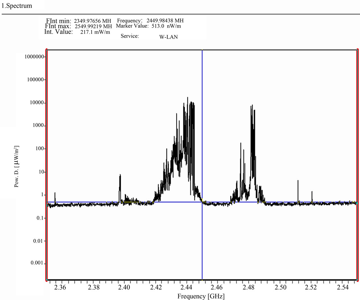
This help?
Company... need to get but will be back.
Shell -
Title: Re: EM Drive Developments - related to space flight applications - Thread 3
Post by: SeeShells on 06/29/2015 10:48 PM -
<a href="http://forum.nasaspaceflight.com/index.php?topic=37642.msg1397567#msg1397567">Quote from: SeeShells on 06/29/2015 10:42 PM</a>
http://file.scirp.org/Html/8-9801080_2771.htm<a href="http://forum.nasaspaceflight.com/index.php?topic=37642.msg1397549#msg1397549">Quote from: aero on 06/29/2015 10:21 PM</a>@SeeShells
Yes, I can add as many sources as I want. But someone else must tell me what and where. And will that help the experimenters or theorists? I wonder if the experimenters here will be able to do add many different sources. Just the problem of coming up with the equipment and materials applied in such a way as to avoid degrading the measurements.
And what is the noise bandwidth of a magnetron?
This help?
Company... need to get but will be back.
Shell
Later...
-
Title: Re: EM Drive Developments - related to space flight applications - Thread 3
Post by: cej on 06/29/2015 10:51 PM -
<a href="http://forum.nasaspaceflight.com/index.php?topic=37642.msg1396916#msg1396916">Quote from: Chrochne on 06/29/2015 09:12 AM</a>
I just read Mr. Traveller claim on reddit that the vibration increase the thrust of the EmDrive. May I ask you folks if there was already a debate about it here? I would be glad to read about it bit more.
I have summarized my interpretation of Shawyer's/TheTraveller's claims here (http://forum.nasaspaceflight.com/index.php?topic=37642.msg1394736#msg1394736), and talked a little more about its implications here (http://forum.nasaspaceflight.com/index.php?topic=37642.msg1394840#msg1394840). If my understanding is correct, then I am very concerned that the experiments we've seen so far are not adequately addressing Shawyer's claims.
In short, one claim is that an EM Drive is an "inertial ratchet": it resists a change in momentum in one direction, and amplifies a change in the opposite direction. The general mechanism by which this is proposed to work is: by maintaining some "angular momentum" (e.g. the EM field, in the case of the EM drive), the ratchet must oppose changes that would increase its angular momentum, and amplify changes that would decrease its angular momentum -- all in order to obey conservation of momentum. A perfect inertial ratchet would negate acceleration in one direction and amplify acceleration in the other (extracting energy from its angular momentum), regardless of its own mass. Another claim is that this inertial ratchet effect can extract work from external vibrations.
I am not certain whether these are reasonable claims. And I suppose the reason why I am painstakingly trying to clearly describe what these claims are is so that they can be properly critiqued. Because TheTraveller's descriptions were so vague, I don't think it was really possible for anyone here to unequivocally refute them.<a href="http://forum.nasaspaceflight.com/index.php?topic=37642.msg1396957#msg1396957">Quote from: Rodal on 06/29/2015 11:22 AM</a>The magnitude and frequency of the vibration that facilitates the measurement of the EM Drive is never addressed.
Nor have any of the public experiments tried to measure these parameters. :(<a href="http://forum.nasaspaceflight.com/index.php?topic=37642.msg1396957#msg1396957">Quote from: Rodal on 06/29/2015 11:22 AM</a>Is the EM Drive an equal opportunity friend of all magnitudes and frequencies of vibration? This is implied, but it leads to absurd nonsense: is nanometer amplitude vibration enough ? How about picometer amplitude vibration? At what level the boundary between vibration in continuum mechanics and quantum mechanics uncertainty is breached ?
I think you make a good point: if it is an inertial ratchet, it is certainly not going to be perfect and the effect will probably be limited to a range of impulses. This range could probably be tuned by adjusting the cavity dimensions and material properties of the drive (electrical resistance, elasticity, mass, etc.). But it is not unheard of to extract work from molecular vibrations when there is a pressure gradient (e.g. a Brownian ratchet or a balloon). An inertial ratchet would effectively induce a pressure gradient, but you would have to input energy to maintain it because the vibrations would also be depleting its angular momentum.<a href="http://forum.nasaspaceflight.com/index.php?topic=37642.msg1397204#msg1397204">Quote from: zen-in on 06/29/2015 04:31 PM</a>One note I would like to add on this subject: If Shawyer's em-drive does not produce any thrust in the absence of vibration then it will not work in outer space. Space is a vacuum and sound waves don't travel in space. There would be no vibrations to "stimulate" the em-drive.
I disagree -- you are forgetting that the EM Drive would be only one component of a space ship. All other components attached to it would very certainly be vibrating and could contribute toward extracting work from an inertial ratchet. But those vibrations might not fall within the range of impulses that it can respond to, as Rodal brought up.
But frobnicat suggested (http://forum.nasaspaceflight.com/index.php?topic=37642.msg1393745#msg1393745) that you could instead attach the drive to an oscillating spring with a mass at the other end, which could be tuned within the ratchet's impulse response range. In any case, it remains to be seen whether the energy required to maintain both the ratchet's angular momentum and the vibrations for the ratchet to extract work from is any more efficient than a photon rocket.<a href="http://forum.nasaspaceflight.com/index.php?topic=37642.msg1397396#msg1397396">Quote from: Rodal on 06/29/2015 07:42 PM</a><a href="http://forum.nasaspaceflight.com/index.php?topic=37642.msg1397386#msg1397386">Quote from: A_M_Swallow on 06/29/2015 07:34 PM</a>
That presumes that all you have to do to get space propulsion is to have internally generated forces (in this case vibration), internal to the spacecraft, that further violates the principle of conservation of momentum. I think that zen-in was looking at externally-forced vibration, in order to try to not break conservation of momentum.<a href="http://forum.nasaspaceflight.com/index.php?topic=37642.msg1397204#msg1397204">Quote from: zen-in on 06/29/2015 04:31 PM</a>(...)
Attaching a vibrator to the drive is not hard. (...)
Would conservation of momentum still be violated if extracting work from the vibrations in turn eliminate those vibrations? (At the limit, causing the space ship to go into a deep freeze.) And as for external vibrations, what if the drive can be tuned such that it extracts work from external QV fluctuations?
On the other hand, a perfect inertial ratchet would resist all acceleration. So if you were in Earth orbit, then you could simply orient the ratchet against Earth's gravity field and you would fly away tangentially -- all for just the cost of restoring its angular momentum from heat/friction losses. Even if the ratchet only reduces the effect of gravity, it might still lower the amount of fuel required to escape orbit as you use your conventional rocket to increase your angular velocity. Note that in this configuration, the rocket would be oriented orthogonal to the ratchet so that its angular momentum is kept roughly static (lost only to heat/friction/vibrations). -
Title: Re: EM Drive Developments - related to space flight applications - Thread 3
Post by: Silvercrys3467 on 06/29/2015 10:57 PM -
Been following this thread for a few weeks, decided to hop in to help if I could.
Aero, do you need only the most recent MEEP package?
I was going to go ahead and compile it from source for you but I found:
http://ab-initio.mit.edu/wiki/index.php/Meep_Download (http://ab-initio.mit.edu/wiki/index.php/Meep_Download)
According to the wiki, they have a precompiled source package available:
"apt-get install meep h5utils"
There is also a parallel source file:
"apt-get install meep-mpi"
If you need other packages compiled with it or the OpenMPI version, I will see what I can do. -
Title: Re: EM Drive Developments - related to space flight applications - Thread 3
Post by: jmossman on 06/29/2015 11:43 PM -
<a href="http://forum.nasaspaceflight.com/index.php?topic=37642.msg1397567#msg1397567">Quote from: SeeShells on 06/29/2015 10:42 PM</a><a href="http://forum.nasaspaceflight.com/index.php?topic=37642.msg1397549#msg1397549">Quote from: aero on 06/29/2015 10:21 PM</a>
@SeeShells
Yes, I can add as many sources as I want. But someone else must tell me what and where. And will that help the experimenters or theorists? I wonder if the experimenters here will be able to do add many different sources. Just the problem of coming up with the equipment and materials applied in such a way as to avoid degrading the measurements.
And what is the noise bandwidth of a magnetron?
This help?
Company... need to get but will be back.
Shell
Paul March had also done a quick-and-dirty measurement of a microwave while warming some coffee (~2.45GHz with ~BW +/- 30MHz)...
http://forum.nasaspaceflight.com/index.php?action=dlattach;topic=36313.0;attach=821772 -
Title: Re: EM Drive Developments - related to space flight applications - Thread 3
Post by: Rodal on 06/29/2015 11:54 PM -
<a href="http://forum.nasaspaceflight.com/index.php?topic=37642.msg1397614#msg1397614">Quote from: jmossman on 06/29/2015 11:43 PM</a><a href="http://forum.nasaspaceflight.com/index.php?topic=37642.msg1397567#msg1397567">Quote from: SeeShells on 06/29/2015 10:42 PM</a><a href="http://forum.nasaspaceflight.com/index.php?topic=37642.msg1397549#msg1397549">Quote from: aero on 06/29/2015 10:21 PM</a>
@SeeShells
Yes, I can add as many sources as I want. But someone else must tell me what and where. And will that help the experimenters or theorists? I wonder if the experimenters here will be able to do add many different sources. Just the problem of coming up with the equipment and materials applied in such a way as to avoid degrading the measurements.
And what is the noise bandwidth of a magnetron?
This help?
Company... need to get but will be back.
Shell
Paul March had also done a quick-and-dirty measurement of a microwave while warming some coffee (~2.45GHz with ~BW +/- 30MHz)...
http://forum.nasaspaceflight.com/index.php?action=dlattach;topic=36313.0;attach=821772
Thank, you this spectrum does make it look like, when using a magnetron, the EM Drive can be switching between modes, so I think we are on to something here: mode superposition at single frequencies + mode switching with the magnetron frequency varying between 2.42 to 2.48 GHz
So the magnetron makes for an always changing situation instead of the frozen standing wave envisioned by Egan.
-
Title: Re: EM Drive Developments - related to space flight applications - Thread 3
Post by: aero on 06/30/2015 12:03 AM -
<a href="http://forum.nasaspaceflight.com/index.php?topic=37642.msg1397577#msg1397577">Quote from: Silvercrys3467 on 06/29/2015 10:57 PM</a>
Been following this thread for a few weeks, decided to hop in to help if I could.
Aero, do you need only the most recent MEEP package?
I was going to go ahead and compile it from source for you but I found:
http://ab-initio.mit.edu/wiki/index.php/Meep_Download (http://ab-initio.mit.edu/wiki/index.php/Meep_Download)
According to the wiki, they have a precompiled source package available:
"apt-get install meep h5utils"
There is also a parallel source file:
"apt-get install meep-mpi"
If you need other packages compiled with it or the OpenMPI version, I will see what I can do.
Oh Thank you so much!
The problem with pre compiled is that they are older packages. I am using a pre compiled package now but it is not current with the documentation. The Meep reference manual was revised/released with the latest source code release so it describes how to do things that exist only in the latest release. My machine has 4 processors and I use OpenMPI.
What I would really like is the configure file to run at the Ubuntu prompt which builds and installs the executable, including Meep, MPB, Harminv, h5utils as well as the other libraries needed to use the Scheme interface. The claim is that if I compile it on my own machine it will run faster. But a complete object module would be my second choice and from there a current, generic downloadable object module.
Your links point to the same place I went when I started. The pre-compiled version is 1.2.1-2 and the multiprocessor version that is claimed, doesn't really exist. It goes to "Package not available in this suite." I was able to get the regular package to use a my processors. (The current Meep source software version is 1.3 or 1.3.1 so it was considered a significant upgrade)
Anyhow, I think this https://github.com/stevengj/meep/blob/master/src/meep.hpp#L169-L172 (https://github.com/stevengj/meep/blob/master/src/meep.hpp#L169-L172) is the latest source. But I don't want to make it to hard for you, anything you can do beyond version 1.2.1-2 will help.
The source link you gave, http://ab-initio.mit.edu/meep/meep-1.3.tar.gz (http://ab-initio.mit.edu/meep/meep-1.3.tar.gz) does include some configures, make_files and an INSTALL file and it is 1.3. I tried to use this data back when I started and got it down to two compile errors before I gave up and went back to my installed the Debian object. -
Title: Re: EM Drive Developments - related to space flight applications - Thread 3
Post by: rfmwguy on 06/30/2015 12:09 AM -
<a href="http://forum.nasaspaceflight.com/index.php?topic=37642.msg1397627#msg1397627">Quote from: Rodal on 06/29/2015 11:54 PM</a>
Basically, a narrow band comb generator. This is slamming the TE & TM modes all over the place, which MAY account for some anomalous results. Modulation: am/fm/phase/pulse and just about anything else you could think up. Shell's idea to filter would require a high Q bandpass but modulation characteristics would remain.<a href="http://forum.nasaspaceflight.com/index.php?topic=37642.msg1397614#msg1397614">Quote from: jmossman on 06/29/2015 11:43 PM</a><a href="http://forum.nasaspaceflight.com/index.php?topic=37642.msg1397567#msg1397567">Quote from: SeeShells on 06/29/2015 10:42 PM</a><a href="http://forum.nasaspaceflight.com/index.php?topic=37642.msg1397549#msg1397549">Quote from: aero on 06/29/2015 10:21 PM</a>@SeeShells
Yes, I can add as many sources as I want. But someone else must tell me what and where. And will that help the experimenters or theorists? I wonder if the experimenters here will be able to do add many different sources. Just the problem of coming up with the equipment and materials applied in such a way as to avoid degrading the measurements.
And what is the noise bandwidth of a magnetron?
This help?
Company... need to get but will be back.
Shell
Paul March had also done a quick-and-dirty measurement of a microwave while warming some coffee (~2.45GHz with ~BW +/- 30MHz)...
http://forum.nasaspaceflight.com/index.php?action=dlattach;topic=36313.0;attach=821772
Thank, you this spectrum does make it look like, when using a magnetron, the EM Drive can be switching between modes, so I think we are on to something here: mode superposition at single frequencies + mode switching with the magnetron frequency varying between 2.42 to 2.48 GHz
So the magnetron makes for an always changing situation instead of the frozen standing wave envisioned by Egan.
While not (normally) scientifically ideal (with all the spectral spewing) perhaps it is...and perhaps this Intermix could be desireable...the old addage...more data needed.
p.s. Had no time today to secure a 100mW exciter (typical) and given the simplicity of magnetron sources, NSF posters, etc...looks like I will take this route as well. Designed the frustum exoskeleton to hold a magnetron, got a good handle on the liquid splices to supply bias and best of all, can still use the fulcrum...off to the races. -
Title: Re: EM Drive Developments - related to space flight applications - Thread 3
Post by: AnalogMan on 06/30/2015 12:17 AM -
<a href="http://forum.nasaspaceflight.com/index.php?topic=37642.msg1397627#msg1397627">Quote from: Rodal on 06/29/2015 11:54 PM</a><a href="http://forum.nasaspaceflight.com/index.php?topic=37642.msg1397614#msg1397614">Quote from: jmossman on 06/29/2015 11:43 PM</a><a href="http://forum.nasaspaceflight.com/index.php?topic=37642.msg1397567#msg1397567">Quote from: SeeShells on 06/29/2015 10:42 PM</a><a href="http://forum.nasaspaceflight.com/index.php?topic=37642.msg1397549#msg1397549">Quote from: aero on 06/29/2015 10:21 PM</a>
@SeeShells
Yes, I can add as many sources as I want. But someone else must tell me what and where. And will that help the experimenters or theorists? I wonder if the experimenters here will be able to do add many different sources. Just the problem of coming up with the equipment and materials applied in such a way as to avoid degrading the measurements.
And what is the noise bandwidth of a magnetron?
This help?
Company... need to get but will be back.
Shell
Paul March had also done a quick-and-dirty measurement of a microwave while warming some coffee (~2.45GHz with ~BW +/- 30MHz)...
Thank, you this spectrum does make it look like, when using a magnetron, the EM Drive can be switching between modes, so I think we are on to something here: mode superposition at single frequencies + mode switching with the magnetron frequency varying between 2.42 to 2.48 GHz
So the magnetron makes for an always changing situation instead of the frozen standing wave envisioned by Egan.
This paper on phase locking magnetrons to a stable reference oscillator may be of interest. It has spectra of a 2.45GHz magnetron showing the effect of varying the heater power from nominal levels to much lower levels. Frequency hopping is noted. (click on image to enlarge)
Noise Performance of Frequency- and Phase-Locked CW Magnetrons Operated as Current-Controlled Oscillators IEEE Trans Electron Dev Vol 52 No 9 2096-2103
Note that injection phase-locking of magnetrons is a well known technique, but may be overly complicated for EM-drive experiments (and may even be detrimental if wideband operation is favored). -
Title: Re: EM Drive Developments - related to space flight applications - Thread 3
Post by: aero on 06/30/2015 12:28 AM -
So I'm thinking that BW = 60 MHz, or 0.025 * drive frequency should work. Maybe Meep can deal with that. I just completed a resonance run on NSF-1701 using Bandwidth = 0.038 * drive freq. and it only took 20 minutes. But resonance runs take a lot longer than the time/field evolution runs.
By the way, I made that run because I moved the antenna nearer to the small end, it is now 1/4 wavelength from the inside face of the small end. The cavity resonated at very nearly the same frequency as before but the already good quality factor, Q went up about 3 times. (From 99,000 to about 300,000) This is very high and I am using the copper model so I wonder about those Q values. -
Title: Re: EM Drive Developments - related to space flight applications - Thread 3
Post by: rfmwguy on 06/30/2015 12:40 AM -
Weird, take a look at: http://jnaudin.free.fr/lifters/act/html/omptv1.htm
"On January 31, 2002, the NASA patent application US2002012221 " Apparatus and Method for generating a thrust using a two dimensional asymmetrical capacitor module " has been granted."
Looks alot like a shawyer frustum... -
Title: Re: EM Drive Developments - related to space flight applications - Thread 3
Post by: demofsky on 06/30/2015 12:49 AM -
<a href="http://forum.nasaspaceflight.com/index.php?topic=37642.msg1397644#msg1397644">Quote from: rfmwguy on 06/30/2015 12:40 AM</a>
Weird, take a look at: http://jnaudin.free.fr/lifters/act/html/omptv1.htm
"On January 31, 2002, the NASA patent application US2002012221 " Apparatus and Method for generating a thrust using a two dimensional asymmetrical capacitor module " has been granted."
Looks alot like a shawyer frustum...
And if the video is to be believed produces more thrust than non superconducting EM drives! -
Title: Re: EM Drive Developments - related to space flight applications - Thread 3
Post by: frobnicat on 06/30/2015 12:50 AM -
<a href="http://forum.nasaspaceflight.com/index.php?topic=37642.msg1397574#msg1397574">Quote from: cej on 06/29/2015 10:51 PM</a>
...
In short, one claim is that an EM Drive is an "inertial ratchet": it resists a change in momentum in one direction, and amplifies a change in the opposite direction. The general mechanism by which this is proposed to work is: by maintaining some "angular momentum" (e.g. the EM field, in the case of the EM drive), the ratchet must oppose changes that would increase its angular momentum, and amplify changes that would decrease its angular momentum -- all in order to obey conservation of momentum. A perfect inertial ratchet would negate acceleration in one direction and amplify acceleration in the other (extracting energy from its angular momentum), regardless of its own mass. Another claim is that this inertial ratchet effect can extract work from external vibrations.
I am not certain whether these are reasonable claims. And I suppose the reason why I am painstakingly trying to clearly describe what these claims are is so that they can be properly critiqued. Because TheTraveller's descriptions were so vague, I don't think it was really possible for anyone here to unequivocally refute them.
...
Here is attached a toy model for a kind of (uncontroversial) mechanical ratchet, ballast in a box, perfect slip in a direction, perfect stop the other way (idealised) :
center -> start position
top -> if pushed to left a certain apparent acceleration (of the green box) is observed
bottom -> if pushed to right a greater apparent acceleration (of the green box) is observed
So this is in effect a system that, as seen from the outside, exhibits higher inertia in a way (mass casing+ballast) and lower the other way (mass of casing alone). Obviously the scheme is limited in total travel (displacement from start) when pushed to the right, in the low inertia direction. At some point the system would need to be "desaturated", that is the inner ballast be put back at right of box, which would neutralise any apparent gain in momentum that a free floating spacecraft could initially get by alternatively pulling and pushing on such box. Source of energy alone is not enough to have the process go on for a long time, conservation of centre of mass is still valid at any time, the centre of mass doesn't move at all.
So an apparent "inertial ratchet" is an easily satisfiable claim, the question is the possibility of such a device that could work for long "unlimited" total displacement, to me this appears more like a problem of conservation of centre of mass than of available energy (unless energy directly beamed to vacuum to get net momentum => photon rocket again). A note of caution : it is easy to get apparent net non zero results from transients or "one shot" effects, that doesn't imply possibility for any long term stationary mode of operation.
-
Title: Re: EM Drive Developments - related to space flight applications - Thread 3
Post by: apoc2021 on 06/30/2015 01:26 AM -
Guys –
I would like to humbly submit for consideration that the efforts in this thread could in effect be viewed as a distributed research project. We have resilient experimenters, brilliant theorists, persistent data analysts.. even some equipment. However, this day in age, there are many other resources potentially available for the community to use - if only we become organized enough to identify and seek them out.
What other resources are needed to move forward the collective work taking place here?
For example, do we need:
- More MEEP analysts, to lessen the load on our brave Aero?
- AmazonAWS/Google Cloud compute time?
- A recurring schedule of group Google Hangouts to discuss current theory and next steps?
- A machine learning/data science expert, to find hidden or subtle relationships?
- Funding/donations for equipment? Perhaps held in a multisig crypto wallet with a major provider?
- A better platform for distributed research projects?
- Simply more hobbyists paying attention and contributing views?
- Perhaps we don't need anything, and this is the most efficient that we can be?
It seems we are all driving towards the same goal.. just some thoughts to consider to take this exploration one efficient step further. Happy to help however possible. -
Title: Re: EM Drive Developments - related to space flight applications - Thread 3
Post by: zen-in on 06/30/2015 02:18 AM -
<a href="http://forum.nasaspaceflight.com/index.php?topic=37642.msg1397644#msg1397644">Quote from: rfmwguy on 06/30/2015 12:40 AM</a>
Weird, take a look at: http://jnaudin.free.fr/lifters/act/html/omptv1.htm
"On January 31, 2002, the NASA patent application US2002012221 " Apparatus and Method for generating a thrust using a two dimensional asymmetrical capacitor module " has been granted."
Looks alot like a shawyer frustum...
The JNaudin website has many variants of Byfield-Brown effect lifters. I remember seeing balsa wood electrostatically driven hoverers in Popular Science in the early 60's. They only work in air and there has been nothing new in over 50 years. The patent you are referring to is something else. It is just an actuator that uses high voltage DC; a kind of capacitor where the two terminals are concentric. It's kind of the same idea as an actuator that uses an iron armatur in a selenoid magnet. When the magnet is energised the armature is pulled in. Similarly when a capacitor is charged up the plates are attracted to each other and that principal can be used to make an actuator as well. There is no relationship to an em-drive cavity except both are empty metal shells and neither one creates momentum out of thin air. -
Title: Re: EM Drive Developments - related to space flight applications - Thread 3
Post by: rfmwguy on 06/30/2015 02:21 AM -
<a href="http://forum.nasaspaceflight.com/index.php?topic=37642.msg1397659#msg1397659">Quote from: apoc2021 on 06/30/2015 01:26 AM</a>
Guys –
Nice post, I'll take a swing...afaik, everyone here is independent and non commercial. However, it will only take a few positive experiments before many more join in. I've thought about exactly what you are proposing...the emdrive.wiki page is a great start, but eventually an entity should be formed, not to control but to consolidate info, organize needs and supply material help as required. I have a sense that a not for profit 501c3 will be a good way to proceed. The nature of all here seems to be for the love of mystery, science, math, etc., and tired of public and private institutional secrecy. That, we have in abundance...
I would like to humbly submit for consideration that the efforts in this thread could in effect be viewed as a distributed research project. We have resilient experimenters, brilliant theorists, persistent data analysts.. even some equipment. However, this day in age, there are many other resources potentially available for the community to use - if only we become organized enough to identify and seek them out.
What other resources are needed to move forward the collective work taking place here?
For example, do we need:
- More MEEP analysts, to lessen the load on our brave Aero?
- AmazonAWS/Google Cloud compute time?
- A recurring schedule of group Google Hangouts to discuss current theory and next steps?
- A machine learning/data science expert, to find hidden or subtle relationships?
- Funding/donations for equipment? Perhaps held in a multisig crypto wallet with a major provider?
- A better platform for distributed research projects?
- Simply more hobbyists paying attention and contributing views?
- Perhaps we don't need anything, and this is the most efficient that we can be?
It seems we are all driving towards the same goal.. just some thoughts to consider to take this exploration one efficient step further. Happy to help however possible. -
Title: Re: EM Drive Developments - related to space flight applications - Thread 3
Post by: DrBagelBites on 06/30/2015 02:30 AM -
<a href="http://forum.nasaspaceflight.com/index.php?topic=37642.msg1397659#msg1397659">Quote from: apoc2021 on 06/30/2015 01:26 AM</a>
Guys –
I would like to humbly submit for consideration that the efforts in this thread could in effect be viewed as a distributed research project. We have resilient experimenters, brilliant theorists, persistent data analysts.. even some equipment. However, this day in age, there are many other resources potentially available for the community to use - if only we become organized enough to identify and seek them out.
What other resources are needed to move forward the collective work taking place here?
For example, do we need:
- More MEEP analysts, to lessen the load on our brave Aero?
- AmazonAWS/Google Cloud compute time?
- A recurring schedule of group Google Hangouts to discuss current theory and next steps?
- A machine learning/data science expert, to find hidden or subtle relationships?
- Funding/donations for equipment? Perhaps held in a multisig crypto wallet with a major provider?
- A better platform for distributed research projects?
- Simply more hobbyists paying attention and contributing views?
- Perhaps we don't need anything, and this is the most efficient that we can be?
It seems we are all driving towards the same goal.. just some thoughts to consider to take this exploration one efficient step further. Happy to help however possible.
Some great ideas! Also a video repository for all tests would be useful as well.
As for the funding idea, are you thinking of just a paypal system where someone can contribute to their favorite builder(s)? Or as a pool where builders request what they need. Obviously, you just came up with this idea, so I am not sure how much thought was put into it. Just some questions.
Brilliant ideas, though. I'll try to help with what I can. -
Title: Re: EM Drive Developments - related to space flight applications - Thread 3
Post by: rfmwguy on 06/30/2015 02:31 AM -
<a href="http://forum.nasaspaceflight.com/index.php?topic=37642.msg1397683#msg1397683">Quote from: zen-in on 06/30/2015 02:18 AM</a>
Thanks. curious, are u 100% certain, beyond any reasonable doubt, that an "empty shell" can never gain momentum and that propulsion must utilize propellants?<a href="http://forum.nasaspaceflight.com/index.php?topic=37642.msg1397644#msg1397644">Quote from: rfmwguy on 06/30/2015 12:40 AM</a>...
The JNaudin website has many variants of Byfield-Brown effect lifters. I remember seeing balsa wood electrostatically driven hoverers in Popular Science in the early 60's. They only work in air and there has been nothing new in over 50 years. The patent you are referring to is something else. It is just an actuator that uses high voltage DC; a kind of capacitor where the two terminals are concentric. It's kind of the same idea as an actuator that uses an iron armatur in a selenoid magnet. When the magnet is energised the armature is pulled in. Similarly when a capacitor is charged up the plates are attracted to each other and that principal can be used to make an actuator as well. There is no relationship to an em-drive cavity except both are empty metal shells and neither one creates momentum out of thin air. -
Title: Re: EM Drive Developments - related to space flight applications - Thread 3
Post by: aero on 06/30/2015 02:52 AM -
<a href="http://forum.nasaspaceflight.com/index.php?topic=37642.msg1397659#msg1397659">Quote from: apoc2021 on 06/30/2015 01:26 AM</a>
Guys –
I would like to humbly submit for consideration that the efforts in this thread could in effect be viewed as a distributed research project. We have resilient experimenters, brilliant theorists, persistent data analysts.. even some equipment. However, this day in age, there are many other resources potentially available for the community to use - if only we become organized enough to identify and seek them out.
What other resources are needed to move forward the collective work taking place here?
For example, do we need:
- More MEEP analysts, to lessen the load on our brave Aero?
- AmazonAWS/Google Cloud compute time?
- A recurring schedule of group Google Hangouts to discuss current theory and next steps?
- A machine learning/data science expert, to find hidden or subtle relationships?
- Funding/donations for equipment? Perhaps held in a multisig crypto wallet with a major provider?
- A better platform for distributed research projects?
- Simply more hobbyists paying attention and contributing views?
- Perhaps we don't need anything, and this is the most efficient that we can be?
It seems we are all driving towards the same goal.. just some thoughts to consider to take this exploration one efficient step further. Happy to help however possible.
I like it, and I certainly like the first bullet. Not so sure about the brave part but the "lessen the load" part sure would help if we could somehow divide the load into parts that could be more responsive to valid and doable requests for data. -
Title: Re: EM Drive Developments - related to space flight applications - Thread 3
Post by: zen-in on 06/30/2015 03:25 AM -
<a href="http://forum.nasaspaceflight.com/index.php?topic=37642.msg1397695#msg1397695">Quote from: rfmwguy on 06/30/2015 02:31 AM</a>
Propulsion does not always require propellants. For example deep space satellites are often swung around a planets to add delta v. However there is no machine that will by itself create momentum. The em-drive will eventually take its place next to cold fusion, polywater, and 300 MPH submarines in the Encyclopedia of Pseudoscience.<a href="http://forum.nasaspaceflight.com/index.php?topic=37642.msg1397683#msg1397683">Quote from: zen-in on 06/30/2015 02:18 AM</a>
Thanks. curious, are u 100% certain, beyond any reasonable doubt, that an "empty shell" can never gain momentum and that propulsion must utilize propellants?<a href="http://forum.nasaspaceflight.com/index.php?topic=37642.msg1397644#msg1397644">Quote from: rfmwguy on 06/30/2015 12:40 AM</a>...
The JNaudin website has many variants of Byfield-Brown effect lifters. I remember seeing balsa wood electrostatically driven hoverers in Popular Science in the early 60's.
...
There is no relationship to an em-drive cavity except both are empty metal shells and neither one creates momentum out of thin air. -
Title: Re: EM Drive Developments - related to space flight applications - Thread 3
Post by: DrBagelBites on 06/30/2015 03:33 AM -
<a href="http://forum.nasaspaceflight.com/index.php?topic=37642.msg1397702#msg1397702">Quote from: aero on 06/30/2015 02:52 AM</a><a href="http://forum.nasaspaceflight.com/index.php?topic=37642.msg1397659#msg1397659">Quote from: apoc2021 on 06/30/2015 01:26 AM</a>
Guys –
I would like to humbly submit for consideration that the efforts in this thread could in effect be viewed as a distributed research project. We have resilient experimenters, brilliant theorists, persistent data analysts.. even some equipment. However, this day in age, there are many other resources potentially available for the community to use - if only we become organized enough to identify and seek them out.
What other resources are needed to move forward the collective work taking place here?
For example, do we need:
- More MEEP analysts, to lessen the load on our brave Aero?
- AmazonAWS/Google Cloud compute time?
- A recurring schedule of group Google Hangouts to discuss current theory and next steps?
- A machine learning/data science expert, to find hidden or subtle relationships?
- Funding/donations for equipment? Perhaps held in a multisig crypto wallet with a major provider?
- A better platform for distributed research projects?
- Simply more hobbyists paying attention and contributing views?
- Perhaps we don't need anything, and this is the most efficient that we can be?
It seems we are all driving towards the same goal.. just some thoughts to consider to take this exploration one efficient step further. Happy to help however possible.
I like it, and I certainly like the first bullet. Not so sure about the brave part but the "lessen the load" part sure would help if we could somehow divide the load into parts that could be more responsive to valid and doable requests for data.
I can try and install Meep on my machine. Running ubuntu, will have to play around and learn syntax and whatnot, though for the program. -
Title: Re: EM Drive Developments - related to space flight applications - Thread 3
Post by: rfmwguy on 06/30/2015 03:40 AM -
<a href="http://forum.nasaspaceflight.com/index.php?topic=37642.msg1397720#msg1397720">Quote from: zen-in on 06/30/2015 03:25 AM</a>
Gravity assist is not technically propulsion nor is dropping a rock. although you did not answer directly, you apparently are on record believing that space propulsion requires propellants. No problem, that is a safe belief system many have from the sidelines. Me? I'm not so sure we're as omnipotent as we may think we are. Otherwise, why bother with imagination and experimentation...everything has been discovered worthy of discovery.<a href="http://forum.nasaspaceflight.com/index.php?topic=37642.msg1397695#msg1397695">Quote from: rfmwguy on 06/30/2015 02:31 AM</a>
Propulsion does not always require propellants. For example deep space satellites are often swung around a planets to add delta v. However there is no machine that will by itself create momentum. The em-drive will eventually take its place next to cold fusion, polywater, and 300 MPH submarines in the Encyclopedia of Pseudoscience.<a href="http://forum.nasaspaceflight.com/index.php?topic=37642.msg1397683#msg1397683">Quote from: zen-in on 06/30/2015 02:18 AM</a>
Thanks. curious, are u 100% certain, beyond any reasonable doubt, that an "empty shell" can never gain momentum and that propulsion must utilize propellants?<a href="http://forum.nasaspaceflight.com/index.php?topic=37642.msg1397644#msg1397644">Quote from: rfmwguy on 06/30/2015 12:40 AM</a>...
The JNaudin website has many variants of Byfield-Brown effect lifters. I remember seeing balsa wood electrostatically driven hoverers in Popular Science in the early 60's.
...
There is no relationship to an em-drive cavity except both are empty metal shells and neither one creates momentum out of thin air. -
Title: Re: EM Drive Developments - related to space flight applications - Thread 3
Post by: SeeShells on 06/30/2015 03:44 AM -
<a href="http://forum.nasaspaceflight.com/index.php?topic=37642.msg1397549#msg1397549">Quote from: aero on 06/29/2015 10:21 PM</a>
@SeeShells
Yes, I can add as many sources as I want. But someone else must tell me what and where. And will that help the experimenters or theorists? I wonder if the experimenters here will be able to do add many different sources. Just the problem of coming up with the equipment and materials applied in such a way as to avoid degrading the measurements.
And what is the noise bandwidth of a magnetron?
Aero,
These are the calculated TM and TE modes from NASA. Try a couple TM modes, be a good first start to see if it can produce a viable sequence. Double check me Jose if you would like something else... no problem.
TM 311 2.4157 Ghz
TM 212 2.45032 Ghz
Shell -
Title: Re: EM Drive Developments - related to space flight applications - Thread 3
Post by: aero on 06/30/2015 03:57 AM -
<a href="http://forum.nasaspaceflight.com/index.php?topic=37642.msg1397736#msg1397736">Quote from: SeeShells on 06/30/2015 03:44 AM</a>
That's a thought. However, I thought that next I might try to generate some numbers from the cavity to get a handle on the field strength and distribution. That should provide some immediately useful data. Not immediate data, but data that will be useful as soon as it arrives.<a href="http://forum.nasaspaceflight.com/index.php?topic=37642.msg1397549#msg1397549">Quote from: aero on 06/29/2015 10:21 PM</a>@SeeShells
Yes, I can add as many sources as I want. But someone else must tell me what and where. And will that help the experimenters or theorists? I wonder if the experimenters here will be able to do add many different sources. Just the problem of coming up with the equipment and materials applied in such a way as to avoid degrading the measurements.
And what is the noise bandwidth of a magnetron?
Aero,
These are the calculated TM and TE modes from NASA. Try a couple TM modes, be a good first start to see if it can produce a viable sequence. Double check me Jose if you would like something else... no problem.
TM 311 2.4157 Ghz
TM 212 2.45032 Ghz
Shell -
Title: Re: EM Drive Developments - related to space flight applications - Thread 3
Post by: SeeShells on 06/30/2015 04:06 AM -
<a href="http://forum.nasaspaceflight.com/index.php?topic=37642.msg1397731#msg1397731">Quote from: rfmwguy on 06/30/2015 03:40 AM</a>
A story...<a href="http://forum.nasaspaceflight.com/index.php?topic=37642.msg1397720#msg1397720">Quote from: zen-in on 06/30/2015 03:25 AM</a>
Gravity assist is not technically propulsion nor is dropping a rock. although you did not answer directly, you apparently are on record believing that space propulsion requires propellants. No problem, that is a safe belief system many have from the sidelines. Me? I'm not so sure we're as omnipotent as we may think we are. Otherwise, why bother with imagination and experimentation...everything has been discovered worthy of discovery.<a href="http://forum.nasaspaceflight.com/index.php?topic=37642.msg1397695#msg1397695">Quote from: rfmwguy on 06/30/2015 02:31 AM</a>
Propulsion does not always require propellants. For example deep space satellites are often swung around a planets to add delta v. However there is no machine that will by itself create momentum. The em-drive will eventually take its place next to cold fusion, polywater, and 300 MPH submarines in the Encyclopedia of Pseudoscience.<a href="http://forum.nasaspaceflight.com/index.php?topic=37642.msg1397683#msg1397683">Quote from: zen-in on 06/30/2015 02:18 AM</a>
Thanks. curious, are u 100% certain, beyond any reasonable doubt, that an "empty shell" can never gain momentum and that propulsion must utilize propellants?<a href="http://forum.nasaspaceflight.com/index.php?topic=37642.msg1397644#msg1397644">Quote from: rfmwguy on 06/30/2015 12:40 AM</a>...
The JNaudin website has many variants of Byfield-Brown effect lifters. I remember seeing balsa wood electrostatically driven hoverers in Popular Science in the early 60's.
...
There is no relationship to an em-drive cavity except both are empty metal shells and neither one creates momentum out of thin air.
Once upon a time there were no laws, no CoM no CoE no Maxwell and spacetime ruled. The laws melted out from the primordial soup of quarks and heat and one force after another assembled to define how our universe could work. To me it was like a can of different sized rocks and sand, when cooling down the universe shook the can and the sand and rocks self assembled.
It doesn't bother me one iota that we're shaking the can of rocks to see what happens and who knows what we will find? This isn't about saying we are going to violate anything, it's saying we are going to inquire and look and do some questioning science.
Shell
-
Title: Re: EM Drive Developments - related to space flight applications - Thread 3
Post by: SeeShells on 06/30/2015 04:21 AM -
<a href="http://forum.nasaspaceflight.com/index.php?topic=37642.msg1397743#msg1397743">Quote from: aero on 06/30/2015 03:57 AM</a>
It's good to have baseline data and I'm sure it will come into play later. So when you can add an ingredient to the soup one at a time.<a href="http://forum.nasaspaceflight.com/index.php?topic=37642.msg1397736#msg1397736">Quote from: SeeShells on 06/30/2015 03:44 AM</a>
That's a thought. However, I thought that next I might try to generate some numbers from the cavity to get a handle on the field strength and distribution. That should provide some immediately useful data. Not immediate data, but data that will be useful as soon as it arrives.<a href="http://forum.nasaspaceflight.com/index.php?topic=37642.msg1397549#msg1397549">Quote from: aero on 06/29/2015 10:21 PM</a>@SeeShells
Yes, I can add as many sources as I want. But someone else must tell me what and where. And will that help the experimenters or theorists? I wonder if the experimenters here will be able to do add many different sources. Just the problem of coming up with the equipment and materials applied in such a way as to avoid degrading the measurements.
And what is the noise bandwidth of a magnetron?
Aero,
These are the calculated TM and TE modes from NASA. Try a couple TM modes, be a good first start to see if it can produce a viable sequence. Double check me Jose if you would like something else... no problem.
TM 311 2.4157 Ghz
TM 212 2.45032 Ghz
Shell
Me I'm back to doing numbers on the helical cone shaped antenna and trying to get it to work well without a ground plane and fit into the cavity where I want it to. -
Title: Re: EM Drive Developments - related to space flight applications - Thread 3
Post by: cej on 06/30/2015 04:59 AM -
<a href="http://forum.nasaspaceflight.com/index.php?topic=37642.msg1397649#msg1397649">Quote from: frobnicat on 06/30/2015 12:50 AM</a>
Here is attached a toy model for a kind of (uncontroversial) mechanical ratchet, ballast in a box, perfect slip in a direction, perfect stop the other way (idealised)
(...)
So an apparent "inertial ratchet" is an easily satisfiable claim, the question is the possibility of such a device that could work for long "unlimited" total displacement, to me this appears more like a problem of conservation of centre of mass than of available energy (unless energy directly beamed to vacuum to get net momentum => photon rocket again). A note of caution : it is easy to get apparent net non zero results from transients or "one shot" effects, that doesn't imply possibility for any long term stationary mode of operation.
I like your analogy -- I was not aware of it. But preserving the center of mass is essentially the same argument as conservation of momentum, which seems to rule out the possibility of any propellant-less thruster that can accelerate faster than a photon rocket. That should raise a lot of doubt. Yet here we are.
Anyhow, I think the answer to how extracting work from vibrations can satisfy conservation of momentum comes down this: there is only so much energy a spaceship can store in vibrations (or to create vibrations), that energy has an effective (finite) mass, and an inertial ratchet probably cannot extract work from that energy any faster than simply expelling it as light.
But what about the idea of an inertial ratchet hovering against gravity? If it could only hover, that would still be very useful and would lead to much more efficient space travel. Since no work is performed by hovering, how would conservation of momentum be violated?
Your mechanical inertial ratchet cannot hover because acceleration will apply evenly to its entire mass. Will the same happen for an inertial ratchet that stores angular momentum in an EM field? (Will the field accelerate along with the mass of the ratchet, or will they push against each other, causing conservation of momentum issues that requires holding the ratchet in place?)
Okay! Let us now assume that the EM Drive is an inertial ratchet, and a pretty good one! It will still extract work from vibrations, but let's assume that it cannot extract that work any faster than a photon rocket. And we'll also assume that inertial ratchets cannot actually hover (or even significantly resist gravity)... Could the "more efficient than a photon rocket" results that we've been seeing in experiments so far instead be an artifact of the unique way in which inertial ratchets respond to vibrations?
In summary, I've counter-raised the following questions for everyone to consider:
1. Can work be extracted from vibrations faster that expelling the equivalent energy as light?
2. Is it plausible for an EM field based inertial ratchet to hover against gravity? (will there be resistance between the EM field and the accelerating mass of the frustum?)
I didn't get to this point, but I'm also curious about:
3. Can an inertial ratchet extract work from QV fluctuations?
If the answer to 1, 2, & 3 are "no"...
4. Are the positive experimental results just an artifact of the inertial ratchet effect?
5. ... Can we at least use an inertial ratchet in the International Space Station as a more efficient, all-in-one air conditioner and orbit corrector?
I hope this post has at least reduced the surface area of the "inertial ratchet = space travel" hypothesis. -
Title: Re: EM Drive Developments - related to space flight applications - Thread 3
Post by: deltaMass on 06/30/2015 05:16 AM - The inertial ratchet route demands that one specifies that thing off of which one pushes. What is it? Why has it not been detected as pushed off of in the other trillions of large and small, uninstrumented to fully instrumented tests of classical mechanics over the centuries? I don't expect a coherent answer, so treat this question as rhetorical and merely as food for thought. Or as a clue.
-
Title: Re: EM Drive Developments - related to space flight applications - Thread 3
Post by: arc on 06/30/2015 05:18 AM -
The following Wave form images might help?, when thinking of the meaning of image colors/densities from meep/comsol etc. There is a relation between wave amplitude/location and the color displayed...each package will have its own definitions for color combinations... it seems that some packages use the same color scheme, but reverse definitions between positive and negative amplitudes, What was the bottom is now the top...this may explain the color switching with meep etc as waves cycle/pivot around a "defined" starting point or zero line within the cavity, or if there exist both positive and negative values in a graph the effective range may adjust to start from the middle ...we need the numeric output tables to enable further examination...still thinking on this...
( )
)
--
Image 1 looking down from the top
( )
)
--
( )
)
--
Image 2 looking down from the top
( )
)
--
-
Title: Re: EM Drive Developments - related to space flight applications - Thread 3
Post by: deuteragenie on 06/30/2015 07:57 AM -
<a href="http://forum.nasaspaceflight.com/index.php?topic=37642.msg1397577#msg1397577">Quote from: Silvercrys3467 on 06/29/2015 10:57 PM</a>
Been following this thread for a few weeks, decided to hop in to help if I could.
Aero, do you need only the most recent MEEP package?
I was going to go ahead and compile it from source for you but I found:
http://ab-initio.mit.edu/wiki/index.php/Meep_Download (http://ab-initio.mit.edu/wiki/index.php/Meep_Download)
According to the wiki, they have a precompiled source package available:
"apt-get install meep h5utils"
There is also a parallel source file:
"apt-get install meep-mpi"
If you need other packages compiled with it or the OpenMPI version, I will see what I can do.
I saw that one as well and was going to try it out.
If you want to help, you could try to create a Ubuntu package for Meep as aero uses Ubuntu (and so am I and a few others). http://packaging.ubuntu.com/html/
I also do not know which compiler / optimization the source code would support, but you may want to explore recompiling the source using different compilers (gcc / LLVM / ICC / VC ...) and different optimization flags. It can also be that the source code could enjoy being made more compiler agnostic. -
Title: Re: EM Drive Developments - related to space flight applications - Thread 3
Post by: deuteragenie on 06/30/2015 08:17 AM -
<a href="http://forum.nasaspaceflight.com/index.php?topic=37642.msg1397702#msg1397702">Quote from: aero on 06/30/2015 02:52 AM</a><a href="http://forum.nasaspaceflight.com/index.php?topic=37642.msg1397659#msg1397659">Quote from: apoc2021 on 06/30/2015 01:26 AM</a>
Guys –
I would like to humbly submit for consideration that the efforts in this thread could in effect be viewed as a distributed research project. We have resilient experimenters, brilliant theorists, persistent data analysts.. even some equipment. However, this day in age, there are many other resources potentially available for the community to use - if only we become organized enough to identify and seek them out.
What other resources are needed to move forward the collective work taking place here?
For example, do we need:
- More MEEP analysts, to lessen the load on our brave Aero?
- AmazonAWS/Google Cloud compute time?
- A recurring schedule of group Google Hangouts to discuss current theory and next steps?
- A machine learning/data science expert, to find hidden or subtle relationships?
- Funding/donations for equipment? Perhaps held in a multisig crypto wallet with a major provider?
- A better platform for distributed research projects?
- Simply more hobbyists paying attention and contributing views?
- Perhaps we don't need anything, and this is the most efficient that we can be?
It seems we are all driving towards the same goal.. just some thoughts to consider to take this exploration one efficient step further. Happy to help however possible.
I like it, and I certainly like the first bullet. Not so sure about the brave part but the "lessen the load" part sure would help if we could somehow divide the load into parts that could be more responsive to valid and doable requests for data.
For Meep and computational resources: it should be possible to run Meep in a distributed way, relying on the BOINC infrastructure. Meep is MPI enabled so it has the essential building block. See here: https://boinc.berkeley.edu/trac/wiki/MpiApps
Making it work in practice is another thing altogether... A nice bachelor end work.
As regards to the analysis, it would be good to have people from the Meep community contributing to /reviewing the models.
It would also be good to try out different approaches than Meep. For example have a look here: http://www.falstad.com/mathphysics.html. The results there are based on QM atomic orbitals, as shown here: http://daugerresearch.com/orbitals/index.shtml.
So yes, they are zillions of things to do.
-
Title: Re: EM Drive Developments - related to space flight applications - Thread 3
Post by: deuteragenie on 06/30/2015 08:22 AM -
<a href="http://forum.nasaspaceflight.com/index.php?topic=37642.msg1397473#msg1397473">Quote from: Rodal on 06/29/2015 09:01 PM</a><a href="http://forum.nasaspaceflight.com/index.php?topic=37642.msg1397467#msg1397467">Quote from: deuteragenie on 06/29/2015 08:56 PM</a>
...
Agreed. Ack. There is a lot to simulate.
Ack.
For a start, it would be good to simulate the effect of changing the dimensions a bit. Does it dramatically affect the results ?
Same for frequency: does a small change in freq affects the results in sigificant way?
Same for antenna length.
Etc.
This could provide valuable information for experimenters.
We are going to have to put some priorities though...(There is also the issues of antenna type, antenna location, waveguide coupling, and on and on) :)
If aero would be willing to share its latest .ctl and indicate what to change to perform sensitivity analysis, it would allow non-physicists to use their computer time and off-load the brave aero from this task. I think we now have 2-3 persons in the audience with Meep up and running. -
Title: Re: EM Drive Developments - related to space flight applications - Thread 3
Post by: Adaptation on 06/30/2015 08:43 AM - Why not build one from aluminum foil. I'm thinking of some setup where the microwave feed is floating and not physically attached. Turn it on and see the aluminum cone dancing around.
-
Title: Re: EM Drive Developments - related to space flight applications - Thread 3
Post by: deuteragenie on 06/30/2015 10:30 AM -
<a href="http://forum.nasaspaceflight.com/index.php?topic=37642.msg1397781#msg1397781">Quote from: arc on 06/30/2015 05:18 AM</a>
The following Wave form images might help?...
A 3D movie with transparency would probably be nice.
See here for example: http://machinedesign.com/archive/fast-solvers-complex-problems
The HDF5 files generated by Meep contain all data you need... problem is to extract it ! -
Title: Re: EM Drive Developments - related to space flight applications - Thread 3
Post by: Rodal on 06/30/2015 11:29 AM -
<a href="http://forum.nasaspaceflight.com/index.php?topic=37642.msg1397781#msg1397781">Quote from: arc on 06/30/2015 05:18 AM</a>
The following Wave form images might help?, when thinking of the meaning of image colors/densities from meep/comsol etc. There is a relation between wave amplitude/location and the color displayed...each package will have its own definitions for color combinations... it seems that some packages use the same color scheme, but reverse definitions between positive and negative amplitudes, What was the bottom is now the top and vise-a-versa...this may explain the color switching with meep etc as waves cycle/pivot around a "defined" starting point or zero line within the cavity, or if there exist both positive and negative values in a graph the effective range may adjust to start from the middle ...still thinking on this......
<a href="http://forum.nasaspaceflight.com/index.php?topic=37642.msg1397863#msg1397863">Quote from: deuteragenie on 06/30/2015 10:30 AM</a>The HDF5 files generated by Meep contain all data you need... problem is to extract it !
<a href="http://forum.nasaspaceflight.com/index.php?topic=37642.msg1397743#msg1397743">Quote from: aero on 06/30/2015 03:57 AM</a>...That's a thought. However, I thought that next I might try to generate some numbers from the cavity to get a handle on the field strength and distribution. That should provide some immediately useful data. Not immediate data, but data that will be useful as soon as it arrives.
A) At the moment we are not even getting NUMBERS from the Meep runs, so:
1) We don't even know whether the field's magnitude are essentially zero (Meep's FD scheme does NOT satisfy Maxwell's equations throughout the meshed surface, therefore what should be zero is displayed as a contour of non-zero numbers. In that case what is displayed is meaningless, just numerical noise that confuses people in thinking that a fractal pattern is real when it is just noise)
2) Therefore we can't distinguish between different field components. Therefore it is even difficult to tell what mode shape is being excited or what is going on.
The first order of business is for Meep to output numbers, so that numbers can be associated with numbered scales for the images.
Without numbers, you won't be able to display any other images, as all images are made from numbers.
No numbers, no comprehension. No numbers, no post-processing (no post-processing of images by others, etc). No numbers, all you have are funky colors and difficult to decipher images output by Meep.
At the moment we are trying to make sense out of this by applying some heuristics, considering anything with fractals throughout as zero, and considering images with well-formed smooth contours to be the significant images.
If people want to help with Meep, what is needed is to know how to get Meep to output the NUMBERS associated with the electromagnetic fields, that is priority #1
//////////////////////////
B) Once we get numbers, the next priority is to output the net Force at every Finite Difference Time step, to be able to plot Force vs. time, for a well-understood case. For example, for the geometry of rfmwguy with L=9 inches that showed mode shape TM212 at 2.45 GHz which agrees with NASA's COMSOL FEA and agrees with the exact solution results. -
Title: Re: EM Drive Developments - related to space flight applications - Thread 3
Post by: Rodal on 06/30/2015 11:44 AM -
<a href="http://forum.nasaspaceflight.com/index.php?topic=37642.msg1397720#msg1397720">Quote from: zen-in on 06/30/2015 03:25 AM</a>
..
Propulsion does not always require propellants. For example deep space satellites are often swung around a planets to add delta v. However there is no machine that will by itself create momentum. The em-drive will eventually take its place next to cold fusion, polywater, and 300 MPH submarines in the Encyclopedia of Pseudoscience.<a href="http://forum.nasaspaceflight.com/index.php?topic=37642.msg1397779#msg1397779">Quote from: deltaMass on 06/30/2015 05:16 AM</a>The inertial ratchet route demands that one specifies that thing off of which one pushes. What is it? Why has it not been detected as pushed off of in the other trillions of large and small, uninstrumented to fully instrumented tests of classical mechanics over the centuries? I don't expect a coherent answer, so treat this question as rhetorical and merely as food for thought. Or as a clue.
For example, one can have a road with friction act as the ratchet medium. The problem is that, according to experimental evidence, the Universe has no aether and no such road. The experiment by Trouton and Noble has shown this to be the case more than 110 years ago, and the experiments conducted from then up to now have verified that there is no background that one can use to push on, to ratchet on, or to pull from:
https://en.wikipedia.org/wiki/Trouton%E2%80%93Noble_experiment
also the Michelson Gale Pearson experiment:
https://en.wikipedia.org/wiki/Michelson%E2%80%93Gale%E2%80%93Pearson_experiment
Propellant less forms of space travel we know we can use are:
1) Solar radiation (Solar sails),
2) gravity (Gravity assist or slingshot) ,
3) electromagnetic fields (Electric Sails, Electrodynamic Tethers),
4) momentum exchange (momentum exchange tethers and tethered formation flying) and
5) Photonic Laser Thrusters (that amplify photon thrust by repetitively bouncing photons between two highly reflective laser mirrors installed on two separate spacecraft platforms in a laser-like arrangement.)
(*) I don't list aerocapture here because aerocapture needs an atmosphere, and hence to me it does not accurately belong in "Space Propulsion" if by Space Travel we mean travel outside an atmosphere. -
Title: Re: EM Drive Developments - related to space flight applications - Thread 3
Post by: rfmwguy on 06/30/2015 12:01 PM -
<a href="http://forum.nasaspaceflight.com/index.php?topic=37642.msg1397750#msg1397750">Quote from: SeeShells on 06/30/2015 04:06 AM</a>
Perhaps those with a negative viewpoint should submit a formal refutation paper in 2016 to the the Joint Army Navy Nasa Airforce org about the folly of Propellantless Propulsion. We're a small group of independents here, these are the big boys: https://www.jannaf.org/mtgs/June2015/pages/sps.html<a href="http://forum.nasaspaceflight.com/index.php?topic=37642.msg1397731#msg1397731">Quote from: rfmwguy on 06/30/2015 03:40 AM</a>
A story...<a href="http://forum.nasaspaceflight.com/index.php?topic=37642.msg1397720#msg1397720">Quote from: zen-in on 06/30/2015 03:25 AM</a>
...<a href="http://forum.nasaspaceflight.com/index.php?topic=37642.msg1397695#msg1397695">Quote from: rfmwguy on 06/30/2015 02:31 AM</a>
...<a href="http://forum.nasaspaceflight.com/index.php?topic=37642.msg1397683#msg1397683">Quote from: zen-in on 06/30/2015 02:18 AM</a>
Thanks. curious, are u 100% certain, beyond any reasonable doubt, that an "empty shell" can never gain momentum and that propulsion must utilize propellants?<a href="http://forum.nasaspaceflight.com/index.php?topic=37642.msg1397644#msg1397644">Quote from: rfmwguy on 06/30/2015 12:40 AM</a>...
...
There is no relationship to an em-drive cavity except both are empty metal shells and neither one creates momentum out of thin air.
The em-drive will eventually take its place next to cold fusion, polywater, and 300 MPH submarines in the Encyclopedia of Pseudoscience.
Once upon a time there were no laws, no CoM no CoE no Maxwell and spacetime ruled. The laws melted out from the primordial soup of quarks and heat and one force after another assembled to define how our universe could work. To me it was like a can of different sized rocks and sand, when cooling down the universe shook the can and the sand and rocks self assembled.
It doesn't bother me one iota that we're shaking the can of rocks to see what happens and who knows what we will find? This isn't about saying we are going to violate anything, it's saying we are going to inquire and look and do some questioning science.
Shell
"Mission Area IV: Propellantless Propulsion Systems
Chair:
Mr. Matthew Gasch, NASA-ARC/Moffett Field
Telephone: (650) 604-5377
Email: matthew.j.gasch@nasa.gov
Emphasis is on solar sail propulsion, electrodynamic and momentum exchange tether propulsion, aerocapture and other innovative technologies that use the natural environments of space to derive propulsion without the expenditure of conventional fuel. Atmospheric entry and thermal protection systems are also of interest.
• Review or summary of previous flight experiments
• Planned and/or funded missions
• Near-term mission concepts
• Advanced mission concepts
• Innovative system or subsystem designs
• Guidance, navigation and control
• Space environmental effects
• Atmospheric entry systems
• Development, characterization, modeling and testing of TPS materials" -
Title: Re: EM Drive Developments - related to space flight applications - Thread 3
Post by: Rodal on 06/30/2015 12:12 PM -
<a href="http://forum.nasaspaceflight.com/index.php?topic=37642.msg1397889#msg1397889">Quote from: rfmwguy on 06/30/2015 12:01 PM</a>
[...
Perhaps those with a negative viewpoint should submit a formal refutation paper in 2016 to the the Joint Army Navy Nasa Airforce org about the folly of Propellantless Propulsion. We're a small group of independents here, these are the big boys: https://www.jannaf.org/mtgs/June2015/pages/sps.html
"Mission Area IV: Propellantless Propulsion Systems
Chair:
Mr. Matthew Gasch, NASA-ARC/Moffett Field
Telephone: (650) 604-5377
Email: matthew.j.gasch@nasa.gov
Emphasis is on solar sail propulsion, electrodynamic and momentum exchange tether propulsion, aerocapture and other innovative technologies that use the natural environments of space to derive propulsion without the expenditure of conventional fuel. ...
If one takes a gander at my message : http://forum.nasaspaceflight.com/index.php?topic=37642.msg1397880#msg1397880
one will see that what the Joint Army Navy Nasa Airforce understands as Propellant-Less Propulsion, namely:
solar sail propulsion, electrodynamic and momentum exchange tether propulsion, aerocapture
is precisely what I had carefully pointed out and enumerated, therefore there is no need to submit a formal refutation paper to the Joint Army Navy Nasa Airforce org, as they understand what is meant by propellant propulsion in scientific/engineering terms.
Everything that the Joint Army Navy Nasa Airforce lists as Propellant Less propulsion respects the known laws of Physics: including both Conservation of Momentum and Conservation of Energy.
The EM Drive (although it has been "around" in some form since 1988's Shawyer's patent application) is not in that list because:
1) The EM Drive experimental results are all over the place with a huge statistical spread (Force/Power Multiple of Photon Rocket ranging from 84 times to 320,000 times)
2) The "explanations" given for its operation (starting with Shawer's) have been met with disapproval by the scientific community. The assumption (used to support extravagant claims for space travel) that it can provide constant force/PowerInput leads to a free-energy machine: this is particularly disturbing to anybody in the scientific/engineering community.
IMHO if the EM Drive is to make it into that list, experimental results will have to be scientifically verified at academic and research institutions and the mode of operation will have to be understood in accord with the same physical laws that govern the rest of the Universe. -
Title: Re: EM Drive Developments - related to space flight applications - Thread 3
Post by: deuteragenie on 06/30/2015 12:43 PM -
<a href="http://forum.nasaspaceflight.com/index.php?topic=37642.msg1397874#msg1397874">Quote from: Rodal on 06/30/2015 11:29 AM</a><a href="http://forum.nasaspaceflight.com/index.php?topic=37642.msg1397781#msg1397781">Quote from: arc on 06/30/2015 05:18 AM</a>
The following Wave form images might help?, when thinking of the meaning of image colors/densities from meep/comsol etc. There is a relation between wave amplitude/location and the color displayed...each package will have its own definitions for color combinations... it seems that some packages use the same color scheme, but reverse definitions between positive and negative amplitudes, What was the bottom is now the top and vise-a-versa...this may explain the color switching with meep etc as waves cycle/pivot around a "defined" starting point or zero line within the cavity, or if there exist both positive and negative values in a graph the effective range may adjust to start from the middle ...still thinking on this......
<a href="http://forum.nasaspaceflight.com/index.php?topic=37642.msg1397863#msg1397863">Quote from: deuteragenie on 06/30/2015 10:30 AM</a>The HDF5 files generated by Meep contain all data you need... problem is to extract it !
<a href="http://forum.nasaspaceflight.com/index.php?topic=37642.msg1397743#msg1397743">Quote from: aero on 06/30/2015 03:57 AM</a>...That's a thought. However, I thought that next I might try to generate some numbers from the cavity to get a handle on the field strength and distribution. That should provide some immediately useful data. Not immediate data, but data that will be useful as soon as it arrives.
A) At the moment we are not even getting NUMBERS from the Meep runs, so:
1) We don't even know whether the field's magnitude are essentially zero (Meep's FD scheme does NOT satisfy Maxwell's equations throughout the meshed surface, therefore what should be zero is displayed as a contour of non-zero numbers. In that case what is displayed is meaningless, just numerical noise that confuses people in thinking that a fractal pattern is real when it is just noise)
2) Therefore we can't distinguish between different field components. Therefore it is even difficult to tell what mode shape is being excited or what is going on.
The first order of business is for Meep to output numbers, so that numbers can be associated with numbered scales for the images.
Without numbers, you won't be able to display any other images, as all images are made from numbers.
No numbers, no comprehension. No numbers, no post-processing (no post-porcessing of images by others, etc). No numbers, all you have are funky colors and difficult to decipher images output by Meep.
At the moment we are trying to make sense out of this by applying some heuristics, considering anything with fractals throughout as zero, and considering images with well-formed smooth contours to be the significant images.
If people want to help with Meep, what is needed is to know how to get Meep to output the NUMBERS associated with the electromagnetic fields, that is priority #1
//////////////////////////
B) Once we get numbers, the next priority is to output the net Force at every Finite Difference Time step, to be able to plot Force vs. time, for a well-understood case. For example, for the geometry of rfmwguy with L=9 inches that showed mode shape TM212 at 2.45 GHz which agrees with NASA's COMSOL FEA and agrees with the exact solution results.
I have already explained how to get a CSV file with the fluxes and repeat the information (example) below for convenience. I have tested it and it works.
1. Define a region where flux is to be measured
(define wvg-pwr (add-flux f 0 1
(make flux-region (direction Z) (center 0 0)
(size (* 1.2 (+ (* 2 sw) s)) (* 1.2 sw) 0))))
2. Display the fluxes (the output will be as CSV), in the run-until section:
(display-fluxes wvg-pwr) -
Title: Re: EM Drive Developments - related to space flight applications - Thread 3
Post by: Rodal on 06/30/2015 12:59 PM -
<a href="http://forum.nasaspaceflight.com/index.php?topic=37642.msg1397905#msg1397905">Quote from: deuteragenie on 06/30/2015 12:43 PM</a>
...
I have already explained how to get a CSV file with the fluxes and repeat the information (example) below for convenience. I have tested it and it works.
1. Define a region where flux is to be measured
(define wvg-pwr (add-flux f 0 1
(make flux-region (direction Z) (center 0 0)
(size (* 1.2 (+ (* 2 sw) s)) (* 1.2 sw) 0))))
2. Display the fluxes (the output will be as CSV), in the run-until section:
(display-fluxes wvg-pwr)
Thank you.
Can you also provide instructions on how to output numbers for the electromagnetic fields (Ex, Ey, Ez, Hx, Hy, Hz) at the final time step ?
Even better, and more desirable, can you provide instructions on how to output a numerical label for the contour plots being displayed by aero, associating the contour colors to numbers, as it is done in just every other FEA and FD computer code contour displays, or as routinely done in Mathematica, Maple, etc. and other software that displays contour plots?
If the answer is no, maybe other readers of this thread, willing to hep, can help. -
Title: Re: EM Drive Developments - related to space flight applications - Thread 3
Post by: deuteragenie on 06/30/2015 01:27 PM -
<a href="http://forum.nasaspaceflight.com/index.php?topic=37642.msg1397913#msg1397913">Quote from: Rodal on 06/30/2015 12:59 PM</a><a href="http://forum.nasaspaceflight.com/index.php?topic=37642.msg1397905#msg1397905">Quote from: deuteragenie on 06/30/2015 12:43 PM</a>
...
I have already explained how to get a CSV file with the fluxes and repeat the information (example) below for convenience. I have tested it and it works.
1. Define a region where flux is to be measured
(define wvg-pwr (add-flux f 0 1
(make flux-region (direction Z) (center 0 0)
(size (* 1.2 (+ (* 2 sw) s)) (* 1.2 sw) 0))))
2. Display the fluxes (the output will be as CSV), in the run-until section:
(display-fluxes wvg-pwr)
Thank you.
Can you also provide instructions on how to output numbers for the electromagnetic fields (Ex, Ey, Ez, Hx, Hy, Hz) at the final time step ?
Even better, and more desirable, can you provide instructions on how to output a numerical label for the contour plots being displayed by aero, associating the contour colors to numbers, as it is done in just every other FEA and FD computer code contour displays, or as routinely done in Mathematica, Maple, etc. and other software that displays contour plots?
If the answer is no, maybe other readers of this thread, willing to hep, can help.
a. Example: (at-end output-efield-z) will store Ez in the final (ie last) HDF5 file.
Update!
How to extract this data in a text format: http://ab-initio.mit.edu/h5utils/h5totxt-man.html
Where aero currently use h5topng to create the images, h5totxt will extract the data as csv. It should be installed on his computer as it is part of the h5 utils tool set. All untested, but we are not too far to get numbers.
b. Unfortunately I do not know how this can be achieved. -
Title: Re: EM Drive Developments - related to space flight applications - Thread 3
Post by: Rodal on 06/30/2015 02:12 PM -
<a href="http://forum.nasaspaceflight.com/index.php?topic=37642.msg1397928#msg1397928">Quote from: deuteragenie on 06/30/2015 01:27 PM</a>
...
How to extract this data in a text format: http://ab-initio.mit.edu/h5utils/h5totxt-man.html
Where aero currently use h5topng to create the images, h5totxt will extract the data as csv. It should be installed on his computer as it is part of the h5 utils tool set. All untested, but we are not too far to get numbers.[/color]
b. Unfortunately I do not know how this can be achieved.
With data extracted as a csv (h5totxt) it would be trivial for any of us to plot the data in a more comprehensible form (than the present display by h5topng that do not show the contour numbers, hence we have no idea of what the contours represent).
I could plot it with Mathematica, for example, displaying the contour field numbers, 3D plots, movies etc.
There are so many programs available to show images out of numeric data, and to post-process the data that appear to be better than h5topng ...
Having the numeric data, we could all post-process the data ourselves to calculate the Poynting vector and other data ourselves directly from the raw numeric data of the field components.
I could plot the field at 45 degrees or any other angle to the Cartesian axis, etc. etc.
All we need is to have the numbers in a file with known format (csv is fine) so that the numbers can be interpreted as such. -
Title: Re: EM Drive Developments - related to space flight applications - Thread 3
Post by: aero on 06/30/2015 03:17 PM -
<a href="http://forum.nasaspaceflight.com/index.php?topic=37642.msg1397928#msg1397928">Quote from: deuteragenie on 06/30/2015 01:27 PM</a><a href="http://forum.nasaspaceflight.com/index.php?topic=37642.msg1397913#msg1397913">Quote from: Rodal on 06/30/2015 12:59 PM</a><a href="http://forum.nasaspaceflight.com/index.php?topic=37642.msg1397905#msg1397905">Quote from: deuteragenie on 06/30/2015 12:43 PM</a>
...
I have already explained how to get a CSV file with the fluxes and repeat the information (example) below for convenience. I have tested it and it works.
1. Define a region where flux is to be measured
(define wvg-pwr (add-flux f 0 1
(make flux-region (direction Z) (center 0 0)
(size (* 1.2 (+ (* 2 sw) s)) (* 1.2 sw) 0))))
2. Display the fluxes (the output will be as CSV), in the run-until section:
(display-fluxes wvg-pwr)
Thank you.
Can you also provide instructions on how to output numbers for the electromagnetic fields (Ex, Ey, Ez, Hx, Hy, Hz) at the final time step ?
Even better, and more desirable, can you provide instructions on how to output a numerical label for the contour plots being displayed by aero, associating the contour colors to numbers, as it is done in just every other FEA and FD computer code contour displays, or as routinely done in Mathematica, Maple, etc. and other software that displays contour plots?
If the answer is no, maybe other readers of this thread, willing to hep, can help.
a. Example: (at-end output-efield-z) will store Ez in the final (ie last) HDF5 file.
Update!
How to extract this data in a text format: http://ab-initio.mit.edu/h5utils/h5totxt-man.html
Where aero currently use h5topng to create the images, h5totxt will extract the data as csv. It should be installed on his computer as it is part of the h5 utils tool set. All untested, but we are not too far to get numbers.
b. Unfortunately I do not know how this can be achieved.
Hey, thanks for taking the time to find that in the documentation. Using it on a 2D test file is a piece of cake. Now to use is on some real 4D data. :) -
Title: Re: EM Drive Developments - related to space flight applications - Thread 3
Post by: zen-in on 06/30/2015 04:05 PM -
<a href="http://forum.nasaspaceflight.com/index.php?topic=37642.msg1397731#msg1397731">Quote from: rfmwguy on 06/30/2015 03:40 AM</a><a href="http://forum.nasaspaceflight.com/index.php?topic=37642.msg1397720#msg1397720">Quote from: zen-in on 06/30/2015 03:25 AM</a>
Gravity assist is not technically propulsion nor is dropping a rock. although you did not answer directly, you apparently are on record believing that space propulsion requires propellants. No problem, that is a safe belief system many have from the sidelines. Me? I'm not so sure we're as omnipotent as we may think we are. Otherwise, why bother with imagination and experimentation...everything has been discovered worthy of discovery.<a href="http://forum.nasaspaceflight.com/index.php?topic=37642.msg1397695#msg1397695">Quote from: rfmwguy on 06/30/2015 02:31 AM</a>
Propulsion does not always require propellants. For example deep space satellites are often swung around a planets to add delta v. However there is no machine that will by itself create momentum. The em-drive will eventually take its place next to cold fusion, polywater, and 300 MPH submarines in the Encyclopedia of Pseudoscience.<a href="http://forum.nasaspaceflight.com/index.php?topic=37642.msg1397683#msg1397683">Quote from: zen-in on 06/30/2015 02:18 AM</a>
Thanks. curious, are u 100% certain, beyond any reasonable doubt, that an "empty shell" can never gain momentum and that propulsion must utilize propellants?<a href="http://forum.nasaspaceflight.com/index.php?topic=37642.msg1397644#msg1397644">Quote from: rfmwguy on 06/30/2015 12:40 AM</a>...
The JNaudin website has many variants of Byfield-Brown effect lifters. I remember seeing balsa wood electrostatically driven hoverers in Popular Science in the early 60's.
...
There is no relationship to an em-drive cavity except both are empty metal shells and neither one creates momentum out of thin air.
Gravity assist is often cited as an example of propellantless propulsion. It is not like dropping a rock. The planet's gravity constrains the satellite to a hyperbolic trajectory but it is the orbital momentum of the planet that is transferred to the spacecraft, not gravitational potential energy. The satellite is pulled to a faster trajectory by the planet. Gravity assist is the only reactionless drive. Electrodynamic tethers push against the Earth, using the geomagnetic field. Solar sails reflect solar radiation, another reaction effect.
"you apparently are on record believing that space propulsion requires propellants"
I don't know where you saw that because that is not my belief. None of the examples I just mentioned require a propellant. And I am certain other novel methods of propellantless spacecraft propulsion will be developed. What I don't believe in is the em-drive. -
Title: Re: EM Drive Developments - related to space flight applications - Thread 3
Post by: aero on 06/30/2015 04:23 PM -
@deuteragenie Thanks again for finding that tool. It's very similar to what I have been using. The command that seems to work for me is
h5totxt -t 325 -0 -x -49 -o ./NSF-1701-work-h5-data/ez-final-base.csv ./NSF-1701-work-h5-data/ez.h5
Of course we will find out as soon as someone starts to look at the data.
So all you data reduction gurus, have a ball.
https://drive.google.com/folderview?id=0B1XizxEfB23tfnEyQ3l2b053cWFaUGxBcGhDb3FXdFZBbkhSaGtZR3RTd0F5THdvd1oxeWM&usp=sharing
There are 6 .csv files of the big end base view at the end of the run. As such they are small files, 250 kB compared to the Meep output .h5 files of 2.9 GB each. I could attach them here, they are small enough, but by putting them on Google drive they are safe from moving up thread. Just save the link. The folder is in the NSF-1701 folder so maybe the old link will work to access them. -
Title: Re: EM Drive Developments - related to space flight applications - Thread 3
Post by: Fractal on 06/30/2015 04:37 PM -
<a href="http://forum.nasaspaceflight.com/index.php?topic=37642.msg1397644#msg1397644">Quote from: rfmwguy on 06/30/2015 12:40 AM</a>
Weird, take a look at: http://jnaudin.free.fr/lifters/act/html/omptv1.htm
"On January 31, 2002, the NASA patent application US2002012221 " Apparatus and Method for generating a thrust using a two dimensional asymmetrical capacitor module " has been granted."
Looks alot like a shawyer frustum...
From the article:
The dielectric material of a capacitor under high voltage experiences a force. Based on the geometry of the capacitor, its material properties, and ambient conditions, the force can be predicted and utilized to move the entire capacitor and its mounting in a predictable direction.
Are there any parts of the EM drive that may act as a high voltage capacitor? -
Title: Re: EM Drive Developments - related to space flight applications - Thread 3
Post by: X_RaY on 06/30/2015 04:41 PM -
Have anybody here full access to the following work?
Or have others link this in the past/other thread in the forum? ::)
find this on a german page:
http://www.pro-physik.de/details/opnews/7298581/Lichtquanten_troedeln_im_Vakuum.html
Spatially structured photons that travel in free space slower than the speed of light
Daniel Giovannini1,*, Jacquiline Romero1,*, Václav Potoček1,2, Gergely Ferenczi1, Fiona Speirits1, Stephen M. Barnett1, Daniele Faccio3, Miles J. Padgett1,†
+
Author Affiliations
1School of Physics and Astronomy, Scottish Universities Physics Alliance (SUPA), University of Glasgow, Glasgow G12 8QQ, UK.
2Faculty of Nuclear Sciences and Physical Engineering, Czech Technical University in Prague, Brehová 7, 115 19 Praha 1, Czech Republic.
3School of Engineering and Physical Sciences, SUPA, Heriot-Watt University, Edinburgh EH14 4AS, UK.
↵†Corresponding author. E-mail: miles.padgett@glasgow.ac.uk
↵* These authors contributed equally to this work.
Abstract
Editor's Summary
That the speed of light in free space is constant is a cornerstone of modern physics. However, light beams have finite transverse size, which leads to a modification of their wave vectors resulting in a change to their phase and group velocities. We study the group velocity of single photons by measuring a change in their arrival time that results from changing the beam’s transverse spatial structure. Using time-correlated photon pairs, we show a reduction in the group velocity of photons in both a Bessel beam and photons in a focused Gaussian beam. In both cases, the delay is several micrometers over a propagation distance of ~1 meter. Our work highlights that, even in free space, the invariance of the speed of light only applies to plane waves.
D. Giovannini et al.: Spatially structured photons that travel in free space slower than the speed of light, Science, online 22. Januar 2015; DOI: 10.1126/science.aaa3035
UPDATE: I got it :) http://arxiv.org/abs/1411.3987 -
Title: Re: EM Drive Developments - related to space flight applications - Thread 3
Post by: WarpTech on 06/30/2015 04:55 PM -
<a href="http://forum.nasaspaceflight.com/index.php?topic=37642.msg1398061#msg1398061">Quote from: Fractal on 06/30/2015 04:37 PM</a><a href="http://forum.nasaspaceflight.com/index.php?topic=37642.msg1397644#msg1397644">Quote from: rfmwguy on 06/30/2015 12:40 AM</a>
Weird, take a look at: http://jnaudin.free.fr/lifters/act/html/omptv1.htm
"On January 31, 2002, the NASA patent application US2002012221 " Apparatus and Method for generating a thrust using a two dimensional asymmetrical capacitor module " has been granted."
Looks alot like a shawyer frustum...
From the article:
The dielectric material of a capacitor under high voltage experiences a force. Based on the geometry of the capacitor, its material properties, and ambient conditions, the force can be predicted and utilized to move the entire capacitor and its mounting in a predictable direction.
Are there any parts of the EM drive that may act as a high voltage capacitor?
More like a high current inductor.
-
Title: Re: EM Drive Developments - related to space flight applications - Thread 3
Post by: Rodal on 06/30/2015 04:59 PM -
<a href="http://forum.nasaspaceflight.com/index.php?topic=37642.msg1398049#msg1398049">Quote from: aero on 06/30/2015 04:23 PM</a>
@deuteragenie Thanks again for finding that tool. It's very similar to what I have been using. The command that seems to work for me is
h5totxt -t 325 -0 -x -49 -o ./NSF-1701-work-h5-data/ez-final-base.csv ./NSF-1701-work-h5-data/ez.h5
Of course we will find out as soon as someone starts to look at the data.
So all you data reduction gurus, have a ball.
https://drive.google.com/folderview?id=0B1XizxEfB23tfnEyQ3l2b053cWFaUGxBcGhDb3FXdFZBbkhSaGtZR3RTd0F5THdvd1oxeWM&usp=sharing
There are 6 .csv files of the big end base view at the end of the run. As such they are small files, 250 kB compared to the Meep output .h5 files of 2.9 GB each. I could attach them here, they are small enough, but by putting them on Google drive they are safe from moving up thread. Just save the link. The folder is in the NSF-1701 folder so maybe the old link will work to access them.
For example, ex-final-base is a perfectly symmetric square array (106 by 106 entries) of very small numbers (see image attached below).
Maximum value of this matrix = 3.78981*10^-8
Minimum value of this matrix = -3.78981*10^-8
The data histogram (after flattening the matrix) shows it to have a perfectly symmetric distribution as shown below, centered around a value of zero.
We need you to disclose the formatting. What is the meaning of the 106 by 106 entries in the array?
What is your Finite Difference Grid Mesh? How many FD grid points in the y axis? in the z axis? Are the FD grid points spaced uniformly apart ? -
Title: Re: EM Drive Developments - related to space flight applications - Thread 3
Post by: deuteragenie on 06/30/2015 05:26 PM -
<a href="http://forum.nasaspaceflight.com/index.php?topic=37642.msg1398049#msg1398049">Quote from: aero on 06/30/2015 04:23 PM</a>
@deuteragenie Thanks again for finding that tool. It's very similar to what I have been using. The command that seems to work for me is
h5totxt -t 325 -0 -x -49 -o ./NSF-1701-work-h5-data/ez-final-base.csv ./NSF-1701-work-h5-data/ez.h5
Of course we will find out as soon as someone starts to look at the data.
So all you data reduction gurus, have a ball.
https://drive.google.com/folderview?id=0B1XizxEfB23tfnEyQ3l2b053cWFaUGxBcGhDb3FXdFZBbkhSaGtZR3RTd0F5THdvd1oxeWM&usp=sharing
There are 6 .csv files of the big end base view at the end of the run. As such they are small files, 250 kB compared to the Meep output .h5 files of 2.9 GB each. I could attach them here, they are small enough, but by putting them on Google drive they are safe from moving up thread. Just save the link. The folder is in the NSF-1701 folder so maybe the old link will work to access them.
Progress ! Would it be possible for you to load the final .h5 file or is it too big ? That will allow everyone to try to extract the data as wished. -
Title: Re: EM Drive Developments - related to space flight applications - Thread 3
Post by: Rodal on 06/30/2015 05:32 PM -
<a href="http://forum.nasaspaceflight.com/index.php?topic=37642.msg1398074#msg1398074">Quote from: Rodal on 06/30/2015 04:59 PM</a><a href="http://forum.nasaspaceflight.com/index.php?topic=37642.msg1398049#msg1398049">Quote from: aero on 06/30/2015 04:23 PM</a>
@deuteragenie Thanks again for finding that tool. It's very similar to what I have been using. The command that seems to work for me is
h5totxt -t 325 -0 -x -49 -o ./NSF-1701-work-h5-data/ez-final-base.csv ./NSF-1701-work-h5-data/ez.h5
Of course we will find out as soon as someone starts to look at the data.
So all you data reduction gurus, have a ball.
https://drive.google.com/folderview?id=0B1XizxEfB23tfnEyQ3l2b053cWFaUGxBcGhDb3FXdFZBbkhSaGtZR3RTd0F5THdvd1oxeWM&usp=sharing
There are 6 .csv files of the big end base view at the end of the run. As such they are small files, 250 kB compared to the Meep output .h5 files of 2.9 GB each. I could attach them here, they are small enough, but by putting them on Google drive they are safe from moving up thread. Just save the link. The folder is in the NSF-1701 folder so maybe the old link will work to access them.
For example, ex-final-base is a perfectly symmetric square array (106 by 106 entries) of very small numbers (see image attached below).
Maximum value of this matrix = 3.78981*10^-8
Minimum value of this matrix = -3.78981*10^-8
The data histogram (after flattening the matrix) shows it to have a perfectly symmetric distribution as shown below, centered around a value of zero.
We need you to disclose the formatting. What is the meaning of the 106 by 106 entries in the array?
What is your Finite Difference Grid Mesh? How many FD grid points in the y axis? in the z axis? Are the FD grid points spaced uniformly apart ?
I attach contour plots of ex and hy with numerical values (of whatever this symmetric square matrix is supposed to be :) )
Where is Waldo ? -
Title: Re: EM Drive Developments - related to space flight applications - Thread 3
Post by: Rodal on 06/30/2015 06:29 PM -
To plot on a meaningful basis, one needs the output to be associated with the x,y,z coordinates of each FD grid point location associated with the field vector component.
For example:
{{Ex1,{ x1, y1, z1}}, {Ex2,{ x2, y2, z2}}.......}
Having field vector component data without an association as to what gridpoints it is attached to, and the coordinates of those gridpoints, would be useful only for a square grid FD mesh of equally spaced FD gridpoints. -
Title: Re: EM Drive Developments - related to space flight applications - Thread 3
Post by: aero on 06/30/2015 06:45 PM -
<a href="http://forum.nasaspaceflight.com/index.php?topic=37642.msg1398085#msg1398085">Quote from: deuteragenie on 06/30/2015 05:26 PM</a><a href="http://forum.nasaspaceflight.com/index.php?topic=37642.msg1398049#msg1398049">Quote from: aero on 06/30/2015 04:23 PM</a>
@deuteragenie Thanks again for finding that tool. It's very similar to what I have been using. The command that seems to work for me is
h5totxt -t 325 -0 -x -49 -o ./NSF-1701-work-h5-data/ez-final-base.csv ./NSF-1701-work-h5-data/ez.h5
Of course we will find out as soon as someone starts to look at the data.
So all you data reduction gurus, have a ball.
https://drive.google.com/folderview?id=0B1XizxEfB23tfnEyQ3l2b053cWFaUGxBcGhDb3FXdFZBbkhSaGtZR3RTd0F5THdvd1oxeWM&usp=sharing
There are 6 .csv files of the big end base view at the end of the run. As such they are small files, 250 kB compared to the Meep output .h5 files of 2.9 GB each. I could attach them here, they are small enough, but by putting them on Google drive they are safe from moving up thread. Just save the link. The folder is in the NSF-1701 folder so maybe the old link will work to access them.
Progress ! Would it be possible for you to load the final .h5 file or is it too big ? That will allow everyone to try to extract the data as wished.
Well, anything is possible but some things are less practical than others. There are 6 final .h5 files, Ex, Ey, Ez, Hx, Hy and Hz. Each of them are 2.9 GB and when zipped all together still nearly 12 GB. I estimate this would take over 16 hours to upload.
We need to reach a consensus on what I can do to reduce the data set. The 2.9GB files have 10 views per cycle. Reducing to 1 view per cycle should reduce the output to about 290 MB, still large, but a much more convenient size to transmit over the Internet. Reducing the output to only 4 views per cycle would still more than halve the size, which would be a big help for moving the data around.
This is a problem that needs to be solved. I already have a fast cable Internet connection so going faster isn't a good answer. And for general investigation working with the .h5 data, I don't know that all of those time slices add very much. -
Title: Re: EM Drive Developments - related to space flight applications - Thread 3
Post by: Fractal on 06/30/2015 06:50 PM -
<a href="http://forum.nasaspaceflight.com/index.php?topic=37642.msg1398090#msg1398090">Quote from: Rodal on 06/30/2015 05:32 PM</a><a href="http://forum.nasaspaceflight.com/index.php?topic=37642.msg1398074#msg1398074">Quote from: Rodal on 06/30/2015 04:59 PM</a><a href="http://forum.nasaspaceflight.com/index.php?topic=37642.msg1398049#msg1398049">Quote from: aero on 06/30/2015 04:23 PM</a>
@deuteragenie Thanks again for finding that tool. It's very similar to what I have been using. The command that seems to work for me is
h5totxt -t 325 -0 -x -49 -o ./NSF-1701-work-h5-data/ez-final-base.csv ./NSF-1701-work-h5-data/ez.h5
Of course we will find out as soon as someone starts to look at the data.
So all you data reduction gurus, have a ball.
https://drive.google.com/folderview?id=0B1XizxEfB23tfnEyQ3l2b053cWFaUGxBcGhDb3FXdFZBbkhSaGtZR3RTd0F5THdvd1oxeWM&usp=sharing
There are 6 .csv files of the big end base view at the end of the run. As such they are small files, 250 kB compared to the Meep output .h5 files of 2.9 GB each. I could attach them here, they are small enough, but by putting them on Google drive they are safe from moving up thread. Just save the link. The folder is in the NSF-1701 folder so maybe the old link will work to access them.
For example, ex-final-base is a perfectly symmetric square array (106 by 106 entries) of very small numbers (see image attached below).
Maximum value of this matrix = 3.78981*10^-8
Minimum value of this matrix = -3.78981*10^-8
The data histogram (after flattening the matrix) shows it to have a perfectly symmetric distribution as shown below, centered around a value of zero.
We need you to disclose the formatting. What is the meaning of the 106 by 106 entries in the array?
What is your Finite Difference Grid Mesh? How many FD grid points in the y axis? in the z axis? Are the FD grid points spaced uniformly apart ?
I attach contour plots of ex and hy with numerical values (of whatever this symmetric square matrix is supposed to be :) )
Where is Waldo ?
To my untrained eyes, the first contour plot pic looks like a 3 wave, and the 2nd pic looks like a 4 wave. -
Title: Re: EM Drive Developments - related to space flight applications - Thread 3
Post by: Rodal on 06/30/2015 06:54 PM -
Before talking about 12 GB files of data, one needs to have, at a minimum knowledge of the Finite Difference mesh:
the x, y, z locations of each FD grid. That is a much, much, smaller, tinier, file.
{{ x1, y1, z1}, { x2, y2, z2}.......}
Ideally, one would have the slice file with each component associated with the gridpoint coordinates:
{{Ex1,{ x1, y1, z1}}, {Ex2,{ x2, y2, z2}}.......}
Otherwise, one could have the correspondence between the matrices, for example:
{{Ex1}, {Ex2}}.......}
where the entries correspond, one-to-one to the grid-points:
{{ x1, y1, z1}, { x2, y2, z2}.......}
-
Title: Re: EM Drive Developments - related to space flight applications - Thread 3
Post by: deuteragenie on 06/30/2015 06:55 PM -
<a href="http://forum.nasaspaceflight.com/index.php?topic=37642.msg1398132#msg1398132">Quote from: aero on 06/30/2015 06:45 PM</a><a href="http://forum.nasaspaceflight.com/index.php?topic=37642.msg1398085#msg1398085">Quote from: deuteragenie on 06/30/2015 05:26 PM</a><a href="http://forum.nasaspaceflight.com/index.php?topic=37642.msg1398049#msg1398049">Quote from: aero on 06/30/2015 04:23 PM</a>
@deuteragenie Thanks again for finding that tool. It's very similar to what I have been using. The command that seems to work for me is
h5totxt -t 325 -0 -x -49 -o ./NSF-1701-work-h5-data/ez-final-base.csv ./NSF-1701-work-h5-data/ez.h5
Of course we will find out as soon as someone starts to look at the data.
So all you data reduction gurus, have a ball.
https://drive.google.com/folderview?id=0B1XizxEfB23tfnEyQ3l2b053cWFaUGxBcGhDb3FXdFZBbkhSaGtZR3RTd0F5THdvd1oxeWM&usp=sharing
There are 6 .csv files of the big end base view at the end of the run. As such they are small files, 250 kB compared to the Meep output .h5 files of 2.9 GB each. I could attach them here, they are small enough, but by putting them on Google drive they are safe from moving up thread. Just save the link. The folder is in the NSF-1701 folder so maybe the old link will work to access them.
Progress ! Would it be possible for you to load the final .h5 file or is it too big ? That will allow everyone to try to extract the data as wished.
Well, anything is possible but some things are less practical than others. There are 6 final .h5 files, Ex, Ey, Ez, Hx, Hy and Hz. Each of them are 2.9 GB and when zipped all together still nearly 12 GB. I estimate this would take over 16 hours to upload.
We need to reach a consensus on what I can do to reduce the data set. The 2.9GB files have 10 views per cycle. Reducing to 1 view per cycle should reduce the output to about 290 MB, still large, but a much more convenient size to transmit over the Internet. Reducing the output to only 4 views per cycle would still more than halve the size, which would be a big help for moving the data around.
This is a problem that needs to be solved. I already have a fast cable Internet connection so going faster isn't a good answer. And for general investigation working with the .h5 data, I don't know that all of those time slices add very much.
Yep I understand the difficulty. Sharing the .ctl file would allow Meep users to recreate locally the .h5 files so that is one option to avoid bandwidth problems at the cost of computational resources. It would also allow others to peer review the model.
The reason I asked if you could share the .h5 file is to check that the right dimension has been extracted. There must be a h5ls utility that allows to check the structure of a h5 file : https://www.physics.ohio-state.edu/~wilkins/computing/HDF/hdf5tutorial/util.html maybe you could run that to be sure you extract the right serie ? -
Title: Re: EM Drive Developments - related to space flight applications - Thread 3
Post by: deltaMass on 06/30/2015 06:56 PM -
<a href="http://forum.nasaspaceflight.com/index.php?topic=37642.msg1398061#msg1398061">Quote from: Fractal on 06/30/2015 04:37 PM</a>
Your primary error is to believe what appears on Naudin's website.<a href="http://forum.nasaspaceflight.com/index.php?topic=37642.msg1397644#msg1397644">Quote from: rfmwguy on 06/30/2015 12:40 AM</a>Weird, take a look at: http://jnaudin.free.fr/lifters/act/html/omptv1.htm
"On January 31, 2002, the NASA patent application US2002012221 " Apparatus and Method for generating a thrust using a two dimensional asymmetrical capacitor module " has been granted."
Looks alot like a shawyer frustum...
From the article:
The dielectric material of a capacitor under high voltage experiences a force. Based on the geometry of the capacitor, its material properties, and ambient conditions, the force can be predicted and utilized to move the entire capacitor and its mounting in a predictable direction.
Are there any parts of the EM drive that may act as a high voltage capacitor? -
Title: Re: EM Drive Developments - related to space flight applications - Thread 3
Post by: tchernik on 06/30/2015 06:58 PM -
<a href="http://forum.nasaspaceflight.com/index.php?topic=37642.msg1398142#msg1398142">Quote from: deltaMass on 06/30/2015 06:56 PM</a><a href="http://forum.nasaspaceflight.com/index.php?topic=37642.msg1398061#msg1398061">Quote from: Fractal on 06/30/2015 04:37 PM</a>
Your primary error is to believe what appears on Naudin's website.<a href="http://forum.nasaspaceflight.com/index.php?topic=37642.msg1397644#msg1397644">Quote from: rfmwguy on 06/30/2015 12:40 AM</a>Weird, take a look at: http://jnaudin.free.fr/lifters/act/html/omptv1.htm
"On January 31, 2002, the NASA patent application US2002012221 " Apparatus and Method for generating a thrust using a two dimensional asymmetrical capacitor module " has been granted."
Looks alot like a shawyer frustum...
From the article:
The dielectric material of a capacitor under high voltage experiences a force. Based on the geometry of the capacitor, its material properties, and ambient conditions, the force can be predicted and utilized to move the entire capacitor and its mounting in a predictable direction.
Are there any parts of the EM drive that may act as a high voltage capacitor?
Isn't he the same guy that says ionocraft (aka lifters) are actually anti-gravity devices?
-
Title: Re: EM Drive Developments - related to space flight applications - Thread 3
Post by: aero on 06/30/2015 07:04 PM -
<a href="http://forum.nasaspaceflight.com/index.php?topic=37642.msg1398120#msg1398120">Quote from: Rodal on 06/30/2015 06:29 PM</a>
To plot on a meaningful basis, one needs the output to be associated with the x,y,z coordinates of each FD grid point location associated with the field vector component.
For example:
{{Ex1,{ x1, y1, z1}}, {Ex2,{ x2, y2, z2}}.......}
Having field vector component data without an association as to what gridpoints it is attached to, and the coordinates of those gridpoints, would be useful only for a square grid FD mesh of equally spaced FD gridpoints.
The .csv files contain end views (y-z plane, with x= -49 being the axial coordinate and t = 325, the time coordinate) of the computational lattice with the zero point centered. From this view, the lattice appears to be square, 106 x 106 uniformly spaced pixels counting both edges. That corresponds to 0.3168268537142857 x 0.3168268537142857 meters, so the pixel separation is about 0.002988933 meters, ~ 3 mm. That is much more separation than I would like but you know my issues with resolution. I could increase resolution some, but not a lot.
edit x = -49 -
Title: Re: EM Drive Developments - related to space flight applications - Thread 3
Post by: Blaine on 06/30/2015 07:22 PM -
Here is a quote about looking for the Higgs Boson, why it is challenging in science to erase all doubts when one is looking for something just above the noise level. It believe this idea of looking just above the noise level for something so deep and profound should challenge us and not deter. Take a look at this quote borrowed from a Live Science article.
"Researchers looking into the depths of the Universe and the inner depths of subatomic particles are searching for signals at the edge of detectability, just above the noise level and in proximity to the signals from other sources."
Do not take my word for it, but IMHO it means that even if the chance is small we should continue to delve into the possibility the EmDrive is real. What do you all think? -
Title: Re: EM Drive Developments - related to space flight applications - Thread 3
Post by: aero on 06/30/2015 07:35 PM -
@Dr. Rodal
Would you like for me to change my coordinate system to make the z axis the axis of rotation? I could do that, most likely it would be quick, but I won't re-run the data that I have already uploaded so you would need to remember which runs are calculated with "image" coordinates and which runs are calculated with "physics conventions." -
Title: Re: EM Drive Developments - related to space flight applications - Thread 3
Post by: Rodal on 06/30/2015 07:37 PM -
<a href="http://forum.nasaspaceflight.com/index.php?topic=37642.msg1398149#msg1398149">Quote from: aero on 06/30/2015 07:04 PM</a><a href="http://forum.nasaspaceflight.com/index.php?topic=37642.msg1398120#msg1398120">Quote from: Rodal on 06/30/2015 06:29 PM</a>
To plot on a meaningful basis, one needs the output to be associated with the x,y,z coordinates of each FD grid point location associated with the field vector component.
For example:
{{Ex1,{ x1, y1, z1}}, {Ex2,{ x2, y2, z2}}.......}
Having field vector component data without an association as to what gridpoints it is attached to, and the coordinates of those gridpoints, would be useful only for a square grid FD mesh of equally spaced FD gridpoints.
The .csv files contain end views (y-z plane, with x= -49 being the axial coordinate and t = 325, the time coordinate) of the computational lattice with the zero point centered. From this view, the lattice appears to be square, 106 x 106 uniformly spaced pixels counting both edges. That corresponds to 0.3168268537142857 x 0.3168268537142857 meters, so the pixel separation is about 0.002988933 meters, ~ 3 mm. That is much more separation than I would like but you know my issues with resolution. I could increase resolution some, but not a lot.
edit x = -49
1) We are not discussing the coarseness of the FD mesh at the moment. All we are discussing is to try to understand what we are plotting.
I thought that these were trapezium views of either the x-z plane or the x-y plane.
You are saying that it is the y-z plane.
If so, this should look like a CIRCLE, instead of a square. The cross section of the truncated cone is circular.
Therefore, to plot the information we need to know the coordinates of the true FD circular grid, which we don't have at the moment
{{ x1, y1, z1}, { x2, y2, z2}.......}
Ideally, we should have:
{{Ex1,{ x1, y1, z1}}, {Ex2,{ x2, y2, z2}}.......}
2) All the contour plots look fractal and malformed. All the numbers looks extremely small (10^-8). These data set does not look like the previous data sets for L=9 of RFMWGUY, that had some sets with well-formed patterns, for the circular view.
What is t = 325? Is that time step 325 ? Or is that in some time unit? Is this set the one that corresponds to the very last time step? If so is the time step equally advanced as the previous data or is this for the early, negligible transient response (and that's why it looks so bad: it is ZERO)
3) If this is the data set for L=10.2 I suggest to give the data sets for the last time step associated with the well-formed electric patterns in the trapezium views instead of circular.
4) The L=9 set had good circular view of one of the magnetic fields showing a quadrupole -
Title: Re: EM Drive Developments - related to space flight applications - Thread 3
Post by: Rodal on 06/30/2015 07:42 PM -
<a href="http://forum.nasaspaceflight.com/index.php?topic=37642.msg1398177#msg1398177">Quote from: aero on 06/30/2015 07:35 PM</a>
@Dr. Rodal
Would you like for me to change my coordinate system to make the z axis the axis of rotation? I could do that, most likely it would be quick, but I won't re-run the data that I have already uploaded so you would need to remember which runs are calculated with "image" coordinates and which runs are calculated with "physics conventions."
No thanks. It is just that it was not clear to me what plane we were looking at. Now I understand that we are looking at the y-z plane. Thanks.
Everything is OK at this point. Don't need a 12 GB file at this point :).
What I would is to get a trapezium view (instead of a circular view) numerical data for L=10.2 for one of the electric view that clearly showed 4 or 3 waves.
It is very difficult to visualize a circle as a square. It will be easier looking at a trapezium view. -
Title: Re: EM Drive Developments - related to space flight applications - Thread 3
Post by: aero on 06/30/2015 07:43 PM -
@Dr. Rodal
Would you like for me to change my coordinate system to make the z axis the axis of rotation? I could do that, most likely it would be quick, but I won't re-run the data that I have already uploaded so you would need to remember which runs are calculated with "image" coordinates and which runs are calculated with "physics conventions."
Right now I'm going to upload image files of the fields for NSF-1701 made by using a Gaussian source with Bandwidth = 0.025 * 2.45 GHz. The fields look much better than those calculated using a continuous source.
I have already uploaded the set of csv files and placed them in the NSF-1701 csv folder. -
Title: Re: EM Drive Developments - related to space flight applications - Thread 3
Post by: aero on 06/30/2015 07:52 PM -
<a href="http://forum.nasaspaceflight.com/index.php?topic=37642.msg1398184#msg1398184">Quote from: Rodal on 06/30/2015 07:42 PM</a><a href="http://forum.nasaspaceflight.com/index.php?topic=37642.msg1398177#msg1398177">Quote from: aero on 06/30/2015 07:35 PM</a>
@Dr. Rodal
Would you like for me to change my coordinate system to make the z axis the axis of rotation? I could do that, most likely it would be quick, but I won't re-run the data that I have already uploaded so you would need to remember which runs are calculated with "image" coordinates and which runs are calculated with "physics conventions."
No thanks. It is just that it was not clear to me what plane we were looking at. Now I understand that we are looking at the y-z plane. Thanks.
Everything is OK at this point. Don't need a 12 GB file at this point :).
What I would is to get a trapezium view (instead of a circular view) numerical data for L=10.2 for one of the electric view that clearly showed 4 or 3 waves.
It is very difficult to see visualize a circle as a square. It will be easier looking at a trapezium view.
The circle is not a square. The circle is embedded within the square. The radius of the circle is 11.01 inches = BIG DIAMETER = 0.29235399999999995 meters and compare with the dimensions of the square computational lattice, 0.3168268537142857 x 0.3168268537142857 meters. The circle is surrounded by the cone skin, thickness = 1/4 inch or 6.35 mm. Maybe you can find that in the data? -
Title: Re: EM Drive Developments - related to space flight applications - Thread 3
Post by: X_RaY on 06/30/2015 08:35 PM -
<a href="http://forum.nasaspaceflight.com/index.php?topic=37642.msg1397407#msg1397407">Quote from: aero on 06/29/2015 07:56 PM</a><a href="http://forum.nasaspaceflight.com/index.php?topic=37642.msg1397391#msg1397391">Quote from: Rodal on 06/29/2015 07:40 PM</a><a href="http://forum.nasaspaceflight.com/index.php?topic=37642.msg1397330#msg1397330">Quote from: aero on 06/29/2015 06:22 PM</a>
Views of NSF-1701 are up:
https://drive.google.com/folderview?id=0B1XizxEfB23tfklENXg2TWhrbUhneGxZQzJ0VVhkRFRwUUhCN2xKX24yOGM2bFQzdVV5NlE&usp=sharing
This file shows the 18 views of the E and H components from x, y and z directions.
This is from a Meep model of rfmwguy's 10.2 inch cavity, in copper, driven by a 2.45000 GHz continuous Ez source. The resonant frequency of this cavity is somewhere close to 2.45 GHz but no resonance solutions indicate exactly 2.45 GHz. The continuous source used in this model is ideal and exact. There are no "shoulders" on the input power source, all input energy is at exactly the drive frequency, 2.45 GHz. The antenna model, a dipole, is oriented perpendicular to the central axis of rotation, one-half wavelength from the small end, and is 0.058 meters long.
An important point is to note that these views use a fixed Max/Min range of power/color intensity. I'll leave it to the experts to analyse the characteristics shown.
Since we continue without having any numerical result, we have to resort to some heuristic as following to interpret these pictures:
1) Picture showing fractal are a numerical artifact due to values close to zero, hence pictures with fractals should be interpreted as low values close to zero
2) Concentrate on images showing smooth and persistent contours (persistent in several frames)
3) Use the field in the longitudinal x direction to determine mode shape
4) Conduct independent eigenvalue analysis to determine frequencies of several modes at 10.2 inches.
///////////////////
Using the above-mentioned heuristics, we determine:
1) The strong field in the longitudinal x direction is Ex, in this case Ex -y (the electric field in the longitudinal direction, seen in the x-z plane with normal y). This field shows 4 wave patterns in the longitudinal direction. Hence p=4. Notice that Ex - z is zero.
2) Hx -y and Hx -z are fractal hence interpreted as close to zero
3) Actually all magnetic fields in this case appear to be fractal, hence interpreted as very low, close to zero
4) Ez is strong both in the planes with y and z normals. Both show p=4
5) The strong Ex points towards a TM mode. The lack of any strong H field in the transverse direcitons points towards a TE mode
6) How can that be? An examination of the eigenvalue problem using Mathematica and the exact solution shows:
TE114 = 2.434 GHz
TM114 = 2.479 GHz
CONCLUSION: TE114 is excited with strong participation of TM114 We see the strength of Meep: while all the other analysis (including COMSOL FEA by NASA) have been eigenvalue analyses, the Meep solution is a transient solution in time, hence it automatically incorporates a spectrum analysis: it looks at participation of nearby modes. (This can also be done with COMSOL FEA and other FEA programs of course, but nobody else has reported transient solutions up to now).
Having two modes with equal m, n, p, nearby results in participation of both modes (having 114 mode shape).
I was thinking that because the intensity scale is fixed over each complete view data set, and there is little or no increase in intensity from beginning to end of the run, then the cavity is not resonating very well, certainly not strongly. The fractal nature of the H fields support that thought, by indicating low energy. JMO. Perhaps I will make the same run using a Gaussian source. Noise Bandwidth say, What? What is the noise bandwidth of a magnatron?
I can not belive this modes, i get TE013, TE114, TM113 near 2,45 GHz (analytical).
TM114 is located at a much higher frequency (~2.9GHz) ???
-
Title: Re: EM Drive Developments - related to space flight applications - Thread 3
Post by: SeeShells on 06/30/2015 08:44 PM -
:)
Confused as well as to what is popping out. I hope we can get it cleared up some.
Shell
-
Title: Re: EM Drive Developments - related to space flight applications - Thread 3
Post by: ElizabethGreene on 06/30/2015 08:49 PM -
I was thinking about the "Thrust greater than a photon rocket" quandry, and came across something interesting.
Source Paper: Transverse Spin and Momentum in Two-Wave
Interference http://www.researchgate.net/publication/264276617QuoteIt is well-known, since the seminal works by J.H. Poynting [1], that light carries
momentum and angular momentum (AM) [2,3]. Typical plane-wave or Gaussian-beam
states exhibit longitudinal momentum associated with the wave vector k and also
longitudinal spin AM associated with the degree of circular polarization (helicity) σ .
Locally, optical momentum and angular-momentum densities can demonstrate unusual
features which have recently attracted considerable attention: “super-momentum” with
values higher than (hbar)k per photon [4–8], transverse helicity-independent spin AM [9–12],
and transverse helicity-dependent momentum [10,13,14]. So far, such abnormal
momentum and spin properties have appeared only in special field configurations, namely,
evanescent waves and optical vortices. Here we find that the simplest propagating non
singular field – two interfering plane waves – also exhibits a variety of extraordinary spin
and momentum properties. Despite the seemingly planar and thoroughly-studied character
of the two-wave system, we discover that such field possesses a transverse (out-of-plane)
helicity-independent spin AM, and also a transverse polarization-dependent momentum
with unusual physical properties.
I only speak pidgin math, but I think the paper translates to say "We predict radiation pressure effects greater than hk/c perpendicular to the plane of incidence when two polarized waves cancel out".
Could I impose on someone to verify my translation? -
Title: Re: EM Drive Developments - related to space flight applications - Thread 3
Post by: Rodal on 06/30/2015 09:01 PM -
<a href="http://forum.nasaspaceflight.com/index.php?topic=37642.msg1398193#msg1398193">Quote from: aero on 06/30/2015 07:52 PM</a><a href="http://forum.nasaspaceflight.com/index.php?topic=37642.msg1398184#msg1398184">Quote from: Rodal on 06/30/2015 07:42 PM</a><a href="http://forum.nasaspaceflight.com/index.php?topic=37642.msg1398177#msg1398177">Quote from: aero on 06/30/2015 07:35 PM</a>
@Dr. Rodal
Would you like for me to change my coordinate system to make the z axis the axis of rotation? I could do that, most likely it would be quick, but I won't re-run the data that I have already uploaded so you would need to remember which runs are calculated with "image" coordinates and which runs are calculated with "physics conventions."
No thanks. It is just that it was not clear to me what plane we were looking at. Now I understand that we are looking at the y-z plane. Thanks.
Everything is OK at this point. Don't need a 12 GB file at this point :).
What I would is to get a trapezium view (instead of a circular view) numerical data for L=10.2 for one of the electric view that clearly showed 4 or 3 waves.
It is very difficult to see visualize a circle as a square. It will be easier looking at a trapezium view.
The circle is not a square. The circle is embedded within the square. The radius of the circle is 11.01 inches = BIG DIAMETER = 0.29235399999999995 meters and compare with the dimensions of the square computational lattice, 0.3168268537142857 x 0.3168268537142857 meters. The circle is surrounded by the cone skin, thickness = 1/4 inch or 6.35 mm. Maybe you can find that in the data?
What is the function of the finite difference grid outside the circle? and why does it have a similar field?
This has been useful as we have determined:
1) The field numbers are extremely small: around 10^-8. This may be due to the Meep units: Meep is a code written for optical applications and you are modeling here something at microwave frequencies that are much lower.
2) Or it may be due to the fact that you gave me data for the big base: all transverse electric fields are supposed to be exactly zero at the base. The only non-zero field is the electric field perpendicular to the base. But if this is an electric mode, the field in the longitudinal direction is supposed to be magnetic and the electric field perpendicular to the base is supposed to be zero.
3) I'll wait until you give us numerical data for the trapezoid sections... -
Title: Re: EM Drive Developments - related to space flight applications - Thread 3
Post by: X_RaY on 06/30/2015 09:04 PM -
<a href="http://forum.nasaspaceflight.com/index.php?topic=37642.msg1398213#msg1398213">Quote from: Rodal on 06/30/2015 08:47 PM</a><a href="http://forum.nasaspaceflight.com/index.php?topic=37642.msg1398208#msg1398208">Quote from: X_RaY on 06/30/2015 08:35 PM</a>
....
I can not belive this modes, i get TE013, TE114, TM113 near 2,45 GHz (analytical).
TM114 is located at a much higher frequency (~2.9GHz) ???
I cant't believe your numbers. What code are you using to get such a high frequency ???
Have you ever checked your code against other solutions for a truncated cone?
COMSOL's FEA analysis gives TM212 for L=9 inches at 2.45 GHz and TM114 at a much lower frequency.
Are you using the formula for a cylinder? or some numerical approximation that is way too stiff?
Sounds like something is wrong with your calculation for TM114
I used the L=10.2inch=259,08 mm; Big Diameter=259,08 mm; Small Diameter =148...155mm .
I integrate over several frequencies given by a fixed length and the Diameter an any z position on this axis to get the eigenvalue of the mode (with respect to the given bessel-funktion of each mode) It's equal to integrate over several diameters like Shawyer said.
This works good enough. I work daily with this code to build conical cavities for NDT-Solutions (I calculate and build the cavities). The frequencies fits for the Eigenstates. (antenna and losses/London penetration depth gives a small frequency shift...). Got a good equipment available (Spec, VNA...!)
TE013 2,540899898GHz
TE114 2,4817950934GHz
TM113 2,5445470879GHz
-
Title: Re: EM Drive Developments - related to space flight applications - Thread 3
Post by: SeeShells on 06/30/2015 09:07 PM -
Nice find! I try to feed the Pidgins sometimes.
I find it interesting that just in normal wave cancellations they are finding this now. I've been digging through the strange Evanescent actions of spin and momentum and will find this a good read.
Thanks for posting.
Shell<a href="http://forum.nasaspaceflight.com/index.php?topic=37642.msg1398216#msg1398216">Quote from: ElizabethGreene on 06/30/2015 08:49 PM</a>I was thinking about the "Thrust greater than a photon rocket" quandry, and came across something interesting.
Source Paper: Transverse Spin and Momentum in Two-Wave
Interference http://www.researchgate.net/publication/264276617QuoteIt is well-known, since the seminal works by J.H. Poynting [1], that light carries
momentum and angular momentum (AM) [2,3]. Typical plane-wave or Gaussian-beam
states exhibit longitudinal momentum associated with the wave vector k and also
longitudinal spin AM associated with the degree of circular polarization (helicity) σ .
Locally, optical momentum and angular-momentum densities can demonstrate unusual
features which have recently attracted considerable attention: “super-momentum” with
values higher than (hbar)k per photon [4–8], transverse helicity-independent spin AM [9–12],
and transverse helicity-dependent momentum [10,13,14]. So far, such abnormal
momentum and spin properties have appeared only in special field configurations, namely,
evanescent waves and optical vortices. Here we find that the simplest propagating non
singular field – two interfering plane waves – also exhibits a variety of extraordinary spin
and momentum properties. Despite the seemingly planar and thoroughly-studied character
of the two-wave system, we discover that such field possesses a transverse (out-of-plane)
helicity-independent spin AM, and also a transverse polarization-dependent momentum
with unusual physical properties.
I only speak pidgin math, but I think the paper translates to say "We predict radiation pressure effects greater than hk/c perpendicular to the plane of incidence when two polarized waves cancel out".
Could I impose on someone to verify my translation? -
Title: Re: EM Drive Developments - related to space flight applications - Thread 3
Post by: Rodal on 06/30/2015 09:13 PM -
<a href="http://forum.nasaspaceflight.com/index.php?topic=37642.msg1398223#msg1398223">Quote from: X_RaY on 06/30/2015 09:04 PM</a><a href="http://forum.nasaspaceflight.com/index.php?topic=37642.msg1398213#msg1398213">Quote from: Rodal on 06/30/2015 08:47 PM</a><a href="http://forum.nasaspaceflight.com/index.php?topic=37642.msg1398208#msg1398208">Quote from: X_RaY on 06/30/2015 08:35 PM</a>
....
I can not belive this modes, i get TE013, TE114, TM113 near 2,45 GHz (analytical).
TM114 is located at a much higher frequency (~2.9GHz) ???
I cant't believe your numbers. What code are you using to get such a high frequency ???
Have you ever checked your code against other solutions for a truncated cone?
COMSOL's FEA analysis gives TM212 for L=9 inches at 2.45 GHz and TM114 at a much lower frequency.
Are you using the formula for a cylinder? or some numerical approximation that is way too stiff?
Sounds like something is wrong with your calculation for TM114
I used the L=10.2inch=259,08 mm; Big Diameter=259,08 mm; Small Diameter =148...155mm .
I integrate over several frequencies given by a fixed length and the Diameter an any z position on this axis to get the eigenvalue of the mode (with respect to the given bessel-funktion of each mode)
This works good enough. I work daily with this code to build conical cavities for NDT-Solutions (I calculate and build the cavities). The frequencies fits for the Eigenstates. (antenna and losses/London penetration depth gives a small frequency shift...). Got a good equipment available (Spec, VNA...!)
TE013 2,540899898GHz
TE114 2,4817950934GHz
TM113 2,5445470879GHz
Sorry, it looks like your solution does not work good enough (at least for this case):
You calculate TM113 2,5445470879GHz for L=10.2 inches, which shows that something is very wrong with your calculation.
NASA COMSOL FEA calculates for L = 9 inches that TM113 has a lower frequency:
TM113 at 2.273 GHz for L=9 inches
the exact solution gives
TM113 2.24832 GHz for L = 9 inches (good agreement with NASA COMSOL FEA)
Frequency goes down with length, not up !!! So for L=10.2 the frequency of TM113 is even lower !!!
instead of higher as you calculate (TM113 2.545 GHz for L=10.2 inches)
NOTE: I notice that you are using cylindrical Bessel functions. The correct functions for truncated cone are the Associated Legendre function and the Spherical Bessel Functions.
-
Title: Re: EM Drive Developments - related to space flight applications - Thread 3
Post by: X_RaY on 06/30/2015 09:23 PM -
<a href="http://forum.nasaspaceflight.com/index.php?topic=37642.msg1398233#msg1398233">Quote from: Rodal on 06/30/2015 09:13 PM</a>
OK maybe (like i said that are analytical things! Maybe i have to increase the Points along the z-axis? I use 15 at the moment this could be a little bit less for modes with higher p value :-\ )<a href="http://forum.nasaspaceflight.com/index.php?topic=37642.msg1398223#msg1398223">Quote from: X_RaY on 06/30/2015 09:04 PM</a><a href="http://forum.nasaspaceflight.com/index.php?topic=37642.msg1398213#msg1398213">Quote from: Rodal on 06/30/2015 08:47 PM</a><a href="http://forum.nasaspaceflight.com/index.php?topic=37642.msg1398208#msg1398208">Quote from: X_RaY on 06/30/2015 08:35 PM</a>....
I can not belive this modes, i get TE013, TE114, TM113 near 2,45 GHz (analytical).
TM114 is located at a much higher frequency (~2.9GHz) ???
I cant't believe your numbers. What code are you using to get such a high frequency ???
Have you ever checked your code against other solutions for a truncated cone?
COMSOL's FEA analysis gives TM212 for L=9 inches at 2.45 GHz and TM114 at a much lower frequency.
Are you using the formula for a cylinder? or some numerical approximation that is way too stiff?
Sounds like something is wrong with your calculation for TM114
I used the L=10.2inch=259,08 mm; Big Diameter=259,08 mm; Small Diameter =148...155mm .
I integrate over several frequencies given by a fixed length and the Diameter an any z position on this axis to get the eigenvalue of the mode (with respect to the given bessel-funktion of each mode)
This works good enough. I work daily with this code to build conical cavities for NDT-Solutions (I calculate and build the cavities). The frequencies fits for the Eigenstates. (antenna and losses/London penetration depth gives a small frequency shift...). Got a good equipment available (Spec, VNA...!)
TE013 2,540899898GHz
TE114 2,4817950934GHz
TM113 2,5445470879GHz
Sorry, it looks like your solution does not work good enough (at least for this case):
You calculate TM113 2,5445470879GHz for L=10.2 inches, which shows that something is very wrong with your calculation.
NASA COMSOL FEA calculates for L = 9 inches that TM113 has a lower frequency:
TM113 at 2.273 GHz for L=9 inches
the exact solution gives
TM113 2.24832 GHz for L = 9 inches (good agreement with NASA COMSOL FEA)
Frequency goes down with length, not up !!! So for L=10.2 the frequency of TM113 is even lower !!!
instead of higher as you calculate (2.545 GHz for L=10.2 inches)
NOTE: I notice that you are using cylindrical Bessel functions. The correct functions for truncated cone are the Associated Legendre function and the Spherical Bessel Functions.
Did i used the right Diameter data? -
Title: Re: EM Drive Developments - related to space flight applications - Thread 3
Post by: Rodal on 06/30/2015 09:27 PM -
<a href="http://forum.nasaspaceflight.com/index.php?topic=37642.msg1398237#msg1398237">Quote from: X_RaY on 06/30/2015 09:23 PM</a>
...
OK maybe (like i said that are analytical things! Maybe i have to increase the Points along the z-axis?)
Did i used the right Diameter data?
Suggestion:
1) Double check all dimensions and your conversions from US to metric
Height: 9.00 inch (228.6 mm)
Top diam.: 6.25 inch (0.1588 mm)
Bottom diam.: 11.01 inch (279.7 mm)
Material: 101 Copper Alloy
2) Perform a convergence analysis by at least doubling the number of points (better in all directions, but longitudinally, specially) for L=10.2 in
3) Do a comparison for L=9 inches instead of L=10.2 and compare with the spreadsheet shown by SeeShell in her message: both vs NASA and exact for ALL the frequencies in the spreadsheet
http://forum.nasaspaceflight.com/index.php?action=dlattach;topic=37642.0;attach=1036684 -
Title: Re: EM Drive Developments - related to space flight applications - Thread 3
Post by: Rodal on 06/30/2015 09:32 PM -
<a href="http://forum.nasaspaceflight.com/index.php?topic=37642.msg1398237#msg1398237">Quote from: X_RaY on 06/30/2015 09:23 PM</a>
I used the L=10.2inch=259,08 mm; Big Diameter=259,08 mm; Small Diameter =148...155mm .
...
OK maybe (like i said that are analytical things! Maybe i have to increase the Points along the z-axis? I use 15 at the moment this could be a little bit less for modes with higher p value :-\ )
Did i used the right Diameter data?
It looks like your diameters are wrong:
NASA Frustum
Height: 9.00 inch (228.6 mm)
Top diam.: 6.25 inch (0.1588 mm)
Bottom diam.: 11.01 inch (279.7 mm)
Material: 101 Copper Alloy -
Title: Re: EM Drive Developments - related to space flight applications - Thread 3
Post by: X_RaY on 06/30/2015 09:36 PM -
<a href="http://forum.nasaspaceflight.com/index.php?topic=37642.msg1398242#msg1398242">Quote from: Rodal on 06/30/2015 09:32 PM</a><a href="http://forum.nasaspaceflight.com/index.php?topic=37642.msg1398237#msg1398237">Quote from: X_RaY on 06/30/2015 09:23 PM</a>
I used the L=10.2inch=259,08 mm; Big Diameter=259,08 mm; Small Diameter =148...155mm .
...
OK maybe (like i said that are analytical things! Maybe i have to increase the Points along the z-axis? I use 15 at the moment this could be a little bit less for modes with higher p value :-\ )
Did i used the right Diameter data?
It looks like your diameters are wrong:
NASA Frustum
Height: 9.00 inch (228.6 mm)
Top diam.: 6.25 inch (0.1588 mm)
Bottom diam.: 11.01 inch (279.7 mm)
Material: 101 Copper Alloy
i will work on it
thanks
Edit: now it's much closer but i have used c in vacuum not in air and i will increase the number of points..
at the moment with this data of the Diameters and 10.2inch(40pionts in z-direction):
TE013=2,4481201288GHz
TE114=2,4599924415GHz
TM014=2,5574279592GHz
TM113=2,4481232842GHz
TM114=2,8893105988GHz :/ ???
-
Title: Re: EM Drive Developments - related to space flight applications - Thread 3
Post by: zellerium on 06/30/2015 10:03 PM -
Hey, quick question to those savvy with microwaves:
We would like to determine how well the magnetron is matched with the manufacturers microwave box so that we have a baseline for safe operating impedance of the magnetron. My idea is to put several temperature probes on the magnetron outside core and heat sink fins and log data. Our probes max out at 130 C, does anyone have any idea how quickly an uncooled magnetron will get there?
This method would allow a simple impedance measurement so that any subsequent cavity we create can be compared to the original microwave. [I'd be making the assumption that the manufacturer created a cavity that is well matched to the magnetron to minimize reflected power. Is this a valid assumption? ]
Any thoughts, concerns, suggestions?
Kurt
-
Title: Re: EM Drive Developments - related to space flight applications - Thread 3
Post by: Rodal on 06/30/2015 10:25 PM -
<a href="http://forum.nasaspaceflight.com/index.php?topic=37642.msg1398193#msg1398193">Quote from: aero on 06/30/2015 07:52 PM</a><a href="http://forum.nasaspaceflight.com/index.php?topic=37642.msg1398184#msg1398184">Quote from: Rodal on 06/30/2015 07:42 PM</a><a href="http://forum.nasaspaceflight.com/index.php?topic=37642.msg1398177#msg1398177">Quote from: aero on 06/30/2015 07:35 PM</a>
@Dr. Rodal
Would you like for me to change my coordinate system to make the z axis the axis of rotation? I could do that, most likely it would be quick, but I won't re-run the data that I have already uploaded so you would need to remember which runs are calculated with "image" coordinates and which runs are calculated with "physics conventions."
No thanks. It is just that it was not clear to me what plane we were looking at. Now I understand that we are looking at the y-z plane. Thanks.
Everything is OK at this point. Don't need a 12 GB file at this point :).
What I would is to get a trapezium view (instead of a circular view) numerical data for L=10.2 for one of the electric view that clearly showed 4 or 3 waves.
It is very difficult to see visualize a circle as a square. It will be easier looking at a trapezium view.
The circle is not a square. The circle is embedded within the square. The radius of the circle is 11.01 inches = BIG DIAMETER = 0.29235399999999995 meters and compare with the dimensions of the square computational lattice, 0.3168268537142857 x 0.3168268537142857 meters. The circle is surrounded by the cone skin, thickness = 1/4 inch or 6.35 mm. Maybe you can find that in the data?
I just found out that you have a finite difference grid outside the area where you are imposing boundary conditions and the antenna RF feed
Assuming that we are not looking at evanescent waves leaking out of the frustum at the moment (no indications of such leaking in the images and movies I have seen of the last few cases)
This is concerning because:
1) Not only you have finite difference grid taking memory space and computer time for no apparent purpose
2) but most importantly this can lead to numerical ill-conditioning of the finite-difference solution. Those finite-difference grids outside the boundary where boundary conditions (BC) are imposed should (if there is no evanescent wave leaking) have a zero field, so when solving for the field in the area outside the boundary where the BC are imposed those FD equations are ill-conditioned, and this numerical problem may translate artificially to the interior (depending on how the Meep authors wrote the code).
Normally one would not include any finite difference mesh outside the boundary where the BC are imposed.
It makes things easier for plotting the results to have the square mesh, though.
Have you double-checked that it is OK with MEEP to have a finite-difference grid outside the boundary where BC are imposed?
///////////////////////
Another question, the last Ex x image you have is for T=325 and it looks like this:
(https://lh4.googleusercontent.com/uFc3R0A0cJ1TpECkcpD7WxUBc7tUWIgHcnPweqtq-3ciaa8XTjvEw6sBUyeVAt31gf8seA=w1875-h799)
observe that there are no field values outside the circle
I attach below the csv file plotted rotated so as to be in similar position. It looks similar, except that
the square is mapped into the circle
So:
It looks like Meep is smart enough to realize that you have FD grids outside the BC and is ignoring them so that all that gets output is the circle FD
-
Title: Re: EM Drive Developments - related to space flight applications - Thread 3
Post by: arc on 06/30/2015 10:53 PM -
<a href="http://forum.nasaspaceflight.com/index.php?topic=37642.msg1397720#msg1397720">Quote from: zen-in on 06/30/2015 03:25 AM</a>
.... The em-drive will eventually take its place next to cold fusion, polywater, and 300 MPH submarines in the Encyclopedia of Pseudoscience.
http://defensetech.org/2009/11/17/super-cavitation-and-the-truth/ (http://defensetech.org/2009/11/17/super-cavitation-and-the-truth/) -
Title: Re: EM Drive Developments - related to space flight applications - Thread 3
Post by: arc on 06/30/2015 11:18 PM -
<a href="http://forum.nasaspaceflight.com/index.php?topic=37642.msg1398072#msg1398072">Quote from: WarpTech on 06/30/2015 04:55 PM</a>
Warptech, this is correct if there is full metal to metal contact at both ends.<a href="http://forum.nasaspaceflight.com/index.php?topic=37642.msg1398061#msg1398061">Quote from: Fractal on 06/30/2015 04:37 PM</a><a href="http://forum.nasaspaceflight.com/index.php?topic=37642.msg1397644#msg1397644">Quote from: rfmwguy on 06/30/2015 12:40 AM</a>Weird, take a look at: http://jnaudin.free.fr/lifters/act/html/omptv1.htm
"On January 31, 2002, the NASA patent application US2002012221 " Apparatus and Method for generating a thrust using a two dimensional asymmetrical capacitor module " has been granted."
Looks alot like a shawyer frustum...
From the article:
The dielectric material of a capacitor under high voltage experiences a force. Based on the geometry of the capacitor, its material properties, and ambient conditions, the force can be predicted and utilized to move the entire capacitor and its mounting in a predictable direction.
Are there any parts of the EM drive that may act as a high voltage capacitor?
More like a high current inductor.
If Shawyer ( and/or others) have used an insulating gasket between the small end and cone, or large end and cone, then there is an increased capacitive effect. the dielectric in this case is the air inside the cavity.
if the gasket is between the large end and cone and the small end is full metal contact with the cone, the small end + cone is one plate of the capacitive effect, the large end is the other plate -
Title: Re: EM Drive Developments - related to space flight applications - Thread 3
Post by: aero on 06/30/2015 11:40 PM -
Meep uses, in this case, a Cartesian coordinate system and computational lattice. The structure is put inside that computational lattice. I put the antenna inside the structure. The fields propagate everywhere except where they are blocked by structure. They are blocked by the material dielectric constant (?). I am running with our copper model which I have discussed before. I may not be implementing the copper permittivity model correctly. I am using 1/4 inch skin model for the frustum. Using perfect metal and a thick enough skin on the frustum, nothing escapes the frustum. Thick enough to avoid having adjacent pixels in the time step or geometric lattice stepping across the skin. The complete Cartesian lattice is still there however.
I suggest that you may wish to look at some of the fields generated with the Gaussian source as they appear to be much stronger than those calculated using the continuous source. Csv files are available for the big end base view, and I'll see about creating csv files for the "transverse" view.
Regarding your observation, "observe that there are no field values outside the circle" I disagree. If there were no fields, the background would show as black, I think. There is some energy there, just the fields are so weak compared to the fields inside that they are not differentiated by color from some very small value. -
Title: Re: EM Drive Developments - related to space flight applications - Thread 3
Post by: zen-in on 07/01/2015 12:06 AM -
<a href="http://forum.nasaspaceflight.com/index.php?topic=37642.msg1398257#msg1398257">Quote from: zellerium on 06/30/2015 10:03 PM</a>
Hey, quick question to those savvy with microwaves:
The reflected wave would likely damage the megnetron before the temperature sensors registered a high temperature. It is better to design the feedline so that the return wave can't get back to the magneron and then match the cavity to minimize the return wave. One photo that was posted awhile back showed a feedline with an inline waveguide circulator. It may have been from the Chinese experiment. It could easily be replicated by a machine shop.
We would like to determine how well the magnetron is matched with the manufacturers microwave box so that we have a baseline for safe operating impedance of the magnetron. My idea is to put several temperature probes on the magnetron outside core and heat sink fins and log data. Our probes max out at 130 C, does anyone have any idea how quickly an uncooled magnetron will get there?
This method would allow a simple impedance measurement so that any subsequent cavity we create can be compared to the original microwave. [I'd be making the assumption that the manufacturer created a cavity that is well matched to the magnetron to minimize reflected power. Is this a valid assumption? ]
Any thoughts, concerns, suggestions?
Kurt
-
Title: Re: EM Drive Developments - related to space flight applications - Thread 3
Post by: quixote on 07/01/2015 12:12 AM -
<a href="http://forum.nasaspaceflight.com/index.php?topic=37642.msg1397827#msg1397827">Quote from: deuteragenie on 06/30/2015 07:57 AM</a><a href="http://forum.nasaspaceflight.com/index.php?topic=37642.msg1397577#msg1397577">Quote from: Silvercrys3467 on 06/29/2015 10:57 PM</a>
Been following this thread for a few weeks, decided to hop in to help if I could.
Aero, do you need only the most recent MEEP package?
I was going to go ahead and compile it from source for you but I found:
http://ab-initio.mit.edu/wiki/index.php/Meep_Download (http://ab-initio.mit.edu/wiki/index.php/Meep_Download)
According to the wiki, they have a precompiled source package available:
"apt-get install meep h5utils"
There is also a parallel source file:
"apt-get install meep-mpi"
If you need other packages compiled with it or the OpenMPI version, I will see what I can do.
I saw that one as well and was going to try it out.
If you want to help, you could try to create a Ubuntu package for Meep as aero uses Ubuntu (and so am I and a few others). http://packaging.ubuntu.com/html/
I also do not know which compiler / optimization the source code would support, but you may want to explore recompiling the source using different compilers (gcc / LLVM / ICC / VC ...) and different optimization flags. It can also be that the source code could enjoy being made more compiler agnostic.
There is already an Ubuntu distrubtion available.
http://ab-initio.mit.edu/wiki/index.php/Meep_download
Then look down at the "Precompiled Meep packages for Debian and Ubuntu" section. It's pretty easy. There is even an MPI enabled version. -
Title: Re: EM Drive Developments - related to space flight applications - Thread 3
Post by: Rodal on 07/01/2015 12:24 AM -
<a href="http://forum.nasaspaceflight.com/index.php?topic=37642.msg1398296#msg1398296">Quote from: aero on 06/30/2015 11:40 PM</a>
...
I suggest that you may wish to look at some of the fields generated with the Gaussian source as they appear to be much stronger than those calculated using the continuous source. Csv files are available for the big end base view, and I'll see about creating csv files for the "transverse" view.
Regarding your observation, "observe that there are no field values outside the circle" I disagree. If there were no fields, the background would show as black, I think. There is some energy there, just the fields are so weak compared to the fields inside that they are not differentiated by color from some very small value.
Nope.: ALL that is shown is inside the boundary condition. If you are inputting a finite difference mesh outside the BC, Meep is ignoring those nodes. Since you are only exciting the inside with RF, and you have BC, Meep has to ignore those nodes outside the BC, otherwise the solution would be ill conditioned
All the points in the csv file are inside the circle. The circle is mapped into the square.
I choose to plot only 10 contours for clarity.
These views are rotated 90 degrees from your views.
I confirm that the fractals are a result of the very coarse mesh you are using: the Ez and Ey fields should be zero at the base. They are not zero: they are about 10 times smaller in magnitude only.
All numbers are very small: the highest magnitude numbers are about 10^(-13) !
-
Title: Re: EM Drive Developments - related to space flight applications - Thread 3
Post by: aero on 07/01/2015 12:43 AM -
<a href="http://forum.nasaspaceflight.com/index.php?topic=37642.msg1398309#msg1398309">Quote from: quixote on 07/01/2015 12:12 AM</a><a href="http://forum.nasaspaceflight.com/index.php?topic=37642.msg1397827#msg1397827">Quote from: deuteragenie on 06/30/2015 07:57 AM</a><a href="http://forum.nasaspaceflight.com/index.php?topic=37642.msg1397577#msg1397577">Quote from: Silvercrys3467 on 06/29/2015 10:57 PM</a>
Been following this thread for a few weeks, decided to hop in to help if I could.
Aero, do you need only the most recent MEEP package?
I was going to go ahead and compile it from source for you but I found:
http://ab-initio.mit.edu/wiki/index.php/Meep_Download (http://ab-initio.mit.edu/wiki/index.php/Meep_Download)
According to the wiki, they have a precompiled source package available:
"apt-get install meep h5utils"
There is also a parallel source file:
"apt-get install meep-mpi"
If you need other packages compiled with it or the OpenMPI version, I will see what I can do.
I saw that one as well and was going to try it out.
If you want to help, you could try to create a Ubuntu package for Meep as aero uses Ubuntu (and so am I and a few others). http://packaging.ubuntu.com/html/
I also do not know which compiler / optimization the source code would support, but you may want to explore recompiling the source using different compilers (gcc / LLVM / ICC / VC ...) and different optimization flags. It can also be that the source code could enjoy being made more compiler agnostic.
There is already an Ubuntu distrubtion available.
http://ab-initio.mit.edu/wiki/index.php/Meep_download
Then look down at the "Precompiled Meep packages for Debian and Ubuntu" section. It's pretty easy. There is even an MPI enabled version.
That is the one that I already use. It is an old version. And try installing the MPI enabled version, if you can find anything more than the promise. -
Title: Re: EM Drive Developments - related to space flight applications - Thread 3
Post by: aero on 07/01/2015 12:46 AM -
<a href="http://forum.nasaspaceflight.com/index.php?topic=37642.msg1398311#msg1398311">Quote from: Rodal on 07/01/2015 12:24 AM</a><a href="http://forum.nasaspaceflight.com/index.php?topic=37642.msg1398296#msg1398296">Quote from: aero on 06/30/2015 11:40 PM</a>
...
I suggest that you may wish to look at some of the fields generated with the Gaussian source as they appear to be much stronger than those calculated using the continuous source. Csv files are available for the big end base view, and I'll see about creating csv files for the "transverse" view.
Regarding your observation, "observe that there are no field values outside the circle" I disagree. If there were no fields, the background would show as black, I think. There is some energy there, just the fields are so weak compared to the fields inside that they are not differentiated by color from some very small value.
Nope.: ALL that is shown is inside the boundary condition. If you are inputting a finite difference mesh outside the BC, Meep is ignoring those nodes. Since you are only exciting the inside with RF, and you have BC, Meep has to ignore those nodes outside the BC, otherwise the solution would be ill conditioned
All the points in the csv file are inside the circle. The circle is mapped into the square.
I choose to plot only 10 contours for clarity.
These views are rotated 90 degrees from your views.
I confirm that the fractals are a result of the very coarse mesh you are using: the Ez and Ey fields should be zero at the base. They are not zero: they are about 10 times smaller in magnitude only.
All numbers are very small: the highest magnitude numbers are about 10^(-13) !
I don't think so. Let me make, or find a clear example data set for you to look at. -
Title: Re: EM Drive Developments - related to space flight applications - Thread 3
Post by: zellerium on 07/01/2015 12:47 AM -
<a href="http://forum.nasaspaceflight.com/index.php?topic=37642.msg1398306#msg1398306">Quote from: zen-in on 07/01/2015 12:06 AM</a><a href="http://forum.nasaspaceflight.com/index.php?topic=37642.msg1398257#msg1398257">Quote from: zellerium on 06/30/2015 10:03 PM</a>
Hey, quick question to those savvy with microwaves:
The reflected wave would likely damage the megnetron before the temperature sensors registered a high temperature. It is better to design the feedline so that the return wave can't get back to the magneron and then match the cavity to minimize the return wave. One photo that was posted awhile back showed a feedline with an inline waveguide circulator. It may have been from the Chinese experiment. It could easily be replicated by a machine shop.
We would like to determine how well the magnetron is matched with the manufacturers microwave box so that we have a baseline for safe operating impedance of the magnetron. My idea is to put several temperature probes on the magnetron outside core and heat sink fins and log data. Our probes max out at 130 C, does anyone have any idea how quickly an uncooled magnetron will get there?
This method would allow a simple impedance measurement so that any subsequent cavity we create can be compared to the original microwave. [I'd be making the assumption that the manufacturer created a cavity that is well matched to the magnetron to minimize reflected power. Is this a valid assumption? ]
Any thoughts, concerns, suggestions?
Kurt
Actually, the temperature sensors performed well and registered a 70 C increase on the core after running the magnetron with an empty microwave for 20 seconds. Heat sink and delivery waveguide temperature increased by about 30 and 10 C respectively, but were very delayed compared to the core. Putting a dielectric inside the microwave definitely slowed the rate of temperature increase, but not significantly. Makes sense that Shawyer decided on a water cooled magnetron...
We are going to contruct an adjustable system and use a VNA to determine the necessary matching adjustments.
How hot can a magnetron get before it is 'damaged'?
I imagine all internal parts are expanding, I wonder how long it takes for parts to plastically deform.
-
Title: Re: EM Drive Developments - related to space flight applications - Thread 3
Post by: Rodal on 07/01/2015 12:53 AM -
<a href="http://forum.nasaspaceflight.com/index.php?topic=37642.msg1398320#msg1398320">Quote from: aero on 07/01/2015 12:43 AM</a><a href="http://forum.nasaspaceflight.com/index.php?topic=37642.msg1398309#msg1398309">Quote from: quixote on 07/01/2015 12:12 AM</a><a href="http://forum.nasaspaceflight.com/index.php?topic=37642.msg1397827#msg1397827">Quote from: deuteragenie on 06/30/2015 07:57 AM</a><a href="http://forum.nasaspaceflight.com/index.php?topic=37642.msg1397577#msg1397577">Quote from: Silvercrys3467 on 06/29/2015 10:57 PM</a>
Been following this thread for a few weeks, decided to hop in to help if I could.
Aero, do you need only the most recent MEEP package?
I was going to go ahead and compile it from source for you but I found:
http://ab-initio.mit.edu/wiki/index.php/Meep_Download (http://ab-initio.mit.edu/wiki/index.php/Meep_Download)
According to the wiki, they have a precompiled source package available:
"apt-get install meep h5utils"
There is also a parallel source file:
"apt-get install meep-mpi"
If you need other packages compiled with it or the OpenMPI version, I will see what I can do.
I saw that one as well and was going to try it out.
If you want to help, you could try to create a Ubuntu package for Meep as aero uses Ubuntu (and so am I and a few others). http://packaging.ubuntu.com/html/
I also do not know which compiler / optimization the source code would support, but you may want to explore recompiling the source using different compilers (gcc / LLVM / ICC / VC ...) and different optimization flags. It can also be that the source code could enjoy being made more compiler agnostic.
There is already an Ubuntu distrubtion available.
http://ab-initio.mit.edu/wiki/index.php/Meep_download
Then look down at the "Precompiled Meep packages for Debian and Ubuntu" section. It's pretty easy. There is even an MPI enabled version.
That is the one that I already use. It is an old version. And try installing the MPI enabled version, if you can find anything more than the promise.
These are 3D plots of the same data shown previously in ContourPlots.
Need to see the trapezium views. 3 Fields at the Base are supposed to be zero. The bases not interesting to look at. -
Title: Re: EM Drive Developments - related to space flight applications - Thread 3
Post by: Rodal on 07/01/2015 12:58 AM -
You are talking about doing a numerical analysis here with really tiny numbers 10^-13 ....
The numbers were 10^-8 before (without the Gaussian noise).
Now that you added Gaussian noise they are much smaller: 10^13 (down by 5 orders of magnitude).
Base circular cross-sections (you chose instead of trapezium) are the worst cross sections to look at:
1) Ez must be zero at the base (it isn't which means that there a boundary condition accuracy problem)
2) Ey must be zero at the base (it isn't which means that there a boundary condition accuracy problem)
3) Hx must be zero at the base (it isn't which means that there a boundary condition accuracy problem)
So three fields must be zero everywhere at the bases.
If you plot the trapezium cross-section, the BC is enforced only at the walls.
The fields that are nonzero (shown in the plots above) are only 10 times larger than the fields that are supposed to be zero
This tells you that any number that is 1/10th of the maximum could be zero, that's the level of numerical uncertainty in the analysis. -
Title: Re: EM Drive Developments - related to space flight applications - Thread 3
Post by: aero on 07/01/2015 01:15 AM - Here are the field patterns for NSF-1701 using a Gaussian source. Take a look at the difference between a noisy source and an ideal continuous source.
-
Title: Re: EM Drive Developments - related to space flight applications - Thread 3
Post by: Rodal on 07/01/2015 01:38 AM -
<a href="http://forum.nasaspaceflight.com/index.php?topic=37642.msg1398336#msg1398336">Quote from: aero on 07/01/2015 01:15 AM</a>
Here are the field patterns for NSF-1701 using a Gaussian source. Take a look at the difference between a noisy source and an ideal continuous source.
Well, it would be nice if you or anybody else would plot your csv files and show how can they be anything resembling the other views. Clearly (to me at least) the csv files are not the same thing. As to what is the relation between the csv files and the images in NSF-1701, who knows ?
There are no circular boundaries on the csv files. The numbers in them are tiny 10^-13.
Anybody can look at the numbers in the csv files: they are 10^-13 for the Gauss files, 10^-8 for the "final" labeled-ones (all it takes is to take a gander at the csv files with Excel)
Something is amiss here with the csv files and their relationship (if any) to the images the program outputs.
The following can be shown from the csv files:
1) the "fractal" looking images are all associated with smaller numbers than those that do not look fractal
2) Fields that are supposed to be exactly zero at the base (Ez, Ey, and Hx) are not zero, they are 10% of the highest numbers in the csv files, which shows that everything 10% or lower than the max could be zero, for all one knows.
These two images don't look at all like the same thing. Something is amiss with the csv files -
Title: Re: EM Drive Developments - related to space flight applications - Thread 3
Post by: quixote on 07/01/2015 02:00 AM -
<a href="http://forum.nasaspaceflight.com/index.php?topic=37642.msg1398320#msg1398320">Quote from: aero on 07/01/2015 12:43 AM</a><a href="http://forum.nasaspaceflight.com/index.php?topic=37642.msg1398309#msg1398309">Quote from: quixote on 07/01/2015 12:12 AM</a><a href="http://forum.nasaspaceflight.com/index.php?topic=37642.msg1397827#msg1397827">Quote from: deuteragenie on 06/30/2015 07:57 AM</a><a href="http://forum.nasaspaceflight.com/index.php?topic=37642.msg1397577#msg1397577">Quote from: Silvercrys3467 on 06/29/2015 10:57 PM</a>
Been following this thread for a few weeks, decided to hop in to help if I could.
Aero, do you need only the most recent MEEP package?
I was going to go ahead and compile it from source for you but I found:
http://ab-initio.mit.edu/wiki/index.php/Meep_Download (http://ab-initio.mit.edu/wiki/index.php/Meep_Download)
According to the wiki, they have a precompiled source package available:
"apt-get install meep h5utils"
There is also a parallel source file:
"apt-get install meep-mpi"
If you need other packages compiled with it or the OpenMPI version, I will see what I can do.
I saw that one as well and was going to try it out.
If you want to help, you could try to create a Ubuntu package for Meep as aero uses Ubuntu (and so am I and a few others). http://packaging.ubuntu.com/html/
I also do not know which compiler / optimization the source code would support, but you may want to explore recompiling the source using different compilers (gcc / LLVM / ICC / VC ...) and different optimization flags. It can also be that the source code could enjoy being made more compiler agnostic.
There is already an Ubuntu distrubtion available.
http://ab-initio.mit.edu/wiki/index.php/Meep_download
Then look down at the "Precompiled Meep packages for Debian and Ubuntu" section. It's pretty easy. There is even an MPI enabled version.
That is the one that I already use. It is an old version. And try installing the MPI enabled version, if you can find anything more than the promise.
It's bleeding edge, but there's these packages for 1.3. I imagine most people will want to select amd64 at the bottom.
https://packages.debian.org/sid/libmeep-openmpi8
-
Title: Re: EM Drive Developments - related to space flight applications - Thread 3
Post by: aero on 07/01/2015 02:55 AM -
<a href="http://forum.nasaspaceflight.com/index.php?topic=37642.msg1398358#msg1398358">Quote from: quixote on 07/01/2015 02:00 AM</a><a href="http://forum.nasaspaceflight.com/index.php?topic=37642.msg1398320#msg1398320">Quote from: aero on 07/01/2015 12:43 AM</a><a href="http://forum.nasaspaceflight.com/index.php?topic=37642.msg1398309#msg1398309">Quote from: quixote on 07/01/2015 12:12 AM</a><a href="http://forum.nasaspaceflight.com/index.php?topic=37642.msg1397827#msg1397827">Quote from: deuteragenie on 06/30/2015 07:57 AM</a><a href="http://forum.nasaspaceflight.com/index.php?topic=37642.msg1397577#msg1397577">Quote from: Silvercrys3467 on 06/29/2015 10:57 PM</a>
Been following this thread for a few weeks, decided to hop in to help if I could.
Aero, do you need only the most recent MEEP package?
I was going to go ahead and compile it from source for you but I found:
http://ab-initio.mit.edu/wiki/index.php/Meep_Download (http://ab-initio.mit.edu/wiki/index.php/Meep_Download)
According to the wiki, they have a precompiled source package available:
"apt-get install meep h5utils"
There is also a parallel source file:
"apt-get install meep-mpi"
If you need other packages compiled with it or the OpenMPI version, I will see what I can do.
I saw that one as well and was going to try it out.
If you want to help, you could try to create a Ubuntu package for Meep as aero uses Ubuntu (and so am I and a few others). http://packaging.ubuntu.com/html/
I also do not know which compiler / optimization the source code would support, but you may want to explore recompiling the source using different compilers (gcc / LLVM / ICC / VC ...) and different optimization flags. It can also be that the source code could enjoy being made more compiler agnostic.
There is already an Ubuntu distrubtion available.
http://ab-initio.mit.edu/wiki/index.php/Meep_download
Then look down at the "Precompiled Meep packages for Debian and Ubuntu" section. It's pretty easy. There is even an MPI enabled version.
That is the one that I already use. It is an old version. And try installing the MPI enabled version, if you can find anything more than the promise.
It's bleeding edge, but there's these packages for 1.3. I imagine most people will want to select amd64 at the bottom.
https://packages.debian.org/sid/libmeep-openmpi8
Now that looks promising. Of course I can't modify the source, oh well - probably wouldn't anyway except for fixes/upgrades from the developers. -
Title: Re: EM Drive Developments - related to space flight applications - Thread 3
Post by: arc on 07/01/2015 04:37 AM -
A quick and rough set of plots, looking for interesting things;
Rotate to full X-aixs:Z-axis:Y=0 view: Reflection and inverted symmetry exists through the middle
( )
)
ex gaus base: similar symmetry
( )
)
Rotate 90: view from Y-axis straight along X-axis
( )
)
Confirmation for @Rodal image: Your csv-matrix decode image (ex-gaus-base) is correct
( )
)
-
Title: Re: EM Drive Developments - related to space flight applications - Thread 3
Post by: TheTraveller on 07/01/2015 05:12 AM -
Should be home tomorrow and back online early next week. Have a new high performance 2.45GHz frustum design (Df 0.92) and have moved to a rotary test rig as there are issues using scales of any kind. Also working on an Engineers explanation of How and Why an EMDrive works and does not violate either CofM or CofE. Roger Shawyer has agreed to check it for errors. Will explain more later.
Attached are the original scan data on my Prostate cancer. So Yes it is very real. The white spot are cross sections of the cancer. BTW my PSA at the time was 3.7, which is inside the normal range for my age and would normally indicate no prostate cancer. My docs said 30% of prostate cancers have low PSA reading.
A man's prostate is normally the size of a walnut. My ball of confused prostate and cancer was 5cm in dia mid Dec 14 and 9cm when removed Jun 2015.
Guys GET YOUR PROSTATE CHECKED.
Apologies for elements of this post being Off Topic. -
Title: Re: EM Drive Developments - related to space flight applications - Thread 3
Post by: zen-in on 07/01/2015 05:32 AM -
<a href="http://forum.nasaspaceflight.com/index.php?topic=37642.msg1398324#msg1398324">Quote from: zellerium on 07/01/2015 12:47 AM</a><a href="http://forum.nasaspaceflight.com/index.php?topic=37642.msg1398306#msg1398306">Quote from: zen-in on 07/01/2015 12:06 AM</a><a href="http://forum.nasaspaceflight.com/index.php?topic=37642.msg1398257#msg1398257">Quote from: zellerium on 06/30/2015 10:03 PM</a>
Hey, quick question to those savvy with microwaves:
The reflected wave would likely damage the megnetron before the temperature sensors registered a high temperature.
...
Our probes max out at 130 C, does anyone have any idea how quickly an uncooled magnetron will get there?
...
Any thoughts, concerns, suggestions?
Kurt
...
Actually, the temperature sensors performed well and registered a 70 C increase on the core after running the magnetron with an empty microwave for 20 seconds. Heat sink and delivery waveguide temperature increased by about 30 and 10 C respectively, but were very delayed compared to the core. Putting a dielectric inside the microwave definitely slowed the rate of temperature increase, but not significantly. Makes sense that Shawyer decided on a water cooled magnetron...
We are going to contruct an adjustable system and use a VNA to determine the necessary matching adjustments.
How hot can a magnetron get before it is 'damaged'?
I imagine all internal parts are expanding, I wonder how long it takes for parts to plastically deform.
I don't know how magnetrons are constructed. They can probably withstand a temperature above 100 C without getting damaged. Indium, which is used to solder glass to metal, has a melting point of 157 C. However if BeO is used instead of glass then Indium would not be used so the max operating temperature could be much higher. My guess though is that high reflected power could cause internal arcing and would not cause a sharp rise in temperature before destroying the magnetron.
The device I saw in a picture from the Chinese experiment (in thread 2) was a waveguide isolator. It is designed to allow the RF to just go in one direction thru it. It is a good idea to use something like that because the RF then has no where to go except into the cavity. -
Title: Re: EM Drive Developments - related to space flight applications - Thread 3
Post by: lmbfan on 07/01/2015 05:36 AM -
I have compiled and tested out Meep on Cygwin. I may be able help anyone who wants to figure out how to compile on Windows using Cygwin (I have some experience with programming, but I am no expert). I can also run any .ctl files if need be.
Just send me a message if you need help or have a .ctl file to use. -
Title: Re: EM Drive Developments - related to space flight applications - Thread 3
Post by: Chrochne on 07/01/2015 07:55 AM -
<a href="http://forum.nasaspaceflight.com/index.php?topic=37642.msg1398428#msg1398428">Quote from: TheTraveller on 07/01/2015 05:12 AM</a>
Should be home tomorrow and back online early next week. Have a new high performance 2.45GHz frustum design (Df 0.92) and have moved to a rotary test rig as there are issues using scales of any kind. Also working on an Engineers explanation of How and Why an EMDrive works and does not violate either CofM or CofE. Roger Shawyer has agreed to check it for errors. Will explain more later.
Attached are the original scan data on my Prostate cancer. So Yes it is very real. The white spot are cross sections of the cancer. BTW my PSA at the time was 3.7, which is inside the normal range for my age and would normally indicate no prostate cancer. My docs said 30% of prostate cancers have low PSA reading.
A man's prostate is normally the size of a walnut. My ball of confused prostate and cancer was 5cm in dia mid Dec 14 and 9cm when removed Jun 2015.
Guys GET YOUR PROSTATE CHECKED.
Apologies for elements of this post being Off Topic.
Good to see you back Mr. Traveller. I wish you speedy recovery.
I am also glad to see that Mr. Roger Shawyer is checking the debate here. We also know that NASA guys are also listening and checking. Also the group here that leads the debate are incredible in their research and ideas.
I congratulate you all to create such a hub of ideas. It is inspirational for young people as me.
Congratulations also goes to moderators for their patience.
-
Title: Re: EM Drive Developments - related to space flight applications - Thread 3
Post by: Rodal on 07/01/2015 12:19 PM -
Concept drawing previously posted by Star-Drive (Paul March) for a magnetron feeding RF to a water-cooled EM Drive at the center of the small base of the EM Drive.
EDIT: Paul March also uses spherical (instead of flat) ends, and places the magnetron at the apex of the cone, extending the EM drive towards the minimum small base diameter possible to accommodate the magnetron. Not concerned about "cut-off" nonsense limits based on cylindrical waveguides (that do not apply to truncated cones). He also plans to excite the lowest natural frequency TM010, which has the highest amplitude of all modes.
Also his design to use the present NASA frustum with an internal partition to resonate at 2.45 GHz in the lower mode, higher amplitude TE011 for the Interferometer tests.
EM Drive testers could use a similar partition to investigate resonance at lower modes, which should exhibit higher amplitude, without needing to cut the EM Drive permanently -
Title: Re: EM Drive Developments - related to space flight applications - Thread 3
Post by: SeeShells on 07/01/2015 12:50 PM -
After some digging I've finally settled on a antenna. It will be placed through the small endcap which will act as a ground plane as well. Nice helical pattern and about 8 db of gain. An axial-mode quadrifilar helical antenna putting out a circularly polarized field. I wrote the company asking if they wanted to donate one, haven't heard back yet and If I don't I'll just make one.
http://orbanmicrowave.com/thebasicsofquadrifilarantennas/ -
Title: Re: EM Drive Developments - related to space flight applications - Thread 3
Post by: SeeShells on 07/01/2015 12:52 PM -
<a href="http://forum.nasaspaceflight.com/index.php?topic=37642.msg1398508#msg1398508">Quote from: Rodal on 07/01/2015 12:19 PM</a>
Concept drawing previously posted by Star-Drive (Paul March) for a magnetron feeding RF to a water-cooled EM Drive at the center of the small base of the EM Drive
Love this design. Can't afford it but like it.
Edit: I've been calculating and digging and researching for days on how to put an antenna into the my copper Frustum and it's pretty much been designed by Dr. Paul March already. I did't see this until this morning but I think it's a beautiful idea. He probably went "Oh no problemo, we can do this off the top of his head". The main difference is I'm going to circularly polarize the field which is something I want to do. -
Title: Re: EM Drive Developments - related to space flight applications - Thread 3
Post by: Rodal on 07/01/2015 01:24 PM -
<a href="http://forum.nasaspaceflight.com/index.php?topic=37642.msg1398428#msg1398428">Quote from: TheTraveller on 07/01/2015 05:12 AM</a>
Should be home tomorrow and back online early next week. Have a new high performance 2.45GHz frustum design (Df 0.92) and have moved to a rotary test rig as there are issues using scales of any kind. Also working on an Engineers explanation of How and Why an EMDrive works and does not violate either CofM or CofE. Roger Shawyer has agreed to check it for errors. Will explain more later.
Attached are the original scan data on my Prostate cancer. So Yes it is very real. The white spot are cross sections of the cancer. BTW my PSA at the time was 3.7, which is inside the normal range for my age and would normally indicate no prostate cancer. My docs said 30% of prostate cancers have low PSA reading.
A man's prostate is normally the size of a walnut. My ball of confused prostate and cancer was 5cm in dia mid Dec 14 and 9cm when removed Jun 2015.
Guys GET YOUR PROSTATE CHECKED.
Apologies for elements of this post being Off Topic.
Sorry to hear about what you had to go through and hoping for a quick recovery.
If you care to discuss further, it would be helpful for others to know what symptoms did you experience that gave you a warning sign.
////
QUESTION: Concerning your rotary test rig, are you planning to use an air bearing set-up, like Shawyer's ? -
Title: Re: EM Drive Developments - related to space flight applications - Thread 3
Post by: SeeShells on 07/01/2015 01:47 PM -
<a href="http://forum.nasaspaceflight.com/index.php?topic=37642.msg1398508#msg1398508">Quote from: Rodal on 07/01/2015 12:19 PM</a>
Concept drawing previously posted by Star-Drive (Paul March) for a magnetron feeding RF to a water-cooled EM Drive at the center of the small base of the EM Drive.
EDIT: Paul March also uses spherical (instead of flat) ends, and places the magnetron at the apex of the cone, extending the EM drive towards the minimum small base diameter possible to accommodate the magnetron. Not concerned about "cut-off" nonsense limits based on cylindrical waveguides (that do not apply to truncated cones). He also plans to excite the lowest natural frequency TM010, which has the highest amplitude of all modes.
Also his design to use the present NASA frustum with an internal partition to resonate at 2.45 GHz in the lower mode, higher amplitude TE011 for the Interferometer tests.
EM Drive testers could use a similar partition to investigate resonance at lower modes, which should exhibit higher amplitude, without needing to cut the EM Drive permanently
That can be easy enough to test with my split design that allowed for inserts along the cavity. -
Title: Re: EM Drive Developments - related to space flight applications - Thread 3
Post by: TheTraveller on 07/01/2015 01:50 PM -
<a href="http://forum.nasaspaceflight.com/index.php?topic=37642.msg1398533#msg1398533">Quote from: Rodal on 07/01/2015 01:24 PM</a><a href="http://forum.nasaspaceflight.com/index.php?topic=37642.msg1398428#msg1398428">Quote from: TheTraveller on 07/01/2015 05:12 AM</a>
Should be home tomorrow and back online early next week. Have a new high performance 2.45GHz frustum design (Df 0.92) and have moved to a rotary test rig as there are issues using scales of any kind. Also working on an Engineers explanation of How and Why an EMDrive works and does not violate either CofM or CofE. Roger Shawyer has agreed to check it for errors. Will explain more later.
Attached are the original scan data on my Prostate cancer. So Yes it is very real. The white spot are cross sections of the cancer. BTW my PSA at the time was 3.7, which is inside the normal range for my age and would normally indicate no prostate cancer. My docs said 30% of prostate cancers have low PSA reading.
A man's prostate is normally the size of a walnut. My ball of confused prostate and cancer was 5cm in dia mid Dec 14 and 9cm when removed Jun 2015.
Guys GET YOUR PROSTATE CHECKED.
Apologies for elements of this post being Off Topic.
Sorry to hear about what you had to go through and hoping for a quick recovery.
If you care to discuss further, it would be helpful for others to know what symptoms did you experience that gave you a warning sign.
////
QUESTION: Concerning your rotary test rig, are you planning to use an air bearing set-up, like Shawyer's ?
My GP talked me into letting him do a DRE (Digital Rectal Exam) as part of a yearly checkup despite my PSA being 3.7. The digital bit is the doctors gloved finger. He found the left side of my prostate was enlarged and sent me to have a prostate biopsy, where they take 12 needle biopsies through the rectal wall. Quick and painless. 20 minutes and they were done. Told me he expected to see nothing as my blood work was excellent and showed no signs of anything. When he got the results, his face was white. 5 of the 6 biopsies of my left prostate had Gleason 8 & 9 cores. 10 is the tops. Means almost the entire left side of my prostate was pure high level cancer cells, yet my PAS was only 3.7.
After the scan the picture was clearer that I had a 5cm fuzzy ball of prostate cancer cells growing inside me and it had exited the prostate and was growing in surrounding tissues.
Had no symptoms. Wee and bowel actions were normal. No suspicious pains. My doc told me he wished he was in my condition when he was my age (late 60s). I'm not on any drugs or medications. Eat very healthy, only fresh fruits and veggies, some meat, mostly salmon. Ave 1 glass of good Aussie Shiraz per day, max 4 in any day. Blood pressure, fasting and non fasting glucose excellent, cholesterol excellent, heart rate excellent. Maybe carrying a bit more weight than I would like but doc says I'm fine, just walk a bit more.
So yes a very big shock to both me and my GP that they took a 9cm ball of cancer cells out of my gut.
As I said, GET YOURSELF CHECKED.
========================
As for the test rig, will use a DIY magnetic thrust bearing as the max load will be around 10kg as against SPR's 100kg test load. Will have 1,000s of output pulses per rev to enable easy accel calcs. All data logged. Will not have adjustable load as such but can vary the mass to get different accel as per A = F/M.
When SPR did this they found the KE transferred to the 100kg load mass was what which was drawn from the power supply, adjusting for losses.
As SPR have not yet published this data, my tests may be the 1st to show the KE gain by the load is sourced from the power supply, which eliminates ZPE as the energy source. Can't do this with scales.
I need to stop as phone battery is almost dead and the nurse will be around any minute. Will be good to be home again. -
Title: Re: EM Drive Developments - related to space flight applications - Thread 3
Post by: SeeShells on 07/01/2015 02:37 PM -
<a href="http://forum.nasaspaceflight.com/index.php?topic=37642.msg1398546#msg1398546">Quote from: TheTraveller on 07/01/2015 01:50 PM</a>
From one DIYer to another....<a href="http://forum.nasaspaceflight.com/index.php?topic=37642.msg1398533#msg1398533">Quote from: Rodal on 07/01/2015 01:24 PM</a>
========================<a href="http://forum.nasaspaceflight.com/index.php?topic=37642.msg1398428#msg1398428">Quote from: TheTraveller on 07/01/2015 05:12 AM</a>
////
QUESTION: Concerning your rotary test rig, are you planning to use an air bearing set-up, like Shawyer's ?
As for the test rig, will use a DIY magnetic thrust bearing as the max load will be around 10kg as against SPR's 100kg test load. Will have 1,000s of output pulses per rev to enable easy accel calcs. All data logged. Will not have adjustable load as such but can vary the mass to get different accel as per A = F/M.
When SPR did this they found the KE transferred to the 100kg load mass was what which was drawn from the power supply, adjusting for losses.
As SPR have not yet published this data, my tests may be the 1st to show the KE gain by the load is sourced from the power supply, which eliminates ZPE as the energy source. Can't do this with scales.
I need to stop as phone battery is almost dead and the nurse will be around any minute. Will be good to be home again.
I'm glad to see you'll be going home and are getting things taken care of. Take it easy, don't overdo it, but I'm sure your wife will make sure of that. ;)
Shell
-
Title: Re: EM Drive Developments - related to space flight applications - Thread 3
Post by: Rodal on 07/01/2015 02:51 PM -
As a means of comparison, this is an early movie (attached below with title "2.1-cone-out2.1" as a mp4 attachment - do NOT confuse with the YouTube movie shown as reference) that was posted by aero of NASA's EM Drive with a dielectric insert. The Meep model in this movie is 2-D instead of 3-D. Observe that it converges to a p=3 mode which was not observed in NASA' experiments (they only observed TM212 and TE012 both of which have p=2 insted of p=3).
The interesting thing that I would like to point out is that this movie shows:
1) The fields settle into standing waves, with a sinusoidal--in-time variation. The behavior is as predicted by standard resonance in a cavity with standing waves fixed in space, instead of the always changing fluctuating steady state with time-asymmetry shown in the recent 3D modeling without a dielectric insert.
2) One can also clearly observe that although the EM Drive being modeled has flat ends, the wave field wants to settle into a spherical wave pattern in its interior, as it should be according to resonant standing waves.
So, it is clear that Meep can predict a standing wave field inside the EM Drive or a fluctuating, time-asymmetric field, depending on the Meep model.
Compare the attached movie mp4 movie using a 2-D model, to the behavior of Ex -y on this 3-D model on the YouTube here :
https://www.youtube.com/watch?t=26&v=Cm9Nl-x1hj4 -
Title: Re: EM Drive Developments - related to space flight applications - Thread 3
Post by: rfmwguy on 07/01/2015 03:04 PM -
Good job, Shell...this helix has high power capability and appears to be a double helix, just like DNA, so if it doesn't provide thrust, it might become a new life form ;)
Welcome back Mr. T. slow and steady as she goes.
Aero and all, very impressed with the NSF-1701 analysis. Need a summary: is 10.2L looking less promising than 9.0L? Initial images appear to be. I can still change the exoskelelton to 9.0L easily now, but the new copper support bars will arrive today and need to have a consensus from the braintrusts here: stick with 1701@10.2L or go to 1701A@9.0L? I have no issues either way.
Onward and upward... -
Title: Re: EM Drive Developments - related to space flight applications - Thread 3
Post by: aero on 07/01/2015 04:07 PM -
<a href="http://forum.nasaspaceflight.com/index.php?topic=37642.msg1398586#msg1398586">Quote from: rfmwguy on 07/01/2015 03:04 PM</a>
Good job, Shell...this helix has high power capability and appears to be a double helix, just like DNA, so if it doesn't provide thrust, it might become a new life form ;)
Welcome back Mr. T. slow and steady as she goes.
Aero and all, very impressed with the NSF-1701 analysis. Need a summary: is 10.2L looking less promising than 9.0L? Initial images appear to be. I can still change the exoskelelton to 9.0L easily now, but the new copper support bars will arrive today and need to have a consensus from the braintrusts here: stick with 1701@10.2L or go to 1701A@9.0L? I have no issues either way.
Onward and upward...
You'd need to get Dr. Rodal's input but as far as I can tell, nothing significant has changed. 10.2 inches seems to be the choice. All that has changed is that some csv files have been generated but they don't seem to contain any definitive data, or if they do, it has yet to be extracted and understood. I doubt we will reach any sort of conclusion soon, maybe in a day or two, but not today.
I "vote" for 10.2 inches but it is not much more than a vote.
Added: Progress -------
I currently have generated the 6 EM field files for NSF-1701 (10.2 inches) at higher resolution both for the copper model and perfect metal, so those long runs are complete. I plan to create and upload csv files for both, then field images. This will help Dr. Rodal to understand just what he is seeing as the perfect metal images (from a quick look) appear to behave as expected regarding the cavity boundaries. Haven't looked at the copper yet except to note that it does show differently in the cavity image, without energy added. -
Title: Re: EM Drive Developments - related to space flight applications - Thread 3
Post by: SeeShells on 07/01/2015 04:14 PM -
<a href="http://forum.nasaspaceflight.com/index.php?topic=37642.msg1398586#msg1398586">Quote from: rfmwguy on 07/01/2015 03:04 PM</a>
Good job, Shell...this helix has high power capability and appears to be a double helix, just like DNA, so if it doesn't provide thrust, it might become a new life form ;)
I really hope the "new life form isn't DOA" hehehe
Welcome back Mr. T. slow and steady as she goes.
Aero and all, very impressed with the NSF-1701 analysis. Need a summary: is 10.2L looking less promising than 9.0L? Initial images appear to be. I can still change the exoskelelton to 9.0L easily now, but the new copper support bars will arrive today and need to have a consensus from the braintrusts here: stick with 1701@10.2L or go to 1701A@9.0L? I have no issues either way.
Onward and upward...
I like this helix design because it gives me a beautiful focused symmetrical pattern with some very nice gain. I'm able to position it directly into the center of the small end and use it as a ground plane. And add a bandwidth that covers the 2.45 Ghz magnetron spectral mix for exciting various modes and I'm happy. The dipoles do ok but you can see from the meep animations the cavities anharmonic response during a phase reversal, I wanted to avoid that. The circular polarization is something I'm also looking for but still doing my pidgin maths (Thanks Elizabeth, I love that word, it truly describes how I feel sometimes).
I still am up in the air on the size too so I heck I'm testing both with one cavity, just change a plate. ;) the inner and outer dimensions of the hexagonal base plate cover both. Plus, I might have figured out to have the cavity do both TM and TE at the same time, and that is a work in progress to see if i can do it or need to. Gads what a EMBlender that would be!
Shell -
Title: Re: EM Drive Developments - related to space flight applications - Thread 3
Post by: Rodal on 07/01/2015 04:48 PM -
Since many times posters have inquired as to why we even bother to understand the reported claims behind the EM Drive, I have added the reported experimental results of a conventional electromagnetic thruster using propellant: Ad Astra's VASIMR VX-200 magnetoplasma engine with argon propellant http://www.adastrarocket.com/aarc/research-and-development to the experimental results in http://emdrive.wiki/Experimental_Results for comparison purposes.
This will help people to understand that NASA's present reported results for the (claimed to be propellant-less) EM Drive force/inputPower are not too far off from the argon-propellant VASIMIR's results, and that Prof. Yang at Northwestern Polytechnical University, College of Aeronautics, in China reported results for her EM Drive have 38 times higher force/InputPower than VASIMIR's (and that, supposedly, is without the need for carrying propellant, which is needed for VASIMIR's case).
( )
)
https://www.youtube.com/watch?v=GIg6pWwezEU
Of course, there is the important question of scaling, as VASIMIR is reporting 5.7 Newtons with 200 kW InputPower, while Prof. Yang reported 0.27 Newtons with 0.3 kW InputPower.
For discussion of VASIMIR, NSF has threads dedicated to this topic, for example: "Why VASIMIR ?" http://forum.nasaspaceflight.com/index.php?topic=18382.0 -
Title: Re: EM Drive Developments - related to space flight applications - Thread 3
Post by: SeeShells on 07/01/2015 05:09 PM -
<a href="http://forum.nasaspaceflight.com/index.php?topic=37642.msg1398648#msg1398648">Quote from: Rodal on 07/01/2015 04:48 PM</a>
Since many times posters have inquired as to why we even bother to understand the reported claims behind the EM Drive, I have added the reported experimental results of Ad Astra's VASIMR VX-200 magnetoplasma engine with argon propellant http://www.adastrarocket.com/aarc/research-and-development to the experimental results in http://emdrive.wiki/Experimental_Results for comparison purposes.
Big differance
This will help people to understand that NASA's present reported results for the (claimed to be propellant-less) EM Drive force/inputPower are not too far off from the argon-propellant VASIMIR's results, and that Prof. Yang at NorthWestern Polytechnic University in China reported results for her EM Drive have 38 times higher force/InputPower than VASIMIR's.
https://www.youtube.com/watch?v=GIg6pWwezEU
Of course, there is the important question of scaling, as VASIMIR is reporting 5.7 Newtons with 200 kW InputPower, while Prof. Yang reported 0.27 Newtons with 0.3 kW InputPower.
For discussion of VASIMIR, NSF has a thread dedicated to this topic.
1.2814 foot lbs for 200kW on the VASIMIR
vs
Yang's @ 200Kw would be 40.4656 foot lbs
I like cars so forgive me Foot Pounds works a little better for me. -
Title: Re: EM Drive Developments - related to space flight applications - Thread 3
Post by: Rodal on 07/01/2015 05:23 PM -
<a href="http://forum.nasaspaceflight.com/index.php?topic=37642.msg1398664#msg1398664">Quote from: SeeShells on 07/01/2015 05:09 PM</a>
Unfortunately for the EM Drive, Prof. Yang has shown that the force/PowerInput for the EM Drive does not scale linearly beyond that,
Big differance
1.2814 foot lbs for 200kW on the VASIMIR
vs
Yang's @ 200Kw would be 40.4656 foot lbs
I like cars so forgive me Foot Pounds works a little better for me.
(http://forum.nasaspaceflight.com/index.php?action=dlattach;topic=36313.0;attach=876514;image)
so to achieve those numbers at 200 kW would take 666 EM Drive engines of the Yang type (each EM Drive engine giving 0.27 Newtons with 0.3 kW InputPower, for 666 engines giving a total 180 Newtons at 200 kW )
(http://static1.squarespace.com/static/52c2df7ae4b0d215dded86fd/t/550d8f2de4b0961711de9f84/1426951982536/)
Conversely, it would take twenty-one (21) EM Drive engines of the Yang type, to produce the same total thrust that VASIMIR but only consuming 6 kW instead of 200 kW
( )
)
-
Title: Re: EM Drive Developments - related to space flight applications - Thread 3
Post by: SeeShells on 07/01/2015 05:53 PM -
<a href="http://forum.nasaspaceflight.com/index.php?topic=37642.msg1398669#msg1398669">Quote from: Rodal on 07/01/2015 05:23 PM</a>
I've suspected that they ran into thermal issues with that closed cavity that gave them a non-linear profile the greater the power but... could be wrong.<a href="http://forum.nasaspaceflight.com/index.php?topic=37642.msg1398664#msg1398664">Quote from: SeeShells on 07/01/2015 05:09 PM</a>
Unfortunately for the EM Drive, Prof. Yang has shown that the force/PowerInput for the EM Drive does not scale linearly beyond that,
Big differance
1.2814 foot lbs for 200kW on the VASIMIR
vs
Yang's @ 200Kw would be 40.4656 foot lbs
I like cars so forgive me Foot Pounds works a little better for me.
() -
Title: Re: EM Drive Developments - related to space flight applications - Thread 3
Post by: rfmwguy on 07/01/2015 05:55 PM -
<a href="http://forum.nasaspaceflight.com/index.php?topic=37642.msg1398664#msg1398664">Quote from: SeeShells on 07/01/2015 05:09 PM</a>
I've lived in technical marketing for so many years, that I cannot help but comment...IMO, the propulsion industry has failed to have enough breakthrough innovations that it has become relatively stagnant (buying russian rocket motors) but probably still very profitable. This is not uncommon in many industries, but what may be going on in our area of interest is better "mousetraps" trying to move past theory and into repeatable demonstration mode. This HAS to be a concern to big players, not involved in "speculative" R&D. Ion engines seem to have taken the early steps and hopefully, other technologies will catch up and surpass. After all, if one considers "gravity assist" as propulsion, then we have a long way to go to reach the stars. Perhaps we never can...I choose not to subscribe to that defeatest mentality. 8)<a href="http://forum.nasaspaceflight.com/index.php?topic=37642.msg1398648#msg1398648">Quote from: Rodal on 07/01/2015 04:48 PM</a>Since many times posters have inquired as to why we even bother to understand the reported claims behind the EM Drive, I have added the reported experimental results of Ad Astra's VASIMR VX-200 magnetoplasma engine with argon propellant http://www.adastrarocket.com/aarc/research-and-development to the experimental results in http://emdrive.wiki/Experimental_Results for comparison purposes.
Big differance
This will help people to understand that NASA's present reported results for the (claimed to be propellant-less) EM Drive force/inputPower are not too far off from the argon-propellant VASIMIR's results, and that Prof. Yang at NorthWestern Polytechnic University in China reported results for her EM Drive have 38 times higher force/InputPower than VASIMIR's.
...
Of course, there is the important question of scaling, as VASIMIR is reporting 5.7 Newtons with 200 kW InputPower, while Prof. Yang reported 0.27 Newtons with 0.3 kW InputPower.
For discussion of VASIMIR, NSF has a thread dedicated to this topic.
1.2814 foot lbs for 200kW on the VASIMIR
vs
Yang's @ 200Kw would be 40.4656 foot lbs
I like cars so forgive me Foot Pounds works a little better for me. -
Title: Re: EM Drive Developments - related to space flight applications - Thread 3
Post by: SeeShells on 07/01/2015 05:57 PM - http://captiongenerator.com/48295/Hitler-Reacts-to-current-EmDrive-Situation
-
Title: Re: EM Drive Developments - related to space flight applications - Thread 3
Post by: tchernik on 07/01/2015 06:12 PM -
<a href="http://forum.nasaspaceflight.com/index.php?topic=37642.msg1398694#msg1398694">Quote from: SeeShells on 07/01/2015 05:57 PM</a>
http://captiongenerator.com/48295/Hitler-Reacts-to-current-EmDrive-Situation
That was both hilarious and poignant.
But when has science really at the limits of knowledge not been fraught with both joy and disappointment? And work, lots of sometimes grueling, ungrateful work. -
Title: Re: EM Drive Developments - related to space flight applications - Thread 3
Post by: SeeShells on 07/01/2015 06:16 PM -
<a href="http://forum.nasaspaceflight.com/index.php?topic=37642.msg1398698#msg1398698">Quote from: tchernik on 07/01/2015 06:12 PM</a>
So right tchernik, a good laugh is a great reset and makes the effort a little easier.<a href="http://forum.nasaspaceflight.com/index.php?topic=37642.msg1398694#msg1398694">Quote from: SeeShells on 07/01/2015 05:57 PM</a>http://captiongenerator.com/48295/Hitler-Reacts-to-current-EmDrive-Situation
That was both hilarious and poignant.
But when has science really at the limits of knowledge not been fraught with both joy and disappointment? And work, lots of sometimes grueling, ungrateful work.
-
Title: Re: EM Drive Developments - related to space flight applications - Thread 3
Post by: Rodal on 07/01/2015 06:16 PM -
<a href="http://forum.nasaspaceflight.com/index.php?topic=37642.msg1398694#msg1398694">Quote from: SeeShells on 07/01/2015 05:57 PM</a>
http://captiongenerator.com/48295/Hitler-Reacts-to-current-EmDrive-Situation
Hilarious, rolling on the floor laughing :)
Whoever put this together, knows this NSF EM Drive thread very well...
The video says "YouTube" but I could not find it on YouTube. I wonder why... -
Title: Re: EM Drive Developments - related to space flight applications - Thread 3
Post by: aero on 07/01/2015 06:17 PM -
@Dr. Rodal
I think I have found what I was doing wrong, maybe not all of it, but one thing for sure. Here's what I did.
- - - Increased resolution by 2.5 times
- - - Replaced copper with perfect metal
- - - Looked at the csv file of the big end base. Same view as I have uploaded
- - - Made the same run using Copper model instead of the perfect metal.
- - - Looked at the corresponding csv file.
By noting that the Copper model csv file showed energies on the order of 10-30 (smaller than before due to increased resolution) while the perfect metal showed exact zero energies throughout, I determined that my x-slice was actually outside of the cavity. That is why you don't see the cavity in the uploaded data. All of the previously uploaded data is wrong and will be removed.
I have attached the perfect metal csv file, as .txt, with the x-slice moved to inside the cavity. (the forum won't attach files with .csv extensions. (same with .sh extensions))
I need to make 72 more runs of h5totxt and h5topng. Can someone help me by converting the attached list of commands into a BASH shell command file. Running those commands manually at the terminal is challenging, exhausting and very prone to errors and I haven't bothered to learn BASH since moving to Ubuntu from Windows a few months ago. Given one working command file, I can likely make the rest myself, and maybe learn to recognize a BASH command file in the process.
-
Title: Re: EM Drive Developments - related to space flight applications - Thread 3
Post by: Rodal on 07/01/2015 06:21 PM -
<a href="http://forum.nasaspaceflight.com/index.php?topic=37642.msg1398704#msg1398704">Quote from: aero on 07/01/2015 06:17 PM</a>
@Dr. Rodal
I think I have found what I was doing wrong, maybe not all of it, but one thing for sure. Here's what I did.
- - - Increased resolution by 2.5 times
- - - Replaced copper with perfect metal
- - - Looked at the csv file of the big end base. Same view as I have uploaded
- - - Made the same run using Copper model instead of the perfect metal.
- - - Looked at the corresponding csv file.
By noting that the Copper model csv file showed energies on the order of 10-30 (smaller than before due to increased resolution) while the perfect metal showed exact zero energies throughout, I determined that my x-slice was actually outside of the cavity. That is why you don't see the cavity in the uploaded data. All of the previously uploaded data is wrong and will be removed.
I have attached the perfect metal csv file, as .txt, with the x-slice moved to inside the cavity. (the forum won't attach files with .csv extensions. (same with .sh extensions))
I need to make 72 more runs of h5totxt and h5topng. Can someone help me by converting the attached list of commands into a BASH shell command file. Running those commands manually at the terminal is challenging, exhausting and very prone to errors and I haven't bothered to learn BASH since moving to Ubuntu from Windows a few months ago. Given one working command file, I can likely make the rest myself, and maybe learn to recognize a BASH command file in the process.
Thanks so much for doing this, like a true hero you have apparently solved the problem in a quiet way. Warm congratulations, as being able to output those csv files would be a giant step forward for people to:
1) Do their own postprocessing (calculating fields at diferent angles: 45 degrees to the axis, etc., calculating Poynting Vector field, etc etc)
2) Plotting Vector Fields, plotting 3D views, etc etc
When you are finally able to output revised csv files, would appreciate also having some trapezium (x z and x y plane views). -
Title: Re: EM Drive Developments - related to space flight applications - Thread 3
Post by: Rodal on 07/01/2015 06:31 PM -
<a href="http://forum.nasaspaceflight.com/index.php?topic=37642.msg1398714#msg1398714">Quote from: aero on 07/01/2015 06:29 PM</a>
Yes, I plan to generate and upload the full set of 18 views and csv data files.
here it is !!!!!!!!!!!! -
Title: Re: EM Drive Developments - related to space flight applications - Thread 3
Post by: aero on 07/01/2015 06:37 PM -
Yes, I plan to generate and upload the full set of 18 views and csv data files.
It sure would help though if I had the BASH shell command file with which to make the runs. I know that someone or several people reading this knows how to use BASH to make it so. My problem is of course, like almost all software problems, that I need it now. And if I get multiple responses, that won't bother me a bit. Thank all in advance. -
Title: Re: EM Drive Developments - related to space flight applications - Thread 3
Post by: SeeShells on 07/01/2015 06:38 PM -
<a href="http://forum.nasaspaceflight.com/index.php?topic=37642.msg1398717#msg1398717">Quote from: Rodal on 07/01/2015 06:31 PM</a>
Oh. My. God.<a href="http://forum.nasaspaceflight.com/index.php?topic=37642.msg1398714#msg1398714">Quote from: aero on 07/01/2015 06:29 PM</a>Yes, I plan to generate and upload the full set of 18 views and csv data files.
here it is !!!!!!!!!!!!
-
Title: Re: EM Drive Developments - related to space flight applications - Thread 3
Post by: deuteragenie on 07/01/2015 06:38 PM -
<a href="http://forum.nasaspaceflight.com/index.php?topic=37642.msg1398576#msg1398576">Quote from: Rodal on 07/01/2015 02:51 PM</a>
As a means of comparison, this is an early movie (attached below with title "2.1-cone-out2.1" as a mp4 attachment - do NOT confuse with the YouTube movie shown as reference) that was posted by aero of NASA's EM Drive with a dielectric insert. The Meep model in this movie is 2-D instead of 3-D. Observe that it converges to a p=3 mode which was not observed in NASA' experiments (they only observed TM212 and TE012 both of which have p=2 insted of p=3).
The interesting thing that I would like to point out is that this movie shows:
1) The fields settle into standing waves, with a sinusoidal--in-time variation. The behavior is as predicted by standard resonance in a cavity with standing waves fixed in space, instead of the always changing fluctuating steady state with time-asymmetry shown in the recent 3D modeling without a dielectric insert.
2) One can also clearly observe that although the EM Drive being modeled has flat ends, the wave field wants to settle into a spherical wave pattern in its interior, as it should be according to resonant standing waves.
So, it is clear that Meep can predict a standing wave field inside the EM Drive or a fluctuating, time-asymmetric field, depending on the Meep model.
Compare the attached movie mp4 movie using a 2-D model, to the behavior of Ex -y on this 3-D model on the YouTube here :
https://www.youtube.com/watch?t=26&v=Cm9Nl-x1hj4
Congratulations to Stephen: this is a very well done video.
After a quadrillion of dependency downloads and re-compiles, I am close to having the latest Meep source building completely on Linux... In fact it does build successfully already but is not able to locate the .h5 library, for unknown reasons. -
Title: Re: EM Drive Developments - related to space flight applications - Thread 3
Post by: graybeardsyseng on 07/01/2015 06:40 PM -
<a href="http://forum.nasaspaceflight.com/index.php?topic=37642.msg1398515#msg1398515">Quote from: SeeShells on 07/01/2015 12:50 PM</a>
After some digging I've finally settled on a antenna. It will be placed through the small endcap which will act as a ground plane as well. Nice helical pattern and about 8 db of gain. An axial-mode quadrifilar helical antenna putting out a circularly polarized field. I wrote the company asking if they wanted to donate one, haven't heard back yet and If I don't I'll just make one.
http://orbanmicrowave.com/thebasicsofquadrifilarantennas/
Quadriflar antennas are great - excellent pattern and gain. I have built several in the 430 Mhz and 900 Mhz range, very straightforward construction. I'm sure you have the factors for calculating the dimensions but in case others might be interested here is a handy "calculator" for these antenna.
http://jcoppens.com/ant/qfh/calc.en.php
Herman -
Title: Re: EM Drive Developments - related to space flight applications - Thread 3
Post by: deuteragenie on 07/01/2015 06:43 PM -
<a href="http://forum.nasaspaceflight.com/index.php?topic=37642.msg1398722#msg1398722">Quote from: aero on 07/01/2015 06:37 PM</a>
Yes, I plan to generate and upload the full set of 18 views and csv data files.
It sure would help though if I had the BASH shell command file with which to make the runs. I know that someone or several people reading this knows how to use BASH to make it so. My problem is of course, like almost all software problems, that I need it now. And if I get multiple responses, that won't bother me a bit. Thank all in advance.
Also add your Meep run, generation of a few PNGs and upload of all files to the script. Make your life easy, drink a beer while the machine works ! -
Title: Re: EM Drive Developments - related to space flight applications - Thread 3
Post by: Rodal on 07/01/2015 06:47 PM -
<a href="http://forum.nasaspaceflight.com/index.php?topic=37642.msg1398723#msg1398723">Quote from: SeeShells on 07/01/2015 06:38 PM</a><a href="http://forum.nasaspaceflight.com/index.php?topic=37642.msg1398717#msg1398717">Quote from: Rodal on 07/01/2015 06:31 PM</a>
Oh. My. God.<a href="http://forum.nasaspaceflight.com/index.php?topic=37642.msg1398714#msg1398714">Quote from: aero on 07/01/2015 06:29 PM</a>Yes, I plan to generate and upload the full set of 18 views and csv data files.
here it is !!!!!!!!!!!!
The fractal views were due to very low numbers (10^-13) showing the fractality and randomness inherent in the Finite Difference numerical scheme, not in the physical problem.
The numbers now are much larger (2*10^-5 instead of 10^-13) and they show much better patterns -
Title: Re: EM Drive Developments - related to space flight applications - Thread 3
Post by: SeeShells on 07/01/2015 06:50 PM -
<a href="http://forum.nasaspaceflight.com/index.php?topic=37642.msg1398731#msg1398731">Quote from: Rodal on 07/01/2015 06:47 PM</a>
They do show better pictures and sorry to get so excited but they are very nice, got my pea brain a working in overtime.<a href="http://forum.nasaspaceflight.com/index.php?topic=37642.msg1398723#msg1398723">Quote from: SeeShells on 07/01/2015 06:38 PM</a><a href="http://forum.nasaspaceflight.com/index.php?topic=37642.msg1398717#msg1398717">Quote from: Rodal on 07/01/2015 06:31 PM</a>
Oh. My. God.<a href="http://forum.nasaspaceflight.com/index.php?topic=37642.msg1398714#msg1398714">Quote from: aero on 07/01/2015 06:29 PM</a>Yes, I plan to generate and upload the full set of 18 views and csv data files.
here it is !!!!!!!!!!!!
The fractal views were due to very low numbers (10^-13) showing the fractality and randomness inherent in the Finite Difference numerical scheme, not in the physical problem.
The numbers now are much larger and they show much better patterns
shell -
Title: Re: EM Drive Developments - related to space flight applications - Thread 3
Post by: aero on 07/01/2015 06:51 PM -
This is a very old fix (2007) for that problem on windows.
Quoting from Meep-Discuss
I received some help from a collegue which proposed editing both selected
Makefile's and configure files: the lines
LIBS=-lhdf5
Were replaced with
LIBS=-lhdf5 -lm -lz -lsz
End Quote.
I believe that is also a current problem with the Python interface version of Meep and the latest upgrade. Not sure, my memory isn't what it used to be.
As for the Video, I did make the .png files, but all credit for making the video belongs to Tom Ligon, of Polywell fame.
-
Title: Re: EM Drive Developments - related to space flight applications - Thread 3
Post by: SeeShells on 07/01/2015 06:52 PM -
<a href="http://forum.nasaspaceflight.com/index.php?topic=37642.msg1398725#msg1398725">Quote from: graybeardsyseng on 07/01/2015 06:40 PM</a>
Thanks! I'll cross check my numbers. Thank goodness they are a forgiving design.<a href="http://forum.nasaspaceflight.com/index.php?topic=37642.msg1398515#msg1398515">Quote from: SeeShells on 07/01/2015 12:50 PM</a>After some digging I've finally settled on a antenna. It will be placed through the small endcap which will act as a ground plane as well. Nice helical pattern and about 8 db of gain. An axial-mode quadrifilar helical antenna putting out a circularly polarized field. I wrote the company asking if they wanted to donate one, haven't heard back yet and If I don't I'll just make one.
http://orbanmicrowave.com/thebasicsofquadrifilarantennas/
Quadriflar antennas are great - excellent pattern and gain. I have built several in the 430 Mhz and 900 Mhz range, very straightforward construction. I'm sure you have the factors for calculating the dimensions but in case others might be interested here is a handy "calculator" for these antenna.
http://jcoppens.com/ant/qfh/calc.en.php
Herman -
Title: Re: EM Drive Developments - related to space flight applications - Thread 3
Post by: VAXHeadroom on 07/01/2015 07:00 PM -
<a href="http://forum.nasaspaceflight.com/index.php?topic=37642.msg1398724#msg1398724">Quote from: deuteragenie on 07/01/2015 06:38 PM</a>
Well... That's my video, so thank you :) But I'm Emory Stagmer, not Stephen !<a href="http://forum.nasaspaceflight.com/index.php?topic=37642.msg1398576#msg1398576">Quote from: Rodal on 07/01/2015 02:51 PM</a>As a means of comparison, this is an early movie (attached below with title "2.1-cone-out2.1" as a mp4 attachment - do NOT confuse with the YouTube movie shown as reference) that was posted by aero of NASA's EM Drive with a dielectric insert. The Meep model in this movie is 2-D instead of 3-D. Observe that it converges to a p=3 mode which was not observed in NASA' experiments (they only observed TM212 and TE012 both of which have p=2 insted of p=3).
The interesting thing that I would like to point out is that this movie shows:
1) The fields settle into standing waves, with a sinusoidal--in-time variation. The behavior is as predicted by standard resonance in a cavity with standing waves fixed in space, instead of the always changing fluctuating steady state with time-asymmetry shown in the recent 3D modeling without a dielectric insert.
2) One can also clearly observe that although the EM Drive being modeled has flat ends, the wave field wants to settle into a spherical wave pattern in its interior, as it should be according to resonant standing waves.
So, it is clear that Meep can predict a standing wave field inside the EM Drive or a fluctuating, time-asymmetric field, depending on the Meep model.
Compare the attached movie mp4 movie using a 2-D model, to the behavior of Ex -y on this 3-D model on the YouTube here :
https://www.youtube.com/watch?t=26&v=Cm9Nl-x1hj4
Congratulations to Stephen: this is a very well done video.
After a quadrillion of dependency downloads and re-compiles, I am close to having the latest Meep source building completely on Linux... In fact it does build successfully already but is not able to locate the .h5 library, for unknown reasons.
-
Title: Re: EM Drive Developments - related to space flight applications - Thread 3
Post by: VAXHeadroom on 07/01/2015 07:01 PM -
<a href="http://forum.nasaspaceflight.com/index.php?topic=37642.msg1398723#msg1398723">Quote from: SeeShells on 07/01/2015 06:38 PM</a>
Exactly my response. That's an Alcubierre metric. Sh!t just got real.<a href="http://forum.nasaspaceflight.com/index.php?topic=37642.msg1398717#msg1398717">Quote from: Rodal on 07/01/2015 06:31 PM</a>
Oh. My. God.<a href="http://forum.nasaspaceflight.com/index.php?topic=37642.msg1398714#msg1398714">Quote from: aero on 07/01/2015 06:29 PM</a>Yes, I plan to generate and upload the full set of 18 views and csv data files.
here it is !!!!!!!!!!!!
-
Title: Re: EM Drive Developments - related to space flight applications - Thread 3
Post by: aero on 07/01/2015 07:12 PM -
Thanks a lot!
Well ... That was easy (for me) and it ran just fine. Now all I need do is a mass edit to change the directory names and I've got it for the Perfect Metal cavity, too. (change the .sh file name, too)
Thanks again!
What happened to your post, though? -
Title: Re: EM Drive Developments - related to space flight applications - Thread 3
Post by: SeeShells on 07/01/2015 07:13 PM -
<a href="http://forum.nasaspaceflight.com/index.php?topic=37642.msg1398749#msg1398749">Quote from: VAXHeadroom on 07/01/2015 07:01 PM</a>
I'm going to wait until the other views are uploaded to draw any serious conclusions but it sent cold chills up my arms.<a href="http://forum.nasaspaceflight.com/index.php?topic=37642.msg1398723#msg1398723">Quote from: SeeShells on 07/01/2015 06:38 PM</a>
Exactly my response. That's an Alcubierre metric. Sh!t just got real.<a href="http://forum.nasaspaceflight.com/index.php?topic=37642.msg1398717#msg1398717">Quote from: Rodal on 07/01/2015 06:31 PM</a>
Oh. My. God.<a href="http://forum.nasaspaceflight.com/index.php?topic=37642.msg1398714#msg1398714">Quote from: aero on 07/01/2015 06:29 PM</a>Yes, I plan to generate and upload the full set of 18 views and csv data files.
here it is !!!!!!!!!!!!
Beautiful work, you guys rock!
Shell -
Title: Re: EM Drive Developments - related to space flight applications - Thread 3
Post by: aero on 07/01/2015 07:17 PM -
Quote
Well... That's my video, so thank you :) But I'm Emory Stagmer, not Stephen !
That's not the same video that ran before, what happened. The one Dr. Rodal posted was my video, but the one you posted is your video? -
Title: Re: EM Drive Developments - related to space flight applications - Thread 3
Post by: tchernik on 07/01/2015 07:21 PM -
<a href="http://forum.nasaspaceflight.com/index.php?topic=37642.msg1398731#msg1398731">Quote from: Rodal on 07/01/2015 06:47 PM</a><a href="http://forum.nasaspaceflight.com/index.php?topic=37642.msg1398723#msg1398723">Quote from: SeeShells on 07/01/2015 06:38 PM</a><a href="http://forum.nasaspaceflight.com/index.php?topic=37642.msg1398717#msg1398717">Quote from: Rodal on 07/01/2015 06:31 PM</a>
Oh. My. God.<a href="http://forum.nasaspaceflight.com/index.php?topic=37642.msg1398714#msg1398714">Quote from: aero on 07/01/2015 06:29 PM</a>Yes, I plan to generate and upload the full set of 18 views and csv data files.
here it is !!!!!!!!!!!!
The fractal views were due to very low numbers (10^-13) showing the fractality and randomness inherent in the Finite Difference numerical scheme, not in the physical problem.
The numbers now are much larger (2*10^-5 instead of 10^-13) and they show much better patterns
Interesting.
For the sake of those of us that aren't physicists. What are we seeing in that graph that looks quite like the Alcubierre metric?
-
Title: Re: EM Drive Developments - related to space flight applications - Thread 3
Post by: saucyjack on 07/01/2015 07:23 PM -
<a href="http://forum.nasaspaceflight.com/index.php?topic=37642.msg1398704#msg1398704">Quote from: aero on 07/01/2015 06:17 PM</a>
I need to make 72 more runs of h5totxt and h5topng. Can someone help me by converting the attached list of commands into a BASH shell command file. Running those commands manually at the terminal is challenging, exhausting and very prone to errors and I haven't bothered to learn BASH since moving to Ubuntu from Windows a few months ago. Given one working command file, I can likely make the rest myself, and maybe learn to recognize a BASH command file in the process.
@aero- would this be of help? PM me if it's not what you're looking for. I don't have MEEP installed here but I think this should do the trick.
https://gist.github.com/rkaiser0324/551b6ce6f5b0bfe15286 -
Title: Re: EM Drive Developments - related to space flight applications - Thread 3
Post by: WarpTech on 07/01/2015 07:25 PM -
<a href="http://forum.nasaspaceflight.com/index.php?topic=37642.msg1398749#msg1398749">Quote from: VAXHeadroom on 07/01/2015 07:01 PM</a><a href="http://forum.nasaspaceflight.com/index.php?topic=37642.msg1398723#msg1398723">Quote from: SeeShells on 07/01/2015 06:38 PM</a>
Exactly my response. That's an Alcubierre metric. Sh!t just got real.<a href="http://forum.nasaspaceflight.com/index.php?topic=37642.msg1398717#msg1398717">Quote from: Rodal on 07/01/2015 06:31 PM</a>
Oh. My. God.<a href="http://forum.nasaspaceflight.com/index.php?topic=37642.msg1398714#msg1398714">Quote from: aero on 07/01/2015 06:29 PM</a>Yes, I plan to generate and upload the full set of 18 views and csv data files.
here it is !!!!!!!!!!!!
No, it's just the difference between a peak and a tough in the E field, within circular boundary. Not quite the same thing... LOL! -
Title: Re: EM Drive Developments - related to space flight applications - Thread 3
Post by: Rodal on 07/01/2015 07:28 PM -
<a href="http://forum.nasaspaceflight.com/index.php?topic=37642.msg1398766#msg1398766">Quote from: tchernik on 07/01/2015 07:21 PM</a>
It does look like the distortion of space caused by an Alcubierre drive doesn't it?<a href="http://forum.nasaspaceflight.com/index.php?topic=37642.msg1398731#msg1398731">Quote from: Rodal on 07/01/2015 06:47 PM</a><a href="http://forum.nasaspaceflight.com/index.php?topic=37642.msg1398723#msg1398723">Quote from: SeeShells on 07/01/2015 06:38 PM</a><a href="http://forum.nasaspaceflight.com/index.php?topic=37642.msg1398717#msg1398717">Quote from: Rodal on 07/01/2015 06:31 PM</a>
Oh. My. God.<a href="http://forum.nasaspaceflight.com/index.php?topic=37642.msg1398714#msg1398714">Quote from: aero on 07/01/2015 06:29 PM</a>Yes, I plan to generate and upload the full set of 18 views and csv data files.
here it is !!!!!!!!!!!!
The fractal views were due to very low numbers (10^-13) showing the fractality and randomness inherent in the Finite Difference numerical scheme, not in the physical problem.
The numbers now are much larger (2*10^-5 instead of 10^-13) and they show much better patterns
Interesting.
For the sake of those of us that aren't physicists. What are we seeing in that graph that looks quite like the Alcubierre metric?
But in this case we are looking at the magnitude of the electric field perpendicular to the base.
We are looking at the base of the truncated cone. We are looking at the electric field with vector component perpendicular to the base of the wall.
This is a transverse magnetic mode, that has an electric field in the longitudinal direction of the EM Drive, perpendicular to the base.
You see that the electric field is maximum (+ red , like a hill) at one side, minimum (- blue , like a deep valley) at the other side and zero at the middle line. The height corresponds to the magnitude of the electric field.
The electric field fluctuates with time, so that what is a hill now will become a valley and what is a valley now will become a hill, fluctuating with a frequency of 2.45 * 10^9 times per second .
-
Title: Re: EM Drive Developments - related to space flight applications - Thread 3
Post by: wallofwolfstreet on 07/01/2015 07:37 PM -
<a href="http://forum.nasaspaceflight.com/index.php?topic=37642.msg1398749#msg1398749">Quote from: VAXHeadroom on 07/01/2015 07:01 PM</a><a href="http://forum.nasaspaceflight.com/index.php?topic=37642.msg1398723#msg1398723">Quote from: SeeShells on 07/01/2015 06:38 PM</a>
Exactly my response. That's an Alcubierre metric. Sh!t just got real.<a href="http://forum.nasaspaceflight.com/index.php?topic=37642.msg1398717#msg1398717">Quote from: Rodal on 07/01/2015 06:31 PM</a>
Oh. My. God.<a href="http://forum.nasaspaceflight.com/index.php?topic=37642.msg1398714#msg1398714">Quote from: aero on 07/01/2015 06:29 PM</a>Yes, I plan to generate and upload the full set of 18 views and csv data files.
here it is !!!!!!!!!!!!
No, that really isn't an Alcubierre metric at all. I'm sorry, but I feel almost obligated to nip this nonsense in the bud.
It looks somewhat like the 2D representation of the Alcubierre metric used to get the idea across in Dr. White's presentations. That's all. The Alcubierre metric is a solution to Einstein's field equations that results in a warping of 3 dimensional space such that there is an expansion of space behind an object (the "hill" in the 2D representation) and a contraction of space in front of an object (the "valley"). In the picture Rodal posted, we are just looking at EM fields imposed on the cavity walls, with height off the plane of the wall being used to indicate magnitude. Any similarity to the Alcubierre metric (or rather the 2D approximation I should say) is purely coincidence.
That exact same shape is produced as one of the mode shapes of a vibrating drum skin, or water sloshing in a bucket. There is no connection. -
Title: Re: EM Drive Developments - related to space flight applications - Thread 3
Post by: SeeShells on 07/01/2015 07:42 PM -
<a href="http://forum.nasaspaceflight.com/index.php?topic=37642.msg1398772#msg1398772">Quote from: Rodal on 07/01/2015 07:28 PM</a>
Until I really looked at the name on the data set image you had me freaked out Doc. Shame on you. lol<a href="http://forum.nasaspaceflight.com/index.php?topic=37642.msg1398766#msg1398766">Quote from: tchernik on 07/01/2015 07:21 PM</a>
It does look like the distortion of space caused by an Alcubierre drive doesn't it?<a href="http://forum.nasaspaceflight.com/index.php?topic=37642.msg1398731#msg1398731">Quote from: Rodal on 07/01/2015 06:47 PM</a><a href="http://forum.nasaspaceflight.com/index.php?topic=37642.msg1398723#msg1398723">Quote from: SeeShells on 07/01/2015 06:38 PM</a><a href="http://forum.nasaspaceflight.com/index.php?topic=37642.msg1398717#msg1398717">Quote from: Rodal on 07/01/2015 06:31 PM</a>
Oh. My. God.<a href="http://forum.nasaspaceflight.com/index.php?topic=37642.msg1398714#msg1398714">Quote from: aero on 07/01/2015 06:29 PM</a>Yes, I plan to generate and upload the full set of 18 views and csv data files.
here it is !!!!!!!!!!!!
The fractal views were due to very low numbers (10^-13) showing the fractality and randomness inherent in the Finite Difference numerical scheme, not in the physical problem.
The numbers now are much larger (2*10^-5 instead of 10^-13) and they show much better patterns
Interesting.
For the sake of those of us that aren't physicists. What are we seeing in that graph that looks quite like the Alcubierre metric?
But in this case we are looking at the magnitude of the electric field perpendicular to the base.
We are looking at the base of the truncated cone. We are looking at the electric field with vector component perpendicular to the base of the wall.
This is a transverse magnetic mode, that has an electric field in the longitudinal direction of the EM Drive, perpendicular to the base.
You see that the electric field is maximum (+ red , like a hill) at one side, minimum (- blue , like a deep valley) at the other side and zero at the middle line, and the electric field is practically linear in between. The height corresponds to the magnitude of the electric field.
The electric field fluctuates with time, so that what is a hill now will become a valley and what is a valley now will become a hill, fluctuating with a frequency of 2.45 * 10^9 times per second .
All it is is one phase before shifting phase in the other direction. Too bad we couldn't somehow rotate the phase so it was always "insync"... back at ya Doc.
Shell -
Title: Re: EM Drive Developments - related to space flight applications - Thread 3
Post by: aero on 07/01/2015 07:53 PM -
Dr. Rodal and all.
The csv files are now up.
https://drive.google.com/folderview?id=0B1XizxEfB23tfmkxNm1Ha1YxR1NZU2ZjUUpBUVVGV0M4QUVxaGYySEVFam5jVzdRYy0tSWs&usp=sharing
Thanks to zxcvb who is brand new to NSF, the BASH command files ran like a charm. All 18 directions are included.
Now I need to edit them (a copy) to execute h5topng. That will take awhile but the images that are already up should be indicative. The difference is the 2.5 times increased resolution so the noise outside the cavity will be much lower for these cases.
Enjoy - and I expect questions as usual. -
Title: Re: EM Drive Developments - related to space flight applications - Thread 3
Post by: VAXHeadroom on 07/01/2015 08:05 PM -
<a href="http://forum.nasaspaceflight.com/index.php?topic=37642.msg1398779#msg1398779">Quote from: wallofwolfstreet on 07/01/2015 07:37 PM</a>
OK, OK, I'll get less excited :)<a href="http://forum.nasaspaceflight.com/index.php?topic=37642.msg1398749#msg1398749">Quote from: VAXHeadroom on 07/01/2015 07:01 PM</a><a href="http://forum.nasaspaceflight.com/index.php?topic=37642.msg1398723#msg1398723">Quote from: SeeShells on 07/01/2015 06:38 PM</a>
Exactly my response. That's an Alcubierre metric. Sh!t just got real.<a href="http://forum.nasaspaceflight.com/index.php?topic=37642.msg1398717#msg1398717">Quote from: Rodal on 07/01/2015 06:31 PM</a>
Oh. My. God.<a href="http://forum.nasaspaceflight.com/index.php?topic=37642.msg1398714#msg1398714">Quote from: aero on 07/01/2015 06:29 PM</a>Yes, I plan to generate and upload the full set of 18 views and csv data files.
here it is !!!!!!!!!!!!
No, that really isn't an Alcubierre metric at all. I'm sorry, but I feel almost obligated to nip this nonsense in the bud.
It looks somewhat like the 2D representation of the Alcubierre metric used to get the idea across in Dr. White's presentations. That's all. The Alcubierre metric is a solution to Einstein's field equations that results in a warping of 3 dimensional space such that there is an expansion of space behind an object (the "hill" in the 2D representation) and a contraction of space in front of an object (the "valley"). In the picture Rodal posted, we are just looking at EM fields imposed on the cavity walls, with height off the plane of the wall being used to indicate magnitude. Any similarity to the Alcubierre metric (or rather the 2D approximation I should say) is purely coincidence.
That exact same shape is produced as one of the mode shapes of a vibrating drum skin, or water sloshing in a bucket. There is no connection.
-
Title: Re: EM Drive Developments - related to space flight applications - Thread 3
Post by: wallofwolfstreet on 07/01/2015 08:15 PM -
<a href="http://forum.nasaspaceflight.com/index.php?topic=37642.msg1398806#msg1398806">Quote from: VAXHeadroom on 07/01/2015 08:05 PM</a><a href="http://forum.nasaspaceflight.com/index.php?topic=37642.msg1398779#msg1398779">Quote from: wallofwolfstreet on 07/01/2015 07:37 PM</a>
OK, OK, I'll get less excited :)<a href="http://forum.nasaspaceflight.com/index.php?topic=37642.msg1398749#msg1398749">Quote from: VAXHeadroom on 07/01/2015 07:01 PM</a><a href="http://forum.nasaspaceflight.com/index.php?topic=37642.msg1398723#msg1398723">Quote from: SeeShells on 07/01/2015 06:38 PM</a>
Exactly my response. That's an Alcubierre metric. Sh!t just got real.<a href="http://forum.nasaspaceflight.com/index.php?topic=37642.msg1398717#msg1398717">Quote from: Rodal on 07/01/2015 06:31 PM</a>
Oh. My. God.<a href="http://forum.nasaspaceflight.com/index.php?topic=37642.msg1398714#msg1398714">Quote from: aero on 07/01/2015 06:29 PM</a>Yes, I plan to generate and upload the full set of 18 views and csv data files.
here it is !!!!!!!!!!!!
No, that really isn't an Alcubierre metric at all. I'm sorry, but I feel almost obligated to nip this nonsense in the bud.
It looks somewhat like the 2D representation of the Alcubierre metric used to get the idea across in Dr. White's presentations. That's all. The Alcubierre metric is a solution to Einstein's field equations that results in a warping of 3 dimensional space such that there is an expansion of space behind an object (the "hill" in the 2D representation) and a contraction of space in front of an object (the "valley"). In the picture Rodal posted, we are just looking at EM fields imposed on the cavity walls, with height off the plane of the wall being used to indicate magnitude. Any similarity to the Alcubierre metric (or rather the 2D approximation I should say) is purely coincidence.
That exact same shape is produced as one of the mode shapes of a vibrating drum skin, or water sloshing in a bucket. There is no connection.
Sorry to be a kill joy, but knowing the way misinformation gets spread across the internet and not wanting to see anymore popsci articles on how "Nasa made a warp drive", I felt like I had to say something.
This thread is fringe enough without having to needlessly bring warp ships into the fray ;) -
Title: Re: EM Drive Developments - related to space flight applications - Thread 3
Post by: Rodal on 07/01/2015 08:19 PM -
<a href="http://forum.nasaspaceflight.com/index.php?topic=37642.msg1398791#msg1398791">Quote from: aero on 07/01/2015 07:53 PM</a>
Dr. Rodal and all.
The csv files are now up.
https://drive.google.com/folderview?id=0B1XizxEfB23tfmkxNm1Ha1YxR1NZU2ZjUUpBUVVGV0M4QUVxaGYySEVFam5jVzdRYy0tSWs&usp=sharing
Thanks to zxcvb who is brand new to NSF, the BASH command files ran like a charm. All 18 directions are included.
Now I need to edit them (a copy) to execute h5topng. That will take awhile but the images that are already up should be indicative. The difference is the 2.5 times increased resolution so the noise outside the cavity will be much lower for these cases.
Enjoy - and I expect questions as usual.
I take it that zxcvb sent you a Personal Message with the BASH command files ?
Because there is no posted message here from zxcvb.
Anyway, a warm welcome to our thread, zxcvb and thank you so much for your help :) -
Title: Re: EM Drive Developments - related to space flight applications - Thread 3
Post by: SeeShells on 07/01/2015 08:24 PM -
<a href="http://forum.nasaspaceflight.com/index.php?topic=37642.msg1398806#msg1398806">Quote from: VAXHeadroom on 07/01/2015 08:05 PM</a>
The fat lady hasn't sung yet.<a href="http://forum.nasaspaceflight.com/index.php?topic=37642.msg1398779#msg1398779">Quote from: wallofwolfstreet on 07/01/2015 07:37 PM</a>
OK, OK, I'll get less excited :)<a href="http://forum.nasaspaceflight.com/index.php?topic=37642.msg1398749#msg1398749">Quote from: VAXHeadroom on 07/01/2015 07:01 PM</a><a href="http://forum.nasaspaceflight.com/index.php?topic=37642.msg1398723#msg1398723">Quote from: SeeShells on 07/01/2015 06:38 PM</a>
Exactly my response. That's an Alcubierre metric. Sh!t just got real.<a href="http://forum.nasaspaceflight.com/index.php?topic=37642.msg1398717#msg1398717">Quote from: Rodal on 07/01/2015 06:31 PM</a>
Oh. My. God.<a href="http://forum.nasaspaceflight.com/index.php?topic=37642.msg1398714#msg1398714">Quote from: aero on 07/01/2015 06:29 PM</a>Yes, I plan to generate and upload the full set of 18 views and csv data files.
here it is !!!!!!!!!!!!
Shell -
Title: Re: EM Drive Developments - related to space flight applications - Thread 3
Post by: aero on 07/01/2015 08:33 PM -
<a href="http://forum.nasaspaceflight.com/index.php?topic=37642.msg1398813#msg1398813">Quote from: Rodal on 07/01/2015 08:19 PM</a><a href="http://forum.nasaspaceflight.com/index.php?topic=37642.msg1398791#msg1398791">Quote from: aero on 07/01/2015 07:53 PM</a>
Dr. Rodal and all.
The csv files are now up.
https://drive.google.com/folderview?id=0B1XizxEfB23tfmkxNm1Ha1YxR1NZU2ZjUUpBUVVGV0M4QUVxaGYySEVFam5jVzdRYy0tSWs&usp=sharing
Thanks to zxcvb who is brand new to NSF, the BASH command files ran like a charm. All 18 directions are included.
Now I need to edit them (a copy) to execute h5topng. That will take awhile but the images that are already up should be indicative. The difference is the 2.5 times increased resolution so the noise outside the cavity will be much lower for these cases.
Enjoy - and I expect questions as usual.
I take it that zxcvb sent you a Personal Message with the BASH command files ?
Because there is no posted message here from zxcvb.
Anyway, a warm welcome to our thread, zxcvb and thank you so much for your help :)
Yes, a very big help from zxcvb, Thank you again, and welcome! -
Title: Re: EM Drive Developments - related to space flight applications - Thread 3
Post by: VAXHeadroom on 07/01/2015 08:35 PM -
<a href="http://forum.nasaspaceflight.com/index.php?topic=37642.msg1398818#msg1398818">Quote from: SeeShells on 07/01/2015 08:24 PM</a>
Yeah, but I'm done breathing into a paper bag for the moment. ;)<a href="http://forum.nasaspaceflight.com/index.php?topic=37642.msg1398806#msg1398806">Quote from: VAXHeadroom on 07/01/2015 08:05 PM</a>
The fat lady hasn't sung yet.<a href="http://forum.nasaspaceflight.com/index.php?topic=37642.msg1398779#msg1398779">Quote from: wallofwolfstreet on 07/01/2015 07:37 PM</a>
OK, OK, I'll get less excited :)<a href="http://forum.nasaspaceflight.com/index.php?topic=37642.msg1398749#msg1398749">Quote from: VAXHeadroom on 07/01/2015 07:01 PM</a><a href="http://forum.nasaspaceflight.com/index.php?topic=37642.msg1398723#msg1398723">Quote from: SeeShells on 07/01/2015 06:38 PM</a>
Exactly my response. That's an Alcubierre metric. Sh!t just got real.<a href="http://forum.nasaspaceflight.com/index.php?topic=37642.msg1398717#msg1398717">Quote from: Rodal on 07/01/2015 06:31 PM</a>
Oh. My. God.<a href="http://forum.nasaspaceflight.com/index.php?topic=37642.msg1398714#msg1398714">Quote from: aero on 07/01/2015 06:29 PM</a>Yes, I plan to generate and upload the full set of 18 views and csv data files.
here it is !!!!!!!!!!!!
Shell
I'll see what I can do with graphics from the CSV files tonight and over my 4 day weekend.
-
Title: Re: EM Drive Developments - related to space flight applications - Thread 3
Post by: RAID_RONIN on 07/01/2015 09:01 PM -
Hi All, long time lurker first time poster. Reddit all a buzz and twitter just now about NASA testing something right now on X-37...
Twitter tweet that NASA successfully tested out a Hall Thruster. Haven't had time to read article yet on www.rocket.com.
This could get very interesting.
Things seem to be coming to head on this technology.
I love listening in on all your correspondence here regarding theory, speculation and you amazing DIY people.
I am living vicariously through you guys.
Keep up the awesome work!
RAID_RONIN -
Title: Re: EM Drive Developments - related to space flight applications - Thread 3
Post by: DrBagelBites on 07/01/2015 09:14 PM -
<a href="http://forum.nasaspaceflight.com/index.php?topic=37642.msg1398717#msg1398717">Quote from: Rodal on 07/01/2015 06:31 PM</a><a href="http://forum.nasaspaceflight.com/index.php?topic=37642.msg1398714#msg1398714">Quote from: aero on 07/01/2015 06:29 PM</a>
Yes, I plan to generate and upload the full set of 18 views and csv data files.
here it is !!!!!!!!!!!!
Absolutely stunning! Amazing work! -
Title: Re: EM Drive Developments - related to space flight applications - Thread 3
Post by: Stormbringer on 07/01/2015 09:39 PM -
<a href="http://forum.nasaspaceflight.com/index.php?topic=37642.msg1398849#msg1398849">Quote from: RAID_RONIN on 07/01/2015 09:01 PM</a>
Hi All, long time lurker first time poster. Reddit all a buzz and twitter just now about NASA testing something right now on X-37...
Hall thrusters are advanced ion/plasma engines. They are exciting; but they are unrelated to EM drives of this sort. Hall thrusters and related drives like ELF tube ion drives are indeed advanced propulsion and the latest generation of these devices offer better performance than the VASIMR drive. But they still work on the known principles of rocketry.
Twitter tweet that NASA successfully tested out a Hall Thruster. Haven't had time to read article yet on www.rocket.com.
This could get very interesting.
Things seem to be coming to head on this technology.
I love listening in on all your correspondence here regarding theory, speculation and you amazing DIY people.
I am living vicariously through you guys.
Keep up the awesome work!
RAID_RONIN -
Title: Re: EM Drive Developments - related to space flight applications - Thread 3
Post by: Star One on 07/01/2015 09:43 PM -
<a href="http://forum.nasaspaceflight.com/index.php?topic=37642.msg1398870#msg1398870">Quote from: Stormbringer on 07/01/2015 09:39 PM</a><a href="http://forum.nasaspaceflight.com/index.php?topic=37642.msg1398849#msg1398849">Quote from: RAID_RONIN on 07/01/2015 09:01 PM</a>
Hi All, long time lurker first time poster. Reddit all a buzz and twitter just now about NASA testing something right now on X-37...
Hall thrusters are advanced ion/plasma engines. They are exciting; but they are unrelated to EM drives of this sort. Hall thrusters and related drives like ELF tube ion drives are indeed advanced propulsion and the latest generation of these devices offer better performance than the VASIMR drive. But they still work on the known principles of rocketry.
Twitter tweet that NASA successfully tested out a Hall Thruster. Haven't had time to read article yet on www.rocket.com.
This could get very interesting.
Things seem to be coming to head on this technology.
I love listening in on all your correspondence here regarding theory, speculation and you amazing DIY people.
I am living vicariously through you guys.
Keep up the awesome work!
RAID_RONIN
Rumoured that the other advanced propulsion device being tested on it is an ELF thruster? -
Title: Re: EM Drive Developments - related to space flight applications - Thread 3
Post by: Rodal on 07/01/2015 10:36 PM -
<a href="http://forum.nasaspaceflight.com/index.php?topic=37642.msg1398791#msg1398791">Quote from: aero on 07/01/2015 07:53 PM</a>
Dr. Rodal and all.
The csv files are now up.
https://drive.google.com/folderview?id=0B1XizxEfB23tfmkxNm1Ha1YxR1NZU2ZjUUpBUVVGV0M4QUVxaGYySEVFam5jVzdRYy0tSWs&usp=sharing
Thanks to zxcvb who is brand new to NSF, the BASH command files ran like a charm. All 18 directions are included.
Now I need to edit them (a copy) to execute h5topng. That will take awhile but the images that are already up should be indicative. The difference is the 2.5 times increased resolution so the noise outside the cavity will be much lower for these cases.
Enjoy - and I expect questions as usual.
Here you have a couple of views for the Copper modeling
Look at the antenna sticking out like a high tower :)
x axis = Longitudinal, perpendicular to the flat bases of the truncated cone
y and z axes = perpendicular to the x axis
Ex = Electric field along longitudinal axis
Ey= Electric field perpendicular to longitudinal axis
H = magnetic field -
Title: Re: EM Drive Developments - related to space flight applications - Thread 3
Post by: zen-in on 07/01/2015 11:00 PM -
<a href="http://forum.nasaspaceflight.com/index.php?topic=37642.msg1398810#msg1398810">Quote from: wallofwolfstreet on 07/01/2015 08:15 PM</a>
...
Sorry to be a kill joy, but knowing the way misinformation gets spread across the internet and not wanting to see anymore popsci articles on how "Nasa made a warp drive", I felt like I had to say something.
This thread is fringe enough without having to needlessly bring warp ships into the fray ;)
I would agree with those sentiments. In thread 2 there was a discussion on the interferometer experiment. It was my opinion then and it still is that the images acquired were just ordinary laser fringes. The images had been processed with 2-D to 3-D rendering software to make them look more dramatic and perhaps spooky to some. -
Title: Re: EM Drive Developments - related to space flight applications - Thread 3
Post by: Rodal on 07/01/2015 11:21 PM - Absolutely, it is a conspiracy to render images with 3D software and movie-making to make them look like spooky curvy scary looking things and keep us awake at night :)
-
Title: Re: EM Drive Developments - related to space flight applications - Thread 3
Post by: Silvercrys3467 on 07/01/2015 11:33 PM -
<a href="http://forum.nasaspaceflight.com/index.php?topic=37642.msg1398724#msg1398724">Quote from: deuteragenie on 07/01/2015 06:38 PM</a>
Congratulations to Stephen: this is a very well done video.
After a quadrillion of dependency downloads and re-compiles, I am close to having the latest Meep source building completely on Linux... In fact it does build successfully already but is not able to locate the .h5 library, for unknown reasons.
Sounds like progress at least.
I made the bonehead move of resizing a 1TB partition on my Ubuntu system.... it's still running after 24+ hours. It's going to be a while before I can work on anything, but I'm planning on compiling MEEP on my system either way so I can also make some runs. -
Title: Re: EM Drive Developments - related to space flight applications - Thread 3
Post by: SeeShells on 07/01/2015 11:33 PM -
Had a Redditor ask me if he could help and 3D print out a Helical Antenna form for me. I thought that was very nice and here it is. This will be much easier than hand forming a 2.45 Ghz and more accurate.
Shell -
Title: Re: EM Drive Developments - related to space flight applications - Thread 3
Post by: SeeShells on 07/01/2015 11:38 PM -
<a href="http://forum.nasaspaceflight.com/index.php?topic=37642.msg1398886#msg1398886">Quote from: Rodal on 07/01/2015 10:36 PM</a>
Absolutely beautiful work. This is perfect, the visual helps see quite clearly the wave actions.<a href="http://forum.nasaspaceflight.com/index.php?topic=37642.msg1398791#msg1398791">Quote from: aero on 07/01/2015 07:53 PM</a>Dr. Rodal and all.
The csv files are now up.
Here you have a couple of views for the Copper modeling
Look at the antenna sticking out like a high tower :)
x axis = Longitudinal, perpendicular to the flat bases of the truncated cone
y and z axes = perpendicular to the x axis
Ex = Electric field along longitudinal axis
Ey= Electric field perpendicular to longitudinal axis
H = magnetic field
Shell -
Title: Re: EM Drive Developments - related to space flight applications - Thread 3
Post by: WarpTech on 07/02/2015 12:11 AM -
<a href="http://forum.nasaspaceflight.com/index.php?topic=37642.msg1398823#msg1398823">Quote from: aero on 07/01/2015 08:33 PM</a><a href="http://forum.nasaspaceflight.com/index.php?topic=37642.msg1398813#msg1398813">Quote from: Rodal on 07/01/2015 08:19 PM</a><a href="http://forum.nasaspaceflight.com/index.php?topic=37642.msg1398791#msg1398791">Quote from: aero on 07/01/2015 07:53 PM</a>
Dr. Rodal and all.
The csv files are now up.
https://drive.google.com/folderview?id=0B1XizxEfB23tfmkxNm1Ha1YxR1NZU2ZjUUpBUVVGV0M4QUVxaGYySEVFam5jVzdRYy0tSWs&usp=sharing
Thanks to zxcvb who is brand new to NSF, the BASH command files ran like a charm. All 18 directions are included.
Now I need to edit them (a copy) to execute h5topng. That will take awhile but the images that are already up should be indicative. The difference is the 2.5 times increased resolution so the noise outside the cavity will be much lower for these cases.
Enjoy - and I expect questions as usual.
I take it that zxcvb sent you a Personal Message with the BASH command files ?
Because there is no posted message here from zxcvb.
Anyway, a warm welcome to our thread, zxcvb and thank you so much for your help :)
Yes, a very big help from zxcvb, Thank you again, and welcome!
Aero, what is the output power of the antenna in the simulation? The numbers are much larger than they were, but they are still much, much lower than I would expect under a resonant condition.
Todd -
Title: Re: EM Drive Developments - related to space flight applications - Thread 3
Post by: Rodal on 07/02/2015 12:16 AM -
<a href="http://forum.nasaspaceflight.com/index.php?topic=37642.msg1398929#msg1398929">Quote from: WarpTech on 07/02/2015 12:11 AM</a><a href="http://forum.nasaspaceflight.com/index.php?topic=37642.msg1398823#msg1398823">Quote from: aero on 07/01/2015 08:33 PM</a><a href="http://forum.nasaspaceflight.com/index.php?topic=37642.msg1398813#msg1398813">Quote from: Rodal on 07/01/2015 08:19 PM</a><a href="http://forum.nasaspaceflight.com/index.php?topic=37642.msg1398791#msg1398791">Quote from: aero on 07/01/2015 07:53 PM</a>
Dr. Rodal and all.
The csv files are now up.
https://drive.google.com/folderview?id=0B1XizxEfB23tfmkxNm1Ha1YxR1NZU2ZjUUpBUVVGV0M4QUVxaGYySEVFam5jVzdRYy0tSWs&usp=sharing
Thanks to zxcvb who is brand new to NSF, the BASH command files ran like a charm. All 18 directions are included.
Now I need to edit them (a copy) to execute h5topng. That will take awhile but the images that are already up should be indicative. The difference is the 2.5 times increased resolution so the noise outside the cavity will be much lower for these cases.
Enjoy - and I expect questions as usual.
I take it that zxcvb sent you a Personal Message with the BASH command files ?
Because there is no posted message here from zxcvb.
Anyway, a warm welcome to our thread, zxcvb and thank you so much for your help :)
Yes, a very big help from zxcvb, Thank you again, and welcome!
Aero, what is the output power of the antenna in the simulation? The numbers are much larger than they were, but they are still much, much lower than I would expect under a resonant condition.
Todd
Todd, are you taking into account that these fields are in Meep dimensionless units ( http://ab-initio.mit.edu/wiki/index.php/Meep_Introduction#Units_in_Meep )? (not normal SI dimensional units)
Also, the value of the field at the antenna is higher than shown, I had to clip the values of the antenna so that the electric fields can be seen. -
Title: Re: EM Drive Developments - related to space flight applications - Thread 3
Post by: aero on 07/02/2015 12:36 AM -
The higher density views are uploaded.
https://drive.google.com/folderview?id=0B1XizxEfB23tfkVzeXVub2NpTm5fanZTTTdrLXNiT3VHaV9FYnB6TVpDUmJsWjRQbEUwdE0&usp=sharing
These Meep runs were made at resolution = 250 which is 2.5 times higher than previously uploaded views. These are the 14 final time slices of a 32 cycle run. 14 images for each view, separated by 0.1 cycle of the drive frequency 2.45 GHz. The Gaussian noise bandwidth of 2.45 GHz * .025 was used which seems reasonable for a magnetron. The 58 mm dipole antenna was located parallel to and 1/4 wavelength from the small end plate, excited with the Ez field component.
Included are two models of the 10.2 inch NSF-1701 cavity, one using copper and the other using Perfect metal.
I expect questions. -
Title: Re: EM Drive Developments - related to space flight applications - Thread 3
Post by: aero on 07/02/2015 12:48 AM - Todd, Its very difficult to dig out the power levels from a Meep run. It is possible to change the signal amplitude but finding out the actual power level is .... Well, the documentation suggests making two runs, and comparing them for relative power. Which doesn't answer the question.
-
Title: Re: EM Drive Developments - related to space flight applications - Thread 3
Post by: VAXHeadroom on 07/02/2015 01:08 AM -
<a href="http://forum.nasaspaceflight.com/index.php?topic=37642.msg1398916#msg1398916">Quote from: SeeShells on 07/01/2015 11:33 PM</a>
Had a Redditor ask me if he could help and 3D print out a Helical Antenna form for me. I thought that was very nice and here it is. This will be much easier than hand forming a 2.45 Ghz and more accurate.
Nice! I have a 3D printer that can do 11" dia and 14.75" tall. Let me know anything you need.
Shell -
Title: Re: EM Drive Developments - related to space flight applications - Thread 3
Post by: WarpTech on 07/02/2015 01:12 AM -
<a href="http://forum.nasaspaceflight.com/index.php?topic=37642.msg1398933#msg1398933">Quote from: Rodal on 07/02/2015 12:16 AM</a><a href="http://forum.nasaspaceflight.com/index.php?topic=37642.msg1398929#msg1398929">Quote from: WarpTech on 07/02/2015 12:11 AM</a><a href="http://forum.nasaspaceflight.com/index.php?topic=37642.msg1398823#msg1398823">Quote from: aero on 07/01/2015 08:33 PM</a>
...
Yes, a very big help from zxcvb, Thank you again, and welcome!
Aero, what is the output power of the antenna in the simulation? The numbers are much larger than they were, but they are still much, much lower than I would expect under a resonant condition.
Todd
Todd, are you taking into account that these fields are in Meep dimensionless units ( http://ab-initio.mit.edu/wiki/index.php/Meep_Introduction#Units_in_Meep )? (not normal SI dimensional units)
Also, the value of the field at the antenna is higher than shown, I had to clip the values of the antenna so that the electric fields can be seen.
Sorry, I must've missed that detail. How do I scale it to V/m and A/m then? I'm looking for some peak and average values so I can estimate the copper losses.
Todd
-
Title: Re: EM Drive Developments - related to space flight applications - Thread 3
Post by: VAXHeadroom on 07/02/2015 01:18 AM -
<a href="http://forum.nasaspaceflight.com/index.php?topic=37642.msg1398948#msg1398948">Quote from: Rodal on 07/02/2015 12:57 AM</a><a href="http://forum.nasaspaceflight.com/index.php?topic=37642.msg1398940#msg1398940">Quote from: aero on 07/02/2015 12:36 AM</a>
The higher density views are uploaded.
https://drive.google.com/folderview?id=0B1XizxEfB23tfkVzeXVub2NpTm5fanZTTTdrLXNiT3VHaV9FYnB6TVpDUmJsWjRQbEUwdE0&usp=sharing
These Meep runs were made at resolution = 250 which is 2.5 times higher than previously uploaded views. These are the 14 final time slices of a 32 cycle run. 14 images for each view, separated by 0.1 cycle of the drive frequency 2.45 GHz. The Gaussian noise bandwidth of 2.45 GHz * .025 was used which seems reasonable for a magnetron. The 58 mm dipole antenna was located parallel to and 1/4 wavelength from the small end plate, excited with the Ez field component.
Included are two models of the 10.2 inch NSF-1701 cavity, one using copper and the other using Perfect metal.
I expect questions.
Looking forward to seeing somebody make movies from these higher density runs !
On it.
-
Title: Re: EM Drive Developments - related to space flight applications - Thread 3
Post by: ElizabethGreene on 07/02/2015 01:35 AM -
<a href="http://forum.nasaspaceflight.com/index.php?topic=37642.msg1398432#msg1398432">Quote from: zen-in on 07/01/2015 05:32 AM</a><a href="http://forum.nasaspaceflight.com/index.php?topic=37642.msg1398324#msg1398324">Quote from: zellerium on 07/01/2015 12:47 AM</a>
How hot can a magnetron get before it is 'damaged'?
I don't know how magnetrons are constructed. They can probably withstand a temperature above 100 C without getting damaged
I imagine all internal parts are expanding, I wonder how long it takes for parts to plastically deform.
Data point: My donor microwave has a thermal cutout mounted 5mm offset from the exterior wall of the heatsink. I searched for those and found they come in 3 temperatures. 190, 200, and 230.
Can you look at your pile of scrap parts and see if you have a bit that looks like this?
( )
)
This is not a 100% answer, as the same vendor also sells Thermal Fuses that go up significantly higher.
( )
)
Parts source:
http://www.electronix.com/advanced_search_result.php?keywords=microwave+oven+thermostat (http://www.electronix.com/advanced_search_result.php?keywords=microwave+oven+thermostat)
The way my donor was wired the cutout kills all power to the device until it cools down. The oven has a mechanical timer, not electronic, so cutting the power to cool down is acceptable.
Here is my wiring diagram. The thermal cutout is visible in the upper right trace.
Moderator note: I resized this down significantly, please let me know if it needs to be smaller to keep the thread width reasonable.
Copyright note: I assume this device diagram is someone's intellectual property. If you are the owner and wish it removed, please let me know.
( )
)
-
Title: Re: EM Drive Developments - related to space flight applications - Thread 3
Post by: aero on 07/02/2015 01:49 AM -
<a href="http://forum.nasaspaceflight.com/index.php?topic=37642.msg1398955#msg1398955">Quote from: WarpTech on 07/02/2015 01:12 AM</a><a href="http://forum.nasaspaceflight.com/index.php?topic=37642.msg1398933#msg1398933">Quote from: Rodal on 07/02/2015 12:16 AM</a><a href="http://forum.nasaspaceflight.com/index.php?topic=37642.msg1398929#msg1398929">Quote from: WarpTech on 07/02/2015 12:11 AM</a><a href="http://forum.nasaspaceflight.com/index.php?topic=37642.msg1398823#msg1398823">Quote from: aero on 07/01/2015 08:33 PM</a>
...
Yes, a very big help from zxcvb, Thank you again, and welcome!
Aero, what is the output power of the antenna in the simulation? The numbers are much larger than they were, but they are still much, much lower than I would expect under a resonant condition.
Todd
Todd, are you taking into account that these fields are in Meep dimensionless units ( http://ab-initio.mit.edu/wiki/index.php/Meep_Introduction#Units_in_Meep )? (not normal SI dimensional units)
Also, the value of the field at the antenna is higher than shown, I had to clip the values of the antenna so that the electric fields can be seen.
Sorry, I must've missed that detail. How do I scale it to V/m and A/m then? I'm looking for some peak and average values so I can estimate the copper losses.
Todd
Here: http://meepunits.wikia.com/wiki/Meep_unit_transformation_Wiki (http://meepunits.wikia.com/wiki/Meep_unit_transformation_Wiki)
With that and knowing that my scale factor, a, is 0.3, take your best shot.
And by comparing the data from the two runs, you may have a shot. The Perfect metal is lossless as I understand it. Everything that I set in the control file were identical so, except for adjustments that Meep may make internally (I don't know about anything in particular) the runs data should be comparable. -
Title: Re: EM Drive Developments - related to space flight applications - Thread 3
Post by: Rodal on 07/02/2015 01:57 AM -
<a href="http://forum.nasaspaceflight.com/index.php?topic=37642.msg1398969#msg1398969">Quote from: aero on 07/02/2015 01:49 AM</a><a href="http://forum.nasaspaceflight.com/index.php?topic=37642.msg1398955#msg1398955">Quote from: WarpTech on 07/02/2015 01:12 AM</a><a href="http://forum.nasaspaceflight.com/index.php?topic=37642.msg1398933#msg1398933">Quote from: Rodal on 07/02/2015 12:16 AM</a><a href="http://forum.nasaspaceflight.com/index.php?topic=37642.msg1398929#msg1398929">Quote from: WarpTech on 07/02/2015 12:11 AM</a><a href="http://forum.nasaspaceflight.com/index.php?topic=37642.msg1398823#msg1398823">Quote from: aero on 07/01/2015 08:33 PM</a>
...
Yes, a very big help from zxcvb, Thank you again, and welcome!
Aero, what is the output power of the antenna in the simulation? The numbers are much larger than they were, but they are still much, much lower than I would expect under a resonant condition.
Todd
Todd, are you taking into account that these fields are in Meep dimensionless units ( http://ab-initio.mit.edu/wiki/index.php/Meep_Introduction#Units_in_Meep )? (not normal SI dimensional units)
Also, the value of the field at the antenna is higher than shown, I had to clip the values of the antenna so that the electric fields can be seen.
Sorry, I must've missed that detail. How do I scale it to V/m and A/m then? I'm looking for some peak and average values so I can estimate the copper losses.
Todd
Here: http://meepunits.wikia.com/wiki/Meep_unit_transformation_Wiki (http://meepunits.wikia.com/wiki/Meep_unit_transformation_Wiki)
With that and knowing that my scale factor, a, is 0.3, take your best shot.
So the electric field has to be multiplied by ( ) to get Volts/meter
and H is already in Amps/meter (H does not need any transformation)
where does the scale factor, a=0.3, enter the picture?
Into the denominator , which is in meters?
So really to get the Electric field one has to multiply by 3767.3/3 = 1255.77 Volts/meter
and the Magnetic field H has to be multiplied by 1/0.3 = 3.33333 Amps/meter -
Title: Re: EM Drive Developments - related to space flight applications - Thread 3
Post by: WarpTech on 07/02/2015 02:29 AM -
<a href="http://forum.nasaspaceflight.com/index.php?topic=37642.msg1398969#msg1398969">Quote from: aero on 07/02/2015 01:49 AM</a><a href="http://forum.nasaspaceflight.com/index.php?topic=37642.msg1398955#msg1398955">Quote from: WarpTech on 07/02/2015 01:12 AM</a><a href="http://forum.nasaspaceflight.com/index.php?topic=37642.msg1398933#msg1398933">Quote from: Rodal on 07/02/2015 12:16 AM</a>
Todd, are you taking into account that these fields are in Meep dimensionless units ( http://ab-initio.mit.edu/wiki/index.php/Meep_Introduction#Units_in_Meep )? (not normal SI dimensional units)
Also, the value of the field at the antenna is higher than shown, I had to clip the values of the antenna so that the electric fields can be seen.
Sorry, I must've missed that detail. How do I scale it to V/m and A/m then? I'm looking for some peak and average values so I can estimate the copper losses.
Todd
Here: http://meepunits.wikia.com/wiki/Meep_unit_transformation_Wiki (http://meepunits.wikia.com/wiki/Meep_unit_transformation_Wiki)
With that and knowing that my scale factor, a, is 0.3, take your best shot.
And by comparing the data from the two runs, you may have a shot. The Perfect metal is lossless as I understand it. Everything that I set in the control file were identical so, except for adjustments that Meep may make internally (I don't know about anything in particular) the runs data should be comparable.
Okay, so if "a = 0.3", then the numbers shown should be divided by 0.3 to give 1/m, or one unit per meter. Then we need to compare runs as;
1. Set an input signal level, make a run.
2. Increase signal level by 5%, make a run and see how the amplitudes were affected. Did they increase 5%, or did resonance amplify the signal?
It also says there is another free variable, the current "I" has to be defined, or the mass "m". One determines the other in this case. If we define I = 1, then we're all good. Easier to scale than if we set m = 1. Can you confirm that you have I = 1?
Todd
-
Title: Re: EM Drive Developments - related to space flight applications - Thread 3
Post by: VAXHeadroom on 07/02/2015 02:59 AM -
<a href="http://forum.nasaspaceflight.com/index.php?topic=37642.msg1398956#msg1398956">Quote from: VAXHeadroom on 07/02/2015 01:18 AM</a><a href="http://forum.nasaspaceflight.com/index.php?topic=37642.msg1398948#msg1398948">Quote from: Rodal on 07/02/2015 12:57 AM</a><a href="http://forum.nasaspaceflight.com/index.php?topic=37642.msg1398940#msg1398940">Quote from: aero on 07/02/2015 12:36 AM</a>
The higher density views are uploaded.
https://drive.google.com/folderview?id=0B1XizxEfB23tfkVzeXVub2NpTm5fanZTTTdrLXNiT3VHaV9FYnB6TVpDUmJsWjRQbEUwdE0&usp=sharing
These Meep runs were made at resolution = 250 which is 2.5 times higher than previously uploaded views. These are the 14 final time slices of a 32 cycle run. 14 images for each view, separated by 0.1 cycle of the drive frequency 2.45 GHz. The Gaussian noise bandwidth of 2.45 GHz * .025 was used which seems reasonable for a magnetron. The 58 mm dipole antenna was located parallel to and 1/4 wavelength from the small end plate, excited with the Ez field component.
Included are two models of the 10.2 inch NSF-1701 cavity, one using copper and the other using Perfect metal.
I expect questions.
Looking forward to seeing somebody make movies from these higher density runs !
On it.
EY-EZ video - others coming ... tonight if I don't fall asleep waiting for the videos to render ::)
https://youtu.be/_rj0-w0JpTI
Edit: Added 11:30PM EDT
EX-HZ video - HY/HZ will have to wait til the morning
https://youtu.be/nEGyOMQy2Js
-
Title: Re: EM Drive Developments - related to space flight applications - Thread 3
Post by: OttO on 07/02/2015 08:29 AM -
Something interesting:
Surface plasmon hurdles leading to a strongly localized giant field enhancement on two-dimensional (2D) metallic diffraction gratings
https://www.osapublishing.org/oe/fulltext.cfm?uri=oe-23-7-9167&id=314369
"An extensive numerical study of diffraction of a plane monochromatic wave by a single gold cone on a plane gold substrate and by a periodical array of such cones shows formation of curls in the map of the Poynting vector....
Arranging the cones in a two-dimensional subwavelength periodic array (diffraction grating), supporting a specular reflected order only, resonantly strengthens the field intensity at the tip of cones and leads to a field intensity enhancement of the order of 10 000 with respect to the incident wave intensity." -
Title: Re: EM Drive Developments - related to space flight applications - Thread 3
Post by: deuteragenie on 07/02/2015 08:43 AM -
<a href="http://forum.nasaspaceflight.com/index.php?topic=37642.msg1398973#msg1398973">Quote from: Rodal on 07/02/2015 01:57 AM</a><a href="http://forum.nasaspaceflight.com/index.php?topic=37642.msg1398969#msg1398969">Quote from: aero on 07/02/2015 01:49 AM</a><a href="http://forum.nasaspaceflight.com/index.php?topic=37642.msg1398955#msg1398955">Quote from: WarpTech on 07/02/2015 01:12 AM</a><a href="http://forum.nasaspaceflight.com/index.php?topic=37642.msg1398933#msg1398933">Quote from: Rodal on 07/02/2015 12:16 AM</a><a href="http://forum.nasaspaceflight.com/index.php?topic=37642.msg1398929#msg1398929">Quote from: WarpTech on 07/02/2015 12:11 AM</a><a href="http://forum.nasaspaceflight.com/index.php?topic=37642.msg1398823#msg1398823">Quote from: aero on 07/01/2015 08:33 PM</a>
...
Yes, a very big help from zxcvb, Thank you again, and welcome!
Aero, what is the output power of the antenna in the simulation? The numbers are much larger than they were, but they are still much, much lower than I would expect under a resonant condition.
Todd
Todd, are you taking into account that these fields are in Meep dimensionless units ( http://ab-initio.mit.edu/wiki/index.php/Meep_Introduction#Units_in_Meep )? (not normal SI dimensional units)
Also, the value of the field at the antenna is higher than shown, I had to clip the values of the antenna so that the electric fields can be seen.
Sorry, I must've missed that detail. How do I scale it to V/m and A/m then? I'm looking for some peak and average values so I can estimate the copper losses.
Todd
Here: http://meepunits.wikia.com/wiki/Meep_unit_transformation_Wiki (http://meepunits.wikia.com/wiki/Meep_unit_transformation_Wiki)
With that and knowing that my scale factor, a, is 0.3, take your best shot.
So the electric field has to be multiplied by () to get Volts/meter
and H is already in Amps/meter (H does not need any transformation)
where does the scale factor, a=0.3, enter the picture?
Into the denominator , which is in meters?
So really to get the Electric field one has to multiply by 3767.3/3 = 1255.77 Volts/meter
and the Magnetic field H has to be multiplied by 1/0.3 = 3.33333 Amps/meter
I think aero adjusted the time, the distances and the frequency with the scale factor (0.3).
One therefore needs to be very careful with conversions to SI. -
Title: Re: EM Drive Developments - related to space flight applications - Thread 3
Post by: arc on 07/02/2015 10:15 AM -
Confirmation for @Rodal's previous graphs . I also have decoded the csv files and the results are the same. I wont bore people here with duplicating the images.
I also see what you meant regarding antenna height (values) sticking up in the wave plot images. Its height values overrode the wave size about 20:1 so excluding antenna plot values {Z axis} above the wave tops was necessary to increase wave signals proportional to background.
Also Thank you and well done to Aero for all his hard work, it is appreciated.
Only other comment is... I do like that Alcubierre like "imaginary space warp" graph. Can I ask you Mr Rodal to create a "Large version" of it that can be accessed/downloaded somewhere, Your program produces much better coloring than the one I use here, the image would be a good talking point for some of the students. -
Title: Re: EM Drive Developments - related to space flight applications - Thread 3
Post by: Rodal on 07/02/2015 11:32 AM -
<a href="http://forum.nasaspaceflight.com/index.php?topic=37642.msg1399075#msg1399075">Quote from: deuteragenie on 07/02/2015 08:43 AM</a>
...
I think aero adjusted the time, the distances and the frequency with the scale factor (0.3).
One therefore needs to be very careful with conversions to SI.Quote from: Mark TwainBe careful about reading health books. You may die of a misprint.
Taking everything into account, the transformation factor for the Electric Field becomes ( ) so that, as remarked by Todd, what one needs to know is whether aero used Io=1 or some other value. The value of a is automatically taken into account in the denominator of ()
Ditto for the magnetizing field H, where the transformation factor is : ( )
)
We need aero to disclose what value he used for Io. -
Title: Re: EM Drive Developments - related to space flight applications - Thread 3
Post by: deuteragenie on 07/02/2015 12:01 PM -
<a href="http://forum.nasaspaceflight.com/index.php?topic=37642.msg1399107#msg1399107">Quote from: Rodal on 07/02/2015 11:32 AM</a><a href="http://forum.nasaspaceflight.com/index.php?topic=37642.msg1399075#msg1399075">Quote from: deuteragenie on 07/02/2015 08:43 AM</a>
...
I think aero adjusted the time, the distances and the frequency with the scale factor (0.3).
One therefore needs to be very careful with conversions to SI.Quote from: Mark TwainBe careful about reading health books. You may die of a misprint.
Taking everything into account, the transformation factor for the Electric Field becomes () so that, as remarked by Todd, what one needs to know is whether aero used Io=1 or some other value. The value of a is automatically taken into account in the denominator of ()
Ditto for the magnetizing field H, where the transformation factor is : ()
We need aero to disclose what value he used for Io.
From what I understand it should be 1 indeed, but aero will for sure confirm after he finishes his beers (plural !) because by now he has already updated his Bash script to pack all CSVs and PNG files into one zip which is subsequently automagically uploaded.
No progress yesterday evening on the HDF5 compilation/linking, which is the last remaining bit before I am able to recompile the full latest Meep version on Ubuntu. Unfortunately, the HDF5 libs seem to be badly designed (require separate compile for MPIs etc.) and to make things worse they have changed the APIs in recent versions. I'll try with a chainsaw this evening to see what gives.Quote from: myselfAll mushrooms can be eaten; some of them will kill you.
-
Title: Re: EM Drive Developments - related to space flight applications - Thread 3
Post by: Rodal on 07/02/2015 02:31 PM -
<a href="http://forum.nasaspaceflight.com/index.php?topic=37642.msg1398940#msg1398940">Quote from: aero on 07/02/2015 12:36 AM</a>
The higher density views are uploaded.
https://drive.google.com/folderview?id=0B1XizxEfB23tfkVzeXVub2NpTm5fanZTTTdrLXNiT3VHaV9FYnB6TVpDUmJsWjRQbEUwdE0&usp=sharing
These Meep runs were made at resolution = 250 which is 2.5 times higher than previously uploaded views. These are the 14 final time slices of a 32 cycle run. 14 images for each view, separated by 0.1 cycle of the drive frequency 2.45 GHz. The Gaussian noise bandwidth of 2.45 GHz * .025 was used which seems reasonable for a magnetron. The 58 mm dipole antenna was located parallel to and 1/4 wavelength from the small end plate, excited with the Ez field component.
Included are two models of the 10.2 inch NSF-1701 cavity, one using copper and the other using Perfect metal.
I expect questions.
Trying to understand the terminology being used. In traditional Finite Difference terminology (von Neumann, Ricthmyer, Lax, Hildebrand, and other classic authors, etc.) the terms "finite difference gridpoint" or "finite difference meshpoint" and "finite difference grid" or "finite difference mesh" is used to characterize the geometrical points at which the Finite Difference scheme is implemented. Von Neumann, Lax, etc., did not use the terminology "pixel" or "resolution" to refer to the Finite Difference mesh.
In some of the Meep literature (http://ab-initio.mit.edu/wiki/index.php/Meep_Reference) I see graphic display terms being used like "pixel" instead of "grid point". And now the term "resolution" as in "display resolution".
I would rather use the traditional, mathematical terms rather than these graphic terms, when referring to the Finite Difference grid (or "mesh") because using graphic terms is apt for confusion. Confusion between the graphic display post-processing of Finite Difference solutions and the Finite Difference mesh used to obtain the solution.
For example, let's say that we have a Finite Difference mesh in the x y plane with 100 FD grid points in both the x and y directions, equally spaced.
For graphic displays one has many alternatives to display the FD solution, for example:
1) display the field variables at every FD grid point (giving 100x100 pixels)
2) display the field variables at every other FD gridpoint (giving 50x50 pixels)
3) use spline (or other form of interpolaton) to display variables in between FD gridpoints in addition to displaying field variables at the gridpoints (giving much more than >>100x100 pixels)
which shows that one should distinguish between the graphic display pixels and resolution and the Finite Difference mesh, because they are not necessarily the same. And in my experience with codes they have not been the same.
And this distinction is particularly important when the discussion, like here, gyrates around graphic displays.
pixel = the smallest element of an image that can be individually processed in a video display system.
QUESTION: is what is being displayed in the Meep graphs obtained at every FD grid point, and that's why display terminology is used instead of FD classic terminology? -
Title: Re: EM Drive Developments - related to space flight applications - Thread 3
Post by: deuteragenie on 07/02/2015 02:49 PM -
<a href="http://forum.nasaspaceflight.com/index.php?topic=37642.msg1399146#msg1399146">Quote from: Rodal on 07/02/2015 02:31 PM</a><a href="http://forum.nasaspaceflight.com/index.php?topic=37642.msg1398940#msg1398940">Quote from: aero on 07/02/2015 12:36 AM</a>
The higher density views are uploaded.
https://drive.google.com/folderview?id=0B1XizxEfB23tfkVzeXVub2NpTm5fanZTTTdrLXNiT3VHaV9FYnB6TVpDUmJsWjRQbEUwdE0&usp=sharing
These Meep runs were made at resolution = 250 which is 2.5 times higher than previously uploaded views. These are the 14 final time slices of a 32 cycle run. 14 images for each view, separated by 0.1 cycle of the drive frequency 2.45 GHz. The Gaussian noise bandwidth of 2.45 GHz * .025 was used which seems reasonable for a magnetron. The 58 mm dipole antenna was located parallel to and 1/4 wavelength from the small end plate, excited with the Ez field component.
Included are two models of the 10.2 inch NSF-1701 cavity, one using copper and the other using Perfect metal.
I expect questions.
Trying to understand the terminology being used. In traditional Finite Difference terminology (von Neumann, Ricthmyer, Lax, Hildebrand, and other classic authors, etc.) the terms "finite difference gridpoint" or "finite difference meshpoint" and "finite difference grid" or "finite difference mesh" is used to characterize the geometrical points at which the Finite Difference scheme is implemented. Von Neumann, Lax, etc., did not use the terminology "pixel" or "resolution" to refer to the Finite Difference mesh.
In some of the Meep literature I see graphic display terms being used like "pixel" instead of "grid point". And now the term "resolution" as in "display resolution".
I would rather use the traditional, mathematical terms rather than these graphic terms, because using graphic terms is apt for confusion. Confusion between the graphic display post-processing of Finite Difference solutions and the Finite Difference mesh used to obtain the solution.
For example, let's say that we have a Finite Difference mesh in the x y plane with 100 FD grid points in both the x and y directions, equally spaced.
For graphic displays one has many alternatives to display the FD solution, for example:
1) display the field variables at every FD grid point (giving 100x100 pixels)
2) display the field variables at every other FD gridpoint (giving 50x50 pixels)
3) use spline (or other form of interpolaton) to display variables in between FD gridpoints in addition to displaying field variables at the gridpoints (giving much more than >>100x100 pixels)
which shows that one should distinguish between the graphic display pixels and resolution and the Finite Difference mesh, because they are not necessarily the same. And in my experience with codes they have not been the same.
QUESTION: is what is being displayed in the Meep graphs obtained at every FD grid point, and that's why display terminology is used instead of FD classic terminology?
Lattice (http://ab-initio.mit.edu/wiki/index.php/Meep_Reference#lattice) specifies the size of the computational cell, whereas resolution specifies the computational grid resolution, in pixels per distance unit.
If the lattice is 100 x 100 and the resolution 10, it results in 1000 x 1000 pixel images. -
Title: Re: EM Drive Developments - related to space flight applications - Thread 3
Post by: Rodal on 07/02/2015 02:52 PM -
<a href="http://forum.nasaspaceflight.com/index.php?topic=37642.msg1399156#msg1399156">Quote from: deuteragenie on 07/02/2015 02:49 PM</a>
...
Lattice (http://ab-initio.mit.edu/wiki/index.php/Meep_Reference#lattice) specifies the size of the computational cell, whereas resolution specifies the computational grid resolution, in pixels per distance unit.
If the lattice is 100 x 100 and the resolution 10, it results in 1000 x 1000 pixel images.
They are using different terminology than used by von Neuman (https://en.wikipedia.org/wiki/John_von_Neumann), Lax (https://en.wikipedia.org/wiki/Peter_Lax), Courant (https://en.wikipedia.org/wiki/Richard_Courant), Richtmyer (https://en.wikipedia.org/wiki/Robert_D._Richtmyer ), Hildebrand (https://en.wikipedia.org/wiki/Francis_B._Hildebrand) and other giants in Finite Difference Method.
Is pixel used only in its proper form (graphic display):
pixel = the smallest element of an image that can be individually processed in a video display system.
Or is pixel being used in some of the Meep literature to mean "Finite Difference Grid Point (or Mesh point)" ?
which would be the wrong use of the word pixel, since pixel is a graphic term that should not be confused with the FD gridpoint, since they are not necessarily the same -
Title: Re: EM Drive Developments - related to space flight applications - Thread 3
Post by: deuteragenie on 07/02/2015 02:59 PM -
<a href="http://forum.nasaspaceflight.com/index.php?topic=37642.msg1399159#msg1399159">Quote from: Rodal on 07/02/2015 02:52 PM</a><a href="http://forum.nasaspaceflight.com/index.php?topic=37642.msg1399156#msg1399156">Quote from: deuteragenie on 07/02/2015 02:49 PM</a>
...
Lattice (http://ab-initio.mit.edu/wiki/index.php/Meep_Reference#lattice) specifies the size of the computational cell, whereas resolution specifies the computational grid resolution, in pixels per distance unit.
If the lattice is 100 x 100 and the resolution 10, it results in 1000 x 1000 pixel images.
But is pixel used only in its proper form:
pixel = the smallest element of an image that can be individually processed in a video display system.
Or is it being used in some of the Meep literature to mean "Finite Difference Grid Point (or Mesh point)" ?
which would be the wrong use of the word pixel, since pixel is a graphic term that should not be confused with the FD gridpoint, since they are not necessarily the same
From reading the manuals, it appears that it is used adequately id est to represent one graphical unit. Maybe what is causing confusion is that the lattice could be 1 x 1, and resolution 100, giving images 100 x 100 pixels, which depending on the distance of 1 lattice unit can represent 1 mm, 1 meter or 1 km.
-
Title: Re: EM Drive Developments - related to space flight applications - Thread 3
Post by: Rodal on 07/02/2015 03:04 PM -
<a href="http://forum.nasaspaceflight.com/index.php?topic=37642.msg1399162#msg1399162">Quote from: deuteragenie on 07/02/2015 02:59 PM</a>
..
From reading the manuals, it appears that it is used adequately id est to represent one graphical unit. Maybe what is causing confusion is that the lattice could be 1 x 1, and resolution 100, giving images 100 x 100 pixels, which depending on the distance of 1 lattice unit can represent 1 mm, 1 meter or 1 km.
Don't agree. For example, a flagrant bad use of the word pixel in the Meep ab initio:QuoteFor CYLINDRICAL simulations with |m| > 1, compute more accurate fields near the origin r = 0 at the expense of requiring a smaller Courant factor. Empirically, when this option is set to true, a Courant factor of roughly min[0.5,1 / ( | m | + 0.5)] (or smaller) seems to be needed. The default is false, in which case the Dr, Dz, and Br fields within |m| pixels of the origin are forced to zero, which usually ensures stability with the default Courant factor of 0.5, at the expense of slowing convergence of the fields near r = 0.
The use of the word pixel there, in conjunction with the Courant factor is wrong, it should have read Finite Difference grid point.
Courant is turning on his grave, unhappy at this use: ( )
)
but (Courant's student) Anneli Lax (https://en.wikipedia.org/wiki/Anneli_Cahn_Lax) does not seem to worry about it (probably because "pixel" is a convenient -if double-meaning- short for the much longer "Finite Difference Grid Point") :-)
She said: <<''There is a misconception among people and schoolchildren about the nature of mathematics,'' she said in a 1979 interview. ''They consider it a matter of rules and regulations instead of thinking.''>>
( )
)
-
Title: Re: EM Drive Developments - related to space flight applications - Thread 3
Post by: aero on 07/02/2015 03:31 PM -
<a href="http://forum.nasaspaceflight.com/index.php?topic=37642.msg1399075#msg1399075">Quote from: deuteragenie on 07/02/2015 08:43 AM</a><a href="http://forum.nasaspaceflight.com/index.php?topic=37642.msg1398973#msg1398973">Quote from: Rodal on 07/02/2015 01:57 AM</a><a href="http://forum.nasaspaceflight.com/index.php?topic=37642.msg1398969#msg1398969">Quote from: aero on 07/02/2015 01:49 AM</a>
snip ...
Here: http://meepunits.wikia.com/wiki/Meep_unit_transformation_Wiki (http://meepunits.wikia.com/wiki/Meep_unit_transformation_Wiki)
With that and knowing that my scale factor, a, is 0.3, take your best shot.
So the electric field has to be multiplied by () to get Volts/meter
and H is already in Amps/meter (H does not need any transformation)
where does the scale factor, a=0.3, enter the picture?
Into the denominator , which is in meters?
So really to get the Electric field one has to multiply by 3767.3/3 = 1255.77 Volts/meter
and the Magnetic field H has to be multiplied by 1/0.3 = 3.33333 Amps/meter
I think aero adjusted the time, the distances and the frequency with the scale factor (0.3).
One therefore needs to be very careful with conversions to SI.
Well - not the time, Meep somehow knows what the time is. Length and frequency, yes. In SI units, the lengths and frequency are as given by the NSF-1701 cavity. -
Title: Re: EM Drive Developments - related to space flight applications - Thread 3
Post by: aero on 07/02/2015 03:56 PM -
As I understand and use the term "pixel" it means Finite Difference Grid Point when referring to Meep calculations and data. Meep stores an array of data at each pixel. It outputs one number from that array to define the field component requested. I don't know, but I expect the usage was accepted during the interminable meetings at MIT that are part and parcel of DoD, Navy and DARPA funded developments.
H5topng converts that single data item defining the output field component at each Finite Difference Grid Point into an actual image pixel. It took finding the word "pixel" strangely used in the documentation a few times before I came to this understanding. People who use Meep use the term as above. I don't know the usage of people who use other FDTD programs or FD schemes but I do know that "Finite Difference Grid Point" is safe usage. And pixel is safe usage among Meep users.
I don't know what the value of Io is but I speculate that it is 1. I do not adjust the Meep default currents in any way.
And by the way, I don't drink... and don't miss it (very much). -
Title: Re: EM Drive Developments - related to space flight applications - Thread 3
Post by: VAXHeadroom on 07/02/2015 04:43 PM -
<a href="http://forum.nasaspaceflight.com/index.php?topic=37642.msg1398956#msg1398956">Quote from: VAXHeadroom on 07/02/2015 01:18 AM</a><a href="http://forum.nasaspaceflight.com/index.php?topic=37642.msg1398948#msg1398948">Quote from: Rodal on 07/02/2015 12:57 AM</a><a href="http://forum.nasaspaceflight.com/index.php?topic=37642.msg1398940#msg1398940">Quote from: aero on 07/02/2015 12:36 AM</a>
The higher density views are uploaded.
https://drive.google.com/folderview?id=0B1XizxEfB23tfkVzeXVub2NpTm5fanZTTTdrLXNiT3VHaV9FYnB6TVpDUmJsWjRQbEUwdE0&usp=sharing
These Meep runs were made at resolution = 250 which is 2.5 times higher than previously uploaded views. These are the 14 final time slices of a 32 cycle run. 14 images for each view, separated by 0.1 cycle of the drive frequency 2.45 GHz. The Gaussian noise bandwidth of 2.45 GHz * .025 was used which seems reasonable for a magnetron. The 58 mm dipole antenna was located parallel to and 1/4 wavelength from the small end plate, excited with the Ez field component.
Included are two models of the 10.2 inch NSF-1701 cavity, one using copper and the other using Perfect metal.
I expect questions.
Looking forward to seeing somebody make movies from these higher density runs !
On it.
EY-EZ video
https://youtu.be/_rj0-w0JpTI
EX-HX video
https://youtu.be/nEGyOMQy2Js
HY-HZ video
https://youtu.be/V9-pbGA8jR0
-
Title: Re: EM Drive Developments - related to space flight applications - Thread 3
Post by: kitsuac on 07/02/2015 05:10 PM - I took a quick look through the MEEP source code and didn't see any assembly optimizations. By identifying bottlenecks and hand writing SIMD assembly routines, you can often improve performance on the order of several hundred percent (it's my day job). If you folks have a set of representative input data, I'll try to take a look with a profiler in search of low-hanging optimization fruit.
-
Title: Re: EM Drive Developments - related to space flight applications - Thread 3
Post by: Devilstower on 07/02/2015 05:27 PM -
As an interesting note, since in these threads we've talked about the possibility of violations of CoE and CoM, there's an article in IO9 today concerning a bit of physics that was once considered an inviolable rule— parity.
http://io9.com/the-experiment-that-overturned-a-basic-law-of-physics-1715265897Until 1956, parity conservation was believed to be one of the fundamental geometric conservation laws (along with conservation of energy and conservation of momentum). However, in 1956 a careful critical review of the existing experimental data by theoretical physicists Tsung-Dao Lee and Chen Ning Yang revealed that while parity conservation had been verified in decays by the strong or electromagnetic interactions, it was untested in the weak interaction. They proposed several possible direct experimental tests. The first test based on beta decay of Cobalt-60 nuclei was carried out in 1956 by a group led by Chien-Shiung Wu, and demonstrated conclusively that weak interactions violate the P symmetry or, as the analogy goes, some reactions did not occur as often as their mirror image.
With the experiments showing parity violation in the 1950s, CP-symmetry was introduced to restore order. Only...
https://en.m.wikipedia.org/wiki/CP_violationIn 1964, James Cronin, Val Fitch and coworkers provided clear evidence (which was first announced at the 12th ICHEP conference in Dubna) that CP-symmetry could be broken. This work won them the 1980 Nobel Prize. This discovery showed that weak interactions violate not only the charge-conjugation symmetry C between particles and antiparticles and the P or parity, but also their combination. The discovery shocked particle physics and opened the door to questions still at the core of particle physics and of cosmology today.
Just a reminder that CoE and CoM were once partners with another "absolute" law. Do I expect either CoE or CoM to fall to microwaves bouncing about in a copper cone? Not really. But I can dream. You get a Nobel Prize, and you get a Nobel Prize, and you...
-
Title: Re: EM Drive Developments - related to space flight applications - Thread 3
Post by: Rodal on 07/02/2015 06:00 PM -
<a href="http://forum.nasaspaceflight.com/index.php?topic=37642.msg1399264#msg1399264">Quote from: Devilstower on 07/02/2015 05:27 PM</a>
...Just a reminder that CoE and CoM were once partners with another "absolute" law. Do I expect either CoE or CoM to fall to microwaves bouncing about in a copper cone? Not really. But I can dream. You get a Nobel Prize, and you get a Nobel Prize, and you...
There is a fundamental difference with parity or CP symmetry. The fundamental difference is that CoE and CoM apply to everything: they apply in Quantum Mechanics, they apply in General Relativity and they apply in Continuum Mechanics. While CoE and CoM have been around and verified from immemorial times, since they governed mechanics in the world we experience: the macro world, CP symmetry was just postulated as something to explain the world for which we have no intuition: the micro world of Quantum Mechanics. The EM Drive copper cone is in the Macro world of Continuum Mechanics, where CoE and CoM rule. There is a tiny little opening in that the microwaves inside the frustum are photons governed by quantum particle-wave duality. But, the energy in the EM Drive is so tiny, that it is nowhere near the energies of a particle collider looking at new and interesting effects, and way smaller than the energies involved during the Big Bang when all forces were unified. Moreover, the EM Drive researchers conduct experiments at these tiny energies at room temperature, and not near zero degrees, where interesting things (Bose-Einstein condensates, etc.) happen. The motion of the center of mass of the copper frustum itself is fully expected to abide by CoE and CoM. -
Title: Re: EM Drive Developments - related to space flight applications - Thread 3
Post by: ZuluMoon99 on 07/02/2015 06:12 PM -
<a href="http://forum.nasaspaceflight.com/index.php?topic=37642.msg1399247#msg1399247">Quote from: kitsuac on 07/02/2015 05:10 PM</a>
I took a quick look through the MEEP source code and didn't see any assembly optimizations. By identifying bottlenecks and hand writing SIMD assembly routines, you can often improve performance on the order of several hundred percent (it's my day job). If you folks have a set of representative input data, I'll try to take a look with a profiler in search of low-hanging optimization fruit.
Kitsuac & Meep users
to make things even more confusing, for me at least there is another version at :
https://launchpad.net/ubuntu/wily/+source/meep
[last updated on 30Jun15]
Version meep 1.3-1, maintained by "Thorsten Alteholz"
I was wondering which one to go for and try and install?
[I have in no way the math skill as demonstrated in this Thread by others but am willing to help out in doing Meep runs if asked - Two Laptops running Linux Mint].
Regards -
Title: Re: EM Drive Developments - related to space flight applications - Thread 3
Post by: VAXHeadroom on 07/02/2015 07:16 PM -
<a href="http://forum.nasaspaceflight.com/index.php?topic=37642.msg1399216#msg1399216">Quote from: VAXHeadroom on 07/02/2015 04:43 PM</a><a href="http://forum.nasaspaceflight.com/index.php?topic=37642.msg1398956#msg1398956">Quote from: VAXHeadroom on 07/02/2015 01:18 AM</a><a href="http://forum.nasaspaceflight.com/index.php?topic=37642.msg1398948#msg1398948">Quote from: Rodal on 07/02/2015 12:57 AM</a><a href="http://forum.nasaspaceflight.com/index.php?topic=37642.msg1398940#msg1398940">Quote from: aero on 07/02/2015 12:36 AM</a>
The higher density views are uploaded.
https://drive.google.com/folderview?id=0B1XizxEfB23tfkVzeXVub2NpTm5fanZTTTdrLXNiT3VHaV9FYnB6TVpDUmJsWjRQbEUwdE0&usp=sharing
These Meep runs were made at resolution = 250 which is 2.5 times higher than previously uploaded views. These are the 14 final time slices of a 32 cycle run. 14 images for each view, separated by 0.1 cycle of the drive frequency 2.45 GHz. The Gaussian noise bandwidth of 2.45 GHz * .025 was used which seems reasonable for a magnetron. The 58 mm dipole antenna was located parallel to and 1/4 wavelength from the small end plate, excited with the Ez field component.
Included are two models of the 10.2 inch NSF-1701 cavity, one using copper and the other using Perfect metal.
I expect questions.
Looking forward to seeing somebody make movies from these higher density runs !
On it.
First cut at a POVRay 3D animation. Let me know what anybody would like to see changed (slower/less/no rotation, less transparency, more loops etc). Personally loving this :D
http://youtu.be/3LGczXgxJKw
EY-EZ video
https://youtu.be/_rj0-w0JpTI
EX-HX video
https://youtu.be/nEGyOMQy2Js
HY-HZ video
https://youtu.be/V9-pbGA8jR0 -
Title: Re: EM Drive Developments - related to space flight applications - Thread 3
Post by: aero on 07/02/2015 07:36 PM -
<a href="http://forum.nasaspaceflight.com/index.php?topic=37642.msg1399247#msg1399247">Quote from: kitsuac on 07/02/2015 05:10 PM</a>
I took a quick look through the MEEP source code and didn't see any assembly optimizations. By identifying bottlenecks and hand writing SIMD assembly routines, you can often improve performance on the order of several hundred percent (it's my day job). If you folks have a set of representative input data, I'll try to take a look with a profiler in search of low-hanging optimization fruit.
Attached find a control file that is representative. It seems that the Harminv module is slower than the normal continuous wave generation. To run the code, first change the extension from .txt to .ctl. See my system's run command at the end of the file. Three dimensional runs are by far the slowest so they could use some help.
Luck, and thanks.
aero -
Title: Re: EM Drive Developments - related to space flight applications - Thread 3
Post by: DrBagelBites on 07/02/2015 09:04 PM -
Just had a thought, would there be interest for an IRC channel for this topic? Unless one has already been setup for it.
It would allow more direct and immediate contact, if desirable. Let me know, and I can set it up. :) -
Title: Re: EM Drive Developments - related to space flight applications - Thread 3
Post by: WarpTech on 07/02/2015 09:27 PM -
In free space, the effective rest-mass of EM energy is
m = U/c2 = hbar*w/c2
In the PV Model, mass is highly dependent on the refractive index. So, is it unreasonable to assume that part of the non-linear affect going on that causes such a large force is that the speed of light is much slower near the small end of the frustum, such that;
m(v) = U/v2 = hbar*w/(c2*(1 - (wc / w)2)
IF this is true, it makes an enormous difference in CoM for the energy being displaced. IMO, it is but I have no "proof" other than this is how it works in GR and PV for gravity.
Todd
-
Title: Re: EM Drive Developments - related to space flight applications - Thread 3
Post by: aero on 07/02/2015 10:59 PM -
@Dr. Rodal,
Yesterday while reading this document
http://meepunits.wikia.com/wiki/Meep_unit_transformation_Wiki (http://meepunits.wikia.com/wiki/Meep_unit_transformation_Wiki)
I found this comment in the code for example 2Quote(define-param srctype Ex) ;direction of the source current
It had never dawned on me that the x on Ex was the direction of the current. I have been alligning my Ez source antenna in the y direction thinking that in the real world, it couldn't matter. But maybe in the numerical model world? I changed direction of the antenna in the NSF-1701 copper model to the z direction, still using Ez as the source current and made a resonance run in Meep.
The antenna direction does not change the resonant frequency but it increased the quality factor Q, by 40 times.
I have since ran and uploaded the full set of .csv files, naming them zCopper .csv to differentiate them from the previously named Copper .csv files. They appear to have much larger numbers than before. You may wish to look at them. -
Title: Re: EM Drive Developments - related to space flight applications - Thread 3
Post by: Rodal on 07/02/2015 11:05 PM -
<a href="http://forum.nasaspaceflight.com/index.php?topic=37642.msg1399417#msg1399417">Quote from: aero on 07/02/2015 10:59 PM</a>
@Dr. Rodal,
Yesterday while reading this document
http://meepunits.wikia.com/wiki/Meep_unit_transformation_Wiki (http://meepunits.wikia.com/wiki/Meep_unit_transformation_Wiki)
I found this comment in the code for example 2Quote(define-param srctype Ex) ;direction of the source current
It had never dawned on me that the x on Ex was the direction of the current. I have been alligning my Ez source antenna in the y direction thinking that in the real world, it couldn't matter. But maybe in the numerical model world? I changed direction of the antenna in the NSF-1701 copper model to the z direction, still using Ez as the source current and made a resonance run in Meep.
The antenna direction does not change the resonant frequency but it increased the quality factor Q, by 40 times.
I have since ran and uploaded the full set of .csv files, naming them zCopper .csv to differentiate them from the previously named Copper .csv files. They appear to have much larger numbers than before. You may wish to look at them.
That sounds very interesting. I am calculating the Poynting vector field based on the previous data, and got some interesting results , hope to report shortly. I am double-checking my results before posting. -
Title: Re: EM Drive Developments - related to space flight applications - Thread 3
Post by: jmossman on 07/03/2015 12:01 AM -
<a href="http://forum.nasaspaceflight.com/index.php?topic=37642.msg1399328#msg1399328">Quote from: aero on 07/02/2015 07:36 PM</a><a href="http://forum.nasaspaceflight.com/index.php?topic=37642.msg1399247#msg1399247">Quote from: kitsuac on 07/02/2015 05:10 PM</a>
I took a quick look through the MEEP source code and didn't see any assembly optimizations. By identifying bottlenecks and hand writing SIMD assembly routines, you can often improve performance on the order of several hundred percent (it's my day job). If you folks have a set of representative input data, I'll try to take a look with a profiler in search of low-hanging optimization fruit.
Attached find a control file that is representative. It seems that the Harminv module is slower than the normal continuous wave generation. To run the code, first change the extension from .txt to .ctl. See my system's run command at the end of the file. Three dimensional runs are by far the slowest so they could use some help.
Luck, and thanks.
aero
For those willing to look at profiling Meep for performance bottlenecks, I believe Meep utilizes BLAS and LAPACK libraries. These libraries can be optionally replaced (at compile time) with GPU optimized versions; other pre-existing optimized libraries may also exist. Also the choice of compiler and compiler optimizations can have non-trivial impacts on floating-point performance.
For example, I had done a quick search a while back for GPU-enabled BLAS and LAPACK libraries and listed a few URLs that I found:
http://forum.nasaspaceflight.com/index.php?topic=37642.msg1391641#msg1391641
For those who aren't familiar, modern 3D graphics involves lots of floating point matrix math. As a result, modern GPU (i.e. Graphics Processor Unit = 3D graphics cards) are *REALLY* good at floating point math. The newest $$$ GPU's contain thousands of smaller floating point engines for parallel processing. The tough part is "moving" the data around efficiently, but that's where the GPU-optimized BLAS and LAPACK libraries should come in handy. For only a ~$200 PCIE graphics card, I suspect most people would see a significant increase (40+%) in their Meep performance if matching GPU-optimized libraries were used.... the tough part is the newer GPU's can require very large power supplies and therefore may not be feasible for older systems. -
Title: Re: EM Drive Developments - related to space flight applications - Thread 3
Post by: Rodal on 07/03/2015 12:36 AM -
I calculated the Poynting Vector Fields
( )
)
from the prior csv Meep data files.
**************************************************************************
( )
)
Dipole radiation of a dipole vertically in the page showing electric field strength (colour) and Poynting vector (arrows) in the plane of the page. [from Wikipedia]
**************************************************************************
There is a strong, definite Poynting vector from the small base towards the big base, which means that the energy flux is from the small base towards the big base. This would mean, that in order to satisfy Conservation of Momentum, the copper cone needs to move in the direction towards the small base to balance the energy flow in the opposite direction. Alternatively, the Poynting vector field may all get dissipated into heat at the big base.
The Poynting vector seems to be strongly associated with the RF feed from the antenna.
The Big base is at the left and the Small Base is at the right for the xz and the xy plane views.
The yz plane view is looking at one of the bases.
Before anybody gets excited about this intriguing result, this maybe a coincidence. We need to check other time steps to see whether this flow is consistent or whether it reverses like a sinusoid function in time. -
Title: Re: EM Drive Developments - related to space flight applications - Thread 3
Post by: aero on 07/03/2015 01:12 AM -
Before anybody gets excited about this intriguing result, this maybe a coincidence. We need to check other time steps to see whether this flow is consistent or whether it reverses like a sinusoid function in time.
Well, if it averages out to zero, at least we have a vibration to start the thrust. ;D -
Title: Re: EM Drive Developments - related to space flight applications - Thread 3
Post by: Rodal on 07/03/2015 01:32 AM -
<a href="http://forum.nasaspaceflight.com/index.php?topic=37642.msg1399448#msg1399448">Quote from: aero on 07/03/2015 01:12 AM</a>
Before anybody gets excited about this intriguing result, this maybe a coincidence. We need to check other time steps to see whether this flow is consistent or whether it reverses like a sinusoid function in time.
Well, if it averages out to zero, at least we have a vibration to start the thrust. ;D
Those Poynting vector results are for the cases "Copper" (the original csv files here: https://drive.google.com/folderview?id=0B1XizxEfB23tfmkxNm1Ha1YxR1NZU2ZjUUpBUVVGV0M4QUVxaGYySEVFam5jVzdRYy0tSWs&usp=sharing from your message http://forum.nasaspaceflight.com/index.php?topic=37642.msg1398791#msg1398791).
Can you also give me csv files for a couple IMMEDIATELY prior time steps ? Or would you need to re-run the case to do that? (If that's the case, I would RE_RUN It exactly the same, as we have a lot of time invested in this case, and that's better than starting with another model) -
Title: Re: EM Drive Developments - related to space flight applications - Thread 3
Post by: Rodal on 07/03/2015 01:49 AM -
**********************************************************************
**********************************************************************
**********************************************************************
Another forum where the EM Drive is discussed has had some commotion during the last couple of days due to one of the moderators stating that the other forum should not be a place to debate whether the Em Drive works, arguing that debate is contentious, toxic, and unproductive. This situation has now been corrected in the other forum, as the moderator has resigned.
I want to use this opportunity to strongly re-state again that skeptical views of the EM Drive as an experimental artifact have always been and will continue to be encouraged in this NSF forum. This NSF forum is not a place to promote companies with a financial stake in the EM Drive (Mr. Shawyer's SPR, Fetta's Cannae, or any other such company with financial interests). All posts should concentrate on scientific and technological facts, and they are open to scientific debate .
Science requires a healthy dose of skepticism.Quote from: George SantayanaSkepticism, like chastity, should not be relinquished too readily.
**********************************************************************
**********************************************************************
**********************************************************************
-
Title: Re: EM Drive Developments - related to space flight applications - Thread 3
Post by: aero on 07/03/2015 01:58 AM -
<a href="http://forum.nasaspaceflight.com/index.php?topic=37642.msg1399455#msg1399455">Quote from: Rodal on 07/03/2015 01:32 AM</a><a href="http://forum.nasaspaceflight.com/index.php?topic=37642.msg1399448#msg1399448">Quote from: aero on 07/03/2015 01:12 AM</a>
Before anybody gets excited about this intriguing result, this maybe a coincidence. We need to check other time steps to see whether this flow is consistent or whether it reverses like a sinusoid function in time.
Well, if it averages out to zero, at least we have a vibration to start the thrust. ;D
Those Poynting vector results are for the cases "Copper" (the original csv files here: https://drive.google.com/folderview?id=0B1XizxEfB23tfmkxNm1Ha1YxR1NZU2ZjUUpBUVVGV0M4QUVxaGYySEVFam5jVzdRYy0tSWs&usp=sharing from your message http://forum.nasaspaceflight.com/index.php?topic=37642.msg1398791#msg1398791).
Can you also give me csv files for a couple IMMEDIATELY prior time steps ? Or would you need to re-run the case to do that? (If that's the case, I would RE_RUN It exactly the same, as we have a lot of time invested in this case, and that's better than starting with another model)
No, I don't need to re-run the case to get more time slices. I have time steps 0 thru 13 in the h5 files. But lets be sure what you want to see before I make and upload the files. (I could upload all 14 in perhaps a day's time.) But you would be looking at time slices at the base only. Another option would be to look at a single time slice but look at slices of the cavity from large to small end, or left to right or front to back. There are a lot of those. More than I could generate or you could look at but we could pick and choose judiciously. 248 slices perpendicular to the x axis, and 265 slices parallel to it, in both y and z directions. Of course some of those x slices are outside of the cavity (look at a .csv file to find where the slice should start and end.) Same with y and z which cut "off-center" slices parallel to the x axis.
And do look at the zCopper .csv files. It is exactly the same model except for the antenna being rotated by 90 degrees. I have the same data set for both copper cases. And the signal is much stronger in the zCopper data set.
I believe I mis-spoke. I did upload y and z central slices already so you have more than just the large end view which is at x = -100, zero being the center of the cavity. Which makes it about row 225 of the csv matrix in the y and z views. -
Title: Re: EM Drive Developments - related to space flight applications - Thread 3
Post by: Rodal on 07/03/2015 02:04 AM -
<a href="http://forum.nasaspaceflight.com/index.php?topic=37642.msg1399461#msg1399461">Quote from: aero on 07/03/2015 01:58 AM</a>
If you want to save time, we could start by looking ONLY at the plane that has "Y" as normal (the x z plane).<a href="http://forum.nasaspaceflight.com/index.php?topic=37642.msg1399455#msg1399455">Quote from: Rodal on 07/03/2015 01:32 AM</a><a href="http://forum.nasaspaceflight.com/index.php?topic=37642.msg1399448#msg1399448">Quote from: aero on 07/03/2015 01:12 AM</a>Before anybody gets excited about this intriguing result, this maybe a coincidence. We need to check other time steps to see whether this flow is consistent or whether it reverses like a sinusoid function in time.
Well, if it averages out to zero, at least we have a vibration to start the thrust. ;D
Those Poynting vector results are for the cases "Copper" (the original csv files here: https://drive.google.com/folderview?id=0B1XizxEfB23tfmkxNm1Ha1YxR1NZU2ZjUUpBUVVGV0M4QUVxaGYySEVFam5jVzdRYy0tSWs&usp=sharing from your message http://forum.nasaspaceflight.com/index.php?topic=37642.msg1398791#msg1398791).
Can you also give me csv files for a couple IMMEDIATELY prior time steps ? Or would you need to re-run the case to do that? (If that's the case, I would RE_RUN It exactly the same, as we have a lot of time invested in this case, and that's better than starting with another model)
No, I don't need to re-run the case. I have time steps 0 thru 13 in the h5 files. But lets be sure what you want to see before I make and upload the files. (I could upload all 14 in perhaps a day's time.) But you would be looking at time slices at the base only. Another option would be to look at a single time slice but look at slices of the cavity from large to small end, or left to right or front to back. There are a lot of those. More that I could generate or you could look at but we could pick and choose judiciously. 248 slices perpendicular to the x axis, and 265 slices parallel to it, in both y and z directions. Of course some of those x slices are outside of the cavity (look at a .csv file to find where the slice should start and end.) Same with y and z which cut "off-center" slices parallel to the x axis.
And do look at the zCopper .csv files. It is exactly the same model except for the antenna being rotated by 90 degrees. I have the same data set for both copper cases. And the signal is much stronger in the zCopper data set.
Please post csv files for
Exy, Eyy, Ezy, Hxy, Hyy, Hzy, (I need all 6 to compute the Poynting vector)
for 3 time steps immediately preceding the last time step for which you already have the csv
Yes, I will look at the zCopper files when i have a chance. Thanks -
Title: Re: EM Drive Developments - related to space flight applications - Thread 3
Post by: aero on 07/03/2015 03:16 AM -
<a href="http://forum.nasaspaceflight.com/index.php?topic=37642.msg1399463#msg1399463">Quote from: Rodal on 07/03/2015 02:04 AM</a><a href="http://forum.nasaspaceflight.com/index.php?topic=37642.msg1399461#msg1399461">Quote from: aero on 07/03/2015 01:58 AM</a>
If you want to save time, we could start by looking ONLY at the plane that has "Y" as normal (the x z plane).<a href="http://forum.nasaspaceflight.com/index.php?topic=37642.msg1399455#msg1399455">Quote from: Rodal on 07/03/2015 01:32 AM</a><a href="http://forum.nasaspaceflight.com/index.php?topic=37642.msg1399448#msg1399448">Quote from: aero on 07/03/2015 01:12 AM</a>Before anybody gets excited about this intriguing result, this maybe a coincidence. We need to check other time steps to see whether this flow is consistent or whether it reverses like a sinusoid function in time.
Well, if it averages out to zero, at least we have a vibration to start the thrust. ;D
Those Poynting vector results are for the cases "Copper" (the original csv files here: https://drive.google.com/folderview?id=0B1XizxEfB23tfmkxNm1Ha1YxR1NZU2ZjUUpBUVVGV0M4QUVxaGYySEVFam5jVzdRYy0tSWs&usp=sharing from your message http://forum.nasaspaceflight.com/index.php?topic=37642.msg1398791#msg1398791).
Can you also give me csv files for a couple IMMEDIATELY prior time steps ? Or would you need to re-run the case to do that? (If that's the case, I would RE_RUN It exactly the same, as we have a lot of time invested in this case, and that's better than starting with another model)
No, I don't need to re-run the case. I have time steps 0 thru 13 in the h5 files. But lets be sure what you want to see before I make and upload the files. (I could upload all 14 in perhaps a day's time.) But you would be looking at time slices at the base only. Another option would be to look at a single time slice but look at slices of the cavity from large to small end, or left to right or front to back. There are a lot of those. More that I could generate or you could look at but we could pick and choose judiciously. 248 slices perpendicular to the x axis, and 265 slices parallel to it, in both y and z directions. Of course some of those x slices are outside of the cavity (look at a .csv file to find where the slice should start and end.) Same with y and z which cut "off-center" slices parallel to the x axis.
And do look at the zCopper .csv files. It is exactly the same model except for the antenna being rotated by 90 degrees. I have the same data set for both copper cases. And the signal is much stronger in the zCopper data set.
Please post csv files for
Exy, Eyy, Ezy, Hxy, Hyy, Hzy, (I need all 6 to compute the Poynting vector)
for 3 time steps immediately preceding the last time step for which you already have the csv
Yes, I will look at the zCopper files when i have a chance. Thanks
Ok- That will give you 4 tenths of a full cycle which I believe will be from the final half cycle of the 32 cycle run. I'm sure it will be actually. The h5 files output starts "after" time = 30.7 periods, the run time is set fo 32 periods and Meep stops as soon as the simulated time exceeds the run time. That should be the same time step that the 14th time slice is written to the h5 file. -
Title: Re: EM Drive Developments - related to space flight applications - Thread 3
Post by: Rodal on 07/03/2015 03:24 AM -
<a href="http://forum.nasaspaceflight.com/index.php?topic=37642.msg1399489#msg1399489">Quote from: aero on 07/03/2015 03:16 AM</a><a href="http://forum.nasaspaceflight.com/index.php?topic=37642.msg1399463#msg1399463">Quote from: Rodal on 07/03/2015 02:04 AM</a><a href="http://forum.nasaspaceflight.com/index.php?topic=37642.msg1399461#msg1399461">Quote from: aero on 07/03/2015 01:58 AM</a>
If you want to save time, we could start by looking ONLY at the plane that has "Y" as normal (the x z plane).<a href="http://forum.nasaspaceflight.com/index.php?topic=37642.msg1399455#msg1399455">Quote from: Rodal on 07/03/2015 01:32 AM</a><a href="http://forum.nasaspaceflight.com/index.php?topic=37642.msg1399448#msg1399448">Quote from: aero on 07/03/2015 01:12 AM</a>Before anybody gets excited about this intriguing result, this maybe a coincidence. We need to check other time steps to see whether this flow is consistent or whether it reverses like a sinusoid function in time.
Well, if it averages out to zero, at least we have a vibration to start the thrust. ;D
Those Poynting vector results are for the cases "Copper" (the original csv files here: https://drive.google.com/folderview?id=0B1XizxEfB23tfmkxNm1Ha1YxR1NZU2ZjUUpBUVVGV0M4QUVxaGYySEVFam5jVzdRYy0tSWs&usp=sharing from your message http://forum.nasaspaceflight.com/index.php?topic=37642.msg1398791#msg1398791).
Can you also give me csv files for a couple IMMEDIATELY prior time steps ? Or would you need to re-run the case to do that? (If that's the case, I would RE_RUN It exactly the same, as we have a lot of time invested in this case, and that's better than starting with another model)
No, I don't need to re-run the case. I have time steps 0 thru 13 in the h5 files. But lets be sure what you want to see before I make and upload the files. (I could upload all 14 in perhaps a day's time.) But you would be looking at time slices at the base only. Another option would be to look at a single time slice but look at slices of the cavity from large to small end, or left to right or front to back. There are a lot of those. More that I could generate or you could look at but we could pick and choose judiciously. 248 slices perpendicular to the x axis, and 265 slices parallel to it, in both y and z directions. Of course some of those x slices are outside of the cavity (look at a .csv file to find where the slice should start and end.) Same with y and z which cut "off-center" slices parallel to the x axis.
And do look at the zCopper .csv files. It is exactly the same model except for the antenna being rotated by 90 degrees. I have the same data set for both copper cases. And the signal is much stronger in the zCopper data set.
Please post csv files for
Exy, Eyy, Ezy, Hxy, Hyy, Hzy, (I need all 6 to compute the Poynting vector)
for 3 time steps immediately preceding the last time step for which you already have the csv
Yes, I will look at the zCopper files when i have a chance. Thanks
Ok- That will give you 4 tenths of a full cycle which I believe will be from the final half cycle of the 32 cycle run. I'm sure it will be actually. The h5 files output starts "after" time = 30.7 periods, the run time is set fo 32 periods and Meep stops as soon as the simulated time exceeds the run time. That should be the same time step that the 14th time slice is written to the h5 file.
I should look at least to a 1/2 cycle, so that means that I need at least 4 time steps immediately preceding the last one then for
Exy, Eyy, Ezy, Hxy, Hyy, Hzy, (I need all 6 to compute the Poynting vector)
in each of them -
Title: Re: EM Drive Developments - related to space flight applications - Thread 3
Post by: SeeShells on 07/03/2015 04:00 AM -
John Henry Poynting is smiling I swear under that mustache.
-
Title: Re: EM Drive Developments - related to space flight applications - Thread 3
Post by: aero on 07/03/2015 04:48 AM -
Dr. Rodal,
I have generated csv data sets for time slice 8, 9, 10, 11, 12, and 13 and uploaded them to the csv folder. Time slice 13 is the same data set as you have been working with, but now they are all named consistently and in the same place.
It only takes a few seconds for h5totxt to run, and about 2 minutes to upload each time slice data set so I spend more time fooling around structuring the folders and moving files than actually running the computer.
Enjoy.
Added: As you can see from my time numbers, I could generate and upload time slices 0 thru 7 without to much trouble. It gets easier as I do it repeatedly. -
Title: Re: EM Drive Developments - related to space flight applications - Thread 3
Post by: SeeShells on 07/03/2015 06:09 AM -
<a href="http://forum.nasaspaceflight.com/index.php?topic=37642.msg1399490#msg1399490">Quote from: Rodal on 07/03/2015 03:24 AM</a><a href="http://forum.nasaspaceflight.com/index.php?topic=37642.msg1399489#msg1399489">Quote from: aero on 07/03/2015 03:16 AM</a><a href="http://forum.nasaspaceflight.com/index.php?topic=37642.msg1399463#msg1399463">Quote from: Rodal on 07/03/2015 02:04 AM</a><a href="http://forum.nasaspaceflight.com/index.php?topic=37642.msg1399461#msg1399461">Quote from: aero on 07/03/2015 01:58 AM</a>
plane).<a href="http://forum.nasaspaceflight.com/index.php?topic=37642.msg1399455#msg1399455">Quote from: Rodal on 07/03/2015 01:32 AM</a><a href="http://forum.nasaspaceflight.com/index.php?topic=37642.msg1399448#msg1399448">Quote from: aero on 07/03/2015 01:12 AM</a>
Exy, Eyy, Ezy, Hxy, Hyy, Hzy, (I need all 6 to compute the Poynting vector)
in each of them
Dr Rodal,
It will be quite interesting to see the differences in the poynting vectors with meep vs your other simulation runs in COMSOL.
http://forum.nasaspaceflight.com/index.php?action=dlattach;topic=36313.0;attach=827007
-
Title: Re: EM Drive Developments - related to space flight applications - Thread 3
Post by: deuteragenie on 07/03/2015 11:45 AM -
<a href="http://forum.nasaspaceflight.com/index.php?topic=37642.msg1399293#msg1399293">Quote from: ZuluMoon99 on 07/02/2015 06:12 PM</a><a href="http://forum.nasaspaceflight.com/index.php?topic=37642.msg1399247#msg1399247">Quote from: kitsuac on 07/02/2015 05:10 PM</a>
I took a quick look through the MEEP source code and didn't see any assembly optimizations. By identifying bottlenecks and hand writing SIMD assembly routines, you can often improve performance on the order of several hundred percent (it's my day job). If you folks have a set of representative input data, I'll try to take a look with a profiler in search of low-hanging optimization fruit.
Kitsuac & Meep users
to make things even more confusing, for me at least there is another version at :
https://launchpad.net/ubuntu/wily/+source/meep
[last updated on 30Jun15]
Version meep 1.3-1, maintained by "Thorsten Alteholz"
I was wondering which one to go for and try and install?
[I have in no way the math skill as demonstrated in this Thread by others but am willing to help out in doing Meep runs if asked - Two Laptops running Linux Mint].
Regards
Dear 99th ZuluMoon,
If you have some time it would be interesting to try recompiling the latest sources of Meep, document the process or otherwise automate it, then create Ubuntu packages with the binaries. I tried this for the past couple of days but I am stuck with the HDF5 dependency, because the HDF5 libraries have not been properly designed on the one hand, and because the dev team changed APIs in recent versions on the other hand, which makes Meep API incompatible with new HDF5 libraries, which forces it to use a workaround. It would be good to upodate the Mee p sources to use the new HDF5 Api.
Only when we can re-compile Meep from its sources can we start looking at improving it (ie speed optimizations, bug fixes etc).
Only when we have clean, "click to install" packages can we expect more people to start modelling and simulating things.
Right now, because of the complexity of the setup, all of the above is a bit difficult.Quote from: ConfuciusLife is really simple, but we insist on making it complicated.
-
Title: Re: EM Drive Developments - related to space flight applications - Thread 3
Post by: deuteragenie on 07/03/2015 12:06 PM -
<a href="http://forum.nasaspaceflight.com/index.php?topic=37642.msg1399534#msg1399534">Quote from: aero on 07/03/2015 04:48 AM</a>
Dr. Rodal,
I have generated csv data sets for time slice 8, 9, 10, 11, 12, and 13 and uploaded them to the csv folder. Time slice 13 is the same data set as you have been working with, but now they are all named consistently and in the same place.
It only takes a few seconds for h5totxt to run, and about 2 minutes to upload each time slice data set so I spend more time fooling around structuring the folders and moving files than actually running the computer.
Enjoy.
Added: As you can see from my time numbers, I could generate and upload time slices 0 thru 7 without to much trouble. It gets easier as I do it repeatedly.
aero if I am not mistaking you were previously searching for an MPI enabled version of Meep. Do you have access to a cluster ? Otherwise, the "serial" version of Meep appears to be multi-threaded and will run as fast if not fasted on multi-core machines.
See here for example: http://biowulf.nih.gov/apps/meep.htmlQuote from: unkwownDirection is so much more important than speed. Many are going nowhere fast.
-
Title: Re: EM Drive Developments - related to space flight applications - Thread 3
Post by: VAXHeadroom on 07/03/2015 12:56 PM -
While the linked article is not exactly relevant to the em nature of what we're working on, the vortex analysis could prove useful once we can lasso this thing :)
http://www.terradaily.com/reports/The_physics_of_swimming_fish_999.html -
Title: Re: EM Drive Developments - related to space flight applications - Thread 3
Post by: JackFlash on 07/03/2015 01:40 PM -
Vax,
First let me say, awesome monnicker :D
To the point, I suspect that the emdrive probably works somewhat more like a squid than a fish, but I'd bet you're on to something here nonetheless :)
-
Title: Re: EM Drive Developments - related to space flight applications - Thread 3
Post by: VAXHeadroom on 07/03/2015 01:47 PM -
<a href="http://forum.nasaspaceflight.com/index.php?topic=37642.msg1399687#msg1399687">Quote from: JackFlash on 07/03/2015 01:40 PM</a>
Vax,
Thanks on both counts :)
First let me say, awesome monnicker :D
To the point, I suspect that the emdrive probably works somewhat more like a squid than a fish, but I'd bet you're on to something here nonetheless :)
I try to aggregate diverse, apparently unrelated information all the time. Sooner or later it all becomes interrelated :) I said to a friend several years ago that I believed geometry is actually all important, and this investigation has only made even more convinced of that.
I'm also a serious space geek. This was linked at www.spacedaily.com, one of about 8 space related websites I read every day.
-
Title: Re: EM Drive Developments - related to space flight applications - Thread 3
Post by: SeeShells on 07/03/2015 02:09 PM -
Sigh... This is like waiting for the 4th of July fireworks.
Shell -
Title: Re: EM Drive Developments - related to space flight applications - Thread 3
Post by: rfmwguy on 07/03/2015 02:19 PM -
This is awesome collaboration on software modeling, guys and gals. Congratulations, its not easy to lose me, technically, but you've all done a fine job. One small favor to help me keep track, can you label any frustum analysis pics or movies by a common name? For example, if its the 11.0x6.25x10.2L (mine), use the label NSF-1701. If its 9.0L, use Brady/ShawyerJulian or whatever everyone thinks is appropriate. Think Shell will need a nickname on her newfangled frustum as well (get busy shell).
Thanks for the consideration and happy 4th to all... -
Title: Re: EM Drive Developments - related to space flight applications - Thread 3
Post by: Rodal on 07/03/2015 02:22 PM -
<a href="http://forum.nasaspaceflight.com/index.php?topic=37642.msg1399534#msg1399534">Quote from: aero on 07/03/2015 04:48 AM</a>
Dr. Rodal,
I have generated csv data sets for time slice 8, 9, 10, 11, 12, and 13 and uploaded them to the csv folder. Time slice 13 is the same data set as you have been working with, but now they are all named consistently and in the same place.
It only takes a few seconds for h5totxt to run, and about 2 minutes to upload each time slice data set so I spend more time fooling around structuring the folders and moving files than actually running the computer.
Enjoy.
Added: As you can see from my time numbers, I could generate and upload time slices 0 thru 7 without to much trouble. It gets easier as I do it repeatedly.
OK I got some more interesting results. In order to avoid people getting too excited, we should double check this to make sure, and get at least full cycle before posting the results. (right now we have 60% of a cycle)
Could you please add 4 or 5 more immediately preceding time steps so that we have at least a total of 10 or 11 time steps so that we have a FULL cycle to show please?
TS03
TS04 (this will give us a full cycle)
TS05
TS06
TS07
__________
PS1: I fully agree with RFMWGUY: we should have a Naming convention for the files, containing the dimensions of the bases, the length, and the excitation frequency at a minimum for each file
PS2: this is an amazing demonstration of what is possible to accomplish nowadays with personal computing and cooperation through the Internet. Nobody to my knowledge had performed this deep and complete an analysis of the EM Drive, nobody had performed a transient analysis, and or showed the Poynting vector field with the RF feed on and losses modeled in the copper. Certainly not Shawyer or Yang or NASA. Greg Egan just modeled the standing waves, frozen in space, without taking into account the RF feed. Many "theories" that have been proposed so far are like "sketches" on a napkin: with drastic simplifications of what is going on.
-
Title: Re: EM Drive Developments - related to space flight applications - Thread 3
Post by: aero on 07/03/2015 02:34 PM -
<a href="http://forum.nasaspaceflight.com/index.php?topic=37642.msg1399665#msg1399665">Quote from: deuteragenie on 07/03/2015 12:06 PM</a><a href="http://forum.nasaspaceflight.com/index.php?topic=37642.msg1399534#msg1399534">Quote from: aero on 07/03/2015 04:48 AM</a>
Dr. Rodal,
I have generated csv data sets for time slice 8, 9, 10, 11, 12, and 13 and uploaded them to the csv folder. Time slice 13 is the same data set as you have been working with, but now they are all named consistently and in the same place.
It only takes a few seconds for h5totxt to run, and about 2 minutes to upload each time slice data set so I spend more time fooling around structuring the folders and moving files than actually running the computer.
Enjoy.
Added: As you can see from my time numbers, I could generate and upload time slices 0 thru 7 without to much trouble. It gets easier as I do it repeatedly.
aero if I am not mistaking you were previously searching for an MPI enabled version of Meep. Do you have access to a cluster ? Otherwise, the "serial" version of Meep appears to be multi-threaded and will run as fast if not fasted on multi-core machines.
See here for example: http://biowulf.nih.gov/apps/meep.htmlQuote from: unkwownDirection is so much more important than speed. Many are going nowhere fast.
No, I hope I typed MPB enabled version. I have been running meep-mpi since almost day one. Multi processor interface programs are not to difficult.
MIT Photonic-Bands package, MPB, is their eigensolver which can be called from Meep when properly configured. That would allow me to get away from such heavy reliance on Harminv. Here:
http://ab-initio.mit.edu/wiki/index.php/MPB_User_Reference (http://ab-initio.mit.edu/wiki/index.php/MPB_User_Reference)
and here:http://ab-initio.mit.edu/wiki/index.php/MIT_Photonic_Bands (http://ab-initio.mit.edu/wiki/index.php/MIT_Photonic_Bands) -
Title: Re: EM Drive Developments - related to space flight applications - Thread 3
Post by: SeeShells on 07/03/2015 02:37 PM -
<a href="http://forum.nasaspaceflight.com/index.php?topic=37642.msg1399701#msg1399701">Quote from: rfmwguy on 07/03/2015 02:19 PM</a>
This is awesome collaboration on software modeling, guys and gals. Congratulations, its not easy to lose me, technically, but you've all done a fine job. One small favor to help me keep track, can you label any frustum analysis pics or movies by a common name? For example, if its the 11.0x6.25x10.2L (mine), use the label NSF-1701. If its 9.0L, use Brady/ShawyerJulian or whatever everyone thinks is appropriate. Think Shell will need a nickname on her newfangled frustum as well (get busy shell).
I'm being busy and it's going well. Been doing the extra drawings I need and getting all the hardware, wires, SS cables, lasers, even graph paper, ordered the Perforated copper, finished the design for 2 antennas, looking into parts and layout to control the frequency stability of the magnetron (if needed), got the composite beam done and may redo it... I've a friend who teaches woodwork and has a great shop offer to build me another much lighter and stronger oh and the last thing I think is I found a magnetron but still looking for a spare.
Thanks for the consideration and happy 4th to all...
You think Warp-Shell is a little much for a name? The tests on the cavity in meep for my design have been done in basic copper but what would make me feel better is seeing the helical 2.45Ghz antenna in a hexagon perforated copper shape and meep as it sits can't do it. Trust me I understand Aero you have done a great job, more than great but no problemo, I have confidence.
Shell -
Title: Re: EM Drive Developments - related to space flight applications - Thread 3
Post by: aero on 07/03/2015 02:53 PM -
<a href="http://forum.nasaspaceflight.com/index.php?topic=37642.msg1399706#msg1399706">Quote from: SeeShells on 07/03/2015 02:37 PM</a><a href="http://forum.nasaspaceflight.com/index.php?topic=37642.msg1399701#msg1399701">Quote from: rfmwguy on 07/03/2015 02:19 PM</a>
This is awesome collaboration on software modeling, guys and gals. Congratulations, its not easy to lose me, technically, but you've all done a fine job. One small favor to help me keep track, can you label any frustum analysis pics or movies by a common name? For example, if its the 11.0x6.25x10.2L (mine), use the label NSF-1701. If its 9.0L, use Brady/ShawyerJulian or whatever everyone thinks is appropriate. Think Shell will need a nickname on her newfangled frustum as well (get busy shell).
I'm being busy and it's going well. Been doing the extra drawings I need and getting all the hardware, wires, SS cables, lasers, even graph paper, ordered the Perforated copper, finished the design for 2 antennas, looking into parts and layout to control the frequency stability of the magnetron (if needed), got the composite beam done and may redo it... I've a friend who teaches woodwork and has a great shop offer to build me another much lighter and stronger oh and the last thing I think is I found a magnetron but still looking for a spare.
Thanks for the consideration and happy 4th to all...
You think Warp-Shell is a little much for a name? The tests on the cavity in meep for my design have been done in basic copper but what would make me feel better is seeing the helical 2.45Ghz antenna in a hexagon perforated copper shape and meep as it sits can't do it. Trust me I understand Aero you have done a great job, more than great but no problemo, I have confidence.
Shell
"Meep Can't" is a little strong.
Right, those are not Meep default options but the cavity could be pieced together, holes and all, and I'd bet that a helical antenna could be modelled as a helix of point sources around a dielectric cylinder, but getting the phasing right between point sources is the part that's tricky. -
Title: Re: EM Drive Developments - related to space flight applications - Thread 3
Post by: SeeShells on 07/03/2015 03:08 PM -
<a href="http://forum.nasaspaceflight.com/index.php?topic=37642.msg1399712#msg1399712">Quote from: aero on 07/03/2015 02:53 PM</a><a href="http://forum.nasaspaceflight.com/index.php?topic=37642.msg1399706#msg1399706">Quote from: SeeShells on 07/03/2015 02:37 PM</a><a href="http://forum.nasaspaceflight.com/index.php?topic=37642.msg1399701#msg1399701">Quote from: rfmwguy on 07/03/2015 02:19 PM</a>
This is awesome collaboration on software modeling, guys and gals. Congratulations, its not easy to lose me, technically, but you've all done a fine job. One small favor to help me keep track, can you label any frustum analysis pics or movies by a common name? For example, if its the 11.0x6.25x10.2L (mine), use the label NSF-1701. If its 9.0L, use Brady/ShawyerJulian or whatever everyone thinks is appropriate. Think Shell will need a nickname on her newfangled frustum as well (get busy shell).
I'm being busy and it's going well. Been doing the extra drawings I need and getting all the hardware, wires, SS cables, lasers, even graph paper, ordered the Perforated copper, finished the design for 2 antennas, looking into parts and layout to control the frequency stability of the magnetron (if needed), got the composite beam done and may redo it... I've a friend who teaches woodwork and has a great shop offer to build me another much lighter and stronger oh and the last thing I think is I found a magnetron but still looking for a spare.
Thanks for the consideration and happy 4th to all...
You think Warp-Shell is a little much for a name? The tests on the cavity in meep for my design have been done in basic copper but what would make me feel better is seeing the helical 2.45Ghz antenna in a hexagon perforated copper shape and meep as it sits can't do it. Trust me I understand Aero you have done a great job, more than great but no problemo, I have confidence.
Shell
"Meep Can't" is a little strong.
Right, those are not Meep default options but the cavity could be pieced together, holes and all, and I'd bet that a helical antenna could be modelled as a helix of point sources around a dielectric cylinder, but getting the phasing right between point sources is the part that's tricky.
Sorry, it was too strong, of course it can be.
It seems like so much work and right now Dr. Rodal has you hopping and that's a huge priority for all of us here.
Also after much deliberation and burning the midnight oil I'm going with these dims on the extended split shape. I was going to go with RS's and TT's but the cone angle isn't right for what I need to do and what I expect the cavity to be doing either.
Warp-shell
Length 9.4488
Large Diameter 7.9134
Small Diameter 5.874
All in inches
2.45 GHz magnetron -
Title: Re: EM Drive Developments - related to space flight applications - Thread 3
Post by: Rodal on 07/03/2015 03:09 PM -
<a href="http://forum.nasaspaceflight.com/index.php?topic=37642.msg1399706#msg1399706">Quote from: SeeShells on 07/03/2015 02:37 PM</a>
...The tests on the cavity in meep for my design have been done in basic copper but what would make me feel better is seeing the helical 2.45Ghz antenna in a hexagon perforated copper shape and meep as it sits can't do it. Trust me I understand Aero you have done a great job, more than great but no problemo, I have confidence.
Modeling the hexagonal shape of the copper boundaries is much, less, less, less important than modeling the geometry of the antenna. One can show that the fields want to be spherical, the field will accommodate to an equivalent circle that is half-way in between the inscribed and circumscribed circles of the hexagon cross-section.
Shell
The difference between the inscribed and circumscribed circles is small, and therefore one can show that the effect of the hexagon is small and negligible.
On the other hand the RF feed has a paramount effect, as it is the only thing that can give thrust. Experimentally we know that with the RF feed OFF there is no thrust. Theoretically we know that with the RF feed OFF all you have are standing waves in a cavity, with a Poyinting vector averaging zero over integer number of periods.
The antenna shape and position is most important. If Meep modeling time would go into this should be in modeling a helical antenna inside a circular frustum, as the hexagonal shape has, in comparison, an insignificant effect. :)
Whether the helical antenna shape is an improvement or not over the dipole antenna remains to be modeled and shown (*), but prior to that we need to arrive at a way to verify thrust (or something "pointing towards" it -pun intended-) in modeling with Meep:
1) by calculating the Poynting vector (being done)
2) by calculating the Meep force at each time step (remains to be done). Also, whether the force calculation is applicable, is debatable, as it assumes conservation of photons. We may need to calculate the force from integration from Maxwell's stress tensor instead.
___________
(*) The dipole antenna is producing almost a flat excitation while the helical should produce a 3D helix, which should be superior -in theory- but is it too long? how should it be optimized? -
Title: Re: EM Drive Developments - related to space flight applications - Thread 3
Post by: SeeShells on 07/03/2015 03:32 PM -
<a href="http://forum.nasaspaceflight.com/index.php?topic=37642.msg1399716#msg1399716">Quote from: Rodal on 07/03/2015 03:09 PM</a><a href="http://forum.nasaspaceflight.com/index.php?topic=37642.msg1399706#msg1399706">Quote from: SeeShells on 07/03/2015 02:37 PM</a>
...The tests on the cavity in meep for my design have been done in basic copper but what would make me feel better is seeing the helical 2.45Ghz antenna in a hexagon perforated copper shape and meep as it sits can't do it. Trust me I understand Aero you have done a great job, more than great but no problemo, I have confidence.
Modeling the hexagonal shape of the copper boundaries is much, less, less, less important than modeling the geometry of the antenna. One can show that the fields want to be spherical, the field will accommodate to an equivalent circle that is half-way in between the inscribed and circumscribed circles of the hexagon cross-section.
Shell
The difference between the inscribed and circumscribed circles is small, and therefore one can show that the effect of the hexagon is small and negligible.
On the other hand the RF feed has a paramount effect, as it is the only thing that can give thrust. Experimentally we know that with the RF feed OFF there is no thrust. Theoretically we know that with the RF feed OFF all you have are standing waves in a cavity, with a Poyinting vector averaging zero over integer number of periods.
The antenna shape and position is most important. If Meep modeling time would go into this should be in modeling a helical antenna inside a circular frustum, as the hexagonal shape has, in comparison, an insignificant effect. :)
Whether the helical antenna shape is an improvement or not over the dipole antenna remains to be modeled and shown (*), but prior to that we need to arrive at a way to verify thrust (or something "pointing towards" it -pun intended-) in modeling with Meep:
1) by calculating the Poynting vector (being done)
2) by calculating the Meep force at each time step (remains to be done). Also, whether the force calculation is applicable, is debatable, as it assumes conservation of photons. We may need to calculate the force from integration from Maxwell's stress tensor instead.
___________
(*) The dipole antenna is producing almost a flat excitation while the helical should produce a 3D helix, which should be superior -in theory- but is it too long? how should it be optimized?
It is the 3D helix symmetrical pattern with ~ 8db of forward gain with a wide frequency response. That is the shape that's needed and the lobes are very minimal on the back side of the pattern. I was going to place this on the small plate but I'm flip flopping until I see the poynting vectors you publish and it may go into the large end plate to use as a ground plane.
A quick calculator for size and care must be taken in the wire size as it's quite important.
http://jcoppens.com/ant/qfh/calc.en.php
I don't think it's too long at just under 2 inches or 48.4 mm 2450 MHz as it will be pointing down the length long axis between the plates.
Edit: added a little clarity. -
Title: Re: EM Drive Developments - related to space flight applications - Thread 3
Post by: Rodal on 07/03/2015 03:55 PM -
<a href="http://forum.nasaspaceflight.com/index.php?topic=37642.msg1399724#msg1399724">Quote from: SeeShells on 07/03/2015 03:32 PM</a>
...
I admit I thought it was longer than 2 inches based on (admittedly bad) guesstimating from the picture. I think what matters is not the free space wavelength but the length of a wave-pattern inside the frustum, where the antenna is located: what matters is the following ratio
A quick calculator for size and care must be taken in the wire size as it's quite important.
http://jcoppens.com/ant/qfh/calc.en.php
I don't think it's too long at just under 2 inches or 48.4 mm 2450 MHz as it will be pointing down the length long axis between the plates.
Edit: added a little clarity.
(Length of Antenna)/(Length of wave-pattern inside the frustum where antenna is located)
The length of wave-pattern inside the frustum where antenna is located depends on the shape of the frustum and the "p" of the mode shape TEmnp or TMmnp, and the position of the antenna, as the wave-pattern length usually (not always) gets longer towards the apex of the cone. -
Title: Re: EM Drive Developments - related to space flight applications - Thread 3
Post by: ZuluMoon99 on 07/03/2015 04:03 PM -
Dear 99th ZuluMoon,
If you have some time it would be interesting to try recompiling the latest sources of Meep, document the process or otherwise automate it, then create Ubuntu packages with the binaries. I tried this for the past couple of days but I am stuck with the HDF5 dependency, because the HDF5 libraries have not been properly designed on the one hand, and because the dev team changed APIs in recent versions on the other hand, which makes Meep API incompatible with new HDF5 libraries, which forces it to use a workaround. It would be good to upodate the Mee p sources to use the new HDF5 Api.
Only when we can re-compile Meep from its sources can we start looking at improving it (ie speed optimizations, bug fixes etc).
Only when we have clean, "click to install" packages can we expect more people to start modelling and simulating things.
Right now, because of the complexity of the setup, all of the above is a bit difficult.Quote from: ConfuciusLife is really simple, but we insist on making it complicated.
[/quote]
Hi deuteragenie
Will look into this and give it a try - not promising anything but will definitely give it a bash.
Will let the forum know how I get on when I make some kind of progress and will document as requested.
Kind Regards
-
Title: Re: EM Drive Developments - related to space flight applications - Thread 3
Post by: SeeShells on 07/03/2015 04:14 PM -
<a href="http://forum.nasaspaceflight.com/index.php?topic=37642.msg1399731#msg1399731">Quote from: Rodal on 07/03/2015 03:55 PM</a>
Considering it will be TE012 (see poynting vector images) from COMSOL I went from the small endplate to seriously considering the larger but i wanted to verify that move with what you will see with the poynting data from meep. I would like for them to agree. Then running in meep both ways will solidify placement.<a href="http://forum.nasaspaceflight.com/index.php?topic=37642.msg1399724#msg1399724">Quote from: SeeShells on 07/03/2015 03:32 PM</a>...
I admit I thought it was longer than 2 inches based on (admittedly bad) guesstimating from the picture. I think what matters is not the free space wavelength but the length of a wave-pattern inside the frustum, where the antenna is located: what matters is the following ratio
A quick calculator for size and care must be taken in the wire size as it's quite important.
http://jcoppens.com/ant/qfh/calc.en.php
I don't think it's too long at just under 2 inches or 48.4 mm 2450 MHz as it will be pointing down the length long axis between the plates.
Edit: added a little clarity.
(Length of Antenna)/(Length of wave-pattern inside the frustum where antenna is located)
The length of wave-pattern inside the frustum where antenna is located depends on the shape of the frustum and the "p" of the mode shape TEmnp or TMmnp, and the position of the antenna, as the wave-pattern length usually (not always) gets longer towards the apex of the cone. -
Title: Re: EM Drive Developments - related to space flight applications - Thread 3
Post by: lmbfan on 07/03/2015 04:30 PM -
<a href="http://forum.nasaspaceflight.com/index.php?topic=37642.msg1399715#msg1399715">Quote from: SeeShells on 07/03/2015 03:08 PM</a><a href="http://forum.nasaspaceflight.com/index.php?topic=37642.msg1399712#msg1399712">Quote from: aero on 07/03/2015 02:53 PM</a><a href="http://forum.nasaspaceflight.com/index.php?topic=37642.msg1399706#msg1399706">Quote from: SeeShells on 07/03/2015 02:37 PM</a><a href="http://forum.nasaspaceflight.com/index.php?topic=37642.msg1399701#msg1399701">Quote from: rfmwguy on 07/03/2015 02:19 PM</a>
This is awesome collaboration on software modeling, guys and gals. Congratulations, its not easy to lose me, technically, but you've all done a fine job. One small favor to help me keep track, can you label any frustum analysis pics or movies by a common name? For example, if its the 11.0x6.25x10.2L (mine), use the label NSF-1701. If its 9.0L, use Brady/ShawyerJulian or whatever everyone thinks is appropriate. Think Shell will need a nickname on her newfangled frustum as well (get busy shell).
I'm being busy and it's going well. Been doing the extra drawings I need and getting all the hardware, wires, SS cables, lasers, even graph paper, ordered the Perforated copper, finished the design for 2 antennas, looking into parts and layout to control the frequency stability of the magnetron (if needed), got the composite beam done and may redo it... I've a friend who teaches woodwork and has a great shop offer to build me another much lighter and stronger oh and the last thing I think is I found a magnetron but still looking for a spare.
Thanks for the consideration and happy 4th to all...
You think Warp-Shell is a little much for a name? The tests on the cavity in meep for my design have been done in basic copper but what would make me feel better is seeing the helical 2.45Ghz antenna in a hexagon perforated copper shape and meep as it sits can't do it. Trust me I understand Aero you have done a great job, more than great but no problemo, I have confidence.
Shell
"Meep Can't" is a little strong.
Right, those are not Meep default options but the cavity could be pieced together, holes and all, and I'd bet that a helical antenna could be modelled as a helix of point sources around a dielectric cylinder, but getting the phasing right between point sources is the part that's tricky.
Sorry, it was too strong, of course it can be.
It seems like so much work and right now Dr. Rodal has you hopping and that's a huge priority for all of us here.
Also after much deliberation and burning the midnight oil I'm going with these dims on the extended split shape. I was going to go with RS's and TT's but the cone angle isn't right for what I need to do and what I expect the cavity to be doing either.
Warp-shell
Length 9.4488
Large Diameter 7.9134
Small Diameter 5.874
All in inches
2.45 GHz magnetron
Just last night I got a hexagonal frustum modeled to my satisfaction. I have plugged in these numbers, plus .125" for the wall thickness and attached a .ctl file as a .txt file. The frequency, material, and scale are completely arbitrary at the moment, just something to test the geometry. It also lacks end caps, which should be relatively easy to add on. I added some comments and removed some dead code just now (I was planning on posting tomorrow, but carpe diem), and since I didn't test it, be prepared to have at least one syntax error (with my luck).
No perforations are modeled, in theory they should not affect the analysis, correct?
-=EDIT=-<a href="http://forum.nasaspaceflight.com/index.php?topic=37642.msg1399716#msg1399716">Quote from: Rodal on 07/03/2015 03:09 PM</a>
Modeling the hexagonal shape of the copper boundaries is much, less, less, less important than modeling the geometry of the antenna. One can show that the fields want to be spherical, the field will accommodate to an equivalent circle that is half-way in between the inscribed and circumscribed circles of the hexagon cross-section.
The difference between the inscribed and circumscribed circles is small, and therefore one can show that the effect of the hexagon is small and negligible.
On the other hand the RF feed has a paramount effect, as it is the only thing that can give thrust. Experimentally we know that with the RF feed OFF there is no thrust. Theoretically we know that with the RF feed OFF all you have are standing waves in a cavity, with a Poyinting vector averaging zero over integer number of periods.
The antenna shape and position is most important. If Meep modeling time would go into this should be in modeling a helical antenna inside a circular frustum, as the hexagonal shape has, in comparison, an insignificant effect. :)
NOW you tell me.
Meep does not support arbitrary geometry for sources (antennas) as far as I can determine, just a point/line/plane/cube. Does anyone have an intuition as to what would be a good way to model the helix? I was thinking of short line segments, but I don't know if the line sources in Meep can be skewed or slanted. The custom-src function looks promising. I may have time this weekend to look into that.
-=EDIT 2=-
Ugh, I fat fingered the dimensions. Lines 8-11 should read:
(define hex-small 5.874) ; radius of the small hex end of the cavity (circumscribed)
(define hex-large 7.9134) ; radius of the large hex end of the cavity
(define hex-h 9.4488) ; height of the hex cavity
(define hex-wall .125) ; thickness of the cavity wall. This is currently limited to a maximum of (hex-large - hex-small)
-
Title: Re: EM Drive Developments - related to space flight applications - Thread 3
Post by: Rodal on 07/03/2015 04:34 PM -
<a href="http://forum.nasaspaceflight.com/index.php?topic=37642.msg1399743#msg1399743">Quote from: SeeShells on 07/03/2015 04:14 PM</a><a href="http://forum.nasaspaceflight.com/index.php?topic=37642.msg1399731#msg1399731">Quote from: Rodal on 07/03/2015 03:55 PM</a>
Considering it will be TE012 (see poynting vector images) from COMSOL I went from the small endplate to seriously considering the larger but i wanted to verify that move with what you will see with the poynting data from meep. I would like for them to agree. Then running in meep both ways will solidify placement.<a href="http://forum.nasaspaceflight.com/index.php?topic=37642.msg1399724#msg1399724">Quote from: SeeShells on 07/03/2015 03:32 PM</a>...
I admit I thought it was longer than 2 inches based on (admittedly bad) guesstimating from the picture. I think what matters is not the free space wavelength but the length of a wave-pattern inside the frustum, where the antenna is located: what matters is the following ratio
A quick calculator for size and care must be taken in the wire size as it's quite important.
http://jcoppens.com/ant/qfh/calc.en.php
I don't think it's too long at just under 2 inches or 48.4 mm 2450 MHz as it will be pointing down the length long axis between the plates.
Edit: added a little clarity.
(Length of Antenna)/(Length of wave-pattern inside the frustum where antenna is located)
The length of wave-pattern inside the frustum where antenna is located depends on the shape of the frustum and the "p" of the mode shape TEmnp or TMmnp, and the position of the antenna, as the wave-pattern length usually (not always) gets longer towards the apex of the cone.
Hi Shell,
You are amazing. How did you get those images?
They are Poynting vector field images I calculated based on a program I wrote using Mathematica, an exact solution using Associated Legendre functions and Spherical Bessel Functions. They are not calculated using COMSOL FEA.
I also wrote the computer program to display the Poynting vector field.
Since they are based on an exact solution for standing waves inside the frustum, the Poynting vector averages zero over an integer number of periods. (It fluctuates like a sine, pointing in one direction over 1/2 a period, and pointing in the opposite direction over the next 1/2 period).
I can already tell you that the Poynting vector field using the exact solution based on standing waves does NOT agree with Meep, because Meep takes into account the RF feed antenna, which the exact solution does NOT. The antenna disturbs the Poynting vector field:
1) It changes its direction around the antenna, this impacts the whole field
2) It changes its time average, which is not zero anymore. -
Title: Re: EM Drive Developments - related to space flight applications - Thread 3
Post by: SeeShells on 07/03/2015 04:40 PM -
<a href="http://forum.nasaspaceflight.com/index.php?topic=37642.msg1399748#msg1399748">Quote from: lmbfan on 07/03/2015 04:30 PM</a><a href="http://forum.nasaspaceflight.com/index.php?topic=37642.msg1399715#msg1399715">Quote from: SeeShells on 07/03/2015 03:08 PM</a><a href="http://forum.nasaspaceflight.com/index.php?topic=37642.msg1399712#msg1399712">Quote from: aero on 07/03/2015 02:53 PM</a><a href="http://forum.nasaspaceflight.com/index.php?topic=37642.msg1399706#msg1399706">Quote from: SeeShells on 07/03/2015 02:37 PM</a><a href="http://forum.nasaspaceflight.com/index.php?topic=37642.msg1399701#msg1399701">Quote from: rfmwguy on 07/03/2015 02:19 PM</a>
Warp-shell
Length 9.4488
Large Diameter 7.9134
Small Diameter 5.874
All in inches
2.45 GHz magnetron
Just last night I got a hexagonal frustum modeled to my satisfaction. I have plugged in these numbers, plus .125" for the wall thickness and attached a .ctl file as a .txt file. The frequency, material, and scale are completely arbitrary at the moment, just something to test the geometry. It also lacks end caps, which should be relatively easy to add on. I added some comments and removed some dead code just now (I was planning on posting tomorrow, but carpe diem), and since I didn't test it, be prepared to have at least one syntax error (with my luck).
No perforations are modeled, in theory they should not affect the analysis, correct?
No, not at all! I'm jazzed! -
Title: Re: EM Drive Developments - related to space flight applications - Thread 3
Post by: aero on 07/03/2015 04:52 PM - Dr. Rodal- Time slices 3 thru 7 have been added to the csv folder on Google Drive. Same place as the other ones, I just changed the name to reflect 3 thru 13.
-
Title: Re: EM Drive Developments - related to space flight applications - Thread 3
Post by: VAXHeadroom on 07/03/2015 04:53 PM -
<a href="http://forum.nasaspaceflight.com/index.php?topic=37642.msg1399750#msg1399750">Quote from: Rodal on 07/03/2015 04:34 PM</a>
.....
I also wrote the computer program to display the Poynting vector field.
.....
1) It changes its direction around the antenna, this impacts the whole field
2) It changes its time average, which is not zero anymore.
I'm not clear on the high-level math, but given an example or an algorithm I can code anything. If you could share the algorithm with me, I can code it in POVRay and generate 3D animated movies to include the E,H, and Poynting vector fields. Being able to see all 3 at once and in motion should be very instructive...
-
Title: Re: EM Drive Developments - related to space flight applications - Thread 3
Post by: SeeShells on 07/03/2015 04:54 PM -
<a href="http://forum.nasaspaceflight.com/index.php?topic=37642.msg1399750#msg1399750">Quote from: Rodal on 07/03/2015 04:34 PM</a><a href="http://forum.nasaspaceflight.com/index.php?topic=37642.msg1399743#msg1399743">Quote from: SeeShells on 07/03/2015 04:14 PM</a><a href="http://forum.nasaspaceflight.com/index.php?topic=37642.msg1399731#msg1399731">Quote from: Rodal on 07/03/2015 03:55 PM</a><a href="http://forum.nasaspaceflight.com/index.php?topic=37642.msg1399724#msg1399724">Quote from: SeeShells on 07/03/2015 03:32 PM</a>
...
A quick calculator for size and care must be taken in the wire size as it's quite important.
http://jcoppens.com/ant/qfh/calc.en.php
I don't think it's too long at just under 2 inches or 48.4 mm 2450 MHz as it will be pointing down the length long axis between the plates.
Edit: added a little clarity.
Hi Shell,
You are amazing. How did you get those images?
***No you are! You sent them to me and i saved them for ref.
They are Poynting vector field images I calculated based on a program I wrote using Mathematica, an exact solution using Associated Legendre functions and Spherical Bessel Functions. They are not calculated using COMSOL FEA.
I also wrote the computer program to display the Poynting vector field.
Since they are based on an exact solution for standing waves inside the frustum, the Poynting vector averages zero over an integer number of periods. (It fluctuates like a sine, pointing in one direction over 1/2 a period, and pointing in the opposite direction over the next 1/2 period).
*** That's not what we want is it. :)
I can already tell you that the Poynting vector field using the exact solution based on standing waves does NOT agree with Meep, because Meep takes into account the RF feed antenna, which the exact solution does NOT. The antenna disturbs the Poynting vector field:
1) It changes its direction around the antenna, this impacts the whole field
2) It changes its time average, which is not zero anymore.
***I wait for Aero and you to meep the poynting vectors. -
Title: Re: EM Drive Developments - related to space flight applications - Thread 3
Post by: thebigcat on 07/03/2015 05:01 PM -
<a href="http://forum.nasaspaceflight.com/index.php?topic=37642.msg1399756#msg1399756">Quote from: VAXHeadroom on 07/03/2015 04:53 PM</a><a href="http://forum.nasaspaceflight.com/index.php?topic=37642.msg1399750#msg1399750">Quote from: Rodal on 07/03/2015 04:34 PM</a>
.....
I also wrote the computer program to display the Poynting vector field.
.....
1) It changes its direction around the antenna, this impacts the whole field
2) It changes its time average, which is not zero anymore.
I'm not clear on the high-level math, but given an example or an algorithm I can code anything. If you could share the algorithm with me, I can code it in POVRay and generate 3D animated movies to include the E,H, and Poynting vector fields. Being able to see all 3 at once and in motion should be very instructive...
To add to this, I do OpenCL and CUDA optimization as well as more generic multi-threading. If you guys have any routines you think can benefit from a GPU let me know :D -
Title: Re: EM Drive Developments - related to space flight applications - Thread 3
Post by: kitsuac on 07/03/2015 06:37 PM -
Since others have expressed interest in optimizing meep - just a quick note on profiling to find bottlenecks via Ubuntu, or if you're just interested in quickly getting meep running (sorry, these instructions aren't for the cutting-edge latest meep source, since the dependencies may not be so trivial in that case).
sudo apt-get install meep h5utils
sudo apt-get install meep-mpich2
Now you can run meep either in single-threaded mode or multi-threaded using MPI:
meep file.ctl
mpirun -np 4 meep-mpich2 file.ctl
If you'd like to get profiling working, build from source with some modifications:
sudo apt-get build-dep meep
sudo apt-get source meep
cd meep-1.1.1
./configure CFLAGS=-pg CXXFLAGS=-pg
make && sudo make install
meep file.ctl
gprof meep > profile.txt
This will give you the human-readable profiler output. Since the .ctl may take a very long time to run (especially without using the MPI binary), I've modified libctl/meep.cpp to install a sigint handler which exits properly in response to ctrl+c so the profiler data will still be generated if you terminate early (see http://www.linuxquestions.org/questions/linux-software-2/gprof-profile-an-application-782385/, You can just place the signal handler setup into ctl_start_hook, for example).
Profiler output after running aero's Bradycone3D.ctl (http://forum.nasaspaceflight.com/index.php?topic=37642.msg1399328#msg1399328):
Each sample counts as 0.01 seconds.
% cumulative self self total
time seconds seconds calls s/call s/call name
8.38 7.33 7.33 557328093 0.00 0.00 meep::ivec::operator-(meep::ivec const&) const
8.36 14.64 7.31 1622701977 0.00 0.00 meep::grid_volume::num_direction(meep::direction) const
7.70 21.38 6.74 3 2.25 12.42 meep::fields::connect_the_chunks()
5.34 26.05 4.67 325024307 0.00 0.00 meep::ivec::operator*(int) const
4.73 30.19 4.14 325042084 0.00 0.00 meep::ivec::operator+(meep::ivec const&) const
4.41 34.05 3.86 521866872 0.00 0.00 meep::grid_volume::owns(meep::ivec const&) const
4.38 37.88 3.83 3 1.28 10.03 meep::fields::find_metals()
4.19 41.55 3.67 110494080 0.00 0.00 meep::fields::on_metal_boundary(meep::ivec const&)
3.04 44.21 2.66 1304761006 0.00 0.00 meep::ivec::in_direction(meep::direction) const
2.98 46.82 2.61 1509572196 0.00 0.00 meep::stop_at_direction(meep::ndim)
2.33 48.85 2.04 1509572196 0.00 0.00 meep::start_at_direction(meep::ndim)
Nothing too surprising, basic vector math eats up most of the CPU cycles. I think the -pg compiler switch disables function inlining, so the real story is probably a bit different than the results a profiler will give. But it's a starting point, anyway. -
Title: Re: EM Drive Developments - related to space flight applications - Thread 3
Post by: deuteragenie on 07/03/2015 07:23 PM -
<a href="http://forum.nasaspaceflight.com/index.php?topic=37642.msg1399782#msg1399782">Quote from: kitsuac on 07/03/2015 06:37 PM</a>
Since others have expressed interest in optimizing meep - just a quick note on profiling to find bottlenecks via Ubuntu, or if you're just interested in quickly getting meep running (sorry, these instructions aren't for the cutting-edge latest meep source, since the dependencies may not be so trivial in that case).
sudo apt-get install meep h5utils
sudo apt-get install meep-mpich2
Now you can run meep either in single-threaded mode or multi-threaded using MPI:
meep file.ctl
mpirun -np 4 meep-mpich2 file.ctl
If you'd like to get profiling working, build from source with some modifications:
sudo apt-get build-dep meep
sudo apt-get source meep
cd meep-1.1.1
./configure CFLAGS=-pg CXXFLAGS=-pg
make && sudo make install
meep file.ctl
gprof meep > profile.txt
This will give you the human-readable profiler output. Since the .ctl may take a very long time to run (especially without using the MPI binary), I've modified libctl/meep.cpp to install a sigint handler which exits properly in response to ctrl+c so the profiler data will still be generated if you terminate early (see http://www.linuxquestions.org/questions/linux-software-2/gprof-profile-an-application-782385/, You can just place the signal handler setup into ctl_start_hook, for example).
Profiler output after running aero's Bradycone3D.ctl (http://forum.nasaspaceflight.com/index.php?topic=37642.msg1399328#msg1399328):
Each sample counts as 0.01 seconds.
% cumulative self self total
time seconds seconds calls s/call s/call name
8.38 7.33 7.33 557328093 0.00 0.00 meep::ivec::operator-(meep::ivec const&) const
8.36 14.64 7.31 1622701977 0.00 0.00 meep::grid_volume::num_direction(meep::direction) const
7.70 21.38 6.74 3 2.25 12.42 meep::fields::connect_the_chunks()
5.34 26.05 4.67 325024307 0.00 0.00 meep::ivec::operator*(int) const
4.73 30.19 4.14 325042084 0.00 0.00 meep::ivec::operator+(meep::ivec const&) const
4.41 34.05 3.86 521866872 0.00 0.00 meep::grid_volume::owns(meep::ivec const&) const
4.38 37.88 3.83 3 1.28 10.03 meep::fields::find_metals()
4.19 41.55 3.67 110494080 0.00 0.00 meep::fields::on_metal_boundary(meep::ivec const&)
3.04 44.21 2.66 1304761006 0.00 0.00 meep::ivec::in_direction(meep::direction) const
2.98 46.82 2.61 1509572196 0.00 0.00 meep::stop_at_direction(meep::ndim)
2.33 48.85 2.04 1509572196 0.00 0.00 meep::start_at_direction(meep::ndim)
Nothing too surprising, basic vector math eats up most of the CPU cycles. I think the -pg compiler switch disables function inlining, so the real story is probably a bit different than the results a profiler will give. But it's a starting point, anyway.
inline direction stop_at_direction(ndim dim) {
return (direction) (dim + 1 + 2 * (dim == D1));
}
I could bet dim never equals to D1 in practice; if that is the case the whole expression can be simplified and moved upstream. But we should discuss this in a Meep forum, not here.
int num_direction(direction d) const {
return num[((int) d) % 3];
};
Maybe a candidate for optimization: is it using ivec ? Can the direction be made of a special form which guarantee that the modulo is always 0 or 1 ? or that mod can be optimized because of the special form of d (ie d is a Mersenne prime etc.)
See http://stackoverflow.com/questions/1697358/fast-modulo-3-or-division-algorithm?lq=1
idiv cycles: approx. 43
shift/add approach cycles: approx 30, so at first glance there is something to be won to optimize %3
Does it beat -O3 ?
Also, what is the value of direction for one run? Does it change or is it set once the .ctl file is loaded? If it is constant troughout a run, this can be simplified a lot of course. -
Title: Re: EM Drive Developments - related to space flight applications - Thread 3
Post by: Rodal on 07/03/2015 07:25 PM -
Again, I calculated the Poynting Vector Fields
()
from the prior csv Meep data files. (This is the equation, that's it really, this is the Abraham definition of the Poynting vector.)
There is a strong, definite Poynting vector from the small base towards the big base, which means that the energy flux is from the small base towards the big base. This would mean, that in order to satisfy Conservation of Momentum, the copper cone needs to move in the direction towards the small base to balance the energy flow in the opposite direction. Alternatively, the Poynting vector field may all get dissipated into heat at the big base. But please note that Meep takes into account losses in detail in the copper model.
The Poynting vector seems to be strongly associated with the RF feed from the antenna.
The Big base is at the left and the Small Base is at the right for the xz and the xy plane views.
NEW INFORMATION: We show here that those (Greg Egan, etc.) that pontificate that the electromagnetic fields inside the EM Drive produce a Poynting vector that sums up to zero over integer periods of time are plain wrong. The reason is that the Poynting vector sums up to zero over integer periods of time only when the electromagnetic fields are standing waves (waves that do not travel in the longitudinal direction). The RF feed antenna disturbs what would otherwise be a standing wave frozen in space and results in waves that travel in the longitudinal direction back and forth and a time variation of the amplitude electromagnetic field that is not a simple sinuosoid, as long as the RF feed is on. This results in a non-zero Poynting vector with a net pointing from the small base to the big base over integer periods of time (probably due to geometric attenuation of the travelling waves due to the conical taper). During EM Drive experiments, the RF feed is on: it is only with the RF feed on that forces have been measured.
Notice that the period of this non-sinusoidal variation of the Poynting vector is half the period of the electromagnetic field (as expected from theoretical considerations).
x = longitudinal axis along the length of the truncated cone
y,z = (transverse) Cartesian axes perpendicular to the longitudinal axis
xz plane (Trapezium flat section)
TS03 = peak flux (pointing from small base towards big base)
TS04 = flux (pointing from small base towards big base)
TS05 = flux (pointing from small base towards big base)
TS06 = significantly less flux (pointing from small base towards big base)
TS07 = minimum flux (pointing from small base towards big base)
TS08 = peak flux (pointing from small base towards big base)
TS09 = flux (pointing from small base towards big base)
TS10 = flux (pointing from small base towards big base)
TS11 = significantly less flux (pointing from small base towards big base)
TS12 = minimum flux (pointing from small base towards big base)
TS13 = peak flux (pointing from small base towards big base)
-
Title: Re: EM Drive Developments - related to space flight applications - Thread 3
Post by: Rodal on 07/03/2015 07:35 PM -
In contrast, on the circular cross section planar section at a base, the field appears to be self -cancelling over integer periods of time, alternating between a sink and source (this is consistent with the fact that it is the geometric attenuation due to the conical taper of the electromagnetic field, and the RF antenna feed that are responsible for the flux being pointed from the small base towards the big base):
yz plane (Circular cross section at Base)
TS03 = peak sink
TS04 = sink
TS05 = self cancelling
TS06 = source
TS07 = source
TS08 = peak sink
TS09 = sink
TS10 = self cancelling
TS11 = source
TS12 = source
TS13 = peak sink
-
Title: Re: EM Drive Developments - related to space flight applications - Thread 3
Post by: Rodal on 07/03/2015 07:39 PM - Due to the planar nature of the dipole antenna effect, the Poynting vector field in the xy plane has significantly smaller amplitude than the one in the xz plane. However, it in increasing with time, the amplitude at Time Step 13 clearly being much larger than at TS03 and TS08 (which are similarly located in the time cycle).
-
Title: Re: EM Drive Developments - related to space flight applications - Thread 3
Post by: tchernik on 07/03/2015 07:41 PM -
Wow. These are fantastic results.
And I imagine that similar modeling can be now done to many other geometries, antenna positions, frequencies, etc, etc, by other people using their own meep installs.
Generating with that a very detailed model of parameters affecting the Poynting vector and probably, thrust.
This basically means experimentalists will no longer be in the dark when trying to understand what happens inside the cavities. Truly remarkable.
PS: open source science rules! -
Title: Re: EM Drive Developments - related to space flight applications - Thread 3
Post by: Possibles on 07/03/2015 07:56 PM -
You know guys... I'm sitting down here procrastinating about this and that.
I must say i have very much enjoyed seeing so much progress especially by the wonderful Aero and Shell. It is genuinely lovely to see such sharp minds at work, and on a forum to boot. Gives one hope for "Da net" instead of reams of rubbish.
Anyhow. Back on track. All this talk of code reminded me of something. The natural laws of the Universe that we know of such as COE are pretty much ironclad. But here I am typing away on a machine that contains several "Virtual machines" that at full tilt runs off a 750w PSU. All I did was take away the hardware resources by using VMware. Which was created by a lot of clever people to make an "unnatural system" work even better. (or even more unnaturally depending on how you look at it) Anyway - this enables such things to happen.
I once heard that we would have to line several stars up in order to distort SpaceTime enough to make a ERB. I don't believe that anymore. The rules are there... But the method? I very much believe that sometimes we can "trick" the Universe into not paying much attention to us. It just has to be done properly.
BTW. Bit extreme with the ERB. Just hoping to give people here a breather and a pat on the back. Well done! -
Title: Re: EM Drive Developments - related to space flight applications - Thread 3
Post by: Rodal on 07/03/2015 07:58 PM -
<a href="http://forum.nasaspaceflight.com/index.php?topic=37642.msg1399755#msg1399755">Quote from: aero on 07/03/2015 04:52 PM</a>
Dr. Rodal- Time slices 3 thru 7 have been added to the csv folder on Google Drive. Same place as the other ones, I just changed the name to reflect 3 thru 13.
@aero:
two important questions to investigate this further:
1) How do you impose boundary conditions? What are your boundary conditions and how do you actually implement them in Meep (I read that boundary conditions can be imposed such that the problem becomes nonlinear, which would also partly explain the results)
2) TS013 : does this mean that you only marched the FD solution through 13 time steps total? If so, this is way insufficient to make sure that this is not just a transient, if so we would need to investigate marching forwards many more time steps to investigate the time evolution -
Title: Re: EM Drive Developments - related to space flight applications - Thread 3
Post by: lmbfan on 07/03/2015 08:04 PM -
Considering that Dr. Rodal's analysis shows only 3 slices of the frustum, what are the odds that there are some vectors in the field that are not show actually point the other way? Is there some way to sum the entire Poynting field, including those not shown in the cross sectional views? I notice that in Meep there is the option to output the Poynting vectors here:
http://ab-initio.mit.edu/wiki/index.php/Meep_Reference#Output_functions (http://ab-initio.mit.edu/wiki/index.php/Meep_Reference#Output_functions)
Notably this section:Quoteoutput-Xfield-x, output-Xfield-y, output-Xfield-z, output-Xfield-r, output-Xfield-p Output the x, y, z, r, or φ component respectively, of the field X, where X is either h, b, e, d, or s for the magnetic, electric, displacement, or Poynting field, respectively. If the field is complex, outputs two datasets, e.g. ex.r and ex.i, within the same HDF5 file for the real and imaginary parts, respectively. Note that for outputting the Poynting field, you might want to wrap the step function in synchronized-magnetic to compute it more accurately; see Synchronizing the magnetic and electric fields.
I wonder if there is a HDF5 reduction tool that can sum up fields in the file and reduce the entire field to one vector, or how complicated it would be to write such a tool. Seems to me to be just adding up a bunch of numbers... which computers are rumored to be good at. -
Title: Re: EM Drive Developments - related to space flight applications - Thread 3
Post by: Rodal on 07/03/2015 08:11 PM -
<a href="http://forum.nasaspaceflight.com/index.php?topic=37642.msg1399802#msg1399802">Quote from: lmbfan on 07/03/2015 08:04 PM</a>
Considering that Dr. Rodal's analysis shows only 3 slices of the frustum, what are the odds that there are some vectors in the field that are not show actually point the other way? Is there some way to sum the entire Poynting field, including those not shown in the cross sectional views? I notice that in Meep there is the option to output the Poynting vectors here:
Nothing left to chance here. In Cartesian coordinates three views should suffice, plus common knowledge of transverse electromagnetic variation with the azimuthal angle. There are only two planes shown at azimuthal angles of 0 and 90 degrees, but the variation with azimuthal angle is shown in the base view and it is a conventional harmonic m=1, n=1 variation.
http://ab-initio.mit.edu/wiki/index.php/Meep_Reference#Output_functions (http://ab-initio.mit.edu/wiki/index.php/Meep_Reference#Output_functions)
Notably this section:Quoteoutput-Xfield-x, output-Xfield-y, output-Xfield-z, output-Xfield-r, output-Xfield-p Output the x, y, z, r, or φ component respectively, of the field X, where X is either h, b, e, d, or s for the magnetic, electric, displacement, or Poynting field, respectively. If the field is complex, outputs two datasets, e.g. ex.r and ex.i, within the same HDF5 file for the real and imaginary parts, respectively. Note that for outputting the Poynting field, you might want to wrap the step function in synchronized-magnetic to compute it more accurately; see Synchronizing the magnetic and electric fields.
I wonder if there is a HDF5 reduction tool that can sum up fields in the file and reduce the entire field to one vector, or how complicated it would be to write such a tool. Seems to me to be just adding up a bunch of numbers... which computers are rumored to be good at.
It is for higher modes, m>1 that what you are discussing would apply, not for m=1, n=1.
We know what the antenna looks like: it is a dipole antenna, the plane views are consistent with it.
To double check this all that is needed is to provide other circular cross-sections: I would favor one at the antenna location, another one close to it, within the same longitudinal wave-pattern, and another one in the next longitudinal wave pattern away from it towards the big base.
Concerning <<seems to me to be just adding up a bunch of numbers... which computers are rumored to be good at.>>, the csv files are available to the public, so anybody can perform their own postprocessing calculations based on the csv, all you have to do is to calculate () this can be done by anybody without using HDF5
-
Title: Re: EM Drive Developments - related to space flight applications - Thread 3
Post by: SeeShells on 07/03/2015 08:12 PM -
<a href="http://forum.nasaspaceflight.com/index.php?topic=37642.msg1399795#msg1399795">Quote from: Rodal on 07/03/2015 07:25 PM</a>
Again, I calculated the Poynting Vector Fields
()
from the prior csv Meep data files. (This is the equation, that's it really, this is the Abraham definition of the Poynting vector.)
There is a strong, definite Poynting vector from the small base towards the big base, which means that the energy flux is from the small base towards the big base. This would mean, that in order to satisfy Conservation of Momentum, the copper cone needs to move in the direction towards the small base to balance the energy flow in the opposite direction. Alternatively, the Poynting vector field may all get dissipated into heat at the big base.
The Poynting vector seems to be strongly associated with the RF feed from the antenna.
The Big base is at the left and the Small Base is at the right for the xz and the xy plane views.
NEW INFORMATION: We show here that those (Greg Egan, etc.) that pontificate that the electromagnetic fields inside the EM Drive produce a Poynting vector that sums up to zero over integer periods of time are plain wrong. The reason is that the Poynting vector sums up to zero over integer periods of time only when the electromagnetic fields are standing waves (waves that do not travel in the longitudinal direction). The RF feed antenna disturbs what would otherwise be a standing wave frozen in space and results in waves that travel in the longitudinal direction back and forth and a time variation of the amplitude electromagnetic field that is not a simple sinuosoid, as long as the RF feed is on. This results in a non-zero Poynting vector with a net pointing from the small base to the big base over integer periods of time (probably due to geometric attenuation of the travelling waves due to the conical taper). During EM Drive experiments, the RF feed is on: it is only with the RF feed on that forces have been measured.
Notice that the period of this non-sinusoidal variation of the Poynting vector is half the period of the electromagnetic field (as expected from theoretical considerations).
x = longitudinal axis along the length of the truncated cone
y,z = (transverse) Cartesian axes perpendicular to the longitudinal axis
xz plane (Trapezium flat section)
TS03 = peak flux (pointing from small base towards big base)
TS04 = flux (pointing from small base towards big base)
TS05 = flux (pointing from small base towards big base)
TS06 = significantly less flux (pointing from small base towards big base)
TS07 = minimum flux (pointing from small base towards big base)
TS08 = peak flux (pointing from small base towards big base)
TS09 = flux (pointing from small base towards big base)
TS10 = flux (pointing from small base towards big base)
TS11 = significantly less flux (pointing from small base towards big base)
TS12 = minimum flux (pointing from small base towards big base)
TS13 = peak flux (pointing from small base towards big base)
Over the top! Beautiful! Dr. Jose Rodal you rock and Aero my hat is off, I'd give you both a hug, but it will have to be a FTL hug. Feel it? Thanks guys.
As to the rest of you what can I say but wow you made this effect become attainable you steely eyed meep meepers.
Let's digest this just a little as I do not want to jump any guns here but right now I'm going to look at where I'm going to place my helix antenna and start to model it into my design.
Wow again. Very nice.
Shell -
Title: Re: EM Drive Developments - related to space flight applications - Thread 3
Post by: deuteragenie on 07/03/2015 08:17 PM -
<a href="http://forum.nasaspaceflight.com/index.php?topic=37642.msg1399802#msg1399802">Quote from: lmbfan on 07/03/2015 08:04 PM</a>
Considering that Dr. Rodal's analysis shows only 3 slices of the frustum, what are the odds that there are some vectors in the field that are not show actually point the other way? Is there some way to sum the entire Poynting field, including those not shown in the cross sectional views? I notice that in Meep there is the option to output the Poynting vectors here:
http://ab-initio.mit.edu/wiki/index.php/Meep_Reference#Output_functions (http://ab-initio.mit.edu/wiki/index.php/Meep_Reference#Output_functions)
Notably this section:Quoteoutput-Xfield-x, output-Xfield-y, output-Xfield-z, output-Xfield-r, output-Xfield-p Output the x, y, z, r, or φ component respectively, of the field X, where X is either h, b, e, d, or s for the magnetic, electric, displacement, or Poynting field, respectively. If the field is complex, outputs two datasets, e.g. ex.r and ex.i, within the same HDF5 file for the real and imaginary parts, respectively. Note that for outputting the Poynting field, you might want to wrap the step function in synchronized-magnetic to compute it more accurately; see Synchronizing the magnetic and electric fields.
I wonder if there is a HDF5 reduction tool that can sum up fields in the file and reduce the entire field to one vector, or how complicated it would be to write such a tool. Seems to me to be just adding up a bunch of numbers... which computers are rumored to be good at.
Like this?
(run-until 200 (synchronized-magnetic output-poynting output-tot-pwr)) -
Title: Re: EM Drive Developments - related to space flight applications - Thread 3
Post by: aero on 07/03/2015 08:19 PM -
<a href="http://forum.nasaspaceflight.com/index.php?topic=37642.msg1399801#msg1399801">Quote from: Rodal on 07/03/2015 07:58 PM</a><a href="http://forum.nasaspaceflight.com/index.php?topic=37642.msg1399755#msg1399755">Quote from: aero on 07/03/2015 04:52 PM</a>
Dr. Rodal- Time slices 3 thru 7 have been added to the csv folder on Google Drive. Same place as the other ones, I just changed the name to reflect 3 thru 13.
@aero:
two important questions to investigate this further:
1) How do you impose boundary conditions? What are your boundary conditions and how do you actually implement them in Meep (I read that boundary conditions can be imposed such that the problem becomes nonlinear, which would also partly explain the results)
The boundary is the copper structure of the cavity itself. The antenna is inside the structure and the energy (mostly) bounces around inside the cavity. Boundary conditions depend on the copper model.Quote
2) TS013 : does this mean that you only marched the FD solution through 13 time steps total? If so, this is way insufficient to make sure that this is not just a transient, if so we would need to investigate marching forwards many more time steps to investigate the time evolution
I marched from the start to 30.7 complete cycles. At time = 30.7 periods of the drive frequency I turned on the data collection. That gave me 14 slices (0 thru 13) until the end of the run. I could just as easily named them 307 thru 320 except I always get confused with counting starting at zero, and I didn't think to do it anyway. But they are in fact time slices 307 to 320 of the run, give or take 1. -
Title: Re: EM Drive Developments - related to space flight applications - Thread 3
Post by: VAXHeadroom on 07/03/2015 08:32 PM -
<a href="http://forum.nasaspaceflight.com/index.php?topic=37642.msg1399797#msg1399797">Quote from: Rodal on 07/03/2015 07:39 PM</a>
Due to the planar nature of the dipole antenna effect, the Poynting vector field in the xy plane has significantly smaller amplitude than the one in the xz plane. However, it in increasing with time, the amplitude at Time Step 13 clearly being much larger than at TS03 and TS08 (which are similarly located in the time cycle).
3D animation rendering, please stand by :)
-
Title: Re: EM Drive Developments - related to space flight applications - Thread 3
Post by: deuteragenie on 07/03/2015 08:34 PM -
<a href="http://forum.nasaspaceflight.com/index.php?topic=37642.msg1399813#msg1399813">Quote from: Rodal on 07/03/2015 08:29 PM</a><a href="http://forum.nasaspaceflight.com/index.php?topic=37642.msg1399811#msg1399811">Quote from: aero on 07/03/2015 08:19 PM</a><a href="http://forum.nasaspaceflight.com/index.php?topic=37642.msg1399801#msg1399801">Quote from: Rodal on 07/03/2015 07:58 PM</a><a href="http://forum.nasaspaceflight.com/index.php?topic=37642.msg1399755#msg1399755">Quote from: aero on 07/03/2015 04:52 PM</a>
Dr. Rodal- Time slices 3 thru 7 have been added to the csv folder on Google Drive. Same place as the other ones, I just changed the name to reflect 3 thru 13.
@aero:
two important questions to investigate this further:
1) How do you impose boundary conditions? What are your boundary conditions and how do you actually implement them in Meep (I read that boundary conditions can be imposed such that the problem becomes nonlinear, which would also partly explain the results)
The boundary is the copper structure of the cavity itself. The antenna is inside the structure and the energy (mostly) bounces around inside the cavity. Boundary conditions depend on the copper model.Quote
2) TS013 : does this mean that you only marched the FD solution through 13 time steps total? If so, this is way insufficient to make sure that this is not just a transient, if so we would need to investigate marching forwards many more time steps to investigate the time evolution
I marched from the start to 30.7 complete cycles. At time = 30.7 periods of the drive frequency I turned on the data collection. That gave me 14 slices (0 thru 13) until the end of the run. I could just as easily named them 307 thru 320 except I always get confused with counting starting at zero, and I didn't think to do it anyway. But they are in fact time slices 307 to 320 of the run, give or take 1.
Thank you for the information on the time steps, I understand now that you have 320 (three hundred and twenty) time steps (the time steps were 307 to 320). Thank you.
I need more details on what boundary conditions you are imposing and exactly how are you imposing them at the nodes to understand the model. I am NOT discussing the copper modeling. I am interested in the boundary conditions you implement such that the transverse electric fields Ez, Ez, Ey are zero at a boundary and that the normal magnetizing field Hx, Hy and Hz is zero at a boundary as appropriate to each boundary. In particular for the side conical walls.
Could you give us an example of the actual code showing the imposition of boundary conditions at a finite difference gridpoint on the conical wall?
From the manual:
"An even simpler boundary condition is a metallic wall, where the fields are simply forced to be zero on the boundaries, as if the cell were surrounded by a perfect metal (zero absorption, zero skin depth). More generally, you can place perfect metal materials anywhere you want in the computational cell, e.g. to simulate metallic cavities of an arbitrary shape. "
In my understanding, wall thickness does not matter with perfect metal. With copper, wall thickness and a PML box encompassing the drive would be needed. -
Title: Re: EM Drive Developments - related to space flight applications - Thread 3
Post by: lmbfan on 07/03/2015 08:40 PM -
<a href="http://forum.nasaspaceflight.com/index.php?topic=37642.msg1399810#msg1399810">Quote from: deuteragenie on 07/03/2015 08:17 PM</a>
Like this?
(run-until 200 (synchronized-magnetic output-poynting output-tot-pwr))
I don't know for sure, I'm not at my home computer, so take the following with a grain of salt. I can't find a reference to the "output-poynting" flag except on the "synchronizing" page, the reference page has "output-Xfield-p" to mean the poynting field, so I'd imagine:
(run-until 200 (synchronized-magnetic output-Xfield-p))
The "output-tot-pwr" is optional, it does not directly affect outputting the poynting field as far as I can tell. It appears to be mentioned on that page because it also benefits from being synchronized. -
Title: Re: EM Drive Developments - related to space flight applications - Thread 3
Post by: VAXHeadroom on 07/03/2015 08:48 PM -
<a href="http://forum.nasaspaceflight.com/index.php?topic=37642.msg1399814#msg1399814">Quote from: VAXHeadroom on 07/03/2015 08:32 PM</a>
I'm thinking I need to maybe switch the 'flat' and 'upright' images in the animation... I swear the Poynting vectors look like they're rowing :)<a href="http://forum.nasaspaceflight.com/index.php?topic=37642.msg1399797#msg1399797">Quote from: Rodal on 07/03/2015 07:39 PM</a>Due to the planar nature of the dipole antenna effect, the Poynting vector field in the xy plane has significantly smaller amplitude than the one in the xz plane. However, it in increasing with time, the amplitude at Time Step 13 clearly being much larger than at TS03 and TS08 (which are similarly located in the time cycle).
3D animation rendering, please stand by :)
https://youtu.be/LLeZqkWdDBQ -
Title: Re: EM Drive Developments - related to space flight applications - Thread 3
Post by: aero on 07/03/2015 08:55 PM -
Could you give us an example of the actual code showing the imposition of boundary conditions at a finite difference gridpoint on the conical wall?
Sure, here - https://github.com/stevengj/meep/blob/master/src/meep.hpp#L169-L172 (https://github.com/stevengj/meep/blob/master/src/meep.hpp#L169-L172)
Dr. Rodal, you are asking about the internals of Meep. I have no idea how to answer that.
In my understanding, wall thickness does not matter with perfect metal. With copper, wall thickness and a PML box encompassing the drive would be needed.
deuteragenie - I think the first sentence is right. As for the second sentence, well, any fields that escape the cavity will bounce around in the computational lattice. But look at some of the .csv files. You can see that the energy outside the cavity is down by nearly 30 orders of magnitude compared to the energy inside the cavity. To me, that seems negligible. -
Title: Re: EM Drive Developments - related to space flight applications - Thread 3
Post by: Rodal on 07/03/2015 08:58 PM -
<a href="http://forum.nasaspaceflight.com/index.php?topic=37642.msg1399806#msg1399806">Quote from: Rodal on 07/03/2015 08:11 PM</a><a href="http://forum.nasaspaceflight.com/index.php?topic=37642.msg1399802#msg1399802">Quote from: lmbfan on 07/03/2015 08:04 PM</a>
Considering that Dr. Rodal's analysis shows only 3 slices of the frustum, what are the odds that there are some vectors in the field that are not show actually point the other way? Is there some way to sum the entire Poynting field, including those not shown in the cross sectional views? I notice that in Meep there is the option to output the Poynting vectors here:
Nothing left to chance here. In Cartesian coordinates three views should suffice, plus common knowledge of transverse electromagnetic variation with the azimuthal angle. There are only two planes shown at azimuthal angles of 0 and 90 degrees, but the variation with azimuthal angle is shown in the base view and it is a conventional harmonic m=1, n=1 variation.
http://ab-initio.mit.edu/wiki/index.php/Meep_Reference#Output_functions (http://ab-initio.mit.edu/wiki/index.php/Meep_Reference#Output_functions)
Notably this section:Quoteoutput-Xfield-x, output-Xfield-y, output-Xfield-z, output-Xfield-r, output-Xfield-p Output the x, y, z, r, or φ component respectively, of the field X, where X is either h, b, e, d, or s for the magnetic, electric, displacement, or Poynting field, respectively. If the field is complex, outputs two datasets, e.g. ex.r and ex.i, within the same HDF5 file for the real and imaginary parts, respectively. Note that for outputting the Poynting field, you might want to wrap the step function in synchronized-magnetic to compute it more accurately; see Synchronizing the magnetic and electric fields.
I wonder if there is a HDF5 reduction tool that can sum up fields in the file and reduce the entire field to one vector, or how complicated it would be to write such a tool. Seems to me to be just adding up a bunch of numbers... which computers are rumored to be good at.
It is for higher modes, m>1 that what you are discussing would apply, not for m=1, n=1.
We know what the antenna looks like: it is a dipole antenna, the plane views are consistent with it.
To double check this all that is needed is to provide other circular cross-sections: I would favor one at the antenna location, another one close to it, within the same longitudinal wave-pattern, and another one in the next longitudinal wave pattern away from it towards the big base.
Concerning <<seems to me to be just adding up a bunch of numbers... which computers are rumored to be good at.>>, the csv files are available to the public, so anybody can perform their own postprocessing calculations based on the csv, all you have to do is to calculate () this can be done by anybody without using HDF5
Somebody sent me a Personal Message asking "How can you be sure that nothing is left to chance ?"
ANSWER: Because this is not a Monte Carlo analysis where statistical uncertainty is inherent in the model. This is a Finite Difference analysis where Maxwell's equations are solved with a Finite Difference discretization scheme both in time and space. As such we are solving Maxwell's equations. The complication comes in through the RF antenna feed, but it is a dipole antenna with a simple geometry: we know what is the field variation produced by such an antenna. We also know what the standing waves look like, because I have run the exact solution for this model (so the truncated cone geometry does not introduce uncertainty). We know that the mode is m=1, n=1 and therefore we know the variation in the azimuthal direction.
These are the errors that can be present:
1) Human error. Human errors in @aero's modeling or human error in my postprocessing to compute the Poynting vector. I have double-checked my solution. The best way to further address this is through indepedent post-processing by others of the same csv files.
2) Finite Difference discretization errors: time space FD discretization was recently addressed by aero by doubling the number of FD gridpoints. This serves to analyze the FD discretization in space. FD discretization in time can be addressed by halving the FD time step and marching to twice the number of time steps to arrive at the same time: compare the results
3) Not having reached steady state: we could examine further marching for another 100 time steps for example.
4) As previously discussed to double check the results I advise to output other circular cross-sections closer to the antenna, to see whether the mode shape deviates from m=1, n=1 closer to the antenna. -
Title: Re: EM Drive Developments - related to space flight applications - Thread 3
Post by: lmbfan on 07/03/2015 08:59 PM -
<a href="http://forum.nasaspaceflight.com/index.php?topic=37642.msg1399813#msg1399813">Quote from: Rodal on 07/03/2015 08:29 PM</a>
I need more details on what boundary conditions you are imposing and exactly how are you imposing them at the nodes to understand the model. I am NOT discussing the copper modeling. I am interested in the boundary conditions you implement such that the transverse electric fields Ez, Ez, Ey are zero at a boundary and that the normal magnetizing field Hx, Hy and Hz is zero at a boundary as appropriate to each boundary. In particular for the side conical walls.
Could you give us an example of the actual code showing the imposition of boundary conditions at a finite difference gridpoint on the conical wall?
The following page may be of interest to you:
http://ab-initio.mit.edu/wiki/index.php/Meep_Introduction#Finite-difference_time-domain_methods
Specifically the following (particularly the bolded sentences):QuoteThe illusion of continuity in Meep
Although FDTD inherently uses discretized space and time, as much as possible Meep attempts to maintain the illusion that you are using a continuous system. At the beginning of the simulation, you specify the spatial resolution, but from that point onwards you generally work in continuous coordinates in your chosen units (see units in Meep, above).
For example, you specify the dielectric function as a function ε(x) of continuous x, or as a set of solid objects like spheres, cylinders, etcetera, and Meep is responsible for figuring out how they are to be represented on a discrete grid. Or if you want to specify a point source, you simply specify the point x where you want the source to reside—Meep will figure out the closest grid points to x and add currents to those points, weighted according to their distance from x. If you change x continously, the current in Meep will also change continuously (by changing the weights). If you ask for the flux through a certain rectangle, then Meep will linearly interpolate the field values from the grid onto that rectangle.
In general, the philosophy of the Meep interface is pervasive interpolation, so that if you change any input continously then the response of the Meep simulation will change continuously as well, and so that it will converge as rapidly and as smoothly as possible to the continuous solution as you increase the spatial resolution.
For example, the ε function used internally by Meep is not simply a discretely sampled version of the ε(x) specified by the user. Rather, each grid point is a kind of average of the ε in the surrounding pixel. Our subpixel average is specially designed in order to minimize the "staircasing" and other errors caused by sharp interfaces, and we believe it is a substantial improvement over past methods used for FDTD. See the paper by Farjadpour et al. in Citing Meep.
A quick look at Meep's source code does not reveal any obvious references to exactly how the "subpixel average" is computed (which is actually a subdivision of the finite difference grid, if I got the gist of the previous discussion).
If this isn't what you were asking about, please ignore. I'm still learning all the jargon that goes along with this field. -
Title: Re: EM Drive Developments - related to space flight applications - Thread 3
Post by: Rodal on 07/03/2015 09:08 PM -
<a href="http://forum.nasaspaceflight.com/index.php?topic=37642.msg1399820#msg1399820">Quote from: VAXHeadroom on 07/03/2015 08:48 PM</a><a href="http://forum.nasaspaceflight.com/index.php?topic=37642.msg1399814#msg1399814">Quote from: VAXHeadroom on 07/03/2015 08:32 PM</a>
I'm thinking I need to maybe switch the 'flat' and 'upright' images in the animation... I swear the Poynting vectors look like they're rowing :)<a href="http://forum.nasaspaceflight.com/index.php?topic=37642.msg1399797#msg1399797">Quote from: Rodal on 07/03/2015 07:39 PM</a>Due to the planar nature of the dipole antenna effect, the Poynting vector field in the xy plane has significantly smaller amplitude than the one in the xz plane. However, it in increasing with time, the amplitude at Time Step 13 clearly being much larger than at TS03 and TS08 (which are similarly located in the time cycle).
3D animation rendering, please stand by :)
https://youtu.be/LLeZqkWdDBQ
This is great !!!
Could you
1) look at this from an angle so that one has a better view of the horizontal plane?
2) Can you rotate it more so that one gets to see the circular cross-section better?
Or would it be too much to ask to get 3 separate movies for each plane separately? -
Title: Re: EM Drive Developments - related to space flight applications - Thread 3
Post by: VAXHeadroom on 07/03/2015 09:14 PM -
<a href="http://forum.nasaspaceflight.com/index.php?topic=37642.msg1399829#msg1399829">Quote from: Rodal on 07/03/2015 09:08 PM</a><a href="http://forum.nasaspaceflight.com/index.php?topic=37642.msg1399820#msg1399820">Quote from: VAXHeadroom on 07/03/2015 08:48 PM</a><a href="http://forum.nasaspaceflight.com/index.php?topic=37642.msg1399814#msg1399814">Quote from: VAXHeadroom on 07/03/2015 08:32 PM</a>
I'm thinking I need to maybe switch the 'flat' and 'upright' images in the animation... I swear the Poynting vectors look like they're rowing :)<a href="http://forum.nasaspaceflight.com/index.php?topic=37642.msg1399797#msg1399797">Quote from: Rodal on 07/03/2015 07:39 PM</a>Due to the planar nature of the dipole antenna effect, the Poynting vector field in the xy plane has significantly smaller amplitude than the one in the xz plane. However, it in increasing with time, the amplitude at Time Step 13 clearly being much larger than at TS03 and TS08 (which are similarly located in the time cycle).
3D animation rendering, please stand by :)
https://youtu.be/LLeZqkWdDBQ
This is great !!!
Could you
1) look at this from an angle so that one has a better view of the horizontal plane?
2) Can you rotate it more so that one gets to see the circular cross-section better?
Or would it be too much to ask to get 3 separate movies for each plane separately?
Your wish is my command. *vanishes in a greasy puff of smoke*
-
Title: Re: EM Drive Developments - related to space flight applications - Thread 3
Post by: deuteragenie on 07/03/2015 09:16 PM -
<a href="http://forum.nasaspaceflight.com/index.php?topic=37642.msg1399821#msg1399821">Quote from: aero on 07/03/2015 08:55 PM</a>
Could you give us an example of the actual code showing the imposition of boundary conditions at a finite difference gridpoint on the conical wall?
Sure, here - https://github.com/stevengj/meep/blob/master/src/meep.hpp#L169-L172 (https://github.com/stevengj/meep/blob/master/src/meep.hpp#L169-L172)
Dr. Rodal, you are asking about the internals of Meep. I have no idea how to answer that.
In my understanding, wall thickness does not matter with perfect metal. With copper, wall thickness and a PML box encompassing the drive would be needed.
deuteragenie - I think the first sentence is right. As for the second sentence, well, any fields that escape the cavity will bounce around in the computational lattice. But look at some of the .csv files. You can see that the energy outside the cavity is down by nearly 30 orders of magnitude compared to the energy inside the cavity. To me, that seems negligible.
If it helps: the below will output the Poynting vector and the total energy density. Tested locally. Works.
(run-until 200 (at-end synchronized-magnetic output-poynting output-tot-pwr) ) -
Title: Re: EM Drive Developments - related to space flight applications - Thread 3
Post by: aero on 07/03/2015 09:29 PM -
<a href="http://forum.nasaspaceflight.com/index.php?topic=37642.msg1399826#msg1399826">Quote from: Rodal on 07/03/2015 09:01 PM</a><a href="http://forum.nasaspaceflight.com/index.php?topic=37642.msg1399821#msg1399821">Quote from: aero on 07/03/2015 08:55 PM</a>
Could you give us an example of the actual code showing the imposition of boundary conditions at a finite difference gridpoint on the conical wall?
Sure, here - https://github.com/stevengj/meep/blob/master/src/meep.hpp#L169-L172 (https://github.com/stevengj/meep/blob/master/src/meep.hpp#L169-L172)
Dr. Rodal, you are asking about the internals of Meep. I have no idea how to answer that.
In my understanding, wall thickness does not matter with perfect metal. With copper, wall thickness and a PML box encompassing the drive would be needed.
deuteragenie - I think the first sentence is right. As for the second sentence, well, any fields that escape the cavity will bounce around in the computational lattice. But look at some of the .csv files. You can see that the energy outside the cavity is down by nearly 30 orders of magnitude compared to the energy inside the cavity. To me, that seems negligible.
I am asking about your model.
Let me put the question this different way:
You input a square grid for the cross-section. The truncated cone circular cross-section is inside this square grid.
How did you let Meep know where the circular boundary gridpoints of the metal are located ?
How did you let Meep know where the copper is located ?
Is this what you want to see?
(define cavity (list
(make cone (center 0 0 0) (radius bwmeep) (height hconemeep)
(radius2 swmeep)
(material (make medium (epsilon 1) (D-conductivity CU-D-conduct)))
(axis axex axey axez) ) ; Use (axis 0 0 1) for end view.
(make cone (center 0 0 0) (radius bwicmeep) (height hicconemeep)
(radius2 swicmeep) (material air) (axis axex axey axez) )
)) ; end cavity
I start with the 3 internal numbers you have posted, 2 radii and height in inches, convert them to meters, add the simulated skin thickness (I use 1/4 inch copper because of cpu time and memory issues). I now have 6 numbers, 3 inside and 3 outside. I convert them to meep units and use them in the above concentric frustums, leaving copper skin with air inside.
As for where the copper falls within the computational lattice, you can see that in the csv files. -
Title: Re: EM Drive Developments - related to space flight applications - Thread 3
Post by: kitsuac on 07/03/2015 09:42 PM -
<a href="http://forum.nasaspaceflight.com/index.php?topic=37642.msg1399794#msg1399794">Quote from: deuteragenie on 07/03/2015 07:23 PM</a>
inline direction stop_at_direction(ndim dim) {
return (direction) (dim + 1 + 2 * (dim == D1));
}
I could bet dim never equals to D1 in practice; if that is the case the whole expression can be simplified and moved upstream. But we should discuss this in a Meep forum, not here.
int num_direction(direction d) const {
return num[((int) d) % 3];
};
Maybe a candidate for optimization: is it using ivec ? Can the direction be made of a special form which guarantee that the modulo is always 0 or 1 ? or that mod can be optimized because of the special form of d (ie d is a Mersenne prime etc.)
See http://stackoverflow.com/questions/1697358/fast-modulo-3-or-division-algorithm?lq=1
idiv cycles: approx. 43
shift/add approach cycles: approx 30, so at first glance there is something to be won to optimize %3
Does it beat -O3 ?
Also, what is the value of direction for one run? Does it change or is it set once the .ctl file is loaded? If it is constant troughout a run, this can be simplified a lot of course.
I'm getting more sensible profiler results using ./configure CFLAGS="-pg -O3" CXXFLAGS="-pg -O3" which keeps inline routines in-tact. The top routine (step_curl_stride1) is a great candidate for SIMD optimization, but looking at the disassembly this is already being done by GCC via -O3's auto-vectorization. It could be improved with hand written assembler, but it wouldn't be enough to make a huge impact on overall performance.
28.28 10.66 10.66 11664 0.00 0.00 meep::step_curl_stride1(double*, meep::component, double const*, d 13.53 15.76 5.10 9678 0.00 0.00 meep::step_update_EDHB_stride1(double*, meep::component, meep::gri 12.02 20.29 4.53 325045889 0.00 0.00 meep::grid_volume::big_corner() const
9.79 23.98 3.69 3 1.23 2.65 meep::fields::find_metals()
7.07 26.65 2.67 521866872 0.00 0.00 meep::grid_volume::owns(meep::ivec const&) const
7.00 29.29 2.64 3 0.88 2.26 meep::fields::connect_the_chunks()
6.07 31.58 2.29 36 0.06 0.93 meep::fields::step()
1.83 32.27 0.69 63836343 0.00 0.00 material_of_unshifted_point_in_tree_inobject
1.78 32.94 0.67 42557562 0.00 0.00 geom_epsilon::eff_chi1inv_row(meep::component, double*, meep::volu
1.34 33.44 0.51 42557562 0.00 0.00 meep::grid_volume::dV(meep::ivec const&, double) const
1.33 33.94 0.50 135 0.00 0.02 meep::structure_chunk::set_chi1inv(meep::component, meep::material
1.27 34.42 0.48 1 0.48 0.48 meep::fields::require_component(meep::component)
I did some experiments running the MPI version of meep with various numbers of concurrent threads, and it speeds up only until about 4 threads and after that the overhead of synchronizing the threads seems to overtake any speed gains. It looks like scaling up performance would require finding a way to divide the work into sections without interdepencies.. but the math is beyond me so I don't know if that's even possible.
From what I can see so far, it looks like the best approach to making good use of CPU power would be to run many instances across 4-threaded cloud servers each with differing initial conditions, allow them all to churn away, and get back a batch of results.<a href="http://forum.nasaspaceflight.com/index.php?topic=37642.msg1399328#msg1399328">Quote from: aero on 07/02/2015 07:36 PM</a>Three dimensional runs are by far the slowest so they could use some help.
Hmm, how do you perform a 3-dimensional run? I'll check that too. -
Title: Re: EM Drive Developments - related to space flight applications - Thread 3
Post by: Rodal on 07/03/2015 09:42 PM -
Quick notes:
We have shown that there is a definite Poynting vector, meaning an energy flux in the longitudinal direction, that persists over integer periods of time.
This has very important consequences regarding the Stress-Energy tensor, regarding momentum. See: https://en.wikipedia.org/wiki/Stress%E2%80%93energy_tensor
( )
)
The Poynting vector is the momentum density part of the Stress-Energy tensor.
We still have to show that the flux goes into momentum of the copper and does not get all dissipated into the walls as heat.
Even if there would be momentum we would have to show that the amount is anywhere close to what experimenters are claiming.
As to how momentum could be produced, notice that Aero has a FD grid outside the cavity.
Aero: do you have any gaps through which evanescent waves can escape? when you had an evanescent wave field in the past, was it achieved through intentional gaps you had placed on purpose?
A possible gap in the EM Drive of experimenters is between the bases and the truncated cone walls: not a perfect conductive seal, as I recall. NASA uses fiber reinforced epoxy bases coated with a very thin layer of copper on the inside. Other experimenters seem to have a gasket between the base and the truncated cone walls. -
Title: Re: EM Drive Developments - related to space flight applications - Thread 3
Post by: aero on 07/03/2015 09:47 PM -
@Dr. Rodal - You wrote
To double check this all that is needed is to provide other circular cross-sections: I would favor one at the antenna location, another one close to it, within the same longitudinal wave-pattern, and another one in the next longitudinal wave pattern away from it towards the big base.
Would you care to look at a csv file with x,y or x,z and tell which row (x dimension is rows, isn't it?) that contains the fields you want to see? I can then take slices of the y,z plane containing those rows. Slicing the cavity in the y,z plane, and uploading to Google drive is faster than doing same for the other two planes, so more slices will not be a big burden. -
Title: Re: EM Drive Developments - related to space flight applications - Thread 3
Post by: aero on 07/03/2015 09:57 PM -
Aero: do you have any gaps through which evanescent waves can escape? when you had an evanescent wave field in the past, was it achieved through intentional gaps you had placed on purpose?
No, there are no gaps, as is evident in the code snippet posted above.
Yes, in the past my frustum was modelled as perfect metal, hence intentional gaps were the only method to allow evanescent waves to escape. I did model the Copper Kettle with perfect metal and the gasket they had used at one point. See image attached. I don't remember anything more about that gasket, but it did make a pretty picture :) -
Title: Re: EM Drive Developments - related to space flight applications - Thread 3
Post by: SeeShells on 07/03/2015 10:13 PM -
<a href="http://forum.nasaspaceflight.com/index.php?topic=37642.msg1399837#msg1399837">Quote from: Rodal on 07/03/2015 09:42 PM</a>
Quick notes:
I know in Feynman's lectures on physics he talks about the energy-flux for a finite space just looping back to cancel to 0 but here we seem to hold it in one place in the small of the cone preventing it from leaking out. If it could the Emfield would seem to want to loop back and sum to zero it can't we have it trapped
We have shown that there is a definite Poynting vector, meaning an energy flux in the longitudinal direction, that persists over integer periods of time.
This has very important consequences regarding the Stress-Energy tensor, regarding momentum. See: https://en.wikipedia.org/wiki/Stress%E2%80%93energy_tensor
()
The Poynting vector is the momentum density part of the Stress-Energy tensor.
We still have to show that the flux goes into momentum of the copper and does not get all dissipated into the walls as heat.
Even if there would be momentum we would have to show that the amount is anywhere close to what experimenters are claiming.
As to how momentum could be produced, notice that Aero has a FD grid outside the cavity.
Aero: do you have any gaps through which evanescent waves can escape? when you had an evanescent wave field in the past, was it achieved through intentional gaps you had placed on purpose?
A possible gap in the EM Drive of experimenters is between the bases and the truncated cone walls: not a perfect conductive seal, as I recall. NASA uses fiber reinforced epoxy bases coated with a very thin layer of copper on the inside. Other experimenters seem to have a gasket between the base and the truncated cone walls.
But evanescent waves escaping couldn't make that loop back to cancel. Evanescent waves will penetrate the copper walls to a depth of what 2-5um and degrade about 1/3 of a
wavelength out from there they were created.
GTG be back neighbor needs help will finish ideas later but think about this... good, bad or wrong. -
Title: Re: EM Drive Developments - related to space flight applications - Thread 3
Post by: aero on 07/03/2015 10:25 PM - Take a look at the image above and tell me if they are evanescent waves or propagating waves outside of the cavity. They must squeeze through the gap as evanescent waves but maybe they self-organize into propagating waves on escaping. What ever they they are, they certainly go farther than 1/3 wavelength from the cavity. Cavity is 9 - 10 inches high and the frequency is like 1.95 GHz.
-
Title: Re: EM Drive Developments - related to space flight applications - Thread 3
Post by: VAXHeadroom on 07/03/2015 10:47 PM -
<a href="http://forum.nasaspaceflight.com/index.php?topic=37642.msg1399830#msg1399830">Quote from: VAXHeadroom on 07/03/2015 09:14 PM</a>
Same data, higher viewpoint, only run at 5 frame/sec (the 10frame/sec seemed really hard to look at).<a href="http://forum.nasaspaceflight.com/index.php?topic=37642.msg1399829#msg1399829">Quote from: Rodal on 07/03/2015 09:08 PM</a><a href="http://forum.nasaspaceflight.com/index.php?topic=37642.msg1399820#msg1399820">Quote from: VAXHeadroom on 07/03/2015 08:48 PM</a><a href="http://forum.nasaspaceflight.com/index.php?topic=37642.msg1399814#msg1399814">Quote from: VAXHeadroom on 07/03/2015 08:32 PM</a>
I'm thinking I need to maybe switch the 'flat' and 'upright' images in the animation... I swear the Poynting vectors look like they're rowing :)<a href="http://forum.nasaspaceflight.com/index.php?topic=37642.msg1399797#msg1399797">Quote from: Rodal on 07/03/2015 07:39 PM</a>Due to the planar nature of the dipole antenna effect, the Poynting vector field in the xy plane has significantly smaller amplitude than the one in the xz plane. However, it in increasing with time, the amplitude at Time Step 13 clearly being much larger than at TS03 and TS08 (which are similarly located in the time cycle).
3D animation rendering, please stand by :)
https://youtu.be/LLeZqkWdDBQ
This is great !!!
Could you
1) look at this from an angle so that one has a better view of the horizontal plane?
2) Can you rotate it more so that one gets to see the circular cross-section better?
Or would it be too much to ask to get 3 separate movies for each plane separately?
Your wish is my command. *vanishes in a greasy puff of smoke*
Original frames have been overlaid on the 3D animation. The 3D animation is now 100 frames and looped 5 times.
We really need this at about 100 frames for one microwave cycle...
http://youtu.be/0GCopLjZcos
-
Title: Re: EM Drive Developments - related to space flight applications - Thread 3
Post by: wallofwolfstreet on 07/03/2015 11:12 PM -
I don't know if there is the same issue here because I haven't read the forum in a while, but there seems to be a bit of a misconception on the Poynting vector and what it indicates over on the reddit forum.
Alot of people seem to have confused the idea of a net, non-zero time averaged poynting vector with a net thrust. This is not true. Such a poynting vector would indicate that their is a store of linear momentum within in the cavity, so at some point a force (the rate of change of linear momentum) must have occured.
To be honest, isn't the result that there is net poynting vector from the small end, where the antenna is located, to the big end rather intuitive? The antenna is "injecting" power into the cavity, so it flows from the small end to the big end. The reflected power from big end to small is less due to losses, so there ought to be a net poynting flow from small end to big end. It's actually much like this (https://en.wikipedia.org/wiki/Poynting_vector#/media/File:Poynting_vectors_of_DC_circuit.svg) picture from the wikipedia article on the poynting vector (https://en.wikipedia.org/wiki/Poynting_vector). Note that there is a net poynting vector to the right, from battery to resistor. Clearly there is no net force on a battery + resistor circuit.
A net poynting vector, even averaged over all time, is NOT indicative of a net force. Force is the rate of change of the poynting vector, so a constant force would have to come from a monotonically increasing poynting vector, such that at any given time step we would need to see a poynting vector greater than the time step before.
I want to stress this point because this is something I've personally stumbled over too many times.
-
Title: Re: EM Drive Developments - related to space flight applications - Thread 3
Post by: Rodal on 07/03/2015 11:16 PM -
<a href="http://forum.nasaspaceflight.com/index.php?topic=37642.msg1399843#msg1399843">Quote from: aero on 07/03/2015 09:57 PM</a>
Aero: do you have any gaps through which evanescent waves can escape? when you had an evanescent wave field in the past, was it achieved through intentional gaps you had placed on purpose?
No, there are no gaps, as is evident in the code snippet posted above.
Yes, in the past my frustum was modelled as perfect metal, hence intentional gaps were the only method to allow evanescent waves to escape. I did model the Copper Kettle with perfect metal and the gasket they had used at one point. See image attached. I don't remember anything more about that gasket, but it did make a pretty picture :)
If there are no gaps, and (assuming that Meep is not modeling any quantum tunneling and/or that the walls are too thick for quantum tunneling to take place) then the asymmetric Poynting vector in the model must be getting dissipated into the copper (eventually resulting into heat). Currents are magnetically induced in the walls by the electromagnetic field, and these currents will meet resistance (eventually dissipating) energy into heat.
Is there a way to look into the current into the walls in Meep ? -
Title: Re: EM Drive Developments - related to space flight applications - Thread 3
Post by: SeeShells on 07/03/2015 11:16 PM -
<a href="http://forum.nasaspaceflight.com/index.php?topic=37642.msg1399851#msg1399851">Quote from: aero on 07/03/2015 10:25 PM</a>
Take a look at the image above and tell me if they are evanescent waves or propagating waves outside of the cavity. They must squeeze through the gap as evanescent waves but maybe they self-organize into propagating waves on escaping. What ever they they are, they certainly go farther than 1/3 wavelength from the cavity. Cavity is 9 - 10 inches high and the frequency is like 1.95 GHz.
EM that would be about a 6 inch wavelength at 1.95Ghz and it fits the pattern size. Plus Evanescent carry no information to propagate as a wave. -
Title: Re: EM Drive Developments - related to space flight applications - Thread 3
Post by: WarpTech on 07/03/2015 11:30 PM -
<a href="http://forum.nasaspaceflight.com/index.php?topic=37642.msg1399801#msg1399801">Quote from: Rodal on 07/03/2015 07:58 PM</a><a href="http://forum.nasaspaceflight.com/index.php?topic=37642.msg1399755#msg1399755">Quote from: aero on 07/03/2015 04:52 PM</a>
Dr. Rodal- Time slices 3 thru 7 have been added to the csv folder on Google Drive. Same place as the other ones, I just changed the name to reflect 3 thru 13.
@aero:
two important questions to investigate this further:
1) How do you impose boundary conditions? What are your boundary conditions and how do you actually implement them in Meep (I read that boundary conditions can be imposed such that the problem becomes nonlinear, which would also partly explain the results)
2) TS013 : does this mean that you only marched the FD solution through 13 time steps total? If so, this is way insufficient to make sure that this is not just a transient, if so we would need to investigate marching forwards many more time steps to investigate the time evolution
It appears from what we're seeing in the gif movies and what I've calculated for a tapered waveguide, that the two match. For a very long frustum waveguide, starting at the small end with a k vector perpendicular to the x-axis, the axis of the frustum;
k2 = 0 + ky2 + kz2, initially.
This is the rocket equation (per photon);
dpx = (E(w)/(c2*px))*[dE(w) + (c/p)*hbar2*(Xmn2/x^3)*dx]
Xmn2 = [(m*pi/A*tanθ)2 + (n*pi/B*tanθ)2], for a tapered rectangular waveguide of width and height;
x*A*tanθ and x*B*tanθ
Multiple reflections from the side wall will rotate k into kx, thereby transferring all of the momentum that was perpendicular to the axis, to be parallel to the axis. That rotation occurs a little bit, each time it reflects from the side walls. You can see this clearly in the Hx-z images from @aero's work. (Thank you @aero and @VAXheadroom) This is WHY a smaller cone angle and a longer frustum is better. "If it were long enough", there would be so many bounces that no energy would reach the big end, it would all be converted into thrust.
I retract my previous statement that I've given up on the microwaves, thanks to all the work done here. Theory and simulation seem to be merging. :)
Todd -
Title: Re: EM Drive Developments - related to space flight applications - Thread 3
Post by: SeeShells on 07/03/2015 11:40 PM -
<a href="http://forum.nasaspaceflight.com/index.php?topic=37642.msg1399876#msg1399876">Quote from: Rodal on 07/03/2015 11:16 PM</a>
I'm not sure how meep can or would model Evanescent EM waves. I'm sure they use it for light but... How about a simple test to see if we can see a EM evanescent waves form with meep. A thin piece of copper ~2um thick with a 2.45GHz dipole on one side ~.12 m X and Y at a 12 to even 45 degree reflective angle and the dipole parallel 1/4 wave from the copper sheet.<a href="http://forum.nasaspaceflight.com/index.php?topic=37642.msg1399843#msg1399843">Quote from: aero on 07/03/2015 09:57 PM</a>Aero: do you have any gaps through which evanescent waves can escape? when you had an evanescent wave field in the past, was it achieved through intentional gaps you had placed on purpose?
No, there are no gaps, as is evident in the code snippet posted above.
Yes, in the past my frustum was modelled as perfect metal, hence intentional gaps were the only method to allow evanescent waves to escape. I did model the Copper Kettle with perfect metal and the gasket they had used at one point. See image attached. I don't remember anything more about that gasket, but it did make a pretty picture :)
If there are no gaps, and (assuming that Meep is not modeling any quantum tunneling and/or that the walls are too thick for quantum tunneling to take place) then the asymmetric Poynting vector in the model must be getting dissipated into the copper (eventually resulting into heat). Currents are magnetically induced in the walls by the electromagnetic field, and these currents will meet resistance (eventually dissipating) energy into heat.
Is there a way to look into the current into the walls in Meep ?
What do you think? -
Title: Re: EM Drive Developments - related to space flight applications - Thread 3
Post by: Rodal on 07/03/2015 11:46 PM -
<a href="http://forum.nasaspaceflight.com/index.php?topic=37642.msg1399872#msg1399872">Quote from: wallofwolfstreet on 07/03/2015 11:12 PM</a>
I don't know if there is the same issue here because I haven't read the forum in a while, but there seems to be a bit of a misconception on the Poynting vector and what it indicates over on the reddit forum.
Alot of people seem to have confused the idea of a net, non-zero time averaged poynting vector with a net thrust. ...
A net poynting vector, even averaged over all time, is NOT indicative of a net force. Force is the rate of change of the poynting vector, so a constant force would have to come from a monotonically increasing poynting vector, such that at any given time step we would need to see a poynting vector greater than the time step before.
I want to stress this point because this is something I've personally stumbled over too many times.
It sounds like the people in the other forum are confused and your post would be helpful over there.
One important point in general, though is that the time-averaged (over an integer number of periods) of the Poynting vector divided by the speed of light in free space is the radiation pressure exerted by an electromagnetic wave on the surface of a target, if the wave is completely absorbed by the target .
Stress = <Poynting vector averaged over integer number of periods> / c
this formula has been verified experimentally multiple times since 1900 when the wave is absorbed by the target, and it can be elementary obtained from the contravariant component of the Stress-Energy tensor in 3+1 General Relativity:
( )
)
-
Title: Re: EM Drive Developments - related to space flight applications - Thread 3
Post by: Rodal on 07/03/2015 11:57 PM -
<a href="http://forum.nasaspaceflight.com/index.php?topic=37642.msg1399886#msg1399886">Quote from: SeeShells on 07/03/2015 11:40 PM</a><a href="http://forum.nasaspaceflight.com/index.php?topic=37642.msg1399876#msg1399876">Quote from: Rodal on 07/03/2015 11:16 PM</a>
I'm not sure how meep can or would model Evanescent EM waves. I'm sure they use it for light but... How about a simple test to see if we can see a EM evanescent waves form with meep. A thin piece of copper ~2um thick with a 2.45GHz dipole on one side ~.12 m X and Y at a 12 to even 45 degree reflective angle and the dipole parallel 1/4 wave from the copper sheet.<a href="http://forum.nasaspaceflight.com/index.php?topic=37642.msg1399843#msg1399843">Quote from: aero on 07/03/2015 09:57 PM</a>Aero: do you have any gaps through which evanescent waves can escape? when you had an evanescent wave field in the past, was it achieved through intentional gaps you had placed on purpose?
No, there are no gaps, as is evident in the code snippet posted above.
Yes, in the past my frustum was modelled as perfect metal, hence intentional gaps were the only method to allow evanescent waves to escape. I did model the Copper Kettle with perfect metal and the gasket they had used at one point. See image attached. I don't remember anything more about that gasket, but it did make a pretty picture :)
If there are no gaps, and (assuming that Meep is not modeling any quantum tunneling and/or that the walls are too thick for quantum tunneling to take place) then the asymmetric Poynting vector in the model must be getting dissipated into the copper (eventually resulting into heat). Currents are magnetically induced in the walls by the electromagnetic field, and these currents will meet resistance (eventually dissipating) energy into heat.
Is there a way to look into the current into the walls in Meep ?
What do you think?
Analysis of evanescent fiber optic sensors using Meep as a simulation tool
http://www.researchgate.net/publication/262955603_Analysis_of_evanescent_fiber_optic_sensors_using_Meep_as_a_simulation_tool
Bloch Modes and Evanescent Modes of Photonic Crystals
http://www.mdpi.com/2073-4352/5/1/14/pdf
-
Title: Re: EM Drive Developments - related to space flight applications - Thread 3
Post by: WarpTech on 07/04/2015 12:01 AM -
<a href="http://forum.nasaspaceflight.com/index.php?topic=37642.msg1399886#msg1399886">Quote from: SeeShells on 07/03/2015 11:40 PM</a><a href="http://forum.nasaspaceflight.com/index.php?topic=37642.msg1399876#msg1399876">Quote from: Rodal on 07/03/2015 11:16 PM</a>
I'm not sure how meep can or would model Evanescent EM waves. I'm sure they use it for light but... How about a simple test to see if we can see a EM evanescent waves form with meep. A thin piece of copper ~2um thick with a 2.45GHz dipole on one side ~.12 m X and Y at a 12 to even 45 degree reflective angle and the dipole parallel 1/4 wave from the copper sheet.<a href="http://forum.nasaspaceflight.com/index.php?topic=37642.msg1399843#msg1399843">Quote from: aero on 07/03/2015 09:57 PM</a>Aero: do you have any gaps through which evanescent waves can escape? when you had an evanescent wave field in the past, was it achieved through intentional gaps you had placed on purpose?
No, there are no gaps, as is evident in the code snippet posted above.
Yes, in the past my frustum was modelled as perfect metal, hence intentional gaps were the only method to allow evanescent waves to escape. I did model the Copper Kettle with perfect metal and the gasket they had used at one point. See image attached. I don't remember anything more about that gasket, but it did make a pretty picture :)
If there are no gaps, and (assuming that Meep is not modeling any quantum tunneling and/or that the walls are too thick for quantum tunneling to take place) then the asymmetric Poynting vector in the model must be getting dissipated into the copper (eventually resulting into heat). Currents are magnetically induced in the walls by the electromagnetic field, and these currents will meet resistance (eventually dissipating) energy into heat.
Is there a way to look into the current into the walls in Meep ?
What do you think?
We are seeing evanescent waves in these images! The power diminishes (exponentially?) as the waves move from front to back. After each reflection, the poynting vectors that hit the wall give up some momentum to the frustum pushing it forward, and redirect themselves more toward the x direction. After each bounce, the vector loses momentum and energy due to heat from copper losses. The less energy and momentum it has when it arrives at the big end plate, and the lowest angle of incidence that can be achieved, the more thrust will be harnessed. Makes me think that "Brass" used by Juan Yang may be better than copper. It's resistivity is 5x higher, and a superconductor may not work as well. Based on this, longer and less taper is better, but I have not calculated an optimum design factor yet.
Todd -
Title: Re: EM Drive Developments - related to space flight applications - Thread 3
Post by: SeeShells on 07/04/2015 12:21 AM -
<a href="http://forum.nasaspaceflight.com/index.php?topic=37642.msg1399890#msg1399890">Quote from: Rodal on 07/03/2015 11:57 PM</a>
I asked because there seems so little on Meep with Microwaves and Evanescent waves.<a href="http://forum.nasaspaceflight.com/index.php?topic=37642.msg1399886#msg1399886">Quote from: SeeShells on 07/03/2015 11:40 PM</a><a href="http://forum.nasaspaceflight.com/index.php?topic=37642.msg1399876#msg1399876">Quote from: Rodal on 07/03/2015 11:16 PM</a>
I'm not sure how meep can or would model Evanescent EM waves. I'm sure they use it for light but... How about a simple test to see if we can see a EM evanescent waves form with meep. A thin piece of copper ~2um thick with a 2.45GHz dipole on one side ~.12 m X and Y at a 12 to even 45 degree reflective angle and the dipole parallel 1/4 wave from the copper sheet.<a href="http://forum.nasaspaceflight.com/index.php?topic=37642.msg1399843#msg1399843">Quote from: aero on 07/03/2015 09:57 PM</a>Aero: do you have any gaps through which evanescent waves can escape? when you had an evanescent wave field in the past, was it achieved through intentional gaps you had placed on purpose?
No, there are no gaps, as is evident in the code snippet posted above.
Yes, in the past my frustum was modelled as perfect metal, hence intentional gaps were the only method to allow evanescent waves to escape. I did model the Copper Kettle with perfect metal and the gasket they had used at one point. See image attached. I don't remember anything more about that gasket, but it did make a pretty picture :)
If there are no gaps, and (assuming that Meep is not modeling any quantum tunneling and/or that the walls are too thick for quantum tunneling to take place) then the asymmetric Poynting vector in the model must be getting dissipated into the copper (eventually resulting into heat). Currents are magnetically induced in the walls by the electromagnetic field, and these currents will meet resistance (eventually dissipating) energy into heat.
Is there a way to look into the current into the walls in Meep ?
What do you think?
Analysis of evanescent fiber optic sensors using Meep as a simulation tool
http://www.researchgate.net/publication/262955603_Analysis_of_evanescent_fiber_optic_sensors_using_Meep_as_a_simulation_tool
Bloch Modes and Evanescent Modes of Photonic Crystals
http://www.mdpi.com/2073-4352/5/1/14/pdf
https://en.wikipedia.org/wiki/Comparison_of_EM_simulation_software
https://en.wikipedia.org/wiki/Comparison_of_EM_simulation_software -
Title: Re: EM Drive Developments - related to space flight applications - Thread 3
Post by: Rodal on 07/04/2015 12:21 AM -
Here are the Poynting Vector fields for the COPPER model and the Meep METAL models
I don't see any appreciable difference between them (at the only time step for which a csv file is available for the METAL model, the last time step) -
Title: Re: EM Drive Developments - related to space flight applications - Thread 3
Post by: demofsky on 07/04/2015 12:28 AM -
<a href="http://forum.nasaspaceflight.com/index.php?topic=37642.msg1399892#msg1399892">Quote from: WarpTech on 07/04/2015 12:01 AM</a>
.....
Makes me think that "Brass" used by Juan Yang may be better than copper. It's resistivity is 5x higher, and a superconductor may not work as well. Based on this, longer and less taper is better, but I have not calculated an optimum design factor yet.
Todd
So is the meep "Perfect Conductor" a reasonable facsimile for a superconductor for our purposes? Or would we be missing important effects, particularly magnetic? Doing a run with brass as the material would also be useful to confirm Warptech's hypothesis.
(And oh man are we cooking!) -
Title: Re: EM Drive Developments - related to space flight applications - Thread 3
Post by: SeeShells on 07/04/2015 12:37 AM -
<a href="http://forum.nasaspaceflight.com/index.php?topic=37642.msg1399896#msg1399896">Quote from: SeeShells on 07/04/2015 12:21 AM</a><a href="http://forum.nasaspaceflight.com/index.php?topic=37642.msg1399890#msg1399890">Quote from: Rodal on 07/03/2015 11:57 PM</a>
I asked because there seems so little on Meep with Microwaves and Evanescent waves.<a href="http://forum.nasaspaceflight.com/index.php?topic=37642.msg1399886#msg1399886">Quote from: SeeShells on 07/03/2015 11:40 PM</a><a href="http://forum.nasaspaceflight.com/index.php?topic=37642.msg1399876#msg1399876">Quote from: Rodal on 07/03/2015 11:16 PM</a>
I'm not sure how meep can or would model Evanescent EM waves. I'm sure they use it for light but... How about a simple test to see if we can see a EM evanescent waves form with meep. A thin piece of copper ~2um thick with a 2.45GHz dipole on one side ~.12 m X and Y at a 12 to even 45 degree reflective angle and the dipole parallel 1/4 wave from the copper sheet.<a href="http://forum.nasaspaceflight.com/index.php?topic=37642.msg1399843#msg1399843">Quote from: aero on 07/03/2015 09:57 PM</a>Aero: do you have any gaps through which evanescent waves can escape? when you had an evanescent wave field in the past, was it achieved through intentional gaps you had placed on purpose?
No, there are no gaps, as is evident in the code snippet posted above.
Yes, in the past my frustum was modelled as perfect metal, hence intentional gaps were the only method to allow evanescent waves to escape. I did model the Copper Kettle with perfect metal and the gasket they had used at one point. See image attached. I don't remember anything more about that gasket, but it did make a pretty picture :)
If there are no gaps, and (assuming that Meep is not modeling any quantum tunneling and/or that the walls are too thick for quantum tunneling to take place) then the asymmetric Poynting vector in the model must be getting dissipated into the copper (eventually resulting into heat). Currents are magnetically induced in the walls by the electromagnetic field, and these currents will meet resistance (eventually dissipating) energy into heat.
Is there a way to look into the current into the walls in Meep ?
What do you think?
Analysis of evanescent fiber optic sensors using Meep as a simulation tool
http://www.researchgate.net/publication/262955603_Analysis_of_evanescent_fiber_optic_sensors_using_Meep_as_a_simulation_tool
Bloch Modes and Evanescent Modes of Photonic Crystals
http://www.mdpi.com/2073-4352/5/1/14/pdf
https://en.wikipedia.org/wiki/Comparison_of_EM_simulation_software
https://en.wikipedia.org/wiki/Comparison_of_EM_simulation_software
Adding something...
https://en.wikipedia.org/wiki/Comparison_of_EM_simulation_software
Edit...EDIT 2013-01-10: I am convinced the problem is really in PML being able to amplify the evanescent waves in the near field of the oscillator. I tried to put a thin highly lossy medium into part of the PML volume. The propagating waves are attenuated enough by PML and do not reflect. The evanescent waves which freely pervade the PML are now attenuated in the lossy medium and the simulation is eventually stable.
There is one caveat: when the evanescent waves get attenuated, most of the resonances in the structure become damped. With the lossy medium or without it, one has to provide enough space around the structure if the narrow resonances are to be simulated properly! Otherwise it makes no sense to run a long simulation anyway.
I have also observed the case when losses and amplification nearly cancelled out and the resonances became narrow even in a small volume. However, generally it is much more practical to allocate a great simulation volume than to fine tune the losses in PML! It would be interesting if a evanescent-wave-friendly PML could be coded in MEEP in the future. -
Title: Re: EM Drive Developments - related to space flight applications - Thread 3
Post by: SeeShells on 07/04/2015 12:53 AM -
<a href="http://forum.nasaspaceflight.com/index.php?topic=37642.msg1399901#msg1399901">Quote from: SeeShells on 07/04/2015 12:37 AM</a><a href="http://forum.nasaspaceflight.com/index.php?topic=37642.msg1399896#msg1399896">Quote from: SeeShells on 07/04/2015 12:21 AM</a><a href="http://forum.nasaspaceflight.com/index.php?topic=37642.msg1399890#msg1399890">Quote from: Rodal on 07/03/2015 11:57 PM</a>
I asked because there seems so little on Meep with Microwaves and Evanescent waves.<a href="http://forum.nasaspaceflight.com/index.php?topic=37642.msg1399886#msg1399886">Quote from: SeeShells on 07/03/2015 11:40 PM</a><a href="http://forum.nasaspaceflight.com/index.php?topic=37642.msg1399876#msg1399876">Quote from: Rodal on 07/03/2015 11:16 PM</a>
I'm not sure how meep can or would model Evanescent EM waves. I'm sure they use it for light but... How about a simple test to see if we can see a EM evanescent waves form with meep. A thin piece of copper ~2um thick with a 2.45GHz dipole on one side ~.12 m X and Y at a 12 to even 45 degree reflective angle and the dipole parallel 1/4 wave from the copper sheet.<a href="http://forum.nasaspaceflight.com/index.php?topic=37642.msg1399843#msg1399843">Quote from: aero on 07/03/2015 09:57 PM</a>Aero: do you have any gaps through which evanescent waves can escape? when you had an evanescent wave field in the past, was it achieved through intentional gaps you had placed on purpose?
No, there are no gaps, as is evident in the code snippet posted above.
Yes, in the past my frustum was modelled as perfect metal, hence intentional gaps were the only method to allow evanescent waves to escape. I did model the Copper Kettle with perfect metal and the gasket they had used at one point. See image attached. I don't remember anything more about that gasket, but it did make a pretty picture :)
If there are no gaps, and (assuming that Meep is not modeling any quantum tunneling and/or that the walls are too thick for quantum tunneling to take place) then the asymmetric Poynting vector in the model must be getting dissipated into the copper (eventually resulting into heat). Currents are magnetically induced in the walls by the electromagnetic field, and these currents will meet resistance (eventually dissipating) energy into heat.
Is there a way to look into the current into the walls in Meep ?
What do you think?
Analysis of evanescent fiber optic sensors using Meep as a simulation tool
http://www.researchgate.net/publication/262955603_Analysis_of_evanescent_fiber_optic_sensors_using_Meep_as_a_simulation_tool
Bloch Modes and Evanescent Modes of Photonic Crystals
http://www.mdpi.com/2073-4352/5/1/14/pdf
https://en.wikipedia.org/wiki/Comparison_of_EM_simulation_software
https://en.wikipedia.org/wiki/Comparison_of_EM_simulation_software
Adding something...
Edit...EDIT 2013-01-10: I am convinced the problem is really in PML being able to amplify the evanescent waves in the near field of the oscillator. I tried to put a thin highly lossy medium into part of the PML volume. The propagating waves are attenuated enough by PML and do not reflect. The evanescent waves which freely pervade the PML are now attenuated in the lossy medium and the simulation is eventually stable.
There is one caveat: when the evanescent waves get attenuated, most of the resonances in the structure become damped. With the lossy medium or without it, one has to provide enough space around the structure if the narrow resonances are to be simulated properly! Otherwise it makes no sense to run a long simulation anyway.
I have also observed the case when losses and amplification nearly cancelled out and the resonances became narrow even in a small volume. However, generally it is much more practical to allocate a great simulation volume than to fine tune the losses in PML! It would be interesting if a evanescent-wave-friendly PML could be coded in MEEP in the future.
Aero, there seems to be some different modes that correct issues with this maybe it would be wise to look at the mods.
https://en.wikipedia.org/wiki/Comparison_of_EM_simulation_software
-
Title: Re: EM Drive Developments - related to space flight applications - Thread 3
Post by: TheTraveller on 07/04/2015 01:23 AM -
My Files.
Here are my files, which include every attachment (image, Pdf, Doc) Paul March uploaded to NSF.
There are a few SPR documents included which are not on their web site.
One very important document is the Cullen 1951 paper (in the SPR and Chinese folder). Good to review section 2.1 as it contains Cullen's equation 15, which is very much the base of Shawyer's theory as to how the momentum transfer of a EM wave, bouncing off an end plate, constrained in a microwave cavity varies as the guide wavelength varies as per the waveguide diameter, excitation mode and external Rf wavelength.
https://drive.google.com/folderview?id=0B7kgKijo-p0ifk9EakZfbW9aZGMwNWZMQ01xVnBON0tkM2w0Q1NLbmtjRFFwMXBuNVlVN0U&usp=sharing -
Title: Re: EM Drive Developments - related to space flight applications - Thread 3
Post by: TheTraveller on 07/04/2015 01:39 AM -
<a href="http://forum.nasaspaceflight.com/index.php?topic=37642.msg1399911#msg1399911">Quote from: Rodal on 07/04/2015 01:32 AM</a><a href="http://forum.nasaspaceflight.com/index.php?topic=37642.msg1399909#msg1399909">Quote from: TheTraveller on 07/04/2015 01:23 AM</a>
My Files.
<< which is very much the base of Shawyer's theory as to how the momentum transfer of a EM wave, bouncing off an end plate, constrained in a microwave cavity >>
Here are my files, which include every attachment (image, Pdf, Doc) Paul March uploaded to NSF.
There are a few SPR documents included which are not on their web site.
One very important document is the Cullen 1951 paper (in the SPR and Chinese folder). Good to review section 2.1 as it contains Cullen's equation 15, which is very much the base of Shawyer's theory as to how the momentum transfer of a EM wave, bouncing off an end plate, constrained in a microwave cavity varies as the guide wavelength varies as per the waveguide diameter, excitation mode and external Rf wavelength.
https://drive.google.com/folderview?id=0B7kgKijo-p0ifk9EakZfbW9aZGMwNWZMQ01xVnBON0tkM2w0Q1NLbmtjRFFwMXBuNVlVN0U&usp=sharing
That's an incorrect statement. It is clear from Dr. Cullen's paper that his Ph.D. thesis (and the paper you referenced, which contains part of his thesis) dealt with waveguides and not with closed cavities.
I was astonished to find out that Shawyer refers to Cullen's paper to defend his theory for a closed cavity, as it is clear from Dr. Cullen's paper that the formula he uses is vaiid for an open waveguide.
Furthermore this is in no way "Cullen's formula", this is Maxwell's formula, as Cullen himself points out. Since some people have difficulty understanding Maxwell, Cullen pointed out in his paper to an easier, more intuitive derivation (done by somebody else much prior to Cullen, as Cullen points out) than Maxwell's derivation.
Boy have you got that wrong.
The guide wavelength inside a waveguide doesn't change if you close the waveguide. A frustum is a variable diameter waveguide. Such diameter adapters are used in the microwave industry all the time.
Instead of having the end plates at the ends of the variable diameter section, you could extend them out say 1m and then put on the end plates. Would still work.
So imagine 150mm dia end cap, 1m of 150mm diameter waveguide, a 250mm long, 150mm to 280mm diameter adapter and then 1m of 280mm diameter waveguide, finished off with a 280mm dia end cap. -
Title: Re: EM Drive Developments - related to space flight applications - Thread 3
Post by: TheTraveller on 07/04/2015 01:50 AM -
<a href="http://forum.nasaspaceflight.com/index.php?topic=37642.msg1399921#msg1399921">Quote from: Rodal on 07/04/2015 01:46 AM</a><a href="http://forum.nasaspaceflight.com/index.php?topic=37642.msg1399918#msg1399918">Quote from: TheTraveller on 07/04/2015 01:39 AM</a>
...
Boy have you got that wrong.
The guide wavelength inside a waveguide doesn't change if you close the waveguide. A frustum is a variable diameter waveguide. Such diameter adapters are used in the microwave industry all the time.
Boy is it evident that you have never read Cullen's paper.
I have read it many times.
Bottom line is Shawyer is right and you are wrong.
Closing a waveguide will not alter the guide wavelength, so your argument is invalid but I think you do know that. -
Title: Re: EM Drive Developments - related to space flight applications - Thread 3
Post by: TheTraveller on 07/04/2015 02:03 AM -
<a href="http://forum.nasaspaceflight.com/index.php?topic=37642.msg1399926#msg1399926">Quote from: Rodal on 07/04/2015 01:51 AM</a><a href="http://forum.nasaspaceflight.com/index.php?topic=37642.msg1399925#msg1399925">Quote from: TheTraveller on 07/04/2015 01:50 AM</a>
...
Bottom line is that ALL your posts are about promoting Shawyer.
Bottom line is Shawyer is right and you are wrong.
Closing a waveguide will not alter the guide wavelength, so your argument is invalid but I think you do know that.
I'm promoting the TRUTH.
ALL your posts are to discredit Shawyer. Not very scientific old chap.
Point was about the guide wavelength not altering when you close the waveguide. Which it does not. Therefore Cullen's equation 15 is valid for a closed waveguide and Shawyer's use of it is valid.
You know that is correct yet you will never stop trying to discredit Shawyer. Do you have some vested interest in discrediting Shawyer or is it you made a mistake and can't walk away from it? -
Title: Re: EM Drive Developments - related to space flight applications - Thread 3
Post by: aero on 07/04/2015 02:06 AM - Rodal and Traveler - Do we have a "Don't like" button on this forum or is that the Moderator's job?
-
Title: Re: EM Drive Developments - related to space flight applications - Thread 3
Post by: TheTraveller on 07/04/2015 02:11 AM -
<a href="http://forum.nasaspaceflight.com/index.php?topic=37642.msg1399932#msg1399932">Quote from: aero on 07/04/2015 02:06 AM</a>
Rodal and Traveler - Do we have a "Don't like" button on this forum or is that the Moderator's job?
Rodal made a clearly incorrect statement about Cullen 15 not being valid for closed waveguides and attached Shawyer for using it.
I showed him he was incorrect.
Knowing I was correct he then attached me for promoting Shawyer, instead of answering my rebuttal.
When someone attacks me, I will defend myself. -
Title: Re: EM Drive Developments - related to space flight applications - Thread 3
Post by: Rodal on 07/04/2015 02:25 AM -
REVIEW OF A.L. Cullen's "Absolute Power Measurement at Microwave Frequencies" in reference to TheTraveller's comments
ABSOLUTE POWER MEASUREMENT AT MICROWAVE FREQUENCIES
By A. L. CULLEN, Ph.D., B.Sc.(Eng.), Associate Member.
(published February, 1952.)
For a copy of Cullen's paper, click here: http://forum.nasaspaceflight.com/index.php?action=dlattach;topic=36313.0;attach=828862
This paper has been referenced by Mr. Shawyer in a number of his papers and presentations on the theory and practice of the EM Drive operation.
As Cullen himself writes, the purpose of Cullen's paper was to describe the techniques adopted for his Ph.D. thesis experiments (at the University of London) and to explain their theoretical basis.
It is apparent, upon reading Cullen's paper, that:
1) No truncated cone (fustrum of a cone, as in Shawyer's EM Drive) of any kind was used in Cullen's experiments or ever discussed in Cullen's paper from a theoretical viewpoint. Cullen used constant (through their length) cross-section waveguides. One waveguide had a rectangular cross-section and another waveguide had a circular cross-section.
2) No summation of forces for microwaves inside a closed cavity truncated cone (fustrum of a cone, as in Shawyer's EM Drive) are ever discussed in Cullen's paper.
3) No Einstein’s law of addition of velocities or relativistic frames for the beam and the waveguide are used or discussed in Cullen's paper.
4) The cylindrical waveguide used in Cullen's experiment for radiation pressure measurement was not a closed-cavity with all internal surfaces reflective (as in the EM Drive) but was instead a cylindrical waveguide with transparent glass as one of its ends (transparent glass which deliberately allowed the microwave beam to enter the cylindrical waveguide and also allowed the reflected waves to escape the cylindrical waveguide so that only travelling waves would hit the other end of the waveguide for pressure measurements).
5) The expressions that Cullen uses to calculate the pressure (including Cullen's Eq. 15) were first derived by Maxwell (the diagonal component of Maxwell's stress tensor). Cullen uses the more intuitive, physical derivation of J.J. Thompson. Cullen never pretends that these are his equations and he makes it clear that he is following Thompson's derivation.
______________
Cullen's article has a number of useful observations:
A) It was impossible to obtain a stable baseline, even on a relatively short-term basis of a minute's duration. This continual drifting of the baseline was found to be due to air convection currents set up by small and changing temperature gradients within the microwave waveguides. The remedy was to reduce the air resistance of the reflecting end plate so that the convection currents would have no appreciable effect. The reflecting end plate was replaced by a system of concentric wire rings (shown on Fig. 12 of Cullen's paper). The rings acted as an almost perfect reflector of the electromagnetic waves but at the same time had a small effective cross-section to air currents. NASA, Shawyer, Yang, and other EM Drive researchers would be well advised to experiment with replacing the end plates of the EM Drive with this system of concentric rings, in order to address the problem of air convection currents that has plagued radiation pressure experiments in ambient conditions ever since Maxwell 140 years ago.
B) Cullen used a rectangular waveguide to direct the radiation. To prevent subsequent radiation from the reflector the waveguide was terminated with a matched load, such that there was no reflection of the incident wave. A T-junction was used for transmission to a piston (a cylindrical waveguide with one end made of transparent glass and the other end capped by a reflector), without reflection into the main guide.
C) Standing wave measurements were separately performed with a closed cavity and movable (micrometer) end plate to assess the purity of mode TM01 in the waveguides, to make sure that resonance at other modes (mainly TM21) was not significant.
-
Title: Re: EM Drive Developments - related to space flight applications - Thread 3
Post by: ThinkerX on 07/04/2015 02:32 AM -
Traveler - Not attacking, just pointing something out.
In my book, Shawyer gets major points. Best I can tell, the conical Frustum EM Drive thing is his concept. He spent a lot of years trying to figure things out, building one experimental model after another. In some areas, he was clearly ahead of the curve - I used to make comments to this effect in prior versions of this thread.
Lately, though, what I see are grand claims lacking substance - most of them coming from you. Grand claims, to be taken seriously, REQUIRE grand evidence. A new theory or model won't suffice here. To back these claims up, to have them taken seriously, Shawyer will need to cough up a truly impressive EM Demo model - one that can be replicated by others. Talking about something that can lift itself, or dang close to it.
At this point, your relentless promotions are hurting Shawyer's case far more than you are helping it. -
Title: Re: EM Drive Developments - related to space flight applications - Thread 3
Post by: SeeShells on 07/04/2015 03:06 AM -
I posted this the other day on reddit and I'm not sure who saw it there and it's true there as here.
As of today I'm aware of around 15 published tests that have observed a pressure or some call it thrust when the drive is powered. It seems to me that the reality of the device to produce an thrust or better a "push" in one direction is out of the noise of experimental error. http://emdrive.wiki/Experimental_Results
There are currently (that we know of) around 10 different theories as to why this works. http://emdrive.wiki/Theory
This is in reality not much different than the theories on explaining black holes, dark energy, dark mass, quantum entanglement, string theories, how standard physics links to the world of quantum effects, even the simple unaccounted forces accounting for the spin on a proton can't be found, the list goes on.
This is science. All we know and can say with conviction is we don't know. We need data to plug into these theories and even Einstein's theory E=Mc2 is continuing to garner data to it's validity.
I have my own prize pets in why it does what it does and they don't quite violate anything but I'll not be a fool and say nothing is impossible until verified, tested and we have data shooting out our arses. Data we can plug into the theories to see how the real word data we collect matches the theories and who knows maybe a whole new theory will evolve not related to anyones.
To this point I'll not argue CoE or Com or Maxwell's violation theories or try to discredit anyone attempt at a theory. I simply don't have enough data to say you're wrong and anyone who says they do just might be proven wrong somewhere down the line.
I'm just going to wait and gather information from the dozen or so builders to see where it leads. http://emdrive.wiki/Building
We are such imperfect creatures trying our damndest to see a perfectly assembled universe of quarks, gluons, vectored forces of energy, time and matter and those imperfections show in our theories in how it all works.
The only thing that is solid is data and to that point it's what the dirty dozen DIYers are trying to do. Even TheTraveler is trying, although he has faced some ridicule in his support of controversial theories from Shawyer. I too have been criticised on my build as most are/have/will be and it's no big deal.
Don't you just love science? -
Title: Re: EM Drive Developments - related to space flight applications - Thread 3
Post by: Rodal on 07/04/2015 03:20 AM -
I attach below a comparison of the Poynting vector field for the zCopper model from @aero with the Copper and the Metal models (for the last time step). It is apparent that the Poynting vector field of the zCopper model is weaker.
QUESTION: what is the difference between the zCopper model and the Copper and Metal models that makes the Poynting vector for the zCopper model weaker?
It is important to understand this difference, as whatever the zCopper model invoves, it looks that is not the way to go to maximize the Poynting vector field. Better to avoid it.
This is the explanation I found:Quote from: aeroIt had never dawned on me that the x on Ex was the direction of the current. I have been alligning my Ez source antenna in the y direction thinking that in the real world, it couldn't matter. But maybe in the numerical model world? I changed direction of the antenna in the NSF-1701 copper model to the z direction, still using Ez as the source current and made a resonance run in Meep.
The antenna direction does not change the resonant frequency but it increased the quality factor Q, by 40 times.
I have since ran and uploaded the full set of .csv files, naming them zCopper .csv to differentiate them from the previously named Copper .csv files. They appear to have much larger numbers than before. You may wish to look at them.
It looks like this increase in Q resulting from the different orientation of the antenna (z instead of y) is counterproductive
It looks like it is better to align the antenna in the y direction with Ez as the source current than aligning the antenna in the z direction with Ez as the source current. -
Title: Re: EM Drive Developments - related to space flight applications - Thread 3
Post by: aero on 07/04/2015 03:33 AM -
The difference between the Metal and the Copper model is perfect metal and our model of copper material. The difference between the Copper and zCopper model is the orientation of the dipole antenna. Both (all 3) models are excited by an Ez source. The Copper model antenna is aligned parallel to the y-axis while the zCopper model antenna is aligned parallel to the z-axis. That is it. Performance wise, the zCopper model gave a meep calculated quality factor ~40 times higher than the already high quality factor of the copper model, and over 10 times higher than the Metal model.
If the Poynting vector field is weaker, doesn't this tell us something? I wonder if the Metal model Poynting vector field is intermediate because the Medal model Q was intermediate. -
Title: Re: EM Drive Developments - related to space flight applications - Thread 3
Post by: Rodal on 07/04/2015 03:37 AM -
<a href="http://forum.nasaspaceflight.com/index.php?topic=37642.msg1399956#msg1399956">Quote from: aero on 07/04/2015 03:33 AM</a>
The difference between the Metal and the Copper model is perfect metal and our model of copper material. The difference between the Copper and zCopper model is the orientation of the dipole antenna. Both (all 3) models are excited by an Ez source. The Copper model antenna is aligned parallel to the y-axis while the zCopper model antenna is aligned parallel to the z-axis. That is it. Performance wise, the zCopper model gave a meep calculated quality factor ~40 times higher than the already high quality factor of the copper model, and over 10 times higher than the Metal model.
If the Poynting vector field is weaker, doesn't this tell us something? I wonder if the Metal model Poynting vector field is intermediate because the Medal model Q was intermediate.
The Metal model and the Copper models give the same Poynting vector field, no difference.
The zCopper model gives a weaker Poynting vector field that both the Copper and Metal models.
1) So it looks like what is important is the orientation of the antenna. It is better to orient the antenna perpendicular (y) to the source current Ez than to align it in the same z direction
QUESTION: Why ?
_________________________________________
2) The material model difference between Copper and Metal makes no difference to the Poynting vector field
-
Title: Re: EM Drive Developments - related to space flight applications - Thread 3
Post by: SeeShells on 07/04/2015 04:26 AM -
<a href="http://forum.nasaspaceflight.com/index.php?topic=37642.msg1399958#msg1399958">Quote from: Rodal on 07/04/2015 03:37 AM</a>
Look at the poynting vectors from this dipole, you posted it this morning.<a href="http://forum.nasaspaceflight.com/index.php?topic=37642.msg1399956#msg1399956">Quote from: aero on 07/04/2015 03:33 AM</a>The difference between the Metal and the Copper model is perfect metal and our model of copper material. The difference between the Copper and zCopper model is the orientation of the dipole antenna. Both (all 3) models are excited by an Ez source. The Copper model antenna is aligned parallel to the y-axis while the zCopper model antenna is aligned parallel to the z-axis. That is it. Performance wise, the zCopper model gave a meep calculated quality factor ~40 times higher than the already high quality factor of the copper model, and over 10 times higher than the Metal model.
If the Poynting vector field is weaker, doesn't this tell us something? I wonder if the Metal model Poynting vector field is intermediate because the Medal model Q was intermediate.
The Metal model and the Copper models give the same Poynting vector field, no difference.
The zCopper model gives a weaker Poynting vector field that both the Copper and Metal models.
1) So it looks like what is important is the orientation of the antenna. It is better to orient the antenna perpendicular (y) to the source current Ez than to align it in the same z direction
QUESTION: Why ?
_________________________________________
2) The material model difference between Copper and Metal makes no difference to the Poynting vector field
https://en.wikipedia.org/wiki/Poynting_vector#/media/File:DipoleRadiation.gif
Dipole Radiation, Dipole parallel to the z-axis, electric field and poynting-vector in the x-z-plane. Colours indicate the strength of the electric field vector.
-
Title: Re: EM Drive Developments - related to space flight applications - Thread 3
Post by: lmbfan on 07/04/2015 04:58 AM - Updated and tested warp_shell.ctl is attached.
-
Title: Re: EM Drive Developments - related to space flight applications - Thread 3
Post by: deltaMass on 07/04/2015 06:46 AM - You guys tickle me pink. It doesn't matter where you put the antenna if you are using Maxwell/Poynting to figure that out. That theory says that you get zero thrust. You're better off with a Hail Mary. It's logical.
-
Title: Re: EM Drive Developments - related to space flight applications - Thread 3
Post by: TheTraveller on 07/04/2015 11:45 AM -
<a href="http://forum.nasaspaceflight.com/index.php?topic=37642.msg1399991#msg1399991">Quote from: deltaMass on 07/04/2015 06:46 AM</a>
You guys tickle me pink. It doesn't matter where you put the antenna if you are using Maxwell/Poynting to figure that out. That theory says that you get zero thrust. You're better off with a Hail Mary. It's logical.
Correct.
Antenna design, placement & impedance matching is critical to being able to have a high Q frustum filled with non phase distorted EM energy.
My spreadsheet can assist where to place the antenna so it continually excites a high energy standing wave with a continually variable guide wavelength.
Get it wrong and well there will little or no Force generated. -
Title: Re: EM Drive Developments - related to space flight applications - Thread 3
Post by: TheTraveller on 07/04/2015 11:58 AM -
<a href="http://forum.nasaspaceflight.com/index.php?topic=37642.msg1399947#msg1399947">Quote from: ThinkerX on 07/04/2015 02:32 AM</a>
Traveler - Not attacking, just pointing something out.
In my book, Shawyer gets major points. Best I can tell, the conical Frustum EM Drive thing is his concept. He spent a lot of years trying to figure things out, building one experimental model after another. In some areas, he was clearly ahead of the curve - I used to make comments to this effect in prior versions of this thread.
Lately, though, what I see are grand claims lacking substance - most of them coming from you. Grand claims, to be taken seriously, REQUIRE grand evidence. A new theory or model won't suffice here. To back these claims up, to have them taken seriously, Shawyer will need to cough up a truly impressive EM Demo model - one that can be replicated by others. Talking about something that can lift itself, or dang close to it.
At this point, your relentless promotions are hurting Shawyer's case far more than you are helping it.
Shawyer is in business to make money from his IP. Can't see him providing DIY kits.
Building a total system that generates 9.8N/ kg of total mass is not easy. Way beyong DIY.
Any statements I make are based on data, images & documents in my files that I recently shared.
I have showed how Shawyers use of Cullen's equation 15 is valid and those that claim otherwise don't understand what guide wavelength is and that it will not vary if you turn a 1 end closed waveguide into a 2 end closed waveguide.
In the near future I will go through each of the 16 equations and 4 diagrams in the Shawyer Theory paper, invite comments, put the negative comments to Shawyer and post back his comments.
You see it is easy to say Shawyers theory is wrong but maybe not so easy to go equation by equation through the theory paper and make such claims when Shawyer will respong.
So let's see how willing those who attach Shawyer when he is not here to defend his theory will be to have to defend their claims when Shawyer will defend them.
If I was a betting man, I would bet the critics don't score one goal. -
Title: Re: EM Drive Developments - related to space flight applications - Thread 3
Post by: SeeShells on 07/04/2015 12:27 PM -
<a href="http://forum.nasaspaceflight.com/index.php?topic=37642.msg1400024#msg1400024">Quote from: TheTraveller on 07/04/2015 11:58 AM</a>
That would be interesting. I try as an researcher and engineer to question everything. Even you and RS's theories as there exists holes in his theories that have been pointed out by people better than me.<a href="http://forum.nasaspaceflight.com/index.php?topic=37642.msg1399947#msg1399947">Quote from: ThinkerX on 07/04/2015 02:32 AM</a>Traveler - Not attacking, just pointing something out.
In my book, Shawyer gets major points. Best I can tell, the conical Frustum EM Drive thing is his concept. He spent a lot of years trying to figure things out, building one experimental model after another. In some areas, he was clearly ahead of the curve - I used to make comments to this effect in prior versions of this thread.
Lately, though, what I see are grand claims lacking substance - most of them coming from you. Grand claims, to be taken seriously, REQUIRE grand evidence. A new theory or model won't suffice here. To back these claims up, to have them taken seriously, Shawyer will need to cough up a truly impressive EM Demo model - one that can be replicated by others. Talking about something that can lift itself, or dang close to it.
At this point, your relentless promotions are hurting Shawyer's case far more than you are helping it.
Shawyer is in business to make money from his IP. Can't see him providing DIY kits.
Building a total system that generates 9.8N/ kg of total mass is not easy. Way beyong DIY.
Any statements I make are based on data, images & documents in my files that I recently shared.
I have showed how Shawyers use of Cullen's equation 15 is valid and those that claim otherwise don't understand what guide wavelength is and that it will not vary if you turn a 1 end closed waveguide into a 2 end closed waveguide.
In the near future I will go through each of the 16 equations and 4 diagrams in the Shawyer Theory paper, invite comments, put the negative comments to Shawyer and post back his comments.
You see it is easy to say Shawyers theory is wrong but maybe not so easy to go equation by equation through the theory paper and make such claims when Shawyer will respong.
So let's see how willing those who attach Shawyer when he is not here to defend his theory will be to have to defend their claims when Shawyer will defend them.
If I was a betting man, I would bet the critics don't score one goal.
I wrote you on the Reddit blog after I read RS's application for a patent and I'll repost here and maybe you'll reply.
QUOTE: Good luck with trying to invalidate Newton's second law by this overly simplistic explanation. On one of my patents invoking the fracture mechanics of a silicon wafer with a wafer carrier I played hell with the reviewers. Fracture mechanics was and still is poorly understood and they beat the crap out of me pushing me to explain what couldn't be explained. It breaks cleanly just didn't do it.
I see SPR having the same issues talking about thrust with this over simplistic explanation. If you are having a tough time convincing some of the more knowledgeable in physics of this working how does SPR think they can convince the reviewers for patents? If you are a friend to RS and a good engineer please tell him it just may not fly because he is seemingly violating one of the most inviolate laws we have and his explanation is severely lacking.
END QUOTE
-
Title: Re: EM Drive Developments - related to space flight applications - Thread 3
Post by: TheTraveller on 07/04/2015 01:35 PM -
<a href="http://forum.nasaspaceflight.com/index.php?topic=37642.msg1400030#msg1400030">Quote from: SeeShells on 07/04/2015 12:27 PM</a><a href="http://forum.nasaspaceflight.com/index.php?topic=37642.msg1400024#msg1400024">Quote from: TheTraveller on 07/04/2015 11:58 AM</a>
That would be interesting. I try as an researcher and engineer to question everything. Even you and RS's theories as there exists holes in his theories that have been pointed out by people better than me.<a href="http://forum.nasaspaceflight.com/index.php?topic=37642.msg1399947#msg1399947">Quote from: ThinkerX on 07/04/2015 02:32 AM</a>Traveler - Not attacking, just pointing something out.
In my book, Shawyer gets major points. Best I can tell, the conical Frustum EM Drive thing is his concept. He spent a lot of years trying to figure things out, building one experimental model after another. In some areas, he was clearly ahead of the curve - I used to make comments to this effect in prior versions of this thread.
Lately, though, what I see are grand claims lacking substance - most of them coming from you. Grand claims, to be taken seriously, REQUIRE grand evidence. A new theory or model won't suffice here. To back these claims up, to have them taken seriously, Shawyer will need to cough up a truly impressive EM Demo model - one that can be replicated by others. Talking about something that can lift itself, or dang close to it.
At this point, your relentless promotions are hurting Shawyer's case far more than you are helping it.
Shawyer is in business to make money from his IP. Can't see him providing DIY kits.
Building a total system that generates 9.8N/ kg of total mass is not easy. Way beyong DIY.
Any statements I make are based on data, images & documents in my files that I recently shared.
I have showed how Shawyers use of Cullen's equation 15 is valid and those that claim otherwise don't understand what guide wavelength is and that it will not vary if you turn a 1 end closed waveguide into a 2 end closed waveguide.
In the near future I will go through each of the 16 equations and 4 diagrams in the Shawyer Theory paper, invite comments, put the negative comments to Shawyer and post back his comments.
You see it is easy to say Shawyers theory is wrong but maybe not so easy to go equation by equation through the theory paper and make such claims when Shawyer will respong.
So let's see how willing those who attach Shawyer when he is not here to defend his theory will be to have to defend their claims when Shawyer will defend them.
If I was a betting man, I would bet the critics don't score one goal.
I wrote you on the Reddit blog after I read RS's application for a patent and I'll repost here and maybe you'll reply.
QUOTE: Good luck with trying to invalidate Newton's second law by this overly simplistic explanation. On one of my patents invoking the fracture mechanics of a silicon wafer with a wafer carrier I played hell with the reviewers. Fracture mechanics was and still is poorly understood and they beat the crap out of me pushing me to explain what couldn't be explained. It breaks cleanly just didn't do it.
I see SPR having the same issues talking about thrust with this over simplistic explanation. If you are having a tough time convincing some of the more knowledgeable in physics of this working how does SPR think they can convince the reviewers for patents? If you are a friend to RS and a good engineer please tell him it just may not fly because he is seemingly violating one of the most inviolate laws we have and his explanation is severely lacking.
END QUOTE
I'm online maybe 2 hours a day every 3 days or so. Some of my meds literally take me off line. Very confused dreams. Weird for me as I normally can almost control my dreans.
BTW I have no theory.
Shawyer recently added more to his theory. Read how he believes Force generation is built up, bounce by bounce, as the EMDrive initially accelerates
http://www.emdrive.com/IAC13paper17254.v2.pdf
I really do wish you luck in your build efforts but believe you will be lucky to see anything.
Had a talk with Shawyer and now understand why scales are a very bad way to try to measure Force. I have changed my build to a rotary test rig as that is really the only way to allow Force to develope as the EMDrive, being free to move, starts to accelerate. -
Title: Re: EM Drive Developments - related to space flight applications - Thread 3
Post by: Rodal on 07/04/2015 01:59 PM -
<a href="http://forum.nasaspaceflight.com/index.php?topic=37642.msg1399991#msg1399991">Quote from: deltaMass on 07/04/2015 06:46 AM</a>
You guys tickle me pink. It doesn't matter where you put the antenna if you are using Maxwell/Poynting to figure that out. That theory says that you get zero thrust. You're better off with a Hail Mary. It's logical.
You have overstated your case. There is nothing in Maxwell's or Poynting's theory saying that one should get zero thrust out of anything. Actually, Maxwell was the first scientist to derive the equations predicting that electromagnetic radiation can produce stresses, and the stress-energy tensor carries his name to honor that achievement.
Case in point: if there is a net Poynting vector due to energy that gets dissipated into heat asymetrically, there maybe asymmetric heat transfer (by convection and/or radiation) resulting in asymmetric forces: "thrust". That is fully consistent with Maxwell's and Poynting's equations as well as consistent with Newton's equations.
A correct statement you could make is that you, personally, don't see a way that enough thrust/InputPower can result from an asymmetric microwave cavity that is in excess of a perfect photon rocket thrust/inputPower by several orders of magnitude, but that is not the statement you made.Quote from: Anson MountI'm an enemy of exposition. I feel there's no need to overstate.
-
Title: Re: EM Drive Developments - related to space flight applications - Thread 3
Post by: SeeShells on 07/04/2015 02:24 PM -
<a href="http://forum.nasaspaceflight.com/index.php?topic=37642.msg1400041#msg1400041">Quote from: TheTraveller on 07/04/2015 01:35 PM</a>
Sorry about the weird effects of your drugs. I have a dear friend right now who is going through untreatable pancreatic cancer and he is at a stage 3 doing heavy drugs. It's just horrible, but one thing you are is head strong and a heck of a fighter. That's obvious and that is really the best meds to have.<a href="http://forum.nasaspaceflight.com/index.php?topic=37642.msg1400030#msg1400030">Quote from: SeeShells on 07/04/2015 12:27 PM</a><a href="http://forum.nasaspaceflight.com/index.php?topic=37642.msg1400024#msg1400024">Quote from: TheTraveller on 07/04/2015 11:58 AM</a>
That would be interesting. I try as an researcher and engineer to question everything. Even you and RS's theories as there exists holes in his theories that have been pointed out by people better than me.<a href="http://forum.nasaspaceflight.com/index.php?topic=37642.msg1399947#msg1399947">Quote from: ThinkerX on 07/04/2015 02:32 AM</a>
I wrote you on the Reddit blog after I read RS's application for a patent and I'll repost here and maybe you'll reply.
QUOTE: Good luck with trying to invalidate Newton's second law by this overly simplistic explanation. On one of my patents invoking the fracture mechanics of a silicon wafer with a wafer carrier I played hell with the reviewers. Fracture mechanics was and still is poorly understood and they beat the crap out of me pushing me to explain what couldn't be explained. It breaks cleanly just didn't do it.
I see SPR having the same issues talking about thrust with this over simplistic explanation. If you are having a tough time convincing some of the more knowledgeable in physics of this working how does SPR think they can convince the reviewers for patents? If you are a friend to RS and a good engineer please tell him it just may not fly because he is seemingly violating one of the most inviolate laws we have and his explanation is severely lacking.
END QUOTE
I'm online maybe 2 hours a day every 3 days or so. Some of my meds literally take me off line. Very confused dreams. Weird for me as I normally can almost control my dreans.
BTW I have no theory.
Shawyer recently added more to his theory. Read how he believes Force generation is built up, bounce by bounce, as the EMDrive initially accelerates
http://www.emdrive.com/IAC13paper17254.v2.pdf
I really do wish you luck in your build efforts but believe you will be lucky to see anything.
Had a talk with Shawyer and now understand why scales are a very bad way to try to measure Force. I have changed my build to a rotary test rig as that is really the only way to allow Force to develope as the EMDrive, being free to move, starts to accelerate.
I re-read RS's patent app and sorry he is still going to get heat, it's the way it's going to be.
You know i decided to not go with yours and RS's cavity profiles but with the Yang profile, and you know it doesn't have as high of Q but the N/Kw ratio is higher, that says something.
As to my cavity design not working, we shall see. Nobody has all the right answers.
I would like to do a overview of why I believe I needed some flexibility from the primary design.
Reddit quote... to you.
The primary design is a copy cat and this copy cat design is what I'll be testing first to gather my baseline data.
Once i have that basic data I need to gain data from other options that may or may not change the operational characteristics of the EMDrive.
I wanted to change one parameter very quickly without designing and building a whole new Frustum. You and others are or have built basic designs that are inviolate and very inflexible. If you do build a new one that new Frustum can introduce more variables in the data.
Design factors that influenced me and are known issues are.
Heat warpage of the solid copper walls changing Q.
Hot air in the frustum causing unwanted buoyancy and a possible misreading of thrust.
Antenna placement and type.
Small reflector plate distance from the large end plate.
Simply being able to see if any plasma discharges were visible within the cavity.
Trying to keep the basic form intact while allowing flexibility during later tests I opted to.
Used a perforated Copper Frustum, letting the hot air out and keeping the walls from buckling under the 800+ watts of Magnetron input and changing Q.
Split cavity. Allows me to be able to open the Frustum and change antennas and position of the antennas, as nobody has really looked at that as a big contributor to thrust.
Also the split design allows me to pull out the small end plate and replace it to do either TM or TE modes for testing.
The basic frustum still maintains the primary design except the perforated Copper walls for cooling but allows me to keep one basic design while being able to only change one item and to log the data.
Make sense? I understand your concern and I hope I kept the copy cat design by only changing the cooling by a perforated copper case.
Quote again....to you questioning my design.
Thanks for your input, I do value it.
I've just fried my brain on reading a great paper from MIT even considering my math skills felt like pidgin math. :) after. Good paper and I highly recommend it. http://web.mit.edu/22.09/ClassHandouts/Charged%20Particle%20Accel/CHAP12.PDF
I've read Rodger Shawyer's paper and while I believe there is much to discuss on the reasons why he has seen thrust. I don't dispute the need for building a stable Q and exciting and maintaining the desired Mode for the cavity. Also there maybe some questions of Q considering Yang's high thrust with lower Q factor.
While I think it's import to have a cavity that is to exact dimensions. I feel the variation of the length by less than 1/2 the thickness of a piece of paper controlling a high Q factor (.05mm) will be subject to the thermal expansion coefficient of the copper Frustum with even a minor temperature increase (tec of Copper 16.6 wiki source) it will deviate enough to change Q.
The question to me is not so much trying to control the dimensionality, but the frequency as well.
I chose a Magnetron because of it's wide spectral transmission centered around 2.45 Ghz and being forgiving in delivering power into a variable expanding and contracting cavity. Not a perfect solution but it should work to give me some base data.
I have a heavy structural heat fin design design in the works for the endplate (similar to the CPU cooling systems you see) that can be coupled to the other endplate using Stainless threaded rod, but only after I've verified with my design the cavity dimensions, mode selections and power factor.
I originally wanted to do a stepper motor feedback and control to adjust the cavity length on the fly using a small loop wire in the cavity. I don't believe it's going to be responsive enough. So eventually I'll be controlling the frequency of the magnetron with a feedback loop by monitoring the Q within the cavity.
I would recommend reading the MIT paper because it covers the steps needed for maintaining high Q in particle accelerators. Hey while your SO has you strapped down in the bed resting, it's a good read.
End Quotes
Rotary designs have been discussed here and RS's air bearing and how it could lead to actions just like we see him expound on (sorry a red flag for me) in a push it a little and watch it go. So kiddo get better and BUILD your drive I suspect you'l not see it turn into a high speed Merry Go Around.
-
Title: Re: EM Drive Developments - related to space flight applications - Thread 3
Post by: WarpTech on 07/04/2015 02:28 PM -
<a href="http://forum.nasaspaceflight.com/index.php?topic=37642.msg1399991#msg1399991">Quote from: deltaMass on 07/04/2015 06:46 AM</a>
You guys tickle me pink. It doesn't matter where you put the antenna if you are using Maxwell/Poynting to figure that out. That theory says that you get zero thrust. You're better off with a Hail Mary. It's logical.
You need to look at the equation I posted yesterday. I shows there is a huge thrust, many orders larger than a photon rocket, going like 1/r^2 from the apex of the cone.
http://forum.nasaspaceflight.com/index.php?topic=37642.msg1399882#msg1399882
Todd
-
Title: Re: EM Drive Developments - related to space flight applications - Thread 3
Post by: Rodal on 07/04/2015 03:30 PM -
<a href="http://forum.nasaspaceflight.com/index.php?topic=37642.msg1400056#msg1400056">Quote from: WarpTech on 07/04/2015 02:28 PM</a><a href="http://forum.nasaspaceflight.com/index.php?topic=37642.msg1399991#msg1399991">Quote from: deltaMass on 07/04/2015 06:46 AM</a>
You guys tickle me pink. It doesn't matter where you put the antenna if you are using Maxwell/Poynting to figure that out. That theory says that you get zero thrust. You're better off with a Hail Mary. It's logical.
You need to look at the equation I posted yesterday. I shows there is a huge thrust, many orders larger than a photon rocket, going like 1/r^2 from the apex of the cone.
http://forum.nasaspaceflight.com/index.php?topic=37642.msg1399882#msg1399882
Todd
Need further exposition to understand your message. For example, when you state:Quote from: WarpTechfor a tapered rectangular waveguide of width and height;
x*A*tanθ and x*B*tanθ
x is previously defined as the longitudinal coordinate. Is x a dimensional coordinate or a dimensionless coordinate?
What is θ ? Is that the cone half-angle measured from the axisymmetry longitudinal axis x?
Do A and B have dimensions?
In that case, and if x has dimensions, did you mean
a tapered rectangular waveguide of width and height;
A*tanθ and B*tanθ
as xA would otherwise have the dimensions of an area.
_______________
When you stateQuotethrust... , going like 1/r^2 from the apex of the cone.
does that mean that the truncated cones should terminate near the apex of the cone, and that therefore they are presently grossly underdesigned, since they terminate way before the apex of the cone? -
Title: Re: EM Drive Developments - related to space flight applications - Thread 3
Post by: deuteragenie on 07/04/2015 03:36 PM -
<a href="http://forum.nasaspaceflight.com/index.php?topic=37642.msg1399882#msg1399882">Quote from: WarpTech on 07/03/2015 11:30 PM</a><a href="http://forum.nasaspaceflight.com/index.php?topic=37642.msg1399801#msg1399801">Quote from: Rodal on 07/03/2015 07:58 PM</a><a href="http://forum.nasaspaceflight.com/index.php?topic=37642.msg1399755#msg1399755">Quote from: aero on 07/03/2015 04:52 PM</a>
Dr. Rodal- Time slices 3 thru 7 have been added to the csv folder on Google Drive. Same place as the other ones, I just changed the name to reflect 3 thru 13.
@aero:
two important questions to investigate this further:
1) How do you impose boundary conditions? What are your boundary conditions and how do you actually implement them in Meep (I read that boundary conditions can be imposed such that the problem becomes nonlinear, which would also partly explain the results)
2) TS013 : does this mean that you only marched the FD solution through 13 time steps total? If so, this is way insufficient to make sure that this is not just a transient, if so we would need to investigate marching forwards many more time steps to investigate the time evolution
It appears from what we're seeing in the gif movies and what I've calculated for a tapered waveguide, that the two match. For a very long frustum waveguide, starting at the small end with a k vector perpendicular to the x-axis, the axis of the frustum;
k2 = 0 + ky2 + kz2, initially.
This is the rocket equation (per photon);
dpx = (E(w)/(c2*px))*[dE(w) + (c/p)*hbar2*(Xmn2/x^3)*dx]
Xmn2 = [(m*pi/A*tanθ)2 + (n*pi/B*tanθ)2], for a tapered rectangular waveguide of width and height;
x*A*tanθ and x*B*tanθ
Multiple reflections from the side wall will rotate k into kx, thereby transferring all of the momentum that was perpendicular to the axis, to be parallel to the axis. That rotation occurs a little bit, each time it reflects from the side walls. You can see this clearly in the Hx-z images from @aero's work. (Thank you @aero and @VAXheadroom) This is WHY a smaller cone angle and a longer frustum is better. "If it were long enough", there would be so many bounces that no energy would reach the big end, it would all be converted into thrust.
I retract my previous statement that I've given up on the microwaves, thanks to all the work done here. Theory and simulation seem to be merging. :)
Todd
If I understand your explanation correctly, there should not be a need for the big end to be closed. Furthermore, linear sides may also not be optimal. An (inverse) hyperbolic shape would give better results.
Would something like this be optimal according to your theory?
Or is it so that the number of bounces need to be maximized and two almost parallel lines going to infinity would be optimal? I can hardly imagine this would be the case, but just to understand... -
Title: Re: EM Drive Developments - related to space flight applications - Thread 3
Post by: Rodal on 07/04/2015 03:51 PM -
<a href="http://forum.nasaspaceflight.com/index.php?topic=37642.msg1400054#msg1400054">Quote from: SeeShells on 07/04/2015 02:24 PM</a>
...
Those are the class notes chapter 12 of MIT's Course in the Nuclear Engineering Department (Dept. 22), Principles of Nuclear Radiation Measurement and Protection, Undergraduate Course 22.09
I've just fried my brain on reading a great paper from MIT even considering my math skills felt like pidgin math. :) after. Good paper and I highly recommend it. http://web.mit.edu/22.09/ClassHandouts/Charged%20Particle%20Accel/CHAP12.PDF...
The following chapters (not as easy to find) may also be of interest:
Chapter 13 Phase Dynamics
https://stuff.mit.edu/afs/athena/course/22/22.09/ClassHandouts/Charged%20Particle%20Accel/CHAP13.PDF
and
Chapter 14 Radio-Frequency Linear Accelerators
https://stuff.mit.edu/afs/athena/course/22/22.09/ClassHandouts/Charged%20Particle%20Accel/CHAP14.PDF
-
Title: Re: EM Drive Developments - related to space flight applications - Thread 3
Post by: wallofwolfstreet on 07/04/2015 04:06 PM -
<a href="http://forum.nasaspaceflight.com/index.php?topic=37642.msg1400045#msg1400045">Quote from: Rodal on 07/04/2015 01:59 PM</a><a href="http://forum.nasaspaceflight.com/index.php?topic=37642.msg1399991#msg1399991">Quote from: deltaMass on 07/04/2015 06:46 AM</a>
You guys tickle me pink. It doesn't matter where you put the antenna if you are using Maxwell/Poynting to figure that out. That theory says that you get zero thrust. You're better off with a Hail Mary. It�#039;s logical.
You have overstated your case. There is nothing in Maxwell's or Poynting's theory saying that one should get zero thrust out of anything. Actually, Maxwell was the first scientist to derive the equations predicting that electromagnetic radiation can produce stresses, and the stress-energy tensor carries his name to honor that achievement.
Case in point: if there is a net Poynting vector due to energy that gets dissipated into heat asymetrically, there maybe asymmetric heat transfer (by convection and/or radiation) resulting in asymmetric forces: "thrust". That is fully consistent with Maxwell's and Poynting's equations as well as consistent with Newton's equations.
A correct statement you could make is that you, personally, don't see a way that enough thrust/InputPower can result from an asymmetric microwave cavity that is in excess of a perfect photon rocket thrust/inputPower by several orders of magnitude, but that is not the statement you made.Quote from: Anson MountI'm an enemy of exposition. I feel there's no need to overstate.
While saying "Maxwell predicts zero thrust" is an overstatement, I have to agree with deltamass here. I will also throw my hat into the ring by saying I don't personally see a way "that thrust/InputPower can result from an asymmetric microwave cavity that is in excess of a perfect photon rocket thrust/inputPower by several orders of magnitude", but I'm going to add something else: I personally see no way that any physics simulation software, FEM, FDM, BEM, or anything else, will show any meaningful thrust on the device.
And in fact, it's worse that that. If you did see thrust with meep, what is more likely:
1) It has accurately predicted emdrive thrust from traditional physics.
2) The simulation was wrong.
I've done plenty of work with numerical methods and written enough FDM codes myself to know that you don't always get exactly what you expect. That's the nature of approximation, especially understanding how error can propagate from grid point to grid point or element to element.
Maybe I have this wrong, but I've gotten the impression that some people feel that all this confusion can be solved with MEEP. If MEEP showed use something that we didn't already know, ie. a net thrust greater than a photon rocket, I wouldn't consider that a plus for the EMdrive. I would consider it a negative for MEEP. -
Title: Re: EM Drive Developments - related to space flight applications - Thread 3
Post by: WarpTech on 07/04/2015 04:13 PM -
<a href="http://forum.nasaspaceflight.com/index.php?topic=37642.msg1400075#msg1400075">Quote from: Rodal on 07/04/2015 03:30 PM</a><a href="http://forum.nasaspaceflight.com/index.php?topic=37642.msg1400056#msg1400056">Quote from: WarpTech on 07/04/2015 02:28 PM</a><a href="http://forum.nasaspaceflight.com/index.php?topic=37642.msg1399991#msg1399991">Quote from: deltaMass on 07/04/2015 06:46 AM</a>
You guys tickle me pink. It doesn't matter where you put the antenna if you are using Maxwell/Poynting to figure that out. That theory says that you get zero thrust. You're better off with a Hail Mary. It's logical.
You need to look at the equation I posted yesterday. I shows there is a huge thrust, many orders larger than a photon rocket, going like 1/r^2 from the apex of the cone.
http://forum.nasaspaceflight.com/index.php?topic=37642.msg1399882#msg1399882
Todd
Need further exposition to understand your message. For example, when you state:Quote from: WarpTechfor a tapered rectangular waveguide of width and height;
x*A*tanθ and x*B*tanθ
x is previously defined as the longitudinal coordinate. Is x a dimensional coordinate or a dimensionless coordinate?
What is θ ? Is that the cone half-angle measured from the axisymmetry longitudinal axis x?
Yes, x is the longitudinal coordinate with units of "meters". I sometimes interchange x and z, I prefer z but since @aero called it x, I'm trying to be consistent with the group.
Yes, θ is the half-angle, just as it's always been.QuoteDo A and B have dimensions?
No, they are dimensionless. I threw those in there at the last minute. My actual equation is just square, it could be a circle, it could be a rectangle. It doesn't make a difference, just easier to solve. A & B were to imply it could be a rectangle as a multiple of "x" in meters. The point is to pull the x dependence out of the wall dimension or diameter, to parameterize the wall dimension in terms of x.QuoteIn that case, and if x has dimensions, did you mean
a tapered rectangular waveguide of width and height;
A*tanθ and B*tanθ
as xA would otherwise have the dimensions of an area.
No, it is length, in meters. Better said A(x)tanθ, then I pulled out the x dependence.Quote_______________
When you stateQuotethrust... , going like 1/r^2 from the apex of the cone.
does that mean that the truncated cones should terminate near the apex of the cone, and that therefore they are presently grossly underdesigned, since they terminate way before the apex of the cone?
My thoughts are presently that the cone should look more like a trombone horn. It should have a very small angle near the antenna so as to setup a standing wave very near the cut-off that propagates very slowly and accelerates as it moves toward the big end. The small end, being nearly a cylinder, allows energy to build up before it accelerates too far, too fast. The power depends on the group velocity, not c, which is nearly zero in the x direction when the force is at it's maximum.
There is a natural acceleration for the Xmm modes in a cone toward the big end. The stored energy and resonant frequency depend on the diameter. As the diameter gets larger the frequency gets lower and this is a gradient in the potential "stored" energy.
Just like Newtonian gravity. There is a force acting on the resonant energy toward the big end that goes like 1/r^2 from the apex. So if you could have a much higher starting frequency you would want to extend the cone to a smaller diameter and a much slower taper.
The k vectors look a lot like this...
https://www.youtube.com/watch?v=tnpp8ZHQttA
Todd -
Title: Re: EM Drive Developments - related to space flight applications - Thread 3
Post by: WarpTech on 07/04/2015 04:22 PM -
<a href="http://forum.nasaspaceflight.com/index.php?topic=37642.msg1400077#msg1400077">Quote from: deuteragenie on 07/04/2015 03:36 PM</a><a href="http://forum.nasaspaceflight.com/index.php?topic=37642.msg1399882#msg1399882">Quote from: WarpTech on 07/03/2015 11:30 PM</a><a href="http://forum.nasaspaceflight.com/index.php?topic=37642.msg1399801#msg1399801">Quote from: Rodal on 07/03/2015 07:58 PM</a><a href="http://forum.nasaspaceflight.com/index.php?topic=37642.msg1399755#msg1399755">Quote from: aero on 07/03/2015 04:52 PM</a>
Dr. Rodal- Time slices 3 thru 7 have been added to the csv folder on Google Drive. Same place as the other ones, I just changed the name to reflect 3 thru 13.
@aero:
two important questions to investigate this further:
1) How do you impose boundary conditions? What are your boundary conditions and how do you actually implement them in Meep (I read that boundary conditions can be imposed such that the problem becomes nonlinear, which would also partly explain the results)
2) TS013 : does this mean that you only marched the FD solution through 13 time steps total? If so, this is way insufficient to make sure that this is not just a transient, if so we would need to investigate marching forwards many more time steps to investigate the time evolution
It appears from what we're seeing in the gif movies and what I've calculated for a tapered waveguide, that the two match. For a very long frustum waveguide, starting at the small end with a k vector perpendicular to the x-axis, the axis of the frustum;
k2 = 0 + ky2 + kz2, initially.
This is the rocket equation (per photon);
dpx = (E(w)/(c2*px))*[dE(w) + (c/p)*hbar2*(Xmn2/x^3)*dx]
Xmn2 = [(m*pi/A*tanθ)2 + (n*pi/B*tanθ)2], for a tapered rectangular waveguide of width and height;
x*A*tanθ and x*B*tanθ
Multiple reflections from the side wall will rotate k into kx, thereby transferring all of the momentum that was perpendicular to the axis, to be parallel to the axis. That rotation occurs a little bit, each time it reflects from the side walls. You can see this clearly in the Hx-z images from @aero's work. (Thank you @aero and @VAXheadroom) This is WHY a smaller cone angle and a longer frustum is better. "If it were long enough", there would be so many bounces that no energy would reach the big end, it would all be converted into thrust.
I retract my previous statement that I'#039;ve given up on the microwaves, thanks to all the work done here. Theory and simulation seem to be merging. :)
Todd
If I understand your explanation correctly, there should not be a need for the big end to be closed. Furthermore, linear sides may also not be optimal. An (inverse) hyperbolic shape would give better results.
Would something like this be optimal according to your theory?
Or is it so that the number of bounces need to be maximized and two almost parallel lines going to infinity would be optimal? I can hardly imagine this would be the case, but just to understand...
Extend the small end to nearly a cylinder, like a Trombone. I can't say it is "optimal", because I haven't optimized any equations yet. But given the equations I have, that's what I am thinking. Energy striking the big end causes it to lose thrust, but gain stored energy. IMO, resonance is just stored energy. It doesn't generate any thrust. It would be better to leave the big end open and pump in higher power. You want Xmn mode resonance, not p mode resonance.
Todd -
Title: Re: EM Drive Developments - related to space flight applications - Thread 3
Post by: Rodal on 07/04/2015 04:24 PM -
<a href="http://forum.nasaspaceflight.com/index.php?topic=37642.msg1400093#msg1400093">Quote from: WarpTech on 07/04/2015 04:13 PM</a>
...
The k vectors look a lot like this...
https://www.youtube.com/watch?v=tnpp8ZHQttA
Todd
Thanks for taking the time to explain this. With the ends closed (as claimed by Shawyer) how can anything get out to result in acceleration of the closed truncated cone without violating conservation of momentum? (if so what gets out and how does it get out?). If nothing gets out, it appears that acceleration of the copper cone would imply a violation of CoM.
Or are you considering that the use of choke joints ( https://en.wikipedia.org/wiki/Waveguide_flange#Choke_connection ) (hat tip R. L. for the references) may allow emission out of the frustum thus preserving conservation of momentum? -
Title: Re: EM Drive Developments - related to space flight applications - Thread 3
Post by: SeeShells on 07/04/2015 05:05 PM -
<a href="http://forum.nasaspaceflight.com/index.php?topic=37642.msg1400085#msg1400085">Quote from: Rodal on 07/04/2015 03:51 PM</a><a href="http://forum.nasaspaceflight.com/index.php?topic=37642.msg1400054#msg1400054">Quote from: SeeShells on 07/04/2015 02:24 PM</a>
...
Those are the class notes chapter 12 of MIT's Course in the Nuclear Engineering Department (Dept. 22), Principles of Nuclear Radiation Measurement and Protection, Undergraduate Course 22.09
I've just fried my brain on reading a great paper from MIT even considering my math skills felt like pidgin math. :) after. Good paper and I highly recommend it. http://web.mit.edu/22.09/ClassHandouts/Charged%20Particle%20Accel/CHAP12.PDF...
The following chapters (not as easy to find) may also be of interest:
Chapter 13 Phase Dynamics
https://stuff.mit.edu/afs/athena/course/22/22.09/ClassHandouts/Charged%20Particle%20Accel/CHAP13.PDF
and
Chapter 14 Radio-Frequency Linear Accelerators
https://stuff.mit.edu/afs/athena/course/22/22.09/ClassHandouts/Charged%20Particle%20Accel/CHAP14.PDF
Thank you Jose!
Shell -
Title: Re: EM Drive Developments - related to space flight applications - Thread 3
Post by: SeeShells on 07/04/2015 05:18 PM -
<a href="http://forum.nasaspaceflight.com/index.php?topic=37642.msg1400097#msg1400097">Quote from: Rodal on 07/04/2015 04:24 PM</a>
It has been a worry of mine where the two halves meet. Ref: http://www.westernrubber.com/products/wesshield-emi-shielding/<a href="http://forum.nasaspaceflight.com/index.php?topic=37642.msg1400093#msg1400093">Quote from: WarpTech on 07/04/2015 04:13 PM</a>...
The k vectors look a lot like this...
https://www.youtube.com/watch?v=tnpp8ZHQttA
Todd
Thanks for taking the time to explain this. With the ends closed (as claimed by Shawyer) how can anything get out to result in acceleration of the closed truncated cone without violating conservation of momentum? (if so what gets out and how does it get out?). If nothing gets out, it appears that acceleration of the copper cone would imply a violation of CoM.
Or are you considering that the use of choke joints ( https://en.wikipedia.org/wiki/Waveguide_flange#Choke_connection ) (hat tip R. L. for the references) may allow emission out of the frustum thus preserving conservation of momentum? -
Title: Re: EM Drive Developments - related to space flight applications - Thread 3
Post by: aero on 07/04/2015 05:25 PM -
@SeeShell -
Are you planning to use an antenna or a waveguide for cavity excitation? I had a thought about using a waveguide, and questions of course.
First, I am thinking of a square cross section and short length, one end excited by a dipole antenna with a noisy (magnetron) source, and the other fixed to the cavity model at the specified center location. Questions:
What would be viable dimensions for this waveguide model?
What would be the attachment point of choice
What would be the injection angle of the wave guide relative to the cavity x, y, z coordinates?
The last question is to point out that with a wave guide, the signal could be injected parallel to the lateral axis and perpendicular to the axis of rotation, but it need not be. The signal could also be injected toward the big or small base, nearly parallel with the axis of rotation, or it could be injected nearly tangentially to the circumference of the cavity, that is nearly perpendicular to a lateral axis. Or of course it could be injected at any combination of those directions. I hope all here understand this question. Mentally, I am using a fire hose model of the injected energy, but the direction of the injected wave will make a difference in the field patterns in the cavity. won't it? -
Title: Re: EM Drive Developments - related to space flight applications - Thread 3
Post by: WarpTech on 07/04/2015 05:27 PM -
<a href="http://forum.nasaspaceflight.com/index.php?topic=37642.msg1400097#msg1400097">Quote from: Rodal on 07/04/2015 04:24 PM</a>
Thanks for taking the time to explain this. With the ends closed (as claimed by Shawyer) how can anything get out to result in acceleration of the closed truncated cone without violating conservation of momentum? (if so what gets out and how does it get out?). If nothing gets out, it appears that acceleration of the copper cone would imply a violation of CoM.
Or are you considering that the use of choke joints ( https://en.wikipedia.org/wiki/Waveguide_flange#Choke_connection ) (hat tip R. L. for the references) may allow emission out of the frustum thus preserving conservation of momentum?
First, does anyone know why the Formatting tools on here don't work anymore? I'm using Safari browser on a Mac. They used to work, but haven't worked for the past couple of weeks.
As I've said for a long time, dissipative systems are not conservative. The question of, "How does it generate a force many orders of magnitude greater than a photon rocket?", has been answered. There is a force acting on the stored energy that goes as 1/r^2, toward the big end. This is many orders of magnitude greater than a photon rocket, near the cut-off frequency.
The question of, "How does the momentum get out?", is a different answer. Obviously, it would have more thrust if the big end were open. Any momentum reflecting off the big end plate will negate the momentum gained in getting there. However, in a dissipative system, after each bounce the wave rotates the momentum a little more into the "x" direction, but loses energy due to dissipation of heat into the copper. That means that when it reaches the back wall, it has less momentum than it should have. The NET is not zero because something was lost along the way.
Alternatively, or in addition to, any DC circulating currents generated at the small end, will produce magnetic flux that experiences the same 1/r^2 force toward the big end. DC magnetic flux can pass through the copper. The flux will be pushed out the big end by this force. It is an inductance gradient. So a DC offset in the copper can and will escape. In doing so, it exerts a lorentz force on the cone walls that push the cone forward.
The essential component in understanding this new force is that the cone geometry (not the end plates) causes a rotation of the k-vector from;
k2 = (ky2 + kz2) -> k2 = kx2
This rotation occurs in both oscillating and DC fields, where k is the direction of the magnetic gauge vector-field and current density, i.e., the vector parallel to the electron waves. I'm thinking it is taking Feynman's EM angular momentum, p = q*A, and rotating it into linear momentum in a way that has never been shown before.
This is why it's taking me so long to write this paper. It's complicated to understand the Math from so many different view points, but that's what I'm good at. It's like merging 5 string theories into M-Theory. :) So far, everything is moving along consistently, which is a good sign.
Todd -
Title: Re: EM Drive Developments - related to space flight applications - Thread 3
Post by: WarpTech on 07/04/2015 05:33 PM -
<a href="http://forum.nasaspaceflight.com/index.php?topic=37642.msg1400125#msg1400125">Quote from: aero on 07/04/2015 05:25 PM</a>
@SeeShell -
Are you planning to use an antenna or a waveguide for cavity excitation? I had a thought about using a waveguide, and questions of course.
First, I am thinking of a square cross section and short length, one end excited by a dipole antenna with a noisy (magnetron) source, and the other fixed to the cavity model at the specified center location. Questions:
What would be viable dimensions for this waveguide model?
What would be the attachment point of choice
What would be the injection angle of the wave guide relative to the cavity x, y, z coordinates?
The last question is to point out that with a wave guide, the signal could be injected parallel to the lateral axis and perpendicular to the axis of rotation, but it need not be. The signal could also be injected toward the big or small base, nearly parallel with the axis of rotation, or it could be injected nearly tangentially to the circumference of the cavity, that is nearly perpendicular to a lateral axis. Or of course it could be injected at any combination of those directions. I hope all here understand this question. Mentally, I am using a fire hose model of the injected energy, but the direction of the injected wave will make a difference in the field patterns in the cavity. won't it?
I think the waveguide should just merge right into the small end and expand from there. You want the cutoff of the waveguide to be as close to the input frequency as possible, so that the waves move very slow through he waveguide and build up stored energy before entering the frustum, tapered part of the guide.
Theoretically, there should be no major VSWR reflected back down the input waveguide because the waves will have expanded beyond the cut-off as soon as they enter the frustum section. Giving up that energy as thrust.
Todd
-
Title: Re: EM Drive Developments - related to space flight applications - Thread 3
Post by: Rodal on 07/04/2015 06:00 PM -
<a href="http://forum.nasaspaceflight.com/index.php?topic=37642.msg1392553#msg1392553">Quote from: aceshigh on 06/22/2015 07:44 PM</a>
did a search and did not find this... hope it was not posted yet
QuoteAIAA Propulsion and Energy Forum and Exposition
27–29 July 2015
Hilton Orlando, Orlando, Florida
...
TUESDAY, JULY 28, 2015
NFF-04. Future Flight Propulsion Systems
Chair(s): Gregory Meholic (The Aerospace Corporation)
Co-Chair(s): Heidi Fearn (California State University, Fullerton)
2:30 PM - 5:30 PM; Lake Nona A
...
3:30 PM - 4:00 PM
Design and First Measurements of a Superconducting Gravity-Impulse-Generator
Istvan Lörincz; Martin Tajmar
4:00 PM - 4:30 PM
Replication and Experimental Characterization of the Wallace Dynamic Force Field Generator
Martin Tajmar
4:30 PM - 5:00 PM
New Theoretical Results for the Mach Effect Thruster
Heidi Fearn
5:00 PM - 5:30 PM
Direct Thrust Measurements of an EMDrive and Evaluation of Possible Side-Effects
Martin Tajmar
I wonder if someone from this thread could attend the conference and if there is a following Q/A, even mention some of the experiments discussed here, ask questions, etc.
I am looking forward to this presentation. Unfortunately, I won't be attending. I have tried to find out, from several different second-hand sources what has been the nature of Martin Tajmar's experiments. It is my personal understanding that his EM Drive experiments have shown very low force/InputPower readings for an EM Drive in a partial vacuum: less than a few dozen or so times the force/InputPower of a perfectly collimated photon rocket, thus much lower thrust force/InputPower than Yang (who reported 300,000 times a photon rocket) and Shawyer (25,000 to 70,000 times) have reported. I understand that the quality factor of resonance (Q) in the experiments is extremely low, much lower than any researcher has reported up to now.
Regarding possible questions to ask if anybody attends, one suggestion (if this is what is reported) is to ask why is his experimental Q so low (less than 100): how could the experiments have been conducted under resonance if the Q was so low?. Another question: what was responsible for such a low Q in the experiments, and whether Tajmar thinks that the discrepancy with other researchers has to do with the different Q reported from different researchers.
-
Title: Re: EM Drive Developments - related to space flight applications - Thread 3
Post by: SeeShells on 07/04/2015 06:15 PM -
<a href="http://forum.nasaspaceflight.com/index.php?topic=37642.msg1400125#msg1400125">Quote from: aero on 07/04/2015 05:25 PM</a>
@SeeShell -
Are you planning to use an antenna or a waveguide for cavity excitation? I had a thought about using a waveguide, and questions of course.
First, I am thinking of a square cross section and short length, one end excited by a dipole antenna with a noisy (magnetron) source, and the other fixed to the cavity model at the specified center location. Questions:
What would be viable dimensions for this waveguide model?
What would be the attachment point of choice
What would be the injection angle of the wave guide relative to the cavity x, y, z coordinates?
The last question is to point out that with a wave guide, the signal could be injected parallel to the lateral axis and perpendicular to the axis of rotation, but it need not be. The signal could also be injected toward the big or small base, nearly parallel with the axis of rotation, or it could be injected nearly tangentially to the circumference of the cavity, that is nearly perpendicular to a lateral axis. Or of course it could be injected at any combination of those directions. I hope all here understand this question. Mentally, I am using a fire hose model of the injected energy, but the direction of the injected wave will make a difference in the field patterns in the cavity. won't it?
Antenna first, of course. With the split cavity design I can change antennas from dipoles to loop to helicals and place anywhere I want for testing. First off this is a testing jig to evaluate different configurations for cavity lengths reflective materials, endplate configurations and whether a CD will act a a good endplate (sorry... :) ) .
The thing I can't do is do a waveguide insertion site and vary position, rotation, direction, phase. IF we really knew with no questions why this works the way it does and what effect we want to amplify where to put this wouldn't be a issue. So it's like the CD as an endplate, one of the last things I test.
After finding the optimal insertion point and if one is needed (remember the helical?) I was planning to do a waveguide but right now the only clue I have or can give you is Yang used a waveguide. If you do use a waveguide you might not want to place it so the wave guide physical guide inserts into the cavity, as it would cause wave pattern interference.
So RS inserted his I believe like this. http://www.emdrive.com/IAC-08-C4-4-7.pdf
Yang did this.
But where i really think it should go is Dr. White's concept.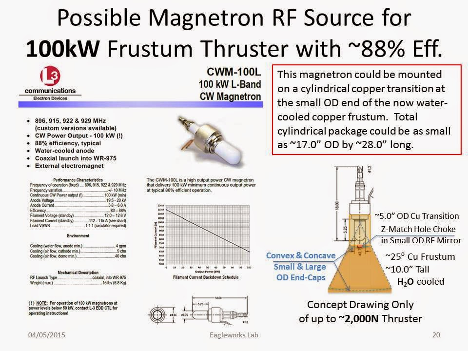
Maybe like him I have a few issues doing a microwave insertion into a asymmetrical point on the cone. It would seem better and I'm not sure of this to insert along the length from the small end centered in the reflective plate through a matching choke through a hole in the small plate. It would be like a RF megahorn very clean and lead to a very nice Q.
Hoped I help and I do like the feed into the end, so much cleaner.
Shell -
Title: Re: EM Drive Developments - related to space flight applications - Thread 3
Post by: cej on 07/04/2015 09:52 PM -
<a href="http://forum.nasaspaceflight.com/index.php?topic=37642.msg1400088#msg1400088">Quote from: wallofwolfstreet on 07/04/2015 04:06 PM</a>
(...)
but I'm going to add something else: I personally see no way that any physics simulation software, FEM, FDM, BEM, or anything else, will show any meaningful thrust on the device.
And in fact, it's worse that that. If you did see thrust with meep, what is more likely:
1) It has accurately predicted emdrive thrust from traditional physics.
2) The simulation was wrong.
I've done plenty of work with numerical methods and written enough FDM codes myself to know that you don't always get exactly what you expect. That's the nature of approximation, especially understanding how error can propagate from grid point to grid point or element to element.
Maybe I have this wrong, but I've gotten the impression that some people feel that all this confusion can be solved with MEEP. If MEEP showed use something that we didn't already know, ie. a net thrust greater than a photon rocket, I wouldn't consider that a plus for the EMdrive. I would consider it a negative for MEEP.
I do not recall anyone here claiming that a simulation (meep) can prove thrust. What it does do, however, is let us quickly test our intuition of how to correctly apply theory to predict the behavior of an EM field in the cavity. For example, it appears to be incorrect to assume a standing wave in the EM Drive.
If the simulation predicts no thrust, then we have ruled out even more "what ifs" questioning whether there might still be a corner case that allows for thrust using conventional physics. And if it does suggest thrust, it will hopefully give us something more specific to test for in an experiment. -
Title: Re: EM Drive Developments - related to space flight applications - Thread 3
Post by: SeeShells on 07/04/2015 10:13 PM -
<a href="http://forum.nasaspaceflight.com/index.php?topic=37642.msg1400125#msg1400125">Quote from: aero on 07/04/2015 05:25 PM</a>
@SeeShell -
Are you planning to use an antenna or a waveguide for cavity excitation? I had a thought about using a waveguide, and questions of course.
First, I am thinking of a square cross section and short length, one end excited by a dipole antenna with a noisy (magnetron) source, and the other fixed to the cavity model at the specified center location. Questions:
What would be viable dimensions for this waveguide model?
What would be the attachment point of choice
What would be the injection angle of the wave guide relative to the cavity x, y, z coordinates?
The last question is to point out that with a wave guide, the signal could be injected parallel to the lateral axis and perpendicular to the axis of rotation, but it need not be. The signal could also be injected toward the big or small base, nearly parallel with the axis of rotation, or it could be injected nearly tangentially to the circumference of the cavity, that is nearly perpendicular to a lateral axis. Or of course it could be injected at any combination of those directions. I hope all here understand this question. Mentally, I am using a fire hose model of the injected energy, but the direction of the injected wave will make a difference in the field patterns in the cavity. won't it?
(sorry was awake most of the night last night... restless hours and just got up after a long 4th o July nap.)
If you're going to build the wave guide yourself what are you going to use? For these powers you need not to consider building a waveguide from old beer cans. There is a much easier fix.
Use the parts from a old microwave, the electronics, Mag, brackets and housings that attaches into the microwave cavity.
But if you insist full DYI I would machine it.
Here are some links for the numbers.
http://www.microwaves101.com/encyclopedias/waveguide-mathematics
Quick calculator and it agrees with MW101 site for what you want to do. I ran them and it's good.
http://www.myteron.de/wavehan/waveguide/antenna2calc.php
When I was a little fuzzier and wrote to you I ran over all the different injection points from satisfactory tested I could find. Dr. White's wasn't but I still like his insertion method. What mode were you trying to meet TE or TM?
I've never seen a meep simulation where the large end was used for the placement of the dipole or waveguide. -
Title: Re: EM Drive Developments - related to space flight applications - Thread 3
Post by: WarpTech on 07/04/2015 10:14 PM -
<a href="http://forum.nasaspaceflight.com/index.php?topic=37642.msg1400181#msg1400181">Quote from: cej on 07/04/2015 09:52 PM</a><a href="http://forum.nasaspaceflight.com/index.php?topic=37642.msg1400088#msg1400088">Quote from: wallofwolfstreet on 07/04/2015 04:06 PM</a>
(...)
but I'm going to add something else: I personally see no way that any physics simulation software, FEM, FDM, BEM, or anything else, will show any meaningful thrust on the device.
And in fact, it's worse that that. If you did see thrust with meep, what is more likely:
1) It has accurately predicted emdrive thrust from traditional physics.
2) The simulation was wrong.
I've done plenty of work with numerical methods and written enough FDM codes myself to know that you don't always get exactly what you expect. That's the nature of approximation, especially understanding how error can propagate from grid point to grid point or element to element.
Maybe I have this wrong, but I've gotten the impression that some people feel that all this confusion can be solved with MEEP. If MEEP showed use something that we didn't already know, ie. a net thrust greater than a photon rocket, I wouldn't consider that a plus for the EMdrive. I would consider it a negative for MEEP.
I do not recall anyone here claiming that a simulation (meep) can prove thrust. What it does do, however, is let us quickly test our intuition of how to correctly apply theory to predict the behavior of an EM field in the cavity. For example, it appears to be incorrect to assume a standing wave in the EM Drive.
If the simulation predicts no thrust, then we have ruled out even more "what ifs" questioning whether there might still be a corner case that allows for thrust using conventional physics. And if it does suggest thrust, it will hopefully give us something more specific to test for in an experiment.
Meep has already output sections of E and B for the interior. It would only need to Sum(E^2 + B^2) at the copper boundary for the entire interior surface area. If that sum is 0, then No NET Thrust. If that sum is not 0? Well, then we have a start. It is best to calculate it in 3 parts. Big end, small end, and conical wall. That way, if they are not zero, we know which direction the thrust is directed.
(May also want to include the sum over the surface area of the antenna too, as forces will act on it as well, depending on constructive and destructive interference.)
Todd -
Title: Re: EM Drive Developments - related to space flight applications - Thread 3
Post by: SeeShells on 07/04/2015 10:24 PM -
<a href="http://forum.nasaspaceflight.com/index.php?topic=37642.msg1400130#msg1400130">Quote from: WarpTech on 07/04/2015 05:33 PM</a>
Ack you make it sound so simple Todd. Well done.<a href="http://forum.nasaspaceflight.com/index.php?topic=37642.msg1400125#msg1400125">Quote from: aero on 07/04/2015 05:25 PM</a>@SeeShell -
I think the waveguide should just merge right into the small end and expand from there. You want the cutoff of the waveguide to be as close to the input frequency as possible, so that the waves move very slow through he waveguide and build up stored energy before entering the frustum, tapered part of the guide.
Theoretically, there should be no major VSWR reflected back down the input waveguide because the waves will have expanded beyond the cut-off as soon as they enter the frustum section. Giving up that energy as thrust.
Todd
Shell -
Title: Re: EM Drive Developments - related to space flight applications - Thread 3
Post by: wallofwolfstreet on 07/04/2015 10:30 PM -
<a href="http://forum.nasaspaceflight.com/index.php?topic=37642.msg1400181#msg1400181">Quote from: cej on 07/04/2015 09:52 PM</a><a href="http://forum.nasaspaceflight.com/index.php?topic=37642.msg1400088#msg1400088">Quote from: wallofwolfstreet on 07/04/2015 04:06 PM</a>
(...)
but I'm going to add something else: I personally see no way that any physics simulation software, FEM, FDM, BEM, or anything else, will show any meaningful thrust on the device.
And in fact, it's worse that that. If you did see thrust with meep, what is more likely:
1) It has accurately predicted emdrive thrust from traditional physics.
2) The simulation was wrong.
I've done plenty of work with numerical methods and written enough FDM codes myself to know that you don't always get exactly what you expect.&nbnbsp; That's the nature of approximation, especially understanding how error can propagate from grid point to grid point or element to element.
Maybe I have this wrong, but I've gotten the impression that some people feel that all this confusion can be solved with MEEP. If MEEP showed use something that we didn't already know, ie. a net thrust greater than a photon rocket, I wouldn't consider that a plus for the EMdrive. I would consider it a negative for MEEP.
I do not recall anyone here claiming that a simulation (meep) can prove thrust. What it does do, however, is let us quickly test our intuition of how to correctly apply theory to predict the behavior of an EM field in the cavity. For example, it appears to be incorrect to assume a standing wave in the EM Drive.
If the simulation predicts no thrust, then we have ruled out even more "what ifs" questioning whether there might still be a corner case that allows for thrust using conventional physics. And if it does suggest thrust, it will hopefully give us something more specific to test for in an experiment.
I wasn't trying to denigrate the importance of the MEEP work being done. I'm sorry if it came across that way.
In many ways, I was addressing that comment more to the people reading this thread than to fellow posters. After all, there are maybe 30-40 NSF contributors here that post on any kind of regular basis. However, this thread has been read 438,431 times. For every contributor, there are 10,000 people just reading.
I know that after a few posts between Aero and Rodal on the finer details of MEEP, I stopped paying attention. Sorry, but FEM analysis is not how I want to spend my free brain time. I'd imagine many of the forums readers zoned out a bit too. So I guess I felt that maybe a few people coming back to the forum, or coming to the forum for the first time, might have seen the awesome visuals that have been posted for the last dozen pages and concluded more than they ought to.
Like I said, great visuals and deeply important results for refining intuition, but it really constitutes a "first step" on the road to understanding this thing. -
Title: Re: EM Drive Developments - related to space flight applications - Thread 3
Post by: Rodal on 07/04/2015 10:43 PM -
<a href="http://forum.nasaspaceflight.com/index.php?topic=37642.msg1400181#msg1400181">Quote from: cej on 07/04/2015 09:52 PM</a>
...
Excellent summary !!!. I could not have written it better. Thanks
I do not recall anyone here claiming that a simulation (meep) can prove thrust. What it does do, however, is let us quickly test our intuition of how to correctly apply theory to predict the behavior of an EM field in the cavity. For example, it appears to be incorrect to assume a standing wave in the EM Drive.
If the simulation predicts no thrust, then we have ruled out even more "what ifs" questioning whether there might still be a corner case that allows for thrust using conventional physics. And if it does suggest thrust, it will hopefully give us something more specific to test for in an experiment. -
Title: Re: EM Drive Developments - related to space flight applications - Thread 3
Post by: Rodal on 07/04/2015 11:07 PM -
<a href="http://forum.nasaspaceflight.com/index.php?topic=37642.msg1399838#msg1399838">Quote from: aero on 07/03/2015 09:47 PM</a>
@Dr. Rodal - You wrote
To double check this all that is needed is to provide other circular cross-sections: I would favor one at the antenna location, another one close to it, within the same longitudinal wave-pattern, and another one in the next longitudinal wave pattern away from it towards the big base.
Would you care to look at a csv file with x,y or x,z and tell which row (x dimension is rows, isn't it?) that contains the fields you want to see? I can then take slices of the y,z plane containing those rows. Slicing the cavity in the y,z plane, and uploading to Google drive is faster than doing same for the other two planes, so more slices will not be a big burden.
I think that the best y-z plane (with normal x) cross-sections would be at the following two locations:
A) 150 in the x direction from the left end, (the end nearest the big base)
B) 209 in the x direction from the left end, (the end nearest the big base)
These cross sections are located near the small end (the 209 location is located near the antenna).
It appears that the matrix is not square in this case (wasn't it square before when it had half the number of entries in each direction?):
the x direction has 247 entries
while the y and the z directions have 264 entries.
Is that in agreement with what you intended?
This will be useful not only to double check the results, and see the circumferential distribution of the Power surface-density flux (the Poynting vector) at those locations -
Title: Re: EM Drive Developments - related to space flight applications - Thread 3
Post by: SeeShells on 07/04/2015 11:10 PM -
<a href="http://forum.nasaspaceflight.com/index.php?topic=37642.msg1400088#msg1400088">Quote from: wallofwolfstreet on 07/04/2015 04:06 PM</a><a href="http://forum.nasaspaceflight.com/index.php?topic=37642.msg1400045#msg1400045">Quote from: Rodal on 07/04/2015 01:59 PM</a><a href="http://forum.nasaspaceflight.com/index.php?topic=37642.msg1399991#msg1399991">Quote from: deltaMass on 07/04/2015 06:46 AM</a>
You guys tickle me pink. It doesn't matter where you put the antenna if you are using Maxwell/Poynting to figure that out. That theory says that you get zero thrust. You're better off with a Hail Mary. It's logical.
You have overstated your case. There is nothing in Maxwell's or Poynting's theory saying that one should get zero thrust out of anything. Actually, Maxwell was the first scientist to derive the equations predicting that electromagnetic radiation can produce stresses, and the stress-energy tensor carries his name to honor that achievement.
Case in point: if there is a net Poynting vector due to energy that gets dissipated into heat asymetrically, there maybe asymmetric heat transfer (by convection and/or radiation) resulting in asymmetric forces: "thrust". That is fully consistent with Maxwell's and Poynting's equations as well as consistent with Newton's equations.
A correct statement you could make is that you, personally, don't see a way that enough thrust/InputPower can result from an asymmetric microwave cavity that is in excess of a perfect photon rocket thrust/inputPower by several orders of magnitude, but that is not the statement you made.Quote from: Anson MountI'm an enemy of exposition. I feel there's no need to overstate.
While saying "Maxwell predicts zero thrust" is an overstatement, I have to agree with deltamass here. I will also throw my hat into the ring by saying I don't personally see a way "that thrust/InputPower can result from an asymmetric microwave cavity that is in excess of a perfect photon rocket thrust/inputPower by several orders of magnitude", but I'm going to add something else: I personally see no way that any physics simulation software, FEM, FDM, BEM, or anything else, will show any meaningful thrust on the device.
And in fact, it's worse that that. If you did see thrust with meep, what is more likely:
1) It has accurately predicted emdrive thrust from traditional physics.
2) The simulation was wrong.
I've done plenty of work with numerical methods and written enough FDM codes myself to know that you don't always get exactly what you expect. That's the nature of approximation, especially understanding how error can propagate from grid point to grid point or element to element.
Maybe I have this wrong, but I've gotten the impression that some people feel that all this confusion can be solved with MEEP. If MEEP showed use something that we didn't already know, ie. a net thrust greater than a photon rocket, I wouldn't consider that a plus for the EMdrive. I would consider it a negative for MEEP.
So... using standard physics in simulations will not give us any foundations to go on? Fact. The numerical simulations have been used for years, the're used in the designing of CERN, fiber optic communications, and in cad and in just about every aspect of numerical modeling in engineering and physics I can think of. They are not perfect but I remember getting my slide rule out and using cheaters to see the divisions better. Yes, they are not perfect but it is what we have other than our gray matter and a pencil and that sucks. ;)
Let's back up and regroup so I can feel better because I'm feeling pretty funky right now. I believe there is enough empirical data in such widely varying test beds and that this is just enough out of the noise of chance that there is something going on and it deserves further testing. Agreed? Maybe? Why are you here? Just a little hope? Ya, I knew it you really don't want us laying in the dirt to look at the stars. That's cool.
We have worlds of ideology clashing into this thing. Standard Physics, you know ohms law, speed of light, gravity. wait...um gravity doesn't belong there, damn, we still are not sure how it works, so out it goes...poof. So we have Einstein's work, CoM, CoE Maxwell's and a beautiful host of other that fit perfectly into our standard model. What, they all don't, we still have questions? Poo.
Ok I got it now I can fix this! What makes all these very nice and obeyed laws work so beautifully (well kinda)? Quantum MECHANICS QV QM QED PMS and lets just throw in a black hole so we can suck it all up so nothing matters. Sorry, it does matter, I was kidding. They all matter but they are like the kid under the stairs a little freaky with glowing eyes and they are so different than the standard model. But, but, but, they make the standard model work. Phew, now here we are trying to figure out how to go backwards from normal physics and a can of microwaves down to quantum world to make thrust, to make it go, to understand. You know it's not easy. Things will not click and work quite like they should and we need to be diligent and have hope.
Is it worth it, you bet, will they be questions, yep. And every bit of it it worth it. So bring your doubting on and your questions and your blind faith and we'll do this, we'll kick this can.
And a Happy 4th Of July to all that are celebrating it.
Shell -
Title: Re: EM Drive Developments - related to space flight applications - Thread 3
Post by: wallofwolfstreet on 07/05/2015 12:22 AM -
<a href="http://forum.nasaspaceflight.com/index.php?topic=37642.msg1400201#msg1400201">Quote from: SeeShells on 07/04/2015 11:10 PM</a>
So... using standard physics in simulations will not give us any foundations to go on? Fact. The numerical simulations have been used for years, the're used in the designing of CERN, fiber optic communications, and in cad and in just about every aspect of numerical modeling in engineering and physics I can think of. They are not perfect but I remember getting my slide rule out and using cheaters to see the divisions better. Yes, they are not perfect but it is what we have other than our gray matter and a pencil and that sucks. ;)
Let's back up and regroup so I can feel better because I'm feeling pretty funky right now. I believe there is enough empirical data in such widely varying test beds and that this is just enough out of the noise of chance that there is something going on and it deserves further testing. Agreed? Maybe? Why are you here? Just a little hope? Ya, I knew it you really don't want us laying in the dirt to look at the stars. That's cool.
We have worlds of ideology clashing into this thing. Standard Physics, you know ohms law, speed of light, gravity. wait...um gravity doesn't belong there, damn, we still are not sure how it works, so out it goes...poof. So we have Einstein's work, CoM, CoE Maxwell's and a beautiful host of other that fit perfectly into our standard model. What, they all don't, we still have questions? Poo.
Ok I got it now I can fix this! What makes all these very nice and obeyed laws work so beautifully (well kinda)? Quantum MECHANICS QV QM QED PMS and lets just throw in a black hole so we can suck it all up so nothing matters. Sorry, it does matter, I was kidding. They all matter but they are like the kid under the stairs a little freaky with glowing eyes and they are so different than the standard model. But, but, but, they make the standard model work. Phew, now here we are trying to figure out how to go backwards from normal physics and a can of microwaves down to quantum world to make thrust, to make it go, to understand. You know it's not easy. Things will not click and work quite like they should and we need to be diligent and have hope.
Is it worth it, you bet, will they be questions, yep. And every bit of it it worth it. So bring your doubting on and your questions and your blind faith and we'll do this, we'll kick this can.
And a Happy 4th Of July to all that are celebrating it.
Shell
I'll be the first to admit there is something going on and it deserves further testing. I have never advocated, and never will, that testing should be abandoned. However, I have always been clear that I feel the likelihood that that something is propellantless thrust to be very low. Finding the exact quirk that gives the appearance of propellantless thrust is a worthwhile scientific endeavor in it's own right though.QuoteI believe there is enough empirical data in such widely varying test beds and that this is just enough out of the noise of chance that there is something going on and it deserves further testing.
This right here is probably where you and I, and everyone else who has a different take on the emdrive from 100% likelihood to 0% likelihood, differ. When the emdrive first popped back into the news last august, I always heard the word replication being thrown around. Nasa has replicated a propellantless drive! It was replicated by the Chinese! UK inventor has drive replicated by Nasa and Chinese Labs! These were the kinds of headlines I saw. However, when you actually read through the individual papers, something practically explodes out at you. None of the experiments are actually replications of any of the others:
The chinese got higher thrust from lower Q than Shawyer - goes against Shaywer's theory
Nasa didn't get thrust from a frustum without a dielectric - goes against Chinese and Shawyer's experimental results, goes against Shawyers theory.
Shawyer has gotten different thrust directions from different set-ups (dielectric vs. none) - goes against theory, just outright strange
So far, every experiment has used a drastically different apparatus, with different variable inputs and gotten massively different results. Thrust direction has not even remained constant. So when you look at the experiments in that light, the empirical data becomes rather sketchy. To date, as far as I know, no lab has truly replicated any other, and that's a problem.
Edit: A problem that may be be solved by all the DIY yourself projects that are coming online this month. I may have to retire this criticism in a few weeks if strong data comes out of some of the replication attempts. -
Title: Re: EM Drive Developments - related to space flight applications - Thread 3
Post by: frobnicat on 07/05/2015 12:24 AM -
<a href="http://forum.nasaspaceflight.com/index.php?topic=37642.msg1400126#msg1400126">Quote from: WarpTech on 07/04/2015 05:27 PM</a>
...
The question of, "How does the momentum get out?", is a different answer. Obviously, it would have more thrust if the big end were open. Any momentum reflecting off the big end plate will negate the momentum gained in getting there. However, in a dissipative system, after each bounce the wave rotates the momentum a little more into the "x" direction, but loses energy due to dissipation of heat into the copper. That means that when it reaches the back wall, it has less momentum than it should have. The NET is not zero because something was lost along the way.
...
Sorry, please explain to the Newtonian guy in me : how a play of throwing and bouncing and catching balls within a free floating box could give any persistent deltaV to the box ? deltaX I see, but not deltaV at the end of the story (when the game stops). At one end of the box you have a source of energy, the energy flows in some arbitrary geometry and after long or short path ends absorbed asymmetrically by some inner walls. Some walls (patches) will have received more energy, some less. A source full of energy (loaded battery, or fresh radioisotopes generator) weighs more than when depleted. A hot wall patch weighs more than a cold one. All that has happened is a (tiny) displacement of the centre of mass within the box, following the displacement of conserved energy. A corresponding tiny deltaX in the opposite direction will be observed from the outside of the box, no deltaV between start and end of "discharge". That is, unless the inner walls bleed thermal IR outside, with photon rocket efficiency as an upper bound.
Do you really say that the mechanism you propose here would allow a system fully enclosed in an ideal perfect thermal blanket to gain an ultimate deltaV, i.e. without bleeding any radiation having permanently (asymptotically after switch off) changed its velocity relative to its initial inertial rest frame, as good as the velocity acquired by a chemical thruster burst is still there indefinitely after power off of said thruster ?
Not addressing the later hypothesis involving DC components, just this specific part quoted, as you seem to imply that it could be valid by itself and independently.
-
Title: Re: EM Drive Developments - related to space flight applications - Thread 3
Post by: WarpTech on 07/05/2015 01:09 AM -
<a href="http://forum.nasaspaceflight.com/index.php?topic=37642.msg1400222#msg1400222">Quote from: frobnicat on 07/05/2015 12:24 AM</a><a href="http://forum.nasaspaceflight.com/index.php?topic=37642.msg1400126#msg1400126">Quote from: WarpTech on 07/04/2015 05:27 PM</a>
...
The question of, "How does the momentum get out?", is a different answer. Obviously, it would have more thrust if the big end were open. Any momentum reflecting off the big end plate will negate the momentum gained in getting there. However, in a dissipative system, after each bounce the wave rotates the momentum a little more into the "x" direction, but loses energy due to dissipation of heat into the copper. That means that when it reaches the back wall, it has less momentum than it should have. The NET is not zero because something was lost along the way.
...
Sorry, please explain to the Newtonian guy in me : how a play of throwing and bouncing and catching balls within a free floating box could give any persistent deltaV to the box ? deltaX I see, but not deltaV at the end of the story (when the game stops). At one end of the box you have a source of energy, the energy flows in some arbitrary geometry and after long or short path ends absorbed asymmetrically by some inner walls. Some walls (patches) will have received more energy, some less. A source full of energy (loaded battery, or fresh radioisotopes generator) weighs more than when depleted. A hot wall patch weighs more than a cold one. All that has happened is a (tiny) displacement of the centre of mass within the box, following the displacement of conserved energy. A corresponding tiny deltaX in the opposite direction will be observed from the outside of the box, no deltaV between start and end of "discharge". That is, unless the inner walls bleed thermal IR outside, with photon rocket efficiency as an upper bound.
Do you really say that the mechanism you propose here would allow a system fully enclosed in an ideal perfect thermal blanket to gain an ultimate deltaV, i.e. without bleeding any radiation having permanently (asymptotically after switch off) changed its velocity relative to its initial inertial rest frame, as good as the velocity acquired by a chemical thruster burst is still there indefinitely after power off of said thruster ?
Not addressing the later hypothesis involving DC components, just this specific part quoted, as you seem to imply that it could be valid by itself and independently.
"... throwing and bouncing and catching balls within a free floating box..." Is a linear equation of momentum. The momentum coming out of the waveguide is a non-linear equation, with a force exerted as 1/r^2. The momentum transferred by the wave is proportional to the phase velocity, not c. So there is more momentum exchange at the small end due to higher phase velocity, than there is at the big end. A photon rocket in free space is a linear equation. Inside a tapered wave guide, it is non-linear. It can't be explained in terms of billiard balls. The question you are asking is the one I am trying to resolve mathematically. My theory is not quite there yet.
This is where I'm at... The attached image is the derivation of the Photon Rocket equation, for an open-ended circular waveguide. So anyone who says a photon rocket can only exert a maximum force of F = 2P/c, is only correct in free space but not when confined to a waveguide. The thrust-to-power ratio is much, much larger near the cut-off.
Todd
-
Title: Re: EM Drive Developments - related to space flight applications - Thread 3
Post by: Rodal on 07/05/2015 02:26 AM -
<a href="http://forum.nasaspaceflight.com/index.php?topic=37642.msg1400126#msg1400126">Quote from: WarpTech on 07/04/2015 05:27 PM</a>
...First, does anyone know why the Formatting tools on here don't work anymore? I'm using Safari browser on a Mac. They used to work, but haven't worked for the past couple of weeks.
...
You are right, the formatting stopped working a couple of weeks ago for Google Chrome as well. Very annoying.
I have found that the formatting still works if you use Mozilla's Firefox as a browser.
https://www.mozilla.org/en-US/firefox/new/ -
Title: Re: EM Drive Developments - related to space flight applications - Thread 3
Post by: aero on 07/05/2015 02:36 AM -
<a href="http://forum.nasaspaceflight.com/index.php?topic=37642.msg1400199#msg1400199">Quote from: Rodal on 07/04/2015 11:07 PM</a><a href="http://forum.nasaspaceflight.com/index.php?topic=37642.msg1399838#msg1399838">Quote from: aero on 07/03/2015 09:47 PM</a>
@Dr. Rodal - You wrote
To double check this all that is needed is to provide other circular cross-sections: I would favor one at the antenna location, another one close to it, within the same longitudinal wave-pattern, and another one in the next longitudinal wave pattern away from it towards the big base.
Would you care to look at a csv file with x,y or x,z and tell which row (x dimension is rows, isn't it?) that contains the fields you want to see? I can then take slices of the y,z plane containing those rows. Slicing the cavity in the y,z plane, and uploading to Google drive is faster than doing same for the other two planes, so more slices will not be a big burden.
I think that the best y-z plane (with normal x) cross-sections would be at the following two locations:
A) 150 in the x direction from the left end, (the end nearest the big base)
B) 209 in the x direction from the left end, (the end nearest the big base)
These cross sections are located near the small end (the 209 location is located near the antenna).
It appears that the matrix is not square in this case (wasn't it square before when it had half the number of entries in each direction?):
the x direction has 247 entries
while the y and the z directions have 264 entries.
Is that in agreement with what you intended?
This will be useful not only to double check the results, and see the circumferential distribution of the Power surface-density flux (the Poynting vector) at those locations
The file got bigger when I increased the resolution from 100 to 250. The file contains the complete lattice which is dimensioned as the maximum diameter and height of the frustum, plus a fixed space all around. The diameter is bigger than the height so the lattice is not square in views where both are seen. When you look at the yz view, you see two diameters, so the lattice projects as a square in that view. But xy and xz show the height and a diameter so not square.
I'll get around to making those csv files ... -
Title: Re: EM Drive Developments - related to space flight applications - Thread 3
Post by: Rodal on 07/05/2015 02:55 AM -
<a href="http://forum.nasaspaceflight.com/index.php?topic=37642.msg1400231#msg1400231">Quote from: WarpTech on 07/05/2015 01:09 AM</a>
...
"... throwing and bouncing and catching balls within a free floating box..." Is a linear equation of momentum. The momentum coming out of the waveguide is a non-linear equation, with a force exerted as 1/r^2. The momentum transferred by the wave is proportional to the phase velocity, not c. So there is more momentum exchange at the small end due to higher phase velocity, than there is at the big end. A photon rocket in free space is a linear equation. Inside a tapered wave guide, it is non-linear. It can't be explained in terms of billiard balls. The question you are asking is the one I am trying to resolve mathematically. My theory is not quite there yet.
...
I would like to point out that Meep takes into account many possible solutions to Maxwell's equations, including travelling, standing and evanescent waves, and other forms that are not simple. That is the power of a time-domain analysis: that it can analyze nonlinear problems that are not subject to exact solutions in terms of well-known functions like harmonic solutions.
I'm not sure that everybody has appreciated the fact that the Poyinting vector field shown in this message: http://forum.nasaspaceflight.com/index.php?topic=37642.msg1399795#msg1399795 shows a very non-harmonic, asymmetric nonlinear time response cycle and its implications: see how the Poynting vector field diminishes with time from its peak in a monotone gradual manner until step TS07 where it reaches minimum and then suddenly it jumps to peak value:
1st cycle
TS03 = peak flux (pointing from small base towards big base)
TS04 = flux (pointing from small base towards big base)
TS05 = flux (pointing from small base towards big base)
TS06 = significantly less flux (pointing from small base towards big base)
TS07 = minimum flux (pointing from small base towards big base)
2nd cycle
TS08 = peak flux (pointing from small base towards big base)
TS09 = flux (pointing from small base towards big base)
TS10 = flux (pointing from small base towards big base)
TS11 = significantly less flux (pointing from small base towards big base)
TS12 = minimum flux (pointing from small base towards big base)
3rd cycle
TS13 = peak flux (pointing from small base towards big base)
This non-harmonic, nonlinear time response is also shown in the movies of the electromagnetic fields.
It is not just a case of the Poynting vector summing up to a finite value over integer number of periods, the reason for this is that the time rate of the Poynting vector through time is not symmetric during a cycle: it jumps from minimum to maximum value much faster than it goes from maximum to minimum.
Those familiar with nonlinear problems will get where this is going. I'll plot this later.
( )
)
-
Title: Re: EM Drive Developments - related to space flight applications - Thread 3
Post by: Ricvil on 07/05/2015 03:23 AM -
This guys think another way
http://arxiv.org/abs/0708.3519
:)
quote author=WarpTech link=topic=37642.msg1400231#msg1400231 date=1436058596]<a href="http://forum.nasaspaceflight.com/index.php?topic=37642.msg1400222#msg1400222">Quote from: frobnicat on 07/05/2015 12:24 AM</a><a href="http://forum.nasaspaceflight.com/index.php?topic=37642.msg1400126#msg1400126">Quote from: WarpTech on 07/04/2015 05:27 PM</a>...
The question of, "How does the momentum get out?", is a different answer. Obviously, it would have more thrust if the big end were open. Any momentum reflecting off the big end plate will negate the momentum gained in getting there. However, in a dissipative system, after each bounce the wave rotates the momentum a little more into the "x" direction, but loses energy due to dissipation of heat into the copper. That means that when it reaches the back wall, it has less momentum than it should have. The NET is not zero because something was lost along the way.
...
Sorry, please explain to the Newtonian guy in me : how a play of throwing and bouncing and catching balls within a free floating box could give any persistent deltaV to the box ? deltaX I see, but not deltaV at the end of the story (when the game stops). At one end of the box you have a source of energy, the energy flows in some arbitrary geometry and after long or short path ends absorbed asymmetrically by some inner walls. Some walls (patches) will have received more energy, some less. A source full of energy (loaded battery, or fresh radioisotopes generator) weighs more than when depleted. A hot wall patch weighs more than a cold one. All that has happened is a (tiny) displacement of the centre of mass within the box, following the displacement of conserved energy. A corresponding tiny deltaX in the opposite direction will be observed from the outside of the box, no deltaV between start and end of "discharge". That is, unless the inner walls bleed thermal IR outside, with photon rocket efficiency as an upper bound.
Do you really say that the mechanism you propose here would allow a system fully enclosed in an ideal perfect thermal blanket to gain an ultimate deltaV, i.e. without bleeding any radiation having permanently (asymptotically after switch off) changed its velocity relative to its initial inertial rest frame, as good as the velocity acquired by a chemical thruster burst is still there indefinitely after power off of said thruster ?
Not addressing the later hypothesis involving DC components, just this specific part quoted, as you seem to imply that it could be valid by itself and independently.
"... throwing and bouncing and catching balls within a free floating box..." Is a linear equation of momentum. The momentum coming out of the waveguide is a non-linear equation, with a force exerted as 1/r^2. The momentum transferred by the wave is proportional to the phase velocity, not c. So there is more momentum exchange at the small end due to higher phase velocity, than there is at the big end. A photon rocket in free space is a linear equation. Inside a tapered wave guide, it is non-linear. It can't be explained in terms of billiard balls. The question you are asking is the one I am trying to resolve mathematically. My theory is not quite there yet.
This is where I'm at... The attached image is the derivation of the Photon Rocket equation, for an open-ended circular waveguide. So anyone who says a photon rocket can only exert a maximum force of F = 2P/c, is only correct in free space but not when confined to a waveguide. The thrust-to-power ratio is much, much larger near the cut-off.
Todd
[/quote]
-
Title: Re: EM Drive Developments - related to space flight applications - Thread 3
Post by: SeeShells on 07/05/2015 03:56 AM -
<a href="http://forum.nasaspaceflight.com/index.php?topic=37642.msg1400221#msg1400221">Quote from: wallofwolfstreet on 07/05/2015 12:22 AM</a>
Degrasse Tyson sumed my work philosophy in Cosmos Unafraid of The Dark.<a href="http://forum.nasaspaceflight.com/index.php?topic=37642.msg1400201#msg1400201">Quote from: SeeShells on 07/04/2015 11:10 PM</a>Shell
I'll be the first to admit there is something going on and it deserves further testing. I have never advocated, and never will, that testing should be abandoned. However, I have always been clear that I feel the likelihood that that something is propellantless thrust to be very low. Finding the exact quirk that gives the appearance of propellantless thrust is a worthwhile scientific endeavor in it's own right though.QuoteI believe there is enough empirical data in such widely varying test beds and that this is just enough out of the noise of chance that there is something going on and it deserves further testing.
This right here is probably where you and I, and everyone else who has a different take on the emdrive from 100% likelihood to 0% likelihood, differ. When the emdrive first popped back into the news last august, I always heard the word replication being thrown around. Nasa has replicated a propellantless drive! It was replicated by the Chinese! UK inventor has drive replicated by Nasa and Chinese Labs! These were the kinds of headlines I saw. However, when you actually read through the individual papers, something practically explodes out at you. None of the experiments are actually replications of any of the others:
The chinese got higher thrust from lower Q than Shawyer - goes against Shaywer's theory
Nasa didn't get thrust from a frustum without a dielectric - goes against Chinese and Shawyer's experimental results, goes against Shawyers theory.
Shawyer has gotten different thrust directions from different set-ups (dielectric vs. none) - goes against theory, just outright strange
So far, every experiment has used a drastically different apparatus, with different variable inputs and gotten massively different results. Thrust direction has not even remained constant. So when you look at the experiments in that light, the empirical data becomes rather sketchy. To date, as far as I know, no lab has truly replicated any other, and that's a problem.
Edit: A problem that may be be solved by all the DIY yourself projects that are coming online this month. I may have to retire this criticism in a few weeks if strong data comes out of some of the replication attempts.
"Question authority.
No idea is true just because someone says so, including me.
Think for yourself.
Question yourself.
Don't believe anything just because you want to.
Believing something doesn't make it so.
Test ideas by the evidence gained from observation and experiment.
If a favorite idea fails a well-designed test, it's wrong! Get over it.
Follow the evidence, wherever it leads.
If you have no evidence, reserve judgment.
And perhaps the most important rule of all Remember, you could be wrong.
Even the best scientists have been wrong about some things.
Newton, Einstein, and every other great scientist in history, they all made mistakes.
Of course they did-- they were human." -
Title: Re: EM Drive Developments - related to space flight applications - Thread 3
Post by: deltaMass on 07/05/2015 03:58 AM -
http://physics.stackexchange.com/questions/190018/does-radiation-force-depend-on-group-velocity-or-on-phase-velocity
The answer is phase velocity
Therefore any explanations for thrust (like Shawyer's for example) which are based on a difference between group velocities, are just plain wrong. -
Title: Re: EM Drive Developments - related to space flight applications - Thread 3
Post by: TheTraveller on 07/05/2015 04:14 AM -
<a href="http://forum.nasaspaceflight.com/index.php?topic=37642.msg1400268#msg1400268">Quote from: deltaMass on 07/05/2015 03:58 AM</a>
http://physics.stackexchange.com/questions/190018/does-radiation-force-depend-on-group-velocity-or-on-phase-velocity
The answer is phase velocity
Therefore any explanations for thrust (like Shawyer's for example) which are based on a difference between group velocities, are just plain wrong.
http://www.microwaves101.com/encyclopedias/waveguide-mathematics#velocity
Inside a waveguide, the wave travels at group velocity and not at phase velocity which would be faster than c.
Shawyer is correct to model end plate forces based on end plate group velocity, which is related to guide wavelength as per the attached.
Any text on waveguides will tell you the energy in the waveguide propogates down the waveguide at group velocity speed. -
Title: Re: EM Drive Developments - related to space flight applications - Thread 3
Post by: WarpTech on 07/05/2015 04:52 AM -
<a href="http://forum.nasaspaceflight.com/index.php?topic=37642.msg1400264#msg1400264">Quote from: Ricvil on 07/05/2015 03:23 AM</a>
This guys think another way
http://arxiv.org/abs/0708.3519
:)<a href="http://forum.nasaspaceflight.com/index.php?topic=37642.msg1400231#msg1400231">Quote from: WarpTech on 07/05/2015 01:09 AM</a>...
This is where I'm at... The attached image is the derivation of the Photon Rocket equation, for an open-ended circular waveguide. So anyone who says a photon rocket can only exert a maximum force of F = 2P/c, is only correct in free space but not when confined to a waveguide. The thrust-to-power ratio is much, much larger near the cut-off.
I tried his approach first, it only leads to a relativistic particle treatment of photons, but nothing more than the equivalent to a photon rocket. In my equation the added thrust comes from the M(z)*dz/z term. Which is a force due to the gradient in a potential caused by the cone geometry.
Todd
-
Title: Re: EM Drive Developments - related to space flight applications - Thread 3
Post by: WarpTech on 07/05/2015 05:04 AM -
<a href="http://forum.nasaspaceflight.com/index.php?topic=37642.msg1400271#msg1400271">Quote from: TheTraveller on 07/05/2015 04:14 AM</a><a href="http://forum.nasaspaceflight.com/index.php?topic=37642.msg1400268#msg1400268">Quote from: deltaMass on 07/05/2015 03:58 AM</a>
http://physics.stackexchange.com/questions/190018/does-radiation-force-depend-on-group-velocity-or-on-phase-velocity
The answer is phase velocity
Therefore any explanations for thrust (like Shawyer's for example) which are based on a difference between group velocities, are just plain wrong.
http://www.microwaves101.com/encyclopedias/waveguide-mathematics#velocity
Inside a waveguide, the wave travels at group velocity and not at phase velocity which would be faster than c.
Shawyer is correct to model end plate forces based on end plate group velocity, which is related to guide wavelength as per the attached.
Any text on waveguides will tell you the energy in the waveguide propogates down the waveguide at group velocity speed.
What you said is correct, if you are looking at energy. However, mass is different. If you want to convert from energy to mass;
(dE/vgroup) = (dM*c2/vgroup) = (dM*vphase)
So momentum depends on phase velocity. It makes a huge difference!
Todd -
Title: Re: EM Drive Developments - related to space flight applications - Thread 3
Post by: TheTraveller on 07/05/2015 05:16 AM -
<a href="http://forum.nasaspaceflight.com/index.php?topic=37642.msg1400277#msg1400277">Quote from: WarpTech on 07/05/2015 05:04 AM</a><a href="http://forum.nasaspaceflight.com/index.php?topic=37642.msg1400271#msg1400271">Quote from: TheTraveller on 07/05/2015 04:14 AM</a><a href="http://forum.nasaspaceflight.com/index.php?topic=37642.msg1400268#msg1400268">Quote from: deltaMass on 07/05/2015 03:58 AM</a>
http://physics.stackexchange.com/questions/190018/does-radiation-force-depend-on-group-velocity-or-on-phase-velocity
The answer is phase velocity
Therefore any explanations for thrust (like Shawyer's for example) which are based on a difference between group velocities, are just plain wrong.
http://www.microwaves101.com/encyclopedias/waveguide-mathematics#velocity
Inside a waveguide, the wave travels at group velocity and not at phase velocity which would be faster than c.
Shawyer is correct to model end plate forces based on end plate group velocity, which is related to guide wavelength as per the attached.
Any text on waveguides will tell you the energy in the waveguide propagates down the waveguide at group velocity speed.
What you said is correct, if you are looking at energy. However, mass is different. If you want to convert from energy to mass;
(dE/vgroup) = (dM*c2/vgroup) = (dM*vphase)
So momentum depends on phase velocity. It makes a huge difference!
Todd
Phase velocity is way over 1c inside a waveguide. You still want to run with phase velocity?
Cullen equation 15 uses the ratio Lambda0 (free) / Lambdag (guide wavelength) as per attached. Simple to derive group velocity from guide wavelength being Vg = c * (Lambda0 / Lambdag)
I have never seen any reference that phase velocity is involved, in a waveguide, in determining the bounce Force imparted to an end plate. If you have a few references, please provide the links.
If you have a look at the equation Shawyer uses, as attached, it sure seems to be the same one Cullen is using to calculate Force generated on a end plate bounce.
You sure you want to say Cullen is wrong in how he calculated the Force generated on the end plate when his microwave EM wave bounced off it?
If Cullen is right then Shawyer is right as Shawyer uses Cullen's equation 15, which is based on the guide wavelength.
-
Title: Re: EM Drive Developments - related to space flight applications - Thread 3
Post by: WarpTech on 07/05/2015 06:18 AM -
DERIVATION OF THRUST FROM A TAPERED WAVEGUIDE PHOTON ROCKET
I updated the equations to make the derivation clearer. In these equations, z is the axis of the cone, theta is the half-angle, E is energy, M and m are mass terms, and the rest is just wave vectors in a waveguide.
You can see that if the cone were not tapered there would be no dependence on z, the last term in the force equation would not exist. If it were not starting in a waveguide, the phase velocity would be c. Then we have a "flashlight" photon rocket. This is a different animal. This Force only applies when the big end is OPEN! Closed, all bets are off, but this explains where the tremendous thrust to power ratios are coming from.
FYI: This is the foundation of the paper I'm writing. Now you have the "tech" right in front of you while I try to put this in "writing". Have at it! Can't wait to see what sort of designs you come up with. 8)
Todd
-
Title: Re: EM Drive Developments - related to space flight applications - Thread 3
Post by: demofsky on 07/05/2015 07:08 AM -
<a href="http://forum.nasaspaceflight.com/index.php?topic=37642.msg1400257#msg1400257">Quote from: Rodal on 07/05/2015 02:55 AM</a>
.....
I'm not sure that everybody has appreciated the fact that the Poyinting vector field shown in this message: http://forum.nasaspaceflight.com/index.php?topic=37642.msg1399795#msg1399795 shows a very non-harmonic, asymmetric nonlinear time response cycle and its implications:
.....
I completely agree with this. While the pointing vector behaviour was a delightful discovery, the nonlinear behaviours are, for me, the real upside for the EM drive vs the standard photon drive. These behaviours offer the possibility that Shawyer's and Yang's claims can be confirmed. -
Title: Re: EM Drive Developments - related to space flight applications - Thread 3
Post by: demofsky on 07/05/2015 07:34 AM -
<a href="http://forum.nasaspaceflight.com/index.php?topic=37642.msg1400264#msg1400264">Quote from: Ricvil on 07/05/2015 03:23 AM</a>
This guys think another way
http://arxiv.org/abs/0708.3519
:)
This is a very interesting paper. From the first paragraph of p 10:QuoteThe effective rest mass of guided photons inside a hollow waveguide, as the rest energy of photons inside the waveguide (i.e., the energy as the group velocity vg =0), arises by forming standing-waves along the transverse cross-section of the waveguide. In other words, it arises by freezing out the degree of freedom of transverse motion, or, by localizing and confining the electromagnetic energy along the 2D space perpendicular to the waveguide.
Hm. -
Title: Re: EM Drive Developments - related to space flight applications - Thread 3
Post by: guckyfan on 07/05/2015 07:51 AM -
I got to admit that I did not wade through the last 1000 posts. Mostly because much of it is way over my head.
So forgive me that question. Is there a timeframe to expect results from the new test setup of NASA Eagleworks? -
Title: Re: EM Drive Developments - related to space flight applications - Thread 3
Post by: ThinkerX on 07/05/2015 08:06 AM -
Quote
So forgive me that question. Is there a timeframe to expect results from the new test setup of NASA Eagleworks?
This July or August...maybe. At least that was when they were hoping to conduct the next round of tests, as of word here a few months ago.
Also, this July, Tajmar (sp?) is supposed to give a presentation on his (?) recent EM Drive research.
Plus, we have two or three DIY posters here, employing the best info available, who should be conducting tests and releasing results end of July, more or less.
-
Title: Re: EM Drive Developments - related to space flight applications - Thread 3
Post by: TheTraveller on 07/05/2015 08:25 AM -
Following discussions with Roger Shawyer, I now understand why using a scale to measure EMDrive Force generation is a waste of time.
1) Basically when you sit the EMDrive on your scale based measurement system, it will be non moving.
2) Once you fill the frustum with microwaves it will be in IDLE mode waiting for some external Force to move/vibrate it slightly big end to small end.
3) Once that happens the EMDrive enters MOTOR mode and starts to build up an external Force. That Force will push against the measurement system and achieve a slight amount of room to slightly accelerate.
4) However soon after what ever compressive movement that was there is now gone, the EMDrive stops moving and flips back into IDLE mode and shutting off Force generation.
The only way to allow the EMDrive to properly enter MOTOR mode and stay there needs the EMDrive to be free to move / accelerate.
My test rig is now being redesigned into a rotary, totally enclosed, low air resistance and battery powered system that will allow continual acceleration for many minutes. A high resolution optical encoder will measure angular rotation to approx 1 part in 10,000 per revolution. On board will be a 8 channel data recorder which will accurately measure battery energy usage.
The system will be able to resolve the apparent CofE paradox:
1) Device continually accelerates obeying A = F/M
2) KE increases at 1/2MV^2.
The measurement of power supply energy consumed by the 20W RF amp as against KE will be done and compared.
The tests will be streamed live. Data will be uploaded after the rotary test rigs stops spinning as there is not a laptop in the spinning test rig.
My gut says I will see a constant energy usage by the 20W RF amp, constant acceleration and KE going up faster than the energy used by the 20W RF amp.
I'm thinking about how to measure if the accumulated KE is real or just numbers on a piece of paper. Would need some form on a Pony Brake or something similar.
Any suggestions most welcome
Crude drawing of rotary test rig attached. -
Title: Re: EM Drive Developments - related to space flight applications - Thread 3
Post by: guckyfan on 07/05/2015 08:43 AM - Thanks to ThinkerX.
-
Title: Re: EM Drive Developments - related to space flight applications - Thread 3
Post by: arc on 07/05/2015 10:44 AM -
<a href="http://forum.nasaspaceflight.com/index.php?topic=37642.msg1400266#msg1400266">Quote from: SeeShells on 07/05/2015 03:56 AM</a>
Degrasse Tyson sumed my work philosophy in Cosmos Unafraid of The Dark.
"Question authority.
No idea is true just because someone says so, including me.
Think for yourself.
Question yourself.
Don't believe anything just because you want to.
Believing something doesn't make it so.
Test ideas by the evidence gained from observation and experiment.
If a favorite idea fails a well-designed test, it's wrong! Get over it.
Follow the evidence, wherever it leads.
If you have no evidence, reserve judgment.
And perhaps the most important rule of all Remember, you could be wrong.
Even the best scientists have been wrong about some things.
Newton, Einstein, and every other great scientist in history, they all made mistakes.
Of course they did-- they were human."
Another one to add to the list.
He who makes No Mistakes... does No Work.
-
Title: Re: EM Drive Developments - related to space flight applications - Thread 3
Post by: Prunesquallor on 07/05/2015 11:50 AM -
<a href="http://forum.nasaspaceflight.com/index.php?topic=37642.msg1400351#msg1400351">Quote from: TheTraveller on 07/05/2015 08:25 AM</a>
Following discussions with Roger Shawyer, I now understand why using a scale to measure EMDrive Force generation is a waste of time.
1) Basically when you sit the EMDrive on your scale based measurement system, it will be non moving.
2) Once you fill the frustum with microwaves it will be in IDLE mode waiting for some external Force to move/vibrate it slightly big end to small end.
3) Once that happens the EMDrive enters MOTOR mode and starts to build up an external Force. That Force will push against the measurement system and achieve a slight amount of room to slightly accelerate.
4) However soon after what ever compressive movement that was there is now gone, the EMDrive stops moving and flips back into IDLE mode and shutting off Force generation.
The only way to allow the EMDrive to properly enter MOTOR mode and stay there needs the EMDrive to be free to move / accelerate.
My test rig is now being redesigned into a rotary, totally enclosed, low air resistance and battery powered system that will allow continual acceleration for many minutes. A high resolution optical encoder will measure angular rotation to approx 1 part in 10,000 per revolution. On board will be a 8 channel data recorder which will accurately measure battery energy usage.
The system will be able to resolve the apparent CofE paradox:
1) Device continually accelerates obeying A = F/M
2) KE increases at 1/2MV^2.
The measurement of power supply energy consumed by the 20W RF amp as against KE will be done and compared.
The tests will be streamed live. Data will be uploaded after the rotary test rigs stops spinning as there is not a laptop in the spinning test rig.
My gut says I will see a constant energy usage by the 20W RF amp, constant acceleration and KE going up faster than the energy used by the 20W RF amp.
I'm thinking about how to measure if the accumulated KE is real or just numbers on a piece of paper. Would need some form on a Pony Brake or something similar.
Any suggestions most welcome
Crude drawing of rotary test rig attached.
So you predict that the rig will experience angular acceleration, that is, rpms will increase until either 1) you shut off the power, or 2) air resistance and bearing friction equal the thruster torque? -
Title: Re: EM Drive Developments - related to space flight applications - Thread 3
Post by: zaphod_vi on 07/05/2015 12:11 PM -
Or you could attach a mechanical device to the drive to induce a known oscillation/vibration. That way you can then vary the frequency/strength of the vibration and see its effect on thrust (if any).
-
Title: Re: EM Drive Developments - related to space flight applications - Thread 3
Post by: SeeShells on 07/05/2015 12:22 PM -
<a href="http://forum.nasaspaceflight.com/index.php?topic=37642.msg1400221#msg1400221">Quote from: wallofwolfstreet on 07/05/2015 12:22 AM</a><a href="http://forum.nasaspaceflight.com/index.php?topic=37642.msg1400201#msg1400201">Quote from: SeeShells on 07/04/2015 11:10 PM</a>
I'll be the first to admit there is something going on and it deserves further testing. I have never advocated, and never will, that testing should be abandoned. However, I have always been clear that I feel the likelihood that that something is propellantless thrust to be very low. Finding the exact quirk that gives the appearance of propellantless thrust is a worthwhile scientific endeavor in it's own right though.QuoteI believe there is enough empirical data in such widely varying test beds and that this is just enough out of the noise of chance that there is something going on and it deserves further testing.
This right here is probably where you and I, and everyone else who has a different take on the emdrive from 100% likelihood to 0% likelihood, differ. When the emdrive first popped back into the news last august, I always heard the word replication being thrown around. Nasa has replicated a propellantless drive! It was replicated by the Chinese! UK inventor has drive replicated by Nasa and Chinese Labs! These were the kinds of headlines I saw. However, when you actually read through the individual papers, something practically explodes out at you. None of the experiments are actually replications of any of the others:
The chinese got higher thrust from lower Q than Shawyer - goes against Shaywer's theory
Nasa didn't get thrust from a frustum without a dielectric - goes against Chinese and Shawyer's experimental results, goes against Shawyers theory.
Shawyer has gotten different thrust directions from different set-ups (dielectric vs. none) - goes against theory, just outright strange
So far, every experiment has used a drastically different apparatus, with different variable inputs and gotten massively different results. Thrust direction has not even remained constant. So when you look at the experiments in that light, the empirical data becomes rather sketchy. To date, as far as I know, no lab has truly replicated any other, and that's a problem.
Edit: A problem that may be be solved by all the DIY yourself projects that are coming online this month. I may have to retire this criticism in a few weeks if strong data comes out of some of the replication attempts.
You and I are not far off on our assessment of the dozen or so published tests. It is a mixed bag from home brew to high tech labs. Yes, I agree the labs were different, the testing was different, directions of thrust were different, sketchy data, all of that. Here is where we diverge. If you are looking at something not under your control as a problem you're looking at it in the wrong way.
Within that mess of data are gems. Clues as to not what is wrong and a problem, but what went right. They all had thrust, they all showed an anomaly called thrust and the sketchy empirical data is in itself the clue (one didn't but I think I know why). When I looked and read and watched videos I asked myself what is the most common thread. Thrust in a enclosed box. It's not a problem it's a diamond in the rough clue, it's what went right! The thrust, it's going to be different, of course, the test beds were different. The time for duplicated tests will come and we'll fine tune the effect and analyze the poo out of it and enhance the effect, but not now.
I hope I can make a diamond in the rough clue and you know if it flops and nothing happens, that's not a problem.
Shell
-
Title: Re: EM Drive Developments - related to space flight applications - Thread 3
Post by: JackFlash on 07/05/2015 01:01 PM -
Quoting Wallofwolfstreet:
"However, when you actually read through the individual papers, something practically explodes out at you. None of the experiments are actually replications of any of the others:
The chinese got higher thrust from lower Q than Shawyer - goes against Shaywer's theory
Nasa didn't get thrust from a frustum without a dielectric - goes against Chinese and Shawyer's experimental results, goes against Shawyers theory.
Shawyer has gotten different thrust directions from different set-ups (dielectric vs. none) - goes against theory, just outright strange
So far, every experiment has used a drastically different apparatus, with different variable inputs and gotten massively different results. Thrust direction has not even remained constant. So when you look at the experiments in that light, the empirical data becomes rather sketchy. To date, as far as I know, no lab has truly replicated any other, and that's a problem.
Edit: A problem that may be be solved by all the DIY yourself projects that are coming online this month. I may have to retire this criticism in a few weeks if strong data comes out of some of the replication attempts."
When I was moderating at reddit, this is precisely the reason that I applied such emphasis on science, and felt it so important to point out the alleged 'modality' of Shawyer's devices, and how they potentially impact both experimental regime and quality of data.
At no time did I tell anyone they had to do anything; at no time did I promote Shawyer's work over any one else's. The only thing I ever promoted was science: following the data. Frankly, until someone gets back to the core of experimental proof conceptually, there *is no meaningful data* you're all just fiddling around with dangerous transmitters; not doing science.
That really sucks because until someone get back on the science train, this will never resolve into anything good or bad or even ugly.
I don't promote Shawyer. I am not a 'believer' or a 'denier'. I follow data; but I'm finding, due to this core issue, that there is very little happening beyond some mildly interesting and colorful electromagnetic simulation.
It doesn't take a PhD to recognize this issue. Any 9th grade earth sciences student with a C average could point this out.
Minor edits for clarity -
Title: Re: EM Drive Developments - related to space flight applications - Thread 3
Post by: Rodal on 07/05/2015 01:04 PM -
<a href="http://forum.nasaspaceflight.com/index.php?topic=37642.msg1400140#msg1400140">Quote from: Rodal on 07/04/2015 06:00 PM</a><a href="http://forum.nasaspaceflight.com/index.php?topic=37642.msg1392553#msg1392553">Quote from: aceshigh on 06/22/2015 07:44 PM</a>
did a search and did not find this... hope it was not posted yet
QuoteAIAA Propulsion and Energy Forum and Exposition
I wonder if someone from this thread could attend the conference and if there is a following Q/A, even mention some of the experiments discussed here, ask questions, etc.
Hilton Orlando, Orlando, Florida...
TUESDAY, JULY 28, 2015
NFF-04. Future Flight Propulsion Systems
...5:00 PM - 5:30 PM
Direct Thrust Measurements of an EMDrive and Evaluation of Possible Side-Effects
Martin Tajmar
I am looking forward to this presentation. Unfortunately, I won't be attending. I have tried to find out, from several different second-hand sources what has been the nature of Martin Tajmar's experiments. It is my personal understanding that his EM Drive experiments have shown very low force/InputPower readings for an EM Drive in a partial vacuum: less than a few dozen or so times the force/InputPower of a perfectly collimated photon rocket, thus much lower thrust force/InputPower than Yang (who reported 300,000 times a photon rocket) and Shawyer (25,000 to 70,000 times) have reported. I understand that the quality factor of resonance (Q) in the experiments is extremely low, much lower than any researcher has reported up to now.
Regarding possible questions to ask if anybody attends, one suggestion (if this is what is reported) is to ask why is his experimental Q so low (less than 100): how could the experiments have been conducted under resonance if the Q was so low?. Another question: what was responsible for such a low Q in the experiments, and whether Tajmar thinks that the discrepancy with other researchers has to do with the different Q reported from different researchers.
Another suggested question to Prof. Tajmar: given the very low force/InputPower readings for an EM Drive in a partial vacuum measured by Prof. Tajmar (less than a few dozen or so times the force/InputPower of a perfectly collimated photon rocket), does Prof. Tajmar see his (and Georg Fiedler's) experiments at The Technische Universität Dresden as a scientific nullification of the claims made by Yang and Shawyer, since Yang and Shawyer claim over 1,000 to 10,000 times greater force/InputPower than what Tajmar measured) ?
Does Prof. Tajmar think that the reason why Shawyer and Yang claimed much higher thrust is because Shawyer and Yang reported tests at ambient pressure (unlike Prof. Tajmar who has performed his tests in a vacuum), and Shawyer and Yang just reported thermal convection artifacts?
If, not a nullification due to Shawyer and Yang not performing tests in vacuum, what does Prof. Tajmar think that the huge difference (1,000 to 10,000 times) is due to ?
-
Title: Re: EM Drive Developments - related to space flight applications - Thread 3
Post by: ElizabethGreene on 07/05/2015 02:02 PM -
<a href="http://forum.nasaspaceflight.com/index.php?topic=37642.msg1400222#msg1400222">Quote from: frobnicat on 07/05/2015 12:24 AM</a>
Sorry, please explain to the Newtonian guy in me : how a play of throwing and bouncing and catching balls within a free floating box could give any persistent deltaV to the box ? deltaX I see, but not deltaV at the end of the story (when the game stops).
Quite simply, you can't by any known method. You get nothing. I've tried it experimentally, and simple radiation pressure is bound by conservation of momentum. It doesn't work by simple bounces, period.
The emDrive does not appear to work this way. You can't think of the light inside the cavity as individual photons, but instead consider the standing waves inside it. The really exciting bits from the last meep run the subsequent S vector calculations. As I see it, a portion of the standing waves "don't fit" the dimensions of the cavity and are being cut down to evanescent waves. The same thing happens in an evanescent filter where you run a signal through a too-small piece of waveguide. These evanescent waves inside the cavity are concentrating at a point forward of their origin and combining to create a new S vector. This is the unbalanced force that makes it go.
Prediction:
1. We'll figure out a way to make this effect occur without a resonator.
2. We'll prove Mach right, that there is a connection between inertia and gravity.
2a. Conservation of momentum will get a loophole.
2b. COM-violating actions that use this loophole will modify their inertia, creating a localized distortion in gravity.
2c. General relativity and the GUT will both need a new equation to describe it.
That will keep the Nobel prize committee busy for a decade
-
Title: Re: EM Drive Developments - related to space flight applications - Thread 3
Post by: deltaMass on 07/05/2015 02:16 PM -
If it works, then conservation of momentum does not hold, so Noether is wrong, so physics will have to be reformulated. Also, either thrust goes like F = k P, which implies that unlimited free energy is available from a perpetual motion machine of the first kind, or it goes like F = P/v, which implies that a preferred inertial reference frame exists, which violates a core principle of relativity and Einstein is wrong.
Feeling lucky? -
Title: Re: EM Drive Developments - related to space flight applications - Thread 3
Post by: ThereIWas3 on 07/05/2015 02:44 PM -
There is technology that makes air currents visible. I do not know the details, but I know that the Germans were doing this in wind tunnels during WW2 in their rocket program - I assume there have been improvements since. (source, Walter Dornberger's book "V2")
I wonder if testing an EMdrive with such technology would reveal air moving around the cavity as a result of heating or electrostatic imbalances or something that would explain the observed "thrust". This would provide more information about what is actually happening than just "it doesn't work in vacuum". -
Title: Re: EM Drive Developments - related to space flight applications - Thread 3
Post by: SeeShells on 07/05/2015 02:52 PM -
<a href="http://forum.nasaspaceflight.com/index.php?topic=37642.msg1400395#msg1400395">Quote from: ElizabethGreene on 07/05/2015 02:02 PM</a>
Well done. I've been following this same path but you just said it better and quite clear with the evanescent wave actions combining to another S vector.<a href="http://forum.nasaspaceflight.com/index.php?topic=37642.msg1400222#msg1400222">Quote from: frobnicat on 07/05/2015 12:24 AM</a>Sorry, please explain to the Newtonian guy in me : how a play of throwing and bouncing and catching balls within a free floating box could give any persistent deltaV to the box ? deltaX I see, but not deltaV at the end of the story (when the game stops).
Quite simply, you can't by any known method. You get nothing. I've tried it experimentally, and simple radiation pressure is bound by conservation of momentum. It doesn't work by simple bounces, period.
The emDrive does not appear to work this way. You can't think of the light inside the cavity as individual photons, but instead consider the standing waves inside it. The really exciting bits from the last meep run the subsequent S vector calculations. As I see it, a portion of the standing waves "don't fit" the dimensions of the cavity and are being cut down to evanescent waves. The same thing happens in an evanescent filter where you run a signal through a too-small piece of waveguide. These evanescent waves inside the cavity are concentrating at a point forward of their origin and combining to create a new S vector. This is the unbalanced force that makes it go.
Prediction:
1. We'll figure out a way to make this effect occur without a resonator.
2. We'll prove Mach right, that there is a connection between inertia and gravity.
2a. Conservation of momentum will get a loophole.
2b. COM-violating actions that use this loophole will modify their inertia, creating a localized distortion in gravity.
2c. General relativity and the GUT will both need a new equation to describe it.
That will keep the Nobel prize committee busy for a decade
Shell -
Title: Re: EM Drive Developments - related to space flight applications - Thread 3
Post by: Rodal on 07/05/2015 03:10 PM -
<a href="http://forum.nasaspaceflight.com/index.php?topic=37642.msg1400382#msg1400382">Quote from: Rodal on 07/05/2015 01:04 PM</a><a href="http://forum.nasaspaceflight.com/index.php?topic=37642.msg1400140#msg1400140">Quote from: Rodal on 07/04/2015 06:00 PM</a><a href="http://forum.nasaspaceflight.com/index.php?topic=37642.msg1392553#msg1392553">Quote from: aceshigh on 06/22/2015 07:44 PM</a>
did a search and did not find this... hope it was not posted yet
QuoteAIAA Propulsion and Energy Forum and Exposition
I wonder if someone from this thread could attend the conference and if there is a following Q/A, even mention some of the experiments discussed here, ask questions, etc.
Hilton Orlando, Orlando, Florida...
TUESDAY, JULY 28, 2015
NFF-04. Future Flight Propulsion Systems
...5:00 PM - 5:30 PM
Direct Thrust Measurements of an EMDrive and Evaluation of Possible Side-Effects
Martin Tajmar
I am looking forward to this presentation. Unfortunately, I won't be attending. I have tried to find out, from several different second-hand sources what has been the nature of Martin Tajmar's experiments. It is my personal understanding that his EM Drive experiments have shown very low force/InputPower readings for an EM Drive in a partial vacuum: less than a few dozen or so times the force/InputPower of a perfectly collimated photon rocket, thus much lower thrust force/InputPower than Yang (who reported 300,000 times a photon rocket) and Shawyer (25,000 to 70,000 times) have reported. I understand that the quality factor of resonance (Q) in the experiments is extremely low, much lower than any researcher has reported up to now.
Regarding possible questions to ask if anybody attends, one suggestion (if this is what is reported) is to ask why is his experimental Q so low (less than 100): how could the experiments have been conducted under resonance if the Q was so low?. Another question: what was responsible for such a low Q in the experiments, and whether Tajmar thinks that the discrepancy with other researchers has to do with the different Q reported from different researchers.
Another suggested question to Prof. Tajmar: given the very low force/InputPower readings for an EM Drive in a partial vacuum measured by Prof. Tajmar (less than a few dozen or so times the force/InputPower of a perfectly collimated photon rocket), does Prof. Tajmar see his (and Georg Fiedler's) experiments at The Technische Universität Dresden as a scientific nullification of the claims made by Yang and Shawyer, since Yang and Shawyer claim over 1,000 to 10,000 times greater force/InputPower than what Tajmar measured) ?
Does Prof. Tajmar think that the reason why Shawyer and Yang claimed much higher thrust is because Shawyer and Yang reported tests at ambient pressure (unlike Prof. Tajmar who has performed his tests in a vacuum), and Shawyer and Yang just reported thermal convection artifacts?
If, not a nullification due to Shawyer and Yang not performing tests in vacuum, what does Prof. Tajmar think that the huge difference (1,000 to 10,000 times) is due to ?
For background reference research purposes, I attach Tajmar et.al.'s previous paper on the peer-reviewed (presently edited by the Program Director, Plasma Physics, US National Science Foundation) IEEE TRANSACTIONS ON PLASMA SCIENCE, VOL. 43, NO. 1, JANUARY 2015 detailing the thrust balance with a resolution of 0.1 μN at Airbus Defence and Space developed with the Technische Universität Dresden for electric propulsion experiments. -
Title: Re: EM Drive Developments - related to space flight applications - Thread 3
Post by: RonM on 07/05/2015 03:23 PM -
<a href="http://forum.nasaspaceflight.com/index.php?topic=37642.msg1400397#msg1400397">Quote from: deltaMass on 07/05/2015 02:16 PM</a>
If it works, then conservation of momentum does not hold, so Noether is wrong, so physics will have to be reformulated. Also, either thrust goes like F = k P, which implies that unlimited free energy is available from a perpetual motion machine of the first kind, or it goes like F = P/v, which implies that a preferred inertial reference frame exists, which violates a core principle of relativity and Einstein is wrong.
Feeling lucky?
True if CoM is violated, but why can't there be something else going on that preserves CoM? If changes in KE maintain a v2 relationship, then there is no problem.
When we get better experimental data we can see if there is anything to EM drives. Obviously, current theory isn't going to explain it (perhaps not easily) and it can't throw Noether or Enstein out the window.
Propellantless propulsion is possible with magnetic fields. Maybe something similar is going on with EM drives. Then again, it could all be experimental error. We need more data. -
Title: Re: EM Drive Developments - related to space flight applications - Thread 3
Post by: Rodal on 07/05/2015 03:35 PM -
New Baby EM Drive "results"
https://hackaday.io/project/5596-em-drive/log/20473-preliminary-tests-swimming-platform
-
Title: Re: EM Drive Developments - related to space flight applications - Thread 3
Post by: Ricvil on 07/05/2015 03:36 PM -
http://forum.nasaspaceflight.com/index.php?action=dlattach;topic=37642.0;attach=1040027<a href="http://forum.nasaspaceflight.com/index.php?topic=37642.msg1400288#msg1400288">Quote from: WarpTech on 07/05/2015 06:18 AM</a>
DERIVATION OF THRUST FROM A TAPERED WAVEGUIDE PHOTON ROCKET
I updated the equations to make the derivation clearer. In these equations, z is the axis of the cone, theta is the half-angle, E is energy, M and m are mass terms, and the rest is just wave vectors in a waveguide.
You can see that if the cone were not tapered there would be no dependence on z, the last term in the force equation would not exist. If it were not starting in a waveguide, the phase velocity would be c. Then we have a "flashlight" photon rocket. This is a different animal. This Force only applies when the big end is OPEN! Closed, all bets are off, but this explains where the tremendous thrust to power ratios are coming from.
FYI: This is the foundation of the paper I'm writing. Now you have the "tech" right in front of you while I try to put this in "writing". Have at it! Can't wait to see what sort of designs you come up with. 8)
Todd
Where the first equation comes from, and what is "Xmn" ??? -
Title: Re: EM Drive Developments - related to space flight applications - Thread 3
Post by: wallofwolfstreet on 07/05/2015 03:47 PM -
<a href="http://forum.nasaspaceflight.com/index.php?topic=37642.msg1400395#msg1400395">Quote from: ElizabethGreene on 07/05/2015 02:02 PM</a>
The same thing happens in an evanescent filter where you run a signal through a too-small piece of waveguide. These evanescent waves inside the cavity are concentrating at a point forward of their origin and combining to create a new S vector. This is the unbalanced force that makes it go.
Maybe I misunderstand you, but I'm going to keep saying it for good measure: The Poynting vector, S, is NOT a force. Just because you see a net, time-averaged Poynting vector doesn't mean you can conclude anything about any unbalanced forces. An constant unbalanced force could only be generated if you saw that Poynting vector continuously and endlessly growing.
This is the link (http://forum.nasaspaceflight.com/index.php?topic=37642.msg1399872#msg1399872) to my previous comment on this issue. -
Title: Re: EM Drive Developments - related to space flight applications - Thread 3
Post by: zen-in on 07/05/2015 03:48 PM -
<a href="http://forum.nasaspaceflight.com/index.php?topic=37642.msg1400351#msg1400351">Quote from: TheTraveller on 07/05/2015 08:25 AM</a>
Following discussions with Roger Shawyer, I now understand why using a scale to measure EMDrive Force generation is a waste of time.
My test rig is now being redesigned into a rotary, totally enclosed, low air resistance and battery powered system that will allow continual acceleration for many minutes. A high resolution optical encoder will measure angular rotation to approx 1 part in 10,000 per revolution. On board will be a 8 channel data recorder which will accurately measure battery energy usage.
That agrees with some of my earlier observations on the NASA Eagleworks experiments. We both agree that none of the Eagleworks experiments showed any force being generated. You say it was impossible for a force to have been produced because they did not use the freely rotating apparatus Mr. Shawyer used and I say no force was produced because the response when RF was switched on did not match the response from the calibration force. I think the Chinese university experiment falls into this same category. No one has replicated Mr. Shawyer's experiment. -
Title: Re: EM Drive Developments - related to space flight applications - Thread 3
Post by: deltaMass on 07/05/2015 04:03 PM -
<a href="http://forum.nasaspaceflight.com/index.php?topic=37642.msg1400423#msg1400423">Quote from: wallofwolfstreet on 07/05/2015 03:47 PM</a>
Correct, as a cursory glance at the units of the Poynting vector will show. It has units of power per unit area, whereby the area refers to the plane orthogonal to the direction of the power flux<a href="http://forum.nasaspaceflight.com/index.php?topic=37642.msg1400395#msg1400395">Quote from: ElizabethGreene on 07/05/2015 02:02 PM</a>The same thing happens in an evanescent filter where you run a signal through a too-small piece of waveguide. These evanescent waves inside the cavity are concentrating at a point forward of their origin and combining to create a new S vector. This is the unbalanced force that makes it go.
Maybe I misunderstand you, but I'm going to keep saying it for good measure: The Poynting vector, S, is NOT a force. Just because you see a net, time-averaged Poynting vector doesn't mean you can conclude anything about any unbalanced forces. An constant unbalanced force could only be generated if you saw that Poynting vector continuously and endlessly growing.
This is the link (http://forum.nasaspaceflight.com/index.php?topic=37642.msg1399872#msg1399872) to my previous comment on this issue. -
Title: Re: EM Drive Developments - related to space flight applications - Thread 3
Post by: deltaMass on 07/05/2015 04:06 PM -
<a href="http://forum.nasaspaceflight.com/index.php?topic=37642.msg1400418#msg1400418">Quote from: Rodal on 07/05/2015 03:35 PM</a>
New Baby EM Drive "results"
You may well use quotation marks, because the SNR is so poor that no definitive conclusions can be drawn, save possibly that the data is consistent with the null hypothesis.
https://hackaday.io/project/5596-em-drive/log/20473-preliminary-tests-swimming-platform -
Title: Re: EM Drive Developments - related to space flight applications - Thread 3
Post by: Rodal on 07/05/2015 04:08 PM -
<a href="http://forum.nasaspaceflight.com/index.php?topic=37642.msg1400426#msg1400426">Quote from: deltaMass on 07/05/2015 04:03 PM</a><a href="http://forum.nasaspaceflight.com/index.php?topic=37642.msg1400423#msg1400423">Quote from: wallofwolfstreet on 07/05/2015 03:47 PM</a>
Correct, as a cursory glance at the units of the Poynting vector will show. It has units of power per unit area, whereby the area refers to the plane orthogonal to the direction of the power flux<a href="http://forum.nasaspaceflight.com/index.php?topic=37642.msg1400395#msg1400395">Quote from: ElizabethGreene on 07/05/2015 02:02 PM</a>The same thing happens in an evanescent filter where you run a signal through a too-small piece of waveguide. These evanescent waves inside the cavity are concentrating at a point forward of their origin and combining to create a new S vector. This is the unbalanced force that makes it go.
Maybe I misunderstand you, but I'm going to keep saying it for good measure: The Poynting vector, S, is NOT a force. Just because you see a net, time-averaged Poynting vector doesn't mean you can conclude anything about any unbalanced forces. An constant unbalanced force could only be generated if you saw that Poynting vector continuously and endlessly growing.
This is the link (http://forum.nasaspaceflight.com/index.php?topic=37642.msg1399872#msg1399872) to my previous comment on this issue.<a href="http://forum.nasaspaceflight.com/index.php?topic=37642.msg1400423#msg1400423">Quote from: wallofwolfstreet on 07/05/2015 03:47 PM</a>..
Maybe I misunderstand you, but I'm going to keep saying it for good measure: The Poynting vector, S, is NOT a force. Just because you see a net, time-averaged Poynting vector doesn't mean you can conclude anything about any unbalanced forces. An constant unbalanced force could only be generated if you saw that Poynting vector continuously and endlessly growing.
...
Incorrect, another over-statement, http://forum.nasaspaceflight.com/index.php?topic=37642.msg1399888#msg1399888 as it is elementary knowledge that the time-averaged (over an integer number of periods) of the Poynting vector divided by the speed of light in free space is the radiation pressure exerted by an electromagnetic wave on the surface of a target, if the wave is completely absorbed by the target .
Stress = <Poynting vector averaged over integer number of periods> / c
this formula has been verified experimentally multiple times since 1900 when the wave is absorbed by the target
Poynting vector = Power Surface Density = Power/area = Force*Velocity/area
Stress= Force/Area = (Power/area)/CharacteristicVelocity =(Powery/area)/SpeedOfLight
As photons travel at the speed of lightQuote from: Anson MountI'm an enemy of exposition. I feel there's no need to overstate.
-
Title: Re: EM Drive Developments - related to space flight applications - Thread 3
Post by: deltaMass on 07/05/2015 04:13 PM -
<a href="http://forum.nasaspaceflight.com/index.php?topic=37642.msg1400432#msg1400432">Quote from: Rodal on 07/05/2015 04:08 PM</a>
Incorrect if you are disputing the units of the Poynting vector as I described them. Are you?<a href="http://forum.nasaspaceflight.com/index.php?topic=37642.msg1400426#msg1400426">Quote from: deltaMass on 07/05/2015 04:03 PM</a><a href="http://forum.nasaspaceflight.com/index.php?topic=37642.msg1400423#msg1400423">Quote from: wallofwolfstreet on 07/05/2015 03:47 PM</a>
Correct, as a cursory glance at the units of the Poynting vector will show. It has units of power per unit area, whereby the area refers to the plane orthogonal to the direction of the power flux<a href="http://forum.nasaspaceflight.com/index.php?topic=37642.msg1400395#msg1400395">Quote from: ElizabethGreene on 07/05/2015 02:02 PM</a>The same thing happens in an evanescent filter where you run a signal through a too-small piece of waveguide. These evanescent waves inside the cavity are concentrating at a point forward of their origin and combining to create a new S vector. This is the unbalanced force that makes it go.
Maybe I misunderstand you, but I'm going to keep saying it for good measure: The Poynting vector, S, is NOT a force. Just because you see a net, time-averaged Poynting vector doesn't mean you can conclude anything about any unbalanced forces. An constant unbalanced force could only be generated if you saw that Poynting vector continuously and endlessly growing.
This is the link (http://forum.nasaspaceflight.com/index.php?topic=37642.msg1399872#msg1399872) to my previous comment on this issue.
Incorrect, another over-statement, http://forum.nasaspaceflight.com/index.php?topic=37642.msg1399888#msg1399888 as it is elementary knowledge that the time-averaged (over an integer number of periods) of the Poynting vector divided by the speed of light in free space is the radiation pressure exerted by an electromagnetic wave on the surface of a target, if the wave is completely absorbed by the target .
Stress = <Poynting vector averaged over integer number of periods> / c
this formula has been verified experimentally multiple times since 1900 when the wave is absorbed by the target
Poynting vector = Power Surface Density = Power/area = Force*Velocity/area
Stress= Force/Area = (Power/area)/CharacteristicVelocity =(Powery/area)/SpeedOfLight
As photons travel at the speed of light -
Title: Re: EM Drive Developments - related to space flight applications - Thread 3
Post by: wallofwolfstreet on 07/05/2015 04:14 PM -
<a href="http://forum.nasaspaceflight.com/index.php?topic=37642.msg1400418#msg1400418">Quote from: Rodal on 07/05/2015 03:35 PM</a>
New Baby EM Drive "results"
https://hackaday.io/project/5596-em-drive/log/20473-preliminary-tests-swimming-platform
Brutal honesty time, and I hope any of the Hackaday guys reading this take it as constructive criticism.
Holy hell, that data is a hot mess.
First things first, label graphs. An unlabelled graph is like a map without any street names; kinda defeats the purpose.
Secondly, it should be a crime against humanity to take data that noisy and presents it's average without any indication of deviation, either using an error bar across the whole average line (so you end up with an average rectangle so to speak) or making a note on the side. I was being serious when I said crime against humanity. Just by looking at the data, I can almost guarantee you that if you applied a t-test (https://en.wikipedia.org/wiki/Student's_t-test) to your calculated means, you would get that there is no statistical significance.
Third, what, if anything, can explain the massive differences that occur between two separate instances of ON vs OFF for a single direction of rotation? It looks like when rotating CCW, the difference between one ON vs OFF cycle was maybe 1/5 of the other ON vs. OFF cycle.
Also, there is clearly one source of systematic error in that the setup; it is affected dramatically be electrical power loads being turned on and off. For example the sudden jump of about 20 units may be due to a neighbour toggling a power load? If a neighbor's household appliance affected the setup that much, than the power supply to the emdrive or even your data logging laptop would have done the same. Since the difference between ON and OFF seems to be in the 0.5-3 range, we know that measured signal values are clearly well below this systematic error. -
Title: Re: EM Drive Developments - related to space flight applications - Thread 3
Post by: Rodal on 07/05/2015 04:18 PM -
<a href="http://forum.nasaspaceflight.com/index.php?topic=37642.msg1400433#msg1400433">Quote from: deltaMass on 07/05/2015 04:13 PM</a>
....Incorrect if you are disputing the units of the Poynting vector as I described them. Are you?
For non-elementary problems in Physics the fundamental quantity to derive forces is the stress. The equations of equilibrium for non-uniform stress are formulated in terms of stress and not forces. -
Title: Re: EM Drive Developments - related to space flight applications - Thread 3
Post by: Prunesquallor on 07/05/2015 04:19 PM -
<a href="http://forum.nasaspaceflight.com/index.php?topic=37642.msg1400418#msg1400418">Quote from: Rodal on 07/05/2015 03:35 PM</a>
New Baby EM Drive "results"
https://hackaday.io/project/5596-em-drive/log/20473-preliminary-tests-swimming-platform
I'm having trouble interpreting that data. Does "cavity off" mean he is powering the electronics, but not feeding power to the thruster? -
Title: Re: EM Drive Developments - related to space flight applications - Thread 3
Post by: deltaMass on 07/05/2015 04:20 PM -
<a href="http://forum.nasaspaceflight.com/index.php?topic=37642.msg1400435#msg1400435">Quote from: Rodal on 07/05/2015 04:18 PM</a>
I don't care. I described the units of the Poynting vector and you replied with "incorrect". You either need to say why I'm incorrect or retract your statement.<a href="http://forum.nasaspaceflight.com/index.php?topic=37642.msg1400433#msg1400433">Quote from: deltaMass on 07/05/2015 04:13 PM</a>....Incorrect if you are disputing the units of the Poynting vector as I described them. Are you?
For non-elementary problems in Physics the fundamental quantity to derive forces is the stress. The equations of equilibrium for non-uniform stress are formulated in terms of stress and not forces. -
Title: Re: EM Drive Developments - related to space flight applications - Thread 3
Post by: ElizabethGreene on 07/05/2015 04:21 PM -
<a href="http://forum.nasaspaceflight.com/index.php?topic=37642.msg1400423#msg1400423">Quote from: wallofwolfstreet on 07/05/2015 03:47 PM</a>
Apologies if I've used the wrong word here then. Please offer a better name for it then. I am specifically referring to the force that follows the vector of the cross product of perpendicular evanescent E and B fields. It's the force used to move particles with Total Internal Reflection Microscopy, and my $0.37 says its the force moving the emdrive.
Maybe I misunderstand you, but I'm going to keep saying it for good measure: The Poynting vector, S, is NOT a force. -
Title: Re: EM Drive Developments - related to space flight applications - Thread 3
Post by: WarpTech on 07/05/2015 04:24 PM -
<a href="http://forum.nasaspaceflight.com/index.php?topic=37642.msg1400419#msg1400419">Quote from: Ricvil on 07/05/2015 03:36 PM</a>
http://forum.nasaspaceflight.com/index.php?action=dlattach;topic=37642.0;attach=1040027
<a href="http://forum.nasaspaceflight.com/index.php?topic=37642.msg1400288#msg1400288">Quote from: WarpTech on 07/05/2015 06:18 AM</a>DERIVATION OF THRUST FROM A TAPERED WAVEGUIDE PHOTON ROCKET
I updated the equations to make the derivation clearer. In these equations, z is the axis of the cone, theta is the half-angle, E is energy, M and m are mass terms, and the rest is just wave vectors in a waveguide.
You can see that if the cone were not tapered there would be no dependence on z, the last term in the force equation would not exist. If it were not starting in a waveguide, the phase velocity would be c. Then we have a "flashlight" photon rocket. This is a different animal. This Force only applies when the big end is OPEN! Closed, all bets are off, but this explains where the tremendous thrust to power ratios are coming from.
FYI: This is the foundation of the paper I'm writing. Now you have the "tech" right in front of you while I try to put this in "writing". Have at it! Can't wait to see what sort of designs you come up with. 8)
Todd
Where the first equation comes from, and what is "Xmn" ???
It comes from the circular resonator equation. Where, Xmn denotes the n-th zero of the m-th cylindrical Bessel function, used for TM modes. For TE modes, X'mn denotes the n-th zero of the derivative of the m-th cylindrical Bessel function. Rather than a longitudinal p-mode, I've shown it as kz as a traveling wave.
Todd -
Title: Re: EM Drive Developments - related to space flight applications - Thread 3
Post by: SeeShells on 07/05/2015 05:19 PM -
Again...!
http://www.nature.com/ncomms/2014/140306/ncomms4300/full/ncomms4300.html
Momentum and spin represent fundamental dynamic properties of quantum particles and fields. In particular, propagating optical waves (photons) carry momentum and longitudinal spin determined by the wave vector and circular polarization, respectively. Here we show that exactly the opposite can be the case for evanescent optical waves. A single evanescent wave possesses a spin component, which is independent of the polarization and is orthogonal to the wave vector. Furthermore, such a wave carries a momentum component, which is determined by the circular polarization and is also orthogonal to the wave vector. We show that these extraordinary properties reveal a fundamental Belinfante’s spin momentum, known in field theory and unobservable in propagating fields. We demonstrate that the transverse momentum and spin push and twist a probe Mie particle in an evanescent field. This allows the observation of ‘impossible’ properties of light and of a fundamental field-theory quantity, which was previously considered as ‘virtual’.
End Quote
Here we go, beat me up as I'm shooting from the hip, We have been looking in the standard model to explain force and thrust of the EMDrive, it's not there, Elizabeth is right on the money, we need to invoke the links into the quantum world for it is there where we will find the fundamental first order forces and the dynamic properties of quantum particles and associated fields the explain the thrust.
This combines the poynting vectors which are time averaged in the area of the antenna in Dr. Rodals and Aero's data from a deep meep analysis. The time averaged pointing vectors are summed in a asymetrical level to be pointing towards the larger end of the fulcrum. This in itself is contributing to the strength of the evanescent field that is forming 1/3 wavelength from the antenna. (quote) A single evanescent wave possesses a spin component, which is independent of the polarization and is orthogonal to the wave vector. Furthermore, such a wave carries a momentum component, which is determined by the circular polarization and is also orthogonal to the wave vector. (end quote)
When I asked Todd about the evanescent waves he said it correctly, he said to the effect "The evanescent waves are all over the cavity". (hate the search function)
If were looking for a first order function of momentum spin and and force coupling into the quantum mechanics of the drive I believe it's right here.
Shell -
Title: Re: EM Drive Developments - related to space flight applications - Thread 3
Post by: Rodal on 07/05/2015 05:21 PM -
<a href="http://forum.nasaspaceflight.com/index.php?topic=37642.msg1400437#msg1400437">Quote from: deltaMass on 07/05/2015 04:20 PM</a><a href="http://forum.nasaspaceflight.com/index.php?topic=37642.msg1400435#msg1400435">Quote from: Rodal on 07/05/2015 04:18 PM</a>
I don't care. I described the units of the Poynting vector and you replied with "incorrect". You either need to say why I'm incorrect or retract your statement.<a href="http://forum.nasaspaceflight.com/index.php?topic=37642.msg1400433#msg1400433">Quote from: deltaMass on 07/05/2015 04:13 PM</a>....Incorrect if you are disputing the units of the Poynting vector as I described them. Are you?
For non-elementary problems in Physics the fundamental quantity to derive forces is the stress. The equations of equilibrium for non-uniform stress are formulated in terms of stress and not forces.
I replied to the "Correct" affirmation to WWS statement that << Just because you see a net, time-averaged Poynting vector doesn't mean you can conclude anything about any unbalanced forces. >> in<a href="http://forum.nasaspaceflight.com/index.php?topic=37642.msg1400426#msg1400426">Quote from: deltaMass on 07/05/2015 04:03 PM</a><a href="http://forum.nasaspaceflight.com/index.php?topic=37642.msg1400423#msg1400423">Quote from: wallofwolfstreet on 07/05/2015 03:47 PM</a>...Maybe I misunderstand you, but I'm going to keep saying it for good measure: The Poynting vector, S, is NOT a force. Just because you see a net, time-averaged Poynting vector doesn't mean you can conclude anything about any unbalanced forces. An constant unbalanced force could only be generated if you saw that Poynting vector continuously and endlessly growing.
Correct, as a cursory glance at the units of the Poynting vector will show. It has units of power per unit area, whereby the area refers to the plane orthogonal to the direction of the power flux
This is the link (http://forum.nasaspaceflight.com/index.php?topic=37642.msg1399872#msg1399872) to my previous comment on this issue.
which is an over-statement, as the time-averaged (over an integer number of periods) of the Poynting vector divided by the speed of light in free space is the radiation pressure exerted by an electromagnetic wave on the surface of a target, if the wave is completely absorbed by the target .
Stress = <Poynting vector averaged over integer number of periods> / c
An increasing with time Poynting vector is not needed in that case, all that is needed is for the average over integer number of periods to be greater than zero, in order to have radiation pressure when the wave is absorbed by the target.
This formula has been verified experimentally multiple times since 1900 when the wave is absorbed by the target.
Equilibirum equations for non-uniform states of stress (which is the case in the EM Drive) are formulated in terms of stresses and not in terms of forces. Forces result from surface integration of stress tensor components. -
Title: Re: EM Drive Developments - related to space flight applications - Thread 3
Post by: wallofwolfstreet on 07/05/2015 05:34 PM -
<a href="http://forum.nasaspaceflight.com/index.php?topic=37642.msg1400466#msg1400466">Quote from: Rodal on 07/05/2015 05:21 PM</a><a href="http://forum.nasaspaceflight.com/index.php?topic=37642.msg1400437#msg1400437">Quote from: deltaMass on 07/05/2015 04:20 PM</a><a href="http://forum.nasaspaceflight.com/index.php?topic=37642.msg1400435#msg1400435">Quote from: Rodal on 07/05/2015 04:18 PM</a>
I don't care. I described the units of the Poynting vector and you replied with "incorrect". You either need to say why I'm incorrect or retract your statement.<a href="http://forum.nasaspaceflight.com/index.php?topic=37642.msg1400433#msg1400433">Quote from: deltaMass on 07/05/2015 04:13 PM</a>....Incorrect if you are disputing the units of the Poynting vector as I described them. Are you?
For non-elementary problems in Physics the fundamental quantity to derive forces is the stress. The equations of equilibrium for non-uniform stress are formulated in terms of stress and not forces.
The statement << Just because you see a net, time-averaged Poynting vector doesn't mean you can conclude anything about any unbalanced forces. >> in<a href="http://forum.nasaspaceflight.com/index.php?topic=37642.msg1400426#msg1400426">Quote from: deltaMass on 07/05/2015 04:03 PM</a><a href="http://forum.nasaspaceflight.com/index.php?topic=37642.msg1400423#msg1400423">Quote from: wallofwolfstreet on 07/05/2015 03:47 PM</a>...Maybe I misunderstand you, but I'm going to keep saying it for good measure: The Poynting vector, S, is NOT a force. Just because you see a net, time-averaged Poynting vector doesn't mean you can conclude anything about any unbalanced forces. An constant unbalanced force could only be generated if you saw that Poynting vector continuously and endlessly growing.
Correct, as a cursory glance at the units of the Poynting vector will show. It has units of power per unit area, whereby the area refers to the plane orthogonal to the direction of the power flux
This is the link (http://forum.nasaspaceflight.com/index.php?topic=37642.msg1399872#msg1399872) to my previous comment on this issue.
is an over-statement, as the time-averaged (over an integer number of periods) of the Poynting vector divided by the speed of light in free space is the radiation pressure exerted by an electromagnetic wave on the surface of a target, if the wave is completely absorbed by the target .
Stress = <Poynting vector averaged over integer number of periods> / c
this formula has been verified experimentally multiple times since 1900 when the wave is absorbed by the target
Completely disagree. My statement << Just because you see a net, time-averaged Poynting vector doesn't mean you can conclude anything about any unbalanced forces. >> is exactly correct.
In specific instances, can a poynting vector be used in an equation to derive force? Yes. As you yourself say, its's elementary. The photon rocket and solar sail are both instances where the poynting vector clearly has a relation with force.
In general however, you can never conclude force from a Poynting vector alone. Look at the attached figure. There is a "time-averaged (over an integer number of periods)" net Poynting vector. NO force. Put a piece of metal sheet between the battery and the resistor. Is there radiation pressure acting there? No, obviously there isn't. Poynting vectors and radiation pressure don't have a 1-1 correspondence.
That figure alone should be enough to convince you that in general, the Poynting vector can not be reduced to a force. Clearly there is some difference between a solar sail being "pushed" by the poynting flux from the sun, and the lack of force on a metal sheet caught in the poynting flux of a simple DC circuit. -
Title: Re: EM Drive Developments - related to space flight applications - Thread 3
Post by: Rodal on 07/05/2015 05:37 PM -
<a href="http://forum.nasaspaceflight.com/index.php?topic=37642.msg1400470#msg1400470">Quote from: wallofwolfstreet on 07/05/2015 05:34 PM</a>
...
Completely disagree. My statement << Just because you see a net, time-averaged Poynting vector doesn't mean you can conclude anything about any unbalanced forces. >> is exactly correct.
In specific instances, can a poynting vector be used in an equation to derive force? Yes. As you yourself say, its's elementary. The photon rocket and solar sail are both instances where the poynting vector clearly has a relation with force.
In general however, you can never conclude force from a Poynting vector alone. Look at the attached figure. There is a "time-averaged (over an integer number of periods)" net Poynting vector. NO force. Put a piece of metal sheet between the battery and the resistor. Is there radiation pressure acting there? No, obviously there isn't. Poynting vectors and radiation pressure don't have a 1-1 correspondence.
That figure alone should be enough to convince you that in general, the Poynting vector can not be reduced to a force. Clearly there is some difference between a solar sail being "pushed" by the poynting flux from the sun, and the lack of force on a metal sheet caught in the poynting flux of a simple DC circuit.
Yes, we disagree. I would not presume, as you are doing, what other analysts can or cannot conclude from their knowledge of a subject.
___
PS: this is a state of non-uniform stress, one of the first steps in analyzing it is to deal with stresses and not forces. Poynting vectors are fluxes: power over surface area, therefore the discussion should be about stresses and not forces. -
Title: Re: EM Drive Developments - related to space flight applications - Thread 3
Post by: wallofwolfstreet on 07/05/2015 05:44 PM -
<a href="http://forum.nasaspaceflight.com/index.php?topic=37642.msg1400475#msg1400475">Quote from: Rodal on 07/05/2015 05:37 PM</a><a href="http://forum.nasaspaceflight.com/index.php?topic=37642.msg1400470#msg1400470">Quote from: wallofwolfstreet on 07/05/2015 05:34 PM</a>
...
Completely disagree. My statement << Just because you see a net, time-averaged Poynting vector doesn't mean you can conclude anything about any unbalanced forces. >> is exactly correct.
In specific instances, can a poynting vector be used in an equation to derive force? Yes. As you yourself say, its's elementary. The photon rocket and solar sail are both instances where the poynting vector clearly has a relation with force.
In general however, you can never conclude force from a Poynting vector alone. Look at the attached figure. There is a "time-averaged (over an integer number of periods)" net Poynting vector. NO force. Put a piece of metal sheet between the battery and the resistor. Is there radiation pressure acting there? No, obviously there isn't. Poynting vectors and radiation pressure don't have a 1-1 correspondence.
That figure alone should be enough to convince you that in general, the Poynting vector can not be reduced to a force. Clearly there is some difference between a solar sail being "pushed" by the poynting flux from the sun, and the lack of force on a metal sheet caught in the poynting flux of a simple DC circuit.
Yes, we disagree. I would not presume, as you are doing, what other analysts can or cannot conclude from their knowledge of a subject.
___
PS: this is a state of non-uniform stress, one of the first steps in analyzing it is to deal with stresses and not forces. Poynting vectors are fluxes: power over surface area, therefore the discussion should be about stresses and not forces.
What is it that I am "presuming"? -
Title: Re: EM Drive Developments - related to space flight applications - Thread 3
Post by: Rodal on 07/05/2015 05:46 PM -
<a href="http://forum.nasaspaceflight.com/index.php?topic=37642.msg1400477#msg1400477">Quote from: wallofwolfstreet on 07/05/2015 05:44 PM</a>
...What is it that I am "presuming"?
Quote from: wallofwolfstreetJust because you see a net, time-averaged Poynting vector doesn't mean you can conclude anything about any unbalanced forces.
If that applies to what you can conclude at the present time, please don't presume that it applies to what others may conclude (based on their knowledge), or even to what you may conclude in the future. -
Title: Re: EM Drive Developments - related to space flight applications - Thread 3
Post by: wallofwolfstreet on 07/05/2015 05:55 PM -
<a href="http://forum.nasaspaceflight.com/index.php?topic=37642.msg1400479#msg1400479">Quote from: Rodal on 07/05/2015 05:46 PM</a><a href="http://forum.nasaspaceflight.com/index.php?topic=37642.msg1400477#msg1400477">Quote from: wallofwolfstreet on 07/05/2015 05:44 PM</a>
...What is it that I am "presuming"?
Quote from: wallofwolfstreetJust because you see a net, time-averaged Poynting vector doesn't mean you can conclude anything about any unbalanced forces.
If that applies to what you can conclude, please don't presume that it applies to what others may conclude (based on their knowledge).
I don't understand. Are you saying that there is a force on a piece of material placed between the battery and resistor in a simple DC circuit?
If you answer no to that question, than we must be in agreement. There is a Poynting vector, there isn't a force. QED, my statement << Just because you see a net, time-averaged Poynting vector doesn't mean you can conclude anything about any unbalanced forces. >> is correct.
If you answerd yes to the question, well I guess you know something I don't. -
Title: Re: EM Drive Developments - related to space flight applications - Thread 3
Post by: mwvp on 07/05/2015 06:29 PM -
<a href="http://forum.nasaspaceflight.com/index.php?topic=37642.msg1400264#msg1400264">Quote from: Ricvil on 07/05/2015 03:23 AM</a>
This guys think another way
http://arxiv.org/abs/0708.3519
:)
"Photons inside a waveguide as massive particles"
What a great paper! Several days ago I started to attempt to answer Rodal's question, 'If it's ratcheting, what is it ratcheting against?'. I concluded what the authors of the paper concluded (bottom).
Yes indeed, the standing wave composed of forward/reverse EM waves at C are stationary in the vacuum. The frustrum, with its currents, is the rotor of a motor, and ratchets against the stationary vacuum EM modes- the stator.
Good to hear Traveller confirm the ratchet/negative inertial resistance priniciple of operation per Shawyer. Dirty little secret he was obfuscating!
Physicists can make things so complicated and obfuscated with axions and QM and saying "evanescent" instead of capacitive/inductive reactance, and what-not.
I think, "Linear Sagnac Ratchet" would be a fitting description of the EM Drive.
pg. 11
"...the vacuum medium as a whole is always resting with respect to all inertial observers. In
other words, the relative velocity between the vacuum medium and an arbitrary inertial
observer cannot be measured (i.e., it is an unobservable quantity), such that one can think it
always vanishes. On the other hand, consider that the velocity of light in vacuum is
invariant with respect to all inertial observers...
...
the velocity of light in vacuum ( c = 1) and the velocity of the vacuum medium
( u = 0 ) are only two genuine velocities in our universe, they are invariant constants for all
inertial frames of reference; all other velocities are the apparent (or average) velocities of
massless fields moving in a zigzag manner.
...
a massive particle corresponds to massless fields
captured in a bag in the form of standing waves, where the bag consists of the vacuum
medium which is unobservable, lossless, and resting with respect to any observer. For an
observer moving with a uniform velocity ( vg ) relative to the standing waves inside the bag,
the bag formed by the vacuum medium keeps resting and appears as a resting waveguide
extending infinitely along the direction of motion, and the massive particle corresponds to
the massless fields moving in a zigzag manner along the waveguide, with the group velocity
of vg . The rest mass of the particle depends on the bag’s sizes and topological structure,
and may also depend on the properties of the vacuum medium inside the bag, as well as the
properties of the massless fields captured in the bag."
BTW,
Are the Meep simulations and Poynting vectors being recorder during the period when the frustrum is fluxing-up, or after several microseconds when an equilibrium between power-input vs. dissipation has been reached?
-
Title: Re: EM Drive Developments - related to space flight applications - Thread 3
Post by: Rodal on 07/05/2015 06:33 PM -
<a href="http://forum.nasaspaceflight.com/index.php?topic=37642.msg1400482#msg1400482">Quote from: wallofwolfstreet on 07/05/2015 05:55 PM</a>
We are discussing and analyzing the EM Drive in this thread. I have not "thrown my hat into the ring" (to borrow your phrase) with regards to whether it is an artifact or not, and if not why it works. My discussion above concerns overstatements. Your initial post on the Poynting vector was helpful to people in another thread that may have read a formal conclusion to a proof, when instead we are still working the problem and we have made important advances in understanding the problem (namely disproving Greg Egan's contention that there is a zero time averaged Poynting vector in the EM Drive over an integer number of periods).<a href="http://forum.nasaspaceflight.com/index.php?topic=37642.msg1400479#msg1400479">Quote from: Rodal on 07/05/2015 05:46 PM</a><a href="http://forum.nasaspaceflight.com/index.php?topic=37642.msg1400477#msg1400477">Quote from: wallofwolfstreet on 07/05/2015 05:44 PM</a>...What is it that I am "presuming"?
Quote from: wallofwolfstreetJust because you see a net, time-averaged Poynting vector doesn't mean you can conclude anything about any unbalanced forces.
If that applies to what you can conclude, please don't presume that it applies to what others may conclude (based on their knowledge).
I don't understand. Are you saying that there is a force on a piece of material placed between the battery and resistor in a simple DC circuit?
If you answer no to that question, than we must be in agreement. There is a Poynting vector, there isn't a force. QED, my statement << Just because you see a net, time-averaged Poynting vector doesn't mean you can conclude anything about any unbalanced forces. >> is correct.
If you answerd yes to the question, well I guess you know something I don't.
However interpreting your statement as saying that nobody can conclude anything about balance of forces, given a Poynting vector field is a bridge too far, an overstatement over which (if that is what you intended) we disagree.
Concerning the EM Drive, I look forward to the upcoming presentation of the EM Drive experiments by Tajmar, Fiedler et.al, at The Technische Universität Dresden, which, from what I gather have been conducted under vacuum and show very low force/InputPower readings but still exceeding (by less than a few dozen or so times) the force/InputPower of a perfectly collimated photon rocket.
It will be interesting to see whether the experiments at The Technische Universität Dresden can be interpreted as a scientific nullification of the claims made by Yang and Shawyer, since Yang and Shawyer claim over 1,000 to 10,000 times greater force/InputPower than what Tajmar measured, but still a validation of something interesting going on with the EM Drive that exceeds the output of a photon rocket.
If so, this will be now two prestigious institutions (NASA and The Technische Universität Dresden, as Tajmar works also in contracts with Airbus Defence and Space) that will have tested in vacuum and obtained results (which although lower by a factor or 1,000 to 10,000 times the huge claims of Shawyer and Yang who only tested in ambient pressure and hence may be the result of thermal convection and other gas effects) points towards something interesting happening in the EM Drive. -
Title: Re: EM Drive Developments - related to space flight applications - Thread 3
Post by: kdhilliard on 07/05/2015 06:39 PM -
<a href="http://forum.nasaspaceflight.com/index.php?topic=37642.msg1400351#msg1400351">Quote from: TheTraveller on 07/05/2015 08:25 AM</a>
Following discussions with Roger Shawyer, I now understand why using a scale to measure EMDrive Force generation is a waste of time.
Hey Traveller,
When I asked (http://forum.nasaspaceflight.com/index.php?topic=37642.msg1380230#msg1380230) about this back in May, you replied (http://forum.nasaspaceflight.com/index.php?topic=37642.msg1380249#msg1380249) that Shawyer has "placed them directly on scales, hung them from springs above scales, used balance beams with scales, plus he used a rotary air bearing system to show true acceleration." Are you now saying that Shawyer does not believe that his scales based experiments returned useful results, or are you saying that they were more complicated then they appeared, and were not simply a shielded drive sitting on a scale?
~Kirk -
Title: Re: EM Drive Developments - related to space flight applications - Thread 3
Post by: A_M_Swallow on 07/05/2015 06:42 PM -
<a href="http://forum.nasaspaceflight.com/index.php?topic=37642.msg1400351#msg1400351">Quote from: TheTraveller on 07/05/2015 08:25 AM</a>
Following discussions with Roger Shawyer, I now understand why using a scale to measure EMDrive Force generation is a waste of time.
1) Basically when you sit the EMDrive on your scale based measurement system, it will be non moving.
2) Once you fill the frustum with microwaves it will be in IDLE mode waiting for some external Force to move/vibrate it slightly big end to small end.
3) Once that happens the EMDrive enters MOTOR mode and starts to build up an external Force. That Force will push against the measurement system and achieve a slight amount of room to slightly accelerate.
4) However soon after what ever compressive movement that was there is now gone, the EMDrive stops moving and flips back into IDLE mode and shutting off Force generation.
{snip}
Please do a control test in which the EMDrive is given the external force whilst switched off. Friction should stop the apparatus after a few seconds. If the EMDrive generated force is less than the air resistance and bearing fiction it will take longer to stop. Hopefully the generated force is greater than the friction so the apparatus keeps spinning. -
Title: Re: EM Drive Developments - related to space flight applications - Thread 3
Post by: ludkokanta on 07/05/2015 06:53 PM -
If you setup a sealed system to give an impulse that would provoke particles to move what would seem faster then the speed of light in classical mechanics, consequential reaction would be smaller then the impulse and a part of the impulse would "externalize".
This is just my guess.
What happens on the level of quantum physics will probably be the last thing we find out on the topic. If we knew quantum physics this well then we wouldn't even need an experiment. However, empirical is still the primary method and everything more specific is also way more abstract.
My working prototype uses a different approach, has better power to weight ratio and will probably be the one to withstand the test of time.
-
Title: Re: EM Drive Developments - related to space flight applications - Thread 3
Post by: Rodal on 07/05/2015 06:56 PM -
<a href="http://forum.nasaspaceflight.com/index.php?topic=37642.msg1400486#msg1400486">Quote from: mwvp on 07/05/2015 06:29 PM</a>
...Are the Meep simulations and Poynting vectors being recorder during the period when the frustrum is fluxing-up, or after several microseconds when an equilibrium between power-input vs. dissipation has been reached?
The RF feed is constantly ON during EM Drive experiments. As Dr. Notsosureofit stated, an equlilibrium may not be reached, at least as a rigorous definition of equilibirum is concerned. Even for rather simple coupled systems of nonlinear differential equations it is difficult to define a "steady state" in a rigorous sense. This issue needs further exploration as the Meep analysis already shows a nonlinear response with time, at least so far in the ~325 times steps that the FD solution has been marched forward. -
Title: Re: EM Drive Developments - related to space flight applications - Thread 3
Post by: wallofwolfstreet on 07/05/2015 07:28 PM -
<a href="http://forum.nasaspaceflight.com/index.php?topic=37642.msg1400488#msg1400488">Quote from: Rodal on 07/05/2015 06:33 PM</a>
....
I am aware we are discussing the emdrive, how could I not be? Not sure what that statement was supposed to convey.
This isn't a complicated issue. Yes or no, is there a force on a piece of material placed between the battery and resistor of a DC circuit?
There is an even easier way to get to the heart of this issue. Let's say I have a Poynting vector field, S(r,t) over all of R3, generated by some "device". I take the integral of this vector field over all of R3 and over some time interval (t1,t2), and discover it does not vanish over any interval of time, i.e. there is a net Poynting vector.
For any of the time intervals in question, is there a force on the device? Not just a net force, but any forces/stresses at all?
If the answer is "impossible to tell with the information given", then my statement is not incorrect or even an "overstatement" as you say. You see a Poynting vector, but you can't conclude anything about the distribution of forces. This is what I said, and you seem to think it is wrong. -
Title: Re: EM Drive Developments - related to space flight applications - Thread 3
Post by: ThinkerX on 07/05/2015 07:39 PM -
Doctor McCulloch made a comment on the MEEP results:Quote
I applaud the NSF people for the work: it's interesting (though they don't give the magnitudes in their plots) but I've been revising Poynting vectors & I don't believe they are going to move the cavity: the consequences still have to obey conservation of momentum as usual (so nothing to do with MiHsC).
In general, I'm wary of the tendency in physics to use complex computer models (eg: thermal explanation of Pioneer, dark matter) to explain things, it is so seductive but the details are hidden and it can give the right answer for the wrong reasons. How many free parameters are in the model? Have they tested it on cavity data? -
Title: Re: EM Drive Developments - related to space flight applications - Thread 3
Post by: cej on 07/05/2015 08:02 PM -
<a href="http://forum.nasaspaceflight.com/index.php?topic=37642.msg1400465#msg1400465">Quote from: SeeShells on 07/05/2015 05:19 PM</a>
Again...!
http://www.nature.com/ncomms/2014/140306/ncomms4300/full/ncomms4300.html
"Momentum and spin represent fundamental dynamic properties of quantum particles and fields. In particular, propagating optical waves (photons) carry momentum and longitudinal spin determined by the wave vector and circular polarization, respectively. Here we show that exactly the opposite can be the case for evanescent optical waves. A single evanescent wave possesses a spin component, which is independent of the polarization and is orthogonal to the wave vector. Furthermore, such a wave carries a momentum component, which is determined by the circular polarization and is also orthogonal to the wave vector. We show that these extraordinary properties reveal a fundamental Belinfante’s spin momentum, known in field theory and unobservable in propagating fields. We demonstrate that the transverse momentum and spin push and twist a probe Mie particle in an evanescent field. This allows the observation of ‘impossible’ properties of light and of a fundamental field-theory quantity, which was previously considered as ‘virtual’."
What is the relationship between the angular momentum (SAM and/or OAM) and the equation for the energy of a photon, E = hf? Does this equation assume zero (or net zero) angular momentum via the correspondence principle?
Is that abstract essentially saying that the observed linear momentum of a photon (in an evanescent optical wave) is a function of its spin instead of (or in addition to) its wavelength? -
Title: Re: EM Drive Developments - related to space flight applications - Thread 3
Post by: dustinthewind on 07/05/2015 08:08 PM -
<a href="http://forum.nasaspaceflight.com/index.php?topic=37642.msg1400288#msg1400288">Quote from: WarpTech on 07/05/2015 06:18 AM</a>
DERIVATION OF THRUST FROM A TAPERED WAVEGUIDE PHOTON ROCKET
I updated the equations to make the derivation clearer. In these equations, z is the axis of the cone, theta is the half-angle, E is energy, M and m are mass terms, and the rest is just wave vectors in a waveguide.
You can see that if the cone were not tapered there would be no dependence on z, the last term in the force equation would not exist. If it were not starting in a waveguide, the phase velocity would be c. Then we have a "flashlight" photon rocket. This is a different animal. This Force only applies when the big end is OPEN! Closed, all bets are off, but this explains where the tremendous thrust to power ratios are coming from.
FYI: This is the foundation of the paper I'm writing. Now you have the "tech" right in front of you while I try to put this in "writing". Have at it! Can't wait to see what sort of designs you come up with. 8)
Todd
Would you say then that the light being reflected down the tapered cavity is trying to set up a standing wave but the magnetic modes keep accelerating downward as they expand? In doing so they are continuously pushed out of phase with the currents in the tapered cavities side walls? These out of phase currents in the side walls then interact with the light destructively attenuating further reflections and instead converting it into a force and a little heat?
On the other hand I have a tendency to think of light as the sum of the local magnetic field propagating at the speed of light. What I mean by this is if you take the Biot-Savart law (magnetic field) for a single charge (1/r^2 behavior) and manipulate it into having a velocity and of the speed of light then integrating it from infinity to "r" you get the electric field of light (1/r behavior). I'll attache what I have for this (see page 121 to 123). In other words, a form of dynamic magnetic fields in motion from other currents in the cavity that will propagate to infinity are interacting with other local cavity currents currents in a non-linear way.
The 1/r^3 dependence comes after integrating the Biot-Savart law in a loop which corresponds to a dipole shift in charge due to time space distortion by relativity (see page 13 - 19).
Would I be wrong in assuming what appears to be propulsion is just the interaction of the light with the currents in the cavity? -
Title: Re: EM Drive Developments - related to space flight applications - Thread 3
Post by: ThinkerX on 07/05/2015 08:08 PM -
Quote
If you setup a sealed system to give an impulse that would provoke particles to move what would seem faster then the speed of light in classical mechanics, consequential reaction would be smaller then the impulse and a part of the impulse would "externalize".
This is just my guess.
What happens on the level of quantum physics will probably be the last thing we find out on the topic. If we knew quantum physics this well then we wouldn't even need an experiment. However, empirical is still the primary method and everything more specific is also way more abstract.
My working prototype uses a different approach, has better power to weight ratio and will probably be the one to withstand the test of time.
Would you care to add your results to the wiki? (link on page 1, post 1 of this thread) -
Title: Re: EM Drive Developments - related to space flight applications - Thread 3
Post by: ludkokanta on 07/05/2015 08:36 PM - My apparatus is different and I am not disclosing until IP is protected and published. I can say for sure that I could get 3 grams from a 100 gram apparatus. Now I get 2 from 500 grams with common materials.
-
Title: Re: EM Drive Developments - related to space flight applications - Thread 3
Post by: Rodal on 07/05/2015 08:37 PM -
<a href="http://forum.nasaspaceflight.com/index.php?topic=37642.msg1400500#msg1400500">Quote from: ThinkerX on 07/05/2015 07:39 PM</a>
Doctor McCulloch made a comment on the MEEP results:
The comment about free parameters was previously made by him also in reference to "analysis with a large number of Finite Elements" by JPL of the Pioneer anomaly or something to that effect. I'm sorry to say this but this is either a poorly phrased statement or a misunderstanding of FD and FE methods, as of course the number of finite elements or finite difference grid points are not free-parameters.QuoteI applaud the NSF people for the work: it's interesting (though they don't give the magnitudes in their plots) but I've been revising Poynting vectors & I don't believe they are going to move the cavity: the consequences still have to obey conservation of momentum as usual (so nothing to do with MiHsC).
In general, I'm wary of the tendency in physics to use complex computer models (eg: thermal explanation of Pioneer, dark matter) to explain things, it is so seductive but the details are hidden and it can give the right answer for the wrong reasons. How many free parameters are in the model? Have they tested it on cavity data?
The repeated statements by a number of people in this regard reveals to me a lack of understanding of numerical methods in Physics. John Von Neumann, arguably the best mathematical physicist of the 20th century, was far away from such an attitude, on the contrary, Von Neumann pioneered the full use of these methods (although Von Neumann was much better at pure math than people criticizing the use of these methods). Ditto with Courant, Lax and many others. I also never met this attitude against numerical methods towards understanding problems at MIT or other institutions when discussing difficult problems. For all my theses I did simultaneously experiments, theoretical work and numerical modeling. Certainly the use of numerical methods was paramount for the Atomic Bomb Project, for NASA going to the Moon, and it is of paramount importance for any serious problem.
It almost feels like some people confuse numerical methods with Computer Aided Design, with black boxes where people just get an output given an input. It is well known that one of the advantages of Meep (that's the use of it at MIT) is that it is an open code: you can write your own constitutive equations.
So the argument that "Meep" cannot do this or that is a canard. It would be like somebody saying "you cannot do this or that with Mathematica". How can somebody say that about an open code?
Even when I was using ADINA (Finite Element code) for cutting edge projects for the Department of Defense as far back as 1981, I (and other team members) were writing our own constitutive equation subroutines (and certainly post-processing) instead of relying on ADINA's built-in models. Ditto for ABAQUS. Ditto for PETROS (Finite Difference Analysis for Predicting Large Elastic-Visco-Plastic Transient Deformations of Variable Thickness Soft-Bonded Thin Shells to explosive loading) .
Now I have seen people saying that "I have Mathematica running and ready" but no evidence that they use Mathematica for anything else than as a powerful calculator, or that they run other's people's programs (instead of writing their own programs). To state that one cannot do this or that with Meep or Mathematica would be like saying you cannot do this or that with Fortran or C.
I am not surprised that people may not be that knowledgeable about numerical methods. What I am surprised is about the sermonizing about what others may or may not be able to do. -
Title: Re: EM Drive Developments - related to space flight applications - Thread 3
Post by: Ricvil on 07/05/2015 08:54 PM -
<a href="http://forum.nasaspaceflight.com/index.php?topic=37642.msg1400439#msg1400439">Quote from: WarpTech on 07/05/2015 04:24 PM</a><a href="http://forum.nasaspaceflight.com/index.php?topic=37642.msg1400419#msg1400419">Quote from: Ricvil on 07/05/2015 03:36 PM</a>
http://forum.nasaspaceflight.com/index.php?action=dlattach;topic=37642.0;attach=1040027
<a href="http://forum.nasaspaceflight.com/index.php?topic=37642.msg1400288#msg1400288">Quote from: WarpTech on 07/05/2015 06:18 AM</a>DERIVATION OF THRUST FROM A TAPERED WAVEGUIDE PHOTON ROCKET
I updated the equations to make the derivation clearer. In these equations, z is the axis of the cone, theta is the half-angle, E is energy, M and m are mass terms, and the rest is just wave vectors in a waveguide.
You can see that if the cone were not tapered there would be no dependence on z, the last term in the force equation would not exist. If it were not starting in a waveguide, the phase velocity would be c. Then we have a "flashlight" photon rocket. This is a different animal. This Force only applies when the big end is OPEN! Closed, all bets are off, but this explains where the tremendous thrust to power ratios are coming from.
FYI: This is the foundation of the paper I'm writing. Now you have the "tech" right in front of you while I try to put this in "writing". Have at it! Can't wait to see what sort of designs you come up with. 8)
Todd
Where the first equation comes from, and what is "Xmn" ???
It comes from the circular resonator equation. Where, Xmn denotes the n-th zero of the m-th cylindrical Bessel function, used for TM modes. For TE modes, X'mn denotes the n-th zero of the derivative of the m-th cylindrical Bessel function. Rather than a longitudinal p-mode, I've shown it as kz as a traveling wave.
Todd
Your first equation ( the definition of the wave vector K), is wrong.
It establishes a erroneous z dependence on K.
The K will depend at most on total geometry( including the dimensions of cavity), medium constitutive relations (mu and epslon), and boundary conditions, which defines de modes inside the sctruture, and thus the modes cut off frequencys. -
Title: Re: EM Drive Developments - related to space flight applications - Thread 3
Post by: WarpTech on 07/05/2015 08:57 PM -
<a href="http://forum.nasaspaceflight.com/index.php?topic=37642.msg1400492#msg1400492">Quote from: ludkokanta on 07/05/2015 06:53 PM</a>
If you setup a sealed system to give an impulse that would provoke particles to move what would seem faster then the speed of light in classical mechanics, consequential reaction would be smaller then the impulse and a part of the impulse would "externalize".
This is just my guess.
What happens on the level of quantum physics will probably be the last thing we find out on the topic. If we knew quantum physics this well then we wouldn't even need an experiment. However, empirical is still the primary method and everything more specific is also way more abstract.
My working prototype uses a different approach, has better power to weight ratio and will probably be the one to withstand the test of time.
What working prototype is that? When will you present some data?
Todd -
Title: Re: EM Drive Developments - related to space flight applications - Thread 3
Post by: wallofwolfstreet on 07/05/2015 09:00 PM -
<a href="http://forum.nasaspaceflight.com/index.php?topic=37642.msg1400510#msg1400510">Quote from: Rodal on 07/05/2015 08:37 PM</a><a href="http://forum.nasaspaceflight.com/index.php?topic=37642.msg1400500#msg1400500">Quote from: ThinkerX on 07/05/2015 07:39 PM</a>
Doctor McCulloch made a comment on the MEEP results:
The comment about free parameters was previously made by him also in reference to "analysis with a large number of Finite Elements" analysis by JPL of the Pioneer anomaly or something to that effect. I'm sorry to say this but this is either a poorly phrased statement or a misunderstanding of FD and FE methods, as of course the number of finite elements or finite difference grid points are not free-parameters.QuoteI applaud the NSF people for the work: it's interesting (though they don't give the magnitudes in their plots) but I've been revising Poynting vectors & I don't believe they are going to move the cavity: the consequences still have to obey conservation of momentum as usual (so nothing to do with MiHsC).
In general, I'm wary of the tendency in physics to use complex computer models (eg: thermal explanation of Pioneer, dark matter) to explain things, it is so seductive but the details are hidden and it can give the right answer for the wrong reasons. How many free parameters are in the model? Have they tested it on cavity data?
His criticism of numerical methods does make sense here (although I don't personally agree with his criticism, I'm much more in your camp) if you consider that McCulloch doesn't consider the Pioneer anomaly to be explainable by conventional physics. Since any software, whether it be MEEP, Mathematica, Matlab or C++ can only simulate what is known, and to him the pioneer anomaly isn't explainable with what exists in known physics, he chose to attack the use of numerical simulation tools in general,l rather than trying to prove exactly what was wrong in the numerical code. I suppose he is claiming the numerical results explain the pioneer anomaly only by coincidence, and the method of that explanation is incorrect.
In essence, McCulloch has a horse in the race with the pioneer anomaly (he has rejected the thermal emissions explanation), and in order to reject the thermal emissions explanation, he must in some sense reject the accuracy of numerical models. -
Title: Re: EM Drive Developments - related to space flight applications - Thread 3
Post by: Rodal on 07/05/2015 09:06 PM -
<a href="http://forum.nasaspaceflight.com/index.php?topic=37642.msg1400517#msg1400517">Quote from: wallofwolfstreet on 07/05/2015 09:00 PM</a><a href="http://forum.nasaspaceflight.com/index.php?topic=37642.msg1400510#msg1400510">Quote from: Rodal on 07/05/2015 08:37 PM</a><a href="http://forum.nasaspaceflight.com/index.php?topic=37642.msg1400500#msg1400500">Quote from: ThinkerX on 07/05/2015 07:39 PM</a>
Doctor McCulloch made a comment on the MEEP results:
The comment about free parameters was previously made by him also in reference to "analysis with a large number of Finite Elements" analysis by JPL of the Pioneer anomaly or something to that effect. I'm sorry to say this but this is either a poorly phrased statement or a misunderstanding of FD and FE methods, as of course the number of finite elements or finite difference grid points are not free-parameters.QuoteI applaud the NSF people for the work: it's interesting (though they don't give the magnitudes in their plots) but I've been revising Poynting vectors & I don't believe they are going to move the cavity: the consequences still have to obey conservation of momentum as usual (so nothing to do with MiHsC).
In general, I'm wary of the tendency in physics to use complex computer models (eg: thermal explanation of Pioneer, dark matter) to explain things, it is so seductive but the details are hidden and it can give the right answer for the wrong reasons. How many free parameters are in the model? Have they tested it on cavity data?
His criticism of numerical methods does make sense here (although I don't personally agree with his criticism, I'm much more in your camp) if you consider that McCulloch considers the Pioneer anomaly to not be explainable by conventional physics. Since any software, whether it be MEEP, Mathematica, Matlab or C++ can only simulate what is known, and to him the pioneer anomaly isn't explainable with what exists in known physics, he chose to attack the use of numerical simulation tools in general rather than trying to prove exactly what was wrong in the numerical code that resulted in the pioneer anomaly being explained with conventional physics.
In essence, McCulloch has a horse in the race with the pioneer anomaly (he has rejected the thermal emissions explanation), and in order to reject the thermal emissions explanation, he must in some sense reject the accuracy of numerical models.
If somebody has a mathematical theory, it certainly can be simulated with Mathematica or with an open code like Meep (where you can write your own equations for pre, concurrent or post-processing), or using C (there is a mathematical proof about that that goes back more than 60 years).
If somebody does not have a mathematical theory about something , then, in my opinion they should stay silent on the subject, instead of sermonizing to others whether they can analyze the problem or not. -
Title: Re: EM Drive Developments - related to space flight applications - Thread 3
Post by: WarpTech on 07/05/2015 09:14 PM -
<a href="http://forum.nasaspaceflight.com/index.php?topic=37642.msg1400515#msg1400515">Quote from: Ricvil on 07/05/2015 08:54 PM</a>
Your first equation ( the definition of the wave vector K), is wrong.
It establishes a erroneous z dependence on K.
The K will depend at most on total geometry( including the dimensions of cavity), medium constitutive relations (mu and epslon), and boundary conditions, which defines de modes inside the sctruture, and thus the modes cut off frequencys.
I am not describing a cavity. It's an open ended tapered waveguide and the radius "IS" dependent on the z coordinate. Can you provide a better way to derive the propagation vector kz for a tapered waveguide than to parameterize the radius in terms of z? The radius is a variable in this waveguide, as is the transverse resonant frequency. Both are dependent on the location along the z axis of the waveguide. It is not "erroneous", it is precisely what makes the tapered waveguide different from a straight one.
EDIT: You said in a previous post,Quote from: Ricvil"...The conical geometry of cavity can produce a gradient intensity of the fields inside it, and resulting on a axial non symmetric scattering of axions (produced by the stationary wave of hybrid modes), and thus the thrust is formed....".
Are you saying that you believe the conical geometry can produce a gradient thrust only with axions but not with transverse, resonant EM standing waves? The equation I derived is exactly that, the gradient in the potential energy stored in the transverse standing wave as it travels down the waveguide. How else would you do it than to parameterize the potential energy wrt z?
Todd -
Title: Re: EM Drive Developments - related to space flight applications - Thread 3
Post by: wallofwolfstreet on 07/05/2015 09:15 PM -
<a href="http://forum.nasaspaceflight.com/index.php?topic=37642.msg1400521#msg1400521">Quote from: Rodal on 07/05/2015 09:06 PM</a><a href="http://forum.nasaspaceflight.com/index.php?topic=37642.msg1400517#msg1400517">Quote from: wallofwolfstreet on 07/05/2015 09:00 PM</a><a href="http://forum.nasaspaceflight.com/index.php?topic=37642.msg1400510#msg1400510">Quote from: Rodal on 07/05/2015 08:37 PM</a><a href="http://forum.nasaspaceflight.com/index.php?topic=37642.msg1400500#msg1400500">Quote from: ThinkerX on 07/05/2015 07:39 PM</a>
Doctor McCulloch made a comment on the MEEP results:
The comment about free parameters was previously made by him also in reference to "analysis with a large number of Finite Elements" analysis by JPL of the Pioneer anomaly or something to that effect. I'm sorry to say this but this is either a poorly phrased statement or a misunderstanding of FD and FE methods, as of course the number of finite elements or finite difference grid points are not free-parameters.QuoteI applaud the NSF people for the work: it's interesting (though they don't give the magnitudes in their plots) but I've been revising Poynting vectors & I don't believe they are going to move the cavity: the consequences still have to obey conservation of momentum as usual (so nothing to do with MiHsC).
In general, I'm wary of the tendency in physics to use complex computer models (eg: thermal explanation of Pioneer, dark matter) to explain things, it is so seductive but the details are hidden and it can give the right answer for the wrong reasons. How many free parameters are in the model? Have they tested it on cavity data?
His criticism of numerical methods does make sense here (although I don't personally agree with his criticism, I'm much more in your camp) if you consider that McCulloch considers the Pioneer anomaly to not be explainable by conventional physics. Since any software, whether it be MEEP, Mathematica, Matlab or C++ can only simulate what is known, and to him the pioneer anomaly isn't explainable with what exists in known physics, he chose to attack the use of numerical simulation tools in general rather than trying to prove exactly what was wrong in the numerical code that resulted in the pioneer anomaly being explained with conventional physics.
In essence, McCulloch has a horse in the race with the pioneer anomaly (he has rejected the thermal emissions explanation), and in order to reject the thermal emissions explanation, he must in some sense reject the accuracy of numerical models.
If somebody has a mathematical theory, it certainly can be simulated with Mathematica or with an open code like Meep (where you can write your own equations for pre, concurrent or post-processing), or using C (there is a mathematical proof about that that goes back more than 60 years).
If somebody does not have a mathematical theory about something , then, in my opinion they have nothing, and they should stay silent on the subject, instead of sermonizing to others whether they can analyze the problem or not.
Absolutely. I was just trying to add some backstory to explain where McCulloch was probably coming from with that comment.
Whenever I see MiHsC brought up, it's always mentioned how it:
1) Explains galaxy rotation without dark matter.
2) Explains cosmic expansion without dark energy.
3) Explains the Pioneer anomaly.
If the Pioneer anomaly is adequately explained by conventional physics married with a simple numerical model, then he loses one of MiHsC's "selling points" so to speak. Rather than attacking conventional physics, he chose to make a general claim against numerical methods.
Just my best guess of where that comment came from. -
Title: Re: EM Drive Developments - related to space flight applications - Thread 3
Post by: deltaMass on 07/05/2015 10:25 PM -
<a href="http://forum.nasaspaceflight.com/index.php?topic=37642.msg1400509#msg1400509">Quote from: ludkokanta on 07/05/2015 08:36 PM</a>
My apparatus is different and I am not disclosing until IP is protected and published. I can say for sure that I could get 3 grams from a 100 gram apparatus. Now I get 2 from 500 grams with common materials.
I assume you mean gm-weight, since I assume you mean a force - right?
Can you at least provide some indication of power level, so that we can write down the Newton/Watt number? -
Title: Re: EM Drive Developments - related to space flight applications - Thread 3
Post by: aero on 07/05/2015 10:29 PM -
Dr. Rodal,
The yz slices along the cavity axis are up. Same top level csv file. Read and understand the description, I won't try to explain my naming convention until/unless more or different information is needed. Ask. -
Title: Re: EM Drive Developments - related to space flight applications - Thread 3
Post by: ThinkerX on 07/05/2015 10:31 PM -
Quote
My apparatus is different and I am not disclosing until IP is protected and published. I can say for sure that I could get 3 grams from a 100 gram apparatus. Now I get 2 from 500 grams with common materials.
At this point, you are making an unsubstantiated claim.
Putting up the relevant data on the wiki does not constitute disclosure.
I would point out that only in a few instances did we have full specifications from the various experimenters.
And consider this: wait to long, and the very bright people here are likely to deduce your devices principles and specifications before much longer anyhow. -
Title: Re: EM Drive Developments - related to space flight applications - Thread 3
Post by: frobnicat on 07/05/2015 10:52 PM -
<a href="http://forum.nasaspaceflight.com/index.php?topic=37642.msg1400231#msg1400231">Quote from: WarpTech on 07/05/2015 01:09 AM</a><a href="http://forum.nasaspaceflight.com/index.php?topic=37642.msg1400222#msg1400222">Quote from: frobnicat on 07/05/2015 12:24 AM</a><a href="http://forum.nasaspaceflight.com/index.php?topic=37642.msg1400126#msg1400126">Quote from: WarpTech on 07/04/2015 05:27 PM</a>
...
The question of, "How does the momentum get out?", is a different answer. Obviously, it would have more thrust if the big end were open. Any momentum reflecting off the big end plate will negate the momentum gained in getting there. However, in a dissipative system, after each bounce the wave rotates the momentum a little more into the "x" direction, but loses energy due to dissipation of heat into the copper. That means that when it reaches the back wall, it has less momentum than it should have. The NET is not zero because something was lost along the way.
...
Sorry, please explain to the Newtonian guy in me : how a play of throwing and bouncing and catching balls within a free floating box could give any persistent deltaV to the box ? deltaX I see, but not deltaV at the end of the story (when the game stops). At one end of the box you have a source of energy, the energy flows in some arbitrary geometry and after long or short path ends absorbed asymmetrically by some inner walls. Some walls (patches) will have received more energy, some less. A source full of energy (loaded battery, or fresh radioisotopes generator) weighs more than when depleted. A hot wall patch weighs more than a cold one. All that has happened is a (tiny) displacement of the centre of mass within the box, following the displacement of conserved energy. A corresponding tiny deltaX in the opposite direction will be observed from the outside of the box, no deltaV between start and end of "discharge". That is, unless the inner walls bleed thermal IR outside, with photon rocket efficiency as an upper bound.
Do you really say that the mechanism you propose here would allow a system fully enclosed in an ideal perfect thermal blanket to gain an ultimate deltaV, i.e. without bleeding any radiation having permanently (asymptotically after switch off) changed its velocity relative to its initial inertial rest frame, as good as the velocity acquired by a chemical thruster burst is still there indefinitely after power off of said thruster ?
Not addressing the later hypothesis involving DC components, just this specific part quoted, as you seem to imply that it could be valid by itself and independently.
"... throwing and bouncing and catching balls within a free floating box..." Is a linear equation of momentum. The momentum coming out of the waveguide is a non-linear equation, with a force exerted as 1/r^2. The momentum transferred by the wave is proportional to the phase velocity, not c. So there is more momentum exchange at the small end due to higher phase velocity, than there is at the big end. A photon rocket in free space is a linear equation. Inside a tapered wave guide, it is non-linear. It can't be explained in terms of billiard balls. The question you are asking is the one I am trying to resolve mathematically. My theory is not quite there yet.
This is where I'm at... The attached image is the derivation of the Photon Rocket equation, for an open-ended circular waveguide. So anyone who says a photon rocket can only exert a maximum force of F = 2P/c, is only correct in free space but not when confined to a waveguide. The thrust-to-power ratio is much, much larger near the cut-off.
Todd
F=2P/c is for a perfectly reflective solar/laser sail receiving an (normal) illumination of power P. The only admitted (upper bound) yield for a photon rocket is F=P/c, not F=2P/c.
While what you are at with your gradient is above my head (not your fault, I'm a Newtonian guy) I think that if it tells you that an open EM drive (big end plate removed) would yield significantly more thrust per power than the closed frustums tested so far (assuming they did thrust) then you have (at least) a contradiction arising.
On attached illustration top, an "open" EM drive :
orange rectangle is battery, blue rectangle is RF amp, black is frustum without big end plate, blue arrow microwave radiations bouncing around before escaping (geometry illustrative only, no details). Dotted line ellipse around figures the whole free floating system. So that we discuss on firm ground : your claim is that this configuration can make for more than thrust/power (power drawn from battery) than claimed by closed frustums tests, that are themselves claimed to be between 1 and 5 orders of magnitude above the "official" thrust/power of photon rocket (namely, 1/c) ? Is that it ?
On attached illustration bottom, same system, linked mechanically within a much wider (drawing not to scale) casing, in grey. Casing assumed an ideal thermal isolator and a perfect microwave absorber. The section of casing more or less in front of the open end of frustum will catch the incoming radiations escaping the open end of the frustum, generating ever increasing heat (red arc circle). The received power can't exceed the output power of the battery (it is actually lower since some energy is lost as heating the RF amp and walls of the frustum). Since we are in a (arbitrarily) big volume, the wavelength is way below cutoff, the casing will absorb the incoming radiations in the same conditions as a perfectly black solar sail in vacuum. So the push (to the left) of this oncoming flux of photon cannot exceed P/c.
By putting the proposed system (open frustum drive) in a completely isolated context, we only lose P/c thrust overall, compared to n times P/c with n claimed >> 10. So this is not a significant improvement to consider an open system compared to a closed one (assuming a closed one could work at all, and at much better than P/c). Your claim that opening the system would make a significant difference (in efficiency) seems inconsistent.
A photon rocket is not supposed to fly within a wave guide, neither in a high refraction index medium, but in deep space. And in deep space vacuum a spent radiation is only worth P/c of thrust, and making accountancy of momentum far from where things have been emitted (and ignoring gory details of process of emission) has always given correct results, in principle equivalent to the results obtained by tackling the local details, but with much lower risks of making mistakes or fooling oneself.
-
Title: Re: EM Drive Developments - related to space flight applications - Thread 3
Post by: Rodal on 07/05/2015 10:53 PM -
<a href="http://forum.nasaspaceflight.com/index.php?topic=37642.msg1400546#msg1400546">Quote from: ThinkerX on 07/05/2015 10:31 PM</a>Quote
My apparatus is different and I am not disclosing until IP is protected and published. I can say for sure that I could get 3 grams from a 100 gram apparatus. Now I get 2 from 500 grams with common materials.
At this point, you are making an unsubstantiated claim.
Putting up the relevant data on the wiki does not constitute disclosure.
...
I propose that we should not put any such claimed data on the wiki without some minimum standards. If somebody wants to keep their experimental information proprietary that's fine, but we should agree on some minimum standards of disclosure to put data on the wiki.
Either one is pregnant or one isn't.
Either one is releasing experimental information to the public for public examination or one isn't.
I suggest that at the minimum we should have the name of the researcher and institution (if they are associated with one) (i.e. "Prof. Yang NWPU", "Brady et.al. NASA", "Iulian Berca", etc.) -no monickers-, geometrical dimensions, force, power input, etc. etc., to put experimental information on the wiki "Experimental Results" section.
Monickers are fine for builds.
There should be a higher standard for the experimental results table than for proposed builds.
The reason for this is that otherwise the table can become a joke (I'm not implying at all that that's the case here, I'm looking at the worst possible scenario, where somebody with a monicker can claim anything: 10^6 Newtons Thrust for 1 Watt and a Free Energy machine).
-
Title: Re: EM Drive Developments - related to space flight applications - Thread 3
Post by: ThinkerX on 07/05/2015 11:07 PM -
Quote
I propose that we should not put any such claimed data on the wiki without some minimum standards. If somebody wants to keep their experimental information proprietary that's fine, but we should agree on some minimum standards of disclosure to put data on the wiki.
Either one is pregnant or one isn't.
Either one is releasing experimental information to the public for public examination or one isn't.
I suggest that at the minimum we should have the name of the researcher and institution (if they are associated with one) (i.e. "Prof. Yang NWPU", "Brady et.al. NASA", "Iulian Berca", etc.) -no monikers-, geometrical dimensions, force, power input, etc. etc., to put experimental information on the wiki "Experimental Results" section.
Monikers are fine for builds.
Agreed. As I pointed out his initial posts fell into the 'unsubstantiated claim' category, something we have enough here already. I was hoping he'd post evidence to support that claim.
Suggestion: Given the number of DIY builds at the moment, could the wiki be modified to include your requested criteria for the EM test models?
-
Title: Re: EM Drive Developments - related to space flight applications - Thread 3
Post by: Rodal on 07/05/2015 11:17 PM -
<a href="http://forum.nasaspaceflight.com/index.php?topic=37642.msg1400553#msg1400553">Quote from: ThinkerX on 07/05/2015 11:07 PM</a>
I suggest to wait and see what happens.QuoteI propose that we should not put any such claimed data on the wiki without some minimum standards. If somebody wants to keep their experimental information proprietary that's fine, but we should agree on some minimum standards of disclosure to put data on the wiki.
Either one is pregnant or one isn't.
Either one is releasing experimental information to the public for public examination or one isn't.
I suggest that at the minimum we should have the name of the researcher and institution (if they are associated with one) (i.e. "Prof. Yang NWPU", "Brady et.al. NASA", "Iulian Berca", etc.) -no monikers-, geometrical dimensions, force, power input, etc. etc., to put experimental information on the wiki "Experimental Results" section.
Monikers are fine for builds.
Agreed. As I pointed out his initial posts fell into the 'unsubstantiated claim' category, something we have enough here already. I was hoping he'd post evidence to support that claim.
Suggestion: Given the number of DIY builds at the moment, could the wiki be modified to include your requested criteria for the EM test models?
If it gets bad we may eventually have to split the table, to separate recognized institutions like NASA, The Technische Universität Dresden, and NorthWestern Polytechnic University from experiments not conducted at research or educational institutions.
I think things are fine for the time being. I was just looking at the worst possible scenario. -
Title: Re: EM Drive Developments - related to space flight applications - Thread 3
Post by: Rodal on 07/05/2015 11:26 PM -
<a href="http://forum.nasaspaceflight.com/index.php?topic=37642.msg1400545#msg1400545">Quote from: aero on 07/05/2015 10:29 PM</a>
Dr. Rodal,
I did not see a text file with a description.
The yz slices along the cavity axis are up. Same top level csv file. Read and understand the description, I won't try to explain my naming convention until/unless more or different information is needed. Ask.
The files are labeled as follows in this example:
exx-s03-m26
e= Electric Field (h for magnetizing field)
xx= x component in the plane with normal x (where x is the Cartesian axis oriented along the longitudinal axis of axisymmetry of the cone)
s03=time step 03
m = does this mean "metal model" ? (and if so, "p" stands for copper model ?)
26 = this must be an identifier of the x position, if so I don't understand why the number 26 instead of 150 though -
Title: Re: EM Drive Developments - related to space flight applications - Thread 3
Post by: zen-in on 07/05/2015 11:38 PM -
35 Watt 2.5 GHz - 3.8 GHz Amp available
I was at Halted Electronics last week and noticed they had a lot of used microwave gear, including an amplifier that could be useful to any DIY'r building a cavity for heating air. The price tag on it was $125, which is a very good price I don't know if it was tested or if they have more. It's most likely a Class C amp. -
Title: Re: EM Drive Developments - related to space flight applications - Thread 3
Post by: WarpTech on 07/05/2015 11:38 PM -
...<a href="http://forum.nasaspaceflight.com/index.php?topic=37642.msg1400550#msg1400550">Quote from: frobnicat on 07/05/2015 10:52 PM</a>
F=2P/c is for a perfectly reflective solar/laser sail receiving an (normal) illumination of power P. The only admitted (upper bound) yield for a photon rocket is F=P/c, not F=2P/c.
While what you are at with your gradient is above my head (not your fault, I'm a Newtonian guy) I think that if it tells you that an open EM drive (big end plate removed) would yield significantly more thrust per power than the closed frustums tested so far (assuming they did thrust) then you have (at least) a contradiction arising.
On attached illustration top, an "open" EM drive :
orange rectangle is battery, blue rectangle is RF amp, black is frustum without big end plate, blue arrow microwave radiations bouncing around before escaping (geometry illustrative only, no details). Dotted line ellipse around figures the whole free floating system. So that we discuss on firm ground : your claim is that this configuration can make for more than thrust/power (power drawn from battery) than claimed by closed frustums tests, that are themselves claimed to be between 1 and 5 orders of magnitude above the "official" thrust/power of photon rocket (namely, 1/c) ? Is that it ?
...
I am saying the thrust-to-power ratio can exceed 1/c by many orders of magnitude, yes. This is done by controlling the potential energy input at the small end of the waveguide and the exit velocity at the big end. This improves the thrust to power ratio significantly and does not violate any CoE or CoM. It's the standard rocket equation, with a non-linear term added onto it. It is getting a "boost" from the non-linear affect of a tapered waveguide, the same as one would get from falling in a gravitational field. I'm not saying it's gravity, I'm saying that there is a Newtonian potential energy gradient from the small end to the big end that pushes the energy out and pushes the waveguide forward.
Right now, I'm not ready to discuss anymore about closed frustums. My goal was to show how to enhance a photon rocket to explain the 10,000x a photon rocket thrust to power ratios we're seeing. I think I have successfully, "theoretically" done this. I have not done it numerically yet and I'm working to finish up the paper, where I present 3 different types of thrust to power equations for a photon rocket. A photon rocket is not quite as easily understood as a flashlight. :)
Todd
-
Title: Re: EM Drive Developments - related to space flight applications - Thread 3
Post by: Rodal on 07/06/2015 12:18 AM -
<a href="http://forum.nasaspaceflight.com/index.php?topic=37642.msg1400560#msg1400560">Quote from: Rodal on 07/05/2015 11:26 PM</a><a href="http://forum.nasaspaceflight.com/index.php?topic=37642.msg1400545#msg1400545">Quote from: aero on 07/05/2015 10:29 PM</a>
Dr. Rodal,
I did not see a text file with a description.
The yz slices along the cavity axis are up. Same top level csv file. Read and understand the description, I won't try to explain my naming convention until/unless more or different information is needed. Ask.
The files are labeled as follows in this example:
exx-s03-m26
e= Electric Field (h for magnetizing field)
xx= x component in the plane with normal x (where x is the Cartesian axis oriented along the longitudinal axis of axisymmetry of the cone)
s03=time step 03
m = does this mean "metal model" ? (and if so, "p" stands for copper model ?)
26 = this must be an identifier of the x position, if so I don't understand why the number 26 instead of 150 though
I am looking at the folder titled "ex-hx-slices"
This folder contains exx and hxx components for the time steps 03-13 for apparently two material models (metal "m" and copper "p") and two x locations (26 and 85)
The Poynting vector cannot be calculated solely based on exx and hxx at a given location. What is needed to calculate the Poynting vector field at a surface are ALL six of the electromagnetic components for that surface:
electricEXx =exx
electricEYx = eyx
electricEZx = ezx
magneticHXx = hxx
magneticHYx = hyx
magneticHZx = hzx
For each location and material model and time step.
I was expecting these data (all electromagnetic components) just for TS13, copper, at the two x locations, to minimize your efforts.
If you like to provide the above data for all time steps, that would be great.
Based on prior information there was no difference between the copper and metal models, so that would be the very last thing to spend time on (just one material model is fine).
____________
I don't understand the naming of 26 and 85. I had asked for x positions 150 and 209 as I recall, from the left end closest to the big end.
If your numbering starts at the right end closest to the small end, and since "x" has 247 entries, this would mean:
247-150= 97
247-209= 38
which are still quite different from 26 and 85 (both differing by "12") -
Title: Re: EM Drive Developments - related to space flight applications - Thread 3
Post by: SeeShells on 07/06/2015 12:43 AM -
Doing some modeling with Aero (what would we do without him!) for my EMDrive where I went with close to Yang's model in dim. So far it's looking interesting as I placed the dipole close to their insertion point at the large end. Not sure how it will turn out but the .gif animation is very different than What we have seen with the antenna to the small end. The modes look very good and it resonates @ 2.463 GHz. We still are looking at the Q as it seems to be a little high and will visit that a little latter.
Shell
-
Title: Re: EM Drive Developments - related to space flight applications - Thread 3
Post by: SeeShells on 07/06/2015 12:45 AM -
meep images.
https://drive.google.com/folderview?id=0B1XizxEfB23tfkF0Z184NHRtd0ViN28tNzRDY3JzSVc0WFBTOGZmSFZMcUpWLWJfcDRfZEU&usp=sharing -
Title: Re: EM Drive Developments - related to space flight applications - Thread 3
Post by: VAXHeadroom on 07/06/2015 01:20 AM -
<a href="http://forum.nasaspaceflight.com/index.php?topic=37642.msg1400581#msg1400581">Quote from: SeeShells on 07/06/2015 12:45 AM</a>
meep images.
https://drive.google.com/folderview?id=0B1XizxEfB23tfkF0Z184NHRtd0ViN28tNzRDY3JzSVc0WFBTOGZmSFZMcUpWLWJfcDRfZEU&usp=sharing
If you want 3d rendered version of these, let me know which...I am using a graphic ray-tracing program (www.povray.org) and have it coded and parameterized, so I can generate the 3d stuff pretty quickly...
-
Title: Re: EM Drive Developments - related to space flight applications - Thread 3
Post by: Ricvil on 07/06/2015 01:35 AM -
http://gregegan.customer.netspace.net.au/SCIENCE/Cavity/Cavity.html
The equations for the em fields of a tampered conical waveguide can be founded above.
The expressions for the cavity( for more simple modes) are founded after matching boundaring conditons at the taps.
The geometry is matched by spherical coordinates, so the fields are spherical coordinate dependent too, an this facilitate match the boundary conditions by aproximation ( the taps are not spherical but planes in real cavity).
But the point is, the fields are expressed by coordinates functions, but the the wave vectors not. In fact the wave vectors are "the coordinates" of the modes of propagation, where the modes are a base to span the function space of em fields inside the guide/cavity.
To be more precise, one has to use a ccordinate system of type (z, theta, phi), express the wave equations on that coordinate system, find the general solutions (if possible) , and match the boundary conditions.<a href="http://forum.nasaspaceflight.com/index.php?topic=37642.msg1400522#msg1400522">Quote from: WarpTech on 07/05/2015 09:14 PM</a><a href="http://forum.nasaspaceflight.com/index.php?topic=37642.msg1400515#msg1400515">Quote from: Ricvil on 07/05/2015 08:54 PM</a>Your first equation ( the definition of the wave vector K), is wrong.
It establishes a erroneous z dependence on K.
The K will depend at most on total geometry( including the dimensions of cavity), medium constitutive relations (mu and epslon), and boundary conditions, which defines de modes inside the sctruture, and thus the modes cut off frequencys.
I am not describing a cavity. It's an open ended tapered waveguide and the radius "IS" dependent on the z coordinate. Can you provide a better way to derive the propagation vector kz for a tapered waveguide than to parameterize the radius in terms of z? The radius is a variable in this waveguide, as is the transverse resonant frequency. Both are dependent on the location along the z axis of the waveguide. It is not "erroneous", it is precisely what makes the tapered waveguide different from a straight one.
EDIT: You said in a previous post,Quote from: Ricvil"...The conical geometry of cavity can produce a gradient intensity of the fields inside it, and resulting on a axial non symmetric scattering of axions (produced by the stationary wave of hybrid modes), and thus the thrust is formed....".
Are you saying that you believe the conical geometry can produce a gradient thrust only with axions but not with transverse, resonant EM standing waves? The equation I derived is exactly that, the gradient in the potential energy stored in the transverse standing wave as it travels down the waveguide. How else would you do it than to parameterize the potential energy wrt z?
Todd -
Title: Re: EM Drive Developments - related to space flight applications - Thread 3
Post by: Rodal on 07/06/2015 01:44 AM -
<a href="http://forum.nasaspaceflight.com/index.php?topic=37642.msg1400599#msg1400599">Quote from: Ricvil on 07/06/2015 01:35 AM</a>
http://gregegan.customer.netspace.net.au/SCIENCE/Cavity/Cavity.html
The equations for the em fields of a tampered conical waveguide can be founded above.
The expressions for the cavity( for more simple modes) are founded after matching boundaring conditons at the taps.
The geometry is matched by spherical coordinates, so the fields are spherical coordinate dependent too, an this facilitate match the boundary conditions by aproximation ( the taps are not spherical but planes in real cavity).
But the point is, the fields are expressed by coordinates functions, but the the wave vectors not. In fact the wave vectors are "the coordinates" the modes of propagation, where the modes are a base to span the function space of em fields inside the guide/cavity.<a href="http://forum.nasaspaceflight.com/index.php?topic=37642.msg1400522#msg1400522">Quote from: WarpTech on 07/05/2015 09:14 PM</a><a href="http://forum.nasaspaceflight.com/index.php?topic=37642.msg1400515#msg1400515">Quote from: Ricvil on 07/05/2015 08:54 PM</a>Your first equation ( the definition of the wave vector K), is wrong.
It establishes a erroneous z dependence on K.
The K will depend at most on total geometry( including the dimensions of cavity), medium constitutive relations (mu and epslon), and boundary conditions, which defines de modes inside the sctruture, and thus the modes cut off frequencys.
I am not describing a cavity. It's an open ended tapered waveguide and the radius "IS" dependent on the z coordinate. Can you provide a better way to derive the propagation vector kz for a tapered waveguide than to parameterize the radius in terms of z? The radius is a variable in this waveguide, as is the transverse resonant frequency. Both are dependent on the location along the z axis of the waveguide. It is not "erroneous", it is precisely what makes the tapered waveguide different from a straight one.
EDIT: You said in a previous post,Quote from: Ricvil"...The conical geometry of cavity can produce a gradient intensity of the fields inside it, and resulting on a axial non symmetric scattering of axions (produced by the stationary wave of hybrid modes), and thus the thrust is formed....".
Are you saying that you believe the conical geometry can produce a gradient thrust only with axions but not with transverse, resonant EM standing waves? The equation I derived is exactly that, the gradient in the potential energy stored in the transverse standing wave as it travels down the waveguide. How else would you do it than to parameterize the potential energy wrt z?
Todd
1) Those equations from Greg Egan only model standing waves frozen in place in the cavity. This is not what Todd is modeling.
2) Those equations from Greg Egan assume ab initio a sinusoidal fluctuation with time of the electromagnetic field.
3) Egan only gives the solutions for the m=0 mode that is constant in the azimuthal direction. It is inapplicable to higher order modes, for example TM212 used by NASA Eagleworks or the TM114 mode in the RFMWGUY recently modeled with Aero.
4) Egan also ignores the DC solution.
5) Egan does not take into account the RF feed at all. All EM Drive experiments have been conducted with the RF feed ON. With the RF feed off there is no measured force.
6) Egans' conclusion regarding the Poynting vector is only applicable for the restricted case he considers: standing waves and no RF feed on in the cavity.
7) The geometry analyzed by Egan does not lead to a closed-form solution: Egan has to solve two eigenvalue problems numerically: one in terms of Associated Legendre Functions and another eigenvalue problem in terms of Spherical Bessel Functions. Egan was not the first to solve the spherical truncated cone this way. It was first done by Schelkunoff prior to the end of WWII.
8) In order to avoid the drastic assumptions made by Egan (that lead to no thrust whatsoever, since Egan only considers standing waves), Todd simplifies the geometry to a more amenable one that is subject to a mathematical closed-form solution (otherwise the eigenvalue problem would need to be solved numerically).
9) Instead of modeling a truncated cone as done by Egan, Todd is modeling a truncated square pyramid
( ) in order to arrive at an amenable closed-form solution.
10) I have not had the time to check Todd's solution, but it looks like he is taking a similar approach as Dr.Nososureofit, who in previous threads described the alternate formalism of considering the x dependence of the wavenumber k, see:
http://emdrive.wiki/@notsosureofit_Hypothesis
for more details. Dr. N. describes this as follows:
<<Rotate the dispersion relation of the cavity into doppler frame to get the Doppler shifts, that is to say, look at the dispersion curve intersections of constant wave number instead of constant frequency>> -
Title: Re: EM Drive Developments - related to space flight applications - Thread 3
Post by: SeeShells on 07/06/2015 01:52 AM -
<a href="http://forum.nasaspaceflight.com/index.php?topic=37642.msg1400597#msg1400597">Quote from: VAXHeadroom on 07/06/2015 01:20 AM</a>
That would be over the top... Thanks!<a href="http://forum.nasaspaceflight.com/index.php?topic=37642.msg1400581#msg1400581">Quote from: SeeShells on 07/06/2015 12:45 AM</a>meep images.
https://drive.google.com/folderview?id=0B1XizxEfB23tfkF0Z184NHRtd0ViN28tNzRDY3JzSVc0WFBTOGZmSFZMcUpWLWJfcDRfZEU&usp=sharing
If you want 3d rendered version of these, let me know which...I am using a graphic ray-tracing program (www.povray.org) and have it coded and parameterized, so I can generate the 3d stuff pretty quickly... -
Title: Re: EM Drive Developments - related to space flight applications - Thread 3
Post by: aero on 07/06/2015 02:03 AM -
<a href="http://forum.nasaspaceflight.com/index.php?topic=37642.msg1400560#msg1400560">Quote from: Rodal on 07/05/2015 11:26 PM</a><a href="http://forum.nasaspaceflight.com/index.php?topic=37642.msg1400545#msg1400545">Quote from: aero on 07/05/2015 10:29 PM</a>
Dr. Rodal,
I did not see a text file with a description.
The yz slices along the cavity axis are up. Same top level csv file. Read and understand the description, I won't try to explain my naming convention until/unless more or different information is needed. Ask.
The files are labeled as follows in this example:
exx-s03-m26
e= Electric Field (h for magnetizing field)
xx= x component in the plane with normal x (where x is the Cartesian axis oriented along the longitudinal axis of axisymmetry of the cone)
s03=time step 03
m = does this mean "metal model" ? (and if so, "p" stands for copper model ?)
26 = this must be an identifier of the x position, if so I don't understand why the number 26 instead of 150 though
Over on the right margin there is a text entry labelled "Description" in my views of Google drive. Is that not shared?
The dash - looks like a minus sign, and I use dashes in the file name. So instead of a dash to negate, I used m, and instead of a + I used p. p and m stand-in for + and -.
They are labelled 85, 26, -26 and -85 because I'm using the slice number which is based on zero at the center of the cavity. The csv line numbers aren't meaningful to h5tocsv. Maybe I could do it differently so that they were, but I didn't. So to get the csv file line number, move the origin from the center 0 to one end or the other and calculate the line number. But that is why I did both positive and negative data slices, so I'd have the right data slice no matter which way you moved to your line numbers. Either add 123 or subtract 123 to get csv file line numbers. I find it very confusing.
Added - So you need to see at least one time slice including ey, ez and hy, hz. Well, I'll do that but after you let me know that you understand my file naming code. Do neither of us any good to have data that you can't associate with a place in the cavity.
-
Title: Re: EM Drive Developments - related to space flight applications - Thread 3
Post by: Rodal on 07/06/2015 02:11 AM -
<a href="http://forum.nasaspaceflight.com/index.php?topic=37642.msg1400603#msg1400603">Quote from: aero on 07/06/2015 02:03 AM</a>
...
No such text entry appears on my Google Drive in my computer. Only the files appear.
Over on the right margin there is a text entry labelled "Description" in my views of Google drive. Is that not shared?
Anyway please take a gander at my later message. The Poynting vector cannot be calculated unless one has all 6 components of the electromagnetic field. exx and hxx are not enough. -
Title: Re: EM Drive Developments - related to space flight applications - Thread 3
Post by: TheTraveller on 07/06/2015 02:36 AM -
<a href="http://forum.nasaspaceflight.com/index.php?topic=37642.msg1400489#msg1400489">Quote from: kdhilliard on 07/05/2015 06:39 PM</a><a href="http://forum.nasaspaceflight.com/index.php?topic=37642.msg1400351#msg1400351">Quote from: TheTraveller on 07/05/2015 08:25 AM</a>
Following discussions with Roger Shawyer, I now understand why using a scale to measure EMDrive Force generation is a waste of time.
Hey Traveller,
When I asked (http://forum.nasaspaceflight.com/index.php?topic=37642.msg1380230#msg1380230) about this back in May, you replied (http://forum.nasaspaceflight.com/index.php?topic=37642.msg1380249#msg1380249) that Shawyer has "placed them directly on scales, hung them from springs above scales, used balance beams with scales, plus he used a rotary air bearing system to show true acceleration." Are you now saying that Shawyer does not believe that his scales based experiments returned useful results, or are you saying that they were more complicated then they appeared, and were not simply a shielded drive sitting on a scale?
~Kirk
All measurement system progress.
For SPR and their EMDrive considerable progress has been made in understanding the dynamics of the device and how to best place an EMDrive into an enviroment which will allow max Force generation to develope and be measured.
Scales have been used and can still be used but with varying results because as soon as the initial Force generation to movement via compression of the measurement system occurs, movement stops and the EMDrive flips into 1st IDLE mode and then GENERATOR mode as the EMDrive resists the effort of the scale to push back the initial compressive effort.
So sure while you can get an indication of EMDrive generated Force on a scale, it is better to use a rotary test rig as then the EMDrive can continuesly accelerate. -
Title: Re: EM Drive Developments - related to space flight applications - Thread 3
Post by: Rodal on 07/06/2015 02:59 AM -
<a href="http://forum.nasaspaceflight.com/index.php?topic=37642.msg1400603#msg1400603">Quote from: aero on 07/06/2015 02:03 AM</a><a href="http://forum.nasaspaceflight.com/index.php?topic=37642.msg1400560#msg1400560">Quote from: Rodal on 07/05/2015 11:26 PM</a><a href="http://forum.nasaspaceflight.com/index.php?topic=37642.msg1400545#msg1400545">Quote from: aero on 07/05/2015 10:29 PM</a>
Dr. Rodal,
I did not see a text file with a description.
The yz slices along the cavity axis are up. Same top level csv file. Read and understand the description, I won't try to explain my naming convention until/unless more or different information is needed. Ask.
The files are labeled as follows in this example:
exx-s03-m26
e= Electric Field (h for magnetizing field)
xx= x component in the plane with normal x (where x is the Cartesian axis oriented along the longitudinal axis of axisymmetry of the cone)
s03=time step 03
m = does this mean "metal model" ? (and if so, "p" stands for copper model ?)
26 = this must be an identifier of the x position, if so I don't understand why the number 26 instead of 150 though
Over on the right margin there is a text entry labelled "Description" in my views of Google drive. Is that not shared?
The dash - looks like a minus sign, and I use dashes in the file name. So instead of a dash to negate, I used m, and instead of a + I used p. p and m stand-in for + and -.
They are labelled 85, 26, -26 and -85 because I'm using the slice number which is based on zero at the center of the cavity. The csv line numbers aren't meaningful to h5tocsv. Maybe I could do it differently so that they were, but I didn't. So to get the csv file line number, move the origin from the center 0 to one end or the other and calculate the line number. But that is why I did both positive and negative data slices, so I'd have the right data slice no matter which way you moved to your line numbers. Either add 123 or subtract 123 to get csv file line numbers. I find it very confusing.
Added - So you need to see at least one time slice including ey, ez and hy, hz. Well, I'll do that but after you let me know that you understand my file naming code. Do neither of us any good to have data that you can't associate with a place in the cavity.
I understand that the notation is the same as I understood previously with the exceptions that:
1) You have 4 cross sections instead of just two: -85, -26, +26 and +85.
2) There is only one material model. I don't recall you stating whether copper or perfect metal, but it does not make any difference anyway.
-
Title: Re: EM Drive Developments - related to space flight applications - Thread 3
Post by: kml on 07/06/2015 03:02 AM -
<a href="http://forum.nasaspaceflight.com/index.php?topic=37642.msg1400271#msg1400271">Quote from: TheTraveller on 07/05/2015 04:14 AM</a>
http://www.microwaves101.com/encyclopedias/waveguide-mathematics#velocity
Inside a waveguide, the wave travels at group velocity and not at phase velocity which would be faster than c.
Shawyer is correct to model end plate forces based on end plate group velocity, which is related to guide wavelength as per the attached.
Any text on waveguides will tell you the energy in the waveguide propogates down the waveguide at group velocity speed.
Interesting fact that I have pointed out before: guide wavelength increases as cutoff dimensions approach operating frequency, however guide wavelength decreases when entering a dielectric (or higher permeability material). The effect of practical dielectrics are so strong that they override the effect of tapering for most designs. This could possibly cause a reversal of force direction depending on if the force depends on group velocity or guide wavelength.
Build update:
I am working on making my test unit more RF tight to minimize RFI with the scale. I also found that placing a copper sheet over the scale pan helps. With these steps I hope to be able to detect legitimate force signatures while quantifying any RFI effects so they can be identified in the data. The RFI effects are very consistent and reproducable so it should not be a problem to subtract them from the data. Of significant note is that the RFI effects have always been observed to reduce indicated weight, never increase it. Any convincing force signal will have to show an increase in weight in one direction with no increase in same orientation while suspended above the scale. -
Title: Re: EM Drive Developments - related to space flight applications - Thread 3
Post by: Ricvil on 07/06/2015 03:03 AM -
<a href="http://forum.nasaspaceflight.com/index.php?topic=37642.msg1400601#msg1400601">Quote from: Rodal on 07/06/2015 01:44 AM</a><a href="http://forum.nasaspaceflight.com/index.php?topic=37642.msg1400599#msg1400599">Quote from: Ricvil on 07/06/2015 01:35 AM</a>
http://gregegan.customer.netspace.net.au/SCIENCE/Cavity/Cavity.html
The equations for the em fields of a tampered conical waveguide can be founded above.
The expressions for the cavity( for more simple modes) are founded after matching boundaring conditons at the taps.
The geometry is matched by spherical coordinates, so the fields are spherical coordinate dependent too, an this facilitate match the boundary conditions by aproximation ( the taps are not spherical but planes in real cavity).
But the point is, the fields are expressed by coordinates functions, but the the wave vectors not. In fact the wave vectors are "the coordinates" the modes of propagation, where the modes are a base to span the function space of em fields inside the guide/cavity.
1- So Todd is not modeling a cavity, just a waveguide? Ok
Egan has modeled both ( traveling waves - Rplus and Rminus) and standing waves resulting from reflections on the taps ( boundary conditons forced at the taps)
2- Yes, they are time harmonic solutions ( Frequency Domain) , but with they are the base to construct the called green-function, wich models any excitation inside waveguide/cavity. For a transient analysis, Time domain solutions are better to see transient responses.
3-Egan has used m=0 modes to simplify the expressions, but a numerical search on boundary conditions will produce all possibles modes.
4- DC solution on a Faraday cage? :)
5-Any RF feed can be modeled by a superposition of em modes. The modes are like base vectors on function space. Any function inside waveguide/cavity can be modeled by a mode superposition ( like a Fourier analysis). If no individual mode produce a net force, then a summ of them will not produce anything at all.
6- No. RF feeds are just superposition of modes, and stand waves are just two counter propagating modes.
7- Yes, closed-form solutions of this geometry would come from closed expressions for the bessel functions zeros and associated legendre polinomials. Anyone has this expressions? No? Then numeric solution is the only way.
8,9,10- And you believes Todd has found closed expression of the field of a pyramidal waveguide on a very simple form? Matching the boundary conditions of the em fields at the tappered rectangular geometry? And the expressions are that with wave vectors varying with z coordinate?
Ok.
<a href="http://forum.nasaspaceflight.com/index.php?topic=37642.msg1400522#msg1400522">Quote from: WarpTech on 07/05/2015 09:14 PM</a><a href="http://forum.nasaspaceflight.com/index.php?topic=37642.msg1400515#msg1400515">Quote from: Ricvil on 07/05/2015 08:54 PM</a>Your first equation ( the definition of the wave vector K), is wrong.
It establishes a erroneous z dependence on K.
The K will depend at most on total geometry( including the dimensions of cavity), medium constitutive relations (mu and epslon), and boundary conditions, which defines de modes inside the sctruture, and thus the modes cut off frequencys.
I am not describing a cavity. It's an open ended tapered waveguide and the radius "IS" dependent on the z coordinate. Can you provide a better way to derive the propagation vector kz for a tapered waveguide than to parameterize the radius in terms of z? The radius is a variable in this waveguide, as is the transverse resonant frequency. Both are dependent on the location along the z axis of the waveguide. It is not "erroneous", it is precisely what makes the tapered waveguide different from a straight one.
EDIT: You said in a previous post,Quote from: Ricvil"...The conical geometry of cavity can produce a gradient intensity of the fields inside it, and resulting on a axial non symmetric scattering of axions (produced by the stationary wave of hybrid modes), and thus the thrust is formed....".
Are you saying that you believe the conical geometry can produce a gradient thrust only with axions but not with transverse, resonant EM standing waves? The equation I derived is exactly that, the gradient in the potential energy stored in the transverse standing wave as it travels down the waveguide. How else would you do it than to parameterize the potential energy wrt z?
Todd
1) Those equations from Greg Egan only model standing waves frozen in place in the cavity. This is not what Todd is modeling.
2) Those equations from Greg Egan assume ab initio a sinusoidal fluctuation with time of the electromagnetic field.
3) Egan only gives the solutions for the m=0 mode that is constant in the azimuthal direction. It is inapplicable to higher order modes, for example TM212 used by NASA Eagleworks or the TM114 mode in the RFMWGUY recently modeled with Aero.
4) Egan also ignores the DC solution.
5) Egan does not take into account the RF feed at all. All EM Drive experiments have been conducted with the RF feed ON. With the RF feed off there is no measured force.
6) Egans' conclusion regarding the Poynting vector is only applicable for the restricted case he considers: standing waves and no RF feed on in the cavity.
7) The geometry analyzed by Egan does not lead to a closed-form solution: Egan has to solve two eigenvalue problems numerically: one in terms of Associated Legendre Functions and another eigenvalue problem in terms of Spherical Bessel Functions. Egan was not the first to solve the spherical truncated cone this way. It was first done by Schelkunoff prior to the end of WWII.
8) In order to avoid the drastic assumptions made by Egan (that lead to no thrust whatsoever, since Egan only considers standing waves), Todd simplifies the geometry to a more amenable one that is subject to a mathematical closed-form solution (otherwise the eigenvalue problem would need to be solved numerically).
9) Instead of modeling a truncated cone as done by Egan, Todd is modeling a truncated square pyramid
() in order to arrive at an amenable closed-form solution.
10) I have not had the time to check Todd's solution, but it looks like he is taking a similar approach as Dr.Nososureofit, who in previous threads described the alternate formalism of considering the x dependence of the wavenumber k, see:
http://emdrive.wiki/@notsosureofit_Hypothesis
for more details. -
Title: Re: EM Drive Developments - related to space flight applications - Thread 3
Post by: TheTraveller on 07/06/2015 03:08 AM -
<a href="http://forum.nasaspaceflight.com/index.php?topic=37642.msg1400622#msg1400622">Quote from: kml on 07/06/2015 03:02 AM</a><a href="http://forum.nasaspaceflight.com/index.php?topic=37642.msg1400271#msg1400271">Quote from: TheTraveller on 07/05/2015 04:14 AM</a>
http://www.microwaves101.com/encyclopedias/waveguide-mathematics#velocity
Inside a waveguide, the wave travels at group velocity and not at phase velocity which would be faster than c.
Shawyer is correct to model end plate forces based on end plate group velocity, which is related to guide wavelength as per the attached.
Any text on waveguides will tell you the energy in the waveguide propogates down the waveguide at group velocity speed.
Interesting fact that I have pointed out before: guide wavelength increases as cutoff dimensions approach operating frequency, however guide wavelength decreases when entering a dielectric (or higher permeability material). The effect of practical dielectrics are so strong that they override the effect of tapering for most designs. This could possibly cause a reversal of force direction depending on if the force depends on group velocity or guide wavelength.
Shawyers 1st UK patent used a non tapered waveguide with a tapered dielectric at one end
https://drive.google.com/file/d/0B7kgKijo-p0iVXBiUHJ0cmFtS1U/view -
Title: Re: EM Drive Developments - related to space flight applications - Thread 3
Post by: aero on 07/06/2015 03:31 AM - I have placed the attached text file in the csv files folder.
-
Title: Re: EM Drive Developments - related to space flight applications - Thread 3
Post by: WarpTech on 07/06/2015 03:37 AM -
<a href="http://forum.nasaspaceflight.com/index.php?topic=37642.msg1400601#msg1400601">Quote from: Rodal on 07/06/2015 01:44 AM</a><a href="http://forum.nasaspaceflight.com/index.php?topic=37642.msg1400599#msg1400599">Quote from: Ricvil on 07/06/2015 01:35 AM</a>
http://gregegan.customer.netspace.net.au/SCIENCE/Cavity/Cavity.html
The equations for the em fields of a tampered conical waveguide can be founded above.
The expressions for the cavity( for more simple modes) are founded after matching boundaring conditons at the taps.
The geometry is matched by spherical coordinates, so the fields are spherical coordinate dependent too, an this facilitate match the boundary conditions by aproximation ( the taps are not spherical but planes in real cavity).
But the point is, the fields are expressed by coordinates functions, but the the wave vectors not. In fact the wave vectors are "the coordinates" the modes of propagation, where the modes are a base to span the function space of em fields inside the guide/cavity.<a href="http://forum.nasaspaceflight.com/index.php?topic=37642.msg1400522#msg1400522">Quote from: WarpTech on 07/05/2015 09:14 PM</a>I am not describing a cavity. It's an open ended tapered waveguide and...
1) Those equations from Greg Egan only model standing waves frozen in place in the cavity. This is not what Todd is modeling.
2) Those equations from Greg Egan assume ab initio a sinusoidal fluctuation with time of the electromagnetic field.
3) Egan only gives the solutions for the m=0 mode that is constant in the azimuthal direction. It is inapplicable to higher order modes, for example TM212 used by NASA Eagleworks or the TM114 mode in the RFMWGUY recently modeled with Aero.
4) Egan also ignores the DC solution.
5) Egan does not take into account the RF feed at all. All EM Drive experiments have been conducted with the RF feed ON. With the RF feed off there is no measured force.
6) Egans' conclusion regarding the Poynting vector is only applicable for the restricted case he considers: standing waves and no RF feed on in the cavity.
7) The geometry analyzed by Egan does not lead to a closed-form solution: Egan has to solve two eigenvalue problems numerically: one in terms of Associated Legendre Functions and another eigenvalue problem in terms of Spherical Bessel Functions. Egan was not the first to solve the spherical truncated cone this way. It was first done by Schelkunoff prior to the end of WWII.
8) In order to avoid the drastic assumptions made by Egan (that lead to no thrust whatsoever, since Egan only considers standing waves), Todd simplifies the geometry to a more amenable one that is subject to a mathematical closed-form solution (otherwise the eigenvalue problem would need to be solved numerically).
9) Instead of modeling a truncated cone as done by Egan, Todd is modeling a truncated square pyramid
<snip> in order to arrive at an amenable closed-form solution.
10) I have not had the time to check Todd's solution, but it looks like he is taking a similar approach as Dr.Nososureofit, who in previous threads described the alternate formalism of considering the x dependence of the wavenumber k, see:
http://emdrive.wiki/@notsosureofit_Hypothesis
for more details. Dr. N. describes this as follows:
<<Rotate the dispersion relation of the cavity into doppler frame to get the Doppler shifts, that is to say, look at the dispersion curve intersections of constant wave number instead of constant frequency>>
Thank you Jose. The equations I posted yesterday, http://forum.nasaspaceflight.com/index.php?topic=37642.msg1400288#msg1400288, are for a tapered circular waveguide with open ends. It is not a truncated pyramid because, the z-dependence (axial coordinate) is identical, regardless if I parameterize a circle, a square or a rectangle. The gradient due to the taper is the same, and the traveling wave in the z-direction is not a standing wave in a cavity.
You are correct, I am trying to simplify the problem to demonstrate that the thrust of a photon rocket is not simply F=P/c. My result is very close to what @Notsosureofit has in his proposal, with more detail. I have no reason or desire to solve the eigenvalue problem for a closed truncated frustum cavity. It is not necessary or pertinent to the rocket equation I've provided.
Todd
-
Title: Re: EM Drive Developments - related to space flight applications - Thread 3
Post by: Rodal on 07/06/2015 03:43 AM -
<a href="http://forum.nasaspaceflight.com/index.php?topic=37642.msg1400629#msg1400629">Quote from: WarpTech on 07/06/2015 03:37 AM</a>
...
I was referring to your previous equation containing A(x) for a square cross section, in this message:
Thank you Jose. The equations I posted yesterday, http://forum.nasaspaceflight.com/index.php?topic=37642.msg1400288#msg1400288, are for a tapered circular waveguide with open ends. It is not a truncated pyramid because, the z-dependence (axial coordinate) is identical, regardless if I parameterize a circle, a square or a rectangle. The gradient due to the taper is the same, and the traveling wave in the z-direction is not a standing wave in a cavity.
You are correct, I am trying to simplify the problem to demonstrate that the thrust of a photon rocket is not simply F=P/c. My result is very close to what @Notsosureofit has in his proposal, with more detail. I have no reason or desire to solve the eigenvalue problem for a closed truncated frustum cavity. It is not necessary or pertinent to the rocket equation I've provided.
Todd
http://forum.nasaspaceflight.com/index.php?topic=37642.msg1399882#msg1399882
<<Xmn2 = [(m*pi/A*tanθ)2 + (n*pi/B*tanθ)2], for a tapered rectangular waveguide of width and height;>>
By the way, on the answer by Ricvil (who instead favors axions as respsonsible for the force), superposition of solutions is inapplicable to nonlinear problems. -
Title: Re: EM Drive Developments - related to space flight applications - Thread 3
Post by: WarpTech on 07/06/2015 03:55 AM -
<a href="http://forum.nasaspaceflight.com/index.php?topic=37642.msg1400624#msg1400624">Quote from: Ricvil on 07/06/2015 03:03 AM</a>
...
4- DC solution on a Faraday cage? :)
...
DC and slowly varying magnetic fields can pass through copper, especially when it is hot and has a high resistance and voltage drop. If there are persistent circulating currents around the circumference of the frustum, the DC magnetic field can escape. That is one method by which I've hypothesized that the momentum can escape. A magnetron is pulsed negative 4kV at 60Hz. It could result in a circulating quasi-DC current.
Todd -
Title: Re: EM Drive Developments - related to space flight applications - Thread 3
Post by: Ricvil on 07/06/2015 04:01 AM -
https://en.m.wikipedia.org/wiki/Microwave_cavity#Cylindrical_cavity
Now I see where the expressions comes from.
The cut off frequency expressions for constant radius R cilindrical waveguide.
It's wrong because, the expressions for constant radius waveguides are used like dispersions relations of a tappered waveguide , and the " constant radius R" is used as a function of spacial coordinates.
Not only this, derivatives of this expressions are done acting on the"ad-hoc" spacial dependency introduced.
Wrong!!! -
Title: Re: EM Drive Developments - related to space flight applications - Thread 3
Post by: TheTraveller on 07/06/2015 04:07 AM -
Interesting news.
My yongest son lectures at the local uni (he is a honours software engineering and physics grad, working on his Masters). He has discussed my planned series of experiments with a few people in the physics department. Seems there is enough interest to schedule a meeting on how we may be able to cooperate in the experimental test runs/data collection and to potentially publish the results in a peer reviewed journal.
Should be interesting. -
Title: Re: EM Drive Developments - related to space flight applications - Thread 3
Post by: ThinkerX on 07/06/2015 04:18 AM -
If I am following Warp Tech correctly, then the thrust produced by his open ended EM Drive / Photon Rocket design is roughly on a par with the Maser design Doctor Bae is experimenting with. The one requiring two spacecraft. I wonder if this near convergence is indicative of some sort of true upper limit for the EM Drive? (once thermal and other artefacts are allowed for)
Also been wondering a bit about the MEEP movies. They show a single cycle. Yet this device should have millions (?) of cycles per second, and billions for an extended period at a minimum. So, given increasing thermal effects, and perhaps other issues, maybe the cycle alters somehow after a few hundred million repetitions? -
Title: Re: EM Drive Developments - related to space flight applications - Thread 3
Post by: ludkokanta on 07/06/2015 05:05 AM -
I am a bit affraid about this but I don't think it will be too easy to figure out. I disclosed it and discussed it with a doctor of physics specialised in quantum. He said "I still don't belive it works but I saw it".
I am interested in your thoughts about commercial application. Obviously, Shawyer has a few Patents... But there is a just a handfull of investors who could develop this into commercial tehnology. -
Title: Re: EM Drive Developments - related to space flight applications - Thread 3
Post by: deltaMass on 07/06/2015 05:20 AM - How much power for how much thrust?
-
Title: Re: EM Drive Developments - related to space flight applications - Thread 3
Post by: TheTraveller on 07/06/2015 08:44 AM -
<a href="http://forum.nasaspaceflight.com/index.php?topic=37642.msg1400644#msg1400644">Quote from: ludkokanta on 07/06/2015 05:05 AM</a>
I am a bit affraid about this but I don't think it will be too easy to figure out. I disclosed it and discussed it with a doctor of physics specialised in quantum. He said "I still don't belive it works but I saw it".
I am interested in your thoughts about commercial application. Obviously, Shawyer has a few Patents... But there is a just a handfull of investors who could develop this into commercial tehnology.
Commercial applications?
1) can it scale?
2) can it generate more than 9.8N/1kg of total device & power supply mass?
If so it may be the end of Wheels, Wings and Rockets.
Big enough market for you?
Then consider that all the companies with 100s of billions (probably trillions) of sunk capital in Wheels, Wings and Rockets may wish to protect their investments and share prices. -
Title: Re: EM Drive Developments - related to space flight applications - Thread 3
Post by: Rodal on 07/06/2015 12:42 PM -
<a href="http://forum.nasaspaceflight.com/index.php?topic=37642.msg1400644#msg1400644">Quote from: ludkokanta on 07/06/2015 05:05 AM</a>
I am a bit affraid about this but I don't think it will be too easy to figure out. I disclosed it and discussed it with a doctor of physics specialised in quantum. He said "I still don't belive it works but I saw it".
I am interested in your thoughts about commercial application. Obviously, Shawyer has a few Patents... But there is a just a handfull of investors who could develop this into commercial tehnology.
Please refer to page 1 of this thread:
<<This is a thread - Thread 3 in the series - focused on objective analysis of whether the EM Drive (a truncated conical cavity resonating at microwave frequencies) reported "thrust force" is an experimental artifact or whether it is a real propulsion effect that can be used for space applications, and if so, in discussing those possible space propulsion applications.>>
Is the prototype you are discussing an EM Drive (a truncated conical cavity resonating at microwave frequencies) with Space Flight Propulsion applications?
Does your working prototype use any propellants to expel as a rocket exhaust and achieve propulsion?
Does it operate at microwave frequencies? -
Title: Re: EM Drive Developments - related to space flight applications - Thread 3
Post by: Rodal on 07/06/2015 01:28 PM -
<a href="http://forum.nasaspaceflight.com/index.php?topic=37642.msg1400628#msg1400628">Quote from: aero on 07/06/2015 03:31 AM</a>
I have placed the attached text file in the csv files folder.
I have been working on computing (from your prior csv data that I used to plot the Poynting vector field) the time evolution of the Poynting vector through time. Ideally, I would like to use a gridpoint along the longitudinal axis of the EM Drive to show this, but in examining your data it has become apparent that your present Finite Difference model mesh does not have Finite Difference grid points along the longitudinal axis of the EM Drive. The closest grid rows are 132 and 133 that are equidistant from the longitudinal axis of axisymmetry of the cone. The reason is that you have an even number of equally spaced gridpoint rows (264) in the direction perpendicular to the longitudinal axis. In the future, if you re-mesh, it would be convenient to have an odd number of gridpoints in the direction perpendicular to the longitudinal axis, so that you have gridpoints located in the longitudinal axis. This would allow direct computation of field quantities at the longitudinal axis (which many times correspond to a maximum) without having to use interpolation.
Having gridpoints along the longitudinal axis of axisymmetry would also allow to define the antenna directly at longitudinal gridpoints, rather than at gridpoints equdistant from the longitudinal axis.
QUESTION: since you do NOT have any gridpoints along the longitudinal axis, how can the antenna location be defined to be in the longitudinal axis? Everything in Finite Differences gets defined only at FD gridpoints. Do you have antennas located at equidistant points from the longitudinal axis? (that's what the plots show).
The csv file data shows the antenna on the xz plane with normal y to be located at both rows z=132 and z=133 gridpoints and at column x=208
Shown below are the Poynting vector x component ( minus sign means direction is towards the big base, plus sign means direction is towards small base) in the xz plane with normal y, at columns x=207,208 and 209, first zooming at the location of the peak and below are the plots showing the whole, un-zoomed range.
It is important to have grid points along the longitudinal axis, in order to avoid the artifact of two peaks seen at column 207 below, and the flat top (a "mesa") seen at column 208 instead of a peak. -
Title: Re: EM Drive Developments - related to space flight applications - Thread 3
Post by: ElizabethGreene on 07/06/2015 01:33 PM -
<a href="http://forum.nasaspaceflight.com/index.php?topic=37642.msg1400470#msg1400470">Quote from: wallofwolfstreet on 07/05/2015 05:34 PM</a>
( )
)
That figure alone should be enough to convince you that in general, the Poynting vector can not be reduced to a force. Clearly there is some difference between a solar sail being "pushed" by the poynting flux from the sun, and the lack of force on a metal sheet caught in the poynting flux of a simple DC circuit.
Please correct me if I am wrong, but there are forces in your simple DC circuit. They are real, but tiny due of the infinitesimal amount of current involved.
( )
)
Schematic diagram of a railgun
Image credit:
https://en.wikipedia.org/wiki/Railgun
(Edited to swap out huge picture for small picture.) -
Title: Re: EM Drive Developments - related to space flight applications - Thread 3
Post by: ElizabethGreene on 07/06/2015 01:50 PM -
<a href="http://forum.nasaspaceflight.com/index.php?topic=37642.msg1400644#msg1400644">Quote from: ludkokanta on 07/06/2015 05:05 AM</a>
I am a bit afraid about this but I don't think it will be too easy to figure out. I disclosed it and discussed it with a doctor of physics specialized in quantum. He said "I still don't believe it works but I saw it".
I am interested in your thoughts about commercial application. Obviously, Shawyer has a few Patents... But there is a just a handful of investors who could develop this into commercial technology.
Disclose or don't. Mumbling about it half-secretively is not just non-productive it is anti-productive. If you are worried about your IP consider that Mr. Shawyer has been shouting his design from the rooftops for a decade, and has, until late last year, had only one (1) nibble. -
Title: Re: EM Drive Developments - related to space flight applications - Thread 3
Post by: aero on 07/06/2015 03:04 PM -
<a href="http://forum.nasaspaceflight.com/index.php?topic=37642.msg1400714#msg1400714">Quote from: Rodal on 07/06/2015 01:28 PM</a><a href="http://forum.nasaspaceflight.com/index.php?topic=37642.msg1400628#msg1400628">Quote from: aero on 07/06/2015 03:31 AM</a>
I have placed the attached text file in the csv files folder.
I have been working on computing (from your prior csv data that I used to plot the Poynting vector field) the time evolution of the Poynting vector through time. Ideally, I would like to use a gridpoint along the longitudinal axis of the EM Drive to show this, but in examining your data it has become apparent that your present Finite Difference model mesh does not have Finite Difference grid points along the longitudinal axis of the EM Drive. The closest grid rows are 132 and 133 that are equidistant from the longitudinal axis of axisymmetry of the cone. The reason is that you have an even number of equally spaced gridpoint rows (264) in the direction perpendicular to the longitudinal axis. In the future, if you re-mesh, it would be convenient to have an odd number of gridpoints in the direction perpendicular to the longitudinal axis, so that you have gridpoints located in the longitudinal axis. This would allow direct computation of field quantities at the longitudinal axis (which many times correspond to a maximum) without having to use interpolation.
Having gridpoints along the longitudinal axis of axisymmetry would also allow to define the antenna directly at longitudinal gridpoints, rather than at gridpoints equdistant from the longitudinal axis.
QUESTION: since you do NOT have any gridpoints along the longitudinal axis, how can the antenna location be defined to be in the longitudinal axis? Everything in Finite Differences gets defined only at FD gridpoints. Do you have antennas located at equidistant points from the longitudinal axis? (that's what the plots show).
The csv file data shows the antenna on the xz plane with normal y to be located at both rows z=132 and z=133 gridpoints and at column x=208
Shown below are the Poynting vector x component ( minus sign means direction is towards the big base, plus sign means direction is towards small base) in the xz plane with normal y, at columns x=207,208 and 209, first zooming at the location of the peak and below are the plots showing the whole, un-zoomed range.
It is important to have grid points along the longitudinal axis, in order to avoid the artifact of two peaks seen at column 207 below, and the flat top (a "mesa") seen at column 208 instead of a peak.
I'll see what I can do.
Meep documentation says that Meep uses "pervasive" interpolation, or some word like that. Implying that when a value not on a grid point is needed, weighted average of adjacent points is calculated. -
Title: Re: EM Drive Developments - related to space flight applications - Thread 3
Post by: Rodal on 07/06/2015 03:11 PM -
<a href="http://forum.nasaspaceflight.com/index.php?topic=37642.msg1400740#msg1400740">Quote from: aero on 07/06/2015 03:04 PM</a>
...I'll see what I can do.
Meep documentation says that Meep uses "pervasive" interpolation, or some word like that. Implying that when a value not on a grid point is needed, weighted average of adjacent points is calculated.
Yes, that's what Meep did (interpolation), as I show in the plots above. But it is not optimal, as I also show what happens at location 207 (double peak). It is much better to have gridpoints along the longitudinal axis, so if you ever re-mesh I suggest to take the opportunity to have an odd number of rows with gridpoints along the longitudinal axis. It is only at Finite Difference gridpoints in a Finite Difference solution that one can control the solution (imposing conditions at gridpoints).
-
Title: Re: EM Drive Developments - related to space flight applications - Thread 3
Post by: ludkokanta on 07/06/2015 03:33 PM -
There is another
This is the best place to comment so I'll go ahead
AMAP device today measured 22 micro Newtons from 4,5 watt input.
Weighing 500 grams the first protoype is nowhere near its potential.
-
Title: Re: EM Drive Developments - related to space flight applications - Thread 3
Post by: Rodal on 07/06/2015 03:53 PM -
<a href="http://forum.nasaspaceflight.com/index.php?topic=37642.msg1400749#msg1400749">Quote from: ludkokanta on 07/06/2015 03:33 PM</a>
There is another
This is the best place to comment so I'll go ahead
AMAP device today measured 22 micro Newtons from 4,5 watt input.
Weighing 500 grams the first protoype is nowhere near its potential.
Please answer these previously asked questions ( http://forum.nasaspaceflight.com/index.php?topic=37642.msg1400695#msg1400695 ), or your posts are in danger of being declared off topic in this thread:
QUESTION 1: Is the prototype you are discussing an EM Drive (a truncated conical cavity resonating at microwave frequencies) with Space Flight Propulsion applications?
QUESTION 2: Does your working prototype use any propellants to expel as a rocket exhaust and achieve propulsion?
QUESTION 3: Does it operate at microwave frequencies?
Please refer to page 1 of this thread:
<<This is a thread - Thread 3 in the series - focused on objective analysis of whether the EM Drive (a truncated conical cavity resonating at microwave frequencies) reported "thrust force" is an experimental artifact or whether it is a real propulsion effect that can be used for space applications, and if so, in discussing those possible space propulsion applications.>>
-
Title: Re: EM Drive Developments - related to space flight applications - Thread 3
Post by: Stormbringer on 07/06/2015 04:10 PM -
at the risk of appearing to disagree with the direction the thread has been on almost since it's inception; i have to point out that two of those are not definitive of the EM drive phenomenon. They are definitive of the type of EM drive this thread has discussed. That is true. but the thread title is not Shawyer, Yang, Cannae, EW type EM drives. It is EM drives.
Now i am suspicious as the next person when someone makes grand claims but will not show any evidence for it. (About the only thing going for him at the moment is he is from where Tesla came from) But it is entirely possible for there to be an EM drive that is not a truncated cone or pyramid that works at another frequency. :)
I would hope that if someone jumped into the discussion that had another approach they would be welcome ( provided they had a solid case to present.) -
Title: Re: EM Drive Developments - related to space flight applications - Thread 3
Post by: Rodal on 07/06/2015 04:19 PM -
<a href="http://forum.nasaspaceflight.com/index.php?topic=37642.msg1400767#msg1400767">Quote from: Stormbringer on 07/06/2015 04:10 PM</a>
at the risk of appearing to disagree with the direction the thread has been on almost since it's inception; i have to point out that two of those are not definitive of the EM drive phenomenon. They are definitive of the type of EM drive this thread has discussed. That is true. but the thread title is not Shawyer, Yang, Cannae, EW type EM drives. It is EM drives.
Now i am suspicious as the next person when someone makes grand claims but will not show any evidence for it. (About the only thing going for him at the moment is he is from where Tesla came from) But it is entirely possible for there to be an EM drive that is not a truncated cone or pyramid that works at another frequency. :)
I would hope that if someone jumped into the discussion that had another approach they would be welcome ( provided they had a solid case to present.)
Please refer to Chris Bergin guidelines and posts on NSF Advanced Concepts and on the EM Drive thread in particular, and the history why this thread was closed in the past.
I agree that we could open the door regarding the shape of the device. However, we should stay within microwave frequencies, otherwise we loose focus for a thread that is already huge and difficult to search through. As I said, other threads can be opened on devices that do not operate at the microwave range of frequencies.
-
Title: Re: EM Drive Developments - related to space flight applications - Thread 3
Post by: Rodal on 07/06/2015 05:17 PM -
<a href="http://forum.nasaspaceflight.com/index.php?topic=37642.msg1400382#msg1400382">Quote from: Rodal on 07/05/2015 01:04 PM</a><a href="http://forum.nasaspaceflight.com/index.php?topic=37642.msg1400140#msg1400140">Quote from: Rodal on 07/04/2015 06:00 PM</a><a href="http://forum.nasaspaceflight.com/index.php?topic=37642.msg1392553#msg1392553">Quote from: aceshigh on 06/22/2015 07:44 PM</a>
did a search and did not find this... hope it was not posted yet
QuoteAIAA Propulsion and Energy Forum and Exposition
I wonder if someone from this thread could attend the conference and if there is a following Q/A, even mention some of the experiments discussed here, ask questions, etc.
Hilton Orlando, Orlando, Florida...
TUESDAY, JULY 28, 2015
NFF-04. Future Flight Propulsion Systems
...5:00 PM - 5:30 PM
Direct Thrust Measurements of an EMDrive and Evaluation of Possible Side-Effects
Martin Tajmar
I am looking forward to this presentation. Unfortunately, I won't be attending. I have tried to find out, from several different second-hand sources what has been the nature of Martin Tajmar's experiments. It is my personal understanding that his EM Drive experiments have shown very low force/InputPower readings for an EM Drive in a partial vacuum: less than a few dozen or so times the force/InputPower of a perfectly collimated photon rocket, thus much lower thrust force/InputPower than Yang (who reported 300,000 times a photon rocket) and Shawyer (25,000 to 70,000 times) have reported. I understand that the quality factor of resonance (Q) in the experiments is extremely low, much lower than any researcher has reported up to now.
Regarding possible questions to ask if anybody attends, one suggestion (if this is what is reported) is to ask why is his experimental Q so low (less than 100): how could the experiments have been conducted under resonance if the Q was so low?. Another question: what was responsible for such a low Q in the experiments, and whether Tajmar thinks that the discrepancy with other researchers has to do with the different Q reported from different researchers.
Another suggested question to Prof. Tajmar: given the very low force/InputPower readings for an EM Drive in a partial vacuum measured by Prof. Tajmar (less than a few dozen or so times the force/InputPower of a perfectly collimated photon rocket), does Prof. Tajmar see his (and Georg Fiedler's) experiments at The Technische Universität Dresden as a scientific nullification of the claims made by Yang and Shawyer, since Yang and Shawyer claim over 1,000 to 10,000 times greater force/InputPower than what Tajmar measured) ?
Does Prof. Tajmar think that the reason why Shawyer and Yang claimed much higher thrust is because Shawyer and Yang reported tests at ambient pressure (unlike Prof. Tajmar who has performed his tests in a vacuum), and Shawyer and Yang just reported thermal convection artifacts?
If, not a nullification due to Shawyer and Yang not performing tests in vacuum, what does Prof. Tajmar think that the huge difference (1,000 to 10,000 times) is due to ?
Another suggested question to ask Tajmar (apparently their experimental measurements at some point showed some 60% orientation dependence if my understanding is correct, not clear whether experimental noise, and whether he will present some updated data):
QUESTION: why did the experiments show approximately 60% different thrust force measurements when the EM Drive was physically rotated 180 degrees from the "forward" thrust tests to the "reverse" thrust tests? Shouldn't the thrust be the same regardless of space orientation? Is this orientation-dependence indicative of an experimental artifact or a dependence on an external field ? -
Title: Re: EM Drive Developments - related to space flight applications - Thread 3
Post by: aero on 07/06/2015 05:20 PM -
<a href="http://forum.nasaspaceflight.com/index.php?topic=37642.msg1400744#msg1400744">Quote from: Rodal on 07/06/2015 03:11 PM</a><a href="http://forum.nasaspaceflight.com/index.php?topic=37642.msg1400740#msg1400740">Quote from: aero on 07/06/2015 03:04 PM</a>
...I'll see what I can do.
Meep documentation says that Meep uses "pervasive" interpolation, or some word like that. Implying that when a value not on a grid point is needed, weighted average of adjacent points is calculated.
Yes, that's what Meep did (interpolation), as I show in the plots above. But it is not optimal, as I also show what happens at location 207 (double peak). It is much better to have gridpoints along the longitudinal axis, so if you ever re-mesh I suggest to take the opportunity to have an odd number of rows with gridpoints along the longitudinal axis. It is only at Finite Difference gridpoints in a Finite Difference solution that one can control the solution (imposing conditions at gridpoints).
I seem to have misplaced the h5 files needed to generate the csv files for the case you are interested in, so I'll need to re-run it. Shall I go ahead and recreate and upload the complete data set with a new mesh, or try to match the data that I already used. (I'm a little concerned that I may have changed the antenna length).
Rerunning and uploading the complete data set won't take as much effort as it did the first time because using my new file naming convention I can do it all en-mass, without the need to keep the default identically named .csv files in separate identifying folders.
Your call. I'm leaning toward the latter to avoid any concern about inconsistent data. -
Title: Re: EM Drive Developments - related to space flight applications - Thread 3
Post by: Rodal on 07/06/2015 05:28 PM -
<a href="http://forum.nasaspaceflight.com/index.php?topic=37642.msg1400801#msg1400801">Quote from: aero on 07/06/2015 05:20 PM</a>
I vote for re-running with a slightly different mesh such that it has gridpoints in the longitudinal direction (an odd number of equi-distant rows). Antenna location the same (near the small end). Orientation the same (if I recall correctly source was Ez but it was oriented along y ? -please double check). Copper model.<a href="http://forum.nasaspaceflight.com/index.php?topic=37642.msg1400744#msg1400744">Quote from: Rodal on 07/06/2015 03:11 PM</a><a href="http://forum.nasaspaceflight.com/index.php?topic=37642.msg1400740#msg1400740">Quote from: aero on 07/06/2015 03:04 PM</a>...I'll see what I can do.
Meep documentation says that Meep uses "pervasive" interpolation, or some word like that. Implying that when a value not on a grid point is needed, weighted average of adjacent points is calculated.
Yes, that's what Meep did (interpolation), as I show in the plots above. But it is not optimal, as I also show what happens at location 207 (double peak). It is much better to have gridpoints along the longitudinal axis, so if you ever re-mesh I suggest to take the opportunity to have an odd number of rows with gridpoints along the longitudinal axis. It is only at Finite Difference gridpoints in a Finite Difference solution that one can control the solution (imposing conditions at gridpoints).
I seem to have misplaced the h5 files needed to generate the csv files for the case you are interested in, so I'll need to re-run it. Shall I go ahead and recreate and upload the complete data set with a new mesh, or try to match the data that I already used. (I'm a little concerned that I may have changed the antenna length).
Rerunning and uploading the complete data set won't take as much effort as it did the first time because using my new file naming convention I can do it all en-mass, without the need to keep the default identically named .csv files in separate identifying folders.
Your call. I'm leaning toward the latter to avoid any concern about inconsistent data. -
Title: Re: EM Drive Developments - related to space flight applications - Thread 3
Post by: ludkokanta on 07/06/2015 06:17 PM -
Regarding the question is my device an EM drive...
It doesn't use propellant and can be used to drive space objects.
It is different from the EM drive, however.
Mine is better it appears.
Both are relativity drives, both are a disproof od Newtons third (which is something special relativity should have taught us), both partially "externalize" impulse and reduce sealed system entropy by doing so.
-
Title: Re: EM Drive Developments - related to space flight applications - Thread 3
Post by: mittelhauser on 07/06/2015 06:42 PM -
<a href="http://forum.nasaspaceflight.com/index.php?topic=37642.msg1400829#msg1400829">Quote from: ludkokanta on 07/06/2015 06:17 PM</a>
Regarding the question is my device an EM drive...
It doesn't use propellant and can be used to drive space objects.
It is different from the EM drive, however.
Mine is better it appears.
Both are relativity drives, both are a disproof od Newtons third (which is something special relativity should have taught us), both partially "externalize" impulse and reduce sealed system entropy by doing so.
I'm assuming that English isn't your native language so I am trying to give you some leeway but...
If you aren't willing to provide any details, what is your purpose in posting here? I'm an active lurker and very much appreciate the signal to noise ration that NSF has maintained. Completely random claims, with no substantiating data, is definitely NOISE not signal.
The "I need to protect my IP" assertion is not helpful. If you aren't going to share information, I ask again, why post on NSF? This is not a place for publicity or fundraising. Of course, both of those would require information as well. So, it appears the most likely case is that you are simply a troll. If you aren't, you need to convince us.
However, it is certainly possible to provide data without revealing IP. And some public documentation of your efforts would certainly be a good way to go after somebody else if desired down the road.
But, frankly, count me in the skeptic category.
Or go get your patents filed and come back once you feel you are covered enough to post something beyond self-congratulatory and unsubstantiated claims... -
Title: Re: EM Drive Developments - related to space flight applications - Thread 3
Post by: sfrank on 07/06/2015 06:47 PM -
<a href="http://forum.nasaspaceflight.com/index.php?topic=37642.msg1400829#msg1400829">Quote from: ludkokanta on 07/06/2015 06:17 PM</a>
Regarding the question is my device an EM drive...
It doesn't use propellant and can be used to drive space objects.
It is different from the EM drive, however.
Mine is better it appears.
Both are relativity drives, both are a disproof od Newtons third (which is something special relativity should have taught us), both partially "externalize" impulse and reduce sealed system entropy by doing so.
It strikes me that there are basically two types of people who claim they've invented miracle devices. You have those like Woodward and Shawyer who fully disclose the concept and their experimental setup and weather the resulting criticism. Then you have those like then infamous Norman Dean who are secretive about the details of how their device work, and do things like charge people to view his prototype device. I think its pretty clear why a lot more attention is given to Shawyer and Woodward's devices than to other, secretive claims.
Bottom line, don't be a Dean Drive. Do what you need to with patents, but you're not going to get any interest from the scientific community unless you disclose details that can be tested and verified.
https://en.wikipedia.org/wiki/Dean_drive -
Title: Re: EM Drive Developments - related to space flight applications - Thread 3
Post by: Blaine on 07/06/2015 06:52 PM - I would like to know what would happen if we were to induce eddy currents by spinning magnets above the EmDrive - like the Hendo hoverboard. I'll remove the post because I feel its random, but if the EmDrive is interacting with an external field wouldn't this be an interesting experiment?
-
Title: Re: EM Drive Developments - related to space flight applications - Thread 3
Post by: Rodal on 07/06/2015 07:58 PM -
<a href="http://forum.nasaspaceflight.com/index.php?topic=37642.msg1400740#msg1400740">Quote from: aero on 07/06/2015 03:04 PM</a>
...
To plot the time variation of the Poynting vector, I need to know your Finite Difference time step in Meep units of time.
I'll see what I can do. -
Title: Re: EM Drive Developments - related to space flight applications - Thread 3
Post by: Stormbringer on 07/06/2015 08:31 PM -
I think it is my fault. He started his own thread. I told him it belonged in this thread because his claims fits the generalized EM drive definition. Then his thread disappeared and he was posting in here. Now it appears the thread isn't for generalized EM drives but specifically A narrow subset and mostly for independent confirmation or nullification thereof. So it is my mistake. Solution... maybe he could post his topic independently again. Maybe a topic for other EM drive schemes that do not follow the shawyer, cannae, Yang, EW general form; like that guy with the weird v shaped antenna in Colorado or was it Iowa?
-
Title: Re: EM Drive Developments - related to space flight applications - Thread 3
Post by: Rodal on 07/06/2015 08:33 PM -
<a href="http://forum.nasaspaceflight.com/index.php?topic=37642.msg1400890#msg1400890">Quote from: Stormbringer on 07/06/2015 08:31 PM</a>
I think it is my fault. He started his own thread. I told him it belonged in this thread because his claims fits the generalized EM drive definition. Then his thread disappeared and he was posting in here. Now it appears the thread isn't for generalized EM drives but specifically A narrow subset and mostly for independent confirmation or nullification thereof. So it is my mistake. Solution... maybe he could post his topic independently again. Maybe a topic for other EM drive schemes that do not follow the shawyer, cannae, Yang, EW general form; like that guy with the weird v shaped antenna in Colorado or was it Iowa?
It appears that you know much more about this than I do. Please let us know
1) at what frequency does his device works.
2) how do you define "a generalized EM drive" as opposed to " the shawyer, cannae, Yang, EW general form". How do they differ, specifically (other than shape).
Thank you. -
Title: Re: EM Drive Developments - related to space flight applications - Thread 3
Post by: Stormbringer on 07/06/2015 08:43 PM -
<a href="http://forum.nasaspaceflight.com/index.php?topic=37642.msg1400892#msg1400892">Quote from: Rodal on 07/06/2015 08:33 PM</a>
I don't know anything about it. :) I also don't think it (his claim) is valid for the reasons pointed out by others and yourself. Without data the claim cannot be evaluated other than negatively.<a href="http://forum.nasaspaceflight.com/index.php?topic=37642.msg1400890#msg1400890">Quote from: Stormbringer on 07/06/2015 08:31 PM</a>I think it is my fault. He started his own thread. I told him it belonged in this thread because his claims fits the generalized EM drive definition. Then his thread disappeared and he was posting in here. Now it appears the thread isn't for generalized EM drives but specifically A narrow subset and mostly for independent confirmation or nullification thereof. So it is my mistake. Solution... maybe he could post his topic independently again. Maybe a topic for other EM drive schemes that do not follow the shawyer, cannae, Yang, EW general form; like that guy with the weird v shaped antenna in Colorado or was it Iowa?
It appears that you know much more about this than I do. Please let us know at what frequency does his device works. Thank you.
Like you and others said; without data it's just noise.
But at the same time EM drives or claims thereof are numerous and varied in schematics. There should be a place/topic thread for discussion and more importantly critical examination somewhere. There are several I am interested in as *potentially* having something more than mistake, delusion or hoax to them. That antenna one for instance has some experimental measurements and data to it even though the rationale is higher on the fringe factor than the EM drives in this thread.
EDIT: EM drives as a general class are propellantless, involve EM energy in some form or fashion and work by a mechanism that is not immediately recognizable as working by familiar physical rules. They appear to violate one or more of the laws of physics but the violation may be illusory. There is considerable variability in the form that an EM drive can take even as there are countless forms of vehicles that have wheels and are used for personal or cargo transportation.
ETA: "there is more than one way to skin a cat." As insane, needlessly gross and cruel as the saying may be.
The most broad definition of the class would however allow ion drives, solar sails, plasma engines and so forth to be counted even though they do have fuel or working fluids and have obvious action reaction mechanisms. -
Title: Re: EM Drive Developments - related to space flight applications - Thread 3
Post by: Rodal on 07/06/2015 09:05 PM -
<a href="http://forum.nasaspaceflight.com/index.php?topic=37642.msg1400829#msg1400829">Quote from: ludkokanta on 07/06/2015 06:17 PM</a>
...
Welcome to this thread.
I understand that you claim to have a device that doesn't use propellant and can be used to drive space objects. I also understand that you disclosed it and discussed it with a Ph.D. in Quantum Physics and that he said "I still don't believe it works but I saw it". Thank you.
I also understand that you are very confident about your device as you state that it appears better than the EM Drive and will probably be the one to withstand the test of time. Well, time will be the judge of that, and that is something that we cannot assess.
I also understand that you claim your device is a relativity drive and you claim your machine constitutes a disproof of Newtons third's law of action and reaction. I don't know what is a "relativity drive" and how do you know that your device is a relativity drive. If by that it is implied something that can travel near the speed of light or something that can distort the spacetime fabric of General Relativity, please understand that those are outsize claims that require outsize proof, and therefore are bound to bring skepticism and debate, so it is better to concentrate on the actual experimental evidence of your device. For example, if somebody says that they have a free energy machine, it will generate a lot of skepticism: it is actually better to discuss the experimental evidence that substantiates the claims of energy output for a given level of input than stating "free energy machine".
I also understand that you claim your device <<today measured 22 micro Newtons from 4,5 watt input.>>, the first protoype <<weighing 500 grams>>.
That is a force/PowerInput ratio that is in the same range as:
NASA Brady, White, March, Lawrence, and Davies, a
NASA Brady, White, March, Lawrence, and Davies, b
Iulian Berca Tests 3 & 3.1 (averaged w/up/down directional effects subtracted)
This is about 1,000 times the Force/PowerInput of a perfectly collimated photon rocket.
Please understand while your device may be of great interest to other threads, we have a strict focus on this thread, and therefore we need you to answer, please, the following question:
QUESTION 3: Does it operate at microwave frequencies?
Thank you -
Title: Re: EM Drive Developments - related to space flight applications - Thread 3
Post by: Flyby on 07/06/2015 09:36 PM -
<a href="http://forum.nasaspaceflight.com/index.php?topic=37642.msg1400749#msg1400749">Quote from: ludkokanta on 07/06/2015 03:33 PM</a>
There is another
This is the best place to comment so I'll go ahead
AMAP device today measured 22 micro Newtons from 4,5 watt input.
Weighing 500 grams the first protoype is nowhere near its potential.
Excuse my french, but i find that rather ...euhm.. unimpressive ?
Unless there is a confusing between mN or µN, your device delivers 4.8 mN per kW, where as dr.Yang's EMdrive experiment (best results so far) reported 1070 mN per kW....
Some serious energy/efficiency gap there to bridge... -
Title: Re: EM Drive Developments - related to space flight applications - Thread 3
Post by: Rodal on 07/06/2015 10:10 PM -
<a href="http://forum.nasaspaceflight.com/index.php?topic=37642.msg1400912#msg1400912">Quote from: Flyby on 07/06/2015 09:36 PM</a><a href="http://forum.nasaspaceflight.com/index.php?topic=37642.msg1400749#msg1400749">Quote from: ludkokanta on 07/06/2015 03:33 PM</a>
There is another
This is the best place to comment so I'll go ahead
AMAP device today measured 22 micro Newtons from 4,5 watt input.
Weighing 500 grams the first protoype is nowhere near its potential.
Excuse my french, but i find that rather ...euhm.. unimpressive ?
Unless there is a confusing between mN or µN, your device delivers 4.8 mN per kW, where as dr.Yang's EMdrive experiment (best results so far) reported 1070 mN per kW....
Some serious energy/efficiency gap there to bridge...
1) Ludko Kanta claimed results are in the same range as:
NASA Brady, White, March, Lawrence, and Davies, a
NASA Brady, White, March, Lawrence, and Davies, b
Iulian Berca Tests 3 & 3.1 (averaged w/up/down directional effects subtracted)
2) Neither Yang or Shawyer conducted their tests in vacuum (the NASA tests in vacuum are even lower than the figures given above in #1)
3) It is my understanding from several second-hand sources that Prof. Tajmar, who has dozens of articles published in peer-reviewed journals and does research for Airbus Defence and Space, will in a few days be presenting a paper at the AIAA reporting on thorough tests in vacuum at The Technische Universität Dresden, giving solid data even lower than #1 above. I suggest people attending his paper to ask him whether he views the tests done under vacuum at The Technische Universität Dresden (and at NASA) as a nullification of the tests done by Yang and Shawyer at ambient conditions.
4) Since Yang and Shawyer's never reported any tests done under vacuum, I suggest to hold on criticism until you have a chance to review the tests of Prof. Tajmar as a) NASA and The Technische Universität Dresden may be seen as more prestigious than NWPU and SPR, b) Tajmar has many more peer-reviewed papers, and c) only NASA and The Technische Universität Dresden appear to have conducted tests in vacuum. Thus the reported results of Yang and Shawyer may be the ones that are unimpressive as they may present thermal convection effects (or it may be due to something that Yang and Shawyer did "right" -we won't know until Yang or Shawyer report tests in vacuum). -
Title: Re: EM Drive Developments - related to space flight applications - Thread 3
Post by: aero on 07/06/2015 10:13 PM -
<a href="http://forum.nasaspaceflight.com/index.php?topic=37642.msg1400807#msg1400807">Quote from: Rodal on 07/06/2015 05:28 PM</a><a href="http://forum.nasaspaceflight.com/index.php?topic=37642.msg1400801#msg1400801">Quote from: aero on 07/06/2015 05:20 PM</a>
I vote for re-running with a slightly different mesh such that it has gridpoints in the longitudinal direction (an odd number of equi-distant rows). Antenna location the same (near the small end). Orientation the same (if I recall correctly source was Ez but it was oriented along y ? -please double check). Copper model.<a href="http://forum.nasaspaceflight.com/index.php?topic=37642.msg1400744#msg1400744">Quote from: Rodal on 07/06/2015 03:11 PM</a><a href="http://forum.nasaspaceflight.com/index.php?topic=37642.msg1400740#msg1400740">Quote from: aero on 07/06/2015 03:04 PM</a>...I'll see what I can do.
Meep documentation says that Meep uses "pervasive" interpolation, or some word like that. Implying that when a value not on a grid point is needed, weighted average of adjacent points is calculated.
Yes, that's what Meep did (interpolation), as I show in the plots above. But it is not optimal, as I also show what happens at location 207 (double peak). It is much better to have gridpoints along the longitudinal axis, so if you ever re-mesh I suggest to take the opportunity to have an odd number of rows with gridpoints along the longitudinal axis. It is only at Finite Difference gridpoints in a Finite Difference solution that one can control the solution (imposing conditions at gridpoints).
I seem to have misplaced the h5 files needed to generate the csv files for the case you are interested in, so I'll need to re-run it. Shall I go ahead and recreate and upload the complete data set with a new mesh, or try to match the data that I already used. (I'm a little concerned that I may have changed the antenna length).
Rerunning and uploading the complete data set won't take as much effort as it did the first time because using my new file naming convention I can do it all en-mass, without the need to keep the default identically named .csv files in separate identifying folders.
Your call. I'm leaning toward the latter to avoid any concern about inconsistent data.
I have re-meshed, does 245x261x261 sound good?
I'll run the 10.2 inch copper model at freq. = 2.45 GHz, BW = 0.025 * freq.
58 mm dipole antenna, 1/4 wavelength from the inside face of the small end, centered and lying along a y diameter. -
Title: Re: EM Drive Developments - related to space flight applications - Thread 3
Post by: Rodal on 07/06/2015 10:16 PM -
<a href="http://forum.nasaspaceflight.com/index.php?topic=37642.msg1400925#msg1400925">Quote from: aero on 07/06/2015 10:13 PM</a>
...
I have re-meshed, does 245x261x261 sound good?
I'll run the 10.2 inch copper model at freq. = 2.45 GHz, BW = 0.025 * freq.
58 mm dipole antenna, 1/4 wavelength from the inside face of the small end, centered and lying along a y diameter.
Good.
_________
Can you give me the deltaT, Finite Difference Time Step in Meep units that you used in your present csv files?
I need it to plot the Poynting fluctuation and to verify the frequency.
Thanks -
Title: Re: EM Drive Developments - related to space flight applications - Thread 3
Post by: WarpTech on 07/06/2015 10:20 PM -
<a href="http://forum.nasaspaceflight.com/index.php?topic=37642.msg1400922#msg1400922">Quote from: Rodal on 07/06/2015 10:10 PM</a><a href="http://forum.nasaspaceflight.com/index.php?topic=37642.msg1400912#msg1400912">Quote from: Flyby on 07/06/2015 09:36 PM</a><a href="http://forum.nasaspaceflight.com/index.php?topic=37642.msg1400749#msg1400749">Quote from: ludkokanta on 07/06/2015 03:33 PM</a>
There is another
This is the best place to comment so I'll go ahead
AMAP device today measured 22 micro Newtons from 4,5 watt input.
Weighing 500 grams the first protoype is nowhere near its potential.
Excuse my french, but i find that rather ...euhm.. unimpressive ?
Unless there is a confusing between mN or µN, your device delivers 4.8 mN per kW, where as dr.Yang's EMdrive experiment (best results so far) reported 1070 mN per kW....
Some serious energy/efficiency gap there to bridge...
1) His claimed results are in the same range as:
NASA Brady, White, March, Lawrence, and Davies, a
NASA Brady, White, March, Lawrence, and Davies, b
Iulian Berca Tests 3 & 3.1 (averaged w/up/down directional effects subtracted)
2) Neither Yang or Shawyer conducted their tests in vacuum (the NASA tests in vacuum are even lower than the figures given above in #1)
3) It is my understanding from several second-hand sources that Prof. Tajmar, who has hundreds of articles published in peer-reviewed journals and does research for Airbus Defence and Space, will in a few days be presenting a paper at the AIAA reporting on thorough tests in vacuum at The Technische Universität Dresden, giving solid data even lower than #1 above. I suggest people attending his paper to ask him whether he views the tests done under vacuum at NASA and The Technische Universität Dresden as a nullification of the tests done by Yang and Shawyer at ambient conditions.
4) Since Yang and Shawyer's never reported any tests done under vacuum, I suggest to hold on criticism until you have a chance to review the tests of Prof. Tajmar as a) NASA and The Technische Universität Dresden may be seen as more prestigious than NWPU and SPR, b) Tajmar has many more peer-reviewed papers, and c) only NASA and The Technische Universität Dresden appear to have conducted tests in vacuum.
Also, did Dr. Tajmar treat his EM Drive as a thruster or a ratchet? According to SPR and TheTraveler, if he was expecting it to thrust, he probably got Null results as is to be expected, since it is not intended to thrust without some outside influence to make it ratchet.
Todd -
Title: Re: EM Drive Developments - related to space flight applications - Thread 3
Post by: Rodal on 07/06/2015 10:25 PM -
<a href="http://forum.nasaspaceflight.com/index.php?topic=37642.msg1400928#msg1400928">Quote from: WarpTech on 07/06/2015 10:20 PM</a>
...
Also, did Dr. Tajmar treat his EM Drive as a thruster or a ratchet? According to SPR and TheTraveler, if he was expecting it to thrust, he probably got Null results as is to be expected, since it is not intended to thrust without some outside influence to make it ratchet.
Todd
Well, I understand that Tajmar will not present his results under vacuum as "null results" but as valid results.
As to the outside influence to motivate the EM Drive, how did Yang motivate her EM Drive to thrust?
and more generally, can you think of a question we could ask Tajmar along these lines? (I have tried to construct such a question and it is difficult to do in a few words, without appearing unintelligible, as first one has to describe what one means by "as a ratchet under outside influence". I have enough trouble understanding what Shawyer may mean by that, much less how to construct such a question in an intelligible manner)
It would be great if you and others could think of how to ask such a question to Tajmar, with a minimum of words and in a way that he understands what the question is about. -
Title: Re: EM Drive Developments - related to space flight applications - Thread 3
Post by: arc on 07/06/2015 10:25 PM -
<a href="http://forum.nasaspaceflight.com/index.php?topic=37642.msg1400829#msg1400829">Quote from: ludkokanta on 07/06/2015 06:17 PM</a>
Regarding the question is my device an EM drive...
The FIRST thing you need to do is take pictures of your device, print the pictures out so you have 2 copies. Make written notes about what you think the device is and how you think it operates. Take all the text, pictures to a courthouse or a lawyer and get them to sign and date everything. Get a lawyer, or your bank or some "Trusted" person to hold the documents securely. This enables you to verify your original claims at some point in the future.
It doesn't use propellant and can be used to drive space objects.
It is different from the EM drive, however.
Mine is better it appears.
Both are relativity drives, both are a disproof od Newtons third (which is something special relativity should have taught us), both partially "externalize" impulse and reduce sealed system entropy by doing so.
Do NOT rely upon on-line sotrage of copies of your devices pictuires, text etc. On-line is NOT a secure environment.
Even with that done you are not "protected" from some people, countries...
-
Title: Re: EM Drive Developments - related to space flight applications - Thread 3
Post by: DrBagelBites on 07/06/2015 10:45 PM -
I thought I would chime in with questions for the AIAA conference. I am going to be attending the event, so I will be able to report back to you guys about what happens, other questions that were asked, etc.
Let me know of a couple of definite questions that anyone would want me to ask during the Q and A, and I'll be sure to ask them and report back the answers. :)
-I -
Title: Re: EM Drive Developments - related to space flight applications - Thread 3
Post by: Rodal on 07/06/2015 11:08 PM -
<a href="http://forum.nasaspaceflight.com/index.php?topic=37642.msg1400935#msg1400935">Quote from: DrBagelBites on 07/06/2015 10:45 PM</a>
I thought I would chime in with questions for the AIAA conference. I am going to be attending the event, so I will be able to report back to you guys about what happens, other questions that were asked, etc.
Let me know of a couple of definite questions that anyone would want me to ask during the Q and A, and I'll be sure to ask them and report back the answers. :)
-I
DrBagelBytes, pleas see below the questions that I already formulated:<a href="http://forum.nasaspaceflight.com/index.php?topic=37642.msg1400799#msg1400799">Quote from: Rodal on 07/06/2015 05:17 PM</a><a href="http://forum.nasaspaceflight.com/index.php?topic=37642.msg1400382#msg1400382">Quote from: Rodal on 07/05/2015 01:04 PM</a><a href="http://forum.nasaspaceflight.com/index.php?topic=37642.msg1400140#msg1400140">Quote from: Rodal on 07/04/2015 06:00 PM</a><a href="http://forum.nasaspaceflight.com/index.php?topic=37642.msg1392553#msg1392553">Quote from: aceshigh on 06/22/2015 07:44 PM</a>did a search and did not find this... hope it was not posted yet
QuoteAIAA Propulsion and Energy Forum and Exposition
I wonder if someone from this thread could attend the conference and if there is a following Q/A, even mention some of the experiments discussed here, ask questions, etc.
Hilton Orlando, Orlando, Florida...
TUESDAY, JULY 28, 2015
NFF-04. Future Flight Propulsion Systems
...5:00 PM - 5:30 PM
Direct Thrust Measurements of an EMDrive and Evaluation of Possible Side-Effects
Martin Tajmar
I am looking forward to this presentation. Unfortunately, I won't be attending. I have tried to find out, from several different second-hand sources what has been the nature of Martin Tajmar's experiments. It is my personal understanding that his EM Drive experiments have shown very low force/InputPower readings for an EM Drive in a partial vacuum: less than a few dozen or so times the force/InputPower of a perfectly collimated photon rocket, thus much lower thrust force/InputPower than Yang (who reported 300,000 times a photon rocket) and Shawyer (25,000 to 70,000 times) have reported. I understand that the quality factor of resonance (Q) in the experiments is extremely low, much lower than any researcher has reported up to now.
Regarding possible questions to ask if anybody attends, one suggestion (if this is what is reported) is to ask why is his experimental Q so low (less than 100): how could the experiments have been conducted under resonance if the Q was so low?. Another question: what was responsible for such a low Q in the experiments, and whether Tajmar thinks that the discrepancy with other researchers has to do with the different Q reported from different researchers.
Another suggested question to Prof. Tajmar: given the very low force/InputPower readings for an EM Drive in a partial vacuum measured by Prof. Tajmar (less than a few dozen or so times the force/InputPower of a perfectly collimated photon rocket), does Prof. Tajmar see his (and Georg Fiedler's) experiments at The Technische Universität Dresden as a scientific nullification of the claims made by Yang and Shawyer, since Yang and Shawyer claim over 1,000 to 10,000 times greater force/InputPower than what Tajmar measured) ?
Does Prof. Tajmar think that the reason why Shawyer and Yang claimed much higher thrust is because Shawyer and Yang reported tests at ambient pressure (unlike Prof. Tajmar who has performed his tests in a vacuum), and Shawyer and Yang just reported thermal convection artifacts?
If, not a nullification due to Shawyer and Yang not performing tests in vacuum, what does Prof. Tajmar think that the huge difference (1,000 to 10,000 times) is due to ?
Another suggested question to ask Tajmar (apparently their experimental measurements at some point showed some 60% orientation dependence if my understanding is correct, not clear whether experimental noise, and whether he will present some updated data):
QUESTION: why did the experiments show approximately 60% different thrust force measurements when the EM Drive was physically rotated 180 degrees from the "forward" thrust tests to the "reverse" thrust tests? Shouldn't the thrust be the same regardless of space orientation? Is this orientation-dependence indicative of an experimental artifact or a dependence on an external field ? -
Title: Re: EM Drive Developments - related to space flight applications - Thread 3
Post by: aero on 07/06/2015 11:20 PM -
<a href="http://forum.nasaspaceflight.com/index.php?topic=37642.msg1400927#msg1400927">Quote from: Rodal on 07/06/2015 10:16 PM</a><a href="http://forum.nasaspaceflight.com/index.php?topic=37642.msg1400925#msg1400925">Quote from: aero on 07/06/2015 10:13 PM</a>
...
I have re-meshed, does 245x261x261 sound good?
I'll run the 10.2 inch copper model at freq. = 2.45 GHz, BW = 0.025 * freq.
58 mm dipole antenna, 1/4 wavelength from the inside face of the small end, centered and lying along a y diameter.
Good.
_________
Can you give me the deltaT, Finite Difference Time Step in Meep units that you used in your present csv files?
I need it to plot the Poynting fluctuation and to verify the frequency.
Thanks
I'm not sure I understand your question. I don't have anything to do with the delta t, just the resolution =250. Meep does output the total number X of time step at the end of the run but I've never recorded them. I'm not sure what it means - I run 32 cycles at resolution 250 which runs for X meep time steps. I guess the total meep time 32* T_meep, could be output, (I think it is, in fact) then divided by the total time steps to get a delta t. Is that what you want? If so, you can have it from my next run. It should be the same for all runs of 32 cycles at 2.45 GHz. -
Title: Re: EM Drive Developments - related to space flight applications - Thread 3
Post by: rfmwguy on 07/06/2015 11:20 PM -
<a href="http://forum.nasaspaceflight.com/index.php?topic=37642.msg1400935#msg1400935">Quote from: DrBagelBites on 07/06/2015 10:45 PM</a>
I thought I would chime in with questions for the AIAA conference. I am going to be attending the event, so I will be able to report back to you guys about what happens, other questions that were asked, etc.
Let me know of a couple of definite questions that anyone would want me to ask during the Q and A, and I'll be sure to ask them and report back the answers. :)
-I
Just me (maybe), but i'd like to know if any entity would like to declare that they had tested a version of an electromagnetic, propellantless engine, got null results and gave up on it. Boeing's "we're not working on it" needs a followup "why not?" to avoid ambiguity. Also, entities can be coy...believing emdrive could be construed by them to be an experiment with a shawyer replication. If I know the biz, they'll come up with a tweak and call it something else. Iow, if you say emdrive, you might get back an honest "no" simply due to a dimensional difference.
Thanks for attending...wish I could.
p.s. back from D.C. and able to dig into NSF-1701 again...
Edit - this question would be for any session or opportunity to chat with key players...not just the 5:30 one...
-
Title: Re: EM Drive Developments - related to space flight applications - Thread 3
Post by: DrBagelBites on 07/06/2015 11:22 PM -
<a href="http://forum.nasaspaceflight.com/index.php?topic=37642.msg1400942#msg1400942">Quote from: Rodal on 07/06/2015 11:08 PM</a>
...
Is there one question in particular you would like me to ask? Not sure if I would be able to ask all of them or even more than one.
-I -
Title: Re: EM Drive Developments - related to space flight applications - Thread 3
Post by: TheTraveller on 07/06/2015 11:27 PM -
<a href="http://forum.nasaspaceflight.com/index.php?topic=37642.msg1400749#msg1400749">Quote from: ludkokanta on 07/06/2015 03:33 PM</a>
There is another
This is the best place to comment so I'll go ahead
AMAP device today measured 22 micro Newtons from 4,5 watt input.
Weighing 500 grams the first protoype is nowhere near its potential.
If I may ask, how did you measure 22uN of Force?
A Snowflake is 30uN.
Even NASA Eagleworks would struggle to accurately measure 22uN.
Very seriously, as an engineer, EMDrive and test rig builder, please share how you measure such small Forces. -
Title: Re: EM Drive Developments - related to space flight applications - Thread 3
Post by: Rodal on 07/06/2015 11:35 PM -
<a href="http://forum.nasaspaceflight.com/index.php?topic=37642.msg1400945#msg1400945">Quote from: aero on 07/06/2015 11:20 PM</a>
I'll appreciate it if you could output that number, and report it thanks.<a href="http://forum.nasaspaceflight.com/index.php?topic=37642.msg1400927#msg1400927">Quote from: Rodal on 07/06/2015 10:16 PM</a><a href="http://forum.nasaspaceflight.com/index.php?topic=37642.msg1400925#msg1400925">Quote from: aero on 07/06/2015 10:13 PM</a>...
I have re-meshed, does 245x261x261 sound good?
I'll run the 10.2 inch copper model at freq. = 2.45 GHz, BW = 0.025 * freq.
58 mm dipole antenna, 1/4 wavelength from the inside face of the small end, centered and lying along a y diameter.
Good.
_________
Can you give me the deltaT, Finite Difference Time Step in Meep units that you used in your present csv files?
I need it to plot the Poynting fluctuation and to verify the frequency.
Thanks
I'm not sure I understand your question. I don't have anything to do with the delta t, just the resolution =250. Meep does output the total number X of time step at the end of the run but I've never recorded them. I'm not sure what it means - I run 32 cycles at resolution 250 which runs for X meep time steps. I guess the total meep time 32* T_meep, could be output, (I think it is, in fact) then divided by the total time steps to get a delta t. Is that what you want? If so, you can have it from my next run. It should be the same for all runs of 32 cycles at 2.45 GHz. -
Title: Re: EM Drive Developments - related to space flight applications - Thread 3
Post by: Rodal on 07/06/2015 11:37 PM -
<a href="http://forum.nasaspaceflight.com/index.php?topic=37642.msg1400949#msg1400949">Quote from: DrBagelBites on 07/06/2015 11:22 PM</a>
As it gets closer to the date of the presentation, I will re-post all the questions in order of importance. As there are going to be more questions posed, it is too early to rank the questions at this point in time.<a href="http://forum.nasaspaceflight.com/index.php?topic=37642.msg1400942#msg1400942">Quote from: Rodal on 07/06/2015 11:08 PM</a>...
Is there one question in particular you would like me to ask? Not sure if I would be able to ask all of them or even more than one.
-I
What is the deadline by which you would like to have the list of questions ranked by importance? -
Title: Re: EM Drive Developments - related to space flight applications - Thread 3
Post by: DrBagelBites on 07/06/2015 11:42 PM -
<a href="http://forum.nasaspaceflight.com/index.php?topic=37642.msg1400947#msg1400947">Quote from: rfmwguy on 07/06/2015 11:20 PM</a><a href="http://forum.nasaspaceflight.com/index.php?topic=37642.msg1400935#msg1400935">Quote from: DrBagelBites on 07/06/2015 10:45 PM</a>
I thought I would chime in with questions for the AIAA conference. I am going to be attending the event, so I will be able to report back to you guys about what happens, other questions that were asked, etc.
Let me know of a couple of definite questions that anyone would want me to ask during the Q and A, and I'll be sure to ask them and report back the answers. :)
-I
Just me (maybe), but i'd like to know if any entity would like to declare that they had tested a version of an electromagnetic, propellantless engine, got null results and gave up on it. Boeing's "we're not working on it" needs a followup "why not?" to avoid ambiguity. Also, entities can be coy...believing emdrive could be construed by them to be an experiment with a shawyer replication. If I know the biz, they'll come up with a tweak and call it something else. Iow, if you say emdrive, you might get back an honest "no" simply due to a dimensional difference.
Thanks for attending...wish I could.
p.s. back from D.C. and able to dig into NSF-1701 again...
Edit - this question would be for any session or opportunity to chat with key players...not just the 5:30 one...
That is one thing I am going to definitely try and avoid: "EmDrive". It is a controversial name, and referring to it by a more generic "electromagnetic, propelantless engine" might incite more of a response. I'll let you know what each company says based off of the question!
I'll probably ask those questions during the time of visiting booths, or if I am lucky enough, to sit next to a key player during the luncheons.
I am very excited. :D -
Title: Re: EM Drive Developments - related to space flight applications - Thread 3
Post by: demofsky on 07/06/2015 11:53 PM -
<a href="http://forum.nasaspaceflight.com/index.php?topic=37642.msg1400929#msg1400929">Quote from: Rodal on 07/06/2015 10:25 PM</a><a href="http://forum.nasaspaceflight.com/index.php?topic=37642.msg1400928#msg1400928">Quote from: WarpTech on 07/06/2015 10:20 PM</a>
...
Also, did Dr. Tajmar treat his EM Drive as a thruster or a ratchet? According to SPR and TheTraveler, if he was expecting it to thrust, he probably got Null results as is to be expected, since it is not intended to thrust without some outside influence to make it ratchet.
Todd
Well, I understand that Tajmar will not present his results under vacuum as "null results" but as valid results.
As to the outside influence to motivate the EM Drive, how did Yang motivate her EM Drive to thrust?
and more generally, can you think of a question we could ask Tajmar along these lines? (I have tried to construct such a question and it is difficult to do in a few words, without appearing unintelligible, as first one has to describe what one means by "as a ratchet under outside influence". I have enough trouble understanding what Shawyer may mean by that, much less how to construct such a question in an intelligible manner)
It would be great if you and others could think of how to ask such a question to Tajmar, with a minimum of words and in a way that he understands what the question is about.
Perhaps the "Ratchet Question" could best be phrased as to whether Prof. Tajmar saw the "EM drive" as a purely closed system or an open one that interacted with its environment. If Tajmar saw "EM drives" as closed, then did they have their own inertial frame of reference.
Does this work? -
Title: Re: EM Drive Developments - related to space flight applications - Thread 3
Post by: arc on 07/06/2015 11:57 PM -
<a href="http://forum.nasaspaceflight.com/index.php?topic=37642.msg1400958#msg1400958">Quote from: DrBagelBites on 07/06/2015 11:42 PM</a>
That is one thing I am going to definitely try and avoid: "EmDrive". It is a controversial name, and referring to it by a more generic "electromagnetic, propelantless engine" might incite more of a response. I'll let you know what each company says based off of the question!
You might like to try the "Field Effect Propulsion" angle as well. I think your assumption is correct in that "emdrive" will just result in rapidly closed doors.
I'll probably ask those questions during the time of visiting booths, or if I am lucky enough, to sit next to a key player during the luncheons.
I am very excited. :D
Perhaps also mention the "Hypothetical concepts surrounding proposals such as present thoughts on the 4 main contenders;
Bias Drive: Works with the properties of space itself, Altering/adjusting the local properties,
Diametric Drive: Works with field sources, diametrically opposed sources reacting upon the mass,
Disjunction Drive: Works with the properties of matter that create and react to a field,
Pitch Drive: Works with the field itself. a slope in scalar potential.
The common theme between them all is the asymmetric field.
WarpTech's conceptual construct of an internal G-mimic within a "partially or fully enclosed em system" is related...
-
Title: Re: EM Drive Developments - related to space flight applications - Thread 3
Post by: Carl G on 07/06/2015 11:58 PM -
Only useful posts please. I notice the main detractors (four of them) who claim this thread (with 460,000 views on this one thread alone) has no place on here are always on this thread too.
Do not respond to posts that have no value. Do not quote them. Report them because they, and your response, will be removed.
And yes, to quote a removed post, I too think this is "all bollocks" but unlike those I referenced, I don't judge my own world view as the law of the land. -
Title: Re: EM Drive Developments - related to space flight applications - Thread 3
Post by: DrBagelBites on 07/06/2015 11:59 PM -
<a href="http://forum.nasaspaceflight.com/index.php?topic=37642.msg1400954#msg1400954">Quote from: Rodal on 07/06/2015 11:37 PM</a><a href="http://forum.nasaspaceflight.com/index.php?topic=37642.msg1400949#msg1400949">Quote from: DrBagelBites on 07/06/2015 11:22 PM</a>
As it gets closer to the date of the presentation, I will re-post all the questions in order of importance. As there are going to be more questions posed, it is too early to rank the questions at this point in time.<a href="http://forum.nasaspaceflight.com/index.php?topic=37642.msg1400942#msg1400942">Quote from: Rodal on 07/06/2015 11:08 PM</a>...
Is there one question in particular you would like me to ask? Not sure if I would be able to ask all of them or even more than one.
-I
What is the deadline by which you would like to have the list of questions ranked by importance?
I live in Orlando, so you can have up until the day of the actual Q/A to have the list. As for other questions that aren't directly towards the Q/A panel and would be acceptable to ask towards the companies attending, such as rfmwguy's, really any time that you find convenient. -
Title: Re: EM Drive Developments - related to space flight applications - Thread 3
Post by: DrBagelBites on 07/07/2015 12:10 AM -
<a href="http://forum.nasaspaceflight.com/index.php?topic=37642.msg1400965#msg1400965">Quote from: arc on 07/06/2015 11:57 PM</a><a href="http://forum.nasaspaceflight.com/index.php?topic=37642.msg1400958#msg1400958">Quote from: DrBagelBites on 07/06/2015 11:42 PM</a>
That is one thing I am going to definitely try and avoid: "EmDrive". It is a controversial name, and referring to it by a more generic "electromagnetic, propelantless engine" might incite more of a response. I'll let you know what each company says based off of the question!
You might like to try the "Field Effect Propulsion" angle as well. I think your assumption is correct in that "emdrive" will just result in rapidly closed doors.
I'll probably ask those questions during the time of visiting booths, or if I am lucky enough, to sit next to a key player during the luncheons.
I am very excited. :D
Perhaps also mention the "Hypothetical concepts surrounding proposals such as present thoughts on the 4 main contenders;
Bias Drive: Works with the properties of space itself, Altering/adjusting the local properties,
Diametric Drive: Works with field sources, diametrically opposed sources reating upon the mass,
Disjunction Drive: Works with the properties of matter that create and react to a field,
Pitch Drive: Works With the field itself. a slope in scalar potential.
The common theme between them all is the asymemtric field.
While I feel those are very interesting topics, and could definitely warrant a question, I feel these are still very very close to "warp drive" and the associations that come with it. I am not saying they are the same at all, but to elicit a response that would really give some new insight as to what is happening, I feel it would be in our best interests to at least phrase it so that there isn't that connection that can completely dismantle the validity of the question.
-
Title: Re: EM Drive Developments - related to space flight applications - Thread 3
Post by: demofsky on 07/07/2015 12:21 AM -
<a href="http://forum.nasaspaceflight.com/index.php?topic=37642.msg1400966#msg1400966">Quote from: Carl G on 07/06/2015 11:58 PM</a>
Only useful posts please. I notice the main detractors (four of them) who claim this thread (with 460,000 views on this one thread alone) has no place on here are always on this thread too.
Do not respond to posts that have no value. Do not quote them. Report them because they, and your response, will be removed.
And yes, to quote a removed post, I too think this is "all bollocks" but unlike those I referenced, I don't judge my own world view as the law of the land.
To build on this, if that poster were to share the results of their meep runs and show why they reached their conclusions everyone on this thread would be delighted. To move this forward we need our bollocks quantified! -
Title: Re: EM Drive Developments - related to space flight applications - Thread 3
Post by: arc on 07/07/2015 12:21 AM -
<a href="http://forum.nasaspaceflight.com/index.php?topic=37642.msg1400970#msg1400970">Quote from: DrBagelBites on 07/07/2015 12:10 AM</a>
While I feel those are very interesting topics, and could definitely warrant a question, I feel these are still very very close to "warp drive" and the associations that come with it. I am not saying they are the same at all, but to elicit a response that would really give some new insight as to what is happening, I feel it would be in our best interests to at least phrase it so that there isn't that connection that can completely dismantle the validity of the question.
I agree, wording and timing is crucial.
I also admit to feeling a certain amount of both frustration and disappointment with the whole field as these things were Hot news way back in the mid 1990's. I remember M.G.Millis, Then of NASA Lewis Research Center presented papers on these same topics... I think it was about 1996-1997 from memory?.
Dr Whites (and others) findings would naturally follow as ongoing consequences of such things.
-
Title: Re: EM Drive Developments - related to space flight applications - Thread 3
Post by: rfmwguy on 07/07/2015 12:34 AM -
<a href="http://forum.nasaspaceflight.com/index.php?topic=37642.msg1400974#msg1400974">Quote from: arc on 07/07/2015 12:21 AM</a>
Fwiw, would not announce ur an experimenter. When I did booth duty (abt 30 years worth), off the wall claims by visitors got a chilly reception. Lots of booth critters are looking for their next sales opportunity. Best to ask a question relevant to their company and if answer not known, ask for a name and is that person available at the show. Also, have a biz card...a title of consultant was pretty commonplace. Trade shows are a blast, always had to stick close to my booth, so never roamed much...that is a privledge...<a href="http://forum.nasaspaceflight.com/index.php?topic=37642.msg1400970#msg1400970">Quote from: DrBagelBites on 07/07/2015 12:10 AM</a>While I feel those are very interesting topics, and could definitely warrant a question, I feel these are still very very close to "warp drive" and the associations that come with it. I am not saying they are the same at all, but to elicit a response that would really give some new insight as to what is happening, I feel it would be in our best interests to at least phrase it so that there isn't that connection that can completely dismantle the validity of the question.
I agree, wording and timing is crucial.
I also admit to feeling a certain amount of both frustration and disappointment with the whole field as these things were Hot news way back in the mid 1990's. I remember M.G.Millis, Then of NASA Lewis Research Center presented papers on these same topics... I think it was about 1996-1997 from memory?. -
Title: Re: EM Drive Developments - related to space flight applications - Thread 3
Post by: DrBagelBites on 07/07/2015 12:38 AM -
<a href="http://forum.nasaspaceflight.com/index.php?topic=37642.msg1400974#msg1400974">Quote from: arc on 07/07/2015 12:21 AM</a>
Well, you had the Breakthrough Propulsion Physic Program, which is exactly what you described, ran from 1996 to 2002 and came up with the different drives that needed a breakthrough in physics before anything else, really.<a href="http://forum.nasaspaceflight.com/index.php?topic=37642.msg1400970#msg1400970">Quote from: DrBagelBites on 07/07/2015 12:10 AM</a>While I feel those are very interesting topics, and could definitely warrant a question, I feel these are still very very close to "warp drive" and the associations that come with it. I am not saying they are the same at all, but to elicit a response that would really give some new insight as to what is happening, I feel it would be in our best interests to at least phrase it so that there isn't that connection that can completely dismantle the validity of the question.
I agree, wording and timing is crucial.
I also admit to feeling a certain amount of both frustration and disappointment with the whole field as these things were Hot news way back in the mid 1990's. I remember M.G.Millis, Then of NASA Lewis Research Center presented papers on these same topics... I think it was about 1996-1997 from memory?.
Dr Whites (and others) findings would naturally follow as ongoing consequences of such things.
However, Mills went on and made the Tau Zero Foundation, tauzero.aero, which is all about interstellar flight.
While I was not old enough to understand anything going on in mid 1990's, things are starting to pick up, I hope. However, NASA has definitely got to be careful, which they are, so as not to give people the impression they created a "warp drive". -
Title: Re: EM Drive Developments - related to space flight applications - Thread 3
Post by: DrBagelBites on 07/07/2015 12:41 AM -
<a href="http://forum.nasaspaceflight.com/index.php?topic=37642.msg1400976#msg1400976">Quote from: rfmwguy on 07/07/2015 12:34 AM</a><a href="http://forum.nasaspaceflight.com/index.php?topic=37642.msg1400974#msg1400974">Quote from: arc on 07/07/2015 12:21 AM</a>
Fwiw, would not announce ur an experimenter. When I did booth duty (abt 30 years worth), off the wall claims by visitors got a chilly reception. Lots of booth critters are looking for their next sales opportunity. Best to ask a question relevant to their company and if answer not known, ask for a name and is that person available at the show. Also, have a biz card...a title of consultant was pretty commonplace. Trade shows are a blast, always had to stick close to my booth, so never roamed much...that is a privledge...<a href="http://forum.nasaspaceflight.com/index.php?topic=37642.msg1400970#msg1400970">Quote from: DrBagelBites on 07/07/2015 12:10 AM</a>While I feel those are very interesting topics, and could definitely warrant a question, I feel these are still very very close to "warp drive" and the associations that come with it. I am not saying they are the same at all, but to elicit a response that would really give some new insight as to what is happening, I feel it would be in our best interests to at least phrase it so that there isn't that connection that can completely dismantle the validity of the question.
I agree, wording and timing is crucial.
I also admit to feeling a certain amount of both frustration and disappointment with the whole field as these things were Hot news way back in the mid 1990's. I remember M.G.Millis, Then of NASA Lewis Research Center presented papers on these same topics... I think it was about 1996-1997 from memory?.
Definitely not going to say anything about experimenting. I am simply someone who has been following what has been going on and am curious on the company's development in that field.
Business cards are being created as we speak. :) -
Title: Re: EM Drive Developments - related to space flight applications - Thread 3
Post by: Slyver on 07/07/2015 01:07 AM -
<a href="http://forum.nasaspaceflight.com/index.php?topic=37642.msg1400963#msg1400963">Quote from: demofsky on 07/06/2015 11:53 PM</a><a href="http://forum.nasaspaceflight.com/index.php?topic=37642.msg1400929#msg1400929">Quote from: Rodal on 07/06/2015 10:25 PM</a><a href="http://forum.nasaspaceflight.com/index.php?topic=37642.msg1400928#msg1400928">Quote from: WarpTech on 07/06/2015 10:20 PM</a>
...
Also, did Dr. Tajmar treat his EM Drive as a thruster or a ratchet? According to SPR and TheTraveler, if he was expecting it to thrust, he probably got Null results as is to be expected, since it is not intended to thrust without some outside influence to make it ratchet.
Todd
Well, I understand that Tajmar will not present his results under vacuum as "null results" but as valid results.
As to the outside influence to motivate the EM Drive, how did Yang motivate her EM Drive to thrust?
and more generally, can you think of a question we could ask Tajmar along these lines? (I have tried to construct such a question and it is difficult to do in a few words, without appearing unintelligible, as first one has to describe what one means by "as a ratchet under outside influence". I have enough trouble understanding what Shawyer may mean by that, much less how to construct such a question in an intelligible manner)
It would be great if you and others could think of how to ask such a question to Tajmar, with a minimum of words and in a way that he understands what the question is about.
Perhaps the "Ratchet Question" could best be phrased as to whether Prof. Tajmar saw the "EM drive" as a purely closed system or an open one that interacted with its environment. If Tajmar saw "EM drives" as closed, then did they have their own inertial frame of reference.
Does this work?
I think that may not be specific enough. I think this is an axiom worthy of experimentation. In an attempt to query more particularly, maybe something like:
----
One experimenter of a similar device has suggested that it works as an “inertial ratchet” whereby when it is turned on, the inertia in one direction along the longitudinal axis is less than the inertia in the opposite direction. This suggests that an induced mechanical vibration of the system might increase the measured force. Alternatively, it suggests that the better the experiment is at decreasing vibrations in the system in an attempt to reduce the noise, the lower the force that will be measured. Has this idea been tested?
----
I’m not in love with the way I have phrased it. If I hadn’t been reading these threads for almost a year I would have difficulty entertaining the idea as anything remotely possible, however; as Tajmar is giving a talk about an “impossible” device, he may be open to it.
If he has tested it and found it to not have been true, great. If he has found it to be true, he will almost certainly mention it in the talk and the question is irrelevant. If he has not been introduced to the idea, planting the thought into someone such as him might be fantastic for verifying/falsifying the axiom.
It is also possible that the question may have at least tentative answers before the conference from some of the experimenters here, and/or the ideas behind the question could change substantially.
-
Title: Re: EM Drive Developments - related to space flight applications - Thread 3
Post by: Rodal on 07/07/2015 01:26 AM -
Background: previous post with Poynting Vector Field plots for time steps 03 through 13: http://forum.nasaspaceflight.com/index.php?topic=37642.msg1399795#msg1399795
I have, from aero's csv files,
1) Calculated the Poynting vector component in the longitudinal direction (the components in the transverse direction are self-cancelling, since they point in opposite directions away from the axis)
2) Determined the location of the local maximum on the wave-pattern immediately downstream (towards the big base) from the antenna location: it is column (x location) 149. Transverse location (either y or z): 132.5
3) calculated the time fluctuation of the Poynting vector component in the longitudinal direction at that local maximum location. It is attached below.
We see that:
1) The average over an integer number of periods is not zero. It is negative, meaning that it points from the small base towards the big base. (We had previously shown this with 3D and also with vector field plots)
2) The magnitude of the Poynting vector (averaged over integer time periods) grows with time
This is all fully consistent with a force acting (to balance momentum) pointing towards the small base. Although consistent, not yet a proof, since:
1) We only have available data for the last 13 steps out of ~325 time steps. We don't know whether this is a transient or how representative it is from the long-term response.
2) This flux (power/area) may get dissipated into heat.
It has to be shown why is the Poynting vector growing with time, how long does this go on for, and whether this all goes into losses at the walls or whether (and if so how) this Poynting vector gets converted into a force.
Units are in Meep units. [Have to take into account also aero's scale factor to figure out SI units]
The dots represent the data points. The smooth curves between the points are interpolated.
We should also be able from these data to calculate the frequency if we knew the time step (the frequency of the Poynting vector should be twice the frequency of the microwave field) and we should also be able to calculate the rate of growth per unit time. -
Title: Re: EM Drive Developments - related to space flight applications - Thread 3
Post by: zaphod_vi on 07/07/2015 01:30 AM -
I don't know whether this is stating the obvious, but one of the TheTraveller's recent posts made me go ahh. With Shawyer's experiments, if the drive is stationary in a low noise environment and switched on, it does not move. Well, it may generate some thrust, but not enough to overcome any friction in the test equipment. It needs an external stimulus or acceleration to get moving. Once moving, and free to accelerate, the drive will generate thrust and continue to accelerate. A sort of feed back loop as it were. Which explains Shawyer's rotating test rig. With a balance scale, when the drive's velocity falls to zero when it is at the top/bottom, the thrust should drop off. However, having a balance scale with a way to inject a known initial acceleration to the drive might be a good way to test.
To my somewhat limited understanding, this looks like some kind of relativity problem. When stationary, or at constant velocity, photons are hitting the walls in the same reference frame. However, with the drive under acceleration, photons will be hitting the walls in different frames, and in some fashion generating thrust.
For the EM drive theories currently being discussed, do they require an initial impetus or acceleration to get the drives to move or not. If not, then this goes against what Shawyer is saying.
Similarly, for analysis being done. Is this assuming a drive at zero or constant velocity, or a drive under acceleration.
It may also be that the earth's rotation is going to have an effect upon the EM drive as the photons bounce around inside.
And if EM drives do work, perhaps they'll have an analogue to the car choke, which gives them a shake to get them started.
-
Title: Re: EM Drive Developments - related to space flight applications - Thread 3
Post by: SeeShells on 07/07/2015 01:42 AM -
<a href="http://forum.nasaspaceflight.com/index.php?topic=37642.msg1400935#msg1400935">Quote from: DrBagelBites on 07/06/2015 10:45 PM</a>
I thought I would chime in with questions for the AIAA conference. I am going to be attending the event, so I will be able to report back to you guys about what happens, other questions that were asked, etc.
Maybe if you could video what you might find important and post the video or even pictures. Only if you are allowed to.
Let me know of a couple of definite questions that anyone would want me to ask during the Q and A, and I'll be sure to ask them and report back the answers. :)
-I
Shell -
Title: Re: EM Drive Developments - related to space flight applications - Thread 3
Post by: aero on 07/07/2015 01:55 AM -
<a href="http://forum.nasaspaceflight.com/index.php?topic=37642.msg1400994#msg1400994">Quote from: Rodal on 07/07/2015 01:26 AM</a>
I have, from aero's csv files,
1) Calculated the Poynting vector component in the longitudinal direction (the components in the transverse direction are self-cancelling, since they point in opposite directions away from the axis)
2) Determined the location of the local maximum on the wave-pattern immediately downstream (towards the big base) from the antenna location: it is column (x location) 149
3) calculated the time fluctuation of the Poynting vector component in the longitudinal direction at that local maximum location. It is attached below.
We see that:
1) The average over an integer number of periods is not zero. It is negative, meaning that it points from the small base towards the big base. (We had previously shown this with 3D and also with vector field plots)
2) The magnitude of the Poynting vector (averaged over integer time periods) grows with time
This is all fully consistent with a force acting (to balance momentum) pointing towards the small base. Although consistent, not yet a proof, since:
1) We only have available data for the last 13 steps out of ~325 time steps. We don't know whether this is a transient or how representative it is from the long-term response.
2) This flux (power/area) may get dissipated into heat.
It has to be shown why is the Poynting vector growing with time, how long does this go on for, and whether this all goes into losses at the walls or whether (and if so how) this Poynting vector gets converted into a force.
Units are in Meep units. [Have to take into account also aero's scale factor to figure out SI units]
The dots represent the data point. The smooth curves between the points are interpolated.
We should also be able from these data to calculate the frequency if we knew the time step (the frequency of the Poynting vector should be twice the frequency of the microwave field) and we should also be able to calculate the rate of growth per unit time.
My latest run has completed. This is the output at the final step.
; run time set to 13.052188647619047 meep time This is printed output from control file set.
;Meep progress: 13.054/13.052188647619047 = 100.0% done in 6479.3s, -0.9s to go
;run 0 finished at t = 13.054 (6527 timesteps)
It looks to me like the number you want is dt = 13.054/6527 which equals 0.002, a nice number. Or maybe you want to use the 100% done numbers.
Anyway, you should be able to use this dt for any of the csv files from the h5 files with dimensions 247x264x264 or any run of 32 cycles with resolution =250 and frequency = 2.45 GHz. That is, they should have those dimensions. -
Title: Re: EM Drive Developments - related to space flight applications - Thread 3
Post by: SeeShells on 07/07/2015 02:05 AM -
<a href="http://forum.nasaspaceflight.com/index.php?topic=37642.msg1400994#msg1400994">Quote from: Rodal on 07/07/2015 01:26 AM</a>
Background: previous post with Poynting Vector Field plots for time steps 03 through 13: http://forum.nasaspaceflight.com/index.php?topic=37642.msg1399795#msg1399795
2) The magnitude of the Poynting vector (averaged over integer time periods) grows with time
This is all fully consistent with a force acting (to balance momentum) pointing towards the small base. Although consistent, not yet a proof, since:
It has to be shown why is the Poynting vector growing with time, how long does this go on for, and whether this all goes into losses at the walls or whether (and if so how) this Poynting vector gets converted into a force.
At what rate do you see the poynting vector grow?
Shell -
Title: Re: EM Drive Developments - related to space flight applications - Thread 3
Post by: Rodal on 07/07/2015 02:11 AM -
<a href="http://forum.nasaspaceflight.com/index.php?topic=37642.msg1401004#msg1401004">Quote from: SeeShells on 07/07/2015 02:05 AM</a>
Did not get the Finite Difference data to calculate that until a few minutes ago (message from aero just above yours :) ) . Will need to convert units and calculate. Got some $$$ paying work to do now, maybe I'll calculate it tomorrow :)<a href="http://forum.nasaspaceflight.com/index.php?topic=37642.msg1400994#msg1400994">Quote from: Rodal on 07/07/2015 01:26 AM</a>Background: previous post with Poynting Vector Field plots for time steps 03 through 13: http://forum.nasaspaceflight.com/index.php?topic=37642.msg1399795#msg1399795
2) The magnitude of the Poynting vector (averaged over integer time periods) grows with time
This is all fully consistent with a force acting (to balance momentum) pointing towards the small base. Although consistent, not yet a proof, since:
It has to be shown why is the Poynting vector growing with time, how long does this go on for, and whether this all goes into losses at the walls or whether (and if so how) this Poynting vector gets converted into a force.
At what rate do you see the poynting vector grow?
Shell
Also have to find previous posts from aero with link to Meep units conversion.
QUESTION TO AERO: is the scale factor the same in all the runs ? -
Title: Re: EM Drive Developments - related to space flight applications - Thread 3
Post by: SeeShells on 07/07/2015 02:13 AM -
<a href="http://forum.nasaspaceflight.com/index.php?topic=37642.msg1401007#msg1401007">Quote from: Rodal on 07/07/2015 02:11 AM</a>
Understand. No problem.<a href="http://forum.nasaspaceflight.com/index.php?topic=37642.msg1401004#msg1401004">Quote from: SeeShells on 07/07/2015 02:05 AM</a>
Did not get the Finite Difference data to calculate that until a few minutes ago (message from aero just above yours :) ) . Will need to convert units and calculate. Got some $$$ paying work to do now, maybe I'll calculate it tomorrow :)<a href="http://forum.nasaspaceflight.com/index.php?topic=37642.msg1400994#msg1400994">Quote from: Rodal on 07/07/2015 01:26 AM</a>Background: previous post with Poynting Vector Field plots for time steps 03 through 13: http://forum.nasaspaceflight.com/index.php?topic=37642.msg1399795#msg1399795
2) The magnitude of the Poynting vector (averaged over integer time periods) grows with time
This is all fully consistent with a force acting (to balance momentum) pointing towards the small base. Although consistent, not yet a proof, since:
It has to be shown why is the Poynting vector growing with time, how long does this go on for, and whether this all goes into losses at the walls or whether (and if so how) this Poynting vector gets converted into a force.
At what rate do you see the poynting vector grow?
Shell -
Title: Re: EM Drive Developments - related to space flight applications - Thread 3
Post by: rfmwguy on 07/07/2015 02:14 AM -
<a href="http://forum.nasaspaceflight.com/index.php?topic=37642.msg1400996#msg1400996">Quote from: zaphod_vi on 07/07/2015 01:30 AM</a>
I don't know whether this is stating the obvious, but one of the TheTraveller's recent posts made me go ahh. With Shawyer's experiments, if the drive is stationary in a low noise environment and switched on, it does not move. Well, it may generate some thrust, but not enough to overcome any friction in the test equipment. It needs an external stimulus or acceleration to get moving. Once moving, and free to accelerate, the drive will generate thrust and continue to accelerate. A sort of feed back loop as it were. Which explains Shawyer's rotating test rig. With a balance scale, when the drive's velocity falls to zero when it is at the top/bottom, the thrust should drop off. However, having a balance scale with a way to inject a known initial acceleration to the drive might be a good way to test.
A photon has zero rest mass...to me, its a vibration; a wave/particle in a medium...what we call space. Logic would state that this medium is not empty. What it contains is not fully understood, imho. If this effect is real, the direction and reflection of energy in a frustum is interacting upon it...assymetrically, meaning a physical dimension is tunneling/focusing photons. What I cannot fathom yet is what makes this closed system open...more open on one end than the other. Is the effect a push or pull? Attraction or repulsion? Or perhaps some hybrid of both. In another sense, we swim in a soup of em...em existing only because of a medium we fail to understand. We could not use a paddle if we didn't understand the water...perhaps its the water we have questions about.
To my somewhat limited understanding, this looks like some kind of relativity problem. When stationary, or at constant velocity, photons are hitting the walls in the same reference frame. However, with the drive under acceleration, photons will be hitting the walls in different frames, and in some fashion generating thrust.
For the EM drive theories currently being discussed, do they require an initial impetus or acceleration to get the drives to move or not. If not, then this goes against what Shawyer is saying.
Similarly, for analysis being done. Is this assuming a drive at zero or constant velocity, or a drive under acceleration.
It may also be that the earth's rotation is going to have an effect upon the EM drive as the photons bounce around inside.
And if EM drives do work, perhaps they'll have an analogue to the car choke, which gives them a shake to get them started. -
Title: Re: EM Drive Developments - related to space flight applications - Thread 3
Post by: Chris Bergin on 07/07/2015 02:16 AM -
So I've just had the cops at the door saying the neighbors are complaining about the noise coming from this thread ;) I see mod notes all over the place, so here's the deal.
1) Always, always, always remember this thread has to be about space flight applications. That's because we're a space flight site. You'd get away with talking about how this is the key to your plans to create an anti-gravity device that you're going to sell on Ebay over at the www.superwackyphysics.net forum, but not here.
2) Lots and lots of people read the threads here (all threads - this isn't some special "everyone's reading it, you should change the name of the site" thread. This is a pretty busy site. Heck if you sneeze SpaceX, hoards of people start mashing their F5 keys like a global event is about to occur). As such, your posts need to be worthwhile, otherwise all those people *reading the thread* sigh with disappointment...and some write me a 20 page e-mail about how I should read every post and personally edit them to fit the site's "tone" (that has happened a few times! ;D ) I don't get paid enough for that (I don't get paid).
Remember, this isn't some chat where only the people posting are reading. You can see from the view count those posting are less than 0.1 percent of those reading this thread. You wouldn't stand in the middle of a busy street and say something silly....same deal in a thread like this.
3) Loooooooooooong threads wander. It's natural. So I think we'll look to start a Thread 4 for this subject this week.
So let's all focus, be civil, be productive and we can all get on with our business ;)
-
Title: Re: EM Drive Developments - related to space flight applications - Thread 3
Post by: aero on 07/07/2015 02:34 AM -
<a href="http://forum.nasaspaceflight.com/index.php?topic=37642.msg1401007#msg1401007">Quote from: Rodal on 07/07/2015 02:11 AM</a><a href="http://forum.nasaspaceflight.com/index.php?topic=37642.msg1401004#msg1401004">Quote from: SeeShells on 07/07/2015 02:05 AM</a>
Did not get the Finite Difference data to calculate that until a few minutes ago (message from aero just above yours :) ) . Will need to convert units and calculate. Got some $$$ paying work to do now, maybe I'll calculate it tomorrow :)<a href="http://forum.nasaspaceflight.com/index.php?topic=37642.msg1400994#msg1400994">Quote from: Rodal on 07/07/2015 01:26 AM</a>Background: previous post with Poynting Vector Field plots for time steps 03 through 13: http://forum.nasaspaceflight.com/index.php?topic=37642.msg1399795#msg1399795
2) The magnitude of the Poynting vector (averaged over integer time periods) grows with time
This is all fully consistent with a force acting (to balance momentum) pointing towards the small base. Although consistent, not yet a proof, since:
It has to be shown why is the Poynting vector growing with time, how long does this go on for, and whether this all goes into losses at the walls or whether (and if so how) this Poynting vector gets converted into a force.
At what rate do you see the poynting vector grow?
Shell
Also have to find previous posts from aero with link to Meep units conversion.
QUESTION TO AERO: is the scale factor the same in all the runs ?
Well, lately it has been 0.3. I think you're safe using 0.3 with any data I've put on Google drive. (I'm sure of it.)
and here: http://meepunits.wikia.com/wiki/Meep_unit_transformation_Wiki (http://meepunits.wikia.com/wiki/Meep_unit_transformation_Wiki) -
Title: Re: EM Drive Developments - related to space flight applications - Thread 3
Post by: Rodal on 07/07/2015 02:39 AM -
<a href="http://forum.nasaspaceflight.com/index.php?topic=37642.msg1401002#msg1401002">Quote from: aero on 07/07/2015 01:55 AM</a>
...
6527 timesteps ? I thought that there were only ~325 time steps or so
;Meep progress: 13.054/13.052188647619047 = 100.0% done in 6479.3s, -0.9s to go
;run 0 finished at t = 13.054 (6527 timesteps)
It looks to me like the number you want is dt = 13.054/6527 which equals 0.002, a nice number. Or maybe you want to use the 100% done numbers.
Anyway, you should be able to use this dt for any of the csv files from the h5 files with dimensions 247x264x264 or any run of 32 cycles with resolution =250 and frequency = 2.45 GHz. That is, they should have those dimensions. -
Title: Re: EM Drive Developments - related to space flight applications - Thread 3
Post by: Prunesquallor on 07/07/2015 02:43 AM -
<a href="http://forum.nasaspaceflight.com/index.php?topic=37642.msg1401012#msg1401012">Quote from: Chris Bergin on 07/07/2015 02:16 AM</a>
So I've just had the cops at the door saying the neighbors are complaining about the noise coming from this thread ;) I see mod notes all over the place, so here's the deal.
1) Always, always, always remember this thread has to be about space flight applications. That's because we're a space flight site. You'd get away with talking about how this is the key to your plans to create an anti-gravity device that you're going to sell on Ebay over at the www.superwackyphysics.net forum, but not here.
2) Lots and lots of people read the threads here (all threads - this isn't some special "everyone's reading it, you should change the name of the site" thread. This is a pretty busy site. Heck if you sneeze SpaceX, hoards of people start mashing their F5 keys like a global event is about to occur). As such, your posts need to be worthwhile, otherwise all those people *reading the thread* sigh with disappointment...and some write me a 20 page e-mail about how I should read every post and personally edit them to fit the site's "tone" (that has happened a few times! ;D ) I don't get paid enough for that (I don't get paid).
Remember, this isn't some chat where only the people posting are reading. You can see from the view count those posting are less than 0.1 percent of those reading this thread. You wouldn't stand in the middle of a busy street and say something silly....same deal in a thread like this.
3) Loooooooooooong threads wander. It's natural. So I think we'll look to start a Thread 4 for this subject this week.
So let's all focus, be civil, be productive and we can all get on with our business ;)
The dilemma I see is that to intelligently discuss emdrive applicability to spaceflight, its operating characteristics need to be debated (assuming it operates at all). Right now, there are several mutually exclusive theories on what those characteristics might be (constant thrust/power, velocity limiting, inertial ratchet, etc.). In my view the theoretical and experimental discussions are vital. -
Title: Re: EM Drive Developments - related to space flight applications - Thread 3
Post by: WarpTech on 07/07/2015 02:55 AM -
<a href="http://forum.nasaspaceflight.com/index.php?topic=37642.msg1400634#msg1400634">Quote from: Ricvil on 07/06/2015 04:01 AM</a>
https://en.m.wikipedia.org/wiki/Microwave_cavity#Cylindrical_cavity
Now I see where the expressions comes from.
The cut off frequency expressions for constant radius R cilindrical waveguide.
It's wrong because, the expressions for constant radius waveguides are used like dispersions relations of a tappered waveguide , and the " constant radius R" is used as a function of spacial coordinates.
Not only this, derivatives of this expressions are done acting on the"ad-hoc" spacial dependency introduced.
Wrong!!!
I don't think so. You, yourself posted,<a href="http://forum.nasaspaceflight.com/index.php?topic=37642.msg1400264#msg1400264">Quote from: Ricvil on 07/05/2015 03:23 AM</a>This guys think another way
http://arxiv.org/abs/0708.3519
:)
In the first paragraph of section 4 of this paper, they decompose the wave vector into time-like and space-like, orthogonal components. This is a more precise derivation of exactly what I am doing. The space-like component must shift mass to match the boundary conditions as the time-like component travels down the waveguide.
It seems you "believe" waveguides are linear and cannot deviate from this expectation. In the case of a tapered waveguide, it mimics gravity which is non-linear. So, I still do not see what is "wrong" with my equation. Although, now I do see a better way to derive it and reference it. Thank you!
Todd
-
Title: Re: EM Drive Developments - related to space flight applications - Thread 3
Post by: SeeShells on 07/07/2015 03:01 AM -
<a href="http://forum.nasaspaceflight.com/index.php?topic=37642.msg1401023#msg1401023">Quote from: Prunesquallor on 07/07/2015 02:43 AM</a>
Prunesquallor, you are aware Chris has over 100,000 posts. I must ask how may has the man read over the years? My head is spinning. He must be a AI program with a sense of humor.<a href="http://forum.nasaspaceflight.com/index.php?topic=37642.msg1401012#msg1401012">Quote from: Chris Bergin on 07/07/2015 02:16 AM</a>So I've just had the cops at the door saying the neighbors are complaining about the noise coming from this thread ;) I see mod notes all over the place, so here's the deal.
1) Always, always, always remember this thread has to be about space flight applications. That's because we're a space flight site. You'd get away with talking about how this is the key to your plans to create an anti-gravity device that you're going to sell on Ebay over at the www.superwackyphysics.net forum, but not here.
2) Lots and lots of people read the threads here (all threads - this isn't some special "everyone's reading it, you should change the name of the site" thread. This is a pretty busy site. Heck if you sneeze SpaceX, hoards of people start mashing their F5 keys like a global event is about to occur). As such, your posts need to be worthwhile, otherwise all those people *reading the thread* sigh with disappointment...and some write me a 20 page e-mail about how I should read every post and personally edit them to fit the site's "tone" (that has happened a few times! ;D ) I don't get paid enough for that (I don't get paid).
Remember, this isn't some chat where only the people posting are reading. You can see from the view count those posting are less than 0.1 percent of those reading this thread. You wouldn't stand in the middle of a busy street and say something silly....same deal in a thread like this.
3) Loooooooooooong threads wander. It's natural. So I think we'll look to start a Thread 4 for this subject this week.
So let's all focus, be civil, be productive and we can all get on with our business ;)
The dilemma I see is that to intelligently discuss emdrive applicability to spaceflight, its operating characteristics need to be debated (assuming it operates at all). Right now, there are several mutually exclusive theories on what those characteristics might be (constant thrust/power, velocity limiting, inertial ratchet, etc.). In my view the theoretical and experimental discussions are vital.
It might get hot and heavy in here but I back away because of it, kind of out numbered here ;). I would not want to be doing anything else even though I retired in 08 (honestly I was feeling a little dumbed out as of late). In just short time everyone here has stepped up to the plate offering articles and papers and thoughts to help this old gal engineer ramp up to speed. It's been incredibly empowering to feel the drive to do something wonderful. And honestly I feel young again with a passion I haven't felt since collage.
Thank you, you know who you are and I'm going to try to repay with the best DYI I can do and if it launches the beer is on me!
Shell
-
Title: Re: EM Drive Developments - related to space flight applications - Thread 3
Post by: Rodal on 07/07/2015 03:09 AM -
<a href="http://forum.nasaspaceflight.com/index.php?topic=37642.msg1401028#msg1401028">Quote from: WarpTech on 07/07/2015 02:55 AM</a>
...
In the first paragraph of section 4 of this paper, they decompose the wave vector into time-like and space-like, orthogonal components. This is a more precise derivation of exactly what I am doing. The space-like component must shift mass to match the boundary conditions as the time-like component travels down the waveguide.
It seems you "believe" waveguides are linear and cannot deviate from this expectation. In the case of a tapered waveguide, it mimics gravity which is non-linear. So, I still do not see what is "wrong" with my equation. Although, now I do see a better way to derive it and reference it. Thank you!
Todd
Todd,
Thank you for pointing this out, as I had not read this paper. You are right:
http://arxiv.org/abs/0708.3519
Photons inside a waveguide as massive particles
Zhi-Yong Wang1, Cai-Dong Xiong
Section 4 RELATIVISTIC QUANTUM-MECHANICAL EQUATION OF GUIDED PHOTONSQuoteEqs. (20) and (21) are expressed in the arbitrary coordinate system (associated with a frame wherefrom the waveguide is viewed along an arbitrary 3D spatial direction), they can be simplified in the coordinate system (associated with a frame wherefrom the waveguide is viewed along the x123{,,}aaa123{,,}eee3-axis, and then one has L3(,0,0,)xtxμ=and 12(0,,,0)mkkμη=).
This similar to what Dr. Notsosureofit was discussing from a long time ago, and I had a hard time grasping :) -
Title: Re: EM Drive Developments - related to space flight applications - Thread 3
Post by: rfmwguy on 07/07/2015 03:35 AM -
So, trying to grasp all theories here lead me to plasmons then to landau damping: https://en.m.wikipedia.org/wiki/Landau_damping and langmuir waves: https://en.m.wikipedia.org/wiki/Plasma_oscillation.
https://en.m.wikipedia.org/wiki/File:Phys_interp_landau_damp.svg
"It is possible to imagine Langmuir waves as waves in the sea, and the particles as surfers trying to catch the wave, all moving in the same direction. If the surfer is moving on the water surface at a velocity slightly less than the waves he will eventually be caught and pushed along the wave (gaining energy), while a surfer moving slightly faster than a wave will be pushing on the wave as he moves uphill (losing energy to the wave)."
Gaining energy can be viewed as gaining vector velocity I believe. What struck me is previous assertions about an emdrive needing an inertial "nudge" from a "motionless" reference frame.
Math wizards and maybe naysayers might want to look at the formulas to see if there is any correlation that can be made...we're talking particle and wave interactions yielding acceleration...not exactly my major in college ;) -
Title: Re: EM Drive Developments - related to space flight applications - Thread 3
Post by: aero on 07/07/2015 03:40 AM -
<a href="http://forum.nasaspaceflight.com/index.php?topic=37642.msg1401022#msg1401022">Quote from: Rodal on 07/07/2015 02:39 AM</a><a href="http://forum.nasaspaceflight.com/index.php?topic=37642.msg1401002#msg1401002">Quote from: aero on 07/07/2015 01:55 AM</a>
...
6527 timesteps ? I thought that there were only ~325 time steps or so
;Meep progress: 13.054/13.052188647619047 = 100.0% done in 6479.3s, -0.9s to go
;run 0 finished at t = 13.054 (6527 timesteps)
It looks to me like the number you want is dt = 13.054/6527 which equals 0.002, a nice number. Or maybe you want to use the 100% done numbers.
Anyway, you should be able to use this dt for any of the csv files from the h5 files with dimensions 247x264x264 or any run of 32 cycles with resolution =250 and frequency = 2.45 GHz. That is, they should have those dimensions.
No, you're confusing time slices and time steps. 320 time slices at one slice output every 1/10 of a cycle, 32 cycles. I don't know how meep gets the extra time slices or sometimes shorts us a few slices, but it does. Time steps is what meep uses to evolve the fields. It needs a minimum of 8 time steps per cycle, or a minimum of 256 (8 * 32) time steps to propagate the fields for 32 cycles. But that is not nearly enough to resolve the structure of our cavities.
So higher resolution = more time steps.
-
Title: Re: EM Drive Developments - related to space flight applications - Thread 3
Post by: SeeShells on 07/07/2015 04:08 AM -
<a href="http://forum.nasaspaceflight.com/index.php?topic=37642.msg1401039#msg1401039">Quote from: rfmwguy on 07/07/2015 03:35 AM</a>
So, trying to grasp all theories here lead me to plasmons then to landau damping: https://en.m.wikipedia.org/wiki/Landau_damping and langmuir waves: https://en.m.wikipedia.org/wiki/Plasma_oscillation.
Well here is a primer from recommended reading from Doc Rodal himself, the man is trying his darndest to burn my gray matter up. Even if you read the very well written text and ignore the pigeon scratchings it can help a lot. I've read it once and will be refreshing by reading again.
https://en.m.wikipedia.org/wiki/File:Phys_interp_landau_damp.svg
"It is possible to imagine Langmuir waves as waves in the sea, and the particles as surfers trying to catch the wave, all moving in the same direction. If the surfer is moving on the water surface at a velocity slightly less than the waves he will eventually be caught and pushed along the wave (gaining energy), while a surfer moving slightly faster than a wave will be pushing on the wave as he moves uphill (losing energy to the wave)."
Gaining energy can be viewed as gaining vector velocity I believe. What struck me is previous assertions about an emdrive needing an inertial "nudge" from a "motionless" reference frame.
Math wizards and maybe naysayers might want to look at the formulas to see if there is any correlation that can be made...we're talking particle and wave interactions yielding acceleration...not exactly my major in college ;)
Shell
-
Title: Re: EM Drive Developments - related to space flight applications - Thread 3
Post by: TheTraveller on 07/07/2015 04:39 AM -
<a href="http://forum.nasaspaceflight.com/index.php?topic=37642.msg1401012#msg1401012">Quote from: Chris Bergin on 07/07/2015 02:16 AM</a>
So I've just had the cops at the door saying the neighbors are complaining about the noise coming from this thread ;) I see mod notes all over the place, so here's the deal.
1) Always, always, always remember this thread has to be about space flight applications. That's because we're a space flight site. You'd get away with talking about how this is the key to your plans to create an anti-gravity device that you're going to sell on Ebay over at the www.superwackyphysics.net forum, but not here.
2) Lots and lots of people read the threads here (all threads - this isn't some special "everyone's reading it, you should change the name of the site" thread. This is a pretty busy site. Heck if you sneeze SpaceX, hoards of people start mashing their F5 keys like a global event is about to occur). As such, your posts need to be worthwhile, otherwise all those people *reading the thread* sigh with disappointment...and some write me a 20 page e-mail about how I should read every post and personally edit them to fit the site's "tone" (that has happened a few times! ;D ) I don't get paid enough for that (I don't get paid).
Remember, this isn't some chat where only the people posting are reading. You can see from the view count those posting are less than 0.1 percent of those reading this thread. You wouldn't stand in the middle of a busy street and say something silly....same deal in a thread like this.
3) Loooooooooooong threads wander. It's natural. So I think we'll look to start a Thread 4 for this subject this week.
So let's all focus, be civil, be productive and we can all get on with our business ;)
I suggest it is understood by all that until someone posts test data showing a propellantless Force generator can develop more than 9.8N/kg of total system mass, the only place such devices have any practice value is in space.
There are at least 6 propellantless devices that have been tested at NASA Eagleworks and found to generate varing levels of Force, including one from Boeing/DARPA.
Currently there is one peer reviewed paper on the EMDrive and soon to be another.
I feel this building evidence base of EMDrive data shows great courage for NSF to be covering the EMDrive emergence into the commercial space thruster market.
Over time it will become clear whose theory does and doesn't explain how the EMDrive generates Force.
This forum is also a great place for EMDrive DIY builders to compare build / measurement plans, progress and to be offered assistance by the various theory camps. The current MEEP work is an excellent example of that.
Overall it is a great place to be as we all do share a common goal, to build a future in space that involves propellantless Force generators.
While to a casual reader there may seem to be nothing but noise happening, that is about as far from reality as can be imagined. This forum is like a busy coffee shop with different groups at each table, each focused on their conservation and occassionally people moving from group to group to share and fertilise conversations at other tables.
To someone who wishes to engage a short time, to see where things are at, almost impossible as they get to hear all the various conversation streams at once, while those at the various tables have developed party hearing and can only hear what it going on in their group.
For us generating the conservations, there is little noise and great progress is being made by both builder and theory groups.
Chris, thanks for making it possible.
-
Title: Re: EM Drive Developments - related to space flight applications - Thread 3
Post by: aero on 07/07/2015 04:43 AM -
Dr. Rodal -
Are these the slices you are going to need? I've only shown the slices for ex, of course you'll need them for the other 5 field components.
h5totxt -t 03 -0 -x -85 -o ./NSF-1701-csv/s03-exx-m85.csv ./h5files-out/ex.h5
h5totxt -t 03 -0 -x -26 -o ./NSF-1701-csv/s03-exx-m26.csv ./h5files-out/ex.h5
h5totxt -t 03 -0 -x 26 -o ./NSF-1701-csv/s03-exx-p26.csv ./h5files-out/ex.h5
h5totxt -t 03 -0 -x 85 -o ./NSF-1701-csv/s03-exx-p85.csv ./h5files-out/ex.h5
h5totxt -t 03 -0 -y 0 -o ./NSF-1701-csv/s03-exy-one.csv ./h5files-out/ex.h5
h5totxt -t 03 -0 -z 0 -o ./NSF-1701-csv/s03-exz-one.csv ./h5files-out/ex.h5
I'll go ahead and get the other 5 component set commands ready while I wait for your answer.
Edit-Add:
Well I sure hope your answer was "Yes" because I went ahead and uploaded the set of 396 files. Put them in the NSF-1701- csv files- All folder, or somewhere close to that.
Let me know.
Let me know. -
Title: Re: EM Drive Developments - related to space flight applications - Thread 3
Post by: TheTraveller on 07/07/2015 05:31 AM -
Once my EMDrive is working on the rotary test rig and the test data is published, full detailed plans, bill of material and suppliers lists will be made available at no cost.
The build will include machined spherical end plates, highly polished, ding & scratch free internal surfaces and optional silver with gold flash coating on all internal surfaces. Unloaded cavity Q, for the coated cavity, is expected to be well over 100,000. Df is around 0.95. This will be a very efficient cavity which will include internal antenna and impedance matching system.
I'm buying a lathe to machine the spherical end plates and end plate flanges, plus to make a mandrel for the 2mm thick frustum and to accurately roll/form it around the mandrel. The frustum butt join & end flanges will be silver soldered to ensure excellent electrical conductivity and strength.
Design will be air tight due to an O ring between the end flanges and the end plates. The frustum side wall will have a small air valve that will allow air to be pumped out and then back filled with dry N2 at various internal pressures. This will also allow internal frustum pressure to be monitored and recorded before, during and after test runs to avoid counter claims that the Force generated was due to hot air leaks.
While the build will not be that technically challenging, I MAY consider providing tested EMDrives at my material costs, to enable anyone who wishes to test an EMDrive to be able to do so without needing to build the device themselves.
Same for the rotary test rig and data collection system.
Please don't get me wrong, this offer will cost me considerable time and make $0 profit as I expect it will take at least 2 weeks to build, align, polish, overcoat and test each EMDrive.
Device will look like the Boeing Flight Thruster and operate at 2.45GHz from a narrow band Rf generator. No magnetrons required.
Once my test data is published, interested parties can contact me to discuss. -
Title: Re: EM Drive Developments - related to space flight applications - Thread 3
Post by: Ricvil on 07/07/2015 06:06 AM -
<a href="http://forum.nasaspaceflight.com/index.php?topic=37642.msg1401028#msg1401028">Quote from: WarpTech on 07/07/2015 02:55 AM</a><a href="http://forum.nasaspaceflight.com/index.php?topic=37642.msg1400634#msg1400634">Quote from: Ricvil on 07/06/2015 04:01 AM</a>
https://en.m.wikipedia.org/wiki/Microwave_cavity#Cylindrical_cavity
Now I see where the expressions comes from.
The cut off frequency expressions for constant radius R cilindrical waveguide.
It's wrong because, the expressions for constant radius waveguides are used like dispersions relations of a tappered waveguide , and the " constant radius R" is used as a function of spacial coordinates.
Not only this, derivatives of this expressions are done acting on the"ad-hoc" spacial dependency introduced.
Wrong!!!
I don't think so. You, yourself posted,<a href="http://forum.nasaspaceflight.com/index.php?topic=37642.msg1400264#msg1400264">Quote from: Ricvil on 07/05/2015 03:23 AM</a>This guys think another way
http://arxiv.org/abs/0708.3519
:)
In the first paragraph of section 4 of this paper, they decompose the wave vector into time-like and space-like, orthogonal components. This is a more precise derivation of exactly what I am doing. The space-like component must shift mass to match the boundary conditions as the time-like component travels down the waveguide.
It seems you "believe" waveguides are linear and cannot deviate from this expectation. In the case of a tapered waveguide, it mimics gravity which is non-linear. So, I still do not see what is "wrong" with my equation. Although, now I do see a better way to derive it and reference it. Thank you!
Todd
The field equations are linear ( any linear combination of field solutions is a solution too).
Non linear are the dispersion relations between frequency (omega) and the wave number(kappa), and this relationship is ditacted solving the maxwell /helmoltz equations for each geometry, boundary conditions and medium of the problem under analysis, and both omega and kappa never has a espatial or temporal dependence just because they are eigenvalues of the differential operators envolved, and the modes are the eigenvectors.
When you put a ad-hoc coordinate dependence you are automaticaly, not solving the original equation.
The waveguide or cavity can be any shape, and linearity is not related to it.
When you take the wikipedia expression for cut off frequency of e regular cylindrical waveguide, and change the constant radius R of the expression for a function of z coordinate in your expression, automatically your expression is not more consistent with the equations, basically because if c a constant, f is a function and d is a differential operator, them d(cf)=cd(f) , but if c is now a function then d(cf)=d(c)f+cd(f), and this new term d(c)f will make the equations not be satisfied, neither the boundary conditions.
The article has a decomposition like any orthogonal decomposition, and if you had noted, all wave numbers kappa are constants.
You have done a transformation inofensive for algebric equation solutions, but for differential equations is wrong.
And if are trying describe fotons in a gravitational field using that same "procedures" you are in error again, because fotons in general relativity also must satisfy differential equations called null geodesic equations.
-
Title: Re: EM Drive Developments - related to space flight applications - Thread 3
Post by: CW on 07/07/2015 07:23 AM -
<a href="http://forum.nasaspaceflight.com/index.php?topic=37642.msg1401034#msg1401034">Quote from: Rodal on 07/07/2015 03:09 AM</a><a href="http://forum.nasaspaceflight.com/index.php?topic=37642.msg1401028#msg1401028">Quote from: WarpTech on 07/07/2015 02:55 AM</a>
...
In the first paragraph of section 4 of this paper, they decompose the wave vector into time-like and space-like, orthogonal components. This is a more precise derivation of exactly what I am doing. The space-like component must shift mass to match the boundary conditions as the time-like component travels down the waveguide.
It seems you "believe" waveguides are linear and cannot deviate from this expectation. In the case of a tapered waveguide, it mimics gravity which is non-linear. So, I still do not see what is "wrong" with my equation. Although, now I do see a better way to derive it and reference it. Thank you!
Todd
Todd,
Thank you for pointing this out, as I had not read this paper. You are right:
http://arxiv.org/abs/0708.3519
Photons inside a waveguide as massive particles
Zhi-Yong Wang1, Cai-Dong Xiong
Section 4 RELATIVISTIC QUANTUM-MECHANICAL EQUATION OF GUIDED PHOTONSQuoteEqs. (20) and (21) are expressed in the arbitrary coordinate system (associated with a frame wherefrom the waveguide is viewed along an arbitrary 3D spatial direction), they can be simplified in the coordinate system (associated with a frame wherefrom the waveguide is viewed along the x123{,,}aaa123{,,}eee3-axis, and then one has L3(,0,0,)xtxμ=and 12(0,,,0)mkkμη=).
This similar to what Dr. Notsosureofit was discussing from a long time ago, and I had a hard time grasping :)
I also tried to point out many a post ago in (I think) the last EM drive thread, that a standing wave might be interpretable as an 'exotic' type of dynamically created massive particle. This whole tapered frustum actually looks to me as if this geometry squeezed one side of this dynamically created exotic particle equivalent. Assuming this point of view, this squeezed dynamic particle should then react and try to escape the squeezing towards the wider end of the frustum, hence being sort of accelerated, while the equivalent but opposite impulse is being imparted towards the smaller frustum end. If this were the case, the type of squeezing reaction might even depend on the type of exotic particle equivalent that is being dynamically generated in terms of frequency, energy density and field distribution/modes. Just the same as static types of particles have different properties that particle physics knows. -
Title: Re: EM Drive Developments - related to space flight applications - Thread 3
Post by: TheTraveller on 07/07/2015 11:41 AM -
Email received from Roger Shawyer today.Quote
Hi TT
Thank you for your observations on IPR. My thoughts about making a fortune from EmDrive are as follows:
EmDrive theories are cheap and easy to come by. I have seen many well-argued theories over the last 15 years ranging from the correct to the absurd.
Making successful EmDrive experimental hardware is more difficult, but can be done by small companies, universities and individuals. There are more out there than you think. Many clever and competent people would not dream of posting their work on a public forum due to the ignorant criticism and ridicule that will inevitably follow.
Producing a flight qualified 1st generation EmDrive thruster for space applications is difficult and expensive. There are vested interests and National Security considerations which will apply. (I know, from 20 years at senior level in Europe’s biggest space company).
Producing a commercially acceptable 2nd generation engine for terrestrial applications, where the real fortunes are to be made, is very difficult and very expensive. It calls for a courageous company to invest the time and money required.
I will be very happy for whoever makes the first fortune out of EmDrive, whoever they are and in whichever country they live.
The eventual market is huge and there is plenty of room for many suppliers.
My IAC 2014 paper has been peer reviewed and accepted for publication in Acta Astronautica, the IAF journal.
The important technical reviewers for our original work were working for the UK Ministry of Defence and are not publically named, and I guess this will remain so for some years.
Feel free to share this on your forum and good luck with your recovery.
Best regards
Roger -
Title: Re: EM Drive Developments - related to space flight applications - Thread 3
Post by: Rodal on 07/07/2015 11:42 AM -
<a href="http://forum.nasaspaceflight.com/index.php?topic=37642.msg1401043#msg1401043">Quote from: aero on 07/07/2015 03:40 AM</a>
Yes, confusion and miscommunication are bound to happen when people collaborate over the Internet thousands of miles apart. We don't have access and knowledge of what you input in Meep. When plotting the time response over just two cycles I thought that you were providing all the time steps information for those two cycles. You see, in order to plot the time response one needs as many points as possible, so that one can better describe the time response, particularly when the response is not a harmonic sinusoid. With the present number of time slices, there are not enough to fully describe the unknown shape of the wave, so that I had to interpolate. The following picture shows the time response, where the circles are the data. You can see from the image that there are too few circles to describe the time response with just two time cycles, and therefore the need for interpolation:<a href="http://forum.nasaspaceflight.com/index.php?topic=37642.msg1401022#msg1401022">Quote from: Rodal on 07/07/2015 02:39 AM</a><a href="http://forum.nasaspaceflight.com/index.php?topic=37642.msg1401002#msg1401002">Quote from: aero on 07/07/2015 01:55 AM</a>...
6527 timesteps ? I thought that there were only ~325 time steps or so
;Meep progress: 13.054/13.052188647619047 = 100.0% done in 6479.3s, -0.9s to go
;run 0 finished at t = 13.054 (6527 timesteps)
It looks to me like the number you want is dt = 13.054/6527 which equals 0.002, a nice number. Or maybe you want to use the 100% done numbers.
Anyway, you should be able to use this dt for any of the csv files from the h5 files with dimensions 247x264x264 or any run of 32 cycles with resolution =250 and frequency = 2.45 GHz. That is, they should have those dimensions.
No, you're confusing time slices and time steps. 320 time slices at one slice output every 1/10 of a cycle, 32 cycles. I don't know how meep gets the extra time slices or sometimes shorts us a few slices, but it does. Time steps is what meep uses to evolve the fields. It needs a minimum of 8 time steps per cycle, or a minimum of 256 (8 * 32) time steps to propagate the fields for 32 cycles. But that is not nearly enough to resolve the structure of our cavities.
So higher resolution = more time steps.
(http://forum.nasaspaceflight.com/xindex.php,qaction=dlattach,3Btopic=37642.0,3Battach=1041078,3Bimage.pagespeed.ic.kyWwa1rK7o.webp)
I'll try to work with what we have, but ideally it would be better to have the time slices (when plotting response data) = time steps. That makes for a file that is 10 times bigger, I understand, though.
If one would know that the response is a sinusoid, just two points per cycle would suffice, as known from FFT analysis. However (as shown in the above) the response is not a simple sinusoid but it is increasing with time.
Looking forward, since the size of the file is an issue, I think it may be better to stay with your present number of time steps per cycle (10) and just increase the number of cycles, to explore the shape of the curve, as that would give us information about the growth of the Poynting vector with time and also give us information about whether this is just a transient or not.
This is what is involved in the analysis of the response.
At the start of this exercise it was stated that the response would show just a standing wave. We have shown that to be wrong. That's progress.
It was stated that Meep would show a Poynting vector that would be self cancelling (over integer number of periods). We have shown that to be wrong. That's progress.
It was stated that Meep would show a Poynting vector that would not grow with time. We have shown that to be wrong. That's progress. But we don't know whether this is just a transient or not. Many other things remain to be explored.
The csv files are available for anybody to calculate the Poynting vector and extract data from them.
We have made progress in showing what's going on inside the EM Drive. It is more complicated than what some people thought. -
Title: Re: EM Drive Developments - related to space flight applications - Thread 3
Post by: TheTraveller on 07/07/2015 12:18 PM -
Roger Shawyer's IAC 2014 paper has been peer reviewed and accepted for publication in Acta Astronautica, the IAF journal.
-
Title: Re: EM Drive Developments - related to space flight applications - Thread 3
Post by: Rodal on 07/07/2015 12:24 PM -
<a href="http://forum.nasaspaceflight.com/index.php?topic=37642.msg1401123#msg1401123">Quote from: TheTraveller on 07/07/2015 12:18 PM</a>
Roger Shawyer's IAC 2014 paper has been peer reviewed and accepted for publication in Acta Astronautica, the IAF journal.
So , is the "2015 peer reviewed paper" that was going to "end all doubt" the same IAC 2014 paper he presented at the 2014 conference?
Or is there something new in the Acta Astronautica version that was not present in the 2014 presentation?
-
Title: Re: EM Drive Developments - related to space flight applications - Thread 3
Post by: TheTraveller on 07/07/2015 12:29 PM -
<a href="http://forum.nasaspaceflight.com/index.php?topic=37642.msg1401125#msg1401125">Quote from: Rodal on 07/07/2015 12:24 PM</a><a href="http://forum.nasaspaceflight.com/index.php?topic=37642.msg1401123#msg1401123">Quote from: TheTraveller on 07/07/2015 12:18 PM</a>
Roger Shawyer's IAC 2014 paper has been peer reviewed and accepted for publication in Acta Astronautica, the IAF journal.
So , is the "2015 peer reviewed paper" that was going to "end all doubt" the same IAC 2014 paper he presented at the 2014 conference?
Or is there something new in the Acta Astronautica version that was not present in the 2014 presentation?
What is in the document has been peer reviewed.
If you have any doubts about the validity of the comments in the paper, take it up with Acta Astronautica and their peer reviewers.
Have attached a few comments from the paper. Comments that are now peer reviewed. -
Title: Re: EM Drive Developments - related to space flight applications - Thread 3
Post by: Rodal on 07/07/2015 12:39 PM -
<a href="http://forum.nasaspaceflight.com/index.php?topic=37642.msg1401126#msg1401126">Quote from: TheTraveller on 07/07/2015 12:29 PM</a><a href="http://forum.nasaspaceflight.com/index.php?topic=37642.msg1401125#msg1401125">Quote from: Rodal on 07/07/2015 12:24 PM</a><a href="http://forum.nasaspaceflight.com/index.php?topic=37642.msg1401123#msg1401123">Quote from: TheTraveller on 07/07/2015 12:18 PM</a>
Roger Shawyer's IAC 2014 paper has been peer reviewed and accepted for publication in Acta Astronautica, the IAF journal.
So , is the "2015 peer reviewed paper" that was going to "end all doubt" the same IAC 2014 paper he presented at the 2014 conference?
Or is there something new in the Acta Astronautica version that was not present in the 2014 presentation?
What is in the document has been peer reviewed.
If you have any doubts about the validity of the comments in the paper, take it up with Acta Astronautica and their peer reviewers.
Have attached a few comments from the paper. Comments that are now peer reviewed.
What prompted your aggressive Non-Sequitur "If you have any doubts about the validity of the comments in the paper, take it up with Acta Astronautica and their peer reviewers." ? there was nothing in my question about doubts about validity of anything. I just asked about whether there was something new in the peer-reviewed paper as you had previously written that the 2015 peer-reviewed paper was going "to remove all doubt"
This is a statement ("to remove all doubt") you made, not that Shawyer made or anything to do with Acta Astronautica. I simply don't understand how can a paper already presented in 2014 is going to "remove all doubt" when re-published in 2015, so I was asking whether there was something new in the re-publication that was going to remove all doubts in 2015 that were still lingering from the 2014 presentation.
If it was going to remove all doubt it should have removed it in 2014 when originally presented, not when re-published in 2015, practically a year later. -
Title: Re: EM Drive Developments - related to space flight applications - Thread 3
Post by: TheTraveller on 07/07/2015 12:51 PM -
<a href="http://forum.nasaspaceflight.com/index.php?topic=37642.msg1401130#msg1401130">Quote from: Rodal on 07/07/2015 12:39 PM</a><a href="http://forum.nasaspaceflight.com/index.php?topic=37642.msg1401126#msg1401126">Quote from: TheTraveller on 07/07/2015 12:29 PM</a><a href="http://forum.nasaspaceflight.com/index.php?topic=37642.msg1401125#msg1401125">Quote from: Rodal on 07/07/2015 12:24 PM</a><a href="http://forum.nasaspaceflight.com/index.php?topic=37642.msg1401123#msg1401123">Quote from: TheTraveller on 07/07/2015 12:18 PM</a>
Roger Shawyer's IAC 2014 paper has been peer reviewed and accepted for publication in Acta Astronautica, the IAF journal.
So , is the "2015 peer reviewed paper" that was going to "end all doubt" the same IAC 2014 paper he presented at the 2014 conference?
Or is there something new in the Acta Astronautica version that was not present in the 2014 presentation?
What is in the document has been peer reviewed.
If you have any doubts about the validity of the comments in the paper, take it up with Acta Astronautica and their peer reviewers.
Have attached a few comments from the paper. Comments that are now peer reviewed.
What prompted your aggressive Non-Sequitur "If you have any doubts about the validity of the comments in the paper, take it up with Acta Astronautica and their peer reviewers." ? there was nothing in my question about doubts about validity of anything. I just asked about whether there was something new in the peer-reviewed paper as you had previously written that the 2015 peer-reviewed paper was going "to remove all doubt"
This is a statement ("to remove all doubt") you made, not that Shawyer made or anything to do with Acta Astronautica. I don't understand how can a paper already presented in 2014 is going to "remove all doubt" when re-published in 2015.
If it was going to remove all doubt it should have removed it in 2014 when originally presented, not when re-published in 2015, practically a year later.
Whatever.
Is clear you will never accept Shawyer knows more about the EMDrive than you do and that your negative opinion of him and his work will never stop.
Point is the peer review is done, 1 to 2 year peer review process is normal and the comments made in the paper are now "beyond doubt".
Don't forget this is the 2nd peer reviewed EMDrive paper, the 1st being the Chinese paper as attached. -
Title: Re: EM Drive Developments - related to space flight applications - Thread 3
Post by: Flyby on 07/07/2015 01:20 PM -
It can not hurt to have different opinions, certainly not at this stage, where we, external observers, are still looking for confirmation that there is indeed a force developing inside the EMdrive.
At best there is "some indication", but far from conclusive. I can imagine R.Shawyer having a different point of view, because he's been spending many years on the topic.
One of the key elements to assess which of the theories fits best, will be the experimental setups that investigate the possible contribution of the side walls. If they contribute nothing, then Shawyer is more likely to have the right direction, if they contribute something (or everything) then Shawyer will have to reconsider part of his theory, i think.
Although the paper contains some new elements, I would rather have preferred some hardcore data on the 2nd generation engine, instead of linear projections of what might/could be possible based upon mathematical models that have yet to be confirmed by experiments.
I, fe, have a hard time believing that the Q will scale so linear as has been assumed, but I would gladly be proven wrong by an experiment that shows it can be done....
Starting to get worried about the NASA highpower test. If only P.Marchal was allowed to drop a few lines on the progress made there... -
Title: Re: EM Drive Developments - related to space flight applications - Thread 3
Post by: DrBagelBites on 07/07/2015 01:44 PM -
<a href="http://forum.nasaspaceflight.com/index.php?topic=37642.msg1400999#msg1400999">Quote from: SeeShells on 07/07/2015 01:42 AM</a><a href="http://forum.nasaspaceflight.com/index.php?topic=37642.msg1400935#msg1400935">Quote from: DrBagelBites on 07/06/2015 10:45 PM</a>
I thought I would chime in with questions for the AIAA conference. I am going to be attending the event, so I will be able to report back to you guys about what happens, other questions that were asked, etc.
Maybe if you could video what you might find important and post the video or even pictures. Only if you are allowed to.
Let me know of a couple of definite questions that anyone would want me to ask during the Q and A, and I'll be sure to ask them and report back the answers. :)
-I
Shell
"Individual videotaping or audio recording of sessions or exhibits as well as the unauthorized sale of AIAA-copyrighted material is prohibited."
Only if I am with the press, which I do not have the credentials for.
However, the proceedings from the event are posted online, I believe. But, not sure if that includes transcripts from Q/A.
-
Title: Re: EM Drive Developments - related to space flight applications - Thread 3
Post by: Star One on 07/07/2015 01:56 PM -
<a href="http://forum.nasaspaceflight.com/index.php?topic=37642.msg1401130#msg1401130">Quote from: Rodal on 07/07/2015 12:39 PM</a><a href="http://forum.nasaspaceflight.com/index.php?topic=37642.msg1401126#msg1401126">Quote from: TheTraveller on 07/07/2015 12:29 PM</a><a href="http://forum.nasaspaceflight.com/index.php?topic=37642.msg1401125#msg1401125">Quote from: Rodal on 07/07/2015 12:24 PM</a><a href="http://forum.nasaspaceflight.com/index.php?topic=37642.msg1401123#msg1401123">Quote from: TheTraveller on 07/07/2015 12:18 PM</a>
Roger Shawyer's IAC 2014 paper has been peer reviewed and accepted for publication in Acta Astronautica, the IAF journal.
So , is the "2015 peer reviewed paper" that was going to "end all doubt" the same IAC 2014 paper he presented at the 2014 conference?
Or is there something new in the Acta Astronautica version that was not present in the 2014 presentation?
What is in the document has been peer reviewed.
If you have any doubts about the validity of the comments in the paper, take it up with Acta Astronautica and their peer reviewers.
Have attached a few comments from the paper. Comments that are now peer reviewed.
What prompted your aggressive Non-Sequitur "If you have any doubts about the validity of the comments in the paper, take it up with Acta Astronautica and their peer reviewers." ? there was nothing in my question about doubts about validity of anything. I just asked about whether there was something new in the peer-reviewed paper as you had previously written that the 2015 peer-reviewed paper was going "to remove all doubt"
This is a statement ("to remove all doubt") you made, not that Shawyer made or anything to do with Acta Astronautica. I simply don't understand how can a paper already presented in 2014 is going to "remove all doubt" when re-published in 2015, so I was asking whether there was something new in the re-publication that was going to remove all doubts in 2015 that were still lingering from the 2014 presentation.
If it was going to remove all doubt it should have removed it in 2014 when originally presented, not when re-published in 2015, practically a year later.
Surely a more positive response was expected to a paper actually getting peer reviewed, which is surely a good development, rather than immediately giving him the fifth degree which is how your post appeared. Maybe that's not how it meant to come across, but it did rather read that way. -
Title: Re: EM Drive Developments - related to space flight applications - Thread 3
Post by: rfmwguy on 07/07/2015 01:57 PM -
<a href="http://forum.nasaspaceflight.com/index.php?topic=37642.msg1401051#msg1401051">Quote from: SeeShells on 07/07/2015 04:08 AM</a>
@shell<a href="http://forum.nasaspaceflight.com/index.php?topic=37642.msg1401039#msg1401039">Quote from: rfmwguy on 07/07/2015 03:35 AM</a>So, trying to grasp all theories here lead me to plasmons then to landau damping: https://en.m.wikipedia.org/wiki/Landau_damping and langmuir waves: https://en.m.wikipedia.org/wiki/Plasma_oscillation.
Well here is a primer from recommended reading from Doc Rodal himself, the man is trying his darndest to burn my gray matter up. Even if you read the very well written text and ignore the pigeon scratchings it can help a lot. I've read it once and will be refreshing by reading again.
https://en.m.wikipedia.org/wiki/File:Phys_interp_landau_damp.svg
"It is possible to imagine Langmuir waves as waves in the sea, and the particles as surfers trying to catch the wave, all moving in the same direction. If the surfer is moving on the water surface at a velocity slightly less than the waves he will eventually be caught and pushed along the wave (gaining energy), while a surfer moving slightly faster than a wave will be pushing on the wave as he moves uphill (losing energy to the wave)."
Gaining energy can be viewed as gaining vector velocity I believe. What struck me is previous assertions about an emdrive needing an inertial "nudge" from a "motionless" reference frame.
Math wizards and maybe naysayers might want to look at the formulas to see if there is any correlation that can be made...we're talking particle and wave interactions yielding acceleration...not exactly my major in college ;)
Shell
Small world, SLAC used to be a customer of mine back in the day for passives. This is particle and wave interaction at its finest...Megavolt...whoa. At first glance, it seems like an ion engine on steroids. Perhaps not applicable to our testing, but does show the energy possible using EM and particle interactions. Still stuck in theory about this. An rf source produces the wave action, where do the particles come from if indeed we are seeing force presented because of the interaction?
I do have some concern about poynting vectors yielding motion. While PV is directional pressure (potential outside a physical conductor), seems to me that the pressure is useless unless its applied against something. Some could argue the force is applied against the irradiator itself...I'm just too lame to visualize the concept at the moment...and I must visualize before putting pen to paper. A total net pointing vector of a system seems to yield a balance or zero force due to CoE.
Unless...we don't grasp all of the properties of a free space medium, which I think is a given. -
Title: Re: EM Drive Developments - related to space flight applications - Thread 3
Post by: Rodal on 07/07/2015 02:11 PM -
<a href="http://forum.nasaspaceflight.com/index.php?topic=37642.msg1401160#msg1401160">Quote from: rfmwguy on 07/07/2015 01:57 PM</a>
...
You can choose to look at a half-filled cup as being half empty or half full.
@shell
Small world, SLAC used to be a customer of mine back in the day for passives. This is particle and wave interaction at its finest...Megavolt...whoa. At first glance, it seems like an ion engine on steroids. Perhaps not applicable to our testing, but does show the energy possible using EM and particle interactions. Still stuck in theory about this. An rf source produces the wave action, where do the particles come from if indeed we are seeing force presented because of the interaction?
I do have some concern about poynting vectors yielding motion. While PV is directional pressure (potential outside a physical conductor), seems to me that the pressure is useless unless its applied against something. Some could argue the force is applied against the irradiator itself...I'm just too lame to visualize the concept at the moment...and I must visualize before putting pen to paper. A total net pointing vector of a system seems to yield a balance or zero force due to CoE.
Unless...we don't grasp all of the properties of a free space medium, which I think is a given.
You can choose to state that a Poynting vector is useless unless it is applied against something, it will be dissipated as heat. This I already stated repeatedly (that the Poynting vector can get dissipated into heat).
But you might also choose to view this as the fact that having something to push or pull against will be of no use unless pushing or pulling is being done. And what we have shown again, is that:
* There is a net, non-zero Poynting vector over an integer number of periods. This negates what Greg Egan showed, where he concluded that the Poynting vector is zero for an EM Drive.
* The Poynting vector is increasing with time. This is required in more general situations (for radiation pressure all that is required is a non-zero average). This is very significant. It remains to be explored whether it is just a transient.
An imperfect analogy (a toy to think about, as all analogies are imperfect): It is like you saying: I see a ship and you have shown somebody is rowing, but I don't know whether there is some medium to row against.
Somebody else may see this as follows: oh this is significant, as even if the ship was on water, if there was no rowing, it would not be able to move.
You might say, well I am not satisfied because you still have not shown what makes the ship move. To which I answer: Rome wasn't built in a day. Certainly Rome wasn't built without laying the foundation and people, building it. Saying "Rome cannot be built" and remaining in the forest will not build Rome.
People might say: oh, I am unsatisfied that a few people working part-time (away from their daily jobs, doing this while others watch TV) have not solved "the problem" in a few months :) . To which I say, it took over 360 years for Fermat's last theorem to be proven. I don't believe in prophesies stating that "people are not going to be able to show what is going on". Eventually we will know.
-
Title: Re: EM Drive Developments - related to space flight applications - Thread 3
Post by: TheTraveller on 07/07/2015 02:14 PM -
<a href="http://forum.nasaspaceflight.com/index.php?topic=37642.msg1401145#msg1401145">Quote from: Flyby on 07/07/2015 01:20 PM</a>
It can not hurt to have different opinions, certainly not at this stage, where we, external observers, are still looking for confirmation that there is indeed a force developing inside the EMdrive.
At best there is "some indication", but far from conclusive. I can imagine R.Shawyer having a different point of view, because he's been spending many years on the topic.
One of the key elements to assess which of the theories fits best, will be the experimental setups that investigate the possible contribution of the side walls. If they contribute nothing, then Shawyer is more likely to have the right direction, if they contribute something (or everything) then Shawyer will have to reconsider part of his theory, i think.
Although the paper contains some new elements, I would rather have preferred some hardcore data on the 2nd generation engine, instead of linear projections of what might/could be possible based upon mathematical models that have yet to be confirmed by experiments.
I, fe, have a hard time believing that the Q will scale so linear as has been assumed, but I would gladly be proven wrong by an experiment that shows it can be done....
Starting to get worried about the NASA highpower test. If only P.Marchal was allowed to drop a few lines on the progress made there...
In regard to Paul March here it is, as good as it gets. Every NSF image and document Paul attached in a easy to view / review format:
https://drive.google.com/folderview?id=0B7kgKijo-p0ifi13QTRLNldVb2llY05DaU5XMXM1OHFrTHRYTlF3bWtKMVNKdTQyeGswTlE&usp=sharing
There is a lot of gold in there. -
Title: Re: EM Drive Developments - related to space flight applications - Thread 3
Post by: rfmwguy on 07/07/2015 02:19 PM -
<a href="http://forum.nasaspaceflight.com/index.php?topic=37642.msg1401168#msg1401168">Quote from: Rodal on 07/07/2015 02:11 PM</a>
Well said doc...u can tell I'm a natural skeptic, which is only healthy to a certain point. I do think there is rowing going on, just cannot visualize against what. That is what keeps me interested. Speaking of which, time to finish the exoskeleton.<a href="http://forum.nasaspaceflight.com/index.php?topic=37642.msg1401160#msg1401160">Quote from: rfmwguy on 07/07/2015 01:57 PM</a>...
You can choose to look at a half-filled cup as being half empty or half full.
@shell
Small world, SLAC used to be a customer of mine back in the day for passives. This is particle and wave interaction at its finest...Megavolt...whoa. At first glance, it seems like an ion engine on steroids. Perhaps not applicable to our testing, but does show the energy possible using EM and particle interactions. Still stuck in theory about this. An rf source produces the wave action, where do the particles come from if indeed we are seeing force presented because of the interaction?
I do have some concern about poynting vectors yielding motion. While PV is directional pressure (potential outside a physical conductor), seems to me that the pressure is useless unless its applied against something. Some could argue the force is applied against the irradiator itself...I'm just too lame to visualize the concept at the moment...and I must visualize before putting pen to paper. A total net pointing vector of a system seems to yield a balance or zero force due to CoE.
Unless...we don't grasp all of the properties of a free space medium, which I think is a given.
You can choose to state that a Poynting vector is useless unless it is applied against something, it will be dissipated as heat. This I already stated repeatedly (that the Poynting vector can get dissipated into heat).
But you might also choose to view this as the fact that having something to push or pull against will be of no use unless pushing or pulling is being done. And what we have shown again, is that:
* There is a net, non-zero Poynting vector over an integer number of periods. This negates what Greg Egan showed, where he concluded that the Poynting vector is zero for an EM Drive.
* The Poynting vector is increasing with time. This is required in more general situations (for radiation pressure all that is required is a non-zero average). This is very significant. It remains to be explored whether it is just a transient.
It is like you saying: I see a ship and you have shown somebody is rowing, but I don't know whether there is some medium to row against.
Somebody else may see this as follows: oh this is significant, as even if the ship was on water, if there was no rowing, it would not be able to move.
You might say, well I am not satisfied because you still have not shown what makes the ship move. To which I answer: Rome wasn't built in a day. Certainly Rome wasn't built without laying the foundation and people working on it saying "Rome cannot be built" and remaining in the forest. -
Title: Re: EM Drive Developments - related to space flight applications - Thread 3
Post by: SeeShells on 07/07/2015 02:21 PM -
<a href="http://forum.nasaspaceflight.com/index.php?topic=37642.msg1401082#msg1401082">Quote from: CW on 07/07/2015 07:23 AM</a>
Yes, yes yes! Perfect. What wonderfully weird actions within 1/3 of a wavelength are occurring by the antenna? A action the can impart spin and momentum and mass to that virtual particle that is being created within the small endcap? It is a evanescent wave action generating first order forces! Evanescent waves can move MIE particles, gold spheres and even charge your cell phone! This isn't a small force we're imparting to the virtual massive particles, this is an evanescent wave action can move particles (MIE spheres with billions of atoms). The poynting vectors which give the momentum and spin of the massive virtual a direction to "push" and that's to the large end.<a href="http://forum.nasaspaceflight.com/index.php?topic=37642.msg1401034#msg1401034">Quote from: Rodal on 07/07/2015 03:09 AM</a><a href="http://forum.nasaspaceflight.com/index.php?topic=37642.msg1401028#msg1401028">Quote from: WarpTech on 07/07/2015 02:55 AM</a>...
In the first paragraph of section 4 of this paper, they decompose the wave vector into time-like and space-like, orthogonal components. This is a more precise derivation of exactly what I am doing. The space-like component must shift mass to match the boundary conditions as the time-like component travels down the waveguide.
It seems you "believe" waveguides are linear and cannot deviate from this expectation. In the case of a tapered waveguide, it mimics gravity which is non-linear. So, I still do not see what is "wrong" with my equation. Although, now I do see a better way to derive it and reference it. Thank you!
Todd
Todd,
Thank you for pointing this out, as I had not read this paper. You are right:
http://arxiv.org/abs/0708.3519
Photons inside a waveguide as massive particles
Zhi-Yong Wang1, Cai-Dong Xiong
Section 4 RELATIVISTIC QUANTUM-MECHANICAL EQUATION OF GUIDED PHOTONSQuoteEqs. (20) and (21) are expressed in the arbitrary coordinate system (associated with a frame wherefrom the waveguide is viewed along an arbitrary 3D spatial direction), they can be simplified in the coordinate system (associated with a frame wherefrom the waveguide is viewed along the x123{,,}aaa123{,,}eee3-axis, and then one has L3(,0,0,)xtxμ=and 12(0,,,0)mkkμη=).
This similar to what Dr. Notsosureofit was discussing from a long time ago, and I had a hard time grasping :)
I also tried to point out many a post ago in (I think) the last EM drive thread, that a standing wave might be interpretable as an 'exotic' type of dynamically created massive particle. This whole tapered frustum actually looks to me as if this geometry squeezed one side of this dynamically created exotic particle equivalent. Assuming this point of view, this squeezed dynamic particle should then react and try to escape the squeezing towards the wider end of the frustum, hence being sort of accelerated, while the equivalent but opposite impulse is being imparted towards the smaller frustum end. If this were the case, the type of squeezing reaction might even depend on the type of exotic particle equivalent that is being dynamically generated in terms of frequency, energy density and field distribution/modes. Just the same as static types of particles have different properties that particle physics knows.
They head out to the large (*edit) end imparting force but being virtual particles that cannot exist without a corresponding real field from the small end cap they decay and disappear back into the Quantum vacuum. This action doesn't violate anything by making a virtual massive particle at the antenna adding energy and direction and thrust towards the large cavity end and then decaying back into the Quantum Vacuum.
I read somewhere and it went like this... short-lived high-mass force-carrier particles seem to violate the laws of conservation of energy and mass -- their mass just can't come out of nowhere!" They can and they do, they are a result of the Heisenberg Uncertainty principle. These high-mass particles come into being and seem to escape the standard model's notice somehow.
These massive virtual particles don't violate COE, in the end of the small cavity within 1/3 wavelength. Assisted by the evanescent waves they come into existence, The poynting vectors give them direction and upon decaying their kinetic energy plus their mass is imparted to the Frustum giving it acceleration and thrust.
Another cup of coffee is needed. ElizabethGreen you want to pop in here if you're around, while I get a cup of coffee, I have an idea you are following me as well as WarpDrive and of course everyone else ;) ? This idea has been cooking for weeks and the parts of it keep falling into place.
Shell
mixed up big and little...me fix -
Title: Re: EM Drive Developments - related to space flight applications - Thread 3
Post by: SeeShells on 07/07/2015 02:25 PM -
<a href="http://forum.nasaspaceflight.com/index.php?topic=37642.msg1401168#msg1401168">Quote from: Rodal on 07/07/2015 02:11 PM</a><a href="http://forum.nasaspaceflight.com/index.php?topic=37642.msg1401160#msg1401160">Quote from: rfmwguy on 07/07/2015 01:57 PM</a>
...
You can choose to look at a half-filled cup as being half empty or half full.
@shell
Small world, SLAC used to be a customer of mine back in the day for passives. This is particle and wave interaction at its finest...Megavolt...whoa. At first glance, it seems like an ion engine on steroids. Perhaps not applicable to our testing, but does show the energy possible using EM and particle interactions. Still stuck in theory about this. An rf source produces the wave action, where do the particles come from if indeed we are seeing force presented because of the interaction?
I do have some concern about poynting vectors yielding motion. While PV is directional pressure (potential outside a physical conductor), seems to me that the pressure is useless unless its applied against something. Some could argue the force is applied against the irradiator itself...I'm just too lame to visualize the concept at the moment...and I must visualize before putting pen to paper. A total net pointing vector of a system seems to yield a balance or zero force due to CoE.
Unless...we don't grasp all of the properties of a free space medium, which I think is a given.
You can choose to state that a Poynting vector is useless unless it is applied against something, it will be dissipated as heat. This I already stated repeatedly (that the Poynting vector can get dissipated into heat).
But you might also choose to view this as the fact that having something to push or pull against will be of no use unless pushing or pulling is being done. And what we have shown again, is that:
* There is a net, non-zero Poynting vector over an integer number of periods. This negates what Greg Egan showed, where he concluded that the Poynting vector is zero for an EM Drive.
* The Poynting vector is increasing with time. This is required in more general situations (for radiation pressure all that is required is a non-zero average). This is very significant. It remains to be explored whether it is just a transient.
An imperfect analogy (a toy to think about, as all analogies are imperfect): It is like you saying: I see a ship and you have shown somebody is rowing, but I don't know whether there is some medium to row against.
Somebody else may see this as follows: oh this is significant, as even if the ship was on water, if there was no rowing, it would not be able to move.
You might say, well I am not satisfied because you still have not shown what makes the ship move. To which I answer: Rome wasn't built in a day. Certainly Rome wasn't built without laying the foundation and people, building it. Saying "Rome cannot be built" and remaining in the forest will not build Rome.
People might say: oh, I am unsatisfied that a few people working part-time (away from their daily jobs, doing this while others watch TV) have not solved "the problem" in a few months. To which I say, it took over 360 years for Fermat's last theorem to be proven. I don't believe in prophesies stating that "people are not going to be able to show what is going on". Eventually we will know.
The glass is just as large as it needs to be to make this work. I see what your talking about Dr. Rodal and it fits very well when all the actions are put together.
Shell -
Title: Re: EM Drive Developments - related to space flight applications - Thread 3
Post by: graybeardsyseng on 07/07/2015 02:47 PM -
<a href="http://forum.nasaspaceflight.com/index.php?topic=37642.msg1401068#msg1401068">Quote from: TheTraveller on 07/07/2015 05:31 AM</a>
Once my EMDrive is working on the rotary test rig and the test data is published, full detailed plans, bill of material and suppliers lists will be made available at no cost.
The build will include machined spherical end plates, highly polished, ding & scratch free internal surfaces and optional silver with gold flash coating on all internal surfaces. Unloaded cavity Q, for the coated cavity, is expected to be well over 100,000. Df is around 0.95. This will be a very efficient cavity which will include internal antenna and impedance matching system.
I'm buying a lathe to machine the spherical end plates and end plate flanges, plus to make a mandrel for the 2mm thick frustum and to accurately roll/form it around the mandrel. The frustum butt join & end flanges will be silver soldered to ensure excellent electrical conductivity and strength.
Design will be air tight due to an O ring between the end flanges and the end plates. The frustum side wall will have a small air valve that will allow air to be pumped out and then back filled with dry N2 at various internal pressures. This will also allow internal frustum pressure to be monitored and recorded before, during and after test runs to avoid counter claims that the Force generated was due to hot air leaks.
While the build will not be that technically challenging, I MAY consider providing tested EMDrives at my material costs, to enable anyone who wishes to test an EMDrive to be able to do so without needing to build the device themselves.
Same for the rotary test rig and data collection system.
Please don't get me wrong, this offer will cost me considerable time and make $0 profit as I expect it will take at least 2 weeks to build, align, polish, overcoat and test each EMDrive.
Device will look like the Boeing Flight Thruster and operate at 2.45GHz from a narrow band Rf generator. No magnetrons required.
Once my test data is published, interested parties can contact me to discuss.
Traveller (hope you are feeling much better!) -
Several comments if you please -
first, please be most careful with the metal working lathe - they can bite bad - it is the only machine in my shop which has successfully taken a chunk out of my fingers not once but twice. - as the saying goes - shame on me.
second, I am glad to hear you are using a narrow band RF source. I understand both the financial and potential technical reasons for using the ubiquitous 2.45 Ghz magnetrons, but I have a feeling that there may be some sharp frequency dependencies/interactions/"bumps in the road" around the design point which they may be masking or at least making harder to identify and quantify. I also have a feeling that the wideband nature of the signal might possible obscure the characteristics of the drive in going from an "idling" type mode to a "thrusting" type mode, or perhaps shed more light on the existance and character of such modes. Perhaps not but it would be nice to observe that cleanly.
third, I would like to encourage data collection by experimenters "off design" i.e. at frequencies seperated from the design point of the frustum, as well as modulated by various schemes. I am NOT necessarily suggesting moving outside the "microwave" regions, but characterization of the DUT (device under test) in "off design" situation often helps in understanding how it operates at design point. For instance, given a f0 design point of 2.45 Ghz. it would be most interesting to test the behavior over several orders of magnitude - say from 200 Mhz through 25 Ghz. What do I expect to see? 'Expect' is likely too strong a word but it would be interesting to see if the device exhibits any sort of tendency to pull to its design point and lock up. Or perhaps it is only metastable at the design point and requires active control to maintain efficent operation. Or are there stable "off design" points where the device will operate - perhaps less efficently. Without logical planned range testing it is difficult to know. I have seen antennas and other RF systems exhibit some very weird behavior over the years and often careful, extensive testing was required to fully understand what was happening from a theoretical stance - and in particular if the EMDRIVE is to move to a practical space drive system. I would also suggest such off design point simulations would be most interesting.
I recognized that a) we may not be ready for such testing just yet as there is much to be done to show that an actual artifact that can produce thrust exists, and b) there may be easier ways to do some of it (fixed RF source and mutiple or scaleable frustums (ala Seeshell's design). But thinking about what sorts of future explorations can be done may influence the design of test units/DIY drives.
Just some semi-random thoughts after the long weekend.
Herman
-
Title: Re: EM Drive Developments - related to space flight applications - Thread 3
Post by: SeeShells on 07/07/2015 02:52 PM -
<a href="http://forum.nasaspaceflight.com/index.php?topic=37642.msg1401171#msg1401171">Quote from: rfmwguy on 07/07/2015 02:19 PM</a>
I wrote that last part before my coffee for you rfmwguy, because I believed what I've been saying all along that the standard model forces need a link into the virtual world of particles and into the Quantum world effecting the local space/time environment of the frustum. In this model there are these three actions working together to rip virtual particles out of nothing (Heisenberg) and give them mass, energy, and force from the evanescent wave actions push and direction. So when every action needs a reaction the virtual particle pops into existence, imparts it's push energy and mass to the frustum and poof disappears back into the quantum world from where it came. It's like we're ripping up space/time by the antenna manipulating it a little pushing it out towards the rear of the cavity and watching it just disappear again after loosing all that made it in the first place.<a href="http://forum.nasaspaceflight.com/index.php?topic=37642.msg1401168#msg1401168">Quote from: Rodal on 07/07/2015 02:11 PM</a>
Well said doc...u can tell I'm a natural skeptic, which is only healthy to a certain point. I do think there is rowing going on, just cannot visualize against what. That is what keeps me interested. Speaking of which, time to finish the exoskeleton.<a href="http://forum.nasaspaceflight.com/index.php?topic=37642.msg1401160#msg1401160">Quote from: rfmwguy on 07/07/2015 01:57 PM</a>...
@shell
Small world, SLAC used to be a customer of mine back in the day for passives. This is particle and wave interaction at its finest...Megavolt...whoa. At first glance, it seems like an ion engine on steroids. Perhaps not applicable to our testing, but does show the energy possible using EM and particle interactions. Still stuck in theory about this. An rf source produces the wave action, where do the particles come from if indeed we are seeing force presented because of the interaction?
Unless...we don't grasp all of the properties of a free space medium, which I think is a given.
(Warped Shell in the morning before any coffee actions) ;)
Shell -
Title: Re: EM Drive Developments - related to space flight applications - Thread 3
Post by: TheTraveller on 07/07/2015 03:16 PM -
<a href="http://forum.nasaspaceflight.com/index.php?topic=37642.msg1401187#msg1401187">Quote from: graybeardsyseng on 07/07/2015 02:47 PM</a><a href="http://forum.nasaspaceflight.com/index.php?topic=37642.msg1401068#msg1401068">Quote from: TheTraveller on 07/07/2015 05:31 AM</a>
Once my EMDrive is working on the rotary test rig and the test data is published, full detailed plans, bill of material and suppliers lists will be made available at no cost.
The build will include machined spherical end plates, highly polished, ding & scratch free internal surfaces and optional silver with gold flash coating on all internal surfaces. Unloaded cavity Q, for the coated cavity, is expected to be well over 100,000. Df is around 0.95. This will be a very efficient cavity which will include internal antenna and impedance matching system.
I'm buying a lathe to machine the spherical end plates and end plate flanges, plus to make a mandrel for the 2mm thick frustum and to accurately roll/form it around the mandrel. The frustum butt join & end flanges will be silver soldered to ensure excellent electrical conductivity and strength.
Design will be air tight due to an O ring between the end flanges and the end plates. The frustum side wall will have a small air valve that will allow air to be pumped out and then back filled with dry N2 at various internal pressures. This will also allow internal frustum pressure to be monitored and recorded before, during and after test runs to avoid counter claims that the Force generated was due to hot air leaks.
While the build will not be that technically challenging, I MAY consider providing tested EMDrives at my material costs, to enable anyone who wishes to test an EMDrive to be able to do so without needing to build the device themselves.
Same for the rotary test rig and data collection system.
Please don't get me wrong, this offer will cost me considerable time and make $0 profit as I expect it will take at least 2 weeks to build, align, polish, overcoat and test each EMDrive.
Device will look like the Boeing Flight Thruster and operate at 2.45GHz from a narrow band Rf generator. No magnetrons required.
Once my test data is published, interested parties can contact me to discuss.
Traveller (hope you are feeling much better!) -
Several comments if you please -
first, please be most careful with the metal working lathe - they can bite bad - it is the only machine in my shop which has successfully taken a chunk out of my fingers not once but twice. - as the saying goes - shame on me.
second, I am glad to hear you are using a narrow band RF source. I understand both the financial and potential technical reasons for using the ubiquitous 2.45 Ghz magnetrons, but I have a feeling that there may be some sharp frequency dependencies/interactions/"bumps in the road" around the design point which they may be masking or at least making harder to identify and quantify. I also have a feeling that the wideband nature of the signal might possible obscure the characteristics of the drive in going from an "idling" type mode to a "thrusting" type mode, or perhaps shed more light on the existance and character of such modes. Perhaps not but it would be nice to observe that cleanly.
third, I would like to encourage data collection by experimenters "off design" i.e. at frequencies seperated from the design point of the frustum, as well as modulated by various schemes. I am NOT necessarily suggesting moving outside the "microwave" regions, but characterization of the DUT (device under test) in "off design" situation often helps in understanding how it operates at design point. For instance, given a f0 design point of 2.45 Ghz. it would be most interesting to test the behavior over several orders of magnitude - say from 200 Mhz through 25 Ghz. What do I expect to see? 'Expect' is likely too strong a word but it would be interesting to see if the device exhibits any sort of tendency to pull to its design point and lock up. Or perhaps it is only metastable at the design point and requires active control to maintain efficent operation. Or are there stable "off design" points where the device will operate - perhaps less efficently. Without logical planned range testing it is difficult to know. I have seen antennas and other RF systems exhibit some very weird behavior over the years and often careful, extensive testing was required to fully understand what was happening from a theoretical stance - and in particular if the EMDRIVE is to move to a practical space drive system. I would also suggest such off design point simulations would be most interesting.
I recognized that a) we may not be ready for such testing just yet as there is much to be done to show that an actual artifact that can produce thrust exists, and b) there may be easier ways to do some of it (fixed RF source and mutiple or scaleable frustums (ala Seeshell's design). But thinking about what sorts of future explorations can be done may influence the design of test units/DIY drives.
Just some semi-random thoughts after the long weekend.
Herman
Thanks for the comments.
Machine shops and I have been friends since I was a kid. Have had 2 lathes, 1st a woodie and then a really fine German metal lathe and never had an incident as I respect geared down HP. Do have a crease in the end of my finger where a table router blade taught me to ALWAYS use a pusher. As you say "Shame on Me".
Microwave kitchen magnetrons I believe are loss leaders in that they seem like a cheap source of a 1kW of microwave energy but come at a cost of the bandwidth which can be 60MHz or +-30MHz as Eagleworks measured in the attachment.
The dilemma is to fit all the microwave energy into the cavity, the cavity bandwidth must be at least 60MHz but then Q takes a really bit hit as 2,450,000,000 / 60,000,000 = ~41 which then says most of your microwave energy is not going to bounce much to generate much Force.
Much better to design a cavity with a Q of 100,000 (machine tolerance +- 0.05mm) that has a cavity bandwidth of +-12.5kHz and use a narrow band Rf gen that can also adjust frequency in 1kHz steps to get right into the middle of the cavities bandwidth window.
I plan to measure what I call Force bandwidth to explore how Force generation falls off as the frequency is slowly stepped in 1kHz steps across the cavity bandwidth and then plot the resultant Force bandwidth, which I feel will reveal a few interesting details.
Plan to build several cavities with different internal treatments to see the effect of Force generation and Force bandwidth versus coatings or not plus air filled, partial air vacuum, N2 filled, N2 filled at partial vacuum test runs.
Should be interesting. -
Title: Re: EM Drive Developments - related to space flight applications - Thread 3
Post by: Rodal on 07/07/2015 03:33 PM -
Trying to grasp the conjecture about vibration or ratcheting of the EM Drive and how best to ask Tajmar about it, and what should experimenters like RFMWGUY and Shell and DrBagelBytes do about it.
As I understand TheTraveller, he has decided the (only ?) satisfactory way to measure the elusive "EMDrive thrust" is to conduct an experiment on a rotating device mounted on a bearing.
1) As I understand it, that means that he finds it unsatisfactory to measure the elusive "EMDrive thrust" not just using mechanical scales but also the teeter-totter and laser pointer that RFMWGUY and SeeShells and DrBagelBytes are planning to use. Is that correct?
2) If that is so, what is the best thing that RFMWGUY or SeeShells or DrBagelBytes (or Tajmar or NASA) can do to "motivate" the EM Drive with their set-up? Is it just to tap it? Or vibrating it, if so how, with what, at what frequency, amplitude and by how much?
3) How are testers going to strike a balance between eliminating background forces (the motion of the teeter totter that RFMWGUY and Dr.BagelBytes have shown due to air convection) and "motivating" the EM Drive?
-
Title: Re: EM Drive Developments - related to space flight applications - Thread 3
Post by: mwvp on 07/07/2015 03:48 PM -
Some interesting stuff from:
"IAC-14-C4,8.5 SECOND GENERATION EMDRIVE PROPULSION APPLIED TO SSTO LAUNCHER AND INTERSTELLAR PROBE"
(Thank's Traveller)Quote...thrust generated in one direction and a reaction force in the
opposite direction. The acceleration measured on
the SPR Demonstrator engine was in the reaction
force direction, which was opposite to the thrust
initially measured on the static composite balance
test rig. Subsequent tests at SPR showed that both
thrust and reaction force could be measured on the
composite balance rig, by selection of different
spring constants.
Wow, measure two opposite thrusts depending on the spring-constant of your scale?!?!
Sounds like "negative inertial resistance" to me.
Different forces at each end (due to Vg), different consequent resonances with the setup mass, therefore different doppler-shifts excite different resonance amplitudes that determine which average thrust or reaction force gets measured.
And:Quote...To compensate for the decrease in
frequency due to the Doppler shift under
acceleration, the axial length of the cavityincreased by piezoelectric elements, mounted
between the side wall and the small end plate. The
voltage controlling the length of the piezoelectric
element is determined by a processor, fed by the
output of an accelerometer.
One of Shawyer's cones had a white-gasket like material, on the large end, I thought might be PZT.
Something Shawyer didn't address in the above paper is where the power goes that falls outside the cavity bandwidth. One would assume it is dissipated as heat. If an energized cavity tuning is changed, work is inserted or exctracted by physically re-tuning it, the energy changing frequency accordingly. -
Title: Re: EM Drive Developments - related to space flight applications - Thread 3
Post by: deuteragenie on 07/07/2015 03:54 PM -
<a href="http://forum.nasaspaceflight.com/index.php?topic=37642.msg1401168#msg1401168">Quote from: Rodal on 07/07/2015 02:11 PM</a>
* There is a net, non-zero Poynting vector over an integer number of periods. This negates what Greg Egan showed, where he concluded that the Poynting vector is zero for an EM Drive.
Has this been demonstrated/accurately calculated? It has been shown that some slices of the data, when represented graphically appear to have large non-zeo Poynting vector. I guess noone will object to this. This does not mean that a) all slices (... infinitesimally small) exhibit the same behavior and b) that the many small (again, infinitesimally small) Poynting vectors which may or may not be graphically represented do not cancel out the large ones which dwarf them graphically. Or am I missing something ?<a href="http://forum.nasaspaceflight.com/index.php?topic=37642.msg1401168#msg1401168">Quote from: Rodal on 07/07/2015 02:11 PM</a>* The Poynting vector is increasing with time. This is required in more general situations (for radiation pressure all that is required is a non-zero average). This is very significant. It remains to be explored whether it is just a transient.
Roughly the same comment on this, but added to the potential need to consider much longer and finer time steps. Has this been taken into account? -
Title: Re: EM Drive Developments - related to space flight applications - Thread 3
Post by: TheTraveller on 07/07/2015 03:55 PM -
<a href="http://forum.nasaspaceflight.com/index.php?topic=37642.msg1401205#msg1401205">Quote from: Rodal on 07/07/2015 03:33 PM</a>
Trying to grasp the conjecture about vibration or ratcheting of the EM Drive and how best to ask Tajmar about it, and what should experimenters like RFMWGUY and Shell and DrBagelBytes do about it.
As I understand TheTraveller, he has decided the (only ?) satisfactory way to measure the elusive "EMDrive thrust" is to conduct an experiment on a rotating device mounted on a bearing.
1) As I understand it, that means that he finds it unsatisfactory to measure the elusive "EMDrive thrust" not just using mechanical scales but also the teeter-totter and laser pointer that RFMWGUY and SeeShells and DrBagelBytes are planning to use. Is that correct?
2) If that is so, what is the best thing that RFMWGUY or SeeShells or DrBagelBytes (or Tajmar or NASA) can do to "motivate" the EM Drive with their set-up? Is it just to tap it? Or vibrating it, if so how, with what, at what frequency, amplitude and by how much?
3) How are testers going to strike a balance between eliminating background forces (the motion of the teeter totter that RFMWGUY and Dr.BagelBytes have shown due to air convection) and "motivating" the EM Drive?
If the EMDrive is not free to accelerate, the limited compression distance for movement a scale may offer, offers little ability to show what it can really do when it is free to accelerate without constraint.
Scales will still show some Force generation but it may not be the best showing.
Unless the experimenter has gone to extreme lengths to eliminate vibration, vibration will be there. Additionally the big end will experience significant sound vibratory Force shoving it gently toward to small end, which will experience less sound vibratory Forces due to reduced surface area.
I believe the lack of sound vibratory forces action on the big end is why Eagleworks experienced reduce Force generation in a vacuum. -
Title: Re: EM Drive Developments - related to space flight applications - Thread 3
Post by: TheTraveller on 07/07/2015 04:00 PM -
<a href="http://forum.nasaspaceflight.com/index.php?topic=37642.msg1401214#msg1401214">Quote from: mwvp on 07/07/2015 03:48 PM</a>
Some interesting stuff from:
"IAC-14-C4,8.5 SECOND GENERATION EMDRIVE PROPULSION APPLIED TO SSTO LAUNCHER AND INTERSTELLAR PROBE"
(Thank's Traveller)Quote...thrust generated in one direction and a reaction force in the
opposite direction. The acceleration measured on
the SPR Demonstrator engine was in the reaction
force direction, which was opposite to the thrust
initially measured on the static composite balance
test rig. Subsequent tests at SPR showed that both
thrust and reaction force could be measured on the
composite balance rig, by selection of different
spring constants.
Wow, measure two opposite thrusts depending on the spring-constant of your scale?!?!
Sounds like "negative inertial resistance" to me.
Different forces at each end (due to Vg), different consequent resonances with the setup mass, therefore different doppler-shifts excite different resonance amplitudes that determine which average thrust or reaction force gets measured.
And:Quote...To compensate for the decrease in
frequency due to the Doppler shift under
acceleration, the axial length of the cavityincreased by piezoelectric elements, mounted
between the side wall and the small end plate. The
voltage controlling the length of the piezoelectric
element is determined by a processor, fed by the
output of an accelerometer.
One of Shawyer's cones had a white-gasket like material, on the large end, I thought might be PZT.
Something Shawyer didn't address in the above paper is where the power goes that falls outside the cavity bandwidth. One would assume it is dissipated as heat. If an energized cavity tuning is changed, work is inserted or extracted by physically re-tuning it, the energy changing frequency accordingly.
As the Chinese built, there needs to be a rejected microwave energy dump (with heat radiators), the device to the right of the microwave distribution system.
Trust you enjoyed the following comments?
Especially the one showing if you build and excite the cavity properly, the spherical waves impart no Forces on the side walls as they are at right angles to the side walls. Nice effect. -
Title: Re: EM Drive Developments - related to space flight applications - Thread 3
Post by: DrBagelBites on 07/07/2015 04:15 PM -
<a href="http://forum.nasaspaceflight.com/index.php?topic=37642.msg1401205#msg1401205">Quote from: Rodal on 07/07/2015 03:33 PM</a>
Trying to grasp the conjecture about vibration or ratcheting of the EM Drive and how best to ask Tajmar about it, and what should experimenters like RFMWGUY and Shell and DrBagelBytes do about it.
As I understand TheTraveller, he has decided the (only ?) satisfactory way to measure the elusive "EMDrive thrust" is to conduct an experiment on a rotating device mounted on a bearing.
1) As I understand it, that means that he finds it unsatisfactory to measure the elusive "EMDrive thrust" not just using mechanical scales but also the teeter-totter and laser pointer that RFMWGUY and SeeShells and DrBagelBytes are planning to use. Is that correct?
2) If that is so, what is the best thing that RFMWGUY or SeeShells or DrBagelBytes (or Tajmar or NASA) can do to "motivate" the EM Drive with their set-up? Is it just to tap it? Or vibrating it, if so how, with what, at what frequency, amplitude and by how much?
3) How are testers going to strike a balance between eliminating background forces (the motion of the teeter totter that RFMWGUY and Dr.BagelBytes have shown due to air convection) and "motivating" the EM Drive?
I can say that I plan to not be in the same room as the test equipment. All vents/cracks/access to airflow will be cut off and allowed to be stagnant for a few hours. Of course, there is still background noise that is going to be there regardless and will be accounted for in the measurements.
An idea for motivating the teeter-totter is a simple servo motor that pulls down on one end to set it in motion. It is exact, repeatable, and easily done from outside of the room.
-I -
Title: Re: EM Drive Developments - related to space flight applications - Thread 3
Post by: RonM on 07/07/2015 04:20 PM -
<a href="http://forum.nasaspaceflight.com/index.php?topic=37642.msg1401205#msg1401205">Quote from: Rodal on 07/07/2015 03:33 PM</a>
3) How are testers going to strike a balance between eliminating background forces (the motion of the teeter totter that RFMWGUY and Dr.BagelBytes have shown due to air convection) and "motivating" the EM Drive?
That is one of the things that bothers me about Shawyer's theory. Even with the rotating setup, how is the tester going to get good data. It will be even harder to reduce background forces on a rotating platform.
The thing that bothers me the most about Shawyer's theory is that no thrust is seen by a stationary drive. That's the same result you would get if EM drives didn't work at all.
Now I'm not saying Shawyer is wrong, it's just that maybe testing his theory is beyond the capacity of DIY testers. Perhaps some vibration is enough for some thrust, but different test rigs will have different levels of vibration resulting in different thrust measurements. As TheTraveller wrote, it could explain the lower thrust results by Eagleworks.
I would like to see EM drive testing for stationary horizontal setups to be rotated by say 30 to 60 degrees between test series. If the thrust changes as the drive position changes, that would indicate an interaction with the Earth's magnetic field.
In a rotating test rig, does the thrust vary based on the position of the drive? Are there enough data points during a test run to look into that question?
In vertical drive setups, changing the angle would show how drive orientation reacts with Earth's gravitational field. Of course, that would make measuring thrust more difficult.
To all the testers out there, be safe and good luck. -
Title: Re: EM Drive Developments - related to space flight applications - Thread 3
Post by: Rodal on 07/07/2015 04:24 PM -
<a href="http://forum.nasaspaceflight.com/index.php?topic=37642.msg1401221#msg1401221">Quote from: TheTraveller on 07/07/2015 03:55 PM</a>
Concerning the upcoming presentation by Prof. Tajmar from The Technische Universität Dresden at the AIAA meeting, and assuming what I heard from several sources is correct that:<a href="http://forum.nasaspaceflight.com/index.php?topic=37642.msg1401205#msg1401205">Quote from: Rodal on 07/07/2015 03:33 PM</a>Trying to grasp the conjecture about vibration or ratcheting of the EM Drive and how best to ask Tajmar about it, and what should experimenters like RFMWGUY and Shell and DrBagelBytes do about it.
As I understand TheTraveller, he has decided the (only ?) satisfactory way to measure the elusive "EMDrive thrust" is to conduct an experiment on a rotating device mounted on a bearing.
1) As I understand it, that means that he finds it unsatisfactory to measure the elusive "EMDrive thrust" not just using mechanical scales but also the teeter-totter and laser pointer that RFMWGUY and SeeShells and DrBagelBytes are planning to use. Is that correct?
2) If that is so, what is the best thing that RFMWGUY or SeeShells or DrBagelBytes (or Tajmar or NASA) can do to "motivate" the EM Drive with their set-up? Is it just to tap it? Or vibrating it, if so how, with what, at what frequency, amplitude and by how much?
3) How are testers going to strike a balance between eliminating background forces (the motion of the teeter totter that RFMWGUY and Dr.BagelBytes have shown due to air convection) and "motivating" the EM Drive?
If the EMDrive is not free to accelerate, the limited compression distance for movement a scale may offer, offers little ability to show what it can really do when it is free to accelerate without constraint.
Scales will still show some Force generation but it may not be the best showing.
Unless the experimenter has gone to extreme lengths to eliminate vibration, vibration will be there. Additionally the big end will experience significant sound vibratory Force shoving it gently toward to small end, which will experience less sound vibratory Forces due to reduced surface area.
I believe the lack of sound vibratory forces action on the big end is why Eagleworks experienced reduce Force generation in a vacuum.
1) The Technische Universität Dresden measured less than 50 microNewtons force from the EM Drive with several hundred Watts in vacuum, under different orientations
2) That Tajmar doesn't know about the vibration/ratcheting conjecture to motivate the EM Drive thrust
how could someone like DrBagelBytes best ask Tajmar during his presentation at the AIAA meeting about whether Tajmar's University team measured such low forces due to the vibration/ratcheting conjecture to motivate the EM Drive thrust, in as few words as possible while simultaneously explaining to Tajmar at the Q/A session what this conjecture is all about? -
Title: Re: EM Drive Developments - related to space flight applications - Thread 3
Post by: mwvp on 07/07/2015 04:25 PM -
<a href="http://forum.nasaspaceflight.com/index.php?topic=37642.msg1401222#msg1401222">Quote from: TheTraveller on 07/07/2015 04:00 PM</a>
As the Chinese built, there needs to be a rejected microwave energy dump (with heat radiators), the device to the right of the microwave distribution system.
Ok. Thanks for pointing that out.<a href="http://forum.nasaspaceflight.com/index.php?topic=37642.msg1401222#msg1401222">Quote from: TheTraveller on 07/07/2015 04:00 PM</a>Trust you enjoyed the following comments?
Especially the one showing if you build and excite the cavity properly, the spherical waves impart no Forces on the side walls as they are at right angles to the side walls. Nice effect.
Very much, thank-you. As far as side wall forces, if there really were none, the EM (vacuum) mode would either be absorbed or radiate away into space ;)
But I don't have a problem considering that they add to reaction force, and not null or balance out asymmetrical force. -
Title: Re: EM Drive Developments - related to space flight applications - Thread 3
Post by: zen-in on 07/07/2015 04:28 PM -
<a href="http://forum.nasaspaceflight.com/index.php?topic=37642.msg1401123#msg1401123">Quote from: TheTraveller on 07/07/2015 12:18 PM</a>
Roger Shawyer's IAC 2014 paper has been peer reviewed and accepted for publication in Acta Astronautica, the IAF journal.
I just finished reading this paper and don't believe any outstanding questions have been answered. In the abstract Mr. Shawyer mentions a high temperature superconductor cavity. There are dimensions and expectations of the performance of this HTS cavity but no mention of any experiments or any data that has been collected. The rest of the paper is devoted to descriptions of hypothetical space drives and dubious math. -
Title: Re: EM Drive Developments - related to space flight applications - Thread 3
Post by: DrBagelBites on 07/07/2015 04:35 PM -
<a href="http://forum.nasaspaceflight.com/index.php?topic=37642.msg1401230#msg1401230">Quote from: Rodal on 07/07/2015 04:24 PM</a><a href="http://forum.nasaspaceflight.com/index.php?topic=37642.msg1401221#msg1401221">Quote from: TheTraveller on 07/07/2015 03:55 PM</a>
Concerning the upcoming presentation by Prof. Tajmar from The Technische Universität Dresden at the AIAA meeting, and assuming what I heard from several sources is correct that:<a href="http://forum.nasaspaceflight.com/index.php?topic=37642.msg1401205#msg1401205">Quote from: Rodal on 07/07/2015 03:33 PM</a>Trying to grasp the conjecture about vibration or ratcheting of the EM Drive and how best to ask Tajmar about it, and what should experimenters like RFMWGUY and Shell and DrBagelBytes do about it.
As I understand TheTraveller, he has decided the (only ?) satisfactory way to measure the elusive "EMDrive thrust" is to conduct an experiment on a rotating device mounted on a bearing.
1) As I understand it, that means that he finds it unsatisfactory to measure the elusive "EMDrive thrust" not just using mechanical scales but also the teeter-totter and laser pointer that RFMWGUY and SeeShells and DrBagelBytes are planning to use. Is that correct?
2) If that is so, what is the best thing that RFMWGUY or SeeShells or DrBagelBytes (or Tajmar or NASA) can do to "motivate" the EM Drive with their set-up? Is it just to tap it? Or vibrating it, if so how, with what, at what frequency, amplitude and by how much?
3) How are testers going to strike a balance between eliminating background forces (the motion of the teeter totter that RFMWGUY and Dr.BagelBytes have shown due to air convection) and "motivating" the EM Drive?
If the EMDrive is not free to accelerate, the limited compression distance for movement a scale may offer, offers little ability to show what it can really do when it is free to accelerate without constraint.
Scales will still show some Force generation but it may not be the best showing.
Unless the experimenter has gone to extreme lengths to eliminate vibration, vibration will be there. Additionally the big end will experience significant sound vibratory Force shoving it gently toward to small end, which will experience less sound vibratory Forces due to reduced surface area.
I believe the lack of sound vibratory forces action on the big end is why Eagleworks experienced reduce Force generation in a vacuum.
1) The Technische Universität Dresden measured less than 50 microNewtons force from the EM Drive with several hundred Watts in vacuum, under different orientations
2) That Tajmar says he doesn't know about the vibration/ratcheting conjecture to motivate the EM Drive thrust
how could someone like DrBagelBytes best ask Tajmar during his presentation at the AIAA meeting about whether Tajmar's University team measured such low forces due to the vibration/ratcheting conjecture to motivate the EM Drive thrust, in as few words as possible while simultaneously explaining to Tajmar at the Q/A session what this conjecture is all about?
Good thing we have ample time to formulate these questions. However, are we completely sure that his results were so low? Is this confirmed? Or just rumors? I'm sure you have friends in higher places than I do, so I'll trust your thought on it.
Also, would you want me to mention that I am asking on behalf of the NasaSpaceFlight forum?
-
Title: Re: EM Drive Developments - related to space flight applications - Thread 3
Post by: TheTraveller on 07/07/2015 04:43 PM -
<a href="http://forum.nasaspaceflight.com/index.php?topic=37642.msg1401228#msg1401228">Quote from: RonM on 07/07/2015 04:20 PM</a><a href="http://forum.nasaspaceflight.com/index.php?topic=37642.msg1401205#msg1401205">Quote from: Rodal on 07/07/2015 03:33 PM</a>
3) How are testers going to strike a balance between eliminating background forces (the motion of the teeter totter that RFMWGUY and Dr.BagelBytes have shown due to air convection) and "motivating" the EM Drive?
That is one of the things that bothers me about Shawyer's theory. Even with the rotating setup, how is the tester going to get good data. It will be even harder to reduce background forces on a rotating platform.
The thing that bothers me the most about Shawyer's theory is that no thrust is seen by a stationary drive. That's the same result you would get if EM drives didn't work at all.
Now I'm not saying Shawyer is wrong, it's just that maybe testing his theory is beyond the capacity of DIY testers. Perhaps some vibration is enough for some thrust, but different test rigs will have different levels of vibration resulting in different thrust measurements. As TheTraveller wrote, it could explain the lower thrust results by Eagleworks.
I would like to see EM drive testing for stationary horizontal setups to be rotated by say 30 to 60 degrees between test series. If the thrust changes as the drive position changes, that would indicate an interaction with the Earth's magnetic field.
In a rotating test rig, does the thrust vary based on the position of the drive? Are there enough data points during a test run to look into that question?
In vertical drive setups, changing the angle would show how drive orientation reacts with Earth's gravitational field. Of course, that would make measuring thrust more difficult.
To all the testers out there, be safe and good luck.
On a rotating table, with no connecting cords, the cavity is free to accelerate for as long as there is power, which is not the case on a scale as it can only accelerate until the scale reaches compressive equilibrium and then the EMDrive stops.
Many simple ways to record the increasing angular acceleration on a rotating table.
There is no interaction with the Earth gravity field as the guide wavelength and thus group velocity is fixed as the the cavity dimensions. EM waves inside the cavity are not free to act as they do outside the cavity.
Shawyer has already tried all that stuff and more. Here is a portion of his report to the UK gov, which was checked by 7 UK aerospace firms and academics appointed and controlled by the UK Dept of Defense.
Attached is the test rig he used for his 1st Experimental EMDrive. -
Title: Re: EM Drive Developments - related to space flight applications - Thread 3
Post by: Rodal on 07/07/2015 04:44 PM -
<a href="http://forum.nasaspaceflight.com/index.php?topic=37642.msg1401235#msg1401235">Quote from: DrBagelBites on 07/07/2015 04:35 PM</a>
...
1) People can independently phone call The Technische Universität Dresden, Institute for Aerospace Engineering, Space Systems, Breakthrough Propulsion Physics research, to verify the information.
Good thing we have ample time to formulate these questions. However, are we completely sure that his results were so low? Is this confirmed? Or just rumors? I'm sure you have friends in higher places than I do, so I'll trust your thought on it.
Also, would you want me to mention that I am asking on behalf of the NasaSpaceFlight forum?
2) There is always the possibility that my information will be stale by the time that Prof Tajmar makes his presentation: they can continue to get more data until the oral presentation.
3) If what he presents is different: that's the reason to have several questions prepared, and adapt what you actually ask according to what he actually presents. Don't assume that you will get to ask more than one question, if one at all, as for example:
a) the AIAA session may run late due to other presenters not abiding by their time allotments. Tajmar's EM Drive presentation is the last one that day, and it may happen that they may have to curtail the Q/A time (it has happened many times before)
b) there will be many people wanting to ask questions, so you may not get the chance to ask any questions.
4) No. I would not suggest to pose a question on behalf of an Internet Forum. -
Title: Re: EM Drive Developments - related to space flight applications - Thread 3
Post by: DrBagelBites on 07/07/2015 04:52 PM -
<a href="http://forum.nasaspaceflight.com/index.php?topic=37642.msg1401240#msg1401240">Quote from: Rodal on 07/07/2015 04:44 PM</a>
1) People can independently phone call The Technische Universität Dresden, Institute for Aerospace Engineering, Space Systems, Breakthrough Propulsion Physics research, to verify the information
2) No. I would not suggest to pose a question on behalf of an Internet Forum.
Fair enough. As I said before, plenty of time to formulate and agree on a question.
Perhaps the tact would be: 1. Give small background of ratchet/vibration conjecture, then 2. Pose question about it to Prof. Tajmar. Interlacing the question with the background I think would be awfully confusing.
Edit: And just an idea, but perhaps a simple poll would be a good idea to see which questions pique the interest of readers/commenters. -
Title: Re: EM Drive Developments - related to space flight applications - Thread 3
Post by: SeeShells on 07/07/2015 04:56 PM -
<a href="http://forum.nasaspaceflight.com/index.php?topic=37642.msg1401205#msg1401205">Quote from: Rodal on 07/07/2015 03:33 PM</a>
Trying to grasp the conjecture about vibration or ratcheting of the EM Drive and how best to ask Tajmar about it, and what should experimenters like RFMWGUY and Shell and DrBagelBytes do about it.
As I understand TheTraveller, he has decided the only satisfactory way to measure the elusive "EMDrive thrust" is to conduct an experiment on a rotating device mounted on a bearing.
1) As I understand it, that means that he finds it unsatisfactory to measure the elusive "EMDrive thrust" not just using mechanical scales but also the teeter-totter that RFMWGUY and SeeShells are planning to use. Is that correct?
2) If that is so, what is the best thing that RFMWGUY or SeeShells (or Tajmar or NASA) can do to "motivate" the EM Drive with their set-up? Is it just to tap it? Or vibrating it, if so how, with what, at what frequency, amplitude and by how much?
3) How are testers going to strike a balance between eliminating background forces (the motion of the teeter totter that RFMWGUY and Dr.BagelBytes have shown due to air convection) and "motivating" the EM Drive?
I see in every test jig which tries to measure movement subject to outside forces that can not be isolated. With the rotary table you have the issues of precession (spinning top https://en.wikipedia.org/wiki/Precession) and balancing the device which maybe a have a even slight asymetrical weight distribution.
If you turn the rotating table on its side 90 degrees and balance it to have a uniform weight distribution so no one side will rotate to the bottom you have a balanced beam action, which we are building.
Even within a closed cavity like TT is building heat will increase or decrease the local density of the air not a large effect but another one we have to deal with.
The torsional horizontal balance beam seemed to be a trade off in building and increased thermal issues. I have a perforated cavity which will allow any heated air to escape and then I only have the heated air rising from the frustum to worry about in my calculations.
I will have isolated the beam from local vibrations by using only two points secured to the beam by SS cables to the top of the 10 foot gantry which is secured into bedrock with a 36 inch concrete base.
A static test is to be preformed measuring and recording any vibrational frequencies and directions that may still make it through to the beam and the average "noise level" will help in the base line numbers.
I'll be using a laser secured to the center pivot point of the 12 foot beam reflected off a mirror on the end of the beam with the frustum, shooting across parallel to the top of the beam to a stable target supported on a variable mass anti-vibration platform. In the static test this should show any external movements on the beam.
The local area around the frustum will be fully enclosed in a double walled Faraday cage comprised of a heavier gauge wire extruded form (support) and with copper fine mesh over the top of it. I'll be building the external frame using 2"x2" wooden beams. Where any sections of fine mesh meet I plan to overlay another fine wire mesh to prevent any leakage or incoming RF frequencies. the area that is around the beam and measuring devices will be enclosed from ceiling to floor using a clear heavy .010 thick PETG plastic sheeting to dampen air circulations.
I plan on documenting and videoing the setup. Including cables, , Magnetron signal generation in the closed faraday cage below and at the center of the fulcrum, spectral data on injected signal will be from the manufacture of the magnetron.
I'm currently trying to enlist the help of some local Hams to "borrow" a VNA and power meters for the DUT. Then we can get the spectral data in the DUT in the faraday cage and outside, all the data on the equipment will be recorded. Still working on that.
All physical distances will be measured and recorded.
That's about it so far and if I missed something I'll post it or if you have questions please ask or suggestions I'm very open.
Shell -
Title: Re: EM Drive Developments - related to space flight applications - Thread 3
Post by: TheTraveller on 07/07/2015 05:00 PM -
<a href="http://forum.nasaspaceflight.com/index.php?topic=37642.msg1401234#msg1401234">Quote from: zen-in on 07/07/2015 04:28 PM</a><a href="http://forum.nasaspaceflight.com/index.php?topic=37642.msg1401123#msg1401123">Quote from: TheTraveller on 07/07/2015 12:18 PM</a>
Roger Shawyer's IAC 2014 paper has been peer reviewed and accepted for publication in Acta Astronautica, the IAF journal.
I just finished reading this paper and don't believe any outstanding questions have been answered. In the abstract Mr. Shawyer mentions a high temperature superconductor cavity. There are dimensions and expectations of the performance of this HTS cavity but no mention of any experiments or any data that has been collected. The rest of the paper is devoted to descriptions of hypothetical space drives and dubious math.
You seem to have ignored the 1st 3 pages of the paper and the various statements made there confirming for the 2nd time in a peer reviewed paper (Chinese peer review was 1st) the EMdrive generates Force as claimed.
There are very significant statements made in the 1st 3 pages, that are now peer reviewed statements and must be taken as fact.
As to your claim of dubious math, you will be writing to Acta Astronautica with your criticism? Will be looking forward to reading your conversation with the peer reviewers. -
Title: Re: EM Drive Developments - related to space flight applications - Thread 3
Post by: SeeShells on 07/07/2015 05:08 PM -
<a href="http://forum.nasaspaceflight.com/index.php?topic=37642.msg1401248#msg1401248">Quote from: SeeShells on 07/07/2015 04:56 PM</a><a href="http://forum.nasaspaceflight.com/index.php?topic=37642.msg1401205#msg1401205">Quote from: Rodal on 07/07/2015 03:33 PM</a>
Trying to grasp the conjecture about vibration or ratcheting of the EM Drive and how best to ask Tajmar about it, and what should experimenters like RFMWGUY and Shell and DrBagelBytes do about it.
As I understand TheTraveller, he has decided the only satisfactory way to measure the elusive "EMDrive thrust" is to conduct an experiment on a rotating device mounted on a bearing.
1) As I understand it, that means that he finds it unsatisfactory to measure the elusive "EMDrive thrust" not just using mechanical scales but also the teeter-totter that RFMWGUY and SeeShells are planning to use. Is that correct?
2) If that is so, what is the best thing that RFMWGUY or SeeShells (or Tajmar or NASA) can do to "motivate" the EM Drive with their set-up? Is it just to tap it? Or vibrating it, if so how, with what, at what frequency, amplitude and by how much?
3) How are testers going to strike a balance between eliminating background forces (the motion of the teeter totter that RFMWGUY and Dr.BagelBytes have shown due to air convection) and "motivating" the EM Drive?
I see in every test jig which tries to measure movement subject to outside forces that can not be isolated. With the rotary table you have the issues of precession (spinning top https://en.wikipedia.org/wiki/Precession) and balancing the device which maybe a have a even slight asymetrical weight distribution.
If you turn the rotating table on its side 90 degrees and balance it to have a uniform weight distribution so no one side will rotate to the bottom you have a balanced beam action, which we are building.
Even within a closed cavity like TT is building heat will increase or decrease the local density of the air not a large effect but another one we have to deal with.
The torsional horizontal balance beam seemed to be a trade off in building and increased thermal issues. I have a perforated cavity which will allow any heated air to escape and then I only have the heated air rising from the frustum to worry about in my calculations.
I will have isolated the beam from local vibrations by using only two points secured to the beam by SS cables to the top of the 10 foot gantry which is secured into bedrock with a 36 inch concrete base.
A static test is to be preformed measuring and recording any vibrational frequencies and directions that may still make it through to the beam and the average "noise level" will help in the base line numbers.
I'll be using a laser secured to the center pivot point of the 12 foot beam reflected off a mirror on the end of the beam with the frustum, shooting across parallel to the top of the beam to a stable target supported on a variable mass anti-vibration platform. In the static test this should show any external movements on the beam.
The local area around the frustum will be fully enclosed in a double walled Faraday cage comprised of a heavier gauge wire extruded form (support) and with copper fine mesh over the top of it. I'll be building the external frame using 2"x2" wooden beams. Where any sections of fine mesh meet I plan to overlay another fine wire mesh to prevent any leakage or incoming RF frequencies. the area that is around the beam and measuring devices will be enclosed from ceiling to floor using a clear heavy .010 thick PETG plastic sheeting to dampen air circulations.
I plan on documenting and videoing the setup. Including cables, , Magnetron signal generation in the closed faraday cage below and at the center of the fulcrum, spectral data on injected signal will be from the manufacture of the magnetron.
I'm currently trying to enlist the help of some local Hams to "borrow" a VNA and power meters for the DUT. Then we can get the spectral data in the DUT in the faraday cage and outside, all the data on the equipment will be recorded. Still working on that.
All physical distances will be measured and recorded.
That's about it so far and if I missed something I'll post it or if you have questions please ask or suggestions I'm very open.
Shell -
Title: Re: EM Drive Developments - related to space flight applications - Thread 3
Post by: DrBagelBites on 07/07/2015 05:10 PM -
<a href="http://forum.nasaspaceflight.com/index.php?topic=37642.msg1401248#msg1401248">Quote from: SeeShells on 07/07/2015 04:56 PM</a>
I see in every test jig which tries to measure movement subject to outside forces that can not be isolated. With the rotary table you have the issues of precession (spinning top https://en.wikipedia.org/wiki/Precession) and balancing the device which maybe a have a even slight asymetrical weight distribution.
If you turn the rotating table on its side 90 degrees and balance it to have a uniform weight distribution so no one side will rotate to the bottom you have a balanced beam action, which we are building.
Even within a closed cavity like TT is building heat will increase or decrease the local density of the air not a large effect but another one we have to deal with.
The torsional horizontal balance beam seemed to be a trade off in building and increased thermal issues. I have a perforated cavity which will allow any heated air to escape and then I only have the heated air rising from the frustum to worry about in my calculations.
I will have isolated the beam from local vibrations by using only two points secured to the beam by SS cables to the top of the 10 foot gantry which is secured into bedrock with a 36 inch concrete base.
A static test is to be preformed measuring and recording any vibrational frequencies and directions that may still make it through to the beam and the average "noise level" will help in the base line numbers.
I'll be using a laser secured to the center pivot point of the 12 foot beam reflected off a mirror on the end of the beam with the frustum, shooting across parallel to the top of the beam to a stable target supported on a variable mass anti-vibration platform. In the static test this should show any external movements on the beam.
The local area around the frustum will be fully enclosed in a double walled Faraday cage comprised of a heavier gauge wire extruded form (support) and with copper fine mesh over the top of it. I'll be building the external frame using 2"x2" wooden beams. Where any sections of fine mesh meet I plan to overlay another fine wire mesh to prevent any leakage or incoming RF frequencies. the area that is around the beam and measuring devices will be enclosed from ceiling to floor using a clear heavy .010 thick PETG plastic sheeting to dampen air circulations.
I plan on documenting and videoing the setup. Including cables, , Magnetron signal generation in the closed faraday cage below and at the center of the fulcrum, spectral data on injected signal will be from the manufacture of the magnetron.
I'm currently trying to enlist the help of some local Hams to "borrow" a VNA and power meters for the DUT. Then we can get the spectral data in the DUT in the faraday cage and outside, all the data on the equipment will be recorded. Still working on that.
All physical distances will be measured and recorded.
That's about it so far and if I missed something I'll post it or if you have questions please ask or suggestions I'm very open.
Shell
I'm a little confused by your laser setup. Is the laser stationary? Or allowed to rotate with the beam? And the mirror is attached to the end of the beam? Maybe I am over thinking it, or it is the lack of sleep, but my brain doesn't visualize what you are doing. ???
-
Title: Re: EM Drive Developments - related to space flight applications - Thread 3
Post by: SeeShells on 07/07/2015 05:16 PM -
https://en.wikipedia.org/wiki/Weighing_scale
A good article summation on simple ways to measure stuff... ;) and the problems. -
Title: Re: EM Drive Developments - related to space flight applications - Thread 3
Post by: SeeShells on 07/07/2015 05:24 PM -
<a href="http://forum.nasaspaceflight.com/index.php?topic=37642.msg1401257#msg1401257">Quote from: DrBagelBites on 07/07/2015 05:10 PM</a>
No the laser is secured to the center of the beam.<a href="http://forum.nasaspaceflight.com/index.php?topic=37642.msg1401248#msg1401248">Quote from: SeeShells on 07/07/2015 04:56 PM</a>
That's about it so far and if I missed something I'll post it or if you have questions please ask or suggestions I'm very open.
Shell
I'm a little confused by your laser setup. Is the laser stationary? Or allowed to rotate with the beam? And the mirror is attached to the end of the beam? Maybe I am over thinking it, or it is the lack of sleep, but my brain doesn't visualize what you are doing. ???
Kinda like this... sorry for the quicky in paint.
Shell
Note: Added second laser to setup for control. A sharp lurker here and bless them saw that the PDF and my how I explained it was different. My bad and thanks to them for getting it. -
Title: Re: EM Drive Developments - related to space flight applications - Thread 3
Post by: Rodal on 07/07/2015 05:26 PM -
<a href="http://forum.nasaspaceflight.com/index.php?topic=37642.msg1401260#msg1401260">Quote from: SeeShells on 07/07/2015 05:16 PM</a>
https://en.wikipedia.org/wiki/Weighing_scale
OK, you have thoroughly covered the issues regarding different testing methods.
A good article summation on simple ways to measure stuff... ;) and the problems.
What do you think of the conjecture that the EM Drive needs to be "motivated" by external vibrations (of unspecified magnitude and frequency) in order to show thrust? and how are you planning to motivate the EM Drive to exhibit such forces? As I understand it from TheTraveller, he is saying that unless you so motivate the EM Drive you will measure very small forces. -
Title: Re: EM Drive Developments - related to space flight applications - Thread 3
Post by: WarpTech on 07/07/2015 05:29 PM -
<a href="http://forum.nasaspaceflight.com/index.php?topic=37642.msg1401074#msg1401074">Quote from: Ricvil on 07/07/2015 06:06 AM</a><a href="http://forum.nasaspaceflight.com/index.php?topic=37642.msg1401028#msg1401028">Quote from: WarpTech on 07/07/2015 02:55 AM</a><a href="http://forum.nasaspaceflight.com/index.php?topic=37642.msg1400634#msg1400634">Quote from: Ricvil on 07/06/2015 04:01 AM</a>
https://en.m.wikipedia.org/wiki/Microwave_cavity#Cylindrical_cavity
Now I see where the expressions comes from.
The cut off frequency expressions for constant radius R cilindrical waveguide.
It's wrong because, the expressions for constant radius waveguides are used like dispersions relations of a tappered waveguide , and the " constant radius R" is used as a function of spacial coordinates.
Not only this, derivatives of this expressions are done acting on the"ad-hoc" spacial dependency introduced.
Wrong!!!
I don't think so. You, yourself posted,<a href="http://forum.nasaspaceflight.com/index.php?topic=37642.msg1400264#msg1400264">Quote from: Ricvil on 07/05/2015 03:23 AM</a>This guys think another way
http://arxiv.org/abs/0708.3519
:)
In the first paragraph of section 4 of this paper, they decompose the wave vector into time-like and space-like, orthogonal components. This is a more precise derivation of exactly what I am doing. The space-like component must shift mass to match the boundary conditions as the time-like component travels down the waveguide.
It seems you "believe" waveguides are linear and cannot deviate from this expectation. In the case of a tapered waveguide, it mimics gravity which is non-linear. So, I still do not see what is "wrong" with my equation. Although, now I do see a better way to derive it and reference it. Thank you!
Todd
The field equations are linear ( any linear combination of field solutions is a solution too).
Non linear are the dispersion relations between frequency (omega) and the wave number(kappa), and this relationship is ditacted solving the maxwell /helmoltz equations for each geometry, boundary conditions and medium of the problem under analysis, and both omega and kappa never has a espatial or temporal dependence just because they are eigenvalues of the differential operators envolved, and the modes are the eigenvectors.
When you put a ad-hoc coordinate dependence you are automaticaly, not solving the original equation.
The waveguide or cavity can be any shape, and linearity is not related to it.
When you take the wikipedia expression for cut off frequency of e regular cylindrical waveguide, and change the constant radius R of the expression for a function of z coordinate in your expression, automatically your expression is not more consistent with the equations, basically because if c a constant, f is a function and d is a differential operator, them d(cf)=cd(f) , but if c is now a function then d(cf)=d(c)f+cd(f), and this new term d(c)f will make the equations not be satisfied, neither the boundary conditions.
The article has a decomposition like any orthogonal decomposition, and if you had noted, all wave numbers kappa are constants.
You have done a transformation inofensive for algebric equation solutions, but for differential equations is wrong.
And if are trying describe fotons in a gravitational field using that same "procedures" you are in error again, because fotons in general relativity also must satisfy differential equations called null geodesic equations.
Please show us the "correct" dispersion relationship for a tapered waveguide then. It is simple to solve the boundary condition for a straight non-tapered waveguide. Show us how to do it for a tapered waveguide, without parameterizing the radius with respect to z. Show us how to derive and solve the differential equations for a tapered waveguide. I defer to your expertise!
Thank you.
Just FYI: My degree is in Quantum Optics, Lasers and Holography, and I have 35 years of experience in power electronics. So I understand resonance and I understand what you are saying. I know how to solve differential equations. If you are expecting a linear solution in a tapered waveguide, you will not find one.
Todd
-
Title: Re: EM Drive Developments - related to space flight applications - Thread 3
Post by: DrBagelBites on 07/07/2015 05:30 PM -
<a href="http://forum.nasaspaceflight.com/index.php?topic=37642.msg1401268#msg1401268">Quote from: SeeShells on 07/07/2015 05:24 PM</a><a href="http://forum.nasaspaceflight.com/index.php?topic=37642.msg1401257#msg1401257">Quote from: DrBagelBites on 07/07/2015 05:10 PM</a>
No the laser is secured to the center of the beam.<a href="http://forum.nasaspaceflight.com/index.php?topic=37642.msg1401248#msg1401248">Quote from: SeeShells on 07/07/2015 04:56 PM</a>
That's about it so far and if I missed something I'll post it or if you have questions please ask or suggestions I'm very open.
Shell
I'm a little confused by your laser setup. Is the laser stationary? Or allowed to rotate with the beam? And the mirror is attached to the end of the beam? Maybe I am over thinking it, or it is the lack of sleep, but my brain doesn't visualize what you are doing. ???
Kinda like this... sorry for the quicky in paint.
Shell
Thanks for the visual! Definitely need more coffee. :) -
Title: Re: EM Drive Developments - related to space flight applications - Thread 3
Post by: zen-in on 07/07/2015 05:32 PM -
<a href="http://forum.nasaspaceflight.com/index.php?topic=37642.msg1401250#msg1401250">Quote from: TheTraveller on 07/07/2015 05:00 PM</a><a href="http://forum.nasaspaceflight.com/index.php?topic=37642.msg1401234#msg1401234">Quote from: zen-in on 07/07/2015 04:28 PM</a><a href="http://forum.nasaspaceflight.com/index.php?topic=37642.msg1401123#msg1401123">Quote from: TheTraveller on 07/07/2015 12:18 PM</a>
Roger Shawyer's IAC 2014 paper has been peer reviewed and accepted for publication in Acta Astronautica, the IAF journal.
I just finished reading this paper and don't believe any outstanding questions have been answered. In the abstract Mr. Shawyer mentions a high temperature superconductor cavity. There are dimensions and expectations of the performance of this HTS cavity but no mention of any experiments or any data that has been collected. The rest of the paper is devoted to descriptions of hypothetical space drives and dubious math.
You seem to have ignored the 1st 3 pages of the paper and the various statements made there confirming for the 2nd time in a peer reviewed paper (Chinese peer review was 1st) the EMdrive generates Force as claimed.
There are very significant statements made in the 1st 3 pages, that are now peer reviewed statements and must be taken as fact.
As to your claim of dubious math, you will be writing to Acta Astronautica with your criticism? Will be looking forward to reading your conversation with the peer reviewers.
The paper starts off describing a superconducting cavity but nowhere is it stated that any experiments were done with this cavity and there is no new data. "Significant statements" are not enough when extraordinary claims are being made. If there is no data to back up these claims then any theoretical work; ie: math, projections, etc; are moot. There are many physicists more competent than I who have disputed Mr Shawyer's math. -
Title: Re: EM Drive Developments - related to space flight applications - Thread 3
Post by: aero on 07/07/2015 05:33 PM -
@Rodal-
Meep can output the time slices as frequently as desired, up to once per time step, or 6527 h5 file time indices (data sets) per run. So instead 10 h5 data sets/cycle, there would result just over 200 h5 data sets/cycle. Neither I nor my computer can deal with that much data over a full run. It would be much smaller impact to increase the run time beyond 32 cycles.
As for increasing the csv data frequency, better to install the latest Meep from source, then explore the use of the newer features of the software to reduce the data at run time, prior to output. That means we would need to drop back 5 and punt, for now, but later we might have a stronger meep to support our efforts. -
Title: Re: EM Drive Developments - related to space flight applications - Thread 3
Post by: ElizabethGreene on 07/07/2015 05:36 PM -
<a href="http://forum.nasaspaceflight.com/index.php?topic=37642.msg1401268#msg1401268">Quote from: SeeShells on 07/07/2015 05:24 PM</a>
No the laser is secured to the center of the beam.
You can double your resolution by fixing the mirror to the beam pivot and bouncing the laser off of it. That's how the Nichols radiometer worked. If you are expecting a tiny displacement, then an optical lever http://badger.physics.wisc.edu/lab/manual/node33_mn.html (http://badger.physics.wisc.edu/lab/manual/node33_mn.html) is another option.
Kinda like this... sorry for the quicky in paint.
Shell
Yes, I'm stalking.. but no new ideas today. Yet. :D
... And if you haven't read SevenEves yet, go grab it. We'll be here when you get back. -
Title: Re: EM Drive Developments - related to space flight applications - Thread 3
Post by: TheTraveller on 07/07/2015 05:43 PM -
<a href="http://forum.nasaspaceflight.com/index.php?topic=37642.msg1401277#msg1401277">Quote from: zen-in on 07/07/2015 05:32 PM</a><a href="http://forum.nasaspaceflight.com/index.php?topic=37642.msg1401250#msg1401250">Quote from: TheTraveller on 07/07/2015 05:00 PM</a><a href="http://forum.nasaspaceflight.com/index.php?topic=37642.msg1401234#msg1401234">Quote from: zen-in on 07/07/2015 04:28 PM</a><a href="http://forum.nasaspaceflight.com/index.php?topic=37642.msg1401123#msg1401123">Quote from: TheTraveller on 07/07/2015 12:18 PM</a>
Roger Shawyer's IAC 2014 paper has been peer reviewed and accepted for publication in Acta Astronautica, the IAF journal.
I just finished reading this paper and don't believe any outstanding questions have been answered. In the abstract Mr. Shawyer mentions a high temperature superconductor cavity. There are dimensions and expectations of the performance of this HTS cavity but no mention of any experiments or any data that has been collected. The rest of the paper is devoted to descriptions of hypothetical space drives and dubious math.
You seem to have ignored the 1st 3 pages of the paper and the various statements made there confirming for the 2nd time in a peer reviewed paper (Chinese peer review was 1st) the EMdrive generates Force as claimed.
There are very significant statements made in the 1st 3 pages, that are now peer reviewed statements and must be taken as fact.
As to your claim of dubious math, you will be writing to Acta Astronautica with your criticism? Will be looking forward to reading your conversation with the peer reviewers.
The paper starts off describing a superconducting cavity but nowhere is it stated that any experiments were done with this cavity and there is no new data. "Significant statements" are not enough when extraordinary claims are being made. If there is no data to back up these claims then any theoretical work; ie: math, projections, etc; are moot. There are many physicists more competent than I who have disputed Mr Shawyer's math.
The extraordinary claims made in the 1st 3 pages, especially in Table 1 on page 1, which mean the mentioned EMDrives work as claimed and are now peer reviewed history. Accept them as factual and move on to new fields.
As for your other physicists, I sure hope they have not dug themselves in so deep, they can't retract their views. -
Title: Re: EM Drive Developments - related to space flight applications - Thread 3
Post by: Rodal on 07/07/2015 05:53 PM -
<a href="http://forum.nasaspaceflight.com/index.php?topic=37642.msg1401278#msg1401278">Quote from: aero on 07/07/2015 05:33 PM</a>
@Rodal-
Meep can output the time slices as frequently as desired, up to once per time step, or 6527 h5 file time indices (data sets) per run. So instead 10 h5 data sets/cycle, there would result just over 200 h5 data sets/cycle. Neither I nor my computer can deal with that much data over a full run. It would be much smaller impact to increase the run time beyond 32 cycles.
As for increasing the csv data frequency, better to install the latest Meep from source, then explore the use of the newer features of the software to reduce the data at run time, prior to output. That means we would need to drop back 5 and punt, for now, but later we might have a stronger meep to support our efforts.
No, as I wrote in my previous (bold added for emphasis):
<<Looking forward, since the size of the file is an issue,I think it may be better to stay with your present number of time steps per cycle (10) and just increase the number of cycles (you only output 2 cycles from which I could obtain the Poynting Vector), to explore the shape of the curve, as that would give us information about the growth of the Poynting vector with time and also give us information about whether this is just a transient or not. >>
as I said, given the present size constraints we are much better off using the same number of time steps (10) per time slice, and exploring more time steps, than outputting every time step as a time slice. -
Title: Re: EM Drive Developments - related to space flight applications - Thread 3
Post by: SeeShells on 07/07/2015 06:01 PM -
<a href="http://forum.nasaspaceflight.com/index.php?topic=37642.msg1401271#msg1401271">Quote from: Rodal on 07/07/2015 05:26 PM</a><a href="http://forum.nasaspaceflight.com/index.php?topic=37642.msg1401260#msg1401260">Quote from: SeeShells on 07/07/2015 05:16 PM</a>
https://en.wikipedia.org/wiki/Weighing_scale
OK, you have thoroughly covered the issues regarding different testing methods.
A good article summation on simple ways to measure stuff... ;) and the problems.
What do you think of the conjecture that the EM Drive needs to be "motivated" by external vibrations (of unspecified magnitude and frequency) in order to show thrust? and how are you planning to motivate the EM Drive to exhibit such forces? As I understand it from TheTraveller, he is saying that unless you so motivate the EM Drive you will measure very small forces.
TT may be right, I don't know, some love it some think it's poo. I'm indifferent. I'm after data. But Jose I plan on running it with out any external push or pull. If nothing happens in the vertical or 180 or even 90 degree rotations than I have a small weight to drop onto the beam in static conditions and than record it and then in activation of the frustum. Well take it from there.
Shell
-
Title: Re: EM Drive Developments - related to space flight applications - Thread 3
Post by: bprager on 07/07/2015 06:10 PM -
<a href="http://forum.nasaspaceflight.com/index.php?topic=37642.msg1401247#msg1401247">Quote from: DrBagelBites on 07/07/2015 04:52 PM</a><a href="http://forum.nasaspaceflight.com/index.php?topic=37642.msg1401240#msg1401240">Quote from: Rodal on 07/07/2015 04:44 PM</a>
1) People can independently phone call The Technische Universität Dresden, Institute for Aerospace Engineering, Space Systems, Breakthrough Propulsion Physics research, to verify the information
2) No. I would not suggest to pose a question on behalf of an Internet Forum.
Fair enough. As I said before, plenty of time to formulate and agree on a question.
Perhaps the tact would be: 1. Give small background of ratchet/vibration conjecture, then 2. Pose question about it to Prof. Tajmar. Interlacing the question with the background I think would be awfully confusing.
Edit: And just an idea, but perhaps a simple poll would be a good idea to see which questions pique the interest of readers/commenters.
I would not be terribly surprised if Martin Tajmar is reading this forum. -
Title: Re: EM Drive Developments - related to space flight applications - Thread 3
Post by: SeeShells on 07/07/2015 06:15 PM -
<a href="http://forum.nasaspaceflight.com/index.php?topic=37642.msg1401280#msg1401280">Quote from: ElizabethGreene on 07/07/2015 05:36 PM</a>
Great idea! Totally missed that measurement trick! Please continue to lurk and pop in if you can.<a href="http://forum.nasaspaceflight.com/index.php?topic=37642.msg1401268#msg1401268">Quote from: SeeShells on 07/07/2015 05:24 PM</a>No the laser is secured to the center of the beam.
You can double your resolution by fixing the mirror to the beam pivot and bouncing the laser off of it. That's how the Nichols radiometer worked. If you are expecting a tiny displacement, then an optical lever http://badger.physics.wisc.edu/lab/manual/node33_mn.html (http://badger.physics.wisc.edu/lab/manual/node33_mn.html) is another option.
Kinda like this... sorry for the quicky in paint.
Shell
Yes, I'm stalking.. but no new ideas today. Yet. :D
... And if you haven't read SevenEves yet, go grab it. We'll be here when you get back.
Neal Stephenson is one of my favorite authors! He rocks as I love hard SciFi and Diamond Dogs... sigh. Thanks. Sorry it's off topic so poke me with a stick and say bad girl!
Shell -
Title: Re: EM Drive Developments - related to space flight applications - Thread 3
Post by: TheTraveller on 07/07/2015 06:16 PM -
<a href="http://forum.nasaspaceflight.com/index.php?topic=37642.msg1401293#msg1401293">Quote from: SeeShells on 07/07/2015 06:01 PM</a><a href="http://forum.nasaspaceflight.com/index.php?topic=37642.msg1401271#msg1401271">Quote from: Rodal on 07/07/2015 05:26 PM</a><a href="http://forum.nasaspaceflight.com/index.php?topic=37642.msg1401260#msg1401260">Quote from: SeeShells on 07/07/2015 05:16 PM</a>
https://en.wikipedia.org/wiki/Weighing_scale
OK, you have thoroughly covered the issues regarding different testing methods.
A good article summation on simple ways to measure stuff... ;) and the problems.
What do you think of the conjecture that the EM Drive needs to be "motivated" by external vibrations (of unspecified magnitude and frequency) in order to show thrust? and how are you planning to motivate the EM Drive to exhibit such forces? As I understand it from TheTraveller, he is saying that unless you so motivate the EM Drive you will measure very small forces.
TT may be right, I don't know, some love it some think it's poo. I'm indifferent. I'm after data. But Jose I plan on running it with out any external push or pull. If nothing happens in the vertical or 180 or even 90 degree rotations than I have a small weight to drop onto the beam in static conditions and than record it and then in activation of the frustum. Well take it from there.
Shell
Unless you have taken efforts to eliminate vibration. your EMDrive should register some Force as long as it can move a little and compress your scale.
As your microwave source is a magnetron and they run on 1/2 wave power. the cavity will power down 60 times a second. and generate Force for 1/2 a cycle while doing nothing for the other 1/2 cycle, resetting the EMdrive into Idle mode at the start of each new 1/2 wave pulse. The 1/2 cycle off time may give your scale enough time to decompress what ever the Force compressed and thus give you a somewhat constant but pulsatile 60 cycle Force output. -
Title: Re: EM Drive Developments - related to space flight applications - Thread 3
Post by: Rodal on 07/07/2015 06:25 PM -
<a href="http://forum.nasaspaceflight.com/index.php?topic=37642.msg1401299#msg1401299">Quote from: TheTraveller on 07/07/2015 06:16 PM</a>
..
For a linear spring constant:
Unless you have taken efforts to eliminate vibration. your EMDrive should register some Force as long as it can move a little and compress your scale. But don't expect it to continuously generate Force as it has little distance to move.
stress = E strain
force/area = E (change in length)/originalSpringLength
force = E (area/originalSpringLength) (change in length)
force = K (change in length)
where K = spring constant = E (area/originalSpringLength)
is a constant.
Hence the spring will continue to displace proportionally under increasing force, as long as it remains within its linear range, where K is a constant.
The force will be proportional to the displacement.
What limits the displacement in Shell's experiment when you state <<it has little distance to move.>>?
For example, if she has a linear scale that can measure accurately up to 0.3 Newtons (Yang's maximum measured force at maximum force/InputPower efficiency was 0.27 Newtons), why would Shell's measurement be limited to a much smaller force?
-
Title: Re: EM Drive Developments - related to space flight applications - Thread 3
Post by: rfmwguy on 07/07/2015 06:31 PM - Project update video: http://youtu.be/N9uGvQqtlm8
-
Title: Re: EM Drive Developments - related to space flight applications - Thread 3
Post by: TheTraveller on 07/07/2015 06:35 PM -
<a href="http://forum.nasaspaceflight.com/index.php?topic=37642.msg1401303#msg1401303">Quote from: Rodal on 07/07/2015 06:25 PM</a><a href="http://forum.nasaspaceflight.com/index.php?topic=37642.msg1401299#msg1401299">Quote from: TheTraveller on 07/07/2015 06:16 PM</a>
..
For a linear spring constant:
Unless you have taken efforts to eliminate vibration. your EMDrive should register some Force as long as it can move a little and compress your scale. But don't expect it to continuously generate Force as it has little distance to move.
stress = E strain
force/area = E (change in length)/originalSpringLength
force = E (area/originalSpringLength) (change in length)
force = K (change in length)
where K = spring constant = E (area/originalSpringLength)
is a constant.
Hence the spring will continue to displace proportionally under increasing force, as long as it remains within its linear range, where K is a constant.
The force will be proportional to the displacement.
What limits the displacement in Shell's experiment when you state <<it has little distance to move.>>?
For example, if she has a linear scale that can measure accurately up to 0.5 Newtons, why would the measurment be limited to a much smaller force?
My comment was about using a scale to directly measure the 60 cycle pulsing Force being generated.
Any scale compresses somewhat as the mass placed on it increases.
In her case the EMDrive will generate Force for 1/2 a cycle and then power down for the following 1/2 cycle as the magnetron is powered by a simple 1/2 wave rectifier. During the NO power time, the Force is gone and the scale will restore itself to the pre Force state. As soon as the next 1/2 wave DC power pulse occur, the EMDrive will power up, enter MOTOR mode and generate Force for 1/120 a second and then power down. Only to repeat the process 60 times a second. -
Title: Re: EM Drive Developments - related to space flight applications - Thread 3
Post by: DrBagelBites on 07/07/2015 06:35 PM -
<a href="http://forum.nasaspaceflight.com/index.php?topic=37642.msg1401305#msg1401305">Quote from: rfmwguy on 07/07/2015 06:31 PM</a>
Project update video: http://youtu.be/N9uGvQqtlm8
Looking good! Can't wait to see it with the mesh inside. :D -
Title: Re: EM Drive Developments - related to space flight applications - Thread 3
Post by: Rodal on 07/07/2015 06:42 PM -
<a href="http://forum.nasaspaceflight.com/index.php?topic=37642.msg1401307#msg1401307">Quote from: TheTraveller on 07/07/2015 06:35 PM</a>
..
My comment was about using a scale to directly measure the 60 cycle pulsing Force being generated.
Any scale compresses somewhat as the mass placed on it increases.
In her case the EMDrive will generate Force for 1/2 a cycle and then power down for the following 1/2 cycle as the magnetron is powered by a simple 1/2 wave rectifier. During the NO power time, the Force is gone and the scale will restore itself to the pre Force state. As soon as the next 1/2 wave DC power pulse occur, the EMDrive will power up, enter MOTOR mode and generate Force for 1/120 a second and then power down. Only to repeat the process 60 times a second.
1) Is that an argument against Magnetrons that can be eliminated with RF feeds that do no have a 60 Hz component?
2) I understand that Yang used a magnetron. How was Yang able to report the highest force/powerinput anyone reported, without having to worry about the magnetron or having to use a rotating platform on a bearing? -
Title: Re: EM Drive Developments - related to space flight applications - Thread 3
Post by: SeeShells on 07/07/2015 07:01 PM -
<a href="http://forum.nasaspaceflight.com/index.php?topic=37642.msg1401299#msg1401299">Quote from: TheTraveller on 07/07/2015 06:16 PM</a><a href="http://forum.nasaspaceflight.com/index.php?topic=37642.msg1401293#msg1401293">Quote from: SeeShells on 07/07/2015 06:01 PM</a><a href="http://forum.nasaspaceflight.com/index.php?topic=37642.msg1401271#msg1401271">Quote from: Rodal on 07/07/2015 05:26 PM</a><a href="http://forum.nasaspaceflight.com/index.php?topic=37642.msg1401260#msg1401260">Quote from: SeeShells on 07/07/2015 05:16 PM</a>
https://en.wikipedia.org/wiki/Weighing_scale
OK, you have thoroughly covered the issues regarding different testing methods.
A good article summation on simple ways to measure stuff... ;) and the problems.
What do you think of the conjecture that the EM Drive needs to be "motivated" by external vibrations (of unspecified magnitude and frequency) in order to show thrust? and how are you planning to motivate the EM Drive to exhibit such forces? As I understand it from TheTraveller, he is saying that unless you so motivate the EM Drive you will measure very small forces.
TT may be right, I don't know, some love it some think it's poo. I'm indifferent. I'm after data. But Jose I plan on running it with out any external push or pull. If nothing happens in the vertical or 180 or even 90 degree rotations than I have a small weight to drop onto the beam in static conditions and than record it and then in activation of the frustum. Well take it from there.
Shell
Unless you have taken efforts to eliminate vibration. your EMDrive should register some Force as long as it can move a little and compress your scale. But don't expect it to continuously generate Force as it has little distance to move.
So you're saying it will start to move and accelerate until the forces from the thrust balance out the weight, then according to you and RS drop back down at a slower rate? I've thought about this some and another reason I went with the fulcrum.
So, if RS and you are right, I'll see an non-uniform sinusoidal movement in the pattern as the beam runs (ratchets) up and down differently compared to the natural harmonic? I'll see a change from Motor to Generator modes, up and down?
The nonuniform sinusoidal action can show me a lot of data within the same plane operating continuously. Will the oscillations vary with time, will the amplitudes get larger, will the upper limit of movement get greater and mirror the downward movement or will it differ in speed?
Ok, simplify. If I watch the beam after a little push I should see the beam move up to a point and then because as the beam reaches balance with the thrust the acceleration is no longer there and it will fall back down. If on the other hand I see the beam accelerate up and stay there suspended, then the ratchet theory is in jeopardy and out come the erasers for a new theory and we'll see what's behind door number 1 or 2 or 3!
You see rotating around on a platform is ok, but you can't change what's needed to test in a dynamic environment. You can just rotate in one direction. But a fulcrum in it's active mode will measure much more in its dynamic moving environment.
I understand what you're saying but this fulcrum can show, acceleration, resistance to movement, thrust forces, and it all will exist in the calculations derived from it attenuating the natural harmonic vibration of the beam and from its quiescent state.
I'm jazzed to get data that you all can chew on.
Shell
little spellingg mstake -
Title: Re: EM Drive Developments - related to space flight applications - Thread 3
Post by: TheTraveller on 07/07/2015 07:16 PM -
<a href="http://forum.nasaspaceflight.com/index.php?topic=37642.msg1401318#msg1401318">Quote from: SeeShells on 07/07/2015 07:01 PM</a><a href="http://forum.nasaspaceflight.com/index.php?topic=37642.msg1401299#msg1401299">Quote from: TheTraveller on 07/07/2015 06:16 PM</a><a href="http://forum.nasaspaceflight.com/index.php?topic=37642.msg1401293#msg1401293">Quote from: SeeShells on 07/07/2015 06:01 PM</a><a href="http://forum.nasaspaceflight.com/index.php?topic=37642.msg1401271#msg1401271">Quote from: Rodal on 07/07/2015 05:26 PM</a><a href="http://forum.nasaspaceflight.com/index.php?topic=37642.msg1401260#msg1401260">Quote from: SeeShells on 07/07/2015 05:16 PM</a>
https://en.wikipedia.org/wiki/Weighing_scale
OK, you have thoroughly covered the issues regarding different testing methods.
A good article summation on simple ways to measure stuff... ;) and the problems.
What do you think of the conjecture that the EM Drive needs to be "motivated" by external vibrations (of unspecified magnitude and frequency) in order to show thrust? and how are you planning to motivate the EM Drive to exhibit such forces? As I understand it from TheTraveller, he is saying that unless you so motivate the EM Drive you will measure very small forces.
TT may be right, I don't know, some love it some think it's poo. I'm indifferent. I'm after data. But Jose I plan on running it with out any external push or pull. If nothing happens in the vertical or 180 or even 90 degree rotations than I have a small weight to drop onto the beam in static conditions and than record it and then in activation of the frustum. Well take it from there.
Shell
Unless you have taken efforts to eliminate vibration. your EMDrive should register some Force as long as it can move a little and compress your scale. But don't expect it to continuously generate Force as it has little distance to move.
So you're saying it will start to move and accelerate until the forces from the thrust balance out the weight, then according to you and RS drop back down at a slower rate? I've thought about this some and another reason I went with the fulcrum.
So, if RS and you are right, I'll see an non-uniform sinusoidal movement in the pattern as the beam runs (ratchets) up and down differently compared to the natural harmonic? I'll see a change from Motor to Generator modes, up and down?
The nonuniform sinusoidal action can show me a lot of data within the same plane operating continuously. Will the oscillations vary with time, will the amplitudes get larger, will the upper limit of movement get greater and mirror the downward movement or will it differ in speed?
Ok, simplify. If I watch the beam after a little push I should see the beam move up to a point and then because as the beam reaches balance with the thrust the acceleration is no longer there and it will fall back down. If on the other hand I see the beam accelerate up and stay there suspended, then the ratchet theory is in jeopardy and out come the erasers for a new theory and we'll see what's behind door number 1 or 2 or 3!
You see rotating around on a platform is ok, but you can't change what's needed to test in a dynamic environment. You can just rotate in one direction. But a fulcrum in it's active mode will measure much more in its dynamic moving environment.
I understand what you're saying but this fulcrum can show, acceleration, resistance to movement, thrust forces, and it all will exist in the calculations derived from it attenuating the natural harmonic vibration of the beam and from its quiescent state.
I'm jazzed to get data that you all can chew on.
Shell
little spellingg mstake
60 times a second your cavity will have no Rf energy inside it for 1/2 cycle. So you will get 60 x 1/2 cycle long periods of powered down EMDrive per second and 60 x 1/2 cycle per second where the cavity will be full of energy.
During the powered down 1/2 cycles I expect your system will react to the lack of Force and try to restore itself back to a non Force state.
So yes there may be some oscillatory element imposed on your measurement system by the 60 1/2 cycle pulses per second of Force generation and the 60 1/2 cycle periods per second of a powered down EMDrive.
Added to that you need a cavity bandwidth wide enough to swallow your magnetron energy envelope or any energy outside the cavity bandwidth will not be accepted and bounced back. This is why the Chinese had the reflected load built into their tests setup. Reflected power will of course reduce the Ws of power actually inside the cavity versus that outputted by the magnetron. -
Title: Re: EM Drive Developments - related to space flight applications - Thread 3
Post by: kdhilliard on 07/07/2015 07:20 PM -
<a href="http://forum.nasaspaceflight.com/index.php?topic=37642.msg1401123#msg1401123">Quote from: TheTraveller on 07/07/2015 12:18 PM</a>
Roger Shawyer's IAC 2014 paper has been peer reviewed and accepted for publication in Acta Astronautica, the IAF journal.
2014 Peer Review IAC 14 paper C4,8.5 final.pdf (http://forum.nasaspaceflight.com/index.php?action=dlattach;topic=37642.0;attach=1041138)
I started making a page by page comparison between this newly uploaded paper and the earlier IAC 14 paper C4,8.5 final.pdf (http://forum.nasaspaceflight.com/index.php?action=dlattach;topic=37642.0;attach=1033496) to determine what changes were introduced in the review process, but it turns out that the two pdf files are byte-identical.
Traveller, can you please confirm that you uploaded the correct paper, and that there were, in fact, no changes introduced into the paper during the review process.
~Kirk -
Title: Re: EM Drive Developments - related to space flight applications - Thread 3
Post by: TheTraveller on 07/07/2015 07:25 PM -
<a href="http://forum.nasaspaceflight.com/index.php?topic=37642.msg1401331#msg1401331">Quote from: kdhilliard on 07/07/2015 07:20 PM</a><a href="http://forum.nasaspaceflight.com/index.php?topic=37642.msg1401123#msg1401123">Quote from: TheTraveller on 07/07/2015 12:18 PM</a>
Roger Shawyer's IAC 2014 paper has been peer reviewed and accepted for publication in Acta Astronautica, the IAF journal.
2014 Peer Review IAC 14 paper C4,8.5 final.pdf (http://forum.nasaspaceflight.com/index.php?action=dlattach;topic=37642.0;attach=1041138)
I started making a page by page comparison between this newly uploaded paper and the earlier IAC 14 paper C4,8.5 final.pdf (http://forum.nasaspaceflight.com/index.php?action=dlattach;topic=37642.0;attach=1033496) to determine what changes were introduced in the review process, but it turns out that the two pdf files are byte-identical.
Traveller, can you please confirm that you uploaded the correct paper, and that there were, in fact, no changes introduced into the paper during the review process.
~Kirk
Roger Shawyer told me his IAC 2014 paper was accepted for publication. He did not mention any changes.
Will ask him and report back. -
Title: Re: EM Drive Developments - related to space flight applications - Thread 3
Post by: Ricvil on 07/07/2015 07:31 PM -
<a href="http://forum.nasaspaceflight.com/index.php?topic=37642.msg1401273#msg1401273">Quote from: WarpTech on 07/07/2015 05:29 PM</a><a href="http://forum.nasaspaceflight.com/index.php?topic=37642.msg1401074#msg1401074">Quote from: Ricvil on 07/07/2015 06:06 AM</a><a href="http://forum.nasaspaceflight.com/index.php?topic=37642.msg1401028#msg1401028">Quote from: WarpTech on 07/07/2015 02:55 AM</a><a href="http://forum.nasaspaceflight.com/index.php?topic=37642.msg1400634#msg1400634">Quote from: Ricvil on 07/06/2015 04:01 AM</a>
https://en.m.wikipedia.org/wiki/Microwave_cavity#Cylindrical_cavity
Now I see where the expressions comes from.
The cut off frequency expressions for constant radius R cilindrical waveguide.
It's wrong because, the expressions for constant radius waveguides are used like dispersions relations of a tappered waveguide , and the " constant radius R" is used as a function of spacial coordinates.
Not only this, derivatives of this expressions are done acting on the"ad-hoc" spacial dependency introduced.
Wrong!!!
I don't think so. You, yourself posted,<a href="http://forum.nasaspaceflight.com/index.php?topic=37642.msg1400264#msg1400264">Quote from: Ricvil on 07/05/2015 03:23 AM</a>This guys think another way
http://arxiv.org/abs/0708.3519
:)
In the first paragraph of section 4 of this paper, they decompose the wave vector into time-like and space-like, orthogonal components. This is a more precise derivation of exactly what I am doing. The space-like component must shift mass to match the boundary conditions as the time-like component travels down the waveguide.
It seems you "believe" waveguides are linear and cannot deviate from this expectation. In the case of a tapered waveguide, it mimics gravity which is non-linear. So, I still do not see what is "wrong" with my equation. Although, now I do see a better way to derive it and reference it. Thank you!
Todd
The field equations are linear ( any linear combination of field solutions is a solution too).
Non linear are the dispersion relations between frequency (omega) and the wave number(kappa), and this relationship is ditacted solving the maxwell /helmoltz equations for each geometry, boundary conditions and medium of the problem under analysis, and both omega and kappa never has a espatial or temporal dependence just because they are eigenvalues of the differential operators envolved, and the modes are the eigenvectors.
When you put a ad-hoc coordinate dependence you are automaticaly, not solving the original equation.
The waveguide or cavity can be any shape, and linearity is not related to it.
When you take the wikipedia expression for cut off frequency of e regular cylindrical waveguide, and change the constant radius R of the expression for a function of z coordinate in your expression, automatically your expression is not more consistent with the equations, basically because if c a constant, f is a function and d is a differential operator, them d(cf)=cd(f) , but if c is now a function then d(cf)=d(c)f+cd(f), and this new term d(c)f will make the equations not be satisfied, neither the boundary conditions.
The article has a decomposition like any orthogonal decomposition, and if you had noted, all wave numbers kappa are constants.
You have done a transformation inofensive for algebric equation solutions, but for differential equations is wrong.
And if are trying describe fotons in a gravitational field using that same "procedures" you are in error again, because fotons in general relativity also must satisfy differential equations called null geodesic equations.
Please show us the "correct" dispersion relationship for a tapered waveguide then. It is simple to solve the boundary condition for a straight non-tapered waveguide. Show us how to do it for a tapered waveguide, without parameterizing the radius with respect to z. Show us how to derive and solve the differential equations for a tapered waveguide. I defer to your expertise!
Thank you.
Just FYI: My degree is in Quantum Optics, Lasers and Holography, and I have 35 years of experience in power electronics. So I understand resonance and I understand what you are saying. I know how to solve differential equations. If you are expecting a linear solution in a tapered waveguide, you will not find one.
Todd
Degree in Quantum Optics, Lasers and Holography?
35 years of experience in power electronics?
Congratulations Todd!!!
I'm no one.
I will be quiet and appreciate the final results of Poynting vector data when available. -
Title: Re: EM Drive Developments - related to space flight applications - Thread 3
Post by: SeeShells on 07/07/2015 07:32 PM -
<a href="http://forum.nasaspaceflight.com/index.php?topic=37642.msg1401327#msg1401327">Quote from: TheTraveller on 07/07/2015 07:16 PM</a><a href="http://forum.nasaspaceflight.com/index.php?topic=37642.msg1401318#msg1401318">Quote from: SeeShells on 07/07/2015 07:01 PM</a><a href="http://forum.nasaspaceflight.com/index.php?topic=37642.msg1401299#msg1401299">Quote from: TheTraveller on 07/07/2015 06:16 PM</a><a href="http://forum.nasaspaceflight.com/index.php?topic=37642.msg1401293#msg1401293">Quote from: SeeShells on 07/07/2015 06:01 PM</a><a href="http://forum.nasaspaceflight.com/index.php?topic=37642.msg1401271#msg1401271">Quote from: Rodal on 07/07/2015 05:26 PM</a><a href="http://forum.nasaspaceflight.com/index.php?topic=37642.msg1401260#msg1401260">Quote from: SeeShells on 07/07/2015 05:16 PM</a>
https://en.wikipedia.org/wiki/Weighing_scale
A good article summation on simple ways to measure stuff... ;) and the problems.
Shell
little spellingg mstake
60 times a second your cavity will have no Rf energy inside it for 1/2 cycle. So you will get 60 x 1/2 cycle long periods of powered down EMDrive per second and 60 x 1/2 cycle per second where the cavity will be full of energy.
During the powered down 1/2 cycles I expect your system will react to the lack of Force and try to restore itself back to a non Force state.
So yes there may be some oscillatory element imposed on your measurement system by the 60 1/2 cycle pulses per second of Force generation and the 60 1/2 cycle periods per second of a powered down EMDrive.
Added to that you need a cavity bandwidth wide enough to swallow your magnetron energy envelope or any energy outside the cavity bandwidth will not be accepted and bounced back. This is why the Chinese had the reflected load built into their tests setup. Reflected power will of course reduce the Ws of power actually inside the cavity versus that outputted by the magnetron.
That's a good thing if i measure any thrust, it will be some factor around half of what can be generated, as I only have a 50% duty cycle. A homer Simpson "whoohooo"!
So I'll modify my magnetron (which can be done) get 100% duty and double the thrust? I'm not really jazzed about that as WarpTech (and I) think that the DC component from the magnetron assists in the thrust. I'll take this first step with a 50% acceleration component if that's what it is. -
Title: Re: EM Drive Developments - related to space flight applications - Thread 3
Post by: TheTraveller on 07/07/2015 07:42 PM -
<a href="http://forum.nasaspaceflight.com/index.php?topic=37642.msg1401338#msg1401338">Quote from: SeeShells on 07/07/2015 07:32 PM</a><a href="http://forum.nasaspaceflight.com/index.php?topic=37642.msg1401327#msg1401327">Quote from: TheTraveller on 07/07/2015 07:16 PM</a><a href="http://forum.nasaspaceflight.com/index.php?topic=37642.msg1401318#msg1401318">Quote from: SeeShells on 07/07/2015 07:01 PM</a><a href="http://forum.nasaspaceflight.com/index.php?topic=37642.msg1401299#msg1401299">Quote from: TheTraveller on 07/07/2015 06:16 PM</a><a href="http://forum.nasaspaceflight.com/index.php?topic=37642.msg1401293#msg1401293">Quote from: SeeShells on 07/07/2015 06:01 PM</a><a href="http://forum.nasaspaceflight.com/index.php?topic=37642.msg1401271#msg1401271">Quote from: Rodal on 07/07/2015 05:26 PM</a><a href="http://forum.nasaspaceflight.com/index.php?topic=37642.msg1401260#msg1401260">Quote from: SeeShells on 07/07/2015 05:16 PM</a>
https://en.wikipedia.org/wiki/Weighing_scale
A good article summation on simple ways to measure stuff... ;) and the problems.
Shell
little spellingg mstake
60 times a second your cavity will have no Rf energy inside it for 1/2 cycle. So you will get 60 x 1/2 cycle long periods of powered down EMDrive per second and 60 x 1/2 cycle per second where the cavity will be full of energy.
During the powered down 1/2 cycles I expect your system will react to the lack of Force and try to restore itself back to a non Force state.
So yes there may be some oscillatory element imposed on your measurement system by the 60 1/2 cycle pulses per second of Force generation and the 60 1/2 cycle periods per second of a powered down EMDrive.
Added to that you need a cavity bandwidth wide enough to swallow your magnetron energy envelope or any energy outside the cavity bandwidth will not be accepted and bounced back. This is why the Chinese had the reflected load built into their tests setup. Reflected power will of course reduce the Ws of power actually inside the cavity versus that outputted by the magnetron.
That's a good thing if i measure any thrust, it will be some factor around half of what can be generated, as I only have a 50% duty cycle. A homer Simpson "whoohooo"!
So I'll modify my magnetron (which can be done) get 100% duty and double the thrust? I'm not really jazzed about that as WarpTech (and I) think that the DC component from the magnetron assists in the thrust. I'll take this first step with a 50% acceleration component if that's what it is.
If using a scale for Force generation measurement I see value in using a pulsed power supply.
Please note both Shawyer/UK and the Chinese run on 50Hz, so they had longer on periods and longer off periods. Depending to the time the measurement system need to reset from the Force pulse, the pulse rate per second may favour 50Hz over 60Hz.
Something to consider.
I have now added a duty cycle test to my test schedule, using a scale to see if I can fine tune the duty cycle, using a 20W Rf amp that I can turn on and off via USB, to get optimal Force measurement. This could be exciting as I may be able to use scales in my independent Force measurement program and avoid the necessity to replicate the rotary test setup. -
Title: Re: EM Drive Developments - related to space flight applications - Thread 3
Post by: demofsky on 07/07/2015 07:59 PM -
<a href="http://forum.nasaspaceflight.com/index.php?topic=37642.msg1401174#msg1401174">Quote from: SeeShells on 07/07/2015 02:21 PM</a><a href="http://forum.nasaspaceflight.com/index.php?topic=37642.msg1401082#msg1401082">Quote from: CW on 07/07/2015 07:23 AM</a>
Yes, yes yes! Perfect. What wonderfully weird actions within 1/3 of a wavelength are occurring by the antenna? A action the can impart spin and momentum and mass to that virtual particle that is being created within the small endcap? It is a evanescent wave action generating first order forces! Evanescent waves can move MIE particles, gold spheres and even charge your cell phone! This isn't a small force we're imparting to the virtual massive particles, this is an evanescent wave action can move particles (MIE spheres with billions of atoms). The poynting vectors which give the momentum and spin of the massive virtual a direction to "push" and that's to the large end.
.......
I also tried to point out many a post ago in (I think) the last EM drive thread, that a standing wave might be interpretable as an 'exotic' type of dynamically created massive particle. This whole tapered frustum actually looks to me as if this geometry squeezed one side of this dynamically created exotic particle equivalent. Assuming this point of view, this squeezed dynamic particle should then react and try to escape the squeezing towards the wider end of the frustum, hence being sort of accelerated, while the equivalent but opposite impulse is being imparted towards the smaller frustum end. If this were the case, the type of squeezing reaction might even depend on the type of exotic particle equivalent that is being dynamically generated in terms of frequency, energy density and field distribution/modes. Just the same as static types of particles have different properties that particle physics knows.
They head out to the large (*edit) end imparting force but being virtual particles that cannot exist without a corresponding real field from the small end cap they decay and disappear back into the Quantum vacuum. This action doesn't violate anything by making a virtual massive particle at the antenna adding energy and direction and thrust towards the large cavity end and then decaying back into the Quantum Vacuum.
I read somewhere and it went like this... short-lived high-mass force-carrier particles seem to violate the laws of conservation of energy and mass -- their mass just can't come out of nowhere!" They can and they do, they are a result of the Heisenberg Uncertainty principle. These high-mass particles come into being and seem to escape the standard model's notice somehow.
These massive virtual particles don't violate COE, in the end of the small cavity within 1/3 wavelength. Assisted by the evanescent waves they come into existence, The poynting vectors give them direction and upon decaying their kinetic energy plus their mass is imparted to the Frustum giving it acceleration and thrust.
......
Oh my! This explanation really works for me! I think this really explains the importance of the standing waves forming and collapsing. I was impressed with the sinusoidal behaviour of the waves we saw in the animations of meep data.
More specifically this is an excellent outline of how an EM drive would work as a closed system!! -
Title: Re: EM Drive Developments - related to space flight applications - Thread 3
Post by: Rodal on 07/07/2015 08:18 PM -
<a href="http://forum.nasaspaceflight.com/index.php?topic=37642.msg1401278#msg1401278">Quote from: aero on 07/07/2015 05:33 PM</a>
@Rodal-
OK, I'm here trying to make sense of the units in your Meep output, in order to be able to interpret the time response.
Meep can output the time slices as frequently as desired, up to once per time step, or 6527 h5 file time indices (data sets) per run. So instead 10 h5 data sets/cycle, there would result just over 200 h5 data sets/cycle. Neither I nor my computer can deal with that much data over a full run. It would be much smaller impact to increase the run time beyond 32 cycles.
As for increasing the csv data frequency, better to install the latest Meep from source, then explore the use of the newer features of the software to reduce the data at run time, prior to output. That means we would need to drop back 5 and punt, for now, but later we might have a stronger meep to support our efforts.
We start with the output:QuoteMy latest run has completed. This is the output at the final step.
; run time set to 13.052188647619047 meep time This is printed output from control file set.
;Meep progress: 13.054/13.052188647619047 = 100.0% done in 6479.3s, -0.9s to go
;run 0 finished at t = 13.054 (6527 timesteps)
and there is extra information, that I need you to double check as to whether you know it for a fact to be precise to make calculations:
320 time slices in the whole run
32 cycles in the whole run (hence 10 time slices per cycle)
Scale Factor "a" = 0.3 meters
Then we start by calculating the Meep unit of time:
tMeep = a /c = 0.3 m / 299792458 m/s = 1.000692*10^(-9) seconds
Then we calculate the period, the time taken for one cycle:
Period = 13.054 tMeep / 32 = 4.082199*10^(-10) seconds
Frequency = 1/Period = 2.44966 GHz
This is very close to 2.45 GHz so it seems fine. (Don't need Harminv to calculate frequency if this is correct).
However, let's use the Finite Difference time step information:
time per time slice =( 6527 time steps/ 320 time slices) (13.054 timeMeep/6527 time steps)*(0.3 m/299792458 m/s timeMeep) =
= 4.082199*10^(-11) seconds/time slice
which is consistent with the previously obtained result for Period time, if one multiplies it by 10 time slices per period.
-
Title: Re: EM Drive Developments - related to space flight applications - Thread 3
Post by: DrBagelBites on 07/07/2015 08:20 PM -
Could an explanation for the EmDrive's internal workings be paralleled to something like cavitation bubbles in liquid? Such as: https://www.youtube.com/watch?v=tX-5WamTFYg
It's kind of a wild thought, but for some reason it made sense to me. -
Title: Re: EM Drive Developments - related to space flight applications - Thread 3
Post by: deuteragenie on 07/07/2015 08:20 PM -
I will repeat my questions here, as it seems they disapeared in the flood of other issues:<a href="http://forum.nasaspaceflight.com/index.php?topic=37642.msg1401168#msg1401168">Quote from: Rodal on 07/07/2015 02:11 PM</a>
* There is a net, non-zero Poynting vector over an integer number of periods. This negates what Greg Egan showed, where he concluded that the Poynting vector is zero for an EM Drive.
Has this been demonstrated/accurately calculated? It has been shown that some slices of the data, when represented graphically appear to have large non-zeo Poynting vector. I guess noone will object to this. This does not mean that a) all slices (... infinitesimally small) exhibit the same behavior and b) that the many small (again, infinitesimally small) Poynting vectors which may or may not be graphically represented do not cancel out the large ones which dwarf them graphically. Or am I missing something ?<a href="http://forum.nasaspaceflight.com/index.php?topic=37642.msg1401168#msg1401168">Quote from: Rodal on 07/07/2015 02:11 PM</a>* The Poynting vector is increasing with time. This is required in more general situations (for radiation pressure all that is required is a non-zero average). This is very significant. It remains to be explored whether it is just a transient.
Roughly the same comment on this, but added to the potential need to consider much longer and finer time steps. Has this been taken into account? -
Title: Re: EM Drive Developments - related to space flight applications - Thread 3
Post by: demofsky on 07/07/2015 08:27 PM -
<a href="http://forum.nasaspaceflight.com/index.php?topic=37642.msg1401341#msg1401341">Quote from: TheTraveller on 07/07/2015 07:42 PM</a><a href="http://forum.nasaspaceflight.com/index.php?topic=37642.msg1401338#msg1401338">Quote from: SeeShells on 07/07/2015 07:32 PM</a>
.......
So I'll modify my magnetron (which can be done) get 100% duty and double the thrust? I'm not really jazzed about that as WarpTech (and I) think that the DC component from the magnetron assists in the thrust. I'll take this first step with a 50% acceleration component if that's what it is.
If using a scale for Force generation measurement I see value in using a pulsed power supply.
Please note both Shawyer/UK and the Chinese run on 50Hz, so they had longer on periods and longer off periods. Depending to the time the measurement system need to reset from the Force pulse, the pulse rate per second may favour 50Hz over 60Hz.
Something to consider.
I have now added a duty cycle test to my test schedule, using a scale to see if I can fine tune the duty cycle, using a 20W Rf amp that I can turn on and off via USB, to get optimal Force measurement. This could be exciting as I may be able to use scales in my independent Force measurement program and avoid the necessity to replicate the rotary test setup.
Testing the duty cycle is very important since this is a major variable introduced by the magnetrons used in many EM drive experiments and, as such, needs to be investigated further experimentally and theoretically (WarpTech, hint, hint).
I had not considered that the duty cycle could be providing input into "Shawyer's Ratchet". Also I agree with TheTraveller that it is indeed an important consideration that Yang had a 50Hz duty cycle.
And I have to say that this is just all amazingly thought provoking!! -
Title: Re: EM Drive Developments - related to space flight applications - Thread 3
Post by: Rodal on 07/07/2015 08:51 PM -
<a href="http://forum.nasaspaceflight.com/index.php?topic=37642.msg1401361#msg1401361">Quote from: deuteragenie on 07/07/2015 08:20 PM</a>
I will repeat my questions here, as it seems they disapeared in the flood of other issues:
<a href="http://forum.nasaspaceflight.com/index.php?topic=37642.msg1401168#msg1401168">Quote from: Rodal on 07/07/2015 02:11 PM</a>* There is a net, non-zero Poynting vector over an integer number of periods. This negates what Greg Egan showed, where he concluded that the Poynting vector is zero for an EM Drive.
Has this been demonstrated/accurately calculated? It has been shown that some slices of the data, when represented graphically appear to have large non-zeo Poynting vector. I guess noone will object to this. This does not mean that a) all slices (... infinitesimally small) exhibit the same behavior and b) that the many small (again, infinitesimally small) Poynting vectors which may or may not be graphically represented do not cancel out the large ones which dwarf them graphically. Or am I missing something ?<a href="http://forum.nasaspaceflight.com/index.php?topic=37642.msg1401168#msg1401168">Quote from: Rodal on 07/07/2015 02:11 PM</a>* The Poynting vector is increasing with time. This is required in more general situations (for radiation pressure all that is required is a non-zero average). This is very significant. It remains to be explored whether it is just a transient.
Roughly the same comment on this, but added to the potential need to consider much longer and finer time steps. Has this been taken into account?
0) I have also performed exact calculations with the RF feed off and compared them with the RF feed on. I have looked at more data that I presented.
1) Your wording and statements are different than mine. I stand behind what I stated (not with your wording). Now I have one comment from WallofWolfStreet that it was intuitively obvious that the Poynting vector would not sum up to zero over an integer number of periods with the RF feed on. Your question negates the fact that it may be "intutively obvious" as you are asking the question. However in retrospect I have to agree with WallofWolfStreet that with the RF feed on is not surprising [after the fact] that the Poynting vector average is not zero.
Also, as I stated, Greg Egan did NOT consider the RF feed being on. With the RF feed being off, as considered by Egan, the Poynting vector is zero, as I have showed with my exact solution.
With the RF feed OFF, energy is just stored in the cavity, hence the Poynting vector averages zero.
So Greg Egan really does not address the case of the RF feed being on. So:
a) WallOfWolfStreet says it is intuitively obvious
b) Greg Egan never considered the RF being on
so, as far as I know, it is (after the fact) not all that surprising that with the RF feed ON the Poynting vector does not sum up to zero.
With the RF feed ON, there is constant power being input into the cavity, so there has to be a net Poynting vector. One expects that power to get dissipated into heat according to CoM and CoE, but it is useful to know that that power is pointing in the right direction to be available as a force to move the cavity, if the right mechanism were to exist for that to happen (which is unproven).
2) What is not intuitively obvious is that the Poynting vector increases with time. I have gone out of my way to state repeatedly that I only looked at 2 cycles at the location of the maximum of the wave in front of the antenna and that the growth may be a transient. There is no way to know this unless the FD solution is further advanced in time and explored.
3) Aside from wording. You and everybody else have access to the same numerical data that I do. They are in the csv files. You and others can calculate the Poynting vector field as well from the data. -
Title: Re: EM Drive Developments - related to space flight applications - Thread 3
Post by: demofsky on 07/07/2015 08:52 PM -
<a href="http://forum.nasaspaceflight.com/index.php?topic=37642.msg1401360#msg1401360">Quote from: DrBagelBites on 07/07/2015 08:20 PM</a>
Could an explanation for the EmDrive's internal workings be paralleled to something like cavitation bubbles in liquid? Such as: https://www.youtube.com/watch?v=tX-5WamTFYg
It's kind of a wild thought, but for some reason it made sense to me.
Initially this did not work for me because I like Shell's explanation earlier today about evanescenct waves creating virtual particles at the small end of the fustrum which disappear at the base.
However, in the video the cracks caused by the cavitation always appeared on the side of the bottle or test tube. This is most likely due to the fact that the glass is stronger on the bottom than the sides.
This got me thinking about the chaotic behaviour exhibited by the Baby EM Drive when it was suspended by two lines.
So if EM Drives start to develop side motion maybe it is due to something like cavitation behaviour at the base finding a weak spot and collapsing asymmetrically.
Kirck: Scotty! What the heck is going on!! Scotty: Cap'n! We have cavitation leaks in the drives!! -
Title: Re: EM Drive Developments - related to space flight applications - Thread 3
Post by: rfmwguy on 07/07/2015 08:58 PM -
Duty cycle on magnetrons...a new power supply would be needed AND figure on 50% reduced RF power (CW) output, or about 400W from an 800W magnetron. Realistically, most of us will have to stick with off the shelf stuff. I suggest that independent experimenters who want to go in that direction should do so, but be aware of the costs associated with custom power supplies and tubes. Here's what I suggest to those about to embark on a more expensive experiment (unless your wealthy ;)):
1) prove you've gotten some results (video the build and test - avoid vaporware/unsubstantiated claims)
2) publicly commit to open source disclosure (unless I am mistaken, this forum is non-commercial)
3) describe where you want to take it next in detail (maybe ask for equip donations)
4) set up a gofundme or similar site and link to it (with the mods permission, that is)
We have a unique opportunity to shove this thing along or simply prove its not possible. While I'd love to prove its real, I'd also feel accomplishment by showing the alternative, as we all should.
As a side note, if I see the slightest positive results when I fire this thing up (prior to the live video stream) I plan to get a 3rd party in to film it as well. Could be a local media outlet or my old colleague who works at NASA Glenn nearby. drbagelbites could get his school's CCTV station there, shell could twist an arm or two in her local media.
Look, this thing could be revolutionary, but if not properly announced, demonstrated and verified, its just another free energy, perpetual motion machine in the public's eye. Experimenters need to think carefully how its presented and it should be done so in a professional manner. /end soapbox ramble. -
Title: Re: EM Drive Developments - related to space flight applications - Thread 3
Post by: deltaMass on 07/07/2015 09:06 PM -
<a href="http://forum.nasaspaceflight.com/index.php?topic=37642.msg1401333#msg1401333">Quote from: TheTraveller on 07/07/2015 07:25 PM</a>
Then what on Earth did you mean by saying that this new paper "will remove all doubt" when it's identical to a paper that's already published? That makes no sense to me. Please clarify.<a href="http://forum.nasaspaceflight.com/index.php?topic=37642.msg1401331#msg1401331">Quote from: kdhilliard on 07/07/2015 07:20 PM</a><a href="http://forum.nasaspaceflight.com/index.php?topic=37642.msg1401123#msg1401123">Quote from: TheTraveller on 07/07/2015 12:18 PM</a>Roger Shawyer's IAC 2014 paper has been peer reviewed and accepted for publication in Acta Astronautica, the IAF journal.
2014 Peer Review IAC 14 paper C4,8.5 final.pdf (http://forum.nasaspaceflight.com/index.php?action=dlattach;topic=37642.0;attach=1041138)
I started making a page by page comparison between this newly uploaded paper and the earlier IAC 14 paper C4,8.5 final.pdf (http://forum.nasaspaceflight.com/index.php?action=dlattach;topic=37642.0;attach=1033496) to determine what changes were introduced in the review process, but it turns out that the two pdf files are byte-identical.
Traveller, can you please confirm that you uploaded the correct paper, and that there were, in fact, no changes introduced into the paper during the review process.
~Kirk
Roger Shawyer told me his IAC 2014 paper was accepted for publication. He did not mention any changes.
Will ask him and report back. -
Title: Re: EM Drive Developments - related to space flight applications - Thread 3
Post by: DrBagelBites on 07/07/2015 09:11 PM -
<a href="http://forum.nasaspaceflight.com/index.php?topic=37642.msg1401374#msg1401374">Quote from: rfmwguy on 07/07/2015 08:58 PM</a>
Duty cycle on magnetrons...a new power supply would be needed AND figure on 50% reduced RF power (CW) output, or about 400W from an 800W magnetron. Realistically, most of us will have to stick with off the shelf stuff. I suggest that independent experimenters who want to go in that direction should do so, but be aware of the costs associated with custom power supplies and tubes. Here's what I suggest to those about to embark on a more expensive experiment (unless your wealthy ;)):
1) prove you've gotten some results (video the build and test - avoid vaporware/unsubstantiated claims)
2) publicly commit to open source disclosure (unless I am mistaken, this forum is non-commercial)
3) describe where you want to take it next in detail (maybe ask for equip donations)
4) set up a gofundme or similar site and link to it (with the mods permission, that is)
We have a unique opportunity to shove this thing along or simply prove its not possible. While I'd love to prove its real, I'd also feel accomplishment by showing the alternative, as we all should.
As a side note, if I see the slightest positive results when I fire this thing up (prior to the live video stream) I plan to get a 3rd party in to film it as well. Could be a local media outlet or my old colleague who works at NASA Glenn nearby. drbagelbites could get his school's CCTV station there, shell could twist an arm or two in her local media.
Look, this thing could be revolutionary, but if not properly announced, demonstrated and verified, its just another free energy, perpetual motion machine in the public's eye. Experimenters need to think carefully how its presented and it should be done so in a professional manner. /end soapbox ramble.
Maybe it is just me, personally, but I would like to be, statistically speaking, at least 95% confident I have something before I start crying wolf.
I only have one chance to have a first impression, and I want to be pretty sure it works before I give that up.
As you said, if not properly announced, demonstrated, and verified it's just another fluke. So, until I can convince myself, I will not be able to convince others.
-I -
Title: Re: EM Drive Developments - related to space flight applications - Thread 3
Post by: deuteragenie on 07/07/2015 09:16 PM -
<a href="http://forum.nasaspaceflight.com/index.php?topic=37642.msg1401370#msg1401370">Quote from: Rodal on 07/07/2015 08:51 PM</a><a href="http://forum.nasaspaceflight.com/index.php?topic=37642.msg1401361#msg1401361">Quote from: deuteragenie on 07/07/2015 08:20 PM</a>
I will repeat my questions here, as it seems they disapeared in the flood of other issues:
<a href="http://forum.nasaspaceflight.com/index.php?topic=37642.msg1401168#msg1401168">Quote from: Rodal on 07/07/2015 02:11 PM</a>* There is a net, non-zero Poynting vector over an integer number of periods. This negates what Greg Egan showed, where he concluded that the Poynting vector is zero for an EM Drive.
Has this been demonstrated/accurately calculated? It has been shown that some slices of the data, when represented graphically appear to have large non-zeo Poynting vector. I guess noone will object to this. This does not mean that a) all slices (... infinitesimally small) exhibit the same behavior and b) that the many small (again, infinitesimally small) Poynting vectors which may or may not be graphically represented do not cancel out the large ones which dwarf them graphically. Or am I missing something ?<a href="http://forum.nasaspaceflight.com/index.php?topic=37642.msg1401168#msg1401168">Quote from: Rodal on 07/07/2015 02:11 PM</a>* The Poynting vector is increasing with time. This is required in more general situations (for radiation pressure all that is required is a non-zero average). This is very significant. It remains to be explored whether it is just a transient.
Roughly the same comment on this, but added to the potential need to consider much longer and finer time steps. Has this been taken into account?
1) Your wording and statements are different than mine. I stand 100% behind what I stated. I don't agree with your wording. Now I have one comment from WallofWolfStreet that it was intuitively obvious that the Poynting vector would not sum up to zero over an integer number of periods. Your question negates the fact that it may be "intutively obvious" as you are asking the question. However in retrospect I have to agree with WallofWolfStreet that with the RF feed on is not surprising that the Poynting vector average is not zero.
2) What is not intuitively obvious is that the Poynting vector increases with time. I have gone out of my way to state the obvious, that I only looked at 2 cycles and that it may be a transient. I think that I stated that every single time
3) Aside from wording. You have access to the same numerical data that I do. They are in the csv files. You and others can calculate the Poynting vector field as well from the data.
Dear Mr Rodal, I have copy/pasted what you have stated in several threads, these words are not mine. Tell me if something I have quoted has been inadvertendly modified, which is doubtful.
1) I have asked a question, which is quite simple, namely: didn't we draw conclusions hastingly from one specific slice whereas all slices (ie to omega) must be considered to get the complete picture? In order to progress constructively in finding an answer to this question, I suggest to (re-)start studying the 2D case, as there exist only one slice in 2D.
2) Fair enough. Still it does not rule out that things may happen between steps. We would need to look at the asymptotic behavior for example, to gain some confidence in the analysis.
3) My purpose in life is to apply critical and logical thinking. I have a track record of beating lawyers 110% of the time at that game ;). I do not need to look at the CSV files and I would not have a clue what the heck a Poyting vector is as this does not seem relevant to the question raised.
I am sorry to question intuitively obvious things, but I have been raised this way. I tried my best to help confirming (or refuting) what seems obvious, and made concrete proposals above, but would appreciate more definitive evidence to be convinced as to me this is insufficient so far.Quote from: Sir Arthur Conan DoyleThere is nothing more deceptive than an obvious fact.
Quote from: Colonel Hans LandaI love rumors! Facts can be so misleading, where rumors, true or false, are often revealing.
-
Title: Re: EM Drive Developments - related to space flight applications - Thread 3
Post by: WarpTech on 07/07/2015 09:23 PM -
<a href="http://forum.nasaspaceflight.com/index.php?topic=37642.msg1401352#msg1401352">Quote from: demofsky on 07/07/2015 07:59 PM</a><a href="http://forum.nasaspaceflight.com/index.php?topic=37642.msg1401174#msg1401174">Quote from: SeeShells on 07/07/2015 02:21 PM</a><a href="http://forum.nasaspaceflight.com/index.php?topic=37642.msg1401082#msg1401082">Quote from: CW on 07/07/2015 07:23 AM</a>
Yes, yes yes! Perfect. What wonderfully weird actions within 1/3 of a wavelength are occurring by the antenna? A action the can impart spin and momentum and mass to that virtual particle that is being created within the small endcap? It is a evanescent wave action generating first order forces! Evanescent waves can move MIE particles, gold spheres and even charge your cell phone! This isn't a small force we're imparting to the virtual massive particles, this is an evanescent wave action can move particles (MIE spheres with billions of atoms). The poynting vectors which give the momentum and spin of the massive virtual a direction to "push" and that's to the large end.
.......
I also tried to point out many a post ago in (I think) the last EM drive thread, that a standing wave might be interpretable as an 'exotic' type of dynamically created massive particle. This whole tapered frustum actually looks to me as if this geometry squeezed one side of this dynamically created exotic particle equivalent. Assuming this point of view, this squeezed dynamic particle should then react and try to escape the squeezing towards the wider end of the frustum, hence being sort of accelerated, while the equivalent but opposite impulse is being imparted towards the smaller frustum end. If this were the case, the type of squeezing reaction might even depend on the type of exotic particle equivalent that is being dynamically generated in terms of frequency, energy density and field distribution/modes. Just the same as static types of particles have different properties that particle physics knows.
They head out to the large (*edit) end imparting force but being virtual particles that cannot exist without a corresponding real field from the small end cap they decay and disappear back into the Quantum vacuum. This action doesn't violate anything by making a virtual massive particle at the antenna adding energy and direction and thrust towards the large cavity end and then decaying back into the Quantum Vacuum.
I read somewhere and it went like this... short-lived high-mass force-carrier particles seem to violate the laws of conservation of energy and mass -- their mass just can't come out of nowhere!" They can and they do, they are a result of the Heisenberg Uncertainty principle. These high-mass particles come into being and seem to escape the standard model's notice somehow.
These massive virtual particles don't violate COE, in the end of the small cavity within 1/3 wavelength. Assisted by the evanescent waves they come into existence, The poynting vectors give them direction and upon decaying their kinetic energy plus their mass is imparted to the Frustum giving it acceleration and thrust.
......
Oh my! This explanation really works for me! I think this really explains the importance of the standing waves forming and collapsing. I was impressed with the sinusoidal behaviour of the waves we saw in the animations of meep data.
More specifically this is an excellent outline of how an EM drive would work as a closed system!!
@CW has the right idea, squeezed light is trying to move to the big end where it is less squeezed, and pushes the frustum the other way in the process. The main issue I have with @SeeShell's idea is that, there is not enough energy in the cavity to create a significant amount of "massive" virtual particles. It would be difficult to even prove that a single electron-positron pair is being created at these energy levels, even at the surface of the antenna. What is in the QV is orders of magnitude too small to couple to, at these energies. IF it could work as Dr. White surmised, as a QV MHD thruster, the amount of current density and magnetic field strength required would be enormous. The QV energy density is concentrated above frequencies > 1022Hz. Frequency in the EM drive is many orders of magnitude below what the QV would need to couple to it.
Todd
-
Title: Re: EM Drive Developments - related to space flight applications - Thread 3
Post by: SeeShells on 07/07/2015 09:23 PM -
<a href="http://forum.nasaspaceflight.com/index.php?topic=37642.msg1401374#msg1401374">Quote from: rfmwguy on 07/07/2015 08:58 PM</a>
Duty cycle on magnetrons...a new power supply would be needed AND figure on 50% reduced RF power (CW) output, or about 400W from an 800W magnetron. Realistically, most of us will have to stick with off the shelf stuff. I suggest that independent experimenters who want to go in that direction should do so, but be aware of the costs associated with custom power supplies and tubes. Here's what I suggest to those about to embark on a more expensive experiment (unless your wealthy ;)):
1) prove you've gotten some results (video the build and test - avoid vaporware/unsubstantiated claims)
2) publicly commit to open source disclosure (unless I am mistaken, this forum is non-commercial)
3) describe where you want to take it next in detail (maybe ask for equip donations)
4) set up a gofundme or similar site and link to it (with the mods permission, that is)
We have a unique opportunity to shove this thing along or simply prove its not possible. While I'd love to prove its real, I'd also feel accomplishment by showing the alternative, as we all should.
As a side note, if I see the slightest positive results when I fire this thing up (prior to the live video stream) I plan to get a 3rd party in to film it as well. Could be a local media outlet or my old colleague who works at NASA Glenn nearby. drbagelbites could get his school's CCTV station there, shell could twist an arm or two in her local media.
Look, this thing could be revolutionary, but if not properly announced, demonstrated and verified, its just another free energy, perpetual motion machine in the public's eye. Experimenters need to think carefully how its presented and it should be done so in a professional manner. /end soapbox ramble.
Very good points to consider. I have so much work ahead of me that I'll be doing the basics to see if I can get thrust, if I do then things change in testing and verification.
Shell -
Title: Re: EM Drive Developments - related to space flight applications - Thread 3
Post by: aero on 07/07/2015 09:25 PM -
<a href="http://forum.nasaspaceflight.com/index.php?topic=37642.msg1401358#msg1401358">Quote from: Rodal on 07/07/2015 08:18 PM</a><a href="http://forum.nasaspaceflight.com/index.php?topic=37642.msg1401278#msg1401278">Quote from: aero on 07/07/2015 05:33 PM</a>
@Rodal-
OK, I'm here trying to make sense of the units in your Meep output, in order to be able to interpret the time response.
Meep can output the time slices as frequently as desired, up to once per time step, or 6527 h5 file time indices (data sets) per run. So instead 10 h5 data sets/cycle, there would result just over 200 h5 data sets/cycle. Neither I nor my computer can deal with that much data over a full run. It would be much smaller impact to increase the run time beyond 32 cycles.
As for increasing the csv data frequency, better to install the latest Meep from source, then explore the use of the newer features of the software to reduce the data at run time, prior to output. That means we would need to drop back 5 and punt, for now, but later we might have a stronger meep to support our efforts.
We start with the output:QuoteMy latest run has completed. This is the output at the final step.
; run time set to 13.052188647619047 meep time This is printed output from control file set.
;Meep progress: 13.054/13.052188647619047 = 100.0% done in 6479.3s, -0.9s to go
;run 0 finished at t = 13.054 (6527 timesteps)
and there is extra information, that I need you to double check as to whether you know it for a fact to be precise to make calculations:
320 time slices in the whole run
32 cycles in the whole run (hence 10 time slices per cycle)
Scale Factor "a" = 0.3 meters
Then we start by calculating the Meep unit of time:
tMeep = a /c = 0.3 m / 299792458 m/s = 1.000692*10^(-9) seconds
Then we calculate the period, the time taken for one cycle:
Period = 13.054 tMeep / 32 = 4.082199*10^(-10) seconds
Frequency = 1/Period = 2.44966 GHz
This is very close to 2.45 GHz so it seems fine. (Don't need Harminv to calculate frequency if this is correct).
However, let's use the Finite Difference time step information:
time per time slice =( 6527 time steps/ 320 time slices) (13.054 timeMeep/6527 time steps)*(0.3 m/299792458 m/s timeMeep) =
= 4.082199*10^(-11) seconds/time slice
which is consistent with the previously obtained result for Period time, if one multiplies it by 10 time slices per period.
However, if you take a look at this picture, there are not 10 slices per period, but there are approximately 9 time slices per period:
(http://forum.nasaspaceflight.com/xindex.php,qaction=dlattach,3Btopic=37642.0,3Battach=1041078,3Bimage.pagespeed.ic.kyWwa1rK7o.webp)
multiplying
4.082199*10^(-11) seconds/time slices * 9 time slices = 3.673979 * 10^(-10) seconds
which gives:
2.7218 GHz frequency instead of 2.44966 GHz
QUESTION:
Where does the information come from that there there are exactly 10 time slices per cycle ?
How do you know that?
I can see that you may know that there are 320 time slices for the complete output. but how do you now that there are 10 time slices per cycle?
(after-time (* 30.7 T_meep) ; to use, uncomment this and the closing parin.
(to-appended "ex" (at-every (* .1 T_meep) output-efield-x)) ; time evolution of fields.
(to-appended "ey" (at-every (* .1 T_meep) output-efield-y))
(to-appended "ez" (at-every (* .1 T_meep) output-efield-z))
(to-appended "hx" (at-every (* .1 T_meep) output-hfield-x))
&nbnbsp; (to-appended "hy" (at-every (* .1 T_meep) output-hfield-y))
(to-appended "hz" (at-every (* .1 T_meep) output-hfield-z)) ) ) -
Title: Re: EM Drive Developments - related to space flight applications - Thread 3
Post by: zen-in on 07/07/2015 09:35 PM -
<a href="http://forum.nasaspaceflight.com/index.php?topic=37642.msg1401284#msg1401284">Quote from: TheTraveller on 07/07/2015 05:43 PM</a>
...
The extraordinary claims made in the 1st 3 pages, especially in Table 1 on page 1, which mean the mentioned EMDrives work as claimed and are now peer reviewed history. Accept them as factual and move on to new fields.
As for your other physicists, I sure hope they have not dug themselves in so deep, they can't retract their views.
Earlier in this thread you disputed the validity of any results from any em-drive that did not use Mr. Shawyer's rotational displacement method. I commented on that and have not heard a reply from you. So I will repeat: If all these other experiments are invalid and therefore cannot be considered replications of Mr. Shawyer's experiment one has to assume there are has been no replication. But now you are saying these other experiments somehow validate Mr. Shawyer's experiment. So which is it? Are all these experiments invalid because they don't use a rotational displacement apparatus or are they replications? I have not seen any data from any em-drive that would indicate that this claimed phenomenon exists. Peer reviewed or not this latest paper doesn't provide any data to support this claim. I don't fault the reviewers or Mr. Shawyer. Anyone is free to submit a paper that proposes some new, unproven hypothesis to the AIAA. I think where the reviewers might scrutinize the paper more closely would be if the paper included experiment data that was interpreted in an unscientific way. Since none of Mr. Shawyer's papers have include actual experimental data he is fine on that account. -
Title: Re: EM Drive Developments - related to space flight applications - Thread 3
Post by: Rodal on 07/07/2015 09:36 PM -
<a href="http://forum.nasaspaceflight.com/index.php?topic=37642.msg1401388#msg1401388">Quote from: deuteragenie on 07/07/2015 09:16 PM</a>
...My purpose in life is to apply critical and logical thinking. I have a track record of beating lawyers 110% of the time at that game ;)
No Sir, I did not draw conclusions hastingly,but after careful analysis. I don't have any interest here in convincing you of anything, on the contrary, I would prefer if others independently do their own independent calculations. I am interested in convincing myself of what is going on (and remain to this point unconvinced whether the EM Drive is a genuine propulsion device and if so how is this happening). Concerning your experience beating lawyers 110% of the time, I have been a successful science and technology Expert Witness in litigation, where the purpose is not to beat lawyers but to prove the case to Judge and Jury (at least in the USA and Canada, where I have been an Expert Witness), but I'm not an expert witness in this forum. -
Title: Re: EM Drive Developments - related to space flight applications - Thread 3
Post by: deltaMass on 07/07/2015 09:36 PM - I see that Shawyer's "latest paper" 8) contains a specification of 2/3 N/W. This corresponds to a breakeven velocity of 3 m/s, mechanically an easily attainable value. Can we therefore expect Shawyer to branch out into the power generation field in the near future?
-
Title: Re: EM Drive Developments - related to space flight applications - Thread 3
Post by: SeeShells on 07/07/2015 09:55 PM -
<a href="http://forum.nasaspaceflight.com/index.php?topic=37642.msg1401397#msg1401397">Quote from: WarpTech on 07/07/2015 09:23 PM</a><a href="http://forum.nasaspaceflight.com/index.php?topic=37642.msg1401352#msg1401352">Quote from: demofsky on 07/07/2015 07:59 PM</a><a href="http://forum.nasaspaceflight.com/index.php?topic=37642.msg1401174#msg1401174">Quote from: SeeShells on 07/07/2015 02:21 PM</a><a href="http://forum.nasaspaceflight.com/index.php?topic=37642.msg1401082#msg1401082">Quote from: CW on 07/07/2015 07:23 AM</a>
......
.......
@CW has the right idea, squeezed light is trying to move to the big end where it is less squeezed, and pushes the frustum the other way in the process. The main issue I have with @SeeShell's idea is that, there is not enough energy in the cavity to create a significant amount of "massive" virtual particles. It would be difficult to even prove that a single electron-positron pair is being created at these energy levels, even at the surface of the antenna. What is in the QV is orders of magnitude too small to couple to, at these energies. IF it could work as Dr. White surmised, as a QV MHD thruster, the amount of current density and magnetic field strength required would be enormous. The QV energy density is concentrated above frequencies > 1022Hz. Frequency in the EM drive is many orders of magnitude below what the QV would need to couple to it.
Todd
I hate the word virtual particles because they are not particles at all but disturbances in the fields of two passing real world particles, but the forces that are created bear characteristics of real particles. What got me going on this is reading Theoretical Physicist Matt Strassler's Q&A on virtual particles.
http://profmattstrassler.com/articles-and-posts/particle-physics-basics/virtual-particles-what-are-they/ This is a good primer for anybody to read.
"Now there are many other types of disturbances that fields can exhibit that are not particles. Another example, and scientifically one of the most important, shows up in the very nature of particles themselves. A particle is not as simple as I have naively described. Even to say a particle like an electron is a ripple purely in the electron field is an approximate statement, and sometimes the fact that it is not exactly true matters.
On virtual particles....
"It turns out that since electrons carry electric charge, their very presence disturbs the electromagnetic field around them, and so electrons spend some of their time as a combination of two disturbances, one in in the electron field and one in the electromagnetic field. The disturbance in the electron field is not an electron particle, and the disturbance in the photon field is not a photon particle. However, the combination of the two is just such as to be a nice ripple, with a well-defined energy and momentum, and with an electron’s mass."
...And this is what I feel the evanescent waves are acting on. Not a real particle at all but just a group of wave functions created that can carry energy and momentum. If they can carry it they can be acted on.
Still make sense?
Shell
Note: WaveTech, I really want to thank you for taking your time to reply to little old lady me. ;) -
Title: Re: EM Drive Developments - related to space flight applications - Thread 3
Post by: flux_capacitor on 07/07/2015 09:57 PM -
<a href="http://forum.nasaspaceflight.com/index.php?topic=37642.msg1401132#msg1401132">Quote from: TheTraveller on 07/07/2015 12:51 PM</a>
Don't forget this is the 2nd peer reviewed EMDrive paper, the 1st being the Chinese paper as attached.
[* 2013 NWPU 2013.pdf]<a href="http://forum.nasaspaceflight.com/index.php?topic=37642.msg1401250#msg1401250">Quote from: TheTraveller on 07/07/2015 05:00 PM</a>the various statements made there confirming for the 2nd time in a peer reviewed paper (Chinese peer review was 1st) the EMdrive generates Force as claimed.
So far Dr. Juan Yang et al. published 5 papers about the EmDrive through peer-review:
ZHU, Yu; YANG, Juan; MA, Nan (September 2008). "The Performance Analysis of Microwave Thrust Without Propellant Based On The Quantum Theory" (http://en.cnki.com.cn/Article_en/CJFDTOTAL-YHXB200805027.htm). Journal of Astronautics (in Chinese) 29 (5): 1612–1615.
YANG, Juan; YANG, Le; ZHU, Yu; MA, Nan. "Applying Method of Reference 2 to Effectively Calculating Performance of Microwave Radiation Thruster" (http://www.emdrive.com/NWPU2010translation.pdf). Journal of Northwestern Polytechnical University 28 (6): 807–813. [Original in Chinese (http://www.emdrive.com/NWPU2010paper.pdf)]
Yang, Juan; Wang, Yu-Quan; Li, Peng-Fei; Wang, Yang; Wang, Yun-Min; Ma, Yan-Jie (2012). "Net thrust measurement of propellantless microwave thrusters" (http://www.emdrive.com/yang-juan-paper-2012.pdf). Acta Physica Sinica (in Chinese) (Chinese Physical Society) 61 (11). doi:10.7498/aps.61.110301
Yang, Juan; Wang, Yu-Quan; Ma, Yan-Jie; Li, Peng-Fei; Yang, Le; Wang, Yang; He, Guo-Qiang (May 2013). "Prediction and experimental measurement of the electromagnetic thrust generated by a microwave thruster system" (http://cpb.iphy.ac.cn/EN/article/downloadArticleFile.do?attachType=PDF&id=53411). Chinese Physics B (IOP Publishing) 22 (5): 050301. doi:10.1088/1674-1056/22/5/050301
Feng, S.; Juan, Y.; Ming-Jie, T. (September 2014). "Resonance experiment on a microwave resonator system" (http://wulixb.iphy.ac.cn/CN/article/downloadArticleFile.do?attachType=PDF&id=60316). Acta Physica Sinica (in Chinese) (Chinese Physical Society) 63 (15): 154103. doi:10.7498/aps.63.154103
-
Title: Re: EM Drive Developments - related to space flight applications - Thread 3
Post by: deuteragenie on 07/07/2015 09:59 PM -
<a href="http://forum.nasaspaceflight.com/index.php?topic=37642.msg1401407#msg1401407">Quote from: Rodal on 07/07/2015 09:36 PM</a><a href="http://forum.nasaspaceflight.com/index.php?topic=37642.msg1401388#msg1401388">Quote from: deuteragenie on 07/07/2015 09:16 PM</a>
...
No Sir, I did not draw conclusions hastingly,but after careful analysis. I have S.B., S.M. and Ph.D. degrees in Aero & Astro, specialize in the field of numerical analysis and 35 years of experience in R&D. I have carefully examined the problem, and have carefully chosen my words. Obviously the graphical data presented is only a small amount of what I have examined. I don't have any interest here in convincing you or anybody else of anything, on the contrary, I would prefer if others independently do their own independent calculations. I am interested in convincing myself of what is going on (and remain to this point unconvinced whether the EM Drive is a genuine propulsion device and if so how is this happening). Concerning your experience beating lawyers 110% of the time, I have been a successful Scientific Expert Witness in litigation, where the purpose is not to beat lawyers but to prove the case to Judge and Jury (at least in the USA and Canada, where I have been an Expert Witness).
Dear Mr Rodal.
I have unfortunately no degrees at all but even more unfortunately still the same questions.
As it is not possible to determine a "limit to infinity" from the Meep analysis, I will not endeavour to study the problem from this necessarily incomplete data as this would clearly be a waste of time to try demonstrating the existence of a net Poynting vector over the (3D) enclosed volume in question from said data. Many nice pictures can be produced, and I have contributed a few, but this will not answer the questions raised above.
Despite these objections, I feel that the Meep analysis done so far have provided a lot of very useful information for experimenters. Great thanks to aero et al for their wonderful contributions, and to you for providing particularly useful insights !
My apologies for raising stupid questions: I am in a bad mood today as it is Waning Gibbous.
This will be my last message in this board. Good luck to all. See you on the other side of the galaxy if/when the drive works.Quote from: Walt DisneyAll our dreams can come true, if we have the courage to pursue them.
-
Title: Re: EM Drive Developments - related to space flight applications - Thread 3
Post by: deltaMass on 07/07/2015 10:04 PM -
One of the more piquant consequences of a self-contained (rotary) overunity energy system is that it makes interstellar travel a snap relative to our current options. Acceleration will increase with time at no fuel cost.
Here are some ship times based on special relativity, when travelling to the nearest star (Alpha Centauri, 4.2 lightyears distant), at various constant accelerations, accelerating to halfway and then braking the other half of the way.
0.1 gee 12.5 years (0.57c max)
1 gee 3.5 years (0.95c max)
10 gee 8.9 months (>0.99c max)
100 gee 1.4 months (>0.99c max)
1,000 gee 7.3 days (>0.99c max)
10,000 gee 18 hours (>0.99c max) -
Title: Re: EM Drive Developments - related to space flight applications - Thread 3
Post by: Rodal on 07/07/2015 10:06 PM -
<a href="http://forum.nasaspaceflight.com/index.php?topic=37642.msg1401424#msg1401424">Quote from: deuteragenie on 07/07/2015 09:59 PM</a>
...
Quote from: Walt DisneyAll our dreams can come true, if we have the courage to pursue them.
Well, I for one will be sorry to see you go and I hope you reconsider as you have made very valuable contributions to this forum, and wish that you continue to help us with your intelligent and helpful contributions. -
Title: Re: EM Drive Developments - related to space flight applications - Thread 3
Post by: tchernik on 07/07/2015 10:22 PM -
<a href="http://forum.nasaspaceflight.com/index.php?topic=37642.msg1401426#msg1401426">Quote from: deltaMass on 07/07/2015 10:04 PM</a>
One of the more piquant consequences of a self-contained (rotary) overunity energy system is that it makes interstellar travel a snap relative to our current options. Acceleration will increase with time at no fuel cost.
Here are some ship times based on special relativity, when travelling to the nearest star (Alpha Centauri, 4.2 lightyears distant), at various constant accelerations, accelerating to halfway and then braking the other half of the way.
0.1 gee 12.5 years (0.57c max)
1 gee 3.5 years (0.95c max)
10 gee 8.9 months (>0.99c max)
100 gee 1.4 months (>0.99c max)
1,000 gee 7.3 days (>0.99c max)
10,000 gee 18 hours (>0.99c max)
The big conceptual problem with any reactionless/accelerating device providing constant thrust at any speed is precisely this humongous accumulation of kinetic energy (because anything massive traveling at such speeds is obscenely energetic). Energy that would be usable for making relativistic killer vehicles just as well as it would be for doing probes and starships.
And this is also the main reason to be very skeptic of them all. They break known physics as much as they break other assumptions about life and the universe.
This doesn't prove the Emdrive doesn't exist, though, because we have already entered into empiric demonstrations of it, and those (when they work) topple even the best of theories. Experiments must tell what's going on, and some theoretical modeling and explanations can help find better ways to do it.
I'd be surprised if this is actually a trick for going around CoM and CoE, though, probably it's a very ingenious measurement error or in the best of worlds, just a novel way to interact with some background field (including gravity). But in a discussion between who's right: theory or experiments, I would have to side with whatever replicable experiments say.
-
Title: Re: EM Drive Developments - related to space flight applications - Thread 3
Post by: ElizabethGreene on 07/07/2015 10:25 PM -
<a href="http://forum.nasaspaceflight.com/index.php?topic=37642.msg1401338#msg1401338">Quote from: SeeShells on 07/07/2015 07:32 PM</a>
So I'll modify my magnetron (which can be done) get 100% duty and double the thrust? I'm not really jazzed about that as WarpTech (and I) think that the DC component from the magnetron assists in the thrust. I'll take this first step with a 50% acceleration component if that's what it is.
No modification to the Magnetron is required (besides cooling). The real changes would be to the power supply. The 50% duty cycle comes from the way the power supply is constructed. It is a half-wave voltage doubler. The transformer takes 60hz 120v(ish) from the wall socket and steps it up to ~2500 volts AC. During the positive half of the AC wave the magnetron receives the voltage from the capacitor (~2500 volts) plus the voltage from the transformer. The other half of the 60hz cycle is negative and the magnetron gets nothing because the diode is diverting the negative voltage off to ground. Replace this kit with a constant voltage current limited 5,000v-ish DC supply and 100% duty cycle is yours for the taking. As a bonus you'll get the ability to somewhat modify the power output too.
If you want an alternative path to more power, pull a waveguide off of your resonator and mount two identical magnetrons facing each other in it. They will slave (* more appropriately called injection locking) together like magic. You can stick more than two of them in the same waveguide, at anti-node intervals. Low budget linear accelerators do this to get more power into the box, though they usually will use a circulator instead of just a waveguide. Impedance match this waveguide to your resonator or the magnetrons closest to it will take severe abuse from the power leaking back from the resonator.
For cooling I've wrapped my magnetron with flexible copper tubing for cooling and am using thermal switches so they don't cook. Used microwaves are cheap, but there is no sense in frying the magnetrons unnecessarily.
-
Title: Re: EM Drive Developments - related to space flight applications - Thread 3
Post by: SeeShells on 07/07/2015 10:34 PM -
<a href="http://forum.nasaspaceflight.com/index.php?topic=37642.msg1401433#msg1401433">Quote from: ElizabethGreene on 07/07/2015 10:25 PM</a>
Wow. Very nice. FWIW I have in my designs (for the future) the same 2 magnetrons slaved!<a href="http://forum.nasaspaceflight.com/index.php?topic=37642.msg1401338#msg1401338">Quote from: SeeShells on 07/07/2015 07:32 PM</a>So I'll modify my magnetron (which can be done) get 100% duty and double the thrust? I'm not really jazzed about that as WarpTech (and I) think that the DC component from the magnetron assists in the thrust. I'll take this first step with a 50% acceleration component if that's what it is.
No modification to the Magnetron is required (besides cooling). The real changes would be to the power supply. The 50% duty cycle comes from the way the power supply is constructed. It is a half-wave voltage doubler. The transformer takes 60hz 120v(ish) from the wall socket and steps it up to ~2500 volts AC. During the positive half of the AC wave the magnetron receives the voltage from the capacitor (~2500 volts) plus the voltage from the transformer. The other half of the 60hz cycle is negative and the magnetron gets nothing because the diode is diverting the negative voltage off to ground. Replace this kit with a constant voltage current limited 5,000v-ish DC supply and 100% duty cycle is yours for the taking. As a bonus you'll get the ability to somewhat modify the power output too.
If you want an alternative path to more power, pull a waveguide off of your resonator and mount two identical magnetrons facing each other in it. They will slave (* more appropriately called injection locking) together like magic. You can stick more than two of them in the same waveguide, at anti-node intervals. Low budget linear accelerators do this to get more power into the box, though they usually will use a circulator instead of just a waveguide. Impedance match this waveguide to your resonator or the magnetrons closest to it will take severe abuse from the power leaking back from the resonator.
For cooling I've wrapped my magnetron with flexible copper tubing for cooling and am using thermal switches so they don't cook. Used microwaves are cheap, but there is no sense in frying the magnetrons unnecessarily.
I had no idea you were pursuing a build. If you would like to share, that would be great or not. Your call.
shell -
Title: Re: EM Drive Developments - related to space flight applications - Thread 3
Post by: rfmwguy on 07/07/2015 10:51 PM -
<a href="http://forum.nasaspaceflight.com/index.php?topic=37642.msg1401436#msg1401436">Quote from: SeeShells on 07/07/2015 10:34 PM</a>
Well now...a lurking experimenter? C'mon elizabeth, throw your hat into the ring...us builders need the moral support ;) what's the scoop?<a href="http://forum.nasaspaceflight.com/index.php?topic=37642.msg1401433#msg1401433">Quote from: ElizabethGreene on 07/07/2015 10:25 PM</a>
Wow. Very nice. FWIW I have in my designs (for the future) the same 2 magnetrons slaved!<a href="http://forum.nasaspaceflight.com/index.php?topic=37642.msg1401338#msg1401338">Quote from: SeeShells on 07/07/2015 07:32 PM</a>So I'll modify my magnetron (which can be done) get 100% duty and double the thrust? I'm not really jazzed about that as WarpTech (and I) think that the DC component from the magnetron assists in the thrust. I'll take this first step with a 50% acceleration component if that's what it is.
No modification to the Magnetron is required (besides cooling). The real changes would be to the power supply. The 50% duty cycle comes from the way the power supply is constructed. It is a half-wave voltage doubler. The transformer takes 60hz 120v(ish) from the wall socket and steps it up to ~2500 volts AC. During the positive half of the AC wave the magnetron receives the voltage from the capacitor (~2500 volts) plus the voltage from the transformer. The other half of the 60hz cycle is negative and the magnetron gets nothing because the diode is diverting the negative voltage off to ground. Replace this kit with a constant voltage current limited 5,000v-ish DC supply and 100% duty cycle is yours for the taking. As a bonus you'll get the ability to somewhat modify the power output too.
If you want an alternative path to more power, pull a waveguide off of your resonator and mount two identical magnetrons facing each other in it. They will slave (* more appropriately called injection locking) together like magic. You can stick more than two of them in the same waveguide, at anti-node intervals. Low budget linear accelerators do this to get more power into the box, though they usually will use a circulator instead of just a waveguide. Impedance match this waveguide to your resonator or the magnetrons closest to it will take severe abuse from the power leaking back from the resonator.
For cooling I've wrapped my magnetron with flexible copper tubing for cooling and am using thermal switches so they don't cook. Used microwaves are cheap, but there is no sense in frying the magnetrons unnecessarily.
I had no idea you were pursuing a build. If you would like to share, that would be great or not. Your call.
shell -
Title: Re: EM Drive Developments - related to space flight applications - Thread 3
Post by: Carl G on 07/07/2015 10:51 PM -
Obvious troll is obvious. The same person is signing up several times to post his illerate rants. Don't respond to trolls. You should know better. The trimmed, troll banned.
-
Title: Re: EM Drive Developments - related to space flight applications - Thread 3
Post by: deltaMass on 07/07/2015 11:01 PM -
<a href="http://forum.nasaspaceflight.com/index.php?topic=37642.msg1401408#msg1401408">Quote from: deltaMass on 07/07/2015 09:36 PM</a>
I see that Shawyer's "latest paper" 8) contains a specification of 2/3 N/W. This corresponds to a breakeven velocity of 3 m/s, mechanically an easily attainable value. Can we therefore expect Shawyer to branch out into the power generation field in the near future?
Just a little follow-up here to answer a question that some may be asking: "What is a reasonable value of Newtons/Watt such that overunity could be achieved with a rotary device in a terrestrial lab?"
It's a mechanical limitation. An aggressive spec. is something like 1,000 gee with a 1 metre radius arm. That's about 1,000 rpm and a tangential velocity of about 100 m/s. That in turn calls for a minimum k-value of
0.02 N/W.
Keep that figure in mind. -
Title: Re: EM Drive Developments - related to space flight applications - Thread 3
Post by: rfmwguy on 07/07/2015 11:31 PM - A month ago, jannaf held a propulsion conference in nashville. Cannot find papers or summaries about their propellantless topic. Anybody else find something or are they strictly private?
-
Title: Re: EM Drive Developments - related to space flight applications - Thread 3
Post by: arc on 07/07/2015 11:37 PM -
<a href="http://forum.nasaspaceflight.com/index.php?topic=37642.msg1401268#msg1401268">Quote from: SeeShells on 07/07/2015 05:24 PM</a>
No the laser is secured to the center of the beam.
Kinda like this... sorry for the quicky in paint.
Shell
Note: Added second laser to setup for control. A sharp lurker here and bless them saw that the PDF and my how I explained it was different. My bad and thanks to them for getting it.
I have used a slightly different setup before. An old 4.5 inch telescope mirror amplifying (through curvature) small lateral movements of a steel beam. The laser was on a separate tripod stand sitting beside the middle of the steel balance arm, not attached to the arm. As the arm moved the mirror on the far end moved with relation to a stationary laser light. The curved mirror was on the far end of the balance arm reflecting back onto a steel ruler. You may be able to attach the laser to the gantry frame that is holding the experiment up off the floor. You may possibly have one of those curved makeup mirrors available.
-
Title: Re: EM Drive Developments - related to space flight applications - Thread 3
Post by: dustinthewind on 07/07/2015 11:45 PM -
<a href="http://forum.nasaspaceflight.com/index.php?topic=37642.msg1401453#msg1401453">Quote from: deltaMass on 07/07/2015 11:01 PM</a><a href="http://forum.nasaspaceflight.com/index.php?topic=37642.msg1401408#msg1401408">Quote from: deltaMass on 07/07/2015 09:36 PM</a>
I see that Shawyer's "latest paper" 8) contains a specification of 2/3 N/W. This corresponds to a breakeven velocity of 3 m/s, mechanically an easily attainable value. Can we therefore expect Shawyer to branch out into the power generation field in the near future?
Just a little follow-up here to answer a question that some may be asking: "What is a reasonable value of Newtons/Watt such that overunity could be achieved with a rotary device in a terrestrial lab?"
It's a mechanical limitation. An aggressive spec. is something like 1,000 gee with a 1 metre radius arm. That's about 1,000 rpm and a tangential velocity of about 100 m/s. That in turn calls for a minimum k-value of
0.02 N/W.
Keep that figure in mind.
Your message reminded me of this post. I would think the video in this link below for the rotary device must be experiencing much more than photon force in N/W and its acceleration doesn't appear to depend on its velocity all that much. I would imagine it accelerates as effective if not more than the EM thruster would (if it does). What is to stop this device from reaching over-unity as you propose it would for the thruster? (I'm not saying that it is over-unity but I am trying to understand your claim in context of this device and the EM drive.)<a href="http://forum.nasaspaceflight.com/index.php?topic=37642.msg1385569#msg1385569">Quote from: dustinthewind on 06/06/2015 07:04 AM</a><a href="http://forum.nasaspaceflight.com/index.php?topic=37642.msg1385551#msg1385551">Quote from: deltaMass on 06/06/2015 05:35 AM</a>One way to pin down this velocity dependent stuff is to imagine a rotary implementation. frobincat has already provided all the details of that, and I've discussed it too, going back to 1996 with my first chat with Woodward.
I wanted to suggest a possible parallel to propellant-less propulsion in a rotary sense. Two examples come to mind that might qualify in this category. One is the device in this video. https://www.youtube.com/watch?v=j6hxhSX4RUk . The device regardless of how fast it rotates can still have energy added to it by torquing against the force of the pull on the weights that pull towards the larger radius. I think it qualifies as propellantless.
Would these devices be in the same category as a propellantless thruster rotating in circles?
If so, what is to stop them from reaching overunity?
...
2nd video if you click the post. -
Title: Re: EM Drive Developments - related to space flight applications - Thread 3
Post by: deltaMass on 07/07/2015 11:53 PM - All YouTube "free energy" videos are junk. You are wasting people's time by posting them. The only quality of merit to be found is in those videos which are deliberate, but cleverly engineered, hoaxes. But I don't believe this thread should be concerned about the ingenuity required to pull off magic tricks.
-
Title: Re: EM Drive Developments - related to space flight applications - Thread 3
Post by: dustinthewind on 07/08/2015 12:01 AM -
<a href="http://forum.nasaspaceflight.com/index.php?topic=37642.msg1401466#msg1401466">Quote from: deltaMass on 07/07/2015 11:53 PM</a>
All YouTube "free energy" videos are junk. You are wasting people's time by posting them. The only quality of merit to be found is in those videos which are deliberate, but cleverly engineered, hoaxes. But I don't believe this thread should be concerned about the ingenuity required to pull off magic tricks.
This is a real engineered device and if you look at how it is made you can see how it will accelerate if you give it a spin and then give the weights torque [back and forth depending on if the weights are moving out or coming in]. (It is the same concept as that of a swing). I don't believe the owner of the original video is claiming it is over unity and I am not (one later video does appear to claim so) but you claimed a propellant-less thruster above a certain efficiency would be over-unity. The parallel line of thought is then to compare the thrust to another known form of propellant-less thrust. -
Title: Re: EM Drive Developments - related to space flight applications - Thread 3
Post by: tchernik on 07/08/2015 12:25 AM -
<a href="http://forum.nasaspaceflight.com/index.php?topic=37642.msg1401469#msg1401469">Quote from: dustinthewind on 07/08/2015 12:01 AM</a><a href="http://forum.nasaspaceflight.com/index.php?topic=37642.msg1401466#msg1401466">Quote from: deltaMass on 07/07/2015 11:53 PM</a>
All YouTube "free energy" videos are junk. You are wasting people's time by posting them. The only quality of merit to be found is in those videos which are deliberate, but cleverly engineered, hoaxes. But I don't believe this thread should be concerned about the ingenuity required to pull off magic tricks.
This is a real engineered device and if you look at how it is made you can see how it will accelerate if you give it a spin and then give the weights torque [back and forth depending on if the weights are moving out or coming in]. (It is the same concept as that of a swing). I don't believe the owner of the original video is claiming it is over unity and I am not (one later video does appear to claim so) but you claimed a propellant-less thruster above a certain efficiency would be over-unity. The parallel line of though is then to compare the thrust to another known form of propellant-less thrust.
As frobnicat, deltaMass and others have much better said: the claims of overunity logically follow from the claims of thrust per watt, independent from speed. No known device produces constant thrust at any speed, being that the defining characteristic of the fabled "reactionless" drives.
You say it produces 2 Newtons per watt? well, then when it exceeds 3 m/s it contains more kinetic energy than the energy you have spent pushing it. Anything faster and it's all gain for you.
It would behave as a windmill, extracting energy from the wind. But in this case, without wind or any known energy source. -
Title: Re: EM Drive Developments - related to space flight applications - Thread 3
Post by: dustinthewind on 07/08/2015 12:30 AM -
<a href="http://forum.nasaspaceflight.com/index.php?topic=37642.msg1401478#msg1401478">Quote from: tchernik on 07/08/2015 12:25 AM</a><a href="http://forum.nasaspaceflight.com/index.php?topic=37642.msg1401469#msg1401469">Quote from: dustinthewind on 07/08/2015 12:01 AM</a><a href="http://forum.nasaspaceflight.com/index.php?topic=37642.msg1401466#msg1401466">Quote from: deltaMass on 07/07/2015 11:53 PM</a>
All YouTube "free energy" videos are junk. You are wasting people's time by posting them. The only quality of merit to be found is in those videos which are deliberate, but cleverly engineered, hoaxes. But I don't believe this thread should be concerned about the ingenuity required to pull off magic tricks.
This is a real engineered device and if you look at how it is made you can see how it will accelerate if you give it a spin and then give the weights torque [back and forth depending on if the weights are moving out or coming in]. (It is the same concept as that of a swing). I don't believe the owner of the original video is claiming it is over unity and I am not (one later video does appear to claim so) but you claimed a propellant-less thruster above a certain efficiency would be over-unity. The parallel line of though is then to compare the thrust to another known form of propellant-less thrust.
As frobnicat, deltaMass and others have much better said: the claims of overunity logically follow from the claims of thrust per watt, independent from speed. No known device produces constant thrust at any speed, being that the defining characteristic of the fabled "reactionless" drives.
You say it produces 2 Newtons per watt? well, then when it exceeds 3 m/s it contains more kinetic energy than the energy you have spent pushing it. Anything faster and it's all gain for you.
It would behave as a windmill, extracting energy from the wind. But in this case, without wind or any known energy source.
Would you then say the device in the video above for energy put in decreases in thrust with speed?
I suppose so in a sense because even classically E=1/2mv^2 and at rest E=0 and a change of 20 units of energy we then get sqrt(20*2/m)=v where as now we start with the device in motion at 2000 unit of energy and add 20. The change in velocity is then sqrt(2020*2/m)-sqrt(2000*2/m)=vf-vi should be a smaller change in velocity than starting from rest.
I suppose then the issue is the em drive carrying no propellant on-board and still accelerating like a rocket (changing in velocity with time at a constant rate). I don't know how we would know it would accelerate like a rocket yet.
Thanks for the mental spar there. I wanted to pick the concept apart so I could better understand what you all were saying. -
Title: Re: EM Drive Developments - related to space flight applications - Thread 3
Post by: ThinkerX on 07/08/2015 12:51 AM -
Elizabeth Greene - As you are pursuing a EM Drive build, and the various theorist, modelers, and others here need all the data available, would you mind entering your devices specifications into the wiki?
Each new physical test, each new MEEP model or comparable simulation, positive or negative, adds a piece to the puzzle. -
Title: Re: EM Drive Developments - related to space flight applications - Thread 3
Post by: demofsky on 07/08/2015 01:02 AM -
<a href="http://forum.nasaspaceflight.com/index.php?topic=37642.msg1401420#msg1401420">Quote from: SeeShells on 07/07/2015 09:55 PM</a><a href="http://forum.nasaspaceflight.com/index.php?topic=37642.msg1401397#msg1401397">Quote from: WarpTech on 07/07/2015 09:23 PM</a><a href="http://forum.nasaspaceflight.com/index.php?topic=37642.msg1401352#msg1401352">Quote from: demofsky on 07/07/2015 07:59 PM</a><a href="http://forum.nasaspaceflight.com/index.php?topic=37642.msg1401174#msg1401174">Quote from: SeeShells on 07/07/2015 02:21 PM</a><a href="http://forum.nasaspaceflight.com/index.php?topic=37642.msg1401082#msg1401082">Quote from: CW on 07/07/2015 07:23 AM</a>
......
.......
@CW has the right idea, squeezed light is trying to move to the big end where it is less squeezed, and pushes the frustum the other way in the process. The main issue I have with @SeeShell's idea is that, there is not enough energy in the cavity to create a significant amount of "massive" virtual particles. It would be difficult to even prove that a single electron-positron pair is being created at these energy levels, even at the surface of the antenna. What is in the QV is orders of magnitude too small to couple to, at these energies. IF it could work as Dr. White surmised, as a QV MHD thruster, the amount of current density and magnetic field strength required would be enormous. The QV energy density is concentrated above frequencies > 1022Hz. Frequency in the EM drive is many orders of magnitude below what the QV would need to couple to it.
Todd
I hate the word virtual particles because they are not particles at all but disturbances in the fields of two passing real world particles, but the forces that are created bear characteristics of real particles. What got me going on this is reading Theoretical Physicist Matt Strassler's Q&A on virtual particles.
http://profmattstrassler.com/articles-and-posts/particle-physics-basics/virtual-particles-what-are-they/ This is a good primer for anybody to read.
"Now there are many other types of disturbances that fields can exhibit that are not particles. Another example, and scientifically one of the most important, shows up in the very nature of particles themselves. A particle is not as simple as I have naively described. Even to say a particle like an electron is a ripple purely in the electron field is an approximate statement, and sometimes the fact that it is not exactly true matters.
On virtual particles....
"It turns out that since electrons carry electric charge, their very presence disturbs the electromagnetic field around them, and so electrons spend some of their time as a combination of two disturbances, one in in the electron field and one in the electromagnetic field. The disturbance in the electron field is not an electron particle, and the disturbance in the photon field is not a photon particle. However, the combination of the two is just such as to be a nice ripple, with a well-defined energy and momentum, and with an electron’s mass."
...And this is what I feel the evanescent waves are acting on. Not a real particle at all but just a group of wave functions created that can carry energy and momentum. If they can carry it they can be acted on.
Still make sense?
Shell
Note: WaveTech, I really want to thank you for taking your time to reply to little old lady me. ;)
Hm. We may have a bit of a nomenclature issue here. I was comfortable with your use of virtual particle but I have to admit that when I see virtual particle I often think of QV since they use that term a lot - and strictly speaking one can argue they are exactly what you describe above.
That said, do we invent a term that specifically refers to your use vs QV or do we expect everyone to understand the difference? One possibility is "EM virtual particle" or EMVP.
Edit: And thank you for the link. That is an excellent and approachable discussion of virtual particles.
-
Title: Re: EM Drive Developments - related to space flight applications - Thread 3
Post by: tleach on 07/08/2015 01:09 AM -
<a href="http://forum.nasaspaceflight.com/index.php?topic=37642.msg1401478#msg1401478">Quote from: tchernik on 07/08/2015 12:25 AM</a>
As frobnicat, deltaMass and others have much better said: the claims of overunity logically follow from the claims of thrust per watt, independent from speed. No known device produces constant thrust at any speed, being that the defining characteristic of the fabled "reactionless" drives.
You say it produces 2 Newtons per watt? well, then when it exceeds 3 m/s it contains more kinetic energy than the energy you have spent pushing it. Anything faster and it's all gain for you.
It would behave as a windmill, extracting energy from the wind. But in this case, without wind or any known energy source.
Three quick questions:
1) Does WarpTech's non-linear gravity-like photon rocket theory/equation lose thrust efficiency as velocity increases in order to avoid the over-unity problem?<a href="http://forum.nasaspaceflight.com/index.php?topic=37642.msg1400564#msg1400564">Quote from: WarpTech on 07/05/2015 11:38 PM</a>I am saying the thrust-to-power ratio can exceed 1/c by many orders of magnitude, yes. This is done by controlling the potential energy input at the small end of the waveguide and the exit velocity at the big end. This improves the thrust to power ratio significantly and does not violate any CoE or CoM. It's the standard rocket equation, with a non-linear term added onto it. It is getting a "boost" from the non-linear affect of a tapered waveguide, the same as one would get from falling in a gravitational field. I'm not saying it's gravity, I'm saying that there is a Newtonian potential energy gradient from the small end to the big end that pushes the energy out and pushes the waveguide forward.
Right now, I'm not ready to discuss anymore about closed frustums. My goal was to show how to enhance a photon rocket to explain the 10,000x a photon rocket thrust to power ratios we're seeing. I think I have successfully, "theoretically" done this. I have not done it numerically yet and I'm working to finish up the paper, where I present 3 different types of thrust to power equations for a photon rocket. A photon rocket is not quite as easily understood as a flashlight. :)
Todd
2) I know there's always room for debate, but wasn't all the energy and matter in the Universe created during the Big Bang (random quantum fluctuation with no external radiation pressure gone amok or some such)? Isn't that a violation of Conservation of Energy? Why does nobody ever bring that up?
3) Is there any possibility excessive extraterrestrial use of over-unity exotic matter power generating EM drives is why we see an accelerating expansion of the universe and no evidence of type 2 or 3 Kardashev civilizations? Why harness the power of a star when you can extract energy directly from the ZPF and only modestly decrease the time it will take this universe to reach the "Big Rip"?<a href="http://forum.nasaspaceflight.com/index.php?topic=37642.msg1394778#msg1394778">Quote from: WarpTech on 06/27/2015 01:00 AM</a><a href="http://forum.nasaspaceflight.com/index.php?topic=37642.msg1394736#msg1394736">Quote from: cej on 06/26/2015 11:15 PM</a>...
1. Small vibrations (heat) that are external to the drive's frustum: like a Brownian motor. An inertial ratchet could become buoyant by inducing its own pressure gradient: particles would impart more momentum on the large end than the small end.
...
Could you elaborate on this "buoyant" effect and provide some references?
It is interesting because in my model of QG, a particle like a proton behaves like a "bag" of zero point fluctuations that act as the "driving" function for the harmonic oscillations. Radiation reaction acts as a damping function and the two are in equilibrium. Gravity arises as a broken symmetry. If you amplify the ZPF in the correct bandwidth, it will inflate the bag, making it buoyant in a gravitational field. It's very counter-intuitive that adding energy reduces the energy density, but that is exactly what happens, just like a hot air balloon. Gravity obeys PV~T. Adding energy to the ZPF inflates the oscillator by dx and the volume of the probability density increases by dx^3, lowering the total Energy density. This is "Exotic Matter", it is the opposite effect of gravitational time dilation and length contraction.
Energy => E/sqrt(K)
Length => L/sqrt(K)
Where K is the refractive index of the vacuum in a gravitational field. If K < 1, Energy goes up, while Energy density goes down, which is "equivalent to" adding negative energy density to a positive energy density.
Todd
P.S. Question 3 is my idea of a lame joke... Sorry about that. -
Title: Re: EM Drive Developments - related to space flight applications - Thread 3
Post by: dustinthewind on 07/08/2015 01:32 AM -
<a href="http://forum.nasaspaceflight.com/index.php?topic=37642.msg1394778#msg1394778">Quote from: WarpTech on 06/27/2015 01:00 AM</a>
Could you elaborate on this "buoyant" effect and provide some references?
It is interesting because in my model of QG, a particle like a proton behaves like a "bag" of zero point fluctuations that act as the "driving" function for the harmonic oscillations. Radiation reaction acts as a damping function and the two are in equilibrium. Gravity arises as a broken symmetry. If you amplify the ZPF in the correct bandwidth, it will inflate the bag, making it buoyant in a gravitational field. It's very counter-intuitive that adding energy reduces the energy density, but that is exactly what happens, just like a hot air balloon. Gravity obeys PV~T. Adding energy to the ZPF inflates the oscillator by dx and the volume of the probability density increases by dx^3, lowering the total Energy density. This is "Exotic Matter", it is the opposite effect of gravitational time dilation and length contraction.
Energy => E/sqrt(K)
Length => L/sqrt(K)
Where K is the refractive index of the vacuum in a gravitational field. If K < 1, Energy goes up, while Energy density goes down, which is "equivalent to" adding negative energy density to a positive energy density.
Todd
This post caught my attention and I wanted to ask if the image I am about to attach is a similar concept to what you are talking about. It is based on the idea of atoms and their atomic wavelengths interacting with the Quantum Vacuum wavelengths of about similar wavelength. It suggest the nature of momentum is the interaction of the waves (similar to how a magnet resists acceleration on an aluminum sheet but not quite the same) and is responsible for resistance to acceleration. It also suggests how we might induce artificial acceleration by reversing the relationship. -
Title: Re: EM Drive Developments - related to space flight applications - Thread 3
Post by: SeeShells on 07/08/2015 01:52 AM -
<a href="http://forum.nasaspaceflight.com/index.php?topic=37642.msg1401485#msg1401485">Quote from: demofsky on 07/08/2015 01:02 AM</a>
Maybe EMVP would be a good choice, I like it. Like I said I dislike Virtual Particle as it can be misconstrued to mean many things to different people. You are way beyond me in understanding the path and physics of the internal operations of not only the drive but in many other areas. All I can do is just look for links and actions that make sense. It's your expertise that can help refine the links I see.<a href="http://forum.nasaspaceflight.com/index.php?topic=37642.msg1401420#msg1401420">Quote from: SeeShells on 07/07/2015 09:55 PM</a><a href="http://forum.nasaspaceflight.com/index.php?topic=37642.msg1401397#msg1401397">Quote from: WarpTech on 07/07/2015 09:23 PM</a><a href="http://forum.nasaspaceflight.com/index.php?topic=37642.msg1401352#msg1401352">Quote from: demofsky on 07/07/2015 07:59 PM</a><a href="http://forum.nasaspaceflight.com/index.php?topic=37642.msg1401174#msg1401174">Quote from: SeeShells on 07/07/2015 02:21 PM</a><a href="http://forum.nasaspaceflight.com/index.php?topic=37642.msg1401082#msg1401082">Quote from: CW on 07/07/2015 07:23 AM</a>
......
.......
I hate the word virtual particles because they are not particles at all but disturbances in the fields of two passing real world particles, but the forces that are created bear characteristics of real particles. What got me going on this is reading Theoretical Physicist Matt Strassler's Q&A on virtual particles.
http://profmattstrassler.com/articles-and-posts/particle-physics-basics/virtual-particles-what-are-they/ This is a good primer for anybody to read.
"Now there are many other types of disturbances that fields can exhibit that are not particles. Another example, and scientifically one of the most important, shows up in the very nature of particles themselves. A particle is not as simple as I have naively described. Even to say a particle like an electron is a ripple purely in the electron field is an approximate statement, and sometimes the fact that it is not exactly true matters.
On virtual particles....
"It turns out that since electrons carry electric charge, their very presence disturbs the electromagnetic field around them, and so electrons spend some of their time as a combination of two disturbances, one in in the electron field and one in the electromagnetic field. The disturbance in the electron field is not an electron particle, and the disturbance in the photon field is not a photon particle. However, the combination of the two is just such as to be a nice ripple, with a well-defined energy and momentum, and with an electron’s mass."
...And this is what I feel the evanescent waves are acting on. Not a real particle at all but just a group of wave functions created that can carry energy and momentum. If they can carry it they can be acted on.
Still make sense?
Shell
Note: WaveTech, I really want to thank you for taking your time to reply to little old lady me. ;)
Hm. We may have a bit of a nomenclature issue here. I was comfortable with your use of virtual particle but I have to admit that when I see virtual particle I often think of QV since they use that term a lot - and strictly speaking one can argue they are exactly what you describe above.
That said, do we invent a term that specifically refers to your use vs QV or do we expect everyone to understand the difference? One possibility is "EM virtual particle" or EMVP.
Edit: And thank you for the link. That is an excellent and approachable discussion of virtual particles.
Evanescent modes are solutions for the Helmholtz wave equation which have a imaginary eigenvalue for the electromagnetic wave vectors. *They have no spacial phase variation,
consequently their "phase shift is zero" during propagation*. Critical piece of information on how they can act on the normal harmonic waves and modes that have a high degree stored energy from the Q.
Got to eat some diner... I'll be back, so roll this around Todd and think how the EMVP's can be acted on by the Evanescent waves.
Shell -
Title: Re: EM Drive Developments - related to space flight applications - Thread 3
Post by: TheTraveller on 07/08/2015 02:03 AM -
<a href="http://forum.nasaspaceflight.com/index.php?topic=37642.msg1401423#msg1401423">Quote from: flux_capacitor on 07/07/2015 09:57 PM</a><a href="http://forum.nasaspaceflight.com/index.php?topic=37642.msg1401132#msg1401132">Quote from: TheTraveller on 07/07/2015 12:51 PM</a>
Don't forget this is the 2nd peer reviewed EMDrive paper, the 1st being the Chinese paper as attached.
[* 2013 NWPU 2013.pdf]<a href="http://forum.nasaspaceflight.com/index.php?topic=37642.msg1401250#msg1401250">Quote from: TheTraveller on 07/07/2015 05:00 PM</a>the various statements made there confirming for the 2nd time in a peer reviewed paper (Chinese peer review was 1st) the EMdrive generates Force as claimed.
So far Dr. Juan Yang et al. published 5 papers about the EmDrive through peer-review:
ZHU, Yu; YANG, Juan; MA, Nan (September 2008). "The Performance Analysis of Microwave Thrust Without Propellant Based On The Quantum Theory" (http://en.cnki.com.cn/Article_en/CJFDTOTAL-YHXB200805027.htm). Journal of Astronautics (in Chinese) 29 (5): 1612–1615.
YANG, Juan; YANG, Le; ZHU, Yu; MA, Nan. "Applying Method of Reference 2 to Effectively Calculating Performance of Microwave Radiation Thruster" (http://www.emdrive.com/NWPU2010translation.pdf). Journal of Northwestern Polytechnical University 28 (6): 807–813. [Original in Chinese (http://www.emdrive.com/NWPU2010paper.pdf)]
Yang, Juan; Wang, Yu-Quan; Li, Peng-Fei; Wang, Yang; Wang, Yun-Min; Ma, Yan-Jie (2012). "Net thrust measurement of propellantless microwave thrusters" (http://www.emdrive.com/yang-juan-paper-2012.pdf). Acta Physica Sinica (in Chinese) (Chinese Physical Society) 61 (11). doi:10.7498/aps.61.110301
Yang, Juan; Wang, Yu-Quan; Ma, Yan-Jie; Li, Peng-Fei; Yang, Le; Wang, Yang; He, Guo-Qiang (May 2013). "Prediction and experimental measurement of the electromagnetic thrust generated by a microwave thruster system" (http://cpb.iphy.ac.cn/EN/article/downloadArticleFile.do?attachType=PDF&id=53411). Chinese Physics B (IOP Publishing) 22 (5): 050301. doi:10.1088/1674-1056/22/5/050301
Feng, S.; Juan, Y.; Ming-Jie, T. (September 2014). "Resonance experiment on a microwave resonator system" (http://wulixb.iphy.ac.cn/CN/article/downloadArticleFile.do?attachType=PDF&id=60316). Acta Physica Sinica (in Chinese) (Chinese Physical Society) 63 (15): 154103. doi:10.7498/aps.63.154103
Thanks.
Will add them to my database. -
Title: Re: EM Drive Developments - related to space flight applications - Thread 3
Post by: WarpTech on 07/08/2015 02:05 AM -
I reverse engineered the amount of energy storage required to exert the forces measured by SPR and Yang, using my non-linear force equation. I did not calculate the Q or use the reported input power, because I don't trust that data since no efficiencies or details of how that data was verified exist. So what this table shows is the Energy required and Power required to sustain that energy. If I were to calculate the "Loaded Q", this energy would be the "Loss per cycle", neglecting heat.
I think the numbers are rather reasonable, about 500X better than a photon rocket operating at the same frequency. Also, I used the resonant frequency of the small end diameter, not the input frequency in my calculation.
Todd
-
Title: Re: EM Drive Developments - related to space flight applications - Thread 3
Post by: rfmwguy on 07/08/2015 02:09 AM -
FWIW...Spaceflight being our topic, here's a minor diversion...nasa's fy 2015 budget summary below. Spaceflight is actually a small portion of their overall budget. ISS support tops the list, but earth science ranks high at about $1.8bil. Cross-agency (?) support ranks high as well.
Now I understand why EW may be underfunded. Its difficult to extract propulsion R&D allocation from this summary. I'm not against earth science, just thought noaa and the nws had their fingers on that pulse. Nasa operates about 21 earth monitoring birds, a bit surprising.
Advanced Spaceflight R&D may best be performed by private individuals and industry considering their budget austerity and "interesting" budget allocations. If any of us are waiting on them, check out the summary...the wait may be long. -
Title: Re: EM Drive Developments - related to space flight applications - Thread 3
Post by: TheTraveller on 07/08/2015 02:17 AM -
<a href="http://forum.nasaspaceflight.com/index.php?topic=37642.msg1401405#msg1401405">Quote from: zen-in on 07/07/2015 09:35 PM</a><a href="http://forum.nasaspaceflight.com/index.php?topic=37642.msg1401284#msg1401284">Quote from: TheTraveller on 07/07/2015 05:43 PM</a>
...
The extraordinary claims made in the 1st 3 pages, especially in Table 1 on page 1, which mean the mentioned EMDrives work as claimed and are now peer reviewed history. Accept them as factual and move on to new fields.
As for your other physicists, I sure hope they have not dug themselves in so deep, they can't retract their views.
Earlier in this thread you disputed the validity of any results from any em-drive that did not use Mr. Shawyer's rotational displacement method. I commented on that and have not heard a reply from you. So I will repeat: If all these other experiments are invalid and therefore cannot be considered replications of Mr. Shawyer's experiment one has to assume there are has been no replication. nbsp; But now you are saying these other experiments somehow validate Mr. Shawyer's experiment. So which is it? Are all these experiments invalid because they don't use a rotational displacement apparatus or are they replications? I have not seen any data from any em-drive that would indicate that this claimed phenomenon exists. Peer reviewed or not this latest paper doesn't provide any data to support this claim. I don't fault the reviewers or Mr. Shawyer. Anyone is free to submit a paper that proposes some new, unproven hypothesis to the AIAA. I think where the reviewers might scrutinize the paper more closely would be if the paper included experiment data that was interpreted in an unscientific way. Since none of Mr. Shawyer's papers have include actual experimental data he is fine on that account.
I have explained many times why Shawyer suggest a free to continuesly accelerate rotary EMDrive measurement system is superior to using a scale that limits the ability to continuesly accererate.
Shawyers recommendation are based on SPR experience in gathering experimental data as per
http://www.emdrive.com/EmDriveForceMeasurement.pdf
So while the earlier SPR experimental data still stands, for future testing, the ability for the EMDrive to be able to continuesly accelerate is the preferred method.
I'm building a rotary test system because it offers more data to collect such as Rf amp power consumption during measured acceleration in Motor mode and the ability to measure acceleration resistance in Generator mode. Can't do that using a scale. -
Title: Re: EM Drive Developments - related to space flight applications - Thread 3
Post by: deltaMass on 07/08/2015 02:24 AM - I have yet to see a video of a continuously accelerating EmDrive (the Shawyer video does not of course count).
-
Title: Re: EM Drive Developments - related to space flight applications - Thread 3
Post by: WarpTech on 07/08/2015 02:29 AM -
<a href="http://forum.nasaspaceflight.com/index.php?topic=37642.msg1401488#msg1401488">Quote from: tleach on 07/08/2015 01:09 AM</a>
Three quick questions:
1) Does WarpTech's non-linear gravity-like photon rocket theory/equation lose thrust efficiency as velocity increases in order to avoid the over-unity problem?
...
Yes, it is inversely proportional to the momentum. So as you input more energy and it gains momentum, it becomes harder to push. In my post, I provided the rocket equation. So starting from a finite mass of ship + energy storage, the kinetic energy can never exceed the total energy it started with.
Todd -
Title: Re: EM Drive Developments - related to space flight applications - Thread 3
Post by: TheTraveller on 07/08/2015 02:30 AM -
<a href="http://forum.nasaspaceflight.com/index.php?topic=37642.msg1401521#msg1401521">Quote from: deltaMass on 07/08/2015 02:24 AM</a>
I have yet to see a video of a continuously accelerating EmDrive (the Shawyer video does not of course count).
So simple to avoid data that doesn't fit your world view. Just ignore it and move on?
https://youtu.be/5P3pzbEnwuA
Will you reject my video data because it also will not fit your world view? -
Title: Re: EM Drive Developments - related to space flight applications - Thread 3
Post by: zen-in on 07/08/2015 02:38 AM -
<a href="http://forum.nasaspaceflight.com/index.php?topic=37642.msg1401518#msg1401518">Quote from: TheTraveller on 07/08/2015 02:17 AM</a>
[
...
I'm building a rotary test system because it offers more data to collect such as Rf amp power consumption during measured acceleration in Motor mode and the ability to measure acceleration resistance in Generator mode. Can't do that using a scale.
Be sure to include a coolant pump on it and make sure the fluid gets pumped in the right direction. If your em-drive rotates in the wrong direction it is because the fluid is being pumped the wrong way. :) -
Title: Re: EM Drive Developments - related to space flight applications - Thread 3
Post by: rfmwguy on 07/08/2015 02:42 AM -
<a href="http://forum.nasaspaceflight.com/index.php?topic=37642.msg1401521#msg1401521">Quote from: deltaMass on 07/08/2015 02:24 AM</a>
I have yet to see a video of a continuously accelerating EmDrive (the Shawyer video does not of course count).
I'd like to see that, too. Best I could provide is a constant holding force in mg with the fulcrum test. Small end will be down, will start off with incremental power settings...using a microwave oven's own controller. 10% to 100% in 10% increments. K.I.S.S.
Rotary/torsion platforms concern me, as the aachen guys are noticing. For even larger test devices, centrifugal/vibratory forces in pumps and fans could easily translate into rotary additive forces. No matter, to each their own. -
Title: Re: EM Drive Developments - related to space flight applications - Thread 3
Post by: WarpTech on 07/08/2015 02:42 AM -
<a href="http://forum.nasaspaceflight.com/index.php?topic=37642.msg1401499#msg1401499">Quote from: dustinthewind on 07/08/2015 01:32 AM</a><a href="http://forum.nasaspaceflight.com/index.php?topic=37642.msg1394778#msg1394778">Quote from: WarpTech on 06/27/2015 01:00 AM</a>
Could you elaborate on this "buoyant" effect and provide some references?
It is interesting because in my model of QG, a particle like a proton behaves like a "bag" of zero point fluctuations that act as the "driving" function for the harmonic oscillations. Radiation reaction acts as a damping function and the two are in equilibrium. Gravity arises as a broken symmetry. If you amplify the ZPF in the correct bandwidth, it will inflate the bag, making it buoyant in a gravitational field. It's very counter-intuitive that adding energy reduces the energy density, but that is exactly what happens, just like a hot air balloon. Gravity obeys PV~T. Adding energy to the ZPF inflates the oscillator by dx and the volume of the probability density increases by dx^3, lowering the total Energy density. This is "Exotic Matter", it is the opposite effect of gravitational time dilation and length contraction.
Energy => E/sqrt(K)
Length => L/sqrt(K)
Where K is the refractive index of the vacuum in a gravitational field. If K < 1, Energy goes up, while Energy density goes down, which is "equivalent to" adding negative energy density to a positive energy density.
Todd
This post caught my attention and I wanted to ask if the image I am about to attach is a similar concept to what you are talking about. It is based on the idea of atoms and their atomic wavelengths interacting with the Quantum Vacuum wavelengths of about similar wavelength. It suggest the nature of momentum is the interaction of the waves (similar to how a magnet resists acceleration on an aluminum sheet but not quite the same) and is responsible for resistance to acceleration. It also suggests how we might induce artificial acceleration by reversing the relationship.
It is basically the same idea, yes. Particles are in equilibrium with their surrounding ZPF, or thermal field. When you exert a force on it, the Doppler shift uses that energy against you and resists it. However, in QED even the mass of the electron is only "partly" due to this effect. There are many other contributions, too complicated to list (or remember). The same is true for other particles, especially the hadrons, where it is the extremely high frequency ZPF trapped inside the bag that is undergoing the Doppler shift that makes them "heavy".
I once had the same idea, that a Low frequency modulation could have the same effect and induce forward momentum. However, I learned that even IF this works to achieve propulsion, the higher frequency waves would still experience Doppler shift, time dilation and length contraction. So it would not achieve a warp drive. In order to achieve warp drive, one must control the bandwidth of the ZPF that interacts with protons & nucleons, and induce the phase shift there. While still keeping the bag inflated to avoid length contraction and time dilation. Not so easy!
Todd
-
Title: Re: EM Drive Developments - related to space flight applications - Thread 3
Post by: Rodal on 07/08/2015 02:46 AM -
<a href="http://forum.nasaspaceflight.com/index.php?topic=37642.msg1401513#msg1401513">Quote from: WarpTech on 07/08/2015 02:05 AM</a>
I reverse engineered the amount of energy storage required to exert the forces measured by SPR and Yang, using my non-linear force equation. I did not calculate the Q or use the reported input power, because I don't trust that data since no efficiencies or details of how that data was verified exist. So what this table shows is the Energy required and Power required to sustain that energy. If I were to calculate the "Loaded Q", this energy would be the "Loss per cycle", neglecting heat.
What is the reason that the photon rocket multiplier of all of them are so close to each other (500x) again?
I think the numbers are rather reasonable, about 500X better than a photon rocket operating at the same frequency. Also, I used the resonant frequency of the small end diameter, not the input frequency in my calculation.
Todd
Is that fact (that they are all so close) telling use the power of the equation to fit this disparate data (fitting the data with Shawyer's or McCulloch's formulae on the other hand leads to differences between them of orders of magnitude)
Is the reason why the NASA data is not included because it contains a dielectric insert? -
Title: Re: EM Drive Developments - related to space flight applications - Thread 3
Post by: rfmwguy on 07/08/2015 02:49 AM -
<a href="http://forum.nasaspaceflight.com/index.php?topic=37642.msg1401524#msg1401524">Quote from: WarpTech on 07/08/2015 02:29 AM</a><a href="http://forum.nasaspaceflight.com/index.php?topic=37642.msg1401488#msg1401488">Quote from: tleach on 07/08/2015 01:09 AM</a>
Three quick questions:
1) Does WarpTech's non-linear gravity-like photon rocket theory/equation lose thrust efficiency as velocity increases in order to avoid the over-unity problem?
...
Yes, it is inversely proportional to the momentum. So as you input more energy and it gains momentum, it becomes harder to push. In my post, I provided the rocket equation. So starting from a finite mass of ship + energy storage, the kinetic energy can never exceed the total energy it started with.
Todd
Dumb question alert - so linear acceleration dimishes with time? If so, at what rate of decay? -
Title: Re: EM Drive Developments - related to space flight applications - Thread 3
Post by: TheTraveller on 07/08/2015 02:50 AM -
<a href="http://forum.nasaspaceflight.com/index.php?topic=37642.msg1401529#msg1401529">Quote from: zen-in on 07/08/2015 02:38 AM</a><a href="http://forum.nasaspaceflight.com/index.php?topic=37642.msg1401518#msg1401518">Quote from: TheTraveller on 07/08/2015 02:17 AM</a>
[
...
I'm building a rotary test system because it offers more data to collect such as Rf amp power consumption during measured acceleration in Motor mode and the ability to measure acceleration resistance in Generator mode. Can't do that using a scale.
Be sure to include a coolant pump on it and make sure the fluid gets pumped in the right direction. If your em-drive rotates in the wrong direction it is because the fluid is being pumped the wrong way. :)
https://youtu.be/5P3pzbEnwuA
You can clearly see there is no movement until the magnetron frequency locks onto the cavity resonance frequency despite the fact that the magnetron was being cooled during the hunt sequence.
Despite the cavity being fill with enough energy to make steam of any internal moisture, there is no rotation.
Maybe you can explain how circulating coolant in a closed system can induce continual acceleration of the test rig but only for the period of magetron lock on? -
Title: Re: EM Drive Developments - related to space flight applications - Thread 3
Post by: zen-in on 07/08/2015 02:58 AM -
<a href="http://forum.nasaspaceflight.com/index.php?topic=37642.msg1401538#msg1401538">Quote from: TheTraveller on 07/08/2015 02:50 AM</a>
Here's an experiment you can do: Mount a motor and battery supply on a freely rotating turntable. Apply power to the motor and the turntable spins. The same result is seen if a fluid is being pumped. Three words: conservation of momentum.
...
You can clearly see there is no movement until the magnetron frequency locks onto the cavity resonance frequency.
Despite the cavity being fill with enough energy to make steam of any internal moisture, there is no rotation.
Maybe you can explain how circulating coolant in a closed system can induce continual acceleration of the test rig but only for the period of magetron lock on? -
Title: Re: EM Drive Developments - related to space flight applications - Thread 3
Post by: rfmwguy on 07/08/2015 03:05 AM -
<a href="http://forum.nasaspaceflight.com/index.php?topic=37642.msg1401538#msg1401538">Quote from: TheTraveller on 07/08/2015 02:50 AM</a><a href="http://forum.nasaspaceflight.com/index.php?topic=37642.msg1401529#msg1401529">Quote from: zen-in on 07/08/2015 02:38 AM</a><a href="http://forum.nasaspaceflight.com/index.php?topic=37642.msg1401518#msg1401518">Quote from: TheTraveller on 07/08/2015 02:17 AM</a>
[
...
I'm building a rotary test system because it offers more data to collect such as Rf amp power consumption during measured acceleration in Motor mode and the ability to measure acceleration resistance in Generator mode. Can't do that using a scale.
Be sure to include a coolant pump on it and make sure the fluid gets pumped in the right direction. If your em-drive rotates in the wrong direction it is because the fluid is being pumped the wrong way. :)
You can clearly see there is no movement until the magnetron frequency locks onto the cavity resonance frequency despite the fact that the magnetron was being cooled during the hunt sequence.
Despite the cavity being fill with enough energy to make steam of any internal moisture, there is no rotation.
Maybe you can explain how circulating coolant in a closed system can induce continual acceleration of the test rig but only for the period of magetron lock on?
Mr. T, without knowing how the system is designed, we don't know if fluids pump continously or with tube or thermal activation. Also, the hv transformer will undoubtedly induce additional mechanical vibrations. Circulating fluids and pumps cause torque and vibration in addition to a buzzing hv transformer...just making sure u take all this into account for ur own build, that's all. -
Title: Re: EM Drive Developments - related to space flight applications - Thread 3
Post by: Prunesquallor on 07/08/2015 03:12 AM -
<a href="http://forum.nasaspaceflight.com/index.php?topic=37642.msg1401383#msg1401383">Quote from: DrBagelBites on 07/07/2015 09:11 PM</a><a href="http://forum.nasaspaceflight.com/index.php?topic=37642.msg1401374#msg1401374">Quote from: rfmwguy on 07/07/2015 08:58 PM</a>
Duty cycle on magnetrons...a new power supply would be needed AND figure on 50% reduced RF power (CW) output, or about 400W from an 800W magnetron. Realistically, most of us will have to stick with off the shelf stuff. I suggest that independent experimenters who want to go in that direction should do so, but be aware of the costs associated with custom power supplies and tubes. Here's what I suggest to those about to embark on a more expensive experiment (unless your wealthy ;)):
1) prove you've gotten some results (video the build and test - avoid vaporware/unsubstantiated claims)
2) publicly commit to open source disclosure (unless I am mistaken, this forum is non-commercial)
3) describe where you want to take it next in detail (maybe ask for equip donations)
4) set up a gofundme or similar site and link to it (with the mods permission, that is)
We have a unique opportunity to shove this thing along or simply prove its not possible. While I'd love to prove its real, I'd also feel accomplishment by showing the alternative, as we all should.
As a side note, if I see the slightest positive results when I fire this thing up (prior to the live video stream) I plan to get a 3rd party in to film it as well. Could be a local media outlet or my old colleague who works at NASA Glenn nearby. drbagelbites could get his school's CCTV station there, shell could twist an arm or two in her local media.
Look, this thing could be revolutionary, but if not properly announced, demonstrated and verified, its just another free energy, perpetual motion machine in the public's eye. Experimenters need to think carefully how its presented and it should be done so in a professional manner. /end soapbox ramble.
Maybe it is just me, personally, but I would like to be, statistically speaking, at least 95% confident I have something before I start crying wolf.
I only have one chance to have a first impression, and I want to be pretty sure it works before I give that up.
As you said, if not properly announced, demonstrated, and verified it's just another fluke. So, until I can convince myself, I will not be able to convince others.
-I
For comparison, the CERN guys' threshold was five sigma before announcing Higgs. -
Title: Re: EM Drive Developments - related to space flight applications - Thread 3
Post by: WarpTech on 07/08/2015 03:19 AM -
<a href="http://forum.nasaspaceflight.com/index.php?topic=37642.msg1401536#msg1401536">Quote from: Rodal on 07/08/2015 02:46 AM</a><a href="http://forum.nasaspaceflight.com/index.php?topic=37642.msg1401513#msg1401513">Quote from: WarpTech on 07/08/2015 02:05 AM</a>
I reverse engineered the amount of energy storage required to exert the forces measured by SPR and Yang, using my non-linear force equation. I did not calculate the Q or use the reported input power, because I don't trust that data since no efficiencies or details of how that data was verified exist. So what this table shows is the Energy required and Power required to sustain that energy. If I were to calculate the "Loaded Q", this energy would be the "Loss per cycle", neglecting heat.
What is the reason that the photon rocket multiplier of all of them are so close to each other (500x) again?
I think the numbers are rather reasonable, about 500X better than a photon rocket operating at the same frequency. Also, I used the resonant frequency of the small end diameter, not the input frequency in my calculation.
Todd
Is that fact (that they are all so close) telling use the power of the equation to fit this disparate data (fitting the data with Shawyer's or McCulloch's formulae on the other hand leads to differences between them of orders of magnitude)
Is the reason why the NASA data is not included because it contains a dielectric insert?
It is because I did not use their reported input power and frequency, and I did not take the difference between two forces. I used the resonant frequency of the energy at small end x Force reported x c, for the photon rocket power. For my prediction, I used the difference in potential energy, not force. The ratio is close because (edit: I'm not comparing it to the input power, and) all the devices are nearly the same size.
The two highest ratios are where SPR has a range of data. I'm not sure what length goes with what end "force" result. If you or TheTraveler can help me narrow that down to a specific length and output force, I could update the table. I think the high values are my error, for not thoroughly checking Shawyer's results for the exact numbers.
Regarding NASA, yes exactly right. My formula does not consider dielectrics. That's a different animal. I am going to refine this some more and see what else I can predict (and design).
Todd
-
Title: Re: EM Drive Developments - related to space flight applications - Thread 3
Post by: aero on 07/08/2015 03:28 AM -
<a href="http://forum.nasaspaceflight.com/index.php?topic=37642.msg1401513#msg1401513">Quote from: WarpTech on 07/08/2015 02:05 AM</a>
I reverse engineered the amount of energy storage required to exert the forces measured by SPR and Yang, using my non-linear force equation. I did not calculate the Q or use the reported input power, because I don't trust that data since no efficiencies or details of how that data was verified exist. So what this table shows is the Energy required and Power required to sustain that energy. If I were to calculate the "Loaded Q", this energy would be the "Loss per cycle", neglecting heat.
I like that - it is a nice grouping.
I think the numbers are rather reasonable, about 500X better than a photon rocket operating at the same frequency. Also, I used the resonant frequency of the small end diameter, not the input frequency in my calculation.
Todd -
Title: Re: EM Drive Developments - related to space flight applications - Thread 3
Post by: ThinkerX on 07/08/2015 03:31 AM -
If a 'motion test' is needed...
...why not put the whole device, power supply and all, in a very small boat and test it in, say, a 'kiddie pool' or something similar? That would be pretty dang close to frictionless, without the technical worries associated with the rotary test. -
Title: Re: EM Drive Developments - related to space flight applications - Thread 3
Post by: rfmwguy on 07/08/2015 03:32 AM -
<a href="http://forum.nasaspaceflight.com/index.php?topic=37642.msg1401547#msg1401547">Quote from: Prunesquallor on 07/08/2015 03:12 AM</a>
yep, with that kinda money on the line, they'd best not make a wrong announcement ala cold fusion. Me? If I see it moving even once, I'm calling the National Enquirer...uhhh, maybe not ;)<a href="http://forum.nasaspaceflight.com/index.php?topic=37642.msg1401383#msg1401383">Quote from: DrBagelBites on 07/07/2015 09:11 PM</a><a href="http://forum.nasaspaceflight.com/index.php?topic=37642.msg1401374#msg1401374">Quote from: rfmwguy on 07/07/2015 08:58 PM</a>Duty cycle on magnetrons...
Maybe it is just me, personally, but I would like to be, statistically speaking, at least 95% confident I have something before I start crying wolf.
I only have one chance to have a first impression, and I want to be pretty sure it works before I give that up.
As you said, if not properly announced, demonstrated, and verified it's just another fluke. So, until I can convince myself, I will not be able to convince others.
-I
For comparison, the CERN guys' threshold was five sigma before announcing Higgs. -
Title: Re: EM Drive Developments - related to space flight applications - Thread 3
Post by: WarpTech on 07/08/2015 03:35 AM -
<a href="http://forum.nasaspaceflight.com/index.php?topic=37642.msg1401537#msg1401537">Quote from: rfmwguy on 07/08/2015 02:49 AM</a><a href="http://forum.nasaspaceflight.com/index.php?topic=37642.msg1401524#msg1401524">Quote from: WarpTech on 07/08/2015 02:29 AM</a><a href="http://forum.nasaspaceflight.com/index.php?topic=37642.msg1401488#msg1401488">Quote from: tleach on 07/08/2015 01:09 AM</a>
Three quick questions:
1) Does WarpTech's non-linear gravity-like photon rocket theory/equation lose thrust efficiency as velocity increases in order to avoid the over-unity problem?
...
Yes, it is inversely proportional to the momentum. So as you input more energy and it gains momentum, it becomes harder to push. In my post, I provided the rocket equation. So starting from a finite mass of ship + energy storage, the kinetic energy can never exceed the total energy it started with.
Todd
Dumb question alert - so linear acceleration dimishes with time? If so, at what rate of decay?
Acceleration is proportional to (1/M)*dM/dt. It is either gaining or losing mass to accelerate. The same applies to a photon rocket, or a chemical rocket. At no time will the kinetic energy exceed the total delta-Mass x c^2.
Todd
-
Title: Re: EM Drive Developments - related to space flight applications - Thread 3
Post by: TheTraveller on 07/08/2015 03:38 AM -
<a href="http://forum.nasaspaceflight.com/index.php?topic=37642.msg1401555#msg1401555">Quote from: ThinkerX on 07/08/2015 03:31 AM</a>
If a 'motion test' is needed...
...why not put the whole device, power supply and all, in a very small boat and test it in, say, a 'kiddie pool' or something similar? That would be pretty dang close to frictionless, without the technical worries associated with the rotary test.
Very hard to collect data on that setup. Even harder to replicate test setups, test run per test run.
The idea of a test rig is to reduce unknows / things you can't control.
I hope to be able to achieve long term test runs that develop 1,000s of RPM from continual long term acceleration. -
Title: Re: EM Drive Developments - related to space flight applications - Thread 3
Post by: deltaMass on 07/08/2015 03:42 AM -
<a href="http://forum.nasaspaceflight.com/index.php?topic=37642.msg1401559#msg1401559">Quote from: TheTraveller on 07/08/2015 03:38 AM</a>
So you truly are following in Shawyer's footsteps.<a href="http://forum.nasaspaceflight.com/index.php?topic=37642.msg1401555#msg1401555">Quote from: ThinkerX on 07/08/2015 03:31 AM</a>If a 'motion test' is needed...
...why not put the whole device, power supply and all, in a very small boat and test it in, say, a 'kiddie pool' or something similar? That would be pretty dang close to frictionless, without the technical worries associated with the rotary test.
Very hard to collect data on that setup. Even harder to replicate test setups, test run per test run.
The idea of a test rig is to reduce unknows / things you can't control.
I hope to be able to achieve long term test runs that develop 1,000s of RPM from continual long term acceleration. -
Title: Re: EM Drive Developments - related to space flight applications - Thread 3
Post by: rfmwguy on 07/08/2015 03:44 AM -
<a href="http://forum.nasaspaceflight.com/index.php?topic=37642.msg1401549#msg1401549">Quote from: SeeShells on 07/08/2015 03:16 AM</a>
Shell...your enthusiasm is welcomed, right or wrong is irrelevant. its part of ur personality and proves u are not jaded. Criticism is easy. proof or refutiation requires hard work and an inquisitive mind. attach some pics of the shellshop project when u get the chance....and don't shut up.<a href="http://forum.nasaspaceflight.com/index.php?topic=37642.msg1401530#msg1401530">Quote from: Rodal on 07/08/2015 02:39 AM</a><a href="http://forum.nasaspaceflight.com/index.php?topic=37642.msg1401510#msg1401510">Quote from: SeeShells on 07/08/2015 01:59 AM</a>
Shell, I hope that you were kidding and that you'll continue speaking your mind<a href="http://forum.nasaspaceflight.com/index.php?topic=37642.msg1401507#msg1401507">Quote from: deltaMass on 07/08/2015 01:54 AM</a>There ought to be a word for people who know just enough physics to be dangerous 8)
Ok I'll shut up.
He's right sometimes I get too excited. I have work to do and the one thing I don't like is putting together the math needed to do the upcoming tests.
I would love to see a attempt from those who love being critical, to not. Maybe in doing so find out that much can be gained from it and what they say will carry much more weight and garner more respect. I hope this is seen as very constructive criticism and I have a great deal of respect for the depth of knowledge presented here.
Shell > off to a late night in the shellshop.
-
Title: Re: EM Drive Developments - related to space flight applications - Thread 3
Post by: rfmwguy on 07/08/2015 03:51 AM -
<a href="http://forum.nasaspaceflight.com/index.php?topic=37642.msg1401557#msg1401557">Quote from: WarpTech on 07/08/2015 03:35 AM</a>
In effect, not a propellantless thruster?<a href="http://forum.nasaspaceflight.com/index.php?topic=37642.msg1401537#msg1401537">Quote from: rfmwguy on 07/08/2015 02:49 AM</a><a href="http://forum.nasaspaceflight.com/index.php?topic=37642.msg1401524#msg1401524">Quote from: WarpTech on 07/08/2015 02:29 AM</a><a href="http://forum.nasaspaceflight.com/index.php?topic=37642.msg1401488#msg1401488">Quote from: tleach on 07/08/2015 01:09 AM</a>Three quick questions:
1) Does WarpTech's non-linear gravity-like photon rocket theory/equation lose thrust efficiency as velocity increases in order to avoid the over-unity problem?
...
Yes, it is inversely proportional to the momentum. So as you input more energy and it gains momentum, it becomes harder to push. In my post, I provided the rocket equation. So starting from a finite mass of ship + energy storage, the kinetic energy can never exceed the total energy it started with.
Todd
Dumb question alert - so linear acceleration dimishes with time? If so, at what rate of decay?
Acceleration is proportional to (1/M)*dM/dt. It is either gaining or losing mass to accelerate. The same applies to a photon rocket, or a chemical rocket. At no time will the kinetic energy exceed the total delta-Mass x c^2.
Todd -
Title: Re: EM Drive Developments - related to space flight applications - Thread 3
Post by: TheTraveller on 07/08/2015 04:02 AM -
<a href="http://forum.nasaspaceflight.com/index.php?topic=37642.msg1401542#msg1401542">Quote from: zen-in on 07/08/2015 02:58 AM</a><a href="http://forum.nasaspaceflight.com/index.php?topic=37642.msg1401538#msg1401538">Quote from: TheTraveller on 07/08/2015 02:50 AM</a>
Here's an experiment you can do: Mount a motor and battery supply on a freely rotating turntable. Apply power to the motor and the turntable spins. The same result is seen if a fluid is being pumped. Three words: conservation of momentum.
...
You can clearly see there is no movement until the magnetron frequency locks onto the cavity resonance frequency.
Despite the cavity being fill with enough energy to make steam of any internal moisture, there is no rotation.
Maybe you can explain how circulating coolant in a closed system can induce continual acceleration of the test rig but only for the period of magetron lock on?
Except the table did not move until the magnetron locked on. You can tell when that happened due to the video sync issues due to leakage from the large amount of EM energy in the now resonant cavity.
http://www.emdrive.com/testnotes.pdf
I'm not using a magnetron. All solid state. No pumps nor motors nor circulating coolants. Nothing moving on the table. -
Title: Re: EM Drive Developments - related to space flight applications - Thread 3
Post by: BL on 07/08/2015 04:05 AM -
Flyby posted this:.
‘I, fe, have a hard time believing that the Q will scale so linear as has been assumed, but I would gladly be proven wrong by an experiment that shows it can be done....”
And rfmwguy said this:
“ We have a unique opportunity to shove this thing along or simply prove its not possible. While I'd love to prove its real, I'd also feel accomplishment by showing the alternative, as we all should. "
As I understand it, Shawyer’s premise all along has been that the EmDrive will produce useful thrust AND that the thrust is proportional to Q and power.
I hope he is right, but I am not qualified to critique his theory.
I am also all for any and all DIY’ers who are building and testing their own systems to, hopefully, either confirm or reject the validity of the generic EmDrive phenomenon.
What I worry about is that none of the experiments that I have seen being proposed on the forum have much of a chance (my opinion) of doing either.
They propose building a frustum ‘to spec’ to use microwave oven magnetrons as drivers. These magnetrons run at 2.45 GHz (nominally), produce a lot of power, are cheap, and readily available.
So what is the problem?
Several.
Let’s postulate that the design/build process actually produces a frustum with one of its many resonant frequencies centered at exactly 2.45 GHz. Let us also postulate that Shawyer was right and that when excited at the proper mode the frustum produces thrust proportional to Q and power. Fixed dimension frustums described on the forum resonate at multiple frequencies, each with its own ‘Q’. Let us also postulate that excited at the optimum mode the frustum has a relatively modest Q of 5000. That implies that the bandwidth at that mode is around 500 kHz.
Oven magnetrons as described on this forum produce lots of power centered, more or less, at the nominal 2.45 GHz. Unfortunately, the power is spread over 30+ MHz and is delivered at several distinct frequencies. The specific frequencies of the spectral lines and the distribution of power among them vary with the load seen by the magnetron, variations in the power supply, the temperature, and, for all I know, the price of tea in China. For the purpose of heating water or ruining meat in an oven, that is not important. For the purpose of testing frustums, it is.
The magnetron CAN be ‘locked’ to an external standard, but the design of the phase lock circuitry is non-trivial. Even when phase locked they cannot be tuned over a wide enough frequency range to explore the various resonant modes of the frustums. From what I have read most or all of the DIY projects will use a free running magnetron.
Given the above, what are the chances that:
a. The frustum, AS BUILT, will actually have a resonant mode at 2.45 GHz?
b. Of the many resonant modes of the frustum the one that produces thrust will occur at 2.45 GHz?
c. One of the spectral peaks in the magnetron output will occur at 2.45 GHz?
d. The spectral line occurring at 2.45 GHz will contain an appreciable portion of the total magnetron output power?
e. The DIY’er who designed and built the frustum will be able to answer any of the above by injecting the output of the magnetron into his frustum?
The magnetron is not easily tuned, so if the DIY’er doesn’t get super lucky and wind up with the predominant magnetron output spectral line occurring at the exact frequency required to excite the frustum in the mode that will produce thrust he (she, in the case of SeeShell) will be dead in the water. None of the ‘features’ of the magnetron output are readily or, perhaps more importantly, precisely and repeatedly, controllable.
What is more likely is that the magnetron will perform as advertised, the frustum will develop hot spots in a pattern that can be analyzed by Dr. Rodal or others to determine the mode which was established, little or no thrust will be detected (even if Shawyer IS right), and the arguments and second guessing re the test procedures, whether the frustum needs to be ‘vibrated’, whether it could accelerate freely enough, whether the output spectrum was optimum, etc. will continue ad infinitum. And that is with EmDrive thrust proportional to Q and power POSTULATED to be valid.
To guarantee that output of the magnetron falls within the bandwidth of the frustum requires a bandwidth of at least 40 MHz, to allow for build tolerance and center frequency variations in the magnetron. That in turn requires that the Q not exceed approximately 60. Which in turn means that even if EmDrive is ‘real’, and thrust is proportional to Q and power (postulated) the likelihood of detecting thrust from a frustum with a Q of 60 is vanishingly small. It also means that exciting a HIGH Q frustum designed for 2.45 GHz with a 2.45 GHz magnetron is ALSO very unlikely to produce measurable, repeatable thrust because of the small chance that a significant fraction of the output power will be centered in the bandwidth of the frustum and REMAIN there for the duration of the test run. Variations in load as seen by the magnetron, the power supply, temperature, the frustum, and a host of other factors make it unlikely that even if thrust is detected on one or several runs, the data will be repeatable enough to be convincing to a sceptic.
In other words, until a high Q frustum is tested with a stable, high power source whose frequency, power, and even output spectrum can be controlled at will, with wide enough frequency coverage to allow excitation at ALL resonant modes, it will not be possible, except for blind squirrel luck, to either confirm OR reject the existence of the generic EmDrive principle.
Alternately, Dr. Rodal and the other theorists could finally torture the equations into confessing THEORETICAL thrust, at which point the equations can be turned into a frustum thruster design cookbook and we can all buy earlybird reduced fare tickets to Mars.
-
Title: Re: EM Drive Developments - related to space flight applications - Thread 3
Post by: TheTraveller on 07/08/2015 04:08 AM -
<a href="http://forum.nasaspaceflight.com/index.php?topic=37642.msg1401562#msg1401562">Quote from: deltaMass on 07/08/2015 03:42 AM</a><a href="http://forum.nasaspaceflight.com/index.php?topic=37642.msg1401559#msg1401559">Quote from: TheTraveller on 07/08/2015 03:38 AM</a>
So you truly are following in Shawyer's footsteps.<a href="http://forum.nasaspaceflight.com/index.php?topic=37642.msg1401555#msg1401555">Quote from: ThinkerX on 07/08/2015 03:31 AM</a>If a 'motion test' is needed...
...why not put the whole device, power supply and all, in a very small boat and test it in, say, a 'kiddie pool' or something similar? That would be pretty dang close to frictionless, without the technical worries associated with the rotary test.
Very hard to collect data on that setup. Even harder to replicate test setups, test run per test run.
The idea of a test rig is to reduce unknows / things you can't control.
I hope to be able to achieve long term test runs that develop 1,000s of RPM from continual long term acceleration.
The SPR rotary test rig had 5 cables connection the equipment on the table to the outside world and thus limiting rotation to a few turns.
I'll have no connections, a totally self contained system that can rotate and accelerate as long as the batteries last and the rotation stays stable. -
Title: Re: EM Drive Developments - related to space flight applications - Thread 3
Post by: TheTraveller on 07/08/2015 04:29 AM -
<a href="http://forum.nasaspaceflight.com/index.php?topic=37642.msg1401573#msg1401573">Quote from: BL on 07/08/2015 04:05 AM</a>
Flyby posted this:.
‘I, fe, have a hard time believing that the Q will scale so linear as has been assumed, but I would gladly be proven wrong by an experiment that shows it can be done....”
And rfmwguy said this:
“ We have a unique opportunity to shove this thing along or simply prove its not possible. While I'd love to prove its real, I'd also feel accomplishment by showing the alternative, as we all should. "
As I understand it, Shawyer’s premise all along has been that the EmDrive will produce useful thrust AND that the thrust is proportional to Q and power.
I hope he is right, but I am not qualified to critique his theory.
I am also all for any and all DIY’ers who are building and testing their own systems to, hopefully, either confirm or reject the validity of the generic EmDrive phenomenon.
What I worry about is that none of the experiments that I have seen being proposed on the forum have much of a chance (my opinion) of doing either.
They propose building a frustum ‘to spec’ to use microwave oven magnetrons as drivers. These magnetrons run at 2.45 GHz (nominally), produce a lot of power, are cheap, and readily available.
So what is the problem?
Several.
Let’s postulate that the design/build process actually produces a frustum with one of its many resonant frequencies centered at exactly 2.45 GHz. Let us also postulate that Shawyer was right and that when excited at the proper mode the frustum produces thrust proportional to Q and power. Fixed dimension frustums described on the forum resonate at multiple frequencies, each with its own ‘Q’. Let us also postulate that excited at the optimum mode the frustum has a relatively modest Q of 5000. That implies that the bandwidth at that mode is around 500 kHz.
Oven magnetrons as described on this forum produce lots of power centered, more or less, at the nominal 2.45 GHz. Unfortunately, the power is spread over 30+ MHz and is delivered at several distinct frequencies. The specific frequencies of the spectral lines and the distribution of power among them vary with the load seen by the magnetron, variations in the power supply, the temperature, and, for all I know, the price of tea in China. For the purpose of heating water or ruining meat in an oven, that is not important. For the purpose of testing frustums, it is.
The magnetron CAN be ‘locked’ to an external standard, but the design of the phase lock circuitry is non-trivial. Even when phase locked they cannot be tuned over a wide enough frequency range to explore the various resonant modes of the frustums. From what I have read most or all of the DIY projects will use a free running magnetron.
Given the above, what are the chances that:
a. The frustum, AS BUILT, will actually have a resonant mode at 2.45 GHz?
b. Of the many resonant modes of the frustum the one that produces thrust will occur at 2.45 GHz?
c. One of the spectral peaks in the magnetron output will occur at 2.45 GHz?
d. The spectral line occurring at 2.45 GHz will contain an appreciable portion of the total magnetron output power?
e. The DIY’er who designed and built the frustum will be able to answer any of the above by injecting the output of the magnetron into his frustum?
The magnetron is not easily tuned, so if the DIY’er doesn’t get super lucky and wind up with the predominant magnetron output spectral line occurring at the exact frequency required to excite the frustum in the mode that will produce thrust he (she, in the case of SeeShell) will be dead in the water. None of the ‘features’ of the magnetron output are readily or, perhaps more importantly, precisely and repeatedly, controllable.
What is more likely is that the magnetron will perform as advertised, the frustum will develop hot spots in a pattern that can be analyzed by Dr. Rodal or others to determine the mode which was established, little or no thrust will be detected (even if Shawyer IS right), and the arguments and second guessing re the test procedures, whether the frustum needs to be ‘vibrated’, whether it could accelerate freely enough, whether the output spectrum was optimum, etc. will continue ad infinitum. And that is with EmDrive thrust proportional to Q and power POSTULATED to be valid.
To guarantee that output of the magnetron falls within the bandwidth of the frustum requires a bandwidth of at least 40 MHz, to allow for build tolerance and center frequency variations in the magnetron. That in turn requires that the Q not exceed approximately 60. Which in turn means that even if EmDrive is ‘real’, and thrust is proportional to Q and power (postulated) the likelihood of detecting thrust from a frustum with a Q of 60 is vanishingly small. It also means that exciting a HIGH Q frustum designed for 2.45 GHz with a 2.45 GHz magnetron is ALSO very unlikely to produce measurable, repeatable thrust because of the small chance that a significant fraction of the output power will be centered in the bandwidth of the frustum and REMAIN there for the duration of the test run. Variations in load as seen by the magnetron, the power supply, temperature, the frustum, and a host of other factors make it unlikely that even if thrust is detected on one or several runs, the data will be repeatable enough to be convincing to a sceptic.
In other words, until a high Q frustum is tested with a stable, high power source whose frequency, power, and even output spectrum can be controlled at will, with wide enough frequency coverage to allow excitation at ALL resonant modes, it will not be possible, except for blind squirrel luck, to either confirm OR reject the existence of the generic EmDrive principle.
Alternately, Dr. Rodal and the other theorists could finally torture the equations into confessing THEORETICAL thrust, at which point the equations can be turned into a frustum thruster design cookbook and we can all buy earlybird reduced fare tickets to Mars.
I concluded quite some time ago magnetrons are not the pathway for DIY builds, for all the reasons you mentioned.
My design is very high Q, aiming for at least 100,000. Rf source is programmable in 1kHz steps. 20W Rf amp then drives the cavity via an isolator.
My EMDrive Calculator, developed with assistance from Roger Shawyer, makes designing the cavity fairly easy.
With the ability to have a very narrow band Rf generator that allows frequency modification, simple to then find the cavity resonant frequency for Shawyer's recommended TE013 mode.
I expect the spreadsheet indicated resonant TE013 frequency to be very close to the actual operational frequency. -
Title: Re: EM Drive Developments - related to space flight applications - Thread 3
Post by: ThinkerX on 07/08/2015 04:54 AM -
Quote
If a 'motion test' is needed...
...why not put the whole device, power supply and all, in a very small boat and test it in, say, a 'kiddie pool' or something similar? That would be pretty dang close to frictionless, without the technical worries associated with the rotary test.QuoteVery hard to collect data on that setup. Even harder to replicate test setups, test run per test run.
The idea of a test rig is to reduce unknows / things you can't control.
I hope to be able to achieve long term test runs that develop 1,000s of RPM from continual long term acceleration.
Possibly you missed the 'technical worries' comment in my post. Both Shawyer's rotary test and the Baby EM rotary test show very high noise to signal ratio's, something commented on by multiple posters in this thread (Rodal and SeaShells among others - and SeaShells has substantial experience with such systems)
A 'boat test,' though, is much simpler. It either moves or it does not, thus testing Shawyer's claim that a vertical/balance test is doomed to failure, minus the distinctive noise associated with rotary tests.
-
Title: Re: EM Drive Developments - related to space flight applications - Thread 3
Post by: TheTraveller on 07/08/2015 05:15 AM -
<a href="http://forum.nasaspaceflight.com/index.php?topic=37642.msg1401579#msg1401579">Quote from: ThinkerX on 07/08/2015 04:54 AM</a>Quote
If a 'motion test' is needed...
...why not put the whole device, power supply and all, in a very small boat and test it in, say, a 'kiddie pool' or something similar? That would be pretty dang close to frictionless, without the technical worries associated with the rotary test.QuoteVery hard to collect data on that setup. Even harder to replicate test setups, test run per test run.
The idea of a test rig is to reduce unknows / things you can't control.
I hope to be able to achieve long term test runs that develop 1,000s of RPM from continual long term acceleration.
Possibly you missed the 'technical worries' comment in my post. Both Shawyer's rotary test and the Baby EM rotary test show very high noise to signal ratio's, something commented on by multiple posters in this thread (Rodal and SeaShells among others - and SeaShells has substantial experience with such systems)
A 'boat test,' though, is much simpler. It either moves or it does not, thus testing Shawyer's claim that a horizontal test is doomed to failure, minus the distinctive noise associated with rotary tests.
The SPR rotary test rig had high noise to signal ratio?? Where did that come from? You have data I don't have?
BTW if you had read the associated test notes you would have learned the high audio noise level in the video was produced by the air compressor feeding the rotary air bearing.
http://www.emdrive.com/testnotes.pdf
I'm not using an air bearing, just a simple magnetic thrust bearing with 2 other low friction/stiction bearings.
My test rig will be very quite, just the sound of the table rotating/acceleration from the EMDrive generated Force/Torque. -
Title: Re: EM Drive Developments - related to space flight applications - Thread 3
Post by: deltaMass on 07/08/2015 05:26 AM -
Erm, audio noise was not what was being indicated by ThinkerX.
BTW, what is Shawyer's record RPM value and do you think you can beat it? -
Title: Re: EM Drive Developments - related to space flight applications - Thread 3
Post by: ThinkerX on 07/08/2015 05:30 AM -
Quote
The SPR rotary test rig had high noise to signal ratio?? Where did that come from? You have data I don't have?
You somehow missed two or three pages of in depth discussion on the topic? Rodal posted a copy of Shawyer's video with attendant comments, mostly about continued acceleration when off. Other posters commented on how much or all of the thrust seemed to come from a 'ratcheting effect.' SeaShells gave what amounted to a miniature paper on the problems inherit with air bearings. Somebody else pointed out they saw a fan on the mechanism (I didn't, but my eyes are not the best anymore.
QuoteI'm not using an air bearing, just a simple magnetic thrust bearing with 2 other low friction/stiction bearings.
To me, this sounds very much like the setup used to detect thrust for the Baby EM Drive. Again, there was extensive commentary about a high noise to signal ratio.
With the boat test...no finicky air bearing, no magnetic bearing causing interference, just water.
(Got to thinking along these lines a few weeks ago when I was at a lake, watching a 2-3 year old toddler pushing a boat around in shallow water without difficulty. On land, he couldn't have budged the boat period, but in the lake, he just gave it a little shove and away it went.) -
Title: Re: EM Drive Developments - related to space flight applications - Thread 3
Post by: TheTraveller on 07/08/2015 05:41 AM -
<a href="http://forum.nasaspaceflight.com/index.php?topic=37642.msg1401585#msg1401585">Quote from: deltaMass on 07/08/2015 05:26 AM</a>
Erm, audio noise was not what was being indicated by ThinkerX.
BTW, what is Shawyer's record RPM value and do you think you can beat it?
Roger told me max was 2 RPM due to cords.
Easy to beat as my rotary test setup has no cords and can accelerate until the batts die or it becomes unstable.
Attached are the published Demonstrator EMDrive static and rotary test results.
BTW SPR never hid the fact that after they switched off the cooling system, when they switched off the magnetron, they had some KE in the coolant loops transfer to rotary KE.
Might have been better to allow the rotation to stop before stopping the coolant flow as then it would have been constant coolant circulation pre, during and post rotation. -
Title: Re: EM Drive Developments - related to space flight applications - Thread 3
Post by: WarpTech on 07/08/2015 05:45 AM -
<a href="http://forum.nasaspaceflight.com/index.php?topic=37642.msg1401567#msg1401567">Quote from: rfmwguy on 07/08/2015 03:51 AM</a><a href="http://forum.nasaspaceflight.com/index.php?topic=37642.msg1401557#msg1401557">Quote from: WarpTech on 07/08/2015 03:35 AM</a>
In effect, not a propellantless thruster?<a href="http://forum.nasaspaceflight.com/index.php?topic=37642.msg1401537#msg1401537">Quote from: rfmwguy on 07/08/2015 02:49 AM</a>Dumb question alert - so linear acceleration dimishes with time? If so, at what rate of decay?
Acceleration is proportional to (1/M)*dM/dt. It is either gaining or losing mass to accelerate. The same applies to a photon rocket, or a chemical rocket. At no time will the kinetic energy exceed the total delta-Mass x c^2.
Todd
I didn't say that. Look at my equation. There are 2 terms for dm/dt. The second one does not need to expel anything. It just needs to drop from the small end to the big end.
Todd
-
Title: Re: EM Drive Developments - related to space flight applications - Thread 3
Post by: TheTraveller on 07/08/2015 05:57 AM -
<a href="http://forum.nasaspaceflight.com/index.php?topic=37642.msg1401587#msg1401587">Quote from: ThinkerX on 07/08/2015 05:30 AM</a>Quote
The SPR rotary test rig had high noise to signal ratio?? Where did that come from? You have data I don't have?
You somehow missed two or three pages of in depth discussion on the topic? Rodal posted a copy of Shawyer's video with attendant comments, mostly about continued acceleration when off. Other posters commented on how much or all of the thrust seemed to come from a 'ratcheting effect.' SeaShells gave what amounted to a miniature paper on the problems inherit with air bearings. Somebody else pointed out they saw a fan on the mechanism (I didn't, but my eyes are not the best anymore.
QuoteI'm not using an air bearing, just a simple magnetic thrust bearing with 2 other low friction/stiction bearings.
To me, this sounds very much like the setup used to detect thrust for the Baby EM Drive. Again, there was extensive commentary about a high noise to signal ratio.
With the boat test...no finicky air bearing, no magnetic bearing causing interference, just water.
(Got to thinking along these lines a few weeks ago when I was at a lake, watching a 2-3 year old toddler pushing a boat around in shallow water without difficulty. On land, he couldn't have budged the boat period, but in the lake, he just gave it a little shove and away it went.)
Must have happened when I was in hospital or in drugged state. Never saw it.
Seems you never saw my drawing either? It is nothing like the Baby EMDrive test rig.
All the various items CG are the same distance from the centre.
All the various items are covered by a transparent cover to give very low and symmetrical wind resistance. -
Title: Re: EM Drive Developments - related to space flight applications - Thread 3
Post by: ThinkerX on 07/08/2015 06:30 AM -
Quote
Seems you never saw my drawing? It is nothing like the Baby EMDrive test rig.
All the various items CG are the same distance from the centre.
All the various items are covered by a transparent cover to give very low and symmetrical wind resistance
A drawing is one thing. A physical device is something else.
Now...NOT an attack, but an expression of concern:
Shawyer gets high marks in my book as far as the EM Drive goes. It was his concept, he holds patents, he built several physical test rigs with results that were interesting.
My issue is this:
Shawyers published test results seem very roughly comparable to those of EW or the Chinese - interesting, but with a fair degree of noise level. No vacuum tests (a critical point). Still, something that might be refined into keeping satellites in place or maybe interplanetary probes, once developed a bit more.
Instead, WITHOUT supporting physical evidence, Shawyer and yourself seem to be jumping straight from those early results into 'flying car' territory. By 'physical evidence,' I mean a functional device producing that kind of thrust that can be replicated elsewhere without involvement from Shawyer. Instead, we get word that his 2014 paper has been peer reviewed and accepted for publication. Not good enough. 'Peer reviewed,' especially with extraordinary or controversial claims, does not equal 'fact.' It might mean more people are taking Shawyers work seriously.
Now here, on the other hand, we have an assortment of very bright people with a wide range of knowledge and experience tackling this problem step by step, attempting to avoid preconceived notions along the way. Going where actual, repeatable, verifiable evidence leads, considering different explanations for said evidence. And most importantly, doing so publically.
-
Title: Re: EM Drive Developments - related to space flight applications - Thread 3
Post by: Chrochne on 07/08/2015 06:59 AM -
<a href="http://forum.nasaspaceflight.com/index.php?topic=37642.msg1401599#msg1401599">Quote from: ThinkerX on 07/08/2015 06:30 AM</a>Quote
Seems you never saw my drawing? It is nothing like the Baby EMDrive test rig.
All the various items CG are the same distance from the centre.
All the various items are covered by a transparent cover to give very low and symmetrical wind resistance
A drawing is one thing. A physical device is something else.
Now...NOT an attack, but an expression of concern:
Shawyer gets high marks in my book as far as the EM Drive goes. It was his concept, he holds patents, he built several physical test rigs with results that were interesting.
My issue is this:
Shawyers published test results seem very roughly comparable to those of EW or the Chinese - interesting, but with a fair degree of noise level. No vacuum tests (a critical point). Still, something that might be refined into keeping satellites in place or maybe interplanetary probes, once developed a bit more.
Instead, WITHOUT supporting physical evidence, Shawyer and yourself seem to be jumping straight from those early results into 'flying car' territory. By 'physical evidence,' I mean a functional device producing that kind of thrust that can be replicated elsewhere without involvement from Shawyer. Instead, we get word that his 2014 paper has been peer reviewed and accepted for publication. Not good enough. 'Peer reviewed,' especially with extraordinary or controversial claims, does not equal 'fact.' It might mean more people are taking Shawyers work seriously.
Now here, on the other hand, we have an assortment of very bright people with a wide range of knowledge and experience tackling this problem step by step, attempting to avoid preconceived notions along the way. Going where actual, repeatable, verifiable evidence leads, considering different explanations for said evidence. And most importantly, doing so publically.
I like this approach Mr. ThinkerX . It can boost the credibility of this project. That evidence is definitely needed.
But I also like to see the enthusiasm. It is good to be enthusiast as it gives you incredible energy to go on! Now I really can not wait for papers from NASA and Mr. Shawyer. Just one working EmDrive of second generations would do wonders...not to mention the income generated by investors for further research.
-
Title: Re: EM Drive Developments - related to space flight applications - Thread 3
Post by: deltaMass on 07/08/2015 08:44 AM -
<a href="http://forum.nasaspaceflight.com/index.php?topic=37642.msg1401453#msg1401453">Quote from: deltaMass on 07/07/2015 11:01 PM</a>
@kdhilliard has been kind enough to point out to me that the correct figure here should be 0.01 N/W, because the power breakeven velocity is what's important from a practical point of view. To recap:<a href="http://forum.nasaspaceflight.com/index.php?topic=37642.msg1401408#msg1401408">Quote from: deltaMass on 07/07/2015 09:36 PM</a>I see that Shawyer's "latest paper" 8) contains a specification of 2/3 N/W. This corresponds to a breakeven velocity of 3 m/s, mechanically an easily attainable value. Can we therefore expect Shawyer to branch out into the power generation field in the near future?
Just a little follow-up here to answer a question that some may be asking: "What is a reasonable value of Newtons/Watt such that overunity could be achieved with a rotary device in a terrestrial lab?"
It's a mechanical limitation. An aggressive spec. is something like 1,000 gee with a 1 metre radius arm. That's about 1,000 rpm and a tangential velocity of about 100 m/s. That in turn calls for a minimum k-value of
0.02 N/W.
Keep that figure in mind.
Energy breakeven velocity = 2/k
Power breakeven velocity = 1/k
The power breakeven proof is not difficult:
Pout = d/dt(0.5 m v2) = m v a = Pin when v := vp
So vp = Pin / (m a) = Pin / F = Pin / (k Pin) = 1/k
QED -
Title: Re: EM Drive Developments - related to space flight applications - Thread 3
Post by: Possibles on 07/08/2015 09:31 AM -
Some interesting reading.
"Extraordinary momentum and spin in evanescent
waves"
http://dml.riken.jp/pdf/ncomms4300rr.pdf
-
Title: Re: EM Drive Developments - related to space flight applications - Thread 3
Post by: Rodal on 07/08/2015 09:42 AM -
<a href="http://forum.nasaspaceflight.com/index.php?topic=37642.msg1401593#msg1401593">Quote from: TheTraveller on 07/08/2015 05:57 AM</a>
...
Are you going to have a vacuum inside the transparent cover?
All the various items are covered by a transparent cover to give very low and symmetrical wind resistance.
If the answer is no, the initially static air has its own inertia and will resist being moved and rotated, it will be moved by the no-slip condition at the boundary with the rotating solid objects, and dragged by its viscosity mainly at the boundary layer. This will still produce fluid mechanics effects, including vortices and aerodynamic drag (what you call "wind resistance) inside the cover until a steady-state is achieved. -
Title: Re: EM Drive Developments - related to space flight applications - Thread 3
Post by: SeeShells on 07/08/2015 11:29 AM -
<a href="http://forum.nasaspaceflight.com/index.php?topic=37642.msg1401631#msg1401631">Quote from: Possibles on 07/08/2015 09:31 AM</a>
Some interesting reading.
"Extraordinary momentum and spin in evanescent
waves"
http://dml.riken.jp/pdf/ncomms4300rr.pdf
I know, I liked that paper as it was very well done and connecting flags all over it.
The rest of this post isn't about your post it's just me stomping my feet and saying grrr. ;)
I've been accused of bonehead thoughts that cause the physicists to curl their toes, well good, you need that, it makes you think! 40 some years as an engineer gave me an advantage to see patterns and link things that are seemingly unrelated. It could be in building the next best doodad or wingwang or taking a physicist's papers with chicken scratchings, understanding them, making them work, or refining them to something better, or curling my toes and saying what a bonehead idea.
When I see something that just seems to work or connect from both sides of the thought table I throw it on this blog, so curl your toes or just think I'm throwing you a bone to chew on. There is no such thing as a bad idea, unless it involves beer and guns.
Like the paper you linked or (read it several time before) or
http://arxiv.org/abs/gr-qc/9906084
On the relation between a zero-point-field-induced inertial effect and the Einstein-de Broglie formula
or
Superluminal Behaviors of Electromagnetic Near-fields
or...or
I've close to 20 papers that say there is a connection in what we just don't quite understand happening in this device that makes it do what it does and but I think it does something extraordinary.
Here I am building something that a dozen theories exist about, no real solid formulas, no solid theoretical design posts, oh, will a stabilized RF source make a difference, or will a higher frequency, or different cavity shape, or hanging it with a rope from the rafters, filling it with jello? I'll do the best I can with the little I have (sounds like NASA by wishing I had just a little more funds than my social Security ;) ) with half baked theories that make me curl my toes too.
Shell
PS: I try to post some pics... -
Title: Re: EM Drive Developments - related to space flight applications - Thread 3
Post by: mwvp on 07/08/2015 11:57 AM -
<a href="http://forum.nasaspaceflight.com/index.php?topic=37642.msg1401573#msg1401573">Quote from: BL on 07/08/2015 04:05 AM</a>
...
They propose building a frustum ‘to spec’ to use microwave oven magnetrons as drivers. These magnetrons run at 2.45 GHz (nominally), produce a lot of power, are cheap, and readily available.
So what is the problem?
Several.
...
Fixed dimension frustums described on the forum resonate at multiple frequencies, each with its own ‘Q’.
...
Oven magnetrons as described on this forum produce lots of power centered, more or less, at the nominal 2.45 GHz. Unfortunately, the power is spread over 30+ MHz and is delivered at several distinct frequencies. The specific frequencies of the spectral lines and the distribution of power among them vary with the load seen by the magnetron, variations in the power supply, the temperature, and, for all I know, the price of tea in China.
...
The magnetron CAN be ‘locked’ to an external standard, but the design of the phase lock circuitry is non-trivial. Even when phase locked they cannot be tuned over a wide enough frequency range to explore the various resonant modes of the frustums. From what I have read most or all of the DIY projects will use a free running magnetron.
Did you have a look at, "IEEE TRANSACTIONS ON ELECTRON DEVICES, VOL. 52, NO. 9, SEPTEMBER 2005, Noise Performance of Frequency- and Phase-Locked CW Magnetrons Operated as Current-Controlled Oscillators, Imran Tahir, Amos Dexter, and Richard Carter, Senior Member, IEEE"
Someone here linked to it. It also points out magnetrons can be "pulled" by a tuned load, which fits with other info I've read. They are negative-resistance oscillators, which will obligingly (for good or ill) lock onto the frequency of the network they are connected to.<a href="http://forum.nasaspaceflight.com/index.php?topic=37642.msg1401573#msg1401573">Quote from: BL on 07/08/2015 04:05 AM</a>Given the above, what are the chances that:
a. The frustum, AS BUILT, will actually have a resonant mode at 2.45 GHz?
Put a tuning slug on your frustrum to tune it to the magnetron.<a href="http://forum.nasaspaceflight.com/index.php?topic=37642.msg1401573#msg1401573">Quote from: BL on 07/08/2015 04:05 AM</a>b. Of the many resonant modes of the frustum the one that produces thrust will occur at 2.45 GHz?
Tune your frustrum.<a href="http://forum.nasaspaceflight.com/index.php?topic=37642.msg1401573#msg1401573">Quote from: BL on 07/08/2015 04:05 AM</a>c. One of the spectral peaks in the magnetron output will occur at 2.45 GHz?
It may work anyways, and has according to Shawyer and NWPU<a href="http://forum.nasaspaceflight.com/index.php?topic=37642.msg1401573#msg1401573">Quote from: BL on 07/08/2015 04:05 AM</a>The magnetron is not easily tuned, so if the DIY’er doesn’t get super lucky and wind up with the predominant magnetron output spectral line occurring at the exact frequency required to excite the frustum in the mode that will produce thrust he (she, in the case of SeeShell) will be dead in the water. None of the ‘features’ of the magnetron output are readily or, perhaps more importantly, precisely and repeatedly, controllable.
When Iullian "published" his results, I shared your above sentiments. Oh, did I mention tuning the frustrum to the magnetron?
And, don't forget the magnetron-ist may cook and/or electrocuting themselves, their pets, and blowing everyone off wifi and cellphones for blocks around, attracting the attention of "Uncle Charlie" (fcc).<a href="http://forum.nasaspaceflight.com/index.php?topic=37642.msg1401573#msg1401573">Quote from: BL on 07/08/2015 04:05 AM</a>What is more likely is...the arguments and second guessing re the test procedures, whether the frustum needs to be ‘vibrated’, whether it could accelerate freely enough, whether the output spectrum was optimum, etc. will continue ad infinitum.
Lol. That's gunna happen anyways.<a href="http://forum.nasaspaceflight.com/index.php?topic=37642.msg1401573#msg1401573">Quote from: BL on 07/08/2015 04:05 AM</a>even if EmDrive is ‘real’, and thrust is proportional to Q and power (postulated) the likelihood of detecting thrust from a frustum with a Q of 60 is vanishingly small.
According to Shawyer and NWPU, not so. Perhaps those without experience in radio/radar will have a vanishingly small chance of making it work.<a href="http://forum.nasaspaceflight.com/index.php?topic=37642.msg1401573#msg1401573">Quote from: BL on 07/08/2015 04:05 AM</a>Variations in load as seen by the magnetron, the power supply, temperature, the frustum, and a host of other factors make it unlikely that even if thrust is detected on one or several runs, the data will be repeatable enough to be convincing to a sceptic.
A sceptic will not be convinced until said device flies up their waveguide ;D
So what.<a href="http://forum.nasaspaceflight.com/index.php?topic=37642.msg1401573#msg1401573">Quote from: BL on 07/08/2015 04:05 AM</a>In other words, until a high Q frustum is tested with a stable, high power source whose frequency, power, and even output spectrum can be controlled at will, with wide enough frequency coverage to allow excitation at ALL resonant modes, it will not be possible, except for blind squirrel luck, to either confirm OR reject the existence of the generic EmDrive principle.
I share your concerns, but disagree. The competent experimenter may tune their frustrum, even auto-tune it with AFC if they're clever, to the magnetron. My understanding is both Shawyer and NWPU have done so.
There are some good things to be said for magnetrons. They are high-power, they're tubes - no ESD sensitivity, and can take abuse/vswr that will destroy expensive solid-state amplifiers.
I looked at some 2.5 GHz power transistors on Digikey yesterday. Several hundred bucks. I don't feel lucky. If the flux moves me, I'd try using a magnetron and detect palpable force levels before trying to detect uN forces with cheap amps or risk VSWR destroying a solid-state power amp. Unless the government was paying for it ;D -
Title: Re: EM Drive Developments - related to space flight applications - Thread 3
Post by: SeeShells on 07/08/2015 12:28 PM -
@rfmwguy
Excellent 👍:D -
Title: Re: EM Drive Developments - related to space flight applications - Thread 3
Post by: Possibles on 07/08/2015 01:06 PM -
@ Shell.
I feel the same way. Although I have no resources to physically check things out myself nor your experience as an engineer, everything I have read and investigated brings me to the conclusion that there is something we are missing here. There are too many seemingly related threads that point to there being really something special to discover. You can almost taste it. And from my experience this doesnt tend to happen with bad ideas. Something is definitely going on.
It's just that finding that damn thing is the difficult bit. -
Title: Re: EM Drive Developments - related to space flight applications - Thread 3
Post by: SeeShells on 07/08/2015 01:45 PM -
<a href="http://forum.nasaspaceflight.com/index.php?topic=37642.msg1401682#msg1401682">Quote from: Possibles on 07/08/2015 01:06 PM</a>
@ Shell.
Well dang it thank you!
I feel the same way. Although I have no resources to physically check things out myself nor your experience as an engineer, everything I have read and investigated brings me to the conclusion that there is something we are missing here. There are too many seemingly related threads that point to there being really something special to discover. You can almost taste it. And from my experience this doesnt tend to happen with bad ideas. Something is definitely going on.
It's just that finding that damn thing is the difficult bit.
One of my favorite books was https://en.wikipedia.org/wiki/The_Mote_in_God's_Eye
They talked about "The Crazy Eddie Drive" and sometimes I begin to feel this is "The Crazy DYI Drive". :D
I have no doubt with the great minds here and those sitting in silence until a time comes to speak up, it will be solved.
Shell
-
Title: Re: EM Drive Developments - related to space flight applications - Thread 3
Post by: SeeShells on 07/08/2015 01:52 PM -
@rfmwguy or any that care to answer.
Everyone (almost) believes that the highest Q will produce the largest results, that's not quite true, that means there is evidence (Chinese tests) that a slight off tuned resonance or sweeping through a resonance mode can produce higher thrust values.
I'm asking because it will help develop my thinking on the next step of MW control and testing. I'm grasping here for thoughts and ideas of why that might be true.
Shell
EDIT: readability -
Title: Re: EM Drive Developments - related to space flight applications - Thread 3
Post by: Rodal on 07/08/2015 02:04 PM -
<a href="http://forum.nasaspaceflight.com/index.php?topic=37642.msg1401688#msg1401688">Quote from: SeeShells on 07/08/2015 01:52 PM</a>
@rfmwguy or any that care to answer.
Everyone (almost) believes that the highest Q will produce the largest results. That means and there is evidence out there (Chinese tests) that this might not be true, that a slight off tuned resonance or sweeping through a resonance mode can produce higher thrust values.
I'm asking because it will help develop my thinking on the next step of MW control and testing. I'm grasping here for thoughts and ideas of why that might be true.
Shell
It is a very confusing picture.
Prof. Tajmar will be presenting results at the AIAA in a few days that, it is my understanding will show very low force/PowerInput in vacuum: less than 50 microNewtons for several hundreds of watts input power, at a very low Q (less than 100).
NASA's results show a very erratic relationship with Q, certainly not monotonic: there are NASA tests showing larger thrust output with lower Q.
Only NASA and Tajmar have run EM Drive tests in vacuum.
Roger Shawyer's tests are notorious for not having reported a single test in vacuum ever, even though he has been reporting on tests longer than anyone else. Shawyer's lack of reporting a single test in vacuum maybe telling us something about the true (much lower) performance of the EM Drive in vacuum.
Shawyer's theoretically extremely high Q superconducting drive has run into development problems for the reasons discussed in his paper: Doppler shift, resulting in lower thrust/InputPower, as he reported in his 2014 paper.
Shawyer's, McCulloch's and Notsosureofit's thrust expressions are all proportional to Q.
If my understanding is correct, Todd's thrust expression is not proportional to Q.
( )
)
-
Title: Re: EM Drive Developments - related to space flight applications - Thread 3
Post by: SeeShells on 07/08/2015 02:34 PM -
<a href="http://forum.nasaspaceflight.com/index.php?topic=37642.msg1401691#msg1401691">Quote from: Rodal on 07/08/2015 02:04 PM</a>
Have the first publishing.<a href="http://forum.nasaspaceflight.com/index.php?topic=37642.msg1401688#msg1401688">Quote from: SeeShells on 07/08/2015 01:52 PM</a>@rfmwguy or any that care to answer.
Everyone (almost) believes that the highest Q will produce the largest results. That means and there is evidence out there (Chinese tests) that this might not be true, that a slight off tuned resonance or sweeping through a resonance mode can produce higher thrust values.
I'm asking because it will help develop my thinking on the next step of MW control and testing. I'm grasping here for thoughts and ideas of why that might be true.
Shell
It is a very confusing picture.
Prof. Tajmar will be presenting results at the AIAA in a few days that, it is my understanding will show very low force/PowerInput in vacuum: less than 50 microNewtons for several hundreds of watts input power, at a very low Q (less than 100).
NASA's results show a very erratic relationship with Q, certainly not monotonic: there are NASA tests showing larger thrust output with lower Q.
Only NASA and Tajmar have run EM Drive tests in vacuum.
Roger Shawyer's tests are notorious for not having reported a single test in vacuum ever, even though he has been reporting on tests longer than anyone else. Shawyer's lack of reporting a single test in vacuum maybe telling us something about the true (much lower) performance of the EM Drive in vacuum.
Shawyer's theoretically extremely high Q superconducting drive has run into development problems for the reasons discussed in his paper: Doppler shift, resulting in lower thrust/InputPower, as he reported in his 2014 paper.
Shawyer's, McCulloch's and Notsosureofit's thrust expressions are all proportional to Q.
If my understanding is correct, Todd's thrust expression is not proportional to Q.
()
I love it when things can pop out of nothing. (Interesting read, with some good flags).
Observation of the Dynamical Casimir Effect in a
Superconducting Circuit
http://arxiv.org/pdf/1105.4714v1.pdf
I've pretty much found the same thing in Q. The vacuum test while showing lower thrust is a great piece of data (hate seeing it as it adds to the complexity) and it might not be the killer we think. Upon seeing the lower values (you know less heat dissipation in a vacuum, right?, think high modified Q through thermal expansion) it might not be as bad as we think. I think I would have pumped the cavity with some air and tested it in a vacuum and that was not done.
Thanks for summarizing the conundrum.
Shell -
Title: Re: EM Drive Developments - related to space flight applications - Thread 3
Post by: rfmwguy on 07/08/2015 02:35 PM -
<a href="http://forum.nasaspaceflight.com/index.php?topic=37642.msg1401688#msg1401688">Quote from: SeeShells on 07/08/2015 01:52 PM</a>
@rfmwguy or any that care to answer.
FWIW, High Q and pure signals are where I've always tried to be, but this thing is different somehow. Before putting time/money at signal purity, CW and highest Q possible, I'm just trying to test a basic concept. There is a good chance that I'll stop there if I have null results and pass the hat to someone else. First, we take baby steps with whatever we have, then tweak it...mainly to test other's claims. So my advice is take a swing at it without over-engineering/over-thinking it. The smallest amount of positive results can lead to modifications, such as top-hat tuning, reduced power/cleaner signal, etc.
Everyone (almost) believes that the highest Q will produce the largest results, that's not quite true, that means there is evidence (Chinese tests) that a slight off tuned resonance or sweeping through a resonance mode can produce higher thrust values.
I'm asking because it will help develop my thinking on the next step of MW control and testing. I'm grasping here for thoughts and ideas of why that might be true.
Shell
EDIT: readability
-
Title: Re: EM Drive Developments - related to space flight applications - Thread 3
Post by: SeeShells on 07/08/2015 02:42 PM -
<a href="http://forum.nasaspaceflight.com/index.php?topic=37642.msg1401707#msg1401707">Quote from: rfmwguy on 07/08/2015 02:35 PM</a>
You're right but I'm thinking after this very basic run. I sometimes feel that I'm pounding a nail with a large rock this first test, when I need a small hammer.<a href="http://forum.nasaspaceflight.com/index.php?topic=37642.msg1401688#msg1401688">Quote from: SeeShells on 07/08/2015 01:52 PM</a>@rfmwguy or any that care to answer.
FWIW, High Q and pure signals are where I've always tried to be, but this thing is different somehow. Before putting time/money at signal purity, CW and highest Q possible, I'm just trying to test a basic concept. There is a good chance that I'll stop there if I have null results and pass the hat to someone else. First, we take baby steps with whatever we have, then tweak it...mainly to test other's claims. So my advice is take a swing at it without over-engineering/over-thinking it. The smallest amount of positive results can lead to modifications, such as top-hat tuning, reduced power/cleaner signal, etc.
Everyone (almost) believes that the highest Q will produce the largest results, that's not quite true, that means there is evidence (Chinese tests) that a slight off tuned resonance or sweeping through a resonance mode can produce higher thrust values.
I'm asking because it will help develop my thinking on the next step of MW control and testing. I'm grasping here for thoughts and ideas of why that might be true.
Shell
EDIT: readability -
Title: Re: EM Drive Developments - related to space flight applications - Thread 3
Post by: Possibles on 07/08/2015 02:43 PM -
Well dang it thank you!
One of my favorite books was https://en.wikipedia.org/wiki/The_Mote_in_God's_Eye
They talked about "The Crazy Eddie Drive" and sometimes I begin to feel this is "The Crazy DYI Drive". :D
I have no doubt with the great minds here and those sitting in silence until a time comes to speak up, it will be solved.
Shell
[/quote]
DYI Drive? ... "Do Yourself In Drive" perhaps? I certainly feel like it that's the case from my side... (-; -
Title: Re: EM Drive Developments - related to space flight applications - Thread 3
Post by: TheTraveller on 07/08/2015 02:49 PM -
<a href="http://forum.nasaspaceflight.com/index.php?topic=37642.msg1401633#msg1401633">Quote from: Rodal on 07/08/2015 09:42 AM</a><a href="http://forum.nasaspaceflight.com/index.php?topic=37642.msg1401593#msg1401593">Quote from: TheTraveller on 07/08/2015 05:57 AM</a>
...
Are you going to have a vacuum inside the transparent cover?
All the various items are covered by a transparent cover to give very low and symmetrical wind resistance.
If the answer is no, the initially static air has its own inertia and will resist being moved and rotated, it will be moved by the no-slip condition at the boundary with the rotating solid objects, and dragged by its viscosity mainly at the boundary layer. This will still produce fluid mechanics effects, including vortices and aerodynamic drag (what you call "wind resistance) inside the cover until a steady-state is achieved.
I'm well aware of what you mention which is still better than allowing the cavity to rotate uncovered and experience full on wind resistance. -
Title: Re: EM Drive Developments - related to space flight applications - Thread 3
Post by: DrBagelBites on 07/08/2015 03:07 PM -
<a href="http://forum.nasaspaceflight.com/index.php?topic=37642.msg1401688#msg1401688">Quote from: SeeShells on 07/08/2015 01:52 PM</a>
@rfmwguy or any that care to answer.
Everyone (almost) believes that the highest Q will produce the largest results, that's not quite true, that means there is evidence (Chinese tests) that a slight off tuned resonance or sweeping through a resonance mode can produce higher thrust values.
I'm asking because it will help develop my thinking on the next step of MW control and testing. I'm grasping here for thoughts and ideas of why that might be true.
Shell
EDIT: readability
Have we run a Meep simulation of the input signal being an oscillating signal from one frequency to another and back down again? I'm not even sure Meep can do that.
Perhaps, creating something like a square wave pattern would be ideal instead of sinusoidal. -
Title: Re: EM Drive Developments - related to space flight applications - Thread 3
Post by: Prunesquallor on 07/08/2015 03:17 PM -
<a href="http://forum.nasaspaceflight.com/index.php?topic=37642.msg1401686#msg1401686">Quote from: SeeShells on 07/08/2015 01:45 PM</a><a href="http://forum.nasaspaceflight.com/index.php?topic=37642.msg1401682#msg1401682">Quote from: Possibles on 07/08/2015 01:06 PM</a>
@ Shell.
Well dang it thank you!
I feel the same way. Although I have no resources to physically check things out myself nor your experience as an engineer, everything I have read and investigated brings me to the conclusion that there is something we are missing here. There are too many seemingly related threads that point to there being really something special to discover. You can almost taste it. And from my experience this doesnt tend to happen with bad ideas. Something is definitely going on.
It's just that finding that damn thing is the difficult bit.
One of my favorite books was https://en.wikipedia.org/wiki/The_Mote_in_God's_Eye
They talked about "The Crazy Eddie Drive" and sometimes I begin to feel this is "The Crazy DYI Drive". :D
I have no doubt with the great minds here and those sitting in silence until a time comes to speak up, it will be solved.
Shell
"...any Motie who comes to believe a solution is possible is labeled as a "Crazy Eddie" and deemed insane".
Hmmmmm... -
Title: Re: EM Drive Developments - related to space flight applications - Thread 3
Post by: DrBagelBites on 07/08/2015 03:22 PM -
<a href="http://forum.nasaspaceflight.com/index.php?topic=37642.msg1401547#msg1401547">Quote from: Prunesquallor on 07/08/2015 03:12 AM</a><a href="http://forum.nasaspaceflight.com/index.php?topic=37642.msg1401383#msg1401383">Quote from: DrBagelBites on 07/07/2015 09:11 PM</a><a href="http://forum.nasaspaceflight.com/index.php?topic=37642.msg1401374#msg1401374">Quote from: rfmwguy on 07/07/2015 08:58 PM</a>
Duty cycle on magnetrons...a new power supply would be needed AND figure on 50% reduced RF power (CW) output, or about 400W from an 800W magnetron. Realistically, most of us will have to stick with off the shelf stuff. I suggest that independent experimenters who want to go in that direction should do so, but be aware of the costs associated with custom power supplies and tubes. Here's what I suggest to those about to embark on a more expensive experiment (unless your wealthy ;)):
1) prove you've gotten some results (video the build and test - avoid vaporware/unsubstantiated claims)
2) publicly commit to open source disclosure (unless I am mistaken, this forum is non-commercial)
3) describe where you want to take it next in detail (maybe ask for equip donations)
4) set up a gofundme or similar site and link to it (with the mods permission, that is)
We have a unique opportunity to shove this thing along or simply prove its not possible. While I'd love to prove its real, I'd also feel accomplishment by showing the alternative, as we all should.
As a side note, if I see the slightest positive results when I fire this thing up (prior to the live video stream) I plan to get a 3rd party in to film it as well. Could be a local media outlet or my old colleague who works at NASA Glenn nearby. drbagelbites could get his school's CCTV station there, shell could twist an arm or two in her local media.
Look, this thing could be revolutionary, but if not properly announced, demonstrated and verified, its just another free energy, perpetual motion machine in the public's eye. Experimenters need to think carefully how its presented and it should be done so in a professional manner. /end soapbox ramble.
Maybe it is just me, personally, but I would like to be, statistically speaking, at least 95% confident I have something before I start crying wolf.
I only have one chance to have a first impression, and I want to be pretty sure it works before I give that up.
As you said, if not properly announced, demonstrated, and verified it's just another fluke. So, until I can convince myself, I will not be able to convince others.
-I
For comparison, the CERN guys' threshold was five sigma before announcing Higgs.
If only I had billions of dollars, then this would be a done deal. ;) -
Title: Re: EM Drive Developments - related to space flight applications - Thread 3
Post by: Rodal on 07/08/2015 03:23 PM -
<a href="http://forum.nasaspaceflight.com/index.php?topic=37642.msg1401724#msg1401724">Quote from: DrBagelBites on 07/08/2015 03:07 PM</a>
yes Meep can do that. Meep is an open source program. Most users write their own constitutive equations and routines, (certainly when they publish papers), instead of using it as a black box.<a href="http://forum.nasaspaceflight.com/index.php?topic=37642.msg1401688#msg1401688">Quote from: SeeShells on 07/08/2015 01:52 PM</a>@rfmwguy or any that care to answer.
Everyone (almost) believes that the highest Q will produce the largest results, that's not quite true, that means there is evidence (Chinese tests) that a slight off tuned resonance or sweeping through a resonance mode can produce higher thrust values.
I'm asking because it will help develop my thinking on the next step of MW control and testing. I'm grasping here for thoughts and ideas of why that might be true.
Shell
EDIT: readability
Have we run a Meep simulation of the input signal being an oscillating signal from one frequency to another and back down again? I'm not even sure Meep can do that.
Perhaps, creating something like a square wave pattern would be ideal.
At the moment we are at a post-processing stage rather than a pre-processing stage: interpreting the data:
1) Initial Meep runs were output with each frame having different Max Min. This lead to images showing fractals which have no physical significance as the fractals were the numerical artifact of very low values (close to zero) showing the numerical fractality of the FD grid and not a physical phenomenon. The images also showed different colors for the zero region outside the EM Drive, for the same artificial reason. This was addressed by having all the frames have the same Max Min. This enables the "movies" to show values close to zero as being close to zero. This also eliminated the artifact of different colors outside the EM Drive geometry.
2) At that point we still had only images, no numerical values, and only for the electromagnetic fields in Cartesian coordinates. The next advance was to output csv files, that everybody has access to: everybody can view these files to ascertain the numerical values in Meep units. We plotted those values as Contour Plots and 3D Plots. The value of this was not just that they look "prettier". The value is that we showed the numerical values and we have contours associated with numerical values in increasing colors. The htoutput (spelling?) images on the other hand have no numerical values and the colors repeat themselves, which is confusing as one cannot ascertain the intensity of the field with a given color.
3) The next stage was to take the numerical csv data that everybody has access to, to show the Poynting vector field. I used Mathematica to perform these computations, based on the csv files output from Meep. Notice that these are vector field plots. These vector plots have much more significance than the contour plots of Cartesian scalar components of the 6 electromagnetic fields, as the Poynting vector gives power surface density= Power/CrossSectionalArea vectors. The Poynting vector away from the antenna was shown to not average to zero (as it does for standing waves with the RF feed OFF). This is due to the RF feed ON from the antenna, which produces time-varying travelling waves (that Zeng and Fan show to "run continuously from a propagating through evanescent as they get closer to the apex of the cone ") instead of frozen in space standing waves.
4) The next stage was to plot the time fluctuation of the Poynting vector. We have done this for just two cycles. We are in the process of evaluating the Meep units into SI units and to ascertain its numerical growth for those two cycles. Obviously two cycles is not enough. After that is done we will need to look at several more cycles to ascertain the evolution of the Poynting vector field through time.
5) Thank you for your idea. we should do that kind of analysis. We also have to take a look at other geometries for different builds: "Shell's Warp", the behavior of different antenna types and locations, and we have to analyze, for example the "pointy cone" geometries that I analyzed with standing waves in a paper weeks ago. -
Title: Re: EM Drive Developments - related to space flight applications - Thread 3
Post by: DrBagelBites on 07/08/2015 03:33 PM -
<a href="http://forum.nasaspaceflight.com/index.php?topic=37642.msg1401732#msg1401732">Quote from: Rodal on 07/08/2015 03:23 PM</a><a href="http://forum.nasaspaceflight.com/index.php?topic=37642.msg1401724#msg1401724">Quote from: DrBagelBites on 07/08/2015 03:07 PM</a>
yes Meep can do that. Meep is an open source program. Most users write their own constitutive equations and routines, (certainly when they publish papers), instead of using it as a black box.<a href="http://forum.nasaspaceflight.com/index.php?topic=37642.msg1401688#msg1401688">Quote from: SeeShells on 07/08/2015 01:52 PM</a>@rfmwguy or any that care to answer.
Everyone (almost) believes that the highest Q will produce the largest results, that's not quite true, that means there is evidence (Chinese tests) that a slight off tuned resonance or sweeping through a resonance mode can produce higher thrust values.
I'm asking because it will help develop my thinking on the next step of MW control and testing. I'm grasping here for thoughts and ideas of why that might be true.
Shell
EDIT: readability
Have we run a Meep simulation of the input signal being an oscillating signal from one frequency to another and back down again? I'm not even sure Meep can do that.
Perhaps, creating something like a square wave pattern would be ideal.
At the moment we are at a post-processing stage rather than a pre-processing stage: interpreting the data:
1) Initial Meep runs were output with each frame having different Max Min. This lead to images showing fractals which have no physical significance as the fractals were the numerical artifact of very low values (close to zero) showing the numerical fractality of the FD grid and not a physical phenomenon. This was addressed by having all the frames have the same Max Min. This enables the "movies" to show values close to zero as being close to zero. This also eliminated the artifact of different colors outside the EM Drive geometry.
2) At that point we still had only images, no numerical values, and only for the electromagnetic fields in Cartesian coordinates. The next advance was to output csv files, that everybody has access to: everybody can view these files to ascertain the numerical values in Meep units. We plotted those values as Contour Plots and 3D Plots. The value of this was not just that they look "prettier". The value is that we showed the numerical values and we have contours associated with numerical values in increasing colors. The htoutput images on the other hand have no numerical values and the colors repeat themselves, which is confusing as one cannot ascertain the intensity of the field with a given color.
3) The next stage was to take the numerical csv data that everybody has access to, to show the Poynting vector field. Notice that these are vector field plots. These vector plots have much more significance than the contour plots of Cartesian scalar components of the 6 electromagnetic fields, as the Poynting vector gives power surface density= Power/CrossSectionalArea vectors. The Poynting vector was shown to not average to zero (as it does for standing waves with the RF feed OFF). This is due to the RF feed ON from the antenna, which produces time-varying travelling waves (that Zeng and Fan show to "run continuously from a propagating through evanescent as they get closer to the apex of the cone ") instead of frozen in space standing waves.
4) The next stage was to plot the time fluctuation of the Poynting vector. We have done this for just two cycles. We are in the process of evaluating the Meep units into SI units and to ascertain its numerical growth for those two cycles. Obviously two cycles is not enough. After that is done we will need to look at several more cycles to ascertain the evolution of the Poynting vector field through time.
Thank you for the summary! Definitely good to have a nice list of what has been going on.
I've been trying to learn Meep in my free time to try and contribute something to you guys as well. Clearly, nothing yet.
Thanks again!
-I -
Title: Re: EM Drive Developments - related to space flight applications - Thread 3
Post by: rfmwguy on 07/08/2015 03:39 PM -
<a href="http://forum.nasaspaceflight.com/index.php?topic=37642.msg1401724#msg1401724">Quote from: DrBagelBites on 07/08/2015 03:07 PM</a>
A Magnetron naturally pulses and sprays all sorts of byproducts around 2.45 GHz. If I were to take another step, it would be to reduce power and spurious to see if the "junk" helps or hurts the cause.<a href="http://forum.nasaspaceflight.com/index.php?topic=37642.msg1401688#msg1401688">Quote from: SeeShells on 07/08/2015 01:52 PM</a>@rfmwguy or any that care to answer.
Everyone (almost) believes that the highest Q will produce the largest results, that's not quite true, that means there is evidence (Chinese tests) that a slight off tuned resonance or sweeping through a resonance mode can produce higher thrust values.
I'm asking because it will help develop my thinking on the next step of MW control and testing. I'm grasping here for thoughts and ideas of why that might be true.
Shell
EDIT: readability
Have we run a Meep simulation of the input signal being an oscillating signal from one frequency to another and back down again? I'm not even sure Meep can do that.
Perhaps, creating something like a square wave pattern would be ideal instead of sinusoidal. -
Title: Re: EM Drive Developments - related to space flight applications - Thread 3
Post by: Rodal on 07/08/2015 03:47 PM -
<a href="http://forum.nasaspaceflight.com/index.php?topic=37642.msg1401737#msg1401737">Quote from: rfmwguy on 07/08/2015 03:39 PM</a>
...
A Magnetron naturally pulses and sprays all sorts of byproducts around 2.45 GHz. If I were to take another step, it would be to reduce power and spurious to see if the "junk" helps or hurts the cause.
What is your guesstimate for the date of your first test ? -
Title: Re: EM Drive Developments - related to space flight applications - Thread 3
Post by: graybeardsyseng on 07/08/2015 04:32 PM -
<a href="http://forum.nasaspaceflight.com/index.php?topic=37642.msg1401712#msg1401712">Quote from: SeeShells on 07/08/2015 02:42 PM</a><a href="http://forum.nasaspaceflight.com/index.php?topic=37642.msg1401707#msg1401707">Quote from: rfmwguy on 07/08/2015 02:35 PM</a>
You're right but I'm thinking after this very basic run. I sometimes feel that I'm pounding a nail with a large rock this first test, when I need a small hammer.<a href="http://forum.nasaspaceflight.com/index.php?topic=37642.msg1401688#msg1401688">Quote from: SeeShells on 07/08/2015 01:52 PM</a>@rfmwguy or any that care to answer.
FWIW, High Q and pure signals are where I've always tried to be, but this thing is different somehow. Before putting time/money at signal purity, CW and highest Q possible, I'm just trying to test a basic concept. There is a good chance that I'll stop there if I have null results and pass the hat to someone else. First, we take baby steps with whatever we have, then tweak it...mainly to test other's claims. So my advice is take a swing at it without over-engineering/over-thinking it. The smallest amount of positive results can lead to modifications, such as top-hat tuning, reduced power/cleaner signal, etc.
Everyone (almost) believes that the highest Q will produce the largest results, that's not quite true, that means there is evidence (Chinese tests) that a slight off tuned resonance or sweeping through a resonance mode can produce higher thrust values.
I'm asking because it will help develop my thinking on the next step of MW control and testing. I'm grasping here for thoughts and ideas of why that might be true.
Shell
EDIT: readability
Shell - have you made any progress in getting a VNA from local hams? I think a VNA may be a very useful piece of test gear, particular as the EMDrive locks in to freq/modulation and/or changes mode; particular if the data can be captured at a high enough data rate. Just FYI, here are a couple of links to a (more or less) affordable 2 port VNA.
http://miniradiosolutions.com/ -the mini VNA tiny will go to 3Ghz
http://www.hamradio.com/detail.cfm?pid=H0-013596 HRO has them for about $575.
**Context Switch**
"Mote in God's Eye" - one of the books I re-read every few years. Maybe the best science fiction ever - perhaps excluding Heinlein. I still want to be Sir Kevin Renner when I grow up.
Herman-W5HLP
-
Title: Re: EM Drive Developments - related to space flight applications - Thread 3
Post by: WarpTech on 07/08/2015 05:47 PM -
<a href="http://forum.nasaspaceflight.com/index.php?topic=37642.msg1401623#msg1401623">Quote from: deltaMass on 07/08/2015 08:44 AM</a><a href="http://forum.nasaspaceflight.com/index.php?topic=37642.msg1401453#msg1401453">Quote from: deltaMass on 07/07/2015 11:01 PM</a>
@kdhilliard has been kind enough to point out to me that the correct figure here should be 0.01 N/W, because the power breakeven velocity is what's important from a practical point of view. To recap:<a href="http://forum.nasaspaceflight.com/index.php?topic=37642.msg1401408#msg1401408">Quote from: deltaMass on 07/07/2015 09:36 PM</a>I see that Shawyer's "latest paper" 8) contains a specification of 2/3 N/W. This corresponds to a breakeven velocity of 3 m/s, mechanically an easily attainable value. Can we therefore expect Shawyer to branch out into the power generation field in the near future?
Just a little follow-up here to answer a question that some may be asking: "What is a reasonable value of Newtons/Watt such that overunity could be achieved with a rotary device in a terrestrial lab?"
It's a mechanical limitation. An aggressive spec. is something like 1,000 gee with a 1 metre radius arm. That's about 1,000 rpm and a tangential velocity of about 100 m/s. That in turn calls for a minimum k-value of
0.02 N/W.
Keep that figure in mind.
Energy breakeven velocity = 2/k
Power breakeven velocity = 1/k
The power breakeven proof is not difficult:
Pout = d/dt(0.5 m v2) = m v a = Pin when v := vp
So vp = Pin / (m a) = Pin / F = Pin / (k Pin) = 1/k
QED
Your equation for Pout is wrong.
Pout = d/dt(0.5 m v2) = m v a + 0.5 v2 dm/dt
When you leave out dm/dt, it results in your over-unity paradox. In order to have acceleration, dm/dt cannot be zero. The kinetic energy gained can never exceed the change in mass, dm * c2.
Todd
-
Title: Re: EM Drive Developments - related to space flight applications - Thread 3
Post by: BL on 07/08/2015 05:49 PM -
For rfvp in response to Post #3648
First, you responded SPECIFICALLY to EACH of the points that I made in my post. I am sure you realize how unusual THAT is on generic internet forums. Thank you.
You may be surprised that I agree with each of your comments. Each and every problem that I mentioned CAN be addressed as you noted. In theory.
On the other hand (remember, we are dealing with my OPINION here), because of their implications, your explanations make MY points pretty effectively.
The generic DIY-er can easily and cheaply make or have made a frustum projected to resonate at 2.45 GHz. Can he/she design and build the circuitry necessary to phase lock it to an external reference or injection lock it to the frustum? Or mechanically lock the frustum to the magnetron? When hooked to the frustum, which of the many resonant frequencies does it lock to? How does the DIY-er know? If no thrust is detected with the first mode, how does he test the other resonant modes? If the magnetron is injection locked to the frustum how does the experimenter tune the magnetron outside the bandwidth of the thruster to determine if the thrust is related to resonance or an artifact of the test apparatus?
Put a tuning slug on the frustum. How does that affect the Q and mode(s) of resonance? How does the DIY-er know? When tuning, what is the feedback to the person doing the tuning, so that he knows what is going on?
Don’t get me wrong; I am VERY supportive of DIY-ers who have the initiative to try to ‘make it happen’; I am just pessimistic as to their chances of success using a free-running magnetron and not as sanguine as you about the triviality of ‘just tune the frustum and allow the magnetron to injection lock to it ‘ solutions to the known problems. I am aware that magnetrons HAVE been used, reportedly with success. I am also aware that one reason that the reported success of the magnetrons is greeted with so much skepticism is that with a magnetron it is difficult to know your test environment with precision. The good news is that if the magnetron is hooked to the frustum and unambiguous thrust appears and disappears in concert with the magnetron being turned on and off, victory can be declared, and we can turn the data over to the theorists to figure out why. Of course the theorists would probably like to know such details as which mode was being excited, the exact frequency that was responsible for the thrust, the Q at that mode, the power being injected within the bandwidth of the frustum and so on, but that could probably be determined post hoc. The bad news would occur if thrust DIDN’T occur. Especially if the frustum had a relatively high Q. Would the principle be falsified? Operating in the wrong mode? Spectral output of the magnetron places little or no energy into the bandwidth of the frustum? What next?
As for risking the destruction of solid state amps with VSWR, how is the magnetron going to cope with a return loss close to 0 dBm? Rack mounted broadband TWTA’s with a couple hundred watts output are available for rent and they are guaranteed to operate into any load without damage (I’d use an external circulator just for fun though.).
I know that one of the reasons that the DIY’ers are doing this is just for the sheer fun of designing, building, and testing their own, personal frustum, but given the time, expense, and other hassles of building a tunable frustum and getting the magnetron to injection lock, accompanied by the difficulty in determining just what is happening when all this tuning is going on makes a TWTA/solid state amp driven by a precision sig gen—where you KNOW what is going on--sound much more attractive to ME. YMMV.
As for SeeShells and the other builders: I don’t know where you are geographically or what access you have to microwave stuff in your ‘day job’, but if you are in the Northern VA/DC/Suburban MD area I MAY be able to get you access to such desirable widgets as a vector network analyzer, precision sig gens (including vector signal generators that in addition to the standard am/fm/cw allow you to generate signals with an arbitrary output spectrum), power meters, spectrum analyzers, and power amplifiers in the 100+ watt range. I am retired, but there is some possibility, considering the implications of real microwave thrusters, that my old employer would give me access, on a not to interfere basis, to any or all of the above. I haven’t asked. Yet.
-
Title: Re: EM Drive Developments - related to space flight applications - Thread 3
Post by: WarpTech on 07/08/2015 05:56 PM -
<a href="http://forum.nasaspaceflight.com/index.php?topic=37642.msg1401691#msg1401691">Quote from: Rodal on 07/08/2015 02:04 PM</a>
...
Shawyer's, McCulloch's and Notsosureofit's thrust expressions are all proportional to Q.
If my understanding is correct, Todd's thrust expression is not proportional to Q.
...
Instantaneous thrust is proportional to Q, but not steady state thrust. In my table, I show the required Delta-Energy. If you divide that by the input energy Pin*t, you have the unloaded Q required to reach that energy state. Once there is thrust however, Q will drop and thrust will drop off, until it recharges again.
Todd
-
Title: Re: EM Drive Developments - related to space flight applications - Thread 3
Post by: zen-in on 07/08/2015 06:45 PM -
<a href="http://forum.nasaspaceflight.com/index.php?topic=37642.msg1401784#msg1401784">Quote from: WarpTech on 07/08/2015 05:47 PM</a>
...
Your equation for Pout is wrong.
Pout = d/dt(0.5 m v2) = m v a + 0.5 v2 dm/dt
When you leave out dm/dt, it results in your over-unity paradox. In order to have acceleration, dm/dt cannot be zero. The kinetic energy gained can never exceed the change in mass, dm * c2.
Todd
While I understand the physics I would like to offer an example that seems to violate this. An electrodynamic tether uses solar electrical power to energize a long cable that is normal to the geomagnetic field. DC power flows through the tether and then back through space with the help of charged particles. The Lorentz force on the tether, F = B X I * L causes the tether to accelerate. Considering the geomagnetic field to be constant for sake of argument and also if the current is constant, the acceleration of the tether will be constant. The geomagnetic field strength does vary around the Earth but we will ignore that. The geomagnetic field strength also doesn't change when the observer is moving. And of course dM/dt = 0. How is this apparent paradox resolved? -
Title: Re: EM Drive Developments - related to space flight applications - Thread 3
Post by: SeeShells on 07/08/2015 06:52 PM -
<a href="http://forum.nasaspaceflight.com/index.php?topic=37642.msg1401729#msg1401729">Quote from: Prunesquallor on 07/08/2015 03:17 PM</a>
And there you have It! DYIers=Crazy Eddies you are one fart smeller... oops I mean one smart feller.<a href="http://forum.nasaspaceflight.com/index.php?topic=37642.msg1401686#msg1401686">Quote from: SeeShells on 07/08/2015 01:45 PM</a><a href="http://forum.nasaspaceflight.com/index.php?topic=37642.msg1401682#msg1401682">Quote from: Possibles on 07/08/2015 01:06 PM</a>@ Shell.
It's just that finding that damn thing is the difficult bit.
Shell
"...any Motie who comes to believe a solution is possible is labeled as a "Crazy Eddie" and deemed insane".
Hmmmmm... -
Title: Re: EM Drive Developments - related to space flight applications - Thread 3
Post by: SeeShells on 07/08/2015 06:56 PM -
<a href="http://forum.nasaspaceflight.com/index.php?topic=37642.msg1401737#msg1401737">Quote from: rfmwguy on 07/08/2015 03:39 PM</a>
I've thought of something like this...<a href="http://forum.nasaspaceflight.com/index.php?topic=37642.msg1401724#msg1401724">Quote from: DrBagelBites on 07/08/2015 03:07 PM</a>
A Magnetron naturally pulses and sprays all sorts of byproducts around 2.45 GHz. If I were to take another step, it would be to reduce power and spurious to see if the "junk" helps or hurts the cause.<a href="http://forum.nasaspaceflight.com/index.php?topic=37642.msg1401688#msg1401688">Quote from: SeeShells on 07/08/2015 01:52 PM</a>@rfmwguy or any that care to answer.
Everyone (almost) believes that the highest Q will produce the largest results, that's not quite true, that means there is evidence (Chinese tests) that a slight off tuned resonance or sweeping through a resonance mode can produce higher thrust values.
I'm asking because it will help develop my thinking on the next step of MW control and testing. I'm grasping here for thoughts and ideas of why that might be true.
Shell
EDIT: readability
Have we run a Meep simulation of the input signal being an oscillating signal from one frequency to another and back down again? I'm not even sure Meep can do that.
Perhaps, creating something like a square wave pattern would be ideal instead of sinusoidal.
http://www.ecnmag.com/articles/2011/05/ac-dc-power-supply-considerations-home-appliances -
Title: Re: EM Drive Developments - related to space flight applications - Thread 3
Post by: SeeShells on 07/08/2015 07:00 PM -
<a href="http://forum.nasaspaceflight.com/index.php?topic=37642.msg1401759#msg1401759">Quote from: graybeardsyseng on 07/08/2015 04:32 PM</a>
My old business partner was K8MBV and one major geek.<a href="http://forum.nasaspaceflight.com/index.php?topic=37642.msg1401712#msg1401712">Quote from: SeeShells on 07/08/2015 02:42 PM</a><a href="http://forum.nasaspaceflight.com/index.php?topic=37642.msg1401707#msg1401707">Quote from: rfmwguy on 07/08/2015 02:35 PM</a>
You're right but I'm thinking after this very basic run. I sometimes feel that I'm pounding a nail with a large rock this first test, when I need a small hammer.<a href="http://forum.nasaspaceflight.com/index.php?topic=37642.msg1401688#msg1401688">Quote from: SeeShells on 07/08/2015 01:52 PM</a>@rfmwguy or any that care to answer.
FWIW, High Q and pure signals are where I've always tried to be, but this thing is different somehow. Before putting time/money at signal purity, CW and highest Q possible, I'm just trying to test a basic concept. There is a good chance that I'll stop there if I have null results and pass the hat to someone else. First, we take baby steps with whatever we have, then tweak it...mainly to test other's claims. So my advice is take a swing at it without over-engineering/over-thinking it. The smallest amount of positive results can lead to modifications, such as top-hat tuning, reduced power/cleaner signal, etc.
Everyone (almost) believes that the highest Q will produce the largest results, that's not quite true, that means there is evidence (Chinese tests) that a slight off tuned resonance or sweeping through a resonance mode can produce higher thrust values.
I'm asking because it will help develop my thinking on the next step of MW control and testing. I'm grasping here for thoughts and ideas of why that might be true.
Shell
EDIT: readability
Shell - have you made any progress in getting a VNA from local hams? I think a VNA may be a very useful piece of test gear, particular as the EMDrive locks in to freq/modulation and/or changes mode; particular if the data can be captured at a high enough data rate. Just FYI, here are a couple of links to a (more or less) affordable 2 port VNA.
http://miniradiosolutions.com/ -the mini VNA tiny will go to 3Ghz
http://www.hamradio.com/detail.cfm?pid=H0-013596 HRO has them for about $575.
**Context Switch**
"Mote in God's Eye" - one of the books I re-read every few years. Maybe the best science fiction ever - perhaps excluding Heinlein. I still want to be Sir Kevin Renner when I grow up.
Herman-W5HLP
No luck on the VNA (still looking) and I wish I had the extra to buy it and a few other things but I'll make due.
Shell -
Title: Re: EM Drive Developments - related to space flight applications - Thread 3
Post by: rfmwguy on 07/08/2015 07:09 PM -
<a href="http://forum.nasaspaceflight.com/index.php?topic=37642.msg1401745#msg1401745">Quote from: Rodal on 07/08/2015 03:47 PM</a>
Still the end of July, but I'm getting the donor microwave today, then the new copper screen later in the week.<a href="http://forum.nasaspaceflight.com/index.php?topic=37642.msg1401737#msg1401737">Quote from: rfmwguy on 07/08/2015 03:39 PM</a>...
A Magnetron naturally pulses and sprays all sorts of byproducts around 2.45 GHz. If I were to take another step, it would be to reduce power and spurious to see if the "junk" helps or hurts the cause.
What is your guesstimate for the date of your first test ? -
Title: Re: EM Drive Developments - related to space flight applications - Thread 3
Post by: WarpTech on 07/08/2015 07:39 PM -
<a href="http://forum.nasaspaceflight.com/index.php?topic=37642.msg1401806#msg1401806">Quote from: zen-in on 07/08/2015 06:45 PM</a><a href="http://forum.nasaspaceflight.com/index.php?topic=37642.msg1401784#msg1401784">Quote from: WarpTech on 07/08/2015 05:47 PM</a>
...
Your equation for Pout is wrong.
Pout = d/dt(0.5 m v2) = m v a + 0.5 v2 dm/dt
When you leave out dm/dt, it results in your over-unity paradox. In order to have acceleration, dm/dt cannot be zero. The kinetic energy gained can never exceed the change in mass, dm * c2.
Todd
While I understand the physics I would like to offer an example that seems to violate this. An electrodynamic tether uses solar electrical power to energize a long cable that is normal to the geomagnetic field. DC power flows through the tether and then back through space with the help of charged particles.
I'm not sure what you mean by that...QuoteThe Lorentz force on the tether, F = B X I * L causes the tether to accelerate....
If it is accelerating, it is either gaining mass or losing mass, therefore dm/dt =/= 0. There is no "other" way to accelerate anything. The force equation must be balanced by an equal and opposite force.Quote...Considering the geomagnetic field to be constant for sake of argument and also if the current is constant, the acceleration of the tether will be constant.
The geomagnetic field strength does vary around the Earth but we will ignore that. The geomagnetic field strength also doesn't change when the observer is moving. And of course dM/dt = 0. How is this apparent paradox resolved?
Both of these assumptions are incorrect and will probably lead to the paradox. The Geomagnetic field, like any other magnetic field, will vary depending on the inertial reference frame. In the case of an accelerating "non-inertial" reference frame, there is no argument to make these assumptions anymore. You must consider the relative motion between the source and the tether. A changing magnetic flux will generate an EMF that will oppose the current and the changing flux. The current "I" will not be constant.
Todd
-
Title: Re: EM Drive Developments - related to space flight applications - Thread 3
Post by: deltaMass on 07/08/2015 07:47 PM -
<a href="http://forum.nasaspaceflight.com/index.php?topic=37642.msg1401784#msg1401784">Quote from: WarpTech on 07/08/2015 05:47 PM</a>
Ahem. You do realise that the system under discussion here might be a little EmDrive mounted at the periphery of a wheel? Is the implication that maybe the spokes get fatter or thinner to produce the dm/dt? 8)<a href="http://forum.nasaspaceflight.com/index.php?topic=37642.msg1401623#msg1401623">Quote from: deltaMass on 07/08/2015 08:44 AM</a><a href="http://forum.nasaspaceflight.com/index.php?topic=37642.msg1401453#msg1401453">Quote from: deltaMass on 07/07/2015 11:01 PM</a>
@kdhilliard has been kind enough to point out to me that the correct figure here should be 0.01 N/W, because the power breakeven velocity is what's important from a practical point of view. To recap:<a href="http://forum.nasaspaceflight.com/index.php?topic=37642.msg1401408#msg1401408">Quote from: deltaMass on 07/07/2015 09:36 PM</a>I see that Shawyer's "latest paper" 8) contains a specification of 2/3 N/W. This corresponds to a breakeven velocity of 3 m/s, mechanically an easily attainable value. Can we therefore expect Shawyer to branch out into the power generation field in the near future?
Just a little follow-up here to answer a question that some may be asking: "What is a reasonable value of Newtons/Watt such that overunity could be achieved with a rotary device in a terrestrial lab?"
It's a mechanical limitation. An aggressive spec. is something like 1,000 gee with a 1 metre radius arm. That's about 1,000 rpm and a tangential velocity of about 100 m/s. That in turn calls for a minimum k-value of
0.02 N/W.
Keep that figure in mind.
Energy breakeven velocity = 2/k
Power breakeven velocity = 1/k
The power breakeven proof is not difficult:
Pout = d/dt(0.5 m v2) = m v a = Pin when v := vp
So vp = Pin / (m a) = Pin / F = Pin / (k Pin) = 1/k
QED
Your equation for Pout is wrong.
Pout = d/dt(0.5 m v2) = m v a + 0.5 v2 dm/dt
When you leave out dm/dt, it results in your over-unity paradox. In order to have acceleration, dm/dt cannot be zero. The kinetic energy gained can never exceed the change in mass, dm * c2.
Todd
When you write "In order to have acceleration, dm/dt cannot be zero" I feel like I'm Bob In Wonderland. I cannot believe that you can write that with a straight face. Look, in the nicest possible way, I think that's complete nonsense.
Here's something for your "dm/dt" to chew on. The discrepancy between Ein and Eout grows with time. Take my toy model parameters and calculate the dm/dt value you predict.
There's a rather nice irony here.
In the Woodward universe, one cannot have propellantless propulsion without dm/dt, and this leads to over-unity.
In the Todd Desiato universe, dm/dt is demanded from a propellantless drive in order to avoid over-unity.
Let me come at this a different way. The over-unity condition occurs when considering only the input and output energy budgets. No differentiation. How will you shoehorn your dm/dt into that?
Here's a reminder of how that goes:
k := F/Pin in Newton/Watt
v = a t = (F/m) t
Ein = Pin t
Eout = 0.5 m v2
From the first 2 equations we get
t = (m v) / (k Pin)
At breakeven, Ein = Eout and v := v0
or
2 Pin m v0 / (k Pin) = mv02
so
v0 = 2/k
Show me please where dm/dt figures in there
ETA Note that 'm' cancels in that final equation, so that v0 is independent of m, as shown. Isn't that a problem when trying to shoehorn in a dm/dt term?
ETA2 Don't make the mistake of thinking that relativistic corrections make enough of a difference to matter here, when we're talking about velocities of around 100 m/s. Is that what you're in fact doing?
-
Title: Re: EM Drive Developments - related to space flight applications - Thread 3
Post by: SeeShells on 07/08/2015 08:05 PM -
<a href="http://forum.nasaspaceflight.com/index.php?topic=37642.msg1401785#msg1401785">Quote from: BL on 07/08/2015 05:49 PM</a>
For rfvp in response to Post #3648
The generic DIY-er can easily and cheaply make or have made a frustum projected to resonate at 2.45 GHz. Can he/she design and build the circuitry necessary to phase lock it to an external reference or injection lock it to the frustum? Or mechanically lock the frustum to the magnetron? When hooked to the frustum, which of the many resonant frequencies does it lock to? How does the DIY-er know? If no thrust is detected with the first mode, how does he test the other resonant modes? If the magnetron is injection locked to the frustum how does the experimenter tune the magnetron outside the bandwidth of the thruster to determine if the thrust is related to resonance or an artifact of the test apparatus?
----
***I'm trying to secure the equipment needed to do just that. I wish I still had my business as I had fun toys like Spec Analysers and O-Scopes and Power Supplies and and and. Miss it.
Controlling a 1000 w magnetron is not that hard, there are ways to make it a full wave 100% duty cycle and control the bandwidth and power out and even frequency lock it to the frustum cavity. What is the fly in the ointment is that thrusts have been measured with the magnetron unaltered and stuck onto the Frustum. I built a lot of flexibility into this first design and tried to stabilize the testing rig for repeatability. Simply it's hitting it with a rock first to see if it hollers, then get a set of micrometers to fine tune. To me it's like putting a firecracker into a can to see it fly when you should just tap it on the side, but it's data that needs to be gotten and I've said it before we need data. Not as much as CERN thank God.
-----
Put a tuning slug on the frustum. How does that affect the Q and mode(s) of resonance? How does the DIY-er know? When tuning, what is the feedback to the person doing the tuning, so that he knows what is going on?
*** You insert a simple loop probe the cavity, monitor the frequencies. Simple stuff.
-----
Don’t get me wrong; I am VERY supportive of DIY-ers who have the initiative to try to ‘make it happen’; I am just pessimistic as to their chances of success using a free-running magnetron and not as sanguine as you about the triviality of ‘just tune the frustum and allow the magnetron to injection lock to it ‘ solutions to the known problems. I am aware that magnetrons HAVE been used, reportedly with success. I am also aware that one reason that the reported success of the magnetrons is greeted with so much skepticism is that with a magnetron it is difficult to know your test environment with precision. The good news is that if the magnetron is hooked to the frustum and unambiguous thrust appears and disappears in concert with the magnetron being turned on and off, victory can be declared, and we can turn the data over to the theorists to figure out why. Of course the theorists would probably like to know such details as which mode was being excited, the exact frequency that was responsible for the thrust, the Q at that mode, the power being injected within the bandwidth of the frustum and so on, but that could probably be determined post hoc. The bad news would occur if thrust DIDN’T occur. Especially if the frustum had a relatively high Q. Would the principle be falsified? Operating in the wrong mode? Spectral output of the magnetron places little or no energy into the bandwidth of the frustum? What next?
-------
****See my first comment on a raw magnetron radiation spewing malstrom into the cavity. If we really knew what was the best configuration and the theory was solid we wouldn't need to start off with a worse case. And it may be this is the key.
It needs to be tested in this configuration... data we need more data. What happens if we control the frequency, power and the lock to give the best Q and poof it doesn't work? I built a lot of flexibility into this first frustum to start the step by step detailed analysis of power, frequencies, harmonics, different physical cavity lengths, antenna placements, dipole to helical to modified helical generating 1/4 wave backfires, waveguide insertion, dual slaved magnetrons into a wave guide locked to the cavity resonance, different end plate configurations small and large.
I'm doing this test not to have fun as much as we need data, we need to know detailed step by step piece by piece analysis. Also and i posted this here before and it may be corny but i don't care.
Because I choose to dream.
I believe we are at a cusp of our growth on this ball of mud and if we don't evolve from this tiny seed called earth we may perish and never know the glorious heights that await us, or the true challenges of a universe that has no bounds. Yes, I dream, for humanity.
-------
As for SeeShells and the other builders: I don’t know where you are geographically or what access you have to microwave stuff in your ‘day job’, but if you are in the Northern VA/DC/Suburban MD area I MAY be able to get you access to such desirable widgets as a vector network analyzer, precision sig gens (including vector signal generators that in addition to the standard am/fm/cw allow you to generate signals with an arbitrary output spectrum), power meters, spectrum analyzers, and power amplifiers in the 100+ watt range. I am retired, but there is some possibility, considering the implications of real microwave thrusters, that my old employer would give me access, on a not to interfere basis, to any or all of the above. I haven’t asked. Yet.
****Sorry you're on the other side of the country from me, (Colorado) but thanks so much.
-
Title: Re: EM Drive Developments - related to space flight applications - Thread 3
Post by: frobnicat on 07/08/2015 08:13 PM -
<a href="http://forum.nasaspaceflight.com/index.php?topic=37642.msg1401806#msg1401806">Quote from: zen-in on 07/08/2015 06:45 PM</a><a href="http://forum.nasaspaceflight.com/index.php?topic=37642.msg1401784#msg1401784">Quote from: WarpTech on 07/08/2015 05:47 PM</a>
...
Your equation for Pout is wrong.
Pout = d/dt(0.5 m v2) = m v a + 0.5 v2 dm/dt
When you leave out dm/dt, it results in your over-unity paradox. In order to have acceleration, dm/dt cannot be zero. The kinetic energy gained can never exceed the change in mass, dm * c2.
Todd
While I understand the physics I would like to offer an example that seems to violate this. An electrodynamic tether uses solar electrical power to energize a long cable that is normal to the geomagnetic field. DC power flows through the tether and then back through space with the help of charged particles. The Lorentz force on the tether, F = B X I * L causes the tether to accelerate. Considering the geomagnetic field to be constant for sake of argument and also if the current is constant, the acceleration of the tether will be constant. The geomagnetic field strength does vary around the Earth but we will ignore that. The geomagnetic field strength also doesn't change when the observer is moving. And of course dM/dt = 0. How is this apparent paradox resolved?
Specifically when pushing on an external DC field, a relative velocity (of device wrt source of field) will naturally impact on "efficiency" (i.e. thrust/power). On your example, F constant, B constant, I constant, but P=U*I and U depends on the relative velocity as per the counter electromotive force. The faster the device, the higher the tension U to overcome this counter electromotive force (while maintaining a stationary I). So higher velocity => higher U => higher P : at constant thrust it requires more power the faster device goes. Same can be said for a car on a road, or a plane in air. In all those cases, the momentum is exchanged between a device and a massive medium that defines a natural rest frame.
What is the natural massive medium that defines a natural rest frame for a device in deep space ? Quantum vacuum is theoretically and experimentally (so far) invariant, it defines no natural rest frame. Saying that we can push on vacuum like a propeller push on water or like a tire pull on road or like an electrodynamic tether thrusts on geomagnetic field is a bad analogy (energy wise). If it is possible to push on quantum vacuum, the analogy, for the medium, would be more like an infinity of conveyor belts crisscrossing in space at all possible relative velocities, and our "car" jumps from belt to belt, always choosing a belt at close velocity. Obviously, most of the kinetic energy gained by such "rest frame jumping" is given by the belts (which, as Rodal put it, implies a mutable vacuum), not by the mechanism that drives the jumping.
Given the fundamental inertial frame invariance of quantum vacuum, making it a "medium" completely different from others (asphalt, water, air, geomagnetic field, gravity field from a massive body...) this "crisscrossing conveyor belts" analogy seems less misleading. It is coherent with what I grock (not much) of White's QV conjecture : I have seen nowhere that the virtual particles were "harvested" (start of interaction of virtual particle with device's fields) at a relative velocity that would change as the device gained velocity (relative to a start of journey). Unlike air with a propeller for instance, where the particles (air molecules) are clearly harvested at greater relative velocities against the thrust vector as a plane gained more velocity (relative to start).
Oh, I see the EMF argument is made already by WarpTech.
Sidenote : I'm not endorsing the view of a mutable vacuum, nor that of "gravinertial transistors" à la Woodward, just saying that both seem to implicitly use a kind of crisscrossing conveyor belt model of space, and have "free energy" as a natural consequence. Edit : also see Stochastic electrodynamics (https://en.wikipedia.org/wiki/Stochastic_electrodynamics) for a similar line of thinking (not endorsing either).
-
Title: Re: EM Drive Developments - related to space flight applications - Thread 3
Post by: BL on 07/08/2015 09:08 PM -
In response to SeeShells' Post #3877
“It needs to be tested in this configuration... data we need more data. What happens if we control the frequency, power and the lock to give the best Q and poof it doesn't work? I built a lot of flexibility into this first frustum to start the step by step detailed analysis of power, frequencies, harmonics, different physical cavity lengths, antenna placements, dipole to helical to modified helical generating 1/4 wave backfires, waveguide insertion, dual slaved magnetrons into a wave guide locked to the cavity resonance, different end plate configurations small and large.”
Sounds like a real, genuine engineer who knows what they are doing. Need a lab tech?
Only semi-serious. Got home issues that would prevent me from leaving Northern VA for an extended period. If those could be resolved would be willing to follow directions and help any way I could. FWIW: I would be willing to work cheap. I. e. free.
If my situation change before your testing is complete I'll let you know.
-
Title: Re: EM Drive Developments - related to space flight applications - Thread 3
Post by: WarpTech on 07/08/2015 09:14 PM -
<a href="http://forum.nasaspaceflight.com/index.php?topic=37642.msg1401830#msg1401830">Quote from: deltaMass on 07/08/2015 07:47 PM</a>
...
Show me please where dm/dt figures in there
...
Ein = Pin * t = c2 * integral(dm/dt)*dt
Eout = 0.5 * (m + integral(dm/dt)*dt) * v2
break even occurs when v = c, Ein = Eout
(1/m(t))*integral(dm/dt)*dt = (1/2)(v/c)^2 * 1/(1 - (1/2)(v/c)^2) = 1 at v = c.
Todd
-
Title: Re: EM Drive Developments - related to space flight applications - Thread 3
Post by: frobnicat on 07/08/2015 09:23 PM -
<a href="http://forum.nasaspaceflight.com/index.php?topic=37642.msg1401573#msg1401573">Quote from: BL on 07/08/2015 04:05 AM</a>
...
In other words, until a high Q frustum is tested with a stable, high power source whose frequency, power, and even output spectrum can be controlled at will, with wide enough frequency coverage to allow excitation at ALL resonant modes, it will not be possible, except for blind squirrel luck, to either confirm OR reject the existence of the generic EmDrive principle.
...
Sound arguments, fair conclusion. But you seem to imply in your posts that the risk is more in false negatives (a working principle and experimenters failing to record thrust from it) rather than false positives (a bogus principle and experimenters failing to report null results, down to a certain sensitivity). So far we don't have much negatives (true or false). We will see with the numerous builder runs to come if it is changing... but as a sceptic my fear is in the difficulty of not getting any signal from pumping watts or kilowatts in a system built on the cheap for maximum sensitivity and with eagerness to see something, assuming there is no real propellantless effect and only spurious couplings with surroundings.
-
Title: Re: EM Drive Developments - related to space flight applications - Thread 3
Post by: SeeShells on 07/08/2015 09:26 PM -
<a href="http://forum.nasaspaceflight.com/index.php?topic=37642.msg1401858#msg1401858">Quote from: BL on 07/08/2015 09:08 PM</a>
In response to SeeShells' Post #3877
“It needs to be tested in this configuration... data we need more data. What happens if we control the frequency, power and the lock to give the best Q and poof it doesn't work? I built a lot of flexibility into this first frustum to start the step by step detailed analysis of power, frequencies, harmonics, different physical cavity lengths, antenna placements, dipole to helical to modified helical generating 1/4 wave backfires, waveguide insertion, dual slaved magnetrons into a wave guide locked to the cavity resonance, different end plate configurations small and large.”
Sounds like a real, genuine engineer who knows what they are doing. Need a lab tech?
Only semi-serious. Got home issues that would prevent me from leaving Northern VA for an extended period. If those could be resolved would be willing to follow directions and help any way I could. FWIW: I would be willing to work cheap. I. e. free.
If my situation change before your testing is complete I'll let you know.
That makes me feel very good and before this thing is over who knows where it will lead. Thank you for your offer.
Shell
PS: Good luck on your home situation. -
Title: Re: EM Drive Developments - related to space flight applications - Thread 3
Post by: ElizabethGreene on 07/08/2015 09:51 PM -
<a href="http://forum.nasaspaceflight.com/index.php?topic=37642.msg1401737#msg1401737">Quote from: rfmwguy on 07/08/2015 03:39 PM</a>
A Magnetron naturally pulses and sprays all sorts of byproducts around 2.45 GHz. If I were to take another step, it would be to reduce power and spurious to see if the "junk" helps or hurts the cause.
This is correct. Magnetrons throw dirty RF.
Building a Microwave Filter requires the same skills as building an EmDrive resonator. Is it worth filtering the magnetron output to get the output where you want it?
You can clean up the magnetron output for cheaper than moving to solid state.
In increasing order of cost/complexity:
-Swap out your power supply for something more stable
-Actively cool the magnetron
-Filter and impedance match the output
-Use a microcontroller to dynamically tune the magnetron.
Tuning is the wrong word here. It's moving the peak of the magnetron output around by changing the magnetic field. Wrap some turns of wire around the magnet coils, measure the post-filter field strength with a micro-controller, and reduce or increase the current to the magnet bias coils with a feedback loop.
This last bit is essentially what MasinaElectrica is doing, just with the micro-controller and filter feedback intelligence instead of manually moving the peak.
I've looked for digestible resources on constructing traveling wave amplifiers to make solid state oscillators a realistic possibility. I have, to date, failed. -
Title: Re: EM Drive Developments - related to space flight applications - Thread 3
Post by: flux_capacitor on 07/08/2015 09:52 PM -
<a href="http://forum.nasaspaceflight.com/index.php?topic=37642.msg1401573#msg1401573">Quote from: BL on 07/08/2015 04:05 AM</a>
In other words, until a high Q frustum is tested with a stable, high power source whose frequency, power, and even output spectrum can be controlled at will, with wide enough frequency coverage to allow excitation at ALL resonant modes, it will not be possible, except for blind squirrel luck, to either confirm OR reject the existence of the generic EmDrive principle.
<a href="http://forum.nasaspaceflight.com/index.php?topic=37642.msg1401737#msg1401737">Quote from: rfmwguy on 07/08/2015 03:39 PM</a>A Magnetron naturally pulses and sprays all sorts of byproducts around 2.45 GHz. If I were to take another step, it would be to reduce power and spurious to see if the "junk" helps or hurts the cause.
Ok then, why no DIYer plan to use a klystron?
Until now, we have two microwave power sources for planned experiments:
* magnetrons from microwave ovens, which are high-power (700-2000W) but also "dirty" (frequency-drifting wide-band spectrum)
* solid-state WiFi amps, which are a cleaner source but very low power (0.1-20W)
Klystrons are low or high power (depends of the model, from milliwatts to tens of kilowatts) and produce a very clean, highly stable and narrow-band output frequency. So for very high-Q cavities, notably with spherical end plates, why nobody thinks about using a klystron?
Some high-power klystrons are on sale on eBay, mainly from Varian. IMHO they should be considered as an alternative to the noisier magnetrons, for high-Q cavities with spherical end plates. What do you think?
EDIT: see this 3.5kW C-band (6GHz) Varian klystron (http://www.ebay.com/itm/Varian-Klystron-RF-Tube-C-Band-3-5-kW-Satcom-24-Channel-VKC-7936-/191600251952) for example. -
Title: Re: EM Drive Developments - related to space flight applications - Thread 3
Post by: ElizabethGreene on 07/08/2015 10:00 PM -
<a href="http://forum.nasaspaceflight.com/index.php?topic=37642.msg1401884#msg1401884">Quote from: flux_capacitor on 07/08/2015 09:52 PM</a>
Ok then, why no DIYer plan to use a klystron?
Having watched ebay for these, I have the following observations.
-Most are old, and the seller knows nothing about them. I,e. operating frequency.
-I've been unable to find an old varian catalog to decode the part numbers.
-The high power units can be very expensive.
On the last point, the last one I bookmarked was a 2.5KW C band unit. It sold for $1/watt. -
Title: Re: EM Drive Developments - related to space flight applications - Thread 3
Post by: flux_capacitor on 07/08/2015 10:07 PM -
<a href="http://forum.nasaspaceflight.com/index.php?topic=37642.msg1401888#msg1401888">Quote from: ElizabethGreene on 07/08/2015 10:00 PM</a>
-I've been unable to find an old varian catalog to decode the part numbers.
Just found this: http://www.cpii.com/docs/related/37/VA936-VKC7936%20C-Band.pdf
Question: What is exactly the "instantaneous 40 MHz bandwidth at –1dB points"? -
Title: Re: EM Drive Developments - related to space flight applications - Thread 3
Post by: deltaMass on 07/08/2015 10:48 PM -
<a href="http://forum.nasaspaceflight.com/index.php?topic=37642.msg1401862#msg1401862">Quote from: WarpTech on 07/08/2015 09:14 PM</a>
Sorry, but I don't understand the final line of algebra. Please expand.<a href="http://forum.nasaspaceflight.com/index.php?topic=37642.msg1401830#msg1401830">Quote from: deltaMass on 07/08/2015 07:47 PM</a>...
Show me please where dm/dt figures in there
...
Ein = Pin * t = c2 * integral(dm/dt)*dt
Eout = 0.5 * (m + integral(dm/dt)*dt) * v2
break even occurs when v = c, Ein = Eout
(1/m(t))*integral(dm/dt)*dt = (1/2)(v/c)^2 * 1/(1 - (1/2)(v/c)^2) = 1 at v = c.
Todd -
Title: Re: EM Drive Developments - related to space flight applications - Thread 3
Post by: rfmwguy on 07/08/2015 10:54 PM -
<a href="http://forum.nasaspaceflight.com/index.php?topic=37642.msg1401892#msg1401892">Quote from: flux_capacitor on 07/08/2015 10:07 PM</a>
Believe this refers to 1db bandwidth of signal, meaning signal is broadband, 40 mhz wide unmodulated. What is missing here is spurious and harmonic specs. look for a spurious spec...<a href="http://forum.nasaspaceflight.com/index.php?topic=37642.msg1401888#msg1401888">Quote from: ElizabethGreene on 07/08/2015 10:00 PM</a>-I've been unable to find an old varian catalog to decode the part numbers.
Just found this: http://www.cpii.com/docs/related/37/VA936-VKC7936%20C-Band.pdf
Question: What is exactly the "instantaneous 40 MHz bandwidth at –1dB points"? -
Title: Re: EM Drive Developments - related to space flight applications - Thread 3
Post by: mwvp on 07/08/2015 10:56 PM -
<a href="http://forum.nasaspaceflight.com/index.php?topic=37642.msg1401785#msg1401785">Quote from: BL on 07/08/2015 05:49 PM</a>
For rfvp in response to Post #3648
...
The generic DIY-er can easily and cheaply make or have made a frustum projected to resonate at 2.45 GHz.
Who's sanguine now? Not I on that point. I don't do metal fab well. Tried to interest some mechanically-inclined local hackers here around Chicago a month back, none seemed enthused.<a href="http://forum.nasaspaceflight.com/index.php?topic=37642.msg1401785#msg1401785">Quote from: BL on 07/08/2015 05:49 PM</a>Can he/she design and build the circuitry necessary to phase lock it to an external reference or injection lock it to the frustum? Or mechanically lock the frustum to the magnetron? When hooked to the frustum, which of the many resonant frequencies does it lock to? How does the DIY-er know? If no thrust is detected with the first mode, how does he test the other resonant modes? If the magnetron is injection locked to the frustum how does the experimenter tune the magnetron out side the bandwidth of the thruster to determine if the thrust is related to resonance or an artifact of the test apparatus?
Like everything, one learns by reading, research, forums, trial and error, or has experience. I guess I take a lot for granted, having worked on mil and commercial radio systems in my career and having read a lot of ham-lit. As well as built a lot of home-brew gadgets.
Specifically, AFAIK particular modes are excited by hitting the right frequency and injecting either an E or H field with the appropriate method at the appropriate point, matching impedance. A mode diagram was posted here a while back. Then trial and error.
Servos can tune screws, insert dielectrics, piezo elements can warp thin metal plate.
To figure out the mode, one could insert steamed CoCl soaked paper, or let thermal paper blacken where the field is highest. Better would be to insert several tiny E or H probes going to mixers to determine the intensity and phase at interesting points.
I understand a magnetron can be tuned by the supply voltage, which needs to be stabilized without the ripple present in cheap oven supplies.
I was thinking pulsing the magnetron and measuring the vibration would be an interesting test, even if not conclusive and keep average power low, and the cavity from heating and detuning.<a href="http://forum.nasaspaceflight.com/index.php?topic=37642.msg1401785#msg1401785">Quote from: BL on 07/08/2015 05:49 PM</a>Put a tuning slug on the frustum. How does that affect the Q and mode(s) of resonance? How does the DIY-er know? When tuning, what is the feedback to the person doing the tuning, so that he knows what is going on?
I suspect a tuning slug will adversely affect performance. They're little screws, not giant bolts though. I gather you know from looking at waveguides, gunplexers, TV tunners, radar detector, radios with cavity filters I've stripped, et. And books and trade journal articles, which I have somewhere that discuss why and how to use 2 screws for waveguide tuning. I forget.
For feedback a small field probe is apparently used by Nasa and Shawyer. I was thinking if a couple points are tapped, an FM discriminator (see Wikipedia) could be made that would servo mechanically tuning the frustrum, provided the loop-bandwidth was low-pass filtered to eliminate the (IMHO good) Sagnac-doppler shifts responsible for forces and motion from the bad thermal detuning.
Of course, the way to find out if that's right or effective to to test it.
I have a vague memory of fixing dozens of HF servo-driven antenna tuners decades ago, after air force techs mangled them. Some of the stuff I worked on I can still remember well enough to roughly draw a schematic of, like a UHF ultrasonic TDR pulser. But not those tuners.<a href="http://forum.nasaspaceflight.com/index.php?topic=37642.msg1401785#msg1401785">Quote from: BL on 07/08/2015 05:49 PM</a>I am just pessimistic as to their chances of success using a free-running magnetron and not as sanguine as you about the triviality of ‘just tune the frustum and allow the magnetron to injection lock to it ‘ solutions to the known problems.
I'm not sanguine at all. If I was, perhaps I'd be working on one and not chatting about it. However, if offered a choice between:
1. Use a cheap low-power ss amp and attempt to measure uN forces
2. Use an expensive and fragile high-power ss amp and measure low mN to high uN forces
3. Use a cheap, robust magnetron and measure mN forces
I would pick 3. YMMV.<a href="http://forum.nasaspaceflight.com/index.php?topic=37642.msg1401785#msg1401785">Quote from: BL on 07/08/2015 05:49 PM</a>The bad news would occur if thrust DIDN’T occur. Especially if the frustum had a relatively high Q. Would the principle be falsified? Operating in the wrong mode? Spectral output of the magnetron places little or no energy into the bandwidth of the frustum? What next?
To falsify Shawyer, I suppose you need to replicate closely what he did and how he did it, same with NWPU or Nasa. I think one could tell by network analysis and sniffing spots in the resonator whether the right mode and energy is present.<a href="http://forum.nasaspaceflight.com/index.php?topic=37642.msg1401785#msg1401785">Quote from: BL on 07/08/2015 05:49 PM</a>(I’d use an external circulator just for fun though.).
Yes, very nice to have. I hear they are non-trivial to design and build.<a href="http://forum.nasaspaceflight.com/index.php?topic=37642.msg1401785#msg1401785">Quote from: BL on 07/08/2015 05:49 PM</a>a TWTA/solid state amp driven by a precision sig gen—where you KNOW what is going on--sound much more attractive to ME. YMMV.
Uh, yea. I wish I had a million dollars worth of test equipment and plumbing around, as I've had in the past. I got a frequency counter, grid-dip meters, diode detectors & stuff in my junk box. Oh, and perhaps I could use my wifi dongle as a spectrum analyzer, with some software.<a href="http://forum.nasaspaceflight.com/index.php?topic=37642.msg1401785#msg1401785">Quote from: BL on 07/08/2015 05:49 PM</a>As for SeeShells and the other builders: I don’t know where you are geographically or what access you have to microwave stuff in your ‘day job’, but if you are in the Northern VA/DC/Suburban MD area I MAY be able to get you access to such desirable widgets as a vector network analyzer, precision sig gens (including vector signal generators that in addition to the standard am/fm/cw allow you to generate signals with an arbitrary output spectrum), power meters, spectrum analyzers, and power amplifiers in the 100+ watt range. I am retired, but there is some possibility, considering the implications of real microwave thrusters, that my old employer would give me access, on a not to interfere basis, to any or all of the above. I haven’t asked. Yet.
Ah, must be nice. Too bad I'm around Chicago :'( -
Title: Re: EM Drive Developments - related to space flight applications - Thread 3
Post by: rfmwguy on 07/08/2015 10:58 PM -
<a href="http://forum.nasaspaceflight.com/index.php?topic=37642.msg1401883#msg1401883">Quote from: ElizabethGreene on 07/08/2015 09:51 PM</a>
I am going with dirty power first. There are many combline bp filters, but at this stage, maybe its the chaos of em that makes it tick...too early to say for sure imho.<a href="http://forum.nasaspaceflight.com/index.php?topic=37642.msg1401737#msg1401737">Quote from: rfmwguy on 07/08/2015 03:39 PM</a>A Magnetron naturally pulses and sprays all sorts of byproducts around 2.45 GHz. If I were to take another step, it would be to reduce power and spurious to see if the "junk" helps or hurts the cause.
This is correct. Magnetrons throw dirty RF.
Building a Microwave Filter requires the same skills as building an EmDrive resonator. Is it worth filtering the magnetron output to get the output where you want it?
You can clean up the magnetron output for cheaper than moving to solid state.
In increasing order of cost/complexity:
-Swap out your power supply for something more stable
-Actively cool the magnetron
-Filter and impedance match the output
-Use a microcontroller to dynamically tune the magnetron.
Tuning is the wrong word here. It's moving the peak of the magnetron output around by changing the magnetic field. Wrap some turns of wire around the magnet coils, measure the post-filter field strength with a micro-controller, and reduce or increase the current to the magnet bias coils with a feedback loop.
This last bit is essentially what MasinaElectrica is doing, just with the micro-controller and filter feedback intelligence instead of manually moving the peak.
I've looked for digestible resources on constructing traveling wave amplifiers to make solid state oscillators a realistic possibility. I have, to date, failed. -
Title: Re: EM Drive Developments - related to space flight applications - Thread 3
Post by: flux_capacitor on 07/08/2015 11:05 PM -
<a href="http://forum.nasaspaceflight.com/index.php?topic=37642.msg1401910#msg1401910">Quote from: rfmwguy on 07/08/2015 10:54 PM</a><a href="http://forum.nasaspaceflight.com/index.php?topic=37642.msg1401892#msg1401892">Quote from: flux_capacitor on 07/08/2015 10:07 PM</a>
Believe this refers to 1db bandwidth of signal, meaning signal is broadband, 40 mhz wide unmodulated. What is missing here is spurious and harmonic specs. look for a spurious spec...<a href="http://forum.nasaspaceflight.com/index.php?topic=37642.msg1401888#msg1401888">Quote from: ElizabethGreene on 07/08/2015 10:00 PM</a>-I've been unable to find an old varian catalog to decode the part numbers.
Just found this: http://www.cpii.com/docs/related/37/VA936-VKC7936%20C-Band.pdf
Question: What is exactly the "instantaneous 40 MHz bandwidth at –1dB points"?
Ok. Should this "40 MHz instantaneous bandwidth" be a problem, other CPI klystrons are more compact and have a narrower instantaneous bandwidth, like those from their Communications & Medical Products Division:
- VKS2200 Series (http://www.cpii.com/product.cfm/7/37/143) (bandwidth 8-9 MHz / power 1000-2500 W / S-band freq. 1.700-2.660 GHz / classic version)
- VKS2509 Series (http://www.cpii.com/product.cfm/7/37/204) (bandwidth 8-9 MHz / power 2000-2500 W / S-band freq. 1.700-2.230 GHz / Multi Stage Depressed Collector, more efficient version)
Those S-band klystrons seem ideal for EmDrive research: compact form factor, very narrow band, high power (kilowatts) and operating frequency similar to 2.45GHz oven magnetrons, so cavities built for them are about the same size.
CPI also makes higher power (10 to 500 kW) S-band CW klystrons in their Microwave Power Products Division (http://www.cpii.com/product.cfm/1/20/46). A bit high for DIYers…
They also make pulsed versions. So far I'm not aware of any EmDrive test using a pulsed MW source instead of CW. I saw that for big high-end klystrons, output power even scales up to megawatts!<a href="http://forum.nasaspaceflight.com/index.php?topic=37642.msg1401912#msg1401912">Quote from: rfmwguy on 07/08/2015 10:58 PM</a>I am going with dirty power first. There are many combline bp filters, but at this stage, maybe its the chaos of em that makes it tick...too early to say for sure imho.
Sure. Paul March talked about that possibility. But Shawyer also said the dirty magnetrons are good for flat end plates, but high-Q cavities with spherical end plates require a cleaner source of microwaves. -
Title: Re: EM Drive Developments - related to space flight applications - Thread 3
Post by: zellerium on 07/08/2015 11:07 PM -
On the topic of magnetrons,
although they aren't a perfect rf source, they are the most feasible option for anyone doing a DIY experiment. Getting a 1 kW source for $20 is a bit unbelievable when you consider renting a 500 W amp for $3,000/month. There are cheaper methods of obtaining a high power amp, but from my experience they seem unreliable.
Yes, the power isn't evenly distributed and the BW is ~60 MHz, but this can be sharpened for the relatively cheap price of metal to create intermediate resonant cavity and high power coax. And keeping the core temperature steady should prevent frequency drifting, correct? So IMO, using low power, narrow BW amps is going to make it more difficult to get a 5 sigma deviation from noise unless you have something equivalent to a low-thrust torsion pendulum.
We have recently been dealing with the issue of replicating a magnetron output using the VNA. So today I cut open magnetron to expose the coupling wire used to transfer energy from the resonant cavity to the antenna. It looks like the antenna used consists of the coupling wire pinched in a copper tube, housed in a stainless steel cylindrical cavity.
To replicate the antenna, we're thinking of sacrificing another magnetron the cut out the full length of coupling wire, and soldering a BNC-to-wire connection. Then we can approximately simulate a magnetron output and measure reflected power to determine positions of resonance for our adjustable, partially loaded cavity.
Also, I noticed many people are opting for a laser measurement system. I think this method is ideal, especially if you can track the laser effectively. We were able to borrow a PSM2-10 Position Sensing Module which apparently has 0.0000 mm resolution. However, we don't know how much noise will be present so our actual resolution is TBD.
Kurt
-
Title: Re: EM Drive Developments - related to space flight applications - Thread 3
Post by: ElizabethGreene on 07/08/2015 11:09 PM -
<a href="http://forum.nasaspaceflight.com/index.php?topic=37642.msg1401892#msg1401892">Quote from: flux_capacitor on 07/08/2015 10:07 PM</a>
Just found this: http://www.cpii.com/docs/related/37/VA936-VKC7936%20C-Band.pdf
Question: What is exactly the "instantaneous 40 MHz bandwidth at –1dB points"?
A Klystron is an Electrical, Magnetic, and Mechanical Device. You mechanically adjust the resonant cavity center frequency by turning a knob. The optional controller module does this with optical encoders and electric motors. You feed a signal into the Klystron and it amplifies it. The peak of the amplification is at the center frequency. The -1db bandwidth is the difference in frequency from the center frequency where the signal is amplified at -1db from the peak.
i.e. I put in a constant 1 dbm signal from an oscillator. At the center frequency I get out +40db. If I shift my oscillator away from the center frequency by the amount of the instantaneous bandwidth I'll get a +39db signal.
I trivialize the device adjustment by calling it a "knob". I've read the process, and a portion of it appears to be non-trivial parts of magic and luck. -
Title: Re: EM Drive Developments - related to space flight applications - Thread 3
Post by: Rodal on 07/08/2015 11:10 PM -
Continuing from messages:
http://forum.nasaspaceflight.com/index.php?topic=37642.msg1400994#msg1400994
http://forum.nasaspaceflight.com/index.php?topic=37642.msg1399795#msg1399795
I have calculated, from aero's csv files,the Poynting vector component in the longitudinal direction (the components in the transverse direction are self-cancelling, since they point in opposite directions away from the axis) at the following location:
*the location of the local maximum on the wave-pattern immediately downstream (towards the big base) from the antenna location: it is column (x location) 149. Transverse location (either y or z): 132.5
and calculated its time fluctuation for the time steps given by aero: TS03 through TS13 (11 Meep time slices) in the csv files.
for the above mentioned cycles, with a couple of nonlinear fits (described below, and in detail, in the images below).
ANALYSIS (Based on these data points available and the input information detailed below):
1) The best frequency fit of the Poynting vector is 2*2.40 GHz, or two times the frequency of the electromagnetic field which is 2.40 GHz, with a very high r squared: R^2 = 0.999964. A fit for frequency of the Poynting vector of 2*2.45 GHz, or two times the frequency of the electromagnetic field of 2.45 GHz corresponds to a still very high but lower r squared R^2 = 0.998513. This is true for both nonlinear fits: both of them give a better fit for a frequency of 2.40 GHz than for 2.45 GHz.
This is in accord with what we expect from Maxwell equations: the frequency of the Poynting vector should be twice the frequency of the electromagnetic field.
2) The linearly increasing time-average + exponentially increasing sinusoid model gives a better fit than the exponentially increasing sine and cosine model with constant time average. The r squared values are: R^2 = 0.999964 as compared to R^2 = 0.997876, respectively.
3) Non-exponentially increasing models do not fit the data well (as it is evident from just looking at the data points).
4) Although it would (obviously) be invalid to extrapolate data, particularly with so few data points, I extrapolate the model fits to the initial steps and 100 time slices into the future to dramatically show the difference between the better fitting model with linearly increasing time-average, as compared to the model with constant time average.
5) Obviously we need to plot many more data cycles in the past history of the Meep model to extract any conclusions. For example, the exponential increase in amplitude observed during these 11 time slice steps could be due to amplitude modulation phenomena rather than due to an exponentially increasing fluctuation from the start. We need to get many more steps to be able to tell one from the other, or other possible explanations.
6) From the SI unit conversions shown below, the Meep model represents an extremely small value of the Poynting vector at the extremely early time being shown (orders of magnitude smaller time than the time lengths of the EM Drive tests). Although the exponentially increasing magnitude of the Poynting vector may look dramatic to the eye, it is still orders of magnitude smaller than needed to produce the measured values of force and heat transfer. The Meep time solution would need to be further advanced and the Poynting vector would need to further increase exponentially several orders of magnitude to meet the reality of measured values of heat and input power.
See the images attached below and the accompanying statistical assessments of the nonlinear fits.
________________________________________________________
NONLINEARLY FITTED MODELS:
a) linearly increasing time-average + exponentially increasing sinusoid
b) exponentially increasing sine and cosine functions
DATA FITTED:
Poynting Vector Component in Longitudinal "x" direction at x=149 (wave just downstream from antenna towards big base) for time steps 03 through 13 discussed in this post: http://forum.nasaspaceflight.com/index.php?topic=37642.msg1399795#msg1399795
STATISTICAL TABLES:
R^2
Fitted model coefficient statistics:
Standard error
t-statistic
P-Value
________________________________________________________
PLOTS:
HORIZONTAL AXIS: Time, in Meep Time Slice Units
VERTICAL AXIS : Poynting Vector Component in Longitudinal "x" direction at x=149 (wave just downstream from antenna towards big base), in Meep Units
________________________________________________________
SI UNITS
To get SI Units from the graphs and equations in Meep units:
1) TIME: Multiply Meep Time Slice "t" in the horizontal axis and in the formulae by the following factor:
((Total Meep Time)/(#Time Slices))*((Length Scale Factor)/(Speed of Light in Vacuum)) =
=((13.054)/(320))*((0.3)/(299792458))
=4.082199*10^(-11) seconds/timeSlice
2) POYNTING VECTOR: Multiply Meep Poynting Vector Component in Longitudinal x direction in the vertical axis and in the formulae by the following factor:
1/(((Length Scale Factor)^2)*(Speed of Light in Vacuum)*(Electric Permittivity of Vacuum))
=1/((0.3^2)*299792458*8.85418717*10^(-12))
&nbnbsp; =4185.892372090 watts/m^2
ASSUMPTIONS: the validity of the following data:
Number of time slices for the total run = 320
Number of Meep time units for the total run = 13.054
Meep Length Scale factor= 0.3 meters
Meep Current (Io) = 1
-
Title: Re: EM Drive Developments - related to space flight applications - Thread 3
Post by: SeeShells on 07/08/2015 11:21 PM -
<a href="http://forum.nasaspaceflight.com/index.php?topic=37642.msg1401914#msg1401914">Quote from: flux_capacitor on 07/08/2015 11:05 PM</a>
Note: see pic.<a href="http://forum.nasaspaceflight.com/index.php?topic=37642.msg1401910#msg1401910">Quote from: rfmwguy on 07/08/2015 10:54 PM</a><a href="http://forum.nasaspaceflight.com/index.php?topic=37642.msg1401892#msg1401892">Quote from: flux_capacitor on 07/08/2015 10:07 PM</a>
Believe this refers to 1db bandwidth of signal, meaning signal is broadband, 40 mhz wide unmodulated. What is missing here is spurious and harmonic specs. look for a spurious spec...<a href="http://forum.nasaspaceflight.com/index.php?topic=37642.msg1401888#msg1401888">Quote from: ElizabethGreene on 07/08/2015 10:00 PM</a>-I've been unable to find an old varian catalog to decode the part numbers.
Just found this: http://www.cpii.com/docs/related/37/VA936-VKC7936%20C-Band.pdf
Question: What is exactly the "instantaneous 40 MHz bandwidth at –1dB points"?
Ok. Should this "40 MHz instantaneous bandwidth" be a problem, other CPI klystrons are more compact and have a narrower instantaneous bandwidth, like those from their Communications & Medical Products Division:
- VKS2200 Series (http://www.cpii.com/product.cfm/7/37/204) (bandwidth 8-9 MHz / power 1000-2500 W / S-band freq. 1.700-2.660 GHz )
- VKS2509 Series (http://www.cpii.com/product.cfm/7/37/204) (bandwidth 8-9 MHz / power 2000-2500 W / S-band freq. 1.700-2.230 GHz)
Those S-band klystrons seem ideal for EmDrive research: compact form factor, very narrow band, high power (kilowatts) and operating frequency similar to 2.45GHz oven magnetrons, so cavities built for them are about the same size.
CPI also makes higher power (10 to 500 kW) S-band CW klystrons in their Microwave Power Products Division (http://www.cpii.com/product.cfm/1/20/46). A bit high for DIYers…
They also make pulsed versions. So far I'm not aware of any EmDrive test using a pulsed MW source instead of CW. I saw that for big high-end klystrons, output power even scales up to megawatts!<a href="http://forum.nasaspaceflight.com/index.php?topic=37642.msg1401912#msg1401912">Quote from: rfmwguy on 07/08/2015 10:58 PM</a>I am going with dirty power first. There are many combline bp filters, but at this stage, maybe its the chaos of em that makes it tick...too early to say for sure imho.
Sure. Paul March talked about that possibility. But Shawyer also said the dirty magnetrons are good for flat end plates, but high-Q cavities with spherical end plates require a cleaner source of microwaves.
Busy BBL... -
Title: Re: EM Drive Developments - related to space flight applications - Thread 3
Post by: watermod on 07/08/2015 11:34 PM -
<a href="http://forum.nasaspaceflight.com/index.php?topic=37642.msg1401911#msg1401911">Quote from: mwvp on 07/08/2015 10:56 PM</a><a href="http://forum.nasaspaceflight.com/index.php?topic=37642.msg1401785#msg1401785">Quote from: BL on 07/08/2015 05:49 PM</a>
For rfvp in response to Post #3648
...
The generic DIY-er can easily and cheaply make or have made a frustum projected to resonate at 2.45 GHz.
Who's sanguine now? Not I on that point. I don't do metal fab well. Tried to interest some mechanically-inclined local hackers here around Chicago a month back, none seemed enthused.<a href="http://forum.nasaspaceflight.com/index.php?topic=37642.msg1401785#msg1401785">Quote from: BL on 07/08/2015 05:49 PM</a>Can he/she design and build the circuitry necessary to phase lock it to an external reference or injection lock it to the frustum? Or mechanically lock the frustum to the magnetron? When hooked to the frustum, which of the many resonant frequencies does it lock to? How does the DIY-er know? If no thrust is detected with the first mode, how does he test the other resonant modes? If the magnetron is injection locked to the frustum how does the experimenter tune the magnetron out side the bandwidth of the thruster to determine if the thrust is related to resonance or an artifact of the test apparatus?
Like everything, one learns by reading, research, forums, trial and error, or has experience. I guess I take a lot for granted, having worked on mil and commercial radio systems in my career and having read a lot of ham-lit. As well as built a lot of home-brew gadgets.
Specifically, AFAIK particular modes are excited by hitting the right frequency and injecting either an E or H field with the appropriate method at the appropriate point, matching impedance. A mode diagram was posted here a while back. Then trial and error.
Servos can tune screws, insert dielectrics, piezo elements can warp thin metal plate.
To figure out the mode, one could insert steamed CoCl soaked paper, or let thermal paper blacken where the field is highest. Better would be to insert several tiny E or H probes going to mixers to determine the intensity and phase at interesting points.
I understand a magnetron can be tuned by the supply voltage, which needs to be stabilized without the ripple present in cheap oven supplies.
I was thinking pulsing the magnetron and measuring the vibration would be an interesting test, even if not conclusive and keep average power low, and the cavity from heating and detuning.<a href="http://forum.nasaspaceflight.com/index.php?topic=37642.msg1401785#msg1401785">Quote from: BL on 07/08/2015 05:49 PM</a>Put a tuning slug on the frustum. How does that affect the Q and mode(s) of resonance? How does the DIY-er know? When tuning, what is the feedback to the person doing the tuning, so that he knows what is going on?
I suspect a tuning slug will adversely affect performance. They're little screws, not giant bolts though. I gather you know from looking at waveguides, gunplexers, TV tunners, radar detector, radios with cavity filters I've stripped, et. And books and trade journal articles, which I have somewhere that discuss why and how to use 2 screws for waveguide tuning. I forget.
For feedback a small field probe is apparently used by Nasa and Shawyer. I was thinking if a couple points are tapped, an FM discriminator (see Wikipedia) could be made that would servo mechanically tuning the frustrum, provided the loop-bandwidth was low-pass filtered to eliminate the (IMHO good) Sagnac-doppler shifts responsible for forces and motion from the bad thermal detuning.
Of course, the way to find out if that's right or effective to to test it.
I have a vague memory of fixing dozens of HF servo-driven antenna tuners decades ago, after air force techs mangled them. Some of the stuff I worked on I can still remember well enough to roughly draw a schematic of, like a UHF ultrasonic TDR pulser. But not those tuners.<a href="http://forum.nasaspaceflight.com/index.php?topic=37642.msg1401785#msg1401785">Quote from: BL on 07/08/2015 05:49 PM</a>I am just pessimistic as to their chances of success using a free-running magnetron and not as sanguine as you about the triviality of ‘just tune the frustum and allow the magnetron to injection lock to it ‘ solutions to the known problems.
I'm not sanguine at all. If I was, perhaps I'd be working on one and not chatting about it. However, if offered a choice between:
1. Use a cheap low-power ss amp and attempt to measure uN forces
2. Use an expensive and fragile high-power ss amp and measure low mN to high uN forces
3. Use a cheap, robust magnetron and measure mN forces
I would pick 3. YMMV.<a href="http://forum.nasaspaceflight.com/index.php?topic=37642.msg1401785#msg1401785">Quote from: BL on 07/08/2015 05:49 PM</a>The bad news would occur if thrust DIDN’T occur. Especially if the frustum had a relatively high Q. Would the principle be falsified? Operating in the wrong mode? Spectral output of the magnetron places little or no energy into the bandwidth of the frustum? What next?
To falsify Shawyer, I suppose you need to replicate closely what he did and how he did it, same with NWPU or Nasa. I think one could tell by network analysis and sniffing spots in the resonator whether the right mode and energy is present.<a href="http://forum.nasaspaceflight.com/index.php?topic=37642.msg1401785#msg1401785">Quote from: BL on 07/08/2015 05:49 PM</a>(I’d use an external circulator just for fun though.).
Yes, very nice to have. I hear they are non-trivial to design and build.<a href="http://forum.nasaspaceflight.com/index.php?topic=37642.msg1401785#msg1401785">Quote from: BL on 07/08/2015 05:49 PM</a>a TWTA/solid state amp driven by a precision sig gen—where you KNOW what is going on--sound much more attractive to ME. YMMV.
Uh, yea. I wish I had a million dollars worth of test equipment and plumbing around, as I've had in the past. I got a frequency counter, grid-dip meters, diode detectors & stuff in my junk box. Oh, and perhaps I could use my wifi dongle as a spectrum analyzer, with some software.<a href="http://forum.nasaspaceflight.com/index.php?topic=37642.msg1401785#msg1401785">Quote from: BL on 07/08/2015 05:49 PM</a>As for SeeShells and the other builders: I don’t know where you are geographically or what access you have to microwave stuff in your ‘day job’, but if you are in the Northern VA/DC/Suburban MD area I MAY be able to get you access to such desirable widgets as a vector network analyzer, precision sig gens (including vector signal generators that in addition to the standard am/fm/cw allow you to generate signals with an arbitrary output spectrum), power meters, spectrum analyzers, and power amplifiers in the 100+ watt range. I am retired, but there is some possibility, considering the implications of real microwave thrusters, that my old employer would give me access, on a not to interfere basis, to any or all of the above. I haven’t asked. Yet.
Ah, must be nice. Too bad I'm around Chicago :'(
If you are Chicago Suburban - Head to Workshop 88 on a Thursday night: http://www.meetup.com/workshop88/ (http://www.meetup.com/workshop88/)
They have electronics, milling machines, 3D printers and lots of experts - they are a hackerspace for the Chicago burbs.
Lots of old Lucent/Motorola/ATT etc. folks who might find your project interesting enough to help you.
Another web page for them: http://workshop88.com/ (http://workshop88.com/)
location http://blog.workshop88.com/about/ (http://blog.workshop88.com/about/)
Other cities all over the world have hackerspaces that might be able to help you in locally.
https://wiki.hackerspaces.org/ (https://wiki.hackerspaces.org/)
-
Title: Re: EM Drive Developments - related to space flight applications - Thread 3
Post by: SeeShells on 07/08/2015 11:34 PM -
Fascinating ...
Shell -
Title: Re: EM Drive Developments - related to space flight applications - Thread 3
Post by: WarpTech on 07/08/2015 11:35 PM -
<a href="http://forum.nasaspaceflight.com/index.php?topic=37642.msg1401907#msg1401907">Quote from: deltaMass on 07/08/2015 10:48 PM</a><a href="http://forum.nasaspaceflight.com/index.php?topic=37642.msg1401862#msg1401862">Quote from: WarpTech on 07/08/2015 09:14 PM</a>
Sorry, but I don't understand the final line of algebra. Please expand.<a href="http://forum.nasaspaceflight.com/index.php?topic=37642.msg1401830#msg1401830">Quote from: deltaMass on 07/08/2015 07:47 PM</a>...
Show me please where dm/dt figures in there
...
Ein = Pin * t = c2 * integral(dm/dt)*dt
Eout = 0.5 * (m + integral(dm/dt)*dt) * v2
break even occurs when v = c, Ein = Eout
(1/m(t))*integral(dm/dt)*dt = (1/2)(v/c)^2 * 1/(1 - (1/2)(v/c)^2) = 1 at v = c.
Todd -
Title: Re: EM Drive Developments - related to space flight applications - Thread 3
Post by: deltaMass on 07/08/2015 11:38 PM -
<a href="http://forum.nasaspaceflight.com/index.php?topic=37642.msg1401929#msg1401929">Quote from: SeeShells on 07/08/2015 11:34 PM</a>
Fascinating ...
Fascinatingly totally unstable. This clearly does not represent reality, but instead we're looking at an artifact of numerical simulation. I would be hard pressed to call this "useful data"
Shell -
Title: Re: EM Drive Developments - related to space flight applications - Thread 3
Post by: deltaMass on 07/08/2015 11:48 PM - @Todd: This makes no sense to me. Yes, I understand the algebra. Surely Integral[dm/dt, t] should = m(t) at all times. If not, why not? What does this mean physically? What is this dm physically?
-
Title: Re: EM Drive Developments - related to space flight applications - Thread 3
Post by: WarpTech on 07/08/2015 11:57 PM -
<a href="http://forum.nasaspaceflight.com/index.php?topic=37642.msg1401933#msg1401933">Quote from: deltaMass on 07/08/2015 11:48 PM</a>
@Todd: This makes no sense to me. Yes, I understand the algebra. Surely Integral[dm/dt, t] should = m(t) at all times. If not, why not? What does this mean physically? What is this dm physically?
Physically? It is the rest mass of the energy being input. Your formula is not a closed system. There is an external energy source, Ein. When you ADD energy you are also adding mass. Okay, my bad. In Eout, it should be (m(0) + dm(t)/dt), where m(0) is the rest mass of the system at t = 0.
EDIT: Since we didn't use relativistic mass or energy, just rest mass and rest energy, this solution is not relativistic, v can exceed c. However, what it says is that when the integral(dm/dt)dt = m(0), then v = c. I.e., if the rest mass is doubled by dm/dt, making it 200% or 2*m(0), then v = c. That is break even in a Newtonian scenario. Or, if 100% of the starting rest mass is expelled as propellant, then v = c, because there is no rest ass remaining to prevent it. I'm sure if relativistic mass and energy were used, it would also be limited to v < c.
The main point is, I've shown that it will never be over-unity.
Todd -
Title: Re: EM Drive Developments - related to space flight applications - Thread 3
Post by: mwvp on 07/09/2015 12:00 AM -
<a href="http://forum.nasaspaceflight.com/index.php?topic=37642.msg1401928#msg1401928">Quote from: watermod on 07/08/2015 11:34 PM</a><a href="http://forum.nasaspaceflight.com/index.php?topic=37642.msg1401911#msg1401911">Quote from: mwvp on 07/08/2015 10:56 PM</a>
If you are Chicago Suburban - Head to Workshop 88 on a Thursday night: http://www.meetup.com/workshop88/ (http://www.meetup.com/workshop88/)
For rfvp in response to Post #3648
...
Tried to interest some mechanically-inclined local hackers here around Chicago a month back, none seemed enthused.
They have electronics, milling machines, 3D printers and lots of experts - they are a hackerspace for the Chicago burbs.
Lots of old Lucent/Motorola/ATT etc. folks who might find your project interesting enough to help you.
Ya don't say? ;) Lol.
Been there, done that. Small World! Great place, W88, lots of cool people and cool stuff. To bad the ones I contacted on the mailing list weren't into this stuff. I suppose I could try PS1 (Chicago) or some local Ham clubs or meetups. I'm an enabler more than an instigator.
I find the odds of this being a credible phenomena greater now that I've researched it a while. But I'm still reluctant to assure anyone their time and effort will be rewarded. For me, this is more of an aesthetic interest, in electromagnetics, physics and circuitry.
I have some deep-rooted psychic desire to prove mainstream cynics are wrong; their are still technical miracles, opportunities for significant progress in this world. Hardly a good reason to drag others into my strange proclivity. -
Title: Re: EM Drive Developments - related to space flight applications - Thread 3
Post by: SeeShells on 07/09/2015 12:03 AM -
<a href="http://forum.nasaspaceflight.com/index.php?topic=37642.msg1401927#msg1401927">Quote from: DrBagelBites on 07/08/2015 11:30 PM</a>
I just spent an hour on the phone with a dear friend who is very creative and damn sharp who also had a hand in building a super collider.<a href="http://forum.nasaspaceflight.com/index.php?topic=37642.msg1401915#msg1401915">Quote from: zellerium on 07/08/2015 11:07 PM</a>
Also, I noticed many people are opting for a laser measurement system. I think this method is ideal, especially if you can track the laser effectively. We were able to borrow a PSM2-10 Position Sensing Module which apparently has 0.0000 mm resolution. However, we don't know how much noise will be present so our actual resolution is TBD.
Kurt
I agree that the laser measurement is ideal. However, what I have been seeing, which was expected, is that over a large distance the size of the laser dot increases therefore reducing accuracy. Will have to cross that bridge of fixing that when I get there.
Also, to the other builders using the laser method, how long of a duration are your lasers able to stay on? Although, mine was cheap, I expected more than 30 minutes before switching batteries. Which is not ideal. >:(
He offered me several wonderful ideas (you are reading this I know, so thank you, you lurker ;) )
Instead of recording off the front side of a sheet of graph paper with the laser shining on it
mount the graph paper so the backside is open and then video the backside and set the camera to timeslice every set number of frames/second.
And as to the issues with the cheap laser shinning onto the paper 20 foot away, make a pinhole to shine the laser through from a thin sheet of stainless steel, just tried it and wow it does great, it gives me a very tiny pinprick of laser light!
See kiddie paint drawing
Shell
-
Title: Re: EM Drive Developments - related to space flight applications - Thread 3
Post by: rfmwguy on 07/09/2015 12:07 AM -
<a href="http://forum.nasaspaceflight.com/index.php?topic=37642.msg1401914#msg1401914">Quote from: flux_capacitor on 07/08/2015 11:05 PM</a>
Hmmm, I guess it depends on your budget and interest in following another persons experiment. Seems we have a reported force using either methodologies. A wide band signal probably has fm or phase noise built in, a narrowband source will be cleaner. Which is best, could not say at these early stages. Pick one and run with it, just be safe with the hv and radiation.<a href="http://forum.nasaspaceflight.com/index.php?topic=37642.msg1401910#msg1401910">Quote from: rfmwguy on 07/08/2015 10:54 PM</a><a href="http://forum.nasaspaceflight.com/index.php?topic=37642.msg1401892#msg1401892">Quote from: flux_capacitor on 07/08/2015 10:07 PM</a>
Believe this refers to 1db bandwidth of signal, meaning signal is broadband, 40 mhz wide unmodulated. What is missing here is spurious and harmonic specs. look for a spurious spec...<a href="http://forum.nasaspaceflight.com/index.php?topic=37642.msg1401888#msg1401888">Quote from: ElizabethGreene on 07/08/2015 10:00 PM</a>-I've been unable to find an old varian catalog to decode the part numbers.
Just found this: http://www.cpii.com/docs/related/37/VA936-VKC7936%20C-Band.pdf
Question: What is exactly the "instantaneous 40 MHz bandwidth at –1dB points"?
Ok. Should this "40 MHz instantaneous bandwidth" be a problem, other CPI klystrons are more compact and have a narrower instantaneous bandwidth, like those from their Communications & Medical Products Division:
- VKS2200 Series (http://www.cpii.com/product.cfm/7/37/143) (bandwidth 8-9 MHz / power 1000-2500 W / S-band freq. 1.700-2.660 GHz / classic version)
- VKS2509 Series (http://www.cpii.com/product.cfm/7/37/204) (bandwidth 8-9 MHz / power 2000-2500 W / S-band freq. 1.700-2.230 GHz / Multi Stage Depressed Collector, more efficient version)
Those S-band klystrons seem ideal for EmDrive research: compact form factor, very narrow band, high power (kilowatts) and operating frequency similar to 2.45GHz oven magnetrons, so cavities built for them are about the same size.
CPI also makes higher power (10 to 500 kW) S-band CW klystrons in their Microwave Power Products Division (http://www.cpii.com/product.cfm/1/20/46). A bit high for DIYers…
They also make pulsed versions. So far I'm not aware of any EmDrive test using a pulsed MW source instead of CW. I saw that for big high-end klystrons, output power even scales up to megawatts!<a href="http://forum.nasaspaceflight.com/index.php?topic=37642.msg1401912#msg1401912">Quote from: rfmwguy on 07/08/2015 10:58 PM</a>I am going with dirty power first. There are many combline bp filters, but at this stage, maybe its the chaos of em that makes it tick...too early to say for sure imho.
Sure. Paul March talked about that possibility. But Shawyer also said the dirty magnetrons are good for flat end plates, but high-Q cavities with spherical end plates require a cleaner source of microwaves. -
Title: Re: EM Drive Developments - related to space flight applications - Thread 3
Post by: Rodal on 07/09/2015 12:13 AM -
<a href="http://forum.nasaspaceflight.com/index.php?topic=37642.msg1401931#msg1401931">Quote from: deltaMass on 07/08/2015 11:38 PM</a>
...Fascinatingly totally unstable. This clearly does not represent reality, but instead we're looking at an artifact of numerical simulation. I would be hard pressed to call this "useful data"
I would be hard pressed to call this comment "useful" as it refers to a post clearly marked "Under Construction" containing an extrapolation well beyond the known data points. And where the author of the post has posted a number of warnings to wait until finished for people to post negative comments. Obviously it is not a question of reality as there are plenty of real unstable processes. Anybody knows that extrapolations are by their nature subject to question, of course.
If you feel compelled to comment there are plenty of other things you can post on. Please have the consideration to wait until the post is finished, and no longer with the "under construction" sign, to jump the gun and make your negative comments.
Thanks for your courtesy. -
Title: Re: EM Drive Developments - related to space flight applications - Thread 3
Post by: SeeShells on 07/09/2015 12:26 AM -
<a href="http://forum.nasaspaceflight.com/index.php?topic=37642.msg1401931#msg1401931">Quote from: deltaMass on 07/08/2015 11:38 PM</a>
All data is relevant, good, bad, or if it's what you want to see, or not.<a href="http://forum.nasaspaceflight.com/index.php?topic=37642.msg1401929#msg1401929">Quote from: SeeShells on 07/08/2015 11:34 PM</a>Fascinating ...
Fascinatingly totally unstable. This clearly does not represent reality, but instead we're looking at an artifact of numerical simulation. I would be hard pressed to call this "useful data"
Shell -
Title: Re: EM Drive Developments - related to space flight applications - Thread 3
Post by: demofsky on 07/09/2015 12:37 AM -
<a href="http://forum.nasaspaceflight.com/index.php?topic=37642.msg1401951#msg1401951">Quote from: SeeShells on 07/09/2015 12:26 AM</a><a href="http://forum.nasaspaceflight.com/index.php?topic=37642.msg1401931#msg1401931">Quote from: deltaMass on 07/08/2015 11:38 PM</a>
All data is relevant, good, bad, or if it's what you want to see, or not.<a href="http://forum.nasaspaceflight.com/index.php?topic=37642.msg1401929#msg1401929">Quote from: SeeShells on 07/08/2015 11:34 PM</a>Fascinating ...
Fascinatingly totally unstable. This clearly does not represent reality, but instead we're looking at an artifact of numerical simulation. I would be hard pressed to call this "useful data"
Shell
Thanks for this Shell. It helped me realize that while some folks like Shawyer believe they have this device nailed down most of us are still in the characterization stage. All of these builds and theories are really diagnostic more than definitive. This thread is really about brainstorming to identify the search space. It is really that early in the process. -
Title: Re: EM Drive Developments - related to space flight applications - Thread 3
Post by: DrBagelBites on 07/09/2015 12:41 AM -
<a href="http://forum.nasaspaceflight.com/index.php?topic=37642.msg1401945#msg1401945">Quote from: SeeShells on 07/09/2015 12:03 AM</a><a href="http://forum.nasaspaceflight.com/index.php?topic=37642.msg1401927#msg1401927">Quote from: DrBagelBites on 07/08/2015 11:30 PM</a>
I just spent an hour on the phone with a dear friend who is very creative and damn sharp who also had a hand in building a super collider.<a href="http://forum.nasaspaceflight.com/index.php?topic=37642.msg1401915#msg1401915">Quote from: zellerium on 07/08/2015 11:07 PM</a>
Also, I noticed many people are opting for a laser measurement system. I think this method is ideal, especially if you can track the laser effectively. We were able to borrow a PSM2-10 Position Sensing Module which apparently has 0.0000 mm resolution. However, we don't know how much noise will be present so our actual resolution is TBD.
Kurt
I agree that the laser measurement is ideal. However, what I have been seeing, which was expected, is that over a large distance the size of the laser dot increases therefore reducing accuracy. Will have to cross that bridge of fixing that when I get there.
Also, to the other builders using the laser method, how long of a duration are your lasers able to stay on? Although, mine was cheap, I expected more than 30 minutes before switching batteries. Which is not ideal. >:(
He offered me several wonderful ideas (you are reading this I know, so thank you, you lurker ;) )
Instead of recording off the front side of a sheet of graph paper with the laser shining on it
mount the graph paper so the backside is open and then video the backside and set the camera to timeslice every set number of frames/second.
And as to the issues with the cheap laser shinning onto the paper 20 foot away, make a pinhole to shine the laser through from a thin sheet of stainless steel, just tried it and wow it does great, it gives me a very tiny pinprick of laser light!
See kiddie paint drawing
Shell
After searching through my scraps of electronics, I have solved my power issue by pretty much dismantling the darn thing and strapping it to an arduino. This solves two problems, actually: with a simple script I can control the laser on/off from outside of the room and power is consistent. So, win/win!
As for tracking the laser point on the wall, I was thinking of using OpenCV. I have some experience using it, and I think it will do a fine job of it. Also, with OpenCV, I'd be able to have real time calculations being done to determine any spikes/changes/etc.
The pinhole idea, now that is a clever one. I'll have to implement that as soon as I can! :) -
Title: Re: EM Drive Developments - related to space flight applications - Thread 3
Post by: rfmwguy on 07/09/2015 01:03 AM -
<a href="http://forum.nasaspaceflight.com/index.php?topic=37642.msg1401915#msg1401915">Quote from: zellerium on 07/08/2015 11:07 PM</a>
On the topic of magnetrons,
Hey kurt...might humbly suggest an N or mini DIN at these freqs and power levels...had some bad experience at 1kw and bncs...not pretty.
although they aren't a perfect rf source, they are the most feasible option for anyone doing a DIY experiment. Getting a 1 kW source for $20 is a bit unbelievable when you consider renting a 500 W amp for $3,000/month. There are cheaper methods of obtaining a high power amp, but from my experience they seem unreliable.
Yes, the power isn't evenly distributed and the BW is ~60 MHz, but this can be sharpened for the relatively cheap price of metal to create intermediate resonant cavity and high power coax. And keeping the core temperature steady should prevent frequency drifting, correct? So IMO, using low power, narrow BW amps is going to make it more difficult to get a 5 sigma deviation from noise unless you have something equivalent to a low-thrust torsion pendulum.
We have recently been dealing with the issue of replicating a magnetron output using the VNA. So today I cut open magnetron to expose the coupling wire used to transfer energy from the resonant cavity to the antenna. It looks like the antenna used consists of the coupling wire pinched in a copper tube, housed in a stainless steel cylindrical cavity.
To replicate the antenna, we're thinking of sacrificing another magnetron the cut out the full length of coupling wire, and soldering a BNC-to-wire connection. Then we can approximately simulate a magnetron output and measure reflected power to determine positions of resonance for our adjustable, partially loaded cavity.
Also, I noticed many people are opting for a laser measurement system. I think this method is ideal, especially if you can track the laser effectively. We were able to borrow a PSM2-10 Position Sensing Module which apparently has 0.0000 mm resolution. However, we don't know how much noise will be present so our actual resolution is TBD.
Kurt
Scope out this chart: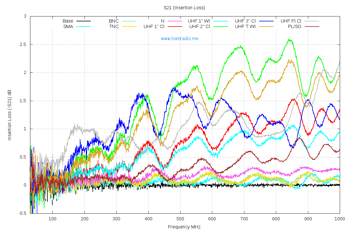
-
Title: Re: EM Drive Developments - related to space flight applications - Thread 3
Post by: deltaMass on 07/09/2015 01:48 AM -
<a href="http://forum.nasaspaceflight.com/index.php?topic=37642.msg1401937#msg1401937">Quote from: WarpTech on 07/08/2015 11:57 PM</a>
I'm experiencing a complete disconnect from what you're doing here. Looking at the input side, which is a battery carried along for the ride - not external, please note - you state<a href="http://forum.nasaspaceflight.com/index.php?topic=37642.msg1401933#msg1401933">Quote from: deltaMass on 07/08/2015 11:48 PM</a>@Todd: This makes no sense to me. Yes, I understand the algebra. Surely Integral[dm/dt, t] should = m(t) at all times. If not, why not? What does this mean physically? What is this dm physically?
Physically? It is the rest mass of the energy being input. Your formula is not a closed system. There is an external energy source, Ein. When you ADD energy you are also adding mass. Okay, my bad. In Eout, it should be (m(0) + dm(t)/dt), where m(0) is the rest mass of the system at t = 0.
EDIT: Since we didn't use relativistic mass or energy, just rest mass and rest energy, this solution is not relativistic, v can exceed c. However, what it says is that when the integral(dm/dt)dt = m(0), then v = c. I.e., if the rest mass is doubled by dm/dt, making it 200% or 2*m(0), then v = c. That is break even in a Newtonian scenario. Or, if 100% of the starting rest mass is expelled as propellant, then v = c, because there is no rest mass remaining to prevent it. I'm sure if relativistic mass and energy were used, it would also be limited to v < c.
The main point is, I've shown that it will never be over-unity.
EDIT 2: Hmmm.. it is insightful that in a Newtonian approximation, the limiting velocity is c not because of relativistic mass, but because to exceed c would produce an over-unity machine. This gives a whole new perspective to the speed limit, doesn't it?
Todd
Pin = dm/dt c2
This says that the battery loses rest mass. That is true, but it is absolutely a tiny mass even over long periods of time, compared with the total rest mass of the device. How is this expected to "save overunity"?
Tell you what - prove it to yourself. Use the numbers I used before (1000 gee, 1 m radius, 100 m/s to my energy breakeven) and recalculate using your dm stuff. I guess you will not see any substantive difference.
My derivation of energy breakeven has been posted here several times. Tossing in some minuscule dm will not make any substantive difference. But you are welcome to go through it line by line and post your version.
-
Title: Re: EM Drive Developments - related to space flight applications - Thread 3
Post by: rfmwguy on 07/09/2015 02:36 AM -
Random thought alert...we've been promised life-changing inventions before like the segway and taco bell home delivery. Yes, they are real; theories have been formulated agreed upon, yet they are never really life-changing in reality.
What we are struggling with here is a real life-changing proposal...interstellar access and down to earth applications. Before we get too critical or demotivational, consider the what-ifs and temper negativity in lieu of the grand potential. We only have a few of these opportunities in a lifetime.
Just a friendly suggestion. -
Title: Re: EM Drive Developments - related to space flight applications - Thread 3
Post by: WarpTech on 07/09/2015 02:51 AM -
<a href="http://forum.nasaspaceflight.com/index.php?topic=37642.msg1401963#msg1401963">Quote from: deltaMass on 07/09/2015 01:48 AM</a>
...
I'm experiencing a complete disconnect from what you're doing here. Looking at the input side, which is a battery carried along for the ride - not external, please note - you state
Pin = dm/dt c2
This says that the battery loses rest mass. That is true, but it is absolutely a tiny mass even over long periods of time, compared with the total rest mass of the device. How is this expected to "save overunity"?
Tell you what - prove it to yourself. Use the numbers I used before (1000 gee, 1 m radius, 100 m/s to my energy breakeven) and recalculate using your dm stuff. I guess you will not see any substantive difference.
My derivation of energy breakeven has been posted here several times. Tossing in some minuscule dm will not make any substantive difference. But you are welcome to go through it line by line and post your version.
If the battery and stored energy is on board the vehicle, that makes it easier. It will run out of fuel before it can go over unity.
Todd
-
Title: Re: EM Drive Developments - related to space flight applications - Thread 3
Post by: SeeShells on 07/09/2015 02:52 AM -
<a href="http://forum.nasaspaceflight.com/index.php?topic=37642.msg1401976#msg1401976">Quote from: rfmwguy on 07/09/2015 02:36 AM</a>
Random thought alert...we've been promised life-changing inventions before like the segway and taco bell home delivery. Yes, they are real; theories have been formulated agreed upon, yet they are never really life-changing in reality.
I for one realize what is on the table here and I'm not alone. Amazon deliveries by EMDrone and Taco Bell in minutes wizzin to your door for those with the munchies and can't drive! Sometimes the un-creativity of the human species scares me a little.
What we are struggling with here is a real life-changing proposal...interstellar access and down to earth applications. Before we get too critical or demotivational, consider the what-ifs and temper negativity in lieu of the grand potential. We only have a few of these opportunities in a lifetime.
Just a friendly suggestion.
I'm going to strive to make a better use of this opportunity.
Shell -
Title: Re: EM Drive Developments - related to space flight applications - Thread 3
Post by: Slyver on 07/09/2015 02:52 AM -
Running with the “inertial ratchet” idea, it could be that air pressure plays a part in the observed force exerted by the frustum. Assuming this means that the effective inertial mass (resistance to acceleration) is less in one direction than the other:
--With an EMdrive's longitudinal axis aligned along the x direction (using parentheses as subscript, not “function of”)
--Assuming a big side radius of 0.1m (and assuming the same effective radius on the small side with regard to air pressure), air pressure of 101325N/m^2 (1atm), EMdrive weight = 1kg
F(x,big) = m(big)a(big) = 101325N/m^2 (pi) (0.1m)^2 = 3183.2N = 1kg (3183.2m/s^2)
F(x,sm) = m(sm)a(sm) = -101325N/m^2 (pi) (0.1m)^2 = -3183.2N = 1.0001kg (-3182.9m/s^2)
a(net) = 3183.2 + -3182.9 = 0.3m/s^2 (towards the sm end)
F(net) = 1kg (0.3m/s^2) = 0.3N
So by this overly simplified model based on the inertial ratchet axiom, a 1kg EMdrive creating an effective mass differential of 0.01% would exert a force of 0.3N on a scale due to external air pressure.
I only expounded on this idea because of the much lower force data we have for vacuum experiments (and because I think the idea is really cool, even if it proves to have no merit). The forces measured in vacuum might be due to vibrations in the system*, which are presumably intentionally minimized.
* which would also produce a force towards the effective smaller mass side as elucidated earlier
-
Title: Re: EM Drive Developments - related to space flight applications - Thread 3
Post by: DrBagelBites on 07/09/2015 02:55 AM -
<a href="http://forum.nasaspaceflight.com/index.php?topic=37642.msg1401979#msg1401979">Quote from: SeeShells on 07/09/2015 02:52 AM</a><a href="http://forum.nasaspaceflight.com/index.php?topic=37642.msg1401976#msg1401976">Quote from: rfmwguy on 07/09/2015 02:36 AM</a>
Random thought alert...we've been promised life-changing inventions before like the segway and taco bell home delivery. Yes, they are real; theories have been formulated agreed upon, yet they are never really life-changing in reality.
I for one realize what is on the table here and I'm not alone. Amazon deliveries by EMDrone and Taco Bell in minutes wizzin to your door for those with the munchies and can't drive! Sometimes the un-creativity of the human species scares me a little.
What we are struggling with here is a real life-changing proposal...interstellar access and down to earth applications. Before we get too critical or demotivational, consider the what-ifs and temper negativity in lieu of the grand potential. We only have a few of these opportunities in a lifetime.
Just a friendly suggestion.
I'm going to strive to make a better use of this opportunity.
Shell
"EMDrones: Both delivering and heating up your food" I think you are on to something. ;)
I know it's off-topic, but it was too good to pass up. -
Title: Re: EM Drive Developments - related to space flight applications - Thread 3
Post by: SeeShells on 07/09/2015 03:02 AM -
<a href="http://forum.nasaspaceflight.com/index.php?topic=37642.msg1401981#msg1401981">Quote from: DrBagelBites on 07/09/2015 02:55 AM</a><a href="http://forum.nasaspaceflight.com/index.php?topic=37642.msg1401979#msg1401979">Quote from: SeeShells on 07/09/2015 02:52 AM</a><a href="http://forum.nasaspaceflight.com/index.php?topic=37642.msg1401976#msg1401976">Quote from: rfmwguy on 07/09/2015 02:36 AM</a>
Random thought alert...we've been promised life-changing inventions before like the segway and taco bell home delivery. Yes, they are real; theories have been formulated agreed upon, yet they are never really life-changing in reality.
I for one realize what is on the table here and I'm not alone. Amazon deliveries by EMDrone and Taco Bell in minutes wizzin to your door for those with the munchies and can't drive! Sometimes the un-creativity of the human species scares me a little.
What we are struggling with here is a real life-changing proposal...interstellar access and down to earth applications. Before we get too critical or demotivational, consider the what-ifs and temper negativity in lieu of the grand potential. We only have a few of these opportunities in a lifetime.
Just a friendly suggestion.
I'm going to strive to make a better use of this opportunity.
Shell
"EMDrones: Both delivering and heating up your food" I think you are on to something. ;)
I know it's off-topic, but it was too good to pass up.
No it's perfect, a chuckle and smile are always on topic. ;D -
Title: Re: EM Drive Developments - related to space flight applications - Thread 3
Post by: deltaMass on 07/09/2015 03:08 AM -
<a href="http://forum.nasaspaceflight.com/index.php?topic=37642.msg1401978#msg1401978">Quote from: WarpTech on 07/09/2015 02:51 AM</a>
Ahem. I thought we were discussing EmDrive, which is a propellantless vehicle. There is no exhaust. The onboard battery provides constant power Pin. The output power is pure kinetic. Ergo your calculation makes no sense when applied to the EmDrive.<a href="http://forum.nasaspaceflight.com/index.php?topic=37642.msg1401963#msg1401963">Quote from: deltaMass on 07/09/2015 01:48 AM</a>...
I'm experiencing a complete disconnect from what you're doing here. Looking at the input side, which is a battery carried along for the ride - not external, please note - you state
Pin = dm/dt c2
This says that the battery loses rest mass. That is true, but it is absolutely a tiny mass even over long periods of time, compared with the total rest mass of the device. How is this expected to "save overunity"?
Tell you what - prove it to yourself. Use the numbers I used before (1000 gee, 1 m radius, 100 m/s to my energy breakeven) and recalculate using your dm stuff. I guess you will not see any substantive difference.
My derivation of energy breakeven has been posted here several times. Tossing in some minuscule dm will not make any substantive difference. But you are welcome to go through it line by line and post your version.
If the battery and stored energy is on board the vehicle, that makes it easier. It will run out of fuel before it can go over unity.
Todd -
Title: Re: EM Drive Developments - related to space flight applications - Thread 3
Post by: dumbo on 07/09/2015 03:20 AM -
The meep results obtained by aero and Dr. Rodal are very suggestive! It would be nice if someone could run the simulation over more cycles; if the Poynting vector growth over time is observed to follow the extrapolations produced by Dr. Rodal, then it would make the case even stronger. Also, how might the fears that this is all an artifact of the numerical simulation process be assauged?
EDIT: pointing -> Poynting, interpolations -> extrapolations -
Title: Re: EM Drive Developments - related to space flight applications - Thread 3
Post by: deltaMass on 07/09/2015 03:24 AM - By posting something that did not contain the phrase ***UNDER CONSTRUCTION***, I am told. :P
-
Title: Re: EM Drive Developments - related to space flight applications - Thread 3
Post by: WarpTech on 07/09/2015 03:28 AM -
Sooooo..... the Poynting vector has a DC offset eh? Who would've thought that! LOL!
http://forum.nasaspaceflight.com/index.php?action=dlattach;topic=37642.0;attach=1041397
This means E and H should have a DC component as well, which means there are probably DC circulating currents around the frustum as it's charging.
At least that is how I would interpret these extrapolations and the uni-directional poynting vector.
Todd
-
Title: Re: EM Drive Developments - related to space flight applications - Thread 3
Post by: dumbo on 07/09/2015 03:39 AM -
<a href="http://forum.nasaspaceflight.com/index.php?topic=37642.msg1401990#msg1401990">Quote from: deltaMass on 07/09/2015 03:24 AM</a>
By posting something that did not contain the phrase ***UNDER CONSTRUCTION***, I am told. :P
Right, now in the (hypothetical) event that more meep data is produced showing results similar to the *** UNDER CONSTRUCTION *** curves by Dr. Rodal, what is to prevent someone from claiming that this is all "clearly" false still? What kind of proof would be acceptable to a skeptic that the meep data is not spurious? I am asking you this since, while everyone does seem to acknowledge the limits of numerical modelling, you are the only one who seems to feel that meep data is a priori invalid. -
Title: Re: EM Drive Developments - related to space flight applications - Thread 3
Post by: WarpTech on 07/09/2015 03:44 AM -
<a href="http://forum.nasaspaceflight.com/index.php?topic=37642.msg1401984#msg1401984">Quote from: deltaMass on 07/09/2015 03:08 AM</a><a href="http://forum.nasaspaceflight.com/index.php?topic=37642.msg1401978#msg1401978">Quote from: WarpTech on 07/09/2015 02:51 AM</a>
Ahem. I thought we were discussing EmDrive, which is a propellantless vehicle. There is no exhaust. The onboard battery provides constant power Pin. The output power is pure kinetic. Ergo your calculation makes no sense when applied to the EmDrive.<a href="http://forum.nasaspaceflight.com/index.php?topic=37642.msg1401963#msg1401963">Quote from: deltaMass on 07/09/2015 01:48 AM</a>...
I'm experiencing a complete disconnect from what you're doing here. Looking at the input side, which is a battery carried along for the ride - not external, please note - you state
Pin = dm/dt c2
This says that the battery loses rest mass. That is true, but it is absolutely a tiny mass even over long periods of time, compared with the total rest mass of the device. How is this expected to "save overunity"?
Tell you what - prove it to yourself. Use the numbers I used before (1000 gee, 1 m radius, 100 m/s to my energy breakeven) and recalculate using your dm stuff. I guess you will not see any substantive difference.
My derivation of energy breakeven has been posted here several times. Tossing in some minuscule dm will not make any substantive difference. But you are welcome to go through it line by line and post your version.
If the battery and stored energy is on board the vehicle, that makes it easier. It will run out of fuel before it can go over unity.
Todd
The paradox with propellant driven space craft was explained too, by Dr. White. It occurs anytime "constant acceleration" is assumed, without taking into account the variables in the av(t) expression I posted. In the case of the EM drive where there is no exhaust, dm/dt is replaced by the change in potential energy from the small end, to the big end, per unit time, /c2.
And BTW, if the EM drive were to store every bit of energy put into it, with a high power source it would have to explode eventually. The energy either needs to escape, generate heat or move the thing in order to dissipate. Or else the source input will eventually become saturated until nothing more will go in.
Todd
-
Title: Re: EM Drive Developments - related to space flight applications - Thread 3
Post by: TheTraveller on 07/09/2015 04:06 AM -
Due to the higher cost and reduced availability of 3.85GHz Rf amplifiers, I've decided to switch my build to 2.45GHz.
I've designed a version of the Flight Thruster that works at TE013 @ 2.45GHz. Build will look like the Flight Thruster, just bigger.
Specifications:
Big end: 400.0mm,
Small end: 148.7mm,
Length: 267.5mm,
Df: 0.9249,
Rf: 2.45GHz via 3 coax feeds,
20W via isolator,
Designed Q 100,000,
Predicted Force generation: 12.34mN or 1.26gf @ 20W as per attached screen shot of my spreadsheet.
Possibility to silver polish electroplate with thin gold over flash to eliminate silver oxidation,
Spherical end plates,
O ring seals at each end,
2mm thick cone side walls,
5mm thick flanges at each end of the cone,
Flanges to cone and cone side wall butt seam will be silver soldered for good electrical conductivity and strength,
Ability to run at reduced atmo pressure on N2 backfill via air valve in cone side wall,
All inside surfaces ding & scratch free, highly polished.
Antenna is 3 x 1/4 wave elements joined together at the centre & fed via 3 cone wall located coax connectors, with the antenna curved to match the spherical EM wave at 1/4 wave from big end.
Plan to do all the machining myself, ordering a new lathe. I've worked in machine shops since 10 and feel very capable of doing the machining to better than +-0.1mm.
Will test on a cordless rotary test rig that can turn for as long as the batteries last. Crude drawing attached. Hope you can understand it.
Once the design is proven, I plan to offer EMDrives for sale, at my material cost, to anyone who can show me they have built my rotary test rig, Rf and data collection system.
Idea is to have many Force generation verifiers all over the planet and to forever stop any doubts about the EMDrive.
My son is a dual honours graduate in Software Engineering and Physics. He lectures at the local uni. We think we can convince the Physics Dept to engage with the testing program and produce a paper on the results and maybe get it peer reviewed. -
Title: Re: EM Drive Developments - related to space flight applications - Thread 3
Post by: lmbfan on 07/09/2015 04:11 AM -
Aero, would it be possible to share your Meep files, along with a write-up on scripts and commands used to generate the data, so that other meepsters can help out and/or replicate the data? A consistent format for outputting csv/png/hdf5 files would speed analysis.
Dr. Rodal, would it be possible to share you Matlab techniques, scrpits, and/or other methods of extracting the Poynting vectors? Again, for helping out and replication. -
Title: Re: EM Drive Developments - related to space flight applications - Thread 3
Post by: zellerium on 07/09/2015 04:14 AM -
<a href="http://forum.nasaspaceflight.com/index.php?topic=37642.msg1401959#msg1401959">Quote from: rfmwguy on 07/09/2015 01:03 AM</a><a href="http://forum.nasaspaceflight.com/index.php?topic=37642.msg1401915#msg1401915">Quote from: zellerium on 07/08/2015 11:07 PM</a>
On the topic of magnetrons,
Hey kurt...might humbly suggest an N or mini DIN at these freqs and power levels...had some bad experience at 1kw and bncs...not pretty.
although they aren't a perfect rf source, they are the most feasible option for anyone doing a DIY experiment. Getting a 1 kW source for $20 is a bit unbelievable when you consider renting a 500 W amp for $3,000/month. There are cheaper methods of obtaining a high power amp, but from my experience they seem unreliable.
Yes, the power isn't evenly distributed and the BW is ~60 MHz, but this can be sharpened for the relatively cheap price of metal to create intermediate resonant cavity and high power coax. And keeping the core temperature steady should prevent frequency drifting, correct? So IMO, using low power, narrow BW amps is going to make it more difficult to get a 5 sigma deviation from noise unless you have something equivalent to a low-thrust torsion pendulum.
We have recently been dealing with the issue of replicating a magnetron output using the VNA. So today I cut open magnetron to expose the coupling wire used to transfer energy from the resonant cavity to the antenna. It looks like the antenna used consists of the coupling wire pinched in a copper tube, housed in a stainless steel cylindrical cavity.
To replicate the antenna, we're thinking of sacrificing another magnetron the cut out the full length of coupling wire, and soldering a BNC-to-wire connection. Then we can approximately simulate a magnetron output and measure reflected power to determine positions of resonance for our adjustable, partially loaded cavity.
Also, I noticed many people are opting for a laser measurement system. I think this method is ideal, especially if you can track the laser effectively. We were able to borrow a PSM2-10 Position Sensing Module which apparently has 0.0000 mm resolution. However, we don't know how much noise will be present so our actual resolution is TBD.
Kurt
Scope out this chart:
The BNC connector is what the vector network analyzer uses, which we will hook up to our 'mock' magnetron antenna (ie the copper wire connected to the manufacturers antenna). We wouldn't send a kW through it, but thank you for the concern. :)
I have been toying around with the idea (possibly for the next iteration) of a direct connection to a coaxial cable from the magnetron's resonant cavity. I need to research more about magnetrons which have a built in coax, but it seems like its possible, and might be an easier/cheaper conversion than an intermediate resonant cavity to send our signal into a vacuum chamber.
Anyone have any experience with magnetrons with built-in coaxial outputs?
-
Title: Re: EM Drive Developments - related to space flight applications - Thread 3
Post by: SeeShells on 07/09/2015 04:38 AM -
<a href="http://forum.nasaspaceflight.com/index.php?topic=37642.msg1401993#msg1401993">Quote from: WarpTech on 07/09/2015 03:44 AM</a>
When taking the time to explain on a reddit sub what a magnetron could put into a cavity the size of the frustum and what the effects would be to help them understand the problems the DYIers are facing using a high power device. I made the mistake of associating the cavity size with a bead box and putting a hair dryer into it. ... They sent me this link. http://what-if.xkcd.com/35/ Sorry Todd you just reminded me of it with your comment.<a href="http://forum.nasaspaceflight.com/index.php?topic=37642.msg1401984#msg1401984">Quote from: deltaMass on 07/09/2015 03:08 AM</a><a href="http://forum.nasaspaceflight.com/index.php?topic=37642.msg1401978#msg1401978">Quote from: WarpTech on 07/09/2015 02:51 AM</a>
Ahem. I thought we were discussing EmDrive, which is a propellantless vehicle. There is no exhaust. The onboard battery provides constant power Pin. The output power is pure kinetic. Ergo your calculation makes no sense when applied to the EmDrive.<a href="http://forum.nasaspaceflight.com/index.php?topic=37642.msg1401963#msg1401963">Quote from: deltaMass on 07/09/2015 01:48 AM</a>...
I'm experiencing a complete disconnect from what you're doing here. Looking at the input side, which is a battery carried along for the ride - not external, please note - you state
Pin = dm/dt c2
This says that the battery loses rest mass. That is true, but it is absolutely a tiny mass even over long periods of time, compared with the total rest mass of the device. How is this expected to "save overunity"?
Tell you what - prove it to yourself. Use the numbers I used before (1000 gee, 1 m radius, 100 m/s to my energy breakeven) and recalculate using your dm stuff. I guess you will not see any substantive difference.
My derivation of energy breakeven has been posted here several times. Tossing in some minuscule dm will not make any substantive difference. But you are welcome to go through it line by line and post your version.
If the battery and stored energy is on board the vehicle, that makes it easier. It will run out of fuel before it can go over unity.
Todd
The paradox with propellant driven space craft was explained too, by Dr. White. It occurs anytime "constant acceleration" is assumed, without taking into account the variables in the av(t) expression I posted. In the case of the EM drive where there is no exhaust, dm/dt is replaced by the change in potential energy from the small end, to the big end, per unit time, /c2.
And BTW, if the EM drive were to store every bit of energy put into it, with a high power source it would have to explode eventually. The energy either needs to escape, generate heat or move the thing in order to dissipate. Or else the source input will eventually become saturated until nothing more will go in.
Todd -
Title: Re: EM Drive Developments - related to space flight applications - Thread 3
Post by: TheTraveller on 07/09/2015 05:20 AM -
Further info on the antenna arrangement I'll be using on my 2.45GHz version of the Flight Thruster.
As the EM waves in a cavity with spherical end plates are spherical, the antenna also needs to be spherical as per the sidewall insertion point curve of the EM wave at that point.
I could have used a single stub 1/4 wave antenna curved to match the spherical EM wave shape but I had reservations that the end point of a single 1/4 wave stub inside the cavity may shift over time.
To stop any shifting, especially as I plan to ship finished EMDrives all over the planet, the single 1/4 wave stub antenna was replaced by 3 x 1/4 wave stub antennas that are joined at the centre and attached to the centre of 3 Rf connectors fitted into the side walls.
Trust the attached crude drawing makes it clear how I intend to excite TE013 mode and do so in a way to introduce min phase distortion into the internal resonant standing wave by the excitation antenna. -
Title: Re: EM Drive Developments - related to space flight applications - Thread 3
Post by: deltaMass on 07/09/2015 06:03 AM -
<a href="http://forum.nasaspaceflight.com/index.php?topic=37642.msg1401993#msg1401993">Quote from: WarpTech on 07/09/2015 03:44 AM</a>
Each time I try to stay on topic with this breakeven business, which you say I have "wrong", you throw another spanner in the works. Let's try and focus here. I want to understand what's "wrong" as you see it. So far, you're not making sense to me. If you do want to make sense to me, and convince me that I'm "wrong", you're going to have to take my derivation and show, line by line, the "right" substitution.<a href="http://forum.nasaspaceflight.com/index.php?topic=37642.msg1401984#msg1401984">Quote from: deltaMass on 07/09/2015 03:08 AM</a><a href="http://forum.nasaspaceflight.com/index.php?topic=37642.msg1401978#msg1401978">Quote from: WarpTech on 07/09/2015 02:51 AM</a>
Ahem. I thought we were discussing EmDrive, which is a propellantless vehicle. There is no exhaust. The onboard battery provides constant power Pin. The output power is pure kinetic. Ergo your calculation makes no sense when applied to the EmDrive.<a href="http://forum.nasaspaceflight.com/index.php?topic=37642.msg1401963#msg1401963">Quote from: deltaMass on 07/09/2015 01:48 AM</a>...
I'm experiencing a complete disconnect from what you're doing here. Looking at the input side, which is a battery carried along for the ride - not external, please note - you state
Pin = dm/dt c2
This says that the battery loses rest mass. That is true, but it is absolutely a tiny mass even over long periods of time, compared with the total rest mass of the device. How is this expected to "save overunity"?
Tell you what - prove it to yourself. Use the numbers I used before (1000 gee, 1 m radius, 100 m/s to my energy breakeven) and recalculate using your dm stuff. I guess you will not see any substantive difference.
My derivation of energy breakeven has been posted here several times. Tossing in some minuscule dm will not make any substantive difference. But you are welcome to go through it line by line and post your version.
If the battery and stored energy is on board the vehicle, that makes it easier. It will run out of fuel before it can go over unity.
Todd
The paradox with propellant driven space craft was explained too, by Dr. White. It occurs anytime "constant acceleration" is assumed, without taking into account the variables in the av(t) expression I posted. In the case of the EM drive where there is no exhaust, dm/dt is replaced by the change in potential energy from the small end, to the big end, per unit time, /c2.
And BTW, if the EM drive were to store every bit of energy put into it, with a high power source it would have to explode eventually. The energy either needs to escape, generate heat or move the thing in order to dissipate. Or else the source input will eventually become saturated until nothing more will go in.
Todd
Over to you. -
Title: Re: EM Drive Developments - related to space flight applications - Thread 3
Post by: ThinkerX on 07/09/2015 06:17 AM -
I'm starting to think that Warp Tech and Delta Mass should establish a formal partnership.
Warp Tech proposes something.
Delta Mass points out a mathematical (or other flaw).
Warp Tech (usually) acknowledges flaw, and recalculates.
Delta Mass reviews again.
And progress gets made. -
Title: Re: EM Drive Developments - related to space flight applications - Thread 3
Post by: deltaMass on 07/09/2015 06:46 AM - It seems usually better with me to talk things out. It wasn't until I came on NSF that my thinking about propellantless propulsion in general crystallised into something really solid, despite having been thinking about it for many years, and bouncing ideas off other people. So thank you NSF folks for giving me the focus.
-
Title: Re: EM Drive Developments - related to space flight applications - Thread 3
Post by: OttO on 07/09/2015 07:00 AM -
@Seeshells
Why not use an interferometer to measure the displacement? Too much noise?
http://www.instructables.com/id/Desktop-Michelson-Morely-Interferometer/
-
Title: Re: EM Drive Developments - related to space flight applications - Thread 3
Post by: TheTraveller on 07/09/2015 07:54 AM -
The Chinese may have figured out how to make a cavity with a Q of 117,500 using flat end plates.
As per the attachment they build in a short section, at each end of the tapered wave guide, of constant diameter circular waveguide that allows the spherical waves in the tapered portion of the cavity to transition from/to a planar wave that will generate no phase distortion as it bounces off the flat end plate.
Very clever.
The drawings also show how they do impedance matching.
See attachment.
I now know my 100,000 Q goal is obtainable. Yea! -
Title: Re: EM Drive Developments - related to space flight applications - Thread 3
Post by: OttO on 07/09/2015 07:58 AM -
Just a thought:
Our apparatus has the same look as a closed end horn antenna. Why not use variable fins to match the cut off? it seems to me that would be an easy way to tune it. -
Title: Re: EM Drive Developments - related to space flight applications - Thread 3
Post by: flux_capacitor on 07/09/2015 09:14 AM -
<a href="http://forum.nasaspaceflight.com/index.php?topic=37642.msg1402007#msg1402007">Quote from: TheTraveller on 07/09/2015 05:20 AM</a>
To stop any shifting, especially as I plan to ship finished EMDrives all over the planet, the single 1/4 wave stub antenna was replaced by 3 x 1/4 wave stub antennas that are joined at the centre and attached to the centre of 3 Rf connectors fitted into the side walls.
Trust the attached crude drawing makes it clear how I intend to excite TE013 mode and do so in a way to introduce min phase distortion into the internal resonant standing wave by the excitation antenna.
I understand you will connect your RF amp to those three 1/4 wave stub antennas.
But after that, does that also allow your design to connect 3 separated RF amps to multiply the input power x3? If so, how to couple those? In read a few pages ago (EDIT: in this post by ElizabethGreene (http://forum.nasaspaceflight.com/index.php?topic=37642.msg1401433#msg1401433)) that some dual magnetron geometries can automatically tune themselves, via "injection locking". What about multiple solid-state WiFi amps? Do we need some external controller or would they naturally lock their frequencies and phases together? -
Title: Re: EM Drive Developments - related to space flight applications - Thread 3
Post by: TheTraveller on 07/09/2015 10:28 AM -
<a href="http://forum.nasaspaceflight.com/index.php?topic=37642.msg1402054#msg1402054">Quote from: flux_capacitor on 07/09/2015 09:14 AM</a><a href="http://forum.nasaspaceflight.com/index.php?topic=37642.msg1402007#msg1402007">Quote from: TheTraveller on 07/09/2015 05:20 AM</a>
To stop any shifting, especially as I plan to ship finished EMDrives all over the planet, the single 1/4 wave stub antenna was replaced by 3 x 1/4 wave stub antennas that are joined at the centre and attached to the centre of 3 Rf connectors fitted into the side walls.
Trust the attached crude drawing makes it clear how I intend to excite TE013 mode and do so in a way to introduce min phase distortion into the internal resonant standing wave by the excitation antenna.
I understand you will connect your RF amp to those three 1/4 wave stub antennas.
But after that, does that also allow your design to connect 3 separated RF amps to multiply the input power x3? If so, how to couple those? In read a few pages ago that some dual magnetron geometries can automatically tune themselves. What about multiple solid-state WiFi amps? Do we need some external controller or would they naturally lock their frequencies and phases together?
Interesting idea.
Each Rf amp would be fed by the same variable freq Rf generator. Depends on how tight the phase shift specs are for each amp. -
Title: Re: EM Drive Developments - related to space flight applications - Thread 3
Post by: TheTraveller on 07/09/2015 10:53 AM -
A friend of mine does a lot of Chinese product sourcing for clients. Told him about my 2.45GHz power amp requirements. Said would get his guys to see what they could find. Look what his guy just found for me!
http://m.alibaba.com/product/60173635690/GSM-CDMA-DCS-Amplifier-100W.html
A sample is on it's way to me for just the shipping costs.
Happy days! 100 lovely Watts! Power output fully adjustable. Happy chappie!
-
Title: Re: EM Drive Developments - related to space flight applications - Thread 3
Post by: Mulletron on 07/09/2015 11:31 AM -
Maybe we could upvote and get Adam Savage's, co-host of MythBusters, attention. It would be a dream to have this myth busted (or confirmed!).
http://www.reddit.com/r/IAmA/comments/3cfqzf/z/csvcjt3
Outer Space or Bust! -
Title: Re: EM Drive Developments - related to space flight applications - Thread 3
Post by: TheTraveller on 07/09/2015 11:48 AM -
<a href="http://forum.nasaspaceflight.com/index.php?topic=37642.msg1402066#msg1402066">Quote from: Mulletron on 07/09/2015 11:31 AM</a>
Maybe we could upvote and get Adam Savage's, co-host of MythBusters, attention. It would be a dream to have this myth busted (or confirmed!).
http://www.reddit.com/r/IAmA/comments/3cfqzf/z/csvcjt3
Outer Space or Bust!
I will confirm it. I have no doubt.
Additionally I'll collect and publish the 1st EMDrive acceleration versus Rf amp power consumption data from a rotary test rig that has no cables and is completely battery powered.
With the 100W Rf amp, expect to get around 6gf to spin a 12kg rotary table. The SPR Denonstrator produced 1.6gf net and spun a 100kg mass. My test rig should accelerate 30x faster than did the SPR rotary video. -
Title: Re: EM Drive Developments - related to space flight applications - Thread 3
Post by: Rodal on 07/09/2015 11:55 AM -
<a href="http://forum.nasaspaceflight.com/index.php?topic=37642.msg1402037#msg1402037">Quote from: TheTraveller on 07/09/2015 07:54 AM</a>
The Chinese may have figured out how to make a cavity with a Q of 117,500 using flat end plates.
As per the attachment they build in a short section, at each end of the tapered wave guide, of constant diameter circular waveguide that allows the spherical waves in the tapered portion of the cavity to transition from/to a planar wave that will generate no phase distortion as it bounces off the flat end plate.
Very clever.
The drawings also show how they do impedance matching.
See attachment.
I now know my 100,000 Q goal is obtainable. Yea!
If you draw a horizontal axis through the middle of the waveguide in the picture you show, what does the waveguide opening into the cavity on the plane perpendicular to that axis look like?
(http://forum.nasaspaceflight.com/xindex.php,qaction=dlattach,3Btopic=37642.0,3Battach=1041542,3Bimage.pagespeed.ic.4Fl_ifE5WD.webp)
In other words, what does the other view look like?
It would be nice if we could guesstimate what the waveguide opening aspect ratio is, compared to the lateral cavity dimensions.
_____________________________________________
Eventually, we could also analyze with Meep the cavity + waveguide -
Title: Re: EM Drive Developments - related to space flight applications - Thread 3
Post by: TheTraveller on 07/09/2015 12:00 PM -
<a href="http://forum.nasaspaceflight.com/index.php?topic=37642.msg1402068#msg1402068">Quote from: Rodal on 07/09/2015 11:55 AM</a><a href="http://forum.nasaspaceflight.com/index.php?topic=37642.msg1402037#msg1402037">Quote from: TheTraveller on 07/09/2015 07:54 AM</a>
The Chinese may have figured out how to make a cavity with a Q of 117,500 using flat end plates.
As per the attachment they build in a short section, at each end of the tapered wave guide, of constant diameter circular waveguide that allows the spherical waves in the tapered portion of the cavity to transition from/to a planar wave that will generate no phase distortion as it bounces off the flat end plate.
Very clever.
The drawings also show how they do impedance matching.
See attachment.
I now know my 100,000 Q goal is obtainable. Yea!
If you draw a horizontal axis through the middle of the waveguide in the picture you show, what does the waveguide opening into the cavity on the plane perpendicular to that axis look like?
(http://forum.nasaspaceflight.com/xindex.php,qaction=dlattach,3Btopic=37642.0,3Battach=1041542,3Bimage.pagespeed.ic.4Fl_ifE5WD.webp)
In other words, what does the other view look like?
It would be nice if we could guesstimate what the waveguide opening aspect ratio is, compared to the lateral cavity dimensions
More info is in the paper, which is in Chinese. Attached.
I don't think the drawing is dimensionally correct. -
Title: Re: EM Drive Developments - related to space flight applications - Thread 3
Post by: ludkokanta on 07/09/2015 12:08 PM -
How would you suggest building a rotational measuring system?
If we were to build it with a few 1 inch peaces of wood as a rotational system which bearing would be fitting?
It would have to take the weight of the "em drive" or whatever and weight of the wood as an axial force and still have less then say 20 micro Newtons of tangential friction resistance. -
Title: Re: EM Drive Developments - related to space flight applications - Thread 3
Post by: Rodal on 07/09/2015 12:13 PM -
<a href="http://forum.nasaspaceflight.com/index.php?topic=37642.msg1401991#msg1401991">Quote from: WarpTech on 07/09/2015 03:28 AM</a>
Sooooo..... the Poynting vector has a DC offset eh? Who would've thought that! LOL!
http://forum.nasaspaceflight.com/index.php?action=dlattach;topic=37642.0;attach=1041397
This means E and H should have a DC component as well, which means there are probably DC circulating currents around the frustum as it's charging.
At least that is how I would interpret these extrapolations and the uni-directional poynting vector.
Todd
1) The Poynting vector analyzed in the post is located at location in the free-space of the cavity next to the longitudinal axis of axisymmetry of the cone (the FD grid had an even number of grids, so it is at the first grid to one side of the longitudinal axis), at the maximum of the first wave-pattern formed downstream from the antenna , in the direction from the small base towards the big base.
2) For purely travelling waves in an open waveguide, the Poynting vector fluctuation with time looks like in this image:
____________________________________________________________________________
( )
)
Electric (E) and Magnetizing (H) fields, and Poynting vector
Open Waveguide
RF feed ON
The frequency is twice the frequency of the electromagnetic fields, it fluctuates between maximum and zero, with an average value half-way in between
____________________________________________________________________________
3) For a pure standing wave in a cavity (the antenna feed being OFF), the Poynting vector fluctuation with time looks like the second image to the right:
____________________________________________________________________________
( )
)
Poynting vector Poynting vector
Open Waveguide Closed Cavity
RF feed ON RF feed OFF
____________________________________________________________________________
Due to the electromagnetic fields in a standing wave looking like this:
(https://encrypted-tbn1.gstatic.com/images?q=tbn:ANd9GcS-Vtx-RzESEfRs5g8XXBmNAGdgwsJ4IFObMX_I1SRrsQnIpXLi1Q)
Electric (E) and Magnetic (B) fields
Closed Cavity
RF feed OFF
This is due to the boundary condition: the Electric field (E) transverse component to a conducting wall is zero, but the magnetic (B) and the magnetizing (H) fields transverse components are not zero. The conducting walls thereby change the phase of the electric and magnetic fields so that they are offset by 90 degrees at the conducting wall at the big base and the small base.
The frequency is twice the frequency of the electromagnetic fields, its average is zero and it fluctuates between equal absolute magnitudes, (+) plus and (-) minus
____________________________________________________________________________
4) In the EM Drive with the RF feed ON we have a superposition of travelling waves. Unlike a cavity with the RF feed OFF, where travelling waves get reflected and perfectly match at resonance to make a standing wave frozen in space, in the EM Drive with the RF feed ON we have a superposition of travelling waves and standing waves. Or, in other words, an unequal superposition of travelling waves propagating in opposite direction.
The fact that the time-average is not zero, but that the minimum amplitude is not zero either but that it fluctuates between negative and positive shows this superposition. The fact that the time-average is very offset means that at this location and at the time steps shown in my analysis, the proportion of the travelling wave propagation is much larger than the amount of standing wave at that location.
(http://forum.nasaspaceflight.com/xindex.php,qaction=dlattach,3Btopic=37642.0,3Battach=1041386,3Bimage.pagespeed.ic.RwswusSU_s.webp)
In other words, with the RF feed ON, the situation is neither a pure travelling wave as in an open waveguide nor is it purely standing waves, but it is a superposition of both.(*)
Since standing waves themselves are constructed by superposition of travelling waves, it really has to do with the superposition of travelling waves coming from opposite directions. The Poynting vector fluctuation depends on the location in the EM Drive. I have examined much more data than I have reported here. There are places in the EM Drive where there is mostly standing waves, and locations where there are mostly travelling waves. The information is very useful to understand what is going on.
Similarly with people building their own experiments, those embarking on a build learn first hand knowledge that may not be available to the public. Ditto for numerical simulation.
There are several people conducting their own experiments. Ideally there would be several people conducting their own independent analyses. The csv files are available for everybody to analyze.
5) What is most interesting to me is the apparent growth with time of the Poynting vector fluctuations during the few time steps examined. This may show:
Only examining many more time steps we will know what is going on.
EDIT: as pointed out by Ricvil, the amplification is probably just what is to be expected from the early evolution of the fields until a balance is reached.
______________
(*) In addition, due to the taper, in the truncated cone with the RF feed ON there are also evanescent waves, as shown in several papers (Zeng and Fan being one of the latest). -
Title: Re: EM Drive Developments - related to space flight applications - Thread 3
Post by: Rodal on 07/09/2015 12:58 PM -
<a href="http://forum.nasaspaceflight.com/index.php?topic=37642.msg1402069#msg1402069">Quote from: TheTraveller on 07/09/2015 12:00 PM</a>
...
Please let us know if you guesstimate what the waveguide opening dimensions used by Prof Yang are.
More info is in the paper, which is in Chinese. Attached.
I don't think the drawing is dimensionally correct.
QUESTION: are you planning to use a waveguide feed into the cavity in your experiment, as used by Prof. Yang? -
Title: Re: EM Drive Developments - related to space flight applications - Thread 3
Post by: TheTraveller on 07/09/2015 01:03 PM -
<a href="http://forum.nasaspaceflight.com/index.php?topic=37642.msg1402085#msg1402085">Quote from: Rodal on 07/09/2015 12:58 PM</a><a href="http://forum.nasaspaceflight.com/index.php?topic=37642.msg1402069#msg1402069">Quote from: TheTraveller on 07/09/2015 12:00 PM</a>
...
Please let us know if you guesstimate what the waveguide opening dimensions used by Prof Yang are.
More info is in the paper, which is in Chinese. Attached.
I don't think the drawing is dimensionally correct.
QUESTION: are you planning to use a waveguide feed into the cavity in your experiment, as used by Prof. Yang?
Will be using a 100W narrow band Rf amp feeding the internal frustum spherical antenna array via 3 coax cables & connectors. -
Title: Re: EM Drive Developments - related to space flight applications - Thread 3
Post by: TheTraveller on 07/09/2015 01:07 PM -
<a href="http://forum.nasaspaceflight.com/index.php?topic=37642.msg1402070#msg1402070">Quote from: ludkokanta on 07/09/2015 12:08 PM</a>
How would you suggest building a rotational measuring system?
If we were to build it with a few 1 inch peaces of wood as a rotational system which bearing would be fitting?
It would have to take the weight of the "em drive" or whatever and weight of the wood as an axial force and still have less then say 20 micro Newtons of tangential friction resistance.
My rough drawing attached. Uses a DIY magnetic thrust bearing with 2 low stiction/friction bearings. -
Title: Re: EM Drive Developments - related to space flight applications - Thread 3
Post by: Rodal on 07/09/2015 01:07 PM -
<a href="http://forum.nasaspaceflight.com/index.php?topic=37642.msg1402087#msg1402087">Quote from: TheTraveller on 07/09/2015 01:03 PM</a>
Where in the frustum will your spherical antenna be located? (is it going to be located in the longitudinal axis of axisymmetry of the cone?, is it going to be located near the big base? near the small base?<a href="http://forum.nasaspaceflight.com/index.php?topic=37642.msg1402085#msg1402085">Quote from: Rodal on 07/09/2015 12:58 PM</a><a href="http://forum.nasaspaceflight.com/index.php?topic=37642.msg1402069#msg1402069">Quote from: TheTraveller on 07/09/2015 12:00 PM</a>...
Please let us know if you guesstimate what the waveguide opening dimensions used by Prof Yang are.
More info is in the paper, which is in Chinese. Attached.
I don't think the drawing is dimensionally correct.
QUESTION: are you planning to use a waveguide feed into the cavity in your experiment, as used by Prof. Yang?
Will be using a 100W narrow band Rf amp feeding the internal frustum spherical antenna array via 3 coax cables & connectors. -
Title: Re: EM Drive Developments - related to space flight applications - Thread 3
Post by: SeeShells on 07/09/2015 01:11 PM -
<a href="http://forum.nasaspaceflight.com/index.php?topic=37642.msg1402027#msg1402027">Quote from: OttO on 07/09/2015 07:00 AM</a>
@Seeshells
Why not use an interferometer to measure the displacement? Too much noise?
http://www.instructables.com/id/Desktop-Michelson-Morely-Interferometer/
That is a great idea.
Noise? I think so, the noise level would probably be off the charts and the display would look a little like a laser light show. Sadly, I have a road with traffic about 500 foot away that I suspect would show up.
I went with the beam supported by the stainless steel wires attached to the center of my fulcrum so I could show about any level of thrust, from small to large. Even micronewtons should show up, very slowly overcoming the mass of the system to accelerate. Wiki has very nice formulas to calculate (thank goodness for wiki). This is why I wanted to control the timestamped frame grabs from the graph at 30 frames second to every hour if needed.
Even on the cheap lasers I figure I have a battery life to consider and they will be powered by stacked C cells to assure me they will not die during a test.
Shell
PS: Do like that simple idea. -
Title: Re: EM Drive Developments - related to space flight applications - Thread 3
Post by: TheTraveller on 07/09/2015 01:13 PM -
<a href="http://forum.nasaspaceflight.com/index.php?topic=37642.msg1402091#msg1402091">Quote from: Rodal on 07/09/2015 01:07 PM</a><a href="http://forum.nasaspaceflight.com/index.php?topic=37642.msg1402087#msg1402087">Quote from: TheTraveller on 07/09/2015 01:03 PM</a>
Where in the frustum will your spherical antenna be located? (is it going to be located in the longitudinal axis of axisymmetry of the cone?, is it going to be located near the big base? near the small base?<a href="http://forum.nasaspaceflight.com/index.php?topic=37642.msg1402085#msg1402085">Quote from: Rodal on 07/09/2015 12:58 PM</a><a href="http://forum.nasaspaceflight.com/index.php?topic=37642.msg1402069#msg1402069">Quote from: TheTraveller on 07/09/2015 12:00 PM</a>...
Please let us know if you guesstimate what the waveguide opening dimensions used by Prof Yang are.
More info is in the paper, which is in Chinese. Attached.
I don't think the drawing is dimensionally correct.
QUESTION: are you planning to use a waveguide feed into the cavity in your experiment, as used by Prof. Yang?
Will be using a 100W narrow band Rf amp feeding the internal frustum spherical antenna array via 3 coax cables & connectors.
http://forum.nasaspaceflight.com/index.php?topic=37642.msg1402007#msg1402007 -
Title: Re: EM Drive Developments - related to space flight applications - Thread 3
Post by: SeeShells on 07/09/2015 01:43 PM -
<a href="http://forum.nasaspaceflight.com/index.php?topic=37642.msg1402007#msg1402007">Quote from: TheTraveller on 07/09/2015 05:20 AM</a>
Further info on the antenna arrangement I'll be using on my 2.45GHz version of the Flight Thruster.
I would hope you take in consideration the phases of your antennas and the distance from each other, you wouldn't want them to cause standing wave attenuations with each other canceling out a good idea.
As the EM waves in a cavity with spherical end plates are spherical, the antenna also needs to be spherical as per the sidewall insertion point curve of the EM wave at that point.
I could have used a single stub 1/4 wave antenna curved to match the spherical EM wave shape but I had reservations that the end point of a single 1/4 wave stub inside the cavity may shift over time.
To stop any shifting, especially as I plan to ship finished EMDrives all over the planet, the single 1/4 wave stub antenna was replaced by 3 x 1/4 wave stub antennas that are joined at the centre and attached to the centre of 3 Rf connectors fitted into the side walls.
Trust the attached crude drawing makes it clear how I intend to excite TE013 mode and do so in a way to introduce min phase distortion into the internal resonant standing wave by the excitation antenna. -
Title: Re: EM Drive Developments - related to space flight applications - Thread 3
Post by: Rodal on 07/09/2015 01:52 PM -
<a href="http://forum.nasaspaceflight.com/index.php?topic=37642.msg1402100#msg1402100">Quote from: SeeShells on 07/09/2015 01:43 PM</a><a href="http://forum.nasaspaceflight.com/index.php?topic=37642.msg1402007#msg1402007">Quote from: TheTraveller on 07/09/2015 05:20 AM</a>
Further info on the antenna arrangement I'll be using on my 2.45GHz version of the Flight Thruster.
I would hope you take in consideration the phases of your antennas and the distance from each other, you wouldn't want them to cause standing wave attenuations with each other canceling out a good idea.
As the EM waves in a cavity with spherical end plates are spherical, the antenna also needs to be spherical as per the sidewall insertion point curve of the EM wave at that point.
I could have used a single stub 1/4 wave antenna curved to match the spherical EM wave shape but I had reservations that the end point of a single 1/4 wave stub inside the cavity may shift over time.
To stop any shifting, especially as I plan to ship finished EMDrives all over the planet, the single 1/4 wave stub antenna was replaced by 3 x 1/4 wave stub antennas that are joined at the centre and attached to the centre of 3 Rf connectors fitted into the side walls.
Trust the attached crude drawing makes it clear how I intend to excite TE013 mode and do so in a way to introduce min phase distortion into the internal resonant standing wave by the excitation antenna.
Shell, there is also the issue that in the drawing, the assumption is made that the wave-patterns in the longitudinal direction are sinusoidal harmonic with equidistant nodal points. This is true for a cylindrical waveguide but it is not true for a conical waveguide (even with spherical ends) (*). With a conical waveguide the wave-patterns in the longitudinal direction are not sinusoidal harmonic: the nodes are not equidistant. How different from equidistant the nodes are depends on the mode(s) being excited and their participation. Hopefully by placing the antenna where it is proposed he can force that mode, but a lot depends on nearby modes and mode participation. Since he is not using a magnetron, that may help in eliminating other modes from participating.
_______
(*) The wave patterns in the longitudinal direction for a spherical wave in a cavity are not sinusoidal harmonic, they are governed by Spherical Bessel functions, which have unequal distance between nodes.
-
Title: Re: EM Drive Developments - related to space flight applications - Thread 3
Post by: SeeShells on 07/09/2015 02:01 PM -
<a href="http://forum.nasaspaceflight.com/index.php?topic=37642.msg1402106#msg1402106">Quote from: Rodal on 07/09/2015 01:52 PM</a>
I know Jose I really know and when the modes collapse and shift which is what needs to happen the antennas and their positions will not be in any kind of phase sitting in the center like that. Maybe linking the 3 dipoles close together in a phase locked arrangement would cause less havoc? What do you think TT?<a href="http://forum.nasaspaceflight.com/index.php?topic=37642.msg1402100#msg1402100">Quote from: SeeShells on 07/09/2015 01:43 PM</a><a href="http://forum.nasaspaceflight.com/index.php?topic=37642.msg1402007#msg1402007">Quote from: TheTraveller on 07/09/2015 05:20 AM</a>Further info on the antenna arrangement I'll be using on my 2.45GHz version of the Flight Thruster.
I would hope you take in consideration the phases of your antennas and the distance from each other, you wouldn't want them to cause standing wave attenuations with each other canceling out a good idea.
As the EM waves in a cavity with spherical end plates are spherical, the antenna also needs to be spherical as per the sidewall insertion point curve of the EM wave at that point.
I could have used a single stub 1/4 wave antenna curved to match the spherical EM wave shape but I had reservations that the end point of a single 1/4 wave stub inside the cavity may shift over time.
To stop any shifting, especially as I plan to ship finished EMDrives all over the planet, the single 1/4 wave stub antenna was replaced by 3 x 1/4 wave stub antennas that are joined at the centre and attached to the centre of 3 Rf connectors fitted into the side walls.
Trust the attached crude drawing makes it clear how I intend to excite TE013 mode and do so in a way to introduce min phase distortion into the internal resonant standing wave by the excitation antenna.
Shell, there is also the issue that in the drawing, the assumption is made that the wave-patterns in the longitudinal direction are sinusoidal harmonic with equidistant nodal points. This is true for a cylindrical waveguide but it is not true for a conical waveguide. With a conical waveguide the wave-patterns in the longitudinal direction are not sinusoidal harmonic: the nodes are not equidistant. How different from equidistant the nodes are depends on the mode(s) being excited and their participation -
Title: Re: EM Drive Developments - related to space flight applications - Thread 3
Post by: Mulletron on 07/09/2015 02:03 PM -
I really thought Pinheiro's "self accelerating engine" would have stirred the pot more than it did.
Folks are up in arms about how EmDrive violates Conservation of Momentum and Newton's Third Law.
This paper really made me go hmmmmm.
On Newton's third law and its symmetry-breaking effects
Mario J Pinheiro
http://iopscience.iop.org/1402-4896/84/5/055004
http://arxiv.org/pdf/1104.5011.pdf (see page 12, pg 18 fig 2)
@Rodal did a fantastic thermal analysis early on. So we're already smart on this.
http://www.researchgate.net/publication/268804028_NASA%27S_MICROWAVE_PROPELLANT-LESS_THRUSTER_ANOMALOUS_RESULTS_CONSIDERATION_OF_A_THERMO-MECHANICAL_EFFECT
So did one end stay hotter than the other while turned on? I bet TE012 would generate tons of heat at the small end (strong magnetic field there). Actual thermal data would be awesome right about now. My dinky amp doesn't generate any noticeable heat and it can't excite TE01X anyway. We miss having you here @Star Drive. I bet you already know all about this.
I did manage to dig up his thermal analysis from here:
http://forum.nasaspaceflight.com/index.php?topic=36313.msg1326997#msg1326997
and is attached. This looks like it was TM212 @ 1946.65 MHz.
Why am I looking into https://en.wikipedia.org/wiki/Non-equilibrium_thermodynamics ?
It is clear to me that the "momentum from the QV fluctuations" mechanism (if it is even really happening) isn't the dominant mechanism here. For cavities sans dielectrics, this is especially apparent. Shawyer et al report thrust from unloaded cavities (Eagleworks did not).
There must be another...or more than one "thrust mechanism" happening simultaneously here.
Gotta go back through the threads and locate which modes @Star Drive said caused the frustum to thrust large end forward to see if there are any patterns. I remember at least one instance where he reported the dielectric fastener popped loose and the thrust reversed too.
Been taking a break on the research and enjoying the summer (really don't want to get burned out here). Turns out there are other things in life besides EmDrive. Enjoying the family time. Will jump back in full swing with the experiment soon.
-
Title: Re: EM Drive Developments - related to space flight applications - Thread 3
Post by: TheTraveller on 07/09/2015 02:06 PM -
<a href="http://forum.nasaspaceflight.com/index.php?topic=37642.msg1402106#msg1402106">Quote from: Rodal on 07/09/2015 01:52 PM</a><a href="http://forum.nasaspaceflight.com/index.php?topic=37642.msg1402100#msg1402100">Quote from: SeeShells on 07/09/2015 01:43 PM</a><a href="http://forum.nasaspaceflight.com/index.php?topic=37642.msg1402007#msg1402007">Quote from: TheTraveller on 07/09/2015 05:20 AM</a>
Further info on the antenna arrangement I'll be using on my 2.45GHz version of the Flight Thruster.
I would hope you take in consideration the phases of your antennas and the distance from each other, you wouldn't want them to cause standing wave attenuations with each other canceling out a good idea.
As the EM waves in a cavity with spherical end plates are spherical, the antenna also needs to be spherical as per the sidewall insertion point curve of the EM wave at that point.
I could have used a single stub 1/4 wave antenna curved to match the spherical EM wave shape but I had reservations that the end point of a single 1/4 wave stub inside the cavity may shift over time.
To stop any shifting, especially as I plan to ship finished EMDrives all over the planet, the single 1/4 wave stub antenna was replaced by 3 x 1/4 wave stub antennas that are joined at the centre and attached to the centre of 3 Rf connectors fitted into the side walls.
Trust the attached crude drawing makes it clear how I intend to excite TE013 mode and do so in a way to introduce min phase distortion into the internal resonant standing wave by the excitation antenna.
Shell, there is also the issue that in the drawing, the assumption is made that the wave-patterns in the longitudinal direction are sinusoidal harmonic with equidistant nodal points. This is true for a cylindrical waveguide but it is not true for a conical waveguide. With a conical waveguide the wave-patterns in the longitudinal direction are not sinusoidal harmonic: the nodes are not equidistant. How different from equidistant the nodes are depends on the mode(s) being excited and their participation. Hopefully by placing the antenna where it is proposed he can force that mode, but a lot depends on nearby modes and mode participation. Since he is not using a magnetron, that may help in eliminating other modes from participating.
I'm quite aware the nodes are not equidistant as the guide wavelength varies as the tapered waveguide diameter varies along the tapered waveguide.
My calculator figures out where the 1/4 wave position is from the big end, factoring in the continually variable guide wavelength and the radius of curvature of the spherical wave at that point.
There are no nearby TE modes and my antenna will not excite TM modes. -
Title: Re: EM Drive Developments - related to space flight applications - Thread 3
Post by: TheTraveller on 07/09/2015 02:10 PM -
<a href="http://forum.nasaspaceflight.com/index.php?topic=37642.msg1402112#msg1402112">Quote from: Mulletron on 07/09/2015 02:03 PM</a>
I really thought Pinheiro's "self accelerating engine" would have stirred the pot more than it did.
Folks are up in arms about how EmDrive violates Conservation of Momentum and Newton's Third Law.
This paper really made me go hmmmmm.
On Newton's third law and its symmetry-breaking effects
Mario J Pinheiro
http://iopscience.iop.org/1402-4896/84/5/055004
http://arxiv.org/pdf/1104.5011.pdf (see page 12, pg 18 fig 2)
@Rodal did a fantastic thermal analysis early on. So we're already smart on this.
http://www.researchgate.net/publication/268804028_NASA%27S_MICROWAVE_PROPELLANT-LESS_THRUSTER_ANOMALOUS_RESULTS_CONSIDERATION_OF_A_THERMO-MECHANICAL_EFFECT
So did one end stay hotter than the other while turned on? I bet TE012 would generate tons of heat at the small end (strong magnetic field there). Actual thermal data would be awesome right about now. My dinky amp doesn't generate any noticeable heat and it can't excite TE01X anyway. We miss having you here @Star Drive. I bet you already know all about this.
I did manage to dig up his thermal analysis from here:
http://forum.nasaspaceflight.com/index.php?topic=36313.msg1326997#msg1326997
and is attached. This looks like it was TM212 @ 1946.65 MHz.
Why am I looking into https://en.wikipedia.org/wiki/Non-equilibrium_thermodynamics ?
It is clear to me that the "momentum from the QV fluctuations" mechanism (if it is even really happening) isn't the dominant mechanism here. For cavities sans dielectrics, this is especially apparent. Shawyer et al report thrust from unloaded cavities (Eagleworks did not).
There must be another...or more than one "thrust mechanism" happening simultaneously here.
Gotta go back through the threads and locate which modes @Star Drive said caused the frustum to thrust large end forward to see if there are any patterns. I remember at least one instance where he reported the dielectric fastener popped loose and the thrust reversed too.
Been taking a break on the research and enjoying the summer (really don't want to get burned out here). Turns out there are other things in life besides EmDrive. Enjoying the family time. Will jump back in full swing with the experiment soon.
Go here.
https://drive.google.com/folderview?id=0B7kgKijo-p0ifk9EakZfbW9aZGMwNWZMQ01xVnBON0tkM2w0Q1NLbmtjRFFwMXBuNVlVN0U&usp=sharing
Open the PaulMarch folder. Has every attached image and doc that Paul shared on NSF. -
Title: Re: EM Drive Developments - related to space flight applications - Thread 3
Post by: Rodal on 07/09/2015 02:20 PM -
<a href="http://forum.nasaspaceflight.com/index.php?topic=37642.msg1402112#msg1402112">Quote from: Mulletron on 07/09/2015 02:03 PM</a>
I really thought Pinheiro's "self accelerating engine" would have stirred the pot more than it did.
Folks are up in arms about how EmDrive violates Conservation of Momentum and Newton's Third Law.
This paper really made me go hmmmmm.
On Newton's third law and its symmetry-breaking effects
Mario J Pinheiro
http://iopscience.iop.org/1402-4896/84/5/055004
http://arxiv.org/pdf/1104.5011.pdf (see page 12, pg 18 fig 2)
...
Very good point !
The lack of an immediate response is a combination of things. There are so many things to analyze that we get overwhelmed. Since we have day jobs, we address either what we are best at or what we find most interesting at the moment. Some of us concentrate on experimental builds, others concentrate on closed-form solutions to simplifications that are amenable to a mathematical solution, and others concentrate on numerical analysis. Also, non-equilibrium thermodynamics of a photon gas is complicated.
To get to the point, concerning <<. The new approach presented here shows that Newton's third law is not verified in systems out of equilibrium due to an additional entropic gradient term present in the particle's momentum>>, I think that Dr. Notsosureofit was looking at this from the non-stationary thermodynamics point of view, but he has a small R&D company to run and many other pressing things to do. We do get small updates every once in a while.
One interesting thing I looked at in this respect is that a photon gas does not have the number N of photons as a thermodynamic constant but photons can be "created" and "anhilitated" all the time, and the number of photons in a photon gas is a very nonlinear function of temperature (the cube of the temperature): (N number of photons)
()
That is very different from a perfect molecular gas where (N number of moles)
( )
)
Showing that at constant pressure and volume, the number of moles is inversely proportional to the temperature.QuoteA very important difference between a gas of massive particles and a photon gas with a black body distribution is that the number of photons in the system is not conserved. A photon may collide with an electron in the wall, exciting it to a higher energy state, removing a photon from the photon gas. This electron may drop back to its lower level in a series of steps, each one of which releases an individual photon back into the photon gas. Although the sum of the energies of the emitted photons are the same as the absorbed photon, the number of emitted photons will vary. It can be shown that, as a result of this lack of constraint on the number of photons in the system, the chemical potential of the photons must be zero for black body radiation.
-
Title: Re: EM Drive Developments - related to space flight applications - Thread 3
Post by: Notsosureofit on 07/09/2015 02:27 PM -
<a href="http://forum.nasaspaceflight.com/index.php?topic=37642.msg1402112#msg1402112">Quote from: Mulletron on 07/09/2015 02:03 PM</a>
I really thought Pinheiro's "self accelerating engine" would have stirred the pot more than it did.
Folks are up in arms about how EmDrive violates Conservation of Momentum and Newton's Third Law.
This paper really made me go hmmmmm.
On Newton's third law and its symmetry-breaking effects
Mario J Pinheiro
http://iopscience.iop.org/1402-4896/84/5/055004
http://arxiv.org/pdf/1104.5011.pdf (see page 12, pg 18 fig 2)
Yes. Slow going w/ very limited time...but from Einstein working forward in terms of limited delta f instead of "black body" radiation, the thermodynamics would seem to be there. So far, I'm still of the opinion that (the Turtle is correct) it's the resonant standing wave condition that supplies the force through a General Relativistic rotation in the time-z plane.
Edit: I should add that finding the 90 degree phase shift component in that rotation is essential to this argument.
-
Title: Re: EM Drive Developments - related to space flight applications - Thread 3
Post by: SeeShells on 07/09/2015 02:32 PM -
<a href="http://forum.nasaspaceflight.com/index.php?topic=37642.msg1402112#msg1402112">Quote from: Mulletron on 07/09/2015 02:03 PM</a>
I really thought Pinheiro's "self accelerating engine" would have stirred the pot more than it did.
Folks are up in arms about how EmDrive violates Conservation of Momentum and Newton's Third Law.
Been taking a break on the research and enjoying the summer (really don't want to get burned out here). Turns out there are other things in life besides EmDrive. Enjoying the family time. Will jump back in full swing with the experiment soon.
Welcome back you were missed. Look forward to you being back.
Shell -
Title: Re: EM Drive Developments - related to space flight applications - Thread 3
Post by: Ricvil on 07/09/2015 02:34 PM - The cavity is reservatory of energy, like a LC circuit. If a mode has been excited by the source is natural the growing of amplitude of the fields because of the succesives reflections of the counter propagating traveling waves ( forming the stationary wave) will summ with waves generated by the source. This grow will happens until the loss in the walls of the cavity becomes equal the power generated by the source.
-
Title: Re: EM Drive Developments - related to space flight applications - Thread 3
Post by: Rodal on 07/09/2015 02:46 PM -
<a href="http://forum.nasaspaceflight.com/index.php?topic=37642.msg1402125#msg1402125">Quote from: Ricvil on 07/09/2015 02:34 PM</a>
The cavity is reservatory of energy, like a LC circuit. If a mode has been excited by the source is natural the growing of amplitude of the fields because of the succesives reflections of the counter propagating traveling waves ( forming the stationary wave) will summ with waves generated by the source. This grow will happens until the loss in the walls of the cavity becomes equal the power generated by the source.
Thank you. I fully agree. Using the SI unit conversions one can see that the Meep analysis is looking at an extremely early time in the time evolution of these fields. -
Title: Re: EM Drive Developments - related to space flight applications - Thread 3
Post by: rfmwguy on 07/09/2015 02:50 PM -
Advanced data analysis - For DIYers, I'd recommend we consider standardizing on some DAC software. I've written a couple of LabView projects which are basically a clean slate in displaying test data. (have no biz relationship with National Instruments BTW, just good results).
http://www.ni.com/labview/
There are student discounts and a free trial period. Chart recordings, temperatures, displacement, vibration, acceleration, voltages, currents, etc are all possible with external sensors. I have this in the back of my mind if I see positive results from the fulcrum test.
Word of note, shielding of all sensor interconnects will be critical and I wouldn't start off with this initially. Non-digital measurement is less risky of false positives, but those planning on more elaborating testing down the road should consider LabView as an easy to use GUI based test platform.
http://sine.ni.com/cms/images/casestudies/bmpc.bmp?size
-
Title: Re: EM Drive Developments - related to space flight applications - Thread 3
Post by: DrBagelBites on 07/09/2015 03:11 PM -
<a href="http://forum.nasaspaceflight.com/index.php?topic=37642.msg1402127#msg1402127">Quote from: rfmwguy on 07/09/2015 02:50 PM</a>
Advanced data analysis - For DIYers, I'd recommend we consider standardizing on some DAC software. I've written a couple of LabView projects which are basically a clean slate in displaying test data. (have no biz relationship with National Instruments BTW, just good results).
http://www.ni.com/labview/
There are student discounts and a free trial period. Chart recordings, temperatures, displacement, vibration, acceleration, voltages, currents, etc are all possible with external sensors. I have this in the back of my mind if I see positive results from the fulcrum test.
Word of note, shielding of all sensor interconnects will be critical and I wouldn't start off with this initially. Non-digital measurement is less risky of false positives, but those planning on more elaborating testing down the road should consider LabView as an easy to use GUI based test platform.
http://sine.ni.com/cms/images/casestudies/bmpc.bmp?size
Already downloaded. :) Using it in conjunction with an oscilloscope to check and make sure the signal generator is outputting the correct values.
The DAQs are quite expensive, at least for me anyways. So, I'll hold off on data acquisition in that respect. But Free/19.99 for student edition is a lot better than $10,000 for the full program.
Edit: once I finish the OpenCV program, I'll post it here in case others want to use this method for data acquisition on a laser. My goal is to be accurate to within a millimeter. Maybe less. -
Title: Re: EM Drive Developments - related to space flight applications - Thread 3
Post by: Rodal on 07/09/2015 03:26 PM -
<a href="http://forum.nasaspaceflight.com/index.php?topic=37642.msg1402123#msg1402123">Quote from: Notsosureofit on 07/09/2015 02:27 PM</a>
...So far, I'm still of the opinion that (the Turtle is correct) it's the resonant standing wave condition that supplies the force through a General Relativistic rotation in the time-z plane.
Have you taken a look at Todd's (WarpTech's ) latest analysis?
Edit: I should add that finding the 90 degree phase shift component in that rotation is essential to this argument.
His formulation looks (at least superficially) similar to yours. Any comments on a comparison of Notsosureofit and WarpTech's latest would be deeply appreciated, if you have a chance.
(http://forum.nasaspaceflight.com/index.php?action=dlattach;topic=37642.0;attach=1040027;image)
http://forum.nasaspaceflight.com/index.php?topic=37642.msg1400288#msg1400288
http://forum.nasaspaceflight.com/index.php?topic=37642.msg1401513#msg1401513 -
Title: Re: EM Drive Developments - related to space flight applications - Thread 3
Post by: SeeShells on 07/09/2015 03:28 PM -
<a href="http://forum.nasaspaceflight.com/index.php?topic=37642.msg1402114#msg1402114">Quote from: TheTraveller on 07/09/2015 02:06 PM</a><a href="http://forum.nasaspaceflight.com/index.php?topic=37642.msg1402106#msg1402106">Quote from: Rodal on 07/09/2015 01:52 PM</a><a href="http://forum.nasaspaceflight.com/index.php?topic=37642.msg1402100#msg1402100">Quote from: SeeShells on 07/09/2015 01:43 PM</a><a href="http://forum.nasaspaceflight.com/index.php?topic=37642.msg1402007#msg1402007">Quote from: TheTraveller on 07/09/2015 05:20 AM</a>
Further info on the antenna arrangement I'll be using on my 2.45GHz version of the Flight Thruster.
I would hope you take in consideration the phases of your antennas and the distance from each other, you wouldn't want them to cause standing wave attenuations with each other canceling out a good idea.
As the EM waves in a cavity with spherical end plates are spherical, the antenna also needs to be spherical as per the sidewall insertion point curve of the EM wave at that point.
I could have used a single stub 1/4 wave antenna curved to match the spherical EM wave shape but I had reservations that the end point of a single 1/4 wave stub inside the cavity may shift over time.
To stop any shifting, especially as I plan to ship finished EMDrives all over the planet, the single 1/4 wave stub antenna was replaced by 3 x 1/4 wave stub antennas that are joined at the centre and attached to the centre of 3 Rf connectors fitted into the side walls.
Trust the attached crude drawing makes it clear how I intend to excite TE013 mode and do so in a way to introduce min phase distortion into the internal resonant standing wave by the excitation antenna.
Shell, there is also the issue that in the drawing, the assumption is made that the wave-patterns in the longitudinal direction are sinusoidal harmonic with equidistant nodal points. This is true for a cylindrical waveguide but it is not true for a conical waveguide. With a conical waveguide the wave-patterns in the longitudinal direction are not sinusoidal harmonic: the nodes are not equidistant. How different from equidistant the nodes are depends on the mode(s) being excited and their participation. Hopefully by placing the antenna where it is proposed he can force that mode, but a lot depends on nearby modes and mode participation. Since he is not using a magnetron, that may help in eliminating other modes from participating.
I'm quite aware the nodes are not equidistant as the guide wavelength varies as the tapered waveguide diameter varies along the tapered waveguide.
My calculator figures out where the 1/4 wave position is from the big end, factoring in the continually variable guide wavelength and the radius of curvature of the spherical wave at that point.
There are no nearby TE modes and my antenna will not excite TM modes.
It will be tight positioning the 3 antennas in that mode looking at the poynting vectors. I'm not saying it can't be done I'm just curious.
Shell
-
Title: Re: EM Drive Developments - related to space flight applications - Thread 3
Post by: rfmwguy on 07/09/2015 03:40 PM -
<a href="http://forum.nasaspaceflight.com/index.php?topic=37642.msg1402136#msg1402136">Quote from: DrBagelBites on 07/09/2015 03:11 PM</a>
Nice, here is the company I used several years ago for inexpensive DAQ stuff: http://www.dataq.com<a href="http://forum.nasaspaceflight.com/index.php?topic=37642.msg1402127#msg1402127">Quote from: rfmwguy on 07/09/2015 02:50 PM</a>Advanced data analysis - For DIYers, I'd recommend we consider standardizing on some DAC software. I've written a couple of LabView projects which are basically a clean slate in displaying test data. (have no biz relationship with National Instruments BTW, just good results).
http://www.ni.com/labview/
There are student discounts and a free trial period. Chart recordings, temperatures, displacement, vibration, acceleration, voltages, currents, etc are all possible with external sensors. I have this in the back of my mind if I see positive results from the fulcrum test.
Word of note, shielding of all sensor interconnects will be critical and I wouldn't start off with this initially. Non-digital measurement is less risky of false positives, but those planning on more elaborating testing down the road should consider LabView as an easy to use GUI based test platform.
http://sine.ni.com/cms/images/casestudies/bmpc.bmp?size
Already downloaded. :) Using it in conjunction with an oscilloscope to check and make sure the signal generator is outputting the correct values.
The DAQs are quite expensive, at least for me anyways. So, I'll hold off on data acquisition in that respect. But Free/19.99 for student edition is a lot better than $10,000 for the full program.
Edit: once I finish the OpenCV program, I'll post it here in case others want to use this method for data acquisition on a laser. My goal is to be accurate to within a millimeter. Maybe less.
Edit: DAC/ADC/DAQ...whatever, I get confused at my age ;) -
Title: Re: EM Drive Developments - related to space flight applications - Thread 3
Post by: Notsosureofit on 07/09/2015 04:13 PM -
<a href="http://forum.nasaspaceflight.com/index.php?topic=37642.msg1402142#msg1402142">Quote from: Rodal on 07/09/2015 03:26 PM</a><a href="http://forum.nasaspaceflight.com/index.php?topic=37642.msg1402123#msg1402123">Quote from: Notsosureofit on 07/09/2015 02:27 PM</a>
...So far, I'm still of the opinion that (the Turtle is correct) it's the resonant standing wave condition that supplies the force through a General Relativistic rotation in the time-z plane.
Have you taken a look at Todd's (WarpTech's ) latest analysis?
Edit: I should add that finding the 90 degree phase shift component in that rotation is essential to this argument.
His formulation looks (at least superficially) similar to yours. Any comments on a comparison of Notsosureofit and WarpTech's latest would be deeply appreciated, if you have a chance.
see: http://www.ece.rutgers.edu/~orfanidi/ewa/ch09.pdf
Not really, time is very short. -
Title: Re: EM Drive Developments - related to space flight applications - Thread 3
Post by: SeeShells on 07/09/2015 04:16 PM -
I really don't like this, to ask. I've always forged my own path through the years with very little help and built businesses in industries where a billion spent is sometimes a drop in the bucket.
Totaling up what the costs I'm facing it became clear that with the little I get on retirement I can't do it in the time frame needed. I guess I'm asking for a little help and only if you can.
I'm so driven to see real data from these test and to add to the pool of knowledge, I have to swallow my pride and ask.
http://www.gofundme.com/yy7yz3k
Thank you all for your support, your ideas and most of all sharing a dream.
Shell -
Title: Re: EM Drive Developments - related to space flight applications - Thread 3
Post by: BL on 07/09/2015 04:20 PM -
Re frobnicat Post #3681
“But you seem to imply in your posts that the risk is more in false negatives (a working principle and experimenters failing to record thrust from it) rather than false positives (a bogus principle and experimenters failing to report null results, down to a certain sensitivity).”
You are right. Sorta. What I am saying is that the risk is BOTH.
We are trying to determine:
a. Is the EmDrive effect real?
b. Or not?
Assume a. A closed frustum will, as advertised by Shawyer et al, produce thrust when excited by a microwave source at one or more of its resonant frequencies. The thrust is proportional to the Q of the frustum and the power applied.
Assume b. A frustum excited by microwaves cannot produce thrust. Previous positive results were artifacts of the test procedures.
The free-running magnetron whose spec sheet says it produces 1 kw @ 2.45 GHz is connected to the frustum that was sized to resonate at 2.45 GHz and is turned on. Thrust ensues. Turned off; thrust disappears. Frustum reversed. Turn on, thrust in the opposite direction, same magnitude. Turn off; no thrust. Victory is ours. Maybe, after we examine the test rig and test procedures to ensure that the thrust was produced by the frustum instead of the test apparatus.
Same procedure. No thrust. Now what?
The typical DIY-er using a $20 magnetron probably doesn’t have a Vector Network Analyzer lying around his garage to sweep the frustum, locate the multiple resonant frequencies and plot their response.
He (or, in the case of SeeShells, she) probably doesn’t have access to a microwave spectrum analyzer to examine the output spectrum of the magnetron, while it is connected to the frustum, and determine if it is producing energy at one or more of the unknown (to him) resonant frequencies of the frustum, or determine how much of the total magnetron output power falls within the bandwidth of the mode in question. Is the resonant mode important? Each frustum has multiple modes of resonance. If the magnetron is producing energy at only ONE of the resonant frequencies, do we have case a or case b? How does the DIY’er determine if he is even TESTING case a?
Go down the decision tree. The only case in which we have learned something is when thrust is always produced (Yay!). That provides ‘proof of principle’, which in this case is what we are all hoping for.
If NO thrust is detected:
Principle not valid?
Wrong mode excited?
Little or no energy at the frequency of resonance?
Low Q at the frequency applied?
SeeShells, and most everyone else, says that we need data. I wholeheartedly agree. My opinion is that except in the single instance in which measurable thrust is produced every time the magnetron is turned on, DIY frustums driven by oven magnetrons don’t provide any. Absent unambiguous, repeatable thrust when the magnetron is energized, DIY free running magnetron driven frustums cannot even HELP us decide between case a and case b.
An example. A frustum is built. It has a Q of (picking a plausible number) 10,000 (bandwidth of ~250 kHz). The magnetron is connected and energized. It has an output spectrum 30+ MHz wide, with power distributed among a LOT of spectral lines, with nothing much in between them. Thrust happens, but tapers off after a few seconds. Test transient? Spectral line at ‘good’ freq on power up, but as the frustum/magnetron heats the spectral line moves off the ‘good freq’? Walls heat, changing resistivity and, as a consequence, lowering Q? Case a or case b? No immediate thrust, but gradual increase in thrust as test continues. Heating frustum/magnetron causes response peak to move over a spectral line or hot air? Case a or case b? No thrust at all. Any energy within the bandwidth of the frustum? Energy within frustum bandwidth, but wrong mode for producing thrust? Case a or case b? If you can’t control your source and match it to the response characteristics of the frustum, you can’t decide. The only situation ‘decidable’ with a free running magnetron is if the phenomenon is real and relatively insensitive to drive characteristics.
The claim by Shawyer and others that thrust occurs and is proportional to Q and power is not falsifiable with a free running magnetron and it is confirmable only with the help of a LOT of luck. The more mods that are applied to the magnetron/frustum to enable the test to be controlled, the closer the whole shebang comes to a synthesized sig gen, driving a broad band power amplifier, feeding a frustum whose response has been carefully measured with a VNA.
-
Title: Re: EM Drive Developments - related to space flight applications - Thread 3
Post by: WarpTech on 07/09/2015 04:21 PM -
<a href="http://forum.nasaspaceflight.com/index.php?topic=37642.msg1402012#msg1402012">Quote from: deltaMass on 07/09/2015 06:03 AM</a><a href="http://forum.nasaspaceflight.com/index.php?topic=37642.msg1401993#msg1401993">Quote from: WarpTech on 07/09/2015 03:44 AM</a>
...
Each time I try to stay on topic with this breakeven business, which you say I have "wrong", you throw another spanner in the works. Let's try and focus here. I want to understand what's "wrong" as you see it. So far, you're not making sense to me. If you do want to make sense to me, and convince me that I'm "wrong", you're going to have to take my derivation and show, line by line, the "right" substitution.
The paradox with propellant driven space craft was explained too, by Dr. White. It occurs anytime "constant acceleration" is assumed, without taking into account the variables in the av(t) expression I posted. In the case of the EM drive where there is no exhaust, dm/dt is replaced by the change in potential energy from the small end, to the big end, per unit time, /c2.
And BTW, if the EM drive were to store every bit of energy put into it, with a high power source it would have to explode eventually. The energy either needs to escape, generate heat or move the thing in order to dissipate. Or else the source input will eventually become saturated until nothing more will go in.
Todd
Over to you.
Here is how it's done, starting from your format to mine. The difference in potential energy is from the initial energy state at the small end, to the final energy state at the big end.
Todd
-
Title: Re: EM Drive Developments - related to space flight applications - Thread 3
Post by: SeeShells on 07/09/2015 04:50 PM -
<a href="http://forum.nasaspaceflight.com/index.php?topic=37642.msg1402180#msg1402180">Quote from: BL on 07/09/2015 04:20 PM</a>
Re frobnicat Post #3681
“But you seem to imply in your posts that the risk is more in false negatives (a working principle and experimenters failing to record thrust from it) rather than false positives (a bogus principle and experimenters failing to report null results, down to a certain sensitivity).”
You are right. Sorta. What I am saying is that the risk is BOTH.
*** That is understood from the start, with great risk comes great reward and great failure. It is what it is, all I want to do is find out what is happening. I use the dream of what might be to drive me, not to jade my outlook at the data may show. Like I said before... there is no bad data.
I would love to have my old lab back, but I don't. I would love to have the equipment to test this thing upside down and inside out but I don't, so I will take the first small step the step that I can and use the data I get to take the next.
I've built machinery that went into cleans rooms in some of the best known names in the industry and the testing was to the extreme. I have no disillusions about what needs to be done, I'm just working with what I have.
Us DYiers or if you want "Crazy Eddies" are doing what industry should with what little we have. Sadly industry has changed over the years and research dollars have been stingy and budgets cut.
You're not pointing out what most of us already know and wished was different.
Shell -
Title: Re: EM Drive Developments - related to space flight applications - Thread 3
Post by: VAXHeadroom on 07/09/2015 05:21 PM -
<a href="http://forum.nasaspaceflight.com/index.php?topic=37642.msg1402175#msg1402175">Quote from: SeeShells on 07/09/2015 04:16 PM</a>
I really don't like this, to ask. I've always forged my own path through the years with very little help and built businesses in industries where a billion spent is sometimes a drop in the bucket.
Totaling up what the costs I'm facing it became clear that with the little I get on retirement I can't do it in the time frame needed. I guess I'm asking for a little help and only if you can.
I'm so driven to see real data from these test and to add to the pool of knowledge, I have to swallow my pride and ask.
http://www.gofundme.com/yy7yz3k
Thank you all for your support, your ideas and most of all sharing a dream.
Shell
Do or do not. There is no try. :)
Putting my money where my mouth is, at least a little.
-
Title: Re: EM Drive Developments - related to space flight applications - Thread 3
Post by: SeeShells on 07/09/2015 05:29 PM -
<a href="http://forum.nasaspaceflight.com/index.php?topic=37642.msg1402069#msg1402069">Quote from: TheTraveller on 07/09/2015 12:00 PM</a><a href="http://forum.nasaspaceflight.com/index.php?topic=37642.msg1402068#msg1402068">Quote from: Rodal on 07/09/2015 11:55 AM</a><a href="http://forum.nasaspaceflight.com/index.php?topic=37642.msg1402037#msg1402037">Quote from: TheTraveller on 07/09/2015 07:54 AM</a>
The Chinese may have figured out how to make a cavity with a Q of 117,500 using flat end plates.
As per the attachment they build in a short section, at each end of the tapered wave guide, of constant diameter circular waveguide that allows the spherical waves in the tapered portion of the cavity to transition from/to a planar wave that will generate no phase distortion as it bounces off the flat end plate.
Very clever.
The drawings also show how they do impedance matching.
See attachment.
I now know my 100,000 Q goal is obtainable. Yea!
If you draw a horizontal axis through the middle of the waveguide in the picture you show, what does the waveguide opening into the cavity on the plane perpendicular to that axis look like?
(http://forum.nasaspaceflight.com/xindex.php,qaction=dlattach,3Btopic=37642.0,3Battach=1041542,3Bimage.pagespeed.ic.4Fl_ifE5WD.webp)
In other words, what does the other view look like?
It would be nice if we could guesstimate what the waveguide opening aspect ratio is, compared to the lateral cavity dimensions
More info is in the paper, which is in Chinese. Attached.
I don't think the drawing is dimensionally correct.
That was very hard to read. there are gems of information within the mix of translations and your right I like the endplates too.
Shell -
Title: Re: EM Drive Developments - related to space flight applications - Thread 3
Post by: SeeShells on 07/09/2015 05:31 PM -
<a href="http://forum.nasaspaceflight.com/index.php?topic=37642.msg1402210#msg1402210">Quote from: VAXHeadroom on 07/09/2015 05:21 PM</a>
Try I do, don't I not.<a href="http://forum.nasaspaceflight.com/index.php?topic=37642.msg1402175#msg1402175">Quote from: SeeShells on 07/09/2015 04:16 PM</a>I really don't like this, to ask. I've always forged my own path through the years with very little help and built businesses in industries where a billion spent is sometimes a drop in the bucket.
Totaling up what the costs I'm facing it became clear that with the little I get on retirement I can't do it in the time frame needed. I guess I'm asking for a little help and only if you can.
I'm so driven to see real data from these test and to add to the pool of knowledge, I have to swallow my pride and ask.
http://www.gofundme.com/yy7yz3k
Thank you all for your support, your ideas and most of all sharing a dream.
Shell
Do or do not. There is no try. :)
Putting my money where my mouth is, at least a little.
Thank you!
Shell -
Title: Re: EM Drive Developments - related to space flight applications - Thread 3
Post by: mwvp on 07/09/2015 05:40 PM -
<a href="http://forum.nasaspaceflight.com/index.php?topic=37642.msg1402071#msg1402071">Quote from: Rodal on 07/09/2015 12:13 PM</a>
5) What is most interesting to me is the apparent growth with time of the Poynting vector fluctuations during the few time steps examined. This may show:
a) amplitude modulation
or/and
b) parametric amplification (which is a well-known amplification mechanism and one that I suspected may be involved in amplifying the fields inside the cavity)
Why parametric amplification? I don't see any variable reactances, such as the waveguide or its elements changing dimension, variable dielectrics or semiconductors. -
Title: Re: EM Drive Developments - related to space flight applications - Thread 3
Post by: Rodal on 07/09/2015 05:45 PM -
<a href="http://forum.nasaspaceflight.com/index.php?topic=37642.msg1402224#msg1402224">Quote from: mwvp on 07/09/2015 05:40 PM</a>
I have an idea about parametric amplification, but it is not well formed at the moment, it is not related to variable dielectrics, semiconductors or reactances.<a href="http://forum.nasaspaceflight.com/index.php?topic=37642.msg1402071#msg1402071">Quote from: Rodal on 07/09/2015 12:13 PM</a>5) What is most interesting to me is the apparent growth with time of the Poynting vector fluctuations during the few time steps examined. This may show:
a) amplitude modulation
or/and
b) parametric amplification (which is a well-known amplification mechanism and one that I suspected may be involved in amplifying the fields inside the cavity)
Why parametric amplification? I don't see any variable reactances, such as the waveguide or its elements changing dimension, variable dielectrics or semiconductors.
I agree with Ricvl that the amplification is the natural result of pumping power into the cavity via the RF feed, and that 6527 finite difference time steps is way too early in the response to reach equilibrium
The total time from start of the RF feed in the Meep response analysis is:
320 ( time slices) * 4.082199*10^(-11) seconds/timeSlice =
= 0.013063 microseconds
I think that this comment from deltaMass jumped the gun:<a href="http://forum.nasaspaceflight.com/index.php?topic=37642.msg1401931#msg1401931">Quote from: deltaMass on 07/08/2015 11:38 PM</a>...Fascinatingly totally unstable. This clearly does not represent reality, but instead we're looking at an artifact of numerical simulation. I would be hard pressed to call this "useful data"
On the contrary, this is what one would expect in reality after only 0.013 microseconds of response. It is a comment written without probably realizing the magnitudes of the horizontal and the vertical axis in the graph.
It is not a "total instability" or an "artifact of the numerical simulation".
The Meep time step meets the Courant factor condition, so as shown by Lax and Ricthmyer in the 1950, there is no numerical instability.
I think that Ricvl wrote this in an excellent way:<a href="http://forum.nasaspaceflight.com/index.php?topic=37642.msg1402125#msg1402125">Quote from: Ricvil on 07/09/2015 02:34 PM</a>The cavity is reservatory of energy, like a LC circuit. If a mode has been excited by the source is natural the growing of amplitude of the fields because of the succesives reflections of the counter propagating traveling waves ( forming the stationary wave) will summ with waves generated by the source. This grow will happens until the loss in the walls of the cavity becomes equal the power generated by the source.
-
Title: Re: EM Drive Developments - related to space flight applications - Thread 3
Post by: mwvp on 07/09/2015 05:47 PM -
<a href="http://forum.nasaspaceflight.com/index.php?topic=37642.msg1402037#msg1402037">Quote from: TheTraveller on 07/09/2015 07:54 AM</a>
The Chinese may have figured out how to make a cavity with a Q of 117,500 using flat end plates.
As per the attachment they build in a short section, at each end of the tapered wave guide, of constant diameter circular waveguide that allows the spherical waves in the tapered portion of the cavity to transition from/to a planar wave that will generate no phase distortion as it bounces off the flat end plate.
Very clever.
The drawings also show how they do impedance matching.
See attachment.
I now know my 100,000 Q goal is obtainable. Yea!
It appears to be a double-tuned circuit; two cavities coupled through a small aperture. I read the NWPU paper a month ago or so. If I understand Shawyer's theory right, the only EM momentum that matters is in the frustrum, and the Q that matters is the Q of the frustrum, not an additional filter cavity that is used to couple energy to it.
But maybe it helps slow the group velocity in the frustrum in some way.
Anyways, is it the Q of the frustrum that is so high, or is it the combination of the two filter cavities that is? -
Title: Re: EM Drive Developments - related to space flight applications - Thread 3
Post by: rfmwguy on 07/09/2015 05:52 PM -
<a href="http://forum.nasaspaceflight.com/index.php?topic=37642.msg1402210#msg1402210">Quote from: VAXHeadroom on 07/09/2015 05:21 PM</a><a href="http://forum.nasaspaceflight.com/index.php?topic=37642.msg1402175#msg1402175">Quote from: SeeShells on 07/09/2015 04:16 PM</a>
I really don't like this, to ask. I've always forged my own path through the years with very little help and built businesses in industries where a billion spent is sometimes a drop in the bucket.
Totaling up what the costs I'm facing it became clear that with the little I get on retirement I can't do it in the time frame needed. I guess I'm asking for a little help and only if you can.
I'm so driven to see real data from these test and to add to the pool of knowledge, I have to swallow my pride and ask.
http://www.gofundme.com/yy7yz3k
Thank you all for your support, your ideas and most of all sharing a dream.
Shell
Do or do not. There is no try. :)
Putting my money where my mouth is, at least a little.
Good for you Shell...I shared your gfm page with my facebook community. They also know I am building a prototype, so this will not be from left field. Good luck with this. I hope all supporters and detractors drop you a couple of bucks for giving it a go. Posting is cheap...building is not. -
Title: Re: EM Drive Developments - related to space flight applications - Thread 3
Post by: deltaMass on 07/09/2015 05:53 PM -
@Rodal
Man O Man, it's really hard to slam something when I don't know what it is! >:(
Yes, that snapshot is way early. Let's look at some decent time evolution first. -
Title: Re: EM Drive Developments - related to space flight applications - Thread 3
Post by: mwvp on 07/09/2015 05:58 PM -
<a href="http://forum.nasaspaceflight.com/index.php?topic=37642.msg1402227#msg1402227">Quote from: Rodal on 07/09/2015 05:45 PM</a>
I have an idea about parametric amplification, but it is not well formed at the moment, it is not related to variable dielectrics, semiconductors or reactances.
I agree with Ricvl that the amplification is the natural result of pumping power into the cavity via the RF feed, and that 6527 finite difference time steps is way too early in the response to reach equilibrium
I did some research in parametrically pumped Faraday waves in fluids recently. Fascinating stuff. I suppose you might consider the mechanical displacement of the frustrum creating doppler shifts which increase or damp travelling waves in the frustrum as parametric pumping, but I would call it a linear Sagnac effect.
-
Title: Re: EM Drive Developments - related to space flight applications - Thread 3
Post by: SeeShells on 07/09/2015 06:00 PM -
<a href="http://forum.nasaspaceflight.com/index.php?topic=37642.msg1402233#msg1402233">Quote from: rfmwguy on 07/09/2015 05:52 PM</a>
This floors me, I expected nothing just silence and the chirping of crickets. that is not to be the case. Thank you very much!<a href="http://forum.nasaspaceflight.com/index.php?topic=37642.msg1402210#msg1402210">Quote from: VAXHeadroom on 07/09/2015 05:21 PM</a><a href="http://forum.nasaspaceflight.com/index.php?topic=37642.msg1402175#msg1402175">Quote from: SeeShells on 07/09/2015 04:16 PM</a>I really don't like this, to ask. I've always forged my own path through the years with very little help and built businesses in industries where a billion spent is sometimes a drop in the bucket.
Totaling up what the costs I'm facing it became clear that with the little I get on retirement I can't do it in the time frame needed. I guess I'm asking for a little help and only if you can.
I'm so driven to see real data from these test and to add to the pool of knowledge, I have to swallow my pride and ask.
http://www.gofundme.com/yy7yz3k
Thank you all for your support, your ideas and most of all sharing a dream.
Shell
Do or do not. There is no try. :)
Putting my money where my mouth is, at least a little.
Good for you Shell...I shared your gfm page with my facebook community. They also know I am building a prototype, so this will not be from left field. Good luck with this. I hope all supporters and detractors drop you a couple of bucks for giving it a go. Posting is cheap...building is not.
(Crazy Eddie) :D
Shell -
Title: Re: EM Drive Developments - related to space flight applications - Thread 3
Post by: Flyby on 07/09/2015 06:04 PM -
<a href="http://forum.nasaspaceflight.com/index.php?topic=37642.msg1402068#msg1402068">Quote from: Rodal on 07/09/2015 11:55 AM</a>
If you draw a horizontal axis through the middle of the waveguide in the picture you show, what does the waveguide opening into the cavity on the plane perpendicular to that axis look like?
(http://forum.nasaspaceflight.com/xindex.php,qaction=dlattach,3Btopic=37642.0,3Battach=1041542,3Bimage.pagespeed.ic.4Fl_ifE5WD.webp)
In other words, what does the other view look like?
It would be nice if we could guesstimate what the waveguide opening aspect ratio is, compared to the lateral cavity dimensions.
_____________________________________________
Eventually, we could also analyze with Meep the cavity + waveguide
If I get you correctly, you'd like to have a top view, cut through the middle of the waveguide?
It all depends on whether that waveguide is rectangular or cylindrical...
If it is cylindrical, i can generate such drawing, if it is square or rectangular, i'll need the width of it...
In the mean time, even I believe the drawing is most likely not accurate, I assumed it was and made the measurements proportional to the full height, that being 100%....
-
Title: Re: EM Drive Developments - related to space flight applications - Thread 3
Post by: Rodal on 07/09/2015 06:04 PM -
<a href="http://forum.nasaspaceflight.com/index.php?topic=37642.msg1402235#msg1402235">Quote from: mwvp on 07/09/2015 05:58 PM</a><a href="http://forum.nasaspaceflight.com/index.php?topic=37642.msg1402227#msg1402227">Quote from: Rodal on 07/09/2015 05:45 PM</a>
I have an idea about parametric amplification, but it is not well formed at the moment, it is not related to variable dielectrics, semiconductors or reactances.
I agree with Ricvl that the amplification is the natural result of pumping power into the cavity via the RF feed, and that 6527 finite difference time steps is way too early in the response to reach equilibrium
I did some research in parametrically pumped Faraday waves in fluids recently. Fascinating stuff. I suppose you might consider the mechanical displacement of the frustrum creating doppler shifts which increase or damp travelling waves in the frustrum as parametric pumping, but I would call it a linear Sagnac effect.
Yes I was thinking along mechanical lines, based on my background in nonlinear aeroelasticity and nonlinear dynamic effects and as a byproduct of reading the effect of mechanical displacements in in asymmetric optical cavities with whispering gallery modes. A very malformed idea that I just wrote without dedicating much time to justify it, I admit :) -
Title: Re: EM Drive Developments - related to space flight applications - Thread 3
Post by: mwvp on 07/09/2015 06:15 PM -
<a href="http://forum.nasaspaceflight.com/index.php?topic=37642.msg1402227#msg1402227">Quote from: Rodal on 07/09/2015 05:45 PM</a>
I agree with Ricvl that the amplification is the natural result of pumping power into the cavity via the RF feed, and that 6527 finite difference time steps is way too early in the response to reach equilibrium
The total time from start of the RF feed in the Meep response analysis is:
320 ( time slices) * 4.082199*10^(-11) seconds/timeSlice =
= 0.013063 microseconds
...
On the contrary, this is what one would expect in reality after only 0.013 microseconds of response. It is a comment he wrote without probably realizing the magnitudes of the horizontal and the vertical axis in the graph.
...
I think that Ricvl wrote this in an excellent way:
http://forum.nasaspaceflight.com/index.php?topic=37642.msg1402125#msg1402125
Yea, that's why I was asking a few days ago. Off the top of my head, a Q of a thousand @ 2GHz is going to take a microsecond or so to "ring-up" to a steady state or equilibrium. Before which, travelling waves and an overall non-zero Poynting vector I would expect, then a much smaller thereafter going from the cavity RF feed to where the heat is dissipated. Those of us who've used spectrum and network analyzer know we can't sweep our filters to fast or we get a distorted Bode plot/transfer function, because the network hasn't had time to absorb enough energy to measure accurately.
-
Title: Re: EM Drive Developments - related to space flight applications - Thread 3
Post by: Rodal on 07/09/2015 06:15 PM -
<a href="http://forum.nasaspaceflight.com/index.php?topic=37642.msg1402244#msg1402244">Quote from: Flyby on 07/09/2015 06:04 PM</a>
...
Thank you so much for dedicating your valuable time to make that drawing.
If I get you correctly, you'd like to have a top view, cut through the middle of the waveguide?
It all depends on whether that waveguide is rectangular or cylindrical...
If it is cylindrical, i can generate such drawing, if it is square or rectangular, i'll need the width of it...
In the mean time, even I believe the drawing is most likely not accurate, I assumed it was and made the measurements proportional to the full height, that being 100%....
Much appreciated.
Yes I was looking for a guesstimate of what it would look like from a view at the plane at 90 degrees, assuming that the cavity is conical with a circular cross section perpendicular to the axis of axisymmetry. -
Title: Re: EM Drive Developments - related to space flight applications - Thread 3
Post by: Ricvil on 07/09/2015 06:18 PM -
<a href="http://forum.nasaspaceflight.com/index.php?topic=37642.msg1402106#msg1402106">Quote from: Rodal on 07/09/2015 01:52 PM</a><a href="http://forum.nasaspaceflight.com/index.php?topic=37642.msg1402100#msg1402100">Quote from: SeeShells on 07/09/2015 01:43 PM</a><a href="http://forum.nasaspaceflight.com/index.php?topic=37642.msg1402007#msg1402007">Quote from: TheTraveller on 07/09/2015 05:20 AM</a>
Further info on the antenna arrangement I'll be using on my 2.45GHz version of the Flight Thruster.
I would hope you take in consideration the phases of your antennas and the distance from each other, you wouldn't want them to cause standing wave attenuations with each other canceling out a good idea.
As the EM waves in a cavity with spherical end plates are spherical, the antenna also needs to be spherical as per the sidewall insertion point curve of the EM wave at that point.
I could have used a single stub 1/4 wave antenna curved to match the spherical EM wave shape but I had reservations that the end point of a single 1/4 wave stub inside the cavity may shift over time.
To stop any shifting, especially as I plan to ship finished EMDrives all over the planet, the single 1/4 wave stub antenna was replaced by 3 x 1/4 wave stub antennas that are joined at the centre and attached to the centre of 3 Rf connectors fitted into the side walls.
Trust the attached crude drawing makes it clear how I intend to excite TE013 mode and do so in a way to introduce min phase distortion into the internal resonant standing wave by the excitation antenna.
Shell, there is also the issue that in the drawing, the assumption is made that the wave-patterns in the longitudinal direction are sinusoidal harmonic with equidistant nodal points. This is true for a cylindrical waveguide but it is not true for a conical waveguide (even with spherical ends) (*). With a conical waveguide the wave-patterns in the longitudinal direction are not sinusoidal harmonic: the nodes are not equidistant. How different from equidistant the nodes are depends on the mode(s) being excited and their participation. Hopefully by placing the antenna where it is proposed he can force that mode, but a lot depends on nearby modes and mode participation. Since he is not using a magnetron, that may help in eliminating other modes from participating.
_______
(*) The wave patterns in the longitudinal direction for a spherical wave in a cavity are not sinusoidal harmonic, they are governed by Spherical Bessel functions, which have unequal distance between nodes.
At this point there is a very important point of attention here.
There are two cavitys been modeled here. One with plane taps, and other if spherical taps.
They are very close in format, but the results are completally diferents.
The cavity with spherical taps has simple analytics descriptions, just because its geometry permits a orthogonal coodinate system be used to match exactly the boundary conditions, and the method of separation of variables to be fully applied, having modes and cut off frequencys well determined, where TE and TM modes are decoupled.
In the case of plane taps, there is no analytical solution avaiable. The geometry in this case cannot be described by an orthogonal coordinate system , and a approximate analytic description would use a method called "impedance matching" to restore a descrition of the problem as a cilyndrical cavity(where the difference of the radius between the large and the small tap is about lambda/4). In that description ( used for analyse corrugated waveguides) there is, in general, a coupling of TE and TM modes resulting an called hybrid mode, very common on dieletric waveguides like optical fibers.
As I said before, a tapered conical cavity with plane taps, can be viewed , by image theory, as a longitudinal half section of a corrugated waveguide with a triangular profile.
I was not surprised when someone ( I don't remember who) has obtained a simultaneous TE and TM modes where his expecting just one of them.
So the real cavity has spherical or plane taps? -
Title: Re: EM Drive Developments - related to space flight applications - Thread 3
Post by: rfmwguy on 07/09/2015 06:19 PM -
<a href="http://forum.nasaspaceflight.com/index.php?topic=37642.msg1402237#msg1402237">Quote from: SeeShells on 07/09/2015 06:00 PM</a>
You are welcome...don't know if it was my FB followers, but you just jumped about 40% in help since I last looked at it about 15 minutes ago...You are doing well...sure have see a lot less worthy efforts get money...Go Shell, go!<a href="http://forum.nasaspaceflight.com/index.php?topic=37642.msg1402233#msg1402233">Quote from: rfmwguy on 07/09/2015 05:52 PM</a>
This floors me, I expected nothing just silence and the chirping of crickets. that is not to be the case. Thank you very much!<a href="http://forum.nasaspaceflight.com/index.php?topic=37642.msg1402210#msg1402210">Quote from: VAXHeadroom on 07/09/2015 05:21 PM</a><a href="http://forum.nasaspaceflight.com/index.php?topic=37642.msg1402175#msg1402175">Quote from: SeeShells on 07/09/2015 04:16 PM</a>I really don't like this, to ask. I've always forged my own path through the years with very little help and built businesses in industries where a billion spent is sometimes a drop in the bucket.
Totaling up what the costs I'm facing it became clear that with the little I get on retirement I can't do it in the time frame needed. I guess I'm asking for a little help and only if you can.
I'm so driven to see real data from these test and to add to the pool of knowledge, I have to swallow my pride and ask.
http://www.gofundme.com/yy7yz3k
Thank you all for your support, your ideas and most of all sharing a dream.
Shell
Do or do not. There is no try. :)
Putting my money where my mouth is, at least a little.
Good for you Shell...I shared your gfm page with my facebook community. They also know I am building a prototype, so this will not be from left field. Good luck with this. I hope all supporters and detractors drop you a couple of bucks for giving it a go. Posting is cheap...building is not.
(Crazy Eddie) :D
Shell -
Title: Re: EM Drive Developments - related to space flight applications - Thread 3
Post by: Rodal on 07/09/2015 06:23 PM -
<a href="http://forum.nasaspaceflight.com/index.php?topic=37642.msg1402254#msg1402254">Quote from: Ricvil on 07/09/2015 06:18 PM</a>
...
Thanks. Excellent analysis. NASA COMSOL FEA found some weird modes also that were a mixture, using plane ends. Most of the researchers have used FLAT ends on their experiments with truncated cones.
So the real cavity has spherical or plane taps?
All NASA experiments have had flat ends. Some of Shawyer''s have had flat ends, from what I recall, according to TheTraveller, Shawyer's FlightThruster has spherical ends.
Prof. Yang's have flat ends.
Iulian Berca has flat ends.
Baby EM Drive has flat ends.
The exact solution I have been using uses spherical ends, when approximating a flat end natural frequency I calculate the geometry that has spherical ends halfway between the circumscribed and the inscribed circles (that came close to NASA's COMSOL FEA analysis of all the modes between 0.8 and 2.6 MHz for.
Meep models have been using flat ends on conical cavities. -
Title: Re: EM Drive Developments - related to space flight applications - Thread 3
Post by: SeeShells on 07/09/2015 06:50 PM -
<a href="http://forum.nasaspaceflight.com/index.php?topic=37642.msg1402254#msg1402254">Quote from: Ricvil on 07/09/2015 06:18 PM</a>
Nice writeup Ric...<a href="http://forum.nasaspaceflight.com/index.php?topic=37642.msg1402106#msg1402106">Quote from: Rodal on 07/09/2015 01:52 PM</a><a href="http://forum.nasaspaceflight.com/index.php?topic=37642.msg1402100#msg1402100">Quote from: SeeShells on 07/09/2015 01:43 PM</a><a href="http://forum.nasaspaceflight.com/index.php?topic=37642.msg1402007#msg1402007">Quote from: TheTraveller on 07/09/2015 05:20 AM</a>Further info on the antenna arrangement I'll be using on my 2.45GHz version of the Flight Thruster.
I would hope you take in consideration the phases of your antennas and the distance from each other, you wouldn't want them to cause standing wave attenuations with each other canceling out a good idea.
At this point there is a very important point of attention here.
There are two cavitys been modeled here. One with plane taps, and other if spherical taps.
They are very close in format, but the results are completally diferents.
The cavity with spherical taps has simple analytics descriptions, just because its geometry permits a orthogonal coodinate system be used to match exactly the boundary conditions, and the method of separation of variables to be fully applied, having modes and cut off frequencys well determined, where TE and TM modes are decoupled.
In the case of plane taps, there is no analytical solution avaiable. The geometry in this case cannot be described by an orthogonal coordinate system , and a approximate analytic description would use a method called "impedance matching" to restore a descrition of the problem as a cilyndrical cavity(where the difference of the radius between the large and the small tap is about lambda/4). In that description ( used for analyse corrugated waveguides) there is, in general, a coupling of TE and TM modes resulting an called hybrid mode, very common on dieletric waveguides like optical fibers.
As I said before, a tapered conical cavity with plane taps, can be viewed , by image theory, as a longitudinal half section of a corrugated waveguide with a triangular profile.
I was not surprised when someone ( I don't remember who) has obtained a simultaneous TE and TM modes where his expecting just one of them.
So the real cavity has spherical or plane taps?
Dr. Rodal and TT and hte key gut Aero. I wonder what a run in meep would make of this solution of three dipoles in a cavity?
Shell -
Title: Re: EM Drive Developments - related to space flight applications - Thread 3
Post by: aero on 07/09/2015 06:59 PM -
There was some question about growth in field strength in the resonant cavity. This shouldn't be a surprise. This is a resonant cavity, an energy storage device, with some value of Q which may be modest or very high. It doesn't matter in this instance because we are working with only 32 cycles from the start at zero energy. 32 cycles is not enough input energy to build up the stored energy in the cavity to its potential. After 32 cycles the stored energy cannot be be close to saturation. We are expecting the stored energy to reach 1000 times that value. The energy (amplitude) within the cavity is increasing due to the constant energy input.
I guess this does underline the need to look at some much longer meep runs. -
Title: Re: EM Drive Developments - related to space flight applications - Thread 3
Post by: SeeShells on 07/09/2015 07:05 PM -
<a href="http://forum.nasaspaceflight.com/index.php?topic=37642.msg1402258#msg1402258">Quote from: Rodal on 07/09/2015 06:23 PM</a>
I keep thinking about flat versus curved. You can get a higher Q shaping the cavity to the spherical wave shape, but peaking the Q will also open the door to more sensitivity to thermal expansion effects thereby dropping the Q in unwanted waveforms and patterns that almost are uncontrolled and sure to be disruptive. At higher powers it could be a detrimental effect as the copper frustum warpage changes from varying heat signatures in the copper.<a href="http://forum.nasaspaceflight.com/index.php?topic=37642.msg1402254#msg1402254">Quote from: Ricvil on 07/09/2015 06:18 PM</a>...
Thanks. Excellent analysis. NASA COMSOL FEA found some weird modes also that were a mixture, using plane ends. Most of the researchers have used FLAT ends on their experiments with truncated cones.
So the real cavity has spherical or plane taps?
All NASA experiments have had flat ends. Some of Shawyer''s have had flat ends, from what I recall, according to TheTraveller, Shawyer's FlightThruster has spherical ends.
Prof. Yang's have flat ends.
Iulian Berca has flat ends.
Baby EM Drive has flat ends.
The exact solution I have been using uses spherical ends, when approximating a flat end natural frequency I calculate the geometry that has spherical ends halfway between the circumscribed and the inscribed circles (that came close to NASA's COMSOL FEA analysis of all the modes between 0.8 and 2.6 MHz for.
Meep models have been using flat ends on conical cavities.
A flat plat will give a Q oh let's say 50-90k and might offer a more forgiving environment.
Shell -
Title: Re: EM Drive Developments - related to space flight applications - Thread 3
Post by: deltaMass on 07/09/2015 07:11 PM -
<a href="http://forum.nasaspaceflight.com/index.php?topic=37642.msg1402181#msg1402181">Quote from: WarpTech on 07/09/2015 04:21 PM</a><a href="http://forum.nasaspaceflight.com/index.php?topic=37642.msg1402012#msg1402012">Quote from: deltaMass on 07/09/2015 06:03 AM</a><a href="http://forum.nasaspaceflight.com/index.php?topic=37642.msg1401993#msg1401993">Quote from: WarpTech on 07/09/2015 03:44 AM</a>
...
Each time I try to stay on topic with this breakeven business, which you say I have "wrong", you throw another spanner in the works. Let's try and focus here. I want to understand what's "wrong" as you see it. So far, you're not making sense to me. If you do want to make sense to me, and convince me that I'm "wrong", you're going to have to take my derivation and show, line by line, the "right" substitution.
The paradox with propellant driven space craft was explained too, by Dr. White. It occurs anytime "constant acceleration" is assumed, without taking into account the variables in the av(t) expression I posted. In the case of the EM drive where there is no exhaust, dm/dt is replaced by the change in potential energy from the small end, to the big end, per unit time, /c2.
And BTW, if the EM drive were to store every bit of energy put into it, with a high power source it would have to explode eventually. The energy either needs to escape, generate heat or move the thing in order to dissipate. Or else the source input will eventually become saturated until nothing more will go in.
Todd
Over to you.
Here is how it's done, starting from your format to mine. The difference in potential energy is from the initial energy state at the small end, to the final energy state at the big end.
Todd
Thanks Todd. That gets me a lot closer to an understanding of your radically different approach. I have gone through your derivation and algebraically I have no issues with it. But I can't say I'm there yet, being ever mystified by this darned dm/dt term. Some comments:
1. Writing 'u' for the phase velocity, you get
k = u/c2 Newton/Watt = 1/c when u=c,
or in other words a pure photon rocket. But experimental evidence suggests a much higher value for k, and so if your formula is correct, it is predicting a superluminal phase velocity.
Is that your intent? Do you think that this observation is important?
2. When you derive the breakeven velocity for the condition dEin = dEout, this is tantamount to the power breakeven condition. In this case, I get vp = 1/k, and so do you. So at least on this point we are in accord.
3. Since, then, you actually derive a value for k (which I do not), you can specify the value
vp = c2/u.
Since you're implying u >> c, it's unclear what the actual value of vp might be, but it certainly is << c if u >> c.
e.g. if we write u = b*c (b >> 1), then
vp = c/b << c
-
Title: Re: EM Drive Developments - related to space flight applications - Thread 3
Post by: rfmwguy on 07/09/2015 07:13 PM -
Poynting Vectors - I've been somewhat reluctant on excepting this theory, not so much that I have experience in it, but the collateral things I have read offsite have turned me off a bit...so I will share:
http://www.americanantigravity.com and Brandenburg's GEM Theory, which was discussed here in thread 2.
While this unification theory might be of interest, his martian civ theory is, uhhh...well. Its too bad that there is a wild mixing of theories out there, for a real one could be lost in the extraneous noise. For me, I began to discount Poynting Vectors simply because of an author's association with "more colorful" theories.
Moral of the story? Be scientific, not sciencefictionous (if thats a word) ;)
-
Title: Re: EM Drive Developments - related to space flight applications - Thread 3
Post by: Rodal on 07/09/2015 07:20 PM -
<a href="http://forum.nasaspaceflight.com/index.php?topic=37642.msg1402295#msg1402295">Quote from: SeeShells on 07/09/2015 07:05 PM</a>
..
I like the way you are thinking about this.
I keep thinking about flat versus curved. You can get a higher Q shaping the cavity to the spherical wave shape, but peaking the Q will also open the door to more sensitivity to thermal expansion effects thereby dropping the Q in unwanted waveforms and patterns that almost are uncontrolled and sure to be disruptive. At higher powers it could be a detrimental effect as the copper frustum warpage changes from varying heat signatures in the copper.
A flat plat will give a Q oh let's say 50-90k and might offer a more forgiving environment.
Shell
Concerning spherical vs. flat, here are some mechanical arguments for spherical ends:
1) For the EM Drive geometries that researchers have investigated so far the spherical ends give an arc that is very shallow: the difference between the spherical arc length and the diameter of the flat end is only about 1% or 2% at most for the geometries I examined.
2) A flat end can buckle, and if it buckles it will adopt a shallow spherical shape under axial thermal loads. A spherical end is already spherical of course: it takes a much larger stress (a pinch force from the convex side) to make it "snap-through buckling" (because that involves higher buckling modes taking more energy).
3) In essence the geometry of an egg has been well-tested by time as being less fragile in a sense than flat ends made of thin materials. Curved shells are better to carry loads than flat plates. Think of an arch as in Roman arches, etc.
7) the best end for a cylindrical vessel under internal or external pressure is hemi-spherical, better than flat ends. -
Title: Re: EM Drive Developments - related to space flight applications - Thread 3
Post by: WarpTech on 07/09/2015 07:22 PM -
<a href="http://forum.nasaspaceflight.com/index.php?topic=37642.msg1402291#msg1402291">Quote from: aero on 07/09/2015 06:59 PM</a>
There was some question about growth in field strength in the resonant cavity. This shouldn't be a surprise. This is a resonant cavity, an energy storage device, with some value of Q which may be modest or very high. It doesn't matter in this instance because we are working with only 32 cycles from the start at zero energy. 32 cycles is not enough input energy to build up the stored energy in the cavity to its potential. After 32 cycles the stored energy cannot be be close to saturation. We are expecting the stored energy to reach 1000 times that value. The energy (amplitude) within the cavity is increasing due to the constant energy input.
I guess this does underline the need to look at some much longer meep runs.
We may be overlooking the significance that I've mentioned several times already. It should only thrust when the thing is charging or discharging. Not when it is in steady state. In this charging phase, we are seeing a Poynting vector doing exactly what it is expected to do. Have a strong DC offset and increasing in amplitude, both of which imply there is thrust. Once it reaches steady state, please don't make the mistake of seeing an oscillating Poynting vector and no DC offset and saying "See, there should not be any thrust!". That would be a huge mistake, IMO.
Todd
-
Title: Re: EM Drive Developments - related to space flight applications - Thread 3
Post by: Rodal on 07/09/2015 07:26 PM -
<a href="http://forum.nasaspaceflight.com/index.php?topic=37642.msg1402310#msg1402310">Quote from: WarpTech on 07/09/2015 07:22 PM</a><a href="http://forum.nasaspaceflight.com/index.php?topic=37642.msg1402291#msg1402291">Quote from: aero on 07/09/2015 06:59 PM</a>
There was some question about growth in field strength in the resonant cavity. This shouldn't be a surprise. This is a resonant cavity, an energy storage device, with some value of Q which may be modest or very high. It doesn't matter in this instance because we are working with only 32 cycles from the start at zero energy. 32 cycles is not enough input energy to build up the stored energy in the cavity to its potential. After 32 cycles the stored energy cannot be be close to saturation. We are expecting the stored energy to reach 1000 times that value. The energy (amplitude) within the cavity is increasing due to the constant energy input.
I guess this does underline the need to look at some much longer meep runs.
We may be overlooking the significance that I've mentioned several times already. It should only thrust when the thing is charging or discharging. Not when it is in steady state. In this charging phase, we are seeing a Poynting vector doing exactly what it is expected to do. Have a strong DC offset and increasing in amplitude, both of which imply there is thrust. Once it reaches steady state, please don't make the mistake of seeing an oscillating Poynting vector and no DC offset and saying "See, there should not be any thrust!". That would be a huge mistake, IMO.
Todd
Excellent thinking!
Yes, although the analysis may not be exactly what is going on (since we have not yet arrived at a formal proof that is universally accepted) the transient response is more important to understand than the standing wave response which is easier to understand and can be obtained from exact solutions.
-
Title: Re: EM Drive Developments - related to space flight applications - Thread 3
Post by: WarpTech on 07/09/2015 07:31 PM -
<a href="http://forum.nasaspaceflight.com/index.php?topic=37642.msg1402304#msg1402304">Quote from: deltaMass on 07/09/2015 07:11 PM</a><a href="http://forum.nasaspaceflight.com/index.php?topic=37642.msg1402181#msg1402181">Quote from: WarpTech on 07/09/2015 04:21 PM</a><a href="http://forum.nasaspaceflight.com/index.php?topic=37642.msg1402012#msg1402012">Quote from: deltaMass on 07/09/2015 06:03 AM</a><a href="http://forum.nasaspaceflight.com/index.php?topic=37642.msg1401993#msg1401993">Quote from: WarpTech on 07/09/2015 03:44 AM</a>
...
Each time I try to stay on topic with this breakeven business, which you say I have "wrong", you throw another spanner in the works. Let's try and focus here. I want to understand what's "wrong" as you see it. So far, you're not making sense to me. If you do want to make sense to me, and convince me that I'm "wrong", you're going to have to take my derivation and show, line by line, the "right" substitution.
The paradox with propellant driven space craft was explained too, by Dr. White. It occurs anytime "constant acceleration" is assumed, without taking into account the variables in the av(t) expression I posted. In the case of the EM drive where there is no exhaust, dm/dt is replaced by the change in potential energy from the small end, to the big end, per unit time, /c2.
And BTW, if the EM drive were to store every bit of energy put into it, with a high power source it would have to explode eventually. The energy either needs to escape, generate heat or move the thing in order to dissipate. Or else the source input will eventually become saturated until nothing more will go in.
Todd
Over to you.
Here is how it's done, starting from your format to mine. The difference in potential energy is from the initial energy state at the small end, to the final energy state at the big end.
Todd
Thanks Todd. That gets me a lot closer to an understanding of your radically different approach. I have gone through your derivation and algebraically I have no issues with it. But I can't say I'm there yet, being ever mystified by this darned dm/dt term. Some comments:
1. Writing 'u' for the phase velocity, you get
k = u/c2 Newton/Watt = 1/c when u=c,
or in other words a pure photon rocket. But experimental evidence suggests a much higher value for k, and so if your formula is correct, it is predicting a superluminal phase velocity.
Is that your intent? Do you think that this observation is important?
2. When you derive the breakeven velocity for the condition dEin = dEout, this is tantamount to the power breakeven condition. In this case, I get vp = 1/k, and so do you. So at least on this point we are in accord.
3. Since, then, you actually derive a value for k (which I do not), you can specify the value
vp = c2/u.
Since you're implying u >> c, it's unclear what the actual value of vp might be, but it certainly is << c if u >> c.
e.g. if we write u = b*c (b >> 1), then
vp = c/b << c
1. For a phase velocity >> c, the group velocity is << c. So F * vg will have a lot more Force with a lot less Power than a photon rocket. So yes, u >> c is very important.
The important thing is, Pin = Pout. The vehicle will accelerate dependent on the available input power until relativistic effects start to change the parameters of the problem. It never goes over-unity. That is simply a mis-inerpretation of what "break-even" means.
Todd -
Title: Re: EM Drive Developments - related to space flight applications - Thread 3
Post by: Flyby on 07/09/2015 07:40 PM -
<a href="http://forum.nasaspaceflight.com/index.php?topic=37642.msg1402253#msg1402253">Quote from: Rodal on 07/09/2015 06:15 PM</a><a href="http://forum.nasaspaceflight.com/index.php?topic=37642.msg1402244#msg1402244">Quote from: Flyby on 07/09/2015 06:04 PM</a>
...
Thank you so much for dedicating your valuable time to make that drawing.
If I get you correctly, you'd like to have a top view, cut through the middle of the waveguide?
It all depends on whether that waveguide is rectangular or cylindrical...
If it is cylindrical, i can generate such drawing, if it is square or rectangular, i'll need the width of it...
In the mean time, even I believe the drawing is most likely not accurate, I assumed it was and made the measurements proportional to the full height, that being 100%....
Much appreciated.
Yes I was looking for a guesstimate of what it would look like from a view at the plane at 90 degrees, assuming that the cavity is conical with a circular cross section perpendicular to the axis of axisymmetry.
huh...
I think you're forgetting that English is only my 3rd language and that i never had any math classes in English...
I've been rereading your phrasing 4 times and still do not understand what you've been saying...sigh... :-[
To put it simple...If the provided drawing is a frontal view cut, do you want :
-left view cut
-right view cut (view towards the waveguide)
-top view cut?
btw, if you and/or aero (or any meep virtuoso) provide new images, could it be possible to use black backgrounds and bright colors, please?
It would allow me to extract an alpha channel from the image RGB values and render a pseudo-3D volumetric of the frustum cavity.
The sample below has only 1 image and took some serious color altering (hence not so accurate) to get an opacity channel from it.
For the final images/animation I can gradually interpolate (percentage mixing according angle) between the different images in the XY and the YZ plane to get a more accurate representation. -
Title: Re: EM Drive Developments - related to space flight applications - Thread 3
Post by: SeeShells on 07/09/2015 07:46 PM -
<a href="http://forum.nasaspaceflight.com/index.php?topic=37642.msg1402309#msg1402309">Quote from: Rodal on 07/09/2015 07:20 PM</a>
It's not the end plates that concern me as much as the sidewalls, don't forget that copper conducts heat quite well. the expansion in the sidewalls will increase the overall length making the cavity resonate a little lower (we see this). The endplates on the other hand if made flat will not tend to buckle in and out of the plane of the cavity but expand outwards towards the sidewalls.<a href="http://forum.nasaspaceflight.com/index.php?topic=37642.msg1402295#msg1402295">Quote from: SeeShells on 07/09/2015 07:05 PM</a>..
I like the way you are thinking about this.
I keep thinking about flat versus curved. You can get a higher Q shaping the cavity to the spherical wave shape, but peaking the Q will also open the door to more sensitivity to thermal expansion effects thereby dropping the Q in unwanted waveforms and patterns that almost are uncontrolled and sure to be disruptive. At higher powers it could be a detrimental effect as the copper frustum warpage changes from varying heat signatures in the copper.
A flat plat will give a Q oh let's say 50-90k and might offer a more forgiving environment.
Shell
Concerning spherical vs. flat, here are some mechanical arguments for spherical ends:
1) For the EM Drive geometries that researchers have investigated so far the spherical ends give an arc that is very shallow: the difference between the spherical arc length and the diameter of the flat end is only about 1% or 2% at most for the geometries I examined.
2) A flat end can buckle, and if it buckles it will adopt a shallow spherical shape under axial thermal loads. A spherical end is already spherical of course: it takes a much larger axial stress to make it "snap-through buckling" (because that involves higher buckling modes taking more energy).
3) In essence the geometry of an egg has been well-tested by time as being less fragile in a sense than flat ends made of thin materials. Curved shells are better to carry loads than flat plates. Think of an arch as in Roman arches, etc.
7) the best end for a cylindrical vessel under internal or external pressure is hemi-spherical, better than flat ends.
I'm not going to bolt or silver solder the endplate in but secure it in place with a shape deforming conductive gasket that will allow the plate to thermally expand. A flatter plate allows this, but I might consider a shallow concave plate after looking some more.
Nasty paint pic following. lol
Shell -
Title: Re: EM Drive Developments - related to space flight applications - Thread 3
Post by: Rodal on 07/09/2015 07:48 PM -
<a href="http://forum.nasaspaceflight.com/index.php?topic=37642.msg1402317#msg1402317">Quote from: Flyby on 07/09/2015 07:40 PM</a>
..
I would appreciate a 1) top view cut and/or 2) left view cut to have an understanding of the waveguide dimension in the transverse direction. But it looks like Yang does not provide the waveguide transverse dimension information, so it is not really possible unless someone like TheTraveller has some intuition (or inside information) as to what Yang did. Do you agree? (we can guesstimate the cone transverse dimensions but not the waveguide's for which we have no information) -
Title: Re: EM Drive Developments - related to space flight applications - Thread 3
Post by: deltaMass on 07/09/2015 07:55 PM -
<a href="http://forum.nasaspaceflight.com/index.php?topic=37642.msg1402313#msg1402313">Quote from: WarpTech on 07/09/2015 07:31 PM</a>
I believe, based on what I wrote above, that you have not made the case for "no power breakeven until v = c". Indeed, we agree that this breakeven speed is substantially less than c if we take your formula for k to be correct and we take the phase velocity to be superluminal. The question which intrigues me is what the value of 'b' might be (u = b*c). Do you have a handle on quantifying this phase velocity value?<a href="http://forum.nasaspaceflight.com/index.php?topic=37642.msg1402304#msg1402304">Quote from: deltaMass on 07/09/2015 07:11 PM</a><a href="http://forum.nasaspaceflight.com/index.php?topic=37642.msg1402181#msg1402181">Quote from: WarpTech on 07/09/2015 04:21 PM</a><a href="http://forum.nasaspaceflight.com/index.php?topic=37642.msg1402012#msg1402012">Quote from: deltaMass on 07/09/2015 06:03 AM</a><a href="http://forum.nasaspaceflight.com/index.php?topic=37642.msg1401993#msg1401993">Quote from: WarpTech on 07/09/2015 03:44 AM</a>...
Each time I try to stay on topic with this breakeven business, which you say I have "wrong", you throw another spanner in the works. Let's try and focus here. I want to understand what's "wrong" as you see it. So far, you're not making sense to me. If you do want to make sense to me, and convince me that I'm "wrong", you're going to have to take my derivation and show, line by line, the "right" substitution.
The paradox with propellant driven space craft was explained too, by Dr. White. It occurs anytime "constant acceleration" is assumed, without taking into account the variables in the av(t) expression I posted. In the case of the EM drive where there is no exhaust, dm/dt is replaced by the change in potential energy from the small end, to the big end, per unit time, /c2.
And BTW, if the EM drive were to store every bit of energy put into it, with a high power source it would have to explode eventually. The energy either needs to escape, generate heat or move the thing in order to dissipate. Or else the source input will eventually become saturated until nothing more will go in.
Todd
Over to you.
Here is how it's done, starting from your format to mine. The difference in potential energy is from the initial energy state at the small end, to the final energy state at the big end.
Todd
Thanks Todd. That gets me a lot closer to an understanding of your radically different approach. I have gone through your derivation and algebraically I have no issues with it. But I can't say I'm there yet, being ever mystified by this darned dm/dt term. Some comments:
1. Writing 'u' for the phase velocity, you get
k = u/c2 Newton/Watt = 1/c when u=c,
or in other words a pure photon rocket. But experimental evidence suggests a much higher value for k, and so if your formula is correct, it is predicting a superluminal phase velocity.
Is that your intent? Do you think that this observation is important?
2. When you derive the breakeven velocity for the condition dEin = dEout, this is tantamount to the power breakeven condition. In this case, I get vp = 1/k, and so do you. So at least on this point we are in accord.
3. Since, then, you actually derive a value for k (which I do not), you can specify the value
vp = c2/u.
Since you're implying u >> c, it's unclear what the actual value of vp might be, but it certainly is << c if u >> c.
e.g. if we write u = b*c (b >> 1), then
vp = c/b << c
1. For a phase velocity >> c, the group velocity is << c. So F * vg will have a lot more Force with a lot less Power than a photon rocket. So yes, u >> c is very important.
The important thing is, Pin = Pout. The vehicle will accelerate dependent on the available input power until relativistic effects start to change the parameters of the problem. It never goes over-unity. That is simply a mis-inerpretation of what "break-even" means.
Todd
-
Title: Re: EM Drive Developments - related to space flight applications - Thread 3
Post by: BL on 07/09/2015 07:58 PM -
Re rfmwguy post #3776
“I hope all supporters and detractors drop you a couple of bucks for giving it a go. Posting is cheap...building is not.”
Just want to let all concerned, especially SeeShells and all the rest who are ‘putting their money where their hopes are’, that in spite of my incessant whining (opinion—would be happy to be proven wrong) about the horrors of oven magnetrons as frustum drivers I am VERY firmly in the supporter camp. As I said before, if any of the DIY’ers are in the Northern VA/DC/Suburban MD area there is at least some possibility that I may be able to get them access to top of the line microwave test equipment, including broadband amplifiers (not magnetrons) in the +40/+50 dBm range.
-
Title: Re: EM Drive Developments - related to space flight applications - Thread 3
Post by: Flyby on 07/09/2015 08:04 PM -
<a href="http://forum.nasaspaceflight.com/index.php?topic=37642.msg1402322#msg1402322">Quote from: Rodal on 07/09/2015 07:48 PM</a><a href="http://forum.nasaspaceflight.com/index.php?topic=37642.msg1402317#msg1402317">Quote from: Flyby on 07/09/2015 07:40 PM</a>
..
I would appreciate a 1) top view cut and/or 2) left view cut to have an understanding of the waveguide dimension in the transverse direction. But it looks like Yang does not provide the waveguide transverse dimension information, so it is not really possible unless someone like TheTraveller has some intuition (or inside information) as to what Yang did. Do you agree? (we can guesstimate the cone transverse dimensions but not the waveguide's for which we have no information)
Does it make sense that the waveguide is a cylinder?
If that is plausible, then it is fairly straightforward to make a cut view.
Even if the waveguide has a square cross section, it is still possible...
However, if it is rectangular, then we need to find the depth dimension, either from another drawing or from the Chinese text, to complete such a drawing.
As the current drawing does not show a typical vertical axis-cut line (according international drawing conventions), we can relative safely assume that the waveguide enters the frustum in the center. -
Title: Re: EM Drive Developments - related to space flight applications - Thread 3
Post by: rfmwguy on 07/09/2015 08:04 PM -
Martin Tajmar - AAIA presentation this month - his possible presentation notes - FYI drbagelbites:
http://tu-dresden.de/die_tu_dresden/fakultaeten/fakultaet_maschinenwesen/ilr/rfs/forschung/folder.2007-08-21.5231434330/ag_raumfahrtantriebe/Biefeld-Brown%20Effect%20AIAA%20Journal%20Revised.pdf
Worth reading as his 2004 paper deals with The Biefeld-Brown Effect: Misinterpretation of Corona Wind
Phenomena
IOW,
"1. The separation of the plates of the capacitor: the closer the plates, the greater the effect.
2. The dielectric strength of the material between the electrodes: the higher the strength, the greater the effect.
3. The area of the conductors: the greater the area, the greater effect.
4. The voltage difference between the plates: the greater the voltage, the greater effect.
5. The mass of the dielectric material; the greater the mass, the greater the effect."
Shawyers frustum appeared to have an insulated larger frustum plate, maybe both. In effect, these plates might have been charged electrodes creating "corona wind". Regardless, might be worth reading before attending his presentation. -
Title: Re: EM Drive Developments - related to space flight applications - Thread 3
Post by: X_RaY on 07/09/2015 08:33 PM -
<a href="http://forum.nasaspaceflight.com/index.php?topic=37642.msg1402295#msg1402295">Quote from: SeeShells on 07/09/2015 07:05 PM</a><a href="http://forum.nasaspaceflight.com/index.php?topic=37642.msg1402258#msg1402258">Quote from: Rodal on 07/09/2015 06:23 PM</a>
I keep thinking about flat versus curved. You can get a higher Q shaping the cavity to the spherical wave shape, but peaking the Q will also open the door to more sensitivity to thermal expansion effects thereby dropping the Q in unwanted waveforms and patterns that almost are uncontrolled and sure to be disruptive. At higher powers it could be a detrimental effect as the copper frustum warpage changes from varying heat signatures in the copper.<a href="http://forum.nasaspaceflight.com/index.php?topic=37642.msg1402254#msg1402254">Quote from: Ricvil on 07/09/2015 06:18 PM</a>...
Thanks. Excellent analysis. NASA COMSOL FEA found some weird modes also that were a mixture, using plane ends. Most of the researchers have used FLAT ends on their experiments with truncated cones.
So the real cavity has spherical or plane taps?
All NASA experiments have had flat ends. Some of Shawyer''s have had flat ends, from what I recall, according to TheTraveller, Shawyer's FlightThruster has spherical ends.
Prof. Yang's have flat ends.
Iulian Berca has flat ends.
Baby EM Drive has flat ends.
The exact solution I have been using uses spherical ends, when approximating a flat end natural frequency I calculate the geometry that has spherical ends halfway between the circumscribed and the inscribed circles (that came close to NASA's COMSOL FEA analysis of all the modes between 0.8 and 2.6 MHz for.
Meep models have been using flat ends on conical cavities.
A flat plat will give a Q oh let's say 50-90k and might offer a more forgiving environment.
Shell
Hi :) Got a stupid question: Leads hyperbolic end plates to a higher Q than a spherical or a flat one? And a curved sidewall to a higher Q than a straight one? -
Title: Re: EM Drive Developments - related to space flight applications - Thread 3
Post by: flux_capacitor on 07/09/2015 08:34 PM -
<a href="http://forum.nasaspaceflight.com/index.php?topic=37642.msg1402328#msg1402328">Quote from: rfmwguy on 07/09/2015 08:04 PM</a>
Shawyers frustum appeared to have an insulated larger frustum plate, maybe both. In effect, these plates might have been charged capacitors exhibiting the "corona wind".
Interesting. This raises two questions:
- Does the process of resonating microwaves inside a cavity is naturally known to produce an electric potential difference between two conductive plates (both isolated from the frustum and each other by a dielectric gasket) ?
- If so, for EmDrive designs with plates electrically isolated from the frustum, could we just connect the two plates together with a ground wire (outside of the cavity) to prevent any voltage and thus any ion wind around the cavity? -
Title: Re: EM Drive Developments - related to space flight applications - Thread 3
Post by: Ricvil on 07/09/2015 08:34 PM -
<a href="http://forum.nasaspaceflight.com/index.php?topic=37642.msg1402311#msg1402311">Quote from: Rodal on 07/09/2015 07:26 PM</a><a href="http://forum.nasaspaceflight.com/index.php?topic=37642.msg1402310#msg1402310">Quote from: WarpTech on 07/09/2015 07:22 PM</a><a href="http://forum.nasaspaceflight.com/index.php?topic=37642.msg1402291#msg1402291">Quote from: aero on 07/09/2015 06:59 PM</a>
There was some question about growth in field strength in the resonant cavity. This shouldn't be a surprise. This is a resonant cavity, an energy storage device, with some value of Q which may be modest or very high. It doesn't matter in this instance because we are working with only 32 cycles from the start at zero energy. 32 cycles is not enough input energy to build up the stored energy in the cavity to its potential. After 32 cycles the stored energy cannot be be close to saturation. We are expecting the stored energy to reach 1000 times that value. The energy (amplitude) within the cavity is increasing due to the constant energy input.
I guess this does underline the need to look at some much longer meep runs.
We may be overlooking the significance that I've mentioned several times already. It should only thrust when the thing is charging or discharging. Not when it is in steady state. In this charging phase, we are seeing a Poynting vector doing exactly what it is expected to do. Have a strong DC offset and increasing in amplitude, both of which imply there is thrust. Once it reaches steady state, please don't make the mistake of seeing an oscillating Poynting vector and no DC offset and saying "See, there should not be any thrust!". That would be a huge mistake, IMO.
Todd
Excellent thinking!
Yes, although the analysis may not be exactly what is going on (since we have not yet arrived at a formal proof that is universally accepted) the transient response is more important to understand than the standing wave response which is easier to understand and can be obtained from exact solutions.
Just another point of attention.
The resulting electromagnetic force, with the fields confined inside cavity, calculated from the poyting vector, is F=-(1/c^2).d(integral_vol(S))/dt, where S=ExH
So a constant, at principle, make no difference to resulting force on whole cavity.
Of course, the graph is about one spacial point, and is a extrapolation of few temporal samples, but the resulting force depends of all volume and the distribuition of the fields.
If one argument about a net force resulting of vibrations, changing the total volume/format of the cavity, will have to demonstrate it, and it will be very hard because the deformations are very tiny, cyclical and field dependent, resulting a zero net force at principle. -
Title: Re: EM Drive Developments - related to space flight applications - Thread 3
Post by: zellerium on 07/09/2015 08:50 PM -
<a href="http://forum.nasaspaceflight.com/index.php?topic=37642.msg1402327#msg1402327">Quote from: Flyby on 07/09/2015 08:04 PM</a><a href="http://forum.nasaspaceflight.com/index.php?topic=37642.msg1402322#msg1402322">Quote from: Rodal on 07/09/2015 07:48 PM</a><a href="http://forum.nasaspaceflight.com/index.php?topic=37642.msg1402317#msg1402317">Quote from: Flyby on 07/09/2015 07:40 PM</a>
..
I would appreciate a 1) top view cut and/or 2) left view cut to have an understanding of the waveguide dimension in the transverse direction. But it looks like Yang does not provide the waveguide transverse dimension information, so it is not really possible unless someone like TheTraveller has some intuition (or inside information) as to what Yang did. Do you agree? (we can guesstimate the cone transverse dimensions but not the waveguide's for which we have no information)
Does it make sense that the waveguide is a cylinder?
If that is plausible, then it is fairly straightforward to make a cut view.
Even if the waveguide has a square cross section, it is still possible...
However, if it is rectangular, then we need to find the depth dimension, either from another drawing or from the Chinese text, to complete such a drawing.
As the current drawing does not show a typical vertical axis-cut line (according international drawing conventions), we can relative safely assume that the waveguide enters the frustum in the center.
Judging by the tuning mechanisms used, looks like they used a rectangular waveguide.
In my opinion, I don't think they would go through the effort of drawing their picture to scale. -
Title: Re: EM Drive Developments - related to space flight applications - Thread 3
Post by: rfmwguy on 07/09/2015 08:55 PM -
<a href="http://forum.nasaspaceflight.com/index.php?topic=37642.msg1402333#msg1402333">Quote from: flux_capacitor on 07/09/2015 08:34 PM</a>
So, I've been SLOWLY working on my own theory at the 40K ft level. Assymetrical (end) plates, insulated from one another are capacitive plates with a dielectric (air) medium. An even better capacitor would be created by putting in a dielectric puck, HDFE, which is what EW did. But don't think thats why they did it.<a href="http://forum.nasaspaceflight.com/index.php?topic=37642.msg1402328#msg1402328">Quote from: rfmwguy on 07/09/2015 08:04 PM</a>Shawyers frustum appeared to have an insulated larger frustum plate, maybe both. In effect, these plates might have been charged capacitors exhibiting the "corona wind".
Interesting. This raises two questions:
- Does the process of resonating microwaves inside a cavity is naturally known to produce an electric potential difference between two conductive plates (both isolated from the frustum and each other by a dielectric gasket) ?
- If so, for EmDrive designs with plates electrically isolated from the frustum, could we just connect the two plates together with a ground wire (outside of the cavity) to prevent any voltage and thus any ion wind around the cavity?
RF radiation striking the end plates impart Ev and a potential builds up ONLY if the plates are insulated from one another. The EW frustum does not appear to have insulated end-plates and I would not call it a capacitor, nor do I think it is exhibiting the corona/ion effect. Outgassing? Maybe.
Regardless, I've set my design up to be able to insulate the end plates, so I can test the capacitor/corona theory. My first test will be with uninsulated end plates, test #2 will be with insulated end plates...as it stands now. -
Title: Re: EM Drive Developments - related to space flight applications - Thread 3
Post by: WarpTech on 07/09/2015 09:12 PM -
<a href="http://forum.nasaspaceflight.com/index.php?topic=37642.msg1402325#msg1402325">Quote from: deltaMass on 07/09/2015 07:55 PM</a><a href="http://forum.nasaspaceflight.com/index.php?topic=37642.msg1402313#msg1402313">Quote from: WarpTech on 07/09/2015 07:31 PM</a>
I believe, based on what I wrote above, that you have not made the case for "no power breakeven until v = c". Indeed, we agree that this breakeven speed is substantially less than c if we take your formula for k to be correct and we take the phase velocity to be superluminal. The question which intrigues me is what the value of 'b' might be (u = b*c). Do you have a handle on quantifying this phase velocity value?
1. For a phase velocity >> c, the group velocity is << c. So F * vg will have a lot more Force with a lot less Power than a photon rocket. So yes, u >> c is very important.
The important thing is, Pin = Pout. The vehicle will accelerate dependent on the available input power until relativistic effects start to change the parameters of the problem. It never goes over-unity. That is simply a mis-inerpretation of what "break-even" means.
Todd
What can I say, except today I have a better handle on it than I did yesterday, or the day before... I'm learning too! Now, I understand that "break even" means that Pin = Pout, or 100% conversion efficiency. It doesn't mean anything more than that.
The phase velocity depends on the dimensions of the frustum and the frequency driving it. There will be more details on that in my forthcoming paper.
Todd
-
Title: Re: EM Drive Developments - related to space flight applications - Thread 3
Post by: DrBagelBites on 07/09/2015 09:43 PM -
<a href="http://forum.nasaspaceflight.com/index.php?topic=37642.msg1402328#msg1402328">Quote from: rfmwguy on 07/09/2015 08:04 PM</a>
Martin Tajmar - AAIA presentation this month - his possible presentation notes - FYI drbagelbites:
http://tu-dresden.de/die_tu_dresden/fakultaeten/fakultaet_maschinenwesen/ilr/rfs/forschung/folder.2007-08-21.5231434330/ag_raumfahrtantriebe/Biefeld-Brown%20Effect%20AIAA%20Journal%20Revised.pdf
Worth reading as his 2004 paper deals with The Biefeld-Brown Effect: Misinterpretation of Corona Wind
Phenomena
IOW,
"1. The separation of the plates of the capacitor: the closer the plates, the greater the effect.
2. The dielectric strength of the material between the electrodes: the higher the strength, the greater the effect.
3. The area of the conductors: the greater the area, the greater effect.
4. The voltage difference between the plates: the greater the voltage, the greater effect.
5. The mass of the dielectric material; the greater the mass, the greater the effect."
Shawyers frustum appeared to have an insulated larger frustum plate, maybe both. In effect, these plates might have been charged electrodes creating "corona wind". Regardless, might be worth reading before attending his presentation.
I'll be sure to take a look prior to the presentation. Thanks for the info -
Title: Re: EM Drive Developments - related to space flight applications - Thread 3
Post by: demofsky on 07/09/2015 09:53 PM -
<a href="http://forum.nasaspaceflight.com/index.php?topic=37642.msg1402328#msg1402328">Quote from: rfmwguy on 07/09/2015 08:04 PM</a>
Martin Tajmar - AAIA presentation this month - his possible presentation notes - FYI drbagelbites:
http://tu-dresden.de/die_tu_dresden/fakultaeten/fakultaet_maschinenwesen/ilr/rfs/forschung/folder.2007-08-21.5231434330/ag_raumfahrtantriebe/Biefeld-Brown%20Effect%20AIAA%20Journal%20Revised.pdf
Worth reading as his 2004 paper deals with The Biefeld-Brown Effect: Misinterpretation of Corona Wind
Phenomena
IOW,
"1. The separation of the plates of the capacitor: the closer the plates, the greater the effect.
2. The dielectric strength of the material between the electrodes: the higher the strength, the greater the effect.
3. The area of the conductors: the greater the area, the greater effect.
4. The voltage difference between the plates: the greater the voltage, the greater effect.
5. The mass of the dielectric material; the greater the mass, the greater the effect."
Shawyers frustum appeared to have an insulated larger frustum plate, maybe both. In effect, these plates might have been charged electrodes creating "corona wind". Regardless, might be worth reading before attending his presentation.
Thanks for the link to this paper. One thing that jumped out at me was the following from the bottom of page 4:QuoteTwo decades later, Talley studied Brown’s electrode configurations in vacuum chambers up to 10-6 Torr in great detail19,20. He found no thrust in the case of a static DC potential applied to the electrodes. However he noticed an anomalous force during electrical breakdowns when a current was flowing.
Hello duty cycle! And in a vacuum!!
A few things from the my recollection of the Townsend Brown legends stood out for me while reading these discussions:
- He got started on his investigations when he noticed that an oscilloscope he was working with jumped noticeably when he turned off the power. Hello fustrum. Hello duty cycle. Note that this was in the 1920's so the scopes of that time used high voltages to drive them.
- A lot of his work involved using solid dielectrics, allegedly, and he got good results with this. (So much for coronal wind.) Most interestingly was his claim that his dielectric levitation effect was a quantized one and not continuous!! That is, the capacitors moved from one discrete level to another rather than smoothly rising.
Edit: tweaking clarity. -
Title: Re: EM Drive Developments - related to space flight applications - Thread 3
Post by: rfmwguy on 07/09/2015 10:10 PM -
<a href="http://forum.nasaspaceflight.com/index.php?topic=37642.msg1402355#msg1402355">Quote from: demofsky on 07/09/2015 09:53 PM</a>
Yep, with a lot of eyes on these types of papers, I'm convinced things will become clear in short order...hopefully not another 95 years ;^)<a href="http://forum.nasaspaceflight.com/index.php?topic=37642.msg1402328#msg1402328">Quote from: rfmwguy on 07/09/2015 08:04 PM</a>Martin Tajmar - AAIA presentation this month - his possible presentation notes - FYI drbagelbites:
http://tu-dresden.de/die_tu_dresden/fakultaeten/fakultaet_maschinenwesen/ilr/rfs/forschung/folder.2007-08-21.5231434330/ag_raumfahrtantriebe/Biefeld-Brown%20Effect%20AIAA%20Journal%20Revised.pdf
Worth reading as his 2004 paper deals with The Biefeld-Brown Effect: Misinterpretation of Corona Wind
Phenomena
IOW,
"1. The separation of the plates of the capacitor: the closer the plates, the greater the effect.
2. The dielectric strength of the material between the electrodes: the higher the strength, the greater the effect.
3. The area of the conductors: the greater the area, the greater effect.
4. The voltage difference between the plates: the greater the voltage, the greater effect.
5. The mass of the dielectric material; the greater the mass, the greater the effect."
Shawyers frustum appeared to have an insulated larger frustum plate, maybe both. In effect, these plates might have been charged electrodes creating "corona wind". Regardless, might be worth reading before attending his presentation.
Thanks for the link to this paper. One thing that jumped out at me was the following from the bottom of page 4:QuoteTwo decades later, Talley studied Brown’s electrode configurations in vacuum chambers up to 10-6 Torr in great detail19,20. He found no thrust in the case of a static DC potential applied to the electrodes. However he noticed an anomalous force during electrical breakdowns when a current was flowing.
Hello duty cycle! And in a vacuum!!
A few things from the my recollection of the Townsend Brown legends stood out for me while reading these discussions:
- He got started on his investigations when he noticed that an oscilloscope he was working with jumped noticeably when he turned off the power. Hello fustrum. Hello duty cycle. Note that this was in the 1920's so the scopes of that time used high voltages to drive them.
- A lot of his work involved using solid dielectrics, allegedly, and he got good results with this. (So much for coronal wind.) Most interestingly was his claim that his dielectric levitation effect was a quantized one and not continuous!! That is, the capacitors moved from one discrete level to another rather than smoothly rising.
Edit: tweaking clarity.
-
Title: Re: EM Drive Developments - related to space flight applications - Thread 3
Post by: mwvp on 07/09/2015 10:18 PM -
Magnetronists may find the following link of interest: http://www.coultersmithing.com/AuxCP/uWaveIon.html
It's about Doug Coulter's magnetron hack for an ECR Fusor source. He discusses the dirty-details of modifying a magnetron power supply, and quirks of its operation, as well as how energy is coupled out and a cavity is tuned for his ECR ion-source application. Very good stuff for the novice magnetronist to know, IMHO.
In brief (starting about 3/4 of the way down the above linked page):Quote...Now for the part that is magic, though it may not seem like it. Teasing something that was designed only for pulse mode into working in CW mode is in this case, quite a trick. Here is one of the power supplies I built...
Quote...you need to make anothe step down transformer to get to the 3.3 volts the magnetron wants for filament power, at 10 amps or so.
Quote...rectify that with shottky diodes, what a pain, and at 10 amps, they need heatsinks too.
Quote...what you do want for this is a constant current type supply for the DC that will do about 4.1 to 4.3 kV and not quite full filament voltage, you want about 3 volts there
Quote...Why this hassle? It's because in a magnetron, running under normal pulsed conditions, builds up electrons during the pulse, and many of them wind up hitting the filament again, heating it up, so even in that mode they don't use the full filament voltage to heat the thing, to compensate. If you try to run one CW, these electrons can just continue to build up and heat the filament further, not to mention that at some point they start inihibiting the oscillations themselves. Luckily, most mass production magnetrons have the magnetic field not quite straight, and this gives the electrons an escape path, spiraling out of the top or bottom of the internal resonator. In fact, if you are unlucky and get a perfect one, you'd have to add a magnetic error (shim) to get that condition, or it won't go CW at all.
[Note: he only wants 20 - 50 watts out of a 600 watt maggie]Quote...The key is using a much smaller capacitor in the series leg of the voltage doubler, about 1/10 of what was in the oven, and another diode and filter cap to produce DC rather than pulses out of the supply.
[Lucky he's using 1/10 of the typical 2uF caps! His cap probably stored .4 J, rather than 4J of energy. 10 J is considered lethal.]Quote...The charge on the output filter cap is lethal! Or close enough, I got zapped by that once when it was up top, and it was pretty bad, so down it goes where I can't touch it by accident.
Quote...there is a 15v supply to run the fan that is strapped to the magnetron to keep it cool, you still need that as the filament power alone will get one hotter than it's specified for, even though we're only pushing 20-50w DC into it, and most of that goes right back out as RF at 2.45 GHz. I used a computer case fan
Quote...The variac is required and the setting is moderately critical. Too high and the thing goes in and out of oscillation as the electrons build up in there, and too low and it's either not enough power to do the job, or it just doesn't go at all. This setting is very near the point where the transformer begins to saturate and draw actual power even at no load
Quote...I do need to add some words about dreaded evil magic, otherwise known as mode hopping in the magnetron. Commerical oven units in general will hae 8 resonators in them, and in real life, they won't all be tuned precisely the same. Combine that with the fact that some will have higher Q than others, and in various circumstances one or a group will determine the precise oscillation frequency, then another at some slightly different frequency. Our cavity adds a ninth resonator. Mostly and surely when the gas isn't lit, it's the highest Q one of them all, and if it's tightly coupled to the tube, it will take over and control the oscillation frequency pretty well. But if that is marginal, you may see the magnetron go in and out of oscillation at our cavity frequency -- it will still be drawing current off its HV supply but the gas won't light off because the high Q of the cavity rejects frequencies it's not tuned to pretty well. In an extreme case, you may have a problem tube and just have to try another, but that hasn't happened here so far, we can always (so far) find a tuning and coupling combo that makes everything happy together, and now we only see any evidence of mode hopping when we put too much power into the magnetron, so one of the oddball tuned resonators in there can become dominant. So, word to the wise, look for the effect and decide what to do about it, likely you'll not notice, tune for max light, and that will be it.
Another good read is "Noise Performance of Frequency- and Phase-Locked CW Magnetrons Operated as Current-Controlled Oscillators", the link was cited here a week or so ago. Notice fig.6; you can see the individual lines of the maggie's cavities when the heater is throttled from nom. 68 W to 8.5 W.QuoteFig. 6 suggests that the magnetron jumps between discrete
frequencies following the natural frequency that shifts with the
100 Hz ripple. Individual spectral peaks have bandwidths of the
order of or less than 50 – 100 kHz. Were the magnetron to be run
at this operating point from a constant current power supply with
zero ripple and after the magnetron’s temperature has stabilized,
one would see a single peak.
So I conclude, if you're lucky with the particular maggie, feed, cool and couple output well, BW may not be 20 MHz but rather < .1 MHz. Of course, YMMV.
Another interesting article from Coulter's forum: "Magnetron to coax adapter"
http://www.coultersmithing.com/forums/viewtopic.php?f=8&t=658 -
Title: Re: EM Drive Developments - related to space flight applications - Thread 3
Post by: TheTraveller on 07/09/2015 10:38 PM -
<a href="http://forum.nasaspaceflight.com/index.php?topic=37642.msg1402346#msg1402346">Quote from: WarpTech on 07/09/2015 09:12 PM</a><a href="http://forum.nasaspaceflight.com/index.php?topic=37642.msg1402325#msg1402325">Quote from: deltaMass on 07/09/2015 07:55 PM</a><a href="http://forum.nasaspaceflight.com/index.php?topic=37642.msg1402313#msg1402313">Quote from: WarpTech on 07/09/2015 07:31 PM</a>
I believe, based on what I wrote above, that you have not made the case for "no power breakeven until v = c". Indeed, we agree that this breakeven speed is substantially less than c if we take your formula for k to be correct and we take the phase velocity to be superluminal. The question which intrigues me is what the value of 'b' might be (u = b*c). Do you have a handle on quantifying this phase velocity value?
1. For a phase velocity >> c, the group velocity is << c. So F * vg will have a lot more Force with a lot less Power than a photon rocket. So yes, u >> c is very important.
The important thing is, Pin = Pout. The vehicle will accelerate dependent on the available input power until relativistic effects start to change the parameters of the problem. It never goes over-unity. That is simply a mis-inerpretation of what "break-even" means.
Todd
What can I say, except today I have a better handle on it than I did yesterday, or the day before... I'm learning too! Now, I understand that "break even" means that Pin = Pout, or 100% conversion efficiency. It doesn't mean anything more than that.
The phase velocity depends on the dimensions of the frustum and the frequency driving it. There will be more details on that in my forthcoming paper.
Todd
Phase velocity + group velocity = 2c.
In a waveguide, group velocity is below 1c and phase velocity is therefore above 1c. As such nothing in a waveguide moves at phase velocity or greater than 1c. Everything in a waveguide moves at group velocity or below 1c.
Outside a waveguide group velocity = phase velocity = 1c. -
Title: Re: EM Drive Developments - related to space flight applications - Thread 3
Post by: TheTraveller on 07/09/2015 10:45 PM -
<a href="http://forum.nasaspaceflight.com/index.php?topic=37642.msg1402328#msg1402328">Quote from: rfmwguy on 07/09/2015 08:04 PM</a>
Martin Tajmar - AAIA presentation this month - his possible presentation notes - FYI drbagelbites:
http://tu-dresden.de/die_tu_dresden/fakultaeten/fakultaet_maschinenwesen/ilr/rfs/forschung/folder.2007-08-21.5231434330/ag_raumfahrtantriebe/Biefeld-Brown%20Effect%20AIAA%20Journal%20Revised.pdf
Worth reading as his 2004 paper deals with The Biefeld-Brown Effect: Misinterpretation of Corona Wind
Phenomena
IOW,
"1. The separation of the plates of the capacitor: the closer the plates, the greater the effect.
2. The dielectric strength of the material between the electrodes: the higher the strength, the greater the effect.
3. The area of the conductors: the greater the area, the greater effect.
4. The voltage difference between the plates: the greater the voltage, the greater effect.
5. The mass of the dielectric material; the greater the mass, the greater the effect."
Shawyers frustum appeared to have an insulated larger frustum plate, maybe both. In effect, these plates might have been charged electrodes creating "corona wind". Regardless, might be worth reading before attending his presentation.
The end plates are not isolated. They are electrically connected to the conic side walls. -
Title: Re: EM Drive Developments - related to space flight applications - Thread 3
Post by: TheTraveller on 07/09/2015 10:56 PM -
<a href="http://forum.nasaspaceflight.com/index.php?topic=37642.msg1402326#msg1402326">Quote from: BL on 07/09/2015 07:58 PM</a>
Re rfmwguy post #3776
“I hope all supporters and detractors drop you a couple of bucks for giving it a go. Posting is cheap...building is not.”
Just want to let all concerned, especially SeeShells and all the rest who are ‘putting their money where their hopes are’, that in spite of my incessant whining (opinion—would be happy to be proven wrong) about the horrors of oven magnetrons as frustum drivers I am VERY firmly in the supporter camp. As I said before, if any of the DIY’ers are in the Northern VA/DC/Suburban MD area there is at least some possibility that I may be able to get them access to top of the line microwave test equipment, including broadband amplifiers (not magnetrons) in the +40/+50 dBm range.
Once i get my test rig running, I plan to do a bulk purchase of the 100W Rf amps my mate found for me. Maybe like $100 + shipping.
Have shared the link, so others can jump in before I get my bulk buy going.
With this amp and a $100 1kHz step Rf generator you can put 100Ws of pure narrow band Rf energy right in the centre of the EMDrives bandwidth. End result is you get all that lovely 100Ws of narrow band Rf INSIDE the cavity and not being rejected and turned into heat.
KISS engineering. -
Title: Re: EM Drive Developments - related to space flight applications - Thread 3
Post by: WarpTech on 07/09/2015 11:10 PM -
<a href="http://forum.nasaspaceflight.com/index.php?topic=37642.msg1402370#msg1402370">Quote from: TheTraveller on 07/09/2015 10:38 PM</a><a href="http://forum.nasaspaceflight.com/index.php?topic=37642.msg1402346#msg1402346">Quote from: WarpTech on 07/09/2015 09:12 PM</a><a href="http://forum.nasaspaceflight.com/index.php?topic=37642.msg1402325#msg1402325">Quote from: deltaMass on 07/09/2015 07:55 PM</a><a href="http://forum.nasaspaceflight.com/index.php?topic=37642.msg1402313#msg1402313">Quote from: WarpTech on 07/09/2015 07:31 PM</a>
I believe, based on what I wrote above, that you have not made the case for "no power breakeven until v = c". Indeed, we agree that this breakeven speed is substantially less than c if we take your formula for k to be correct and we take the phase velocity to be superluminal. The question which intrigues me is what the value of 'b' might be (u = b*c). Do you have a handle on quantifying this phase velocity value?
1. For a phase velocity >> c, the group velocity is << c. So F * vg will have a lot more Force with a lot less Power than a photon rocket. So yes, u >> c is very important.
The important thing is, Pin = Pout. The vehicle will accelerate dependent on the available input power until relativistic effects start to change the parameters of the problem. It never goes over-unity. That is simply a mis-inerpretation of what "break-even" means.
Todd
What can I say, except today I have a better handle on it than I did yesterday, or the day before... I'm learning too! Now, I understand that "break even" means that Pin = Pout, or 100% conversion efficiency. It doesn't mean anything more than that.
The phase velocity depends on the dimensions of the frustum and the frequency driving it. There will be more details on that in my forthcoming paper.
Todd
Phase velocity + group velocity = 2c.
In a waveguide, group velocity is below 1c and phase velocity is therefore above 1c. As such nothing in a waveguide moves at phase velocity or greater than 1c. Everything in a waveguide moves at group velocity or below 1c.
Outside a waveguide group velocity = phase velocity = 1c.
That's incorrect. vp * vg = c2
Inside a waveguide, the phase of the wave moves with the phase velocity, the "energy" moves with the group velocity. IMO, the phase is not "nothing", it has a physical meaning even if it's not a physically measurable quantity, the effects of phase-interference are.
Todd
-
Title: Re: EM Drive Developments - related to space flight applications - Thread 3
Post by: TheTraveller on 07/09/2015 11:12 PM -
<a href="http://forum.nasaspaceflight.com/index.php?topic=37642.msg1402295#msg1402295">Quote from: SeeShells on 07/09/2015 07:05 PM</a><a href="http://forum.nasaspaceflight.com/index.php?topic=37642.msg1402258#msg1402258">Quote from: Rodal on 07/09/2015 06:23 PM</a>
I keep thinking about flat versus curved. You can get a higher Q shaping the cavity to the spherical wave shape, but peaking the Q will also open the door to more sensitivity to thermal expansion effects thereby dropping the Q in unwanted waveforms and patterns that almost are uncontrolled and sure to be disruptive. At higher powers it could be a detrimental effect as the copper frustum warpage changes from varying heat signatures in the copper.<a href="http://forum.nasaspaceflight.com/index.php?topic=37642.msg1402254#msg1402254">Quote from: Ricvil on 07/09/2015 06:18 PM</a>...
Thanks. Excellent analysis. NASA COMSOL FEA found some weird modes also that were a mixture, using plane ends. Most of the researchers have used FLAT ends on their experiments with truncated cones.
So the real cavity has spherical or plane taps?
All NASA experiments have had flat ends. Some of Shawyer''s have had flat ends, from what I recall, according to TheTraveller, Shawyer's FlightThruster has spherical ends.
Prof. Yang's have flat ends.
Iulian Berca has flat ends.
Baby EM Drive has flat ends.
The exact solution I have been using uses spherical ends, when approximating a flat end natural frequency I calculate the geometry that has spherical ends halfway between the circumscribed and the inscribed circles (that came close to NASA's COMSOL FEA analysis of all the modes between 0.8 and 2.6 MHz for.
Meep models have been using flat ends on conical cavities.
A flat plat will give a Q oh let's say 50-90k and might offer a more forgiving environment.
Shell
If you are using a programmable Rf generator, simple to adjust the frequency slightly to track any resonant changes due to thermal expansion. When my build is finished, I'll share my tracking software.
The 100W amp I'll be using can be programmatically dropped down to a few watts output. It has an inbuilt VSWR function which will allow me to monitor that output as an indicator when the Rf frequency is in the middle of the cavity bandwidth. So then everytime I go to do a Force measure, the system will auto tune the frequency to be in the middle of the frustum bandwidth.
To help reduce thermal expansion you can increase the thermal mass of the EMDrive. In my build, the side walls are 2mm thick, the end flanges 6mm thick and the spherical end plates are a min 6mm thick. -
Title: Re: EM Drive Developments - related to space flight applications - Thread 3
Post by: tchernik on 07/09/2015 11:15 PM -
<a href="http://forum.nasaspaceflight.com/index.php?topic=37642.msg1402326#msg1402326">Quote from: BL on 07/09/2015 07:58 PM</a>
Re rfmwguy post #3776
“I hope all supporters and detractors drop you a couple of bucks for giving it a go. Posting is cheap...building is not.”
Just want to let all concerned, especially SeeShells and all the rest who are ‘putting their money where their hopes are’, that in spite of my incessant whining (opinion—would be happy to be proven wrong) about the horrors of oven magnetrons as frustum drivers I am VERY firmly in the supporter camp. As I said before, if any of the DIY’ers are in the Northern VA/DC/Suburban MD area there is at least some possibility that I may be able to get them access to top of the line microwave test equipment, including broadband amplifiers (not magnetrons) in the +40/+50 dBm range.
If I have confirmed something here and elsewhere, is that in science, a staunch critic is not necessarily your enemy, and a question-less supporter is not necessarily your friend. -
Title: Re: EM Drive Developments - related to space flight applications - Thread 3
Post by: DrBagelBites on 07/09/2015 11:20 PM -
<a href="http://forum.nasaspaceflight.com/index.php?topic=37642.msg1402376#msg1402376">Quote from: TheTraveller on 07/09/2015 10:56 PM</a><a href="http://forum.nasaspaceflight.com/index.php?topic=37642.msg1402326#msg1402326">Quote from: BL on 07/09/2015 07:58 PM</a>
Re rfmwguy post #3776
“I hope all supporters and detractors drop you a couple of bucks for giving it a go. Posting is cheap...building is not.”
Just want to let all concerned, especially SeeShells and all the rest who are ‘putting their money where their hopes are’, that in spite of my incessant whining (opinion—would be happy to be proven wrong) about the horrors of oven magnetrons as frustum drivers I am VERY firmly in the supporter camp. As I said before, if any of the DIY’ers are in the Northern VA/DC/Suburban MD area there is at least some possibility that I may be able to get them access to top of the line microwave test equipment, including broadband amplifiers (not magnetrons) in the +40/+50 dBm range.
Once i get my test rig running, I plan to do a bulk purchase of the 100W Rf amps my mate found for me. Maybe like $100 + shipping.
Have shared the link, so others can jump in before I get my bulk buy going.
With this amp and a $100 1kHz step Rf generator you can put 100Ws of pure narrow band Rf energy right in the centre of the EMDrives bandwidth. End result is you get all that lovely 100Ws of narrow band Rf INSIDE the cavity and not being rejected and turned into heat.
KISS engineering.
Which Rf generator are you using? -
Title: Re: EM Drive Developments - related to space flight applications - Thread 3
Post by: TheTraveller on 07/09/2015 11:27 PM -
<a href="http://forum.nasaspaceflight.com/index.php?topic=37642.msg1402228#msg1402228">Quote from: mwvp on 07/09/2015 05:47 PM</a><a href="http://forum.nasaspaceflight.com/index.php?topic=37642.msg1402037#msg1402037">Quote from: TheTraveller on 07/09/2015 07:54 AM</a>
The Chinese may have figured out how to make a cavity with a Q of 117,500 using flat end plates.
As per the attachment they build in a short section, at each end of the tapered wave guide, of constant diameter circular waveguide that allows the spherical waves in the tapered portion of the cavity to transition from/to a planar wave that will generate no phase distortion as it bounces off the flat end plate.
Very clever.
The drawings also show how they do impedance matching.
See attachment.
I now know my 100,000 Q goal is obtainable. Yea!
It appears to be a double-tuned circuit; two cavities coupled through a small aperture. I read the NWPU paper a month ago or so. If I understand Shawyer's theory right, the only EM momentum that matters is in the frustrum, and the Q that matters is the Q of the frustrum, not an additional filter cavity that is used to couple energy to it.
But maybe it helps slow the group velocity in the frustrum in some way.
Anyways, is it the Q of the frustrum that is so high, or is it the combination of the two filter cavities that is?
Only the cavity stores energy, so the Q is there, the feed is how they get good impedance matching when feeding the cavity via a waveguide.
The only way they can get a Q of 117,500 using flat end plates is by using the clever constant diameter circular waveguide spherical to/from planar wave front converter that they show between the tapered waveguide and the flat end plates.
-
Title: Re: EM Drive Developments - related to space flight applications - Thread 3
Post by: TheTraveller on 07/09/2015 11:33 PM -
<a href="http://forum.nasaspaceflight.com/index.php?topic=37642.msg1402215#msg1402215">Quote from: SeeShells on 07/09/2015 05:29 PM</a><a href="http://forum.nasaspaceflight.com/index.php?topic=37642.msg1402069#msg1402069">Quote from: TheTraveller on 07/09/2015 12:00 PM</a><a href="http://forum.nasaspaceflight.com/index.php?topic=37642.msg1402068#msg1402068">Quote from: Rodal on 07/09/2015 11:55 AM</a><a href="http://forum.nasaspaceflight.com/index.php?topic=37642.msg1402037#msg1402037">Quote from: TheTraveller on 07/09/2015 07:54 AM</a>
The Chinese may have figured out how to make a cavity with a Q of 117,500 using flat end plates.
As per the attachment they build in a short section, at each end of the tapered wave guide, of constant diameter circular waveguide that allows the spherical waves in the tapered portion of the cavity to transition from/to a planar wave that will generate no phase distortion as it bounces off the flat end plate.
Very clever.
The drawings also show how they do impedance matching.
See attachment.
I now know my 100,000 Q goal is obtainable. Yea!
If you draw a horizontal axis through the middle of the waveguide in the picture you show, what does the waveguide opening into the cavity on the plane perpendicular to that axis look like?
(http://forum.nasaspaceflight.com/xindex.php,qaction=dlattach,3Btopic=37642.0,3Battach=1041542,3Bimage.pagespeed.ic.4Fl_ifE5WD.webp)
In other words, what does the other view look like?
It would be nice if we could guesstimate what the waveguide opening aspect ratio is, compared to the lateral cavity dimensions
More info is in the paper, which is in Chinese. Attached.
I don't think the drawing is dimensionally correct.
That was very hard to read. there are gems of information within the mix of translations and your right I like the endplates too.
Shell
Yes clever Chinese, getting Q of 117,500 without needing to go to spherical end plates.
Anybody translate the tags pointing to the 2 flat to/from spherical converter sections? I think I know how to calc the min length but knowing what those tags say may help. -
Title: Re: EM Drive Developments - related to space flight applications - Thread 3
Post by: TheTraveller on 07/09/2015 11:44 PM -
<a href="http://forum.nasaspaceflight.com/index.php?topic=37642.msg1402175#msg1402175">Quote from: SeeShells on 07/09/2015 04:16 PM</a>
I really don't like this, to ask. I've always forged my own path through the years with very little help and built businesses in industries where a billion spent is sometimes a drop in the bucket.
Totaling up what the costs I'm facing it became clear that with the little I get on retirement I can't do it in the time frame needed. I guess I'm asking for a little help and only if you can.
I'm so driven to see real data from these test and to add to the pool of knowledge, I have to swallow my pride and ask.
http://www.gofundme.com/yy7yz3k
Thank you all for your support, your ideas and most of all sharing a dream.
Shell
If you would like to verify my test results, I'll gradly send you one of my EMDrives and the 100W Rf amp, Rf gen and frequency tracking system at no cost. I'll even pay shipping both ways. You will need to build the rotary test system but that should be simple for you.
Us retired engineers need to stick together. -
Title: Re: EM Drive Developments - related to space flight applications - Thread 3
Post by: rfmwguy on 07/09/2015 11:46 PM -
<a href="http://forum.nasaspaceflight.com/index.php?topic=37642.msg1402371#msg1402371">Quote from: TheTraveller on 07/09/2015 10:45 PM</a>
Mr. T, please ask whomever you need to accurately describe the material that is prohibiting metal to metal contact of the end plates to the frustum. Thanks.<a href="http://forum.nasaspaceflight.com/index.php?topic=37642.msg1402328#msg1402328">Quote from: rfmwguy on 07/09/2015 08:04 PM</a>Martin Tajmar - AAIA presentation this month - his possible presentation notes - FYI drbagelbites:
http://tu-dresden.de/die_tu_dresden/fakultaeten/fakultaet_maschinenwesen/ilr/rfs/forschung/folder.2007-08-21.5231434330/ag_raumfahrtantriebe/Biefeld-Brown%20Effect%20AIAA%20Journal%20Revised.pdf
Worth reading as his 2004 paper deals with The Biefeld-Brown Effect: Misinterpretation of Corona Wind
Phenomena
IOW,
"1. The separation of the plates of the capacitor: the closer the plates, the greater the effect.
2. The dielectric strength of the material between the electrodes: the higher the strength, the greater the effect.
3. The area of the conductors: the greater the area, the greater effect.
4. The voltage difference between the plates: the greater the voltage, the greater effect.
5. The mass of the dielectric material; the greater the mass, the greater the effect."
Shawyers frustum appeared to have an insulated larger frustum plate, maybe both. In effect, these plates might have been charged electrodes creating "corona wind". Regardless, might be worth reading before attending his presentation.
The end plates are not isolated. They are electrically connected to the conic side walls. -
Title: Re: EM Drive Developments - related to space flight applications - Thread 3
Post by: SeeShells on 07/09/2015 11:49 PM -
<a href="http://forum.nasaspaceflight.com/index.php?topic=37642.msg1402392#msg1402392">Quote from: TheTraveller on 07/09/2015 11:44 PM</a>
Who says I retired ... lol. Working harder now. I'll tell you what after all is said and done and we have made our tests, we'll swap. Deal? I'll test yours on my beam and you test mine on your carousel. Great comparison I think.<a href="http://forum.nasaspaceflight.com/index.php?topic=37642.msg1402175#msg1402175">Quote from: SeeShells on 07/09/2015 04:16 PM</a>I really don't like this, to ask. I've always forged my own path through the years with very little help and built businesses in industries where a billion spent is sometimes a drop in the bucket.
Totaling up what the costs I'm facing it became clear that with the little I get on retirement I can't do it in the time frame needed. I guess I'm asking for a little help and only if you can.
I'm so driven to see real data from these test and to add to the pool of knowledge, I have to swallow my pride and ask.
http://www.gofundme.com/yy7yz3k
Thank you all for your support, your ideas and most of all sharing a dream.
Shell
If you would like to verify my test results, I'll gradly send you one of my EMDrives and the 100W Rf amp, Rf gen and frequency tracking system at no cost. I'll even pay shipping both ways. You will need to build the rotary test system but that should be simple for you.
Us retired engineers need to stick together.
Shell -
Title: Re: EM Drive Developments - related to space flight applications - Thread 3
Post by: TheTraveller on 07/09/2015 11:54 PM -
<a href="http://forum.nasaspaceflight.com/index.php?topic=37642.msg1402394#msg1402394">Quote from: rfmwguy on 07/09/2015 11:46 PM</a><a href="http://forum.nasaspaceflight.com/index.php?topic=37642.msg1402371#msg1402371">Quote from: TheTraveller on 07/09/2015 10:45 PM</a>
Mr. T, please ask whomever you need to accurately describe the material that is prohibiting metal to metal contact of the end plates to the frustum. Thanks.<a href="http://forum.nasaspaceflight.com/index.php?topic=37642.msg1402328#msg1402328">Quote from: rfmwguy on 07/09/2015 08:04 PM</a>Martin Tajmar - AAIA presentation this month - his possible presentation notes - FYI drbagelbites:
http://tu-dresden.de/die_tu_dresden/fakultaeten/fakultaet_maschinenwesen/ilr/rfs/forschung/folder.2007-08-21.5231434330/ag_raumfahrtantriebe/Biefeld-Brown%20Effect%20AIAA%20Journal%20Revised.pdf
Worth reading as his 2004 paper deals with The Biefeld-Brown Effect: Misinterpretation of Corona Wind
Phenomena
IOW,
"1. The separation of the plates of the capacitor: the closer the plates, the greater the effect.
2. The dielectric strength of the material between the electrodes: the higher the strength, the greater the effect.
3. The area of the conductors: the greater the area, the greater effect.
4. The voltage difference between the plates: the greater the voltage, the greater effect.
5. The mass of the dielectric material; the greater the mass, the greater the effect."
Shawyers frustum appeared to have an insulated larger frustum plate, maybe both. In effect, these plates might have been charged electrodes creating "corona wind". Regardless, might be worth reading before attending his presentation.
The end plates are not isolated. They are electrically connected to the conic side walls.
Do you think every bolt between the end flanges and the end plates are electrically isolated?
Like my design, there is a air tight gasket, I use an O ring. Inside the gasket, the machined side wall end contacts the machined end plate. Additionally the many bolts provide electrical conductivity between the side walls and the end plates.
-
Title: Re: EM Drive Developments - related to space flight applications - Thread 3
Post by: TheTraveller on 07/09/2015 11:56 PM -
<a href="http://forum.nasaspaceflight.com/index.php?topic=37642.msg1402395#msg1402395">Quote from: SeeShells on 07/09/2015 11:49 PM</a><a href="http://forum.nasaspaceflight.com/index.php?topic=37642.msg1402392#msg1402392">Quote from: TheTraveller on 07/09/2015 11:44 PM</a>
Who says I retired ... lol. Working harder now. I'll tell you what after all is said and done and we have made our tests, we'll swap. Deal? I'll test yours on my beam and you test mine on your carousel. Great comparison I think.<a href="http://forum.nasaspaceflight.com/index.php?topic=37642.msg1402175#msg1402175">Quote from: SeeShells on 07/09/2015 04:16 PM</a>I really don't like this, to ask. I've always forged my own path through the years with very little help and built businesses in industries where a billion spent is sometimes a drop in the bucket.
Totaling up what the costs I'm facing it became clear that with the little I get on retirement I can't do it in the time frame needed. I guess I'm asking for a little help and only if you can.
I'm so driven to see real data from these test and to add to the pool of knowledge, I have to swallow my pride and ask.
http://www.gofundme.com/yy7yz3k
Thank you all for your support, your ideas and most of all sharing a dream.
Shell
If you would like to verify my test results, I'll gradly send you one of my EMDrives and the 100W Rf amp, Rf gen and frequency tracking system at no cost. I'll even pay shipping both ways. You will need to build the rotary test system but that should be simple for you.
Us retired engineers need to stick together.
Shell
Done deal. -
Title: Re: EM Drive Developments - related to space flight applications - Thread 3
Post by: rfmwguy on 07/10/2015 12:00 AM -
<a href="http://forum.nasaspaceflight.com/index.php?topic=37642.msg1402400#msg1402400">Quote from: TheTraveller on 07/09/2015 11:54 PM</a>
So, you do not know what the gasket material is? Is it an insulator or dielectric material?<a href="http://forum.nasaspaceflight.com/index.php?topic=37642.msg1402394#msg1402394">Quote from: rfmwguy on 07/09/2015 11:46 PM</a><a href="http://forum.nasaspaceflight.com/index.php?topic=37642.msg1402371#msg1402371">Quote from: TheTraveller on 07/09/2015 10:45 PM</a>
Mr. T, please ask whomever you need to accurately describe the material that is prohibiting metal to metal contact of the end plates to the frustum. Thanks.<a href="http://forum.nasaspaceflight.com/index.php?topic=37642.msg1402328#msg1402328">Quote from: rfmwguy on 07/09/2015 08:04 PM</a>Martin Tajmar - AAIA presentation this month - his possible presentation notes - FYI drbagelbites:
http://tu-dresden.de/die_tu_dresden/fakultaeten/fakultaet_maschinenwesen/ilr/rfs/forschung/folder.2007-08-21.5231434330/ag_raumfahrtantriebe/Biefeld-Brown%20Effect%20AIAA%20Journal%20Revised.pdf
Worth reading as his 2004 paper deals with The Biefeld-Brown Effect: Misinterpretation of Corona Wind
Phenomena
IOW,
"1. The separation of the plates of the capacitor: the closer the plates, the greater the effect.
2. The dielectric strength of the material between the electrodes: the higher the strength, the greater the effect.
3. The area of the conductors: the greater the area, the greater effect.
4. The voltage difference between the plates: the greater the voltage, the greater effect.
5. The mass of the dielectric material; the greater the mass, the greater the effect."
Shawyers frustum appeared to have an insulated larger frustum plate, maybe both. In effect, these plates might have been charged electrodes creating "corona wind". Regardless, might be worth reading before attending his presentation.
The end plates are not isolated. They are electrically connected to the conic side walls.
Do you think every bolt between the end flanges and the end plates are electrically isolated?
Like my design, there is a air tight gasket, I use an O ring. Inside the gasket, the machined side wall end contacts the machined end plate. Additionally the many bolts provide electrical conductivity between the side walls and the end plates. -
Title: Re: EM Drive Developments - related to space flight applications - Thread 3
Post by: deltaMass on 07/10/2015 12:04 AM -
<a href="http://forum.nasaspaceflight.com/index.php?topic=37642.msg1402346#msg1402346">Quote from: WarpTech on 07/09/2015 09:12 PM</a>
[...]
Oh, but indeed it does! It means that if the breakeven velocity is physically attainable (which implies at least that it's less than c), then you have free energy forever in a perpetual motion machine of the first kind. That's kinda important 8)
What can I say, except today I have a better handle on it than I did yesterday, or the day before... I'm learning too! Now, I understand that "break even" means that Pin = Pout, or 100% conversion efficiency. It doesn't mean anything more than that.
[...] -
Title: Re: EM Drive Developments - related to space flight applications - Thread 3
Post by: TheTraveller on 07/10/2015 12:13 AM -
<a href="http://forum.nasaspaceflight.com/index.php?topic=37642.msg1402403#msg1402403">Quote from: rfmwguy on 07/10/2015 12:00 AM</a><a href="http://forum.nasaspaceflight.com/index.php?topic=37642.msg1402400#msg1402400">Quote from: TheTraveller on 07/09/2015 11:54 PM</a>
So, you do not know what the gasket material is? Is it an insulator or dielectric material?<a href="http://forum.nasaspaceflight.com/index.php?topic=37642.msg1402394#msg1402394">Quote from: rfmwguy on 07/09/2015 11:46 PM</a><a href="http://forum.nasaspaceflight.com/index.php?topic=37642.msg1402371#msg1402371">Quote from: TheTraveller on 07/09/2015 10:45 PM</a>
Mr. T, please ask whomever you need to accurately describe the material that is prohibiting metal to metal contact of the end plates to the frustum. Thanks.<a href="http://forum.nasaspaceflight.com/index.php?topic=37642.msg1402328#msg1402328">Quote from: rfmwguy on 07/09/2015 08:04 PM</a>Martin Tajmar - AAIA presentation this month - his possible presentation notes - FYI drbagelbites:
http://tu-dresden.de/die_tu_dresden/fakultaeten/fakultaet_maschinenwesen/ilr/rfs/forschung/folder.2007-08-21.5231434330/ag_raumfahrtantriebe/Biefeld-Brown%20Effect%20AIAA%20Journal%20Revised.pdf
Worth reading as his 2004 paper deals with The Biefeld-Brown Effect: Misinterpretation of Corona Wind
Phenomena
IOW,
"1. The separation of the plates of the capacitor: the closer the plates, the greater the effect.
2. The dielectric strength of the material between the electrodes: the higher the strength, the greater the effect.
3. The area of the conductors: the greater the area, the greater effect.
4. The voltage difference between the plates: the greater the voltage, the greater effect.
5. The mass of the dielectric material; the greater the mass, the greater the effect."
Shawyers frustum appeared to have an insulated larger frustum plate, maybe both. In effect, these plates might have been charged electrodes creating "corona wind". Regardless, might be worth reading before attending his presentation.
The end plates are not isolated. They are electrically connected to the conic side walls.
Do you think every bolt between the end flanges and the end plates are electrically isolated?
Like my design, there is a air tight gasket, I use an O ring. Inside the gasket, the machined side wall end contacts the machined end plate. Additionally the many bolts provide electrical conductivity between the side walls and the end plates.
I have no idea if there is anything there or not. Suspect what you are seeing are just reflections. I do know there is no dielectric inside the Flight Thruster.
Attached is a crude drawing of how I will seal the cavity and ensure good electrical conductivity. -
Title: Re: EM Drive Developments - related to space flight applications - Thread 3
Post by: deltaMass on 07/10/2015 12:19 AM -
<a href="http://forum.nasaspaceflight.com/index.php?topic=37642.msg1402370#msg1402370">Quote from: TheTraveller on 07/09/2015 10:38 PM</a>
Phase velocity + group velocity = 2c.
Wrong -
Title: Re: EM Drive Developments - related to space flight applications - Thread 3
Post by: TheTraveller on 07/10/2015 12:20 AM -
<a href="http://forum.nasaspaceflight.com/index.php?topic=37642.msg1402408#msg1402408">Quote from: deltaMass on 07/10/2015 12:19 AM</a><a href="http://forum.nasaspaceflight.com/index.php?topic=37642.msg1402370#msg1402370">Quote from: TheTraveller on 07/09/2015 10:38 PM</a>
Phase velocity + group velocity = 2c.
Wrong
Group velocity X phase velocity = 2c.
Point being nothing in a waveguide travels at phase velocity as it is > 1c. Everything travels at group velocity. -
Title: Re: EM Drive Developments - related to space flight applications - Thread 3
Post by: deltaMass on 07/10/2015 12:24 AM -
<a href="http://forum.nasaspaceflight.com/index.php?topic=37642.msg1402409#msg1402409">Quote from: TheTraveller on 07/10/2015 12:20 AM</a>
Also wrong<a href="http://forum.nasaspaceflight.com/index.php?topic=37642.msg1402408#msg1402408">Quote from: deltaMass on 07/10/2015 12:19 AM</a><a href="http://forum.nasaspaceflight.com/index.php?topic=37642.msg1402370#msg1402370">Quote from: TheTraveller on 07/09/2015 10:38 PM</a>Phase velocity + group velocity = 2c.
Wrong
Group velocity X phase velocity = 2c. -
Title: Re: EM Drive Developments - related to space flight applications - Thread 3
Post by: TheTraveller on 07/10/2015 12:26 AM -
<a href="http://forum.nasaspaceflight.com/index.php?topic=37642.msg1402410#msg1402410">Quote from: deltaMass on 07/10/2015 12:24 AM</a><a href="http://forum.nasaspaceflight.com/index.php?topic=37642.msg1402409#msg1402409">Quote from: TheTraveller on 07/10/2015 12:20 AM</a>
Also wrong<a href="http://forum.nasaspaceflight.com/index.php?topic=37642.msg1402408#msg1402408">Quote from: deltaMass on 07/10/2015 12:19 AM</a><a href="http://forum.nasaspaceflight.com/index.php?topic=37642.msg1402370#msg1402370">Quote from: TheTraveller on 07/09/2015 10:38 PM</a>Phase velocity + group velocity = 2c.
Wrong
Group velocity X phase velocity = 2c.
Waiting for your proof.
Here is mine:
http://www.microwaves101.com/encyclopedias/waveguide-mathematics#velocity
As attached -
Title: Re: EM Drive Developments - related to space flight applications - Thread 3
Post by: deltaMass on 07/10/2015 12:51 AM -
<a href="http://forum.nasaspaceflight.com/index.php?topic=37642.msg1402378#msg1402378">Quote from: WarpTech on 07/09/2015 11:10 PM</a>
For TheTraveller<a href="http://forum.nasaspaceflight.com/index.php?topic=37642.msg1402370#msg1402370">Quote from: TheTraveller on 07/09/2015 10:38 PM</a><a href="http://forum.nasaspaceflight.com/index.php?topic=37642.msg1402346#msg1402346">Quote from: WarpTech on 07/09/2015 09:12 PM</a><a href="http://forum.nasaspaceflight.com/index.php?topic=37642.msg1402325#msg1402325">Quote from: deltaMass on 07/09/2015 07:55 PM</a><a href="http://forum.nasaspaceflight.com/index.php?topic=37642.msg1402313#msg1402313">Quote from: WarpTech on 07/09/2015 07:31 PM</a>
I believe, based on what I wrote above, that you have not made the case for "no power breakeven until v = c". Indeed, we agree that this breakeven speed is substantially less than c if we take your formula for k to be correct and we take the phase velocity to be superluminal. The question which intrigues me is what the value of 'b' might be (u = b*c). Do you have a handle on quantifying this phase velocity value?
1. For a phase velocity >> c, the group velocity is << c. So F * vg will have a lot more Force with a lot less Power than a photon rocket. So yes, u >> c is very important.
The important thing is, Pin = Pout. The vehicle will accelerate dependent on the available input power until relativistic effects start to change the parameters of the problem. It never goes over-unity. That is simply a mis-inerpretation of what "break-even" means.
Todd
What can I say, except today I have a better handle on it than I did yesterday, or the day before... I'm learning too! Now, I understand that "break even" means that Pin = Pout, or 100% conversion efficiency. It doesn't mean anything more than that.
The phase velocity depends on the dimensions of the frustum and the frequency driving it. There will be more details on that in my forthcoming paper.
Todd
Phase velocity + group velocity = 2c.
In a waveguide, group velocity is below 1c and phase velocity is therefore above 1c. As such nothing in a waveguide moves at phase velocity or greater than 1c. Everything in a waveguide moves at group velocity or below 1c.
Outside a waveguide group velocity = phase velocity = 1c.
That's incorrect. vp * vg = c2
Inside a waveguide, the phase of the wave moves with the phase velocity, the "energy" moves with the group velocity. IMO, the phase is not "nothing", it has a physical meaning even if it's not a physically measurable quantity, the effects of phase-interference are.
Todd -
Title: Re: EM Drive Developments - related to space flight applications - Thread 3
Post by: deltaMass on 07/10/2015 12:55 AM -
A proof
http://www.dpedtech.com/VelocityEquation.pdf
page 3 -
Title: Re: EM Drive Developments - related to space flight applications - Thread 3
Post by: deltaMass on 07/10/2015 01:06 AM - Have you considered going outside and walking around a bit? LOL
-
Title: Re: EM Drive Developments - related to space flight applications - Thread 3
Post by: frobnicat on 07/10/2015 01:22 AM -
<a href="http://forum.nasaspaceflight.com/index.php?topic=37642.msg1402335#msg1402335">Quote from: Ricvil on 07/09/2015 08:34 PM</a><a href="http://forum.nasaspaceflight.com/index.php?topic=37642.msg1402311#msg1402311">Quote from: Rodal on 07/09/2015 07:26 PM</a><a href="http://forum.nasaspaceflight.com/index.php?topic=37642.msg1402310#msg1402310">Quote from: WarpTech on 07/09/2015 07:22 PM</a><a href="http://forum.nasaspaceflight.com/index.php?topic=37642.msg1402291#msg1402291">Quote from: aero on 07/09/2015 06:59 PM</a>
There was some question about growth in field strength in the resonant cavity. This shouldn't be a surprise. This is a resonant cavity, an energy storage device, with some value of Q which may be modest or very high. It doesn't matter in this instance because we are working with only 32 cycles from the start at zero energy. 32 cycles is not enough input energy to build up the stored energy in the cavity to its potential. After 32 cycles the stored energy cannot be be close to saturation. We are expecting the stored energy to reach 1000 times that value. The energy (amplitude) within the cavity is increasing due to the constant energy input.
I guess this does underline the need to look at some much longer meep runs.
We may be overlooking the significance that I've mentioned several times already. It should only thrust when the thing is charging or discharging. Not when it is in steady state. In this charging phase, we are seeing a Poynting vector doing exactly what it is expected to do. Have a strong DC offset and increasing in amplitude, both of which imply there is thrust. Once it reaches steady state, please don't make the mistake of seeing an oscillating Poynting vector and no DC offset and saying "See, there should not be any thrust!". That would be a huge mistake, IMO.
Todd
Excellent thinking!
Yes, although the analysis may not be exactly what is going on (since we have not yet arrived at a formal proof that is universally accepted) the transient response is more important to understand than the standing wave response which is easier to understand and can be obtained from exact solutions.
Just another point of attention.
The resulting electromagnetic force, with the fields confined inside cavity, calculated from the poyting vector, is F=-(1/c^2).d(integral_vol(S))/dt, where S=ExH
So a constant, at principle, make no difference to resulting force on whole cavity.
Of course, the graph is about one spacial point, and is a extrapolation of few temporal samples, but the resulting force depends of all volume and the distribuition of the fields.
If one argument about a net force resulting of vibrations, changing the total volume/format of the cavity, will have to demonstrate it, and it will be very hard because the deformations are very tiny, cyclical and field dependent, resulting a zero net force at principle.
Since a consensus seems to appear that a steady state (spatially integrated) Poynting vector imply no thrust, that asymmetric (integrated) radiation pressure (=apparent net force=thrust) will only occur when such Poynting vector magnitude is increasing or decreasing, and since such a transient (by definition) can't last forever, the question that naturally arise is then : isn't the apparent thrust occurring on the rising transient (between switch on and live steady state) of same magnitude and opposite to the decay transient (between switch off and dead steady state), with a total gained momentum of 0 after end of such on/off cycle (and only a very modest gained delta X) ?
I'm not talking here of the long term destiny of the energy that was transferred from on board battery to some wall of cavity, as heat will radiate away sooner or later, and can impart some real net momentum when leaving, as IR waste, but obviously at photon rocket efficiency at most.
Argument goes as follow : Poynting vector is flow of energy (power) (per surface). From dead steady state to live steady flow, we are starting to move some mass_energy from one place (on board battery) to another (absorbing cavity walls) through RF injection port. Initially, when power on energy front just left the antenna and is coasting to destination, we see thrust. The energy front doesn't even know yet that the other end of the cavity is closed, if it were open this initial thrust would be gained "for good". But since it is closed, it is absorbed and opposite thrust compensate the initial kick. We have reached live steady state, a constant flow of energy from places A (battery) to places B (cavity walls, some patches more, some less). During this phase, the process is not thrusting, but it is coasting, at (very small) constant velocity that was given by the (very short lived) initial transient kick. We would like to continue on this acquired velocity at no ongoing energetic flow (constant power) cost, but switching off the process we will see the energy tail leave the antenna a little bit before it reaches the walls : during this transient the kick is opposite to the initial one, and we are back at the same inertial rest frame as initially (albeit a little bit translated). Overall, on the on/off cycle we have gained a delta X but not a delta V.
I'm assuming here absorbing walls, I know the whole point of the EM drive cavity is to resonate and the walls have low absorbivity (?), that complicates the argument a little bit but don't change the following conclusion (I think). Take whatever resonance, whispering or evanescent modes or real or virtual gradients of refraction, linear or nonlinear effects, point is at the end of an on/off cycle what has changed (from start to end) is the repartition of density of energy within the volume of the hull of a closed spacecraft system (battery is lighter, hot walls are heavier). Not only this will give no long lasting delta V (as would a normal thruster, for which acquired velocity is not lost after on/off cycle) but the delta X gained is limited to the size of the hull : a 100m long star cruiser of 100 tons will move 90m at most when it has blasted its 90 tons of matter+antimatter stored in its nose and have sent the massive photon flux to crash on the inside of its (indestructible and perfectly thermally isolated) rear plate, making it 90 tons heavier by heat alone. For a final acquired deltaV of ... 0 (until the heat is released and thrusting for good, at photon rocket efficiency)
For a 2m long spacecraft of 2kg, a lithium battery of 1kg storing E=1MJ in front, discharging in a cavity (whatever shape, or a resistor, would be as good) at rear, is a move of E/c²=10^-11 kg by 2m backward, allowing a move of 2kg by 10^-11 m. The spacecraft can go forward by a tenth of an angstrom, and stop. Just shooting 1MJ as collimated photons (photon rocket) would yield an acquired momentum 3.3*10-3 kg*m/s => 1.6 mm/s for said spacecraft. It takes 6ns to travel 10^-11m at 1.6mm/s : in the closed case, this is the time of free coasting of energy during the transit from initial position front battery to final destination rear plate.
We are not going to see an EMdrive effect unless some other "teeming streaming background field" is put in that picture of energy_repartition_end minus energy_repartition_start in a closed system.
-
Title: Re: EM Drive Developments - related to space flight applications - Thread 3
Post by: TheTraveller on 07/10/2015 01:31 AM -
<a href="http://forum.nasaspaceflight.com/index.php?topic=37642.msg1402423#msg1402423">Quote from: deltaMass on 07/10/2015 12:55 AM</a>
A proof
http://www.dpedtech.com/VelocityEquation.pdf
page 3
It appears my reference dropped the superscript between the c and 2.
Group velocity X Phase velocity = c^2. -
Title: Re: EM Drive Developments - related to space flight applications - Thread 3
Post by: Rodal on 07/10/2015 01:34 AM -
<a href="http://forum.nasaspaceflight.com/index.php?topic=37642.msg1402428#msg1402428">Quote from: frobnicat on 07/10/2015 01:22 AM</a>
...
But equally so, the "teeming streaming background field" will do you no good if you don't have an electromagnetic stress acting on it, so until the "teeming streaming background field" is found we might as well calculate the electromagnetic stress stress energy tensor components and at least verify whether they are pointing in the right direction.
We are not going to see an EMdrive effect unless some other "teeming streaming background field" is put in that picture of energy_repartition_end minus energy_repartition_start in a closed system. -
Title: Re: EM Drive Developments - related to space flight applications - Thread 3
Post by: Rodal on 07/10/2015 02:01 AM -
I went outside for a walk and I found out that actually:
(Group velocity*Electric Permitivity of Free space)*(Phase velocity*Magnetic Permeability of Free space) = 1
(all these multiplied together give exactly one)
How about that? -
Title: Re: EM Drive Developments - related to space flight applications - Thread 3
Post by: VAXHeadroom on 07/10/2015 02:09 AM -
<a href="http://forum.nasaspaceflight.com/index.php?topic=37642.msg1402428#msg1402428">Quote from: frobnicat on 07/10/2015 01:22 AM</a>
...
but switching off the process we will see the energy tail leave the antenna a little bit before it reaches the walls : during this transient the kick is opposite to the initial one, and we are back at the same inertial rest frame as initially (albeit a little bit translated). Overall, on the on/off cycle we have gained a delta X but not a delta V.
It is not at all obvious that this reverse transient imparts an equal and opposite momentum to the device. Equal and opposite energy, yes, but that's not the same as a decaying energy state being coupled with the same efficiency as the driving state. It would only take a small imbalance in the momentum exchange to provide a net force in one direction.
-
Title: Re: EM Drive Developments - related to space flight applications - Thread 3
Post by: deltaMass on 07/10/2015 02:09 AM -
A toy thought experiment might help some to visualise @frobnicat's point. All this floating in asymptotically flat and field-free spacetime. Take a long hollow opaque cylinder aligned with axis along the x-direction. There's a ball throwing device inside mounted on a frictionless slider, which slider runs the length of the cylinder. A ball is tossed at the end wall in the x-direction.
I won't go through the various bounce and/or absorption scenarios, but you can certainly see that, viewed from the outside, it appears as if the cylinder, initially at rest wrt to the inertial observer's frame, impulsively begins to move in the x-direction. Some time later the cylinder comes to rest in that same frame. It has undergone a finite translation but has done no work in so doing. Both momentum and energy are thus conserved. -
Title: Re: EM Drive Developments - related to space flight applications - Thread 3
Post by: VAXHeadroom on 07/10/2015 02:12 AM -
<a href="http://forum.nasaspaceflight.com/index.php?topic=37642.msg1402438#msg1402438">Quote from: Rodal on 07/10/2015 02:01 AM</a>
I went outside for a walk and I found out that actually:
(Group velocity*Electric Permitivity of Free space)*(Phase velocity*Magnetic Permeability of Free space) = 1
(all these multiplied together give exactly one)
How about that?
You need to go outside for walks more often :D
-
Title: Re: EM Drive Developments - related to space flight applications - Thread 3
Post by: deltaMass on 07/10/2015 02:13 AM -
<a href="http://forum.nasaspaceflight.com/index.php?topic=37642.msg1402438#msg1402438">Quote from: Rodal on 07/10/2015 02:01 AM</a>
I went outside for a walk and I found out that actually:
Self-evident and rather contrived :D
(Group velocity*Electric Permitivity of Free space)*(Phase velocity*Magnetic Permeability of Free space) = 1
(all these multiplied together give exactly one)
How about that? -
Title: Re: EM Drive Developments - related to space flight applications - Thread 3
Post by: Ricvil on 07/10/2015 02:13 AM -
<a href="http://forum.nasaspaceflight.com/index.php?topic=37642.msg1402428#msg1402428">Quote from: frobnicat on 07/10/2015 01:22 AM</a><a href="http://forum.nasaspaceflight.com/index.php?topic=37642.msg1402335#msg1402335">Quote from: Ricvil on 07/09/2015 08:34 PM</a><a href="http://forum.nasaspaceflight.com/index.php?topic=37642.msg1402311#msg1402311">Quote from: Rodal on 07/09/2015 07:26 PM</a><a href="http://forum.nasaspaceflight.com/index.php?topic=37642.msg1402310#msg1402310">Quote from: WarpTech on 07/09/2015 07:22 PM</a><a href="http://forum.nasaspaceflight.com/index.php?topic=37642.msg1402291#msg1402291">Quote from: aero on 07/09/2015 06:59 PM</a>
There was some question about growth in field strength in the resonant cavity. This shouldn't be a surprise. This is a resonant cavity, an energy storage device, with some value of Q which may be modest or very high. It doesn't matter in this instance because we are working with only 32 cycles from the start at zero energy. 32 cycles is not enough input energy to build up the stored energy in the cavity to its potential. After 32 cycles the stored energy cannot be be close to saturation. We are expecting the stored energy to reach 1000 times that value. The energy (amplitude) within the cavity is increasing due to the constant energy input.
I guess this does underline the need to look at some much longer meep runs.
We may be overlooking the significance that I've mentioned several times already. It should only thrust when the thing is charging or discharging. Not when it is in steady state. In this charging phase, we are seeing a Poynting vector doing exactly what it is expected to do. Have a strong DC offset and increasing in amplitude, both of which imply there is thrust. Once it reaches steady state, please don't make the mistake of seeing an oscillating Poynting vector and no DC offset and saying "See, there should not be any thrust!". That would be a huge mistake, IMO.
Todd
Excellent thinking!
Yes, although the analysis may not be exactly what is going on (since we have not yet arrived at a formal proof that is universally accepted) the transient response is more important to understand than the standing wave response which is easier to understand and can be obtained from exact solutions.
Just another point of attention.
The resulting electromagnetic force, with the fields confined inside cavity, calculated from the poyting vector, is F=-(1/c^2).d(integral_vol(S))/dt, where S=ExH
So a constant, at principle, make no difference to resulting force on whole cavity.
Of course, the graph is about one spacial point, and is a extrapolation of few temporal samples, but the resulting force depends of all volume and the distribuition of the fields.
If one argument about a net force resulting of vibrations, changing the total volume/format of the cavity, will have to demonstrate it, and it will be very hard because the deformations are very tiny, cyclical and field dependent, resulting a zero net force at principle.
Since a consensus seems to appear that a steady state (spatially integrated) Poynting vector imply no thrust, that asymmetric (integrated) radiation pressure (=apparent net force=thrust) will only occur when such Poynting vector magnitude is increasing or decreasing, and since such a transient (by definition) can't last forever, the question that naturally arise is then : isn't the apparent thrust occurring on the rising transient (between switch on and live steady state) of same magnitude and opposite to the decay transient (between switch off and dead steady state), with a total gained momentum of 0 after end of such on/off cycle (and only a very modest gained delta X) ?
I'm not talking here of the long term destiny of the energy that was transferred from on board battery to some wall of cavity, as heat will radiate away sooner or later, and can impart some real net momentum when leaving, as IR waste, but obviously at photon rocket efficiency at most.
Argument goes as follow : Poynting vector is flow of energy (power) (per surface). From dead steady state to live steady flow, we are starting to move some mass_energy from one place (on board battery) to another (absorbing cavity walls) through RF injection port. Initially, when power on energy front just left the antenna and is coasting to destination, we see thrust. The energy front doesn't even know yet that the other end of the cavity is closed, if it were open this initial thrust would be gained "for good". But since it is closed, it is absorbed and opposite thrust compensate the initial kick. We have reached live steady state, a constant flow of energy from places A (battery) to places B (cavity walls, some patches more, some less). During this phase, the process is not thrusting, but it is coasting, at (very small) constant velocity that was given by the (very short lived) initial transient kick. We would like to continue on this acquired velocity at no ongoing energetic flow (constant power) cost, but switching off the process we will see the energy tail leave the antenna a little bit before it reaches the walls : during this transient the kick is opposite to the initial one, and we are back at the same inertial rest frame as initially (albeit a little bit translated). Overall, on the on/off cycle we have gained a delta X but not a delta V.
I'm assuming here absorbing walls, I know the whole point of the EM drive cavity is to resonate and the walls have low absorbivity (?), that complicates the argument a little bit but don't change the following conclusion (I think). Take whatever resonance, whispering or evanescent modes or real or virtual gradients of refraction, linear or nonlinear effects, point is at the end of an on/off cycle what has changed (from start to end) is the repartition of density of energy within the volume of the hull of a closed spacecraft system (battery is lighter, hot walls are heavier). Not only this will give no long lasting delta V (as would a normal thruster, for which acquired velocity is not lost after on/off cycle) but the delta X gained is limited to the size of the hull : a 100m long star cruiser of 100 tons will move 90m at most when it has blasted its 90 tons of matter+antimatter stored in its nose and have sent the massive photon flux to crash on the inside of its (indestructible and perfectly thermally isolated) rear plate, making it 90 tons heavier by heat alone. For a final acquired deltaV of ... 0 (until the heat is released and thrusting for good, at photon rocket efficiency)
For a 2m long spacecraft of 2kg, a lithium battery of 1kg storing E=1MJ in front, discharging in a cavity (whatever shape, or a resistor, would be as good) at rear, is a move of E/c²=10^-11 kg by 2m backward, allowing a move of 2kg by 10^-11 m. The spacecraft can go forward by a tenth of an angstrom, and stop. Just shooting 1MJ as collimated photons (photon rocket) would yield an acquired momentum 3.3*10-3 kg*m/s => 1.6 mm/s for said spacecraft. It takes 6ns to travel 10^-11m at 1.6mm/s : in the closed case, this is the time of free coasting of energy during the transit from initial position front battery to final destination rear plate.
We are not going to see an EMdrive effect unless some other "teeming streaming background field" is put in that picture of energy_repartition_end minus energy_repartition_start in a closed system.
Let me think..........yep.
That is CoE and CoM in action.
Must be a coupling between the closed electromagnetic system cavity+microwave source system and something not enclosed by the same system to transfer moment and to produce a net force.
Options:
Violate the CoM and CoE principles ? ( And what to use as base? )
Coupling the cavity with gravity by energy-momentum tensor?
Coupling the cavity with axions by axion electrodynamic?
Coupling with a more exotic field or particle?
In the conventional electromagnetic domain, there is no way to obtain thrust/ net force.
(CoE +CoM are valid) AND ( the real cavity really produce thrust) => There are some other thing beyond conventional Electromagnetism behind this.
I really think that way.
-
Title: Re: EM Drive Developments - related to space flight applications - Thread 3
Post by: SeeShells on 07/10/2015 02:23 AM -
<a href="http://forum.nasaspaceflight.com/index.php?topic=37642.msg1402438#msg1402438">Quote from: Rodal on 07/10/2015 02:01 AM</a>
I went outside for a walk and I found out that actually:
So what group were you walking with, in what space? Solid observation Jose'. ;)
(Group velocity*Electric Permitivity of Free space)*(Phase velocity*Magnetic Permeability of Free space) = 1
(all these multiplied together give exactly one)
How about that? -
Title: Re: EM Drive Developments - related to space flight applications - Thread 3
Post by: WarpTech on 07/10/2015 03:16 AM -
<a href="http://forum.nasaspaceflight.com/index.php?topic=37642.msg1402405#msg1402405">Quote from: deltaMass on 07/10/2015 12:04 AM</a><a href="http://forum.nasaspaceflight.com/index.php?topic=37642.msg1402346#msg1402346">Quote from: WarpTech on 07/09/2015 09:12 PM</a>
[...]
Oh, but indeed it does! It means that if the breakeven velocity is physically attainable (which implies at least that it's less than c), then you have free energy forever in a perpetual motion machine of the first kind. That's kinda important 8)
What can I say, except today I have a better handle on it than I did yesterday, or the day before... I'm learning too! Now, I understand that "break even" means that Pin = Pout, or 100% conversion efficiency. It doesn't mean anything more than that.
[...]
It's a good thing I'm going to bring this debate to a close. The answer is embarrassingly simple. It embarrasses me, you and everyone else who's been gawking at it and writing about this paradox. Not to forget to mention everyone of us who "thinks" we know rocket science! In a way, you are correct. In the Newtonian approximation the break even happens for k=1/c when 2/3 of the initial rest mass has been converted into kinetic energy. That is a significant speed where relativity is no longer negligible.
So then I decided to look at it relativistically rather than solve for an incorrect speed... That's when I said "OUCH!" This is going to hurt.... but you said yourself, you're power source is a battery on board the moving vehicle. :(
Convinced now?
Todd
-
Title: Re: EM Drive Developments - related to space flight applications - Thread 3
Post by: SeeShells on 07/10/2015 03:22 AM -
@frobnicat, I have the utmost respect for you.
Is this a test? Do I get to pick A, B, C or N for Newtonian? Your beautifully right in your analysis.
If there is something happening in the EMDrive it will not be found excluding the foundations that make Newtonian and the standard models work. Currently I see close to a dozen models and theories trying to explain how we can not violate these fundamental laws and still achieve thrust, some make sense and some are wishful thinking and some are . . . she knows just enough physics to be dangerous. (that's me) ;D
If there is no thrust than hooray for Maxwell, Newton and even Einstein will get a nod.
If there is thrust we better get back to the drawing board, because it all is up for grabs. Maybe.
Maybe I am a little dangerious, like Robbi the robot from Lost in Space, running around saying "Danger Danger Danger Will Robinson". But that's ok, it means I consider it's up for grabs if this thing works, which I think it does somehow. And a year from now we all will be saying dang, why didn't I think of that, that Nobel prize would look good on my mantel. There is so much at stake here just maybe being a little dangerous will give the Ah ha moment to someone.
For those who are interested, I've extra copper, silver solder, and a lot of duct tape (kidding) on order and will be taking some time tomorrow to pick up some more needed items for my test, well your test, no our test is better.
Good nite it's been a very long day and the hot tub looks wonderful.
Shell -
Title: Re: EM Drive Developments - related to space flight applications - Thread 3
Post by: deltaMass on 07/10/2015 03:36 AM -
<a href="http://forum.nasaspaceflight.com/index.php?topic=37642.msg1402456#msg1402456">Quote from: WarpTech on 07/10/2015 03:16 AM</a>
Sorry, but I've no idea how you got the final line, and I certainly don't accept the expression for Eout without some explanation.<a href="http://forum.nasaspaceflight.com/index.php?topic=37642.msg1402405#msg1402405">Quote from: deltaMass on 07/10/2015 12:04 AM</a><a href="http://forum.nasaspaceflight.com/index.php?topic=37642.msg1402346#msg1402346">Quote from: WarpTech on 07/09/2015 09:12 PM</a>[...]
Oh, but indeed it does! It means that if the breakeven velocity is physically attainable (which implies at least that it's less than c), then you have free energy forever in a perpetual motion machine of the first kind. That's kinda important 8)
What can I say, except today I have a better handle on it than I did yesterday, or the day before... I'm learning too! Now, I understand that "break even" means that Pin = Pout, or 100% conversion efficiency. It doesn't mean anything more than that.
[...]
It's a good thing I'm going to bring this debate to a close. The answer is embarrassingly simple. It embarrasses me, you and everyone else who's been gawking at it and writing about this paradox. Not to forget to mention everyone of us who "thinks" we know rocket science! In a way, you are correct. In the Newtonian approximation the break even happens for k=1/c when 2/3 of the initial rest mass has been converted into kinetic energy. That is a significant speed where relativity is no longer negligible.
So then I decided to look at it relativistically rather than solve for an incorrect speed... That's when I said "OUCH!" This is going to hurt.... but you said yourself, you're power source is a battery on board the moving vehicle. :(
Convinced now?
Todd -
Title: Re: EM Drive Developments - related to space flight applications - Thread 3
Post by: WarpTech on 07/10/2015 03:42 AM -
<a href="http://forum.nasaspaceflight.com/index.php?topic=37642.msg1402335#msg1402335">Quote from: Ricvil on 07/09/2015 08:34 PM</a><a href="http://forum.nasaspaceflight.com/index.php?topic=37642.msg1402311#msg1402311">Quote from: Rodal on 07/09/2015 07:26 PM</a><a href="http://forum.nasaspaceflight.com/index.php?topic=37642.msg1402310#msg1402310">Quote from: WarpTech on 07/09/2015 07:22 PM</a>
...<a href="http://forum.nasaspaceflight.com/index.php?topic=37642.msg1402291#msg1402291">Quote from: aero on 07/09/2015 06:59 PM</a>...
...
Just another point of attention.
The resulting electromagnetic force, with the fields confined inside cavity, calculated from the poyting vector, is F=-(1/c^2).d(integral_vol(S))/dt, where S=ExH
So a constant, at principle, make no difference to resulting force on whole cavity.
...
I think you are overlooking the point I brought up earlier, that the DC magnetic flux can pass through copper. There is no skin effect for the DC offset, so it makes this an open system. Magnetic flux can carry momentum and energy "out" of the frustum and allow it to escape. For DC currents flowing in the copper, the frustum is wide open.
Todd
-
Title: Re: EM Drive Developments - related to space flight applications - Thread 3
Post by: SeeShells on 07/10/2015 03:42 AM -
<a href="http://forum.nasaspaceflight.com/index.php?topic=37642.msg1402456#msg1402456">Quote from: WarpTech on 07/10/2015 03:16 AM</a>
AH HA moment!<a href="http://forum.nasaspaceflight.com/index.php?topic=37642.msg1402405#msg1402405">Quote from: deltaMass on 07/10/2015 12:04 AM</a><a href="http://forum.nasaspaceflight.com/index.php?topic=37642.msg1402346#msg1402346">Quote from: WarpTech on 07/09/2015 09:12 PM</a>[...]
Oh, but indeed it does! It means that if the breakeven velocity is physically attainable (which implies at least that it's less than c), then you have free energy forever in a perpetual motion machine of the first kind. That's kinda important 8)
What can I say, except today I have a better handle on it than I did yesterday, or the day before... I'm learning too! Now, I understand that "break even" means that Pin = Pout, or 100% conversion efficiency. It doesn't mean anything more than that.
[...]
It's a good thing I'm going to bring this debate to a close. The answer is embarrassingly simple. It embarrasses me, you and everyone else who's been gawking at it and writing about this paradox. Not to forget to mention everyone of us who "thinks" we know rocket science! In a way, you are correct. In the Newtonian approximation the break even happens for k=1/c when 2/3 of the initial rest mass has been converted into kinetic energy. That is a significant speed where relativity is no longer negligible.
So then I decided to look at it relativistically rather than solve for an incorrect speed... That's when I said "OUCH!" This is going to hurt.... but you said yourself, you're power source is a battery on board the moving vehicle. :(
Convinced now?
Todd -
Title: Re: EM Drive Developments - related to space flight applications - Thread 3
Post by: SeeShells on 07/10/2015 03:43 AM -
<a href="http://forum.nasaspaceflight.com/index.php?topic=37642.msg1402463#msg1402463">Quote from: WarpTech on 07/10/2015 03:42 AM</a>
Hmmm how about perforated copper sheeting? ;)<a href="http://forum.nasaspaceflight.com/index.php?topic=37642.msg1402335#msg1402335">Quote from: Ricvil on 07/09/2015 08:34 PM</a><a href="http://forum.nasaspaceflight.com/index.php?topic=37642.msg1402311#msg1402311">Quote from: Rodal on 07/09/2015 07:26 PM</a><a href="http://forum.nasaspaceflight.com/index.php?topic=37642.msg1402310#msg1402310">Quote from: WarpTech on 07/09/2015 07:22 PM</a>
...<a href="http://forum.nasaspaceflight.com/index.php?topic=37642.msg1402291#msg1402291">Quote from: aero on 07/09/2015 06:59 PM</a>...
...
Just another point of attention.
The resulting electromagnetic force, with the fields confined inside cavity, calculated from the poyting vector, is F=-(1/c^2).d(integral_vol(S))/dt, where S=ExH
So a constant, at principle, make no difference to resulting force on whole cavity.
...
I think you are overlooking the point I brought up earlier, that the DC magnetic flux can pass through copper. There is no skin effect for the DC offset, so it makes this an open system. Magnetic flux can carry momentum and energy "out" of the frustum and allow it to escape. For DC currents flowing in the copper, the frustum is wide open.
Todd -
Title: Re: EM Drive Developments - related to space flight applications - Thread 3
Post by: aero on 07/10/2015 03:55 AM -
<a href="http://forum.nasaspaceflight.com/index.php?topic=37642.msg1402339#msg1402339">Quote from: rfmwguy on 07/09/2015 08:55 PM</a><a href="http://forum.nasaspaceflight.com/index.php?topic=37642.msg1402333#msg1402333">Quote from: flux_capacitor on 07/09/2015 08:34 PM</a>
So, I've been SLOWLY working on my own theory at the 40K ft level. Assymetrical (end) plates, insulated from one another are capacitive plates with a dielectric (air) medium. An even better capacitor would be created by putting in a dielectric puck, HDFE, which is what EW did. But don't think thats why they did it.<a href="http://forum.nasaspaceflight.com/index.php?topic=37642.msg1402328#msg1402328">Quote from: rfmwguy on 07/09/2015 08:04 PM</a>Shawyers frustum appeared to have an insulated larger frustum plate, maybe both. In effect, these plates might have been charged capacitors exhibiting the "corona wind".
Interesting. This raises two questions:
- Does the process of resonating microwaves inside a cavity is naturally known to produce an electric potential difference between two conductive plates (both isolated from the frustum and each other by a dielectric gasket) ?
- If so, for EmDrive designs with plates electrically isolated from the frustum, could we just connect the two plates together with a ground wire (outside of the cavity) to prevent any voltage and thus any ion wind around the cavity?
RF radiation striking the end plates impart Ev and a potential builds up ONLY if the plates are insulated from one another. The EW frustum does not appear to have insulated end-plates and I would not call it a capacitor, nor do I think it is exhibiting the corona/ion effect. Outgassing? Maybe.
Regardless, I've set my design up to be able to insulate the end plates, so I can test the capacitor/corona theory. My first test will be with uninsulated end plates, test #2 will be with insulated end plates...as it stands now.
As I have mentioned before, if anything is escaping the cavity, and if it's somehow real and not quantum, then it can only escape through gaps. Gasket gaps are good in that regard. But if something is escaping, shouldn't the real world direction of the escape be a consideration? It was back when I was looking at forces through gaps, trying to measure evanescent waves. Making the ends like corks in a bottle, instead of like a cap on a pipe made a big difference, percentage wise in the forces.
-
Title: Re: EM Drive Developments - related to space flight applications - Thread 3
Post by: saucyjack on 07/10/2015 03:59 AM -
<a href="http://forum.nasaspaceflight.com/index.php?topic=37642.msg1402069#msg1402069">Quote from: TheTraveller on 07/09/2015 12:00 PM</a>
More info is in the paper, which is in Chinese. Attached.
I don't think the drawing is dimensionally correct.
I hunted throughout the Chinese Physical Society site (http://wulixb.iphy.ac.cn) but didn't find any English translations of the 2014 Chinese paper. So after going through various machine translation software, I've uploaded to the wiki a more readable English version, with most of the formatting and images intact; may be of help.
http://emdrive.wiki/images/9/9c/2014_Yang_NWPU_Paper.docx -
Title: Re: EM Drive Developments - related to space flight applications - Thread 3
Post by: WarpTech on 07/10/2015 04:06 AM -
<a href="http://forum.nasaspaceflight.com/index.php?topic=37642.msg1402432#msg1402432">Quote from: Rodal on 07/10/2015 01:34 AM</a><a href="http://forum.nasaspaceflight.com/index.php?topic=37642.msg1402428#msg1402428">Quote from: frobnicat on 07/10/2015 01:22 AM</a>
...
But equally so, the "teeming streaming background field" will do you no good if you don't have an electromagnetic stress acting on it, so until the "teeming streaming background field" is found we might as well calculate the electromagnetic stress stress energy tensor components and at least verify whether they are pointing in the right direction.
We are not going to see an EMdrive effect unless some other "teeming streaming background field" is put in that picture of energy_repartition_end minus energy_repartition_start in a closed system.
When there is a DC offset with an AC signal riding on top of it. The copper acts as a low-pass filter. The AC will be reflected. The DC will pass through. When it is charging AND discharging, the DC magnetic flux will be pushed out the Big end due to the gradient force from the geometry acting on it. The polarity of the magnetic flux, Phi does not matter, the force depends on Phi2. You'll have to wait for my paper because I'm still fleshing out the details myself.
Todd
-
Title: Re: EM Drive Developments - related to space flight applications - Thread 3
Post by: aero on 07/10/2015 04:18 AM -
<a href="http://forum.nasaspaceflight.com/index.php?topic=37642.msg1402438#msg1402438">Quote from: Rodal on 07/10/2015 02:01 AM</a>
I went outside for a walk and I found out that actually:
(Group velocity*Electric Permitivity of Free space)*(Phase velocity*Magnetic Permeability of Free space) = 1
(all these multiplied together give exactly one)
How about that?
great, but not the least bit surprising as vg * vp = c2 and eo * muo = 1/c2 -
Title: Re: EM Drive Developments - related to space flight applications - Thread 3
Post by: WarpTech on 07/10/2015 04:28 AM -
<a href="http://forum.nasaspaceflight.com/index.php?topic=37642.msg1402459#msg1402459">Quote from: deltaMass on 07/10/2015 03:36 AM</a><a href="http://forum.nasaspaceflight.com/index.php?topic=37642.msg1402456#msg1402456">Quote from: WarpTech on 07/10/2015 03:16 AM</a>
Sorry, but I've no idea how you got the final line, and I certainly don't accept the expression for Eout without some explanation.<a href="http://forum.nasaspaceflight.com/index.php?topic=37642.msg1402405#msg1402405">Quote from: deltaMass on 07/10/2015 12:04 AM</a><a href="http://forum.nasaspaceflight.com/index.php?topic=37642.msg1402346#msg1402346">Quote from: WarpTech on 07/09/2015 09:12 PM</a>[...]
Oh, but indeed it does! It means that if the breakeven velocity is physically attainable (which implies at least that it's less than c), then you have free energy forever in a perpetual motion machine of the first kind. That's kinda important 8)
What can I say, except today I have a better handle on it than I did yesterday, or the day before... I'm learning too! Now, I understand that "break even" means that Pin = Pout, or 100% conversion efficiency. It doesn't mean anything more than that.
[...]
It's a good thing I'm going to bring this debate to a close. The answer is embarrassingly simple. It embarrasses me, you and everyone else who's been gawking at it and writing about this paradox. Not to forget to mention everyone of us who "thinks" we know rocket science! In a way, you are correct. In the Newtonian approximation the break even happens for k=1/c when 2/3 of the initial rest mass has been converted into kinetic energy. That is a significant speed where relativity is no longer negligible.
So then I decided to look at it relativistically rather than solve for an incorrect speed... That's when I said "OUCH!" This is going to hurt.... but you said yourself, you're power source is a battery on board the moving vehicle. :(
Convinced now?
Todd
Your in denial! Sit down, have a pint and you'll see how it works. It's just algebra, set them equal and solve for gamma.
Eout is self explanatory. You start with an initial total rest-energy of your vehicle plus charged battery. You expend battery energy Ein, in order to generate thrust, regardless of how it is used to generate force and acceleration, this is the energy from the battery. That energy spent is subtracted from the initial total rest-energy and converted to kinetic energy by whatever means. At t=0, v=0, gamma=1. Plug in the total energy available in your battery for Ein. Then you have the gamma value and the maximum attainable speed. It will never give you more than you started with. Please don't embarrass us further...
Todd
-
Title: Re: EM Drive Developments - related to space flight applications - Thread 3
Post by: deltaMass on 07/10/2015 04:32 AM -
<a href="http://forum.nasaspaceflight.com/index.php?topic=37642.msg1402456#msg1402456">Quote from: WarpTech on 07/10/2015 03:16 AM</a>
In a way, you are correct. In the Newtonian approximation the break even happens for k=1/c when 2/3 of the initial rest mass has been converted into kinetic energy. That is a significant speed where relativity is no longer negligible.
You must have been reading someone else's posts, because I never wrote any of that (and nor do I plan to)! In my simple Newtonian analysis, the value of 'k' is not specified at all. I have no clue where you get this stuff! -
Title: Re: EM Drive Developments - related to space flight applications - Thread 3
Post by: WarpTech on 07/10/2015 04:32 AM -
<a href="http://forum.nasaspaceflight.com/index.php?topic=37642.msg1402468#msg1402468">Quote from: aero on 07/10/2015 03:55 AM</a>
As I have mentioned before, if anything is escaping the cavity, and if it's somehow real and not quantum, then it can only escape through gaps. Gasket gaps are good in that regard. But if something is escaping, shouldn't the real world direction of the escape be a consideration? It was back when I was looking at forces through gaps, trying to measure evanescent waves. Making the ends like corks in a bottle, instead of like a cap on a pipe made a big difference, percentage wise in the forces.
Put a magnet inside the sealed "copper" cavity and see how much gets out. LOL!
Todd
-
Title: Re: EM Drive Developments - related to space flight applications - Thread 3
Post by: deltaMass on 07/10/2015 04:36 AM -
<a href="http://forum.nasaspaceflight.com/index.php?topic=37642.msg1402478#msg1402478">Quote from: WarpTech on 07/10/2015 04:28 AM</a>
I'm sorry to say that any embarrassment belongs to you. What you have done here is set up equations that guarantee that over-unity cannot occur, then performed some algebraic manipulation to show that...presto!...over-unity cannot occur.<a href="http://forum.nasaspaceflight.com/index.php?topic=37642.msg1402459#msg1402459">Quote from: deltaMass on 07/10/2015 03:36 AM</a><a href="http://forum.nasaspaceflight.com/index.php?topic=37642.msg1402456#msg1402456">Quote from: WarpTech on 07/10/2015 03:16 AM</a>
Sorry, but I've no idea how you got the final line, and I certainly don't accept the expression for Eout without some explanation.<a href="http://forum.nasaspaceflight.com/index.php?topic=37642.msg1402405#msg1402405">Quote from: deltaMass on 07/10/2015 12:04 AM</a><a href="http://forum.nasaspaceflight.com/index.php?topic=37642.msg1402346#msg1402346">Quote from: WarpTech on 07/09/2015 09:12 PM</a>[...]
Oh, but indeed it does! It means that if the breakeven velocity is physically attainable (which implies at least that it's less than c), then you have free energy forever in a perpetual motion machine of the first kind. That's kinda important 8)
What can I say, except today I have a better handle on it than I did yesterday, or the day before... I'm learning too! Now, I understand that "break even" means that Pin = Pout, or 100% conversion efficiency. It doesn't mean anything more than that.
[...]
It's a good thing I'm going to bring this debate to a close. The answer is embarrassingly simple. It embarrasses me, you and everyone else who's been gawking at it and writing about this paradox. Not to forget to mention everyone of us who "thinks" we know rocket science! In a way, you are correct. In the Newtonian approximation the break even happens for k=1/c when 2/3 of the initial rest mass has been converted into kinetic energy. That is a significant speed where relativity is no longer negligible.
So then I decided to look at it relativistically rather than solve for an incorrect speed... That's when I said "OUCH!" This is going to hurt.... but you said yourself, you're power source is a battery on board the moving vehicle. :(
Convinced now?
Todd
Your in denial! Sit down, have a pint and you'll see how it works. It's just algebra, set them equal and solve for gamma.
Eout is self explanatory. You start with an initial total rest-energy of your vehicle plus charged battery. You expend battery energy Ein, in order to generate thrust, regardless of how it is used to generate force and acceleration, this is the energy from the battery. That energy spent is subtracted from the initial total rest-energy and converted to kinetic energy by whatever means. At t=0, v=0, gamma=1. Plug in the total energy available in your battery for Ein. Then you have the gamma value and the maximum attainable speed. It will never give you more than you started with. Please don't embarrass us further...
Todd
Sorry - profoundly underwhelmed. -
Title: Re: EM Drive Developments - related to space flight applications - Thread 3
Post by: WarpTech on 07/10/2015 04:59 AM -
<a href="http://forum.nasaspaceflight.com/index.php?topic=37642.msg1402480#msg1402480">Quote from: deltaMass on 07/10/2015 04:32 AM</a><a href="http://forum.nasaspaceflight.com/index.php?topic=37642.msg1402456#msg1402456">Quote from: WarpTech on 07/10/2015 03:16 AM</a>
In a way, you are correct. In the Newtonian approximation the break even happens for k=1/c when 2/3 of the initial rest mass has been converted into kinetic energy. That is a significant speed where relativity is no longer negligible.
You must have been reading someone else's posts, because I never wrote any of that (and nor do I plan to)! In my simple Newtonian analysis, the value of 'k' is not specified at all. I have no clue where you get this stuff!
You said,<a href="http://forum.nasaspaceflight.com/index.php?topic=37642.msg1402325#msg1402325">Quote from: deltaMass on 07/09/2015 07:55 PM</a>...
1. Writing 'u' for the phase velocity, you get
k = u/c2 Newton/Watt = 1/c when u=c,
or in other words a pure photon rocket. But experimental evidence suggests a much higher value for k, and so if your formula is correct, it is predicting a superluminal phase velocity.
Is that your intent? Do you think that this observation is important?
...
I used 1/c as an example to solve for a particular case where break even was < c. But then I had an "AH HA Moment". LOL! Here is the Newtonian version too, in this case, the velocity goes to infinity rather than c, when 100% of the initial rest-energy has been spent. I hope you realize what this is saying. That for whatever energy is available in the battery to use for thrust, there will be a limiting velocity because the battery will go dead. It will not suddenly start to recharge when the speed exceeds some limit.
Todd -
Title: Re: EM Drive Developments - related to space flight applications - Thread 3
Post by: TheTraveller on 07/10/2015 05:02 AM -
<a href="http://forum.nasaspaceflight.com/index.php?topic=37642.msg1402469#msg1402469">Quote from: saucyjack on 07/10/2015 03:59 AM</a><a href="http://forum.nasaspaceflight.com/index.php?topic=37642.msg1402069#msg1402069">Quote from: TheTraveller on 07/09/2015 12:00 PM</a>
More info is in the paper, which is in Chinese. Attached.
I don't think the drawing is dimensionally correct.
I hunted throughout the Chinese Physical Society site (http://wulixb.iphy.ac.cn) but didn't find any English translations of the 2014 Chinese paper. So after going through various machine translation software, I've uploaded to the wiki a more readable English version, with most of the formatting and images intact; may be of help.
http://emdrive.wiki/images/9/9c/2014_Yang_NWPU_Paper.docx
Thanks for doing that.
As I'm restricted to bed for the next few weeks, will try to straighten out some of the formatting issues. -
Title: Re: EM Drive Developments - related to space flight applications - Thread 3
Post by: zen-in on 07/10/2015 05:30 AM -
<a href="http://forum.nasaspaceflight.com/index.php?topic=37642.msg1402388#msg1402388">Quote from: TheTraveller on 07/09/2015 11:33 PM</a>
...
Yes clever Chinese, getting Q of 117,500 without needing to go to spherical end plates.
Anybody translate the tags pointing to the 2 flat to/from spherical converter sections? I think I know how to calc the min length but knowing what those tags say may help.
Earlier in this thread there was a discussion on how the Chinese calculated Q. The conclusion was they are not calculating Q correctly. The actual Q of their cavity, based on network analyzer sweeps was closer to 3,000. I don't recall the exact number but it was 1000 < Q < 5000. -
Title: Re: EM Drive Developments - related to space flight applications - Thread 3
Post by: TheTraveller on 07/10/2015 06:35 AM -
<a href="http://forum.nasaspaceflight.com/index.php?topic=37642.msg1402490#msg1402490">Quote from: zen-in on 07/10/2015 05:30 AM</a><a href="http://forum.nasaspaceflight.com/index.php?topic=37642.msg1402388#msg1402388">Quote from: TheTraveller on 07/09/2015 11:33 PM</a>
...
Yes clever Chinese, getting Q of 117,500 without needing to go to spherical end plates.
Anybody translate the tags pointing to the 2 flat to/from spherical converter sections? I think I know how to calc the min length but knowing what those tags say may help.
Earlier in this thread there was a discussion on how the Chinese calculated Q. The conclusion was they are not calculating Q correctly. The actual Q of their cavity, based on network analyzer sweeps was closer to 3,000. I don't recall the exact number but it was 1000 < Q < 5000.
The calcs in the latest paper are correct. Check it out.
Suggest the earlier low Q was related to cavity bandwidth needed to accept their magnetron output bandwidth.QuoteAbstract
A microwave resonator system is made, which has a tapered resonant cavity, a microwave source, and a transmission device.
Because of the electromagnetic pressure gradient on the tapered resonant cavity, a net electromagnetic force along the axis of the cavity may be observed, which is needed to verify experimentally the use of the independent microwave resonator system.
It is also needed to keep the independent microwave resonator system in resonating state, which is the important procedure to demonstrate the possibility of net electromagnetic force.
Thus, a low-signal resonating experiment on the tapered resonant cavity combined with resonating parts is completed to accurately find out the resonant frequency of 2.45 GHz and to analyze the influence of temperature on the resonant state.
Experimental result shows that the resonant frequency and quality factor of the independent microwave resonator system are 2.44895 GHz and 117495.08 respectively.
When the temperature of the tapered resonant cavity wall rises, the resonant frequency will be decreased and the quality factor changed separately. -
Title: Re: EM Drive Developments - related to space flight applications - Thread 3
Post by: TheTraveller on 07/10/2015 07:16 AM -
What I read into the latest Chinese paper is:
1) They have worked out how to build a +100K Q cavity with flat end plates.
2) They have worked out how to drive this cavity with a narrow band Rf coax source.
3) They have worked out how to build a Rf control system that will automatically adjust the frequency to always stay in the middle of a dynamically changing cavity resonance bandwidth.
To me this suggests they are probably not that far away from going commercial with their propellantless thruster. -
Title: Re: EM Drive Developments - related to space flight applications - Thread 3
Post by: WBY1984 on 07/10/2015 08:03 AM -
The layman EMDrive thread has disappeared down the list, so could anyone give a brief (and simple) description of where you guys are at on this issue?
Thanks. -
Title: Re: EM Drive Developments - related to space flight applications - Thread 3
Post by: zen-in on 07/10/2015 08:38 AM -
<a href="http://forum.nasaspaceflight.com/index.php?topic=37642.msg1402499#msg1402499">Quote from: TheTraveller on 07/10/2015 06:35 AM</a>
[/quote]<a href="http://forum.nasaspaceflight.com/index.php?topic=37642.msg1402490#msg1402490">Quote from: zen-in on 07/10/2015 05:30 AM</a><a href="http://forum.nasaspaceflight.com/index.php?topic=37642.msg1402388#msg1402388">Quote from: TheTraveller on 07/09/2015 11:33 PM</a>
...
Yes clever Chinese, getting Q of 117,500 without needing to go to spherical end plates.
Anybody translate the tags pointing to the 2 flat to/from spherical converter sections? I think I know how to calc the min length but knowing what those tags say may help.
Earlier in this thread there was a discussion on how the Chinese calculated Q. The conclusion was they are not calculating Q correctly. The actual Q of their cavity, based on network analyzer sweeps was closer to 3,000. I don't recall the exact number but it was 1000 < Q < 5000.
The calcs in the latest paper are correct. Check it out.
Suggest the earlier low Q was related to cavity bandwidth needed to accept their magnetron output bandwidth.
...
Experimental result shows that the resonant frequency and quality factor of the independent microwave resonator system are 2.44895 GHz and 117495.08 respectively.
When the temperature of the tapered resonant cavity wall rises, the resonant frequency will be decreased and the quality factor changed separately.
No, this was discussed before. The method the Chinese use to calculate Q is wrong. The top illustration you show is a linear/linear plot that shows the correct way to measure Q.
Q = (Center Freq)/(Half power Bandwidth)
The second figure you showed is a different graph than what was discussed earlier and it is a linear-log plot. The half power bandwith is the width measured at 3 dB below the reference. So (Half Power Bandwith) = .1 MHz. This makes the Q = 2.5/.0001 = 25000. I think even this is unrealistic. Here is the Wikipedia page on Q:
https://en.wikipedia.org/wiki/Q_factor
I have read a lot of well intentioned but misinformed ideas in this forum on RF, waveguides, filters, Q, etc, etc. The idea that the higher the Q the more thrust you get is wrong. It is just another red flag. If you get thrust then you have to be transferring power out of the cavity. But if the cavity is losing power the Q can't be high. So this idea that a high Q is needed for thrust is just another way the em-drive supplies free energy and therefore is the stuff of someones' dreams.
http://urgentcomm.com/mag/make-vhf-cavities-over-counter-hardware
The extremely high Q claimed for the Chinese and other em-drive cavities is completely wrong. I have already showed they are not calculating Q correctly. The graph shown is not a photo taken from a network analyzer and so I believe it is just made up data. These cavities are similar in most respects to cavity filters used for VHF and UHF repeaters. A 145 MHz cavity typically has a Q = 350. Scaling this up to 2.5 GHz and the Q may be as high as 1,000 - 2,000. The skin effect and other factors increase the losses at higher frequencies. -
Title: Re: EM Drive Developments - related to space flight applications - Thread 3
Post by: deltaMass on 07/10/2015 08:52 AM -
<a href="http://forum.nasaspaceflight.com/index.php?topic=37642.msg1402487#msg1402487">Quote from: WarpTech on 07/10/2015 04:59 AM</a>
Dude. Your Newtonian expression for kinetic energy is not 0.5*m*v2, so how can I take this seriously?<a href="http://forum.nasaspaceflight.com/index.php?topic=37642.msg1402480#msg1402480">Quote from: deltaMass on 07/10/2015 04:32 AM</a><a href="http://forum.nasaspaceflight.com/index.php?topic=37642.msg1402456#msg1402456">Quote from: WarpTech on 07/10/2015 03:16 AM</a>In a way, you are correct. In the Newtonian approximation the break even happens for k=1/c when 2/3 of the initial rest mass has been converted into kinetic energy. That is a significant speed where relativity is no longer negligible.
You must have been reading someone else's posts, because I never wrote any of that (and nor do I plan to)! In my simple Newtonian analysis, the value of 'k' is not specified at all. I have no clue where you get this stuff!
You said,<a href="http://forum.nasaspaceflight.com/index.php?topic=37642.msg1402325#msg1402325">Quote from: deltaMass on 07/09/2015 07:55 PM</a>...
1. Writing 'u' for the phase velocity, you get
k = u/c2 Newton/Watt = 1/c when u=c,
or in other words a pure photon rocket. But experimental evidence suggests a much higher value for k, and so if your formula is correct, it is predicting a superluminal phase velocity.
Is that your intent? Do you think that this observation is important?
...
I used 1/c as an example to solve for a particular case where break even was < c. But then I had an "AH HA Moment". LOL! Here is the Newtonian version too, in this case, the velocity goes to infinity rather than c, when 100% of the initial rest-energy has been spent. I hope you realize what this is saying. That for whatever energy is available in the battery to use for thrust, there will be a limiting velocity because the battery will go dead. It will not suddenly start to recharge when the speed exceeds some limit.
Todd -
Title: Re: EM Drive Developments - related to space flight applications - Thread 3
Post by: TheTraveller on 07/10/2015 09:39 AM -
<a href="http://forum.nasaspaceflight.com/index.php?topic=37642.msg1402512#msg1402512">Quote from: zen-in on 07/10/2015 08:38 AM</a>
The extremely high Q claimed for the Chinese and other em-drive cavities is completely wrong. I have already showed they are not calculating Q correctly. The graph shown is not a photo taken from a network analyzer and so I believe it is just made up data. These cavities are similar in most respects to cavity filters used for VHF and UHF repeaters. A 145 MHz cavity typically has a Q = 350. Scaling this up to 2.5 GHz and the Q may be as high as 1,000 - 2,000. The skin effect and other factors increase the losses at higher frequencies.
So easy to claim the Chinese data has been made up, despite having no proof. Along with silly claims that would also say Eagleworks doesn't know how to measure Q either as per attached measured Q of 50,995.
I'll not bother to send you my data as you will claim it is also made up. -
Title: Re: EM Drive Developments - related to space flight applications - Thread 3
Post by: flux_capacitor on 07/10/2015 09:43 AM -
<a href="http://forum.nasaspaceflight.com/index.php?topic=37642.msg1402507#msg1402507">Quote from: WBY1984 on 07/10/2015 08:03 AM</a>
The layman EMDrive thread has disappeared down the list, so could anyone give a brief (and simple) description of where you guys are at on this issue?
Thanks.
I suggest you read the posts on the EmDrive subreddit entitled "As the Frustum Turns" which are written by @bitofaknowitall on a regular basis and consist of a summary of the most important stories discussed here in this NSF thread. The last one to date is from 7th July 2015 and covers the week of 28 June - 4 July 2015 (Episode 5 (https://www.reddit.com/r/EmDrive/comments/3cay7v/as_the_frustum_turns_episode_5_a_summary_of_the/)). -
Title: Re: EM Drive Developments - related to space flight applications - Thread 3
Post by: Rodal on 07/10/2015 11:13 AM -
<a href="http://forum.nasaspaceflight.com/index.php?topic=37642.msg1402474#msg1402474">Quote from: aero on 07/10/2015 04:18 AM</a><a href="http://forum.nasaspaceflight.com/index.php?topic=37642.msg1402438#msg1402438">Quote from: Rodal on 07/10/2015 02:01 AM</a>
I went outside for a walk and I found out that actually:
(Group velocity*Electric Permitivity of Free space)*(Phase velocity*Magnetic Permeability of Free space) = 1
(all these multiplied together give exactly one)
How about that?
great, but not the least bit surprising as vg * vp = c2 and eo * muo = 1/c2
Of course, it was a contrived attempt at humor concerning several posts remarking the not least beat surprising fact that 2c is not the same thing as c^2 (unless c=2): :)<a href="http://forum.nasaspaceflight.com/index.php?topic=37642.msg1402427#msg1402427">Quote from: deltaMass on 07/10/2015 01:06 AM</a>Have you considered going outside and walking around a bit? LOL
<a href="http://forum.nasaspaceflight.com/index.php?topic=37642.msg1402410#msg1402410">Quote from: deltaMass on 07/10/2015 12:24 AM</a><a href="http://forum.nasaspaceflight.com/index.php?topic=37642.msg1402409#msg1402409">Quote from: TheTraveller on 07/10/2015 12:20 AM</a>
Also wrong<a href="http://forum.nasaspaceflight.com/index.php?topic=37642.msg1402408#msg1402408">Quote from: deltaMass on 07/10/2015 12:19 AM</a><a href="http://forum.nasaspaceflight.com/index.php?topic=37642.msg1402370#msg1402370">Quote from: TheTraveller on 07/09/2015 10:38 PM</a>Phase velocity + group velocity = 2c.
Wrong
Group velocity X phase velocity = 2c.<a href="http://forum.nasaspaceflight.com/index.php?topic=37642.msg1402408#msg1402408">Quote from: deltaMass on 07/10/2015 12:19 AM</a><a href="http://forum.nasaspaceflight.com/index.php?topic=37642.msg1402370#msg1402370">Quote from: TheTraveller on 07/09/2015 10:38 PM</a>Phase velocity + group velocity = 2c.
Wrong -
Title: Re: EM Drive Developments - related to space flight applications - Thread 3
Post by: TheTraveller on 07/10/2015 11:37 AM -
<a href="http://forum.nasaspaceflight.com/index.php?topic=37642.msg1402545#msg1402545">Quote from: Rodal on 07/10/2015 11:13 AM</a><a href="http://forum.nasaspaceflight.com/index.php?topic=37642.msg1402474#msg1402474">Quote from: aero on 07/10/2015 04:18 AM</a><a href="http://forum.nasaspaceflight.com/index.php?topic=37642.msg1402438#msg1402438">Quote from: Rodal on 07/10/2015 02:01 AM</a>
I went outside for a walk and I found out that actually:
(Group velocity*Electric Permitivity of Free space)*(Phase velocity*Magnetic Permeability of Free space) = 1
(all these multiplied together give exactly one)
How about that?
great, but not the least bit surprising as vg * vp = c2 and eo * muo = 1/c2
Of course, it was a contrived attempt at humor answering these posts concerning somebody posting several posts remaking the well known fact that it is not the least beat surprising that 2c is not the same thing as c^2 (unless c=2): :)<a href="http://forum.nasaspaceflight.com/index.php?topic=37642.msg1402427#msg1402427">Quote from: deltaMass on 07/10/2015 01:06 AM</a>Have you considered going outside and walking around a bit? LOL
<a href="http://forum.nasaspaceflight.com/index.php?topic=37642.msg1402410#msg1402410">Quote from: deltaMass on 07/10/2015 12:24 AM</a><a href="http://forum.nasaspaceflight.com/index.php?topic=37642.msg1402409#msg1402409">Quote from: TheTraveller on 07/10/2015 12:20 AM</a>
Also wrong<a href="http://forum.nasaspaceflight.com/index.php?topic=37642.msg1402408#msg1402408">Quote from: deltaMass on 07/10/2015 12:19 AM</a><a href="http://forum.nasaspaceflight.com/index.php?topic=37642.msg1402370#msg1402370">Quote from: TheTraveller on 07/09/2015 10:38 PM</a>Phase velocity + group velocity = 2c.
Wrong
Group velocity X phase velocity = 2c.
Real issue is information, energy & momentum travels in a waveguide at group velocity, below 1c and not at phase velocity, above 1c as some have claimed. Would be nice if momentum travelled at phase velocity, above 1c, as it bounced off the end plate but it doesn't. -
Title: Re: EM Drive Developments - related to space flight applications - Thread 3
Post by: TheTraveller on 07/10/2015 12:12 PM -
Shawyer's theory of how cavity acceleration generates asymmetric Force is attached as an image:
Please review sections 1, 2 & 3 of the IAC 2013 paper as attached for more details.QuoteThe Q factor of the cavity is defined as the stored energy divided by the energy lost per cycle.
Thus as stored energy is transferred to kinetic energy, the decrease in stored energy results in a decrease in Q factor.
Thus as acceleration increases, Q decreases and thus thrust decreases.
The performance of superconducting thrusters was predicted using this simple energy theory, but without identifying the actual mechanism.
This paper corrects this situation by describing the Doppler shifts which cause a decrease in stored energy, but which, more importantly, cause the frequency of the propagating wave to move outside the narrow resonant bandwidth of the cavity.
Basically cavity acceleration causes asymmetric resonant wave path length variation that causes either MOTOR mode or GENERATOR mode operation. No acceleration, no asymmetric resonant wave path length variation and the cavity is in IDLE mode.
-
Title: Re: EM Drive Developments - related to space flight applications - Thread 3
Post by: TheTraveller on 07/10/2015 12:34 PM -
<a href="http://forum.nasaspaceflight.com/index.php?topic=37642.msg1402557#msg1402557">Quote from: Rodal on 07/10/2015 12:24 PM</a><a href="http://forum.nasaspaceflight.com/index.php?topic=37642.msg1402554#msg1402554">Quote from: TheTraveller on 07/10/2015 12:12 PM</a>
Shawyer's theory of how cavity acceleration generates asymmetric Force is attached as an image:
I'm curious as to why you are attaching images of a text page of the report that you also attach as a pdf. Attaching an image of the text page takes more of your time, and more bandwidth, while the text information in the image is already in the pdf you attach. If it is to call attention to a particular section, you already detail that in your message ("Please review sections 1, 2 & 3")
Please review sections 1, 2 & 3 of the IAC 2013 paper as attached for more details.
...
Simple.
People look at / read images more than they download and read the attached paper. -
Title: Re: EM Drive Developments - related to space flight applications - Thread 3
Post by: Rodal on 07/10/2015 12:53 PM -
<a href="http://forum.nasaspaceflight.com/index.php?topic=37642.msg1402554#msg1402554">Quote from: TheTraveller on 07/10/2015 12:12 PM</a>
..
So you are saying that the EM Drive needs to be accelerated by other means, in order to itself engage in "motor" mode and produce any acceleration.
Basically cavity acceleration causes asymmetric resonant wave path length variation that causes either MOTOR mode or GENERATOR mode operation. No acceleration, no asymmetric resonant wave path length variation and the cavity is in IDLE mode.
But the EM Drive in Shawyer's and other researcher's experiments is located on a rotating Earth that is experiencing centripetal acceleration: 0.034 m/s^2 near the Equator , (and a centripetal acceleration around the Sun of 0.005928 m/s^2)
Why isn't the centripetal acceleration of the Earth enough to cause the "motor" mode to engage?
How much threshold acceleration is required for the "motor" mode to engage and what is this acceleration threshold value based on, or due to? -
Title: Re: EM Drive Developments - related to space flight applications - Thread 3
Post by: TheTraveller on 07/10/2015 01:11 PM -
<a href="http://forum.nasaspaceflight.com/index.php?topic=37642.msg1402566#msg1402566">Quote from: Rodal on 07/10/2015 12:53 PM</a><a href="http://forum.nasaspaceflight.com/index.php?topic=37642.msg1402554#msg1402554">Quote from: TheTraveller on 07/10/2015 12:12 PM</a>
..
So you are saying that the EM Drive needs to be accelerated by other means, in order to itself engage in "motor" mode and produce any acceleration.
Basically cavity acceleration causes asymmetric resonant wave path length variation that causes either MOTOR mode or GENERATOR mode operation. No acceleration, no asymmetric resonant wave path length variation and the cavity is in IDLE mode.
But the EM Drive in Shawyer's and other researcher's experiments is located on a rotating Earth that is experiencing centripetal acceleration: 0.034 m/s^2 near the Equator , (and a centripetal acceleration around the Sun of 0.005928 m/s^2)
Why isn't the centripetal acceleration of the Earth enough to cause the "motor" mode to engage?
How much acceleration is required for the "motor" mode to engage and what is this acceleration value based on, or due to?
Could say the same thing about a can of Coke and the Coke fluid inside it.
Will the Coke can accelerate relative to the fluid inside it without an external accelerative Force being applied to the Can? Of course it will not. -
Title: Re: EM Drive Developments - related to space flight applications - Thread 3
Post by: Rodal on 07/10/2015 01:16 PM -
Neither a Coke can, nor the fluid inside it have a "motor" mode or a "generator" mode that are triggered by acceleration. Nobody to my knowledge has posited to use a Coke can as a means of space propulsion.
The questions:
1) Why isn't the centripetal acceleration of the Earth enough to cause the conjectured "motor" mode of an EM Drive to engage?
2) How much threshold acceleration is required for the "motor" mode to engage and what is this acceleration threshold value based on, or due to?
are not answered by substituting an analogy of the EM Drive to a Coke can with a fluid inside it.
I guess that there is no answer to the above questions at the moment. -
Title: Re: EM Drive Developments - related to space flight applications - Thread 3
Post by: ElizabethGreene on 07/10/2015 01:32 PM -
Last night I read:
Wimmer, M., Regensburger, A., Bersch, C., Miri, M., Batz, S., Onishchukov, G., & ... Peschel, U. (2013). Optical diametric drive acceleration through action-reaction symmetry breaking. Nature Physics, 9(12), 780-784. doi:10.1038/nphys2777
Two sentence summary: Photon-Photon interactions in clever devices are predicted and observed to break Newton's third law Symmetry. I.e. S1 collides with S2 and both end up traveling in the same direction and velocity as S1's original vector.
If S2 is trapped bouncing off of the end plate of your resonator and a steady stream of input energy S1, then it isn't difficult to imagine this broken symmetry leading to a violation of Conservation of Momentum.
If your library has ebscohost you can get the paper free. If you don't have access, PM me.
Are there other examples of broken symmetries?
-
Title: Re: EM Drive Developments - related to space flight applications - Thread 3
Post by: TheTraveller on 07/10/2015 01:41 PM -
<a href="http://forum.nasaspaceflight.com/index.php?topic=37642.msg1402577#msg1402577">Quote from: Rodal on 07/10/2015 01:16 PM</a>
Neither a Coke can, nor the fluid inside it have a "motor" mode or a "generator" mode that are triggered by acceleration. Nobody to my knowledge has posited to use a Coke can as a means of space propulsion.
The questions:
1) Why isn't the centripetal acceleration of the Earth enough to cause the conjectured "motor" mode of an EM Drive to engage?
2) How much threshold acceleration is required for the "motor" mode to engage and what is this acceleration threshold value based on, or due to?
are not answered by substituting an analogy of the EM Drive to a Coke can with a fluid inside it.
I guess that there is no answer to the above questions at the moment.
1) Both the EM energy inside the EMDrive and the cavity experience the same centripetal acceleration of the Earth, just as does the Coke can and the Coke fluid inside it.
2) I don't know how much initial acceleration is required to trigger MOTOR mode. Suggest it is not much as vibration can trigger it. -
Title: Re: EM Drive Developments - related to space flight applications - Thread 3
Post by: rfmwguy on 07/10/2015 01:45 PM -
<a href="http://forum.nasaspaceflight.com/index.php?topic=37642.msg1402526#msg1402526">Quote from: TheTraveller on 07/10/2015 09:39 AM</a>
You guys are in my world when you talk Q, and yes, I've used $100K network analyzers and handhelds. Here's the deal...A Q of 10K is theoretically possible but highly unlikely. A 2.45 Ghz bandpass cavity would have to have a 3dB (half power BW) of 245 Khz...I've never seen such a beast. Here's the problem...center frequency drift of both the cavity and the source. You'd be chasing your tail trying to keep it centered.<a href="http://forum.nasaspaceflight.com/index.php?topic=37642.msg1402512#msg1402512">Quote from: zen-in on 07/10/2015 08:38 AM</a>The extremely high Q claimed for the Chinese and other em-drive cavities is completely wrong. I have already showed they are not calculating Q correctly. The graph shown is not a photo taken from a network analyzer and so I believe it is just made up data. These cavities are similar in most respects to cavity filters used for VHF and UHF repeaters. A 145 MHz cavity typically has a Q = 350. Scaling this up to 2.5 GHz and the Q may be as high as 1,000 - 2,000. The skin effect and other factors increase the losses at higher frequencies.
So easy to claim the Chinese data has been made up, despite having no proof. Along with silly claims that would also say Eagleworks doesn't know how to measure Q either as per attached measured Q of 50,995.
I'll not bother to send you my data as you will claim it is also made up.
I'm for projecting Qs of this design between 1 and 5K, meaning between about 2 & 5 Mhz 3dB BW. Even at this reduced Q, there will be drift concerns due to heating.
Bottom line, Qs are not 5 digits. On paper, yes...real world, no. -
Title: Re: EM Drive Developments - related to space flight applications - Thread 3
Post by: birchoff on 07/10/2015 01:46 PM -
Has anyone seen this paper yet. I am wondering if this is the paper @Traveller was talking about some pages back.
http://www.sciencedirect.com/science/article/pii/S0094576515002726
-
Title: Re: EM Drive Developments - related to space flight applications - Thread 3
Post by: Rodal on 07/10/2015 01:52 PM -
<a href="http://forum.nasaspaceflight.com/index.php?topic=37642.msg1402583#msg1402583">Quote from: ElizabethGreene on 07/10/2015 01:32 PM</a>
Last night I read:
Wimmer, M., Regensburger, A., Bersch, C., Miri, M., Batz, S., Onishchukov, G., & ... Peschel, U. (2013). Optical diametric drive acceleration through action-reaction symmetry breaking. Nature Physics, 9(12), 780-784. doi:10.1038/nphys2777
Two sentence summary: Photon-Photon interactions in clever devices are predicted and observed to break Newton's third law Symmetry. I.e. S1 collides with S2 and both end up traveling in the same direction and velocity as S1's original vector.
If S2 is trapped bouncing off of the end plate of your resonator and a steady stream of input energy S1, then it isn't difficult to imagine this broken symmetry leading to a violation of Conservation of Momentum.
If your library has ebscohost you can get the paper free. If you don't have access, PM me.
Are there other examples of broken symmetries?
Here is a shorter Power Point presentation they made:
http://blogs.df.ufpe.br/~lightmatter3/files/presentation/Ulf_Peschel.pdf
And here is Regensburger's Ph.D. dissertation detailing his experiments:
http://www.opus4.kobv.de/opus4-fau/oai/container/index/docId/3954 -
Title: Re: EM Drive Developments - related to space flight applications - Thread 3
Post by: SeeShells on 07/10/2015 01:54 PM -
<a href="http://forum.nasaspaceflight.com/index.php?topic=37642.msg1402583#msg1402583">Quote from: ElizabethGreene on 07/10/2015 01:32 PM</a>
Last night I read:
Kind of...broken
Wimmer, M., Regensburger, A., Bersch, C., Miri, M., Batz, S., Onishchukov, G., & ... Peschel, U. (2013). Optical diametric drive acceleration through action-reaction symmetry breaking. Nature Physics, 9(12), 780-784. doi:10.1038/nphys2777
Two sentence summary: Photon-Photon interactions in clever devices are predicted and observed to break Newton's third law Symmetry. I.e. S1 collides with S2 and both end up traveling in the same direction and velocity as S1's original vector.
If S2 is trapped bouncing off of the end plate of your resonator and a steady stream of input energy S1, then it isn't difficult to imagine this broken symmetry leading to a violation of Conservation of Momentum.
If your library has ebscohost you can get the paper free. If you don't have access, PM me.
Are there other examples of broken symmetries?
A good paper with some interesting ideas and recommended.
Shell -
Title: Re: EM Drive Developments - related to space flight applications - Thread 3
Post by: WarpTech on 07/10/2015 01:59 PM -
<a href="http://forum.nasaspaceflight.com/index.php?topic=37642.msg1402515#msg1402515">Quote from: deltaMass on 07/10/2015 08:52 AM</a><a href="http://forum.nasaspaceflight.com/index.php?topic=37642.msg1402487#msg1402487">Quote from: WarpTech on 07/10/2015 04:59 AM</a>
Dude. Your Newtonian expression for kinetic energy is not 0.5*m*v2, so how can I take this seriously?<a href="http://forum.nasaspaceflight.com/index.php?topic=37642.msg1402480#msg1402480">Quote from: deltaMass on 07/10/2015 04:32 AM</a><a href="http://forum.nasaspaceflight.com/index.php?topic=37642.msg1402456#msg1402456">Quote from: WarpTech on 07/10/2015 03:16 AM</a>In a way, you are correct. In the Newtonian approximation the break even happens for k=1/c when 2/3 of the initial rest mass has been converted into kinetic energy. That is a significant speed where relativity is no longer negligible.
You must have been reading someone else's posts, because I never wrote any of that (and nor do I plan to)! In my simple Newtonian analysis, the value of 'k' is not specified at all. I have no clue where you get this stuff!
You said,<a href="http://forum.nasaspaceflight.com/index.php?topic=37642.msg1402325#msg1402325">Quote from: deltaMass on 07/09/2015 07:55 PM</a>...
1. Writing 'u' for the phase velocity, you get
k = u/c2 Newton/Watt = 1/c when u=c,
or in other words a pure photon rocket. But experimental evidence suggests a much higher value for k, and so if your formula is correct, it is predicting a superluminal phase velocity.
Is that your intent? Do you think that this observation is important?
...
I used 1/c as an example to solve for a particular case where break even was < c. But then I had an "AH HA Moment". LOL! Here is the Newtonian version too, in this case, the velocity goes to infinity rather than c, when 100% of the initial rest-energy has been spent. I hope you realize what this is saying. That for whatever energy is available in the battery to use for thrust, there will be a limiting velocity because the battery will go dead. It will not suddenly start to recharge when the speed exceeds some limit.
Todd
It is exactly that. The mass at any time after you start the engine is (m - Ein/c^2). It is the mass you started with minus the mass you are using to accelerate. In your derivation, you hand wave this part by saying Ein, when in fact, there is no input to the system. Then you ignore where the energy is coming from by assuming that what comes out of the battery has negligible mass, then claim over unity by counting the energy gained from that expenditure as gravy.
Paradox resolved, case closed. My job is not to convince you, but to make sure others don't buy into more of this paradox fantasy.
Todd
-
Title: Re: EM Drive Developments - related to space flight applications - Thread 3
Post by: Rodal on 07/10/2015 02:04 PM -
<a href="http://forum.nasaspaceflight.com/index.php?topic=37642.msg1402515#msg1402515">Quote from: deltaMass on 07/10/2015 08:52 AM</a>
...]Dude. Your Newtonian expression for kinetic energy is not 0.5*m*v2, so how can I take this seriously?
<a href="http://forum.nasaspaceflight.com/index.php?topic=37642.msg1402592#msg1402592">Quote from: WarpTech on 07/10/2015 01:59 PM</a>...
you ignore where the energy is coming from by assuming that what comes out of the battery has negligible mass, then claim over unity by counting the energy gained from that expenditure as gravy.
Paradox resolved, case closed. My job is not to convince you, but to make sure others don't buy into more of this paradox fantasy.
Todd
Thanks for taking your valuable time to carefully address this, Todd. -
Title: Re: EM Drive Developments - related to space flight applications - Thread 3
Post by: TheTraveller on 07/10/2015 02:10 PM -
<a href="http://forum.nasaspaceflight.com/index.php?topic=37642.msg1402586#msg1402586">Quote from: rfmwguy on 07/10/2015 01:45 PM</a><a href="http://forum.nasaspaceflight.com/index.php?topic=37642.msg1402526#msg1402526">Quote from: TheTraveller on 07/10/2015 09:39 AM</a>
You guys are in my world when you talk Q, and yes, I've used $100K network analyzers and handhelds. Here's the deal...A Q of 10K is theoretically possible but highly unlikely. A 2.45 Ghz bandpass cavity would have to have a 3dB (half power BW) of 245 Khz...I've never seen such a beast. Here's the problem...center frequency drift of both the cavity and the source. You'd be chasing your tail trying to keep it centered.<a href="http://forum.nasaspaceflight.com/index.php?topic=37642.msg1402512#msg1402512">Quote from: zen-in on 07/10/2015 08:38 AM</a>The extremely high Q claimed for the Chinese and other em-drive cavities is completely wrong. I have already showed they are not calculating Q correctly. The graph shown is not a photo taken from a network analyzer and so I believe it is just made up data. These cavities are similar in most respects to cavity filters used for VHF and UHF repeaters. A 145 MHz cavity typically has a Q = 350. Scaling this up to 2.5 GHz and the Q may be as high as 1,000 - 2,000. The skin effect and other factors increase the losses at higher frequencies.
So easy to claim the Chinese data has been made up, despite having no proof. Along with silly claims that would also say Eagleworks doesn't know how to measure Q either as per attached measured Q of 50,995.
I'll not bother to send you my data as you will claim it is also made up.
I'm for projecting Qs of this design between 1 and 5K, meaning between about 2 & 5 Mhz 3dB BW. Even at this reduced Q, there will be drift concerns due to heating.
Bottom line, Qs are not 5 digits. On paper, yes...real world, no.
Maybe you need to actually measure a EMDrive cavity, as Eagleworks did as per attached.
With the low power from the NA, there will not be any significant heating of the cavity, so the resonant frequency will not be shifting around. You will need to sweep very slowly as it will take time for the cavity to fully fill with energy. -
Title: Re: EM Drive Developments - related to space flight applications - Thread 3
Post by: TheTraveller on 07/10/2015 02:16 PM -
<a href="http://forum.nasaspaceflight.com/index.php?topic=37642.msg1402587#msg1402587">Quote from: birchoff on 07/10/2015 01:46 PM</a>
Has anyone seen this paper yet. I am wondering if this is the paper @Traveller was talking about some pages back.
http://www.sciencedirect.com/science/article/pii/S0094576515002726
That is the one.
Which makes 6 peer reviewed EMDrive papers, published in 5 different journals / publications. -
Title: Re: EM Drive Developments - related to space flight applications - Thread 3
Post by: rfcavity on 07/10/2015 02:19 PM -
<a href="http://forum.nasaspaceflight.com/index.php?topic=37642.msg1402595#msg1402595">Quote from: TheTraveller on 07/10/2015 02:10 PM</a><a href="http://forum.nasaspaceflight.com/index.php?topic=37642.msg1402586#msg1402586">Quote from: rfmwguy on 07/10/2015 01:45 PM</a><a href="http://forum.nasaspaceflight.com/index.php?topic=37642.msg1402526#msg1402526">Quote from: TheTraveller on 07/10/2015 09:39 AM</a>
You guys are in my world when you talk Q, and yes, I've used $100K network analyzers and handhelds. Here's the deal...A Q of 10K is theoretically possible but highly unlikely. A 2.45 Ghz bandpass cavity would have to have a 3dB (half power BW) of 245 Khz...I've never seen such a beast. Here's the problem...center frequency drift of both the cavity and the source. You'd be chasing your tail trying to keep it centered.<a href="http://forum.nasaspaceflight.com/index.php?topic=37642.msg1402512#msg1402512">Quote from: zen-in on 07/10/2015 08:38 AM</a>The extremely high Q claimed for the Chinese and other em-drive cavities is completely wrong. I have already showed they are not calculating Q correctly. The graph shown is not a photo taken from a network analyzer and so I believe it is just made up data. These cavities are similar in most respects to cavity filters used for VHF and UHF repeaters. A 145 MHz cavity typically has a Q = 350. Scaling this up to 2.5 GHz and the Q may be as high as 1,000 - 2,000. The skin effect and other factors increase the losses at higher frequencies.
So easy to claim the Chinese data has been made up, despite having no proof. Along with silly claims that would also say Eagleworks doesn't know how to measure Q either as per attached measured Q of 50,995.
I'll not bother to send you my data as you will claim it is also made up.
I'm for projecting Qs of this design between 1 and 5K, meaning between about 2 & 5 Mhz 3dB BW. Even at this reduced Q, there will be drift concerns due to heating.
Bottom line, Qs are not 5 digits. On paper, yes...real world, no.
Maybe you need to actually measure a EMDrive cavity, as Eagleworks did as per attached.
With the low power from the NA, there will not be any significant heating of the cavity, so the resonant frequency will not be shifting around. You will need to sweep very slowly as it will take time for the cavity to fully fill with energy.
The shape of the emdrive cavity, just due to its nature, will have a lower Q than a cylindrical cavity. Any EM professional (or even just grad student) has done material characterization in a cylindrical cavity of high Q in a strict measurement environment. This is because it's a required course at most places. Large Q is tricky to get, and can vary wildly with tiny temperature variations. The higher the q, the larger the variations. Why you find it prudent to argue against multiple experts with a Chinese journal paper (notoriously low quality) will forever be beyond me. -
Title: Re: EM Drive Developments - related to space flight applications - Thread 3
Post by: birchoff on 07/10/2015 02:21 PM -
<a href="http://forum.nasaspaceflight.com/index.php?topic=37642.msg1402597#msg1402597">Quote from: TheTraveller on 07/10/2015 02:16 PM</a><a href="http://forum.nasaspaceflight.com/index.php?topic=37642.msg1402587#msg1402587">Quote from: birchoff on 07/10/2015 01:46 PM</a>
Has anyone seen this paper yet. I am wondering if this is the paper @Traveller was talking about some pages back.
http://www.sciencedirect.com/science/article/pii/S0094576515002726
That is the one.
Which makes 6 peer reviewed EMDrive papers, published in 5 different journals / publications.
I believe there were a bunch of questions about if there was new experimental evidence included in the paper. Assuming my recollection of the questions that were being asked is correct. I feel safe in answering that from "MY PERSPECTIVE" it looks to be another design study. I do not see any new experimental data being discussed in the paper. Granted I have only skimmed through it since I just got it about 30 minutes ago. -
Title: Re: EM Drive Developments - related to space flight applications - Thread 3
Post by: Flyby on 07/10/2015 02:23 PM -
<a href="http://forum.nasaspaceflight.com/index.php?topic=37642.msg1402338#msg1402338">Quote from: zellerium on 07/09/2015 08:50 PM</a>
Judging by the tuning mechanisms used, looks like they used a rectangular waveguide.
In my opinion, I don't think they would go through the effort of drawing their picture to scale.
( )
)
thank you very much for the details...
you are correct of course that the drawings are most likely not to scale, i'm aware of that, but considering it is all we have...as Dr. Rodal indicated, it's a guesstimate... while being well aware it might be faulty, i might give some insights we otherwise could overlook...
Now, the cavity dimensions of the detail do not fit very well with the cut, but I'm taking the cavity inside as a guideline. You then get a 38.6%x87.5% (proportional dimension to the interior height of the frustum. (drawing will follow)
Secondly, the "microwave coupling window" (metal piece with rectangular opening) doesn't fit on the waveguide at all, it its current position, which lets me assume it should be rotate 90°...
From that translated text, I could extract the dimensions from the best working opening (they tried 15 versions) 43.34mm x 31.78mm
I'll try to put that all into a top-cut drawing when i got some time... -
Title: Re: EM Drive Developments - related to space flight applications - Thread 3
Post by: TheTraveller on 07/10/2015 02:29 PM -
<a href="http://forum.nasaspaceflight.com/index.php?topic=37642.msg1402598#msg1402598">Quote from: rfcavity on 07/10/2015 02:19 PM</a><a href="http://forum.nasaspaceflight.com/index.php?topic=37642.msg1402595#msg1402595">Quote from: TheTraveller on 07/10/2015 02:10 PM</a><a href="http://forum.nasaspaceflight.com/index.php?topic=37642.msg1402586#msg1402586">Quote from: rfmwguy on 07/10/2015 01:45 PM</a><a href="http://forum.nasaspaceflight.com/index.php?topic=37642.msg1402526#msg1402526">Quote from: TheTraveller on 07/10/2015 09:39 AM</a>
You guys are in my world when you talk Q, and yes, I've used $100K network analyzers and handhelds. Here's the deal...A Q of 10K is theoretically possible but highly unlikely. A 2.45 Ghz bandpass cavity would have to have a 3dB (half power BW) of 245 Khz...I've never seen such a beast. Here's the problem...center frequency drift of both the cavity and the source. You'd be chasing your tail trying to keep it centered.<a href="http://forum.nasaspaceflight.com/index.php?topic=37642.msg1402512#msg1402512">Quote from: zen-in on 07/10/2015 08:38 AM</a>The extremely high Q claimed for the Chinese and other em-drive cavities is completely wrong. I have already showed they are not calculating Q correctly. The graph shown is not a photo taken from a network analyzer and so I believe it is just made up data. These cavities are similar in most respects to cavity filters used for VHF and UHF repeaters. A 145 MHz cavity typically has a Q = 350. Scaling this up to 2.5 GHz and the Q may be as high as 1,000 - 2,000. The skin effect and other factors increase the losses at higher frequencies.
So easy to claim the Chinese data has been made up, despite having no proof. Along with silly claims that would also say Eagleworks doesn't know how to measure Q either as per attached measured Q of 50,995.
I'll not bother to send you my data as you will claim it is also made up.
I'm for projecting Qs of this design between 1 and 5K, meaning between about 2 & 5 Mhz 3dB BW. Even at this reduced Q, there will be drift concerns due to heating.
Bottom line, Qs are not 5 digits. On paper, yes...real world, no.
Maybe you need to actually measure a EMDrive cavity, as Eagleworks did as per attached.
With the low power from the NA, there will not be any significant heating of the cavity, so the resonant frequency will not be shifting around. You will need to sweep very slowly as it will take time for the cavity to fully fill with energy.
The shape of the emdrive cavity, just due to its nature, will have a lower Q than a cylindrical cavity. Any EM professional (or even just grad student) has done material characterization in a cylindrical cavity of high Q in a strict measurement environment. This is because it's a required course at most places. Large Q is tricky to get, and can vary wildly with tiny temperature variations. The higher the q, the larger the variations. Why you find it prudent to argue against multiple experts with a Chinese journal paper (notoriously low quality) will forever be beyond me.
Why you ignore the Eagleworks measured Q, attached, is beyond me?
For my build, length changes need to exceed +-0.04m for any significant resonance to change and even then it is small.
Both Shawyer and the Chinese have recognised this effect and designed variable Rf generators that automatically adjust their frequency to track cavity resonant changes, as have I.
You see when you give an engineer a problem, he/she designs a way to cope with it and makes a more robust system.
BWT for the 5 Chinese peer reviewed papers, there are 4 different Journals/Publications involved. -
Title: Re: EM Drive Developments - related to space flight applications - Thread 3
Post by: MyronQG on 07/10/2015 02:35 PM -
<a href="http://forum.nasaspaceflight.com/index.php?topic=37642.msg1402487#msg1402487">Quote from: WarpTech on 07/10/2015 04:59 AM</a><a href="http://forum.nasaspaceflight.com/index.php?topic=37642.msg1402480#msg1402480">Quote from: deltaMass on 07/10/2015 04:32 AM</a><a href="http://forum.nasaspaceflight.com/index.php?topic=37642.msg1402456#msg1402456">Quote from: WarpTech on 07/10/2015 03:16 AM</a>
In a way, you are correct. In the Newtonian approximation the break even happens for k=1/c when 2/3 of the initial rest mass has been converted into kinetic energy. That is a significant speed where relativity is no longer negligible.
You must have been reading someone else's posts, because I never wrote any of that (and nor do I plan to)! In my simple Newtonian analysis, the value of 'k' is not specified at all. I have no clue where you get this stuff!
You said,<a href="http://forum.nasaspaceflight.com/index.php?topic=37642.msg1402325#msg1402325">Quote from: deltaMass on 07/09/2015 07:55 PM</a>...
1. Writing 'u' for the phase velocity, you get
k = u/c2 Newton/Watt = 1/c when u=c,
or in other words a pure photon rocket. But experimental evidence suggests a much higher value for k, and so if your formula is correct, it is predicting a superluminal phase velocity.
Is that your intent? Do you think that this observation is important?
...
I used 1/c as an example to solve for a particular case where break even was < c. But then I had an "AH HA Moment". LOL! Here is the Newtonian version too, in this case, the velocity goes to infinity rather than c, when 100% of the initial rest-energy has been spent. I hope you realize what this is saying. That for whatever energy is available in the battery to use for thrust, there will be a limiting velocity because the battery will go dead. It will not suddenly start to recharge when the speed exceeds some limit.
Todd
It seems something is wrong with your derivation of the relativistic breakeven velocity equation. In the limiting case Ein=0 (no on board source of propulsive energy) the solution turns out to be imaginary!
Besides, your Newtonian approximation lacks the rest mass equivalent energy in the Eout calculation; you only took into account the total battery energy. -
Title: Re: EM Drive Developments - related to space flight applications - Thread 3
Post by: SeeShells on 07/10/2015 02:40 PM -
<a href="http://forum.nasaspaceflight.com/index.php?topic=37642.msg1402586#msg1402586">Quote from: rfmwguy on 07/10/2015 01:45 PM</a>
Wonderful! Real world vs paper ideas. On paper and software >meeps the Q of my build is quite high but in the real world I'll be happy with anything under 10k. Just too many variables that effect it and a increased input bandwidth from the magnetron might not be a bad thing as the tuned system fluctuates due to every major component in the system.<a href="http://forum.nasaspaceflight.com/index.php?topic=37642.msg1402526#msg1402526">Quote from: TheTraveller on 07/10/2015 09:39 AM</a>
You guys are in my world when you talk Q, and yes, I've used $100K network analyzers and handhelds. Here's the deal...A Q of 10K is theoretically possible but highly unlikely. A 2.45 Ghz bandpass cavity would have to have a 3dB (half power BW) of 245 Khz...I've never seen such a beast. Here's the problem...center frequency drift of both the cavity and the source. You'd be chasing your tail trying to keep it centered.<a href="http://forum.nasaspaceflight.com/index.php?topic=37642.msg1402512#msg1402512">Quote from: zen-in on 07/10/2015 08:38 AM</a>The extremely high Q claimed for the Chinese and other em-drive cavities is completely wrong. I have already showed they are not calculating Q correctly. The graph shown is not a photo taken from a network analyzer and so I believe it is just made up data. These cavities are similar in most respects to cavity filters used for VHF and UHF repeaters. A 145 MHz cavity typically has a Q = 350. Scaling this up to 2.5 GHz and the Q may be as high as 1,000 - 2,000. The skin effect and other factors increase the losses at higher frequencies.
So easy to claim the Chinese data has been made up, despite having no proof. Along with silly claims that would also say Eagleworks doesn't know how to measure Q either as per attached measured Q of 50,995.
I'll not bother to send you my data as you will claim it is also made up.
I'm for projecting Qs of this design between 1 and 5K, meaning between about 2 & 5 Mhz 3dB BW. Even at this reduced Q, there will be drift concerns due to heating.
Bottom line, Qs are not 5 digits. On paper, yes...real world, no.
You all have a good day, I'm off to get more pieces and parts.
Shell -
Title: Re: EM Drive Developments - related to space flight applications - Thread 3
Post by: Rodal on 07/10/2015 02:45 PM -
<a href="http://forum.nasaspaceflight.com/index.php?topic=37642.msg1402605#msg1402605">Quote from: TheTraveller on 07/10/2015 02:29 PM</a><a href="http://forum.nasaspaceflight.com/index.php?topic=37642.msg1402598#msg1402598">Quote from: rfcavity on 07/10/2015 02:19 PM</a><a href="http://forum.nasaspaceflight.com/index.php?topic=37642.msg1402595#msg1402595">Quote from: TheTraveller on 07/10/2015 02:10 PM</a><a href="http://forum.nasaspaceflight.com/index.php?topic=37642.msg1402586#msg1402586">Quote from: rfmwguy on 07/10/2015 01:45 PM</a><a href="http://forum.nasaspaceflight.com/index.php?topic=37642.msg1402526#msg1402526">Quote from: TheTraveller on 07/10/2015 09:39 AM</a>
You guys are in my world when you talk Q, and yes, I've used $100K network analyzers and handhelds. Here's the deal...A Q of 10K is theoretically possible but highly unlikely. A 2.45 Ghz bandpass cavity would have to have a 3dB (half power BW) of 245 Khz...I've never seen such a beast. Here's the problem...center frequency drift of both the cavity and the source. You'd be chasing your tail trying to keep it centered.<a href="http://forum.nasaspaceflight.com/index.php?topic=37642.msg1402512#msg1402512">Quote from: zen-in on 07/10/2015 08:38 AM</a>The extremely high Q claimed for the Chinese and other em-drive cavities is completely wrong. I have already showed they are not calculating Q correctly. The graph shown is not a photo taken from a network analyzer and so I believe it is just made up data. These cavities are similar in most respects to cavity filters used for VHF and UHF repeaters. A 145 MHz cavity typically has a Q = 350. Scaling this up to 2.5 GHz and the Q may be as high as 1,000 - 2,000. The skin effect and other factors increase the losses at higher frequencies.
So easy to claim the Chinese data has been made up, despite having no proof. Along with silly claims that would also say Eagleworks doesn't know how to measure Q either as per attached measured Q of 50,995.
I'll not bother to send you my data as you will claim it is also made up.
I'm for projecting Qs of this design between 1 and 5K, meaning between about 2 & 5 Mhz 3dB BW. Even at this reduced Q, there will be drift concerns due to heating.
Bottom line, Qs are not 5 digits. On paper, yes...real world, no.
Maybe you need to actually measure a EMDrive cavity, as Eagleworks did as per attached.
With the low power from the NA, there will not be any significant heating of the cavity, so the resonant frequency will not be shifting around. You will need to sweep very slowly as it will take time for the cavity to fully fill with energy.
The shape of the emdrive cavity, just due to its nature, will have a lower Q than a cylindrical cavity. Any EM professional (or even just grad student) has done material characterization in a cylindrical cavity of high Q in a strict measurement environment. This is because it's a required course at most places. Large Q is tricky to get, and can vary wildly with tiny temperature variations. The higher the q, the larger the variations. Why you find it prudent to argue against multiple experts with a Chinese journal paper (notoriously low quality) will forever be beyond me.
Why you ignore the Eagleworks measured Q, attached, is beyond me?
For my build, length changes need to exceed +-0.04m for any significant resonance to change and even then it is small.
Both Shawyer and the Chinese have recognised this effect and designed variable Rf generators that automatically adjust their frequency to track cavity resonant changes, as have I.
You see when you give an engineer a problem, he/she designs a way to cope with it and makes a more robust system.
BWT for the 5 Chinese peer reviewed papers, there are 4 different Journals/Publications involved.
But to make rfcavity's point, if we are going to quote NASA, these are the reported Q's for NASA's experiments:
NASA Brady, White, March, Lawrence, and Davies, a 7320
NASA Brady, White, March, Lawrence, and Davies, b 18100
NASA Brady, White, March, Lawrence, and Davies, c 22000
NASA March et.al. Partial vacuum 6726
Minimum Q = 6726 (vacuum experiment)
Maximum Q = 22 000 (experiment with TE012 that they were NOT able to replicate)
Mean Q = 13500
Most of the latest experiments reported by NASA were in vacuum, with Q's of about 7,000
All these experimental reports make the point that the Q=50,000 in the image you quote is not representative of the actual Q's of the EM Drive during NASA's EM Drive experiments. -
Title: Re: EM Drive Developments - related to space flight applications - Thread 3
Post by: TheTraveller on 07/10/2015 02:54 PM -
<a href="http://forum.nasaspaceflight.com/index.php?topic=37642.msg1402616#msg1402616">Quote from: Rodal on 07/10/2015 02:45 PM</a><a href="http://forum.nasaspaceflight.com/index.php?topic=37642.msg1402605#msg1402605">Quote from: TheTraveller on 07/10/2015 02:29 PM</a><a href="http://forum.nasaspaceflight.com/index.php?topic=37642.msg1402598#msg1402598">Quote from: rfcavity on 07/10/2015 02:19 PM</a><a href="http://forum.nasaspaceflight.com/index.php?topic=37642.msg1402595#msg1402595">Quote from: TheTraveller on 07/10/2015 02:10 PM</a><a href="http://forum.nasaspaceflight.com/index.php?topic=37642.msg1402586#msg1402586">Quote from: rfmwguy on 07/10/2015 01:45 PM</a><a href="http://forum.nasaspaceflight.com/index.php?topic=37642.msg1402526#msg1402526">Quote from: TheTraveller on 07/10/2015 09:39 AM</a>
You guys are in my world when you talk Q, and yes, I've used $100K network analyzers and handhelds. Here's the deal...A Q of 10K is theoretically possible but highly unlikely. A 2.45 Ghz bandpass cavity would have to have a 3dB (half power BW) of 245 Khz...I've never seen such a beast. Here's the problem...center frequency drift of both the cavity and the source. You'd be chasing your tail trying to keep it centered.<a href="http://forum.nasaspaceflight.com/index.php?topic=37642.msg1402512#msg1402512">Quote from: zen-in on 07/10/2015 08:38 AM</a>The extremely high Q claimed for the Chinese and other em-drive cavities is completely wrong. I have already showed they are not calculating Q correctly. The graph shown is not a photo taken from a network analyzer and so I believe it is just made up data. These cavities are similar in most respects to cavity filters used for VHF and UHF repeaters. A 145 MHz cavity typically has a Q = 350. Scaling this up to 2.5 GHz and the Q may be as high as 1,000 - 2,000. The skin effect and other factors increase the losses at higher frequencies.
So easy to claim the Chinese data has been made up, despite having no proof. Along with silly claims that would also say Eagleworks doesn't know how to measure Q either as per attached measured Q of 50,995.
I'll not bother to send you my data as you will claim it is also made up.
I'm for projecting Qs of this design between 1 and 5K, meaning between about 2 & 5 Mhz 3dB BW. Even at this reduced Q, there will be drift concerns due to heating.
Bottom line, Qs are not 5 digits. On paper, yes...real world, no.
Maybe you need to actually measure a EMDrive cavity, as Eagleworks did as per attached.
With the low power from the NA, there will not be any significant heating of the cavity, so the resonant frequency will not be shifting around. You will need to sweep very slowly as it will take time for the cavity to fully fill with energy.
The shape of the emdrive cavity, just due to its nature, will have a lower Q than a cylindrical cavity. Any EM professional (or even just grad student) has done material characterization in a cylindrical cavity of high Q in a strict measurement environment. This is because it's a required course at most places. Large Q is tricky to get, and can vary wildly with tiny temperature variations. The higher the q, the larger the variations. Why you find it prudent to argue against multiple experts with a Chinese journal paper (notoriously low quality) will forever be beyond me.
Why you ignore the Eagleworks measured Q, attached, is beyond me?
For my build, length changes need to exceed +-0.04m for any significant resonance to change and even then it is small.
Both Shawyer and the Chinese have recognised this effect and designed variable Rf generators that automatically adjust their frequency to track cavity resonant changes, as have I.
You see when you give an engineer a problem, he/she designs a way to cope with it and makes a more robust system.
BWT for the 5 Chinese peer reviewed papers, there are 4 different Journals/Publications involved.
But to make rfcavity's point, if we are going to quote NASA, these are the published Q's for their experiments:
NASA Brady, White, March, Lawrence, and Davies, a 7320
NASA Brady, White, March, Lawrence, and Davies, b 18100
NASA Brady, White, March, Lawrence, and Davies, c 22000
NASA March et.al. Partial vacuum 6726
Minimum Q = 6726 (vacuum experiment)
Maximum Q = 22 000 (experiment with TE012 that they were NOT able to replicate)
Mean Q = 13500
Please stop with the one sided half truths. You know very well those cavities had a big dielectric inside then and dielectrics inside the cavity increase losses and reduce Q, yet you failed to mention that very important fact.
I will attach again the Eagleworks measured Q of their copper cavity WITHOUT A DIELECTRIC. As I assume you can read, if you ignore it again, well that is your loss.
You need to understand I have every image and document Paul March attached to his many years of NSF posts. -
Title: Re: EM Drive Developments - related to space flight applications - Thread 3
Post by: Rodal on 07/10/2015 02:58 PM -
<a href="http://forum.nasaspaceflight.com/index.php?topic=37642.msg1402621#msg1402621">Quote from: TheTraveller on 07/10/2015 02:54 PM</a>
...
My post listed correct facts: I listed all of NASA's experimental reports for Q where they reported thrust from an EM Drive.
Please stop with the one sided half truths. You know very well those cavities had a big dielectric inside then and dielectrics inside the cavity increase losses and reduce Q, yet you failed to mention that very important fact.
I will attach again the Eagleworks measured Q of their copper cavity WITHOUT A DIELECTRIC. As I assume you can read, if you ignore it again, well that is your loss.
You need to understand I have every image and document Paul March attached to his many years of NSF posts.
I even took the time to list the authors, the reported Q, and to calculate the Min, Max, and Mean of the measurements.
You instead are reporting the Q of an EM Drive sitting on a surface, not involved in any experimental thrust measurement ! , made by @Star-Drive at the NSF forum with the explicit quote that he didn't know what mode shape it was being excited or whether it would result in any thrust measurement. Then you follow that with an unfair accusation.
My point was, and continues to be, that NASA has not reported any thrust measurement with an EM Drive where the Q was higher than 22000, and the latest reports in a vacuum have a Q of only about 7,000. -
Title: Re: EM Drive Developments - related to space flight applications - Thread 3
Post by: sghill on 07/10/2015 02:59 PM - Keep it civil please gents. This 3rd thread has over half a million views on it. Perhaps it's time for a fourth.
-
Title: Re: EM Drive Developments - related to space flight applications - Thread 3
Post by: rfmwguy on 07/10/2015 03:09 PM -
<a href="http://forum.nasaspaceflight.com/index.php?topic=37642.msg1402605#msg1402605">Quote from: TheTraveller on 07/10/2015 02:29 PM</a>
I have to say Mr. T. if there was anything that singlehandedly caused me to doubt EW's testing, it was their staggering claims of 50K Q and 1.1 VSWR. I've refrained from beeing too disbelieving, but the topic has come up too many times. I was not there and don't feel the right to hammer them, just want to make the point that in 30+ years of working with similar stuff (all symetrical cans and boxes designed for max Q) I have never seen anything like it. Consider this a rare hand-wave.<a href="http://forum.nasaspaceflight.com/index.php?topic=37642.msg1402598#msg1402598">Quote from: rfcavity on 07/10/2015 02:19 PM</a><a href="http://forum.nasaspaceflight.com/index.php?topic=37642.msg1402595#msg1402595">Quote from: TheTraveller on 07/10/2015 02:10 PM</a><a href="http://forum.nasaspaceflight.com/index.php?topic=37642.msg1402586#msg1402586">Quote from: rfmwguy on 07/10/2015 01:45 PM</a><a href="http://forum.nasaspaceflight.com/index.php?topic=37642.msg1402526#msg1402526">Quote from: TheTraveller on 07/10/2015 09:39 AM</a>
You guys are in my world when you talk Q, and yes, I've used $100K network analyzers and handhelds. Here's the deal...A Q of 10K is theoretically possible but highly unlikely. A 2.45 Ghz bandpass cavity would have to have a 3dB (half power BW) of 245 Khz...I've never seen such a beast. Here's the problem...center frequency drift of both the cavity and the source. You'd be chasing your tail trying to keep it centered.<a href="http://forum.nasaspaceflight.com/index.php?topic=37642.msg1402512#msg1402512">Quote from: zen-in on 07/10/2015 08:38 AM</a>The extremely high Q claimed for the Chinese and other em-drive cavities is completely wrong. I have already showed they are not calculating Q correctly. The graph shown is not a photo taken from a network analyzer and so I believe it is just made up data. These cavities are similar in most respects to cavity filters used for VHF and UHF repeaters. A 145 MHz cavity typically has a Q = 350. Scaling this up to 2.5 GHz and the Q may be as high as 1,000 - 2,000. The skin effect and other factors increase the losses at higher frequencies.
So easy to claim the Chinese data has been made up, despite having no proof. Along with silly claims that would also say Eagleworks doesn't know how to measure Q either as per attached measured Q of 50,995.
I'll not bother to send you my data as you will claim it is also made up.
I'm for projecting Qs of this design between 1 and 5K, meaning between about 2 & 5 Mhz 3dB BW. Even at this reduced Q, there will be drift concerns due to heating.
Bottom line, Qs are not 5 digits. On paper, yes...real world, no.
Maybe you need to actually measure a EMDrive cavity, as Eagleworks did as per attached.
With the low power from the NA, there will not be any significant heating of the cavity, so the resonant frequency will not be shifting around. You will need to sweep very slowly as it will take time for the cavity to fully fill with energy.
The shape of the emdrive cavity, just due to its nature, will have a lower Q than a cylindrical cavity. Any EM professional (or even just grad student) has done material characterization in a cylindrical cavity of high Q in a strict measurement environment. This is because it's a required course at most places. Large Q is tricky to get, and can vary wildly with tiny temperature variations. The higher the q, the larger the variations. Why you find it prudent to argue against multiple experts with a Chinese journal paper (notoriously low quality) will forever be beyond me.
Why you ignore the Eagleworks measured Q, attached, is beyond me?
For my build, length changes need to exceed +-0.04m for any significant resonance to change and even then it is small.
Both Shawyer and the Chinese have recognised this effect and designed variable Rf generators that automatically adjust their frequency to track cavity resonant changes.
You see when you give an engineer a problem, he/she designs a way to cope with it and makes a more robust system.
BWT for the 5 Chinese peer reviewed papers, there are 4 different Journals/Publications involved. -
Title: Re: EM Drive Developments - related to space flight applications - Thread 3
Post by: TheTraveller on 07/10/2015 03:12 PM -
<a href="http://forum.nasaspaceflight.com/index.php?topic=37642.msg1402623#msg1402623">Quote from: Rodal on 07/10/2015 02:58 PM</a><a href="http://forum.nasaspaceflight.com/index.php?topic=37642.msg1402621#msg1402621">Quote from: TheTraveller on 07/10/2015 02:54 PM</a>
...
My post was correct: I listed all of NASA's experimental reports for Q where they reported thrust from an EM Drive.
Please stop with the one sided half truths. You know very well those cavities had a big dielectric inside then and dielectrics inside the cavity increase losses and reduce Q, yet you failed to mention that very important fact.
I will attach again the Eagleworks measured Q of their copper cavity WITHOUT A DIELECTRIC. As I assume you can read, if you ignore it again, well that is your loss.
You need to understand I have every image and document Paul March attached to his many years of NSF posts.
I even took the time to list the authors, the reported Q, and to calculate the Min, Max, and Mean of the measurements.
You instead are reporting the Q of an EM Drive sitting on a surface, not involved in any experimental thrust measurement ! , and with an accusation.
You listed a selected subset of the available data. Plus now and then you failed to mention an important fact:
All those measured cavity Qs you listed had an internal dielectric that increases losses and reduced the Q.
So you can't compare those dielectric cavity Qs to a cavity that has no dielectric.
This is the data you selected to not mention:
Shawyer's 1st Experimental EMDrive used a dielectric, reported Q 5,900.
Shawyer's 2nd Demonstrator EMDrive did not use a dielectric, reported Q 45,000.
Shawyer's 3rd Flight Thruster EMDrive did not use a dielectric, reported Q 50,000. -
Title: Re: EM Drive Developments - related to space flight applications - Thread 3
Post by: Rodal on 07/10/2015 03:19 PM -
<a href="http://forum.nasaspaceflight.com/index.php?topic=37642.msg1402636#msg1402636">Quote from: TheTraveller on 07/10/2015 03:12 PM</a>
..
Of course not.
You listed a selected subset of the available data. Plus now and then you failed to mention an important fact:
All those measured cavity Qs you listed had an internal dielectric that increases losses and reduced the Q.
So you can't compare those dielectric cavity Qs to a cavity that has no dielectric.
This is the data you selected to not mention:
Shawyer's 1st Experimental EMDrive used a dielectric, reported Q 5,900.
Shawyer's 2nd Demonstrator EMDrive did not use a dielectric, reported Q 45,000.
Shawyer's 3rd Flight Thruster EMDrive did not use a dielectric, reported Q 50,000.
This is what I posted:
<<But to make rfcavity's point, if we are going to quote NASA, these are the reported Q's for NASA's experiments>>
It explicitly refers to NASA's experiments, the point being to bring in the reported Q's for experiments involved in thrust measurements, so as to not to miss-characterized them based on the measurement of an EM Drive sitting on a surface that was never tested for thrust, and where the author warns that he doesn't know the mode shape and warns that he doesn't now whether it could result in a thrust measurement.
Of course I didn't list Shawyer's Q, neither Yang's or Prof. Tajmar's. No post is meant to be a complete compilation of all the data that has ever been reported by everybody in the world.
I understand that Prof. Tajmar is going to be reporting extremely low Q's
You should not be unfairly accusing people. We are having a conversation to find out what's going on. If you have other data to bring up to the conversation, great, please do it in a positive manner, without accusing others. -
Title: Re: EM Drive Developments - related to space flight applications - Thread 3
Post by: rfcavity on 07/10/2015 03:20 PM -
<a href="http://forum.nasaspaceflight.com/index.php?topic=37642.msg1402636#msg1402636">Quote from: TheTraveller on 07/10/2015 03:12 PM</a><a href="http://forum.nasaspaceflight.com/index.php?topic=37642.msg1402623#msg1402623">Quote from: Rodal on 07/10/2015 02:58 PM</a><a href="http://forum.nasaspaceflight.com/index.php?topic=37642.msg1402621#msg1402621">Quote from: TheTraveller on 07/10/2015 02:54 PM</a>
...
My post was correct: I listed all of NASA's experimental reports for Q where they reported thrust from an EM Drive.
Please stop with the one sided half truths. You know very well those cavities had a big dielectric inside then and dielectrics inside the cavity increase losses and reduce Q, yet you failed to mention that very important fact.
I will attach again the Eagleworks measured Q of their copper cavity WITHOUT A DIELECTRIC. As I assume you can read, if you ignore it again, well that is your loss.
You need to understand I have every image and document Paul March attached to his many years of NSF posts.
I even took the time to list the authors, the reported Q, and to calculate the Min, Max, and Mean of the measurements.
You instead are reporting the Q of an EM Drive sitting on a surface, not involved in any experimental thrust measurement ! , and with an accusation.
You listed a selected subset of the available data. Plus now and then you failed to mention an important fact:
All those measured cavity Qs you listed had an internal dielectric that increases losses and reduced the Q.
So you can't compare those dielectric cavity Qs to a cavity that has no dielectric.
This is the data you selected to not mention:
Shawyer's 1st Experimental EMDrive used a dielectric, reported Q 5,900.
Shawyer's 2nd Demonstrator EMDrive did not use a dielectric, reported Q 45,000.
Shawyer's 3rd Flight Thruster EMDrive did not use a dielectric, reported Q 50,000.
Can you demonstrate the calculation method of these q and the calibration method to move the analyzers reference plane to the cavity? -
Title: Re: EM Drive Developments - related to space flight applications - Thread 3
Post by: wallofwolfstreet on 07/10/2015 03:22 PM -
<a href="http://forum.nasaspaceflight.com/index.php?topic=37642.msg1402592#msg1402592">Quote from: WarpTech on 07/10/2015 01:59 PM</a>
It is exactly that. The mass at any time after you start the engine is (m - Ein/c^2). It is the mass you started with minus the mass you are using to accelerate. In your derivation, you hand wave this part by saying Ein, when in fact, there is no input to the system. Then you ignore where the energy is coming from by assuming that what comes out of the battery has negligible mass, then claim over unity by counting the energy gained from that expenditure as gravy.
Paradox resolved, case closed. My job is not to convince you, but to make sure others don't buy into more of this paradox fantasy.
Todd
No, the paradox is not at all "resolved". I honestly did my best to just stay out of this whole conversation, but there is no other way around it. I read through all your posts, none of them offer any resolution to this issue. I pray people reading this aren't taken in. I feel like I'm taking crazy pills.
First of all, energy conservation when the drive is on a ship that is accelerating is a red herring. It's been stated and shown so many times that I'm not going to bother to link it, but a COE paradox exists if the drive is just attached to a wheel and spun at a great enough velocity. No tangential acceleration. The energy source need not be attached to the wheel itself, so your expression for Eout doesn't hold. Even if what you posted previously worked, which it doesn't, you wouldn't have resolved the COE issue.
Come back to the Newtonian version you posted here (http://forum.nasaspaceflight.com/index.php?topic=37642.msg1402487#msg1402487). This time, instead of assuming COE by equating Ein and Eout, let Ein=Pin*t. Now let k=F/Pin and solve for v. You can do this the hard way with integral of F/m(t), where m(t)=mo-Pin*t/c2 or do it the easy way by realizing you underestimate v (and consequently Eout) if you just set m(t)=mo (v=(Pin*k*t)/mo). Thus this simplification sets a lower Eout then in actuality,
Go through that procedure as I just did with a k greater than 1/c. See if Ein<Eout for some v<c.QuoteParadox resolved, case closed. My job is not to convince you, but to make sure others don't buy into more of this paradox fantasy.
Out of all the things involving the EMdrive, the COE paradox is one of the least fantasy of them all. -
Title: Re: EM Drive Developments - related to space flight applications - Thread 3
Post by: TheTraveller on 07/10/2015 03:27 PM -
<a href="http://forum.nasaspaceflight.com/index.php?topic=37642.msg1402633#msg1402633">Quote from: rfmwguy on 07/10/2015 03:09 PM</a><a href="http://forum.nasaspaceflight.com/index.php?topic=37642.msg1402605#msg1402605">Quote from: TheTraveller on 07/10/2015 02:29 PM</a>
I have to say Mr. T. if there was anything that singlehandedly caused me to doubt EW's testing, it was their staggering claims of 50K Q and 1.1 VSWR. I've refrained from beeing too disbelieving, but the topic has come up too many times. I was not there and don't feel the right to hammer them, just want to make the point that in 30+ years of working with similar stuff (all symetrical cans and boxes designed for max Q) I have never seen anything like it. Consider this a rare hand-wave.<a href="http://forum.nasaspaceflight.com/index.php?topic=37642.msg1402598#msg1402598">Quote from: rfcavity on 07/10/2015 02:19 PM</a><a href="http://forum.nasaspaceflight.com/index.php?topic=37642.msg1402595#msg1402595">Quote from: TheTraveller on 07/10/2015 02:10 PM</a><a href="http://forum.nasaspaceflight.com/index.php?topic=37642.msg1402586#msg1402586">Quote from: rfmwguy on 07/10/2015 01:45 PM</a><a href="http://forum.nasaspaceflight.com/index.php?topic=37642.msg1402526#msg1402526">Quote from: TheTraveller on 07/10/2015 09:39 AM</a>
You guys are in my world when you talk Q, and yes, I've used $100K network analyzers and handhelds. Here's the deal...A Q of 10K is theoretically possible but highly unlikely. A 2.45 Ghz bandpass cavity would have to have a 3dB (half power BW) of 245 Khz...I've never seen such a beast. Here's the problem...center frequency drift of both the cavity and the source. You'd be chasing your tail trying to keep it centered.<a href="http://forum.nasaspaceflight.com/index.php?topic=37642.msg1402512#msg1402512">Quote from: zen-in on 07/10/2015 08:38 AM</a>The extremely high Q claimed for the Chinese and other em-drive cavities is completely wrong. I have already showed they are not calculating Q correctly. The graph shown is not a photo taken from a network analyzer and so I believe it is just made up data. These cavities are similar in most respects to cavity filters used for VHF and UHF repeaters. A 145 MHz cavity typically has a Q = 350. Scaling this up to 2.5 GHz and the Q may be as high as 1,000 - 2,000. The skin effect and other factors increase the losses at higher frequencies.
So easy to claim the Chinese data has been made up, despite having no proof. Along with silly claims that would also say Eagleworks doesn't know how to measure Q either as per attached measured Q of 50,995.
I'll not bother to send you my data as you will claim it is also made up.
I'm for projecting Qs of this design between 1 and 5K, meaning between about 2 & 5 Mhz 3dB BW. Even at this reduced Q, there will be drift concerns due to heating.
Bottom line, Qs are not 5 digits. On paper, yes...real world, no.
Maybe you need to actually measure a EMDrive cavity, as Eagleworks did as per attached.
With the low power from the NA, there will not be any significant heating of the cavity, so the resonant frequency will not be shifting around. You will need to sweep very slowly as it will take time for the cavity to fully fill with energy.
The shape of the emdrive cavity, just due to its nature, will have a lower Q than a cylindrical cavity. Any EM professional (or even just grad student) has done material characterization in a cylindrical cavity of high Q in a strict measurement environment. This is because it's a required course at most places. Large Q is tricky to get, and can vary wildly with tiny temperature variations. The higher the q, the larger the variations. Why you find it prudent to argue against multiple experts with a Chinese journal paper (notoriously low quality) will forever be beyond me.
Why you ignore the Eagleworks measured Q, attached, is beyond me?
For my build, length changes need to exceed +-0.04m for any significant resonance to change and even then it is small.
Both Shawyer and the Chinese have recognised this effect and designed variable Rf generators that automatically adjust their frequency to track cavity resonant changes.
You see when you give an engineer a problem, he/she designs a way to cope with it and makes a more robust system.
BWT for the 5 Chinese peer reviewed papers, there are 4 different Journals/Publications involved.
Have you ever tested a cylindrical tapered cavity resonator?
You see here is what I read:
1) Shawyer reports non dielectric cavity Qs of 45,000 and 50,000.
2) The Chinese report non dielectric cavity Qs of 117,500 in a very unusual cavity design that minick's spherical end plates using flat end plates.
3) Eagleworks reports a non dielectric cavity Q of 50,955.
Just maybe there is something going on here that is outside your experience base? -
Title: Re: EM Drive Developments - related to space flight applications - Thread 3
Post by: TheTraveller on 07/10/2015 03:34 PM -
<a href="http://forum.nasaspaceflight.com/index.php?topic=37642.msg1402640#msg1402640">Quote from: rfcavity on 07/10/2015 03:20 PM</a><a href="http://forum.nasaspaceflight.com/index.php?topic=37642.msg1402636#msg1402636">Quote from: TheTraveller on 07/10/2015 03:12 PM</a><a href="http://forum.nasaspaceflight.com/index.php?topic=37642.msg1402623#msg1402623">Quote from: Rodal on 07/10/2015 02:58 PM</a><a href="http://forum.nasaspaceflight.com/index.php?topic=37642.msg1402621#msg1402621">Quote from: TheTraveller on 07/10/2015 02:54 PM</a>
...
My post was correct: I listed all of NASA's experimental reports for Q where they reported thrust from an EM Drive.
Please stop with the one sided half truths. You know very well those cavities had a big dielectric inside then and dielectrics inside the cavity increase losses and reduce Q, yet you failed to mention that very important fact.
I will attach again the Eagleworks measured Q of their copper cavity WITHOUT A DIELECTRIC. As I assume you can read, if you ignore it again, well that is your loss.
You need to understand I have every image and document Paul March attached to his many years of NSF posts.
I even took the time to list the authors, the reported Q, and to calculate the Min, Max, and Mean of the measurements.
You instead are reporting the Q of an EM Drive sitting on a surface, not involved in any experimental thrust measurement ! , and with an accusation.
You listed a selected subset of the available data. Plus now and then you failed to mention an important fact:
All those measured cavity Qs you listed had an internal dielectric that increases losses and reduced the Q.
So you can't compare those dielectric cavity Qs to a cavity that has no dielectric.
This is the data you selected to not mention:
Shawyer's 1st Experimental EMDrive used a dielectric, reported Q 5,900.
Shawyer's 2nd Demonstrator EMDrive did not use a dielectric, reported Q 45,000.
Shawyer's 3rd Flight Thruster EMDrive did not use a dielectric, reported Q 50,000.
Can you demonstrate the calculation method of these q and the calibration method to move the analyzers reference plane to the cavity?
What nonsense.
The data I have is what you have. Anything not published that Roger Shawyer has shared with me was posted on NSF.
Shawyer has been working with microwave systems most of his professional life. I'm sure he knows how to measure Q.
Both the results of the Experimental EMDrive and of the Demonstrator EMDrive were checked by a group of UK aerospace experts, under control of the UK Dept of Defense. -
Title: Re: EM Drive Developments - related to space flight applications - Thread 3
Post by: Rodal on 07/10/2015 03:40 PM -
Please let's don't answer others by replying that what they are asking or writing is nonsense, referring to them as "Dude", making toes curl, writing about crazy pills, or accusing them. It stops the conversation. Let's have a conversation by using facts and analysis and let's avoid writing about any negative personal feelings.
-
Title: Re: EM Drive Developments - related to space flight applications - Thread 3
Post by: Rodal on 07/10/2015 04:02 PM -
QUESTIONS:
1) Is there an IEEE or other organization's standard for how to properly measure and report loaded Q's ?
2) Is there an IEEE or other organization's standard for how to establish the zero dB reference plane for an S11 plot, for how to measure the S11 VNA return loss? (*)
_________________________________
(*) Apparently, the Agilent VNA manual all it says on this S11 topic is that first perform an open & short calibration of the VNA, then use resulting zero dB reference plane as your S11 zero energy standard. -
Title: Re: EM Drive Developments - related to space flight applications - Thread 3
Post by: Notsosureofit on 07/10/2015 04:07 PM - For what it's worth we always used the phase shift rather than loss measurements (old time stuff)
-
Title: Re: EM Drive Developments - related to space flight applications - Thread 3
Post by: rfmwguy on 07/10/2015 04:22 PM -
For those serious students of filters, there is only one reference:
http://ieeexplore.ieee.org/stamp/stamp.jsp?arnumber=6323867
The Handbook of Filter Systhesis written in 1967 stands unchallenged as THE definitive reference; highpass, bandpass, lowpass and bandstop (notch). Chebychev, Gaussian, Bessel, Linear Phase, Elliptical functions; its all there. If Zverev were alive today, he would no doubt vigorously challenge 5 digit Qs, as I think we all should in non-optical systems.
I cannot refute any claim, as I did not witness the test procedure...its simply a red flag based on my personal experience.
-
Title: Re: EM Drive Developments - related to space flight applications - Thread 3
Post by: mittelhauser on 07/10/2015 04:24 PM -
<a href="http://forum.nasaspaceflight.com/index.php?topic=37642.msg1402649#msg1402649">Quote from: TheTraveller on 07/10/2015 03:34 PM</a>
Both the results of the Experimental EMDrive and of the Demonstrator EMDrive were checked by a group of UK aerospace experts, under control of the UK Dept of Defense.
I'm a very interested lurker who I believe represents a large number of folks who follow along with these debates and form our own opinions on who is credible and who is not.
Traveller, you often throw out this tidbit as proof. However, I have not seen or found reference to this beyond your repeated statement. I agree that such a validation would be very valuable.
My (very specific) question for you is...
How do I verify that statement ("Both the results of the Experimental EMDrive and of the Demonstrator EMDrive were checked by a group of UK aerospace experts, under control of the UK Dept of Defense.") as being accurate?
Can you point me to a report produced by those experts which validated the data?
Having read every post for the last 6 months, I don't believe that I have seen that. I'd love to see something written by somebody besides you which actually validated the data. It would be a major credibility boost.
Thanks,
-Jon
-
Title: Re: EM Drive Developments - related to space flight applications - Thread 3
Post by: hhexo on 07/10/2015 04:31 PM -
<a href="http://forum.nasaspaceflight.com/index.php?topic=37642.msg1402428#msg1402428">Quote from: frobnicat on 07/10/2015 01:22 AM</a>
...
Initially, when power on energy front just left the antenna and is coasting to destination, we see thrust. The energy front doesn't even know yet that the other end of the cavity is closed, if it were open this initial thrust would be gained "for good". But since it is closed, it is absorbed and opposite thrust compensate the initial kick. We have reached live steady state, a constant flow of energy from places A (battery) to places B (cavity walls, some patches more, some less). During this phase, the process is not thrusting, but it is coasting, at (very small) constant velocity that was given by the (very short lived) initial transient kick. We would like to continue on this acquired velocity at no ongoing energetic flow (constant power) cost, but switching off the process we will see the energy tail leave the antenna a little bit before it reaches the walls : during this transient the kick is opposite to the initial one, and we are back at the same inertial rest frame as initially (albeit a little bit translated). Overall, on the on/off cycle we have gained a delta X but not a delta V.
...
@frobnicat's excellent analysis of the initial (and final) transient of the on/off cycle got me thinking...
It's true that the on/off transitory is too quick (a microsecond or so, somebody calculated) and doesn't affect the experiments much.
However, it occurs to me that it should be possible, by modulating Pin with a Low Frequency Oscillation (i.e. very low compared to the resonant frequency, fLFO << fresonance), to induce a corresponding LFO in the frustum's position.
The amplitude modulation of the power constitutes a "signal" carried over the "carrier" which is the EM wave at the resonance frequency (hah! My little knowledge of signal theory is finally useful! Well, sort of...).
This signal propagates at the group velocity vg, so if the resonant signal "bounces" a lot of times there is a very small but significant delay between the power issued at the RF feed and the power eventually dissipated at some point in the frustum.
If the RF feed is positioned so that the radiation emitted by the RF feed hits one plate with less delay than the other, there will be a difference in the power hitting each plate, but not in the power emitted in any direction at the RF feed. So the instantaneous momentum transfer from the RF feed to the body of the device is zero, but the instantaneous momentum transfer to the device from the power modulation hitting the plates is non-zero.
Of course, it all integrates to zero on an integer number of LFO periods. I'm not claiming average thrust, only oscillation.
Basically, if the power is modulated, the "delayed" version on one plate is always at a phase offset compared to the "delayed" version on the other plate. The "bouncing" only exasperates this effect as the phase offset situation repeats at every "bounce" and at each plate we have a composition of a large number of phase-shifted copies of the modulation. If the power modulation is a sinusoid, the sum of these phase-delayed sinusoids produces, again, a sinusoid (as it is well known).
And so the difference of the power hitting each plate is again a sinusoid at fLFO.
The net effect is that there will be a swing towards one side, and then a swing towards the other side, following the LFO modulation of Pin, and the total net effect averaged over an integer number of periods will still be zero. Nil.
However, fLFO can be made arbitrarily low. The lower it is, the longer the oscillation will be, although at the same time the entity of the oscillation force reduces. Still, the oscillation force is amplified by the "bouncing" (i.e. by the Q?) because of the constructive composition of all the phase-shifted sinusoids and might end up being measurable.
Why is this important?
If our experiments only bother to measure thrust for a few seconds (e.g. Iulian's), and the power supply to the RF feed has some LFO we don't know about, with a frequency low enough, we could erroneously believe to have measured genuine thrust when we have measured only a portion of a transient oscillation.
Any EmDrive experiment should run for a long time, or alternatively carefully check Pin for LFOs.
Don't just "wub" the frustum! :)
-
Title: Re: EM Drive Developments - related to space flight applications - Thread 3
Post by: rfmwguy on 07/10/2015 04:47 PM -
<a href="http://forum.nasaspaceflight.com/index.php?topic=37642.msg1402722#msg1402722">Quote from: hhexo on 07/10/2015 04:31 PM</a>
Waskly Wabbit, you...very obvious you're thinking. I've skirted this also, but not as thoroughly. If this were true, why the different end plate diameters? These bad boys should also show force, but to my knowledge never have:<a href="http://forum.nasaspaceflight.com/index.php?topic=37642.msg1402428#msg1402428">Quote from: frobnicat on 07/10/2015 01:22 AM</a>...
Initially, when power on energy front just left the antenna and is coasting to destination, we see thrust. The energy front doesn't even know yet that the other end of the cavity is closed, if it were open this initial thrust would be gained "for good". But since it is closed, it is absorbed and opposite thrust compensate the initial kick. We have reached live steady state, a constant flow of energy from places A (battery) to places B (cavity walls, some patches more, some less). During this phase, the process is not thrusting, but it is coasting, at (very small) constant velocity that was given by the (very short lived) initial transient kick. We would like to continue on this acquired velocity at no ongoing energetic flow (constant power) cost, but switching off the process we will see the energy tail leave the antenna a little bit before it reaches the walls : during this transient the kick is opposite to the initial one, and we are back at the same inertial rest frame as initially (albeit a little bit translated). Overall, on the on/off cycle we have gained a delta X but not a delta V.
...
@frobnicat's excellent analysis of the initial (and final) transient of the on/off cycle got me thinking...
It's true that the on/off transitory is too quick (a microsecond or so, somebody calculated) and doesn't affect the experiments much.
However, it occurs to me that it should be possible, by modulating Pin with a Low Frequency Oscillation (i.e. very low compared to the resonant frequency, fLFO << fresonance), to induce a corresponding LFO in the frustum's position.
The amplitude modulation of the power constitutes a "signal" carried over the "carrier" which is the EM wave at the resonance frequency (hah! My little knowledge of signal theory is finally useful! Well, sort of...).
This signal propagates at the group velocity vg, so if the resonant signal "bounces" a lot of times there is a very small but significant delay between the power issued at the RF feed and the power eventually dissipated at some point in the frustum.
If the RF feed is positioned so that the radiation emitted by the RF feed hits one plate with less delay than the other, there will be a difference in the power hitting each plate, but not in the power emitted in any direction at the RF feed. So the instantaneous momentum transfer from the RF feed to the body of the device is zero, but the instantaneous momentum transfer to the device from the power modulation hitting the plates is non-zero.
Of course, it all integrates to zero on an integer number of LFO periods. I'm not claiming average thrust, only oscillation.
Basically, if the power is modulated, the "delayed" version on one plate is always at a phase offset compared to the "delayed" version on the other plate. The "bouncing" only exasperates this effect as the phase offset situation repeats at every "bounce" and at each plate we have a composition of a large number of phase-shifted copies of the modulation. If the power modulation is a sinusoid, the sum of these phase-delayed sinusoids produces, again, a sinusoid (as it is well known).
And so the difference of the power hitting each plate is again a sinusoid at fLFO.
The net effect is that there will be a swing towards one side, and then a swing towards the other side, following the LFO modulation of Pin, and the total net effect averaged over an integer number of periods will still be zero. Nil.
However, fLFO can be made arbitrarily low. The lower it is, the longer the oscillation will be, although at the same time the entity of the oscillation force reduces. Still, the oscillation force is amplified by the "bouncing" (i.e. by the Q?) because of the constructive composition of all the phase-shifted sinusoids and might end up being measurable.
Why is this important?
If our experiments only bother to measure thrust for a few seconds (e.g. Iulian's), and the power supply to the RF feed has some LFO we don't know about, with a frequency low enough, we could erroneously believe to have measured genuine thrust when we have measured only a portion of a transient oscillation.
Any EmDrive experiment should run for a long time, or alternatively carefully check Pin for LFOs.
Don't just "wub" the frustum! :)
-
Title: Re: EM Drive Developments - related to space flight applications - Thread 3
Post by: rfcavity on 07/10/2015 04:58 PM -
I think this is interesting:Quote
A better approach is to use more of the points near the peak to improve
accuracy. A technique that applies this idea to transmission (S21)
measurements of the Q of a cavityis described admirablybyLeong and
Mazierska [5]. Their method involves fitting a circle to complex S21
values plotted on a Smith Chart, and removes the effects of cables, connectors,
and mismatches to give an accurate determination of Q-factors
in the range 103
–107
. It is well-suited to precision metrology, in a setup
where phase information is available.
From http://eprints.whiterose.ac.uk/639/1/robinsonmp1.pdf
-
Title: Re: EM Drive Developments - related to space flight applications - Thread 3
Post by: rfmwguy on 07/10/2015 05:04 PM -
<a href="http://forum.nasaspaceflight.com/index.php?topic=37642.msg1402769#msg1402769">Quote from: Rodal on 07/10/2015 04:48 PM</a>
Q is definitely in the eye of the beholder. In the world, its simply ctr/3db BW. Not all systems are bandpass, so other definitions are created. This paper from Brookhaven National Labs is an example where S21 is less straight forward since they have an unusual cavity type:<a href="http://forum.nasaspaceflight.com/index.php?topic=37642.msg1402698#msg1402698">Quote from: rfmwguy on 07/10/2015 04:22 PM</a>For those serious students of filters, there is only one reference:
In other words (please correct me if I'm wrong) in all your extensive professional experience you are not aware of IEEE or other organization's standard method for measuring and reporting loaded Q's. If that is correct, then this controversy could simply be a case of different researchers reporting Q measurements based on different standards.
http://ieeexplore.ieee.org/stamp/stamp.jsp?arnumber=6323867
The Handbook of Filter Systhesis written in 1967 stands unchallenged as THE definitive reference; highpass, bandpass, lowpass and bandstop (notch). Chebychev, Gaussian, Bessel, Linear Phase, Elliptical functions; its all there. If Zverev were alive today, he would no doubt vigorously challenge 5 digit Qs, as I think we all should in non-optical systems.
I cannot refute any claim, as I did not witness the test procedure...its simply a red flag based on my personal experience.
http://www0.bnl.gov/isd/documents/79592.pdf
"This paper discussed the conventional -3dB method of Q values measurement in the room temperature cavity and the issues of this method caused bythe field polarization of the slightlty elliptical cavity. The reasons of cavity polarization, which causes the S21 distortion, were described. The new S21 formula for the splitting modes was derived and used to fit the measurement data. The fitted S21 and Q values match the simulated results very well."
As resonant cavity, like a frustum, is inherently Bandpass and should have a center frequency and 3db (half power) bandwidth. Those claiming 1.1:1 VSWR and a Q of over 20K might have just invented the world's best BP filter. I seriously doubt the robust commercial filter suppliers would have not known about this for decades.
So my professional guess is one of 3 things:
1) They aren't filter people and applied other calculations which inflated Q in comparison to typical industry standards.
2) They purposely defined Q high nefariously.
3) A combination of above.
My pick is #1.
-
Title: Re: EM Drive Developments - related to space flight applications - Thread 3
Post by: hhexo on 07/10/2015 05:09 PM -
<a href="http://forum.nasaspaceflight.com/index.php?topic=37642.msg1402760#msg1402760">Quote from: rfmwguy on 07/10/2015 04:47 PM</a>
Waskly Wabbit, you...very obvious you're thinking. I've skirted this also, but not as thoroughly. If this were true, why the different end plate diameters? These bad boys should also show force, but to my knowledge never have:
Hm... true, this should be true for cylindrical cavities too, provided the RF feed is injected at an asymmetric point in the cavity, but nobody has seen that. Hm.
Maybe I'm oversimplifying the problem... just considering the power hitting the plates might not be enough, in theory we'd have to analyse the evolution of the (delayed) power distribution on the whole body of the frustum over the modulation time, and solve Maxwell's equations properly.
A bit like what Greg Egan did with the standing waves, but also considering an LFO modulation of the power (is that possible?).
(I think somebody has already pointed out on this thread that Egan's solution, although correct for a resonant EM field with no change in power, was not taking into account the continuous RF feed from the antenna in equilibrium with heat dissipation, equilibrium that I think is transiently broken by input power modulation... but I may be wrong)
My maths is not good enough to do the proper analysis. :) Intuitively, it would seem to me that there should be an LFO of the EM field in the frustum. But then why wouldn't it be there for a cylinder too?
On the other hand, the net effect integrated over an integer number of periods is still zero. Maybe really nobody noticed. :) -
Title: Re: EM Drive Developments - related to space flight applications - Thread 3
Post by: Notsosureofit on 07/10/2015 05:19 PM -
<a href="http://forum.nasaspaceflight.com/index.php?topic=37642.msg1402784#msg1402784">Quote from: rfcavity on 07/10/2015 04:58 PM</a>
I think this is interesting:
QuoteA better approach is to use more of the points near the peak to improve
accuracy. A technique that applies this idea to transmission (S21)
measurements of the Q of a cavityis described admirablybyLeong and
Mazierska [5]. Their method involves fitting a circle to complex S21
values plotted on a Smith Chart, and removes the effects of cables, connectors,
and mismatches to give an accurate determination of Q-factors
in the range 103
–107
. It is well-suited to precision metrology, in a setup
where phase information is available.
From http://eprints.whiterose.ac.uk/639/1/robinsonmp1.pdf
Yes. We would first use this method to check for isolated resonances before making the precision phase measurements. -
Title: Re: EM Drive Developments - related to space flight applications - Thread 3
Post by: deltaMass on 07/10/2015 05:36 PM -
<a href="http://forum.nasaspaceflight.com/index.php?topic=37642.msg1402641#msg1402641">Quote from: wallofwolfstreet on 07/10/2015 03:22 PM</a>
Thank you! I was getting tired of being the sole defender of mainstream physics. Your mathematical suggestions are cogent and valid, and put the argument to bed in favour of known physics.<a href="http://forum.nasaspaceflight.com/index.php?topic=37642.msg1402592#msg1402592">Quote from: WarpTech on 07/10/2015 01:59 PM</a>It is exactly that. The mass at any time after you start the engine is (m - Ein/c^2). It is the mass you started with minus the mass you are using to accelerate. In your derivation, you hand wave this part by saying Ein, when in fact, there is no input to the system. Then you ignore where the energy is coming from by assuming that what comes out of the battery has negligible mass, then claim over unity by counting the energy gained from that expenditure as gravy.
Paradox resolved, case closed. My job is not to convince you, but to make sure others don't buy into more of this paradox fantasy.
Todd
No, the paradox is not at all "resolved". I honestly did my best to just stay out of this whole conversation, but there is no other way around it. I read through all your posts, none of them offer any resolution to this issue. I pray people reading this aren't taken in. I feel like I'm taking crazy pills.
First of all, energy conservation when the drive is on a ship that is accelerating is a red herring. It's been stated and shown so many times that I'm not going to bother to link it, but a COE paradox exists if the drive is just attached to a wheel and spun at a great enough velocity. No tangential acceleration. The energy source need not be attached to the wheel itself, so your expression for Eout doesn't hold. Even if what you posted previously worked, which it doesn't, you wouldn't have resolved the COE issue.
Come back to the Newtonian version you posted here (http://forum.nasaspaceflight.com/index.php?topic=37642.msg1402487#msg1402487). This time, instead of assuming COE by equating Ein and Eout, let Ein=Pin*t. Now let k=F/Pin and solve for v. You can do this the hard way with integral of F/m(t), where m(t)=mo-Pin*t/c2 or do it the easy way by realizing you underestimate v (and consequently Eout) if you just set m(t)=mo (v=(Pin*k*t)/mo). Thus this simplification sets a lower Eout then in actuality,
Go through that procedure as I just did with a k greater than 1/c. See if Ein<Eout for some v<c.QuoteParadox resolved, case closed. My job is not to convince you, but to make sure others don't buy into more of this paradox fantasy.
Out of all the things involving the EMdrive, the COE paradox is one of the least fantasy of them all.
A predominantly qualitative argument easily demonstrates the incorrectness of WarpTech's approach. According to him, the error in my rather elementary Newtonian analysis arises from a lack of consideration of the mass loss of the battery. He asserts this despite the fact that the systems under consideration here are expected to have a mass on order tens of kilograms. Well, let's run the numbers.
Let's take a ridiculously powerful battery and run it for a long time, in the context of an on-board EmDrive power source. Say 1 MW for 1 hour. This produces a total output energy of 3.6*109 Joules. WarpTech's correction demands we express this as an equivalent mass, which we do by dividing by c2, a huge number of magnitude roughly 1017. What we get is an equivalent mass of 3.6*10-8 Kg. When we compare this smidgeon with a typical system mass of probably north of a metric ton, we can see that it is so far down in the noise as to be completely insignificant. It cannot possibly make any substantive difference to the power breakeven velocity = 1/k.
-
Title: Re: EM Drive Developments - related to space flight applications - Thread 3
Post by: rfmwguy on 07/10/2015 05:41 PM -

The attached instrument display insets are return loss measurements, S11 of about 23.5dB or 1.14:1 VSWR (on the right) and should not be confused as S21, ampliture response in the frequency domain. There are also no time domain measurements (phase) in the passband. No idea if it is linear. Also, would liked to have seen passband Group Delay measurements in nSecs; Bessel usually has fairly flat GD, is it a true bessel? Is there little ringing or overshoot in pulsed measurements ala Gaussian?
So many questions, so few answers...suffice it to saw there is only partial disclosure by all parties here. -
Title: Re: EM Drive Developments - related to space flight applications - Thread 3
Post by: deltaMass on 07/10/2015 06:06 PM - The irony in WarpTech's incorrect theory claiming that over-unity is "a fantasy" is that, as pointed out by @wallofwolfstreet, it tends to make it easier to achieve over-unity - by lowering the critical velocity below the Newtonian value!
-
Title: Re: EM Drive Developments - related to space flight applications - Thread 3
Post by: MyronQG on 07/10/2015 06:53 PM -
<a href="http://forum.nasaspaceflight.com/index.php?topic=37642.msg1402826#msg1402826">Quote from: deltaMass on 07/10/2015 06:06 PM</a>
The irony in WarpTech's incorrect theory claiming that over-unity is "a fantasy" is that, as pointed out by @wallofwolfstreet, it tends to make it easier to achieve over-unity - by lowering the critical velocity below the Newtonian value!
WarpTech's theory in its relativistic version, which should be deemed as the correct one, is fatally flawed. It predicts an imaginary break-even (Eout=Ein) velocity for the limiting case Ein=0. -
Title: Re: EM Drive Developments - related to space flight applications - Thread 3
Post by: Notsosureofit on 07/10/2015 06:57 PM -
<a href="http://forum.nasaspaceflight.com/index.php?topic=37642.msg1402826#msg1402826">Quote from: deltaMass on 07/10/2015 06:06 PM</a>
The irony in WarpTech's incorrect theory claiming that over-unity is "a fantasy" is that, as pointed out by @wallofwolfstreet, it tends to make it easier to achieve over-unity - by lowering the critical velocity below the Newtonian value!
I'd have to work it out exactly, (and I probably won't have time) but the centrifugal "force" should distort the mode such as to limit the accelerating force available as a function of angular velocity. (Due to the taper of the cavity) So there is a very good chance that over-unity is just fantasy.
-
Title: Re: EM Drive Developments - related to space flight applications - Thread 3
Post by: WarpTech on 07/10/2015 07:09 PM -
<a href="http://forum.nasaspaceflight.com/index.php?topic=37642.msg1402840#msg1402840">Quote from: MyronQG on 07/10/2015 06:53 PM</a><a href="http://forum.nasaspaceflight.com/index.php?topic=37642.msg1402826#msg1402826">Quote from: deltaMass on 07/10/2015 06:06 PM</a>
The irony in WarpTech's incorrect theory claiming that over-unity is "a fantasy" is that, as pointed out by @wallofwolfstreet, it tends to make it easier to achieve over-unity - by lowering the critical velocity below the Newtonian value!
WarpTech's theory in its relativistic version, which should be deemed as the correct one, is fatally flawed. It predicts an imaginary break-even (Eout=Ein) velocity for the limiting case Ein=0.
This is because I attempted to satisfy the condition that Eout=Ein. Since this is an impossible condition, you get an impossible answer. :)
The correct answer has gamma = Eout/(m0*c^2 - Ein).
Where, if Ein = 0, Eout = m0*c^2.
Todd
-
Title: Re: EM Drive Developments - related to space flight applications - Thread 3
Post by: SeeShells on 07/10/2015 07:14 PM -
I'm back and I'm glad you all didn't verbally slash and gash your way to figuring out the Q of a frustum. :D Or the way the EMDrive does what it does while violating CoE CoM or not. The EMDrive is going to do what it wants.
We're close to where we were hundreds of pages ago. Nobody knows for sure, that's it. It's simple as that. You all need data plain and simple, heck I need data.
The EMDrive will do what physics says it can do and that is the ultimate calculator of forces and formulas. This is why I swallowed my pride and did a gofundme. I WILL build one of these babies and test it inside out and upside down using the ultimate calculator, mother nature, we all pale to her breadth and depth of knowing what will happen.
I've tried to come up with a game plan of what ifs and feel free to add to it.
What if it just sits and hums?
Regroup, recheck, re-evaluate, re-test, ask for help.
What if it thrusts the wrong way"
Regroup, recheck, re-evaluate, re-test, ask for help.
What if the drive shoots off the fulcrum and measurements show it violates CoE and Newton and Maxwell are turning over in their graves?
Regroup, recheck, re-evaluate, re-test, ask for help.
What if it kind of works with tiny itsy bitsy thrust?
Regroup, recheck, re-evaluate, re-test, ask for help.
What if it really works and we get measured movement and thrust?
Regroup, recheck, re-evaluate, re-test, ask for help.
I can regroup, I can recheck, I can re-test, but help has to come from here. I have little control over the quality of help or the cooperation of help. I need this cooperation, we need this. I'll be spending countless hours making sure we get what we need, all I'm asking is cooperation I can depend on to reach our goals. This is a cooperative hunt, not who can stand alone on the hill and pee the furthest.
Ok, off my soapbox, but this is part of the equation that needs to be met in figuring out the why to one of the strangest problems I've seen in all my decades in the field. I can't do this alone.
Shell
(Crazy Eddie for sure) -
Title: Re: EM Drive Developments - related to space flight applications - Thread 3
Post by: Rodal on 07/10/2015 07:50 PM -
<a href="http://forum.nasaspaceflight.com/index.php?topic=37642.msg1402847#msg1402847">Quote from: SeeShells on 07/10/2015 07:14 PM</a>
I'm back and I'm glad you all didn't verbally slash and gash your way to figuring out the Q of a frustum. :D Or the way the EMDrive does what it does while violating CoE CoM or not. The EMDrive is going to do what it wants.
The verbal slashing and gashing is an unfortunate outcome of Internet Forum discussions where people (actually men: I don't see women doing this here :) ) interface using monickers and not face to face. It would not happen if people were to have the same conversation in a cafe. :)
...
However, something good came out of this discussion: it is apparent that there are no IEEE or international organization standards of how to measure and report loaded Q's. Nobody has yet brought up any such standard.
Authors have reported Q's sometimes without clearly reporting how they determined such Q's. So, it is quite probable that people are using different ways to measure and report Q values, and this is a source of miscommunication. It would be like people with different languages using the same word to describe something but with different meanings. -
Title: Re: EM Drive Developments - related to space flight applications - Thread 3
Post by: deltaMass on 07/10/2015 07:55 PM -
<a href="http://forum.nasaspaceflight.com/index.php?topic=37642.msg1402840#msg1402840">Quote from: MyronQG on 07/10/2015 06:53 PM</a>
I am having trouble seeing that. Can you expand please?<a href="http://forum.nasaspaceflight.com/index.php?topic=37642.msg1402826#msg1402826">Quote from: deltaMass on 07/10/2015 06:06 PM</a>The irony in WarpTech's incorrect theory claiming that over-unity is "a fantasy" is that, as pointed out by @wallofwolfstreet, it tends to make it easier to achieve over-unity - by lowering the critical velocity below the Newtonian value!
WarpTech's theory in its relativistic version, which should be deemed as the correct one, is fatally flawed. It predicts an imaginary break-even (Eout=Ein) velocity for the limiting case Ein=0. -
Title: Re: EM Drive Developments - related to space flight applications - Thread 3
Post by: deltaMass on 07/10/2015 08:08 PM -
<a href="http://forum.nasaspaceflight.com/index.php?topic=37642.msg1402841#msg1402841">Quote from: Notsosureofit on 07/10/2015 06:57 PM</a>
That muddies the waters, in that a rotary implementation is not the only implementation. A linear reciprocating engine may also be built and achieve a similar objective of producing over-unity energy. Perhaps "mode distortion" is also present for the linear case, but that's above my pay grade.<a href="http://forum.nasaspaceflight.com/index.php?topic=37642.msg1402826#msg1402826">Quote from: deltaMass on 07/10/2015 06:06 PM</a>The irony in WarpTech's incorrect theory claiming that over-unity is "a fantasy" is that, as pointed out by @wallofwolfstreet, it tends to make it easier to achieve over-unity - by lowering the critical velocity below the Newtonian value!
I'd have to work it out exactly, (and I probably won't have time) but the centrifugal "force" should distort the mode such as to limit the accelerating force available as a function of angular velocity. (Due to the taper of the cavity) So there is a very good chance that over-unity is just fantasy.
I used @wallofwolfstreet's approximation and ratio'd it with the exact solution (which is pretty horrific). We are substantially correct in saying that @WarpTech's maths results in a lower energy breakeven velocity, which is 2/k for pure Newtonian. @WarpTech is therefore incorrect in saying that there's no break-even: in actual fact he predicts that it's easier.
The reduction factor in the energy breakeven velocity turns out to be
r = ( b / (1 - b) ) * ln( 1 / (1 - b) )
where b = Pin*t / (m0*c2)
Physical values of 'b' will be tiny for all reasonable time values, and as b->0, r->0, and thus the breakeven energy velocity ->0, per @WarpTech's theory.
-
Title: Re: EM Drive Developments - related to space flight applications - Thread 3
Post by: Ricvil on 07/10/2015 08:21 PM -
Someone has the first 3 resonance frequencys of cavity with flat ends, and the frequency of the microwave source?
Thanks. -
Title: Re: EM Drive Developments - related to space flight applications - Thread 3
Post by: WarpTech on 07/10/2015 08:42 PM -
<a href="http://forum.nasaspaceflight.com/index.php?topic=37642.msg1402817#msg1402817">Quote from: deltaMass on 07/10/2015 05:36 PM</a><a href="http://forum.nasaspaceflight.com/index.php?topic=37642.msg1402641#msg1402641">Quote from: wallofwolfstreet on 07/10/2015 03:22 PM</a>
...<a href="http://forum.nasaspaceflight.com/index.php?topic=37642.msg1402592#msg1402592">Quote from: WarpTech on 07/10/2015 01:59 PM</a>...
...
Out of all the things involving the EMdrive, the COE paradox is one of the least fantasy of them all.
Let's take a ridiculously powerful battery and run it for a long time, in the context of an on-board EmDrive power source. Say 1 MW for 1 hour. This produces a total output energy of 3.6*109 Joules. WarpTech's correction demands we express this as an equivalent mass, which we do by dividing by c2, a huge number of magnitude roughly 1017. What we get is an equivalent mass of 3.6*10-8 Kg. When we compare this smidgeon with a typical system mass of probably north of a metric ton, we can see that it is so far down in the noise as to be completely insignificant. It cannot possibly make any substantive difference to the power breakeven velocity = 1/k.
I rest my case... Force goes to zero at a limiting velocity, even in the Newtonian case.
Todd
PS: This is Newtonian, v is not limited by c.
-
Title: Re: EM Drive Developments - related to space flight applications - Thread 3
Post by: SeeShells on 07/10/2015 08:46 PM -
<a href="http://forum.nasaspaceflight.com/index.php?topic=37642.msg1402862#msg1402862">Quote from: Rodal on 07/10/2015 07:50 PM</a>
Q is such a tough one and at least it came out there is no real standard. This is why I didn't post my Q, it's so open for debate and in the real world testing this device, it is, what it will be. (hopefully >2)<a href="http://forum.nasaspaceflight.com/index.php?topic=37642.msg1402847#msg1402847">Quote from: SeeShells on 07/10/2015 07:14 PM</a>I'm back and I'm glad you all didn't verbally slash and gash your way to figuring out the Q of a frustum. :D Or the way the EMDrive does what it does while violating CoE CoM or not. The EMDrive is going to do what it wants.
The verbal slashing and gashing is an unfortunate outcome of Internet Forum discussions where people (actually men: I don't see women doing this here :) ) interface using monickers and not face to face. It would not happen if people were to have the same conversation in a cafe. :)
...
However, something good came out of this discussion: it is apparent that there are no IEEE or international organization standards of how to measure and report loaded Q's. Nobody has yet brought up any such standard.
Authors have reported Q's sometimes without clearly reporting how they determined such Q's. So, it is quite probable that people are using different ways to measure and report Q values, and this is a source of miscommunication. It would be like people with different languages using the same word to describe something but with different meanings.
Shell
-
Title: Re: EM Drive Developments - related to space flight applications - Thread 3
Post by: deltaMass on 07/10/2015 08:57 PM -
<a href="http://forum.nasaspaceflight.com/index.php?topic=37642.msg1402887#msg1402887">Quote from: WarpTech on 07/10/2015 08:42 PM</a>
I would advise against resting it. You have made the same mistake as you did some time ago. You cannot write "v = a t" for this nonlinear dynamic. You have to integrate.<a href="http://forum.nasaspaceflight.com/index.php?topic=37642.msg1402817#msg1402817">Quote from: deltaMass on 07/10/2015 05:36 PM</a><a href="http://forum.nasaspaceflight.com/index.php?topic=37642.msg1402641#msg1402641">Quote from: wallofwolfstreet on 07/10/2015 03:22 PM</a>
...<a href="http://forum.nasaspaceflight.com/index.php?topic=37642.msg1402592#msg1402592">Quote from: WarpTech on 07/10/2015 01:59 PM</a>...
...
Out of all the things involving the EMdrive, the COE paradox is one of the least fantasy of them all.
Let's take a ridiculously powerful battery and run it for a long time, in the context of an on-board EmDrive power source. Say 1 MW for 1 hour. This produces a total output energy of 3.6*109 Joules. WarpTech's correction demands we express this as an equivalent mass, which we do by dividing by c2, a huge number of magnitude roughly 1017. What we get is an equivalent mass of 3.6*10-8 Kg. When we compare this smidgeon with a typical system mass of probably north of a metric ton, we can see that it is so far down in the noise as to be completely insignificant. It cannot possibly make any substantive difference to the power breakeven velocity = 1/k.
I rest my case... Force goes to zero at a limiting velocity, even in the Newtonian case.
Todd
Nevertheless, I'll flog through a full treatment because, despite the logical error, it's an interesting observation. More to follow, I hope.
ETA: You are implicitly assuming that 'k' is variable. If that's the case, then it's a function of velocity, and we're back to a preferred rest frame. If you want to go that route, simply write F = Pin/v by pretending that the EmDrive "knows" its velocity somehow. Now you have Ein=Eout and Pin=Pout at all times, and all energy conservation considerations are satisfied.
Unfortunately, IMHO spacetime is not a road and EmDrive is not a tyre riding on it. -
Title: Re: EM Drive Developments - related to space flight applications - Thread 3
Post by: rfmwguy on 07/10/2015 09:10 PM -
<a href="http://forum.nasaspaceflight.com/index.php?topic=37642.msg1402889#msg1402889">Quote from: SeeShells on 07/10/2015 08:46 PM</a>
Shell, you know shat "Specsmanship" is, right? Think of Q that way...people can define it differently to show as high a number as they want. "The bigger the Q, the better it is" type attitude. As Doc said, who knows if Q is even a relavent number...it contains no measurement, only a ratio. It is relative to common industrial standards, unfortunately not across all disciplines.<a href="http://forum.nasaspaceflight.com/index.php?topic=37642.msg1402862#msg1402862">Quote from: Rodal on 07/10/2015 07:50 PM</a>
Q is such a tough one and at least it came out there is no real standard. This is why I didn't post my Q, it's so open for debate and in the real world testing this device, it is, what it will be. (hopefully >2)<a href="http://forum.nasaspaceflight.com/index.php?topic=37642.msg1402847#msg1402847">Quote from: SeeShells on 07/10/2015 07:14 PM</a>I'm back and I'm glad you all didn't verbally slash and gash your way to figuring out the Q of a frustum. :D Or the way the EMDrive does what it does while violating CoE CoM or not. The EMDrive is going to do what it wants.
The verbal slashing and gashing is an unfortunate outcome of Internet Forum discussions where people (actually men: I don't see women doing this here :) ) interface using monickers and not face to face. It would not happen if people were to have the same conversation in a cafe. :)
...
However, something good came out of this discussion: it is apparent that there are no IEEE or international organization standards of how to measure and report loaded Q's. Nobody has yet brought up any such standard.
Authors have reported Q's sometimes without clearly reporting how they determined such Q's. So, it is quite probable that people are using different ways to measure and report Q values, and this is a source of miscommunication. It would be like people with different languages using the same word to describe something but with different meanings.
Shell -
Title: Re: EM Drive Developments - related to space flight applications - Thread 3
Post by: WarpTech on 07/10/2015 09:14 PM -
<a href="http://forum.nasaspaceflight.com/index.php?topic=37642.msg1402895#msg1402895">Quote from: deltaMass on 07/10/2015 08:57 PM</a><a href="http://forum.nasaspaceflight.com/index.php?topic=37642.msg1402887#msg1402887">Quote from: WarpTech on 07/10/2015 08:42 PM</a>
I would advise against resting it. You have made the same mistake as you did some time ago. You cannot write "v = a t" for this nonlinear dynamic.<a href="http://forum.nasaspaceflight.com/index.php?topic=37642.msg1402817#msg1402817">Quote from: deltaMass on 07/10/2015 05:36 PM</a><a href="http://forum.nasaspaceflight.com/index.php?topic=37642.msg1402641#msg1402641">Quote from: wallofwolfstreet on 07/10/2015 03:22 PM</a>
...<a href="http://forum.nasaspaceflight.com/index.php?topic=37642.msg1402592#msg1402592">Quote from: WarpTech on 07/10/2015 01:59 PM</a>...
...
Out of all the things involving the EMdrive, the COE paradox is one of the least fantasy of them all.
Let's take a ridiculously powerful battery and run it for a long time, in the context of an on-board EmDrive power source. Say 1 MW for 1 hour. This produces a total output energy of 3.6*109 Joules. WarpTech's correction demands we express this as an equivalent mass, which we do by dividing by c2, a huge number of magnitude roughly 1017. What we get is an equivalent mass of 3.6*10-8 Kg. When we compare this smidgeon with a typical system mass of probably north of a metric ton, we can see that it is so far down in the noise as to be completely insignificant. It cannot possibly make any substantive difference to the power breakeven velocity = 1/k.
I rest my case... Force goes to zero at a limiting velocity, even in the Newtonian case.
Todd
Nevertheless, I'll flog through a full treatment because, despite the logical error, it's an interesting observation. More to follow, I hope.
ETA: You are implicitly assuming that 'k' is variable. If that's the case, then it's a function of velocity, and we're back to a preferred rest frame. If you want to go that route, simply write F = Pin/v by pretending that the EmDrive "knows" its velocity somehow. Now you have Ein=Eout and Pin=Pout at all times, and all energy conservation considerations are satisfied.
Unfortunately, IMHO spacetime is not a road and EmDrive is not a tyre riding on it.
Ah, but you are forgetting that the vehicle's battery does know. The vehicle started at rest with a total rest energy of m0*c^2, and it ended at it's final velocity, totally depleted of battery power with a rest energy of (m0*c^2 - Ein). It has less rest-energy. So it knows it has been spent. Besides, this is Newtonian mechanics, relativity does not apply. Newton used a preferred rest frame. I can add a few factors of gamma and a Lorentz transformation if you want to make that argument, but I'd prefer to put this damn thing to bed.
Todd
-
Title: Re: EM Drive Developments - related to space flight applications - Thread 3
Post by: deltaMass on 07/10/2015 09:17 PM -
<a href="http://forum.nasaspaceflight.com/index.php?topic=37642.msg1402900#msg1402900">Quote from: rfmwguy on 07/10/2015 09:10 PM</a>
My Bleaney & Bleaney lists several different formulae for calculating the Q of even the lowly lossy tuned circuit. It's probably not worth listing them here. But they are all very similar when calculated out.<a href="http://forum.nasaspaceflight.com/index.php?topic=37642.msg1402889#msg1402889">Quote from: SeeShells on 07/10/2015 08:46 PM</a>
Shell, you know shat "Specsmanship" is, right? Think of Q that way...people can define it differently to show as high a number as they want. "The bigger the Q, the better it is" type attitude. As Doc said, who knows if Q is even a relavent number...it contains no measurement, only a ratio. It is relative to common industrial standards, unfortunately not across all disciplines.<a href="http://forum.nasaspaceflight.com/index.php?topic=37642.msg1402862#msg1402862">Quote from: Rodal on 07/10/2015 07:50 PM</a>
Q is such a tough one and at least it came out there is no real standard. This is why I didn't post my Q, it's so open for debate and in the real world testing this device, it is, what it will be. (hopefully >2)<a href="http://forum.nasaspaceflight.com/index.php?topic=37642.msg1402847#msg1402847">Quote from: SeeShells on 07/10/2015 07:14 PM</a>I'm back and I'm glad you all didn't verbally slash and gash your way to figuring out the Q of a frustum. :D Or the way the EMDrive does what it does while violating CoE CoM or not. The EMDrive is going to do what it wants.
The verbal slashing and gashing is an unfortunate outcome of Internet Forum discussions where people (actually men: I don't see women doing this here :) ) interface using monickers and not face to face. It would not happen if people were to have the same conversation in a cafe. :)
...
However, something good came out of this discussion: it is apparent that there are no IEEE or international organization standards of how to measure and report loaded Q's. Nobody has yet brought up any such standard.
Authors have reported Q's sometimes without clearly reporting how they determined such Q's. So, it is quite probable that people are using different ways to measure and report Q values, and this is a source of miscommunication. It would be like people with different languages using the same word to describe something but with different meanings.
Shell -
Title: Re: EM Drive Developments - related to space flight applications - Thread 3
Post by: deltaMass on 07/10/2015 09:21 PM -
<a href="http://forum.nasaspaceflight.com/index.php?topic=37642.msg1402901#msg1402901">Quote from: WarpTech on 07/10/2015 09:14 PM</a>
Well Todd, it is news to me that a moving battery is aware of its "absolute velocity". This is totally new physics 8) Perhaps you could consider starting a company which used a battery as an absolute speed indicator? It would be fabulous for space missions.<a href="http://forum.nasaspaceflight.com/index.php?topic=37642.msg1402895#msg1402895">Quote from: deltaMass on 07/10/2015 08:57 PM</a><a href="http://forum.nasaspaceflight.com/index.php?topic=37642.msg1402887#msg1402887">Quote from: WarpTech on 07/10/2015 08:42 PM</a>
I would advise against resting it. You have made the same mistake as you did some time ago. You cannot write "v = a t" for this nonlinear dynamic.<a href="http://forum.nasaspaceflight.com/index.php?topic=37642.msg1402817#msg1402817">Quote from: deltaMass on 07/10/2015 05:36 PM</a><a href="http://forum.nasaspaceflight.com/index.php?topic=37642.msg1402641#msg1402641">Quote from: wallofwolfstreet on 07/10/2015 03:22 PM</a>
...<a href="http://forum.nasaspaceflight.com/index.php?topic=37642.msg1402592#msg1402592">Quote from: WarpTech on 07/10/2015 01:59 PM</a>...
...
Out of all the things involving the EMdrive, the COE paradox is one of the least fantasy of them all.
Let's take a ridiculously powerful battery and run it for a long time, in the context of an on-board EmDrive power source. Say 1 MW for 1 hour. This produces a total output energy of 3.6*109 Joules. WarpTech's correction demands we express this as an equivalent mass, which we do by dividing by c2, a huge number of magnitude roughly 1017. What we get is an equivalent mass of 3.6*10-8 Kg. When we compare this smidgeon with a typical system mass of probably north of a metric ton, we can see that it is so far down in the noise as to be completely insignificant. It cannot possibly make any substantive difference to the power breakeven velocity = 1/k.
I rest my case... Force goes to zero at a limiting velocity, even in the Newtonian case.
Todd
Nevertheless, I'll flog through a full treatment because, despite the logical error, it's an interesting observation. More to follow, I hope.
ETA: You are implicitly assuming that 'k' is variable. If that's the case, then it's a function of velocity, and we're back to a preferred rest frame. If you want to go that route, simply write F = Pin/v by pretending that the EmDrive "knows" its velocity somehow. Now you have Ein=Eout and Pin=Pout at all times, and all energy conservation considerations are satisfied.
Unfortunately, IMHO spacetime is not a road and EmDrive is not a tyre riding on it.
Ah, but you are forgetting that the vehicle's battery does know. The vehicle started at rest with a total rest energy of m0*c^2, and it ended at it's final velocity, totally depleted of battery power with a rest energy of (m0*c^2 - Ein). It has less rest-energy. So it knows it has been spent. Besides, this is Newtonian mechanics, relativity does not apply. Newton used a preferred rest frame. I can add a few factors of gamma and a Lorentz transformation if you want to make that argument, but I'd prefer to put this damn thing to bed.
Todd -
Title: Re: EM Drive Developments - related to space flight applications - Thread 3
Post by: WarpTech on 07/10/2015 09:25 PM -
<a href="http://forum.nasaspaceflight.com/index.php?topic=37642.msg1402864#msg1402864">Quote from: deltaMass on 07/10/2015 07:55 PM</a><a href="http://forum.nasaspaceflight.com/index.php?topic=37642.msg1402840#msg1402840">Quote from: MyronQG on 07/10/2015 06:53 PM</a>
I am having trouble seeing that. Can you expand please?<a href="http://forum.nasaspaceflight.com/index.php?topic=37642.msg1402826#msg1402826">Quote from: deltaMass on 07/10/2015 06:06 PM</a>The irony in WarpTech's incorrect theory claiming that over-unity is "a fantasy" is that, as pointed out by @wallofwolfstreet, it tends to make it easier to achieve over-unity - by lowering the critical velocity below the Newtonian value!
WarpTech's theory in its relativistic version, which should be deemed as the correct one, is fatally flawed. It predicts an imaginary break-even (Eout=Ein) velocity for the limiting case Ein=0.
If Ein = 0, then gamma = 0, which can only happen if v is infinite and imaginary. It's impossible and comes from setting Eout = Ein in the equation, which is also impossible.
Todd
-
Title: Re: EM Drive Developments - related to space flight applications - Thread 3
Post by: WarpTech on 07/10/2015 09:27 PM -
<a href="http://forum.nasaspaceflight.com/index.php?topic=37642.msg1402907#msg1402907">Quote from: deltaMass on 07/10/2015 09:21 PM</a><a href="http://forum.nasaspaceflight.com/index.php?topic=37642.msg1402901#msg1402901">Quote from: WarpTech on 07/10/2015 09:14 PM</a>
Well Todd, it is news to me that a moving battery is aware of its "absolute velocity". This is totally new physics 8) Perhaps you could consider starting a company which used a battery as an absolute speed indicator? It would be fabulous for space missions.<a href="http://forum.nasaspaceflight.com/index.php?topic=37642.msg1402895#msg1402895">Quote from: deltaMass on 07/10/2015 08:57 PM</a><a href="http://forum.nasaspaceflight.com/index.php?topic=37642.msg1402887#msg1402887">Quote from: WarpTech on 07/10/2015 08:42 PM</a>
I would advise against resting it. You have made the same mistake as you did some time ago. You cannot write "v = a t" for this nonlinear dynamic.<a href="http://forum.nasaspaceflight.com/index.php?topic=37642.msg1402817#msg1402817">Quote from: deltaMass on 07/10/2015 05:36 PM</a><a href="http://forum.nasaspaceflight.com/index.php?topic=37642.msg1402641#msg1402641">Quote from: wallofwolfstreet on 07/10/2015 03:22 PM</a>
...<a href="http://forum.nasaspaceflight.com/index.php?topic=37642.msg1402592#msg1402592">Quote from: WarpTech on 07/10/2015 01:59 PM</a>...
...
Out of all the things involving the EMdrive, the COE paradox is one of the least fantasy of them all.
Let's take a ridiculously powerful battery and run it for a long time, in the context of an on-board EmDrive power source. Say 1 MW for 1 hour. This produces a total output energy of 3.6*109 Joules. WarpTech's correction demands we express this as an equivalent mass, which we do by dividing by c2, a huge number of magnitude roughly 1017. What we get is an equivalent mass of 3.6*10-8 Kg. When we compare this smidgeon with a typical system mass of probably north of a metric ton, we can see that it is so far down in the noise as to be completely insignificant. It cannot possibly make any substantive difference to the power breakeven velocity = 1/k.
I rest my case... Force goes to zero at a limiting velocity, even in the Newtonian case.
Todd
Nevertheless, I'll flog through a full treatment because, despite the logical error, it's an interesting observation. More to follow, I hope.
ETA: You are implicitly assuming that 'k' is variable. If that's the case, then it's a function of velocity, and we're back to a preferred rest frame. If you want to go that route, simply write F = Pin/v by pretending that the EmDrive "knows" its velocity somehow. Now you have Ein=Eout and Pin=Pout at all times, and all energy conservation considerations are satisfied.
Unfortunately, IMHO spacetime is not a road and EmDrive is not a tyre riding on it.
Ah, but you are forgetting that the vehicle's battery does know. The vehicle started at rest with a total rest energy of m0*c^2, and it ended at it's final velocity, totally depleted of battery power with a rest energy of (m0*c^2 - Ein). It has less rest-energy. So it knows it has been spent. Besides, this is Newtonian mechanics, relativity does not apply. Newton used a preferred rest frame. I can add a few factors of gamma and a Lorentz transformation if you want to make that argument, but I'd prefer to put this damn thing to bed.
Todd
Well, if the battery is dead and you try to start the engine and go faster from there, you'll be S.O.L. So it must know something. 8) -
Title: Re: EM Drive Developments - related to space flight applications - Thread 3
Post by: deltaMass on 07/10/2015 09:31 PM -
<a href="http://forum.nasaspaceflight.com/index.php?topic=37642.msg1402909#msg1402909">Quote from: WarpTech on 07/10/2015 09:27 PM</a>
Two batteries in two inertial frames with nonzero relative velocity should have identical physics. If you contradict that, then you contradict relativity. Which you are doing.<a href="http://forum.nasaspaceflight.com/index.php?topic=37642.msg1402907#msg1402907">Quote from: deltaMass on 07/10/2015 09:21 PM</a><a href="http://forum.nasaspaceflight.com/index.php?topic=37642.msg1402901#msg1402901">Quote from: WarpTech on 07/10/2015 09:14 PM</a>
Well Todd, it is news to me that a moving battery is aware of its "absolute velocity". This is totally new physics 8) Perhaps you could consider starting a company which used a battery as an absolute speed indicator? It would be fabulous for space missions.<a href="http://forum.nasaspaceflight.com/index.php?topic=37642.msg1402895#msg1402895">Quote from: deltaMass on 07/10/2015 08:57 PM</a><a href="http://forum.nasaspaceflight.com/index.php?topic=37642.msg1402887#msg1402887">Quote from: WarpTech on 07/10/2015 08:42 PM</a>
I would advise against resting it. You have made the same mistake as you did some time ago. You cannot write "v = a t" for this nonlinear dynamic.<a href="http://forum.nasaspaceflight.com/index.php?topic=37642.msg1402817#msg1402817">Quote from: deltaMass on 07/10/2015 05:36 PM</a><a href="http://forum.nasaspaceflight.com/index.php?topic=37642.msg1402641#msg1402641">Quote from: wallofwolfstreet on 07/10/2015 03:22 PM</a>
...<a href="http://forum.nasaspaceflight.com/index.php?topic=37642.msg1402592#msg1402592">Quote from: WarpTech on 07/10/2015 01:59 PM</a>...
...
Out of all the things involving the EMdrive, the COE paradox is one of the least fantasy of them all.
Let's take a ridiculously powerful battery and run it for a long time, in the context of an on-board EmDrive power source. Say 1 MW for 1 hour. This produces a total output energy of 3.6*109 Joules. WarpTech's correction demands we express this as an equivalent mass, which we do by dividing by c2, a huge number of magnitude roughly 1017. What we get is an equivalent mass of 3.6*10-8 Kg. When we compare this smidgeon with a typical system mass of probably north of a metric ton, we can see that it is so far down in the noise as to be completely insignificant. It cannot possibly make any substantive difference to the power breakeven velocity = 1/k.
I rest my case... Force goes to zero at a limiting velocity, even in the Newtonian case.
Todd
Nevertheless, I'll flog through a full treatment because, despite the logical error, it's an interesting observation. More to follow, I hope.
ETA: You are implicitly assuming that 'k' is variable. If that's the case, then it's a function of velocity, and we're back to a preferred rest frame. If you want to go that route, simply write F = Pin/v by pretending that the EmDrive "knows" its velocity somehow. Now you have Ein=Eout and Pin=Pout at all times, and all energy conservation considerations are satisfied.
Unfortunately, IMHO spacetime is not a road and EmDrive is not a tyre riding on it.
Ah, but you are forgetting that the vehicle's battery does know. The vehicle started at rest with a total rest energy of m0*c^2, and it ended at it's final velocity, totally depleted of battery power with a rest energy of (m0*c^2 - Ein). It has less rest-energy. So it knows it has been spent. Besides, this is Newtonian mechanics, relativity does not apply. Newton used a preferred rest frame. I can add a few factors of gamma and a Lorentz transformation if you want to make that argument, but I'd prefer to put this damn thing to bed.
Todd
Well, if the battery is dead and you try to start the engine and go faster from there, you'll be S.O.L. So it must know something. 8) -
Title: Re: EM Drive Developments - related to space flight applications - Thread 3
Post by: deltaMass on 07/10/2015 09:36 PM -
<a href="http://forum.nasaspaceflight.com/index.php?topic=37642.msg1402914#msg1402914">Quote from: Rodal on 07/10/2015 09:35 PM</a>
I see. Well, that is far more egregious compared to what I referenced.<a href="http://forum.nasaspaceflight.com/index.php?topic=37642.msg1402903#msg1402903">Quote from: deltaMass on 07/10/2015 09:17 PM</a>My Bleaney & Bleaney lists several different formulae for calculating the Q of even the lowly lossy tuned circuit. It's probably not worth listing them here. But they are all very similar when calculated out.
The problem here, in reporting Q's (as made apparent by Yang, who clearly discussed this in one of her papers, as first brought up to the surface by zen-in (hat-tip) is not so much in how a scientific calculation of Q should be done, but it is in the arbitrary selection of how to establish the zero dB reference plane for an S11 plot, (how to measure the S11 VNA return loss). Yang was obtaining a Q of 1500 (hat-tip to zen-in) if one calculates her Q according to 3db half-power bandwidth (which is in itself an arbitrary value for a bandwidth) but it was a wildly different reported Q's on her tables in her same paper because as she discussed in her paper she established the zero dB reference plane on a very different basis as done by NASA (from what I recall). -
Title: Re: EM Drive Developments - related to space flight applications - Thread 3
Post by: deltaMass on 07/10/2015 09:39 PM -
<a href="http://forum.nasaspaceflight.com/index.php?topic=37642.msg1402908#msg1402908">Quote from: WarpTech on 07/10/2015 09:25 PM</a>
I'm surprised alarm bells aren't sounding for you and your theory, then. As another poster remarked, Ein=0 is a perfectly physical situation. But it causes your mathematical edifice to explode, without any consideration for breakeven and the like. That fact alone should tip you off that your theory is wrong.<a href="http://forum.nasaspaceflight.com/index.php?topic=37642.msg1402864#msg1402864">Quote from: deltaMass on 07/10/2015 07:55 PM</a><a href="http://forum.nasaspaceflight.com/index.php?topic=37642.msg1402840#msg1402840">Quote from: MyronQG on 07/10/2015 06:53 PM</a>
I am having trouble seeing that. Can you expand please?<a href="http://forum.nasaspaceflight.com/index.php?topic=37642.msg1402826#msg1402826">Quote from: deltaMass on 07/10/2015 06:06 PM</a>The irony in WarpTech's incorrect theory claiming that over-unity is "a fantasy" is that, as pointed out by @wallofwolfstreet, it tends to make it easier to achieve over-unity - by lowering the critical velocity below the Newtonian value!
WarpTech's theory in its relativistic version, which should be deemed as the correct one, is fatally flawed. It predicts an imaginary break-even (Eout=Ein) velocity for the limiting case Ein=0.
If Ein = 0, then gamma = 0, which can only happen if v is infinite and imaginary. It's impossible and comes from setting Eout = Ein in the equation, which is also impossible.
Todd -
Title: Re: EM Drive Developments - related to space flight applications - Thread 3
Post by: Rodal on 07/10/2015 09:43 PM - Blessed are those who persevere, against major odds, in building mathematical edifices and understanding of what is behind this EM Drive, and in performing experiments (whether explaining it as an artifact or as something useful for space propulsion), for theirs alone is the kingdom of heavens (or Earth -if the right explanation is an artifact-).
-
Title: Re: EM Drive Developments - related to space flight applications - Thread 3
Post by: deltaMass on 07/10/2015 09:49 PM -
<a href="http://forum.nasaspaceflight.com/index.php?topic=37642.msg1402917#msg1402917">Quote from: Rodal on 07/10/2015 09:43 PM</a>
Blessed are those who persevere, against major odds, in building mathematical edifices and understanding of what is behind this EM Drive, and in performing experiments (whether explaining it as an artifact or as something useful for space propulsion), for theirs alone is the kingdom of heavens (or Earth -if the right explanation is an artifact-).
Are you saying to me in subtext that you will brook no criticism of Todd's theory because it demotivates him?
I sincerely hope that you are not, for that is not how we do science. -
Title: Re: EM Drive Developments - related to space flight applications - Thread 3
Post by: Rodal on 07/10/2015 09:53 PM -
<a href="http://forum.nasaspaceflight.com/index.php?topic=37642.msg1402920#msg1402920">Quote from: deltaMass on 07/10/2015 09:49 PM</a>
No, I am certainly all in for scientific criticism, just saying that building is much more difficult than tearing down. Tearing down is very important, not just in science but in all engineering, as an unsafe bridge, building or vehicle deserves tearing down in order not to hurt occupants.<a href="http://forum.nasaspaceflight.com/index.php?topic=37642.msg1402917#msg1402917">Quote from: Rodal on 07/10/2015 09:43 PM</a>Blessed are those who persevere, against major odds, in building mathematical edifices and understanding of what is behind this EM Drive, and in performing experiments (whether explaining it as an artifact or as something useful for space propulsion), for theirs alone is the kingdom of heavens (or Earth -if the right explanation is an artifact-).
Are you saying to me in subtext that you will brook no criticism of Todd's theory because it demotivates him?
I sincerely hope that you are not, for that is not how we do science.
Praising the builder does not mean being against polite and factual scientific criticism. What has been described as "verbal slashing and gashing" is not done in scientific journals to criticize theories: just stating the facts makes the argument stronger. Verbal slashing and gashing makes the scientific argument weaker.
There is no verbal slashing and gashing in a mathematical statement proving something wrong.
Math and factual information speak louder than bombastic words in Science and Engineering. -
Title: Re: EM Drive Developments - related to space flight applications - Thread 3
Post by: rfmwguy on 07/10/2015 09:56 PM -
<a href="http://forum.nasaspaceflight.com/index.php?topic=37642.msg1402920#msg1402920">Quote from: deltaMass on 07/10/2015 09:49 PM</a>
Think Doc is saying that critics are reactive and theorists/builders are proactive...thats my story and I'm stickin' to it...;^)<a href="http://forum.nasaspaceflight.com/index.php?topic=37642.msg1402917#msg1402917">Quote from: Rodal on 07/10/2015 09:43 PM</a>Blessed are those who persevere, against major odds, in building mathematical edifices and understanding of what is behind this EM Drive, and in performing experiments (whether explaining it as an artifact or as something useful for space propulsion), for theirs alone is the kingdom of heavens (or Earth -if the right explanation is an artifact-).
Are you saying to me in subtext that you will brook no criticism of Todd's theory because it demotivates him?
I sincerely hope that you are not, for that is not how we do science.
-
Title: Re: EM Drive Developments - related to space flight applications - Thread 3
Post by: deltaMass on 07/10/2015 10:02 PM - OK. Because you have no idea of the tremendous restraint I am exercising :-X
-
Title: Re: EM Drive Developments - related to space flight applications - Thread 3
Post by: mwvp on 07/10/2015 10:07 PM -
<a href="http://forum.nasaspaceflight.com/index.php?topic=37642.msg1402878#msg1402878">Quote from: Ricvil on 07/10/2015 08:21 PM</a>
Someone has the first 3 resonance frequencys of cavity with flat ends, and the frequency of the microwave source?
Thanks.
Perhaps this may help?
http://forum.nasaspaceflight.com/index.php?topic=36313.msg1333246#msg1333246
Re: EM Drive Developments - related to space flight applications - Thread 2
« Reply #775 on: 02/18/2015 12:32 PM »
see "Frustrum modes overview 2A.pdf" attachment -
Title: Re: EM Drive Developments - related to space flight applications - Thread 3
Post by: WarpTech on 07/10/2015 10:16 PM -
<a href="http://forum.nasaspaceflight.com/index.php?topic=37642.msg1402912#msg1402912">Quote from: deltaMass on 07/10/2015 09:31 PM</a><a href="http://forum.nasaspaceflight.com/index.php?topic=37642.msg1402909#msg1402909">Quote from: WarpTech on 07/10/2015 09:27 PM</a>
...
Two batteries in two inertial frames with nonzero relative velocity should have identical physics. If you contradict that, then you contradict relativity. Which you are doing.
Well, if the battery is dead and you try to start the engine and go faster from there, you'll be S.O.L. So it must know something. 8)
As I said, relativity does not apply in this Newtonian case. On one hand you require a Newtonian analysis and on the other hand, you want it not to violate relativity. Make up your mind! Which way do you want it?
Also, as I've said many times, in GR the gravitational potential energy matters. Which means that m0*c^2 vs (m0*c^2 - Ein) makes a difference. The one that was accelerated has less rest-energy and more kinetic energy. It has undergone length contraction and time dilation. So it is physically different than an identical vehicle and battery that did not undergo acceleration. It's not new physics. It is the same thing that happens when it changes altitude in a gravitational field. The "scale" changes. The Twin Paradox is not a paradox. It is supposed to present an example that the two frames are NOT identical, that the physics is NOT symmetrical when in one case there was acceleration and in the other there was not.
Todd -
Title: Re: EM Drive Developments - related to space flight applications - Thread 3
Post by: WarpTech on 07/10/2015 10:19 PM -
<a href="http://forum.nasaspaceflight.com/index.php?topic=37642.msg1402916#msg1402916">Quote from: deltaMass on 07/10/2015 09:39 PM</a>
No, it proves your theory is wrong. That Ein =/= Eout. My formula for Eout is perfectly correct. It is only when I try to equate it to Ein that it fails, because it can never happen. There is no "break even" in the relativistic case.<a href="http://forum.nasaspaceflight.com/index.php?topic=37642.msg1402908#msg1402908">Quote from: WarpTech on 07/10/2015 09:25 PM</a>
I'm surprised alarm bells aren't sounding for you and your theory, then. As another poster remarked, Ein=0 is a perfectly physical situation. But it causes your mathematical edifice to explode, without any consideration for breakeven and the like. That fact alone should tip you off that your theory is wrong.<a href="http://forum.nasaspaceflight.com/index.php?topic=37642.msg1402864#msg1402864">Quote from: deltaMass on 07/10/2015 07:55 PM</a><a href="http://forum.nasaspaceflight.com/index.php?topic=37642.msg1402840#msg1402840">Quote from: MyronQG on 07/10/2015 06:53 PM</a>
I am having trouble seeing that. Can you expand please?<a href="http://forum.nasaspaceflight.com/index.php?topic=37642.msg1402826#msg1402826">Quote from: deltaMass on 07/10/2015 06:06 PM</a>The irony in WarpTech's incorrect theory claiming that over-unity is "a fantasy" is that, as pointed out by @wallofwolfstreet, it tends to make it easier to achieve over-unity - by lowering the critical velocity below the Newtonian value!
WarpTech's theory in its relativistic version, which should be deemed as the correct one, is fatally flawed. It predicts an imaginary break-even (Eout=Ein) velocity for the limiting case Ein=0.
If Ein = 0, then gamma = 0, which can only happen if v is infinite and imaginary. It's impossible and comes from setting Eout = Ein in the equation, which is also impossible.
Todd
Todd
-
Title: Re: EM Drive Developments - related to space flight applications - Thread 3
Post by: SeeShells on 07/10/2015 10:31 PM -
<a href="http://forum.nasaspaceflight.com/index.php?topic=37642.msg1402895#msg1402895">Quote from: deltaMass on 07/10/2015 08:57 PM</a><a href="http://forum.nasaspaceflight.com/index.php?topic=37642.msg1402887#msg1402887">Quote from: WarpTech on 07/10/2015 08:42 PM</a><a href="http://forum.nasaspaceflight.com/index.php?topic=37642.msg1402817#msg1402817">Quote from: deltaMass on 07/10/2015 05:36 PM</a><a href="http://forum.nasaspaceflight.com/index.php?topic=37642.msg1402641#msg1402641">Quote from: wallofwolfstreet on 07/10/2015 03:22 PM</a><a href="http://forum.nasaspaceflight.com/index.php?topic=37642.msg1402592#msg1402592">Quote from: WarpTech on 07/10/2015 01:59 PM</a>
...
Unfortunately, IMHO spacetime is not a road and EmDrive is not a tyre riding on it.
Help me here, I'm grappling at something and trying to get my head around it. Everything is in a frame of reference to everything else?
When an object is moving at a whatever speed, doesn't matter what speed it's all relative, how does spacetime keep track of it's speed in relation to light speed the limiting factor?
What in the object has the signature that records the speed? Is it the space in between the quarks and gluons? Vector change or strength in the weak and strong forces? Not only for me but others who are wondering, Inquiring minds want to know.
Shell -
Title: Re: EM Drive Developments - related to space flight applications - Thread 3
Post by: tleach on 07/10/2015 10:46 PM -
<a href="http://forum.nasaspaceflight.com/index.php?topic=37642.msg1402933#msg1402933">Quote from: SeeShells on 07/10/2015 10:31 PM</a>
Help me here, I'm grappling at something and trying to get my head around it. Everything is in a frame of reference to everything else?
Are we back to Mach's Conjecture? "Inertial frames are determined by the large scale distribution of matter"?
https://en.wikipedia.org/wiki/Mach%27s_principle -
Title: Re: EM Drive Developments - related to space flight applications - Thread 3
Post by: deltaMass on 07/10/2015 10:55 PM -
<a href="http://forum.nasaspaceflight.com/index.php?topic=37642.msg1402933#msg1402933">Quote from: SeeShells on 07/10/2015 10:31 PM</a>
I'm sorry to say that light doesn't help in an asymptotically flat and field-free spacetime - i.e. floating in the black, empty void of deep space, far from anything. Light always presents the same face to you, unwavering and constant; it always wizzes past you at the same speed. It doesn't care about "how fast you are going relative to X"<a href="http://forum.nasaspaceflight.com/index.php?topic=37642.msg1402895#msg1402895">Quote from: deltaMass on 07/10/2015 08:57 PM</a><a href="http://forum.nasaspaceflight.com/index.php?topic=37642.msg1402887#msg1402887">Quote from: WarpTech on 07/10/2015 08:42 PM</a><a href="http://forum.nasaspaceflight.com/index.php?topic=37642.msg1402817#msg1402817">Quote from: deltaMass on 07/10/2015 05:36 PM</a><a href="http://forum.nasaspaceflight.com/index.php?topic=37642.msg1402641#msg1402641">Quote from: wallofwolfstreet on 07/10/2015 03:22 PM</a><a href="http://forum.nasaspaceflight.com/index.php?topic=37642.msg1402592#msg1402592">Quote from: WarpTech on 07/10/2015 01:59 PM</a>...
Unfortunately, IMHO spacetime is not a road and EmDrive is not a tyre riding on it.
Help me here, I'm grappling at something and trying to get my head around it. Everything is in a frame of reference to everything else?
When an object is moving at a whatever speed, doesn't matter what speed it's all relative, how does spacetime keep track of it's speed in relation to light speed the limiting factor?
What in the object has the signature that records the speed? Is it the space in between the quarks and gluons? Vector change or strength in the weak and strong forces? Not only for me but others who are wondering, Inquiring minds want to know.
Shell
However, those wishing to rescue conservation of energy (they already lost the battle over conservation of momentum) propose some relationship between motive force F and "velocity v". Now this works fine and dandy for a tyre attached to a car travelling along a road on Earth, because we can ignore the back-reaction from an orders of magnitude argument. One just writes F = Pin/v and everything works out fine.
Which begs your question - how is this supposed to work in deep space? Why would the motive force magically decrease as you went faster? You can make the ridiculousness of this proposal even more ridiculous and consider two EmDrives stopping and starting acceleration. It's only sensible to think like that when there's something to grab hold of - a "road" of some sort. Relativity says that there is no road, that there is no preferred inertial frame of reference, that the physics in any two inertial frames is the same, irrespective of their relative velocity. Therefore, when these people try to say that EmDrive1 in Frame1 is thrusting harder than EmDrive2 in Frame2, simply because they belong to different inertial frames, they are directly contradicting physics as we know it. -
Title: Re: EM Drive Developments - related to space flight applications - Thread 3
Post by: WarpTech on 07/10/2015 11:00 PM -
<a href="http://forum.nasaspaceflight.com/index.php?topic=37642.msg1402933#msg1402933">Quote from: SeeShells on 07/10/2015 10:31 PM</a><a href="http://forum.nasaspaceflight.com/index.php?topic=37642.msg1402895#msg1402895">Quote from: deltaMass on 07/10/2015 08:57 PM</a><a href="http://forum.nasaspaceflight.com/index.php?topic=37642.msg1402887#msg1402887">Quote from: WarpTech on 07/10/2015 08:42 PM</a><a href="http://forum.nasaspaceflight.com/index.php?topic=37642.msg1402817#msg1402817">Quote from: deltaMass on 07/10/2015 05:36 PM</a><a href="http://forum.nasaspaceflight.com/index.php?topic=37642.msg1402641#msg1402641">Quote from: wallofwolfstreet on 07/10/2015 03:22 PM</a><a href="http://forum.nasaspaceflight.com/index.php?topic=37642.msg1402592#msg1402592">Quote from: WarpTech on 07/10/2015 01:59 PM</a>
...
Unfortunately, IMHO spacetime is not a road and EmDrive is not a tyre riding on it.
Help me here, I'm grappling at something and trying to get my head around it. Everything is in a frame of reference to everything else?
When an object is moving at a whatever speed, doesn't matter what speed it's all relative, how does spacetime keep track of it's speed in relation to light speed the limiting factor?
What in the object has the signature that records the speed? Is it the space in between the quarks and gluons? Vector change or strength in the weak and strong forces? Not only for me but others who are wondering, Inquiring minds want to know.
Shell
The scale of rulers and clocks is relative to the gravitational potential with which they are in equilibrium. The scale is variable in a gravitational field. So in that sense, a vehicle starting on Earth has a scale that is different than say a vehicle starting near the event horizon of a black hole. In that regard, the "preferred frame" is the one from which the vehicle originated. It is not absolute, it is relative, but it is different from some other location at a different gravitational potential. So, there is a preferred frame but it's not absolute, it's relative.
Todd
-
Title: Re: EM Drive Developments - related to space flight applications - Thread 3
Post by: zen-in on 07/10/2015 11:04 PM -
<a href="http://forum.nasaspaceflight.com/index.php?topic=37642.msg1402914#msg1402914">Quote from: Rodal on 07/10/2015 09:35 PM</a><a href="http://forum.nasaspaceflight.com/index.php?topic=37642.msg1402903#msg1402903">Quote from: deltaMass on 07/10/2015 09:17 PM</a>
My Bleaney & Bleaney lists several different formulae for calculating the Q of even the lowly lossy tuned circuit. It's probably not worth listing them here. But they are all very similar when calculated out.
The problem here, in reporting Q's (as made apparent by Yang, who clearly discussed this in one of her papers, as first brought up to the surface by zen-in (hat-tip) is not so much in how a scientific calculation of Q should be done, but it is in the arbitrary selection of how to establish the zero dB reference plane for an S11 plot, (how to measure the S11 VNA return loss). Yang was obtaining a Q of 1500 (hat-tip to zen-in) if one calculates her Q according to 3db half-power bandwidth (which is in itself an arbitrary value for a bandwidth) but the reported Q's on her tables in her same paper were wildly higher because as she discussed in her paper she established the zero dB reference plane on a very different basis as done by NASA (from what I recall), resulting in huge magnification of reported Q.
Yes, that is an accurate statement of the facts. Q can't be measured precisely because it relies on a measurement of power. Several years ago I had the great privlege of attending a course in RF measurement techniques taught by Stephen F. Adam. http://ieeexplore.ieee.org/stamp/stamp.jsp?arnumber=4915012 Mr Adam worked in Hewlett Packard's microwave division for many years. One day he used flow graphs to show how power measurement of RF energy is never more than 10% accurate. As others have stated, Q measurements of more than 4 figures are wrong and out of the range of expected measurement error.
For many years the standard for Q measurement was manufactured by Boonton Electronics. (260-A Q Meter shown below). These instruments produced accurate (+/- 10% or more) and reproduceable measurements up to UHF frequencies. However if you also had an HP Q meter the measurement would be different. Not by a lot but always different. Some component companies still refer their measurements to the 260-A. -
Title: Re: EM Drive Developments - related to space flight applications - Thread 3
Post by: deltaMass on 07/10/2015 11:12 PM -
<a href="http://forum.nasaspaceflight.com/index.php?topic=37642.msg1402941#msg1402941">Quote from: WarpTech on 07/10/2015 11:00 PM</a>
Consider asymptotically flat, field-free spacetime please. You may keep your gravitational potential, but please don't change it. It simply muddies the waters and confuses people. Leave gravity out of this because all it does is obfuscate. I trust your intentions are not to obfuscate.<a href="http://forum.nasaspaceflight.com/index.php?topic=37642.msg1402933#msg1402933">Quote from: SeeShells on 07/10/2015 10:31 PM</a><a href="http://forum.nasaspaceflight.com/index.php?topic=37642.msg1402895#msg1402895">Quote from: deltaMass on 07/10/2015 08:57 PM</a><a href="http://forum.nasaspaceflight.com/index.php?topic=37642.msg1402887#msg1402887">Quote from: WarpTech on 07/10/2015 08:42 PM</a><a href="http://forum.nasaspaceflight.com/index.php?topic=37642.msg1402817#msg1402817">Quote from: deltaMass on 07/10/2015 05:36 PM</a><a href="http://forum.nasaspaceflight.com/index.php?topic=37642.msg1402641#msg1402641">Quote from: wallofwolfstreet on 07/10/2015 03:22 PM</a><a href="http://forum.nasaspaceflight.com/index.php?topic=37642.msg1402592#msg1402592">Quote from: WarpTech on 07/10/2015 01:59 PM</a>...
Unfortunately, IMHO spacetime is not a road and EmDrive is not a tyre riding on it.
Help me here, I'm grappling at something and trying to get my head around it. Everything is in a frame of reference to everything else?
When an object is moving at a whatever speed, doesn't matter what speed it's all relative, how does spacetime keep track of it's speed in relation to light speed the limiting factor?
What in the object has the signature that records the speed? Is it the space in between the quarks and gluons? Vector change or strength in the weak and strong forces? Not only for me but others who are wondering, Inquiring minds want to know.
Shell
The scale of rulers and clocks is relative to the gravitational potential with which they are in equilibrium. The scale is variable in a gravitational field. So in that sense, a vehicle starting on Earth has a scale that is different than say a vehicle starting near the event horizon of a black hole. In that regard, the "preferred frame" is the one from which the vehicle originated. It is not absolute, it is relative, but it is different from some other location at a different gravitational potential. So, there is a preferred frame but it's not absolute, it's relative.
Todd -
Title: Re: EM Drive Developments - related to space flight applications - Thread 3
Post by: SeeShells on 07/10/2015 11:17 PM -
<a href="http://forum.nasaspaceflight.com/index.php?topic=37642.msg1402939#msg1402939">Quote from: deltaMass on 07/10/2015 10:55 PM</a>
That's correct but doesn't answer the question. The EMDrive is a tyre (tire for us Rebels) and it is something that maintains a relative gravitational potential no matter where it is. It warps spacetime, just a little but it does.<a href="http://forum.nasaspaceflight.com/index.php?topic=37642.msg1402933#msg1402933">Quote from: SeeShells on 07/10/2015 10:31 PM</a>
I'm sorry to say that light doesn't help in an asymptotically flat and field-free spacetime - i.e. floating in the black, empty void of deep space, far from anything. Light always presents the same face to you, unwavering and constant; it always wizzes past you at the same speed. It doesn't care about "how fast you are going relative to X"<a href="http://forum.nasaspaceflight.com/index.php?topic=37642.msg1402895#msg1402895">Quote from: deltaMass on 07/10/2015 08:57 PM</a><a href="http://forum.nasaspaceflight.com/index.php?topic=37642.msg1402887#msg1402887">Quote from: WarpTech on 07/10/2015 08:42 PM</a><a href="http://forum.nasaspaceflight.com/index.php?topic=37642.msg1402817#msg1402817">Quote from: deltaMass on 07/10/2015 05:36 PM</a><a href="http://forum.nasaspaceflight.com/index.php?topic=37642.msg1402641#msg1402641">Quote from: wallofwolfstreet on 07/10/2015 03:22 PM</a><a href="http://forum.nasaspaceflight.com/index.php?topic=37642.msg1402592#msg1402592">Quote from: WarpTech on 07/10/2015 01:59 PM</a>...
Unfortunately, IMHO spacetime is not a road and EmDrive is not a tyre riding on it.
Help me here, I'm grappling at something and trying to get my head around it. Everything is in a frame of reference to everything else?
When an object is moving at a whatever speed, doesn't matter what speed it's all relative, how does spacetime keep track of it's speed in relation to light speed the limiting factor?
What in the object has the signature that records the speed? Is it the space in between the quarks and gluons? Vector change or strength in the weak and strong forces? Not only for me but others who are wondering, Inquiring minds want to know.
Shell
I can follow you both, I've worked with physicists and theories and engineers and techs all my life and they worked for me. The question is very relevant for I believe it's one of the keys here.
How would you put it together to make sense of what Todd is trying to say. I really would like to read and understand how you would do it. Your a very sharp guy, a very nice and respectful please. -
Title: Re: EM Drive Developments - related to space flight applications - Thread 3
Post by: SeeShells on 07/10/2015 11:19 PM -
<a href="http://forum.nasaspaceflight.com/index.php?topic=37642.msg1402937#msg1402937">Quote from: tleach on 07/10/2015 10:46 PM</a>
Ehhh let me think about it. ok, not really, good idea though.<a href="http://forum.nasaspaceflight.com/index.php?topic=37642.msg1402933#msg1402933">Quote from: SeeShells on 07/10/2015 10:31 PM</a>Help me here, I'm grappling at something and trying to get my head around it. Everything is in a frame of reference to everything else?
Are we back to Mach's Conjecture? "Inertial frames are determined by the large scale distribution of matter"?
https://en.wikipedia.org/wiki/Mach%27s_principle -
Title: Re: EM Drive Developments - related to space flight applications - Thread 3
Post by: SeeShells on 07/10/2015 11:25 PM -
<a href="http://forum.nasaspaceflight.com/index.php?topic=37642.msg1402949#msg1402949">Quote from: deltaMass on 07/10/2015 11:12 PM</a>
No, quite serious here. I just see everything modifying and bending spacetime from the smallest to the largest. You need to include it.<a href="http://forum.nasaspaceflight.com/index.php?topic=37642.msg1402941#msg1402941">Quote from: WarpTech on 07/10/2015 11:00 PM</a>
Consider asymptotically flat, field-free spacetime please. You may keep your gravitational potential, but please don't change it. It simply muddies the waters and confuses people. Leave gravity out of this because all it does is obfuscate. I trust your intentions are not to obfuscate.<a href="http://forum.nasaspaceflight.com/index.php?topic=37642.msg1402933#msg1402933">Quote from: SeeShells on 07/10/2015 10:31 PM</a><a href="http://forum.nasaspaceflight.com/index.php?topic=37642.msg1402895#msg1402895">Quote from: deltaMass on 07/10/2015 08:57 PM</a><a href="http://forum.nasaspaceflight.com/index.php?topic=37642.msg1402887#msg1402887">Quote from: WarpTech on 07/10/2015 08:42 PM</a><a href="http://forum.nasaspaceflight.com/index.php?topic=37642.msg1402817#msg1402817">Quote from: deltaMass on 07/10/2015 05:36 PM</a><a href="http://forum.nasaspaceflight.com/index.php?topic=37642.msg1402641#msg1402641">Quote from: wallofwolfstreet on 07/10/2015 03:22 PM</a><a href="http://forum.nasaspaceflight.com/index.php?topic=37642.msg1402592#msg1402592">Quote from: WarpTech on 07/10/2015 01:59 PM</a>...
Unfortunately, IMHO spacetime is not a road and EmDrive is not a tyre riding on it.
Help me here, I'm grappling at something and trying to get my head around it. Everything is in a frame of reference to everything else?
When an object is moving at a whatever speed, doesn't matter what speed it's all relative, how does spacetime keep track of it's speed in relation to light speed the limiting factor?
What in the object has the signature that records the speed? Is it the space in between the quarks and gluons? Vector change or strength in the weak and strong forces? Not only for me but others who are wondering, Inquiring minds want to know.
Shell
The scale of rulers and clocks is relative to the gravitational potential with which they are in equilibrium. The scale is variable in a gravitational field. So in that sense, a vehicle starting on Earth has a scale that is different than say a vehicle starting near the event horizon of a black hole. In that regard, the "preferred frame" is the one from which the vehicle originated. It is not absolute, it is relative, but it is different from some other location at a different gravitational potential. So, there is a preferred frame but it's not absolute, it's relative.
Todd
-
Title: Re: EM Drive Developments - related to space flight applications - Thread 3
Post by: deltaMass on 07/10/2015 11:39 PM -
In principle a resounding "Yes". In practice, obfuscatory. It's all about orders of magnitude. The gravitational effects considered by @Warptech were also considered by @StrongGR. He concluded that they were so many orders of magnitude smaller than the macroscopic effects that they could be disregarded.
A similar thing happened with @Warptech's latest attempts to include the loss of mass of the battery via special relativity. It is so incredibly tiny (10 orders or more down) that it too can be disregarded.
It's easy to do this maths. Take someone like Shawyer using a certain power for a certain time. Divide that energy by c2, and compare that mass to the mass of his rig. It's about 14 orders down, I reckon.
(1 KW, 30 seconds, 50 Kg) -
Title: Re: EM Drive Developments - related to space flight applications - Thread 3
Post by: deltaMass on 07/11/2015 12:04 AM -
<a href="http://forum.nasaspaceflight.com/index.php?topic=37642.msg1402953#msg1402953">Quote from: SeeShells on 07/10/2015 11:17 PM</a>
Todd has been a Rebel in physics since I've known him (over ten years I reckon, dating back to my Woodward days and my collaborations with Woodward, Paul March and others). My love affair with Woodward's version of Mach's Principle lasted 15 years and consumed large amounts of my time, both theoretically and experimentally. As legacy and witness, I sit in a room festooned with equipment and tools and instruments, all dedicated to the cause. Todd has had a love affair with Hal Puthoff's Polarisable Vacuum (PV) theory for at least as long. My affair ended; Todd's continues. That's the short version :)<a href="http://forum.nasaspaceflight.com/index.php?topic=37642.msg1402939#msg1402939">Quote from: deltaMass on 07/10/2015 10:55 PM</a>
That's correct but doesn't answer the question. The EMDrive is a tyre (tire for us Rebels) and it is something that maintains a relative gravitational potential no matter where it is. It warps spacetime, just a little but it does.<a href="http://forum.nasaspaceflight.com/index.php?topic=37642.msg1402933#msg1402933">Quote from: SeeShells on 07/10/2015 10:31 PM</a>
I'm sorry to say that light doesn't help in an asymptotically flat and field-free spacetime - i.e. floating in the black, empty void of deep space, far from anything. Light always presents the same face to you, unwavering and constant; it always wizzes past you at the same speed. It doesn't care about "how fast you are going relative to X"<a href="http://forum.nasaspaceflight.com/index.php?topic=37642.msg1402895#msg1402895">Quote from: deltaMass on 07/10/2015 08:57 PM</a><a href="http://forum.nasaspaceflight.com/index.php?topic=37642.msg1402887#msg1402887">Quote from: WarpTech on 07/10/2015 08:42 PM</a><a href="http://forum.nasaspaceflight.com/index.php?topic=37642.msg1402817#msg1402817">Quote from: deltaMass on 07/10/2015 05:36 PM</a><a href="http://forum.nasaspaceflight.com/index.php?topic=37642.msg1402641#msg1402641">Quote from: wallofwolfstreet on 07/10/2015 03:22 PM</a><a href="http://forum.nasaspaceflight.com/index.php?topic=37642.msg1402592#msg1402592">Quote from: WarpTech on 07/10/2015 01:59 PM</a>...
Unfortunately, IMHO spacetime is not a road and EmDrive is not a tyre riding on it.
Help me here, I'm grappling at something and trying to get my head around it. Everything is in a frame of reference to everything else?
When an object is moving at a whatever speed, doesn't matter what speed it's all relative, how does spacetime keep track of it's speed in relation to light speed the limiting factor?
What in the object has the signature that records the speed? Is it the space in between the quarks and gluons? Vector change or strength in the weak and strong forces? Not only for me but others who are wondering, Inquiring minds want to know.
Shell
I can follow you both, I've worked with physicists and theories and engineers and techs all my life and they worked for me. The question is very relevant for I believe it's one of the keys here.
How would you put it together to make sense of what Todd is trying to say. I really would like to read and understand how you would do it. Your a very sharp guy, a very nice and respectful please.
-
Title: Re: EM Drive Developments - related to space flight applications - Thread 3
Post by: SeeShells on 07/11/2015 12:11 AM -
<a href="http://forum.nasaspaceflight.com/index.php?topic=37642.msg1402963#msg1402963">Quote from: deltaMass on 07/10/2015 11:39 PM</a>
In principle a resounding "Yes". In practice, obfuscatory. It's all about orders of magnitude. The gravitational effects considered by @Warptech were also considered by @StrongGR. He concluded that they were so many orders of magnitude smaller than the macroscopic effects that they could be disregarded.
It is very small no doubt, gravity is such a weak force but not that weak, but what it has is the potential to scale to effect and overcome all other forces. You have to love it, it's the gorrilla in the pink panties. :D
A similar thing happened with @Warptech's latest attempts to include the loss of mass of the battery via special relativity. It is so incredibly tiny (10 orders or more down) that it too can be disregarded.
It's easy to do this maths. Take someone like Shawyer using a certain power for a certain time. Divide that energy by c2, and compare that mass to the mass of his rig. It's about 14 orders down, I reckon.
(1 KW, 30 seconds, 50 Kg)
I'm still wondering how you could, if you could re-write what you both have been working on to make it work. And honestly I don't care if you make the old masters turn over in their graves. So violate them just a little for me. -
Title: Re: EM Drive Developments - related to space flight applications - Thread 3
Post by: Rodal on 07/11/2015 12:11 AM -
We had agreed to explore the Poynting vector field in circular cross-section planes of the truncated cone EM Drive other than the big and small base, previously shown, to find out whether there were other locations in the azimuthal (circumferential) direction other than the y and z axis previously shown for the xy and xz planes where the Poynting vector may reach higher amplitude than in the xy and xz plane. @aero has made available a number of csv files at 4 internal locations in the longitudinal x direction: at x=38, x=97, x=149, and x=208 (x ranging from 1 to 245, with x=1 at the extreme end beyond the big base and x= 245 at the extreme end beyond the small base). The plane x=208 is near the antenna, and x=149 is the very important wave that is downstream of the antenna in the direction towards the big base.
See the very last picture attached below to locate the 4 locations x=38, x=97, x=149, and x=208, where the x axis is the horizontal axis in the last picture
CONCLUSION: although these images show Poynting vector fields in the interior that are much more complicated than the m=1 (1 full-wavepattern in the azimuthal direction), and n=1 mode, the important thing, for the Poynting vector in the x direction perpendicular to the circular cross-sections shown, are the sources and sinks in these cross-sections, because the Poynting vector peak magnitude in the x direction will show up as sources or sinks in these planes. One can verify that the sources and sinks are in the y and z directions. Hence it is perfectly valid to look for the Poynting vector maxima in the x-y and x-z planes, as suspected to be valid for mode shapes m=1, n=1.
We start by showing the circular cross-sectional yz plane at x=38, located on the interior, closest to the big end -
Title: Re: EM Drive Developments - related to space flight applications - Thread 3
Post by: deltaMass on 07/11/2015 12:21 AM -
<a href="http://forum.nasaspaceflight.com/index.php?topic=37642.msg1402976#msg1402976">Quote from: Rodal on 07/11/2015 12:11 AM</a>
****UNDER CONSTRUCTION *****
NO COMMENT. I didn't say a word. Honest, guv. Nada, Zip, Nichevo, Rien. ::)
[snip...] -
Title: Re: EM Drive Developments - related to space flight applications - Thread 3
Post by: SeeShells on 07/11/2015 12:25 AM -
<a href="http://forum.nasaspaceflight.com/index.php?topic=37642.msg1402972#msg1402972">Quote from: deltaMass on 07/11/2015 12:04 AM</a>
But you know I love you guys, you keep my head spinning and between the both of you I don't think IMHO few have such a wonderful grasp of just how this can do what it does. I don't care you argue and disagree that's ok, I just want to see this puzzle completed and the picture it shows.<a href="http://forum.nasaspaceflight.com/index.php?topic=37642.msg1402953#msg1402953">Quote from: SeeShells on 07/10/2015 11:17 PM</a>
Todd has been a Rebel in physics since I've known him (over ten years I reckon, dating back to my Woodward days and my collaborations with Woodward, Paul March and others). My love affair with Woodward's version of Mach's Principle lasted 15 years and consumed large amounts of my time, both theoretically and experimentally. As legacy and witness, I sit in a room festooned with equipment and tools and instruments, all dedicated to the cause. Todd has had a love affair with Hal Puthoff's Polarisable Vacuum (PV) theory for at least as long. My affair ended; Todd's continues. That's the short version :)<a href="http://forum.nasaspaceflight.com/index.php?topic=37642.msg1402939#msg1402939">Quote from: deltaMass on 07/10/2015 10:55 PM</a>
That's correct but doesn't answer the question. The EMDrive is a tyre (tire for us Rebels) and it is something that maintains a relative gravitational potential no matter where it is. It warps spacetime, just a little but it does.<a href="http://forum.nasaspaceflight.com/index.php?topic=37642.msg1402933#msg1402933">Quote from: SeeShells on 07/10/2015 10:31 PM</a>
I'm sorry to say that light doesn't help in an asymptotically flat and field-free spacetime - i.e. floating in the black, empty void of deep space, far from anything. Light always presents the same face to you, unwavering and constant; it always wizzes past you at the same speed. It doesn't care about "how fast you are going relative to X"<a href="http://forum.nasaspaceflight.com/index.php?topic=37642.msg1402895#msg1402895">Quote from: deltaMass on 07/10/2015 08:57 PM</a><a href="http://forum.nasaspaceflight.com/index.php?topic=37642.msg1402887#msg1402887">Quote from: WarpTech on 07/10/2015 08:42 PM</a><a href="http://forum.nasaspaceflight.com/index.php?topic=37642.msg1402817#msg1402817">Quote from: deltaMass on 07/10/2015 05:36 PM</a><a href="http://forum.nasaspaceflight.com/index.php?topic=37642.msg1402641#msg1402641">Quote from: wallofwolfstreet on 07/10/2015 03:22 PM</a><a href="http://forum.nasaspaceflight.com/index.php?topic=37642.msg1402592#msg1402592">Quote from: WarpTech on 07/10/2015 01:59 PM</a>...
Unfortunately, IMHO spacetime is not a road and EmDrive is not a tyre riding on it.
Help me here, I'm grappling at something and trying to get my head around it. Everything is in a frame of reference to everything else?
When an object is moving at a whatever speed, doesn't matter what speed it's all relative, how does spacetime keep track of it's speed in relation to light speed the limiting factor?
What in the object has the signature that records the speed? Is it the space in between the quarks and gluons? Vector change or strength in the weak and strong forces? Not only for me but others who are wondering, Inquiring minds want to know.
Shell
I can follow you both, I've worked with physicists and theories and engineers and techs all my life and they worked for me. The question is very relevant for I believe it's one of the keys here.
How would you put it together to make sense of what Todd is trying to say. I really would like to read and understand how you would do it. Your a very sharp guy, a very nice and respectful please.
I think you're both better than the past theories and I think if the two of you really sat down, poo would happen in a very good way. But that is my humble opinion.
Shell
-
Title: Re: EM Drive Developments - related to space flight applications - Thread 3
Post by: deltaMass on 07/11/2015 12:30 AM - Here's the real problem - neither of us are professional physicists. We are both engineers (hardware/software/systems)
-
Title: Re: EM Drive Developments - related to space flight applications - Thread 3
Post by: wallofwolfstreet on 07/11/2015 12:32 AM -
<a href="http://forum.nasaspaceflight.com/index.php?topic=37642.msg1402908#msg1402908">Quote from: WarpTech on 07/10/2015 09:25 PM</a><a href="http://forum.nasaspaceflight.com/index.php?topic=37642.msg1402864#msg1402864">Quote from: deltaMass on 07/10/2015 07:55 PM</a><a href="http://forum.nasaspaceflight.com/index.php?topic=37642.msg1402840#msg1402840">Quote from: MyronQG on 07/10/2015 06:53 PM</a>
I am having trouble seeing that. Can you expand please?<a href="http://forum.nasaspaceflight.com/index.php?topic=37642.msg1402826#msg1402826">Quote from: deltaMass on 07/10/2015 06:06 PM</a>The irony in WarpTech's incorrect theory claiming that over-unity is "a fantasy" is that, as pointed out by @wallofwolfstreet, it tends to make it easier to achieve over-unity - by lowering the critical velocity below the Newtonian value!
WarpTech's theory in its relativistic version, which should be deemed as the correct one, is fatally flawed. It predicts an imaginary break-even (Eout=Ein) velocity for the limiting case Ein=0.
If Ein = 0, then gamma = 0, which can only happen if v is infinite and imaginary. It's impossible and comes from setting Eout = Ein in the equation, which is also impossible.
Todd
No idea where you got this notion that Ein=Eout is an impossible condition. That's literally COE. The emdrive must obey Ein=Eout for all t (and all values of v,c,P,k etc) unless you can prove it is an open system where energy can come from somewhere else, not accounted for in the Ein and Eout expressions.
In fact, something that has been completely ignored up to now is the fact that many of your expressions have Ein greater than Eout until a limiting velocity is reached. So where does this missing energy go? If it goes to heating the frustum walls, then boom, we now have the patented wallofwolfsteet thermal velocimeter. By measuring the temperature/heat flux coming off of an emdrive, one can measure it's velocity uniquely by understanding the relationship between Ein and Eout. -
Title: Re: EM Drive Developments - related to space flight applications - Thread 3
Post by: deltaMass on 07/11/2015 12:35 AM -
<a href="http://forum.nasaspaceflight.com/index.php?topic=37642.msg1402982#msg1402982">Quote from: Rodal on 07/11/2015 12:31 AM</a>
Oh crap - now I did it. :o<a href="http://forum.nasaspaceflight.com/index.php?topic=37642.msg1402972#msg1402972">Quote from: deltaMass on 07/11/2015 12:04 AM</a>...
That's correct but doesn't answer the question. The EMDrive is a tyre (tire for us Rebels) and it is something that maintains a relative gravitational potential no matter where it is. It warps spacetime, just a little but it does.
Todd has been a Rebel in physics since I've known him (over ten years I reckon, dating back to my Woodward days and my collaborations with Woodward, Paul March and others). My love affair with Woodward's version of Mach's Principle lasted 15 years and consumed large amounts of my time, both theoretically and experimentally. As legacy and witness, I sit in a room festooned with equipment and tools and instruments, all dedicated to the cause. Todd has had a love affair with Hal Puthoff's Polarisable Vacuum (PV) theory for at least as long. My affair ended; Todd's continues. That's the short version :)
Had I known that you had a << love affair with Woodward's version of Mach's Principle lasted 15 years and consumed large amounts of ...time, both theoretically and experimentally>>... :)
I would like to ask many questions then.
So, first three questions:
1) do you consider Woodward's version of Mach's Principle to be within what you have called in previous posts "mainstream physics" ?
2) does Woodward's version of Mach's Principle lead to overunity and free-energy?)
3) can an EM Drive without a dielectric insert be possibly explained by Woodward's theory?
1) No
2) Yes**
3) Yes
** but globally no, taking "the universe" as "the system" -
Title: Re: EM Drive Developments - related to space flight applications - Thread 3
Post by: wallofwolfstreet on 07/11/2015 12:37 AM -
<a href="http://forum.nasaspaceflight.com/index.php?topic=37642.msg1402931#msg1402931">Quote from: WarpTech on 07/10/2015 10:19 PM</a><a href="http://forum.nasaspaceflight.com/index.php?topic=37642.msg1402916#msg1402916">Quote from: deltaMass on 07/10/2015 09:39 PM</a>
No, it proves your theory is wrong. That Ein =/= Eout. My formula for Eout is perfectly correct. It is only when I try to equate it to Ein that it fails, because it can never happen. There is no "break even" in the relativistic case.<a href="http://forum.nasaspaceflight.com/index.php?topic=37642.msg1402908#msg1402908">Quote from: WarpTech on 07/10/2015 09:25 PM</a>
I'm surprised alarm bells aren't sounding for you and your theory, then. As another poster remarked, Ein=0 is a perfectly physical situation. But it causes your mathematical edifice to explode, without any consideration for breakeven and the like. That fact alone should tip you off that your theory is wrong.<a href="http://forum.nasaspaceflight.com/index.php?topic=37642.msg1402864#msg1402864">Quote from: deltaMass on 07/10/2015 07:55 PM</a><a href="http://forum.nasaspaceflight.com/index.php?topic=37642.msg1402840#msg1402840">Quote from: MyronQG on 07/10/2015 06:53 PM</a>
I am having trouble seeing that. Can you expand please?<a href="http://forum.nasaspaceflight.com/index.php?topic=37642.msg1402826#msg1402826">Quote from: deltaMass on 07/10/2015 06:06 PM</a>The irony in WarpTech's incorrect theory claiming that over-unity is "a fantasy" is that, as pointed out by @wallofwolfstreet, it tends to make it easier to achieve over-unity - by lowering the critical velocity below the Newtonian value!
WarpTech's theory in its relativistic version, which should be deemed as the correct one, is fatally flawed. It predicts an imaginary break-even (Eout=Ein) velocity for the limiting case Ein=0.
If Ein = 0, then gamma = 0, which can only happen if v is infinite and imaginary. It's impossible and comes from setting Eout = Ein in the equation, which is also impossible.
Todd
Todd
So you're saying COE is obeyed because Ein can't equal Eout??? If COE is obeyed, then where is this missing energy such that Ein will equal Eout, which it must for COE to be valid? -
Title: Re: EM Drive Developments - related to space flight applications - Thread 3
Post by: SeeShells on 07/11/2015 12:42 AM -
<a href="http://forum.nasaspaceflight.com/index.php?topic=37642.msg1402981#msg1402981">Quote from: deltaMass on 07/11/2015 12:30 AM</a>
Here's the real problem - neither of us are professional physicists. We are both engineers (hardware/software/systems)
HA! That never stopped me or my old business partner, he didn't have a degree, but he taught computer science at Case Western, he had patents up the kazzo at Motorola and the list goes on and he even routinely debated with Brian Green and sometimes won. Ack, degree. :)
Shell -
Title: Re: EM Drive Developments - related to space flight applications - Thread 3
Post by: deltaMass on 07/11/2015 12:48 AM -
<a href="http://forum.nasaspaceflight.com/index.php?topic=37642.msg1402988#msg1402988">Quote from: SeeShells on 07/11/2015 12:42 AM</a>
I confess I do have an honours degree in Physics (Oxford, got a place when I was 16, my biggest claim to fame I suppose) but that was the sixties and I did get a bit... distracted. 8)<a href="http://forum.nasaspaceflight.com/index.php?topic=37642.msg1402981#msg1402981">Quote from: deltaMass on 07/11/2015 12:30 AM</a>Here's the real problem - neither of us are professional physicists. We are both engineers (hardware/software/systems)
HA! That never stopped me or my old business partner, he didn't have a degree, but he taught computer science at Case Western, he had patents up the kazzo at Motorola and the list goes on and he even routinely debated with Brian Green and sometimes won. Ack, degree. :)
Shell
I also have about 18 patents. I'm a bit of a klutz with my hands, so experimental work is somewhat uphill sledding for me. But there's nothing like strong motivation to get me bending metal and soldering (I built my first radio aged nine). If I saw some decent experimental results coming out of the superb DIY community here, I'd be clearing off the dusty workbench in two shakes of a lamb's tail; you can take that to the bank.
-
Title: Re: EM Drive Developments - related to space flight applications - Thread 3
Post by: Rodal on 07/11/2015 12:50 AM -
<a href="http://forum.nasaspaceflight.com/index.php?topic=37642.msg1402986#msg1402986">Quote from: deltaMass on 07/11/2015 12:35 AM</a>
...
How can an EM Drive without a dielectric insert be possibly explained by Woodward's theory?
3) can an EM Drive without a dielectric insert be possibly explained by Woodward's theory?
...
3) Yes -
Title: Re: EM Drive Developments - related to space flight applications - Thread 3
Post by: SeeShells on 07/11/2015 12:57 AM -
<a href="http://forum.nasaspaceflight.com/index.php?topic=37642.msg1402989#msg1402989">Quote from: deltaMass on 07/11/2015 12:48 AM</a>
I'm going to do my absolute best to make you hold to that. ;) I've never backed away from a challenge. I must admit you beat me out at 9 took me to 14-15 to do my first TV.<a href="http://forum.nasaspaceflight.com/index.php?topic=37642.msg1402988#msg1402988">Quote from: SeeShells on 07/11/2015 12:42 AM</a>
I confess I do have an honours degree in Physics (Oxford, got a place when I was 16, my biggest claim to fame I suppose) but that was the sixties and I did get a bit... distracted. 8)<a href="http://forum.nasaspaceflight.com/index.php?topic=37642.msg1402981#msg1402981">Quote from: deltaMass on 07/11/2015 12:30 AM</a>Here's the real problem - neither of us are professional physicists. We are both engineers (hardware/software/systems)
HA! That never stopped me or my old business partner, he didn't have a degree, but he taught computer science at Case Western, he had patents up the kazzo at Motorola and the list goes on and he even routinely debated with Brian Green and sometimes won. Ack, degree. :)
Shell
I also have about 18 patents. I'm a bit of a klutz with my hands, so experimental work is somewhat uphill sledding for me. But there's nothing like strong motivation to get me bending metal and soldering (I built my first radio aged nine). If I saw some decent experimental results coming out of the superb DIY community here, I'd be clearing off the dusty workbench in two shakes of a lamb's tail; you can take that to the bank.
Shell
PS: Yep the 60's and 70's at the UofM were kinda spacy. -
Title: Re: EM Drive Developments - related to space flight applications - Thread 3
Post by: deltaMass on 07/11/2015 01:03 AM -
<a href="http://forum.nasaspaceflight.com/index.php?topic=37642.msg1402990#msg1402990">Quote from: Rodal on 07/11/2015 12:50 AM</a>
Because it's general enough to talk about time rate of change of energy density in anything. That would putatively include the frustum itself, but putatively also the equivalent mass of its contained fields. Remember that, since 1905, we talk about mass-energy, because they are two sides of the same coin. Todd will be the first to tell you that fields gravitate just like Pluto.<a href="http://forum.nasaspaceflight.com/index.php?topic=37642.msg1402986#msg1402986">Quote from: deltaMass on 07/11/2015 12:35 AM</a>...
How can an EM Drive without a dielectric insert be possibly explained by Woodward's theory?
3) can an EM Drive without a dielectric insert be possibly explained by Woodward's theory?
...
3) Yes -
Title: Re: EM Drive Developments - related to space flight applications - Thread 3
Post by: SeeShells on 07/11/2015 01:04 AM -
<a href="http://forum.nasaspaceflight.com/index.php?topic=37642.msg1402991#msg1402991">Quote from: SeeShells on 07/11/2015 12:57 AM</a>
An honours degree in Physics at Oxford? To me that's better than the real thing, very classy.<a href="http://forum.nasaspaceflight.com/index.php?topic=37642.msg1402989#msg1402989">Quote from: deltaMass on 07/11/2015 12:48 AM</a>
I'm going to do my absolute best to make you hold to that. ;) I've never backed away from a challenge. I must admit you beat me out at 9 took me to 14-15 to do my first TV.<a href="http://forum.nasaspaceflight.com/index.php?topic=37642.msg1402988#msg1402988">Quote from: SeeShells on 07/11/2015 12:42 AM</a>
I confess I do have an honours degree in Physics (Oxford, got a place when I was 16, my biggest claim to fame I suppose) but that was the sixties and I did get a bit... distracted. 8)<a href="http://forum.nasaspaceflight.com/index.php?topic=37642.msg1402981#msg1402981">Quote from: deltaMass on 07/11/2015 12:30 AM</a>Here's the real problem - neither of us are professional physicists. We are both engineers (hardware/software/systems)
HA! That never stopped me or my old business partner, he didn't have a degree, but he taught computer science at Case Western, he had patents up the kazzo at Motorola and the list goes on and he even routinely debated with Brian Green and sometimes won. Ack, degree. :)
Shell
I also have about 18 patents. I'm a bit of a klutz with my hands, so experimental work is somewhat uphill sledding for me. But there's nothing like strong motivation to get me bending metal and soldering (I built my first radio aged nine). If I saw some decent experimental results coming out of the superb DIY community here, I'd be clearing off the dusty workbench in two shakes of a lamb's tail; you can take that to the bank.
Shell
PS: Yep the 60's and 70's at the UofM were kinda spacy.
Shell -
Title: Re: EM Drive Developments - related to space flight applications - Thread 3
Post by: deltaMass on 07/11/2015 01:07 AM -
<a href="http://forum.nasaspaceflight.com/index.php?topic=37642.msg1402994#msg1402994">Quote from: SeeShells on 07/11/2015 01:04 AM</a>
I'm afraid to ask what "the real thing" might be. LOL. I would so like to avoid being banned.<a href="http://forum.nasaspaceflight.com/index.php?topic=37642.msg1402991#msg1402991">Quote from: SeeShells on 07/11/2015 12:57 AM</a>
An honours degree in Physics at Oxford? To me that's better than the real thing, very classy.<a href="http://forum.nasaspaceflight.com/index.php?topic=37642.msg1402989#msg1402989">Quote from: deltaMass on 07/11/2015 12:48 AM</a>
I'm going to do my absolute best to make you hold to that. ;) I've never backed away from a challenge. I must admit you beat me out at 9 took me to 14-15 to do my first TV.<a href="http://forum.nasaspaceflight.com/index.php?topic=37642.msg1402988#msg1402988">Quote from: SeeShells on 07/11/2015 12:42 AM</a>
I confess I do have an honours degree in Physics (Oxford, got a place when I was 16, my biggest claim to fame I suppose) but that was the sixties and I did get a bit... distracted. 8)<a href="http://forum.nasaspaceflight.com/index.php?topic=37642.msg1402981#msg1402981">Quote from: deltaMass on 07/11/2015 12:30 AM</a>Here's the real problem - neither of us are professional physicists. We are both engineers (hardware/software/systems)
HA! That never stopped me or my old business partner, he didn't have a degree, but he taught computer science at Case Western, he had patents up the kazzo at Motorola and the list goes on and he even routinely debated with Brian Green and sometimes won. Ack, degree. :)
Shell
I also have about 18 patents. I'm a bit of a klutz with my hands, so experimental work is somewhat uphill sledding for me. But there's nothing like strong motivation to get me bending metal and soldering (I built my first radio aged nine). If I saw some decent experimental results coming out of the superb DIY community here, I'd be clearing off the dusty workbench in two shakes of a lamb's tail; you can take that to the bank.
Shell
PS: Yep the 60's and 70's at the UofM were kinda spacy.
Shell -
Title: Re: EM Drive Developments - related to space flight applications - Thread 3
Post by: Rodal on 07/11/2015 01:22 AM -
CONTINUED from http://forum.nasaspaceflight.com/index.php?topic=37642.msg1402976#msg1402976
We continue by showing the Poynting Vector Field at the circular cross-sectional yz plane at x=97, located on the interior, between the big end and the middle of the frustum -
Title: Re: EM Drive Developments - related to space flight applications - Thread 3
Post by: Rodal on 07/11/2015 01:26 AM -
CONTINUED from http://forum.nasaspaceflight.com/index.php?topic=37642.msg1402997#msg1402997
We continue by showing the Poynting Vector Field at a most important circular cross-sectional yz plane at x=149, located on the interior, between the middle and the antenna -
Title: Re: EM Drive Developments - related to space flight applications - Thread 3
Post by: deltaMass on 07/11/2015 01:29 AM -
I stand with Woodward on his attitude to Shawyer. But all this is theory and to be frank I am still looking for something to make sense. I was about to say "However, Woodward would kill for Shawyer's thrust-to-power ratios" but there was a time, albeit very brief, when Woodward was measuring 15 mN of thrust from 1 KW input. He could never repeat it. Now he has Langmuir's Disease**, and is regularly down around 2 uN. My prognosis is that eventually, like the smile on the Cheshire Cat, the effect will vanish entirely. I would love to be wrong about that.
**
https://en.wikipedia.org/wiki/Pathological_science -
Title: Re: EM Drive Developments - related to space flight applications - Thread 3
Post by: Rodal on 07/11/2015 01:30 AM -
Continued from http://forum.nasaspaceflight.com/index.php?topic=37642.msg1402998#msg1402998
We finish by showing the Poynting Vector Field at the circular cross-sectional yz plane at x=208, located on the interior, near the antenna, near the small end of the frustum -
Title: Re: EM Drive Developments - related to space flight applications - Thread 3
Post by: deltaMass on 07/11/2015 01:38 AM - @Rodal re. Poynting vectors: What is the total duration of each series?
-
Title: Re: EM Drive Developments - related to space flight applications - Thread 3
Post by: Rodal on 07/11/2015 01:40 AM -
<a href="http://forum.nasaspaceflight.com/index.php?topic=37642.msg1403002#msg1403002">Quote from: deltaMass on 07/11/2015 01:38 AM</a>
@Rodal re. Poynting vectors: What is the total duration of each series?
The total time from start of the RF feed in the Meep response analysis to the very last step is:
320 ( time slices) * 4.082199*10^(-11) seconds/timeSlice =
= 0.013063 microseconds
Each "time slice" step is 4.082199*10^(-11) seconds/timeSlice
Duration of the total of 13 time slice steps = 53.068 *10^(-11) seconds
Last time step is at 0.013063 microseconds from the start of the RF feed ON
SI UNITS
To get SI Units from the graphs and equations in Meep units:
1) TIME: Multiply Meep Time Slice "t" in the horizontal axis and in the formulae by the following factor:
((Total Meep Time)/(#Time Slices))*((Length Scale Factor)/(Speed of Light in Vacuum)) =
=((13.054)/(320))*((0.3)/(299792458))
=4.082199*10^(-11) seconds/timeSlice
ASSUMPTIONS: the validity of the following data:
Number of time slices for the total run = 320
Number of Meep time units for the total run = 13.054
Meep Length Scale factor= 0.3 meters
Meep Current (Io) = 1 -
Title: Re: EM Drive Developments - related to space flight applications - Thread 3
Post by: deltaMass on 07/11/2015 01:47 AM -
Perhaps it would be optimal to run the simulation to equilibrium (depends on the Q of course) and then to record a couple of cycles?
(Sorry - some sort of browser glitch happened) -
Title: Re: EM Drive Developments - related to space flight applications - Thread 3
Post by: deltaMass on 07/11/2015 01:53 AM -
Ah yes. Also "A journey of a thousand lightyears begins with a single Joule"
If Q is high, looks like you're getting into some serious MIPS territory.
But hey, transients can be fruitful. No argument here.
But there's a back-reaction on the antenna feed, you know. -
Title: Re: EM Drive Developments - related to space flight applications - Thread 3
Post by: Rodal on 07/11/2015 01:57 AM -
Barring getting many more time steps, what I will probably do next is to compute the Stress tensor, directly from the csv files available now.
I like to see what magnitude of forces we get on each face (even if overall they should sum up to zero, although Yang wrote in her paper that she got a non-zero value for the Stress Tensor ???????? ).
In my Mathematica exact solution for standing waves I get a zero Maxwell stress tensor overall, and a zero time average Poynting vector over an integer number of periods. -
Title: Re: EM Drive Developments - related to space flight applications - Thread 3
Post by: rfmwguy on 07/11/2015 02:05 AM -
<a href="http://forum.nasaspaceflight.com/index.php?topic=37642.msg1402999#msg1402999">Quote from: deltaMass on 07/11/2015 01:29 AM</a>
I stand with Woodward on his attitude to Shawyer. But all this is theory and to be frank I am still looking for something to make sense. I was about to say "However, Woodward would kill for Shawyer's thrust-to-power ratios" but there was a time, albeit very brief, when Woodward was measuring 15 mN of thrust from 1 KW input. He could never repeat it. Now he has Langmuir's Disease**, and is regularly down around 2 uN. My prognosis is that eventually, like the smile on the Cheshire Cat, the effect will vanish entirely. I would love to be wrong about that.
Dm,
**
https://en.wikipedia.org/wiki/Pathological_science
Congrats on ur self studies which have made u to a bonafide physics guru in my view. Purdue taught me aviation, life taught me rf, so understand it can be done on ur own.
Regarding langmuirs disease, this perhaps is the most important thing we all should keep in mind, when research turns to advocacy, its time to research something else. This for ur insight...and advancing beyond a forum nickname. Keep us on track and don't be afraid to plant some seeds of ur own. -
Title: Re: EM Drive Developments - related to space flight applications - Thread 3
Post by: Ricvil on 07/11/2015 02:08 AM -
<a href="http://forum.nasaspaceflight.com/index.php?topic=37642.msg1402926#msg1402926">Quote from: mwvp on 07/10/2015 10:07 PM</a><a href="http://forum.nasaspaceflight.com/index.php?topic=37642.msg1402878#msg1402878">Quote from: Ricvil on 07/10/2015 08:21 PM</a>
Someone has the first 3 resonance frequencys of cavity with flat ends, and the frequency of the microwave source?
Thanks.
Perhaps this may help?
http://forum.nasaspaceflight.com/index.php?topic=36313.msg1333246#msg1333246
Re: EM Drive Developments - related to space flight applications - Thread 2
« Reply #775 on: 02/18/2015 12:32 PM »
see "Frustrum modes overview 2A.pdf" attachment
Thank you very much!
I'm just looking for a possible hybrid mode on cavity. But it is not so easy.
There are some possibles candidates on Nasa's paper.
Some formulas of sensitivity can be used for adjust the dimensions of cavity and to control the frequencys.
Very cool.
By the way. In corrugated waveguides, hybrid modes have very low losses. In cavity, perhaps they produce more higher Q. -
Title: Re: EM Drive Developments - related to space flight applications - Thread 3
Post by: deltaMass on 07/11/2015 02:55 AM -
<a href="http://forum.nasaspaceflight.com/index.php?topic=37642.msg1403012#msg1403012">Quote from: rfmwguy on 07/11/2015 02:05 AM</a>
Thanks and back atcha for the energy you inject here. I hope to continue the ribbing about bendy pieces of wood you found on the floor for some time yet (just kidding).<a href="http://forum.nasaspaceflight.com/index.php?topic=37642.msg1402999#msg1402999">Quote from: deltaMass on 07/11/2015 01:29 AM</a>I stand with Woodward on his attitude to Shawyer. But all this is theory and to be frank I am still looking for something to make sense. I was about to say "However, Woodward would kill for Shawyer's thrust-to-power ratios" but there was a time, albeit very brief, when Woodward was measuring 15 mN of thrust from 1 KW input. He could never repeat it. Now he has Langmuir's Disease**, and is regularly down around 2 uN. My prognosis is that eventually, like the smile on the Cheshire Cat, the effect will vanish entirely. I would love to be wrong about that.
Dm,
**
https://en.wikipedia.org/wiki/Pathological_science
Congrats on ur self studies which have made u to a bonafide physics guru in my view. Purdue taught me aviation, life taught me rf, so understand it can be done on ur own.
Regarding langmuirs disease, this perhaps is the most important thing we all should keep in mind, when research turns to advocacy, its time to research something else. This for ur insight...and advancing beyond a forum nickname. Keep us on track and don't be afraid to plant some seeds of ur own.
For quite some time I've thought, based on rough calculations, that a lot of this bleeding edge stuff is best served (i.e. best performance, etc.) at the nano-scale with metamaterials, MEMS, etc. There has been great progress of late in that regard (metamaterials research e.g. all beginning with Veselago's seminal paper in 1964) as can be seen from, for example, the progress in cloaking devices, which march on apace. This actually plays into the PV (Puthoff) and QV (White) space, and also into the Woodward space. Unfortunately, the amateur experimenter is SOL with such technology; it's still strictly under the provenance of well-funded research departments. Many orders of magnitude in performance improvement can be expected. Of course, the sceptic will tell you that a large number times zero is still not a lot :)
Just wanted to throw that out there.
-
Title: Re: EM Drive Developments - related to space flight applications - Thread 3
Post by: rfmwguy on 07/11/2015 03:48 AM -
<a href="http://forum.nasaspaceflight.com/index.php?topic=37642.msg1403019#msg1403019">Quote from: deltaMass on 07/11/2015 02:55 AM</a>
I hear you...graphene caught my attention some time ago and it seems to have some unusual properties relating to single layer carbon atoms and or nanotech. Levitation by light...not 100% convinced of that but interested enougn to keep my eye on it. Thinking it might interact with photons differently...may be worthy of experimenting with it on the small end plate...seems cheap enough.<a href="http://forum.nasaspaceflight.com/index.php?topic=37642.msg1403012#msg1403012">Quote from: rfmwguy on 07/11/2015 02:05 AM</a>
Thanks and back atcha for the energy you inject here. I hope to continue the ribbing about bendy pieces of wood you found on the floor for some time yet (just kidding).<a href="http://forum.nasaspaceflight.com/index.php?topic=37642.msg1402999#msg1402999">Quote from: deltaMass on 07/11/2015 01:29 AM</a>I stand with Woodward on his attitude to Shawyer. But all this is theory and to be frank I am still looking for something to make sense. I was about to say "However, Woodward would kill for Shawyer's thrust-to-power ratios" but there was a time, albeit very brief, when Woodward was measuring 15 mN of thrust from 1 KW input. He could never repeat it. Now he has Langmuir's Disease**, and is regularly down around 2 uN. My prognosis is that eventually, like the smile on the Cheshire Cat, the effect will vanish entirely. I would love to be wrong about that.
Dm,
**
https://en.wikipedia.org/wiki/Pathological_science
Congrats on ur self studies which have made u to a bonafide physics guru in my view. Purdue taught me aviation, life taught me rf, so understand it can be done on ur own.
Regarding langmuirs disease, this perhaps is the most important thing we all should keep in mind, when research turns to advocacy, its time to research something else. This for ur insight...and advancing beyond a forum nickname. Keep us on track and don't be afraid to plant some seeds of ur own.
For quite some time I've thought, based on rough calculations, that a lot of this bleeding edge stuff is best served (i.e. best performance, etc.) at the nano-scale with metamaterials, MEMS, etc. There has been great progress of late in that regard (metamaterials research e.g. all beginning with Veselago's seminal paper in 1964) as can be seen from, for example, the progress in cloaking devices, which march on apace. This actually plays into the PV (Puthoff) and QV (White) space, and also into the Woodward space. Unfortunately, the amateur experimenter is SOL with such technology; it's still strictly under the provenance of well-funded research departments. Many orders of magnitude in performance improvement can be expected. Of course, the sceptic will tell you that a large number times zero is still not a lot :)
Just wanted to throw that out there. -
Title: Re: EM Drive Developments - related to space flight applications - Thread 3
Post by: deltaMass on 07/11/2015 05:22 AM -
Another little thought experiment, aimed at those that think that, in deep space, an EmDrive produces thrust that is a function of its velocity relative to some absolute inertial reference frame in some way. We start off two identical EmDrives on parallel courses (far enough part to ignore any inter-drive forces to first order). We turn them both off at some particular speed, and they both coast in unison. While still turned off, we cause one of them to traverse a region of higher drag, and so of course it slows down relative to the other one. We then turn both batteries back on. Is it a reasonable demand to expect that both drives resume acceleration with different thrusts? Of course, it is not. Does their battery "know" their current speed? Of course, it does not. Although both batteries are emptied to the same extent, the speeds of the two drives are different! Now repeat the experiment, this time by booting one in the backside (say with a powerful laser) while both batteries are again off. Ask the same two questions after they both resume thrusting. The answers will be the same. There can be no dependency on speed for the thrust developed by the drive.
Where does that leave us? With the potential for over-unity, of course! The value of k [N/W] is a fixed number descriptive of the EmDrive design; it is not a dynamical quantity. The acceleration will be constant as long as the battery lasts, or unless we feed back excess power to self-sustain this perpetual motion machine of the first kind. The drive obeys special relativity of course, and can never exceed light speed.
It's not a pretty sight, but that's how the physics logically must be. -
Title: Re: EM Drive Developments - related to space flight applications - Thread 3
Post by: TheTraveller on 07/11/2015 05:34 AM -
The Traveller's EMDrive independent Force verifier program
Would appreciate a email from those who are interested in verifying the Force generation from my 2.45GHz variation of the SPR Flight Thruster.
After I complete and publish my series of experimental tests on the EMDrive, I plan on making around 6 more EMDrive systems, complete with 100W Rf amp, frequency tracking control system, BlueTooth data logging and control system, plus the PC software to control the system.
Expected Force generation, at 100 Ws, should be around 60mN or 6gf.
Those who are willing to replicate my rotary test setup, will be considered to have sent to them, at my expense, all the above hardware for independent verification of the Force generation.
After the independent tester has verified and reported the Force generation, if they wish to keep the hardware I have supplied, it will be available to them at my cost.
If you wish to enquire further about this independent verification program, please email me:
"The Traveller E M D at g mail dot com" Of course remove the spaces, at = @ and dot = . -
Title: Re: EM Drive Developments - related to space flight applications - Thread 3
Post by: TheTraveller on 07/11/2015 05:37 AM -
<a href="http://forum.nasaspaceflight.com/index.php?topic=37642.msg1403041#msg1403041">Quote from: deltaMass on 07/11/2015 05:22 AM</a>
Another little thought experiment, aimed at those that think that, in deep space, an EmDrive produces thrust that is a function of its velocity relative to some absolute inertial reference frame in some way. We start off two identical EmDrives on parallel courses (far enough part to ignore any inter-drive forces to first order). We turn them both off at some particular speed, and they both coast in unison. While still turned off, we cause one of them to traverse a region of higher drag, and so of course it slows down relative to the other one. We then turn both batteries back on. Is it a reasonable demand to expect that both drives resume acceleration with different thrusts? Of course, it is not. Does their battery "know" their current speed? Of course, it does not. Although both batteries are emptied to the same extent, the speeds of the two drives are different! Now repeat the experiment, this time by booting one in the backside (say with a powerful laser) while both batteries are again off. Ask the same two questions after they both resume thrusting. The answers will be the same. There can be no dependency on speed for the thrust developed by the drive.
Where does that leave us? With the potential for over-unity, of course! The value of k [N/W] is a fixed number descriptive of the EmDrive design; it is not a dynamical quantity. The acceleration will be constant as long as the battery lasts, or unless we feed back excess power to self-sustain this perpetual motion machine of the first kind. The drive obeys special relativity of course, and can never exceed light speed.
It's not a pretty sight, but that's how the physics logically must be.
The accelerating EMDrive obeys A = F/M. It only knows generated Force doing Work accelerating a Mass. The Mass's Velocity and KE mean nothing to the accelerating EMDrive. -
Title: Re: EM Drive Developments - related to space flight applications - Thread 3
Post by: deltaMass on 07/11/2015 05:40 AM -
A design exercise: the design of an EmDrive spacecraft. The core idea is that the whole thing is propellantless, and therefore the craft will contain two types of EmDrive; one type being a set of rotary devices operating at overunity, and thus able to supply continuous free power to the second set of drive types, which fill the role of the main thrusters. Sadly we cannot exploit the overunity characteristics of the main drives, but on the other hand that might be seen as just plain greedy, since we already have free energy forever to accelerate the ship and to decelerate it too - all without propellant.
Ad Astra indeed. -
Title: Re: EM Drive Developments - related to space flight applications - Thread 3
Post by: TheTraveller on 07/11/2015 05:48 AM -
<a href="http://forum.nasaspaceflight.com/index.php?topic=37642.msg1403048#msg1403048">Quote from: deltaMass on 07/11/2015 05:40 AM</a>
A design exercise: the design of an EmDrive spacecraft. The core idea is that the whole thing is propellantless, and therefore the craft will contain two types of EmDrive; one type being a set of rotary devices operating at overunity, and thus able to supply continuous free power to the second set of drive types, which fill the role of the main thrusters. Sadly we cannot exploit the overunity characteristics of the main drives, but on the other hand that might be seen as just plain greedy, since we already have free energy forever to accelerate the ship and to decelerate it too - all without propellant.
Ad Astra indeed.
The universe may just have an, untold as of yet, Gotcha Effect, that we will never experience until we try to go overunity.
With a really good and careful build I may be able to get to 1.0N/kW (0.1N/100W in reality) with a high quality silver/gold internal layer and high precision frequency tracking system but that is then about the limit for non superconducting cavities.
Would be really delighted to learn your thoughts on how to push that EMDrive into predicted overunity so we can see what happens?????? -
Title: Re: EM Drive Developments - related to space flight applications - Thread 3
Post by: deltaMass on 07/11/2015 06:24 AM -
<a href="http://forum.nasaspaceflight.com/index.php?topic=37642.msg1403049#msg1403049">Quote from: TheTraveller on 07/11/2015 05:48 AM</a><a href="http://forum.nasaspaceflight.com/index.php?topic=37642.msg1403048#msg1403048">Quote from: deltaMass on 07/11/2015 05:40 AM</a>
A design exercise: the design of an EmDrive spacecraft. The core idea is that the whole thing is propellantless, and therefore the craft will contain two types of EmDrive; one type being a set of rotary devices operating at overunity, and thus able to supply continuous free power to the second set of drive types, which fill the role of the main thrusters. Sadly we cannot exploit the overunity characteristics of the main drives, but on the other hand that might be seen as just plain greedy, since we already have free energy forever to accelerate the ship and to decelerate it too - all without propellant.
Ad Astra indeed.
The universe may just have a, untold as of yet, Gotcha Effect, that we will never experience until we try to go overunity.
With a really good and careful build I may be able to get to 1.0N/kW with a high quality silver/gold internal layer and high precision frequency tracking system but that is then about the limit for non superconducting cavities.
Would be really delighted to learn your thoughts on how to push that EMDrive into predicted overunity so we can see what happens??????
Let me delight you, then 8)
As already posted, there are two breakeven speeds.
The lower one, vP, occurs at speed 1/k m/s (for k=0.001 N/W, vP=1 Km/s) and is the speed above which more power is produced than is being input. I call it the "power breakeven" speed.
The higher one, vE, occurs at speed 2/k m/s (for k=0.001 N/W, vE=2 Km/s) and is the speed above which the kinetic energy exceeds the total energy input up to that time. I call it the "energy breakeven" speed, and it assumes constant acceleration up to vE.
There will be a generator coaxial with the rotary thruster, and there is an overall efficiency figure for the system, being a function of generator efficiency, electronic power conversion efficiency and mechanical losses. If this is for example 50%, then you will need to double both the above speeds (they become 2 Km/s and 4 Km/s). An added complication is that in practice the overall rotary efficiency depends on the angular frequency, so an exact mathematical treatment is not possible without knowing the details of the efficiency as a function of angular speed. But to first order we can approximate the efficiency with a single figure.
It is the effective power breakeven speed (1/e) * vP that's of interest (e = fractional efficiency, e.g. 0.5). For example, with e=50%=0.5 and k = 0.001 N/W, we need at least 2 Km/s effective speed.
As a practical matter in a terrestrial lab, this is problematic. The speed of sound at sea level is about 340 m/s and so we are calling for about Mach 2000/340 ~= Mach 6!
For a 0.5 metre radius arm, this corresponds to an angular frequency of f = v/ (2*PI*r) ~= 640 Hz = 3,800 rpm. The centrifugal acceleration is v2/r = 8*106 m/s2, or a little less than 1 million gee!! That is out of the question, and so a larger radius arm would be needed, and a big vacuum chamber to contain it. This is at the limit of what can be done in a terrestrial lab with lots of funding, so I doubt you'll be able to try this out.
Something just within the realm of possibility (??) would have say 4,000 gee centrifugal acceleration for that 2 Km/s tangential velocity. This corresponds to a radius arm of length 100 metres! That's one mondo vacuum chamber. And "interesting" mechanical engineering challenges too.
Everything hinges on the achievable N/W k-value. If something like 0.001 N/W is indeed the practical limit, then power generation is going to have to be space-based. Out there, there is no problem with higher speeds, and the radius arm can be made very long to lower the gee-stresses.
-
Title: Re: EM Drive Developments - related to space flight applications - Thread 3
Post by: TheTraveller on 07/11/2015 07:21 AM -
<a href="http://forum.nasaspaceflight.com/index.php?topic=37642.msg1403060#msg1403060">Quote from: deltaMass on 07/11/2015 07:01 AM</a>
Please read my updated version. I misread 1 N/KW as 1 N/W.
Best delete your reply back there, as it contains an invalid quote from me.
Did that.
Here is an interesting bit of old but forgotten data from the Demonstrator rotary test.
Note how the Power drawn from the power supply drops as the EMDrive accelerates and Velocity increases. In the attachment I took the measured Velocity curve, inverted it and placed it under the measured Power curve so the relationship is clearer.
Just maybe Shawyer is right and there is no overunity here. -
Title: Re: EM Drive Developments - related to space flight applications - Thread 3
Post by: deltaMass on 07/11/2015 07:30 AM -
<a href="http://forum.nasaspaceflight.com/index.php?topic=37642.msg1403061#msg1403061">Quote from: TheTraveller on 07/11/2015 07:21 AM</a>
I would draw the opposite conclusion. If, as velocity increases, power drops as acceleration remains approximately constant, then 'k' is increasing with speed. We only require it to stay constant, so that's better than we expect.<a href="http://forum.nasaspaceflight.com/index.php?topic=37642.msg1403060#msg1403060">Quote from: deltaMass on 07/11/2015 07:01 AM</a>Please read my updated version. I misread 1 N/KW as 1 N/W.
Best delete your reply back there, as it contains an invalid quote from me.
Did that.
Here is an interesting bit of old but forgotten data from the Demonstrator rotary test.
Note how the Power drawn from the power supply drops as the EMDrive accelerates and Velocity increases. In the attachment I took the measured Velocity curve, inverted it and placed it under the measured Power curve so the relationship is clearer.
Just maybe Shawyer is right and there is no overunity here.
Do you have the raw data behind that graph? -
Title: Re: EM Drive Developments - related to space flight applications - Thread 3
Post by: TheTraveller on 07/11/2015 07:35 AM -
<a href="http://forum.nasaspaceflight.com/index.php?topic=37642.msg1403062#msg1403062">Quote from: deltaMass on 07/11/2015 07:30 AM</a><a href="http://forum.nasaspaceflight.com/index.php?topic=37642.msg1403061#msg1403061">Quote from: TheTraveller on 07/11/2015 07:21 AM</a>
I would draw the opposite conclusion. If, as velocity increases, power drops as acceleration remains approximately constant, then 'k' is increasing with speed. We only require it to stay constant, so that's better than we expect.<a href="http://forum.nasaspaceflight.com/index.php?topic=37642.msg1403060#msg1403060">Quote from: deltaMass on 07/11/2015 07:01 AM</a>Please read my updated version. I misread 1 N/KW as 1 N/W.
Best delete your reply back there, as it contains an invalid quote from me.
Did that.
Here is an interesting bit of old but forgotten data from the Demonstrator rotary test.
Note how the Power drawn from the power supply drops as the EMDrive accelerates and Velocity increases. In the attachment I took the measured Velocity curve, inverted it and placed it under the measured Power curve so the relationship is clearer.
Just maybe Shawyer is right and there is no overunity here.
Do you have the raw data behind that graph?
Did ask for it, but so far nothing. Have not had any replies to my emails in some time. Normally happens when he is travelling and working with his clients.
As far as I know, the measured relationship between dropping Power and increasing Velocity has never been discussed before. -
Title: Re: EM Drive Developments - related to space flight applications - Thread 3
Post by: deltaMass on 07/11/2015 07:44 AM -
<a href="http://forum.nasaspaceflight.com/index.php?topic=37642.msg1403065#msg1403065">Quote from: TheTraveller on 07/11/2015 07:35 AM</a>
Well, it bears repeating that it's an excellent characteristic from the point of view of over-unity power generation. The acceleration looks approximately constant, and that's a measure of the thrust (mass is constant, a = F/m). So since k = F/Pin, and F is ~constant, and Pin is decreasing, then k is increasing.<a href="http://forum.nasaspaceflight.com/index.php?topic=37642.msg1403062#msg1403062">Quote from: deltaMass on 07/11/2015 07:30 AM</a><a href="http://forum.nasaspaceflight.com/index.php?topic=37642.msg1403061#msg1403061">Quote from: TheTraveller on 07/11/2015 07:21 AM</a>
I would draw the opposite conclusion. If, as velocity increases, power drops as acceleration remains approximately constant, then 'k' is increasing with speed. We only require it to stay constant, so that's better than we expect.<a href="http://forum.nasaspaceflight.com/index.php?topic=37642.msg1403060#msg1403060">Quote from: deltaMass on 07/11/2015 07:01 AM</a>Please read my updated version. I misread 1 N/KW as 1 N/W.
Best delete your reply back there, as it contains an invalid quote from me.
Did that.
Here is an interesting bit of old but forgotten data from the Demonstrator rotary test.
Note how the Power drawn from the power supply drops as the EMDrive accelerates and Velocity increases. In the attachment I took the measured Velocity curve, inverted it and placed it under the measured Power curve so the relationship is clearer.
Just maybe Shawyer is right and there is no overunity here.
Do you have the raw data behind that graph?
Did ask for it, but so far nothing. Have not had any replies to my emails in some time. Normally happens when he is travelling and working with his clients.
As far as I know, the measured relationship between dropping Power and increasing Velocity has never been discussed before. -
Title: Re: EM Drive Developments - related to space flight applications - Thread 3
Post by: TheTraveller on 07/11/2015 08:01 AM -
<a href="http://forum.nasaspaceflight.com/index.php?topic=37642.msg1403067#msg1403067">Quote from: deltaMass on 07/11/2015 07:44 AM</a><a href="http://forum.nasaspaceflight.com/index.php?topic=37642.msg1403065#msg1403065">Quote from: TheTraveller on 07/11/2015 07:35 AM</a>
Well, it bears repeating that it's an excellent characteristic from the point of view of over-unity power generation. The acceleration looks approximately constant, and that's a measure of the thrust (mass is constant, a = F/m). So since k = F/Pin, and F is ~constant, and Pin is decreasing, then k is increasing.<a href="http://forum.nasaspaceflight.com/index.php?topic=37642.msg1403062#msg1403062">Quote from: deltaMass on 07/11/2015 07:30 AM</a><a href="http://forum.nasaspaceflight.com/index.php?topic=37642.msg1403061#msg1403061">Quote from: TheTraveller on 07/11/2015 07:21 AM</a>
I would draw the opposite conclusion. If, as velocity increases, power drops as acceleration remains approximately constant, then 'k' is increasing with speed. We only require it to stay constant, so that's better than we expect.<a href="http://forum.nasaspaceflight.com/index.php?topic=37642.msg1403060#msg1403060">Quote from: deltaMass on 07/11/2015 07:01 AM</a>Please read my updated version. I misread 1 N/KW as 1 N/W.
Best delete your reply back there, as it contains an invalid quote from me.
Did that.
Here is an interesting bit of old but forgotten data from the Demonstrator rotary test.
Note how the Power drawn from the power supply drops as the EMDrive accelerates and Velocity increases. In the attachment I took the measured Velocity curve, inverted it and placed it under the measured Power curve so the relationship is clearer.
Just maybe Shawyer is right and there is no overunity here.
Do you have the raw data behind that graph?
Did ask for it, but so far nothing. Have not had any replies to my emails in some time. Normally happens when he is travelling and working with his clients.
As far as I know, the measured relationship between dropping Power and increasing Velocity has never been discussed before.
Don't believe Force is ~constant. Believe Force it is dropping quite a bit.
F = (2 Q Df P) / c.
As Power is dropping, Force will also drop. Suggest the Power curve to the right of the start of Velocity increasing should also represent Force decreasing as Velocity increases. -
Title: Re: EM Drive Developments - related to space flight applications - Thread 3
Post by: deltaMass on 07/11/2015 08:03 AM -
Design considerations for an over-unity EmDrive power generator
Caveat: this violates physical law. Proceed with extreme scepticism.
The system under consideration is a rotary EmDrive. One fact that has not yet been emphasised is that continuous power generation is only possible while the drive is accelerating. Rotation at constant speed will not produce constant net power, but will merely maintain constant rotational energy. Clearly rotational velocity cannot be allowed to increase without limit, and so the "preferred embodiment" will be to maintain a set of such generators, phased such that some are accelerating while some are decelerating, both under constant input power. The minimum speed will be roughly the effective power breakeven speed, and the maximum speed will be dictated by the mechanical constraints, chiefly the centrifugal stress. Therefore the entire set is constantly changing speed between these two limits.
The available output power (before efficiency is factored in) is d/dt(0.5 m v2) = m v a. -
Title: Re: EM Drive Developments - related to space flight applications - Thread 3
Post by: deltaMass on 07/11/2015 08:09 AM -
<a href="http://forum.nasaspaceflight.com/index.php?topic=37642.msg1403069#msg1403069">Quote from: TheTraveller on 07/11/2015 08:01 AM</a>
Valid observation, but it's a contradiction. That's to say that given equation you quote relating Force to input Power does not seem to apply.<a href="http://forum.nasaspaceflight.com/index.php?topic=37642.msg1403067#msg1403067">Quote from: deltaMass on 07/11/2015 07:44 AM</a><a href="http://forum.nasaspaceflight.com/index.php?topic=37642.msg1403065#msg1403065">Quote from: TheTraveller on 07/11/2015 07:35 AM</a>
Well, it bears repeating that it's an excellent characteristic from the point of view of over-unity power generation. The acceleration looks approximately constant, and that's a measure of the thrust (mass is constant, a = F/m). So since k = F/Pin, and F is ~constant, and Pin is decreasing, then k is increasing.<a href="http://forum.nasaspaceflight.com/index.php?topic=37642.msg1403062#msg1403062">Quote from: deltaMass on 07/11/2015 07:30 AM</a><a href="http://forum.nasaspaceflight.com/index.php?topic=37642.msg1403061#msg1403061">Quote from: TheTraveller on 07/11/2015 07:21 AM</a>
I would draw the opposite conclusion. If, as velocity increases, power drops as acceleration remains approximately constant, then 'k' is increasing with speed. We only require it to stay constant, so that's better than we expect.<a href="http://forum.nasaspaceflight.com/index.php?topic=37642.msg1403060#msg1403060">Quote from: deltaMass on 07/11/2015 07:01 AM</a>Please read my updated version. I misread 1 N/KW as 1 N/W.
Best delete your reply back there, as it contains an invalid quote from me.
Did that.
Here is an interesting bit of old but forgotten data from the Demonstrator rotary test.
Note how the Power drawn from the power supply drops as the EMDrive accelerates and Velocity increases. In the attachment I took the measured Velocity curve, inverted it and placed it under the measured Power curve so the relationship is clearer.
Just maybe Shawyer is right and there is no overunity here.
Do you have the raw data behind that graph?
Did ask for it, but so far nothing. Have not had any replies to my emails in some time. Normally happens when he is travelling and working with his clients.
As far as I know, the measured relationship between dropping Power and increasing Velocity has never been discussed before.
Don't believe Force is ~constant. Believe Force it is dropping quite a bit.
F = (2 Q Df P) / c.
As Power is dropping, Force will also drop. Suggest the Power curve to the right of the start of Velocity increasing should also represent Force decreasing as Velocity increases.
The acceleration (a) is the slope of the velocity curve against time. Roughly speaking, that slope is positive and constant. That in turn implies constant Force, via F = m a.
My general impression is that is a very strange graph. For example, the speed continues to increase after the power is switched off!! -
Title: Re: EM Drive Developments - related to space flight applications - Thread 3
Post by: TheTraveller on 07/11/2015 08:20 AM -
<a href="http://forum.nasaspaceflight.com/index.php?topic=37642.msg1403073#msg1403073">Quote from: deltaMass on 07/11/2015 08:09 AM</a><a href="http://forum.nasaspaceflight.com/index.php?topic=37642.msg1403069#msg1403069">Quote from: TheTraveller on 07/11/2015 08:01 AM</a>
Valid observation, but it's a contradiction. That's to say that given equation you quote relating Force to input Power does not seem to apply.<a href="http://forum.nasaspaceflight.com/index.php?topic=37642.msg1403067#msg1403067">Quote from: deltaMass on 07/11/2015 07:44 AM</a><a href="http://forum.nasaspaceflight.com/index.php?topic=37642.msg1403065#msg1403065">Quote from: TheTraveller on 07/11/2015 07:35 AM</a>
Well, it bears repeating that it's an excellent characteristic from the point of view of over-unity power generation. The acceleration looks approximately constant, and that's a measure of the thrust (mass is constant, a = F/m). So since k = F/Pin, and F is ~constant, and Pin is decreasing, then k is increasing.<a href="http://forum.nasaspaceflight.com/index.php?topic=37642.msg1403062#msg1403062">Quote from: deltaMass on 07/11/2015 07:30 AM</a><a href="http://forum.nasaspaceflight.com/index.php?topic=37642.msg1403061#msg1403061">Quote from: TheTraveller on 07/11/2015 07:21 AM</a>
I would draw the opposite conclusion. If, as velocity increases, power drops as acceleration remains approximately constant, then 'k' is increasing with speed. We only require it to stay constant, so that's better than we expect.<a href="http://forum.nasaspaceflight.com/index.php?topic=37642.msg1403060#msg1403060">Quote from: deltaMass on 07/11/2015 07:01 AM</a>Please read my updated version. I misread 1 N/KW as 1 N/W.
Best delete your reply back there, as it contains an invalid quote from me.
Did that.
Here is an interesting bit of old but forgotten data from the Demonstrator rotary test.
Note how the Power drawn from the power supply drops as the EMDrive accelerates and Velocity increases. In the attachment I took the measured Velocity curve, inverted it and placed it under the measured Power curve so the relationship is clearer.
Just maybe Shawyer is right and there is no overunity here.
Do you have the raw data behind that graph?
Did ask for it, but so far nothing. Have not had any replies to my emails in some time. Normally happens when he is travelling and working with his clients.
As far as I know, the measured relationship between dropping Power and increasing Velocity has never been discussed before.
Don't believe Force is ~constant. Believe Force it is dropping quite a bit.
F = (2 Q Df P) / c.
As Power is dropping, Force will also drop. Suggest the Power curve to the right of the start of Velocity increasing should also represent Force decreasing as Velocity increases.
The acceleration (a) is the slope of the velocity curve against time. Roughly speaking, that slope is positive and constant. That in turn implies constant Force, via F = m a.
My general impression is that is a very strange graph. For example, the speed continues to increase after the power is switched off!!
What happens inside an accelerating cavity is not straightforward as cavity Q, resonant frequency and bandwidth window all modify under the influence of acceleration.
I'm sure your know what caused the additional straight line velocity increase post magnetron power off. They switched off the magnetron coolant pumps before the EMDrive had come to rest. If you watch the entire test video,
https://www.youtube.com/watch?v=5P3pzbEnwuA
is clear there was no movement, despite the magnetron coolant pumps being on during the cavity resonant frequency search time.
BTW the frequency Shawyer calls out in the Video are from an IF strip. Need to multiple the frequency calls by 100 for cavity frequency. -
Title: Re: EM Drive Developments - related to space flight applications - Thread 3
Post by: deltaMass on 07/11/2015 08:26 AM -
I'm sorry - they did what now? The power plot does not represent the actual input power?
Or the velocity plot does not represent the true velocity? -
Title: Re: EM Drive Developments - related to space flight applications - Thread 3
Post by: TheTraveller on 07/11/2015 08:29 AM -
<a href="http://forum.nasaspaceflight.com/index.php?topic=37642.msg1403077#msg1403077">Quote from: deltaMass on 07/11/2015 08:26 AM</a>
I'm sorry - they did what now? The power plot does not represent the actual input power?
The Power plot is only for the Power used by the magnetron.
On board were various other support systems, including a coolant circulatory system for the magnetron. -
Title: Re: EM Drive Developments - related to space flight applications - Thread 3
Post by: deltaMass on 07/11/2015 08:34 AM -
I'm only interested in the magnetron power of course. So the power plot is correct.
Now, please explain again how, with power turned off at the end, kinetic energy is being added to the system, as can be seen by a further increase in velocity after the power goes off.
Are you going to say that it's the stored cavity energy? I hope not, because that's not much at all. -
Title: Re: EM Drive Developments - related to space flight applications - Thread 3
Post by: TheTraveller on 07/11/2015 08:46 AM -
<a href="http://forum.nasaspaceflight.com/index.php?topic=37642.msg1403081#msg1403081">Quote from: deltaMass on 07/11/2015 08:34 AM</a>
I'm only interested in the magnetron power of course. So the power plot is correct.
Now, please explain again how, with power turned off at the end, kinetic energy is being added to the system, as can be seen by a further increase in velocity after the power goes off.
Are you going to say that it's the stored cavity energy? I hope not, because that's not much at all.
The post off coolant slosh effect was discussed in the 2009 SPR paper.
There is also a bit more data.
Note the impedance change comment in the 2nd Slosh attachment, which means the magnetron saw a higher load impedance and delivered less Power into the cavity. -
Title: Re: EM Drive Developments - related to space flight applications - Thread 3
Post by: deltaMass on 07/11/2015 08:58 AM -
So pumped coolant is contributing to the rotational energy, and is also capable of transferring angular momentum to the platform. Jumping Jehosophat. That is abysmal experimental technique, you know. Because it's impossible to separate any putative thrust due to the EmDrive from what the coolant pump is doing to the angular momentum. In fact, looking at the velocity slope due to the "slosh", the coolant pump appears to account for most of the action.
It didn't have to be designed like that.
As for that text snippet - if I told you what I really thought of that, I would probably be banned. -
Title: Re: EM Drive Developments - related to space flight applications - Thread 3
Post by: Rodal on 07/11/2015 09:18 AM -
<a href="http://forum.nasaspaceflight.com/index.php?topic=37642.msg1403087#msg1403087">Quote from: deltaMass on 07/11/2015 08:58 AM</a>
So pumped coolant is contributing to the rotational energy, and is also capable of transferring angular momentum to the platform. Jumping Jehosophat. That is abysmal experimental technique, you know. Because it's impossible to separate any putative thrust due to the EmDrive from what the coolant pump is doing to the angular momentum. In fact, looking at the velocity slope due to the "slosh", the coolant pump appears to account for most of the action.
It didn't have to be designed like that.
As for that text snippet - if I told you what I really thought of that, I would probably be banned.
Hat tip to zen-in.
Zen-In has been saying this from thread 1: that the response in Shawyer's Demonstrator rotary test was due to the sloshing fluid that the coolant pump on the air bearing was accounting for most of the action.
It was one of the first initial posts by Zen-In.
(http://forum.nasaspaceflight.com/index.php?action=dlattach;topic=37642.0;attach=1042228;image) -
Title: Re: EM Drive Developments - related to space flight applications - Thread 3
Post by: TheTraveller on 07/11/2015 09:20 AM -
<a href="http://forum.nasaspaceflight.com/index.php?topic=37642.msg1403087#msg1403087">Quote from: deltaMass on 07/11/2015 08:58 AM</a>
So pumped coolant is contributing to the rotational energy, and is also capable of transferring angular momentum to the platform. Jumping Jehosophat. That is abysmal experimental technique, you know. Because it's impossible to separate any putative thrust due to the EmDrive from what the coolant pump is doing to the angular momentum. In fact, looking at the velocity slope due to the "slosh", the coolant pump appears to account for most of the action.
It didn't have to be designed like that.
As for that text snippet - if I told you what I really thought of that, I would probably be banned.
If you watch the video, there is no acceleration / velocity change, despite the magnetron coolant and pump system being operational pre the frequency lock on and start of acceleration. I assume once the pump was switched off, some coolant flowed into a storage tank and that mass movement was what caused the post power off slight increase in table velocity. Also note the slight velocity increase post power off was linear and not log. -
Title: Re: EM Drive Developments - related to space flight applications - Thread 3
Post by: TheTraveller on 07/11/2015 09:30 AM -
<a href="http://forum.nasaspaceflight.com/index.php?topic=37642.msg1403088#msg1403088">Quote from: Rodal on 07/11/2015 09:18 AM</a><a href="http://forum.nasaspaceflight.com/index.php?topic=37642.msg1403087#msg1403087">Quote from: deltaMass on 07/11/2015 08:58 AM</a>
So pumped coolant is contributing to the rotational energy, and is also capable of transferring angular momentum to the platform. Jumping Jehosophat. That is abysmal experimental technique, you know. Because it's impossible to separate any putative thrust due to the EmDrive from what the coolant pump is doing to the angular momentum. In fact, looking at the velocity slope due to the "slosh", the coolant pump appears to account for most of the action.
It didn't have to be designed like that.
As for that text snippet - if I told you what I really thought of that, I would probably be banned.
Hat tip to zen-in.
Zen-In has been saying this from thread 1: that the response in Shawyer's Demonstrator rotary test was due to the sloshing fluid that the coolant pump on the air bearing was accounting for most of the action.
It was one of the first initial posts by Zen-In.
(http://forum.nasaspaceflight.com/index.php?action=dlattach;topic=37642.0;attach=1042228;image)
Got that wrong.
Maybe you can explain why there was no movement for 130 sec, yet the coolant pumps and coolant were at work cooling the magnetron, which in the 1st 130 sec was consuming much more power than during the acceleration phase?
Also observe the post power off slosh generated increase in velocity was linear and not log, despite the 130 to 210 sec acceleration velocity being log?
-
Title: Re: EM Drive Developments - related to space flight applications - Thread 3
Post by: deltaMass on 07/11/2015 09:43 AM -
Maybe the table was clamped until lock was achieved?
There's a lot going on here, which is why it's such a shitty experiment. To even think of presenting that data in public is unthinkable (but he did). F'rinstance:
1. It searches for tune and eventually locks
2. The VSWR increases as the input impedance wanders off and the input power drops precipitously (no feedback)
3. The air bearing is doing its air bearing thing and jiggling stuff about in a way that isn't characterised
4. The coolant is circulating and has an angular momentum component with a finite dot product with the main axis of rotation, instead of being orthogonal to it (why?)
5. Equipment on the table has its own fans. Not discussed at all.
Just a mess. No attempt to calibrate out the various disturbances via control experiments. Completely amateurish. -
Title: Re: EM Drive Developments - related to space flight applications - Thread 3
Post by: TheTraveller on 07/11/2015 10:41 AM -
<a href="http://forum.nasaspaceflight.com/index.php?topic=37642.msg1403096#msg1403096">Quote from: deltaMass on 07/11/2015 09:43 AM</a>
Maybe the table was clamped until lock was achieved?
There's a lot going on here, which is why it's such a shitty experiment. To even think of presenting that data in public is unthinkable (but he did). F'rinstance:
1. It searches for tune and eventually locks
2. The VSWR increases as the input impedance wanders off and the input power drops precipitously (no feedback)
3. The air bearing is doing its air bearing thing and jiggling stuff about in a way that isn't characterised
4. The coolant is circulating and has an angular momentum component with a finite dot product with the main axis of rotation, instead of being orthogonal to it (why?)
5. Equipment on the table has its own fans. Not discussed at all.
Just a mess. No attempt to calibrate out the various disturbances via control experiments. Completely amateurish.
If you actually read all the various papers about that test rig, per and post calibration runs were done for every test run.
The fans are for a reflected power radiator because as you say, while searching for the right frequency, almostcall the power is reflected from the cavity and like the Chinese test setup, you must be able to dump the reflected energy into a heat sink and then to get rid of the waste heat.
However once cavity lockon happens, there is very little reflected energy that needs to be turned into heat and discharged out the top of the unit.
So like the case of the coolant heat load being highest in the 1st 130 sec and no table movement, likewise the reflected power load would have been the highest heat load during the 1st 130 sec, yet no movement.
As for claiming the table was clamped, might as well also claim it had a small hidden remote controlled motor as all that would be fraud. -
Title: Re: EM Drive Developments - related to space flight applications - Thread 3
Post by: TheTraveller on 07/11/2015 10:49 AM -
<a href="http://forum.nasaspaceflight.com/index.php?topic=37642.msg1403044#msg1403044">Quote from: TheTraveller on 07/11/2015 05:34 AM</a>
The Traveller's EMDrive independent Force verifier program
Would appreciate a email from those who are interested in verifying the Force generation from my 2.45GHz variation of the SPR Flight Thruster.
After I complete and publish my series of experimental tests on the EMDrive, I plan on making around 6 more EMDrive systems, complete with 100W Rf amp, frequency tracking control system, BlueTooth data logging and control system, plus the PC software to control the system.
Expected Force generation, at 100 Ws, should be around 60mN or 6gf.
Those who are willing to replicate my rotary test setup, will be considered to have sent to them, at my expense, all the above hardware for independent verification of the Force generation.
After the independent tester has verified and reported the Force generation, if they wish to keep the hardware I have supplied, it will be available to them at my cost.
If you wish to enquire further about this independent verification program, please email me:
"The Traveller E M D at g mail dot com" Of course remove the spaces, at = @ and dot = .
Have decided to make 7 EMDrive Force verification systems instead of 6.
System #1 will be sent to Roger Shawyer to find a worthy home in some deserving UK university that will publish their independent test results.
Requests are being received from other interested parties. -
Title: Re: EM Drive Developments - related to space flight applications - Thread 3
Post by: TheTraveller on 07/11/2015 11:02 AM -
<a href="http://forum.nasaspaceflight.com/index.php?topic=37642.msg1403096#msg1403096">Quote from: deltaMass on 07/11/2015 09:43 AM</a>
Maybe the table was clamped until lock was achieved?
There's a lot going on here, which is why it's such a shitty experiment. To even think of presenting that data in public is unthinkable (but he did). F'rinstance:
1. It searches for tune and eventually locks
2. The VSWR increases as the input impedance wanders off and the input power drops precipitously (no feedback)
3. The air bearing is doing its air bearing thing and jiggling stuff about in a way that isn't characterised
4. The coolant is circulating and has an angular momentum component with a finite dot product with the main axis of rotation, instead of being orthogonal to it (why?)
5. Equipment on the table has its own fans. Not discussed at all.
Just a mess. No attempt to calibrate out the various disturbances via control experiments. Completely amateurish.
Would have been really simple for Shawyer to not include the post power off velocity gain in the chart. Real simple and no one would ever know.
But he didn't do that and explained why it happened.
What I see is a man being 100% transparent, showing us the real test data and explaining why the Murphy incident occurred.
Likewise he could have revideoed the test run and left the coolant pumps running post the magnetron power off and until the table stopped rotating.
But he did not and showed us the full video, speed bumps and all. I say that speaks volumes for his data and personal integrity. -
Title: Re: EM Drive Developments - related to space flight applications - Thread 3
Post by: SeeShells on 07/11/2015 01:30 PM -
When looking for a complicated effect like what may be happening in the EMThruster I've elected to keep it simple stupid. I have watched Rs's rotary table several times and analysed everything I could from the sounds of the air compressor rattling to coolant pumps and air bearing actions. While it looks impressive it is so complicated that questions are going to arise just like they are.
There may be an effect and there may be a thrust but digging that fact out from all the "stuff" on that rotating platform is nearly impossible. Makes me frustrated.
Even knowing all the details of this build you have so many devices on the platform that can vary their momentum and even react with each other let alone the Frustum throughout the test make it a tough test to decipher.
Even labs (EW) and Yang's who have access to some of the best testing equipment and designed tests for the DUTs come under fire. I'm sure my test and TT's test and rfmwguy's and EG's and all the others will too. It should be welcome for we all want to see this work and be proved one way or the other.
Shell
-
Title: Re: EM Drive Developments - related to space flight applications - Thread 3
Post by: Blaine on 07/11/2015 01:38 PM - Insanity: doing the same thing over and over again and expecting different results. And that is what this thread has become with the exception of a few people. Therefore, I will check back in a 2 weeks. But until the traveler stops posting nonsensical crap I am gone for now.
-
Title: Re: EM Drive Developments - related to space flight applications - Thread 3
Post by: SeeShells on 07/11/2015 01:54 PM -
<a href="http://forum.nasaspaceflight.com/index.php?topic=37642.msg1403135#msg1403135">Quote from: Blaine on 07/11/2015 01:38 PM</a>
Insanity: doing the same thing over and over again and expecting different results. And that is what this thread has become with the exception of a few people. Therefore, I will check back in a 2 weeks. But until the traveler stops posting nonsensical crap I am gone for now.
It's science in its raw form, a virtual meeting room with all the warts and B.O., in plain view with no filters. It human and it's who we are. -
Title: Re: EM Drive Developments - related to space flight applications - Thread 3
Post by: Rodal on 07/11/2015 02:16 PM -
Somebody posted this a couple of hours ago in another EM Drive forum:
<<You need to ask yourself why copper mesh is not used in the microwave industry to build waveguides? Would be heaps lighter, lower weight and cost.
Might be because mesh it is good at absorbing microwave energy that strikes it but bad at reflecting / propogating microwave energy that strikes it.
The inside of your cavity needs to be very highly polished, ding & scratch free rigid copper that reflects and propogates microwave energy with VERY little energy loss, instead of absorbing the energy and turning it into heat.>>
That's not correct, actually in the aerospace industry the use of a mesh is quite common:
" Why is my Satellite Dish full of holes?" http://www.thenakedscientists.com/forum/index.php?topic=16208.0
"A study of microwave transmission perforated flat plates" http://ipnpr.jpl.nasa.gov/progress_report2/II/IIO.PDF
Wikipedia <<With lower frequencies, C-band for example (IEEE C 4 – 8 GHz), dish designers have a wider choice of materials. The large size of dish required for lower frequencies led to the dishes being constructed from metal mesh on a metal framework. At higher frequencies, mesh type designs are rarer though some designs have used a solid dish with perforations>>
http://www.yldperforatedmetal.com/Perforated-Metal-Screen.htm
-
Title: Re: EM Drive Developments - related to space flight applications - Thread 3
Post by: rfmwguy on 07/11/2015 02:19 PM -
<a href="http://forum.nasaspaceflight.com/index.php?topic=37642.msg1403143#msg1403143">Quote from: Rodal on 07/11/2015 02:16 PM</a>
Somebody posted this a couple of hours ago in another EM Drive forum:
Very perceptive of you Doc, thought this was my little secret ;)
<<You need to ask yourself why copper mesh is not used in the microwave industry to build waveguides? Would be heaps lighter, lower weight and cost.
Might be because mesh it is good at absorbing microwave energy that strikes it but bad at reflecting / propogating microwave energy that strikes it.
The inside of your cavity needs to be very highly polished, ding & scratch free rigid copper that reflects and propogates microwave energy with VERY little energy loss, instead of absorbing the energy and turning it into heat.>>
That's not correct, actually in the aerospace industry the use of a mesh is quite common:
" Why is my Satellite Dish full of holes?" http://www.thenakedscientists.com/forum/index.php?topic=16208.0
Wikipedia <<With lower frequencies, C-band for example (IEEE C 4 – 8 GHz), dish designers have a wider choice of materials. The large size of dish required for lower frequencies led to the dishes being constructed from metal mesh on a metal framework. At higher frequencies, mesh type designs are rarer though some designs have used a solid dish with perforations>> -
Title: Re: EM Drive Developments - related to space flight applications - Thread 3
Post by: TheTraveller on 07/11/2015 02:22 PM -
<a href="http://forum.nasaspaceflight.com/index.php?topic=37642.msg1403143#msg1403143">Quote from: Rodal on 07/11/2015 02:16 PM</a>
Somebody posted this a couple of hours ago in another EM Drive forum:
<<You need to ask yourself why copper mesh is not used in the microwave industry to build waveguides? Would be heaps lighter, lower weight and cost.
Might be because mesh it is good at absorbing microwave energy that strikes it but bad at reflecting / propogating microwave energy that strikes it.
The inside of your cavity needs to be very highly polished, ding & scratch free rigid copper that reflects and propogates microwave energy with VERY little energy loss, instead of absorbing the energy and turning it into heat.>>
That's not correct, actually in the aerospace industry the use of a mesh is quite common:
" Why is my Satellite Dish full of holes?" http://www.thenakedscientists.com/forum/index.php?topic=16208.0
Wikipedia <<With lower frequencies, C-band for example (IEEE C 4 – 8 GHz), dish designers have a wider choice of materials. The large size of dish required for lower frequencies led to the dishes being constructed from metal mesh on a metal framework. At higher frequencies, mesh type designs are rarer though some designs have used a solid dish with perforations>>
I will state my case again:
Why does the waveguide industry NOT make cavities of copper mesh?
The EMDrive is a tapered waveguide. -
Title: Re: EM Drive Developments - related to space flight applications - Thread 3
Post by: SeeShells on 07/11/2015 02:31 PM -
<a href="http://forum.nasaspaceflight.com/index.php?topic=37642.msg1403143#msg1403143">Quote from: Rodal on 07/11/2015 02:16 PM</a>
Somebody posted this a couple of hours ago in another EM Drive forum:
My very first clue was the mesh in the microwave, if the mesh absorbed microwaves it would get quite hot and your coffee would stay cold. The second was it is used for lightening the weight of large dishes and simply to let the rain water and snow escape. Digging further it became apparent that this would be a good build and even if the reflective end plates became a issue from an unseen leakage or excess generation of absorbed heat it would be a simple matter to replace them with a solid.
<<You need to ask yourself why copper mesh is not used in the microwave industry to build waveguides? Would be heaps lighter, lower weight and cost.
Might be because mesh it is good at absorbing microwave energy that strikes it but bad at reflecting / propogating microwave energy that strikes it.
The inside of your cavity needs to be very highly polished, ding & scratch free rigid copper that reflects and propogates microwave energy with VERY little energy loss, instead of absorbing the energy and turning it into heat.>>
That's not correct, actually in the aerospace industry the use of a mesh is quite common:
" Why is my Satellite Dish full of holes?" http://www.thenakedscientists.com/forum/index.php?topic=16208.0
Wikipedia <<With lower frequencies, C-band for example (IEEE C 4 – 8 GHz), dish designers have a wider choice of materials. The large size of dish required for lower frequencies led to the dishes being constructed from metal mesh on a metal framework. At higher frequencies, mesh type designs are rarer though some designs have used a solid dish with perforations>>
I verified this with an old lurker here (you know who you are) who is a ham and a technical geek of unusual abilities. He asked how big were my holes and then scoffed and said that is not a problem at all.
I also reviewed several publications online (links provided were from here) and found out it also wasn't a issue.
Believe me I needed to be skeptical, microwaves are nothing to develop a cavalier attitude about.
Thanks Dr. Rodal for that link.
Shell -
Title: Re: EM Drive Developments - related to space flight applications - Thread 3
Post by: SeeShells on 07/11/2015 02:43 PM -
This is what I'm using...
0.0625 holes with 3/32 stagger spacing copper perforated sheet ~.020 thick. Have thicker on order but needs to be made.
.0625 inch hole works out to 188.9 GHz wavelength.<a href="http://forum.nasaspaceflight.com/index.php?topic=37642.msg1403143#msg1403143">Quote from: Rodal on 07/11/2015 02:16 PM</a>Somebody posted this a couple of hours ago in another EM Drive forum:
<<You need to ask yourself why copper mesh is not used in the microwave industry to build waveguides? Would be heaps lighter, lower weight and cost.
Might be because mesh it is good at absorbing microwave energy that strikes it but bad at reflecting / propogating microwave energy that strikes it.
The inside of your cavity needs to be very highly polished, ding & scratch free rigid copper that reflects and propogates microwave energy with VERY little energy loss, instead of absorbing the energy and turning it into heat.>>
That's not correct, actually in the aerospace industry the use of a mesh is quite common:
" Why is my Satellite Dish full of holes?" http://www.thenakedscientists.com/forum/index.php?topic=16208.0
"A study of microwave transmission perforated flat plates" http://ipnpr.jpl.nasa.gov/progress_report2/II/IIO.PDF
Wikipedia <<With lower frequencies, C-band for example (IEEE C 4 – 8 GHz), dish designers have a wider choice of materials. The large size of dish required for lower frequencies led to the dishes being constructed from metal mesh on a metal framework. At higher frequencies, mesh type designs are rarer though some designs have used a solid dish with perforations>>
http://www.yldperforatedmetal.com/Perforated-Metal-Screen.htm -
Title: Re: EM Drive Developments - related to space flight applications - Thread 3
Post by: TheTraveller on 07/11/2015 02:49 PM -
Bringing Light to the Dark
There is virtually no detailed experimental data for any EMDrive test. The data which is available is not independently verified. We try to form understandings of what is going on inside the EMDrive based on no detailed and verifiable data. The process becomes more faith based than science based. Until we have independently verified experimental data, on the same device but verified by multiple independent sources, nothing useful will happen.
That is why I constructed my experimental EMDrive program, to provide detailed independently verified data that can become the focus of theory discussions.
During my experimental data runs, I will provide live streaming video, live data feeds and real time chat. I will publish the live session times and you all are welcome to stop by, observe and make suggestions on test protocols, data collection methods and what to test for. With-in the limits of my test system, I will try to honour every data/test request in as close to real time as possible.
Once that process is completed, I will provide independent verifiers, at no cost, a complete EMDrive test system, minus the rotary test rig.
This is the only way I know of to allow all of us to focus on what the independently verified experimental data will be trying to teach us.
-
Title: Re: EM Drive Developments - related to space flight applications - Thread 3
Post by: rfmwguy on 07/11/2015 02:55 PM -
<a href="http://forum.nasaspaceflight.com/index.php?topic=37642.msg1403146#msg1403146">Quote from: TheTraveller on 07/11/2015 02:22 PM</a>
Very simple...rigidity and weather resistance.<a href="http://forum.nasaspaceflight.com/index.php?topic=37642.msg1403143#msg1403143">Quote from: Rodal on 07/11/2015 02:16 PM</a>Somebody posted this a couple of hours ago in another EM Drive forum:
<<You need to ask yourself why copper mesh is not used in the microwave industry to build waveguides? Would be heaps lighter, lower weight and cost.
Might be because mesh it is good at absorbing microwave energy that strikes it but bad at reflecting / propogating microwave energy that strikes it.
The inside of your cavity needs to be very highly polished, ding & scratch free rigid copper that reflects and propogates microwave energy with VERY little energy loss, instead of absorbing the energy and turning it into heat.>>
That's not correct, actually in the aerospace industry the use of a mesh is quite common:
" Why is my Satellite Dish full of holes?" http://www.thenakedscientists.com/forum/index.php?topic=16208.0
Wikipedia <<With lower frequencies, C-band for example (IEEE C 4 – 8 GHz), dish designers have a wider choice of materials. The large size of dish required for lower frequencies led to the dishes being constructed from metal mesh on a metal framework. At higher frequencies, mesh type designs are rarer though some designs have used a solid dish with perforations>>
I will state my case again:
Why does the waveguide industry NOT make cavities of copper mesh?
The EMDrive is a tapered waveguide. -
Title: Re: EM Drive Developments - related to space flight applications - Thread 3
Post by: SeeShells on 07/11/2015 03:04 PM -
<a href="http://forum.nasaspaceflight.com/index.php?topic=37642.msg1403146#msg1403146">Quote from: TheTraveller on 07/11/2015 02:22 PM</a><a href="http://forum.nasaspaceflight.com/index.php?topic=37642.msg1403143#msg1403143">Quote from: Rodal on 07/11/2015 02:16 PM</a>
Somebody posted this a couple of hours ago in another EM Drive forum:
I will state my case again:
Why does the waveguide industry NOT make cavities of copper mesh?
The EMDrive is a tapered waveguide.<a href="http://forum.nasaspaceflight.com/index.php?topic=37642.msg1403146#msg1403146">Quote from: TheTraveller on 07/11/2015 02:22 PM</a>
*****<a href="http://forum.nasaspaceflight.com/index.php?topic=37642.msg1403143#msg1403143">Quote from: Rodal on 07/11/2015 02:16 PM</a>Somebody posted this a couple of hours ago in another EM Drive forum:
I will state my case again:
Why does the waveguide industry NOT make cavities of copper mesh?
The EMDrive is a tapered waveguide.
Heat in a heavy commercial waveguide from continuous running, changing and longitudinal dimensions thereby affecting wave transmission. It would be nice if we could afford a slab of copper (like what was used in the design of the SCSC for accelerating the proton beams) to absorb the excess heat, but my gofundme isn't going to allow that.
A closed cavity is like a copper pot capped off on your stove heating water for tea. You cannot control the retention of the heat and eventually at 1000 watts input it might reach a thermal equilibrium of about 170F or 76.6C but not without going through growth pains. If you throw in some water into the cavity with a hole, it might whistle like a teapot before too long. ;)
The perforated copper at least allows some heat to escape and prevents the hot air balloon theory. The side walls are the killer in thermal expansion, just like a high power wave guide where the tune length is the critical issue.
My endplates are allowed to laterally expand and I'm limiting the long axis expansion with a perforated copper design for heat. -
Title: Re: EM Drive Developments - related to space flight applications - Thread 3
Post by: TheTraveller on 07/11/2015 03:10 PM -
<a href="http://forum.nasaspaceflight.com/index.php?topic=37642.msg1403157#msg1403157">Quote from: rfmwguy on 07/11/2015 02:55 PM</a><a href="http://forum.nasaspaceflight.com/index.php?topic=37642.msg1403146#msg1403146">Quote from: TheTraveller on 07/11/2015 02:22 PM</a>
Very simple...rigidity and weather resistance.<a href="http://forum.nasaspaceflight.com/index.php?topic=37642.msg1403143#msg1403143">Quote from: Rodal on 07/11/2015 02:16 PM</a>Somebody posted this a couple of hours ago in another EM Drive forum:
<<You need to ask yourself why copper mesh is not used in the microwave industry to build waveguides? Would be heaps lighter, lower weight and cost.
Might be because mesh it is good at absorbing microwave energy that strikes it but bad at reflecting / propogating microwave energy that strikes it.
The inside of your cavity needs to be very highly polished, ding & scratch free rigid copper that reflects and propogates microwave energy with VERY little energy loss, instead of absorbing the energy and turning it into heat.>>
That's not correct, actually in the aerospace industry the use of a mesh is quite common:
" Why is my Satellite Dish full of holes?" http://www.thenakedscientists.com/forum/index.php?topic=16208.0
Wikipedia <<With lower frequencies, C-band for example (IEEE C 4 – 8 GHz), dish designers have a wider choice of materials. The large size of dish required for lower frequencies led to the dishes being constructed from metal mesh on a metal framework. At higher frequencies, mesh type designs are rarer though some designs have used a solid dish with perforations>>
I will state my case again:
Why does the waveguide industry NOT make cavities of copper mesh?
The EMDrive is a tapered waveguide.
Build as you will, just understand there is NO data that I can find on how copper mesh works as a waveguide. That should maybe tell you something?
I'll build using solid and rigid copper than has a highly polished, scratch and ding free internal surface and is capable of being silver plated with a gold over flash.
Time will tell what results the copper mesh builders get. -
Title: Re: EM Drive Developments - related to space flight applications - Thread 3
Post by: SeeShells on 07/11/2015 03:13 PM -
<a href="http://forum.nasaspaceflight.com/index.php?topic=37642.msg1403156#msg1403156">Quote from: TheTraveller on 07/11/2015 02:49 PM</a>
Bringing Light to the Dark
Two others and one just posted a bit ago before disappearing into China we assume built or are building solid copper frustums. We still cannot "look" into one and see what is going on. we still are not sure if we have addressed the thermal expansion of a solid copper cavity in the heating of the air. We still haven't addressed reducing the weight while still maintaining the EMDrive thrust effects.
There is virtually no detailed experimental data for any EMDrive test. The data which is available is not independently verified. We try to form understandings of what is going on inside the EMDrive based on no detailed and verifiable data. The process becomes more faith based than science based. Until we have independently verified experimental data, on the same device but verified by multiple independent sources, nothing useful will happen.
That is why I constructed my experimental EMDrive program, to provide detailed independently verified data that can become the focus of theory discussions.
During my experimental data runs, I will provide live streaming video, live data feeds and real time chat. I will publish the live session times and you all are welcome to stop by, observe and make suggestions on test protocols, data collection methods and what to test for. With-in the limits of my test system, I will try to honour every data/test request in as close to real time as possible.
Once that process is completed, I will provide independent verifiers, at no cost, a complete EMDrive test system, minus the rotary test rig.
This is the only way I know of to allow all of us to focus on what the independently verified experimental data will be trying to teach us.
The only thing that has changed in my design is the perforated copper sheet and it will be interesting to compare yours and any others to this. -
Title: Re: EM Drive Developments - related to space flight applications - Thread 3
Post by: SeeShells on 07/11/2015 03:16 PM -
<a href="http://forum.nasaspaceflight.com/index.php?topic=37642.msg1403160#msg1403160">Quote from: TheTraveller on 07/11/2015 03:10 PM</a>
Read this...<a href="http://forum.nasaspaceflight.com/index.php?topic=37642.msg1403157#msg1403157">Quote from: rfmwguy on 07/11/2015 02:55 PM</a><a href="http://forum.nasaspaceflight.com/index.php?topic=37642.msg1403146#msg1403146">Quote from: TheTraveller on 07/11/2015 02:22 PM</a>
Very simple...rigidity and weather resistance.<a href="http://forum.nasaspaceflight.com/index.php?topic=37642.msg1403143#msg1403143">Quote from: Rodal on 07/11/2015 02:16 PM</a>Somebody posted this a couple of hours ago in another EM Drive forum:
<<You need to ask yourself why copper mesh is not used in the microwave industry to build waveguides? Would be heaps lighter, lower weight and cost.
Might be because mesh it is good at absorbing microwave energy that strikes it but bad at reflecting / propogating microwave energy that strikes it.
The inside of your cavity needs to be very highly polished, ding & scratch free rigid copper that reflects and propogates microwave energy with VERY little energy loss, instead of absorbing the energy and turning it into heat.>>
That's not correct, actually in the aerospace industry the use of a mesh is quite common:
" Why is my Satellite Dish full of holes?" http://www.thenakedscientists.com/forum/index.php?topic=16208.0
Wikipedia <<With lower frequencies, C-band for example (IEEE C 4 – 8 GHz), dish designers have a wider choice of materials. The large size of dish required for lower frequencies led to the dishes being constructed from metal mesh on a metal framework. At higher frequencies, mesh type designs are rarer though some designs have used a solid dish with perforations>>
I will state my case again:
Why does the waveguide industry NOT make cavities of copper mesh?
The EMDrive is a tapered waveguide.
Build as you will, just understand there is NO data that I can find on how copper mesh works as a waveguide. That should maybe tell you something?
I'll build using solid and rigid copper than has a highly polished, scratch and ding free internal surface and is capable of being silver plated with a gold over flash.
Time will tell what results the copper mesh builders get.
http://ipnpr.jpl.nasa.gov/progress_report2/II/IIO.PDF
Shell -
Title: Re: EM Drive Developments - related to space flight applications - Thread 3
Post by: SeeShells on 07/11/2015 03:18 PM -
<a href="http://forum.nasaspaceflight.com/index.php?topic=37642.msg1403162#msg1403162">Quote from: Rodal on 07/11/2015 03:14 PM</a>
Ha! You're very fast Doc! I read this weeks ago.<a href="http://forum.nasaspaceflight.com/index.php?topic=37642.msg1403160#msg1403160">Quote from: TheTraveller on 07/11/2015 03:10 PM</a>...
Build as you will, just understand there is NO data that I can find on how copper mesh works as a waveguide. That should maybe tell you something?
I'll build using solid and rigid copper than has a highly polished, scratch and ding free internal surface and is capable of being silver plated with a gold over flash.
Time will tell what results the copper mesh builders get.
Data here for example:
http://ipnpr.jpl.nasa.gov/progress_report2/II/IIO.PDF
including waveguide and free space techniques. -
Title: Re: EM Drive Developments - related to space flight applications - Thread 3
Post by: TheTraveller on 07/11/2015 03:18 PM -
<a href="http://forum.nasaspaceflight.com/index.php?topic=37642.msg1403159#msg1403159">Quote from: SeeShells on 07/11/2015 03:04 PM</a><a href="http://forum.nasaspaceflight.com/index.php?topic=37642.msg1403146#msg1403146">Quote from: TheTraveller on 07/11/2015 02:22 PM</a><a href="http://forum.nasaspaceflight.com/index.php?topic=37642.msg1403143#msg1403143">Quote from: Rodal on 07/11/2015 02:16 PM</a>
Somebody posted this a couple of hours ago in another EM Drive forum:
I will state my case again:
Why does the waveguide industry NOT make cavities of copper mesh?
The EMDrive is a tapered waveguide.<a href="http://forum.nasaspaceflight.com/index.php?topic=37642.msg1403146#msg1403146">Quote from: TheTraveller on 07/11/2015 02:22 PM</a>
*****<a href="http://forum.nasaspaceflight.com/index.php?topic=37642.msg1403143#msg1403143">Quote from: Rodal on 07/11/2015 02:16 PM</a>Somebody posted this a couple of hours ago in another EM Drive forum:
I will state my case again:
Why does the waveguide industry NOT make cavities of copper mesh?
The EMDrive is a tapered waveguide.
Heat in a heavy commercial waveguide from continuous running, changing and longitudinal dimensions thereby affecting wave transmission. It would be nice if we could afford a slab of copper (like what was used in the design of the SCSC for accelerating the proton beams) to absorb the excess heat, but my gofundme isn't going to allow that.
A closed cavity is like a copper pot capped off on your stove heating water for tea. You cannot control the retention of the heat and eventually at 1000 watts input it might reach a thermal equilibrium of about 170F or 76.6C but not without going through growth pains. If you throw in some water into the cavity with a hole, it might whistle like a teapot before too long. ;)
The perforated copper at least allows some heat to escape and prevents the hot air balloon theory. The side walls are the killer in thermal expansion, just like a high power wave guide where the tune length is the critical issue.
My endplates are allowed to laterally expand and I'm limiting the long axis expansion with a perforated copper design for heat.
I suggest you might be lucky to get 100W inside the cavity as the magnetron output is all over the board.
My build is air tight, with O ring seals at the end. There is an air valve in the side wall that will allow the cavity to be pumped down to a partial vacuum and back filled with N. It will still run at a partial vacuum but filled with N.
I believe around 10Ws of power will be more than enough to get good acceleration on my rotary test rig. While I will do tests up to 100W, they will not be the normal test runs, which will be run at around 10Ws.
I have no intention of frying my EMDrive, that has taken 2 weeks full time work to manufacture, by subjecting it to high heat stress. -
Title: Re: EM Drive Developments - related to space flight applications - Thread 3
Post by: SeeShells on 07/11/2015 03:29 PM -
<a href="http://forum.nasaspaceflight.com/index.php?topic=37642.msg1403167#msg1403167">Quote from: TheTraveller on 07/11/2015 03:18 PM</a>
With great power comes great load.<a href="http://forum.nasaspaceflight.com/index.php?topic=37642.msg1403159#msg1403159">Quote from: SeeShells on 07/11/2015 03:04 PM</a><a href="http://forum.nasaspaceflight.com/index.php?topic=37642.msg1403146#msg1403146">Quote from: TheTraveller on 07/11/2015 02:22 PM</a><a href="http://forum.nasaspaceflight.com/index.php?topic=37642.msg1403143#msg1403143">Quote from: Rodal on 07/11/2015 02:16 PM</a>Somebody posted this a couple of hours ago in another EM Drive forum:
I will state my case again:
Why does the waveguide industry NOT make cavities of copper mesh?
The EMDrive is a tapered waveguide.<a href="http://forum.nasaspaceflight.com/index.php?topic=37642.msg1403146#msg1403146">Quote from: TheTraveller on 07/11/2015 02:22 PM</a>
*****<a href="http://forum.nasaspaceflight.com/index.php?topic=37642.msg1403143#msg1403143">Quote from: Rodal on 07/11/2015 02:16 PM</a>Somebody posted this a couple of hours ago in another EM Drive forum:
I will state my case again:
Why does the waveguide industry NOT make cavities of copper mesh?
The EMDrive is a tapered waveguide.
Heat in a heavy commercial waveguide from continuous running, changing and longitudinal dimensions thereby affecting wave transmission. It would be nice if we could afford a slab of copper (like what was used in the design of the SCSC for accelerating the proton beams) to absorb the excess heat, but my gofundme isn't going to allow that.
A closed cavity is like a copper pot capped off on your stove heating water for tea. You cannot control the retention of the heat and eventually at 1000 watts input it might reach a thermal equilibrium of about 170F or 76.6C but not without going through growth pains. If you throw in some water into the cavity with a hole, it might whistle like a teapot before too long. ;)
The perforated copper at least allows some heat to escape and prevents the hot air balloon theory. The side walls are the killer in thermal expansion, just like a high power wave guide where the tune length is the critical issue.
My endplates are allowed to laterally expand and I'm limiting the long axis expansion with a perforated copper design for heat.
I suggest you might be lucky to get 100W inside the cavity as the magnetron output is all over the board.
My build is air tight, with O ring seals at the end. There is an air valve in the side wall that will allow the cavity to be pumped down to a partial vacuum and back filled with N. It will still run at a partial vacuum but filled with N.
I believe around 10Ws of power will be more than enough to get good acceleration on my rotary test rig. While I will do tests up to 100W, they will not be the normal test runs, which will be run at around 10Ws.
I have no intention of frying my EMDrive, that has taken 2 weeks full time work to manufacture, by subjecting it to high heat stress.
Are you putting your carousel on a anti-vibration stand?
Shell -
Title: Re: EM Drive Developments - related to space flight applications - Thread 3
Post by: TheTraveller on 07/11/2015 03:37 PM -
<a href="http://forum.nasaspaceflight.com/index.php?topic=37642.msg1403162#msg1403162">Quote from: Rodal on 07/11/2015 03:14 PM</a><a href="http://forum.nasaspaceflight.com/index.php?topic=37642.msg1403160#msg1403160">Quote from: TheTraveller on 07/11/2015 03:10 PM</a>
...
Build as you will, just understand there is NO data that I can find on how copper mesh works as a waveguide. That should maybe tell you something?
I'll build using solid and rigid copper than has a highly polished, scratch and ding free internal surface and is capable of being silver plated with a gold over flash.
Time will tell what results the copper mesh builders get.
Data here for example, in the Jet Propulsion Laboratory website:
http://ipnpr.jpl.nasa.gov/progress_report2/II/IIO.PDF
including waveguide and free space techniques.
Mostly aerospace applications are interested in this. You are not going to find people interested in making small-cross-section waveguides out of perforated plates, for commercial applications since durability much trumps any weight savings for commercial applications.
My comments were in reference to copper mesh (very big holes with very small conductive surface area) and not to copper plate with holes in it, which according to the paper, shows a loss at the DSS 14 antenna of 43db transmission loss. That is a lot of loss for one bounce. -
Title: Re: EM Drive Developments - related to space flight applications - Thread 3
Post by: zellerium on 07/11/2015 03:38 PM -
<a href="http://forum.nasaspaceflight.com/index.php?topic=37642.msg1403167#msg1403167">Quote from: TheTraveller on 07/11/2015 03:18 PM</a>
I suggest you might be lucky to get 100W inside the cavity as the magnetron output is all over the board.
...
Could you please elaborate?
Do you mean 100 W at the resonant frequency?
-
Title: Re: EM Drive Developments - related to space flight applications - Thread 3
Post by: TheTraveller on 07/11/2015 03:43 PM -
<a href="http://forum.nasaspaceflight.com/index.php?topic=37642.msg1403168#msg1403168">Quote from: SeeShells on 07/11/2015 03:29 PM</a><a href="http://forum.nasaspaceflight.com/index.php?topic=37642.msg1403167#msg1403167">Quote from: TheTraveller on 07/11/2015 03:18 PM</a>
With great power comes great load.<a href="http://forum.nasaspaceflight.com/index.php?topic=37642.msg1403159#msg1403159">Quote from: SeeShells on 07/11/2015 03:04 PM</a><a href="http://forum.nasaspaceflight.com/index.php?topic=37642.msg1403146#msg1403146">Quote from: TheTraveller on 07/11/2015 02:22 PM</a><a href="http://forum.nasaspaceflight.com/index.php?topic=37642.msg1403143#msg1403143">Quote from: Rodal on 07/11/2015 02:16 PM</a>Somebody posted this a couple of hours ago in another EM Drive forum:
I will state my case again:
Why does the waveguide industry NOT make cavities of copper mesh?
The EMDrive is a tapered waveguide.<a href="http://forum.nasaspaceflight.com/index.php?topic=37642.msg1403146#msg1403146">Quote from: TheTraveller on 07/11/2015 02:22 PM</a>
*****<a href="http://forum.nasaspaceflight.com/index.php?topic=37642.msg1403143#msg1403143">Quote from: Rodal on 07/11/2015 02:16 PM</a>Somebody posted this a couple of hours ago in another EM Drive forum:
I will state my case again:
Why does the waveguide industry NOT make cavities of copper mesh?
The EMDrive is a tapered waveguide.
Heat in a heavy commercial waveguide from continuous running, changing and longitudinal dimensions thereby affecting wave transmission. It would be nice if we could afford a slab of copper (like what was used in the design of the SCSC for accelerating the proton beams) to absorb the excess heat, but my gofundme isn't going to allow that.
A closed cavity is like a copper pot capped off on your stove heating water for tea. You cannot control the retention of the heat and eventually at 1000 watts input it might reach a thermal equilibrium of about 170F or 76.6C but not without going through growth pains. If you throw in some water into the cavity with a hole, it might whistle like a teapot before too long. ;)
The perforated copper at least allows some heat to escape and prevents the hot air balloon theory. The side walls are the killer in thermal expansion, just like a high power wave guide where the tune length is the critical issue.
My endplates are allowed to laterally expand and I'm limiting the long axis expansion with a perforated copper design for heat.
I suggest you might be lucky to get 100W inside the cavity as the magnetron output is all over the board.
My build is air tight, with O ring seals at the end. There is an air valve in the side wall that will allow the cavity to be pumped down to a partial vacuum and back filled with N. It will still run at a partial vacuum but filled with N.
I believe around 10Ws of power will be more than enough to get good acceleration on my rotary test rig. While I will do tests up to 100W, they will not be the normal test runs, which will be run at around 10Ws.
I have no intention of frying my EMDrive, that has taken 2 weeks full time work to manufacture, by subjecting it to high heat stress.
Are you putting your carousel on a anti-vibration stand?
Shell
My workshop has a leveled hand laid, not by me, firebrick floor on 200mm of leveled and hard packed sand, with 5m or so of carpeted work bench area. There will be plenty of vibration to trigger MOTOR mode. -
Title: Re: EM Drive Developments - related to space flight applications - Thread 3
Post by: TheTraveller on 07/11/2015 03:47 PM -
<a href="http://forum.nasaspaceflight.com/index.php?topic=37642.msg1403173#msg1403173">Quote from: Rodal on 07/11/2015 03:39 PM</a><a href="http://forum.nasaspaceflight.com/index.php?topic=37642.msg1403171#msg1403171">Quote from: TheTraveller on 07/11/2015 03:37 PM</a>
...
Of course, as I pointed out under cons: "perforation has to be significantly smaller than the microwave wavelength"
My comments were in reference to copper mesh (very big holes with very small conductive surface area) and not to copper plate with holes in it, which according to the paper, shows a loss at the DSS 14 antenna of 43db transmission loss. That is a lot of loss for one bounce.
Maybe you didn't read my comments, which were about using copper mesh and not about using plate with holes punched in it. So now you go off on a tangent on holey plate which also shows massive reflection loss. What is your point?
As I originally said, there are no copper mesh waveguides. -
Title: Re: EM Drive Developments - related to space flight applications - Thread 3
Post by: TheTraveller on 07/11/2015 04:00 PM -
<a href="http://forum.nasaspaceflight.com/index.php?topic=37642.msg1403172#msg1403172">Quote from: zellerium on 07/11/2015 03:38 PM</a><a href="http://forum.nasaspaceflight.com/index.php?topic=37642.msg1403167#msg1403167">Quote from: TheTraveller on 07/11/2015 03:18 PM</a>
I suggest you might be lucky to get 100W inside the cavity as the magnetron output is all over the board.
...
Could you please elaborate?
Do you mean 100 W at the resonant frequency?
Microwave magnetrons can have a +-30MHz bandwidth. If you designed a cavity bandwidth wide enough to suck all that up, the Q would be around 41.
So you design for a Q as high as possible and hope one of the narrow band variable frequency bursts (see the attachment) will occur at the right frequency and get inside, which means a lot of the magnetron energy will be reflected back to the magnetron and the Rf system better have a way to deal with the reflected microwave energy.
In the attached Chinese image you can see the method they developed to deal with using high Q cavities, fed with wide band magnetron energy with a lot of reflected energy coming back from the cavity. (upper right)
Variable freq narrow band Rf gens with 100W Rf amp coax connection eliminates so many issues and boils the Rf feed system down to KISS (Keep It Simple Stupid). -
Title: Re: EM Drive Developments - related to space flight applications - Thread 3
Post by: aero on 07/11/2015 04:04 PM -
<a href="http://forum.nasaspaceflight.com/index.php?topic=37642.msg1403169#msg1403169">Quote from: Rodal on 07/11/2015 03:31 PM</a>
The pros and cons of a perforated mesh:
PROS:
* reduces weight (very important for aerospace applications and for EM Drive testing)
* reduces wind resistance effects (very important for large satellite dishes and for EM Drive testing to prevent gas effect that has plagued microwave pressure experiments since Maxwell's times, and as demonstrated on the first experiment ever to accurately measure microwave pressure, by Dr. Cullen in his Ph.D. thesis)
* visibility of what is happening inside the microwave cavity
*it prevents a microwave sealed cavity from becoming a pressure vessel as moist air inside it heats up and therefore pressure increases as PV=nRT (important for EM Drive experiments where an exhaust jet may be produced)
* it prevents a non-sealed microwave cavity from experiencing buoyancy effects (important for EM Drive experiments)
* it prevents liquids like water (rain, snow, etc.) to collect inside (hat tip Shell)
CONS
* perforation has to be significantly smaller than the microwave wavelength
* perforation reduces stiffness, and therefore perforated mesh is more subject to distortion
* durability (the reduced stiffness of perforated plates means that eventually they will get distorted by handling stresses, this is the main reason why waveguides are not made of perforated meshes, as waveguides usually weigh little and durability concerns vastly exceed the benefits of weight saving for a waveguide)
COULD BE A CON OR A PRO depending on input power going into heat and time length of operation:
* CON: perforation means less thermally conductive metal to act as a heat sink, on the other hand the PRO: open perforation acts as a means to get convective heat transfer through the holes, so the con of reduced heat sink has to be compared with the benefits of convective heat transfer. It basically depends on the thickness (thermal diffusivity is most effective in the thickness direction than in lateral directions). A thick non-perforated plate should be better than a thin perforated plate since thermal diffusivity through a metal is much, much faster than thermal convection, therefore the benefits of a thick plate will outweigh the benefits of a perforated thin sheet until enough heat is absorbed in the thick plate at which point thermal convection benefits of the perforated plate may outweigh the benefits of a thick non-perforated plate (depends on the speed of convection).
And of course in a vacuum environment (space for example) all considerations of convection are void.
But for now, we are experimenting at a much more fundamental level than designing space drives. -
Title: Re: EM Drive Developments - related to space flight applications - Thread 3
Post by: SeeShells on 07/11/2015 04:06 PM -
<a href="http://forum.nasaspaceflight.com/index.php?topic=37642.msg1403171#msg1403171">Quote from: TheTraveller on 07/11/2015 03:37 PM</a>
I read this wrong?<a href="http://forum.nasaspaceflight.com/index.php?topic=37642.msg1403162#msg1403162">Quote from: Rodal on 07/11/2015 03:14 PM</a><a href="http://forum.nasaspaceflight.com/index.php?topic=37642.msg1403160#msg1403160">Quote from: TheTraveller on 07/11/2015 03:10 PM</a>...
Build as you will, just understand there is NO data that I can find on how copper mesh works as a waveguide. That should maybe tell you something?
I'll build using solid and rigid copper than has a highly polished, scratch and ding free internal surface and is capable of being silver plated with a gold over flash.
Time will tell what results the copper mesh builders get.
Data here for example, in the Jet Propulsion Laboratory website:
http://ipnpr.jpl.nasa.gov/progress_report2/II/IIO.PDF
including waveguide and free space techniques.
Mostly aerospace applications are interested in this. You are not going to find people interested in making small-cross-section waveguides out of perforated plates, for commercial applications since durability much trumps any weight savings for commercial applications.
My comments were in reference to copper mesh (very big holes with very small conductive surface area) and not to copper plate with holes in it, which according to the paper, shows a loss at the DSS 14 antenna of 43db transmission loss. That is a lot of loss for one bounce.
It's only true where the E-field is normal to the plane of incidence..... at 2295 MHz AND 30 degree angle of incidence. We don't have that here.
-
Title: Re: EM Drive Developments - related to space flight applications - Thread 3
Post by: SeeShells on 07/11/2015 04:10 PM -
<a href="http://forum.nasaspaceflight.com/index.php?topic=37642.msg1403179#msg1403179">Quote from: TheTraveller on 07/11/2015 04:00 PM</a><a href="http://forum.nasaspaceflight.com/index.php?topic=37642.msg1403172#msg1403172">Quote from: zellerium on 07/11/2015 03:38 PM</a><a href="http://forum.nasaspaceflight.com/index.php?topic=37642.msg1403167#msg1403167">Quote from: TheTraveller on 07/11/2015 03:18 PM</a>
I suggest you might be lucky to get 100W inside the cavity as the magnetron output is all over the board.
...
Could you please elaborate?
Do you mean 100 W at the resonant frequency?
Microwave magnetrons can have a +-30MHz bandwidth. If you designed a cavity bandwidth wide enough to suck all that up, the Q would be around 41.
So you design for a Q as high as possible and hope one of the narrow band variable frequency bursts (see the attachment) will occur at the right frequency and get inside, which means a lot of the magnetron energy will be reflected back to the magnetron and the Rf system better have a way to deal with the reflected microwave energy.
In the attached Chinese image you can see the method they developed to deal with using high Q cavities, fed with wide band magnetron energy with a lot of reflected energy coming back from the cavity. (upper right)
Variable freq narrow band Rf gens with 100W Rf amp coax connection eliminates so many issues and boils the Rf feed system down to KISS (Keep It Simple Stupid).
And they reported the highest thrust with a calculated Q of just over 1500. Interesting. -
Title: Re: EM Drive Developments - related to space flight applications - Thread 3
Post by: Rodal on 07/11/2015 04:20 PM -
<a href="http://forum.nasaspaceflight.com/index.php?topic=37642.msg1403181#msg1403181">Quote from: SeeShells on 07/11/2015 04:06 PM</a>
...
It's only true where the E-field is normal to the plane of incidence..... at 2295 MHz AND 30 degree angle of incidence. We don't have that here.
Excellent point, as in previous posts TT had posted that he was going to be resonating cavities with mode TE013. Transverse electric modes have a magnetic field in the longitudinal direction, and only transverse electric fields (the electric fields in a TE mode are parallel to surfaces), therefore the emphasis on an E-field normal to the plane of incidence doesn't follow. It is a non-sequitur to the mode shape that he said he was going to use, for any excitation using a transverse electric mode, at any microwave frequency. -
Title: Re: EM Drive Developments - related to space flight applications - Thread 3
Post by: SeeShells on 07/11/2015 04:54 PM -
snip snip snip
----------------------
Are you putting your carousel on a anti-vibration stand?
Shell
----------------------
TheTraveler: My workshop has a leveled hand laid, not by me, firebrick floor on 200mm of leveled and hard packed sand, with 5m or so of carpeted work bench area. There will be plenty of vibration to trigger MOTOR mode.
----------------------
My recommendation would be to do a anti-vibration platform. I can show you how to make a variable mass platform with stuff you can get at your hardware store, very inexpensive to build but embodies the basics of a tunable media for vibration. (had a silly patent on it) It's a plastic tub with a sponge or large celled foam pad that can absorb water sitting on 4 foam pads.
Pop a laser in the middle of it on a 50-100mm long flexible spring so you'll catch short and long wave acoustic propagation that will be in your area. Shine it on a wall and watch the vibrations. You'll be surprised. Fill the tub slowly with water and watch the vibrations on the laser spot slowly fade. Go with too much water and the vibrations will increase, take water out.
Test with no vibration the EM drive carousel but keep your laser on to monitor vibrations. Take a wine glass fill it with water (or wine) tap it and touch it to your carousel and see if that starts movement, no? drink some (wine opps water) from the glass tap and do it again. Still nothing? Remove some water from the Anti-vibration table still monitoring the laser spot and when you get thrust record the laser spot vibrations with your video camera.
-
Title: Re: EM Drive Developments - related to space flight applications - Thread 3
Post by: rfmwguy on 07/11/2015 05:06 PM -
<a href="http://forum.nasaspaceflight.com/index.php?topic=37642.msg1403182#msg1403182">Quote from: SeeShells on 07/11/2015 04:10 PM</a>
Thus, Doc has maintained that Q is not necessarily a driving factor. Another reason I chose to mesh and not to polish...it ain't optical photons.<a href="http://forum.nasaspaceflight.com/index.php?topic=37642.msg1403179#msg1403179">Quote from: TheTraveller on 07/11/2015 04:00 PM</a><a href="http://forum.nasaspaceflight.com/index.php?topic=37642.msg1403172#msg1403172">Quote from: zellerium on 07/11/2015 03:38 PM</a><a href="http://forum.nasaspaceflight.com/index.php?topic=37642.msg1403167#msg1403167">Quote from: TheTraveller on 07/11/2015 03:18 PM</a>
I suggest you might be lucky to get 100W inside the cavity as the magnetron output is all over the board.
...
Could you please elaborate?
Do you mean 100 W at the resonant frequency?
Microwave magnetrons can have a +-30MHz bandwidth. If you designed a cavity bandwidth wide enough to suck all that up, the Q would be around 41.
So you design for a Q as high as possible and hope one of the narrow band variable frequency bursts (see the attachment) will occur at the right frequency and get inside, which means a lot of the magnetron energy will be reflected back to the magnetron and the Rf system better have a way to deal with the reflected microwave energy.
In the attached Chinese image you can see the method they developed to deal with using high Q cavities, fed with wide band magnetron energy with a lot of reflected energy coming back from the cavity. (upper right)
Variable freq narrow band Rf gens with 100W Rf amp coax connection eliminates so many issues and boils the Rf feed system down to KISS (Keep It Simple Stupid).
And they reported the highest thrust with a calculated Q of just over 1500. Interesting. -
Title: Re: EM Drive Developments - related to space flight applications - Thread 3
Post by: TheTraveller on 07/11/2015 05:13 PM -
<a href="http://forum.nasaspaceflight.com/index.php?topic=37642.msg1403182#msg1403182">Quote from: SeeShells on 07/11/2015 04:10 PM</a><a href="http://forum.nasaspaceflight.com/index.php?topic=37642.msg1403179#msg1403179">Quote from: TheTraveller on 07/11/2015 04:00 PM</a><a href="http://forum.nasaspaceflight.com/index.php?topic=37642.msg1403172#msg1403172">Quote from: zellerium on 07/11/2015 03:38 PM</a><a href="http://forum.nasaspaceflight.com/index.php?topic=37642.msg1403167#msg1403167">Quote from: TheTraveller on 07/11/2015 03:18 PM</a>
I suggest you might be lucky to get 100W inside the cavity as the magnetron output is all over the board.
...
Could you please elaborate?
Do you mean 100 W at the resonant frequency?
Microwave magnetrons can have a +-30MHz bandwidth. If you designed a cavity bandwidth wide enough to suck all that up, the Q would be around 41.
So you design for a Q as high as possible and hope one of the narrow band variable frequency bursts (see the attachment) will occur at the right frequency and get inside, which means a lot of the magnetron energy will be reflected back to the magnetron and the Rf system better have a way to deal with the reflected microwave energy.
In the attached Chinese image you can see the method they developed to deal with using high Q cavities, fed with wide band magnetron energy with a lot of reflected energy coming back from the cavity. (upper right)
Variable freq narrow band Rf gens with 100W Rf amp coax connection eliminates so many issues and boils the Rf feed system down to KISS (Keep It Simple Stupid).
And they reported the highest thrust with a calculated Q of just over 1500. Interesting.
Actually that is not what Prof Yang claims in the 2013 paper you were quoting:QuoteIn Ref. [16], we applied the finite element method to numerically simulate the EM fields inside different cylindrical tapered resonant cavities resonating on the equivalent principal modes of TE011, TE012, TE111, and TM011, and calculated the relevant quality factors.
Then the EM thrusts produced by the microwave thrusters with these different tapered resonant cavities were theoretically predicted.
It was found that the thruster cavity made by copper and resonating on the equivalent TE011 mode has a quality factor 320,400 and generates total net EM thrust 411 mN for 1000 W 2.45 GHz incident microwave.
Could not find anywhere else in the paper she mentions Q.
Fig 13 in the paper that you refer to is not the cavity Q but as they say in the paper isQuoteAccording to the return loss testing method of the passive parts of microwave apparatus,[17] the resonating property of the thruster cavity can be tested with a microwave network analyzer.
Figure 13 shows the measured relation between the frequency and the return loss of the thruster cavity.
The return loss is defined as Lr = 10lg (Pr/Pi) (dB), where Pr and Pi are respectively the reflected and the incident microwave power.
When Lr=0, the power is completely reflected from the cavity.
At the point Lr = Lrmin, the power is reflected on a minimum level, which denotes that the cavity is in resonant
state and the frequency is defined as resonant frequency f0.
We define the resonant frequency band as Df = f2 f1 at Lr = 0.707Lrmin.
Figure 13 shows that the resonant frequency and band are f0 = 2.450 GHz and Df = 0.0016 GHz, respectively.
The circumstance shows that when the microwave output frequency ranges from 2.4492 GHz to 2.4508 GHz, more than 50% of microwave power can be absorbed by the resonant cavity to generate the EM thrust. -
Title: Re: EM Drive Developments - related to space flight applications - Thread 3
Post by: TheTraveller on 07/11/2015 05:14 PM -
<a href="http://forum.nasaspaceflight.com/index.php?topic=37642.msg1403196#msg1403196">Quote from: rfmwguy on 07/11/2015 05:06 PM</a><a href="http://forum.nasaspaceflight.com/index.php?topic=37642.msg1403182#msg1403182">Quote from: SeeShells on 07/11/2015 04:10 PM</a>
Thus, Doc has maintained that Q is not necessarily a driving factor. Another reason I chose to mesh and not to polish...it ain't optical photons.<a href="http://forum.nasaspaceflight.com/index.php?topic=37642.msg1403179#msg1403179">Quote from: TheTraveller on 07/11/2015 04:00 PM</a><a href="http://forum.nasaspaceflight.com/index.php?topic=37642.msg1403172#msg1403172">Quote from: zellerium on 07/11/2015 03:38 PM</a><a href="http://forum.nasaspaceflight.com/index.php?topic=37642.msg1403167#msg1403167">Quote from: TheTraveller on 07/11/2015 03:18 PM</a>
I suggest you might be lucky to get 100W inside the cavity as the magnetron output is all over the board.
...
Could you please elaborate?
Do you mean 100 W at the resonant frequency?
Microwave magnetrons can have a +-30MHz bandwidth. If you designed a cavity bandwidth wide enough to suck all that up, the Q would be around 41.
So you design for a Q as high as possible and hope one of the narrow band variable frequency bursts (see the attachment) will occur at the right frequency and get inside, which means a lot of the magnetron energy will be reflected back to the magnetron and the Rf system better have a way to deal with the reflected microwave energy.
In the attached Chinese image you can see the method they developed to deal with using high Q cavities, fed with wide band magnetron energy with a lot of reflected energy coming back from the cavity. (upper right)
Variable freq narrow band Rf gens with 100W Rf amp coax connection eliminates so many issues and boils the Rf feed system down to KISS (Keep It Simple Stupid).
And they reported the highest thrust with a calculated Q of just over 1500. Interesting.
Doc is incorrect. -
Title: Re: EM Drive Developments - related to space flight applications - Thread 3
Post by: SeeShells on 07/11/2015 05:20 PM -
<a href="http://forum.nasaspaceflight.com/index.php?topic=37642.msg1403198#msg1403198">Quote from: TheTraveller on 07/11/2015 05:14 PM</a>
I'm with rfmwguy (and doc) in saying that the figures are totally out of reality of a Q of hundreds of thousands!<a href="http://forum.nasaspaceflight.com/index.php?topic=37642.msg1403196#msg1403196">Quote from: rfmwguy on 07/11/2015 05:06 PM</a><a href="http://forum.nasaspaceflight.com/index.php?topic=37642.msg1403182#msg1403182">Quote from: SeeShells on 07/11/2015 04:10 PM</a>
Thus, Doc has maintained that Q is not necessarily a driving factor. Another reason I chose to mesh and not to polish...it ain't optical photons.<a href="http://forum.nasaspaceflight.com/index.php?topic=37642.msg1403179#msg1403179">Quote from: TheTraveller on 07/11/2015 04:00 PM</a><a href="http://forum.nasaspaceflight.com/index.php?topic=37642.msg1403172#msg1403172">Quote from: zellerium on 07/11/2015 03:38 PM</a><a href="http://forum.nasaspaceflight.com/index.php?topic=37642.msg1403167#msg1403167">Quote from: TheTraveller on 07/11/2015 03:18 PM</a>
I suggest you might be lucky to get 100W inside the cavity as the magnetron output is all over the board.
...
Could you please elaborate?
Do you mean 100 W at the resonant frequency?
Microwave magnetrons can have a +-30MHz bandwidth. If you designed a cavity bandwidth wide enough to suck all that up, the Q would be around 41.
So you design for a Q as high as possible and hope one of the narrow band variable frequency bursts (see the attachment) will occur at the right frequency and get inside, which means a lot of the magnetron energy will be reflected back to the magnetron and the Rf system better have a way to deal with the reflected microwave energy.
In the attached Chinese image you can see the method they developed to deal with using high Q cavities, fed with wide band magnetron energy with a lot of reflected energy coming back from the cavity. (upper right)
Variable freq narrow band Rf gens with 100W Rf amp coax connection eliminates so many issues and boils the Rf feed system down to KISS (Keep It Simple Stupid).
And they reported the highest thrust with a calculated Q of just over 1500. Interesting.
Doc is incorrect. -
Title: Re: EM Drive Developments - related to space flight applications - Thread 3
Post by: TheTraveller on 07/11/2015 05:28 PM -
<a href="http://forum.nasaspaceflight.com/index.php?topic=37642.msg1403193#msg1403193">Quote from: SeeShells on 07/11/2015 04:54 PM</a>
snip snip snip
----------------------
Are you putting your carousel on a anti-vibration stand?
Shell
----------------------
TheTraveler: My workshop has a leveled hand laid, not by me, firebrick floor on 200mm of leveled and hard packed sand, with 5m or so of carpeted work bench area. There will be plenty of vibration to trigger MOTOR mode.
----------------------
My recommendation would be to do a anti-vibration platform. I can show you how to make a variable mass platform with stuff you can get at your hardware store, very inexpensive to build but embodies the basics of a tunable media for vibration. (had a silly patent on it) It's a plastic tub with a sponge or large celled foam pad that can absorb water sitting on 4 foam pads.
Pop a laser in the middle of it on a 50-100mm long flexible spring so you'll catch short and long wave acoustic propagation that will be in your area. Shine it on a wall and watch the vibrations. You'll be surprised. Fill the tub slowly with water and watch the vibrations on the laser spot slowly fade. Go with too much water and the vibrations will increase, take water out.
Test with no vibration the EM drive carousel but keep your laser on to monitor vibrations. Take a wine glass fill it with water (or wine) tap it and touch it to your carousel and see if that starts movement, no? drink some (wine opps water) from the glass tap and do it again. Still nothing? Remove some water from the Anti-vibration table still monitoring the laser spot and when you get thrust record the laser spot vibrations with your video camera.
I believe differential air vibrations on the bigger end area compared to the smaller end area will cause natural air borne vibrations to generate small acceleration Forces toward the small end. Eliminating air borne vibration will need a vacuum chamber much bigger than the 150mm dia bell jar I have.
My big end internal diameter is 400mm and the small end internal is 148.7mm with internal length between the spherical end plates of 267.5mm. Df is 0.925 with resonance at TE013 of 2.45GHz.
Have saved your post and image for possible future use. -
Title: Re: EM Drive Developments - related to space flight applications - Thread 3
Post by: phaseshift on 07/11/2015 05:34 PM -
Howdy all,
been lurking for a while as I have just too much on my plate to participate as fully as I would like - but today's read through made me think of something.
As TheTraveller has mentioned he is going to be silvering and gold plating the inside of his frustum. What if the frustum were built first with only solid copper then run all the tests and collect data. Then silver the insides (remove some copper from the outside of the frustum to compensate for the mass change) and rerun the tests. Do the same with gold. If there is a change in measured 'thrust' what would be the explanation if nothing else about the test system or the frustum changed? Would this not bolster the idea that there is actual thrust. Maybe trying to prove a delta in thrust would be easier.
If there are things that could be pointed to as a possible cause of change in thrust wouldn't they be easier to compensate for then the complex systems and measurement devices being proposed. Measuring absolute thrust seems really hard. -
Title: Re: EM Drive Developments - related to space flight applications - Thread 3
Post by: aero on 07/11/2015 05:36 PM -
All this talk of Q is interesting, and it does concern me in the sense that we need to see long runs from meep but the question to me becomes, "How long should the run be?" And there, the definition of Q becomes a problem. I have attached an image of what Wikipedia says about it. Which one are we using?
The problem, as it looks to me is that it will take several thousand cycles for the energy stored to reach steady state, everything before that is transient. So again, "How long should the run be?" -
Title: Re: EM Drive Developments - related to space flight applications - Thread 3
Post by: TheTraveller on 07/11/2015 05:41 PM -
<a href="http://forum.nasaspaceflight.com/index.php?topic=37642.msg1403206#msg1403206">Quote from: Rodal on 07/11/2015 05:23 PM</a>
As first discussed by Paul March of NASA (hat tip) before TT joined this Forum thread, Prof. Yang actually details her very unorthodox calculation method which she uses to arrive at the strambotic supercalifragilisticexpialidociously high qualitiy factor of <<It was found that the thruster cavity made by copper and resonating on the equivalent TE011 mode has a quality factor 320,400 >>
As others said, if somebody can get a Q=320,400 (calculated with conventional methods) there is an excellent commercial business unrelated to thrust that can use such ultra high Q's at ambient temperature.
My point was fig 13 is not a Q graphic, It is a return loss bandwidth graphic, so people should stop saying she got the highest Force at a Q of 1,500 because that is totally incorrect and not a proper understanding of fig 13.
Plus Prog Yang never said it. -
Title: Re: EM Drive Developments - related to space flight applications - Thread 3
Post by: aero on 07/11/2015 05:42 PM -
<a href="http://forum.nasaspaceflight.com/index.php?topic=37642.msg1403211#msg1403211">Quote from: phaseshift on 07/11/2015 05:34 PM</a>
Howdy all,
been lurking for a while as I have just too much on my plate to participate as fully as I would like - but today's read through made me think of something.
As TheTraveller has mentioned he is going to be silvering and gold plating the inside of his frustum. What if the frustum were built first with only solid copper then run all the tests and collect data. Then silver the insides (remove some copper from the outside of the frustum to compensate for the mass change) and rerun the tests. Do the same with gold. If there is a change in measured 'thrust' what would be the explanation if nothing else about the test system or the frustum changed? Would this not bolster the idea that there is actual thrust. Maybe trying to prove a delta in thrust would be easier.
If there are things that could be pointed to as a possible cause of change in thrust wouldn't they be easier to compensate for then the complex systems and measurement devices being proposed. Measuring absolute thrust seems really hard.
Welcome.
I think a big problem is trying to get two runs in a row that give the same results. Until that is accomplished, measuring deltas is not really feasable. -
Title: Re: EM Drive Developments - related to space flight applications - Thread 3
Post by: phaseshift on 07/11/2015 05:45 PM -
<a href="http://forum.nasaspaceflight.com/index.php?topic=37642.msg1403214#msg1403214">Quote from: aero on 07/11/2015 05:42 PM</a>
Welcome.
I think a big problem is trying to get two runs in a row that give the same results. Until that is accomplished, measuring deltas is not really feasable.
It would seem that a large enough number of runs would produce something of statistical value that could be compared between setups. -
Title: Re: EM Drive Developments - related to space flight applications - Thread 3
Post by: TheTraveller on 07/11/2015 05:45 PM -
<a href="http://forum.nasaspaceflight.com/index.php?topic=37642.msg1403211#msg1403211">Quote from: phaseshift on 07/11/2015 05:34 PM</a>
Howdy all,
been lurking for a while as I have just too much on my plate to participate as fully as I would like - but today's read through made me think of something.
As TheTraveller has mentioned he is going to be silvering and gold plating the inside of his frustum. What if the frustum were built first with only solid copper then run all the tests and collect data. Then silver the insides (remove some copper from the outside of the frustum to compensate for the mass change) and rerun the tests. Do the same with gold. If there is a change in measured 'thrust' what would be the explanation if nothing else about the test system or the frustum changed? Would this not bolster the idea that there is actual thrust. Maybe trying to prove a delta in thrust would be easier.
If there are things that could be pointed to as a possible cause of change in thrust wouldn't they be easier to compensate for then the complex systems and measurement devices being proposed. Measuring absolute thrust seems really hard.
I intend to start with a highly polished, scratch and ding free copper interior surface as Roger Shawyer recommended to me. I do intend to make at least 3 experimental cavities and one of them will be, after testing, silver electropolished electroplated with a very thin gold over flash, just enough to stop the silver oxidizing. -
Title: Re: EM Drive Developments - related to space flight applications - Thread 3
Post by: TheTraveller on 07/11/2015 05:49 PM -
<a href="http://forum.nasaspaceflight.com/index.php?topic=37642.msg1403206#msg1403206">Quote from: Rodal on 07/11/2015 05:23 PM</a>
As first discussed by Paul March of NASA (hat tip) before TT joined this Forum thread, Prof. Yang actually details her very unorthodox calculation method...
Care to share her method so I can study it? -
Title: Re: EM Drive Developments - related to space flight applications - Thread 3
Post by: Rodal on 07/11/2015 06:01 PM -
This was discussed back in May:
http://forum.nasaspaceflight.com/index.php?topic=36313.msg1369553#msg1369553Quote from: RodalPaul March has addressed and explained this as follows: Chinese (Prof. Yang) calculated loaded Q factors are much higher than the Q's reported by Shawyer and by NASA' Eagleworks because of the unorthodox way that the Chinese calculate their loaded Q factors. Instead of using the S11 zero dB reference plane to measure their -3dB down bandwidths from, as is done elsewhere, the Chinese use the most negative dB S11 value located at the resonance frequency and measure up 3dB toward the S11 zero dB plane. Therefore, of course, the bandwidth figures used by the Chinese in this unorthodox calculation are going to be ridiculously small which yields correspondingly artificially large values of the calculated Q-factor. .
-
Title: Re: EM Drive Developments - related to space flight applications - Thread 3
Post by: SeeShells on 07/11/2015 06:10 PM -
I have big girl toys to build and a shop to get ready ... as one PM email said "Get er Done"!
Thanks I enjoy our chats... sometimes. ;)
Shell -
Title: Re: EM Drive Developments - related to space flight applications - Thread 3
Post by: Rodal on 07/11/2015 06:17 PM -
<a href="http://forum.nasaspaceflight.com/index.php?topic=37642.msg1403212#msg1403212">Quote from: aero on 07/11/2015 05:36 PM</a>
All this talk of Q is interesting, and it does concern me in the sense that we need to see long runs from meep but the question to me becomes, "How long should the run be?" And there, the definition of Q becomes a problem. I have attached an image of what Wikipedia says about it. Which one are we using?
The problem, as it looks to me is that it will take several thousand cycles for the energy stored to reach steady state, everything before that is transient. So again, "How long should the run be?"
The generic calculation formulas you posted from Wikipedia, are not an issue, as they give similar results. The issue, as excellently discussed by zen-in, rfcavity, rfmwguy and others has to do with how to experimentally measure power and calculate loaded Q based on S11 (and/or S21 -there are papers on figuring out loaded Q using both S11 and S21).
Dr. Notsosureofit who has very long-term experience in this field, has posted that he has always used phase rather than return loss for calculating Q.
Yang nstead of using the S11 zero dB reference plane to measure their -3dB down bandwidths from, as is done by Paul at NASA, uses the most negative dB S11 value located at the resonance frequency and measure up 3dB toward the S11 zero dB plane. Therefore, of course, the bandwidth figures used by the Chinese in this unorthodox calculation are going to be ridiculously small which yields correspondingly artificially large values of the calculated Q-factor.
The issue of how long you would have to march the Finite Difference solution to reach steady-state (if steady-state is achievable with the RF feed on ) can only be addressed by solving the transient solution for a truncated cone cavity, and that cannot be done exactly because there is no such exact solution. Others have posted that you would have to get close to a microsecond. This means that you would have to have from 1 to 2 orders of magnitude greater number of time steps, as your present run represents only 0.013063 microseconds of transient response.
That means that instead of the 6,527 time steps now, you would need from 65,000 to 650,000 FD time steps.
By the way, it is known in the numerical solution literature than experimental Q's are usually much lower than calculated Q's, as losses are usually underestimated. -
Title: Re: EM Drive Developments - related to space flight applications - Thread 3
Post by: deltaMass on 07/11/2015 06:50 PM - Excuse my ignorance of the basic algorithm used in this Finite Difference technique, but is it the case that, as the name implies, total simulation error accumulates with the number of cycles simulated? That being so, is there a way of knowing how many cycles it takes before the error causes significant non-physical divergence of the simulation results? I ask because a few hundred thousand cycles might be out of reach for that reason.
-
Title: Re: EM Drive Developments - related to space flight applications - Thread 3
Post by: Flyby on 07/11/2015 06:52 PM -
<a href="http://forum.nasaspaceflight.com/index.php?topic=37642.msg1403153#msg1403153">Quote from: SeeShells on 07/11/2015 02:43 PM</a>
This is what I'm using...
I understand your reason to choose for the mesh, but..
0.0625 holes with 3/32 stagger spacing copper perforated sheet ~.020 thick. Have thicker on order but needs to be made.
.0625 inch hole works out to 188.9 GHz wavelength.
I'm just worried about how the mesh will react to the accumulated heat inside.
IIRC, Shawyer did have several burn trough's with a full metal frustum..
The narrow material pathways between the holes might burn through a lot quicker...
So... keep your distances and keep those fingers on the "off" switch... -
Title: Re: EM Drive Developments - related to space flight applications - Thread 3
Post by: Rodal on 07/11/2015 07:01 PM -
<a href="http://forum.nasaspaceflight.com/index.php?topic=37642.msg1403256#msg1403256">Quote from: deltaMass on 07/11/2015 06:50 PM</a>
Excuse my ignorance of the basic algorithm used in this Finite Difference technique, but is it the case that, as the name implies, total simulation error accumulates with the number of cycles simulated? That being so, is there a way of knowing how many cycles it takes before the error causes significant non-physical divergence of the simulation results? I ask because a few hundred thousand cycles might be out of reach for that reason.
Stability errors were addressed early by Courant and finally in the magnus-opus of Lax and Richtmyer in the middle '50s (attached below) . See for numerical accumulation errors: http://link.springer.com/article/10.1007%2FBF01398460
Problems requiring hundreds of thousand of finite difference time steps have been tackled since WWII for DoD purposes successfully. Once stability of the FD scheme has been addressed, and one is working with double precision it is mainly an issue that differences of small magnitude are avoided. This is an important reason that Meep uses a non-dimensional scheme: to avoid such errors. If errors occur they will be apparent as the solution will look fractal, which is an immediate give away of a numerical issue. I think the main issue with FD schemes is to address FD stability and FD mesh convergence. There is an intimate connection between stability and the growth of round-off errors, which was also discussed in other publications by Lax. -
Title: Re: EM Drive Developments - related to space flight applications - Thread 3
Post by: TheTraveller on 07/11/2015 07:07 PM -
<a href="http://forum.nasaspaceflight.com/index.php?topic=37642.msg1403233#msg1403233">Quote from: Rodal on 07/11/2015 06:17 PM</a><a href="http://forum.nasaspaceflight.com/index.php?topic=37642.msg1403212#msg1403212">Quote from: aero on 07/11/2015 05:36 PM</a>
All this talk of Q is interesting, and it does concern me in the sense that we need to see long runs from meep but the question to me becomes, "How long should the run be?" And there, the definition of Q becomes a problem. I have attached an image of what Wikipedia says about it. Which one are we using?
The problem, as it looks to me is that it will take several thousand cycles for the energy stored to reach steady state, everything before that is transient. So again, "How long should the run be?"
The generic calculation formulas you posted from Wikipedia, are not an issue, as they give similar results. The issue, as excellently discussed by zen-in, rfcavity, rfmwguy and others has to do with how to experimentally measure power and calculate loaded Q based on S11 (and/or S21 -there are papers on figuring out loaded Q using both S11 and S21).
Dr. Notsosureofit who has very long-term experience in this field, has posted that he has always used phase rather than return loss for calculating Q.
Yang instead of using the S11 zero dB reference plane to measure their -3dB down bandwidths from, as is done elsewhere, uses the most negative dB S11 value located at the resonance frequency and measure up 3dB toward the S11 zero dB plane. Therefore, of course, the bandwidth figures used by the Chinese in this unorthodox calculation are going to be ridiculously small which yields correspondingly artificially large values of the calculated Q-factor.
The issue of how long you would have to march the Finite Difference solution to reach steady-state (if steady-state is achievable with the RF feed on ) can only be addressed by solving the transient solution for a truncated cone cavity, and that cannot be done exactly because there is no such exact solution. Others have posted that you would have to get close to a microsecond. This means that you would have to have from 1 to 2 orders of magnitude greater number of time steps, as your present run represents only 0.013063 microseconds of transient response.
That means that instead of the 6,527 time steps now, you would need from 65,000 to 650,000 FD time steps.
By the way, it is known in the numerical solution literature than experimental Q's are usually much lower than calculated Q's, as losses are usually underestimated.
Even since I was 10, tearing apart and rebuilding scrap Korean War transceivers (taught myself electronics) to convert them to the ham bands and making more money than my dad, I knew to calculated a LC circuits Q as -3db down from the peak as attached.
Never have I heard that you calculated Q 3db up from the zero reference level. That is just nuts, You want to know the bandwidth from the peak of the Q, which as Wikipedia says:QuoteIn physics and engineering the quality factor or Q factor is a dimensionless parameter that describes how under-damped an oscillator or resonator is, as well as characterizes a resonator's bandwidth relative to its center frequency.
https://en.wikipedia.org/wiki/Q_factor
-
Title: Re: EM Drive Developments - related to space flight applications - Thread 3
Post by: rfmwguy on 07/11/2015 07:09 PM -
<a href="http://forum.nasaspaceflight.com/index.php?topic=37642.msg1403227#msg1403227">Quote from: Rodal on 07/11/2015 06:01 PM</a>
This was discussed back in May:
Here is where they went wrong...under no industrial RF standard does anyone measure Q on return loss, S11. It is done on S21, forward power in the frequency domain for cavities. I stand by my claim that "Specsmanship" was used to create an unnaturally large Q, either by unfamiliarity or intent.
http://forum.nasaspaceflight.com/index.php?topic=36313.msg1369553#msg1369553Quote from: RodalPaul March has addressed and explained this as follows: Chinese (Prof. Yang) calculated loaded Q factors are much higher than the Q's reported by Shawyer and by NASA' Eagleworks because of the unorthodox way that the Chinese calculate their loaded Q factors. Instead of using the S11 zero dB reference plane to measure their -3dB down bandwidths from, as is done elsewhere, the Chinese use the most negative dB S11 value located at the resonance frequency and measure up 3dB toward the S11 zero dB plane. Therefore, of course, the bandwidth figures used by the Chinese in this unorthodox calculation are going to be ridiculously small which yields correspondingly artificially large values of the calculated Q-factor. .
Note that S21 requires a 2 port measurement, input and output (note the sampling port on the frustums will provide the output). I'd bet a six-pack of craft beer that realistic Qs are in the 4 digit range for both shawyer and yang. And yes Doc, Yang should have used the -3dB points below 0 insertion, not -3dB above best return loss...not RF types IMHO.
-
Title: Re: EM Drive Developments - related to space flight applications - Thread 3
Post by: TheTraveller on 07/11/2015 07:19 PM -
<a href="http://forum.nasaspaceflight.com/index.php?topic=37642.msg1403267#msg1403267">Quote from: rfmwguy on 07/11/2015 07:09 PM</a><a href="http://forum.nasaspaceflight.com/index.php?topic=37642.msg1403227#msg1403227">Quote from: Rodal on 07/11/2015 06:01 PM</a>
This was discussed back in May:
Here is where they went wrong...under no industrial RF standard does anyone measure Q on return loss, S11. It is done on S21, forward power in the frequency domain for cavities. I stand by my claim that "Specsmanship" was used to create an unnaturally large Q, either by unfamiliarity or intent.
http://forum.nasaspaceflight.com/index.php?topic=36313.msg1369553#msg1369553Quote from: RodalPaul March has addressed and explained this as follows: Chinese (Prof. Yang) calculated loaded Q factors are much higher than the Q's reported by Shawyer and by NASA' Eagleworks because of the unorthodox way that the Chinese calculate their loaded Q factors. Instead of using the S11 zero dB reference plane to measure their -3dB down bandwidths from, as is done elsewhere, the Chinese use the most negative dB S11 value located at the resonance frequency and measure up 3dB toward the S11 zero dB plane. Therefore, of course, the bandwidth figures used by the Chinese in this unorthodox calculation are going to be ridiculously small which yields correspondingly artificially large values of the calculated Q-factor. .
Note that S21 requires a 2 port measurement, input and output (note the sampling port on the frustums will provide the output). I'd bet a six-pack of craft beer that realistic Qs are in the 4 digit range for both shawyer and yang. And yes Doc, Yang should have used the -3dB points below 0 insertion, not -3dB above best return loss...not RF types IMHO.
Simple to understand paper on S21 Q measurements (which is -3db down from the peak):
http://www.beehive-electronics.com/articles/Resonator%20measurements%20with%20non-contact%20probes%201.0.pdf -
Title: Re: EM Drive Developments - related to space flight applications - Thread 3
Post by: Rodal on 07/11/2015 07:38 PM -
<a href="http://forum.nasaspaceflight.com/index.php?topic=37642.msg1403267#msg1403267">Quote from: rfmwguy on 07/11/2015 07:09 PM</a>
Wish we had Paul in the thread, to discuss the NASA measured Q's. Meanwhile here is a reference using one port S11 (unloaded Q):<a href="http://forum.nasaspaceflight.com/index.php?topic=37642.msg1403227#msg1403227">Quote from: Rodal on 07/11/2015 06:01 PM</a>This was discussed back in May:
Here is where they went wrong...under no industrial RF standard does anyone measure Q on return loss, S11. It is done on S21, forward power in the frequency domain for cavities. I stand by my claim that "Specsmanship" was used to create an unnaturally large Q, either by unfamiliarity or intent.
http://forum.nasaspaceflight.com/index.php?topic=36313.msg1369553#msg1369553Quote from: RodalPaul March has addressed and explained this as follows: Chinese (Prof. Yang) calculated loaded Q factors are much higher than the Q's reported by Shawyer and by NASA' Eagleworks because of the unorthodox way that the Chinese calculate their loaded Q factors. Instead of using the S11 zero dB reference plane to measure their -3dB down bandwidths from, as is done elsewhere, the Chinese use the most negative dB S11 value located at the resonance frequency and measure up 3dB toward the S11 zero dB plane. Therefore, of course, the bandwidth figures used by the Chinese in this unorthodox calculation are going to be ridiculously small which yields correspondingly artificially large values of the calculated Q-factor. .
Note that S21 requires a 2 port measurement, input and output (note the sampling port on the frustums will provide the output). I'd bet a six-pack of craft beer that realistic Qs are in the 4 digit range for both shawyer and yang. And yes Doc, Yang should have used the -3dB points below 0 insertion, not -3dB above best return loss...not RF types IMHO.
http://www.engineering.olemiss.edu/~eedarko/experience/rfqmeas2b.pdf
http://www.jpier.org/PIER/pier127/29.12032613.pdf
S21 for loaded Q by Petersan:
http://arxiv.org/pdf/cond-mat/9805365
MY CONCLUSION SO FAR:
1) No IEEE or other organization standards on how to measure Q's
2) EM Drive authors report Q's using different methods, often not detailing what method is used (or even whether the loaded or unloaded Q is reported)
3) EM Drive researchers would be well-advised to report in detail how their Q is calculated, when reporting quality factors -
Title: Re: EM Drive Developments - related to space flight applications - Thread 3
Post by: apoc2021 on 07/11/2015 08:03 PM -
@aero et al - regarding longer MEEP runs
If we can figure out how to offload the MEEP computation to the cloud, I would be willing to contribute server time (within reason, of course). I suspect others may be willing to donate server time, too.
Have you heard of the FEFF project? Link here: http://www.feffproject.org/feffproject-scc-caseexamples-meep.html. Seems they've done some of the heavy lifting to link MEEP and Amazon AWS. Might be helpful.. -
Title: Re: EM Drive Developments - related to space flight applications - Thread 3
Post by: rfmwguy on 07/11/2015 08:07 PM -
For those who want to learn Filter terminology from a leader in this biz, go here:
http://www.klmicrowave.com/catalog/KLCat02.pdf
I consulted for this company and competed with them on many occasions...they are the defacto filter experts up to 18 GHz in mil/aero. Notice they use Q in their Terms and Definitions for bandpass and notch filters, it is useless for low and highpass filters. This is the industrial standard I was speaking of f0/3dB BW...
A frustum cavity of any size and shape is bandpass...assymetrical, but its bandpass and Q should be measured at its center frequency divided by its total 3dB bandwidth. And the Qs will remain below 5 digits in real life. -
Title: Re: EM Drive Developments - related to space flight applications - Thread 3
Post by: ElizabethGreene on 07/11/2015 08:08 PM -
<a href="http://forum.nasaspaceflight.com/index.php?topic=37642.msg1403146#msg1403146">Quote from: TheTraveller on 07/11/2015 02:22 PM</a>
I will state my case again:
Why does the waveguide industry NOT make cavities of copper mesh?
The EMDrive is a tapered waveguide.
They are, in situations where extreme weight restrictions are in place. The difficulty with using a mesh is that there is some leakage of energy into space through the mesh.
Theoretically it would be fine to use a mesh waveguide for a bunch of different things, but inevitably you'll have some high-quality "enguneer" that zip-ties a bunch of signal cables to the holy waveguide to make it tidy. Then you'll spend 3 months trying to figure out why you've got a bunch of spurious noise.
You can measure this effect on your home microwave. Compare the rf level at 1 cm from the mesh part of the door to 1cm from a solid wall. -
Title: Re: EM Drive Developments - related to space flight applications - Thread 3
Post by: zen-in on 07/11/2015 08:31 PM -
<a href="http://forum.nasaspaceflight.com/index.php?topic=37642.msg1403146#msg1403146">Quote from: TheTraveller on 07/11/2015 02:22 PM</a>
...
I will state my case again:
Why does the waveguide industry NOT make cavities of copper mesh?
The EMDrive is a tapered waveguide.
The problem with copper mesh, if it is actually woven copper screen, is the poor conductivity between wires and so is not isotropic. I haven't seen Copper screen that has been spot welded and I suspect it is not made because it is too difficult to get a reliable spot weld and welding with an eutectic alloy would lead to disimilar metal problems. In a woven screen the wires just contact each other with little surface area so the impedance to RF is high. An example that was discussed earlier described concentric rings at the end of a circular waveguide. This would have much lower impedance. Copper sheet with holes punched in it is isotropic and would also have a low impedance. If the diameter of the holes are below the cutoff frequency only evanescent (near field) radiation would be detected on the other side of it. -
Title: Re: EM Drive Developments - related to space flight applications - Thread 3
Post by: deltaMass on 07/11/2015 08:53 PM -
On sealed and closed cavities vs. open cavities, both in air and containing air.
The sealed cavity will exhibit a buoyancy effect because increased temperature will cause the enclosed air to exert wall pressure and cause slight ballooning of the cavity walls. For example, a sealed thin aluminium soft drink can when heated a few tens of degrees will exhibit on order 50 ug-w of buoyancy.
The open cavity will lose heated air in order to maintain constant pressure with the outside. Thus its weight will decrease because a volume of heated air weighs less than that same volume of colder air.
Both effects cause an apparent loss in weight. It's to be expected that an open cavity will produce a bigger weight loss than a sealed cavity, because of the high stiffness of the sealed cavity.
This weight loss can readily be factored out by either
a) measuring thrust in the horizontal direction, or
b) differencing the measured weights with thrust-downward resp. thrust-upward
-
Title: Re: EM Drive Developments - related to space flight applications - Thread 3
Post by: aero on 07/11/2015 08:59 PM -
<a href="http://forum.nasaspaceflight.com/index.php?topic=37642.msg1403286#msg1403286">Quote from: apoc2021 on 07/11/2015 08:03 PM</a>
@aero et al - regarding longer MEEP runs
If we can figure out how to offload the MEEP computation to the cloud, I would be willing to contribute server time (within reason, of course). I suspect others may be willing to donate server time, too.
Have you heard of the FEFF project? Link here: http://www.feffproject.org/feffproject-scc-caseexamples-meep.html. Seems they've done some of the heavy lifting to link MEEP and Amazon AWS. Might be helpful..
Thanks. If someone has done it, that means running meep on the cloud is possible. Good to know.
Add: There are two issues with meep and computers. One is the CPU time required for long runs at modest resolution and/or small lattices. The other issue is the high memory requirements of for any run with high resolution or larger lattices. The minimum lattice size is set by the model geometry but when investigating field energies outside of the model, the lattice size must include area outside the cavity model plus a boundary layer area around it. And there is again the factor of 8 memory increase for each doubling the lattice dimensions.
It is easy to imagine that the cloud could provide sufficient memory but it does come down to "How much memory is addressable by each processor"?
For the current case of long runs with a small lattice and modest resolution, memory should not be an issue. And run time might not be an issue for some. It is for me because I am required (by the wife) to turn my computer off at night. With 32 complete cycles requiring just less than 1 hour run time, 100 cycles should complete in less that 3 hours but 1000 cycles would exceed my allotted run window of about 14 hours maximum. A 30 hour computer run is not that bad in a laboratory environment. It's just to much for me to do at home. If I can learn how to start meep from saved data, that may be an easy solution. But if it is decided that 10,000 cycles are needed, well, that's not so easy. -
Title: Re: EM Drive Developments - related to space flight applications - Thread 3
Post by: X_RaY on 07/11/2015 09:09 PM -
<a href="http://forum.nasaspaceflight.com/index.php?topic=37642.msg1403143#msg1403143">Quote from: Rodal on 07/11/2015 02:16 PM</a>
Somebody posted this a couple of hours ago in another EM Drive forum:
<<You need to ask yourself why copper mesh is not used in the microwave industry to build waveguides? Would be heaps lighter, lower weight and cost.
Might be because mesh it is good at absorbing microwave energy that strikes it but bad at reflecting / propogating microwave energy that strikes it.
The inside of your cavity needs to be very highly polished, ding & scratch free rigid copper that reflects and propogates microwave energy with VERY little energy loss, instead of absorbing the energy and turning it into heat.>>
That's not correct, actually in the aerospace industry the use of a mesh is quite common:
" Why is my Satellite Dish full of holes?" http://www.thenakedscientists.com/forum/index.php?topic=16208.0
"A study of microwave transmission perforated flat plates" http://ipnpr.jpl.nasa.gov/progress_report2/II/IIO.PDF
Wikipedia <<With lower frequencies, C-band for example (IEEE C 4 – 8 GHz), dish designers have a wider choice of materials. The large size of dish required for lower frequencies led to the dishes being constructed from metal mesh on a metal framework. At higher frequencies, mesh type designs are rarer though some designs have used a solid dish with perforations>>
http://www.yldperforatedmetal.com/Perforated-Metal-Screen.htm
Even if the mesh width is small for a given wavelength the Q will be a little bit lower than in the full metal case.
The shielding with mesh isn't perfect and maybe there are currents at the outside also. That could be resulting into radiation from the whole cavity outside into free space. ???
I got experimental data for the use of a Cu- mesh only for one endplate. Qualitative by using of only 1 layer of mesh the Q factor of a given (H) resonance is smaller than with 2 layers (both with a mesh wide ~1/12 Lambda).
and:
Hans A. Wolfsperger
Elektromagnetische
Schirmung
Theorie und Praxisbeispiele
e-ISBN 978-3-540-76913-2
Translation Page 269.
"The attenuation at hole coupling is proportional 10 log (1 / r ^06)
= 20 log (1 / r ^03) = 60log (1 / r ^0). That is, a doubling of the hole
diameter reduces the shielding effectiveness of 18.1 dB" :) -
Title: Re: EM Drive Developments - related to space flight applications - Thread 3
Post by: Rodal on 07/11/2015 09:16 PM -
The pros and cons of a perforated mesh:
PROS:
* reduces weight (very important for aerospace applications and for EM Drive testing)
* reduces wind resistance effects (very important for large satellite dishes and for EM Drive testing to prevent gas effect that has plagued microwave pressure experiments since Maxwell's times, and as demonstrated on the first successful experiment to accurately measure microwave pressure, by Dr. Cullen in his Ph.D. thesis)
* visibility of what is happening inside the microwave cavity
*it prevents a microwave sealed cavity from becoming a pressure vessel as moist air inside it heats up and therefore pressure increases as PV=nRT (important for EM Drive experiments where an exhaust jet may be produced)
* it diminishes buoyancy effects (important for EM Drive experiments) See deltaMass's's post for more comprehensive discussion http://forum.nasaspaceflight.com/index.php?topic=37642.msg1403300#msg1403300
* it prevents liquids like water (rain, snow, etc.) to collect inside (hat tip Shell)
* reduced Eddy-Current losses due to reduced surface area exposed to the magnetic field. See rfmwguy http://forum.nasaspaceflight.com/index.php?topic=37642.msg1403367#msg1403367
CONS:
* perforation has to be significantly smaller than the microwave wavelength. See X-Ray's post for more discussion: http://forum.nasaspaceflight.com/index.php?topic=37642.msg1403303#msg1403303
* perforation reduces stiffness, and therefore perforated mesh is more subject to distortion
* durability (the reduced stiffness of perforated plates means that eventually they will get distorted by handling stresses, this is the main reason why waveguides are not made of perforated meshes, as waveguides usually weigh little and durability concerns vastly exceed the benefits of weight saving for a waveguide)
* conductivity between wires and possibly anisotropy of a wire mesh, impedance in perforated plates. See zen-in's post: http://forum.nasaspaceflight.com/index.php?topic=37642.msg1403296#msg1403296
* spurious noise and other issues from some energy leakage. See ElizabethGreene's post http://forum.nasaspaceflight.com/index.php?topic=37642.msg1403288#msg1403288
the following COULD BE A CON OR A PRO depending on input power going into heat and time length of operation:
* CON: perforation means less thermally conductive metal to act as a heat sink, on the other hand the PRO: open perforation acts as a means to get convective heat transfer through the holes, so the con of reduced heat sink has to be compared with the benefits of convective heat transfer. It basically depends on the thickness (thermal diffusivity is most effective in the thickness direction than in lateral directions). A thick non-perforated plate should be better than a thin perforated plate since thermal diffusivity through a metal is much, much faster than thermal convection, therefore the benefits of a thick plate will outweigh the benefits of a perforated thin sheet until enough heat is absorbed in the thick plate at which point thermal convection benefits of the perforated plate may outweigh the benefits of a thick non-perforated plate (depends on the speed of convection).
In outer space (vacuum) there is no thermal convection whatsoever, (hat-tip aero for reminding us of that) therefore the thermal sink advantage of a non-perforated plate are even more significant and have to be balanced against the weight savings for payload weight reduction from a perforated plate. -
Title: Re: EM Drive Developments - related to space flight applications - Thread 3
Post by: mwvp on 07/11/2015 09:29 PM -
<a href="http://forum.nasaspaceflight.com/index.php?topic=37642.msg1403179#msg1403179">Quote from: TheTraveller on 07/11/2015 04:00 PM</a>
Microwave magnetrons can have a +-30MHz bandwidth. If you designed a cavity bandwidth wide enough to suck all that up, the Q would be around 41.
Perhaps you missed my earlier post:
http://forum.nasaspaceflight.com/index.php?PHPSESSID=43unoij870akptr8943h1chf64&topic=37642.msg1403044#msg1403044
Mr. Coulter is getting 50 - 100KHz BW. Done right, the maggie may obligingly mode-lock for you. -
Title: Re: EM Drive Developments - related to space flight applications - Thread 3
Post by: mwvp on 07/11/2015 09:45 PM -
<a href="http://forum.nasaspaceflight.com/index.php?topic=37642.msg1403013#msg1403013">Quote from: Ricvil on 07/11/2015 02:08 AM</a>
I'm just looking for a possible hybrid mode on cavity. But it is not so easy.
There are some possibles candidates on Nasa's paper.
Some formulas of sensitivity can be used for adjust the dimensions of cavity and to control the frequencys.
Very cool.
By the way. In corrugated waveguides, hybrid modes have very low losses. In cavity, perhaps they produce more higher Q.
Interesting. I'd like to see a simulation of what a doppler shift does to the RF in the cavity, forward/reverse paths mode-split or something. If it takes an hour to FDTD simulate a few dozen nanoseconds, is it 100 years to simulate a dozen milliseconds?
Oh well.
There's another graph that was posted here, showing frequency and modes "Shawyer Conical Resonant Cavity Modes-2 (4).jpg". Couldn't find it using search, here it is again:
(http://file:///home/pete/Downloads/EMDrive/Shawyer Conical Resonant Cavity Modes-2 (4).jpg)
-
Title: Re: EM Drive Developments - related to space flight applications - Thread 3
Post by: aero on 07/11/2015 09:52 PM -
I have a question for the theorists.
Isn't it our objective to pack as much energy into the cavity as we can just to see the real world physical effect?
So lets imagine a cavity made of "Unobtainium" that will not melt or deform under any circumstance. And let it have an infinite Q for good measure. At what energy level do "Known" things start to happen within that cavity? Doesn't it start to create electrons and perhaps other particles? At what energy does it start to create gravitons, or will the electron creation drain energy to the point that the graviton creation energy levels can't be reached? Higgs particles if you prefer. -
Title: Re: EM Drive Developments - related to space flight applications - Thread 3
Post by: mwvp on 07/11/2015 10:04 PM -
Just for something to consider a bit later,
Notice that Yang's using a cavity-like "coupler" to the waveguide feed for her frustrum, with a network analyzer stuck in back. I'll repeat an earlier post - maybe, due to the small aperture, it constitutes a weakly-coupled, high-Q, double-tuned circuit with significant group delay that enhances the Sagnac-Ratchet effect responsible for the thrust. But maybe that enhancement results in a lowerering of the thrust vs. velocity curve also.
Just a SWAG. -
Title: Re: EM Drive Developments - related to space flight applications - Thread 3
Post by: rfmwguy on 07/11/2015 10:16 PM -
<a href="http://forum.nasaspaceflight.com/index.php?topic=37642.msg1403306#msg1403306">Quote from: Rodal on 07/11/2015 09:16 PM</a>
The pros and cons of a perforated mesh:
Another possible pro for mesh is lower power lost due to eddy currents:
PROS:
* reduces weight (very important for aerospace applications and for EM Drive testing)
* reduces wind resistance effects (very important for large satellite dishes and for EM Drive testing to prevent gas effect that has plagued microwave pressure experiments since Maxwell's times, and as demonstrated on the first successful experiment to accurately measure microwave pressure, by Dr. Cullen in his Ph.D. thesis)
* visibility of what is happening inside the microwave cavity
*it prevents a microwave sealed cavity from becoming a pressure vessel as moist air inside it heats up and therefore pressure increases as PV=nRT (important for EM Drive experiments where an exhaust jet may be produced)
* it diminishes buoyancy effects (important for EM Drive experiments) See deltaMass's's post for more comprehensive discussion http://forum.nasaspaceflight.com/index.php?topic=37642.msg1403300#msg1403300
* it prevents liquids like water (rain, snow, etc.) to collect inside (hat tip Shell)
CONS:
* perforation has to be significantly smaller than the microwave wavelength. See X-Ray's post for more discussion: http://forum.nasaspaceflight.com/index.php?topic=37642.msg1403303#msg1403303
* perforation reduces stiffness, and therefore perforated mesh is more subject to distortion
* durability (the reduced stiffness of perforated plates means that eventually they will get distorted by handling stresses, this is the main reason why waveguides are not made of perforated meshes, as waveguides usually weigh little and durability concerns vastly exceed the benefits of weight saving for a waveguide)
* conductivity between wires and possibly anistropy of a wire mesh, impedance in perforated plates. See zen-in's post: http://forum.nasaspaceflight.com/index.php?topic=37642.msg1403296#msg1403296
* spurious noise and other issues from some energy leakage. See ElizabethGreene's post http://forum.nasaspaceflight.com/index.php?topic=37642.msg1403288#msg1403288
the following COULD BE A CON OR A PRO depending on input power going into heat and time length of operation:
* CON: perforation means less thermally conductive metal to act as a heat sink, on the other hand the PRO: open perforation acts as a means to get convective heat transfer through the holes, so the con of reduced heat sink has to be compared with the benefits of convective heat transfer. It basically depends on the thickness (thermal diffusivity is most effective in the thickness direction than in lateral directions). A thick non-perforated plate should be better than a thin perforated plate since thermal diffusivity through a metal is much, much faster than thermal convection, therefore the benefits of a thick plate will outweigh the benefits of a perforated thin sheet until enough heat is absorbed in the thick plate at which point thermal convection benefits of the perforated plate may outweigh the benefits of a thick non-perforated plate (depends on the speed of convection).
In outer space (vacuum) there is no thermal convection whatsoever, (hat-tip aero for reminding us of that) therefore the thermal sink advantage of a non-perforated plate are even more significant and have to be balanced against the weight savings for payload weight reduction from a perforated plate.
https://en.m.wikipedia.org/wiki/Eddy_current
These are normally associated with AC, but are basically heat losses due to reversing mag fields. I assume Tm radiation will also experience eddy losses, so a thinner material could be an advantage...haven't proven that, but did think it has potential. Comments welcomed. -
Title: Re: EM Drive Developments - related to space flight applications - Thread 3
Post by: deltaMass on 07/11/2015 10:18 PM -
<a href="http://forum.nasaspaceflight.com/index.php?topic=37642.msg1403319#msg1403319">Quote from: aero on 07/11/2015 09:52 PM</a>
I have a question for the theorists.
You're alluding to something called the Schwinger limit, which refers to an E-field so intense that virtual pair production actualises from the vacuum (it is thought - nobody has seen this I think). That critical field value is about 1018 V/m
Isn't it our objective to pack as much energy into the cavity as we can just to see the real world physical effect?
So lets imagine a cavity made of "Unobtainium" that will not melt or deform under any circumstance. And let it have an infinite Q for good measure. At what energy level do "Known" things start to happen within that cavity? Doesn't it start to create electrons and perhaps other particles? At what energy does it start to create gravitons, or will the electron creation drain energy to the point that the graviton creation energy levels can't be reached? Higgs particles if you prefer.
Since we're already far out, let's go even further. The highest known energy density due to an immaterial field is found near magnetars, and is about 1025 J/m3, and that's a pure B-field of gazillions of Tesla. That's 10,000 times the energy density of lead, btw.
There are quite a few active magnetars in this galaxy (and thousands of expired ones). Once we get this show on the road, we can go look 8)
https://en.wikipedia.org/wiki/Schwinger_limit
-
Title: Re: EM Drive Developments - related to space flight applications - Thread 3
Post by: Blaine on 07/11/2015 10:20 PM -
<a href="http://forum.nasaspaceflight.com/index.php?topic=37642.msg1403319#msg1403319">Quote from: aero on 07/11/2015 09:52 PM</a>
I have a question for the theorists.
Isn't it our objective to pack as much energy into the cavity as we can just to see the real world physical effect?
So lets imagine a cavity made of "Unobtainium" that will not melt or deform under any circumstance. And let it have an infinite Q for good measure. At what energy level do "Known" things start to happen within that cavity? Doesn't it start to create electrons and perhaps other particles? At what energy does it start to create gravitons, or will the electron creation drain energy to the point that the graviton creation energy levels can't be reached? Higgs particles if you prefer.
Thank you very very much. Indeed that is sorta what I was trying to say when I posted about pilot waves earlier. If these things were created the more exotic particles might be able to tunnel right on through. And I know I said I was not going to be here for two more weeks, but here I am. -
Title: Re: EM Drive Developments - related to space flight applications - Thread 3
Post by: Blaine on 07/11/2015 10:23 PM -
<a href="http://forum.nasaspaceflight.com/index.php?topic=37642.msg1403327#msg1403327">Quote from: deltaMass on 07/11/2015 10:18 PM</a><a href="http://forum.nasaspaceflight.com/index.php?topic=37642.msg1403319#msg1403319">Quote from: aero on 07/11/2015 09:52 PM</a>
I have a question for the theorists.
You're alluding to something called the Schwinger limit, which refers to an E-field so intense that virtual pair production actualises from the vacuum (it is thought - nobody has seen this I think). That critical field value is about 1018 V/m
Isn't it our objective to pack as much energy into the cavity as we can just to see the real world physical effect?
So lets imagine a cavity made of "Unobtainium" that will not melt or deform under any circumstance. And let it have an infinite Q for good measure. At what energy level do "Known" things start to happen within that cavity? Doesn't it start to create electrons and perhaps other particles? At what energy does it start to create gravitons, or will the electron creation drain energy to the point that the graviton creation energy levels can't be reached? Higgs particles if you prefer.
That is because everyone blindly excepts the standard equations for quantum mechanics which is foolish IMHO. -
Title: Re: EM Drive Developments - related to space flight applications - Thread 3
Post by: deltaMass on 07/11/2015 10:26 PM -
<a href="http://forum.nasaspaceflight.com/index.php?topic=37642.msg1403331#msg1403331">Quote from: Blaine on 07/11/2015 10:23 PM</a>
Got something better?<a href="http://forum.nasaspaceflight.com/index.php?topic=37642.msg1403327#msg1403327">Quote from: deltaMass on 07/11/2015 10:18 PM</a><a href="http://forum.nasaspaceflight.com/index.php?topic=37642.msg1403319#msg1403319">Quote from: aero on 07/11/2015 09:52 PM</a>I have a question for the theorists.
You're alluding to something called the Schwinger limit, which refers to an E-field so intense that virtual pair production actualises from the vacuum (it is thought - nobody has seen this I think). That critical field value is about 1018 V/m
Isn't it our objective to pack as much energy into the cavity as we can just to see the real world physical effect?
So lets imagine a cavity made of "Unobtainium" that will not melt or deform under any circumstance. And let it have an infinite Q for good measure. At what energy level do "Known" things start to happen within that cavity? Doesn't it start to create electrons and perhaps other particles? At what energy does it start to create gravitons, or will the electron creation drain energy to the point that the graviton creation energy levels can't be reached? Higgs particles if you prefer.
That is because everyone blindly excepts the standard equations for quantum mechanics which is foolish IMHO.
("accepts" btw) -
Title: Re: EM Drive Developments - related to space flight applications - Thread 3
Post by: Blaine on 07/11/2015 10:32 PM -
<a href="http://forum.nasaspaceflight.com/index.php?topic=37642.msg1403333#msg1403333">Quote from: deltaMass on 07/11/2015 10:26 PM</a><a href="http://forum.nasaspaceflight.com/index.php?topic=37642.msg1403331#msg1403331">Quote from: Blaine on 07/11/2015 10:23 PM</a>
Got something better?<a href="http://forum.nasaspaceflight.com/index.php?topic=37642.msg1403327#msg1403327">Quote from: deltaMass on 07/11/2015 10:18 PM</a><a href="http://forum.nasaspaceflight.com/index.php?topic=37642.msg1403319#msg1403319">Quote from: aero on 07/11/2015 09:52 PM</a>I have a question for the theorists.
You're alluding to something called the Schwinger limit, which refers to an E-field so intense that virtual pair production actualises from the vacuum (it is thought - nobody has seen this I think). That critical field value is about 1018 V/m
Isn't it our objective to pack as much energy into the cavity as we can just to see the real world physical effect?
So lets imagine a cavity made of "Unobtainium" that will not melt or deform under any circumstance. And let it have an infinite Q for good measure. At what energy level do "Known" things start to happen within that cavity? Doesn't it start to create electrons and perhaps other particles? At what energy does it start to create gravitons, or will the electron creation drain energy to the point that the graviton creation energy levels can't be reached? Higgs particles if you prefer.
That is because everyone blindly excepts the standard equations for quantum mechanics which is foolish IMHO.
("accepts" btw)
Well, no, I haven't anything better. But that is because I never bothered to go back to college. Yet, I can pick up on anything and would be willing to learn more. So, I will sit back and listen for now. Thank you. Maybe I'll have something later when I study Louis de Broglie... -
Title: Re: EM Drive Developments - related to space flight applications - Thread 3
Post by: deltaMass on 07/11/2015 10:34 PM -
I hope you see that we are all in the same boat. We simply go on with the best we have until some bright spark comes along with something better. That's the way it works and it's common sense.
And I suspect you just read that article about droplets and pilot wave theory and Bohm and de Broglie ;) -
Title: Re: EM Drive Developments - related to space flight applications - Thread 3
Post by: rq3 on 07/11/2015 10:42 PM -
<a href="http://forum.nasaspaceflight.com/index.php?topic=37642.msg1403319#msg1403319">Quote from: aero on 07/11/2015 09:52 PM</a>
I have a question for the theorists.
Isn't it our objective to pack as much energy into the cavity as we can just to see the real world physical effect?
So lets imagine a cavity made of "Unobtainium" that will not melt or deform under any circumstance. And let it have an infinite Q for good measure. At what energy level do "Known" things start to happen within that cavity? Doesn't it start to create electrons and perhaps other particles? At what energy does it start to create gravitons, or will the electron creation drain energy to the point that the graviton creation energy levels can't be reached? Higgs particles if you prefer.
A thought. Is this thing Q switching? As far as I can see, most of the devices demonstrating any thrust at all are energized with magnetrons on a 50 or 60 Hertz power supply. This means that the frustum is storing roughly 50 million microwave cycles before it it is abruptly switched off for another 50 million microwave cycles. The cycle repeats. Sounds an awful lot like a Q-switched laser to me.
I don't think I've seen any simulations, MEEP or otherwise, that account for this. None have run for simulated "on" periods of anything like 16-20 msecs (?), nor would I expect the simulations to be able to deal with the result.
Just a thought.
Rip -
Title: Re: EM Drive Developments - related to space flight applications - Thread 3
Post by: X_RaY on 07/11/2015 11:02 PM -
<a href="http://forum.nasaspaceflight.com/index.php?topic=37642.msg1403326#msg1403326">Quote from: rfmwguy on 07/11/2015 10:16 PM</a><a href="http://forum.nasaspaceflight.com/index.php?topic=37642.msg1403306#msg1403306">Quote from: Rodal on 07/11/2015 09:16 PM</a>
The pros and cons of a perforated mesh:
Another possible pro for mesh is lower power lost due to eddy currents:
PROS:
* reduces weight (very important for aerospace applications and for EM Drive testing)
* reduces wind resistance effects (very important for large satellite dishes and for EM Drive testing to prevent gas effect that has plagued microwave pressure experiments since Maxwell's times, and as demonstrated on the first successful experiment to accurately measure microwave pressure, by Dr. Cullen in his Ph.D. thesis)
* visibility of what is happening inside the microwave cavity
*it prevents a microwave sealed cavity from becoming a pressure vessel as moist air inside it heats up and therefore pressure increases as PV=nRT (important for EM Drive experiments where an exhaust jet may be produced)
* it diminishes buoyancy effects (important for EM Drive experiments) See deltaMass's's post for more comprehensive discussion http://forum.nasaspaceflight.com/index.php?topic=37642.msg1403300#msg1403300
* it prevents liquids like water (rain, snow, etc.) to collect inside (hat tip Shell)
CONS:
* perforation has to be significantly smaller than the microwave wavelength. See X-Ray's post for more discussion: http://forum.nasaspaceflight.com/index.php?topic=37642.msg1403303#msg1403303
* perforation reduces stiffness, and therefore perforated mesh is more subject to distortion
* durability (the reduced stiffness of perforated plates means that eventually they will get distorted by handling stresses, this is the main reason why waveguides are not made of perforated meshes, as waveguides usually weigh little and durability concerns vastly exceed the benefits of weight saving for a waveguide)
* conductivity between wires and possibly anistropy of a wire mesh, impedance in perforated plates. See zen-in's post: http://forum.nasaspaceflight.com/index.php?topic=37642.msg1403296#msg1403296
* spurious noise and other issues from some energy leakage. See ElizabethGreene's post http://forum.nasaspaceflight.com/index.php?topic=37642.msg1403288#msg1403288
the following COULD BE A CON OR A PRO depending on input power going into heat and time length of operation:
* CON: perforation means less thermally conductive metal to act as a heat sink, on the other hand the PRO: open perforation acts as a means to get convective heat transfer through the holes, so the con of reduced heat sink has to be compared with the benefits of convective heat transfer. It basically depends on the thickness (thermal diffusivity is most effective in the thickness direction than in lateral directions). A thick non-perforated plate should be better than a thin perforated plate since thermal diffusivity through a metal is much, much faster than thermal convection, therefore the benefits of a thick plate will outweigh the benefits of a perforated thin sheet until enough heat is absorbed in the thick plate at which point thermal convection benefits of the perforated plate may outweigh the benefits of a thick non-perforated plate (depends on the speed of convection).
In outer space (vacuum) there is no thermal convection whatsoever, (hat-tip aero for reminding us of that) therefore the thermal sink advantage of a non-perforated plate are even more significant and have to be balanced against the weight savings for payload weight reduction from a perforated plate.
https://en.m.wikipedia.org/wiki/Eddy_current
These are normally associated with AC, but are basically heat losses due to reversing mag fields. I assume Tm radiation will also experience eddy losses, so a thinner material could be an advantage...haven't proven that, but did think it has potential. Comments welcomed.
The penetration depth is only a few µm. You don't want to build a cavity with such thin material.May be you can build got a ceramic with thin Cu- inlay, but the weight would be almost as high as in the metal case. Like rodal said the stiffness is a important factor.
If the metal is thinner than the penetration depth thermal heat will be higher and the field leaks out, standard penetration depth as per definition 1/e ~37% of the field strength.
Did you ever seen a very thin metal film on a ceramic in a cooking microwave oven? I am sure you did ;)
But yes there is potential to reduce the mass. :) -
Title: Re: EM Drive Developments - related to space flight applications - Thread 3
Post by: SeeShells on 07/11/2015 11:12 PM -
Just a very quick note as it's a crazy day here for a Sat.
Perforated on .040 http://www.sequoia-brass-copper.com/alloy-101-ofe-ofhc-copper-sheet.html
Which will be a Oxygen Free High Conductivity Copper and it's the same stuff used in waveguides. But I'm putting holes in it!!!
Have a great Saturday. I'll be back on later.
Shell
-
Title: Re: EM Drive Developments - related to space flight applications - Thread 3
Post by: Rodal on 07/11/2015 11:16 PM -
<a href="http://forum.nasaspaceflight.com/index.php?topic=37642.msg1403326#msg1403326">Quote from: rfmwguy on 07/11/2015 10:16 PM</a>
...
Comment: At 2.45 GHz, for copper, the skin depth is only 1.322 micrometers, or 52.04 microinches. Let's say that you use a 0.09 mm thin copper mesh, then the skin thickness is still 1/68 th of that thickness (1.47 %) .
Another possible pro for mesh is lower power lost due to eddy currents:
https://en.m.wikipedia.org/wiki/Eddy_current
These are normally associated with AC, but are basically heat losses due to reversing mag fields. I assume Tm radiation will also experience eddy losses, so a thinner material could be an advantage...haven't proven that, but did think it has potential. Comments welcomed.
EDIT: If one uses .040 http://www.sequoia-brass-copper.com/alloy-101-ofe-ofhc-copper-sheet.html instead, the skin thickness is 1/769 th of that thickness (0.13 %) -
Title: Re: EM Drive Developments - related to space flight applications - Thread 3
Post by: deltaMass on 07/11/2015 11:41 PM -
<a href="http://forum.nasaspaceflight.com/index.php?topic=37642.msg1403349#msg1403349">Quote from: SeeShells on 07/11/2015 11:12 PM</a>
Just a very quick note as it's a crazy day here for a Sat.
Pounds and inches and a local Silicon Valley company to boot - disgraceful! :(
Perforated on .040 http://www.sequoia-brass-copper.com/alloy-101-ofe-ofhc-copper-sheet.html
Which will be a Oxygen Free High Conductivity Copper and it's the same stuff used in waveguides. But I'm putting holes in it!!!
Have a great Saturday. I'll be back on later.
Shell -
Title: Re: EM Drive Developments - related to space flight applications - Thread 3
Post by: rfmwguy on 07/12/2015 12:06 AM -
<a href="http://forum.nasaspaceflight.com/index.php?topic=37642.msg1403350#msg1403350">Quote from: Rodal on 07/11/2015 11:16 PM</a>
Would less surface area in mesh translate into less overall loss?<a href="http://forum.nasaspaceflight.com/index.php?topic=37642.msg1403326#msg1403326">Quote from: rfmwguy on 07/11/2015 10:16 PM</a>...
Comment: At 2.45 GHz, for copper, the skin depth is only 1.322 micrometers, or 52.04 microinches. Let's say that you use a 0.09 mm thin copper mesh, then the skin thickness is still 1/68 th of that thickness (1.47 %) .
Another possible pro for mesh is lower power lost due to eddy currents:
https://en.m.wikipedia.org/wiki/Eddy_current
These are normally associated with AC, but are basically heat losses due to reversing mag fields. I assume Tm radiation will also experience eddy losses, so a thinner material could be an advantage...haven't proven that, but did think it has potential. Comments welcomed.
If one uses .040 http://www.sequoia-brass-copper.com/alloy-101-ofe-ofhc-copper-sheet.html instead, the skin thickness is 1/769 th of that thickness (0.13 %) -
Title: Re: EM Drive Developments - related to space flight applications - Thread 3
Post by: rfmwguy on 07/12/2015 12:19 AM -
<a href="http://forum.nasaspaceflight.com/index.php?topic=37642.msg1403366#msg1403366">Quote from: Rodal on 07/12/2015 12:17 AM</a>
Whew...this was one of the reasons I chose to go this route, doc.<a href="http://forum.nasaspaceflight.com/index.php?topic=37642.msg1403363#msg1403363">Quote from: rfmwguy on 07/12/2015 12:06 AM</a>
Great point, yes roughly proportional to the area.<a href="http://forum.nasaspaceflight.com/index.php?topic=37642.msg1403350#msg1403350">Quote from: Rodal on 07/11/2015 11:16 PM</a>
Would less surface area in mesh translate into less overall loss?<a href="http://forum.nasaspaceflight.com/index.php?topic=37642.msg1403326#msg1403326">Quote from: rfmwguy on 07/11/2015 10:16 PM</a>...
Comment: At 2.45 GHz, for copper, the skin depth is only 1.322 micrometers, or 52.04 microinches. Let's say that you use a 0.09 mm thin copper mesh, then the skin thickness is still 1/68 th of that thickness (1.47 %) .
Another possible pro for mesh is lower power lost due to eddy currents:
https://en.m.wikipedia.org/wiki/Eddy_current
These are normally associated with AC, but are basically heat losses due to reversing mag fields. I assume Tm radiation will also experience eddy losses, so a thinner material could be an advantage...haven't proven that, but did think it has potential. Comments welcomed.
If one uses .040 http://www.sequoia-brass-copper.com/alloy-101-ofe-ofhc-copper-sheet.html instead, the skin thickness is 1/769 th of that thickness (0.13 %) -
Title: Re: EM Drive Developments - related to space flight applications - Thread 3
Post by: Rodal on 07/12/2015 12:21 AM -
<a href="http://forum.nasaspaceflight.com/index.php?topic=37642.msg1403367#msg1403367">Quote from: rfmwguy on 07/12/2015 12:19 AM</a>
...
I added it to the pro's with a link to your message
Whew...this was one of the reasons I chose to go this route, doc. -
Title: Re: EM Drive Developments - related to space flight applications - Thread 3
Post by: pierre on 07/12/2015 12:54 AM -
FYI if anyone needs to do long runs of MEEP simulations with a fine grid that requires lots of memory, you may want to take a look at https://cloud.google.com/compute/
Google offers computation time on Linux computers with up to 32 CPU cores and 208 GB (!) of RAM. I would suggest the batch/preemtible mode, since it's cheaper. -
Title: Re: EM Drive Developments - related to space flight applications - Thread 3
Post by: frobnicat on 07/12/2015 01:06 AM -
<a href="http://forum.nasaspaceflight.com/index.php?topic=37642.msg1403300#msg1403300">Quote from: deltaMass on 07/11/2015 08:53 PM</a>
On sealed and closed cavities vs. open cavities, both in air and containing air.
The sealed cavity will exhibit a buoyancy effect because increased temperature will cause the enclosed air to exert wall pressure and cause slight ballooning of the cavity walls. For example, a sealed thin aluminium soft drink can when heated a few tens of degrees will exhibit on order 50 ug-w of buoyancy.
The open cavity will lose heated air in order to maintain constant pressure with the outside. Thus its weight will decrease because a volume of heated air weighs less than that same volume of colder air.
Both effects cause an apparent loss in weight. It's to be expected that an open cavity will produce a bigger weight loss than a sealed cavity, because of the high stiffness of the sealed cavity.
This weight loss can readily be factored out by either
a) measuring thrust in the horizontal direction, or
b) differencing the measured weights with thrust-downward resp. thrust-upward
For b) we would still have asymmetric convection flows if the frustum is "naked", i.e. with direct convective cooling on the outside, making for a non null difference even in the absence of real thrust. Perforated walls are not a guarantee against that as the aerodynamic drag is only slightly lower (I guess we are not speaking of a light mesh with high hole/wire diameter ratio). For a) also there can be asymmetric convective aerodynamic effects... In both cases a signal must be interpreted within the hard to predict envelopes of such effects.
Short of running the experiment in vacuum, maybe accessible to DIYers to rule out those problems with some level of confidence is to dress the frustum with some thermal blanket. This has the unfortunate consequence of forbidding long steady state mode of operation, and requiring long pauses between runs to evacuate heat. But at this stage sceptics wait for optimisation of scientific control of the existence of thrust at all, not yet of its harnessing.
One of the very few experimental nullification (down to some sensitivity) in the domain of "exhaustless" propulsion, was mentioned earlier in thread 1, by Brito, Marini, Galian. They use phase change material around the active elements of the system (Mach effect : capacitor+coil) to swallow the heat (up to some limited amount) without much movements of mass nor much temperature changes, which would be a plus for the case of the resonant cavity of EM thruster, limiting thermal drift of geometry. At equal thermal capacity, thin copper+phase change material could experience much lower temperature rise (->expansion) than thick copper alone.
Null Findings on Electromagnetic Inertia Thruster Experiments using a Torsion Pendulum (http://enu.kz/repository/2009/AIAA-2009-5070.pdf)QuoteThe capacitor-coil assembly is wired as a tank circuit and mounted in a common acrylic housing filled with a Phase Change Material (PCM), for limited thermal control of the assembly.
For the casual reader (clearly not you deltaMass !), this is about a test of Mach effect device, which is not the same kind of system as discussed here (EM drive). I'm citing this because it is nevertheless a test of an "exhaustless propulsion" claim, and a successful nullification (i.e. good experimental procedures to meditate).
I don't see in the paper how the rising volume or pressure of enclosed air is handled, is it vented or not ? But since it is an horizontal set up there is no direct effect of buoyancy, and with the active elements thermally isolated there is no risk of asymmetric "thrusting" aerodynamic convection on the outside. If it is vented it can be vented radially or axially to avoid some recoil (jet effect) imparted on the measured torque.
-
Title: Re: EM Drive Developments - related to space flight applications - Thread 3
Post by: deltaMass on 07/12/2015 01:26 AM -
Just to note that there have been dozens of experiments on The Woodward Effect which have returned a result compatible with the null hypothesis. This is not something that one normally hears about, though.
Many nails in that coffin, sad to say. -
Title: Re: EM Drive Developments - related to space flight applications - Thread 3
Post by: dumbo on 07/12/2015 01:47 AM -
<a href="http://forum.nasaspaceflight.com/index.php?topic=37642.msg1403301#msg1403301">Quote from: aero on 07/11/2015 08:59 PM</a>
For the current case of long runs with a small lattice and modest resolution, memory should not be an issue. And run time might not be an issue for some. It is for me because I am required (by the wife) to turn my computer off at night. With 32 complete cycles requiring just less than 1 hour run time, 100 cycles should complete in less that 3 hours but 1000 cycles would exceed my allotted run window of about 14 hours maximum. A 30 hour computer run is not that bad in a laboratory environment. It's just to much for me to do at home. If I can learn how to start meep from saved data, that may be an easy solution. But if it is decided that 10,000 cycles are needed, well, that's not so easy.
10,000 cycles the rate of 32 cycles per hour is just some 300 hours of computing time. At the current Amazon EC2 price of $0.11/hour (c4.large instance type), we are talking like $35 in total, to get some numerical data for the theorists to demolish. :P
Is there any chance you could share the input files used for the last run?
-
Title: Re: EM Drive Developments - related to space flight applications - Thread 3
Post by: deltaMass on 07/12/2015 02:39 AM -
<a href="http://forum.nasaspaceflight.com/index.php?topic=37642.msg1403382#msg1403382">Quote from: Rodal on 07/12/2015 01:45 AM</a>
To be fair they were largely MLTs. I kinda lost interest after that.<a href="http://forum.nasaspaceflight.com/index.php?topic=37642.msg1403379#msg1403379">Quote from: deltaMass on 07/12/2015 01:26 AM</a>Just to note that there have been dozens of experiments on The Woodward Effect which have returned a result compatible with the null hypothesis. This is not something that one normally hears about, though.
I would be interested in knowing of any nullification experiments for Woodward's hypothesis. The only one I had seen was the one by Brito Marini and Galian but a number of Mach Effect supporters came from other threads and posted that I should ignore it because that report dealt with what they call Mach Lorentz thruster (MLT) and not the Mach Effect thruster (MET) (or something to that effect MET dealing with piezoelectric effects instead of electromagnetic effects for MLT, of something like that, I don't recall the gory details). Any other nulllifiication reports, please
Many nails in that coffin, sad to say. -
Title: Re: EM Drive Developments - related to space flight applications - Thread 3
Post by: deltaMass on 07/12/2015 02:51 AM -
If output power of a generator = m v a, how can power be extracted at constant speed? For then, a=0. What are the relevant equations?
P = F v comes in somewhere.
ETA OK I get it. There is no need to cycle acceleration/deceleration phases in the over-unity power generator. Constant speed operation will work fine. It goes like this:
- The speed v is set to something higher than effective power breakeven speed (i.e. including the efficiency (e) term): v = n/k, where n > 1/e
- The dissipative load exerts an equal and opposite force to the driving force, so acceleration = 0 and
F = k Pin
- The dissipated power PD = F v = k Pin * n/k = n Pin
And that's all folx. -
Title: Re: EM Drive Developments - related to space flight applications - Thread 3
Post by: SeeShells on 07/12/2015 03:29 AM -
Been a long day and I'm wore out. I've got plenty to digest in the morning when the head is working and quiet dominates. I see you hacked the perforated copper up one side and down the other, good thoughts but GN all.
Shell -
Title: Re: EM Drive Developments - related to space flight applications - Thread 3
Post by: Ricvil on 07/12/2015 04:12 AM -
<a href="http://forum.nasaspaceflight.com/index.php?topic=37642.msg1403316#msg1403316">Quote from: mwvp on 07/11/2015 09:45 PM</a><a href="http://forum.nasaspaceflight.com/index.php?topic=37642.msg1403013#msg1403013">Quote from: Ricvil on 07/11/2015 02:08 AM</a>
I'm just looking for a possible hybrid mode on cavity. But it is not so easy.
There are some possibles candidates on Nasa's paper.
Some formulas of sensitivity can be used for adjust the dimensions of cavity and to control the frequencys.
Very cool.
By the way. In corrugated waveguides, hybrid modes have very low losses. In cavity, perhaps they produce more higher Q.
Interesting. I'd like to see a simulation of what a doppler shift does to the RF in the cavity, forward/reverse paths mode-split or something. If it takes an hour to FDTD simulate a few dozen nanoseconds, is it 100 years to simulate a dozen milliseconds?
Oh well.
There's another graph that was posted here, showing frequency and modes "Shawyer Conical Resonant Cavity Modes-2 (4).jpg". Couldn't find it using search, here it is again:
(http://file:///home/pete/Downloads/EMDrive/Shawyer Conical Resonant Cavity Modes-2 (4).jpg)
Oh oh oh!!
Nice. The graph shows the mixing of the modes as a function of cavity shape.
There is a choice of frequency, and dimension on graph. Any specific motivation?
I'm looking for a configuration when there is one hybrid mode, followed by any other mode very close.
Why? Because I think there is another thing interacting with the electromagnetic field of cavity.
This thing probally will have a very small coupling with the electromagnetic field.
To enhance this coupling I need:
- A mode excited by a source puting the max energy on cavity
- At least one second mode with frequecy very close to the first but not excited by the source.
In this situation, when a small region of the cavity has its electromagnetics properties changed to anything different of vacuum (epslon0 and mu0), then this little "scatter" region triggers a very strong perturbation called "ghost mode".
In waveguides "ghost modes" are caused by deformations or imperfections on waveguide, but in principle, any "pertubation" can cause this effect.
This "ghost modes" can in some situations, reflect almost all power flux in the waveguide, and the "scatter" will be under very strong radiation pressure.
I don't know if this case can be considered also a type of Fano resonance, but I think if I want some type of interaction of the field inside of cavity with some "other thing", I would try to maximize this interaction with this setup.
To me this thing is the axion field/particle. To others can be particles from "quantum vacuum" or a space-time flutuactions, but the result of the ghost mode arising is the same, change the incidence of electromagnetic radiation on the walls of cavity. -
Title: Re: EM Drive Developments - related to space flight applications - Thread 3
Post by: dumbo on 07/12/2015 04:14 AM -
Ok, so from previous posts by aero, I was able to find the Bradycone3D.ctl file used for the meep run. I have now also contacted the FEFF project requesting access to their MEEP AMI.
Assuming they agree to this request, I can then start to run the simulation in an Amazon EC2 instance where the concerns of wives and whatnot will not influence the possible computation length, and so will be able to run over thousands of cycles. -
Title: Re: EM Drive Developments - related to space flight applications - Thread 3
Post by: aero on 07/12/2015 05:13 AM -
<a href="http://forum.nasaspaceflight.com/index.php?topic=37642.msg1403402#msg1403402">Quote from: dumbo on 07/12/2015 04:14 AM</a>
Ok, so from previous posts by aero, I was able to find the Bradycone3D.ctl file used for the meep run. I have now also contacted the FEFF project requesting access to their MEEP AMI.
Assuming they agree to this request, I can then start to run the simulation in an Amazon EC2 instance where the concerns of wives and whatnot will not influence the possible computation length, and so will be able to run over thousands of cycles.
It seems you are serious. So use the right model, the one for which Dr. Rodal has already performed a significant analysis on the short time runs. It is a model of rfmwguy's NSF-1701 cavity. It is attached, and is set to produce output.
A few points.
Line 76 names the output directory
Line 230 "cc" defines the number of cycles to run currently set to 32. We need to decide how much data is needed.
Line 251 starts the output data flow
followed by 6 lines naming the field types and output frequency.
I have not yet discovered how to turn the output off, after turning it on but that is something that you will likely need. A 13 cycle .h5 data set of 14 time slices of one field component, (1.4 cycles) is 1.9 GB, so the six components weigh in at about 11.4 GB. Not really something you'd want to upload to many times but needed every so often. -
Title: Re: EM Drive Developments - related to space flight applications - Thread 3
Post by: apoc2021 on 07/12/2015 05:34 AM -
<a href="http://forum.nasaspaceflight.com/index.php?topic=37642.msg1403407#msg1403407">Quote from: aero on 07/12/2015 05:13 AM</a><a href="http://forum.nasaspaceflight.com/index.php?topic=37642.msg1403402#msg1403402">Quote from: dumbo on 07/12/2015 04:14 AM</a>
Assuming they agree to this request, I can then start to run the simulation in an Amazon EC2 instance where the concerns of wives and whatnot will not influence the possible computation length, and so will be able to run over thousands of cycles.
It seems you are serious. So use the right model, the one for which Dr. Rodal has already performed a significant analysis on the short time runs.
Let me know if/when you need an AWS account. -
Title: Re: EM Drive Developments - related to space flight applications - Thread 3
Post by: demofsky on 07/12/2015 06:23 AM -
<a href="http://forum.nasaspaceflight.com/index.php?topic=37642.msg1403411#msg1403411">Quote from: apoc2021 on 07/12/2015 05:34 AM</a><a href="http://forum.nasaspaceflight.com/index.php?topic=37642.msg1403407#msg1403407">Quote from: aero on 07/12/2015 05:13 AM</a><a href="http://forum.nasaspaceflight.com/index.php?topic=37642.msg1403402#msg1403402">Quote from: dumbo on 07/12/2015 04:14 AM</a>
Assuming they agree to this request, I can then start to run the simulation in an Amazon EC2 instance where the concerns of wives and whatnot will not influence the possible computation length, and so will be able to run over thousands of cycles.
It seems you are serious. So use the right model, the one for which Dr. Rodal has already performed a significant analysis on the short time runs.
Let me know if/when you need an AWS account.
The other nice thing about this is that you don't have to upload anything to the cloud. Just use the AWS version of google drive. -
Title: Re: EM Drive Developments - related to space flight applications - Thread 3
Post by: dumbo on 07/12/2015 06:44 AM -
<a href="http://forum.nasaspaceflight.com/index.php?topic=37642.msg1403407#msg1403407">Quote from: aero on 07/12/2015 05:13 AM</a>
It seems you are serious. So use the right model, the one for which Dr. Rodal has already performed a significant analysis on the short time runs. It is a model of rfmwguy's NSF-1701 cavity. It is attached, and is set to produce output.
A few points.
Line 76 names the output directory
Line 230 "cc" defines the number of cycles to run currently set to 32. We need to decide how much data is needed.
Line 251 starts the output data flow
followed by 6 lines naming the field types and output frequency.
I have not yet discovered how to turn the output off, after turning it on but that is something that you will likely need. A 13 cycle .h5 data set of 14 time slices of one field component, (1.4 cycles) is 1.9 GB, so the six components weigh in at about 11.4 GB. Not really something you'd want to upload to many times but needed every so often.
Many thanks for the file aero, and for the additional clarifying comments you have made. Given the sizes of the time-slices, I am thinking a possible space-saving shortcut would be to have meep compute the Poynting-vector directly, instead of after the computation has finished. So basically just replacing:
(after-time (* 30.7 T_meep) ; to use, uncomment this and the closing parin.
(to-appended "ex" (at-every (* .1 T_meep) output-efield-x)) ; time evolution of fields.
(to-appended "ey" (at-every (* .1 T_meep) output-efield-y))
(to-appended "ez" (at-every (* .1 T_meep) output-efield-z))
(to-appended "hx" (at-every (* .1 T_meep) output-hfield-x))
(to-appended "hy" (at-every (* .1 T_meep) output-hfield-y))
(to-appended "hz" (at-every (* .1 T_meep) output-hfield-z)) )
with
(after-time (* 30.7 T_meep)
(to-appended "poynting" (synchronized-magnetic output-poynting)))
This will save us from shuffling terabytes of data around. Please let me know if you have any objections to this idea, maybe I am misunderstanding something about how meep works. -
Title: Re: EM Drive Developments - related to space flight applications - Thread 3
Post by: TheTraveller on 07/12/2015 09:13 AM -
I would suggest to every EMDrive builder that having a Vector Network Analyser and understanding what it is telling you is critical to your success.
Doing 1 cable SLOW sweeps can test your excitation antenna design, impedance matching, find your cavity resonances, peak return loss dBs, VSWR, reflection coefficient, Q and cavity bandwidth.
Without a VNA, it is hard to understand how any build could achieve Force generation as there are so many VNA determinant / measurable variables that need to be all as close as possible to optimum values.
My soon to arrive 100W Rf amp has the ability to be throttled from 50dBm (100W) output to 19dBm (79mW) output and has a real time analogue VSWR output pin, which I plan to use to generate a DIY VNA as knowing the VSWR, Rf amp impedance and the frequency will enable real time calculation of the return loss db, the reflection coefficient, how well the cavity is impedance matched to the Rf amp, the cavity unloaded Q and Q bandwidth.
http://cgi.www.telestrian.co.uk/cgi-bin/www.telestrian.co.uk/vswr.pl
Seems a lot of information to get from 1 pin of analogue information, but the Rf amp is driving the cavity at it's impedance, output frequency and reporting on what is happening via the VSWR analogue output. Additionally doing it this way ensures each EMDrive is impedance matched as close as possible to it's 100W Rf amp.
Comments from the experienced microwave guys that have used 1 cable VNA measurements most welcome. -
Title: Re: EM Drive Developments - related to space flight applications - Thread 3
Post by: rfmwguy on 07/12/2015 12:40 PM -
<a href="http://forum.nasaspaceflight.com/index.php?topic=37642.msg1403431#msg1403431">Quote from: TheTraveller on 07/12/2015 09:13 AM</a>
I would suggest to every EMDrive builder that having a Vector Network Analyser and understanding what it is telling you is critical to your success.
Agreed but a 1 port measurement is simply return loss or an antenna measurement not a bandpass cavity where a sample port is needed for S21. call it reflected S11 Q not forward S21 Q. This will give unnaturally high numbers leading to confusion. If u get the chance, ask shawyer for S21 plots since he had a sample port. This should illustrate assymetrical bandpass response.
Doing 1 cable SLOW sweeps can test your excitation antenna design, impedance matching, find your cavity resonances, peak return loss dBs, VSWR, reflection coefficient, Q and cavity bandwidth.
Without a VNA, it is hard to understand how any build could achieve Force generation as there are so many VNA determinant / measurable variables that need to be all as close as possible to optimum values.
My soon to arrive 100W Rf amp has the ability to be throttled from 50dBm (100W) output to 19dBm (79mW) output and has a real time analogue VSWR output pin, which I plan to use to generate a DIY VNA as knowing the VSWR, Rf amp impedance and the frequency will enable real time calculation of the return loss db, the reflection coefficient, how well the cavity is impedance matched to the Rf amp, the cavity unloaded Q and Q bandwidth.
http://cgi.www.telestrian.co.uk/cgi-bin/www.telestrian.co.uk/vswr.pl
Seems a lot of information to get from 1 pin of analogue information, but the Rf amp is driving the cavity at it's impedance, output frequency and reporting on what is happening via the VSWR analogue output. Additionally doing it this way ensures each EMDrive is impedance matched as close as possible to it's 100W Rf amp.
Comments from the experienced microwave guys that have used 1 cable VNA measurements most welcome. -
Title: Re: EM Drive Developments - related to space flight applications - Thread 3
Post by: TheTraveller on 07/12/2015 01:06 PM -
<a href="http://forum.nasaspaceflight.com/index.php?topic=37642.msg1403457#msg1403457">Quote from: rfmwguy on 07/12/2015 12:40 PM</a><a href="http://forum.nasaspaceflight.com/index.php?topic=37642.msg1403431#msg1403431">Quote from: TheTraveller on 07/12/2015 09:13 AM</a>
I would suggest to every EMDrive builder that having a Vector Network Analyser and understanding what it is telling you is critical to your success.
Agreed but a 1 port measurement is simply return loss or an antenna measurement not a bandpass cavity where a sample port is needed for S21. call it reflected S11 Q not forward S21 Q. This will give unnaturally high numbers leading to confusion. If u get the chance, ask shawyer for S21 plots since he had a sample port. This should illustrate assymetrical bandpass response.
Doing 1 cable SLOW sweeps can test your excitation antenna design, impedance matching, find your cavity resonances, peak return loss dBs, VSWR, reflection coefficient, Q and cavity bandwidth.
Without a VNA, it is hard to understand how any build could achieve Force generation as there are so many VNA determinant / measurable variables that need to be all as close as possible to optimum values.
My soon to arrive 100W Rf amp has the ability to be throttled from 50dBm (100W) output to 19dBm (79mW) output and has a real time analogue VSWR output pin, which I plan to use to generate a DIY VNA as knowing the VSWR, Rf amp impedance and the frequency will enable real time calculation of the return loss db, the reflection coefficient, how well the cavity is impedance matched to the Rf amp, the cavity unloaded Q and Q bandwidth.
http://cgi.www.telestrian.co.uk/cgi-bin/www.telestrian.co.uk/vswr.pl
Seems a lot of information to get from 1 pin of analogue information, but the Rf amp is driving the cavity at it's impedance, output frequency and reporting on what is happening via the VSWR analogue output. Additionally doing it this way ensures each EMDrive is impedance matched as close as possible to it's 100W Rf amp.
Comments from the experienced microwave guys that have used 1 cable VNA measurements most welcome.
As my Rf gen frequency can be stepped in 1kHz increments and the Rf amps power dropped to 79 mWs, simple to then initially find the biggest return dB loss frequency (lowest VSWR as measured by the Rf amp and converted to rtn loss dBs) and then step the frequency +- away from the centre frequency until the return loss peak drops 3dB (Rf amp measured VSWR increases, so rtn loss dB decreases) from the max return loss value frequency at the higher and lower frequency sides of the slope.
Do that for both sides and I then have the cavity bandwidth and unloaded Q.
Correct?
From your description, what I'm measuring is reflected S11 Q. Why is that not a valid Q measurement of what is going on inside a non accelerating cavity? What I'm proposing to measure is what the Rf amp will be seeing when it drives my EMDrive cavity.
As far as I know, the Shawyer, Chineses and Eagleworks sample ports were used as feedback into the Rf frequency tracking system to keep the externally generated frequency always locked to the dynamically real time changing cavity resonance frequency.
Another thought. Just maybe Shawyer's Force equation F = (2 Df P Q) / c is based on the Q being measured as reflected S11 Q and thus the high values are correct as far as the equation is concerned? Will ask him if the Qs he and the Chinese quote are based on reflected S11 Q or forward S21 Q?
For now I will assume Shawyer's and the Chinese Qs are based on reflected S11 Q, because that seems to fit the measured and quoted Q data. -
Title: Re: EM Drive Developments - related to space flight applications - Thread 3
Post by: SeeShells on 07/12/2015 02:15 PM -
<a href="http://forum.nasaspaceflight.com/index.php?topic=37642.msg1403457#msg1403457">Quote from: rfmwguy on 07/12/2015 12:40 PM</a><a href="http://forum.nasaspaceflight.com/index.php?topic=37642.msg1403431#msg1403431">Quote from: TheTraveller on 07/12/2015 09:13 AM</a>
I would suggest to every EMDrive builder that having a Vector Network Analyser and understanding what it is telling you is critical to your success.
Agreed but a 1 port measurement is simply return loss or an antenna measurement not a bandpass cavity where a sample port is needed for S21. call it reflected S11 Q not forward S21 Q. This will give unnaturally high numbers leading to confusion. If u get the chance, ask shawyer for S21 plots since he had a sample port. This should illustrate assymetrical bandpass response.
Doing 1 cable SLOW sweeps can test your excitation antenna design, impedance matching, find your cavity resonances, peak return loss dBs, VSWR, reflection coefficient, Q and cavity bandwidth.
Without a VNA, it is hard to understand how any build could achieve Force generation as there are so many VNA determinant / measurable variables that need to be all as close as possible to optimum values.
My soon to arrive 100W Rf amp has the ability to be throttled from 50dBm (100W) output to 19dBm (79mW) output and has a real time analogue VSWR output pin, which I plan to use to generate a DIY VNA as knowing the VSWR, Rf amp impedance and the frequency will enable real time calculation of the return loss db, the reflection coefficient, how well the cavity is impedance matched to the Rf amp, the cavity unloaded Q and Q bandwidth.
http://cgi.www.telestrian.co.uk/cgi-bin/www.telestrian.co.uk/vswr.pl
Seems a lot of information to get from 1 pin of analogue information, but the Rf amp is driving the cavity at it's impedance, output frequency and reporting on what is happening via the VSWR analogue output. Additionally doing it this way ensures each EMDrive is impedance matched as close as possible to it's 100W Rf amp.
Comments from the experienced microwave guys that have used 1 cable VNA measurements most welcome.
What are your thoughts on this solution?
http://www.ebay.com/itm/138M-4-4G-SMA-signal-source-generator-simple-spectrum-analyzer-Tracking-source-/111493176997?pt=LH_DefaultDomain_0&hash=item19f582dea5
Add a couple of SMA 3dB attenuators for mismatch.
Add a sampling port to the frustum with the software and a laptop it should do what needs to be done.
(much thanks to someone that has been a wonderful source of information saving me hours of research)
Shell -
Title: Re: EM Drive Developments - related to space flight applications - Thread 3
Post by: TheTraveller on 07/12/2015 02:48 PM -
<a href="http://forum.nasaspaceflight.com/index.php?topic=37642.msg1403475#msg1403475">Quote from: SeeShells on 07/12/2015 02:15 PM</a><a href="http://forum.nasaspaceflight.com/index.php?topic=37642.msg1403457#msg1403457">Quote from: rfmwguy on 07/12/2015 12:40 PM</a><a href="http://forum.nasaspaceflight.com/index.php?topic=37642.msg1403431#msg1403431">Quote from: TheTraveller on 07/12/2015 09:13 AM</a>
I would suggest to every EMDrive builder that having a Vector Network Analyser and understanding what it is telling you is critical to your success.
Agreed but a 1 port measurement is simply return loss or an antenna measurement not a bandpass cavity where a sample port is needed for S21. call it reflected S11 Q not forward S21 Q. This will give unnaturally high numbers leading to confusion. If u get the chance, ask shawyer for S21 plots since he had a sample port. This should illustrate assymetrical bandpass response.
Doing 1 cable SLOW sweeps can test your excitation antenna design, impedance matching, find your cavity resonances, peak return loss dBs, VSWR, reflection coefficient, Q and cavity bandwidth.
Without a VNA, it is hard to understand how any build could achieve Force generation as there are so many VNA determinant / measurable variables that need to be all as close as possible to optimum values.
My soon to arrive 100W Rf amp has the ability to be throttled from 50dBm (100W) output to 19dBm (79mW) output and has a real time analogue VSWR output pin, which I plan to use to generate a DIY VNA as knowing the VSWR, Rf amp impedance and the frequency will enable real time calculation of the return loss db, the reflection coefficient, how well the cavity is impedance matched to the Rf amp, the cavity unloaded Q and Q bandwidth.
http://cgi.www.telestrian.co.uk/cgi-bin/www.telestrian.co.uk/vswr.pl
Seems a lot of information to get from 1 pin of analogue information, but the Rf amp is driving the cavity at it's impedance, output frequency and reporting on what is happening via the VSWR analogue output. Additionally doing it this way ensures each EMDrive is impedance matched as close as possible to it's 100W Rf amp.
Comments from the experienced microwave guys that have used 1 cable VNA measurements most welcome.
What are your thoughts on this solution?
http://www.ebay.com/itm/138M-4-4G-SMA-signal-source-generator-simple-spectrum-analyzer-Tracking-source-/111493176997?pt=LH_DefaultDomain_0&hash=item19f582dea5
Add a couple of SMA 3dB attenuators for mismatch.
Add a sampling port to the frustum with the software and a laptop it should do what needs to be done.
(much thanks to someone that has been a wonderful source of information saving me hours of research)
Shell
I'll let rfmwguy answer your and my questions.
You may find this microwave engineers discussion of S parameters of interest:
http://www.microwaves101.com/encyclopedias/438-s-parameters-microwave-encyclopedia-microwaves101-com -
Title: Re: EM Drive Developments - related to space flight applications - Thread 3
Post by: WarpTech on 07/12/2015 04:05 PM -
<a href="http://forum.nasaspaceflight.com/index.php?topic=37642.msg1403301#msg1403301">Quote from: aero on 07/11/2015 08:59 PM</a><a href="http://forum.nasaspaceflight.com/index.php?topic=37642.msg1403286#msg1403286">Quote from: apoc2021 on 07/11/2015 08:03 PM</a>
@aero et al - regarding longer MEEP runs
...
Thanks. If someone has done it, that means running meep on the cloud is possible. Good to know.
...
I have the opposite request if you would please. I would like to see the reflections of short pulse, 1 or 2 cycles, and nothing after it until it goes dark, starting at the antenna. When the antenna sends out the pulse, I would like to see what happens after the end of the pulse reaches the big end. It may require more time slices I think, but not such a long time.
We can see the reflections from the antenna now, moving toward the back end. What I want to see is what happens when the antenna turns on and shuts off. How does it evolve from there? That will give us the full path of the wave, forward and backward. I have a hunch that it does not persist too long, but it will persist for a while before it dissipates and the whole time the vector dS/dt will still be in the same direction, exerting thrust forward. It will show us the evolution of a decaying evanescent wave, rather than a growing evanescent wave which we have now.
Thanks!
Todd -
Title: Re: EM Drive Developments - related to space flight applications - Thread 3
Post by: aero on 07/12/2015 04:13 PM -
We've been talking about the 50% duty cycle of magnetrons causing the cavity Pin to switch on ond off every half cycle of the 60 cycle wall plug power.
If anyone is interested, meep does allow the source to be switched off. I could make a slightly different run so we could look at the field images immediately after power-off if that would be of interest. Maybe a normal of 32 cycles with data collection turned on at 32 instead of 30.7 cycles as before, but instead of stopping the run at 32 cycles, just switch the source off at 32 cycles and let the run continue to, say, 33.4 cycles. That would give 14 time slices with the first being the same as the last one of previous runs, but the remainder showing the immediate transient after power off.
If that would provide helpful information, let me know.
Add: Its funny in a way - we cross posted the same thought. -
Title: Re: EM Drive Developments - related to space flight applications - Thread 3
Post by: TheTraveller on 07/12/2015 04:24 PM -
<a href="http://forum.nasaspaceflight.com/index.php?topic=37642.msg1403215#msg1403215">Quote from: phaseshift on 07/11/2015 05:45 PM</a>
...
Sent you a PM about your Flight Thruster 3D files. Please check your private messages. Thanks -
Title: Re: EM Drive Developments - related to space flight applications - Thread 3
Post by: SeeShells on 07/12/2015 05:45 PM -
To hone my test equipment and my building skills I'm going with two first designs. First is the crash dummy low power, made from OTS perforated copper sheet. the second will be after that the one using O2 free copper and a little thicker but still with holes.
https://concordsheetmetal.com/store/perforated-copper/
I might for Myth Busters sake go full power on the first one video and record the results. ;)
Wish I had a Tech here to tell them to push the button!
I am planing to build more than just two basic designs, I have on the drawing board injected microwaveguide phase locked magnetrons that the power supply has been modified to narrow the hash and be able to sweep and phase lock the to cavity and vary the duty cycles.
And that may prove interesting, as it currently is a 50% duty cycle on the standard microwave magnetron seems to be pointing st some form of action in the cavity.
This isn't a simple on the weekend hang from the shower curtain build this is to narrow down the actions that produce the measured thrusts and add that data to the theories of how it works.
Be out in the shop busy today... have a great day all.
Shell -
Title: Re: EM Drive Developments - related to space flight applications - Thread 3
Post by: Rodal on 07/12/2015 05:51 PM -
<a href="http://forum.nasaspaceflight.com/index.php?topic=37642.msg1403267#msg1403267">Quote from: rfmwguy on 07/11/2015 07:09 PM</a><a href="http://forum.nasaspaceflight.com/index.php?topic=37642.msg1403227#msg1403227">Quote from: Rodal on 07/11/2015 06:01 PM</a>
This was discussed back in May:
Here is where they went wrong...under no industrial RF standard does anyone measure Q on return loss, S11. It is done on S21, forward power in the frequency domain for cavities. I stand by my claim that "Specsmanship" was used to create an unnaturally large Q, either by unfamiliarity or intent.
http://forum.nasaspaceflight.com/index.php?topic=36313.msg1369553#msg1369553Quote from: RodalPaul March has addressed and explained this as follows: Chinese (Prof. Yang) calculated loaded Q factors are much higher than the Q's reported by Shawyer and by NASA' Eagleworks because of the unorthodox way that the Chinese calculate their loaded Q factors. Instead of using the S11 zero dB reference plane to measure their -3dB down bandwidths from, as is done elsewhere, the Chinese use the most negative dB S11 value located at the resonance frequency and measure up 3dB toward the S11 zero dB plane. Therefore, of course, the bandwidth figures used by the Chinese in this unorthodox calculation are going to be ridiculously small which yields correspondingly artificially large values of the calculated Q-factor. .
Note that S21 requires a 2 port measurement, input and output (note the sampling port on the frustums will provide the output). I'd bet a six-pack of craft beer that realistic Qs are in the 4 digit range for both shawyer and yang. And yes Doc, Yang should have used the -3dB points below 0 insertion, not -3dB above best return loss...not RF types IMHO.
rfmwguy, a big thanks from me, and a big applause, for clarifying this issue: you are 100% right.
The Q should be measured using two port S21.
All Q measurements using S11 are suspect: everybody should take with a grain of salt the reported Q's from different EM Drive researchers, unless the procedure to measure the Q is detailed and they have used S21. -
Title: Re: EM Drive Developments - related to space flight applications - Thread 3
Post by: mwvp on 07/12/2015 06:16 PM -
<a href="http://forum.nasaspaceflight.com/index.php?topic=37642.msg1403431#msg1403431">Quote from: TheTraveller on 07/12/2015 09:13 AM</a>
I would suggest to every EMDrive builder that having a Vector Network Analyser and understanding what it is telling you is critical to your success.
...
a real time analogue VSWR output pin, which I plan to use to generate a DIY VNA as knowing the VSWR, Rf amp impedance and the frequency will enable real time calculation of the return loss db, the reflection coefficient, how well the cavity is impedance matched to the Rf amp, the cavity unloaded Q and Q bandwidth.
...
Comments from the experienced microwave guys that have used 1 cable VNA measurements most welcome.
I've used VNA's to do antenna sweeps. I taught cellular engineers how to do antenna sweeps. The VNA was 2 port that went to a duplexer to make it 1 port.
Anyways, your transmitter VSWR isn't a VNA, it gives you a scalar, not vector (phase information) that is useful for determining Q. I've tuned a lot of stuff, but never needed to measure Q. BW, Ripple, insertion loss, return loss, but never was the Q of anything spec'd for the systems I worked on.
Anyways, doing the VNA thing means applying loads (open, short, 50ohm) and hitting the apt. calibrate buttons. Otherwise, how do you know your coax/waveguide isn't affecting the inferred reading you get from the return loss?
Putting a sample port on the frustrum isn't a bad idea anyways. You can make a very simple diode detector (resistor, cap, diode - costs $1) and see the peak on a $5 DVM.
Although, the ancient and venerable grid dip meter can give you an indication of Q, but I think you'd have a heck of a time coupling to a closed frustrum. Just don't bother with that!
Best use a very lightly, barely, coupled sample port. There's a lot of power in your 100K+ Q cavity! -
Title: Re: EM Drive Developments - related to space flight applications - Thread 3
Post by: mwvp on 07/12/2015 06:22 PM -
<a href="http://forum.nasaspaceflight.com/index.php?topic=37642.msg1403495#msg1403495">Quote from: aero on 07/12/2015 04:13 PM</a>
...If anyone is interested, meep does allow the source to be switched off. I could make a slightly different run so we could look at the field images immediately after power-off if that would be of interest.
...
If that would provide helpful information, let me know.
Yes! Why couldn't I have thought of that? One would think the ring down would look much like the ring-up.
Are your latest models including copper loss? The heck with the real (reactive) component of complex permittivity for a metal, just the complex/lossy component should matter?
I'd really like to see are images of a comparison of the static fields and pressure, and doppler-shifted fields and pressures. -
Title: Re: EM Drive Developments - related to space flight applications - Thread 3
Post by: mwvp on 07/12/2015 06:24 PM -
<a href="http://forum.nasaspaceflight.com/index.php?topic=37642.msg1403518#msg1403518">Quote from: SeeShells on 07/12/2015 05:45 PM</a>
...I am planing to build more than just two basic designs, I have on the drawing board injected microwaveguide phase locked magnetrons that the power supply has been modified to narrow the hash and be able to sweep and phase lock the to cavity and vary the duty cycles.
I'm interested in your power-supply design, if you care to share ;) -
Title: Re: EM Drive Developments - related to space flight applications - Thread 3
Post by: aero on 07/12/2015 06:35 PM -
<a href="http://forum.nasaspaceflight.com/index.php?topic=37642.msg1403526#msg1403526">Quote from: mwvp on 07/12/2015 06:22 PM</a>
Yes<a href="http://forum.nasaspaceflight.com/index.php?topic=37642.msg1403495#msg1403495">Quote from: aero on 07/12/2015 04:13 PM</a>...If anyone is interested, meep does allow the source to be switched off. I could make a slightly different run so we could look at the field images immediately after power-off if that would be of interest.
...
If that would provide helpful information, let me know.
Yes! Why couldn't I have thought of that? One would think the ring down would look much like the ring-up.
Are your latest models including copper loss? The heck with the real (reactive) component of complex permittivity for a metal, just the complex/lossy component should matter?QuoteI'd really like to see are images of a comparison of the static fields and pressure, and doppler-shifted fields and pressures.
Don't know what that is, and so have no idea how to make it. I'll provide the data that I can and you or someone else can do the rest. -
Title: Re: EM Drive Developments - related to space flight applications - Thread 3
Post by: rfmwguy on 07/12/2015 06:44 PM -
Frustum with copper screen mesh complete. I'm a bit OCD on building...could not form the mesh to be 100% perfect. Guess there is variation with solid copper sheeting too, but did the best I could. Took 4 hours of shaping, cutting and soldering...glad its over. Magnetron will be mounted this week. Mr Whiskers the cat seems unimpressed.
Saw some questions while I was building...thks doc, S21 Q is only Q that matters. Antennas (S11) are measured not with Q but simple return loss or more commonly VSWR. This still is only a portion of what's important in an antenna. Radiation pattern and gain are just as important. An S11 is really only used to guarantee good match to the rf source. Outside that, it does not address antenna performance...an emdrive has more to it than a simple load match to the source, its more than an antenna....at least we think it is.
Shell, saw your ebay find...too cheap not to try it out. Not sure what u want with 3dB pads other than to make a broadband match to something that's at a different impedance. Could u rephrase ur question? -
Title: Re: EM Drive Developments - related to space flight applications - Thread 3
Post by: ThinkerX on 07/12/2015 06:52 PM -
Quote
All Q measurements using S11 are suspect: everybody should take with a grain of salt the reported Q's from different EM Drive researchers, unless the procedure to measure the Q is detailed and they have used S21.
Perhaps this should go into the wiki?
Also, perhaps existing data results in the wiki should be crosschecked against this method, if possible.
Might put a different spin on things. -
Title: Re: EM Drive Developments - related to space flight applications - Thread 3
Post by: Rodal on 07/12/2015 06:54 PM -
<a href="http://forum.nasaspaceflight.com/index.php?topic=37642.msg1403531#msg1403531">Quote from: rfmwguy on 07/12/2015 06:44 PM</a>
...
I'm glad you are here. I don't have your experience in this area, and it took me some time to check what you were saying. You are 100% right. Calculating Q on S21 is much more unambiguous than using S11.
Saw some questions while I was building...thks doc, S21 Q is only Q that matters. Antennas (S11) are measured not with Q but simple return loss or more commonly VSWR. This still is only a portion of what's important in an antenna. Radiation pattern and gain are just as important. An S11 is really only used to guarantee good match to the rf source. Outside that, it does not address antenna performance...an emdrive has more to it than a simple load match to the source, its more than an antenna....at least we think it is.
.. -
Title: Re: EM Drive Developments - related to space flight applications - Thread 3
Post by: DrBagelBites on 07/12/2015 06:56 PM -
<a href="http://forum.nasaspaceflight.com/index.php?topic=37642.msg1403475#msg1403475">Quote from: SeeShells on 07/12/2015 02:15 PM</a><a href="http://forum.nasaspaceflight.com/index.php?topic=37642.msg1403457#msg1403457">Quote from: rfmwguy on 07/12/2015 12:40 PM</a><a href="http://forum.nasaspaceflight.com/index.php?topic=37642.msg1403431#msg1403431">Quote from: TheTraveller on 07/12/2015 09:13 AM</a>
I would suggest to every EMDrive builder that having a Vector Network Analyser and understanding what it is telling you is critical to your success.
Agreed but a 1 port measurement is simply return loss or an antenna measurement not a bandpass cavity where a sample port is needed for S21. call it reflected S11 Q not forward S21 Q. This will give unnaturally high numbers leading to confusion. If u get the chance, ask shawyer for S21 plots since he had a sample port. This should illustrate assymetrical bandpass response.
Doing 1 cable SLOW sweeps can test your excitation antenna design, impedance matching, find your cavity resonances, peak return loss dBs, VSWR, reflection coefficient, Q and cavity bandwidth.
Without a VNA, it is hard to understand how any build could achieve Force generation as there are so many VNA determinant / measurable variables that need to be all as close as possible to optimum values.
My soon to arrive 100W Rf amp has the ability to be throttled from 50dBm (100W) output to 19dBm (79mW) output and has a real time analogue VSWR output pin, which I plan to use to generate a DIY VNA as knowing the VSWR, Rf amp impedance and the frequency will enable real time calculation of the return loss db, the reflection coefficient, how well the cavity is impedance matched to the Rf amp, the cavity unloaded Q and Q bandwidth.
http://cgi.www.telestrian.co.uk/cgi-bin/www.telestrian.co.uk/vswr.pl
Seems a lot of information to get from 1 pin of analogue information, but the Rf amp is driving the cavity at it's impedance, output frequency and reporting on what is happening via the VSWR analogue output. Additionally doing it this way ensures each EMDrive is impedance matched as close as possible to it's 100W Rf amp.
Comments from the experienced microwave guys that have used 1 cable VNA measurements most welcome.
What are your thoughts on this solution?
http://www.ebay.com/itm/138M-4-4G-SMA-signal-source-generator-simple-spectrum-analyzer-Tracking-source-/111493176997?pt=LH_DefaultDomain_0&hash=item19f582dea5
Add a couple of SMA 3dB attenuators for mismatch.
Add a sampling port to the frustum with the software and a laptop it should do what needs to be done.
(much thanks to someone that has been a wonderful source of information saving me hours of research)
Shell
That's the exact signal generator I have! Awesome! However, I did not buy it with the tracking source.
Just a little precaution to others who plan on buying this, there is very little documentation, and the documentation that there is was translated from German and Chinese, so it is a little unintelligible.
Just a bit of a heads up. :) -
Title: Re: EM Drive Developments - related to space flight applications - Thread 3
Post by: TheTraveller on 07/12/2015 09:14 PM -
<a href="http://forum.nasaspaceflight.com/index.php?topic=37642.msg1403524#msg1403524">Quote from: mwvp on 07/12/2015 06:16 PM</a><a href="http://forum.nasaspaceflight.com/index.php?topic=37642.msg1403431#msg1403431">Quote from: TheTraveller on 07/12/2015 09:13 AM</a>
I would suggest to every EMDrive builder that having a Vector Network Analyser and understanding what it is telling you is critical to your success.
...
a real time analogue VSWR output pin, which I plan to use to generate a DIY VNA as knowing the VSWR, Rf amp impedance and the frequency will enable real time calculation of the return loss db, the reflection coefficient, how well the cavity is impedance matched to the Rf amp, the cavity unloaded Q and Q bandwidth.
...
Comments from the experienced microwave guys that have used 1 cable VNA measurements most welcome.
I've used VNA's to do antenna sweeps. I taught cellular engineers how to do antenna sweeps. The VNA was 2 port that went to a duplexer to make it 1 port.
Anyways, your transmitter VSWR isn't a VNA, it gives you a scalar, not vector (phase information) that is useful for determining Q. I've tuned a lot of stuff, but never needed to measure Q. BW, Ripple, insertion loss, return loss, but never was the Q of anything spec'd for the systems I worked on.
Anyways, doing the VNA thing means applying loads (open, short, 50ohm) and hitting the apt. calibrate buttons. Otherwise, how do you know your coax/waveguide isn't affecting the inferred reading you get from the return loss?
Putting a sample port on the frustrum isn't a bad idea anyways. You can make a very simple diode detector (resistor, cap, diode - costs $1) and see the peak on a $5 DVM.
Although, the ancient and venerable grid dip meter can give you an indication of Q, but I think you'd have a heck of a time coupling to a closed frustrum. Just don't bother with that!
Best use a very lightly, barely, coupled sample port. There's a lot of power in your 100K+ Q cavity!
Thanks for the comments and suggestions.
I would suspect a typical antenna's Q would be 1, being energy in per cycle would equal energy lost (radiated) per cycle so no need to measure Q.
I understand using the Rf amps VSWR output as I intent doesn't make it a true VNA but it should give me the 1 port like S11 VNA information I desire.
1st at very low power it can sweep the output frequency back and forth, by varing the Rf gen frequency, looking for the lowest VSWR around my spreadsheets calculated resonate frequency as lowest VSWR is the same thing as the highest return loss.
Once that sweet spot is found I can lock the Rf gen to that frequency and manually adjust the load impedance screws on the cavity to get the lowest VSWR output and then repeat the sweep process and manually adjust the screws a few times.
For this application, it doesn't matter that the Rf amps output impedance is not calibrated to any standard. It only matters that the VSWR reported by the Rf amp, when driving the cavity, is as low as possible as that means the input and output impedances of the 2 devices are as closely matched as possible and that the cavity will accept the max Rf energy it can, while rejecting the min Rf energy it can.
Further by doing real time monitoring of the VSWR, while the Rf amp is driving the cavity, my embedded micro controller can detect when conditions inside the cavity have changed and the Rf gen's frequency needs to be adjusted to stay in the middle of the cavities resonance curve.
As an ex ham, I don't see why an antenna can't have a bandwidth measured at it's -3dB points as determined by converting the measured VSWR change, caused by deliberate Rf gen frequency change, into return loss dB change to determine the -3dB points from the peak return loss or lowest VSWR.
That said the same thing applies to my cavity, which to my Rf amp, is an antenna like output load, except unlike the radiant antenna which doesn't store energy, the cavity does store energy and doesn't radiate it's stored energy away to atmo or space. -
Title: Re: EM Drive Developments - related to space flight applications - Thread 3
Post by: X_RaY on 07/12/2015 09:41 PM -
Some times ago i posted this picture. For this case i got some Results now. The qualitativ results may be interesting for the group.
I Did an experiment with a Agilent Networkanalizer in the K band regime. I got used up to 8 identical conical cavities in the setup -BD; SD; length- all got the same cone angle and all got the same resonant frequency. CNC machine builded components... The small diameter matches exact to the Cut Off diameter. The mode was TE011 for a single cavity resonator. Of course if there are 2 cavities in line the Mode will be TE012 and so on for more resonators. The antenna was optimated for this mode and installed at the bigger diameter.
Results:
A following results got same resonant frequency.
For only one resonator the S11 shows a curve whit a minimum |r|~0.1 if the small diameter was closed. If the cavity is open ended there is no detectable resonance (reference as expected).
For 2 cavitys inline in the closed case the 3dB BW is even smaller than with only 1 cavity (this is normal for higher p value) the impedance matching was a little better with |r| ~0.05. If the double resonator was open there was a very less coupled resonance with large BW in the right frequency region.
For 3 cavitys in the open ended case this resonance was couppled better- the Q was higher.
I did this strate forworth up to 8 cavitys.
In the last case the resonance in the open ended cavity was most equal to the case of a closed resonator |r|~0.12. There was only a little difference if the open end would closed up with a metal plate |r|~0.1.
conclusions:
Every half wavelength a part of the energy is reflected and goes back to the antenna. There will be a constructive interference all Lambda(0.5Lambda forward direction and 0.5Lambda backward) at the trace back to the antenna cause of the equal length of the single cavities.
Based on the periodic structure with some regions equal to cutoff there is no long way propagation of the wave along the structure.
The field strength in every single cavity in the forward direction will smaller from one to the next conical cavity in this case.
So i am no longer sure that this structure is able to increase possible net forces. It may be helpful to do research in evanescent wave theories / effects of conical resonators like posted here in the forum. -
Title: Re: EM Drive Developments - related to space flight applications - Thread 3
Post by: TheTraveller on 07/12/2015 09:53 PM -
<a href="http://forum.nasaspaceflight.com/index.php?topic=37642.msg1403569#msg1403569">Quote from: X_RaY on 07/12/2015 09:41 PM</a>
Some times ago i posted this picture. For this case i got some Results now. The qualitativ results may be interesting for the group.
I Did an experiment with a Agilent Networkanalizer in the K band regime. I got used up to 8 identical conical cavities in the setup -BD; SD; length- all got the same cone angle and all got the same resonant frequency. CNC machine builded components... The small diameter matches exact to the Cut Off diameter. The mode was TE011 for a single cavity resonator. Of course if there are 2 cavities in line the Mode will be TE012 and so on for more resonators. The antenna was optimated for this mode and installed at the bigger diameter.
Results:
A following results got same resonant frequency.
For only one resonator the S11 shows a curve whit a minimum |r|~0.1 if the small diameter was closed. If the cavity is open ended there is no detectable resonance (reference as expected).
For 2 cavitys inline in the closed case the 3dB BW is even smaller than with only 1 cavity (this is normal for higher p value) the impedance matching was a little better with |r| ~0.05. If the double resonator was open there was a very less coupled resonance with large BW in the right frequency region.
For 3 cavitys in the open ended case this resonance was couppled better- the Q was higher.
I did this strate forworth up to 8 cavitys.
In the last case the resonance in the open ended cavity was most equal to the case of a closed resonator |r|~0.12. There was only a little difference if the open end would closed up with a metal plate |r|~0.1.
conclusions:
Every half wavelength a part of the energy is reflected and goes back to the antenna. There will be a constructive interference all Lambda(0.5Lambda forward direction and 0.5Lambda backward) at the trace back to the antenna cause of the equal length of the single cavities.
Based on the periodic structure with some regions equal to cutoff there is no long way propagation of the wave along the structure.
The field strength in every single cavity in the forward direction will smaller from one to the next conical cavity in this case.
So i am no longer sure that this structure is able to increase possible net forces. It may be helpful to do research in evanescent wave theories / effects of conical resonators like posted here in the forum.
Interesting.
What was your build geometry? Big dia, small dia, length and frequency? Will run the data through my EMDrive calculator and post the results. -
Title: Re: EM Drive Developments - related to space flight applications - Thread 3
Post by: X_RaY on 07/12/2015 10:18 PM -
<a href="http://forum.nasaspaceflight.com/index.php?topic=37642.msg1403576#msg1403576">Quote from: TheTraveller on 07/12/2015 09:53 PM</a><a href="http://forum.nasaspaceflight.com/index.php?topic=37642.msg1403569#msg1403569">Quote from: X_RaY on 07/12/2015 09:41 PM</a>
Some times ago i posted this picture. For this case i got some Results now. The qualitativ results may be interesting for the group.
I Did an experiment with a Agilent Networkanalizer in the K band regime. I got used up to 8 identical conical cavities in the setup -BD; SD; length- all got the same cone angle and all got the same resonant frequency. CNC machine builded components... The small diameter matches exact to the Cut Off diameter. The mode was TE011 for a single cavity resonator. Of course if there are 2 cavities in line the Mode will be TE012 and so on for more resonators. The antenna was optimated for this mode and installed at the bigger diameter.
Results:
A following results got same resonant frequency.
For only one resonator the S11 shows a curve whit a minimum |r|~0.1 if the small diameter was closed. If the cavity is open ended there is no detectable resonance (reference as expected).
For 2 cavitys inline in the closed case the 3dB BW is even smaller than with only 1 cavity (this is normal for higher p value) the impedance matching was a little better with |r| ~0.05. If the double resonator was open there was a very less coupled resonance with large BW in the right frequency region.
For 3 cavitys in the open ended case this resonance was couppled better- the Q was higher.
I did this strate forworth up to 8 cavitys.
In the last case the resonance in the open ended cavity was most equal to the case of a closed resonator |r|~0.12. There was only a little difference if the open end would closed up with a metal plate |r|~0.1.
conclusions:
Every half wavelength a part of the energy is reflected and goes back to the antenna. There will be a constructive interference all Lambda(0.5Lambda forward direction and 0.5Lambda backward) at the trace back to the antenna cause of the equal length of the single cavities.
Based on the periodic structure with some regions equal to cutoff there is no long way propagation of the wave along the structure.
The field strength in every single cavity in the forward direction will smaller from one to the next conical cavity in this case.
So i am no longer sure that this structure is able to increase possible net forces. It may be helpful to do research in evanescent wave theories / effects of conical resonators like posted here in the forum.
Interesting.
What was your build geometry? Big dia, small dia, length and frequency? Will run the data through my EMDrive calculator and post the results.
:( I am sure my company doesn't allow me to post the exact dimensions. That is why i don't did that in the post. I only can talk about the quantitative effects...
You can choose a cone half angle. Lets say 12° or 14°. The effect is the same if the small diameter is in the cutoff region (for the cylindrical case).
The microwave stuff is almost the same at work as the hobby stuff here. I did that experiment with Resonators for other applications.
Sorry i cant post more details like this. -
Title: Re: EM Drive Developments - related to space flight applications - Thread 3
Post by: TheTraveller on 07/12/2015 10:28 PM -
Just to throw another log on the fire in Bringing Light into the Dark.
In the 2010 Chinese paper, Prof Yang discloses the equation they use to calculate cavity Q. Yes that is right, they don't measure Q, they calculate it from their in-house developed equation.
Search for equation 14 in the 2010 paper:
http://www.emdrive.com/NWPU2010translation.pdfQuoteThe quality factor of this resonator under no load can be calculated by the following equation:
Qu=∫|H|2dv/h/2∫|nxH|2ds+tgd∫|H|2dv = (14)
Where tg is the electric loss within the cavity, n is the normal vector of the wall, s is the cavity surface area, v is the volume of the cavity.
Who will be the 1st to post an Excel spreadsheet that duplicates Prof Yang's equation?
-
Title: Re: EM Drive Developments - related to space flight applications - Thread 3
Post by: leomillert on 07/12/2015 10:39 PM -
Doctor Rodal,
if I understand correctly, you are calculating the Poynting vector by hand?
Because I believe MEEP has functions to do this automatically:
(get-poynting which-band)
(output-poynting which-band)
(output-poynting-x which-band)
(output-poynting-y which-band)
(output-poynting-z which-band)
http://ab-initio.mit.edu/wiki/index.php/MPB_User_Reference#Storing_and_combining_multiple_fields
-
Title: Re: EM Drive Developments - related to space flight applications - Thread 3
Post by: rfmwguy on 07/12/2015 10:51 PM -
<a href="http://forum.nasaspaceflight.com/index.php?topic=37642.msg1403585#msg1403585">Quote from: TheTraveller on 07/12/2015 10:28 PM</a>
Just to throw another log on the fire in Bringing Light into the Dark.
Sorry mr t, this is an arbitrary equation of limited value imo. One must ask why estimate when one can measure.
In the 2010 Chinese paper, Prof Yang discloses the equation they use to calculate cavity Q. Yes that is right, they don't measure Q, they calculate it from their in-house developed equation.
Search for equation 14 in the 2010 paper:
http://www.emdrive.com/NWPU2010translation.pdfQuoteThe quality factor of this resonator under no load can be calculated by the following equation:
Qu=∫|H|2dv/h/2∫|nxH|2ds+tgd∫|H|2dv = (14)
Where tg is the electric loss within the cavity, n is the normal vector of the wall, s is the cavity surface area, v is the volume of the cavity.
Who will be the 1st to post an Excel spreadsheet that duplicates Prof Yang's equation? -
Title: Re: EM Drive Developments - related to space flight applications - Thread 3
Post by: TheTraveller on 07/12/2015 10:54 PM -
<a href="http://forum.nasaspaceflight.com/index.php?topic=37642.msg1403592#msg1403592">Quote from: rfmwguy on 07/12/2015 10:51 PM</a><a href="http://forum.nasaspaceflight.com/index.php?topic=37642.msg1403585#msg1403585">Quote from: TheTraveller on 07/12/2015 10:28 PM</a>
Just to throw another log on the fire in Bringing Light into the Dark.
Sorry mr t, this is an arbitrary equation of limited value imo. One must ask why estimate when one can measure.
In the 2010 Chinese paper, Prof Yang discloses the equation they use to calculate cavity Q. Yes that is right, they don't measure Q, they calculate it from their in-house developed equation.
Search for equation 14 in the 2010 paper:
http://www.emdrive.com/NWPU2010translation.pdfQuoteThe quality factor of this resonator under no load can be calculated by the following equation:
Qu=∫|H|2dv/h/2∫|nxH|2ds+tgd∫|H|2dv = (14)
Where tg is the electric loss within the cavity, n is the normal vector of the wall, s is the cavity surface area, v is the volume of the cavity.
Who will be the 1st to post an Excel spreadsheet that duplicates Prof Yang's equation?
My point is this equation is what the Chinese use when they quote device Q. They don't, as far as I know, measure the quoted devices Q. -
Title: Re: EM Drive Developments - related to space flight applications - Thread 3
Post by: rfmwguy on 07/12/2015 11:20 PM -
<a href="http://forum.nasaspaceflight.com/index.php?topic=37642.msg1403594#msg1403594">Quote from: TheTraveller on 07/12/2015 10:54 PM</a>
Seems like it mr t...with all the proper gear in their lab, why they chose not to measure is beyond me.<a href="http://forum.nasaspaceflight.com/index.php?topic=37642.msg1403592#msg1403592">Quote from: rfmwguy on 07/12/2015 10:51 PM</a><a href="http://forum.nasaspaceflight.com/index.php?topic=37642.msg1403585#msg1403585">Quote from: TheTraveller on 07/12/2015 10:28 PM</a>Just to throw another log on the fire in Bringing Light into the Dark.
Sorry mr t, this is an arbitrary equation of limited value imo. One must ask why estimate when one can measure.
In the 2010 Chinese paper, Prof Yang discloses the equation they use to calculate cavity Q. Yes that is right, they don't measure Q, they calculate it from their in-house developed equation.
Search for equation 14 in the 2010 paper:
http://www.emdrive.com/NWPU2010translation.pdfQuoteThe quality factor of this resonator under no load can be calculated by the following equation:
Qu=∫|H|2dv/h/2∫|nxH|2ds+tgd∫|H|2dv = (14)
Where tg is the electric loss within the cavity, n is the normal vector of the wall, s is the cavity surface area, v is the volume of the cavity.
Who will be the 1st to post an Excel spreadsheet that duplicates Prof Yang's equation?
My point is this equation is what the Chinese use when they quote device Q. They don't, as far as I know, measure the quoted devices Q. -
Title: Re: EM Drive Developments - related to space flight applications - Thread 3
Post by: Rodal on 07/12/2015 11:28 PM -
<a href="http://forum.nasaspaceflight.com/index.php?topic=37642.msg1403588#msg1403588">Quote from: leomillert on 07/12/2015 10:39 PM</a>
Doctor Rodal,
if I understand correctly, you are calculating the Poynting vector by hand?
Because I believe MEEP has functions to do this automatically:
(get-poynting which-band)
(output-poynting which-band)
(output-poynting-x which-band)
(output-poynting-y which-band)
(output-poynting-z which-band)
http://ab-initio.mit.edu/wiki/index.php/MPB_User_Reference#Storing_and_combining_multiple_fields
Thanks for your comment, that is surely useful to other users wanting to use Meep as a black box. There have been several such requests, by many people in this thread. It is not my interest in using computer programs as a black box, particularly for this problem (EM Drive), because its analysis (if it is not an experimental artifact) will eventually require something beyond standard-Meep, so we choose to start coding now. (Even if it is an experimental artifact, certain standard multi-physics simulations will require going beyond Meep: thermal stress, etc.)
1) I am calculating the Poynting vector using Wolfram's Mathematica (http://www.wolfram.com/mathematica/) (a very powerful program in its own right), and not by hand. I own two current licenses to Mathematica and I have it running Mathematica 10.1 running in two separate machines.
2) Meep's output program does not have the ability to produce vector field plots. The Poynting vector is a vector and I would rather see the vector field plots rather than the components themselves. I think that the vector field plots give a much better physical picture of what is going on. I have displayed the Poynting vector fields on the planes, rather than individual components. The actual calculation of the Poynting vector by Mathematica takes practically no time. More time is spent on the vector field plot calculation than on the Poynting vector calculation. Thus for my purposes there would be practically no advantage in plotting the vector field plot from components from Meep rather than computing it raw from the electromagnetic field.
3) Apparently Meep's routintes are only Cartesian or Polar. One of my goals was to plot in the intrinsic spherical system if required (which would also mean postprocessing) as well as vector and tensor transformations.
4) The contour plots displayed by the Meep postprocessing facility (hstop spelling ?) for the components so far have been bad quality: they have not displayed the magnitude of the color contours and the contours get repeated at different magnitudes which makes for a very confusing picture, that's why I would rather plot the contour plots also by myself.
5) Ditto to show 3D plots.
6) My ultimate goal was to compute the stress tensor which is the quantity that really matters. My understanding is that Meep does not calculate the stress tensor. It calculates an overall force via an approximation valid for optical frequencies, whose validity remains to be shown. I am interested in the stress tensor.
7) The power of Meep is it is an open program and many users that use Meep for publication purposes write their own processing and post-processing routines doing things that are not implicit in Meep rather than use it as a black box.
I will be showing the stress tensor shortly, which is very interesting -
Title: Re: EM Drive Developments - related to space flight applications - Thread 3
Post by: leomillert on 07/13/2015 12:00 AM -
Reasonable enough, Doctor Rodal. I can see how using it as a black box is limiting.
Do you plan to formalize and make available the entire process once you are done?
From rfmwguy's EM thruster to aero's MEEP modelling/simulation of it to your final computations and analysis.
-
Title: Re: EM Drive Developments - related to space flight applications - Thread 3
Post by: TheTraveller on 07/13/2015 12:15 AM -
EMDrive Control and Monitoring System (CMS)
Have attached the Raspberry Pi model 2B Control and Monitoring System I'm developing.
As you can see the control of the Rf frequency and the Rf amp power output is fully under software control. Rf amp power can be turned off or on and the power output set to between 100Ws and 79mWs via the Raspberry.
Likewise RF amp Forward power, VSWR, Rf amp temp, voltage and current is monitored. Additionally the 7,200p/rev optical encoder output from the rotary table is monitored. All monitored data is recorded in the Raspberry's 1GB of memory.
During development and static testing, the wired USB connection is used. Then when doing cordless rotary table acceleration testing, the wired USB cable will be removed and the wireless BlueTooth link will be used for monitoring and control.
Everything you see on the page, except the Laptop, Faraday Cage and 4 x 12v 6Ah SLA batteries will be supplied to the Force verifiers. Will also supply the full software suite, both PC and Raspberry.
Comments most welcome. -
Title: Re: EM Drive Developments - related to space flight applications - Thread 3
Post by: mwvp on 07/13/2015 12:23 AM -
<a href="http://forum.nasaspaceflight.com/index.php?topic=37642.msg1403401#msg1403401">Quote from: Ricvil on 07/12/2015 04:12 AM</a>
Nice. The graph shows the mixing of the modes as a function of cavity shape.
No idea.
There is a choice of frequency, and dimension on graph. Any specific motivation?<a href="http://forum.nasaspaceflight.com/index.php?topic=37642.msg1403401#msg1403401">Quote from: Ricvil on 07/12/2015 04:12 AM</a>I'm looking for a configuration when there is one hybrid mode, followed by any other mode very close.
Why? Because I think there is another thing interacting with the electromagnetic field of cavity.
This thing probally will have a very small coupling with the electromagnetic field.
To enhance this coupling I need:
- A mode excited by a source puting the max energy on cavity
- At least one second mode with frequecy very close to the first but not excited by the source.
In this situation, when a small region of the cavity has its electromagnetics properties changed to anything different of vacuum (epslon0 and mu0), then this little "scatter" region triggers a very strong perturbation called "ghost mode".
In waveguides "ghost modes" are caused by deformations or imperfections on waveguide, but in principle, any "pertubation" can cause this effect.
This "ghost modes" can in some situations, reflect almost all power flux in the waveguide, and the "scatter" will be under very strong radiation pressure.
I don't know if this case can be considered also a type of Fano resonance, but I think if I want some type of interaction of the field inside of cavity with some "other thing", I would try to maximize this interaction with this setup.
To me this thing is the axion field/particle. To others can be particles from "quantum vacuum" or a space-time flutuactions, but the result of the ghost mode arising is the same, change the incidence of electromagnetic radiation on the walls of cavity.
I had to look up ghost mode and Fano reasonance, interesting stuff to know. Perhaps explains why putting a dielectric in the frustrum is a bad thing. Dielectric loss aside, it could cause ghost modes if there are nearby modes available. Lots of google hits on microwave/klystron windows pertaining to ghost modes. Wikipedia notes microwaves are associated with Fano resonance. A 1958 paper by Jaynes http://bayes.wustl.edu/etj/articles/ghost.modes.pdf notes that microwave ghost modes have a similarity to localized imperfections in crystalline periodic structures (such as dopants) leads to bound states that overlap the conduction band. If that Fano resonance too? I'll have to absorb that awhile. I have no idea how that could conjure axions out of the qv. -
Title: Re: EM Drive Developments - related to space flight applications - Thread 3
Post by: TheTraveller on 07/13/2015 12:35 AM -
<a href="http://forum.nasaspaceflight.com/index.php?topic=37642.msg1403598#msg1403598">Quote from: rfmwguy on 07/12/2015 11:20 PM</a><a href="http://forum.nasaspaceflight.com/index.php?topic=37642.msg1403594#msg1403594">Quote from: TheTraveller on 07/12/2015 10:54 PM</a>
Seems like it mr t...with all the proper gear in their lab, why they chose not to measure is beyond me.<a href="http://forum.nasaspaceflight.com/index.php?topic=37642.msg1403592#msg1403592">Quote from: rfmwguy on 07/12/2015 10:51 PM</a><a href="http://forum.nasaspaceflight.com/index.php?topic=37642.msg1403585#msg1403585">Quote from: TheTraveller on 07/12/2015 10:28 PM</a>Just to throw another log on the fire in Bringing Light into the Dark.
Sorry mr t, this is an arbitrary equation of limited value imo. One must ask why estimate when one can measure.
In the 2010 Chinese paper, Prof Yang discloses the equation they use to calculate cavity Q. Yes that is right, they don't measure Q, they calculate it from their in-house developed equation.
Search for equation 14 in the 2010 paper:
http://www.emdrive.com/NWPU2010translation.pdfQuoteThe quality factor of this resonator under no load can be calculated by the following equation:
Qu=∫|H|2dv/h/2∫|nxH|2ds+tgd∫|H|2dv = (14)
Where tg is the electric loss within the cavity, n is the normal vector of the wall, s is the cavity surface area, v is the volume of the cavity.
Who will be the 1st to post an Excel spreadsheet that duplicates Prof Yang's equation?
My point is this equation is what the Chinese use when they quote device Q. They don't, as far as I know, measure the quoted devices Q.
At least now we know how they calculate their reported Q.
So one step forward, a bit further out of the Dark. -
Title: Re: EM Drive Developments - related to space flight applications - Thread 3
Post by: mwvp on 07/13/2015 01:18 AM -
<a href="http://forum.nasaspaceflight.com/index.php?topic=37642.msg1403566#msg1403566">Quote from: TheTraveller on 07/12/2015 09:14 PM</a>
Thanks for the comments and suggestions.
Your welcome. Very happy to help - can't wait to see your drive work and figure out how its doing it.<a href="http://forum.nasaspaceflight.com/index.php?topic=37642.msg1403566#msg1403566">Quote from: TheTraveller on 07/12/2015 09:14 PM</a>I would suspect a typical antenna's Q would be 1, being energy in per cycle would equal energy lost (radiated) per cycle so no need to measure Q.
Not exactly. Best case is a tuned, long, thick conductor. A dipole is around 70 ohms, free space is 377 or so; antennas have an (evanescent) near field, which isn't radiated. The thicker the conductor or antenna width, the wider the bandwidth.
The antenna has an effective "radiation resistance". An AM radio ferrite loop antenna is a "high Q" antenna. They're called "electrically short" antennas. Typically poor radiation resistance to dielectric/ferrite/conductor loss. So your ferrite bar & tuning cap may have a Q of 100, and IIRC radiate < 5% of its power and make 95% heat from its losses.
You can tune up the transmitter and coax to an electrically short antenna for very low VSWR, and it will still suck because the energy isn't going to be radiated so much as heat the little antenna.<a href="http://forum.nasaspaceflight.com/index.php?topic=37642.msg1403566#msg1403566">Quote from: TheTraveller on 07/12/2015 09:14 PM</a>1st at very low power it can sweep the output frequency back and forth, by varing the Rf gen frequency, looking for the lowest VSWR around my spreadsheets calculated resonate frequency as lowest VSWR is the same thing as the highest return loss.
I think high reflected power for high return loss (say, -3db). A low reflected power (-20db) I suppose you might call high because its a bigger negative number, but -3db is 1/2 and -20db is 1/100. But its been a long time...<a href="http://forum.nasaspaceflight.com/index.php?topic=37642.msg1403566#msg1403566">Quote from: TheTraveller on 07/12/2015 09:14 PM</a>For this application, it doesn't matter that the Rf amps output impedance is not calibrated to any standard. It only matters that the VSWR reported by the Rf amp, when driving the cavity, is as low as possible as that means the input and output impedances of the 2 devices are as closely matched as possible and that the cavity will accept the max Rf energy it can, while rejecting the min Rf energy it can.
I would be shocked if it isn't 50 ohms.<a href="http://forum.nasaspaceflight.com/index.php?topic=37642.msg1403566#msg1403566">Quote from: TheTraveller on 07/12/2015 09:14 PM</a>Further by doing real time monitoring of the VSWR, while the Rf amp is driving the cavity, my embedded micro controller can detect when conditions inside the cavity have changed and the Rf gen's frequency needs to be adjusted to stay in the middle of the cavities resonance curve.
As an ex ham, I don't see why an antenna can't have a bandwidth measured at it's -3dB points as determined by converting the measured VSWR change, caused by deliberate Rf gen frequency change, into return loss dB change to determine the -3dB points from the peak return loss or lowest VSWR.
As with the difference between the dipole and the AM ferrite loop, or a tiny BaTiO:Zr dielectric puck for GPS. You can tune the coax to a Z-matched high-Q network fine, with VSWR meter. But does it really give you the Q of the network if you've got a length of un-tuned coax going to it, and the cavity feed and transmitter are also not perfectly matched?
Several variables involved, but the largest probably is the resonances and anti-resonances of the high-Q cavity. I think its best to put on a monitoring port. 1/16" hole with a tiny wire, maybe only 1/16" in, far from the feed point. But I've never messed with cavities before.
-
Title: Re: EM Drive Developments - related to space flight applications - Thread 3
Post by: TheTraveller on 07/13/2015 01:46 AM -
<a href="http://forum.nasaspaceflight.com/index.php?topic=37642.msg1403620#msg1403620">Quote from: mwvp on 07/13/2015 01:18 AM</a><a href="http://forum.nasaspaceflight.com/index.php?topic=37642.msg1403566#msg1403566">Quote from: TheTraveller on 07/12/2015 09:14 PM</a>
Thanks for the comments and suggestions.
Your welcome. Very happy to help - can't wait to see your drive work and figure out how its doing it.<a href="http://forum.nasaspaceflight.com/index.php?topic=37642.msg1403566#msg1403566">Quote from: TheTraveller on 07/12/2015 09:14 PM</a>I would suspect a typical antenna's Q would be 1, being energy in per cycle would equal energy lost (radiated) per cycle so no need to measure Q.
Not exactly. Best case is a tuned, long, thick conductor. A dipole is around 70 ohms, free space is 377 or so; antennas have an (evanescent) near field, which isn't radiated. The thicker the conductor or antenna width, the wider the bandwidth.
The antenna has an effective "radiation resistance". An AM radio ferrite loop antenna is a "high Q" antenna. They're called "electrically short" antennas. Typically poor radiation resistance to dielectric/ferrite/conductor loss. So your ferrite bar & tuning cap may have a Q of 100, and IIRC radiate < 5% of its power and make 95% heat from its losses.
You can tune up the transmitter and coax to an electrically short antenna for very low VSWR, and it will still suck because the energy isn't going to be radiated so much as heat the little antenna.<a href="http://forum.nasaspaceflight.com/index.php?topic=37642.msg1403566#msg1403566">Quote from: TheTraveller on 07/12/2015 09:14 PM</a>1st at very low power it can sweep the output frequency back and forth, by varing the Rf gen frequency, looking for the lowest VSWR around my spreadsheets calculated resonate frequency as lowest VSWR is the same thing as the highest return loss.
I think high reflected power for high return loss (say, -3db). A low reflected power (-20db) I suppose you might call high because its a bigger negative number, but -3db is 1/2 and -20db is 1/100. But its been a long time...<a href="http://forum.nasaspaceflight.com/index.php?topic=37642.msg1403566#msg1403566">Quote from: TheTraveller on 07/12/2015 09:14 PM</a>For this application, it doesn't matter that the Rf amps output impedance is not calibrated to any standard. It only matters that the VSWR reported by the Rf amp, when driving the cavity, is as low as possible as that means the input and output impedances of the 2 devices are as closely matched as possible and that the cavity will accept the max Rf energy it can, while rejecting the min Rf energy it can.
I would be shocked if it isn't 50 ohms.<a href="http://forum.nasaspaceflight.com/index.php?topic=37642.msg1403566#msg1403566">Quote from: TheTraveller on 07/12/2015 09:14 PM</a>Further by doing real time monitoring of the VSWR, while the Rf amp is driving the cavity, my embedded micro controller can detect when conditions inside the cavity have changed and the Rf gen's frequency needs to be adjusted to stay in the middle of the cavities resonance curve.
As an ex ham, I don't see why an antenna can't have a bandwidth measured at it's -3dB points as determined by converting the measured VSWR change, caused by deliberate Rf gen frequency change, into return loss dB change to determine the -3dB points from the peak return loss or lowest VSWR.
As with the difference between the dipole and the AM ferrite loop, or a tiny BaTiO:Zr dielectric puck for GPS. You can tune the coax to a Z-matched high-Q network fine, with VSWR meter. But does it really give you the Q of the network if you've got a length of un-tuned coax going to it, and the cavity feed and transmitter are also not perfectly matched?
Several variables involved, but the largest probably is the resonances and anti-resonances of the high-Q cavity. I think its best to put on a monitoring port. 1/16" hole with a tiny wire, maybe only 1/16" in, far from the feed point. But I've never messed with cavities before.
An yes the Ferrite bar antenna. Forgot about those. Clever devices.
Been doing more reading on measuring unloaded Q in microwave resonators using both S11 and S21 techniques.
Seems it is acceptable to do unloaded cavity Q measurements based only on S11 reflected data. Issue is that the S11 technique and data can't do a good job measuring loaded cavity Q, which is where the S21 technique shines.
For EMDrive Force prediction the variety of the Q used is the unloaded variety, which can be measured via S11 reflectance.
What I see is the EMDrive cavity loads the Rf amp like an antenna does but unlike a conventional microwave cavity, the EMDrive cavity has only one Rf in port.
-
Title: Re: EM Drive Developments - related to space flight applications - Thread 3
Post by: Rodal on 07/13/2015 01:49 AM -
ELECTROMAGNETIC STRESS (2nd order tensor of Force/UnitArea calculation for the EM Drive)
After having reported the first published calculations of the Poynting vector (momentum density components in the relativity energy-stress tensor) for
a) initially for the exact solution (standing waves with RF Feed OFF)
and, lately for:
b) transient Finite Difference (using Meep) solution for RF feed ON,
we now report the first published calculations of the Stress tensor
()
(https://encrypted-tbn2.gstatic.com/images?q=tbn:ANd9GcQg5KXhQk8x_c9ZB4vuZt8dQnFHhu1xcihyunNYNTJj0pBWf9R78w)
(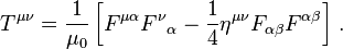 )
)
( ) is the electromagnetic tensor and where (
 ) is the Minkowski metric tensor of metric signature (−+++)
()
( )
)
(*)
(**)
obtained using Wolfram Mathematica ( http://www.wolfram.com/mathematica/ ) , post-processed from the transient Finite Difference (using Meep) solution for RF feed ON for an EM Drive.
0) The highest stress by far is the one produced by the antenna. It appears that the stress at other locations along the longitudinal axis of axi-symmetry is due to the antenna.
1) On the copper circular perimeter the stress tensor component sigma xx (acting normal to the circular cross section plane) fluctuates in certain locations (for example along the conical lateral surface at positions x=97 and x=149). We naturally expect that the stress tensor on the copper itself should sum up to zero in order to satisfy the momentum equilibrium equation implied by Maxwell's equation. Intriguingly, the stress tensor component sigma xx (acting normal to the circular cross section plane) in the copper at the location nearest the big base x=38 is consistently acting in the direction predicted by Roger Shawyer for the big base: pressing on it. We need to also calculate in the future -not tonight :) - the stress on the copper big base to see whether it agrees or not with Roger Shawyer's conjecture, and most importantly we need to also calculate the stress at the small base.
2) Along the longitudinal axis (x) of axi-symmetry of the EM Drive the stress tensor component sigma xx (acting normal to the circular cross section plane) reaches its maximum value in the interior of the EM Drive and it is consistently pressing. In the calculated grids shown below (on the axis) the harmonic variation of the stress tensor is alternating between zero and it maximum value, at twice the frequency of the electromagnetic field. Possibilities are that:
a) the stress tensor is pressing on a classical field (for example ionized plasma resulting from moist air inside the cavity) if it leaks out as an exhaust or
b) a non-classical field (i.e. axionic dark matter, or more controversial conjectures like the mutable, degradable Quantum Vacuum of Dr. White, or violation of p-t symmetry in QV, etc.)
3) Due to the fact that the studied cycles are after only 0.01 microseconds from RF feed turning on, this is very early in the process and hence the stress tensor is a million times smaller than in reported measurements. However it is growing exponentially with time. Based on extrapolation it would be required more than a hundred times longer (longer than one microsecond) at this exponential rate for the stress tensor to reach the reported values.
4) Now we have a more quantitative method to establish whether different antenna arrangements or mode shapes, or geometries may be better than others, to maximize the electromagnetic stress in the longitudinal direction perpendicular to the circular cross-sections.
@aero has made available a number of csv files at 4 internal locations in the longitudinal x direction: at x=38, x=97, x=149, and x=208 (x ranging from 1 to 245, with x=1 at the extreme end beyond the big base and x= 245 at the extreme end beyond the small base). The plane x=208 is near the antenna, and x=149 is the very important wave that is downstream of the antenna in the direction towards the big base.
See the very last picture attached below (showing the Poynting vector field) to locate the 4 locations x=38, x=97, x=149, and x=208, where the x axis is the horizontal axis in the last picture
We start by showing the stress component sigma xx in the circular cross-sectional yz plane at x=38, located on the interior, closest to the big end
EDIT:
1) Magnitude of stress is dependent on input power set for antenna. Aero needs to inform what this input power is.
2) Blue is minimum and Red is maximum. A plot ranging from 0 to +0.02 will show a blue plane for 0, while a plot ranging from 0 to -0.02 will show a red plane for 0. A plot ranging from +0.02 to -0.02 will show a green plane for 0. It was easier for me to set PlotRange to Automatic, than to run through all the Max and Min and having to re-set all the Plots to be rendered to the same Max Min color rendering scheme. At the beginning of the computation we don't know what the Max Min are going to be, so it is more expedient to set the range to Automatic. The Max Min color rendering scheme can only be done post-fact after the results have been obtained for a cycle.
__________
(*) (where we denote by sigmaxx =σxx= T11 the contravariant component of the tensor acting along the longitudinal direction "x" of the EM Drive, normal to the the plane yz having normal x, where direction "1" is "x")
(**) For the copper diamagnetism is assumed such that the magnetization M is assumed proportional to the applied magnetic field such that ( ) for free space it is assumed that M is zero in free space in the relationship (
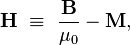 )
)
-
Title: Re: EM Drive Developments - related to space flight applications - Thread 3
Post by: Rodal on 07/13/2015 01:59 AM - We continue by showing the stress tensor component sigma xx at the circular cross-sectional yz plane at x=97, located on the interior, between the big end and the middle of the frustum
-
Title: Re: EM Drive Developments - related to space flight applications - Thread 3
Post by: Rodal on 07/13/2015 02:02 AM - We continue by showing the stress tensor component sigmaxx at a most important circular cross-sectional yz plane at x=149, located on the interior, between the middle and the antenna
-
Title: Re: EM Drive Developments - related to space flight applications - Thread 3
Post by: Rodal on 07/13/2015 02:05 AM - We finish by showing the stress tensor component sigma xx at the circular cross-sectional yz plane at x=208, located on the interior, near the antenna, near the small end of the frustum
-
Title: Re: EM Drive Developments - related to space flight applications - Thread 3
Post by: rfmwguy on 07/13/2015 02:12 AM - Impressive doc, nicely done...
-
Title: Re: EM Drive Developments - related to space flight applications - Thread 3
Post by: Rodal on 07/13/2015 02:25 AM -
Stress tensor component sigma xx (acting normal to the circular cross section plane) plotted vs time (data points interpolated using cubic splines)
The total time from start of the RF feed in the Meep response analysis to the very last step is:
320 ( time slices) * 4.082199*10^(-11) seconds/timeSlice =
= 0.013063 microseconds
Each "time slice" step is 4.082199*10^(-11) seconds/timeSlice
Duration of the total of 13 time slice steps = 53.068 *10^(-11) seconds
Last time step is at 0.013063 microseconds from the start of the RF feed ON
___________________________________________________________
Conversion to get SI Units from the graphs and equations in Meep units:
TIME: Multiply Meep Time Slice "t" in the horizontal axis and in the formulae by the following factor:
((Total Meep Time)/(#Time Slices))*((Length Scale Factor)/(Speed of Light in Vacuum)) =
=((13.054)/(320))*((0.3)/(299792458))
=4.082199*10^(-11) seconds/timeSlice
ASSUMPTIONS: the validity of the following data:
Number of time slices for the total run = 320
Number of Meep time units for the total run = 13.054
Meep Length Scale factor= 0.3 meters
Meep Current (Io) = 1 -
Title: Re: EM Drive Developments - related to space flight applications - Thread 3
Post by: Ricvil on 07/13/2015 02:59 AM -
<a href="http://forum.nasaspaceflight.com/index.php?topic=37642.msg1403610#msg1403610">Quote from: mwvp on 07/13/2015 12:23 AM</a><a href="http://forum.nasaspaceflight.com/index.php?topic=37642.msg1403401#msg1403401">Quote from: Ricvil on 07/12/2015 04:12 AM</a>
Nice. The graph shows the mixing of the modes as a function of cavity shape.
No idea.
There is a choice of frequency, and dimension on graph. Any specific motivation?<a href="http://forum.nasaspaceflight.com/index.php?topic=37642.msg1403401#msg1403401">Quote from: Ricvil on 07/12/2015 04:12 AM</a>I'm looking for a configuration when there is one hybrid mode, followed by any other mode very close.
Why? Because I think there is another thing interacting with the electromagnetic field of cavity.
This thing probally will have a very small coupling with the electromagnetic field.
To enhance this coupling I need:
- A mode excited by a source puting the max energy on cavity
- At least one second mode with frequecy very close to the first but not excited by the source.
In this situation, when a small region of the cavity has its electromagnetics properties changed to anything different of vacuum (epslon0 and mu0), then this little "scatter" region triggers a very strong perturbation called "ghost mode".
In waveguides "ghost modes" are caused by deformations or imperfections on waveguide, but in principle, any "pertubation" can cause this effect.
This "ghost modes" can in some situations, reflect almost all power flux in the waveguide, and the "scatter" will be under very strong radiation pressure.
I don't know if this case can be considered also a type of Fano resonance, but I think if I want some type of interaction of the field inside of cavity with some "other thing", I would try to maximize this interaction with this setup.
To me this thing is the axion field/particle. To others can be particles from "quantum vacuum" or a space-time flutuactions, but the result of the ghost mode arising is the same, change the incidence of electromagnetic radiation on the walls of cavity.
I had to look up ghost mode and Fano reasonance, interesting stuff to know. Perhaps explains why putting a dielectric in the frustrum is a bad thing. Dielectric loss aside, it could cause ghost modes if there are nearby modes available. Lots of google hits on microwave/klystron windows pertaining to ghost modes. Wikipedia notes microwaves are associated with Fano resonance. A 1958 paper by Jaynes http://bayes.wustl.edu/etj/articles/ghost.modes.pdf notes that microwave ghost modes have a similarity to localized imperfections in crystalline periodic structures (such as dopants) leads to bound states that overlap the conduction band. If that Fano resonance too? I'll have to absorb that awhile. I have no idea how that could conjure axions out of the qv.
In axion electrodynamic, the axion field equation has as source of the field a term like alfaE.B (dot product), where alfa is the coupling constant between the E and B fields and the axion field. For EM fields distribuitions where E.B different from zero ( like in hybrid modes) the the axion field is very small ( because the coupling constant) but different from zero.
For the other side, when a axion field is present, they act as a metamaterial medium with very interesting properties like create Poynting vectors vortices as example.
The idea is to enhance the "ghost mode" effect caused by axion "metamaterial" scatter field. -
Title: Re: EM Drive Developments - related to space flight applications - Thread 3
Post by: SeeShells on 07/13/2015 03:55 AM -
You know if all those images were in the same plane you could stack them into a video.
Long day off to bed.
Nite
Shell
Beautiful work! -
Title: Re: EM Drive Developments - related to space flight applications - Thread 3
Post by: WarpTech on 07/13/2015 03:59 AM -
<a href="http://forum.nasaspaceflight.com/index.php?topic=37642.msg1403520#msg1403520">Quote from: Rodal on 07/12/2015 05:51 PM</a><a href="http://forum.nasaspaceflight.com/index.php?topic=37642.msg1403267#msg1403267">Quote from: rfmwguy on 07/11/2015 07:09 PM</a>
...
Here is where they went wrong...under no industrial RF standard does anyone measure Q on return loss, S11. It is done on S21, forward power in the frequency domain for cavities. I stand by my claim that "Specsmanship" was used to create an unnaturally large Q, either by unfamiliarity or intent.
Note that S21 requires a 2 port measurement, input and output (note the sampling port on the frustums will provide the output). I'd bet a six-pack of craft beer that realistic Qs are in the 4 digit range for both shawyer and yang. And yes Doc, Yang should have used the -3dB points below 0 insertion, not -3dB above best return loss...not RF types IMHO.
rfmwguy, a big thanks from me, and a big applause, for clarifying this issue: you are 100% right.
The Q should be measured using two port S21.
All Q measurements using S11 are suspect: everybody should take with a grain of salt the reported Q's from different EM Drive researchers, unless the procedure to measure the Q is detailed and they have used S21.
Hence, why I ignored them and calculated the change in energy required for a given thrust, rather than a thrust given the reported stored energy based on Q. I don't trust the data.
Todd -
Title: Re: EM Drive Developments - related to space flight applications - Thread 3
Post by: WarpTech on 07/13/2015 04:22 AM -
Resolution of the Space-Drive Energy Paradox (version 6)
Have at it @deltaMass and @wallofwolfstreet. I'm looking forward to your responses.
https://www.dropbox.com/s/p86dvc8733h9iph/Desiato-Energy_Paradox-v6.pdf?dl=0
Todd
-
Title: Re: EM Drive Developments - related to space flight applications - Thread 3
Post by: TheTraveller on 07/13/2015 04:27 AM -
<a href="http://forum.nasaspaceflight.com/index.php?topic=37642.msg1403662#msg1403662">Quote from: WarpTech on 07/13/2015 03:59 AM</a><a href="http://forum.nasaspaceflight.com/index.php?topic=37642.msg1403520#msg1403520">Quote from: Rodal on 07/12/2015 05:51 PM</a><a href="http://forum.nasaspaceflight.com/index.php?topic=37642.msg1403267#msg1403267">Quote from: rfmwguy on 07/11/2015 07:09 PM</a>
...
Here is where they went wrong...under no industrial RF standard does anyone measure Q on return loss, S11. It is done on S21, forward power in the frequency domain for cavities. I stand by my claim that "Specsmanship" was used to create an unnaturally large Q, either by unfamiliarity or intent.
Note that S21 requires a 2 port measurement, input and output (note the sampling port on the frustums will provide the output). I'd bet a six-pack of craft beer that realistic Qs are in the 4 digit range for both shawyer and yang. And yes Doc, Yang should have used the -3dB points below 0 insertion, not -3dB above best return loss...not RF types IMHO.
rfmwguy, a big thanks from me, and a big applause, for clarifying this issue: you are 100% right.
The Q should be measured using two port S21.
All Q measurements using S11 are suspect: everybody should take with a grain of salt the reported Q's from different EM Drive researchers, unless the procedure to measure the Q is detailed and they have used S21.
Hence, why I ignored them and calculated the change in energy required for a given thrust, rather than a thrust given the reported stored energy based on Q. I don't trust the data.
Todd
Shawyer uses unloaded cavity Q for his Force calculations as the cavity is never attached to nor filled with anything to alter it's unloaded status. The unloaded Q is all there is. As I see it, it's like a LC circuit that never drives / is connected to anything but just sits there doing it's resonate thing and has its stored energy topped up, from time to time, to replace the parasitic energy loss.
So loaded cavity Q measurements have no place in the EMDrive world as the cavity is never loaded. It is a 1 port cavity.
Unloaded cavity Q can be calculated by 1 port S11 return loss measurements based on the side frequencies that are 3 dB down from the return loss peak.
It can also be calculated, in real time, by my Control & Measurement System, based on the Rf amps VSWR output. -
Title: Re: EM Drive Developments - related to space flight applications - Thread 3
Post by: SeeShells on 07/13/2015 04:47 AM -
Got up to get a glass of milk and while browsing the clickbates I ran across the competitions extreme mass thruster. What could go wrong?
http://phys.org/news/2015-07-boeing-patent-focus-laser-powered-propulsion.html -
Title: Re: EM Drive Developments - related to space flight applications - Thread 3
Post by: WarpTech on 07/13/2015 04:48 AM -
<a href="http://forum.nasaspaceflight.com/index.php?topic=37642.msg1403669#msg1403669">Quote from: TheTraveller on 07/13/2015 04:27 AM</a><a href="http://forum.nasaspaceflight.com/index.php?topic=37642.msg1403662#msg1403662">Quote from: WarpTech on 07/13/2015 03:59 AM</a><a href="http://forum.nasaspaceflight.com/index.php?topic=37642.msg1403520#msg1403520">Quote from: Rodal on 07/12/2015 05:51 PM</a><a href="http://forum.nasaspaceflight.com/index.php?topic=37642.msg1403267#msg1403267">Quote from: rfmwguy on 07/11/2015 07:09 PM</a>
...
Here is where they went wrong...under no industrial RF standard does anyone measure Q on return loss, S11. It is done on S21, forward power in the frequency domain for cavities. I stand by my claim that "Specsmanship" was used to create an unnaturally large Q, either by unfamiliarity or intent.
Note that S21 requires a 2 port measurement, input and output (note the sampling port on the frustums will provide the output). I'd bet a six-pack of craft beer that realistic Qs are in the 4 digit range for both shawyer and yang. And yes Doc, Yang should have used the -3dB points below 0 insertion, not -3dB above best return loss...not RF types IMHO.
rfmwguy, a big thanks from me, and a big applause, for clarifying this issue: you are 100% right.
The Q should be measured using two port S21.
All Q measurements using S11 are suspect: everybody should take with a grain of salt the reported Q's from different EM Drive researchers, unless the procedure to measure the Q is detailed and they have used S21.
Hence, why I ignored them and calculated the change in energy required for a given thrust, rather than a thrust given the reported stored energy based on Q. I don't trust the data.
Todd
Shawyer uses unloaded cavity Q for his Force calculations as the cavity is never attached to nor filled with anything to alter it's unloaded status. The unloaded Q is all there is. As I see it, it's like a LC circuit that never drives / is connected to anything but just sits there doing it's resonate thing and has its stored energy topped up, from time to time, to replace the parasitic energy loss.
So loaded cavity Q measurements have no place in the EMDrive world as the cavity is never loaded. It is a 1 port cavity.
Unloaded cavity Q can be calculated by 1 port S11 return loss measurements based on the side frequencies that are 3 dB down from the return loss peak.
It can also be calculated, in real time, by my Control & Measurement System, based on the Rf amps VSWR output.
IMO, it would be more important to measure the energy and frequency stored at the small end, vs the energy and frequency stored at the big end, and maximize the difference. The Q means nothing, what matters is the difference in potential energy between the two ends.
Todd
-
Title: Re: EM Drive Developments - related to space flight applications - Thread 3
Post by: mwvp on 07/13/2015 06:36 AM -
<a href="http://forum.nasaspaceflight.com/index.php?topic=37642.msg1403669#msg1403669">Quote from: TheTraveller on 07/13/2015 04:27 AM</a>
Shawyer uses unloaded cavity Q for his Force calculations as the cavity is never attached to nor filled with anything to alter it's unloaded status. The unloaded Q is all there is. As I see it, it's like a LC circuit that never drives / is connected to anything but just sits there doing it's resonate thing and has its stored energy topped up, from time to time, to replace the parasitic energy loss.
So loaded cavity Q measurements have no place in the EMDrive world as the cavity is never loaded. It is a 1 port cavity.
Unloaded cavity Q can be calculated by 1 port S11 return loss measurements based on the side frequencies that are 3 dB down from the return loss peak.
It can also be calculated, in real time, by my Control & Measurement System, based on the Rf amps VSWR output.
Are you sure the EMDrive will never be "loaded"? Didn't Shawyer describe it as a motor/generator depending one which direction its moving? At rest, its RF-wise at equilibrium. If it moves backwards, it generates and a reflected wave will move towards your transmitter. Moving forward, shouldn't it present a greater load on the transmitter then?
Perhaps any coax reactance (a coax with an unevent # of 1/4 wavelengths) will be absorbed/dwarfed by the cavity tuning, so perhaps S11 is good enough for tuning.
However, wouldn't it be nice to sense each of the 3 modes in a TE013 frustrum at 90 degree points, and watch the amplitude modulations/traveling wave or Sagnac effect as it spins to or fro? Or configure the taps for phase rather than amplitude measurement to measure group velocity?
Would be a good reality check for the FEA/FDTD simulations.
BTW, I'm pretty sure the transmitter will have an isolator or circulator to protect the PA from VSWR damage. If it doesn't, it may be very easy to burn it out if its tuned at high-power while the cavity is tuned through its anti-resonance. -
Title: Re: EM Drive Developments - related to space flight applications - Thread 3
Post by: dustinthewind on 07/13/2015 07:28 AM -
<a href="http://forum.nasaspaceflight.com/index.php?topic=37642.msg1403666#msg1403666">Quote from: WarpTech on 07/13/2015 04:22 AM</a>
Resolution of the Space-Drive Energy Paradox (version 6)
Have at it @deltaMass and @wallofwolfstreet. I'm looking forward to your responses.
https://www.dropbox.com/s/p86dvc8733h9iph/Desiato-Energy_Paradox-v6.pdf?dl=0
Todd
So then if one appears to be traveling near light speed then one is indeed traveling near light speed (gravitationally) even though if in the moving frame light still appears to recede at light speed. And if space is moving in to a point at near light speed then there is no escape (event horizion). Velocity with respect to space being absolute.
It reminds me of a non-rotating wheel as observed from a rotating observer. A wheel is either rotating or it is not. For a rotating observer he cannot say the wheel that rests in the lab frame appears to be rotating so it must experience acceleration. If all the bonds are broken the wheel will not fly apart as it does not experience acceleration. As a result rotation with respect to a center is absolute. -
Title: Re: EM Drive Developments - related to space flight applications - Thread 3
Post by: TheTraveller on 07/13/2015 08:22 AM -
<a href="http://forum.nasaspaceflight.com/index.php?topic=37642.msg1403685#msg1403685">Quote from: mwvp on 07/13/2015 06:36 AM</a><a href="http://forum.nasaspaceflight.com/index.php?topic=37642.msg1403669#msg1403669">Quote from: TheTraveller on 07/13/2015 04:27 AM</a>
Shawyer uses unloaded cavity Q for his Force calculations as the cavity is never attached to nor filled with anything to alter it's unloaded status. The unloaded Q is all there is. As I see it, it's like a LC circuit that never drives / is connected to anything but just sits there doing it's resonate thing and has its stored energy topped up, from time to time, to replace the parasitic energy loss.
So loaded cavity Q measurements have no place in the EMDrive world as the cavity is never loaded. It is a 1 port cavity.
Unloaded cavity Q can be calculated by 1 port S11 return loss measurements based on the side frequencies that are 3 dB down from the return loss peak.
It can also be calculated, in real time, by my Control & Measurement System, based on the Rf amps VSWR output.
Are you sure the EMDrive will never be "loaded"? Didn't Shawyer describe it as a motor/generator depending one which direction its moving? At rest, its RF-wise at equilibrium. If it moves backwards, it generates and a reflected wave will move towards your transmitter. Moving forward, shouldn't it present a greater load on the transmitter then?
Perhaps any coax reactance (a coax with an unevent # of 1/4 wavelengths) will be absorbed/dwarfed by the cavity tuning, so perhaps S11 is good enough for tuning.
However, wouldn't it be nice to sense each of the 3 modes in a TE013 frustrum at 90 degree points, and watch the amplitude modulations/traveling wave or Sagnac effect as it spins to or fro? Or configure the taps for phase rather than amplitude measurement to measure group velocity?
Would be a good reality check for the FEA/FDTD simulations.
BTW, I'm pretty sure the transmitter will have an isolator or circulator to protect the PA from VSWR damage. If it doesn't, it may be very easy to burn it out if its tuned at high-power while the cavity is tuned through its anti-resonance.
Thanks for the suggestions.
My 1st goal is to prove beyond doubt my EMDrive generates Force without using any form of propellant. Other interesting stuff may happen later as the Force verifiers are doing their jobs.
All that happens in GENERATOR mode is the absorbed KE is converted into increased Rf cavity energy and finally increased cavity heat. Can't back convert the increased cavity Rf energy into electricity and shove in back into the electrical power source.
The 100W Rf amp I'll be using has inbuilt protection against high reflected power, shorted output and overheat, plus my CMS can quickly shut down the Rf amp if anything reaches the boundary conditions I set in the software. So 2 layers of protection.
-
Title: Re: EM Drive Developments - related to space flight applications - Thread 3
Post by: dumbo on 07/13/2015 08:27 AM -
I did not receive a reply from the FEFF project. But I have now configured an AMI image based on Ubuntu with meep installed. I have also uploaded aero's file to it. Also, for some strange reason (meep version differences?) I had to change all occurences of the type:
(define variable)
(set! variable some-value)
to
(define variable some-value)
in order to get the simulation to start.
Also, I have wrapped the main run statement in a (synchronized-magnetic ...) statement, to avoid the situation described on the meep wiki:Quote from: meep wikiIn the finite-difference time-domain method, the electric and magnetic fields are stored at different times (and different positions in space), in a "leap-frog" fashion. At any given time-step t during the simulation, the E and D fields are stored at time t, but the H and B fields are stored at time t − Δt / 2 (where Δt is the time-step size).
This means that when you output the electric and magnetic fields from a given time step, for example, the fields actually correspond to times Δt / 2 apart. For most purposes, this slight difference in time doesn't actually matter much, but it makes a difference when you compute quantities like the Poynting flux \mathbf{E}\times\mathbf{H} that combine electric and magnetic fields together, e.g. for the output-poynting function. If what you really want is the Poynting flux \mathbf{S}(t) at time t, then computing \mathbf{E}(t)\times\mathbf{H}(t-\Delta t/2) is slightly off from this — the error is of order O(Δt), or first-order accuracy. This is unfortunate, because the underlying FDTD method ideally can have second-order accuracy.
To improve the accuracy for computations involving both electric and magnetic fields, Meep provides a facility to synchronize the H and B fields with the E and D fields in time. Technically, what it does is to compute the magnetic fields at time t + Δt / 2 by performing part of a timestep, and then averaging those fields with the fields at time t − Δt / 2. This produces the magnetic fields at time t to second-order accuracy O(Δt2), which is the best we can do in second-order FDTD. Meep also saves a copy of the magnetic fields at t − Δt / 2, so that it can restore those fields for subsequent timestepping.
Ok, so most of the configuration work is done. My questions are now:
1) How many cycles should we run?
2) Is user apoc2021's generous offer to donate server time still open? -
Title: Re: EM Drive Developments - related to space flight applications - Thread 3
Post by: Rodal on 07/13/2015 10:51 AM -
In any case, and moreover when proposing changes to the statements of aero that may impact the results, the first and most hygienic thing to do in any numerical study is to
1) Run the exact same case run by aero with NO changes whatsoever
2) Run the exact same case (same FD mesh, same number of cycles, same antenna, same material model, same Boundary Conditions, etc.) with the single change (not more than one change at a time) you would like to make (wrapped the main run statement in a (synchronized-magnetic ...) )
Same output statements (time slices, everything). Otherwise, it will be impossible to know what is responsible for what if there are different results. Once it has been established that everything is the same (or if there are changes, that the results are an improvement) should one contemplate further cycles (it will take ~ 500 times -I emphasize times: multiplication of the present number- more cycles to reach anything close to steady state if the exponential magnification of the last cycles is representative of the long term exponential magnification. ). Given that that is a huge number of finite difference time steps (6500*500=3.25 million time steps) and that it would be prudent to examine the progress of the numerical solution for stability (and interaction with round off error accumulation) I would advise that it should first be studied how to run Meep in increments such that intermediate results are saved to enable shorter runs, examination of intermediate data and re-start with the finite difference data needed to continue.
Meanwhile aero could run parallel studies, as already advised by Todd:
Run with the RF feed ON for the same number of FD Time Steps (6527 ?), and turn RF feed OFF at that point and run for another identical number of steps (over 13,000 time steps).
This would also be interesting:
Run with the RF feed ON for the same number of FD Time Steps (6527 ?), everything the same as now, except that at the big end there is a big opening instead of copper metal. This will require a large Finite Difference mesh area to the side of the big end representing for example a chamber. Chamber required to be at least 3 or more times the length of the cavity, in the direction pointing from the small end to the big end. "Chamber" walls should not be reflective, chamber walls should not have metal boundary condition (is there a free-space B.C. ?) -
Title: Re: EM Drive Developments - related to space flight applications - Thread 3
Post by: SeeShells on 07/13/2015 11:11 AM -
I'm working on the losses of energy through the perforated copper asymmetrical waveguide and perforated endplates on my EMDrive design. I've found it's important to look at each hole as a tiny little waveguide and the incident angle of reflection of the 2.45 GHZ propagating wave within the cavity effecting it... so I'm number crunching.
Before I head back into disproving the heavy flack I've gotten in using a perforated copper frustum I want to as Dr. Rodal a question that was bugging me as I reviewed the images dancing in my head (like counting sheep) before falling to sleep last night.
Why does sequence of images show increasing levels of activity outside of the frustum solid boundary walls in your simulation? Stepping through each one it was apparent when you're calculating the stress tensor component strengths it shows up outside the cavity. Is this an artifact?
Ok back at crunching.
Todd, looks like great info and will read a later this morning.
TT, nice bluetooth setup, make sure you wear your perforated foil hat when running to protect your gray matter.
Shell -
Title: Re: EM Drive Developments - related to space flight applications - Thread 3
Post by: Rodal on 07/13/2015 11:18 AM -
<a href="http://forum.nasaspaceflight.com/index.php?topic=37642.msg1403711#msg1403711">Quote from: SeeShells on 07/13/2015 11:11 AM</a>
I'm working on the losses of energy through the perforated copper asymmetrical waveguide and perforated endplates on my EMDrive design. I've found it's important to look at each hole as a tiny little waveguide and the incident angle of reflection of the 2.45 GHZ propagating wave within the cavity effecting it... so I'm number crunching.
Before I head back into disproving the heavy flack I've gotten in using a perforated copper frustum I want to as Dr. Rodal a question that was bugging me as I reviewed the images dancing in my head (like counting sheep) before falling to sleep last night.
Why does sequence of images show increasing levels of activity outside of the frustum solid boundary walls in your simulation? Stepping through each one it was apparent when you're calculating the stress tensor component strengths it shows up outside the cavity. Is this an artifact?
Ok back at crunching.
Todd, looks like great info and will read a later this morning.
TT, nice bluetooth setup, make sure you wear your perforated foil hat when running to protect your gray matter.
Shell
The stress outside the EM Drive is zero in all cases I recall (have I missed one? -- in which case please indicate the figure ?) . The planes outside the EM Drive have different color because I plotted them with automatic Max Min rendering to show the shape of each stress field no matter how much smaller amplitude. Blue is minimum and Red is maximum. A plot ranging from 0 to +0.02 will show a blue plane for 0, while a plot ranging from 0 to -0.02 will show a red plane for 0. A plot ranging from +0.02 to -0.02 will show a green plane for 0.
In this case (unlike in the early Meep figures) it is OK to do this because I am showing the numerical magnitude of the stress tensor in the vertical axis. In the early Meep output that was made into movies, no numerical magnitude was being shown. Hence I was objecting to being shown images with changing colors where we did not know what was the numerical meaning of the colors.
Please notice that the numerical magnitude of the stress generated by the antenna at its maximum is several times greater than the stress shown in other images.
If there would be an interest in making movies out of this, they would need to be re-plotted as follows:
1) Same Max Min
2) Fix the space view (instead of changing the view to appreciate what is going)
Eventually we should do that, I agree.
My focus at the moment is in:
1) Plotting the Stress Tensor at the big base and the small base (was Roger Shawyer's conjecture regarding the sign of the stress tensor at the bases correct: is the stress on the big base purely in the direction towards the big base ? -never mind the separate Shawyer's conjecture regarding zero stress at the lateral conical walls that is obviously incorrect, as elementary analysis can show. Even his follower, Prof. Yang, has shown that Shawyer's assumption of zero stress at the conical walls is incorrect- )
2) Plot the Stress Tensor at other locations (eventually we would have over 260 circular cross sections for the whole model to explore).
-
Title: Re: EM Drive Developments - related to space flight applications - Thread 3
Post by: SeeShells on 07/13/2015 11:48 AM -
<a href="http://forum.nasaspaceflight.com/index.php?topic=37642.msg1403712#msg1403712">Quote from: Rodal on 07/13/2015 11:18 AM</a>
Good to know that was an intended artifact. :D<a href="http://forum.nasaspaceflight.com/index.php?topic=37642.msg1403711#msg1403711">Quote from: SeeShells on 07/13/2015 11:11 AM</a>I'm working on the losses of energy through the perforated copper asymmetrical waveguide and perforated endplates on my EMDrive design. I've found it's important to look at each hole as a tiny little waveguide and the incident angle of reflection of the 2.45 GHZ propagating wave within the cavity effecting it... so I'm number crunching.
Before I head back into disproving the heavy flack I've gotten in using a perforated copper frustum I want to as Dr. Rodal a question that was bugging me as I reviewed the images dancing in my head (like counting sheep) before falling to sleep last night.
Why does sequence of images show increasing levels of activity outside of the frustum solid boundary walls in your simulation? Stepping through each one it was apparent when you're calculating the stress tensor component strengths it shows up outside the cavity. Is this an artifact?
Ok back at crunching.
Todd, looks like great info and will read a later this morning.
TT, nice bluetooth setup, make sure you wear your perforated foil hat when running to protect your gray matter.
Shell
The stress outside the EM Drive is zero in all cases I recall (have I missed one? -- in which case please indicate the figure ?) . The planes outside the EM Drive have different color because I plotted them with automatic Max Min rendering to show the shape of each stress field no matter how much smaller amplitude. A plot ranging from 0 to +0.02 will show a blue plane for 0, while a plot ranging from 0 to -0.02 will show a red plane for 0.
In this case (unlike in the early Meep figures) it is OK to do this because I am showing the numerical magnitude of the stress tensor in the vertical axis. In the early Meep output that was made into movies, no numerical magnitude was being shown.
Please notice that the numerical magnitude of the stress generated by the antenna at its maximum is several times greater than the stress shown in other images.
If there would be an interest in making movies out of this, they would need to be re-plotted as follows:
1) Same Max Min
2) Fix the space view
I expected a high level around the antenna and it's nice to see but what else I find totally unexpected is the vertical flattened pancaked shape, is that due to the end cavity plates?
A animated visual would be great for those viewing here that get lost in the heavy maths tagged with a ELI5 descriptor. -
Title: Re: EM Drive Developments - related to space flight applications - Thread 3
Post by: Rodal on 07/13/2015 12:19 PM -
It was a convenient (*) color-rendering artifact, the numbers are innocent: the numbers in the vertical scale are correct in all the images, hence a color-rendering artifact rather than numerical artifact :).
(*) It was easier for me to set PlotRange to Automatic, than to run through all the Max and Min and having to re-set all the Plots to be rendered to the same Max Min color rendering scheme. At the beginning of the computation we don't know what the Max Min are going to be, so it is more expedient to set the range to Automatic. The Max Min color rendering scheme can only be done post-fact after the results have been obtained for a cycle.
(https://encrypted-tbn3.gstatic.com/images?q=tbn:ANd9GcTbmWtfRTcrKVJn5_T1SZEJzBHEpbcOsCXIdOan7VZEmxbefHso) -
Title: Re: EM Drive Developments - related to space flight applications - Thread 3
Post by: deltaMass on 07/13/2015 12:46 PM -
<a href="http://forum.nasaspaceflight.com/index.php?topic=37642.msg1403671#msg1403671">Quote from: WarpTech on 07/13/2015 04:48 AM</a>
IMO, it would be more important to measure the energy and frequency stored at the small end, vs the energy and frequency stored at the big end, and maximize the difference. The Q means nothing, what matters is the difference in potential energy between the two ends.
I do hope we're not entering TT Brown "asymmetric capacitor" country with that remark. I think we all know that that particular line of enquiry ended badly!
Todd -
Title: Re: EM Drive Developments - related to space flight applications - Thread 3
Post by: WarpTech on 07/13/2015 01:52 PM -
<a href="http://forum.nasaspaceflight.com/index.php?topic=37642.msg1403723#msg1403723">Quote from: deltaMass on 07/13/2015 12:46 PM</a>
Nothing of the sort! Just a simple change in potential energy, due to the gradient in the geometry.<a href="http://forum.nasaspaceflight.com/index.php?topic=37642.msg1403671#msg1403671">Quote from: WarpTech on 07/13/2015 04:48 AM</a>IMO, it would be more important to measure the energy and frequency stored at the small end, vs the energy and frequency stored at the big end, and maximize the difference. The Q means nothing, what matters is the difference in potential energy between the two ends.
I do hope we're not entering TT Brown "asymmetric capacitor" country with that remark. I think we all know that that particular line of enquiry ended badly!
Todd
Todd -
Title: Re: EM Drive Developments - related to space flight applications - Thread 3
Post by: Rodal on 07/13/2015 02:10 PM -
Aero:
Need information on what is the input power you set as an initial condition for Meep: how did you decide the parameters to use for the antenna?
The magnitude of the stress depends on the input power. -
Title: Re: EM Drive Developments - related to space flight applications - Thread 3
Post by: TheTraveller on 07/13/2015 02:14 PM -
<a href="http://forum.nasaspaceflight.com/index.php?topic=37642.msg1403711#msg1403711">Quote from: SeeShells on 07/13/2015 11:11 AM</a>
TT, nice bluetooth setup, make sure you wear your perforated foil hat when running to protect your gray matter.
There will be a significant Faraday Shield around the EMDrive. If the BlueTooth can't connect, will increase it to a double Faraday Shield with optional additional full mu-metal shield to block out low H field leakage as well. Remember min wall thickness is 2mm and I can reduce Rf amp power down to 79mWs. Don't expect any issues but if they occur I know how to deal with them.
The BlueTooth link, when doing cordless rotates, will be operational.
What Shawyer did with his 1st Experimental EMDrive (attached) is a good reference. -
Title: Re: EM Drive Developments - related to space flight applications - Thread 3
Post by: SeeShells on 07/13/2015 02:51 PM -
I posted a Danger alert and it went poof. Summary as I'll try again, weird.
I asked why the shape of the calculated stress values were shaped around the antenna like they were, squeezed in the forward accelerating direction and flattened out to the sides.
It reminds me of Einstein effects for an object approaching the speed of light. Interesting all other meep views were of this nice round antenna shape.
Just wondering how that compressed stress took that shape.
Shell -
Title: Re: EM Drive Developments - related to space flight applications - Thread 3
Post by: Rodal on 07/13/2015 03:27 PM -
<a href="http://forum.nasaspaceflight.com/index.php?topic=37642.msg1403772#msg1403772">Quote from: SeeShells on 07/13/2015 02:51 PM</a>
I posted a Danger alert and it went poof. Summary as I'll try again, weird.
I asked why the shape of the calculated stress values were shaped around the antenna like they were, squeezed in the forward accelerating direction and flattened out to the sides.
It reminds me of Einstein effects for an object approaching the speed of light. Interesting all other meep views were of this nice round antenna shape.
Just wondering how that compressed stress took that shape.
Shell
I don't recall Meep views of a round antenna shape.
The antenna is much longer in one direction and has a "thickness" of only 2 Finite Difference nodes.
So, viewed from one side the antenna looks like a line, and when looked from the perpendicular view it looks like a point (or a very small circle of just 2 Finite Difference nodes).
When plotting the stress as the height of the "line antenna" the stress looks like a plate with rounded corners at the top.
Could you please link to the message, or even better copy and paste the round antenna image in your response ?
I need to see the 2 images you are referring to as a picture is worth a thousand words.
Thanks -
Title: Re: EM Drive Developments - related to space flight applications - Thread 3
Post by: zen-in on 07/13/2015 03:45 PM -
<a href="http://forum.nasaspaceflight.com/index.php?topic=37642.msg1403754#msg1403754">Quote from: TheTraveller on 07/13/2015 02:14 PM</a>
...
There will be a significant Faraday Shield around the EMDrive. If the BlueTooth can't connect, will increase it to a double Faraday Shield with optional additional full mu-metal shield to block out low H field leakage as well. Remember min wall thickness is 2mm and I can reduce Rf amp power down to 79mWs. Don't expect any issues but if they occur I know how to deal with them.
The BlueTooth link, when doing cordless rotates, will be operational.
...
It will be interesting to see how well the Bluetooth works. Bluetooth uses the same ISM band (2.4 - 2.5 GHz). No amount of shielding is 100% effective.
-
Title: Re: EM Drive Developments - related to space flight applications - Thread 3
Post by: ludkokanta on 07/13/2015 03:51 PM - Who is interested in the subject and has a lot of money?
-
Title: Re: EM Drive Developments - related to space flight applications - Thread 3
Post by: Rodal on 07/13/2015 04:01 PM -
See the NSF thread on EM Drive X-Prize, where an entrepreneur was interested in starting an EM Drive X-Prize . That thread gives actual numbers for how much money was the X-Prize supposed to award.
Mixed response, including skepticism about whether the EM Drive is an artifact, whether an EM Drive implies "free energy" (a big no-no for funding :) ), controversy about how to measure a significant X-Prize achievement, controversy whether there should be an EM Drive X-prize, how to prevent artifacts from award competition, and the spontaneous rise of a number of inventors willing to use their own time to demonstrate the EM Drive put a halt to the initiative until after this summer. It may get re-visited again this coming Fall.
A lot depends on:
* test results from independent inventors
* upcoming presentation on EM Drive from Prof Tajmar at TU Dresden Germany (first University in the West to report on an EM Drive experimental program)
* further testing at NASA Eagleworks -
Title: Re: EM Drive Developments - related to space flight applications - Thread 3
Post by: marshallC on 07/13/2015 04:21 PM -
Hi guys, layman here, though I've been following the threads for the last few months or so.
A question popped into my head today - can photons collide/interfere, and if so, do they perform behavior that may change the outcome of the meep results? A Google seems to return conflicting sources on whether photons collide, and what happens in that case, but considering we're pumping a constant stream of the things into a highly resonant container (if I'm understanding Q correctly), I figured it might be worth mentioning.
Also, I know stardrive went incommunicado after the 'warp drive'media fiasco, but does anyone have any inside information on whether the Eagleworks test is still going on this month?
Thanks!
Marshall -
Title: Re: EM Drive Developments - related to space flight applications - Thread 3
Post by: Rodal on 07/13/2015 04:24 PM - I think we should not entertain gossip about Eagleworks testing until Star-Drive re-appears, as engaging in such discussion may jeopardize NASA Eagleworks's ongoing efforts, giving NASA's response to the "warp-drive" media articles.
-
Title: Re: EM Drive Developments - related to space flight applications - Thread 3
Post by: marshallC on 07/13/2015 04:31 PM -
<a href="http://forum.nasaspaceflight.com/index.php?topic=37642.msg1403819#msg1403819">Quote from: Rodal on 07/13/2015 04:24 PM</a>
I think we should not entertain gossip about Eagleworks testing until Star-Drive re-appears, as engaging in such discussion may jeopardize NASA Eagleworks's ongoing efforts, giving NASA's response to the "warp-drive" media articles.
Understandable. Thanks! -
Title: Re: EM Drive Developments - related to space flight applications - Thread 3
Post by: Rodal on 07/13/2015 04:36 PM -
<a href="http://forum.nasaspaceflight.com/index.php?topic=37642.msg1403821#msg1403821">Quote from: marshallC on 07/13/2015 04:31 PM</a><a href="http://forum.nasaspaceflight.com/index.php?topic=37642.msg1403819#msg1403819">Quote from: Rodal on 07/13/2015 04:24 PM</a>
I think we should not entertain gossip about Eagleworks testing until Star-Drive re-appears, as engaging in such discussion may jeopardize NASA Eagleworks's ongoing efforts, giving NASA's response to the "warp-drive" media articles.
Understandable. Thanks!
There is a short-fim made about this (if you speak German, turn-off the sound and just read the English subtitles) :) :
http://captiongenerator.com/48295/Hitler-Reacts-to-current-EmDrive-Situation -
Title: Re: EM Drive Developments - related to space flight applications - Thread 3
Post by: CraigPichach on 07/13/2015 04:45 PM -
<a href="http://forum.nasaspaceflight.com/index.php?topic=37642.msg1398508#msg1398508">Quote from: Rodal on 07/01/2015 12:19 PM</a>
Concept drawing previously posted by Star-Drive (Paul March) for a magnetron feeding RF to a water-cooled EM Drive at the center of the small base of the EM Drive.
EDIT: Paul March also uses spherical (instead of flat) ends, and places the magnetron at the apex of the cone, extending the EM drive towards the minimum small base diameter possible to accommodate the magnetron. Not concerned about "cut-off" nonsense limits based on cylindrical waveguides (that do not apply to truncated cones). He also plans to excite the lowest natural frequency TM010, which has the highest amplitude of all modes.
Also his design to use the present NASA frustum with an internal partition to resonate at 2.45 GHz in the lower mode, higher amplitude TE011 for the Interferometer tests.
EM Drive testers could use a similar partition to investigate resonance at lower modes, which should exhibit higher amplitude, without needing to cut the EM Drive permanently
I want to build this version as I feel it might produce results we can actually do some validation on; looking at working with some local universities and fabrication shops. Seems easy to build and relatively cheap ($20K). HOWEVER in discussions with the magnetron manufacturer the unit he is looking at the unit is doing just 915MHz vs. 2.45GHz on current experiments.
I see he has a slide at 957.8MHz - is that what was used for the 17" OD long and 28" length (TM010 design?). Can anyone confirm that (or better yet design for TE012 at 915MHz)? Why does he go 957.833MHz instead of the commercial 915MHz? Is this going to be impossible to tune to resonance given if you buy that magnetron it has a set frequency?
Does anyone see any downside to those lower frequencies? Why does he go TM010 when it looks like TE012 on the experiments does better? -
Title: Re: EM Drive Developments - related to space flight applications - Thread 3
Post by: marshallC on 07/13/2015 04:50 PM -
<a href="http://forum.nasaspaceflight.com/index.php?topic=37642.msg1403826#msg1403826">Quote from: Rodal on 07/13/2015 04:36 PM</a><a href="http://forum.nasaspaceflight.com/index.php?topic=37642.msg1403821#msg1403821">Quote from: marshallC on 07/13/2015 04:31 PM</a><a href="http://forum.nasaspaceflight.com/index.php?topic=37642.msg1403819#msg1403819">Quote from: Rodal on 07/13/2015 04:24 PM</a>
I think we should not entertain gossip about Eagleworks testing until Star-Drive re-appears, as engaging in such discussion may jeopardize NASA Eagleworks's ongoing efforts, giving NASA's response to the "warp-drive" media articles.
Understandable. Thanks!
There is a short-fim made about this (if you speak German, turn-off the sound and just read the English subtitles) :) :
http://captiongenerator.com/48295/Hitler-Reacts-to-current-EmDrive-Situation
Hah, I saw that linked a while back, but only ever browse on my phone, so I never clicked it >_< I'll have to watch it after work.
Also, thinking more on the collision of photons, one source said they may form a matter/antimatter pair. If this source is accurate, and collisions are occurring, is it possible the formation and annihilation redirects the forces of the photons in some odd manner?
I apologize if I'm derailing the discussion, feel free to stop me at any point :) -
Title: Re: EM Drive Developments - related to space flight applications - Thread 3
Post by: deltaMass on 07/13/2015 04:55 PM -
<a href="http://forum.nasaspaceflight.com/index.php?topic=37642.msg1403832#msg1403832">Quote from: marshallC on 07/13/2015 04:50 PM</a>
Photons do scatter off one another, but the energy densities required are beyond experimental reach currently. PVAS is the European facility that promises to get closest to seeing at least some nonlinearities in the near future using extremely high-power lasers. For ordinary experiments, you might as well assume they don't see each other at all.<a href="http://forum.nasaspaceflight.com/index.php?topic=37642.msg1403826#msg1403826">Quote from: Rodal on 07/13/2015 04:36 PM</a><a href="http://forum.nasaspaceflight.com/index.php?topic=37642.msg1403821#msg1403821">Quote from: marshallC on 07/13/2015 04:31 PM</a><a href="http://forum.nasaspaceflight.com/index.php?topic=37642.msg1403819#msg1403819">Quote from: Rodal on 07/13/2015 04:24 PM</a>I think we should not entertain gossip about Eagleworks testing until Star-Drive re-appears, as engaging in such discussion may jeopardize NASA Eagleworks's ongoing efforts, giving NASA's response to the "warp-drive" media articles.
Understandable. Thanks!
There is a short-fim made about this (if you speak German, turn-off the sound and just read the English subtitles) :) :
http://captiongenerator.com/48295/Hitler-Reacts-to-current-EmDrive-Situation
Hah, I saw that linked a while back, but only ever browse on my phone, so I never clicked it >_< I'll have to watch it after work.
Also, thinking more on the collision of photons, one source said they may form a matter/antimatter pair. If this source is accurate, and collisions are occurring, is it possible the formation and annihilation redirects the forces of the photons in some odd manner?
I apologize if I'm derailing the discussion, feel free to stop me at any point :) -
Title: Re: EM Drive Developments - related to space flight applications - Thread 3
Post by: marshallC on 07/13/2015 04:59 PM -
<a href="http://forum.nasaspaceflight.com/index.php?topic=37642.msg1403833#msg1403833">Quote from: deltaMass on 07/13/2015 04:55 PM</a><a href="http://forum.nasaspaceflight.com/index.php?topic=37642.msg1403832#msg1403832">Quote from: marshallC on 07/13/2015 04:50 PM</a>
Photons do scatter off one another, but the energy densities required are beyond experimental reach currently. PVAS is the European facility that promises to get closest to seeing at least some nonlinearities in the near future using extremely high-power lasers. For ordinary experiments, you might as well assume they don't see each other at all.<a href="http://forum.nasaspaceflight.com/index.php?topic=37642.msg1403826#msg1403826">Quote from: Rodal on 07/13/2015 04:36 PM</a><a href="http://forum.nasaspaceflight.com/index.php?topic=37642.msg1403821#msg1403821">Quote from: marshallC on 07/13/2015 04:31 PM</a><a href="http://forum.nasaspaceflight.com/index.php?topic=37642.msg1403819#msg1403819">Quote from: Rodal on 07/13/2015 04:24 PM</a>I think we should not entertain gossip about Eagleworks testing until Star-Drive re-appears, as engaging in such discussion may jeopardize NASA Eagleworks's ongoing efforts, giving NASA's response to the "warp-drive" media articles.
Understandable. Thanks!
There is a short-fim made about this (if you speak German, turn-off the sound and just read the English subtitles) :) :
http://captiongenerator.com/48295/Hitler-Reacts-to-current-EmDrive-Situation
Hah, I saw that linked a while back, but only ever browse on my phone, so I never clicked it >_< I'll have to watch it after work.
Also, thinking more on the collision of photons, one source said they may form a matter/antimatter pair. If this source is accurate, and collisions are occurring, is it possible the formation and annihilation redirects the forces of the photons in some odd manner?
I apologize if I'm derailing the discussion, feel free to stop me at any point :)
And just to be sure, that includes considering the frustrum's shape being a wave-guide, correct? I'm not sure if that would make them more likely to connect, despite the small density. -
Title: Re: EM Drive Developments - related to space flight applications - Thread 3
Post by: deltaMass on 07/13/2015 05:03 PM -
Give it up. EmDrive contains no black holes, cosmic strings, gravity anomalies, self-interacting photons, axions, WIMPs, MACHOs, pink unicorns or floobie-dust.
Although there might be some floobie-dust 8) -
Title: Re: EM Drive Developments - related to space flight applications - Thread 3
Post by: SeeShells on 07/13/2015 05:04 PM -
<a href="http://forum.nasaspaceflight.com/index.php?topic=37642.msg1403789#msg1403789">Quote from: Rodal on 07/13/2015 03:27 PM</a>
You 're quite right the antenna is being shown in the horizontal plane not the vertical. I asked the question nicely and did say it was a danger alert. It is the exact way it should be and nothing is funny about it.<a href="http://forum.nasaspaceflight.com/index.php?topic=37642.msg1403772#msg1403772">Quote from: SeeShells on 07/13/2015 02:51 PM</a>I posted a Danger alert and it went poof. Summary as I'll try again, weird.
I asked why the shape of the calculated stress values were shaped around the antenna like they were, squeezed in the forward accelerating direction and flattened out to the sides.
It reminds me of Einstein effects for an object approaching the speed of light. Interesting all other meep views were of this nice round antenna shape.
Just wondering how that compressed stress took that shape.
Shell
I don't recall Meep views of a round antenna shape.
The antenna is much longer in one direction and has a "thickness" of only 2 Finite Difference nodes.
So, viewed from one side the antenna looks like a line, and when looked from the perpendicular view it looks like a point (or a very small circle of just 2 Finite Difference nodes).
When plotting the stress as the height of the "line antenna" the stress looks like a plate with rounded corners at the top.
Could you please link to the message, or even better copy and paste the round antenna image in your response ?
I need to see the 2 images you are referring to as a picture is worth a thousand words.
Thanks
Edit: added the picture of the vertical antenna of the poynting vector you calculated associated the 2 and did a divide by 0. -
Title: Re: EM Drive Developments - related to space flight applications - Thread 3
Post by: rfcavity on 07/13/2015 05:06 PM -
<a href="http://forum.nasaspaceflight.com/index.php?topic=37642.msg1403834#msg1403834">Quote from: marshallC on 07/13/2015 04:59 PM</a><a href="http://forum.nasaspaceflight.com/index.php?topic=37642.msg1403833#msg1403833">Quote from: deltaMass on 07/13/2015 04:55 PM</a><a href="http://forum.nasaspaceflight.com/index.php?topic=37642.msg1403832#msg1403832">Quote from: marshallC on 07/13/2015 04:50 PM</a>
Photons do scatter off one another, but the energy densities required are beyond experimental reach currently. PVAS is the European facility that promises to get closest to seeing at least some nonlinearities in the near future using extremely high-power lasers. For ordinary experiments, you might as well assume they don't see each other at all.<a href="http://forum.nasaspaceflight.com/index.php?topic=37642.msg1403826#msg1403826">Quote from: Rodal on 07/13/2015 04:36 PM</a><a href="http://forum.nasaspaceflight.com/index.php?topic=37642.msg1403821#msg1403821">Quote from: marshallC on 07/13/2015 04:31 PM</a><a href="http://forum.nasaspaceflight.com/index.php?topic=37642.msg1403819#msg1403819">Quote from: Rodal on 07/13/2015 04:24 PM</a>I think we should not entertain gossip about Eagleworks testing until Star-Drive re-appears, as engaging in such discussion may jeopardize NASA Eagleworks's ongoing efforts, giving NASA's response to the "warp-drive" media articles.
Understandable. Thanks!
There is a short-fim made about this (if you speak German, turn-off the sound and just read the English subtitles) :) :
http://captiongenerator.com/48295/Hitler-Reacts-to-current-EmDrive-Situation
Hah, I saw that linked a while back, but only ever browse on my phone, so I never clicked it >_< I'll have to watch it after work.
Also, thinking more on the collision of photons, one source said they may form a matter/antimatter pair. If this source is accurate, and collisions are occurring, is it possible the formation and annihilation redirects the forces of the photons in some odd manner?
I apologize if I'm derailing the discussion, feel free to stop me at any point :)
And just to be sure, that includes considering the frustrum's shape being a wave-guide, correct? I'm not sure if that would make them more likely to connect, despite the small density.
Not at all. One of the great things to come from EM is superposition. For example, you have two point sources of EM separated by some distance. All you have to do is add together the (complex valued) fields contributed from each point source and you directly get the field everywhere. This means you can integrate over non-point volume/line sources very easily to get the field in free space. Its like the reason we can get analytical solutions for shaped cavities. -
Title: Re: EM Drive Developments - related to space flight applications - Thread 3
Post by: Rodal on 07/13/2015 05:07 PM -
<a href="http://forum.nasaspaceflight.com/index.php?topic=37642.msg1403831#msg1403831">Quote from: CraigPichach on 07/13/2015 04:45 PM</a>
...
Resonant response should be higher at lower frequency modes: something true in all kinds of resonance oscillations, including electromagnetic resonance.
Does anyone see any downside to those lower frequencies? Why does he go TM010 when it looks like TE012 on the experiments does better?
The issue here is the controversy surrounding the EM Drive, as to whether it is a real effect or an experimental artifact. If it is a real effect, how can it get propulsion without violating conservation of momentum? Is it a free-energy machine? Until we know how it works, we won't know precisely whether certain modes are better than others . Yang has reported highest thrust and she has written that TE modes are to be preferred. It looks like Shawyer has favored TE modes, particularly after discarding the dielectric inserts. NASA Eagleworks preference for TM modes may be related to their preference to use dielectric inserts, as TM modes have an electric field in the longitudinal direction of the EM Drive and it may favor the interaction of the electric axial field with the dielectric.
NASA reported the highest thrust/inputPower with TE012 with a dielectric but it looks like it was difficult to reproduce. They reported no thrust with TE012 without a dielectric.
So, in a few words, their preference for TM010 instead of TE012 may be due to:
1) TM010 has lower frequency thant TE012, which should translate in higher amplitude
2) preference for TM modes in general because that's what they have been using the most in their testing (although for this particular example they were not intending to use a dielectric)
3) Dr. White's QV computer program may favor TM over TE modes even without a dielectric. -
Title: Re: EM Drive Developments - related to space flight applications - Thread 3
Post by: marshallC on 07/13/2015 05:09 PM -
<a href="http://forum.nasaspaceflight.com/index.php?topic=37642.msg1403836#msg1403836">Quote from: deltaMass on 07/13/2015 05:03 PM</a>
Give it up. EmDrive contains no black holes, cosmic strings, gravity anomalies, self-interacting photons, axions, WIMPs, MACHOs, pink unicorns or floobie-dust.
Although there might be some floobie-dust 8)
As a member of the pink unicorn religion, I am offended at such flagrant heresy.
Thanks for the explanations, deltamass and rfcavity. -
Title: Re: EM Drive Developments - related to space flight applications - Thread 3
Post by: CraigPichach on 07/13/2015 05:32 PM -
<a href="http://forum.nasaspaceflight.com/index.php?topic=37642.msg1403839#msg1403839">Quote from: Rodal on 07/13/2015 05:07 PM</a><a href="http://forum.nasaspaceflight.com/index.php?topic=37642.msg1403831#msg1403831">Quote from: CraigPichach on 07/13/2015 04:45 PM</a>
...
Resonant response should be higher at lower frequency modes: something true in all kinds of resonance oscillations, including electromagnetic resonance.
Does anyone see any downside to those lower frequencies? Why does he go TM010 when it looks like TE012 on the experiments does better?
The issue here is the controversy surrounding the EM Drive, as to whether it is a real effect or an experimental artifact. If it is a real effect, how can it get propulsion without violating conservation of momentum? Is it a free-energy machine? Until we know how it works, we won't know precisely whether certain modes are better than others . Yang has reported highest thrust and she has written that TE modes are to be preferred. It looks like Shawyer has favored TE modes, particularly after discarding the dielectric inserts. NASA Eagleworks preference for TM modes may be related to their preference to use dielectric inserts, as TM modes have an electric field in the longitudinal direction of the EM Drive and it may favor the interaction of the electric axial field with the dielectric.
NASA reported the highest thrust/inputPower with TE012 with a dielectric but it looks like it was difficult to reproduce. They reported no thrust with TE012 without a dielectric.
So, in a few words, their preference for TM010 instead of TE012 may be due to:
1) TM010 has lower frequency thant TE012, which should translate in higher amplitude
2) preference for TM modes in general because that's what they have been using the most in their testing (although for this particular example they were not intending to use a dielectric)
3) Dr. White's QV computer program may favor TM over TE modes even without a dielectric.
Honestly I think that is why Paul's design makes the most sense for next step - fire an EM Thruster with enough juice that you produce some usable results, however inefficient or unoptimized - to at least determine if all of the theoretical arguments are worth spending time analyzing. My guess is that we need more experimental data anyway to validate a theory (especially if we are talking quantum vacuum), if any theory ends up being needed. If it is a real effect than let's see something real. Man discovered and used fire before understanding combustion. Let's get a thrust > 1 N - for $20K that is money well spent win or lose.
My understanding on the HDPE dielectric is that NASA thought it was only needed due to the low power input of their experiments and that at the kW range no additional dielectric is needed (apart from air) which is why Shawyer's EMDrive experiments work with no HDPE insert?
I think the liquid cooling is literally dump the Q-thruster in a pail of cold water and fire it for a second; at >1N thrust that's all you need to get a result.... that is if you actually can design the thruster for 957.833MHz at TM010. My worry is that you build this thruster using a 915MHz unit at TM010 and it does nothing, where as if you could fire it at exactly 957.833MHz the thing would take off (which seemed to occur in the experiments). Wish I knew how to modify that CWM-100L across the L-band but it looks like they are just +/- 10MHz. Any solutions here?
Wish I knew the tolerance on that COMSOL screen shot, I would assume that is the 17"Od x 28" long unit at 957MHz. I bet he ran it at 929Hz too and that is "off set high" case....... tempted just to go ahead and try and see what happens. Have a local University willing to run tests on it.
-
Title: Re: EM Drive Developments - related to space flight applications - Thread 3
Post by: SeeShells on 07/13/2015 05:32 PM -
<a href="http://forum.nasaspaceflight.com/index.php?topic=37642.msg1403844#msg1403844">Quote from: Rodal on 07/13/2015 05:24 PM</a>
Yes, it is a Lost in Space reference. It means a visual type Engineer thinking about physics and postulating by what they see.<a href="http://forum.nasaspaceflight.com/index.php?topic=37642.msg1403837#msg1403837">Quote from: SeeShells on 07/13/2015 05:04 PM</a>...
Sorry, I am a foreigner and don't understand what Danger Alert meant :). I might have been clueless, was that a Lost in Space reference?
You 're quite right the antenna is being shown in the horizontal plane not the vertical. I asked the question nicely and did say it was a danger alert. It is the exact way it should be and nothing is funny about it. -
Title: Re: EM Drive Developments - related to space flight applications - Thread 3
Post by: ElizabethGreene on 07/13/2015 05:42 PM -
<a href="http://forum.nasaspaceflight.com/index.php?topic=37642.msg1403816#msg1403816">Quote from: marshallC on 07/13/2015 04:21 PM</a>
A question popped into my head today - can photons collide/interfere, and if so,...
I can't answer your latter questions, but I can answer this one.
Yes, photons can collide and interfere. One of the really fascinating things about light is that it can, in photon-photon interactions, behave as if it has no mass, positive mass, or negative mass. For all of these cases, F=mA still applies. If you interact a photon in positive mass mode with a photon in negative mass mode then you can have two photons exit the collision moving in the same direction. This is real, measurable, and breaks the symmetry of Newtons 3rd law [1].
(end of facts, beginning wild supposition here)
The above effect leads directly to my theory du jour for the operating principle of the emDrive. The asymmetric resonator is creating a standing wave of photons producing identical radiation pressure on the front and rear endplates. Some light is leaking into the space at the small end and is trapped bouncing back and forth between the standing waves (no radiation pressure) and the small end (radiation pressure). This latter light is what moves the drive. The reflectivity of the small end and the strength of the standing wave determine the "lifespan" of the trapped light and explain the correlation between Q and thrust.
I have a few ideas on proving this, but nothing substantial yet.
[1] Optical diametric drive acceleration through action–reaction symmetry breaking - Martin Wimmer, Alois Regensburger, Christoph Bersch, Mohammad-Ali Miri, Sascha Batz, Georgy Onishchukov, Demetrios N. Christodoulides & Ulf Peschel
http://www.nature.com/nphys/journal/v9/n12/full/nphys2777.html
(If your local library has ebscohost, it is available there in full text.)
-
Title: Re: EM Drive Developments - related to space flight applications - Thread 3
Post by: Rodal on 07/13/2015 05:44 PM -
<a href="http://forum.nasaspaceflight.com/index.php?topic=37642.msg1403848#msg1403848">Quote from: SeeShells on 07/13/2015 05:32 PM</a><a href="http://forum.nasaspaceflight.com/index.php?topic=37642.msg1403844#msg1403844">Quote from: Rodal on 07/13/2015 05:24 PM</a>
Yes, it is a Lost in Space reference. It means a visual type Engineer thinking about physics and postulating by what they see.<a href="http://forum.nasaspaceflight.com/index.php?topic=37642.msg1403837#msg1403837">Quote from: SeeShells on 07/13/2015 05:04 PM</a>...
Sorry, I am a foreigner and don't understand what Danger Alert meant :). I might have been clueless, was that a Lost in Space reference?
You 're quite right the antenna is being shown in the horizontal plane not the vertical. I asked the question nicely and did say it was a danger alert. It is the exact way it should be and nothing is funny about it.
Now I feel like Data in Star Trek Next Gen, being told a joke
( )
)
-
Title: Re: EM Drive Developments - related to space flight applications - Thread 3
Post by: D_Dom on 07/13/2015 06:16 PM -
<a href="http://forum.nasaspaceflight.com/index.php?topic=37642.msg1403856#msg1403856">Quote from: ElizabethGreene on 07/13/2015 05:42 PM</a>
... my theory du jour for the operating principle of the emDrive. The asymmetric resonator is creating a standing wave of photons producing identical radiation pressure on the front and rear endplates. Some light is leaking into the space at the small end and is trapped bouncing back and forth between the standing waves (no radiation pressure) and the small end (radiation pressure). This latter light is what moves the drive.
Thanks for posting that. Every time I feel close to understanding this conversation I have learned to ask a clarifying question. Can you explain " light is leaking into the space at the small end"? I think you mean random ambient light through gaps in the construction.
Similarly (to my meager grasp of the concept) "trapped bouncing back and forth between the standing waves" brought to mind particles interacting with the energy of RF peaks... "and the small end (radiation pressure)" which I read as the reflective surface of the end plate.
-
Title: Re: EM Drive Developments - related to space flight applications - Thread 3
Post by: DaCunha on 07/13/2015 06:40 PM -
<a href="http://forum.nasaspaceflight.com/index.php?topic=37642.msg1403847#msg1403847">Quote from: CraigPichach on 07/13/2015 05:32 PM</a><a href="http://forum.nasaspaceflight.com/index.php?topic=37642.msg1403839#msg1403839">Quote from: Rodal on 07/13/2015 05:07 PM</a><a href="http://forum.nasaspaceflight.com/index.php?topic=37642.msg1403831#msg1403831">Quote from: CraigPichach on 07/13/2015 04:45 PM</a>
...
Resonant response should be higher at lower frequency modes: something true in all kinds of resonance oscillations, including electromagnetic resonance.
Does anyone see any downside to those lower frequencies? Why does he go TM010 when it looks like TE012 on the experiments does better?
The issue here is the controversy surrounding the EM Drive, as to whether it is a real effect or an experimental artifact. If it is a real effect, how can it get propulsion without violating conservation of momentum? Is it a free-energy machine? Until we know how it works, we won't know precisely whether certain modes are better than others . Yang has reported highest thrust and she has written that TE modes are to be preferred. It looks like Shawyer has favored TE modes, particularly after discarding the dielectric inserts. NASA Eagleworks preference for TM modes may be related to their preference to use dielectric inserts, as TM modes have an electric field in the longitudinal direction of the EM Drive and it may favor the interaction of the electric axial field with the dielectric.
NASA reported the highest thrust/inputPower with TE012 with a dielectric but it looks like it was difficult to reproduce. They reported no thrust with TE012 without a dielectric.
So, in a few words, their preference for TM010 instead of TE012 may be due to:
1) TM010 has lower frequency thant TE012, which should translate in higher amplitude
2) preference for TM modes in general because that's what they have been using the most in their testing (although for this particular example they were not intending to use a dielectric)
3) Dr. White's QV computer program may favor TM over TE modes even without a dielectric.
Honestly I think that is why Paul's design makes the most sense for next step - fire an EM Thruster with enough juice that you produce some usable results, however inefficient or unoptimized - to at least determine if all of the theoretical arguments are worth spending time analyzing. My guess is that we need more experimental data anyway to validate a theory (especially if we are talking quantum vacuum), if any theory ends up being needed. If it is a real effect than let's see something real. Man discovered and used fire before understanding combustion. Let's get a thrust > 1 N - for $20K that is money well spent win or lose.
My understanding on the HDPE dielectric is that NASA thought it was only needed due to the low power input of their experiments and that at the kW range no additional dielectric is needed (apart from air) which is why Shawyer's EMDrive experiments work with no HDPE insert?
I think the liquid cooling is literally dump the Q-thruster in a pail of cold water and fire it for a second; at >1N thrust that's all you need to get a result.... that is if you actually can design the thruster for 957.833MHz at TM010. My worry is that you build this thruster using a 915MHz unit at TM010 and it does nothing, where as if you could fire it at exactly 957.833MHz the thing would take off (which seemed to occur in the experiments). Wish I knew how to modify that CWM-100L across the L-band but it looks like they are just +/- 10MHz. Any solutions here?
Wish I knew the tolerance on that COMSOL screen shot, I would assume that is the 17"Od x 28" long unit at 957MHz. I bet he ran it at 929Hz too and that is "off set high" case....... tempted just to go ahead and try and see what happens. Have a local University willing to run tests on it.
>The problem is EW does not have 20k $ to spend "win or lose". And, what makes it very painful if you ask me, we the people are not allowed to crowdfund their work.
Quote from Paul March: "As to crowd sourcing, as I and several others have tried to explain on the NASASpaceFlight.com EM-Drive forum in the past, NASA projects can't take outside funding from non-government entities except via a space act agreement through NASA Headquarters in Washington DC, so crowd sourcing is not possible. However thanks for the thought."
However, I see a small chance. Tomorrow New Horizons will pass Pluto at closest distance. And this event could remind everyone that this will be the last planetoid extraterrestrial unknown object that we will discover.
It will remind them, that without new propulsion technology this will be the end of human space exploration.
What if we start a white house petition to show the government the people's interest in investigating the EMDrive concept?
If all who visited this thread would sign it.. I think this would increase the chances for a space act drastically. -
Title: Re: EM Drive Developments - related to space flight applications - Thread 3
Post by: marshallC on 07/13/2015 06:49 PM -
<a href="http://forum.nasaspaceflight.com/index.php?topic=37642.msg1403856#msg1403856">Quote from: ElizabethGreene on 07/13/2015 05:42 PM</a><a href="http://forum.nasaspaceflight.com/index.php?topic=37642.msg1403816#msg1403816">Quote from: marshallC on 07/13/2015 04:21 PM</a>
A question popped into my head today - can photons collide/interfere, and if so,...
I can't answer your latter questions, but I can answer this one.
Yes, photons can collide and interfere. One of the really fascinating things about light is that it can, in photon-photon interactions, behave as if it has no mass, positive mass, or negative mass. For all of these cases, F=mA still applies. If you interact a photon in positive mass mode with a photon in negative mass mode then you can have two photons exit the collision moving in the same direction. This is real, measurable, and breaks the symmetry of Newtons 3rd law [1].
(end of facts, beginning wild supposition here)
The above effect leads directly to my theory du jour for the operating principle of the emDrive. The asymmetric resonator is creating a standing wave of photons producing identical radiation pressure on the front and rear endplates. Some light is leaking into the space at the small end and is trapped bouncing back and forth between the standing waves (no radiation pressure) and the small end (radiation pressure). This latter light is what moves the drive. The reflectivity of the small end and the strength of the standing wave determine the "lifespan" of the trapped light and explain the correlation between Q and thrust.
I have a few ideas on proving this, but nothing substantial yet.
[1] Optical diametric drive acceleration through action–reaction symmetry breaking - Martin Wimmer, Alois Regensburger, Christoph Bersch, Mohammad-Ali Miri, Sascha Batz, Georgy Onishchukov, Demetrios N. Christodoulides & Ulf Peschel
http://www.nature.com/nphys/journal/v9/n12/full/nphys2777.html
(If your local library has ebscohost, it is available there in full text.)
Would you know if this is a behavior that could be modeled and added to meep's computations? It's been a bit since I've had ebscohost access from a college, so I'll have to check my library. Thank you for bringing this information up :) -
Title: Re: EM Drive Developments - related to space flight applications - Thread 3
Post by: CraigPichach on 07/13/2015 06:54 PM -
Quote
Quote from Paul March: "As to crowd sourcing, as I and several others have tried to explain on the NASASpaceFlight.com EM-Drive forum in the past, NASA projects can't take outside funding from non-government entities except via a space act agreement through NASA Headquarters in Washington DC, so crowd sourcing is not possible. However thanks for the thought."
However, I see a small chance. Tomorrow New Horizons will pass Pluto at closest distance. And this event could remind everyone that this will be the last planetoid extraterrestrial unknown object that we will discover.
It will remind them, that without new propulsion technology this will be the end of human space exploration.
What if we start a white house petition to show the government the people's interest in investigating the EMDrive concept?
If all who visited this thread would sign it.. I think this would increase the chances for a space act drastically.
I think a better strategy is to use the clues (CWM-100L at 100kW at 957.833MHz, 17"OD x 28" long) and build it for him and publish the results here. That fulfills the NASA mandate of creating triggers within the market which he can in turn use to push his projects forward. -
Title: Re: EM Drive Developments - related to space flight applications - Thread 3
Post by: rfmwguy on 07/13/2015 07:02 PM -
<a href="http://forum.nasaspaceflight.com/index.php?topic=37642.msg1403836#msg1403836">Quote from: deltaMass on 07/13/2015 05:03 PM</a>
Give it up. EmDrive contains no black holes, cosmic strings, gravity anomalies, self-interacting photons, axions, WIMPs, MACHOs, pink unicorns or floobie-dust.
DM, if I had not nicknamed my project NSF-1701, "Floobie Dust" would have been a brilliant name ;^)
Although there might be some floobie-dust 8) -
Title: Re: EM Drive Developments - related to space flight applications - Thread 3
Post by: aero on 07/13/2015 07:09 PM -
<a href="http://forum.nasaspaceflight.com/index.php?topic=37642.msg1403700#msg1403700">Quote from: dumbo on 07/13/2015 08:27 AM</a>
I did not receive a reply from the FEFF project. But I have now configured an AMI image based on Ubuntu with meep installed. I have also uploaded aero's file to it. Also, for some strange reason (meep version differences?) I had to change all occurences of the type:
(define variable)
(set! variable some-value)
to
(define variable some-value)
in order to get the simulation to start.
Also, I have wrapped the main run statement in a (synchronized-magnetic ...) statement, to avoid the situation described on the meep wiki:Quote from: meep wikiIn the finite-difference time-domain method, the electric and magnetic fields are stored at different times (and different y O(Δt2), which is the best we can do in second-order FDTD.
... Snip ...
Meep also saves a copy of the magnetic fields at t − Δt / 2, so that it can restore those fields for subsequent timestepping.
Ok, so most of the configuration work is done. My questions are now:
1) How many cycles should we run?
2) Is user apoc2021's generous offer to donate server time still open?
I would like to see the changes you have made, particularly "Also, I have wrapped the main run statement in a (synchronized-magnetic ...) statement, to avoid the situation described on the meep wiki:"
If you would be so kind as to post the snippets showing the relevant code. -
Title: Re: EM Drive Developments - related to space flight applications - Thread 3
Post by: zen-in on 07/13/2015 07:26 PM -
<a href="http://forum.nasaspaceflight.com/index.php?topic=37642.msg1403886#msg1403886">Quote from: DaCunha on 07/13/2015 06:40 PM</a>
Like you I am fascinated by the results from the NH spacecraft. A dear friend of mine and former co-worker at NASA has been involved in this project for several years now. I playfully chided her a few short years ago that it would take a long, long time to reach Pluto. But now we are there. There will be other discoveries, asteroids to visit, etc. I don't think NASA needs to be convinced of the need for a means of high specific impulse propulsion. There is a potential downside to your suggestion of a petition. What if there is nothing to the em-drive but poor experimental practices? NASA gets whip-sawed so much by Congress, pork-belly politics, and well-meaning academics already. They are already supporting the Eagleworks Lab and nothing conclusive has come from that. If your petition were successful and NASA sunk $100M into an accelerated research program that proved without a doubt the em-drive is not a form of propulsion that would set back other more promising research. NASA critics would then point to the em-drive fiasco and say "No, we don't want to get burned again by bad science."
...
>The problem is EW does not have 20k $ to spend "win or lose". And, what makes it very painful if you ask me, we the people are not allowed to crowdfund their work.
...
However, I see a small chance. Tomorrow New Horizons will pass Pluto at closest distance. And this event could remind everyone that this will be the last planetoid extraterrestrial unknown object that we will discover.
It will remind them, that without new propulsion technology this will be the end of human space exploration.
What if we start a white house petition to show the government the people's interest in investigating the EMDrive concept?
If all who visited this thread would sign it.. I think this would increase the chances for a space act drastically. -
Title: Re: EM Drive Developments - related to space flight applications - Thread 3
Post by: CW on 07/13/2015 07:59 PM -
<a href="http://forum.nasaspaceflight.com/index.php?topic=37642.msg1403886#msg1403886">Quote from: DaCunha on 07/13/2015 06:40 PM</a>
>The problem is EW does not have 20k $ to spend "win or lose". And, what makes it very painful if you ask me, we the people are not allowed to crowdfund their work.
Quote from Paul March: "As to crowd sourcing, as I and several others have tried to explain on the NASASpaceFlight.com EM-Drive forum in the past, NASA projects can't take outside funding from non-government entities except via a space act agreement through NASA Headquarters in Washington DC, so crowd sourcing is not possible. However thanks for the thought."
However, I see a small chance. Tomorrow New Horizons will pass Pluto at closest distance. And this event could remind everyone that this will be the last planetoid extraterrestrial unknown object that we will discover.
It will remind them, that without new propulsion technology this will be the end of human space exploration.
What if we start a white house petition to show the government the people's interest in investigating the EMDrive concept?
If all who visited this thread would sign it.. I think this would increase the chances for a space act drastically.
Just one comment about crowdfunding not being possible for NASA.. that restraint is, and please forgive my unfiltered rage, pure unadulterated horse shite. If tax payers money isn't crowdfunding on the largest possible scale already, I don't know what is. Maybe they don't like the thought that tax payers might do productive things without consent from 'authorities'. Hey mom! Can I have my EM drive allowance, please? No? Why!? But I was a good boy! Aww... . OK, mom. Yes, wars are important. Maybe next week?
*CoM violating facepalm deluxe*. -
Title: Re: EM Drive Developments - related to space flight applications - Thread 3
Post by: Rodal on 07/13/2015 08:15 PM -
<a href="http://forum.nasaspaceflight.com/index.php?topic=37642.msg1403900#msg1403900">Quote from: aero on 07/13/2015 07:09 PM</a>
I understand that there are 6527 FD time steps for a total Meep time of 13.054, giving<a href="http://forum.nasaspaceflight.com/index.php?topic=37642.msg1403700#msg1403700">Quote from: dumbo on 07/13/2015 08:27 AM</a>I did not receive a reply from the FEFF project. But I have now configured an AMI image based on Ubuntu with meep installed. I have also uploaded aero's file to it. Also, for some strange reason (meep version differences?) I had to change all occurences of the type:
(define variable)
(set! variable some-value)
to
(define variable some-value)
in order to get the simulation to start.
Also, I have wrapped the main run statement in a (synchronized-magnetic ...) statement, to avoid the situation described on the meep wiki:Quote from: meep wikiIn the finite-difference time-domain method, the electric and magnetic fields are stored at different times (and different y O(Δt2), which is the best we can do in second-order FDTD.
... Snip ...
Meep also saves a copy of the magnetic fields at t − Δt / 2, so that it can restore those fields for subsequent timestepping.
Ok, so most of the configuration work is done. My questions are now:
1) How many cycles should we run?
2) Is user apoc2021's generous offer to donate server time still open?
I would like to see the changes you have made, particularly "Also, I have wrapped the main run statement in a (synchronized-magnetic ...) statement, to avoid the situation described on the meep wiki:"
If you would be so kind as to post the snippets showing the relevant code.
FD time step = 0.002 Meep time
there are 32 periods in the total Meep time of 13.054
1 period = 13.054/32 Meep time
so
1 period = 13.054/(32*0.002) FD time steps
= 203.9687 FD time steps
or
1 FD time step = 0.002*32/13.054 period
= 0.490% of a period
The "error" you are discussing is 1/2 of a finite difference time step, which means: 0.245% of a period. This "error" does not affect the stability scheme (that's why the standard Meep option is not to synchronize). It is small for the microwave frequencies we are discussing because microwave frequencies are much lower than optical frequencies, it is something to take into account when dealing with very high frequencies which have much shorter periods, and when calculating Poynting vectors.
There is a price: synchronizing the fields takes time, and also increases the memory usage in order to backup the unsynchronized fields.
If you think that it is worthy to spend the resources to synchronize because of this 0.245% "error", you might consider as an alternative decreasing the time step, which decreases this "error" while simultaneously improving stability (which synchronization does not).
This "error" 0.245% per period mainly affects the Poynting vector calculation because of ExH affects the time but it does not impact the stress calculation, because the stress calculation deals with the square of E and B, and for the stress calcualtion those terms get algebraically added instead of multiplied.
Then again, if synchronization does not take much computer resources, you might as well synchronize.
But it is important to compare apples to apples, I suggest that @dumbo run
1) Identical (NO changes) file as run by aero to calculate the Poynting vector with no synchronization
2) Identical (NO changes) file as run by aero to calculate the Poynting vector with synchronization
To compare results with and without synchronization.
If a) synchronization leads to significantly different results and b) it involves negligible increase in computer time, then do synchronization from then on.
If a) synchronization leads to significantly different results and b) it involves a significant increase in computer time, then you have to consider: c) do you need to calculate the Poynting vector, and if the answer is yes, then d) consider increasing the number of time steps without doing synchronization: which reduces synchronization error linearly but improves stability (which synchronization does not improve), and compare that with doing synchronization with the present FD time step. -
Title: Re: EM Drive Developments - related to space flight applications - Thread 3
Post by: deltaMass on 07/13/2015 08:45 PM -
<a href="http://forum.nasaspaceflight.com/index.php?topic=37642.msg1403856#msg1403856">Quote from: ElizabethGreene on 07/13/2015 05:42 PM</a>
Yabut, this is lattice optics. It requires the presence of a medium in order to get these funky effects. For every apparent violation of conservation laws, there is a compensating dynamic invoked on the medium itself, so that the system as a whole is well-behaved. This cannot happen inside an empty cavity.<a href="http://forum.nasaspaceflight.com/index.php?topic=37642.msg1403816#msg1403816">Quote from: marshallC on 07/13/2015 04:21 PM</a>A question popped into my head today - can photons collide/interfere, and if so,...
I can't answer your latter questions, but I can answer this one.
Yes, photons can collide and interfere. One of the really fascinating things about light is that it can, in photon-photon interactions, behave as if it has no mass, positive mass, or negative mass. For all of these cases, F=mA still applies. If you interact a photon in positive mass mode with a photon in negative mass mode then you can have two photons exit the collision moving in the same direction. This is real, measurable, and breaks the symmetry of Newtons 3rd law [1].
(end of facts, beginning wild supposition here)
The above effect leads directly to my theory du jour for the operating principle of the emDrive. The asymmetric resonator is creating a standing wave of photons producing identical radiation pressure on the front and rear endplates. Some light is leaking into the space at the small end and is trapped bouncing back and forth between the standing waves (no radiation pressure) and the small end (radiation pressure). This latter light is what moves the drive. The reflectivity of the small end and the strength of the standing wave determine the "lifespan" of the trapped light and explain the correlation between Q and thrust.
I have a few ideas on proving this, but nothing substantial yet.
[1] Optical diametric drive acceleration through action–reaction symmetry breaking - Martin Wimmer, Alois Regensburger, Christoph Bersch, Mohammad-Ali Miri, Sascha Batz, Georgy Onishchukov, Demetrios N. Christodoulides & Ulf Peschel
http://www.nature.com/nphys/journal/v9/n12/full/nphys2777.html
(If your local library has ebscohost, it is available there in full text.) -
Title: Re: EM Drive Developments - related to space flight applications - Thread 3
Post by: rq3 on 07/13/2015 09:14 PM -
<a href="http://forum.nasaspaceflight.com/index.php?topic=37642.msg1403837#msg1403837">Quote from: SeeShells on 07/13/2015 05:04 PM</a><a href="http://forum.nasaspaceflight.com/index.php?topic=37642.msg1403789#msg1403789">Quote from: Rodal on 07/13/2015 03:27 PM</a>
You 're quite right the antenna is being shown in the horizontal plane not the vertical. I asked the question nicely and did say it was a danger alert. It is the exact way it should be and nothing is funny about it.<a href="http://forum.nasaspaceflight.com/index.php?topic=37642.msg1403772#msg1403772">Quote from: SeeShells on 07/13/2015 02:51 PM</a>I posted a Danger alert and it went poof. Summary as I'll try again, weird.
I asked why the shape of the calculated stress values were shaped around the antenna like they were, squeezed in the forward accelerating direction and flattened out to the sides.
It reminds me of Einstein effects for an object approaching the speed of light. Interesting all other meep views were of this nice round antenna shape.
Just wondering how that compressed stress took that shape.
Shell
I don't recall Meep views of a round antenna shape.
The antenna is much longer in one direction and has a "thickness" of only 2 Finite Difference nodes.
So, viewed from one side the antenna looks like a line, and when looked from the perpendicular view it looks like a point (or a very small circle of just 2 Finite Difference nodes).
When plotting the stress as the height of the "line antenna" the stress looks like a plate with rounded corners at the top.
Could you please link to the message, or even better copy and paste the round antenna image in your response ?
I need to see the 2 images you are referring to as a picture is worth a thousand words.
Thanks
Edit: added the picture of the vertical antenna of the poynting vector you calculated associated the 2 and did a divide by 0.
Why are all of these new plots looking more and more like those for the Alcubierre metric?
Rip -
Title: Re: EM Drive Developments - related to space flight applications - Thread 3
Post by: tchernik on 07/13/2015 09:16 PM -
<a href="http://forum.nasaspaceflight.com/index.php?topic=37642.msg1403925#msg1403925">Quote from: deltaMass on 07/13/2015 08:45 PM</a><a href="http://forum.nasaspaceflight.com/index.php?topic=37642.msg1403856#msg1403856">Quote from: ElizabethGreene on 07/13/2015 05:42 PM</a>
Yabut, this is lattice optics. It requires the presence of a medium in order to get these funky effects. For every apparent violation of conservation laws, there is a compensating dynamic invoked on the medium itself, so that the system as a whole is well-behaved. This cannot happen inside an empty cavity.<a href="http://forum.nasaspaceflight.com/index.php?topic=37642.msg1403816#msg1403816">Quote from: marshallC on 07/13/2015 04:21 PM</a>A question popped into my head today - can photons collide/interfere, and if so,...
I can't answer your latter questions, but I can answer this one.
Yes, photons can collide and interfere. One of the really fascinating things about light is that it can, in photon-photon interactions, behave as if it has no mass, positive mass, or negative mass. For all of these cases, F=mA still applies. If you interact a photon in positive mass mode with a photon in negative mass mode then you can have two photons exit the collision moving in the same direction. This is real, measurable, and breaks the symmetry of Newtons 3rd law [1].
(end of facts, beginning wild supposition here)
The above effect leads directly to my theory du jour for the operating principle of the emDrive. The asymmetric resonator is creating a standing wave of photons producing identical radiation pressure on the front and rear endplates. Some light is leaking into the space at the small end and is trapped bouncing back and forth between the standing waves (no radiation pressure) and the small end (radiation pressure). This latter light is what moves the drive. The reflectivity of the small end and the strength of the standing wave determine the "lifespan" of the trapped light and explain the correlation between Q and thrust.
I have a few ideas on proving this, but nothing substantial yet.
[1] Optical diametric drive acceleration through action–reaction symmetry breaking - Martin Wimmer, Alois Regensburger, Christoph Bersch, Mohammad-Ali Miri, Sascha Batz, Georgy Onishchukov, Demetrios N. Christodoulides & Ulf Peschel
http://www.nature.com/nphys/journal/v9/n12/full/nphys2777.html
(If your local library has ebscohost, it is available there in full text.)
As far as I understand, the cavity is not empty. It has air.
Have we ruled out that the gases inside the cavity have something to do with any potential thrust?
Yes, I'm aware that something that works only with air inside and outside sounds bad, by implying this only works like a lifter. But has anyone tested if having air inside an air tight cavity running with vacuum outside changes anything? -
Title: Re: EM Drive Developments - related to space flight applications - Thread 3
Post by: Rodal on 07/13/2015 09:49 PM -
<a href="http://forum.nasaspaceflight.com/index.php?topic=37642.msg1403930#msg1403930">Quote from: rq3 on 07/13/2015 09:14 PM</a>
....
Because man/woman is a being who rose among all others on Earth by his/her ability to see patterns. So we see patterns everywhere (the face on Mars, canals on Mars, trees on Mars, etc.) even when those patterns are just a mirage.
Why are all of these new plots looking more and more like those for the Alcubierre metric?
Rip -
Title: Re: EM Drive Developments - related to space flight applications - Thread 3
Post by: rfmwguy on 07/13/2015 09:53 PM -
<a href="http://forum.nasaspaceflight.com/index.php?topic=37642.msg1403931#msg1403931">Quote from: tchernik on 07/13/2015 09:16 PM</a>
Discussed in threads 1 & 2...<a href="http://forum.nasaspaceflight.com/index.php?topic=37642.msg1403925#msg1403925">Quote from: deltaMass on 07/13/2015 08:45 PM</a><a href="http://forum.nasaspaceflight.com/index.php?topic=37642.msg1403856#msg1403856">Quote from: ElizabethGreene on 07/13/2015 05:42 PM</a>
Yabut, this is lattice optics. It requires the presence of a medium in order to get these funky effects. For every apparent violation of conservation laws, there is a compensating dynamic invoked on the medium itself, so that the system as a whole is well-behaved. This cannot happen inside an empty cavity.<a href="http://forum.nasaspaceflight.com/index.php?topic=37642.msg1403816#msg1403816">Quote from: marshallC on 07/13/2015 04:21 PM</a>A question popped into my head today - can photons collide/interfere, and if so,...
I can't answer your latter questions, but I can answer this one.
Yes, photons can collide and interfere. One of the really fascinating things about light is that it can, in photon-photon interactions, behave as if it has no mass, positive mass, or negative mass. For all of these cases, F=mA still applies. If you interact a photon in positive mass mode with a photon in negative mass mode then you can have two photons exit the collision moving in the same direction. This is real, measurable, and breaks the symmetry of Newtons 3rd law [1].
(end of facts, beginning wild supposition here)
The above effect leads directly to my theory du jour for the operating principle of the emDrive. The asymmetric resonator is creating a standing wave of photons producing identical radiation pressure on the front and rear endplates. Some light is leaking into the space at the small end and is trapped bouncing back and forth between the standing waves (no radiation pressure) and the small end (radiation pressure). This latter light is what moves the drive. The reflectivity of the small end and the strength of the standing wave determine the "lifespan" of the trapped light and explain the correlation between Q and thrust.
I have a few ideas on proving this, but nothing substantial yet.
[1] Optical diametric drive acceleration through action–reaction symmetry breaking - Martin Wimmer, Alois Regensburger, Christoph Bersch, Mohammad-Ali Miri, Sascha Batz, Georgy Onishchukov, Demetrios N. Christodoulides & Ulf Peschel
http://www.nature.com/nphys/journal/v9/n12/full/nphys2777.html
(If your local library has ebscohost, it is available there in full text.)
As far as I understand, the cavity is not empty. It has air.
Have we ruled out that the gases inside the cavity have something to do with any potential thrust?
Yes, I'm aware that something that works only with air inside and outside sounds bad, by implying this only works like a lifter. But has anyone tested if having air inside an air tight cavity running with vacuum outside changes anything? -
Title: Re: EM Drive Developments - related to space flight applications - Thread 3
Post by: ElizabethGreene on 07/13/2015 09:55 PM -
<a href="http://forum.nasaspaceflight.com/index.php?topic=37642.msg1403925#msg1403925">Quote from: deltaMass on 07/13/2015 08:45 PM</a>
Yabut, this is lattice optics. It requires the presence of a medium in order to get these funky effects. For every apparent violation of conservation laws, there is a compensating dynamic invoked on the medium itself, so that the system as a whole is well-behaved. This cannot happen inside an empty cavity.
In what way is intersecting beams of collimated light different from the interaction between different modes of standing waves within the same optical cavity?
(Yes, this is a real question, and please let me be the first to admit that I don't know what I don't know.)
-
Title: Re: EM Drive Developments - related to space flight applications - Thread 3
Post by: SeeShells on 07/13/2015 09:59 PM -
<a href="http://forum.nasaspaceflight.com/index.php?topic=37642.msg1403939#msg1403939">Quote from: Rodal on 07/13/2015 09:49 PM</a>
Internet is very touchy today grrrr.<a href="http://forum.nasaspaceflight.com/index.php?topic=37642.msg1403930#msg1403930">Quote from: rq3 on 07/13/2015 09:14 PM</a>....
Because man/woman is a being who rose among all others on Earth by his/her ability to see patterns. So we see patterns everywhere (the face on Mars, canals on Mars, trees on Mars, etc.) even when those patterns are just a mirage.
Why are all of these new plots looking more and more like those for the Alcubierre metric?
Rip
Or like highly visual Engineers (me) who see patterns and sometimes it supersedes all else. No, there is no Santa Claus bearing gifts in these pictures. What we are looking for is such a small effect it would really be hard to pick out in a visual anyway. Raw numbers will speak louder.
Popped off again... grrr. Be back on later folks.
Shell -
Title: Re: EM Drive Developments - related to space flight applications - Thread 3
Post by: Rodal on 07/13/2015 09:59 PM -
<a href="http://forum.nasaspaceflight.com/index.php?topic=37642.msg1403941#msg1403941">Quote from: rfmwguy on 07/13/2015 09:53 PM</a>
Discussed but never resolved. The fact is that those with the highest thrust claims: Shawyer and Yang have never reported a single test in vacuum. This is particularly concerning regarding the inventor, whose first patent on the EM Drive goes back to the late 1980's and whose present company was started 15 years ago. Why never a single test in vacuum reported?<a href="http://forum.nasaspaceflight.com/index.php?topic=37642.msg1403931#msg1403931">Quote from: tchernik on 07/13/2015 09:16 PM</a>
Discussed in threads 1 & 2...
As far as I understand, the cavity is not empty. It has air.
Have we ruled out that the gases inside the cavity have something to do with any potential thrust?
Yes, I'm aware that something that works only with air inside and outside sounds bad, by implying this only works like a lifter. But has anyone tested if having air inside an air tight cavity running with vacuum outside changes anything?
On the other hand testers from prestigious institutions : first NASA and now Prof. Tajmar at TU Dresden University, Germany, tested in vacuum and obtained thrust that is orders of magnitude smaller than those reported by Shawyer and Yang. Very concerning as to whether Shawyer and Yang's numbers are achievable in a vacuum...
Still some thrust in vacuum is better than nothing... -
Title: Re: EM Drive Developments - related to space flight applications - Thread 3
Post by: apoc2021 on 07/13/2015 10:44 PM -
<a href="http://forum.nasaspaceflight.com/index.php?topic=37642.msg1403700#msg1403700">Quote from: dumbo on 07/13/2015 08:27 AM</a>
2) Is user apoc2021's generous offer to donate server time still open?
Yes - will just need to figure out the required services and details. I'll PM you and aero now.
Thanks,
Dan -
Title: Re: EM Drive Developments - related to space flight applications - Thread 3
Post by: leomillert on 07/13/2015 11:02 PM -
I have just installed MEEP and NSF-1701.ctl is sitting here on my hard drive.
How can I help?
-
Title: Re: EM Drive Developments - related to space flight applications - Thread 3
Post by: Dortex on 07/13/2015 11:12 PM -
<a href="http://forum.nasaspaceflight.com/index.php?topic=37642.msg1403945#msg1403945">Quote from: Rodal on 07/13/2015 09:59 PM</a>
On the other hand testers from prestigious institutions : first NASA and now Prof. Tajmar at TU Dresden University, Germany, tested in vacuum and obtained thrust that is orders of magnitude smaller than those reported by Shawyer and Yang.
Let's not forget NASA used the "wrong" frequencies and had failing equipment in the vacuum tests. -
Title: Re: EM Drive Developments - related to space flight applications - Thread 3
Post by: deltaMass on 07/13/2015 11:26 PM - Give me one microNewton of genuine propellantless thrust and I will give you the stars.
-
Title: Re: EM Drive Developments - related to space flight applications - Thread 3
Post by: wallofwolfstreet on 07/13/2015 11:49 PM -
<a href="http://forum.nasaspaceflight.com/index.php?topic=37642.msg1403951#msg1403951">Quote from: WarpTech on 07/13/2015 10:21 PM</a><a href="http://forum.nasaspaceflight.com/index.php?topic=37642.msg1403666#msg1403666">Quote from: WarpTech on 07/13/2015 04:22 AM</a>
Resolution of the Space-Drive Energy Paradox (version 6)
Have at it @deltaMass and @wallofwolfstreet. I'm looking forward to your responses.
https://www.dropbox.com/s/p86dvc8733h9iph/Desiato-Energy_Paradox-v6.pdf?dl=0
Todd
<<crickets>>
LOL you crack me up. I don't know how many times people have corrected your math now, only for you to throw a new version back at them as though nothing even happened, not even the slightest acknowledgement of error or miscalculation. I take a day to respond to a post and you're gloating already. I do have a day job to attend, commenting on NSF doesn't pay bills (to my knowledge).
Rather than addressing each issue one by one in posts back and forth, I'll just lay them all out here:
1) In equation ( 8 ), Eout is equal to the invariant rest mass-energy of the vehicle and battery minus Pin* time*gamma? How do you figure that? No KE dependence? As time goes on, Eout will monotonically decrease? If we let the drive run forever, using an external power source, to what value does Eout go? To negative infinity? Sorry, but this expression for Eout doesn't make sense.
2) Equation (9), the function for v, is for the "maximum velocity ... limited by the amount of energy stored in the battery", correct? If so, you've lost track of your own variable names. You then say "Thrust is dependent on the instantaneous velocity at time t", without ever showing it. equation (10) shows k=1/v, which isn't the instantaneous velocity at all, but the limiting velocity you just derived one equation up.
3) Two issues with equation (11). No idea how you move from the second last line to the last line (=Pin). As before, you misapply equation (9). If equation (9) is the maximum velocity, how is it you are able to sub it in to v(t)?
4) Most obvious issue, k has a v dependence. I can't copy all the relevant text, but you seem to think this is a-okay: "I believe the argument originates in the way Lorentz Transforms and the symmetry of two inertial
reference frames is taught. In addition to, a failure to correctly learn and understand the effects of an
accelerated reference frame, or its equivalence to a gravitational field." - Maybe the failure to understand is on your part? Like it or not, you are now claiming the emdrive is a velocimeter, because k can easily be measured with an accelerometer and a multi-meter. My professors told me such a velocimeter, independently measuring absolute velocity in a closed system, was impossible. Maybe you know more than them, and they are the ones with the misunderstanding.
5) As I mentioned in this post (http://forum.nasaspaceflight.com/index.php?topic=37642.msg1402641#msg1402641), you are oversimplifying the "Energy paradox" to instances with acceleration and onboard power supplies. A free energy machine needs neither, and so even if you dismiss all of the above, paradox still stands firm.
Conclusions? Swing and a miss. Can't imagine why you've gotten so hung up on this thing. -
Title: Re: EM Drive Developments - related to space flight applications - Thread 3
Post by: aero on 07/14/2015 12:00 AM -
<a href="http://forum.nasaspaceflight.com/index.php?topic=37642.msg1403958#msg1403958">Quote from: leomillert on 07/13/2015 11:02 PM</a>
I have just installed MEEP and NSF-1701.ctl is sitting here on my hard drive.
How can I help?
Good! Run it and see how the data compares to posted data. In particular, generate some csv files, then "diff" them with the "identical" data on Google drive. If you haven't changed any settings, the data should be there. If you change anything at all, chances are your data will be different. If that is the case post a copy of your file to me and I'll run it as is then post a some csv files back to you.
I think that is probably the most straight forward way to check installations. Of course your computer word length may be different so that might not work either.
aero
-
Title: Re: EM Drive Developments - related to space flight applications - Thread 3
Post by: deltaMass on 07/14/2015 12:31 AM - @WarpTech: I haven't yet found time to read your paper, but it seems from what @wallofwolfstreet says in his review that you're up to your same old tricks - ignoring prior criticism without comment, and still maintaining that there is an absolute reference frame. And then blaming this on teaching methods? Really, old chap.
-
Title: Re: EM Drive Developments - related to space flight applications - Thread 3
Post by: Notsosureofit on 07/14/2015 12:33 AM -
<a href="http://forum.nasaspaceflight.com/index.php?topic=37642.msg1403666#msg1403666">Quote from: WarpTech on 07/13/2015 04:22 AM</a>
Resolution of the Space-Drive Energy Paradox (version 6)
Have at it @deltaMass and @wallofwolfstreet. I'm looking forward to your responses.
https://www.dropbox.com/s/p86dvc8733h9iph/Desiato-Energy_Paradox-v6.pdf?dl=0
Todd
Looks like you are getting there...keep at it! (I'll nitpick if I get some time) -
Title: Re: EM Drive Developments - related to space flight applications - Thread 3
Post by: rq3 on 07/14/2015 02:15 AM -
<a href="http://forum.nasaspaceflight.com/index.php?topic=37642.msg1403939#msg1403939">Quote from: Rodal on 07/13/2015 09:49 PM</a><a href="http://forum.nasaspaceflight.com/index.php?topic=37642.msg1403930#msg1403930">Quote from: rq3 on 07/13/2015 09:14 PM</a>
....
Because man/woman is a being who rose among all others on Earth by his/her ability to see patterns. So we see patterns everywhere (the face on Mars, canals on Mars, trees on Mars, etc.) even when those patterns are just a mirage.
Why are all of these new plots looking more and more like those for the Alcubierre metric?
Rip
Cute. Now answer the question. Is there any possible correlation? You folks are chasing what appears to be impossible physics, why get snooty when someone sees an apparent correlation to other apparently impossible physics? I've already posted an observation that the devices described so far seem to be Q switched resonators, with no coherent (pardon the pun) response.
Rip -
Title: Re: EM Drive Developments - related to space flight applications - Thread 3
Post by: Rodal on 07/14/2015 02:23 AM -
Ar SeeShells request, here is the stress tensor (previously shown in http://forum.nasaspaceflight.com/index.php?topic=37642.msg1403629#msg1403629, at the same previous locations, this time all shown to the same scale and from the same viewpoint.
I made an avi movie with Wolfram Mathematica but it is 150 megabytes (so I'm not posting it :) ), so perhaps someone else can attempt to make a good fidelity movie that takes less bandwidth :-)
We start by showing the stress component sigma xx in the circular cross-sectional yz plane at x=38, located on the interior, closest to the big end
______________________
The actual stress and the actual Poynting vector in the previously presented images are actually higher than the units shown, as the units are predicated (as I understand from aero) taking the default Meep value for current Io of 1 rather than the actual power input into the antenna.
Therefore to get the actual values for a particular antenna power input, the values have to be scaled up as a function of the actual power input from the antenna. -
Title: Re: EM Drive Developments - related to space flight applications - Thread 3
Post by: Rodal on 07/14/2015 02:26 AM - We continue by showing the stress tensor component sigma xx at the circular cross-sectional yz plane at x=97, located on the interior, between the big end and the middle of the frustum
-
Title: Re: EM Drive Developments - related to space flight applications - Thread 3
Post by: Rodal on 07/14/2015 02:30 AM - We continue by showing the stress tensor component sigmaxx at a most important circular cross-sectional yz plane at x=149, located on the interior, between the middle and the antenna
-
Title: Re: EM Drive Developments - related to space flight applications - Thread 3
Post by: Rodal on 07/14/2015 02:33 AM - We finish by showing the stress tensor component sigma xx at the circular cross-sectional yz plane at x=208, located on the interior, near the antenna, near the small end of the frustum
-
Title: Re: EM Drive Developments - related to space flight applications - Thread 3
Post by: wallofwolfstreet on 07/14/2015 02:34 AM -
<a href="http://forum.nasaspaceflight.com/index.php?topic=37642.msg1403998#msg1403998">Quote from: rq3 on 07/14/2015 02:15 AM</a><a href="http://forum.nasaspaceflight.com/index.php?topic=37642.msg1403939#msg1403939">Quote from: Rodal on 07/13/2015 09:49 PM</a><a href="http://forum.nasaspaceflight.com/index.php?topic=37642.msg1403930#msg1403930">Quote from: rq3 on 07/13/2015 09:14 PM</a>
....
Because man/woman is a being who rose among all others on Earth by his/her ability to see patterns. So we see patterns everywhere (the face on Mars, canals on Mars, trees on Mars, etc.) even when those patterns are just a mirage.
Why are all of these new plots looking more and more like those for the Alcubierre metric?
Rip
Cute. Now answer the question. Is there any possible correlation? You folks are chasing what appears to be impossible physics, why get snooty when someone sees an apparent correlation to other apparently impossible physics? I've already posted an observation that the devices described so far seem to be Q switched resonators, with no coherent (pardon the pun) response.
Rip
Not the person you asked but I'll take a swing.
No. There is no correlation. Two totally different things. It doesn't even look like the alcubierre metric in actuality. The real metric is defined in 3D; the 2D visualisation of the Alcubierre metric commonly shown is were any similarities lie. That general shape, where there is a valley on one side and a hill on the other isn't particularly rare or anything. Pure coincidence. -
Title: Re: EM Drive Developments - related to space flight applications - Thread 3
Post by: WarpTech on 07/14/2015 02:37 AM -
<a href="http://forum.nasaspaceflight.com/index.php?topic=37642.msg1403963#msg1403963">Quote from: wallofwolfstreet on 07/13/2015 11:49 PM</a>
Just having fun sir! :) The math in the original paper was "so wrong" I started over from scratch, with minor edits to the abstract and conclusion. I believe it is correct. We shall see...<a href="http://forum.nasaspaceflight.com/index.php?topic=37642.msg1403951#msg1403951">Quote from: WarpTech on 07/13/2015 10:21 PM</a><a href="http://forum.nasaspaceflight.com/index.php?topic=37642.msg1403666#msg1403666">Quote from: WarpTech on 07/13/2015 04:22 AM</a>Resolution of the Space-Drive Energy Paradox (version 6)
Have at it @deltaMass and @wallofwolfstreet. I'm looking forward to your responses.
https://www.dropbox.com/s/p86dvc8733h9iph/Desiato-Energy_Paradox-v6.pdf?dl=0
Todd
<<crickets>>
LOL you crack me up. I don't know how many times people have corrected your math now, only for you to throw a new version back at them as though nothing even happened, not even the slightest acknowledgement of error or miscalculation. I take a day to respond to a post and you're gloating already. I do have a day job to attend, commenting on NSF doesn't pay bills (to my knowledge).Quote
Rather than addressing each issue one by one in posts back and forth, I'll just lay them all out here:
1) In equation ( 8 ), Eout is equal to the invariant rest mass-energy of the vehicle and battery minus Pin* time*gamma? How do you figure that? No KE dependence? As time goes on, Eout will monotonically decrease? If we let the drive run forever, using an external power source, to what value does Eout go? To negative infinity? Sorry, but this expression for Eout doesn't make sense.
Do you believe that Special Relativity is an accurate and correct theory, or are you one of "those" people who thinks it is wrong?
This is the relativistic energy equation for a rocket, or any vehicle where mass-energy is being expended to produce propulsion. I specified that there was a battery on board that supplies the input power. Therefore, just as with propellant, energy "at rest" is converted into thrust and must be subtracted from the rest mass term, and added into the kinetic energy term. The "remaining" rest mass at time t is less than it was a t=0, fuel/energy was spent. Therefore, Eout is the total energy at any time, t > or = 0 because, I specified that 100% of the energy stored in the battery is converted into thrust.
Equation (7) defined this, starting at time t=0, and equation (9) starts at v=0. The limiting velocity is when the battery runs out. I did not calculate "when" that would be, because I did not specify how much energy was in the battery.
You may connect an external power source. Simply change the sign of Pin*t from negative, to positive. Very simple. But now you have an unlimited external supply of energy to start with. You don't need an over-unity machine. :)Quote2) Equation (9), the function for v, is for the "maximum velocity ... limited by the amount of energy stored in the battery", correct? If so, you've lost track of your own variable names. You then say "Thrust is dependent on the instantaneous velocity at time t", without ever showing it. equation (10) shows k=1/v, which isn't the instantaneous velocity at all, but the limiting velocity you just derived one equation up.
It is true that the maximum speed is limited by what is stored in the battery. However, the v in equation (9) is a function of time, t. As is evidenced by the right hand side of the equation. I should explicitly show this as v(t) and k(t) to be clear. It's sloppy, thank you. I will fix it and reword it.Quote3) Two issues with equation (11). No idea how you move from the second last line to the last line (=Pin). As before, you misapply equation (9). If equation (9) is the maximum velocity, how is it you are able to sub it in to v(t)?
It is not the maximum, it is v(t). As I said, 100% of the energy stored in the battery will be converted into thrust, meaning I have a 100% conversion efficiency, from the energy input to the energy output. Therefore, Pin = Pout. I then use this FACT to solve for the instantaneous Force and acceleration at time t. As most engineers would do.Quote4) Most obvious issue, k has a v dependence. I can't copy all the relevant text, but you seem to think this is a-okay: "I believe the argument originates in the way Lorentz Transforms and the symmetry of two inertial
reference frames is taught. In addition to, a failure to correctly learn and understand the effects of an
accelerated reference frame, or its equivalence to a gravitational field." - Maybe the failure to understand is on your part? Like it or not, you are now claiming the emdrive is a velocimeter, because k can easily be measured with an accelerometer and a multi-meter. My professors told me such a velocimeter, independently measuring absolute velocity in a closed system, was impossible. Maybe you know more than them, and they are the ones with the misunderstanding.
You will need an accelerometer AND two clocks, (one left behind) not a velocimeter, to determine the state of the vehicle. What I am claiming, and "correctly" showing is that it obeys Special and General Relativity.
Tell me, do you remember the resolution of the Twin Paradox? Because it is the same paradox, just offered under a different scenario. If you do not remember how to solve it. Please go back and review it as I have done. It may jog your memory.Quote5) As I mentioned in this post (http://forum.nasaspaceflight.com/index.php?topic=37642.msg1402641#msg1402641), you are oversimplifying the "Energy paradox" to instances with acceleration and onboard power supplies. A free energy machine needs neither, and so even if you dismiss all of the above, paradox still stands firm.
Conclusions? Swing and a miss. Can't imagine why you've gotten so hung up on this thing.
I'm just having fun. Like I said, if you have an external (eternal) power supply to power it, what do you need an over-unity machine for? You must prove over-unity using a finite supply of energy, not an external source. The external source will simply add more and more mass. It will never have a constant thrust-to-power ratio, and it will never exceed unity, and we are a long way from 100% efficiency. :(
Todd
-
Title: Re: EM Drive Developments - related to space flight applications - Thread 3
Post by: SeeShells on 07/14/2015 03:24 AM - Don't have the software to do the integration on the images but I did the large end.
-
Title: Re: EM Drive Developments - related to space flight applications - Thread 3
Post by: SeeShells on 07/14/2015 03:33 AM - middle
-
Title: Re: EM Drive Developments - related to space flight applications - Thread 3
Post by: TheTraveller on 07/14/2015 03:34 AM -
<a href="http://forum.nasaspaceflight.com/index.php?topic=37642.msg1403961#msg1403961">Quote from: deltaMass on 07/13/2015 11:26 PM</a>
Give me one microNewton of genuine propellantless thrust and I will give you the stars.
I'll give you a lot more than that. -
Title: Re: EM Drive Developments - related to space flight applications - Thread 3
Post by: TheTraveller on 07/14/2015 03:38 AM -
<a href="http://forum.nasaspaceflight.com/index.php?topic=37642.msg1403959#msg1403959">Quote from: Dortex on 07/13/2015 11:12 PM</a><a href="http://forum.nasaspaceflight.com/index.php?topic=37642.msg1403945#msg1403945">Quote from: Rodal on 07/13/2015 09:59 PM</a>
On the other hand testers from prestigious institutions : first NASA and now Prof. Tajmar at TU Dresden University, Germany, tested in vacuum and obtained thrust that is orders of magnitude smaller than those reported by Shawyer and Yang.
Let's not forget NASA used the "wrong" frequencies and had failing equipment in the vacuum tests.
Eagleworks needs to kick their dielectric habit if they really want to measure good mN Force levels. -
Title: Re: EM Drive Developments - related to space flight applications - Thread 3
Post by: WarpTech on 07/14/2015 03:38 AM -
<a href="http://forum.nasaspaceflight.com/index.php?topic=37642.msg1403993#msg1403993">Quote from: birchoff on 07/14/2015 01:56 AM</a><a href="http://forum.nasaspaceflight.com/index.php?topic=37642.msg1403951#msg1403951">Quote from: WarpTech on 07/13/2015 10:21 PM</a><a href="http://forum.nasaspaceflight.com/index.php?topic=37642.msg1403666#msg1403666">Quote from: WarpTech on 07/13/2015 04:22 AM</a>
Resolution of the Space-Drive Energy Paradox (version 6)
Have at it @deltaMass and @wallofwolfstreet. I'm looking forward to your responses.
https://www.dropbox.com/s/p86dvc8733h9iph/Desiato-Energy_Paradox-v6.pdf?dl=0
Todd
" crickets "
I have been glued to the forum all day eagerly awaiting rebuttals and discussion. A bit disappointed that there seems to be none so far. Though I am wondering if it is hard to formulate a rebuttal when part of your argument @WarpTech is in a yet to be completed paper.
The type of propulsion system only changes the efficiency of converting the battery energy or propellant into thrust, it doesn't change the equations.
However, point taken about my future paper. But.. any prediction of constant thrust to power ratio, is simply wrong. Which is why I've been reluctant to push any formula to derive thrust, until the paper is written. I will probably add this as an appendix in the main paper, when I send it to JBIS. :)
As it is now, it's not ready for publication, but it is ready for discussion. I'm happy to hash out the errors in a public forum, as long as the end result is that I learn the right way to do it.
Todd
-
Title: Re: EM Drive Developments - related to space flight applications - Thread 3
Post by: SeeShells on 07/14/2015 03:45 AM - small end antenna
-
Title: Re: EM Drive Developments - related to space flight applications - Thread 3
Post by: TheTraveller on 07/14/2015 03:46 AM -
<a href="http://forum.nasaspaceflight.com/index.php?topic=37642.msg1403912#msg1403912">Quote from: CW on 07/13/2015 07:59 PM</a><a href="http://forum.nasaspaceflight.com/index.php?topic=37642.msg1403886#msg1403886">Quote from: DaCunha on 07/13/2015 06:40 PM</a>
>The problem is EW does not have 20k $ to spend "win or lose". And, what makes it very painful if you ask me, we the people are not allowed to crowdfund their work.
Quote from Paul March: "As to crowd sourcing, as I and several others have tried to explain on the NASASpaceFlight.com EM-Drive forum in the past, NASA projects can't take outside funding from non-government entities except via a space act agreement through NASA Headquarters in Washington DC, so crowd sourcing is not possible. However thanks for the thought."
However, I see a small chance. Tomorrow New Horizons will pass Pluto at closest distance. And this event could remind everyone that this will be the last planetoid extraterrestrial unknown object that we will discover.
It will remind them, that without new propulsion technology this will be the end of human space exploration.
What if we start a white house petition to show the government the people's interest in investigating the EMDrive concept?
If all who visited this thread would sign it.. I think this would increase the chances for a space act drastically.
Just one comment about crowdfunding not being possible for NASA.. that restraint is, and please forgive my unfiltered rage, pure unadulterated horse shite. If tax payers money isn't crowdfunding on the largest possible scale already, I don't know what is. Maybe they don't like the thought that tax payers might do productive things without consent from 'authorities'. Hey mom! Can I have my EM drive allowance, please? No? Why!? But I was a good boy! Aww... . OK, mom. Yes, wars are important. Maybe next week?
*CoM violating facepalm deluxe*.
I have allocated $20k of my money to make my 1st EMDrive build, CMS build, rotary test rig build, live video streaming of the tests and 7 x Force verifiers program work.
Why?
Because it is time to draw a line in the sand. -
Title: Re: EM Drive Developments - related to space flight applications - Thread 3
Post by: SeeShells on 07/14/2015 03:49 AM -
<a href="http://forum.nasaspaceflight.com/index.php?topic=37642.msg1404021#msg1404021">Quote from: Rodal on 07/14/2015 03:37 AM</a>
I hope I got it back. I love being able to see what can't be seen. I just don't want to be going to sleep tonight dreaming of these gifs lol.<a href="http://forum.nasaspaceflight.com/index.php?topic=37642.msg1404018#msg1404018">Quote from: SeeShells on 07/14/2015 03:33 AM</a>middle
Glad that you got your Internet back!
It makes "the force" come alive doesn't it?
What is it about the human mind that we are transfixed by these movies. I keep staring at the movie. :)
Shell -
Title: Re: EM Drive Developments - related to space flight applications - Thread 3
Post by: WarpTech on 07/14/2015 03:51 AM -
<a href="http://forum.nasaspaceflight.com/index.php?topic=37642.msg1404015#msg1404015">Quote from: SeeShells on 07/14/2015 03:24 AM</a>
Don't have the software to do the integration on the images but I did the large end.
I hope you have good solder joints people! The maximum stress seems to ride the seem of the large end. Hence, the use of bolts, not solder to hold it together. Hmmm...
It makes sense though, that when the mode energy reaches the big end, it has already expanded. So after that, most of the reflections must be concentrated around the perimeter of the big end. That's why I want to see a simulation of it turned off. I want to see how far back up the frustum the wave goes after it is reflected from the big end, and for how long.
Todd -
Title: Re: EM Drive Developments - related to space flight applications - Thread 3
Post by: SeeShells on 07/14/2015 03:53 AM -
<a href="http://forum.nasaspaceflight.com/index.php?topic=37642.msg1404026#msg1404026">Quote from: TheTraveller on 07/14/2015 03:46 AM</a><a href="http://forum.nasaspaceflight.com/index.php?topic=37642.msg1403912#msg1403912">Quote from: CW on 07/13/2015 07:59 PM</a><a href="http://forum.nasaspaceflight.com/index.php?topic=37642.msg1403886#msg1403886">Quote from: DaCunha on 07/13/2015 06:40 PM</a>
>The problem is EW does not have 20k $ to spend "win or lose". And, what makes it very painful if you ask me, we the people are not allowed to crowdfund their work.
Quote from Paul March: "As to crowd sourcing, as I and several others have tried to explain on the NASASpaceFlight.com EM-Drive forum in the past, NASA projects can't take outside funding from non-government entities except via a space act agreement through NASA Headquarters in Washington DC, so crowd sourcing is not possible. However thanks for the thought."
However, I see a small chance. Tomorrow New Horizons will pass Pluto at closest distance. And this event could remind everyone that this will be the last planetoid extraterrestrial unknown object that we will discover.
It will remind them, that without new propulsion technology this will be the end of human space exploration.
What if we start a white house petition to show the government the people's interest in investigating the EMDrive concept?
If all who visited this thread would sign it.. I think this would increase the chances for a space act drastically.
Just one comment about crowdfunding not being possible for NASA.. that restraint is, and please forgive my unfiltered rage, pure unadulterated horse shite. If tax payers money isn't crowdfunding on the largest possible scale already, I don't know what is. Maybe they don't like the thought that tax payers might do productive things without consent from 'authorities'. Hey mom! Can I have my EM drive allowance, please? No? Why!? But I was a good boy! Aww... . OK, mom. Yes, wars are important. Maybe next week?
*CoM violating facepalm deluxe*.
I have allocated $20k of my money to make my 1st EMDrive build, CMS build, rotary test rig build, live video streaming of the tests and 7 x Force verifiers program work.
Why?
Because it is time to draw a line in the sand.
Hmmm. I thought you were going to say "Because you choose to dream".
Shell -
Title: Re: EM Drive Developments - related to space flight applications - Thread 3
Post by: Rodal on 07/14/2015 03:54 AM -
<a href="http://forum.nasaspaceflight.com/index.php?topic=37642.msg1404029#msg1404029">Quote from: WarpTech on 07/14/2015 03:51 AM</a><a href="http://forum.nasaspaceflight.com/index.php?topic=37642.msg1404015#msg1404015">Quote from: SeeShells on 07/14/2015 03:24 AM</a>
Don't have the software to do the integration on the images but I did the large end.
I hope you have good solder joints people! The maximum stress seems to ride the seem of the large end. Hence, the use of bolts, not solder to hold it together. Hmmm...
It makes sense though, that when the mode energy reaches the big end, it has already expanded. So after that, most of the reflections must be concentrated around the perimeter of the big end. That's why I want to see a simulation of it turned off. I want to see how far back up the frustum the wave goes after it is reflected from the big end, and for how long.
Todd
It is a location NEAR the big end, but NOT at the big end. I still have to plot the stresses at the big and at the small ends -
Title: Re: EM Drive Developments - related to space flight applications - Thread 3
Post by: TheTraveller on 07/14/2015 04:02 AM -
<a href="http://forum.nasaspaceflight.com/index.php?topic=37642.msg1403796#msg1403796">Quote from: zen-in on 07/13/2015 03:45 PM</a><a href="http://forum.nasaspaceflight.com/index.php?topic=37642.msg1403754#msg1403754">Quote from: TheTraveller on 07/13/2015 02:14 PM</a>
...
There will be a significant Faraday Shield around the EMDrive. If the BlueTooth can't connect, will increase it to a double Faraday Shield with optional additional full mu-metal shield to block out low H field leakage as well. Remember min wall thickness is 2mm and I can reduce Rf amp power down to 79mWs. Don't expect any issues but if they occur I know how to deal with them.
The BlueTooth link, when doing cordless rotates, will be operational.
...
It will be interesting to see how well the Bluetooth works. Bluetooth uses the same ISM band (2.4 - 2.5 GHz). No amount of shielding is 100% effective.
I agree.
However I can make the BlueTooth distance very small and can adjust Rf amp power output from 79mW to 100W. This is not a magnetron. I have total control over power and frequency.
Worst case is the CMS can't do BlueTooth comms while rotating but can do data logging and dump that data once the Rf amp is disabled.
There is always a way. -
Title: Re: EM Drive Developments - related to space flight applications - Thread 3
Post by: aero on 07/14/2015 04:04 AM -
<a href="http://forum.nasaspaceflight.com/index.php?topic=37642.msg1404031#msg1404031">Quote from: Rodal on 07/14/2015 03:54 AM</a><a href="http://forum.nasaspaceflight.com/index.php?topic=37642.msg1404029#msg1404029">Quote from: WarpTech on 07/14/2015 03:51 AM</a><a href="http://forum.nasaspaceflight.com/index.php?topic=37642.msg1404015#msg1404015">Quote from: SeeShells on 07/14/2015 03:24 AM</a>
Don't have the software to do the integration on the images but I did the large end.
I hope you have good solder joints people! The maximum stress seems to ride the seem of the large end. Hence, the use of bolts, not solder to hold it together. Hmmm...
It makes sense though, that when the mode energy reaches the big end, it has already expanded. So after that, most of the reflections must be concentrated around the perimeter of the big end. That's why I want to see a simulation of it turned off. I want to see how far back up the frustum the wave goes after it is reflected from the big end, and for how long.
Todd
It is a location NEAR the big end, but NOT at the big end. I still have to plot the stresses at the big and at the small ends
In order to do that, don't you need csv files at the big and small ends? If so, tell me where they are. That is, what rows of the xz or xy csv files that you have correspond to the big and small ends? Then I can cut x slices at those rows and make the right csv files. -
Title: Re: EM Drive Developments - related to space flight applications - Thread 3
Post by: SeeShells on 07/14/2015 04:08 AM -
<a href="http://forum.nasaspaceflight.com/index.php?topic=37642.msg1404029#msg1404029">Quote from: WarpTech on 07/14/2015 03:51 AM</a>
So what levels of force do you expect to be able to break a silver solder joint?<a href="http://forum.nasaspaceflight.com/index.php?topic=37642.msg1404015#msg1404015">Quote from: SeeShells on 07/14/2015 03:24 AM</a>Don't have the software to do the integration on the images but I did the large end.
I hope you have good solder joints people! The maximum stress seems to ride the seem of the large end. Hence, the use of bolts, not solder to hold it together. Hmmm...
It makes sense though, that when the mode energy reaches the big end, it has already expanded. So after that, most of the reflections must be concentrated around the perimeter of the big end. That's why I want to see a simulation of it turned off. I want to see how far back up the frustum the wave goes after it is reflected from the big end, and for how long.
Todd
-
Title: Re: EM Drive Developments - related to space flight applications - Thread 3
Post by: TheTraveller on 07/14/2015 04:16 AM -
Interesting.
Just found a 1kW 2.4-2.5GHz Rf amp. Don't think I'll need it for my tests but nice to know it is available.
With that Rf amp could maybe generate 1N of Force. -
Title: Re: EM Drive Developments - related to space flight applications - Thread 3
Post by: WarpTech on 07/14/2015 04:17 AM -
<a href="http://forum.nasaspaceflight.com/index.php?topic=37642.msg1404028#msg1404028">Quote from: Rodal on 07/14/2015 03:50 AM</a>
This is a previous image posted by Star-Drive from NASA research:
What is the "e/p plasma mirror" ?
I have no idea, but I had a similar idea, where it would generate e/p pairs and use them as thrust in a MHD like device. Then someone pointed out to me how to calculate the temperature of an e/p pair annihilation and I saw the biggest issue with the idea.
2mc^2 / Boltzmann's constant = 11,800,000,000.0 Kelvin, (edit) ADD 273 for Centigrade. ;) Anybody see an issue with that?
Todd
-
Title: Re: EM Drive Developments - related to space flight applications - Thread 3
Post by: SeeShells on 07/14/2015 04:22 AM -
<a href="http://forum.nasaspaceflight.com/index.php?topic=37642.msg1404040#msg1404040">Quote from: WarpTech on 07/14/2015 04:17 AM</a>
Add a Anti-Hobbs to the Kelvin? It doesn't seem likely and we have brought this up before.<a href="http://forum.nasaspaceflight.com/index.php?topic=37642.msg1404028#msg1404028">Quote from: Rodal on 07/14/2015 03:50 AM</a>This is a previous image posted by Star-Drive from NASA research:
What is the "e/p plasma mirror" ?
I have no idea, but I had a similar idea, where it would generate e/p pairs and use them as thrust in a MHD like device. Then someone pointed out to me how to calculate the temperature of an e/p pair annihilation and I saw the biggest issue with the idea.
2mc^2 / Boltzmann's constant = 11,800,000,000.0 Kelvin, subtract 273 for Centigrade. ;) Anybody see an issue with that?
Todd -
Title: Re: EM Drive Developments - related to space flight applications - Thread 3
Post by: WarpTech on 07/14/2015 04:24 AM -
<a href="http://forum.nasaspaceflight.com/index.php?topic=37642.msg1404037#msg1404037">Quote from: SeeShells on 07/14/2015 04:08 AM</a><a href="http://forum.nasaspaceflight.com/index.php?topic=37642.msg1404029#msg1404029">Quote from: WarpTech on 07/14/2015 03:51 AM</a>
So what levels of force do you expect to be able to break a silver solder joint?<a href="http://forum.nasaspaceflight.com/index.php?topic=37642.msg1404015#msg1404015">Quote from: SeeShells on 07/14/2015 03:24 AM</a>Don't have the software to do the integration on the images but I did the large end.
I hope you have good solder joints people! The maximum stress seems to ride the seem of the large end. Hence, the use of bolts, not solder to hold it together. Hmmm...
It makes sense though, that when the mode energy reaches the big end, it has already expanded. So after that, most of the reflections must be concentrated around the perimeter of the big end. That's why I want to see a simulation of it turned off. I want to see how far back up the frustum the wave goes after it is reflected from the big end, and for how long.
Todd
No clue, but... They don't use dozens of small bolts to hold microwave equipment together for nothing. To get a measurable asymmetry between two opposing forces, I assume they are going to need to be quite large forces. But hey, I'm the electronics guy, you need to talk to the structural engineering dept.
Todd -
Title: Re: EM Drive Developments - related to space flight applications - Thread 3
Post by: SeeShells on 07/14/2015 04:25 AM -
<a href="http://forum.nasaspaceflight.com/index.php?topic=37642.msg1404039#msg1404039">Quote from: TheTraveller on 07/14/2015 04:16 AM</a>
Interesting.
I'm interested TT in something. You said you were going to evacuate your cavity and refill it with something, was it Nitrogen? I don't remember and the search here is lacking.
Just found a 1kW 2.4-2.5GHz Rf amp. Don't think I'll need it for my tests but nice to know it is available.
With that Rf amp could maybe generate 1N of Force.
shell -
Title: Re: EM Drive Developments - related to space flight applications - Thread 3
Post by: SeeShells on 07/14/2015 04:31 AM -
<a href="http://forum.nasaspaceflight.com/index.php?topic=37642.msg1404043#msg1404043">Quote from: WarpTech on 07/14/2015 04:24 AM</a><a href="http://forum.nasaspaceflight.com/index.php?topic=37642.msg1404037#msg1404037">Quote from: SeeShells on 07/14/2015 04:08 AM</a><a href="http://forum.nasaspaceflight.com/index.php?topic=37642.msg1404029#msg1404029">Quote from: WarpTech on 07/14/2015 03:51 AM</a>
So what levels of force do you expect to be able to break a silver solder joint?<a href="http://forum.nasaspaceflight.com/index.php?topic=37642.msg1404015#msg1404015">Quote from: SeeShells on 07/14/2015 03:24 AM</a>Don't have the software to do the integration on the images but I did the large end.
I hope you have good solder joints people! The maximum stress seems to ride the seem of the large end. Hence, the use of bolts, not solder to hold it together. Hmmm...
It makes sense though, that when the mode energy reaches the big end, it has already expanded. So after that, most of the reflections must be concentrated around the perimeter of the big end. That's why I want to see a simulation of it turned off. I want to see how far back up the frustum the wave goes after it is reflected from the big end, and for how long.
Todd
No clue, but... They don't use dozens of small bolts to hold microwave equipment together for nothing. To get a measurable asymmetry between two opposing forces, I assume they are going to need to be quite large forces. But hey, I'm the electronics guy, you need to talk to the structural engineering dept.
Todd
A 100 newtons is just over 10Kg of force or 22.48 Foot pounds, not a great deal.
Sealed cavity? hmmm I think something else is going on. Air pressure from the heating can cause more than that per sq in deforming the cavity, killing off the Q. -
Title: Re: EM Drive Developments - related to space flight applications - Thread 3
Post by: TheTraveller on 07/14/2015 04:45 AM -
<a href="http://forum.nasaspaceflight.com/index.php?topic=37642.msg1404044#msg1404044">Quote from: SeeShells on 07/14/2015 04:25 AM</a><a href="http://forum.nasaspaceflight.com/index.php?topic=37642.msg1404039#msg1404039">Quote from: TheTraveller on 07/14/2015 04:16 AM</a>
Interesting.
I'm interested TT in something. You said you were going to evacuate your cavity and refill it with something, was it Nitrogen? I don't remember and the search here is lacking.
Just found a 1kW 2.4-2.5GHz Rf amp. Don't think I'll need it for my tests but nice to know it is available.
With that Rf amp could maybe generate 1N of Force.
shell
Plan to pump the sealed cavity down as far as my lab pump will go, then back fill with N2 to 2 x atmo. Then repeat the process a few times and finally run at 50% atmo with mostly N2 inside. Done to eliminate as many water molecules as possible.
Just realised I didn't show the side wall mounted air valve nor the pressure gauge on the CMS drawing. Plan is to monitor and log the internal cavity N2 pressure along with all the other monitored data.
Just found the Raspberry Pi 2B had an inbuilt 3 axis accelerometer. Sweet. Need to check this out further. -
Title: Re: EM Drive Developments - related to space flight applications - Thread 3
Post by: SeeShells on 07/14/2015 04:53 AM -
<a href="http://forum.nasaspaceflight.com/index.php?topic=37642.msg1404047#msg1404047">Quote from: TheTraveller on 07/14/2015 04:45 AM</a>
Why N2? O2 is very obvious :D (love myth busters) because its a Chiral gas you expect any changes?<a href="http://forum.nasaspaceflight.com/index.php?topic=37642.msg1404044#msg1404044">Quote from: SeeShells on 07/14/2015 04:25 AM</a><a href="http://forum.nasaspaceflight.com/index.php?topic=37642.msg1404039#msg1404039">Quote from: TheTraveller on 07/14/2015 04:16 AM</a>Interesting.
I'm interested TT in something. You said you were going to evacuate your cavity and refill it with something, was it Nitrogen? I don't remember and the search here is lacking.
Just found a 1kW 2.4-2.5GHz Rf amp. Don't think I'll need it for my tests but nice to know it is available.
With that Rf amp could maybe generate 1N of Force.
shell
Plan to pump the sealed cavity down as far as my lab pump will go, then back fill with N2 to 2 x atmo. Then repeat the process a few times and finally run at 50% atmo with mostly N2 inside. Done to eliminate as many water molecules as possible.
Just realised I didn't show the side wall mounted air valve nor the pressure gauge on the CMS drawing. Plan is to monitor and log the internal cavity N2 pressure along with all the other monitored data.
Just found the Raspberry Pi 2B had an inbuilt 3 axis accelerometer. Sweet. Need to check this out further.
edit readability -
Title: Re: EM Drive Developments - related to space flight applications - Thread 3
Post by: TheTraveller on 07/14/2015 04:58 AM -
<a href="http://forum.nasaspaceflight.com/index.php?topic=37642.msg1404043#msg1404043">Quote from: WarpTech on 07/14/2015 04:24 AM</a>
No clue, but... They don't use dozens of small bolts to hold microwave equipment together for nothing. To get a measurable asymmetry between two opposing forces, I assume they are going to need to be quite large forces. But hey, I'm the electronics guy, you need to talk to the structural engineering dept.
Todd
Engineers like bolts, the more bolts the better.
Engineer pissing up the wall contest. My design has more bolts than yours. Accountant come along and says get rid of most of the bolts. Spoil sport accountants.
Waveguide couplings normally don't have a lot of bolts, 4 as attached. However if working in vac or using seals or a big joint, yes the number of bolts does increase.
-
Title: Re: EM Drive Developments - related to space flight applications - Thread 3
Post by: tleach on 07/14/2015 04:59 AM -
<a href="http://forum.nasaspaceflight.com/index.php?topic=37642.msg1400096#msg1400096">Quote from: WarpTech on 07/04/2015 04:22 PM</a>
Extend the small end to nearly a cylinder, like a Trombone. I can't say it is "optimal", because I haven't optimized any equations yet. But given the equations I have, that's what I am thinking.
The more I think about it, the more I think that you should calculate the resonant frequency of an ACTUAL trombone bell. It looks like it's close to the right shape... Sound, radiation, gravity, they're all inverse squares, right?
http://www.edwards-instruments.com/trombone/tenor/bells.php
I don't know anything about trombones, but this company sells bells. Maybe you could calculate for a .547" bore (am I reading that right?) to an 8 1/2" bell? If it works, it would make replications ridiculously easy. -
Title: Re: EM Drive Developments - related to space flight applications - Thread 3
Post by: TheTraveller on 07/14/2015 05:01 AM -
<a href="http://forum.nasaspaceflight.com/index.php?topic=37642.msg1404048#msg1404048">Quote from: SeeShells on 07/14/2015 04:53 AM</a><a href="http://forum.nasaspaceflight.com/index.php?topic=37642.msg1404047#msg1404047">Quote from: TheTraveller on 07/14/2015 04:45 AM</a>
Why N2? O2 is very obvious :D (love myth busters) because its a Chiral gas you expect any changes?<a href="http://forum.nasaspaceflight.com/index.php?topic=37642.msg1404044#msg1404044">Quote from: SeeShells on 07/14/2015 04:25 AM</a><a href="http://forum.nasaspaceflight.com/index.php?topic=37642.msg1404039#msg1404039">Quote from: TheTraveller on 07/14/2015 04:16 AM</a>Interesting.
I'm interested TT in something. You said you were going to evacuate your cavity and refill it with something, was it Nitrogen? I don't remember and the search here is lacking.
Just found a 1kW 2.4-2.5GHz Rf amp. Don't think I'll need it for my tests but nice to know it is available.
With that Rf amp could maybe generate 1N of Force.
shell
Plan to pump the sealed cavity down as far as my lab pump will go, then back fill with N2 to 2 x atmo. Then repeat the process a few times and finally run at 50% atmo with mostly N2 inside. Done to eliminate as many water molecules as possible.
Just realised I didn't show the side wall mounted air valve nor the pressure gauge on the CMS drawing. Plan is to monitor and log the internal cavity N2 pressure along with all the other monitored data.
Just found the Raspberry Pi 2B had an inbuilt 3 axis accelerometer. Sweet. Need to check this out further.
edit readability
N2 will not oxidise the EMDrive's very shiny, highly polished, scratch and ding free copper interior. -
Title: Re: EM Drive Developments - related to space flight applications - Thread 3
Post by: SeeShells on 07/14/2015 05:04 AM -
<a href="http://forum.nasaspaceflight.com/index.php?topic=37642.msg1404047#msg1404047">Quote from: TheTraveller on 07/14/2015 04:45 AM</a>
That is sweet, waiting for mine to arrive. was ordered today.<a href="http://forum.nasaspaceflight.com/index.php?topic=37642.msg1404044#msg1404044">Quote from: SeeShells on 07/14/2015 04:25 AM</a><a href="http://forum.nasaspaceflight.com/index.php?topic=37642.msg1404039#msg1404039">Quote from: TheTraveller on 07/14/2015 04:16 AM</a>Interesting.
I'm interested TT in something. You said you were going to evacuate your cavity and refill it with something, was it Nitrogen? I don't remember and the search here is lacking.
Just found a 1kW 2.4-2.5GHz Rf amp. Don't think I'll need it for my tests but nice to know it is available.
With that Rf amp could maybe generate 1N of Force.
shell
Plan to pump the sealed cavity down as far as my lab pump will go, then back fill with N2 to 2 x atmo. Then repeat the process a few times and finally run at 50% atmo with mostly N2 inside. Done to eliminate as many water molecules as possible.
Just realised I didn't show the side wall mounted air valve nor the pressure gauge on the CMS drawing. Plan is to monitor and log the internal cavity N2 pressure along with all the other monitored data.
Just found the Raspberry Pi 2B had an inbuilt 3 axis accelerometer. Sweet. Need to check this out further. -
Title: Re: EM Drive Developments - related to space flight applications - Thread 3
Post by: deltaMass on 07/14/2015 06:10 AM -
@Warptech.
I read your reply to @wallofwolfstreet, so am taking that into account here.
1. GR has been worried over by minds far smarter than ours continually since 1915. It is a statement of extraordinary hubris to say in the Abstract that you feel this paper of yours might "result in a deeper understanding of GR". It says more about you than your paper, needless to mention.
2. Re. eqn 8, the very first original equation in the paper makes no sense to me. Using the shorthand
E0 = m0 c2 = const., Ein = Pin t, g = gamma, it transforms to
g2 = 1 + ( Ein / (E0 - Ein) )2
@t=0, Ein=0, and so g2 = 1, so that makes sense.
Also, gamma = infinity when Ein = E0.
In other words, v=c when the battery has used up all the rest energy, including the rest mass of the cavity and that of the battery. That's not unreasonable, because then there's a limiting velocity < c.
When I get to eqn 9, I suspect I'll see that you calculate the value of this limiting velocity.
But what happened to the relativistic kinetic energy term (g-1)*E0?
It is buried in there somewhere. What you should have, relativistically, is
Eout = (g-1)*E0
But you don't.
3. Eqn 9 is OK, given eqn 8.
4. Eqn 10 makes no sense to me. You throw in force F and it immediately disappears in equivalent symbols, which you have nowhere before defined. The only reference to F before this is in your illustration of my proof of over-unity, which you write out for illustrative purposes only, and will presumably intend to refute later. But here you are using F in eqn 10 as if we knew what it was algebraically. We don't; we only know what it is supposed not to be!
So I cannot follow your derivation for eqn 10.
I'll stop writing for now and read on.
-
Title: Re: EM Drive Developments - related to space flight applications - Thread 3
Post by: deltaMass on 07/14/2015 06:28 AM -
@Warptech.
1. CONCLUSIONS
There is no difference in the thrust-to-force ratios, when mass is accelerated by a conventional means or by
radiation pressure from a photon rocket, the solar wind or a “space-drive” with an internal potential energy
gradient. The equation for the thrust-to-power ratio is the same and it is not constant at any speed, as
illustrated in the derivation of equation (10).
This is wrong. It is a well-understood identity that k = 1/c for a photon rocket. Last I checked, c was a local invariant.
2. I think that gravity plays no role here. We can take our drive out to an almost-field-free region of spacetime, and we can assume that the spacetime is asymptotically flat (the CMB seems to think so too). Lo and behold, we get over-unity. Therefore I look upon all references to gravity as pure obfuscation.
3. The same goes for using the gamma factor. The Newtonian calculation of the power over-unity velocity vP=1/k can happily refer to the severely sub-relativistic regime. For instance, there is talk here of a k-value of about 0.001 N/W. That corresponds to 1000 m/s. There is absolutely no need to use SR calculations in this velocity regime. To do so is pure obfuscation.
4. At the end of the day, you are back to stating that spacetime is a road and EmDrive the tyre which rides along it. That's because you're back to stating that F = Pin/v. Or, as @wallofwolfstreet likes to describe it, you claim to be able to construct an absolute velocity measuring device. As we've both said, you can't do that. Einstein's ghost will bite you in the neck as you sleep if you suggest it again. And again, I have to mention the delicious irony of you breaking a fundamental tenet of relativity, when you're the only one trying to use SR to wriggle out of the clearly predicted fact of over-unity.
-
Title: Re: EM Drive Developments - related to space flight applications - Thread 3
Post by: deltaMass on 07/14/2015 10:03 AM -
@Warptech
A couple more notes:
1. You say that you will address the incorrect assumption that the input energy term Pin*t is much smaller than the rest energy term m0*c2. Problem is that you never mention it again!!
Furthermore, you apparently ignore the post I made showing that for eminently reasonable physical values, the input energy term is about 14 orders down on the rest energy term!! Why have you conveniently blocked this out? You are quite capable of calculating it yourself. Are you therefore prepared to admit that the input energy term can be neglected in comparison with the rest energy term?
That being the case, all your equations collapse into tautology.
2. That peculiar little model about potential energy difference plays absolutely no role in your derivation. You write it down once and that's all. Like referring to gravity, and like using the gamma factor, this is yet another red herring that serves only to obfuscate.
I'm afraid your paper doesn't achieve what it intended. It serves only to demonstrate that you are engaging in woolly thinking, have no handle on orders of magnitude, cannot resist the temptation to use SR and GR when wholly inappropriate, and believe that something called "absolute velocity" exists and can be sensed by the (purported) thrust-producing mechanism - this last utterly in contradiction with relativity itself.
-
Title: Re: EM Drive Developments - related to space flight applications - Thread 3
Post by: TheTraveller on 07/14/2015 10:16 AM -
Seems the Chinese, Shawyer and Cullen all agree that momentum, in a waveguide, travels at the Group Velocity of the Guide Wavelength of the EM wave.
Those that believe momentum, in a waveguide, travels at superluminal (greater than c) Phase Velocity may need to review their belief. -
Title: Re: EM Drive Developments - related to space flight applications - Thread 3
Post by: deltaMass on 07/14/2015 10:21 AM -
Thrust goes as 2*P/c, not 2*P/vg
Thus attempts to explain net thrust as due to a difference in group velocity at either end are doomed to fail. -
Title: Re: EM Drive Developments - related to space flight applications - Thread 3
Post by: TheTraveller on 07/14/2015 10:25 AM -
<a href="http://forum.nasaspaceflight.com/index.php?topic=37642.msg1404115#msg1404115">Quote from: deltaMass on 07/14/2015 10:21 AM</a>
Thrust goes as 2*P/c, not 2*P/vg
Inside a waveguide everything (information, energy & momentum) moves at Group Velocity and not c or Phase Velocity.
You need to accept Group Velocity and Guide Wavelength, inside a waveguide are real and are controlled by the Cutoff Wavelength, which is controlled by waveguide diameter, excitation mode and external frequency.
Please study Cullen 15 to see your earlier statement is incorrect. -
Title: Re: EM Drive Developments - related to space flight applications - Thread 3
Post by: flux_capacitor on 07/14/2015 10:39 AM -
<a href="http://forum.nasaspaceflight.com/index.php?topic=37642.msg1404039#msg1404039">Quote from: TheTraveller on 07/14/2015 04:16 AM</a>
Interesting.
Just found a 1kW 2.4-2.5GHz Rf amp. Don't think I'll need it for my tests but nice to know it is available.
With that Rf amp could maybe generate 1N of Force.
Wow. Do you have a web link for that beast? -
Title: Re: EM Drive Developments - related to space flight applications - Thread 3
Post by: leomillert on 07/14/2015 11:01 AM -
<a href="http://forum.nasaspaceflight.com/index.php?topic=37642.msg1403965#msg1403965">Quote from: aero on 07/14/2015 12:00 AM</a><a href="http://forum.nasaspaceflight.com/index.php?topic=37642.msg1403958#msg1403958">Quote from: leomillert on 07/13/2015 11:02 PM</a>
I have just installed MEEP and NSF-1701.ctl is sitting here on my hard drive.
How can I help?
Good! Run it and see how the data compares to posted data. In particular, generate some csv files, then "diff" them with the "identical" data on Google drive. If you haven't changed any settings, the data should be there. If you change anything at all, chances are your data will be different. If that is the case post a copy of your file to me and I'll run it as is then post a some csv files back to you.
I think that is probably the most straight forward way to check installations. Of course your computer word length may be different so that might not work either.
aero
I ran "meep NSF-1701.ctl" and got the following files:
Name Size MD5
-------------------------- ------------ ---------------------------------------------------------
eps-000000000.h5 127.3M 7028e98b42305c0fc5bd285c70766e17
ex.h5 1.7G f515221aee0ff2b82a32c69ee4c4a54b
ey.h5 1.7G 069ec826d6803e2e67f0619617c641b7
ez-000000003.h5 127.3M 4865721e49192853eb998efe0fa76b0f
ez-000000021.h5 127.3M 8675ee3158b64285aa1fb4e36833217b
ez.h5 1.7G 920f598802f7eee417465c0f2703872c
hx.h5 1.7G c4c14a37208eed92f8dff0c1aef7762c
hy.h5 1.7G 01ff935ad90d58e0d31f93c84244ee95
hz.h5 1.7G f9ee7c2e08c895bd57ac7b7cbc200913
Should I use h5totxt to convert each file, individually?
What is the expected output? The Google Drive has a lot of .csv files, I'm not sure which ones I'm supposed to independently replicate and compare to. -
Title: Re: EM Drive Developments - related to space flight applications - Thread 3
Post by: deltaMass on 07/14/2015 11:08 AM - http://physics.stackexchange.com/questions/190018/does-radiation-force-depend-on-group-velocity-or-on-phase-velocity
-
Title: Re: EM Drive Developments - related to space flight applications - Thread 3
Post by: deltaMass on 07/14/2015 12:10 PM -
Well done USA! Pluto is now in the rearview mirror (we hope).
I was thinking...its orbital period is about 248 years. Where were we the last time it passed by this neck of the woods?
The year was 1767. We didn't understand electromagnetism. We didn't understand quantum mechanics. We didn't understand relativity. We didn't understand rockets. We didn't understand rocket fuels. Our telescopes were primitive, but had been around for a century or so. We didn't even know Pluto was there. In 1687, 80 years prior, Newton had published his Principia Mathematica containing his Laws of Motion, so at least we did have the navigational expertise.
It's a sobering thought that almost all of the expertise we needed to get to Pluto today was gathered within the last 100 years or so. A scant two generations. -
Title: Re: EM Drive Developments - related to space flight applications - Thread 3
Post by: Rodal on 07/14/2015 12:25 PM -
<a href="http://forum.nasaspaceflight.com/index.php?topic=37642.msg1404036#msg1404036">Quote from: aero on 07/14/2015 04:04 AM</a><a href="http://forum.nasaspaceflight.com/index.php?topic=37642.msg1404031#msg1404031">Quote from: Rodal on 07/14/2015 03:54 AM</a><a href="http://forum.nasaspaceflight.com/index.php?topic=37642.msg1404029#msg1404029">Quote from: WarpTech on 07/14/2015 03:51 AM</a><a href="http://forum.nasaspaceflight.com/index.php?topic=37642.msg1404015#msg1404015">Quote from: SeeShells on 07/14/2015 03:24 AM</a>
Don't have the software to do the integration on the images but I did the large end.
I hope you have good solder joints people! The maximum stress seems to ride the seem of the large end. Hence, the use of bolts, not solder to hold it together. Hmmm...
It makes sense though, that when the mode energy reaches the big end, it has already expanded. So after that, most of the reflections must be concentrated around the perimeter of the big end. That's why I want to see a simulation of it turned off. I want to see how far back up the frustum the wave goes after it is reflected from the big end, and for how long.
Todd
It is a location NEAR the big end, but NOT at the big end. I still have to plot the stresses at the big and at the small ends
In order to do that, don't you need csv files at the big and small ends? If so, tell me where they are. That is, what rows of the xz or xy csv files that you have correspond to the big and small ends? Then I can cut x slices at those rows and make the right csv files.
I thought you had determined that these csv files were one of the circular cross-sections bases
\\ts03\\s3-exx.csv
\\ts03\\s3-exx.csv
\\ts03\\s3-eyx.csv
\\ts03\\s3-ezx.csv
\\ts03\\s3-hxx.csv
\\ts03\\s3-hyx.csv
\\ts03\\s3-hzx.csv
etc. up to ts13
dated 07/03/2015 in the folder "time slices 3-13"
Please let me know whether these cross-sections are of one of the bases (if so what base) or if this cross section is not located at a base at what column is this cross-section located (the files are not labeled as to such location, all they state is exx.csv)
Reminder: remember that your original csv file had a cross-section that contained noise, and you traced it back to the fact that the cross-section was outside the EM Drive in nowhere land. Then you determined where the metal base was located. -
Title: Re: EM Drive Developments - related to space flight applications - Thread 3
Post by: TheTraveller on 07/14/2015 12:55 PM -
<a href="http://forum.nasaspaceflight.com/index.php?topic=37642.msg1404137#msg1404137">Quote from: deltaMass on 07/14/2015 11:08 AM</a>
http://physics.stackexchange.com/questions/190018/does-radiation-force-depend-on-group-velocity-or-on-phase-velocity
Is that all you have to prove momentum moves at Phase Velocity inside a waveguide?
The Phase Velocity in a waveguide is greater than c and nothing moves at greater than c.
Here is what a microwave engineers web site has to say about Phase Velocity inside a waveguide.
http://www.microwaves101.com/encyclopedias/waveguide-mathematicsQuotePhase velocity is an almost useless piece of information you'll find in waveguide mathematics; here you multiply frequency times guide wavelength, and come up with a number that exceeds the speed of light!
Be assured that the energy in your wave is not exceeding the speed of light, because it travels at what is called the group velocity of the waveguide:
Cullen, Shawyer and Prof Yang are correct that the Force generated on the end plates as the EM wave bounces off them is from momentum that travers, inside a waveguide, at Group Velocity. The Group Velocity and thus the Force generated from the EM waves bounce at each end varies as to the EM waves Group Velocity at each end varies. -
Title: Re: EM Drive Developments - related to space flight applications - Thread 3
Post by: rfmwguy on 07/14/2015 01:06 PM -
Congrats New Horizons team, very impressed...the best media question I heard was "when are we going back?" The answer was interesting, there are designs being worked on.
IMHO, the key for planetary science and space exploration success is becoming clear. It is not more sensitive instrumentation, it is not lower cost hardware...it is faster propulsion. This is your challenge scientific community...to shrink the fabric of space and time with modern propulsion research.
To the propulsion industry...think outside the box. Your equations have shown us that propellants will never get us to where we want to go...faster and farther. Perhaps in this forum, one of us may help show you the way. -
Title: Re: EM Drive Developments - related to space flight applications - Thread 3
Post by: TheTraveller on 07/14/2015 01:12 PM -
<a href="http://forum.nasaspaceflight.com/index.php?topic=37642.msg1404305#msg1404305">Quote from: rfmwguy on 07/14/2015 01:06 PM</a>
Congrats New Horizons team, very impressed...the best media question I heard was "when are we going back?" The answer was interesting, there are designs being worked on.
IMHO, the key for planetary science and space exploration success is becoming clear. It is not more sensitive instrumentation, it is not lower cost hardware...it is faster propulsion. This is your challenge scientific community...to shrink the fabric of space and time with modern propulsion research.
To the propulsion industry...think outside the box. Your equations have shown us that propellants will never get us to where we want to go...faster and farther. Perhaps in this forum, one of us may help show you the way.
The 20 x 4N/kW EMDrive powered IXS Clark could have a 90t crewed spacecraft in orbit around Pluto in 167 days:
http://emdrive.wiki/Potential_EMDrive_solar_system_explorer_ship -
Title: Re: EM Drive Developments - related to space flight applications - Thread 3
Post by: Rodal on 07/14/2015 01:23 PM -
-
Title: Re: EM Drive Developments - related to space flight applications - Thread 3
Post by: TheTraveller on 07/14/2015 01:29 PM -
<a href="http://forum.nasaspaceflight.com/index.php?topic=37642.msg1404120#msg1404120">Quote from: flux_capacitor on 07/14/2015 10:39 AM</a><a href="http://forum.nasaspaceflight.com/index.php?topic=37642.msg1404039#msg1404039">Quote from: TheTraveller on 07/14/2015 04:16 AM</a>
Interesting.
Just found a 1kW 2.4-2.5GHz Rf amp. Don't think I'll need it for my tests but nice to know it is available.
With that Rf amp could maybe generate 1N of Force.
Wow. Do you have a web link for that beast?
No link. Was told it was possible on a 8-10 week lead time. Price $2.5k. Min order 10. -
Title: Re: EM Drive Developments - related to space flight applications - Thread 3
Post by: leomillert on 07/14/2015 01:32 PM -
Doctor Rodal, I found an interesting discussion about validating an FDTD model by calculating the Poynting vector field.
Maybe it's old news for you, but I'm posting it here for others trying to independently study the aero's MEEP model. It provides some tips.
https://scicomp.stackexchange.com/questions/10692/fdtd-poynting-vector
-
Title: Re: EM Drive Developments - related to space flight applications - Thread 3
Post by: Rodal on 07/14/2015 01:56 PM -
<a href="http://forum.nasaspaceflight.com/index.php?topic=37642.msg1404320#msg1404320">Quote from: leomillert on 07/14/2015 01:32 PM</a>
Doctor Rodal, I found an interesting discussion about validating an FDTD model by calculating the Poynting vector field.
Yes he made a number of mistakes, most importantly not understanding that:
Maybe it's old news for you, but I'm posting it here for others trying to independently study the aero's MEEP model. It provides some tips.
https://scicomp.stackexchange.com/questions/10692/fdtd-poynting-vector
<< the source is a sinusoid, the magnitude (and Poynting vector) will, of course, oscillate.>>
He initially plotted the magnitude of the Poynting vector and disregarded its time variation.
To compound the problem, he was performing calculations in single precision ( !!! ) instead of double precision
<<This is running on consumer-grade GPUs, most of which don't support double.>> ???
Please notice:
1) I have plotted the Poynting vector as a vector field and not its absolute magnitude
2) I have taken into account its time variation
3) I have calculated the stress tensor separately, without any involvement whatsoever of the Poynting vector.
Others have discussed in this thread obtaining forces from the Poynting vector. This is not the best way to go (as it would involve numerical differentiation, which is always something to be avoided in numerical schemes) as well known in fluid mechanics: the best thing is to calculate the stress tensor directly and not from the momentum equilibrium equation. -
Title: Re: EM Drive Developments - related to space flight applications - Thread 3
Post by: wallofwolfstreet on 07/14/2015 02:12 PM -
<a href="http://forum.nasaspaceflight.com/index.php?topic=37642.msg1404009#msg1404009">Quote from: WarpTech on 07/14/2015 02:37 AM</a>
...
Thanks for the reply.
Before I address you're comments, maybe one way for me and people like me to get our minds around what you are doing is for you to use actual numbers in place of variables within your equations, and in so doing demonstrate COE. Actual numbers have a way of cutting through the abstractions.
Ex: We have an emdrive that gets 10 N/W, less than Shawyer's claimed superconducting specific thrust. We run it for 1 s with an electrical power input of 1 W when it is attached to a 1 kg spaceship.
At t=1, with Newtonian approximation:
Ein=Pin*t
=(1 W)*(1 s)
=1 J
Eout=0.5*m*v^2
=0.5*m*(int(F/m,dt))^2
=0.5*m*(k*Pin*t/m)^2
=0.5*1*(10*1*1/1)^2
=50 J
The mass change, delM, of the battery is calculated as:
delM=Ein/c^2
=1/300,000,000^2
=1.1*(10^-17) kg
So with all of those numbers in mind, can you show me, preferably for all t in [0,1] but just for t=1 is fine, how your math results in Ein=Eout? Showing as many steps as possible would also be appreciated. -
Title: Re: EM Drive Developments - related to space flight applications - Thread 3
Post by: Rodal on 07/14/2015 02:20 PM -
<a href="http://forum.nasaspaceflight.com/index.php?topic=37642.msg1404352#msg1404352">Quote from: wallofwolfstreet on 07/14/2015 02:12 PM</a>
10 N/W cannot be considered to be a "real" number: there is no experimental data justifying this number for an EM Drive. It appears to be an extrapolation orders of magnitude greater than present experimental data.<a href="http://forum.nasaspaceflight.com/index.php?topic=37642.msg1404009#msg1404009">Quote from: WarpTech on 07/14/2015 02:37 AM</a>...
Thanks for the reply.
Before I address you're comments, maybe one way for me and people like me to get our minds around what you are doing is for you to use actual numbers in place of variables within your equations, and in so doing demonstrate COE. Real numbers have a way of cutting through the abstractions.
Ex: We have an emdrive that gets 10 N/W, less than Shawyer's claimed superconducting specific thrust. ....
Bringing this back to reality, the highest force/InputPower measured in vacuum has been by NASA:
1.1*10^(-6) N/W
This actual measured force is ten million times less than the number assumed above
http://emdrive.wiki/Experimental_Results
I agree with your statement quoted below, running numbers brings things back to reality. Numbers that are 7 orders of magnitude less than 10 N/W .Quote from: WallOfWolfStreetReal numbers have a way of cutting through the abstractions.
To further bring this back to reality, Prof. Tajmar from TU Dresden University in Germany will be the second prestigious institution reporting on scientific tests performed in vacuum (instead of fictional numbers). Tajmar's numbers are substantially lower than 1.1*10^(-6) N/W
SUGGESTION: Use of real numbers, like 1.1*10^(-6) N/W would bring this discussion back to reality.
Even if one were to use the highest number reported by Yang (not performed in vacuum) (which is slightly higher than Cannae LLC, G. Fetta, Superconducting test )
0.001070 N/W
is 10,000 times less than the assumed value of 10 N/W
-
Title: Re: EM Drive Developments - related to space flight applications - Thread 3
Post by: SeeShells on 07/14/2015 02:36 PM -
<a href="http://forum.nasaspaceflight.com/index.php?topic=37642.msg1404318#msg1404318">Quote from: TheTraveller on 07/14/2015 01:29 PM</a>
I'm waiting for a reply from L3 communications I'll update when I do.<a href="http://forum.nasaspaceflight.com/index.php?topic=37642.msg1404120#msg1404120">Quote from: flux_capacitor on 07/14/2015 10:39 AM</a><a href="http://forum.nasaspaceflight.com/index.php?topic=37642.msg1404039#msg1404039">Quote from: TheTraveller on 07/14/2015 04:16 AM</a>Interesting.
Just found a 1kW 2.4-2.5GHz Rf amp. Don't think I'll need it for my tests but nice to know it is available.
With that Rf amp could maybe generate 1N of Force.
Wow. Do you have a web link for that beast?
No link. Was told it was possible on a 8-10 week lead time. Price $2.5k. Min order 10.
http://www.l-3com.com/ -
Title: Re: EM Drive Developments - related to space flight applications - Thread 3
Post by: wallofwolfstreet on 07/14/2015 02:37 PM -
<a href="http://forum.nasaspaceflight.com/index.php?topic=37642.msg1404009#msg1404009">Quote from: WarpTech on 07/14/2015 02:37 AM</a>
......
I will echo what @deltamass has said, in that I would strongly advise against including any reference to "misunderstandings" or incorrect teaching methods if/when you send this off for peer review. I can't imagine any peer reviewer will look favourably on that, and they will definitely request it's removal.QuoteDo you believe that Special Relativity is an accurate and correct theory, or are you one of "those" people who thinks it is wrong?
uhhh, No? About as orthodox a student as you can get.QuoteThis is the relativistic energy equation for a rocket, or any vehicle where mass-energy is being expended to produce propulsion.
I'm quite certain it's not. If it is, it is at the very least missing some terms. As I said in my original post, there must be some dependence on KE within the Eout expression. How can your Eout expression possibly be divorced from KE?QuoteYou may connect an external power source. Simply change the sign of Pin*t from negative, to positive. Very simple. But now you have an unlimited external supply of energy to start with. You don't need an over-unity machine. :)
The power supply need not be "unlimited". It could be a basic car battery. Simply removing it from the "spaceship" breaks any notion of "relativistic rocket equation", so your equations no longer apply.QuoteYou will need an accelerometer AND two clocks, (one left behind) not a velocimeter, to determine the state of the vehicle. What I am claiming, and "correctly" showing is that it obeys Special and General Relativity.
Nope. No need for a clock. Use the accelerometer and the known mass of you ship to solve for force. Use your multimeter to calculate the energy you're feeding the emdrive. Use the equations you have presented in your paper to uniquely solve for velocity.QuoteTell me, do you remember the resolution of the Twin Paradox? Because it is the same paradox, just offered under a different scenario. If you do not remember how to solve it. Please go back and review it as I have done. It may jog your memory.
No idea what the twin paradox has to do with this. While you brought it up, I don't agree with you're resolution to the twin paradox anyway and it is not the way I ever learned it. The wikipedia article (https://en.wikipedia.org/wiki/Twin_paradox) even lays it out:QuoteAlthough some texts assign a crucial role to the acceleration of the travelling twin at the time of the turnaround,[7][8][9][10] others note that the effect also arises if one imagines separate outward-going and inward-coming travellers, who pass each other and synchronize their clocks at the point corresponding to "turnaround" of a single traveller. In this version, acceleration plays no direct role
QuoteYou must prove over-unity using a finite supply of energy, not an external source
A thing can't be external and finite? And within your equations, I have worked out overunity using a finite supply of energy. As I said above, I'm not following this line of reasoning. -
Title: Re: EM Drive Developments - related to space flight applications - Thread 3
Post by: wallofwolfstreet on 07/14/2015 02:42 PM -
<a href="http://forum.nasaspaceflight.com/index.php?topic=37642.msg1404355#msg1404355">Quote from: Rodal on 07/14/2015 02:20 PM</a>
10 N/W cannot be considered to be a real number. There is no experimental data justifying this number for an EM Drive.
You misunderstand my use of "real". I don't mean real as in experimentally measured, I mean real as in an element of R.
In @warptech's math, k is a variable, completely unbounded. It could by anything. 0.000001 N/kW. 1 N/kW 10000 N/W. If the math is right, the value of k is irrelevant, because the math must work for all k in R.
Talking about whether or not the k is experimentally real is a totally different issue completely outside of my suggestion.
A better word to have used on my part is "actual", since of course the variable's themselves can be real numbers.
-
Title: Re: EM Drive Developments - related to space flight applications - Thread 3
Post by: TheTraveller on 07/14/2015 02:51 PM -
Direction and Strength of Generated Force
With all the theory walk, it should be noted that using a dielectric in the cavity generates a weaker externally generated Force pushing in the opposite direction than if there was no dielectric in the cavity.
1) Dielectric attached to small end: Generated Force is weakly pushing the Small end to the Big end.
2) No dielectric in cavity: Generated Force is strongly pushing the Big end to the Small end.
If an EMDrive theory can't handle both conditions and predict the correct Force direction / strength, it may need to be worked on. -
Title: Re: EM Drive Developments - related to space flight applications - Thread 3
Post by: aero on 07/14/2015 02:52 PM -
<a href="http://forum.nasaspaceflight.com/index.php?topic=37642.msg1404132#msg1404132">Quote from: leomillert on 07/14/2015 11:01 AM</a><a href="http://forum.nasaspaceflight.com/index.php?topic=37642.msg1403965#msg1403965">Quote from: aero on 07/14/2015 12:00 AM</a><a href="http://forum.nasaspaceflight.com/index.php?topic=37642.msg1403958#msg1403958">Quote from: leomillert on 07/13/2015 11:02 PM</a>
I have just installed MEEP and NSF-1701.ctl is sitting here on my hard drive.
How can I help?
Good! Run it and see how the data compares to posted data. In particular, generate some csv files, then "diff" them with the "identical" data on Google drive. If you haven't changed any settings, the data should be there. If you change anything at all, chances are your data will be different. If that is the case post a copy of your file to me and I'll run it as is then post a some csv files back to you.
I think that is probably the most straight forward way to check installations. Of course your computer word length may be different so that might not work either.
aero
I ran "meep NSF-1701.ctl" and got the following files:
Name Size MD5
-------------------------- ------------ ---------------------------------------------------------
eps-000000000.h5 127.3M 7028e98b42305c0fc5bd285c70766e17
ex.h5 1.7G f515221aee0ff2b82a32c69ee4c4a54b
ey.h5 1.7G 069ec826d6803e2e67f0619617c641b7
ez-000000003.h5 127.3M 4865721e49192853eb998efe0fa76b0f
ez-000000021.h5 127.3M 8675ee3158b64285aa1fb4e36833217b
ez.h5 1.7G 920f598802f7eee417465c0f2703872c
hx.h5 1.7G  nbsp; c4c14a37208eed92f8dff0c1aef7762c
hy.h5 1.7G 01ff935ad90d58e0d31f93c84244ee95
hz.h5 1.7G f9ee7c2e08c895bd57ac7b7cbc200913
Should I use h5totxt to convert each file, individually?
What is the expected output? The Google Drive has a lot of .csv files, I'm not sure which ones I'm supposed to independently replicate and compare to.
If you have HDFview installed, look at the images of the eps file, then the two ez-000000003.h5 and ez-000000021.h5 just to verify that the antenna is there and in the correct location near the small end of the cavity. If you don't have or don't know how to use HDFview then just use h5topng to generate images of those files.
Make one or more csv files of any of the other .h5 files. Just pick one, ex.h5 is the first. Make a csv file of the final image, image 13, then we'll help you to find it on Google drive. It will be in the NSF-1701 folder under csv files but I need to know which one to look for. -
Title: Re: EM Drive Developments - related to space flight applications - Thread 3
Post by: Rodal on 07/14/2015 02:56 PM -
McCulloch has been writing more on his theory:
MiHsC and EmDrive: Clarification (dated today July 14 2015)
http://physicsfromtheedge.blogspot.com/2015/07/mihsc-and-emdrive-clarification.html
McCulloch<<It seems, after several comments I've received, and from reviewers too, that the way MiHsC works on the emdrive is not quite clear, so here is an attempt to clarify why I think you get a push consistently towards the narrow end from MiHsC and why, although new physics, it is at least perfectly self-consistent.>>
and has also written about Shawyer's theory:
Critique of Shawyer's emdrive theory
http://physicsfromtheedge.blogspot.com/2015_06_01_archive.html
McCulloch<< I'd like here to criticise Shawyer's theory of it, which I believe is confused. >>
____________
I don't recall whether McCulloch's theory has anything to say (and if so what does it have to say) about the effect of the dielectric insert used by NASA. Does it?
-
Title: Re: EM Drive Developments - related to space flight applications - Thread 3
Post by: leomillert on 07/14/2015 03:00 PM -
<a href="http://forum.nasaspaceflight.com/index.php?topic=37642.msg1404383#msg1404383">Quote from: aero on 07/14/2015 02:52 PM</a><a href="http://forum.nasaspaceflight.com/index.php?topic=37642.msg1404132#msg1404132">Quote from: leomillert on 07/14/2015 11:01 AM</a><a href="http://forum.nasaspaceflight.com/index.php?topic=37642.msg1403965#msg1403965">Quote from: aero on 07/14/2015 12:00 AM</a><a href="http://forum.nasaspaceflight.com/index.php?topic=37642.msg1403958#msg1403958">Quote from: leomillert on 07/13/2015 11:02 PM</a>
I have just installed MEEP and NSF-1701.ctl is sitting here on my hard drive.
How can I help?
Good! Run it and see how the data compares to posted data. In particular, generate some csv files, then "diff" them with the "identical" data on Google drive. If you haven't changed any settings, the data should be there. If you change anything at all, chances are your data will be different. If that is the case post a copy of your file to me and I'll run it as is then post a some csv files back to you.
I think that is probably the most straight forward way to check installations. Of course your computer word length may be different so that might not work either.
aero
I ran "meep NSF-1701.ctl" and got the following files:
Name Size MD5
-------------------------- ------------ ---------------------------------------------------------
eps-000000000.h5 127.3M 7028e98b42305c0fc5bd285c70766e17
ex.h5 1.7G f515221aee0ff2b82a32c69ee4c4a54b
ey.h5 1.7G 069ec826d6803e2e67f0619617c641b7
ez-000000003.h5 127.3M 4865721e49192853eb998efe0fa76b0f
ez-000000021.h5 127.3M 8675ee3158b64285aa1fb4e36833217b
ez.h5 1.7G 920f598802f7eee417465c0f2703872c
hx.h5 1.7G c4c14a37208eed92f8dff0c1aef7762c
hy.h5 1.7G 01ff935ad90d58e0d31f93c84244ee95
hz.h5 1.7G f9ee7c2e08c895bd57ac7b7cbc200913
Should I use h5totxt to convert each file, individually?
What is the expected output? The Google Drive has a lot of .csv files, I'm not sure which ones I'm supposed to independently replicate and compare to.
If you have HDFview installed, look at the images of the eps file, then the two ez-000000003.h5 and ez-000000021.h5 just to verify that the antenna is there and in the correct location near the small end of the cavity. If you don't have or don't know how to use HDFview then just use h5topng to generate images of those files.
Make one or more csv files of any of the other .h5 files. Just pick one, ex.h5 is the first. Make a csv file of the final image, image 13, then we'll help you to find it on Google drive. It will be in the NSF-1701 folder under csv files but I need to know which one to look for.
h5topng asks me to specify a slice.
Which one should I use?
Anyway, if this is just to verify our files is the same, you could do a simple "md5sum" on your .h5 files and confirm the hash values. If they match, our files are the same. -
Title: Re: EM Drive Developments - related to space flight applications - Thread 3
Post by: TheTraveller on 07/14/2015 03:05 PM -
<a href="http://forum.nasaspaceflight.com/index.php?topic=37642.msg1404386#msg1404386">Quote from: Rodal on 07/14/2015 02:56 PM</a>
McCulloch has been writing more on his theory:
MiHsC and EmDrive: Clarification (dated today July 14 2015
http://physicsfromtheedge.blogspot.com/2015/07/mihsc-and-emdrive-clarification.html
McCulloch<<It seems, after several comments I've received, and from reviewers too, that the way MiHsC works on the emdrive is not quite clear, so here is an attempt to clarify why I think you get a push consistently towards the narrow end from MiHsC and why, although new physics, it is at least perfectly self-consistent.>>
Critique of Shawyer's emdrive theory
http://physicsfromtheedge.blogspot.com/2015_06_01_archive.html
McCulloch<< I'd like here to criticise Shawyer's theory of it, which I believe is confused. >>
Mike doesn't understand that an EM wave in a waveguide is velocity restricted below c, moves at Group Velocity and not at c.
Thus his theory, based on constant EM wave velocity at c, inside a waveguide, can't be valid as it is against all known microwave waveguide physics, as I posted on his Blog:
http://physicsfromtheedge.blogspot.com/2015/07/mihsc-and-emdrive-clarification.html?showComment=1436887078021#c266729468057178512 -
Title: Re: EM Drive Developments - related to space flight applications - Thread 3
Post by: rfmwguy on 07/14/2015 04:02 PM -
NSF-1701 will be using:
Item No.: 2M218J Magnetron tube
Peak anode voltage (ebm): 4.0+/-0.2KV
Average anode current (ib): 300mAdc
Average output power (Po): 900+/-40W
Frequency (Fo): 2458+/-10MHz
Filament voltage(Ef): 3.3V -
Title: Re: EM Drive Developments - related to space flight applications - Thread 3
Post by: aero on 07/14/2015 04:06 PM -
<a href="http://forum.nasaspaceflight.com/index.php?topic=37642.msg1404271#msg1404271">Quote from: Rodal on 07/14/2015 12:25 PM</a><a href="http://forum.nasaspaceflight.com/index.php?topic=37642.msg1404036#msg1404036">Quote from: aero on 07/14/2015 04:04 AM</a><a href="http://forum.nasaspaceflight.com/index.php?topic=37642.msg1404031#msg1404031">Quote from: Rodal on 07/14/2015 03:54 AM</a><a href="http://forum.nasaspaceflight.com/index.php?topic=37642.msg1404029#msg1404029">Quote from: WarpTech on 07/14/2015 03:51 AM</a><a href="http://forum.nasaspaceflight.com/index.php?topic=37642.msg1404015#msg1404015">Quote from: SeeShells on 07/14/2015 03:24 AM</a>
Don't have the software to do the integration on the images but I did the large end.
I hope you have good solder joints people! The maximum stress seems to ride the seem of the large end. Hence, the use of bolts, not solder to hold it together. Hmmm...
It makes sense though, that when the mode energy reaches the big end, it has already expanded. So after that, most of the reflections must be concentrated around the perimeter of the big end. That's why I want to see a simulation of it turned off. I want to see how far back up the frustum the wave goes after it is reflected from the big end, and for how long.
Todd
It is a location NEAR the big end, but NOT at the big end. I still have to plot the stresses at the big and at the small ends
In order to do that, don't you need csv files at the big and small ends? If so, tell me where they are. That is, what rows of the xz or xy csv files that you have correspond to the big and small ends? Then I can cut x slices at those rows and make the right csv files.
I thought you had determined that these csv files were one of the circular cross-sections bases
\\ts03\\s3-exx.csv
\\ts03\\s3-exx.csv
\\ts03\\s3-eyx.csv
\\ts03\\s3-ezx.csv
\\ts03\\s3-hxx.csv
\\ts03\\s3-hyx.csv
\\ts03\\s3-hzx.csv
etc. up to ts13
dated 07/03/2015 in the folder "time slices 3-13"
Please let me know whether these cross-sections are of one of the bases (if so what base) or if this cross section is not located at a base at what column is this cross-section located (the files are not labeled as to such location, all they state is exx.csv)
Reminder: remember that your original csv file had a cross-section that contained noise, and you traced it back to the fact that the cross-section was outside the EM Drive in nowhere land. Then you determined where the metal base was located.
If that is what I said, then those files are likely the best I can come up with for the inside of the big end. Pardon my poor memory.
-
Title: Re: EM Drive Developments - related to space flight applications - Thread 3
Post by: aero on 07/14/2015 04:11 PM -
<a href="http://forum.nasaspaceflight.com/index.php?topic=37642.msg1404305#msg1404305">Quote from: rfmwguy on 07/14/2015 01:06 PM</a>
Congrats New Horizons team, very impressed...the best media question I heard was "when are we going back?" The answer was interesting, there are designs being worked on.
IMHO, the key for planetary science and space exploration success is becoming clear. It is not more sensitive instrumentation, it is not lower cost hardware...it is faster propulsion. This is your challenge scientific community...to shrink the fabric of space and time with modern propulsion research.
To the propulsion industry...think outside the box. Your equations have shown us that propellants will never get us to where we want to go...faster and farther. Perhaps in this forum, one of us may help show you the way.
In case you are wondering, Space is big. Here is a "to scale" map of the solar system with the moon diameter as the scale length of one pixel. http://joshworth.com/dev/pixelspace/pixelspace_solarsystem.html (http://joshworth.com/dev/pixelspace/pixelspace_solarsystem.html) No wonder it takes so much time to get anywhere. -
Title: Re: EM Drive Developments - related to space flight applications - Thread 3
Post by: WarpTech on 07/14/2015 04:14 PM -
<a href="http://forum.nasaspaceflight.com/index.php?topic=37642.msg1404064#msg1404064">Quote from: deltaMass on 07/14/2015 06:10 AM</a>
@Warptech.
What I have in equation (13) is the correct expression for the kinetic energy. What I show in equation 8 is the total energy at time t. All of the equations are time dependent. (Unfortunately, in my haste, only equation (12) explicitly shows this.) What you are forgetting is that in any form of rocket with on-board power, some portion of the rest mass is converted into thrust. I think the terminology is "wet mass" and "dry mass". What is left over after accelerating the vehicle to some velocity v, and then decelerating back to v = 0, is not the SAME rest mass that was there at t=0. Only the "dry mass" remains. So that portion that is used, the "wet mass" must be subtracted from the initial rest mass. Neglecting this fact will lead to an over-unity condition.
I read your reply to @wallofwolfstreet, so am taking that into account here.
...
But what happened to the relativistic kinetic energy term (g-1)*E0?
It is buried in there somewhere. What you should have, relativistically, is
Eout = (g-1)*E0
But you don't.Quote3. Eqn 9 is OK, given eqn 8.
4. Eqn 10 makes no sense to me. You throw in force F and it immediately disappears in equivalent symbols, which you have nowhere before defined. The only reference to F before this is in your illustration of my proof of over-unity, which you write out for illustrative purposes only, and will presumably intend to refute later. But here you are using F in eqn 10 as if we knew what it was algebraically. We don't; we only know what it is supposed not to be!
So I cannot follow your derivation for eqn 10.
I'll stop writing for now and read on.
Point taken, we all agree that the verbiage leading up to equations (9) and (10) needs some explanation, such as; this is the instantaneous velocity of the rocket as viewed by a stationary observer at rest in the original inertial reference frame and is NOT the exhaust velocity of the rocket, in the frame of the rocket. Understood.
Todd
-
Title: Re: EM Drive Developments - related to space flight applications - Thread 3
Post by: rfmwguy on 07/14/2015 04:27 PM -
<a href="http://forum.nasaspaceflight.com/index.php?topic=37642.msg1404427#msg1404427">Quote from: aero on 07/14/2015 04:11 PM</a>
Yep, which it never ceases to amaze me that we are trying to illuminate the solar system with a match. Goddard and Von Braun had their day, time to take the next step. Sounds crazy, but if I were a billionaire that really wanted to leave a scientific legacy, here's what I would do:<a href="http://forum.nasaspaceflight.com/index.php?topic=37642.msg1404305#msg1404305">Quote from: rfmwguy on 07/14/2015 01:06 PM</a>Congrats New Horizons team, very impressed...the best media question I heard was "when are we going back?" The answer was interesting, there are designs being worked on.
IMHO, the key for planetary science and space exploration success is becoming clear. It is not more sensitive instrumentation, it is not lower cost hardware...it is faster propulsion. This is your challenge scientific community...to shrink the fabric of space and time with modern propulsion research.
To the propulsion industry...think outside the box. Your equations have shown us that propellants will never get us to where we want to go...faster and farther. Perhaps in this forum, one of us may help show you the way.
In case you are wondering, Space is big. Here is a "to scale" map of the solar system with the moon diameter as the scale length of one pixel. http://joshworth.com/dev/pixelspace/pixelspace_solarsystem.html (http://joshworth.com/dev/pixelspace/pixelspace_solarsystem.html) No wonder it takes so much time to get anywhere.
Offer a $250M prize to a winner of a race. The race would be:
From LEO to 2AU...shortest time to get there wins.
Let them use gravity assist, chemical propellants, ion engines, floobie dust (hat-tip deltamass), its a simple time and speed calculation. Limit total mass to lets say a few hundred kg just to make it interesting.
Once qualified, Mr Billionaire pays for standardized ride to LEO and a standardized telemetry pack to be built in. Time begins at release. Releases can be sequential. Window of release: 2 years.
Now, there's something outside the box for all those X prize types out there. Call it the Galactic 500 (only because I'm from Indy). ;) -
Title: Re: EM Drive Developments - related to space flight applications - Thread 3
Post by: ElizabethGreene on 07/14/2015 04:38 PM -
<a href="http://forum.nasaspaceflight.com/index.php?topic=37642.msg1404427#msg1404427">Quote from: aero on 07/14/2015 04:11 PM</a>
In case you are wondering, Space is big. Here is a "to scale" map of the solar system with the moon diameter as the scale length of one pixel. http://joshworth.com/dev/pixelspace/pixelspace_solarsystem.html (http://joshworth.com/dev/pixelspace/pixelspace_solarsystem.html) No wonder it takes so much time to get anywhere.
The Hitchhiker's Guide says it quite well:
“Space is big. You just won’t believe how vastly, hugely, mind-bogglingly big it is. I mean, you may think it’s a long way down the road to the chemist’s, but that’s just peanuts to space.” -
Title: Re: EM Drive Developments - related to space flight applications - Thread 3
Post by: DaCunha on 07/14/2015 04:43 PM -
the fact that the magnetic field in the truncated cone walls is finite while the electric field is zero made me think about a work I read a long time ago .
The polarization and magnetization and the Lagrange function of the virtual electron sea was calculated out of the Hamilton Density (energy density) of the virtual electron sea inside an external electric and magnetic field by Heisenberg and Euler in 1934.
Due to the dependence of the Lagrange function of the Lorentz invariants E²-B² and (EB)² the analysis is valid for all field polarizations.
The assumption of the calculation was that the wavelength of the external fields is long compared to the Compton wavelength of the electron. (Which is perfectly fulfilled for microwaves)
The difference of the density matrices of the occupied and unoccupied states was calculated and according to Dirac's procedure of removing singular energy densities a corresponding density matrix S was calculated and subtracted.
The dirac equation was solved for a potential wall of 2mc².
The eigenfunctions of the equation were found and used to calculate the energy density.
The total energy density inside the field is composed of the classical maxwellian part E²+B² and the shown quantumelectrodynamical part.
The electron sea concept is old but the shown calculations lead to correct results:
For example: In 2002 photon splitting in magnetic fields was measured and correctly described by this energy density and it's corresponding lagrange function.
The important thing now is: In the last equation the first row is the contribution from the singularity density matrix S and has to be subtracted. Some of the remaining terms that stem from the vacuum (= electron sea) polarization, contain the magnetic field strength and have a negative sign. They are thus lowering the energy density of the electron sea relative to free space. I was asking myself if there is a possibilty of lowering of the energy density in the region of standing waves where there is a finite and large magnetic field but a weak or zero electric field.
However, the negative terms just form a tiny contribution compared to the maxwellian contribution 1/8pi (E²+B²) in free space. But inside the truncated cone geometry this could no longer be true.
If we suppose that these negative terms could become dominant under certain conditions then inside the EMdrive an effect similar to the Casimir effect could occur. The negative terms inside the Hamilton density could lower the energy density relative to the fieldless space outside the resonator.
Because the larger part of the cone has a larger volume the spacetime curvature could cause more repulsion at that end and less at the smaller end.
I just wanted to say that there are indeed negative terms inside the more exact expression of the electron sea Hamiltonian and maybe we can find more theorists to investigate this in case of the truncated cone geometry
If you are further interested, read: W. Heisenberg and H. Euler, Folgerungen aus der Diracschen Theorie des Positrons Z. Phys. 98, 714 (1936).
(It is in german...)
-
Title: Re: EM Drive Developments - related to space flight applications - Thread 3
Post by: aero on 07/14/2015 04:51 PM -
<a href="http://forum.nasaspaceflight.com/index.php?topic=37642.msg1404391#msg1404391">Quote from: leomillert on 07/14/2015 03:00 PM</a><a href="http://forum.nasaspaceflight.com/index.php?topic=37642.msg1404383#msg1404383">Quote from: aero on 07/14/2015 02:52 PM</a><a href="http://forum.nasaspaceflight.com/index.php?topic=37642.msg1404132#msg1404132">Quote from: leomillert on 07/14/2015 11:01 AM</a><a href="http://forum.nasaspaceflight.com/index.php?topic=37642.msg1403965#msg1403965">Quote from: aero on 07/14/2015 12:00 AM</a><a href="http://forum.nasaspaceflight.com/index.php?topic=37642.msg1403958#msg1403958">Quote from: leomillert on 07/13/2015 11:02 PM</a>
I have just installed MEEP and NSF-1701.ctl is sitting here on my hard drive.
How can I help?
Good! Run it and see how the data compares to posted data. In particular, generate some csv files, then "diff" them with the "identical" data on Google drive. If you haven't changed any settings, the data should be there. If you change anything at all, chances are your data will be different. If that is the case post a copy of your file to me and I'll run it as is then post a some csv files back to you.
I think that is probably the most straight forward way to check installations. Of course your computer word length may be different so that might not work either.
aero
I ran "meep NSF-1701.ctl" and got the following files:
Name Size MD5
-------------------------- ------------ ---------------------------------------------------------
eps-000000000.h5 127.3M 7028e98b42305c0fc5bd285c70766e17
ex.h5 1.7G f515221aee0ff2b82a32c69ee4c4a54b
ey.h5 1.7G 069ec826d6803e2e67f0619617c641b7
ez-000000003.h5 127.3M 4865721e49192853eb998efe0fa76b0f
ez-000000021.h5 127.3M 8675ee3158b64285aa1fb4e36833217b
ez.h5 1.7G 920f598802f7eee417465c0f2703872c
hx.h5 1.7G c4c14a37208eed92f8dff0c1aef7762c
hy.h5 1.7G 01ff935ad90d58e0d31f93c84244ee95
hz.h5 1.7G f9ee7c2e08c895bd57ac7b7cbc200913
Should I use h5totxt to convert each file, individually?
What is the expected output? The Google Drive has a lot of .csv files, I'm not sure which ones I'm supposed to independently replicate and compare to.
If you have HDFview installed, look at the images of the eps file, then the two ez-000000003.h5 and ez-000000021.h5 just to verify that the antenna is there and in the correct location near the small end of the cavity. If you don't have or don't know how to use HDFview then just use h5topng to generate images of those files.
Make one or more csv files of any of the other .h5 files. Just pick one, ex.h5 is the first. Make a csv file of the final image, image 13, then we'll help you to find it on Google drive. It will be in the NSF-1701 folder under csv files but I need to know which one to look for.
h5topng asks me to specify a slice.
Which one should I use?
Anyway, if this is just to verify our files is the same, you could do a simple "md5sum" on your .h5 files and confirm the hash values. If they match, our files are the same.
A check sum won't do it. I've already tried that route with another meep user. Our machines are different and there are machine dependencies embedded in the files.
Here:
h5totxt -t 13 -0 -y -0 -o ./NSF-1701CopperEzAnt-z-out/Allfiles.csv/zCopper-exy.csv ./NSF-1701CopperEzAnt-z-out/ex.h5
Change the folder and file names to the ones you are using.
In the above
-t 13 ------------------the 13th time slice
-0 ---------------------standing alone, move the coordinate reference to the center 0,0,0 point
-y -0 -----------------confusing, -y 0 would be the same thing, the y slice showing x,z through the y=0 point
-o ./NSF-1701CopperEzAnt-z-out/Allfiles.csv/zCopper-exy.csv ---------- output file name
./NSF-1701CopperEzAnt-z-out/ex.h5 ----------------------------------------------- input file name
Oh, and just my thought on the matter, you need to check, but our computers are different. My h5 files are 1.9 GHz while yours are 1.7 GHz. Maybe a different word size? So if diff shows that the csv files are different, don't be to surprised. Just load both csv files into sheets 1 and 2 of your spreadsheet program then set sheet 3 to sheet 1 minus sheet 2. Since when you get to here, diff has already shown the files to be different, sheet 3 should be filled with a lot of very small numbers, on the order of word truncation error. If it is the same data. -
Title: Re: EM Drive Developments - related to space flight applications - Thread 3
Post by: WarpTech on 07/14/2015 04:52 PM -
<a href="http://forum.nasaspaceflight.com/index.php?topic=37642.msg1404066#msg1404066">Quote from: deltaMass on 07/14/2015 06:28 AM</a>
@Warptech.
1. CONCLUSIONS
There is no difference in the thrust-to-force ratios, when mass is accelerated by a conventional means or by
radiation pressure from a photon rocket, the solar wind or a “space-drive” with an internal potential energy
gradient. The equation for the thrust-to-power ratio is the same and it is not constant at any speed, as
illustrated in the derivation of equation (10).
This is wrong. It is a well-understood identity that k = 1/c for a photon rocket. Last I checked, c was a local invariant.
I will show this is the special case of a "flashlight" type photon rocket. There are 2 other types of photon rockets where this relationship does not hold. Also, the instantaneous output power of the vehicle is m*v*a = Pout, depends on the instantaneous velocity of the vehicle, not the exhaust velocity, c.
I think there is some confusion on everyone's part here, regarding where 1/k is specified and to be measured. Is it specified in the frame of the moving vehicle? Or is it specified in the frame of an inertial observer at rest in the frame of origin? You and @wall, seem to swap one for the other as if they were the same, without regard to the frame of reference from which it is measured. That is incorrect.Quote2. I think that gravity plays no role here. We can take our drive out to an almost-field-free region of spacetime, and we can assume that the spacetime is asymptotically flat (the CMB seems to think so too). Lo and behold, we get over-unity. Therefore I look upon all references to gravity as pure obfuscation.
Do you also think that gravitational time dilation and length contraction is somehow "different" or "more real" that time dilation and length contraction caused by accelerating to a higher velocity potential? In other words, do you believe Einstein's equivalence principle is correct or not?Quote3. The same goes for using the gamma factor. The Newtonian calculation of the power over-unity velocity vP=1/k can happily refer to the severely sub-relativistic regime. For instance, there is talk here of a k-value of about 0.001 N/W. That corresponds to 1000 m/s. There is absolutely no need to use SR calculations in this velocity regime. To do so is pure obfuscation.
My equation (9) show that if you choose to ignore Pin*t, as being negligible compared to m0*c^2, then the instantaneous velocity at all times, is v=0. If you ignore this, it leads directly to your over-unity machine because you are not subtracting off the part of the energy you are using to accelerate. Therefore, the energy at time t > 0, is greater than it would've been, had you properly subtracted the power consumption.
I'm presenting the actual equation to calculate the velocity based on the power consumed. You are handwaving and saying this is irrelevant, then claim over-unity. Who is the one trying to obfuscate here?Quote4. At the end of the day, you are back to stating that spacetime is a road and EmDrive the tyre which rides along it. That's because you're back to stating that F = Pin/v. Or, as @wallofwolfstreet likes to describe it, you claim to be able to construct an absolute velocity measuring device. As we've both said, you can't do that. Einstein's ghost will bite you in the neck as you sleep if you suggest it again. And again, I have to mention the delicious irony of you breaking a fundamental tenet of relativity, when you're the only one trying to use SR to wriggle out of the clearly predicted fact of over-unity.
Wrong, you both misunderstand Special Relativity and ignore the effects of acceleration, as used in General Relativity. I can measure the difference between two identical vehicles on two identical clocks, synchronized at t=0. One clock + vehicle is left behind and one is traveling along an acceleration curve through space-time. I can measure the acceleration of the vehicle over time using the accelerometer from my friends Mini Cooper. :) Therefore, I can measure the acceleration which acted upon those clocks before they were compared a second time. I can also read the fuel gauge on the battery and see that it was discharged, and weigh both vehicles and see that the one that traveled has lost rest-mass.
When the clocks are compared after the journey, they read off different amounts of elapsed time. Even if it is just a billionth of a nanosecond difference, this comparison shows that Lorentz symmetry was broken by the acceleration. Just as it is in a gravitational field. The effect on the matter accelerated is "physical", it is not simply ignored by handwaving and the symmetry of a Lorentz Transformation, when in fact, the world-lines are not symmetrical.
Todd -
Title: Re: EM Drive Developments - related to space flight applications - Thread 3
Post by: leomillert on 07/14/2015 05:08 PM -
<a href="http://forum.nasaspaceflight.com/index.php?topic=37642.msg1404448#msg1404448">Quote from: aero on 07/14/2015 04:51 PM</a><a href="http://forum.nasaspaceflight.com/index.php?topic=37642.msg1404391#msg1404391">Quote from: leomillert on 07/14/2015 03:00 PM</a><a href="http://forum.nasaspaceflight.com/index.php?topic=37642.msg1404383#msg1404383">Quote from: aero on 07/14/2015 02:52 PM</a><a href="http://forum.nasaspaceflight.com/index.php?topic=37642.msg1404132#msg1404132">Quote from: leomillert on 07/14/2015 11:01 AM</a><a href="http://forum.nasaspaceflight.com/index.php?topic=37642.msg1403965#msg1403965">Quote from: aero on 07/14/2015 12:00 AM</a><a href="http://forum.nasaspaceflight.com/index.php?topic=37642.msg1403958#msg1403958">Quote from: leomillert on 07/13/2015 11:02 PM</a>
I have just installed MEEP and NSF-1701.ctl is sitting here on my hard drive.
How can I help?
Good! Run it and see how the data compares to posted data. In particular, generate some csv files, then "diff" them with the "identical" data on Google drive. If you haven't changed any settings, the data should be there. If you change anything at all, chances are your data will be different. If that is the case post a copy of your file to me and I'll run it as is then post a some csv files back to you.
I think that is probably the most straight forward way to check installations. Of course your computer word length may be different so that might not work either.
aero
I ran "meep NSF-1701.ctl" and got the following files:
Name Size MD5
-------------------------- ------------ ---------------------------------------------------------
eps-000000000.h5 127.3M 7028e98b42305c0fc5bd285c70766e17
ex.h5 1.7G f515221aee0ff2b82a32c69ee4c4a54b
ey.h5 1.7G 069ec826d6803e2e67f0619617c641b7
ez-000000003.h5 127.3M 4865721e49192853eb998efe0fa76b0f
ez-000000021.h5 127.3M 8675ee3158b64285aa1fb4e36833217b
ez.h5 1.7G 920f598802f7eee417465c0f2703872c
hx.h5 1.7G c4c14a37208eed92f8dff0c1aef7762c
hy.h5 1.7G 01ff935ad90d58e0d31f93c84244ee95
hz.h5 1.7G f9ee7c2e08c895bd57ac7b7cbc200913
Should I use h5totxt to convert each file, individually?
What is the expected output? The Google Drive has a lot of .csv files, I'm not sure which ones I'm supposed to independently replicate and compare to.
If you have HDFview installed, look at the images of the eps file, then the two ez-000000003.h5 and ez-000000021.h5 just to verify that the antenna is there and in the correct location near the small end of the cavity. If you don't have or don't know how to use HDFview then just use h5topng to generate images of those files.
Make one or more csv files of any of the other .h5 files. Just pick one, ex.h5 is the first. Make a csv file of the final image, image 13, then we'll help you to find it on Google drive. It will be in the NSF-1701 folder under csv files but I need to know which one to look for.
h5topng asks me to specify a slice.
Which one should I use?
Anyway, if this is just to verify our files is the same, you could do a simple "md5sum" on your .h5 files and confirm the hash values. If they match, our files are the same.
A check sum won't do it. I've already tried that route with another meep user. Our machines are different and there are machine dependencies embedded in the files.
Here:
h5totxt -t 13 -0 -y -0 -o ./NSF-1701CopperEzAnt-z-out/Allfiles.csv/zCopper-exy.csv ./NSF-1701CopperEzAnt-z-out/ex.h5
Change the folder and file names to the ones you are using.
In the above
-t 13 ------------------the 13th time slice
-0 ---------------------standing alone, move the coordinate reference to the center 0,0,0 point
-y -0 -----------------confusing, -y 0 would be the same thing, the y slice showing x,z through the y=0 point
-o ./NSF-1701CopperEzAnt-z-out/Allfiles.csv/zCopper-exy.csv ---------- output file name
./NSF-1701CopperEzAnt-z-out/ex.h5 ----------------------------------------------- input file name
Oh, and just my thought on the matter, you need to check, but our computers are different. My h5 files are 1.9 GHz while yours are 1.7 GHz. Maybe a different word size? So if diff shows that the csv files are different, don't be to surprised. Just load both csv files into sheets 1 and 2 of your spreadsheet program then set sheet 3 to sheet 1 minus sheet 2. Since when you get to here, diff has already shown the files to be different, sheet 3 should be filled with a lot of very small numbers, on the order of word truncation error. If it is the same data.
Your zCopper-exy.csv and mine appear to be far too different, from a first look at it.
I'm not sure why, since we used the same model (NSF-1701.ctl).
I'm sending my csv file as an attachment so you can check it too. -
Title: Re: EM Drive Developments - related to space flight applications - Thread 3
Post by: CraigPichach on 07/14/2015 05:39 PM -
MWVP thanks for posting this!!!! Is there a slide out there with a Bottom Radius 431.8mm and height 711.2mm?!?!? Looking at this slide you can see that the 431.8mm x 711.2mm is probably not designed for the 2.4GHz frequency... and you can see that the TM010 design is the one that achieves resonance at the lowest frequency - I think March is going TM010 to allow a commercial L-band magnetron to achieve resonance.
Anyone else think it is safe to assume that the 17" OD long and 28" length is designed for an L-Band unit (I'd guess 915MHz - 957.833MHz). How accurate do we think these COMSOL calculated frequencies are? Anyone care to guess if you can be +/-50MHz and still see some thrust at 100kW? -
Title: Re: EM Drive Developments - related to space flight applications - Thread 3
Post by: aero on 07/14/2015 05:40 PM -
<a href="http://forum.nasaspaceflight.com/index.php?topic=37642.msg1404461#msg1404461">Quote from: leomillert on 07/14/2015 05:08 PM</a>
Your zCopper-exy.csv and mine appear to be far too different, from a first look at it.
I'm not sure why, since we used the same model (NSF-1701.ctl).
I'm sending my csv file as an attachment so you can check it too.
OK, that could be any one of a number of things. I am re-running the file NSF-1701 (copy).txt (changed back to .ctl) exactly as I uploaded it and will create the csv file using the command I posted above. Then compare the two using my spread sheet as I outlined above. That way we should be comparing exactly the same data excepting machine dependencies. It will take some time for the meep run to complete.
-
Title: Re: EM Drive Developments - related to space flight applications - Thread 3
Post by: SeeShells on 07/14/2015 05:42 PM -
Busy morning and thought I'd give you all a update on the build. Thank goodness for gofundme I couldn't be doing this and I'd be hanging this baby off my bathroom shower curtain rod or throwing into my hot tub. http://www.gofundme.com/yy7yz3k
I just ordered hollow carbon fiber rods 12.7 mm x 1.8 m, weight 354 grams or about 12 oz for the test Fulcrum to measure thrust.
I've ordered a Raspberry Pi 2 Model B (1GB) Ultimate Starter Kit-- Includes over 40 components--Raspberry Pi 2 Model B--200 Page User Guide--Edimax EW-7811Un 150Mbps for data logging.
Added a iPazzPort Raspberry Pi Mini Wireless Handheld Remote Control Keyboard with Multi Touch Touchpad Work for Android and Google Smart TV XBMC KP-810-21B for remote control and added a 32gb San disk for a great price.
I've got 2 sheets of perforated copper on order 3x5 ft ~.020 thick for making the test dummy Plus a sheet of O2 free copper conductive .040 perforated copper for the real test.
I've got price quotes coming from L3 for a complete power supply with a .01-50% duty cycle along with a 800w magnetron water cooled.
If that doesn't work out and proves to much than I'll use for first test a standard 800 w OTS magnetron and power supply.
What else? Oh ya, a http://www.ebay.com/itm/138M-4-4G-SMA-signal-source-generator-simple-spectrum-analyzer-Tracking-source-/111493176997?pt=LH_DefaultDomain_0&hash=item19f582dea5
I've got wires and silver solder and cables on order Shielded where needed. Oh and a couple of inexpensive lasers and mirrors and graph paper, a tub and foam for the anti-vibration component of the test.
I have a android pad w/wifi and blue tooth that I'll use as well.
Now starts the process of putting it all together get
Here we go!!! I'm so jazzed to see this project go ahead.
Note to self, don't talk on the phone while typing.. sheesh.
-
Title: Re: EM Drive Developments - related to space flight applications - Thread 3
Post by: Rodal on 07/14/2015 05:58 PM -
<a href="http://forum.nasaspaceflight.com/index.php?topic=37642.msg1404036#msg1404036">Quote from: aero on 07/14/2015 04:04 AM</a><a href="http://forum.nasaspaceflight.com/index.php?topic=37642.msg1404031#msg1404031">Quote from: Rodal on 07/14/2015 03:54 AM</a><a href="http://forum.nasaspaceflight.com/index.php?topic=37642.msg1404029#msg1404029">Quote from: WarpTech on 07/14/2015 03:51 AM</a><a href="http://forum.nasaspaceflight.com/index.php?topic=37642.msg1404015#msg1404015">Quote from: SeeShells on 07/14/2015 03:24 AM</a>
Don't have the software to do the integration on the images but I did the large end.
I hope you have good solder joints people! The maximum stress seems to ride the seem of the large end. Hence, the use of bolts, not solder to hold it together. Hmmm...
It makes sense though, that when the mode energy reaches the big end, it has already expanded. So after that, most of the reflections must be concentrated around the perimeter of the big end. That's why I want to see a simulation of it turned off. I want to see how far back up the frustum the wave goes after it is reflected from the big end, and for how long.
Todd
It is a location NEAR the big end, but NOT at the big end. I still have to plot the stresses at the big and at the small ends
In order to do that, don't you need csv files at the big and small ends? If so, tell me where they are. That is, what rows of the xz or xy csv files that you have correspond to the big and small ends? Then I can cut x slices at those rows and make the right csv files.
aero, I figured out exactly where the bases are located in the RFMWGUY latest model that has
245 FD nodes in the longitudinal x direction
261 FD nodes in the transverse y and z directions
BIG BASE is at x = 16 (row 16 of 245 rows)
SMALL BASE is at x = 231 (row 231 of 245 rows)
(x corresponds to the row number in the matrix)
So, I would need TS013 to TS13 for at x = 16 and at x = 231
It is very important to get the exact location, as x=15 and x = 232 have zero fields.
If you decide to locate the cross sections based on the middle node located at:
x = (245-1)/2 + 1
= 123
then
BIG BASE x = 16 corresponds to 123 - 107
SMALL BASE x = 231 corresponds to 123 + 108
In other words, the bases are NOT equidistant from the middle node. The big base is closer by one node to the middle node than the small base -
Title: Re: EM Drive Developments - related to space flight applications - Thread 3
Post by: rfmwguy on 07/14/2015 06:07 PM -
Building and thinking...of the 4 known fundamental forces, only gravity is assymetrical, meaning it is only attractive and cannot be repulsive. We have a problem here...CoE. with no cosmic balance, no conservation, the universe collapses...rapidly...yet it expands. This is a known fact.
There is antigravity, we just can't wrap our heads around it imho. EM is symmetrical, CoE maintained. I've read countless theories on this over the years, none seems to 100% unlock the mystery of an expanding universe.
Consider this, nature loves symmetry and we are studying an asymmetric, EM charged object trying to maintain CoE. Perhaps this opens a link to a force we fail to grasp. To maintain its own CoE, the frustum must borrow from something else. That something else is where I've been stuck.
Quantum vacuum, dark energy, etc,. are theoretical terms to explain antigravity, or perhaps a repulsive condition of gravity itself, which is my bet. Warning...ask me for an equation and you'll receive none...yet. ;) -
Title: Re: EM Drive Developments - related to space flight applications - Thread 3
Post by: tchernik on 07/14/2015 06:27 PM -
I agree. All existing evidence shows that the universe consistently violates CoM and CoE, both at the start (the Big Bang being a big one) and even now, with the apparent acceleration of universal expansion. That's not "fringe physics", just what the evidence shows.
I wouldn't be surprised if it could do it again, in fact or in appearance.
So far we haven't seen any confirmed non-negligible example usable at our human scale. But that only needs an example in order to change.
It may never happen as well, because nature doesn't have to follow our expectations. We should just keep our eyes and ears open for seeing and hearing what the universe has to show&tell, whatever it is. -
Title: Re: EM Drive Developments - related to space flight applications - Thread 3
Post by: X_RaY on 07/14/2015 06:56 PM -
<a href="http://forum.nasaspaceflight.com/index.php?topic=37642.msg1404490#msg1404490">Quote from: rfmwguy on 07/14/2015 06:07 PM</a>
Building and thinking...of the 4 known fundamental forces, only gravity is assymetrical, meaning it is only attractive and cannot be repulsive. We have a problem here...CoE. with no cosmic balance, no conservation, the universe collapses...rapidly...yet it expands. This is a known fact.
If, after the time of inflation, everything shrinks faster and faster inclusive all forces, but condensed matter(higher energy density, shrinks faster) and free space(lower energy density, shrinks slower) with different velocities, for any internal observer it seems to be a faster and faster expansion. Would be explain redshift for example ;) Everything is relative... ;D -
Title: Re: EM Drive Developments - related to space flight applications - Thread 3
Post by: rfmwguy on 07/14/2015 07:07 PM -
<a href="http://forum.nasaspaceflight.com/index.php?topic=37642.msg1404523#msg1404523">Quote from: X_RaY on 07/14/2015 06:56 PM</a><a href="http://forum.nasaspaceflight.com/index.php?topic=37642.msg1404490#msg1404490">Quote from: rfmwguy on 07/14/2015 06:07 PM</a>
Building and thinking...of the 4 known fundamental forces, only gravity is assymetrical, meaning it is only attractive and cannot be repulsive. We have a problem here...CoE. with no cosmic balance, no conservation, the universe collapses...rapidly...yet it expands. This is a known fact.
If everything shrinks faster and faster inclusive all forces, but condensed matter(higher energy density, shrinks faster) and free space(lower energy density, shrinks slower) with different velocities, for an internal observer it seems to be a faster and faster expansion. Would be explain redshift for example ;) Everything is relative... ;D
Good point, although if we are shrinking on our own reference frame, there should be microscopic black holes appearing around us. maybe there are and that explains what happened to our Jimmy Hoffa decades ago ;)
-
Title: Re: EM Drive Developments - related to space flight applications - Thread 3
Post by: X_RaY on 07/14/2015 07:13 PM -
<a href="http://forum.nasaspaceflight.com/index.php?topic=37642.msg1404533#msg1404533">Quote from: rfmwguy on 07/14/2015 07:07 PM</a>
Matter inside black holes would shrink faster than the regions with lower density in this picture.<a href="http://forum.nasaspaceflight.com/index.php?topic=37642.msg1404523#msg1404523">Quote from: X_RaY on 07/14/2015 06:56 PM</a><a href="http://forum.nasaspaceflight.com/index.php?topic=37642.msg1404490#msg1404490">Quote from: rfmwguy on 07/14/2015 06:07 PM</a>Building and thinking...of the 4 known fundamental forces, only gravity is assymetrical, meaning it is only attractive and cannot be repulsive. We have a problem here...CoE. with no cosmic balance, no conservation, the universe collapses...rapidly...yet it expands. This is a known fact.
If everything shrinks faster and faster inclusive all forces, but condensed matter(higher energy density, shrinks faster) and free space(lower energy density, shrinks slower) with different velocities, for an internal observer it seems to be a faster and faster expansion. Would be explain redshift for example ;) Everything is relative... ;D
Good point, although if we are shrinking on our own reference frame, there should be microscopic black holes appearing around us. maybe there are and that explains what happened to our Jimmy Hoffa decades ago ;)
Some times i think a have got a black hole under my table, every time something is falling down it is away ??? ;) -
Title: Re: EM Drive Developments - related to space flight applications - Thread 3
Post by: Blaine on 07/14/2015 07:20 PM -
<a href="http://forum.nasaspaceflight.com/index.php?topic=37642.msg1404539#msg1404539">Quote from: X_RaY on 07/14/2015 07:13 PM</a><a href="http://forum.nasaspaceflight.com/index.php?topic=37642.msg1404533#msg1404533">Quote from: rfmwguy on 07/14/2015 07:07 PM</a>
Matter inside black holes would shrink faster than the regions with lower density in this picture.<a href="http://forum.nasaspaceflight.com/index.php?topic=37642.msg1404523#msg1404523">Quote from: X_RaY on 07/14/2015 06:56 PM</a><a href="http://forum.nasaspaceflight.com/index.php?topic=37642.msg1404490#msg1404490">Quote from: rfmwguy on 07/14/2015 06:07 PM</a>Building and thinking...of the 4 known fundamental forces, only gravity is assymetrical, meaning it is only attractive and cannot be repulsive. We have a problem here...CoE. with no cosmic balance, no conservation, the universe collapses...rapidly...yet it expands. This is a known fact.
If everything shrinks faster and faster inclusive all forces, but condensed matter(higher energy density, shrinks faster) and free space(lower energy density, shrinks slower) with different velocities, for an internal observer it seems to be a faster and faster expansion. Would be explain redshift for example ;) Everything is relative... ;D
Good point, although if we are shrinking on our own reference frame, there should be microscopic black holes appearing around us. maybe there are and that explains what happened to our Jimmy Hoffa decades ago ;)
Some times i think a have got a black hole under my table, every time something is falling down it is away ??? ;)
I believe Lenard Susskin said that we are pretty much living in a black hole on one of Hawking's Into the Universe. I forgert which one. -
Title: Re: EM Drive Developments - related to space flight applications - Thread 3
Post by: deltaMass on 07/14/2015 07:23 PM -
<a href="http://forum.nasaspaceflight.com/index.php?topic=37642.msg1404110#msg1404110">Quote from: deltaMass on 07/14/2015 10:03 AM</a>
@Warptech
@Warptech.
A couple more notes:
1. You say that you will address the incorrect assumption that the input energy term Pin*t is much smaller than the rest energy term m0*c2. Problem is that you never mention it again!!
Furthermore, you apparently ignore the post I made showing that for eminently reasonable physical values, the input energy term is about 14 orders down on the rest energy term!! Why have you conveniently blocked this out? You are quite capable of calculating it yourself. Are you therefore prepared to admit that the input energy term can be neglected in comparison with the rest energy term?
That being the case, all your equations collapse into tautology.
2. That peculiar little model about potential energy difference plays absolutely no role in your derivation. You write it down once and that's all. Like referring to gravity, and like using the gamma factor, this is yet another red herring that serves only to obfuscate.
I'm afraid your paper doesn't achieve what it intended. It serves only to demonstrate that you are engaging in woolly thinking, have no handle on orders of magnitude, cannot resist the temptation to use SR and GR when wholly inappropriate, and believe that something called "absolute velocity" exists and can be sensed by the (purported) thrust-producing mechanism - this last utterly in contradiction with relativity itself.
At least do us the favour of replying to the first point here. You have done a lot of replying, but have studiously skirted this core point, it seems to me.
The fact that your equations produce nonsense when you make this approximation is really your problem, not anyone else's. They are, after all, yours.
Re. your query "How is 'k' measured?"
At these severely sub-relativistic speeds (even the smallest experimental k-value predicts breakeven at less than 1%c) we don't need SR or GR. Pin is measured with a power meter onboard. Acceleration may be measured onboard with an accelerometer, or by an external inertial observer who logs deltaV over deltaT. There is no black magic to be squeezed from this. It is thoroughly mundane. Force F is directly calculable from acceleration (F = m a) because m is invariant to first order (and with 14 orders down on your SR twiddle, arguably to even higher order). Thus we can calculate 'k'.
I'm with @wallofwolfstreet here: plug in some numbers and amaze us with your theory.
-
Title: Re: EM Drive Developments - related to space flight applications - Thread 3
Post by: rfcavity on 07/14/2015 07:48 PM -
<a href="http://forum.nasaspaceflight.com/index.php?topic=37642.msg1404473#msg1404473">Quote from: SeeShells on 07/14/2015 05:42 PM</a>
Busy morning and thought I'd give you all a update on the build. Thank goodness for gofundme I couldn't be doing this and I'd be hanging this baby off my bathroom shower curtain rod or throwing into my hot tub. http://www.gofundme.com/yy7yz3k
I just ordered hollow carbon fiber rods 12.7 mm x 1.8 m, weight 354 grams or about 12 oz for the test Fulcrum to measure thrust.
I've ordered a Raspberry Pi 2 Model B (1GB) Ultimate Starter Kit-- Includes over 40 components--Raspberry Pi 2 Model B--200 Page User Guide--Edimax EW-7811Un 150Mbps for data logging.
Added a iPazzPort Raspberry Pi Mini Wireless Handheld Remote Control Keyboard with Multi Touch Touchpad Work for Android and Google Smart TV XBMC KP-810-21B for remote control and added a 32gb San disk for a great price.
I've got 2 sheets of perforated copper on order 3x5 ft ~.020 thick for making the test dummy Plus a sheet of O2 free copper conductive .040 perforated copper for the real test.
I've got price quotes coming from L3 for a complete power supply with a .01-50% duty cycle along with a 800w magnetron water cooled.
If that doesn't work out and proves to much than I'll use for first test a standard 800 w OTS magnetron and power supply.
What else? Oh ya, a http://www.ebay.com/itm/138M-4-4G-SMA-signal-source-generator-simple-spectrum-analyzer-Tracking-source-/111493176997?pt=LH_DefaultDomain_0&hash=item19f582dea5
I've got wires and silver solder and cables on order Shielded where needed. Oh and a couple of inexpensive lasers and mirrors and graph paper, a tub and foam for the anti-vibration component of the test.
I have a android pad w/wifi and blue tooth that I'll use as well.
Now starts the process of putting it all together get
Here we go!!! I'm so jazzed to see this project go ahead.
Note to self, don't talk on the phone while typing.. sheesh.
I don't understand why perforated copper sheets instead of solid. At that frequency it will decrease the effective conductivity and ruin the Q of any cavity. Additionally you lose structural rigidity and will be suspect to thermal effects changing the shape of the cavity (having a variable Q). -
Title: Re: EM Drive Developments - related to space flight applications - Thread 3
Post by: X_RaY on 07/14/2015 08:01 PM -
<a href="http://forum.nasaspaceflight.com/index.php?topic=37642.msg1404555#msg1404555">Quote from: rfcavity on 07/14/2015 07:48 PM</a><a href="http://forum.nasaspaceflight.com/index.php?topic=37642.msg1404473#msg1404473">Quote from: SeeShells on 07/14/2015 05:42 PM</a>
Busy morning and thought I'd give you all a update on the build. Thank goodness for gofundme I couldn't be doing this and I'd be hanging this baby off my bathroom shower curtain rod or throwing into my hot tub. http://www.gofundme.com/yy7yz3k
I just ordered hollow carbon fiber rods 12.7 mm x 1.8 m, weight 354 grams or about 12 oz for the test Fulcrum to measure thrust.
I've ordered a Raspberry Pi 2 Model B (1GB) Ultimate Starter Kit-- Includes over 40 components--Raspberry Pi 2 Model B--200 Page User Guide--Edimax EW-7811Un 150Mbps for data logging.
Added a iPazzPort Raspberry Pi Mini Wireless Handheld Remote Control Keyboard with Multi Touch Touchpad Work for Android and Google Smart TV XBMC KP-810-21B for remote control and added a 32gb San disk for a great price.
I've got 2 sheets of perforated copper on order 3x5 ft ~.020 thick for making the test dummy Plus a sheet of O2 free copper conductive .040 perforated copper for the real test.
I've got price quotes coming from L3 for a complete power supply with a .01-50% duty cycle along with a 800w magnetron water cooled.
If that doesn't work out and proves to much than I'll use for first test a standard 800 w OTS magnetron and power supply.
What else? Oh ya, a http://www.ebay.com/itm/138M-4-4G-SMA-signal-source-generator-simple-spectrum-analyzer-Tracking-source-/111493176997?pt=LH_DefaultDomain_0&hash=item19f582dea5
I've got wires and silver solder and cables on order Shielded where needed. Oh and a couple of inexpensive lasers and mirrors and graph paper, a tub and foam for the anti-vibration component of the test.
I have a android pad w/wifi and blue tooth that I'll use as well.
Now starts the process of putting it all together get
Here we go!!! I'm so jazzed to see this project go ahead.
Note to self, don't talk on the phone while typing.. sheesh.
I don't understand why perforated copper sheets instead of solid. At that frequency it will decrease the effective conductivity and ruin the Q of any cavity. Additionally you lose structural rigidity and will be suspect to thermal effects changing the shape of the cavity (having a variable Q).
Think the only reasons are one can look into the cavity(possible plasma strokes) and the thermal heated gas can evacuated it selves by convection... Q can only be less than in a solid case. But i also think these are interesting experiments, we will see whats happens and the "bandwidth" of experiments can't be high enough :) -
Title: Re: EM Drive Developments - related to space flight applications - Thread 3
Post by: ElizabethGreene on 07/14/2015 08:03 PM -
<a href="http://forum.nasaspaceflight.com/index.php?topic=37642.msg1404555#msg1404555">Quote from: rfcavity on 07/14/2015 07:48 PM</a>
I don't understand why perforated copper sheets instead of solid. At that frequency it will decrease the effective conductivity and ruin the Q of any cavity. Additionally you lose structural rigidity and will be suspect to thermal effects changing the shape of the cavity (having a variable Q).
The idea with perforations was to eliminate the possibility that the cavity could be working as a hot-air balloon. A perforated cavity reduces hot air as an error factor significantly.
(Reduces, not eliminates.) -
Title: Re: EM Drive Developments - related to space flight applications - Thread 3
Post by: rfcavity on 07/14/2015 08:12 PM -
<a href="http://forum.nasaspaceflight.com/index.php?topic=37642.msg1404561#msg1404561">Quote from: ElizabethGreene on 07/14/2015 08:03 PM</a><a href="http://forum.nasaspaceflight.com/index.php?topic=37642.msg1404555#msg1404555">Quote from: rfcavity on 07/14/2015 07:48 PM</a>
I don't understand why perforated copper sheets instead of solid. At that frequency it will decrease the effective conductivity and ruin the Q of any cavity. Additionally you lose structural rigidity and will be suspect to thermal effects changing the shape of the cavity (having a variable Q).
The idea with perforations was to eliminate the possibility that the cavity could be working as a hot-air balloon. A perforated cavity reduces hot air as an error factor significantly.
(Reduces, not eliminates.)
Then you make some small venting areas. Making the whole thing out of it can have really weird side effects (even if all the holes are much smaller than a wavelength).
Check out application of a perforated metal sheet at this frequency (2.45 GHz)
http://repository.upenn.edu/cgi/viewcontent.cgi?article=1614&context=ese_papers -
Title: Re: EM Drive Developments - related to space flight applications - Thread 3
Post by: marshallC on 07/14/2015 08:12 PM -
<a href="http://forum.nasaspaceflight.com/index.php?topic=37642.msg1404561#msg1404561">Quote from: ElizabethGreene on 07/14/2015 08:03 PM</a><a href="http://forum.nasaspaceflight.com/index.php?topic=37642.msg1404555#msg1404555">Quote from: rfcavity on 07/14/2015 07:48 PM</a>
I don't understand why perforated copper sheets instead of solid. At that frequency it will decrease the effective conductivity and ruin the Q of any cavity. Additionally you lose structural rigidity and will be suspect to thermal effects changing the shape of the cavity (having a variable Q).
The idea with perforations was to eliminate the possibility that the cavity could be working as a hot-air balloon. A perforated cavity reduces hot air as an error factor significantly.
(Reduces, not eliminates.)
If the emdrive functions as you think it may, and deltamass' statement about the air (acting as a necessary medium) absorbing the apparent violations of CoM is correct, would allowing air to escape mask the fact that air is effectively acting as reaction mass?
Again, my apologies if I'm misunderstanding somewhere. -
Title: Re: EM Drive Developments - related to space flight applications - Thread 3
Post by: Rodal on 07/14/2015 08:15 PM -
<a href="http://forum.nasaspaceflight.com/index.php?topic=37642.msg1404555#msg1404555">Quote from: rfcavity on 07/14/2015 07:48 PM</a>
...
I don't understand why perforated copper sheets instead of solid. At that frequency it will decrease the effective conductivity and ruin the Q of any cavity. Additionally you lose structural rigidity and will be suspect to thermal effects changing the shape of the cavity (having a variable Q).
See this post with the PROS and CONS of perforated sheet vs solid:
http://forum.nasaspaceflight.com/index.php?topic=37642.msg1403306#msg1403306
Please let us know whether you would like to modify or add to the pros and cons.
____________________
BACKGROUND: SeeShells has a comprehensive program, where she will initially use perforated sheets to start with, to take care of several pros, most prominent among them the "gas effect" that has plagued all radiation pressure measurements in air since the time of Maxwell.
The first successful measurement of microwave radiation pressure was performed by Prof.Dr. Cullen in his Ph.D. thesis (a full half-century after the first successful radiation pressure in vacuum for optical frequencies). Prof. Cullen detailed in his article (often quoted by Roger Shawyer who unfortunately did NOT follow Cullen's advise to use grids on the bases to prevent the gas effect) how he initially started with solid sheets that proved a disaster concerning measurements as doing so the experiment is plagued with noise. He succesfully addressed the "gas effect" by using an open grid for a base instead of a solid sheet for the base of his cylindrical waveguide (which had solid cylindrical surfaces).
Observe that those that have solely performed experiments in air (Shawyer and Yang, who have never reported of a single experiment in vacuum) claim measurements that are orders of magnitude larger than those that have performed experiments in vacuum (the more prestigious NASA and TU Dresden University). Interestingly, both Shawyer and Yang have used solid sheets in their experiments in air, and therefore Shawyer's and Yang's experiments are highly questionable to say the least, according to Prof. Cullen's work. -
Title: Re: EM Drive Developments - related to space flight applications - Thread 3
Post by: ElizabethGreene on 07/14/2015 08:17 PM -
<a href="http://forum.nasaspaceflight.com/index.php?topic=37642.msg1404565#msg1404565">Quote from: marshallC on 07/14/2015 08:12 PM</a>
If the emdrive functions as you think it may, and deltamass' statement about the air (acting as a necessary medium) absorbing the apparent violations of CoM is correct, would allowing air to escape mask the fact that air is effectively acting as reaction mass?
Again, my apologies if I'm misunderstanding somewhere.
Nasa has eliminated air as reaction mass by testing the emDrive in a hard vacuum.
(If you meant my personal theory, I don't know enough to answer that question.) -
Title: Re: EM Drive Developments - related to space flight applications - Thread 3
Post by: X_RaY on 07/14/2015 08:44 PM -
<a href="http://forum.nasaspaceflight.com/index.php?topic=37642.msg1404565#msg1404565">Quote from: marshallC on 07/14/2015 08:12 PM</a>
If there is any thrust for real(and i hope for), the conservation of momentum is be fulfilled if one accept that a part of the energy is translated into acceleration of the whole cavity (the energie whats lost in the field inside the resonator is still there, conserved in the speed(*restmass)).<a href="http://forum.nasaspaceflight.com/index.php?topic=37642.msg1404561#msg1404561">Quote from: ElizabethGreene on 07/14/2015 08:03 PM</a><a href="http://forum.nasaspaceflight.com/index.php?topic=37642.msg1404555#msg1404555">Quote from: rfcavity on 07/14/2015 07:48 PM</a>I don't understand why perforated copper sheets instead of solid. At that frequency it will decrease the effective conductivity and ruin the Q of any cavity. Additionally you lose structural rigidity and will be suspect to thermal effects changing the shape of the cavity (having a variable Q).
The idea with perforations was to eliminate the possibility that the cavity could be working as a hot-air balloon. A perforated cavity reduces hot air as an error factor significantly.
(Reduces, not eliminates.)
If the emdrive functions as you think it may, and deltamass' statement about the air (acting as a necessary medium) absorbing the apparent violations of CoM is correct, would allowing air to escape mask the fact that air is effectively acting as reaction mass?
Again, my apologies if I'm misunderstanding somewhere.
The NASA get no thrust without dielectric insert but that can depend on the used mode or something else. For the air it may be the same unknown effect. -
Title: Re: EM Drive Developments - related to space flight applications - Thread 3
Post by: rfmwguy on 07/14/2015 08:47 PM -
<a href="http://forum.nasaspaceflight.com/index.php?topic=37642.msg1404564#msg1404564">Quote from: rfcavity on 07/14/2015 08:12 PM</a>
Weird is what we are after. Others used solid materials, I plan to use screen for reasons Doc transcribed earlier in the thread. The paper is dealing with EM cloaking, not an effect we are after.<a href="http://forum.nasaspaceflight.com/index.php?topic=37642.msg1404561#msg1404561">Quote from: ElizabethGreene on 07/14/2015 08:03 PM</a><a href="http://forum.nasaspaceflight.com/index.php?topic=37642.msg1404555#msg1404555">Quote from: rfcavity on 07/14/2015 07:48 PM</a>I don't understand why perforated copper sheets instead of solid. At that frequency it will decrease the effective conductivity and ruin the Q of any cavity. Additionally you lose structural rigidity and will be suspect to thermal effects changing the shape of the cavity (having a variable Q).
The idea with perforations was to eliminate the possibility that the cavity could be working as a hot-air balloon. A perforated cavity reduces hot air as an error factor significantly.
(Reduces, not eliminates.)
Then you make some small venting areas. Making the whole thing out of it can have really weird side effects (even if all the holes are much smaller than a wavelength).
Check out application of a perforated metal sheet at this frequency (2.45 GHz)
http://repository.upenn.edu/cgi/viewcontent.cgi?article=1614&context=ese_papers -
Title: Re: EM Drive Developments - related to space flight applications - Thread 3
Post by: mwvp on 07/14/2015 08:57 PM -
<a href="http://forum.nasaspaceflight.com/index.php?topic=37642.msg1404471#msg1404471">Quote from: CraigPichach on 07/14/2015 05:39 PM</a>
MWVP thanks for posting this!!!! Is there a slide out there with a Bottom Radius 431.8mm and height 711.2mm?!?!? Looking at this slide you can see that the 431.8mm x 711.2mm is probably not designed for the 2.4GHz frequency... and you can see that the TM010 design is the one that achieves resonance at the lowest frequency - I think March is going TM010 to allow a commercial L-band magnetron to achieve resonance.
Your welcome, but someone else deserves credit for posting on ~5/22/15. That's all I know.
Maybe Traveller's got more at his dropbox?
Can we have that dropbox URL again Traveller? Thanks. -
Title: Re: EM Drive Developments - related to space flight applications - Thread 3
Post by: aero on 07/14/2015 09:17 PM -
@leomillert
I think you're fine - looks like you have a good meep install.
Yes, all of the numbers in your csv file were different than the numbers in my csv file, the not by much. I loaded both csv files into a spread sheep program then subtracted one from the other, entry by entry. Then I looked for the largest positive difference and the absolute value of the largest negative difference. I came up with 4.16333634234434E-017 and 2.7972416050126E-017. That is the difference in numerical precision of our two machines, nothing more.
You're good to go, and for all you theorists out there, leomillert is now set to generate meep data for you.
and leomillert, here are some links to manuals that you may wish to bookmark if you haven't already.
http://www.gnu.org/software/mit-scheme/documentation/mit-scheme-user.pdf (http://www.gnu.org/software/mit-scheme/documentation/mit-scheme-user.pdf)
http://www.gnu.org/software/mit-scheme/documentation/mit-scheme-ref.pdf (http://www.gnu.org/software/mit-scheme/documentation/mit-scheme-ref.pdf)
https://www.mail-archive.com/meep-discuss@ab-initio.mit.edu/ (https://www.mail-archive.com/meep-discuss@ab-initio.mit.edu/) - You may need to join.
http://ab-initio.mit.edu/wiki/index.php/Meep_Tutorial (http://ab-initio.mit.edu/wiki/index.php/Meep_Tutorial)
http://ab-initio.mit.edu/wiki/index.php/Meep_Reference (http://ab-initio.mit.edu/wiki/index.php/Meep_Reference)
http://ab-initio.mit.edu/h5utils/h5topng-man.html (http://ab-initio.mit.edu/h5utils/h5topng-man.html)
http://ab-initio.mit.edu/h5utils/h5totxt-man.html (http://ab-initio.mit.edu/h5utils/h5totxt-man.html)
http://www.hdfgroup.org/products/java/hdfview/UsersGuide/index.html (http://www.hdfgroup.org/products/java/hdfview/UsersGuide/index.html)
and don't forget, Google is your friend.
aero -
Title: Re: EM Drive Developments - related to space flight applications - Thread 3
Post by: X_RaY on 07/14/2015 09:20 PM -
Is there someone who explain me the following?
I don't understand in Dr White's theory of virtual electrons and positrons:
This particles are real after creation (for a really short time, not an infinite) and are able to interact with the copper at the large diameter. If a created positron for example interacts with a electron inside the copper it'll annihilate and erased, at the same time a photon will radiate from the annihilation point(with a other wavelength, feynman diagramm)... how can it be that there are "real-virtual" particle from inside deliver to outside the cavity. I think i've got read about the energy to create those particles is spent by the quantum vacuum energy for a short while to get real particles, real particles can interact with other real particles and the copper is a great barrier for the positrons and electrons. Don't know how this particle can escape. Please help me to understand. Got i am wrong or not? :-\ If i am wrong Hawking radiation is also. :o
-
Title: Re: EM Drive Developments - related to space flight applications - Thread 3
Post by: Tetrakis on 07/14/2015 09:25 PM -
"Hard" vacuum is relative.
To get to 1-10 millitorr, PTFE gaskets and a standard rotary pump will do.
To get far below that, you start needing to use polished steel, all-metal gaskets, turbomolecular or oil-diffusion pumps backed with a rotary pump, etcetera.
What was the pressure of the "hard vacuum" tests by NASA? -
Title: Re: EM Drive Developments - related to space flight applications - Thread 3
Post by: zellerium on 07/14/2015 09:38 PM -
<a href="http://forum.nasaspaceflight.com/index.php?topic=37642.msg1404620#msg1404620">Quote from: Tetrakis on 07/14/2015 09:25 PM</a>
"Hard" vacuum is relative.
To get to 1-10 millitorr, PTFE gaskets and a standard rotary pump will do.
To get far below that, you start needing to use polished steel, all-metal gaskets, turbomolecular or oil-diffusion pumps backed with a rotary pump, etcetera.
What was the pressure of the "hard vacuum" tests by NASA?
[quote ]
They have now confirmed that there is a thrust signature in a hard vacuum (~5.0x10^-6 Torr) in both the forward direction, (approx. +50 micro-Newton (uN) with 50W at 1,937.115 MHz), and the reversed direction, (up to -16uN with a failing RF amp), when the thruster is rotated 180 degrees on the torque pendulum.
[/quote]
source:
http://nextbigfuture.com/2015/04/eagleworks-nasa-updated-emdrive-models.html -
Title: Re: EM Drive Developments - related to space flight applications - Thread 3
Post by: aero on 07/14/2015 09:43 PM -
<a href="http://forum.nasaspaceflight.com/index.php?topic=37642.msg1404486#msg1404486">Quote from: Rodal on 07/14/2015 05:58 PM</a><a href="http://forum.nasaspaceflight.com/index.php?topic=37642.msg1404036#msg1404036">Quote from: aero on 07/14/2015 04:04 AM</a><a href="http://forum.nasaspaceflight.com/index.php?topic=37642.msg1404031#msg1404031">Quote from: Rodal on 07/14/2015 03:54 AM</a><a href="http://forum.nasaspaceflight.com/index.php?topic=37642.msg1404029#msg1404029">Quote from: WarpTech on 07/14/2015 03:51 AM</a><a href="http://forum.nasaspaceflight.com/index.php?topic=37642.msg1404015#msg1404015">Quote from: SeeShells on 07/14/2015 03:24 AM</a>
Don't have the software to do the integration on the images but I did the large end.
I hope you have good solder joints people! The maximum stress seems to ride the seem of the large end. Hence, the use of bolts, not solder to hold it together. Hmmm...
It makes sense though, that when the mode energy reaches the big end, it has already expanded. So after that, most of the reflections must be concentrated around the perimeter of the big end. That's why I want to see a simulation of it turned off. I want to see how far back up the frustum the wave goes after it is reflected from the big end, and for how long.
Todd
It is a location NEAR the big end, but NOT at the big end. I still have to plot the stresses at the big and at the small ends
In order to do that, don't you need csv files at the big and small ends? If so, tell me where they are. That is, what rows of the xz or xy csv files that you have correspond to the big and small ends? Then I can cut x slices at those rows and make the right csv files.
aero, I figured out exactly where the bases are located in the RFMWGUY latest model that has
245 FD nodes in the longitudinal x direction
261 FD nodes in the transverse y and z directions
BIG BASE is at x = 16 (column 16 of 245 columns)
SMALL BASE is at x = 231 (column 231 of 245 columns)
(x corresponds to the column number in the matrix)
So, I would need TS013 to TS13 for at x = 16 and at x = 231
It is very important to get the exact location, as x=15 and x = 232 have zero fields.
If you decide to locate the cross sections based on the middle node located at:
x = (245-1)/2 + 1
= 123
then
BIG BASE x = 16 corresponds to 123 - 107
SMALL BASE x = 231 corresponds to 123 + 108
In other words, the bases are NOT equidistant from the middle node. The big base is closer by one node to the middle node than the small base
You have confused me. Did you transpose the matrix? My csv files have 245 rows and JA columns = 261 columns.
I will trust that you intended "rows" instead of "columns," because the x dimension corresponding to length is smaller than the y,z dimension corresponding to diameter of the cavity. -
Title: Re: EM Drive Developments - related to space flight applications - Thread 3
Post by: leomillert on 07/14/2015 09:52 PM -
<a href="http://forum.nasaspaceflight.com/index.php?topic=37642.msg1404615#msg1404615">Quote from: aero on 07/14/2015 09:17 PM</a>
@leomillert
I think you're fine - looks like you have a good meep install.
Yes, all of the numbers in your csv file were different than the numbers in my csv file, the not by much. I loaded both csv files into a spread sheep program then subtracted one from the other, entry by entry. Then I looked for the largest positive difference and the absolute value of the largest negative difference. I came up with 4.16333634234434E-017 and 2.7972416050126E-017. That is the difference in numerical precision of our two machines, nothing more.
You're good to go, and for all you theorists out there, leomillert is now set to generate meep data for you.
and leomillert, here are some links to manuals that you may wish to bookmark if you haven't already.
http://www.gnu.org/software/mit-scheme/documentation/mit-scheme-user.pdf (http://www.gnu.org/software/mit-scheme/documentation/mit-scheme-user.pdf)
http://www.gnu.org/software/mit-scheme/documentation/mit-scheme-ref.pdf (http://www.gnu.org/software/mit-scheme/documentation/mit-scheme-ref.pdf)
https://www.mail-archive.com/meep-discuss@ab-initio.mit.edu/ (https://www.mail-archive.com/meep-discuss@ab-initio.mit.edu/) - You may need to join.
http://ab-initio.mit.edu/wiki/index.php/Meep_Tutorial (http://ab-initio.mit.edu/wiki/index.php/Meep_Tutorial)
http://ab-initio.mit.edu/wiki/index.php/Meep_Reference (http://ab-initio.mit.edu/wiki/index.php/Meep_Reference)
http://ab-initio.mit.edu/h5utils/h5topng-man.html (http://ab-initio.mit.edu/h5utils/h5topng-man.html)
http://ab-initio.mit.edu/h5utils/h5totxt-man.html (http://ab-initio.mit.edu/h5utils/h5totxt-man.html)
http://www.hdfgroup.org/products/java/hdfview/UsersGuide/index.html (http://www.hdfgroup.org/products/java/hdfview/UsersGuide/index.html)
and don't forget, Google is your friend.
aero
Good to hear, aero!
This is all a bit overwhelming for me, but I believe I will be able to provide some sensitivity analysis on some parameters (if my old laptop cooperates, this simulation is pretty demanding). I'm thinking about changing line 86 of NSF-1701.ctl from (set! high 10.2) to (set! high 14) and provide the resulting .csv files here, so scientist can see how such a change influence the Poynting vector, stress tensor, etc. What do you think?
I'll try to write a step-by-step guide soon so others can do what I am doing in order to provide more data to the scientists.
PS: if you post all the commands you use to generate .csv out of .h5 files, I can automate the process through a shell script. That should simplify things a little bit. I know one command already: h5totxt -t 13 -0 -y -0 ex.h5 > zCopper-exy.csv -
Title: Re: EM Drive Developments - related to space flight applications - Thread 3
Post by: aero on 07/14/2015 09:54 PM -
<a href="http://forum.nasaspaceflight.com/index.php?topic=37642.msg1404617#msg1404617">Quote from: X_RaY on 07/14/2015 09:20 PM</a>
Is there someone who explain me the following?
I don't understand in Dr White's theory of virtual electrons and positrons:
This particles are real after creation (for a really short time, not an infinite) and are able to interact with the copper at the large diameter. If a created positron for example interacts with a electron inside the copper it'll annihilate and erased, at the same time a photon will radiate from the annihilation point(with a other wavelength, feynman diagramm)... how can it be that there are "real-virtual" particle from inside deliver to outside the cavity. I think i've got read about the energy to create those particles is spent by the quantum vacuum energy for a short while to get real particles, real particles can interact with other real particles and the copper is a great barrier for the positrons and electrons. Don't know how this particle can escape. Please help me to understand. Got i am wrong or not? :-\ If i am wrong Hawking radiation is also. :o
My guess, and it's just a guess mind you, is that it is exactly the same phenomenon that results in tunnelling. That is, the annihilation results in the the creation, but not at exactly the same point but somewhere near-by in the QV. I don't know what "near-by" means in the QV world but I suspect that statistically, the outside of the copper is within reach. And I think this idea could extend to superluminal velocity of evanescent photons. They don't really go faster than speed of light, they tunnel, and tunnelling is near instantaneous. Again, just a guess, no math for it. -
Title: Re: EM Drive Developments - related to space flight applications - Thread 3
Post by: X_RaY on 07/14/2015 10:12 PM -
<a href="http://forum.nasaspaceflight.com/index.php?topic=37642.msg1404629#msg1404629">Quote from: aero on 07/14/2015 09:54 PM</a>
thanks. got some equal ideas about it like you, but i don't sure about caused by the potential wall is really huge for such particles i think<a href="http://forum.nasaspaceflight.com/index.php?topic=37642.msg1404617#msg1404617">Quote from: X_RaY on 07/14/2015 09:20 PM</a>Is there someone who explain me the following?
I don't understand in Dr White's theory of virtual electrons and positrons:
This particles are real after creation (for a really short time, not an infinite) and are able to interact with the copper at the large diameter. If a created positron for example interacts with a electron inside the copper it'll annihilate and erased, at the same time a photon will radiate from the annihilation point(with a other wavelength, feynman diagramm)... how can it be that there are "real-virtual" particle from inside deliver to outside the cavity. I think i've got read about the energy to create those particles is spent by the quantum vacuum energy for a short while to get real particles, real particles can interact with other real particles and the copper is a great barrier for the positrons and electrons. Don't know how this particle can escape. Please help me to understand. Got i am wrong or not? :-\ If i am wrong Hawking radiation is also. :o
My guess, and it's just a guess mind you, is that it is exactly the same phenomenon that results in tunnelling. That is, the annihilation results in the the creation, but not at exactly the same point but somewhere near-by in the QV. I don't know what "near-by" means in the QV world but I suspect that statistically, the outside of the copper is within reach. And I think this idea could extend to superluminal velocity of evanescent photons. They don't really go faster than speed of light, they tunnel, and tunnelling is near instantaneous. Again, just a guess, no math for it. -
Title: Re: EM Drive Developments - related to space flight applications - Thread 3
Post by: SeeShells on 07/14/2015 10:13 PM -
<a href="http://forum.nasaspaceflight.com/index.php?topic=37642.msg1404560#msg1404560">Quote from: X_RaY on 07/14/2015 08:01 PM</a>
I've tossed around the plusses and minuses of a perforated sheet and have read several papers on the effect of a perforated sheet. See inside is a plus as nobody has seen it before. I have two perforated copper sheets I'm using right now. The first is a cheap (well inexpensive) dummy test sheet to iron out the bugs, test some equipment, test the fulcrums accuracy to thrust, make sure the wires meet and match and all those things that you need to do. And most of all to solidify the actual building and securing edges and testing end plate tapered drive pins and the conductive expansion seals I'm using to allow the endcaps to expand as temperature changes occur. Take some low power cavity measurements. Even thought of putting a candle under the cavity (BTUs are well established) and see how the thermal heat from a thermal currents with a perforated copper sheet effect the test. Hard to do with a closed cavity.<a href="http://forum.nasaspaceflight.com/index.php?topic=37642.msg1404555#msg1404555">Quote from: rfcavity on 07/14/2015 07:48 PM</a><a href="http://forum.nasaspaceflight.com/index.php?topic=37642.msg1404473#msg1404473">Quote from: SeeShells on 07/14/2015 05:42 PM</a>Busy morning and thought I'd give you all a update on the build. Thank goodness for gofundme I couldn't be doing this and I'd be hanging this baby off my bathroom shower curtain rod or throwing into my hot tub. http://www.gofundme.com/yy7yz3k
I just ordered hollow carbon fiber rods 12.7 mm x 1.8 m, weight 354 grams or about 12 oz for the test Fulcrum to measure thrust.
I've ordered a Raspberry Pi 2 Model B (1GB) Ultimate Starter Kit-- Includes over 40 components--Raspberry Pi 2 Model B--200 Page User Guide--Edimax EW-7811Un 150Mbps for data logging.
Added a iPazzPort Raspberry Pi Mini Wireless Handheld Remote Control Keyboard with Multi Touch Touchpad Work for Android and Google Smart TV XBMC KP-810-21B for remote control and added a 32gb San disk for a great price.
I've got 2 sheets of perforated copper on order 3x5 ft ~.020 thick for making the test dummy Plus a sheet of O2 free copper conductive .040 perforated copper for the real test.
I've got price quotes coming from L3 for a complete power supply with a .01-50% duty cycle along with a 800w magnetron water cooled.
If that doesn't work out and proves to much than I'll use for first test a standard 800 w OTS magnetron and power supply.
What else? Oh ya, a http://www.ebay.com/itm/138M-4-4G-SMA-signal-source-generator-simple-spectrum-analyzer-Tracking-source-/111493176997?pt=LH_DefaultDomain_0&hash=item19f582dea5
I've got wires and silver solder and cables on order Shielded where needed. Oh and a couple of inexpensive lasers and mirrors and graph paper, a tub and foam for the anti-vibration component of the test.
I have a android pad w/wifi and blue tooth that I'll use as well.
Now starts the process of putting it all together get
Here we go!!! I'm so jazzed to see this project go ahead.
Note to self, don't talk on the phone while typing.. sheesh.
I don't understand why perforated copper sheets instead of solid. At that frequency it will decrease the effective conductivity and ruin the Q of any cavity. Additionally you lose structural rigidity and will be suspect to thermal effects changing the shape of the cavity (having a variable Q).
Think the only reasons are one can look into the cavity(possible plasma strokes) and the thermal heated gas can evacuated it selves by convection... Q can only be less than in a solid case. But i also think these are interesting experiments, we will see whats happens and the "bandwidth" of experiments can't be high enough :)
(Also I have in the works an active design for keeping the cavity tuned, but I'm still working on that. I used a similar design in a much more demanding environments than this.)
The way I see it is these are all small steps necessary to solidify the EMDrive to provide good data and define the next step. All heading to a real test bed for ideas on increasing the efficiency and thrust and controlling the Q and making something viable.
Shell
Some papers deal with the angle of incidence at an angle of around 60 degrees where it becomes a serious Q sap, I'm running about 6 degrees on the side walls of the cavity. The ends will loose some from the holes looking like a waveguide for anything aboue 150GHz and should not present a large issue in losses, perforated holes are used in microwave dishes where weight and wind load and draining off water.
The cavity is a hexagon shape that will be stronger than a curver frustum also it will allow me to place the magnetron flat against the surface to mount in various places. The split cavity can easily be taken apart for different endplate sizes assisting and placement of antennas and also cleaning -
Title: Re: EM Drive Developments - related to space flight applications - Thread 3
Post by: saucyjack on 07/14/2015 10:14 PM -
<a href="http://forum.nasaspaceflight.com/index.php?topic=37642.msg1404628#msg1404628">Quote from: leomillert on 07/14/2015 09:52 PM</a>
I'll try to write a step-by-step guide soon so others can do what I am doing in order to provide more data to the scientists.
@leomillert (and @aero, @dumbo, et al.) - I started this page: http://emdrive.wiki/MEEP - please document your setup steps there, so folks can set up a new environment, compile MEEP, execute the .ctl file, and postprocess the CSVs as needed. And it would be great to put your .ctl file up on, say, Github and link to it as well.
Perhaps @dumbo could also share his Amazon AMI with MEEP set up?
I suspect there are a lot of lurkers out there who would like to lend a hand in these areas.
-
Title: Re: EM Drive Developments - related to space flight applications - Thread 3
Post by: Rodal on 07/14/2015 10:17 PM -
<a href="http://forum.nasaspaceflight.com/index.php?topic=37642.msg1404625#msg1404625">Quote from: aero on 07/14/2015 09:43 PM</a>
..
All the numbers I gave you were correct. You are right, the words "row" and "column" in my post were transposed because I keep thinking of the EM Drive as being longer than its mean diameter, and I keep forgetting that your Finite Difference grid has more nodes in the diameter direction than in the longitudinal direction. If given the choice I would have put more grid points in the longitudinal direction, in the direction where the fields have the most variation. I am correcting the initial post to transpose rows with columns. Thank you.
You have confused me. Did you transpose the matrix? My csv files have 245 rows and JA columns = 261 columns.
I will trust that you intended "rows" instead of "columns," because the x dimension corresponding to length is smaller than the y,z dimension corresponding to diameter of the cavity.
Also I keep thinking of the x axis as the horizontal axis, but your matrix is set-up so that x is in the vertical direction of the matrix (x indicates the number of rows) .
My intuition is to have the z axis as the longitudinal axis of a cone, but you have the x axis as the longitudinal axis, so I have to keep reminding me of all this stuff (particularly when I type fast :) ). Too late to change it (these directions are arbitrary as long as we remember them). I would not be surprised if unwillingly I make the same mistake again (thinking of the x axis in the horizontal direction) -
Title: Re: EM Drive Developments - related to space flight applications - Thread 3
Post by: Rodal on 07/14/2015 10:28 PM -
<a href="http://forum.nasaspaceflight.com/index.php?topic=37642.msg1404617#msg1404617">Quote from: X_RaY on 07/14/2015 09:20 PM</a>
Is there someone who explain me the following?
I don't understand in Dr White's theory of virtual electrons and positrons:
This particles are real after creation (for a really short time, not an infinite) and are able to interact with the copper at the large diameter. If a created positron for example interacts with a electron inside the copper it'll annihilate and erased, at the same time a photon will radiate from the annihilation point(with a other wavelength, feynman diagramm)... how can it be that there are "real-virtual" particle from inside deliver to outside the cavity. I think i've got read about the energy to create those particles is spent by the quantum vacuum energy for a short while to get real particles, real particles can interact with other real particles and the copper is a great barrier for the positrons and electrons. Don't know how this particle can escape. Please help me to understand. Got i am wrong or not? :-\ If i am wrong Hawking radiation is also. :o
I suppose the best one can do (short of getting in touch with Dr. White) is to look at Dr. White's papers justifying his model. Some of the last posts of Paul March at this NSF thread were about his latest paper (by Dr. White, co-authored with March and others), justifying the assumption of a mutable and degradable vacuum with separate levels. It is somewhere in thread 2. -
Title: Re: EM Drive Developments - related to space flight applications - Thread 3
Post by: Eer on 07/14/2015 10:31 PM -
<a href="http://forum.nasaspaceflight.com/index.php?topic=37642.msg1404640#msg1404640">Quote from: saucyjack on 07/14/2015 10:14 PM</a><a href="http://forum.nasaspaceflight.com/index.php?topic=37642.msg1404628#msg1404628">Quote from: leomillert on 07/14/2015 09:52 PM</a>
I'll try to write a step-by-step guide soon so others can do what I am doing in order to provide more data to the scientists.
@leomillert (and @aero, @dumbo, et al.) - I started this page: http://emdrive.wiki/MEEP - please document your setup steps there, so folks can set up a new environment, compile MEEP, execute the .ctl file, and postprocess the CSVs as needed. And it would be great to put your .ctl file up on, say, Github and link to it as well.
Perhaps @dumbo could also share his Amazon AMI with MEEP set up?
I suspect there are a lot of lurkers out there who would like to lend a hand in these areas.
I'm interested, too. I know there was a message a ways back up list detailing things, but a README or Setup Dependencies section on that Wiki page would be a better place to record:
What version of MEEP?
Windows or just Linux versions? Separate pointers to each setup section, as they're different.
What versions of which RPM/tar.gz/whatever packages for each dependency
Installation sequence
Recommended configure options to tailor facilities.
Then - how much process memory / system memory required?
Is it thread safe and if so, how many threads can be allocated usefully (may be result of trial and error)
And of course, a section on parallel / cluster installs - what API sets, and whether the scripts are already setup for distributed partition of the various sets (unlikely) or not - that's likely to be an area of some "fooling around" in any event.
Thanks -
Title: Re: EM Drive Developments - related to space flight applications - Thread 3
Post by: leomillert on 07/14/2015 10:48 PM -
Quote
What version of MEEP?
I am using MEEP 1.3 with libctl 3.2.2, Guile 2.0.11, Harminv 1.4 and OpenBLAS 0.2.12
HDF5 is version 1.9.224 and h5utils is 1.12.1QuoteWindows or just Linux versions? Separate pointers to each setup section, as they're different.
I am using LinuxQuoteWhat versions of which RPM/tar.gz/whatever packages for each dependency
I installed everything except OpenBLAS from source, compiled myself. It was really tricky, so I strongly recommend people to see first if their distribution has MEEP pre-packaged.QuoteInstallation sequence
http://ab-initio.mit.edu/wiki/index.php/Meep_InstallationQuoteThen - how much process memory / system memory required?
I didn't benchmark, but on my old laptop, it took around 5 hours for MEEP to finish the simulation and output the .h5 files.QuoteIs it thread safe and if so, how many threads can be allocated usefully (may be result of trial and error)
No idea.QuoteAnd of course, a section on parallel / cluster installs
I think MPI covers all this.
http://ab-initio.mit.edu/wiki/index.php/Meep_Installation#MPI_.28parallel_machines.29
-------------------------------------------------------------------------------------------------------------------------------------------
In the end, I believe hunting down each program to the same exact version and same exact configuration is too hard to justify it.
My suggestion is to just install MEEP from your package manager, run NSF-1701.ctl and compare the output (converted to .csv) with either mine or aero's. If the difference is negligible, you are good to go. If it's non-negligible, then it's a good time to hunt down what's causing the difference.
-------------------------------------------------------------------------------------------------------------------------------------------
@saucyjack
I think you have the right idea in mind. By documenting everything, anyone can install MEEP, change a single value on the NSF-1701 model and provide useful results for the scientists to further analyze.
-
Title: Re: EM Drive Developments - related to space flight applications - Thread 3
Post by: WarpTech on 07/14/2015 11:20 PM -
<a href="http://forum.nasaspaceflight.com/index.php?topic=37642.msg1404523#msg1404523">Quote from: X_RaY on 07/14/2015 06:56 PM</a><a href="http://forum.nasaspaceflight.com/index.php?topic=37642.msg1404490#msg1404490">Quote from: rfmwguy on 07/14/2015 06:07 PM</a>
Building and thinking...of the 4 known fundamental forces, only gravity is assymetrical, meaning it is only attractive and cannot be repulsive. We have a problem here...CoE. with no cosmic balance, no conservation, the universe collapses...rapidly...yet it expands. This is a known fact.
If, after the time of inflation, everything shrinks faster and faster inclusive all forces, but condensed matter(higher energy density, shrinks faster) and free space(lower energy density, shrinks slower) with different velocities, for any internal observer it seems to be a faster and faster expansion. Would be explain redshift for example ;) Everything is relative... ;D
Yup! The Hubble expansion can be explained by considering, "What if a meter were shrinking by 6.8 nanometers per century, relative to the distant past?" As we look out into space and billions of years back into time, it would appear that light is red-shifted because our ruler is shrinking, as the "anti-gravity" energy that is inflating it is running down. Matter is collapsing but from our perspective, it looks like the universe is expanding. As matter collapses faster, it will look like the expansion is accelerating. To my knowledge, there is no known observation that can quantify it or distinguish the difference.
Todd
-
Title: Re: EM Drive Developments - related to space flight applications - Thread 3
Post by: WarpTech on 07/14/2015 11:28 PM -
<a href="http://forum.nasaspaceflight.com/index.php?topic=37642.msg1404543#msg1404543">Quote from: deltaMass on 07/14/2015 07:23 PM</a><a href="http://forum.nasaspaceflight.com/index.php?topic=37642.msg1404110#msg1404110">Quote from: deltaMass on 07/14/2015 10:03 AM</a>
@Warptech
@Warptech.
A couple more notes:
1. You say that you will address the incorrect assumption that the input energy term Pin*t is much smaller than the rest energy term m0*c2. Problem is that you never mention it again!!
Furthermore, you apparently ignore the post I made showing that for eminently reasonable physical values, the input energy term is about 14 orders down on the rest energy term!! Why have you conveniently blocked this out? You are quite capable of calculating it yourself. Are you therefore prepared to admit that the input energy term can be neglected in comparison with the rest energy term?
That being the case, all your equations collapse into tautology.
...
At least do us the favour of replying to the first point here. You have done a lot of replying, but have studiously skirted this core point, it seems to me.
The fact that your equations produce nonsense when you make this approximation is really your problem, not anyone else's. They are, after all, yours.
Re. your query "How is 'k' measured?"
At these severely sub-relativistic speeds (even the smallest experimental k-value predicts breakeven at less than 1%c) we don't need SR or GR. Pin is measured with a power meter onboard. Acceleration may be measured onboard with an accelerometer, or by an external inertial observer who logs deltaV over deltaT. There is no black magic to be squeezed from this. It is thoroughly mundane. Force F is directly calculable from acceleration (F = m a) because m is invariant to first order (and with 14 orders down on your SR twiddle, arguably to even higher order). Thus we can calculate 'k'.
I'm with @wallofwolfstreet here: plug in some numbers and amaze us with your theory.
That's what I've been doing, messing with MathCAD on my (lunch?) break. :) Here you go. I will admit, @wallofwolfstreet was correct in that I need to include the kinetic energy in my Eout term, and what I have is not Eout but E-total. So progress is being made here...
See attached PDF file with equations and plots from v=0 to c.
Todd
-
Title: Re: EM Drive Developments - related to space flight applications - Thread 3
Post by: WarpTech on 07/14/2015 11:39 PM -
<a href="http://forum.nasaspaceflight.com/index.php?topic=37642.msg1404642#msg1404642">Quote from: Rodal on 07/14/2015 10:17 PM</a>
Ditto on the x vs z direction. It confuses me too.<a href="http://forum.nasaspaceflight.com/index.php?topic=37642.msg1404625#msg1404625">Quote from: aero on 07/14/2015 09:43 PM</a>..
All the numbers I gave you were correct. You are right, the words "row" and "column" in my post were transposed because I keep thinking of the EM Drive as being longer than its mean diameter, and I keep forgetting that your Finite Difference grid has more nodes in the diameter direction than in the longitudinal direction. If given the choice I would have put more grid points in the longitudinal direction, in the direction where the fields have the most variation. I am correcting the initial post to transpose rows with columns. Thank you.
You have confused me. Did you transpose the matrix? My csv files have 245 rows and JA columns = 261 columns.
I will trust that you intended "rows" instead of "columns," because the x dimension corresponding to length is smaller than the y,z dimension corresponding to diameter of the cavity.
Also I keep thinking of the x axis as the horizontal axis, but your matrix is set-up so that x is in the vertical direction of the matrix (x indicates the number of rows) .
My intuition is to have the z axis as the longitudinal axis of a cone, but you have the x axis as the longitudinal axis, so I have to keep reminding me of all this stuff (particularly when I type fast :) ). Too late to change it (these directions are arbitrary as long as we remember them). I would not be surprised if unwillingly I make the same mistake again (thinking of the x axis in the horizontal direction)
Todd
-
Title: Re: EM Drive Developments - related to space flight applications - Thread 3
Post by: deltaMass on 07/14/2015 11:54 PM -
<a href="http://forum.nasaspaceflight.com/index.php?topic=37642.msg1404671#msg1404671">Quote from: WarpTech on 07/14/2015 11:28 PM</a>
OK, will review shortly. And I said the same thing as @wall to you about the KE. Now for the third time, I think, that direct question to you, as yet unanswered<a href="http://forum.nasaspaceflight.com/index.php?topic=37642.msg1404543#msg1404543">Quote from: deltaMass on 07/14/2015 07:23 PM</a><a href="http://forum.nasaspaceflight.com/index.php?topic=37642.msg1404110#msg1404110">Quote from: deltaMass on 07/14/2015 10:03 AM</a>@Warptech
@Warptech.
A couple more notes:
1. You say that you will address the incorrect assumption that the input energy term Pin*t is much smaller than the rest energy term m0*c2. Problem is that you never mention it again!!
Furthermore, you apparently ignore the post I made showing that for eminently reasonable physical values, the input energy term is about 14 orders down on the rest energy term!! Why have you conveniently blocked this out? You are quite capable of calculating it yourself. Are you therefore prepared to admit that the input energy term can be neglected in comparison with the rest energy term?
That being the case, all your equations collapse into tautology.
...
At least do us the favour of replying to the first point here. You have done a lot of replying, but have studiously skirted this core point, it seems to me.
The fact that your equations produce nonsense when you make this approximation is really your problem, not anyone else's. They are, after all, yours.
Re. your query "How is 'k' measured?"
At these severely sub-relativistic speeds (even the smallest experimental k-value predicts breakeven at less than 1%c) we don't need SR or GR. Pin is measured with a power meter onboard. Acceleration may be measured onboard with an accelerometer, or by an external inertial observer who logs deltaV over deltaT. There is no black magic to be squeezed from this. It is thoroughly mundane. Force F is directly calculable from acceleration (F = m a) because m is invariant to first order (and with 14 orders down on your SR twiddle, arguably to even higher order). Thus we can calculate 'k'.
I'm with @wallofwolfstreet here: plug in some numbers and amaze us with your theory.
That's what I've been doing, messing with MathCAD on my (lunch?) break. :) Here you go. I will admit, @wallofwolfstreet was correct in that I need to include the kinetic energy in my Eout term, and what I have is not Eout but E-total. So progress is being made here...
See attached PDF file with equations and plots from v=0 to c.
Todd
You apparently ignore the post I made showing that for eminently reasonable physical values, the input energy term is about 14 orders down on the rest energy term!! Why have you conveniently blocked this out? You are quite capable of calculating it yourself. Are you therefore prepared to admit that the input energy term can be neglected in comparison with the rest energy term?
-
Title: Re: EM Drive Developments - related to space flight applications - Thread 3
Post by: SeeShells on 07/14/2015 11:58 PM -
Would anyone be interested that would model a perforated copper sheet for me in meep?
I post the specs of the sheets and angles to run at.
Shell -
Title: Re: EM Drive Developments - related to space flight applications - Thread 3
Post by: deltaMass on 07/14/2015 11:59 PM -
@WarpTech - I looked at your pdf.
Einstein's ghost will bite you in the neck while you sleep.
Force cannot depend on velocity. -
Title: Re: EM Drive Developments - related to space flight applications - Thread 3
Post by: A_M_Swallow on 07/15/2015 12:03 AM - Are the heat effects within the -10° to 150° C range of a normal thermal camera? (Cost about £700)
-
Title: Re: EM Drive Developments - related to space flight applications - Thread 3
Post by: Rodal on 07/15/2015 12:12 AM -
<a href="http://forum.nasaspaceflight.com/index.php?topic=37642.msg1404678#msg1404678">Quote from: SeeShells on 07/14/2015 11:58 PM</a>
Would anyone be interested that would model a perforated copper sheet for me in meep?
I post the specs of the sheets and angles to run at.
Shell
Excellent point. There is no fundamental problem whatsoever in modelling this in Meep. This is what FD and FE programs are for.
It is a pre-processing problem. It requires for somebody to write a pre-processing mesh routine to locate copper and holes in a grid with holes in them. The number of nodes required to do this will be much, much larger than the present number of nodes used, and therefore the amount of computer memory and computer time will be much larger.
Another way to handle this (not requiring a different mesh than presently used) would be to use an equivalent constitutive model for the copper with holes (letting wavelengths small enough pass through holes and large wavelengths not pass through, and distributing this wavelength dependence at every node in an average sense). For example, one may start by modeling a problem with a known exact solution, either a rectangular or cylindrical cross-section cavity of smaller dimensions, modeled with and without the perforated holes to see what difference it makes if any, and if it makes a difference, work out a model for the copper with holes using an equivalent model with copper with no holes for the truncated cone. Theoretical and/or experimental papers on the effect of perforation on microwaves waveguides would be very helpful for this. The simplest thing is to refer to papers and ascertain whether the effect of the small wavelength is negligible and henceforth deduce that the effect of the holes is negligible.
The practical problem of holes is lack of stiffness, and this compliance leading to distortion that may affect the Q.
If these effects are of interest, I would start by modeling the hexagonal cross-section and see what difference that makes. (The hexagonal model will take much less computer resources than modeling the holes). -
Title: Re: EM Drive Developments - related to space flight applications - Thread 3
Post by: Rodal on 07/15/2015 01:06 AM -
<a href="http://forum.nasaspaceflight.com/index.php?topic=37642.msg1404681#msg1404681">Quote from: A_M_Swallow on 07/15/2015 12:03 AM</a>
Are the heat effects within the -10° to 150° C range of a normal thermal camera? (Cost about £700)
Yes, and this would serve many purposes. Not only would this document the thermal history (temperature profile in space vs. time), but when focusing on the bases of the truncated cone it would reveal the actual mode shape being excited.
Neither Shawyer nor Yang ever offered any experimental verification of the mode shapes that were excited in their tests. The only experimental verification was made by Paul March at NASA that verified the excitation of mode shape TM212 for NASA tests. -
Title: Re: EM Drive Developments - related to space flight applications - Thread 3
Post by: deltaMass on 07/15/2015 01:08 AM -
Go New Horizons! At 3*10-19 Watts received power and 1500 b/s @8.44 GHz, both transmitters phoned home with perfect status. One heck of a radio!! ;D ;D ;D
Not a bad spacecraft either ;D -
Title: Re: EM Drive Developments - related to space flight applications - Thread 3
Post by: Rodal on 07/15/2015 01:20 AM -
We continue the program started with posts
http://forum.nasaspaceflight.com/index.php?topic=37642.msg1403629#msg1403629
http://forum.nasaspaceflight.com/index.php?topic=37642.msg1404000#msg1404000
http://forum.nasaspaceflight.com/index.php?topic=37642.msg1404004#msg1404004
http://forum.nasaspaceflight.com/index.php?topic=37642.msg1404005#msg1404005
http://forum.nasaspaceflight.com/index.php?topic=37642.msg1404006#msg1404006
showing for the first time (this has not been previously shown anywhere else) what the stress (force/unitArea) on the Big Base looks like.
The stress tensor is obtained using Wolfram Mathematica ( http://www.wolfram.com/mathematica/ ) , post-processed from the transient Finite Difference (using Meep) solution for RF feed ON for an EM Drive.
Looking at the surface of the Big Base from a point located inside the cavity, the normal stress at the Big Base is pointed in the direction from the small base towards the big base, applying pressure on it, as required for a recoil motion to take place and accelerate the EM Drive in the opposite direction, towards the small base. The stress is not uniformly distributed through the big base (at least for the mode shape TM11 excited in this example) but instead it is distributed mainly in the circumferential outer periphery of the Big Base.
The stress at the Big Base is similar to the one shown at section x=38 near the Big Base, previously shown in this post http://forum.nasaspaceflight.com/index.php?topic=37642.msg1404000#msg1404000, except that the stress is significantly higher and much concentrated at the copper and much less at the center of the Big Base.
We naturally expect that the stress tensor on the copper itself should sum up to zero in order to satisfy the momentum equilibrium equation implied by Maxwell's equation. We have yet to plot the stress at the Small Base (and the lateral surfaces) to make this comparison.
______________________________
()
()
(*) (where we denote by sigmaxx =σxx= T11 the contravariant component of the tensor acting along the longitudinal direction "x" of the EM Drive, normal to the the plane yz having normal x, where direction "1" is "x")
(**) For the copper diamagnetism is assumed such that the magnetization M is assumed proportional to the applied magnetic field such that () for free space it is assumed that M is zero in free space in the relationship ()
-
Title: Re: EM Drive Developments - related to space flight applications - Thread 3
Post by: deltaMass on 07/15/2015 01:22 AM -
@Rodal:
Is it possible with this data to confirm or deny the correctness of 2*P/c versus 2*P/vg? -
Title: Re: EM Drive Developments - related to space flight applications - Thread 3
Post by: aero on 07/15/2015 01:23 AM -
Dr. Rodal
A new folder, end-cuts-July14-2015 is on Google Drive.
https://drive.google.com/file/d/0B1XizxEfB23tbVExQjlsRDFyMkk/view?usp=sharing (https://drive.google.com/file/d/0B1XizxEfB23tbVExQjlsRDFyMkk/view?usp=sharing)
Do you need new side view csv files. These seem to me to be from the same run that we have been using, that is the NSF-1701 control file that I uploaded several days ago. Anyhow, the matrix dimensions are right. Let me know. -
Title: Re: EM Drive Developments - related to space flight applications - Thread 3
Post by: Rodal on 07/15/2015 01:52 AM - And here we show the fluctuation of the stress with time, for the component σxx acting along the longitudinal direction "x" of the EM Drive, normal to the the circular cross-section plane yz having normal x, calculated at the center of the Big Base.
-
Title: Re: EM Drive Developments - related to space flight applications - Thread 3
Post by: Rodal on 07/15/2015 02:56 AM -
Dr. Notsosureofit added this important remark to the Wiki section on his hypothesis
http://emdrive.wiki/@notsosureofit_HypothesisQuoteNotice that this is the static thrust per photon in a rest (un-accelerated) frame traveling with the cavity. That is to say, thrust is dependent on the acceleration that the physical cavity experiences and goes to zero at the acceleration g. This is an example of a negative feedback system where the steady state acceleration in the cavity frame of a free cavity will always be less than that calculated from the static force. It has no dependence on the linear velocity. (The case of circular motion is different in that the centrifugal "force" is dependent on angular velocity and will further negatively affect the thrust.)
This remark pertains to a lot of the discussions that have been taking place concerning the implications of thrust in the EM Drive vis-a-vis conservation of energy and the issue of measurement of such a thrust. -
Title: Re: EM Drive Developments - related to space flight applications - Thread 3
Post by: deltaMass on 07/15/2015 03:09 AM -
Quote
the number of cycles for the photons in the cavity to reach velocity c
Is it just me, or is getting hot in here? -
Title: Re: EM Drive Developments - related to space flight applications - Thread 3
Post by: leomillert on 07/15/2015 03:10 AM -
<a href="http://forum.nasaspaceflight.com/index.php?topic=37642.msg1404615#msg1404615">Quote from: aero on 07/14/2015 09:17 PM</a>
@leomillert
I think you're fine - looks like you have a good meep install.
Yes, all of the numbers in your csv file were different than the numbers in my csv file, the not by much. I loaded both csv files into a spread sheep program then subtracted one from the other, entry by entry. Then I looked for the largest positive difference and the absolute value of the largest negative difference. I came up with 4.16333634234434E-017 and 2.7972416050126E-017. That is the difference in numerical precision of our two machines, nothing more.
You're good to go, and for all you theorists out there, leomillert is now set to generate meep data for you.
and leomillert, here are some links to manuals that you may wish to bookmark if you haven't already.
http://www.gnu.org/software/mit-scheme/documentation/mit-scheme-user.pdf (http://www.gnu.org/software/mit-scheme/documentation/mit-scheme-user.pdf)
http://www.gnu.org/software/mit-scheme/documentation/mit-scheme-ref.pdf (http://www.gnu.org/software/mit-scheme/documentation/mit-scheme-ref.pdf)
https://www.mail-archive.com/meep-discuss@ab-initio.mit.edu/ (https://www.mail-archive.com/meep-discuss@ab-initio.mit.edu/) - You may need to join.
http://ab-initio.mit.edu/wiki/index.php/Meep_Tutorial (http://ab-initio.mit.edu/wiki/index.php/Meep_Tutorial)
http://ab-initio.mit.edu/wiki/index.php/Meep_Reference (http://ab-initio.mit.edu/wiki/index.php/Meep_Reference)
http://ab-initio.mit.edu/h5utils/h5topng-man.html (http://ab-initio.mit.edu/h5utils/h5topng-man.html)
http://ab-initio.mit.edu/h5utils/h5totxt-man.html (http://ab-initio.mit.edu/h5utils/h5totxt-man.html)
http://www.hdfgroup.org/products/java/hdfview/UsersGuide/index.html (http://www.hdfgroup.org/products/java/hdfview/UsersGuide/index.html)
and don't forget, Google is your friend.
aero
aero, I tried to replicate your method but using the UNIX shell instead of spreadsheet programs, since that is more portable and efficient. And it would also help novices, since it would eliminate the need for them to deal with spreadsheets and all that.
However, my sh abilities are a bit rusty and I ended up getting a different (probably wrong) result. The difference between our models according to my script is much greater than the one you calculated.
Can you spot the error?
Here's the script. I added comments so you could better understand it.
Run as "sh compare.sh", should take around a 1 minute to finish executing and outputting its result.
#!/bin/sh
# considering 2 models
# zCopper-exy-leo.csv
# zCopper-exy-aero.csv
# change all commas for newlines
tr ',' '\n' < zCopper-exy-leo.csv > tmp1
tr ',' '\n' < zCopper-exy-aero.csv > tmp2
# define variables a and b as how many lines each file has
a=$(wc -l < tmp1)
b=$(wc -l < tmp2)
# calculate how many extra lines one file has
d=$(echo $a-$b | bc)
# get absolute value of amount of extra lines
if [ $d -lt 0 ]
then
d=$(echo $d*-1 | bc)
fi
# check which file had extra lines (leo or aero) and remove those extra lines
if [ $a -lt $b ]
then
head -n -$d tmp2 > tmp3
# join the two .csv files, line by line
paste tmp1 tmp3 > pst
fi
if [ $b -lt $a ]
then
head -n -$d tmp1 > tmp3
# join the two .csv files, line by line
paste tmp1 tmp3 > pst
fi
rm tmp1
rm tmp2
rm tmp3
# remove extra tab between values and add a minus in its place
# also fix scientific notation so bc understands it later on
sed -e 's/ / - /g' -e 's/e/*10^/g' pst > tab
rm pst
# subtract each entry, line by line
IFS=$'\n'
set -f
for i in $(cat ./tab); do
echo "scale=50; "$i"" | bc >> res
done
rm tab
# sort values from lowest to highest
sort -nk1,1 res > srt
rm res
# create file with the lowest value and the highest value
(head -n1 && tail -n1) < srt > end
# print result to screen
cat end
-
Title: Re: EM Drive Developments - related to space flight applications - Thread 3
Post by: dumbo on 07/15/2015 03:15 AM -
Hi everyone,
I see there has been frantic activity in the forum since I last checked in. I have received some great PMs from users with offers of donating server time, etc. Unfortunately, it looks like I am going to be very busy with my day job all week, and so from my side it will take some longer time before I can begin.
But if any other intrepid soul wants to have a go in the meantime, feel free to use the EC2 AMI that I have created and now made public:
The AMI name is ubuntu-trusty-meep-emdrive with AMI id ami-3f54560f. The AMI is based on the stock Ubuntu AMI provided by Amazon with the following modifications:
1) I have installed packages meep and meep-mpi-default
2) I have placed aero's config file in the root folder of user ubuntu
3) The configuration file has been slighly altered to make sure it can run on the version of meep I installed. The only change is that all instances of the type:
(define variable)
(set! variable some-value)
have been changed to
(define variable some-value)
This change was necessary as the simulation otherwise refused to start.
4) The main run statement has been wrapped in a (synchronized-magnetic ...) statement which will increase runtime and memory usage, but also increase accuracy as per the meep wiki.
Happy Pluto day everybody! I am in awe of the incredible men and women who have taken us so far already into space. Heute die welt, morgen das sonnensystem!
Best regards,
dumbo -
Title: Re: EM Drive Developments - related to space flight applications - Thread 3
Post by: deltaMass on 07/15/2015 03:39 AM - Sicherlich hebt es das Konzept 'Lebensraum' noch hoeher 8)
-
Title: Re: EM Drive Developments - related to space flight applications - Thread 3
Post by: WarpTech on 07/15/2015 03:56 AM -
<a href="http://forum.nasaspaceflight.com/index.php?topic=37642.msg1404679#msg1404679">Quote from: deltaMass on 07/14/2015 11:59 PM</a>
@WarpTech - I looked at your pdf.
Einstein's ghost will bite you in the neck while you sleep.
Force cannot depend on velocity.
Okay, Okay, Okay, I found the confusing part. I hope everyone is listening. I'm sorry that I've probably made the confusion worse, not better. :(
What is causing the confusion (for me anyway) is the reference frame of the problem. The equations I wrote down were all done from the perspective of an observer in the inertial reference frame from where the vehicle started at rest, with a fully charged battery. I did "everything" from that reference frame.
However, the value of thrust-to-power in this frame is not what is being specified in the paradox, which was my misunderstanding. What should have been specified explicitly, which I failed to understand, is the use of the rocket equation to calculate k. In that equation k is not arbitrary. It depends on the exit velocity of the propellant in the frame of the rocket! When the problem is formulated as such, the thrust-to-power ratio IS constant, in this frame. See attachment 1.
I failed to understand that the thrust depends on the velocity at the exit of the rocket. The c2 in the denominator cancels the 16 orders of magnitude that @deltaMass was saying made the power used have negligible mass. On the contrary, the majority of thrust is due to the mass, because the k value is so small! See attachment 2.
It is the assumption that is made, where k is arbitrarily large, when it is in fact very small because the exit velocity must be less than c, that causes the over-unity paradox.
I got confused by Eout = 0.5*m*v2, because in the frame of the rocket, v=0. So I was thinking that v was measured as the instantaneous velocity in the frame of an inertial observer. It is not. It is measured, as I've been told, as v=a*t, in the frame of the rocket. My mistake.
So, thanks for the education. I apologize for confusing people and I hope my mistakes can be forgiven. Live and learn.
Todd
-
Title: Re: EM Drive Developments - related to space flight applications - Thread 3
Post by: TheTraveller on 07/15/2015 04:12 AM -
<a href="http://forum.nasaspaceflight.com/index.php?topic=37642.msg1404679#msg1404679">Quote from: deltaMass on 07/14/2015 11:59 PM</a>
@WarpTech - I looked at your pdf.
Einstein's ghost will bite you in the neck while you sleep.
Force cannot depend on velocity.
Inside a microwave waveguide Cullen has shown the bounce Force generated is reletative to the EM waves Guide Wavelength or Group Velocity, which is below c and is determined by Cutoff Wavelength which is determined by waveguide diameter, excitation mode & external frequency.
So no bites in the neck from Einstein's ghost, just microwave physics in action.
Cullen's ghost may bite you in the neck for not understanding and respecting his work. -
Title: Re: EM Drive Developments - related to space flight applications - Thread 3
Post by: TheTraveller on 07/15/2015 04:22 AM -
<a href="http://forum.nasaspaceflight.com/index.php?topic=37642.msg1404828#msg1404828">Quote from: WarpTech on 07/15/2015 03:56 AM</a>
Todd
Todd,
Any EMDrive theory must show the direction of the dielectric generated Force (Small to Big) at 180 deg opposite the non dielectric case (Big to Small) and the dielectric Force to be much weaker than the non dielectric case.
Can your theory do that? -
Title: Re: EM Drive Developments - related to space flight applications - Thread 3
Post by: aero on 07/15/2015 04:56 AM -
@leomillert
I didn't look very hard because Bash is not something I use often so am really not good at it. I did notice that the first thing you did was count lines and discard any extra. There is no reason to discard the extra lines or to go farther than discovering that the files don't have the same number of lines. (or columns) If they don't, they are not identical and you're done.
aero -
Title: Re: EM Drive Developments - related to space flight applications - Thread 3
Post by: WarpTech on 07/15/2015 05:19 AM -
<a href="http://forum.nasaspaceflight.com/index.php?topic=37642.msg1404758#msg1404758">Quote from: deltaMass on 07/15/2015 01:22 AM</a>
@Rodal:
Is it possible with this data to confirm or deny the correctness of 2*P/c versus 2*P/vg?
The group velocity in a waveguide is by definition; vg = dw/dk, correct?
So, break it apart into dw = vg*dk, then,
dw/dt = P
dk/dt = F
So, F * vg = P
but this is only for waves in a waveguide. For a rocket with propellant, it's the opposite because ue is the group velocity of matter going out the rocket nozzle. In terms of power,
F/P = ue/c2, but this is 1/(phase velocity)!
So, F * c2/ue = P
In other words, apparently EM waves in a waveguide behave differently than matter in a rocket, in this regard.
Or am I botching it again?
Todd
-
Title: Re: EM Drive Developments - related to space flight applications - Thread 3
Post by: deltaMass on 07/15/2015 05:35 AM -
<a href="http://forum.nasaspaceflight.com/index.php?topic=37642.msg1404828#msg1404828">Quote from: WarpTech on 07/15/2015 03:56 AM</a>
Your great enlightenment (what, number ten is it now in the series of consecutive samadhis?) is unfortunately not shared by me, despite its clearly blinding power over the transformation of your logics. It must be fun in there.<a href="http://forum.nasaspaceflight.com/index.php?topic=37642.msg1404679#msg1404679">Quote from: deltaMass on 07/14/2015 11:59 PM</a>@WarpTech - I looked at your pdf.
Einstein's ghost will bite you in the neck while you sleep.
Force cannot depend on velocity.
Okay, Okay, Okay, I found the confusing part. I hope everyone is listening. I'm sorry that I've probably made the confusion worse, not better. :(
What is causing the confusion (for me anyway) is the reference frame of the problem. The equations I wrote down were all done from the perspective of an observer in the inertial reference frame from where the vehicle started at rest, with a fully charged battery. I did "everything" from that reference frame.
However, the value of thrust-to-power in this frame is not what is being specified in the paradox, which was my misunderstanding. What should have been specified explicitly, which I failed to understand, is the use of the rocket equation to calculate k. In that equation k is not arbitrary. It depends on the exit velocity of the propellant in the frame of the rocket! When the problem is formulated as such, the thrust-to-power ratio IS constant, in this frame. See attachment 1.
I failed to understand that the thrust depends on the velocity at the exit of the rocket. The c2 in the denominator cancels the 16 orders of magnitude that @deltaMass was saying made the power used have negligible mass. On the contrary, the majority of thrust is due to the mass, because the k value is so small! See attachment 2.
It is the assumption that is made, where k is arbitrarily large, when it is in fact very small because the exit velocity must be less than c, that causes the over-unity paradox.
I got confused by Eout = 0.5*m*v2, because in the frame of the rocket, v=0. So I was thinking that v was measured as the instantaneous velocity in the frame of an inertial observer. It is not. It is measured, as I've been told, as v=a*t, in the frame of the rocket. My mistake.
So, thanks for the education. I apologize for confusing people and I hope my mistakes can be forgiven. Live and learn.
Todd
Look: EmDrive is not a rocket, which is why we call it propellantless. Dear Tsiolkovsky had the right of it when he defined exhaust velocity as an invariant when measured with respect to the rocket. Such luxury you do not have because you have no exhaust to manipulate here.
Additional to that misunderstanding (masquerading in your mind, apparently, as a revelation) comes your further misunderstanding that 'v' is relative to the EmDrive. The 'v' used in my proof, clear to most I should have thought, is defined with respect to the original inertial frame in which motion began. In no way should you attempt to interpret it as you now have as relative to the EmDrive itself, for that is not how it is defined in my proof.
-
Title: Re: EM Drive Developments - related to space flight applications - Thread 3
Post by: aero on 07/15/2015 05:35 AM -
<a href="http://forum.nasaspaceflight.com/index.php?topic=37642.msg1404754#msg1404754">Quote from: Rodal on 07/15/2015 01:20 AM</a>
We continue the program started with posts ____________________________
This seems consistent with results from my attempts to measure force from circular gaps cut in the base of the frustum while investigating evanescent waves. The detected F/P was much higher as the gap approached the outer conic (copper) section. That is, given a circular gap with center radius r, the F/P increased very sharply as r approached the end radius of the cavity. F/P also increased sharply as the width of the gap diminished. Unfortunately both F and P diminished as the gap narrowed, going to zero as the gap closed.
[img]https://upload.
http://forum.nasaspaceflight.com/index.php?topic=37642.msg1403629#msg1403629
http://forum.nasaspaceflight.com/index.php?topic=37642.msg1404000#msg1404000
http://forum.nasaspaceflight.com/index.php?topic=37642.msg1404004#msg1404004
http://forum.nasaspaceflight.com/index.php?topic=37642.msg1404005#msg1404005
http://forum.nasaspaceflight.com/index.php?topic=37642.msg1404006#msg1404006
showing for the first time (this has not been previously shown anywhere else) what the stress (force/unitArea) on the Big Base looks like.
The stress tensor is obtained using Wolfram Mathematica, post-processed from the transient Finite Difference (using Meep) solution for RF feed ON for an EM Drive.
Notice that the stress at the Big Base is pointed in the direction from the small base towards the big base, as required for a recoil motion to take place and accelerate the EM Drive in the opposite direction, towards the small base. This is in accord with Dr. White and Shawyer. (It may also work with conventional microwaving of moist air resulting in plasma ions leaking out of the EM Drive or stressed axionic dark matter for example ) However, the stress is not uniformly distributed through the big base (at least for the mode shape TM11 excited in this example) but instead it is distributed mainly in the circumferential outer periphery of the Big Base.
The stress at the Big Base is similar to the one shown at section x=38 near the Big Base, previously shown in this post http://forum.nasaspaceflight.com/index.php?topic=37642.msg1404000#msg1404000, except that the stress is significantly higher and much concentrated at the copper and much less at the center of the Big Base.
... snip ...
A high F/P is good, but with F in the nano range or smaller, not very practical. That was my evanescent wave conclusion. Of course with slightly larger gaps, higher levels of force were detected with the cavity still resonating strongly. But F/P never approached values measured experimentally, not repeatably. -
Title: Re: EM Drive Developments - related to space flight applications - Thread 3
Post by: WarpTech on 07/15/2015 05:54 AM -
<a href="http://forum.nasaspaceflight.com/index.php?topic=37642.msg1404853#msg1404853">Quote from: deltaMass on 07/15/2015 05:35 AM</a>
Your great enlightenment (what, number ten is it now in the series of consecutive samadhis?) is unfortunately not shared by me, despite its clearly blinding power over the transformation of your logics. It must be fun in there.
You do realize don't you? That you are equating 2 energies, Ein = Eout, that are measured in 2 different reference frames, by two different observers. One that is inertial and one that is not. I thought you or @wallofwolfstreet, said to use an accelerometer and a clock. Such a measurement of velocity is measured in the frame of the rocket.
Look: EmDrive is not a rocket, which is why we call it propellantless. Dear Tsiolkovsky had the right of it when he defined exhaust velocity as an invariant when measured with respect to the rocket. Such luxury you do not have because you have no exhaust to manipulate here.
Additional to that misunderstanding (masquerading in your mind, apparently, as a revelation) comes your further misunderstanding that 'v' is relative to the EmDrive. The 'v' used in my proof, clear to most I should have thought, is defined with respect to the original inertial frame in which motion began. In no way should you attempt to interpret it as you now have as relative to the EmDrive itself, for that is not how it is defined in my proof.
Todd -
Title: Re: EM Drive Developments - related to space flight applications - Thread 3
Post by: deltaMass on 07/15/2015 05:55 AM - Even with very modest k (say 10-6 N/W) one can achieve excellent mission performance when lots of power is available. Let's go to Pluto (40 AU, 100 Kg). With 1 MW power it takes 1.1 years and maximum speed is 0.1%c.
-
Title: Re: EM Drive Developments - related to space flight applications - Thread 3
Post by: TheTraveller on 07/15/2015 05:57 AM -
<a href="http://forum.nasaspaceflight.com/index.php?topic=37642.msg1404849#msg1404849">Quote from: WarpTech on 07/15/2015 05:19 AM</a>
The group velocity in a waveguide is by definition; vg = dw/dk, correct?
vg = c * (lambda0 / lambdag)
where
lambda0 = free wavelength
lambdag = guide wavelength -
Title: Re: EM Drive Developments - related to space flight applications - Thread 3
Post by: tleach on 07/15/2015 06:22 AM -
<a href="http://forum.nasaspaceflight.com/index.php?topic=37642.msg1404849#msg1404849">Quote from: WarpTech on 07/15/2015 05:19 AM</a>
In other words, apparently EM waves in a waveguide behave differently than matter in a rocket, in this regard.
Or am I botching it again?
Todd
Don't be so hard on yourself! Leave that to deltaMass ;-) At least you can do math. Many of us lurkers have to forcibly uncross our eyes after reading some of the posts on this forum.
I guess what I'm trying to say is, "don't throw the baby out with the bath water." I don't think you can treat the EM waves in a waveguide exactly like matter in a rocket. That just nets you a photon rocket, which only generates thrust via emissivity.
I think what your theory is describing (and please forgive me if I'm way off base here) is a frustum shape / EM frequency combo wherein the EM waves propagate down an a tapered waveguide. As the photons propagate through the tapered waveguide, they repeatedly reflect off of the inside of the walls. With each bounce, some of the photons are absorbed into the frustum and these photons transfer their momentum into the frustum, exerting Radiation Pressure by Absorption.
Because of the waveguide's taper, the expanding wavefront's frequency drops with each consecutive reflection. As the frequency shifts, that extra momentum is once again transferred into the frustum in the form of Radiation Pressure By Reflection.
Any photons that make it to the end of the tapered waveguide are emitted and thereby transfer some of their momentum to the frustum via Radiation Pressure by Emission<a href="http://forum.nasaspaceflight.com/index.php?topic=37642.msg1399892#msg1399892">Quote from: WarpTech on 07/04/2015 12:01 AM</a>We are seeing evanescent waves in these images! The power diminishes (exponentially?) as the waves move from front to back. After each reflection, the poynting vectors that hit the wall give up some momentum to the frustum pushing it forward, and redirect themselves more toward the x direction. After each bounce, the vector loses momentum and energy due to heat from copper losses. The less energy and momentum it has when it arrives at the big end plate, and the lowest angle of incidence that can be achieved, the more thrust will be harnessed. Makes me think that "Brass" used by Juan Yang may be better than copper. It's resistivity is 5x higher, and a superconductor may not work as well. Based on this, longer and less taper is better, but I have not calculated an optimum design factor yet.
Todd
What you end up with, is an EM drive wherein Radiation Pressure by Absorption is ADDED to Radiation Pressure by Reflection and then ADDED to Radiation Pressure by Emission. It's more like a "Perfect Photon Rocket" with all (or some arbitrarily high percentage) of the generated EM photons' momentum being converted directly into momentum of the frustum (i.e. kinetic energy).
Maybe? -
Title: Re: EM Drive Developments - related to space flight applications - Thread 3
Post by: TheTraveller on 07/15/2015 06:22 AM -
<a href="http://forum.nasaspaceflight.com/index.php?topic=37642.msg1404859#msg1404859">Quote from: deltaMass on 07/15/2015 05:55 AM</a>
Even with very modest k (say 10-6 N/W) one can achieve excellent mission performance when lots of power is available. Let's go to Pluto (40 AU, 100 Kg). With 1 MW power it takes 1.1 years and maximum speed is 0.1%c.
I'm fairly sure 1N/kW is doable without going superconducting.
With 1MWe that gives us 1,000N pushing 100kg at 1g.
At 40AU and doing a 180 deg flip 1/2 way then decelerating I get
max vel: 0.026c
transit time: 18 days
However 100kg for 1MWe is not a real number.
Using the IXS Clark example: 2MWe at 90t and using 1N/kW EMDrives we get:
2,000N pushing 90t = 0.0023g half way there, then doing a 180 deg flip and decelerating the last half
Max vel: 0.0012c
transit time: 377 days
ref:
http://nathangeffen.webfactional.com/spacetravel/spacetravel.php
Here are Dr. White's Pluto calcs for the IXS Clark with either 0.4N/kW or 4N/kW EMDrives at 2MWe and a 90t crewed ship. -
Title: Re: EM Drive Developments - related to space flight applications - Thread 3
Post by: TheTraveller on 07/15/2015 06:29 AM -
<a href="http://forum.nasaspaceflight.com/index.php?topic=37642.msg1404862#msg1404862">Quote from: tleach on 07/15/2015 06:22 AM</a>
Because of the waveguide's taper, the expanding wavefront's frequency drops with each consecutive reflection. As the frequency shifts, that extra momentum is once again transferred into the frustum in the form of Radiation Pressure By Reflection.
The Group Velocity and Guide wavelength change as the tapered waveguides diameter changes. The EM waves frequency (Guide Wavelength) doesn't change because of the end plate bounce. -
Title: Re: EM Drive Developments - related to space flight applications - Thread 3
Post by: tleach on 07/15/2015 06:31 AM -
<a href="http://forum.nasaspaceflight.com/index.php?topic=37642.msg1404865#msg1404865">Quote from: TheTraveller on 07/15/2015 06:29 AM</a>
The Group Velocity and Guide wavelength change as the tapered waveguides diameter changes. The EM waves frequency (Guide Wavelength) doesn't change because of the end plate bounce.
WarpTech's frustum doesn't have an end plate. -
Title: Re: EM Drive Developments - related to space flight applications - Thread 3
Post by: TheTraveller on 07/15/2015 06:50 AM -
<a href="http://forum.nasaspaceflight.com/index.php?topic=37642.msg1404868#msg1404868">Quote from: tleach on 07/15/2015 06:31 AM</a><a href="http://forum.nasaspaceflight.com/index.php?topic=37642.msg1404865#msg1404865">Quote from: TheTraveller on 07/15/2015 06:29 AM</a>
The Group Velocity and Guide wavelength change as the tapered waveguides diameter changes. The EM waves frequency (Guide Wavelength) doesn't change because of the end plate bounce.
WarpTech's frustum doesn't have an end plate.
Was responding to this statementQuoteQuote from: tleach on Today at 06:22 AM
Because of the waveguide's taper, the expanding wavefront's frequency drops with each consecutive reflection. As the frequency shifts, that extra momentum is once again transferred into the frustum in the form of Radiation Pressure By Reflection. -
Title: Re: EM Drive Developments - related to space flight applications - Thread 3
Post by: TheTraveller on 07/15/2015 08:05 AM -
Good video on making a DIY VSWR meter. Will work fine at 2.45GHz:
https://www.youtube.com/watch?v=tfF_KMSfkXo
With a variable frequency generator and small Rf amp, a VSWR reading can sweep the frequency range and find the frequency where the Return Loss dB (converted from VSWR) is the max. Then knowing the max Return Loss dB, the side frequencies where the Return Loss is 3dB less than the max dB can be found and the unloaded cavity Q determined as follows:
Unloaded Q = Best Return Loss dB frequency / (high frequency down 3dB - low frequency down 3dB)
If you are not into building the VSWR meter, here is a review of a $90 EBAY VSWR 2.45 GHZ VSWR meter:
https://www.youtube.com/watch?v=6U0YG_GR8Cc
If you are interested in obtaining this device, please read the comments on the YouTube page so you buy the correct 2.45GHZ version.QuoteThis Redot model is the 5011 (specifically for 2.4 GHz), not the 1050A (specifically for 100 - 500 MHz).
Here is one source, I'm sure there are others:
http://www.aliexpress.com/item/FREE-SHIPPING-REDDOT-5011-SW-M2400-2-4g-WLAN-WIFI-DIGITAL-SWR-METER-N-Female-Conntctor/1858620818.html
Or you can go fo the Daiwa CN-801SII UHF/VHF RF Wattmeter - GSM/Cellular at $270
http://www.aliexpress.com/item/FREE-SHIPPING-REDDOT-5011-SW-M2400-2-4g-WLAN-WIFI-DIGITAL-SWR-METER-N-Female-Conntctor/1858620818.html
For the extra $200, I would buy the Daiwa even though it doesn't have a USB interface. -
Title: Re: EM Drive Developments - related to space flight applications - Thread 3
Post by: SeeShells on 07/15/2015 08:33 AM -
<a href="http://forum.nasaspaceflight.com/index.php?topic=37642.msg1404684#msg1404684">Quote from: Rodal on 07/15/2015 12:12 AM</a><a href="http://forum.nasaspaceflight.com/index.php?topic=37642.msg1404678#msg1404678">Quote from: SeeShells on 07/14/2015 11:58 PM</a>
Would anyone be interested that would model a perforated copper sheet for me in meep?
I'll post the specs of the sheets and angles to run at.
Shell
Excellent point. There is no fundamental problem whatsoever in modelling this in Meep. This is what FD and FE programs are for.
It is a pre-processing problem. It requires for somebody to write a pre-processing mesh routine to locate copper and holes in a grid with holes in them. The number of nodes required to do this will be much, much larger than the present number of nodes used, and therefore the amount of computer memory and computer time will be much larger.
Another way to handle this (not requiring a different mesh than presently used) would be to use an equivalent constitutive model for the copper with holes (letting wavelengths small enough pass through holes and large wavelengths not pass through, and distributing this wavelength dependence at every node in an average sense). For example, one may start by modeling a problem with a known exact solution, either a rectangular or cylindrical cross-section cavity of smaller dimensions, modeled with and without the perforated holes to see what difference it makes if any, and if it makes a difference, work out a model for the copper with holes using an equivalent model with copper with no holes for the truncated cone. Theoretical and/or experimental papers on the effect of perforation on microwaves waveguides would be very helpful for this. The simplest thing is to refer to papers and ascertain whether the effect of the small wavelength is negligible and henceforth deduce that the effect of the holes is negligible.
The practical problem of holes is lack of stiffness, and this compliance leading to distortion that may affect the Q.
If these effects are of interest, I would start by modeling the hexagonal cross-section and see what difference that makes. (The hexagonal model will take much less computer resources than modeling the holes).
A good way to start off the test could be. Let's just take the model Aero has NSF-1701 and model the large end plate, leave the rest of the model solid. We've talked about the end plate having holes or a concentric ring pattern before. Well tested design in meep and your simulations.
First sheet
Hole pattern 1/16″ on staggered 3/32″ .020" thick
Second sheet
Hole pattern 1/32' on staggered 1/4" .040 thick
pdf paper of perforated sheets included -
Title: Re: EM Drive Developments - related to space flight applications - Thread 3
Post by: Rodal on 07/15/2015 09:22 AM -
See this article on a holey waveguide analysis with Meep:
http://ab-initio.mit.edu/wiki/index.php/Meep_Tutorial/Band_diagram,_resonant_modes,_and_transmission_in_a_holey_waveguide
If anybody attempts to model the bases with holes in Meep, please note that this would involve a greater number of FD nodes that at present in the circular cross-section, and therefore the number of FD nodes in the circular cross section would end up being greater than in the longitudinal direction (unless those are also increased). If the FD cell defined by a number of FD nodes is too distorted (a long rectangle instead of an ideal square, or worse a geometrical figure with very different inscribed angles) numerical issues ensue, so please look into acceptable Finite Difference mesh distortion before meshing and calculating. -
Title: Re: EM Drive Developments - related to space flight applications - Thread 3
Post by: Rodal on 07/15/2015 09:30 AM -
<a href="http://forum.nasaspaceflight.com/index.php?topic=37642.msg1404758#msg1404758">Quote from: deltaMass on 07/15/2015 01:22 AM</a>
@Rodal:
IMHO, unfortunately at the moment, not possible with the limited data available to me from the csv file . For group velocity one needs to perform a differentiation (the derivative of frequency with respect to wavevector) . Here: they show a routine that calculates the group velocity: http://ab-initio.mit.edu/wiki/index.php/Meep_Tutorial/Optical_forces using MPB .
Is it possible with this data to confirm or deny the correctness of 2*P/c versus 2*P/vg?
Please note that in http://ab-initio.mit.edu/wiki/index.php/Meep_Tutorial/Optical_forces they state:Quote from: Meep ab initiosince we know that the total power transmitted through the waveguide is P = vg U / L (vg is the group velocity, L is the waveguide length and U is defined as before [ U is the total energy of the electromagnetic fields])
MPB (MIT Photonic-Bands package) can calculate the group velocity: http://ab-initio.mit.edu/wiki/index.php/MPB_User_Reference, given a set of eigenstates at a given k-point, computing their group velocities (the derivative of frequency with respect to wavevector) using the Hellman-Feynmann theorem ( https://en.wikipedia.org/wiki/Hellmann%E2%80%93Feynman_theorem ).
With Meep for a constant cross-section waveguide you could compute the band diagram exciting a single mode at a time using a narrow-band source and compute the group velocity as the ratio of flux to energy density (but this assumes this known relationship):
Cycle Averaged (Power/unitArea)/(Energy/unitVolume) = Cycle Averaged (Poynting flux)/(Energy Density)
= group velocity (see slide attached below)
Interesting reference: Group Velocity and Finite Difference Methods (deals with Group Velocity and Finite Differences in general, not just electromagnetic): http://math.oregonstate.edu/~bokilv/MTH453-553S07/TrefethenGroup.pdf -
Title: Re: EM Drive Developments - related to space flight applications - Thread 3
Post by: SeeShells on 07/15/2015 09:57 AM -
<a href="http://forum.nasaspaceflight.com/index.php?topic=37642.msg1404892#msg1404892">Quote from: Rodal on 07/15/2015 09:22 AM</a>
See this article on a holey waveguide analysis with Meep:
I bow to your expertise in this. Whatcha need from the sleepless girl in the hot tub?
http://ab-initio.mit.edu/wiki/index.php/Meep_Tutorial/Band_diagram,_resonant_modes,_and_transmission_in_a_holey_waveguide
If anybody attempts to model the bases with holes in Meep, please note that this would involve a greater number of FD nodes that at present in the circular cross-section, and therefore the number of FD nodes in the circular cross section would end up being greater than in the longitudinal direction (unless those are also increased). If the FD cell defined by a number of FD nodes is too distorted (a long rectangle instead of an ideal square, or worse a geometrical figure with very different inscribed angles) numerical issues ensue, so please look into acceptable Finite Difference mesh distortion before meshing and calculating.
-
Title: Re: EM Drive Developments - related to space flight applications - Thread 3
Post by: SeeShells on 07/15/2015 10:13 AM -
<a href="http://forum.nasaspaceflight.com/index.php?topic=37642.msg1404892#msg1404892">Quote from: Rodal on 07/15/2015 09:22 AM</a>
See this article on a holey waveguide analysis with Meep:
Why don't I think of something tougher? Just read the article.
http://ab-initio.mit.edu/wiki/index.php/Meep_Tutorial/Band_diagram,_resonant_modes,_and_transmission_in_a_holey_waveguide
If anybody attempts to model the bases with holes in Meep, please note that this would involve a greater number of FD nodes that at present in the circular cross-section, and therefore the number of FD nodes in the circular cross section would end up being greater than in the longitudinal direction (unless those are also increased). If the FD cell defined by a number of FD nodes is too distorted (a long rectangle instead of an ideal square, or worse a geometrical figure with very different inscribed angles) numerical issues ensue, so please look into acceptable Finite Difference mesh distortion before meshing and calculating.
I wonder how they model a dish with perforations? Off to dig.
Shell -
Title: Re: EM Drive Developments - related to space flight applications - Thread 3
Post by: TheTraveller on 07/15/2015 10:24 AM - Wonder what would happen if I arrived at SpaceX reception, with several working 1N/kW EMDrive complete systems in tow and asked to see Elon Musk?
-
Title: Re: EM Drive Developments - related to space flight applications - Thread 3
Post by: SeeShells on 07/15/2015 10:27 AM -
<a href="http://forum.nasaspaceflight.com/index.php?topic=37642.msg1404904#msg1404904">Quote from: TheTraveller on 07/15/2015 10:24 AM</a>
Wonder what would happen if I arrived at SpaceX reception, with several working 1N/kW EMDrive complete systems in tow and asked to see Elon Musk?
I would recommend the EMDrives towing you. -
Title: Re: EM Drive Developments - related to space flight applications - Thread 3
Post by: TheTraveller on 07/15/2015 10:58 AM -
<a href="http://forum.nasaspaceflight.com/index.php?topic=37642.msg1404905#msg1404905">Quote from: SeeShells on 07/15/2015 10:27 AM</a><a href="http://forum.nasaspaceflight.com/index.php?topic=37642.msg1404904#msg1404904">Quote from: TheTraveller on 07/15/2015 10:24 AM</a>
Wonder what would happen if I arrived at SpaceX reception, with several working 1N/kW EMDrive complete systems in tow and asked to see Elon Musk?
I would recommend the EMDrives towing you.
Have already started discussions with SPR to explore license conditions to sell commercial 1N/kW complete (EMDrive + 1kW Rf amp + CMS) EMDrive systems. Customer will only needs to supply power and a few commands to the CMS.
And no I'm not jumping the gun. It is all doable. -
Title: Re: EM Drive Developments - related to space flight applications - Thread 3
Post by: RotoSequence on 07/15/2015 11:05 AM -
<a href="http://forum.nasaspaceflight.com/index.php?topic=37642.msg1404910#msg1404910">Quote from: TheTraveller on 07/15/2015 10:58 AM</a>
And no I'm not jumping the gun. It is all doable.
I admire your confidence, but even as a hopeful and optimistic observer, you're really counting your chickens before they've hatched. :-\ -
Title: Re: EM Drive Developments - related to space flight applications - Thread 3
Post by: TheTraveller on 07/15/2015 11:19 AM -
<a href="http://forum.nasaspaceflight.com/index.php?topic=37642.msg1404911#msg1404911">Quote from: RotoSequence on 07/15/2015 11:05 AM</a><a href="http://forum.nasaspaceflight.com/index.php?topic=37642.msg1404910#msg1404910">Quote from: TheTraveller on 07/15/2015 10:58 AM</a>
And no I'm not jumping the gun. It is all doable.
I admire your confidence, but even as a hopeful and optimistic observer, you're really counting your chickens before they've hatched. :-\
No not really. You see I have no doubt the EMDrive works as Shawyer claims. My plan just engages known knowledge plus engineer $s and hours to achieve a desired end result. I have committed $20k to the 1st and 2nd stages.
1) Build EMDrive, CMS and rotary table to demo continual acceleration. SPR did this back in 2006 but their table could only turn a few revs due to cords. My table can turn an unlimited number of turns as it is cordless.
2) Build and distribute 7 x 100W EMDrive complete systems to Force verifiers.
Then commercial production of a 1kW Rf amp powered 1N/kW EMDrive becomes interesting. This system may be 2.45GHz or 5.8GHz or even 24GHz. Depends on test data.
This is like building a conventional Sterling Engine and Generator combo but this Sterling Engine doesn't need any heat input to generate output energy to turn the Generator. -
Title: Re: EM Drive Developments - related to space flight applications - Thread 3
Post by: ElizabethGreene on 07/15/2015 11:34 AM -
<a href="http://forum.nasaspaceflight.com/index.php?topic=37642.msg1404915#msg1404915">Quote from: TheTraveller on 07/15/2015 11:19 AM</a>
This is like building a conventional Sterling Engine and Generator combo but this Sterling Engine doesn't need any heat input to generate output energy to turn the Generator.
Tangent question: Is there an off-the shelf source for a (preferably inexpensive) Sterling engine/generator combo? I saw a kickstarter for one a few years ago but that's it.
I choose to ignore the high-quality perpetual motion machine bait. :) -
Title: Re: EM Drive Developments - related to space flight applications - Thread 3
Post by: TheTraveller on 07/15/2015 11:57 AM -
<a href="http://forum.nasaspaceflight.com/index.php?topic=37642.msg1404917#msg1404917">Quote from: ElizabethGreene on 07/15/2015 11:34 AM</a><a href="http://forum.nasaspaceflight.com/index.php?topic=37642.msg1404915#msg1404915">Quote from: TheTraveller on 07/15/2015 11:19 AM</a>
This is like building a conventional Sterling Engine and Generator combo but this Sterling Engine doesn't need any heat input to generate output energy to turn the Generator.
Tangent question: Is there an off-the shelf source for a (preferably inexpensive) Sterling engine/generator combo? I saw a kickstarter for one a few years ago but that's it.
I choose to ignore the high-quality perpetual motion machine bait. :)
Not that I'm aware of but I haven't followed Sterling development / availability for a year or so.
Suspect problem is self limiting. No / little volume = high prices and limited availability. -
Title: Re: EM Drive Developments - related to space flight applications - Thread 3
Post by: teitur on 07/15/2015 12:20 PM -
<a href="http://forum.nasaspaceflight.com/index.php?topic=37642.msg1404917#msg1404917">Quote from: ElizabethGreene on 07/15/2015 11:34 AM</a><a href="http://forum.nasaspaceflight.com/index.php?topic=37642.msg1404915#msg1404915">Quote from: TheTraveller on 07/15/2015 11:19 AM</a>
This is like building a conventional Sterling Engine and Generator combo but this Sterling Engine doesn't need any heat input to generate output energy to turn the Generator.
Tangent question: Is there an off-the shelf source for a (preferably inexpensive) Sterling engine/generator combo? I saw a kickstarter for one a few years ago but that's it.
I choose to ignore the high-quality perpetual motion machine bait. :)
A friend of mine has one which is like a child's toy. You might find one in the toy store :) -
Title: Re: EM Drive Developments - related to space flight applications - Thread 3
Post by: rfcavity on 07/15/2015 01:01 PM -
<a href="http://forum.nasaspaceflight.com/index.php?topic=37642.msg1404915#msg1404915">Quote from: TheTraveller on 07/15/2015 11:19 AM</a>
A 1kW RF amp that doesn't put any heat into the system... I wish! You could make a lot of money on just that alone if it were true.<a href="http://forum.nasaspaceflight.com/index.php?topic=37642.msg1404911#msg1404911">Quote from: RotoSequence on 07/15/2015 11:05 AM</a><a href="http://forum.nasaspaceflight.com/index.php?topic=37642.msg1404910#msg1404910">Quote from: TheTraveller on 07/15/2015 10:58 AM</a>And no I'm not jumping the gun. It is all doable.
I admire your confidence, but even as a hopeful and optimistic observer, you're really counting your chickens before they've hatched. :-\
No not really. You see I have no doubt the EMDrive works as Shawyer claims. My plan just engages known knowledge plus engineer $s and hours to achieve a desired end result. I have committed $20k to the 1st and 2nd stages.
1) Build EMDrive, CMS and rotary table to demo continual acceleration. SPR did this back in 2006 but their table could only turn a few revs due to cords. My table can turn an unlimited number of turns as it is cordless.
2) Build and distribute 7 x 100W EMDrive complete systems to Force verifiers.
Then commercial production of a 1kW Rf amp powered 1N/kW EMDrive becomes interesting. This system may be 2.45GHz or 5.8GHz or even 24GHz. Depends on test data.
This is like building a conventional Sterling Engine and Generator combo but this Sterling Engine doesn't need any heat input to generate output energy to turn the Generator. -
Title: Re: EM Drive Developments - related to space flight applications - Thread 3
Post by: TheTraveller on 07/15/2015 01:26 PM -
<a href="http://forum.nasaspaceflight.com/index.php?topic=37642.msg1404929#msg1404929">Quote from: rfcavity on 07/15/2015 01:01 PM</a>
A 1kW RF amp that doesn't put any heat into the system... I wish! You could make a lot of money on just that alone if it were true.
When did I say that?
In space apps, almost all the waste heat will be from the Rf amps.
As in this picture, space based EMDrives will need significant heat radiators to deal with their Rf amps waste heat output. -
Title: Re: EM Drive Developments - related to space flight applications - Thread 3
Post by: wallofwolfstreet on 07/15/2015 02:33 PM -
<a href="http://forum.nasaspaceflight.com/index.php?topic=37642.msg1404836#msg1404836">Quote from: TheTraveller on 07/15/2015 04:22 AM</a><a href="http://forum.nasaspaceflight.com/index.php?topic=37642.msg1404828#msg1404828">Quote from: WarpTech on 07/15/2015 03:56 AM</a>
Todd
Todd,
Any EMDrive theory must show the direction of the dielectric generated Force (Small to Big) at 180 deg opposite the non dielectric case (Big to Small) and the dielectric Force to be much weaker than the non dielectric case.
Can your theory do that?
Traveller, is it true that a tapered waveguide with a dielectric insert in the small end will thrust towards the big end, and that the same tapered waveguide without the dielectric will thrust toward the small end? Do I have that right?
With that in mind, how does Shawyer's variable group velocity ==> variable radiation pressure theory explain this flipping thrust direction? -
Title: Re: EM Drive Developments - related to space flight applications - Thread 3
Post by: SeeShells on 07/15/2015 02:44 PM -
Momentum, spin, force, acceleration, mass, magnetic, electric forces of light, light is even a particle and a wave that exhibits quantum effects (slit experiment) and spooky actions of entanglement with superluminal instantaneous actions across long distances, evanescent waves like a stripped down version of a wave that can impart first order forces and control the movement of small particles. All of these forces and actions are carried in a wave. I keep remembering Einstein's equation E=MC2 and remind myself that light (energy) is simply a form of the forces that make matter what it is. If there is a formula for controlling mass and acceleration and warping spacetime like matter does it is in the waves (energy) on the other side of the equation. Making all this work like it does is the Quantum Vacuum of space-time.
There are about 12 theories out there and each has pluses and minuses understanding how the fundamental makeup of light (RF shoved into in the EMDrive) can be modified to give us an effect that takes us places with out thrust. We really are not violating anything but using what mother nature gave us in E=MC2.
So why is light massless?
Einstein's special relativity says E2=p2c2+m2c4 and if E=pc, then we're all okay (? Ha) with zero mass... nonvanishing energy and momentum... my head spins.
My hat is off to you here who can find the Betty Crocker ingredients in a photon to rip and cajole out mass and momentum.
Shell
Note to self. quit playing physics. Because some neutrinos are not massless.
Another note: What Betty Crocker mix makes some neutrinos show mass and some not?
Final note and mod: Nobody need to answer this because the answers are online. I just had a dream this morning I was in the kitchen (I do go there) with a beater made of EM microwaves stirring a bowl shaped like a EMDrive, weird huh? I think I'll go sit in the hot tub. -
Title: Re: EM Drive Developments - related to space flight applications - Thread 3
Post by: leomillert on 07/15/2015 02:55 PM -
How to help scientists gather data and study the EMDrive, even if you are an absolute novice.
If you are excited about the EMDrive and wants to contribute to its research, but don't know how, this is a step-by-step guide that if performed correctly by anyone out there interested in helping would provide valuable information for the scientists to study and better understand the EMDrive behavior.
1. Install MEEP http://ab-initio.mit.edu/wiki/index.php/Meep (preferably from your package manager)
2. Download https://forum.nasaspaceflight.com/index.php?action=dlattach;topic=37642.0;attach=1042821 and rename it to NSF-1701.ctl
3. meep NSF-1701.ctl
4. Eventually, MEEP will output nine .h5 files. It may take a long time depending on your computer. Patience is a virtue.
5. h5totxt -t 13 -0 -y -0 ex.h5 > zCopper-exy.csv
6. Open your zCopper-exy.csv on a spread sheet and aero's zCopper-exy.csv on another. Open a third spread sheet that is one spread sheet minus the other, entry by entry. Check that highest entry (in absolute value). If it's negligible you are good to go. If it's a value too big, greater than 10^-6, your MEEP installation isn't in sync with ours, so it's no use.
7. Now you are good to go. Make a new directory to start the tests. Copy NSF-1701.ctl there.
8. Open NSF-1701.ctl in a text editor and change a single value. For example, (set! high 10.2) means the model is 10.2 inches high. Change the 10.2 to another value and save NSF-1701.ctl with this single change. This is called sensitivity analysis. One value at a time. (set! high 10.2) was just an example, change any value of interest
9. meep NSF-1701.ctl
10. h5totxt -t 13 -0 -y -0 ex.h5 > zCopper-exy.csv
11. Compare your new zCopper-exy.csv with your old one. See if there was any relevant change (do the spreadsheet comparison again). If there was no considerable change in values, it means the modification made doesn't impact the behavior of the EMDrive. This is an important information for scientists, so let us know. Otherwise, if there was a significant change, let us know if it was positive or negative and its intensity. If you don't know how, just upload the .h5 files somewhere and we will analyze it.
-
Title: Re: EM Drive Developments - related to space flight applications - Thread 3
Post by: Rodal on 07/15/2015 03:17 PM -
Continued from here: http://forum.nasaspaceflight.com/index.php?topic=37642.msg1404893#msg1404893
Dissipation leads to decay of a wave form. Dispersion leads to gradual separation of wave patterns into a train of oscillations� This depends upon constructive and destructive interference of Fourier components�. Although many partial di�fferential equations are nondispersive� their Finite Difference approximations are almost invariably dispersive�. �Phase and group velocity analysis depend upon the problem being linear and nondissipative. Thus this problem (EM Drive truncated cone with RF feed ON) is not as trivial as R. Shawyer makes it to be nor as its detractors make it to be. The whole discussion about "phase vs. group velocity" is too simplistic for a truncated cone with the RF feed ON.
In a numerical scheme like Finite Differences (used by Meep) group velocity has more physical meaning than phase velocity. � On a periodic grid� any Fourier mode can be represented in terms of infi�nitely many possible choices of � frequency and wavevector� that are indistinguishable physically. ��Each choice gives a di�fferent phase velocity.
�One cannot tell how fast a pure complex exponential wave is moving if one sees it at only intermittent points in space or time� for one wave crest is indistinguishable from another.� By contrast� the group velocity is well� defi�ned� since it depends only on the slope� which is a local property� formula.
But if the problem entails dissipation as well dispersion, the discussion about phase vs. group velocity (and what they mean) approaches being moot, since such confining discussion would ignore the dissipation aspect of the problem.
-
Title: Re: EM Drive Developments - related to space flight applications - Thread 3
Post by: rfmwguy on 07/15/2015 03:21 PM -
<a href="http://forum.nasaspaceflight.com/index.php?topic=37642.msg1404968#msg1404968">Quote from: SeeShells on 07/15/2015 02:44 PM</a>
Momentum, spin, force, acceleration, mass, magnetic, electric forces of light, light is even a particle and a wave that exhibits quantum effects (slit experiment) and spooky actions of entanglement with superluminal instantaneous actions across long distances, evanescent waves like a stripped down version of a wave that can impart first order forces and control the movement of small particles. All of these forces and actions are carried in a wave. I keep remembering Einstein's equation E=MC2 and remind myself that light (energy) is simply a form of the forces that make matter what it is. If there is a formula for controlling mass and acceleration and warping spacetime like matter does it is in the waves (energy) on the other side of the equation. Making all this work like it does is the Quantum Vacuum of space-time.
Before particles began to mix things up, photonic energy was considered ripples in space-time itself...simply a resonance of the fabric so to speak. A ripple on the ocean contains only the ocean; a massless force that created the ripple.
There are about 12 theories out there and each has pluses and minuses understanding how the fundamental makeup of light (RF shoved into in the EMDrive) can be modified to give us an effect that takes us places with out thrust. We really are not violating anything but using what mother nature gave us in E=MC2.
So why is light massless?
Einstein's special relativity says E2=p2c2+m2c4 and if E=pc, then we're all okay (? Ha) with zero mass... nonvanishing energy and momentum... my head spins.
My hat is off to you here who can find the Betty Crocker ingredients in a photon to rip and cajole out mass and momentum.
Shell
Note to self. quit playing physics. Because some neutrinos are not massless.
Another note: What Betty Crocker mix makes some neutrinos show mass and some not?
So then came particles and the assumption of mass. -
Title: Re: EM Drive Developments - related to space flight applications - Thread 3
Post by: SeeShells on 07/15/2015 03:28 PM -
<a href="http://forum.nasaspaceflight.com/index.php?topic=37642.msg1404995#msg1404995">Quote from: rfmwguy on 07/15/2015 03:21 PM</a>
I know. The let there be light was a biggie but let there be mass is where we are now. I have on my bookshelf A brief history of time and The universe in a nutshell, I'll take out and re-read just to see a complex universe shown simply, that in itself is beautiful.<a href="http://forum.nasaspaceflight.com/index.php?topic=37642.msg1404968#msg1404968">Quote from: SeeShells on 07/15/2015 02:44 PM</a>Momentum, spin, force, acceleration, mass, magnetic, electric forces of light, light is even a particle and a wave that exhibits quantum effects (slit experiment) and spooky actions of entanglement with superluminal instantaneous actions across long distances, evanescent waves like a stripped down version of a wave that can impart first order forces and control the movement of small particles. All of these forces and actions are carried in a wave. I keep remembering Einstein's equation E=MC2 and remind myself that light (energy) is simply a form of the forces that make matter what it is. If there is a formula for controlling mass and acceleration and warping spacetime like matter does it is in the waves (energy) on the other side of the equation. Making all this work like it does is the Quantum Vacuum of space-time.
Before particles began to mix things up, photonic energy was considered ripples in space-time itself...simply a resonance of the fabric so to speak. A ripple on the ocean contains only the ocean; a massless force that created the ripple.
There are about 12 theories out there and each has pluses and minuses understanding how the fundamental makeup of light (RF shoved into in the EMDrive) can be modified to give us an effect that takes us places with out thrust. We really are not violating anything but using what mother nature gave us in E=MC2.
So why is light massless?
Einstein's special relativity says E2=p2c2+m2c4 and if E=pc, then we're all okay (? Ha) with zero mass... nonvanishing energy and momentum... my head spins.
My hat is off to you here who can find the Betty Crocker ingredients in a photon to rip and cajole out mass and momentum.
Shell
Note to self. quit playing physics. Because some neutrinos are not massless.
Another note: What Betty Crocker mix makes some neutrinos show mass and some not?
So then came particles and the assumption of mass. -
Title: Re: EM Drive Developments - related to space flight applications - Thread 3
Post by: TheTraveller on 07/15/2015 03:31 PM -
<a href="http://forum.nasaspaceflight.com/index.php?topic=37642.msg1404966#msg1404966">Quote from: wallofwolfstreet on 07/15/2015 02:33 PM</a><a href="http://forum.nasaspaceflight.com/index.php?topic=37642.msg1404836#msg1404836">Quote from: TheTraveller on 07/15/2015 04:22 AM</a><a href="http://forum.nasaspaceflight.com/index.php?topic=37642.msg1404828#msg1404828">Quote from: WarpTech on 07/15/2015 03:56 AM</a>
Todd
Todd,
Any EMDrive theory must show the direction of the dielectric generated Force (Small to Big) at 180 deg opposite the non dielectric case (Big to Small) and the dielectric Force to be much weaker than the non dielectric case.
Can your theory do that?
Traveller, is it true that a tapered waveguide with a dielectric insert in the small end will thrust towards the big end, and that the same tapered waveguide without the dielectric will thrust toward the small end? Do I have that right?
With that in mind, how does Shawyer's variable group velocity ==> variable radiation pressure theory explain this flipping thrust direction?
The flipped Force direction is correct as per published experimental data from 4 experimenters as attached
As far as I know, Shawyer never addressed the dielectric results in his theory, other than in the 2 relevant UK patents attached.
So the field is wide open for you and others to have a go. Good luck.
BTW your claimed that Shawyer's claim that variable group velocity (variable Guide Wavelength) generates variable radiation Force is a theory is not correct. Cullen 15 (attached) and waveguide physics proves it is correct.
If you don't understand that please check out how Group Velocity and Group Wavelength are related Vg = c * (Lambda0 / Lambdag) Lambdag is the Guide Wavelength and it changes as the tapered waveguide diameter changes as the EM wave passes along the tapered waveguide. -
Title: Re: EM Drive Developments - related to space flight applications - Thread 3
Post by: TheTraveller on 07/15/2015 03:39 PM -
<a href="http://forum.nasaspaceflight.com/index.php?topic=37642.msg1404987#msg1404987">Quote from: Rodal on 07/15/2015 03:17 PM</a>
Continued from here: http://forum.nasaspaceflight.com/index.php?topic=37642.msg1404893#msg1404893
Dissipation leads to decay of a wave form. Dispersion leads to gradual separation of wave patterns into a train of oscillations� This depends upon constructive and destructive interference of Fourier components�. Although many partial di�fferential equations are nondispersive� their Finite Difference approximations are almost invariably dispersive�. �Phase and group velocity analysis depend upon the problem being linear and nondissipative. Thus this problem (EM Drive truncated cone with RF feed ON) is not as trivial as R. Shawyer makes it to be nor as its detractors make it to be. The whole discussion about "phase vs. group velocity" is too simplistic for a truncated cone with the RF feed ON.
In a numerical scheme like Finite Differences (used by Meep) group velocity has more physical meaning than phase velocity. � On a periodic grid� any Fourier mode can be represented in terms of infi�nitely many possible choices of � frequency and wavevector� that are indistinguishable physically. ��Each choice gives a di�fferent phase velocity.
�One cannot tell how fast a pure complex exponential wave is moving if one sees it at only intermittent points in space or time� for one wave crest is indistinguishable from another.� By contrast� the group velocity is well� defi�ned� since it depends only on the slope� which is a local property� formula.
But if the problem entails dissipation as well dispersion, the discussion about phase vs. group velocity (and what they mean) approaches being moot, since such confining discussion would ignore the dissipation aspect of the problem.
Here is the simple bit.
In a waveguide Group Velocity is below c and is the speed that info, energy and momentum travels inside a waveguide. Phase Velocity, inside a waveguide, is above c. Nothing travels at Phase Velocity inside a waveguide.
So learn to deal with variable Group Velocity (Guide Wavelength), driven by waveguide diameter changes, being the velocity that information, energy and momentum travels inside a waveguide or go up against waveguide physics and reality.
Cullen is correct. Shawyer is correct. Prof Yang is correct.
Your theory that Group Velocity is not the velocity of momentum inside a waveguide and that the Group Velocity doesn't vary with diameter change is not correct. -
Title: Re: EM Drive Developments - related to space flight applications - Thread 3
Post by: SeeShells on 07/15/2015 03:40 PM -
<a href="http://forum.nasaspaceflight.com/index.php?topic=37642.msg1405005#msg1405005">Quote from: TheTraveller on 07/15/2015 03:31 PM</a>
Were is the reaction in the graph, only thrust is shown. Terminology defining thrust, reaction, of a force, it's all messed up and confusing. Needs to be cleaned up to make sense. MHO<a href="http://forum.nasaspaceflight.com/index.php?topic=37642.msg1404966#msg1404966">Quote from: wallofwolfstreet on 07/15/2015 02:33 PM</a><a href="http://forum.nasaspaceflight.com/index.php?topic=37642.msg1404836#msg1404836">Quote from: TheTraveller on 07/15/2015 04:22 AM</a><a href="http://forum.nasaspaceflight.com/index.php?topic=37642.msg1404828#msg1404828">Quote from: WarpTech on 07/15/2015 03:56 AM</a>Todd
Todd,
Any EMDrive theory must show the direction of the dielectric generated Force (Small to Big) at 180 deg opposite the non dielectric case (Big to Small) and the dielectric Force to be much weaker than the non dielectric case.
Can your theory do that?
Traveller, is it true that a tapered waveguide with a dielectric insert in the small end will thrust towards the big end, and that the same tapered waveguide without the dielectric will thrust toward the small end? Do I have that right?
With that in mind, how does Shawyer's variable group velocity ==> variable radiation pressure theory explain this flipping thrust direction?
The flipped Force direction is correct as per published experimental data from 4 experimenters as attached
As far as I know, Shawyer never addressed the dielectric results in his theory, other than in the 2 relevant UK patents attached.
So the field is wide open for you and others to have a go. Good luck.
BTW your claimed that Shawyer's claim that variable group velocity (variable Guide Wavelength) generates variable radiation Force is a theory is not correct. Cullen 15 (attached) and waveguide physics proves it is correct.
If you don't understand that please check out how Group Velocity and Group Wavelength are related Vg = c * (Lambda0 / Lambdag) Lambdag is the Guide Wavelength and it changes as the tapered waveguide diameter changes as the EM wave passes along the tapered waveguide.
Shell -
Title: Re: EM Drive Developments - related to space flight applications - Thread 3
Post by: TheTraveller on 07/15/2015 03:47 PM -
<a href="http://forum.nasaspaceflight.com/index.php?topic=37642.msg1405024#msg1405024">Quote from: SeeShells on 07/15/2015 03:40 PM</a><a href="http://forum.nasaspaceflight.com/index.php?topic=37642.msg1405005#msg1405005">Quote from: TheTraveller on 07/15/2015 03:31 PM</a>
Were is the reaction in the graph, only thrust is shown. Terminology defining thrust, reaction, of a force, it's all messed up and confusing. Needs to be cleaned up to make sense. MHO<a href="http://forum.nasaspaceflight.com/index.php?topic=37642.msg1404966#msg1404966">Quote from: wallofwolfstreet on 07/15/2015 02:33 PM</a><a href="http://forum.nasaspaceflight.com/index.php?topic=37642.msg1404836#msg1404836">Quote from: TheTraveller on 07/15/2015 04:22 AM</a><a href="http://forum.nasaspaceflight.com/index.php?topic=37642.msg1404828#msg1404828">Quote from: WarpTech on 07/15/2015 03:56 AM</a>Todd
Todd,
Any EMDrive theory must show the direction of the dielectric generated Force (Small to Big) at 180 deg opposite the non dielectric case (Big to Small) and the dielectric Force to be much weaker than the non dielectric case.
Can your theory do that?
Traveller, is it true that a tapered waveguide with a dielectric insert in the small end will thrust towards the big end, and that the same tapered waveguide without the dielectric will thrust toward the small end? Do I have that right?
With that in mind, how does Shawyer's variable group velocity ==> variable radiation pressure theory explain this flipping thrust direction?
The flipped Force direction is correct as per published experimental data from 4 experimenters as attached
As far as I know, Shawyer never addressed the dielectric results in his theory, other than in the 2 relevant UK patents attached.
So the field is wide open for you and others to have a go. Good luck.
BTW your claimed that Shawyer's claim that variable group velocity (variable Guide Wavelength) generates variable radiation Force is a theory is not correct. Cullen 15 (attached) and waveguide physics proves it is correct.
If you don't understand that please check out how Group Velocity and Group Wavelength are related Vg = c * (Lambda0 / Lambdag) Lambdag is the Guide Wavelength and it changes as the tapered waveguide diameter changes as the EM wave passes along the tapered waveguide.
Shell
Forget what you think the labels mean. Read the table in the middle side. Shows in which direction (Reaction or Thrust) Force is generated for each case.
I will admit it could be made clearer.
Try the attached. -
Title: Re: EM Drive Developments - related to space flight applications - Thread 3
Post by: wallofwolfstreet on 07/15/2015 03:59 PM -
<a href="http://forum.nasaspaceflight.com/index.php?topic=37642.msg1405005#msg1405005">Quote from: TheTraveller on 07/15/2015 03:31 PM</a><a href="http://forum.nasaspaceflight.com/index.php?topic=37642.msg1404966#msg1404966">Quote from: wallofwolfstreet on 07/15/2015 02:33 PM</a><a href="http://forum.nasaspaceflight.com/index.php?topic=37642.msg1404836#msg1404836">Quote from: TheTraveller on 07/15/2015 04:22 AM</a><a href="http://forum.nasaspaceflight.com/index.php?topic=37642.msg1404828#msg1404828">Quote from: WarpTech on 07/15/2015 03:56 AM</a>
Todd
Todd,
Any EMDrive theory must show the direction of the dielectric generated Force (Small to Big) at 180 deg opposite the non dielectric case (Big to Small) and the dielectric Force to be much weaker than the non dielectric case.
Can your theory do that?
Traveller, is it true that a tapered waveguide with a dielectric insert in the small end will thrust towards the big end, and that the same tapered waveguide without the dielectric will thrust toward the small end? Do I have that right?
With that in mind, how does Shawyer's variable group velocity ==> variable radiation pressure theory explain this flipping thrust direction?
The flipped Force direction is correct as per published experimental data from 4 experimenters as attached
As far as I know, Shawyer never addressed the dielectric results in his theory, other than in the 2 relevant UK patents attached.
So the field is wide open for you and others to have a go. Good luck.
BTW your claimed that Shawyer's claim that variable group velocity (variable Guide Wavelength) generates variable radiation Force is a theory is not correct. Cullen 15 (attached) and waveguide physics proves it is correct.
If you don't understand that please check out how Group Velocity and Group Wavelength are related Vg = c * (Lambda0 / Lambdag) Lambdag is the Guide Wavelength and it changes as the tapered waveguide diameter changes as the EM wave passes along the tapered waveguide.
The first of your linked patents, GB 2229865A, has the following quote from Shawyer. the patent is for a cylindrical waveguide that has a dielectric insert at one end.Quote from: ShawyerThe force resulting from reflections of the guided electromagnetic waves in the end section containing the electrical material will be greater than the force resulting from reflections in the air or vacuum filled end section. The difference between these forces will give rise to a resultant thrust on the unit.
To me that reads like Shawyer, at least back in 1988, believed that the thrust would be towards the dielectric filled section. Assuming he was using variable group velocity as an explanation for thrust, do you or anyone else know of how the dielectric insert affects groups velocity? And if the insert doesn't affect group velocity, is this design effectively operating off a different principle than a tapered cavity does? -
Title: Re: EM Drive Developments - related to space flight applications - Thread 3
Post by: Rodal on 07/15/2015 04:01 PM -
<a href="http://forum.nasaspaceflight.com/index.php?topic=37642.msg1405022#msg1405022">Quote from: TheTraveller on 07/15/2015 03:39 PM</a>
...
Your complete misrepresentation of what I wrote stands most prominent among your frequent misrepresentations. I am glad that others can read and interpret for themselves what I wrote ( http://forum.nasaspaceflight.com/index.php?topic=37642.msg1404987#msg1404987 ) without your complete mis-quotation.
Your theory that Group Velocity is not the velocity of momentum inside a waveguide and that the Group Velocity doesn't vary with diameter change is not correct. -
Title: Re: EM Drive Developments - related to space flight applications - Thread 3
Post by: TheTraveller on 07/15/2015 04:15 PM -
<a href="http://forum.nasaspaceflight.com/index.php?topic=37642.msg1405048#msg1405048">Quote from: Rodal on 07/15/2015 04:01 PM</a><a href="http://forum.nasaspaceflight.com/index.php?topic=37642.msg1405022#msg1405022">Quote from: TheTraveller on 07/15/2015 03:39 PM</a>
...
Your complete misrepresentation of what I wrote stands most prominent among your frequent misrepresentations. I am glad that others can read and interpret for themselves what I wrote ( http://forum.nasaspaceflight.com/index.php?topic=37642.msg1404987#msg1404987 ) without your complete mis-quotation.
Your theory that Group Velocity is not the velocity of momentum inside a waveguide and that the Group Velocity doesn't vary with diameter change is not correct.
You have denied variable Group Velocity since I 1st came here.
Are you now reversing your position and accepting:
1) Group velocity is the velocity the EM waves momentum is travelling at, inside the waveguide, when it hits the end plate?
2) Group velocity varies as the cavity diameter varies and is different upon hitting each end plate?
3) Because of the different Group Velocity at each end plate, the Force generated as the EM wave bounces off the end plate varies as to the EM waves Group Velocity?
The above 3 statements are what Cullen, Shawyer and Prof Yang claim happens.
Do you now agree with them? -
Title: Re: EM Drive Developments - related to space flight applications - Thread 3
Post by: SeeShells on 07/15/2015 04:20 PM -
This is interesting!!!
Attractive photons in a quantum nonlinear medium
http://www.nature.com/nature/journal/v502/n7469/full/nature12512.html
The fundamental properties of light derive from its constituent
particles—massless quanta (photons) that do not interact with one
another. However, it has long been known that the realization of
coherent interactions between individual photons, akin to those
associated with conventional massive particles, could enable a wide
variety of novel scientific and engineering applications2,3. Here we
demonstrate a quantum nonlinear medium inside which individual
photons travel as massive particles with strong mutual attraction,
such that the propagation of photon pairs is dominated by a twophoton
bound state4–7. We achieve this through dispersive coupling
of light to strongly interacting atomsin highly excited Rydberg states.
We measure the dynamical evolution of the two-photon wavefunction
using time-resolved quantum state tomography, and demonstrate
a conditional phase shift8 exceeding one radian, resulting in
polarization-entangled photon pairs. Particular applications of this
technique include all-optical switching, deterministic photonic
quantum logic and the generation of strongly correlated states of
light...
http://www.rle.mit.edu/eap/documents/Nature_attractive_photons.pdf
edit better link... a key. -
Title: Re: EM Drive Developments - related to space flight applications - Thread 3
Post by: DaCunha on 07/15/2015 05:37 PM -
I have a question:
What is the most powerful microwave source that is available to private persons?
And what is the maximum intensity that, say, copper can withstand without melting, exploding or whatever?
Could we just buy a 1 MW+ microwave source build a frustrum resonator and see what happens?
After seeking cover of course.
Let us find a bored millionaire.
This can't be too expensive. We don't have to optimize the system, which would become expensive at long term of course.
Just apply the maximum power to a frustrum and check what will happen. -
Title: Re: EM Drive Developments - related to space flight applications - Thread 3
Post by: ElizabethGreene on 07/15/2015 05:38 PM -
<a href="http://forum.nasaspaceflight.com/index.php?topic=37642.msg1404834#msg1404834">Quote from: TheTraveller on 07/15/2015 04:12 AM</a>
Inside a microwave waveguide Cullen has shown the bounce Force generated is reletative to the EM waves .....
May I have the title of this book or article? Was it in Modern Radio Science 1988? That's the only book I can find by him.
Thanks. -
Title: Re: EM Drive Developments - related to space flight applications - Thread 3
Post by: TheTraveller on 07/15/2015 05:40 PM -
<a href="http://forum.nasaspaceflight.com/index.php?topic=37642.msg1405072#msg1405072">Quote from: ElizabethGreene on 07/15/2015 05:38 PM</a><a href="http://forum.nasaspaceflight.com/index.php?topic=37642.msg1404834#msg1404834">Quote from: TheTraveller on 07/15/2015 04:12 AM</a>
Inside a microwave waveguide Cullen has shown the bounce Force generated is reletative to the EM waves .....
May I have the title of this book or article? Was it in Modern Radio Science 1988? That's the only book I can find by him.
Thanks.
Cullen's equation 15 (2 different copies of his paper attached) is the basis for the microwave waveguide bounce Force calculation in both Shawyer's work and in Prof Yang's work. Please note the Force is related to the EM waves Lambda / Lambdag (Guide Wavelength), which is virtually the same thing as c / Group Velocity. -
Title: Re: EM Drive Developments - related to space flight applications - Thread 3
Post by: SeeShells on 07/15/2015 05:46 PM -
<a href="http://forum.nasaspaceflight.com/index.php?topic=37642.msg1405070#msg1405070">Quote from: DaCunha on 07/15/2015 05:37 PM</a>
I have a question:
What is the most powerful microwave source that is available to private persons?
And what is the maximum intensity that, say, copper can withstand without melting, exploding or whatever?
Could we just buy a 1 MW+ microwave source build a frustrum resonator and see what happens?
After seeking cover of course.
Let us find a bored millionaire.
This can't be too expensive. We don't have to optimize the system, which would become expensive at long term of course.
Just apply the maximum power to a frustrum and check what will happen.
Ask the Myth Busters. They like blowing things up. :D -
Title: Re: EM Drive Developments - related to space flight applications - Thread 3
Post by: WarpTech on 07/15/2015 05:46 PM -
<a href="http://forum.nasaspaceflight.com/index.php?topic=37642.msg1404836#msg1404836">Quote from: TheTraveller on 07/15/2015 04:22 AM</a><a href="http://forum.nasaspaceflight.com/index.php?topic=37642.msg1404828#msg1404828">Quote from: WarpTech on 07/15/2015 03:56 AM</a>
Todd
Todd,
Any EMDrive theory must show the direction of the dielectric generated Force (Small to Big) at 180 deg opposite the non dielectric case (Big to Small) and the dielectric Force to be much weaker than the non dielectric case.
Can your theory do that?
At present, I am not modeling anything with a dielectric insert. I am only "attempting" to model a tapered waveguide "correctly", per Zeng and Fan. What I'm missing is, how much "power" is required, in the frame of the EM Drive, to make it go. What I'm getting is, a rocket equation with an "extra" term, dependent on the gradient of the potential energy and a non-linear equation that implies power consumption is reduced. However, after yesterdays misunderstanding, revelation and embarrassment. I am still trying to put all the pieces back together in a comprehendible way.
The good news is, the discussion about the paradox cleared up a few things that will help me to finish the other paper correctly, but my question about F*vgroup for EM waves vs F*vphase for matter waves or propellant, still has me confused as to; Why are they different?
Todd
-
Title: Re: EM Drive Developments - related to space flight applications - Thread 3
Post by: ElizabethGreene on 07/15/2015 06:00 PM -
<a href="http://forum.nasaspaceflight.com/index.php?topic=37642.msg1405070#msg1405070">Quote from: DaCunha on 07/15/2015 05:37 PM</a>
I have a question:
What is the most powerful microwave source that is available to private persons? And what is the maximum intensity that, say, copper can withstand without melting, exploding or whatever?
Your difficulty isn't that the copper melts, instead you have arcing inside the waveguide and resonator. The gas (or lack thereof) inside the waveguide or cavity determines when this happens. Arcing happens more readily in vacuum than in air than in https://en.wikipedia.org/wiki/Sulfur_hexafluoride (https://en.wikipedia.org/wiki/Sulfur_hexafluoride). The latter, Sulfur Hexafluoride, is used in large Van de Graaf generators to prevent arcing. The gas inside the resonator is a type of dielectric, so you'll have a change in the group velocity and other math to consider.
To your other question, what is the largest size microwave source can you buy: Big. They are not controlled devices. If you accidentally melt a busload of people with one, that will likely change.
The largest microwave sources I found were Gyrotrons. There is a company, "Gyrotron Technology Inc." that offers custom and semi-custom gyrotrons with remarkable microwave sources available. I have not reached out to them for pricing or capability details. -
Title: Re: EM Drive Developments - related to space flight applications - Thread 3
Post by: TheTraveller on 07/15/2015 06:04 PM -
<a href="http://forum.nasaspaceflight.com/index.php?topic=37642.msg1405078#msg1405078">Quote from: WarpTech on 07/15/2015 05:46 PM</a><a href="http://forum.nasaspaceflight.com/index.php?topic=37642.msg1404836#msg1404836">Quote from: TheTraveller on 07/15/2015 04:22 AM</a><a href="http://forum.nasaspaceflight.com/index.php?topic=37642.msg1404828#msg1404828">Quote from: WarpTech on 07/15/2015 03:56 AM</a>
Todd
Todd,
Any EMDrive theory must show the direction of the dielectric generated Force (Small to Big) at 180 deg opposite the non dielectric case (Big to Small) and the dielectric Force to be much weaker than the non dielectric case.
Can your theory do that?
At present, I am not modeling anything with a dielectric insert. I am only "attempting" to model a tapered waveguide "correctly", per Zeng and Fan. What I'm missing is, how much "power" is required, in the frame of the EM Drive, to make it go. What I'm getting is, a rocket equation with an "extra" term, dependent on the gradient of the potential energy and a non-linear equation that implies power consumption is reduced. However, after yesterdays misunderstanding, revelation and embarrassment. I am still trying to put all the pieces back together in a comprehendible way.
The good news is, the discussion about the paradox cleared up a few things that will help me to finish the other paper correctly, but my question about F*vgroup for EM waves vs F*vphase for matter waves or propellant, still has me confused as to; Why are they different?
Todd
In a waveguide Group Velocity is below c and Phase Velocity is above c. Phase Velocity X Group Velocity = c^2.
Information, energy and momentum, in a waveguide travels at Group Velocity. As Phase Velocity is above c it is imaginary inside a waveguide and thus nothing inside a waveguide travels at Phase Velocity. This is microwave waveguide engineering 101.
Outside a waveguide normally Group Velocity = Phase Velocity = c.
So forget about Phase Velocity when dealing with EM waves inside a waveguide.
Group Velocity = c * (Free wavelength / Guide Wavelength).
Guide Wavelength depends on Cutoff Wavelength, which depends on excitation mode, waveguide diameter at the waves position and external Rf frequency.
Read this:
http://www.microwaves101.com/encyclopedias/waveguide-mathematics#guide -
Title: Re: EM Drive Developments - related to space flight applications - Thread 3
Post by: ElizabethGreene on 07/15/2015 06:18 PM -
<a href="http://forum.nasaspaceflight.com/index.php?topic=37642.msg1405087#msg1405087">Quote from: TheTraveller on 07/15/2015 06:04 PM</a>
So forget about Phase Velocity when dealing with EM waves inside a waveguide.
I've yet to find any use for the Phase Velocity. I had a brief thought that obscene >> c values might cause some issues due to charges or magnetic fields being unable to rearrange fast enough in the material, but I intuit that should cause localized heating, not thrust. -
Title: Re: EM Drive Developments - related to space flight applications - Thread 3
Post by: Rodal on 07/15/2015 06:51 PM -
Estimate of Power in Meep Computer Simulations with Dipole Antenna RF feed
I have translated the Meep units for time and electromagnetic fields, but the Power Input into the Meep computer runs still has not been tackled.
I propose the following estimate of Power Input (comments, modifications and improvements are welcome).
We know the following:
@aero has modeled the RF feed with a dipole antenna (the simplest and most widely used class of antenna), consisting of two identical conductive elements such as metal wires or rods, which are bilaterally symmetrical. The driving current from the transmitter is applied, between the two halves of the antenna.
( )
)
The driving current in the Meep runs has been taking as the default value: 1 Amp
Length of Dipole Antenna modeled: 0.058 m
We can calculate the free-space wavelength as: λ = c / frequency
Taking the frequency to be 2.45 GHz (as per @rfmwguy's model) then λ = c / frequency = 0.122364 m
Therefore the ratio of the dipole antenna length L to the wavelength λ is:
L / λ = 0.058 m/0.122364 m
= 0.4740
Which is close to 1/2.
( )
)
Hence we take the Half-Wave dipole antenna far-field radiation resistance value for a half-wave dipole antenna (https://en.wikipedia.org/wiki/Dipole_antenna#Half-wave_dipole )
R = 73.1 Ω
(Using the short-dipole approximation (https://en.wikipedia.org/wiki/Dipole_antenna#Short_dipole ) way outside its valid range would give, by comparison, R = 44.26 Ω or 61% of the half-wave far-field resistance)
Now we use the relationship:
InputPower *Efficiency = (Io)2 R/2
(where the value of 1/2 is due to the cyclic time-average of the harmonic oscillation of Io)
Therefore the InputPower is
InputPower = (Io)2 R/ (2* Efficiency)
Using a value of Efficiency = 0.85, the Half-Wave Resistance value, and the Meep default value for Io =1 Amp we get:
InputPower = (Io)2 R/ (2* Efficiency)
= 1 * 73.1 / (2 *0.85)
= 43 Watts
So the previous Poynting Vector and Stress calculations are for an Input Power of 43 Watts (similar to the value used by NASA in some of their runs).
The Poynting vector and the Stress values are proportional to the Input Power, so for example, if the Input Power were 860 Watts, that means that the calculated values for Poynting vector and Stress are 860 Watts/ 43 Watts = 20 times greater than shown in the plots. In other words, for 860 Watts InputPower, the values for Poynting Vector and Stress in the plots need to be multiplied by a factor of 20.
-
Title: Re: EM Drive Developments - related to space flight applications - Thread 3
Post by: flux_capacitor on 07/15/2015 08:24 PM -
<a href="http://forum.nasaspaceflight.com/index.php?topic=37642.msg1405083#msg1405083">Quote from: ElizabethGreene on 07/15/2015 06:00 PM</a><a href="http://forum.nasaspaceflight.com/index.php?topic=37642.msg1405070#msg1405070">Quote from: DaCunha on 07/15/2015 05:37 PM</a>
I have a question:
What is the most powerful microwave source that is available to private persons? And what is the maximum intensity that, say, copper can withstand without melting, exploding or whatever?
Your difficulty isn't that the copper melts, instead you have arcing inside the waveguide and resonator. The gas (or lack thereof) inside the waveguide or cavity determines when this happens. Arcing happens more readily in vacuum than in air than in https://en.wikipedia.org/wiki/Sulfur_hexafluoride (https://en.wikipedia.org/wiki/Sulfur_hexafluoride). The latter, Sulfur Hexafluoride, is used in large Van de Graaf generators to prevent arcing. The gas inside the resonator is a type of dielectric, so you'll have a change in the group velocity and other math to consider.
To your other question, what is the largest size microwave source can you buy: Big. They are not controlled devices. If you accidentally melt a busload of people with one, that will likely change.
The largest microwave sources I found were Gyrotrons. There is a company, "Gyrotron Technology Inc." that offers custom and semi-custom gyrotrons with remarkable microwave sources available. I have not reached out to them for pricing or capability details.
Along gyrotrons, the most powerful manmade source of microwaves are klystrons. SLAC (https://en.wikipedia.org/wiki/SLAC_National_Accelerator_Laboratory) uses 150 megawatts (pulsed) S-band (3GHz) klystrons (http://www.slac.stanford.edu/cgi-wrap/getdoc/slac-pub-7232.pdf) and 1.25 MW CW klystrons! But we don't wand to ignite the plasma of a tokamak or power a particle accelerator, and we're not quite yet feeding lift engines of a mothership.
Below, a 65 MW SLAC klystron:
(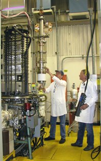 )
)
-
Title: Re: EM Drive Developments - related to space flight applications - Thread 3
Post by: deltaMass on 07/15/2015 08:35 PM -
<a href="http://forum.nasaspaceflight.com/index.php?topic=37642.msg1404961#msg1404961">Quote from: SeeShells on 07/15/2015 02:17 PM</a>
Oxen ye shall receive :P<a href="http://forum.nasaspaceflight.com/index.php?topic=37642.msg1404914#msg1404914">Quote from: deltaMass on 07/15/2015 11:10 AM</a>First, locate your eggs 8)
This is a Yoke, right? -
Title: Re: EM Drive Developments - related to space flight applications - Thread 3
Post by: Notsosureofit on 07/15/2015 08:43 PM -
FYI:
http://www.huffingtonpost.com/benjamin-t-solomon/a-propellantless-propulsi_b_7718408.html
-
Title: Re: EM Drive Developments - related to space flight applications - Thread 3
Post by: Tron on 07/15/2015 09:22 PM -
Sorry for interrupting, but there are a couple things that puzzle me. I don't think I'll post much or at all after this, since the thread is so active and I don't have the energy to keep up with it continuously.
First, I don't quite understand the discussion about how wave behave in a waveguide, when we're not dealing with waveguides; the frustrum is a not (just) that but a resonant chamber. This means the radiation inside should form standing waves, with their nodes where the field is always zero, and whatnot, am I correct?
I've been looking at several sources, but they confirm that, if we have a standing wave the phase velocity is zero and group velocity is infinite. I can't tell who's right, but either the resonant chamber should not move at all, or resonant chambers should all explode the instant you put some energy in them, depending on who's right.
Second, the talk about conservation of energy got entangled in relativity, and the reason confuses me. Could we agree to discuss scenarios where v<<c so gamma is close to 1? This way we can use classical mechanics and not get needlessly bogged down on einstenian paradoxes while imultaneously recognizing that al inertial reference frames should be equivalent. Not that you need relativity for that, since equivalence under Galilean transformations has been part of classical mechanics for a very long time. -
Title: Re: EM Drive Developments - related to space flight applications - Thread 3
Post by: Star One on 07/15/2015 09:24 PM -
<a href="http://forum.nasaspaceflight.com/index.php?topic=37642.msg1405180#msg1405180">Quote from: Notsosureofit on 07/15/2015 08:43 PM</a>
FYI:
http://www.huffingtonpost.com/benjamin-t-solomon/a-propellantless-propulsi_b_7718408.html
Well New Horizons has shown if you really want to completely study somewhere like Pluto you're going to need a much quicker way to get there. -
Title: Re: EM Drive Developments - related to space flight applications - Thread 3
Post by: deltaMass on 07/15/2015 09:26 PM -
A comment about conservation. That might come as a surprise to some here, since I almost never talk about that.
Let's think about the battery, and its associated parameters Ein and Pin.
Let's imagine some propellantless drive under battery power, undergoing two scenarios:
1. Drive clamped to the lab frame and so constrained from moving while battery gives rise to a thrust.
2. Drive accelerates for some time (severely subrelativistically at all times), and then the battery power is switched off, leaving it coasting. We apply an external force to decelerate the "dead" drive to a full stop.
In both cases we aim to consume the same fraction f of the total battery power.
We can make a measurement for both scenarios in the lab frame.
Does that imply that this is the same thing as switching both drives on for the same amount of time?
What does it mean to measure the energy of a moving battery in the lab frame?
To guide your thinking on these questions, here's something you might not know about energy transformation between two inertial frames. It is not as simple as you might imagine. It goes like this, per Newton, and describes how kinetic energy changes transform:
dE1 = dE0 + m dv deltaV
where
m is the mass of the object possessing kinetic energy
deltaV is the change in velocity of the object in the rest frame (frame 0)
dv is the component of the relative velocity of the frames along the direction of kinetic motion
You can prove this quite simply using a small amount of algebra. I will if you want me to.
-
Title: Re: EM Drive Developments - related to space flight applications - Thread 3
Post by: deltaMass on 07/15/2015 09:32 PM -
<a href="http://forum.nasaspaceflight.com/index.php?topic=37642.msg1405197#msg1405197">Quote from: Tron on 07/15/2015 09:22 PM</a>
[snip..] the talk about conservation of energy got entangled in relativity, and the reason confuses me. Could we agree to discuss scenarios where v<<c so gamma is close to 1? This way we can use classical mechanics and not get needlessly bogged down on einstenian paradoxes while imultaneously recognizing that al inertial reference frames should be equivalent. Not that you need relativity for that, since equivalence under Galilean transformations has been part of classical mechanics for a very long time.
You can thank @WarpTech for that. He continually obfuscates what is clearly a problem in strictly classical mechanics with his gammas, gravity references, black holes, rest energies and metric tensor components. I for one am sick of it. -
Title: Re: EM Drive Developments - related to space flight applications - Thread 3
Post by: LasJayhawk on 07/15/2015 10:43 PM -
The transmitter at Arecibo is 1 megawatt at 2.3 GHz CW.
It was built by Continential Electronics out of Texas, I'm sure if you have the money, they will make whatever you want. -
Title: Re: EM Drive Developments - related to space flight applications - Thread 3
Post by: deltaMass on 07/15/2015 11:12 PM -
<a href="http://forum.nasaspaceflight.com/index.php?topic=37642.msg1405266#msg1405266">Quote from: LasJayhawk on 07/15/2015 10:43 PM</a>
The transmitter at Arecibo is 1 megawatt at 2.3 GHz CW.
Wikipedia says
It was built by Continential Electronics out of Texas, I'm sure if you have the money, they will make whatever you want.QuoteThe Arecibo Radio Telescope has three radar transmitters, with effective isotropic radiated powers of 20 TW at 2380 MHz, 2.5 TW (pulse peak) at 430 MHz, and 300 MW at 47 MHz.
Conflict? -
Title: Re: EM Drive Developments - related to space flight applications - Thread 3
Post by: rfmwguy on 07/15/2015 11:27 PM -
<a href="http://forum.nasaspaceflight.com/index.php?topic=37642.msg1405210#msg1405210">Quote from: deltaMass on 07/15/2015 09:32 PM</a>
There is an imbalance in the cosmos which classical physics has failed to resolve. Gravity and its antithesis; a counterbalance to the only known force without a repulsive state. While I surmise em radiation has a counterbalance for CoE and may not directly produce thrust, gravity has zero, zip, nada CoE. This leaves us an opening to explore. Definition of this force is still in the "duh" phase. While I think no new physics are needed to resolve it, it remains unresolved because an old master failed to grasp it. So try this one for size; gravity is weak and extends to a cosmic scale. For every instance of gravity, a weak cosmic force equal to it is created. Failure to accept this theory leads to the opposite of what the universe is doing right now. So DM, time to define this force...perhaps its the only real explanation for what people are reporting. c'mon dm, you can do it! ;)<a href="http://forum.nasaspaceflight.com/index.php?topic=37642.msg1405197#msg1405197">Quote from: Tron on 07/15/2015 09:22 PM</a>[snip..] the talk about conservation of energy got entangled in relativity, and the reason confuses me. Could we agree to discuss scenarios where v<<c so gamma is close to 1? This way we can use classical mechanics and not get needlessly bogged down on einstenian paradoxes while imultaneously recognizing that al inertial reference frames should be equivalent. Not that you need relativity for that, since equivalence under Galilean transformations has been part of classical mechanics for a very long time.
You can thank @WarpTech for that. He continually obfuscates what is clearly a problem in strictly classical mechanics with his gammas, gravity references, black holes, rest energies and metric tensor components. I for one am sick of it.
I'll even get you started
g = GM/r2
Write its equivalent opposite equation. Forget that 5th force thing
https://en.m.wikipedia.org/wiki/Fifth_force
(Crickets)
x = r2/GM
x is worth thinking about 8) -
Title: Re: EM Drive Developments - related to space flight applications - Thread 3
Post by: ElizabethGreene on 07/15/2015 11:30 PM -
<a href="http://forum.nasaspaceflight.com/index.php?topic=37642.msg1405170#msg1405170">Quote from: flux_capacitor on 07/15/2015 08:24 PM</a>
I was very wrong, thank you for the correction. Klystrons appear to beat Gyrotrons by a wide margin at cm frequencies. Gyrotrons only come into their own in the mm range. Learned.<a href="http://forum.nasaspaceflight.com/index.php?topic=37642.msg1405083#msg1405083">Quote from: ElizabethGreene on 07/15/2015 06:00 PM</a>The largest microwave sources I found were Gyrotrons. ...
Along gyrotrons, the most powerful manmade source of microwaves are klystrons. SLAC (https://en.wikipedia.org/wiki/SLAC_National_Accelerator_Laboratory) uses 150 megawatts (pulsed) S-band (3GHz) klystrons (http://www.slac.stanford.edu/cgi-wrap/getdoc/slac-pub-7232.pdf) and 1.25 MW CW klystrons!<a href="http://forum.nasaspaceflight.com/index.php?topic=37642.msg1405170#msg1405170">Quote from: flux_capacitor on 07/15/2015 08:24 PM</a>But we don't wand to ignite the plasma of a tokamak or power a particle accelerator, and we're not quite yet feeding lift engines of a mothership.
Particle accelerator? Sounds like an excellent plan. I could use one* when we get the emDrive mothership in orbit.
* In my idea book I have a sketch of a unique nuclear reactor. It uses an accelerator to fire high energy electrons into a Tungsten target that fires high energy protons into Thorium and Beryllium fuel rods. Be + 1.5 MeV photon = 1 neutron + 2 4He... 4Be + n = 2 4 2He + 2n ... 4Be + 4 2He = 12 6C + n ... Thorium + n = U233. U233 Fission = Power for the mothership.
This is the only nuclear reactor I know of that a.) can be bought/built by Greene on the street and b.) you can turn on, i.e. make hot, once you are in orbit and safely out of the purview of NEST, the IAEA, etc. Until you set it off the components are safe**.
** Ok, you aren't going to put Beryllium in your kids crayons, but it's still "safe" compared to your average nuclear reactor fuel rod.
*** I don't know if this works from a neutron economy POV, It's just another idea in the book until I do that research. The EmDrive comes first. -
Title: Re: EM Drive Developments - related to space flight applications - Thread 3
Post by: Eer on 07/15/2015 11:38 PM -
<a href="http://forum.nasaspaceflight.com/index.php?topic=37642.msg1404977#msg1404977">Quote from: leomillert on 07/15/2015 02:55 PM</a>
How to help scientists gather data and study the EMDrive, even if you are an absolute novice.
If you are excited about the EMDrive and wants to contribute to its research, but don't know how, this is a step-by-step guide that if performed correctly by anyone out there interested in helping would provide valuable information for the scientists to study and better understand the EMDrive behavior.
1. Install MEEP http://ab-initio.mit.edu/wiki/index.php/Meep (preferably from your package manager)
2. Download https://forum.nasaspaceflight.com/index.php?action=dlattach;topic=37642.0;attach=1042821 and rename it to NSF-1701.ctl
3. meep NSF-1701.ctl
4. Eventually, MEEP will output nine .h5 files. It may take a long time depending on your computer. Patience is a virtue.
5. h5totxt -t 13 -0 -y -0 ex.h5 > zCopper-exy.csv
6. Open your zCopper-exy.csv on a spread sheet and aero's zCopper-exy.csv on another. Open a third spread sheet that is one spread sheet minus the other, entry by entry. Check that highest entry (in absolute value). If it's negligible you are good to go. If it's a value too big, greater than 10^-6, your MEEP installation isn't in sync with ours, so it's no use.
7. Now you are good to go. Make a new directory to start the tests. Copy NSF-1701.ctl there.
8. Open NSF-1701.ctl in a text editor and change a single value. For example, (set! high 10.2) means the model is 10.2 inches high. Change the 10.2 to another value and save NSF-1701.ctl with this single change. This is called sensitivity analysis. One value at a time. (set! high 10.2) was just an example, change any value of interest
9. meep NSF-1701.ctl
10. h5totxt -t 13 -0 -y -0 ex.h5 > zCopper-exy.csv
11. Compare your new zCopper-exy.csv with your old one. See if there was any relevant change (do the spreadsheet comparison again). If there was no considerable change in values, it means the modification made doesn't impact the behavior of the EMDrive. This is an important information for scientists, so let us know. Otherwise, if there was a significant change, let us know if it was positive or negative and its intensity. If you don't know how, just upload the .h5 files somewhere and we will analyze it.
FYI, I've begun down this path. Gave up trying to get RPM packages with all the right versions to work together, and installed Debian 8. Am running on a dual quad-core Xeon in VMware, allocated 2 processors x 2 cores each, but I see it's only really using 1 cpu (which is maxed out, purely user space cpu time as expected). 6GB memory allocated, but it's only using a shade more than 3GB for the meep process. Have not investigated the MPI alternatives, as I think those are more intended for clusters than symmetric multiprocessors.
It's presently up to step 1339 of its first run through NSF-1701.ctl. Has about 57 min of cputime so far. 3 *.h5 files produced so far.
I'll work my way through your steps above and report results when I have them. -
Title: Re: EM Drive Developments - related to space flight applications - Thread 3
Post by: rfmwguy on 07/16/2015 12:35 AM -
<a href="http://forum.nasaspaceflight.com/index.php?topic=37642.msg1404433#msg1404433">Quote from: rfmwguy on 07/14/2015 04:27 PM</a><a href="http://forum.nasaspaceflight.com/index.php?topic=37642.msg1404427#msg1404427">Quote from: aero on 07/14/2015 04:11 PM</a>
Yep, which it never ceases to amaze me that we are trying to illuminate the solar system with a match. Goddard and Von Braun had their day, time to take the next step. Sounds crazy, but if I were a billionaire that really wanted to leave a scientific legacy, here's what I would do:<a href="http://forum.nasaspaceflight.com/index.php?topic=37642.msg1404305#msg1404305">Quote from: rfmwguy on 07/14/2015 01:06 PM</a>Congrats New Horizons team, very impressed...the best media question I heard was "when are we going back?" The answer was interesting, there are designs being worked on.
IMHO, the key for planetary science and space exploration success is becoming clear. It is not more sensitive instrumentation, it is not lower cost hardware...it is faster propulsion. This is your challenge scientific community...to shrink the fabric of space and time with modern propulsion research.
To the propulsion industry...think outside the box. Your equations have shown us that propellants will never get us to where we want to go...faster and farther. Perhaps in this forum, one of us may help show you the way.
In case you are wondering, Space is big. Here is a "to scale" map of the solar system with the moon diameter as the scale length of one pixel. http://joshworth.com/dev/pixelspace/pixelspace_solarsystem.html (http://joshworth.com/dev/pixelspace/pixelspace_solarsystem.html) No wonder it takes so much time to get anywhere.
Offer a $250M prize to a winner of a race. The race would be:
From LEO to 2AU...shortest time to get there wins.
Let them use gravity assist, chemical propellants, ion engines, floobie dust (hat-tip deltamass), its a simple time and speed calculation. Limit total mass to lets say a few hundred kg just to make it interesting.
Once qualified, Mr Billionaire pays for standardized ride to LEO and a standardized telemetry pack to be built in. Time begins at release. Releases can be sequential. Window of release: 2 years.
Now, there's something outside the box for all those X prize types out there. Call it the Galactic 500 (only because I'm from Indy). ;)
Hey...no fair...this guy needs to credit me ;)
http://www.huffingtonpost.com/benjamin-t-solomon/a-propellantless-propulsi_b_7718408.html -
Title: Re: EM Drive Developments - related to space flight applications - Thread 3
Post by: TheTraveller on 07/16/2015 12:52 AM -
<a href="http://forum.nasaspaceflight.com/index.php?topic=37642.msg1405197#msg1405197">Quote from: Tron on 07/15/2015 09:22 PM</a>
Sorry for interrupting, but there are a couple things that puzzle me. I don't think I'll post much or at all after this, since the thread is so active and I don't have the energy to keep up with it continuously.
First, I don't quite understand the discussion about how wave behave in a waveguide, when we're not dealing with waveguides; the frustrum is a not (just) that but a resonant chamber. This means the radiation inside should form standing waves, with their nodes where the field is always zero, and whatnot, am I correct?
I've been looking at several sources, but they confirm that, if we have a standing wave the phase velocity is zero and group velocity is infinite. I can't tell who's right, but either the resonant chamber should not move at all, or resonant chambers should all explode the instant you put some energy in them, depending on who's right.
Second, the talk about conservation of energy got entangled in relativity, and the reason confuses me. Could we agree to discuss scenarios where v<<c so gamma is close to 1? This way we can use classical mechanics and not get needlessly bogged down on einstenian paradoxes while imultaneously recognizing that al inertial reference frames should be equivalent. Not that you need relativity for that, since equivalence under Galilean transformations has been part of classical mechanics for a very long time.
A frustum is 1st a tapered microwave waveguide that is closed at each end. The EM waves inside behave as per known microwave waveguide physics.
Continuously variable Guide Wavelength/Group Velocity EM waves are bouncing from end to end. EM waves don't stand still. They can't. -
Title: Re: EM Drive Developments - related to space flight applications - Thread 3
Post by: TheTraveller on 07/16/2015 01:00 AM -
<a href="http://forum.nasaspaceflight.com/index.php?topic=37642.msg1405095#msg1405095">Quote from: Rodal on 07/15/2015 06:51 PM</a>
Length of Dipole Antenna modeled: 0.058 m
We can calculate the free-space wavelength as: λ = c / frequency
Taking the frequency to be 2.45 GHz (as per @rfmwguy's model) then λ = c / frequency = 0.122364 m
Therefore the ratio of the dipole antenna length L to the wavelength λ is:
L / λ = 0.058 m/0.122364 m
= 0.4740
The internal Guide Waveguide, inside the cavity, is what you need to based your antenna length on. Not the external wavelength. Then as the waveguide is tapered, you need to calc the Guide Wavelength at the point of side wall insertion diameter. BTW you only need a 1/4 wave antenna (at the selected Guide Wavelength) with the outer shield connected to the side wall. -
Title: Re: EM Drive Developments - related to space flight applications - Thread 3
Post by: deltaMass on 07/16/2015 01:20 AM -
<a href="http://forum.nasaspaceflight.com/index.php?topic=37642.msg1405312#msg1405312">Quote from: TheTraveller on 07/16/2015 01:04 AM</a>
vgroup + vphase = 2*c<a href="http://forum.nasaspaceflight.com/index.php?topic=37642.msg1405090#msg1405090">Quote from: ElizabethGreene on 07/15/2015 06:18 PM</a><a href="http://forum.nasaspaceflight.com/index.php?topic=37642.msg1405087#msg1405087">Quote from: TheTraveller on 07/15/2015 06:04 PM</a>So forget about Phase Velocity when dealing with EM waves inside a waveguide.
I've yet to find any use for the Phase Velocity. I had a brief thought that obscene >> c values might cause some issues due to charges or magnetic fields being unable to rearrange fast enough in the material, but I intuit that should cause localized heating, not thrust.
Phase Velocity, inside a waveguide, is above c and is imaginary.
http://www.microwaves101.com/encyclopedias/waveguide-mathematics#velocity
Any reference or belief that anything inside a waveguide travels at Phase Velocity (greater than c) is just plain wrong and a failure to understand basic microwave waveguide engineering and physics.
was the physics you posted here a couple of days ago.
Now here you are laying down the law like a distinguished and irascible professor.
;D ::)
-
Title: Re: EM Drive Developments - related to space flight applications - Thread 3
Post by: apoc2021 on 07/16/2015 01:38 AM -
<a href="http://forum.nasaspaceflight.com/index.php?topic=37642.msg1405078#msg1405078">Quote from: WarpTech on 07/15/2015 05:46 PM</a>
However, after yesterdays misunderstanding, revelation and embarrassment. I am still trying to put all the pieces back together in a comprehendible way.
Embarrassment - are you kidding? You are one of the most courageous people I know, and one of few here. You are hurling decades of learning and practical experience at a difficult, ambiguous problem, in full view of the public and without a shroud of anonymity, despite knowing the possibility of being wrong and despite knowing that [at times impolite] reviewers are waiting for a misstep. You know going into it that you might err, and whenever you do you publicly take ownership of the mistake and detail how and why you were wrong. And then you go right back to working on it again!
Please - and you don't need to hear this from me, but - just keep going. If everyone who was capable simply did what you do routinely, our society might be much closer to cracking this right now.
So let me just take the opportunity to say thanks. And kids, if you're reading, know that this man Todd is a man of courage! -
Title: Re: EM Drive Developments - related to space flight applications - Thread 3
Post by: WarpTech on 07/16/2015 01:49 AM -
<a href="http://forum.nasaspaceflight.com/index.php?topic=37642.msg1405276#msg1405276">Quote from: rfmwguy on 07/15/2015 11:27 PM</a>
...
There is an imbalance in the cosmos which classical physics has failed to resolve. Gravity and its antithesis; a counterbalance to the only known force without a repulsive state. While I surmise em radiation has a counterbalance for CoE and may not directly produce thrust, gravity has zero, zip, nada CoE. This leaves us an opening to explore. Definition of this force is still in the "duh" phase. While I think no new physics are needed to resolve it, it remains unresolved because an old master failed to grasp it. So try this one for size; gravity is weak and extends to a cosmic scale. For every instance of gravity, a weak cosmic force equal to it is created. Failure to accept this theory leads to the opposite of what the universe is doing right now. So DM, time to define this force...perhaps its the only real explanation for what people are reporting. c'mon dm, you can do it! ;)
I'll even get you started
g = GM/r2
Write its equivalent opposite equation. Forget that 5th force thing
https://en.m.wikipedia.org/wiki/Fifth_force
(Crickets)
x = r2/GM
x is worth thinking about 8)
The "balance" or symmetry of gravity is that for any quantum harmonic oscillator in it's ground state, the power radiated by the oscillator TO the ZPF is equal to the power absorbed by the oscillator FROM the ZPF.
Gravity depends on gradient in the available power of the ZPF. Particles "contract" as they fall toward the CM and into a gravity well. They also "inflate" or expand when they move away from the CM. So gravity is a lack of available power in the ZPF, and its opposite would be an increase in available power of the ZPF. Like inflating a balloon with ZPF energy. This is "exotic matter", the opposite of gravity.
Todd -
Title: Re: EM Drive Developments - related to space flight applications - Thread 3
Post by: aero on 07/16/2015 01:53 AM -
<a href="http://forum.nasaspaceflight.com/index.php?topic=37642.msg1405281#msg1405281">Quote from: Eer on 07/15/2015 11:38 PM</a><a href="http://forum.nasaspaceflight.com/index.php?topic=37642.msg1404977#msg1404977">Quote from: leomillert on 07/15/2015 02:55 PM</a>
How to help scientists gather data and study the EMDrive, even if you are an absolute novice.
If you are excited about the EMDrive and wants to contribute to its research, but don't know how, this is a step-by-step guide that if performed correctly by anyone out there interested in helping would provide valuable information for the scientists to study and better understand the EMDrive behavior.
1. Install MEEP http://ab-initio.mit.edu/wiki/index.php/Meep (preferably from your package manager)
2. Download https://forum.nasaspaceflight.com/index.php?action=dlattach;topic=37642.0;attach=1042821 and rename it to NSF-1701.ctl
3. meep NSF-1701.ctl
4. Eventually, MEEP will output nine .h5 files. It may take a long time depending on your computer. Patience is a virtue.
5. h5totxt -t 13 -0 -y -0 ex.h5 > zCopper-exy.csv
6. Open your zCopper-exy.csv on a spread sheet and aero's zCopper-exy.csv on another. Open a third spread sheet that is one spread sheet minus the other, entry by entry. Check that highest entry (in absolute value). If it's negligible you are good to go. If it's a value too big, greater than 10^-6, your MEEP installation isn't in sync with ours, so it's no use.
7. Now you are good to go. Make a new directory to start the tests. Copy NSF-1701.ctl there.
8. Open NSF-1701.ctl in a text editor and change a single value. For example, (set! high 10.2) means the model is 10.2 inches high. Change the 10.2 to another value and save NSF-1701.ctl with this single change. This is called sensitivity analysis. One value at a time. (set! high 10.2) was just an example, change any value of interest
9. meep NSF-1701.ctl
10. h5totxt -t 13 -0 -y -0 ex.h5 > zCopper-exy.csv
11. Compare your new zCopper-exy.csv with your old one. See if there was any relevant change (do the spreadsheet comparison again). If there was no considerable change in values, it means the modification made doesn't impact the behavior of the EMDrive. This is an important information for scientists, so let us know. Otherwise, if there was a significant change, let us know if it was positive or negative and its intensity. If you don't know how, just upload the .h5 files somewhere and we will analyze it.
FYI, I've begun down this path. Gave up trying to get RPM packages with all the right versions to work together, and installed Debian 8. Am running on a dual quad-core Xeon in VMware, allocated 2 processors x 2 cores each, but I see it's only really using 1 cpu (which is maxed out, purely user space cpu time as expected). 6GB memory allocated, but it's only using a shade more than 3GB for the meep process. Have not investigated the MPI alternatives, as I think those are more intended for clusters than symmetric multiprocessors.
It's presently up to step 1339 of its first run through NSF-1701.ctl. Has about 57 min of cputime so far. 3 *.h5 files produced so far.
I'll work my way through your steps above and report results when I have them.
You need MPI in order to make use of more than one core. You seem to be running serially on one cpu and it is taking a long time. Allocating 2 processors is quite adequate for the NSF-1701 problem, it is not so large as to benefit from more than 2 processors, (a little benefit, but very little). But without MPI, meep can't work with the second processor. I run that problem, all 6527 timesteps, in 1 hr. 33.9 minutes (5635.3 seconds) on my AMD Phenom quad core. (2.9 GHz).
Xeon in VMware - Your Xeon is very likely a better processor than mine, and as I understand it, the virtual box imposes surprisingly little overhead for this problem. I urge you to take the step of installing Open MPI or MPICH, MIT's version of MPI. You will be rewarded by significantly better run time. It won't cut the run time in half, but it will reduce it a lot. -
Title: Re: EM Drive Developments - related to space flight applications - Thread 3
Post by: cuddihy on 07/16/2015 01:55 AM -
<a href="http://forum.nasaspaceflight.com/index.php?topic=37642.msg1405277#msg1405277">Quote from: ElizabethGreene on 07/15/2015 11:30 PM</a>
I could see how it would work from a neutron economy, you could probably get the geometry needed...once. As soon as neutrons start producing lots of hot Helium and irradiated Carbon though, the matrix will expand rapidly and the He will cause leaks.
* In my idea book I have a sketch of a unique nuclear reactor. It uses an accelerator to fire high energy electrons into a Tungsten target that fires high energy protons into Thorium and Beryllium fuel rods. Be + 1.5 MeV photon = 1 neutron + 2 4He... 4Be + n = 2 4 2He + 2n ... 4Be + 4 2He = 12 6C + n ... Thorium + n = U233. U233 Fission = Power for the mothership.
This is the only nuclear reactor I know of that a.) can be bought/built by Greene on the street and b.) you can turn on, i.e. make hot, once you are in orbit and safely out of the purview of NEST, the IAEA, etc. Until you set it off the components are safe**.
** Ok, you aren't going to put Beryllium in your kids crayons, but it's still "safe" compared to your average nuclear reactor fuel rod.
*** I don't know if this works from a neutron economy POV, It's just another idea in the book until I do that research. The EmDrive comes first.
That's what my nuclear gut says ;-) -
Title: Re: EM Drive Developments - related to space flight applications - Thread 3
Post by: Eer on 07/16/2015 02:01 AM -
<a href="http://forum.nasaspaceflight.com/index.php?topic=37642.msg1405325#msg1405325">Quote from: aero on 07/16/2015 01:53 AM</a><a href="http://forum.nasaspaceflight.com/index.php?topic=37642.msg1405281#msg1405281">Quote from: Eer on 07/15/2015 11:38 PM</a><a href="http://forum.nasaspaceflight.com/index.php?topic=37642.msg1404977#msg1404977">Quote from: leomillert on 07/15/2015 02:55 PM</a>
How to help scientists gather data and study the EMDrive, even if you are an absolute novice.
If you are excited about the EMDrive and wants to contribute to its research, but don't know how, this is a step-by-step guide that if performed correctly by anyone out there interested in helping would provide valuable information for the scientists to study and better understand the EMDrive behavior.
1. Install MEEP http://ab-initio.mit.edu/wiki/index.php/Meep (preferably from your package manager)
2. Download https://forum.nasaspaceflight.com/index.php?action=dlattach;topic=37642.0;attach=1042821 and rename it to NSF-1701.ctl
3. meep NSF-1701.ctl
4. Eventually, MEEP will output nine .h5 files. It may take a long time depending on your computer. Patience is a virtue.
5. h5totxt -t 13 -0 -y -0 ex.h5 > zCopper-exy.csv
6. Open your zCopper-exy.csv on a spread sheet and aero's zCopper-exy.csv on another. Open a third spread sheet that is one spread sheet minus the other, entry by entry. Check that highest entry (in absolute value). If it's negligible you are good to go. If it's a value too big, greater than 10^-6, your MEEP installation isn't in sync with ours, so it's no use.
...
FYI, I've begun down this path. Gave up trying to get RPM packages with all the right versions to work together, and installed Debian 8. Am running on a dual quad-core Xeon in VMware, allocated 2 processors x 2 cores each, but I see it's only really using 1 cpu (which is maxed out, purely user space cpu time as expected). 6GB memory allocated, but it's only using a shade more than 3GB for the meep process. Have not investigated the MPI alternatives, as I think those are more intended for clusters than symmetric multiprocessors.
It's presently up to step 1339 of its first run through NSF-1701.ctl. Has about 57 min of cputime so far. 3 *.h5 files produced so far.
I'll work my way through your steps above and report results when I have them.
You need MPI in order to make use of more than one core. You seem to be running serially on one cpu and it is taking a long time. Allocating 2 processors is quite adequate for the NSF-1701 problem, it is not so large as to benefit from more than 2 processors, (a little benefit, but very little). But without MPI, meep can't work with the second processor. I run that problem, all 6527 timesteps, in 1 hr. 33.9 minutes (5635.3 seconds) on my AMD Phenom quad core. (2.9 GHz).
Xeon in VMware - Your Xeon is very likely a better processor than mine, and as I understand it, the virtual box imposes surprisingly little overhead for this problem. I urge you to take the step of installing Open MPI or MPICH, MIT's version of MPI. You will be rewarded by significantly better run time. It won't cut the run time in half, but it will reduce it a lot.
Indeed - I'll do so. Run just completed and it took quite a while serialized to one CPU, as you said.
And, having run the comparison, we're out of sync. I used the apt-get install meep approach, and evidently that's in adequate.
I'll next turn my attention to reviewing the recompilation of everything (hmph) and will try to reproduce the reference csv with small error across all cells before moving on to trying to get an MPI version that also matches closely.
Thanks,
Ed -
Title: Re: EM Drive Developments - related to space flight applications - Thread 3
Post by: rfmwguy on 07/16/2015 02:15 AM -
<a href="http://forum.nasaspaceflight.com/index.php?topic=37642.msg1405323#msg1405323">Quote from: WarpTech on 07/16/2015 01:49 AM</a>
So we have someone willing to address this classical question. Well done warptech. Let's explore how we can invoke an imbalance between g and x. You may do this far quicker than my synapses fire. Here's why I say this, its what I expect to have left over after eliminating other possibilities. Its the missing link of GUT...giving away some working theories of mine, if thrust appears, I predict it will differ towards and away from a gravitational source. Interested? Hope so...its a hot potato subject you know.<a href="http://forum.nasaspaceflight.com/index.php?topic=37642.msg1405276#msg1405276">Quote from: rfmwguy on 07/15/2015 11:27 PM</a>...
There is an imbalance in the cosmos which classical physics has failed to resolve. Gravity and its antithesis; a counterbalance to the only known force without a repulsive state. While I surmise em radiation has a counterbalance for CoE and may not directly produce thrust, gravity has zero, zip, nada CoE. This leaves us an opening to explore. Definition of this force is still in the "duh" phase. While I think no new physics are needed to resolve it, it remains unresolved because an old master failed to grasp it. So try this one for size; gravity is weak and extends to a cosmic scale. For every instance of gravity, a weak cosmic force equal to it is created. Failure to accept this theory leads to the opposite of what the universe is doing right now. So DM, time to define this force...perhaps its the only real explanation for what people are reporting. c'mon dm, you can do it! ;)
I'll even get you started
g = GM/r2
Write its equivalent opposite equation. Forget that 5th force thing
https://en.m.wikipedia.org/wiki/Fifth_force
(Crickets)
x = r2/GM
x is worth thinking about 8)
The "balance" or symmetry of gravity is that for any quantum harmonic oscillator in it's ground state, the power radiated by the oscillator TO the ZPF is equal to the power absorbed by the oscillator FROM the ZPF.
Gravity depends on gradient in the available power of the ZPF. Particles "contract" as they fall toward the CM and into a gravity well. They also "inflate" or expand when they move away from the CM. So gravity is a lack of available power in the ZPF, and its opposite would be an increase in available power of the ZPF. Like inflating a balloon with ZPF energy. This is "exotic matter", the opposite of gravity.
Todd -
Title: Re: EM Drive Developments - related to space flight applications - Thread 3
Post by: Notsosureofit on 07/16/2015 02:26 AM -
<a href="http://forum.nasaspaceflight.com/index.php?topic=37642.msg1405333#msg1405333">Quote from: rfmwguy on 07/16/2015 02:15 AM</a>
Its the missing link of GUT...giving away some working theories of mine, if thrust appears, I predict it will differ towards and away from a gravitational source. Interested? Hope so...its a hot potato subject you know.
I would have to agree, the gravitational dispersion would add or subtract with the direction of the cavity.
-
Title: Re: EM Drive Developments - related to space flight applications - Thread 3
Post by: WarpTech on 07/16/2015 02:33 AM -
<a href="http://forum.nasaspaceflight.com/index.php?topic=37642.msg1405312#msg1405312">Quote from: TheTraveller on 07/16/2015 01:04 AM</a><a href="http://forum.nasaspaceflight.com/index.php?topic=37642.msg1405090#msg1405090">Quote from: ElizabethGreene on 07/15/2015 06:18 PM</a><a href="http://forum.nasaspaceflight.com/index.php?topic=37642.msg1405087#msg1405087">Quote from: TheTraveller on 07/15/2015 06:04 PM</a>
So forget about Phase Velocity when dealing with EM waves inside a waveguide.
I've yet to find any use for the Phase Velocity. I had a brief thought that obscene >> c values might cause some issues due to charges or magnetic fields being unable to rearrange fast enough in the material, but I intuit that should cause localized heating, not thrust.
Phase Velocity, inside a waveguide, is above c and is imaginary.
http://www.microwaves101.com/encyclopedias/waveguide-mathematics#velocity
Any reference or belief that anything inside a waveguide travels at Phase Velocity (greater than c) is just plain wrong and a failure to understand basic microwave waveguide engineering and physics.
TT, I think you resolved my confusion anyway. From Cullen, you posted,
F = (2*P/c)*(λo/λg),
You also posted,
λg = λo/sqrt(1 - (λo/λc)2),
and
vg = c*sqrt(1 - (λo/λc)2),
Substituting these into the force equation gives,
F = 2*P*vg/c2,
which gives 2*P/vp, or F*vp = 2*P,
In other words, it is the rocket equation, "the same" as it is for matter, not different as I was thinking it was. What is different is that dw/dk =/= dE/dp but rather E/p, and that still perplexes me.
Todd -
Title: Re: EM Drive Developments - related to space flight applications - Thread 3
Post by: deltaMass on 07/16/2015 02:46 AM -
So
F = 2*P / vphase
which is what I posted about a week ago
http://physics.stackexchange.com/questions/190018/does-radiation-force-depend-on-group-velocity-or-on-phase-velocity
Glad we all agree. -
Title: Re: EM Drive Developments - related to space flight applications - Thread 3
Post by: deltaMass on 07/16/2015 02:48 AM -
<a href="http://forum.nasaspaceflight.com/index.php?topic=37642.msg1405337#msg1405337">Quote from: Notsosureofit on 07/16/2015 02:26 AM</a>
I am curious as to where you intend to get a "good supply" of gravity (or of its gradient or indeed of the curl of its potential ;) ) when navigating in deep space?<a href="http://forum.nasaspaceflight.com/index.php?topic=37642.msg1405333#msg1405333">Quote from: rfmwguy on 07/16/2015 02:15 AM</a>Its the missing link of GUT...giving away some working theories of mine, if thrust appears, I predict it will differ towards and away from a gravitational source. Interested? Hope so...its a hot potato subject you know.
I would have to agree, the gravitational dispersion would add or subtract with the direction of the cavity. -
Title: Re: EM Drive Developments - related to space flight applications - Thread 3
Post by: LasJayhawk on 07/16/2015 02:54 AM -
<a href="http://forum.nasaspaceflight.com/index.php?topic=37642.msg1405271#msg1405271">Quote from: deltaMass on 07/15/2015 11:12 PM</a>
Antenna gain is over 70dB giving an ERP in the 20 terra watt range. The S band transmitter itself is 1 MW give or take a few watts :) 2380 may be nominal frequency, I just remember it was around the frequency of a microwave oven magnatron.<a href="http://forum.nasaspaceflight.com/index.php?topic=37642.msg1405266#msg1405266">Quote from: LasJayhawk on 07/15/2015 10:43 PM</a>The transmitter at Arecibo is 1 megawatt at 2.3 GHz CW.
Wikipedia says
It was built by Continential Electronics out of Texas, I'm sure if you have the money, they will make whatever you want.QuoteThe Arecibo Radio Telescope has three radar transmitters, with effective isotropic radiated powers of 20 TW at 2380 MHz, 2.5 TW (pulse peak) at 430 MHz, and 300 MW at 47 MHz.
Conflict? -
Title: Re: EM Drive Developments - related to space flight applications - Thread 3
Post by: WarpTech on 07/16/2015 03:01 AM -
<a href="http://forum.nasaspaceflight.com/index.php?topic=37642.msg1405333#msg1405333">Quote from: rfmwguy on 07/16/2015 02:15 AM</a><a href="http://forum.nasaspaceflight.com/index.php?topic=37642.msg1405323#msg1405323">Quote from: WarpTech on 07/16/2015 01:49 AM</a>
So we have someone willing to address this classical question. Well done warptech. Let's explore how we can invoke an imbalance between g and x. You may do this far quicker than my synapses fire. Here's why I say this, its what I expect to have left over after eliminating other possibilities. Its the missing link of GUT...giving away some working theories of mine, if thrust appears, I predict it will differ towards and away from a gravitational source. Interested? Hope so...its a hot potato subject you know.<a href="http://forum.nasaspaceflight.com/index.php?topic=37642.msg1405276#msg1405276">Quote from: rfmwguy on 07/15/2015 11:27 PM</a>...
There is an imbalance in the cosmos which classical physics has failed to resolve. Gravity and its antithesis; a counterbalance to the only known force without a repulsive state. While I surmise em radiation has a counterbalance for CoE and may not directly produce thrust, gravity has zero, zip, nada CoE. This leaves us an opening to explore. Definition of this force is still in the "duh" phase. While I think no new physics are needed to resolve it, it remains unresolved because an old master failed to grasp it. So try this one for size; gravity is weak and extends to a cosmic scale. For every instance of gravity, a weak cosmic force equal to it is created. Failure to accept this theory leads to the opposite of what the universe is doing right now. So DM, time to define this force...perhaps its the only real explanation for what people are reporting. c'mon dm, you can do it! ;)
I'll even get you started
g = GM/r2
Write its equivalent opposite equation. Forget that 5th force thing
https://en.m.wikipedia.org/wiki/Fifth_force
(Crickets)
x = r2/GM
x is worth thinking about 8)
The "balance" or symmetry of gravity is that for any quantum harmonic oscillator in it's ground state, the power radiated by the oscillator TO the ZPF is equal to the power absorbed by the oscillator FROM the ZPF.
Gravity depends on gradient in the available power of the ZPF. Particles "contract" as they fall toward the CM and into a gravity well. They also "inflate" or expand when they move away from the CM. So gravity is a lack of available power in the ZPF, and its opposite would be an increase in available power of the ZPF. Like inflating a balloon with ZPF energy. This is "exotic matter", the opposite of gravity.
Todd
That's what I've been saying! 8) The EM Drive mimics gravity over a narrow bandwidth of the EM spectrum, near the cut-off modes of the cavity. There is a gradient in both the energy and the power, and this makes the thrust. "UP" is toward the small end in this gradient. Resonant modes at the small end fall down to the big end, so the frustum moves up to compensate. As long as water keeps flowing over the falls, it keeps rising. I don't care if the water bounces at the bottom of the fall, as long as it "eventually" dissipates "down there".
So we want to inject power as a circular standing wave at the small end and make it as small as possible. Simple as that, gravity will do the rest. The question is, how much power is required? That's what I'm trying to figure out!
Todd
PS: That Trombone Bell is looking better and better! 8)
-
Title: Re: EM Drive Developments - related to space flight applications - Thread 3
Post by: graybeardsyseng on 07/16/2015 04:09 AM -
<a href="http://forum.nasaspaceflight.com/index.php?topic=37642.msg1405347#msg1405347">Quote from: WarpTech on 07/16/2015 03:01 AM</a><a href="http://forum.nasaspaceflight.com/index.php?topic=37642.msg1405333#msg1405333">Quote from: rfmwguy on 07/16/2015 02:15 AM</a><a href="http://forum.nasaspaceflight.com/index.php?topic=37642.msg1405323#msg1405323">Quote from: WarpTech on 07/16/2015 01:49 AM</a>
So we have someone willing to address this classical question. Well done warptech. Let's explore how we can invoke an imbalance between g and x. You may do this far quicker than my synapses fire. Here's why I say this, its what I expect to have left over after eliminating other possibilities. Its the missing link of GUT...giving away some working theories of mine, if thrust appears, I predict it will differ towards and away from a gravitational source. Interested? Hope so...its a hot potato subject you know.<a href="http://forum.nasaspaceflight.com/index.php?topic=37642.msg1405276#msg1405276">Quote from: rfmwguy on 07/15/2015 11:27 PM</a>...
There is an imbalance in the cosmos which classical physics has failed to resolve. Gravity and its antithesis; a counterbalance to the only known force without a repulsive state. While I surmise em radiation has a counterbalance for CoE and may not directly produce thrust, gravity has zero, zip, nada CoE. This leaves us an opening to explore. Definition of this force is still in the "duh" phase. While I think no new physics are needed to resolve it, it remains unresolved because an old master failed to grasp it. So try this one for size; gravity is weak and extends to a cosmic scale. For every instance of gravity, a weak cosmic force equal to it is created. Failure to accept this theory leads to the opposite of what the universe is doing right now. So DM, time to define this force...perhaps its the only real explanation for what people are reporting. c'mon dm, you can do it! ;)
I'll even get you started
g = GM/r2
Write its equivalent opposite equation. Forget that 5th force thing
https://en.m.wikipedia.org/wiki/Fifth_force
(Crickets)
x = r2/GM
x is worth thinking about 8)
The "balance" or symmetry of gravity is that for any quantum harmonic oscillator in it's ground state, the power radiated by the oscillator TO the ZPF is equal to the power absorbed by the oscillator FROM the ZPF.
Gravity depends on gradient in the available power of the ZPF. Particles "contract" as they fall toward the CM and into a gravity well. They also "inflate" or expand when they move away from the CM. So gravity is a lack of available power in the ZPF, and its opposite would be an increase in available power of the ZPF. Like inflating a balloon with ZPF energy. This is "exotic matter", the opposite of gravity.
Todd
That's what I've been saying! 8) The EM Drive mimics gravity over a narrow bandwidth of the EM spectrum, near the cut-off modes of the cavity. There is a gradient in both the energy and the power, and this makes the thrust. "UP" is toward the small end in this gradient. Resonant modes at the small end fall down to the big end, so the frustum moves up to compensate. As long as water keeps flowing over the falls, it keeps rising. I don't care if the water bounces at the bottom of the fall, as long as it "eventually" dissipates "down there".
So we want to inject power as a circular standing wave at the small end and make it as small as possible. Simple as that, gravity will do the rest. The question is, how much power is required? That's what I'm trying to figure out!
Todd
PS: That Trombone Bell is looking better and better! 8)
Very interesting line of thought. Since in this concept "The EM Drive mimics gravity over a narrow bandwidth of the EM spectrum, near the cut-off modes of the cavity" then it would be interesting to see how the overall effect varies with the cut-off mode and frequency of the cavity (i.e. 1.2 Ghz, 2.4 Ghz. 5.8 etc). You mention "as small as possible" which would seem to imply as high a freq as possible but how does it vary (linear, exponential, ???). Cost to generate clean RF goes up much faster than linear as frequency increases into the millimeter range so this will be a cost driver - hence the need to find the "sweet spot" for N/kg AND N/$.
Its late and I may not be expressing this very well.
Herman -
Title: Re: EM Drive Developments - related to space flight applications - Thread 3
Post by: TheTraveller on 07/16/2015 04:25 AM -
<a href="http://forum.nasaspaceflight.com/index.php?topic=37642.msg1405356#msg1405356">Quote from: graybeardsyseng on 07/16/2015 04:09 AM</a>
Cost to generate clean RF goes up much faster than linear as frequency increases into the millimeter range so this will be a cost driver - hence the need to find the "sweet spot" for N/kg AND N/$.
Its late and I may not be expressing this very well.
Herman
Estimated $/N, based on my build and research, is currently around $10k/N, inclusive commercial quality EMDrive, 1kW Rf amp and control electronics but ex power supply, shipping, install & commission costs.
This is probably the 1st time, that I know of, a $/N price has been quoted for a commercial quality EMDrive.
Thanks for making me think about it. -
Title: Re: EM Drive Developments - related to space flight applications - Thread 3
Post by: aero on 07/16/2015 04:35 AM -
<a href="http://forum.nasaspaceflight.com/index.php?topic=37642.msg1405331#msg1405331">Quote from: Eer on 07/16/2015 02:01 AM</a>
... snip ...
Indeed - I'll do so. Run just completed and it took quite a while serialized to one CPU, as you said.
And, having run the comparison, we're out of sync. I used the apt-get install meep approach, and evidently that's in adequate.
I'll next turn my attention to reviewing the recompilation of everything (hmph) and will try to reproduce the reference csv with small error across all cells before moving on to trying to get an MPI version that also matches closely.
Thanks,
Ed
The sudo apt-get approach worked for me. One important thing was to remember to install MPI first, else meep can't link to it, and MPI doesn't automatically link to code that needs it. As I recall, I used sudo apt-get install mpi,
then sudo apt-get for all of the other stuff that goes with Meep. But there are other far more knowledgeable Linux people reading this thread, anybody ...? -
Title: Re: EM Drive Developments - related to space flight applications - Thread 3
Post by: SeeShells on 07/16/2015 05:59 AM -
<a href="http://forum.nasaspaceflight.com/index.php?topic=37642.msg1405170#msg1405170">Quote from: flux_capacitor on 07/15/2015 08:24 PM</a>
Here is power! 9 tubes at 20MW each.<a href="http://forum.nasaspaceflight.com/index.php?topic=37642.msg1405083#msg1405083">Quote from: ElizabethGreene on 07/15/2015 06:00 PM</a><a href="http://forum.nasaspaceflight.com/index.php?topic=37642.msg1405070#msg1405070">Quote from: DaCunha on 07/15/2015 05:37 PM</a>I have a question:
What is the most powerful microwave source that is available to private persons? And what is the maximum intensity that, say, copper can withstand without melting, exploding or whatever?
Your difficulty isn't that the copper melts, instead you have arcing inside the waveguide and resonator. The gas (or lack thereof) inside the waveguide or cavity determines when this happens. Arcing happens more readily in vacuum than in air than in https://en.wikipedia.org/wiki/Sulfur_hexafluoride (https://en.wikipedia.org/wiki/Sulfur_hexafluoride). The latter, Sulfur Hexafluoride, is used in large Van de Graaf generators to prevent arcing. The gas inside the resonator is a type of dielectric, so you'll have a change in the group velocity and other math to consider.
To your other question, what is the largest size microwave source can you buy: Big. They are not controlled devices. If you accidentally melt a busload of people with one, that will likely change.
The largest microwave sources I found were Gyrotrons. There is a company, "Gyrotron Technology Inc." that offers custom and semi-custom gyrotrons with remarkable microwave sources available. I have not reached out to them for pricing or capability details.
Along gyrotrons, the most powerful manmade source of microwaves are klystrons. SLAC (https://en.wikipedia.org/wiki/SLAC_National_Accelerator_Laboratory) uses 150 megawatts (pulsed) S-band (3GHz) klystrons (http://www.slac.stanford.edu/cgi-wrap/getdoc/slac-pub-7232.pdf) and 1.25 MW CW klystrons! But we don't wand to ignite the plasma of a tokamak or power a particle accelerator, and we're not quite yet feeding lift engines of a mothership.
Below, a 65 MW SLAC klystron:
()
Shell -
Title: Re: EM Drive Developments - related to space flight applications - Thread 3
Post by: DaCunha on 07/16/2015 07:10 AM -
<a href="http://forum.nasaspaceflight.com/index.php?topic=37642.msg1405077#msg1405077">Quote from: SeeShells on 07/15/2015 05:46 PM</a><a href="http://forum.nasaspaceflight.com/index.php?topic=37642.msg1405070#msg1405070">Quote from: DaCunha on 07/15/2015 05:37 PM</a>
I have a question:
What is the most powerful microwave source that is available to private persons?
And what is the maximum intensity that, say, copper can withstand without melting, exploding or whatever?
Could we just buy a 1 MW+ microwave source build a frustrum resonator and see what happens?
After seeking cover of course.
Let us find a bored millionaire.
This can't be too expensive. We don't have to optimize the system, which would become expensive at long term of course.
Just apply the maximum power to a frustrum and check what will happen.
Ask the Myth Busters. They like blowing things up. :D
Sea! You are ingenious!
That is the idea!
It could be the solution to our problem!:
NASA EW doesn't have the funds to check the behaviour of frustrum at 1 MW input and we are not allowed to fund their work.
BUT: Tax payer is not as interested in professional research as he is in entertainment!!That is why TV has millions and of dollars while NASA EW does not even have 100000 $.
Let us use this circumstance for our purpose!!
Mythbusters could demonstrate the Shawyer effect for 1 MW input power. (Of course without all the optimization that has to be done as a result of long and serious science) But a demonstration of an unoptimized system just fed with a lot of power to compensate for this unoptimized state is all we need to raise awareness of NASA and the rest of the community!
I have found out that you can actually send e-Mails with proposals for "Myths" to the producers!
Let us work together and send E-Mails: Send an email to mythfans@beyond.com.au with the title of your myth in the subject heading. This email goes directly to the team that makes the show.
You can read about it here: http://www.discovery.com/tv-shows/mythbusters/about-this-show/mythbusters-submit-a-myth/
I already sent them an E-Mail but I think we need a lot more people to raise their awareness. I received an automatic answer, that they can not answer to individual mails but will "eventually" read it.
-
Title: Re: EM Drive Developments - related to space flight applications - Thread 3
Post by: teitur on 07/16/2015 07:46 AM -
<a href="http://forum.nasaspaceflight.com/index.php?topic=37642.msg1405318#msg1405318">Quote from: apoc2021 on 07/16/2015 01:38 AM</a><a href="http://forum.nasaspaceflight.com/index.php?topic=37642.msg1405078#msg1405078">Quote from: WarpTech on 07/15/2015 05:46 PM</a>
However, after yesterdays misunderstanding, revelation and embarrassment. I am still trying to put all the pieces back together in a comprehendible way.
Embarrassment - are you kidding? You are one of the most courageous people I know, and one of few here. You are hurling decades of learning and practical experience at a difficult, ambiguous problem, in full view of the public and without a shroud of anonymity, despite knowing the possibility of being wrong and despite knowing that [at times impolite] reviewers are waiting for a misstep. You know going into it that you might err, and whenever you do you publicly take ownership of the mistake and detail how and why you were wrong. And then you go right back to working on it again!
Please - and you don't need to hear this from me, but - just keep going. If everyone who was capable simply did what you do routinely, our society might be much closer to cracking this right now.
So let me just take the opportunity to say thanks. And kids, if you're reading, know that this man Todd is a man of courage!
I just want to support this wholeheartedly !
Todd is not just a courageous man but a man with integrity. Despite all the impolite posts he answers politely, even thanks the posters for helping him find mistakes.
I have not the knowledge to judge if Todd is on the right track or not, but the way he behaves is a model for any scientist.
Current and future scientists - watch and learn !
Teitur -
Title: Re: EM Drive Developments - related to space flight applications - Thread 3
Post by: TheTraveller on 07/16/2015 08:43 AM -
<a href="http://forum.nasaspaceflight.com/index.php?topic=37642.msg1405372#msg1405372">Quote from: SeeShells on 07/16/2015 05:59 AM</a>
Here is power! 9 tubes at 20MW each.
Shell
Only need 2MWs of microwave energy, fed to 20 x 100N/100kW EMDrives. Total Force is then 2,000N. Apply that to a 90t crewed ship and it will accelerate at 0.0023g.
That ship can enter Pluto's orbit (40AU avg distance) in 12.4 months.
Can do Mars at avg distance 225mkm in 73 days or at close approach, 60mkm, in 38 days.
So no need for massive levels of Rf power. 2MWs of Rf (100kW of Rf per EMDrive) is more than enough to explore and colonise the whole solar system. -
Title: Re: EM Drive Developments - related to space flight applications - Thread 3
Post by: TheTraveller on 07/16/2015 09:44 AM -
<a href="http://forum.nasaspaceflight.com/index.php?topic=37642.msg1405397#msg1405397">Quote from: DaCunha on 07/16/2015 09:22 AM</a><a href="http://forum.nasaspaceflight.com/index.php?topic=37642.msg1405392#msg1405392">Quote from: TheTraveller on 07/16/2015 08:43 AM</a><a href="http://forum.nasaspaceflight.com/index.php?topic=37642.msg1405372#msg1405372">Quote from: SeeShells on 07/16/2015 05:59 AM</a>
Here is power! 9 tubes at 20MW each.
Shell
Only need 2MWs of microwave energy, fed to 20 x 100N/100kW EMDrives. Total Force is then 2,000N. Apply that to a 90t crewed ship and it will accelerate at 0.0023g.
That ship can enter Pluto's orbit (40AU avg distance) in 12.4 months.
Can do Mars at avg distance 225mkm in 73 days or at close approach, 60mkm, in 38 days.
So no need for massive levels of Rf power. 2MWs of Rf (100kW of Rf per EMDrive) is more than enough to explore and colonise the whole solar system.
Nice data. But to really make this happen send a proposal to Mythbusters via mythfans@beyond.com.au.
Read about how to write the Mail: http://www.discovery.com/tv-shows/mythbusters/about-this-show/mythbusters-submit-a-myth/
I plan on visiting SpaceX and Eagleworks with my roadshow 100mN/100W EMDrive total system. Might as well drop by MythBusters while I'm in the US. Maybe also do a few US talk shows, so millions can see an EMDrive madly spinning on it's cordless rotary test rig.
Should be fun as the physicists who claimed the EMDrive was impossible and have held this tech back for 15 years, scatter for cover.QuoteDo not go gentle into that good night, Old age should burn and rave at close of day;
Dylan Thomas -
Title: Re: EM Drive Developments - related to space flight applications - Thread 3
Post by: Rodal on 07/16/2015 11:16 AM -
Somebody who is really confident would be using their real name to make such extravagant predictions instead of an anonymous moniker:<a href="http://forum.nasaspaceflight.com/index.php?topic=37642.msg1405400#msg1405400">Quote from: TheTraveller on 07/16/2015 09:44 AM</a>
visiting SpaceX and Eagleworks with my roadshow 100mN/100W EMDrive total system. Might as well drop by MythBusters while I'm in the US. Maybe also do a few US talk shows, so millions can see an EMDrive madly spinning on it's cordless rotary test rig.
Should be fun as the physicists who claimed the EMDrive was impossible and have held this tech back for 15 years, scatter for cover. -
Title: Re: EM Drive Developments - related to space flight applications - Thread 3
Post by: Notsosureofit on 07/16/2015 11:18 AM -
<a href="http://forum.nasaspaceflight.com/index.php?topic=37642.msg1405356#msg1405356">Quote from: graybeardsyseng on 07/16/2015 04:09 AM</a>
Very interesting line of thought. Since in this concept "The EM Drive mimics gravity over a narrow bandwidth of the EM spectrum, near the cut-off modes of the cavity" then it would be interesting to see how the overall effect varies with the cut-off mode and frequency of the cavity (i.e. 1.2 Ghz, 2.4 Ghz. 5.8 etc). You mention "as small as possible" which would seem to imply as high a freq as possible but how does it vary (linear, exponential, ???). Cost to generate clean RF goes up much faster than linear as frequency increases into the millimeter range so this will be a cost driver - hence the need to find the "sweet spot" for N/kg AND N/$.
Its late and I may not be expressing this very well.
Herman
Not exactly the same as Todd's but...
http://emdrive.wiki/@notsosureofit_Hypothesis
-
Title: Re: EM Drive Developments - related to space flight applications - Thread 3
Post by: leomillert on 07/16/2015 11:25 AM -
aero, I have modified the 86th line from (set! high 10.2) to (set! high 5.1)
In other words, I have made the EMDrive half its original height, for sensitivity analysis.
All .h5 files are now sitting on my hard drive, totaling 6.1 GB.
Could you please post the exact h5totext commands I have to use to get the relevant csv files? I could even make a script out them to automate the process in the future for us and others dealing with MEEP.
Once I have all the h5totext commands, I could then zip all those csv files and upload for proper analysis by Rodal et al.
According to tidux:QuoteExtracting only the necessary data to csv and compressing the csv file with 7zip or xz will provide up to an order of magnitude decrease in file size.
Cheers. -
Title: Re: EM Drive Developments - related to space flight applications - Thread 3
Post by: rfmwguy on 07/16/2015 11:42 AM -
<a href="http://forum.nasaspaceflight.com/index.php?topic=37642.msg1405343#msg1405343">Quote from: deltaMass on 07/16/2015 02:48 AM</a>
Here is where it may fall apart...perhaps the effect is only noticeable in an intense gravity field. Lots of testing needs to be completed...onwards and upwards.<a href="http://forum.nasaspaceflight.com/index.php?topic=37642.msg1405337#msg1405337">Quote from: Notsosureofit on 07/16/2015 02:26 AM</a>
I am curious as to where you intend to get a "good supply" of gravity (or of its gradient or indeed of the curl of its potential ;) ) when navigating in deep space?<a href="http://forum.nasaspaceflight.com/index.php?topic=37642.msg1405333#msg1405333">Quote from: rfmwguy on 07/16/2015 02:15 AM</a>Its the missing link of GUT...giving away some working theories of mine, if thrust appears, I predict it will differ towards and away from a gravitational source. Interested? Hope so...its a hot potato subject you know.
I would have to agree, the gravitational dispersion would add or subtract with the direction of the cavity. -
Title: Re: EM Drive Developments - related to space flight applications - Thread 3
Post by: dumbo on 07/16/2015 12:16 PM - In parallel to @leomillert's work, I have now started a run using the (synchronized-magnetic ...) magic. I want to validate that the Poynting vector is increasing under this configuration before I contemplate doing longer runs.
-
Title: Re: EM Drive Developments - related to space flight applications - Thread 3
Post by: DaCunha on 07/16/2015 12:31 PM - Wow I tried to post a thread about a plan to let Mythbusters check the EMDrive but it was deleted. Does anyone know why?
-
Title: Re: EM Drive Developments - related to space flight applications - Thread 3
Post by: SeeShells on 07/16/2015 12:32 PM -
<a href="http://forum.nasaspaceflight.com/index.php?topic=37642.msg1405410#msg1405410">Quote from: Notsosureofit on 07/16/2015 11:18 AM</a>
If someone had a more than a gut feeling combining all these different ideas they would make their cavity with a sidewall with a very low angle from the centerline and be able to extend the small cavity endcap down the length of the cavity?<a href="http://forum.nasaspaceflight.com/index.php?topic=37642.msg1405356#msg1405356">Quote from: graybeardsyseng on 07/16/2015 04:09 AM</a>
Very interesting line of thought. Since in this concept "The EM Drive mimics gravity over a narrow bandwidth of the EM spectrum, near the cut-off modes of the cavity" then it would be interesting to see how the overall effect varies with the cut-off mode and frequency of the cavity (i.e. 1.2 Ghz, 2.4 Ghz. 5.8 etc). You mention "as small as possible" which would seem to imply as high a freq as possible but how does it vary (linear, exponential, ???). Cost to generate clean RF goes up much faster than linear as frequency increases into the millimeter range so this will be a cost driver - hence the need to find the "sweet spot" for N/kg AND N/$.
Its late and I may not be expressing this very well.
Herman
Not exactly the same as Todd's but...
http://emdrive.wiki/@notsosureofit_Hypothesis
I think it was a good idea over a month ago and a even better one today. My very first drawing of what I felt I needed to make and test.
Shell
-
Title: Re: EM Drive Developments - related to space flight applications - Thread 3
Post by: SeeShells on 07/16/2015 12:35 PM -
<a href="http://forum.nasaspaceflight.com/index.php?topic=37642.msg1405392#msg1405392">Quote from: TheTraveller on 07/16/2015 08:43 AM</a><a href="http://forum.nasaspaceflight.com/index.php?topic=37642.msg1405372#msg1405372">Quote from: SeeShells on 07/16/2015 05:59 AM</a>
Here is power! 9 tubes at 20MW each.
Shell
Only need 2MWs of microwave energy, fed to 20 x 100N/100kW EMDrives. Total Force is then 2,000N. Apply that to a 90t crewed ship and it will accelerate at 0.0023g.
That ship can enter Pluto's orbit (40AU avg distance) in 12.4 months.
Can do Mars at avg distance 225mkm in 73 days or at close approach, 60mkm, in 38 days.
So no need for massive levels of Rf power. 2MWs of Rf (100kW of Rf per EMDrive) is more than enough to explore and colonise the whole solar system.
We need to get it out of the dirt first.
Shell -
Title: Re: EM Drive Developments - related to space flight applications - Thread 3
Post by: TheTraveller on 07/16/2015 12:38 PM -
<a href="http://forum.nasaspaceflight.com/index.php?topic=37642.msg1405436#msg1405436">Quote from: SeeShells on 07/16/2015 12:35 PM</a><a href="http://forum.nasaspaceflight.com/index.php?topic=37642.msg1405392#msg1405392">Quote from: TheTraveller on 07/16/2015 08:43 AM</a><a href="http://forum.nasaspaceflight.com/index.php?topic=37642.msg1405372#msg1405372">Quote from: SeeShells on 07/16/2015 05:59 AM</a>
Here is power! 9 tubes at 20MW each.
Shell
Only need 2MWs of microwave energy, fed to 20 x 100N/100kW EMDrives. Total Force is then 2,000N. Apply that to a 90t crewed ship and it will accelerate at 0.0023g.
That ship can enter Pluto's orbit (40AU avg distance) in 12.4 months.
Can do Mars at avg distance 225mkm in 73 days or at close approach, 60mkm, in 38 days.
So no need for massive levels of Rf power. 2MWs of Rf (100kW of Rf per EMDrive) is more than enough to explore and colonise the whole solar system.
We need to get it out of the dirt first.
Shell
That is the plan and why I'll be building a commercial quality EMDrive full system from the start.
Is always important to understand where your project & product are going and what are the end goals, before you finalise the design and start the build. What I call integrated product development. -
Title: Re: EM Drive Developments - related to space flight applications - Thread 3
Post by: DaCunha on 07/16/2015 12:51 PM -
Neither your simulations nor tests which yield µN or mN of thrust will get the EMDrive out of the dirt.
The possibility of measurement errors will always be used as an argument against you. And that is completely right!
We need a cavity that is lifting off in front of our own eyes. Nothing else will convince people.
You may call this populistic.. maybe so. And maybe you don't like this. If an invention is among the most important discoveries of mankind it tends to be communicated in a populistic way.
What else did you expect?! -
Title: Re: EM Drive Developments - related to space flight applications - Thread 3
Post by: SeeShells on 07/16/2015 12:56 PM -
<a href="http://forum.nasaspaceflight.com/index.php?topic=37642.msg1405438#msg1405438">Quote from: TheTraveller on 07/16/2015 12:38 PM</a><a href="http://forum.nasaspaceflight.com/index.php?topic=37642.msg1405436#msg1405436">Quote from: SeeShells on 07/16/2015 12:35 PM</a><a href="http://forum.nasaspaceflight.com/index.php?topic=37642.msg1405392#msg1405392">Quote from: TheTraveller on 07/16/2015 08:43 AM</a><a href="http://forum.nasaspaceflight.com/index.php?topic=37642.msg1405372#msg1405372">Quote from: SeeShells on 07/16/2015 05:59 AM</a>
Here is power! 9 tubes at 20MW each.
Shell
Only need 2MWs of microwave energy, fed to 20 x 100N/100kW EMDrives. Total Force is then 2,000N. Apply that to a 90t crewed ship and it will accelerate at 0.0023g.
That ship can enter Pluto's orbit (40AU avg distance) in 12.4 months.
Can do Mars at avg distance 225mkm in 73 days or at close approach, 60mkm, in 38 days.
So no need for massive levels of Rf power. 2MWs of Rf (100kW of Rf per EMDrive) is more than enough to explore and colonise the whole solar system.
We need to get it out of the dirt first.
Shell
That is the plan and why I'll be building a commercial quality EMDrive full system from the start.
Is always important to understand where you are going and what are the end goals, before you finalise the design and start the build. What I call integrated product development.
:) I've built companies from almost nothing to compete in a multi-billion dollar industry with a game plan from the first step and the game plan was still viable 10 years later. Not my first rodeo as we say out here in the Old West.
I've always held this close but now I think I have found what.
“I want to do something splendid...something heroic or wonderful that won't be forgotten after I'm dead. I don't know what, but I'm on the watch for it and mean to astonish you all someday.”
― Louisa May Alcott, Little Women
Michelle Broyles
You can see it on my http://www.gofundme.com/yy7yz3k page anyway.
Shell -
Title: Re: EM Drive Developments - related to space flight applications - Thread 3
Post by: SeeShells on 07/16/2015 01:43 PM -
<a href="http://forum.nasaspaceflight.com/index.php?topic=37642.msg1405447#msg1405447">Quote from: DaCunha on 07/16/2015 12:51 PM</a>
Neither your simulations nor tests which yield µN or mN of thrust will get the EMDrive out of the dirt.
You are right, buzz sells and funds.
The possibility of measurement errors will always be used as an argument against you. And that is completely right!
We need a cavity that is lifting off in front of our own eyes. Nothing else will convince people.
You may call this populistic.. maybe so. And maybe you don't like this. If an invention is among the most important discoveries of mankind it tends to be communicated in a populistic way.
What else did you expect?!
But...
For a fact several designs comprised of different constructions and theories have produced thrust. You tell me which one will scale to lift off the ground? In the 60's I watched NASA launch rocket after rocket and end in a spectacular ball of fire. The theories were solid and the engineering the finest there ever was, but still boom. It took the combined brilliance of Robert Goddard, Von Braun, Korolev and scores of others I can't think of right off my head to simply combine reactive fuels to punch into space.
I don't want to see extravagant claims of leaping buildings with a single bound go boom, good press and bad press works both ways. -
Title: Re: EM Drive Developments - related to space flight applications - Thread 3
Post by: WarpTech on 07/16/2015 01:46 PM -
<a href="http://forum.nasaspaceflight.com/index.php?topic=37642.msg1405410#msg1405410">Quote from: Notsosureofit on 07/16/2015 11:18 AM</a><a href="http://forum.nasaspaceflight.com/index.php?topic=37642.msg1405356#msg1405356">Quote from: graybeardsyseng on 07/16/2015 04:09 AM</a>
Very interesting line of thought. Since in this concept "The EM Drive mimics gravity over a narrow bandwidth of the EM spectrum, near the cut-off modes of the cavity" then it would be interesting to see how the overall effect varies with the cut-off mode and frequency of the cavity (i.e. 1.2 Ghz, 2.4 Ghz. 5.8 etc). You mention "as small as possible" which would seem to imply as high a freq as possible but how does it vary (linear, exponential, ???). Cost to generate clean RF goes up much faster than linear as frequency increases into the millimeter range so this will be a cost driver - hence the need to find the "sweet spot" for N/kg AND N/$.
Its late and I may not be expressing this very well.
Herman
Not exactly the same as Todd's but...
http://emdrive.wiki/@notsosureofit_Hypothesis
@notsosureofit, Last equation lost the "n" in the numerator in NT2, but thanks! Nice!
Todd
-
Title: Re: EM Drive Developments - related to space flight applications - Thread 3
Post by: deltaMass on 07/16/2015 01:47 PM - The horizontal rotational acceleration test would be quite convincing so long as decent speeds could be attained. I think TT has the right idea there. But be prepared for complete and utter disappointment.
-
Title: Re: EM Drive Developments - related to space flight applications - Thread 3
Post by: Rodal on 07/16/2015 01:51 PM -
<a href="http://forum.nasaspaceflight.com/index.php?topic=37642.msg1405465#msg1405465">Quote from: deltaMass on 07/16/2015 01:47 PM</a>
The horizontal rotational acceleration test would be quite convincing so long as decent speeds could be attained. I think TT has the right idea there. But be prepared for complete and utter disappointment.
Unfortunately, the "complete and utter disappointment" will belong to those honest people who sincerely believe the extravagant predictions of an anonymous prophet. The prophet, being anonymous, suffers no loss of prestige, since such prophesies were posted anonymously and not using a real name. -
Title: Re: EM Drive Developments - related to space flight applications - Thread 3
Post by: TheTraveller on 07/16/2015 01:59 PM -
<a href="http://forum.nasaspaceflight.com/index.php?topic=37642.msg1405378#msg1405378">Quote from: DaCunha on 07/16/2015 07:10 AM</a><a href="http://forum.nasaspaceflight.com/index.php?topic=37642.msg1405077#msg1405077">Quote from: SeeShells on 07/15/2015 05:46 PM</a><a href="http://forum.nasaspaceflight.com/index.php?topic=37642.msg1405070#msg1405070">Quote from: DaCunha on 07/15/2015 05:37 PM</a>
I have a question:
What is the most powerful microwave source that is available to private persons?
And what is the maximum intensity that, say, copper can withstand without melting, exploding or whatever?
Could we just buy a 1 MW+ microwave source build a frustrum resonator and see what happens?
After seeking cover of course.
Let us find a bored millionaire.
This can't be too expensive. We don't have to optimize the system, which would become expensive at long term of course.
Just apply the maximum power to a frustrum and check what will happen.
Ask the Myth Busters. They like blowing things up. :D
Sea! You are ingenious!
That is the idea!
It could be the solution to our problem!:
NASA EW doesn't have the funds to check the behaviour of frustrum at 1 MW input and we are not allowed to fund their work.
BUT: Tax payer is not as interested in professional research as he is in entertainment!!That is why TV has millions and of dollars while NASA EW does not even have 100000 $.
Let us use this circumstance for our purpose!!
Mythbusters could demonstrate the Shawyer effect for 1 MW input power. (Of course without all the optimization that has to be done as a result of long and serious science) But a demonstration of an unoptimized system just fed with a lot of power to compensate for this unoptimized state is all we need to raise awareness of NASA and the rest of the community!
I have found out that you can actually send e-Mails with proposals for "Myths" to the producers!
Let us work together and send E-Mails: Send an email to mythfans@beyond.com.au with the title of your myth in the subject heading. This email goes directly to the team that makes the show.
You can read about it here: http://www.discovery.com/tv-shows/mythbusters/about-this-show/mythbusters-submit-a-myth/
I already sent them an E-Mail but I think we need a lot more people to raise their awareness. I received an automatic answer, that they can not answer to individual mails but will "eventually" read it.
No need for a MW of Rf. 100Ws of Rf will make my rotary test rig rotate at least at 120 rpm or 2 rps. Depending on how well I reduce windage, maybe up to 600 rpm or 10 rps.
More than enough for Myth Busters, Eagleworks, SpaceX, whoever to know for sure it is real. -
Title: Re: EM Drive Developments - related to space flight applications - Thread 3
Post by: WBY1984 on 07/16/2015 02:06 PM -
<a href="http://forum.nasaspaceflight.com/index.php?topic=37642.msg1405468#msg1405468">Quote from: Rodal on 07/16/2015 01:51 PM</a><a href="http://forum.nasaspaceflight.com/index.php?topic=37642.msg1405465#msg1405465">Quote from: deltaMass on 07/16/2015 01:47 PM</a>
The horizontal rotational acceleration test would be quite convincing so long as decent speeds could be attained. I think TT has the right idea there. But be prepared for complete and utter disappointment.
Unfortunately, the "complete and utter disappointment" will belong to those honest people who sincerely believe the extravagant predictions of an anonymous prophet. The prophet, being anonymous, suffers no loss of prestige, since such prophesies were posted anonymously and not using a real name.
This is what I don't get: The measurements are so small and inconsistent, and the originator of this propulsion concept has been shown to not understand the physics of his own device. Why are people proclaiming we are on the verge of some grand new era of spaceflight when the foundations of all this are so dodgy? It just seems like wishful thinking. -
Title: Re: EM Drive Developments - related to space flight applications - Thread 3
Post by: TheTraveller on 07/16/2015 02:08 PM -
<a href="http://forum.nasaspaceflight.com/index.php?topic=37642.msg1405447#msg1405447">Quote from: DaCunha on 07/16/2015 12:51 PM</a>
Neither your simulations nor tests which yield µN or mN of thrust will get the EMDrive out of the dirt.
The possibility of measurement errors will always be used as an argument against you. And that is completely right!
We need a cavity that is lifting off in front of our own eyes. Nothing else will convince people.
You may call this populistic.. maybe so. And maybe you don't like this. If an invention is among the most important discoveries of mankind it tends to be communicated in a populistic way.
What else did you expect?!
So a totally self contained cordless rotary test rig, setup in any inside wind free location, accelerating from stop to say 120 rpm or 2 rps, then stopping and doing it again 10 times will not convince you? -
Title: Re: EM Drive Developments - related to space flight applications - Thread 3
Post by: TheTraveller on 07/16/2015 02:14 PM -
<a href="http://forum.nasaspaceflight.com/index.php?topic=37642.msg1405472#msg1405472">Quote from: WBY1984 on 07/16/2015 02:06 PM</a><a href="http://forum.nasaspaceflight.com/index.php?topic=37642.msg1405468#msg1405468">Quote from: Rodal on 07/16/2015 01:51 PM</a><a href="http://forum.nasaspaceflight.com/index.php?topic=37642.msg1405465#msg1405465">Quote from: deltaMass on 07/16/2015 01:47 PM</a>
The horizontal rotational acceleration test would be quite convincing so long as decent speeds could be attained. I think TT has the right idea there. But be prepared for complete and utter disappointment.
Unfortunately, the "complete and utter disappointment" will belong to those honest people who sincerely believe the extravagant predictions of an anonymous prophet. The prophet, being anonymous, suffers no loss of prestige, since such prophesies were posted anonymously and not using a real name.
This is what I don't get: The measurements are so small and inconsistent, and the originator of this propulsion concept has been shown to not understand the physics of his own device. Why are people proclaiming we are on the verge of some grand new era of spaceflight when the foundations of all this are so dodgy? It just seems like wishful thinking.
That may be true of the Eagleworks tests using a known low Force dielectric inside the frustum but it is not true of SPR's 2nd and 3rd EMDrive tests nor of Prof Yang's tests that rejected using lossey dielectrics. -
Title: Re: EM Drive Developments - related to space flight applications - Thread 3
Post by: MyronQG on 07/16/2015 02:24 PM -
<a href="http://forum.nasaspaceflight.com/index.php?topic=37642.msg1405473#msg1405473">Quote from: TheTraveller on 07/16/2015 02:08 PM</a><a href="http://forum.nasaspaceflight.com/index.php?topic=37642.msg1405447#msg1405447">Quote from: DaCunha on 07/16/2015 12:51 PM</a>
Neither your simulations nor tests which yield µN or mN of thrust will get the EMDrive out of the dirt.
The possibility of measurement errors will always be used as an argument against you. And that is completely right!
We need a cavity that is lifting off in front of our own eyes. Nothing else will convince people.
You may call this populistic.. maybe so. And maybe you don't like this. If an invention is among the most important discoveries of mankind it tends to be communicated in a populistic way.
What else did you expect?!
So a totally self contained cordless rotary test rig, setup in any inside wind free location, accelerating from stop to say 120 rpm or 2 rps, then stopping and doing it again 10 times will not convince you?
You will have to convince people that there are no EM interaction between the currents flowing in the wirings of your test rig and the surrounding medium, or that interaction averages out to zero on each turn. -
Title: Re: EM Drive Developments - related to space flight applications - Thread 3
Post by: WBY1984 on 07/16/2015 02:24 PM -
Quote
That may be true of the Eagleworks tests using a known low Force dielectric inside the frustum but it is not true of SPR's 2nd and 3rd EMDrive tests nor of Prof Yang's tests that rejected using lossey dielectrics.
How much do you trust SPR, since Shawer has, as I've said before, made a number of physics blunders (just going on what others have said on other pages in the threads) and has made outlandish and even silly statements in the press. Doesn't sound very trustworthy to me. -
Title: Re: EM Drive Developments - related to space flight applications - Thread 3
Post by: Blaine on 07/16/2015 02:34 PM - This will be one of the few times I defend the Traveller for what he says in regards to Shawyer. If one cannot prove that its just magentic forces going trough wires, or some mysterious force, than one must do more tests. Science doesn't form opinions. Science is all about the facts. So straighten up people. That includes the TheTraveller.
-
Title: Re: EM Drive Developments - related to space flight applications - Thread 3
Post by: rfmwguy on 07/16/2015 02:35 PM -
<a href="http://forum.nasaspaceflight.com/index.php?topic=37642.msg1405480#msg1405480">Quote from: WBY1984 on 07/16/2015 02:24 PM</a>
Thus the genesis of these threads and independent builders. If it were taken for granted, there would be no need to be here.QuoteThat may be true of the Eagleworks tests using a known low Force dielectric inside the frustum but it is not true of SPR's 2nd and 3rd EMDrive tests nor of Prof Yang's tests that rejected using lossey dielectrics.
How much do you trust SPR, since Shawer has, as I've said before, made a number of physics blunders (just going on what others have said on other pages in the threads) and has made outlandish and even silly statements in the press. Doesn't sound very trustworthy to me. -
Title: Re: EM Drive Developments - related to space flight applications - Thread 3
Post by: WBY1984 on 07/16/2015 02:50 PM -
<a href="http://forum.nasaspaceflight.com/index.php?topic=37642.msg1405484#msg1405484">Quote from: rfmwguy on 07/16/2015 02:35 PM</a><a href="http://forum.nasaspaceflight.com/index.php?topic=37642.msg1405480#msg1405480">Quote from: WBY1984 on 07/16/2015 02:24 PM</a>
Thus the genesis of these threads and independent builders. If it were taken for granted, there would be no need to be here.QuoteThat may be true of the Eagleworks tests using a known low Force dielectric inside the frustum but it is not true of SPR's 2nd and 3rd EMDrive tests nor of Prof Yang's tests that rejected using lossey dielectrics.
How much do you trust SPR, since Shawer has, as I've said before, made a number of physics blunders (just going on what others have said on other pages in the threads) and has made outlandish and even silly statements in the press. Doesn't sound very trustworthy to me.
Indeed, I'm just put off by what seems to be a lot of 'jumping the gun' before enough independent verification has taken place. -
Title: Re: EM Drive Developments - related to space flight applications - Thread 3
Post by: TheTraveller on 07/16/2015 02:52 PM -
<a href="http://forum.nasaspaceflight.com/index.php?topic=37642.msg1405479#msg1405479">Quote from: MyronQG on 07/16/2015 02:24 PM</a><a href="http://forum.nasaspaceflight.com/index.php?topic=37642.msg1405473#msg1405473">Quote from: TheTraveller on 07/16/2015 02:08 PM</a><a href="http://forum.nasaspaceflight.com/index.php?topic=37642.msg1405447#msg1405447">Quote from: DaCunha on 07/16/2015 12:51 PM</a>
Neither your simulations nor tests which yield µN or mN of thrust will get the EMDrive out of the dirt.
The possibility of measurement errors will always be used as an argument against you. And that is completely right!
We need a cavity that is lifting off in front of our own eyes. Nothing else will convince people.
You may call this populistic.. maybe so. And maybe you don't like this. If an invention is among the most important discoveries of mankind it tends to be communicated in a populistic way.
What else did you expect?!
So a totally self contained cordless rotary test rig, setup in any inside wind free location, accelerating from stop to say 120 rpm or 2 rps, then stopping and doing it again 10 times will not convince you?
You will have to convince people that there are no EM interaction between the currents flowing in the wirings of your test rig and the surrounding medium, or that interaction averages out to zero on each turn.
The rotary test rig is portable. Made from compressed wood fibre. 2 low stiction bearing and a magnetic thrust bearing in the lower end of the rotary shaft. 8 fully visible components. 4 x 12v 6AH SLA batteries, USB Rf gen, Rf amp, Raspberry Pi 2B based real time controller and monitoring system and the EMDrive. Easy to move and set up wherever. No hidden wires, air currents, fishing line, gyro torquers.
The people seeing the demo select the indoor site.
I then put together the rotary test rig, which they can fully inspect, even xray if they wish.
Will then install all the EMDrive system components on the rotary test table and do a few checks to be sure it is all working as expected.
Will then step away and invite further inspection.
When that is completed, will wirelessly switch on the system and explain how it auto configures itself, finds the best frequency to use and how it starts out at low power (continually testing for the best frequency) and builds up the power to obtain a set acceleration rate, continues acceleration until a set RPM is achieved and then switches off for the next test run, all data recorded. This way I can let it auto search, accelerate, hit target RPM, switch off and repeat the process, while recording heaps of data.
It is based on Keep It Simple Stupid (KISS) engineering -
Title: Re: EM Drive Developments - related to space flight applications - Thread 3
Post by: RonM on 07/16/2015 02:55 PM -
<a href="http://forum.nasaspaceflight.com/index.php?topic=37642.msg1405416#msg1405416">Quote from: rfmwguy on 07/16/2015 11:42 AM</a><a href="http://forum.nasaspaceflight.com/index.php?topic=37642.msg1405343#msg1405343">Quote from: deltaMass on 07/16/2015 02:48 AM</a>
Here is where it may fall apart...perhaps the effect is only noticeable in an intense gravity field. Lots of testing needs to be completed...onwards and upwards.<a href="http://forum.nasaspaceflight.com/index.php?topic=37642.msg1405337#msg1405337">Quote from: Notsosureofit on 07/16/2015 02:26 AM</a>
I am curious as to where you intend to get a "good supply" of gravity (or of its gradient or indeed of the curl of its potential ;) ) when navigating in deep space?<a href="http://forum.nasaspaceflight.com/index.php?topic=37642.msg1405333#msg1405333">Quote from: rfmwguy on 07/16/2015 02:15 AM</a>Its the missing link of GUT...giving away some working theories of mine, if thrust appears, I predict it will differ towards and away from a gravitational source. Interested? Hope so...its a hot potato subject you know.
I would have to agree, the gravitational dispersion would add or subtract with the direction of the cavity.
If EM drives requires a "good supply" of gravity, it won't work in deep space, but it would still be a very useful device for interplanetary travel. A spacecraft with EM drives in LEO could rapidly accelerate and build up enough velocity to travel to another planet before it is too far out of Earth's gravitational field. -
Title: Re: EM Drive Developments - related to space flight applications - Thread 3
Post by: TheTraveller on 07/16/2015 02:55 PM -
<a href="http://forum.nasaspaceflight.com/index.php?topic=37642.msg1405480#msg1405480">Quote from: WBY1984 on 07/16/2015 02:24 PM</a>Quote
That may be true of the Eagleworks tests using a known low Force dielectric inside the frustum but it is not true of SPR's 2nd and 3rd EMDrive tests nor of Prof Yang's tests that rejected using lossey dielectrics.
How much do you trust SPR, since Shawer has, as I've said before, made a number of physics blunders (just going on what others have said on other pages in the threads) and has made outlandish and even silly statements in the press. Doesn't sound very trustworthy to me.
Proof will be in my test results. -
Title: Re: EM Drive Developments - related to space flight applications - Thread 3
Post by: rfmwguy on 07/16/2015 02:58 PM -
<a href="http://forum.nasaspaceflight.com/index.php?topic=37642.msg1405488#msg1405488">Quote from: WBY1984 on 07/16/2015 02:50 PM</a>
Point well taken. I admire big picture ideas, but personally prefer to take small steps first. IMHO, we need to avoid a P.T. Barnum mentality and report things as we see them...small scale then large scale.<a href="http://forum.nasaspaceflight.com/index.php?topic=37642.msg1405484#msg1405484">Quote from: rfmwguy on 07/16/2015 02:35 PM</a><a href="http://forum.nasaspaceflight.com/index.php?topic=37642.msg1405480#msg1405480">Quote from: WBY1984 on 07/16/2015 02:24 PM</a>
Thus the genesis of these threads and independent builders. If it were taken for granted, there would be no need to be here.QuoteThat may be true of the Eagleworks tests using a known low Force dielectric inside the frustum but it is not true of SPR's 2nd and 3rd EMDrive tests nor of Prof Yang's tests that rejected using lossey dielectrics.
How much do you trust SPR, since Shawer has, as I've said before, made a number of physics blunders (just going on what others have said on other pages in the threads) and has made outlandish and even silly statements in the press. Doesn't sound very trustworthy to me.
Indeed, I'm just put off by what seems to be a lot of 'jumping the gun' before enough independent verification has taken place. -
Title: Re: EM Drive Developments - related to space flight applications - Thread 3
Post by: Ricvil on 07/16/2015 03:14 PM -
http://arxiv.org/pdf/0704.0373
Some troubles about definitions of momentum in general coordinates system.
So the question about momentum in a tappered waveguide is not trivial.
-
Title: Re: EM Drive Developments - related to space flight applications - Thread 3
Post by: SeeShells on 07/16/2015 03:23 PM -
<a href="http://forum.nasaspaceflight.com/index.php?topic=37642.msg1405495#msg1405495">Quote from: rfmwguy on 07/16/2015 02:58 PM</a>
I'm with you rfmwguy when leaping a tall building with a single bound you don't start at the top.<a href="http://forum.nasaspaceflight.com/index.php?topic=37642.msg1405488#msg1405488">Quote from: WBY1984 on 07/16/2015 02:50 PM</a>
Point well taken. I admire big picture ideas, but personally prefer to take small steps first. IMHO, we need to avoid a P.T. Barnum mentality and report things as we see them...small scale then large scale.<a href="http://forum.nasaspaceflight.com/index.php?topic=37642.msg1405484#msg1405484">Quote from: rfmwguy on 07/16/2015 02:35 PM</a><a href="http://forum.nasaspaceflight.com/index.php?topic=37642.msg1405480#msg1405480">Quote from: WBY1984 on 07/16/2015 02:24 PM</a>
Thus the genesis of these threads and independent builders. If it were taken for granted, there would be no need to be here.QuoteThat may be true of the Eagleworks tests using a known low Force dielectric inside the frustum but it is not true of SPR's 2nd and 3rd EMDrive tests nor of Prof Yang's tests that rejected using lossey dielectrics.
How much do you trust SPR, since Shawer has, as I've said before, made a number of physics blunders (just going on what others have said on other pages in the threads) and has made outlandish and even silly statements in the press. Doesn't sound very trustworthy to me.
Indeed, I'm just put off by what seems to be a lot of 'jumping the gun' before enough independent verification has taken place.
Shell -
Title: Re: EM Drive Developments - related to space flight applications - Thread 3
Post by: TheTraveller on 07/16/2015 03:23 PM -
<a href="http://forum.nasaspaceflight.com/index.php?topic=37642.msg1405495#msg1405495">Quote from: rfmwguy on 07/16/2015 02:58 PM</a><a href="http://forum.nasaspaceflight.com/index.php?topic=37642.msg1405488#msg1405488">Quote from: WBY1984 on 07/16/2015 02:50 PM</a>
Point well taken. I admire big picture ideas, but personally prefer to take small steps first. IMHO, we need to avoid a P.T. Barnum mentality and report things as we see them...small scale then large scale.<a href="http://forum.nasaspaceflight.com/index.php?topic=37642.msg1405484#msg1405484">Quote from: rfmwguy on 07/16/2015 02:35 PM</a><a href="http://forum.nasaspaceflight.com/index.php?topic=37642.msg1405480#msg1405480">Quote from: WBY1984 on 07/16/2015 02:24 PM</a>
Thus the genesis of these threads and independent builders. If it were taken for granted, there would be no need to be here.QuoteThat may be true of the Eagleworks tests using a known low Force dielectric inside the frustum but it is not true of SPR's 2nd and 3rd EMDrive tests nor of Prof Yang's tests that rejected using lossey dielectrics.
How much do you trust SPR, since Shawer has, as I've said before, made a number of physics blunders (just going on what others have said on other pages in the threads) and has made outlandish and even silly statements in the press. Doesn't sound very trustworthy to me.
Indeed, I'm just put off by what seems to be a lot of 'jumping the gun' before enough independent verification has taken place.
How much smaller can I go?
Have designed a 2.45GHz version of the Flight Thruster. Will drive it with a 100W Rf and variable frequency Rf generator being controlled by a Raspberry Pi 2B computer, using 4 x 12v 6AH SLA batteries for power on a rotary test rig.
I agree with Shawyer, static testing is fraught with difficulties and so free to accelerate EMDrive testing is the way to go.
Shawyer achieved ~0.4N/kW in his Flight Thruster testing. I expect to be able to do that and maybe more. With a design Q of 100k and a Df of 0.925. Expect to see around 62mN or 6gf or 0.62N/kW of Force generated from the 100Ws of Rf.
In the Demonstrator EMDrive full video, the EMDrive had a 8.2g static load applied and generated 9.8g of Force for a net Force for rotation of 1.6g accelerating a 100kg mass.
YouTube video: https://www.youtube.com/watch?v=5P3pzbEnwuA
Test notes: http://www.emdrive.com/testnotes.pdf
The total rotary mass is expected to be around 20kg (20% of the SPR test above) with 6g of Force (3.75 more Force) pushing it. So expect it to accelerate much faster than the above SPR test run and reach 120 RPM very quickly. -
Title: Re: EM Drive Developments - related to space flight applications - Thread 3
Post by: Notsosureofit on 07/16/2015 03:27 PM -
<a href="http://forum.nasaspaceflight.com/index.php?topic=37642.msg1405499#msg1405499">Quote from: Ricvil on 07/16/2015 03:14 PM</a>
http://arxiv.org/pdf/0704.0373
Some troubles about definitions of momentum in general coordinates system.
So the question about momentum in a tappered waveguide is not trivial.
Many have floundered on that rock. Thanks for the ref. -
Title: Re: EM Drive Developments - related to space flight applications - Thread 3
Post by: rfmwguy on 07/16/2015 03:33 PM -
<a href="http://forum.nasaspaceflight.com/index.php?topic=37642.msg1405504#msg1405504">Quote from: TheTraveller on 07/16/2015 03:23 PM</a>
Mr T, I have lost count on the number of times this old video has been posted...friendly hint.<a href="http://forum.nasaspaceflight.com/index.php?topic=37642.msg1405495#msg1405495">Quote from: rfmwguy on 07/16/2015 02:58 PM</a><a href="http://forum.nasaspaceflight.com/index.php?topic=37642.msg1405488#msg1405488">Quote from: WBY1984 on 07/16/2015 02:50 PM</a>
Point well taken. I admire big picture ideas, but personally prefer to take small steps first. IMHO, we need to avoid a P.T. Barnum mentality and report things as we see them...small scale then large scale.<a href="http://forum.nasaspaceflight.com/index.php?topic=37642.msg1405484#msg1405484">Quote from: rfmwguy on 07/16/2015 02:35 PM</a><a href="http://forum.nasaspaceflight.com/index.php?topic=37642.msg1405480#msg1405480">Quote from: WBY1984 on 07/16/2015 02:24 PM</a>
Thus the genesis of these threads and independent builders. If it were taken for granted, there would be no need to be here.QuoteThat may be true of the Eagleworks tests using a known low Force dielectric inside the frustum but it is not true of SPR's 2nd and 3rd EMDrive tests nor of Prof Yang's tests that rejected using lossey dielectrics.
How much do you trust SPR, since Shawer has, as I've said before, made a number of physics blunders (just going on what others have said on other pages in the threads) and has made outlandish and even silly statements in the press. Doesn't sound very trustworthy to me.
Indeed, I'm just put off by what seems to be a lot of 'jumping the gun' before enough independent verification has taken place.
How much smaller can I go?
Have designed a 2.45GHz version of the Flight Thruster. Will drive it with a 100W Rf and variable frequency Rf generator being controlled by a Raspberry Pi 2B computer, using 4 x 12v 6AH SLA batteries for power on a rotary test rig.
I agree with Shawyer, static testing is fraught with difficulties and so free to accelerate EMDrive testing is the way to go.
Shawyer achieved ~0.4N/kW in his Flight Thruster testing. I expect to be able to do that and maybe more. With a design Q of 100k and a Df of 0.925. Expect to see around 62mN or 6gf or 0.62N/kW of Force generated from the 100Ws of Rf.
In the Demonstrator EMDrive full video, the EMDrive had a 8.2g static load applied and generated 9.8g of Force for a net Force for rotation of 1.6g accelerating a 100kg mass.
(...)
The total rotary mass is expected to be around 20kg (20% of the SPR test above) with 6g of Force (3.75 more Force) pushing it. So expect it to accelerate much faster than the above SPR test run and reach 120 RPM very quickly. -
Title: Re: EM Drive Developments - related to space flight applications - Thread 3
Post by: SeeShells on 07/16/2015 03:33 PM -
<a href="http://forum.nasaspaceflight.com/index.php?topic=37642.msg1405504#msg1405504">Quote from: TheTraveller on 07/16/2015 03:23 PM</a><a href="http://forum.nasaspaceflight.com/index.php?topic=37642.msg1405495#msg1405495">Quote from: rfmwguy on 07/16/2015 02:58 PM</a><a href="http://forum.nasaspaceflight.com/index.php?topic=37642.msg1405488#msg1405488">Quote from: WBY1984 on 07/16/2015 02:50 PM</a><a href="http://forum.nasaspaceflight.com/index.php?topic=37642.msg1405484#msg1405484">Quote from: rfmwguy on 07/16/2015 02:35 PM</a><a href="http://forum.nasaspaceflight.com/index.php?topic=37642.msg1405480#msg1405480">Quote from: WBY1984 on 07/16/2015 02:24 PM</a>Quote
How much smaller can I go?
YouTube video: https://www.youtube.com/watch?v=5P3pzbEnwuA
Test notes: http://www.emdrive.com/testnotes.pdf
First step before you start running. No extravagant claims of your dreams of the future. Simple small first step before you leap. Running going round and round is all and that's not much to ask, is it?
And not RS's video, yours. There are too many uncertainties in this build and I just detailed out one of the air bearing.
Shell -
Title: Re: EM Drive Developments - related to space flight applications - Thread 3
Post by: SeeShells on 07/16/2015 03:40 PM -
<a href="http://forum.nasaspaceflight.com/index.php?topic=37642.msg1405512#msg1405512">Quote from: SeeShells on 07/16/2015 03:33 PM</a><a href="http://forum.nasaspaceflight.com/index.php?topic=37642.msg1405504#msg1405504">Quote from: TheTraveller on 07/16/2015 03:23 PM</a><a href="http://forum.nasaspaceflight.com/index.php?topic=37642.msg1405495#msg1405495">Quote from: rfmwguy on 07/16/2015 02:58 PM</a><a href="http://forum.nasaspaceflight.com/index.php?topic=37642.msg1405488#msg1405488">Quote from: WBY1984 on 07/16/2015 02:50 PM</a><a href="http://forum.nasaspaceflight.com/index.php?topic=37642.msg1405484#msg1405484">Quote from: rfmwguy on 07/16/2015 02:35 PM</a><a href="http://forum.nasaspaceflight.com/index.php?topic=37642.msg1405480#msg1405480">Quote from: WBY1984 on 07/16/2015 02:24 PM</a>Quote
How much smaller can I go?
First step before you start running. No extravagant claims of your dreams of the future. Simple small first step before you leap. Running going round and round is all and that's not much to ask, is it?
And not RS's video, yours. There are too many uncertainties in this build and I just detailed out one of the air bearing.
Shell
For a simple example. You ever took a marble, put it atop a jet of air from a air compressor nozzle? It spins. I'll point you to several papers on it if you want. These forces just in themselves could cause the error we are seeing, not dissing RS just the test. -
Title: Re: EM Drive Developments - related to space flight applications - Thread 3
Post by: TheTraveller on 07/16/2015 03:41 PM -
<a href="http://forum.nasaspaceflight.com/index.php?topic=37642.msg1405511#msg1405511">Quote from: rfmwguy on 07/16/2015 03:33 PM</a>
Mr T, I have lost count on the number of times this old video has been posted...friendly hint.
That is the just released full length video with audio. Not the old short, no audio video.
I posted it so people can see the acceleration rate achieved when 1.6g of Force accelerates a 100kg mass and can get an idea how much faster will be the acceleration rate with 6g of Force acceleration a 20kg mass. -
Title: Re: EM Drive Developments - related to space flight applications - Thread 3
Post by: TheTraveller on 07/16/2015 03:45 PM -
<a href="http://forum.nasaspaceflight.com/index.php?topic=37642.msg1405513#msg1405513">Quote from: SeeShells on 07/16/2015 03:40 PM</a>
For a simple example. You ever took a marble, put it atop a jet of air from a air compressor nozzle? It spins. I'll point you to several papers on it if you want. These forces just in themselves could cause the error we are seeing, not dissing RS just the test.
So why didn't it spin for the 1st 130 seconds of power on and only starting moving when the magnetron frequency locked onto the EMDrive's resonant frequency? -
Title: Re: EM Drive Developments - related to space flight applications - Thread 3
Post by: SeeShells on 07/16/2015 03:53 PM -
<a href="http://forum.nasaspaceflight.com/index.php?topic=37642.msg1405517#msg1405517">Quote from: TheTraveller on 07/16/2015 03:45 PM</a>
Resonate harmonics within the air bearing related to the EMI signature of the magnetron power supply is one thought. What happens to the magnetron power supply right at lock?<a href="http://forum.nasaspaceflight.com/index.php?topic=37642.msg1405513#msg1405513">Quote from: SeeShells on 07/16/2015 03:40 PM</a>For a simple example. You ever took a marble, put it atop a jet of air from a air compressor nozzle? It spins. I'll point you to several papers on it if you want. These forces just in themselves could cause the error we are seeing, not dissing RS just the test.
So why didn't it spin for the 1st 130 seconds of power on and only starting moving when the magnetron frequency locked onto the EMDrive's resonant frequency?
-
Title: Re: EM Drive Developments - related to space flight applications - Thread 3
Post by: SeeShells on 07/16/2015 04:07 PM -
<a href="http://forum.nasaspaceflight.com/index.php?topic=37642.msg1405518#msg1405518">Quote from: SeeShells on 07/16/2015 03:53 PM</a>
I'm not attacking you or RS. I'm asking you to be a engineer first and answer like an engineer not a marketing dude. Question everything test all. This doesn't disprove it didn't work, it says I have some serious questions and If I don't ask and question, what do you think when you run into the E Musk head bangers?<a href="http://forum.nasaspaceflight.com/index.php?topic=37642.msg1405517#msg1405517">Quote from: TheTraveller on 07/16/2015 03:45 PM</a>
Resonate harmonics within the air bearing related to the EMI signature of the magnetron power supply is one thought. What happens to the magnetron power supply right at lock?<a href="http://forum.nasaspaceflight.com/index.php?topic=37642.msg1405513#msg1405513">Quote from: SeeShells on 07/16/2015 03:40 PM</a>For a simple example. You ever took a marble, put it atop a jet of air from a air compressor nozzle? It spins. I'll point you to several papers on it if you want. These forces just in themselves could cause the error we are seeing, not dissing RS just the test.
So why didn't it spin for the 1st 130 seconds of power on and only starting moving when the magnetron frequency locked onto the EMDrive's resonant frequency?
I didn't become a builder or a Crazy Eddie kind of gal to supersede what took years to gain without questioning marketing hype from good scientific questioning.
Shell -
Title: Re: EM Drive Developments - related to space flight applications - Thread 3
Post by: kml on 07/16/2015 04:44 PM -
Linear waveguide test update:
I have successfully eliminated the RFI that was affecting my scale. It took better shielding of the waveguide, scale and most importantly the cables coming from the scale.
After eliminating RFI I have not seen any thrust signal, but at least I have a system that could identify a thrust signal.
Last night I finished assembling a 30W PA and moved the sample port to a new location where it has significantly less loading. I'm building an an RF remote control system to allow for maximum breeze isolation. The previous infrared remote control system required an arm to be extended into the chamber near an IR phototransistor. Over the next few days I will be running tests with this new configuration and I will post the results, even if they are null.
These tests are still utilizing various combinations of ABS and Al2O3 dielectrics. SrTiO3 powder has arrived but "some assembly" is required before I can use that. -
Title: Re: EM Drive Developments - related to space flight applications - Thread 3
Post by: TheTraveller on 07/16/2015 04:57 PM -
<a href="http://forum.nasaspaceflight.com/index.php?topic=37642.msg1405521#msg1405521">Quote from: SeeShells on 07/16/2015 04:07 PM</a><a href="http://forum.nasaspaceflight.com/index.php?topic=37642.msg1405518#msg1405518">Quote from: SeeShells on 07/16/2015 03:53 PM</a>
I'm not attacking you or RS. I'm asking you to be a engineer first and answer like an engineer not a marketing dude. Question everything test all. This doesn't disprove it didn't work, it says I have some serious questions and If I don't ask and question, what do you think when you run into the E Musk head bangers?<a href="http://forum.nasaspaceflight.com/index.php?topic=37642.msg1405517#msg1405517">Quote from: TheTraveller on 07/16/2015 03:45 PM</a>
Resonate harmonics within the air bearing related to the EMI signature of the magnetron power supply is one thought. What happens to the magnetron power supply right at lock?<a href="http://forum.nasaspaceflight.com/index.php?topic=37642.msg1405513#msg1405513">Quote from: SeeShells on 07/16/2015 03:40 PM</a>For a simple example. You ever took a marble, put it atop a jet of air from a air compressor nozzle? It spins. I'll point you to several papers on it if you want. These forces just in themselves could cause the error we are seeing, not dissing RS just the test.
So why didn't it spin for the 1st 130 seconds of power on and only starting moving when the magnetron frequency locked onto the EMDrive's resonant frequency?
I didn't become a builder or a Crazy Eddie kind of gal to supersede what took years to gain without questioning marketing hype from good scientific questioning.
Shell
I started out as an EMDrive agnostic.
The more I studied, the more dots points in my head started to connect. When I worked on my spreadsheet model with RS, it all just fell into place. I could see how it worked as a motor engineer can see how a fuel injected, computer controlled complex engine works. I'm sure you can do that with your past projects.
There comes a time when you can live inside the device or you can't and will never truly understand it.
For me now this is like building a brush less DC motor for the 1st time. Something that only a few generations of engineers ago would have seemed impossible. But with a different approach to motor design, powerful PM magnets made to your design and switching semiconductors it becomes easy.
Once I publish the full and detailed plans, physically building a high performance and reliable EMDrive will be simple, quick and easy. Likewise the Raspberry Pi software will be downloadable in source form. So no hidden IP or industrial trade secrets. All out in the open. All replicable. -
Title: Re: EM Drive Developments - related to space flight applications - Thread 3
Post by: SeeShells on 07/16/2015 05:13 PM -
<a href="http://forum.nasaspaceflight.com/index.php?topic=37642.msg1405530#msg1405530">Quote from: TheTraveller on 07/16/2015 04:57 PM</a><a href="http://forum.nasaspaceflight.com/index.php?topic=37642.msg1405521#msg1405521">Quote from: SeeShells on 07/16/2015 04:07 PM</a><a href="http://forum.nasaspaceflight.com/index.php?topic=37642.msg1405518#msg1405518">Quote from: SeeShells on 07/16/2015 03:53 PM</a>
I'm not attacking you or RS. I'm asking you to be a engineer first and answer like an engineer not a marketing dude. Question everything test all. This doesn't disprove it didn't work, it says I have some serious questions and If I don't ask and question, what do you think when you run into the E Musk head bangers?<a href="http://forum.nasaspaceflight.com/index.php?topic=37642.msg1405517#msg1405517">Quote from: TheTraveller on 07/16/2015 03:45 PM</a>
Resonate harmonics within the air bearing related to the EMI signature of the magnetron power supply is one thought. What happens to the magnetron power supply right at lock?<a href="http://forum.nasaspaceflight.com/index.php?topic=37642.msg1405513#msg1405513">Quote from: SeeShells on 07/16/2015 03:40 PM</a>For a simple example. You ever took a marble, put it atop a jet of air from a air compressor nozzle? It spins. I'll point you to several papers on it if you want. These forces just in themselves could cause the error we are seeing, not dissing RS just the test.
So why didn't it spin for the 1st 130 seconds of power on and only starting moving when the magnetron frequency locked onto the EMDrive's resonant frequency?
I didn't become a builder or a Crazy Eddie kind of gal to supersede what took years to gain without questioning marketing hype from good scientific questioning.
Shell
I started out as an EMDrive agnostic.
The more I studied, the more dots points in my head started to connect. When I worked on my spreadsheet model with RS, it all just fell into place. I could see how it worked as a motor engineer can see how a fuel injected, computer controlled complex engine works. I'm sure you can do that with your past projects.
There comes a time when you can live inside the device or you can't and will never truly understand it.
For me now this is like building a brush less DC motor for the 1st time. Something that only a few generations of engineers ago would have seemed impossible. But with a different approach to motor design, powerful PM magnets made to your design and switching semiconductors it becomes easy.
Once I publish the full and detailed plans, physically building a high performance and reliable EMDrive will be simple, quick and easy. Likewise the Raspberry Pi software will be downloadable in source form. So no hidden IP or industrial trade secrets. All out in the open. All replicable.
Thank you. I believe something will happen and hopefully good, we can hope. First off we will get the sorely needed data to step this up and present it to the world not as hype but as reality.
-
Title: Re: EM Drive Developments - related to space flight applications - Thread 3
Post by: Ricvil on 07/16/2015 06:04 PM -
http://jetp.ac.ru/cgi-bin/dn/e_013_01_0081.pdf
Interesting analysis about a "preferred coordinate system", conservation laws and correspondence principle.
The author uses a expression of scattering of plane waves by gravity fields and stress the use of harmonic coordinates.
-
Title: Re: EM Drive Developments - related to space flight applications - Thread 3
Post by: graybeardsyseng on 07/16/2015 06:09 PM -
<a href="http://forum.nasaspaceflight.com/index.php?topic=37642.msg1405488#msg1405488">Quote from: WBY1984 on 07/16/2015 02:50 PM</a><a href="http://forum.nasaspaceflight.com/index.php?topic=37642.msg1405484#msg1405484">Quote from: rfmwguy on 07/16/2015 02:35 PM</a><a href="http://forum.nasaspaceflight.com/index.php?topic=37642.msg1405480#msg1405480">Quote from: WBY1984 on 07/16/2015 02:24 PM</a>
Thus the genesis of these threads and independent builders. If it were taken for granted, there would be no need to be here.QuoteThat may be true of the Eagleworks tests using a known low Force dielectric inside the frustum but it is not true of SPR's 2nd and 3rd EMDrive tests nor of Prof Yang's tests that rejected using lossey dielectrics.
How much do you trust SPR, since Shawer has, as I've said before, made a number of physics blunders (just going on what others have said on other pages in the threads) and has made outlandish and even silly statements in the press. Doesn't sound very trustworthy to me.
Indeed, I'm just put off by what seems to be a lot of 'jumping the gun' before enough independent verification has taken place.
"Jumping the gun" may be very much like beauty - i.e. in the eye of the beholder. I am all for more and more extensive testing - which I think the number of DIYers plus labs are going to provide soon. As I have said before I think we need data on variations in size, angle, frequency, mode and modulation. However, looking at the data already reported from a number of sources gives one the feeling (technical term for "hunch") that there is some there there. Yes - each set of data could be 1) falsified 2) results of bad methodology or 3)hidden systemic error; but that when they all seem to see "something"?? Hmmm - That is starting to stack up on the side of the "something is there".
Jumping into full fledged public demos - or at least planning to once the unit is built and pushing or rotating or lifting - may seem to be jumping the gun but to me it just seems like planning ahead. Have a goal and move toward it.
Herman -
Title: Re: EM Drive Developments - related to space flight applications - Thread 3
Post by: SeeShells on 07/16/2015 06:28 PM -
<a href="http://forum.nasaspaceflight.com/index.php?topic=37642.msg1405549#msg1405549">Quote from: graybeardsyseng on 07/16/2015 06:09 PM</a>
My goal is to look in the night sky and see a twinkling light again like I saw in 1957 on a cold October night and know it is a EMDrive. Good enough?<a href="http://forum.nasaspaceflight.com/index.php?topic=37642.msg1405488#msg1405488">Quote from: WBY1984 on 07/16/2015 02:50 PM</a><a href="http://forum.nasaspaceflight.com/index.php?topic=37642.msg1405484#msg1405484">Quote from: rfmwguy on 07/16/2015 02:35 PM</a><a href="http://forum.nasaspaceflight.com/index.php?topic=37642.msg1405480#msg1405480">Quote from: WBY1984 on 07/16/2015 02:24 PM</a>
Thus the genesis of these threads and independent builders. If it were taken for granted, there would be no need to be here.QuoteThat may be true of the Eagleworks tests using a known low Force dielectric inside the frustum but it is not true of SPR's 2nd and 3rd EMDrive tests nor of Prof Yang's tests that rejected using lossey dielectrics.
How much do you trust SPR, since Shawer has, as I've said before, made a number of physics blunders (just going on what others have said on other pages in the threads) and has made outlandish and even silly statements in the press. Doesn't sound very trustworthy to me.
Indeed, I'm just put off by what seems to be a lot of 'jumping the gun' before enough independent verification has taken place.
"Jumping the gun" may be very much like beauty - i.e. in the eye of the beholder. I am all for more and more extensive testing - which I think the number of DIYers plus labs are going to provide soon. As I have said before I think we need data on variations in size, angle, frequency, mode and modulation. However, looking at the data already reported from a number of sources gives one the feeling (technical term for "hunch") that there is some there there. Yes - each set of data could be 1) falsified 2) results of bad methodology or 3)hidden systemic error; but that when they all seem to see "something"?? Hmmm - That is starting to stack up on the side of the "something is there".
Jumping into full fledged public demos - or at least planning to once the unit is built and pushing or rotating or lifting - may seem to be jumping the gun but to me it just seems like planning ahead. Have a goal and move toward it.
Herman -
Title: Re: EM Drive Developments - related to space flight applications - Thread 3
Post by: rfmwguy on 07/16/2015 08:54 PM -
NFF-04. Future Flight Propulsion Systems
Chair(s): Gregory Meholic (The Aerospace Corporation)
Co-Chair(s): Heidi Fearn (California State University, Fullerton)
2:30 PM - 5:30 PM; Lake Nona A
2:30 PM - 3:00 PM AIAA-2015-4078. Atmospheric Mining in the Outer Solar System: Aerial Vehicle Mission and Design Issues Bryan A. Palaszewski
3:00 PM - 3:30 PM AIAA-2015-4079. Space-to-Space Power Beaming Enabling High Performance Rapid Geocentric Orbit Transfer John Dankanich; Corinne Vassallo; Megan Tadge
3:30 PM - 4:00 PM AIAA-2015-4080. Design and First Measurements of a Superconducting Gravity-Impulse-Generator Istvan Lörincz; Martin Tajmar
4:00 PM - 4:30 PM AIAA-2015-4081. Replication and Experimental Characterization of the Wallace Dynamic Force Field Generator Martin Tajmar
4:30 PM - 5:00 PM AIAA-2015-4082. New Theoretical Results for the Mach Effect Thruster Heidi Fearn
5:00 PM - 5:30 PM AIAA-2015-4083. Direct Thrust Measurements of an EMDrive and Evaluation of Possible Side-Effects Martin Tajmar -
Title: Re: EM Drive Developments - related to space flight applications - Thread 3
Post by: tleach on 07/16/2015 09:23 PM -
<a href="http://forum.nasaspaceflight.com/index.php?topic=37642.msg1405588#msg1405588">Quote from: rfmwguy on 07/16/2015 08:54 PM</a>
NFF-04. Future Flight Propulsion Systems
Chair(s): Gregory Meholic (The Aerospace Corporation)
Co-Chair(s): Heidi Fearn (California State University, Fullerton)
2:30 PM - 5:30 PM; Lake Nona A
2:30 PM - 3:00 PM AIAA-2015-4078. Atmospheric Mining in the Outer Solar System: Aerial Vehicle Mission and Design Issues Bryan A. Palaszewski
3:00 PM - 3:30 PM AIAA-2015-4079. Space-to-Space Power Beaming Enabling High Performance Rapid Geocentric Orbit Transfer John Dankanich; Corinne Vassallo; Megan Tadge
3:30 PM - 4:00 PM AIAA-2015-4080. Design and First Measurements of a Superconducting Gravity-Impulse-Generator Istvan Lörincz; Martin Tajmar
4:00 PM - 4:30 PM AIAA-2015-4081. Replication and Experimental Characterization of the Wallace Dynamic Force Field Generator Martin Tajmar
4:30 PM - 5:00 PM AIAA-2015-4082. New Theoretical Results for the Mach Effect Thruster Heidi Fearn
5:00 PM - 5:30 PM AIAA-2015-4083. Direct Thrust Measurements of an EMDrive and Evaluation of Possible Side-Effects Martin Tajmar
Wow!
Experimental results from a Gravity-Impulse-Generator, a Wallace Dynamic Force Field Generator, and an EMDrive? Is this an episode of Punk'D? Are the attendees going to be surprised by a giant projection screen featuring Rick Astley?
****EDIT****
http://www.aiaa-propulsionenergy.org/techprogramoverview/ -
Title: Re: EM Drive Developments - related to space flight applications - Thread 3
Post by: rfmwguy on 07/16/2015 09:53 PM -
Advanced propulsion is a noticeably small portion of this conference. It seems to be mainly a retooling of legacy products such as chemical/solid rocket and jet propulsion as you would suspect in a mature technology.
I've seen this before, when PCs and cellphones first came out. In a short while, those disruptive technologies outgrew the platforms that were hosting them. Perhaps the same can happen here. Trouble I've noticed is there are many fringe groups out there where this potential technology could get lost. Lets hope not. -
Title: Re: EM Drive Developments - related to space flight applications - Thread 3
Post by: Rodal on 07/16/2015 10:03 PM -
We continue the program started with posts
http://forum.nasaspaceflight.com/index.php?topic=37642.msg1403629#msg1403629
http://forum.nasaspaceflight.com/index.php?topic=37642.msg1404000#msg1404000
http://forum.nasaspaceflight.com/index.php?topic=37642.msg1404004#msg1404004
http://forum.nasaspaceflight.com/index.php?topic=37642.msg1404005#msg1404005
http://forum.nasaspaceflight.com/index.php?topic=37642.msg1404006#msg1404006
http://forum.nasaspaceflight.com/index.php?topic=37642.msg1404754#msg1404754
http://forum.nasaspaceflight.com/index.php?topic=37642.msg1404783#msg1404783
showing the stress (force/unitArea) on the small and the big Base.
(We had previously shown the stress on the Big Base for another mesh (files \\ ts03 \\s3-exx.csv, etc.) which had an even number of nodes in the direction of the diameter, while we now show it for a mesh having an odd number of nodes in the direction of the diameter (files end-cuts-July-14-2015\\ big-ex-t03.csv, etc.) -as one can see the difference due to the mesh is negligible).
The stress tensor σxx (*) component is obtained using Wolfram Mathematica ( http://www.wolfram.com/mathematica/ ) , post-processed from the transient Finite Difference (using Meep) solution for RF feed ON for an EM Drive of the geometry of @rfmwguy.
The stress component σxx has a negative magnitude, in both bases: it is compressive on both the Small and the Big base. Since it has negative magnitude on both bases it obviously points in different directions: at the big base it points in the direction from the small base to the big base while at the small base it points in the direction from the big base to the small base. From the interior to the surface in both cases. In other words, the electromagnetic field exerts a pressure on both surfaces.
The stress is not uniformly distributed through the big base (at least for the mode shape TM11 excited in this example) but instead it is distributed mainly in the circumferential outer periphery of the Big Base in two crescent shapes opposite each other, as it corresponds to mode TM11 (m=1 full-wave pattern in the circumferential direction and n=1 half-wave pattern in the diameter direction).
The stress at the small base looks completely different: it has a maximum at the center of the cross section, looking like a bell. This may be due to the proximity of the antenna to the small base. The antenna overwhelms the natural TM11 mode that would occur otherwise: there is no trace of the two crescent shapes at the small base.
It is also very interesting to point out that:
1) The maximum stress at the small base is much larger than the maximum stress at the big base
2) the time at which the maximum occurs at the (at the outer crescents of the) big base is phase-shifted with respect to the time at which the maximum stress occurs at the (center of the) small base.
3) We naturally expect that the stress tensor on the copper itself should sum up to zero in order to satisfy the momentum equilibrium equation implied by Maxwell's equation. We have not had an opportunity to integrate the stress to calculate the force at each base: the peak stress at the small base is significantly higher and it extends over the whole circumference, on the other hand the stress at the big base is of lower magnitude and it extends only in two crescent shapes at the outer periphery, but the diameter of the big base is greater than the diameter of the small base. Also, the time at which the maxima occurs is phase-shifted for one base with respect to the other.
______________________________
()
()
(*) (where we denote by σxx= T11 the contravariant component of the tensor acting along the longitudinal direction "x" of the EM Drive, normal to the the plane yz having normal x, where direction "1" is "x")
(**) For the copper diamagnetism is assumed such that the magnetization M is assumed proportional to the applied magnetic field such that () for free space it is assumed that M is zero in free space in the relationship ()
(***) The Stress calculations are for an Input Power of 43 Watts (similar to the value used by NASA in some of their runs). The Stress values are proportional to the Input Power, so for example, if the Input Power were 860 Watts, that means that the calculated values for Stress are 860 Watts/ 43 Watts = 20 times greater than shown in the plots. In other words, for 860 Watts InputPower, the values for Stress in the plots need to be multiplied by a factor of 20.
-
Title: Re: EM Drive Developments - related to space flight applications - Thread 3
Post by: Rodal on 07/16/2015 10:05 PM - And here is the stress for the small base
-
Title: Re: EM Drive Developments - related to space flight applications - Thread 3
Post by: Rodal on 07/16/2015 10:11 PM -
Here I show the time fluctuation of the normal stress component at both bases, calculated at the center in both cases (notice that the stress at the center for the Big Base is not the location of the maximum for the Big Base, hence the big difference between the stress at the bases in this picture).
The reverse occurs at the periphery: the stress at the outer periphery is higher at the big base, in two crescent shapes. -
Title: Re: EM Drive Developments - related to space flight applications - Thread 3
Post by: DrBagelBites on 07/16/2015 10:18 PM -
<a href="http://forum.nasaspaceflight.com/index.php?topic=37642.msg1405607#msg1405607">Quote from: Rodal on 07/16/2015 10:11 PM</a>
Who had predicted that it was better to put the antenna at the small end ? (I think it was WarpTech, and I think he is right)
____________
Here I show the time fluctuation of the normal stress component at both bases, calculated at the center in both cases (notice that the stress at the center for the Big Base is not the location of the maximum for the Big Base, hence the big difference between the stress at the bases in this picture)
Rodal,
Although I may not understand 100% of what you do, I have to say that it is absolutely outstanding. I have been following as closely as I can, and seeing the progress made is a great thing to see.
Thanks for doing what you're doing!
-I -
Title: Re: EM Drive Developments - related to space flight applications - Thread 3
Post by: rq3 on 07/16/2015 10:42 PM -
<a href="http://forum.nasaspaceflight.com/index.php?topic=37642.msg1405493#msg1405493">Quote from: RonM on 07/16/2015 02:55 PM</a><a href="http://forum.nasaspaceflight.com/index.php?topic=37642.msg1405416#msg1405416">Quote from: rfmwguy on 07/16/2015 11:42 AM</a><a href="http://forum.nasaspaceflight.com/index.php?topic=37642.msg1405343#msg1405343">Quote from: deltaMass on 07/16/2015 02:48 AM</a>
Here is where it may fall apart...perhaps the effect is only noticeable in an intense gravity field. Lots of testing needs to be completed...onwards and upwards.<a href="http://forum.nasaspaceflight.com/index.php?topic=37642.msg1405337#msg1405337">Quote from: Notsosureofit on 07/16/2015 02:26 AM</a>
I am curious as to where you intend to get a "good supply" of gravity (or of its gradient or indeed of the curl of its potential ;) ) when navigating in deep space?<a href="http://forum.nasaspaceflight.com/index.php?topic=37642.msg1405333#msg1405333">Quote from: rfmwguy on 07/16/2015 02:15 AM</a>Its the missing link of GUT...giving away some working theories of mine, if thrust appears, I predict it will differ towards and away from a gravitational source. Interested? Hope so...its a hot potato subject you know.
I would have to agree, the gravitational dispersion would add or subtract with the direction of the cavity.
If EM drives requires a "good supply" of gravity, it won't work in deep space, but it would still be a very useful device for interplanetary travel. A spacecraft with EM drives in LEO could rapidly accelerate and build up enough velocity to travel to another planet before it is too far out of Earth's gravitational field.
So now we have to map Alderson points, and avoid them before we make the jump. -
Title: Re: EM Drive Developments - related to space flight applications - Thread 3
Post by: ElizabethGreene on 07/16/2015 10:54 PM -
<a href="http://forum.nasaspaceflight.com/index.php?topic=37642.msg1405604#msg1405604">Quote from: Rodal on 07/16/2015 10:03 PM</a>
We continue the program started with posts
... <snip away many beautiful images>
Looking at these images gives me an idea. Intuitively, looking at the door and ventilation holes in my microwave oven, it appears you can reduce the surface area of a resonator wall by drilling holes in it with d << 1/4 lambda. It looks like 50% can be removed and still be resonant.
I'd be willing to make a small wager that you could significantly change the thrust of a functioning emdrive by drilling holes in the areas of peak stress on the big end.
-
Title: Re: EM Drive Developments - related to space flight applications - Thread 3
Post by: RonM on 07/16/2015 11:04 PM -
<a href="http://forum.nasaspaceflight.com/index.php?topic=37642.msg1405621#msg1405621">Quote from: rq3 on 07/16/2015 10:42 PM</a><a href="http://forum.nasaspaceflight.com/index.php?topic=37642.msg1405493#msg1405493">Quote from: RonM on 07/16/2015 02:55 PM</a><a href="http://forum.nasaspaceflight.com/index.php?topic=37642.msg1405416#msg1405416">Quote from: rfmwguy on 07/16/2015 11:42 AM</a><a href="http://forum.nasaspaceflight.com/index.php?topic=37642.msg1405343#msg1405343">Quote from: deltaMass on 07/16/2015 02:48 AM</a>
Here is where it may fall apart...perhaps the effect is only noticeable in an intense gravity field. Lots of testing needs to be completed...onwards and upwards.<a href="http://forum.nasaspaceflight.com/index.php?topic=37642.msg1405337#msg1405337">Quote from: Notsosureofit on 07/16/2015 02:26 AM</a>
I am curious as to where you intend to get a "good supply" of gravity (or of its gradient or indeed of the curl of its potential ;) ) when navigating in deep space?<a href="http://forum.nasaspaceflight.com/index.php?topic=37642.msg1405333#msg1405333">Quote from: rfmwguy on 07/16/2015 02:15 AM</a>Its the missing link of GUT...giving away some working theories of mine, if thrust appears, I predict it will differ towards and away from a gravitational source. Interested? Hope so...its a hot potato subject you know.
I would have to agree, the gravitational dispersion would add or subtract with the direction of the cavity.
If EM drives requires a "good supply" of gravity, it won't work in deep space, but it would still be a very useful device for interplanetary travel. A spacecraft with EM drives in LEO could rapidly accelerate and build up enough velocity to travel to another planet before it is too far out of Earth's gravitational field.
So now we have to map Alderson points, and avoid them before we make the jump.
You're getting your SF mixed up. An Alderson point is where you want to be when you fire up the Alderson drive. -
Title: Re: EM Drive Developments - related to space flight applications - Thread 3
Post by: deltaMass on 07/16/2015 11:26 PM -
<a href="http://forum.nasaspaceflight.com/index.php?topic=37642.msg1405627#msg1405627">Quote from: RonM on 07/16/2015 11:04 PM</a>
You're getting your SF mixed up. An Alderson point is where you want to be when you fire up the Alderson drive.
Far worse than Alderson jump shock is to be Frustumated. -
Title: Re: EM Drive Developments - related to space flight applications - Thread 3
Post by: deltaMass on 07/17/2015 12:05 AM -
<a href="http://forum.nasaspaceflight.com/index.php?topic=37642.msg1405595#msg1405595">Quote from: tleach on 07/16/2015 09:23 PM</a><a href="http://forum.nasaspaceflight.com/index.php?topic=37642.msg1405588#msg1405588">Quote from: rfmwguy on 07/16/2015 08:54 PM</a>
NFF-04. Future Flight Propulsion Systems
Chair(s): Gregory Meholic (The Aerospace Corporation)
Co-Chair(s): Heidi Fearn (California State University, Fullerton)
2:30 PM - 5:30 PM; Lake Nona A
2:30 PM - 3:00 PM AIAA-2015-4078. Atmospheric Mining in the Outer Solar System: Aerial Vehicle Mission and Design Issues Bryan A. Palaszewski
3:00 PM - 3:30 PM AIAA-2015-4079. Space-to-Space Power Beaming Enabling High Performance Rapid Geocentric Orbit Transfer John Dankanich; Corinne Vassallo; Megan Tadge
3:30 PM - 4:00 PM AIAA-2015-4080. Design and First Measurements of a Superconducting Gravity-Impulse-Generator Istvan Lörincz; Martin Tajmar
4:00 PM - 4:30 PM AIAA-2015-4081. Replication and Experimental Characterization of the Wallace Dynamic Force Field Generator Martin Tajmar
4:30 PM - 5:00 PM AIAA-2015-4082. New Theoretical Results for the Mach Effect Thruster Heidi Fearn
5:00 PM - 5:30 PM AIAA-2015-4083. Direct Thrust Measurements of an EMDrive and Evaluation of Possible Side-Effects Martin Tajmar
Wow!
Experimental results from a Gravity-Impulse-Generator, a Wallace Dynamic Force Field Generator, and an EMDrive? Is this an episode of Punk'D? Are the attendees going to be surprised by a giant projection screen featuring Rick Astley?
****EDIT****
http://www.aiaa-propulsionenergy.org/techprogramoverview/
Will 2015 be the anus mirabilis for physics? -
Title: Re: EM Drive Developments - related to space flight applications - Thread 3
Post by: aero on 07/17/2015 12:12 AM -
Dr. Rodal,
Can you give us the sum of the integrals of stress on both bases?
Would you like to see some data with the antenna equidistant from the two bases, at the center that is?
aero -
Title: Re: EM Drive Developments - related to space flight applications - Thread 3
Post by: leomillert on 07/17/2015 12:15 AM -
aero, I ran the simulation for 2 different heights: 5.1 (half of the original) and 2.55 (a quarter of the original).
I have all .h5 files ready, but I'm not sure what I should extract.
Could you please post all h5totxt commands I should run? I would also be able to create a simple shell script to automate this process, given you provide me with this information.
Thanks a lot. -
Title: Re: EM Drive Developments - related to space flight applications - Thread 3
Post by: Rodal on 07/17/2015 12:22 AM -
<a href="http://forum.nasaspaceflight.com/index.php?topic=37642.msg1405641#msg1405641">Quote from: aero on 07/17/2015 12:12 AM</a>
Dr. Rodal,
I need some data:
Can you give us the sum of the integrals of stress on both bases?
Would you like to see some data with the antenna equidistant from the two bases, at the center that is?
aero
1) Dimensions of your model: (all in meters) I think it is the RFMWGUY model at 2.45 GHz excitation frequency
Dbig=
Dsmall=
Length =
2) To perform the integration I need to know where are the boundary nodes (I have to first drop all the entries in the matrix that consists of nodes that are not in the base). -
Title: Re: EM Drive Developments - related to space flight applications - Thread 3
Post by: leomillert on 07/17/2015 12:26 AM -
<a href="http://forum.nasaspaceflight.com/index.php?topic=37642.msg1405643#msg1405643">Quote from: Rodal on 07/17/2015 12:22 AM</a>
I need some data:
1) Dimensions of your model: (all in meters) I think it is the RFMWGUY model at 2.45 GHz excitation frequency
Dbig=
Dsmall=
Length =
(set! bigdia 11.01) ; ID - inches
(set! smalldia 6.25) ; ID - inches
(set! high 10.2) ; length - inches
Source: https://forum.nasaspaceflight.com/index.php?action=dlattach;topic=37642.0;attach=1042821
So, using your notation and SI units:
Dbig= 0.279654 meters
Dsmall= 0.15875 meters
Length = 0.25908 meters
----------------------------------------------------------------
Note to aero: maybe it would be a good idea to define the .ctl model entirely in SI units, from the very start, instead of converting it all later. What do you think? -
Title: Re: EM Drive Developments - related to space flight applications - Thread 3
Post by: Rodal on 07/17/2015 12:26 AM -
<a href="http://forum.nasaspaceflight.com/index.php?topic=37642.msg1405639#msg1405639">Quote from: deltaMass on 07/17/2015 12:05 AM</a>
5:00 PM - 5:30 PM AIAA-2015-4083. Direct Thrust Measurements of an EMDrive and Evaluation of Possible Side-Effects Martin Tajmar
Wow!
Will 2015 be the anus mirabilis for physics?
annus veritas for the EM Drive
More like the year in which Prof. Tajmar will show comprehensive testing for the EM Drive in vacuum, in various orientations, showing force/InputPower even lower than NASA's and orders of magnitude lower than what Shawyer and Yang have claimed. All at a Q much lower than reported by NASA and orders of magnitude lower than claimed by Shawyer.
-
Title: Re: EM Drive Developments - related to space flight applications - Thread 3
Post by: deltaMass on 07/17/2015 01:19 AM - I really hate explaining jokes 8)
-
Title: Re: EM Drive Developments - related to space flight applications - Thread 3
Post by: A_M_Swallow on 07/17/2015 01:23 AM -
<a href="http://forum.nasaspaceflight.com/index.php?topic=37642.msg1405490#msg1405490">Quote from: TheTraveller on 07/16/2015 02:52 PM</a><a href="http://forum.nasaspaceflight.com/index.php?topic=37642.msg1405479#msg1405479">Quote from: MyronQG on 07/16/2015 02:24 PM</a>
{snip}
You will have to convince people that there are no EM interaction between the currents flowing in the wirings of your test rig and the surrounding medium, or that interaction averages out to zero on each turn.
The rotary test rig is portable. Made from compressed wood fibre. 2 low stiction bearing and a magnetic thrust bearing in the lower end of the rotary shaft. 8 fully visible components. 4 x 12v 6AH SLA batteries, USB Rf gen, Rf amp, Raspberry Pi 2B based real time controller and monitoring system and the EMDrive. Easy to move and set up wherever. No hidden wires, air currents, fishing line, gyro torquers.
The people seeing the demo select the indoor site.
I then put together the rotary test rig, which they can fully inspect, even xray if they wish.
Will then install all the EMDrive system components on the rotary test table and do a few checks to be sure it is all working as expected.
Will then step away and invite further inspection.
When that is completed, will wirelessly switch on the system and explain how it auto configures itself, finds the best frequency to use and how it starts out at low power (continually testing for the best frequency) and builds up the power to obtain a set acceleration rate, continues acceleration until a set RPM is achieved and then switches off for the next test run, all data recorded. This way I can let it auto search, accelerate, hit target RPM, switch off and repeat the process, while recording heaps of data.
It is based on Keep It Simple Stupid (KISS) engineering
Any way of keeping the frequency wrong to show that it is the EM Drive that causes the movement?
This eliminates magnetic and heat effects. -
Title: Re: EM Drive Developments - related to space flight applications - Thread 3
Post by: aero on 07/17/2015 01:23 AM -
@leomillert
For your information, the conversion from inches to meters is: 1 inch = 0.0254 meter.
The NSF-1701 cavity is specified in units of inches. That's why I code the input in inches and let the computer convert.
The Yang-Shell model is specified in units of meters, so I input the specified value in meters, no conversion needed.
aero -
Title: Re: EM Drive Developments - related to space flight applications - Thread 3
Post by: leomillert on 07/17/2015 01:38 AM -
<a href="http://forum.nasaspaceflight.com/index.php?topic=37642.msg1405658#msg1405658">Quote from: aero on 07/17/2015 01:23 AM</a>
@leomillert
For your information, the conversion from inches to meters is: 1 inch = 0.0254 meter.
I know that, I converted it on my post.<a href="http://forum.nasaspaceflight.com/index.php?topic=37642.msg1405658#msg1405658">Quote from: aero on 07/17/2015 01:23 AM</a>The NSF-1701 cavity is specified in units of inches.
That's fine, I just find it weird to use non-SI units in science. No big deal.
---------------------------------------------------------
Anyway, could you please provide all h5totxt commands needed to get the relevant csv files out of the h5 files?
I performed some sensitivity analysis that I believe would be of interest.
Thank you.
-
Title: Re: EM Drive Developments - related to space flight applications - Thread 3
Post by: aero on 07/17/2015 01:41 AM -
<a href="http://forum.nasaspaceflight.com/index.php?topic=37642.msg1405642#msg1405642">Quote from: leomillert on 07/17/2015 12:15 AM</a>
aero, I ran the simulation for 2 different heights: 5.1 (half of the original) and 2.55 (a quarter of the original).
I have all .h5 files ready, but I'm not sure what I should extract.
Could you please post all h5totxt commands I should run? I would also be able to create a simple shell script to automate this process, given you provide me with this information.
Thanks a lot.
Did you check the cavity resonance for these dimensions? Set the "continuous" switch = 0, and the Gaussian switch = 1, then run the model. You will get from one to six lines of output on the terminal, nothing in the output directory. If Harminv finds nothing, you will get the one header line only. Harminv is set to detect up to 5 resonance frequencies.
(after-sources (harminv Ez (vector3 0.05 0.05 0.05) fmeep BW 5)) )
If you do get resonance data, please tell us. -
Title: Re: EM Drive Developments - related to space flight applications - Thread 3
Post by: leomillert on 07/17/2015 01:54 AM -
<a href="http://forum.nasaspaceflight.com/index.php?topic=37642.msg1405664#msg1405664">Quote from: aero on 07/17/2015 01:41 AM</a><a href="http://forum.nasaspaceflight.com/index.php?topic=37642.msg1405642#msg1405642">Quote from: leomillert on 07/17/2015 12:15 AM</a>
aero, I ran the simulation for 2 different heights: 5.1 (half of the original) and 2.55 (a quarter of the original).
I have all .h5 files ready, but I'm not sure what I should extract.
Could you please post all h5totxt commands I should run? I would also be able to create a simple shell script to automate this process, given you provide me with this information.
Thanks a lot.
Did you check the cavity resonance for these dimensions? Set the "continuous" switch = 0, and the Gaussian switch = 1, then run the model. You will get from one to six lines of output on the terminal, nothing in the output directory. If Harminv finds nothing, you will get the one header line only. Harminv is set to detect up to 5 resonance frequencies.
(after-sources (harminv Ez (vector3 0.05 0.05 0.05) fmeep BW 5)) )
If you do get resonance data, please tell us.
Does this look okay? Continuous was set to 1, so I changed to 0. Gaussian was already set to 1, so I kept it intact.
(define-param Continuous 0) ; ***** Continuous******* to see images.
(define-param Gaussian 1) ; ***** Gaussian noise ****** to check resonance and Q
Model is running, will report once it finishes. -
Title: Re: EM Drive Developments - related to space flight applications - Thread 3
Post by: TheTraveller on 07/17/2015 01:59 AM -
<a href="http://forum.nasaspaceflight.com/index.php?topic=37642.msg1405657#msg1405657">Quote from: A_M_Swallow on 07/17/2015 01:23 AM</a><a href="http://forum.nasaspaceflight.com/index.php?topic=37642.msg1405490#msg1405490">Quote from: TheTraveller on 07/16/2015 02:52 PM</a><a href="http://forum.nasaspaceflight.com/index.php?topic=37642.msg1405479#msg1405479">Quote from: MyronQG on 07/16/2015 02:24 PM</a>
{snip}
You will have to convince people that there are no EM interaction between the currents flowing in the wirings of your test rig and the surrounding medium, or that interaction averages out to zero on each turn.
The rotary test rig is portable. Made from compressed wood fibre. 2 low stiction bearing and a magnetic thrust bearing in the lower end of the rotary shaft. 8 fully visible components. 4 x 12v 6AH SLA batteries, USB Rf gen, Rf amp, Raspberry Pi 2B based real time controller and monitoring system and the EMDrive. Easy to move and set up wherever. No hidden wires, air currents, fishing line, gyro torquers.
The people seeing the demo select the indoor site.
I then put together the rotary test rig, which they can fully inspect, even xray if they wish.
Will then install all the EMDrive system components on the rotary test table and do a few checks to be sure it is all working as expected.
Will then step away and invite further inspection.
When that is completed, will wirelessly switch on the system and explain how it auto configures itself, finds the best frequency to use and how it starts out at low power (continually testing for the best frequency) and builds up the power to obtain a set acceleration rate, continues acceleration until a set RPM is achieved and then switches off for the next test run, all data recorded. This way I can let it auto search, accelerate, hit target RPM, switch off and repeat the process, while recording heaps of data.
It is based on Keep It Simple Stupid (KISS) engineering
Any way of keeping the frequency wrong to show that it is the EM Drive that causes the movement?
This eliminates magnetic and heat effects.
Good idea. Thanks. That is simple to do. -
Title: Re: EM Drive Developments - related to space flight applications - Thread 3
Post by: Rodal on 07/17/2015 02:21 AM -
<a href="http://forum.nasaspaceflight.com/index.php?topic=37642.msg1405644#msg1405644">Quote from: leomillert on 07/17/2015 12:26 AM</a><a href="http://forum.nasaspaceflight.com/index.php?topic=37642.msg1405643#msg1405643">Quote from: Rodal on 07/17/2015 12:22 AM</a>
I need some data:
1) Dimensions of your model: (all in meters) I think it is the RFMWGUY model at 2.45 GHz excitation frequency
Dbig=
Dsmall=
Length =
(set! bigdia 11.01) ; ID - inches
(set! smalldia 6.25) ; ID - inches
(set! high 10.2) ; length - inches
Source: https://forum.nasaspaceflight.com/index.php?action=dlattach;topic=37642.0;attach=1042821
So, using your notation and SI units:
Dbig= 0.279654 meters
Dsmall= 0.15875 meters
Length = 0.25908 meters
----------------------------------------------------------------
Note to aero: maybe it would be a good idea to define the .ctl model entirely in SI units, from the very start, instead of converting it all later. What do you think?
Thanks. I used Wolfram Mathematica to figure out where the circle nodes are located on the y and z axes.
Number of Rows: 1 to 245
Number of Columns: 1 to 261
- Big base x = Row 15, y & z = columns 15 and 248
- Small base x = Row 232, y & z =columns 65 and 198
Notice that the center of the circles is not at node 131 ((261-1)/2+1=131), but it is equidistant from nodes 131 and 132 (at x=131.5)
I am told that the fact that the center node is not at node 131 may be due to "meep's eps averaging" ( http://ab-initio.mit.edu/wiki/index.php/Meep_FAQ#Why_doesn.27t_turning_off_subpixel_averaging_work.3F ) even though there is no dielectric insert in this model, and/or the fact that the antenna is given a thickness of two nodes and it is centered between them. The antenna is located at nodes 131 and 132 (centered at x=131.5).
Also notice that this does not quite scale exactly as
Big Diameter = 11.01 in = 279.65 mm
279.65 mm/ (248 - 15) = 1.200 mm distance between nodes in the circular cross-section
____________________
Small Diameter = 6.25 in = 158.75 mm
158.75 mm/(198 - 65) = 1.194 mm distance between nodes in the circular cross-section -
Title: Re: EM Drive Developments - related to space flight applications - Thread 3
Post by: rfmwguy on 07/17/2015 03:03 AM - NSF-1701 update...good news for meepers, I have not yet placed the magnetron into the frustum. I will this weekend, so here's ur chance to suggest placement. Suggest wavelength placement and locale...near big, near small or centered. I was planning on 1/2 wavelength from small end...doesn't matter to me. Julian moved from large end to center...meepers can respond.
-
Title: Re: EM Drive Developments - related to space flight applications - Thread 3
Post by: ThinkerX on 07/17/2015 03:11 AM -
Quote
NSF-1701 update...good news for meepers, I have not yet placed the magnetron into the frustum. I will this weekend, so here's ur chance to suggest placement. Suggest wavelength placement and locale...near big, near small or centered. I was planning on 1/2 wavelength from small end...doesn't matter to me. Julian moved from large end to center...meepers can respond.
Vote from the peanut gallery: start at the small end and work your way towards the base in measured increments? -
Title: Re: EM Drive Developments - related to space flight applications - Thread 3
Post by: DrBagelBites on 07/17/2015 03:37 AM -
<a href="http://forum.nasaspaceflight.com/index.php?topic=37642.msg1405685#msg1405685">Quote from: Rodal on 07/17/2015 03:16 AM</a><a href="http://forum.nasaspaceflight.com/index.php?topic=37642.msg1405681#msg1405681">Quote from: rfmwguy on 07/17/2015 03:03 AM</a>
NSF-1701 update...good news for meepers, I have not yet placed the magnetron into the frustum. I will this weekend, so here's ur chance to suggest placement. Suggest wavelength placement and locale...near big, near small or centered. I was planning on 1/2 wavelength from small end...doesn't matter to me. Julian moved from large end to center...meepers can respond.
Based on the Wolfram Mathematica analysis of the Meep model, the antenna RF feed should be close to the small end, in the location that aero modeled (aero to respond as to exact location).
According to this model, the antenna at the big end is a no-no. Bad, because it equalizes the pressure distribution at both ends.
What about directly on top of the small end? -
Title: Re: EM Drive Developments - related to space flight applications - Thread 3
Post by: SeeShells on 07/17/2015 03:38 AM -
<a href="http://forum.nasaspaceflight.com/index.php?topic=37642.msg1405685#msg1405685">Quote from: Rodal on 07/17/2015 03:16 AM</a><a href="http://forum.nasaspaceflight.com/index.php?topic=37642.msg1405681#msg1405681">Quote from: rfmwguy on 07/17/2015 03:03 AM</a>
NSF-1701 update...good news for meepers, I have not yet placed the magnetron into the frustum. I will this weekend, so here's ur chance to suggest placement. Suggest wavelength placement and locale...near big, near small or centered. I was planning on 1/2 wavelength from small end...doesn't matter to me. Julian moved from large end to center...meepers can respond.
Based on the Wolfram Mathematica analysis of the Meep model, the antenna RF feed should be close to the small end, in the location that aero modeled (aero to respond as to exact location).
According to this model, the antenna at the big end is a no-no. Bad, because it equalizes the pressure distribution at both ends.
We have meep data on this Doc? For the big end?
Shell -
Title: Re: EM Drive Developments - related to space flight applications - Thread 3
Post by: SeeShells on 07/17/2015 03:48 AM -
<a href="http://forum.nasaspaceflight.com/index.php?topic=37642.msg1405685#msg1405685">Quote from: Rodal on 07/17/2015 03:16 AM</a><a href="http://forum.nasaspaceflight.com/index.php?topic=37642.msg1405681#msg1405681">Quote from: rfmwguy on 07/17/2015 03:03 AM</a>
NSF-1701 update...good news for meepers, I have not yet placed the magnetron into the frustum. I will this weekend, so here's ur chance to suggest placement. Suggest wavelength placement and locale...near big, near small or centered. I was planning on 1/2 wavelength from small end...doesn't matter to me. Julian moved from large end to center...meepers can respond.
http://electronicdesign.com/wireless/what-s-difference-between-dipole-and-ground-plane-antenna
Figures 3 and 4 treat the small endplate as the ground plane horizontal to the plate,
<4. This is the vertical radiation pattern showing elevation of signal from a horizontal dipole one half wavelength above the ground.>
Based on the Wolfram Mathematica analysis of the Meep model, the antenna RF feed should be close to the small end, in the location that aero modeled (aero to respond as to exact location).
According to this model, the antenna at the big end is a no-no. Bad, because it equalizes the pressure distribution at both ends. -
Title: Re: EM Drive Developments - related to space flight applications - Thread 3
Post by: rfmwguy on 07/17/2015 04:20 AM - The easiest install will be a centered insert on the small diameter. Antenna is monopole. Small end would be ground plane. Can also locate on frustum side near small end. Question would be does center insertion on small plate disrupt anticipated vectors...hmmm
-
Title: Re: EM Drive Developments - related to space flight applications - Thread 3
Post by: WarpTech on 07/17/2015 05:24 AM -
<a href="http://forum.nasaspaceflight.com/index.php?topic=37642.msg1405701#msg1405701">Quote from: rfmwguy on 07/17/2015 04:20 AM</a>
The easiest install will be a centered insert on the small diameter. Antenna is monopole. Small end would be ground plane. Can also locate on frustum side near small end. Question would be does center insertion on small plate disrupt anticipated vectors...hmmm
What would you do for an antenna if you wanted to setup an circular Bessel function standing wave with near zero group velocity, at the smallest diameter of the frustum? Would you use a monopole or a loop? I think for the TM modes, it needs to use a monopole and for TE modes, it would need to be a loop. Is that correct? And I think it would need to be centered at the small end, just as you said.
Maybe we should also model the best way to setup a standing wave for the small diameter dimension, rather than in the length dimension, by modeling a straight cylinder waveguide and find the antenna configuration & location, that has the lowest group velocity and least distortion. Then taper the cavity from there.
Just a thought.
Todd
-
Title: Re: EM Drive Developments - related to space flight applications - Thread 3
Post by: DaCunha on 07/17/2015 06:39 AM -
According to present data, testing the EMDrive with input powers at or above 1 MW is necessary to reach a thrust that can actually be experienced without doubt of measurement errors.
Achieving a thrust level high enough to lift an object would (as done by Goddard with chemical rockets) finally convince people to adequately fund R&D in this area.
Let us gather enough supporters to send an E-Mail to Mythbusters.
They definitely have the money and means to use a Gyrotron, Klystron or a similar powerful microwave source and build a simple truncated cone microwave resonator to see whether they can achieve a level of thrust high enough to convince people to fund adequate R&D in this area. -
Title: Re: EM Drive Developments - related to space flight applications - Thread 3
Post by: Damon Hill on 07/17/2015 07:19 AM -
A megawatt is very serious power.
Where is the excess energy going? Something's got to be getting very, very hot. -
Title: Re: EM Drive Developments - related to space flight applications - Thread 3
Post by: TheTraveller on 07/17/2015 07:44 AM -
<a href="http://forum.nasaspaceflight.com/index.php?topic=37642.msg1405709#msg1405709">Quote from: WarpTech on 07/17/2015 05:24 AM</a><a href="http://forum.nasaspaceflight.com/index.php?topic=37642.msg1405701#msg1405701">Quote from: rfmwguy on 07/17/2015 04:20 AM</a>
The easiest install will be a centered insert on the small diameter. Antenna is monopole. Small end would be ground plane. Can also locate on frustum side near small end. Question would be does center insertion on small plate disrupt anticipated vectors...hmmm
What would you do for an antenna if you wanted to setup an circular Bessel function standing wave with near zero group velocity, at the smallest diameter of the frustum? Would you use a monopole or a loop? I think for the TM modes, it needs to use a monopole and for TE modes, it would need to be a loop. Is that correct? And I think it would need to be centered at the small end, just as you said.
Maybe we should also model the best way to setup a standing wave for the small diameter dimension, rather than in the length dimension, by modeling a straight cylinder waveguide and find the antenna configuration & location, that has the lowest group velocity and least distortion. Then taper the cavity from there.
Just a thought.
Todd
Attached is now you would drive a TE01 constant diameter circular horn antenna (such as a WiFi can antenna). Lambda is of course the Guide Wavelength and not the free space wavelength.
Would be interesting to see the Meep analysis based on a known excitation antenna setup.
Gets more interesting when the EM wave that needs to be excited / reinforced has spherical and not planar wave fronts.
Just remember the antenna, in the case of a resonant cavity, is there to excite and reinforce an existing EM wave front. It is no longer an antenna as in the classical case of emitting unrestricted EM waves into free space. It needs to couple to and reinforce the existing spherical EM waves trapped inside the cavity, while causing minimal disturbance (phase distortion) to the resonant spherical EM waves. -
Title: Re: EM Drive Developments - related to space flight applications - Thread 3
Post by: Jeff131 on 07/17/2015 08:35 AM -
I like the idea because I actually think THAT the EMDrive IS a myth. And nothing else.
And it definitely should be the matter of Mythbusters and not of serious scientists. -
Title: Re: EM Drive Developments - related to space flight applications - Thread 3
Post by: DaCunha on 07/17/2015 08:57 AM -
I agree with you, partially. Maybe, we will see nothing else than discharges, light arcs, and a hot cone shaped metal cavity resonator. If so, the whole EMDrive discussion is over. Only if not, adequate research should start.
We can't decide at the moment. If you want to support the idea send an E-Mail to the makers of Mythbusters. They accept suggestions of myths via E-Mail. -
Title: Re: EM Drive Developments - related to space flight applications - Thread 3
Post by: Jeff131 on 07/17/2015 09:05 AM - So? Where should I send this E-Mail? What should be written inside?
-
Title: Re: EM Drive Developments - related to space flight applications - Thread 3
Post by: DaCunha on 07/17/2015 09:24 AM -
<a href="http://forum.nasaspaceflight.com/index.php?topic=37642.msg1405735#msg1405735">Quote from: Jeff131 on 07/17/2015 09:05 AM</a>
So? Where should I send this E-Mail? What should be written inside?
Sorry, the original thread was deleted and the replies were inserted here. I hope you will find my answer here.
You can send the E-Mail to mythfans@beyond.com.au.
As a subject choose something like "Space ship drive with 1 Megawatt microwaves and a truncated metal cone"
And just write the question " Can you build a spaceship drive if you let a power of 1 MW enter a truncated metal cone".
It has to sound simple and not too scientific. Keep in mind they are interested in show not in science. -
Title: Re: EM Drive Developments - related to space flight applications - Thread 3
Post by: Flyby on 07/17/2015 09:38 AM -
<a href="http://forum.nasaspaceflight.com/index.php?topic=37642.msg1405718#msg1405718">Quote from: DaCunha on 07/17/2015 06:39 AM</a>
According to present data, testing the EMDrive with input powers at or above 1 MW is necessary to reach a thrust that can actually be experienced without doubt of measurement errors.
Achieving a thrust level high enough to lift an object would (as done by Goddard with chemical rockets) finally convince people to adequately fund R&D in this area.
Let us gather enough supporters to send an E-Mail to Mythbusters.
They definitely have the money and means to use a Gyrotron, Klystron or a similar powerful microwave source and build a simple truncated cone microwave resonator to see whether they can achieve a level of thrust high enough to convince people to fund adequate R&D in this area.
You do not need that kind of power to have convincing application for the EMdrive.
All depends on the type of application you're projecting.
A weak but working EMdrive would have a tremendous impact already on the space industry as orbital position thrusters. A huge fuel saver !
If , fe, one of the DIY devices would be able to replicate prof Yang's results, in the order of 72gf, that on itself would be a real, usable result..
If however you want to achieve the rather inflated claims of EMdrives lifting tons and traveling to the nearest star system in 11years, then yes you'll need a lot more of power. But , let's be honest, those are claims made on paper and are not based upon a real world EMdrive.
What scales nicely on paper almost never scales like that in the real world...
BUT...Let's just concentrate first on getting clear and unambiguous results so that the EMdrive can gain credibility. If it cant, well.... then it has been an interesting reading on the forum here and a fun hoax to spend our time on... -
Title: Re: EM Drive Developments - related to space flight applications - Thread 3
Post by: deltaMass on 07/17/2015 10:42 AM -
<a href="http://forum.nasaspaceflight.com/index.php?topic=37642.msg1405742#msg1405742">Quote from: Flyby on 07/17/2015 09:38 AM</a>
If EmDrive works, and if it performs at around 1 N/KW, then it can be used in a rotary configuration whereby its tangential speed exceeds 1 Km/s. Then you get as much power as you like. Some would say that the very fact that a statement like that can be made means that EmDrive will never work.<a href="http://forum.nasaspaceflight.com/index.php?topic=37642.msg1405718#msg1405718">Quote from: DaCunha on 07/17/2015 06:39 AM</a>According to present data, testing the EMDrive with input powers at or above 1 MW is necessary to reach a thrust that can actually be experienced without doubt of measurement errors.
Achieving a thrust level high enough to lift an object would (as done by Goddard with chemical rockets) finally convince people to adequately fund R&D in this area.
Let us gather enough supporters to send an E-Mail to Mythbusters.
They definitely have the money and means to use a Gyrotron, Klystron or a similar powerful microwave source and build a simple truncated cone microwave resonator to see whether they can achieve a level of thrust high enough to convince people to fund adequate R&D in this area.
You do not need that kind of power to have convincing application for the EMdrive.
All depends on the type of application you're projecting.
A weak but working EMdrive would have a tremendous impact already on the space industry as orbital position thrusters. A huge fuel saver !
If , fe, one of the DIY devices would be able to replicate prof Yang's results, in the order of 72gf, that on itself would be a real, usable result..
If however you want to achieve the rather inflated claims of EMdrives lifting tons and traveling to the nearest star system in 11years, then yes you'll need a lot more of power. But , let's be honest, those are claims made on paper and are not based upon a real world EMdrive.
What scales nicely on paper almost never scales like that in the real world...
BUT...Let's just concentrate first on getting clear and unambiguous results so that the EMdrive can gain credibility. If it cant, well.... then it has been an interesting reading on the forum here and a fun hoax to spend our time on... -
Title: Re: EM Drive Developments - related to space flight applications - Thread 3
Post by: deltaMass on 07/17/2015 11:28 AM -
http://www.nanowerk.com/nanotechnology-news/newsid=40797.php
Here's a high Q cavity for light that's a bit weird. Nobody has noticed it moving about 8) -
Title: Re: EM Drive Developments - related to space flight applications - Thread 3
Post by: Chrochne on 07/17/2015 12:00 PM -
<a href="http://forum.nasaspaceflight.com/index.php?topic=37642.msg1405727#msg1405727">Quote from: Jeff131 on 07/17/2015 08:35 AM</a>
I like the idea because I actually think THAT the EMDrive IS a myth. And nothing else.
And it definitely should be the matter of Mythbusters and not of serious scientists.
I disagree. From the independent scientific level Dr. Rodal and the others here are actually very sceptic about the EmDrive. Still their research based on rigorous work is starting to show that there may be something into it. You have to understand that even after the years of claims that EmDrive works (claimed by Mr. Shawyer) the true research begun only just now ( from the time NASA EW and chinese folks showed their first results).
I learned here that too much shouting why it can and why it can not work leads to dead end only and proves nothing.
-
Title: Re: EM Drive Developments - related to space flight applications - Thread 3
Post by: TheUberOverLord on 07/17/2015 12:17 PM -
<a href="http://forum.nasaspaceflight.com/index.php?topic=37642.msg1405766#msg1405766">Quote from: Chrochne on 07/17/2015 12:00 PM</a><a href="http://forum.nasaspaceflight.com/index.php?topic=37642.msg1405727#msg1405727">Quote from: Jeff131 on 07/17/2015 08:35 AM</a>
I like the idea because I actually think THAT the EMDrive IS a myth. And nothing else.
And it definitely should be the matter of Mythbusters and not of serious scientists.
I disagree. From the independent scientific level Dr. Rodal and the others here are actually very sceptic about the EmDrive. Still their research based on rigorous work is starting to show that there may be something into it. You have to understand that even after the years of claims that EmDrive works (claimed by Mr. Shawyer) the true research begun only just now ( from the time NASA EW and chinese folks showed their first results).
I learned here that too much shouting why it can and why it can not work leads to dead end only and proves nothing.
If the EM Drive turns out to be a valid form of propellant-less propulsion? Is it not also fair to also give credit where credit is due?
After all. Do you think that the first human that discovered the wheel could explain why it worked? Does that mean that there was ("as you say") no ("true research") by the original builder of the wheel, until the reasons why the wheel worked could be explained in full detail, by others?
After all. Even Newton was not 100 percent correct with all his known statements, Yet we still respect him on what he was correct about vs. trash talking him about what he was incorrect about.
Note: We as humans have been manipulating atoms in many ways, for many reasons and for many purposes, for some time now. However, only recently have we been able to determine why atoms have mass.
Don -
Title: Re: EM Drive Developments - related to space flight applications - Thread 3
Post by: rfmwguy on 07/17/2015 01:16 PM -
<a href="http://forum.nasaspaceflight.com/index.php?topic=37642.msg1405768#msg1405768">Quote from: TheUberOverLord on 07/17/2015 12:17 PM</a>
Well written for a newbie to the forum, congrats. I think lurkers might get the impression that advocacy science is being done here when most of it is the opposite. Think serious theorists and builders here have a healthy dose of skepticism...which is a good thing. People looking for free energy or perpetual motion machines will tire of our discussions quickly and move along. I'm enjoying all the well written critiques and challenges. "It ain't gonna work" statements are, well...cheap and easy obviously without much deep thought/effort behind them.<a href="http://forum.nasaspaceflight.com/index.php?topic=37642.msg1405766#msg1405766">Quote from: Chrochne on 07/17/2015 12:00 PM</a><a href="http://forum.nasaspaceflight.com/index.php?topic=37642.msg1405727#msg1405727">Quote from: Jeff131 on 07/17/2015 08:35 AM</a>I like the idea because I actually think THAT the EMDrive IS a myth. And nothing else.
And it definitely should be the matter of Mythbusters and not of serious scientists.
I disagree. From the independent scientific level Dr. Rodal and the others here are actually very sceptic about the EmDrive. Still their research based on rigorous work is starting to show that there may be something into it. You have to understand that even after the years of claims that EmDrive works (claimed by Mr. Shawyer) the true research begun only just now ( from the time NASA EW and chinese folks showed their first results).
I learned here that too much shouting why it can and why it can not work leads to dead end only and proves nothing.
If the EM Drive turns out to be a valid form of propellant-less propulsion? Is it not also fair to also give credit where credit is due?
After all. Do you think that the first human that discovered the wheel could explain why it worked? Does that mean that there was ("as you say") no ("true research") by the original builder of the wheel, until the reasons why the wheel worked could be explained in full detail, by others?
After all. Even Newton was not 100 percent correct with all his known statements, Yet we still respect him on what he was correct about vs. trash talking him about what he was incorrect about.
Note: We as humans have been manipulating atoms in many ways, for many reasons and for many purposes, for some time now. However, only recently have we been able to determine why atoms have mass.
Don
For me, its like Shell said upthread...looking up at the night sky as a kid and seeing Sputnik race by inspired her to think outside the box. Me too only it was Echo One that captured my imagination. Nothing may come of my NSF-1701 project, but the build, the enjoyable conversations...and the POSSIBILITY are motivation enough. I choose not to sit back and throw stones, but to participate. Why wait for others? Heat up that soldering iron and have some fun. -
Title: Re: EM Drive Developments - related to space flight applications - Thread 3
Post by: SeeShells on 07/17/2015 01:30 PM -
<a href="http://forum.nasaspaceflight.com/index.php?topic=37642.msg1405764#msg1405764">Quote from: deltaMass on 07/17/2015 11:28 AM</a>
http://www.nanowerk.com/nanotechnology-news/newsid=40797.php
Here's a high Q cavity for light that's a bit weird. Nobody has noticed it moving about 8)
Beautiful and quite symmetrical. -
Title: Re: EM Drive Developments - related to space flight applications - Thread 3
Post by: TheUberOverLord on 07/17/2015 01:40 PM -
<a href="http://forum.nasaspaceflight.com/index.php?topic=37642.msg1405773#msg1405773">Quote from: rfmwguy on 07/17/2015 01:16 PM</a><a href="http://forum.nasaspaceflight.com/index.php?topic=37642.msg1405768#msg1405768">Quote from: TheUberOverLord on 07/17/2015 12:17 PM</a>
Well written for a newbie to the forum, congrats. I think lurkers might get the impression that advocacy science is being done here when most of it is the opposite. Think serious theorists and builders here have a healthy dose of skepticism...which is a good thing. People looking for free energy or perpetual motion machines will tire of our discussions quickly and move along. I'm enjoying all the well written critiques and challenges. "It ain't gonna work" statements are, well...cheap and easy obviously without much deep thought/effort behind them.<a href="http://forum.nasaspaceflight.com/index.php?topic=37642.msg1405766#msg1405766">Quote from: Chrochne on 07/17/2015 12:00 PM</a><a href="http://forum.nasaspaceflight.com/index.php?topic=37642.msg1405727#msg1405727">Quote from: Jeff131 on 07/17/2015 08:35 AM</a>I like the idea because I actually think THAT the EMDrive IS a myth. And nothing else.
And it definitely should be the matter of Mythbusters and not of serious scientists.
I disagree. From the independent scientific level Dr. Rodal and the others here are actually very sceptic about the EmDrive. Still their research based on rigorous work is starting to show that there may be something into it. You have to understand that even after the years of claims that EmDrive works (claimed by Mr. Shawyer) the true research begun only just now ( from the time NASA EW and chinese folks showed their first results).
I learned here that too much shouting why it can and why it can not work leads to dead end only and proves nothing.
If the EM Drive turns out to be a valid form of propellant-less propulsion? Is it not also fair to also give credit where credit is due?
After all. Do you think that the first human that discovered the wheel could explain why it worked? Does that mean that there was ("as you say") no ("true research") by the original builder of the wheel, until the reasons why the wheel worked could be explained in full detail, by others?
After all. Even Newton was not 100 percent correct with all his known statements, Yet we still respect him on what he was correct about vs. trash talking him about what he was incorrect about.
Note: We as humans have been manipulating atoms in many ways, for many reasons and for many purposes, for some time now. However, only recently have we been able to determine why atoms have mass.
Don
For me, its like Shell said upthread...looking up at the night sky as a kid and seeing Sputnik race by inspired her to think outside the box. Me too only it was Echo One that captured my imagination. Nothing may come of my NSF-1701 project, but the build, the enjoyable conversations...and the POSSIBILITY are motivation enough. I choose not to sit back and throw stones, but to participate. Why wait for others? Heat up that soldering iron and have some fun.
Thanks.
When I performed maintenance on my first water cooled 10 KW klystron amplifier in Martina Franca Italy, using my Air Force training ("click for more detail and photos") (http://airforce.togetherweserved.com/sbv/TheUberOverLord) everything went well. My eyesight was fine afterwards and and I was also able to have children in the future 8)
Yet, I did not have a full grasp on all details on how a klystron amplifier functioned. While I never created a klystron amplifier I was dangerous enough to be tasked to maintain them. So I personally think it's not fair to discredit a creator of something, simply because they can't accurately explain how it works, in all ways, in great detail.
Hence my reason for posting on how much intimate detail of how a wheel works did the creator of the wheel actually have analogy in my prior post here.
Don -
Title: Re: EM Drive Developments - related to space flight applications - Thread 3
Post by: rq3 on 07/17/2015 01:43 PM -
<a href="http://forum.nasaspaceflight.com/index.php?topic=37642.msg1405627#msg1405627">Quote from: RonM on 07/16/2015 11:04 PM</a><a href="http://forum.nasaspaceflight.com/index.php?topic=37642.msg1405621#msg1405621">Quote from: rq3 on 07/16/2015 10:42 PM</a><a href="http://forum.nasaspaceflight.com/index.php?topic=37642.msg1405493#msg1405493">Quote from: RonM on 07/16/2015 02:55 PM</a><a href="http://forum.nasaspaceflight.com/index.php?topic=37642.msg1405416#msg1405416">Quote from: rfmwguy on 07/16/2015 11:42 AM</a><a href="http://forum.nasaspaceflight.com/index.php?topic=37642.msg1405343#msg1405343">Quote from: deltaMass on 07/16/2015 02:48 AM</a>
Here is where it may fall apart...perhaps the effect is only noticeable in an intense gravity field. Lots of testing needs to be completed...onwards and upwards.<a href="http://forum.nasaspaceflight.com/index.php?topic=37642.msg1405337#msg1405337">Quote from: Notsosureofit on 07/16/2015 02:26 AM</a>
I am curious as to where you intend to get a "good supply" of gravity (or of its gradient or indeed of the curl of its potential ;) ) when navigating in deep space?<a href="http://forum.nasaspaceflight.com/index.php?topic=37642.msg1405333#msg1405333">Quote from: rfmwguy on 07/16/2015 02:15 AM</a>Its the missing link of GUT...giving away some working theories of mine, if thrust appears, I predict it will differ towards and away from a gravitational source. Interested? Hope so...its a hot potato subject you know.
I would have to agree, the gravitational dispersion would add or subtract with the direction of the cavity.
If EM drives requires a "good supply" of gravity, it won't work in deep space, but it would still be a very useful device for interplanetary travel. A spacecraft with EM drives in LEO could rapidly accelerate and build up enough velocity to travel to another planet before it is too far out of Earth's gravitational field.
So now we have to map Alderson points, and avoid them before we make the jump.
You're getting your SF mixed up. An Alderson point is where you want to be when you fire up the Alderson drive.
Right. The Alderson point was free of gravitational influences that would make the Alderson drive non-functional. If the Emdrive needs to "push" on a gravitational field, you need to avoid the Alderson point. -
Title: Re: EM Drive Developments - related to space flight applications - Thread 3
Post by: ElizabethGreene on 07/17/2015 02:27 PM -
<a href="http://forum.nasaspaceflight.com/index.php?topic=37642.msg1405768#msg1405768">Quote from: TheUberOverLord on 07/17/2015 12:17 PM</a>
If the EM Drive turns out to be a valid form of propellant-less propulsion?
Correct me if I'm wrong, but I seem to recall Mr. Shawyer discovered the emdrive effect while researching excessive position keeping fuel consumption in a flight vehicle in orbit.
Am I wrong in that? I can't find a source for it now. -
Title: Re: EM Drive Developments - related to space flight applications - Thread 3
Post by: RonM on 07/17/2015 02:36 PM -
<a href="http://forum.nasaspaceflight.com/index.php?topic=37642.msg1405784#msg1405784">Quote from: rq3 on 07/17/2015 01:43 PM</a><a href="http://forum.nasaspaceflight.com/index.php?topic=37642.msg1405627#msg1405627">Quote from: RonM on 07/16/2015 11:04 PM</a><a href="http://forum.nasaspaceflight.com/index.php?topic=37642.msg1405621#msg1405621">Quote from: rq3 on 07/16/2015 10:42 PM</a><a href="http://forum.nasaspaceflight.com/index.php?topic=37642.msg1405493#msg1405493">Quote from: RonM on 07/16/2015 02:55 PM</a>
If EM drives requires a "good supply" of gravity, it won't work in deep space, but it would still be a very useful device for interplanetary travel. A spacecraft with EM drives in LEO could rapidly accelerate and build up enough velocity to travel to another planet before it is too far out of Earth's gravitational field.
So now we have to map Alderson points, and avoid them before we make the jump.
You're getting your SF mixed up. An Alderson point is where you want to be when you fire up the Alderson drive.
Right. The Alderson point was free of gravitational influences that would make the Alderson drive non-functional. If the Emdrive needs to "push" on a gravitational field, you need to avoid the Alderson point.
Good point. Your ship could coast to the jump point, but after exiting on the other side the EM drive would be useless. Not a good combination of SF technologies.
Getting away from SF and back to reality, assuming an EM drive does produce thrust, what are the implications of the various theories people have been discussing?
Roger Shawyer's theory allows for EM drives with a thrust to mass ratio greater than one, powerful enough to launch from Earth's surface. Not restricted to external conditions or fields, Shawyer's drive could be used for rapid interplanetary travel and even interstellar missions. Hard to imagine a system that would have a bigger impact on space travel, greatly reducing costs and travel time.
Per the discussion above, an EM drive dependent on the strength of the local gravitational field would be useful for orbital operations, but would be limited in interplanetary operations. Build up enough velocity early and it could send a spacecraft to other planets. Going to a low gravity object, such as an asteroid, would be problematic since the EM drive could not be used for the return trip due to the weak gravitation field of the asteroid. If such an EM drive had a thrust to mass ratio greater than one, if would also revolutionize getting to LEO.
What about the other theories people have proposed? Do they fit the two scenarios listed above or do they have different implications? -
Title: Re: EM Drive Developments - related to space flight applications - Thread 3
Post by: SeeShells on 07/17/2015 02:44 PM -
As history marches on we tend to forget who discovered the wheel or tamed the first horse or made cats and dogs our friends and who discovered fire? It's all lost to time and memory but the impact of those discoveries cave carries through the centuries. I hope the writer in the Forbes article was right that this will be like discovering fire.
-------------------------------------
On another thought...
Just about everyone here knows by now I'm a visual kinda gal and even though I can cluck like a chicken, scratching out the formulas in the dirt. Still I like to visualize waves and interactions, it's much faster.
http://www.met.reading.ac.uk/clouds/maxwell/total_internal_reflection.html
This is beautiful, a reflection from a 45 degree wall of perfect reflector (like to do this in meep with a small perforated copper sheet a a 6.1 degree angle of incidence)... hint hint.
Several things that have been bothering me on my build and have been from the start. The antenna placements are all over the place from resonate chambered iris to dipoles to just reflecting off the ground planes of the endplates and or inserted into the nodes of a mode internally (TT's).
What configuration really enhances thrust, or let's say produces any thrust? The answer is with a few boundary rules of resonance and good Q ... all have.
The answer is right there in front of us, not in the antenna small end vs big end or side wall waveguide insertion it's in making sure a few simple harmonic actions are there. It's in the data very clearly posted by the builders.
The last month I've been struggling like rfmwguy to place my antenna... somewhere along I realized it might not matter if a few basics were met. Get the thing to resonate and generate a clean mode action increasing and stabilizing a good Q. Boom, thrust!
I've tried to get someone to do a meep with not only the harmonics of the wave actions but the evanescent waves. Even WarpTech remarked once they are everywhere, he was so right.
If I couple the strange and spooky high order actions of a evanescent wave reflecting of the side walls (like they do on the reflector animation). I see through that perfect reflector evanescent waves are in inside and outside.
When I couple the actions reported in this paper "Extraordinary momentum and spin in evanescent waves"
Konstantin Y. Bliokh1,2, Aleksandr Y. Bekshaev3,4, and Franco Nori3,5,6
I see a first order effect of a stripped down version of a real wave (love that) with extraordinary action imparting spin and momentum acting on the medium around and in by even moving particles comprised of billions of atoms. Waves generated like the EMDrive. Then I wondered why there is little thrust in a vacuum, could it be no particles of air for the evanescent wave action to act on?
My hot tub thoughts this morning. That was so good I may jump in again need to flesh this out in the effanscant bubbles of the tub.
Still think the Perforated Copper sheeting for the EMDRive is a bad one? I don't know? All I know is I want to build it and make it so.
I think we have built a gigantic pair of EM evanescent wave tweezers grabbing particles and throwing them around to create thrust. I like this thought.
Shell
double slit wording lol -
Title: Re: EM Drive Developments - related to space flight applications - Thread 3
Post by: TheTraveller on 07/17/2015 02:45 PM -
<a href="http://forum.nasaspaceflight.com/index.php?topic=37642.msg1405718#msg1405718">Quote from: DaCunha on 07/17/2015 06:39 AM</a>
According to present data, testing the EMDrive with input powers at or above 1 MW is necessary to reach a thrust that can actually be experienced without doubt of measurement errors.
Achieving a thrust level high enough to lift an object would (as done by Goddard with chemical rockets) finally convince people to adequately fund R&D in this area.
Let us gather enough supporters to send an E-Mail to Mythbusters.
They definitely have the money and means to use a Gyrotron, Klystron or a similar powerful microwave source and build a simple truncated cone microwave resonator to see whether they can achieve a level of thrust high enough to convince people to fund adequate R&D in this area.
100Ws will generate more than enough Force, if applied to a 20kg load on a 1.5 mtr wide rotary table, to generate continual acceleration for many minutes, going from 0 rpm to over 120 rpm or 2 rps. All cordless, totally self contained.
Can then repeat that process, over and over again, until the 24v 24AH SLA batteries are drained.
There will be no doubt, after such a demo that the EMDrive works as Shawyer has claimed since 2002. -
Title: Re: EM Drive Developments - related to space flight applications - Thread 3
Post by: rfmwguy on 07/17/2015 02:53 PM -
<a href="http://forum.nasaspaceflight.com/index.php?topic=37642.msg1405797#msg1405797">Quote from: ElizabethGreene on 07/17/2015 02:27 PM</a>
That is correct as far as the legend goes. How much drift, what type of satellite, what kind of power being transmitted at what frequency...who knows.<a href="http://forum.nasaspaceflight.com/index.php?topic=37642.msg1405768#msg1405768">Quote from: TheUberOverLord on 07/17/2015 12:17 PM</a>
If the EM Drive turns out to be a valid form of propellant-less propulsion?
Correct me if I'm wrong, but I seem to recall Mr. Shawyer discovered the emdrive effect while researching excessive position keeping fuel consumption in a flight vehicle in orbit.
Am I wrong in that? I can't find a source for it now. -
Title: Re: EM Drive Developments - related to space flight applications - Thread 3
Post by: Rodal on 07/17/2015 03:05 PM -
<a href="http://forum.nasaspaceflight.com/index.php?topic=37642.msg1405808#msg1405808">Quote from: rfmwguy on 07/17/2015 02:53 PM</a>
Microwave transmission for such man-made objects in orbit do not use closed cavities in Faraday cages. So the story doesn't make sense with why he chose a closed cavity.<a href="http://forum.nasaspaceflight.com/index.php?topic=37642.msg1405797#msg1405797">Quote from: ElizabethGreene on 07/17/2015 02:27 PM</a>
That is correct as far as the legend goes. How much drift, what type of satellite, what kind of power being transmitted at what frequency...who knows.<a href="http://forum.nasaspaceflight.com/index.php?topic=37642.msg1405768#msg1405768">Quote from: TheUberOverLord on 07/17/2015 12:17 PM</a>
If the EM Drive turns out to be a valid form of propellant-less propulsion?
Correct me if I'm wrong, but I seem to recall Mr. Shawyer discovered the emdrive effect while researching excessive position keeping fuel consumption in a flight vehicle in orbit.
Am I wrong in that? I can't find a source for it now.
Microwave transmission dishes: (completely open at the wide end)
( )
)
The fact that a microwave transmitter (open at the wide end) has an (extremely small) energy flux out of it is not controversial, it was well known much before Shawyer did anything. It could be well calculated by Aerospace Engineers. What Shawyer did was to propose propulsion from a completely closed cavity which is, Ahem, controversial to say the least (it certainly violates conservation of momentum), and which has no verification for vehicles in orbit.
If there would have been verification of propulsion for closed microwave cavities in orbit, Shawyer's concept would not be so controversial, and so universally derided in academia (i.e. Prof. Sean Carroll at CalTech, Prof. Baez, etc.). -
Title: Re: EM Drive Developments - related to space flight applications - Thread 3
Post by: Rodal on 07/17/2015 03:20 PM -
<a href="http://forum.nasaspaceflight.com/index.php?topic=37642.msg1405691#msg1405691">Quote from: SeeShells on 07/17/2015 03:38 AM</a>
Rigorously speaking the question cannot be answered until there is an accepted proof of how this thing can generate any thrust and not be an experimental artifact.<a href="http://forum.nasaspaceflight.com/index.php?topic=37642.msg1405685#msg1405685">Quote from: Rodal on 07/17/2015 03:16 AM</a><a href="http://forum.nasaspaceflight.com/index.php?topic=37642.msg1405681#msg1405681">Quote from: rfmwguy on 07/17/2015 03:03 AM</a>NSF-1701 update...good news for meepers, I have not yet placed the magnetron into the frustum. I will this weekend, so here's ur chance to suggest placement. Suggest wavelength placement and locale...near big, near small or centered. I was planning on 1/2 wavelength from small end...doesn't matter to me. Julian moved from large end to center...meepers can respond.
Based on the Wolfram Mathematica analysis of the Meep model, the antenna RF feed should be close to the small end, in the location that aero modeled (aero to respond as to exact location).
According to this model, the antenna at the big end is a no-no. Bad, because it equalizes the pressure distribution at both ends.
We have meep data on this Doc? For the big end?
Shell
My comment was made on a quick visual inspection of a run that aero made of one of your models with the antenna close to the big end. I need to perform further analysis of the data to have confidence about it. Hopefully within the next few days. -
Title: Re: EM Drive Developments - related to space flight applications - Thread 3
Post by: Rodal on 07/17/2015 03:30 PM -
<a href="http://forum.nasaspaceflight.com/index.php?topic=37642.msg1405802#msg1405802">Quote from: SeeShells on 07/17/2015 02:44 PM</a>
...I've tried to get someone to do a meep with not only the harmonics of the wave actions but the evanescent waves...
The Meep analyses that I have analyzed with Wolfram Mathematica for postprocessing are Finite Difference in time (and FD in space) analysis. As such they do not only contain only the harmonics but they contain all possible solutions to Maxwell's equations.
The FD in time solution with Meep is not a harmonic analysis. Aero has used Harminv in some analysis to extract harmonic information, but this is separate from the FD solution, that contains all possible solutions to Maxwell's equations.
The present analyses certainly contain evanescent wave solutions.
In principle, it is not possible to separate the complete response into harmonic and evanescent waves, since the complete response involves dispersion as well as attenuation. -
Title: Re: EM Drive Developments - related to space flight applications - Thread 3
Post by: Rodal on 07/17/2015 03:45 PM -
<a href="http://forum.nasaspaceflight.com/index.php?topic=37642.msg1405802#msg1405802">Quote from: SeeShells on 07/17/2015 02:44 PM</a>
As history marches on we tend to forget who discovered the wheel or tamed the first horse or made cats and dogs .... Then I wondered why there is little thrust in a vacuum, could it be no particles of air for the evanescent wave action to act on?...
Yes, and let's wonder why Shawyer whose first patent on this was in the late 1980's has never reported on thrust from the EM Drive in vacuum ? And why Yang with all her University resources (which is very well equipped as the data shows) has never reported on experiments done in vacuum either? And why didn't Boeing continue the contract work with SPR on the Flight Thruster? Could it be because of the lower thrust in vacuum as reported by Paul March and soon to be reported in the AIAA by Prof. Tajmar from TU Dresden, Germany?
Also think about this: if air or another gas is required, how is it required? because if it is required as a propellant (with air ions leaking to the outside) this is no longer a propellant-less propulsion, is it. And if it is using surrounding air, it cannot be used in space (just like air-breathing jet engines cannot be used in space).
Also recall that all the EM Drive tests have been run for relatively short periods of time up to now.
Many things to wonder about :) -
Title: Re: EM Drive Developments - related to space flight applications - Thread 3
Post by: SeeShells on 07/17/2015 04:06 PM -
<a href="http://forum.nasaspaceflight.com/index.php?topic=37642.msg1405821#msg1405821">Quote from: Rodal on 07/17/2015 03:30 PM</a><a href="http://forum.nasaspaceflight.com/index.php?topic=37642.msg1405802#msg1405802">Quote from: SeeShells on 07/17/2015 02:44 PM</a>
...I've tried to get someone to do a meep with not only the harmonics of the wave actions but the evanescent waves...
The Meep analyses that I have analyzed with Wolfram Mathematica for postprocessing are Finite Difference in time (and FD in space) analysis. As such they do not only contain the harmonics but they contain all possible solutions to Maxwell's equations.
The present analyses certainly contain evanescent wave solutions.
And after the hot tub, it doesn't totally need true particles of air or normal mass it can act on the eddies of virtual particles too.
Shell -
Title: Re: EM Drive Developments - related to space flight applications - Thread 3
Post by: SeeShells on 07/17/2015 04:10 PM -
<a href="http://forum.nasaspaceflight.com/index.php?topic=37642.msg1405826#msg1405826">Quote from: Rodal on 07/17/2015 03:45 PM</a>
I've pondered over this for some time but I kept on coming back to it. I do think there is a way to take a real advantage of this effect in a vacuum if it proves out to be true. Last hot tub idea.<a href="http://forum.nasaspaceflight.com/index.php?topic=37642.msg1405802#msg1405802">Quote from: SeeShells on 07/17/2015 02:44 PM</a>As history marches on we tend to forget who discovered the wheel or tamed the first horse or made cats and dogs .... Then I wondered why there is little thrust in a vacuum, could it be no particles of air for the evanescent wave action to act on?...
Yes, and let's wonder why Shawyer whose first patent on this was in the late 1980's has never reported on thrust from the EM Drive in vacuum ? And why Yang with all her University resources (which is very well equipped as the data shows) has never reported on experiments done in vacuum either? And why didn't Boeing continue the contract work with SPR on the Flight Thruster? Could it be because of the lower thrust in vacuum as reported by Paul March and soon to be reported in the AIAA by Prof. Tajmar from TU Dresden, Germany?
Also think about this: if air or another gas is required, how is it required? because if it is required as a propellant (with air ions leaking to the outside) this is no longer a propellant-less propulsion, is it. And if it is using surrounding air, it cannot be used in space (just like air-breathing jet engines cannot be used in space).
Also recall that all the EM Drive tests have been run for relatively short periods of time up to now.
Many things to wonder about :)
Shell -
Title: Re: EM Drive Developments - related to space flight applications - Thread 3
Post by: SeeShells on 07/17/2015 04:20 PM -
<a href="http://forum.nasaspaceflight.com/index.php?topic=37642.msg1405838#msg1405838">Quote from: Rodal on 07/17/2015 04:14 PM</a>
(
Makes me sad as I didn't want to throw a bucket of hot tub water on the blog. I hear crickets again... sigh. )
)
Ok look at this. How many orders of thrust do were see above Ion or Light propulsion? This is an effect that can change most everything if used correctly and still satisfy all the critical poo from the Com and CoE advocates and even Maxwell is happy.
We still have a high thrust system. -
Title: Re: EM Drive Developments - related to space flight applications - Thread 3
Post by: graybeardsyseng on 07/17/2015 04:24 PM -
<a href="http://forum.nasaspaceflight.com/index.php?topic=37642.msg1405764#msg1405764">Quote from: deltaMass on 07/17/2015 11:28 AM</a>
http://www.nanowerk.com/nanotechnology-news/newsid=40797.php
Here's a high Q cavity for light that's a bit weird. Nobody has noticed it moving about 8)
Very beautiful patterns
I wanted to address a point I have seen mentioned before and alluded to here and elsewhere. "Nobody has noticed it moving about" or 'Lots of waveguides out there and none of them generate thrust' (approximate quote from several threads back).
This doesn't provide any data one way or another. No-one would see the kind of forces we are discussing here unless they specifically instrumented for it and worked very hard at reducing noise (mechanical and electrical) from the systems. That is why this is HARD to find or prove or disprove. Of course we would have noticed big signals before, but these are small. Engineers normally design support structures for things like antennas and waveguides specifically so they won't move. And the add a little more strength for good measure. Even in systems where weight is critical - aircraft and spacecraft - support structures for waveguides and antennas are pretty stout as they have to survive launch or take off and landing loads. Just to put something on an aircraft you normally have to meet a 9 or 16 g crash load margin (depends on where it is on plane and what type of plane -among other things). So the bottom line is - just because force doesn't just show up in random places doesn't mean it isn't there. Unless we are looking for it - carefully and precisely - we are very unlikely to have noticed it.
Assuming there is something to EMDrive - once it has been shown in a controlled repeatable fashion, then optimized through theoritical analysis, experimentation, and careful engineering it may may lift cars . . . or spacecraft . . . or flying cities ala Ringworld. Or perhaps only keep satellites on station. In either case if its real its going to be exciting.
Herman -
Title: Re: EM Drive Developments - related to space flight applications - Thread 3
Post by: Rodal on 07/17/2015 04:27 PM -
<a href="http://forum.nasaspaceflight.com/index.php?topic=37642.msg1405841#msg1405841">Quote from: SeeShells on 07/17/2015 04:20 PM</a>
...
Ok look at this. How many orders of thrust do were see above Ion or Light propulsion? This is an effect that can change most everything if used correctly and still satisfy all the critical poo from the Com and CoE advocates and even Maxwell is happy.
We still have a high thrust system.
Yes certainly above a flaslight photon rocket. Compared to VASIMIR at 8500 a photon rocket thrust/InputPower, the numbers reported by March in vacuum were 25 times lower: 330 times a photon rocket. Prof. Tajmar will report significantly lower numbers. So, if NASA can increase the numbers reported by March for vacuum by a factor of 30, (30 mN/kW) we would have something better than VASIMIR, and hopefully not using propellant (VASIMIR uses argon). -
Title: Re: EM Drive Developments - related to space flight applications - Thread 3
Post by: SeeShells on 07/17/2015 04:42 PM -
<a href="http://forum.nasaspaceflight.com/index.php?topic=37642.msg1405826#msg1405826">Quote from: Rodal on 07/17/2015 03:45 PM</a>
It has been known that Evanescent waves are around any antenna and can propagate through materials with some funny actions. https://en.wikipedia.org/wiki/Evanescent_wave<a href="http://forum.nasaspaceflight.com/index.php?topic=37642.msg1405802#msg1405802">Quote from: SeeShells on 07/17/2015 02:44 PM</a>As history marches on we tend to forget who discovered the wheel or tamed the first horse or made cats and dogs .... Then I wondered why there is little thrust in a vacuum, could it be no particles of air for the evanescent wave action to act on?...
Yes, and let's wonder why Shawyer whose first patent on this was in the late 1980's has never reported on thrust from the EM Drive in vacuum ? And why Yang with all her University resources (which is very well equipped as the data shows) has never reported on experiments done in vacuum either? And why didn't Boeing continue the contract work with SPR on the Flight Thruster? Could it be because of the lower thrust in vacuum as reported by Paul March and soon to be reported in the AIAA by Prof. Tajmar from TU Dresden, Germany?
Also think about this: if air or another gas is required, how is it required? because if it is required as a propellant (with air ions leaking to the outside) this is no longer a propellant-less propulsion, is it. And if it is using surrounding air, it cannot be used in space (just like air-breathing jet engines cannot be used in space).
Also recall that all the EM Drive tests have been run for relatively short periods of time up to now.
Many things to wonder about :)
https://www.youtube.com/watch?v=MNvM1Rc01Pc
https://www.youtube.com/watch?v=mGUGXtc9B0A
Like the last one. -
Title: Re: EM Drive Developments - related to space flight applications - Thread 3
Post by: SeeShells on 07/17/2015 04:47 PM -
<a href="http://forum.nasaspaceflight.com/index.php?topic=37642.msg1405847#msg1405847">Quote from: Rodal on 07/17/2015 04:27 PM</a>
YES!!! And the effect can be increased I think by several orders of magnitude by the selection of the right materials and increasing the evanescent wave actions! this thing isn't dead at all but uses a very neat piece of physics that is pretty well understood.<a href="http://forum.nasaspaceflight.com/index.php?topic=37642.msg1405841#msg1405841">Quote from: SeeShells on 07/17/2015 04:20 PM</a>...
Ok look at this. How many orders of thrust do were see above Ion or Light propulsion? This is an effect that can change most everything if used correctly and still satisfy all the critical poo from the Com and CoE advocates and even Maxwell is happy.
We still have a high thrust system.
Yes certainly above a flaslight photon rocket. Compared to VASIMIR at 8500 a photon rocket thrust/InputPower, the numbers reported by March in vacuum were 25 times lower: 330 times a photon rocket. Prof. Tajmar will report significantly lower numbers. So, if NASA can increase the numbers reported by March for vacuum by a factor of 30, (30 mN/kW) we would have something better than VASIMIR, and hopefully not using propellant (VASIMIR uses argon).
Shell
booboos correction -
Title: Re: EM Drive Developments - related to space flight applications - Thread 3
Post by: rfmwguy on 07/17/2015 04:59 PM -
<a href="http://forum.nasaspaceflight.com/index.php?topic=37642.msg1405834#msg1405834">Quote from: SeeShells on 07/17/2015 04:10 PM</a>
Good reading this AM has me leaning towards centered small base injection of the monopole because of what Shell said about the variety of insertion points yielding apparent results. NSF-1701 will be similar to EW except a monopole rather than a coupling loop.<a href="http://forum.nasaspaceflight.com/index.php?topic=37642.msg1405826#msg1405826">Quote from: Rodal on 07/17/2015 03:45 PM</a>
I've pondered over this for some time but I kept on coming back to it. I do think there is a way to take a real advantage of this effect in a vacuum if it proves out to be true. Last hot tub idea.<a href="http://forum.nasaspaceflight.com/index.php?topic=37642.msg1405802#msg1405802">Quote from: SeeShells on 07/17/2015 02:44 PM</a>As history marches on we tend to forget who discovered the wheel or tamed the first horse or made cats and dogs .... Then I wondered why there is little thrust in a vacuum, could it be no particles of air for the evanescent wave action to act on?...
Yes, and let's wonder why Shawyer whose first patent on this was in the late 1980's has never reported on thrust from the EM Drive in vacuum ? And why Yang with all her University resources (which is very well equipped as the data shows) has never reported on experiments done in vacuum either? And why didn't Boeing continue the contract work with SPR on the Flight Thruster? Could it be because of the lower thrust in vacuum as reported by Paul March and soon to be reported in the AIAA by Prof. Tajmar from TU Dresden, Germany?
Also think about this: if air or another gas is required, how is it required? because if it is required as a propellant (with air ions leaking to the outside) this is no longer a propellant-less propulsion, is it. And if it is using surrounding air, it cannot be used in space (just like air-breathing jet engines cannot be used in space).
Also recall that all the EM Drive tests have been run for relatively short periods of time up to now.
Many things to wonder about :)
Shell
Other variations frow EW:
1) Copper mesh sidewalls
2) 10.2 inch length
3) 900 W @2.45 GHz
Thats probably enough variance...too much and I could be too far off previous experiments. Once I do some powered-up static testing of the magnetron's core temperature, I'll know how much to push the signal duration.
-
Title: Re: EM Drive Developments - related to space flight applications - Thread 3
Post by: SeeShells on 07/17/2015 05:02 PM -
Ok here is a fiber optic cone shape with just light traveling through it grab a cell of trillions of atoms and shove it along? If there wasn't the viscous medium how fast would the cells accelerate?
https://www.youtube.com/watch?v=rUUfmrXgRU0
No, MHO this EMDrive IMHO is just starting to show what it really can do. Not warp space or bend time or increase mass (not too much yet) but provide a way to increase real thrust.
Shell -
Title: Re: EM Drive Developments - related to space flight applications - Thread 3
Post by: deltaMass on 07/17/2015 05:15 PM -
Let's examine the possibility of lift-off from Earth's surface with an EmDrive. To be able to do this, the thrust must exceed the weight, so we require
k > g / PMR
where g~=10 and PMR is the power to mass ratio in W/Kg. k as usual is in N/W.
Now look here
https://en.wikipedia.org/wiki/Power-to-weight_ratio
The top candidate is the General Atomics HV capacitor: 6.8*106 W/Kg.
http://www.ga.com/series-cmx-self-healing-energy-storage-capacitors
This sets the constraint
k > 1.5*10-6 N/W
Note that lift-off refers to the all-up mass, so we must arrange matters such that the total mass is predominantly that of the power source.
Note also that the above is wildly optimistic - just dig in on the cap specs a little and you'll see why.
You'll get a little hop that is powered for about 300 us :) -
Title: Re: EM Drive Developments - related to space flight applications - Thread 3
Post by: Rodal on 07/17/2015 05:22 PM -
<a href="http://forum.nasaspaceflight.com/index.php?topic=37642.msg1405881#msg1405881">Quote from: deltaMass on 07/17/2015 05:15 PM</a>
Let's examine the possibility of lift-off from Earth's surface with an EmDrive. To be able to do this, the thrust must exceed the weight, so we require
Although I agree that the calculation is elucidating in its own right, and I thank you for doing it, and I realize you know this, but as a remark to the general reader reading this, NASA Eagleworks is not presently proposing to use this technology for lift-off from the Earth's surface, or even from Mars (although it would be very feasible for lift off from Phobos or Deimos), but its purpose is to be used in space like ion rockets are deployed into space by conventional chemical propulsion. The proposed advantage (if the EM Drive were to work in vacuum as proposed but not proven) is thrust/InputPower for continuous acceleration like an ion rocket, the thrust itself being too small for Earth's lift-off.
k > g / PMR
where g~=10 and PMR is the power to mass ratio in W/Kg. k as usual is in N/W.
Now look here
https://en.wikipedia.org/wiki/Power-to-weight_ratio
The top candidate is the General Atomics HV capacitor: 6.8*106 W/Kg.
This sets the constraint
k > 1.5*10-6 N/W
Note that lift-off refers to the all-up mass, so we must arrange matters such that the total mass is predominantly that of the power source. -
Title: Re: EM Drive Developments - related to space flight applications - Thread 3
Post by: mwvp on 07/17/2015 05:35 PM -
<a href="http://forum.nasaspaceflight.com/index.php?topic=37642.msg1405681#msg1405681">Quote from: rfmwguy on 07/17/2015 03:03 AM</a>
NSF-1701 update...good news for meepers, I have not yet placed the magnetron into the frustum. I will this weekend, so here's ur chance to suggest placement. Suggest wavelength placement and locale...near big, near small or centered. I was planning on 1/2 wavelength from small end...doesn't matter to me. Julian moved from large end to center...meepers can respond.
Sorry I haven't done any simulations yet, installed MPD and ran through an example. Only required the FT package, so if you've got Meep, MPD isn't another big install.
As for placement, and speaking as someone who hasn't worked with waveguides but has seen quite a bit of RF lit, I would say probe or link/loop coupling for the desired mode at its 50 ohm point.
If one were to take the E and B field plots from Meep and divide the E/B and plot the zones, you'd know where to put an appropriate impedance probe, oriented to excite the field in question.
I have on my hypothetical todo list to go to a forum where experienced engineers hang, and get expert advice. Probably my best suggestion. Go find RF/microwave trade journals, like RF Design, Microwaves & RF, RF Cafe et., go to their forums and ask an expert.
And tell us what you find. Or wait till I get around to it (probably a bad idea). -
Title: Re: EM Drive Developments - related to space flight applications - Thread 3
Post by: mittelhauser on 07/17/2015 05:41 PM -
<a href="http://forum.nasaspaceflight.com/index.php?topic=37642.msg1405803#msg1405803">Quote from: TheTraveller on 07/17/2015 02:45 PM</a><a href="http://forum.nasaspaceflight.com/index.php?topic=37642.msg1405718#msg1405718">Quote from: DaCunha on 07/17/2015 06:39 AM</a>
According to present data, testing the EMDrive with input powers at or above 1 MW is necessary to reach a thrust that can actually be experienced without doubt of measurement errors.
Achieving a thrust level high enough to lift an object would (as done by Goddard with chemical rockets) finally convince people to adequately fund R&D in this area.
Let us gather enough supporters to send an E-Mail to Mythbusters.
They definitely have the money and means to use a Gyrotron, Klystron or a similar powerful microwave source and build a simple truncated cone microwave resonator to see whether they can achieve a level of thrust high enough to convince people to fund adequate R&D in this area.
100Ws will generate more than enough Force, if applied to a 20kg load on a 1.5 mtr wide rotary table, to generate continual acceleration for many minutes, going from 0 rpm to over 120 rpm or 2 rps. All cordless, totally self contained.
Can then repeat that process, over and over again, until the 24v 24AH SLA batteries are drained.
There will be no doubt, after such a demo that the EMDrive works as Shawyer has claimed since 2002.
Traveller, I truly appreciate your optimism. However, I am also very tired of hearing about what your test WILL do. The fact that you have no doubts actually makes me more concerned (not less).
PLEASE just go prove me wrong and come back with actual results. Then I will give your posts more credibility (especially if others can replicate as you keep insisting they'll be able to). Until then, I am tired of hearing predictions stated with unreasonable confidence. -
Title: Re: EM Drive Developments - related to space flight applications - Thread 3
Post by: TheTraveller on 07/17/2015 05:44 PM -
<a href="http://forum.nasaspaceflight.com/index.php?topic=37642.msg1405891#msg1405891">Quote from: Rodal on 07/17/2015 05:22 PM</a><a href="http://forum.nasaspaceflight.com/index.php?topic=37642.msg1405881#msg1405881">Quote from: deltaMass on 07/17/2015 05:15 PM</a>
Let's examine the possibility of lift-off from Earth's surface with an EmDrive. To be able to do this, the thrust must exceed the weight, so we require
Although I agree that the calculation is elucidating in its own right, and I thank you for doing it, and I realize you know this, but as a remark to the general reader reading this, NASA Eagleworks is not presently proposing to use this technology for lift-off from the Earth's surface, or even from Mars (although it would be very feasible for lift off from Phobos or Deimos), but its purpose is to be used in space like ion rockets are deployed into space by conventional chemical propulsion. The proposed advantage (if the EM Drive were to work in vacuum as proposed but not proven) is thrust/InputPower for continuous acceleration like an ion rocket, the thrust itself being too small for Earth's lift-off.
k > g / PMR
where g~=10 and PMR is the power to mass ratio in W/Kg. k as usual is in N/W.
Now look here
https://en.wikipedia.org/wiki/Power-to-weight_ratio
The top candidate is the General Atomics HV capacitor: 6.8*106 W/Kg.
This sets the constraint
k > 1.5*10-6 N/W
Note that lift-off refers to the all-up mass, so we must arrange matters such that the total mass is predominantly that of the power source.
Assuming a 1N/kW EMDrive could power wise scale to 100N/100kW and using 20 of these on a 90t crewed ship could do at 0.0023g:
LEO to Pluto low orbit (40AUs), 12.4 months.
LEO to Mars low orbit, at min 60mkm, 37 days.
LEO to Mars low orbit, at avg 225mkm, 78 days.
So with just 100N/100kW EMDrives, the entire solar system would be open to human exploration and colonisation. Would still need propellant based rockets to Taxis from low orbit >< the surface. -
Title: Re: EM Drive Developments - related to space flight applications - Thread 3
Post by: deltaMass on 07/17/2015 05:49 PM -
<a href="http://forum.nasaspaceflight.com/index.php?topic=37642.msg1405915#msg1405915">Quote from: TheTraveller on 07/17/2015 05:44 PM</a>
How do you propose to garner your required 2 MW?<a href="http://forum.nasaspaceflight.com/index.php?topic=37642.msg1405891#msg1405891">Quote from: Rodal on 07/17/2015 05:22 PM</a><a href="http://forum.nasaspaceflight.com/index.php?topic=37642.msg1405881#msg1405881">Quote from: deltaMass on 07/17/2015 05:15 PM</a>Let's examine the possibility of lift-off from Earth's surface with an EmDrive. To be able to do this, the thrust must exceed the weight, so we require
Although I agree that the calculation is elucidating in its own right, and I thank you for doing it, and I realize you know this, but as a remark to the general reader reading this, NASA Eagleworks is not presently proposing to use this technology for lift-off from the Earth's surface, or even from Mars (although it would be very feasible for lift off from Phobos or Deimos), but its purpose is to be used in space like ion rockets are deployed into space by conventional chemical propulsion. The proposed advantage (if the EM Drive were to work in vacuum as proposed but not proven) is thrust/InputPower for continuous acceleration like an ion rocket, the thrust itself being too small for Earth's lift-off.
k > g / PMR
where g~=10 and PMR is the power to mass ratio in W/Kg. k as usual is in N/W.
Now look here
https://en.wikipedia.org/wiki/Power-to-weight_ratio
The top candidate is the General Atomics HV capacitor: 6.8*106 W/Kg.
This sets the constraint
k > 1.5*10-6 N/W
Note that lift-off refers to the all-up mass, so we must arrange matters such that the total mass is predominantly that of the power source.
Assuming a 1N/kW EMDrive could power wise scale to 100N/100kW and using 20 of these on a 90t crewed ship could do at 0.0023g:
LEO to Pluto low orbit (40AUs), 12.4 months.
LEO to Mars low orbit, at min 60mkm, 37 days.
LEO to Mars low orbit, at avg 225mkm, 78 days.
So with just 100N/100kW EMDrives, the entire solar system would be open to human exploration and colonisation. Would still need propellant based rockets to Taxis from low orbit >< the surface. -
Title: Re: EM Drive Developments - related to space flight applications - Thread 3
Post by: rfmwguy on 07/17/2015 05:51 PM -
<a href="http://forum.nasaspaceflight.com/index.php?topic=37642.msg1405905#msg1405905">Quote from: mwvp on 07/17/2015 05:35 PM</a>
Here's an article I had published in MW&RF: http://mwrf.com/commercial/assemble-high-power-attenuator-systems<a href="http://forum.nasaspaceflight.com/index.php?topic=37642.msg1405681#msg1405681">Quote from: rfmwguy on 07/17/2015 03:03 AM</a>NSF-1701 update...good news for meepers, I have not yet placed the magnetron into the frustum. I will this weekend, so here's ur chance to suggest placement. Suggest wavelength placement and locale...near big, near small or centered. I was planning on 1/2 wavelength from small end...doesn't matter to me. Julian moved from large end to center...meepers can respond.
Sorry I haven't done any simulations yet, installed MPD and ran through an example. Only required the FT package, so if you've got Meep, MPD isn't another big install.
As for placement, and speaking as someone who hasn't worked with waveguides but has seen quite a bit of RF lit, I would say probe or link/loop coupling for the desired mode at its 50 ohm point.
If one were to take the E and B field plots from Meep and divide the E/B and plot the zones, you'd know where to put an appropriate impedance probe, oriented to excite the field in question.
I have on my hypothetical todo list to go to a forum where experienced engineers hang, and get expert advice. Probably my best suggestion. Go find RF/microwave trade journals, like RF Design, Microwaves & RF, RF Cafe et., go to their forums and ask an expert.
And tell us what you find. Or wait till I get around to it (probably a bad idea). -
Title: Re: EM Drive Developments - related to space flight applications - Thread 3
Post by: Ricvil on 07/17/2015 05:51 PM -
Just a thought. ;D
It is just a ray trace realization of a resonant cavity with metamaterial inside ( n= -1; negative refraction index)
The result cavity shape is a tappered conical ( in 3D by revolution symmetry).
I1,I2,I3 and I4 are the images of point P (no diffraction idealization).
The metallic mirrors are to reflect back any ray from P point ( focal point inside metamaterial).
My doubt... what will be the result force in resonance?
-
Title: Re: EM Drive Developments - related to space flight applications - Thread 3
Post by: deltaMass on 07/17/2015 05:52 PM - Here's a design challenge: Can a mechanical device be built that rotates an EmDrive at 1 Km/s at Earth's surface?
-
Title: Re: EM Drive Developments - related to space flight applications - Thread 3
Post by: SeeShells on 07/17/2015 06:01 PM -
<a href="http://forum.nasaspaceflight.com/index.php?topic=37642.msg1405881#msg1405881">Quote from: deltaMass on 07/17/2015 05:15 PM</a>
Let's examine the possibility of lift-off from Earth's surface with an EmDrive. To be able to do this, the thrust must exceed the weight, so we require
For the current designs yes if this is indeed what this is. Don't forget there was something happening in some vacuum chamber this this doesn't explain.
k > g / PMR
where g~=10 and PMR is the power to mass ratio in W/Kg. k as usual is in N/W.
Now look here
https://en.wikipedia.org/wiki/Power-to-weight_ratio
The top candidate is the General Atomics HV capacitor: 6.8*106 W/Kg.
http://www.ga.com/series-cmx-self-healing-energy-storage-capacitors
This sets the constraint
k > 1.5*10-6 N/W
Note that lift-off refers to the all-up mass, so we must arrange matters such that the total mass is predominantly that of the power source.
Note also that the above is wildly optimistic - just dig in on the cap specs a little and you'll see why.
You'll get a little hop that is powered for about 300 us :)
-
Title: Re: EM Drive Developments - related to space flight applications - Thread 3
Post by: TheTraveller on 07/17/2015 06:06 PM -
<a href="http://forum.nasaspaceflight.com/index.php?topic=37642.msg1405912#msg1405912">Quote from: mittelhauser on 07/17/2015 05:41 PM</a><a href="http://forum.nasaspaceflight.com/index.php?topic=37642.msg1405803#msg1405803">Quote from: TheTraveller on 07/17/2015 02:45 PM</a><a href="http://forum.nasaspaceflight.com/index.php?topic=37642.msg1405718#msg1405718">Quote from: DaCunha on 07/17/2015 06:39 AM</a>
According to present data, testing the EMDrive with input powers at or above 1 MW is necessary to reach a thrust that can actually be experienced without doubt of measurement errors.
Achieving a thrust level high enough to lift an object would (as done by Goddard with chemical rockets) finally convince people to adequately fund R&D in this area.
Let us gather enough supporters to send an E-Mail to Mythbusters.
They definitely have the money and means to use a Gyrotron, Klystron or a similar powerful microwave source and build a simple truncated cone microwave resonator to see whether they can achieve a level of thrust high enough to convince people to fund adequate R&D in this area.
100Ws will generate more than enough Force, if applied to a 20kg load on a 1.5 mtr wide rotary table, to generate continual acceleration for many minutes, going from 0 rpm to over 120 rpm or 2 rps. All cordless, totally self contained.
Can then repeat that process, over and over again, until the 24v 24AH SLA batteries are drained.
There will be no doubt, after such a demo that the EMDrive works as Shawyer has claimed since 2002.
Traveller, I truly appreciate your optimism. However, I am also very tired of hearing about what your test WILL do. The fact that you have no doubts actually makes me more concerned (not less).
PLEASE just go prove me wrong and come back with actual results. Then I will give your posts more credibility (especially if others can replicate as you keep insisting they'll be able to). Until then, I am tired of hearing predictions stated with unreasonable confidence.
What I'm replication was done in 2006. The Demonstrator EMDrive and rotary test rig were funded by a UK gov grant. SPR didn't get final payment until the UK Dept of Defense appointed, 7 UK aerospace companies and other academic experts signed off on the validity of the test results.
Plus I have a direct link to the guy who built the Demonstrator EMDrive and the 10 inch Loadpoint D03099 air bearing based rotary test rig. Any suggestions that this air bearing could self rotate with a 100kg load are rubbish. Anybody making such claims has not done their research.
So yes I have NO doubt I can replicate the narrow band Flight Thruster, it's control & monitoring system and a rotary test rig with a 20kg load and get good acceleration and rotation, while collecting quality data. -
Title: Re: EM Drive Developments - related to space flight applications - Thread 3
Post by: mwvp on 07/17/2015 06:13 PM -
<a href="http://forum.nasaspaceflight.com/index.php?topic=37642.msg1405925#msg1405925">Quote from: rfmwguy on 07/17/2015 05:51 PM</a>
Here's an article I had published in MW&RF: http://mwrf.com/commercial/assemble-high-power-attenuator-systems
Cool. The highest power systems I've worked on, cellular and an tactical satellite, were only a few hundred watts (cooking in the microwave oven notwithstanding). The fusor-guy, Coulter, I referenced mentioned his (IIRC) RG-58 getting a bit warm at the current-nodes along the coax. Wonder if I could get away with a 30 second run with a meter of RG-178, 500 W @ 2.4 GHz? Probably not -
Title: Re: EM Drive Developments - related to space flight applications - Thread 3
Post by: rfmwguy on 07/17/2015 06:22 PM -
<a href="http://forum.nasaspaceflight.com/index.php?topic=37642.msg1405943#msg1405943">Quote from: mwvp on 07/17/2015 06:13 PM</a>
Got my feet wet into 10kW and 1 GHz in the broadcast marketplace. Never saw a cavity launch into space tho ;^)<a href="http://forum.nasaspaceflight.com/index.php?topic=37642.msg1405925#msg1405925">Quote from: rfmwguy on 07/17/2015 05:51 PM</a>Here's an article I had published in MW&RF: http://mwrf.com/commercial/assemble-high-power-attenuator-systems
Cool. The highest power systems I've worked on, cellular and an tactical satellite, were only a few hundred watts (cooking in the microwave oven notwithstanding). The fusor-guy, Coulter, I referenced mentioned his (IIRC) RG-58 getting a bit warm at the current-nodes along the coax. Wonder if I could get away with a 30 second run with a meter of RG-178, 500 W @ 2.4 GHz? Probably not -
Title: Re: EM Drive Developments - related to space flight applications - Thread 3
Post by: mwvp on 07/17/2015 06:45 PM -
<a href="http://forum.nasaspaceflight.com/index.php?topic=37642.msg1405926#msg1405926">Quote from: Ricvil on 07/17/2015 05:51 PM</a>
Just a thought. ;D
It is just a ray trace realization of a resonant cavity with metamaterial inside ( n= -1; negative refraction index)
The result cavity shape is a tappered conical ( in 3D by revolution symmetry).
I1,I2,I3 and I4 are the images of point P (no diffraction idealization).
The metallic mirrors are to reflect back any ray from P point ( focal point inside metamaterial).
My doubt... what will be the result force in resonance?
Sounds like a job for MPD & Meep. I was thinking that the atomic dipoles of the metamaterial/dielectric will be in motion and subtract from the vacuum-mode reaction against the frustrum, but that doesn't seem to matter in fiber-optic gyros. I would think with using a gaseous or liquid masing/lasing medium the forces will go into merely stirring things up.
After absorbing Jayne's paper on ghost modes in microwave waveguides, photonic crystals and Schrodinger-waves in semiconductors, and in light of apparent exhaust-less thrust being measured in phonon-dispersive Peltier devices, I can imagine a number of ways ratcheting could be created by energy, other than microwaves in a frustrum.
Since some of the most efficient generators of EM energy are magnetrons and klystrons, why not just fire an electron beam down a tapered-impedance (dispersive) slow-wave waveguide, so as to integrate the microwave generator and thruster into a single assembly? But again, there would be the reaction against the electron beam. -
Title: Re: EM Drive Developments - related to space flight applications - Thread 3
Post by: SeeShells on 07/17/2015 07:13 PM -
<a href="http://forum.nasaspaceflight.com/index.php?topic=37642.msg1405938#msg1405938">Quote from: TheTraveller on 07/17/2015 06:06 PM</a>
How bout that I know and have met and worked on air bearings, powered and not, with my design projects? How about working with the Load Point engineers and the VP of engineering back when the were called WestWind and even after they changed?<a href="http://forum.nasaspaceflight.com/index.php?topic=37642.msg1405912#msg1405912">Quote from: mittelhauser on 07/17/2015 05:41 PM</a><a href="http://forum.nasaspaceflight.com/index.php?topic=37642.msg1405803#msg1405803">Quote from: TheTraveller on 07/17/2015 02:45 PM</a><a href="http://forum.nasaspaceflight.com/index.php?topic=37642.msg1405718#msg1405718">Quote from: DaCunha on 07/17/2015 06:39 AM</a>According to present data, testing the EMDrive with input powers at or above 1 MW is necessary to reach a thrust that can actually be experienced without doubt of measurement errors.
Achieving a thrust level high enough to lift an object would (as done by Goddard with chemical rockets) finally convince people to adequately fund R&D in this area.
Let us gather enough supporters to send an E-Mail to Mythbusters.
They definitely have the money and means to use a Gyrotron, Klystron or a similar powerful microwave source and build a simple truncated cone microwave resonator to see whether they can achieve a level of thrust high enough to convince people to fund adequate R&D in this area.
100Ws will generate more than enough Force, if applied to a 20kg load on a 1.5 mtr wide rotary table, to generate continual acceleration for many minutes, going from 0 rpm to over 120 rpm or 2 rps. All cordless, totally self contained.
Can then repeat that process, over and over again, until the 24v 24AH SLA batteries are drained.
There will be no doubt, after such a demo that the EMDrive works as Shawyer has claimed since 2002.
Traveller, I truly appreciate your optimism. However, I am also very tired of hearing about what your test WILL do. The fact that you have no doubts actually makes me more concerned (not less).
PLEASE just go prove me wrong and come back with actual results. Then I will give your posts more credibility (especially if others can replicate as you keep insisting they'll be able to). Until then, I am tired of hearing predictions stated with unreasonable confidence.
What I'm replication was done in 2006. The Demonstrator EMDrive and rotary test rig were funded by a UK gov grant. SPR didn't get final payment until the UK Dept of Defense appointed, 7 UK aerospace companies and other academic experts signed off on the validity of the test results.
Plus I have a direct link to the guy who built the Demonstrator EMDrive and the 10 inch Loadpoint D03099 air bearing based rotary test rig. Any suggestions that this air bearing could self rotate with a 100kg load are rubbish. Anybody making such claims has not done their research.
So yes I have NO doubt I can replicate the narrow band Flight Thruster, it's control & monitoring system and a rotary test rig with a 20kg load and get good acceleration and rotation, while collecting quality data.
I'm quite aware of who they are.
Shell
shell
-
Title: Re: EM Drive Developments - related to space flight applications - Thread 3
Post by: Rodal on 07/17/2015 07:34 PM -
<a href="http://forum.nasaspaceflight.com/index.php?topic=37642.msg1405974#msg1405974">Quote from: SeeShells on 07/17/2015 07:13 PM</a>
...
Rest assured, Shell that we know you as a real person with a real name, while the person that rampantly charged <<rubbish. Anybody making such claims has not done their research....>> did so under cover of an anonymous monicker.
How bout that I know and have met and worked on air bearings, powered and not, with my design projects? How about working with the Load Point engineers and the VP of engineering back when the were called WestWind and even after they changed?
I'm quite aware of who they are.
Shell -
Title: Re: EM Drive Developments - related to space flight applications - Thread 3
Post by: SeeShells on 07/17/2015 08:01 PM -
<a href="http://forum.nasaspaceflight.com/index.php?topic=37642.msg1405847#msg1405847">Quote from: Rodal on 07/17/2015 04:27 PM</a>
It seems to propel organic molecules quite well in the fibre optics, but driving it with a NY Steak strapped to it isn't my idea of getting better thrust. I'm reading and digging and I think I'm quite close to a answer that might work.<a href="http://forum.nasaspaceflight.com/index.php?topic=37642.msg1405841#msg1405841">Quote from: SeeShells on 07/17/2015 04:20 PM</a>...
Ok look at this. How many orders of thrust do were see above Ion or Light propulsion? This is an effect that can change most everything if used correctly and still satisfy all the critical poo from the Com and CoE advocates and even Maxwell is happy.
We still have a high thrust system.
Yes certainly above a flaslight photon rocket. Compared to VASIMIR at 8500 a photon rocket thrust/InputPower, the numbers reported by March in vacuum were 25 times lower: 330 times a photon rocket. Prof. Tajmar will report significantly lower numbers. So, if NASA can increase the numbers reported by March for vacuum by a factor of 30, (30 mN/kW) we would have something better than VASIMIR, and hopefully not using propellant (VASIMIR uses argon).
Shell
-
Title: Re: EM Drive Developments - related to space flight applications - Thread 3
Post by: X_RaY on 07/17/2015 08:55 PM -
<a href="http://forum.nasaspaceflight.com/index.php?topic=37642.msg1405926#msg1405926">Quote from: Ricvil on 07/17/2015 05:51 PM</a>
Just a thought. ;D
It is just a ray trace realization of a resonant cavity with metamaterial inside ( n= -1; negative refraction index)
The result cavity shape is a tappered conical ( in 3D by revolution symmetry).
I1,I2,I3 and I4 are the images of point P (no diffraction idealization).
The metallic mirrors are to reflect back any ray from P point ( focal point inside metamaterial).
My doubt... what will be the result force in resonance?
Metamaterial at µW frequency was already realized several years ago. But in most cases it consists of flat metallic structures based on a lot of equal layers. These metallic structures are local compositions of inductors and capacitors. The direction of the wave propagation is not equal for all impact angles. The refractive angle is only for a few degree in phase to create a resulting negative permittivity and/or permeability. ;)
Sure, it may be possible to create 3D structures to do the job for any angle but i've never seen till now. :-\
If anybody is able to create a metamaterial with large BW in the optically and the IR what works for any angle the military will be interested for sure! :o ;D ;D
BTW dielectric inlays at the small diameter are almost equal to a more complex geometry in this area, it is not longer a simple frustum caused by a grater possible wave number in that region (for all the different modes this leads to different resulting geometry, sine/cosine of the E field with boundary conditions, diameter and length with respect to the z-axis). The higher the Epsilon the bigger the resulting equal geometry without dielectrica. ::) -
Title: Re: EM Drive Developments - related to space flight applications - Thread 3
Post by: Chrochne on 07/17/2015 08:58 PM -
<a href="http://forum.nasaspaceflight.com/index.php?topic=37642.msg1405768#msg1405768">Quote from: TheUberOverLord on 07/17/2015 12:17 PM</a><a href="http://forum.nasaspaceflight.com/index.php?topic=37642.msg1405766#msg1405766">Quote from: Chrochne on 07/17/2015 12:00 PM</a><a href="http://forum.nasaspaceflight.com/index.php?topic=37642.msg1405727#msg1405727">Quote from: Jeff131 on 07/17/2015 08:35 AM</a>
I like the idea because I actually think THAT the EMDrive IS a myth. And nothing else.
And it definitely should be the matter of Mythbusters and not of serious scientists.
I disagree. From the independent scientific level Dr. Rodal and the others here are actually very sceptic about the EmDrive. Still their research based on rigorous work is starting to show that there may be something into it. You have to understand that even after the years of claims that EmDrive works (claimed by Mr. Shawyer) the true research begun only just now ( from the time NASA EW and chinese folks showed their first results).
I learned here that too much shouting why it can and why it can not work leads to dead end only and proves nothing.
If the EM Drive turns out to be a valid form of propellant-less propulsion? Is it not also fair to also give credit where credit is due?
After all. Do you think that the first human that discovered the wheel could explain why it worked? Does that mean that there was ("as you say") no ("true research") by the original builder of the wheel, until the reasons why the wheel worked could be explained in full detail, by others?
After all. Even Newton was not 100 percent correct with all his known statements, Yet we still respect him on what he was correct about vs. trash talking him about what he was incorrect about.
Note: We as humans have been manipulating atoms in many ways, for many reasons and for many purposes, for some time now. However, only recently have we been able to determine why atoms have mass.
Don
Mr. Don,
Thank you for your reply. No worries I give credit to Mr. Shawyer. And I do want EmDrive to work, as I said to Dr. Rodal several pages before. I have very good understanding of the international relations and EmDrive could well be the changer of the world in many good ways - but that is off topic and I do now want to elaborate on that. I just only want to see continuous work of all independent scientists, theorists and engineers here. It also gives hope :)
Of course if its do. We will have a great party on the flying hovercraft above the home of Mr. Shawyer :D
Now back to the shadows where I belong to. -
Title: Re: EM Drive Developments - related to space flight applications - Thread 3
Post by: Ricvil on 07/17/2015 09:00 PM -
<a href="http://forum.nasaspaceflight.com/index.php?topic=37642.msg1405968#msg1405968">Quote from: mwvp on 07/17/2015 06:45 PM</a><a href="http://forum.nasaspaceflight.com/index.php?topic=37642.msg1405926#msg1405926">Quote from: Ricvil on 07/17/2015 05:51 PM</a>
Just a thought. ;D
It is just a ray trace realization of a resonant cavity with metamaterial inside ( n= -1; negative refraction index)
The result cavity shape is a tappered conical ( in 3D by revolution symmetry).
I1,I2,I3 and I4 are the images of point P (no diffraction idealization).
The metallic mirrors are to reflect back any ray from P point ( focal point inside metamaterial).
My doubt... what will be the result force in resonance?
Sounds like a job for MPD & Meep. I was thinking that the atomic dipoles of the metamaterial/dielectric will be in motion and subtract from the vacuum-mode reaction against the frustrum, but that doesn't seem to matter in fiber-optic gyros. I would think with using a gaseous or liquid masing/lasing medium the forces will go into merely stirring things up.
After absorbing Jayne's paper on ghost modes in microwave waveguides, photonic crystals and Schrodinger-waves in semiconductors, and in light of apparent exhaust-less thrust being measured in phonon-dispersive Peltier devices, I can imagine a number of ways ratcheting could be created by energy, other than microwaves in a frustrum.
Since some of the most efficient generators of EM energy are magnetrons and klystrons, why not just fire an electron beam down a tapered-impedance (dispersive) slow-wave waveguide, so as to integrate the microwave generator and thruster into a single assembly? But again, there would be the reaction against the electron beam.
Axion electrodynamic too? ;) -
Title: Re: EM Drive Developments - related to space flight applications - Thread 3
Post by: Rodal on 07/17/2015 09:51 PM -
<a href="http://forum.nasaspaceflight.com/index.php?topic=37642.msg1405859#msg1405859">Quote from: rfmwguy on 07/17/2015 04:59 PM</a>
...
Good reading this AM has me leaning towards centered small base injection of the monopole because of what Shell said about the variety of insertion points yielding apparent results. ...
I would put the antenna near the small end, definitely not at the center.
We have:
A) Todd (WarpTech) who described a theory as to why it is better to put the RF feed near the small end:
http://forum.nasaspaceflight.com/index.php?topic=36313.msg1373334#msg1373334
B) Paul March (NASA) with the drawing putting a magnetron at the very end of the small end, as the ideal design
(http://forum.nasaspaceflight.com/index.php?action=dlattach;topic=36313.0;attach=852672;image)
C) Meep simulations showing that phase difference between ends is important to generate asymmetry, that taper and attenuation is important to generate asymmetry. Why put the antenna at the middle which is the most symmetric place? Ideally one wants the antenna at the place where it will generate the greatest asymmetry
(http://forum.nasaspaceflight.com/xindex.php,qaction=dlattach,3Btopic=37642.0,3Battach=1042990,3Bimage.pagespeed.ic.fPJkqoRv5I.webp)
D) In a regular antenna one has the feed at the small end, not at the middle or at the large end:
( )
)
()
E) We have Todd's theory, Shawyer's theory, McCulloch's theory,
(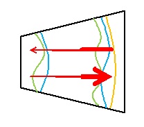 )
)
and Meep's FD simulations all remarking the importance of viewing the problem as one of travelling waves and not standing waves frozen in space.
-
Title: Re: EM Drive Developments - related to space flight applications - Thread 3
Post by: SeeShells on 07/17/2015 10:22 PM -
Received my carbon fiber woven tubes. Very nice and very strong plus a few other things, a Raspberry PI and multiple attachments.
Will be out testing and learning.
Shell -
Title: Re: EM Drive Developments - related to space flight applications - Thread 3
Post by: Blaine on 07/17/2015 10:28 PM - Hey Shell, you could recycle those after your experiments. Basically, you wrap that in damp paper towel and magnesium strips to make a magnesium air batter. Good luck with the EmDrive experiments, just something to do with them in case it doesn't work out for you.
-
Title: Re: EM Drive Developments - related to space flight applications - Thread 3
Post by: Rodal on 07/18/2015 01:09 AM -
EM DRIVE FORCE vs. TIME
We continue the program started with posts
http://forum.nasaspaceflight.com/index.php?topic=37642.msg1403629#msg1403629
http://forum.nasaspaceflight.com/index.php?topic=37642.msg1404000#msg1404000
http://forum.nasaspaceflight.com/index.php?topic=37642.msg1404004#msg1404004
http://forum.nasaspaceflight.com/index.php?topic=37642.msg1404005#msg1404005
http://forum.nasaspaceflight.com/index.php?topic=37642.msg1404006#msg1404006
http://forum.nasaspaceflight.com/index.php?topic=37642.msg1404754#msg1404754
http://forum.nasaspaceflight.com/index.php?topic=37642.msg1404783#msg1404783
http://forum.nasaspaceflight.com/index.php?topic=37642.msg1405604#msg1405604
http://forum.nasaspaceflight.com/index.php?topic=37642.msg1405605#msg1405605
showing the Force (Newtons) on the small and the big base vs. time and the net force ( (force on big base) - (force on small base)).
The forces on the bases are obtained by numerical integration of the stress tensor σxx (*) component ( obtained using Wolfram Mathematica ( http://www.wolfram.com/mathematica/ ) , post-processed from the transient Finite Difference (using Meep) solution for RF feed ON for an EM Drive of the geometry of @rfmwguy (Db=11.01 in, Ds=6.25 in, L=10.2 in).
The stress component σxx is compressive at both bases. Therefore the force obviously points in different directions: at the big base it points in the direction from the small base to the big base while at the small base it points in the direction from the big base to the small base. From the interior to the surface in both cases. In other words, the electromagnetic field exerts a pressure on both surfaces and the force points from the interior to the bases.
It is also very interesting to point out that:
1) The compressive force against the big base is larger (due to the greater surface of the big base) than the compressive force against the small base, even though the maximum stress at the small base is higher.
2) the time at which the maximum force occurs at the big base is phase-shifted with respect to the time at which the maximum force occurs at the small base. The force at the small base leads, because the antenna is much closer to the small base than to the big base.
3) Notice that when the net force is at a minimum, it actually points for a very short amount of time towards the small base (positive direction). Most of the time it points towards the big base (negative direction).
4) We naturally expect that force on the overall copper itself should sum up to zero in order to satisfy the momentum equilibrium equation implied by Maxwell's equation. We expect that the imbalance in net force between the bases should be compensated by the electromagnetic pressure on the lateral surfaces, leading to a component on the direction of the small base to result in a net overall force of zero. We don't have access to the electromagnetic fields at the lateral surfaces computed by Meep, in order to calculate the stress tensor at the lateral surfaces and integrate it to get the force on the lateral surface.
5) It is still highly suggestive that there is a net force in the direction of the big base as a result of the imbalance between the big base and the small base, although the stress at the small base is higher, and although the stress distribution is completely different (as previously shown) at both bases. Also, the Poynting vector is strongly pointing towards the big base (as previously shown). If the EM Drive is not an experimental artifact, whatever is responsible for the acceleration must be using this net imbalance and phase shift between the forces at the bases (for example: plasma ions produced by microwave heating of the air inside the cavity, leaking out and producing an exhaust, or evanescent waves acting on air molecules, or electromagnetic pressure acting on axionic dark matter or on a degradable level of the Quantum Vacuum, etc.). The net force imbalance between the bases, pointing towards the big base, is entirely consistent with a reaction acceleration of the EM Drive in the opposite direction as a result of a recoil force.
6) A fitted model of the time variation of the force (with excellent R^2 = 0.999981), shows that the present Finite Difference model (from which the force has been computed at the last two cycles ending at 0.013 microseconds from the time at which the Microwave feed was turned on), would have to be marched forward for 1,000 times longer, to a total of 10 microseconds, for the force to be magnified by the calculated exponential growth to a value of 10 microNewtons (for an inputPower of 43 watts). Given the fact that the present Meep model takes an hour to run on a good PC modern computer, 1,000 hours of computer time represents over 41 days of computing time. Thus running the Meep model to steady state is impractical. Rather than using a supercomputer to perform such a computation, I suggest to use an implicit (unconditionally stable) Finite (*****) Difference model in time (rather than the explicit time difference model presently used that is subject to stability problems that limit the maximum finite difference time step). Such implicit finite difference models are well known (I developed a version of them in my PhD thesis 35 years ago) and can be run much faster than explicit FD models. There are also numerous alternative numerical schemes that are more accurate than Finite Differences.
______________________________
NOTES:
Stress calculation:
()
()
(*) (where we denote by σxx= T11 the contravariant component of the tensor acting along the longitudinal direction "x" of the EM Drive, normal to the the plane yz having normal x, where direction "1" is "x")
(**) For the copper diamagnetism is assumed such that the magnetization M is assumed proportional to the applied magnetic field such that () for free space it is assumed that M is zero in free space in the relationship ()
(***) The Stress calculations are for an Input Power of 43 Watts (similar to the value used by NASA in some of their runs). The Stress values are proportional to the Input Power, so for example, if the Input Power were 860 Watts, that means that the calculated values for Stress are 860 Watts/ 43 Watts = 20 times greater than shown in the plots. In other words, for 860 Watts InputPower, the values for Stress in the plots need to be multiplied by a factor of 20. Ditto for the force.
(****) The total time from start of the RF feed in the Meep response analysis to the very last step is:
320 ( time slices) * 4.082199*10^(-11) seconds/timeSlice =
= 0.013063 microseconds
Each "time slice" step is 4.082199*10^(-11) seconds/timeSlice
Duration of the total of 13 time slice steps = 53.068 *10^(-11) seconds
Last time step is at 0.013063 microseconds from the start of the RF feed ON
___________________________________________________________
Conversion to get SI Units from the graphs and equations in Meep units:
TIME: Multiply Meep Time Slice "t" in the horizontal axis and in the formulae by the following factor:
((Total Meep Time)/(#Time Slices))*((Length Scale Factor)/(Speed of Light in Vacuum)) =
=((13.054)/(320))*((0.3)/(299792458))
=4.082199*10^(-11) seconds/timeSlice
ASSUMPTIONS: the validity of the following data:
Number of time slices for the total run = 320
Number of Meep time units for the total run = 13.054
Meep Length Scale factor= 0.3 meters
Meep Current (Io) = 1
(*****) One of the earliest unconditionally stable, implicit time domain methods was developed by John Houbolt (https://en.wikipedia.org/wiki/John_Houbolt ) at NACA (predecessor of NASA) in 1950:
.J. C. Houbolt, ‘A recurrence matrix solution for the dynamic response of elastic aircraft’, J. Aeronaut. Sci., 17,540-550, (1950).
, the same Houbolt who had the genius to create the Lunar orbit rendezvous method to land astronauts on the moon with a single Saturn V, and prevail over Von Braun's Nova rocket concept (eventually von Braun came around and supported Houbolt's proposal). It was due to Houbolt's concept that the US was able to reach the Moon by 1969.
( )
)
-
Title: Re: EM Drive Developments - related to space flight applications - Thread 3
Post by: TheTraveller on 07/18/2015 01:22 AM -
<a href="http://forum.nasaspaceflight.com/index.php?topic=37642.msg1405974#msg1405974">Quote from: SeeShells on 07/17/2015 07:13 PM</a>
How bout that I know and have met and worked on air bearings, powered and not, with my design projects? How about working with the Load Point engineers and the VP of engineering back when the were called WestWind and even after they changed?
I'm quite aware of who they are.
Shell
Glad to know that. Shawyer did likewise and as a senior UK aerospace engineer, funded by the UK gov, had assistance to make sure the SPR air bearing build had no issues. Watching the long video it is clear there is no movement of the 100kg mass on the air bearing until the magnetron finds cavity resonance lock and then it begins to slowly accelerate, which can be see from the Velocity curve. Once the magnetron is switched off, it stops moving.
This is not a marble in an air stream velocity curve, that just happens to start at 130 sec but nothing before. -
Title: Re: EM Drive Developments - related to space flight applications - Thread 3
Post by: TheTraveller on 07/18/2015 02:25 AM -
I'm excited.
Found Prof Yang has achieved my long term goal of 1N/kW as attached.
More good news is my friend who found the 100W Rf amp, is arranging to have my EMDrives manufactured in China, to my specs (2mm thick OFC side walls and spherical end plates to +-0.05mm), including being highly optically polished inside, O ring seals and N2 filled to stop oxidation. I will, at first, still need to install the 3 x spherical antenna array.
When I'm ready to try out internal silver plating, my friend can arrange that as well.
I'm excited!!! -
Title: Re: EM Drive Developments - related to space flight applications - Thread 3
Post by: Rodal on 07/18/2015 02:35 AM -
SeeShells: notice
<< to my specs ... O ring seals and N2 filled >> chirality and nitrogen inversion at room temperature
Add some ammonia for a Maser effect. -
Title: Re: EM Drive Developments - related to space flight applications - Thread 3
Post by: TheTraveller on 07/18/2015 02:42 AM -
<a href="http://forum.nasaspaceflight.com/index.php?topic=37642.msg1406078#msg1406078">Quote from: Rodal on 07/18/2015 02:35 AM</a>
SeeShells: notice
<< to my specs ....and N2 filled >> chirality and nitrongen inversion at room temperature
Pure N2 in my cavity can convert to chiral molecules???????????
Sure Ammonia can do this trick but pure N2?
https://en.wikipedia.org/wiki/Nitrogen_inversion -
Title: Re: EM Drive Developments - related to space flight applications - Thread 3
Post by: TheTraveller on 07/18/2015 02:58 AM -
<a href="http://forum.nasaspaceflight.com/index.php?topic=37642.msg1406082#msg1406082">Quote from: Rodal on 07/18/2015 02:47 AM</a><a href="http://forum.nasaspaceflight.com/index.php?topic=37642.msg1406080#msg1406080">Quote from: TheTraveller on 07/18/2015 02:42 AM</a>
Are you using polymer O Rings ?<a href="http://forum.nasaspaceflight.com/index.php?topic=37642.msg1406078#msg1406078">Quote from: Rodal on 07/18/2015 02:35 AM</a>SeeShells: notice
<< to my specs ....and N2 filled >> chirality and nitrongen inversion at room temperature
Pure N2 in my cavity can convert to chiral molecules???????????
Was planning on using space qualified (no outgassing) silicon O rings. -
Title: Re: EM Drive Developments - related to space flight applications - Thread 3
Post by: mwvp on 07/18/2015 04:38 AM -
<a href="http://forum.nasaspaceflight.com/index.php?topic=37642.msg1406009#msg1406009">Quote from: Ricvil on 07/17/2015 09:00 PM</a><a href="http://forum.nasaspaceflight.com/index.php?topic=37642.msg1405968#msg1405968">Quote from: mwvp on 07/17/2015 06:45 PM</a><a href="http://forum.nasaspaceflight.com/index.php?topic=37642.msg1405926#msg1405926">Quote from: Ricvil on 07/17/2015 05:51 PM</a>
I can imagine a number of ways ratcheting could be created by energy, other than microwaves in a frustrum.
Axion electrodynamic too? ;)
Why not. Need some equivalent of Maxwell Eq. for the Axion field and coupling constant to the EM field.
Maybe nuclear forces are dispersive; that could save a lot of bother. Red Mercury? ;D -
Title: Re: EM Drive Developments - related to space flight applications - Thread 3
Post by: mwvp on 07/18/2015 04:48 AM -
<a href="http://forum.nasaspaceflight.com/index.php?topic=37642.msg1406029#msg1406029">Quote from: Rodal on 07/17/2015 09:51 PM</a>
B) Paul March (NASA) with the drawing putting a magnetron at the very end of the small end, as the ideal design
(http://forum.nasaspaceflight.com/index.php?action=dlattach;topic=36313.0;attach=852672;image)
I like it. Like Yang's test, he's got a tuned cavity to stabilize and narrow the magnetron bandwidth, and a small aperture to impedance match to the frustrum. And I suspect there may be the benefit of added group delay (for low velocity or acceleration), kind of like having a transmission with a low-gear. The aperture would be dilated for increased coupling, reduced impedance and increased BW for better efficiency - high-gear. -
Title: Re: EM Drive Developments - related to space flight applications - Thread 3
Post by: mwvp on 07/18/2015 04:59 AM -
FYI, waveguide design info:
A great resource is the ancient and venerable MIT Radiation Laboratory Series;
https://www.jlab.org/ir/MITSeries.html
The index - https://www.jlab.org/ir/MITSeries/V28.PDF
Vol 10 Waveguides: https://www.jlab.org/ir/MITSeries/V10.PDF
Also scribd.com; you can get a free 2 week account so you can download stuff. -
Title: Re: EM Drive Developments - related to space flight applications - Thread 3
Post by: TheTraveller on 07/18/2015 08:07 AM -
<a href="http://forum.nasaspaceflight.com/index.php?topic=37642.msg1406109#msg1406109">Quote from: mwvp on 07/18/2015 04:48 AM</a><a href="http://forum.nasaspaceflight.com/index.php?topic=37642.msg1406029#msg1406029">Quote from: Rodal on 07/17/2015 09:51 PM</a>
B) Paul March (NASA) with the drawing putting a magnetron at the very end of the small end, as the ideal design
(http://forum.nasaspaceflight.com/index.php?action=dlattach;topic=36313.0;attach=852672;image)
I like it. Like Yang's test, he's got a tuned cavity to stabilize and narrow the magnetron bandwidth, and a small aperture to impedance match to the frustrum. And I suspect there may be the benefit of added group delay (for low velocity or acceleration), kind of like having a transmission with a low-gear. The aperture would be dilated for increased coupling, reduced impedance and increased BW for better efficiency - high-gear.
Just maybe each of the 20 x 100kW EMDrives on the IXS Clark are modeled on that design. Nice redundancy, 1 x 100kW magnetron per EMDrive pod.
Like it. -
Title: Re: EM Drive Developments - related to space flight applications - Thread 3
Post by: deltaMass on 07/18/2015 08:35 AM -
The name is Clarke.
Sir Arthur C. Clarke.
-
Title: Re: EM Drive Developments - related to space flight applications - Thread 3
Post by: Stormbringer on 07/18/2015 08:39 AM -
Weyl fermions; massless particle found.
http://phys.org/news/2015-07-year-massless-particle-next-generation-electronics.html
how many more of these sorts of things are there out there? -
Title: Re: EM Drive Developments - related to space flight applications - Thread 3
Post by: TheTraveller on 07/18/2015 08:49 AM -
<a href="http://forum.nasaspaceflight.com/index.php?topic=37642.msg1406125#msg1406125">Quote from: deltaMass on 07/18/2015 08:35 AM</a>
The name is Clarke.
Sir Arthur C. Clarke.
Here is my IXS Doable:
5 x BA330s, 3 x D2 taxis, 2 x spare docking ports, 1,650m3 of pressurised volume, 80% more than the ISS. Not as pretty as IXS Clarke but much more Doable and buildable now.
IXS Clarke image attached. -
Title: Re: EM Drive Developments - related to space flight applications - Thread 3
Post by: deltaMass on 07/18/2015 10:05 AM - Fission reactor? Heat radiators? Why use any fuel at all? Just power the main engines with a rotary overunity EmDrive power unit 8)
-
Title: Re: EM Drive Developments - related to space flight applications - Thread 3
Post by: TheTraveller on 07/18/2015 10:28 AM -
<a href="http://forum.nasaspaceflight.com/index.php?topic=37642.msg1406138#msg1406138">Quote from: deltaMass on 07/18/2015 10:05 AM</a>
Fission reactor? Heat radiators? Why use any fuel at all? Just power the main engines with a rotary overunity EmDrive power unit 8)
What I think is we don't know what rules will apply but there will not be any overunity.
What I see in this measured example, attached, is magnetron Power usage dropping, while Velocity increases. Note I copied the Velocity curve, inverted it and placed it under the Power curve. Close match. Suggest this data is trying to tell us something about an area of physics we have almost no experimental data on. -
Title: Re: EM Drive Developments - related to space flight applications - Thread 3
Post by: RotoSequence on 07/18/2015 10:29 AM -
<a href="http://forum.nasaspaceflight.com/index.php?topic=37642.msg1406138#msg1406138">Quote from: deltaMass on 07/18/2015 10:05 AM</a>
Fission reactor? Heat radiators? Why use any fuel at all? Just power the main engines with a rotary overunity EmDrive power unit 8)
A lot of us are axiomatically opposed to EM Drives being both a real effect and a free energy device, and insist that it must have some sort of over-unity protection mechanism. I'm not very good at following the math that's been sent back and forth, so I could be wrong, but I'm under the impression that a lot of time, electronic breath, and effort is being wasted arguing around the acceptance or refusal of this axiom. Without a concrete demonstration of a working drive, I'm not sure we'll know if there is a mechanism that prevents over-unity or not. I'm certainly not under the impression that anyone's going to be convinced by talking about it some more. :-\ -
Title: Re: EM Drive Developments - related to space flight applications - Thread 3
Post by: TheTraveller on 07/18/2015 10:40 AM -
<a href="http://forum.nasaspaceflight.com/index.php?topic=37642.msg1406143#msg1406143">Quote from: RotoSequence on 07/18/2015 10:29 AM</a><a href="http://forum.nasaspaceflight.com/index.php?topic=37642.msg1406138#msg1406138">Quote from: deltaMass on 07/18/2015 10:05 AM</a>
Fission reactor? Heat radiators? Why use any fuel at all? Just power the main engines with a rotary overunity EmDrive power unit 8)
A lot of us are axiomatically opposed to EM Drives being both a real effect and a free energy device, and insist that it must have some sort of over-unity protection mechanism. I'm not very good at following the math that's been sent back and forth, so I could be wrong, but I'm under the impression that a lot of time, electronic breath, and effort is being wasted arguing around the acceptance or refusal of this axiom. Without a concrete demonstration of a working drive, I'm not sure we'll know if there is a mechanism that prevents over-unity or not. I'm certainly not under the impression that anyone's going to be convinced by talking about it some more. :-\
The image I posted was from the 188 run of the SPR Demonstrator rotary test. Same test run as the video.
What I read from that rotary test experimental data is there is no overunity as magnetron Power is dropping as Velocity is increasing. Shawyer has explained this happens because acceleration shifts the cavity resonant frequency, Q drops from some of the EM wave cavity energy being converted into kinetic, increasing cavity losses, Force generated drops, stopping overunity operation.
Shawyer has been saying this for years and in the graphic we can see it actually happening.
Sorry but there is no overunity as multiple acceleration related effects inside the cavity stop OU happening. -
Title: Re: EM Drive Developments - related to space flight applications - Thread 3
Post by: Notsosureofit on 07/18/2015 11:36 AM -
<a href="http://forum.nasaspaceflight.com/index.php?topic=37642.msg1406126#msg1406126">Quote from: Stormbringer on 07/18/2015 08:39 AM</a>
Weyl fermions; massless particle found.
http://phys.org/news/2015-07-year-massless-particle-next-generation-electronics.html
how many more of these sorts of things are there out there?
", the researchers used the Princeton Institute for the Science and Technology of Materials (PRISM) and Laboratory for Topological Quantum Matter and Spectroscopy in Princeton's Jadwin Hall to research and simulate dozens of crystal structures before seizing upon the asymmetrical tantalum arsenide crystal, which has a differently shaped top and bottom."
-
Title: Re: EM Drive Developments - related to space flight applications - Thread 3
Post by: deltaMass on 07/18/2015 11:48 AM -
<a href="http://forum.nasaspaceflight.com/index.php?topic=37642.msg1406144#msg1406144">Quote from: TheTraveller on 07/18/2015 10:40 AM</a>
If that is Shawyer's reason for there being no over-unity, then the man believes that a radio can never be tuned. It is an unbelievably weak and pathetic explanation.<a href="http://forum.nasaspaceflight.com/index.php?topic=37642.msg1406143#msg1406143">Quote from: RotoSequence on 07/18/2015 10:29 AM</a><a href="http://forum.nasaspaceflight.com/index.php?topic=37642.msg1406138#msg1406138">Quote from: deltaMass on 07/18/2015 10:05 AM</a>Fission reactor? Heat radiators? Why use any fuel at all? Just power the main engines with a rotary overunity EmDrive power unit 8)
A lot of us are axiomatically opposed to EM Drives being both a real effect and a free energy device, and insist that it must have some sort of over-unity protection mechanism. I'm not very good at following the math that's been sent back and forth, so I could be wrong, but I'm under the impression that a lot of time, electronic breath, and effort is being wasted arguing around the acceptance or refusal of this axiom. Without a concrete demonstration of a working drive, I'm not sure we'll know if there is a mechanism that prevents over-unity or not. I'm certainly not under the impression that anyone's going to be convinced by talking about it some more. :-\
The image I posted was from the 188 run of the SPR Demonstrator rotary test. Same test run as the video.
What I read from that rotary test experimental data is there is no overunity as magnetron Power is dropping as Velocity is increasing. Shawyer has explained this happens because acceleration shifts the cavity resonant frequency, Q drops from some of the EM wave cavity energy being converted into kinetic, increasing cavity losses, Force generated drops, stopping overunity operation.
Shawyer has been saying this for years and in the graphic we can see it actually happening.
Sorry but there is no overunity as multiple acceleration related effects inside the cavity stop OU happening. -
Title: Re: EM Drive Developments - related to space flight applications - Thread 3
Post by: TheTraveller on 07/18/2015 11:51 AM -
<a href="http://forum.nasaspaceflight.com/index.php?topic=37642.msg1406150#msg1406150">Quote from: deltaMass on 07/18/2015 11:48 AM</a><a href="http://forum.nasaspaceflight.com/index.php?topic=37642.msg1406144#msg1406144">Quote from: TheTraveller on 07/18/2015 10:40 AM</a>
If that is Shawyer's reason for there being no over-unity, then the man believes that a radio can never be tuned. It is an unbelievably weak and pathetic explanation.<a href="http://forum.nasaspaceflight.com/index.php?topic=37642.msg1406143#msg1406143">Quote from: RotoSequence on 07/18/2015 10:29 AM</a><a href="http://forum.nasaspaceflight.com/index.php?topic=37642.msg1406138#msg1406138">Quote from: deltaMass on 07/18/2015 10:05 AM</a>Fission reactor? Heat radiators? Why use any fuel at all? Just power the main engines with a rotary overunity EmDrive power unit 8)
A lot of us are axiomatically opposed to EM Drives being both a real effect and a free energy device, and insist that it must have some sort of over-unity protection mechanism. I'm not very good at following the math that's been sent back and forth, so I could be wrong, but I'm under the impression that a lot of time, electronic breath, and effort is being wasted arguing around the acceptance or refusal of this axiom. Without a concrete demonstration of a working drive, I'm not sure we'll know if there is a mechanism that prevents over-unity or not. I'm certainly not under the impression that anyone's going to be convinced by talking about it some more. :-\
The image I posted was from the 188 run of the SPR Demonstrator rotary test. Same test run as the video.
What I read from that rotary test experimental data is there is no overunity as magnetron Power is dropping as Velocity is increasing. Shawyer has explained this happens because acceleration shifts the cavity resonant frequency, Q drops from some of the EM wave cavity energy being converted into kinetic, increasing cavity losses, Force generated drops, stopping overunity operation.
Shawyer has been saying this for years and in the graphic we can see it actually happening.
Sorry but there is no overunity as multiple acceleration related effects inside the cavity stop OU happening.
The measured rotary test data is hard to ignore.
Follow the DATA, theory or desired OU outcome be damned!!! -
Title: Re: EM Drive Developments - related to space flight applications - Thread 3
Post by: graybeardsyseng on 07/18/2015 12:05 PM -
<a href="http://forum.nasaspaceflight.com/index.php?topic=37642.msg1405943#msg1405943">Quote from: mwvp on 07/17/2015 06:13 PM</a><a href="http://forum.nasaspaceflight.com/index.php?topic=37642.msg1405925#msg1405925">Quote from: rfmwguy on 07/17/2015 05:51 PM</a>
Here's an article I had published in MW&RF: http://mwrf.com/commercial/assemble-high-power-attenuator-systems
Cool. The highest power systems I've worked on, cellular and an tactical satellite, were only a few hundred watts (cooking in the microwave oven notwithstanding). The fusor-guy, Coulter, I referenced mentioned his (IIRC) RG-58 getting a bit warm at the current-nodes along the coax. Wonder if I could get away with a 30 second run with a meter of RG-178, 500 W @ 2.4 GHz? Probably not
Check out the specs on RG-178.
http://www.datasheets.pl/coaxial_cables/RG-178_COAXIAL_CABLE.pdf
http://www.belden.com/techdatas/english/83265.pdf
at 2.4 Ghz there is 2.9 dB of loss in 1 meter of cable. That is nearly 1/2 your power going into heat. Note - the loss specs are a VSWR of 1.3 max so unless load and source are well matched coax loss will be even greater.
Belden specs their RG-178 only to 1 Ghz but max power handling at that freq is only 66 watts. After all the center conductor is only 30 AWG.
I used a lot of 178 for small signal work at HF and VHF in DIY projects (half way through my second 1000ft roll). It is GREAT for small signal work and runs up to say 5 meters at up to maybe 100Mhz but I think 30 seconds with 500 watts at 2.4 Ghz will convert 1 meter of 178 into an open circuit - which would be bad for your source too.
Herman
-
Title: Re: EM Drive Developments - related to space flight applications - Thread 3
Post by: SeeShells on 07/18/2015 12:29 PM -
<a href="http://forum.nasaspaceflight.com/index.php?topic=37642.msg1406143#msg1406143">Quote from: RotoSequence on 07/18/2015 10:29 AM</a><a href="http://forum.nasaspaceflight.com/index.php?topic=37642.msg1406138#msg1406138">Quote from: deltaMass on 07/18/2015 10:05 AM</a>
Fission reactor? Heat radiators? Why use any fuel at all? Just power the main engines with a rotary overunity EmDrive power unit 8)
A lot of us are axiomatically opposed to EM Drives being both a real effect and a free energy device, and insist that it must have some sort of over-unity protection mechanism. I'm not very good at following the math that's been sent back and forth, so I could be wrong, but I'm under the impression that a lot of time, electronic breath, and effort is being wasted arguing around the acceptance or refusal of this axiom. Without a concrete demonstration of a working drive, I'm not sure we'll know if there is a mechanism that prevents over-unity or not. I'm certainly not under the impression that anyone's going to be convinced by talking about it some more. :-\
Very true.
I also realize we know so little. We don't know how the universe started or how the universe will end, in between we don't know what it's made of,, we only understand a little of it. 4.6% is the stuff we know about.
http://map.gsfc.nasa.gov/universe/uni_matter.html
I'm reminded of the three blind men describing a elephant, one feels the tail, one feels the trunk and one feels the body and each describe it differently. We only can feel the trunk and sometimes building this EMDrive I think I got ahold of the other end, so I try to keep an open mind and duck and cover when the time calls for it. :D
Will be working in the shop most of the day, I've got a lot to prepare for and building the test stand for the DUT.
Shell -
Title: Re: EM Drive Developments - related to space flight applications - Thread 3
Post by: TheTraveller on 07/18/2015 12:34 PM -
<a href="http://forum.nasaspaceflight.com/index.php?topic=37642.msg1406153#msg1406153">Quote from: graybeardsyseng on 07/18/2015 12:05 PM</a><a href="http://forum.nasaspaceflight.com/index.php?topic=37642.msg1405943#msg1405943">Quote from: mwvp on 07/17/2015 06:13 PM</a><a href="http://forum.nasaspaceflight.com/index.php?topic=37642.msg1405925#msg1405925">Quote from: rfmwguy on 07/17/2015 05:51 PM</a>
Here's an article I had published in MW&RF: http://mwrf.com/commercial/assemble-high-power-attenuator-systems
Cool. The highest power systems I've worked on, cellular and an tactical satellite, were only a few hundred watts (cooking in the microwave oven notwithstanding). The fusor-guy, Coulter, I referenced mentioned his (IIRC) RG-58 getting a bit warm at the current-nodes along the coax. Wonder if I could get away with a 30 second run with a meter of RG-178, 500 W @ 2.4 GHz? Probably not
Check out the specs on RG-178.
http://www.datasheets.pl/coaxial_cables/RG-178_COAXIAL_CABLE.pdf
http://www.belden.com/techdatas/english/83265.pdf
at 2.4 Ghz there is 2.9 dB of loss in 1 meter of cable. That is nearly 1/2 your power going into heat. Note - the loss specs are a VSWR of 1.3 max so unless load and source are well matched coax loss will be even greater.
Belden specs their RG-178 only to 1 Ghz but max power handling at that freq is only 66 watts. After all the center conductor is only 30 AWG.
I used a lot of 178 for small signal work at HF and VHF in DIY projects (half way through my second 1000ft roll). It is GREAT for small signal work and runs up to say 5 meters at up to maybe 100Mhz but I think 30 seconds with 500 watts at 2.4 Ghz will convert 1 meter of 178 into an open circuit - which would be bad for your source too.
Herman
I plan to use EcoFlex15 PLUS coax (specs attached) unless anyone knows of anything better?
0.149dB loss / mtr at 2.45GHz & 350W capacity. -
Title: Re: EM Drive Developments - related to space flight applications - Thread 3
Post by: graybeardsyseng on 07/18/2015 12:53 PM -
<a href="http://forum.nasaspaceflight.com/index.php?topic=37642.msg1406154#msg1406154">Quote from: SeeShells on 07/18/2015 12:29 PM</a><a href="http://forum.nasaspaceflight.com/index.php?topic=37642.msg1406143#msg1406143">Quote from: RotoSequence on 07/18/2015 10:29 AM</a><a href="http://forum.nasaspaceflight.com/index.php?topic=37642.msg1406138#msg1406138">Quote from: deltaMass on 07/18/2015 10:05 AM</a>
Fission reactor? Heat radiators? Why use any fuel at all? Just power the main engines with a rotary overunity EmDrive power unit 8)
A lot of us are axiomatically opposed to EM Drives being both a real effect and a free energy device, and insist that it must have some sort of over-unity protection mechanism. I'm not very good at following the math that's been sent back and forth, so I could be wrong, but I'm under the impression that a lot of time, electronic breath, and effort is being wasted arguing around the acceptance or refusal of this axiom. Without a concrete demonstration of a working drive, I'm not sure we'll know if there is a mechanism that prevents over-unity or not. I'm certainly not under the impression that anyone's going to be convinced by talking about it some more. :-\
Very true.
I also realize we know so little. We don't know how the universe started or how the universe will end, in between we don't know what it's made of,, we only understand a little of it. 4.6% is the stuff we know about.
http://map.gsfc.nasa.gov/universe/uni_matter.html
I'm reminded of the three blind men describing a elephant, one feels the tail, one feels the trunk and one feels the body and each describe it differently. We only can feel the trunk and sometimes building this EMDrive I think I got ahold of the other end, so I try to keep an open mind and duck and cover when the time calls for it. :D
Will be working in the shop most of the day, I've got a lot to prepare for and building the test stand for the DUT.
Shell
"I think I got ahold of the other end, so I try to keep an open mind and duck and cover when the time calls for it. :D"
- You quack me up! ;D Sorry - couldn't resist.
Herman
-
Title: Re: EM Drive Developments - related to space flight applications - Thread 3
Post by: graybeardsyseng on 07/18/2015 01:02 PM -
<a href="http://forum.nasaspaceflight.com/index.php?topic=37642.msg1406155#msg1406155">Quote from: TheTraveller on 07/18/2015 12:34 PM</a><a href="http://forum.nasaspaceflight.com/index.php?topic=37642.msg1406153#msg1406153">Quote from: graybeardsyseng on 07/18/2015 12:05 PM</a><a href="http://forum.nasaspaceflight.com/index.php?topic=37642.msg1405943#msg1405943">Quote from: mwvp on 07/17/2015 06:13 PM</a><a href="http://forum.nasaspaceflight.com/index.php?topic=37642.msg1405925#msg1405925">Quote from: rfmwguy on 07/17/2015 05:51 PM</a>
Here's an article I had published in MW&RF: http://mwrf.com/commercial/assemble-high-power-attenuator-systems
Cool. The highest power systems I've worked on, cellular and an tactical satellite, were only a few hundred watts (cooking in the microwave oven notwithstanding). The fusor-guy, Coulter, I referenced mentioned his (IIRC) RG-58 getting a bit warm at the current-nodes along the coax. Wonder if I could get away with a 30 second run with a meter of RG-178, 500 W @ 2.4 GHz? Probably not
Check out the specs on RG-178.
http://www.datasheets.pl/coaxial_cables/RG-178_COAXIAL_CABLE.pdf
http://www.belden.com/techdatas/english/83265.pdf
at 2.4 Ghz there is 2.9 dB of loss in 1 meter of cable. That is nearly 1/2 your power going into heat. Note - the loss specs are a VSWR of 1.3 max so unless load and source are well matched coax loss will be even greater.
Belden specs their RG-178 only to 1 Ghz but max power handling at that freq is only 66 watts. After all the center conductor is only 30 AWG.
I used a lot of 178 for small signal work at HF and VHF in DIY projects (half way through my second 1000ft roll). It is GREAT for small signal work and runs up to say 5 meters at up to maybe 100Mhz but I think 30 seconds with 500 watts at 2.4 Ghz will convert 1 meter of 178 into an open circuit - which would be bad for your source too.
Herman
I plan to use EcoFlex15 PLUS coax (specs attached) unless anyone knows of anything better?
0.149dB loss / mtr at 2.45GHz & 350W capacity.
That is good stuff. I have seen it used and worked with it on both L band and Ku band (short run) projects - Only advice is to watch the minimum bend radius carefully. I would use the 15 cycle bend radius rather than the single time bend radius just to be on the safe side. To tight and it will either short circuit or your loss will go up radically (and the effect may not be seen right away.
Herman -
Title: Re: EM Drive Developments - related to space flight applications - Thread 3
Post by: TheTraveller on 07/18/2015 01:33 PM -
<a href="http://forum.nasaspaceflight.com/index.php?topic=37642.msg1406162#msg1406162">Quote from: graybeardsyseng on 07/18/2015 01:02 PM</a><a href="http://forum.nasaspaceflight.com/index.php?topic=37642.msg1406155#msg1406155">Quote from: TheTraveller on 07/18/2015 12:34 PM</a><a href="http://forum.nasaspaceflight.com/index.php?topic=37642.msg1406153#msg1406153">Quote from: graybeardsyseng on 07/18/2015 12:05 PM</a><a href="http://forum.nasaspaceflight.com/index.php?topic=37642.msg1405943#msg1405943">Quote from: mwvp on 07/17/2015 06:13 PM</a><a href="http://forum.nasaspaceflight.com/index.php?topic=37642.msg1405925#msg1405925">Quote from: rfmwguy on 07/17/2015 05:51 PM</a>
Here's an article I had published in MW&RF: http://mwrf.com/commercial/assemble-high-power-attenuator-systems
Cool. The highest power systems I've worked on, cellular and an tactical satellite, were only a few hundred watts (cooking in the microwave oven notwithstanding). The fusor-guy, Coulter, I referenced mentioned his (IIRC) RG-58 getting a bit warm at the current-nodes along the coax. Wonder if I could get away with a 30 second run with a meter of RG-178, 500 W @ 2.4 GHz? Probably not
Check out the specs on RG-178.
http://www.datasheets.pl/coaxial_cables/RG-178_COAXIAL_CABLE.pdf
http://www.belden.com/techdatas/english/83265.pdf
at 2.4 Ghz there is 2.9 dB of loss in 1 meter of cable. That is nearly 1/2 your power going into heat. Note - the loss specs are a VSWR of 1.3 max so unless load and source are well matched coax loss will be even greater.
Belden specs their RG-178 only to 1 Ghz but max power handling at that freq is only 66 watts. After all the center conductor is only 30 AWG.
I used a lot of 178 for small signal work at HF and VHF in DIY projects (half way through my second 1000ft roll). It is GREAT for small signal work and runs up to say 5 meters at up to maybe 100Mhz but I think 30 seconds with 500 watts at 2.4 Ghz will convert 1 meter of 178 into an open circuit - which would be bad for your source too.
Herman
I plan to use EcoFlex15 PLUS coax (specs attached) unless anyone knows of anything better?
0.149dB loss / mtr at 2.45GHz & 350W capacity.
That is good stuff. I have seen it used and worked with it on both L band and Ku band (short run) projects - Only advice is to watch the minimum bend radius carefully. I would use the 15 cycle bend radius rather than the single time bend radius just to be on the safe side. To tight and it will either short circuit or your loss will go up radically (and the effect may not be seen right away.
Herman
Thanks. Will follow the 15 bend radius even though it will only be bent once and then clamped to the rotary table surface, where possible, as will all the other wiring. -
Title: Re: EM Drive Developments - related to space flight applications - Thread 3
Post by: frobnicat on 07/18/2015 02:03 PM -
<a href="http://forum.nasaspaceflight.com/index.php?topic=37642.msg1406143#msg1406143">Quote from: RotoSequence on 07/18/2015 10:29 AM</a><a href="http://forum.nasaspaceflight.com/index.php?topic=37642.msg1406138#msg1406138">Quote from: deltaMass on 07/18/2015 10:05 AM</a>
Fission reactor? Heat radiators? Why use any fuel at all? Just power the main engines with a rotary overunity EmDrive power unit 8)
A lot of us are axiomatically opposed to EM Drives being both a real effect and a free energy device, and insist that it must have some sort of over-unity protection mechanism. I'm not very good at following the math that's been sent back and forth, so I could be wrong, but I'm under the impression that a lot of time, electronic breath, and effort is being wasted arguing around the acceptance or refusal of this axiom. Without a concrete demonstration of a working drive, I'm not sure we'll know if there is a mechanism that prevents over-unity or not. I'm certainly not under the impression that anyone's going to be convinced by talking about it some more. :-\
A lot more effort and reputation of advanced concepts research could be wasted on illusory claims. There is ongoing outright intellectual dishonesty with the proponents insisting on selling an effect enabling extravagant deep space deltaVs at clearly overunity discount energetic costs and insisting on non overunity of the effect.<a href="http://forum.nasaspaceflight.com/index.php?topic=37642.msg1405915#msg1405915">Quote from: TheTraveller on 07/17/2015 05:44 PM</a>...
Assuming a 1N/kW EMDrive could power wise scale to 100N/100kW and using 20 of these on a 90t crewed ship could do at 0.0023g:
LEO to Pluto low orbit (40AUs), 12.4 months.
LEO to Mars low orbit, at min 60mkm, 37 days.
LEO to Mars low orbit, at avg 225mkm, 78 days.
So with just 100N/100kW EMDrives, the entire solar system would be open to human exploration and colonisation. Would still need propellant based rockets to Taxis from low orbit >< the surface.
Going straight trajectory for simplicity : 0.0023g (2.25e-2 m/s²) for 6.2 month (1.6e7 s) is a deltaV (at half travel) of 360 km/s.
2MW generator power for 6.2 month : cost = 3.2e13 J (32 terajoules)
90 t at 360km/s, .5*m*v² : benefit = 5.8e15 J (5800 terajoules)
180 times more kinetic energy out than energy that was put in.
This is not something we could do even if solar system were paved from Sun to Pluto and we had tyres to pull on that ground at 100% efficiency. So this extravagant claim of Pluto at 12.4 month is not dependant on cheap momentum, it is entirely, utterly, irremediably dependant on cheap energy.
This is something we could do if solar system were crossed by a conveyor belt that happen to move from sun outward to Pluto at above 360km/s and our ship could drag on that flow. Solar wind fits the bill, but it is not of high enough density (and clearly can't explain results down in earth labs). If EM drive is possible and enables such deep space transit times, then the problem is not that it respects CoE or not, the problem is how it could respect CoE when we see the required energy leverage ratio : this makes it closer to sailing than driving. And no proponent claiming both those transit times (implicitly overunity energy) and respect of CoE have ever cared to publish the slightest remark or experimental sidereal time check about a possible preferred frame to sail on (heliocentric ? galactocentric ? CMBcentric ?). They clearly don't believe in such possibility despite being the only way to reconcile both short transit times and serious CoE (short of plain ZPF energy extraction).<a href="http://forum.nasaspaceflight.com/index.php?topic=37642.msg1406144#msg1406144">Quote from: TheTraveller on 07/18/2015 10:40 AM</a>...
The image I posted was from the 188 run of the SPR Demonstrator rotary test. Same test run as the video.
What I read from that rotary test experimental data is there is no overunity as magnetron Power is dropping as Velocity is increasing. Shawyer has explained this happens because acceleration shifts the cavity resonant frequency, Q drops from some of the EM wave cavity energy being converted into kinetic, increasing cavity losses, Force generated drops, stopping overunity operation.
Shawyer has been saying this for years and in the graphic we can see it actually happening.
Sorry but there is no overunity as multiple acceleration related effects inside the cavity stop OU happening.
So why in hell are you never ever applying those purported OU limiting effect with mission profiles ? How can you decently say "1N/kW => Pluto in a year" in a post and "there is no overunity as magnetron Power is dropping as Velocity is increasing" the following post ? Please apply those purported OU protecting effect in the sold mission profiles. Otherwise it's like saying that your Unicorn can find shortcuts through fairyland in one post, and saying that of course fairies don't exist the next one. Hope you understand why this feels dishonest, and why a number of contributors will always strongly object as long as such canards are sold as perfectly all right.
-
Title: Re: EM Drive Developments - related to space flight applications - Thread 3
Post by: rq3 on 07/18/2015 02:12 PM -
<a href="http://forum.nasaspaceflight.com/index.php?topic=37642.msg1406086#msg1406086">Quote from: TheTraveller on 07/18/2015 02:58 AM</a><a href="http://forum.nasaspaceflight.com/index.php?topic=37642.msg1406082#msg1406082">Quote from: Rodal on 07/18/2015 02:47 AM</a><a href="http://forum.nasaspaceflight.com/index.php?topic=37642.msg1406080#msg1406080">Quote from: TheTraveller on 07/18/2015 02:42 AM</a>
Are you using polymer O Rings ?<a href="http://forum.nasaspaceflight.com/index.php?topic=37642.msg1406078#msg1406078">Quote from: Rodal on 07/18/2015 02:35 AM</a>SeeShells: notice
<< to my specs ....and N2 filled >> chirality and nitrongen inversion at room temperature
Pure N2 in my cavity can convert to chiral molecules???????????
Was planning on using space qualified (no outgassing) silicon O rings.
I've never heard of a silicon "O" ring. If there is such an animal, it would be fantastically brittle.
If you actually mean "silicone", they may be low outgassing and "space qualified" but will be VERY gas permeable. Perhaps almost as bad as polytetrafluoroethylene.
You might want to contact a company like Chomerics, who specializes in conductive "O" rings for applications like this.
Good luck. -
Title: Re: EM Drive Developments - related to space flight applications - Thread 3
Post by: rfmwguy on 07/18/2015 02:14 PM - Proper scientific study is small steps with valid results. Hyperbole like heavy lifters, mass production and pluto missions are, well...hyperbole. Yes, I am a sales and marketing expert with a very technical background. I would humbly suggest we leave sales & marketing/blue sky plans to another forum. Not that we can't deam, however...
-
Title: Re: EM Drive Developments - related to space flight applications - Thread 3
Post by: TheTraveller on 07/18/2015 02:25 PM -
<a href="http://forum.nasaspaceflight.com/index.php?topic=37642.msg1406171#msg1406171">Quote from: frobnicat on 07/18/2015 02:03 PM</a><a href="http://forum.nasaspaceflight.com/index.php?topic=37642.msg1406143#msg1406143">Quote from: RotoSequence on 07/18/2015 10:29 AM</a><a href="http://forum.nasaspaceflight.com/index.php?topic=37642.msg1406138#msg1406138">Quote from: deltaMass on 07/18/2015 10:05 AM</a>
Fission reactor? Heat radiators? Why use any fuel at all? Just power the main engines with a rotary overunity EmDrive power unit 8)
A lot of us are axiomatically opposed to EM Drives being both a real effect and a free energy device, and insist that it must have some sort of over-unity protection mechanism. I'm not very good at following the math that's been sent back and forth, so I could be wrong, but I'm under the impression that a lot of time, electronic breath, and effort is being wasted arguing around the acceptance or refusal of this axiom. Without a concrete demonstration of a working drive, I'm not sure we'll know if there is a mechanism that prevents over-unity or not. I'm certainly not under the impression that anyone's going to be convinced by talking about it some more. :-\
A lot more effort and reputation of advanced concepts research could be wasted on illusory claims. There is ongoing outright intellectual dishonesty with the proponents insisting on selling an effect enabling extravagant deep space deltaVs at clearly overunity discount energetic costs and insisting on non overunity of the effect.<a href="http://forum.nasaspaceflight.com/index.php?topic=37642.msg1405915#msg1405915">Quote from: TheTraveller on 07/17/2015 05:44 PM</a>...
Assuming a 1N/kW EMDrive could power wise scale to 100N/100kW and using 20 of these on a 90t crewed ship could do at 0.0023g:
LEO to Pluto low orbit (40AUs), 12.4 months.
LEO to Mars low orbit, at min 60mkm, 37 days.
LEO to Mars low orbit, at avg 225mkm, 78 days.
So with just 100N/100kW EMDrives, the entire solar system would be open to human exploration and colonisation. Would still need propellant based rockets to Taxis from low orbit >< the surface.
Going straight trajectory for simplicity : 0.0023g (2.25e-2 m/s²) for 6.2 month (1.6e7 s) is a deltaV (at half travel) of 360 km/s.
2MW generator power for 6.2 month : cost = 3.2e13 J (32 terajoules)
90 t at 360km/s, .5*m*v² : benefit = 5.8e15 J (5800 terajoules)
180 times more kinetic energy out than energy that was put in.
This is not something we could do even if solar system were paved from Sun to Pluto and we had tyres to pull on that ground at 100% efficiency. So this extravagant claim of Pluto at 12.4 month is not dependant on cheap momentum, it is entirely, utterly, irremediably dependant on cheap energy.
This is something we could do if solar system were crossed by a conveyor belt that happen to move from sun outward to Pluto at above 360km/s and our ship could drag on that flow. Solar wind fits the bill, but it is not of high enough density (and clearly can't explain results down in earth labs). If EM drive is possible and enables such deep space transit times, then the problem is not that it respects CoE or not, the problem is how it could respect CoE when we see the required energy leverage ratio : this makes it closer to sailing than driving. And no proponent claiming both those transit times (implicitly overunity energy) and respect of CoE have ever cared to publish the slightest remark or experimental sidereal time check about a possible preferred frame to sail on (heliocentric ? galactocentric ? CMBcentric ?). They clearly don't believe in such possibility despite being the only way to reconcile both short transit times and serious CoE (short of plain ZPF energy extraction).<a href="http://forum.nasaspaceflight.com/index.php?topic=37642.msg1406144#msg1406144">Quote from: TheTraveller on 07/18/2015 10:40 AM</a>...
The image I posted was from the 188 run of the SPR Demonstrator rotary test. Same test run as the video.
What I read from that rotary test experimental data is there is no overunity as magnetron Power is dropping as Velocity is increasing. Shawyer has explained this happens because acceleration shifts the cavity resonant frequency, Q drops from some of the EM wave cavity energy being converted into kinetic, increasing cavity losses, Force generated drops, stopping overunity operation.
Shawyer has been saying this for years and in the graphic we can see it actually happening.
Sorry but there is no overunity as multiple acceleration related effects inside the cavity stop OU happening.
So why in hell are you never ever applying those purported OU limiting effect with mission profiles ? How can you decently say "1N/kW => Pluto in a year" in a post and "there is no overunity as magnetron Power is dropping as Velocity is increasing" the following post ? Please apply those purported OU protecting effect in the sold mission profiles. Otherwise it's like saying that your Unicorn can find shortcuts through fairyland in one post, and saying that of course fairies don't exist the next one. Hope you understand why this feels dishonest, and why a number of contributors will always strongly object as long as such canards are sold as perfectly all right.
Glad you read and enjoyed the data.
Hope to keep you further entertained when I publish my rotary test data.
BTW after careful examination of Prof Yang's experimental data, it would seem 4N/kW is doable.
Click here and scroll down for Dr. Whites 4N/kW solar system transit times:
http://emdrive.wiki/Potential_EMDrive_solar_system_explorer_ship
-
Title: Re: EM Drive Developments - related to space flight applications - Thread 3
Post by: TheTraveller on 07/18/2015 02:43 PM -
<a href="http://forum.nasaspaceflight.com/index.php?topic=37642.msg1406175#msg1406175">Quote from: rq3 on 07/18/2015 02:12 PM</a><a href="http://forum.nasaspaceflight.com/index.php?topic=37642.msg1406086#msg1406086">Quote from: TheTraveller on 07/18/2015 02:58 AM</a><a href="http://forum.nasaspaceflight.com/index.php?topic=37642.msg1406082#msg1406082">Quote from: Rodal on 07/18/2015 02:47 AM</a><a href="http://forum.nasaspaceflight.com/index.php?topic=37642.msg1406080#msg1406080">Quote from: TheTraveller on 07/18/2015 02:42 AM</a>
Are you using polymer O Rings ?<a href="http://forum.nasaspaceflight.com/index.php?topic=37642.msg1406078#msg1406078">Quote from: Rodal on 07/18/2015 02:35 AM</a>SeeShells: notice
<< to my specs ....and N2 filled >> chirality and nitrongen inversion at room temperature
Pure N2 in my cavity can convert to chiral molecules???????????
Was planning on using space qualified (no outgassing) silicon O rings.
I've never heard of a silicon "O" ring. If there is such an animal, it would be fantastically brittle.
If you actually mean "silicone", they may be low outgassing and "space qualified" but will be VERY gas permeable. Perhaps almost as bad as polytetrafluoroethylene.
You might want to contact a company like Chomerics, who specializes in conductive "O" rings for applications like this.
Good luck.
So quick to attach! Apologies, dropped the e.
Sometime my big fingers on a small mobile phone screen gens typos or my old eyes miss errors.
Will probably be a gasket. Have a few mates in the aerospace industry that are working on the best material to provide good electrical conductivity and good sealing, with min outgassing using N2 inside the frustum at 1/2 atmo pressure.
You have any suggestions? -
Title: Re: EM Drive Developments - related to space flight applications - Thread 3
Post by: Rodal on 07/18/2015 02:49 PM -
<a href="http://forum.nasaspaceflight.com/index.php?topic=37642.msg1406176#msg1406176">Quote from: rfmwguy on 07/18/2015 02:14 PM</a>
Proper scientific study is small steps with valid results. Hyperbole like heavy lifters, mass production and pluto missions are, well...hypobole. Yes, I am a sales and marketing expert with a very technical background. I would humbly suggest we leave sales & marketing/blue sky plans to another forum. Not that we can't deam, however...
The big difference between Internet Forums and sales and marketing in the real commercial world is that in an Internet Forum sales and marketing hyperbole can be done posting anonymously in various forums, so when the dreams of honest followers and believers that have invested their time in such hopes are eventually dashed, there will be no loss of reputation of the anonymous poster, who can then quietly disappear and assume another moniker.
In the stock market it is well known that financial message boards are full of anonymous posters that use financial message board forums to "pump and dump" stocks playing on the hope and fear of honest stock market investors: https://en.wikipedia.org/wiki/Pump_and_dump -
Title: Re: EM Drive Developments - related to space flight applications - Thread 3
Post by: rfmwguy on 07/18/2015 03:01 PM -
<a href="http://forum.nasaspaceflight.com/index.php?topic=37642.msg1406180#msg1406180">Quote from: Rodal on 07/18/2015 02:49 PM</a>
Well said, Doc. One I outted my name with my prelim paper, I have a whole new appreciation for keeping it real, so to speak...you, shell, and several other serious scientific types have done the same. Bravo.<a href="http://forum.nasaspaceflight.com/index.php?topic=37642.msg1406176#msg1406176">Quote from: rfmwguy on 07/18/2015 02:14 PM</a>Proper scientific study is small steps with valid results. Hyperbole like heavy lifters, mass production and pluto missions are, well...hypobole. Yes, I am a sales and marketing expert with a very technical background. I would humbly suggest we leave sales & marketing/blue sky plans to another forum. Not that we can't deam, however...
The big difference with sales and marketing in the real commercial world is that in an Internet Forum sales and marketing hyperbole are done posting anonymously in various forums, so when the dreams of honest followers and believers that have invested their time in such hopes are eventually dashed, there will be no loss of reputation of the anonymous poster, who can then quietly disappear and assume another moniker.
In the stock market it is well known that financial message boards are full of anonymous posters that use the forum to "pump and dump" stocks playing on the hope and fear of honest stock market investors. -
Title: Re: EM Drive Developments - related to space flight applications - Thread 3
Post by: Notsosureofit on 07/18/2015 03:06 PM -
FYI
Roughly 8 X 10^8 Nm/kg is the minimum needed from Earth orbit to Pluto's ..
Just passing thru so maybe not relevant ?
-
Title: Re: EM Drive Developments - related to space flight applications - Thread 3
Post by: tidux on 07/18/2015 03:18 PM -
Hello,
I've been tinkering around with meep on Debian, and I have a procedure for installing meep 1.3 on Debian 8, which packages the older meep 1.2 by default:
# apt-get install h5utils openmpi-bin
# apt-get build-dep meep-openmpi
This installs everything we'll need for dependencies, but by default ./configure won't find libhdf5, so we need to do this.
# cd /usr/lib/x86_64-linux-gnu/
# ln -s libhdf5_openmpi.so libhdf5.so
# export CPPFLAGS="-I/usr/include/hdf5/openmpi"
Now we can head back to our source-building directory and get on with it.
# wget http://ab-initio.mit.edu/meep/meep-1.3.tar.gz
# cd meep-1.3
# ./configure --with-mpi --prefix=$HOME
Obviously this assumes $HOME is in your path, you can install it wherever.
# make
# make install
If anyone has meep files that they lack the time to process on their own hardware, I have a reasonably powerful system that can crank through a 12-thread run of NSF-1701.ctl in about 40 minutes, as well as a web server (nginx) running so I can package the output files (h5, csv, png, whatever) and provide a link. I'm a sysadmin by trade, and the last physics I took was Newton, so I don't yet know enough to write my own Scheme scripts for meep and get any meaningful output.
Yes, for those wondering, I'm also tidux on /r/emdrive.
-
Title: Re: EM Drive Developments - related to space flight applications - Thread 3
Post by: frobnicat on 07/18/2015 03:26 PM -
<a href="http://forum.nasaspaceflight.com/index.php?topic=37642.msg1406184#msg1406184">Quote from: Notsosureofit on 07/18/2015 03:06 PM</a>
FYI
Roughly 8 X 10^8 Nm/kg is the minimum needed from Earth orbit to Pluto's ..
Just passing thru so maybe not relevant ?
Which amounts to a deltaV of 40km/s, the claimed short transit time (unadulterated 1N/kW => 12.4 month) amounts to deltaV of 360km/s, square the ratio for energy density comparison... at those levels trajectories becomes quite straight and Sun's gravity well (departure from LEO) becomes a marginal gentle slope.
-
Title: Re: EM Drive Developments - related to space flight applications - Thread 3
Post by: Ricvil on 07/18/2015 03:38 PM -
https://en.m.wikipedia.org/wiki/Maxwell_stress_tensor<a href="http://forum.nasaspaceflight.com/index.php?topic=37642.msg1406062#msg1406062">Quote from: Rodal on 07/18/2015 01:09 AM</a>
EM DRIVE FORCE vs. TIME
The stress component σxx is compressive at both bases. Therefore the force obviously points in different directions: at the big base it points in the direction from the small base to the big base while at the small base it points in the direction from the big base to the small base. From the interior to the surface in both cases.
I think Is the opposite Rodal.
See in wikipedia, the force density f=div(sigma) +Poynting vector term, and the expressions "negative pressure" & "negative direction"
If one want to calculate the force on a object ( the big end for example), one must enclose the object by a surface of outward normal orientation ,to use gauss divergence theorem, and to obtains a surface integral.
For the big end, the normal of the enclosing surface, where the sigmas are non zero ( inside cavity), is pointing to -x direction, so when integrating the force on the big end , we have dfx=sigmaxx.(-ds).
Then the force acting on big end is positive and pointing to positive x direction, because sigmaxx is negative.
For the small end is the inverse.
This is natural. The big end and the small and are both reflecting the waves backward to cavity.
-
Title: Re: EM Drive Developments - related to space flight applications - Thread 3
Post by: TheTraveller on 07/18/2015 03:43 PM -
<a href="http://forum.nasaspaceflight.com/index.php?topic=37642.msg1406188#msg1406188">Quote from: frobnicat on 07/18/2015 03:26 PM</a><a href="http://forum.nasaspaceflight.com/index.php?topic=37642.msg1406184#msg1406184">Quote from: Notsosureofit on 07/18/2015 03:06 PM</a>
FYI
Roughly 8 X 10^8 Nm/kg is the minimum needed from Earth orbit to Pluto's ..
Just passing thru so maybe not relevant ?
Which amounts to a deltaV of 40km/s, the claimed short transit time (unadulterated 1N/kW => 12.4 month) amounts to deltaV of 360km/s, square the ratio for energy density comparison... at those levels trajectories becomes quite straight and Sun's gravity well (departure from LEO) becomes a marginal gentle slope.
Eagleworks Dr. White's Pluto data is attached.
Enjoy. -
Title: Re: EM Drive Developments - related to space flight applications - Thread 3
Post by: CW on 07/18/2015 03:53 PM -
<a href="http://forum.nasaspaceflight.com/index.php?topic=37642.msg1406180#msg1406180">Quote from: Rodal on 07/18/2015 02:49 PM</a><a href="http://forum.nasaspaceflight.com/index.php?topic=37642.msg1406176#msg1406176">Quote from: rfmwguy on 07/18/2015 02:14 PM</a>
Proper scientific study is small steps with valid results. Hyperbole like heavy lifters, mass production and pluto missions are, well...hypobole. Yes, I am a sales and marketing expert with a very technical background. I would humbly suggest we leave sales & marketing/blue sky plans to another forum. Not that we can't deam, however...
The big difference between Internet Forums and sales and marketing in the real commercial world is that in an Internet Forum sales and marketing hyperbole can be done posting anonymously in various forums, so when the dreams of honest followers and believers that have invested their time in such hopes are eventually dashed, there will be no loss of reputation of the anonymous poster, who can then quietly disappear and assume another moniker.
In the stock market it is well known that financial message boards are full of anonymous posters that use financial message board forums to "pump and dump" stocks playing on the hope and fear of honest stock market investors: https://en.wikipedia.org/wiki/Pump_and_dump
I find it laughable to even talk about spaceships and missions without even having an established and widely accepted, repeatable science behind it. It baffles me to read time and again that Mr. Shawyer is sitting on the holy grail of propulsion, but doesn't seem to be willing to publicly present a current device that produces Newtons of thrust, as claimed by him since quite a long time now.
Show it, or shut it.
@Rodal
Great work so far, good doctor :) -
Title: Re: EM Drive Developments - related to space flight applications - Thread 3
Post by: rq3 on 07/18/2015 04:14 PM -
<a href="http://forum.nasaspaceflight.com/index.php?topic=37642.msg1406179#msg1406179">Quote from: TheTraveller on 07/18/2015 02:43 PM</a><a href="http://forum.nasaspaceflight.com/index.php?topic=37642.msg1406175#msg1406175">Quote from: rq3 on 07/18/2015 02:12 PM</a><a href="http://forum.nasaspaceflight.com/index.php?topic=37642.msg1406086#msg1406086">Quote from: TheTraveller on 07/18/2015 02:58 AM</a><a href="http://forum.nasaspaceflight.com/index.php?topic=37642.msg1406082#msg1406082">Quote from: Rodal on 07/18/2015 02:47 AM</a><a href="http://forum.nasaspaceflight.com/index.php?topic=37642.msg1406080#msg1406080">Quote from: TheTraveller on 07/18/2015 02:42 AM</a>
Are you using polymer O Rings ?<a href="http://forum.nasaspaceflight.com/index.php?topic=37642.msg1406078#msg1406078">Quote from: Rodal on 07/18/2015 02:35 AM</a>SeeShells: notice
<< to my specs ....and N2 filled >> chirality and nitrongen inversion at room temperature
Pure N2 in my cavity can convert to chiral molecules???????????
Was planning on using space qualified (no outgassing) silicon O rings.
I've never heard of a silicon "O" ring. If there is such an animal, it would be fantastically brittle.
If you actually mean "silicone", they may be low outgassing and "space qualified" but will be VERY gas permeable. Perhaps almost as bad as polytetrafluoroethylene.
You might want to contact a company like Chomerics, who specializes in conductive "O" rings for applications like this.
Good luck.
So quick to attach! Apologies, dropped the e.
Sometime my big fingers on a small mobile phone screen gens typos or my old eyes miss errors.
Will probably be a gasket. Have a few mates in the aerospace industry that are working on the best material to provide good electrical conductivity and good sealing, with min outgassing using N2 inside the frustum at 1/2 atmo pressure.
You have any suggestions?
Not an attach (attack?), just pointing out that you might have issues with the silicon "O" ring. There are indeed metal seals used for ulta-high vacuum work, and brittle seals made of all manner of strange materials are used for diamond cells at ultra-high pressures.
Then assuming that you actually meant "silicone", I merely point out that silicone tends to be quite gas permeable. Nor are silicones inherently electrically conductive.
I already provided a suggestion, in the form of just one reference to just one firm that does this kind of thing for a living.
If you'd like another suggestion, here's one. Do not use a gasket, as in a compressed sheet of conductive material between the walls and the end plate(s). You want the end plate(s) to be in close physical AND electrical contact with the wall, ideally with a knife-edge compression seal on the interior wall of the "O" ring groove. This is why microwave assemblies have multiple screws/bolts spaced MUCH less than a wavelength apart. They provide multiple, sub-wavelength, electrical paths AND provide even compression to the seal.
Personally, I would fabricate a template out of machineable wax, and then use the result to electroform the required frustum. This would allow the fabrication of integrated "O" ring grooves, and if done properly would yield a frustum of any required wall thickness with an interior surface already silver plated (as part of the electroforming process) and a surface finish of 2 uinch or better. It would also provide dimensional tolerances much tighter than fabricating the frustum out of OFHC copper sheet or plate, and would be potentially much less expensive as an added benefit. -
Title: Re: EM Drive Developments - related to space flight applications - Thread 3
Post by: Rodal on 07/18/2015 04:20 PM -
<a href="http://forum.nasaspaceflight.com/index.php?topic=37642.msg1406191#msg1406191">Quote from: Ricvil on 07/18/2015 03:38 PM</a>
https://en.m.wikipedia.org/wiki/Maxwell_stress_tensor
<a href="http://forum.nasaspaceflight.com/index.php?topic=37642.msg1406062#msg1406062">Quote from: Rodal on 07/18/2015 01:09 AM</a>EM DRIVE FORCE vs. TIME
The stress component σxx is compressive at both bases. Therefore the force obviously points in different directions: at the big base it points in the direction from the small base to the big base while at the small base it points in the direction from the big base to the small base. From the interior to the surface in both cases.
I think Is the opposite Rodal.
See in wikipedia, the force density f=div(sigma) +Poynting vector term, and the expressions "negative pressure" & "negative direction"
If one want to calculate the force on a object ( the big end for example), one must enclose the object by a surface of outward normal orientation ,to use gauss divergence theorem, and to obtains a surface integral.
For the big end, the normal of the enclosing surface, where the sigmas are non zero ( inside cavity), is pointing to -x direction, so when integrating the force on the big end , we have dfx=sigmaxx.(-ds).
Then the force acting on big end is positive and pointing to positive x direction, because sigmaxx is negative.
For the small end is the inverse.
This is natural. The big end and the small and are both reflecting the waves backward to cavity.
For a second order tensor, one defines the unit cube as follows:
(http://qph.is.quoracdn.net/main-qimg-c3b947172e44730ab8a863cb067b1b9d?convert_to_webp=true)
Stress component sign conventions are as follows.
• For a normal stress: positive (negative) if it produces tension (compression) in the material.
• For a shear stress: positive if, when acting on the + face identified by the first index, it points
in the + direction identified by the second index. Example: τxy is + if on the +x face it points
in the +y direction
It is the same in Continuum Mechanics, comprising solid and fluid mechanics, electromagnetism and General Relativity.
By definition, equilibrium is embedded in the definition of the stress tensor unit cube: hence its symmetry.
For example: on one face of the unit cube above you have σ11. On the opposite side of the cube you have σ11 acting in the OPPOSITE direction. If one face σ11 is applying pressure on the surface, on the opposite side you hve σ11 applying pressure on the other surface. There is no need to refer to the equilibrium equations involving the flux (Poynting vector), divergence etc., to ascertain the meaning of the stress tensor components. When analyzing a solid body, or a fluid problem, if you are told that the normal component of stress is negative you know that means COMPRESSION.
As in Continuum Mechanics, it is easy:
a negative stress tensor diagonal component means a compressive pressure on the unit cube (inward presssure on the surface)
a positive stress tensor diagonal component means a tension on the unit cube (outward tension on the surface)
Hence a negative value of the stress tensor means that the unit cube is in compression.
Both the big and small bases are in a state of compression normal to the surface.
The direction of the force is a compressive pressure pushing against the surface.
It is the same situation as a compressive force acting on a solid surface, or a fluid. Negative stress means forces pressing on the surface, NOT pulling on them.
"This is natural" and well understood: the electromagnetic fields produce a pressure on the surfaces, certainly they are not pulling on the surfaces, they are applying pressure on them. Hence the direction of the forces were correctly defined.
( )
)
-
Title: Re: EM Drive Developments - related to space flight applications - Thread 3
Post by: RonM on 07/18/2015 04:29 PM -
<a href="http://forum.nasaspaceflight.com/index.php?topic=37642.msg1406188#msg1406188">Quote from: frobnicat on 07/18/2015 03:26 PM</a><a href="http://forum.nasaspaceflight.com/index.php?topic=37642.msg1406184#msg1406184">Quote from: Notsosureofit on 07/18/2015 03:06 PM</a>
FYI
Roughly 8 X 10^8 Nm/kg is the minimum needed from Earth orbit to Pluto's ..
Just passing thru so maybe not relevant ?
Which amounts to a deltaV of 40km/s, the claimed short transit time (unadulterated 1N/kW => 12.4 month) amounts to deltaV of 360km/s, square the ratio for energy density comparison... at those levels trajectories becomes quite straight and Sun's gravity well (departure from LEO) becomes a marginal gentle slope.
The rocket equation and delta-v do not apply in this situation. There is no propellent being expelled. This is simple kinematics.
x=1/2*a*t2, solve for time.
Calculate for half the distance to account for acceleration and double the time to account for deceleration.
A drive that produces 1 N for every 1000 W pumped into it is not a perpetual motion machine. It's not even efficient. The advantage is not having to carry and spew propellent out the back.
Whether or not this is real or science fiction is the question. -
Title: Re: EM Drive Developments - related to space flight applications - Thread 3
Post by: aero on 07/18/2015 04:44 PM -
<a href="http://forum.nasaspaceflight.com/index.php?topic=37642.msg1406185#msg1406185">Quote from: tidux on 07/18/2015 03:18 PM</a>
Hello,
I've been tinkering around with meep on Debian, and I have a procedure for installing meep 1.3 on Debian 8, which packages the older meep 1.2 by default:
# apt-get install h5utils openmpi-bin
# apt-get build-dep meep-openmpi
This installs everything we'll need for dependencies, but by default ./configure won't find libhdf5, so we need to do this.
# cd /usr/lib/x86_64-linux-gnu/
# ln -s libhdf5_openmpi.so libhdf5.so
# export CPPFLAGS="-I/usr/include/hdf5/openmpi"
Now we can head back to our source-building directory and get on with it.
# wget http://ab-initio.mit.edu/meep/meep-1.3.tar.gz
# cd meep-1.3
# ./configure --with-mpi --prefix=$HOME
Obviously this assumes $HOME is in your path, you can install it wherever.
# make
# make install
If anyone has meep files that they lack the time to process on their own hardware, I have a reasonably powerful system that can crank through a 12-thread run of NSF-1701.ctl in about 40 minutes, as well as a web server (nginx) running so I can package the output files (h5, csv, png, whatever) and provide a link. I'm a sysadmin by trade, and the last physics I took was Newton, so I don't yet know enough to write my own Scheme scripts for meep and get any meaningful output.
Yes, for those wondering, I'm also tidux on /r/emdrive.
40 minutes hmm. That means you could change line 230 of the control file to (define cc 64) instead of (define cc 32), and make the run in less than an hour and a half. Running for 64 cycles would give you .h5 files containing 33 + complete cycles of data beyond anything Dr. Rodal has had to work with to date. That is, if you don't change line 251, which gives the start of output of time slices. Now, he may not want to work with 330+ time slices, so need to get him to make the request, but I for one would like to see the continuation of the net force graph he posted above. I think he has or is developing a standardized data request form/file which explains what he wants and should be included with the output data when you post it, but I could be mistaken.
You might want to run a few little timing tests to identify the correct number of threads to use. There is a trade in meep between the logic of the lattice bunch interfaces (read that processor interfaces, but in meep code) and the straight number crunch of propagating the numbers within the bunches. Each model is optimized with a different trade unless the computational model problem is so very large that it just generally needs more machine. The NSF-1701 model is not that large. -
Title: Re: EM Drive Developments - related to space flight applications - Thread 3
Post by: deltaMass on 07/18/2015 04:45 PM -
<a href="http://forum.nasaspaceflight.com/index.php?topic=37642.msg1406207#msg1406207">Quote from: RonM on 07/18/2015 04:29 PM</a>
I'm sorry, but this is not even wrong. Do a simple calculation of energy in vs. energy out over time and you'll see the problem. What you mean by "is not efficient" is unclear.<a href="http://forum.nasaspaceflight.com/index.php?topic=37642.msg1406188#msg1406188">Quote from: frobnicat on 07/18/2015 03:26 PM</a><a href="http://forum.nasaspaceflight.com/index.php?topic=37642.msg1406184#msg1406184">Quote from: Notsosureofit on 07/18/2015 03:06 PM</a>FYI
Roughly 8 X 10^8 Nm/kg is the minimum needed from Earth orbit to Pluto's ..
Just passing thru so maybe not relevant ?
Which amounts to a deltaV of 40km/s, the claimed short transit time (unadulterated 1N/kW => 12.4 month) amounts to deltaV of 360km/s, square the ratio for energy density comparison... at those levels trajectories becomes quite straight and Sun's gravity well (departure from LEO) becomes a marginal gentle slope.
The rocket equation and delta-v do not apply in this situation. There is no propellent being expelled. This is simple kinematics.
x=1/2*a*t2, solve for time.
Calculate for half the distance to account for acceleration and double the time to account for deceleration.
A drive that produces 1 N for every 1000 W pumped into it is not a perpetual motion machine. It's not even efficient. The advantage is not having to carry and spew propellent out the back.
Whether or not this is real or science fiction is the question. -
Title: Re: EM Drive Developments - related to space flight applications - Thread 3
Post by: aero on 07/18/2015 04:57 PM -
<a href="http://forum.nasaspaceflight.com/index.php?topic=37642.msg1406191#msg1406191">Quote from: Ricvil on 07/18/2015 03:38 PM</a>
https://en.m.wikipedia.org/wiki/Maxwell_stress_tensor
<a href="http://forum.nasaspaceflight.com/index.php?topic=37642.msg1406062#msg1406062">Quote from: Rodal on 07/18/2015 01:09 AM</a>EM DRIVE FORCE vs. TIME
The stress component σxx is compressive at both bases. Therefore the force obviously points in different directions: at the big base it points in the direction from the small base to the big base while at the small base it points in the direction from the big base to the small base. From the interior to the surface in both cases.
I think Is the opposite Rodal.
See in wikipedia, the force density f=div(sigma) +Poynting vector term, and the expressions "negative pressure" & "negative direction"
If one want to calculate the force on a object ( the big end for example), one must enclose the object by a surface of outward normal orientation ,to use gauss divergence theorem, and to obtains a surface integral.
For the big end, the normal of the enclosing surface, where the sigmas are non zero ( inside cavity), is pointing to -x direction, so when integrating the force on the big end , we have dfx=sigmaxx.(-ds).
Then the force acting on big end is positive and pointing to positive x direction, because sigmaxx is negative.
For the small end is the inverse.
This is natural. The big end and the small and are both reflecting the waves backward to cavity.
While the solar sail analogy is attractive, the antenna standing in for the sun and augmented by resonant reflections, that analogy breaks down in the face of experiment. EW data shows the thrust from large end to small end, as I understand it. That is not consistent with the solar sail analogy. -
Title: Re: EM Drive Developments - related to space flight applications - Thread 3
Post by: apoc2021 on 07/18/2015 05:04 PM -
<a href="http://forum.nasaspaceflight.com/index.php?topic=37642.msg1406193#msg1406193">Quote from: CW on 07/18/2015 03:53 PM</a>
I find it laughable to even talk about spaceships and missions without even having an established and widely accepted, repeatable science behind it. It baffles me to read time and again that Mr. Shawyer is sitting on the holy grail of propulsion, but doesn't seem to be willing to publicly present a current device that produces Newtons of thrust, as claimed by him since quite a long time now.
Show it, or shut it.
@Rodal
Great work so far, good doctor :)
Couldn't agree with you more. Between 2006 and 2015 we have nine full years, during which any number of videos, live streams, supplementary demonstrations, etc etc could have been published and discussed. Videos of higher quality than the 2006 video could be made with a run of the mill cell phone. Opportunities to engage with an interested community of potential supporters are abundant. Many areas of experimental inquiry (such as running the demonstrator engine in a vacuum) still exist. The fact that none of these have happened suggests ... nothing good?
I also feel compelled to state what I think is fairly obvious to anyone familiar with business: SPR is not a robust commercial enterprise working diligently towards refining and licensing its technology. SPR is simply a legal entity - a corporation created to represent the efforts and house the expected IP of what is in effect a one-man operation. Any of us could do the same with a few hundred dollars and a few hours of time filling out web forms. So we are best reminded when discussing the volition of SPR Ltd that we are in fact discussing the volition of Roger Shawyer.
I have nothing against Roger Shawyer, the man. It seems he came across this phenomenon, tried to refine, explain and commercialize it, and for whatever reasons financial or intellectual has been unable to do so effectively. Where I take issue, however, is in the disconnect between his claims and his actions. He claims to hold in his hands the power to change and improve the world - to fundamentally alter the human experience for the better - and yet he seems to feel no moral imperative to do so. If it was me, I would shout from every mountaintop until the world heard. Including this one here, full of interested and capable theorists, experimentalists and supporters. I find it telling that this isn't happening.
-
Title: Re: EM Drive Developments - related to space flight applications - Thread 3
Post by: aero on 07/18/2015 05:35 PM - Dr. Rodal - Looking at your net force curves and trying to see a graphic straight line average, it looks to me like the average force for that cycle is ~ -0.00045x10⁻¹² N and changing (going more negative) at a rate of about 0.0002 x 10⁻¹² N/cycle. Plug in period in seconds for cycle and you see that that is not to shabby. Well, maybe not great at about -0.5 micro-Newton/second. We need to see a larger number of cycles, either all together or intermittently from a longer simulation run, But You Need to Request Such a Run, clearly and unambiguously. If you would like to ask it of me, I will interface for you to make sure that someone running my model understands your request.
-
Title: Re: EM Drive Developments - related to space flight applications - Thread 3
Post by: Flyby on 07/18/2015 05:38 PM -
<a href="http://forum.nasaspaceflight.com/index.php?topic=37642.msg1406220#msg1406220">Quote from: apoc2021 on 07/18/2015 05:04 PM</a>
I have nothing against Roger Shawyer, the man. It seems he came across this phenomenon, tried to refine, explain and commercialize it, and for whatever reasons financial or intellectual has been unable to do so effectively. Where I take issue, however, is in the disconnect between his claims and his actions. He claims to hold in his hands the power to change and improve the world - to fundamentally alter the human experience for the better - and yet he seems to feel no moral imperative to do so. If it was me, I would shout from every mountaintop until the world heard. Including this one here, full of interested and capable theorists, experimentalists and supporters. I find it telling that this isn't happening.
I could not have said it better...
There is nothing wrong with having dreams and hopes, as long they are in the domain of the achievable.
Once you go beyond that borderline you wander into the land of illusions and air castles...
Dreaming about interplanetary travel only makes sense, once we have the general established evidence that the EMdrive really works.
Once that confirmed, then it make sense of dreaming up the needed improvements to make interplanetary or even interstellar voyages...
In the current situation - with only shallow indications that something might be going on - it actually hurts the credibility of the EMdrive, instead of helping it....
so.. focus, focus and focus on getting down to earth results instead of fabricating an illusive future....
BTW, we're well over the 200 pages.... hmmm... time to swap to thread #4?
-
Title: Re: EM Drive Developments - related to space flight applications - Thread 3
Post by: RonM on 07/18/2015 06:03 PM -
<a href="http://forum.nasaspaceflight.com/index.php?topic=37642.msg1406214#msg1406214">Quote from: deltaMass on 07/18/2015 04:45 PM</a><a href="http://forum.nasaspaceflight.com/index.php?topic=37642.msg1406207#msg1406207">Quote from: RonM on 07/18/2015 04:29 PM</a>
I'm sorry, but this is not even wrong. Do a simple calculation of energy in vs. energy out over time and you'll see the problem. What you mean by "is not efficient" is unclear.<a href="http://forum.nasaspaceflight.com/index.php?topic=37642.msg1406188#msg1406188">Quote from: frobnicat on 07/18/2015 03:26 PM</a><a href="http://forum.nasaspaceflight.com/index.php?topic=37642.msg1406184#msg1406184">Quote from: Notsosureofit on 07/18/2015 03:06 PM</a>FYI
Roughly 8 X 10^8 Nm/kg is the minimum needed from Earth orbit to Pluto's ..
Just passing thru so maybe not relevant ?
Which amounts to a deltaV of 40km/s, the claimed short transit time (unadulterated 1N/kW => 12.4 month) amounts to deltaV of 360km/s, square the ratio for energy density comparison... at those levels trajectories becomes quite straight and Sun's gravity well (departure from LEO) becomes a marginal gentle slope.
The rocket equation and delta-v do not apply in this situation. There is no propellent being expelled. This is simple kinematics.
x=1/2*a*t2, solve for time.
Calculate for half the distance to account for acceleration and double the time to account for deceleration.
A drive that produces 1 N for every 1000 W pumped into it is not a perpetual motion machine. It's not even efficient. The advantage is not having to carry and spew propellent out the back.
Whether or not this is real or science fiction is the question.
Oh, I see what you mean. That is about 180 times too high. The upper theoretical limit would be about 0.0056N/kW. An actual drive would not be that good. This puts the EM drive at about an order of magnitude less thrust than ion propulsion. -
Title: Re: EM Drive Developments - related to space flight applications - Thread 3
Post by: Machine on 07/18/2015 06:05 PM - I really don't see the point of the posts describing again and again how shorter travel times would be with a working EMDrive tech. Everyone knows wonderful things could be achieved. There is no scientific value in such "projections".
-
Title: Re: EM Drive Developments - related to space flight applications - Thread 3
Post by: Rodal on 07/18/2015 06:21 PM -
<a href="http://forum.nasaspaceflight.com/index.php?topic=37642.msg1406241#msg1406241">Quote from: RonM on 07/18/2015 06:03 PM</a>
Yes, to bring this back to reality, NASA reported 0.0011 N/kW in vacuum, or about 20% of that " upper theoretical limit ".<a href="http://forum.nasaspaceflight.com/index.php?topic=37642.msg1406214#msg1406214">Quote from: deltaMass on 07/18/2015 04:45 PM</a><a href="http://forum.nasaspaceflight.com/index.php?topic=37642.msg1406207#msg1406207">Quote from: RonM on 07/18/2015 04:29 PM</a>
I'm sorry, but this is not even wrong. Do a simple calculation of energy in vs. energy out over time and you'll see the problem. What you mean by "is not efficient" is unclear.<a href="http://forum.nasaspaceflight.com/index.php?topic=37642.msg1406188#msg1406188">Quote from: frobnicat on 07/18/2015 03:26 PM</a><a href="http://forum.nasaspaceflight.com/index.php?topic=37642.msg1406184#msg1406184">Quote from: Notsosureofit on 07/18/2015 03:06 PM</a>FYI
Roughly 8 X 10^8 Nm/kg is the minimum needed from Earth orbit to Pluto's ..
Just passing thru so maybe not relevant ?
Which amounts to a deltaV of 40km/s, the claimed short transit time (unadulterated 1N/kW => 12.4 month) amounts to deltaV of 360km/s, square the ratio for energy density comparison... at those levels trajectories becomes quite straight and Sun's gravity well (departure from LEO) becomes a marginal gentle slope.
The rocket equation and delta-v do not apply in this situation. There is no propellent being expelled. This is simple kinematics.
x=1/2*a*t2, solve for time.
Calculate for half the distance to account for acceleration and double the time to account for deceleration.
A drive that produces 1 N for every 1000 W pumped into it is not a perpetual motion machine. It's not even efficient. The advantage is not having to carry and spew propellent out the back.
Whether or not this is real or science fiction is the question.
Oh, I see what you mean. That is about 180 times too high. The upper theoretical limit would be about 0.0056N/kW. An actual drive would not be that good. This puts the EM drive at about an order of magnitude less thrust than ion propulsion.
Shawyer's first EM Drive patent was in the late 1980's but he has never reported any thrust figures for a test in vacuum. Neither has Yang reported any thrust figures for a test in vacuum. -
Title: Re: EM Drive Developments - related to space flight applications - Thread 3
Post by: SeeShells on 07/18/2015 06:23 PM -
Ready for a cold drink and a break before I head back out the the shop. Look what happens while I'm away, someone is claiming the moon while sitting on this ball of mud looking at it.
I was asked what I dream about and I said looking up at the sky and seeing that same twinkling light I saw on a cold night in October of 1957. Others dream of other things not quite as noble but holding up the seedier side of humanity to see. It makes me very sad to see such a noble deed of trying to take man to the stars commercialized with blubbering rubbish.
I will say this before I head out to the shop again. I choose to dream, for humanity. Just like I've said here and on other sites.
We should put aside the Ronco toy salesmanship claims, (like putting the mute on the TV during a bad commercial) letting them postulate that they do own the moon, while we know better.
I have work to do... >pressing mute.
Shell
-
Title: Re: EM Drive Developments - related to space flight applications - Thread 3
Post by: Rodal on 07/18/2015 06:58 PM -
<a href="http://forum.nasaspaceflight.com/index.php?topic=37642.msg1406228#msg1406228">Quote from: aero on 07/18/2015 05:35 PM</a>
Dr. Rodal - Looking at your net force curves and trying to see a graphic straight line average, it looks to me like the average force for that cycle is ~ -0.00045x10⁻¹² N and changing (going more negative) at a rate of about 0.0002 x 10⁻¹² N/cycle. Plug in period in seconds for cycle and you see that that is not to shabby. Well, maybe not great at about -0.5 micro-Newton/second. We need to see a larger number of cycles, either all together or intermittently from a longer simulation run, But You Need to Request Such a Run, clearly and unambiguously. If you would like to ask it of me, I will interface for you to make sure that someone running my model understands your request.
This was my analysis:
<<6) A fitted model of the time variation of the force (with excellent R^2 = 0.999981), shows that the present Finite Difference model (from which the force has been computed at the last two cycles ending at 0.013 microseconds from the time at which the Microwave feed was turned on), would have to be marched forward for 1,000 times longer, to a total of 10 microseconds, for the force to be magnified by the calculated exponential growth to a value of 10 microNewtons (for an inputPower of 43 watts). Given the fact that the present Meep model takes an hour to run on a good PC modern computer, 1,000 hours of computer time represents over 41 days of computing time. Thus running the Meep model to steady state is impractical. Rather than using a supercomputer to perform such a computation, I suggest to use an implicit (unconditionally stable) Finite Difference model in time (rather than the explicit time difference model presently used that is subject to stability problems that limit the maximum finite difference time step). Such implicit finite difference models are well known (I developed a version of them in my PhD thesis 35 years ago) and can be run much faster than explicit FD models. There are also numerous alternative numerical schemes that are more accurate than Finite Differences.>>
At the present number of time steps, the solution at 0.013 microseconds has only achieved 10^(-15) Newton, that is 9 orders of magnitude (1 billion times) smaller than 1 microNewton (10^(-6) Newtons). It will take a lot of cycles even with an exponential rate of increase to grow by 1 billion times. I calculate that the model would have to reach about 10 microseconds, in other words, that is 1,000 times greater, as discussed above, to reach 10 microNewtons.
Ten microseconds is not that much time to achieve steady state. Before arriving at this conclusion someone else in this forum, based on experience, had predicted it would take over 1 microsecond. So that is consistent.
Ten microseconds is not even appreciable in the NASA time response plots, which have a duration of ~40 seconds.
-
Title: Re: EM Drive Developments - related to space flight applications - Thread 3
Post by: Ricvil on 07/18/2015 07:32 PM -
<a href="http://forum.nasaspaceflight.com/index.php?topic=37642.msg1406202#msg1406202">Quote from: Rodal on 07/18/2015 04:20 PM</a><a href="http://forum.nasaspaceflight.com/index.php?topic=37642.msg1406191#msg1406191">Quote from: Ricvil on 07/18/2015 03:38 PM</a>
https://en.m.wikipedia.org/wiki/Maxwell_stress_tensor
<a href="http://forum.nasaspaceflight.com/index.php?topic=37642.msg1406062#msg1406062">Quote from: Rodal on 07/18/2015 01:09 AM</a>EM DRIVE FORCE vs. TIME
The stress component σxx is compressive at both bases. Therefore the force obviously points in different directions: at the big base it points in the direction from the small base to the big base while at the small base it points in the direction from the big base to the small base. From the interior to the surface in both cases.
I think Is the opposite Rodal.
See in wikipedia, the force density f=div(sigma) +Poynting vector term, and the expressions "negative pressure" & "negative direction"
If one want to calculate the force on a object ( the big end for example), one must enclose the object by a surface of outward normal orientation ,to use gauss divergence theorem, and to obtains a surface integral.
For the big end, the normal of the enclosing surface, where the sigmas are non zero ( inside cavity), is pointing to -x direction, so when integrating the force on the big end , we have dfx=sigmaxx.(-ds).
Then the force acting on big end is positive and pointing to positive x direction, because sigmaxx is negative.
For the small end is the inverse.
This is natural. The big end and the small and are both reflecting the waves backward to cavity.
For a second order tensor, one defines the unit cube as follows:
(http://qph.is.quoracdn.net/main-qimg-c3b947172e44730ab8a863cb067b1b9d?convert_to_webp=true)
Stress component sign conventions are as follows.
• For a normal stress: positive (negative) if it produces tension (compression) in the material.
• For a shear stress: positive if, when acting on the + face identified by the first index, it points
in the + direction identified by the second index. Example: τxy is + if on the +x face it points
in the +y direction
It is the same in Continuum Mechanics, comprising solid and fluid mechanics, electromagnetism and General Relativity.
By definition, equilibrium is embedded in the definition of the stress tensor unit cube: hence its symmetry.
For example: on one face of the unit cube above you have σ11. On the opposite side of the cube you have σ11 acting in the OPPOSITE direction. If one face σ11 is applying pressure on the surface, on the opposite side you hve σ11 applying pressure on the other surface. There is no need to refer to the equilibrium equations involving the flux (Poynting vector), divergence etc., to ascertain the meaning of the stress tensor components. When analyzing a solid body, or a fluid problem, if you are told that the normal component of stress is negative you know that means COMPRESSION.
As in Continuum Mechanics, it is easy:
a negative stress tensor diagonal component means a compressive pressure on the unit cube (inward presssure on the surface)
a positive stress tensor diagonal component means a tension on the unit cube (outward tension on the surface)
Hence a negative value of the stress tensor means that the unit cube is in compression.
Both the big and small bases are in a state of compression normal to the surface.
The direction of the force is a compressive pressure pushing against the surface.
It is the same situation as a compressive force acting on a solid surface, or a fluid. Negative stress means forces pressing on the surface, NOT pulling on them.
"This is natural" and well understood: the electromagnetic fields produce a pressure on the surfaces, certainly they are not pulling on the surfaces, they are applying pressure on them. Hence the direction of the forces were correctly defined.
()
Ok.
Then using the notation /convention above, that is what I'm trying to say.
-
Title: Re: EM Drive Developments - related to space flight applications - Thread 3
Post by: Rodal on 07/18/2015 08:19 PM -
Yes, that drawing agrees with the force in my plots, positive at the small base, and negative at the big base. Forces are directed from the interior to the bases, acting as pressure. (Aero chose x as the longitudinal axis, oriented positive pointing from the big base to the small base).
EDIT: Evidently the discrepancy was because you had the x axis oriented posiive from the small base to the big base.
Aero chose the x axis oriented in the opposite direction: oriented from the big base to the small base.
Aero has the big base at the left, and the small base at the right -
Title: Re: EM Drive Developments - related to space flight applications - Thread 3
Post by: SeeShells on 07/18/2015 08:24 PM -
Ok let me take it down to a simple analogy I can understand. Nice piece of work BTW.
I have a pressure tank for air and it looks like a Frustum cavity, big end little end. I fill it up with pressure then put a speaker in the end and blast away with the 1812 Overture towards one end that's high with the differential pressure from the speaker. The cannons stet off and pressure differential inside of the tank becomes more asymmetrical with more energy and pressure accumulated at one end. The tank sits, unmoving.
Give me a link to the outside, a hole and I can move it.
Added a little -
Title: Re: EM Drive Developments - related to space flight applications - Thread 3
Post by: Rodal on 07/18/2015 08:34 PM - The link to the outside (or to some outside field) is of paramount importance, otherwise it will not move (maybe just explode :) )
-
Title: Re: EM Drive Developments - related to space flight applications - Thread 3
Post by: aero on 07/18/2015 09:01 PM -
<a href="http://forum.nasaspaceflight.com/index.php?topic=37642.msg1406265#msg1406265">Quote from: Rodal on 07/18/2015 08:34 PM</a>
The link to the outside (or to some outside field) is of paramount importance, otherwise it will not move (maybe just explode :) )
Hasn't that always been the fundamental problem needing a solution? -
Title: Re: EM Drive Developments - related to space flight applications - Thread 3
Post by: SeeShells on 07/18/2015 09:08 PM -
<a href="http://forum.nasaspaceflight.com/index.php?topic=37642.msg1406265#msg1406265">Quote from: Rodal on 07/18/2015 08:34 PM</a>
The link to the outside (or to some outside field) is of paramount importance, otherwise it will not move (maybe just explode :) )
I can hear it through the walls of the tank louder at one end and that's the key as I see it.
If we work backwards instead of inside out we hit the wall of the tank and there is where it falls apart.
Evanescent waves tunneling quantum superluminal effects that throw this thing for a loop and me.
I watched two videos this morning as a refresher.
In the first video a basic understanding of Maxwell's and even Newton's laws providing a basic understanding of waves then feeling good about myself I delved into to a head spinning review of the formation of evanescent waves, barrier tunneling and even a hint of superluminal effects.
I'll be the first to admit it was getting deep in the second video when I asked where in the hell did he get that 1 from?
https://www.youtube.com/watch?v=yINtzw63Knc
https://www.youtube.com/watch?v=Ion-h6ZPOYo
-
Title: Re: EM Drive Developments - related to space flight applications - Thread 3
Post by: SeeShells on 07/18/2015 09:11 PM -
<a href="http://forum.nasaspaceflight.com/index.php?topic=37642.msg1406268#msg1406268">Quote from: aero on 07/18/2015 09:01 PM</a>
Out west we have a saying... YEEUPP.<a href="http://forum.nasaspaceflight.com/index.php?topic=37642.msg1406265#msg1406265">Quote from: Rodal on 07/18/2015 08:34 PM</a>The link to the outside (or to some outside field) is of paramount importance, otherwise it will not move (maybe just explode :) )
Hasn't that always been the fundamental problem needing a solution? -
Title: Re: EM Drive Developments - related to space flight applications - Thread 3
Post by: aero on 07/18/2015 09:29 PM -
Dr. Rodel,
Attached is a screen shot of a corner of the .h5 file for SeeShell's model. It illustrates the problem of accurately locating the inside corner of the big end of the frustum. No such problem at the small end. -
Title: Re: EM Drive Developments - related to space flight applications - Thread 3
Post by: BL on 07/18/2015 10:00 PM -
Ref TheTraveller Post #4570
I don't know your critical specs, so I don't know if these are 'better' or not:
Insulated Wire: http://www.iw-microwave.com/cable_specs
The cable series numbers are their nominal diameter in mils. To get specs for a specific cable just click on the cable number. The 280 series provides around .25 dB/m @ 2.5 GHz and will handle around 1 kw, for example.
IW brags about their low insertion loss but the ones I have used tend to be relatively stiff for a given diameter.
Or
W. L. Gore: http://tools.gore.com/gmcacalc/#/
The Gore link is to their cable calculator, which provides specs for connectorized cables of the length specified at the freq of interest. ( .32 db/1 m @ 2.5 GHz, with a power rating of 1532 watts, for example.)
Gore is known for extreme flexibility, low insertion loss, good VSWR, and tolerance for small radius bends They also define the term 'expensive cables'.
-
Title: Re: EM Drive Developments - related to space flight applications - Thread 3
Post by: Rodal on 07/18/2015 10:02 PM -
<a href="http://forum.nasaspaceflight.com/index.php?topic=37642.msg1406278#msg1406278">Quote from: aero on 07/18/2015 09:29 PM</a>
Dr. Rodel,
the result of eps averaging no doubt. Codes like Meep that do eps averaging should have a routine to output the location of where Boundary Conditions are enforced. If it doesn't, that's what we expect from a free open code, where the user is expected to do it. At the moment I'm using Mathematica to figure out where the nodes are.
Attached is a screen shot of a corner of the .h5 file for SeeShell's model. It illustrates the problem of accurately locating the inside corner of the big end of the frustum. No such problem at the small end. -
Title: Re: EM Drive Developments - related to space flight applications - Thread 3
Post by: SeeShells on 07/18/2015 10:02 PM -
<a href="http://forum.nasaspaceflight.com/index.php?topic=37642.msg1406278#msg1406278">Quote from: aero on 07/18/2015 09:29 PM</a>
Dr. Rodel,
I'm not stirring the pot here but asking if anyone you know or anyone here of has looked at this program running in Linux written in C?
Attached is a screen shot of a corner of the .h5 file for SeeShell's model. It illustrates the problem of accurately locating the inside corner of the big end of the frustum. No such problem at the small end.
http://www.met.reading.ac.uk/clouds/maxwell/ -
Title: Re: EM Drive Developments - related to space flight applications - Thread 3
Post by: SeeShells on 07/18/2015 10:05 PM -
<a href="http://forum.nasaspaceflight.com/index.php?topic=37642.msg1406285#msg1406285">Quote from: BL on 07/18/2015 10:00 PM</a>
Ref TheTraveller Post #4570
I have a quote coming from Gore, I suspect your right they are not cheap.
I don't know your critical specs, so I don't know if these are 'better' or not:
Insulated Wire: http://www.iw-microwave.com/cable_specs
The cable series numbers are their nominal diameter in mils. To get specs for a specific cable just click on the cable number. The 280 series provides around .25 dB/m @ 2.5 GHz and will handle around 1 kw, for example.
IW brags about their low insertion loss but the ones I have used tend to be relatively stiff for a given diameter.
Or
W. L. Gore: http://tools.gore.com/gmcacalc/#/
The Gore link is to their cable calculator, which provides specs for connectorized cables of the length specified at the freq of interest. ( .32 db/1 m @ 2.5 GHz, with a power rating of 1532 watts, for example.)
Gore is known for extreme flexibility, low insertion loss, good VSWR, and tolerance for small radius bends They also define the term 'expensive cables'. -
Title: Re: EM Drive Developments - related to space flight applications - Thread 3
Post by: Rodal on 07/18/2015 10:05 PM -
<a href="http://forum.nasaspaceflight.com/index.php?topic=37642.msg1406287#msg1406287">Quote from: SeeShells on 07/18/2015 10:02 PM</a><a href="http://forum.nasaspaceflight.com/index.php?topic=37642.msg1406278#msg1406278">Quote from: aero on 07/18/2015 09:29 PM</a>
Dr. Rodel,
I'm not stirring the pot here but asking if anyone you know or anyone here of has looked at this program running in Linux written in C?
Attached is a screen shot of a corner of the .h5 file for SeeShell's model. It illustrates the problem of accurately locating the inside corner of the big end of the frustum. No such problem at the small end.
http://www.met.reading.ac.uk/clouds/maxwell/
Seems to only solve solutions to Maxwell's equations in a 2D domain (using the Finite-Difference Time-Domain method) not 3D. As such it would model the truncated cone as a perfectly flat sheet with trapezium boundaries. The azimuthal electromagnetic field vectors would become scalar dots in such a model. -
Title: Re: EM Drive Developments - related to space flight applications - Thread 3
Post by: LasJayhawk on 07/18/2015 10:15 PM -
<a href="http://forum.nasaspaceflight.com/index.php?topic=37642.msg1406288#msg1406288">Quote from: SeeShells on 07/18/2015 10:05 PM</a><a href="http://forum.nasaspaceflight.com/index.php?topic=37642.msg1406285#msg1406285">Quote from: BL on 07/18/2015 10:00 PM</a>
Ref TheTraveller Post #4570
I have a quote coming from Gore, I suspect your right they are not cheap.
I don't know your critical specs, so I don't know if these are 'better' or not:
Insulated Wire: http://www.iw-microwave.com/cable_specs
The cable series numbers are their nominal diameter in mils. To get specs for a specific cable just click on the cable number. The 280 series provides around .25 dB/m @ 2.5 GHz and will handle around 1 kw, for example.
IW brags about their low insertion loss but the ones I have used tend to be relatively stiff for a given diameter.
Or
W. L. Gore: http://tools.gore.com/gmcacalc/#/
The Gore link is to their cable calculator, which provides specs for connectorized cables of the length specified at the freq of interest. ( .32 db/1 m @ 2.5 GHz, with a power rating of 1532 watts, for example.)
Gore is known for extreme flexibility, low insertion loss, good VSWR, and tolerance for small radius bends They also define the term 'expensive cables'.
A 4' Gore-Tex cable terminated in type N connectors ran about $400... In the mid 1990's.
You should be sitting down when you open the quote. -
Title: Re: EM Drive Developments - related to space flight applications - Thread 3
Post by: SeeShells on 07/18/2015 10:21 PM -
<a href="http://forum.nasaspaceflight.com/index.php?topic=37642.msg1406289#msg1406289">Quote from: Rodal on 07/18/2015 10:05 PM</a>
Ahh that makes sense I knew it was a 2D program using the FDTD method but didn't figure on the vectors we need becoming dots and unusable. Thanks Doc!<a href="http://forum.nasaspaceflight.com/index.php?topic=37642.msg1406287#msg1406287">Quote from: SeeShells on 07/18/2015 10:02 PM</a><a href="http://forum.nasaspaceflight.com/index.php?topic=37642.msg1406278#msg1406278">Quote from: aero on 07/18/2015 09:29 PM</a>Dr. Rodel,
I'm not stirring the pot here but asking if anyone you know or anyone here of has looked at this program running in Linux written in C?
Attached is a screen shot of a corner of the .h5 file for SeeShell's model. It illustrates the problem of accurately locating the inside corner of the big end of the frustum. No such problem at the small end.
http://www.met.reading.ac.uk/clouds/maxwell/
Seems to only solve solutions to Maxwell's equations in a 2D domain (using the Finite-Difference Time-Domain method) not 3D. As such it would model the truncated cone as a perfectly flat sheet with trapezium boundaries. The azimuthal electromagnetic field vectors would become scalar dots in such a model. -
Title: Re: EM Drive Developments - related to space flight applications - Thread 3
Post by: SeeShells on 07/18/2015 10:23 PM -
<a href="http://forum.nasaspaceflight.com/index.php?topic=37642.msg1406291#msg1406291">Quote from: LasJayhawk on 07/18/2015 10:15 PM</a>
More than even I thought. Thanks for the heads up.<a href="http://forum.nasaspaceflight.com/index.php?topic=37642.msg1406288#msg1406288">Quote from: SeeShells on 07/18/2015 10:05 PM</a><a href="http://forum.nasaspaceflight.com/index.php?topic=37642.msg1406285#msg1406285">Quote from: BL on 07/18/2015 10:00 PM</a>Ref TheTraveller Post #4570
I have a quote coming from Gore, I suspect your right they are not cheap.
I don't know your critical specs, so I don't know if these are 'better' or not:
Insulated Wire: http://www.iw-microwave.com/cable_specs
The cable series numbers are their nominal diameter in mils. To get specs for a specific cable just click on the cable number. The 280 series provides around .25 dB/m @ 2.5 GHz and will handle around 1 kw, for example.
IW brags about their low insertion loss but the ones I have used tend to be relatively stiff for a given diameter.
Or
W. L. Gore: http://tools.gore.com/gmcacalc/#/
The Gore link is to their cable calculator, which provides specs for connectorized cables of the length specified at the freq of interest. ( .32 db/1 m @ 2.5 GHz, with a power rating of 1532 watts, for example.)
Gore is known for extreme flexibility, low insertion loss, good VSWR, and tolerance for small radius bends They also define the term 'expensive cables'.
A 4' Gore-Tex cable terminated in type N connectors ran about $400... In the mid 1990's.
You should be sitting down when you open the quote.
Shell -
Title: Re: EM Drive Developments - related to space flight applications - Thread 3
Post by: Rodal on 07/18/2015 10:28 PM -
<a href="http://forum.nasaspaceflight.com/index.php?topic=37642.msg1406292#msg1406292">Quote from: SeeShells on 07/18/2015 10:21 PM</a>
It would be an approximation to an EM Drive with a uniform cross-section-height throughout (not flared cs height) rectangular cross section, where the cross-sectional width is much longer than the cross-sectional height, so as to have an almost flat field configuration.<a href="http://forum.nasaspaceflight.com/index.php?topic=37642.msg1406289#msg1406289">Quote from: Rodal on 07/18/2015 10:05 PM</a>
Ahh that makes sense I knew it was a 2D program using the FDTD method but didn't figure on the vectors we need becoming dots and unusable. Thanks Doc!<a href="http://forum.nasaspaceflight.com/index.php?topic=37642.msg1406287#msg1406287">Quote from: SeeShells on 07/18/2015 10:02 PM</a><a href="http://forum.nasaspaceflight.com/index.php?topic=37642.msg1406278#msg1406278">Quote from: aero on 07/18/2015 09:29 PM</a>Dr. Rodel,
I'm not stirring the pot here but asking if anyone you know or anyone here of has looked at this program running in Linux written in C?
Attached is a screen shot of a corner of the .h5 file for SeeShell's model. It illustrates the problem of accurately locating the inside corner of the big end of the frustum. No such problem at the small end.
http://www.met.reading.ac.uk/clouds/maxwell/
Seems to only solve solutions to Maxwell's equations in a 2D domain (using the Finite-Difference Time-Domain method) not 3D. As such it would model the truncated cone as a perfectly flat sheet with trapezium boundaries. The azimuthal electromagnetic field vectors would become scalar dots in such a model.
-
Title: Re: EM Drive Developments - related to space flight applications - Thread 3
Post by: Eer on 07/18/2015 10:31 PM -
<a href="http://forum.nasaspaceflight.com/index.php?topic=37642.msg1406185#msg1406185">Quote from: tidux on 07/18/2015 03:18 PM</a>
Hello,
I've been tinkering around with meep on Debian, and I have a procedure for installing meep 1.3 on Debian 8, which packages the older meep 1.2 by default:
# apt-get install h5utils openmpi-bin
# apt-get build-dep meep-openmpi
This installs everything we'll need for dependencies, but by default ./configure won't find libhdf5, so we need to do this.
# cd /usr/lib/x86_64-linux-gnu/
# ln -s libhdf5_openmpi.so libhdf5.so
# export CPPFLAGS="-I/usr/include/hdf5/openmpi"
Now we can head back to our source-building directory and get on with it.
# wget http://ab-initio.mit.edu/meep/meep-1.3.tar.gz
# cd meep-1.3
# ./configure --with-mpi --prefix=$HOME
Obviously this assumes $HOME is in your path, you can install it wherever.
# make
# make install
If anyone has meep files that they lack the time to process on their own hardware, I have a reasonably powerful system that can crank through a 12-thread run of NSF-1701.ctl in about 40 minutes, as well as a web server (nginx) running so I can package the output files (h5, csv, png, whatever) and provide a link. I'm a sysadmin by trade, and the last physics I took was Newton, so I don't yet know enough to write my own Scheme scripts for meep and get any meaningful output.
Yes, for those wondering, I'm also tidux on /r/emdrive.
Attempting to follow this on Ubunto, which is, I think, Debian jessie (8.1).
I don't wind up with a libhdf5_openmpi.so, but rather x86_64-linux-gnu/libhdf5.so -> libhdf5.so.7.0.0
There's no directory /usr/include/hdf5/openmpi, but there is /usr/include/openmpi. The hdf5* files are in /usr/include.
meep-1.3 requires libctl version 3.2 or later, but version 3.1 got installed.
These don't seem insurmountable, but it sounds like I am not driving against the same repository you are. Can you give me a pointer as to how to update my repository list to match yours for, e.g., meep-openmpi ?
Thanks
-
Title: Re: EM Drive Developments - related to space flight applications - Thread 3
Post by: rq3 on 07/18/2015 10:31 PM -
<a href="http://forum.nasaspaceflight.com/index.php?topic=37642.msg1406288#msg1406288">Quote from: SeeShells on 07/18/2015 10:05 PM</a><a href="http://forum.nasaspaceflight.com/index.php?topic=37642.msg1406285#msg1406285">Quote from: BL on 07/18/2015 10:00 PM</a>
Ref TheTraveller Post #4570
I have a quote coming from Gore, I suspect your right they are not cheap.
I don't know your critical specs, so I don't know if these are 'better' or not:
Insulated Wire: http://www.iw-microwave.com/cable_specs
The cable series numbers are their nominal diameter in mils. To get specs for a specific cable just click on the cable number. The 280 series provides around .25 dB/m @ 2.5 GHz and will handle around 1 kw, for example.
IW brags about their low insertion loss but the ones I have used tend to be relatively stiff for a given diameter.
Or
W. L. Gore: http://tools.gore.com/gmcacalc/#/
The Gore link is to their cable calculator, which provides specs for connectorized cables of the length specified at the freq of interest. ( .32 db/1 m @ 2.5 GHz, with a power rating of 1532 watts, for example.)
Gore is known for extreme flexibility, low insertion loss, good VSWR, and tolerance for small radius bends They also define the term 'expensive cables'.
Shell, you'll probably need another gofundme to buy Gore cables. You may be able to get samples, it never hurts to ask.
Semirigid coax is another way to go, unless you absolutely need flexibility. In either case, it is good assembly practice to "exercise" the cable over it's full temperature range (or more) before assembly to force it to stabilize, especially in phase sensitive applications. For those attempting a phase locked loop configuration for the frustum drive, this may be critical to success.
Not being insulting here (or at least trying not to), but all the uwave neophytes need to keep in mind that a 3 dB loss is 0.5 milliwatt in the cable with a 0 dBm signal. Its 500 Watts with a 60 dBm signal.
Ideally your magnetron or better yet, klystron, will be mounted directly, and hermetically, on the frustum. The only need for coax will be for low level signal "sniffing" through very lightly coupled antenna ports, or via a short dual directional coupler in waveguide between the magnetron/klystron and frustum. -
Title: Re: EM Drive Developments - related to space flight applications - Thread 3
Post by: SeeShells on 07/18/2015 10:41 PM -
<a href="http://forum.nasaspaceflight.com/index.php?topic=37642.msg1406294#msg1406294">Quote from: Rodal on 07/18/2015 10:28 PM</a>
And when in the case of perforated copper a 2D line just wouldn't cut it. I've picked the brain of one of the scientist at the SCSC (he's the one who took the pic of me standing in front of the RF injectors, that's RF power) and he seems to think that because of the angle and size that the losses should be minimal.<a href="http://forum.nasaspaceflight.com/index.php?topic=37642.msg1406292#msg1406292">Quote from: SeeShells on 07/18/2015 10:21 PM</a>
It would be an approximation to an EM Drive with a rectangular cross section, closer to a rectangular cross section where the cross-sectional width is much longer than the cross-sectional height, so as to have an almost flat field configuration.<a href="http://forum.nasaspaceflight.com/index.php?topic=37642.msg1406289#msg1406289">Quote from: Rodal on 07/18/2015 10:05 PM</a>
Ahh that makes sense I knew it was a 2D program using the FDTD method but didn't figure on the vectors we need becoming dots and unusable. Thanks Doc!<a href="http://forum.nasaspaceflight.com/index.php?topic=37642.msg1406287#msg1406287">Quote from: SeeShells on 07/18/2015 10:02 PM</a><a href="http://forum.nasaspaceflight.com/index.php?topic=37642.msg1406278#msg1406278">Quote from: aero on 07/18/2015 09:29 PM</a>Dr. Rodel,
I'm not stirring the pot here but asking if anyone you know or anyone here of has looked at this program running in Linux written in C?
Attached is a screen shot of a corner of the .h5 file for SeeShell's model. It illustrates the problem of accurately locating the inside corner of the big end of the frustum. No such problem at the small end.
http://www.met.reading.ac.uk/clouds/maxwell/
Seems to only solve solutions to Maxwell's equations in a 2D domain (using the Finite-Difference Time-Domain method) not 3D. As such it would model the truncated cone as a perfectly flat sheet with trapezium boundaries. The azimuthal electromagnetic field vectors would become scalar dots in such a model.
You know for years evanescent waves were though to be just ghosts with no way to do work through a barrier. Maxwell's equations stated that. Now that's all under question with some of the new studies that are showing extraordinary spin and momentum can be carried. This old gal learned something new. -
Title: Re: EM Drive Developments - related to space flight applications - Thread 3
Post by: SeeShells on 07/18/2015 10:47 PM -
<a href="http://forum.nasaspaceflight.com/index.php?topic=37642.msg1406295#msg1406295">Quote from: Eer on 07/18/2015 10:31 PM</a>
I hope all of you meeps out there know how seriously appreciated you are. I'd give you each a hug if I could. From the builders to the theorists we all gain from your work.<a href="http://forum.nasaspaceflight.com/index.php?topic=37642.msg1406185#msg1406185">Quote from: tidux on 07/18/2015 03:18 PM</a>Hello,
I've been tinkering around with meep on Debian, and I have a procedure for installing meep 1.3 on Debian 8, which packages the older meep 1.2 by default:
# apt-get install h5utils openmpi-bin
# apt-get build-dep meep-openmpi
This installs everything we'll need for dependencies, but by default ./configure won't find libhdf5, so we need to do this.
# cd /usr/lib/x86_64-linux-gnu/
# ln -s libhdf5_openmpi.so libhdf5.so
# export CPPFLAGS="-I/usr/include/hdf5/openmpi"
Now we can head back to our source-building directory and get on with it.
# wget http://ab-initio.mit.edu/meep/meep-1.3.tar.gz
# cd meep-1.3
# ./configure --with-mpi --prefix=$HOME
Obviously this assumes $HOME is in your path, you can install it wherever.
# make
# make install
If anyone has meep files that they lack the time to process on their own hardware, I have a reasonably powerful system that can crank through a 12-thread run of NSF-1701.ctl in about 40 minutes, as well as a web server (nginx) running so I can package the output files (h5, csv, png, whatever) and provide a link. I'm a sysadmin by trade, and the last physics I took was Newton, so I don't yet know enough to write my own Scheme scripts for meep and get any meaningful output.
Yes, for those wondering, I'm also tidux on /r/emdrive.
Attempting to follow this on Ubunto, which is, I think, Debian jessie (8.1).
I don't wind up with a libhdf5_openmpi.so, but rather x86_64-linux-gnu/libhdf5.so -> libhdf5.so.7.0.0
There's no directory /usr/include/hdf5/openmpi, but there is /usr/include/openmpi. The hdf5* files are in /usr/include.
meep-1.3 requires libctl version 3.2 or later, but version 3.1 got installed.
These don't seem insurmountable, but it sounds like I am not driving against the same repository you are. Can you give me a pointer as to how to update my repository list to match yours for, e.g., meep-openmpi ?
Thanks
Shell -
Title: Re: EM Drive Developments - related to space flight applications - Thread 3
Post by: Rodal on 07/18/2015 11:43 PM -
We continue the program started with posts
http://forum.nasaspaceflight.com/index.php?topic=37642.msg1403629#msg1403629
http://forum.nasaspaceflight.com/index.php?topic=37642.msg1404000#msg1404000
http://forum.nasaspaceflight.com/index.php?topic=37642.msg1404004#msg1404004
http://forum.nasaspaceflight.com/index.php?topic=37642.msg1404005#msg1404005
http://forum.nasaspaceflight.com/index.php?topic=37642.msg1404006#msg1404006
http://forum.nasaspaceflight.com/index.php?topic=37642.msg1404754#msg1404754
http://forum.nasaspaceflight.com/index.php?topic=37642.msg1404783#msg1404783
showing the stress (force/unitArea) on the small and the big Base for what is believed to be Yang's EM Drive geometry: (Db=0.201m,Ds=0.1492m,L=0.24m), with the dipole antenna previously used by aero for the RFMWGUY geometry, but this time located near the big end: dipole 0.058 m long in the y direction, with Ez excitation where Cartesian axes y and z are perpendicular to longitudinal axis x.
The stress tensor σxx (*) component is obtained using Wolfram Mathematica ( http://www.wolfram.com/mathematica/ ) , post-processed from the transient Finite Difference (using Meep) solution for RF feed ON.
The stress component σxx has a negative magnitude, in both bases: it is compressive on both the Small and the Big bases. Since it has negative magnitude on both bases it obviously points in different directions: at the big base it points in the direction from the small base to the big base while at the small base it points in the direction from the big base to the small base. From the interior to the surface in both cases. In other words, the electromagnetic field exerts a pressure on both surfaces.
The stress is distributed in the shape of a bell at the big base (narrowly distributed over the central 1/3 of the diameter) and in the shape of a central bell with two crescent sections at the outer periphery at the small base. This distribution is quite different from the distribution in the case of rfmwguy, which as one may recall had two crescent sections at the periphery for the big base, close to zero at the center, and a bell shape at the small base with no crescent periphery sections.
Notice that several changes were made at once for this Meep FD model:
1) the geometry from rfmwguy's dimensions to Yang's dimensions.
2) the location of the antenna from being near the small base for rfmwguy to being near the big end for Yang's geometry.
3) the Finite Difference mesh is coarser for the smaller big diameter of the Yang model (0.201m) than the big diameter of rfmwguy's model (0.2794 m): a less precise FD mesh with less nodes in the cross-section. The actual physical distance between nodes was kept practically the same. But what matters for a numerical discretization of a partial differential equation is the number of nodes to characterize the fields in the solution to the partial differential equation. For the same natural mode shape it would be best to keep the same mesh regardless of the actual physical size.
We observe the behavior that we saw for rfmwguy's geometry: the antenna overwhelms the natural TM11 mode that would occur otherwise: there is no trace of the two crescent shapes this time at the big base because the antenna is near the big base.
It is also very interesting to point out that:
1) The maximum stress at the small base is much larger than the maximum stress at the big base
2) the time at which the maximum stress occurs at the big base is NOT phase-shifted with respect to the time at which the maximum stress occurs at the small base. I believe that this is due to placing the antenna near the big base rather than the small base. I think that this is bad.
3) I will post the net force vs. time in a future post.
______________________________
()
()
(*) (we denote by σxx= T11 the contravariant component of the tensor acting along the longitudinal direction "x" of the EM Drive, normal to the the plane yz having normal x, where direction "1" is "x")
(**) For the copper diamagnetism is assumed such that the magnetization M is assumed proportional to the applied magnetic field such that () for free space it is assumed that M is zero in free space in the relationship ()
(***) The Stress calculations are for an Input Power of 43 Watts (similar to the value used by NASA in some of their runs). The Stress values are proportional to the Input Power, so for example, if the Input Power were 860 Watts, that means that the calculated values for Stress are 860 Watts/ 43 Watts = 20 times greater than shown in the plots. In other words, for 860 Watts InputPower, the values for Stress in the plots need to be multiplied by a factor of 20.
-
Title: Re: EM Drive Developments - related to space flight applications - Thread 3
Post by: Rodal on 07/18/2015 11:45 PM - I attached with the message above the σ#963;xx stress component normal to the big base for the Yang geometry. Attached below is the σxx stress component normal to the small base for the Yang geometry.
-
Title: Re: EM Drive Developments - related to space flight applications - Thread 3
Post by: Rodal on 07/18/2015 11:51 PM -
EM DRIVE FORCE vs. TIME
1) The compressive force for what is believed to be Yang's EM Drive (Db=0.201m,Ds=0.1492m,L=0.24m) against the small base is larger than the compressive force against the big base. This is contrary to what was observed for the model for rfmwguy. One big difference is that for the geometry of rfmwguy (Db=0.280m,Ds=0.1588m,L=0.259m), with the antenna near the small base, the pressure at the big base had two large crescent shaped regions at the periphery due to the TM11 mode. This crescent shape regions are gone for the Yang model, we suspect because of the placement of the antenna near the big base. The antenna replaces the natural mode shape TM11 (pressure along the periphery in two crescents) with a central pressure that results in a smaller overall force.
EDIT: This reminds me of when I asked Paul March whether he ever measured a force in the opposite direction. and he said yes, that when he placed the dielectric at the big end instead of the small end, the force was in the opposite direction (and weaker).
2) the time at which the maximum force occurs at the big base is NOT phase-shifted with respect to the time at which the maximum force occurs at the small base. This is contrary to what was observed for the model for rfmwguy. The lack of phase-shifting indicates perhaps more of a standing wave distribution for this model with the antenna near the big base.
3) The net force consistently, all of the time, points towards the small base (positive direction). This is contrary to what was observed for the model for rfmwguy, where the force pointed towards the big base most of the cycle time, but also pointed towards the small base for a small amount of the cycle time.
4) The magnitude of the net force calculated is significantly smaller (less than 1/3) than the net force calculated for rfmwguy's dimensions.
5) The fact that the force is smaller (less than 1/3), that it is pointing in the opposite direction and that the forces at the bases are not phase-shifted, may most likely be due to the placement of the antenna near the big base or it could be due to Yang's geometry (we suspect strongly the former).
6) We naturally expect that force on the overall copper itself should sum up to zero in order to satisfy the momentum equilibrium equation implied by Maxwell's equation. We expect that the imbalance in net force between the bases should be compensated by the electromagnetic stress on the lateral surfaces, leading to a component on the direction of the big base to result in a net overall force of zero. This means that a net tensile force, a suction would be needed on the lateral surfaces. This is the contrary to the geometry of rfmwguy where a presssure was needed on the lateral surfaces [Although the presence of suction sounds strange at first sight, this had already been pointed out by Greg Egan for the case of standing waves]. Greg Egan justifies this tension as follows: "the tension on the walls due to the Coulomb force acting on the charge distribution induced by the electric field meeting the walls"
( )
)
We don't have access to the electromagnetic fields at the lateral surfaces computed by Meep, in order to calculate the stress tensor at the lateral surfaces and integrate it to get the force on the lateral surface.
7) We still need to calculate the Poynting vector field for this case, to see whether it is pointing towards the small base for the antenna located near the big base. The net force imbalance between the bases (not taking into account the lateral surfaces), pointing towards the small base, would mean a reaction acceleration of the EM Drive in the opposite direction, towards the big base, as a result of a recoil force.
8) A fitted model of the time variation of the force (with excellent R^2 = 0.999353), shows that the present Finite Difference model (from which the force has been computed at the last two cycles ending at 0.013 microseconds from the time at which the Microwave feed was turned on), would have to be marched forward for 1,000 times longer, to a total of 10 microseconds, for the force to be magnified by the calculated exponential growth to a value of 10 microNewtons (for an inputPower of 43 watts). Given the fact that the present Meep model takes an hour to run on a good PC modern computer, 1,000 hours of computer time represents over 41 days of computing time. Thus running the Meep model to steady state is impractical. Rather than using a supercomputer to perform such a computation, I suggest to use an implicit (unconditionally stable) Finite Difference model in time (rather than the explicit time difference model presently used that is subject to stability problems that limit the maximum finite difference time step). Such implicit finite difference models are well known (I developed a version of them in my PhD thesis 35 years ago) and can be run much faster than explicit FD models. There are also numerous alternative numerical schemes that are more accurate than Finite Differences.
__________________________Quote from: aer
NSF-1701 - 245x261x261
Yang-Shell - 229x196x196
This is the final summary output from the log file.
run 0 finished at t = 13.054 (6527 timesteps)
Total number of slices 14, the last 14 of 32 full cycles, or periods at 0.1 period intervals. That is, at 30.7, 30.8 and so forth to 32.0 periods of the drive center frequency.
Number of time steps, 6527 and total meep time = 13.054 time units.Quote from: aeroSame antenna, 58 mm in the y direction, Ez excitation.
(set! antlongx 0) ; direction vector of dipole antenna SI units
(set! antlongy 0.058) ; = 58 mm
(set! antlongz 0) -
Title: Re: EM Drive Developments - related to space flight applications - Thread 3
Post by: deltaMass on 07/19/2015 12:20 AM - What about the momentum back-reaction on the antenna feed?
-
Title: Re: EM Drive Developments - related to space flight applications - Thread 3
Post by: deltaMass on 07/19/2015 12:48 AM - Radiation reaction will occur as a result of antenna action.
-
Title: Re: EM Drive Developments - related to space flight applications - Thread 3
Post by: SeeShells on 07/19/2015 01:13 AM -
Could you clarify why in the Wiki page it shows NWPU Prof. Juan Yang's test showed TE012 mode and in this you state mode TM11?
Nice piece of work Aero and Dr. Rodal!!! -
Title: Re: EM Drive Developments - related to space flight applications - Thread 3
Post by: Rodal on 07/19/2015 01:20 AM -
<a href="http://forum.nasaspaceflight.com/index.php?topic=37642.msg1406319#msg1406319">Quote from: SeeShells on 07/19/2015 01:13 AM</a>
Could you clarify why in the Wiki page it shows NWPU Prof. Juan Yang's test showed TE012 mode and in this you state mode TM11?
Was the antenna placed to excite a TM (transverse magnetic) mode instead of trying to excite a TE (transverse electric mode)?
Nice piece of work Aero and Dr. Rodal!!!
I'm not sure about the M here, I'm pretty sure about the 11
My understanding is that the antenna is identical to rfmwguy except the placementQuote from: aeroSame antenna, 58 mm in the y direction, Ez excitation.
(set! antlongx 0) ; direction vector of dipole antenna SI units
(set! antlongy 0.058) ; = 58 mm
(set! antlongz 0)
Many modes nearby, which mode you excite has a lot to do with the antenna placement.
-
Title: Re: EM Drive Developments - related to space flight applications - Thread 3
Post by: SeeShells on 07/19/2015 01:41 AM -
I did want to see the actions in a parallel situation Exciting a TM mode on the large endplate.
We tried to do a TE mode for the small endplate (need to refresh) but it wasn't quite what we wanted the TM worked well for the small.
Tm looks like a bust for the large end, I suspected it but you even stated it wasn't going to be quite what we were looking for. Needed to test anyway.
So it looks like the final will be the TE012 dipole vertical centered Yang's dim on the large plate and compare the TM and TE modes and stress for both.
-
Title: Re: EM Drive Developments - related to space flight applications - Thread 3
Post by: tidux on 07/19/2015 02:07 AM -
<a href="http://forum.nasaspaceflight.com/index.php?topic=37642.msg1406295#msg1406295">Quote from: Eer on 07/18/2015 10:31 PM</a>
Attempting to follow this on Ubunto, which is, I think, Debian jessie (8.1).
I don't wind up with a libhdf5_openmpi.so, but rather x86_64-linux-gnu/libhdf5.so -> libhdf5.so.7.0.0
There's no directory /usr/include/hdf5/openmpi, but there is /usr/include/openmpi. The hdf5* files are in /usr/include.
meep-1.3 requires libctl version 3.2 or later, but version 3.1 got installed.
These don't seem insurmountable, but it sounds like I am not driving against the same repository you are. Can you give me a pointer as to how to update my repository list to match yours for, e.g., meep-openmpi ?
Thanks
Ubuntu stopped being a straight rebuild of Debian a while ago, and usually corresponds to frozen snapshots of the unstable repository, rather than a 1:1 match of stable releases like CentOS and Red Hat Enterprise Linux. You can search for what versions of a package are in a given version of Ubuntu at http://packages.ubuntu.com/
It looks like 14.04 was the last version with the old version of libctl, so unless you specifically need an LTS build I'd suggest updating to 15.04 (current supported non-LTS). Ubuntu 15.10 will have meep 1.3 packaged as well, but that won't hit a stable release until early October. Otherwise, you'll have to build the newer libctl from source yourself too.
When it comes to the CPPFLAGS environment variable, make sure that's set to wherever the hdf5 openmpi .h files are, (you should be able to find them with "dpkg -L libhdf5-openmpi-dev | grep .h\$"). The -I just tells the C Preprocessor (hence CPP) that the directory contains header files. For the symlink, just make sure the libhdf5_openmpi.so.something.something with the longest version string is linked to libhdf5.so. The specific version doesn't matter, this is just a kludge to get the configure script to find -lhdf5.
UPDATE: it looks like for the NSF-1701 meep job, I can get it done in about 45 minutes with 8 threads. 12 threads definitely seems to be overkill. -
Title: Re: EM Drive Developments - related to space flight applications - Thread 3
Post by: aero on 07/19/2015 02:20 AM -
@Rodal.Quote
the Finite Difference mesh is coarser for the smaller big diameter of the Yang model (0.201m) than the big diameter of rfmwguy's model (0.2794 m): a less precise FD mesh with less nodes in the cross-section. The actual physical distance between nodes was kept practically the same. But what matters for a numerical discretization of a partial differential equation is the number of nodes to characterize the fields in the solution to the partial differential equation. For the same natural frequency mode shape it would be best to keep the same mesh regardless of the actual physical size. ]
I don't know why you say that. It is not correct. The actual Meep pixel separation is identical at 0.004 and the time step is identical at 0.002 between the Yang-Shell model and rfmwguy's NSF-1701 model. I use the same code, setting a switch to select the Yang-Shell model dimensions and antenna location. When creating the lattice, the control file is designed to use only a large enough lattice to include the model and a fixed space around the model. Because the Yang-Shell frustum has a significantly smaller big base diameter, the lattice is significantly smaller in the y and z coordinate directions, but the step size and node separation within the cavity is identical between the two models. The drive center frequency and noise bandwidth is identical between models so there are an identical number of nodes per wavelength and an identical number of time steps per period. The mesh is NOT courser. It is identical. The difference is that the Yang-Shell frustum is smaller, so the lattice surrounding the frustum is smaller. -
Title: Re: EM Drive Developments - related to space flight applications - Thread 3
Post by: rfmwguy on 07/19/2015 02:21 AM - NSF-1701 thanks everyone!
-
Title: Re: EM Drive Developments - related to space flight applications - Thread 3
Post by: Rodal on 07/19/2015 02:34 AM -
<a href="http://forum.nasaspaceflight.com/index.php?topic=37642.msg1406327#msg1406327">Quote from: aero on 07/19/2015 02:20 AM</a>
@Rodal.
Quotethe Finite Difference mesh is coarser for the smaller big diameter of the Yang model (0.201m) than the big diameter of rfmwguy's model (0.2794 m): a less precise FD mesh with less nodes in the cross-section. The actual physical distance between nodes was kept practically the same. But what matters for a numerical discretization of a partial differential equation is the number of nodes to characterize the fields in the solution to the partial differential equation. For the same natural frequency mode shape it would be best to keep the same mesh regardless of the actual physical size. ]
I don't know why you say that. It is not correct. The actual Meep pixel separation is identical at 0.004 and the time step is identical at 0.002 between the Yang-Shell model and rfmwguy's NSF-1701 model. I use the same code, setting a switch to select the Yang-Shell model dimensions and antenna location. When creating the lattice, the control file is designed to use only a large enough lattice to include the model and a fixed space around the model. Because the Yang-Shell frustum has a significantly smaller big base diameter, the lattice is significantly smaller in the y and z coordinate directions, but the step size and node separation within the cavity is identical between the two models. The drive center frequency and noise bandwidth is identical between models so there are an identical number of nodes per wavelength and an identical number of time steps per period. The mesh is NOT courser. It is identical. The difference is that the Yang-Shell frustum is smaller, so the lattice surrounding the frustum is smaller.
I see what you are saying that you expected perhaps to excite a lower mode with less of a field variation. That you expected perhaps to excite a 01 mode instead of a 11 mode. But one doesn't know the solution ahead of time, otherwise one would not be using a numerical solution to solve the problem. In this case the indication (the two crescent shapes characteristic of mode 11) is that mode 11 was excited, not 01. Even if you expected to excite m=0 (constant in the circumferential direction), TE01 still has n=1 requiring the same discretization in the diameter direction as TM11 for example, they both have n=1.
The FD mesh you used is coarser:
NSF-1701 - 245x261x261
Yang-Shell - 229x196x196
245 is larger than 229
261 is larger than 196
261 is larger than 196
Multiplying all the numbers, the mesh is 1.89 times coarser . The mesh for RFMWGUY had 1.89 times more nodes. Using the same FD operator. That's what matters.
The FD mesh is the number of nodes per side. That's it.
<<The actual Meep pixel separation is identical at 0.004 >><< node separation within the cavity is identical between the two models.>> yes, that's what I said. That's the physical distance between the nodes (in meters) .
What matters is the discretization of the fields.
A smaller EM Drive, operating at the same mode shape at higher frequency should require the same mesh discretization not the same physical distance between the nodes. If one carries this to the absurdum: if one insists on the separation between nodes in meters as being significant, you would be saying that something smaller than the distance between the nodes would require no nodes to be modeled.
To model something that is nanometers long still requires a fine mesh if it has strong field variation.
Partial differential equations are solved by the FD method at the FD nodes. (Keeping the same type of FD operator, for example for a central-difference operator being used in both cases) The number of nodes is what matters.
-
Title: Re: EM Drive Developments - related to space flight applications - Thread 3
Post by: Rodal on 07/19/2015 02:55 AM -
<a href="http://forum.nasaspaceflight.com/index.php?topic=37642.msg1406327#msg1406327">Quote from: aero on 07/19/2015 02:20 AM</a>
...
Regarding SeeShell's question?
Was the same antenna dimensions and orientation and Io=1 amp used for Yang-Shell as for RFMWGUY NSF-1701 ? Was all you changed (regarding the antenna) the location to be near the big end?
-
Title: Re: EM Drive Developments - related to space flight applications - Thread 3
Post by: TheTraveller on 07/19/2015 03:46 AM -
<a href="http://forum.nasaspaceflight.com/index.php?topic=37642.msg1406285#msg1406285">Quote from: BL on 07/18/2015 10:00 PM</a>
Ref TheTraveller Post #4570
I don't know your critical specs, so I don't know if these are 'better' or not:
Insulated Wire: http://www.iw-microwave.com/cable_specs
The cable series numbers are their nominal diameter in mils. To get specs for a specific cable just click on the cable number. The 280 series provides around .25 dB/m @ 2.5 GHz and will handle around 1 kw, for example.
IW brags about their low insertion loss but the ones I have used tend to be relatively stiff for a given diameter.
Or
W. L. Gore: http://tools.gore.com/gmcacalc/#/
The Gore link is to their cable calculator, which provides specs for connectorized cables of the length specified at the freq of interest. ( .32 db/1 m @ 2.5 GHz, with a power rating of 1532 watts, for example.)
Gore is known for extreme flexibility, low insertion loss, good VSWR, and tolerance for small radius bends They also define the term 'expensive cables'.
Thanks for that.
The EcoFlex15PLUS rates at 0.15dB loss per mtr at 2.5GHz and can handle 350W. My max is 100W. Price from one supplier is around $15/mtr 10mtr min. Very doable. -
Title: Re: EM Drive Developments - related to space flight applications - Thread 3
Post by: TheTraveller on 07/19/2015 04:01 AM -
<a href="http://forum.nasaspaceflight.com/index.php?topic=37642.msg1406242#msg1406242">Quote from: Machine on 07/18/2015 06:05 PM</a>
I really don't see the point of the posts describing again and again how shorter travel times would be with a working EMDrive tech. Everyone knows wonderful things could be achieved. There is no scientific value in such "projections".
Eagleworks' Dr. White was the 1st to show a series of planetary journey times, based on 0.4N/kW and 4N/kW propollentless drives. They can be found here by scrolling down a bit.
http://emdrive.wiki/Potential_EMDrive_solar_system_explorer_ship
I then did a few journeys at 1N/kW and for that action a few folks here want to tar & feather me.
Go figure?
Guys if you have an issue with those examples, take it up with Dr. White. -
Title: Re: EM Drive Developments - related to space flight applications - Thread 3
Post by: rfmwguy on 07/19/2015 04:10 AM -
<a href="http://forum.nasaspaceflight.com/index.php?topic=37642.msg1406339#msg1406339">Quote from: TheTraveller on 07/19/2015 04:01 AM</a>
I think we all cringed at whites quick assumptions. So did nasa perhaps. First things first...more tests...more builds...more data...more theory...rinse and repeat.<a href="http://forum.nasaspaceflight.com/index.php?topic=37642.msg1406242#msg1406242">Quote from: Machine on 07/18/2015 06:05 PM</a>I really don't see the point of the posts describing again and again how shorter travel times would be with a working EMDrive tech. Everyone knows wonderful things could be achieved. There is no scientific value in such "projections".
Eagleworks' Dr. White was the 1st to show a series of planetary journey times, based on 0.4N/kW and 4N/kW propollentless drives. They can be found here by scrolling down a bit.
http://emdrive.wiki/Potential_EMDrive_solar_system_explorer_ship
I then did a few journeys at 1N/kW and for that action a few folks here want to tar & feather me.
Go figure?
Guys if you have an issue with those examples, take it up with Dr. White. -
Title: Re: EM Drive Developments - related to space flight applications - Thread 3
Post by: deltaMass on 07/19/2015 05:11 AM - Yes, we cringed.
-
Title: Re: EM Drive Developments - related to space flight applications - Thread 3
Post by: D_Dom on 07/19/2015 05:41 AM -
<a href="http://forum.nasaspaceflight.com/index.php?topic=37642.msg1406074#msg1406074">Quote from: TheTraveller on 07/18/2015 02:25 AM</a>
I'm excited.
Found Prof Yang has achieved my long term goal of 1N/kW as attached.
I am happy to read about progress in any effort. Thanks to all who share their knowledge! -
Title: Re: EM Drive Developments - related to space flight applications - Thread 3
Post by: TheTraveller on 07/19/2015 07:09 AM -
<a href="http://forum.nasaspaceflight.com/index.php?topic=37642.msg1406350#msg1406350">Quote from: deltaMass on 07/19/2015 05:11 AM</a>
Yes, we cringed.
Experimenters can do as much static testing as they wish but it will not reveal the very important dynamic characteristics such as the rate that Power is consumed to the rate of Acceleration and Velocity increase.
So far there is only one published data set of Power usage versus Velocity increase and it makes me cringe because it shows Power consumed dropping as Velocity increases. I think I understand why that happened but need to confirm it from my test data.
Which is another reason I decided to abandon doing Static testing as I want to explore the Power to Acceleration & Velocity relationships as if there is any new physics, that is where it may show up.
Doing such dynamic testing is not easy, quick nor simple as you need to be able to dynamically measure and record Rf amp power usage, velocity, rate of angular acceleration, cavity bandwidth change, VSWR, tracking frequency change, cavity temperature and internal pressure to name a few.
Add to that Raspberry Pi 2B software engineering development load, having the control requirements to continually track best cavity resonant frequency and keep the Rf gen right in the middle of the cavity bandwidth plus developing monitoring and data logging and the PC side software. Overall a major IT project in itself.
Static testing is so much easier to do but in reality produces little useful data and the data it does produce may be subject to scale compression ability versus the magnetron duty cycle and rep rate per second.
In my opinion any serious EMDrive experimenter should be doing rotary testing as that is where the sweet meat is, despite it needing around 50x times the man hours to develop, debug and get working correctly. I have great respect for the EMC issues that will need to be solved to get quite baselines and really good signal to noise ratios. Just look at all the time Paul March puts into getting good signal to noise ratio data and his test rig was static.
Bottom line is good testing is not simple, quick or easy. It is bloody difficult, especially when you have NSF looking over your shoulder. ;) Which is all good! -
Title: Re: EM Drive Developments - related to space flight applications - Thread 3
Post by: Rodal on 07/19/2015 08:16 AM -
According to this graph (original by Roger Shawyer):
(http://forum.nasaspaceflight.com/index.php?action=dlattach;topic=37642.0;attach=1044996;image)
Yang's EM Drive should exhibit a force in the opposite direction to the force direction exhibited by NASA's truncated cone. This is in agreement with these Meep/Wolfram Mathematica results ( http://forum.nasaspaceflight.com/index.php?topic=37642.msg1406309#msg1406309 ) , as the geometry of RFMWGUY has the same diameters as NASA's truncated cone, and the Meep/Wolfram Mathematica results show the force to be in opposite direction between Yang-Shell and NASA-rfmwguy.
It was a very good idea to place the antenna in the opposite direction, this time next to the big base, to see its effect.
Very different results were obtained as a result of these changes.
One learns a lot from big changes in output.
Many changes were made at once in the input: different geometry (Yang-Shell vs NASA-rfmwguy) and antenna placement (near the big base and small base respectively) so we are not sure what is responsible for the different results. Now, if only one change is made at once in the input (either just the placement of the antenna: for example same Yang-Shell with antenna at small base or for example NASA-rfmwguy with antenna placed at big end) we will learn what change in input was responsible for the big change in output (force in opposite direction). -
Title: Re: EM Drive Developments - related to space flight applications - Thread 3
Post by: graybeardsyseng on 07/19/2015 12:07 PM -
<a href="http://forum.nasaspaceflight.com/index.php?topic=37642.msg1406338#msg1406338">Quote from: TheTraveller on 07/19/2015 03:46 AM</a><a href="http://forum.nasaspaceflight.com/index.php?topic=37642.msg1406285#msg1406285">Quote from: BL on 07/18/2015 10:00 PM</a>
Ref TheTraveller Post #4570
I don't know your critical specs, so I don't know if these are 'better' or not:
Insulated Wire: http://www.iw-microwave.com/cable_specs
The cable series numbers are their nominal diameter in mils. To get specs for a specific cable just click on the cable number. The 280 series provides around .25 dB/m @ 2.5 GHz and will handle around 1 kw, for example.
IW brags about their low insertion loss but the ones I have used tend to be relatively stiff for a given diameter.
Or
W. L. Gore: http://tools.gore.com/gmcacalc/#/
The Gore link is to their cable calculator, which provides specs for connectorized cables of the length specified at the freq of interest. ( .32 db/1 m @ 2.5 GHz, with a power rating of 1532 watts, for example.)
Gore is known for extreme flexibility, low insertion loss, good VSWR, and tolerance for small radius bends They also define the term 'expensive cables'.
Thanks for that.
The EcoFlex15PLUS rates at 0.15dB loss per mtr at 2.5GHz and can handle 350W. My max is 100W. Price from one supplier is around $15/mtr 10mtr min. Very doable.
You might want to check Universal Radio:
http://www.universal-radio.com/catalog/cable/2499.html
They seem to have -15plus for about $8.2/meter (they quote per foot) and IIRC their min is 10 feet. Pretty good prices on N connectors for the EcoFlex15Plus (around $13.00 each). No connection to them - have bought other items from them in the past. Another place with good prices (especially if you can order without VAT) is
http://www.thedxshop.com/ecoflex/ecoflex-15-plus-cables-connectors.html
Never have used them.
BTW - Traveller, I'm sure you are well aware of this, but for the others out there who might be using some EcoFlex15 or similar -connections are absolutely critical, especially for hi power hi freq RF.
If one is not quite comfortable attaching these specialty connectors (or any coax for that matter) - buy some extra and practice. It is quite possible to get a connection which looks good and even feels secure but in fact has a lot of loss. A poorly executed connector installation can add several dB of loss or even an open circuit. Is it worth "several" x $13.00 for practice - YES ! Poor connections can not only totally screw up your results but potentially damage your RF source.
Also, I agree completely with rq3 on reply 4619 - in these ranges, if possible avoid coax for hi power and use direct coupling or short waveguides. -
Title: Re: EM Drive Developments - related to space flight applications - Thread 3
Post by: aero on 07/19/2015 03:20 PM -
<a href="http://forum.nasaspaceflight.com/index.php?topic=37642.msg1406329#msg1406329">Quote from: Rodal on 07/19/2015 02:34 AM</a>
No - I have absolutely no expectation as to what will be produced and certainly no desire to color the analysis by "adjusting" to achieve some desired result. That is exactly what I do NOT want to do.<a href="http://forum.nasaspaceflight.com/index.php?topic=37642.msg1406327#msg1406327">Quote from: aero on 07/19/2015 02:20 AM</a>@Rodal.
Quotethe Finite Difference mesh is coarser for the smaller big diameter of the Yang model (0.201m) than the big diameter of rfmwguy's model (0.2794 m): a less precise FD mesh with less nodes in the cross-section. The actual physical distance between nodes was kept practically the same. But what matters for a numerical discretization of a partial differential equation is the number of nodes to characterize the fields in the solution to the partial differential equation. For the same natural frequency mode shape it would be best to keep the same mesh regardless of the actual physical size. ]
I don't know why you say that. It is not correct. The actual Meep pixel separation is identical at 0.004 and the time step is identical at 0.002 between the Yang-Shell model and rfmwguy's NSF-1701 model. I use the same code, setting a switch to select the Yang-Shell model dimensions and antenna location. When creating the lattice, the control file is designed to use only a large enough lattice to include the model and a fixed space around the model. Because the Yang-Shell frustum has a significantly smaller big base diameter, the lattice is significantly smaller in the y and z coordinate directions, but the step size and node separation within the cavity is identical between the two models. The drive center frequency and noise bandwidth is identical between models so there are an identical number of nodes per wavelength and an identical number of time steps per period. The mesh is NOT courser. It is identical. The difference is that the Yang-Shell frustum is smaller, so the lattice surrounding the frustum is smaller.
I see what you are saying that you expected perhaps to excite a lower mode with less of a field variation. That you expected perhaps to excite a 01 mode instead of a 11 mode. But one doesn't know the solution ahead of time, otherwise one would not be using a numerical solution to solve the problem. In this case the indication (the two crescent shapes characteristic of mode 11) is that mode 11 was excited, not 01. Even if you expected to excite m=0 (constant in the circumferential direction), TE01 still has n=1 requiring the same discretization in the diameter direction as TM11 for example, they both have n=1.QuoteThe FD mesh you used is coarser:
You still have it wrong Dr. Rodal, perhaps its terminology.
NSF-1701 - 245x261x261
Yang-Shell - 229x196x196
245 is larger than 229
261 is larger than 196
261 is larger than 196
Multiplying all the numbers, the mesh is 1.89 times coarser . The mesh for RFMWGUY had 1.89 times more nodes. Using the same FD operator. That's what matters.
The FD mesh is the number of nodes per side. That's it.
<<The actual Meep pixel separation is identical at 0.004 >><< node separation within the cavity is identical between the two models.>> yes, that's what I said. That's the physical distance between the nodes (in meters) .
What matters is the discretization of the fields.
A smaller EM Drive, operating at the same mode shape at higher frequency should require the same mesh discretization not the same physical distance between the nodes. If one carries this to the absurdum: if one insists on the separation between nodes in meters as being significant, you would be saying that something smaller than the distance between the nodes would require no nodes to be modeled.
To model something that is nanometers long still requires a fine mesh if it has strong field variation.
Partial differential equations are solved by the FD method at the FD nodes. (Keeping the same type of FD operator, for example for a central-difference operator being used in both cases) The number of nodes is what matters.
courserQuoteadjective, Mathematics
1.
of or relating to a topology on a topological space whose open sets are included among the open sets of a second specified topology on the space.
Compare finer.
But you said that The FD mesh I used is coarser:
NSF-1701 - 245x261x261
Yang-Shell - 229x196x196
No - NSF-1701 is bigger than Yang-Shell. That is all there is to it.
You also said, "What matters is the discretization of the fields." That is true. In both cases above, the frequency was identical at 2.45 GHz, the node separation was identical at 0.004 meep lengths and the time discretization was 0.002 meep time units per step. Therefore, the fields were propagated identically within the cavities. Any numerical errors were therefore identical per time /space step.
My point is that differences in your calculated results for the two models can not be laid at the feet of differences in the meep calculations. The two models are calculated/propagated as identically can be. If you continue to assume that the runs were somehow different you color your own thought process with an erroneous assumption which may lead you in a direction different from what your results are truly showing. -
Title: Re: EM Drive Developments - related to space flight applications - Thread 3
Post by: aero on 07/19/2015 03:30 PM -
<a href="http://forum.nasaspaceflight.com/index.php?topic=37642.msg1406333#msg1406333">Quote from: Rodal on 07/19/2015 02:55 AM</a><a href="http://forum.nasaspaceflight.com/index.php?topic=37642.msg1406327#msg1406327">Quote from: aero on 07/19/2015 02:20 AM</a>
...
Regarding SeeShell's question?
Was the same antenna dimensions and orientation and Io=1 amp used for Yang-Shell as for RFMWGUY NSF-1701 ? Was all you changed (regarding the antenna) the location to be near the big end?
Yes. The antenna location and the name of the run log file.
-
Title: Re: EM Drive Developments - related to space flight applications - Thread 3
Post by: aero on 07/19/2015 03:36 PM -
<a href="http://forum.nasaspaceflight.com/index.php?topic=37642.msg1406312#msg1406312">Quote from: deltaMass on 07/19/2015 12:20 AM</a>
What about the momentum back-reaction on the antenna feed?
Radiation is symmetrically emitted from the antenna. All back reactions cancel at the antenna. -
Title: Re: EM Drive Developments - related to space flight applications - Thread 3
Post by: leomillert on 07/19/2015 03:51 PM -
I think there is miscommunication here.
Is "mesh coarseness" and "mesh density" the same things?
It is important to define terms before discussing them. Doesn't the MEEP manual talk about this subject? I personally couldn&##039;t find it. -
Title: Re: EM Drive Developments - related to space flight applications - Thread 3
Post by: apoc2021 on 07/19/2015 04:12 PM -
<a href="http://forum.nasaspaceflight.com/index.php?topic=37642.msg1406422#msg1406422">Quote from: leomillert on 07/19/2015 03:51 PM</a>
I think there is miscommunication here.
Yes.. isn't the 'coarser' mesh as it is because its modeled cavity is smaller, thus requiring fewer points? My understanding was that meep plants a mesh on the model plus some fixed distance around that model.
Is "mesh coarseness" and "mesh density" the same things?
It is important to define terms before discussing them. Doesn't the MEEP manual talk about this subject? I personally couldn't find it.
Perhaps a disagreement of definitions. -
Title: Re: EM Drive Developments - related to space flight applications - Thread 3
Post by: Rodal on 07/19/2015 04:46 PM -
<a href="http://forum.nasaspaceflight.com/index.php?topic=37642.msg1406426#msg1406426">Quote from: apoc2021 on 07/19/2015 04:12 PM</a>
So accordingly something smaller deserves less Finite Difference nodes just on the basis of being smaller?<a href="http://forum.nasaspaceflight.com/index.php?topic=37642.msg1406422#msg1406422">Quote from: leomillert on 07/19/2015 03:51 PM</a>I think there is miscommunication here.
Yes.. isn't the 'coarser' mesh as it is because its modeled cavity is smaller, thus requiring fewer points? My understanding was that meep plants a mesh on the model plus some fixed distance around that model.
Is "mesh coarseness" and "mesh density" the same things?
It is important to define terms before discussing them. Doesn't the MEEP manual talk about this subject? I personally couldn't find it.
Perhaps a disagreement of definitions.
So accordingly the Baby EM Drive could be analyzed with Meep using a Finite Difference mesh with much less nodes than the NASA EM Drive truncated cone?. And something smaller than the present (arbitrarily chosen) distance between nodes could be analyzed with no nodes at all? Of course not.
This is not a disagreement about definitions. This pertains to an understanding of how the Finite Difference model solves the partial differential equations.
The required number of nodes in a given direction has to do with the examined field variation in that direction, and not just a function of the physical size of the object.
If you need to analyze the same mode shape for the Baby EM Drive than for NASA's EM Drive, you should use the same number of nodes, despite the much smaller sizer of the Baby EM Drive.
In this case, the mesh should be chosen on the basis of the highest mode shapes [*] that can possibly be excited in the bandwidth of interest.
[*] I emphasize mode shapes, not frequencies ! . Higher mode shapes require more node spatial discretization to characterize their field variations in space, regardless of the physical size of the object. Higher frequency requires smaller finite difference time steps. For conditionally stable operators the discretization in time is related to discretization in space due to stability consideration. -
Title: Re: EM Drive Developments - related to space flight applications - Thread 3
Post by: wallofwolfstreet on 07/19/2015 05:12 PM -
<a href="http://forum.nasaspaceflight.com/index.php?topic=37642.msg1406433#msg1406433">Quote from: Rodal on 07/19/2015 04:46 PM</a><a href="http://forum.nasaspaceflight.com/index.php?topic=37642.msg1406426#msg1406426">Quote from: apoc2021 on 07/19/2015 04:12 PM</a>
So accordingly something smaller deserves less Finite Difference nodes just on the basis of being smaller?<a href="http://forum.nasaspaceflight.com/index.php?topic=37642.msg1406422#msg1406422">Quote from: leomillert on 07/19/2015 03:51 PM</a>I think there is miscommunication here.
Yes.. isn't the 'coarser' mesh as it is because its modeled cavity is smaller, thus requiring fewer points? My understanding was that meep plants a mesh on the model plus some fixed distance around that model.
Is "mesh coarseness" and "mesh density" the same things?
It is important to define terms before discussing them. Doesn't the MEEP manual talk about this subject? I personally couldn't find it.
Perhaps a disagreement of definitions.
So accordingly the Baby EM Drive could be analyzed with Meep using a Finite Difference mesh with much less nodes than the NASA EM Drive truncated cone? Of course not.
This is not a disagreement about definitions. This pertains to an understanding of how the Finite Difference model solves the partial differential equations.
Have to agree with Rodal here, smaller objects don't have fewer grid points. The number of grid points shouldn't scale by size.
Mesh coarseness and mesh density are the inverse of one another, in that a coarse mesh has a low density and a "fine" mesh a high density. In my experience, I always used and heard people use mesh coarseness over mesh density. -
Title: Re: EM Drive Developments - related to space flight applications - Thread 3
Post by: dustinthewind on 07/19/2015 05:39 PM -
<a href="http://forum.nasaspaceflight.com/index.php?topic=37642.msg1406360#msg1406360">Quote from: TheTraveller on 07/19/2015 07:09 AM</a><a href="http://forum.nasaspaceflight.com/index.php?topic=37642.msg1406350#msg1406350">Quote from: deltaMass on 07/19/2015 05:11 AM</a>
Yes, we cringed.
...dynamic characteristics such as the rate that Power is consumed to the rate of Acceleration and Velocity increase.
...I decided to abandon doing Static testing as I want to explore the Power to Acceleration & Velocity relationships as if there is any new physics, that is where it may show up.
...
In my opinion any serious EMDrive experimenter should be doing rotary testing...
I can't say your wrong to explore that. One thing caught my attention when you mentioned rotary testing. I don't think the radiation necessarily rotates with the cavity when the cavity is rotated. As a result I would think the Q of the cavity should drop in relation to its rate of rotation. Similar to when moving a metal sheet with respect to a magnet and the magnet induces currents that resist the motion. The reflected waves should still be bouncing in a direction and then as the cavity rotates they should experience slight changes in dimension and react accordingly. I have to admit that considering the time to reach resonance and your rate of rotation that the effect may be negligible. Then again, depending on the field strengths inside maybe it's not negligible. -
Title: Re: EM Drive Developments - related to space flight applications - Thread 3
Post by: deltaMass on 07/19/2015 05:44 PM -
Seems to me that in general the value of A/B should remain approximately constant between models, where
A = # nodes per unit length
B = some measure of dE/dx or dB/dx.
In other words the number of nodes per unit length should be sufficient to capture the spatial differentials. -
Title: Re: EM Drive Developments - related to space flight applications - Thread 3
Post by: Rodal on 07/19/2015 05:49 PM -
<a href="http://forum.nasaspaceflight.com/index.php?topic=37642.msg1406441#msg1406441">Quote from: deltaMass on 07/19/2015 05:44 PM</a>
Seems to me that in general the value of A/B should remain approximately constant between models, where
Yes, and the issue is that higher mode shapes have higher variation of dE/dx etc. (the lowest mode shape m=0 is constant in the azimuthal direction). The issue is that in a given bandwidth there are several mode shapes, some having significantly higher m, than others. The number of nodes thus should be based on the highest mode that can possibly be excited in a given bandwith.
A = # nodes per unit length
B = some measure of dE/dx or dB/dx.
In other words the number of nodes per unit length should be sufficient to capture the spatial differentials. -
Title: Re: EM Drive Developments - related to space flight applications - Thread 3
Post by: deltaMass on 07/19/2015 05:53 PM -
<a href="http://forum.nasaspaceflight.com/index.php?topic=37642.msg1406442#msg1406442">Quote from: Rodal on 07/19/2015 05:49 PM</a>
Roger that, Captain! :D<a href="http://forum.nasaspaceflight.com/index.php?topic=37642.msg1406441#msg1406441">Quote from: deltaMass on 07/19/2015 05:44 PM</a>Seems to me that in general the value of A/B should remain approximately constant between models, where
Yes, and the issue is that higher mode shapes have higher variation of dE/dx etc. (the lowest mode shape m=0 is constant in the azimuthal direction). The issue is that in a given bandwidth there are several mode shapes, some having significantly higher m, than others. The number of nodes thus should be based on the highest mode that can possibly be excited in a given bandwith.
A = # nodes per unit length
B = some measure of dE/dx or dB/dx.
In other words the number of nodes per unit length should be sufficient to capture the spatial differentials. -
Title: Re: EM Drive Developments - related to space flight applications - Thread 3
Post by: SeeShells on 07/19/2015 05:58 PM -
<a href="http://forum.nasaspaceflight.com/index.php?topic=37642.msg1406420#msg1406420">Quote from: aero on 07/19/2015 03:36 PM</a>
The run you have just did was for the Yang size with the antenna in the large end dipole parallel and centered in the plate.<a href="http://forum.nasaspaceflight.com/index.php?topic=37642.msg1406312#msg1406312">Quote from: deltaMass on 07/19/2015 12:20 AM</a>What about the momentum back-reaction on the antenna feed?
Radiation is symmetrically emitted from the antenna. All back reactions cancel at the antenna.
All you need to do now to help me complete my analysis of antenna placements is the same run but flip the Dipole 90 degrees to excite the TE 012 mode. This will be just like the Yang's device.
Dr. Rodal would you be so kind as to run your magic Wolfram calculations when Aero is done?
As you all know I've set up this EMDrive test to be narrowing down what is causing the thrust. It will be interesting to compare meep, Wolfram and real world tests. This is picking it apart bit by bit.
I've started my physical build and the first test will be the best chance of thrust scenario measuring the pressure in a static test with a digital scale and the beam riding on a V shaped knife edge.
The second series will be run with the beam and fulcrum being allowed to move giving acceleration curves. All I have to do is replace the Carbon fiber Tube with another I have bought that will allow Stainless Steel Cabling to connect to the pivot point, calibrate and run while all the other test hardware remains the same.
The first test drawing is about done, just a few tweaks but I wanted to post it anyway.
-
Title: Re: EM Drive Developments - related to space flight applications - Thread 3
Post by: Rodal on 07/19/2015 06:03 PM -
Yes, and aero, please just change one thing at a time. Just change the antenna orientation, keep the same mesh. We'll deal with the mesh convergence at a later time.
EDIT: Yet another run will be required with the antenna at the same proportionally scaled distance to the smalll base as rfmwguy in the same orientation to know whether the change in thrust direction is due to the antenna distance to the bases or is it due to the geometry of Yang vs NASA/rfmwguy -
Title: Re: EM Drive Developments - related to space flight applications - Thread 3
Post by: aero on 07/19/2015 06:04 PM -
<a href="http://forum.nasaspaceflight.com/index.php?topic=37642.msg1406436#msg1406436">Quote from: wallofwolfstreet on 07/19/2015 05:12 PM</a><a href="http://forum.nasaspaceflight.com/index.php?topic=37642.msg1406433#msg1406433">Quote from: Rodal on 07/19/2015 04:46 PM</a><a href="http://forum.nasaspaceflight.com/index.php?topic=37642.msg1406426#msg1406426">Quote from: apoc2021 on 07/19/2015 04:12 PM</a>
So accordingly something smaller deserves less Finite Difference nodes just on the basis of being smaller?<a href="http://forum.nasaspaceflight.com/index.php?topic=37642.msg1406422#msg1406422">Quote from: leomillert on 07/19/2015 03:51 PM</a>I think there is miscommunication here.
Yes.. isn't the 'coarser' mesh as it is because its modeled cavity is smaller, thus requiring fewer points? My understanding was that meep plants a mesh on the model plus some fixed distance around that model.
Is "mesh coarseness" and "mesh density" the same things?
It is important to define terms before discussing them. Doesn't the MEEP manual talk about this subject? I personally couldn't find it.
Perhaps a disagreement of definitions.
So accordingly the Baby EM Drive could be analyzed with Meep using a Finite Difference mesh with much less nodes than the NASA EM Drive truncated cone? Of course not.
This is not a disagreement about definitions. This pertains to an understanding of how the Finite Difference model solves the partial differential equations.
Have to agree with Rodal here, smaller objects don't have fewer grid points. The number of grid points shouldn't scale by size.
Mesh coarseness and mesh density are the inverse of one another, in that a coarse mesh has a low density and a "fine" mesh a high density. In my experience, I always used and heard people use mesh coarseness over mesh density.
Of course the number of grid points scale by size all else being equal as they are for NSF-1701 and Yang-Shell models. Rodal's example of the Baby EM drive is a red herring. The cavity is much smaller but operates at ~10 times higher frequency. So all else is not equal for that cavity. To properly model the Baby EM drive one would certainly adjust the meep resolution, perhaps increase it by a factor of 10. Node spacing = 1/resolution. = 1/250 =0.004 currently. The scale factor could be adjusted for convenience but if left at 0.3 then to use the same number of time steps per period would require resolution = 2500.
The number of grid points scale by size just like the number of node points in a window screen scale by window size. Of course you could use different screens on bigger windows, and maintain the number of nodes equal. That is, until the bugs came in through the screen. -
Title: Re: EM Drive Developments - related to space flight applications - Thread 3
Post by: Rodal on 07/19/2015 06:17 PM -
<a href="http://forum.nasaspaceflight.com/index.php?topic=37642.msg1406447#msg1406447">Quote from: aero on 07/19/2015 06:04 PM</a>
... Rodal's example of the Baby EM drive is a red herring. ...
Not a red herring but a didactic way for people to understand that it is incorrect to determine the number of nodes solely on the basis of physical size. It should be based as per my prior posts that I will not repeat. You are entitled to your own personal opinions on this matter. I don't agree with them.
On with EM Drive Developments - related to space flight applications :) -
Title: Re: EM Drive Developments - related to space flight applications - Thread 3
Post by: dustinthewind on 07/19/2015 06:17 PM -
<a href="http://forum.nasaspaceflight.com/index.php?topic=37642.msg1406420#msg1406420">Quote from: aero on 07/19/2015 03:36 PM</a><a href="http://forum.nasaspaceflight.com/index.php?topic=37642.msg1406312#msg1406312">Quote from: deltaMass on 07/19/2015 12:20 AM</a>
What about the momentum back-reaction on the antenna feed?
Radiation is symmetrically emitted from the antenna. All back reactions cancel at the antenna.
I don't know that I would assume all back reactions cancel at the antenna if non-symmetric dissipation is going on inside the frustum. A phase array antenna which can steer projected radiation with out any moving parts uses simple antennas. Though they emit symmetrically, as a whole they do not and a resulting force is experienced. -
Title: Re: EM Drive Developments - related to space flight applications - Thread 3
Post by: Rodal on 07/19/2015 06:21 PM -
<a href="http://forum.nasaspaceflight.com/index.php?topic=37642.msg1406452#msg1406452">Quote from: dustinthewind on 07/19/2015 06:17 PM</a>
Some of your initial posts had to do with phase shift between the small base and the big base. Have you had a chance to see the phase shift in the force between the big base and the small base for the Meep/Wolfram Mathematica model for rfmwguy?<a href="http://forum.nasaspaceflight.com/index.php?topic=37642.msg1406420#msg1406420">Quote from: aero on 07/19/2015 03:36 PM</a><a href="http://forum.nasaspaceflight.com/index.php?topic=37642.msg1406312#msg1406312">Quote from: deltaMass on 07/19/2015 12:20 AM</a>What about the momentum back-reaction on the antenna feed?
Radiation is symmetrically emitted from the antenna. All back reactions cancel at the antenna.
I don't know that I would assume all back reactions cancel at the antenna if dissipation is going on inside the frustum. A phase array antenna which can steer projected radiation with out any moving parts uses simple antennas. Though they emit symmetrically, as a whole they do not and a resulting force is experienced.
The antenna is close to the small base and the force at the small base leads. -
Title: Re: EM Drive Developments - related to space flight applications - Thread 3
Post by: rfmwguy on 07/19/2015 06:42 PM - You guys are in luck, as NSF-1701 is easily reconfigurable. Here's what I propose. Assymetrical placement of monopole in both the small base and big base. This will not be frustum side insertion, but parallel to axis, offset from centerline for assymetry. My reccomendation is 1/4 wavelength from frustum sidewall to realize 50 ohm match. It will be more like nasa insertion but not a perpendicular coupling loop. For now, polarity is parallel to frustum length axis...the easiest way to swap ends for insertion tests. I'll start at a large diameter insertion for static temp testing of magnetron core. Now, off to get some more solder...IR thermometer arrives mid week, will video static test. Max core temp is 160°C. Exceeding that typifies poor impedance match according to my research. If matched properly, power-up can exceed 5 minutes.
-
Title: Re: EM Drive Developments - related to space flight applications - Thread 3
Post by: dustinthewind on 07/19/2015 06:57 PM -
<a href="http://forum.nasaspaceflight.com/index.php?topic=37642.msg1406454#msg1406454">Quote from: Rodal on 07/19/2015 06:21 PM</a><a href="http://forum.nasaspaceflight.com/index.php?topic=37642.msg1406452#msg1406452">Quote from: dustinthewind on 07/19/2015 06:17 PM</a>
Some of your initial posts had to do with phase shift between the small base and the big base. Have you had a chance to see the phase shift in the force between the big base and the small base for the Meep/Wolfram Mathematica model for rfmwguy?<a href="http://forum.nasaspaceflight.com/index.php?topic=37642.msg1406420#msg1406420">Quote from: aero on 07/19/2015 03:36 PM</a><a href="http://forum.nasaspaceflight.com/index.php?topic=37642.msg1406312#msg1406312">Quote from: deltaMass on 07/19/2015 12:20 AM</a>What about the momentum back-reaction on the antenna feed?
Radiation is symmetrically emitted from the antenna. All back reactions cancel at the antenna.
I don't know that I would assume all back reactions cancel at the antenna if dissipation is going on inside the frustum. A phase array antenna which can steer projected radiation with out any moving parts uses simple antennas. Though they emit symmetrically, as a whole they do not and a resulting force is experienced.
I think i saw your post. I thought it interesting that there was a phase shift between the forces and a net force on the two bases in a single direction. It appears it is still open as to the net force on the side walls and the antenna.
I think in the diagram I was using of interacting currents [block diagram], even though there was a phase shift in current, the force given was not phase shifted. I think what matters is if there is a net-force in a single direction. The diagram I used didn't take into account charge separation (in a wire) which fights against the magnetic interaction (for propulsion) but still, the static field appears to lose out in the case of a phase array antenna, leaving the weak photon propulsion.
The reason I drew the model of the two cavities out of phase was to minimize the distance between plates with currents out of phase so as to maximize their interaction. My idea was to eliminate the charge separation and so I suggested the two cylindrical cavities in a TE mode so that current circulates around the axis of the circular plates in a way that eliminates charge separation. It would appear then energy alternates between the currents in the plates and the light stored in the cavity. The phase relationship between the cavities when brought close should have near field interaction and one cavity should lose radiation to the other and possibly allow radiation not only to tunnel from one to the other but possibly to tunnel out of both cavities in one direction. At least that is what I am imagining in my head for all the good that does me.
If only magnetic interaction between the plates doesn't provide the propulsion Edit:(then) the other alternative would be transverse magnetic where charge separation does occur and then we have both magnetic and static electric field interaction between the cavities. My suspicion is that one of these would provide more propulsion than the other. -
Title: Re: EM Drive Developments - related to space flight applications - Thread 3
Post by: X_RaY on 07/19/2015 07:24 PM -
<a href="http://forum.nasaspaceflight.com/index.php?topic=37642.msg1406459#msg1406459">Quote from: dustinthewind on 07/19/2015 06:57 PM</a><a href="http://forum.nasaspaceflight.com/index.php?topic=37642.msg1406454#msg1406454">Quote from: Rodal on 07/19/2015 06:21 PM</a><a href="http://forum.nasaspaceflight.com/index.php?topic=37642.msg1406452#msg1406452">Quote from: dustinthewind on 07/19/2015 06:17 PM</a>
Some of your initial posts had to do with phase shift between the small base and the big base. Have you had a chance to see the phase shift in the force between the big base and the small base for the Meep/Wolfram Mathematica model for rfmwguy?<a href="http://forum.nasaspaceflight.com/index.php?topic=37642.msg1406420#msg1406420">Quote from: aero on 07/19/2015 03:36 PM</a><a href="http://forum.nasaspaceflight.com/index.php?topic=37642.msg1406312#msg1406312">Quote from: deltaMass on 07/19/2015 12:20 AM</a>What about the momentum back-reaction on the antenna feed?
Radiation is symmetrically emitted from the antenna. All back reactions cancel at the antenna.
I don't know that I would assume all back reactions cancel at the antenna if dissipation is going on inside the frustum. A phase array antenna which can steer projected radiation with out any moving parts uses simple antennas. Though they emit symmetrically, as a whole they do not and a resulting force is experienced.
I think i saw your post. I thought it interesting that there was a phase shift between the forces and a net force on the two bases in a single direction. It appears it is still open as to the net force on the side walls and the antenna.
I think in the diagram I was using of interacting currents [block diagram], even though there was a phase shift in current, the force given was not phase shifted. I think what matters is if there is a net-force in a single direction. The diagram I used didn't take into account charge separation (in a wire) which fights against the magnetic interaction (for propulsion) but still, the static field appears to lose out in the case of a phase array antenna, leaving the weak photon propulsion.
The reason I drew the model of the two cavities out of phase was to minimize the distance between plates with currents out of phase so as to maximize their interaction. My idea was to eliminate the charge separation and so I suggested the two cylindrical cavities in a TE mode so that current circulates around the axis of the circular plates in a way that eliminates charge separation. It would appear then energy alternates between the currents in the plates and the light stored in the cavity. The phase relationship between the cavities when brought close should have near field interaction and one cavity should lose radiation to the other and possibly allow radiation not only to tunnel from one to the other but possibly to tunnel out of both cavities in one direction. At least that is what I am imagining in my head for all the good that does me.
If only magnetic interaction between the plates doesn't provide the propulsion Edit:(then) the other alternative would be transverse magnetic where charge separation does occur and then we have both magnetic and static electric field interaction between the cavities. My suspicion is that one of these would provide more propulsion than the other.
I have got a question. Are these cavities of a pure dielectrically type (non metallic plates between them)? If not there may be a problem with that idea: If there are metallic plates the penetration depth is only a few µm..
Was your idea to transform the SHORT at the end plate to be an OPEN a quarter wavelength away? I think there is a physically short at the end plate of the second cavity because there is a metallic plate also(boundary conditions). The currents are not at the outside of a metallic cavity resonator(for this high frequencies).
Time average of any thrust will be zero even there is a phase shift. -
Title: Re: EM Drive Developments - related to space flight applications - Thread 3
Post by: SeeShells on 07/19/2015 07:31 PM -
https://www.youtube.com/watch?v=N2LYNNuzHNQ
Just got this looks sweet. -
Title: Re: EM Drive Developments - related to space flight applications - Thread 3
Post by: dustinthewind on 07/19/2015 07:42 PM -
<a href="http://forum.nasaspaceflight.com/index.php?topic=37642.msg1406463#msg1406463">Quote from: X_RaY on 07/19/2015 07:24 PM</a><a href="http://forum.nasaspaceflight.com/index.php?topic=37642.msg1406459#msg1406459">Quote from: dustinthewind on 07/19/2015 06:57 PM</a>
My suspicion is that one of these would provide more propulsion than the other.
I have got a question. Are these cavities of a pure dielectrically type (non metallic plates between them)? If not there may be a problem with that idea: If there are metallic plates the penetration depth is only a few µm..
Was your idea to transform the SHORT at the end plate to be an OPEN a quarter wavelength away? I think there is a physically short at the end plate of the second cavity because there is a metallic plate also(boundary conditions). The currents are not at the outside of a metallic cavity resonator(for this high frequencies).
the picture of the 2 cavities is of only space and metal. The reason I think radiation would tunnel is because of interaction of evanescent currents should attenuate current in one cavity and amplify current in the other to bring them both to some happy medium where their currents want to circulate in unison, however, the radiation fights this. Because the currents are now no longer circulating only in response to the radiation and are out of phase with the radiation in the cavities. The cavities can no longer reflect the radiation as effectively. As a result some radiation should tunnel from one cavity to the next but now the radiation I think as it tunnels is also out of phase with radiation inside the new cavity. The radiation from the 1st cavity now in the 2nd cavity traveling and still out of phase may encounter currents in the back plate of the 2nd cavity out of phase with it. As a result a portion of its radiation may escape that cavity altogether.
This was my line of thinking but maybe it's flawed or I am not understanding your question.
An alternative to this was with a single cavity and two antennas where I was hoping to open up the cavity to transmit radiation (Radio frequency spectrum) that did use dielectrics to slow light but also used metal. Attached the image. -
Title: Re: EM Drive Developments - related to space flight applications - Thread 3
Post by: X_RaY on 07/19/2015 08:08 PM -
<a href="http://forum.nasaspaceflight.com/index.php?topic=37642.msg1406467#msg1406467">Quote from: dustinthewind on 07/19/2015 07:42 PM</a>
OK if there are 2 antennas, one inside, one outside the cavity out of phase. Let us think there may be some photons entering the metallic cavity from the outer dielectric (very thin metal film between cavity and dielectric ~1µm) the resonance inside the metal cavity will be degenerate by modification of the second stimulation of some cavity eigenvalue. Its just wave-mixing. If there are in phase at a position there will be constructive interference..<a href="http://forum.nasaspaceflight.com/index.php?topic=37642.msg1406463#msg1406463">Quote from: X_RaY on 07/19/2015 07:24 PM</a><a href="http://forum.nasaspaceflight.com/index.php?topic=37642.msg1406459#msg1406459">Quote from: dustinthewind on 07/19/2015 06:57 PM</a>
My suspicion is that one of these would provide more propulsion than the other.
I have got a question. Are these cavities of a pure dielectrically type (non metallic plates between them)? If not there may be a problem with that idea: If there are metallic plates the penetration depth is only a few µm..
Was your idea to transform the SHORT at the end plate to be an OPEN a quarter wavelength away? I think there is a physically short at the end plate of the second cavity because there is a metallic plate also(boundary conditions). The currents are not at the outside of a metallic cavity resonator(for this high frequencies).
the picture of the 2 cavities is of only space and metal. The reason I think radiation would tunnel is because of interaction of evanescent currents should attenuate current in one cavity and amplify current in the other to bring them both to some happy medium where their currents want to circulate in unison, however, the radiation fights this. Because the currents are now no longer circulating only in response to the radiation and are out of phase with the radiation in the cavities. The cavities can no longer reflect the radiation as effectively. As a result some radiation should tunnel from one cavity to the next but now the radiation I think as it tunnels is also out of phase with radiation inside the new cavity. The radiation from the 1st cavity now in the 2nd cavity traveling and still out of phase may encounter currents in the back plate of the 2nd cavity out of phase with it. As a result a portion of its radiation may escape that cavity altogether.
This was my line of thinking but maybe it's flawed or I am not understanding your question.
An alternative to this was with a single cavity and two antennas where I was hoping to open up the cavity to transmit radiation (Radio frequency spectrum) that did use dielectrics to slow light but also used metal. Attached the image.
I think if the metal in the real is thicker this will not be the case. There is only the effect of a photon rocket based of the antenna outside in the dielectrica...
edit:
http://arxiv.org/pdf/physics/0311061v7.pdf
There is a diagram of the group velocity at cutoff diameter... IMHO thats for examplethe why evanecent waves are in dicussion for the conical cavity :)
Sorry, the magnetic antenna you've draw doesn't work. The wave will be splitted into two parts and propagate along the wire, at half the way in the loop they will interact to form a maximum (that works like an electrically dipole). A magnetic antenna loop have to be in contact to the opposite potential at the end of the loop, whatever capacitive or galvanic...
-
Title: Re: EM Drive Developments - related to space flight applications - Thread 3
Post by: tidux on 07/19/2015 08:46 PM -
<a href="http://forum.nasaspaceflight.com/index.php?topic=37642.msg1406457#msg1406457">Quote from: rfmwguy on 07/19/2015 06:42 PM</a>
You guys are in luck, as NSF-1701 is easily reconfigurable. Here's what I propose. Assymetrical placement of monopole in both the small base and big base. This will not be frustum side insertion, but parallel to axis, offset from centerline for assymetry. My reccomendation is 1/4 wavelength from frustum sidewall to realize 50 ohm match. It will be more like nasa insertion but not a perpendicular coupling loop. For now, polarity is parallel to frustum length axis...the easiest way to swap ends for insertion tests. I'll start at a large diameter insertion for static temp testing of magnetron core. Now, off to get some more solder...IR thermometer arrives mid week, will video static test. Max core temp is 160°C. Exceeding that typifies poor impedance match according to my research. If matched properly, power-up can exceed 5 minutes.
So for a meep run of that, would the change be from (set! antSIx (- (/ (* high .0254) 2) (/ (/ csi fsi) 4))) to (set! antSIx (* 0.25 wl_meep) or (set! antSIx 0) ? -
Title: Re: EM Drive Developments - related to space flight applications - Thread 3
Post by: Prunesquallor on 07/19/2015 08:52 PM -
<a href="http://forum.nasaspaceflight.com/index.php?topic=37642.msg1404859#msg1404859">Quote from: deltaMass on 07/15/2015 05:55 AM</a>
Even with very modest k (say 10-6 N/W) one can achieve excellent mission performance when lots of power is available. Let's go to Pluto (40 AU, 100 Kg). With 1 MW power it takes 1.1 years and maximum speed is 0.1%c.
Uhh, and how do you fit a 1 MW power plant into 100 kg? -
Title: Re: EM Drive Developments - related to space flight applications - Thread 3
Post by: SeeShells on 07/19/2015 09:10 PM -
<a href="http://forum.nasaspaceflight.com/index.php?topic=37642.msg1406474#msg1406474">Quote from: Prunesquallor on 07/19/2015 08:52 PM</a>
Nukler Fishin?<a href="http://forum.nasaspaceflight.com/index.php?topic=37642.msg1404859#msg1404859">Quote from: deltaMass on 07/15/2015 05:55 AM</a>Even with very modest k (say 10-6 N/W) one can achieve excellent mission performance when lots of power is available. Let's go to Pluto (40 AU, 100 Kg). With 1 MW power it takes 1.1 years and maximum speed is 0.1%c.
Uhh, and how do you fit a 1 MW power plant into 100 kg? -
Title: Re: EM Drive Developments - related to space flight applications - Thread 3
Post by: deltaMass on 07/19/2015 09:14 PM -
<a href="http://forum.nasaspaceflight.com/index.php?topic=37642.msg1406474#msg1406474">Quote from: Prunesquallor on 07/19/2015 08:52 PM</a>
That took long enough ;)<a href="http://forum.nasaspaceflight.com/index.php?topic=37642.msg1404859#msg1404859">Quote from: deltaMass on 07/15/2015 05:55 AM</a>Even with very modest k (say 10-6 N/W) one can achieve excellent mission performance when lots of power is available. Let's go to Pluto (40 AU, 100 Kg). With 1 MW power it takes 1.1 years and maximum speed is 0.1%c.
Uhh, and how do you fit a 1 MW power plant into 100 kg?
Well, of course using an overunity EmDrive power generator! You can have as much power as you like 8) -
Title: Re: EM Drive Developments - related to space flight applications - Thread 3
Post by: SeeShells on 07/19/2015 09:28 PM -
<a href="http://forum.nasaspaceflight.com/index.php?topic=37642.msg1406457#msg1406457">Quote from: rfmwguy on 07/19/2015 06:42 PM</a>
You guys are in luck, as NSF-1701 is easily reconfigurable. Here's what I propose. Assymetrical placement of monopole in both the small base and big base. This will not be frustum side insertion, but parallel to axis, offset from centerline for assymetry. My reccomendation is 1/4 wavelength from frustum sidewall to realize 50 ohm match. It will be more like nasa insertion but not a perpendicular coupling loop. For now, polarity is parallel to frustum length axis...the easiest way to swap ends for insertion tests. I'll start at a large diameter insertion for static temp testing of magnetron core. Now, off to get some more solder...IR thermometer arrives mid week, will video static test. Max core temp is 160°C. Exceeding that typifies poor impedance match according to my research. If matched properly, power-up can exceed 5 minutes.
I'm getting so jazzed to see you getting close to testing! Can't wait!
Shell -
Title: Re: EM Drive Developments - related to space flight applications - Thread 3
Post by: deltaMass on 07/19/2015 09:28 PM -
Or per this
https://en.wikipedia.org/wiki/Power-to-weight_ratio
we need > 100 MW/100 Kg or > 10,000 W/Kg.
SAFT Li-ion batteries do that. -
Title: Re: EM Drive Developments - related to space flight applications - Thread 3
Post by: Rodal on 07/19/2015 09:30 PM -
I would like to correct some statements that have appeared in another forum, concerning the Meep/Wolfram Mathematica calculations:
1) << If you get the Poynting vector, in the end you can calculate backwards force from areas and pressure. >>
I have not at all calculated the force from the Poynting vector !.
To calculate the force from the Poynting vector would be very imprecise as it would involve time differentiation, which is always to be avoided in numerical solutions. I have calculated the force from integration of the stress tensor, as done in fluid mechanics problems, for example (instead of calculating the force based on the power flux), which is a much better numerically conditioned problem. The stress tensor has nothing to do with the Poynting vector. The stress tensor is a 2nd order tensor, not a vector. It is a completely different quantity familiar to anybody that has dealt with fluid or solid mechanics.
2) << there's a problem: it appears to not be stable in time >>
The solution grows with time because what has been computed is a very early state of the transient solution (only 0.013 microseconds !!!). This growth has nothing to do with an inherent instability. It is typical of transient solutions to grow with time (not just in electromagnetics, but in fluid mechanics, heat transfer and solid mechanics). It makes eminent sense that steady-state should be preceded by a transient solution growing with time from zero initial conditions. This has nothing to do with instability. What would be un-physical would be to reach steady state instantaneously. :)
(and 0.013 microseconds is a very short period of time, the last time I checked :) )
3) << MEEP is very picky about the boundary conditions so if you change the model slightly you can get very different transient results>>
Meep is just another Finite Difference code, practically the oldest numerical technique to solve partial differential equations (it goes back to at least a century ago). It uses the central-difference explicit operator (one of the oldest known FD operators). There is nothing particular about Meep "being picky about boundary conditions" vs. any other finite difference code. Concerning the material model, a Meep default of perfect metal was compared to a copper model using Drude's equation, with parameters suggested by deltaMass based on careful analysis. No significant difference was detected in the electromagnetic field results. The statement that <<if you change the model slightly you can get very different transient results>> has no basis on reality, on the contrary, the opposite was shown to be the case.
-
Title: Re: EM Drive Developments - related to space flight applications - Thread 3
Post by: Prunesquallor on 07/19/2015 10:13 PM -
<a href="http://forum.nasaspaceflight.com/index.php?topic=37642.msg1406478#msg1406478">Quote from: deltaMass on 07/19/2015 09:14 PM</a><a href="http://forum.nasaspaceflight.com/index.php?topic=37642.msg1406474#msg1406474">Quote from: Prunesquallor on 07/19/2015 08:52 PM</a>
That took long enough ;)<a href="http://forum.nasaspaceflight.com/index.php?topic=37642.msg1404859#msg1404859">Quote from: deltaMass on 07/15/2015 05:55 AM</a>Even with very modest k (say 10-6 N/W) one can achieve excellent mission performance when lots of power is available. Let's go to Pluto (40 AU, 100 Kg). With 1 MW power it takes 1.1 years and maximum speed is 0.1%c.
Uhh, and how do you fit a 1 MW power plant into 100 kg?
Well, of course using an overunity EmDrive power generator! You can have as much power as you like 8)
Sorry :-) was off the grid for 1 (one!) week and was trying to catch up on 30 (thirty!) page of posts.
BTW I'm working on a write-up of the acceleration one would need from something like a Cubesat to unambiguously see orbital trajectory effects in the presence of drag. Hope to make it available in the next week or so. -
Title: Re: EM Drive Developments - related to space flight applications - Thread 3
Post by: dustinthewind on 07/19/2015 10:26 PM -
<a href="http://forum.nasaspaceflight.com/index.php?topic=37642.msg1406470#msg1406470">Quote from: X_RaY on 07/19/2015 08:08 PM</a><a href="http://forum.nasaspaceflight.com/index.php?topic=37642.msg1406467#msg1406467">Quote from: dustinthewind on 07/19/2015 07:42 PM</a>
OK if there are 2 antennas, one inside, one outside the cavity out of phase. Let us think there may be some photons entering the metallic cavity from the outer dielectric (very thin metal film between cavity and dielectric ~1µm) the resonance inside the metal cavity will be degenerate by modification of the second stimulation of some cavity eigenvalue. Its just wave-mixing. If there are in phase at a position there will be constructive interference..<a href="http://forum.nasaspaceflight.com/index.php?topic=37642.msg1406463#msg1406463">Quote from: X_RaY on 07/19/2015 07:24 PM</a><a href="http://forum.nasaspaceflight.com/index.php?topic=37642.msg1406459#msg1406459">Quote from: dustinthewind on 07/19/2015 06:57 PM</a>
My suspicion is that one of these would provide more propulsion than the other.
I have got a question. Are these cavities of a pure dielectrically type (non metallic plates between them)? If not there may be a problem with that idea: If there are metallic plates the penetration depth is only a few µm..
Was your idea to transform the SHORT at the end plate to be an OPEN a quarter wavelength away? I think there is a physically short at the end plate of the second cavity because there is a metallic plate also(boundary conditions). The currents are not at the outside of a metallic cavity resonator(for this high frequencies).
the picture of the 2 cavities is of only space and metal. The reason I think radiation would tunnel is because of interaction of evanescent currents should attenuate current in one cavity and amplify current in the other to bring them both to some happy medium where their currents want to circulate in unison, however, the radiation fights this. Because the currents are now no longer circulating only in response to the radiation and are out of phase with the radiation in the cavities. The cavities can no longer reflect the radiation as effectively. As a result some radiation should tunnel from one cavity to the next but now the radiation I think as it tunnels is also out of phase with radiation inside the new cavity. The radiation from the 1st cavity now in the 2nd cavity traveling and still out of phase may encounter currents in the back plate of the 2nd cavity out of phase with it. As a result a portion of its radiation may escape that cavity altogether.
This was my line of thinking but maybe it's flawed or I am not understanding your question.
An alternative to this was with a single cavity and two antennas where I was hoping to open up the cavity to transmit radiation (Radio frequency spectrum) that did use dielectrics to slow light but also used metal. Attached the image.
I think if the metal in the real is thicker this will not be the case. There is only the effect of a photon rocket based of the antenna outside in the dielectrica...
edit:
http://arxiv.org/pdf/physics/0311061v7.pdf
There is a diagram of the group velocity at cutoff diameter... IMHO thats for examplethe why evanecent waves are in dicussion for the conical cavity :)
Sorry, the magnetic antenna you've draw doesn't work. The wave will be splitted into two parts and propagate along the wire, at half the way in the loop they will interact to form a maximum (that works like an electrically dipole). A magnetic antenna loop have to be in contact to the opposite potential at the end of the loop, whatever capacitive or galvanic...
One of the reasons stating that the near field propagates faster than light bothers me is because for a single charge the magnetic field decreases by 1/r^2 as given by the Biot-Savart law. By induction then so does the resulting electric field. From the electric field of an accelerating charge can be derived the electric field of light and is done so by Edward Purcell in his book "Electricity and Magnetism" in the appendix. As a result the magnetic field of the charge is directly related to the light. Stating that the near field propagates faster than light while the light only propagates at light speed bothers me as a result because either I am not understanding what the near field is or this understanding of light is flawed.
http://www.amazon.com/Electricity-Magnetism-Edward-M-Purcell/dp/1107014026
I can understand group velocities being super-luminal as the waves them selves are not super-luminal but for the near-field of a single charge to propagate super-luminal is beyond me at the moment. -
Title: Re: EM Drive Developments - related to space flight applications - Thread 3
Post by: deltaMass on 07/19/2015 10:41 PM -
<a href="http://forum.nasaspaceflight.com/index.php?topic=37642.msg1406488#msg1406488">Quote from: Prunesquallor on 07/19/2015 10:13 PM</a>
I have not seen that analysis and would very much welcome it.<a href="http://forum.nasaspaceflight.com/index.php?topic=37642.msg1406478#msg1406478">Quote from: deltaMass on 07/19/2015 09:14 PM</a><a href="http://forum.nasaspaceflight.com/index.php?topic=37642.msg1406474#msg1406474">Quote from: Prunesquallor on 07/19/2015 08:52 PM</a>
That took long enough ;)<a href="http://forum.nasaspaceflight.com/index.php?topic=37642.msg1404859#msg1404859">Quote from: deltaMass on 07/15/2015 05:55 AM</a>Even with very modest k (say 10-6 N/W) one can achieve excellent mission performance when lots of power is available. Let's go to Pluto (40 AU, 100 Kg). With 1 MW power it takes 1.1 years and maximum speed is 0.1%c.
Uhh, and how do you fit a 1 MW power plant into 100 kg?
Well, of course using an overunity EmDrive power generator! You can have as much power as you like 8)
Sorry :-) was off the grid for 1 (one!) week and was trying to catch up on 30 (thirty!) page of posts.
BTW I'm working on a write-up of the acceleration one would need from something like a Cubesat to unambiguously see orbital trajectory effects in the presence of drag. Hope to make it available in the next week or so.
There are at least two important issues to bear in mind with that:
1. Determination of position in realtime
2. Determination of perturbation and error sources.
It seems to me that much of such designs immediately simplifies out when two identical craft are flown close by one another. The trade-off for "close" is
a) not so close that e/m or gravitational perturbations become significant between them
b) not so far away that the local environment is significantly changed (gravity, solar wind, solar flux, residual atmosphere, etc.)
The craft are outfitted with LIDAR and comms to support that data (one may contain a dummy to get back to "identical"). At predetermined times, one is switched on, and ditto off.
I think that's the best that can be done. We've factored out the local environment and are sensing only a difference between a powered and an unpowered module. The question is what sensitivity can be expected?
An alternative to LIDAR occurs to me that has a couple of advantages - some sort of instrumented high tech spring equivalent. This is cheaper and occupies less volume (a CubeSat consideration) than LIDAR, and also ensures that unforeseen drift does not occur between them due to an imperfect twin launch. A slight disadvantage accrues with this spring idea in that there will always be a finite almost-perfectly-undamped oscillation in their separation, since the spring operates in both compression and in expansion. Note that a bungee cord equivalent would not be a good idea because it is unable to provide mutual repulsion.
An even simpler differencing protocol obtains by equipping both craft with an accelerometer and comms to support its data. Probably the best bet. The flight profile would be:
1. both off
2. A on, B off
3. A off, B on (to catch up)
Lather, rinse, repeat.
The main problem is going to be rotation. The thrust vector needs to be in a defined direction - somehow. -
Title: Re: EM Drive Developments - related to space flight applications - Thread 3
Post by: Rodal on 07/19/2015 11:06 PM -
Obtaining Q simply from the phase slope or phase measurements alone:
Here is a way to get an artificially high Q (pointed out to my by an anonymous friend) that if one is not careful, will give an artificially high Q of hundreds of thousands:
http://www.millertechinc.com/pdf_files/MTI%20TN114%20RLC%20Q%20Phase%20Group%20Delay.htm
( )
)
The frequency in this group-delay Q-factor equation is supposed to be in radians/sec, not cycles per second or Hz (as it is pointed out later in the note). One has to divide by 180 degrees/Pi radians = 57.296 degrees/radians conversion to get the correct Q, otherwise the calculation will give a Q about 57 times higher than what it is supposed to be, so, for example if the Q is supposed to be 5,000, this method will give a Q = 286,500 (if one doesn't divide by 180/Pi )
:) -
Title: Re: EM Drive Developments - related to space flight applications - Thread 3
Post by: VAXHeadroom on 07/19/2015 11:36 PM -
<a href="http://forum.nasaspaceflight.com/index.php?topic=37642.msg1406492#msg1406492">Quote from: deltaMass on 07/19/2015 10:41 PM</a><a href="http://forum.nasaspaceflight.com/index.php?topic=37642.msg1406488#msg1406488">Quote from: Prunesquallor on 07/19/2015 10:13 PM</a>
I have not seen that analysis and would very much welcome it.
...snip...lots...
Sorry :-) was off the grid for 1 (one!) week and was trying to catch up on 30 (thirty!) page of posts.
BTW I'm working on a write-up of the acceleration one would need from something like a Cubesat to unambiguously see orbital trajectory effects in the presence of drag. Hope to make it available in the next week or so.
...snip...
There are at least two important issues to bear in mind with that:
1. Determination of position in realtime
2. Determination of perturbation and error sources.
...even more pruning...
It can be done way simpler than that. A satellite emitting a carrier on an S-Band omnidirectional antenna. Ground can detect a change in frequency and therefore velocity down to mm/s. We did that on LCROSS showing that the water evaporating off the Centaur upper stage was pushing it and the shepherding spacecraft around. I was kinda dumb-founded that they could detect the delta V to that degree...
-
Title: Re: EM Drive Developments - related to space flight applications - Thread 3
Post by: deltaMass on 07/20/2015 12:05 AM -
<a href="http://forum.nasaspaceflight.com/index.php?topic=37642.msg1406501#msg1406501">Quote from: VAXHeadroom on 07/19/2015 11:36 PM</a>
There's still the rotation issue. 6 thrusters for stabilisation are going to be required. And then there's noise from the environment that has to be accounted for. But a pair of such satellites - now we're talking. So long as they are "close"<a href="http://forum.nasaspaceflight.com/index.php?topic=37642.msg1406492#msg1406492">Quote from: deltaMass on 07/19/2015 10:41 PM</a><a href="http://forum.nasaspaceflight.com/index.php?topic=37642.msg1406488#msg1406488">Quote from: Prunesquallor on 07/19/2015 10:13 PM</a>
I have not seen that analysis and would very much welcome it.
...snip...lots...
Sorry :-) was off the grid for 1 (one!) week and was trying to catch up on 30 (thirty!) page of posts.
BTW I'm working on a write-up of the acceleration one would need from something like a Cubesat to unambiguously see orbital trajectory effects in the presence of drag. Hope to make it available in the next week or so.
...snip...
There are at least two important issues to bear in mind with that:
1. Determination of position in realtime
2. Determination of perturbation and error sources.
...even more pruning...
It can be done way simpler than that. A satellite emitting a carrier on an S-Band omnidirectional antenna. Ground can detect a change in frequency and therefore velocity down to mm/s. We did that on LCROSS showing that the water evaporating off the Centaur upper stage was pushing it and the shepherding spacecraft around. I was kinda dumb-founded that they could detect the delta V to that degree... -
Title: Re: EM Drive Developments - related to space flight applications - Thread 3
Post by: aero on 07/20/2015 12:05 AM -
<a href="http://forum.nasaspaceflight.com/index.php?topic=37642.msg1406473#msg1406473">Quote from: tidux on 07/19/2015 08:46 PM</a><a href="http://forum.nasaspaceflight.com/index.php?topic=37642.msg1406457#msg1406457">Quote from: rfmwguy on 07/19/2015 06:42 PM</a>
You guys are in luck, as NSF-1701 is easily reconfigurable. Here's what I propose. Assymetrical placement of monopole in both the small base and big base. This will not be frustum side insertion, but parallel to axis, offset from centerline for assymetry. My reccomendation is 1/4 wavelength from frustum sidewall to realize 50 ohm match. It will be more like nasa insertion but not a perpendicular coupling loop. For now, polarity is parallel to frustum length axis...the easiest way to swap ends for insertion tests. I'll start at a large diameter insertion for static temp testing of magnetron core. Now, off to get some more solder...IR thermometer arrives mid week, will video static test. Max core temp is 160°C. Exceeding that typifies poor impedance match according to my research. If matched properly, power-up can exceed 5 minutes.
So for a meep run of that, would the change be from (set! antSIx (- (/ (* high .0254) 2) (/ (/ csi fsi) 4))) to (set! antSIx (* 0.25 wl_meep) or (set! antSIx 0) ?
I'm not sure what he wants to do. I think ... but a little annotated sketch would be most helpful. I think he proposed (and it is his model) to leave the small end antenna x distance 1/4 wavelength from the small end as it is. But move it laterally in the y direction until it is 1/4 wavelength from the inside of the cavity at that radius. Need to check that the radius is greater than 1/4 wavelength at that x location. Then he wants to turn the antenna from the lateral direction as it is now, to the axial direction. Need to check that the antenna is not to long as is, to turn it. That is, using an antenna length of 58 mm,
is 0.058/2 m < wavelength/4 I think it is Ok. In my most evolved model, there are parameters antlongx, antlongy and antlongz. At the moment, the antenna is in the lateral y direction so antlongy = 0.058 meters. Turning the antenna amounts to setting antlongx = .058 meters, antlongy = 0, and leaving antlonz = 0. If your model does not have those parameters, let me know and I will post a current copy.
Then I get the impression that he proposes a second antenna located diagonally across the cavity center and placed relative to the big end and radius at 1/4 wavelength from the cavity wall in the -y direction. antlongx, antlongy and antlongz same as above.
Specifically @tidux, the parameter, ant SI x is the x coordinate of the antenna center in SI units. Similarly for parameters antSIy and antSIz. If you don't see those parameters, then it is probably something I have added recently. Let me know.
Here, we are in the model definition section where the parameters have not yet been completely defined, so they must be calculated based on what has been defined and set. This is the correct place to be, but there are a couple of changes/additions needed later, too.
As it is currently, antSIx = (Inside length / 2) - (wave length /4) in SI units, that is, meters from the x=0 center of the cavity. We cannot use wl_meep as it has not yet been defined and if it is defined here then the code flow would be broken, and anyway, you don't want to add or subtract meep units from SI units. So for your second set statement, use (set! antSIx (* 0.25 (/ csi fsi))). Now you have the antenna center x coordinate at 1/4 wavelength from the center toward the small end and in meters. Your third set statement works as it because it sets the antenna center location x coordinate at the center of the cavity.
I do not see what x location rfmwguy wants for the antenna, only the y location offset from center. If rfmwguy would be so good as to give us the antenna x, y, z center location in meters or inches from some reference surface (both antennas) modelling it in meep would be straight forward. Then what is left is to convert units to meep units, and add the second antenna source, either to the source-Gaus definition, or define source-Gaus2 using the second antenna and append it to the sources list. -
Title: Re: EM Drive Developments - related to space flight applications - Thread 3
Post by: deltaMass on 07/20/2015 12:08 AM - I notice that the Aachen boys have gone quiet.
-
Title: Re: EM Drive Developments - related to space flight applications - Thread 3
Post by: Prunesquallor on 07/20/2015 12:13 AM -
<a href="http://forum.nasaspaceflight.com/index.php?topic=37642.msg1406492#msg1406492">Quote from: deltaMass on 07/19/2015 10:41 PM</a><a href="http://forum.nasaspaceflight.com/index.php?topic=37642.msg1406488#msg1406488">Quote from: Prunesquallor on 07/19/2015 10:13 PM</a>
I have not seen that analysis and would very much welcome it.<a href="http://forum.nasaspaceflight.com/index.php?topic=37642.msg1406478#msg1406478">Quote from: deltaMass on 07/19/2015 09:14 PM</a><a href="http://forum.nasaspaceflight.com/index.php?topic=37642.msg1406474#msg1406474">Quote from: Prunesquallor on 07/19/2015 08:52 PM</a>
That took long enough ;)<a href="http://forum.nasaspaceflight.com/index.php?topic=37642.msg1404859#msg1404859">Quote from: deltaMass on 07/15/2015 05:55 AM</a>Even with very modest k (say 10-6 N/W) one can achieve excellent mission performance when lots of power is available. Let'#039;s go to Pluto (40 AU, 100 Kg). With 1 MW power it takes 1.1 years and maximum speed is 0.1%c.
Uhh, and how do you fit a 1 MW power plant into 100 kg?
Well, of course using an overunity EmDrive power generator! You can have as much power as you like 8)
Sorry :-) was off the grid for 1 (one!) week and was trying to catch up on 30 (thirty!) page of posts.
BTW I'm working on a write-up of the acceleration one would need from something like a Cubesat to unambiguously see orbital trajectory effects in the presence of drag. Hope to make it available in the next week or so.
There are at least two important issues to bear in mind with that:
1. Determination of position in realtime
2. Determination of perturbation and error sources.
It seems to me that much of such designs immediately simplifies out when two identical craft are flown close by one another. The trade-off for "close" is
a) not so close that e/m or gravitational perturbations become significant between them
b) not so far away that the local environment is significantly changed (gravity, solar wind, solar flux, residual atmosphere, etc.)
The craft are outfitted with LIDAR and comms to support that data (one may contain a dummy to get back to "identical"). At predetermined times, one is switched on, and ditto off.
I think that's the best that can be done. We've factored out the local environment and are sensing only a difference between a powered and an unpowered module. The question is what sensitivity can be expected?
An alternative to LIDAR occurs to me that has a couple of advantages - some sort of instrumented high tech spring equivalent. This is cheaper and occupies less volume (a CubeSat consideration) than LIDAR, and also ensures that unforeseen drift does not occur between them due to an imperfect twin launch. A slight disadvantage accrues with this spring idea in that there will always be a finite almost-perfectly-undamped oscillation in their separation, since the spring operates in both compression and in expansion. Note that a bungee cord equivalent would not be a good idea because it is unable to provide mutual repulsion.
An even simpler differencing protocol obtains by equipping both craft with an accelerometer and comms to support its data. Probably the best bet. The flight profile would be:
1. both off
2. A on, B off
3. A off, B on (to catch up)
Lather, rinse, repeat.
The main problem is going to be rotation. The thrust vector needs to be in a defined direction - somehow.
Your comments are all excellent and are geared to a flight experiment that would WORK.
The first stage of the analysis I'm doing is to caution against flight experiments that would NOT work (the vast majority I have seen so far). Essentially, it is trying to establish the acceleration a single CubeSat should attain up and beyond the DEceleration from orbital drag to unambiguously demonstrate trajectory modification (i.e., orbit raising). It would assume "perfect" ground tracking of the CubeSat and perfect thrust vector control.
As you allude, there are better (and more complex/expensive) ways to do this. This is meant to be the first step down the path to illustrate this. -
Title: Re: EM Drive Developments - related to space flight applications - Thread 3
Post by: aero on 07/20/2015 12:13 AM -
<a href="http://forum.nasaspaceflight.com/index.php?topic=37642.msg1406490#msg1406490">Quote from: dustinthewind on 07/19/2015 10:26 PM</a><a href="http://forum.nasaspaceflight.com/index.php?topic=37642.msg1406470#msg1406470">Quote from: X_RaY on 07/19/2015 08:08 PM</a><a href="http://forum.nasaspaceflight.com/index.php?topic=37642.msg1406467#msg1406467">Quote from: dustinthewind on 07/19/2015 07:42 PM</a>
OK if there are 2 antennas, one inside, one outside the cavity out of phase. Let us think there may be some photons entering the metallic cavity from the outer dielectric (very thin metal film between cavity and dielectric ~1µm) the resonance inside the metal cavity will be degenerate by modification of the second stimulation of some cavity eigenvalue. Its just wave-mixing. If there are in phase at a position there will be constructive interference..<a href="http://forum.nasaspaceflight.com/index.php?topic=37642.msg1406463#msg1406463">Quote from: X_RaY on 07/19/2015 07:24 PM</a><a href="http://forum.nasaspaceflight.com/index.php?topic=37642.msg1406459#msg1406459">Quote from: dustinthewind on 07/19/2015 06:57 PM</a>
My suspicion is that one of these would provide more propulsion than the other.
I have got a question. Are these cavities of a pure dielectrically type (non metallic plates between them)? If not there may be a problem with that idea: If there are metallic plates the penetration depth is only a few µm..
Was your idea to transform the SHORT at the end plate to be an OPEN a quarter wavelength away? I think there is a physically short at the end plate of the second cavity because there is a metallic plate also(boundary conditions). The currents are not at the outside of a metallic cavity resonator(for this high frequencies).
the picture of the 2 cavities is of only space and metal. The reason I think radiation would tunnel is because of interaction of evanescent currents should attenuate current in one cavity and amplify current in the other to bring them both to some happy medium where their currents want to circulate in unison, however, the radiation fights this. Because the currents are now no longer circulating only in response to the radiation and are out of phase with the radiation in the cavities. The cavities can no longer reflect the radiation as effectively. As a result some radiation should tunnel from one cavity to the next but now the radiation I think as it tunnels is also out of phase with radiation inside the new cavity. The radiation from the 1st cavity now in the 2nd cavity traveling and still out of phase may encounter currents in the back plate of the 2nd cavity out of phase with it. As a result a portion of its radiation may escape that cavity altogether.
This was my line of thinking but maybe it's flawed or I am not understanding your question.
An alternative to this was with a single cavity and two antennas where I was hoping to open up the cavity to transmit radiation (Radio frequency spectrum) that did use dielectrics to slow light but also used metal. Attached the image.
I think if the metal in the real is thicker this will not be the case. There is only the effect of a photon rocket based of the antenna outside in the dielectrica...
edit:
http://arxiv.org/pdf/physics/0311061v7.pdf
There is a diagram of the group velocity at cutoff diameter... IMHO thats for examplethe why evanecent waves are in dicussion for the conical cavity :)
Sorry, the magnetic antenna you've draw doesn't work. The wave will be splitted into two parts and propagate along the wire, at half the way in the loop they will interact to form a maximum (that works like an electrically dipole). A magnetic antenna loop have to be in contact to the opposite potential at the end of the loop, whatever capacitive or galvanic...
One of the reasons stating that the near field propagates faster than light bothers me is because for a single charge the magnetic field decreases by 1/r^2 as given by the Biot-Savart law. By induction then so does the resulting electric field. From the electric field of an accelerating charge can be derived the electric field of light and is done so by Edward Purcell in his book "Electricity and Magnetism" in the appendix. As a result the magnetic field of the charge is directly related to the light. Stating that the near field propagates faster than light while the light only propagates at light speed bothers me as a result because either I am not understanding what the near field is or this understanding of light is flawed.
http://www.amazon.com/Electricity-Magnetism-Edward-M-Purcell/dp/1107014026
I can understand group velocities being super-luminal as the waves them selves are not super-luminal but for the near-field of a single charge to propagate super-luminal is beyond me at the moment.
Evanescent waves have been experimentally measured as moving faster than light, there are many papers describing and discussing these experiments. How does it do so? I don't know but I have speculated that they tunnel. They are not propagating waves, so they don't propagate hence I think that releaves them of the duty to move as propagating waves do. And we do know that tunneling is faster than light. -
Title: Re: EM Drive Developments - related to space flight applications - Thread 3
Post by: deltaMass on 07/20/2015 12:22 AM - If a space-based test is to merely indicate whether an EmDrive provides thrust, then all that's required is to establish a time correlation between drive power on/off activity and measured acceleration.
-
Title: Re: EM Drive Developments - related to space flight applications - Thread 3
Post by: Prunesquallor on 07/20/2015 12:39 AM -
<a href="http://forum.nasaspaceflight.com/index.php?topic=37642.msg1406514#msg1406514">Quote from: deltaMass on 07/20/2015 12:22 AM</a>
If a space-based test is to merely indicate whether an EmDrive provides thrust, then all that's required is to establish a time correlation between drive power on/off activity and measured acceleration.
Maybe, if the differences are (once again) outside the environmental "noise". If the expected thrust is an order of magnitude or two above the somewhat unpredictable (and sometimes variable) drag effects, great. If not, then it's not clear it was worth the effort.
Edit: typo -
Title: Re: EM Drive Developments - related to space flight applications - Thread 3
Post by: ElizabethGreene on 07/20/2015 12:46 AM -
<a href="http://forum.nasaspaceflight.com/index.php?topic=37642.msg1406193#msg1406193">Quote from: CW on 07/18/2015 03:53 PM</a>
I find it laughable to even talk about spaceships and missions without even having an established and widely accepted, repeatable science behind it. It baffles me to read time and again that Mr. Shawyer is sitting on the holy grail of propulsion, but doesn't seem to be willing to publicly present a current device that produces Newtons of thrust, as claimed by him since quite a long time now.
I respectfully disagree on both points. Regarding hypothetical mission profiles, I've been reading about https://en.wikipedia.org/wiki/Alcubierre_drive (https://en.wikipedia.org/wiki/Alcubierre_drive) Alcubierre Drives for two decades. Mars Direct mission profiles based on uninvented but plausible technology have been around a very long time as well. Add to this uncountable hours of fantasy around warp drives, wormholes, and other means of faster-than light travel. How is this substantively different or less outrageous than hypothetical emdrive mission profiles based on thrust levels within a few orders of magnitude of what you can build in your own garage with microwave oven parts? Without these dreams space is just a big expensive empty place.
To your second point, Mr. Shawyer has been shouting from rooftops for a decade about patented working and demonstrable technology. He has been conspicuously ignored, laughed at, and called charlatan fraud. On this very forum are people who, despite zero effort in replication, deride emdrive technology as an impossible unworkable fools errand. Parallel to this you have the folks over at the Cannae drive shop who have managed to patent core emdrive technology that stomps all over over Mr. Shawyer's existing IP. If SPR believes it is in their best interest to not publish any more data or share their newest work then that is their hard earned and battle-won prerogative.
Respectfully. -
Title: Re: EM Drive Developments - related to space flight applications - Thread 3
Post by: Prunesquallor on 07/20/2015 12:58 AM -
<a href="http://forum.nasaspaceflight.com/index.php?topic=37642.msg1406518#msg1406518">Quote from: ElizabethGreene on 07/20/2015 12:46 AM</a><a href="http://forum.nasaspaceflight.com/index.php?topic=37642.msg1406193#msg1406193">Quote from: CW on 07/18/2015 03:53 PM</a>
I find it laughable to even talk about spaceships and missions without even having an established and widely accepted, repeatable science behind it. It baffles me to read time and again that Mr. Shawyer is sitting on the holy grail of propulsion, but doesn't seem to be willing to publicly present a current device that produces Newtons of thrust, as claimed by him since quite a long time now.
I respectfully disagree on both points. Regarding hypothetical mission profiles, I've been reading about https://en.wikipedia.org/wiki/Alcubierre_drive (https://en.wikipedia.org/wiki/Alcubierre_drive) Alcubierre Drives for two decades. Mars Direct mission profiles based on uninvented but plausible technology have been around a very long time as well. Add to this uncountable hours of fantasy around warp drives, wormholes, and other means of faster-than light travel. How is this substantively different or less outrageous than hypothetical emdrive mission profiles based on thrust levels within a few orders of magnitude of what you can build in your own garage with microwave oven parts? Without these dreams space is just a big expensive empty place.
To your second point, Mr. Shawyer has been shouting from rooftops for a decade about patented working and demonstrable technology. He has been conspicuously ignored, laughed at, and called charlatan fraud. On this very forum are people who, despite zero effort in replication, deride emdrive technology as an impossible unworkable fools errand. Parallel to this you have the folks over at the Cannae drive shop who have managed to patent core emdrive technology that stomps all over over Mr. Shawyer's existing IP. If SPR believes it is in their best interest to not publish any more data or share their newest work then that is their hard earned and battle-won prerogative.
Respectfully.
On your first point, I agree. I remember early comments (not on this forum) of the perceived minuscule thrust levels that were reported for the NASA experiments and how they had no practical implications. The NASA IEEE paper in particular I think illustrates that milli-g acceleration can be quite impressive. YES there are CoM issues, YES there are CoE issues. YES we don't know the operational characteristics (if any) of EM Drive. I think there is value in discussing POSSIBILITIES to put the potential in perspective, otherwise we are adrift.
Edit: Comment added for emphasis. -
Title: Re: EM Drive Developments - related to space flight applications - Thread 3
Post by: kdhilliard on 07/20/2015 01:01 AM -
The Space Show (http://thespaceshow.com/) has posted this coming week's newsletter (http://thespaceshow.com/newsletterfinal.htm), and:
* Tuesday, July 21, 2015; 7-8:30 PM PDT (10-11:30 PM EDT): Dr. JIM WOODWARD back to update us on his work with a Mach effect drive impulse engine and gravitational physics.
~Kirk -
Title: Re: EM Drive Developments - related to space flight applications - Thread 3
Post by: rfmwguy on 07/20/2015 01:06 AM -
Meepers...here's a video that describes my antenna placement in NSF-1701:
https://youtu.be/q2pGd8sisaY -
Title: Re: EM Drive Developments - related to space flight applications - Thread 3
Post by: Rodal on 07/20/2015 01:10 AM -
For a comparison of time to reach "steady state" from a completely different model of the EM Drive, here is Dr. White's Quantum Vacuum code calculations (last slide I remember seeing):
(http://forum.nasaspaceflight.com/index.php?action=dlattach;topic=36313.0;attach=862497;image)
Notice:
Dr. White QV code Meep rfmwguy "NSF 1701"
Time step 7.17 picoseconds 2.001 picoseconds
Max time run 1.076 microseconds 0.013 microseconds
Max # steps run 150,000 6,527
That's a hundred times longer than what Meep has been run up to now. We see the recurring theme that one needs to run a simulation to at least 1 microsecond duration. -
Title: Re: EM Drive Developments - related to space flight applications - Thread 3
Post by: ZuluMoon99 on 07/20/2015 01:10 AM -
<a href="http://forum.nasaspaceflight.com/index.php?topic=37642.msg1406509#msg1406509">Quote from: deltaMass on 07/20/2015 12:08 AM</a>
I notice that the Aachen boys have gone quiet.
deltamass
when I checked on Thursday they were in the middle of a redesign - their old setup was causing too many measurement problems.
-
Title: Re: EM Drive Developments - related to space flight applications - Thread 3
Post by: Prunesquallor on 07/20/2015 01:24 AM -
<a href="http://forum.nasaspaceflight.com/index.php?topic=37642.msg1405718#msg1405718">Quote from: DaCunha on 07/17/2015 06:39 AM</a>
According to present data, testing the EMDrive with input powers at or above 1 MW is necessary to reach a thrust that can actually be experienced without doubt of measurement errors.
Achieving a thrust level high enough to lift an object would (as done by Goddard with chemical rockets) finally convince people to adequately fund R&D in this area.
Let us gather enough supporters to send an E-Mail to Mythbusters.
They definitely have the money and means to use a Gyrotron, Klystron or a similar powerful microwave source and build a simple truncated cone microwave resonator to see whether they can achieve a level of thrust high enough to convince people to fund adequate R&D in this area.
And in exactly what way is a show that throws together a demonstration in a week with the ultimate goal of blowing it up if it doesn't work going to advance the cause? -
Title: Re: EM Drive Developments - related to space flight applications - Thread 3
Post by: rfmwguy on 07/20/2015 02:16 AM -
<a href="http://forum.nasaspaceflight.com/index.php?topic=37642.msg1406522#msg1406522">Quote from: kdhilliard on 07/20/2015 01:01 AM</a>
The Space Show (http://thespaceshow.com/) has posted this coming week's newsletter (http://thespaceshow.com/newsletterfinal.htm), and:
Interesting...bet if he followed this thread, he could book lots of guests. Probably been a while since there was grassroots/collaborative space research efforts such as what we have here...perhaps never ;)
* Tuesday, July 21, 2015; 7-8:30 PM PDT (10-11:30 PM EDT): Dr. JIM WOODWARD back to update us on his work with a Mach effect drive impulse engine and gravitational physics.
~Kirkz -
Title: Re: EM Drive Developments - related to space flight applications - Thread 3
Post by: LasJayhawk on 07/20/2015 03:25 AM -
We see this a lot. Someone at the test site is playing with a high power S band transmitter. Could be almost anything, including EM drive testing
http://s1365.photobucket.com/user/LASJayhawk/media/c860b277-9e8c-4a21-9c00-3c113f89c159_zpst4vaiem9.jpg.html
X marks the spot. -
Title: Re: EM Drive Developments - related to space flight applications - Thread 3
Post by: tidux on 07/20/2015 03:28 AM -
<a href="http://forum.nasaspaceflight.com/index.php?topic=37642.msg1406523#msg1406523">Quote from: rfmwguy on 07/20/2015 01:06 AM</a>
Meepers...here's a video that describes my antenna placement in NSF-1701:
https://youtu.be/q2pGd8sisaY
Here's the output of h5totxt -t 13 -0 -y -0 ex.h5 for both the "standard" NSF-1701.ctl (centered antenna, small end) and for the small end offset as shown in the video. I'm still working out how to modify the antenna placement variables to put it on the larger end, but once that's done I'll run those and upload the output as well.
http://borg.moe/data/NSF-1701-normal-zCopper-exy.csv
http://borg.moe/data/NSF-1701-asymmetrical-zCopper-exy.csv
I still have the h5 files on disk for these runs, so if you need a different set of data, or even the raw files, I can tar/zip them up and copy those to my webserver directory in a matter of seconds. -
Title: Re: EM Drive Developments - related to space flight applications - Thread 3
Post by: leomillert on 07/20/2015 04:02 AM -
<a href="http://forum.nasaspaceflight.com/index.php?topic=37642.msg1406524#msg1406524">Quote from: Rodal on 07/20/2015 01:10 AM</a>
For a comparison of time to reach "steady state" from a completely different model of the EM Drive, here is Dr. White's Quantum Vacuum code calculations (last slide I remember seeing):
(http://forum.nasaspaceflight.com/index.php?action=dlattach;topic=36313.0;attach=862497;image)
Notice:
Dr. White QV code Meep rfmwguy "NSF 1701"
Time step 7.17 picoseconds 2.001 picoseconds
Max time run 1.076 microseconds 0.013 microseconds
Max # steps run 150,000 6,527
That's a hundred times longer than what Meep has been run up to now. We see the recurring theme that one needs to run a simulation to at least 1 microsecond duration.
tidux can get the current meep model done in about 45 minutes with 8 threads out of his 12 threads. Considering it scales linearly, he could get a performance of 30 minutes.
So, <0.5 hour / 0.013 microseconds>. So it would take tidux's server just a little bit over 2 days to complete 1.3 microseconds, which is completely reasonable on my opinion. Do you believe it would be a good use for his server, Doctor Rodal? And what do you think, Mister tidux? -
Title: Re: EM Drive Developments - related to space flight applications - Thread 3
Post by: tidux on 07/20/2015 04:10 AM -
<a href="http://forum.nasaspaceflight.com/index.php?topic=37642.msg1406551#msg1406551">Quote from: leomillert on 07/20/2015 04:02 AM</a><a href="http://forum.nasaspaceflight.com/index.php?topic=37642.msg1406524#msg1406524">Quote from: Rodal on 07/20/2015 01:10 AM</a>
For a comparison of time to reach "steady state" from a completely different model of the EM Drive, here is Dr. White's Quantum Vacuum code calculations (last slide I remember seeing):
(http://forum.nasaspaceflight.com/index.php?action=dlattach;topic=36313.0;attach=862497;image)
Notice:
Dr. White QV code Meep rfmwguy "NSF 1701"
Time step 7.17 picoseconds 2.001 picoseconds
Max time run 1.076 microseconds 0.013 microseconds
Max # steps run 150,000 6,527
That's a hundred times longer than what Meep has been run up to now. We see the recurring theme that one needs to run a simulation to at least 1 microsecond duration.
tidux can get the current meep model done in about 45 minutes with 8 threads out of his 12 threads. Considering it scales linearly, he could get a performance of 30 minutes.
So, <0.5 hour / 0.013 microseconds>. So it would take tidux's server just a little bit over 2 days to complete 1.3 microseconds, which is completely reasonable on my opinion. Do you believe it would be a good use for his server, Doctor Rodal? And what do you think, Mister tidux?
It's not quite half an hour at 12 threads, it's closer to 35 minutes, but that's close enough to linear scale for our purposes.
I'm willing if Dr. Rodal thinks it would provide useful data. The system is located in a datacenter, not my home, so there aren't any issues with noise, heat, or power failures from running a two day job. -
Title: Re: EM Drive Developments - related to space flight applications - Thread 3
Post by: deltaMass on 07/20/2015 04:33 AM - Good for you
-
Title: Re: EM Drive Developments - related to space flight applications - Thread 3
Post by: Eer on 07/20/2015 04:45 AM -
Alright - here we go.
With help from tidux and leomillert I am reporting my results of running meep-mpi against the NSF-1701.ctl file attached.
The zCopper-exy.csv that I produce is different from the file I've been comparing it to from Aero - I took it from https://drive.google.com/folderview?id=0B1XizxEfB23tfmkxNm1Ha1YxR1NZU2ZjUUpBUVVGV0M4QUVxaGYySEVFam5jVzdRYy0tSWs&usp=sharing the file zCopper-exy.csv.
Aero's file has 247 rows, and mine produces 245. Aero's file has jd columns, mine has ja.
However, I get the same results as tidux.
Attached is the NSF-1701.ctl file I used, and a three-sheet spreadsheet (zCopper-exy-eer1p.ods) holding (a) my zCopper-exy-eer1p sheet, (b) tidux' NSF-1701-normal-zCopper-exy sheet, and (c) a Delta sheet calculating the difference of each cell of (a) and (b). There are no differences. The value in the Delta cell A247 is the max(a1:ja245), which is zero.
So - tidux and I match. Either I am comparing to the wrong csv file from Aero, or we're out of sync in some other way.
For comparison, a second spreadsheet - zCopper-exy-aero.ods - compares my zCopper-exy-eer1p to Aero's zCopper-exy-aero sheets in a Delta sheet. There, cell A249 shows the max of the absolute value of cell differences to be 0.004464033.
Please advise whether my results are accurate enough to contribute further.
I also suggest we get into a pattern of reporting results with a copy of the control file used and whatever output files we provide, all associated in some way (in a directory or zip file) noting a name or description of the run, who ran it, and when it was run (perhaps those things should be recorded on a data description sheet also included with the control run and output files).
Configuration management is about to be important, here, tracking inputs, outputs, and the configurations used to perform them (so they can be reproduced upon need).
Surely there are experimental data procedures already defined and well used by various communities for such things.
Note - I'm uploading ods format spreadsheet files because (a) we're all using Linux and so Open Office in one form or another is readily available to us all there, (b) when I tried to save in xls format - the older Excel format - it seems there were too many columns to be saved, so I switched to ods. I believe that current Excel product from Microsoft can read ods files.
Ed -
Title: Re: EM Drive Developments - related to space flight applications - Thread 3
Post by: aero on 07/20/2015 05:11 AM -
<a href="http://forum.nasaspaceflight.com/index.php?topic=37642.msg1406556#msg1406556">Quote from: Eer on 07/20/2015 04:45 AM</a>
Alright - here we go.
With help from tidux and leomillert I am reporting my results of running meep-mpi against the NSF-1701.ctl file attached.
The zCopper-exy.csv that I produce is different from the file I've been comparing it to from Aero - I took it from https://drive.google.com/folderview?id=0B1XizxEfB23tfmkxNm1Ha1YxR1NZU2ZjUUpBUVVGV0M4QUVxaGYySEVFam5jVzdRYy0tSWs&usp=sharing the file zCopper-exy.csv.
Aero's file has 247 rows, and mine produces 245. Aero's file has jd columns, mine has ja.
However, I get the same results as tidux.
Attached is the NSF-1701.ctl file I used, and a three-sheet spreadsheet (zCopper-exy-eer1p.ods) holding (a) my zCopper-exy-eer1p sheet, (b) tidux' NSF-1701-normal-zCopper-exy sheet, and (c) a Delta sheet calculating the difference of each cell of (a) and (b). There are no differences. The value in the Delta cell A247 is the max(a1:ja245), which is zero.
So - tidux and I match. Either I am comparing to the wrong csv file from Aero, or we're out of sync in some other way.
For comparison, a second spreadsheet - zCopper-exy-aero.ods - compares my zCopper-exy-eer1p to Aero's zCopper-exy-aero sheets in a Delta sheet. There, cell A249 shows the max of the absolute value of cell differences to be 0.004464033.
Please advise whether my results are accurate enough to contribute further.
I also suggest we get into a pattern of reporting results with a copy of the control file used and whatever output files we provide, all associated in some way (in a directory or zip file) noting a name or description of the run, who ran it, and when it was run (perhaps those things should be recorded on a data description sheet also included with the control run and output files).
Configuration management is about to be important, here, tracking inputs, outputs, and the configurations used to perform them (so they can be reproduced upon need).
Surely there are experimental data procedures already defined and well used by various communities for such things.
Note - I'm uploading ods format spreadsheet files because (a) we're all using Linux and so Open Office in one form or another is readily available to us all there, (b) when I tried to save in xls format - the older Excel format - it seems there were too many columns to be saved, so I switched to ods. I believe that current Excel product from Microsoft can read ods files.
Ed
As I wrote in reply to you in PM, I expect that you both have good installs. Chances of both being identically bad installs aren't worth considering.
As for comparing csv files with different number of Rows or columns, don't do that. They're different, and there is no "close enough."
Attached find a current copy of NSF-1701. I think you'll find it a little easier to work with because you will have to modify it. It is a control file after all, and if you make two runs in a row with the same control settings, something isn't working.
As for data control measures. Yes we need something like that, and we need a mechanism for the physicist and DIYers in our community to request data, in a hard numbers sort of way. After all, building the cavity is an engineering job, and building a model of the cavity requires engineering data too. Maybe not as many numbers but they are needed just as badly. We need a mechanism to communicate the need for data to the meeper generating the data.
-
Title: Re: EM Drive Developments - related to space flight applications - Thread 3
Post by: TheTraveller on 07/20/2015 05:19 AM -
<a href="http://forum.nasaspaceflight.com/index.php?topic=37642.msg1406464#msg1406464">Quote from: SeeShells on 07/19/2015 07:31 PM</a>
.....
Just got this looks sweet.
The SA0314 looks very interesting. Price is good.
http://www.rfinstruments.com/php/pdf/SA0314%20datasheet.pdf
You should be able to measure and record the output power bandwidth of your magnetron and if you barely insert the tip of a probe inside your frustum (good to put in some attenuation so you don't blow the input stage of the spectrum analyser), should see the acceptance bandwidth of your frustum and record. Can then compare the charts to work out which of the magnetron frequencies are being accepted by your frustum and which are being rejected.
Is that how you plan to use this? -
Title: Re: EM Drive Developments - related to space flight applications - Thread 3
Post by: tidux on 07/20/2015 05:58 AM -
<a href="http://forum.nasaspaceflight.com/index.php?topic=37642.msg1406556#msg1406556">Quote from: Eer on 07/20/2015 04:45 AM</a>
Alright - here we go.
With help from tidux and leomillert I am reporting my results of running meep-mpi against the NSF-1701.ctl file attached.
The zCopper-exy.csv that I produce is different from the file I've been comparing it to from Aero - I took it from https://drive.google.com/folderview?id=0B1XizxEfB23tfmkxNm1Ha1YxR1NZU2ZjUUpBUVVGV0M4QUVxaGYySEVFam5jVzdRYy0tSWs&usp=sharing the file zCopper-exy.csv.
Aero's file has 247 rows, and mine produces 245. Aero's file has jd columns, mine has ja.
However, I get the same results as tidux.
Attached is the NSF-1701.ctl file I used, and a three-sheet spreadsheet (zCopper-exy-eer1p.ods) holding (a) my zCopper-exy-eer1p sheet, (b) tidux' NSF-1701-normal-zCopper-exy sheet, and (c) a Delta sheet calculating the difference of each cell of (a) and (b). There are no differences. The value in the Delta cell A247 is the max(a1:ja245), which is zero.
So - tidux and I match. Either I am comparing to the wrong csv file from Aero, or we're out of sync in some other way.
For comparison, a second spreadsheet - zCopper-exy-aero.ods - compares my zCopper-exy-eer1p to Aero's zCopper-exy-aero sheets in a Delta sheet. There, cell A249 shows the max of the absolute value of cell differences to be 0.004464033.
Please advise whether my results are accurate enough to contribute further.
I also suggest we get into a pattern of reporting results with a copy of the control file used and whatever output files we provide, all associated in some way (in a directory or zip file) noting a name or description of the run, who ran it, and when it was run (perhaps those things should be recorded on a data description sheet also included with the control run and output files).
Configuration management is about to be important, here, tracking inputs, outputs, and the configurations used to perform them (so they can be reproduced upon need).
Surely there are experimental data procedures already defined and well used by various communities for such things.
Note - I'm uploading ods format spreadsheet files because (a) we're all using Linux and so Open Office in one form or another is readily available to us all there, (b) when I tried to save in xls format - the older Excel format - it seems there were too many columns to be saved, so I switched to ods. I believe that current Excel product from Microsoft can read ods files.
Ed
We need an accessible way to put the control files under version control, possibly on github. Then we can use the hex hash identifying which git commit of the control file we're using to name output files.
If there's a better option that's more friendly to CAD files (git is notoriously sucky with large binaries), I could get behind that as well. -
Title: Re: EM Drive Developments - related to space flight applications - Thread 3
Post by: SeeShells on 07/20/2015 11:09 AM -
<a href="http://forum.nasaspaceflight.com/index.php?topic=37642.msg1406563#msg1406563">Quote from: TheTraveller on 07/20/2015 05:19 AM</a>
That is one way and the other is to record the baseline activity inside and outside the faraday cages when it's off.<a href="http://forum.nasaspaceflight.com/index.php?topic=37642.msg1406464#msg1406464">Quote from: SeeShells on 07/19/2015 07:31 PM</a>.....
Just got this looks sweet.
The SA0314 looks very interesting. Price is good.
http://www.rfinstruments.com/php/pdf/SA0314%20datasheet.pdf
You should be able to measure and record the output power bandwidth of your magnetron and if you barely insert the tip of a probe inside your frustum (good to put in some attenuation so you don't blow the input stage of the spectrum analyser), should see the acceptance bandwidth of your frustum and record. Can then compare the charts to work out which of the magnetron frequencies are being accepted by your frustum and which are being rejected.
Is that how you plan to use this? -
Title: Re: EM Drive Developments - related to space flight applications - Thread 3
Post by: SeeShells on 07/20/2015 11:11 AM - On another note, my mother who (85) has just went under the care of Hospice and may not have much longer for this world, she has been by my side all of my career and childhood, encouraging me, pushing me. She was the one who stood beside me on that cold night in October of 1957 and said "Look there it is, see that twinkling light." It was Sputnik. And as much as the men and women at NSF and some of my dear friends have helped I want to dedicate this work I'm doing to her and to "Make it so".
-
Title: Re: EM Drive Developments - related to space flight applications - Thread 3
Post by: TheTraveller on 07/20/2015 11:44 AM -
<a href="http://forum.nasaspaceflight.com/index.php?topic=37642.msg1406594#msg1406594">Quote from: SeeShells on 07/20/2015 11:09 AM</a><a href="http://forum.nasaspaceflight.com/index.php?topic=37642.msg1406563#msg1406563">Quote from: TheTraveller on 07/20/2015 05:19 AM</a>
That is one way and the other is to record the baseline activity inside and outside the faraday cages when it's off.<a href="http://forum.nasaspaceflight.com/index.php?topic=37642.msg1406464#msg1406464">Quote from: SeeShells on 07/19/2015 07:31 PM</a>.....
Just got this looks sweet.
The SA0314 looks very interesting. Price is good.
http://www.rfinstruments.com/php/pdf/SA0314%20datasheet.pdf
You should be able to measure and record the output power bandwidth of your magnetron and if you barely insert the tip of a probe inside your frustum (good to put in some attenuation so you don't blow the input stage of the spectrum analyser), should see the acceptance bandwidth of your frustum and record. Can then compare the charts to work out which of the magnetron frequencies are being accepted by your frustum and which are being rejected.
Is that how you plan to use this?
Good idea. -
Title: Re: EM Drive Developments - related to space flight applications - Thread 3
Post by: SeeShells on 07/20/2015 12:01 PM -
<a href="http://forum.nasaspaceflight.com/index.php?topic=37642.msg1406604#msg1406604">Quote from: TheTraveller on 07/20/2015 11:44 AM</a>
Thanks. The price was so good I had to get it and couldn't touch a full fledged stand alone for that price.<a href="http://forum.nasaspaceflight.com/index.php?topic=37642.msg1406594#msg1406594">Quote from: SeeShells on 07/20/2015 11:09 AM</a><a href="http://forum.nasaspaceflight.com/index.php?topic=37642.msg1406563#msg1406563">Quote from: TheTraveller on 07/20/2015 05:19 AM</a>
That is one way and the other is to record the baseline activity inside and outside the faraday cages when it's off.<a href="http://forum.nasaspaceflight.com/index.php?topic=37642.msg1406464#msg1406464">Quote from: SeeShells on 07/19/2015 07:31 PM</a>.....
Just got this looks sweet.
The SA0314 looks very interesting. Price is good.
http://www.rfinstruments.com/php/pdf/SA0314%20datasheet.pdf
You should be able to measure and record the output power bandwidth of your magnetron and if you barely insert the tip of a probe inside your frustum (good to put in some attenuation so you don't blow the input stage of the spectrum analyser), should see the acceptance bandwidth of your frustum and record. Can then compare the charts to work out which of the magnetron frequencies are being accepted by your frustum and which are being rejected.
Is that how you plan to use this?
Good idea. -
Title: Re: EM Drive Developments - related to space flight applications - Thread 3
Post by: TheTraveller on 07/20/2015 12:35 PM -
<a href="http://forum.nasaspaceflight.com/index.php?topic=37642.msg1406607#msg1406607">Quote from: SeeShells on 07/20/2015 12:01 PM</a><a href="http://forum.nasaspaceflight.com/index.php?topic=37642.msg1406604#msg1406604">Quote from: TheTraveller on 07/20/2015 11:44 AM</a>
Thanks. The price was so good I had to get it and couldn't touch a full fledged stand alone for that price.<a href="http://forum.nasaspaceflight.com/index.php?topic=37642.msg1406594#msg1406594">Quote from: SeeShells on 07/20/2015 11:09 AM</a><a href="http://forum.nasaspaceflight.com/index.php?topic=37642.msg1406563#msg1406563">Quote from: TheTraveller on 07/20/2015 05:19 AM</a>
That is one way and the other is to record the baseline activity inside and outside the faraday cages when it's off.<a href="http://forum.nasaspaceflight.com/index.php?topic=37642.msg1406464#msg1406464">Quote from: SeeShells on 07/19/2015 07:31 PM</a>.....
Just got this looks sweet.
The SA0314 looks very interesting. Price is good.
http://www.rfinstruments.com/php/pdf/SA0314%20datasheet.pdf
You should be able to measure and record the output power bandwidth of your magnetron and if you barely insert the tip of a probe inside your frustum (good to put in some attenuation so you don't blow the input stage of the spectrum analyser), should see the acceptance bandwidth of your frustum and record. Can then compare the charts to work out which of the magnetron frequencies are being accepted by your frustum and which are being rejected.
Is that how you plan to use this?
Good idea.
PC side software looks good. Will buy one as well. -
Title: Re: EM Drive Developments - related to space flight applications - Thread 3
Post by: Rodal on 07/20/2015 12:45 PM -
<a href="http://forum.nasaspaceflight.com/index.php?topic=37642.msg1406552#msg1406552">Quote from: tidux on 07/20/2015 04:10 AM</a>
Thanks for the offer.<a href="http://forum.nasaspaceflight.com/index.php?topic=37642.msg1406551#msg1406551">Quote from: leomillert on 07/20/2015 04:02 AM</a>...
tidux can get the current meep model done in about 45 minutes with 8 threads out of his 12 threads. Considering it scales linearly, he could get a performance of 30 minutes.
So, <0.5 hour / 0.013 microseconds>. So it would take tidux's server just a little bit over 2 days to complete 1.3 microseconds, which is completely reasonable on my opinion. Do you believe it would be a good use for his server, Doctor Rodal? And what do you think, Mister tidux?
It's not quite half an hour at 12 threads, it's closer to 35 minutes, but that's close enough to linear scale for our purposes.
I'm willing if Dr. Rodal thinks it would provide useful data. The system is located in a datacenter, not my home, so there aren't any issues with noise, heat, or power failures from running a two day job.
1) Yes, it would be useful to have a Meep run for a file extended to run over 100 times longer, over a microsecond total run time, if and only if it has been previously run, examined and certified before, to match the input and output of a previously examined file.
2) To be useful data the same input would have to be shown previously to match another csv file previously run. Having different number of rows and columns is not acceptable. The number of rows and columns corresponds to the number of finite difference nodes in the finite difference discretization mesh, and thus it is of crucial importance to the partial differential equation solution.
3) To post-process output data it is preferable to have csv file output than ods file output.
-
Title: Re: EM Drive Developments - related to space flight applications - Thread 3
Post by: Eer on 07/20/2015 01:34 PM -
<a href="http://forum.nasaspaceflight.com/index.php?topic=37642.msg1406625#msg1406625">Quote from: Rodal on 07/20/2015 12:45 PM</a>
Thanks for the offer.
1) Yes, it would be useful to have a Meep run for a file extended to run over 100 times longer, over a microsecond total run time, if and only if it has been previously run, examined and certified before, to match the input and output of a previously examined file.
2) To be useful data the same input would have to be shown previously to match another csv file previously run. Having different number of rows and columns is not acceptable. The number of rows and columns corresponds to the number of finite difference nodes in the finite difference discretization mesh, and thus it is of crucial importance to the partial differential equation solution.
3) To post-process output data it is preferable to have csv file output than ods file output.
To be clear:
2) Agreed. New results needs to be able to be matched to previous runs. The issue with different number of rows and columns was to document a disconnect in specifications of what version of file output I was attempting to compare my runs against - it seems the file I thought I was supposed to use was not, in fact, a comparable run, and as a result I spent three days trying to make my output match the previous one. Thus my suggestion that control files used to create output files always be provided with those output files in the future. That, at least, should allow follow-on efforts to re-run the control file and verify the output files associated with it.
3) Agreed. However, the use of files other than csv formats may be necessary when collecting multiple output files into a single package file to support direct comparisons of cell values across runs. It's clumsy, but better than using file references for links between multiple csv files. So consider it an artifact of the post-processing analysis like any other tool you might use. CSV is a simple, easy to review, widely supported standard data interchange format that we should use for sharing data among researchers. The alternative is to use versions of MEEP/HDF5 which store binary data in canonical format that is not machine independent, and I think that's not worth while.
Ed -
Title: Re: EM Drive Developments - related to space flight applications - Thread 3
Post by: Rodal on 07/20/2015 01:46 PM -
<a href="http://forum.nasaspaceflight.com/index.php?topic=37642.msg1406639#msg1406639">Quote from: Eer on 07/20/2015 01:34 PM</a>
..
I agree that it would be helpful to have unadulterated MEEP INPUT control files used to create OUTPUT files be provided with output files.
To be clear:
2) Agreed. New results needs to be able to be matched to previous runs. The issue with different number of rows and columns was to document a disconnect in specifications of what version of file output I was attempting to compare my runs against - it seems the file I thought I was supposed to use was not, in fact, a comparable run, and as a result I spent three days trying to make my output match the previous one. Thus my suggestion that control files used to create output files always be provided with those output files in the future. That, at least, should allow follow-on efforts to re-run the control file and verify the output files associated with it.
3) Agreed. However, the use of files other than csv formats may be necessary when collecting multiple output files into a single package file to support direct comparisons of cell values across runs. It's clumsy, but better than using file references for links between multiple csv files. So consider it an artifact of the post-processing analysis like any other tool you might use. CSV is a simple, easy to review, widely supported standard data interchange format that we should use for sharing data among researchers. The alternative is to use versions of MEEP/HDF5 which store binary data in canonical format that is not machine independent, and I think that's not worth while.
Ed
The Meep input control file controls the Meep analysis, thus it is all one needs to run the analysis, "it is all you need". More or different is not better because it would be subject to interpretation. Same as providing numerical data in engineering drawings: redundant information is not better. Extra information should be provided as comments. The Meep input control files could explained, with comments, as much as necessary but they should never be substituted by any other type of input description that may be subject to interpretation or translation issues.
Ditto for the MEEP OUTPUT information. To post-process the data, the actual output information from Meep is needed:
* the total Meep time (the computer run time is completely irrelevant to post-processing),
* the total number of Meep time slices
* the total number of Meep time steps
etc.
It would be helpful to have both the MEEP INPUT control file and the MEEP OUTPUT file information referred to above be provided as .txt files in the same Google Drive folder where the csv files are provided, for easy reference to understand what is the input and output associated with the csv files.
This is all part of formalizing a collaboration between multiple parties. -
Title: Re: EM Drive Developments - related to space flight applications - Thread 3
Post by: TheTraveller on 07/20/2015 03:06 PM -
This is what happens when the cavity input bandwidth is not aligned with the magnetron output bandwidth.
The small rectangle on the lower left of each diagram is the cavity input bandwidth versus the magnetron.
If you plan on using / are using a magnetron and don't get this right, very little energy will entry the cavity and the rest will be rejected. End result will be very low Force generation.
Data from the 2012 NWPU paper attached
Magnetron pwr, Cavity Pwr, Force generated, Specific Force Mag Pwr, Specific Force Cavity Pwr
a) 200Wmag, 013Wcav, 170mN, 0.85N/kW, 13.1N/kW
b) 300Wmag, 120Wcav, 270mN, 0.90N/kW, 2.25N/kW
c) 400Wmag, 085Wcav, 225mN, 0.56N/kW, 2.65N/kW
d) 500Wmag, 065Wcav, 200mN, 0.40N/kW, 3.08N/kW
e) 600Wmag, 045Wcav, 180mN, 0.30N/kW, 4.00N/kW <<< Maybe where Dr. White got his 4N/kW figure?
f) 700Wmag, 048Wcav, 210mN, 0.30N/kW, 4.38N/kW <<< " " " " " " " " -
Title: Re: EM Drive Developments - related to space flight applications - Thread 3
Post by: Devilstower on 07/20/2015 04:07 PM -
I suspect everyone has seen some version of Escape Dynamic's microwave-powered shuttle at this point, but just in case, here's a short (and badly written) article that includes a nice bit of embedded animation. It's only vaguely related, but hey, it is a spacecraft proposal, and it is using microwaves, so... here you go.
http://www.engadget.com/2015/07/20/escape-dynamics-microwave-spacecraft/
As several people have pointed out, the energy losses in using the kind of microwave sources that ED is proposing would seem to be pretty daunting. Of course, much could be solved if they could instead smack their shuttle with Masers.
Side benefit: developing the requisite high Q-factor microwave cavities necessary for building all those big Masers might give an opportunity to test... some other theories. -
Title: Re: EM Drive Developments - related to space flight applications - Thread 3
Post by: deltaMass on 07/20/2015 04:26 PM -
http://escapedynamics.com/technology/hpm-2/
500 KW CW @92 GHz good enough? :P -
Title: Re: EM Drive Developments - related to space flight applications - Thread 3
Post by: Rodal on 07/20/2015 04:29 PM -
<a href="http://forum.nasaspaceflight.com/index.php?topic=37642.msg1400942#msg1400942">Quote from: Rodal on 07/06/2015 11:08 PM</a><a href="http://forum.nasaspaceflight.com/index.php?topic=37642.msg1400935#msg1400935">Quote from: DrBagelBites on 07/06/2015 10:45 PM</a>
I thought I would chime in with questions for the AIAA conference. I am going to be attending the event, so I will be able to report back to you guys about what happens, other questions that were asked, etc.
Let me know of a couple of definite questions that anyone would want me to ask during the Q and A, and I'll be sure to ask them and report back the answers. :)
-I
DrBagelBytes, pleas see below the questions that I already formulated:<a href="http://forum.nasaspaceflight.com/index.php?topic=37642.msg1400799#msg1400799">Quote from: Rodal on 07/06/2015 05:17 PM</a><a href="http://forum.nasaspaceflight.com/index.php?topic=37642.msg1400382#msg1400382">Quote from: Rodal on 07/05/2015 01:04 PM</a><a href="http://forum.nasaspaceflight.com/index.php?topic=37642.msg1400140#msg1400140">Quote from: Rodal on 07/04/2015 06:00 PM</a><a href="http://forum.nasaspaceflight.com/index.php?topic=37642.msg1392553#msg1392553">Quote from: aceshigh on 06/22/2015 07:44 PM</a>did a search and did not find this... hope it was not posted yet
QuoteAIAA Propulsion and Energy Forum and Exposition
I wonder if someone from this thread could attend the conference and if there is a following Q/A, even mention some of the experiments discussed here, ask questions, etc.
Hilton Orlando, Orlando, Florida...
TUESDAY, JULY 28, 2015
NFF-04. Future Flight Propulsion Systems
...5:00 PM - 5:30 PM
Direct Thrust Measurements of an EMDrive and Evaluation of Possible Side-Effects
Martin Tajmar
I am looking forward to this presentation. Unfortunately, I won't be attending. I have tried to find out, from several different second-hand sources what has been the nature of Martin Tajmar's experiments. It is my personal understanding that his EM Drive experiments have shown very low force/InputPower readings for an EM Drive in a partial vacuum: less than a few dozen or so times the force/InputPower of a perfectly collimated photon rocket, thus much lower thrust force/InputPower than Yang (who reported 300,000 times a photon rocket) and Shawyer (25,000 to 70,000 times) have reported. I understand that the quality factor of resonance (Q) in the experiments is extremely low, much lower than any researcher has reported up to now.
Regarding possible questions to ask if anybody attends, one suggestion (if this is what is reported) is to ask why is his experimental Q so low (less than 100): how could the experiments have been conducted under resonance if the Q was so low?. Another question: what was responsible for such a low Q in the experiments, and whether Tajmar thinks that the discrepancy with other researchers has to do with the different Q reported from different researchers.
Another suggested question to Prof. Tajmar: given the very low force/InputPower readings for an EM Drive in a partial vacuum measured by Prof. Tajmar (less than a few dozen or so times the force/InputPower of a perfectly collimated photon rocket), does Prof. Tajmar see his (and Georg Fiedler's) experiments at The Technische Universität Dresden as a scientific nullification of the claims made by Yang and Shawyer, since Yang and Shawyer claim over 1,000 to 10,000 times greater force/InputPower than what Tajmar measured) ?
Does Prof. Tajmar think that the reason why Shawyer and Yang claimed much higher thrust is because Shawyer and Yang reported tests at ambient pressure (unlike Prof. Tajmar who has performed his tests in a vacuum), and Shawyer and Yang just reported thermal convection artifacts?
If, not a nullification due to Shawyer and Yang not performing tests in vacuum, what does Prof. Tajmar think that the huge difference (1,000 to 10,000 times) is due to ?
Another suggested question to ask Tajmar (apparently their experimental measurements at some point showed some 60% orientation dependence if my understanding is correct, not clear whether experimental noise, and whether he will present some updated data):
QUESTION: why did the experiments show approximately 60% different thrust force measurements when the EM Drive was physically rotated 180 degrees from the "forward" thrust tests to the "reverse" thrust tests? Shouldn't the thrust be the same regardless of space orientation? Is this orientation-dependence indicative of an experimental artifact or a dependence on an external field ?
(motivated by TT's post http://forum.nasaspaceflight.com/index.php?topic=37642.msg1406672#msg1406672 )
QUESTION TO TAJMAR: What is the explanation for the very low Q of only 50 in your EM Drive experiments?. Shawyer has reported Q=45,000 for his Demonstrator at your same tested frequency 2.45 GHz. Is it because you did not use the usual waveguide isolator and 3-stub tuner between the magnetron and test article?
Has Prof. Tajmar's team grossly over-coupled the RF input to the EM Drive copper truncated cone?
Over-coupling is a matter of putting a larger resistive load on the resonant cavity by shunting more of the source load onto the cavity. Over-coupling can give an "equivalent" bandwidth which includes more than one mode.
How wide was the high filament current magnetron bandwidth?.
Was Tajmar trying to match it w/ ~ 50 MHz ? -
Title: Re: EM Drive Developments - related to space flight applications - Thread 3
Post by: rfmwguy on 07/20/2015 04:44 PM - Interesting, a Q of 50 would translate roughly into the total frequency spread of a typical magnetron; about 49 MHz. This would avoid the need for a tuner either on the frustum or the magnetron. Wonder if this is telling us something...
-
Title: Re: EM Drive Developments - related to space flight applications - Thread 3
Post by: TheTraveller on 07/20/2015 04:56 PM -
<a href="http://forum.nasaspaceflight.com/index.php?topic=37642.msg1406720#msg1406720">Quote from: rfmwguy on 07/20/2015 04:44 PM</a>
Interesting, a Q of 50 would translate roughly into the total frequency spread of a typical magnetron; about 49 MHz. This would avoid the need for a tuner either on the frustum or the magnetron. Wonder if this is telling us something...
Q=50 * P=1,000W wideband magnetron input = 50kW equivalent field strength inside the cavity
Q=50,000 * P=100W narrow band input = 5MW equivalent field strength inside the cavity (100x greater)
Using F = (2 P Df Q) / c, Force generation will be 100x greater at 100W narrow band with Q 50,000 than at 1,000W wideband with Q 50. -
Title: Re: EM Drive Developments - related to space flight applications - Thread 3
Post by: Rodal on 07/20/2015 04:59 PM -
<a href="http://forum.nasaspaceflight.com/index.php?topic=37642.msg1406726#msg1406726">Quote from: TheTraveller on 07/20/2015 04:56 PM</a>
Last I heard, he had measured less than 50 microNewtons (what you call mosquito force) for several hundred watts of power, with a Q=50, in a partial vacuum<a href="http://forum.nasaspaceflight.com/index.php?topic=37642.msg1406720#msg1406720">Quote from: rfmwguy on 07/20/2015 04:44 PM</a>Interesting, a Q of 50 would translate roughly into the total frequency spread of a typical magnetron; about 49 MHz. This would avoid the need for a tuner either on the frustum or the magnetron. Wonder if this is telling us something...
Q=50 * P=1,000W wideband magnetron input = 50kW equivalent field strength inside the cavity
Q=50,000 * P=100W narrow band input = 5MW equivalent field strength inside the cavity (100x greater)
Using F = (2 P Df Q) / c, Force generation will be 100x greater at 100W narrow band with Q 50,000 than at 1,000W wideband with Q 50.
Less than 1/1,000 of what Prof. Yang reported as Force/InputPower -
Title: Re: EM Drive Developments - related to space flight applications - Thread 3
Post by: deltaMass on 07/20/2015 05:01 PM - Some time back I sent EW a paper on maintaining active tune resonance using a microwave PLL. I don't imagine anyone here has the resources for that, though. Which is why using very high Q is going to be problematic.
-
Title: Re: EM Drive Developments - related to space flight applications - Thread 3
Post by: rfmwguy on 07/20/2015 05:04 PM -
<a href="http://forum.nasaspaceflight.com/index.php?topic=37642.msg1406727#msg1406727">Quote from: Rodal on 07/20/2015 04:59 PM</a><a href="http://forum.nasaspaceflight.com/index.php?topic=37642.msg1406726#msg1406726">Quote from: TheTraveller on 07/20/2015 04:56 PM</a>
Last I heard, he had measured less than 50 microNewtons (what you call mosquito force) for several hundred watts of power, with a Q=50, in a partial vacuum<a href="http://forum.nasaspaceflight.com/index.php?topic=37642.msg1406720#msg1406720">Quote from: rfmwguy on 07/20/2015 04:44 PM</a>Interesting, a Q of 50 would translate roughly into the total frequency spread of a typical magnetron; about 49 MHz. This would avoid the need for a tuner either on the frustum or the magnetron. Wonder if this is telling us something...
Q=50 * P=1,000W wideband magnetron input = 50kW equivalent field strength inside the cavity
Q=50,000 * P=100W narrow band input = 5MW equivalent field strength inside the cavity (100x greater)
Using F = (2 P Df Q) / c, Force generation will be 100x greater at 100W narrow band with Q 50,000 than at 1,000W wideband with Q 50.
0.005098581064889641 gram force at the expense of several hundred watts...hmmm -
Title: Re: EM Drive Developments - related to space flight applications - Thread 3
Post by: Rodal on 07/20/2015 05:05 PM -
<a href="http://forum.nasaspaceflight.com/index.php?topic=37642.msg1406731#msg1406731">Quote from: rfmwguy on 07/20/2015 05:04 PM</a><a href="http://forum.nasaspaceflight.com/index.php?topic=37642.msg1406727#msg1406727">Quote from: Rodal on 07/20/2015 04:59 PM</a><a href="http://forum.nasaspaceflight.com/index.php?topic=37642.msg1406726#msg1406726">Quote from: TheTraveller on 07/20/2015 04:56 PM</a>
Last I heard, he had measured less than 50 microNewtons (what you call mosquito force) for several hundred watts of power, with a Q=50, in a partial vacuum<a href="http://forum.nasaspaceflight.com/index.php?topic=37642.msg1406720#msg1406720">Quote from: rfmwguy on 07/20/2015 04:44 PM</a>Interesting, a Q of 50 would translate roughly into the total frequency spread of a typical magnetron; about 49 MHz. This would avoid the need for a tuner either on the frustum or the magnetron. Wonder if this is telling us something...
Q=50 * P=1,000W wideband magnetron input = 50kW equivalent field strength inside the cavity
Q=50,000 * P=100W narrow band input = 5MW equivalent field strength inside the cavity (100x greater)
Using F = (2 P Df Q) / c, Force generation will be 100x greater at 100W narrow band with Q 50,000 than at 1,000W wideband with Q 50.
0.005098581064889641 gram force at the expense of several hundred watts...hmmm
annus veritas for the EM Drive -
Title: Re: EM Drive Developments - related to space flight applications - Thread 3
Post by: TheTraveller on 07/20/2015 05:08 PM -
Are Photons Degraded after they:
1) bounce off a non moving end plate, EMDrive in Idle mode?
2) bounce off a moving end plate, EMDrive in Motor mode?
Assuming the Photon hitting the moving end plate is 1st absorbed by the end plate atoms and then re emitted, is the re emitted Photon's wavelength longer (Red Shifted) to account for the lost momentum at absorption and then again at remittance?
Is Compton scattering in action inside an accelerating EMDrive? https://en.wikipedia.org/wiki/Compton_scattering
Interesting discussion here:
http://www.thenakedscientists.com/forum/index.php?topic=41821.0 -
Title: Re: EM Drive Developments - related to space flight applications - Thread 3
Post by: TheTraveller on 07/20/2015 05:12 PM -
<a href="http://forum.nasaspaceflight.com/index.php?topic=37642.msg1406732#msg1406732">Quote from: Rodal on 07/20/2015 05:05 PM</a><a href="http://forum.nasaspaceflight.com/index.php?topic=37642.msg1406731#msg1406731">Quote from: rfmwguy on 07/20/2015 05:04 PM</a><a href="http://forum.nasaspaceflight.com/index.php?topic=37642.msg1406727#msg1406727">Quote from: Rodal on 07/20/2015 04:59 PM</a><a href="http://forum.nasaspaceflight.com/index.php?topic=37642.msg1406726#msg1406726">Quote from: TheTraveller on 07/20/2015 04:56 PM</a>
Last I heard, he had measured less than 50 microNewtons (what you call mosquito force) for several hundred watts of power, with a Q=50, in a partial vacuum<a href="http://forum.nasaspaceflight.com/index.php?topic=37642.msg1406720#msg1406720">Quote from: rfmwguy on 07/20/2015 04:44 PM</a>Interesting, a Q of 50 would translate roughly into the total frequency spread of a typical magnetron; about 49 MHz. This would avoid the need for a tuner either on the frustum or the magnetron. Wonder if this is telling us something...
Q=50 * P=1,000W wideband magnetron input = 50kW equivalent field strength inside the cavity
Q=50,000 * P=100W narrow band input = 5MW equivalent field strength inside the cavity (100x greater)
Using F = (2 P Df Q) / c, Force generation will be 100x greater at 100W narrow band with Q 50,000 than at 1,000W wideband with Q 50.
0.005098581064889641 gram force at the expense of several hundred watts...hmmm
annus veritas for the EM Drive
Would be good to see the actual experimental data, what the build / frustum was like and how it was tested before making statements? There are many effects to be accounted for and just maybe this was not a good design. -
Title: Re: EM Drive Developments - related to space flight applications - Thread 3
Post by: Rodal on 07/20/2015 05:15 PM -
Annus Veritas means the year in which we will find out the truth:
1) You are the one that claimed "all doubts will be removed" this year (you referring to the re-publication of Shawyer's 2014 Conference paper)
2) With the great testing set-up of rfmwguy, SeeShells and others, I have great expectations that we will learn a lot from rfmwguy, SeeShells and others.
3) You have claimed that you will be reporting on tests too
4) With Prof. Tajmar reporting tests in a vacuum we will now have two prestigious institutions (NASA and TU Dresden, Germany) reporting on EM Drive tests in vacuum (something that neither Shawyer or Yang ever reported: not a single test in vacuum)
5) Hopefully NASA will report later in the year as to the progress of their tests?
So I expect 2015 to be an important year to learn about the EM Drive, yes, "Annus Veritas" -
Title: Re: EM Drive Developments - related to space flight applications - Thread 3
Post by: TheTraveller on 07/20/2015 05:30 PM -
<a href="http://forum.nasaspaceflight.com/index.php?topic=37642.msg1406729#msg1406729">Quote from: deltaMass on 07/20/2015 05:01 PM</a>
Some time back I sent EW a paper on maintaining active tune resonance using a microwave PLL. I don't imagine anyone here has the resources for that, though. Which is why using very high Q is going to be problematic.
Which is why I will be using active frequency control based on monitoring the real time VSWR from my Rf amp and constantly adjusting frequency (in +-1kHz steps) for lowest VSWR, which will keep my frequency right in the middle of the cavity sweet spot, even if it heats up and moves around a bit. -
Title: Re: EM Drive Developments - related to space flight applications - Thread 3
Post by: Rodal on 07/20/2015 05:38 PM - Assuming that the control algorithm can adequately predict the future behavior of the actual process based on historical feedback. Control operates based on feedback, which implies a time lag between feedback input and actuator output. Whether the control will be successful is predicated on how well can the control algorithm model and actively adapt to the process without being unstable or lagging.
-
Title: Re: EM Drive Developments - related to space flight applications - Thread 3
Post by: TheTraveller on 07/20/2015 05:42 PM -
<a href="http://forum.nasaspaceflight.com/index.php?topic=37642.msg1406738#msg1406738">Quote from: Rodal on 07/20/2015 05:15 PM</a>
Charging again without substance?
Annus Veritas means the year in which we will find out the truth:
1) You are the one that claimed "all doubts will be removed" this year (you referring to the re-publication of Shawyer's 2014 Conference paper)
2) With the great testing set-up of rfmwguy, SeeShells and others, I have great expectations that we will learn a lot from rfmwguy, SeeShells and others.
3) You have claimed that you will be reporting on tests too
4) With Prof. Tajmar reporting tests in a vacuum we will now have two prestigious institutions (NASA and TU Dresden, Germany) reporting on EM Drive tests in vacuum (something that neither Shawyer or Yang ever reported: not a single test in vacuum)
5) Hopefully NASA will report later in the year as to the progress of their tests?
So I expect 2015 to be an important year to learn about the EM Drive, yes, "Annus Veritas"
I'm Ok with others doing static Force measurements.
My test data will be based on long time acceleration data, well long time if you allow 15 minutes continual acceleration time as a long time, going from 0 RPM to around 120 RPM at various Rf amp output and table masses.
This will allow data collection as the initial cavity fill energy is converted into accelerative KE of the rotary tables 20kg mass, and then further data collection as additional energy is backfilled by the Rf amp to achieve a steady state cavity energy state. Balancing increased accelerative cavity energy losses to KE as against new energy inflow from the RF amp, with the cavity working at a lower loaded Q due to increased cavity losses. -
Title: Re: EM Drive Developments - related to space flight applications - Thread 3
Post by: TheTraveller on 07/20/2015 05:49 PM -
<a href="http://forum.nasaspaceflight.com/index.php?topic=37642.msg1406749#msg1406749">Quote from: Rodal on 07/20/2015 05:38 PM</a>
Assuming that the control algorithm can adequately predict the future behavior of the actual process based on historical feedback. Control operates based on feedback, which implies a time lag between feedback input and actuator output. Whether the control will be successful is predicated on how well can the control algorithm model and actively adapt to the process without being unstable or lagging.
No worries. Have built many such systems. All control systems have hysteresis loops that need to be dealt with. Just need to get it running to characterise it's loops so can handle corner turns and keep the VSWR as low as possible. My spreadsheet analysis suggests a +-5kHz range, in 1kHz steps should keep the excitation frequency very close to the ideal. -
Title: Re: EM Drive Developments - related to space flight applications - Thread 3
Post by: ElizabethGreene on 07/20/2015 06:48 PM -
<a href="http://forum.nasaspaceflight.com/index.php?topic=37642.msg1406734#msg1406734">Quote from: TheTraveller on 07/20/2015 05:08 PM</a>
Are Photons Degraded after they:
1) bounce off a non moving end plate, EMDrive in Idle mode?
...
The energy in the system should not change unless work is performed. For a system that is not doing work (accelerating) the loss in the system should be decay from surface losses (controlled by Q) and what is lost to impedance mismatch reflection.
For a system doing work accelerating towards the little end you have the same lost energy plus the work done by the light. Mr. Shawyer models this as doppler shift, but I'm not convinced that fits properly. The net is the same, the frequency of the light inside the cavity will decrease as it does work. Interestingly, the light's frequency should increase when it strikes the big end in an accelerating system. The difference between these two is based on the difference in the index of refraction on each end. (n changes based on the dielectric constant of the media or by group velocity.)
Generator mode is problematic for me. I doubt that an emdrive being accelerated backwards will spontaneously create microwaves from nothing.* If however there is a signal in the cavity already the frequency of that light should increase. There will be a limit to how far the increase can go. The limit comes from two factors. One limit can be that the frequency slides out of the bandwidth of the cavity. Limit two happens when the wavelength is short enough so that that Vg(little) goes to C causing no difference in n between the two ends. (1/2 lambda_{free} > a)
* Any low frequency light in the cavity with lambda > resonator cutoff can't propagate.
(I've not put any thought at all into amplitude changing instead of frequency. I don't think that's possible because of quantization.) -
Title: Re: EM Drive Developments - related to space flight applications - Thread 3
Post by: tidux on 07/20/2015 06:56 PM -
<a href="http://forum.nasaspaceflight.com/index.php?topic=37642.msg1406647#msg1406647">Quote from: Rodal on 07/20/2015 01:46 PM</a><a href="http://forum.nasaspaceflight.com/index.php?topic=37642.msg1406639#msg1406639">Quote from: Eer on 07/20/2015 01:34 PM</a>
..
I agree that it would be helpful to have unadulterated MEEP INPUT control files used to create OUTPUT files be provided with output files.
To be clear:
2) Agreed. New results needs to be able to be matched to previous runs. The issue with different number of rows and columns was to document a disconnect in specifications of what version of file output I was attempting to compare my runs against - it seems the file I thought I was supposed to use was not, in fact, a comparable run, and as a result I spent three days trying to make my output match the previous one. Thus my suggestion that control files used to create output files always be provided with those output files in the future. That, at least, should allow follow-on efforts to re-run the control file and verify the output files associated with it.
3) Agreed. However, the use of files other than csv formats may be necessary when collecting multiple output files into a single package file to support direct comparisons of cell values across runs. It's clumsy, but better than using file references for links between multiple csv files. So consider it an artifact of the post-processing analysis like any other tool you might use. CSV is a simple, easy to review, widely supported standard data interchange format that we should use for sharing data among researchers. The alternative is to use versions of MEEP/HDF5 which store binary data in canonical format that is not machine independent, and I think that's not worth while.
Ed
The Meep input control file controls the Meep analysis, thus it is all one needs to run the analysis, "it is all you need". More or different is not better because it would be subject to interpretation. Same as providing numerical data in engineering drawings: redundant information is not better. Extra information should be provided as comments. The Meep input control files could explained, with comments, as much as necessary but they should never be substituted by any other type of input description that may be subject to interpretation or translation issues.
Ditto for the MEEP OUTPUT information. To post-process the data, the actual output information from Meep is needed:
* the total Meep time (the computer run time is completely irrelevant to post-processing),
* the total number of Meep time slices
* the total number of Meep time steps
etc.
It would be helpful to have both the MEEP INPUT control file and the MEEP OUTPUT file information referred to above be provided as .txt files in the same Google Drive folder where the csv files are provided, for easy reference to understand what is the input and output associated with the csv files.
This is all part of formalizing a collaboration between multiple parties.
Eer, aero, and I have already confirmed that our meep installations are getting the same csv output bit-for-bit from the same input control file.
I do not recommend using Google Drive for this. We'll be dealing with small text files (typical csv output size is 1.4MB, control files are only a few K), possibly hundreds of them. A source control repository is a much better solution for our use case. I can set up a git repository on my server if everyone is comfortable using git and SSH with public key logins, or we can use github. If I do host it on my server, I have registered the domain name emdrive.science for our purposes.
In terms of organizing the repository, we have a ton of flexibility. My initial suggestion is to organize the filesystem by drive type, then by antenna location, then by time run.
So, for example the root of the repository could look like:
$ ls -F $REPOSITORY_ROOT
NSF-1701/
SeeShells/
TheTraveller/
Yang/
And then drilling down, we'd have:
$ cd NSF-1701
$ ls -F
big-end-asymmetrical/
big-end-centered/
small-end-asymmetrical/
small-end-centered/
$ cd big-end-asymmetrical/
$ ls -F
0.013-microsec/
1.3-microsec/
Then within each of those directories we'd have the input and output files, kept in version control for successive runs rather than needing to generate unique human readable names or UUIDs for each new run.
Another advantage of using git over Google Drive is that in case of connectivity failure to the internet you still have a complete working copy of the data thus far. Some of us live in areas prone to intense thunderstorms this time of year, and home networking equipment is squirrely at the best of times.
We could also use the Fossil SCM if that's more to people's tastes, but I have less experience with it so it would take longer for me to set up at first. -
Title: Re: EM Drive Developments - related to space flight applications - Thread 3
Post by: rfmwguy on 07/20/2015 07:14 PM -
Rotating, levitating "dust" ring around magnetron...semiconductor deposition stuff, but thought it was interesting:
http://www.researchgate.net/publication/230647596_Rotating_dust_ring_in_an_RF_discharge_coupled_with_a_dc-magnetron_sputter_source._Experiment_and_simulation -
Title: Re: EM Drive Developments - related to space flight applications - Thread 3
Post by: saucyjack on 07/20/2015 07:23 PM -
<a href="http://forum.nasaspaceflight.com/index.php?topic=37642.msg1406778#msg1406778">Quote from: tidux on 07/20/2015 06:56 PM</a>
...
I do not recommend using Google Drive for this. We'll be dealing with small text files (typical csv output size is 1.4MB, control files are only a few K), possibly hundreds of them. A source control repository is a much better solution for our use case. I can set up a git repository on my server if everyone is comfortable using git and SSH with public key logins, or we can use github. If I do host it on my server, I have registered the domain name emdrive.science for our purposes.
@tidux-
+1 for this, I've been clamoring to use source control for the MEEP assets for awhile. While for folks who haven't used Git before there might be a small learning curve, the payoff in having everything 100% organized, backed up, and annotated with a complete history, will far outweigh that.
I have a Gitlab Community instance already running on the http://emdrive.wiki server so we can alternatively set up a public repo there - for access PM me. But frankly Github might be the best option as it would be a bit harder for the Men In Black to take that offline when they finally decide to. :)
-
Title: Re: EM Drive Developments - related to space flight applications - Thread 3
Post by: leomillert on 07/20/2015 07:23 PM -
@tidux
Sounds great!
Concerning the revision control software to be used, I think it boils down to what you prefer, since I believe you would be the one dealing with it more than others. Git, mercurial, fossil, anything goes. (as long as it's not svn, obviously).
It would also be good to have a folder for post-processed data (from Doctor Rodal) and observations/conclusions from such data (mostly also from Doctor Rodal). Maybe it could be even in an HTML format, so it's more accessible for readers. You could teach him to edit it directly.
These are great times, contribution is getting really organized and tidy. Good work, everyone.
@saucyjack
Users who have never used git and don't have the time/desire to learn it can continue uploading their files as attachments here on the forum and we commit it to the emdrive.science repository. (Although ideally they would learn to use the revision control system of choice).
There could be a github mirror of emdrive.science's cgit for backup, if you are worried about "Men In Black", but I really don't see a reason to be. -
Title: Re: EM Drive Developments - related to space flight applications - Thread 3
Post by: flux_capacitor on 07/20/2015 07:23 PM -
<a href="http://forum.nasaspaceflight.com/index.php?topic=37642.msg1406706#msg1406706">Quote from: Devilstower on 07/20/2015 04:07 PM</a>
I suspect everyone has seen some version of Escape Dynamic's microwave-powered shuttle at this point, but just in case, here's a short (and badly written) article that includes a nice bit of embedded animation. It's only vaguely related, but hey, it is a spacecraft proposal, and it is using microwaves, so... here you go.
http://www.engadget.com/2015/07/20/escape-dynamics-microwave-spacecraft/
As several people have pointed out, the energy losses in using the kind of microwave sources that ED is proposing would seem to be pretty daunting. Of course, much could be solved if they could instead smack their shuttle with Masers.
Side benefit: developing the requisite high Q-factor microwave cavities necessary for building all those big Masers might give an opportunity to test... some other theories.<a href="http://forum.nasaspaceflight.com/index.php?topic=37642.msg1406715#msg1406715">Quote from: deltaMass on 07/20/2015 04:26 PM</a>http://escapedynamics.com/technology/hpm-2/
500 KW CW @92 GHz good enough? :P
It reminds me of Leik Myrabo (https://en.wikipedia.org/wiki/Leik_Myrabo)'s Lightcraft. A propellantless concept based at the beginning on firing a laser from the ground onto a metallic disk shaped like a citrus squeezer. The concept evolved into a magnetohydrodynamic saucer powered by microwaves emitted from the ground. Besides onboard electric power generation through a "rectenna", the microwaves were also aimed to ionize the air surrounding the aircraft, to create a plasma on which Lorentz forces could act upon, for propulsion (MHD slipstream accelerator) and also focused ahead of the aircraft through parabolic microwave reflectors to create a "plasma air spike" mitigating and deflecting the front shockwave. Myrabo wrote a book about that concept, entitled Lightcraft Flight Handbook LTI-20: Hypersonic Flight Transport for an Era Beyond Oil (http://www.amazon.com/Lightcraft-Flight-Handbook-LTI-20-Hypersonic/dp/1926592034). Interesting lecture…
( ) (http://www.amazon.com/Lightcraft-Flight-Handbook-LTI-20-Hypersonic/dp/1926592034)
I wonder if a space launch platform lifted by EmDrives could be powered by microwaves emitted from the ground. Instead of converting the microwaves to electric power onboard through lossy rectennas, the microwaves would be directed into the cavities. No electric conversion! -
Title: Re: EM Drive Developments - related to space flight applications - Thread 3
Post by: leomillert on 07/20/2015 07:31 PM -
I have a further suggestion: make all files public-domain. Specially all .ctl files.
That way anyone can benefit from the work without any kind of bureaucracy.
Public-domain helps the advancement of science. -
Title: Re: EM Drive Developments - related to space flight applications - Thread 3
Post by: saucyjack on 07/20/2015 07:39 PM -
<a href="http://forum.nasaspaceflight.com/index.php?topic=37642.msg1406855#msg1406855">Quote from: leomillert on 07/20/2015 07:31 PM</a>
I have a further suggestion: make all files public-domain. Specially all .ctl files.
That way anyone can benefit from the work without any kind of bureaucracy.
Public-domain helps the advancement of science.
Completely agree - repo should be publicly browseable, with accounts only needed for people committing. And ignore my "Men In Black" bad joke...
If you want me to set this up on the wiki server, let me know; would just take a few minutes. -
Title: Re: EM Drive Developments - related to space flight applications - Thread 3
Post by: Rodal on 07/20/2015 07:43 PM -
<a href="http://forum.nasaspaceflight.com/index.php?topic=37642.msg1406778#msg1406778">Quote from: tidux on 07/20/2015 06:56 PM</a>
...I do not recommend using Google Drive for this. We'll be dealing with small text files (typical csv output size is 1.4MB, control files are only a few K), possibly hundreds of them. A source control repository is a much better solution for our use case...
It depends on what one means by better. If the files go into the Google Drive, and I have share permission for the drive, they go automatically into my Google Drive, and the program I wrote in Wolfram Mathematica can access them and process them without intervention from me. Due to my daily job I wouldn't have the time to go click and download files from a place where human intervention is required to find the files and download the files.
So, unless the csv files are available such that they get automatically into my computer drives (*), without me having to click and download files (which is the case for Google Drive, because they go directly into my several computers) I would not be able to process the csv files.
(*) or that the files are in a server with the files accessible by http (no passwords !!) in a structured way that I can program into Mathematica- that would also work, as I can have Mathematica automatically download from http (no passwords !!) -
Title: Re: EM Drive Developments - related to space flight applications - Thread 3
Post by: leomillert on 07/20/2015 07:43 PM -
<a href="http://forum.nasaspaceflight.com/index.php?topic=37642.msg1406881#msg1406881">Quote from: saucyjack on 07/20/2015 07:39 PM</a><a href="http://forum.nasaspaceflight.com/index.php?topic=37642.msg1406855#msg1406855">Quote from: leomillert on 07/20/2015 07:31 PM</a>
I have a further suggestion: make all files public-domain. Specially all .ctl files.
That way anyone can benefit from the work without any kind of bureaucracy.
Public-domain helps the advancement of science.
Completely agree - repo should be publicly browseable, with accounts only needed for people committing. And ignore my "Men In Black" bad joke...
If you want me to set this up on the wiki server, let me know; would just take a few minutes.
tidux will do most heavy computing, so I think it would be better to have it set up on his emdrive.science. (but let's wait to see his opinion).
Maybe we could use the wiki to detail the structure of the repository (its folders and files), how someone can commit, etc. What do you think?
-
Title: Re: EM Drive Developments - related to space flight applications - Thread 3
Post by: leomillert on 07/20/2015 08:11 PM -
<a href="http://forum.nasaspaceflight.com/index.php?topic=37642.msg1406895#msg1406895">Quote from: Rodal on 07/20/2015 07:43 PM</a>
(*) or that the files are in a server with the files accessible by http (no passwords !!) in a structured way that I can program into Mathematica- that would also work, as I can have Mathematica automatically download from http (no passwords !!)
That's possible with both cgit, cvs and mercurial.
Here are examples of all 3 of them in action for other projects:
http://git.zx2c4.com/cgit/tree/ (files in black, folders in blue)
http://cvsweb.netbsd.org/bsdweb.cgi/?only_with_tag=MAIN
http://hg.savannah.gnu.org/hgweb/octave/file/131ce8cfaa80
All folders and files are accessible and downloadable from http.
I think most people are used to git (and its web-interface, cgit). -
Title: Re: EM Drive Developments - related to space flight applications - Thread 3
Post by: Rodal on 07/20/2015 08:15 PM -
<a href="http://forum.nasaspaceflight.com/index.php?topic=37642.msg1406321#msg1406321">Quote from: Rodal on 07/19/2015 01:20 AM</a><a href="http://forum.nasaspaceflight.com/index.php?topic=37642.msg1406319#msg1406319">Quote from: SeeShells on 07/19/2015 01:13 AM</a>
Could you clarify why in the Wiki page it shows NWPU Prof. Juan Yang's test showed TE012 mode and in this you state mode TM11?
Was the antenna placed to excite a TM (transverse magnetic) mode instead of trying to excite a TE (transverse electric mode)?
Nice piece of work Aero and Dr. Rodal!!!
I'm not sure about the M here, I'm pretty sure about the 11
My understanding is that the antenna is identical to rfmwguy except the placementQuote from: aeroSame antenna, 58 mm in the y direction, Ez excitation.
(set! antlongx 0) ; direction vector of dipole antenna SI units
(set! antlongy 0.058) ; = 58 mm
(set! antlongz 0)
Many modes nearby, which mode you excite has a lot to do with the antenna placement.
Shell, I have verified that the mode that was excited in the Yang/Shell model discussed in my stress and force calculations (http://forum.nasaspaceflight.com/index.php?topic=37642.msg1406306#msg1406306 and http://forum.nasaspaceflight.com/index.php?topic=37642.msg1406307#msg1406307 and http://forum.nasaspaceflight.com/index.php?topic=37642.msg1406309#msg1406309) was TM11, transversely magnetic m=1, n=1. The "Mexican Hat" [no, I'm not Mexican :) , but Alcubierre is Mexican] shape of the stress tensor at the small end
(http://forum.nasaspaceflight.com/xindex.php,qaction=dlattach,3Btopic=37642.0,3Battach=1046511,3Bimage.pagespeed.ic.qPIpvnIQWm.webp)
is exactly the shape of the normal stress component one expects for mode TM11 (under steady state standing waves). The fact that the stress at the big end does not have the two crescent patterns at the periphery must be due to the close proximity of the antenna to the big end disturbing the standing wave formation.
As to why TM11 was excited instead of TE01 that you were expecting, my understanding is that this is due to the fact that the antenna was placed to excite a TM (transverse magnetic) mode. -
Title: Re: EM Drive Developments - related to space flight applications - Thread 3
Post by: Eer on 07/20/2015 08:19 PM -
<a href="http://forum.nasaspaceflight.com/index.php?topic=37642.msg1406896#msg1406896">Quote from: leomillert on 07/20/2015 07:43 PM</a><a href="http://forum.nasaspaceflight.com/index.php?topic=37642.msg1406881#msg1406881">Quote from: saucyjack on 07/20/2015 07:39 PM</a><a href="http://forum.nasaspaceflight.com/index.php?topic=37642.msg1406855#msg1406855">Quote from: leomillert on 07/20/2015 07:31 PM</a>
I have a further suggestion: make all files public-domain. Specially all .ctl files.
That way anyone can benefit from the work without any kind of bureaucracy.
Public-domain helps the advancement of science.
Completely agree - repo should be publicly browseable, with accounts only needed for people committing. And ignore my "Men In Black" bad joke...
If you want me to set this up on the wiki server, let me know; would just take a few minutes.
tidux will do most heavy computing, so I think it would be better to have it set up on his emdrive.science. (but let's wait to see his opinion).
Maybe we could use the wiki to detail the structure of the repository (its folders and files), how someone can commit, etc. What do you think?
I concur on git, and suggest a clone on two sites is a good idea. Time I learned git.
I'd still like to see a file/directory/test-run naming convention. The hierarchy proposed is a good start down that direction, but a uniform naming convention makes sense when there are multiple providers as well as multiple consumers.
One question I have - who is expecting whom to hack on control files? How will the modifications be validated / verified against test objectives? I don't feel qualified, at either the lisp, the scheme, the meep script, nor scientific or engineering basis to make ANY sort of valid judgments as to how things should be coded. -
Title: Re: EM Drive Developments - related to space flight applications - Thread 3
Post by: saucyjack on 07/20/2015 08:20 PM -
<a href="http://forum.nasaspaceflight.com/index.php?topic=37642.msg1406896#msg1406896">Quote from: leomillert on 07/20/2015 07:43 PM</a>
tidux will do most heavy computing, so I think it would be better to have it set up on his emdrive.science. (but let's wait to see his opinion).
Maybe we could use the wiki to detail the structure of the repository (its folders and files), how someone can commit, etc. What do you think?
Good idea, I am happy to document this on the wiki once the repo is in place.
To @Rodal's point, I believe you were trying to avoid downloading files manually. While what @leomillert said is correct (depending the server software that will be used; Github for example has web access built in), you won't need to access the file URLs via that mechanism if you don't want to.
By switching to Git, you'll be able to pull down all the updates on-demand via a single 'git pull' command, which will sync everything to your local directory (just like Google Drive does automatically). You won't have to download anything manually. I will add a quick primer on Git to the wiki, but that command is really almost all you'd have to know to be up and running. There are also a number of GUI clients you can use if you'd rather not use a DOS or Mac terminal window. -
Title: Re: EM Drive Developments - related to space flight applications - Thread 3
Post by: leomillert on 07/20/2015 08:23 PM -
<a href="http://forum.nasaspaceflight.com/index.php?topic=37642.msg1406966#msg1406966">Quote from: Eer on 07/20/2015 08:19 PM</a><a href="http://forum.nasaspaceflight.com/index.php?topic=37642.msg1406896#msg1406896">Quote from: leomillert on 07/20/2015 07:43 PM</a><a href="http://forum.nasaspaceflight.com/index.php?topic=37642.msg1406881#msg1406881">Quote from: saucyjack on 07/20/2015 07:39 PM</a><a href="http://forum.nasaspaceflight.com/index.php?topic=37642.msg1406855#msg1406855">Quote from: leomillert on 07/20/2015 07:31 PM</a>
I have a further suggestion: make all files public-domain. Specially all .ctl files.
That way anyone can benefit from the work without any kind of bureaucracy.
Public-domain helps the advancement of science.
Completely agree - repo should be publicly browseable, with accounts only needed for people committing. And ignore my "Men In Black" bad joke...
If you want me to set this up on the wiki server, let me know; would just take a few minutes.
tidux will do most heavy computing, so I think it would be better to have it set up on his emdrive.science. (but let's wait to see his opinion).
Maybe we could use the wiki to detail the structure of the repository (its folders and files), how someone can commit, etc. What do you think?
I concur on git, and suggest a clone on two sites is a good idea. Time I learned git.
I'd still like to see a file/directory/test-run naming convention. The hierarchy proposed is a good start down that direction, but a uniform naming convention makes sense when there are multiple providers as well as multiple consumers.
One question I have - who is expecting whom to hack on control files? How will the modifications be validated / verified against test objectives? I don't feel qualified, at either the lisp, the scheme, the meep script, nor scientific or engineering basis to make ANY sort of valid judgments as to how things should be coded.
It's very easy to open the .ctl file and change single values for sensitivity analysis, anyone can do that.
However, I believe only aero has a good understanding of the model as a whole so far.
Maybe we should, once the repository is set-up and all the .ctl files in place, post about this on the MEEP mailing list ( http://ab-initio.mit.edu/cgi-bin/mailman/listinfo/meep-discuss ) and see if we find more experts on the field interested in contributing. Let's see, time will tell. -
Title: Re: EM Drive Developments - related to space flight applications - Thread 3
Post by: deltaMass on 07/20/2015 08:24 PM -
<a href="http://forum.nasaspaceflight.com/index.php?topic=37642.msg1406732#msg1406732">Quote from: Rodal on 07/20/2015 05:05 PM</a>
annus veritas for the EM Drive
Sorry: you need the genitive singular of the feminine gender (3rd declension) noun for "truth" (veritas) - hence: Annus veritatis -
Title: Re: EM Drive Developments - related to space flight applications - Thread 3
Post by: deltaMass on 07/20/2015 08:30 PM -
<a href="http://forum.nasaspaceflight.com/index.php?topic=37642.msg1406745#msg1406745">Quote from: TheTraveller on 07/20/2015 05:30 PM</a>
Excellent. Using a PID?<a href="http://forum.nasaspaceflight.com/index.php?topic=37642.msg1406729#msg1406729">Quote from: deltaMass on 07/20/2015 05:01 PM</a>Some time back I sent EW a paper on maintaining active tune resonance using a microwave PLL. I don't imagine anyone here has the resources for that, though. Which is why using very high Q is going to be problematic.
Which is why I will be using active frequency control based on monitoring the real time VSWR from my Rf amp and constantly adjusting frequency (in +-1kHz steps) for lowest VSWR, which will keep my frequency right in the middle of the cavity sweet spot, even if it heats up and moves around a bit. -
Title: Re: EM Drive Developments - related to space flight applications - Thread 3
Post by: notarget on 07/20/2015 08:34 PM -
<a href="http://forum.nasaspaceflight.com/index.php?topic=37642.msg1406855#msg1406855">Quote from: leomillert on 07/20/2015 07:31 PM</a>
I have a further suggestion: make all files public-domain. Specially all .ctl files.
That way anyone can benefit from the work without any kind of bureaucracy.
Public-domain helps the advancement of science.
Hi all - been watching for 6 mos - I'm a former Aero CFD developer / researcher with a background in MechE / Aero Astro and Big Data / Data Science.
+1 for putting the Meep ctls and results on Git with open read access and moderated commits.
I plan to work on a GPU port of Meep to get it running 10x faster and have a cluster of machines on which I can / will run experiments as requested or available to help with the parameter studies and fundamentals.
To help people like me contribute, perhaps this list can develop a set of parameter study requests that you can post on the wiki and people can register that they are running some parts of it and post results into the Git repo? -
Title: Re: EM Drive Developments - related to space flight applications - Thread 3
Post by: tidux on 07/20/2015 08:42 PM -
I'm in the process of setting up git with gitolite3 (user management tools) and cgit (a web interface) on my server. This means that anyone who wants commit access should send me their SSH public key(s) via PM. You will then be able to access the repository with passwordless SSH transport, with the initial command being "git clone git@emdrive.science:emdrive" to get a local copy. Having multiple keys for different machines is totally fine.
@Rodal
If Mathematica can't handle shelling out to non-interactive git commands but can handle http, cgit will expose everything over passwordless http, so you don't have to worry about manually typing passwords in either case. I'm also configuring cgit so it should use nice URL paths instead of a million & clauses. When it's ready, it will be accessible at http://git.emdrive.science/. You can even script automatic uploads via "git add", "git commit", and "git push".
@leomillert
Feel free to do periodic clones of the repository on emdrive.wiki, or wherever else you like. Everything will be open to the public via the web. By software licensing convention, adding a comment to the head of each control file explicitly stating that the file is public domain is enough to make it so. I've also added a redirect from http://emdrive.science/wiki to http://emdrive.wiki for ease of discoverability.
@notarget
GPU Meep sounds excellent in the general case, but I'm not sure how much our particular use case of meep can be parallelized. It's already hitting the limits of Amdahl's Law - going from eight CPU threads to twelve CPU threads only saves about ten minutes on my machine (50% more threads = 22% less time). This is somewhat expected since it's modeling the behavior of a system over time - every step depends on the output of the step before it. -
Title: Re: EM Drive Developments - related to space flight applications - Thread 3
Post by: rfmwguy on 07/20/2015 08:44 PM -
<a href="http://forum.nasaspaceflight.com/index.php?topic=37642.msg1406988#msg1406988">Quote from: notarget on 07/20/2015 08:34 PM</a>
For the record, all the dimensions and configuration of my NSF-1701 project is open-source for non-commercial use and gladly offered to interested parties.<a href="http://forum.nasaspaceflight.com/index.php?topic=37642.msg1406855#msg1406855">Quote from: leomillert on 07/20/2015 07:31 PM</a>I have a further suggestion: make all files public-domain. Specially all .ctl files.
That way anyone can benefit from the work without any kind of bureaucracy.
Public-domain helps the advancement of science.
Hi all - been watching for 6 mos - I'm a former Aero CFD developer / researcher with a background in MechE / Aero Astro and Big Data / Data Science.
+1 for putting the Meep ctls and results on Git with open read access and moderated commits.
I plan to work on a GPU port of Meep to get it running 10x faster and have a cluster of machines on which I can / will run experiments as requested or available to help with the parameter studies and fundamentals.
To help people like me contribute, perhaps this list can develop a set of parameter study requests that you can post on the wiki and people can register that they are running some parts of it and post results into the Git repo? -
Title: Re: EM Drive Developments - related to space flight applications - Thread 3
Post by: notarget on 07/20/2015 08:52 PM -
<a href="http://forum.nasaspaceflight.com/index.php?topic=37642.msg1406998#msg1406998">Quote from: tidux on 07/20/2015 08:42 PM</a>
@notarget
GPU Meep sounds excellent in the general case, but I'm not sure how much our particular use case of meep can be parallelized. It's already hitting the limits of Amdahl's Law - going from eight CPU threads to twelve CPU threads only saves about ten minutes on my machine. This is somewhat expected since it's modeling the behavior of a system over time - every step depends on the output of the step before it.
@tidux
We'll see - not to consume this thread's BW on it too much, the short answer is that a GPU port is straightforward fine grained parallelism. The case we're running fits in GDDR on a K20/K40 card easily, and so we can run thousands of threads on it in a manner for which GPUs are designed, not dissimilar from using a Cray's 256-deep vector units. There is ample evidence for speedups in the 10x range IMO, enough that I'll go after it. I've also done a *lot* of work with MPI on large (1000+ node) machines, and understand Amdahl's law quantitatively in that regard - latencies of a couple of (us) are enough to kill things.
OTOH - I think both getting Rodal some qualitative visualizations and some parameter studies WRT antenna placement and / or geometries could be useful to flesh the EM drive out. We're all missing something WRT understanding the behavior IMO - ISTM that Traveller's theories of dissipative behavior [sic] can be studied using numerical experiments... -
Title: Re: EM Drive Developments - related to space flight applications - Thread 3
Post by: Rodal on 07/20/2015 09:45 PM -
<a href="http://forum.nasaspaceflight.com/index.php?topic=37642.msg1407007#msg1407007">Quote from: notarget on 07/20/2015 08:52 PM</a>
...We're all missing something WRT understanding the behavior IMO - ISTM that Traveller's theories of dissipative behavior [sic] can be studied using numerical experiments...
Welcome to the thread ! :)
It's great to have somebody that is familiar with CFD analysis in the thread.
Traveller closely follows Shawyer, and Shawyer says that all that is required is Classical Physics (Maxwell's equations and Special Relativity) and no external fields are required to explain the EM Drive's behavior. Maxwell's equations and Special Relativity can be completely modeled with numerical experiments.
White and McCulloch invoke the Quantum Vacuum. That can also be studied using numerical experiments, but it requires writing a routine invoking the external QV field and possibly other constitutive equations. That can also be modeled numerically (White is studying it numerically). Meep is an open source code, most Meep users that write papers using Meep write their own routines rather than using it as a black box.
In my calculations I'm using Meep's electromagnetic fields as an input, I perform all the stress calculations externally, using Wolfram Mathematica.
At this point, I think that the transient problem can be much better handled with an unconditionally stable FD time-domain operator rather than the conditionally-stable central difference FD time-domain operator used by Meep that constraints the solution to extremely small time steps and hence huge running times. If I get the time I may write a code to do that. I'll wait to see what happens with rfmwguy and SeeShell's experiments to dedicate the time to do that.
At this point it is not even clear whether the EM Drive is an experimental artifact or whether it is something that can be used for space propulsion. It is not just the conservation of momentum problem, but Frobnicat and deltaMass have argued strongly that there are some powerful constraints related to conservation of energy that severely restrict what is being claimed. -
Title: Re: EM Drive Developments - related to space flight applications - Thread 3
Post by: ElizabethGreene on 07/20/2015 10:23 PM -
<a href="http://forum.nasaspaceflight.com/index.php?topic=37642.msg1406839#msg1406839">Quote from: flux_capacitor on 07/20/2015 07:23 PM</a>
I wonder if a space launch platform lifted by EmDrives could be powered by microwaves emitted from the ground. Instead of converting the microwaves to electric power onboard through lossy rectennas, the microwaves would be directed into the cavities. No electric conversion!
Possible, yes. Depending on the width of the beam it can also make a lovely beacon off into space for ET to home in on.
The applications for EmDrive technology is stunning. Here's one I sketched in my idea book last week...
The (current) fatal flaw with a Space Elevator is that we lack materials strong enough to construct it. There is a huge compression load during construction followed by tension load when the counterweight goes up. If it works out that superconducting emdrives are capable of high static thrust but really bad at acceleration (i.e. what Mr. Shawyer described in his old superconducting cavity paper) then we can use ground-powered emdrives to construct a space elevator. During construction the drives hold the cable up and are powered by microwaves pointed up from the ground. When Centripetal acceleration starts to pull the cable then we reverse the drives (flip them from pointed up to pointed down) to keep the tension on the cable within engineering limits.
Once the elevator construction is complete we put an orbital power station on top of it and power it from the top down through superconducting cables piped down from the top. (I don't want to fire the energy downward from orbit because people might take poorly to being irradiated with megawatts of microwaves from space.)
The flaw in the last bit is that in geostationary orbit it'll be dark half the time. That means it will provide base generation capacity during the day and base load at night.
In my perfect-not-bounded-by-laws-of-physics-or-economics world we also attach vertical piping to the cable from the earth to the orbital platform. A relatively tiny earthborne compressor can send up hydrogen and oxygen to the orbital platform. Converting them to LOX and LH2 in orbit gives you dirt-cheap reaction mass right where you want it, in high orbit next to the orbital starship construction facility.
... back of the envelope numbers for a 35Gm orbit
2" Cabling: 400,000 Tons of steel
Cost of cabling alone: $118B
For scale, the entire shuttle program clicked out at $209B.
On the other hand, what is the value of being able to place thousands of tons in orbit every day? Not everything has to run all the way out to geo if you have leo golf-carts to delta-v payloads up to speed from a cable mounted launch platform.
"Emdrive technology has the the same potential to change human civilization as radically as the invention of the printing press, the steam engine, and the transistor." -me -
Title: Re: EM Drive Developments - related to space flight applications - Thread 3
Post by: ElizabethGreene on 07/20/2015 10:33 PM -
<a href="http://forum.nasaspaceflight.com/index.php?topic=37642.msg1406988#msg1406988">Quote from: notarget on 07/20/2015 08:34 PM</a>
I plan to work on a GPU port of Meep to get it running 10x faster and have a cluster of machines on which I can / will run experiments as requested or available to help with the parameter studies and fundamentals.
GPU support is abstracted off into the Linear algebra libraries (BLAS). If you install the GPU versions of those then ./configure should find them and off you go.
Cluster support is via the MPI framework and is also baked in. -
Title: Re: EM Drive Developments - related to space flight applications - Thread 3
Post by: notarget on 07/20/2015 11:30 PM -
<a href="http://forum.nasaspaceflight.com/index.php?topic=37642.msg1407042#msg1407042">Quote from: Rodal on 07/20/2015 09:45 PM</a>
At this point, I think that the transient problem can be much better handled with an unconditionally stable FD time-domain operator rather than the conditionally-stable central difference FD time-domain operator used by Meep that constraints the solution to extremely small time steps and hence huge running times. If I get the time I may write a code to do that. I'll wait to see what happens with rfmwguy and SeeShell's experiments to dedicate the time to do that.
I looked briefly at the recent history of CEM FDTD stuff post-Taflove and see that people have done some work with implicit formulations, but I'm not sure how effective they are at really increasing CFL. As you know with CFD, the implicit methods don't improve things much for transient analysis when linearized and the fuller matrix solvers are too expensive for the benefit.
For this case are we suffering from not enough time for evolution of the behavior? How much time do we need to get a meaningful qualitative view?
One thing I'd like to do is just walk through the E/B fields with Fieldview or another decent viz tool (wish I still had access to AVS or Ames' FAST) and get a feeling for the cycles and interactions and also a quality assessment of the simulation. Any suggestion for a good OSS 4D capable visualization tool? -
Title: Re: EM Drive Developments - related to space flight applications - Thread 3
Post by: tidux on 07/20/2015 11:41 PM -
http://home.penglab.com/proj/vaa3d/home/index.html
Supposedly this can do 4D and 5D visualizations of data. Is this what you were looking for, notarget? -
Title: Re: EM Drive Developments - related to space flight applications - Thread 3
Post by: Rodal on 07/21/2015 12:20 AM -
<a href="http://forum.nasaspaceflight.com/index.php?topic=37642.msg1407089#msg1407089">Quote from: notarget on 07/20/2015 11:30 PM</a><a href="http://forum.nasaspaceflight.com/index.php?topic=37642.msg1407042#msg1407042">Quote from: Rodal on 07/20/2015 09:45 PM</a>
At this point, I think that the transient problem can be much better handled with an unconditionally stable FD time-domain operator rather than the conditionally-stable central difference FD time-domain operator used by Meep that constraints the solution to extremely small time steps and hence huge running times. If I get the time I may write a code to do that. I'll wait to see what happens with rfmwguy and SeeShell's experiments to dedicate the time to do that.
I looked briefly at the recent history of CEM FDTD stuff post-Taflove and see that people have done some work with implicit formulations, but I'm not sure how effective they are at really increasing CFL. As you know with CFD, the implicit methods don't improve things much for transient analysis when linearized and the fuller matrix solvers are too expensive for the benefit.
For this case are we suffering from not enough time for evolution of the behavior? How much time do we need to get a meaningful qualitative view?
One thing I'd like to do is just walk through the E/B fields with Fieldview or another decent viz tool (wish I still had access to AVS or Ames' FAST) and get a feeling for the cycles and interactions and also a quality assessment of the simulation. Any suggestion for a good OSS 4D capable visualization tool?
The equations being solved (Maxwell's equations) are much simpler than the (nonlinear) Navier Stokes equations. Maxwell's equations are linear. The behavior is much, much simpler than in fluid dynamics. A cursory review of the literature shows that the algorithms being used in electromagnetism have not been at the forefront of numerical analysis (they are much behind those used in nonlinear solid mechanics and fluid dynamics). While for nonlinear systems of partial differential equations in the transient regime, it is true that there are limits on how much of a larger time step an unconditionally stable operator can provide, I don't see as much of a case for linear Maxwell problems like this one.
Any way, at present aero has run about 6500 time steps to about 0.013 microseconds. It expect that it will take 1 to 10 microseconds to reach steady state.
Also what is most needed is:
1) People to write an RF Source routine for Meep to model a magnetron, and much simpler than that just to turn -off the source: something that Todd Desiato (WarpTech) asked some time ago, but remains to be done
2) People to write a pre-processing routine to model perforated end-plates with different patterns of perforation, and/or the whole fustrum perforated as presently being tested by rfmwguy and SeeShells. -
Title: Re: EM Drive Developments - related to space flight applications - Thread 3
Post by: notarget on 07/21/2015 12:26 AM -
<a href="http://forum.nasaspaceflight.com/index.php?topic=37642.msg1407094#msg1407094">Quote from: tidux on 07/20/2015 11:41 PM</a>
http://home.penglab.com/proj/vaa3d/home/index.html
Supposedly this can do 4D and 5D visualizations of data. Is this what you were looking for, notarget?
More like this: https://wci.llnl.gov/simulation/computer-codes/visit/gallery
Generalized field visualization tools - AVS5 was the best of them IMO as you could program what was missing simply. It turns out that it's still in use at various SC centers, but has fallen into disrepair (sigh).
Again - I'm concerned that the tools discussion shouldn't take too much site BW away from the actual work at hand. I'll find some good tools / results and post soon. -
Title: Re: EM Drive Developments - related to space flight applications - Thread 3
Post by: notarget on 07/21/2015 12:37 AM -
<a href="http://forum.nasaspaceflight.com/index.php?topic=37642.msg1407122#msg1407122">Quote from: Rodal on 07/21/2015 12:20 AM</a>
The equations being solved (Maxwell's equations) are much simpler than the (nonlinear) Navier Stokes equations. Maxwell's equations are linear. The behavior is much, much simpler than in fluid dynamics.
Right - I thought so - couldn't think of a nonlinear EM situation apart from modeling a soliton - remembering Taflove's work...<a href="http://forum.nasaspaceflight.com/index.php?topic=37642.msg1407122#msg1407122">Quote from: Rodal on 07/21/2015 12:20 AM</a>
Any way, at present aero has run about 6500 time steps to about 0.013 microseconds. It expect that it will take 1 to 10 microseconds to reach steady state.
IC - that's a big jump - we're doing 0.013us in about 45 mins, so to get 10us is 580 hours. Ouch.
If I get 10x using GPU (looked into it, possible as code is modular and the explicit time evolution is nicely contained) we're still looking at 58 hours, which exceeds my 12 hour threshold for "worth it" simulations. Even a cluster doing parameter studies is marginal unless we get below 12 hours per run IMO.<a href="http://forum.nasaspaceflight.com/index.php?topic=37642.msg1407122#msg1407122">Quote from: Rodal on 07/21/2015 12:20 AM</a>Also what is most needed is:
1) People to write an RF Source routine for Meep to model a magnetron, and much simpler than that just to turn -off the source: something that Todd Desiato (WarpTech) asked some time ago, but remains to be done
2) People to write a pre-processing routine to model perforated end-plates with different patterns of perforation, and/or the whole fustrum perforated as presently being tested by rfmwguy and SeeShells.
I could possibly tackle (1) WRT turning off the source - I don't know what a magnetron does exactly, though I could find out.
(2) sounds like it modifies the boundary conditions in an interesting manner - my lack of experience with CEM would be stretched here... -
Title: Re: EM Drive Developments - related to space flight applications - Thread 3
Post by: aero on 07/21/2015 12:42 AM -
<a href="http://forum.nasaspaceflight.com/index.php?topic=37642.msg1406966#msg1406966">Quote from: Eer on 07/20/2015 08:19 PM</a><a href="http://forum.nasaspaceflight.com/index.php?topic=37642.msg1406896#msg1406896">Quote from: leomillert on 07/20/2015 07:43 PM</a><a href="http://forum.nasaspaceflight.com/index.php?topic=37642.msg1406881#msg1406881">Quote from: saucyjack on 07/20/2015 07:39 PM</a><a href="http://forum.nasaspaceflight.com/index.php?topic=37642.msg1406855#msg1406855">Quote from: leomillert on 07/20/2015 07:31 PM</a>
I have a further suggestion: make all files public-domain. Specially all .ctl files.
That way anyone can benefit from the work without any kind of bureaucracy.
Public-domain helps the advancement of science.
Completely agree - repo should be publicly browseable, with accounts only needed for people committing. And ignore my "Men In Black" bad joke...
If you want me to set this up on the wiki server, let me know; would just take a few minutes.
tidux will do most heavy computing, so I think it would be better to have it set up on his emdrive.science. (but let's wait to see his opinion).
Maybe we could use the wiki to detail the structure of the repository (its folders and files), how someone can commit, etc. What do you think?
I concur on git, and suggest a clone on two sites is a good idea. Time I learned git.
I'd still like to see a file/directory/test-run naming convention. The hierarchy proposed is a good start down that direction, but a uniform naming convention makes sense when there are multiple providers as well as multiple consumers.
One question I have - who is expecting whom to hack on control files? How will the modifications be validated / verified against test objectives? I don't feel qualified, at either the lisp, the scheme, the meep script, nor scientific or engineering basis to make ANY sort of valid judgments as to how things should be coded.
@All meepers -
Two things on my mind today.
1) Interface management between Data Requesters and Meepers.
2) Reduce file output volume from meep without sacrificing usable data.
1) Interface management I have prepared a file - form that would work for me. If I received this file from wherever we choose to locate it, I believe I could make the run and produce the requested data without difficulty. It will likely need some additions including meep run time and some other details that Dr. Rodal asks for. And it needs to be changed to indicate the location we choose to use to communicate the resulting files to the requester. And it should be made pretty. I don't see any good reason to require the compete control file in this form. It is the meeper's task to translate requests for data into control files, not the requester's.
Note the request for csv file row numbers. These can be obtained from an ez.000000003.h5 file (or similar) made during a very short initial run. Such runs are necessary anyway, just to verify the antenna location if for no other reason.
2) Reduce file output volume On my computer the 6 .h5 files total 11.4 GB for 14 time slices on the NSF-1701 model run. A longer run with for example, 14 time slices every 100 cycles could quickly consume my 250 GB of available disk although I doubt I could run long enough in one day to do so. The 396 csv files only total 591.6 MB and the 252 png files only 71.9 MB so outputting them directly from meep would reduce the storage load (and file write time) by a factor of about 94%. There is the further difficulty of stopping and restarting the output which meep doesn't seem to provide by default.
I propose that someone who understands the Scheme language write two different step output functions for our use. One each for .png files and .csv files, and with internal control that can be set to output time slice data at meeper controlled intervals during a sequence of meep time windows and while keeping the time slice data files uniquely identified and saved. The only difficulty in doing this is meep and the Scheme language. It would be easy in most languages though the file naming could be a little tricky.
See this section of the Meep Reference manual.
http://ab-initio.mit.edu/wiki/index.php/Meep_Reference#Writing_your_own_step_functions (http://ab-initio.mit.edu/wiki/index.php/Meep_Reference#Writing_your_own_step_functions)
Meep already supports direct output of the .png files without the need to save the .h5 files or post process with h5topng. (But not including the switch off/on feature.) I did not find a similar step function output using h5tocsv, but conceptually it should be straight forward to create one.
-
Title: Re: EM Drive Developments - related to space flight applications - Thread 3
Post by: leomillert on 07/21/2015 01:02 AM -
This should also help a bit.
http://ab-initio.mit.edu/wiki/index.php/Meep_Tutorial#Output_tips_and_tricks
I also remember: when in doubt, ask the MEEP mailing list. http://ab-initio.mit.edu/cgi-bin/mailman/listinfo/meep-discuss
-
Title: Re: EM Drive Developments - related to space flight applications - Thread 3
Post by: aero on 07/21/2015 01:13 AM -
Here is a visualization tool, its large though.
http://www.paraview.org/Wiki/images/5/5d/ParaViewTutorial41.pdf (http://www.paraview.org/Wiki/images/5/5d/ParaViewTutorial41.pdf)
I have tried to use for a few hours but gave up when it got to tough. Of course software to look into a data set and extract patterns won't be simple although I was able to find the frustum embedded within a 3-D data set of EM fields. Freehand rotation of the view seemed nice and numeric and graphic field strength data and curves was interesting. -
Title: Re: EM Drive Developments - related to space flight applications - Thread 3
Post by: aero on 07/21/2015 01:14 AM -
<a href="http://forum.nasaspaceflight.com/index.php?topic=37642.msg1407148#msg1407148">Quote from: leomillert on 07/21/2015 01:02 AM</a>
This should also help a bit.
http://ab-initio.mit.edu/wiki/index.php/Meep_Tutorial#Output_tips_and_tricks
I also remember: when in doubt, ask the MEEP mailing list. http://ab-initio.mit.edu/cgi-bin/mailman/listinfo/meep-discuss
Have you gotten a reply from the meep mailing list yet? I have received a few replies, maybe I ask dumb questions. -
Title: Re: EM Drive Developments - related to space flight applications - Thread 3
Post by: Rodal on 07/21/2015 01:14 AM -
<a href="http://forum.nasaspaceflight.com/index.php?topic=37642.msg1407133#msg1407133">Quote from: notarget on 07/21/2015 12:37 AM</a>
...
<a href="http://forum.nasaspaceflight.com/index.php?topic=37642.msg1407122#msg1407122">Quote from: Rodal on 07/21/2015 12:20 AM</a>Also what is most needed is:
1) People to write an RF Source routine for Meep to model a magnetron, and much simpler than that just to turn -off the source: something that Todd Desiato (WarpTech) asked some time ago, but remains to be done
2) People to write a pre-processing routine to model perforated end-plates with different patterns of perforation, and/or the whole fustrum perforated as presently being tested by rfmwguy and SeeShells.
I could possibly tackle (1) WRT turning off the source - I don't know what a magnetron does exactly, though I could find out.
(2) sounds like it modifies the boundary conditions in an interesting manner - my lack of experience with CEM would be stretched here...
Right now, turning off the source after 0.013 microseconds would be much more informative than running Meep up to 1 microseconds and beyond.
This is something that Todd asked many days ago: just turning off the source and seeing what happens. -
Title: Re: EM Drive Developments - related to space flight applications - Thread 3
Post by: aero on 07/21/2015 01:17 AM -
<a href="http://forum.nasaspaceflight.com/index.php?topic=37642.msg1407148#msg1407148">Quote from: leomillert on 07/21/2015 01:02 AM</a>
This should also help a bit.
http://ab-initio.mit.edu/wiki/index.php/Meep_Tutorial#Output_tips_and_tricks
I also remember: when in doubt, ask the MEEP mailing list. http://ab-initio.mit.edu/cgi-bin/mailman/listinfo/meep-discuss
And how does that help? Tell us why it helps with the problem we have? -
Title: Re: EM Drive Developments - related to space flight applications - Thread 3
Post by: Ricvil on 07/21/2015 01:19 AM - Beyound a source of microwave, could the magnetron coupled to cavity be acting as a amplifier too?
-
Title: Re: EM Drive Developments - related to space flight applications - Thread 3
Post by: leomillert on 07/21/2015 01:23 AM -
<a href="http://forum.nasaspaceflight.com/index.php?topic=37642.msg1407155#msg1407155">Quote from: aero on 07/21/2015 01:17 AM</a><a href="http://forum.nasaspaceflight.com/index.php?topic=37642.msg1407148#msg1407148">Quote from: leomillert on 07/21/2015 01:02 AM</a>
This should also help a bit.
http://ab-initio.mit.edu/wiki/index.php/Meep_Tutorial#Output_tips_and_tricks
I also remember: when in doubt, ask the MEEP mailing list. http://ab-initio.mit.edu/cgi-bin/mailman/listinfo/meep-discuss
And how does that help? Tell us why it helps with the problem we have?
It tells how to output directly to images instead of h5 files.
(run-until 200 (at-every 0.6 (output-png Ez "-Zc bluered")))
From that command, it should be possible to discover how to output to csv files, which was, if I understood correctly, what you wanted to do.
Maybe output-txt instead of output-png? I don't know, but it's a single command, so it shouldn't be too hard for us to discover it. -
Title: Re: EM Drive Developments - related to space flight applications - Thread 3
Post by: ThinkerX on 07/21/2015 01:24 AM -
Quote
Right now, turning off the source after 0.013 microseconds would be much more informative than running Meep up to 1 microseconds and beyond.
This is something that Todd asked many days ago: just turning off the source and seeing what happens.
Self sustaining action of some sort? (if only for a fragment of a microsecond) -
Title: Re: EM Drive Developments - related to space flight applications - Thread 3
Post by: aero on 07/21/2015 01:33 AM -
<a href="http://forum.nasaspaceflight.com/index.php?topic=37642.msg1407160#msg1407160">Quote from: leomillert on 07/21/2015 01:23 AM</a><a href="http://forum.nasaspaceflight.com/index.php?topic=37642.msg1407155#msg1407155">Quote from: aero on 07/21/2015 01:17 AM</a><a href="http://forum.nasaspaceflight.com/index.php?topic=37642.msg1407148#msg1407148">Quote from: leomillert on 07/21/2015 01:02 AM</a>
This should also help a bit.
http://ab-initio.mit.edu/wiki/index.php/Meep_Tutorial#Output_tips_and_tricks
I also remember: when in doubt, ask the MEEP mailing list. http://ab-initio.mit.edu/cgi-bin/mailman/listinfo/meep-discuss
And how does that help? Tell us why it helps with the problem we have?
It tells how to output directly to images instead of h5 files.
(run-until 200 (at-every 0.6 (output-png Ez "-Zc bluered")))
From that command, it should be possible to discover how to output to csv files, which was, if I understood correctly, what you wanted to do.
Maybe output-txt instead of output-png? I don't know, but it's a single command, so it shouldn't be too hard for us to discover it.
Go for it, and good luck. -
Title: Re: EM Drive Developments - related to space flight applications - Thread 3
Post by: aero on 07/21/2015 01:38 AM -
<a href="http://forum.nasaspaceflight.com/index.php?topic=37642.msg1407161#msg1407161">Quote from: ThinkerX on 07/21/2015 01:24 AM</a>Quote
Right now, turning off the source after 0.013 microseconds would be much more informative than running Meep up to 1 microseconds and beyond.
This is something that Todd asked many days ago: just turning off the source and seeing what happens.
Self sustaining action of some sort? (if only for a fragment of a microsecond)
This is another question that is answered with, "write your own function," when ask of the meep-discuss mailing list.
I sometimes get the idea that searching the mailing list for the key words "write your own function." would be a more fruitful way to find the non-answers to questions I have. It's to bad Stack- Overflow doesn't have a good section on meep, or I haven't found it. -
Title: Re: EM Drive Developments - related to space flight applications - Thread 3
Post by: Ricvil on 07/21/2015 01:59 AM -
http://arxiv.org/abs/1505.02520<a href="http://forum.nasaspaceflight.com/index.php?topic=37642.msg1407166#msg1407166">Quote from: Rodal on 07/21/2015 01:31 AM</a><a href="http://forum.nasaspaceflight.com/index.php?topic=37642.msg1407157#msg1407157">Quote from: Ricvil on 07/21/2015 01:19 AM</a>
Beyound a source of microwave, could the magnetron coupled to cavity be acting as a amplifier too?
It would be nice to elaborate on that.
Yes. The cavity is a periodic structure under mirror images symmetry of the planar ends.
If the magnetron is acting as a amplifier there is a chance of a effective active load on the cavity, and perhaps some nonreciprocity too.
The article above talks about alternating gain/loss media produces nonreciprocal scattering associated to a PT symmetry breaking. -
Title: Re: EM Drive Developments - related to space flight applications - Thread 3
Post by: Rodal on 07/21/2015 02:00 AM -
Yes, "write your own functions" is certainly the Meep way to do things. Although that carried to the extreme would be why bother with Meep, just write your own Meep :)
At the moment what I see is that (really the only ?) new important thing I see with Meep vs the steady-state standing wave solution is the influence of the antenna RF feed
The stress at the opposite end of the antenna is what one sees in the standing wave solution. What gets modified is the stress at the base near the antenna and the whole field near the antenna. (Also the Poynting vector field near the antenna gets modified)
I expect that by turning the RF feed OFF we will see the standing wave solution (just at a lower intensity because it is so early in the process after 0.013 microseconds).
Since the only new thing I see coming from Meep transient analysis is the antenna, it would be most important to model:
1) Different antenna locations (being done)
2) Different antennas (monopoles, loop, etc.)
3) A Magnetron [all kinds of things here -- just see the post above by Ricvil, besides the obvious one of the Magnetron bandwidth, the Frequency, Amplitude and Phase modulation provided by the magnetron, etc.]
4) A waveguide feed (as used by Yang -- who used a waveguide feed instead, and reported the highest force)
All of this is more important IMHO, than running Meep to steady-state. I agree with Todd.
Todd, where are you ? we miss you :) -
Title: Re: EM Drive Developments - related to space flight applications - Thread 3
Post by: Rodal on 07/21/2015 02:08 AM -
<a href="http://forum.nasaspaceflight.com/index.php?topic=37642.msg1407007#msg1407007">Quote from: notarget on 07/20/2015 08:52 PM</a>
...some parameter studies WRT antenna placement and / or geometries could be useful to flesh the EM drive out. We're all missing something ..
RIGHT ON !
Agreed 100% -
Title: Re: EM Drive Developments - related to space flight applications - Thread 3
Post by: mwvp on 07/21/2015 02:35 AM -
<a href="http://forum.nasaspaceflight.com/index.php?topic=37642.msg1407187#msg1407187">Quote from: Ricvil on 07/21/2015 01:59 AM</a><a href="http://forum.nasaspaceflight.com/index.php?topic=37642.msg1407166#msg1407166">Quote from: Rodal on 07/21/2015 01:31 AM</a>
...If the magnetron is acting as a amplifier there is a chance of a effective active load on the cavity, and perhaps some nonreciprocity too.<a href="http://forum.nasaspaceflight.com/index.php?topic=37642.msg1407157#msg1407157">Quote from: Ricvil on 07/21/2015 01:19 AM</a>Beyound a source of microwave, could the magnetron coupled to cavity be acting as a amplifier too?
It would be nice to elaborate on that.
Long way back I read a tech journal article about magnetrons, modeled as negative-resistance oscillators/amplifiers. You push on it (EMF), it pushes back harder, if the signal is in its bandwidth. If put in a loop with a circulator, you can indeed use it, as well as other negative-resistance devices (tunnel diodes, gunn diodes, et) or circuits (transistors) as 2-port amplifiers.
As far as modeling goes, I suspect you'd use 8 or so tuned circuits, in parallel with negative resistances, more or less coupled together and coupled to the I/O E-field probe. What frequency are the resonator cavities tuned to? How much coupling? Good questions. Perhaps they try to drill them all the same, but inevitable tolerances mean differences. And different cavities have different gains. You can see it in the output spectrum of the under-heated tube in the IEEE article posted that I referenced.
The load the magnetron drives will then most definitely affect the frequency it generates, withing BW and reason of course. "Oscillator pulling" is a problem with any oscillator, hence heroic efforts are often required to make stable, non crystal/saw oscillators with shieldeding and buffering. -
Title: Re: EM Drive Developments - related to space flight applications - Thread 3
Post by: mwvp on 07/21/2015 03:05 AM -
<a href="http://forum.nasaspaceflight.com/index.php?topic=37642.msg1407190#msg1407190">Quote from: Rodal on 07/21/2015 02:08 AM</a><a href="http://forum.nasaspaceflight.com/index.php?topic=37642.msg1407007#msg1407007">Quote from: notarget on 07/20/2015 08:52 PM</a>
...some parameter studies WRT antenna placement and / or geometries could be useful to flesh the EM drive out. We're all missing something ..
RIGHT ON !
Agreed 100%
If I might be pardoned for butting in, the simulations so far, while very important to familiarize with the software, don't inspire my confidence WRT utility.
Why not follow conventional industry wisdom using conventional E-field probe, H-field loop, or aperture methods of excitation, similar to Shawyer, White or Yang? For instance, see:
http://www.scribd.com/doc/111892661/Waveguide-Theory pg. 10 on coupling methods.
That short document has pretty pictures, the pretty equations are in the MIT Radiation Lab series.
A big 'ol dipole thrown in anywhere probably will trash the Q of the cavity.
Rfmwguy has the right idea, I think, in putting the probe 1/4 wave from the wall, but what is the impedance at that point?
I've been perusing documents lately, but I got mpd installed (it can be called by meep) because I think the methodology to follow is to calculate the modes using a fast harmonic solver (mpd), plot the cavity Z and Vg (E/B), calculate the Q and other nearby modes, then -
Use the eigenvalue mode of interest to excite the cavity in the time-domain (meep) and see what it does when the cavity is accelerated. I believe meep can do this. I read a post on the meep mailing list where the Cerenkov effect was being modeled by moving the charge-source between runs. Why not the cavity? Something I hope to look into.
Because Shawyer somewhat obscurely, in a couple documents states that motion is necessary to produce thrust. Since we're considering his cone, why not his important precondition for its operation?
The cone is an impedance gradient; as Frobnicat points out, equivalent to gravity or an accelerated inertial frame.
If the cone is accelerated, it "straightens out" the cavity, affecting field/energy/momentum distribution, and delta-momentum means a change in force inside the frustrum. The antenna is bolted to the inertial frame of the cone, but with a Q of 10k, there is 10^4 times more stale energy than fresh energy to apply force to an accelerating frustrum.
Its great to have newcomers with hardware. Let's not waste this great opportunity! I wish I had more experience with EM and waveguides. We could really use some expert advice. Microwave circuits have been called a "black art" for a reason. -
Title: Re: EM Drive Developments - related to space flight applications - Thread 3
Post by: mwvp on 07/21/2015 03:25 AM -
While I have the temerity to vomit-out my ignorant opinion,
Its been my sad experience, too often, computers have been a hindrance rather than an asset. Those working in analog electronics know that whatever they calculate, component tolerances and environment, especially around high-Q and high-gain circuits, will need to be physically tuned, so rfmwguy will probably have a working system while others pound on their keyboards. It's really neat the way he can just slide the probe around to find tune. But that won't help elucidate theory. With a loop coupling, the loop can be simply rotated to vary the coupling, to balance cavity Q vs. power supplied.
However, even a battery powered, low-power oscillator driving a frustrum, with probes at various points, can measure amplitude and phase fluctuations of a moving frustrum to validate/refute Shawyer's claims about the behavior (although not reaction force or thrust) of his system. And it won't cause near (like say, 10^5) as much thermal detuning, neither oscillator or cavity. Saw and dielectric resonator are available cheap for 900MHz & 2.5 GHz.
That would be a relatively simple and safe experiment to acquaint oneself with the technology and art before attempting to use a deadly magnetron or expensive and fragile semiconductor amplifier, which could easily cause big trouble if not shielded adequately. -
Title: Re: EM Drive Developments - related to space flight applications - Thread 3
Post by: DeWeave on 07/21/2015 03:54 AM -
So I won't pretend that I'm an expert on this subject, I've just been following this for a while as I find it interesting to watch this all develop in realtime.
One thing I haven't noticed being discussed is any possibility that the emdrive could be generating a Mach effect. Reading Woodwards description of transient mass fluctuation, makes it sound very similar to what is being discussed here. Is there a possibility that all of standing waves and power being pumped into the copper fulstrum is making it mimic one of Woodwards capacitors?
Would provide a (relatively) clean way to try to tie the effect back into the realm of accepted physics. But again, I may just be oversimplifying it. -
Title: Re: EM Drive Developments - related to space flight applications - Thread 3
Post by: deltaMass on 07/21/2015 03:57 AM -
The Woodward Effect requires something to be accelerated while its energy density changes in time. Make of that what you will.
And whatever makes you think that the Woodward Effect is "accepted physics"? -
Title: Re: EM Drive Developments - related to space flight applications - Thread 3
Post by: SeeShells on 07/21/2015 04:02 AM -
<a href="http://forum.nasaspaceflight.com/index.php?topic=37642.msg1407220#msg1407220">Quote from: mwvp on 07/21/2015 03:25 AM</a>
While I have the temerity to vomit-out my ignorant opinion,
Got his on order.
Its been my sad experience, too often, computers have been a hindrance rather than an asset. Those working in analog electronics know that whatever they calculate, component tolerances and environment, especially around high-Q and high-gain circuits, will need to be physically tuned, so rfmwguy will probably have a working system while others pound on their keyboards. It's really neat the way he can just slide the probe around to find tune. But that won't help elucidate theory. With a loop coupling, the loop can be simply rotated to vary the coupling, to balance cavity Q vs. power supplied.
However, even a battery powered, low-power oscillator driving a frustrum, with probes at various points, can measure amplitude and phase fluctuations of a moving frustrum to validate/refute Shawyer's claims about the behavior (although not reaction force or thrust) of his system. And it won't cause near (like say, 10^5) as much thermal detuning, neither oscillator or cavity. Saw and dielectric resonator are available cheap for 900MHz & 2.5 GHz.
That would be a relatively simple and safe experiment to acquaint oneself with the technology and art before attempting to use a deadly magnetron or expensive and fragile semiconductor amplifier, which could easily cause big trouble if not shielded adequately.
http://www.ebay.com/itm/New-USB-138M-4-4G-Signal-Source-Signal-Generator-Simple-Spectrum-Analyzer-/251600378012?pt=LH_DefaultDomain_0&hash=item3a948d189c
Should allow a nice static test and coupled with the USB spectrum analyser.
http://www.ebay.com/itm/281744660852?_trksid=p2057872.m2749.l2649&ssPageName=STRK%3AMEBIDX%3AIT
Give should give me a fine real world low power test. Data that we can use to fine tune meep and at least compare. -
Title: Re: EM Drive Developments - related to space flight applications - Thread 3
Post by: TheTraveller on 07/21/2015 04:49 AM -
<a href="http://forum.nasaspaceflight.com/index.php?topic=37642.msg1407234#msg1407234">Quote from: SeeShells on 07/21/2015 04:02 AM</a>
Should allow a nice static test and coupled with the USB spectrum analyser.
http://www.ebay.com/itm/281744660852?_trksid=p2057872.m2749.l2649&ssPageName=STRK%3AMEBIDX%3AIT
Give should give me a fine real world low power test. Data that we can use to fine tune meep and at least compare.
Good to see they send a 30dB 2 Watt attenuator to protect the Rf input stage from overload. -
Title: Re: EM Drive Developments - related to space flight applications - Thread 3
Post by: TheTraveller on 07/21/2015 05:07 AM -
<a href="http://forum.nasaspaceflight.com/index.php?topic=37642.msg1407220#msg1407220">Quote from: mwvp on 07/21/2015 03:25 AM</a>
While I have the temerity to vomit-out my ignorant opinion,
Its been my sad experience, too often, computers have been a hindrance rather than an asset. Those working in analog electronics know that whatever they calculate, component tolerances and environment, especially around high-Q and high-gain circuits, will need to be physically tuned, so rfmwguy will probably have a working system while others pound on their keyboards. It's really neat the way he can just slide the probe around to find tune. But that won't help elucidate theory. With a loop coupling, the loop can be simply rotated to vary the coupling, to balance cavity Q vs. power supplied.
However, even a battery powered, low-power oscillator driving a frustrum, with probes at various points, can measure amplitude and phase fluctuations of a moving frustrum to validate/refute Shawyer's claims about the behavior (although not reaction force or thrust) of his system. And it won't cause near (like say, 10^5) as much thermal detuning, neither oscillator or cavity. Saw and dielectric resonator are available cheap for 900MHz & 2.5 GHz.
That would be a relatively simple and safe experiment to acquaint oneself with the technology and art before attempting to use a deadly magnetron or expensive and fragile semiconductor amplifier, which could easily cause big trouble if not shielded adequately.
My 100W Rf amp can be throttled down to 79mWs for testing / lowest VSWR searching. Has a 5 stage inbuilt attenuator as well as auto shutdown at VSWR > 3.0 and on thermal over temperature. So maybe not so fragile?
Experience I have gained from others says it is critical to be able to tune the Rf amp frequency to the highest Return Loss dB (lowest VSWR) from the cavity as otherwise little or no Force generation will happen.
With respect, trying to play the EMDrive Poker Machine and hope a Rf gen frequency matches what the cavity needs is a good recipe to waste a lot of time and money. Or you could get lucky but then as the cavity warms up, you lose the sweet spot and have no way to readjust the frequency to regain the sweet spot.
The data from Prof Yang, that I published earlier, shows what happens if your magnetron output bandwidth fails to match that of the cavity.
http://forum.nasaspaceflight.com/index.php?topic=37642.msg1406672#msg1406672
Can't see much point in doing a EMDrive build if you can't get the Rf energy inside the cavity at it's resonant frequency at the desired excitation mode. -
Title: Re: EM Drive Developments - related to space flight applications - Thread 3
Post by: WarpTech on 07/21/2015 05:12 AM -
<a href="http://forum.nasaspaceflight.com/index.php?topic=37642.msg1407189#msg1407189">Quote from: Rodal on 07/21/2015 02:00 AM</a>
Yes, "write your own functions" is certainly the Meep way to do things. Although that carried to the extreme would be why bother with Meep, just write your own Meep :)
At the moment what I see is that (really the only ?) new important thing I see with Meep vs the steady-state standing wave solution is the influence of the antenna RF feed
The stress at the opposite end of the antenna is what one sees in the standing wave solution. What gets modified is the stress at the base near the antenna and the whole field near the antenna. (Also the Poynting vector field near the antenna gets modified)
I expect that by turning the RF feed OFF we will see the standing wave solution (just at a lower intensity because it is so early in the process after 0.013 microseconds).
Since the only new thing I see coming from Meep transient analysis is the antenna, it would be most important to model:
1) Different antenna locations (being done)
2) Different antennas (monopoles, loop, etc.)
3) A Magnetron [all kinds of things here -- just see the post above by Ricvil, besides the obvious one of the Magnetron bandwidth, the Frequency, Amplitude and Phase modulation provided by the magnetron, etc.]
4) A waveguide feed (as used by Yang -- who used a waveguide feed instead, and reported the highest force)
All of this is more important IMHO, than running Meep to steady-state. I agree with Todd.
Todd, where are you ? we miss you :)
Thanks! I've had my nose buried in dispersion equations and metric line elements. Too much I don't remember from way back when, lots of re-learning to do to try and get this right. So far, I've found 3 different thrust-to-power ratios. One of which is consistent with a photon rocket, one of which is consistent with over-unity, and one I haven't quite figured out yet because my significant other thinks I'm spending way too much time on this and I'm going to end up living in a FEMA trailer park. :-/
I for one would like to know how the wave progresses after the source is shut off. How long does it persist and how far back up the frustum does it travel. So far, all of my equations point to the idea that the input frequency matches the small end Xmm resonant mode, with near zero group velocity. From there, the mass-energy falls to the big end and lifts the frustum forward. A trumpet shape is better than a frustum because the long, slow group velocity will allow the wave-train to pile up before it falls over the cliff.
I'm on break...
Todd
-
Title: Re: EM Drive Developments - related to space flight applications - Thread 3
Post by: TheTraveller on 07/21/2015 05:22 AM -
<a href="http://forum.nasaspaceflight.com/index.php?topic=37642.msg1407217#msg1407217">Quote from: mwvp on 07/21/2015 03:05 AM</a><a href="http://forum.nasaspaceflight.com/index.php?topic=37642.msg1407190#msg1407190">Quote from: Rodal on 07/21/2015 02:08 AM</a><a href="http://forum.nasaspaceflight.com/index.php?topic=37642.msg1407007#msg1407007">Quote from: notarget on 07/20/2015 08:52 PM</a>
...some parameter studies WRT antenna placement and / or geometries could be useful to flesh the EM drive out. We're all missing something ..
RIGHT ON !
Agreed 100%
If I might be pardoned for butting in, the simulations so far, while very important to familiarize with the software, don't inspire my confidence WRT utility.
Why not follow conventional industry wisdom using conventional E-field probe, H-field loop, or aperture methods of excitation, similar to Shawyer, White or Yang? For instance, see:
http://www.scribd.com/doc/111892661/Waveguide-Theory pg. 10 on coupling methods.
That short document has pretty pictures, the pretty equations are in the MIT Radiation Lab series.
A big 'ol dipole thrown in anywhere probably will trash the Q of the cavity.
Rfmwguy has the right idea, I think, in putting the probe 1/4 wave from the wall, but what is the impedance at that point?
I've been perusing documents lately, but I got mpd installed (it can be called by meep) because I think the methodology to follow is to calculate the modes using a fast harmonic solver (mpd), plot the cavity Z and Vg (E/B), calculate the Q and other nearby modes, then -
Use the eigenvalue mode of interest to excite the cavity in the time-domain (meep) and see what it does when the cavity is accelerated. I believe meep can do this. I read a post on the meep mailing list where the Cerenkov effect was being modeled by moving the charge-source between runs. Why not the cavity? Something I hope to look into.
Because Shawyer somewhat obscurely, in a couple documents states that motion is necessary to produce thrust. Since we're considering his cone, why not his important precondition for its operation?
The cone is an impedance gradient; as Frobnicat points out, equivalent to gravity or an accelerated inertial frame.
If the cone is accelerated, it "straightens out" the cavity, affecting field/energy/momentum distribution, and delta-momentum means a change in force inside the frustrum. The antenna is bolted to the inertial frame of the cone, but with a Q of 10k, there is 10^4 times more stale energy than fresh energy to apply force to an accelerating frustrum.
Its great to have newcomers with hardware. Let's not waste this great opportunity! I wish I had more experience with EM and waveguides. We could really use some expert advice. Microwave circuits have been called a "black art" for a reason.
The antenna inside an EMDrive is there to synergistically add energy to, couple to, an existing resonant standing EM wave which has a spherical wavefront. It is not there to radiate EM waves into free space. Different job to do, different design. -
Title: Re: EM Drive Developments - related to space flight applications - Thread 3
Post by: TheTraveller on 07/21/2015 05:28 AM -
<a href="http://forum.nasaspaceflight.com/index.php?topic=37642.msg1407217#msg1407217">Quote from: mwvp on 07/21/2015 03:05 AM</a>
http://www.scribd.com/doc/111892661/Waveguide-Theory pg. 10 on coupling methods.
Non paywalled version:
http://www.navymars.org/national/training/nmo_courses/nmo1/module11/14183_ch1.pdf -
Title: Re: EM Drive Developments - related to space flight applications - Thread 3
Post by: CW on 07/21/2015 05:30 AM - If it's about accelerating simulations, couldn't we theoretically try and make something like the SETI client and distribute prepared packages to those willing to donate CPU time to simulate a ton of EM drive configurations - even over longer periods of time and operation?
-
Title: Re: EM Drive Developments - related to space flight applications - Thread 3
Post by: mwvp on 07/21/2015 06:35 AM -
<a href="http://forum.nasaspaceflight.com/index.php?topic=37642.msg1407229#msg1407229">Quote from: DeWeave on 07/21/2015 03:54 AM</a>
...Reading Woodwards description of transient mass fluctuation, makes it sound very similar to what is being discussed here. Is there a possibility that all of standing waves and power being pumped into the copper fulstrum is making it mimic one of Woodwards capacitors?
Would provide a (relatively) clean way to try to tie the effect back into the realm of accepted physics. But again, I may just be oversimplifying it.
My take on it, if it's for real, is that it behaves like an animation I saw on (the only?) youtube lecture by Woodward; a rocket with a spring and brick on back bouncing its way forward, sort of like a squid.
Unlike the Woodward effect which relies on the charged capacitor having more inertia than an uncharged one, the "Shawyer Effect" I call a "Sagnac Ratchet"; the force in the forward, and impedance in the reverse directions are the result the frustrum's asymmetrical dispersion, group velocity, and sum/difference frequency filtering characteristics.
Maybe Shawyer would have gotten a different response if he made it clear it was acting as a ratchet, so CoM wouldn't have been the issue. -
Title: Re: EM Drive Developments - related to space flight applications - Thread 3
Post by: mwvp on 07/21/2015 06:46 AM -
<a href="http://forum.nasaspaceflight.com/index.php?topic=37642.msg1407246#msg1407246">Quote from: TheTraveller on 07/21/2015 05:07 AM</a>
...Experience I have gained from others says it is critical to be able to tune the Rf amp frequency to the highest Return Loss dB (lowest VSWR) from the cavity as otherwise little or no Force generation will happen.
With respect, trying to play the EMDrive Poker Machine and hope a Rf gen frequency matches what the cavity needs is a good recipe to waste a lot of time and money.
I was going to correct you on your use of "Return Loss". I looked it up: https://en.wikipedia.org/wiki/Return_loss
Everyone I've been around was doing it wrong; we tuned for "low" (as in big-negative) return loss. But wikipedia says that's backwards. Well, you can't believe everything you read there, now can you?
Anyways, if you really want to tune to the center frequency of the cavity, put at tap on it, and put an amplifier between the very loosely coupled cavity output tap and the exciter loop. Then it's the tuning element of an oscillator, and will track the cavity. ;D Not like you couldn't tune the cavity.
However, it may be advantageous to to just above or below the point it may oscillate at to maximize effects. Something to consider. -
Title: Re: EM Drive Developments - related to space flight applications - Thread 3
Post by: TheTraveller on 07/21/2015 07:04 AM -
<a href="http://forum.nasaspaceflight.com/index.php?topic=37642.msg1407257#msg1407257">Quote from: mwvp on 07/21/2015 06:46 AM</a><a href="http://forum.nasaspaceflight.com/index.php?topic=37642.msg1407246#msg1407246">Quote from: TheTraveller on 07/21/2015 05:07 AM</a>
...Experience I have gained from others says it is critical to be able to tune the Rf amp frequency to the highest Return Loss dB (lowest VSWR) from the cavity as otherwise little or no Force generation will happen.
With respect, trying to play the EMDrive Poker Machine and hope a Rf gen frequency matches what the cavity needs is a good recipe to waste a lot of time and money.
I was going to correct you on your use of "Return Loss". I looked it up: https://en.wikipedia.org/wiki/Return_loss
Everyone I've been around was doing it wrong; we tuned for "low" (as in big-negative) return loss. But wikipedia says that's backwards. Well, you can't believe everything you read there, now can you?
Anyways, if you really want to tune to the center frequency of the cavity, put at tap on it, and put an amplifier between the very loosely coupled cavity output tap and the exciter loop. Then it's the tuning element of an oscillator, and will track the cavity. ;D Not like you couldn't tune the cavity.
However, it may be advantageous to to just above or below the point it may oscillate at to maximize effects. Something to consider.
Using a 1 port example, Return Loss dB, VSWR and reflection coefficient are just different ways to measure the same thing.
http://cgi.www.telestrian.co.uk/cgi-bin/www.telestrian.co.uk/vswr.pl
As example a measured VSWR of 1.04:1 is also
1) Return Loss of: 34.151 dB
2) Reflection coefficient: 0.020
My Rf amp measures the real time VSWR when actively driving the cavity. I can then adjust the freq to get min VSWR or max Return Loss dBs. Doing this at min power of 79mWs will ensures no damage will happen to my 100W Rf amp.
Then knowing the max Return Loss dBs means I can take 3dBs off the peak value:
34.151dBs - 3dBs = 31.151dBs = 1.057 VSWR at the -3dB bandwidth points. Then simple to vary the frequency +- until the VSWR hits 1.057 at each side and measure the unloaded cavity bandwidth and unloaded Q.
Which then gives me an inbuilt 1 port S11 VNA like capability.
This calculator is also useful as it shows delivered power and reflected power (in Watts and dBms) as per the VSWR:
http://www.csgnetwork.com/vswrlosscalc.html -
Title: Re: EM Drive Developments - related to space flight applications - Thread 3
Post by: Ricvil on 07/21/2015 10:10 AM -
What about the cavity effective Q with negative resistence added by the magnetron?
One can model the magnetron amplification by making the dipole antenna with negative loss material in Meep? -
Title: Re: EM Drive Developments - related to space flight applications - Thread 3
Post by: mwvp on 07/21/2015 11:51 AM -
<a href="http://forum.nasaspaceflight.com/index.php?topic=37642.msg1407286#msg1407286">Quote from: Ricvil on 07/21/2015 10:10 AM</a>
What about the cavity effective Q with negative resistence added by the magnetron?
Depends what you mean by "effective". It's as you suspect, up to the point the magnetron saturates. You can increase the "effective" Q with either a 1 port negative resistance, or with a 2 port amplifier, if "effective" to you means having a high Q cavity for, say a filter or preselector on your radio and are not going to be saturating or running the magnetron at its maximum output.
I've tested circuits active filters with positive feedback that show increased Q. The downside is higher noise, and the potential for instability as the Barkhausen stability criterion unity-gain is approached.
But if "effective" for you is having the energy-equivalent of a magic-mass that exhibits asymmetrical inertia, or negative inertial impedance, then you want max energy, max mass, max magnetron output and the limiting factor for the max energy/effective cavity mass-energy is going to be the loss and dissipation of the cavity and max magnetron output. The effective Q drops as the magnetron saturates.
So you go nowhere with this unless you're into filter-sharpening and don't care too much about stability, repeatability or noise.<a href="http://forum.nasaspaceflight.com/index.php?topic=37642.msg1407286#msg1407286">Quote from: Ricvil on 07/21/2015 10:10 AM</a>One can model the magnetron amplification by making the dipole antenna with negative loss material in Meep?
Lol. Now you have an unstable computer simulation ;D -
Title: Re: EM Drive Developments - related to space flight applications - Thread 3
Post by: Rodal on 07/21/2015 12:12 PM -
<a href="http://forum.nasaspaceflight.com/index.php?topic=37642.msg1407217#msg1407217">Quote from: mwvp on 07/21/2015 03:05 AM</a>
...If I might be pardoned for butting in, the simulations so far, while very important to familiarize with the software, don't inspire my confidence WRT utility.....Use the eigenvalue mode of interest to excite the cavity in the time-domain (meep) and see what it does when the cavity is accelerated. I believe meep can do this. I read a post on the meep mailing list where the Cerenkov effect was being modeled by moving the charge-source between runs. Why not the cavity? Something I hope to look into....
Most important is familiarization with the numerical technique used to solve the partial differential equations and familiarization with what partial differential equations are being solved by the software.
With respect to what Meep can or cannot do, Meep is an open source software program NOT meant to be used as a black box but most people that use Meep in published papers write their own equations (constitutive equations, etc.) into Meep, thus the answer to most newbie questions into Meep is naturally "write your own function".
To write your own procedures, one has to familiarize himself/herself with what the code is actually solving.
With respect to << excite the cavity in the time-domain (meep) and see what it does when the cavity is accelerated. I believe meep can do this. I read a post on the meep mailing list where the Cerenkov effect was being modeled by moving the charge-source between runs. Why not the cavity?>> the answer is that Meep, out of the box, canNOT show you any cavity acceleration whatsoever.
Meep only solves Maxwell's equations. There are no mechanical equations in Meep, there are no equations there that will allow you to model any Newtonian acceleration, even as a rigid-body (and much less as a deformable body, thermoelastic deformation, etc.).
Writing a procedure to move the charge-source between runs to model the Cerenkov effect is trivial in comparison with re-writing Meep to allow modeling of cavity acceleration.
Meep is not a multi-physics program. For a multi-physics simulation you can use ANSYS, COMSOL, ADINA, and other codes, etc. To include mechanical, multi-physics simulations into Meep would mean a major re-write, one would be better off writing the whole code from scratch. To model cavity acceleration, thermoelastic deformation of the cavity, mechanical vibration, and other effects one needs something much more powerful and capable than Meep.
-
Title: Re: EM Drive Developments - related to space flight applications - Thread 3
Post by: Ricvil on 07/21/2015 12:23 PM -
<a href="http://forum.nasaspaceflight.com/index.php?topic=37642.msg1407312#msg1407312">Quote from: mwvp on 07/21/2015 11:51 AM</a><a href="http://forum.nasaspaceflight.com/index.php?topic=37642.msg1407286#msg1407286">Quote from: Ricvil on 07/21/2015 10:10 AM</a>
What about the cavity effective Q with negative resistence added by the magnetron?
Depends what you mean by "effective". It's as you suspect, up to the point the magnetron saturates. You can increase the "effective" Q with either a 1 port negative resistance, or with a 2 port amplifier, if "effective" to you means having a high Q cavity for, say a filter or preselector on your radio and are not going to be saturating or running the magnetron at its maximum output.
I've tested circuits active filters with positive feedback that show increased Q. The downside is higher noise, and the potential for instability as the Barkhausen stability criterion unity-gain is approached.
But if "effective" for you is having the energy-equivalent of a magic-mass that exhibits asymmetrical inertia, or negative inertial impedance, then you want max energy, max mass, max magnetron output and the limiting factor for the max energy/effective cavity mass-energy is going to be the loss and dissipation of the cavity and max magnetron output. The effective Q drops as the magnetron saturates.
So you go nowhere with this unless you're into filter-sharpening and don't care too much about stability, repeatability or noise.<a href="http://forum.nasaspaceflight.com/index.php?topic=37642.msg1407286#msg1407286">Quote from: Ricvil on 07/21/2015 10:10 AM</a>One can model the magnetron amplification by making the dipole antenna with negative loss material in Meep?
Lol. Now you have an unstable computer simulation ;D
Snif. So simulate a laser/maser cavity is futile. :) -
Title: Re: EM Drive Developments - related to space flight applications - Thread 3
Post by: Rodal on 07/21/2015 12:43 PM -
<a href="http://forum.nasaspaceflight.com/index.php?topic=37642.msg1407256#msg1407256">Quote from: mwvp on 07/21/2015 06:35 AM</a>
...
My take on it, if it's for real, is that it behaves like an animation I saw on (the only?) youtube lecture by Woodward; a rocket with a spring and brick on back bouncing its way forward, sort of like a squid.
Unlike the Woodward effect which relies on the charged capacitor having more inertia than an uncharged one, the "Shawyer Effect" I call a "Sagnac Ratchet"; the force in the forward, and impedance in the reverse directions are the result the frustrum's asymmetrical dispersion, group velocity, and sum/difference frequency filtering characteristics.
Maybe Shawyer would have gotten a different response if he made it clear it was acting as a ratchet, so CoM wouldn't have been the issue.
Variable inertia (Woodward, etc.) gets around the Conservation of Momentum issue (and brings bigger cosmological problems, I will not get into now) but
"asymmetrical dispersion, group velocity, and sum/difference frequency filtering characteristics"
don't really get around the Conservation of Momentum issue in a frame-indifferent Universe.
Conservation of Momentum issues remain, and as often remarked by Frobnicat and deltaMass, even more disturbing issues related to conservation of energy are brought forth.
Even if it takes a little tap or a little vibration to get it started, it remains an overunity machine if it produces constant acceleration for a given Power Input that result in a free-energy machine. Just changing the initial conditions does not solve the conservation of momentum and the conservation of energy problems.
-
Title: Re: EM Drive Developments - related to space flight applications - Thread 3
Post by: TheTraveller on 07/21/2015 01:33 PM -
<a href="http://forum.nasaspaceflight.com/index.php?topic=37642.msg1407256#msg1407256">Quote from: mwvp on 07/21/2015 06:35 AM</a>
Maybe Shawyer would have gotten a different response if he made it clear it was acting as a ratchet, so CoM wouldn't have been the issue.
He did make it clear, see attached, just nobody cared to read and think. Much easier to join groupthink, bash the man and his invention. -
Title: Re: EM Drive Developments - related to space flight applications - Thread 3
Post by: Rodal on 07/21/2015 01:45 PM -
People read statements like this in slide #5 of the previous document
<<An EM wave propagated inside a CLOSED waveguide is an OPEN system
Momentum can therefore be exchanged between the EM wave and the waveguide end walls
Momentum is therefore conserved>>
The man is not bashed. Statements like these are bashed. See the difference?
For more on this, and to appreciate that statements like these are bashed, rather than the man, read for example:
https://golem.ph.utexas.edu/category/2006/10/new_scientist_reacts.htmlQuote from: Greg EganShawyer’s claim is that the photons bounce against the walls of the cavity, and in so doing exert a force on it. In this he is perfectly correct. He further claims, however, that the net force on the cavity is asymmetrical, without any photons leaving the cavity, and in this he is not correct. The centre of mass of a closed system can not accelerate (or resist gravity either, since that amounts to the same thing) as a result of interactions between the parts of the system. That has been understood theoretically since the time of Newton, and confirmed experimentally in thousands of contexts and probably billions of individual events.
Quote from: Greg EganWell, firstly Shawyer doesn’t actually share your belief that there is “a big new field yet to be discovered”, because he thinks his claims are a consequence of two old, established and respected theories: Maxwell’s theory of electromagnetism and Einstein’s theory of special relativity. He didn’t build his gizmo, measure this mysterious thrust, and then ask “What new science can explain this?” Rather, he invented the “drive” first on (he says) purely theoretical grounds, based on established theory.
This is why I (and a few million other people) know with mathematical certainty that his theoretical claims are wrong. Maxwell and Einstein’s theories can be expressed mathematically, and it can be proven that they will always without exception respect the relativistic law of conservation of momentum. In other words, whatever Shawyer has measured in the lab, if he thinks he has deduced theoretically from Maxwell and Einstein some consequence that violates that law, he is making a statement about mathematics, and it is trivially easy to prove that it is wrong.
Shawyer in fact insists that the claimed operation of his drive would not violate the law of conservation of momentum. Unfortunately for him, it’s even clearer that this is false. Before the drive is switched on, the momentum of the spacecraft in its rest frame is zero. If the drive is used for some time and then switched off, the momentum of the spacecraft in that same frame is now non-zero. The only way to make the “before” and “after” momenta equal is if there’s something else hanging around in the “after” scenario, such as photons emitted as exhaust. But Shawyer himself denies that there is any such exhaust (and even if there was, it would actually carry thousands of times too little momentum to balance his claimed effect). So he is claiming that zero equals something other than zero. I’m all for healthy scepticism against scientific orthodoxy, but that’s just farcical.
Then we come to his experiments, which conveniently support an effect that Shawyer “predicted” with this garbled non-theory. Can you really think of no other explanations for small forces appearing in a machine with a big power supply and a cooling system, other than your suggestion of exotic new physics (which is not Shawyer’s own claim at all), or Shawyer’s suggestion that zero equals not zero?
The problem people have is NOT so much with the invention and it is certainly NOT with the man, it is the fact that the man from the start advanced a theory, and continues to support a theory that goes against known Physics. It is his counter-Physics theory that is bashed, not the man.
What many people also ask, is whether it was wise for the man to have advanced and continue to defend this theory, when the man is not an academic, instead of concentrating on proving his invention and making his invention a commercial success.
In stark contrast, Edison did not advance and continue to push theories that went against known physics. Edison invented and concentrated his efforts in making his inventions useful to mankind and a commercial success. -
Title: Re: EM Drive Developments - related to space flight applications - Thread 3
Post by: Ricvil on 07/21/2015 02:16 PM - Another thougth.
-
Title: Re: EM Drive Developments - related to space flight applications - Thread 3
Post by: mwvp on 07/21/2015 02:26 PM -
<a href="http://forum.nasaspaceflight.com/index.php?topic=37642.msg1407321#msg1407321">Quote from: Rodal on 07/21/2015 12:12 PM</a>
...With respect to what Meep can or cannot do, Meep is an open source software program NOT meant to be used as a black box..."write your own function".
Of course; the C and scripting allows the user to run it iteratively, change variables, to optimize parameters.<a href="http://forum.nasaspaceflight.com/index.php?topic=37642.msg1407217#msg1407217">Quote from: mwvp on 07/21/2015 03:05 AM</a>...excite the cavity in the time-domain (meep) and see what it does when the cavity is accelerated. I believe meep can do this.
<a href="http://forum.nasaspaceflight.com/index.php?topic=37642.msg1407321#msg1407321">Quote from: Rodal on 07/21/2015 12:12 PM</a>the answer is that Meep, out of the box, canNOT show you any cavity acceleration whatsoever.
Meep only solves Maxwell's equations. There are no mechanical equations in Meep, there are no equations there that will allow you to model any Newtonian acceleration
...
Writing a procedure to move the charge-source between runs to model the Cerenkov effect is trivial in comparison with re-writing Meep to allow modeling of cavity acceleration.
I didn't think I would have to re-write Meep, just write a script to either modify the position of the frusturm WRT the field variables (or vice-versa), or shift the phase of the fields on the frustrum and enclosed space, for each iterative step.
A far less elegant, conclusive, but far faster executing hack (plan-B) is to integrate the fields, and derive a lumped impedance equivalent network to create a spice model from, then use a phase shifting component in spice to model the doppler shift. The forces on the frustrum would be derived from the voltage and currents in the equivalent network.
You're no doubt the expert WRT FEA & such. Hope you're wrong about Meep. -
Title: Re: EM Drive Developments - related to space flight applications - Thread 3
Post by: deltaMass on 07/21/2015 02:29 PM -
<a href="http://forum.nasaspaceflight.com/index.php?topic=37642.msg1407347#msg1407347">Quote from: TheTraveller on 07/21/2015 01:33 PM</a>
My advice to you is to cut down on your theoretical "thinking" and continue with building your experiment. This strategy maximises your chances of success.<a href="http://forum.nasaspaceflight.com/index.php?topic=37642.msg1407256#msg1407256">Quote from: mwvp on 07/21/2015 06:35 AM</a>Maybe Shawyer would have gotten a different response if he made it clear it was acting as a ratchet, so CoM wouldn't have been the issue.
He did make it clear, see attached, just nobody cared to read and think. Much easier to join groupthink, bash the man and his invention. -
Title: Re: EM Drive Developments - related to space flight applications - Thread 3
Post by: deltaMass on 07/21/2015 02:34 PM -
<a href="http://forum.nasaspaceflight.com/index.php?topic=37642.msg1407364#msg1407364">Quote from: mwvp on 07/21/2015 02:26 PM</a>
A far less elegant, conclusive, but far faster executing hack (plan-B) is to integrate the fields, and derive a lumped impedance equivalent network to create a spice model from, then use a phase shifting component in spice to model the doppler shift. The forces on the frustrum would be derived from the voltage and currents in the equivalent network.
How did Doppler shift suddenly creep in to the discussion? What is the physics basis for that statement? -
Title: Re: EM Drive Developments - related to space flight applications - Thread 3
Post by: mwvp on 07/21/2015 02:49 PM -
<a href="http://forum.nasaspaceflight.com/index.php?topic=37642.msg1407333#msg1407333">Quote from: Rodal on 07/21/2015 12:43 PM</a><a href="http://forum.nasaspaceflight.com/index.php?topic=37642.msg1407256#msg1407256">Quote from: mwvp on 07/21/2015 06:35 AM</a>
...Maybe Shawyer would have gotten a different response if he made it clear it was acting as a ratchet, so CoM wouldn't have been the issue.
"asymmetrical dispersion, group velocity, and sum/difference frequency filtering characteristics"
don't really get around the Conservation of Momentum issue in a frame-indifferent Universe.
It isn't a matter of getting around CoM, it's a matter of how its conforming with it.<a href="http://forum.nasaspaceflight.com/index.php?topic=37642.msg1407256#msg1407256">Quote from: mwvp on 07/21/2015 06:35 AM</a>...Conservation of Momentum issues remain, and as often remarked by Frobnicat and deltaMass, even more disturbing issues related to conservation of energy are brought forth.
Yes, I followed that exchange a few days back, and felt like a naive sucker for trusting the rocket-scientists at Eagleworks' figures - 4N/kW, 2 week mars trips, et. I haven't had the heart, patience or time to do the math myself, but I get specifying constant force/power can result in CoE violation. Shame on them.
And I know EW is testing several devices with several different theories and they have a few theories of their own. But don't fling Eagleworks' 4N/kW rottting, dead, CoM-violating cat at Shawyer, because he does point out he believes his gadget looses power with acceleration and conforms with CoE and CoM. This adds to his credibility. Eagleworks credibility should be questioned for sighting such figures as they have without qualification. -
Title: Re: EM Drive Developments - related to space flight applications - Thread 3
Post by: TheTraveller on 07/21/2015 02:50 PM -
<a href="http://forum.nasaspaceflight.com/index.php?topic=37642.msg1407365#msg1407365">Quote from: deltaMass on 07/21/2015 02:29 PM</a><a href="http://forum.nasaspaceflight.com/index.php?topic=37642.msg1407347#msg1407347">Quote from: TheTraveller on 07/21/2015 01:33 PM</a>
My advice to you is to cut down on your theoretical "thinking" and continue with building your experiment. This strategy maximises your chances of success.<a href="http://forum.nasaspaceflight.com/index.php?topic=37642.msg1407256#msg1407256">Quote from: mwvp on 07/21/2015 06:35 AM</a>Maybe Shawyer would have gotten a different response if he made it clear it was acting as a ratchet, so CoM wouldn't have been the issue.
He did make it clear, see attached, just nobody cared to read and think. Much easier to join groupthink, bash the man and his invention.
My theoretical understanding of how an EMDrive works is fine as is the build progress. There is no doubt of anything but success as Shawyer and the team at SPR has already travelled this pathway.
I note Dr. Rodal didn't comment on slides 6 nor 7 but quoted slide 5 out of context of the other slides.
Dr Rodal and others here will need to learn to think outside the square a bit more. More on that when I have my experimental data showing how microwave Power (I can directly measure and record power supply Power consumed, Forward and Reverse Power, try doing that with a magnetron), EMDrive generated Force, rotary table Acceleration and Velocity all link together. -
Title: Re: EM Drive Developments - related to space flight applications - Thread 3
Post by: TheTraveller on 07/21/2015 02:59 PM -
<a href="http://forum.nasaspaceflight.com/index.php?topic=37642.msg1407371#msg1407371">Quote from: mwvp on 07/21/2015 02:49 PM</a>
But don't fling Eagleworks' 4N/kW rottting, dead, CoM-violating cat at Shawyer, because he does point out he believes his gadget looses power with acceleration and conforms with CoE and CoM. This adds to his credibility. Eagleworks credibility should be questioned for sighting such figures as they have without qualification.
The SPR published rotary table data, attached, supports Shawyer's claim. Plain to see in the attachment that Power consumption drops as Velocity increases. End Velocity was 2cm/sec and the 100kg mass was moved 1.85m in 80 seconds.
Shawyer's comment on the chart:QuoteAn electrical reaction occurs between the EM wave and the reflector surfaces of the resonator, resulting in an input impedance change with acceleration. This is seen in the power curve in fig 10.
-
Title: Re: EM Drive Developments - related to space flight applications - Thread 3
Post by: mwvp on 07/21/2015 02:59 PM -
<a href="http://forum.nasaspaceflight.com/index.php?topic=37642.msg1407367#msg1407367">Quote from: deltaMass on 07/21/2015 02:34 PM</a><a href="http://forum.nasaspaceflight.com/index.php?topic=37642.msg1407364#msg1407364">Quote from: mwvp on 07/21/2015 02:26 PM</a>
A far less elegant, conclusive, but far faster executing hack (plan-B) is to integrate the fields, and derive a lumped impedance equivalent network to create a spice model from, then use a phase shifting component in spice to model the doppler shift. The forces on the frustrum would be derived from the voltage and currents in the equivalent network.
How did Doppler shift suddenly creep in to the discussion? What is the physics basis for that statement?
Oh no, I can see where this is going. Of course your right; there is no absolute velocity detector or relativity violation. I use doppler-shift WRT the relative velocity of the frustrum WRT stale, old energy (the vast majority according to Q) in the space it encloses. New energy is applied to the frustrum by a probe that is in the same inertial frame as the frustrum. The ~10^4 greater old energy is what is responsible for the thrust/reaction forces. If you don't like doppler shift, how about accelerated photons scattered off the accelerated frustrum? -
Title: Re: EM Drive Developments - related to space flight applications - Thread 3
Post by: bprager on 07/21/2015 03:38 PM -
<a href="http://forum.nasaspaceflight.com/index.php?topic=37642.msg1407251#msg1407251">Quote from: CW on 07/21/2015 05:30 AM</a>
If it's about accelerating simulations, couldn't we theoretically try and make something like the SETI client and distribute prepared packages to those willing to donate CPU time to simulate a ton of EM drive configurations - even over longer periods of time and operation?
We could make a MEEP Docker package that gets the data either from the Google drive or the Git repo. Anybody with a Windows, Mac, or Linux box can run it. -
Title: Re: EM Drive Developments - related to space flight applications - Thread 3
Post by: notarget on 07/21/2015 04:38 PM -
<a href="http://forum.nasaspaceflight.com/index.php?topic=37642.msg1407154#msg1407154">Quote from: Rodal on 07/21/2015 01:14 AM</a>
I've attached a movie file showing a Ez spatial slice just off of the input source for one source period at the end of the simulation (30 source periods), courtesy of Aero's ctl file). If we're looking for amplification / resonance ISTM that it takes a lot more than 30 time periods of duration to get there based on this E-field animation...
Right now, turning off the source after 0.013 microseconds would be much more informative than running Meep up to 1 microseconds and beyond.
This is something that Todd asked many days ago: just turning off the source and seeing what happens.
WRT meep - I'm puzzling out how an input labeled "gaussian pulse" appears to translate to a continuously modulating source. Also - just feeling things out, this is a cartesian coordinate simulation tool, so the boundaries are stairsteps that are sub-grid fitted and the whole simulation is in a cartesian block as compared with a curvilinear fitted/transformed space - ugly IMO, but I'm not a CEM person...
To "stop the source" will introduce some noise into the sim one way or another. My immediate thought was to just restart the sim from a previous result by reading in the E/B fields and having the source absent. But I think this will create a lot of spurious transient noise. Alternatively, I think I can mod the source class to drop the amplitude over some periods, which seems preferable. -
Title: Re: EM Drive Developments - related to space flight applications - Thread 3
Post by: Rodal on 07/21/2015 04:51 PM -
<a href="http://forum.nasaspaceflight.com/index.php?topic=37642.msg1407422#msg1407422">Quote from: notarget on 07/21/2015 04:38 PM</a>
...
I understood from aero that the simulation for rfmwguy had:
I've attached a movie file showing a Ez spatial slice just off of the input source for one source period at the end of the simulation (30 source periods), courtesy of Aero's ctl file). If we're looking for amplification / resonance ISTM that it takes a lot more than 30 time periods of duration to get there based on this E-field animation...
...
32 time periods = 320 time slices @ ~10 time slices per period
Yes, there is no doubt that 32 time periods is relatively nothing. I estimated it will take 100 to 1,000 longer time to get to steady state standing waves.<a href="http://forum.nasaspaceflight.com/index.php?topic=37642.msg1407422#msg1407422">Quote from: notarget on 07/21/2015 04:38 PM</a>
Ugly indeed. Initially images with contour plots were given that had the maxima at the maximum color for each image. Naturally this showed fractals that were a complete numerical artifact of the staircase boundary condition and the near zero level of the initial frames.
... this is a cartesian coordinate simulation tool, so the boundaries are stairsteps that are sub-grid fitted and the whole simulation is in a cartesian block as compared with a curvilinear fitted/transformed space - ugly IMO, but I'm not a CEM person......
The use of Cartesian Coordinates for a problem that has spherical coordinates as their natural coordinates is ugly, but typical of this kind of code.
Mesh convergence should not be taken for granted, particularly near the boundary condition. Anything looking like a fractal should be suspected to be a numerical artifact due to the coarse mesh. Meep meshes are suspect until a convergence study is made to study solution convergence.
This Meep mesh appears to be favoring lower m modes, for example rfmwguy appears as a TM114 mode, instead of higher m modes: I have not seen a Meep result showing the TM212 mode that was verified by NASA (at a lower frequency because they used a dielectric, without a dielectric the TM212 mode appears near 2.4GHz). To model higher m modes, a finer, less coarse mesh is needed. So the actual mode shape shown by Meep is also suspect when a lower mode is shown, as it may be due to the use of a coarse mesh. Coarser meshes favor lower m modes.
Coarser meshes are a result of: finer meshes take much longer amount of time (this is a 3D problem so it goes like the cube of the sides) and even now for just 32 periods the calculations were running 1 hour. Running of Meep at longer times/overnight was precluded.
___________________
On the positive side:
1) Meep has shown the importance of antenna location and its effect. This remains to be further exploited: studying other antenna locations, antenna geometries, types of antenna, a magnetron as a source, a waveguide as a source, etc.
-
Title: Re: EM Drive Developments - related to space flight applications - Thread 3
Post by: deltaMass on 07/21/2015 05:13 PM -
<a href="http://forum.nasaspaceflight.com/index.php?topic=37642.msg1407372#msg1407372">Quote from: TheTraveller on 07/21/2015 02:50 PM</a>
My theoretical understanding of how an EMDrive works is fine
That's the problem, right there. 8) -
Title: Re: EM Drive Developments - related to space flight applications - Thread 3
Post by: notarget on 07/21/2015 05:25 PM -
<a href="http://forum.nasaspaceflight.com/index.php?topic=37642.msg1407434#msg1407434">Quote from: Rodal on 07/21/2015 04:51 PM</a>
Yes, there is no doubt that 32 time periods is relatively nothing. I estimated it will take 100 to 1,000 longer time to get to steady state standing waves.
I just started a 320 period run and I'm outputting a two period Ez file at the end with 1/50 sampling to get a better look at the wave activity - should take about 8 hours (on one four core VM).
Today I'll work on "switching off" the input source in some manner. I do think I need to put in a "restart" capability - it isn't there by default - odd! -
Title: Re: EM Drive Developments - related to space flight applications - Thread 3
Post by: TheTraveller on 07/21/2015 05:27 PM -
<a href="http://forum.nasaspaceflight.com/index.php?topic=37642.msg1407443#msg1407443">Quote from: deltaMass on 07/21/2015 05:13 PM</a><a href="http://forum.nasaspaceflight.com/index.php?topic=37642.msg1407372#msg1407372">Quote from: TheTraveller on 07/21/2015 02:50 PM</a>
My theoretical understanding of how an EMDrive works is fine
That's the problem, right there. 8)
You still believe:
1) Momentum in a waveguide travels at Phase Velocity?
2) Cullen, Shawyer and Yang are wrong to use Guide Wavelength / Group Velocity to calculate end plate bounce Force?
3) Group Velocity / Guide Wavelength are the same at each end of the cavity?
4) Bounce Force generated at each end end plate is the same?
5) There is no Idle mode nor Motor mode nor Generator mode?
6) The EMDrive is an Over Unity device, despite seeing the rotary Power curve showing that is not so? -
Title: Re: EM Drive Developments - related to space flight applications - Thread 3
Post by: aero on 07/21/2015 05:56 PM -
I don't feel comfortable with cylindrical coordinates, but if someone wants to take a crack at converting the Cartesian coordinate model to a cylindrical coordinate model, here is what the documentation has to say.
http://ab-initio.mit.edu/wiki/index.php/Cylindrical_coordinates_in_Meep (http://ab-initio.mit.edu/wiki/index.php/Cylindrical_coordinates_in_Meep)
There is likely more information posted on the internet if it can be found.
If you'd like to try it but don't have access to meep, here is a solution prepared for us by Quixote who's day job is software engineer and systems administrator for a rather large (very large) corporation in Silicon Valey, CA. First step, read the instructions, then follow them.
https://drive.google.com/folderview?id=0B91RvuTQIsPkfkFvdGlVelRRX2xwTXVlTHB4LWU2b1FEUlVPUDQtVEJxcHJlNC1LYzB3bU0&usp=drive_web (https://drive.google.com/folderview?id=0B91RvuTQIsPkfkFvdGlVelRRX2xwTXVlTHB4LWU2b1FEUlVPUDQtVEJxcHJlNC1LYzB3bU0&usp=drive_web)
I logged on my Ubuntu OS and logged back on to my Windows 7 OS, followed the instructions and now have Meep running in a virtual machine on Windows. It doesn't run quite as fast as my meep code running on bare metal under Ubuntu OS, but it is significantly faster than the downloaded pre-compiled debian meep package. And it is completely up to date running Meep 1.3. something 1.3.0.11 I think, it includes the integrated MPB capability, MPB stand-alone, HDFview and the rest, all current, freshly compiled from source this month (july, 2015).
There will be some questions, but they should be few, and the same area, so ask, I probably have already asked them, but if not will be able to find answers.
I am posting this so that all of you theorists can easily run meep to look into your own area of interest without becoming S/W engineers, so go for it. I'm sure the meepers here will help you with running it after you have it available. -
Title: Re: EM Drive Developments - related to space flight applications - Thread 3
Post by: flux_capacitor on 07/21/2015 06:08 PM -
<a href="http://forum.nasaspaceflight.com/index.php?topic=37642.msg1406988#msg1406988">Quote from: notarget on 07/20/2015 08:34 PM</a>
I plan to work on a GPU port of Meep to get it running 10x faster and have a cluster of machines on which I can / will run experiments as requested or available to help with the parameter studies and fundamentals.
Just curious, will you use CUDA (https://en.wikipedia.org/wiki/CUDA) or OpenCL (https://en.wikipedia.org/wiki/OpenCL) ? CUDA only works with NVIDIA GPUs (proprietary), while OpenCL works with NVIDIA, AMD or Intel GPUs. -
Title: Re: EM Drive Developments - related to space flight applications - Thread 3
Post by: notarget on 07/21/2015 06:21 PM -
<a href="http://forum.nasaspaceflight.com/index.php?topic=37642.msg1407471#msg1407471">Quote from: aero on 07/21/2015 05:56 PM</a>
I don't feel comfortable with cylindrical coordinates, but if someone wants to take a crack at converting the Cartesian coordinate model to a cylindrical coordinate model, here is what the documentation has to say.
Hey "aero" - meep's cyl coordinates are for 2D calculations using rotational symmetry. Since we have 3D spatial variation, that wouldn't work for us here...
In order to fix meep's reduction to first order accuracy at boundaries due to the use of "stair step" geometry, we'd need to implement a new kernel based on the maxwell equations transformed into generalized curvilinear coordinates - or perhaps into an analytical spherical coordinate transformation if we're only going to model sections of a sphere... But then we'd have to have the input source conform to the analytic spherical coordinates. I'd prefer the generalized transform. This is not easy to do - though there's precedent for it and similarities to CFD methods, etc to draw upon.
In the meantime - the meep formulation has some advantages - it's quick and simple, but as Rodal points out - we have to watch out for being misled on the quantitative accuracy of the simulations. A convergence study, where we'd validate that we are accurate - should show that we need to increase the density linearly to get more accurate results - a bummer in that better conformal methods have 2nd order (faster) grid convergence. -
Title: Re: EM Drive Developments - related to space flight applications - Thread 3
Post by: notarget on 07/21/2015 06:25 PM -
<a href="http://forum.nasaspaceflight.com/index.php?topic=37642.msg1407481#msg1407481">Quote from: flux_capacitor on 07/21/2015 06:08 PM</a>
Just curious, will you use CUDA (https://en.wikipedia.org/wiki/CUDA) or OpenCL (https://en.wikipedia.org/wiki/OpenCL) ? CUDA only works with NVIDIA GPUs (proprietary), while OpenCL works with NVIDIA, AMD or Intel GPUs.
Ideally I'd work with OpenACC in the gnu compiler - or potentially just generate code using llvm and nvvm, which allows for interoperability among systems.
In this case - the most expedient way to go is with Cuda on Nvidia - I have a K20 and some Titan-X cards lying around and can use that quickly. The memory used by this case and resolution appears to be about 4GB, so would fit in GDDR. -
Title: Re: EM Drive Developments - related to space flight applications - Thread 3
Post by: aero on 07/21/2015 06:26 PM -
<a href="http://forum.nasaspaceflight.com/index.php?topic=37642.msg1407481#msg1407481">Quote from: flux_capacitor on 07/21/2015 06:08 PM</a>
What about openblas?<a href="http://forum.nasaspaceflight.com/index.php?topic=37642.msg1406988#msg1406988">Quote from: notarget on 07/20/2015 08:34 PM</a>I plan to work on a GPU port of Meep to get it running 10x faster and have a cluster of machines on which I can / will run experiments as requested or available to help with the parameter studies and fundamentals.
Just curious, will you use CUDA (https://en.wikipedia.org/wiki/CUDA) or OpenCL (https://en.wikipedia.org/wiki/OpenCL) ? CUDA only works with NVIDIA GPUs (proprietary), while OpenCL works with NVIDIA, AMD or Intel GPUs.
-
Title: Re: EM Drive Developments - related to space flight applications - Thread 3
Post by: aero on 07/21/2015 06:47 PM -
<a href="http://forum.nasaspaceflight.com/index.php?topic=37642.msg1407489#msg1407489">Quote from: notarget on 07/21/2015 06:21 PM</a><a href="http://forum.nasaspaceflight.com/index.php?topic=37642.msg1407471#msg1407471">Quote from: aero on 07/21/2015 05:56 PM</a>
I don't feel comfortable with cylindrical coordinates, but if someone wants to take a crack at converting the Cartesian coordinate model to a cylindrical coordinate model, here is what the documentation has to say.
Hey "aero" - meep's cyl coordinates are for 2D calculations using rotational symmetry. Since we have 3D spatial variation, that wouldn't work for us here...
In order to fix meep's reduction to first order accuracy at boundaries due to the use of "stair step" geometry, we'd need to implement a new kernel based on the maxwell equations transformed into generalized curvilinear coordinates - or perhaps into an analytical spherical coordinate transformation if we're only going to model sections of a sphere... But then we'd have to have the input source conform to the analytic spherical coordinates. I'd prefer the generalized transform. This is not easy to do - though there's precedent for it and similarities to CFD methods, etc to draw upon.
In the meantime - the meep formulation has some advantages - it's quick and simple, but as Rodal points out - we have to watch out for being misled on the quantitative accuracy of the simulations. A convergence study, where we'd validate that we are accurate - should show that we need to increase the density linearly to get more accurate results - a bummer in that better conformal methods have 2nd order (faster) grid convergence.
Well, yes but when the antenna is on the axis of rotation and either a point source or axial in length, the frustum is rotationally symmetric. Meep also allows specification of mirror symmetry which reduces run time significantly but does not address the granularity issue. But while on this topic, note that the granularity issue is not as severe as the images would have us believe. Within the computational lattice there are ~200 pixels between the ends of the cavity. The images make it appear as though there are about 20 stair-steps, when in reality there are about 200. Probably still a large discontinuity for bouncing EM waves but really only about (Big radius - Small radius)/200 per discontinuity.
That comes out to be ( (11.01 in inches /2) - (6.25 inches /2) ) / 200 discontinuities = 0.0119 inch/discontinuity or 0.00030226 meters/discontinuity. Pretty rough surface though it is further smoothed by eps averaging use in meep.
-
Title: Re: EM Drive Developments - related to space flight applications - Thread 3
Post by: notarget on 07/21/2015 06:53 PM -
<a href="http://forum.nasaspaceflight.com/index.php?topic=37642.msg1407492#msg1407492">Quote from: aero on 07/21/2015 06:26 PM</a><a href="http://forum.nasaspaceflight.com/index.php?topic=37642.msg1407481#msg1407481">Quote from: flux_capacitor on 07/21/2015 06:08 PM</a>
What about openblas?
BLAS isn't used here - the curl evaluations are hand coded. The main issue is yo avoid copying in and out of GPU memory, so in concept it's simple: copy all field data into GPU and run loops there. -
Title: Re: EM Drive Developments - related to space flight applications - Thread 3
Post by: tidux on 07/21/2015 06:56 PM -
<a href="http://forum.nasaspaceflight.com/index.php?topic=37642.msg1407387#msg1407387">Quote from: bprager on 07/21/2015 03:38 PM</a><a href="http://forum.nasaspaceflight.com/index.php?topic=37642.msg1407251#msg1407251">Quote from: CW on 07/21/2015 05:30 AM</a>
If it's about accelerating simulations, couldn't we theoretically try and make something like the SETI client and distribute prepared packages to those willing to donate CPU time to simulate a ton of EM drive configurations - even over longer periods of time and operation?
We could make a MEEP Docker package that gets the data either from the Google drive or the Git repo. Anybody with a Windows, Mac, or Linux box can run it.
Docker is still Linux, so you'd still have Linux VM overhead on Windows and OS X. It's not an OS-independent lightweight VM like the JVM or Parrot. It's just a bit smaller than VirtualBox, and mostly meant for prototyping web apps on developers' laptops, not CPU-intensive scientific computing like meep.
http://docs.docker.com/installation/windows/
http://docs.docker.com/installation/mac/ -
Title: Re: EM Drive Developments - related to space flight applications - Thread 3
Post by: aero on 07/21/2015 07:08 PM -
<a href="http://forum.nasaspaceflight.com/index.php?topic=37642.msg1407506#msg1407506">Quote from: tidux on 07/21/2015 06:56 PM</a><a href="http://forum.nasaspaceflight.com/index.php?topic=37642.msg1407387#msg1407387">Quote from: bprager on 07/21/2015 03:38 PM</a><a href="http://forum.nasaspaceflight.com/index.php?topic=37642.msg1407251#msg1407251">Quote from: CW on 07/21/2015 05:30 AM</a>
If it's about accelerating simulations, couldn't we theoretically try and make something like the SETI client and distribute prepared packages to those willing to donate CPU time to simulate a ton of EM drive configurations - even over longer periods of time and operation?
We could make a MEEP Docker package that gets the data either from the Google drive or the Git repo. Anybody with a Windows, Mac, or Linux box can run it.
Docker is still Linux, so you'd still have Linux VM overhead on Windows and OS X. It's not an OS-independent lightweight VM like the JVM or Parrot. It's just a bit smaller than VirtualBox, and mostly meant for prototyping web apps on developers' laptops, not CPU-intensive scientific computing like meep.
http://docs.docker.com/installation/windows/
http://docs.docker.com/installation/mac/
Virtual Box overhead is not nearly as severe as the overhead of a downloaded pre-compiled package. My timing runs show it to have only 3% to 10% overhead compared to a fresh compile on my target machine.
The downloaded Debian package has about 28% overhead compared to the same fresh compile on my target machine. That is, the timing run used to take 2400 seconds using the pre-compiled download, but after compiling from source, it takes 1875 seconds wall clock.
-
Title: Re: EM Drive Developments - related to space flight applications - Thread 3
Post by: Rodal on 07/21/2015 07:15 PM -
I wrote my own program to side-step these issues with Meep:
1) I compute the standing wave steady state solution with RF feed OFF
2) Computing time: under 1 minute
3) Boundary Conditions: satisfied exactly on the conical boundary (no staircase effect). Lack of vertical wall is due to the fact that there is no field outside the brim of the hat. The jagged vertical wall in the Meep output is a numerical artifact of the Finite Difference solution.
4) I confirm that for Yang/Shell, the mode shape calculated by Meep/Post-Processed by Wolfram Mathematica is TM113. I calculate a natural frequency for this mode shape of 2.4941 GHz
5) I confirm that the "Mexican Hat" shape for the stress calculated by Meep at the Small Base is correct
6) At the Big Base, with the RF Feed off there is another Mexican Hat shape at the Big Base, but this Mexican Hat is squashed: it is a "Pancake" due to the much smaller magnitude
7) I confirm Meep/Post-Processed by Wolfram Mathematica result that the stress on the big base is smaller than the stress in the small base
8) I confirm that the central bulge in the stress at the big end calculated by Meep/Post-Processed by Wolfram Mathematica is due to the antenna in close proximity with the big base. This central bulge disappears upon turning the RF feed off.
9) Pay no attention to the vertical numerical values for the stresses I just calculated, I still have to work on computing the power scaling.
I show below first the steady state stresses
and below, the previously computed stresses at 0.013 microseconds by Meep/Post-Processed by Wolfram Mathematica -
Title: Re: EM Drive Developments - related to space flight applications - Thread 3
Post by: X_RaY on 07/21/2015 07:26 PM -
<a href="http://forum.nasaspaceflight.com/index.php?topic=37642.msg1407359#msg1407359">Quote from: Ricvil on 07/21/2015 02:16 PM</a>
Another thougth.
upon reflection light undergoes a 180 degree phase change on metal surfaces
BTW http://forum.nasaspaceflight.com/index.php?topic=37642.msg1403569#msg1403569 :D -
Title: Re: EM Drive Developments - related to space flight applications - Thread 3
Post by: notarget on 07/21/2015 07:56 PM -
<a href="http://forum.nasaspaceflight.com/index.php?topic=37642.msg1407514#msg1407514">Quote from: Rodal on 07/21/2015 07:15 PM</a>
I show below first the steady state stresses and below, the previously computed stresses at 0.013 microseconds by Meep/Post-Processed by Wolfram Mathematica
Qualitatively these look very similar which is/was encouraging! Also - the stairstep boundary conditions on meep actually seem to be OK - note the shape of the stress function as it approaches the wall seems smooth and similar to the analytical standing wave solution.
What I want to see is some of the qualitative behavior surmised by some (Traveler I think?) where the wave dissipates into the big end, aliasing into the wall as dissipation (ultimately) into thermal energy, creating a kind of momentum sink. If I understand correctly - we would need to model the dissipative wall effects in meep explicitly in the boundary condition, as this isn't a "multi-physics" package as was pointed out. We'd have whatever surface currents exist in the walls creating a dissipation into heat based on material characteristics, certainly do-able.
Do I have this right? Is it important in the presumed phenomenology? -
Title: Re: EM Drive Developments - related to space flight applications - Thread 3
Post by: Ricvil on 07/21/2015 07:58 PM -
<a href="http://forum.nasaspaceflight.com/index.php?topic=37642.msg1407516#msg1407516">Quote from: X_RaY on 07/21/2015 07:26 PM</a><a href="http://forum.nasaspaceflight.com/index.php?topic=37642.msg1407359#msg1407359">Quote from: Ricvil on 07/21/2015 02:16 PM</a>
Another thougth.
upon reflection light undergoes a 180 degree phase change on metal surfaces
Yes, and this situation is modeled by a traveling wave with reverse propagation and exactly 180 degrees of phase difference producing a destructive interference exactly at the mirror position.
With two mirrors one has to satisfy the destructive interference at two points simultaneously, and this condition defines the possibles modes on "cavity".
This is a example of superposition principle to model boundary conditions. -
Title: Re: EM Drive Developments - related to space flight applications - Thread 3
Post by: Rodal on 07/21/2015 08:01 PM -
<a href="http://forum.nasaspaceflight.com/index.php?topic=37642.msg1407527#msg1407527">Quote from: notarget on 07/21/2015 07:56 PM</a><a href="http://forum.nasaspaceflight.com/index.php?topic=37642.msg1407514#msg1407514">Quote from: Rodal on 07/21/2015 07:15 PM</a>
I show below first the steady state stresses and below, the previously computed stresses at 0.013 microseconds by Meep/Post-Processed by Wolfram Mathematica
Qualitatively these look very similar which is/was encouraging! Also - the stairstep boundary conditions on meep actually seem to be OK - note the shape of the stress function as it approaches the wall seems smooth and similar to the analytical standing wave solution.
What I want to see is some of the qualitative behavior surmised by some (Traveler I think?) where the wave dissipates into the big end, aliasing into the wall as dissipation (ultimately) into thermal energy, creating a kind of momentum sink. If I understand correctly - we would need to model the dissipative wall effects in meep explicitly in the boundary condition, as this isn't a "multi-physics" package as was pointed out. We'd have whatever surface currents exist in the walls creating a dissipation into heat based on material characteristics, certainly do-able.
Do I have this right? Is it important in the presumed phenomenology?
What you are saying is correct, including modeling the dissipative effects. I understand that Aero has modeled the wall as a Perfect Meep metal and also using a Drude model in Meep with numbers suggested by deltaMass but that the Drude model made no difference.
I don't understand why you refer to TheTraveller concerning the dissipative effect at the wall :)
My understanding, IMHO TheTraveller follows Shawyer, nothing extra is needed:
are you referring to the "motor" and "generator" effect described by Shawyer?
or are you referring to TheTraveller instead of Todd Desiato "WarpTech" who suggested dissipation as important to the problem? -
Title: Re: EM Drive Developments - related to space flight applications - Thread 3
Post by: Rodal on 07/21/2015 08:07 PM -
1) I have confirmed that the fact that the stress is much higher at the small base than the big base for Yang Shell has nothing to do with the RF feed being on. It is due to the standing waves
2) I don't understand at the moment how these forces are going to be balanced in the conical lateral walls. That's one of the reasons that I wrote my own code to examine this. I am going to examine what is happening with the stress at the conical walls.
3) It seems to me that to balance the greater force at the small end, the stress at the conical walls has to be a suction instead of a pressure (in order to give an axial component to balance the forces) or else there has to be a huge shear force to balance the greater force at the small end
4) I understand that Coulomb forces due to the Magnetic Field producing eddy currents can result in a suction force.
5) Regardless of the nature of the suction/and/or/shear stress necessary to balance the forces at the ends. I propose that it may be very easy to disrupt these forces. It seems to me that it may be much easier to maintain pressure than suction, and to maintain pressure than shear.
WARNING: not a well-formed idea follows:
6) Perhaps the "ratcheting" effect of the EM Drive is all due to the momentary disruption of these boundary conditions. In other words: set-up an electromagnetic field whereby there is greater force at the small end than the force at the big end. If the pressure at the small end is much greater, this has to be counterbalanced by a suction and/or shear on the conical lateral walls. While it may be possible to have suction and/or/shear due to the Magnetic field and eddy -currents, it may be easy to disrupt them, hence the ratcheting effect. It would be like disrupting boundary conditions in a submarine propeller with cavitation or disrupting the no-slip boundary condition in a fluid-elastic viscous flow (in this last case, resulting in stick-slip at the boundary oscillating between plug flow and viscous flow). -
Title: Re: EM Drive Developments - related to space flight applications - Thread 3
Post by: notarget on 07/21/2015 08:13 PM -
@Rodal
Yah - It's Todd's theory I'm referring to - sorry to be responding by phone leading to mis-attribution :-)
OK - I will look up Aero's prior oosts on wall... -
Title: Re: EM Drive Developments - related to space flight applications - Thread 3
Post by: VAXHeadroom on 07/21/2015 08:15 PM -
The Space Show will have Dr. Jim Woodward on tonight.
Tuesday, July 21, 2015; 7-8:30 PM PDT (10-11:30 PM EDT; 9-10:30 PM-1 PM CDT): We welcome DR. JJIM WOODWARD back to the show to update us on his work with a Mach effect drive impulse engine- and gravitational physics.
http://www.thespaceshow.com/ -
Title: Re: EM Drive Developments - related to space flight applications - Thread 3
Post by: flux_capacitor on 07/21/2015 08:31 PM -
<a href="http://forum.nasaspaceflight.com/index.php?topic=37642.msg1407232#msg1407232">Quote from: deltaMass on 07/21/2015 03:57 AM</a>
And whatever makes you think that the Woodward Effect is "accepted physics"?
@deltaMass, I know you know a loooooot about Woodward's theory and experiments so what I write below is not directly for your but for all others.
Basically, I think @DeWeave claimed "accepted physics" about Woodward because Mach's principle explains inertia as a gravitational effect within general relativity, as per Einstein and Wheeler, on strong theoretical grounds. For the EmDrive on the other hand, we have very speculative ideas, and McCulloch's MiHsC states some quantum fields are required to explain inertia.
To summarize, inertia according to Mach's principle is "plain vanilla" GR, while MiHsC is a ZPF theory, which adds unnecessary complication.
I'm not arguing about Woodward's experimental MLTs and METs test articles, more the fundamental basis of inertia in Machian GR, theoretically explored already by Sciama, Barbour, Bondi, Hoyle… BTW I found the full paper Heidi Fearn (Woodward's coworker) is about to present at the IAAA conference, along Tajmar's paper on the EmDrive:
Fearn, Heidi (July 2015). "New Theoretical Results for the Mach Effect Thruster" (https://www.researchgate.net/publication/280134421_New_Theoretical_Results_for_the_Mach_Effect_Thruster), AIAA: Joint Propulsion conference, Orlando Florida.
Paper attached. It represents the latest news on the Woodward front. -
Title: Re: EM Drive Developments - related to space flight applications - Thread 3
Post by: DrBagelBites on 07/21/2015 08:45 PM -
<a href="http://forum.nasaspaceflight.com/index.php?topic=37642.msg1406523#msg1406523">Quote from: rfmwguy on 07/20/2015 01:06 AM</a>
Meepers...here's a video that describes my antenna placement in NSF-1701:
https://youtu.be/q2pGd8sisaY
Looking great! I have a design suggestion, though.
You could attach the magnetron to a removable strip of copper. That way you can test all locations from the center to the edge and we can hopefully see some relationship of R to thrust as well as top/bottom to thrust.
-I
-
Title: Re: EM Drive Developments - related to space flight applications - Thread 3
Post by: X_RaY on 07/21/2015 08:54 PM -
<a href="http://forum.nasaspaceflight.com/index.php?topic=37642.msg1407529#msg1407529">Quote from: Ricvil on 07/21/2015 07:58 PM</a><a href="http://forum.nasaspaceflight.com/index.php?topic=37642.msg1407516#msg1407516">Quote from: X_RaY on 07/21/2015 07:26 PM</a><a href="http://forum.nasaspaceflight.com/index.php?topic=37642.msg1407359#msg1407359">Quote from: Ricvil on 07/21/2015 02:16 PM</a>
Another thougth.
upon reflection light undergoes a 180 degree phase change on metal surfaces
Yes, and this situation is modeled by a traveling wave with reverse propagation and exactly 180 degrees of phase difference producing a destructive interference exactly at the mirror position.
With two mirrors one has to satisfy the destructive interference at two points simultaneously, and this condition defines the possibles modes on "cavity".
This is a example of superposition principle to model boundary conditions.
There isn't destructive interference at all (otherwise there isn't a propagating wave...). ;)
Into the direction of the small diameter there will be a gain in the field strength (see horn antennas) -
Title: Re: EM Drive Developments - related to space flight applications - Thread 3
Post by: rq3 on 07/21/2015 09:10 PM -
<a href="http://forum.nasaspaceflight.com/index.php?topic=37642.msg1407256#msg1407256">Quote from: mwvp on 07/21/2015 06:35 AM</a><a href="http://forum.nasaspaceflight.com/index.php?topic=37642.msg1407229#msg1407229">Quote from: DeWeave on 07/21/2015 03:54 AM</a>
...Reading Woodwards description of transient mass fluctuation, makes it sound very similar to what is being discussed here. Is there a possibility that all of standing waves and power being pumped into the copper fulstrum is making it mimic one of Woodwards capacitors?
Would provide a (relatively) clean way to try to tie the effect back into the realm of accepted physics. But again, I may just be oversimplifying it.
My take on it, if it's for real, is that it behaves like an animation I saw on (the only?) youtube lecture by Woodward; a rocket with a spring and brick on back bouncing its way forward, sort of like a squid.
Unlike the Woodward effect which relies on the charged capacitor having more inertia than an uncharged one, the "Shawyer Effect" I call a "Sagnac Ratchet"; the force in the forward, and impedance in the reverse directions are the result the frustrum's asymmetrical dispersion, group velocity, and sum/difference frequency filtering characteristics.
Maybe Shawyer would have gotten a different response if he made it clear it was acting as a ratchet, so CoM wouldn't have been the issue.
Exactly. And let's not forget that the "average homebrew" magnetron is running from a half-wave rectified high voltage supply. The magnetron output goes to zero 50-60 times per second. -
Title: Re: EM Drive Developments - related to space flight applications - Thread 3
Post by: Ricvil on 07/21/2015 09:15 PM -
<a href="http://forum.nasaspaceflight.com/index.php?topic=37642.msg1407534#msg1407534">Quote from: Rodal on 07/21/2015 08:07 PM</a>
1) I have confirmed that the fact that the stress is much higher at the small base than the big base for Yang Shell has nothing to do with the RF feed being on. It is due to the standing waves
2) I don't understand at the moment how these forces are going to be balanced in the conical lateral walls. That's one of the reasons that I wrote my own code to examine this. I am going to examine what is happening with the stress at the conical walls.
3) It seems to me that to balance the greater force at the small end, the stress at the conical walls has to be a suction instead of a pressure (in order to give an axial component to balance the forces) or else there has to be a huge shear force to balance the greater force at the small end
4) I understand that Coulomb forces due to the Magnetic Field producing eddy currents can result in a suction force.
5) Regardless of the nature of the suction/and/or/shear stress necessary to balance the forces at the ends. I propose that it may be very easy to disrupt these forces. It seems to me that it may be much easier to maintain pressure than suction, and to maintain pressure than shear.
WARNING: not a well-formed idea follows:
6) Perhaps the "ratcheting" effect of the EM Drive is all due to the momentary disruption of these boundary conditions. In other words: set-up an electromagnetic field whereby there is greater force at the small end than the force at the big end. If the pressure at the small end is much greater, this has to be counterbalanced by a suction and/or shear on the conical lateral walls. While it may be possible to have suction and/or/shear due to the Magnetic field and eddy -currents, it may be easy to disrupt them, hence the ratcheting effect. It would be like disrupting boundary conditions in a submarine propeller with cavitation or disrupting the no-slip boundary condition in a fluid-elastic viscous flow (in this last case, resulting in stick-slip at the boundary oscillating between plug flow and viscous flow).
Don't forget the force on the antenna. Calculate using closed surface with the antenna inside and with outward normal.
The antenna is a metallic dipole, right? -
Title: Re: EM Drive Developments - related to space flight applications - Thread 3
Post by: rq3 on 07/21/2015 09:31 PM -
<a href="http://forum.nasaspaceflight.com/index.php?topic=37642.msg1407534#msg1407534">Quote from: Rodal on 07/21/2015 08:07 PM</a>
1) I have confirmed that the fact that the stress is much higher at the small base than the big base for Yang Shell has nothing to do with the RF feed being on. It is due to the standing waves
How do you get standing waves with no RF feed? Some kind of Casimir effect? ;) -
Title: Re: EM Drive Developments - related to space flight applications - Thread 3
Post by: Rodal on 07/21/2015 09:39 PM -
<a href="http://forum.nasaspaceflight.com/index.php?topic=37642.msg1407571#msg1407571">Quote from: rq3 on 07/21/2015 09:31 PM</a>
No. It is similar to what happens when you strike a bell, and it continues to resonate when you are not hitting it. It is just oscillation at a natural frequency. The higher the Q the longer it will continue to resonate. The only reason why it stops resonating has to do with damping: damping is inversely proportional to Q.<a href="http://forum.nasaspaceflight.com/index.php?topic=37642.msg1407534#msg1407534">Quote from: Rodal on 07/21/2015 08:07 PM</a>1) I have confirmed that the fact that the stress is much higher at the small base than the big base for Yang Shell has nothing to do with the RF feed being on. It is due to the standing waves
How do you get standing waves with no RF feed? Some kind of Casimir effect ;) -
Title: Re: EM Drive Developments - related to space flight applications - Thread 3
Post by: Ricvil on 07/21/2015 09:41 PM -
http://m.youtube.com/watch?v=ic73oZoqr70
See that. :)<a href="http://forum.nasaspaceflight.com/index.php?topic=37642.msg1407553#msg1407553">Quote from: X_RaY on 07/21/2015 08:54 PM</a><a href="http://forum.nasaspaceflight.com/index.php?topic=37642.msg1407529#msg1407529">Quote from: Ricvil on 07/21/2015 07:58 PM</a><a href="http://forum.nasaspaceflight.com/index.php?topic=37642.msg1407516#msg1407516">Quote from: X_RaY on 07/21/2015 07:26 PM</a><a href="http://forum.nasaspaceflight.com/index.php?topic=37642.msg1407359#msg1407359">Quote from: Ricvil on 07/21/2015 02:16 PM</a>Another thougth.
upon reflection light undergoes a 180 degree phase change on metal surfaces
Yes, and this situation is modeled by a traveling wave with reverse propagation and exactly 180 degrees of phase difference producing a destructive interference exactly at the mirror position.
With two mirrors one has to satisfy the destructive interference at two points simultaneously, and this condition defines the possibles modes on "cavity".
This is a example of superposition principle to model boundary conditions.
There isn't destructive interference at all (otherwise there isn't a propagating wave...). ;)
Into the direction of the small diameter there will be a gain in the field strength (see horn antennas)
I think the difference between a resonator and a waveguide is: (pre sign of the field
,see picture-example for TE011)
please correct me if i am wrong
-
Title: Re: EM Drive Developments - related to space flight applications - Thread 3
Post by: lmbfan on 07/21/2015 10:02 PM -
I'm back from vacation, and have just finished reading a weeks worth of posts. Y'all talk too much :) . I have downloaded and run the NSF-1701.ctl at home while I'm at work, for benchmarking and verification with existing output. I'll work on adapting my hexagonal cone to the same standards, using similar naming conventions and outputs.
Some observations and notes related to meep:
Back at the beginning of my readings, someone had to switch (set! ...) with (define ...) to get meep to run. This is bad. It most likely indicates a bad Scheme install. The "set" commands modify meep defined variables to control the output. If these are overridden by local defines, the calculations are not guaranteed to match the changed variables. Swapping set with define was, if I recall correctly, done on the google (maybe amazon?) host, so this would need to be corrected before that option would be viable, in my opinion.
As far as punching holes in the walls (hi Shell!), the biggest problem I see with this is that the mesh density would have to increase a great deal. Meep automagically sub-divides the mesh into voxels, which means that in order to model holes of a certain size, the voxels should be at least 1/2 the radius of the hole, but that's pushing it (no numerical analysis, just my gut feeling). For 3/16" holes (I think that's what they were), the current meep sub-divisions are right at that threshold. For better analysis, 2 or 3 times the number of subdivisions will be needed, which drives simulation times way up. If a comparison between solid an perforated sheets is all that is desired, then that can be done relatively easily, but it remains to be seen how long it will take to run. I'll see if I can work up some meep geometry for that. If there is a simpler model than the hex cone that I could use, that would help out too, maybe something square-shaped.
Meep natively has an option to start the output from a specific time. So, it can relatively quickly run thru the simulation up to a time, then start outputting data. I mention this because the currently hard-to-obtain goal of 1,000 times longer run time may be substantially shortened by using this method if all y'all are interested in is the last 300-400 time slices. This also dramatically reduces the storage requirements from 1 TB to 1GB per file per run.
Meep also allows a source (antenna) to be turned off at a specific time via the "end-time" parameter on the
"src-time" classes such as "continuous-src" and "gaussian-src". I could run this when I get home tonight if no one beats me to the punch. -
Title: Re: EM Drive Developments - related to space flight applications - Thread 3
Post by: mwvp on 07/21/2015 10:07 PM -
<a href="http://forum.nasaspaceflight.com/index.php?topic=37642.msg1407527#msg1407527">Quote from: notarget on 07/21/2015 07:56 PM</a>
...What I want to see is some of the qualitative behavior surmised by some (Traveler I think?) where the wave dissipates into the big end, aliasing into the wall as dissipation (ultimately) into thermal energy, creating a kind of momentum sink. If I understand correctly - we would need to model the dissipative wall effects in meep explicitly in the boundary condition, as this isn't a "multi-physics" package as was pointed out. We'd have whatever surface currents exist in the walls creating a dissipation into heat based on material characteristics, certainly do-able.
Do I have this right? Is it important in the presumed phenomenology?
I posited filter-selected sideband thermal dissipation a couple months back:
http://forum.nasaspaceflight.com/index.php?topic=37642.msg1380201#msg1380201
I still think its a significant, as I discussed. I'm not a pan-gloss; I'm guessing a 50-50 chance of this being for real. If I was more certain, I would no doubt spend more time, effort and money like Traveler.
Thanks so much for helping out notarget! Looking forward to resolving this mystery, and moving on. I'm not going to make a business of it. -
Title: Re: EM Drive Developments - related to space flight applications - Thread 3
Post by: tidux on 07/21/2015 10:09 PM -
The git repository is up!
Web Interface: http://git.emdrive.science/
Please send your SSH keys if you'd like commit access. I'm still working on read-only anonymous access, so that's not ready yet. -
Title: Re: EM Drive Developments - related to space flight applications - Thread 3
Post by: mwvp on 07/21/2015 10:12 PM -
<a href="http://forum.nasaspaceflight.com/index.php?topic=37642.msg1407529#msg1407529">Quote from: Ricvil on 07/21/2015 07:58 PM</a><a href="http://forum.nasaspaceflight.com/index.php?topic=37642.msg1407516#msg1407516">Quote from: X_RaY on 07/21/2015 07:26 PM</a>
upon reflection light undergoes a 180 degree phase change on metal surfaces
Yes, and this situation is modeled by a traveling wave with reverse propagation and exactly 180 degrees of phase difference producing a destructive interference exactly at the mirror position.
With two mirrors one has to satisfy the destructive interference at two points simultaneously, and this condition defines the possibles modes on "cavity".
This is a example of superposition principle to model boundary conditions.
Know anything about increased skin depth and attenuation with evanescent modes? I read somewhere bends in the waveguide cause increased RF penetration and loss, and evanescent modes came to mind. Googled around for it briefly but didn't find anything. That would help explain selective sideband attenuation, but the big end, rather than the small end (with the low cutoff) is what's been observed to get hot. -
Title: Re: EM Drive Developments - related to space flight applications - Thread 3
Post by: notarget on 07/21/2015 10:16 PM -
<a href="http://forum.nasaspaceflight.com/index.php?topic=37642.msg1407501#msg1407501">Quote from: aero on 07/21/2015 06:47 PM</a>
Well, yes but when the antenna is on the axis of rotation and either a point source or axial in length, the frustum is rotationally symmetric. Meep also allows specification of mirror symmetry which reduces run time significantly but does not address the granularity issue.
Hey - as I was thinking about this, I think a cylindrical 2D model could be *very* helpful in understanding the qualitative behavior if Todd's theories or the ratchet theory are involved here. We could do the sims in (1/261)th the time. With a 2D cyl, we would assume a circular plate source (a line in the 2D plane).... I'll check it out unless you beat me to it... -
Title: Re: EM Drive Developments - related to space flight applications - Thread 3
Post by: rq3 on 07/21/2015 10:19 PM -
<a href="http://forum.nasaspaceflight.com/index.php?topic=37642.msg1407574#msg1407574">Quote from: Rodal on 07/21/2015 09:39 PM</a><a href="http://forum.nasaspaceflight.com/index.php?topic=37642.msg1407571#msg1407571">Quote from: rq3 on 07/21/2015 09:31 PM</a>
No. It is similar to what happens when you strike a bell, and it continues to resonate when you are not hitting it. It is just oscillation at a natural frequency. The higher the Q the longer it will continue to resonate. The only reason why it stops resonating has to do with damping: damping is inversely proportional to Q.<a href="http://forum.nasaspaceflight.com/index.php?topic=37642.msg1407534#msg1407534">Quote from: Rodal on 07/21/2015 08:07 PM</a>1) I have confirmed that the fact that the stress is much higher at the small base than the big base for Yang Shell has nothing to do with the RF feed being on. It is due to the standing waves
How do you get standing waves with no RF feed? Some kind of Casimir effect ;)
OK. True. I'll buy that. A well designed quartz oscillator aiming for extremely low phase noise can take several SECONDS just to turn on, let alone stabilize. It's easily visible on a 'scope. But as I understand it, due to computation time, no-one has ever run a MEEP simulation over several ON-OFF (20-100 millisecond) cycles of a typical magnetron source running from a half-wave rectified high voltage power supply. I've mentioned this in previous posts. I'm seeing this thread getting wrapped up in software.
So why are folks relying on MEEP to model a physical process that, according to known physics, is impossible? MEEP is a model itself, and must have been designed to give reliable results according to known physics. Attempting to warp the model to fit unknown physics seems like a phenomenal waste of time, especially when no one can replicate the effect of the unknown physics on a reliable basis.
Good science goes:
1) I believe that x may be true (hypothesis)
2) Based on what I know, if I do y I should see z, proving or disproving x for this reason (theory)
3) Do 2 above, with controls (experiment)
4) Modify 1 based on results of 3 (new hypothesis)
With MEEP:
1) I believe that x may be true (hypothesis)
DO
2) Based on what I THINK I know, run a computer simulation of x, with uncontrolled variables
3) When I don't get the results I expect, modify the computer simulation
LOOP
Until someone has a reliable, physical, and functional Emdrive with a signal (at least 4 sigma, not asking for the moon here) above noise, MEEP is worthless. Sorry folks. For those building hardware, keep it up. For those doing MEEP, stand by for useful data to plug in to your model. -
Title: Re: EM Drive Developments - related to space flight applications - Thread 3
Post by: mwvp on 07/21/2015 10:30 PM -
<a href="http://forum.nasaspaceflight.com/index.php?topic=37642.msg1407534#msg1407534">Quote from: Rodal on 07/21/2015 08:07 PM</a>
3) It seems to me that to balance the greater force at the small end, the stress at the conical walls has to be a suction instead of a pressure (in order to give an axial component to balance the forces) or else there has to be a huge shear force to balance the greater force at the small end
I read (somewhere lately) that if a TM mode cylindrical cavity is compressed from the outside-top/bottom inward, the field potential energy is reduced, and the frequency is reduced. As would be expected with the plates of a capacitor.
If the cavity is bent inwards from the sides, the frequency is increased. As one would expect from compressing the B field and increasing its intensity.,
It also makes me think there is an attractive force between the can top and bottom, and internal pressure (pondermotive force) against the sidewalls, inside-out.
One would expect reciprocal behavior in a TE mode cavity? Magnetic pressure against the top and bottom, and internal electrostatic suction on the sidewalls. -
Title: Re: EM Drive Developments - related to space flight applications - Thread 3
Post by: lmbfan on 07/21/2015 11:10 PM -
<a href="http://forum.nasaspaceflight.com/index.php?topic=37642.msg1407593#msg1407593">Quote from: rq3 on 07/21/2015 10:19 PM</a>
<snip>
So why are folks relying on MEEP to model a physical process that, according to known physics, is impossible? MEEP is a model itself, and must have been designed to give reliable results according to known physics. Attempting to warp the model to fit unknown physics seems like a phenomenal waste of time, especially when no one can replicate the effect of the unknown physics on a reliable basis.
Good science goes:
1) I believe that x may be true (hypothesis)
2) Based on what I know, if I do y I should see z, proving or disproving x for this reason (theory)
3) Do 2 above, with controls (experiment)
4) Modify 1 based on results of 3 (new hypothesis)
With MEEP:
1) I believe that x may be true (hypothesis)
DO
2) Based on what I THINK I know, run a computer simulation of x, with uncontrolled variables
3) When I don't get the results I expect, modify the computer simulation
LOOP
Until someone has a reliable, physical, and functional Emdrive with a signal (at least 4 sigma, not asking for the moon here) above noise, MEEP is worthless. Sorry folks. For those building hardware, keep it up. For those doing MEEP, stand by for useful data to plug in to your model.
There are a number of more qualified people to speak to these points, but as someone who is trying to help by using meep, I feel like you are grossly mischaracterizing what is happening. People with the knowledge, experience, technical know-how, and money required to actually build and test microwave devices are in short supply. People who know how to use a computer and can run simulations are more plentiful. Simulations that are designed to reveal what, using currently known physics, is actually happening inside the cavities. The tweaking being done is not to build "unknown physics" models. No modifications to the code are being made that would entail changing physics to match something (to match what? I don't even know what results we "expect." There is no a priori goal here.). There is no "warp[ing] the model to fit unknown physics " using meep going on in this thread.
In addition, there are several experiments that HAVE been done, and HAVE produced results, and we have "useful data to plug in to your model" as you said. So we are plugging, and seeing what comes out. The first, intuitive explanations (as proposed by other theorists) have proven inaccurate (no simple standing waves, asymmetric Poynting vectors, etc.). I would argue that simulation is required if we want to understand what is going on, as the behavior of the cavity is complex and poorly understood.
I, for one, am curious to help and to see what others are doing. I don't have the time/money/experience/etc. to build a physical device. I would rather be helping out with meep than just sitting passively by, waiting. -
Title: Re: EM Drive Developments - related to space flight applications - Thread 3
Post by: Prunesquallor on 07/21/2015 11:12 PM -
<a href="http://forum.nasaspaceflight.com/index.php?topic=37642.msg1407371#msg1407371">Quote from: mwvp on 07/21/2015 02:49 PM</a><a href="http://forum.nasaspaceflight.com/index.php?topic=37642.msg1407333#msg1407333">Quote from: Rodal on 07/21/2015 12:43 PM</a><a href="http://forum.nasaspaceflight.com/index.php?topic=37642.msg1407256#msg1407256">Quote from: mwvp on 07/21/2015 06:35 AM</a>
...Maybe Shawyer would have gotten a different response if he made it clear it was acting as a ratchet, so CoM wouldn't have been the issue.
"asymmetrical dispersion, group velocity, and sum/difference frequency filtering characteristics"
don't really get around the Conservation of Momentum issue in a frame-indifferent Universe.
It isn't a matter of getting around CoM, it's a matter of how its conforming with it.<a href="http://forum.nasaspaceflight.com/index.php?topic=37642.msg1407256#msg1407256">Quote from: mwvp on 07/21/2015 06:35 AM</a>...Conservation of Momentum issues remain, and as often remarked by Frobnicat and deltaMass, even more disturbing issues related to conservation of energy are brought forth.
Yes, I followed that exchange a few days back, and felt like a naive sucker for trusting the rocket-scientists at Eagleworks' figures - 4N/kW, 2 week mars trips, et. I haven't had the heart, patience or time to do the math myself, but I get specifying constant force/power can result in CoE violation. Shame on them.
And I know EW is testing several devices with several different theories and they have a few theories of their own. But don't fling Eagleworks' 4N/kW rottting, dead, CoM-violating cat at Shawyer, because he does point out he believes his gadget looses power with acceleration and conforms with CoE and CoM. This adds to his credibility. Eagleworks credibility should be questioned for sighting such figures as they have without qualification.
I have NOT seen ANY proposed thruster operational characteristic that does not violate CoM as usually construed. -
Title: Re: EM Drive Developments - related to space flight applications - Thread 3
Post by: tleach on 07/21/2015 11:21 PM -
<a href="http://forum.nasaspaceflight.com/index.php?topic=37642.msg1407527#msg1407527">Quote from: notarget on 07/21/2015 07:56 PM</a>
What I want to see is some of the qualitative behavior surmised by some where the wave dissipates into the big end, aliasing into the wall as dissipation (ultimately) into thermal energy, creating a kind of momentum sink.
"Momentum Sink"
I like it. If the frustum acts as a Momentum Sink, soaking ALL of the radiation's (microwaves') momentum up and converting it into momentum of the frustum, then we avoid the conservation of momentum issues, right? -
Title: Re: EM Drive Developments - related to space flight applications - Thread 3
Post by: Rodal on 07/21/2015 11:53 PM -
It is not just the gross mischaracterization of what is happening, accompanied by an obvious misunderstanding of how the scientific process works , but the sheer pomposity of pretending to teach others how science should be conducted. The question asked, has been answered repeatedly in this thread. The people doing the testing (rfmwguy, SeeShells, etc.) have worked together with the people doing these simulations, whose object has been to understand the mode shapes, electromagnetic fields, flux and stresses excited in the microwave cavity, just like Prof. Yang conducted computer simulations (prior to her test results: the highest forces ever reported) and just like it has been done in all R&D since WWII.
The hubris of somebody that just joined this 600 pages long thread telling others to "stand by", is just outstanding.
All done anonymously, of course. -
Title: Re: EM Drive Developments - related to space flight applications - Thread 3
Post by: frobnicat on 07/22/2015 12:11 AM -
<a href="http://forum.nasaspaceflight.com/index.php?topic=37642.msg1407610#msg1407610">Quote from: tleach on 07/21/2015 11:21 PM</a><a href="http://forum.nasaspaceflight.com/index.php?topic=37642.msg1407527#msg1407527">Quote from: notarget on 07/21/2015 07:56 PM</a>
What I want to see is some of the qualitative behavior surmised by some where the wave dissipates into the big end, aliasing into the wall as dissipation (ultimately) into thermal energy, creating a kind of momentum sink.
"Momentum Sink"
I like it. If the frustum acts as a Momentum Sink, soaking ALL of the radiation's (microwaves') momentum up and converting it into momentum of the frustum, then we avoid the conservation of momentum issues, right?
An astronaut leaving right side of a space station (by pushing with feet, or repulsing with magnet, whatever) and coasting through and being "soaked" (grabbing) on the left side will move the space station to the right (by a few centimetres or millimetres), but that don't yield an acquired deltaV at end of the exercise. It is trivial to move a box "propellentless" by moving things (mass or energy) inside the box, but the centre of mass of the whole system (box + content of box) is not departing from inertial trajectory (no move overall). And this is one shot, can't be cycled for added displacement (can't be used to "crawl").
http://forum.nasaspaceflight.com/index.php?topic=37642.msg1402428#msg1402428
( for a 2kg 2m sized spacecraft on lithium ion battery such mass_energy displacement amounts for a one shot of one tenth of an angström... and it couldn't possibly exceed the size of the spacecraft even with antimatter batteries)
This is for deep space flat spacetime. In curved spacetime things can be a bit different and cycling can yield added displacement, but this is a very small magnitude effect : swimming in spacetime (http://web.mit.edu/wisdom/www/swimming.pdf)
(was already mentioned in thread 1)
The curvature of spacetime is very slight, so the ability to swim in spacetime is unlikely to lead to new propulsion devices. For a meter-sized object performing meter-sized deformations at the surface of the Earth, the displacement is of order 10^-23m
More accessible illustrated sciam article on the principle. (http://www.brophy.net/Downloads/AIL%20Class%20on%20Reality%20%26%20Unreality/READING%20MATERIAL%20IN%20PDF%20FORMAT/87%20SWIMMING%20in%20curved%20spacetime.pdf) ( the article on the publisher's site is paywalled, not sure if this full length article copy is legit )
edited:left/right blunder
-
Title: Re: EM Drive Developments - related to space flight applications - Thread 3
Post by: rfmwguy on 07/22/2015 12:17 AM -
FWIW, I admire the meepers doing what I cannot do, burn through iterations and generate 3D models. I vote for both us builders, meepers and theoretical types keep doing what we are doing...trying to help in our own way.
p.s. NSF-1701 exoskeleton needed some strengthening today. Just got that completed. I'll post a pic in a minute. -
Title: Re: EM Drive Developments - related to space flight applications - Thread 3
Post by: tleach on 07/22/2015 12:22 AM -
<a href="http://forum.nasaspaceflight.com/index.php?topic=37642.msg1407643#msg1407643">Quote from: frobnicat on 07/22/2015 12:11 AM</a><a href="http://forum.nasaspaceflight.com/index.php?topic=37642.msg1407610#msg1407610">Quote from: tleach on 07/21/2015 11:21 PM</a><a href="http://forum.nasaspaceflight.com/index.php?topic=37642.msg1407527#msg1407527">Quote from: notarget on 07/21/2015 07:56 PM</a>
What I want to see is some of the qualitative behavior surmised by some where the wave dissipates into the big end, aliasing into the wall as dissipation (ultimately) into thermal energy, creating a kind of momentum sink.
"Momentum Sink"
I like it. If the frustum acts as a Momentum Sink, soaking ALL of the radiation's (microwaves') momentum up and converting it into momentum of the frustum, then we avoid the conservation of momentum issues, right?
An astronaut leaving right side of a space station (by pushing with feet, or repulsing with magnet, whatever) and coasting through and being "soaked" (grabbing) on the left side will move the space station to the right (by a few centimetres or millimetres), but that don't yield an acquired deltaV at end of the exercise. It is trivial to move a box "propellentless" by moving things (mass or energy) inside the box, but the centre of mass of the whole system (box + content of box) is not departing from inertial trajectory (no move overall). And this is one shot, can't be cycled for added displacement (can't be used to "crawl").
http://forum.nasaspaceflight.com/index.php?topic=37642.msg1402428#msg1402428
( for a 2kg 2m sized spacecraft on lithium ion battery such mass_energy displacement amounts for a one shot of one tenth of an angström... and it couldn't possibly exceed the size of the spacecraft even with antimatter batteries)
This is for deep space flat spacetime. In curved spacetime things can be a bit different and cycling can yield added displacement, but this is a very small magnitude effect : swimming in spacetime (http://web.mit.edu/wisdom/www/swimming.pdf)
(was already mentioned in thread 1)
The curvature of spacetime is very slight, so the ability to swim in spacetime is unlikely to lead to new propulsion devices. For a meter-sized object performing meter-sized deformations at the surface of the Earth, the displacement is of order 10^-23m
More accessible illustrated sciam article on the principle. (http://www.brophy.net/Downloads/AIL%20Class%20on%20Reality%20%26%20Unreality/READING%20MATERIAL%20IN%20PDF%20FORMAT/87%20SWIMMING%20in%20curved%20spacetime.pdf) ( the article on the publisher's site is paywalled, not sure if this full length article copy is legit )
edited:left/right blunder
OK, but your example (and thank you for using a simple analogy that us non math people can follow) is... macroscopic. Astronauts have mass and hence have inertia. Photons do not. I'm suggesting that perhaps the momentum is being directly transferred without changing the center of mass.
Edit: I mean, ok, I guess the center of mass would change, but the center of mass would change as a result of the direct transfer of the momentum from the photons to the frustum, not as an intermediary step on the way to acceleration. -
Title: Re: EM Drive Developments - related to space flight applications - Thread 3
Post by: deltaMass on 07/22/2015 12:24 AM -
<a href="http://forum.nasaspaceflight.com/index.php?topic=37642.msg1407647#msg1407647">Quote from: rfmwguy on 07/22/2015 12:17 AM</a>
FWIW, I admire the meepers doing what I cannot do, burn through iterations and generate 3D models. I vote for both us builders, meepers and theoretical types keep doing what we are doing...trying to help in our own way.
Elon Musk found out that he had a similar problem this week too :P
p.s. NSF-1701 exoskeleton needed some strengthening today. Just got that completed. I'll post a pic in a minute. -
Title: Re: EM Drive Developments - related to space flight applications - Thread 3
Post by: rfmwguy on 07/22/2015 12:29 AM - nsf-1701 exoskeleton complete today. copper tape with conductive adhesive added on top and bottom edge seams.
-
Title: Re: EM Drive Developments - related to space flight applications - Thread 3
Post by: aero on 07/22/2015 12:32 AM -
Quote
Meep also allows a source (antenna) to be turned off at a specific time via the "end-time" parameter on the
"src-time" classes such as "continuous-src" and "gaussian-src". I could run this when I get home tonight if no one beats me to the punch.
make a run and check the fields, (look at the antenna), but when I did it, it was clear that the gaussian-src did not turn off at the end time. That is consistent with the reference manual which gives "end-time" as a a parameter for continuous-src and for custom-src but not for gaussian-src. Unfortunately meep does not throw an error when this is used, so running and looking is the only way I know to determine what happens. When I searched on the meep mailing list for how to turn off a Gaussian, that was one of those questions for which the answer was, "write your own function." -
Title: Re: EM Drive Developments - related to space flight applications - Thread 3
Post by: ArbitraryConstant on 07/22/2015 01:25 AM -
<a href="http://forum.nasaspaceflight.com/index.php?topic=37642.msg1406706#msg1406706">Quote from: Devilstower on 07/20/2015 04:07 PM</a>
I suspect everyone has seen some version of Escape Dynamic's microwave-powered shuttle at this point, but just in case, here's a short (and badly written) article that includes a nice bit of embedded animation. It's only vaguely related, but hey, it is a spacecraft proposal, and it is using microwaves, so... here you go.
They use reaction mass though. :) -
Title: Re: EM Drive Developments - related to space flight applications - Thread 3
Post by: rfmwguy on 07/22/2015 01:31 AM -
<a href="http://forum.nasaspaceflight.com/index.php?topic=37642.msg1407651#msg1407651">Quote from: Rodal on 07/22/2015 12:27 AM</a>
lol...I hope musk uses more than Cu foil to fix his rockets. Had I known I was going to use a heavy magnetron, i'd have started off with sturdier material...oh well, minor tweak...as it stands now, my weight budget is around 2kg, not 1.5. Still light enough to react to small forces on the fulcrum, or as deltamass would call it: floobie stick ;)<a href="http://forum.nasaspaceflight.com/index.php?topic=37642.msg1407650#msg1407650">Quote from: deltaMass on 07/22/2015 12:24 AM</a><a href="http://forum.nasaspaceflight.com/index.php?topic=37642.msg1407647#msg1407647">Quote from: rfmwguy on 07/22/2015 12:17 AM</a>FWIW, I admire the meepers doing what I cannot do, burn through iterations and generate 3D models. I vote for both us builders, meepers and theoretical types keep doing what we are doing...trying to help in our own way.
Elon Musk found out that he had a similar problem this week too :P
p.s. NSF-1701 exoskeleton needed some strengthening today. Just got that completed. I'll post a pic in a minute.
Yes, calculating stresses and testing stress-strain properties is important in many fields :P
<<The roughly 2-foot-long (0.6 meters) struts hold these bottles in place. Each strut is certified to withstand about 10,000 lbs. (4,500 kilograms) of force. Based on when the explosion happened — less than 3 minutes after liftoff — the strut in question apparently broke under a load of less than 2,000 lbs. (900 kg), Musk said.
"It's not something that should have ever failed at this force level," he said. The strut "would appear to be incorrectly made, but there was no visible way of telling that from the outside."
SpaceX sources these struts from an outside company and will probably change suppliers now, Musk added. In addition, SpaceX plans to individually test and certify every strut that will fly, to ensure that no faulty ones make it on board, he said>> -
Title: Re: EM Drive Developments - related to space flight applications - Thread 3
Post by: rq3 on 07/22/2015 01:42 AM -
<a href="http://forum.nasaspaceflight.com/index.php?topic=37642.msg1407634#msg1407634">Quote from: Rodal on 07/21/2015 11:53 PM</a>
It is not just the gross mischaracterization of what is happening, accompanied by an obvious misunderstanding of how the scientific process works , but the sheer pomposity of pretending to teach others how science should be conducted. The question asked, has been answered repeatedly in this thread. The people doing the testing (rfmwguy, SeeShells, etc.) have worked together with the people doing these simulations, whose object has been to understand the mode shapes, electromagnetic fields, flux and stresses excited in the microwave cavity, just like Prof. Yang conducted computer simulations (prior to her test results: the highest forces ever reported) and just like it has been done in all R&D since WWII.
The hubris of somebody that just joined this 600 pages long thread telling others to "stand by", is just outstanding.
All done anonymously, of course.
Please address sequentially. I asked no questions. I made clear statements. If you have issues with my clear statements, please don't wave your arms generically and discount my statements. Please address my statements.
I believe that this thread has devolved into:
1) Hardware experiments with no new data SO FAR
2) Software simulations, based on known physics, attempting to predict unknown physics based on no new data SO FAR
Also, please see my previous posts to this forum. If you have missed them, perhaps you are only paying attention to those that agree with you. Bad science. -
Title: Re: EM Drive Developments - related to space flight applications - Thread 3
Post by: ElizabethGreene on 07/22/2015 01:47 AM -
<a href="http://forum.nasaspaceflight.com/index.php?topic=37642.msg1407593#msg1407593">Quote from: rq3 on 07/21/2015 10:19 PM</a>
So why are folks relying on MEEP to model a physical process that, according to known physics, is impossible?
The answer is quite simple. It takes me ~20 hours to build a bad emdrive. Bad in this case doesn't mean non-functional, it means "I forgot to carry a 1 and now the resonant frequency is off by more than the 50Mhz window where I can reliably phase lock a magnetron."
Meep/Harminv, or in my case Comsol, allows me to moron-test a resonator before breaking out the tin snips. It can tell me if I have a bunch of eigenvalues all piled up around my desired mode. With Comsol and Solidworks integration I can adjust a cavity dimension, rebuild the model, and hit compute faster than I can type this message. Further, by pulling my model directly from Solidworks and using it to create my sheetmetal template then I can cut out a dozen fidgety and error-prone fabrication steps. This combination of tools enables me to do work I couldn't even dream of without them.
That's just the tip of the iceberg. Plodding through the Comsol sample models has given me dozens of new ideas. One example: Negative refraction index split ring and pole metamaterials. Hypothetically, using these as the big end of the resonator can make the thrust higher for the same unit volume by pulling the big end and pushing the little one. (Chalk that one up as today's idea book contribution.)
I am firmly in the "build it and play with it" camp. That said, I am willing to putz around in software for days if it will save me years of unproductive work. -
Title: Re: EM Drive Developments - related to space flight applications - Thread 3
Post by: WarpTech on 07/22/2015 01:48 AM -
<a href="http://forum.nasaspaceflight.com/index.php?topic=37642.msg1407592#msg1407592">Quote from: notarget on 07/21/2015 10:16 PM</a><a href="http://forum.nasaspaceflight.com/index.php?topic=37642.msg1407501#msg1407501">Quote from: aero on 07/21/2015 06:47 PM</a>
Well, yes but when the antenna is on the axis of rotation and either a point source or axial in length, the frustum is rotationally symmetric. Meep also allows specification of mirror symmetry which reduces run time significantly but does not address the granularity issue.
Hey - as I was thinking about this, I think a cylindrical 2D model could be *very* helpful in understanding the qualitative behavior if Todd's theories or the ratchet theory are involved here. We could do the sims in (1/261)th the time. With a 2D cyl, we would assume a circular plate source (a line in the 2D plane).... I'll check it out unless you beat me to it...
Unfortunately, 3D is needed to model an EM wave. If you want to do a scalar field in 2D, that may work but how well does that model EM, which is a vector field? Starting with an open ended 3D cylinder, rather than a frustum and determining the right antenna configuration at one end, to get resonance at near zero, 0 group velocity, without mode distortion would be closer to what we need.
Think of this, instead of a large Q, what we could have is a long, slow moving wave train. We are inputting energy at 2.4GHz, and the traveling wave is moving at "almost" zero velocity down a straight pipe. The energy will pile up into a very short wavelength "mass" that has an enormous amount of energy. At the end of the day, a slow moving wave-train or a high Q will both result in an enormous energy storage. The difference is, the moving wave-train has focused momentum, where a high Q has zero!
So, I shall reiterate. I believe what we want is the resonance of the circular Bessel function, Xmn mode, and a long, slow moving wave-train of "mass" moving down the pipe. Then the pipe starts to taper outward and all that mass "falls" to the bottom of the well, the big end. In response, the frustum-pipe thrusts the other way. As I've said, as long as that energy does not go all the way back "up" the hill to where it started, the potential energy has dropped and it cannot be recovered. The energy lost by the waves is gained by the frustum and so the frustum's CM is shifted forward. Conservation of energy and momentum is inherent. Regardless of the thrust-to-power ratio, it is a conserved system;
d(K + P)/dt = 0
where K is kinetic energy and P is potential energy input at the small end.
Regarding the ratchet, if this works, that works too. Same process, different design. I would optimize it differently if I wanted to design a ratchet. What I've proposed above is not optimized to be a ratchet. It is a thruster. I have the force equation. What I am still trying to determine is how to formulate the power "correctly". I would think this should be a piece of cake, but there are too many interrelated equations and options I am not 100% comfortable with ....yet. Thanks for thinking of me! I appreciate it. :)
Todd
-
Title: Re: EM Drive Developments - related to space flight applications - Thread 3
Post by: ThinkerX on 07/22/2015 01:52 AM -
Quote
Please address sequentially. I asked no questions. I made clear statements. If you have issues with my clear statements, please don't wave your arms generically and discount my statements. Please address my statements.
I believe that this thread has devolved into:
1) Hardware experiments with no new data SO FAR
2) Software simulations, based on known physics, attempting to predict unknown physics based on no new data SO FAR
'devolved' is probably the wrong word. 'focused' might be a better choice.
As to the 'so far,' bit much of the conversation is 'prep work' to ensure the best possible (new) results - positive or negative. Plus, much of the modeling and test work is just barely getting started. One does not immediately jump from highly preliminary tests, calculations, and models to a definitive conclusion. That is the mistake too often made by those who claim to have invented perpetual motion machines or some such.
-
Title: Re: EM Drive Developments - related to space flight applications - Thread 3
Post by: SeeShells on 07/22/2015 01:55 AM -
Very busy day here, getting all the little pieces and parts screws glues and soft pads to shine up the fulcrum, extra gas for the little torches...... Plenty of little details. Plus digging into dipoles and everything you ever wanted to know about that black art. ;) Thanks for the great help, you know who you are!
Meep is a tool nothing more and if you see everything as a hammer, well you know the saying.
The data needs to be flushed out with every tool we have. Meep is a tool that's not going to miraculously discover why this gives thrust but it can provide stress and wave densities that may be of use later after we plug in the real data.
This thing is simply going to take a engineering test bed to take it apart piece by piece and I've tried to build one to do just that. I hope to be able to provide quantified data on active and passive motions during power times, TE and TM modes and different power levels, different insertion sites. different models of cavity lengths different materials from perforated copper to solid to flat to convex end plates. I know there will be more from varying the duty cycles on the magnetron fro 10% up to 100%. I'm even going to use an old trick keeping the cavity resonate at a good Q from my sub hunting days but I'll detail that out later.
I'm remembering or relearning or just plain learning while I do all of this but in the end I hope to be able to provide a nice set of data to crunch on using the same test bed.
I want to thank everyone for the wonderful help, I've never been blessed in my career to have so much talent in one room. Well a blog room that is.
Shell -
Title: Re: EM Drive Developments - related to space flight applications - Thread 3
Post by: DeWeave on 07/22/2015 02:28 AM -
'Accepted physics' was rather inartful phrasing on my part.
A better summary would be, Mach effect and the Emdrive have both been shown to occur through initial testing. Whether either or both evaporate into the Ether with closer examination remains to be seen, and further testing is the most useful next step either way.
It just seems that the more the MEEp folks to try define exactly what happens to the fulstrum when you're running it, the more it sounds like Woodword theories. I'm not saying this is necessarily the Mach effect, more that both theories sound similar enough that perhaps you're converging on the same principle from different sides.
At risk of over thinking it:
Woodword coming from the theory side is taking the simplest possible approach to validate his theory; using a capacitor. But you could generate the same effect through a much more complex means, which could be what's happening here. -
Title: Re: EM Drive Developments - related to space flight applications - Thread 3
Post by: rfmwguy on 07/22/2015 02:51 AM -
<a href="http://forum.nasaspaceflight.com/index.php?topic=37642.msg1407669#msg1407669">Quote from: rq3 on 07/22/2015 01:42 AM</a>
And you would like the thread to be...uhhh, what? Opinions are only semi-welcomed, contructive critiques or suggestions are OK. Real work on hardware or software...even better. Find a niche and let's get this thing resolved: refuted or confirmed. After hundreds of pages, that is my takeaway fwiw.<a href="http://forum.nasaspaceflight.com/index.php?topic=37642.msg1407634#msg1407634">Quote from: Rodal on 07/21/2015 11:53 PM</a>It is not just the gross mischaracterization of what is happening, accompanied by an obvious misunderstanding of how the scientific process works , but the sheer pomposity of pretending to teach others how science should be conducted. The question asked, has been answered repeatedly in this thread. The people doing the testing (rfmwguy, SeeShells, etc.) have worked together with the people doing these simulations, whose object has been to understand the mode shapes, electromagnetic fields, flux and stresses excited in the microwave cavity, just like Prof. Yang conducted computer simulations (prior to her test results: the highest forces ever reported) and just like it has been done in all R&D since WWII.
The hubris of somebody that just joined this 600 pages long thread telling others to "stand by", is just outstanding.
All done anonymously, of course.
Please address sequentially. I asked no questions. I made clear statements. If you have issues with my clear statements, please don't wave your arms generically and discount my statements. Please address my statements.
I believe that this thread has devolved into:
1) Hardware experiments with no new data SO FAR
2) Software simulations, based on known physics, attempting to predict unknown physics based on no new data SO FAR
Also, please see my previous posts to this forum. If you have missed them, perhaps you are only paying attention to those that agree with you. Bad science. -
Title: Re: EM Drive Developments - related to space flight applications - Thread 3
Post by: notarget on 07/22/2015 03:03 AM -
<a href="http://forum.nasaspaceflight.com/index.php?topic=37642.msg1407671#msg1407671">Quote from: WarpTech on 07/22/2015 01:48 AM</a>
Hey Todd - the sim we're describing is actually a 3D sim, but assumes rotational symmetry. We can have your blobs of EM traveling in 3D space as E + B vector fields with interlaced curl - no worries :-)
Unfortunately, 3D is needed to model an EM wave. If you want to do a scalar field in 2D, that may work but how well does that model EM, which is a vector field? Starting with an open ended 3D cylinder, rather than a frustum and determining the right antenna configuration at one end, to get resonance at near zero, 0 group velocity, without mode distortion would be closer to what we need.
What would blow this sim is if there were something about this phenom that required a non-rotationally symmetric solution. Even spiral eddy currents (helical) are admitted in rotational symmetric solutions, so I can't think of anything that rules it out for this case...
At this point, not being an EM person (more mechanical / Aero), I would just like to understand some of the EM physics better by doing some meaningful sims - particularly as your theories have turned toward an aliasing of momentum into entropy - which implies an interaction with the boundaries and materials... -
Title: Re: EM Drive Developments - related to space flight applications - Thread 3
Post by: notarget on 07/22/2015 04:26 AM -
<a href="http://forum.nasaspaceflight.com/index.php?topic=37642.msg1407686#msg1407686">Quote from: notarget on 07/22/2015 03:03 AM</a>
I now see the confusion - "cylindrical symmetry" is not what I've been thinking about, rather I'm referring to "axisymmetry" or periodic in the angular coordinate around the frustum's length axis. We often exploited this in CFD for propulsion systems - I typically used a periodic boundary condition and was able to use one 2D plane worth of model space to do the sims.<a href="http://forum.nasaspaceflight.com/index.php?topic=37642.msg1407671#msg1407671">Quote from: WarpTech on 07/22/2015 01:48 AM</a>
Hey Todd - the sim we're describing is actually a 3D sim, but assumes rotational symmetry. We can have your blobs of EM traveling in 3D space as E + B vector fields with interlaced curl - no worries :-)
Unfortunately, 3D is needed to model an EM wave. If you want to do a scalar field in 2D, that may work but how well does that model EM, which is a vector field? Starting with an open ended 3D cylinder, rather than a frustum and determining the right antenna configuration at one end, to get resonance at near zero, 0 group velocity, without mode distortion would be closer to what we need.
Unfortunately - meep doesn't do that. I can do quarter symmetry which will save 1/4 of the space / time but it doesn't seem to do axisymmetry per-se.
I'm going to run some more stuff and post what I get - too much talk on this stuff for this thread IMO. -
Title: Re: EM Drive Developments - related to space flight applications - Thread 3
Post by: WarpTech on 07/22/2015 04:26 AM -
<a href="http://forum.nasaspaceflight.com/index.php?topic=37642.msg1407686#msg1407686">Quote from: notarget on 07/22/2015 03:03 AM</a><a href="http://forum.nasaspaceflight.com/index.php?topic=37642.msg1407671#msg1407671">Quote from: WarpTech on 07/22/2015 01:48 AM</a>
Hey Todd - the sim we're describing is actually a 3D sim, but assumes rotational symmetry. We can have your blobs of EM traveling in 3D space as E + B vector fields with interlaced curl - no worries :-)
Unfortunately, 3D is needed to model an EM wave. If you want to do a scalar field in 2D, that may work but how well does that model EM, which is a vector field? Starting with an open ended 3D cylinder, rather than a frustum and determining the right antenna configuration at one end, to get resonance at near zero, 0 group velocity, without mode distortion would be closer to what we need.
What would blow this sim is if there were something about this phenom that required a non-rotationally symmetric solution. Even spiral eddy currents (helical) are admitted in rotational symmetric solutions, so I can't think of anything that rules it out for this case...
At this point, not being an EM person (more mechanical / Aero), I would just like to understand some of the EM physics better by doing some meaningful sims - particularly as your theories have turned toward an aliasing of momentum into entropy - which implies an interaction with the boundaries and materials...
At the moment, I'm concentrating on dispersion forces with an open-ended waveguide, not entropy. Once I discover what generates the high thrust-to-power ratios that Yang has reported, then I can turn my attention toward what happens when the big end is closed off. Right now, I've got my head wrapped around inverse metric coefficients acting on the phase velocity.
Break over...
Todd
-
Title: Re: EM Drive Developments - related to space flight applications - Thread 3
Post by: ElizabethGreene on 07/22/2015 04:53 AM -
<a href="http://forum.nasaspaceflight.com/index.php?topic=37642.msg1407643#msg1407643">Quote from: frobnicat on 07/22/2015 12:11 AM</a>
An astronaut leaving right side of a space station (by pushing with feet, or repulsing with magnet, whatever) and coasting through and being "soaked" (grabbing) on the left side will move the space station to the right (by a few centimetres or millimetres), but that don't yield an acquired deltaV at end of the exercise. It is trivial to move a box "propellentless" by moving things (mass or energy) inside the box, but the centre of mass of the whole system (box + content of box) is not departing from inertial trajectory (no move overall).
There is a fundamental difference between light bouncing around in an emdrive and the astronaut in the space station. It took me a while to grok this, but I think I can explain it now.
The astronaut pushes off of one side of the spacecraft with a specific amount of force. He moves left, the spacecraft moves right. These forces are balanced. There is nothing he can do, Pre-emdrive, to accelerate himself left that doesn't generate a corresponding thrust on the spacecraft to the right. He cannot change his mass or acceleration without a corresponding change to the spacecraft. This is classic conservation of momentum.
Light does not obey conservation of momentum under specific conditions.
This has been demonstrated:
Optical diametric drive acceleration through action–reaction symmetry breaking
http://www.nature.com/nphys/journal/v9/n12/full/nphys2777.html
Under specific conditions, Light can push off the right wall of the spacecraft with a small force and hit the left wall with a large force, bounce off, and hit the right wall with a small force again. This will move the spacecraft's CG.
How do you make light do this? Take a look at the equation for radiation pressure.
F=hf/c
Force = Planck constant times frequency divided by the speed of light.
The c term is really important It is not c0, 3x10⁸ meters per second the speed of light in a vacuum. The divisor is c, not c0. It is the speed of light _in the medium_.
If that equation holds true, F=hf/c, then slowing light down INCREASES the force of radiation pressure. That is completely non-intuitive for me. It makes no sense whatsoever. Slower should be less force, right?
No. It's been demonstrated.
The Measurement of Optical Radiation Pressure in Dispersive Media
http://www.jstor.org/stable/79586
Abstract Snippet: "The new experiment confirms, to a precision of about 0.05%, that the momentum associated with electromagnetic radiation increases directly with the refractive index of the medium into which it passes."
Key: Radiation pressure varies inversely with the speed of light.
I'm still perplexed by this, and I wish to know more.
If you accept that slowing light down will increase its force, how does this work in a tapered non-dielectric emdrive waveguide? How does it slow light down?
Answering this requires an understanding of light propagation in a waveguide.
In this video https://youtu.be/NOW8Bgx-CU0?t=33m40s (https://youtu.be/NOW8Bgx-CU0?t=33m40s) Professor Lewin demonstrates that polarized light with the E field perpendicular to two parallel plates will not propagate if the distance between them is less than half of the wavelength.
In waveguides you have a similar limitation. If the longest dimension of the waveguide is less than half the wavelength then the light is absorbed.
The point where light will no longer propagate, i.e. where the light can no longer fit, is called the upper cutoff wavelength or the lower cutoff frequency. You can see get formulas for these from the waveguide math page at microwaves101.com. http://www.microwaves101.com/encyclopedias/waveguide-mathematics#cutoff
What's interesting for our purposes is not what happens at the cutoff frequency f=c/2a, but what happens between cutoff f=c/2a and where an entire wavelength will fit in the waveguide f=c/a.
When the wide part of the waveguide (a) is less than the wavelength then light has to reflect off the sides to fit in the guide. This makes the light move more slowly, at a speed called the Group Velocity.
( ).
).
Driving the point home, it is possible to make a waveguide small enough that you can outrun the light in it without breaking a sweat.
This explains the tapered waveguide emdrive. At the big end the radiation pressure is close to hf/c0. At the little end, the light is much slower, approaching zero, so the radiation pressure is radically larger. The imbalance in forces makes the ship go.
That leaves the dielectric case unexplained. The missing piece is that there is a connection between n (index of refraction) and the electric and magnetic permeabilities of dielectrics. The dielectric slows light down, increasing its wavelength, and increasing radiation pressure .
In the non-dielectric end, the force is hf/c0. (a small number)
In the dielectric end, the force is hfn/c0. (a bigger number)
That's _almost_ enough to explain a dielectric emdrive in a closed waveguide, but not quite. I'll dig into the remainder in a moment.
Putting these together gives you the guts of Mr. Shawyer's emdrive theory, ignoring the bits around general relativity. The net force is the large radiation pressure from the slow moving light in the near-cutoff or dielectric little end minus the small radiation pressure from the freespace propagating big end.
Back to the dielectric for a moment.
If you drew this out on paper you'd see that some radiation reflects from the dielectric instead of on the metal endcap. This reflection is an impedance mismatch and it generates radiation pressure too. You can eliminate this reflection and it's associated thrust in the wrong direction if you can find a place where the electric field in the waveguide is zero. We're lucky. In a standing wave like a waveguide or resonator there are points called nodes. At a node the wave "stands still".
(http://www.physicsclassroom.com/Class/waves/h4.gif) The electric field is zero, so a transition to a dielectric at that point yields no thrust in the wrong direction.
* elaborating:
Poynting gave us
S = E x H
In english, the Energy transferred is the cross product of the Electric and Magnetic field vectors. If either of these vectors are zero, the energy transferred _and the radiation pressure_ are zero.
Transitioning from freespace to dielectric propagation at a node yields no impedance mismatch reflection and no backwards radiation pressure.
This last component probably explains why some promising looking EmDrives don't work. If the small end has a node parked in it then the energy transfer to the business end will be dramatically reduced. Possibly reduced so much that you have to tap the emdrive to get it started.
... that ran long...
Bringing it back to the original comment:
Light bouncing in a space capsule is different from an astronaut bouncing because the Astronaut Force is constantly balanced, but the force exerted by the light varies based on the speed of light in the medium and the phase of light as it reflects.
Arc, this is the bit for your question:
I believe light can skirt conservation of momentum because it has no mass. I do NOT believe it violates conservation of energy. Some quantity of energy will be converted to motion by the work of accelerating the emDrive. This energy has to come from absorption of the light or by decreasing its frequency. Mr. Shawyer calls this Doppler shift, but I think it's closer to Compton scattering. In either case, the energy will come from somewhere.
A bright fellow could answer this question with a specially designed reflector where the large waveguide dimension could be adjusted (changing Vg) and separate input and output ports. A frequency shift between input and output ports that correlates to work would be an interesting clue.
This has some connotations for emdrive design.
You want the big end a >= lambda and the little end close to cutoff. You want an antinode in the little end and a node (or several) at the big end. The guide wavelength will change across the tapered section, so predicting the best cavity length requires compensating for that. There may be some point where higher Q does not increase thrust because the frequency shift of doing work moves the little-end-bounced light out of the range of resonance or below cutoff. This is frequency shift probably the limiting mechanism for maximum work.
Last piece. I cannot see the emdrive as an overunity device. Lifting a tennis ball from the floor to the ceiling is roughly 10 joules, and if done in one second 10 Watts. I do not understand how less than half of that force (4 newton-meters) at a cost of 1,000 electrical watts begins to approach overunity.
What am I missing?
Edit: Changed Planck Length to Planck Constant. Again. -
Title: Re: EM Drive Developments - related to space flight applications - Thread 3
Post by: X_RaY on 07/22/2015 06:41 AM -
<a href="http://forum.nasaspaceflight.com/index.php?topic=37642.msg1407575#msg1407575">Quote from: Ricvil on 07/21/2015 09:41 PM</a>
http://m.youtube.com/watch?v=ic73oZoqr70
Yes you are right.I was thinking about smith diagram. And yes there is a difference in the direction in the diagram if one looks into the propagation direction of the source or away from it. Yesterday I missed this fact in my mind :-\ :-[
See that. :)<a href="http://forum.nasaspaceflight.com/index.php?topic=37642.msg1407553#msg1407553">Quote from: X_RaY on 07/21/2015 08:54 PM</a><a href="http://forum.nasaspaceflight.com/index.php?topic=37642.msg1407529#msg1407529">Quote from: Ricvil on 07/21/2015 07:58 PM</a><a href="http://forum.nasaspaceflight.com/index.php?topic=37642.msg1407516#msg1407516">Quote from: X_RaY on 07/21/2015 07:26 PM</a><a href="http://forum.nasaspaceflight.com/index.php?topic=37642.msg1407359#msg1407359">Quote from: Ricvil on 07/21/2015 02:16 PM</a>Another thougth.
upon reflection light undergoes a 180 degree phase change on metal surfaces
Yes, and this situation is modeled by a traveling wave with reverse propagation and exactly 180 degrees of phase difference producing a destructive interference exactly at the mirror position.
With two mirrors one has to satisfy the destructive interference at two points simultaneously, and this condition defines the possibles modes on "cavity".
This is a example of superposition principle to model boundary conditions.
There isn't destructive interference at all (otherwise there isn't a propagating wave...). ;)
Into the direction of the small diameter there will be a gain in the field strength (see horn antennas)
I think the difference between a resonator and a waveguide is: (pre sign of the field
,see picture-example for TE011)
please correct me if i am wrong -
Title: Re: EM Drive Developments - related to space flight applications - Thread 3
Post by: aero on 07/22/2015 07:08 AM -
@SeeShell -
Your .png and .csv files datais/are uphave been uploaded here:
https://drive.google.com/folderview?id=0B1XizxEfB23tfm04QWNVVVVvT3gtcVAzRUp6T1BCLVpoV0EyeVVKR2ZxQkp2a3NKcUNPMU0&usp=sharing (https://drive.google.com/folderview?id=0B1XizxEfB23tfm04QWNVVVVvT3gtcVAzRUp6T1BCLVpoV0EyeVVKR2ZxQkp2a3NKcUNPMU0&usp=sharing)
I uploaded my meep data request file/form to hopefully explain what the data is, although it needs more English and fewer Scheme statements. The inside big end is at row 15 and small end at row 216 of the csv files, and the total run meep time t = 13.054 (6527 timesteps). -
Title: Re: EM Drive Developments - related to space flight applications - Thread 3
Post by: mwvp on 07/22/2015 10:08 AM -
You've provoked me to attempt to clarify and express my own vague notions. Apologies.<a href="http://forum.nasaspaceflight.com/index.php?topic=37642.msg1407704#msg1407704">Quote from: ElizabethGreene on 07/22/2015 04:53 AM</a>
There is a fundamental difference between light bouncing around in an emdrive and the astronaut in the space station.
Agreed...<a href="http://forum.nasaspaceflight.com/index.php?topic=37642.msg1407704#msg1407704">Quote from: ElizabethGreene on 07/22/2015 04:53 AM</a>Light does not obey conservation of momentum under specific conditions.
It is, however counter-intuitively<a href="http://forum.nasaspaceflight.com/index.php?topic=37642.msg1407704#msg1407704">Quote from: ElizabethGreene on 07/22/2015 04:53 AM</a>This has been practically demonstrated:
Optical diametric drive acceleration through action–reaction symmetry breaking
http://www.nature.com/nphys/journal/v9/n12/full/nphys2777.html
That involves nonlinear materials; waveguides, in our power-regime and consistent with Maxwell are linear<a href="http://forum.nasaspaceflight.com/index.php?topic=37642.msg1407704#msg1407704">Quote from: ElizabethGreene on 07/22/2015 04:53 AM</a>Take a look at the equation for radiation pressure.
F=hf/c
...
If that equation holds true, F=hf/c, then slowing light down INCREASES the force of radiation pressure. That is completely non-intuitive for me. It makes no sense whatsoever. Slower should be less force, right?
If you consider Force is the consequence of change in momentum, momentum the product of mass and velocity, and those depend on the characteristics of the propagation medium.
Power=1/2 Capacitance x Voltage^2, and P=1/2 Inductance x Current^2. And V=1/C LC^.5. In a waveguide, you have the causal E and H fields, and the resultant D and B flux densities, and Vg. Its obvious to me, that physical materials with dipole densities are capable of becoming polarized and storing far more energy than free space, and they will have the same palpable forces one feels with magnets or piezoelectric crystals, much greater than free space and have much greater propagation delays. In the case of the hollow metallic waveguide, the geometry determines the inductance and capacitance. That's all intuitive to me, when I follow the energy as a first principle and consider propagation velocity as a consequence.<a href="http://forum.nasaspaceflight.com/index.php?topic=37642.msg1407704#msg1407704">Quote from: ElizabethGreene on 07/22/2015 04:53 AM</a>Key: Radiation pressure varies inversely with the speed of light.
I'm still perplexed by this, and I wish to know more.
Well, there again, I'm thinking energy density, and first-principles: Epsilon-r and Mu-r of the medium, and that wave propagation velocity as a consequence and not a cause.<a href="http://forum.nasaspaceflight.com/index.php?topic=37642.msg1407704#msg1407704">Quote from: ElizabethGreene on 07/22/2015 04:53 AM</a>What's interesting for our purposes is not what happens at the cutoff frequency f=c/2a, but what happens between cutoff f=c/2a and where an entire wavelength will fit in the waveguide f=c/a.
Something very interesting and important occurs as the cutoff is closely approached. The group velocity decrease exponentially.<a href="http://forum.nasaspaceflight.com/index.php?topic=37642.msg1407704#msg1407704">Quote from: ElizabethGreene on 07/22/2015 04:53 AM</a>This explains the tapered waveguide emdrive. At the big end the radiation pressure is close to hf/c0. At the little end, the light is much slower, approaching zero, so the radiation pressure is radically larger. The imbalance in forces makes the ship go.
Ieeeee...think not.<a href="http://forum.nasaspaceflight.com/index.php?topic=37642.msg1407704#msg1407704">Quote from: ElizabethGreene on 07/22/2015 04:53 AM</a>Putting these together gives you the guts of Mr. Shawyer's emdrive theory, ignoring the bits around general relativity.
What!?!? Why, that's where the strangeness, beauty and magic happen!<a href="http://forum.nasaspaceflight.com/index.php?topic=37642.msg1407704#msg1407704">Quote from: ElizabethGreene on 07/22/2015 04:53 AM</a>The net force is the large radiation pressure from the slow moving light in the near-cutoff or dielectric little end minus the small radiation pressure from the free space propagating big end
Net force? Really? I considered that initially too. A very crude analogy is to consider a photon-gas in a balloon. A plasma balloon would want to be a Spheromak, but consider a soap bubble. Its round; minimum energy configuration. How to make it a cone? Lets say its a viscous, UV curing polymer bubble and you hit an annular ring at top with some UV to thicken it, blow more air in. Now its a conical bubble. What is the gas pressure gradient? Is it moving? No (helium notwithstanding). However, the narrow top skin that was UV-hardened is now under higher tension to hold the shape, more than the naturally relaxed round bottom. The gas pressure is homogeneous, but not the skin tension.
Somewhat similarly in the frustrum waveguide, The TM013 shows stronger fields near the apex than the bottom. EM energy in free space tries to relax homogeneously, but impinges on the frustrum, induces currents and force, is reflected and concentrated or dispersed according to the geometry. The tensioned frustrum creates the inhomogeneous environment, and the EM energy relaxes to an inhomogeneous equilibrium standing wave.
I know the waveguide geometry defines the inductance and capacitance, and tend to think that the E and H fields would be homogeneous but the D and B flux densities are concentrated according to the frustrum geometry and consequent complex impedance, but I'm not certain.
What I'm sure of is uniform energy relaxation in the structure (CoE) at equilibrium.<a href="http://forum.nasaspaceflight.com/index.php?topic=37642.msg1407704#msg1407704">Quote from: ElizabethGreene on 07/22/2015 04:53 AM</a>...
What am I missing?
Several things;
If it works, this is how I think it will:
The vacuum and the speed of light are special, counter-intuitive absolute inertial frames (relativity).
http://forum.nasaspaceflight.com/index.php?topic=37642.msg1400486#msg1400486
http://arxiv.org/abs/0708.3519
The Sagnac effect; Doppler-induced AM modulation of the standing wave, superposition of sum & difference frequencies
https://en.wikipedia.org/wiki/Sagnac_effect
The frustrum as:
1. a rotor, and its enclosed free space with its absolute frames as a stator
2. a sideband filter, selectively attenuating and reinforcing the sum/difference Sagnac interference frequencies
In the static case, EM energy reaches a force balance equilibrium with the frustrum; no change in EM mode/momentum
In the frustrum-perturbed case, Doppler-shift induced Sagnac interference modulation of the standing waves results in AM modulation of the EM modes, a traveling wave of changing momentum, reacting against the frustrum to boost forward acceleration, and retard reverse acceleration.
Behavior is characterized as negative inertial impedance or ratcheting. Mechanical vibration is expected according to the mass of the device and the spring tension of a load cell.
It isn't an absolute velocimeter; The frustrum power coupling probe/loop supplies EM energy in the inertial frame of the frustrum, but due to the high-Q of the cavity, most energy is stale.
Alas, that I could do the math.
Or perhaps its just taken me a couple months to abandon common sense and delude myself with wishful-thinking;
https://en.wikipedia.org/wiki/Pathological_science#N-rays -
Title: Re: EM Drive Developments - related to space flight applications - Thread 3
Post by: arc on 07/22/2015 11:18 AM -
<a href="http://forum.nasaspaceflight.com/index.php?topic=37642.msg1407704#msg1407704">Quote from: ElizabethGreene on 07/22/2015 04:53 AM</a>
There is a fundamental difference between light bouncing around in an emdrive and the astronaut in the space station. It took me a while to grok this, but I think I can explain it now.
grok... been a while since i've heard that... good on you
Ok... Im thinking on this because you have tied in concepts that originated a while ago (years) and have bubbled to the surface through Warptech and Notsosureofit. Somewhere in this the combinational factors of cavity-shape, E-field, B(H)-field, Q-concentrator(field_density_factor) elements work to invoke warptechs g_mimic and consequently/inherently a time dependent transitive localised distortion.
-
Title: Re: EM Drive Developments - related to space flight applications - Thread 3
Post by: deltaMass on 07/22/2015 11:59 AM -
<a href="http://forum.nasaspaceflight.com/index.php?topic=37642.msg1407704#msg1407704">Quote from: ElizabethGreene on 07/22/2015 04:53 AM</a>
F=hf/c
It's a bad idea to write down physics equations in which the units do not match on either side.
Force = Planck length times frequency divided by the speed of light.
It's also a bad idea to misrepresent Planck's constant as "Planck length".
But the worst idea of all is to post such stuff on a public forum.
It guarantees that people will not take seriously anything you say about physics ever again.
-
Title: Re: EM Drive Developments - related to space flight applications - Thread 3
Post by: ElizabethGreene on 07/22/2015 12:22 PM -
<a href="http://forum.nasaspaceflight.com/index.php?topic=37642.msg1407754#msg1407754">Quote from: deltaMass on 07/22/2015 11:59 AM</a>
It's a bad idea to write down physics equations in which the units do not match on either side. It's also a bad idea to misrepresent Planck's constant as "Planck length".
Fixed. Again.QuoteBut the worst idea of all is to post such stuff on a public forum.
I'll repeat it, in case I haven't been clear in disclaiming this already. I should not be taken seriously. I am seeking enlightenment, not providing it.
It guarantees that people will not take seriously anything you say about physics ever again -
Title: Re: EM Drive Developments - related to space flight applications - Thread 3
Post by: SeeShells on 07/22/2015 12:44 PM -
<a href="http://forum.nasaspaceflight.com/index.php?topic=37642.msg1407647#msg1407647">Quote from: rfmwguy on 07/22/2015 12:17 AM</a>
FWIW, I admire the meepers doing what I cannot do, burn through iterations and generate 3D models. I vote for both us builders, meepers and theoretical types keep doing what we are doing...trying to help in our own way.
That is the truth. Reminds me of my CFO who had her masters in business and was an EE too boot. We were working on a deadline project and all hands on deck were called to make it so. She asked if she could help. Sure, I said, we need some holes drilled here in this aluminum. Handed her the drill and made sure she found the marks to simply drill some holes. I thought it was very nice of her to offer her help. Twenty minutes later I looked over and she was still drilling the same hole, red faced and sweating. I walked over and said please take a break. She said geez this aluminum is hard to drill I never thought it was so hard. Looking at the drill I said, you have it going the wrong way.
p.s. NSF-1701 exoskeleton needed some strengthening today. Just got that completed. I'll post a pic in a minute.
True story and it's the same here.
Shell -
Title: Re: EM Drive Developments - related to space flight applications - Thread 3
Post by: Notsosureofit on 07/22/2015 12:59 PM - In the comparison of a Sagnac resonator to a frustum resonator, the "area" is spacial-temporal for the frustum, as opposed to spacial-spacial for the Sagnac. A symmetric cavity corresponds to a zero-area Sagnac. They are both subject to gravity-wave distortion.
-
Title: Re: EM Drive Developments - related to space flight applications - Thread 3
Post by: deltaMass on 07/22/2015 01:44 PM -
<a href="http://forum.nasaspaceflight.com/index.php?topic=37642.msg1407763#msg1407763">Quote from: ElizabethGreene on 07/22/2015 12:22 PM</a>
OK, now using Planck's constant. But do you also understand that the units are wrong, and that what you have written is like saying 2 apples = 3 pears?<a href="http://forum.nasaspaceflight.com/index.php?topic=37642.msg1407754#msg1407754">Quote from: deltaMass on 07/22/2015 11:59 AM</a>It's a bad idea to write down physics equations in which the units do not match on either side. It's also a bad idea to misrepresent Planck's constant as "Planck length".
Fixed. Again.QuoteBut the worst idea of all is to post such stuff on a public forum.
I'll repeat it, in case I haven't been clear in disclaiming this already. I should not be taken seriously. I am seeking enlightenment, not providing it.
It guarantees that people will not take seriously anything you say about physics ever again -
Title: Re: EM Drive Developments - related to space flight applications - Thread 3
Post by: Rodal on 07/22/2015 01:57 PM -
<a href="http://forum.nasaspaceflight.com/index.php?topic=37642.msg1407745#msg1407745">Quote from: mwvp on 07/22/2015 10:08 AM</a>
...
Cut-off is a concept that applies to constant section waveguides. It does not apply to tapered waveguides, as it has been remarked and shown in several peer-reviewed papers I have pointed out in the paper I wrote about cut-off frequencies of the truncated cone used for the EM Drive (which I attach below).<a href="http://forum.nasaspaceflight.com/index.php?topic=37642.msg1407704#msg1407704">Quote from: ElizabethGreene on 07/22/2015 04:53 AM</a>What's interesting for our purposes is not what happens at the cutoff frequency f=c/2a, but what happens between cutoff f=c/2a and where an entire wavelength will fit in the waveguide f=c/a.
Something very interesting and important occurs as the cutoff is closely approached. The group velocity decrease exponentially.
...
As shown by several authors, and latest by Zeng and Fan (often quoted by Todd "WarpTech") in a tapered waveguide all modes run continuously from a travelling wave region through a transition to an evanescent wave region and the value of the attenuation increases as the cone vertex is approached.
I have also shown this in detail for the EM Drive for several geometries: there is no such thing as cut-off unless you approach a small end of zero dimensions (which is impractical). One can safely reduce the small diameters of the EM Drives used by Shawyer, NASA and Yang to only 20% of its tested value without reaching cut-off per se. Now, whether it is better or worse to have such a longer cone remains to be explored (as the whole issue of whether the EM Drive force is real or an experimental artifact also remains to be proven). But that the cut-off concept does not apply is well confirmed by now. In a tapered waveguide modes do not get cut-off, instead the modes persist, with a larger diameter region where the wave is a travelling wave to a transition region to a region near the apex where the wave becomes evanescent. -
Title: Re: EM Drive Developments - related to space flight applications - Thread 3
Post by: Ricvil on 07/22/2015 02:17 PM -
<a href="http://forum.nasaspaceflight.com/index.php?topic=37642.msg1407590#msg1407590">Quote from: mwvp on 07/21/2015 10:12 PM</a><a href="http://forum.nasaspaceflight.com/index.php?topic=37642.msg1407529#msg1407529">Quote from: Ricvil on 07/21/2015 07:58 PM</a><a href="http://forum.nasaspaceflight.com/index.php?topic=37642.msg1407516#msg1407516">Quote from: X_RaY on 07/21/2015 07:26 PM</a>
upon reflection light undergoes a 180 degree phase change on metal surfaces
Yes, and this situation is modeled by a traveling wave with reverse propagation and exactly 180 degrees of phase difference producing a destructive interference exactly at the mirror position.
With two mirrors one has to satisfy the destructive interference at two points simultaneously, and this condition defines the possibles modes on "cavity".
This is a example of superposition principle to model boundary conditions.
Know anything about increased skin depth and attenuation with evanescent modes? I read somewhere bends in the waveguide cause increased RF penetration and loss, and evanescent modes came to mind. Googled around for it briefly but didn't find anything. That would help explain selective sideband attenuation, but the big end, rather than the small end (with the low cutoff) is what's been observed to get hot.
If the antenna is close of big base then I have a possible explanation.
The antenna is a pertubation on the shape of the cavity, and the tappered conical cavity has many modes very close each other at some frequencys. This is a scenario of a "ghost mode" rising.
In waveguides, a ghost mode is a localized resonance of very high Q which concentrates very high EM fields in a region of few lambdas. If the length of the cavity is greater than the extension of the ghost mode region ( in the case near the big base), then the small base will not feel the strong field of the ghost mode.
The magnetron can amplify the strenght of ghost mode too.
Then the big base is hot because the proximity of the ghost mode, and the small base not. -
Title: Re: EM Drive Developments - related to space flight applications - Thread 3
Post by: Rodal on 07/22/2015 02:28 PM -
<a href="http://forum.nasaspaceflight.com/index.php?topic=37642.msg1407797#msg1407797">Quote from: Ricvil on 07/22/2015 02:17 PM</a><a href="http://forum.nasaspaceflight.com/index.php?topic=37642.msg1407590#msg1407590">Quote from: mwvp on 07/21/2015 10:12 PM</a><a href="http://forum.nasaspaceflight.com/index.php?topic=37642.msg1407529#msg1407529">Quote from: Ricvil on 07/21/2015 07:58 PM</a><a href="http://forum.nasaspaceflight.com/index.php?topic=37642.msg1407516#msg1407516">Quote from: X_RaY on 07/21/2015 07:26 PM</a>
upon reflection light undergoes a 180 degree phase change on metal surfaces
Yes, and this situation is modeled by a traveling wave with reverse propagation and exactly 180 degrees of phase difference producing a destructive interference exactly at the mirror position.
With two mirrors one has to satisfy the destructive interference at two points simultaneously, and this condition defines the possibles modes on "cavity".
This is a example of superposition principle to model boundary conditions.
Know anything about increased skin depth and attenuation with evanescent modes? I read somewhere bends in the waveguide cause increased RF penetration and loss, and evanescent modes came to mind. Googled around for it briefly but didn't find anything. That would help explain selective sideband attenuation, but the big end, rather than the small end (with the low cutoff) is what's been observed to get hot.
If the antenna is close of big base then I have a possible explanation.
The antenna is a pertubation on the shape of the cavity, and the tappered conical cavity has many modes very close each other at some frequencys. This is a scenario of a "ghost mode" rising.
In waveguides, a ghost mode is a localized resonance of very high Q which concentrates very high EM fields in a region of few lambdas. If the length of the cavity is greater than the extension of the ghost mode region ( in the case near the big base), then the small base will not feel the strong field of the ghost mode.
The magnetron can amplify the strenght of ghost mode too.
Then the big base is hot because the proximity of the ghost mode, and the small base not.
Very interesting observation.
Let's couple this observation with the fact that tapered waveguides (ref.: my previous post) do not have sharp cut-off frequencies, but that modes that would be sharply cut-off instead transition from a travelling wave region through an evanescent wave region at the small end.
I imagine that the RF feed (whether located near the big end or the small end, but particularly near the small end) might also affect this transition (for better or for worse).
An antenna near the big end may amplify the participation of a ghost mode, particularly a ghost mode that would naively be discounted as cut-off (it is not sharply cut-off if the cross section is tapered) when using cut-off frequency formulas based on constant cross-section waveguides. -
Title: Re: EM Drive Developments - related to space flight applications - Thread 3
Post by: rfmwguy on 07/22/2015 02:44 PM -
Thought experiment alert -
I won't give the links out to the youtube videos, because the filmakers are idiots, but suffice it to say magnetrons are dangerous and powerful. Most of the videos involve an open-ended can or cone that radiates the EM at objects; exploding a boom-box is one of them.
More interesting is the plasma that is created at sharp edges on non-grounded metallic objects. The visual on the plasma "waves" inside exposed lightbulbs was strange...just before the filaments arc'd and burnt.
Multiply the potential for plasma arcs by several fold in a closed cavity, and you can surmise there is significant energy there. How that Energy potential translated into kinetic energy is my conundrum. One thing to keep in mind is that particulates in the air, including water droplets, can become excited and thrown in a certain direction...so here's the thought experiment...
The small and large plates are basically mirrors, reflecting radiation back and forth for X (?) cycles before being lost as heat. Concave end plates would create more of a focus. Lets say some EM gets reflected out of this TE or TM reflecting "column" and strikes the frustum sides...possibly imparting momentum. In which direction you ask? Towards the small end, along the taper. A vector force if you will, as the end plate reflections would balance out with CoM.
So, do we have a Maser-like device that allows some energy to escape the column and strike the frustum before its lost...maybe, maybe not. I still have not rationalized "mass-less" EM imparting kinetic energy beyond a photo rocket. That is unless it is picking up particulates in the air and firing them off...
(tilt) -
Title: Re: EM Drive Developments - related to space flight applications - Thread 3
Post by: SeeShells on 07/22/2015 03:17 PM -
<a href="http://forum.nasaspaceflight.com/index.php?topic=37642.msg1407723#msg1407723">Quote from: aero on 07/22/2015 07:08 AM</a>
@SeeShell -
Thanks, interesting but not quite what we were looking to do. I'm still working out the antenna shape and placement and getting feedback like I said I was going to do on launching a Te mode. What I found out is a answer from a wonderful source that mretty much just lurks here.
Your .png and .csv files datais/are uphave been uploaded here:
https://drive.google.com/folderview?id=0B1XizxEfB23tfm04QWNVVVVvT3gtcVAzRUp6T1BCLVpoV0EyeVVKR2ZxQkp2a3NKcUNPMU0&usp=sharing (https://drive.google.com/folderview?id=0B1XizxEfB23tfm04QWNVVVVvT3gtcVAzRUp6T1BCLVpoV0EyeVVKR2ZxQkp2a3NKcUNPMU0&usp=sharing)
I uploaded my meep data request file/form to hopefully explain what the data is, although it needs more English and fewer Scheme statements. The inside big end is at row 15 and small end at row 216 of the csv files, and the total run meep time t = 13.054 (6527 timesteps).
Of course doing it isn't as easy as it seemed to be and I'm not sure you can do it in a meep model.
Quote from a email:
"Your test setup looks great. If you use a 1/4 probe on the big end or little end you will launch a TM mode. If you use a 1/10 wave loop you will excite a TE mode at either top or bottom. I believe If you launch from the big end the net force will be toward the small end or vice versa launching from the small end as the reflected wave will be reduced by Q losses and will be smaller in magnitude than the launched wave. A loop on the side wall will excite either mode depending on orientation wrt the frustum z axis. All walls on the frustum look like a conductive ground plane. For low power testing ,with the sweeper , the sample port I would use a probe 1/4 wavelength from the side wall, variable probe depth for the needed coupling to put the SA sampler in its optimum resolution range. If you use a loop you should place it at a low impedance point or H plane max node. <End Quote>
After hours of reading and several emails to people who are beyond my skills in antennas I would agree with this.
Shell -
Title: Re: EM Drive Developments - related to space flight applications - Thread 3
Post by: SeeShells on 07/22/2015 03:20 PM -
<a href="http://forum.nasaspaceflight.com/index.php?topic=37642.msg1407790#msg1407790">Quote from: Rodal on 07/22/2015 01:57 PM</a>
Dr. Rodal,<a href="http://forum.nasaspaceflight.com/index.php?topic=37642.msg1407745#msg1407745">Quote from: mwvp on 07/22/2015 10:08 AM</a>...
Cut-off is a concept that applies to constant section waveguides. It does not apply to tapered waveguides, as it has been remarked and shown in several peer-reviewed papers I have pointed out in the paper I wrote about cut-off frequencies of the truncated cone used for the EM Drive (which I attach below).<a href="http://forum.nasaspaceflight.com/index.php?topic=37642.msg1407704#msg1407704">Quote from: ElizabethGreene on 07/22/2015 04:53 AM</a>What's interesting for our purposes is not what happens at the cutoff frequency f=c/2a, but what happens between cutoff f=c/2a and where an entire wavelength will fit in the waveguide f=c/a.
Something very interesting and important occurs as the cutoff is closely approached. The group velocity decrease exponentially.
...
As shown by several authors, and latest by Zeng and Fan (often quoted by Todd "WarpTech") in a tapered waveguide all modes run continuously from a travelling wave region through a transition to an evanescent wave region and the value of the attenuation increases as the cone vertex is approached.
I have also shown this in detail for the EM Drive for several geometries: there is no such thing as cut-off unless you approach a small end of zero dimensions (which is impractical). One can safely reduce the small diameters of the EM Drives used by Shawyer, NASA and Yang to only 20% of its tested value without reaching cut-off per se. Now, whether it is better or worse to have such a longer cone remains to be explored (as the whole issue of whether the EM Drive force is real or an experimental artifact also remains to be proven). But that the cut-off concept does not apply is well confirmed by now. In a tapered waveguide modes do not get cut-off, instead the modes persist, with a larger diameter region where the wave is a travelling wave to a transition region to a region near the apex where the wave becomes evanescent.
To make this work with the 1/2 centerline 6.1 degree angle of my cavity I need to rerun your numbers and spreadsheet it. Can you help here?
Shell -
Title: Re: EM Drive Developments - related to space flight applications - Thread 3
Post by: Carl G on 07/22/2015 03:22 PM -
Reminder.
You need to ensure your posts are useful, correctly formatted, on topic and related to space flight, or they will be trimmed to stop the thread turning into a mess. -
Title: Re: EM Drive Developments - related to space flight applications - Thread 3
Post by: Rodal on 07/22/2015 03:27 PM -
<a href="http://forum.nasaspaceflight.com/index.php?topic=37642.msg1407831#msg1407831">Quote from: SeeShells on 07/22/2015 03:20 PM</a>
...
What are the parameters of what you would like to have calculated:
Dr. Rodal,
To make this work with the 1/2 centerline 6.1 degree angle of my cavity I need to rerun your numbers and spreadsheet it. Can you help here?
Shell
Big Diameter = meters
SmallDiameter = meters
Axial Length measured perpendicular to ends = meters
Ends= Flat or Spherical
Excitation Frequency = GHz -
Title: Re: EM Drive Developments - related to space flight applications - Thread 3
Post by: SeeShells on 07/22/2015 03:40 PM -
<a href="http://forum.nasaspaceflight.com/index.php?topic=37642.msg1407837#msg1407837">Quote from: Rodal on 07/22/2015 03:27 PM</a><a href="http://forum.nasaspaceflight.com/index.php?topic=37642.msg1407831#msg1407831">Quote from: SeeShells on 07/22/2015 03:20 PM</a>
...
What are the parameters of what you would like to have calculated:
Dr. Rodal,
To make this work with the 1/2 centerline 6.1 degree angle of my cavity I need to rerun your numbers and spreadsheet it. Can you help here?
Shell
Big Diameter = meters
SmallDiameter = meters
Axial Length measured perpendicular to ends = meters
Ends= Flat or Spherical
Excitation Frequency = GHz
Thank You...
Big Diameter = .201 meters
SmallDiameter = .1492 meters
Axial Length measured perpendicular to ends = .24 meters
Ends= Flat
Excitation Frequency = 2.45 GHz -
Title: Re: EM Drive Developments - related to space flight applications - Thread 3
Post by: Rodal on 07/22/2015 04:16 PM -
Wikipedia has changed the title of the article from EM Drive to https://en.wikipedia.org/wiki/RF_resonant_cavity_thruster
Perhaps we should change the title of this thread as well, in the upcoming thread 4 to RF resonant cavity thruster - related to space flight applications ?
or Microwave cavity thruster - related to space flight applications ?
keeping up with Wikipedia, in a more descriptive name that is not tied (as the name "EM Drive" is) to the commercial enterprise of Roger Shawyer?
Feedback?
PS: I don't like the use of acronyms like "RF" or "EM" -
Title: Re: EM Drive Developments - related to space flight applications - Thread 3
Post by: WarpTech on 07/22/2015 04:23 PM -
<a href="http://forum.nasaspaceflight.com/index.php?topic=37642.msg1407790#msg1407790">Quote from: Rodal on 07/22/2015 01:57 PM</a><a href="http://forum.nasaspaceflight.com/index.php?topic=37642.msg1407745#msg1407745">Quote from: mwvp on 07/22/2015 10:08 AM</a>
...
Cut-off is a concept that applies to constant section waveguides. It does not apply to tapered waveguides, as it has been remarked and shown in several peer-reviewed papers I have pointed out in the paper I wrote about cut-off frequencies of the truncated cone used for the EM Drive (which I attach below).<a href="http://forum.nasaspaceflight.com/index.php?topic=37642.msg1407704#msg1407704">Quote from: ElizabethGreene on 07/22/2015 04:53 AM</a>What's interesting for our purposes is not what happens at the cutoff frequency f=c/2a, but what happens between cutoff f=c/2a and where an entire wavelength will fit in the waveguide f=c/a.
Something very interesting and important occurs as the cutoff is closely approached. The group velocity decrease exponentially.
...
As shown by several authors, and latest by Zeng and Fan (often quoted by Todd "WarpTech") in a tapered waveguide all modes run continuously from a travelling wave region through a transition to an evanescent wave region and the value of the attenuation increases as the cone vertex is approached.
I have also shown this in detail for the EM Drive for several geometries: there is no such thing as cut-off unless you approach a small end of zero dimensions (which is impractical). One can safely reduce the small diameters of the EM Drives used by Shawyer, NASA and Yang to only 20% of its tested value without reaching cut-off per se. Now, whether it is better or worse to have such a longer cone remains to be explored (as the whole issue of whether the EM Drive force is real or an experimental artifact also remains to be proven). But that the cut-off concept does not apply is well confirmed by now. In a tapered waveguide modes do not get cut-off, instead the modes persist, with a larger diameter region where the wave is a travelling wave to a transition region to a region near the apex where the wave becomes evanescent.
However.... in a tapered waveguide, the group and phase velocity are NOT constant. Regardless if there is no cut-off per-se, the wave is either accelerating toward the big end, or being attenuated toward the small end. The velocity in the "z" direction is not constant, which is all he was referring to and that is absolutely correct.
What I have now is a Thrust-to-power ratio that reduces to 1/c for no waveguide, or 1/v_phase for a straight waveguide, but something radically different for a tapered waveguide that Zeng and Fan write about. There is nothing inconsistent between what was said here about group velocity going to zero, and what Zeng and Fan wrote. Point is, don't nit-pick the English language.
Todd
-
Title: Re: EM Drive Developments - related to space flight applications - Thread 3
Post by: SeeShells on 07/22/2015 04:27 PM -
<a href="http://forum.nasaspaceflight.com/index.php?topic=37642.msg1407861#msg1407861">Quote from: Rodal on 07/22/2015 04:16 PM</a>
Wikipedia has changed the title of the article from EM Drive to https://en.wikipedia.org/wiki/RF_resonant_cavity_thruster
Neither do I.
Perhaps we should change the title of this thread as well, in the upcoming thread 4 to RF resonant cavity thruster - related to space flight applications ?
or Microwave cavity thruster - related to space flight applications ?
keeping up with Wikipedia, in a more descriptive name that is not tied (as the name "EM Drive" is) to the commercial enterprise of Roger Shawyer?
Feedback?
PS: I don't like the use of acronyms like "RF" or "EM"
I have the title of my gofundme as ElectroMagnetic Reaction Drive for that very reason but it would be weird to rename this that wouldn't it?
I bow to the other powers here and must get out into the shop building.
Shell -
Title: Re: EM Drive Developments - related to space flight applications - Thread 3
Post by: rfmwguy on 07/22/2015 05:13 PM -
<a href="http://forum.nasaspaceflight.com/index.php?topic=37642.msg1407861#msg1407861">Quote from: Rodal on 07/22/2015 04:16 PM</a>
Wikipedia has changed the title of the article from EM Drive to https://en.wikipedia.org/wiki/RF_resonant_cavity_thruster
Good plan, I'd change it over to resonant cavity thruster. RF is typically up to 1-3 GHz (depending on who you ask) and MW acronym takes over from there. There's my 2 cents
Perhaps we should change the title of this thread as well, in the upcoming thread 4 to RF resonant cavity thruster - related to space flight applications ?
or Microwave cavity thruster - related to space flight applications ?
keeping up with Wikipedia, in a more descriptive name that is not tied (as the name "EM Drive" is) to the commercial enterprise of Roger Shawyer?
Feedback?
PS: I don't like the use of acronyms like "RF" or "EM" -
Title: Re: EM Drive Developments - related to space flight applications - Thread 3
Post by: Mulletron on 07/22/2015 05:21 PM -
I support "Resonant Cavity Thruster" as well.
-
Title: Re: EM Drive Developments - related to space flight applications - Thread 3
Post by: deltaMass on 07/22/2015 05:49 PM -
"Resonant" is a bit odd. On the one hand, all cavities are resonant in principle, rendering the name tautologous. On the other hand, some people may feel that running off resonance has advantages of some sort.
Unfortunately, "Cavity Drive" makes one think of an urgent trip to the dentist. ???
I'd vote for Propellantless Microwave Drive (PMD). -
Title: Re: EM Drive Developments - related to space flight applications - Thread 3
Post by: rfmwguy on 07/22/2015 06:10 PM -
<a href="http://forum.nasaspaceflight.com/index.php?topic=37642.msg1407914#msg1407914">Quote from: deltaMass on 07/22/2015 05:49 PM</a>
"Resonant" is a bit odd. On the one hand, all cavities are resonant in principle. On the other hand, some people may feel that running off resonance has advantages of some sort.
Electromagnetic Thruster is Cannae's patent, QV Thruster is White, EM Drive is SPR...Electromagnetic Drive or Reactor seems safe, perhaps a little better than Thruster since we're not 100% sure its pushing rather than pulling.
Unfortunately, "Cavity Drive" makes one think of an urgent trip to the dentist. ??? -
Title: Re: EM Drive Developments - related to space flight applications - Thread 3
Post by: Mulletron on 07/22/2015 06:31 PM -
Phonons or photons. From sound to X-rays and beyond....the frequency band is not the most fundamental thing here. Why should we be hamstrung to microwaves only, when optics and sound are equally mature and fertile.
The issue is...whether or not a cavity resonator (be it a pillbox or the frustum of a cone or some other configuration) can be useful as a propulsion device; and if so can it be useful for spaceflight. -
Title: Re: EM Drive Developments - related to space flight applications - Thread 3
Post by: Rodal on 07/22/2015 06:39 PM -
Propellantless Electromagnetic Drive ?
Seems to satisfy all the above constraints... -
Title: Re: EM Drive Developments - related to space flight applications - Thread 3
Post by: mwvp on 07/22/2015 06:53 PM -
<a href="http://forum.nasaspaceflight.com/index.php?topic=37642.msg1407790#msg1407790">Quote from: Rodal on 07/22/2015 01:57 PM</a><a href="http://forum.nasaspaceflight.com/index.php?topic=37642.msg1407745#msg1407745">Quote from: mwvp on 07/22/2015 10:08 AM</a>
Something very interesting and important occurs as the cutoff is closely approached. The group velocity decrease exponentially.
Cut-off is a concept that ... does not apply to tapered waveguides, as it has been remarked and shown in several peer-reviewed papers I have pointed out in the paper I wrote about cut-off frequencies of the truncated cone used for the EM Drive (which I attach below).
...
One can safely reduce the small diameters of the EM Drives used by Shawyer, NASA and Yang to only 20% of its tested value without reaching cut-off per se. Now, whether it is better or worse to have such a longer cone remains to be explored
Thank you very much. Looks like its got some very useful stuff. I just glanced through it, I'll look at it in detail later. What I'd like to see, in some other similar papers also, is the effect on Q as the cavity length is extended and dia. reduced beyond the arbitrary, non-applicable "cutoff".
I was reading that it was better to terminate a cavity; leaving an open is not so much radiation loss but reactance, or evanescence that will cause losses, Q reduction.
So in addition to having field data on cavity, Q and complex impedance vs. frequency would be interesting also. In my thinking frustrum motion causes Doppler sidebands to occur in stale cavity energy, and these sideband will be dispersed, and I think the region around and the geometry of the frustrum at the short end will be significant. If not in frequency-selective attenuation of reflections due to dissipation, than by phase-shifting the E & H fields and changing the power factor.
Something else to consider, along the lines of dielectric/waveguide-defect ghost modes:
Attenuation in Rectangular Waveguides with Finite Conductivity Walls
Kim Ho YEAP1, Choy Yoong THAM 2, Ghassan YASSIN 3, Kee Choon YEONG4
"We have examined the validity of our model by carrying
out measurements on the loss arising from the fundamental
TE10 mode near the cutoff frequency. We also found good
agreement...our method gives higher losses, which we
attribute to the coupling between modes as a result of
dispersion.
...
ment with the PPM and experimental results for the case of
the dominant TE10 mode. An important consequence of this
work is the demonstration that the loss computed for de-
generate modes propagating simultaneously is not simply
additive. In other words, the combined loss of two co-ex-
isting modes is higher than adding the losses of two modes
propagating independently. This can be explained by the
mode coupling effects, which is significant when the phase
constants of two propagating modes are different yet very
close." -
Title: Re: EM Drive Developments - related to space flight applications - Thread 3
Post by: mwvp on 07/22/2015 06:57 PM -
<a href="http://forum.nasaspaceflight.com/index.php?topic=37642.msg1407945#msg1407945">Quote from: Rodal on 07/22/2015 06:39 PM</a>
Propellantless Electromagnetic Drive ?
Seems to satisfy all the above constraints...
+1. Otherwise "dispersive" should qualify cavity. -
Title: Re: EM Drive Developments - related to space flight applications - Thread 3
Post by: Rodal on 07/22/2015 07:06 PM -
<a href="http://forum.nasaspaceflight.com/index.php?topic=37642.msg1407952#msg1407952">Quote from: mwvp on 07/22/2015 06:53 PM</a>
Excellent idea.<a href="http://forum.nasaspaceflight.com/index.php?topic=37642.msg1407790#msg1407790">Quote from: Rodal on 07/22/2015 01:57 PM</a><a href="http://forum.nasaspaceflight.com/index.php?topic=37642.msg1407745#msg1407745">Quote from: mwvp on 07/22/2015 10:08 AM</a>Something very interesting and important occurs as the cutoff is closely approached. The group velocity decrease exponentially.
Cut-off is a concept that ... does not apply to tapered waveguides, as it has been remarked and shown in several peer-reviewed papers I have pointed out in the paper I wrote about cut-off frequencies of the truncated cone used for the EM Drive (which I attach below).
...
One can safely reduce the small diameters of the EM Drives used by Shawyer, NASA and Yang to only 20% of its tested value without reaching cut-off per se. Now, whether it is better or worse to have such a longer cone remains to be explored
Thank you very much. Looks like its got some very useful stuff. I just glanced through it, I'll look at it in detail later. What I'd like to see, in some other similar papers also, is the effect on Q as the cavity length is extended and dia. reduced beyond the arbitrary, non-applicable "cutoff"....
I will compute the effect on theoretical Q and report back when I have a chance. Basically I will assume the same skin depth formula applies all over the cavity, calculated the standard way, and the effect on Q should emerge from the ratio of the volume integral of the squared magnitude of the magnetic field to its surface integral. (The ratio of the average electromagnetic energy density to the average dissipated power in the wall -times 2 divided by the skin depth-). -
Title: Re: EM Drive Developments - related to space flight applications - Thread 3
Post by: flux_capacitor on 07/22/2015 07:21 PM -
<a href="http://forum.nasaspaceflight.com/index.php?topic=37642.msg1407914#msg1407914">Quote from: deltaMass on 07/22/2015 05:49 PM</a>
"Resonant" is a bit odd. On the one hand, all cavities are resonant in principle, rendering the name tautologous.
There is an entry on Wikipedia as cavity resonator (https://en.wikipedia.org/wiki/Resonator#Cavity_resonators) within the article about resonators, and there is a dedicated article microwave cavity (https://en.wikipedia.org/wiki/Microwave_cavity) (/RF cavity).<a href="http://forum.nasaspaceflight.com/index.php?topic=37642.msg1407914#msg1407914">Quote from: deltaMass on 07/22/2015 05:49 PM</a>Unfortunately, "Cavity Drive" makes one think of an urgent trip to the dentist. ???
You made my day with this one :D<a href="http://forum.nasaspaceflight.com/index.php?topic=37642.msg1407945#msg1407945">Quote from: Rodal on 07/22/2015 06:39 PM</a>Propellantless Electromagnetic Drive ?
Seems to satisfy all the above constraints...
I don't think it fits. "Propellantless Electromagnetic Drive" seems way too vague. This term is so general that it could apply to any propellantless propulsion based on electromagnetic fields: Woodward's Mach-Lorentz Thruster (MLT) and Mach-Effect Thruster (MET), White's Q-Thruster, Serrano's Field Propulsion Thruster, Podkletnov's Gravity-Impulse Generator… and the other fringe stuff like Searl's disks, EM ash can covers, toilet seats and whatnot.
We're dealing with microwave cavities here. So I would largely prefer the more specific resonant cavity thruster, dropping RF and microwave since cavities could maybe operate at different frequencies.<a href="http://forum.nasaspaceflight.com/index.php?topic=37642.msg1407956#msg1407956">Quote from: mwvp on 07/22/2015 06:57 PM</a>Otherwise "dispersive" should qualify cavity.
Very precise for scientists, but I'm afraid it would be incomprehensible for the layman. -
Title: Re: EM Drive Developments - related to space flight applications - Thread 3
Post by: deltaMass on 07/22/2015 07:38 PM - The Frustumator?
-
Title: Re: EM Drive Developments - related to space flight applications - Thread 3
Post by: deltaMass on 07/22/2015 07:39 PM - It seems to me that a key characteristic is the asymmetry. This is not a feature of any other drive of which I'm aware, save Cannae.
-
Title: Re: EM Drive Developments - related to space flight applications - Thread 3
Post by: leomillert on 07/22/2015 07:43 PM - Asymmetric dispersive drive (ADD)?
-
Title: Re: EM Drive Developments - related to space flight applications - Thread 3
Post by: deltaMass on 07/22/2015 07:53 PM -
Asymmetric Cavity Thruster (ACT)
(Cannae's is only asymmetric on the inside) -
Title: Re: EM Drive Developments - related to space flight applications - Thread 3
Post by: DrBagelBites on 07/22/2015 07:54 PM - Perhaps a poll would be in order?
-
Title: Re: EM Drive Developments - related to space flight applications - Thread 3
Post by: leomillert on 07/22/2015 08:00 PM -
To all those proposing to use Thruster in the name, I reiterate what rfmwguy said:<a href="http://forum.nasaspaceflight.com/index.php?topic=37642.msg1407926#msg1407926">Quote from: rfmwguy on 07/22/2015 06:10 PM</a>
Electromagnetic Drive or Reactor seems safe, perhaps a little better than Thruster since we're not 100% sure its pushing rather than pulling.
-
Title: Re: EM Drive Developments - related to space flight applications - Thread 3
Post by: SeeShells on 07/22/2015 08:02 PM - Propellantless Mass System?
-
Title: Re: EM Drive Developments - related to space flight applications - Thread 3
Post by: Hauerg on 07/22/2015 08:06 PM -
ACD
Asymmetric Cavity Drive
-
Title: Re: EM Drive Developments - related to space flight applications - Thread 3
Post by: rfmwguy on 07/22/2015 08:11 PM -
DIYer head's up. Copper flashing seems to be a cost-effect solution for frustum walls if you are not using mesh. As I was looking around for supplies, found this: http://www.acehardware.com/product/index.jsp?productId=1290779&KPID=984489&kpid=984489&pla=pla_984489
A 10ft roll seems to be the smallest length. I'd recommend the 14 inch for frustum heights to 11 inches. I can say from experience that .021 thickness will not be self-supporting and an exoskeleton will be needed. When I switched to a magnetron, the 1/8 in square copper supports were not ideal. I'd move to 1/4 in copper struts or possibly tubing.
Top and bottom plates on nsf-1701 were 1/2 oz copper clad pc board, again too flimsy for a 750g magnetron. Try the next size up. Solid copper plates would weigh too much, I stick with the pcb stuff, just make sure there are plated thru-holes or plenty of bolts to connect the 2 ground planes.
Any metal above ground potential will be subject to plasma discharge, so "mind the gaps" ;)
p.s. Bonus points for anyone who knows that phrase... -
Title: Re: EM Drive Developments - related to space flight applications - Thread 3
Post by: SeeShells on 07/22/2015 08:16 PM -
<a href="http://forum.nasaspaceflight.com/index.php?topic=37642.msg1407952#msg1407952">Quote from: mwvp on 07/22/2015 06:53 PM</a><a href="http://forum.nasaspaceflight.com/index.php?topic=37642.msg1407790#msg1407790">Quote from: Rodal on 07/22/2015 01:57 PM</a><a href="http://forum.nasaspaceflight.com/index.php?topic=37642.msg1407745#msg1407745">Quote from: mwvp on 07/22/2015 10:08 AM</a>
Something very interesting and important occurs as the cutoff is closely approached. The group velocity decrease exponentially.
Cut-off is a concept that ... does not apply to tapered waveguides, as it has been remarked and shown in several peer-reviewed papers I have pointed out in the paper I wrote about cut-off frequencies of the truncated cone used for the EM Drive (which I attach below).
Something else to consider, along the lines of dielectric/waveguide-defect ghost modes:
Attenuation in Rectangular Waveguides with Finite Conductivity Walls
Kim Ho YEAP1, Choy Yoong THAM 2, Ghassan YASSIN 3, Kee Choon YEONG4
ment with the PPM and experimental results for the case of
the dominant TE10 mode. An important consequence of this
work is the demonstration that the loss computed for de-
generate modes propagating simultaneously is not simply
additive. In other words, the combined loss of two co-ex-
isting modes is higher than adding the losses of two modes
propagating independently. This can be explained by the
mode coupling effects, which is significant when the phase
constants of two propagating modes are different yet very
close."
This so rings a bell, I was just mentioning this to someone today. I couldn't agree more.
snip...
"Well anyway I want to squeeze the traveling resonate modes down into the small end of the cavity as far as I can exciting ghost modes and evanescent waves because maxwell equations dealing with normal waveform degradation is quite set in how it works, but maxwell stumbles in evanescent and ghost mode calculations (not so much ghost but it becomes very hard to calculate interactions) and they both have extraordinary pumped up Q energy of spin and momentum within them.
Had my second cuppa and toast and off to the shop...again."
end snip.
Funny how things work out isn't it?
Shell
-
Title: Re: EM Drive Developments - related to space flight applications - Thread 3
Post by: X_RaY on 07/22/2015 08:17 PM -
<a href="http://forum.nasaspaceflight.com/index.php?topic=37642.msg1408006#msg1408006">Quote from: Hauerg on 07/22/2015 08:06 PM</a>
ACD
Asymmetric Cavity Drive
This debate is actually not really helpful. :-\ The one who explains the physics correctly will give it a name in his paper, or do it democratically, but let's go back to science right now ::)
This for example:
ghost modes in imperfect waveguides
http://bayes.wustl.edu/etj/articles/ghost.modes.pdf -
Title: Re: EM Drive Developments - related to space flight applications - Thread 3
Post by: deltaMass on 07/22/2015 08:29 PM -
<a href="http://forum.nasaspaceflight.com/index.php?topic=37642.msg1407991#msg1407991">Quote from: DrBagelBites on 07/22/2015 07:54 PM</a>
Perhaps a poll would be in order?
Easier to just count the Likes -
Title: Re: EM Drive Developments - related to space flight applications - Thread 3
Post by: deltaMass on 07/22/2015 08:32 PM -
<a href="http://forum.nasaspaceflight.com/index.php?topic=37642.msg1408016#msg1408016">Quote from: X_RaY on 07/22/2015 08:17 PM</a>
Interesting paper. To explore further, cast a jaundiced eye on that shiny new gleaming copper frustum, and reach for the planishing hammer 8)<a href="http://forum.nasaspaceflight.com/index.php?topic=37642.msg1408006#msg1408006">Quote from: Hauerg on 07/22/2015 08:06 PM</a>ACD
Asymmetric Cavity Drive
This debate is actually not really helpful. :-\ The one who explains the correct physics will give it a name in his paper, or do it democratically, but let's go back to science right now ::)
This for example:
ghost modes in imperfect waveguides
http://bayes.wustl.edu/etj/articles/ghost.modes.pdf
Watchword: dimples.
Can they be MEEPed? -
Title: Re: EM Drive Developments - related to space flight applications - Thread 3
Post by: DrBagelBites on 07/22/2015 08:36 PM -
<a href="http://forum.nasaspaceflight.com/index.php?topic=37642.msg1408010#msg1408010">Quote from: rfmwguy on 07/22/2015 08:11 PM</a>
DIYer head's up. Copper flashing seems to be a cost-effect solution for frustum walls if you are not using mesh. As I was looking around for supplies, found this: http://www.acehardware.com/product/index.jsp?productId=1290779&KPID=984489&kpid=984489&pla=pla_984489
A 10ft roll seems to be the smallest length. I'd recommend the 14 inch for frustum heights to 11 inches. I can say from experience that .021 thickness will not be self-supporting and an exoskeleton will be needed. When I switched to a magnetron, the 1/8 in square copper supports were not ideal. I'd move to 1/4 in copper struts or possibly tubing.
Top and bottom plates on nsf-1701 were 1/2 oz copper clad pc board, again too flimsy for a 750g magnetron. Try the next size up. Solid copper plates would weigh too much, I stick with the pcb stuff, just make sure there are plated thru-holes or plenty of bolts to connect the 2 ground planes.
Any metal above ground potential will be subject to plasma discharge, so "mind the gaps" ;)
p.s. Bonus points for anyone who knows that phrase...
So, a problem I ran into is that when doing it the sheet method and you have the flat pattern of the section without top and bottom, the height of the frustum isn't the correct gauge for the width of the sheet metal.
For instance, I created a printout for a frustum cavity of height 9", and it did not fit on a sheet of width 12". Hence, I had to buy more sheet metal in order to correctly fit the flat diagram.
So, for any other builders using sheets, the dimension that you want to find in order to get the right sized sheet is the height from the "points" to the bottom of the larger diameter curve.
-I -
Title: Re: EM Drive Developments - related to space flight applications - Thread 3
Post by: kdhilliard on 07/22/2015 08:40 PM -
<a href="http://forum.nasaspaceflight.com/index.php?topic=37642.msg1407538#msg1407538">Quote from: VAXHeadroom on 07/21/2015 08:15 PM</a>
The Space Show will have Dr. Jim Woodward on tonight.
Tuesday, July 21, 2015; 7-8:30 PM PDT (10-11:30 PM EDT; 9-10:30 PM-1 PM CDT): We welcome DR. JJIM WOODWARD back to the show to update us on his work with a Mach effect drive impulse engine- and gravitational physics.
http://www.thespaceshow.com/
The show has archived: http://thespaceshow.com/detail.asp?q=2509
Direct link to audio: http://archived.thespaceshow.com/shows/2509-BWB-2015-07-21.mp3
Both Sonny White and Paul March were mentioned in passing, but EM Drive was not specifically discussed.
~Kirk -
Title: Re: EM Drive Developments - related to space flight applications - Thread 3
Post by: SeeShells on 07/22/2015 08:46 PM -
<a href="http://forum.nasaspaceflight.com/index.php?topic=37642.msg1408010#msg1408010">Quote from: rfmwguy on 07/22/2015 08:11 PM</a>
DIYer head's up. Copper flashing seems to be a cost-effect solution for frustum walls if you are not using mesh. As I was looking around for supplies, found this: http://www.acehardware.com/product/index.jsp?productId=1290779&KPID=984489&kpid=984489&pla=pla_984489
Had to do with electric trolleys I think. Before my time.
A 10ft roll seems to be the smallest length. I'd recommend the 14 inch for frustum heights to 11 inches. I can say from experience that .021 thickness will not be self-supporting and an exoskeleton will be needed. When I switched to a magnetron, the 1/8 in square copper supports were not ideal. I'd move to 1/4 in copper struts or possibly tubing.
Top and bottom plates on nsf-1701 were 1/2 oz copper clad pc board, again too flimsy for a 750g magnetron. Try the next size up. Solid copper plates would weigh too much, I stick with the pcb stuff, just make sure there are plated thru-holes or plenty of bolts to connect the 2 ground planes.
Any metal above ground potential will be subject to plasma discharge, so "mind the gaps" ;)
p.s. Bonus points for anyone who knows that phrase...
One thing you need to be aware of in copper is that it's mixed with tin to prevent corrosion, 80-90% mix is normal and if not 99% pure copper it will cause more heating signal loss and not be as a good cavity.
Shell
PS:
I'm still waiting (have some time) for my last piece of copper is holed out to my specs, was hoping to have a simulation run, it is 99% pure the same they use in waveguides. -
Title: Re: EM Drive Developments - related to space flight applications - Thread 3
Post by: Johnny_Tsunami on 07/22/2015 09:44 PM - Use a simple internal working name (that describes the effect) for the overall project of discovering the theory/physics/mechanics of how (or if) this works, and take a hint from the marketing gurus in big pharma who put the scientific name in small print under the BIG EASY TO REMEMBER MARKETABLE NAME of a new drug splashed across the (insert media here). Brand it when there is a device that you want to have the masses interested enough in to fund it. Big companies may invest in it, but the masses still fund it, whether they want to ride on it or have it bounce reruns of Cheers to them from orbit.
-
Title: Re: EM Drive Developments - related to space flight applications - Thread 3
Post by: flux_capacitor on 07/22/2015 10:09 PM -
Can someone here whose job is in microwave physics and resonant cavities industry for years (not someone who is learning stuff through online sources) please clarify the following facts that are not even well explained among 600 pages of three consecutive EmDrive threads:
- Which conveys momentum in a waveguide: phase velocity or group velocity?
- Does the group velocity vary while bouncing from one end to the other in a tapered cavity, the group velocity being faster at the big end and slower at the small end?
- Is there a travelling wave (like in a waveguide) in a microwave cavity besides a standing wave, especially when the cavity is tapered like a frustum, and when an antenna/waveguide continuously adds energy into the cavity?
- If so, can a resonant cavity with a travelling wave within can be treated as a waveguide?
- Is there such thing as a cut-off diameter in a tapered cavity?
We need those answers because the current war between proponents of opposite statements cripples the debate. Alas microwave physics seems different in free-space than in a waveguide, different in a tapered waveguide than in a constant-section waveguide and different in a cavity with a travelling wave than in a cavity with a standing wave only. And I'm not talking about evanescent waves! I even think Wikipedia is wrong on some of those claims. -
Title: Re: EM Drive Developments - related to space flight applications - Thread 3
Post by: rq3 on 07/22/2015 10:13 PM -
<a href="http://forum.nasaspaceflight.com/index.php?topic=37642.msg1408010#msg1408010">Quote from: rfmwguy on 07/22/2015 08:11 PM</a>
DIYer head's up. Copper flashing seems to be a cost-effect solution for frustum walls if you are not using mesh. As I was looking around for supplies, found this: http://www.acehardware.com/product/index.jsp?productId=1290779&KPID=984489&kpid=984489&pla=pla_984489
A 10ft roll seems to be the smallest length. I'd recommend the 14 inch for frustum heights to 11 inches. I can say from experience that .021 thickness will not be self-supporting and an exoskeleton will be needed. When I switched to a magnetron, the 1/8 in square copper supports were not ideal. I'd move to 1/4 in copper struts or possibly tubing.
Top and bottom plates on nsf-1701 were 1/2 oz copper clad pc board, again too flimsy for a 750g magnetron. Try the next size up. Solid copper plates would weigh too much, I stick with the pcb stuff, just make sure there are plated thru-holes or plenty of bolts to connect the 2 ground planes.
Any metal above ground potential will be subject to plasma discharge, so "mind the gaps" ;)
p.s. Bonus points for anyone who knows that phrase...
Does this help? OFHC copper in all kinds of thicknesses:
http://www.mcmaster.com/#standard-red-metal-sheets/=y6269f
"Mind the Gaps" - the space between a railroad car and the passenger platform. -
Title: Re: EM Drive Developments - related to space flight applications - Thread 3
Post by: ElizabethGreene on 07/22/2015 10:25 PM -
<a href="http://forum.nasaspaceflight.com/index.php?topic=37642.msg1407790#msg1407790">Quote from: Rodal on 07/22/2015 01:57 PM</a>
Cut-off is a concept that applies to constant section waveguides. It does not apply to tapered waveguides, as it has been remarked and shown in several peer-reviewed papers I have pointed out ... In a tapered waveguide modes do not get cut-off, instead the modes persist, with a larger diameter region where the wave is a traveling wave to a transition region to a region near the apex where the wave becomes evanescent.
I played with this today and I believe I understand now.
In a straight waveguide energy propagates at the speed of light until the widest dimension (a) becomes shorter than the wavelength. At this point the speed of propagation drops, slowly at first and then exponentially as a approaches half of the wavelength. Below half-wavelength, no energy propagates.
In a tapered waveguide energy will still propagate, because the light, freed by non-orthogonal axis, has far more options for rearranging to match boundary conditions within the space.
I'm taking homework to play with this some more and see how very large or and very small angles effect this relationship. Thank you for the entertaining evening. -
Title: Re: EM Drive Developments - related to space flight applications - Thread 3
Post by: Rodal on 07/22/2015 10:31 PM -
<a href="http://forum.nasaspaceflight.com/index.php?topic=37642.msg1407723#msg1407723">Quote from: aero on 07/22/2015 07:08 AM</a>
@SeeShell -
Your .png and .csv files datais/are uphave been uploaded here:
https://drive.google.com/folderview?id=0B1XizxEfB23tfm04QWNVVVVvT3gtcVAzRUp6T1BCLVpoV0EyeVVKR2ZxQkp2a3NKcUNPMU0&usp=sharing (https://drive.google.com/folderview?id=0B1XizxEfB23tfm04QWNVVVVvT3gtcVAzRUp6T1BCLVpoV0EyeVVKR2ZxQkp2a3NKcUNPMU0&usp=sharing)
I uploaded my meep data request file/form to hopefully explain what the data is, although it needs more English and fewer Scheme statements. The inside big end is at row 15 and small end at row 216 of the csv files, and the total run meep time t = 13.054 (6527 timesteps).
I see a number of files labeled as follows: AxialAnt-##-eXBc.csv and AxialAnt-##-eXSc.csv where I suppose ## stands for the time slice number, X stands for components x, y and z, and "B" stands for BigBase and "S" stands for SmallBase.
However, these are all Electric Field components. I don't see any files labeled AxialAnt-##-hXBc.csv or AxialAnt-##-hXSc.csv with the Magnetizing H field components. To calculate the stresses I need all 6 components: all E components and all H components.
Are the Magnetizing H field component files for the AxialAnt case somewhere and I missed them ? -
Title: Re: EM Drive Developments - related to space flight applications - Thread 3
Post by: A_M_Swallow on 07/22/2015 11:03 PM -
<a href="http://forum.nasaspaceflight.com/index.php?topic=37642.msg1408010#msg1408010">Quote from: rfmwguy on 07/22/2015 08:11 PM</a>
{snip}
Any metal above ground potential will be subject to plasma discharge, so "mind the gaps" ;)
p.s. Bonus points for anyone who knows that phrase...
Seems appropriate for an underground transport system. -
Title: Re: EM Drive Developments - related to space flight applications - Thread 3
Post by: rfmwguy on 07/22/2015 11:03 PM -
<a href="http://forum.nasaspaceflight.com/index.php?topic=37642.msg1408035#msg1408035">Quote from: SeeShells on 07/22/2015 08:46 PM</a>
Ok shell, I accept ur tease about my age...elect trolleys ;)<a href="http://forum.nasaspaceflight.com/index.php?topic=37642.msg1408010#msg1408010">Quote from: rfmwguy on 07/22/2015 08:11 PM</a>DIYer head's up. Copper flashing seems to be a cost-effect solution for frustum walls if you are not using mesh. As I was looking around for supplies, found this: http://www.acehardware.com/product/index.jsp?productId=1290779&KPID=984489&kpid=984489&pla=pla_984489
Had to do with electric trolleys I think. Before my time.
A 10ft roll seems to be the smallest length. I'd recommend the 14 inch for frustum heights to 11 inches. I can say from experience that .021 thickness will not be self-supporting and an exoskeleton will be needed. When I switched to a magnetron, the 1/8 in square copper supports were not ideal. I'd move to 1/4 in copper struts or possibly tubing.
Top and bottom plates on nsf-1701 were 1/2 oz copper clad pc board, again too flimsy for a 750g magnetron. Try the next size up. Solid copper plates would weigh too much, I stick with the pcb stuff, just make sure there are plated thru-holes or plenty of bolts to connect the 2 ground planes.
Any metal above ground potential will be subject to plasma discharge, so "mind the gaps" ;)
p.s. Bonus points for anyone who knows that phrase...
One thing you need to be aware of in copper is that it's mixed with tin to prevent corrosion, 80-90% mix is normal and if not 99% pure copper it will cause more heating signal loss and not be as a good cavity.
Shell
PS:
I'm still waiting (have some time) for my last piece of copper is holed out to my specs, was hoping to have a simulation run, it is 99% pure the same they use in waveguides.
Actually, mind the gap is a well known sign in the london underground.
Good point on tin mix. I've got the 99% stuff on my mesh, tin mix on skeleton. -
Title: Re: EM Drive Developments - related to space flight applications - Thread 3
Post by: rfmwguy on 07/22/2015 11:08 PM -
<a href="http://forum.nasaspaceflight.com/index.php?topic=37642.msg1408127#msg1408127">Quote from: A_M_Swallow on 07/22/2015 11:03 PM</a>
Hey, no fair, u being from england...that was a test for Yanks only ;)<a href="http://forum.nasaspaceflight.com/index.php?topic=37642.msg1408010#msg1408010">Quote from: rfmwguy on 07/22/2015 08:11 PM</a>{snip}
Any metal above ground potential will be subject to plasma discharge, so "mind the gaps" ;)
p.s. Bonus points for anyone who knows that phrase...
Seems appropriate for an underground transport system. -
Title: Re: EM Drive Developments - related to space flight applications - Thread 3
Post by: rq3 on 07/22/2015 11:31 PM -
<a href="http://forum.nasaspaceflight.com/index.php?topic=37642.msg1408035#msg1408035">Quote from: SeeShells on 07/22/2015 08:46 PM</a><a href="http://forum.nasaspaceflight.com/index.php?topic=37642.msg1408010#msg1408010">Quote from: rfmwguy on 07/22/2015 08:11 PM</a>
DIYer head's up. Copper flashing seems to be a cost-effect solution for frustum walls if you are not using mesh. As I was looking around for supplies, found this: http://www.acehardware.com/product/index.jsp?productId=1290779&KPID=984489&kpid=984489&pla=pla_984489
Had to do with electric trolleys I think. Before my time.
A 10ft roll seems to be the smallest length. I'd recommend the 14 inch for frustum heights to 11 inches. I can say from experience that .021 thickness will not be self-supporting and an exoskeleton will be needed. When I switched to a magnetron, the 1/8 in square copper supports were not ideal. I'd move to 1/4 in copper struts or possibly tubing.
Top and bottom plates on nsf-1701 were 1/2 oz copper clad pc board, again too flimsy for a 750g magnetron. Try the next size up. Solid copper plates would weigh too much, I stick with the pcb stuff, just make sure there are plated thru-holes or plenty of bolts to connect the 2 ground planes.
Any metal above ground potential will be subject to plasma discharge, so "mind the gaps" ;)
p.s. Bonus points for anyone who knows that phrase...
One thing you need to be aware of in copper is that it's mixed with tin to prevent corrosion, 80-90% mix is normal and if not 99% pure copper it will cause more heating signal loss and not be as a good cavity.
Shell
PS:
I'm still waiting (have some time) for my last piece of copper is holed out to my specs, was hoping to have a simulation run, it is 99% pure the same they use in waveguides.
Shell, there are hundreds of copper alloys. Copper alloyed with tin is bronze. Copper alloyed with zinc is brass (both very generically speaking). What you are probably after is the highest possible electrical conductivity, which is commercially called 101 copper, or Oxygen Free High Conductivity (OFHC) copper.
Both brass and bronze typically have drastically lower conductivity than OFHC copper. Waveguides are often brass for structural reasons (its much stiffer and harder than OFHC), and are often silver plated internally to enhance conductivity. Cheaper waveguides are usually aluminum.
McMaster Carr (mcmaster.com) is a somewhat pricey but immediately available source for OFHC. Browse under "Raw Materials". They may even have perforated sheet. -
Title: Re: EM Drive Developments - related to space flight applications - Thread 3
Post by: aero on 07/22/2015 11:50 PM -
<a href="http://forum.nasaspaceflight.com/index.php?topic=37642.msg1408116#msg1408116">Quote from: Rodal on 07/22/2015 10:31 PM</a><a href="http://forum.nasaspaceflight.com/index.php?topic=37642.msg1407723#msg1407723">Quote from: aero on 07/22/2015 07:08 AM</a>
@SeeShell -
Your .png and .csv files datais/are uphave been uploaded here:
https://drive.google.com/folderview?id=0B1XizxEfB23tfm04QWNVVVVvT3gtcVAzRUp6T1BCLVpoV0EyeVVKR2ZxQkp2a3NKcUNPMU0&usp=sharing (https://drive.google.com/folderview?id=0B1XizxEfB23tfm04QWNVVVVvT3gtcVAzRUp6T1BCLVpoV0EyeVVKR2ZxQkp2a3NKcUNPMU0&usp=sharing)
I uploaded my meep data request file/form to hopefully explain what the data is, although it needs more English and fewer Scheme statements. The inside big end is at row 15 and small end at row 216 of the csv files, and the total run meep time t = 13.054 (6527 timesteps).
I see a number of files labeled as follows: AxialAnt-##-eXBc.csv and AxialAnt-##-eXSc.csv where I suppose ## stands for the time slice number, X stands for components x, y and z, and "B" stands for BigBase and "S" stands for SmallBase.
However, these are all Electric Field components. I don't see any files labeled AxialAnt-##-hXBc.csv or AxialAnt-##-hXSc.csv with the Magnetizing H field components. To calculate the stresses I need all 6 components: all E components and all H components.
Are the Magnetizing H field component files for the AxialAnt case somewhere and I missed them ?
I wondered why that went quicker last night. Not quick but a little quicker. I guess you found out.
Check it again, they are there now. -
Title: Re: EM Drive Developments - related to space flight applications - Thread 3
Post by: rfmwguy on 07/23/2015 12:17 AM -
<a href="http://forum.nasaspaceflight.com/index.php?topic=37642.msg1408030#msg1408030">Quote from: kdhilliard on 07/22/2015 08:40 PM</a>
Listening to it as I type. Fascinating discussion about the politics of advanced propulsion techniques. Regarding his theory, seems like spooky action at a distance on steroids. Heavy lifter discussion...cart B4 horse again.<a href="http://forum.nasaspaceflight.com/index.php?topic=37642.msg1407538#msg1407538">Quote from: VAXHeadroom on 07/21/2015 08:15 PM</a>The Space Show will have Dr. Jim Woodward on tonight.
Tuesday, July 21, 2015; 7-8:30 PM PDT (10-11:30 PM EDT; 9-10:30 PM-1 PM CDT): We welcome DR. JJIM WOODWARD back to the show to update us on his work with a Mach effect drive impulse engine- and gravitational physics.
http://www.thespaceshow.com/
The show has archived: http://thespaceshow.com/detail.asp?q=2509
Direct link to audio: http://archived.thespaceshow.com/shows/2509-BWB-2015-07-21.mp3
Both Sonny White and Paul March were mentioned in passing, but EM Drive was not specifically discussed.
~Kirk -
Title: Re: EM Drive Developments - related to space flight applications - Thread 3
Post by: Rodal on 07/23/2015 12:27 AM -
<a href="http://forum.nasaspaceflight.com/index.php?topic=37642.msg1408145#msg1408145">Quote from: aero on 07/22/2015 11:50 PM</a>
...I wondered why that went quicker last night. Not quick but a little quicker. I guess you found out.
I'm looking at the Yang/Shell Axial Antenna at Big Base case now: very unusual: the stress, and hence the force at the small base is practically zero. The stress at the big base is a central point stress from the antenna. Close inspection of this mode looks like another TM11 transverse magnetic mode but with drastically lower amplitude.
Check it again, they are there now.
QUESTION1: was the mesh kept the same as in the previous csv Yang/Shell case, and you are sure this is the stress at the small base and not outside it?
Most important: QUESTION2: did Meep give you a Q value for this case ?
Thanks -
Title: Re: EM Drive Developments - related to space flight applications - Thread 3
Post by: Prunesquallor on 07/23/2015 12:55 AM -
<a href="http://forum.nasaspaceflight.com/index.php?topic=37642.msg1407995#msg1407995">Quote from: leomillert on 07/22/2015 08:00 PM</a>
To all those proposing to use Thruster in the name, I reiterate what rfmwguy said:
<a href="http://forum.nasaspaceflight.com/index.php?topic=37642.msg1407926#msg1407926">Quote from: rfmwguy on 07/22/2015 06:10 PM</a>Electromagnetic Drive or Reactor seems safe, perhaps a little better than Thruster since we're not 100% sure its pushing rather than pulling.
What could the possible difference be between "pushing" and "pulling"? -
Title: Re: EM Drive Developments - related to space flight applications - Thread 3
Post by: aero on 07/23/2015 01:18 AM -
<a href="http://forum.nasaspaceflight.com/index.php?topic=37642.msg1408155#msg1408155">Quote from: Rodal on 07/23/2015 12:27 AM</a><a href="http://forum.nasaspaceflight.com/index.php?topic=37642.msg1408145#msg1408145">Quote from: aero on 07/22/2015 11:50 PM</a>
...I wondered why that went quicker last night. Not quick but a little quicker. I guess you found out.
I'm looking at the Yang/Shell Axial Antenna at Big Base case now: very unusual: the stress, and hence the force at the small base is practically zero. The stress at the big base is a central point stress from the antenna. Close inspection of this mode looks like another TM11 transverse magnetic mode but with drastically different amplitude.
Check it again, they are there now.
QUESTION1: was the mesh kept the same as in the previous csv Yang/Shell case, and you are sure this is the stress at the small base and not outside it?
Most important: QUESTION2: did Meep give you a Q value for this case ?
Thanks
Everything about the run was identical except the antenna. The csv files are the same size aren't they? If something were changed likely they would change size. And really, the bases should be in the same place they were previously. I looked at this data set with HDFview. But note that the row numbers I gave you I had 1 added, to start at 1 like the csv matrices, instead of 0 as HDFview uses. If you also added 1, that would be the problem. The model skin is three matrix rows thick, adding an extra 1 would make the small base row be inside the skin.
It was also the same 58 mm antenna centered quarter wavelength from the inside face of the big base but rotated 90 degrees to an axial orentation. Note that 1/4 wave length is only slightly more than half of 58 mm, so the end of the antenna near the big base was about 1.5 mm away from the base, and excited with ez component although hy would have been more natural.
Q? Yea, Q was ridiculously high, like 60 million and the resonant frequency was like 2.463 GHz, which I ignored and made the run at 2.45 GHz. -
Title: Re: EM Drive Developments - related to space flight applications - Thread 3
Post by: deltaMass on 07/23/2015 01:18 AM -
<a href="http://forum.nasaspaceflight.com/index.php?topic=37642.msg1408160#msg1408160">Quote from: Prunesquallor on 07/23/2015 12:55 AM</a>
A sign ;D<a href="http://forum.nasaspaceflight.com/index.php?topic=37642.msg1407995#msg1407995">Quote from: leomillert on 07/22/2015 08:00 PM</a>To all those proposing to use Thruster in the name, I reiterate what rfmwguy said:
<a href="http://forum.nasaspaceflight.com/index.php?topic=37642.msg1407926#msg1407926">Quote from: rfmwguy on 07/22/2015 06:10 PM</a>Electromagnetic Drive or Reactor seems safe, perhaps a little better than Thruster since we're not 100% sure its pushing rather than pulling.
What could the possible difference be between "pushing" and "pulling"? -
Title: Re: EM Drive Developments - related to space flight applications - Thread 3
Post by: Rodal on 07/23/2015 01:42 AM -
<a href="http://forum.nasaspaceflight.com/index.php?topic=37642.msg1407829#msg1407829">Quote from: SeeShells on 07/22/2015 03:17 PM</a><a href="http://forum.nasaspaceflight.com/index.php?topic=37642.msg1407723#msg1407723">Quote from: aero on 07/22/2015 07:08 AM</a>
@SeeShell -
Thanks, interesting but not quite what we were looking to do. I'm still working out the antenna shape and placement and getting feedback like I said I was going to do on launching a Te mode. What I found out is a answer from a wonderful source that mretty much just lurks here.
Your .png and .csv files datais/are uphave been uploaded here:
https://drive.google.com/folderview?id=0B1XizxEfB23tfm04QWNVVVVvT3gtcVAzRUp6T1BCLVpoV0EyeVVKR2ZxQkp2a3NKcUNPMU0&usp=sharing (https://drive.google.com/folderview?id=0B1XizxEfB23tfm04QWNVVVVvT3gtcVAzRUp6T1BCLVpoV0EyeVVKR2ZxQkp2a3NKcUNPMU0&usp=sharing)
I uploaded my meep data request file/form to hopefully explain what the data is, although it needs more English and fewer Scheme statements. The inside big end is at row 15 and small end at row 216 of the csv files, and the total run meep time t = 13.054 (6527 timesteps).
Of course doing it isn't as easy as it seemed to be and I'm not sure you can do it in a meep model.
Quote from a email:
"Your test setup looks great. If you use a 1/4 probe on the big end or little end you will launch a TM mode. If you use a 1/10 wave loop you will excite a TE mode at either top or bottom. I believe If you launch from the big end the net force will be toward the small end or vice versa launching from the small end as the reflected wave will be reduced by Q losses and will be smaller in magnitude than the launched wave. A loop on the side wall will excite either mode depending on orientation wrt the frustum z axis. All walls on the frustum look like a conductive ground plane. For low power testing ,with the sweeper , the sample port I would use a probe 1/4 wavelength from the side wall, variable probe depth for the needed coupling to put the SA sampler in its optimum resolution range. If you use a loop you should place it at a low impedance point or H plane max node. <End Quote>
After hours of reading and several emails to people who are beyond my skills in antennas I would agree with this.
Shell
Here you have a Master of Science thesis on the RF fields excited by dipole and loop antennas inside a stainless steel wire mesh cage :
http://epublications.marquette.edu/cgi/viewcontent.cgi?article=1011&context=theses_open
Besides the obvious interest in the simulation of the mesh, notice the considerable effort in modeling antennas.QuoteThree types of antennas were used for simulations; dipole, monopole, and loop. For experiments, only monopole and loops were used. The dipole was used because of its simplicity, and ability to excite the E���-fields within the cage. The loop was used because it is a magnetic antenna, and well suited to excite the H��-fields.
For our case, the TMagnetic modes have an axial electric field, hence excited by the dipole antenna. To excite a TElectric field which has a magnetic axial field, a loop antenna is needed.QuoteSince the strongest E-fields created by the dipole are in the axial direction, to couple to a cavity it should be orientated in the same direction as the E���-fields described by the mode configuration.
The author used numerical simulation of electromagnetic fields, using The Numerical Electromagnetics Code (NEC) for simulation of the electromagnetic fields inside the cage and Matlab for post-processing of the results from NEC.
Showing once again that it is usual for researchers to use other codes to post-process data. (Ditto for post-processing Meep data). -
Title: Re: EM Drive Developments - related to space flight applications - Thread 3
Post by: aero on 07/23/2015 01:49 AM -
Quote
AxialAnt-06-exSx.csv; AxialAnt-06-eySx.csv and AxialAnt-06-ezSx.csv
Actually, it looks like I completely skipped the entire 06 time slice last night. Guess I need to work on my shell command file. Hand editing is slow and obviously error prone.
It's up now. -
Title: Re: EM Drive Developments - related to space flight applications - Thread 3
Post by: SeeShells on 07/23/2015 02:13 AM -
<a href="http://forum.nasaspaceflight.com/index.php?topic=37642.msg1408138#msg1408138">Quote from: rq3 on 07/22/2015 11:31 PM</a>
A good heads up, I'm having to have the final copper frustum which is OFHC drilled and used for wave guides. Looked at McMaster Carr (bought a lot of stuff over the years from them) and it doesn't seem the have the right copper perforated sheets for the final build.<a href="http://forum.nasaspaceflight.com/index.php?topic=37642.msg1408035#msg1408035">Quote from: SeeShells on 07/22/2015 08:46 PM</a><a href="http://forum.nasaspaceflight.com/index.php?topic=37642.msg1408010#msg1408010">Quote from: rfmwguy on 07/22/2015 08:11 PM</a>DIYer head's up. Copper flashing seems to be a cost-effect solution for frustum walls if you are not using mesh. As I was looking around for supplies, found this: http://www.acehardware.com/product/index.jsp?productId=1290779&KPID=984489&kpid=984489&pla=pla_984489
Had to do with electric trolleys I think. Before my time.
A 10ft roll seems to be the smallest length. I�#039;d recommend the 14 inch for frustum heights to 11 inches. I can say from experience that .021 thickness will not be self-supporting and an exoskeleton will be needed. When I switched to a magnetron, the 1/8 in square copper supports were not ideal. I'd move to 1/4 in copper struts or possibly tubing.
Top and bottom plates on nsf-1701 were 1/2 oz copper clad pc board, again too flimsy for a 750g magnetron. Try the next size up. Solid copper plates would weigh too much, I stick with the pcb stuff, just make sure there are plated thru-holes or plenty of bolts to connect the 2 ground planes.
Any metal above ground potential will be subject to plasma discharge, so "mind the gaps" ;)
p.s. Bonus points for anyone who knows that phrase...
One thing you need to be aware of in copper is that it's mixed with tin to prevent corrosion, 80-90% mix is normal and if not 99% pure copper it will cause more heating signal loss and not be as a good cavity.
Shell
PS:
I'm still waiting (have some time) for my last piece of copper is holed out to my specs, was hoping to have a simulation run, it is 99% pure the same they use in waveguides.
Shell, there are hundreds of copper alloys. Copper alloyed with tin is bronze. Copper alloyed with zinc is brass (both very generically speaking). What you are probably after is the highest possible electrical conductivity, which is commercially called 101 copper, or Oxygen Free High Conductivity (OFHC) copper.
Both brass and bronze typically have drastically lower conductivity than OFHC copper. Waveguides are often brass for structural reasons (its much stiffer and harder than OFHC), and are often silver plated internally to enhance conductivity. Cheaper waveguides are usually aluminum.
McMaster Carr (mcmaster.com) is a somewhat pricey but immediately available source for OFHC. Browse under "Raw Materials". They may even have perforated sheet.
Thanks!
Shell -
Title: Re: EM Drive Developments - related to space flight applications - Thread 3
Post by: rfmwguy on 07/23/2015 02:14 AM -
<a href="http://forum.nasaspaceflight.com/index.php?topic=37642.msg1408168#msg1408168">Quote from: deltaMass on 07/23/2015 01:18 AM</a>
IOW propulsion or repulsion. GUT advocates await discovery of gravity's alter ego, or repulsive force. Slim possibility in classic physics to date, but who knows what the future holds. Leaving open the small possibility of "expanding" past a propellant thrusting mentality.<a href="http://forum.nasaspaceflight.com/index.php?topic=37642.msg1408160#msg1408160">Quote from: Prunesquallor on 07/23/2015 12:55 AM</a>
A sign ;D<a href="http://forum.nasaspaceflight.com/index.php?topic=37642.msg1407995#msg1407995">Quote from: leomillert on 07/22/2015 08:00 PM</a>To all those proposing to use Thruster in the name, I reiterate what rfmwguy said:
<a href="http://forum.nasaspaceflight.com/index.php?topic=37642.msg1407926#msg1407926">Quote from: rfmwguy on 07/22/2015 06:10 PM</a>Electromagnetic Drive or Reactor seems safe, perhaps a little better than Thruster since we're not 100% sure its pushing rather than pulling.
What could the possible difference be between "pushing" and "pulling"?
-
Title: Re: EM Drive Developments - related to space flight applications - Thread 3
Post by: SeeShells on 07/23/2015 02:18 AM -
<a href="http://forum.nasaspaceflight.com/index.php?topic=37642.msg1408155#msg1408155">Quote from: Rodal on 07/23/2015 12:27 AM</a>
He emailed me saying the Q was something like 57,000+ but was worried about the antenna position, I said run it if you want but I was still doing research into the antenna and had questions out to ppl who had 40 years + in this field. It's not one I would want to make.<a href="http://forum.nasaspaceflight.com/index.php?topic=37642.msg1408145#msg1408145">Quote from: aero on 07/22/2015 11:50 PM</a>...I wondered why that went quicker last night. Not quick but a little quicker. I guess you found out.
I'm looking at the Yang/Shell Axial Antenna at Big Base case now: very unusual: the stress, and hence the force at the small base is practically zero. The stress at the big base is a central point stress from the antenna. Close inspection of this mode looks like another TM11 transverse magnetic mode but with drastically lower amplitude.
Check it again, they are there now.
QUESTION1: was the mesh kept the same as in the previous csv Yang/Shell case, and you are sure this is the stress at the small base and not outside it?
Most important: QUESTION2: did Meep give you a Q value for this case ?
Thanks
Shell
Added: I certainly do not want to waste anyones time here and since Aero has been so good at running interactions in meep and interfacing with the new group getting them up to speed I didn't want to wedge into any of his time, And I still wanted to do some more research on the antenna placements.
I finally come to find out the hoop would be best for giving data but wasn't sure it Aero could model it. Not a lot of gain but highly directional, one reason they use them for the military in remote zones and also for RDFs Radio Direction Finders. -
Title: Re: EM Drive Developments - related to space flight applications - Thread 3
Post by: deltaMass on 07/23/2015 02:32 AM - I'm curious as to why the capable engineers at EagleWorks are finding Q-values around 5,000 to 6,000, and yet around here there's a lot of talk about Q-values ten times higher?
-
Title: Re: EM Drive Developments - related to space flight applications - Thread 3
Post by: rfmwguy on 07/23/2015 02:33 AM -
<a href="http://forum.nasaspaceflight.com/index.php?topic=37642.msg1408205#msg1408205">Quote from: SeeShells on 07/23/2015 02:18 AM</a>
Friendly reminder that Qs over 10K are probably impractical to consider because of the extremely narrow bandwidth; subject to wide variation of resonant freq caused by thermal/mechanical stresses. You could wind up chasing resonance around, especially with a magnetron. I'm with doc on this, high q is not a prerequisite imho.<a href="http://forum.nasaspaceflight.com/index.php?topic=37642.msg1408155#msg1408155">Quote from: Rodal on 07/23/2015 12:27 AM</a>
He emailed me saying the Q was something like 57,000+ but was worried about the antenna position, I said run it if you want but I was still doing research into the antenna and had questions out to ppl who had 40 years + in this field. It's not one I would want to make.<a href="http://forum.nasaspaceflight.com/index.php?topic=37642.msg1408145#msg1408145">Quote from: aero on 07/22/2015 11:50 PM</a>...I wondered why that went quicker last night. Not quick but a little quicker. I guess you found out.
I'm looking at the Yang/Shell Axial Antenna at Big Base case now: very unusual: the stress, and hence the force at the small base is practically zero. The stress at the big base is a central point stress from the antenna. Close inspection of this mode looks like another TM11 transverse magnetic mode but with drastically lower amplitude.
Check it again, they are there now.
QUESTION1: was the mesh kept the same as in the previous csv Yang/Shell case, and you are sure this is the stress at the small base and not outside it?
Most important: QUESTION2: did Meep give you a Q value for this case ?
Thanks
Shell -
Title: Re: EM Drive Developments - related to space flight applications - Thread 3
Post by: SeeShells on 07/23/2015 02:40 AM -
<a href="http://forum.nasaspaceflight.com/index.php?topic=37642.msg1408172#msg1408172">Quote from: Rodal on 07/23/2015 01:42 AM</a>
I'll be the first to say, need to learn more on antennas and looks like a good bedtime story. The mesh I understand why it's not a good reflector being almost 1/2 inch openings but I'll take it all in.<a href="http://forum.nasaspaceflight.com/index.php?topic=37642.msg1407829#msg1407829">Quote from: SeeShells on 07/22/2015 03:17 PM</a><a href="http://forum.nasaspaceflight.com/index.php?topic=37642.msg1407723#msg1407723">Quote from: aero on 07/22/2015 07:08 AM</a>@SeeShell -
Thanks, interesting but not quite what we were looking to do. I'm still working out the antenna shape and placement and getting feedback like I said I was going to do on launching a Te mode. What I found out is a answer from a wonderful source that mretty much just lurks here.
Your .png and .csv files datais/are uphave been uploaded here:
https://drive.google.com/folderview?id=0B1XizxEfB23tfm04QWNVVVVvT3gtcVAzRUp6T1BCLVpoV0EyeVVKR2ZxQkp2a3NKcUNPMU0&usp=sharing (https://drive.google.com/folderview?id=0B1XizxEfB23tfm04QWNVVVVvT3gtcVAzRUp6T1BCLVpoV0EyeVVKR2ZxQkp2a3NKcUNPMU0&usp=sharing)
I uploaded my meep data request file/form to hopefully explain what the data is, although it needs more English and fewer Scheme statements. The inside big end is at row 15 and small end at row 216 of the csv files, and the total run meep time t = 13.054 (6527 timesteps).
Of course doing it isn't as easy as it seemed to be and I'm not sure you can do it in a meep model.
Quote from a email:
"Your test setup looks great. If you use a 1/4 probe on the big end or little end you will launch a TM mode. If you use a 1/10 wave loop you will excite a TE mode at either top or bottom. I believe If you launch from the big end the net force will be toward the small end or vice versa launching from the small end as the reflected wave will be reduced by Q losses and will be smaller in magnitude than the launched wave. A loop on the side wall will excite either mode depending on orientation wrt the frustum z axis. All walls on the frustum look like a conductive ground plane. For low power testing ,with the sweeper , the sample port I would use a probe 1/4 wavelength from the side wall, variable probe depth for the needed coupling to put the SA sampler in its optimum resolution range. If you use a loop you should place it at a low impedance point or H plane max node. <End Quote>
After hours of reading and several emails to people who are beyond my skills in antennas I would agree with this.
Shell
Here you have a Master of Science thesis on the RF fields excited by dipole and loop antennas inside a stainless steel wire mesh cage :
http://epublications.marquette.edu/cgi/viewcontent.cgi?article=1011&context=theses_open
Besides the obvious interest in the simulation of the mesh, notice the considerable effort in modeling antennas.QuoteThree types of antennas were used for simulations; dipole, monopole, and loop. For experiments, only monopole and loops were used. The dipole was used because of its simplicity, and ability to excite the E���-fields within the cage. The loop was used because it is a magnetic antenna, and well suited to excite the H��-fields.
For our case, the TMagnetic modes have an axial electric field, hence excited by the dipole antenna. To excite a TElectric field which has a magnetic axial field, a loop antenna is needed.QuoteSince the strongest E-fields created by the dipole are in the axial direction, to couple to a cavity it should be orientated in the same direction as the E���-fields described by the mode configuration.
The author used numerical simulation of electromagnetic fields, using The Numerical Electromagnetics Code (NEC) for simulation of the electromagnetic fields inside the cage and Matlab for post-processing of the results from NEC.
Showing once again that it is usual for researchers to use other codes to post-process data. (Ditto for post-processing Meep data).
Thnaks,
Shell -
Title: Re: EM Drive Developments - related to space flight applications - Thread 3
Post by: aero on 07/23/2015 02:42 AM -
<a href="http://forum.nasaspaceflight.com/index.php?topic=37642.msg1408223#msg1408223">Quote from: deltaMass on 07/23/2015 02:32 AM</a>
I'm curious as to why the capable engineers at EagleWorks are finding Q-values around 5,000 to 6,000, and yet around here there's a lot of talk about Q-values ten times higher?
Because EW is using real world materials with analog sources, not discretized sources and idealized copper that doesn't seem to heat or suffer significant losses of any sort. Perhaps, just guessing here, perhaps if the node granularity was less than the skin depth of the copper, we could see more realistic skin effects. But its not so we can't. -
Title: Re: EM Drive Developments - related to space flight applications - Thread 3
Post by: rfmwguy on 07/23/2015 02:55 AM -
Speaking of magnetrons and antenna matching, read a lot of design papers on microwave ovens lately. An empty microwave is designed for ideal match. Food or liquid changes impedance match, yet magnetrons are not recommended to be fired into an empty microwave cavity. Since therrs nothing to absorb the em, the radome/monopole heats up on the reflected or standing waves.
Also read waveguide launchers for magnetrons are not designed for 50 ohms. One I read about was 550 ohms. In addition, standard mw magnetrons or designed to accept a mismatch up to 3:1 vswr. average mtbf is about 6k hours.
Perhaps we see why spr cooled their magnetron, to bleed of heat due to high standing waves. Wonder if the dielectric insert at ew was perhaps a radiation "sink". so many questions, so few data runs...hope to fix that. -
Title: Re: EM Drive Developments - related to space flight applications - Thread 3
Post by: deltaMass on 07/23/2015 03:25 AM -
I think I've lost track of all the DIYers now. Let's see:
1. TheTraveller
2. SeeShells
3. rfmwguy
4. Mulletron (?)
5. klm(?)
Is this on the wiki?
Is the wiki link not supposed to be at the top of the page btw? - can't find it. -
Title: Re: EM Drive Developments - related to space flight applications - Thread 3
Post by: SeeShells on 07/23/2015 03:33 AM -
<a href="http://forum.nasaspaceflight.com/index.php?topic=37642.msg1408260#msg1408260">Quote from: deltaMass on 07/23/2015 03:25 AM</a>
I think I've lost track of all the DIYers now. Let's see:
1. TheTraveller
2. SeeShells
3. rfmwguy
4. Mulletron (?)
5. klm(?)
Is this on the wiki?
http://emdrive.wiki/Main_Page
http://emdrive.wiki/Building
I guess it's a dirty dozen so far
Is the wiki link not supposed to be at the top of the page btw? - can't find it. -
Title: Re: EM Drive Developments - related to space flight applications - Thread 3
Post by: SeeShells on 07/23/2015 03:55 AM -
<a href="http://forum.nasaspaceflight.com/index.php?topic=37642.msg1408167#msg1408167">Quote from: aero on 07/23/2015 01:18 AM</a>
I was looking for this Aero but models of a loop are hard to do. Any ideas out there?<a href="http://forum.nasaspaceflight.com/index.php?topic=37642.msg1408155#msg1408155">Quote from: Rodal on 07/23/2015 12:27 AM</a><a href="http://forum.nasaspaceflight.com/index.php?topic=37642.msg1408145#msg1408145">Quote from: aero on 07/22/2015 11:50 PM</a>...I wondered why that went quicker last night. Not quick but a little quicker. I guess you found out.
I'm looking at the Yang/Shell Axial Antenna at Big Base case now: very unusual: the stress, and hence the force at the small base is practically zero. The stress at the big base is a central point stress from the antenna. Close inspection of this mode looks like another TM11 transverse magnetic mode but with drastically different amplitude.
Check it again, they are there now.
QUESTION1: was the mesh kept the same as in the previous csv Yang/Shell case, and you are sure this is the stress at the small base and not outside it?
Most important: QUESTION2: did Meep give you a Q value for this case ?
Thanks
Everything about the run was identical except the antenna. The csv files are the same size aren't they? If something were changed likely they would change size. And really, the bases should be in the same place they were previously. I looked at this data set with HDFview. But note that the row numbers I gave you I had 1 added, to start at 1 like the csv matrices, instead of 0 as HDFview uses. If you also added 1, that would be the problem. The model skin is three matrix rows thick, adding an extra 1 would make the small base row be inside the skin.
It was also the same 58 mm antenna centered quarter wavelength from the inside face of the big base but rotated 90 degrees to an axial orentation. Note that 1/4 wave length is only slightly more than half of 58 mm, so the end of the antenna near the big base was about 1.5 mm away from the base, and excited with ez component although hy would have been more natural.
Q? Yea, Q was ridiculously high, like 60 million and the resonant frequency was like 2.463 GHz, which I ignored and made the run at 2.45 GHz.
Shell -
Title: Re: EM Drive Developments - related to space flight applications - Thread 3
Post by: SeeShells on 07/23/2015 08:17 AM -
<a href="http://forum.nasaspaceflight.com/index.php?topic=37642.msg1408246#msg1408246">Quote from: rfmwguy on 07/23/2015 02:55 AM</a>
Speaking of magnetrons and antenna matching, read a lot of design papers on microwave ovens lately. An empty microwave is designed for ideal match. Food or liquid changes impedance match, yet magnetrons are not recommended to be fired into an empty microwave cavity. Since therrs nothing to absorb the em, the radome/monopole heats up on the reflected or standing waves.
Just like this 2D simulation.
Also read waveguide launchers for magnetrons are not designed for 50 ohms. One I read about was 550 ohms. In addition, standard mw magnetrons or designed to accept a mismatch up to 3:1 vswr. average mtbf is about 6k hours.
Perhaps we see why spr cooled their magnetron, to bleed of heat due to high standing waves. Wonder if the dielectric insert at ew was perhaps a radiation "sink". so many questions, so few data runs...hope to fix that.
http://www.met.reading.ac.uk/clouds/maxwell/microwave_oven.html
Shell
PS:
Looks just like evanescent waves inside of the potato, not bad for an imaginary wave function that carries no energy.
Back to sleep. -
Title: Re: EM Drive Developments - related to space flight applications - Thread 3
Post by: SeeShells on 07/23/2015 08:36 AM -
<a href="http://forum.nasaspaceflight.com/index.php?topic=37642.msg1408016#msg1408016">Quote from: X_RaY on 07/22/2015 08:17 PM</a>
Thanks, a good ghost story at bedtime. Nice info in there.<a href="http://forum.nasaspaceflight.com/index.php?topic=37642.msg1408006#msg1408006">Quote from: Hauerg on 07/22/2015 08:06 PM</a>ACD
Asymmetric Cavity Drive
This debate is actually not really helpful. :-\ The one who explains the physics correctly will give it a name in his paper, or do it democratically, but let's go back to science right now ::)
This for example:
ghost modes in imperfect waveguides
http://bayes.wustl.edu/etj/articles/ghost.modes.pdf
Shell -
Title: Re: EM Drive Developments - related to space flight applications - Thread 3
Post by: mwvp on 07/23/2015 08:55 AM -
<a href="http://forum.nasaspaceflight.com/index.php?topic=37642.msg1408099#msg1408099">Quote from: Johnny_Tsunami on 07/22/2015 09:44 PM</a>
Use a simple internal working name...and take a hint from the marketing gurus in big pharma...the BIG EASY TO REMEMBER MARKETABLE NAME
...Brand it when there is a device that you want to have the masses interested enough in to fund it. Big companies may invest in it, but the masses still fund it, whether they want to ride on it or have it bounce reruns of Cheers to them from orbit.
Then how 'bout "E-Jet; Shawyer-tron electrodynamic propulsor" :D
Very sorry for that.
I need a laugh after watching the Woodward interview last night. Perhaps I was too vicious to the Eagleworks crew for marketing hype. Isn't the first time I've heard good scientists, engineers & professors lament corruption, politics and funding woes. -
Title: Re: EM Drive Developments - related to space flight applications - Thread 3
Post by: mwvp on 07/23/2015 09:42 AM -
Regarding using wire mesh,
A wire mesh waveguide is described in https://www.jlab.org/ir/MITSeries/V9.PDF pg 287 with a loss of .4db/m, compared to (typical?) .02db/m. Only ~10%. However, wouldn't one have to multiply that by the expected number of reverberations the wave will traverse? My math on factorials or series is a bit rusty.
$120 for a roll of copper looks pricey compared to the $15 aluminum next to it. Perhaps it can be copper plated? Pretty simple to copper plate.
Another paper on how to hack a magnetron, to work as an amplifier, CW and very (relatively) narrow bandwidth, and use magnetic solenoid tuning:
http://n5dux.com/ham/files/pdf/The%20Magnetron-A%20Low%20Noise%20Long%20Life%20Amplifier.pdf
-
Title: Re: EM Drive Developments - related to space flight applications - Thread 3
Post by: Rodal on 07/23/2015 10:04 AM -
The question was not what name to use to market this device, or what name to use to write an article on a paper. The question was whether to continue to use "EM Drive" for this thread in its next chapter #4, or to change it, to better describe what the thread should be about (motivated by the fact that we are close to starting a new thread and by the fact that Wikipedia decided to stop calling it "EM Drive" and have switched to "RF resonant cavity thruster"). The name "EM Drive" is trademarked in the UK and in the US to mean something completely different dealing with electric motors (http://www.trademarkia.co.uk/uk/em-drive-827809.htm and https://trademarks.justia.com/778/89/emdrive-77889765.html).
Yang, et al's 2008-2014 papers called it a microwave resonant cavity thruster. -
Title: Re: EM Drive Developments - related to space flight applications - Thread 3
Post by: graybeardsyseng on 07/23/2015 10:05 AM -
<a href="http://forum.nasaspaceflight.com/index.php?topic=37642.msg1408199#msg1408199">Quote from: SeeShells on 07/23/2015 02:13 AM</a><a href="http://forum.nasaspaceflight.com/index.php?topic=37642.msg1408138#msg1408138">Quote from: rq3 on 07/22/2015 11:31 PM</a>
A good heads up, I'm having to have the final copper frustum which is OFHC drilled and used for wave guides. Looked at McMaster Carr (bought a lot of stuff over the years from them) and it doesn't seem the have the right copper perforated sheets for the final build.<a href="http://forum.nasaspaceflight.com/index.php?topic=37642.msg1408035#msg1408035">Quote from: SeeShells on 07/22/2015 08:46 PM</a><a href="http://forum.nasaspaceflight.com/index.php?topic=37642.msg1408010#msg1408010">Quote from: rfmwguy on 07/22/2015 08:11 PM</a>DIYer head's up. Copper flashing seems to be a cost-effect solution for frustum walls if you are not using mesh. As I was looking around for supplies, found this: http://www.acehardware.com/product/index.jsp?productId=1290779&KPID=984489&kpid=984489&pla=pla_984489
Had to do with electric trolleys I think. Before my time.
A 10ft roll seems to be the smallest length. I'd recommend the 14 inch for frustum heights to 11 inches. I can say from experience that .021 thickness will not be self-supporting and an exoskeleton will be needed. When I switched to a magnetron, the 1/8 in square copper supports were not ideal. I'd move to 1/4 in copper struts or possibly tubing.
Top and bottom plates on nsf-1701 were 1/2 oz copper clad pc board, again too flimsy for a 750g magnetron. Try the next size up. Solid copper plates would weigh too much, I stick with the pcb stuff, just make sure there are plated thru-holes or plenty of bolts to connect the 2 ground planes.
Any metal above ground potential will be subject to plasma discharge, so "mind the gaps" ;)
p.s. Bonus points for anyone who knows that phrase...
One thing you need to be aware of in copper is that it's mixed with tin to prevent corrosion, 80-90% mix is normal and if not 99% pure copper it will cause more heating signal loss and not be as a good cavity.
Shell
PS:
I'm still waiting (have some time) for my last piece of copper is holed out to my specs, was hoping to have a simulation run, it is 99% pure the same they use in waveguides.
Shell, there are hundreds of copper alloys. Copper alloyed with tin is bronze. Copper alloyed with zinc is brass (both very generically speaking). What you are probably after is the highest possible electrical conductivity, which is commercially called 101 copper, or Oxygen Free High Conductivity (OFHC) copper.
Both brass and bronze typically have drastically lower conductivity than OFHC copper. Waveguides are often brass for structural reasons (its much stiffer and harder than OFHC), and are often silver plated internally to enhance conductivity. Cheaper waveguides are usually aluminum.
McMaster Carr (mcmaster.com) is a somewhat pricey but immediately available source for OFHC. Browse under "Raw Materials". They may even have perforated sheet.
Thanks!
Shell
A good source of copper sheet, bar etc we use for grounding and other electrical apps is:
Georgia Copper
http://www.gacopper.com/
Somewhat pricey on some things but they are fast with good customer service. Also have some copper fittings - i.e. nuts, bolts etc.
Herman
-
Title: Re: EM Drive Developments - related to space flight applications - Thread 3
Post by: RERT on 07/23/2015 11:16 AM -
Folks - this is a contribution to theory, not replication. It demonstrates a solution to Maxwell's equations in a theoretical infinite two-dimensional cavity which describes a net total Lorentz force on the conductors. There are some reasons why this might be an academic curiosity, but it may be of interest.
The reason that the net force is not zero is that I've postulated that reflected waves at a conducting surface experience a small delay before being reflected. Since electrons have non-zero mass, this is a reasonable assumption, though the exact form of a constant delay is clearly an approximation. The second assumption is that the environment at either face of the cavity is asymmetric, and that consequently the delay experienced at each end may be different.
The scale of delay I'm contemplating is around 10^-13 seconds.
The 'cavity' is the space between two perfectly conducting planes at x=0 and x=-L. The fields are polarised with the Electric field in the y direction and and magnetic field in the z direction.
The classic solution (with no delays) is for the fields to be zero for x>0 and x<-L, and to be
E = 2A*sin(wt)*sin(wx/c)
B = (2A/c)*cos(wt)*cos(wx/c)
between the planes, where A is the amplitude of the electric field in the incident wave (travelling towards increasing x). w is the angular frequency of the wave, i.e. w = 2*pi*f, where f is the real frequency, and t and c are the time and speed of light respectively.
w is constrained by the geometry so that the incident wave is identical to itself reflected off both planes, giving w =2n*pi*c/L
Thinking first about reflection off a single plane with delay d, the fields within the cavity become
E = 2A*sin(w(t-d/2))*sin(w((x/c)-(d/2)))
B =(2A/c)*cos(w(t-d/2))*cos(w((x/c)-(d/2)))
This is interesting in itself, in as far as they are the same as the original, with the time origin displaced by around 10^-14 seconds and the position of the wall out by c*d/2 or about 10^-5 metres.
For x>0, i.e. outside the cavity to the right, the fields are:
E = -2A*sin(wd/2)*sin(w(t-(x/c)-(d/2)))
B = -(2A/c)*sin(wd/2)*sin(w(t-(x/c)-(d/2)))
This is a plane wave travelling to the right. The factor sin(wd/2) makes these fields small. For 3 GHz radiation the scale is around 10^-3.
We can find the surface current in this plane by using Maxwell's equations:
J = (1/mu)(Curl(B))-(epsilon)dE/dt
The non-zero component is in the y direction and is
J = 4A*(epsilon)*w*sin(wd/2)*cos(w(t-d/2))
We can now calculate the Lorentz force density on the wall, by averaging the force J^B due to B on either side:
F (x direction) = 4*(epsilon)*(A^2)*(w/c)*sin(wd/2)*g(x,t)
where, resetting the origin of t so that t-d/2 ->t,
g(x,t) = cos(wt)[cos(wd/2)*cos(wt) - sin(wd/2)*sin(wt)]
The time average of the second term is zero, as it is like sin(2wt). The time average of the first is
cos(wd/2)*0.5
and this gives the time average force density at the wall of
F = (epsilon)*(A^2)*(w/c)*sin(wd)
I guess the punchline is just to observe that this depends on d. The situation at the opposite face is reversed, and so if there are two different delays at each face, the net force per unit area on the system is
F = (epsilon)*(A^2)*(w/c)*(sin(wd1) - sin(wd2))
Where d1 is the delay at x=0 and d2 the delay at x=-L.
To put a scale on this, observe that (epsilon)*(A^2) is the time average radiation pressure due to the incident plane wave. Switching to a more practical context, we can see that as
2*Q*P/c
where P is input power and Q is some quality factor. That gives
F = (2*Q*P/c)*(w/c)*(w*d1-w*d2)
(having used sin a ~ a for small a)
So say we have approximately:
(d1-d2) = 10^-14 seconds
w = 2*pi*3*10^9
c= 3*10^8 m s-1
Q=10^4
P = 1000 Watts/m^2
F = 2*10^4*1000*36*(pi^2)*10^18*10^-14/(9*10^16)
F = 8*10^-4 N/m^2
Since I think not many people will have read this far, I will post some more comments in a separate reply.
For those who have, thank you. If any of you have the time and inclination, I would really appreciate any efforts to find and fix any conceptual or algebraic errors in the above.
R. -
Title: Re: EM Drive Developments - related to space flight applications - Thread 3
Post by: Notsosureofit on 07/23/2015 11:33 AM -
Mmmm....shouldn't Q be a function of the delay loss ?
-
Title: Re: EM Drive Developments - related to space flight applications - Thread 3
Post by: Rodal on 07/23/2015 11:43 AM -
<a href="http://forum.nasaspaceflight.com/index.php?topic=37642.msg1408362#msg1408362">Quote from: RERT on 07/23/2015 11:16 AM</a>
Folks - this is a contribution to theory, not replication. It demonstrates a solution to Maxwell's equations in a theoretical infinite two-dimensional cavity which describes a net total Lorentz force on the conductors. There are some reasons why this might be an academic curiosity, but it may be of interest....
The theory does not seem to address conservation of linear momentum (if I missed it, please let me know).
The center of mass of a closed system can not accelerate as a result of internal interactions between the parts of the system.
Interactions between internal parts of the EM Drive system are described that apparently will produce an internal asymmetric force. However, conservation of momentum precludes any such unbalanced force on the center of mass and thus preclude acceleration of the center of mass solely on this basis.
In Mechanics of Solid and Fluid Continuum, many solutions for phsyical problems can be posited, however, if any such solution does not satisfy the equations of equilibrium, then any such solution cannot be a physical solution to the problem. The equations of equilibrium (in this case, conservation of momentum) needs to be addressed. -
Title: Re: EM Drive Developments - related to space flight applications - Thread 3
Post by: RERT on 07/23/2015 11:46 AM -
ref my post above, and why I bothered.
The lack of consideration of electron inertia has always bugged me. We are looking for a very small effect, and the fact there are small effects sitting around being ignored doesn't make much sense. It isn't obvious to me how to model this realistically without going to a numerical model. I decided that would take me forever, hence the above.
Second, the explanation in terms of radiation pressure in a shaped cavity has always struck me as mince.
Thirdly, there is at least scope to no lose heart. The paper I referred to aeons ago by Tuval and Yahalom (2013) points out that it is straightforward physics that a system of self-interacting moving charges and currents need not have a zero net force. Conservation of momentum only means that momentum has to be carried away in the EM field, which is what happens in my example.
Fourth, note that the 10^-13 delay time I used comes from a simple model giving a time characteristic of
t = 3 (m/e)*(sigma/rho)
where m is electron mass, e charge, sigma conductivity, and rho conduction electron charge density. I then plugged in the values for copper, and got around 7*10^-14.
The model is probably tendentious, but it is highly likely that different materials will have different characteristic times. This invites experimentation with using materials to make the frustrum asymmetric, as well as geometry. In other words, by using different materials at each end - though beware that if there is any reality in what I say there is scope for putting them the wrong way round!
R. -
Title: Re: EM Drive Developments - related to space flight applications - Thread 3
Post by: RERT on 07/23/2015 11:52 AM -
Dr. Rodal -
The plane waves off to left and right carry off momentum. The delay causes the conducting barriers to carry
an induced current, and they radiate in both directions.
Notsureofit -
Yes, I'm sure there should be a relationship between Q and wall losses, but I will have to think some more about that.
R. -
Title: Re: EM Drive Developments - related to space flight applications - Thread 3
Post by: Rodal on 07/23/2015 12:14 PM -
<a href="http://forum.nasaspaceflight.com/index.php?topic=37642.msg1408237#msg1408237">Quote from: aero on 07/23/2015 02:42 AM</a><a href="http://forum.nasaspaceflight.com/index.php?topic=37642.msg1408223#msg1408223">Quote from: deltaMass on 07/23/2015 02:32 AM</a>
I'm curious as to why the capable engineers at EagleWorks are finding Q-values around 5,000 to 6,000, and yet around here there's a lot of talk about Q-values ten times higher?
Because EW is using real world materials with analog sources, not discretized sources and idealized copper that doesn't seem to heat or suffer significant losses of any sort. Perhaps, just guessing here, perhaps if the node granularity was less than the skin depth of the copper, we could see more realistic skin effects. But its not so we can't.
Examination of the equations used to calculate Q reveal that the higher Q's being discussed cannot be due to NASA Eagleworks using real world materials, (instead of "unreal materials" being used in the Q calculations)
On the contrary:
1) Examination of the equation used to calculate Q
( )
)
shows that the material properties have the least influence on the calculated Q. The material properties are known, they can be accurately quantified and it is trivial to show that the difference between copper, bronze and brass cannot result in calculated Q's to differ by a factor 10, from 5,000 to 50,000, and much less to differ by the calculated values. See what is the functional dependence of Q on resistivity
(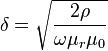 )
)
(it is a very weak dependence: it depends on the square root of the material properties)
and then see this table: http://eddy-current.com/conductivity-of-metals-sorted-by-resistivity/
To produce a change in Q of a factor of 10, the resistivity ρ would have to differ by a factor of 100. Not possible. To produce a change in Q of a factor 1,000, the resistivity ρ would have to differ by a factor of 1,000,000. Completely impossible.
The permeability of free space μo is a constant. The relativity permeability μr of copper is very slightly less than 1. Copper's relative permeability is not going to differ by a large factor.
2) The expression being used to calculate Q is a very different expression than the expression used to measure Q
(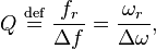 )
)
. One needs to look at what is being calculated as Q (and what variables affect the calculated result) as opposed to what is measured as Q.
3) Homonyms are words that are both spelled and pronounced the same, but have different meanings. If one assumes that they have the same meaning, one will end up in confusion. If we want to understand the difference, we have to understand how Q is being calculated and how it is being measured. Then it becomes clear.
4) Neither what is measured as Q nor what is calculated as Q may correspond to what one thinks Q represents. Not just using calculated Q, but using measured Q may lead to misinterpretation of what is going on, if one doesn't carefully go through the equations. -
Title: Re: EM Drive Developments - related to space flight applications - Thread 3
Post by: Rodal on 07/23/2015 12:17 PM -
<a href="http://forum.nasaspaceflight.com/index.php?topic=37642.msg1408370#msg1408370">Quote from: RERT on 07/23/2015 11:52 AM</a>
Dr. Rodal -
The plane waves off to left and right carry off momentum. The delay causes the conducting barriers to carry
an induced current, and they radiate in both directions.
...
Thanks for the reply. I'm interested on whether you could elaborate further as to how the electromagnetic waves escape the "Faraday cage" of the copper cavity. The electromagnetic fields are inside the cavity. At the copper surface one usually assumes a boundary condition that the tangential Electric Field will always be zero on a metal like copper. How do electromagnetic waves get out ? How does momentum get carried to the outside of the cavity ?
If it is posited that momentum is carried off by black body radiation from the metal to the exterior environment (it would have to radiate more in the big base than the small base and the lateral surface axial component), a calculation shows that the black body radiation cannot account for the forces and accelerations being claimed by the EM Drive researchers. The momentum carried by black body radiation is several orders of magnitude smaller than what is claimed. -
Title: Re: EM Drive Developments - related to space flight applications - Thread 3
Post by: Tron on 07/23/2015 02:05 PM -
Ignore this if it's already posted, but you may want to have a look at this paper:
http://arxiv.org/pdf/1302.2537v1.pdf
"Newton’s Third Law in the Framework of Special Relativity"
The conclusions are pretty juicy, I quote part of them:
"We have shown in this paper that in general Newton’s third law is not compatible with the principles of special relativity and the total force on a two current loop system is not zero"
Then discusses how to get constant (reactionless!) force using two wires of conducting material, one with constant direct current and the other carefully modulated, if I understand the paper well enough,. -
Title: Re: EM Drive Developments - related to space flight applications - Thread 3
Post by: rfmwguy on 07/23/2015 02:16 PM -
<a href="http://forum.nasaspaceflight.com/index.php?topic=37642.msg1408346#msg1408346">Quote from: mwvp on 07/23/2015 09:42 AM</a>
Regarding using wire mesh,
Nice links. wire mesh intrigued me for several reasons that Doc has summarized. Another one may be the angle of reflection, or better yet, scattering of radiation. Assuming outward vector forces are striking frustum side walls.
A wire mesh waveguide is described in https://www.jlab.org/ir/MITSeries/V9.PDF pg 287 with a loss of .4db/m, compared to (typical?) .02db/m. Only ~10%. However, wouldn't one have to multiply that by the expected number of reverberations the wave will traverse? My math on factorials or series is a bit rusty.
$120 for a roll of copper looks pricey compared to the $15 aluminum next to it. Perhaps it can be copper plated? Pretty simple to copper plate.
Another paper on how to hack a magnetron, to work as an amplifier, CW and very (relatively) narrow bandwidth, and use magnetic solenoid tuning:
http://n5dux.com/ham/files/pdf/The%20Magnetron-A%20Low%20Noise%20Long%20Life%20Amplifier.pdf -
Title: Re: EM Drive Developments - related to space flight applications - Thread 3
Post by: SeeShells on 07/23/2015 02:29 PM -
<a href="http://forum.nasaspaceflight.com/index.php?topic=37642.msg1408225#msg1408225">Quote from: rfmwguy on 07/23/2015 02:33 AM</a><a href="http://forum.nasaspaceflight.com/index.php?topic=37642.msg1408205#msg1408205">Quote from: SeeShells on 07/23/2015 02:18 AM</a>
Friendly reminder that Qs over 10K are probably impractical to consider because of the extremely narrow bandwidth; subject to wide variation of resonant freq caused by thermal/mechanical stresses. You could wind up chasing resonance around, especially with a magnetron. I'm with doc on this, high q is not a prerequisite imho.<a href="http://forum.nasaspaceflight.com/index.php?topic=37642.msg1408155#msg1408155">Quote from: Rodal on 07/23/2015 12:27 AM</a>
He emailed me saying the Q was something like 57,000+ but was worried about the antenna position, I said run it if you want but I was still doing research into the antenna and had questions out to ppl who had 40 years + in this field. It's not one I would want to make.<a href="http://forum.nasaspaceflight.com/index.php?topic=37642.msg1408145#msg1408145">Quote from: aero on 07/22/2015 11:50 PM</a>...I wondered why that went quicker last night. Not quick but a little quicker. I guess you found out.
I'm looking at the Yang/Shell Axial Antenna at Big Base case now: very unusual: the stress, and hence the force at the small base is practically zero. The stress at the big base is a central point stress from the antenna. Close inspection of this mode looks like another TM11 transverse magnetic mode but with drastically lower amplitude.
Check it again, they are there now.
QUESTION1: was the mesh kept the same as in the previous csv Yang/Shell case, and you are sure this is the stress at the small base and not outside it?
Most important: QUESTION2: did Meep give you a Q value for this case ?
Thanks
Shell
Design and testing thoughts during this first cup of coffee.....
I couldn't agree more on the Q. To me Q is like a slippery fish, you squeeze it tighter and pop away it goes. Plus running your frequency in a narrow bandwidth you just might be leaving out ghost modes and evanescent waves that are having an effect in generation of thrust. I want to catch this fish.
I've been keeping my eye (ebay and some of my old friends in the industry) on power supplies in the semiconductor industry that are used for magnetron sputtering for metal deposition, they are high power and have the controls to vary their output from duty cycle to frequency and bandwidth and power.
I have a AC rheostat that I was thinking about putting on the current magnetron heater I'm using to drop the voltage lowering the output power and narrowing the bandwidth of the magnetron. I have about 3 volts to work with so it will be touchy. Thoughts here?
You see where I'm going here? The magnetron can be a key in focusing what wave actions are causing the thrust. If I can control the input to the Cavity through the magnetron I can set up a low to medium power test getting stable thrust. Then by varying bandwidth, frequency, duty cycles and even modulate using FM or AM, sweeping the signal across the tune point even varying the Q actions of the cavity and monitoring the thrust. This is another reason I selected the beam to measure. When I "tune" in the maximum thrust I can then set the beam to a acceleration mode to monitor a real world acceleration thrust.
This active mode of the fulcrum beam could be used to test out the theory of motor/generator mode of RS. Small linear springs can be used top and bottom of the beam arm I'd I keep the same cupped dual knife edge (A slight V shape where the carbon fiber tube (CFT) sits in, it keeps it from rolling off). Or and I like this better, suspend the CFT with SS wires @ a 45 degree angle on the center point and drop a arm with a small weight on with a pointer to a scale under the CFT and monitor it's movement, I could calibrate the divisions with weights on the end of the CFT.
Thanks for the Ghost mode and Cavity Mesh measurements to read last night.
Shell -
Title: Re: EM Drive Developments - related to space flight applications - Thread 3
Post by: Rodal on 07/23/2015 02:36 PM -
<a href="http://forum.nasaspaceflight.com/index.php?topic=37642.msg1408260#msg1408260">Quote from: deltaMass on 07/23/2015 03:25 AM</a>
I think I've lost track of all the DIYers now. Let's see:
1. TheTraveller
2. SeeShells
3. rfmwguy
4. Mulletron (?)
5. klm(?)
Is this on the wiki?
Is the wiki link not supposed to be at the top of the page btw? - can't find it.
Concerning, this, what do people think about reporting NULL results of experimenters ? .
So far we have put in the wiki the information about the Aachen Baby EM Drive guys results as being Null, as hard as they try they are clearly Null, so far (and they have tried different measurements).
However we have not reported as Null the partial results of others (with a question mark on the list).
Should we post those partial null results as NULL in the Wiki experimental results table http://emdrive.wiki/Experimental_Results ?
And how should we report the results of rfmwguy and SeeShells and others if they are initially reported as NULL ?
Should we put those results as Null in the the wiki or wait some amount of time (what amount of time ? ) until they perform further experiments and analysis ?
(and if they are initially positive, do we report them right away as positive or do we wait a period of time ?)
-
Title: Re: EM Drive Developments - related to space flight applications - Thread 3
Post by: RonM on 07/23/2015 03:10 PM -
<a href="http://forum.nasaspaceflight.com/index.php?topic=37642.msg1408456#msg1408456">Quote from: Rodal on 07/23/2015 02:36 PM</a><a href="http://forum.nasaspaceflight.com/index.php?topic=37642.msg1408260#msg1408260">Quote from: deltaMass on 07/23/2015 03:25 AM</a>
I think I've lost track of all the DIYers now. Let's see:
1. TheTraveller
2. SeeShells
3. rfmwguy
4. Mulletron (?)
5. klm(?)
Is this on the wiki?
Is the wiki link not supposed to be at the top of the page btw? - can't find it.
Concerning, this, what do people think about reporting NULL results of experimenters ? .
So far we have put in the wiki the information about the Aachen Baby EM Drive guys results as being Null, as hard as they try they are clearly Null, so far (and they have tried different measurements).
However we have not reported as Null the partial results of others (with a question mark on the list).
Should we post those partial null results as NULL in the Wiki experimental results table http://emdrive.wiki/Experimental_Results ?
I think it would be useful to list partial results as they come in, whether they are null or not. Perhaps in a second table to distinguish ongoing experimental series from completed experiments.
Usually, I think it would be best to wait until an experiment is complete before reporting results, but considering the activity of this thread, there is a daily interest in the latest news. And it could help the DIY experimenters by continuing the conversation on designing and running their experiments.
There should be some caveat about the preliminary results being, well, preliminary. -
Title: Re: EM Drive Developments - related to space flight applications - Thread 3
Post by: rfmwguy on 07/23/2015 03:17 PM -
<a href="http://forum.nasaspaceflight.com/index.php?topic=37642.msg1408456#msg1408456">Quote from: Rodal on 07/23/2015 02:36 PM</a>
100% recommend Null results...thats valuable alongside other test data. I'd post it as soon as someone reported it. Guess refutiation is as interesting to me as other data when I study the configuration they were using.<a href="http://forum.nasaspaceflight.com/index.php?topic=37642.msg1408260#msg1408260">Quote from: deltaMass on 07/23/2015 03:25 AM</a>I think I've lost track of all the DIYers now. Let's see:
1. TheTraveller
2. SeeShells
3. rfmwguy
4. Mulletron (?)
5. klm(?)
Is this on the wiki?
Is the wiki link not supposed to be at the top of the page btw? - can't find it.
Concerning, this, what do people think about reporting NULL results of experimenters ? .
So far we have put in the wiki the information about the Aachen Baby EM Drive guys results as being Null, as hard as they try they are clearly Null, so far (and they have tried different measurements).
However we have not reported as Null the partial results of others (with a question mark on the list).
Should we post those partial null results as NULL in the Wiki experimental results table http://emdrive.wiki/Experimental_Results ?
And how should we report the results of rfmwguy and SeeShells and others if they are initially reported as NULL ?
Should we put those results as Null in the the wiki or wait some amount of time (what amount of time ? ) until they perform further experiments and analysis ?
(and if they are initially positive, do we report them right away as positive or do we wait a period of time ?)
Aachen? Yes, I'd plug it in as Null for Design #1. Note there were a couple of Test Method changes, perhaps Design #1, test methods #1, #2, etc. (hope I said this clearly)
I'd also suggest Design naming, like NSF-1701, not change to NSF-1701A unless a significant mechanical or electrical change was made. Think each DIYer can give you the heads-up on that.
-
Title: Re: EM Drive Developments - related to space flight applications - Thread 3
Post by: SeeShells on 07/23/2015 03:17 PM -
<a href="http://forum.nasaspaceflight.com/index.php?topic=37642.msg1408434#msg1408434">Quote from: rfmwguy on 07/23/2015 02:16 PM</a><a href="http://forum.nasaspaceflight.com/index.php?topic=37642.msg1408346#msg1408346">Quote from: mwvp on 07/23/2015 09:42 AM</a>
Regarding using wire mesh,
Nice links. wire mesh intrigued me for several reasons that Doc has summarized. Another one may be the angle of reflection, or better yet, scattering of radiation. Assuming outward vector forces are striking frustum side walls.
A wire mesh waveguide is described in https://www.jlab.org/ir/MITSeries/V9.PDF pg 287 with a loss of .4db/m, compared to (typical?) .02db/m. Only ~10%. However, wouldn't one have to multiply that by the expected number of reverberations the wave will traverse? My math on factorials or series is a bit rusty.
$120 for a roll of copper looks pricey compared to the $15 aluminum next to it. Perhaps it can be copper plated? Pretty simple to copper plate.
Another paper on how to hack a magnetron, to work as an amplifier, CW and very (relatively) narrow bandwidth, and use magnetic solenoid tuning:
http://n5dux.com/ham/files/pdf/The%20Magnetron-A%20Low%20Noise%20Long%20Life%20Amplifier.pdf
I found that article months ago and couldn't locate it again, nice, you may have just made my day!
I've found it interesting and keep coming back to the red flags in the tests.
Air pressure=thrust vs Vacuum=small thrust
This is the 800 pound gorilla sitting in the middle of the lab and nobody wants to poke it. :D
I picked the Perforated copper sheets (not *wire mesh* it's not as good in making a resonating cavity) for a couple reasons and not all listed here, because the boundary conditions of the incident reflected wave actions are not quite the same across a hole boundary as they are from solid copper surface. (we also can see the pretty lights inside). I think I can poke this gorrilla through the holes. I think there are some loopholes in Maxwell's theories that can be taken advantage of.
I'll fill this thought out later as I have some more goodies to pick up for the test bed in town. See ya'll in a couple hours.
Shell -
Title: Re: EM Drive Developments - related to space flight applications - Thread 3
Post by: SeeShells on 07/23/2015 03:20 PM -
<a href="http://forum.nasaspaceflight.com/index.php?topic=37642.msg1408456#msg1408456">Quote from: Rodal on 07/23/2015 02:36 PM</a>
Preliminary or static tests can be listed in the chart, if reported. It categorizes them not as a fully functioning test to achieve thrust.<a href="http://forum.nasaspaceflight.com/index.php?topic=37642.msg1408260#msg1408260">Quote from: deltaMass on 07/23/2015 03:25 AM</a>I think I've lost track of all the DIYers now. Let's see:
1. TheTraveller
2. SeeShells
3. rfmwguy
4. Mulletron (?)
5. klm(?)
Is this on the wiki?
Is the wiki link not supposed to be at the top of the page btw? - can't find it.
Concerning, this, what do people think about reporting NULL results of experimenters ? .
So far we have put in the wiki the information about the Aachen Baby EM Drive guys results as being Null, as hard as they try they are clearly Null, so far (and they have tried different measurements).
However we have not reported as Null the partial results of others (with a question mark on the list).
Should we post those partial null results as NULL in the Wiki experimental results table http://emdrive.wiki/Experimental_Results ?
And how should we report the results of rfmwguy and SeeShells and others if they are initially reported as NULL ?
Should we put those results as Null in the the wiki or wait some amount of time (what amount of time ? ) until they perform further experiments and analysis ?
(and if they are initially positive, do we report them right away as positive or do we wait a period of time ?) -
Title: Re: EM Drive Developments - related to space flight applications - Thread 3
Post by: Ricvil on 07/23/2015 04:22 PM -
<a href="http://forum.nasaspaceflight.com/index.php?topic=37642.msg1408429#msg1408429">Quote from: Tron on 07/23/2015 02:05 PM</a>
Ignore this if it's already posted, but you may want to have a look at this paper:
http://arxiv.org/pdf/1302.2537v1.pdf
"Newton’s Third Law in the Framework of Special Relativity"
The conclusions are pretty juicy, I quote part of them:
"We have shown in this paper that in general Newton’s third law is not compatible with the principles of special relativity and the total force on a two current loop system is not zero"
Then discusses how to get constant (reactionless!) force using two wires of conducting material, one with constant direct current and the other carefully modulated, if I understand the paper well enough,.
It is just a directional "two loop" antenna. The net force becomes from non isotropic asymmetrical radiaton pattern of the antenna. -
Title: Re: EM Drive Developments - related to space flight applications - Thread 3
Post by: frobnicat on 07/23/2015 04:40 PM -
<a href="http://forum.nasaspaceflight.com/index.php?topic=37642.msg1408515#msg1408515">Quote from: Ricvil on 07/23/2015 04:22 PM</a><a href="http://forum.nasaspaceflight.com/index.php?topic=37642.msg1408429#msg1408429">Quote from: Tron on 07/23/2015 02:05 PM</a>
Ignore this if it's already posted, but you may want to have a look at this paper:
http://arxiv.org/pdf/1302.2537v1.pdf
"Newton’s Third Law in the Framework of Special Relativity"
The conclusions are pretty juicy, I quote part of them:
"We have shown in this paper that in general Newton’s third law is not compatible with the principles of special relativity and the total force on a two current loop system is not zero"
Then discusses how to get constant (reactionless!) force using two wires of conducting material, one with constant direct current and the other carefully modulated, if I understand the paper well enough,.
It is just a directional "two loop" antenna. The net force becomes from non isotropic asymmetrical radiaton pattern of the antenna.
This was discussed in thread 2, thing is for a "propulsive effect" of constant thrust it relies on a non stationary ever increasing current :
http://forum.nasaspaceflight.com/index.php?topic=36313.msg1350655#msg1350655
-
Title: Re: EM Drive Developments - related to space flight applications - Thread 3
Post by: dumbo on 07/23/2015 05:16 PM -
<a href="http://forum.nasaspaceflight.com/index.php?topic=37642.msg1408525#msg1408525">Quote from: frobnicat on 07/23/2015 04:40 PM</a>
This was discussed in thread 2, thing is for a "propulsive effect" of constant thrust it relies on a non stationary ever increasing current :
http://forum.nasaspaceflight.com/index.php?topic=36313.msg1350655#msg1350655
They also have a more recent paper called "Relativistic Engine Based on a Permanent Magnet" (from July 13, 2015). The link is: http://lib-arxiv-008.serverfarm.cornell.edu/pdf/1507.02897v1.pdf
-
Title: Re: EM Drive Developments - related to space flight applications - Thread 3
Post by: Rodal on 07/23/2015 05:29 PM -
<a href="http://forum.nasaspaceflight.com/index.php?topic=37642.msg1400935#msg1400935">Quote from: DrBagelBites on 07/06/2015 10:45 PM</a>
I thought I would chime in with questions for the AIAA conference. I am going to be attending the event, so I will be able to report back to you guys about what happens, other questions that were asked, etc.
Let me know of a couple of definite questions that anyone would want me to ask during the Q and A,
AIAA Propulsion and Energy Forum and Exposition
Hilton Orlando, Orlando, Florida...
TUESDAY, JULY 28, 2015 NFF-04. Future Flight Propulsion Systems ...5:00 PM - 5:30 PM
Direct Thrust Measurements of an EMDrive and Evaluation of Possible Side-Effects Martin Tajmar
Suggested questions to Prof. Tajmar arranged in order of importance:
Q1. What is the explanation for the very low Q (only 50) in your EM Drive experiments?. Shawyer has reported Q=45,000 for his Demonstrator at your same tested frequency of 2.45 GHz. Is it because you did not use the usual waveguide isolator and 3-stub tuner between the magnetron and test article?
Has Prof. Tajmar's team grossly over-coupled the RF input to the EM Drive copper truncated cone? Over-coupling is a matter of putting a larger resistive load on the resonant cavity by shunting more of the source load onto the cavity. Over-coupling can give an "equivalent" bandwidth which includes more than one mode.
Was Tajmar trying to match it w/ ~ 50 MHz ? How wide was the high filament current magnetron bandwidth?.
_____________________________________________________
Q2. why your experiments show approximately 60% different thrust force measurements when the EM Drive was physically rotated 180 degrees from the "forward" thrust tests to the "reverse" thrust tests? Shouldn't the thrust be the same regardless of space orientation? Is this orientation-dependence indicative of an experimental artifact or a dependence on an external field ?
_____________________________________________________
Q3. Does Prof. Tajmar think that the reason why Shawyer and Yang claimed much higher thrust (over 1,000 to 10,000 times greater force/InputPower than what Tajmar measured) is because Shawyer and Yang reported tests at ambient pressure (unlike Prof. Tajmar who has performed his tests in a vacuum), and Shawyer and Yang just reported thermal convection artifacts? If, not a nullification due to Shawyer and Yang not performing tests in vacuum, what does Prof. Tajmar think that the huge difference (1,000 to 10,000 times) is due to ?
_____________________________________________________
Q4: What does Prof. Tajmar think about the "motor", "generator" conjecture of Shawyer?: that the EM Drive will not register a significant acceleration unless motivated to do so by vibrations of unspecified magnitude and frequency to produce initial acceleration in the direction pointing from the big base to the small base. Does Prof. Tajmar think that the reason why he measured much lower thrust is because he didn't vibrate the EM Drive to provide such initial condition?
-
Title: Re: EM Drive Developments - related to space flight applications - Thread 3
Post by: deltaMass on 07/23/2015 05:57 PM -
<a href="http://forum.nasaspaceflight.com/index.php?topic=37642.msg1408429#msg1408429">Quote from: Tron on 07/23/2015 02:05 PM</a>
Ignore this if it's already posted, but you may want to have a look at this paper:
Another photon rocket, I think
http://arxiv.org/pdf/1302.2537v1.pdf
"Newton’s Third Law in the Framework of Special Relativity"
The conclusions are pretty juicy, I quote part of them:
"We have shown in this paper that in general Newton’s third law is not compatible with the principles of special relativity and the total force on a two current loop system is not zero"
Then discusses how to get constant (reactionless!) force using two wires of conducting material, one with constant direct current and the other carefully modulated, if I understand the paper well enough,.
http://www.talk-polywell.org/bb/viewtopic.php?f=10&t=5940&start=15#p120645
At least that's a peer-reviewed version.
I'll take a closer look nonetheless. -
Title: Re: EM Drive Developments - related to space flight applications - Thread 3
Post by: aero on 07/23/2015 06:00 PM -
<a href="http://forum.nasaspaceflight.com/index.php?topic=37642.msg1408523#msg1408523">Quote from: kitsuac on 07/23/2015 04:39 PM</a><a href="http://forum.nasaspaceflight.com/index.php?topic=37642.msg1408237#msg1408237">Quote from: aero on 07/23/2015 02:42 AM</a>
Because EW is using real world materials with analog sources, not discretized sources and idealized copper that doesn't seem to heat or suffer significant losses of any sort. Perhaps, just guessing here, perhaps if the node granularity was less than the skin depth of the copper, we could see more realistic skin effects. But its not so we can't.
I'm currently running some tests using MIT's starcluster to automate a cluster of meep servers. Using a higher resolution setting in meep of course is much slower, but I think it may allow for more parallelism. If that proves to be true, higher resolutions could be run at a more feasible speed at the expense of using a more costly cluster of servers. Would that be helpful to you folks?
Yes it would.
My point of Node granularity being less than skin depth is simply that with the current resolution, node granularity, being about 1.2 mm, is about 1000 times larger than skin depth, and it is within the skin where the losses must occur. This is true for both the sides and the ends. As Dr. Rodal posted, Q is inversely proportional to losses but running at the current resolution meep cannot "sample" the skin depth so losses there don't exist in the numerical model. Hence the only "known" source of losses is ignored --> very high Q.
I addressed this issue late last year on the meep-discuss mailing list and got two responses.
First response, can meep use a high resolution for the geometry of the skin while low resolution in the rest of the lattice where 10 nodes per wavelength is adequate? The response was no, meep doesn't do that but perhaps I should use a commercial software as some do have that capability, or alternatively as the source code is available, I am welcome to write my own functions.
Second response, which we may now have the talent to address here was,
"Fictitious materials can be used in place of the metal skin, materials designed to have a gross response like copper except that the response occurs over a much greater skin depth more suitable to the resolution at which the model runs."
I still have no idea how to design such a material (a Drude model of some sort) but it would be straight forward to increase the thickness of the cavity material in the model, within reason, to accommodate such a fictitious material. -
Title: Re: EM Drive Developments - related to space flight applications - Thread 3
Post by: Rodal on 07/23/2015 06:20 PM -
Clearly the most important thing to do in Meep simulations is to
model a loop antenna to excite TE (transverse electric) modes.
The presently used dipole antenna has only excited Transverse Magnetic modes whether at the big end or at the small end, whether oriented in the transverse or the longitudinal directions, whether for rfmwguy/NSF-1701 or for Yang/Shell geometry.
If unable to model a loop antenna to excite TE modes, what could be done as the next step is to place the dipole antenna in the transverse direction near the small end, to be able to compare the two runs made for Yang/Shell with the dipole antenna at the big end.
________________
After modeling the loop antenna, the next most important thing is to:
model a magnetron as the RF source
model a waveguide entering the EM Drive, as done by Prof. Yang -
Title: Re: EM Drive Developments - related to space flight applications - Thread 3
Post by: aero on 07/23/2015 06:37 PM -
@Rodal - I'm not sure where you are getting the data indicating that Q varies by 3 orders of magnitude, perhaps a miscommunication somewhere. If your source is meep Harminv data, then the correct values as I recorded them at the time of the runs are:
Q 87,830,861
Q 87,830,729
Q 5,068,251
Q 59,477,392
where the first two were using, I believe, a shorter dipole antenna (29 mm) and driving with the previously determined resonance frequency to hone in on the actual cavity resonance frequency as model. It is very consistently 2.46316012E+009 Hz within kHz. The final two were from the model with drive frequency = 2.45 GHz and antenna length = 58 mm as used to generate the 2 Yang-Shell data sets uploaded to Google drive. -
Title: Re: EM Drive Developments - related to space flight applications - Thread 3
Post by: Rodal on 07/23/2015 06:44 PM -
<a href="http://forum.nasaspaceflight.com/index.php?topic=37642.msg1408570#msg1408570">Quote from: aero on 07/23/2015 06:37 PM</a>
@Rodal - I'm not sure where you are getting the data indicating that Q varies by 3 orders of magnitude, perhaps a miscommunication somewhere. If your source is meep Harminv data, then the correct values as I recorded them at the time of the runs are:
Q 87,830,861
Q 87,830,729
Q 5,068,251
Q 59,477,392
where the first two were using, I believe, a shorter dipole antenna (29 mm) and driving with the previously determined resonance frequency to hone in on the actual cavity resonance frequency as model. It is very consistently 2.46316012E+009 Hz within kHz. The final two were from the model with drive frequency = 2.45 GHz and antenna length = 58 mm as used to generate the 2 Yang-Shell data sets uploaded to Google drive.
aero, the information comes from your message quoted again below:<a href="http://forum.nasaspaceflight.com/index.php?topic=37642.msg1408167#msg1408167">Quote from: aero on 07/23/2015 01:18 AM</a><a href="http://forum.nasaspaceflight.com/index.php?topic=37642.msg1408155#msg1408155">Quote from: Rodal on 07/23/2015 12:27 AM</a><a href="http://forum.nasaspaceflight.com/index.php?topic=37642.msg1408145#msg1408145">Quote from: aero on 07/22/2015 11:50 PM</a>...I wondered why that went quicker last night. Not quick but a little quicker. I guess you found out.
I'm looking at the Yang/Shell Axial Antenna at Big Base case now: very unusual: the stress, and hence the force at the small base is practically zero. The stress at the big base is a central point stress from the antenna. Close inspection of this mode looks like another TM11 transverse magnetic mode but with drastically different amplitude.
Check it again, they are there now.
QUESTION1: was the mesh kept the same as in the previous csv Yang/Shell case, and you are sure this is the stress at the small base and not outside it?
Most important: QUESTION2: did Meep give you a Q value for this case ?
Thanks
Everything about the run was identical except the antenna. The csv files are the same size aren't they? If something were changed likely they would change size. And really, the bases should be in the same place they were previously. I looked at this data set with HDFview. But note that the row numbers I gave you I had 1 added, to start at 1 like the csv matrices, instead of 0 as HDFview uses. If you also added 1, that would be the problem. The model skin is three matrix rows thick, adding an extra 1 would make the small base row be inside the skin.
It was also the same 58 mm antenna centered quarter wavelength from the inside face of the big base but rotated 90 degrees to an axial orentation. Note that 1/4 wave length is only slightly more than half of 58 mm, so the end of the antenna near the big base was about 1.5 mm away from the base, and excited with ez component although hy would have been more natural.
Q? Yea, Q was ridiculously high, like 60 million and the resonant frequency was like 2.463 GHz, which I ignored and made the run at 2.45 GHz.
In my post I was discussing your statement <<Q? Yea, Q was ridiculously high, like 60 million >>
referring to the last run for Yang/Shell with the antenna oriented along the longitudinal x axis
Q=60 million is more than 1,000 times greater than Q=50,000 reported by Shawyer
===> I thought you were getting reasonable Q's for your other runs. My understanding from Shell is that your prior model for Yang/Shell was giving Q = 87,000+
Are you getting Q's with Meep of millions for all the runs?
===> The program I wrote gives a Q=50,175 for rfmwguy/NSF-1701, I have not had the chance to calculate it for Yang/Shell yet.
If Meep is giving a Q=80 million for rfmwguy/NSF-1701 there is something wrong somewhere...
Are you getting Q=80 million numbers with the Drude model ?
Or perhaps the interpretation of Q in Meep is wrong: it is 3 orders of magnitude larger than reasonable -
Title: Re: EM Drive Developments - related to space flight applications - Thread 3
Post by: aero on 07/23/2015 07:22 PM -
<a href="http://forum.nasaspaceflight.com/index.php?topic=37642.msg1408577#msg1408577">Quote from: Rodal on 07/23/2015 06:44 PM</a><a href="http://forum.nasaspaceflight.com/index.php?topic=37642.msg1408570#msg1408570">Quote from: aero on 07/23/2015 06:37 PM</a>
@Rodal - I'm not sure where you are getting the data indicating that Q varies by 3 orders of magnitude, perhaps a miscommunication somewhere. If your source is meep Harminv data, then the correct values as I recorded them at the time of the runs are:
Q 87,830,861
Q 87,830,729
Q 5,068,251
Q 59,477,392
where the first two were using, I believe, a shorter dipole antenna (29 mm) and driving with the previously determined resonance frequency to hone in on the actual cavity resonance frequency as model. It is very consistently 2.46316012E+009 Hz within kHz. The final two were from the model with drive frequency = 2.45 GHz and antenna length = 58 mm as used to generate the 2 Yang-Shell data sets uploaded to Google drive.
aero, the information comes from your message quoted again below:<a href="http://forum.nasaspaceflight.com/index.php?topic=37642.msg1408167#msg1408167">Quote from: aero on 07/23/2015 01:18 AM</a><a href="http://forum.nasaspaceflight.com/index.php?topic=37642.msg1408155#msg1408155">Quote from: Rodal on 07/23/2015 12:27 AM</a><a href="http://forum.nasaspaceflight.com/index.php?topic=37642.msg1408145#msg1408145">Quote from: aero on 07/22/2015 11:50 PM</a>...I wondered why that went quicker last night. Not quick but a little quicker. I guess you found out.
I'm looking at the Yang/Shell Axial Antenna at Big Base case now: very unusual: the stress, and hence the force at the small base is practically zero. The stress at the big base is a central point stress from the antenna. Close inspection of this mode looks like another TM11 transverse magnetic mode but with drastically different amplitude.
Check it again, they are there now.
QUESTION1: was the mesh kept the same as in the previous csv Yang/Shell case, and you are sure this is the stress at the small base and not outside it?
Most important: QUESTION2: did Meep give you a Q value for this case ?
Thanks
Everything about the run was identical except the antenna. The csv files are the same size aren't they? If something were changed likely they would change size. And really, the bases should be in the same place they were previously. I looked at this data set with HDFview. But note that the row numbers I gave you I had 1 added, to start at 1 like the csv matrices, instead of 0 as HDFview uses. If you also added 1, that would be the problem. The model skin is three matrix rows thick, adding an extra 1 would make the small base row be inside the skin.
It was also the same 58 mm antenna centered quarter wavelength from the inside face of the big base but rotated 90 degrees to an axial orentation. Note that 1/4 wave length is only slightly more than half of 58 mm, so the end of the antenna near the big base was about 1.5 mm away from the base, and excited with ez component although hy would have been more natural.
Q? Yea, Q was ridiculously high, like 60 million and the resonant frequency was like 2.463 GHz, which I ignored and made the run at 2.45 GHz.
Again, in my post I was discussing your statement <<Q? Yea, Q was ridiculously high, like 60 million >>
referring to the last run for Yang/Shell with the antenna oriented along the longitudinal x axis
Q=60 million is 1,000 times greater than Q=60,000
The ~60 million is correct, it is the ~60,000 that I am wondering about. The closest number that I recorded was ~5 million, only 1 order of magnitude difference.
As forQuoteIf unable to model a loop antenna to excite TE modes, what could be done as the next step is to place the dipole antenna in the transverse direction near the small end, to be able to compare the two runs made for Yang/Shell with the dipole antenna at the big end.
That is what the first Yang-Shell data set was. See attached as downloaded from Google drive just now. Only one data set (the latest uploaded) had the longitudinal dipole antenna at the big end.
Note that the small end antenna .csv files are in the same folder as the big end antenna csv files. Sorted alphabetically all of the "small" are after all of the "Big" file names. And I note that the data seems to have been generated using a lattice size different from the current lattice size. I don't have a good way to check end row or antenna location using the uploaded data, I hope you do. I will run it again if needed.
-
Title: Re: EM Drive Developments - related to space flight applications - Thread 3
Post by: Rodal on 07/23/2015 07:27 PM -
I just calculated Yang/Shell TM113 with my program:
Q =45,039 Yang/Shell (copper) natural frequency for TM113 = 2.4941 GHz
Q =50,175 rfmwguy/NSF-1701(copper)
Used the following material properties:
epsilon0 = 8.854187817*10^-12);
mu0 = 0.999991(*copper*)*4*Pi*10^(-7);
resistivity = 1.678*10^(-8)(*copper*);
For using same material constants, I get
If I use brass or bronze I will get a lower Q. For example, for:
resistivity = 1.437*10^(-7) high strength brass
giving:
Q= 15,391 (Yang/Shell) high strength brass
Q= 17,146 (rfmwguy/NSF1701) high strength brass
what material model are you using to get Q's in the millions? are you using the Drude model ?
I would look for something responsible for orders of magnitude off: Meep units conversion ?
____________
PS: I edited my prior message, eliminating reference to the 60 million Q, as it appears that all the Q's from Meep runs are suspect. -
Title: Re: EM Drive Developments - related to space flight applications - Thread 3
Post by: tchernik on 07/23/2015 07:51 PM -
<a href="http://forum.nasaspaceflight.com/index.php?topic=37642.msg1408538#msg1408538">Quote from: dumbo on 07/23/2015 05:16 PM</a><a href="http://forum.nasaspaceflight.com/index.php?topic=37642.msg1408525#msg1408525">Quote from: frobnicat on 07/23/2015 04:40 PM</a>
This was discussed in thread 2, thing is for a "propulsive effect" of constant thrust it relies on a non stationary ever increasing current :
http://forum.nasaspaceflight.com/index.php?topic=36313.msg1350655#msg1350655
They also have a more recent paper called "Relativistic Engine Based on a Permanent Magnet" (from July 13, 2015). The link is: http://lib-arxiv-008.serverfarm.cornell.edu/pdf/1507.02897v1.pdf
Remarkable paper. Does this paper suggest a new kind of thruster we could build in practice? or is this un-physical due to it assuming things like Terawatts or input power or some such?
Because it sounds mechanically simple. So, where's the catch? -
Title: Re: EM Drive Developments - related to space flight applications - Thread 3
Post by: b0nafide on 07/23/2015 08:10 PM -
<a href="http://forum.nasaspaceflight.com/index.php?topic=37642.msg1408456#msg1408456">Quote from: Rodal on 07/23/2015 02:36 PM</a>
...what do people think about reporting NULL results of experimenters ? ...
I'm just a random person following this thread, but I have been waiting for kml's null tests to appear on the experimental results section of the wiki ever since kml reported his findings. It has been bothering me that nobody else seems to think kml's test is notable. I learned something new. We can alter the reading of a digital scale without touching it. -
Title: Re: EM Drive Developments - related to space flight applications - Thread 3
Post by: flux_capacitor on 07/23/2015 08:10 PM -
<a href="http://forum.nasaspaceflight.com/index.php?topic=37642.msg1408604#msg1408604">Quote from: tchernik on 07/23/2015 07:51 PM</a>
Remarkable paper. Does this paper suggest a new kind of thruster we could build in practice? or is this un-physical due to it assuming things like Terawatts or input power or some such?
Because it sounds mechanically simple. So, where's the catch?
The catch is maybe in the following sentence in their paper:
"hence for any momentum that is acquired by matter an opposite momentum is attributed to the electromagnetic field."
Does that sentence preclude the device from being used as a thruster? -
Title: Re: EM Drive Developments - related to space flight applications - Thread 3
Post by: aero on 07/23/2015 08:14 PM -
<a href="http://forum.nasaspaceflight.com/index.php?topic=37642.msg1408596#msg1408596">Quote from: Rodal on 07/23/2015 07:27 PM</a>
I just calculated Yang/Shell TM113 with my program:
The Drude model.
Q =45,039 Yang/Shell (copper) natural frequency for TM113 = 2.4941 GHz
Q =50,175 rfmwguy/NSF-1701(copper)
Used the following material properties:
epsilon0 = 8.854187817*10^-12);
mu0 = nbsp; 0.999991(*copper*)*4*Pi*10^(-7);
resistivity = 1.678*10^(-8)(*copper*);
For using same material constants, I get
If I use brass or bronze I will get a lower Q. For example, for:
resistivity = 1.437*10^(-7) high strength brass
giving:
Q= 15,391 (Yang/Shell) high strength brass
Q= 17,146 (rfmwguy/NSF1701) high strength brass
what material model are you using to get Q's in the millions? are you using the Drude model ?Quote____________
PS: I edited my prior message, eliminating reference to the 60 million Q, as it appears that all the Q's from Meep runs are suspect.
Of course they are. There are no losses, not because of the material model, but because of the sampling resolution, (node separation). They are a valid indication of whether or not the cavity model will resonate but more than that it is hard to say. I use them for that purpose, interpreting high Q's as strong resonance of the model and low or no Q's to indicate low or no resonance at that frequency/antenna configuration as modelled.
We have known for a long time that Q's in the millions are not realistic for room temperature cavities. -
Title: Re: EM Drive Developments - related to space flight applications - Thread 3
Post by: Rodal on 07/23/2015 08:17 PM -
<a href="http://forum.nasaspaceflight.com/index.php?topic=37642.msg1408608#msg1408608">Quote from: b0nafide on 07/23/2015 08:10 PM</a><a href="http://forum.nasaspaceflight.com/index.php?topic=37642.msg1408456#msg1408456">Quote from: Rodal on 07/23/2015 02:36 PM</a>
...what do people think about reporting NULL results of experimenters ? ...
I'm just a random person following this thread, but I have been waiting for kml's null tests to appear on the experimental results section of the wiki ever since kml reported his findings. It has been bothering me that nobody else seems to think kml's test is notable. I learned something new. We can alter the reading of a digital scale without touching it.
I think that one reason they have not been listed yet is because:
IMPORTANT: The other EM Drive listed have variable cross-section. KML is testing a constant-cross section cavity.
It looks like if it is listed it should be listed separately, as it does not conform to the "tapered cross-section" concept. -
Title: Re: EM Drive Developments - related to space flight applications - Thread 3
Post by: Rodal on 07/23/2015 08:22 PM -
<a href="http://forum.nasaspaceflight.com/index.php?topic=37642.msg1408612#msg1408612">Quote from: aero on 07/23/2015 08:14 PM</a>
...
Of course they are. There are no losses, not because of the material model, but because of the sampling resolution, (node separation). They are a valid indication of whether or not the cavity model will resonate but more than that it is hard to say. I use them for that purpose, interpreting high Q's as strong resonance of the model and low or no Q's to indicate low or no resonance at that frequency/antenna configuration as modelled.
We have known for a long time that Q's in the millions are not realistic for room temperature cavities.
I don't agree that the losses should be modeled with nodes through a micrometer skin depth. That's not the way that losses are modeled in COMSOL FEA or in most modeling programs, or in my computer program, nor do I think that's how Meep should do it. It would not be feasible to model the losses that way nor do I think it would be a good way to do it. It would be very inaccurate, and computer-time wasting. The skin depth problem has an exact solution, well-known and verified in too many experiments.
All you have to do to model the Q is to perform a volume integral and a separate surface integration. If not built-in in Meep maybe someone has already done it.
No need for nodes: the losses are just the skin depth times the surface integral of the square magnitude of the B field. The losses are surface losses.
Q should be calculated as follows:
()
The numerator is a volume integral (of the energy density), while the denominator is a surface integral.
do you have a link for how (what equation it uses) Meep calculates the Q quality factor ?
I feel that there is some conversion issue or a wrong constant somewhere...
-
Title: Re: EM Drive Developments - related to space flight applications - Thread 3
Post by: notarget on 07/23/2015 08:29 PM -
<a href="http://forum.nasaspaceflight.com/index.php?topic=37642.msg1408612#msg1408612">Quote from: aero on 07/23/2015 08:14 PM</a>
For interest, I've attached a movie of a mid-plane Y direction slice of the NSF frustum playing the Ez field. The movie covers about 400 cycles right before then after the Gaussian pulse ends - so shows the resonating cavity as the energy diminishes.
Of course they are. There are no losses, not because of the material model, but because of the sampling resolution, (node separation). They are a valid indication of whether or not the cavity model will resonate but more than that it is hard to say. I use them for that purpose, interpreting high Q's as strong resonance of the model and low or no Q's to indicate low or no resonance at that frequency/antenna configuration as modelled.
We have known for a long time that Q's in the millions are not realistic for room temperature cavities.
I've also attached the ctl file I used to generate this case - note that I'm using quarter symmetry and a reduced resolution of 150 as I was centering in on the pulse behavior. In the movie, I've clamped the Ez values to +/- 0.028665 so that the effect of the source isn't overwhelming in the beginning when it's on.
Note that in the ctl file, I've included an alternative Cu model that is taken from the reference: http://falsecolour.com/aw/meep_metals/investigation.html#SECTION00011600000000000000 where the author validated the Cu model inside meep.
I'm running higher res (250) now and bracketing the interesting time period on output after the Gaussian pulse ends. I think we should probably naturally terminate the Gaussian source pulse instead of artificially terminating it to avoid the transients.
WRT running a loop source, should be pretty easy, though the aliasing into the cartesian mesh is going to introduce some weird frequencies... -
Title: Re: EM Drive Developments - related to space flight applications - Thread 3
Post by: A_M_Swallow on 07/23/2015 08:31 PM -
<a href="http://forum.nasaspaceflight.com/index.php?topic=37642.msg1408477#msg1408477">Quote from: SeeShells on 07/23/2015 03:17 PM</a>
{snip}
I've found it interesting and keep coming back to the red flags in the tests.
Air pressure=thrust vs Vacuum=small thrust
This is the 800 pound gorilla sitting in the middle of the lab and nobody wants to poke it. :D
{snip}
That is why I suggested to Traveller that he design his device with an off resonate frequency mode. Heat and magnetic effects would still cause movements in air but not the EM Drive itself. We can test vacuum effects when we have a design that works reliably in air. -
Title: Re: EM Drive Developments - related to space flight applications - Thread 3
Post by: CraigPichach on 07/23/2015 09:05 PM -
New question for design purposes - For commercial magnetrons at 100kW need Solenoid, Waveguide Launcher and Isolator. I am proposing to feed the copper frustrum after the end of the isolator (where a waterload is used to absorb RF energy); this is different than what Eagleworks proposed. I guess one could attach the thruster at the end of the waveguide launcher but that would require a perfect impedance match between the magnetron and the thruster otherwise any reflected energy would immediately do damage to the magnetron. If we do that the EM-Drive/Q-Thruster "thrust" should still occur as in theory at resonance there should be no return to the magnetron ? ? ? ? (is this correct???)
Also has anyone worked with CST software? Anyone think that's the software to use to confirm dimensions for resonance frequency at 930MHz (it seriously looks like >2GHz is out for any magnetron application over 10kW)? -
Title: Re: EM Drive Developments - related to space flight applications - Thread 3
Post by: notarget on 07/23/2015 09:15 PM -
<a href="http://forum.nasaspaceflight.com/index.php?topic=37642.msg1408558#msg1408558">Quote from: Rodal on 07/23/2015 06:15 PM</a>
Number of time steps, 6527 and total meep time = 13.054 time units.
Wow - got it - so we're showing an exponential growth of force on the large base for the Yang model, but we need to run a lot further in time to get where we want to be. Are these the forces output by meep or calculated by you afterward? Can you please summarize what you need for the force calculation / output? -
Title: Re: EM Drive Developments - related to space flight applications - Thread 3
Post by: Rodal on 07/23/2015 09:52 PM -
<a href="http://forum.nasaspaceflight.com/index.php?topic=37642.msg1408640#msg1408640">Quote from: notarget on 07/23/2015 09:15 PM</a>
1) I calculate the forces using Wolfram Mathematica (https://www.wolfram.com/) post-processing .csv files<a href="http://forum.nasaspaceflight.com/index.php?topic=37642.msg1408558#msg1408558">Quote from: Rodal on 07/23/2015 06:15 PM</a>Number of time steps, 6527 and total meep time = 13.054 time units.
Wow - got it - so we're showing an exponential growth of force on the large base for the Yang model, but we need to run a lot further in time to get where we want to be. Are these the forces output by meep or calculated by you afterward? Can you please summarize what you need for the force calculation / output?
2) I need all 6 electromagnetic fields at a surface to calculate the stress. For example, for the Big Base, with normal "x" (*) Cartesian axis of axi-symmetry of the truncated cone and y and z transverse axes perpendicular to x, I need:
Exx, Exy, Exz, Hxx, Hxy and Hxz fields at the Big Base
where the first subscript refers to the axis perpendicular to the surface, and the second subscript refers to the component of the electromagnetic field vector
Ditto for the 6 fields at the small base
3) aero has been outputting this information for the last 14 time slices (of the total of 320 time slices), the 6 fields for the Small Base and for the Big Base.
4) aero has been using eps averaging done automatically by Meep, so the location of the bases (and other nodes for the material) may not be where you expect them to be: have to check the location of the bases ahead of time, and output the csv files such as to have the 6 fields in contact with the base
5) I need to have the output information: total Meep run time (in aero's case it was 13.054 as I recall), the total number of Meep time slices (it was 320) and the total number of Finite Difference times steps ( 6527 ). I use this information for scaling purposes, since Meep units need to be scaled to real time, etc.
6) I need all Meed scaling information: Meep length (for aero is 0.3), Meep Current (aero uses default input Io=1 Amp) etc.
(*) I would use z as the longitudinal axis of axi-symmetry of the cone, but aero has been using x. The choice is arbitrary of course
-
Title: Re: EM Drive Developments - related to space flight applications - Thread 3
Post by: kml on 07/23/2015 10:00 PM -
<a href="http://forum.nasaspaceflight.com/index.php?topic=37642.msg1408608#msg1408608">Quote from: b0nafide on 07/23/2015 08:10 PM</a><a href="http://forum.nasaspaceflight.com/index.php?topic=37642.msg1408456#msg1408456">Quote from: Rodal on 07/23/2015 02:36 PM</a>
...what do people think about reporting NULL results of experimenters ? ...
I'm just a random person following this thread, but I have been waiting for kml's null tests to appear on the experimental results section of the wiki ever since kml reported his findings. It has been bothering me that nobody else seems to think kml's test is notable. I learned something new. We can alter the reading of a digital scale without touching it.
Those early test results were confirmed to be the result of RFI affecting the scale, so they should be disregarded.
The original design with an adjustable copper covered plunger on one end was not very RF tight. The current design with copper gaskets at each end is much better and most of the RFI issues since that change have been with the remote control transmitter and not the test unit.
I am continuing to run test and collect data. I have been holding off on posting more test results until I am absolutely sure that the data is clean and not affected by RFI. I can say the vast majority of the test runs have shown no deviation from the thermal slope while RF is on. The few that did have either been confirmed or suspected as RFI related. Early indications are that a dielectric alone is not able to produce the effect.
Here is an updated picture of the test rig with the 30W PA driven by an alinco DJ-G7T transciever in crossband repeat mode. The fan on the PA is not used during test runs. The new sample port location is on the left side.
(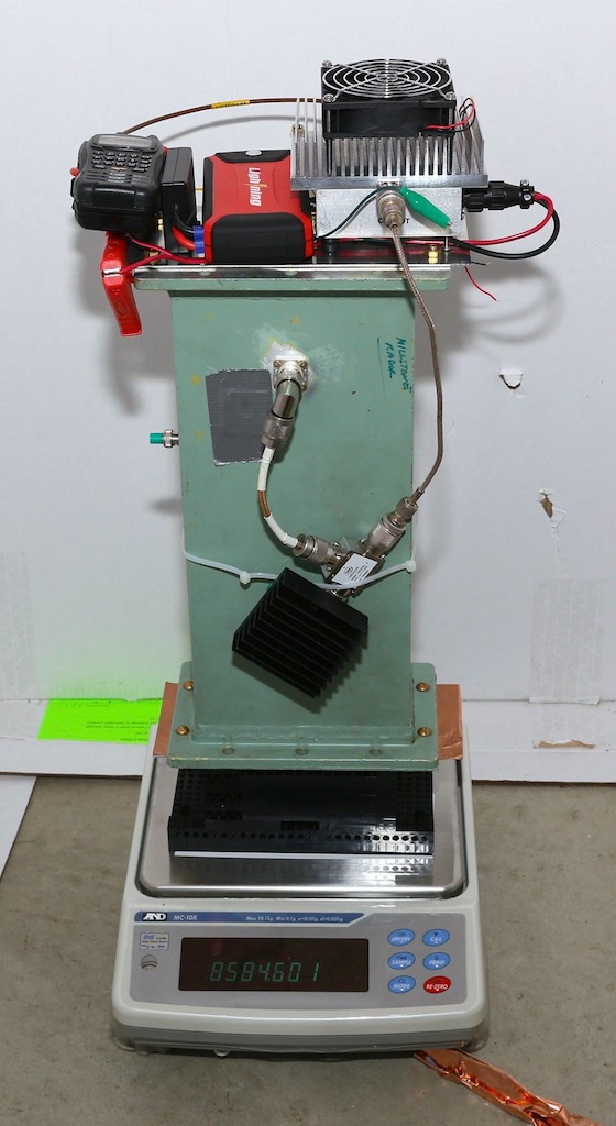 )
)
-
Title: Re: EM Drive Developments - related to space flight applications - Thread 3
Post by: notarget on 07/23/2015 10:01 PM -
<a href="http://forum.nasaspaceflight.com/index.php?topic=37642.msg1408649#msg1408649">Quote from: Rodal on 07/23/2015 09:52 PM</a>
3) aero has been outputting this information for the last 14 time slices (of the total of 320 time slices), the 6 fields for the Small Base and for the Big Base.
Got it - BTW props to Aero (Steve) for learning meep and putting the input / geoms together - I'm drafting his work effectively.
I'll do some long runs and save a lot more time steps to get a feel for the transients. Pls stand by as I'm fumbling around. -
Title: Re: EM Drive Developments - related to space flight applications - Thread 3
Post by: Rodal on 07/23/2015 10:04 PM -
<a href="http://forum.nasaspaceflight.com/index.php?topic=37642.msg1408654#msg1408654">Quote from: kml on 07/23/2015 10:00 PM</a><a href="http://forum.nasaspaceflight.com/index.php?topic=37642.msg1408608#msg1408608">Quote from: b0nafide on 07/23/2015 08:10 PM</a><a href="http://forum.nasaspaceflight.com/index.php?topic=37642.msg1408456#msg1408456">Quote from: Rodal on 07/23/2015 02:36 PM</a>
...what do people think about reporting NULL results of experimenters ? ...
I'm just a random person following this thread, but I have been waiting for kml's null tests to appear on the experimental results section of the wiki ever since kml reported his findings. It has been bothering me that nobody else seems to think kml's test is notable. I learned something new. We can alter the reading of a digital scale without touching it.
Those early test results were confirmed to be the result of RFI affecting the scale, so they should be disregarded.
The original design with an adjustable copper covered plunger on one end was not very RF tight. The current design with copper gaskets at each end is much better and most of the RFI issues since that change have been with the remote control transmitter and not the test unit.
I am continuing to run test and collect data. I have been holding off on posting more test results until I am absolutely sure that the data is clean and not affected by RFI. I can say the vast majority of the test runs have shown no deviation from the thermal slope while RF is on. The few that did have either been confirmed or suspected as RFI related. Early indications are that a dielectric alone is not able to produce the effect.
Here is an updated picture of the test rig with the 30W PA driven by an alinco DJ-G7T transciever in crossband repeat mode. The fan on the PA is not used during test runs. The new sample port location is on the left side.
Great information !!!
2 questions:
1) Should we document your present results as NULL in the Wiki or do you want us to wait?
2) Have you "motivated" the EM Drive by tapping it or vibrating it? ==> Recall TheTraveller/Shawyer's conjecture that for EM Drive to register a force, it needs to be motivated by tapping it or vibrating it -
Title: Re: EM Drive Developments - related to space flight applications - Thread 3
Post by: kml on 07/23/2015 10:14 PM -
<a href="http://forum.nasaspaceflight.com/index.php?topic=37642.msg1408658#msg1408658">Quote from: Rodal on 07/23/2015 10:04 PM</a>
2 questions:
1) Should we document your present results as NULL in the Wiki or do you want us to wait?
2) Have you "motivated" the EM Drive by tapping it or vibrating it? ==> Recall TheTraveller/Shawyer's conjecture that for EM Drive to register a force, it needs to be motivated by tapping it or vibrating it
Please hold off on listing it as NULL until I post plots that have all of the test parameters on them. A NULL result without knowing the power level, Q etc will be less useful.
I have thought about inducing vibration in a controlled way. I did some test runs with the PA fan operating specifically as a source of vibration but it induces 200mg-f swings in force that would obscure any real signal. A small solenoid with an adjustable function generator would be ideal. -
Title: Re: EM Drive Developments - related to space flight applications - Thread 3
Post by: frobnicat on 07/23/2015 11:28 PM -
<a href="http://forum.nasaspaceflight.com/index.php?topic=37642.msg1408609#msg1408609">Quote from: flux_capacitor on 07/23/2015 08:10 PM</a><a href="http://forum.nasaspaceflight.com/index.php?topic=37642.msg1408604#msg1408604">Quote from: tchernik on 07/23/2015 07:51 PM</a>
Remarkable paper. Does this paper suggest a new kind of thruster we could build in practice? or is this un-physical due to it assuming things like Terawatts or input power or some such?
Because it sounds mechanically simple. So, where's the catch?
The catch is maybe in the following sentence in their paper:
"hence for any momentum that is acquired by matter an opposite momentum is attributed to the electromagnetic field."
Does that sentence preclude the device from being used as a thruster?
The catch appears to be the same as the previous paper, starting from the same idea (eq. 21 in new paper) and arriving at similar conclusion (eq. 48) that a force is proportional to the second derivative of current driven in a loop. While nothing factually wrong is written, nothing hints at a "rectification" (no square term for instance) and nothing justify the deceptive mention of microwave currents as an implied mean to reach a steady state net force (just before conclusion). By eq. 48, For a steady state net force the second derivative of current must be constant, that makes a current not only increasing constantly but also accelerating in rate of increase. A stationary current (AC, DC, AC+DC, random of constant magnitude envelope...) would amount to 0 net thrust averaged.
Taking the numbers for making this flying saucer to fly (last part before conclusion) 1.9*10^22 A/s², so first second of hovering needs about 10^22 A, and only increasing quadratically. Any copper coil would sublimate instantly, going superconducting niobium-tin @ 200000 A/cm² would require a coil with an astonishing section of 5 trillion square meters, more than surface of India...
-
Title: Re: EM Drive Developments - related to space flight applications - Thread 3
Post by: SeeShells on 07/23/2015 11:28 PM -
It seems somewhere I read or heard Solidworks could output a C++ code to a output file for a object. It's been awhile so I might be wrong. If it can ,could that C++ code be used in MEEP for the loop antenna? Areo would be happy.
-
Title: Re: EM Drive Developments - related to space flight applications - Thread 3
Post by: aero on 07/23/2015 11:37 PM -
<a href="http://forum.nasaspaceflight.com/index.php?topic=37642.msg1408621#msg1408621">Quote from: notarget on 07/23/2015 08:29 PM</a><a href="http://forum.nasaspaceflight.com/index.php?topic=37642.msg1408612#msg1408612">Quote from: aero on 07/23/2015 08:14 PM</a>
For interest, I've attached a movie of a mid-plane Y direction slice of the NSF frustum playing the Ez field. The movie covers about 400 cycles right before then after the Gaussian pulse ends - so shows the resonating cavity as the energy diminishes.
Of course they are. There are no losses, not because of the material model, but because of the sampling resolution, (node separation). They are a valid indication of whether or not the cavity model will resonate but more than that it is hard to say. I use them for that purpose, interpreting high Q's as strong resonance of the model and low or no Q's to indicate low or no resonance at that frequency/antenna configuration as modelled.
We have known for a long time that Q's in the millions are not realistic for room temperature cavities.
I've also attached the ctl file I used to generate this case - note that I'm using quarter symmetry and a reduced resolution of 150 as I was centering in on the pulse behavior. In the movie, I've clamped the Ez values to +/- 0.028665 so that the effect of the source isn't overwhelming in the beginning when it's on.
Note that in the ctl file, I've included an alternative Cu model that is taken from the reference: http://falsecolour.com/aw/meep_metals/investigation.html#SECTION00011600000000000000 where the author validated the Cu model inside meep.
I'm running higher res (250) now and bracketing the interesting time period on output after the Gaussian pulse ends. I think we should probably naturally terminate the Gaussian source pulse instead of artificially terminating it to avoid the transients.
WRT running a loop source, should be pretty easy, though the aliasing into the cartesian mesh is going to introduce some weird frequencies...
I couldn't tell from the video at what point the source pulse cut off. Do you know?
As for the copper model used, it is the one developed by Aaron Webster here:
http://www.fzu.cz/~dominecf/meep/data/meep-metals.pdf (http://www.fzu.cz/~dominecf/meep/data/meep-metals.pdf)
and using the pattern developed by Bala Krishna Juluri here:
http://juluribk.com/2011/04/27/plasmonic-materials-in-meep/ (http://juluribk.com/2011/04/27/plasmonic-materials-in-meep/)
It is unfortunate that the data modelled was for wavelengths ranging from 2 x10⁻⁷ to 2 x 10⁻⁶ That is micro meter wavelength. Copper behaves quite differently in the millimeter wavelength range.
-
Title: Re: EM Drive Developments - related to space flight applications - Thread 3
Post by: aero on 07/24/2015 12:31 AM -
<a href="http://forum.nasaspaceflight.com/index.php?topic=37642.msg1408676#msg1408676">Quote from: SeeShells on 07/23/2015 11:28 PM</a>
It seems somewhere I read or heard Solidworks could output a C++ code to a output file for a object. It's been awhile so I might be wrong. If it can ,could that C++ code be used in MEEP for the loop antenna? Areo would be happy.
I would be happy. I might even be able to get it compiled into meep and running. With help. -
Title: Re: EM Drive Developments - related to space flight applications - Thread 3
Post by: WarpTech on 07/24/2015 01:46 AM -
<a href="http://forum.nasaspaceflight.com/index.php?topic=37642.msg1408556#msg1408556">Quote from: Rodal on 07/23/2015 06:13 PM</a>
The stress at the small base is practically zero for all the previously shown time steps. In order to save bandwidth I only show the last step
Therefore (?), all of the energy is attenuated by the side walls before it reaches the small base?
Todd -
Title: Re: EM Drive Developments - related to space flight applications - Thread 3
Post by: Rodal on 07/24/2015 02:07 AM -
<a href="http://forum.nasaspaceflight.com/index.php?topic=37642.msg1408850#msg1408850">Quote from: WarpTech on 07/24/2015 01:46 AM</a><a href="http://forum.nasaspaceflight.com/index.php?topic=37642.msg1408556#msg1408556">Quote from: Rodal on 07/23/2015 06:13 PM</a>
The stress at the small base is practically zero for all the previously shown time steps. In order to save bandwidth I only show the last step
Therefore (?), all of the energy is attenuated by the side walls before it reaches the small base?
Todd
This is a very unusual case. The dipole antenna cannot excite a TE mode. To best excite the TM mode it has to be oriented in the transverse direction. In the previous run it was oriented in the transverse direction, it excited TM113 and the energy was felt at the small end. See http://forum.nasaspaceflight.com/index.php?topic=37642.msg1406307#msg1406307 and the post below it. Actually the highest stress was and highest force was at the small end.
(http://forum.nasaspaceflight.com/xindex.php,qaction=dlattach,3Btopic=37642.0,3Battach=1046519,3Bimage.pagespeed.ic.0VUqjMT_nn.webp)
In this case it is oriented in the longitudinal direction and the energy does not reach the small end. There are no indications of having succeeded at exciting a mode. The Meep output movies are very misleading because they do not give you the magnitude of the electromagnetic fields shown. It is trying to excite TM113 again but the magnitude is extremely small. In this case the electromagnetic field from the antenna has a huge a large magnitude spike and that's it. Very little of anything else going on in the cavity besides the antenna.
(http://forum.nasaspaceflight.com/xindex.php,qaction=dlattach,3Btopic=37642.0,3Battach=1048867,3Bimage.pagespeed.ic.fmFvPq1vj2.webp) -
Title: Re: EM Drive Developments - related to space flight applications - Thread 3
Post by: mwvp on 07/24/2015 02:09 AM -
<a href="http://forum.nasaspaceflight.com/index.php?topic=37642.msg1408449#msg1408449">Quote from: SeeShells on 07/23/2015 02:29 PM</a>
...
I have a AC rheostat that I was thinking about putting on the current magnetron heater I'm using to drop the voltage lowering the output power and narrowing the bandwidth of the magnetron. I have about 3 volts to work with so it will be touchy. Thoughts here?
You do know the heater is at a deadly 4kV potential, the rheostat must handle perhaps 10A for a 30W filament? Could always use a plastic tube to tune it. I was thinking either lithium batteries, or probably an opto-isolated mosfet PWM by a controller. The opto-isolator is all that protects the fragile electronics and perhaps myself from a Very Bad (last) Day. -
Title: Re: EM Drive Developments - related to space flight applications - Thread 3
Post by: aero on 07/24/2015 02:15 AM -
<a href="http://forum.nasaspaceflight.com/index.php?topic=37642.msg1408850#msg1408850">Quote from: WarpTech on 07/24/2015 01:46 AM</a><a href="http://forum.nasaspaceflight.com/index.php?topic=37642.msg1408556#msg1408556">Quote from: Rodal on 07/23/2015 06:13 PM</a>
The stress at the small base is practically zero for all the previously shown time steps. In order to save bandwidth I only show the last step
Therefore (?), all of the energy is attenuated by the side walls before it reaches the small base?
Todd
Dr. Rodal,
I suggest that I move the small base cuts one row toward the center to confirm that the cut I made was not actually inside the surface of the copper base. If you get markedly different results one row further inward, doesn't that mean that the current cut was most likely in the wrong place? And if you get very similar results, does that confirm the cut location? Or do I need to move the cut further inward to confirm? And even if the current cut is in the correct location, wouldn't a few cuts in toward the center tell us something? How many and how much? -
Title: Re: EM Drive Developments - related to space flight applications - Thread 3
Post by: WarpTech on 07/24/2015 02:44 AM -
<a href="http://forum.nasaspaceflight.com/index.php?topic=37642.msg1408604#msg1408604">Quote from: tchernik on 07/23/2015 07:51 PM</a><a href="http://forum.nasaspaceflight.com/index.php?topic=37642.msg1408538#msg1408538">Quote from: dumbo on 07/23/2015 05:16 PM</a><a href="http://forum.nasaspaceflight.com/index.php?topic=37642.msg1408525#msg1408525">Quote from: frobnicat on 07/23/2015 04:40 PM</a>
This was discussed in thread 2, thing is for a "propulsive effect" of constant thrust it relies on a non stationary ever increasing current :
http://forum.nasaspaceflight.com/index.php?topic=36313.msg1350655#msg1350655
They also have a more recent paper called "Relativistic Engine Based on a Permanent Magnet" (from July 13, 2015). The link is: http://lib-arxiv-008.serverfarm.cornell.edu/pdf/1507.02897v1.pdf
Remarkable paper. Does this paper suggest a new kind of thruster we could build in practice? or is this un-physical due to it assuming things like Terawatts or input power or some such?
Because it sounds mechanically simple. So, where's the catch?
Let's do the math:
N1 = 1000 turns
I1 = 100 A
Inductance ~ u0*10002 ~ millihenry to henry range
And they want to charge and discharge this inductor to 100A, in 0.3 nanoseconds each way... Hmmm
L*dI/dt ~ (1 Hy)*(100A)/(.3E-09) ~ 300,000,000,000 Volts!
So 100A x 3E11V = 30 Terawatts of peak power! (Give or take a couple of orders of magnitude, eh? )
Between equations 15 and 16, the author seems to hand-wave the canceling of the E field, and continues with only the B field that does not cancel. Unfortunately, such a large E field will cause material to polarize, across the magnetic moment and it cannot be neglected. It will (practically) nullify the force, except for leakage, which makes it a simple photon rocket as @deltaMass surmised. I know this because I've beat this idea to death over the past 20 years. My first paper on warp drive used precisely this idea of phased antenna arrays because the magnetic field does exactly what they're saying. It was wrong when the E field is considered too. I think it's a photon rocket, nothing more.
Todd
-
Title: Re: EM Drive Developments - related to space flight applications - Thread 3
Post by: WarpTech on 07/24/2015 02:51 AM -
<a href="http://forum.nasaspaceflight.com/index.php?topic=37642.msg1408612#msg1408612">Quote from: aero on 07/23/2015 08:14 PM</a><a href="http://forum.nasaspaceflight.com/index.php?topic=37642.msg1408596#msg1408596">Quote from: Rodal on 07/23/2015 07:27 PM</a>
I just calculated Yang/Shell TM113 with my program:
The Drude model.
Q =45,039 Yang/Shell (copper) natural frequency for TM113 = 2.4941 GHz
Q =50,175 rfmwguy/NSF-1701(copper)
Used the following material properties:
epsilon0 = 8.854187817*10^-12);
mu0 = 0.999991(*copper*)*4*Pi*10^(-7);
resistivity = 1.678*10^(-8)(*copper*);
For using same material constants, I get
If I use brass or bronze I will get a lower Q. For example, for:
resistivity = 1.437*10^(-7) high strength brass
giving:
Q= 15,391 (Yang/Shell) high strength brass
Q= 17,146 (rfmwguy/NSF1701) high strength brass
what material model are you using to get Q's in the millions? are you using the Drude model ?Quote____________
PS: I edited my prior message, eliminating reference to the 60 million Q, as it appears that all the Q's from Meep runs are suspect.
Of course they are. There are no losses, not because of the material model, but because of the sampling resolution, (node separation). They are a valid indication of whether or not the cavity model will resonate but more than that it is hard to say. I use them for that purpose, interpreting high Q's as strong resonance of the model and low or no Q's to indicate low or no resonance at that frequency/antenna configuration as modelled.
We have known for a long time that Q's in the millions are not realistic for room temperature cavities.
The only reason this would even matter is to determine the steady state stored energy. As long as we don't do that, and don't allow it to run so long that the stored energy becomes unrealistic, this is not an issue at all. What is important is the relative value of stored energy remains realistic, not the Q. IMO.
Todd
-
Title: Re: EM Drive Developments - related to space flight applications - Thread 3
Post by: deltaMass on 07/24/2015 03:09 AM -
<a href="http://forum.nasaspaceflight.com/index.php?topic=37642.msg1408674#msg1408674">Quote from: frobnicat on 07/23/2015 11:28 PM</a>
Typically for these sorts of propellantless ideas, the theoretical ease of achievement of goals is, from easiest to hardest:<a href="http://forum.nasaspaceflight.com/index.php?topic=37642.msg1408609#msg1408609">Quote from: flux_capacitor on 07/23/2015 08:10 PM</a><a href="http://forum.nasaspaceflight.com/index.php?topic=37642.msg1408604#msg1408604">Quote from: tchernik on 07/23/2015 07:51 PM</a>Remarkable paper. Does this paper suggest a new kind of thruster we could build in practice? or is this un-physical due to it assuming things like Terawatts or input power or some such?
Because it sounds mechanically simple. So, where's the catch?
The catch is maybe in the following sentence in their paper:
"hence for any momentum that is acquired by matter an opposite momentum is attributed to the electromagnetic field."
Does that sentence preclude the device from being used as a thruster?
The catch appears to be the same as the previous paper, starting from the same idea (eq. 21 in new paper) and arriving at similar conclusion (eq. 48) that a force is proportional to the second derivative of current driven in a loop. While nothing factually wrong is written, nothing hints at a "rectification" (no square term for instance) and nothing justify the deceptive mention of microwave currents as an implied mean to reach a steady state net force (just before conclusion). By eq. 48, For a steady state net force the second derivative of current must be constant, that makes a current not only increasing constantly but also accelerating in rate of increase. A stationary current (AC, DC, AC+DC, random of constant magnitude envelope...) would amount to 0 net thrust averaged.
Taking the numbers for making this flying saucer to fly (last part before conclusion) 1.9*10^22 A/s², so first second of hovering needs about 10^22 A, and only increasing quadratically. Any copper coil would sublimate instantly, going superconducting niobium-tin @ 200000 A/cm² would require a coil with an astonishing section of 5 trillion square meters, more than surface of India...
1. Producing a unidirectional force of small magnitude
2. Demonstrating (at least local, apparent) overunity
3. Lifting off Earth's surface.
So I'd suggest looking at forces in the microNewton range and seeing if anything realistic can be constructed. I'll probably have a play around with it. What's intriguing is that to which @frobnicat alludes; namely, that the square law for current does not appear symmetrical, and so the reset phase of the cycle back down to zero current again might be imagined to be accomplished with less total work done than was done by the force in the quadratic current phase of the cycle. This is tantamount to a force rectification, but one would need to do some gnarly integrals (I think) in order to prove that Integral[F0.ds] differs from Integral[F1.ds]. If you see what I mean (I'm not expressing this very well, sorry). -
Title: Re: EM Drive Developments - related to space flight applications - Thread 3
Post by: WarpTech on 07/24/2015 03:22 AM -
<a href="http://forum.nasaspaceflight.com/index.php?topic=37642.msg1408873#msg1408873">Quote from: deltaMass on 07/24/2015 03:09 AM</a><a href="http://forum.nasaspaceflight.com/index.php?topic=37642.msg1408674#msg1408674">Quote from: frobnicat on 07/23/2015 11:28 PM</a>
Typically for these sorts of propellantless ideas, the theoretical ease of achievement of goals is, from easiest to hardest:<a href="http://forum.nasaspaceflight.com/index.php?topic=37642.msg1408609#msg1408609">Quote from: flux_capacitor on 07/23/2015 08:10 PM</a><a href="http://forum.nasaspaceflight.com/index.php?topic=37642.msg1408604#msg1408604">Quote from: tchernik on 07/23/2015 07:51 PM</a>Remarkable paper. Does this paper suggest a new kind of thruster we could build in practice? or is this un-physical due to it assuming things like Terawatts or input power or some such?
Because it sounds mechanically simple. So, where's the catch?
The catch is maybe in the following sentence in their paper:
"hence for any momentum that is acquired by matter an opposite momentum is attributed to the electromagnetic field."
Does that sentence preclude the device from being used as a thruster?
The catch appears to be the same as the previous paper, starting from the same idea (eq. 21 in new paper) and arriving at similar conclusion (eq. 48) that a force is proportional to the second derivative of current driven in a loop. While nothing factually wrong is written, nothing hints at a "rectification" (no square term for instance) and nothing justify the deceptive mention of microwave currents as an implied mean to reach a steady state net force (just before conclusion). By eq. 48, For a steady state net force the second derivative of current must be constant, that makes a current not only increasing constantly but also accelerating in rate of increase. A stationary current (AC, DC, AC+DC, random of constant magnitude envelope...) would amount to 0 net thrust averaged.
Taking the numbers for making this flying saucer to fly (last part before conclusion) 1.9*10^22 A/s², so first second of hovering needs about 10^22 A, and only increasing quadratically. Any copper coil would sublimate instantly, going superconducting niobium-tin @ 200000 A/cm² would require a coil with an astonishing section of 5 trillion square meters, more than surface of India...
1. Producing a unidirectional force of small magnitude
2. Demonstrating (at least local, apparent) overunity
3. Lifting off Earth's surface.
So I'd suggest looking at forces in the microNewton range and seeing if anything realistic can be constructed. I'll probably have a play around with it. What's intriguing is that to which @frobnicat alludes; namely, that the square law for current does not appear symmetrical, and so the reset phase of the cycle back down to zero current again might be imagined to be accomplished with less total work done than was done by the force in the quadratic current phase of the cycle. This is tantamount to a force rectification, but one would need to do some gnarly integrals (I think) in order to prove that Integral[F0.ds] differs from Integral[F1.ds]. If you see what I mean (I'm not expressing this very well, sorry).
Been there, done that years ago. The integral around the current loop is easy. Optimization leads to making the loop smaller so that a higher current can be achieved. Eventually, you end up with a dipole antenna. Until that point, I found the integral of the E field to be practically impossible to do by hand. For the dipole antenna, I was able to use a near field approximation. Then, I found the charge density on the antenna moves to exert forces that oppose the change in magnetic flux. This results in simply a unidirectional, 1/4-wave dipole antenna array, whose thrust is proportional to the output power by 1/c. :) Have fun!
Todd
-
Title: Re: EM Drive Developments - related to space flight applications - Thread 3
Post by: mwvp on 07/24/2015 03:54 AM -
<a href="http://forum.nasaspaceflight.com/index.php?topic=37642.msg1408795#msg1408795">Quote from: aero on 07/24/2015 12:31 AM</a><a href="http://forum.nasaspaceflight.com/index.php?topic=37642.msg1408676#msg1408676">Quote from: SeeShells on 07/23/2015 11:28 PM</a>
It seems somewhere I read or heard Solidworks could output a C++ code to a output file for a object. It's been awhile so I might be wrong. If it can ,could that C++ code be used in MEEP for the loop antenna? Areo would be happy.
I would be happy. I might even be able to get it compiled into meep and running. With help.
That may not be necessary or cycle-consuming overkill, as I think I read that Meep has a magnetic-current source, and can employ point or patch sources. So although a discrete stitched-together loop might be more true to life, a square 1/2" patch normal to the sidewall might be faster, simpler & expedient. -
Title: Re: EM Drive Developments - related to space flight applications - Thread 3
Post by: deltaMass on 07/24/2015 04:37 AM -
<a href="http://forum.nasaspaceflight.com/index.php?topic=37642.msg1408875#msg1408875">Quote from: WarpTech on 07/24/2015 03:22 AM</a>
Been there, done that years ago. The integral around the current loop is easy. Optimization leads to making the loop smaller so that a higher current can be achieved. Eventually, you end up with a dipole antenna. Until that point, I found the integral of the E field to be practically impossible to do by hand. For the dipole antenna, I was able to use a near field approximation. Then, I found the charge density on the antenna moves to exert forces that oppose the change in magnetic flux. This results in simply a unidirectional, 1/4-wave dipole antenna array, whose thrust is proportional to the output power by 1/c. :) Have fun!
Excellent! I have only one caveat, and it's this odd square-law dependence for the current and its possible resultant force rectification over a cycle. Did you look at this specifically?
Todd -
Title: Re: EM Drive Developments - related to space flight applications - Thread 3
Post by: WarpTech on 07/24/2015 05:16 AM -
<a href="http://forum.nasaspaceflight.com/index.php?topic=37642.msg1408890#msg1408890">Quote from: deltaMass on 07/24/2015 04:37 AM</a><a href="http://forum.nasaspaceflight.com/index.php?topic=37642.msg1408875#msg1408875">Quote from: WarpTech on 07/24/2015 03:22 AM</a>
Been there, done that years ago. The integral around the current loop is easy. Optimization leads to making the loop smaller so that a higher current can be achieved. Eventually, you end up with a dipole antenna. Until that point, I found the integral of the E field to be practically impossible to do by hand. For the dipole antenna, I was able to use a near field approximation. Then, I found the charge density on the antenna moves to exert forces that oppose the change in magnetic flux. This results in simply a unidirectional, 1/4-wave dipole antenna array, whose thrust is proportional to the output power by 1/c. :) Have fun!
Excellent! I have only one caveat, and it's this odd square-law dependence for the current and its possible resultant force rectification over a cycle. Did you look at this specifically?
Todd
Yes, it's not odd. EM waves are 2nd order derivatives of the potential. In the paper he is integrating to get the potential, so the emitted radiation is 2nd order effect. 1st order EM waves don't propagate. The effect is maximized at 1/4 wavelength separation, but it's there at other separations at reduced thrust. I've heard from lots of people who had the same idea over the years.
So... getting back to thrust-to-power ratios. What do you think of this result (attached) for an open-ended, tapered waveguide? Given my parameterization in the first equation is correct for small angles that is...
Todd
-
Title: Re: EM Drive Developments - related to space flight applications - Thread 3
Post by: SeeShells on 07/24/2015 05:19 AM -
<a href="http://forum.nasaspaceflight.com/index.php?topic=37642.msg1408853#msg1408853">Quote from: mwvp on 07/24/2015 02:09 AM</a><a href="http://forum.nasaspaceflight.com/index.php?topic=37642.msg1408449#msg1408449">Quote from: SeeShells on 07/23/2015 02:29 PM</a>
...
I have a AC rheostat that I was thinking about putting on the current magnetron heater I'm using to drop the voltage lowering the output power and narrowing the bandwidth of the magnetron. I have about 3 volts to work with so it will be touchy. Thoughts here?
You do know the heater is at a deadly 4kV potential, the rheostat must handle perhaps 10A for a 30W filament? Could always use a plastic tube to tune it. I was thinking either lithium batteries, or probably an opto-isolated mosfet PWM by a controller. The opto-isolator is all that protects the fragile electronics and perhaps myself from a Very Bad (last) Day.
I have a large 1000W rheostat that we used in the prototype lab, this will be used on the input AC voltage 110VAC to drop the input and the heater current (sorry to confuse you). It will vary the out power as well. No, I don't want to have a bad day either.
-
Title: Re: EM Drive Developments - related to space flight applications - Thread 3
Post by: SeeShells on 07/24/2015 05:30 AM -
<a href="http://forum.nasaspaceflight.com/index.php?topic=37642.msg1408880#msg1408880">Quote from: mwvp on 07/24/2015 03:54 AM</a>
Good idea on the pad. The Solidworks output file was mentioned to me about 12-14 years ago by my programmer who also worked with Cad. I don't remember if he wrote a program or not to do it. It was just knocking on a door I remembered hoping to help aero.<a href="http://forum.nasaspaceflight.com/index.php?topic=37642.msg1408795#msg1408795">Quote from: aero on 07/24/2015 12:31 AM</a><a href="http://forum.nasaspaceflight.com/index.php?topic=37642.msg1408676#msg1408676">Quote from: SeeShells on 07/23/2015 11:28 PM</a>It seems somewhere I read or heard Solidworks could output a C++ code to a output file for a object. It's been awhile so I might be wrong. If it can ,could that C++ code be used in MEEP for the loop antenna? Areo would be happy.
I would be happy. I might even be able to get it compiled into meep and running. With help.
That may not be necessary or cycle-consuming overkill, as I think I read that Meep has a magnetic-current source, and can employ point or patch sources. So although a discrete stitched-together loop might be more true to life, a square 1/2" patch normal to the sidewall might be faster, simpler & expedient. -
Title: Re: EM Drive Developments - related to space flight applications - Thread 3
Post by: deltaMass on 07/24/2015 06:26 AM -
<a href="http://forum.nasaspaceflight.com/index.php?topic=37642.msg1408897#msg1408897">Quote from: WarpTech on 07/24/2015 05:16 AM</a>
At first look I can't find the obvious error, but F/P has to equal 1/c, so it cannot be right.<a href="http://forum.nasaspaceflight.com/index.php?topic=37642.msg1408890#msg1408890">Quote from: deltaMass on 07/24/2015 04:37 AM</a><a href="http://forum.nasaspaceflight.com/index.php?topic=37642.msg1408875#msg1408875">Quote from: WarpTech on 07/24/2015 03:22 AM</a>Been there, done that years ago. The integral around the current loop is easy. Optimization leads to making the loop smaller so that a higher current can be achieved. Eventually, you end up with a dipole antenna. Until that point, I found the integral of the E field to be practically impossible to do by hand. For the dipole antenna, I was able to use a near field approximation. Then, I found the charge density on the antenna moves to exert forces that oppose the change in magnetic flux. This results in simply a unidirectional, 1/4-wave dipole antenna array, whose thrust is proportional to the output power by 1/c. :) Have fun!
Excellent! I have only one caveat, and it's this odd square-law dependence for the current and its possible resultant force rectification over a cycle. Did you look at this specifically?
Todd
Yes, it's not odd. EM waves are 2nd order derivatives of the potential. In the paper he is integrating to get the potential, so the emitted radiation is 2nd order effect. 1st order EM waves don't propagate. The effect is maximized at 1/4 wavelength separation, but it's there at other separations at reduced thrust. I've heard from lots of people who had the same idea over the years.
So... getting back to thrust-to-power ratios. What do you think of this result (attached) for an open-ended, tapered waveguide? Given my parameterization in the first equation is correct for small angles that is...
Todd -
Title: Re: EM Drive Developments - related to space flight applications - Thread 3
Post by: RERT on 07/24/2015 07:26 AM -
Dr. Rodal -
When I mentioned that the effect might be an academic curiosity, I was referring to the fact that the conducting walls are infinitely thin. The induced surface current radiates on both sides, both into and out of the 'cavity'.
R. -
Title: Re: EM Drive Developments - related to space flight applications - Thread 3
Post by: SeeShells on 07/24/2015 12:10 PM -
<a href="http://forum.nasaspaceflight.com/index.php?topic=37642.msg1408556#msg1408556">Quote from: Rodal on 07/23/2015 06:13 PM</a>
The stress at the small base is practically zero for all the previously shown time steps. In order to save bandwidth I only show the last step
Dr. Rodal,
Are you planning to do a slice through the center?
------
We continue by showing the stress tensor component sigma xx at the circular cross-sectional yz plane at x=97, located on the interior, between the big end and the middle of the frustum.
http://forum.nasaspaceflight.com/index.php?topic=37642.msg1403635#msg1403635
------ -
Title: Re: EM Drive Developments - related to space flight applications - Thread 3
Post by: Rodal on 07/24/2015 12:47 PM -
<a href="http://forum.nasaspaceflight.com/index.php?topic=37642.msg1408857#msg1408857">Quote from: aero on 07/24/2015 02:15 AM</a><a href="http://forum.nasaspaceflight.com/index.php?topic=37642.msg1408850#msg1408850">Quote from: WarpTech on 07/24/2015 01:46 AM</a><a href="http://forum.nasaspaceflight.com/index.php?topic=37642.msg1408556#msg1408556">Quote from: Rodal on 07/23/2015 06:13 PM</a>
The stress at the small base is practically zero for all the previously shown time steps. In order to save bandwidth I only show the last step
Therefore (?), all of the energy is attenuated by the side walls before it reaches the small base?
Todd
Dr. Rodal,
I suggest that I move the small base cuts one row toward the center to confirm that the cut I made was not actually inside the surface of the copper base. If you get markedly different results one row further inward, doesn't that mean that the current cut was most likely in the wrong place? And if you get very similar results, does that confirm the cut location? Or do I need to move the cut further inward to confirm? And even if the current cut is in the correct location, wouldn't a few cuts in toward the center tell us something? How many and how much?
Thanks for your offer to further clarify this.
I looked at the matrix, and established that the inner electromagnetic fields outermost positions in the longitudinal x direction are at:
Row 16 (rows ranging from 1 to 229) which should be the "Big Base" location
Row 215 (rows ranging from 1 to 229) which should be the "Small Base" location
Please confirm whether the present locations you supplied of the Big Base and the Small Base are at these locations (notice that the first row is defined as 1, not 0) or at another location (and if so at what location).
Thanks
______________
EDIT:
From your message:<a href="http://forum.nasaspaceflight.com/index.php?topic=37642.msg1407723#msg1407723">Quote from: aero on 07/22/2015 07:08 AM</a>@SeeShell -
Your .png and .csv files datais/are uphave been uploaded here:
https://drive.google.com/folderview?id=0B1XizxEfB23tfm04QWNVVVVvT3gtcVAzRUp6T1BCLVpoV0EyeVVKR2ZxQkp2a3NKcUNPMU0&usp=sharing (https://drive.google.com/folderview?id=0B1XizxEfB23tfm04QWNVVVVvT3gtcVAzRUp6T1BCLVpoV0EyeVVKR2ZxQkp2a3NKcUNPMU0&usp=sharing)
I uploaded my meep data request file/form to hopefully explain what the data is, although it needs more English and fewer Scheme statements. The inside big end is at row 15 and small end at row 216 of the csv files, and the total run meep time t = 13.054 (6527 timesteps).
you don't specify whether you are counting rows starting at 0 or at 1 (1 is the most common convention), but it is apparent that the location of the big base and small base cuts appear to be 1 row beyond the correct location for the field next to the boundary, which should be 16 and 215 instead of 15 and 216 -
Title: Re: EM Drive Developments - related to space flight applications - Thread 3
Post by: Rodal on 07/24/2015 12:52 PM -
<a href="http://forum.nasaspaceflight.com/index.php?topic=37642.msg1408963#msg1408963">Quote from: SeeShells on 07/24/2015 12:10 PM</a><a href="http://forum.nasaspaceflight.com/index.php?topic=37642.msg1408556#msg1408556">Quote from: Rodal on 07/23/2015 06:13 PM</a>
The stress at the small base is practically zero for all the previously shown time steps. In order to save bandwidth I only show the last step
Dr. Rodal,
Are you planning to do a slice through the center?
------
We continue by showing the stress tensor component sigma xx at the circular cross-sectional yz plane at x=97, located on the interior, between the big end and the middle of the frustum.
http://forum.nasaspaceflight.com/index.php?topic=37642.msg1403635#msg1403635
------
There is no center location csv file (at least labeled as such) among the csv files that were supplied by aero. The csv files that were labeled were the Big Base and the Small Base that I already processed.
aero is also to confirm as to whether what was labeled as the Small Base is at the correct location:
Row 215 (rows ranging from 1 to 229)
I attach a 3D view of the (azimuthal) Hyy Magnetizing field normal to the xz plane at time slice 00 showing that there is a non-zero magnetizing field throughout. It is confirmed that the mode shape is indeed TM113.
Closest to you is the big base and furthest away is the small base, in this view of the planar cut (where the truncated cone is a trapezium in the planar cut).
Units are Meep units. -
Title: Re: EM Drive Developments - related to space flight applications - Thread 3
Post by: SeeShells on 07/24/2015 01:17 PM -
<a href="http://forum.nasaspaceflight.com/index.php?topic=37642.msg1408974#msg1408974">Quote from: Rodal on 07/24/2015 12:52 PM</a>
Looking at the images he posted it does seem that the end of the antenna is too close to the large end plate but it is hard to see in the pictures.<a href="http://forum.nasaspaceflight.com/index.php?topic=37642.msg1408963#msg1408963">Quote from: SeeShells on 07/24/2015 12:10 PM</a><a href="http://forum.nasaspaceflight.com/index.php?topic=37642.msg1408556#msg1408556">Quote from: Rodal on 07/23/2015 06:13 PM</a>The stress at the small base is practically zero for all the previously shown time steps. In order to save bandwidth I only show the last step
Dr. Rodal,
Are you planning to do a slice through the center?
------
We continue by showing the stress tensor component sigma xx at the circular cross-sectional yz plane at x=97, located on the interior, between the big end and the middle of the frustum.
http://forum.nasaspaceflight.com/index.php?topic=37642.msg1403635#msg1403635
------
There is no center location csv file (at least labeled as such) among the csv files that were supplied by aero. The csv files that were labeled were the Big Base and the Small Base that I already processed.
aero is also to confirm as to whether what was labeled as the Small Base is at the correct location:
Row 215 (rows ranging from 1 to 229)
I attach a 3D view of the (azimuthal) Hyy Magnetizing field normal to the xz plane at time slice 00 showing that there is a non-zero magnetizing field throughout. It is confirmed that the mode shape is indeed TM113 -
Title: Re: EM Drive Developments - related to space flight applications - Thread 3
Post by: mrseanpaul81 on 07/24/2015 01:30 PM -
I am a novice and my expertise has almost no relevance to this. i have been following this discussion since December 2014.
Has anyone attempted to use Eureqa (http://www.nutonian.com/products/eureqa/) to get an equation based on the available data from all the experiments.
Basically, Eureqa is an AI able to analyze data and come up with equations that fit the data (it independently discovered the Law Of Conservation of energy). Here is the wikipedia page (https://en.wikipedia.org/wiki/Eureqa).
Just the first time that I feel I could very slightly add something that could be constructive to this high level discussion :) -
Title: Re: EM Drive Developments - related to space flight applications - Thread 3
Post by: Rodal on 07/24/2015 02:08 PM -
<a href="http://forum.nasaspaceflight.com/index.php?topic=37642.msg1408980#msg1408980">Quote from: SeeShells on 07/24/2015 01:17 PM</a>
...
Looking at the images he posted it does seem that the end of the antenna is too close to the large end plate but it is hard to see in the pictures.
Shell,
aero had posted that the antenna was only 1.5 mm (0.059 in) away from the big base in the message posted below. (*)<a href="http://forum.nasaspaceflight.com/index.php?topic=37642.msg1408167#msg1408167">Quote from: aero on 07/23/2015 01:18 AM</a>...It was also the same 58 mm antenna centered quarter wavelength from the inside face of the big base but rotated 90 degrees to an axial orentation. Note that 1/4 wave length is only slightly more than half of 58 mm, so the end of the antenna near the big base was about 1.5 mm away from the base, and excited with ez component although hy would have been more natural.
Q? Yea, Q was ridiculously high, like 60 million and the resonant frequency was like 2.463 GHz, which I ignored and made the run at 2.45 GHz.
(*) it may be even closer, given the fact that aero thought that the bases were one row beyond their actual locations: row 16 instead of row 15 -
Title: Re: EM Drive Developments - related to space flight applications - Thread 3
Post by: rfmwguy on 07/24/2015 02:16 PM -
NSF-1701 quick update - ordered additional copper clad PCBs for top and bottom plates. Have thought a lot about the static test which I was going to do this weekend. After watching idiots on youtube, I will enclose the open 4 sides of the unit with my remaining copper mesh to further eliminate radiation leakage. (basically enclosing it in a faraday cage.
The top and bottom ends will be the solid copper clad PCB. It can be reconfigurable with mesh at the ends, but I plan on extended duration power-on, so safety is job #1.
Will video static test in a few days. -
Title: Re: EM Drive Developments - related to space flight applications - Thread 3
Post by: Rodal on 07/24/2015 02:18 PM - After watching what on youtube ?
-
Title: Re: EM Drive Developments - related to space flight applications - Thread 3
Post by: WarpTech on 07/24/2015 02:19 PM -
<a href="http://forum.nasaspaceflight.com/index.php?topic=37642.msg1408917#msg1408917">Quote from: deltaMass on 07/24/2015 06:26 AM</a><a href="http://forum.nasaspaceflight.com/index.php?topic=37642.msg1408897#msg1408897">Quote from: WarpTech on 07/24/2015 05:16 AM</a>
...
At first look I can't find the obvious error, but F/P has to equal 1/c, so it cannot be right.
So... getting back to thrust-to-power ratios. What do you think of this result (attached) for an open-ended, tapered waveguide? Given my parameterization in the first equation is correct for small angles that is...
Todd
If there is no waveguide, where the cut-off is 0-Hz, then it is 1/c. If there is a waveguide with a cut-off, the phase velocity is used and where there is a tapered waveguide the term in the denominator is used. So it gives what is expected in all 3 cases.
Todd -
Title: Re: EM Drive Developments - related to space flight applications - Thread 3
Post by: ElizabethGreene on 07/24/2015 02:25 PM -
<a href="http://forum.nasaspaceflight.com/index.php?topic=37642.msg1408674#msg1408674">Quote from: frobnicat on 07/23/2015 11:28 PM</a>
Taking the numbers for making this flying saucer to fly (last part before conclusion) 1.9*10^22 A/s², so first second of hovering needs about 10^22 A, and only increasing quadratically. Any copper coil would sublimate instantly, going superconducting niobium-tin @ 200000 A/cm² would require a coil with an astonishing section of 5 trillion square meters, more than surface of India...
I apologize if I misunderstand, but there are two dots above the I in that equation. I believe that to mean that the rate of the change in the change of current flow needs to be ~ 10^22 amperes per second squared, not that the total power requirements are of that order of magnitude. The latter part of the same paragraph implies that is roughly 5 amps at 10GHz.
Is that right?
Is that incorrect? -
Title: Re: EM Drive Developments - related to space flight applications - Thread 3
Post by: SeeShells on 07/24/2015 02:27 PM -
<a href="http://forum.nasaspaceflight.com/index.php?topic=37642.msg1408990#msg1408990">Quote from: Rodal on 07/24/2015 02:08 PM</a>
Looking at the configuration data it does say it was but it looks closer than .59 inch comparing to some of the other images in other tests. Maybe that's just an artifact of meep?<a href="http://forum.nasaspaceflight.com/index.php?topic=37642.msg1408980#msg1408980">Quote from: SeeShells on 07/24/2015 01:17 PM</a>...
Looking at the images he posted it does seem that the end of the antenna is too close to the large end plate but it is hard to see in the pictures.
Shell,
aero had specified that the antenna was only 1.5 mm away from the big base in the message posted below.<a href="http://forum.nasaspaceflight.com/index.php?topic=37642.msg1408167#msg1408167">Quote from: aero on 07/23/2015 01:18 AM</a>...It was also the same 58 mm antenna centered quarter wavelength from the inside face of the big base but rotated 90 degrees to an axial orentation. Note that 1/4 wave length is only slightly more than half of 58 mm, so the end of the antenna near the big base was about 1.5 mm away from the base, and excited with ez component although hy would have been more natural.
Q? Yea, Q was ridiculously high, like 60 million and the resonant frequency was like 2.463 GHz, which I ignored and made the run at 2.45 GHz.
Everything about this test was a little off with the Q being so high, it looked like the antenna was acting to just tune the cavity to the million+ Q range. I don't know enough about how meep calculates Q before a run to even be sure. -
Title: Re: EM Drive Developments - related to space flight applications - Thread 3
Post by: SeeShells on 07/24/2015 02:32 PM -
<a href="http://forum.nasaspaceflight.com/index.php?topic=37642.msg1408993#msg1408993">Quote from: rfmwguy on 07/24/2015 02:16 PM</a>
NSF-1701 quick update - ordered additional copper clad PCBs for top and bottom plates. Have thought a lot about the static test which I was going to do this weekend. After watching idiots on youtube, I will enclose the open 4 sides of the unit with my remaining copper mesh to further eliminate radiation leakage. (basically enclosing it in a faraday cage.
Looking forward to seeing your setup!
The top and bottom ends will be the solid copper clad PCB. It can be reconfigurable with mesh at the ends, but I plan on extended duration power-on, so safety is job #1.
Will video static test in a few days.
Shell -
Title: Re: EM Drive Developments - related to space flight applications - Thread 3
Post by: Rodal on 07/24/2015 02:37 PM -
<a href="http://forum.nasaspaceflight.com/index.php?topic=37642.msg1409000#msg1409000">Quote from: SeeShells on 07/24/2015 02:27 PM</a>
...
Looking at the configuration data it does say it was but it looks closer than .59 inch comparing to some of the other images in other tests. Maybe that's just an artifact of meep?
Not an artifact apparently, aero thought that the bases were one row outside their actual locations: the big base is at row 16 instead of row 15.
QUESTION: how close did you want the antenna to be to the big base ?
-
Title: Re: EM Drive Developments - related to space flight applications - Thread 3
Post by: Rodal on 07/24/2015 02:44 PM -
<a href="http://forum.nasaspaceflight.com/index.php?topic=37642.msg1409000#msg1409000">Quote from: SeeShells on 07/24/2015 02:27 PM</a>
...
Everything about this test was a little off with the Q being so high, it looked like the antenna was acting to just tune the cavity to the million+ Q range. I don't know enough about how meep calculates Q before a run to even be sure.
We have to correct a misunderstanding: my understanding from the above message (and from a prior message were you though that aero had previously calculated a "Q=87,000+" for another run of Yang/Shell) is that you think that aero was calculating more reasonable Q's than this run before.
From this message of aero:<a href="http://forum.nasaspaceflight.com/index.php?topic=37642.msg1408570#msg1408570">Quote from: aero on 07/23/2015 06:37 PM</a>@Rodal - I'm not sure where you are getting the data indicating that Q varies by 3 orders of magnitude, perhaps a miscommunication somewhere. If your source is meep Harminv data, then the correct values as I recorded them at the time of the runs are:
Q 87,830,861
Q 87,830,729
Q 5,068,251
Q 59,477,392
where the first two were using, I believe, a shorter dipole antenna (29 mm) and driving with the previously determined resonance frequency to hone in on the actual cavity resonance frequency as model. It is very consistently 2.46316012E+009 Hz within kHz. The final two were from the model with drive frequency = 2.45 GHz and antenna length = 58 mm as used to generate the 2 Yang-Shell data sets uploaded to Google drive.
It appears that ALL the Q's calculated by Meep so far are way too high for ALL the Meep runs he conducted. Notice: 87 million rather than 87 thousand.
I calculate with my program Q=45,000 or so for Yang/Shell, for copper, and Q=15,000 for bronze, which are more reasonable numbers.
I think that there is an issue of a constant in Meep being way off its correct value (by orders of magnitude) or there is an issue of Meep units. The Drude model parameters input into Meep apparently may be the culprit: giving an effective resistivity that is way too low.
I would suggest using Drude values that give a reasonable Q (I calculate 45,000 using copper for Yang/Shell) instead of the present values input for the Drude model for Meep. Also look at whether there is a Meep units issue in going from the Drude model values suggested by deltaMass to the Drude model units used by Meep -
Title: Re: EM Drive Developments - related to space flight applications - Thread 3
Post by: SeeShells on 07/24/2015 02:48 PM -
<a href="http://forum.nasaspaceflight.com/index.php?topic=37642.msg1409005#msg1409005">Quote from: Rodal on 07/24/2015 02:37 PM</a>
A mirror of the one we ran on the small end plate perpendicular antenna.<a href="http://forum.nasaspaceflight.com/index.php?topic=37642.msg1409000#msg1409000">Quote from: SeeShells on 07/24/2015 02:27 PM</a>...
Looking at the configuration data it does say it was but it looks closer than .59 inch comparing to some of the other images in other tests. Maybe that's just an artifact of meep?
Not an artifact apparently, aero thought that the bases were one row outside their actual locations: the big base is at row 16 instead of row 15.
QUESTION: how close did you want the antenna to be to the big base ?
Let's hold off for now as I'm trying to find this publication.
http://www.ncbi.nlm.nih.gov/pubmed/25321046
Single dipole evanescently coupled to a multimode waveguide
Found a full pub
https://www.osapublishing.org/view_article.cfm?gotourl=https%3A%2F%2Fwww%2Eosapublishing%2Eorg%2FDirectPDFAccess%2F8574813D-CAD2-B455-D0A507BFC5A64934_298621%2Foe-22-16-19633%2Epdf%3Fda%3D1%26id%3D298621%26seq%3D0%26mobile%3Dno&org=
If we want to do a 1/4 wave snub embedded the center of the large endplate it still will not (if I have this right) excite a TE mode but should give us more than a full dipole where areo put it and I told him pop it 1/4 wave from the end. The snub may be worth a run in the center to see if we can maintain the asymmetrical stress we just saw and still produce a relatively high Q and TM mode.
Coming in from the side wall with the snub form what I understand will excite a Te mode if I'm getting this right.
Please bear with me as I'm still trying to learn about old white haired wizard's with hammers making waveguides. Honestly I thought when someone told me that they fine tuned particle accelerators copper walled cavities with ball peen hammers I thought they were pulling my leg. I guess not.
http://www.microwaves101.com/encyclopedias/waveguide-primer
Edit added more -
Title: Re: EM Drive Developments - related to space flight applications - Thread 3
Post by: X_RaY on 07/24/2015 02:59 PM -
<a href="http://forum.nasaspaceflight.com/index.php?topic=37642.msg1408993#msg1408993">Quote from: rfmwguy on 07/24/2015 02:16 PM</a>
NSF-1701 quick update - ordered additional copper clad PCBs for top and bottom plates. Have thought a lot about the static test which I was going to do this weekend. After watching idiots on youtube, I will enclose the open 4 sides of the unit with my remaining copper mesh to further eliminate radiation leakage. (basically enclosing it in a faraday cage.
The top and bottom ends will be the solid copper clad PCB. It can be reconfigurable with mesh at the ends, but I plan on extended duration power-on, so safety is job #1.
Will video static test in a few days.
Good idea so far. In addition to that it may be helpful to use a bit of absorber material between the outside of your mesh cavity and the shield to suppress possible resonances in that volume.
-
Title: Re: EM Drive Developments - related to space flight applications - Thread 3
Post by: rfmwguy on 07/24/2015 03:10 PM -
<a href="http://forum.nasaspaceflight.com/index.php?topic=37642.msg1408994#msg1408994">Quote from: Rodal on 07/24/2015 02:18 PM</a>
After watching what on youtube ?
Don't want to provide links, but some numbskulls speaking russian made several videos of open magnetron horns lighting up bulbs, blowing up radios, etc. All done with kitchen magnetrons and an open horn or can. One of them had a leakage meter and it went off at least 30ft away from the open horn.
I'm sure the perps have a few less brain cells as a result >:( -
Title: Re: EM Drive Developments - related to space flight applications - Thread 3
Post by: WarpTech on 07/24/2015 03:14 PM -
<a href="http://forum.nasaspaceflight.com/index.php?topic=37642.msg1409009#msg1409009">Quote from: Rodal on 07/24/2015 02:44 PM</a>
...
I would suggest using Drude values that give a reasonable Q (I calculate 45,000 using copper for Yang/Shell) instead of the present values input for the Drude model for Meep. Also look at whether there is a Meep units issue in going from the Drude model values suggested by deltaMass to the Drude model units used by Meep
If that's the case, why not just compare your exact solution to @aero's Meep value, define a scaling factor and be done with it? Compare it at one or 2 different results and see if that gives reasonable numbers.
Todd
-
Title: Re: EM Drive Developments - related to space flight applications - Thread 3
Post by: Rodal on 07/24/2015 03:16 PM -
<a href="http://forum.nasaspaceflight.com/index.php?topic=37642.msg1409021#msg1409021">Quote from: WarpTech on 07/24/2015 03:14 PM</a><a href="http://forum.nasaspaceflight.com/index.php?topic=37642.msg1409009#msg1409009">Quote from: Rodal on 07/24/2015 02:44 PM</a>
...
I would suggest using Drude values that give a reasonable Q (I calculate 45,000 using copper for Yang/Shell) instead of the present values input for the Drude model for Meep. Also look at whether there is a Meep units issue in going from the Drude model values suggested by deltaMass to the Drude model units used by Meep
If that's the case, why not just compare your exact solution to @aero's Meep value, define a scaling factor and be done with it? Compare it at one or 2 different results and see if that gives reasonable numbers.
Todd
That's why I bothered to give all these numerical data in my previous message (for Yang/Shell and for rfmwguy/NSF1701):
http://forum.nasaspaceflight.com/index.php?topic=37642.msg1408596#msg1408596
Part of the Socratic method (https://en.wikipedia.org/wiki/Socratic_method). Are you saying that I'm not direct enough? :) -
Title: Re: EM Drive Developments - related to space flight applications - Thread 3
Post by: sghill on 07/24/2015 03:17 PM -
<a href="http://forum.nasaspaceflight.com/index.php?topic=37642.msg1409019#msg1409019">Quote from: rfmwguy on 07/24/2015 03:10 PM</a><a href="http://forum.nasaspaceflight.com/index.php?topic=37642.msg1408994#msg1408994">Quote from: Rodal on 07/24/2015 02:18 PM</a>
After watching what on youtube ?
Don't want to provide links, but some numbskulls speaking russian made several videos of open magnetron horns lighting up bulbs, blowing up radios, etc. All done with kitchen magnetrons and an open horn or can. One of them had a leakage meter and it went off at least 30ft away from the open horn.
I'm sure the perps have a few less brain cells as a result >:(
I wonder if they go blind from the bathtub vodka or the magnetron radiation first...
-
Title: Re: EM Drive Developments - related to space flight applications - Thread 3
Post by: SeeShells on 07/24/2015 03:22 PM -
http://forum.nasaspaceflight.com/index.php?topic=37642.msg1409010#msg1409010
Was editing when kicked off the internet... -
Title: Re: EM Drive Developments - related to space flight applications - Thread 3
Post by: wembley on 07/24/2015 03:48 PM -
A bit of an update - can't release details from Tajmar yet, but keep watching...
http://www.wired.co.uk/news/archive/2015-07/24/emdrive-space-drive-pluto-mission -
Title: Re: EM Drive Developments - related to space flight applications - Thread 3
Post by: SeeShells on 07/24/2015 03:56 PM -
<a href="http://forum.nasaspaceflight.com/index.php?topic=37642.msg1409031#msg1409031">Quote from: Rodal on 07/24/2015 03:33 PM</a>
I agree what you see as well. I'm just looking at the red flags and this is one of them. One can't help but wonder why the Chinese have pursued the TE modes along with Shawyer, whereas I read a listing on a image where EW elected to ignore the Chinese thrusts because it couldn't be verified even when their highest thrust was an TE mode. (don't know the timeline for the discounting and the testing for EW TEmode vs the Chinese)<a href="http://forum.nasaspaceflight.com/index.php?topic=37642.msg1409026#msg1409026">Quote from: SeeShells on 07/24/2015 03:22 PM</a>http://forum.nasaspaceflight.com/index.php?topic=37642.msg1409010#msg1409010
Was editing when kicked off the internet...
NASA found Transverse Electric mode TE012 to be the one that produced the highest force/InputPower (http://emdrive.wiki/Experimental_Results), however they could not replicate it consistently (it is in their report). NASA found the Transverse Magnetic Modes to be easier to excite and reproduce apparently ? (They also explain that TM modes are better according to White's QV theory)
It is also interesting that apparently Shawyer started with TM modes and later on switched to TE modes.
Yang has been using TE modes apparently.
Image clipped from a larger picture and sharpened for clarity.
-
Title: Re: EM Drive Developments - related to space flight applications - Thread 3
Post by: Rodal on 07/24/2015 04:00 PM -
<a href="http://forum.nasaspaceflight.com/index.php?topic=37642.msg1409036#msg1409036">Quote from: wembley on 07/24/2015 03:48 PM</a>
A bit of an update - can't release details from Tajmar yet, but keep watching...
http://www.wired.co.uk/news/archive/2015-07/24/emdrive-space-drive-pluto-mission
Look at this:
http://forum.nasaspaceflight.com/index.php?topic=37642.msg1408539#msg1408539
I find the extremely small force/InputPower measured by Tajmar NOT to be something that Shawyer should be so encouraged about, for the reasons in my post. I don't see anything in Tajmar's results pointing towards the practicality of an EM Drive mission to Pluto in 18 months anytime soon. We will see...
It certainly would be nice to find out I'm wrong about this :) -
Title: Re: EM Drive Developments - related to space flight applications - Thread 3
Post by: Rodal on 07/24/2015 04:01 PM -
<a href="http://forum.nasaspaceflight.com/index.php?topic=37642.msg1409041#msg1409041">Quote from: SeeShells on 07/24/2015 03:56 PM</a><a href="http://forum.nasaspaceflight.com/index.php?topic=37642.msg1409031#msg1409031">Quote from: Rodal on 07/24/2015 03:33 PM</a>
I agree what you see as well. I'm just looking at the red flags and this is one of them. One can't help but wonder why the Chinese have pursued the TE modes along with Shawyer, whereas I read a listing on a image where EW elected to ignore the Chinese thrusts because it couldn't be verified even when their highest thrust was an TE mode. (don't know the timeline for the discounting and the testing for EW TEmode vs the Chinese)<a href="http://forum.nasaspaceflight.com/index.php?topic=37642.msg1409026#msg1409026">Quote from: SeeShells on 07/24/2015 03:22 PM</a>http://forum.nasaspaceflight.com/index.php?topic=37642.msg1409010#msg1409010
Was editing when kicked off the internet...
NASA found Transverse Electric mode TE012 to be the one that produced the highest force/InputPower (http://emdrive.wiki/Experimental_Results), however they could not replicate it consistently (it is in their report). NASA found the Transverse Magnetic Modes to be easier to excite and reproduce apparently ? (They also explain that TM modes are better according to White's QV theory)
It is also interesting that apparently Shawyer started with TM modes and later on switched to TE modes.
Yang has been using TE modes apparently.
Image clipped from a larger picture and sharpened for clarity.
Well, I trust NASA Eagleworks more than Yang. Neither Yang nor Shawyer ever reported a single test in vacuum. We will see :) -
Title: Re: EM Drive Developments - related to space flight applications - Thread 3
Post by: SeeShells on 07/24/2015 04:28 PM -
<a href="http://forum.nasaspaceflight.com/index.php?topic=37642.msg1409043#msg1409043">Quote from: Rodal on 07/24/2015 04:01 PM</a>
True, we will see. It somehow feels like this all is coming to a head. I'm still planing to build and test because I simply feel there isn't a solid and truly verifiable theory as to why this works and maybe this old gal will excite enough brain cells to find something useful. So keep me on the straight and narrow and focused so I don't try to suck up everything at once. https://www.youtube.com/watch?v=iO_eXXgOsFI<a href="http://forum.nasaspaceflight.com/index.php?topic=37642.msg1409041#msg1409041">Quote from: SeeShells on 07/24/2015 03:56 PM</a><a href="http://forum.nasaspaceflight.com/index.php?topic=37642.msg1409031#msg1409031">Quote from: Rodal on 07/24/2015 03:33 PM</a>
I agree what you see as well. I'm just looking at the red flags and this is one of them. One can't help but wonder why the Chinese have pursued the TE modes along with Shawyer, whereas I read a listing on a image where EW elected to ignore the Chinese thrusts because it couldn't be verified even when their highest thrust was an TE mode. (don't know the timeline for the discounting and the testing for EW TEmode vs the Chinese)<a href="http://forum.nasaspaceflight.com/index.php?topic=37642.msg1409026#msg1409026">Quote from: SeeShells on 07/24/2015 03:22 PM</a>http://forum.nasaspaceflight.com/index.php?topic=37642.msg1409010#msg1409010
Was editing when kicked off the internet...
NASA found Transverse Electric mode TE012 to be the one that produced the highest force/InputPower (http://emdrive.wiki/Experimental_Results), however they could not replicate it consistently (it is in their report). NASA found the Transverse Magnetic Modes to be easier to excite and reproduce apparently ? (They also explain that TM modes are better according to White's QV theory)
It is also interesting that apparently Shawyer started with TM modes and later on switched to TE modes.
Yang has been using TE modes apparently.
Image clipped from a larger picture and sharpened for clarity.
Well, I trust NASA Eagleworks more than Yang. Neither Yang nor Shawyer ever reported a single test in vacuum. We will see :) -
Title: Re: EM Drive Developments - related to space flight applications - Thread 3
Post by: aero on 07/24/2015 04:55 PM -
<a href="http://forum.nasaspaceflight.com/index.php?topic=37642.msg1408972#msg1408972">Quote from: Rodal on 07/24/2015 12:47 PM</a><a href="http://forum.nasaspaceflight.com/index.php?topic=37642.msg1408857#msg1408857">Quote from: aero on 07/24/2015 02:15 AM</a><a href="http://forum.nasaspaceflight.com/index.php?topic=37642.msg1408850#msg1408850">Quote from: WarpTech on 07/24/2015 01:46 AM</a><a href="http://forum.nasaspaceflight.com/index.php?topic=37642.msg1408556#msg1408556">Quote from: Rodal on 07/23/2015 06:13 PM</a>
The stress at the small base is practically zero for all the previously shown time steps. In order to save bandwidth I only show the last step
Therefore (?), all of the energy is attenuated by the side walls before it reaches the small base?
Todd
Dr. Rodal,
I suggest that I move the small base cuts one row toward the center to confirm that the cut I made was not actually inside the surface of the copper base. If you get markedly different results one row further inward, doesn't that mean that the current cut was most likely in the wrong place? And if you get very similar results, does that confirm the cut location? Or do I need to move the cut further inward to confirm? And even if the current cut is in the correct location, wouldn't a few cuts in toward the center tell us something? How many and how much?
Thanks for your offer to further clarify this.
I looked at the matrix, and established that the inner electromagnetic fields outermost positions in the longitudinal x direction are at:
Row 16 (rows ranging from 1 to 229) which should be the "Big Base" location
Row 215 (rows ranging from 1 to 229) which should be the "Small Base" location
Please confirm whether the present locations you supplied of the Big Base and the Small Base are at these locations (notice that the first row is defined as 1, not 0) or at another location (and if so at what location).
Thanks
______________
EDIT:
From your message:<a href="http://forum.nasaspaceflight.com/index.php?topic=37642.msg1407723#msg1407723">Quote from: aero on 07/22/2015 07:08 AM</a>@SeeShell -
Your .png and .csv files datais/are uphave been uploaded here:
https://drive.google.com/folderview?id=0B1XizxEfB23tfm04QWNVVVVvT3gtcVAzRUp6T1BCLVpoV0EyeVVKR2ZxQkp2a3NKcUNPMU0&usp=sharing (https://drive.google.com/folderview?id=0B1XizxEfB23tfm04QWNVVVVvT3gtcVAzRUp6T1BCLVpoV0EyeVVKR2ZxQkp2a3NKcUNPMU0&usp=sharing)
I uploaded my meep data request file/form to hopefully explain what the data is, although it needs more English and fewer Scheme statements. The inside big end is at row 15 and small end at row 216 of the csv files, and the total run meep time t = 13.054 (6527 timesteps).
you don't specify whether you are counting rows starting at 0 or at 1 (1 is the most common convention), but it is apparent that the location of the big base and small base cuts appear to be 1 row beyond the correct location for the field next to the boundary, which should be 16 and 215 instead of 15 and 216
I made the cuts of the .h5 file at rows 15 and 216. Looks like I messed up the cuts by converting to the csv row numbers before making the cuts on the .h5 file. Of course I need to leave them relative to the .h5 file while cutting the .h5 file. So I cut the .h5 file at row 15 (the csv line number I applied to the .h5 file line number 15, starting from 0, and at row 216 which applied to the .h5 file row number 216 starting at 0. That means that my cuts were really at rows 16 and 217 in the output csv rfiles.
Cutting the Big end one row closer to the antenna will make a huge difference as one row in the lattice corresponds to 0.0012 mm, a large fraction of the separation between the big base and the antenna. And of course cutting the small end one row closer puts it inside the metal so that data is meaningless.
I will re-run the csv data. I understand that you want the .CSV file rows 16 and 215, counting from 1. That will make them rows 15 and 214 of the .h5 file, counting from 0. Please verify -
Title: Re: EM Drive Developments - related to space flight applications - Thread 3
Post by: TheTraveller on 07/24/2015 05:48 PM -
<a href="http://forum.nasaspaceflight.com/index.php?topic=37642.msg1409041#msg1409041">Quote from: SeeShells on 07/24/2015 03:56 PM</a>
I agree what you see as well. I'm just looking at the red flags and this is one of them. One can't help but wonder why the Chinese have pursued the TE modes along with Shawyer, whereas I read a listing on a image where EW elected to ignore the Chinese thrusts because it couldn't be verified even when their highest thrust was an TE mode. (don't know the timeline for the discounting and the testing for EW TEmode vs the Chinese)
While not a dielectric fan or expert, exciting TM mode has the E field banging on the end plates and dielectric. When Shawyer used dielectrics, he excited in TM mode as EW are doing.
After giving away dielectrics, Shawyer and Prof Yang switched to TE mode as that way the more powerful H field is banging away on the end plates and delivering more Force than the E field (TM mode) can.
As Prof Yang commented:QuoteThe thrust curves demonstrate that on the surfaces of the major
and the minor end plates, the magnetic thrust is two orders
of magnitude higher than the electric thrust.
Seems go for TM modes if using dielectrics, get very low "electric thrust" Force generation or go with no dielectrics, TE modes, "magnetic thrust", to get the best Force generation.
BTW back in hospital, last surgery. If this doesn't work, will be time to use the magnetron on my pelvic regions. -
Title: Re: EM Drive Developments - related to space flight applications - Thread 3
Post by: aceshigh on 07/24/2015 05:56 PM -
I hope we might soon get a The Space Show program with Dr Paul March or Dr Sonny White.
In the Space Show interview with Dr Jim Woodward, about Mach Effect Theory (link in the related thread), in the beginning of the interview (around minute 15-20 I think), the show host Dr David Livingstone talks with Dr Jim Woodward about Dr White and Dr Paul March (Woodward seems to be acquainted with Dr White and I know he IS acquainted with Paul March), and complains that NASA is making it very difficult, to not say impossible, for him to contact Dr White for a new interview to talk about EM Drive, Warp Drive, etc.
Dr Jim Woodward then told Livingstone that he would later give him the personal phone of Paul March, so he could call him and get him as a show guest.
Let's hope... -
Title: Re: EM Drive Developments - related to space flight applications - Thread 3
Post by: Rodal on 07/24/2015 05:56 PM -
<a href="http://forum.nasaspaceflight.com/index.php?topic=37642.msg1409082#msg1409082">Quote from: TheTraveller on 07/24/2015 05:48 PM</a>
..
While not a dielectric fan or expert, exciting TM mode has the E field banging on the end plates and dielectric. When Shawyer used dielectrics, he excited in TM mode as EW are doing.
After giving away dielectrics, Shawyer and Prof Yang switched to TE mode as that way the more powerful H field is banging away on the end plates and delivering more Force than the E field (TM mode) can.
As Prof Yang commented:QuoteThe thrust curves demonstrate that on the surfaces of the major
and the minor end plates, the magnetic thrust is two orders
of magnitude higher than the electric thrust.
Seems go for TM modes if using dielectrics, get very low "electric thrust" Force generation or go with no dielectrics, TE modes, "magnetic thrust", to get the best Force generation.
BTW back in hospital, last surgery. If this doesn't work, will be time to use the magnetron on my pelvic regions.
We care about you. Thank you for keeping in touch. Best, -
Title: Re: EM Drive Developments - related to space flight applications - Thread 3
Post by: Eer on 07/24/2015 05:56 PM -
<a href="http://forum.nasaspaceflight.com/index.php?topic=37642.msg1409067#msg1409067">Quote from: Rodal on 07/24/2015 05:03 PM</a>
QUESTION: Why do you count from zero ? Mathematica counting rows or columns starts at 1. It is actually arbitrary, but it would be nice to agree on a common convention, I suggest to use the common mathematical convention to count rows and columns starting at one unless there is some compelling reason to do otherwise.
The convention goes back to counting fingers, as the integers starting at one were known much before they came up with the notion of zero as a number.
The On-Line Encyclopedia of Integer Sequences
https://oeis.org/A000027
http://mathworld.wolfram.com/CountingNumber.html
http://mathworld.wolfram.com/NaturalNumber.html
Yes, I know that Wikipedia does not take a position: https://en.wikipedia.org/wiki/Natural_number <<There is no universal agreement about whether to include zero in the set of natural numbers. Some authors begin the natural numbers with 0, corresponding to the non-negative integers 0, 1, 2, 3, ..., whereas others start with 1, corresponding to the positive integers 1, 2, 3, ....[7][8][9][10] This distinction is of no fundamental concern for the natural numbers as such, since their core construction is the unary operation successor. Including the number 0 just supplies an identity element for the (binary) operation of addition, which makes up together with the multiplication the usual arithmetic in the natural numbers, to be completed within the integers and the rational numbers, only.>>
One reason for starting with zero relates to how array and table data structures are addressed in memory - using a base address and an offset to the beginning of data for the record or array entry desired. In such a scheme, offset 0 references the first entry or element or record of the table or array.
In the C language, which is really just a cross platform assembler, this is represented as the address of an entry in the array A[entry]. The first one is 0, the second is 1 and so forth, because 0 multiplied by the length of the entry, when added to the base address (pointer) of A gets you the address of that 1st entry in the table. Ditto 1 times the entry length gets you the starting offset in the table of the 2nd entry.
It's a source of continuing confusion. Yes, make clear what convention you are using (0-based or 1-based arrays) when discussing them.
Strongly typed languages, including Pascal and Ada, make it practical to define arrays as ranging from 1..max, but C, being a glorified assembler, only represents arrays as 0..max-1.
I took your question to be an honest one and not rhetorical. Sorry if I missed intended irony. -
Title: Re: EM Drive Developments - related to space flight applications - Thread 3
Post by: aero on 07/24/2015 06:00 PM -
Counting the .h5 rows from 0 is not my choice, it is the way they are numbered and I don't get to choose.Quote
rows 16 and 215, counting from 1 as I wrote. (rows ranging from 1 to 229)
so that will be rows 15 and 214 for .h5 rows ranging from 0 to 228.
I have attached a screen shot of part of the big end and the antenna, showing the separation. This screen shot was taken after 3 meep time-steps. You can see the field energy penetrating the surface of the big end and observe that the antenna is very close. Well, I'll attach it to the following post as I can't add an image by editing this post. -
Title: Re: EM Drive Developments - related to space flight applications - Thread 3
Post by: Rodal on 07/24/2015 06:09 PM -
Continuing from this: http://forum.nasaspaceflight.com/index.php?topic=37642.msg1408974#msg1408974 and this one: http://forum.nasaspaceflight.com/index.php?topic=37642.msg1408555#msg1408555
Here are the Poynting vector fields in the xy and xz planes (x being the longitudinal axis of axi-symmetry of the cone and y and z are perpendicular Cartesian axes) for Yang/Shell with the Antenna in the Axial x orientation next to the big base, at time slice 00 (the 14th previous time slice to the end of the run). In contrast with the Poynting vector field previously shown for rfmwguy/NSF-1701, this Yang/Shell case shows all Poynting vector flux concentrated at the antenna and a negligible amount elsewhere -
Title: Re: EM Drive Developments - related to space flight applications - Thread 3
Post by: kitsuac on 07/24/2015 06:14 PM -
<a href="http://forum.nasaspaceflight.com/index.php?topic=37642.msg1408549#msg1408549">Quote from: aero on 07/23/2015 06:00 PM</a><a href="http://forum.nasaspaceflight.com/index.php?topic=37642.msg1408523#msg1408523">Quote from: kitsuac on 07/23/2015 04:39 PM</a><a href="http://forum.nasaspaceflight.com/index.php?topic=37642.msg1408237#msg1408237">Quote from: aero on 07/23/2015 02:42 AM</a>
Because EW is using real world materials with analog sources, not discretized sources and idealized copper that doesn't seem to heat or suffer significant losses of any sort. Perhaps, just guessing here, perhaps if the node granularity was less than the skin depth of the copper, we could see more realistic skin effects. But its not so we can't.
I'm currently running some tests using MIT's starcluster to automate a cluster of meep servers. Using a higher resolution setting in meep of course is much slower, but I think it may allow for more parallelism. If that proves to be true, higher resolutions could be run at a more feasible speed at the expense of using a more costly cluster of servers. Would that be helpful to you folks?
Yes it would.
My point of Node granularity being less than skin depth is simply that with the current resolution, node granularity, being about 1.2 mm, is about 1000 times larger than skin depth, and it is within the skin where the losses must occur. This is true for both the sides and the ends. As Dr. Rodal posted, Q is inversely proportional to losses but running at the current resolution meep cannot "sample" the skin depth so losses there don't exist in the numerical model. Hence the only "known" source of losses is ignored --> very high Q.
I addressed this issue late last year on the meep-discuss mailing list and got two responses.
First response, can meep use a high resolution for the geometry of the skin while low resolution in the rest of the lattice where 10 nodes per wavelength is adequate? The response was no, meep doesn't do that but perhaps I should use a commercial software as some do have that capability, or alternatively as the source code is available, I am welcome to write my own functions.
Second response, which we may now have the talent to address here was,
"Fictitious materials can be used in place of the metal skin, materials designed to have a gross response like copper except that the response occurs over a much greater skin depth more suitable to the resolution at which the model runs."
I still have no idea how to design such a material (a Drude model of some sort) but it would be straight forward to increase the thickness of the cavity material in the model, within reason, to accommodate such a fictitious material.
Just an update in case anyone is interested in meep scalability. Increasing resolution did in fact increase parallelism (did some experiments using 4/8/16/32/64/128 worker nodes in starcluster). Unfortunately, the step preceding the first meep time step does not speed up by throwing more workers at it. Increasing the number of workers improved the time step speed nearly proportionally to the number of workers, but after a certain number of workers the preceding step began taking so long that I had to give up and kill the experiment (left it running for about an hour, which isn't cheap at that scale). There is also an unfortunate limit where a resolution of > ~800 fails because some integer value wraps around the max, turns negative, and an error is thrown.
I'll likely write up an article with simple steps for anyone to setup starcluster + meep. Perhaps someone more well versed in meep would be able to get rid of the parallelism bottleneck(s) and at that point having a way to scale things up will become useful. To those talking about GPU optimizing meep - Good luck, you will most likely run into the same issue and then some.
-
Title: Re: EM Drive Developments - related to space flight applications - Thread 3
Post by: aero on 07/24/2015 06:25 PM - Here is the image I referred to above.
-
Title: Re: EM Drive Developments - related to space flight applications - Thread 3
Post by: SeeShells on 07/24/2015 07:12 PM -
<a href="http://forum.nasaspaceflight.com/index.php?topic=37642.msg1409082#msg1409082">Quote from: TheTraveller on 07/24/2015 05:48 PM</a><a href="http://forum.nasaspaceflight.com/index.php?topic=37642.msg1409041#msg1409041">Quote from: SeeShells on 07/24/2015 03:56 PM</a>
I agree what you see as well. I'm just looking at the red flags and this is one of them. One can't help but wonder why the Chinese have pursued the TE modes along with Shawyer, whereas I read a listing on a image where EW elected to ignore the Chinese thrusts because it couldn't be verified even when their highest thrust was an TE mode. (don't know the timeline for the discounting and the testing for EW TEmode vs the Chinese)
While not a dielectric fan or expert, exciting TM mode has the E field banging on the end plates and dielectric. When Shawyer used dielectrics, he excited in TM mode as EW are doing.
After giving away dielectrics, Shawyer and Prof Yang switched to TE mode as that way the more powerful H field is banging away on the end plates and delivering more Force than the E field (TM mode) can.
As Prof Yang commented:QuoteThe thrust curves demonstrate that on the surfaces of the major
and the minor end plates, the magnetic thrust is two orders
of magnitude higher than the electric thrust.
Seems go for TM modes if using dielectrics, get very low "electric thrust" Force generation or go with no dielectrics, TE modes, "magnetic thrust", to get the best Force generation.
BTW back in hospital, last surgery. If this doesn't work, will be time to use the magnetron on my pelvic regions.
Thank You for you input and insight. And hoping all goes well for you.
Shell -
Title: Re: EM Drive Developments - related to space flight applications - Thread 3
Post by: frobnicat on 07/24/2015 08:14 PM -
<a href="http://forum.nasaspaceflight.com/index.php?topic=37642.msg1408999#msg1408999">Quote from: ElizabethGreene on 07/24/2015 02:25 PM</a><a href="http://forum.nasaspaceflight.com/index.php?topic=37642.msg1408674#msg1408674">Quote from: frobnicat on 07/23/2015 11:28 PM</a>
Taking the numbers for making this flying saucer to fly (last part before conclusion) 1.9*10^22 A/s², so first second of hovering needs about 10^22 A, and only increasing quadratically. Any copper coil would sublimate instantly, going superconducting niobium-tin @ 200000 A/cm² would require a coil with an astonishing section of 5 trillion square meters, more than surface of India...
I apologize if I misunderstand, but there are two dots above the I in that equation. I believe that to mean that the rate of the change in the change of current flow needs to be ~ 10^22 amperes per second squared, not that the total power requirements are of that order of magnitude. The latter part of the same paragraph implies that is roughly 5 amps at 10GHz.
Is that right?
Is that incorrect?
What I said was the current requirement at the end of 1s of hovering. In general, the current requirement for their flying saucer goes as I(t)=0.5*1.9*1022*t² where t is duration of steady state hovering. The "imply a few amps at 10GHz" mention is a farce, 10GHz means a periodic current, so while it might be true that they show a force enough to levitate for a fraction of a nanosecond on achievable AC current, the next half-period(*) of such achievable AC current the force is reversed, and so on, and 0 on average.
Eq. 48 says it all, force proportional to I_dot_dot, not I_dot_dot² nor absolute_value(I_dot_dot).
Take a periodic current, any shape (even asymmetric, ramp up, down, whatever) it decomposes on sum of sines (Fourier...), the second derivative of the sum of components is the sum of the second derivative of components (derivation is linear) each component yielding 0 net second derivative value on average. Periodic current => 0 force, according to their own formula.
The other way around, constant force => constant second derivative of current => quadratically (wrt time) diverging current. A sine is not a quadratic function, even if it locally closely follows quadratic shape for fraction of period. A quadratic diverging excitation is required. So why the authors seem to imply that an argument about an AC current of reasonable magnitude is relevant ? Notice that they don't speak of power, nor of duration of the hovering...
Thanks @WarpTech for pointing out other blanks in this paper (AC current => not strictly 0 force actually, but only at photon rocket efficiencies at most).
(*) corrected period -> half-period
-
Title: Re: EM Drive Developments - related to space flight applications - Thread 3
Post by: WarpTech on 07/24/2015 08:59 PM -
<a href="http://forum.nasaspaceflight.com/index.php?topic=37642.msg1409193#msg1409193">Quote from: frobnicat on 07/24/2015 08:14 PM</a><a href="http://forum.nasaspaceflight.com/index.php?topic=37642.msg1408999#msg1408999">Quote from: ElizabethGreene on 07/24/2015 02:25 PM</a><a href="http://forum.nasaspaceflight.com/index.php?topic=37642.msg1408674#msg1408674">Quote from: frobnicat on 07/23/2015 11:28 PM</a>
Taking the numbers for making this flying saucer to fly (last part before conclusion) 1.9*10^22 A/s², so first second of hovering needs about 10^22 A, and only increasing quadratically. Any copper coil would sublimate instantly, going superconducting niobium-tin @ 200000 A/cm² would require a coil with an astonishing section of 5 trillion square meters, more than surface of India...
I apologize if I misunderstand, but there are two dots above the I in that equation. I believe that to mean that the rate of the change in the change of current flow needs to be ~ 10^22 amperes per second squared, not that the total power requirements are of that order of magnitude. The latter part of the same paragraph implies that is roughly 5 amps at 10GHz.
Is that right?
Is that incorrect?
... so while it might be true that they show a force enough to levitate for a fraction of a nanosecond on achievable AC current, the next period of such achievable AC current the force is reversed, and so on, and 0 on average.
...
No, that's not quite right. When the two current loops are separated by 1/4 wavelength, the force exerted on both loops is full-wave rectified to be in the same direction. If a high enough frequency, current at a close separation can be achieved, the force due to the magnetic field is not negligible! However, the force due to the electric field is not negligible either, which is where the authors are missing the opposing force. The magnetic force and the electric force, "independently" do not average 0 over a full sin(wt) cycle. They are both full-wave rectified but in opposite directions.
Todd
-
Title: Re: EM Drive Developments - related to space flight applications - Thread 3
Post by: aero on 07/24/2015 09:27 PM -
@Rodal and SeeShell,
Rerun csv files are uploaded, here
https://drive.google.com/folderview?id=0B1XizxEfB23tflNPTnJEcWVZNkVJSUhuUkUtdzJEaWlSRWR0R2xsdmN4Y05mdlBzRHAza28&usp=sharing (https://drive.google.com/folderview?id=0B1XizxEfB23tflNPTnJEcWVZNkVJSUhuUkUtdzJEaWlSRWR0R2xsdmN4Y05mdlBzRHAza28&usp=sharing) -
Title: Re: EM Drive Developments - related to space flight applications - Thread 3
Post by: frobnicat on 07/24/2015 09:39 PM -
<a href="http://forum.nasaspaceflight.com/index.php?topic=37642.msg1409210#msg1409210">Quote from: WarpTech on 07/24/2015 08:59 PM</a><a href="http://forum.nasaspaceflight.com/index.php?topic=37642.msg1409193#msg1409193">Quote from: frobnicat on 07/24/2015 08:14 PM</a>
... so while it might be true that they show a force enough to levitate for a fraction of a nanosecond on achievable AC current, the next period of such achievable AC current the force is reversed, and so on, and 0 on average.
...
No, that's not quite right. When the two current loops are separated by 1/4 wavelength, the force exerted on both loops is full-wave rectified to be in the same direction. If a high enough frequency, current at a close separation can be achieved, the force due to the magnetic field is not negligible! However, the force due to the electric field is not negligible either, which is where the authors are missing the opposing force. The magnetic force and the electric force, "independently" do not average 0 over a full sin(wt) cycle. They are both full-wave rectified but in opposite directions.
Todd
I trust you on that, I was just taking the consequence of their own equation, not questioning its validity. Their equation tells a 0 net average force on AC current (corrected in my comment : period -> half-period).
-
Title: Re: EM Drive Developments - related to space flight applications - Thread 3
Post by: Rodal on 07/24/2015 09:39 PM -
<a href="http://forum.nasaspaceflight.com/index.php?topic=37642.msg1409221#msg1409221">Quote from: aero on 07/24/2015 09:27 PM</a>
Did you make any changes other than to output different locations (like changed mesh, time step, time slices, scaling factor, material Drude model, antenna location and type, etc.) ?
@Rodal and SeeShell,
Rerun csv files are uploaded, here
https://drive.google.com/folderview?id=0B1XizxEfB23tflNPTnJEcWVZNkVJSUhuUkUtdzJEaWlSRWR0R2xsdmN4Y05mdlBzRHAza28&usp=sharing (https://drive.google.com/folderview?id=0B1XizxEfB23tflNPTnJEcWVZNkVJSUhuUkUtdzJEaWlSRWR0R2xsdmN4Y05mdlBzRHAza28&usp=sharing) -
Title: Re: EM Drive Developments - related to space flight applications - Thread 3
Post by: aero on 07/24/2015 09:50 PM -
Looking for Harminv Q calculation formula - here
https://github.com/stevengj/harminv (https://github.com/stevengj/harminv)
I found this,QuoteYou can get the "quality factor" Q (pi |freq| / decay) by:
does that make any sense to anyone?
I'd rather not guess what it means, but there is a hint that what is now labelled as the imaginary frequency was previously labelled "decay". Here is the line of output for the latest Harminv run for SeeShell's axially oriented antenna 1/4 wavelength from the big end.
Yang-Shell harminv0: frequency imag. freq. Q |amp|
big end axial ant. harminv0: 2.464865332 -2.07E-008 59,477,392 3.6868535094
amplitude error
3.1499611941641876-1.9158896823060045i 4.470790574981857e-11+0.0i
-
Title: Re: EM Drive Developments - related to space flight applications - Thread 3
Post by: Rodal on 07/24/2015 10:00 PM -
<a href="http://forum.nasaspaceflight.com/index.php?topic=37642.msg1409221#msg1409221">Quote from: aero on 07/24/2015 09:27 PM</a>
@Rodal and SeeShell,
Rerun csv files are uploaded, here
https://drive.google.com/folderview?id=0B1XizxEfB23tflNPTnJEcWVZNkVJSUhuUkUtdzJEaWlSRWR0R2xsdmN4Y05mdlBzRHAza28&usp=sharing (https://drive.google.com/folderview?id=0B1XizxEfB23tflNPTnJEcWVZNkVJSUhuUkUtdzJEaWlSRWR0R2xsdmN4Y05mdlBzRHAza28&usp=sharing)
Time slice 10 is totally missing -
Title: Re: EM Drive Developments - related to space flight applications - Thread 3
Post by: aero on 07/24/2015 10:01 PM -
<a href="http://forum.nasaspaceflight.com/index.php?topic=37642.msg1409228#msg1409228">Quote from: Rodal on 07/24/2015 09:39 PM</a><a href="http://forum.nasaspaceflight.com/index.php?topic=37642.msg1409221#msg1409221">Quote from: aero on 07/24/2015 09:27 PM</a>
Did you make any changes other than to output different locations (like changed mesh, time step, time slices, scaling factor, material Drude model, antenna location and type, etc.) ?
@Rodal and SeeShell,
Rerun csv files are uploaded, here
https://drive.google.com/folderview?id=0B1XizxEfB23tflNPTnJEcWVZNkVJSUhuUkUtdzJEaWlSRWR0R2xsdmN4Y05mdlBzRHAza28&usp=sharing (https://drive.google.com/folderview?id=0B1XizxEfB23tflNPTnJEcWVZNkVJSUhuUkUtdzJEaWlSRWR0R2xsdmN4Y05mdlBzRHAza28&usp=sharing)
No, I just re-sliced the existing .h5 files which I had saved. I did not re-run meep.
-
Title: Re: EM Drive Developments - related to space flight applications - Thread 3
Post by: Star One on 07/24/2015 10:02 PM -
<a href="http://forum.nasaspaceflight.com/index.php?topic=37642.msg1409042#msg1409042">Quote from: Rodal on 07/24/2015 04:00 PM</a><a href="http://forum.nasaspaceflight.com/index.php?topic=37642.msg1409036#msg1409036">Quote from: wembley on 07/24/2015 03:48 PM</a>
A bit of an update - can't release details from Tajmar yet, but keep watching...
http://www.wired.co.uk/news/archive/2015-07/24/emdrive-space-drive-pluto-mission
Look at this:
http://forum.nasaspaceflight.com/index.php?topic=37642.msg1408539#msg1408539
I find the extremely small force/InputPower measured by Tajmar NOT to be something that Shawyer should be so encouraged about, for the reasons in my post. I don't see anything in Tajmar's results pointing towards the practicality of an EM Drive mission to Pluto in 18 months anytime soon. We will see...
It certainly would be nice to find out I'm wrong about this :)
You might want to see what he actual says. I wish people would stop reporting on stories where the actual results haven't been published yet. -
Title: Re: EM Drive Developments - related to space flight applications - Thread 3
Post by: X_RaY on 07/24/2015 10:04 PM -
To get more control about the transmission factor into the resonator and get impedance matching against the magnetron there may be a (relative) simple way.
For that one need a 3 stub tuner, 50 Ohm broadband load, two high voltage schottky diodes and a xy-oscilloscope.
If the coupling is realized as a waveguide(the magnetron is), it is possible to use 2 schottky in a small distance(i think the needed was 45 deg? of phaseshift inside the waveguide) to get I,Q signal. Power schottky are available for high voltages (for example 170V) but it would be important to use a verry short length of the schottky stub-antenna inside the high power waveguide otherwise the magnetron kill the diode.
The signals on the diodes will generated by signal mixing of the forward(45deg) and reflected(also 45deg) wave component. That results in 2 canals with 90 deg phase difference --> Inphase and Quadrature
Use a xy-oscilloscope, put the load at the end of the magnetron and tuner line (unused tuner, screws as out as possible). Put the RF on. Measure the Voltage of the diodes. Tune both channels to be null Volt DC with the scope offsets. Switch the RF off.
After this, place the waveguide antenna feed onto the cavity.
Switch the RF on again and use the waveguidtuner to get impedance matching (the scope have to show null Volts for both channels as you are calibrated before)
tadaaa Z=~50 Ohm ;D 8)
Tuner:
Take a (rectangular) waveguide for the frequency of interest.
Calculate the wavelength using the dimensions of your waveguide.
Drill 3 holes into the waveguide at the middle of the a-axis, the first is random, the next two have to be in a distance of, i think it was for example(take a look of some design rules..) 1*lambda/8, 3*lambda/8, or 5*lambda/8 or something like that. Take some screws and put they into the holes
Detector diodes:
Same game, drill a hole (random) in a waveguide (some half wavelength away from the tuner) and a second in a distance of Lambda/8 to the first (or lambda/4? can't remember exactly) than stick one wire of the diode into the hole and fix it. This technique is also be used in gunn oscillator transceivers (CW).
I have tested the procedure for commercial µW-sensors, it will work 8)
good luck and have fun while testing -
Title: Re: EM Drive Developments - related to space flight applications - Thread 3
Post by: aero on 07/24/2015 10:14 PM -
<a href="http://forum.nasaspaceflight.com/index.php?topic=37642.msg1409236#msg1409236">Quote from: Rodal on 07/24/2015 10:00 PM</a><a href="http://forum.nasaspaceflight.com/index.php?topic=37642.msg1409221#msg1409221">Quote from: aero on 07/24/2015 09:27 PM</a>
@Rodal and SeeShell,
Rerun csv files are uploaded, here
https://drive.google.com/folderview?id=0B1XizxEfB23tflNPTnJEcWVZNkVJSUhuUkUtdzJEaWlSRWR0R2xsdmN4Y05mdlBzRHAza28&usp=sharing (https://drive.google.com/folderview?id=0B1XizxEfB23tflNPTnJEcWVZNkVJSUhuUkUtdzJEaWlSRWR0R2xsdmN4Y05mdlBzRHAza28&usp=sharing)
Time slice 10 is totally missing
So it is. Give me a minute. Ok - They should be there now.
I'll need to fix my bash shell file some more. Once I get it right, it should stay right.
-
Title: Re: EM Drive Developments - related to space flight applications - Thread 3
Post by: Rodal on 07/24/2015 10:39 PM -
<a href="http://forum.nasaspaceflight.com/index.php?topic=37642.msg1409231#msg1409231">Quote from: aero on 07/24/2015 09:50 PM</a>
Looking for Harminv Q calculation formula - here
https://github.com/stevengj/harminv (https://github.com/stevengj/harminv)
I found this,QuoteYou can get the "quality factor" Q (pi |freq| / decay) by:
does that make any sense to anyone?
I'd rather not guess what it means, but there is a hint that what is now labelled as the imaginary frequency was previously labelled "decay". Here is the line of output for the latest Harminv run for SeeShell's axially oriented antenna 1/4 wavelength from the big end.
Yang-Shell harminv0: frequency imag. freq. Q |amp|
big end axial ant. harminv0: 2.464865332 -2.07E-008 59,477,392 3.6868535094
amplitude error
3.1499611941641876-1.9158896823060045i 4.470790574981857e-11+0.0i
The quality factor Q can be expressed as 2 Pi times the exponential decay time (https://en.wikipedia.org/wiki/Exponential_decay) of the stored energy times the natural frequency or by
( ) where (https://upload.wikimedia.org/math/4/8/e/48e40fc77489bb27f6b0d26b41a8fcf0.png) and (
 ) is the stored energy in the cavity
Since the time dependence is exponential , - e(- beta t )/( d( e(- t/exponentialDecayTime )/dt) = exponentialDecayTime
so
Q = 2 * Pi * frequency * exponentialDecayTime -
Title: Re: EM Drive Developments - related to space flight applications - Thread 3
Post by: Star One on 07/24/2015 10:56 PM -
<a href="http://forum.nasaspaceflight.com/index.php?topic=37642.msg1409244#msg1409244">Quote from: Rodal on 07/24/2015 10:12 PM</a><a href="http://forum.nasaspaceflight.com/index.php?topic=37642.msg1409239#msg1409239">Quote from: Star One on 07/24/2015 10:02 PM</a>
Dr. Bagelbytes posted that he was going to be attending the conference, and he asked for people in this thread to contribute questions, weeks ago. I dedicated my own time to inquire about what is going to be presented, from various trustworthy, knowlegeable sources and to carefully formulate suggested questions for Dr.Bagelbytes to ask at the session based on the testing results I heard have been obtained at The Technische Universität Dresden. Of course nobody can predict what Prof. Tajmar is exactly going to say, that's why it is a live presentation and not a recorded presentation, I even stated that obvious fact in my previous posts, besides the fact that any testing information I received may be stale by the time of the presentation.<a href="http://forum.nasaspaceflight.com/index.php?topic=37642.msg1409042#msg1409042">Quote from: Rodal on 07/24/2015 04:00 PM</a><a href="http://forum.nasaspaceflight.com/index.php?topic=37642.msg1409036#msg1409036">Quote from: wembley on 07/24/2015 03:48 PM</a>
A bit of an update - can't release details from Tajmar yet, but keep watching...
http://www.wired.co.uk/news/archive/2015-07/24/emdrive-space-drive-pluto-mission
Look at this:
http://forum.nasaspaceflight.com/index.php?topic=37642.msg1408539#msg1408539
I find the extremely small force/InputPower measured by Tajmar NOT to be something that Shawyer should be so encouraged about, for the reasons in my post. I don't see anything in Tajmar's results pointing towards the practicality of an EM Drive mission to Pluto in 18 months anytime soon. We will see...
It certainly would be nice to find out I'm wrong about this :)
You might want to see what he actual says. I wish people would stop reporting on stories where the actual results haven't been published yet.
You on the other hand neglected to formulate any questions as per Dr. Bagelbytes request, and now you are complaining that you don't like reading about unpublished results. It is a live presentation, not a publication. If you don't like reading the post nobody is forcing you to read this thread.
My comments about publishing articles on unpublished results was more a function of my disappointment at Wired doing this. -
Title: Re: EM Drive Developments - related to space flight applications - Thread 3
Post by: deltaMass on 07/24/2015 10:58 PM - I'm sure New Scientist will attempt to out-sensationalise Wired in due course.
-
Title: Re: EM Drive Developments - related to space flight applications - Thread 3
Post by: birchoff on 07/24/2015 11:09 PM -
<a href="http://forum.nasaspaceflight.com/index.php?topic=37642.msg1409244#msg1409244">Quote from: Rodal on 07/24/2015 10:12 PM</a><a href="http://forum.nasaspaceflight.com/index.php?topic=37642.msg1409239#msg1409239">Quote from: Star One on 07/24/2015 10:02 PM</a>
Dr. Bagelbytes posted that he was going to be attending the conference, and he asked for people in this thread to contribute questions, weeks ago. I dedicated my own time to inquire about what is going to be presented, from various trustworthy, knowlegeable sources and to carefully formulate suggested questions for Dr.Bagelbytes to ask at the session based on the testing results I heard have been obtained at The Technische Universität Dresden. Of course nobody can predict what Prof. Tajmar is exactly going to say, that's why it is a live presentation and not a recorded presentation, I even stated that obvious fact in my previous posts, besides the fact that any testing information I received may be stale by the time of the presentation.<a href="http://forum.nasaspaceflight.com/index.php?topic=37642.msg1409042#msg1409042">Quote from: Rodal on 07/24/2015 04:00 PM</a><a href="http://forum.nasaspaceflight.com/index.php?topic=37642.msg1409036#msg1409036">Quote from: wembley on 07/24/2015 03:48 PM</a>
A bit of an update - can't release details from Tajmar yet, but keep watching...
http://www.wired.co.uk/news/archive/2015-07/24/emdrive-space-drive-pluto-mission
Look at this:
http://forum.nasaspaceflight.com/index.php?topic=37642.msg1408539#msg1408539
I find the extremely small force/InputPower measured by Tajmar NOT to be something that Shawyer should be so encouraged about, for the reasons in my post. I don't see anything in Tajmar's results pointing towards the practicality of an EM Drive mission to Pluto in 18 months anytime soon. We will see...
It certainly would be nice to find out I'm wrong about this :)
You might want to see what he actual says. I wish people would stop reporting on stories where the actual results haven't been published yet.
It is a live presentation, not a publication. If you don't like reading the post nobody is forcing you to read this thread.
I saw the questions you proposed. What is perplexing is you seem to make reference to test results and I cannot find any information anywhere on what tajmar's results were. Are you holding out on us Dr.???<jk/>
My real question is, did I miss something and are the experimental results avialable somewhere I missed. -
Title: Re: EM Drive Developments - related to space flight applications - Thread 3
Post by: Rodal on 07/24/2015 11:14 PM -
<a href="http://forum.nasaspaceflight.com/index.php?topic=37642.msg1409258#msg1409258">Quote from: birchoff on 07/24/2015 11:09 PM</a>
...
I saw the questions you proposed. What is perplexing is you seem to make reference to test results and I cannot find any information anywhere on what tajmar's results were. Are you holding out on us Dr.???<jk/>
My real question is, did I miss something and are the experimental results avialable somewhere I missed.
As I said in this post (which I now removed after Star-One's explanation) and in previous posts:QuoteI dedicated my own time to inquire about what is going to be presented, from various trustworthy, knowlegeable sources and to carefully formulate suggested questions for Dr.Bagelbytes to ask at the session based on the testing results I heard have been obtained at The Technische Universität Dresden.
I repeat: " based on the testing results I heard have been obtained at The Technische Universität Dresden" from various trustworthy, knowlegeable sources.
No, the results are not yet available from the AIAA. They will be available from the AIAA at and after the conference, and hopefully we will get a first hand report from Dr. BagelBytes :)
-
Title: Re: EM Drive Developments - related to space flight applications - Thread 3
Post by: rq3 on 07/24/2015 11:22 PM -
<a href="http://forum.nasaspaceflight.com/index.php?topic=37642.msg1409241#msg1409241">Quote from: X_RaY on 07/24/2015 10:04 PM</a>
To get more control about the transmission factor into the resonator and get impedance matching against the magnetron there may be a (relative) simple way.
For that one need a 3 stub tuner, 50 Ohm broadband load, two high voltage schottky diodes and a xy-oscilloscope.
If the coupling is realized as a waveguide(the magnetron is), it is possible to use 2 schottky in a small distance(i think the needed was 45 deg? of phaseshift inside the waveguide) to get I,Q signal. Power schottky are available for high voltages (for example 170V) but it would be important to use a verry short length of the schottky stub-antenna inside the high power waveguide otherwise the magnetron kill the diode.
The signals on the diodes will generated by signal mixing of the forward(45deg) and reflected(also 45deg) wave component. That results in 2 canals with 90 deg phase difference --> Inphase and Quadrature
Use a xy-oscilloscope, put the load at the end of the magnetron and tuner line (unused tuner, screws as out as possible). Put the RF on. Measure the Voltage of the diodes. Tune both channels to be null Volt DC with the scope offsets. Switch the RF off.
After this, place the waveguide antenna feed onto the cavity.
Switch the RF on again and use the waveguidtuner to get impedance matching (the scope have to show null Volts for both channels as you are calibrated before)
tadaaa Z=~50 Ohm ;D 8)
Tuner:
Take a (rectangular) waveguide for the frequency of interest.
Calculate the wavelength using the dimensions of your waveguide.
Drill 3 holes into the waveguide at the middle of the a-axis, the first is random, the next two have to be in a distance of, i think it was for example(take a look of some design rules..) 1*lambda/8, 3*lambda/8, or 5*lambda/8 or something like that. Take some screws and put they into the holes
Detector diodes:
Same game, drill a hole (random) in a waveguide (some half wavelength away from the tuner) and a second in a distance of Lambda/8 to the first (or lambda/4? can't remember exactly) than stick one wire of the diode into the hole and fix it. This technique is also be used in gunn oscillator transceivers (CW).
I have tested the procedure for commercial µW-sensors, it will work 8)
good luck and have fun while testing
This is a great idea, and will indeed work, BUT. It uses a "pure" 50 ohm load as the "reference". The frustum is very likely nowhere near a 50 ohm load, nor is that the load that the magnetron is expecting to see for maximum radiated power ( best match) in all likelyhood.
My own thought is that trying to design a cavity (frustum) "tuned" to a spectrally noisy source like a magnetron is a thankless task. How about designing the cavity (frustum) to a "best practices" standard. OFHC walls and ends, internally silver plated. Later you could even niobium plate it for superconducting tests. I'd consider making the frustum capable of at least 60 PSI internal pressure, or internal hard vacuum for later filling with arc suppressors, maser gain media for higher frequency designs, or testing under vacuum.
The source would be a klystron (or other high power/high gain/relatively low phase noise amplifier of your choice - NOT a noisy oscillator like a magnetron), coupled to the frustum via a crossguide or other well matched dual-directional coupler. This would almost take the frustum out of the equation, leaving you with a microwave source, driving the klystron, that could be a good lab quality microwave synthesizer. This gives you control over frequency, modulation (AM/FM,perhaps even phase), and power. The coupler gives you direct forward and reflected power, allowing direct match and Q measurement via power meters or spectrum analysis (or even a VNA), and the sampled signals could be used to directly phase or frequency lock the synthesizer at any point of interest (like measured thrust). Most modern lab quality synthesizers can be easily phase locked to a coupler output with a bit of signal conditioning.
I know this kind of turns the approach "on its head". Experimenters seem to be trying to make the perfect frustum for a very imperfect source. I think SeaShell has recognized this by making a frustum that can be relatively easily modified, and may negate atmospheric effects. I submit it's the microwave source that needs control, not the frustum. In other words, there's nothing "magic" about a magnetron. There may be something about the inherent modulation of an easily available magnetron (they're inherently very low Q oscillators, and amplitude modulate 100% at 50 or 60 Hertz if they are powered by a microwave oven supply).
This could be (relatively) easily tested with a fully controllable source, with the frustum itself as a "fixed" element in the experimental protocol.
Just some thoughts. -
Title: Re: EM Drive Developments - related to space flight applications - Thread 3
Post by: rq3 on 07/24/2015 11:43 PM -
SNIP > While not a dielectric fan
You don't have Barium Titanate blades? I'm sorry, engineering humor. ;) -
Title: Re: EM Drive Developments - related to space flight applications - Thread 3
Post by: aero on 07/24/2015 11:46 PM -
<a href="http://forum.nasaspaceflight.com/index.php?topic=37642.msg1409252#msg1409252">Quote from: Rodal on 07/24/2015 10:39 PM</a><a href="http://forum.nasaspaceflight.com/index.php?topic=37642.msg1409231#msg1409231">Quote from: aero on 07/24/2015 09:50 PM</a>
Looking for Harminv Q calculation formula - here
https://github.com/stevengj/harminv (https://github.com/stevengj/harminv)
I found this,QuoteYou can get the "quality factor" Q (pi |freq| / decay) by:
does that make any sense to anyone?
I'd rather not guess what it means, but there is a hint that what is now labelled as the imaginary frequency was previously labelled "decay". Here is the line of output for the latest Harminv run for SeeShell's axially oriented antenna 1/4 wavelength from the big end.
Yang-Shell harminv0: frequency imag. freq. Q |amp|
big end axial ant. harminv0: 2.464865332 -2.07E-008 59,477,392 3.6868535094
amplitude error
3.1499611941641876-1.9158896823060045i 4.470790574981857e-11+0.0i
The quality factor Q can be expressed as 2 Pi times the exponential decay time (https://en.wikipedia.org/wiki/Exponential_decay) of the stored energy times the natural frequency or by
() where (https://upload.wikimedia.org/math/4/8/e/48e40fc77489bb27f6b0d26b41a8fcf0.png) and () is the stored energy in the cavity
Since the time dependence is exponential , - e(- beta t )/( d( e(- t/exponentialDecayTime )/dt) = exponentialDecayTime
so
Q = 2 * Pi * frequency * exponentialDecayTime
Well great, that obviously means something to you. :)
So can you use this to relate the number Harminv provides to the Q that you calculate? If so, what is the numerical value that results from the Harminv number above, and what calculation do I put into my spread sheet to produce that numerical value? Or is one of the terms determined on a case by case basis? -
Title: Re: EM Drive Developments - related to space flight applications - Thread 3
Post by: Silversheep2011 on 07/24/2015 11:48 PM -
Is this article of any interest to the experimenter's on the em thread?
I see a lot of talk about material selection. brass sheets, copper, copper perforation shapes angles, total surface areas and frustum point
design. And at danger of not know 'if' its of any real value [moderators feel free to delete]
https://www.newscientist.com/article/mg22630235.400-spacecraft-built-from-graphene-could-run-on-nothing-but-sunlight
this part of article interest me as it seems to be related- to quote:
"But how was this movement happening? One explanation is that the material acts like a solar sail. Photons can transfer momentum to an object and propel it forwards, and in the vacuum of space this tiny effect can build up enough thrust to move a spacecraft. Just last week, the Planetary Society in Pasadena, California, launched a small solar sail to test the technology. But the forces the team saw were too large to come from photons alone.
The team also ruled out the idea that the laser vaporises some of the graphene and makes it spit out carbon atoms.
Instead, they think the graphene absorbs laser energy and builds up a charge of electrons. Eventually it can’t hold any more, and extra electrons are released, pushing the sponge in the opposite direction. Although it’s not clear why the electrons don’t fly off randomly, the team was able to confirm a current flowing away from the graphene as it was exposed to a laser, suggesting this hypothesis is correct (arxiv.org/abs/1505.04254).
Graphene sponge could be used to make a light-powered propulsion system for spacecraft that would beat solar sails. “While the propulsion force is still smaller than conventional chemical rockets, it is already several orders larger than that from light pressure,” they write."
So is a Cone in Graphene sponge a 'possibility' in this sort of application?
-
Title: Re: EM Drive Developments - related to space flight applications - Thread 3
Post by: Rodal on 07/25/2015 12:05 AM -
<a href="http://forum.nasaspaceflight.com/index.php?topic=37642.msg1409267#msg1409267">Quote from: aero on 07/24/2015 11:46 PM</a><a href="http://forum.nasaspaceflight.com/index.php?topic=37642.msg1409252#msg1409252">Quote from: Rodal on 07/24/2015 10:39 PM</a><a href="http://forum.nasaspaceflight.com/index.php?topic=37642.msg1409231#msg1409231">Quote from: aero on 07/24/2015 09:50 PM</a>
Looking for Harminv Q calculation formula - here
https://github.com/stevengj/harminv (https://github.com/stevengj/harminv)
I found this,QuoteYou can get the "quality factor" Q (pi |freq| / decay) by:
does that make any sense to anyone?
I'd rather not guess what it means, but there is a hint that what is now labelled as the imaginary frequency was previously labelled "decay". Here is the line of output for the latest Harminv run for SeeShell's axially oriented antenna 1/4 wavelength from the big end.
Yang-Shell harminv0: frequency imag. freq. Q |amp|
big end axial ant. harminv0: 2.464865332 -2.07E-008 59,477,392 3.6868535094
amplitude error
3.1499611941641876-1.9158896823060045i 4.470790574981857e-11+0.0i
The quality factor Q can be expressed as 2 Pi times the exponential decay time (https://en.wikipedia.org/wiki/Exponential_decay) of the stored energy times the natural frequency or by
() where (https://upload.wikimedia.org/math/4/8/e/48e40fc77489bb27f6b0d26b41a8fcf0.png) and () is the stored energy in the cavity
Since the time dependence is exponential , - e(- beta t )/( d( e(- t/exponentialDecayTime )/dt) = exponentialDecayTime
so
Q = 2 * Pi * frequency * exponentialDecayTime
Well great, that obviously means something to you. :)
So can you use this to relate the number Harminv provides to the Q that you calculate? If so, what is the numerical value that results from the Harminv number above, and what calculation do I put into my spread sheet to produce that numerical value? Or is one of the terms determined on a case by case basis?
What Steve Ng wrote is correct (except he forgot the factor of 2 in 2 Pi). You can get Q from:
Q = 2 * Pi * frequency * exponentialDecayTime
You know what is Pi, and you know what is the frequency. You need the exponential decay time to calculate Q.
(I suspect that when doing so you will get the same Q that was output).
Since your calculated Q was 59,477,392, then the decay number you are looking for is
59,477,392/(2 Pi 2.46 *10^9 1/sec) = 3.840*10^(-3) sec
and remember that Meep time = a/c = 10^(-9)
Please look at your output for what is the decay time. If you did not output it, then you may have to request its value to be output.
In other words: where is the decay time ?
If HarmInv is trying to get a decay time from this transient response, all such attempts are futile as the Borgs say.
There is no decay during this transient, on the contrary, the response is exponentially increasing with time.
To get a decay, you have to turn the RF feed off. -
Title: Re: EM Drive Developments - related to space flight applications - Thread 3
Post by: dustinthewind on 07/25/2015 12:21 AM - If I have a cavity that is in resonance with the light inside, so that there is current flowing in the cavity, then if I get an external metal plate close to the cavity (less than a 1/4 wavelength), will there be counter currents developed in the external metal plate?
-
Title: Re: EM Drive Developments - related to space flight applications - Thread 3
Post by: Rodal on 07/25/2015 12:38 AM -
We continue the program started with posts
http://forum.nasaspaceflight.com/index.php?topic=37642.msg1403629#msg1403629
http://forum.nasaspaceflight.com/index.php?topic=37642.msg1404000#msg1404000
http://forum.nasaspaceflight.com/index.php?topic=37642.msg1404004#msg1404004
http://forum.nasaspaceflight.com/index.php?topic=37642.msg1404005#msg1404005
http://forum.nasaspaceflight.com/index.php?topic=37642.msg1404006#msg1404006
http://forum.nasaspaceflight.com/index.php?topic=37642.msg1404754#msg1404754
http://forum.nasaspaceflight.com/index.php?topic=37642.msg1404783#msg1404783
http://forum.nasaspaceflight.com/index.php?topic=37642.msg1406306#msg1406306
showing the stress (force/unitArea) on the small and the big Base for what is believed to be Yang's EM Drive geometry: (Db=0.201m,Ds=0.1492m,L=0.24m), with the dipole antenna previously used by aero for the RFMWGUY and the Yang/Shell geometry, but this time located near the big end in the longitudinal instead of the transverse direction: dipole 0.058 m long in the axis of axi-symmetry x of the truncated cone.
The stress tensor σxx (*) component is obtained using Wolfram Mathematica ( http://www.wolfram.com/mathematica/ ) , post-processed from the transient Finite Difference (using Meep) solution for RF feed ON.
The stress component σxx has a negative magnitude, at the Big Base: it is compressive. Since it has a negative magnitude it points in the direction from the small base to the big base. From the interior to the surface. In other words, the electromagnetic field exerts a pressure.
The stress is distributed in the shape of a spike at the big base (very narrowly distributed over its central portion). The stress is practically zero at the small base. This distribution is quite different from the distribution in the case of rfmwguy/NSF -1701 and Yang/Shell cases with the antenna located in the transverse direction.
In order to compare the stresses to the previous case of Yang/Shell with the antenna in the transverse direction, I have shown all plots to the same numerical scale. This means that the huge spike produced by the antenna had to be clipped (the magnitude of this stress spike is much higher).
The Finite Difference mesh identical to the one used for the previous Yang/Shell model that had the dipole antenna in the transverse direction.
The antenna overwhelms the natural TM113 mode that would occur otherwise: there is no trace of the two crescent shapes this time at the big base because the antenna is so near the big base.
______________________________
()
()
(*) (we denote by σxx= T11 the contravariant component of the tensor acting along the longitudinal direction &ququot;x" of the EM Drive, normal to the the plane yz having normal x, where direction "1" is "x")
(**) For the copper diamagnetism is assumed such that the magnetization M is assumed proportional to the applied magnetic field such that () for free space it is assumed that M is zero in free space in the relationship ()
(***) The Stress calculations are for an Input Power of 43 Watts (similar to the value used by NASA in some of their runs). The Stress values are proportional to the Input Power, so for example, if the Input Power were 860 Watts, that means that the calculated values for Stress are 860 Watts/ 43 Watts = 20 times greater than shown in the plots. In other words, for 860 Watts InputPower, the values for Stress in the plots need to be multiplied by a factor of 20.
-
Title: Re: EM Drive Developments - related to space flight applications - Thread 3
Post by: Rodal on 07/25/2015 12:41 AM - The stress at the small base. It clearly shows a transverse magnetic TM11 m=1, n=1 mode shape, same mode shape as previously shown for the antenna in the transverse direction. Compare with this: http://forum.nasaspaceflight.com/index.php?topic=37642.msg1406307#msg1406307
-
Title: Re: EM Drive Developments - related to space flight applications - Thread 3
Post by: Rodal on 07/25/2015 12:42 AM -
EM DRIVE FORCE vs. TIME
Compare with http://forum.nasaspaceflight.com/index.php?topic=37642.msg1406309#msg1406309
The force difference between the big and small faces is almost self-cancelling.
The net force difference for the case with the antenna in the transverse direction was much larger (not self-cancelling).
The time response is such that the big base leads and the small base follows. The time phase difference is due to the fact that the antenna is next to the big base, that leads the response.
__________________________Quote from: aero
Yang-Shell - 229x196x196
This is the final summary output from the log file.
run 0 finished at t = 13.054 (6527 timesteps)
Total number of slices 14, the last 14 of 32 full cycles, or periods at 0.1 period intervals. That is, at 30.7, 30.8 and so forth to 32.0 periods of the drive center frequency.
Number of time steps, 6527 and total meep time = 13.054 time units. -
Title: Re: EM Drive Developments - related to space flight applications - Thread 3
Post by: mwvp on 07/25/2015 12:43 AM -
<a href="http://forum.nasaspaceflight.com/index.php?topic=37642.msg1409231#msg1409231">Quote from: aero on 07/24/2015 09:50 PM</a>
Looking for Harminv Q calculation formula - here
https://github.com/stevengj/harminv (https://github.com/stevengj/harminv)
I found this,QuoteYou can get the "quality factor" Q (pi |freq| / decay) by:
does that make any sense to anyone?
I'd rather not guess what it means, but there is a hint that what is now labelled as the imaginary frequency was previously labelled "decay".
I'll guess. Imaginary frequency is modulated frequency. If the frequency is only real, it is continuous (CW). And apparently, negative imaginary is decaying.
I re-read your Harminv links; been rebuilding my desktop linux system, accelerated with an Nivida GPU; got CUDA installed last night after a minor driver conflict. What point, or over what area/volume integral the data for Harminv is coming from?
Would I be correct in assuming the dipole feed terminals, after the power is cut?
Is the dipole source a resonator too? Is it a superconducting (loss-less) resonator? Maybe that's why the Q is so high?
I would think the method is sound for a 2 pole/order network. But trouble and even chaos might be found where tuned-length waveguide couplers like Yang & EW's 100kW design. Energy can slosh around, pass-band ripple, giving odd results depending on when the data is analyzed.
I worked on a couple systems, a holographic acoustic microscope, and cellular antenna feeds, that were both complex signal, narrow band, and had to be analyzed with a narrow-band (FM) chirp, which was transformed to the time-domain with an inverse Fourier transform by the VNA. Accurate impulse response (wide band) data was impossible.
Hopefully, I can get my %#& ^%@! *$^#) box of pain and grief up soon and can help. -
Title: Re: EM Drive Developments - related to space flight applications - Thread 3
Post by: Rodal on 07/25/2015 12:47 AM -
<a href="http://forum.nasaspaceflight.com/index.php?topic=37642.msg1409283#msg1409283">Quote from: mwvp on 07/25/2015 12:43 AM</a>
...
It is either because
Is the dipole source a resonator too? Is it a superconducting (loss-less) resonator? Maybe that's why the Q is so high?
...
1) aero is modeling the Copper as a Drude material model. But there is no readily available data for a Drude material model for copper at 2.45 GHz. The Drude material model at optical frequencies is inapplicable.
An idea would be to try different Drude material constants that effectively bring up the resistivity such that a reasonable Q=45,000 is obtained
and / or
2) it is due to the fact that Meep is attempting to obtain Q from a time decay from the time response.
At this early time in the transient with the RF feed ON there is no decay, on the contrary, there is magnification.
To get decay he has to turn the RF feed OFF and calculate the Q based on the decay.
This is what the comment from Steve Ng is hinting at.
Otherwise Meep needs to perform volume and surface integrations of the fields, in order to calculate Q during this transient period.
-
Title: Re: EM Drive Developments - related to space flight applications - Thread 3
Post by: mwvp on 07/25/2015 01:24 AM -
<a href="http://forum.nasaspaceflight.com/index.php?topic=37642.msg1409284#msg1409284">Quote from: Rodal on 07/25/2015 12:47 AM</a>
...
1) aero is modeling the Copper as a Drude material. The Drude material constants he is using are equivalent to a material of unrealistically small resistivity. An idea would be to try different Drude material constants that effectively bring up the resistivity such that a reasonable Q=45,000 is obtained
That sounds like cheating, a bad idea if it masks a flawed premise, like using an over-coupled dipole where a loosely coupled 1/4 wave probe or loop should be used. Or even an eigenmode excitation from Mpd. Just saying. I know, I need to stop criticizing and do it. I want to. My computer isn't amenable.
I would think if the Drude model came from Meepers, the units, being normalized to u0 and e0, would be natural and not the problem. But I speak from ignorance I'm eager to relieve.<a href="http://forum.nasaspaceflight.com/index.php?topic=37642.msg1409284#msg1409284">Quote from: Rodal on 07/25/2015 12:47 AM</a>2) it is due to the fact that Meep is attempting to obtain Q from a time decay from the time response.
That should be entirely valid. However, think of the whispering gallery, with start-up transients. It matters where, as well as when the measurement is made.<a href="http://forum.nasaspaceflight.com/index.php?topic=37642.msg1409284#msg1409284">Quote from: Rodal on 07/25/2015 12:47 AM</a>Otherwise Meep needs to perform volume and surface integrations of the fields, in order to calculate Q during this transient period.
Perhaps Mpd (Meeps eigenmode harmonic solver) could do that real fast? -
Title: Re: EM Drive Developments - related to space flight applications - Thread 3
Post by: Rodal on 07/25/2015 01:35 AM -
<a href="http://forum.nasaspaceflight.com/index.php?topic=37642.msg1409292#msg1409292">Quote from: mwvp on 07/25/2015 01:24 AM</a><a href="http://forum.nasaspaceflight.com/index.php?topic=37642.msg1409284#msg1409284">Quote from: Rodal on 07/25/2015 12:47 AM</a>
...
1) aero is modeling the Copper as a Drude material. The Drude material constants he is using are equivalent to a material of unrealistically small resistivity. An idea would be to try different Drude material constants that effectively bring up the resistivity such that a reasonable Q=45,000 is obtained
That sounds like cheating, a bad idea if it masks a flawed premise, like using an over-coupled dipole where a loosely coupled 1/4 wave probe or loop should be used. Or even an eigenmode excitation from Mpd. Just saying. I know, I need to stop criticizing and do it. I want to. My computer isn't amenable.
I would think if the Drude model came from Meepers, the units, being normalized to u0 and e0, would be natural and not the problem. But I speak from ignorance I'm eager to relieve.<a href="http://forum.nasaspaceflight.com/index.php?topic=37642.msg1409284#msg1409284">Quote from: Rodal on 07/25/2015 12:47 AM</a>2) it is due to the fact that Meep is attempting to obtain Q from a time decay from the time response.
That should be entirely valid. However, think of the whispering gallery, with start-up transients. It matters where, as well as when the measurement is made.<a href="http://forum.nasaspaceflight.com/index.php?topic=37642.msg1409284#msg1409284">Quote from: Rodal on 07/25/2015 12:47 AM</a>Otherwise Meep needs to perform volume and surface integrations of the fields, in order to calculate Q during this transient period.
Perhaps Mpd (Meeps eigenmode harmonic solver) could do that real fast?
<<I would think if the Drude model came from Meepers, the units, being normalized to u0 and e0, would be natural and not the problem. But I speak from ignorance I'm eager to relieve.>>
No, take a look at the Drude model, its properties are very dependent on frequency. The Drude model constants available are for the optical range and wholly inapplicable to the 2.45 GHz range. The Drude model constants are not u0 and e0
( )
)
-
Title: Re: EM Drive Developments - related to space flight applications - Thread 3
Post by: aero on 07/25/2015 01:36 AM -
<a href="http://forum.nasaspaceflight.com/index.php?topic=37642.msg1409275#msg1409275">Quote from: Rodal on 07/25/2015 12:19 AM</a>
As Todd Desiato "WarpTech" said, why don't you just scale your Drude model with a different Drude constant such that the Q output is a reasonable number like the ones I provided for Yang/Shell and rfrmwguy/NSF-1701 based on my solution? :)
Seems like the most expedient thing to do...
Love to do it that way. Who knows the Drude model to use? The skin thickness to use? A way to parameterize the Drude model using multiple runs to find the value that gives a valid Q? There is only one term in my model as long as we leave er ~=1 as a metal. But I'd guess, I don't know, but I'd guess that we should leave the frequency term alone (adjusting for er, the divisor) and increase er. I'll make a run or two that way and let you know. -
Title: Re: EM Drive Developments - related to space flight applications - Thread 3
Post by: Rodal on 07/25/2015 01:40 AM -
<a href="http://forum.nasaspaceflight.com/index.php?topic=37642.msg1409298#msg1409298">Quote from: aero on 07/25/2015 01:36 AM</a><a href="http://forum.nasaspaceflight.com/index.php?topic=37642.msg1409275#msg1409275">Quote from: Rodal on 07/25/2015 12:19 AM</a>
As Todd Desiato "WarpTech" said, why don't you just scale your Drude model with a different Drude constant such that the Q output is a reasonable number like the ones I provided for Yang/Shell and rfrmwguy/NSF-1701 based on my solution? :)
Seems like the most expedient thing to do...
Love to do it that way. Who knows the Drude model to use? The skin thickness to use? A way to parameterize the Drude model using multiple runs to find the value that gives a valid Q? There is only one term in my model as long as we leave er ~=1 as a metal. But I'd guess, I don't know, but I'd guess that we should leave the frequency term alone (adjusting for er, the divisor) and increase er. I'll make a run or two that way and let you know.
Do NOT change or play with the skin thickness. The skin thickness is well defined and understood. Square root of resistiviity ...
calculate the skin thickness:
http://www.microwaves101.com/calculators/869-skin-depth-calculator
http://www.rfcafe.com/references/calculators/skin-depth-calculator.htm
And yes, you have to, you must change the frequency term too.
The frequency term is called the relaxation time, and it is the relaxation time that is related to resistivity !
http://optics.hanyang.ac.kr/~shsong/27-Metals.pdf
But if Meep is trying to calculate Q from a time decay, all of this is FUTILE.
You have to turn the RF feed OFF to get a time decay -
Title: Re: EM Drive Developments - related to space flight applications - Thread 3
Post by: WarpTech on 07/25/2015 02:07 AM -
<a href="http://forum.nasaspaceflight.com/index.php?topic=37642.msg1409300#msg1409300">Quote from: Rodal on 07/25/2015 01:40 AM</a><a href="http://forum.nasaspaceflight.com/index.php?topic=37642.msg1409298#msg1409298">Quote from: aero on 07/25/2015 01:36 AM</a><a href="http://forum.nasaspaceflight.com/index.php?topic=37642.msg1409275#msg1409275">Quote from: Rodal on 07/25/2015 12:19 AM</a>
As Todd Desiato "WarpTech" said, why don't you just scale your Drude model with a different Drude constant such that the Q output is a reasonable number like the ones I provided for Yang/Shell and rfrmwguy/NSF-1701 based on my solution? :)
Seems like the most expedient thing to do...
Love to do it that way. Who knows the Drude model to use? The skin thickness to use? A way to parameterize the Drude model using multiple runs to find the value that gives a valid Q? There is only one term in my model as long as we leave er ~=1 as a metal. But I'd guess, I don't know, but I'd guess that we should leave the frequency term alone (adjusting for er, the divisor) and increase er. I'll make a run or two that way and let you know.
Do NOT change or play with the skin thickness. The skin thickness is well defined and understood. Square root of resistiviity ...
calculate the skin thickness:
http://www.microwaves101.com/calculators/869-skin-depth-calculator
http://www.rfcafe.com/references/calculators/skin-depth-calculator.htm
And yes, you have to, you must change the frequency term too.
The frequency term is called the relaxation time, and it is the relaxation time that is related to resistivity !
http://optics.hanyang.ac.kr/~shsong/27-Metals.pdf
But if Meep is trying to calculate Q from a time decay, all of this is FUTILE.
You have to turn the RF feed OFF to get a time decay
What I was trying to say is, we can estimate the resistance per square meter (square inch) on the surface of the copper, at the frequency. Once we have the Rho = Ohms/m^2, it's just a matter of applying it to the E field on the surface using Ohm's law, for each cycle. In the simulation, this loss would be subtracted from the gain on each cycle.
Power loss = E^2/Rho,
You just need a value for Rho at the given frequency. I saw one in a paper a while back. I'll try to find it if @Rodal doesn't have it.
Todd -
Title: Re: EM Drive Developments - related to space flight applications - Thread 3
Post by: Rodal on 07/25/2015 02:18 AM -
This table gives resistivity in Ohm-m for many copper alloys:
http://eddy-current.com/conductivity-of-metals-sorted-by-resistivity/ -
Title: Re: EM Drive Developments - related to space flight applications - Thread 3
Post by: aero on 07/25/2015 02:22 AM -
<a href="http://forum.nasaspaceflight.com/index.php?topic=37642.msg1409300#msg1409300">Quote from: Rodal on 07/25/2015 01:40 AM</a><a href="http://forum.nasaspaceflight.com/index.php?topic=37642.msg1409298#msg1409298">Quote from: aero on 07/25/2015 01:36 AM</a><a href="http://forum.nasaspaceflight.com/index.php?topic=37642.msg1409275#msg1409275">Quote from: Rodal on 07/25/2015 12:19 AM</a>
As Todd Desiato "WarpTech" said, why don't you just scale your Drude model with a different Drude constant such that the Q output is a reasonable number like the ones I provided for Yang/Shell and rfrmwguy/NSF-1701 based on my solution? :)
Seems like the most expedient thing to do...
Love to do it that way. Who knows the Drude model to use? The skin thickness to use? A way to parameterize the Drude model using multiple runs to find the value that gives a valid Q?&nnbsp; There is only one term in my model as long as we leave er ~=1 as a metal. But I'd guess, I don't know, but I'd guess that we should leave the frequency term alone (adjusting for er, the divisor) and increase er. I'll make a run or two that way and let you know.
Do NOT change or play with the skin thickness. The skin thickness is well defined and understood. Square root of resistiviity ...
calculate the skin thickness:
http://www.microwaves101.com/calculators/869-skin-depth-calculator
http://www.rfcafe.com/references/calculators/skin-depth-calculator.htm
And yes, you have to, you must change the frequency term too.
The frequency term is called the relaxation time, and it is the relaxation time that is related to resistivity !
http://optics.hanyang.ac.kr/~shsong/27-Metals.pdf
But if Meep is trying to calculate Q from a time decay, all of this is FUTILE.
You have to turn the RF feed OFF to get a time decay
No, I miss spoke, not skin thickness, rather wall thickness. Skin thickness as used in EM physics is not an available parameter. But a different material, and that is what we are discussing, will have it's own skin thickness.
As for where Harminv is sampling the field decay, here (vector3 0.05 0.05 0.05). It samples after the gaussian source shuts off but I have no control over that using the published information. There must be a way to turn it off because when running Harminv, source is supposed to turn off, propagate waiting for the fields to decay, then Harminv samples the remaining fields for frequency and amplitude assuming sin waves. -
Title: Re: EM Drive Developments - related to space flight applications - Thread 3
Post by: aero on 07/25/2015 02:29 AM -
Quote
What I was trying to say is, we can estimate the resistance per square meter (square inch) on the surface of the copper, at the frequency. Once we have the Rho = Ohms/m^2, it's just a matter of applying it to the E field on the surface using Ohm's law, for each cycle. In the simulation, this loss would be subtracted from the gain on each cycle.
I think that is what the Drude model is supposed to do, or at least one of the things it is supposed to do. Because the material model is the only way meep allows the user to access the fields. Short of "write your own function", that is. -
Title: Re: EM Drive Developments - related to space flight applications - Thread 3
Post by: WarpTech on 07/25/2015 03:18 AM -
<a href="http://forum.nasaspaceflight.com/index.php?topic=37642.msg1409308#msg1409308">Quote from: aero on 07/25/2015 02:29 AM</a>Quote
What I was trying to say is, we can estimate the resistance per square meter (square inch) on the surface of the copper, at the frequency. Once we have the Rho = Ohms/m^2, it's just a matter of applying it to the E field on the surface using Ohm's law, for each cycle. In the simulation, this loss would be subtracted from the gain on each cycle.
I think that is what the Drude model is supposed to do, or at least one of the things it is supposed to do. Because the material model is the only way meep allows the user to access the fields. Short of "write your own function", that is.
I see. So if this is what you have to work with,
()
and the conductivity is already entered correctly, and the frequency is determined elsewhere. Then perhaps there is a way to set a maximum value for tau? The problem is as was said, it's not calculating the decay time because at this time it is in a transient where the signal is growing. So tau is probably infinite. If you set a realistic maximum value, then there should be losses starting from the beginning. Hopefully, you can scale tau to match @Rodal's number for Q?
FYI: I used to program simulations of DC to AC and AC to DC converters using Turbo Basic on an XT 286, back in the 80's. I had to program the output display to my orange screen, pixel by pixel. When I finally upgraded to a 486 and 64 colors, I had to add time delay and stop commands to the output display, because it went by so fast I couldn't see it. LOL!
Todd
-
Title: Re: EM Drive Developments - related to space flight applications - Thread 3
Post by: TheTraveller on 07/25/2015 03:35 AM -
Eagleworks has a Facebook page
https://www.facebook.com/eagleworksnasa
Maybe stop by and make a comment or so.
You can also search the NASA data base for all the papers with Dr. White and/or Paul March as authors. Lots of interesting stuff there.
http://ntrs.nasa.gov/search.jsp?R=20110023492
Enjoy -
Title: Re: EM Drive Developments - related to space flight applications - Thread 3
Post by: lmbfan on 07/25/2015 05:15 AM -
For those looking for output functions for meep, I finally found them in a file called "meep.scm". In my build it is in "/usr/local/share/meep".
I know very little about Guile/Scheme (the .scm files) and so I'm not entirely sure I modified this file the best way. I have attached a text file that can be added to the end of "meep.scm" anywhere after the "ouptut-png+h5" function (line 990). Usage is similar to the following:
(output-txt Ez "-0 -z 0 -o output_directory/ez.csv" )
The "Ez" term can be changed to "Ex", "Hx", etc for electric and magnetic fields. I think it will do "s" and "b" and "d" terms as well, similar to output-png.
Please note that this implementation, similar to the output-png function, appears to write a temporary h5 file, export a .csv, then delete the h5 file. I can't imagine this is very fast, so using this may slow down simulation time dramatically. I would expect there is a quicker/more efficient way to do this in native C++ code, but that's beyond me right now.
The geometry functions (block, cylinder, etc) are over in "/usr/local/share/libctl/utils" and the files are "geom.c" and "geom.scm" for those looking to perhaps import some type of geometry. These files are part of the libctl install (a required lib).
-
Title: Re: EM Drive Developments - related to space flight applications - Thread 3
Post by: ThinkerX on 07/25/2015 05:26 AM -
Last post I saw on the Eagleworks Facebook page is from July 3rd by Paul Harstad.
Don't know enough to evaluate that posts contents:QuoteThe EM Drive produces movement in the surrounding area in the same way that buoyancy works. By distorting the electro hydrodynamic pressure in the surrounding area, it will move towards the lower pressure area and away from the higher pressure area.
It's basically an inverse Doppler effect. Using the Doppler effect to propel something by inducing the difference in field strength on the surrounding area.
The main reason this hasn't gotten much attention over the years is that equating "space-time" with "localized EMF fields" is normally consider invalid, even though Einstein himself presented a paper on relativity being mathematically equivalent to localized another theory.
But all these devices (Cannae Drive/EM Drive) work by manipulating "space-time" with "EMF", logically what we know as space-time can also be modeled as an EMF Field tensor towards gravity sources that creates a centripetal force on any travelling EMF.
Also all the relativity experiments are just as consistent with a tensor caused by EMF flow towards mass. You can just as easily explain it as "The boat goes through water traveling east" as "The water to the east of the boat takes up less space-time". They are two ways of saying the same thing, but the first explanation is better for logical application.
I corrected the spelling, otherwise its a straight copy.
To me, it seems a little like the 'inertial ratchet' theory put forth here now and again. -
Title: Re: EM Drive Developments - related to space flight applications - Thread 3
Post by: demofsky on 07/25/2015 06:03 AM -
<a href="http://forum.nasaspaceflight.com/index.php?topic=37642.msg1409327#msg1409327">Quote from: ThinkerX on 07/25/2015 05:26 AM</a>
Last post I saw on the Eagleworks Facebook page is from July 3rd by Paul Harstad.
Don't know enough to evaluate that posts contents:QuoteThe EM Drive produces movement in the surrounding area in the same way that buoyancy works. By distorting the electro hydrodynamic pressure in the surrounding area, it will move towards the lower pressure area and away from the higher pressure area.
It's basically an inverse Doppler effect. Using the Doppler effect to propel something by inducing the difference in field strength on the surrounding area.
The main reason this hasn't gotten much attention over the years is that equating "space-time" with "localized EMF fields" is normally consider invalid, even though Einstein himself presented a paper on relativity being mathematically equivalent to localized another theory.
But all these devices (Cannae Drive/EM Drive) work by manipulating "space-time" with "EMF", logically what we know as space-time can also be modeled as an EMF Field tensor towards gravity sources that creates a centripetal force on any travelling EMF.
Also all the relativity experiments are just as consistent with a tensor caused by EMF flow towards mass. You can just as easily explain it as "The boat goes through water traveling east" as "The water to the east of the boat takes up less space-time". They are two ways of saying the same thing, but the first explanation is better for logical application.
I corrected the spelling, otherwise its a straight copy.
To me, it seems a little like the 'inertial ratchet' theory put forth here now and again.
So now we have the 'EMF Boyancy' theory. In some ways this should be (very slightly) less controversial than the 'Inertial Ratchet' theory since they are not invoking inertia and much less controversial than the 'QV Propeller' theory.
On the other hand this espouses an open system approach, some form of which I believe will ultimately prevail.
Also, this is an interesting theoretical approach from the perspective that it aligns with some of Einstein's thinking in the 20's. -
Title: Re: EM Drive Developments - related to space flight applications - Thread 3
Post by: mwvp on 07/25/2015 07:15 AM -
<a href="http://forum.nasaspaceflight.com/index.php?topic=37642.msg1409327#msg1409327">Quote from: ThinkerX on 07/25/2015 05:26 AM</a>
Last post I saw on the Eagleworks Facebook page is from July 3rd by Paul Harstad.
Don't know enough to evaluate that posts contents:
Some principles must be understood, before descriptions make sense. Mathematics, for instants.QuoteThe EM Drive produces movement in the surrounding area in the same way that buoyancy works. By distorting the electro hydrodynamic pressure in the surrounding area, it will move towards the lower pressure area and away from the higher pressure area.
The area surrounded is the area in the frustrum. The pressure is the energy/frequency of the photon gas, which expands to lower frequency by the doppler shift.QuoteIt's basically an inverse Doppler effect. Using the Doppler effect to propel something by inducing the difference in field strength on the surrounding area.
Well said. The currents in the frustrum are reacting against the absolute-rest frame of space time and the absolute energy frame of the EM field at C. Since those frames are absolute, they might as well be outside the frustrum. Its an open system.QuoteThe main reason this hasn't gotten much attention over the years is that equating "space-time" with "localized EMF fields" is normally consider invalid, even though Einstein himself presented a paper on relativity being mathematically equivalent to localized another theory.
That's obscure. It makes sense, in the context of stating there are two absolute inertial frames; the vacuum at rest, and energy at C.QuoteBut all these devices (Cannae Drive/EM Drive) work by manipulating "space-time" with "EMF", logically what we know as space-time can also be modeled as an EMF Field tensor towards gravity sources that creates a centripetal force on any travelling EMF.
I would have said the EM Drive frustrum is manipulated (translated) through space by the induced currents reacting against the trapped EM mode, when the system is destabilized (forced from equilibrium) by doppler shift. Space and energy at C are the absolute stator, the frustrum is the rotor of a motor.QuoteAlso all the relativity experiments are just as consistent with a tensor caused by EMF flow towards mass. You can just as easily explain it as "The boat goes through water traveling east" as "The water to the east of the boat takes up less space-time". They are two ways of saying the same thing, but the first explanation is better for logical application.
I think of the frustrum as an accelerated frame, distorting the confined EM mode from its natural energy state. When its accelerated, the mode relaxes, falls to a lower energy state, or to a higher energy state in the opposite direction. Light takes the path of least-action. Doppler shifted photons find the frustrum either longer or shorter, so the photon-mode either is relaxed or compressed, gaining or losing energy to the frustrum, which either increases or decreases momentum.<a href="http://forum.nasaspaceflight.com/index.php?topic=37642.msg1409327#msg1409327">Quote from: ThinkerX on 07/25/2015 05:26 AM</a>I corrected the spelling, otherwise its a straight copy.
To me, it seems a little like the 'inertial ratchet' theory put forth here now and again.
Yep. Perhaps more than simple a ratchet, an unstable, precariously balanced ratchet that can accelerate by "falling" forward, dissipating energy. But I still have doubts :-\ -
Title: Re: EM Drive Developments - related to space flight applications - Thread 3
Post by: SeeShells on 07/25/2015 08:53 AM -
MWVP you said...
Yep. Perhaps more than simple a ratchet, an unstable, precariously balanced ratchet that can accelerate by "falling" forward, dissipating energy. But I still have doubts :-\
--------------------------------
I like this one,
"This paper will discuss the current viewpoint of the vacuum state and explore the idea of a "natural" vacuum as opposed to immutable, non-degradable vacuum. This concept will be explored for all primary quantum numbers to show consistency with observation at the level of Bohr theory. A comparison with the Casimir force per unit area will be made, and an explicit function for the spatial variation of the vacuum density around the atomic nucleus will be derived. This explicit function will be numerically modeled using the industry multi-physics tool, COMSOL(trademark), and the eigenfrequencies for the n = 1 to n = 7 states will be found and compared to expectation."
http://ntrs.nasa.gov/search.jsp?R=20150006842&qs=Nm%3D4294903350%7CAuthor%7CWhite%2C%2520Harold%26N%3D0
Makes so much sense in ways that even I can draw a parallel between all of them, eigenfrequencies, the casimir effect and a natural vacuum state that really seems to be mutable.
The EMDrive has shown a red flag by
Air=thrust, No air=little thrust
Doesn't this come close to what Todd has been thinking? What if through the wave actions of the cavity we alter the natural mutable vacuum by modifying the eigenfrequencies of the matter in the cavity and even the walls of the frustum creating an area where the flustrum falls forward because it mutates the immutable Q vacuum and interacts with the "outside" QV.
Air=thrust
No air=little thrust ... the only thing still around is the QV and the copper of the cavity. The inside copper skin of the cavity ~5um is still interacting with the harmonic wave actions including evanescent and ghost modes inside of the cavity so the ~5um depth may be a little deeper.
What I'm wondering we have a thrust of (Ta) Thrust air and Thrust (Na) no air, what is the percentage of difference in mass between the two? Can a close ratio be derived between the thrust values?
My SO is telling me I need to go to bed. So I'll leave you all with this crazy Eddie thought. Be back in the morning over a cuppa joe.
Shell
-
Title: Re: EM Drive Developments - related to space flight applications - Thread 3
Post by: Chrochne on 07/25/2015 09:59 AM -
The latest article by Wired about the EmDrive hit the space community hard (already 200 shares of the article). I see all the channels I check buzz with the news. Even some hardcore sceptics are looking with some kind of interest to see what Prof. Tajmar results will be (as far as I can tell). Many "enthusiasts" as me are dejected, because of possibly very low thrust, but I want to believe that all new technology need to start somewhere and can develop. And hope that maybe we can use it for terrestrial application in some not so distant future. And of course even low thrust can be the start of the new era in space for humanity and perhaps colonization of our solar system in very distant future.
By the way just curious. This Prof. Tajmar has really this good reputation? Or rather he has a good laboratory to prove / disprove EmDrive works?
Thanks and have a nice weekend because this Monday will really be interesting.
PS: Get ready the forum can be flooded by posts for a while before it calms down after the Prof. Tajmar results. -
Title: EM Drive Developments - related to space flight applications - Thread 3
Post by: Star One on 07/25/2015 10:27 AM -
<a href="http://forum.nasaspaceflight.com/index.php?topic=37642.msg1409357#msg1409357">Quote from: Chrochne on 07/25/2015 09:59 AM</a>
The latest article by Wired about the EmDrive hit the space community hard (already 200 shares of the article). I see all the channels I check buzz with the news. Even some hardcore sceptics are looking with some kind of interest to see what Prof. Tajmar results will be (as far as I can tell). Many "enthusiasts" as me are dejected, because of possibly very low thrust, but I want to believe that all new technology need to start somewhere and can develop. And hope that maybe we can use it for terrestrial application in some not so distant future. And of course even low thrust can be the start of the new era in space for humanity and perhaps colonization of our solar system in very distant future.
By the way just curious. This Prof. Tajmar has really this good reputation? Or rather he has a good laboratory to prove / disprove EmDrive works?
Thanks and have a nice weekend because this Monday will really be interesting.
PS: Get ready the forum can be flooded by posts for a while before it calms down after the Prof. Tajmar results.
I've read that even with low thrust it would still be useful for getting around the Solar System? -
Title: Re: EM Drive Developments - related to space flight applications - Thread 3
Post by: TheTraveller on 07/25/2015 10:58 AM -
<a href="http://forum.nasaspaceflight.com/index.php?topic=37642.msg1409349#msg1409349">Quote from: SeeShells on 07/25/2015 08:53 AM</a>
The EMDrive has shown a red flag by
Air=thrust, No air=little thrust
Air = acoustic vibration on big end plate greater than small end plate (enables switch from IDLE to MOTOR mode).
No air = no acoustic vibration (hard to get out of IDLE mode). -
Title: Re: EM Drive Developments - related to space flight applications - Thread 3
Post by: X_RaY on 07/25/2015 11:59 AM -
Interesting book!
chapter 5, page 167ff, output circuits
Q factor of a magnetron and many more
https://www.jlab.org/ir/MITSeries/V6.PDF -
Title: Re: EM Drive Developments - related to space flight applications - Thread 3
Post by: Rodal on 07/25/2015 12:07 PM -
<a href="http://forum.nasaspaceflight.com/index.php?topic=37642.msg1409357#msg1409357">Quote from: Chrochne on 07/25/2015 09:59 AM</a>
The latest article by Wired about the EmDrive hit the space community hard (already 200 shares of the article). I see all the channels I check buzz with the news. Even some hardcore sceptics are looking with some kind of interest to see what Prof. Tajmar results will be (as far as I can tell). Many "enthusiasts" as me are dejected, because of possibly very low thrust, but I want to believe that all new technology need to start somewhere and can develop. And hope that maybe we can use it for terrestrial application in some not so distant future. And of course even low thrust can be the start of the new era in space for humanity and perhaps colonization of our solar system in very distant future.
I'm concerned with the headline "EmDrive could reach Pluto in 18 months" being so at odds with what I heard was Prof. Tajmar's experimental data he had obtained a couple of months ago:
By the way just curious. This Prof. Tajmar has really this good reputation? Or rather he has a good laboratory to prove / disprove EmDrive works?
Thanks and have a nice weekend because this Monday will really be interesting.
PS: Get ready the forum can be flooded by posts for a while before it calms down after the Prof. Tajmar results.
less than 50 microNewton for hundreds of watts inputPower, in a partial Vacuum
To put this in context, see: http://emdrive.wiki/Experimental_Results
if this is compared with "propellant-less" claims
Yang 270,000 microNewtons for 300 watts inputPower in Air
Shawyer 174,000 microNewtons for 400 watts inputPower in Air
NASA 55 microNewtons for 50 watts inputPower in Vacuum
Tajmar less than 50 microNewtons for several hundreds or watts inputPower in Vacuum
compare with the propellant competition:
VASIMIR 5,700,000 microNewtons for 200,000 watts inputPower in Vacuum with Argon Propellant
The numbers obtained by Tajmar a couple of months ago are so much lower than reported by Yang and Shawyer and even lower (when taking into account the InputPower) than obtained by NASA.
Who thinks that one can get to Pluto in 18 months with something that only gives 50 microNewton for hundreds of watts inputPower Vacuum. ???
Actually, 50 microNewtons for hundreds of watts is such a low thrust/InputPower that it is dubious whether it can even show anything in Low Earth Orbit, as air drag in LEO may overwhelm such tiny thrust.
The headline (Pluto in 18 months) is so at odds with actual experimental results !
Unless Prof. Tajmar has obtained much higher numbers than what he got a couple of months ago, on the contrary, these data is going to be seen by John Baez and Sean Carroll and others as showing what they already called "the incredibly shrinking force" as the thrust/InputPower, instead of increasing with further examination progressively shrinks.
I don't understand how raising the hopes sky-high with "reaching Pluto in 18 months" is commensurate with new results showing a thrust that is orders of magnitude smaller than what others previously claimed.
On the contrary, raising the hopes sky-high (in another EM Drive forum people are already posting that Tajmar's presentation is going to be "huge" news) can only serve to further raise disappointment. It would have been much better if people would have waited to see what Tajmar actually presents.
-
Title: Re: EM Drive Developments - related to space flight applications - Thread 3
Post by: Prunesquallor on 07/25/2015 12:10 PM -
<a href="http://forum.nasaspaceflight.com/index.php?topic=37642.msg1409359#msg1409359">Quote from: Star One on 07/25/2015 10:27 AM</a><a href="http://forum.nasaspaceflight.com/index.php?topic=37642.msg1409357#msg1409357">Quote from: Chrochne on 07/25/2015 09:59 AM</a>
The latest article by Wired about the EmDrive hit the space community hard (already 200 shares of the article). I see all the channels I check buzz with the news. Even some hardcore sceptics are looking with some kind of interest to see what Prof. Tajmar results will be (as far as I can tell). Many "enthusiasts" as me are dejected, because of possibly very low thrust, but I want to believe that all new technology need to start somewhere and can develop. And hope that maybe we can use it for terrestrial application in some not so distant future. And of course even low thrust can be the start of the new era in space for humanity and perhaps colonization of our solar system in very distant future.
By the way just curious. This Prof. Tajmar has really this good reputation? Or rather he has a good laboratory to prove / disprove EmDrive works?
Thanks and have a nice weekend because this Monday will really be interesting.
PS: Get ready the forum can be flooded by posts for a while before it calms down after the Prof. Tajmar results.
I've read that even with low thrust it would still be useful for getting around the Solar System?
The key parameter is Thrust/Power. That is, assuming that continuous thrust is possible, about which some have strong opinions. -
Title: Re: EM Drive Developments - related to space flight applications - Thread 3
Post by: Star One on 07/25/2015 12:16 PM -
<a href="http://forum.nasaspaceflight.com/index.php?topic=37642.msg1409370#msg1409370">Quote from: Rodal on 07/25/2015 12:07 PM</a><a href="http://forum.nasaspaceflight.com/index.php?topic=37642.msg1409357#msg1409357">Quote from: Chrochne on 07/25/2015 09:59 AM</a>
The latest article by Wired about the EmDrive hit the space community hard (already 200 shares of the article). I see all the channels I check buzz with the news. Even some hardcore sceptics are looking with some kind of interest to see what Prof. Tajmar results will be (as far as I can tell). Many "enthusiasts" as me are dejected, because of possibly very low thrust, but I want to believe that all new technology need to start somewhere and can develop. And hope that maybe we can use it for terrestrial application in some not so distant future. And of course even low thrust can be the start of the new era in space for humanity and perhaps colonization of our solar system in very distant future.
I'm concerned with the title of the article EM Drive getting to Pluto in 18 months being so at odds with what I heard Prof. Tajmar's experimental data had obtained a couple of months ago:
By the way just curious. This Prof. Tajmar has really this good reputation? Or rather he has a good laboratory to prove / disprove EmDrive works?
Thanks and have a nice weekend because this Monday will really be interesting.
PS: Get ready the forum can be flooded by posts for a while before it calms down after the Prof. Tajmar results.
less than 50 microNewton for hundreds of watts inputPower, in a partial Vacuum
To put this in context, see: http://emdrive.wiki/Experimental_Results
if this is compared with
Yang 270,000 microNewtons for 300 watts inputPower in Air
Shawyer 174,000 microNewtons for 400 watts inputPower in Air
NASA 55 microNewtons for 50 watts inputPower in Air
it can only be seen as disappointing, as the numbers obtained by Tajmar a couple of months ago are so much lower than reported by Yang and Shawyer and even much lower (when taking into account the InputPower) than obtained by NASA.
Who thinks that one can get to Pluto in 18 months with something that only gives 50 microNewton for hundreds of watts inputPower Vacuum. ???
Unless Prof. Tajmar has obtained much higher numbers than what he got a couple of months ago, on the contrary, these data is going to be seen by John Baez and Sean Carroll and others as showing what they already called "the incredibly shrinking force" as the thrust/InputPower, instead of increasing with further examination progressively shrinks.
I don't understand how raising the hopes sky-high with "reaching Pluto in 18 months" is commensurate with new results showing a thrust that is orders of magnitude smaller than what others previously claimed.
On the contrary, raising the hopes sky-high (in another EM Drive forum people are already posting that Tajmar's presentation is going to be "huge" news) can only serve to further raise skepticism. It would have been much better if people would have waited to see what Tajmar actually presents.
Precisely headline seems to be just click bait & nothing else. -
Title: Re: EM Drive Developments - related to space flight applications - Thread 3
Post by: rfmwguy on 07/25/2015 01:27 PM -
This is a good news bad news article for sure. Without knowing the mechanical and electrical configuration, its hard to judge...
However, for a lab that is known for eliminating measurement "noise", this experiment appears to rise above it in a vacuum; meaning this is not a propellant force, it is a propellantless force.
The door has been cracked open. Maybe one of us can help walk through it... -
Title: Re: EM Drive Developments - related to space flight applications - Thread 3
Post by: Prunesquallor on 07/25/2015 01:32 PM -
<a href="http://forum.nasaspaceflight.com/index.php?topic=37642.msg1409370#msg1409370">Quote from: Rodal on 07/25/2015 12:07 PM</a>
it can only be seen as disappointing, as the numbers obtained by Tajmar a couple of months ago are so much lower than reported by Yang and Shawyer and even much lower (when taking into account the InputPower) than obtained by NASA.
Who thinks that one can get to Pluto in 18 months with something that only gives 50 microNewton for hundreds of watts inputPower Vacuum. ???
I look at this quite differently. If ANY verifiable, repeatable, non-experimental-artifact thrust significantly exceeding photon rocket level is demonstrated, it is mind-blowing. I seriously doubt that the experiments being performed today would have stumbled upon the optimal combination of design parameters that maximize performance. Getting the general principles accepted and understood is step one. THEN the engineers can go wild and see what the potential really is. Having goals for that performance (e.g. space applications) is, I think useful even if the lab results are not there yet.
The Wright brothers demonstrated that the combination of the tecnology of the internal combustion engine and the science of aerodynamics could result in a heavier-than-air machine with lift/weight>1. Many experts had declared that impossible. One could argue that the P-51 or the B-29 were straightforward engineering enhancements of those basic principles. -
Title: Re: EM Drive Developments - related to space flight applications - Thread 3
Post by: Rodal on 07/25/2015 01:49 PM -
<a href="http://forum.nasaspaceflight.com/index.php?topic=37642.msg1409308#msg1409308">Quote from: aero on 07/25/2015 02:29 AM</a>
...
aero: did you say that you had run a Yang/Shell model with the antenna near the small end, in the transverse direction? (I thought you said that in a message, but I cannot find it)
If so, where are those .csv files? in what folder?
are the Big End and Small End cuts at the correct location, or do you also have to re-run them again for the Yang/Shell case with the antenna near the small end?
is the mesh and the time step and the time slice information exactly the same as for the model with the antenna at the big end?
I cannot find such information
It would be nice to compare Yang/Shell with the antenna near the small end to see whether it looks better than with the antenna near the big end.
Based on the last run, placing the 58mm dipole antenna next to the big end in the longitudinal direction really looks bad. -
Title: Re: EM Drive Developments - related to space flight applications - Thread 3
Post by: SeeShells on 07/25/2015 02:04 PM -
<a href="http://forum.nasaspaceflight.com/index.php?topic=37642.msg1409361#msg1409361">Quote from: TheTraveller on 07/25/2015 10:58 AM</a><a href="http://forum.nasaspaceflight.com/index.php?topic=37642.msg1409349#msg1409349">Quote from: SeeShells on 07/25/2015 08:53 AM</a>
The EMDrive has shown a red flag by
Air=thrust, No air=little thrust
Air = acoustic vibration on big end plate greater than small end plate (enables switch from IDLE to MOTOR mode).
No air = no acoustic vibration (hard to get out of IDLE mode).
But it does indicate thrust ~1.22% of the thrust with air. Where I'm at now is digging through the calculations to compare the number of molecules in a copper frustum on the inside copper, 3-5 um deep where I suspect ~20% are under the influence of the EM waves in the small end part of the cavity and compare that number with the amount of air that's removed in a vacuum. I think we'll find a good correlation.
I'll take this from Dr. Rodal's post just below.
Yang 270,000 microNewtons for 300 watts inputPower in Air
Shawyer 174,000 microNewtons for 400 watts inputPower in Air
NASA 55 microNewtons for 50 watts inputPower in Vacuum
Tajmar less than 50 microNewtons for several hundreds or watts inputPower in Vacuum
This is where I'm at and starting to bog down.
AIR
1 ft³ of air = 28.316847 litres
1 mole of any gas at STP = 22.4 litres
so 28.316847 litres of air = (28.316847 / 22.4) moles
= 1.264145 moles
= 761.286E+21 atoms.
Surface area of the Copper Frustum
A = π2 (r12 + r22 + (r1 + r2) * s) = π * [ r12 + r22 + (r1 + r2) * √((r1 - r2)2 + h2) ]
r1 = 0.0794 m
r2 = 0.13985 m
h = 0.2286 m
s = 0.2365 m
V = 0.008849 m3
L = 0.1629 m2
T = 0.01981 m2
B = 0.06144 m2
A = 0.2441 m2
r1 = radius1
r2 = radius2
h = height
s = slant height
V = volume
L = lateral surface area
T = top surface area
B = base surface area
A = total surface area
π = pi = 3.14159
√ = square root
A = 0.2441 m2 /2 to get interior surface area 0.12206 m2
If anyone who is much better than me at this want to jump in feel free otherwise it's gonna be awhile. ;)
-
Title: Re: EM Drive Developments - related to space flight applications - Thread 3
Post by: zen-in on 07/25/2015 02:12 PM -
<a href="http://forum.nasaspaceflight.com/index.php?topic=37642.msg1409357#msg1409357">Quote from: Chrochne on 07/25/2015 09:59 AM</a>
The latest article by Wired about the EmDrive hit the space community hard (already 200 shares of the article). I see all the channels I check buzz with the news. Even some hardcore sceptics are looking with some kind of interest to see what Prof. Tajmar results will be (as far as I can tell). Many "enthusiasts" as me are dejected, because of possibly very low thrust, but I want to believe that all new technology need to start somewhere and can develop. And hope that maybe we can use it for terrestrial application in some not so distant future. And of course even low thrust can be the start of the new era in space for humanity and perhaps colonization of our solar system in very distant future.
By the way just curious. This Prof. Tajmar has really this good reputation? Or rather he has a good laboratory to prove / disprove EmDrive works?
Thanks and have a nice weekend because this Monday will really be interesting.
PS: Get ready the forum can be flooded by posts for a while before it calms down after the Prof. Tajmar results.
The wired article just says there is yet another theory about how the em-drive works.
http://www.wired.co.uk/news/archive/2015-07/24/emdrive-space-drive-pluto-mission
-
Title: Re: EM Drive Developments - related to space flight applications - Thread 3
Post by: X_RaY on 07/25/2015 02:13 PM -
<a href="http://forum.nasaspaceflight.com/index.php?topic=37642.msg1409263#msg1409263">Quote from: rq3 on 07/24/2015 11:22 PM</a>
For all the people with lab in background or much money it's true that is no problem to measure the S-parameter with VNA. And it is no problem with broadband source and amp to find the optimal frequency (where S11 |r|=~0).<a href="http://forum.nasaspaceflight.com/index.php?topic=37642.msg1409241#msg1409241">Quote from: X_RaY on 07/24/2015 10:04 PM</a>To get more control about the transmission factor into the resonator and get impedance matching against the magnetron there may be a (relative) simple way.
For that one need a 3 stub tuner, 50 Ohm broadband load, two high voltage schottky diodes and a xy-oscilloscope.
If the coupling is realized as a waveguide(the magnetron is), it is possible to use 2 schottky in a small distance(i think the needed was 45 deg? of phaseshift inside the waveguide) to get I,Q signal. Power schottky are available for high voltages (for example 170V) but it would be important to use a verry short length of the schottky stub-antenna inside the high power waveguide otherwise the magnetron kill the diode.
The signals on the diodes will generated by signal mixing of the forward(45deg) and reflected(also 45deg) wave component. That results in 2 canals with 90 deg phase difference --> Inphase and Quadrature
Use a xy-oscilloscope, put the load at the end of the magnetron and tuner line (unused tuner, screws as out as possible). Put the RF on. Measure the Voltage of the diodes. Tune both channels to be null Volt DC with the scope offsets. Switch the RF off.
After this, place the waveguide antenna feed onto the cavity.
Switch the RF on again and use the waveguidtuner to get impedance matching (the scope have to show null Volts for both channels as you are calibrated before)
tadaaa Z=~50 Ohm ;D 8)
Tuner:
Take a (rectangular) waveguide for the frequency of interest.
Calculate the wavelength using the dimensions of your waveguide.
Drill 3 holes into the waveguide at the middle of the a-axis, the first is random, the next two have to be in a distance of, i think it was for example(take a look of some design rules..) 1*lambda/8, 3*lambda/8, or 5*lambda/8 or something like that. Take some screws and put they into the holes
Detector diodes:
Same game, drill a hole (random) in a waveguide (some half wavelength away from the tuner) and a second in a distance of Lambda/8 to the first (or lambda/4? can't remember exactly) than stick one wire of the diode into the hole and fix it. This technique is also be used in gunn oscillator transceivers (CW).
I have tested the procedure for commercial µW-sensors, it will work 8)
good luck and have fun while testing
This is a great idea, and will indeed work, BUT. It uses a "pure" 50 ohm load as the "reference". The frustum is very likely nowhere near a 50 ohm load, nor is that the load that the magnetron is expecting to see for maximum radiated power ( best match) in all likelyhood.
My own thought is that trying to design a cavity (frustum) "tuned" to a spectrally noisy source like a magnetron is a thankless task. How about designing the cavity (frustum) to a "best practices" standard. OFHC walls and ends, internally silver plated. Later you could even niobium plate it for superconducting tests. I'd consider making the frustum capable of at least 60 PSI internal pressure, or internal hard vacuum for later filling with arc suppressors, maser gain media for higher frequency designs, or testing under vacuum.
The source would be a klystron (or other high power/high gain/relatively low phase noise amplifier of your choice - NOT a noisy oscillator like a magnetron), coupled to the frustum via a crossguide or other well matched dual-directional coupler. This would almost take the frustum out of the equation, leaving you with a microwave source, driving the klystron, that could be a good lab quality microwave synthesizer. This gives you control over frequency, modulation (AM/FM,perhaps even phase), and power. The coupler gives you direct forward and reflected power, allowing direct match and Q measurement via power meters or spectrum analysis (or even a VNA), and the sampled signals could be used to directly phase or frequency lock the synthesizer at any point of interest (like measured thrust). Most modern lab quality synthesizers can be easily phase locked to a coupler output with a bit of signal conditioning.
I know this kind of turns the approach "on its head". Experimenters seem to be trying to make the perfect frustum for a very imperfect source. I think SeaShell has recognized this by making a frustum that can be relatively easily modified, and may negate atmospheric effects. I submit it's the microwave source that needs control, not the frustum. In other words, there's nothing "magic" about a magnetron. There may be something about the inherent modulation of an easily available magnetron (they're inherently very low Q oscillators, and amplitude modulate 100% at 50 or 60 Hertz if they are powered by a microwave oven supply).
This could be (relatively) easily tested with a fully controllable source, with the frustum itself as a "fixed" element in the experimental protocol.
Just some thoughts.
It's a possible way for people with low budget and Microwave Oven magnetrons. They can't sweep the frequency.
And yes of course (for this one point calibration) use a termination-load, it produce almost no reflections. For a magnetron+resonator situation this is the point with highest Transmission factor into* the resonator, means highest Q of the whole system. The waveguide tuner is a transducer between the different Z values of the magnetron and the cavity (one can tune also the cavity it selves or the antenna but all that leads to ~equal results, impedance matching).
* into AND out of the cavity! Both the internal Q of the resonator and the external Q (magnetron, waveguide losses, coupling factor,...) is important in real world experiments:
1/Q_eff= 1/Q_int+1/Q_ext -
Title: Re: EM Drive Developments - related to space flight applications - Thread 3
Post by: SeeShells on 07/25/2015 02:14 PM -
<a href="http://forum.nasaspaceflight.com/index.php?topic=37642.msg1409404#msg1409404">Quote from: rfmwguy on 07/25/2015 01:27 PM</a>
This is a good news bad news article for sure. Without knowing the mechanical and electrical configuration, its hard to judge...
Honestly I think the crack is showing and after I went to bed last night up way too long I could do nothing but semi-dream of the actions in the frustum.
However, for a lab that is known for eliminating measurement "noise", this experiment appears to rise above it in a vacuum; meaning this is not a propellant force, it is a propellantless force.
The door has been cracked open. Maybe one of us can help walk through it...
<quote>
http://ntrs.nasa.gov/search.jsp?R=20150006842&qs=Nm%3D4294903350%7CAuthor%7CWhite%2C%2520Harold%26N%3D0
Makes so much sense in ways that even I can draw a parallel between all of them, eigenfrequencies, the casimir effect and a natural vacuum state that really seems to be mutable.
The EMDrive has shown a red flag by
Air=thrust, No air=little thrust
Doesn't this come close to what Todd has been thinking? What if through the wave actions of the cavity we alter the natural mutable vacuum by modifying the eigenfrequencies of the matter in the cavity and even the walls of the frustum creating an area where the flustrum falls forward because it mutates the immutable Q vacuum and interacts with the "outside" QV.
Air=thrust
No air=little thrust ... the only thing still around is the QV and the copper of the cavity. The inside copper skin of the cavity ~5um is still interacting with the harmonic wave actions including evanescent and ghost modes inside of the cavity so the ~5um depth may be a little deeper.
What I'm wondering we have a thrust of (Ta) Thrust air and Thrust (Na) no air, what is the percentage of difference in mass between the two? Can a close ratio be derived between the thrust values?
My SO is telling me I need to go to bed. So I'll leave you all with this crazy Eddie thought. Be back in the morning over a cuppa joe.
Shell <End Quote>
http://forum.nasaspaceflight.com/index.php?topic=37642.msg1409349#msg1409349
So not able to sleep I got my cuppa of coffee and started to drudge through volumes of air vs no air and compare thrusts with what is left in the evacuated frustum... copper ~5 um of copper and compare it to the decrease in thrust percentages.
What I see and what I can calculate with rusty math is gonna take awhile.
And a good morn to you... need more coffee!!! ;)
Shell
Added..
And the 5 um depth isn't just a solid barrier where the wave actions switch on and off it is starting to involve Heisenberg and all the actions on the immediate surface and into a depth of the copper where the EM waves strike. I need to simply simplify this is not a paper just rough calculations. -
Title: Re: EM Drive Developments - related to space flight applications - Thread 3
Post by: Rodal on 07/25/2015 02:18 PM -
<a href="http://forum.nasaspaceflight.com/index.php?topic=37642.msg1409421#msg1409421">Quote from: SeeShells on 07/25/2015 02:04 PM</a>
...
If anyone who is much better than me at this want to jump in feel free otherwise it's gonna be awhile. ;)
Look at the mean free path : https://en.wikipedia.org/wiki/Mean_free_path and the vacuum https://en.wikipedia.org/wiki/Vacuum Wikipedia articles:
NASA and Tajmar tested (5*10^(-4) to 5*10^(-6) Torr) under high vacuum defined as (10^(−3) to 10^(−9) Torr) hence
10^13 – 10^9 molecules per cubic centimeter
as compared to
2.7 × 10^19 molecules per cubic centimeter at ambient pressure
so, ambient air has more than a milllion 10^6 =1,000,000 (to up to 10^10=10 billion) times more molecules per cubic centimeter
-
Title: Re: EM Drive Developments - related to space flight applications - Thread 3
Post by: SeeShells on 07/25/2015 02:29 PM -
<a href="http://forum.nasaspaceflight.com/index.php?topic=37642.msg1409428#msg1409428">Quote from: Rodal on 07/25/2015 02:18 PM</a>
True... from https://answers.yahoo.com/question/index?qid=20111022145659AA2rCsy<a href="http://forum.nasaspaceflight.com/index.php?topic=37642.msg1409421#msg1409421">Quote from: SeeShells on 07/25/2015 02:04 PM</a>...
If anyone who is much better than me at this want to jump in feel free otherwise it's gonna be awhile. ;)
Look at the mean free path : https://en.wikipedia.org/wiki/Mean_free_path and the vacuum https://en.wikipedia.org/wiki/Vacuum Wikipedia articles:
NASA and Tajmar tested (5*10^(-4) to 5*10^(-6) Torr) under high vacuum defined as (10^(−3) to 10^(−9) Torr) hence
10^13 – 10^9 molecules per cubic centimeter
as compared to
2.7 × 10^19 molecules per cubic centimeter at ambient pressure
so, ambient air has more than a milllion 10^6 =1,000,000 (to up to 10^10=10 billion) times more molecules per cubic centimeter
The molar mass of copper is 63.55 g/mol. So, you convert grams to moles 127.08/63.55 =1.999 moles copper. Now, 1 mole = 6.022e23 atoms, so multiply # of moles by 6.022e23. 1.999 x 6.022e23= # of atoms of copper.
Then I need to consider how the EM wave might have more of an effect on the copper than air, different permeabilities.
Added. I sure don't want to throw this little hot potato into someones lap but I could use some help, maybe a little butter and salt on it? It is now getting beyond what my rusty math can do on a piece of paper. so Doc if you want to make mashed potatoes of it I'll try to help where I can. -
Title: Re: EM Drive Developments - related to space flight applications - Thread 3
Post by: RotoSequence on 07/25/2015 03:07 PM - I'm not sure I completely grok where we're the discussion is going, but are we thinking about taking a look at a gas-filled, sealed (safety valves obviously necessary) EM drive, to see if it will achieve greater thrust in a vacuum than ventilated test articles?
-
Title: Re: EM Drive Developments - related to space flight applications - Thread 3
Post by: RonM on 07/25/2015 03:15 PM -
<a href="http://forum.nasaspaceflight.com/index.php?topic=37642.msg1409410#msg1409410">Quote from: Prunesquallor on 07/25/2015 01:32 PM</a><a href="http://forum.nasaspaceflight.com/index.php?topic=37642.msg1409370#msg1409370">Quote from: Rodal on 07/25/2015 12:07 PM</a>
it can only be seen as disappointing, as the numbers obtained by Tajmar a couple of months ago are so much lower than reported by Yang and Shawyer and even much lower (when taking into account the InputPower) than obtained by NASA.
Who thinks that one can get to Pluto in 18 months with something that only gives 50 microNewton for hundreds of watts inputPower Vacuum. ???
I look at this quite differently. If ANY verifiable, repeatable, non-experimental-artifact thrust significantly exceeding photon rocket level is demonstrated, it is mind-blowing. I seriously doubt that the experiments being performed today would have stumbled upon the optimal combination of design parameters that maximize performance. Getting the general principles accepted and understood is step one. THEN the engineers can go wild and see what the potential really is. Having goals for that performance (e.g. space applications) is, I think useful even if the lab results are not there yet.
I agree. By accepted theory, there should be no thrust whatsoever beyond a photon rocket. If there really is verifiable excess thrust, no matter how small, then this a breakthrough.
Still, I await the numbers and verification at other labs before I believe it. However, I am more optimistic that another test in vacuum shows some thrust.<a href="http://forum.nasaspaceflight.com/index.php?topic=37642.msg1409410#msg1409410">Quote from: Prunesquallor on 07/25/2015 01:32 PM</a>The Wright brothers demonstrated that the combination of the tecnology of the internal combustion engine and the science of aerodynamics could result in a heavier-than-air machine with lift/weight>1. Many experts had declared that impossible. One could argue that the P-51 or the B-29 were straightforward engineering enhancements of those basic principles.
With more hard work we went from the P-51 to the SR-71. Maybe one day the EM drive will live up to the hype. -
Title: Re: EM Drive Developments - related to space flight applications - Thread 3
Post by: RonM on 07/25/2015 03:24 PM -
<a href="http://forum.nasaspaceflight.com/index.php?topic=37642.msg1409445#msg1409445">Quote from: RotoSequence on 07/25/2015 03:07 PM</a>
I'm not sure I completely grok where we're the discussion is going, but are we thinking about taking a look at a gas-filled, sealed (safety valves obviously necessary) EM drive, to see if it will achieve greater thrust in a vacuum than ventilated test articles?
That is worth testing. Without a proven theory to guide experimenters, it's worth testing various combinations and designs of EM drives. We're kind of at the alchemy level of knowledge, so experiments are the key. -
Title: Re: EM Drive Developments - related to space flight applications - Thread 3
Post by: ThereIWas3 on 07/25/2015 03:24 PM - If I follow Shell's reasoning correctly, it may matter exactly which gas fills the chamber, and how the Cu walls interact with it. Perhaps air (mostly Nitrogen) is not the best choice.
-
Title: Re: EM Drive Developments - related to space flight applications - Thread 3
Post by: SeeShells on 07/25/2015 03:29 PM -
<a href="http://forum.nasaspaceflight.com/index.php?topic=37642.msg1409445#msg1409445">Quote from: RotoSequence on 07/25/2015 03:07 PM</a>
I'm not sure I completely grok where we're the discussion is going, but are we thinking about taking a look at a gas-filled, sealed (safety valves obviously necessary) EM drive, to see if it will achieve greater thrust in a vacuum than ventilated test articles?
Yes, along those lines, you have any answers on it? Does anything change if the frustum is filled? If so what percentages of change in thrust? What gas is used? What air pressures? Was the vacuum chamber slowly filled to ambient air pressures monitoring thrust? Did the thrust reappear when all else remained the same except the Vacuum chamber's air pressure?
Shell
speeeelingug -
Title: Re: EM Drive Developments - related to space flight applications - Thread 3
Post by: Notsosureofit on 07/25/2015 03:34 PM -
<a href="http://forum.nasaspaceflight.com/index.php?topic=37642.msg1409447#msg1409447">Quote from: RonM on 07/25/2015 03:15 PM</a>
I agree. By accepted theory, there should be no thrust whatsoever beyond a photon rocket. If there really is verifiable excess thrust, no matter how small, then this a breakthrough.
If by accepted theory you include General Relativity, then there should be a small thrust as long as you can accept some deviation from perfectly "flat" space. (the swimming spaceman was a good example)
-
Title: Re: EM Drive Developments - related to space flight applications - Thread 3
Post by: Ricvil on 07/25/2015 03:37 PM -
<a href="http://forum.nasaspaceflight.com/index.php?topic=37642.msg1409297#msg1409297">Quote from: Rodal on 07/25/2015 01:35 AM</a><a href="http://forum.nasaspaceflight.com/index.php?topic=37642.msg1409292#msg1409292">Quote from: mwvp on 07/25/2015 01:24 AM</a><a href="http://forum.nasaspaceflight.com/index.php?topic=37642.msg1409284#msg1409284">Quote from: Rodal on 07/25/2015 12:47 AM</a>
...
1) aero is modeling the Copper as a Drude material. The Drude material constants he is using are equivalent to a material of unrealistically small resistivity. An idea would be to try different Drude material constants that effectively bring up the resistivity such that a reasonable Q=45,000 is obtained
That sounds like cheating, a bad idea if it masks a flawed premise, like using an over-coupled dipole where a loosely coupled 1/4 wave probe or loop should be used. Or even an eigenmode excitation from Mpd. Just saying. I know, I need to stop criticizing and do it. I want to. My computer isn't amenable.
I would think if the Drude model came from Meepers, the units, being normalized to u0 and e0, would be natural and not the problem. But I speak from ignorance I'm eager to relieve.<a href="http://forum.nasaspaceflight.com/index.php?topic=37642.msg1409284#msg1409284">Quote from: Rodal on 07/25/2015 12:47 AM</a>2) it is due to the fact that Meep is attempting to obtain Q from a time decay from the time response.
That should be entirely valid. However, think of the whispering gallery, with start-up transients. It matters where, as well as when the measurement is made.<a href="http://forum.nasaspaceflight.com/index.php?topic=37642.msg1409284#msg1409284">Quote from: Rodal on 07/25/2015 12:47 AM</a>Otherwise Meep needs to perform volume and surface integrations of the fields, in order to calculate Q during this transient period.
Perhaps Mpd (Meeps eigenmode harmonic solver) could do that real fast?
<<I would think if the Drude model came from Meepers, the units, being normalized to u0 and e0, would be natural and not the problem. But I speak from ignorance I'm eager to relieve.>>
No, take a look at the Drude model, its properties are very dependent on frequency. The Drude model constants available are for the optical range and wholly inapplicable to the 2.45 GHz range. The Drude model constants are not u0 and e0
()
This Drude model is in Frequency Domain (FD) and Meep's cavity simulation works in Time Domain (TD), then how a complex number apears in a TD simulation? -
Title: Re: EM Drive Developments - related to space flight applications - Thread 3
Post by: Rodal on 07/25/2015 03:38 PM -
<a href="http://forum.nasaspaceflight.com/index.php?topic=37642.msg1409450#msg1409450">Quote from: SeeShells on 07/25/2015 03:29 PM</a><a href="http://forum.nasaspaceflight.com/index.php?topic=37642.msg1409445#msg1409445">Quote from: RotoSequence on 07/25/2015 03:07 PM</a>
I'm not sure I completely grok where we're the discussion is going, but are we thinking about taking a look at a gas-filled, sealed (safety valves obviously necessary) EM drive, to see if it will achieve greater thrust in a vacuum than ventilated test articles?
Yes, along those lines, you have any answers on it? Does anything change if the frustum is filled? If so what percentages of change in thrust? What gas is used? What air pressures? Was the vacuum chamber slowly filled to ambient air pressures monitoring thrust? Did the thrust reappear when all else remained the same except the Vacuum chamber's air pressure?
Shell
speeeelingug
Many things are changed by a gas: Ammonia was responsible for the first practical Maser, as Ammonia emits at ~24GHz
The microwaves can convert humid air into an ionized plasma. Just wait until you take movies of what's happening inside: I will not be surprised at seeing evidence of ionized plasma. -
Title: Re: EM Drive Developments - related to space flight applications - Thread 3
Post by: Rodal on 07/25/2015 03:40 PM -
<a href="http://forum.nasaspaceflight.com/index.php?topic=37642.msg1409452#msg1409452">Quote from: Ricvil on 07/25/2015 03:37 PM</a><a href="http://forum.nasaspaceflight.com/index.php?topic=37642.msg1409297#msg1409297">Quote from: Rodal on 07/25/2015 01:35 AM</a>
[...
<<I would think if the Drude model came from Meepers, the units, being normalized to u0 and e0, would be natural and not the problem. But I speak from ignorance I'm eager to relieve.>>
No, take a look at the Drude model, its properties are very dependent on frequency. The Drude model constants available are for the optical range and wholly inapplicable to the 2.45 GHz range. The Drude model constants are not u0 and e0
()
This Drude model is in Frequency Domain (FD) and Meep's cavity simulation works in Time Domain (TD), then how a complex number apears in a TD simulation?
see: http://www.fzu.cz/~dominecf/meep/data/meep-metals.pdf
http://www.fzu.cz/~dominecf/meep/
( )
)
-
Title: Re: EM Drive Developments - related to space flight applications - Thread 3
Post by: SeeShells on 07/25/2015 03:47 PM -
<a href="http://forum.nasaspaceflight.com/index.php?topic=37642.msg1409453#msg1409453">Quote from: Rodal on 07/25/2015 03:38 PM</a>
I know I'll see plasma discharges with the perforated copper and I have an idea at which points. As one friend said it will be like a Frustum Jack-o-Lantern. Video at 6 is the catch phrase.<a href="http://forum.nasaspaceflight.com/index.php?topic=37642.msg1409450#msg1409450">Quote from: SeeShells on 07/25/2015 03:29 PM</a><a href="http://forum.nasaspaceflight.com/index.php?topic=37642.msg1409445#msg1409445">Quote from: RotoSequence on 07/25/2015 03:07 PM</a>I'm not sure I completely grok where we're the discussion is going, but are we thinking about taking a look at a gas-filled, sealed (safety valves obviously necessary) EM drive, to see if it will achieve greater thrust in a vacuum than ventilated test articles?
Yes, along those lines, you have any answers on it? Does anything change if the frustum is filled? If so what percentages of change in thrust? What gas is used? What air pressures? Was the vacuum chamber slowly filled to ambient air pressures monitoring thrust? Did the thrust reappear when all else remained the same except the Vacuum chamber's air pressure?
Shell
speeeelingug
Many things are changed by a gas: Ammonia was responsible for the first practical Maser, as Ammonia emits at ~24GHz
The microwaves can convert humid air into an ionized plasma. Just wait until you take movies of what's happening inside: I will not be surprise at seeing evidence of ionized plasma.
I wish i had a vacuum chamber. I'd put my perforated copper frustum into it, evacuate the air and power it up, see low thrust numbers and then while it's operating fill the chamber.
-
Title: Re: EM Drive Developments - related to space flight applications - Thread 3
Post by: RonM on 07/25/2015 03:48 PM -
<a href="http://forum.nasaspaceflight.com/index.php?topic=37642.msg1409451#msg1409451">Quote from: Notsosureofit on 07/25/2015 03:34 PM</a><a href="http://forum.nasaspaceflight.com/index.php?topic=37642.msg1409447#msg1409447">Quote from: RonM on 07/25/2015 03:15 PM</a>
I agree. By accepted theory, there should be no thrust whatsoever beyond a photon rocket. If there really is verifiable excess thrust, no matter how small, then this a breakthrough.
If by accepted theory you include General Relativity, then there should be a small thrust as long as you can accept some deviation from perfectly "flat" space. (the swimming spaceman was a good example)
Good point, but I believe conventional wisdom is that space is flat. Of course, conventional wisdom could be wrong. If space isn't perfectly flat, then maybe we are on to something that would make a good drive for spaceflight. Still, no flying cars. :( -
Title: Re: EM Drive Developments - related to space flight applications - Thread 3
Post by: birchoff on 07/25/2015 03:53 PM -
<a href="http://forum.nasaspaceflight.com/index.php?topic=37642.msg1409457#msg1409457">Quote from: RonM on 07/25/2015 03:48 PM</a><a href="http://forum.nasaspaceflight.com/index.php?topic=37642.msg1409451#msg1409451">Quote from: Notsosureofit on 07/25/2015 03:34 PM</a><a href="http://forum.nasaspaceflight.com/index.php?topic=37642.msg1409447#msg1409447">Quote from: RonM on 07/25/2015 03:15 PM</a>
I agree. By accepted theory, there should be no thrust whatsoever beyond a photon rocket. If there really is verifiable excess thrust, no matter how small, then this a breakthrough.
If by accepted theory you include General Relativity, then there should be a small thrust as long as you can accept some deviation from perfectly "flat" space. (the swimming spaceman was a good example)
Good point, but I believe conventional wisdom is that space is flat. Of course, conventional wisdom could be wrong. If space isn't perfectly flat, then maybe we are on to something that would make a good drive for spaceflight. Still, no flying cars. :(
I thought we had observations showing that space is flat. -
Title: Re: EM Drive Developments - related to space flight applications - Thread 3
Post by: Chrochne on 07/25/2015 03:56 PM -
<a href="http://forum.nasaspaceflight.com/index.php?topic=37642.msg1409424#msg1409424">Quote from: zen-in on 07/25/2015 02:12 PM</a><a href="http://forum.nasaspaceflight.com/index.php?topic=37642.msg1409357#msg1409357">Quote from: Chrochne on 07/25/2015 09:59 AM</a>
The latest article by Wired about the EmDrive hit the space community hard (already 200 shares of the article). I see all the channels I check buzz with the news. Even some hardcore sceptics are looking with some kind of interest to see what Prof. Tajmar results will be (as far as I can tell). Many "enthusiasts" as me are dejected, because of possibly very low thrust, but I want to believe that all new technology need to start somewhere and can develop. And hope that maybe we can use it for terrestrial application in some not so distant future. And of course even low thrust can be the start of the new era in space for humanity and perhaps colonization of our solar system in very distant future.
By the way just curious. This Prof. Tajmar has really this good reputation? Or rather he has a good laboratory to prove / disprove EmDrive works?
Thanks and have a nice weekend because this Monday will really be interesting.
PS: Get ready the forum can be flooded by posts for a while before it calms down after the Prof. Tajmar results.
The wired article just says there is yet another theory about how the em-drive works.
http://www.wired.co.uk/news/archive/2015-07/24/emdrive-space-drive-pluto-mission
That is interesting look into it Zen-In. I am also looking forward what do you think about the Tajmars results once they are available. -
Title: Re: EM Drive Developments - related to space flight applications - Thread 3
Post by: SeeShells on 07/25/2015 04:05 PM -
This is what I have and it's a little lacking, they needed to pressurize the chamber slowly and monitor thrust.
http://ntrs.nasa.gov/archive/nasa/casi.ntrs.nasa.gov/20140009930.pdf
(For TT)
<quote>
During test run data takes at vacuum, the turbo pumps continue to run to maintain the hard vacuum environment. The high-frequency vibrations from the turbo pump have no noticeable effect on the testing seismic environment.
<end Quote>
<summary>
F. Tapered Cavity RF Evaluation, General Findings and Lessons Learned Overall, the biggest lesson learned was that RF tuning and optimization constraints are very challenging. We
discovered early in the COMSOL® analysis process that just because you can achieve a great RF solution does not mean that it will be an ideal Q-thruster implementation.
There appears to be a clear dependency between thrust magnitude and the presence of some sort of dielectric RF resonator in the thrust chamber. The geometry, location, and material properties of this resonator must be evaluated using numerous COMSOL® iterations to arrive at a viable thruster solution. We performed some very early
evaluations without the dielectric resonator (TE012 mode at 2168 MHz, with power levels up to ~30 watts) and measured no significant net thrust.
Numerous COMSOL® analysis runs also indicated a strong dependency between thrust magnitude and antenna type, location, orientation, and number of antenna feeds. Slight changes in antenna design and number of feeds changed the COMSOL® thrust prediction by a factor of three which forced our team to implement tighter configuration control protocols during testing to ensure close representation of as built hardware to the analyzed
configuration. <end>
-
Title: Re: EM Drive Developments - related to space flight applications - Thread 3
Post by: ScottD on 07/25/2015 04:06 PM -
Hello everyone. I've been lurking since the middle of Thread 2. I would like to thank everyone that is striving to find out the truth of what is happening with this type of device. The potential of what this could lead to is hard to really appreciate.
I certainly can't hope to keep up with the physicists, electrical engineers, and other theoreticians, but maybe I can toss out some thoughts from time to time.
Here are some thoughts that I have been having:
1. I have read a good bit in the threads with people arguing about apparent violations of COM and COE by these devices (mostly based on people working up equations to support a theory). Some of the devices being tested may be air tight. They may act as, or be in, a Faraday cage. But just because a system appears to be closed, does not mean that it is. There may be energy/force transport mechanism that we don't yet recognize.
2. The recent observation that when tested in air produced a certain amount of thrust, but when tested in a vacuum produced a much smaller amount of thrust is, as others have pointed out, very interesting. If it produced no thrust in vacuum, then it would appear to be little more than an ion type fan. But with there still being thrust in a vacuum seems to indicate that it isn't as simple as that. There are three separate places in and around the Drive where air could have some impact. Inside the frustum; Outside the frustum but inside the body being "propelled"; and outside the body being "propelled".
I suppose it could be possible that the air inside the frustum could be contributing to the propulsive effect along with the material of the frustum itself. So, testing with a pressurized frustum with the rest of the system in an evacuated state makes sense to do.
The air outside the frustum but inside the body being propelled would likely have little if any impact on the propulsion. Someone mentioned that magnetic fields from DC current could pass through the copper wall. I don't see how that, interacting with the air outside the frustum, could do anything like produce the thrust that people seem to be seeing.
Anyway, thank you for taking the time to read my post. You guys and gals are way ahead of me on the theoretical and practical sides of seeing this turned into something real.
Scott -
Title: Re: EM Drive Developments - related to space flight applications - Thread 3
Post by: Rodal on 07/25/2015 04:19 PM -
<a href="http://forum.nasaspaceflight.com/index.php?topic=37642.msg1409463#msg1409463">Quote from: ScottD on 07/25/2015 04:06 PM</a>
Hello everyone. ...
WELCOME to the thread and thanks for your great post :) -
Title: Re: EM Drive Developments - related to space flight applications - Thread 3
Post by: WarpTech on 07/25/2015 04:22 PM -
<a href="http://forum.nasaspaceflight.com/index.php?topic=37642.msg1409458#msg1409458">Quote from: birchoff on 07/25/2015 03:53 PM</a><a href="http://forum.nasaspaceflight.com/index.php?topic=37642.msg1409457#msg1409457">Quote from: RonM on 07/25/2015 03:48 PM</a><a href="http://forum.nasaspaceflight.com/index.php?topic=37642.msg1409451#msg1409451">Quote from: Notsosureofit on 07/25/2015 03:34 PM</a><a href="http://forum.nasaspaceflight.com/index.php?topic=37642.msg1409447#msg1409447">Quote from: RonM on 07/25/2015 03:15 PM</a>
I agree. By accepted theory, there should be no thrust whatsoever beyond a photon rocket. If there really is verifiable excess thrust, no matter how small, then this a breakthrough.
If by accepted theory you include General Relativity, then there should be a small thrust as long as you can accept some deviation from perfectly "flat" space. (the swimming spaceman was a good example)
Good point, but I believe conventional wisdom is that space is flat. Of course, conventional wisdom could be wrong. If space isn't perfectly flat, then maybe we are on to something that would make a good drive for spaceflight. Still, no flying cars. :(
I thought we had observations showing that space is flat.
We have experiments that show there is thrust greater than that of a photon rocket, even in vacuum. I believe the thrust comes from a gradient, just like Newtonian gravity except that it is only acting over a very narrow bandwidth of the EM spectrum that is effected by the waveguide. It does not affect the full bandwidth of all sub-atomic particles as gravity would.
Consider this simple example. A straight waveguide has a frequency dependent group velocity, but at any constant frequency the group velocity is a constant. This means, that the wave and the waveguide are a relative inertial reference frame. When the waveguide is tapered, the group velocity is not constant anymore at any frequency. So this introduces an "accelerated reference frame", and per Einstein's Equivalence Principle, this is equivalent to a gravitational field acting over a narrow bandwidth of the EM spectrum. There is no question about this, it is a fact.
Todd
-
Title: Re: EM Drive Developments - related to space flight applications - Thread 3
Post by: SeeShells on 07/25/2015 04:35 PM -
<a href="http://forum.nasaspaceflight.com/index.php?topic=37642.msg1409463#msg1409463">Quote from: ScottD on 07/25/2015 04:06 PM</a>
Hello everyone. I've been lurking since the middle of Thread 2. I would like to thank everyone that is striving to find out the truth of what is happening with this type of device. The potential of what this could lead to is hard to really appreciate.
Welcome Scott, good summary and good observations. That's a great skill to have and you have hit upon the points that we all are trying to address.
I certainly can't hope to keep up with the physicists, electrical engineers, and other theoreticians, but maybe I can toss out some thoughts from time to time.
Here are some thoughts that I have been having:
1. I have read a good bit in the threads with people arguing about apparent violations of COM and COE by these devices (mostly based on people working up equations to support a theory). Some of the devices being tested may be air tight. They may act as, or be in, a Faraday cage. But just because a system appears to be closed, does not mean that it is. There may be energy/force transport mechanism that we don't yet recognize.
2. The recent observation that when tested in air produced a certain amount of thrust, but when tested in a vacuum produced a much smaller amount of thrust is, as others have pointed out, very interesting. If it produced no thrust in vacuum, then it would appear to be little more than an ion type fan. But with there still being thrust in a vacuum seems to indicate that it isn't as simple as that. There are three separate places in and around the Drive where air could have some impact. Inside the frustum; Outside the frustum but inside the body being "propelled"; and outside the body being "propelled".
I suppose it could be possible that the air inside the frustum could be contributing to the propulsive effect along with the material of the frustum itself. So, testing with a pressurized frustum with the rest of the system in an evacuated state makes sense to do.
The air outside the frustum but inside the body being propelled would likely have little if any impact on the propulsion. Someone mentioned that magnetic fields from DC current could pass through the copper wall. I don't see how that, interacting with the air outside the frustum, could do anything like produce the thrust that people seem to be seeing.
Anyway, thank you for taking the time to read my post. You guys and gals are way ahead of me on the theoretical and practical sides of seeing this turned into something real.
Scott
Shell -
Title: Re: EM Drive Developments - related to space flight applications - Thread 3
Post by: Notsosureofit on 07/25/2015 04:40 PM -
<a href="http://forum.nasaspaceflight.com/index.php?topic=37642.msg1409466#msg1409466">Quote from: WarpTech on 07/25/2015 04:22 PM</a><a href="http://forum.nasaspaceflight.com/index.php?topic=37642.msg1409458#msg1409458">Quote from: birchoff on 07/25/2015 03:53 PM</a><a href="http://forum.nasaspaceflight.com/index.php?topic=37642.msg1409457#msg1409457">Quote from: RonM on 07/25/2015 03:48 PM</a><a href="http://forum.nasaspaceflight.com/index.php?topic=37642.msg1409451#msg1409451">Quote from: Notsosureofit on 07/25/2015 03:34 PM</a><a href="http://forum.nasaspaceflight.com/index.php?topic=37642.msg1409447#msg1409447">Quote from: RonM on 07/25/2015 03:15 PM</a>
I agree. By accepted theory, there should be no thrust whatsoever beyond a photon rocket. If there really is verifiable excess thrust, no matter how small, then this a breakthrough.
If by accepted theory you include General Relativity, then there should be a small thrust as long as you can accept some deviation from perfectly "flat" space. (the swimming spaceman was a good example)
Good point, but I believe conventional wisdom is that space is flat. Of course, conventional wisdom could be wrong. If space isn't perfectly flat, then maybe we are on to something that would make a good drive for spaceflight. Still, no flying cars. :(
I thought we had observations showing that space is flat.
We have experiments that show there is thrust greater than that of a photon rocket, even in vacuum. I believe the thrust comes from a gradient, just like Newtonian gravity except that it is only acting over a very narrow bandwidth of the EM spectrum that is effected by the waveguide. It does not affect the full bandwidth of all sub-atomic particles as gravity would.
Consider this simple example. A straight waveguide has a frequency dependent group velocity, but at any constant frequency the group velocity is a constant. This means, that the wave and the waveguide are a relative inertial reference frame. When the waveguide is tapered, the group velocity is not constant anymore at any frequency. So this introduces an "accelerated reference frame", and per Einstein's Equivalence Principle, this is equivalent to a gravitational field acting over a narrow bandwidth of the EM spectrum. There is no question about this, it is a fact.
Todd
By Jove ! I think you've got it !
-
Title: Re: EM Drive Developments - related to space flight applications - Thread 3
Post by: SeeShells on 07/25/2015 04:48 PM -
<a href="http://forum.nasaspaceflight.com/index.php?topic=37642.msg1409466#msg1409466">Quote from: WarpTech on 07/25/2015 04:22 PM</a>
Like it.<a href="http://forum.nasaspaceflight.com/index.php?topic=37642.msg1409458#msg1409458">Quote from: birchoff on 07/25/2015 03:53 PM</a><a href="http://forum.nasaspaceflight.com/index.php?topic=37642.msg1409457#msg1409457">Quote from: RonM on 07/25/2015 03:48 PM</a><a href="http://forum.nasaspaceflight.com/index.php?topic=37642.msg1409451#msg1409451">Quote from: Notsosureofit on 07/25/2015 03:34 PM</a><a href="http://forum.nasaspaceflight.com/index.php?topic=37642.msg1409447#msg1409447">Quote from: RonM on 07/25/2015 03:15 PM</a>
I agree. By accepted theory, there should be no thrust whatsoever beyond a photon rocket. If there really is verifiable excess thrust, no matter how small, then this a breakthrough.
If by accepted theory you include General Relativity, then there should be a small thrust as long as you can accept some deviation from perfectly "flat" space. (the swimming spaceman was a good example)
Good point, but I believe conventional wisdom is that space is flat. Of course, conventional wisdom could be wrong. If space isn't perfectly flat, then maybe we are on to something that would make a good drive for spaceflight. Still, no flying cars. :(
I thought we had observations showing that space is flat.
We have experiments that show there is thrust greater than that of a photon rocket, even in vacuum. I believe the thrust comes from a gradient, just like Newtonian gravity except that it is only acting over a very narrow bandwidth of the EM spectrum that is effected by the waveguide. It does not affect the full bandwidth of all sub-atomic particles as gravity would.
Consider this simple example. A straight waveguide has a frequency dependent group velocity, but at any constant frequency the group velocity is a constant. This means, that the wave and the waveguide are a relative inertial reference frame. When the waveguide is tapered, the group velocity is not constant anymore at any frequency. So this introduces an "accelerated reference frame", and per Einstein's Equivalence Principle, this is equivalent to a gravitational field acting over a narrow bandwidth of the EM spectrum. There is no question about this, it is a fact.
Todd
I need to go out to the shop in a bit but let's add air to that thought is the air internally being effected as well? More mass=greater effects.
Shell
-
Title: Re: EM Drive Developments - related to space flight applications - Thread 3
Post by: WarpTech on 07/25/2015 05:07 PM -
Thrust To Power Derivation
I posted the attached derivation the other day. The only response was an off the cuff remark from @deltaMass. I guess what I'm looking for is some discussion on why this is wrong, or not. The algebra is correct, the interpretation is that as the Xmn "resonant" wave propagates down the expanding waveguide, the gradient enhances the thrust. I estimated using Wolfram Alpha's waveguide simulator (using 2 different size waveguides) that if the wavelength expansion follows the taper, and the frequency is very near the cut-off. The resulting thrust to power is several orders of magnitude greater than a photon rocket, over a short distance. If the waveguide is long, then it all reduces to 1/c at the far end. If there is no taper, it reduces to 1/v_phase. Taper adds a gradient that depends on the direction of the taper. In one direction it attenuates, in the other it accelerates.
Let me know what you think.
Todd
-
Title: Re: EM Drive Developments - related to space flight applications - Thread 3
Post by: deltaMass on 07/25/2015 05:26 PM -
<a href="http://forum.nasaspaceflight.com/index.php?topic=37642.msg1409370#msg1409370">Quote from: Rodal on 07/25/2015 12:07 PM</a>
Using an RTG like Cassini's (250W, 50 Kg) and a 50 Kg drive (10-7 N/W) would get you to Pluto (6*1012 m) in 220 years.
it can only be seen as disappointing, as the numbers obtained by Tajmar a couple of months ago are so much lower than reported by Yang and Shawyer and even much lower (when taking into account the InputPower) than obtained by NASA.
Who thinks that one can get to Pluto in 18 months with something that only gives 50 microNewton for hundreds of watts inputPower Vacuum. ??? -
Title: Re: EM Drive Developments - related to space flight applications - Thread 3
Post by: aero on 07/25/2015 05:27 PM -
Quote
Yang 270,000 microNewtons for 300 watts inputPower in Air
We should add a line to this table
Shawyer 174,000 microNewtons for 400 watts inputPower in Air
NASA 55 microNewtons for 50 watts inputPower in Air
Photon Rocket 50 microNewtons for 15 kW in vacuum
Did Tajmar use 15 kW of input power, or is his result still better than a Photon Rocket?
And we should add another line, Completely sealed Photon Rocket -
Thrust = 0.000 microNewtons for infinite input power.
This is being overlooked when comparing all of these numbers, but if the cavity is sealed against radiation leakage, then classic physics guarantees zero thrust. Relativistic physics, a different story.
-
Title: Re: EM Drive Developments - related to space flight applications - Thread 3
Post by: SeeShells on 07/25/2015 05:33 PM -
<a href="http://forum.nasaspaceflight.com/index.php?topic=37642.msg1409476#msg1409476">Quote from: WarpTech on 07/25/2015 05:07 PM</a>
Thrust To Power Derivation
I think your ringing some bells here. But ELI5 why is this different Todd
I posted the attached derivation the other day. The only response was an off the cuff remark from @deltaMass. I guess what I'm looking for is some discussion on why this is wrong, or not. The algebra is correct, the interpretation is that as the Xmn "resonant" wave propagates down the expanding waveguide, the gradient enhances the thrust. I estimated using Wolfram Alpha's waveguide simulator (using 2 different size waveguides) that if the wavelength expansion follows the taper, and the frequency is very near the cut-off. The resulting thrust to power is several orders of magnitude greater than a photon rocket, over a short distance. If the waveguide is long, then it all reduces to 1/c at the far end. If there is no taper, it reduces to 1/v_phase. Taper adds a gradient that depends on the direction of the taper. In one direction it attenuates, in the other it accelerates.
Let me know what you think.
Todd
.
http://www.microwaves101.com/encyclopedias/klopfenstein-taper
Off to the shop again, needed coffee again for some reason.
Shell -
Title: Re: EM Drive Developments - related to space flight applications - Thread 3
Post by: demofsky on 07/25/2015 05:39 PM -
<a href="http://forum.nasaspaceflight.com/index.php?topic=37642.msg1409453#msg1409453">Quote from: Rodal on 07/25/2015 03:38 PM</a><a href="http://forum.nasaspaceflight.com/index.php?topic=37642.msg1409450#msg1409450">Quote from: SeeShells on 07/25/2015 03:29 PM</a><a href="http://forum.nasaspaceflight.com/index.php?topic=37642.msg1409445#msg1409445">Quote from: RotoSequence on 07/25/2015 03:07 PM</a>
I'm not sure I completely grok where we're the discussion is going, but are we thinking about taking a look at a gas-filled, sealed (safety valves obviously necessary) EM drive, to see if it will achieve greater thrust in a vacuum than ventilated test articles?
Yes, along those lines, you have any answers on it? Does anything change if the frustum is filled? If so what percentages of change in thrust? What gas is used? What air pressures? Was the vacuum chamber slowly filled to ambient air pressures monitoring thrust? Did the thrust reappear when all else remained the same except the Vacuum chamber's air pressure?
Shell
speeeelingug
Many things are changed by a gas: Ammonia was responsible for the first practical Maser, as Ammonia emits at ~24GHz
The microwaves can convert humid air into an ionized plasma. Just wait until you take movies of what's happening inside: I will not be surprised at seeing evidence of ionized plasma.
This just reminded me: Those experimentalists using microwave magnetrons (which are tuned for water) and are not purged with something like nitrogen or a vacuum should keep track of the humidity. This time of year especially there will be big differences between, say, North Carolina and Colorado.
I also would like to say that I like Rodal's idea of investigating whether creating essentially a maser like the baby EM drive filled with ammonia will enhance any thrust signals. This really should be something that should be investigated at some point. Admittedly, this will be tricky if non oxidized inner surfaces are required... -
Title: Re: EM Drive Developments - related to space flight applications - Thread 3
Post by: rfmwguy on 07/25/2015 05:46 PM -
<a href="http://forum.nasaspaceflight.com/index.php?topic=37642.msg1409474#msg1409474">Quote from: Rodal on 07/25/2015 04:49 PM</a>
Unless I am mistaken, there is only 1 recognized force (besides experimental error) that could account for variance due to orientation in a vacuum: Electromagnetism. Gravity as we understand it is not variable in a 360 degree horizontal rotation...Am I right on this assumption, Doc?<a href="http://forum.nasaspaceflight.com/index.php?topic=37642.msg1409404#msg1409404">Quote from: rfmwguy on 07/25/2015 01:27 PM</a>This is a good news bad news article for sure. Without knowing the mechanical and electrical configuration, its hard to judge...
Unfortunately the "noise" criticism will persist just as strongly, if the experiments to be reported by Tajmar are in the same status as a couple of months ago: the experiments at that time showed approximately 60% different thrust force measurements when the EM Drive was physically rotated 180 degrees from the "forward" thrust tests to the "reverse" thrust tests. Shouldn't the thrust be the same regardless of space orientation?
However, for a lab that is known for eliminating measurement "noise", this experiment appears to rise above it in a vacuum; meaning this is not a propellant force, it is a propellantless force.
The door has been cracked open. Maybe one of us can help walk through it...
Unless one can show a specific reason for this orientation-dependence, the critics (John Baez @ University of California, Riverside, Sean Carroll @ CalTech) will point out once again that this is indicative of an experimental artifact.
There are some skeptics that have asked for 4 sigma: Ha Ha Ha, that will be the day: 4 sigma is 99.993666% within the CI. I consider 4 sigma to be absurd at this point of knowledge (just discussion of sigma presumes a Gaussian probability distribution: a distribution assumption which is completely baseless when discussing an experiment whose physical nature is under argument, and where the population of experimental results does not even justify a statistical frequentist analysis at this point :) ). The probabilitty distribution shown by the experimenters right now (to the arguable extent that one can discuss a probability distribution with a population of only a dozen or so results is very, very fat-tailed).
But 60% difference in results arising from orientation dependence is easily going to be attacked as poor experimental corroboration by the skeptics.
And with Tajmar reporting thrust/InputPower thousands of times less than Shawyer/Yang and even less than what NASA reported, be prepared for XYCD to re-run their comic.
http://www.explainxkcd.com/wiki/index.php/1404:_Quantum_Vacuum_Virtual_Plasma
(XYCD has it wrong: nobody pumped 20 kilowatts into an EM Drive: NASA only pumped 50 Watts, and actually only 2.6 watts for the TE012 experiment that resulted in the greatest thrust/InputPower.) -
Title: Re: EM Drive Developments - related to space flight applications - Thread 3
Post by: deltaMass on 07/25/2015 05:50 PM -
Classically there's a force on each endplate given by F = 2 P/v (use the v of your choice). So if you clamped one endplate+frustum and allowed the other (movable) endplate to express this force (a puzzle I'll leave to you mechanical engineers), at P=1.5 KW you'd expect ~10 uN (1mg-f). I'd have thought that was detectable.
Then repeat with the opposite endplate being movable. Subtract the two forces and Viola! -
Title: Re: EM Drive Developments - related to space flight applications - Thread 3
Post by: Rodal on 07/25/2015 05:50 PM -
<a href="http://forum.nasaspaceflight.com/index.php?topic=37642.msg1409476#msg1409476">Quote from: WarpTech on 07/25/2015 05:07 PM</a>
Thrust To Power Derivation
I applaud your effort to explain the magnification of thrust over a photon rocket.
I posted the attached derivation the other day. The only response was an off the cuff remark from @deltaMass. I guess what I'm looking for is some discussion on why this is wrong, or not. The algebra is correct, the interpretation is that as the Xmn "resonant" wave propagates down the expanding waveguide, the gradient enhances the thrust. I estimated using Wolfram Alpha's waveguide simulator (using 2 different size waveguides) that if the wavelength expansion follows the taper, and the frequency is very near the cut-off. The resulting thrust to power is several orders of magnitude greater than a photon rocket, over a short distance. If the waveguide is long, then it all reduces to 1/c at the far end. If there is no taper, it reduces to 1/v_phase. Taper adds a gradient that depends on the direction of the taper. In one direction it attenuates, in the other it accelerates.
Let me know what you think.
Todd
My comment on the derivation is that you have to justify how you immediately go into a differential equation where the frequency omega and the wavenumber k are treated as differentials but the cylindrical Bessel function stays constant and unadulterated.
You need to justify the meaning of kdk. You need to justify how can a cylindrical Bessel function enter into a tapered waveguide: which is a cone. This is the same approximation that TheTraveller, Notsosureofit and others do ab initio. It needs to be justified. I agree that solving the exact solution in terms of Legendre Associated functions and Spherical Bessel functions does not appear feasible in terms of obtaining a closed-form solution, but perhaps you could attempt a perturbation analysis for example instead of jumping right away into a differential equation for a tapered waveguide with Bessel cylindrical functions.
A perturbation solution in terms of small cone half-angle, for example, where the cylinder is the limit geometry for cone half-angle approaching zero. For small cone angles the solution should be close to a cylindrical Bessel function, but how close does it have to be?
If it is very close, the magnification factor may be negligible, as the magnification factor arises from the cone angle being different from zero.
The perturbation approach also would provide an estimate of the errors involved in the solution (an estimate of the size of the neglected higher order terms). -
Title: Re: EM Drive Developments - related to space flight applications - Thread 3
Post by: aero on 07/25/2015 05:50 PM -
@Rodal
Small end cuts for the lateral, small end antenna are here- Go all the way to the bottom, it is a large file and Google takes some time to load it. The big end cuts are at the top, the y-z views are in the middle and the small end cuts are at the bottom. No, I can't guarantee that the lattice is the same for this data as it is for more recent data. The image files, views, are still valid for what it's worth.
https://drive.google.com/file/d/0B1XizxEfB23taGRGU1ozYUNuYTg/view?usp=sharing (https://drive.google.com/file/d/0B1XizxEfB23taGRGU1ozYUNuYTg/view?usp=sharing)
That is my recollection. However it is confusing and perhaps not complete WRT the data I have been generating recently for your use. I suggest that if you can't quickly make sense of the data, that I remove the existing file named csv data in the Yang-Shell folder and regenerate data to your latest requirements for both big end lateral and small end lateral antenna, stored in separate folders. Now that I hopefully have my bash shell file corrected, it should be quick, though I will need to re-run meep to guarantee the same lattice. -
Title: Re: EM Drive Developments - related to space flight applications - Thread 3
Post by: Rodal on 07/25/2015 05:54 PM -
<a href="http://forum.nasaspaceflight.com/index.php?topic=37642.msg1409489#msg1409489">Quote from: rfmwguy on 07/25/2015 05:46 PM</a>
...
Ha, my message is gone puff.
Unless I am mistaken, there is only 1 recognized force (besides experimental error) that could account for variance due to orientation in a vacuum: Electromagnetism. Gravity as we understand it is not variable in a 360 degree horizontal rotation...Am I right on this assumption, Doc?
You rescued it:
Yes, the first thing that comes to mind is electromagnetism, concerning orientation dependence in a horizontal plane, but I think that Sean Carroll and John Baez will use the dependence on orientation as being an experimental artifact arising from the device used to measure the force: they and other skeptics may posit that the measuring device itself was subject to orientation dependence (*) due to purely mechanical reasons and hence that the measured forces are within experimental errors and thus subject to be attacked as noise.
(*) Frobnicat has explained orientation dependence problems with a torque balance, for example, arising from the position of the center of mass. -
Title: Re: EM Drive Developments - related to space flight applications - Thread 3
Post by: Rodal on 07/25/2015 05:58 PM -
<a href="http://forum.nasaspaceflight.com/index.php?topic=37642.msg1409493#msg1409493">Quote from: aero on 07/25/2015 05:50 PM</a>
@Rodal
Small end cuts for the lateral, small end antenna are here- Go all the way to the bottom, it is a large file and Google takes some time to load it. The big end cuts are at the top, the y-z views are in the middle and the small end cuts are at the bottom. No, I can't guarantee that the lattice is the same for this data as it is for more recent data. The image files, views, are still valid for what it's worth.
https://drive.google.com/file/d/0B1XizxEfB23taGRGU1ozYUNuYTg/view?usp=sharing (https://drive.google.com/file/d/0B1XizxEfB23taGRGU1ozYUNuYTg/view?usp=sharing)
That is my recollection. However it is confusing and perhaps not complete WRT the data I have been generating recently for your use. I suggest that if you can't quickly make sense of the data, that I remove the existing file named csv data in the Yang-Shell folder and regenerate data to your latest requirements for both big end lateral and small end lateral antenna, stored in separate folders. Now that I hopefully have my bash shell file corrected, it should be quick, though I will need to re-run meep to guarantee the same lattice.
Yeah, I'm sorry: I tried to make sense out of it but it was just too much work to check those files. I'm not sure whether they are right or not. It would be very helpful if you could rerun and label the files as you did with the more recent ones: B for big end, S for small end, etc. Your latest labeling is very good and intuitive. -
Title: Re: EM Drive Developments - related to space flight applications - Thread 3
Post by: aero on 07/25/2015 06:09 PM -
<a href="http://forum.nasaspaceflight.com/index.php?topic=37642.msg1409497#msg1409497">Quote from: Rodal on 07/25/2015 05:58 PM</a><a href="http://forum.nasaspaceflight.com/index.php?topic=37642.msg1409493#msg1409493">Quote from: aero on 07/25/2015 05:50 PM</a>
@Rodal
Small end cuts for the lateral, small end antenna are here- Go all the way to the bottom, it is a large file and Google takes some time to load it. The big end cuts are at the top, the y-z views are in the middle and the small end cuts are at the bottom. No, I can't guarantee that the lattice is the same for this data as it is for more recent data. The image files, views, are still valid for what it's worth.
https://drive.google.com/file/d/0B1XizxEfB23taGRGU1ozYUNuYTg/view?usp=sharing (https://drive.google.com/file/d/0B1XizxEfB23taGRGU1ozYUNuYTg/view?usp=sharing)
That is my recollection. However it is confusing and perhaps not complete WRT the data I have been generating recently for your use. I suggest that if you can't quickly make sense of the data, that I remove the existing file named csv data in the Yang-Shell folder and regenerate data to your latest requirements for both big end lateral and small end lateral antenna, stored in separate folders. Now that I hopefully have my bash shell file corrected, it should be quick, though I will need to re-run meep to guarantee the same lattice.
Yeah, I'm sorry: I tried to make sense out of it but it was just too much work to check those files. I'm not sure whether they are right or not. It would be very helpful if you could rerun and label the files as you did with the more recent ones: B for big end, S for small end, etc. Your latest labeling is very good and intuitive.
Ok, I'll do that. It will be a few hours until its uploaded. -
Title: Re: EM Drive Developments - related to space flight applications - Thread 3
Post by: dustinthewind on 07/25/2015 06:44 PM -
<a href="http://forum.nasaspaceflight.com/index.php?topic=37642.msg1409457#msg1409457">Quote from: RonM on 07/25/2015 03:48 PM</a><a href="http://forum.nasaspaceflight.com/index.php?topic=37642.msg1409451#msg1409451">Quote from: Notsosureofit on 07/25/2015 03:34 PM</a><a href="http://forum.nasaspaceflight.com/index.php?topic=37642.msg1409447#msg1409447">Quote from: RonM on 07/25/2015 03:15 PM</a>
I agree. By accepted theory, there should be no thrust whatsoever beyond a photon rocket. If there really is verifiable excess thrust, no matter how small, then this a breakthrough.
If by accepted theory you include General Relativity, then there should be a small thrust as long as you can accept some deviation from perfectly "flat" space. (the swimming spaceman was a good example)
Good point, but I believe conventional wisdom is that space is flat. Of course, conventional wisdom could be wrong. If space isn't perfectly flat, then maybe we are on to something that would make a good drive for spaceflight. Still, no flying cars. :(
space time is only flat where there is no gravity. This is why light follows a curved path in the presence of a gravitational well. http://www.math.brown.edu/~banchoff/STG/ma8/papers/dstanke/Project/curved_space.html
If you can artificially engineer a gravitational well of sorts, "maybe not exactly gravity but mimic it at a specific frequency", then you might be able to effectively curve space and time/energy at that particular wavelength. -
Title: Re: EM Drive Developments - related to space flight applications - Thread 3
Post by: birchoff on 07/25/2015 06:51 PM - Just a heads up you guys dont have to wait till tuesday to get tajmar's paper. its availabe from AIAA's archive for 25 bucks. Working my way through it and his other papers....
-
Title: Re: EM Drive Developments - related to space flight applications - Thread 3
Post by: X_RaY on 07/25/2015 07:15 PM -
<a href="http://forum.nasaspaceflight.com/index.php?topic=37642.msg1409509#msg1409509">Quote from: dustinthewind on 07/25/2015 06:44 PM</a>
Every kind of energy in a given volume leads to deformed spacetime. The question is, is it a the dominant effect inside the frustum to generate the measured thrust. IMHO the Coupling of the EM field and the gravitative would be strong enough the measure that in other experiments also.<a href="http://forum.nasaspaceflight.com/index.php?topic=37642.msg1409457#msg1409457">Quote from: RonM on 07/25/2015 03:48 PM</a><a href="http://forum.nasaspaceflight.com/index.php?topic=37642.msg1409451#msg1409451">Quote from: Notsosureofit on 07/25/2015 03:34 PM</a><a href="http://forum.nasaspaceflight.com/index.php?topic=37642.msg1409447#msg1409447">Quote from: RonM on 07/25/2015 03:15 PM</a>
I agree. By accepted theory, there should be no thrust whatsoever beyond a photon rocket. If there really is verifiable excess thrust, no matter how small, then this a breakthrough.
If by accepted theory you include General Relativity, then there should be a small thrust as long as you can accept some deviation from perfectly "flat" space. (the swimming spaceman was a good example)
Good point, but I believe conventional wisdom is that space is flat. Of course, conventional wisdom could be wrong. If space isn't perfectly flat, then maybe we are on to something that would make a good drive for spaceflight. Still, no flying cars. :(
space time is only flat where there is no gravity. This is why light follows a curved path in the presence of a gravitational well. http://www.math.brown.edu/~banchoff/STG/ma8/papers/dstanke/Project/curved_space.html
If you can artificially engineer a gravitational well of sorts, "maybe not exactly gravity but mimic it at a specific frequency", then you might be able to effectively curve space and time/energy at that particular wavelength. -
Title: Re: EM Drive Developments - related to space flight applications - Thread 3
Post by: deltaMass on 07/25/2015 07:16 PM -
<a href="http://forum.nasaspaceflight.com/index.php?topic=37642.msg1409509#msg1409509">Quote from: dustinthewind on 07/25/2015 06:44 PM</a>
Think about what you just said. What "gravity simulation" corresponds to a mirror reflecting light? Did it curve space-time?<a href="http://forum.nasaspaceflight.com/index.php?topic=37642.msg1409457#msg1409457">Quote from: RonM on 07/25/2015 03:48 PM</a><a href="http://forum.nasaspaceflight.com/index.php?topic=37642.msg1409451#msg1409451">Quote from: Notsosureofit on 07/25/2015 03:34 PM</a><a href="http://forum.nasaspaceflight.com/index.php?topic=37642.msg1409447#msg1409447">Quote from: RonM on 07/25/2015 03:15 PM</a>
I agree. By accepted theory, there should be no thrust whatsoever beyond a photon rocket. If there really is verifiable excess thrust, no matter how small, then this a breakthrough.
If by accepted theory you include General Relativity, then there should be a small thrust as long as you can accept some deviation from perfectly "flat" space. (the swimming spaceman was a good example)
Good point, but I believe conventional wisdom is that space is flat. Of course, conventional wisdom could be wrong. If space isn't perfectly flat, then maybe we are on to something that would make a good drive for spaceflight. Still, no flying cars. :(
space time is only flat where there is no gravity. This is why light follows a curved path in the presence of a gravitational well. http://www.math.brown.edu/~banchoff/STG/ma8/papers/dstanke/Project/curved_space.html
If you can artificially engineer a gravitational well of sorts, "maybe not exactly gravity but mimic it at a specific frequency", then you might be able to effectively curve space and time/energy at that particular wavelength.
No, it did not. -
Title: Re: EM Drive Developments - related to space flight applications - Thread 3
Post by: wembley on 07/25/2015 07:22 PM -
<a href="http://forum.nasaspaceflight.com/index.php?topic=37642.msg1409370#msg1409370">Quote from: Rodal on 07/25/2015 12:07 PM</a>
I'm concerned with the headline "EmDrive could reach Pluto in 18 months" being so at odds with what I heard was Prof. Tajmar's experimental data he had obtained a couple of months ago:
Well, it might be that Prof Tajmar's setup had rather a low Q value, but this was not important as his test apparatus went down to sub-micronewton measurement. -
Title: Re: EM Drive Developments - related to space flight applications - Thread 3
Post by: rfmwguy on 07/25/2015 07:29 PM -
<a href="http://forum.nasaspaceflight.com/index.php?topic=37642.msg1409512#msg1409512">Quote from: birchoff on 07/25/2015 06:51 PM</a>
Just a heads up you guys dont have to wait till tuesday to get tajmar's paper. its availabe from AIAA's archive for 25 bucks. Working my way through it and his other papers....
Excellent! Questions abound, obviously. Good luck digging thru it. While reposting may not be cool until after the presentation, summation is welcomed.
-
Title: Re: EM Drive Developments - related to space flight applications - Thread 3
Post by: rfmwguy on 07/25/2015 07:32 PM -
<a href="http://forum.nasaspaceflight.com/index.php?topic=37642.msg1409496#msg1409496">Quote from: Rodal on 07/25/2015 05:54 PM</a>
Thanks Doc...very possible test aparatus itself is subject to magnetic orientation. Which begs the question why not rotate the frustum only. May not be possible, but think it would be the logical choice to avoid induced variables.<a href="http://forum.nasaspaceflight.com/index.php?topic=37642.msg1409489#msg1409489">Quote from: rfmwguy on 07/25/2015 05:46 PM</a>...
Ha, my message is gone puff.
Unless I am mistaken, there is only 1 recognized force (besides experimental error) that could account for variance due to orientation in a vacuum: Electromagnetism. Gravity as we understand it is not variable in a 360 degree horizontal rotation...Am I right on this assumption, Doc?
You rescued it:
Yes, the first thing that comes to mind is electromagnetism, concerning orientation dependence in a horizontal plane, but I think that Sean Carroll and John Baez will use the dependence on orientation as being an experimental artifact arising from the device used to measure the force: they and other skeptics may posit that the measuring device itself was subject to orientation dependence (*) due to purely mechanical reasons and hence that the measured forces are within experimental errors and thus subject to be attacked as noise.
(*) Frobnicat has explained orientation dependence problems with a torque balance, for example, arising from the position of the center of mass. -
Title: Re: EM Drive Developments - related to space flight applications - Thread 3
Post by: dustinthewind on 07/25/2015 07:45 PM -
<a href="http://forum.nasaspaceflight.com/index.php?topic=37642.msg1409518#msg1409518">Quote from: deltaMass on 07/25/2015 07:16 PM</a>
I was mostly just addressing what curved space was.<a href="http://forum.nasaspaceflight.com/index.php?topic=37642.msg1409509#msg1409509">Quote from: dustinthewind on 07/25/2015 06:44 PM</a>
Think about what you just said. What "gravity simulation" corresponds to a mirror reflecting light? Did it curve space-time?<a href="http://forum.nasaspaceflight.com/index.php?topic=37642.msg1409457#msg1409457">Quote from: RonM on 07/25/2015 03:48 PM</a><a href="http://forum.nasaspaceflight.com/index.php?topic=37642.msg1409451#msg1409451">Quote from: Notsosureofit on 07/25/2015 03:34 PM</a><a href="http://forum.nasaspaceflight.com/index.php?topic=37642.msg1409447#msg1409447">Quote from: RonM on 07/25/2015 03:15 PM</a>
I agree. By accepted theory, there should be no thrust whatsoever beyond a photon rocket. If there really is verifiable excess thrust, no matter how small, then this a breakthrough.
If by accepted theory you include General Relativity, then there should be a small thrust as long as you can accept some deviation from perfectly "flat" space. (the swimming spaceman was a good example)
Good point, but I believe conventional wisdom is that space is flat. Of course, conventional wisdom could be wrong. If space isn't perfectly flat, then maybe we are on to something that would make a good drive for spaceflight. Still, no flying cars. :(
space time is only flat where there is no gravity. This is why light follows a curved path in the presence of a gravitational well. http://www.math.brown.edu/~banchoff/STG/ma8/papers/dstanke/Project/curved_space.html
If you can artificially engineer a gravitational well of sorts, "maybe not exactly gravity but mimic it at a specific frequency", then you might be able to effectively curve space and time/energy at that particular wavelength.
No, it did not.
I did mention about the engineering and I think that was in relation to Tod's idea. That being I thought for instance the idea Tod was working on was that one end of the frustum was slowing light down. Light slowing down in a gravitational well but in this case only working at wavelengths near the cut off diameter of the frustum (suggested as a black hole?).
I guess I was paralleling this to slowing down light and increasing its effective mass. Here is a link and a quote:
http://www.physicscentral.com/explore/action/light.cfm "It’s possible to slow light down by making it interact with matter and, in a sense, converting photons to something with mass. "
I am not sure the idea parallels all that well. Maybe the light could be interacting with plasma I suppose but maybe that's a stretch.
A possibly related link here: https://sites.google.com/site/oferfirst/ quote: "These so-called dark-state polaritons exhibit several unique properties: their group velocity is much smaller than the speed of light in vacuum owing to their stationary atomic components; their group-velocity dispersion endows them with an effective mass; and their absorption (scattering) is suppressed despite the light being resonant with the atomic transitions." -
Title: Re: EM Drive Developments - related to space flight applications - Thread 3
Post by: Rodal on 07/25/2015 07:46 PM -
<a href="http://forum.nasaspaceflight.com/index.php?topic=37642.msg1409512#msg1409512">Quote from: birchoff on 07/25/2015 06:51 PM</a>
Just a heads up you guys dont have to wait till tuesday to get tajmar's paper. its availabe from AIAA's archive for 25 bucks. Working my way through it and his other papers....
Please let us know whether you see anything different from what I posted. Thanks -
Title: Re: EM Drive Developments - related to space flight applications - Thread 3
Post by: Star One on 07/25/2015 07:47 PM -
<a href="http://forum.nasaspaceflight.com/index.php?topic=37642.msg1409523#msg1409523">Quote from: rfmwguy on 07/25/2015 07:29 PM</a><a href="http://forum.nasaspaceflight.com/index.php?topic=37642.msg1409512#msg1409512">Quote from: birchoff on 07/25/2015 06:51 PM</a>
Just a heads up you guys dont have to wait till tuesday to get tajmar's paper. its availabe from AIAA's archive for 25 bucks. Working my way through it and his other papers....
Excellent! Questions abound, obviously. Good luck digging thru it. While reposting may not be cool until after the presentation, summation is welcomed.
Wouldn't even a summation be rather rude until he's presented it himself? -
Title: Re: EM Drive Developments - related to space flight applications - Thread 3
Post by: birchoff on 07/25/2015 07:49 PM -
<a href="http://forum.nasaspaceflight.com/index.php?topic=37642.msg1409523#msg1409523">Quote from: rfmwguy on 07/25/2015 07:29 PM</a><a href="http://forum.nasaspaceflight.com/index.php?topic=37642.msg1409512#msg1409512">Quote from: birchoff on 07/25/2015 06:51 PM</a>
Just a heads up you guys dont have to wait till tuesday to get tajmar's paper. its availabe from AIAA's archive for 25 bucks. Working my way through it and his other papers....
Excellent! Questions abound, obviously. Good luck digging thru it. While reposting may not be cool until after the presentation, summation is welcomed.
How is InputPower determiend for the http://emdrive.wiki/Experimental_Results table. Is it the power fed to the RF source? or the power leaving the RF source being fed to the cavity? -
Title: Re: EM Drive Developments - related to space flight applications - Thread 3
Post by: Rodal on 07/25/2015 07:49 PM -
<a href="http://forum.nasaspaceflight.com/index.php?topic=37642.msg1409527#msg1409527">Quote from: rfmwguy on 07/25/2015 07:32 PM</a>
Yes that's what Tajmar did: he tested the EM Drive in different orientations.<a href="http://forum.nasaspaceflight.com/index.php?topic=37642.msg1409496#msg1409496">Quote from: Rodal on 07/25/2015 05:54 PM</a>
Thanks Doc...very possible test aparatus itself is subject to magnetic orientation. Which begs the question why not rotate the frustum only. May not be possible, but think it would be the logical choice to avoid induced variables.<a href="http://forum.nasaspaceflight.com/index.php?topic=37642.msg1409489#msg1409489">Quote from: rfmwguy on 07/25/2015 05:46 PM</a>...
Ha, my message is gone puff.
Unless I am mistaken, there is only 1 recognized force (besides experimental error) that could account for variance due to orientation in a vacuum: Electromagnetism. Gravity as we understand it is not variable in a 360 degree horizontal rotation...Am I right on this assumption, Doc?
You rescued it:
Yes, the first thing that comes to mind is electromagnetism, concerning orientation dependence in a horizontal plane, but I think that Sean Carroll and John Baez will use the dependence on orientation as being an experimental artifact arising from the device used to measure the force: they and other skeptics may posit that the measuring device itself was subject to orientation dependence (*) due to purely mechanical reasons and hence that the measured forces are within experimental errors and thus subject to be attacked as noise.
(*) Frobnicat has explained orientation dependence problems with a torque balance, for example, arising from the position of the center of mass. -
Title: Re: EM Drive Developments - related to space flight applications - Thread 3
Post by: Rodal on 07/25/2015 07:53 PM -
<a href="http://forum.nasaspaceflight.com/index.php?topic=37642.msg1409521#msg1409521">Quote from: wembley on 07/25/2015 07:22 PM</a>
Did Tajmar ever say that his experimental results can be extrapolated to reach Pluto in 18 months using an EM Drive as the means of propulsion?<a href="http://forum.nasaspaceflight.com/index.php?topic=37642.msg1409370#msg1409370">Quote from: Rodal on 07/25/2015 12:07 PM</a>
I'm concerned with the headline "EmDrive could reach Pluto in 18 months" being so at odds with what I heard was Prof. Tajmar's experimental data he had obtained a couple of months ago:
Well, it might be that Prof Tajmar's setup had rather a low Q value, but this was not important as his test apparatus went down to sub-micronewton measurement. -
Title: Re: EM Drive Developments - related to space flight applications - Thread 3
Post by: birchoff on 07/25/2015 07:55 PM -
<a href="http://forum.nasaspaceflight.com/index.php?topic=37642.msg1409538#msg1409538">Quote from: Rodal on 07/25/2015 07:53 PM</a><a href="http://forum.nasaspaceflight.com/index.php?topic=37642.msg1409521#msg1409521">Quote from: wembley on 07/25/2015 07:22 PM</a>
Did Tajmar ever say that his experimental results can be extrapolated to reach Pluto in 18 months?<a href="http://forum.nasaspaceflight.com/index.php?topic=37642.msg1409370#msg1409370">Quote from: Rodal on 07/25/2015 12:07 PM</a>
I'm concerned with the headline "EmDrive could reach Pluto in 18 months" being so at odds with what I heard was Prof. Tajmar's experimental data he had obtained a couple of months ago:
Well, it might be that Prof Tajmar's setup had rather a low Q value, but this was not important as his test apparatus went down to sub-micronewton measurement.
Not in the conference paper -
Title: EM Drive Developments - related to space flight applications - Thread 3
Post by: Star One on 07/25/2015 07:56 PM - That title was chosen I reckon because people searching for news on Pluto would get that article coming up as well.
-
Title: Re: EM Drive Developments - related to space flight applications - Thread 3
Post by: Rodal on 07/25/2015 07:58 PM -
<a href="http://forum.nasaspaceflight.com/index.php?topic=37642.msg1409509#msg1409509">Quote from: dustinthewind on 07/25/2015 06:44 PM</a>
Spacetime is curved in the presence of gravity but all measurements up to now is that space itself (not spacetime) is Euclidean flat. RonM's statement was that space is (Euclidean) flat. He is correct.<a href="http://forum.nasaspaceflight.com/index.php?topic=37642.msg1409457#msg1409457">Quote from: RonM on 07/25/2015 03:48 PM</a><a href="http://forum.nasaspaceflight.com/index.php?topic=37642.msg1409451#msg1409451">Quote from: Notsosureofit on 07/25/2015 03:34 PM</a><a href="http://forum.nasaspaceflight.com/index.php?topic=37642.msg1409447#msg1409447">Quote from: RonM on 07/25/2015 03:15 PM</a>
I agree. By accepted theory, there should be no thrust whatsoever beyond a photon rocket. If there really is verifiable excess thrust, no matter how small, then this a breakthrough.
If by accepted theory you include General Relativity, then there should be a small thrust as long as you can accept some deviation from perfectly "flat" space. (the swimming spaceman was a good example)
Good point, but I believe conventional wisdom is that space is flat. Of course, conventional wisdom could be wrong. If space isn't perfectly flat, then maybe we are on to something that would make a good drive for spaceflight. Still, no flying cars. :(
space time is only flat where there is no gravity. This is why light follows a curved path in the presence of a gravitational well. http://www.math.brown.edu/~banchoff/STG/ma8/papers/dstanke/Project/curved_space.html
If you can artificially engineer a gravitational well of sorts, "maybe not exactly gravity but mimic it at a specific frequency", then you might be able to effectively curve space and time/energy at that particular wavelength.
Experimental data from various, independent sources (WMAP, BOOMERanG and Planck for example) confirm that the universe is flat with only a 0.4% margin of error.
https://en.wikipedia.org/wiki/Shape_of_the_universe#Curvature_of_Universe
This is an important distinction.
Spacetime should not be confused with space. -
Title: Re: EM Drive Developments - related to space flight applications - Thread 3
Post by: dustinthewind on 07/25/2015 08:00 PM -
<a href="http://forum.nasaspaceflight.com/index.php?topic=37642.msg1409543#msg1409543">Quote from: Rodal on 07/25/2015 07:58 PM</a><a href="http://forum.nasaspaceflight.com/index.php?topic=37642.msg1409509#msg1409509">Quote from: dustinthewind on 07/25/2015 06:44 PM</a>
Spacetime is curved in the presence of gravity but all measurements up to now is that space itself (not spacetime) is Euclidean flat. RonM's statement was that space is (Euclidean) flat. He is correct.
space time is only flat where there is no gravity. This is why light follows a curved path in the presence of a gravitational well. http://www.math.brown.edu/~banchoff/STG/ma8/papers/dstanke/Project/curved_space.html
If you can artificially engineer a gravitational well of sorts, "maybe not exactly gravity but mimic it at a specific frequency", then you might be able to effectively curve space and time/energy at that particular wavelength.
Experimental data from various, independent sources (WMAP, BOOMERanG and Planck for example) confirm that the universe is flat with only a 0.4% margin of error.
This is an important distinction.
Spacetime should not be confused with space.
Ok i see what was being referred to then. Sorry for the confusion. -
Title: Re: EM Drive Developments - related to space flight applications - Thread 3
Post by: WarpTech on 07/25/2015 08:03 PM -
<a href="http://forum.nasaspaceflight.com/index.php?topic=37642.msg1409492#msg1409492">Quote from: Rodal on 07/25/2015 05:50 PM</a><a href="http://forum.nasaspaceflight.com/index.php?topic=37642.msg1409476#msg1409476">Quote from: WarpTech on 07/25/2015 05:07 PM</a>
Thrust To Power Derivation
I applaud your effort to explain the magnification of thrust over a photon rocket.
I posted the attached derivation the other day. The only response was an off the cuff remark from @deltaMass. I guess what I'm looking for is some discussion on why this is wrong, or not. The algebra is correct, the interpretation is that as the Xmn "resonant" wave propagates down the expanding waveguide, the gradient enhances the thrust. I estimated using Wolfram Alpha's waveguide simulator (using 2 different size waveguides) that if the wavelength expansion follows the taper, and the frequency is very near the cut-off. The resulting thrust to power is several orders of magnitude greater than a photon rocket, over a short distance. If the waveguide is long, then it all reduces to 1/c at the far end. If there is no taper, it reduces to 1/v_phase. Taper adds a gradient that depends on the direction of the taper. In one direction it attenuates, in the other it accelerates.
Let me know what you think.
Todd
My comment on the derivation is that you have to justify how you immediately go into a differential equation where the frequency omega and the wavenumber k are treated as differentials but the cylindrical Bessel function stays constant and unadulterated.
You need to justify the meaning of kdk. You need to justify how can a cylindrical Bessel function enter into a tapered waveguide: which is a cone. This is the same approximation that TheTraveller, Notsosureofit and others do ab initio. It needs to be justified. I agree that solving the exact solution in terms of Legendre Associated functions and Spherical Bessel functions does not appear feasible in terms of obtaining a closed-form solution, but perhaps you could attempt a perturbation analysis for example instead of jumping right away into a differential equation for a tapered waveguide with Bessel cylindrical functions.
A perturbation solution in terms of small cone half-angle, for example, where the cylinder is the limit geometry for cone half-angle approaching zero. For small cone angles the solution should be close to a cylindrical Bessel function, but how close does it have to be?
If it is very close, the magnification factor may be negligible, as the magnification factor arises from the cone angle being different from zero.
The perturbation approach also would provide an estimate of the errors involved in the solution (an estimate of the size of the neglected higher order terms).
I haven't used perturbation theory since circa 1992. That would take a great deal of effort for something I find to be trivially obvious. Look at the attached equation for the wave vector in a circular waveguide. If w0 = wmn, there is no propagation. There can be however, periodic boundary conditions and localized standing waves. On the other hand, even if w0 > wmn such that it is a traveling wave. There is an inertial frame where the group velocity is zero, and the same situation applies, periodic in z, with a stationary resonant standing wave.
Now, what is the difference if I slowly increase w0, or slowly decrease wmn by introducing a taper? Nothing, as far as I can see. The end result is the same, a traveling wave that is accelerating. Why does this need to be proven? it's obvious. If not, why isn't it?
I am not considering a closed ended frustum here. Only the tapered waveguide vs a straight waveguide. It is only a resonant cavity in 2D, the circular cross section, not the length. Bessel function is the solution for a circle. It shifts frequency for the same reason "time dilation" occurs in a gravitational field. It is in a potential energy gradient.
Todd
-
Title: Re: EM Drive Developments - related to space flight applications - Thread 3
Post by: Rodal on 07/25/2015 08:04 PM -
<a href="http://forum.nasaspaceflight.com/index.php?topic=37642.msg1409541#msg1409541">Quote from: Star One on 07/25/2015 07:56 PM</a>
That title was chosen I reckon because people searching for news on Pluto would get that article coming up as well.
That explains Pluto in the headline, but where did the duration: 18 months trip come from? -
Title: Re: EM Drive Developments - related to space flight applications - Thread 3
Post by: Rodal on 07/25/2015 08:11 PM -
<a href="http://forum.nasaspaceflight.com/index.php?topic=37642.msg1409545#msg1409545">Quote from: WarpTech on 07/25/2015 08:03 PM</a>
...
It is the difference between a spherical wave and a flat wave. The flat wave solution with the cylindrical Bessel function in the cross section applies to a perfect cylinder. The tapered, conical waveguide does not have the flat wave solution in general, only as an approximation. The flat wave solution does not respect the boundary conditions of the lateral surface of the cone. See the paper of Yang and Fan: they consider an open waveguide and they had to use the spherical wave solution.
I haven't used perturbation theory since circa 1992. That would take a great deal of effort for something I find to be trivially obvious. Look at the attached equation for the wave vector in a circular waveguide. If w0 = wmn, there is no propagation. There can be however, periodic boundary conditions and localized standing waves. On the other hand, even if w0 > wmn such that it is a traveling wave. There is an inertial frame where the group velocity is zero, and the same situation applies, periodic in z, with a stationary resonant standing wave.
Now, what is the difference if I slowly increase w0, or slowly decrease wmn by introducing a taper? Nothing, as far as I can see. The end result is the same, a traveling wave that is accelerating. Why does this need to be proven? it's obvious. If not, why isn't it?
I am not considering a closed ended frustum here. Only the tapered waveguide vs a straight waveguide. It is only a resonant cavity in 2D, the circular cross section, not the length. Bessel function is the solution for a circle. It shifts frequency for the same reason "time dilation" occurs in a gravitational field. It is in a potential energy gradient.
Todd
You asked for comments. Your solution is an approximation to the spherical wave solution. The objection can be raised that the accuracy of the amplification factor is unknown, as the solution is predicated on a flat wave that does not exactly respect the boundary conditions for an open conical waveguide (or section of a cone). The cylindrical Bessel function is assumed ab initio. Satisfaction of boundary conditions is not discussed in your paper.
-
Title: Re: EM Drive Developments - related to space flight applications - Thread 3
Post by: X_RaY on 07/25/2015 08:13 PM -
<a href="http://forum.nasaspaceflight.com/index.php?topic=37642.msg1409545#msg1409545">Quote from: WarpTech on 07/25/2015 08:03 PM</a><a href="http://forum.nasaspaceflight.com/index.php?topic=37642.msg1409492#msg1409492">Quote from: Rodal on 07/25/2015 05:50 PM</a><a href="http://forum.nasaspaceflight.com/index.php?topic=37642.msg1409476#msg1409476">Quote from: WarpTech on 07/25/2015 05:07 PM</a>
Thrust To Power Derivation
I applaud your effort to explain the magnification of thrust over a photon rocket.
I posted the attached derivation the other day. The only response was an off the cuff remark from @deltaMass. I guess what I'm looking for is some discussion on why this is wrong, or not. The algebra is correct, the interpretation is that as the Xmn "resonant" wave propagates down the expanding waveguide, the gradient enhances the thrust. I estimated using Wolfram Alpha's waveguide simulator (using 2 different size waveguides) that if the wavelength expansion follows the taper, and the frequency is very near the cut-off. The resulting thrust to power is several orders of magnitude greater than a photon rocket, over a short distance. If the waveguide is long, then it all reduces to 1/c at the far end. If there is no taper, it reduces to 1/v_phase. Taper adds a gradient that depends on the direction of the taper. In one direction it attenuates, in the other it accelerates.
Let me know what you think.
Todd
My comment on the derivation is that you have to justify how you immediately go into a differential equation where the frequency omega and the wavenumber k are treated as differentials but the cylindrical Bessel function stays constant and unadulterated.
You need to justify the meaning of kdk. You need to justify how can a cylindrical Bessel function enter into a tapered waveguide: which is a cone. This is the same approximation that TheTraveller, Notsosureofit and others do ab initio. It needs to be justified. I agree that solving the exact solution in terms of Legendre Associated functions and Spherical Bessel functions does not appear feasible in terms of obtaining a closed-form solution, but perhaps you could attempt a perturbation analysis for example instead of jumping right away into a differential equation for a tapered waveguide with Bessel cylindrical functions.
A perturbation solution in terms of small cone half-angle, for example, where the cylinder is the limit geometry for cone half-angle approaching zero. For small cone angles the solution should be close to a cylindrical Bessel function, but how close does it have to be?
If it is very close, the magnification factor may be negligible, as the magnification factor arises from the cone angle being different from zero.
The perturbation approach also would provide an estimate of the errors involved in the solution (an estimate of the size of the neglected higher order terms).
I haven't used perturbation theory since circa 1992. That would take a great deal of effort for something I find to be trivially obvious. Look at the attached equation for the wave vector in a circular waveguide. If w0 = wmn, there is no propagation. There can be however, periodic boundary conditions and localized standing waves. On the other hand, even if w0 > wmn such that it is a traveling wave. There is an inertial frame where the group velocity is zero, and the same situation applies, periodic in z, with a stationary resonant standing wave.
Now, what is the difference if I slowly increase w0, or slowly decrease wmn by introducing a taper? Nothing, as far as I can see. The end result is the same, a traveling wave that is accelerating. Why does this need to be proven? it's obvious. If not, why isn't it?
I am not considering a closed ended frustum here. Only the tapered waveguide vs a straight waveguide. It is only a resonant cavity in 2D, the circular cross section, not the length. Bessel function is the solution for a circle. It shifts frequency for the same reason "time dilation" occurs in a gravitational field. It is in a potential energy gradient.
Todd
It shifts frequency? :o The frequency is determined by the EM source.
It shifts the wavenumber k -
Title: Re: EM Drive Developments - related to space flight applications - Thread 3
Post by: rfmwguy on 07/25/2015 08:22 PM -
<a href="http://forum.nasaspaceflight.com/index.php?topic=37642.msg1409534#msg1409534">Quote from: Star One on 07/25/2015 07:47 PM</a><a href="http://forum.nasaspaceflight.com/index.php?topic=37642.msg1409523#msg1409523">Quote from: rfmwguy on 07/25/2015 07:29 PM</a><a href="http://forum.nasaspaceflight.com/index.php?topic=37642.msg1409512#msg1409512">Quote from: birchoff on 07/25/2015 06:51 PM</a>
Just a heads up you guys dont have to wait till tuesday to get tajmar's paper. its availabe from AIAA's archive for 25 bucks. Working my way through it and his other papers....
Excellent! Questions abound, obviously. Good luck digging thru it. While reposting may not be cool until after the presentation, summation is welcomed.
Wouldn't even a summation be rather rude until he's presented it himself?
I'd say yes, except for it is already available for download, therefore purchase and commentary. If it wasn't on-line, then courtesy would be to hold off...just my opinion however. -
Title: Re: EM Drive Developments - related to space flight applications - Thread 3
Post by: Rodal on 07/25/2015 08:32 PM -
<a href="http://forum.nasaspaceflight.com/index.php?topic=37642.msg1409551#msg1409551">Quote from: rfmwguy on 07/25/2015 08:22 PM</a>
Since when is the case that a paper that is already available for download to the general public cannot be freely discussed by the general public?<a href="http://forum.nasaspaceflight.com/index.php?topic=37642.msg1409534#msg1409534">Quote from: Star One on 07/25/2015 07:47 PM</a><a href="http://forum.nasaspaceflight.com/index.php?topic=37642.msg1409523#msg1409523">Quote from: rfmwguy on 07/25/2015 07:29 PM</a><a href="http://forum.nasaspaceflight.com/index.php?topic=37642.msg1409512#msg1409512">Quote from: birchoff on 07/25/2015 06:51 PM</a>Just a heads up you guys dont have to wait till tuesday to get tajmar's paper. its availabe from AIAA's archive for 25 bucks. Working my way through it and his other papers....
Excellent! Questions abound, obviously. Good luck digging thru it. While reposting may not be cool until after the presentation, summation is welcomed.
Wouldn't even a summation be rather rude until he's presented it himself?
I'd say yes, except for it is already available for download, therefore purchase and commentary. If it wasn't on-line, then courtesy would be to hold off...just my opinion however.
The conferences I'm familiar with show the complete opposite: such papers are made available PRIOR to the oral presentation for scientific and engineering presentations ON PURPOSE so that the studious, well prepared participant at the audience can better listen to the presentation and ask questions at the conference. The papers are made available ahead of time for scientific purposes. We are not talking here about the remarks of a politician or a businessman or a drug company preparing to make a sensational announcement and surprise an unsuspecting audience willing to be amazed. We are not talking here about an artist, a musician, painter or sculptor preparing to unveil to the public his/her latest creation.
A studious, well-informed audience is a much better audience than an ignorant, passive audience. Scientists are not people that are expected to just sit there "prepared to be amazed" sitting passively as a magical act is performed in front of them. Discussion of papers before presentations is a tradition that goes back to Einstein, Pauli, Heissenberg and countless other presentations.
The presenter can say whatever he/she wants during his/her oral presentation. There are countless famous cases: one of the most recent and well known ones is when Hawkings recanted (sort of) on the information paradox problem for the black hole, as his paper was made available prior to the presentation, and a number of people with different opinions were well prepared for the presentation by studying the paper ahead of the presentation.
Maybe a politician would not like that his/her remarks be made public before surprising his/her audience. A teacher/Professor on the other hand would be delighted to have a studious audience that would have discussed and studied his/her lecture ahead of time. We are talking about a full Professor of Astronautics, Head of Space Systems and Chair, at TU Dresden University here, not about a politician or a businessman. We are not talking about the head of Apple preparing to amaze the customers and business community with the latest Apple device while Apple fans sit in a long line prepared to buy it.
This is the link to Martin Tajmar's EM Drive paper:
http://arc.aiaa.org/doi/pdf/10.2514/6.2015-4083 -
Title: Re: EM Drive Developments - related to space flight applications - Thread 3
Post by: X_RaY on 07/25/2015 09:05 PM -
<a href="http://forum.nasaspaceflight.com/index.php?topic=37642.msg1409553#msg1409553">Quote from: Rodal on 07/25/2015 08:32 PM</a>
I fully agree with you at this point.<a href="http://forum.nasaspaceflight.com/index.php?topic=37642.msg1409551#msg1409551">Quote from: rfmwguy on 07/25/2015 08:22 PM</a>
Since when is the case that a paper that is already available for download to the general public cannot be freely discussed by the general public?<a href="http://forum.nasaspaceflight.com/index.php?topic=37642.msg1409534#msg1409534">Quote from: Star One on 07/25/2015 07:47 PM</a><a href="http://forum.nasaspaceflight.com/index.php?topic=37642.msg1409523#msg1409523">Quote from: rfmwguy on 07/25/2015 07:29 PM</a><a href="http://forum.nasaspaceflight.com/index.php?topic=37642.msg1409512#msg1409512">Quote from: birchoff on 07/25/2015 06:51 PM</a>Just a heads up you guys dont have to wait till tuesday to get tajmar's paper. its availabe from AIAA's archive for 25 bucks. Working my way through it and his other papers....
Excellent! Questions abound, obviously. Good luck digging thru it. While reposting may not be cool until after the presentation, summation is welcomed.
Wouldn't even a summation be rather rude until he's presented it himself?
I'd say yes, except for it is already available for download, therefore purchase and commentary. If it wasn't on-line, then courtesy would be to hold off...just my opinion however.
The conferences I'm familiar show the complete opposite: such papers are made available PRIOR to the oral presentation for scientific and engineering presentations ON PURPOSE so that the studious, well prepared participant at the audience can better listen to the presentation and ask questions at the conference. The papers are made available ahead of time for scientific purposes. We are not talking here about the remarks of a politician or a businessman or a drug company preparing to make a sensational announcement and surprise an unsuspecting audience willing to be amazed. We are not talking here about an artist, a musician, painter or sculptor preparing to unveil to the public his/her latest creation.
An informed, studious, well-informed audience is a much better audience than an ignorant audience. Scientists are not people that are expected to just sit there "prepared to be amazed". Discussion of papers before presentations is a tradition that goes back to Einstein, Pauli, Heissenberg and countless other presentations.
The presenter can say whatever he/she wants during his/her oral presentation. There are countless famous cases: one of the most recent and well known ones is when Hawkings recanted (sort of) on the information paradox problem for the black hole, as his paper was made available prior to the presentation, and a number of people with different opinions were well prepared for the presentation by studying the paper ahead of the presentation.
Maybe a politician would not like that his/her remarks be made public before surprising his/her audience. A teacher/Professor on the other hand would be delighted to have a studious audience that would have discussed and studied his/her lecture ahead of time. We are talking about a full Professor of Astronautics, Head of Space Systems and Chair, at TU Dresden University here, not about a politician or a businessman. We are not talking about the head of Apple preparing to amaze the customers and business community with the latest Apple device while Apple fans sit in a long line prepared to buy it.
This is the link to Martin Tajmar's EM Drive paper:
http://arc.aiaa.org/doi/pdf/10.2514/6.2015-4083
But a abstract is the one thing a full review paper another...
And hey this guy is paid with my tax, lets wait a few days we will see what's coming on of his research :) -
Title: Re: EM Drive Developments - related to space flight applications - Thread 3
Post by: birchoff on 07/25/2015 09:14 PM -
Tajmar Experimental results
Cavity Length(m) = 0.0686
Big Diameter(m) = 0.0541
Small Diameter(m) = 0.0385
Dielectric = None
Frequency = 2.44Ghz
Input Power = 700w (output of magnetron)
Balance Beam Test(Thermal Isolation + Magnetic Isolation + Circulation block)Quote from: Direct Thrust Measurements of an EM Drive and Evaluation of Possible Side-EffectsWe first tested our EMDrive on a beam balance setup using a sensitive Sartorius AX224 sxale with a resolution
of 0.1 mg which translates into 1 µN. Since the EMDrive was much heavier than the maximum 220 g which the
balance can support, the thruster was mounted inside a large aluminum box on one side and counter weights together with the balance on the other side using a knife-egde balance setup14 on top of a granite table to reduce vibrations as shown in Fig. 4. The magnetron was connected with three cables to the high-voltage electronics that was powered by a computer-controlled power supply (two from the HV transformer and one grounding cable). After installation, the box was sealed using an aluminum sheet and tape around the box such that hot air can not easily escape the measurement box. All other surface-edges inside the box where sealed using silicon.
In addition to testing the thruster in different directions (upwards, downwards and horizontally – the balance reading was such that an upwards oriented thruster shall give positive weight changes/thrusts), we implemented several different isolation methods (see Fig. 4c) in order to evaluate and remove possible effects from electromagnetic or buoyancy influence. Specifically, we implemented:
Thermal isolation: Glass whool wrapped around the thruster and fixed with tape in order to slow down heating of the air around the EMDrive
Magnetic isolation: Iron sheets with high magnetic permeability were also wrapped around the thruster
Air Circulation Block: The whole interior of the measurement box was filled up with glass whool in order to reduce any hot air currents inside the measurement box
Moreover, we also checked if the operation of the EMDrive itself does influence the Sartorius balance by powering it up in the same setup but using less counter weight such that the balance was free. The balance reading was stable during turn-on/off and therefore no electromagnetic influence was seen.
Pressure = Ambient
Q = 48.8 (measured and calculated before they started testing)
Force (mN) = 0.229
Torsion balance(Oil fluid damping + magnetron pointing outwards from liquid metal connections)Quote from: Direct Thrust Measurements of an EM Drive and Evaluation of Possible Side-EffectsWe have built a torsion balance for electric propulsion testing that can support 12 kg on a balance arm and features liquid metal power feeding (using Galinstan cups), magnetic and fluid damping. We use the attocube FPS laser interferometer with superior resolution and drift characteristics which results in sub nano-Newton thrust resolutions and very low drifts which makes it one of the best thrust balances available today15. The torsion balance is mounted inside a large vacuum chamber (1.5 m length and 0.9 m diameter) which sits on top of a Newport optical table to damp it from outside vibrations (see Fig. 6). In addition, rubber damping is used inside the vacuum hamber to further isolate the balance. The chamber is equipped with an Edwards XDS35i scroll pump and a Pfeiffer HiPace 2300 turbo pump (>2000 l/s) to achieve a base pressure in the 10-7 mbar range. Fig. 7 shows the different thruster orientations on the balance that we tested: horizontal (positive and negative thrust directions) as well as vertical (pointing upwards). We believed that a vertical thruster orientation would be a better zero-reference compared to the resistor replacement of the thruster as done by Brady et al13 as here we can better catch the same thermal/magnetic signature. Also, we found out by using a microwave detector that during testing, some microwave radiation was leaking out into the vacuum chamber although the tapered cavity was soldered and glued together. In this setup, the power electronics were outside the chamber (HV transformer, capacitor, diode) and the three connections required by the magnetron (HV plus/minus and ground) were supplied via the liquid metal contacts next to the thruster.
Pressure = 4×10⁻⁶
Q = 20.3 (seems like this was measured and calculated after they finished all reported testing)
Force (mN) = 0.02
The results for the torsion balance test that I have summarized is the last reported run which they did. I opted to not summarize the second to last run for brevity. Let me know if you would like that summarized also. That particular run was meant to be closer to the Brady et al tapered frustum experiment. Where the vacuum chamber was not evacuated but closed. They got really weird results with the horizontal-left(positive) orientation reporting 96 microNewtons, horizontal-right (negative) orientation reported a POSITIVE 145 micro newtons. On top of that the vertical orientation which should have been null reporting 224 microNewtons. They suspected magnetic interaction to be the culprit and in their last test run, which I summarized above, evacuated the chamber; switched out the magnetic eddy-current damping for oil damping and flipped the emdrive so that its attached magnetron would be pointing away (no longer adjacent) from the liquid metal connections. -
Title: Re: EM Drive Developments - related to space flight applications - Thread 3
Post by: birchoff on 07/25/2015 09:24 PM -
<a href="http://forum.nasaspaceflight.com/index.php?topic=37642.msg1409553#msg1409553">Quote from: Rodal on 07/25/2015 08:32 PM</a><a href="http://forum.nasaspaceflight.com/index.php?topic=37642.msg1409551#msg1409551">Quote from: rfmwguy on 07/25/2015 08:22 PM</a>
Since when is the case that a paper that is already available for download to the general public cannot be freely discussed by the general public?<a href="http://forum.nasaspaceflight.com/index.php?topic=37642.msg1409534#msg1409534">Quote from: Star One on 07/25/2015 07:47 PM</a><a href="http://forum.nasaspaceflight.com/index.php?topic=37642.msg1409523#msg1409523">Quote from: rfmwguy on 07/25/2015 07:29 PM</a><a href="http://forum.nasaspaceflight.com/index.php?topic=37642.msg1409512#msg1409512">Quote from: birchoff on 07/25/2015 06:51 PM</a>Just a heads up you guys dont have to wait till tuesday to get tajmar's paper. its availabe from AIAA's archive for 25 bucks. Working my way through it and his other papers....
Excellent! Questions abound, obviously. Good luck digging thru it. While reposting may not be cool until after the presentation, summation is welcomed.
Wouldn't even a summation be rather rude until he's presented it himself?
I'd say yes, except for it is already available for download, therefore purchase and commentary. If it wasn't on-line, then courtesy would be to hold off...just my opinion however.
The conferences I'm familiar show the complete opposite: such papers are made available PRIOR to the oral presentation for scientific and engineering presentations ON PURPOSE so that the studious, well prepared participant at the audience can better listen to the presentation and ask questions at the conference. The papers are made available ahead of time for scientific purposes. We are not talking here about the remarks of a politician or a businessman or a drug company preparing to make a sensational announcement and surprise an unsuspecting audience willing to be amazed. We are not talking here about an artist, a musician, painter or sculptor preparing to unveil to the public his/her latest creation.
An informed, studious, well-informed audience is a much better audience than an ignorant audience. Scientists are not people that are expected to just sit there "prepared to be amazed". Discussion of papers before presentations is a tradition that goes back to Einstein, Pauli, Heissenberg and countless other presentations.
The presenter can say whatever he/she wants during his/her oral presentation. There are countless famous cases: one of the most recent and well known ones is when Hawkings recanted (sort of) on the information paradox problem for the black hole, as his paper was made available prior to the presentation, and a number of people with different opinions were well prepared for the presentation by studying the paper ahead of the presentation.
Maybe a politician would not like that his/her remarks be made public before surprising his/her audience. A teacher/Professor on the other hand would be delighted to have a studious audience that would have discussed and studied his/her lecture ahead of time. We are talking about a full Professor of Astronautics, Head of Space Systems and Chair, at TU Dresden University here, not about a politician or a businessman. We are not talking about the head of Apple preparing to amaze the customers and business community with the latest Apple device while Apple fans sit in a long line prepared to buy it.
This is the link to Martin Tajmar's EM Drive paper:
http://arc.aiaa.org/doi/pdf/10.2514/6.2015-4083
I agree with Rodal on this. which is why I put together a high level summary with enough information to at least fill out the emdrive wiki results page. and what I hope is sufficient context about the test runs they reported on in the paper.
That said, the paper is still a good read. All this time I was expecting Tajmar was doing another rought approximation of an emdrive similar to what Brady et al did. I was pleasantly surprised to see that it looks like he really did a replication. It looks like there was some collaboration with Shawyer to help with constructing the device. From my interpretation of the paper it looks like the theory Tajmar is using to evaluate the observed thrust is Shawyers and not Dr. White's. That said while Tajmar still observed thrust still an order of magnitude more effective than pure radiation thrust after removing thermal/magnetic/air circulation as possible measurement errors; there are still some anomalies. -
Title: Re: EM Drive Developments - related to space flight applications - Thread 3
Post by: WarpTech on 07/25/2015 09:26 PM -
<a href="http://forum.nasaspaceflight.com/index.php?topic=37642.msg1409548#msg1409548">Quote from: Rodal on 07/25/2015 08:11 PM</a><a href="http://forum.nasaspaceflight.com/index.php?topic=37642.msg1409545#msg1409545">Quote from: WarpTech on 07/25/2015 08:03 PM</a>
...
It is the difference between a spherical wave and a flat wave. The flat wave solution with the cylindrical Bessel function in the cross section applies to a perfect cylinder. The tapered, conical waveguide does not have the flat wave solution in general, only as an approximation. The flat wave solution does not respect the boundary conditions of the lateral surface of the cone. See the paper of Yang and Fan: they consider an open waveguide and they had to use the spherical wave solution.
I haven't used perturbation theory since circa 1992. That would take a great deal of effort for something I find to be trivially obvious. Look at the attached equation for the wave vector in a circular waveguide. If w0 = wmn, there is no propagation. There can be however, periodic boundary conditions and localized standing waves. On the other hand, even if w0 > wmn such that it is a traveling wave. There is an inertial frame where the group velocity is zero, and the same situation applies, periodic in z, with a stationary resonant standing wave.
Now, what is the difference if I slowly increase w0, or slowly decrease wmn by introducing a taper? Nothing, as far as I can see. The end result is the same, a traveling wave that is accelerating. Why does this need to be proven? it's obvious. If not, why isn't it?
I am not considering a closed ended frustum here. Only the tapered waveguide vs a straight waveguide. It is only a resonant cavity in 2D, the circular cross section, not the length. Bessel function is the solution for a circle. It shifts frequency for the same reason "time dilation" occurs in a gravitational field. It is in a potential energy gradient.
Todd
You asked for comments. Your solution is an approximation to the spherical wave solution. The objection can be raised that the accuracy of the amplification factor is unknown, as the solution is predicated on a flat wave that does not exactly respect the boundary conditions for an open conical waveguide (or section of a cone). The cylindrical Bessel function is assumed ab initio. Satisfaction of boundary conditions is not discussed in your paper.
I appreciate the help. Now i understand the issue. However, wouldn't a ray-vector approach show the same behavior without the need for spherical harmonics?
Below is what Zeng & Fan wrote for impedances. Impedance is basically u0*velocity. The TE mode is the phase velocity, the TM mode is the group velocity. How do we plot this as a function of kr? I can't interpret something I don't understand and this just looks like gibberish to me, without some way to plot it out and visualize it. Sorry, I'm an engineer not a mathematician.
Todd
-
Title: Re: EM Drive Developments - related to space flight applications - Thread 3
Post by: birchoff on 07/25/2015 09:27 PM - Updated my summary to show that the input power reported is the power being outputted by the magnetron to the cavity not the power being fed to the magnetron. Something else to be aware of is that he used a wave guide instead of an RF antenna.
-
Title: Re: EM Drive Developments - related to space flight applications - Thread 3
Post by: X_RaY on 07/25/2015 09:42 PM -
<a href="http://forum.nasaspaceflight.com/index.php?topic=37642.msg1409574#msg1409574">Quote from: WarpTech on 07/25/2015 09:26 PM</a><a href="http://forum.nasaspaceflight.com/index.php?topic=37642.msg1409548#msg1409548">Quote from: Rodal on 07/25/2015 08:11 PM</a><a href="http://forum.nasaspaceflight.com/index.php?topic=37642.msg1409545#msg1409545">Quote from: WarpTech on 07/25/2015 08:03 PM</a>
...
It is the difference between a spherical wave and a flat wave. The flat wave solution with the cylindrical Bessel function in the cross section applies to a perfect cylinder. The tapered, conical waveguide does not have the flat wave solution in general, only as an approximation. The flat wave solution does not respect the boundary conditions of the lateral surface of the cone. See the paper of Yang and Fan: they consider an open waveguide and they had to use the spherical wave solution.
I haven't used perturbation theory since circa 1992. That would take a great deal of effort for something I find to be trivially obvious. Look at the attached equation for the wave vector in a circular waveguide. If w0 = wmn, there is no propagation. There can be however, periodic boundary conditions and localized standing waves. On the other hand, even if w0 > wmn such that it is a traveling wave. There is an inertial frame where the group velocity is zero, and the same situation applies, periodic in z, with a stationary resonant standing wave.
Now, what is the difference if I slowly increase w0, or slowly decrease wmn by introducing a taper? Nothing, as far as I can see. The end result is the same, a traveling wave that is accelerating. Why does this need to be proven? it's obvious. If not, why isn't it?
I am not considering a closed ended frustum here. Only the tapered waveguide vs a straight waveguide. It is only a resonant cavity in 2D, the circular cross section, not the length. Bessel function is the solution for a circle. It shifts frequency for the same reason "time dilation" occurs in a gravitational field. It is in a potential energy gradient.
Todd
You asked for comments. Your solution is an approximation to the spherical wave solution. The objection can be raised that the accuracy of the amplification factor is unknown, as the solution is predicated on a flat wave that does not exactly respect the boundary conditions for an open conical waveguide (or section of a cone). The cylindrical Bessel function is assumed ab initio. Satisfaction of boundary conditions is not discussed in your paper.
I appreciate the help. Now i understand the issue. However, wouldn't a ray-vector approach show the same behavior without the need for spherical harmonics?
Below is what Zeng & Fan wrote for impedances. Impedance is basically u0*velocity. The TE mode is the phase velocity, the TM mode is the group velocity. How do we plot this as a function of kr? I can't interpret something I don't understand and this just looks like gibberish to me, without some way to plot it out and visualize it. Sorry, I'm an engineer not a mathematician.
Todd
TE and TM are different field configurations. Not phase and group velocities..
For higher kr see the last picture please -
Title: Re: EM Drive Developments - related to space flight applications - Thread 3
Post by: WarpTech on 07/25/2015 09:56 PM -
<a href="http://forum.nasaspaceflight.com/index.php?topic=37642.msg1409580#msg1409580">Quote from: X_RaY on 07/25/2015 09:42 PM</a><a href="http://forum.nasaspaceflight.com/index.php?topic=37642.msg1409574#msg1409574">Quote from: WarpTech on 07/25/2015 09:26 PM</a><a href="http://forum.nasaspaceflight.com/index.php?topic=37642.msg1409548#msg1409548">Quote from: Rodal on 07/25/2015 08:11 PM</a><a href="http://forum.nasaspaceflight.com/index.php?topic=37642.msg1409545#msg1409545">Quote from: WarpTech on 07/25/2015 08:03 PM</a>
...
It is the difference between a spherical wave and a flat wave. The flat wave solution with the cylindrical Bessel function in the cross section applies to a perfect cylinder. The tapered, conical waveguide does not have the flat wave solution in general, only as an approximation. The flat wave solution does not respect the boundary conditions of the lateral surface of the cone. See the paper of Yang and Fan: they consider an open waveguide and they had to use the spherical wave solution.
I haven't used perturbation theory since circa 1992. That would take a great deal of effort for something I find to be trivially obvious. Look at the attached equation for the wave vector in a circular waveguide. If w0 = wmn, there is no propagation. There can be however, periodic boundary conditions and localized standing waves. On the other hand, even if w0 > wmn such that it is a traveling wave. There is an inertial frame where the group velocity is zero, and the same situation applies, periodic in z, with a stationary resonant standing wave.
Now, what is the difference if I slowly increase w0, or slowly decrease wmn by introducing a taper? Nothing, as far as I can see. The end result is the same, a traveling wave that is accelerating. Why does this need to be proven? it's obvious. If not, why isn't it?
I am not considering a closed ended frustum here. Only the tapered waveguide vs a straight waveguide. It is only a resonant cavity in 2D, the circular cross section, not the length. Bessel function is the solution for a circle. It shifts frequency for the same reason "time dilation" occurs in a gravitational field. It is in a potential energy gradient.
Todd
You asked for comments. Your solution is an approximation to the spherical wave solution. The objection can be raised that the accuracy of the amplification factor is unknown, as the solution is predicated on a flat wave that does not exactly respect the boundary conditions for an open conical waveguide (or section of a cone). The cylindrical Bessel function is assumed ab initio. Satisfaction of boundary conditions is not discussed in your paper.
I appreciate the help. Now i understand the issue. However, wouldn't a ray-vector approach show the same behavior without the need for spherical harmonics?
Below is what Zeng & Fan wrote for impedances. Impedance is basically u0*velocity. The TE mode is the phase velocity, the TM mode is the group velocity. How do we plot this as a function of kr? I can't interpret something I don't understand and this just looks like gibberish to me, without some way to plot it out and visualize it. Sorry, I'm an engineer not a mathematician.
Todd
TE and TM are different field configurations. Not phase and group velocities..
Please stop nitpicking what I say. https://en.wikipedia.org/wiki/Wave_impedance
The equations below clearly show what I said is correct.
Z0=u0c,
So these show it to be;
ZTE = u0*phase velocity,
ZTM = u0*group velocity.
The same is true for what Zeng and Fan wrote for a tapered waveguide. Therefore, their two equations are proportional to the velocities by a constant, u0.
Todd
-
Title: Re: EM Drive Developments - related to space flight applications - Thread 3
Post by: Rodal on 07/25/2015 10:08 PM -
<a href="http://forum.nasaspaceflight.com/index.php?topic=37642.msg1409569#msg1409569">Quote from: birchoff on 07/25/2015 09:14 PM</a>
Tajmar Experimental results
Cavity Length(m) = 0.0686
Big Diameter(m) = 0.0541
Small Diameter(m) = 0.0385
Dielectric = None
Frequency = 2.44Ghz
Input Power = 700w (output of magnetron)
Balance Beam Test(Thermal Isolation + Magnetic Isolation + Circulation block)Quote from: Direct Thrust Measurements of an EM Drive and Evaluation of Possible Side-EffectsWe first tested our EMDrive on a beam balance setup using a sensitive Sartorius AX224 sxale with a resolution
of 0.1 mg which translates into 1 µN. Since the EMDrive was much heavier than the maximum 220 g which the
balance can support, the thruster was mounted inside a large aluminum box on one side and counter weights together with the balance on the other side using a knife-egde balance setup14 on top of a granite table to reduce vibrations as shown in Fig. 4. The magnetron was connected with three cables to the high-voltage electronics that was powered by a computer-controlled power supply (two from the HV transformer and one grounding cable). After installation, the box was sealed using an aluminum sheet and tape around the box such that hot air can not easily escape the measurement box. All other surface-edges inside the box where sealed using silicon.
In addition to testing the thruster in different directions (upwards, downwards and horizontally – the balance reading was such that an upwards oriented thruster shall give positive weight changes/thrusts), we implemented several different isolation methods (see Fig. 4c) in order to evaluate and remove possible effects from electromagnetic or buoyancy influence. Specifically, we implemented:
Thermal isolation: Glass whool wrapped around the thruster and fixed with tape in order to slow down heating of the air around the EMDrive
Magnetic isolation: Iron sheets with high magnetic permeability were also wrapped around the thruster
Air Circulation Block: The whole interior of the measurement box was filled up with glass whool in order to reduce any hot air currents inside the measurement box
Moreover, we also checked if the operation of the EMDrive itself does influence the Sartorius balance by powering it up in the same setup but using less counter weight such that the balance was free. The balance reading was stable during turn-on/off and therefore no electromagnetic influence was seen.
Pressure = Ambient
Q = 48.8 (measured and calculated before they started testing)
Force (mN) = 0.229
Torsion balance(Oil fluid damping + magnetron pointing outwards from liquid metal connections)Quote from: Direct Thrust Measurements of an EM Drive and Evaluation of Possible Side-EffectsWe have built a torsion balance for electric propulsion testing that can support 12 kg on a balance arm and features liquid metal power feeding (using Galinstan cups), magnetic and fluid damping. We use the attocube FPS laser interferometer with superior resolution and drift characteristics which results in sub nano-Newton thrust resolutions and very low drifts which makes it one of the best thrust balances available today15. The torsion balance is mounted inside a large vacuum chamber (1.5 m length and 0.9 m diameter) which sits on top of a Newport optical table to damp it from outside vibrations (see Fig. 6). In addition, rubber damping is used inside the vacuum hamber to further isolate the balance. The chamber is equipped with an Edwards XDS35i scroll pump and a Pfeiffer HiPace 2300 turbo pump (>2000 l/s) to achieve a base pressure in the 10-7 mbar range. Fig. 7 shows the different thruster orientations on the balance that we tested: horizontal (positive and negative thrust directions) as well as vertical (pointing upwards). We believed that a vertical thruster orientation would be a better zero-reference compared to the resistor replacement of the thruster as done by Brady et al13 as here we can better catch the same thermal/magnetic signature. Also, we found out by using a microwave detector that during testing, some microwave radiation was leaking out into the vacuum chamber although the tapered cavity was soldered and glued together. In this setup, the power electronics were outside the chamber (HV transformer, capacitor, diode) and the three connections required by the magnetron (HV plus/minus and ground) were supplied via the liquid metal contacts next to the thruster.
Pressure = 4×10⁻⁶
Q = 20.3 (seems like this was measured and calculated after they finished all reported testing)
Force (mN) = 0.02
The results for the torsion balance test that I have summarized is the last reported run which they did. I opted to not summarize the second to last run for brevity. Let me know if you would like that summarized also. That particular run was meant to be closer to the Brady et al tapered frustum experiment. Where the vacuum chamber was not evacuated but closed. They got really weird results with the horizontal-left(positive) orientation reporting 96 microNewtons, horizontal-right (negative) orientation reported a POSITIVE 145 micro newtons. On top of that the vertical orientation which should have been null reporting 224 microNewtons. They suspected magnetic interaction to be the culprit and in their last test run, which I summarized above, evacuated the chamber; switched out the magnetic eddy-current damping for oil damping and flipped the emdrive so that its attached magnetron would be pointing away (no longer adjacent) from the liquid metal connections.
That fully confirms what I posted:
* Q below 50
* Force in vacuum only 20 microNewtons for hundreds of watts.
* Orientation sensitivity is a problem
Even the test in air are orders of magnitude below what Shawyer and Yang have claimed.
The tests in air are close to what NASA and Iulian Berca reported in force/InputPower
The tests in vacuum are even lower than what NASA reported.
This can be taken as a confirmation of NASA Eagleworks excellent testing program.
-
Title: Re: EM Drive Developments - related to space flight applications - Thread 3
Post by: flux_capacitor on 07/25/2015 10:08 PM -
From the intro in the abstract paper (http://arc.aiaa.org/doi/abs/10.2514/6.2015-4083):
How can Tajmar says:QuoteAfter developing a numerical model to properly design our cavity for high efficiencies in close cooperation with the EM Drive's inventor
and then measure:QuoteDue to a low Q factor of <50
Why was the Q so desperately low? What could possibly have gone wrong with all those experts onboard and Dresden leading-edge technologies? -
Title: Re: EM Drive Developments - related to space flight applications - Thread 3
Post by: Rodal on 07/25/2015 10:10 PM -
<a href="http://forum.nasaspaceflight.com/index.php?topic=37642.msg1409587#msg1409587">Quote from: flux_capacitor on 07/25/2015 10:08 PM</a>
From the intro in the abstract paper (http://arc.aiaa.org/doi/abs/10.2514/6.2015-4083):
How can Tajmar says:QuoteAfter developing a numerical model to properly design our cavity for high efficiencies in close cooperation with the EM Drive's inventor
and then measure:QuoteDue to a low Q factor of <50
Why was the Q so desperately low? What could possibly have gone wrong with all those experts onboard and Dresden leading-edge technologies?
Take a look at my prior posts (the ones were I suggested questions for Dr. Bagelbytes to ask). I think that there was gross overcoupling.
Perhaps intentional to the magnetron's bandwidth. -
Title: Re: EM Drive Developments - related to space flight applications - Thread 3
Post by: Rodal on 07/25/2015 10:16 PM -
<a href="http://forum.nasaspaceflight.com/index.php?topic=37642.msg1409574#msg1409574">Quote from: WarpTech on 07/25/2015 09:26 PM</a><a href="http://forum.nasaspaceflight.com/index.php?topic=37642.msg1409548#msg1409548">Quote from: Rodal on 07/25/2015 08:11 PM</a><a href="http://forum.nasaspaceflight.com/index.php?topic=37642.msg1409545#msg1409545">Quote from: WarpTech on 07/25/2015 08:03 PM</a>
...
It is the difference between a spherical wave and a flat wave. The flat wave solution with the cylindrical Bessel function in the cross section applies to a perfect cylinder. The tapered, conical waveguide does not have the flat wave solution in general, only as an approximation. The flat wave solution does not respect the boundary conditions of the lateral surface of the cone. See the paper of Yang and Fan: they consider an open waveguide and they had to use the spherical wave solution.
I haven't used perturbation theory since circa 1992. That would take a great deal of effort for something I find to be trivially obvious. Look at the attached equation for the wave vector in a circular waveguide. If w0 = wmn, there is no propagation. There can be however, periodic boundary conditions and localized standing waves. On the other hand, even if w0 > wmn such that it is a traveling wave. There is an inertial frame where the group velocity is zero, and the same situation applies, periodic in z, with a stationary resonant standing wave.
Now, what is the difference if I slowly increase w0, or slowly decrease wmn by introducing a taper? Nothing, as far as I can see. The end result is the same, a traveling wave that is accelerating. Why does this need to be proven? it's obvious. If not, why isn't it?
I am not considering a closed ended frustum here. Only the tapered waveguide vs a straight waveguide. It is only a resonant cavity in 2D, the circular cross section, not the length. Bessel function is the solution for a circle. It shifts frequency for the same reason "time dilation" occurs in a gravitational field. It is in a potential energy gradient.
Todd
You asked for comments. Your solution is an approximation to the spherical wave solution. The objection can be raised that the accuracy of the amplification factor is unknown, as the solution is predicated on a flat wave that does not exactly respect the boundary conditions for an open conical waveguide (or section of a cone). The cylindrical Bessel function is assumed ab initio. Satisfaction of boundary conditions is not discussed in your paper.
I appreciate the help. Now i understand the issue. However, wouldn't a ray-vector approach show the same behavior without the need for spherical harmonics?
Below is what Zeng & Fan wrote for impedances. Impedance is basically u0*velocity. The TE mode is the phase velocity, the TM mode is the group velocity. How do we plot this as a function of kr? I can't interpret something I don't understand and this just looks like gibberish to me, without some way to plot it out and visualize it. Sorry, I'm an engineer not a mathematician.
Todd
I think they are Henkel spherical functions. I could plot it with Mathematica but I have some $$$ work to do. Didn't Zeng and Fan have some plots of impedance in their paper? -
Title: Re: EM Drive Developments - related to space flight applications - Thread 3
Post by: ThereIWas3 on 07/25/2015 10:16 PM - "Cavity Length(m) = 0.0686". 6cm? Is this typical of the cavity sizes in the other experiments?
-
Title: Re: EM Drive Developments - related to space flight applications - Thread 3
Post by: SeeShells on 07/25/2015 10:19 PM -
<a href="http://forum.nasaspaceflight.com/index.php?topic=37642.msg1409589#msg1409589">Quote from: Rodal on 07/25/2015 10:10 PM</a>
The Q is a major question mark why so low and you might be right on the coupling or placement of insertion, but still no air filled cavity in vacuum and we still see the major difference in vacuum and air.<a href="http://forum.nasaspaceflight.com/index.php?topic=37642.msg1409587#msg1409587">Quote from: flux_capacitor on 07/25/2015 10:08 PM</a>From the intro in the abstract paper (http://arc.aiaa.org/doi/abs/10.2514/6.2015-4083):
How can Tajmar says:QuoteAfter developing a numerical model to properly design our cavity for high efficiencies in close cooperation with the EM Drive's inventor
and then measure:QuoteDue to a low Q factor of <50
Why was the Q so desperately low? What could possibly have gone wrong with all those experts onboard and Dresden leading-edge technologies?
Take a look at my prior posts (the ones were I suggested questions for Dr. Bagelbytes to ask). I think that there was gross overcoupling.
Perhaps intentional to the magnetron's bandwidth.
Shell
-
Title: Re: EM Drive Developments - related to space flight applications - Thread 3
Post by: birchoff on 07/25/2015 10:21 PM -
<a href="http://forum.nasaspaceflight.com/index.php?topic=37642.msg1409589#msg1409589">Quote from: Rodal on 07/25/2015 10:10 PM</a><a href="http://forum.nasaspaceflight.com/index.php?topic=37642.msg1409587#msg1409587">Quote from: flux_capacitor on 07/25/2015 10:08 PM</a>
From the intro in the abstract paper (http://arc.aiaa.org/doi/abs/10.2514/6.2015-4083):
How can Tajmar says:QuoteAfter developing a numerical model to properly design our cavity for high efficiencies in close cooperation with the EM Drive's inventor
and then measure:QuoteDue to a low Q factor of <50
Why was the Q so desperately low? What could possibly have gone wrong with all those experts onboard and Dresden leading-edge technologies?
Take a look at my prior posts (the ones were I suggested questions for Dr. Bagelbytes to ask). I think that there was gross overcoupling.
Perhaps intentional to the magnetron's bandwidth.
Not sure if it was overcoupling. But the magnetron only outputted 2.4ghz. They would have needed something that outputed 3Ghz to get a higher Q -
Title: Re: EM Drive Developments - related to space flight applications - Thread 3
Post by: Blaine on 07/25/2015 10:23 PM - What is overcoupling?
-
Title: Re: EM Drive Developments - related to space flight applications - Thread 3
Post by: Prunesquallor on 07/25/2015 10:32 PM -
<a href="http://forum.nasaspaceflight.com/index.php?topic=37642.msg1409569#msg1409569">Quote from: birchoff on 07/25/2015 09:14 PM</a>
Tajmar Experimental results
Cavity Length(m) = 0.0686
Big Diameter(m) = 0.0541
Small Diameter(m) = 0.0385
Ugh... This thruster is teeny. Like half a shot glass.
Edit: corrected cut -
Title: Re: EM Drive Developments - related to space flight applications - Thread 3
Post by: flux_capacitor on 07/25/2015 10:37 PM -
<a href="http://forum.nasaspaceflight.com/index.php?topic=37642.msg1409593#msg1409593">Quote from: SeeShells on 07/25/2015 10:19 PM</a>
The Q is a major question mark why so low and you might be right on the coupling or placement of insertion, but still no air filled cavity in vacuum and we still see the major difference in vacuum and air.
Shell
Yes, to approximately summarize the difference between ambient air and a hard vacuum in Tajmar's experiment, the force in a vacuum was about ten times less than in air, at half the Q. -
Title: Re: EM Drive Developments - related to space flight applications - Thread 3
Post by: deltaMass on 07/25/2015 10:37 PM - With such small thrust and the apparatus not being self-contained, I am wary to break out any champagne here.
-
Title: Re: EM Drive Developments - related to space flight applications - Thread 3
Post by: WarpTech on 07/25/2015 10:40 PM -
<a href="http://forum.nasaspaceflight.com/index.php?topic=37642.msg1409590#msg1409590">Quote from: Rodal on 07/25/2015 10:16 PM</a><a href="http://forum.nasaspaceflight.com/index.php?topic=37642.msg1409574#msg1409574">Quote from: WarpTech on 07/25/2015 09:26 PM</a>
I appreciate the help. Now i understand the issue. However, wouldn't a ray-vector approach show the same behavior without the need for spherical harmonics?
Below is what Zeng & Fan wrote for impedances. Impedance is basically u0*velocity. The TE mode is the phase velocity, the TM mode is the group velocity. How do we plot this as a function of kr? I can't interpret something I don't understand and this just looks like gibberish to me, without some way to plot it out and visualize it. Sorry, I'm an engineer not a mathematician.
Todd
I think they are Henkel spherical functions. I could plot it with Mathematica but I have some $$$ work to do. Didn't Zeng and Fan have some plots of impedance in their paper?
Ha! Too much going on in my house and head right now. I almost missed it. Thank you! :) And there's our answer! Look at TM01 mode graph. Since they normalized to Z0, (Eta), then c=1. This graph clearly shows that the group velocity for small kr is faster than light. Likewise, the TE11 mode gives the phase velocity as slower than light for small kr.
Given the thrust to power ratio F/P = 1/v_phase. Then for small kr, there is an enormous thrust for very little power!
Thanks Doc! That helped. No need to do the math, perturbations or the plots, it's all right here. I pulled apart their impedance equation as best I could and found that 1/kr = c*cos(theta)/wz, which is the same 1/wz dependence I have in the cylindrical equation. Also, the derivative of the Hankel function is in the same place as the gradient dw/dz in my cylindrical equation. So the cylindrical equation is a good way to visualize it, IMO. Zeng and Fan give the exact solution, which for small kr and large kr, is in agreement with the cylindrical equation. What my equation is missing are the resonant peaks and valleys in the impedance, but the 1st approximation of the curve has the correct dependence for small and large kr. Woo hoo!
Todd -
Title: Re: EM Drive Developments - related to space flight applications - Thread 3
Post by: aero on 07/25/2015 10:40 PM -
@Dr. Rodal
The new big and small end lateral antenna csv files are up and I have removed the previous version. This time they are in two folders so you won't get them mixed up. Naming convention is the same as my most recent previous data set uploaded, with only the base name changed, as you will see.
Each folder contains a Meep Data Request file to describe the run. Ask me for the information that I forgot to add.
https://drive.google.com/folderview?id=0B1XizxEfB23tfkF0Z184NHRtd0ViN28tNzRDY3JzSVc0WFBTOGZmSFZMcUpWLWJfcDRfZEU&usp=sharing (https://drive.google.com/folderview?id=0B1XizxEfB23tfkF0Z184NHRtd0ViN28tNzRDY3JzSVc0WFBTOGZmSFZMcUpWLWJfcDRfZEU&usp=sharing)
aero -
Title: Re: EM Drive Developments - related to space flight applications - Thread 3
Post by: RonM on 07/25/2015 10:40 PM -
<a href="http://forum.nasaspaceflight.com/index.php?topic=37642.msg1409543#msg1409543">Quote from: Rodal on 07/25/2015 07:58 PM</a><a href="http://forum.nasaspaceflight.com/index.php?topic=37642.msg1409509#msg1409509">Quote from: dustinthewind on 07/25/2015 06:44 PM</a>
Spacetime is curved in the presence of gravity but all measurements up to now is that space itself (not spacetime) is Euclidean flat. RonM's statement was that space is (Euclidean) flat. He is correct.<a href="http://forum.nasaspaceflight.com/index.php?topic=37642.msg1409457#msg1409457">Quote from: RonM on 07/25/2015 03:48 PM</a><a href="http://forum.nasaspaceflight.com/index.php?topic=37642.msg1409451#msg1409451">Quote from: Notsosureofit on 07/25/2015 03:34 PM</a><a href="http://forum.nasaspaceflight.com/index.php?topic=37642.msg1409447#msg1409447">Quote from: RonM on 07/25/2015 03:15 PM</a>
I agree. By accepted theory, there should be no thrust whatsoever beyond a photon rocket. If there really is verifiable excess thrust, no matter how small, then this a breakthrough.
If by accepted theory you include General Relativity, then there should be a small thrust as long as you can accept some deviation from perfectly "flat" space. (the swimming spaceman was a good example)
Good point, but I believe conventional wisdom is that space is flat. Of course, conventional wisdom could be wrong. If space isn't perfectly flat, then maybe we are on to something that would make a good drive for spaceflight. Still, no flying cars. :(
space time is only flat where there is no gravity. This is why light follows a curved path in the presence of a gravitational well. http://www.math.brown.edu/~banchoff/STG/ma8/papers/dstanke/Project/curved_space.html
If you can artificially engineer a gravitational well of sorts, "maybe not exactly gravity but mimic it at a specific frequency", then you might be able to effectively curve space and time/energy at that particular wavelength.
Experimental data from various, independent sources (WMAP, BOOMERanG and Planck for example) confirm that the universe is flat with only a 0.4% margin of error.
https://en.wikipedia.org/wiki/Shape_of_the_universe#Curvature_of_Universe
This is an important distinction.
Spacetime should not be confused with space.
Does the 0.4% margin of error in space being Euclidean flat leave enough room for a General Relativity explanation of EM drive thrust? -
Title: Re: EM Drive Developments - related to space flight applications - Thread 3
Post by: demofsky on 07/25/2015 10:49 PM -
<a href="http://forum.nasaspaceflight.com/index.php?topic=37642.msg1409595#msg1409595">Quote from: birchoff on 07/25/2015 10:21 PM</a><a href="http://forum.nasaspaceflight.com/index.php?topic=37642.msg1409589#msg1409589">Quote from: Rodal on 07/25/2015 10:10 PM</a><a href="http://forum.nasaspaceflight.com/index.php?topic=37642.msg1409587#msg1409587">Quote from: flux_capacitor on 07/25/2015 10:08 PM</a>
From the intro in the abstract paper (http://arc.aiaa.org/doi/abs/10.2514/6.2015-4083):
How can Tajmar says:QuoteAfter developing a numerical model to properly design our cavity for high efficiencies in close cooperation with the EM Drive's inventor
and then measure:QuoteDue to a low Q factor of <50
Why was the Q so desperately low? What could possibly have gone wrong with all those experts onboard and Dresden leading-edge technologies?
Take a look at my prior posts (the ones were I suggested questions for Dr. Bagelbytes to ask). I think that there was gross overcoupling.
Perhaps intentional to the magnetron's bandwidth.
Not sure if it was overcoupling. But the magnetron only outputted 2.4ghz. They would have needed something that outputed 3Ghz to get a higher Q
Also, the waveguide was almost as big as the fustrum! Based on what has been discussed in these threads I am shocked they get a result at all!
The following image is From "Direct Thrust Measurements of an EM Drive and Evaluation of Possible Side-Effects M. Tajmar and G. Fiedler"
51st AIAA/SAE/ASEE Joint Propulsion Conference
http://arc.aiaa.org/doi/pdf/10.2514/6.2015-4083
Edit: Added attribution. -
Title: Re: EM Drive Developments - related to space flight applications - Thread 3
Post by: demofsky on 07/25/2015 10:51 PM -
And here is the COMOSOL plot.
The following image is From "Direct Thrust Measurements of an EM Drive and Evaluation of Possible Side-Effects M. Tajmar and G. Fiedler"
51st AIAA/SAE/ASEE Joint Propulsion Conference
http://arc.aiaa.org/doi/pdf/10.2514/6.2015-4083
Edit: Added attribution. -
Title: Re: EM Drive Developments - related to space flight applications - Thread 3
Post by: birchoff on 07/25/2015 10:52 PM -
<a href="http://forum.nasaspaceflight.com/index.php?topic=37642.msg1409600#msg1409600">Quote from: deltaMass on 07/25/2015 10:37 PM</a>
With such small thrust and the apparatus not being self-contained, I am wary to break out any champagne here.
What do you mean by the aparatus not being self contained? -
Title: Re: EM Drive Developments - related to space flight applications - Thread 3
Post by: Rodal on 07/25/2015 10:54 PM -
<a href="http://forum.nasaspaceflight.com/index.php?topic=37642.msg1409608#msg1409608">Quote from: demofsky on 07/25/2015 10:51 PM</a>
And here is the COMOSOL plot.
That shows it!
They went for the lowest mode !
That explains the small dimensions: they are necessary to excite the lowest fundamental mode at 2.45 GHz
Makes perfect sense. Lowest modes have higher output. This is what NASA was going to do also with the magnetron: excite the lowest mode (remember how they were going to segment the present truncated cone to do that).
It never made sense to me to go for TE013, TM212 or TM114 or TM113
The higher the mode the lower the amplitude -
Title: Re: EM Drive Developments - related to space flight applications - Thread 3
Post by: RonM on 07/25/2015 10:56 PM -
<a href="http://forum.nasaspaceflight.com/index.php?topic=37642.msg1409600#msg1409600">Quote from: deltaMass on 07/25/2015 10:37 PM</a>
With such small thrust and the apparatus not being self-contained, I am wary to break out any champagne here.
I'll drink a couple of beers to it. Then again, I was planning on doing that tonight anyway. ;)
Still, the results are positive. There's more work to do to figure out what is or is not going on.
I'd like to help, but my BS degree isn't up to the math and I've never worked with microwaves before, just optical wavelengths. Microwaves are dangerous. So I'll let the experts carry on the good work. -
Title: Re: EM Drive Developments - related to space flight applications - Thread 3
Post by: aero on 07/25/2015 10:57 PM -
<a href="http://forum.nasaspaceflight.com/index.php?topic=37642.msg1409598#msg1409598">Quote from: Prunesquallor on 07/25/2015 10:32 PM</a><a href="http://forum.nasaspaceflight.com/index.php?topic=37642.msg1409569#msg1409569">Quote from: birchoff on 07/25/2015 09:14 PM</a>
Tajmar Experimental results
Cavity Length(m) = 0.0686
Big Diameter(m) = 0.0541
Small Diameter(m) = 0.0385
Ugh... This thruster is teeny. Like half a shot glass.
Edit: corrected cut
Dr. Rodal - using your exact solution, what is the resonant frequency of this cavity?
And does that huge waveguide hanging off the side make the device something other than a conical frustum? Looks like different geometry to me.
aero -
Title: Re: EM Drive Developments - related to space flight applications - Thread 3
Post by: Rodal on 07/25/2015 11:01 PM -
<a href="http://forum.nasaspaceflight.com/index.php?topic=37642.msg1409612#msg1409612">Quote from: aero on 07/25/2015 10:57 PM</a><a href="http://forum.nasaspaceflight.com/index.php?topic=37642.msg1409598#msg1409598">Quote from: Prunesquallor on 07/25/2015 10:32 PM</a><a href="http://forum.nasaspaceflight.com/index.php?topic=37642.msg1409569#msg1409569">Quote from: birchoff on 07/25/2015 09:14 PM</a>
Tajmar Experimental results
Cavity Length(m) = 0.0686
Big Diameter(m) = 0.0541
Small Diameter(m) = 0.0385
Ugh... This thruster is teeny. Like half a shot glass.
Edit: corrected cut
Dr. Rodal - using your exact solution, what is the resonant frequency of this cavity?
And does that huge waveguide hanging off the side make the device something other than a conical frustum? Looks like different geometry to me.
aero
Excellent point. I should analyze that when I have a chance. Now I have to havea couple of beers, a Martini, to join Ron M :) -
Title: Re: EM Drive Developments - related to space flight applications - Thread 3
Post by: flux_capacitor on 07/25/2015 11:07 PM -
<a href="http://forum.nasaspaceflight.com/index.php?topic=37642.msg1409614#msg1409614">Quote from: Rodal on 07/25/2015 11:01 PM</a>
Excellent point. I should analyze that when I have a chance. Now I have to have
a couple of beers, a Martini, to join Ron M :)
Me too! Shaken, not stirred ;)
This tiny size is even weirder considering Shawyer helped Tajmar in designing the cavity. -
Title: Re: EM Drive Developments - related to space flight applications - Thread 3
Post by: WarpTech on 07/25/2015 11:12 PM -
<a href="http://forum.nasaspaceflight.com/index.php?topic=37642.msg1409604#msg1409604">Quote from: RonM on 07/25/2015 10:40 PM</a><a href="http://forum.nasaspaceflight.com/index.php?topic=37642.msg1409543#msg1409543">Quote from: Rodal on 07/25/2015 07:58 PM</a><a href="http://forum.nasaspaceflight.com/index.php?topic=37642.msg1409509#msg1409509">Quote from: dustinthewind on 07/25/2015 06:44 PM</a>
Spacetime is curved in the presence of gravity but all measurements up to now is that space itself (not spacetime) is Euclidean flat. RonM's statement was that space is (Euclidean) flat. He is correct.<a href="http://forum.nasaspaceflight.com/index.php?topic=37642.msg1409457#msg1409457">Quote from: RonM on 07/25/2015 03:48 PM</a><a href="http://forum.nasaspaceflight.com/index.php?topic=37642.msg1409451#msg1409451">Quote from: Notsosureofit on 07/25/2015 03:34 PM</a><a href="http://forum.nasaspaceflight.com/index.php?topic=37642.msg1409447#msg1409447">Quote from: RonM on 07/25/2015 03:15 PM</a>
I agree. By accepted theory, there should be no thrust whatsoever beyond a photon rocket. If there really is verifiable excess thrust, no matter how small, then this a breakthrough.
If by accepted theory you include General Relativity, then there should be a small thrust as long as you can accept some deviation from perfectly "flat" space. (the swimming spaceman was a good example)
Good point, but I believe conventional wisdom is that space is flat. Of course, conventional wisdom could be wrong. If space isn't perfectly flat, then maybe we are on to something that would make a good drive for spaceflight. Still, no flying cars. :(
space time is only flat where there is no gravity. This is why light follows a curved path in the presence of a gravitational well. http://www.math.brown.edu/~banchoff/STG/ma8/papers/dstanke/Project/curved_space.html
If you can artificially engineer a gravitational well of sorts, "maybe not exactly gravity but mimic it at a specific frequency", then you might be able to effectively curve space and time/energy at that particular wavelength.
Experimental data from various, independent sources (WMAP, BOOMERanG and Planck for example) confirm that the universe is flat with only a 0.4% margin of error.
https://en.wikipedia.org/wiki/Shape_of_the_universe#Curvature_of_Universe
This is an important distinction.
Spacetime should not be confused with space.
Does the 0.4% margin of error in space being Euclidean flat leave enough room for a General Relativity explanation of EM drive thrust?
If spacetime were flat in 4D, there would be no gravity anywhere. Mass & energy curve spacetime, black holes and neutron stars exist, gravity exists. There is no doubt about these things. Spacetime is not flat near matter or energy.
On the cosmic scale of the entire universe, they do not detect any curvature that would indicate it is either open like a saddle, or closed like a sphere. That is what they mean by "flat". On the scale of things, the Earth is polished smoother than a new bowling ball, yet I would not want to climb Mt. Everest.
Inside the frustum, if resonant EM frequency shifts from one end to the other, and its potential energy drops. Then it is mimicking Newtonian gravity. One thing I'm trying to remember that might help, is that a variable refractive index with variable speed of light c/K is equivalent to a variable impedance Z with a constant speed of light, c. It is equivalent to doing a coordinate transformation from that of a distant inertial observer to that of a local inertial reference frame. Two sides of the same coin.
Todd
-
Title: Re: EM Drive Developments - related to space flight applications - Thread 3
Post by: birchoff on 07/25/2015 11:13 PM -
<a href="http://forum.nasaspaceflight.com/index.php?topic=37642.msg1409611#msg1409611">Quote from: RonM on 07/25/2015 10:56 PM</a><a href="http://forum.nasaspaceflight.com/index.php?topic=37642.msg1409600#msg1409600">Quote from: deltaMass on 07/25/2015 10:37 PM</a>
With such small thrust and the apparatus not being self-contained, I am wary to break out any champagne here.
I'll drink a couple of beers to it. Then again, I was planning on doing that tonight anyway. ;)
Still, the results are positive. There's more work to do to figure out what is or is not going on.
...
Intriguing... by all means. But I need to see an explaination for why the vertical orientation still registering thrust on the torsion balance. I have been following these emdrive threads with the assumption that a torsion balance could only move horizontally left(positive) or right(negative). So if arranging the thruster in a vertical orientation still registers thrust in the positive direction and my assumption is correct. Either there is still another source of error in the measurement or preferrably or that behavior tells us more about how the emdrive is propelling itself. -
Title: Re: EM Drive Developments - related to space flight applications - Thread 3
Post by: deltaMass on 07/25/2015 11:21 PM -
<a href="http://forum.nasaspaceflight.com/index.php?topic=37642.msg1409602#msg1409602">Quote from: WarpTech on 07/25/2015 10:40 PM</a>
This graph clearly shows that the group velocity for small kr is faster than light.
Seriously? -
Title: Re: EM Drive Developments - related to space flight applications - Thread 3
Post by: WarpTech on 07/25/2015 11:21 PM -
<a href="http://forum.nasaspaceflight.com/index.php?topic=37642.msg1409606#msg1409606">Quote from: demofsky on 07/25/2015 10:49 PM</a><a href="http://forum.nasaspaceflight.com/index.php?topic=37642.msg1409595#msg1409595">Quote from: birchoff on 07/25/2015 10:21 PM</a><a href="http://forum.nasaspaceflight.com/index.php?topic=37642.msg1409589#msg1409589">Quote from: Rodal on 07/25/2015 10:10 PM</a><a href="http://forum.nasaspaceflight.com/index.php?topic=37642.msg1409587#msg1409587">Quote from: flux_capacitor on 07/25/2015 10:08 PM</a>
From the intro in the abstract paper (http://arc.aiaa.org/doi/abs/10.2514/6.2015-4083):
How can Tajmar says:QuoteAfter developing a numerical model to properly design our cavity for high efficiencies in close cooperation with the EM Drive's inventor
and then measure:QuoteDue to a low Q factor of <50
Why was the Q so desperately low? What could possibly have gone wrong with all those experts onboard and Dresden leading-edge technologies?
Take a look at my prior posts (the ones were I suggested questions for Dr. Bagelbytes to ask). I think that there was gross overcoupling.
Perhaps intentional to the magnetron's bandwidth.
Not sure if it was overcoupling. But the magnetron only outputted 2.4ghz. They would have needed something that outputed 3Ghz to get a higher Q
Also, the waveguide was almost as big as the fustrum! Based on what has been discussed in these threads I am shocked they get a result at all!
This is what happens when physicists pretend to be engineers. LOL!
-
Title: Re: EM Drive Developments - related to space flight applications - Thread 3
Post by: deltaMass on 07/25/2015 11:27 PM -
<a href="http://forum.nasaspaceflight.com/index.php?topic=37642.msg1409609#msg1409609">Quote from: birchoff on 07/25/2015 10:52 PM</a>
The power supply was not a part of the device for which a force was measured. Instead, it was connected to the device via Galinstan contacts. Thus the measured device was not self-contained, and leaves open the possibility of spurious forces caused by this external connection (thermal catenary sag for one, electromagnetic coupling for another, etc.).<a href="http://forum.nasaspaceflight.com/index.php?topic=37642.msg1409600#msg1409600">Quote from: deltaMass on 07/25/2015 10:37 PM</a>With such small thrust and the apparatus not being self-contained, I am wary to break out any champagne here.
What do you mean by the aparatus not being self contained? -
Title: Re: EM Drive Developments - related to space flight applications - Thread 3
Post by: WarpTech on 07/25/2015 11:30 PM -
<a href="http://forum.nasaspaceflight.com/index.php?topic=37642.msg1409628#msg1409628">Quote from: deltaMass on 07/25/2015 11:21 PM</a><a href="http://forum.nasaspaceflight.com/index.php?topic=37642.msg1409602#msg1409602">Quote from: WarpTech on 07/25/2015 10:40 PM</a>
This graph clearly shows that the group velocity for small kr is faster than light.
Seriously?
I am interpreting what I see. If you or anyone else has a different interpretation of it, by all means let's discuss it. This is important, because this is where the breakthrough in "new physics" is going to be found. Impedance is what it is, permeability x velocity. Normalized, these plots represent relative velocity, relative impedance or relative refractive index as a function of kr and cone angle. Take your pick.
Hmm... getting over that peak in the phase velocity sort of reminds me of jumping to warp, doesn't it? ;)
Todd
EDIT: The peak in the TE11 graph occurs at the same kr, where the light barrier is broken in the TM01 graph. It is precisely where the ingoing wave becomes evanescent.
-
Title: Re: EM Drive Developments - related to space flight applications - Thread 3
Post by: Tron on 07/25/2015 11:33 PM -
<a href="http://forum.nasaspaceflight.com/index.php?topic=37642.msg1409569#msg1409569">Quote from: birchoff on 07/25/2015 09:14 PM</a>
Tajmar Experimental results
Cavity Length(m) = 0.0686
Big Diameter(m) = 0.0541
Small Diameter(m) = 0.0385
Dielectric = None
Frequency = 2.44Ghz
Input Power = 700w (output of magnetron)
Pressure = 4×10⁻⁶
Q = 20.3 (seems like this was measured and calculated after they finished all reported testing)
Force (mN) = 0.02
McCulloch's formula F = 6PQL/c * ( 1/(L+4wb) - 1/(L+4ws) ) predicts unless I'm mistaken 0,019 mN for those numbers. I think it's remarkable. -
Title: Re: EM Drive Developments - related to space flight applications - Thread 3
Post by: demofsky on 07/25/2015 11:34 PM -
<a href="http://forum.nasaspaceflight.com/index.php?topic=37642.msg1409624#msg1409624">Quote from: birchoff on 07/25/2015 11:13 PM</a><a href="http://forum.nasaspaceflight.com/index.php?topic=37642.msg1409611#msg1409611">Quote from: RonM on 07/25/2015 10:56 PM</a><a href="http://forum.nasaspaceflight.com/index.php?topic=37642.msg1409600#msg1409600">Quote from: deltaMass on 07/25/2015 10:37 PM</a>
With such small thrust and the apparatus not being self-contained, I am wary to break out any champagne here.
I'll drink a couple of beers to it. Then again, I was planning on doing that tonight anyway. ;)
Still, the results are positive. There's more work to do to figure out what is or is not going on.
...
Intriguing... by all means. But I need to see an explaination for why the vertical orientation still registering thrust on the torsion balance. I have been following these emdrive threads with the assumption that a torsion balance could only move horizontally left(positive) or right(negative). So if arranging the thruster in a vertical orientation still registers thrust in the positive direction and my assumption is correct. Either there is still another source of error in the measurement or preferrably or that behavior tells us more about how the emdrive is propelling itself.
This gets into an earlier discussion about what might be happening inside the fustrum. Shell speculated that evanescent waves collapsed at the big end which prompted DrBagleBites to recall a simple cavitation experiment. In essence, there may be a weakness around the seams of the base and evanescent waves (or something) are leaking out the sides asymmetrically.
This type of leakage could explain the chaotic behaviour exhibited by the baby EM Drive, for instance.<a href="http://forum.nasaspaceflight.com/index.php?topic=37642.msg1401360#msg1401360">Quote from: DrBagelBites on 07/07/2015 08:20 PM</a>Could an explanation for the EmDrive's internal workings be paralleled to something like cavitation bubbles in liquid? Such as: https://www.youtube.com/watch?v=tX-5WamTFYg
It's kind of a wild thought, but for some reason it made sense to me. -
Title: Re: EM Drive Developments - related to space flight applications - Thread 3
Post by: birchoff on 07/25/2015 11:42 PM -
<a href="http://forum.nasaspaceflight.com/index.php?topic=37642.msg1409630#msg1409630">Quote from: deltaMass on 07/25/2015 11:27 PM</a><a href="http://forum.nasaspaceflight.com/index.php?topic=37642.msg1409609#msg1409609">Quote from: birchoff on 07/25/2015 10:52 PM</a>
The power supply was not a part of the device for which a force was measured. Instead, it was connected to the device via Galinstan contacts. Thus the measured device was not self-contained, and leaves open the possibility of spurious forces caused by this external connection (thermal catenary sag for one, electromagnetic coupling for another, etc.).<a href="http://forum.nasaspaceflight.com/index.php?topic=37642.msg1409600#msg1409600">Quote from: deltaMass on 07/25/2015 10:37 PM</a>With such small thrust and the apparatus not being self-contained, I am wary to break out any champagne here.
What do you mean by the aparatus not being self contained?
Thanks for the explaination. though I cannot say I share your concern, eventhough I am also not ready to consider this a validation. -
Title: Re: EM Drive Developments - related to space flight applications - Thread 3
Post by: birchoff on 07/25/2015 11:49 PM -
<a href="http://forum.nasaspaceflight.com/index.php?topic=37642.msg1409633#msg1409633">Quote from: demofsky on 07/25/2015 11:34 PM</a><a href="http://forum.nasaspaceflight.com/index.php?topic=37642.msg1409624#msg1409624">Quote from: birchoff on 07/25/2015 11:13 PM</a><a href="http://forum.nasaspaceflight.com/index.php?topic=37642.msg1409611#msg1409611">Quote from: RonM on 07/25/2015 10:56 PM</a><a href="http://forum.nasaspaceflight.com/index.php?topic=37642.msg1409600#msg1409600">Quote from: deltaMass on 07/25/2015 10:37 PM</a>
With such small thrust and the apparatus not being self-contained, I am wary to break out any champagne here.
I'll drink a couple of beers to it. Then again, I was planning on doing that tonight anyway. ;)
Still, the results are positive. There's more work to do to figure out what is or is not going on.
...
Intriguing... by all means. But I need to see an explaination for why the vertical orientation still registering thrust on the torsion balance. I have been following these emdrive threads with the assumption that a torsion balance could only move horizontally left(positive) or right(negative). So if arranging the thruster in a vertical orientation still registers thrust in the positive direction and my assumption is correct. Either there is still another source of error in the measurement or preferrably or that behavior tells us more about how the emdrive is propelling itself.
This gets into an earlier discussion about what might be happening inside the fustrum. Shell speculated that evanescent waves collapsed at the big end which prompted DrBagleBites to recall a simple cavitation experiment. In essence, there may be a weakness around the seams of the base an evanescent waves (or something) are leaking out the sides asymmetrically.
This type of leakage could explain the chaotic behaviour exhibited by the baby EM Drive, for instance.<a href="http://forum.nasaspaceflight.com/index.php?topic=37642.msg1401360#msg1401360">Quote from: DrBagelBites on 07/07/2015 08:20 PM</a>Could an explanation for the EmDrive's internal workings be paralleled to something like cavitation bubbles in liquid? Such as:
...
It's kind of a wild thought, but for some reason it made sense to me.
Entirely plausible. Since the detected microwave radiation leaking out of the device even though it was sealed. -
Title: Re: EM Drive Developments - related to space flight applications - Thread 3
Post by: inquisitive-j on 07/25/2015 11:53 PM - I'm sure someone has addressed this concern before but just in case it hasn't been brought up, has anyone considered the gyroscopic effect? My understanding is that a magnetron works by moving electrons in a circular path. I realize that the mass of the electrons and therefore the corresponding gyroscopic effect would be very small, but we are talking about exceedingly small forces here. The emdrive is being tested on a torsion pendulum and a gyroscope hanging from a pendulum will attempt to move in a precession motion. This might help explain why, according to some reports, the orientation of the engine affects the measured thrust. If it is the gyroscopic effect that is producing the apparent thrust, then it will of course be useless as any sort of engine.
-
Title: Re: EM Drive Developments - related to space flight applications - Thread 3
Post by: rfmwguy on 07/26/2015 12:38 AM -
<a href="http://forum.nasaspaceflight.com/index.php?topic=37642.msg1409640#msg1409640">Quote from: inquisitive-j on 07/25/2015 11:53 PM</a>
I'm sure someone has addressed this concern before but just in case it hasn't been brought up, has anyone considered the gyroscopic effect? My understanding is that a magnetron works by moving electrons in a circular path. I realize that the mass of the electrons and therefore the corresponding gyroscopic effect would be very small, but we are talking about exceedingly small forces here. The emdrive is being tested on a torsion pendulum and a gyroscope hanging from a pendulum will attempt to move in a precession motion. This might help explain why, according to some reports, the orientation of the engine affects the measured thrust. If it is the gyroscopic effect that is producing the apparent thrust, then it will of course be useless as any sort of engine.
Em is swirling out of a magnetron but not sure if i'd call it useless.
Big thks to mr B for an excellent summary...well done.
Very surprised at the small size, might show the shape has validity but at reduced performance.
I'm sipping some black and tans...the knife edge fulcrum was test platform, makes me feel good abt my video a few wks ago.
a reputable guy reports results that are not easily dismissed...reason for all interested to lift a glass to him. Prosit, cheers and here's mud in yer eye...good day for theorists, diyers, fans and interested followers...happy Saturday to all at nsf. heres to more progress in the near future. -
Title: Re: EM Drive Developments - related to space flight applications - Thread 3
Post by: Rodal on 07/26/2015 01:01 AM -
<a href="http://forum.nasaspaceflight.com/index.php?topic=37642.msg1409612#msg1409612">Quote from: aero on 07/25/2015 10:57 PM</a>
Aero, your intuition is correct<a href="http://forum.nasaspaceflight.com/index.php?topic=37642.msg1409598#msg1409598">Quote from: Prunesquallor on 07/25/2015 10:32 PM</a><a href="http://forum.nasaspaceflight.com/index.php?topic=37642.msg1409569#msg1409569">Quote from: birchoff on 07/25/2015 09:14 PM</a>Tajmar Experimental results
Cavity Length(m) = 0.0686
Big Diameter(m) = 0.0541
Small Diameter(m) = 0.0385
Ugh... This thruster is teeny. Like half a shot glass.
Edit: corrected cut
Dr. Rodal - using your exact solution, what is the resonant frequency of this cavity?
And does that huge waveguide hanging off the side make the device something other than a conical frustum? Looks like different geometry to me.
aero
Even the lowest modes, have a frequency higher than 2.45 GHz:
These are the lowest natural frequencies I calculate for those dimensions:
4.376 GHz "TE111 Cyl" Q=56,599
4.717 GHz "TM010 Cyl" (*) Q=24,677
The Q's are based on pure copper and perfect geometry, a copper alloy would have lower Q.
the only way I can see this "EM Drive" having a natural frequency at 2.45 GHz would be because of the huge opening for the waveguide, which should lower the natural frequency.
(http://forum.nasaspaceflight.com/478x358xindex.php,qaction=dlattach,3Btopic=37642.0,3Battach=1049935,3Bimage.pagespeed.ic.8TrzQQfnoY.webp)
__________
(*) the equivalent of TM010 in a cylinder (a degenerate mode since there is no such thing as TM010 in a truncated cone because p cannot be 0 because the fields in a truncated cone longitudinal direction cannot be constant , so this mode should be called something else) -
Title: Re: EM Drive Developments - related to space flight applications - Thread 3
Post by: Rodal on 07/26/2015 01:11 AM -
<a href="http://forum.nasaspaceflight.com/index.php?topic=37642.msg1409600#msg1409600">Quote from: deltaMass on 07/25/2015 10:37 PM</a>
With such small thrust and the apparatus not being self-contained, I am wary to break out any champagne here.
Tajmar concludes:Quote from: Tajmar and FiedlerThe nature of the thrusts observed is still unclear. Additional tests need to be carried out to study the magnetic interaction of the power feeding lines used for the liquid metal contacts. Our test campaign can not confirm or refute the claims of the EMDrive but intends to independently assess possible side-effects in the measurements methods used so far
This is the most lukewarm kind of support imaginable. Shawyer is encouraged by this ? ( http://www.wired.co.uk/news/archive/2015-07/24/emdrive-space-drive-pluto-mission )Quote from: Wired article The 'impossible' EmDrive could reach Pluto in 18 monthsRoger Shawyer is encouraged by Tajmar's work, which he says validates his own theoretical predictions as well as his experimental results.
The authors state that they can not confirm or refute the claims of the EMDrive !!!!!
(page 9 of Tajmar's report)
If the authors themselves conclude that they cannot confirm or deny the EM Drive claims, there is nothing here for John Baez or Sean Carroll to have to respond to. All that Baez and Carroll have to do is to quote the authors saying that the authors accept that their report is inconclusive ! -
Title: Re: EM Drive Developments - related to space flight applications - Thread 3
Post by: deltaMass on 07/26/2015 01:19 AM -
<a href="http://forum.nasaspaceflight.com/index.php?topic=37642.msg1409652#msg1409652">Quote from: Rodal on 07/26/2015 01:11 AM</a>
A huge clue to Tajmar's studied ambivalence is the title of his paper, containing as it does the designator "side-effects". His arm would need to twisted a lot harder for him to entitle it "thrust". There are politics involved here too.<a href="http://forum.nasaspaceflight.com/index.php?topic=37642.msg1409600#msg1409600">Quote from: deltaMass on 07/25/2015 10:37 PM</a>With such small thrust and the apparatus not being self-contained, I am wary to break out any champagne here.
Tajmar concludes:QuoteThe nature of the thrusts observed is still unclear. Additional tests need to be carried out to study the magnetic interaction of the power feeding lines used for the liquid metal contacts. Our test campaign can not confirm or refute the claims of the EMDrive but intends to independently assess possible side-effects in the measurements methods used so far
This is the most lukewarm kind of support imaginable.
The authors state that they can not confirm or refute the claims of the EMDrive !!!!!
(page 9 of Tajmar's report)
If the authors themselves conclude that they cannot confirm or deny the EM Drive claims, there is nothing here for John Baez or Sean Carroll to have to respond to. All that Baez and Carroll have to do is to quote the authors saying that the authors accept that their report is inconclusive ! -
Title: Re: EM Drive Developments - related to space flight applications - Thread 3
Post by: rfmwguy on 07/26/2015 01:19 AM -
<a href="http://forum.nasaspaceflight.com/index.php?topic=37642.msg1409651#msg1409651">Quote from: Rodal on 07/26/2015 01:01 AM</a>
Meeper alert - other than frustum size, there is one other variance in design...slit antenna from waveguide launcher.<a href="http://forum.nasaspaceflight.com/index.php?topic=37642.msg1409612#msg1409612">Quote from: aero on 07/25/2015 10:57 PM</a>
Aero, your intuition is correct<a href="http://forum.nasaspaceflight.com/index.php?topic=37642.msg1409598#msg1409598">Quote from: Prunesquallor on 07/25/2015 10:32 PM</a><a href="http://forum.nasaspaceflight.com/index.php?topic=37642.msg1409569#msg1409569">Quote from: birchoff on 07/25/2015 09:14 PM</a>Tajmar Experimental results
Cavity Length(m) = 0.0686
Big Diameter(m) = 0.0541
Small Diameter(m) = 0.0385
Ugh... This thruster is teeny. Like half a shot glass.
Edit: corrected cut
Dr. Rodal - using your exact solution, what is the resonant frequency of this cavity?
And does that huge waveguide hanging off the side make the device something other than a conical frustum? Looks like different geometry to me.
aero
Even the lowest modes, have a frequency higher than 2.45 GHz:
This are the lowest natural frequencies I calculate for those dimensions:
4.376 GHz "TE111 Cyl" Q=56,599
4.717 GHz "TM010 Cyl" (*) Q=24,677
The Q's are based on pure copper and perfect geometry, a copper alloy would have lower Q.
the only way I can see this "EM Drive" having a natural frequency at 2.45 GHz would be because of the huge opening for the waveguide, which should lower the natural frequency.
(http://forum.nasaspaceflight.com/478x358xindex.php,qaction=dlattach,3Btopic=37642.0,3Battach=1049935,3Bimage.pagespeed.ic.8TrzQQfnoY.webp)
__________
(*) the equivalent of TM010 in a cylinder (a degenerate mode since there is no such thing as TM010 in a truncated cone because p cannot be 0 because the fields in a truncated cone longitudinal direction cannot be constant , so this mode should be called something else)
This is quite different from other tests. wasn't going to link to idiots playing with magnetrons, but below you will see the effects of a polarized output, what happens when you insert a grid or slit.
Effective radiation is reduced significantly. Does an omni pattern provide more radiation? I think yes. Did it affect tajmars experment? Possibly.
https://youtu.be/z_3o_3OWgNE -
Title: Re: EM Drive Developments - related to space flight applications - Thread 3
Post by: Rodal on 07/26/2015 01:31 AM -
<a href="http://forum.nasaspaceflight.com/index.php?topic=37642.msg1409655#msg1409655">Quote from: rfmwguy on 07/26/2015 01:19 AM</a><a href="http://forum.nasaspaceflight.com/index.php?topic=37642.msg1409651#msg1409651">Quote from: Rodal on 07/26/2015 01:01 AM</a>
Meeper alert - other than frustum size, there is one other variance in design...slit antenna from waveguide launcher.<a href="http://forum.nasaspaceflight.com/index.php?topic=37642.msg1409612#msg1409612">Quote from: aero on 07/25/2015 10:57 PM</a>
Aero, your intuition is correct<a href="http://forum.nasaspaceflight.com/index.php?topic=37642.msg1409598#msg1409598">Quote from: Prunesquallor on 07/25/2015 10:32 PM</a><a href="http://forum.nasaspaceflight.com/index.php?topic=37642.msg1409569#msg1409569">Quote from: birchoff on 07/25/2015 09:14 PM</a>Tajmar Experimental results
Cavity Length(m) = 0.0686
Big Diameter(m) = 0.0541
Small Diameter(m) = 0.0385
Ugh... This thruster is teeny. Like half a shot glass.
Edit: corrected cut
Dr. Rodal - using your exact solution, what is the resonant frequency of this cavity?
And does that huge waveguide hanging off the side make the device something other than a conical frustum? Looks like different geometry to me.
aero
Even the lowest modes, have a frequency higher than 2.45 GHz:
This are the lowest natural frequencies I calculate for those dimensions:
4.376 GHz "TE111 Cyl" Q=56,599
4.717 GHz "TM010 Cyl" (*) Q=24,677
The Q's are based on pure copper and perfect geometry, a copper alloy would have lower Q.
the only way I can see this "EM Drive" having a natural frequency at 2.45 GHz would be because of the huge opening for the waveguide, which should lower the natural frequency.
(http://forum.nasaspaceflight.com/478x358xindex.php,qaction=dlattach,3Btopic=37642.0,3Battach=1049935,3Bimage.pagespeed.ic.8TrzQQfnoY.webp)
__________
(*) the equivalent of TM010 in a cylinder (a degenerate mode since there is no such thing as TM010 in a truncated cone because p cannot be 0 because the fields in a truncated cone longitudinal direction cannot be constant , so this mode should be called something else)
This is quite different from other tests. wasn't going to link to idiots playing with magnetrons, but below you will see the effects of a polarized output, what happens when you insert a grid or slit.
Effective radiation is reduced significantly. Does an omni pattern provide more radiation? I think yes. Did it affect tajmars experment? Possibly.
...
We have to add this new chapter to the strange history of the EM Drive: that the paper states:QuoteWe would like to thank Roger Shawyer for his assistance
andQuote from: Wired article The 'impossible' EmDrive could reach Pluto in 18 monthsRoger Shawyer is encouraged by Tajmar's work, which he says validates his own theoretical predictions as well as his experimental results.
when they tested a tiny EM Drive, with a huge waveguide on its side, and a Q=50 . What kind of assistance did Shawyer provide????
Somehow I get the impression that Shawyer provided more assistance to TheTraveller, or else that TheTraveller followed more closely Shawyer's advice -
Title: Re: EM Drive Developments - related to space flight applications - Thread 3
Post by: birchoff on 07/26/2015 01:34 AM -
<a href="http://forum.nasaspaceflight.com/index.php?topic=37642.msg1409652#msg1409652">Quote from: Rodal on 07/26/2015 01:11 AM</a><a href="http://forum.nasaspaceflight.com/index.php?topic=37642.msg1409600#msg1409600">Quote from: deltaMass on 07/25/2015 10:37 PM</a>
With such small thrust and the apparatus not being self-contained, I am wary to break out any champagne here.
Tajmar concludes:Quote from: Tajmar and FiedlerThe nature of the thrusts observed is still unclear. Additional tests need to be carried out to study the magnetic interaction of the power feeding lines used for the liquid metal contacts. Our test campaign can not confirm or refute the claims of the EMDrive but intends to independently assess possible side-effects in the measurements methods used so far
This is the most lukewarm kind of support imaginable. Shawyer is encouraged by this ? ( http://www.wired.co.uk/news/archive/2015-07/24/emdrive-space-drive-pluto-mission )Quote from: Wired article The 'impossible' EmDrive could reach Pluto in 18 monthsRoger Shawyer is encouraged by Tajmar's work, which he says validates his own theoretical predictions as well as his experimental results.
The authors state that they can not confirm or refute the claims of the EMDrive !!!!!
(page 9 of Tajmar's report)
If the authors themselves conclude that they cannot confirm or deny the EM Drive claims, there is nothing here for John Baez or Sean Carroll to have to respond to. All that Baez and Carroll have to do is to quote the authors saying that the authors accept that their report is inconclusive !
Considering the fact that tajmar was not able to completely refute his claims. I can see how Shawyer would be encoraged. Think about it this way. Since he went public with his claims most everyone in the scientific community as labelled him a crack pot selling snake oil, or an idiot that doesnt know how to run an experiment. I believe in an earlier segment of this thread a comment was made about not trying hard enough to find your own errors. The fact that his experiment has received this much scrutiny from a NASA lab and now Tajmar's lab and the possibility that this is actually useful thrust has not been completely taken off the table. If I were him I would be encouraged too. Sure this wont win over the hard skeptics, But I think their is pretty much no room left for skeptics claiming that the reason this signal is still being seen is because of something trivial. -
Title: Re: EM Drive Developments - related to space flight applications - Thread 3
Post by: rfmwguy on 07/26/2015 01:45 AM -
Well said mr B. I agree with doc, if a reduced size frustum with slit feed was shawyers advice, i'd wonder about the usefulness of it. 2 key attributes were changed and the feed is definitely a big one. Don't think yang fed with slit and know ew didn't.
Yet, there is still something going on.
Seems more + than - considering the variance. Our aachen friends might agree considering the results of their micro frustum @25ghz and mw power levels...3 major variants. -
Title: Re: EM Drive Developments - related to space flight applications - Thread 3
Post by: birchoff on 07/26/2015 02:12 AM -
@Rodal or anyone for that matter know how to calculate shawyer's design factor?
In the conclusion Tajmar also said that the thrust measured in the oil damped torsion balance was close to the original predicted thrust if they take into consideration the smaller Q (the value they analyzed and calculated at the end of the oil damped torsion test). Since he states the original prediction of 98.2 micro newtons as if it was calculated using the output power of the magnetron via Shawyer's model. I would like to believe that his statement in the conclusion means they re ran the calculation for the prediction with the new Q value. -
Title: Re: EM Drive Developments - related to space flight applications - Thread 3
Post by: Rodal on 07/26/2015 02:13 AM -
Tajmar et.al.'s observation on the knife-edge balance that may be useful to rfmwgy and SeeShell's experiments:Quote from: M. Tajmar and G. Fiedler
...The difference between upwards and downwards measurements was 229 μN and therefore close to our expectation of 2x98 μN. The horizontal direction was supposed to be our zero thrust reference, and indeed it was about only 1/3 of the downwards measure...
observations are as follows:
� The balance configuration seems to indeed measure thrust in the correct direction and magnitude as claimed by
Shawyer.
� The horizontal direction was supposed to measure only thermal effects and no thrust. We observed a turn-on
effect (of the same magnitude compared to other thrust directions but with an opposite value) and then an
increase to about 100 μN until the power was turned off. We then saw a behavior that was indeed expected from
a thermal side-effect: The thrust still further increased a bit (delay from thermal shielding) and then went down
to zero.
� The thruster up/down direction showed a very different behavior. They increased to 620 μN and 391 μN
respectively and then remained constant for a much larger time compared to the horizontal direction. A different
orientation of the magnetron (horizontal versus vertical) may have caused different thermal signatures and
therefore buoyancy effects. Still, this behavior was really different and repeatable. In the much lower power
measurements from Brady et al on the torsion balance, we can also see that it took some time after power turnoff that the balance reading went back to zero as if the EMDrive got somehow charged and produced thrust which rather decays contrary to a simple switch off after power is removed.
Our weakest part in this setup was certainly the simple connection of the magnetron with three flexible silicon
isolated wires to the power supply. A current of several Ampere is flowing over those wires which can generate
significant magnetic forces (although we tried to keep the wires close together such that the magnetic effects cancel) that may have influenced our measurements. This together with the buoyancy effect made this measurement setup less convincing compared to a torsion balance setup.
The buoyancy observations match the buoyancy observations of Iulian Berca.
-
Title: Re: EM Drive Developments - related to space flight applications - Thread 3
Post by: SeeShells on 07/26/2015 02:15 AM -
<a href="http://forum.nasaspaceflight.com/index.php?topic=37642.msg1409624#msg1409624">Quote from: birchoff on 07/25/2015 11:13 PM</a>
Producing a pressure and producing thrust and movement are close but no cigar. I've setup my fulcrum beam to be able to show both by just removing the scales measuring a pressure I have a beam free to swing up or down. I then can compare both sets of data to see if they match or show any abnormalities. I'm going to put a small arm and a weight attached down from the center of the fulcrum to measure acceleration for a given distance.<a href="http://forum.nasaspaceflight.com/index.php?topic=37642.msg1409611#msg1409611">Quote from: RonM on 07/25/2015 10:56 PM</a><a href="http://forum.nasaspaceflight.com/index.php?topic=37642.msg1409600#msg1409600">Quote from: deltaMass on 07/25/2015 10:37 PM</a>With such small thrust and the apparatus not being self-contained, I am wary to break out any champagne here.
I'll drink a couple of beers to it. Then again, I was planning on doing that tonight anyway. ;)
Still, the results are positive. There's more work to do to figure out what is or is not going on.
...
Intriguing... by all means. But I need to see an explaination for why the vertical orientation still registering thrust on the torsion balance. I have been following these emdrive threads with the assumption that a torsion balance could only move horizontally left(positive) or right(negative). So if arranging the thruster in a vertical orientation still registers thrust in the positive direction and my assumption is correct. Either there is still another source of error in the measurement or preferrably or that behavior tells us more about how the emdrive is propelling itself. -
Title: Re: EM Drive Developments - related to space flight applications - Thread 3
Post by: deltaMass on 07/26/2015 02:21 AM - I spent a few fine nights and days with Martin Tajmar and Woodward and the gang down at STAIF in Albuquerque.
-
Title: Re: EM Drive Developments - related to space flight applications - Thread 3
Post by: Rodal on 07/26/2015 02:24 AM - we'll keep that a secret and we'll not tell anybody about that
-
Title: Re: EM Drive Developments - related to space flight applications - Thread 3
Post by: birchoff on 07/26/2015 02:40 AM -
<a href="http://forum.nasaspaceflight.com/index.php?topic=37642.msg1409666#msg1409666">Quote from: birchoff on 07/26/2015 02:12 AM</a>
@Rodal or anyone for that matter know how to calculate shawyer's design factor?
In the conclusion Tajmar also said that the thrust measured in the oil damped torsion balance was close to the original predicted thrust if they take into consideration the smaller Q (the value they analyzed and calculated at the end of the oil damped torsion test). Since he states the original prediction of 98.2 micro newtons as if it was calculated using the output power of the magnetron via Shawyer's model. I would like to believe that his statement in the conclusion means they re ran the calculation for the prediction with the new Q value.
So assuming the Shawyer model Tajmar is referring to is Equation 1 in www.emdrive.com/Brighton2005paper.doc
then based on the original calculation that lead to a thrust prediction of 98.2 micronewtons. The design factor needed to get that result (according to wolfram alpha) is
0.430907777745901639344262295081967213114754098360655737704918...
rerunning equation 1 with the lower Q value from the end of the experiment and the new predicted thrust is
40.85 micronewtons
So under the assumption that I am using the model that Tajmar is referring to and my ability to solve for a variable hasnt completely vanished. I think its fair to say Tajmar's conclusion that the oil damped torsion balance result was close to the predicted thrust once you account for the lower Q. -
Title: Re: EM Drive Developments - related to space flight applications - Thread 3
Post by: WarpTech on 07/26/2015 02:47 AM -
<a href="http://forum.nasaspaceflight.com/index.php?topic=37642.msg1409631#msg1409631">Quote from: WarpTech on 07/25/2015 11:30 PM</a><a href="http://forum.nasaspaceflight.com/index.php?topic=37642.msg1409628#msg1409628">Quote from: deltaMass on 07/25/2015 11:21 PM</a><a href="http://forum.nasaspaceflight.com/index.php?topic=37642.msg1409602#msg1409602">Quote from: WarpTech on 07/25/2015 10:40 PM</a>
This graph clearly shows that the group velocity for small kr is faster than light.
Seriously?
I am interpreting what I see. If you or anyone else has a different interpretation of it, by all means let's discuss it. This is important, because this is where the breakthrough in "new physics" is going to be found. Impedance is what it is, permeability x velocity. Normalized, these plots represent relative velocity, relative impedance or relative refractive index as a function of kr and cone angle. Take your pick.
Hmm... getting over that peak in the phase velocity sort of reminds me of jumping to warp, doesn't it? ;)
Todd
EDIT: The peak in the TE11 graph occurs at the same kr, where the light barrier is broken in the TM01 graph. It is precisely where the ingoing wave becomes evanescent.
I'm sitting here, staring at these impedance plots from Zeng and Fan, that look vaguely familiar too me. Knowing these are normalized, they represent the relative impedance or the relative refractive index. Then it dawned on me, that I saw this before. In a paper I wrote like 12 years ago.
https://www.researchgate.net/publication/277058111_Event_horizons_in_the_Polarizable_Vacuum_Model
Below, I've plotted the Reissner-Nordstrom "Charged" metric coefficients, normalized G=c=e0=u0=1, M=1, Q=1.2 (because it looked better), and compared this to the impedance plots from Zeng and Fan. Here is the result...
There's your metric! You be the judge.
Todd
EDIT: This is well known physics of GR, exposing a naked singularity as is given in D'inverno, "Introducing Einstein's Relativity", Ch. 18, Fig. 18.2. Is it coincidence that an EM device obeys an EM radial symmetric metric? I think not! It has always been a curiosity of mine, as to whether the R-N metric is correct and if so, how could I use the fact that charge increases the speed of light to create FTL. FTL is what is necessary to create a thrust to power ratio greater than a photon rocket. These graphs from Zeng and Fan show precisely what I needed to see, a way to mimic the R-N metric and achieve that goal.
-
Title: Re: EM Drive Developments - related to space flight applications - Thread 3
Post by: deltaMass on 07/26/2015 05:19 AM -
<a href="http://forum.nasaspaceflight.com/index.php?topic=37642.msg1409693#msg1409693">Quote from: conflagration on 07/26/2015 04:58 AM</a>
http://jpkc.fudan.edu.cn/picture/article/90/64657339-a919-423f-b5ff-425cd2983d2d/3f750fa7-9772-40c4-802b-2a27834d20e9.pdf
If we told you the truth, we'd have to ... well, you know the rest 8)
Just popping in after months of lurking; this seems appropriate for context to the above post. Still behind on the math, but getting there...
edit: also still unsure if this is a huge conspiracy by Tajmar, Woodward, DeltaMass, Rodal, Shawyer, et al. but i'm giving it a chance. -
Title: Re: EM Drive Developments - related to space flight applications - Thread 3
Post by: WarpTech on 07/26/2015 05:21 AM -
<a href="http://forum.nasaspaceflight.com/index.php?topic=37642.msg1409693#msg1409693">Quote from: conflagration on 07/26/2015 04:58 AM</a>
http://jpkc.fudan.edu.cn/picture/article/90/64657339-a919-423f-b5ff-425cd2983d2d/3f750fa7-9772-40c4-802b-2a27834d20e9.pdf
Just popping in after months of lurking; this seems appropriate for context to the above post. Still behind on the math, but getting there...
edit: also still unsure if this is a huge conspiracy by Tajmar, Woodward, DeltaMass, Rodal, Shawyer, et al. but i'm giving it a chance.
Well for your first post, that was a doozie! This paper supports exactly what is going on here. Thank you and welcome to the group.
Todd
-
Title: Re: EM Drive Developments - related to space flight applications - Thread 3
Post by: TheTraveller on 07/26/2015 06:13 AM -
<a href="http://forum.nasaspaceflight.com/index.php?topic=37642.msg1409666#msg1409666">Quote from: birchoff on 07/26/2015 02:12 AM</a>
@Rodal or anyone for that matter know how to calculate shawyer's design factor?
Shawyer's Df equation is attached. Have verified with Shawyer that it is correct. -
Title: Re: EM Drive Developments - related to space flight applications - Thread 3
Post by: TheTraveller on 07/26/2015 06:55 AM -
<a href="http://forum.nasaspaceflight.com/index.php?topic=37642.msg1409674#msg1409674">Quote from: birchoff on 07/26/2015 02:40 AM</a>
So assuming the Shawyer model Tajmar is referring to is Equation 1 in www.emdrive.com/Brighton2005paper.doc
The equations in the Brighton paper are outdated. Please refer to the theory paper:
http://www.emdrive.com/theorypaper9-4.pdf -
Title: Re: EM Drive Developments - related to space flight applications - Thread 3
Post by: deltaMass on 07/26/2015 07:07 AM -
<a href="http://forum.nasaspaceflight.com/index.php?topic=37642.msg1409703#msg1409703">Quote from: TheTraveller on 07/26/2015 06:13 AM</a>
Writing x0,x1,x2 for the 3 lambdas, this can be expressed as<a href="http://forum.nasaspaceflight.com/index.php?topic=37642.msg1409666#msg1409666">Quote from: birchoff on 07/26/2015 02:12 AM</a>@Rodal or anyone for that matter know how to calculate shawyer's design factor?
Shawyer's Df equation is attached. Have verified with Shawyer that it is correct.
D = [(1-a)/sqrt(a)] * [sqrt(b)/(1-b)], where a = x1/x2, b = x02/(x1*x2)
Notice that D is a separable function of a,b and so can be readily optimised by inspection.
Dmax -> infinity when a->0 and/or b->1.
Do other relations between x0,1,2 exist to prevent D becoming infinite?
Obviously if a > 0 and b < 1 then Dmax when a is min, b is max -
Title: Re: EM Drive Developments - related to space flight applications - Thread 3
Post by: dustinthewind on 07/26/2015 07:16 AM -
<a href="http://forum.nasaspaceflight.com/index.php?topic=37642.msg1409693#msg1409693">Quote from: conflagration on 07/26/2015 04:58 AM</a>
http://jpkc.fudan.edu.cn/picture/article/90/64657339-a919-423f-b5ff-425cd2983d2d/3f750fa7-9772-40c4-802b-2a27834d20e9.pdf
Just popping in after months of lurking; this seems appropriate for context to the above post. Still behind on the math, but getting there...
edit: also still unsure if this is a huge conspiracy by Tajmar, Woodward, DeltaMass, Rodal, Shawyer, et al. but i'm giving it a chance.
here is a video in which the group velocity can exceed the phase velocity and also c. https://www.youtube.com/watch?v=tlM9vq-bepA
this article was referenced in the comments of the video. It references some past experiments where laser pulses exceed the speed of light and also a circuit in which the same occurred. http://www.npl.washington.edu/AV/altvw105.html There is also some mention of the faster than light evanescent waves.
There is also this video in which there is a negative velocity pulse: https://www.youtube.com/watch?v=-4KfNUfiYlM which I believe to be related to this paper here where they are using meta-materials and the pulse appears at distance and travels backwards (time reversed): http://www.u.arizona.edu/~dbauer/TERM%20PAPER%20final.pdf They appear to state they are dealing with superluminal behavior. I get the impression the rising pulse is the past pulse from the future and then it splits into two to merge with its past self (time reversal from exceeding c). Maybe that suggest if you meet your future self you'll be annihilated? o.O xD The beginnings of a star trek transporter?
Welcome to the forum also. -
Title: Re: EM Drive Developments - related to space flight applications - Thread 3
Post by: Prunesquallor on 07/26/2015 07:17 AM -
<a href="http://forum.nasaspaceflight.com/index.php?topic=37642.msg1409447#msg1409447">Quote from: RonM on 07/25/2015 03:15 PM</a><a href="http://forum.nasaspaceflight.com/index.php?topic=37642.msg1409410#msg1409410">Quote from: Prunesquallor on 07/25/2015 01:32 PM</a><a href="http://forum.nasaspaceflight.com/index.php?topic=37642.msg1409370#msg1409370">Quote from: Rodal on 07/25/2015 12:07 PM</a>
it can only be seen as disappointing, as the numbers obtained by Tajmar a couple of months ago are so much lower than reported by Yang and Shawyer and even much lower (when taking into account the InputPower) than obtained by NASA.
Who thinks that one can get to Pluto in 18 months with something that only gives 50 microNewton for hundreds of watts inputPower Vacuum. ???
I look at this quite differently. If ANY verifiable, repeatable, non-experimental-artifact thrust significantly exceeding photon rocket level is demonstrated, it is mind-blowing. I seriously doubt that the experiments being performed today would have stumbled upon the optimal combination of design parameters that maximize performance. Getting the general principles accepted and understood is step one. THEN the engineers can go wild and see what the potential really is. Having goals for that performance (e.g. space applications) is, I think useful even if the lab results are not there yet.
I agree. By accepted theory, there should be no thrust whatsoever beyond a photon rocket. If there really is verifiable excess thrust, no matter how small, then this a breakthrough.
Still, I await the numbers and verification at other labs before I believe it. However, I am more optimistic that another test in vacuum shows some thrust.<a href="http://forum.nasaspaceflight.com/index.php?topic=37642.msg1409410#msg1409410">Quote from: Prunesquallor on 07/25/2015 01:32 PM</a>The Wright brothers demonstrated that the combination of the tecnology of the internal combustion engine and the science of aerodynamics could result in a heavier-than-air machine with lift/weight>1. Many experts had declared that impossible. One could argue that the P-51 or the B-29 were straightforward engineering enhancements of those basic principles.
With more hard work we went from the P-51 to the SR-71. Maybe one day the EM drive will live up to the hype.
Agree. I always considered the jet turbine (and subsequent variations) to be a "break" in the Wright brothers' development lineage (what would today have been called a disruptive technology) as it rapidly replaced the reciprocating engine in all high performance aircraft. I'm hoping that if the EMDrive/Crazy Eddie Drive pans out, it would not require ANOTHER technical "miracle" to "live up to the hype".
Anyway, that's my analogy and I'm sticking to it. :-) -
Title: Re: EM Drive Developments - related to space flight applications - Thread 3
Post by: TheTraveller on 07/26/2015 07:22 AM -
<a href="http://forum.nasaspaceflight.com/index.php?topic=37642.msg1409667#msg1409667">Quote from: Rodal on 07/26/2015 02:13 AM</a>
Tajmar et.al.'s observation on the knife-edge balance that may be useful to rfmwgy and SeeShell's experiments:
Quote from: M. Tajmar and G. Fiedler
...The difference between upwards and downwards measurements was 229 μN and therefore close to our expectation of 2x98 μN. The horizontal direction was supposed to be our zero thrust reference, and indeed it was about only 1/3 of the downwards measure...
observations are as follows:
� The balance configuration seems to indeed measure thrust in the correct direction and magnitude as claimed by
Shawyer.
� The horizontal direction was supposed to measure only thermal effects and no thrust. We observed a turn-on
effect (of the same magnitude compared to other thrust directions but with an opposite value) and then an
increase to about 100 μN until the power was turned off. We then saw a behavior that was indeed expected from
a thermal side-effect: The thrust still further increased a bit (delay from thermal shielding) and then went down
to zero.
� The thruster up/down direction showed a very different behavior. They increased to 620 μN and 391 μN
respectively and then remained constant for a much larger time compared to the horizontal direction. A different
orientation of the magnetron (horizontal versus vertical) may have caused different thermal signatures and
therefore buoyancy effects. Still, this behavior was really different and repeatable. In the much lower power
measurements from Brady et al on the torsion balance, we can also see that it took some time after power turnoff that the balance reading went back to zero as if the EMDrive got somehow charged and produced thrust which rather decays contrary to a simple switch off after power is removed.
Our weakest part in this setup was certainly the simple connection of the magnetron with three flexible silicon
isolated wires to the power supply. A current of several Ampere is flowing over those wires which can generate
significant magnetic forces (although we tried to keep the wires close together such that the magnetic effects cancel) that may have influenced our measurements. This together with the buoyancy effect made this measurement setup less convincing compared to a torsion balance setup.
The buoyancy observations match the buoyancy observations of Iulian Berca.
Looks similar to Shawyer's 1st Experimental test setup as attached. Note at the back of the cavity, the big waveguide that connected to 5 different magnetrons (he burnt out 3 magnetrons plus burnt a hole in a waveguide getting it working). -
Title: Re: EM Drive Developments - related to space flight applications - Thread 3
Post by: TheTraveller on 07/26/2015 07:34 AM - Interesting that Tajmar's EMDrive had the ability to vary the cavity length, to get resonance. As did the Shawyer Experimental and Demonstrator EMDrives.
-
Title: Re: EM Drive Developments - related to space flight applications - Thread 3
Post by: Star One on 07/26/2015 08:44 AM -
<a href="http://forum.nasaspaceflight.com/index.php?topic=37642.msg1409657#msg1409657">Quote from: birchoff on 07/26/2015 01:34 AM</a><a href="http://forum.nasaspaceflight.com/index.php?topic=37642.msg1409652#msg1409652">Quote from: Rodal on 07/26/2015 01:11 AM</a><a href="http://forum.nasaspaceflight.com/index.php?topic=37642.msg1409600#msg1409600">Quote from: deltaMass on 07/25/2015 10:37 PM</a>
With such small thrust and the apparatus not being self-contained, I am wary to break out any champagne here.
Tajmar concludes:Quote from: Tajmar and FiedlerThe nature of the thrusts observed is still unclear. Additional tests need to be carried out to study the magnetic interaction of the power feeding lines used for the liquid metal contacts. Our test campaign can not confirm or refute the claims of the EMDrive but intends to independently assess possible side-effects in the measurements methods used so far
This is the most lukewarm kind of support imaginable. Shawyer is encouraged by this ? ( http://www.wired.co.uk/news/archive/2015-07/24/emdrive-space-drive-pluto-mission )Quote from: Wired article The 'impossible' EmDrive could reach Pluto in 18 monthsRoger Shawyer is encouraged by Tajmar's work, which he says validates his own theoretical predictions as well as his experimental results.
The authors state that they can not confirm or refute the claims of the EMDrive !!!!!
(page 9 of Tajmar's report)
If the authors themselves conclude that they cannot confirm or deny the EM Drive claims, there is nothing here for John Baez or Sean Carroll to have to respond to. All that Baez and Carroll have to do is to quote the authors saying that the authors accept that their report is inconclusive !
Considering the fact that tajmar was not able to completely refute his claims. I can see how Shawyer would be encoraged. Think about it this way. Since he went public with his claims most everyone in the scientific community as labelled him a crack pot selling snake oil, or an idiot that doesnt know how to run an experiment. I believe in an earlier segment of this thread a comment was made about not trying hard enough to find your own errors. The fact that his experiment has received this much scrutiny from a NASA lab and now Tajmar's lab and the possibility that this is actually useful thrust has not been completely taken off the table. If I were him I would be encouraged too. Sure this wont win over the hard skeptics, But I think their is pretty much no room left for skeptics claiming that the reason this signal is still being seen is because of something trivial.
I know there is plenty that could be said negatively about him for good reason. But sometimes it seems his critics feel unable or unwilling to give him even the slightest sliver of positive response. I suspect that this will be another of those occasions which will end with more negativity going in his direction. -
Title: Re: EM Drive Developments - related to space flight applications - Thread 3
Post by: TheTraveller on 07/26/2015 08:47 AM -
<a href="http://forum.nasaspaceflight.com/index.php?topic=37642.msg1409656#msg1409656">Quote from: Rodal on 07/26/2015 01:31 AM</a>
This are the lowest natural frequencies I calculate for those dimensions:
4.376 GHz "TE111 Cyl" Q=56,599
Using the "SPR" method Shawyer shared with me, the TE111 resonate frequency is 4.592GHz with a Df of 0.631. About 5% higher than Dr. Rodal's Cyl calc.
Suspect Shawyer, via Tajmar, has just given out another Breadcrumb, showing us there is a way to get an EMDrive to work using a subharmonic drive frequency of the higher cavity resonant frequency.
Will be exploring this very interesting Breadcrumb further. -
Title: Re: EM Drive Developments - related to space flight applications - Thread 3
Post by: TheTraveller on 07/26/2015 09:00 AM -
<a href="http://forum.nasaspaceflight.com/index.php?topic=37642.msg1409720#msg1409720">Quote from: Star One on 07/26/2015 08:44 AM</a>
I know there is plenty that could be said negatively about him for good reason. But sometimes it seems his critics feel unable or unwilling to give him even the slightest sliver of positive response. I suspect that this will be another of those occasions which will end with more negativity going in his direction.
Suspect too many physicists and mathematicians have dug too deep a hole for themselves to ever admit they were mistaken about Shawyer.
When I get my rotary test rig up and spinning, will watch how many have the guts to admit they were wrong.
And to answer the big question: Why is the vacuum Force generated less than in air? Explained here:
http://www.emdrive.com/EmDriveForceMeasurement.pdfQuoteA number of methods have been used in the UK, the US and China to measure the
forces produced by an EmDrive thruster.
In each successful case, the EmDrive force data has been superimposed on an
increasing or decreasing background force, generated by the test equipment itself.
Indeed, in the UK when the background force changes were eliminated, in an effort
to improve force measurement resolution, no EmDrive force was measured. This
was clearly a result of attempting to measure the forces on a fully static thruster,
where T and R cancel each other.
UK flight thruster measurements employ this principle to calibrate the background
noise on the force balance prior to carrying out force measurements.
What major external force is available in air that is not available in vacuum? Air vibrations which will generate a bigger Big to Small force than Small to Big force. Perfect for moving an EMDrive from IDLE mode into MOTOR mode when being tested in atmo but no help at all when testing in vacuum. -
Title: Re: EM Drive Developments - related to space flight applications - Thread 3
Post by: TheTraveller on 07/26/2015 09:22 AM -
It would appear the Tajmar EMDrive is operating on a harmonic of the 2.45GHz prime drive frequency.
Should be able to mod my spreadsheet to handle harmonics of the prime drive frequency and see what it says.
Looks like the Tajmar cavity could be running on the 3rd harmonic 7.35GHz, in TE113, Df 0.381. With a Q of 43 and 200W inside the cavity, Force is predicted at 0.022mN. -
Title: Re: EM Drive Developments - related to space flight applications - Thread 3
Post by: SeeShells on 07/26/2015 09:30 AM -
<a href="http://forum.nasaspaceflight.com/index.php?topic=37642.msg1409724#msg1409724">Quote from: TheTraveller on 07/26/2015 09:00 AM</a>
The easier way to test this is to fill the Frustum with air and put it into a vacuum, or vice-versa. A sound proof enclosure with air and an evacuated Frustum can also show your effect.<a href="http://forum.nasaspaceflight.com/index.php?topic=37642.msg1409720#msg1409720">Quote from: Star One on 07/26/2015 08:44 AM</a>I know there is plenty that could be said negatively about him for good reason. But sometimes it seems his critics feel unable or unwilling to give him even the slightest sliver of positive response. I suspect that this will be another of those occasions which will end with more negativity going in his direction.
Suspect too many physicists and mathematicians have dug too deep a hole for themselves to ever admit they were mistaken about Shawyer.
When I get my rotary test rig up and spinning, will watch how many have the guts to admit they were wrong.
And to answer the big question: Why is the vacuum Force generated less than in air? Explained here:
http://www.emdrive.com/EmDriveForceMeasurement.pdfQuoteA number of methods have been used in the UK, the US and China to measure the
forces produced by an EmDrive thruster.
In each successful case, the EmDrive force data has been superimposed on an
increasing or decreasing background force, generated by the test equipment itself.
Indeed, in the UK when the background force changes were eliminated, in an effort
to improve force measurement resolution, no EmDrive force was measured. This
was clearly a result of attempting to measure the forces on a fully static thruster,
where T and R cancel each other.
UK flight thruster measurements employ this principle to calibrate the background
noise on the force balance prior to carrying out force measurements.
What major external force is available in air that is not available in vacuum? Air vibrations which will generate a bigger Big to Small force than Small to Big force. Perfect for moving an EMDrive from IDLE mode into MOTOR mode when being tested in atmo but no help at all when testing in vacuum.
What doesn't seem to make any sense, is in a vacuum, no sound or vibration thrust is still seen although only 10% of the thrust in air. It's a piece of the puzzle that doesn't fit.
-
Title: Re: EM Drive Developments - related to space flight applications - Thread 3
Post by: TheTraveller on 07/26/2015 09:58 AM -
<a href="http://forum.nasaspaceflight.com/index.php?topic=37642.msg1409728#msg1409728">Quote from: SeeShells on 07/26/2015 09:30 AM</a><a href="http://forum.nasaspaceflight.com/index.php?topic=37642.msg1409724#msg1409724">Quote from: TheTraveller on 07/26/2015 09:00 AM</a>
The easier way to test this is to fill the Frustum with air and put it into a vacuum, or vice-versa. A sound proof enclosure with air and an evacuated Frustum can also show your effect.<a href="http://forum.nasaspaceflight.com/index.php?topic=37642.msg1409720#msg1409720">Quote from: Star One on 07/26/2015 08:44 AM</a>I know there is plenty that could be said negatively about him for good reason. But sometimes it seems his critics feel unable or unwilling to give him even the slightest sliver of positive response. I suspect that this will be another of those occasions which will end with more negativity going in his direction.
Suspect too many physicists and mathematicians have dug too deep a hole for themselves to ever admit they were mistaken about Shawyer.
When I get my rotary test rig up and spinning, will watch how many have the guts to admit they were wrong.
And to answer the big question: Why is the vacuum Force generated less than in air? Explained here:
http://www.emdrive.com/EmDriveForceMeasurement.pdfQuoteA number of methods have been used in the UK, the US and China to measure the
forces produced by an EmDrive thruster.
In each successful case, the EmDrive force data has been superimposed on an
increasing or decreasing background force, generated by the test equipment itself.
Indeed, in the UK when the background force changes were eliminated, in an effort
to improve force measurement resolution, no EmDrive force was measured. This
was clearly a result of attempting to measure the forces on a fully static thruster,
where T and R cancel each other.
UK flight thruster measurements employ this principle to calibrate the background
noise on the force balance prior to carrying out force measurements.
What major external force is available in air that is not available in vacuum? Air vibrations which will generate a bigger Big to Small force than Small to Big force. Perfect for moving an EMDrive from IDLE mode into MOTOR mode when being tested in atmo but no help at all when testing in vacuum.
What doesn't seem to make any sense, is in a vacuum, no sound or vibration thrust is still seen although only 10% of the thrust in air. It's a piece of the puzzle that doesn't fit.
Shawyer clearly says doing static tests in an environment with decreasing external vibratory forces will result in decreasing Force generation. Can't see how air (assuming perfectly dry air and a sealed frustum) or not inside the frustum has any effect on Force generation?
What we don't know is how much vibratory external force is needed to move a IDLE mode frustum to MOTOR mode and if there is a scaling factor involved (does the Force generated scale based on the level of the external vibratory force) or is it a binary effect that too little = 0 and just over the tipping point = full force.
My gut tells me there is hysteresis involved and starting from zero there is no Force effect until a tipping point is reached and then it takes off but still in the low Force regions more external vibratory force helps the process.
What I would like to see in both air and vacuum testing is a axial vibrator attached to the centre of the big end that can be turned off and on. Would be really simple to see if there is an effect or not. -
Title: Re: EM Drive Developments - related to space flight applications - Thread 3
Post by: Chris Bergin on 07/26/2015 11:42 AM -
Just a drive by post from me, but getting in this morning to a lot of report to mods (which is the only thing the mods react to - no one reads every post on this forum - that would be impossible). Remember not to post copyrighted material on here or link to sites where it's been blatantly ripped and uploaded (you know, sites with no morals - and there's a lot of those now social media is all over the place). Always link to the source. It's the only way to respect and thank the author - and be legal.
I'll let you get on with your business ;)
-
Title: Re: EM Drive Developments - related to space flight applications - Thread 3
Post by: DrBagelBites on 07/26/2015 11:56 AM -
<a href="http://forum.nasaspaceflight.com/index.php?topic=37642.msg1408539#msg1408539">Quote from: Rodal on 07/23/2015 05:29 PM</a><a href="http://forum.nasaspaceflight.com/index.php?topic=37642.msg1400935#msg1400935">Quote from: DrBagelBites on 07/06/2015 10:45 PM</a>
I thought I would chime in with questions for the AIAA conference. I am going to be attending the event, so I will be able to report back to you guys about what happens, other questions that were asked, etc.
Let me know of a couple of definite questions that anyone would want me to ask during the Q and A,
AIAA Propulsion and Energy Forum and Exposition
Hilton Orlando, Orlando, Florida...
TUESDAY, JULY 28, 2015 NFF-04. Future Flight Propulsion Systems ...5:00 PM - 5:30 PM
Direct Thrust Measurements of an EMDrive and Evaluation of Possible Side-Effects Martin Tajmar
Suggested questions to Prof. Tajmar arranged in order of importance:
Q1. What is the explanation for the very low Q (only 50) in your EM Drive experiments?. Shawyer has reported Q=45,000 for his Demonstrator at your same tested frequency of 2.45 GHz. Is it because you did not use the usual waveguide isolator and 3-stub tuner between the magnetron and test article?
Has Prof. Tajmar's team grossly over-coupled the RF input to the EM Drive copper truncated cone? Over-coupling is a matter of putting a larger resistive load on the resonant cavity by shunting more of the source load onto the cavity. Over-coupling can give an "equivalent" bandwidth which includes more than one mode.
Was Tajmar trying to match it w/ ~ 50 MHz ? How wide was the high filament current magnetron bandwidth?.
_____________________________________________________
Q2. why your experiments show approximately 60% different thrust force measurements when the EM Drive was physically rotated 180 degrees from the "forward" thrust tests to the "reverse" thrust tests? Shouldn't the thrust be the same regardless of space orientation? Is this orientation-dependence indicative of an experimental artifact or a dependence on an external field ?
_____________________________________________________
Q3. Does Prof. Tajmar think that the reason why Shawyer and Yang claimed much higher thrust (over 1,000 to 10,000 times greater force/InputPower than what Tajmar measured) is because Shawyer and Yang reported tests at ambient pressure (unlike Prof. Tajmar who has performed his tests in a vacuum), and Shawyer and Yang just reported thermal convection artifacts? If, not a nullification due to Shawyer and Yang not performing tests in vacuum, what does Prof. Tajmar think that the huge difference (1,000 to 10,000 times) is due to ?
_____________________________________________________
Q4: What does Prof. Tajmar think about the "motor", "generator" conjecture of Shawyer?: that the EM Drive will not register a significant acceleration unless motivated to do so by vibrations of unspecified magnitude and frequency to produce initial acceleration in the direction pointing from the big base to the small base. Does Prof. Tajmar think that the reason why he measured much lower thrust is because he didn't vibrate the EM Drive to provide such initial condition?
Sorry for the major delay. Was out enjoying a nice weekend vacation with my family. :)
I'll be sure to ask at least the first question. If I have the opportunity to ask more, that would be even better.
I'll be covering the event and doing updates on /r/EmDrive just because it is easier to do on mobile.
-I -
Title: Re: EM Drive Developments - related to space flight applications - Thread 3
Post by: Rodal on 07/26/2015 12:09 PM -
<a href="http://forum.nasaspaceflight.com/index.php?topic=37642.msg1409745#msg1409745">Quote from: DrBagelBites on 07/26/2015 11:56 AM</a><a href="http://forum.nasaspaceflight.com/index.php?topic=37642.msg1408539#msg1408539">Quote from: Rodal on 07/23/2015 05:29 PM</a><a href="http://forum.nasaspaceflight.com/index.php?topic=37642.msg1400935#msg1400935">Quote from: DrBagelBites on 07/06/2015 10:45 PM</a>
I thought I would chime in with questions for the AIAA conference. I am going to be attending the event, so I will be able to report back to you guys about what happens, other questions that were asked, etc.
Let me know of a couple of definite questions that anyone would want me to ask during the Q and A,
AIAA Propulsion and Energy Forum and Exposition
Hilton Orlando, Orlando, Florida...
TUESDAY, JULY 28, 2015 NFF-04. Future Flight Propulsion Systems ...5:00 PM - 5:30 PM
Direct Thrust Measurements of an EMDrive and Evaluation of Possible Side-Effects Martin Tajmar
Suggested questions to Prof. Tajmar arranged in order of importance:
Q1. What is the explanation for the very low Q (only 50) in your EM Drive experiments?. Shawyer has reported Q=45,000 for his Demonstrator at your same tested frequency of 2.45 GHz. Is it because you did not use the usual waveguide isolator and 3-stub tuner between the magnetron and test article?
Has Prof. Tajmar's team grossly over-coupled the RF input to the EM Drive copper truncated cone? Over-coupling is a matter of putting a larger resistive load on the resonant cavity by shunting more of the source load onto the cavity. Over-coupling can give an "equivalent" bandwidth which includes more than one mode.
Was Tajmar trying to match it w/ ~ 50 MHz ? How wide was the high filament current magnetron bandwidth?.
_____________________________________________________
Q2. why your experiments show approximately 60% different thrust force measurements when the EM Drive was physically rotated 180 degrees from the "forward" thrust tests to the "reverse" thrust tests? Shouldn't the thrust be the same regardless of space orientation? Is this orientation-dependence indicative of an experimental artifact or a dependence on an external field ?
_____________________________________________________
Q3. Does Prof. Tajmar think that the reason why Shawyer and Yang claimed much higher thrust (over 1,000 to 10,000 times greater force/InputPower than what Tajmar measured) is because Shawyer and Yang reported tests at ambient pressure (unlike Prof. Tajmar who has performed his tests in a vacuum), and Shawyer and Yang just reported thermal convection artifacts? If, not a nullification due to Shawyer and Yang not performing tests in vacuum, what does Prof. Tajmar think that the huge difference (1,000 to 10,000 times) is due to ?
_____________________________________________________
Q4: What does Prof. Tajmar think about the "motor", "generator" conjecture of Shawyer?: that the EM Drive will not register a significant acceleration unless motivated to do so by vibrations of unspecified magnitude and frequency to produce initial acceleration in the direction pointing from the big base to the small base. Does Prof. Tajmar think that the reason why he measured much lower thrust is because he didn't vibrate the EM Drive to provide such initial condition?
Sorry for the major delay. Was out enjoying a nice weekend vacation with my family. :)
I'll be sure to ask at least the first question. If I have the opportunity to ask more, that would be even better.
I'll be covering the event and doing updates on /r/EmDrive just because it is easier to do on mobile.
-I
I wrote those questions before the paper was released, based on information from knowledgeable sources (apparently the information I got was good). Upon reading the final paper, I would move this question up, as questions 2 and 3 are pretty much answered in the paper:Q4Q1: What does Prof. Tajmar think about the "motor", "generator" conjecture of Shawyer?: that the EM Drive will not register a significant acceleration unless motivated to do so by vibrations of unspecified magnitude and frequency to produce initial acceleration in the direction pointing from the big base to the small base. Does Prof. Tajmar think that the reason why he measured much lower thrust in vacuum is because he didn't vibrate the EM Drive to provide such initial condition? Could this also be a reason as to the variability in experimental results ? -
Title: Re: EM Drive Developments - related to space flight applications - Thread 3
Post by: flux_capacitor on 07/26/2015 12:09 PM -
<a href="http://forum.nasaspaceflight.com/index.php?topic=37642.msg1409602#msg1409602">Quote from: WarpTech on 07/25/2015 10:40 PM</a>
And there's our answer! Look at TM01 mode graph. Since they normalized to Z0, (Eta), then c=1. This graph clearly shows that the group velocity for small kr is faster than light. Likewise, the TE11 mode gives the phase velocity as slower than light for small kr.
Given the thrust to power ratio F/P = 1/v_phase. Then for small kr, there is an enormous thrust for very little power!
This is over my head, please ELI5 what is the physical meaning of a "small kr"? Geometrically, does a "small kr" belongs to a particular region of a continuously- tapered waveguide? The apex maybe?
We now understand that the group velocity exponentially decreases while approaching the small end (for a closed frustum, and if the cavity is properly designed as if it had a "cut-off diameter"). But you also says that group velocity becomes superluminal for small kr in TM01 mode, so what is the dependence between the two? -
Title: Re: EM Drive Developments - related to space flight applications - Thread 3
Post by: Rodal on 07/26/2015 12:13 PM -
<a href="http://forum.nasaspaceflight.com/index.php?topic=37642.msg1409747#msg1409747">Quote from: flux_capacitor on 07/26/2015 12:09 PM</a><a href="http://forum.nasaspaceflight.com/index.php?topic=37642.msg1409602#msg1409602">Quote from: WarpTech on 07/25/2015 10:40 PM</a>
And there's our answer! Look at TM01 mode graph. Since they normalized to Z0, (Eta), then c=1. This graph clearly shows that the group velocity for small kr is faster than light. Likewise, the TE11 mode gives the phase velocity as slower than light for small kr.
Given the thrust to power ratio F/P = 1/v_phase. Then for small kr, there is an enormous thrust for very little power!
This is over my head, please ELI5 what is the physical meaning of a "small kr"? Geometrically, does a "small kr" belongs to a particular region of a continuously- tapered waveguide? The apex maybe?
We now understand that the group velocity exponentially decreases while approaching the small end (for a closed frustum, and if the cavity is properly designed as if it had a "cut-off diameter"). But you also says that group velocity becomes superluminal for small kr in TM01 mode, so what is the dependence between the two?
It is not "kr" but it is a product of two variables: k times r: k * r , where:
r is the spherical radius: the distance from the apex of the cone.
()
k is the wavenumber (https://en.wikipedia.org/wiki/Wavenumber) k = 2 Pi/wavelength,
k * r is the dimensionless distance from the apex of the cone, non-dimensionalized by k, since r has units of length and k has units of 1/length
k * r = 0 is the apex of the cone, since r=0 is the apex of the cone -
Title: Re: EM Drive Developments - related to space flight applications - Thread 3
Post by: flux_capacitor on 07/26/2015 12:18 PM -
<a href="http://forum.nasaspaceflight.com/index.php?topic=37642.msg1409751#msg1409751">Quote from: Rodal on 07/26/2015 12:13 PM</a><a href="http://forum.nasaspaceflight.com/index.php?topic=37642.msg1409747#msg1409747">Quote from: flux_capacitor on 07/26/2015 12:09 PM</a><a href="http://forum.nasaspaceflight.com/index.php?topic=37642.msg1409602#msg1409602">Quote from: WarpTech on 07/25/2015 10:40 PM</a>
And there's our answer! Look at TM01 mode graph. Since they normalized to Z0, (Eta), then c=1. This graph clearly shows that the group velocity for small kr is faster than light. Likewise, the TE11 mode gives the phase velocity as slower than light for small kr.
Given the thrust to power ratio F/P = 1/v_phase. Then for small kr, there is an enormous thrust for very little power!
This is over my head, please ELI5 what is the physical meaning of a "small kr"? Geometrically, does a "small kr" belongs to a particular region of a continuously- tapered waveguide? The apex maybe?
We now understand that the group velocity exponentially decreases while approaching the small end (for a closed frustum, and if the cavity is properly designed as if it had a "cut-off diameter"). But you also says that group velocity becomes superluminal for small kr in TM01 mode, so what is the dependence between the two?
It is not kr but k times r: k * r , where:
r is the spherical radius: the distance from the apex of the cone.
k is the wavenumber (https://en.wikipedia.org/wiki/Wavenumber) k = 2 Pi/wavelength,
k * r is the dimensionless distance from the apex of the cone, non-dimensionalized by k
k * r = 0 is the apex of the cone, since r=0 is the apex of the cone
Thanks Doc! But something still puzzles me: how can group velocity gradually decrease while travelling from a larger cross-section region to a smaller cross-section region (so, towards the apex) but could become superluminal (at TM01 mode according to @WarpTech) near the apex (= small kr)? This is a contradiction to me.
EDIT: I didn't understand kr was actually k * r
So it depends on frequency besides distance from the apex. -
Title: Re: EM Drive Developments - related to space flight applications - Thread 3
Post by: TheTraveller on 07/26/2015 12:20 PM -
Being careful to not copy and paste from copyrighted papers behind paywalls.
The Tajmar paper makes a powerful statement as to why the cavity Q dropped from 48.8 to 20.3 during the tests. After internal inspection it was found the cavity internal surfaces had oxidised.
Shawyer recommended to me that all the cavity internal surfaces should be polished to a mirror like finish and be scratch / ding free. To protect that finish from oxidisation, my cavity will be airtight (2 Silicone space rated low outgassing O rings at each end) and to be filled with N2 at 1/2 atmo pressure to stop oxidisation of the internal surfaces.
What this says to me is Shawyer's recommendation for a highly polished is spot on and Tajmar's observations about oxidised internal cavity surfaces reducing Q over 50% are both very valid points to be considered by DIY cavity makers who desire to have their EMDrive's Q as high as possible.
BTW I'm surprised the Tajmar Q is a high as it is, considering the opening size of the WR340 waveguide is 86 x 43mm, 3,698mm area. Frustum side wall area 10,064.2 mm and the hole in the side wall for the waveguide is ~37% of the total. So maybe a Q of 48.8 is not that bad. -
Title: Re: EM Drive Developments - related to space flight applications - Thread 3
Post by: Rodal on 07/26/2015 12:26 PM -
<a href="http://forum.nasaspaceflight.com/index.php?topic=37642.msg1409755#msg1409755">Quote from: TheTraveller on 07/26/2015 12:20 PM</a>
...
Now put those thoughts together concerning the natural frequency: 2.45 GHz is NOT a subharmonic response it is the natural frequency of this device, as calculated by COMSOL Finite Element analysis.
BTW I'm surprised the Tajmar Q is a high as it is, considering the opening size of the WR340 waveguide is 86 x 43mm, 3,698mm area. Frustum side wall area 10,064.2 mm and the hole in the side wall for the waveguide is ~37% of the total. So maybe a Q of 48.8 is not that bad.
For the same reason you are discussing above:
<<the opening size of the WR340 waveguide is 86 x 43mm, 3,698mm area. Frustum side wall area 10,064.2 mm and the hole in the side wall for the waveguide is ~37% of the total. >>
you canNOT use a formula for a close, perfect truncated cone to calculate the natural frequency of this device. The huge hole lowers the natural frequency of TE111 from over 4 GHz to 2.45 GHz.
Do a back of the envelope analysis and you will see.
This is why CERN and other particle accelerators use FEA to calculate natural frequencies for open cavities. Once you have a hole in the cavity that represents 37% of the total , of course the natural frequency is going to be much lower than calculated ignoring the hole.
Not a subharmonic response, it is the natural frequency of the cavity taking into account the huge hole from the side waveguide.
If you don't believe it, please consult particle accelerator literature, where cavities with huge holes are common. -
Title: Re: EM Drive Developments - related to space flight applications - Thread 3
Post by: Rodal on 07/26/2015 12:33 PM -
<a href="http://forum.nasaspaceflight.com/index.php?topic=37642.msg1409754#msg1409754">Quote from: flux_capacitor on 07/26/2015 12:18 PM</a>
...
I agree, when I first saw the notation kr in Yang and Fan's paper I found that confusing too, as it could be interpreted as k sub r, a variable instead of two variables multiplied by each other. I don't like the notation kr. It would be better if the multiplication sign would be included or if big separation would be included to make it clear that it is the product of two variables, one of the variables (k) dependent on wavelength, and hence dependent on frequency.
EDIT: I didn't understand kr was actually k * r
So it depends on frequency besides distance from the apex. -
Title: Re: EM Drive Developments - related to space flight applications - Thread 3
Post by: flux_capacitor on 07/26/2015 12:40 PM -
<a href="http://forum.nasaspaceflight.com/index.php?topic=37642.msg1409759#msg1409759">Quote from: Rodal on 07/26/2015 12:33 PM</a><a href="http://forum.nasaspaceflight.com/index.php?topic=37642.msg1409754#msg1409754">Quote from: flux_capacitor on 07/26/2015 12:18 PM</a>
...
I agree, when I first saw the notation kr in Yang and Fan's paper I found that confusing too, as it could be interpreted as k sub r, a variable instead of two variables multiplied by each other. I don't like the notation kr. It would be better if the multiplication sign would be included or if big separation would be included to make it clear that it is the product of two variables, one of the variables (k) dependent on wavelength, and hence dependent on frequency.
EDIT: I didn't understand kr was actually k * r
So it depends on frequency besides distance from the apex.
I concur. Following this idea: since k = 2 Pi/wavelength
A small k implies a longer wavelength so a lower frequency.
A small k*r is dimensionless but implies both a low operating frequency and a short distance from the apex
In a closed cavity there are two ways of getting closer to the apex:
1- Increase the cone angle so the apex is closer to the small end plate
or
2- Make the end plate as smaller as possible
Since we saw Yang's design with a low cone angle is more efficient, we should not try (1) but (2). Which is difficult since the lower the frequency, the bigger the frustum.
Am I right on this?
But how the group velocity can become superluminal while it decreases approaching the apex is still beyond me.
PS: in a tapered waveguide the wavelength naturally varies along its propagation. It is longer near the smaller cross-section region, so k naturally decreases toward the small end. -
Title: Re: EM Drive Developments - related to space flight applications - Thread 3
Post by: Rodal on 07/26/2015 12:42 PM -
<a href="http://forum.nasaspaceflight.com/index.php?topic=37642.msg1409761#msg1409761">Quote from: flux_capacitor on 07/26/2015 12:40 PM</a>
It should be explored, but until a theory is corroborated to explain the anomalous thrust, what is optimal will not be known<a href="http://forum.nasaspaceflight.com/index.php?topic=37642.msg1409759#msg1409759">Quote from: Rodal on 07/26/2015 12:33 PM</a><a href="http://forum.nasaspaceflight.com/index.php?topic=37642.msg1409754#msg1409754">Quote from: flux_capacitor on 07/26/2015 12:18 PM</a>...
I agree, when I first saw the notation kr in Yang and Fan's paper I found that confusing too, as it could be interpreted as k sub r, a variable instead of two variables multiplied by each other. I don't like the notation kr. It would be better if the multiplication sign would be included or if big separation would be included to make it clear that it is the product of two variables, one of the variables (k) dependent on wavelength, and hence dependent on frequency.
EDIT: I didn't understand kr was actually k * r
So it depends on frequency besides distance from the apex.
I concur. Following this idea: since k = 2 Pi/wavelength
A small k implies a longer wavelength so a lower frequency.
A small k*r is dimensionless but implies both a low operating frequency and a short distance from the apex
In a closed cavity there are two ways of getting closer to the apex:
1- Increase the cone angle so the apex is closer to the small end plate
or
2- Make the end plate as smaller as possible
Since we saw Yang's design with a low cone angle is more efficient, we should not try (1) but (2). Which is difficult since the lower the frequency, the bigger the frustum.
Am I right on this?
But how the group velocity can become superluminal while it decreases is still beyond me.
EDIT: but yes, getting closer to the apex is interesting, that's why I wrote the paper about the fact that strong cut-off doesn't apply to conical cavities. Getting close to the apex brings up General Relativity and other interesting things into the picture. However, getting close to the apex may also affect the Q. It needs to be tested -
Title: Re: EM Drive Developments - related to space flight applications - Thread 3
Post by: TheTraveller on 07/26/2015 12:54 PM -
<a href="http://forum.nasaspaceflight.com/index.php?topic=37642.msg1409757#msg1409757">Quote from: Rodal on 07/26/2015 12:26 PM</a><a href="http://forum.nasaspaceflight.com/index.php?topic=37642.msg1409755#msg1409755">Quote from: TheTraveller on 07/26/2015 12:20 PM</a>
...
Now put those thoughts together concerning the natural frequency: 2.45 GHz is NOT a subharmonic response it is the natural frequency of this device, as calculated by COMSOL Finite Element analysis.
BTW I'm surprised the Tajmar Q is a high as it is, considering the opening size of the WR340 waveguide is 86 x 43mm, 3,698mm area. Frustum side wall area 10,064.2 mm and the hole in the side wall for the waveguide is ~37% of the total. So maybe a Q of 48.8 is not that bad.
For the same reason you are discussing above:
<<the opening size of the WR340 waveguide is 86 x 43mm, 3,698mm area. Frustum side wall area 10,064.2 mm and the hole in the side wall for the waveguide is ~37% of the total. >>
you canNOT use a formula for a close, perfect truncated cone to calculate the natural frequency of this device. The huge hole lowers the natural frequency of TE111 from over 4 GHz to 2.45 GHz.
Do a back of the envelope analysis and you will see.
This is why CERN and other particle accelerators use FEA to calculate natural frequencies for open cavities. Once you have a hole in the cavity that represents 37% of the total surface of the cavity, of course the natural frequency is going to be much lower than calculated ignoring the hole.
Not a subharmonic response, it is the natural frequency of the cavity taking into account the huge hole from the side waveguide.
If you don't believe it, please consult particle accelerator literature, where cavities with huge holes are common.
Looking at the side image, it appears the WR40 waveguide is attached to the magnetron but then drops down in size through 2 other smaller then smaller waveguide sections as the cavity side wall is not 86mm long.
Suspect there may be an iris between one of the waveguide to waveguide couplings. Probably at the coupling nearest to the cavity side entrance. Also expect to see some impedance tuning screws as Shawyer told me he has never heard of a successful EMDrive build without having the ability to tune for impedance matching. -
Title: Re: EM Drive Developments - related to space flight applications - Thread 3
Post by: TheTraveller on 07/26/2015 01:14 PM -
<a href="http://forum.nasaspaceflight.com/index.php?topic=37642.msg1409766#msg1409766">Quote from: Rodal on 07/26/2015 01:00 PM</a><a href="http://forum.nasaspaceflight.com/index.php?topic=37642.msg1409765#msg1409765">Quote from: TheTraveller on 07/26/2015 12:54 PM</a>
Both the CAD image and the COMSOL image (most important, as this was used for analyis of natural frequency purposes) show a big opening instead of an Iris. The COMSOL FEA analysis was modeled as if there is a huge opening, not an Iris. They would not have gone through the time and expense of doing the COMSOL analysis based on a wrong model of the opening.<a href="http://forum.nasaspaceflight.com/index.php?topic=37642.msg1409757#msg1409757">Quote from: Rodal on 07/26/2015 12:26 PM</a><a href="http://forum.nasaspaceflight.com/index.php?topic=37642.msg1409755#msg1409755">Quote from: TheTraveller on 07/26/2015 12:20 PM</a>...
Now put those thoughts together concerning the natural frequency: 2.45 GHz is NOT a subharmonic response it is the natural frequency of this device, as calculated by COMSOL Finite Element analysis.
BTW I'm surprised the Tajmar Q is a high as it is, considering the opening size of the WR340 waveguide is 86 x 43mm, 3,698mm area. Frustum side wall area 10,064.2 mm and the hole in the side wall for the waveguide is ~37% of the total. So maybe a Q of 48.8 is not that bad.
For the same reason you are discussing above:
<<the opening size of the WR340 waveguide is 86 x 43mm, 3,698mm area. Frustum side wall area 10,064.2 mm and the hole in the side wall for the waveguide is ~37% of the total. >>
you canNOT use a formula for a close, perfect truncated cone to calculate the natural frequency of this device. The huge hole lowers the natural frequency of TE111 from over 4 GHz to 2.45 GHz.
Do a back of the envelope analysis and you will see.
This is why CERN and other particle accelerators use FEA to calculate natural frequencies for open cavities. Once you have a hole in the cavity that represents 37% of the total surface of the cavity, of course the natural frequency is going to be much lower than calculated ignoring the hole.
Not a subharmonic response, it is the natural frequency of the cavity taking into account the huge hole from the side waveguide.
If you don't believe it, please consult particle accelerator literature, where cavities with huge holes are common.
Looking at the side image, it appears the WR40 waveguide is attached to the magnetron but then drops down in size through 2 other smaller then smaller waveguide sections as the cavity side wall is not 86mm long.
Suspect there may be an iris between one of the waveguide to waveguide couplings. Probably at the coupling nearest to the cavity side entrance. Also expect to see some impedance tuning screws as Shawyer told me he has never heard of a successful EMDrive build without having the ability to tune for impedance matching.
Also, and most important, the COMSOL FEA analysis shows the distortion of the electromagnetic field due to the huge opening for the waveguide at the right
That image is copyrighted and behind a paywall. As per Chris's request it should not be posted.
I suspect the iris may be at the right side of the smallest entry waveguide, which would not impact the COMSOL image. Additionally the 3 dropping in size waveguides feeding the cavity will alter the guide wavelength entering the cavity.
The attached might help to shine some light and shows the small end adjustable retraction depth as used on the small end of the Tajmar cavity to tune for highest Q. -
Title: Re: EM Drive Developments - related to space flight applications - Thread 3
Post by: Rodal on 07/26/2015 01:19 PM -
The request referred to your posting of a link to another website that was breaking the copyright of the paper so that people could access the paper without paying. I referred to a single image to clarify a technical issue for aerospace research purposes. I never broke any copyrights, I purchased my own copy of the paper (as the AIAA can verify). The image is used to answer an aerospace research question under the Fair Use principle. I am shocked by your pontificating attitude on this issue, when 1) I was addressing a technical issue that you brought up (incorrectly saying that there is an Iris) and 2) you are the one that posted a link to a copyright infringement place.
Have a good day. -
Title: Re: EM Drive Developments - related to space flight applications - Thread 3
Post by: DrBagelBites on 07/26/2015 01:23 PM -
<a href="http://forum.nasaspaceflight.com/index.php?topic=37642.msg1409746#msg1409746">Quote from: Rodal on 07/26/2015 12:09 PM</a>
I wrote those questions before the paper was released, based on information from knowledgeable sources (apparently the information I got was good). Upon reading the final paper, I would move this question up, as questions 2 and 3 are pretty much answered in the paper:Q4Q1: What does Prof. Tajmar think about the "motor", "generator" conjecture of Shawyer?: that the EM Drive will not register a significant acceleration unless motivated to do so by vibrations of unspecified magnitude and frequency to produce initial acceleration in the direction pointing from the big base to the small base. Does Prof. Tajmar think that the reason why he measured much lower thrust in vacuum is because he didn't vibrate the EM Drive to provide such initial condition? Could this also be a reason as to the variability in experimental results ?
Ah, my mistake. I replied to you before I read the paper. I agree, those questions were answered.
Will keep everyone posted on Prof. Tajmar's response to the "motor"," generator" question.
-
Title: Re: EM Drive Developments - related to space flight applications - Thread 3
Post by: Rodal on 07/26/2015 01:44 PM -
<a href="http://forum.nasaspaceflight.com/index.php?topic=37642.msg1409775#msg1409775">Quote from: RotoSequence on 07/26/2015 01:41 PM</a>
Fine, I removed the single image from Tajmar's paper that was used for research purposes to answer a technical question.<a href="http://forum.nasaspaceflight.com/index.php?topic=37642.msg1409773#msg1409773">Quote from: Rodal on 07/26/2015 01:33 PM</a>As in copyright law:
Quote from: Copyright Fair UseWhy are you using the image? If it is “…for purposes such as criticism, comment, news reporting, teaching (including multiple copies for classroom use), scholarship, or research…” you’re on the right track.
.
Amazing that the same person that posted a link to a copyright infringement place is now pontificating on the use of an image to discuss an aerospace research issue, which is a well-known accepted and valid practice.
The liability isn't on your part, it's on Chris Bergin's and NSF's; since the site receives ad revenues, there's a degree of profit that comes from hosting the material on his part, and I'm not sure the thread's intentions of teaching individuals and performing academic study is sufficient to warrant the placement of significant excerpts without NSF inheriting some legal liabilities. Of course, I could be wrong; copyright law and controlling the distribution of information for money is a huge pain in the butt.
I guess that from now on, according to your interpretation, NO more images can be posted "for purposes such as criticism, comment, news reporting, scholarship, or research…" (something which is entirely OK under US Fair Practice Law and has been done in this thread and multiple other threads thousands of times). I don't think that's what Chris was referring to. That would mean no pictures of space shuttles, or satellites, or Space X, etc, etc., even when full attibution to the author is made and the picture is posted for research purposes to answer a specific question.
Do you see the flagrant difference between posting a single image with attribution to the author, to answer an aerospace research question (something that is explicitly approved under US fair practice law, as I have understood from corporate lawyers) and posting a link to a copyright infringement place from a foreign country to enable people to access the whole paper without paying (something that is explicitly precluded by law)? -
Title: Re: EM Drive Developments - related to space flight applications - Thread 3
Post by: TheTraveller on 07/26/2015 01:50 PM -
<a href="http://forum.nasaspaceflight.com/index.php?topic=37642.msg1409776#msg1409776">Quote from: Rodal on 07/26/2015 01:44 PM</a><a href="http://forum.nasaspaceflight.com/index.php?topic=37642.msg1409775#msg1409775">Quote from: RotoSequence on 07/26/2015 01:41 PM</a>
Fine, I removed the single image that was used for research purposes to answer a technical question.<a href="http://forum.nasaspaceflight.com/index.php?topic=37642.msg1409773#msg1409773">Quote from: Rodal on 07/26/2015 01:33 PM</a>As in copyright law:
Quote from: Copyright Fair UseWhy are you using the image? If it is “…for purposes such as criticism, comment, news reporting, teaching (including multiple copies for classroom use), scholarship, or research…” you’re on the right track.
.
Amazing that the same person that posted a link to a copyright infringement place is now pontificating on the use of an image to discuss an aerospace research issue, which is a well-known accepted and valid practice.
The liability isn't on your part, it's on Chris Bergin's and NSF's; since the site receives ad revenues, there's a degree of profit that comes from hosting the material on his part, and I'm not sure the thread's intentions of teaching individuals and performing academic study is sufficient to warrant the placement of significant excerpts without NSF inheriting some legal liabilities. Of course, I could be wrong; copyright law and controlling the distribution of information for money is a huge pain in the butt.
Do you see the flagrant difference between that and this poster that is now pontificating after he posted a link to a copyright infringement place?
The Tajmar paper is no longer behind a paywall.
It is now openly available.
I had no part in that action.
Is easy enough to find and download.
I believed there is sufficient experimental data to warrant all active NSF posters to have the paper.
Have discussed this with Chris and I do apologise for posting the link.
We can't copy and paste images, charts and text from the paper without subjecting NSF to possible copyright actions. To protect NSF and comply with Chris's request, any who have copied and pasted text and images from the paper should remove them ASAP. -
Title: Re: EM Drive Developments - related to space flight applications - Thread 3
Post by: Mulletron on 07/26/2015 01:59 PM -
This is legal:
http://fairuse.stanford.edu/overview/fair-use/what-is-fair-use/
This is not:
Linking to a leaked full copy on a known copyright infringement website knowingly circumventing payment of membership fees.
Rodal is engaging in fair use.
/tangent -
Title: Re: EM Drive Developments - related to space flight applications - Thread 3
Post by: TheTraveller on 07/26/2015 02:13 PM -
Training your Dragon or Tuning your EmDrive
Prof Yang's team when through 3 stages to tune their cavity to get a final unloaded Q of 117,500.
1st they made 7 Big and 7 Small end caps with different retraction lengths, Then tried all 49 combinations to find the combo that generated the highest Q. Best combo was 4mm retraction for the Big end and 12mm retraction for the Small end. Best Q was then 977.
Next they tried many combinations of the iris with the best Q occurring with an iris opening size of L1 = 43.34 mm, L2 = 31.78 mm for the rectangular microwave coupling window. Max Q increased to 1,512.
Finally the 2 impedance matching screws were adjusted to get max Q 117,500.
Sound easy when the process is laid out and explained. -
Title: Re: EM Drive Developments - related to space flight applications - Thread 3
Post by: flux_capacitor on 07/26/2015 02:44 PM -
Gentlemen, you have a considerable audience here, more interested in EmDrive developments related to space flight applications. Please settle this issue via PM. You are both two very valuable persons, and I enjoy reading your thoughts most of the time when they are not against one's behavior. Science needs you two.
Another matter. Today I wrote a clarification on Physics Stack Exchange about group velocity in a waveguide and momentum transmission, which is different than electromagnetic waves propagating in free space.
If you think the content there has worth, please go to the post, read it and upvote :)
If you think it is incomplete or false, comments are of course welcome:
http://physics.stackexchange.com/questions/190018/does-radiation-force-depend-on-group-velocity-or-on-phase-velocity/196014#196014 (http://physics.stackexchange.com/questions/190018/does-radiation-force-depend-on-group-velocity-or-on-phase-velocity/196014#196014)
I've commented on this mainly because what was stated previously on Wikipedia about phase velocity in a waveguide (which is superluminal) was IMO false.
-
Title: Re: EM Drive Developments - related to space flight applications - Thread 3
Post by: SeeShells on 07/26/2015 02:53 PM -
<a href="http://forum.nasaspaceflight.com/index.php?topic=37642.msg1409789#msg1409789">Quote from: flux_capacitor on 07/26/2015 02:44 PM</a>
Gentlemen, you have a considerable audience here, more interested in EmDrive developments related to space flight applications. Please settle this issue via PM. You are both two very valuable persons, and I enjoy reading your thoughts most of the time when they are not against one's behavior. Science needs you two.
I'll read it in a bit but I want to air an observation that has shaken the foundations of what I thought I knew and accepted for years. For years I thought evanescent waves were kind of a numerical aberration of a waveform and carried no ability to do work, this has been proven wrong. I was also taught that actions could supersede light, they can. I was also taught that a group velocity couldn't cause any effects, this is also becoming untrue. So many things I thought I knew are being overturned and questioned by some of the new physics. And you know... I like it!
Another matter. Today I wrote a clarification on Physics Stack Exchange about group velocity in a waveguide and momentum transmission, which is different than electromagnetic waves propagating in free space.
If you think the content there has worth, please go to the post, read it and upvote :)
If you think it is incomplete or false, comments are of course welcome:
http://physics.stackexchange.com/questions/190018/does-radiation-force-depend-on-group-velocity-or-on-phase-velocity/196014#196014 (http://physics.stackexchange.com/questions/190018/does-radiation-force-depend-on-group-velocity-or-on-phase-velocity/196014#196014)
I've commented on this mainly because what was stated previously on Wikipedia about phase velocity in a waveguide (which is superluminal) was IMO false. -
Title: Re: EM Drive Developments - related to space flight applications - Thread 3
Post by: RERT on 07/26/2015 02:55 PM -
Guys -
This is several steps ahead of ourselves, but may be of interest, especially to The Traveller.
The data posted here on the Drude model confirmed that the relaxation time was, within a constant, how I had modelled it as mentioned to in a recent post. I was able to calculate with some confidence the relaxation time of Silver and Copper. The time for silver is much larger than for copper (about 50% bigger). Conductivity is also a notch better with Silver.
It occurred to me that if we had thrust measurements for frustrums with:
1. Copper at each end
2. Copper at the large end and silver at the small end
3. Silver at the small end and copper at the large end
4. Silver at each end
Then we might see the effects of these material changes, if they exist, in thrust changes.
I believe The Traveller has said that he will be silver/gold plating components of his many Frustrums. Having many frustrums in different states of plating, it seems like this is something which might be testable along the way.
Another thought related to recent posts is that all of these tests could be carried out at constant Q by using the 'impedance matching screws' (whatever they are!) to de-tune the better cavities to the Q of the worst.
Thrust anomalies which depended only on the electrical characteristics of the materials inside the frustrum
might provide a challenge to sceptics.
That said, if The Traveller's program works, sceptics will already be in retreat....
R.
-
Title: Re: EM Drive Developments - related to space flight applications - Thread 3
Post by: flux_capacitor on 07/26/2015 03:00 PM -
<a href="http://forum.nasaspaceflight.com/index.php?topic=37642.msg1409792#msg1409792">Quote from: RERT on 07/26/2015 02:55 PM</a>
1. Copper at each end
May I add:
2. Copper at the large end and silver at the small end
3. Silver at the small end and copper at the large end
4. Silver at each end
5. Metglas at the large end
According to Fran De Acquino, Professor Emeritus of Physics, Maranhão State University (UEMA) and Titular Researcher, National Institute for Space Research (INPE):
Fran De Aquino (2014). How the Thrust of Shawyer’s Thruster can be Strongly Increased (https://hal.archives-ouvertes.fr/hal-01074608/document) <hal-01074608>
Metglas (https://en.wikipedia.org/wiki/Metglas)® 2714A is an amorphous metal alloy with a ultrahigh relative magnetic permeability µr = 1,000,000 which should strongly increase EmDrive thrust if plated on the large end. This was discussed previously in this thread.
Metglas® 2714A Magnetic Alloy spec sheet (http://www.metglas.com/products/magnetic_materials/2714A.asp) -
Title: Re: EM Drive Developments - related to space flight applications - Thread 3
Post by: deltaMass on 07/26/2015 03:22 PM -
Those pix look a bit familiar. Ya Think???<a href="http://forum.nasaspaceflight.com/index.php?topic=37642.msg1409712#msg1409712">Quote from: TheTraveller on 07/26/2015 07:22 AM</a>
-
Title: Re: EM Drive Developments - related to space flight applications - Thread 3
Post by: deltaMass on 07/26/2015 03:30 PM -
<a href="http://forum.nasaspaceflight.com/index.php?topic=37642.msg1409724#msg1409724">Quote from: TheTraveller on 07/26/2015 09:00 AM</a>
Suspect too many physicists and mathematicians have dug too deep a hole for themselves to ever admit they were mistaken about Shawyer.
I sincerely hope you realise that statements like that cut both ways.
When I get my rotary test rig up and spinning, will watch how many have the guts to admit they were wrong.
How about eating your hat? Up for that? -
Title: Re: EM Drive Developments - related to space flight applications - Thread 3
Post by: birchoff on 07/26/2015 03:35 PM -
<a href="http://forum.nasaspaceflight.com/index.php?topic=37642.msg1409793#msg1409793">Quote from: flux_capacitor on 07/26/2015 03:00 PM</a><a href="http://forum.nasaspaceflight.com/index.php?topic=37642.msg1409792#msg1409792">Quote from: RERT on 07/26/2015 02:55 PM</a>
1. Copper at each end
May I add:
2. Copper at the large end and silver at the small end
3. Silver at the small end and copper at the large end
4. Silver at each end
5. Metglas at the large end
According to Fran De Acquino, Professor Emeritus of Physics, Maranhão State University (UEMA) and Titular Researcher, National Institute for Space Research (INPE):
Fran De Aquino (2014). How the Thrust of Shawyer’s Thruster can be Strongly Increased (https://hal.archives-ouvertes.fr/hal-01074608/document) <hal-01074608>
Metglas (https://en.wikipedia.org/wiki/Metglas)® 2714A is an amorphous metal alloy with a ultrahigh relative magnetic permeability µr = 1,000,000 which should strongly increase EmDrive thrust if plated on the large end. This was discussed previously in this thread.
Metglas® 2714A Magnetic Alloy spec sheet (http://www.metglas.com/products/magnetic_materials/2714A.asp)
Can this be included in a meep run? -
Title: Re: EM Drive Developments - related to space flight applications - Thread 3
Post by: SeeShells on 07/26/2015 03:37 PM -
I know this is not quite related to space flight or new propulsive ideas but it's something deeper and rests in the foundations of what and who we all are, it is the passion to learn and strive to learn and question and be better than we can ever believe we could be. It is as important as any formula posted.
I lost my mother last night and it's a very heavy hearted day. There is a plus side also, on reflecting on all of those who are here and even those who are just visiting. I know there was/is someone in your life who pushed you to learn and cheered you to take that next step. Whether it was your mother or father or someone you admired. It was my mother who instilled in me the faith that I could follow my dreams, solve the questions I had. She didn't even scold me when I took apart our only wind up alarm clock at 4, but instead helped me put it back together again.
She taught me that brilliance and the number of degrees you had or not was only one small part of the equation to discover truths, she taught me that passion and inquisitiveness and being encouraging and instilling that passion into others was the full equation to be successful.
I don't have the degrees some have here, I don't have the brilliance but I have the gift she gave me and that is the gift of passion and to encourage and cheer on a idea or thought and push to do it together. This is the other half of finding the truth. I thank her for that.
I will continue to cheer others on and be kind and thoughtful and look at their thought and ideas as they were the most important thing in the world, for those equations and formulas are derived from knowledge but are driven by passion.
I'm sorry this isn't about a scientific thought or a new wizzbang formula but in truth it is the other side of what makes this work and that's the passion of the Woo Hoo moment we're all after.
Shell -
Title: Re: EM Drive Developments - related to space flight applications - Thread 3
Post by: RotoSequence on 07/26/2015 03:38 PM -
Sorry for the awful news, Shells :(
Is there a reasonable expectation of ARXIV getting a copy of M. Tajmar's paper on Tuesday? -
Title: Re: EM Drive Developments - related to space flight applications - Thread 3
Post by: deltaMass on 07/26/2015 03:43 PM - Shells - my heartfelt condolences on your loss.
-
Title: Re: EM Drive Developments - related to space flight applications - Thread 3
Post by: TheTraveller on 07/26/2015 03:45 PM -
<a href="http://forum.nasaspaceflight.com/index.php?topic=37642.msg1409793#msg1409793">Quote from: flux_capacitor on 07/26/2015 03:00 PM</a><a href="http://forum.nasaspaceflight.com/index.php?topic=37642.msg1409792#msg1409792">Quote from: RERT on 07/26/2015 02:55 PM</a>
1. Copper at each end
May I add:
2. Copper at the large end and silver at the small end
3. Silver at the small end and copper at the large end
4. Silver at each end
5. Metglas at the large end
According to Fran De Acquino, Professor Emeritus of Physics, Maranhão State University (UEMA) and Titular Researcher, National Institute for Space Research (INPE):
Fran De Aquino (2014). How the Thrust of Shawyer’s Thruster can be Strongly Increased (https://hal.archives-ouvertes.fr/hal-01074608/document) <hal-01074608>
Metglas (https://en.wikipedia.org/wiki/Metglas)® 2714A is an amorphous metal alloy with a ultrahigh relative magnetic permeability µr = 1,000,000 which should strongly increase EmDrive thrust if plated on the large end. This was discussed previously in this thread.
Metglas® 2714A Magnetic Alloy spec sheet (http://www.metglas.com/products/magnetic_materials/2714A.asp)
Thanks for that.
2 issues.
1) In a EMDrive the EM wave bounces off the end plate and gets 2x the inward momentum lick on the end plate (1x from the photons being absorbed and 1x from the photons being re emitted) and get to do that as many times as the Q allows. Of course the re emitted photons have a red shifted wavelength as some of their energy is now in the end plate, that is assuming the end plate can be moved / accelerated.
2) In the attached Permeability versus Frequency curves the 100kHz permeability value has really dropped. Don't believe there would be anything there at 2.45GHz as the magnetic domains just can't move / rotate into alignment or not that quickly. Having a saturation of 0.57T s very impressive, especially as most material like this saturate at very low T values and then any mag fields above saturation go through the material like a hot knife through butter. -
Title: Re: EM Drive Developments - related to space flight applications - Thread 3
Post by: demofsky on 07/26/2015 03:46 PM -
<a href="http://forum.nasaspaceflight.com/index.php?topic=37642.msg1409802#msg1409802">Quote from: SeeShells on 07/26/2015 03:37 PM</a>
....
She taught me that brilliance and the number of degrees you had or not was only one small part of the equation to discover truths, she taught me that passion and inquisitiveness and being encouraging and instilling that passion into others was the full equation to be successful.
I don't have the degrees some have here, I don't have the brilliance but I have the gift she gave me and that is the gift of passion and to encourage and cheer on a idea or thought and push to do it together. This is the other half of finding the truth. I thank her for that.
....
So very sorry for your loss. And thank you very much for sharing these thoughts. This is what drives us all here each in our own way. -
Title: Re: EM Drive Developments - related to space flight applications - Thread 3
Post by: aero on 07/26/2015 03:52 PM -
<a href="http://forum.nasaspaceflight.com/index.php?topic=37642.msg1409715#msg1409715">Quote from: TheTraveller on 07/26/2015 07:34 AM</a>
Interesting that Tajmar's EMDrive had the ability to vary the cavity length, to get resonance. As did the Shawyer Experimental and Demonstrator EMDrives.
This post shows an image ot Tajmar's cavity and wave guide. I have modelled the bare cavity in meep, in perfect metal and driven by an antenna. I could not detect resonance at 2.44 GHz but an image of the cavity field patterns (or lack of patterns) is attached. The antenna was to long for the cavity, but the correct length for the frequency.
I did detect huge (meep's trick with Q) resonance above 4 GHz, and have attached an image.
I also generated images at 4.376 GHz with lateral antenna configured 1/4 wavelength from the small end and at 4.717 GHz with axial antenna 1/4 wavelength from the small end. In both cases the antenna length was correct based on the frequency. However the small size of the cavity resulted in 1/4 wavelength from the small end being less than 1/4 wavelength from the big end. The cavity is less than 1/2 wavelength long?
It seems that the next logical step would be to model the wave guide and the cavity together as any resonance at 2.44 GHz must include the field energies within the big wave guide and the cavity. That might also explain the unexpected lateral force measured. -
Title: Re: EM Drive Developments - related to space flight applications - Thread 3
Post by: TheTraveller on 07/26/2015 03:53 PM -
<a href="http://forum.nasaspaceflight.com/index.php?topic=37642.msg1409802#msg1409802">Quote from: SeeShells on 07/26/2015 03:37 PM</a>
I know this is not quite related to space flight or new propulsive ideas but it's something deeper and rests in the foundations of what and who we all are, it is the passion to learn and strive to learn and question and be better than we can ever believe we could be. It is as important as any formula posted.
I lost my mother last night and it's a very heavy hearted day. There is a plus side also, on reflecting on all of those who are here and even those who are just visiting. I know there was/is someone in your life who pushed you to learn and cheered you to take that next step. Whether it was your mother or father or someone you admired. It was my mother who instilled in me the faith that I could follow my dreams, solve the questions I had. She didn't even scold me when I took apart our only wind up alarm clock at 4, but instead helped me put it back together again.
She taught me that brilliance and the number of degrees you had or not was only one small part of the equation to discover truths, she taught me that passion and inquisitiveness and being encouraging and instilling that passion into others was the full equation to be successful.
I don't have the degrees some have here, I don't have the brilliance but I have the gift she gave me and that is the gift of passion and to encourage and cheer on a idea or thought and push to do it together. This is the other half of finding the truth. I thank her for that.
I will continue to cheer others on and be kind and thoughtful and look at their thought and ideas as they were the most important thing in the world, for those equations and formulas are derived from knowledge but are driven by passion.
I'm sorry this isn't about a scientific thought or a new wizzbang formula but in truth it is the other side of what makes this work and that's the passion of the Woo Hoo moment we're all after.
Shell
I'm so sorry to learn your sad news.
When I lost my dad, I told my mother (who has also since passed) that dad will live on in our memories and to think of him many times every day.
Every day I think of them both and how they protected me from my grandmother when I (at eight) took apart a 150 years old French mantle clock that had not worked for a long time. Lucky for me I found the fault, put the clock back together and as far as I know it still works.
They say good engineers are born. I guess we just proved that.
Keep your mothers memory alive and she will live on in you. -
Title: Re: EM Drive Developments - related to space flight applications - Thread 3
Post by: SeeShells on 07/26/2015 03:58 PM -
<a href="http://forum.nasaspaceflight.com/index.php?topic=37642.msg1409808#msg1409808">Quote from: aero on 07/26/2015 03:52 PM</a>
You're quick.<a href="http://forum.nasaspaceflight.com/index.php?topic=37642.msg1409715#msg1409715">Quote from: TheTraveller on 07/26/2015 07:34 AM</a>Interesting that Tajmar's EMDrive had the ability to vary the cavity length, to get resonance. As did the Shawyer Experimental and Demonstrator EMDrives.
This post shows an image ot Tajmar's cavity and wave guide. I have modelled the bare cavity in meep, in perfect metal and driven by an antenna. I could not detect resonance at 2.44 GHz but an image of the cavity field patterns (or lack of patterns) is attached. The antenna was to long for the cavity, but the correct length for the frequency.
I did detect huge (meep's trick with Q) resonance above 4 GHz, and have attached an image.
I also generated images at 4.376 GHz with lateral antenna configured 1/4 wavelength from the small end and at 4.717 GHz with axial antenna 1/4 wavelength from the small end. In both cases the antenna length was correct based on the frequency. However the small size of the cavity resulted in 1/4 wavelength from the small end being less than 1/4 wavelength from the big end. The cavity is less than 1/2 wavelength long?
It seems that the next logical step would be to model the wave guide and the cavity together as any resonance at 2.44 GHz must include the field energies within the big wave guide and the cavity. That might also explain the unexpected lateral force measured.
Could you do a 1/4 wave snub in the sidewall, enough room? -
Title: Re: EM Drive Developments - related to space flight applications - Thread 3
Post by: Rodal on 07/26/2015 04:02 PM -
<a href="http://forum.nasaspaceflight.com/index.php?topic=37642.msg1409808#msg1409808">Quote from: aero on 07/26/2015 03:52 PM</a><a href="http://forum.nasaspaceflight.com/index.php?topic=37642.msg1409715#msg1409715">Quote from: TheTraveller on 07/26/2015 07:34 AM</a>
Interesting that Tajmar's EMDrive had the ability to vary the cavity length, to get resonance. As did the Shawyer Experimental and Demonstrator EMDrives.
This post shows an image ot Tajmar's cavity and wave guide. I have modelled the bare cavity in meep, in perfect metal and driven by an antenna. I could not detect resonance at 2.44 GHz but an image of the cavity field patterns (or lack of patterns) is attached. The antenna was to long for the cavity, but the correct length for the frequency.
I did detect huge (meep's trick with Q) resonance above 4 GHz, and have attached an image.
I also generated images at 4.376 GHz with lateral antenna configured 1/4 wavelength from the small end and at 4.717 GHz with axial antenna 1/4 wavelength from the small end. In both cases the antenna length was correct based on the frequency. However the small size of the cavity resulted in 1/4 wavelength from the small end being less than 1/4 wavelength from the big end. The cavity is less than 1/2 wavelength long?
It seems that the next logical step would be to model the wave guide and the cavity together as any resonance at 2.44 GHz must include the field energies within the big wave guide and the cavity. That might also explain the unexpected lateral force measured.
( )
)
Thank you for doing this work.
Excellent point about the "unexpected lateral force measurement". I completely agree, it must be due to the huge opening from the waveguide.
I enclose strictly for discussion, research and illustration purposes Fig. 2, page 3 of Tajmar et.al. about the COMSOL Finite Element Analysis of the waveguide, to help in modeling it with Meep.
Notice how huge is the entrance of the waveguide into TU Dresden's EM Drive cavity:
“…for purposes such as criticism, comment, news reporting, scholarship, or research…” under US Fair Use
http://fairuse.stanford.edu/overview/fair-use/what-is-fair-use/
This is the American Institute of Aeronautics and Astronautics link to Martin Tajmar's et.al. paper, that should be obtained from the American Institute of Aeronautics and Astronautics:
Direct Thrust Measurements of an EM Drive and Evaluation of Possible Side-Effects M. Tajmar and G. Fiedler
51st AIAA/SAE/ASEE Joint Propulsion Conference
http://arc.aiaa.org/doi/pdf/10.2514/6.2015-4083
Notice the huge waveguide opening to the right and how the electromagnetic field is distorted into the waveguide opening, clearly showing how the waveguide affects the field
-
Title: Re: EM Drive Developments - related to space flight applications - Thread 3
Post by: TheTraveller on 07/26/2015 04:09 PM -
<a href="http://forum.nasaspaceflight.com/index.php?topic=37642.msg1409798#msg1409798">Quote from: deltaMass on 07/26/2015 03:30 PM</a><a href="http://forum.nasaspaceflight.com/index.php?topic=37642.msg1409724#msg1409724">Quote from: TheTraveller on 07/26/2015 09:00 AM</a>
Suspect too many physicists and mathematicians have dug too deep a hole for themselves to ever admit they were mistaken about Shawyer.
I sincerely hope you realise that statements like that cut both ways.
When I get my rotary test rig up and spinning, will watch how many have the guts to admit they were wrong.
How about eating your hat? Up for that?
Absolutely. When I post the experimental data it will either be victory or a bitter pill to swallow.
I have no doubt about getting Force generation from my 100W of Rf. Only unknown is how much Force will be generated. Even there I have no doubt I can get a really excellent Force value as I have heaps of tuning tools at my disposal to "Train My Dragon".
Prof Yang has shown there is an art and method to developing a 117,500 Q cavity.
I'm now considering making both end of my design with a sliding end plate, to duplicate the 49 step process Prof Yang's team developed to "Train Their Dragon". At least initially, then can maybe design in the optimal step out distance at each end. This short length, constant diameter, cylindrical step out ("retraction" size of the cover depth) design also seems to eliminate the need for spherical end plates, which would be a really big win.QuoteWith 7 sets of different retraction size of the cover depth, you can get 49 kinds of different combinations for large small end retraction different depths,
debugging within selected large end retraction depth 4 mm, 12 mm small end retraction depth is the best combination, at this point closest to the resonant frequency of 2.45 GHz -
Title: Re: EM Drive Developments - related to space flight applications - Thread 3
Post by: Star One on 07/26/2015 04:15 PM -
<a href="http://forum.nasaspaceflight.com/index.php?topic=37642.msg1409802#msg1409802">Quote from: SeeShells on 07/26/2015 03:37 PM</a>
I know this is not quite related to space flight or new propulsive ideas but it's something deeper and rests in the foundations of what and who we all are, it is the passion to learn and strive to learn and question and be better than we can ever believe we could be. It is as important as any formula posted.
I lost my mother last night and it's a very heavy hearted day. There is a plus side also, on reflecting on all of those who are here and even those who are just visiting. I know there was/is someone in your life who pushed you to learn and cheered you to take that next step. Whether it was your mother or father or someone you admired. It was my mother who instilled in me the faith that I could follow my dreams, solve the questions I had. She didn't even scold me when I took apart our only wind up alarm clock at 4, but instead helped me put it back together again.
She taught me that brilliance and the number of degrees you had or not was only one small part of the equation to discover truths, she taught me that passion and inquisitiveness and being encouraging and instilling that passion into others was the full equation to be successful.
I don't have the degrees some have here, I don't have the brilliance but I have the gift she gave me and that is the gift of passion and to encourage and cheer on a idea or thought and push to do it together. This is the other half of finding the truth. I thank her for that.
I will continue to cheer others on and be kind and thoughtful and look at their thought and ideas as they were the most important thing in the world, for those equations and formulas are derived from knowledge but are driven by passion.
I'm sorry this isn't about a scientific thought or a new wizzbang formula but in truth it is the other side of what makes this work and that's the passion of the Woo Hoo moment we're all after.
Shell
Sorry to hear your sad news you have my condolences. -
Title: Re: EM Drive Developments - related to space flight applications - Thread 3
Post by: deltaMass on 07/26/2015 04:15 PM - Some experimenters would be pretty content with about 100 uN but Tajmar gets about that in the direction at right angles to the frustum axis (labelled "Horizontal" on his graph). Having read through the foregoing posts, it seems likely that the huge waveguide orifice has something to do with this. He's basically extended the cavity geometry a little way at right angles to the frustum main axis.
-
Title: Re: EM Drive Developments - related to space flight applications - Thread 3
Post by: Star One on 07/26/2015 04:16 PM - Will the Tajmar talk be viewable afterwards say on You Tube etc?
-
Title: Re: EM Drive Developments - related to space flight applications - Thread 3
Post by: aero on 07/26/2015 04:18 PM -
@SeeShell,
You have my deepest condolences for your loss.
And regarding a 1/4 wavelength stub antenna in the sidewall (midpoint?), I can do that but likely not today as it is my boy's 5 birthday party at the park with all his school friends and parents so as co-host, I will be there.
aero -
Title: Re: EM Drive Developments - related to space flight applications - Thread 3
Post by: rfmwguy on 07/26/2015 04:36 PM - doing frustum research in frankenmuth michigan today :)
-
Title: Re: EM Drive Developments - related to space flight applications - Thread 3
Post by: Rodal on 07/26/2015 04:45 PM -
<a href="http://forum.nasaspaceflight.com/index.php?topic=37642.msg1409819#msg1409819">Quote from: deltaMass on 07/26/2015 04:15 PM</a>
Some experimenters would be pretty content with about 100 uN but Tajmar gets about that in the direction at right angles to the frustum axis (labelled "Horizontal" on his graph). Having read through the foregoing posts, it seems likely that the huge waveguide orifice has something to do with this. He's basically extended the cavity geometry a little way at right angles to the frustum main axis.
Excellent observation, deltaMass. In retrospect this is almost obvious, but it is not pointed out in the paper as a possible explanation for the side force.
This is another possible question to discuss with Tajmar at the AIAA presentation. -
Title: Re: EM Drive Developments - related to space flight applications - Thread 3
Post by: SeeShells on 07/26/2015 04:48 PM -
<a href="http://forum.nasaspaceflight.com/index.php?topic=37642.msg1409829#msg1409829">Quote from: rfmwguy on 07/26/2015 04:36 PM</a>
doing frustum research in frankenmuth michigan today :)
I see your checking out the disappearing effervescent waves. :D Thanks, needed a smile.
Shell -
Title: Re: EM Drive Developments - related to space flight applications - Thread 3
Post by: SeeShells on 07/26/2015 05:03 PM -
Thinking helps me to take a pause.
I have a silly question that I'm trying to wrap my head around it and need some help.
The group velocity holds the energy, momentum and information in a waveguide but the phase velocity can be superluminal in a waveguide. I see this.
But...
When the waves carrying energy, momentum and information reach cutoff and collapse in a wave guide then the superluminal phase velocity also collapses and in that instant where the phase velocities are collapsing from a superluminal speed into the group velocity wave front. What happens? Make sense?
Shell
-
Title: Re: EM Drive Developments - related to space flight applications - Thread 3
Post by: flux_capacitor on 07/26/2015 05:27 PM -
<a href="http://forum.nasaspaceflight.com/index.php?topic=37642.msg1409815#msg1409815">Quote from: TheTraveller on 07/26/2015 04:09 PM</a>
This short length, constant diameter, cylindrical step out ("retraction" size of the cover depth) design also seems to eliminate the need for spherical end plates, which would be a really big win.
Yes but the Chinese used a noisy 2500W magnetron (big oven, huh?) which has AM and FM modulation over a wider bandwidth than your cleaner solid-state 100W RF amp. I remember Shawyer told you to use a magnetron with flat end plates, but a narrow-band emitter with spherical ends. -
Title: Re: EM Drive Developments - related to space flight applications - Thread 3
Post by: X_RaY on 07/26/2015 05:35 PM -
@SeeShells
sorry about your loss -
Title: Re: EM Drive Developments - related to space flight applications - Thread 3
Post by: TheTraveller on 07/26/2015 05:41 PM -
<a href="http://forum.nasaspaceflight.com/index.php?topic=37642.msg1409842#msg1409842">Quote from: flux_capacitor on 07/26/2015 05:27 PM</a><a href="http://forum.nasaspaceflight.com/index.php?topic=37642.msg1409815#msg1409815">Quote from: TheTraveller on 07/26/2015 04:09 PM</a>
This short length, constant diameter, cylindrical step out ("retraction" size of the cover depth) design also seems to eliminate the need for spherical end plates, which would be a really big win.
Yes but the Chinese used a noisy 1000W magnetron, which has AM and FM modulation over a wider bandwidth than your cleaner solid-state 100W RF amp. I remember Shawyer told you to use a magnetron with flat end plates, but a narrow-band emitter with spherical ends.
Correct.
But the new build Prof Yang has shared allows using flat end plates to obtain a Q of 117,500 by using short constant diameter set backs as attached. I assume the set backs convert a spherical wavefront into a planar wavefront in both directions.
When using a tapered waveguide to connect different diameter cylindrical waveguides this is what happens. Planar going in, spherical inside the tapered section and planar when emerging into the opposite side constant diameter cylindrical section.
I see this as a major advancement in EMDrive frustum design.
My 1st build has now altered to be able to experiment with this new structure as attached. Double ended tuning with sliding end plates inside constant diameter sections. Shawyer did do this for the small end in his Demonstrator EMDrive and repeated it with the Tajmar EMDrive. Both magnetron driven.
If this setup can eliminate the need for spherical end plates and still deliver an unloaded Q of 117,500, bring it on.
BTW to those "group velocity is different at each end of the frustum" doubters, wonder what the group velocity will be in those constant diameter sections? Would suggest it will be the group velocity as per the constant diameter circular waveguide equations. Which means Cullen, Shawyer & Prof Yang are correct. -
Title: Re: EM Drive Developments - related to space flight applications - Thread 3
Post by: X_RaY on 07/26/2015 05:56 PM -
@WarpTech
was confused yesterday caused by the notation "kr". Dr Rodal posted the description of what is meaning it (namely not the radii of the cone at a given point at the z-axis, but the radius based on the cone apex).
@Rodal
Thanks for the explanation
http://forum.nasaspaceflight.com/index.php?topic=37642.msg1409751#msg1409751 -
Title: Re: EM Drive Developments - related to space flight applications - Thread 3
Post by: WarpTech on 07/26/2015 06:05 PM -
<a href="http://forum.nasaspaceflight.com/index.php?topic=37642.msg1409762#msg1409762">Quote from: Rodal on 07/26/2015 12:42 PM</a><a href="http://forum.nasaspaceflight.com/index.php?topic=37642.msg1409761#msg1409761">Quote from: flux_capacitor on 07/26/2015 12:40 PM</a>
It should be explored, but until a theory is corroborated to explain the anomalous thrust, what is optimal will not be known<a href="http://forum.nasaspaceflight.com/index.php?topic=37642.msg1409759#msg1409759">Quote from: Rodal on 07/26/2015 12:33 PM</a><a href="http://forum.nasaspaceflight.com/index.php?topic=37642.msg1409754#msg1409754">Quote from: flux_capacitor on 07/26/2015 12:18 PM</a>...
I agree, when I first saw the notation kr in Yang and Fan's paper I found that confusing too, as it could be interpreted as k sub r, a variable instead of two variables multiplied by each other. I don't like the notation kr. It would be better if the multiplication sign would be included or if big separation would be included to make it clear that it is the product of two variables, one of the variables (k) dependent on wavelength, and hence dependent on frequency.
EDIT: I didn't understand kr was actually k * r
So it depends on frequency besides distance from the apex.
I concur. Following this idea: since k = 2 Pi/wavelength
A small k implies a longer wavelength so a lower frequency.
A small k*r is dimensionless but implies both a low operating frequency and a short distance from the apex
In a closed cavity there are two ways of getting closer to the apex:
1- Increase the cone angle so the apex is closer to the small end plate
or
2- Make the end plate as smaller as possible
Since we saw Yang's design with a low cone angle is more efficient, we should not try (1) but (2). Which is difficult since the lower the frequency, the bigger the frustum.
Am I right on this?
But how the group velocity can become superluminal while it decreases is still beyond me.
EDIT: but yes, getting closer to the apex is interesting, that's why I wrote the paper about the fact that strong cut-off doesn't apply to conical cavities. Getting close to the apex brings up General Relativity and other interesting things into the picture. However, getting close to the apex may also affect the Q. It needs to be tested
Look up the Reissner-Nordstrom metric: https://en.wikipedia.org/wiki/Reissner–Nordström_metric (https://en.wikipedia.org/wiki/Reissner–Nordström_metric)
(rQ/r)2 is Lorentz Force*G/c4
So it has to do with the EM pressure and stress near the apex. The group velocity of the wave slows down until it becomes an evanescent wave, and then it goes superluminal.
However, my hypothesis is in the other direction. Energy input at the small end that is "squeezed" by the cavity will expand at superluminal speed, and exert a much higher thrust than a photon rocket. Now, we have a metric equation to describe the effect, with numerical simulations by Zeng and Fan, as well as experimental evidence in vacuum that supports the effect. I think, theoretically, this is a giant leap in understanding of how it works. I need to crunch some data and see where each frustum falls on the impedance curve. That will tell us what the thrust-to-power ratio "could be" at the right k value.
NOTE: I am NOT saying that an EM drive can achieve FTL. No Way! SR will prevent it, but what I am saying is that the EM energy in the reference frame of the cavity, can exert forces greater than a photon rocket. This is not new physics, it is GR in the case of a large EM force and a small mass.
1 > (Q/r)2 > (2M/r)
Todd
-
Title: Re: EM Drive Developments - related to space flight applications - Thread 3
Post by: WarpTech on 07/26/2015 06:19 PM -
<a href="http://forum.nasaspaceflight.com/index.php?topic=37642.msg1409853#msg1409853">Quote from: X_RaY on 07/26/2015 05:56 PM</a>
@WarpTech
was confused yesterday caused by the notification "kr". Dr Rodal posted the description of what is meaning it (namely not the radii of the cone at a given point at the z-axis, but the radius based on the cone apex).
@Rodal
Thanks for the explanation
http://forum.nasaspaceflight.com/index.php?topic=37642.msg1409751#msg1409751
I'm not confused by this. I know that kr = k*r, is the distance from the cone apex in terms of phase. I agree the paper is confusing in the way it is written because they also use kr.
In my equation for the tapered cylinder using Bessel functions, I had z*w/c, which is the same thing. For a given k value based on the input frequency, k being the wavenumber of the propagating mode in the z direction, r is the distance from the apex. It is simply their way of normalizing the graph, because computing the Hankle functions is easier that way.
The graphs I posted for the Reissner-Nordstrom metric are equivalent representations for k=1, where r is the radial coordinate. It is the radial solution for a charged black hole. What is wrong with that? What we are dealing with is a frequency dependent, electromagnetic metric. It does not affect matter the way normal gravity would, but it does effect the EM waves that fall in the right bandwidth in such a way as to mimic gravity.
Todd -
Title: Re: EM Drive Developments - related to space flight applications - Thread 3
Post by: frobnicat on 07/26/2015 06:29 PM -
<a href="http://forum.nasaspaceflight.com/index.php?topic=37642.msg1409834#msg1409834">Quote from: Rodal on 07/26/2015 04:45 PM</a><a href="http://forum.nasaspaceflight.com/index.php?topic=37642.msg1409819#msg1409819">Quote from: deltaMass on 07/26/2015 04:15 PM</a>
Some experimenters would be pretty content with about 100 uN but Tajmar gets about that in the direction at right angles to the frustum axis (labelled "Horizontal" on his graph). Having read through the foregoing posts, it seems likely that the huge waveguide orifice has something to do with this. He's basically extended the cavity geometry a little way at right angles to the frustum main axis.
Excellent observation, deltaMass. In retrospect this is almost obvious, but it is not pointed out in the paper as a possible explanation for the side force.
This is another possible question to discuss with Tajmar at the AIAA presentation.
Those with access to the paper can check that maybe the vertical set-up of frustum (on horizontal balance measurement) is with the waveguide axis aligned with arm : if we define a plane with both the axis of frustum and axis of waveguide, thrust would be expected only in this plane of symmetry, if this plane is parallel to vertical axis of rotation it would come as a surprise that there is some measured thrust vector orthogonal to such plane of symmetry, by symmetry argument alone, regardless of possible mechanisms unless some very strong (and strange) kind of parity breaking, i.e. naming axis of frustum is X and waveguide is (roughly orthogonal) Y it's like measuring net thrust on Z, sorry for the clumsy wording...
-
Title: Re: EM Drive Developments - related to space flight applications - Thread 3
Post by: Rodal on 07/26/2015 06:31 PM -
<a href="http://forum.nasaspaceflight.com/index.php?topic=37642.msg1409865#msg1409865">Quote from: frobnicat on 07/26/2015 06:29 PM</a><a href="http://forum.nasaspaceflight.com/index.php?topic=37642.msg1409834#msg1409834">Quote from: Rodal on 07/26/2015 04:45 PM</a><a href="http://forum.nasaspaceflight.com/index.php?topic=37642.msg1409819#msg1409819">Quote from: deltaMass on 07/26/2015 04:15 PM</a>
Some experimenters would be pretty content with about 100 uN but Tajmar gets about that in the direction at right angles to the frustum axis (labelled "Horizontal" on his graph). Having read through the foregoing posts, it seems likely that the huge waveguide orifice has something to do with this. He's basically extended the cavity geometry a little way at right angles to the frustum main axis.
Excellent observation, deltaMass. In retrospect this is almost obvious, but it is not pointed out in the paper as a possible explanation for the side force.
Is it this one?
This is another possible question to discuss with Tajmar at the AIAA presentation.
Those with access to the paper can check that maybe the vertical set-up of frustum (on horizontal balance measurement) is with the waveguide axis aligned with arm : if we define a plane with both the axis of frustum and axis of waveguide, thrust would be expected only in this plane of symmetry, if this plane is parallel to vertical axis of rotation it would come as a surprise that there is some measured thrust vector orthogonal to such plane of symmetry, by symmetry argument alone, regardless of possible mechanisms unless some very strong (and strange) kind of parity breaking, i.e. naming axis of frustum is X and waveguide is (roughly orthogonal) Y it's like measuring net thrust on Z, sorry for the clumsy wording...
Thanks, I have authorized access to the paper but I had not checked that. What figure in the paper are you referring to ? is it this one?
I enclose strictly for discussion, research and illustration purposes Fig. 7 c of Tajmar et.al. about torsional pendulum
“…for purposes such as criticism, comment, news reporting, scholarship, or research…” under US Fair Use
http://fairuse.stanford.edu/overview/fair-use/what-is-fair-use/
This is the American Institute of Aeronautics and Astronautics link to Martin Tajmar's et.al. paper, that should be obtained from the American Institute of Aeronautics and Astronautics:
Direct Thrust Measurements of an EM Drive and Evaluation of Possible Side-Effects M. Tajmar and G. Fiedler
51st AIAA/SAE/ASEE Joint Propulsion Conference
http://arc.aiaa.org/doi/pdf/10.2514/6.2015-4083 -
Title: Re: EM Drive Developments - related to space flight applications - Thread 3
Post by: X_RaY on 07/26/2015 06:40 PM -
<a href="http://forum.nasaspaceflight.com/index.php?topic=37642.msg1409861#msg1409861">Quote from: WarpTech on 07/26/2015 06:19 PM</a><a href="http://forum.nasaspaceflight.com/index.php?topic=37642.msg1409853#msg1409853">Quote from: X_RaY on 07/26/2015 05:56 PM</a>
@WarpTech
was confused yesterday caused by the notification "kr". Dr Rodal posted the description of what is meaning it (namely not the radii of the cone at a given point at the z-axis, but the radius based on the cone apex).
@Rodal
Thanks for the explanation
http://forum.nasaspaceflight.com/index.php?topic=37642.msg1409751#msg1409751
I'm not confused by this. I know that kr = k*r, is the distance from the cone apex in terms of phase. I agree the paper is confusing in the way it is written because they also use kr.
In my equation for the tapered cylinder using Bessel functions, I had z*w/c, which is the same thing. For a given k value based on the input frequency, k being the wavenumber of the propagating mode in the z direction, r is the distance from the apex. It is simply their way of normalizing the graph, because computing the Hankle functions is easier that way.
The graphs I posted for the Reissner-Nordstrom metric are equivalent representations for k=1, where r is the radial coordinate. It is the radial solution for a charged black hole. What is wrong with that? What we are dealing with is a frequency dependent, electromagnetic metric. It does not affect matter the way normal gravity would, but it does effect the EM waves that fall in the right bandwidth in such a way as to mimic gravity.
Todd
Is your underlying idea that the expanding photon gas give some extra thrust?
May be in such a situation you described (open horn antenna?) could be more thrust like simple photon rocket.
(expanding of the photon gas plus backreaction while radiation?)
For conical cavity thrusters who are not spitz and closed to be a resonator the situation is different? I am not sure.
Some times ago i had a similar idea...
Look at point "2."
http://forum.nasaspaceflight.com/index.php?topic=37642.msg1382616#msg1382616
Or do you think this is at the end a pure gravity effect? -
Title: Re: EM Drive Developments - related to space flight applications - Thread 3
Post by: Rodal on 07/26/2015 06:51 PM -
<a href="http://forum.nasaspaceflight.com/index.php?topic=37642.msg1409867#msg1409867">Quote from: Rodal on 07/26/2015 06:31 PM</a><a href="http://forum.nasaspaceflight.com/index.php?topic=37642.msg1409865#msg1409865">Quote from: frobnicat on 07/26/2015 06:29 PM</a>
Those with access to the paper can check that maybe the vertical set-up of frustum (on horizontal balance measurement) is with the waveguide axis aligned with arm : if we define a plane with both the axis of frustum and axis of waveguide, thrust would be expected only in this plane of symmetry, if this plane is parallel to vertical axis of rotation it would come as a surprise that there is some measured thrust vector orthogonal to such plane of symmetry, by symmetry argument alone, regardless of possible mechanisms unless some very strong (and strange) kind of parity breaking, i.e. naming axis of frustum is X and waveguide is (roughly orthogonal) Y it's like measuring net thrust on Z, sorry for the clumsy wording...
Thanks, I have authorized access to the paper but I had not checked that. What figure in the paper are you referring to ? is it this one?
I enclose strictly for discussion, research and illustration purposes Fig. 7 c of Tajmar et.al. about torsional pendulum...
http://arc.aiaa.org/doi/pdf/10.2514/6.2015-4083
Notice from the COMSOL FEA picture of the electromagnetic field in my post http://forum.nasaspaceflight.com/index.php?topic=37642.msg1409813#msg1409813
that the waveguide is NOT aligned with the center axis of axi-symmetry of the truncated cone EM Drive.
If you were to cut the EM Drive truncated cone along a plane intersecting the axis of axi-symmetry where the electromagnetic field is shown in the COMSOL image, the waveguide enters the EM Drive completely on the 1/2 of the EM Drive. The center axis of the waveguide is way off, away from the plane where the electromagnetic field is shown.
Thus << if we define a plane with both the axis of frustum and axis of waveguide>> is not the correct plane, because the waveguide is entering the EM Drive off-axis.
Could you envision a torque, due to the waveguide entering the EM Drive not symmetrically, resulting from two thrust vectors: one thrust vector aligned with the axis of axi-symmetry of the EM Drive and the other axis being the axis of the waveguide?
Imagine a vertical vector (due to the EM Drive cone) and a horizontal force vector that is acting at a distance R from the vertical vector. This seems to result in a torque. If everything is rigid, this torque is reacted by the table, and it may show up as a torsional displacement, registering as a horizontal force (which arises from the torque produced by the waveguide acting asymmetrically). -
Title: Re: EM Drive Developments - related to space flight applications - Thread 3
Post by: TheTraveller on 07/26/2015 06:54 PM -
What I can't understand about Tajmar's build is he could have easily duplicated Shawyer's 1st Experimental EMDrive as it was driven by a non water cooled low cost 2.45GHz magnetron just as Tajmar used.
His vacuum chamber is more than large enough to handle the 160mm diameter big end.
At 16mN Force output, his measurement system could have easily measured the Force generated.
This Tajmar mini EMDrive is really a very strange build. -
Title: Re: EM Drive Developments - related to space flight applications - Thread 3
Post by: Rodal on 07/26/2015 06:58 PM - Links can be used to refer to previous posted images. This saves bandwidth, and prevents the thread to be clogged by pictures of the same image being posted again and again
-
Title: Re: EM Drive Developments - related to space flight applications - Thread 3
Post by: wembley on 07/26/2015 07:02 PM -
<a href="http://forum.nasaspaceflight.com/index.php?topic=37642.msg1409538#msg1409538">Quote from: Rodal on 07/25/2015 07:53 PM</a>
No, that's from a NASA 0.4 model<a href="http://forum.nasaspaceflight.com/index.php?topic=37642.msg1409521#msg1409521">Quote from: wembley on 07/25/2015 07:22 PM</a>
Did Tajmar ever say that his experimental results can be extrapolated to reach Pluto in 18 months using an EM Drive as the means of propulsion?<a href="http://forum.nasaspaceflight.com/index.php?topic=37642.msg1409370#msg1409370">Quote from: Rodal on 07/25/2015 12:07 PM</a>
I'm concerned with the headline "EmDrive could reach Pluto in 18 months" being so at odds with what I heard was Prof. Tajmar's experimental data he had obtained a couple of months ago:
Well, it might be that Prof Tajmar's setup had rather a low Q value, but this was not important as his test apparatus went down to sub-micronewton measurement. -
Title: Re: EM Drive Developments - related to space flight applications - Thread 3
Post by: TheTraveller on 07/26/2015 07:05 PM -
<a href="http://forum.nasaspaceflight.com/index.php?topic=37642.msg1409873#msg1409873">Quote from: wembley on 07/26/2015 07:02 PM</a><a href="http://forum.nasaspaceflight.com/index.php?topic=37642.msg1409538#msg1409538">Quote from: Rodal on 07/25/2015 07:53 PM</a>
No, that's from a NASA 0.4 model<a href="http://forum.nasaspaceflight.com/index.php?topic=37642.msg1409521#msg1409521">Quote from: wembley on 07/25/2015 07:22 PM</a>
Did Tajmar ever say that his experimental results can be extrapolated to reach Pluto in 18 months using an EM Drive as the means of propulsion?<a href="http://forum.nasaspaceflight.com/index.php?topic=37642.msg1409370#msg1409370">Quote from: Rodal on 07/25/2015 12:07 PM</a>
I'm concerned with the headline "EmDrive could reach Pluto in 18 months" being so at odds with what I heard was Prof. Tajmar's experimental data he had obtained a couple of months ago:
Well, it might be that Prof Tajmar's setup had rather a low Q value, but this was not important as his test apparatus went down to sub-micronewton measurement.
From this Eagleworks slide.
Shawyer's Flight Thruster test data does 0.4N/kW. Prof Yang has test data showing 1N/kW and 4N/kW. -
Title: Re: EM Drive Developments - related to space flight applications - Thread 3
Post by: wembley on 07/26/2015 07:07 PM -
<a href="http://forum.nasaspaceflight.com/index.php?topic=37642.msg1409652#msg1409652">Quote from: Rodal on 07/26/2015 01:11 AM</a><a href="http://forum.nasaspaceflight.com/index.php?topic=37642.msg1409600#msg1409600">Quote from: deltaMass on 07/25/2015 10:37 PM</a>
With such small thrust and the apparatus not being self-contained, I am wary to break out any champagne here.
Tajmar concludes:Quote from: Tajmar and FiedlerThe nature of the thrusts observed is still unclear. Additional tests need to be carried out to study the magnetic interaction of the power feeding lines used for the liquid metal contacts. Our test campaign can not confirm or refute the claims of the EMDrive but intends to independently assess possible side-effects in the measurements methods used so far
This is the most lukewarm kind of support imaginable. Shawyer is encouraged by this ? ( http://www.wired.co.uk/news/archive/2015-07/24/emdrive-space-drive-pluto-mission )Quote from: Wired article The 'impossible' EmDrive could reach Pluto in 18 monthsRoger Shawyer is encouraged by Tajmar's work, which he says validates his own theoretical predictions as well as his experimental results.
The authors state that they can not confirm or refute the claims of the EMDrive !!!!!
(page 9 of Tajmar's report)
If the authors themselves conclude that they cannot confirm or deny the EM Drive claims, there is nothing here for John Baez or Sean Carroll to have to respond to. All that Baez and Carroll have to do is to quote the authors saying that the authors accept that their report is inconclusive !
Disagree. What Tajmar is saying in effect is
1) The device produces exactly the thrust that Shawyer predicts
2) He can't explain it
3) He can't find any faults or error in the apparatus to explain it
As far as Tajmar can tell, Shawyer is 100% right. That's pretty strong support, IMO -
Title: Re: EM Drive Developments - related to space flight applications - Thread 3
Post by: Rodal on 07/26/2015 07:08 PM -
<a href="http://forum.nasaspaceflight.com/index.php?topic=37642.msg1409871#msg1409871">Quote from: TheTraveller on 07/26/2015 06:54 PM</a>
What I can't understand about Tajmar's build is he could have easily duplicated Shawyer's 1st Experimental EMDrive ...This Tajmar mini EMDrive is really a very strange build.
Tajmar's paper:QuoteWe would like to thank Roger Shawyer for his assistance
-
Title: Re: EM Drive Developments - related to space flight applications - Thread 3
Post by: Rodal on 07/26/2015 07:10 PM -
<a href="http://forum.nasaspaceflight.com/index.php?topic=37642.msg1409876#msg1409876">Quote from: wembley on 07/26/2015 07:07 PM</a>
...As far as Tajmar can tell, Shawyer is 100% right. That's pretty strong support, IMO
The authors of the paper (M. Tajmar and G. Fiedler) speaking in their own words:Quote from: M. Tajmar and G. FiedlerIt must be noted that Shawyers analysis and claims are highly controversial (e.g. Ref. 9) as this would obviously violate the conservation of momentum (pushing against itself) following his theory
Quote from: M. Tajmar and G. FiedlerAdditional tests need to be carried out to study the magnetic interaction of the power feeding lines used for the liquid metal contacts. Our test campaign can not confirm or refute the claims of the EMDrive but intends to independently assess possible side-effects in the measurements methods used so far. Nevertheless, we do observe thrusts close to the magnitude of the actual predictions after eliminating many possible error sources that should warrant further investigation into the phenomena. Next steps include better magnetic shielding, further vacuum tests and improved EMDrive models with higher Q factors and electronics that allow tuning for optimal operation. As a worst case we may find how to effectively shield thrust balances from magnetic fields.
Bold added for emphasis
This is the American Institute of Aeronautics and Astronautics link to Martin Tajmar's et.al. paper, that should be obtained from the American Institute of Aeronautics and Astronautics:
Direct Thrust Measurements of an EM Drive and Evaluation of Possible Side-Effects M. Tajmar and G. Fiedler
51st AIAA/SAE/ASEE Joint Propulsion Conference
http://arc.aiaa.org/doi/pdf/10.2514/6.2015-4083 -
Title: Re: EM Drive Developments - related to space flight applications - Thread 3
Post by: flux_capacitor on 07/26/2015 07:16 PM -
<a href="http://forum.nasaspaceflight.com/index.php?topic=37642.msg1409879#msg1409879">Quote from: Rodal on 07/26/2015 07:10 PM</a>Quote
Additional tests need to be carried out to study the magnetic interaction of the power feeding lines used for the liquid metal contacts. Our test campaign can not confirm or refute the claims of the EMDrive
The bold emphasis is there because of the sentence preceding it: there is a magnetic interaction of the power feeding lines used for the liquid metal contacts, which produces an anomalous thrust in the "null" vertical configuration, which was intended as the experimental control. The experimental control is screwed up. But does that mean the positive horizontal thrust in the positive direction, and the negative horizontal thrust in the negative direction, both in agreement with the theoretical predictions, are wrong? -
Title: Re: EM Drive Developments - related to space flight applications - Thread 3
Post by: TheTraveller on 07/26/2015 07:18 PM -
<a href="http://forum.nasaspaceflight.com/index.php?topic=37642.msg1409877#msg1409877">Quote from: Rodal on 07/26/2015 07:08 PM</a><a href="http://forum.nasaspaceflight.com/index.php?topic=37642.msg1409871#msg1409871">Quote from: TheTraveller on 07/26/2015 06:54 PM</a>
What I can't understand about Tajmar's build is he could have easily duplicated Shawyer's 1st Experimental EMDrive ...This Tajmar mini EMDrive is really a very strange build.
Tajmar's paper:QuoteWe would like to thank Roger Shawyer for his assistance
I'm sure that Shawyer helped to make sure it worked as best it could.
Still makes no sense, to an engineer, for Tajmar to build what he did.
There are heaps of real engineering issues that will really dent the Force generated.
I don't believe there was a good impedance match as the magnetron ran at 200C while the hottest the cavity got was 35C at the small end. To me that suggest the cavity was rejecting / reflecting back most of the magnetrons Rf energy.
Would like to see the peak return loss dBs Tajmar measured when doing the bandwidth and Q calculations. Knowing that would reveal the VSWR and the reflection coefficient.
To do these Force measurements, you need to know the actual forward power delivered into the cavity and not just assume the magnetrons rated 700Ws has magically turned up inside the cavity. -
Title: Re: EM Drive Developments - related to space flight applications - Thread 3
Post by: TheTraveller on 07/26/2015 07:34 PM -
Have been told the max return loss was an estimated 12.5dBs.
This is a terrible result with at best 360Ws making it into the cavity and then only if the cavity bandwidth is wide enough to handle the magnetron's power output bandwidth. If not then even less power gets inside the cavity and even more gets rejected and reflected back to the magnetron to heat it up.
Sorry but a terrible design and build. -
Title: Re: EM Drive Developments - related to space flight applications - Thread 3
Post by: TheTraveller on 07/26/2015 07:48 PM -
<a href="http://forum.nasaspaceflight.com/index.php?topic=37642.msg1409889#msg1409889">Quote from: conflagration on 07/26/2015 07:44 PM</a>
Would it be correct to say that the Shawyer construction injects the microwaves near the top or small end, rather than from the sides? There was definitely discussion of this previously but I can't seem to find it.
In the 1st Experimental EMDrive the waveguide entry was roughly centered on the side wall.
In the 2nd Demonstrator EMDrive, the waveguide entry was near the bottom end.
In the 3rd Flight Thruster EMDrive, the coax entered near the bottom end. -
Title: Re: EM Drive Developments - related to space flight applications - Thread 3
Post by: birchoff on 07/26/2015 07:50 PM -
<a href="http://forum.nasaspaceflight.com/index.php?topic=37642.msg1409886#msg1409886">Quote from: TheTraveller on 07/26/2015 07:34 PM</a>
Have been told the max return loss was an estimated 12.5dBs.
This is a terrible result with at best 360Ws making it into the cavity and then only if the cavity bandwidth is wide enough to handle the magnetron's power output bandwidth. If not then even less power gets inside the cavity and even more gets rejected and reflected back to the magnetron to heat it up.
Sorry but a terrible design and build.
Given the information we have from the paper and this new information whats the Df -
Title: Re: EM Drive Developments - related to space flight applications - Thread 3
Post by: TheTraveller on 07/26/2015 08:04 PM -
<a href="http://forum.nasaspaceflight.com/index.php?topic=37642.msg1409891#msg1409891">Quote from: birchoff on 07/26/2015 07:50 PM</a><a href="http://forum.nasaspaceflight.com/index.php?topic=37642.msg1409886#msg1409886">Quote from: TheTraveller on 07/26/2015 07:34 PM</a>
Have been told the max return loss was an estimated 12.5dBs.
This is a terrible result with at best 360Ws making it into the cavity and then only if the cavity bandwidth is wide enough to handle the magnetron's power output bandwidth. If not then even less power gets inside the cavity and even more gets rejected and reflected back to the magnetron to heat it up.
Sorry but a terrible design and build.
Given the information we have from the paper and this new information whats the Df
My calculator can't get resonance or a Df at any mode using 2.45GHz as the driven frequency other than by using the 3rd of 4th harmonic of 2.45GHz. Magnetrons are supposedly good at driving higher harmonics, so maybe that is what is happening.
As I said before, this is a very strange build to a guy who understands how to build EMDrives. It just doesn't make sense.
-
Title: Re: EM Drive Developments - related to space flight applications - Thread 3
Post by: DrBagelBites on 07/26/2015 08:27 PM -
<a href="http://forum.nasaspaceflight.com/index.php?topic=37642.msg1409843#msg1409843">Quote from: conflagration on 07/26/2015 05:27 PM</a>
Who from this forum is going to be at the AIAA conference?
I'll be attending the conference. -
Title: EM Drive Developments - related to space flight applications - Thread 3
Post by: Star One on 07/26/2015 08:35 PM - One thing that bothers me if as we keep hearing better drives are going to rely on super conductivity isn't that going to be an issue in itself. With one tricky technology relying on another tricky technology?
-
Title: Re: EM Drive Developments - related to space flight applications - Thread 3
Post by: WarpTech on 07/26/2015 08:58 PM -
<a href="http://forum.nasaspaceflight.com/index.php?topic=37642.msg1409868#msg1409868">Quote from: X_RaY on 07/26/2015 06:40 PM</a><a href="http://forum.nasaspaceflight.com/index.php?topic=37642.msg1409861#msg1409861">Quote from: WarpTech on 07/26/2015 06:19 PM</a><a href="http://forum.nasaspaceflight.com/index.php?topic=37642.msg1409853#msg1409853">Quote from: X_RaY on 07/26/2015 05:56 PM</a>
@WarpTech
was confused yesterday caused by the notification "kr". Dr Rodal posted the description of what is meaning it (namely not the radii of the cone at a given point at the z-axis, but the radius based on the cone apex).
@Rodal
Thanks for the explanation
http://forum.nasaspaceflight.com/index.php?topic=37642.msg1409751#msg1409751
I'm not confused by this. I know that kr = k*r, is the distance from the cone apex in terms of phase. I agree the paper is confusing in the way it is written because they also use kr.
In my equation for the tapered cylinder using Bessel functions, I had z*w/c, which is the same thing. For a given k value based on the input frequency, k being the wavenumber of the propagating mode in the z direction, r is the distance from the apex. It is simply their way of normalizing the graph, because computing the Hankle functions is easier that way.
The graphs I posted for the Reissner-Nordstrom metric are equivalent representations for k=1, where r is the radial coordinate. It is the radial solution for a charged black hole. What is wrong with that? What we are dealing with is a frequency dependent, electromagnetic metric. It does not affect matter the way normal gravity would, but it does effect the EM waves that fall in the right bandwidth in such a way as to mimic gravity.
Todd
Is your underlying idea that the expanding photon gas give some extra thrust?
May be in such a situation you described (open horn antenna?) could be more thrust like simple photon rocket.
(expanding of the photon gas plus backreaction while radiation?)
For conical cavity thrusters who are not spitz and closed to be a resonator the situation is different? I am not sure.
Some times ago i had a similar idea...
Look at point "2."
http://forum.nasaspaceflight.com/index.php?topic=37642.msg1382616#msg1382616
Or do you think this is at the end a pure gravity effect?
Yes, very similar to your point "2", with the inclusion of the non-linear affect of gravity. Due to this non-linearity, the momentum exchange at the small end is larger than at the big end. I'm making progress toward deriving everything, but I'm not quite there yet.
I put together a spreadsheet of the EM Drive experimental designs, and where they stand on the Impedance charts from Zeng & Fan that I posted yesterday. http://forum.nasaspaceflight.com/index.php?topic=37642.msg1409676#msg1409676 (http://forum.nasaspaceflight.com/index.php?topic=37642.msg1409676#msg1409676)
I give the kr value for small end and the big end at the input frequency. I also give the relative angle, color coded like Zeng & Fan and a little in-between. :)
What I see is, at the resonant frequency it has a minimum kr defined by the small end and therefore, does not exceed c while resonating. In all cases, it appears that the resonance is operating on nearly the same portion of the impedance curve, just outside the deepest part of the gravity well shown on the TM01 chart. However, once the waves decay and become evanescent, k->0 for those waves at a very high thrust to power ratio. I could be wrong, I'm still trying to understand this myself.
Todd
EDIT 2: Updated Tajmar's frustum dimensions X2, per @TheTraveller's observations. Now, this frustum is operating mostly on the same part of the impedance curve as the others.
-
Title: Re: EM Drive Developments - related to space flight applications - Thread 3
Post by: X_RaY on 07/26/2015 09:10 PM -
Tajmar Experimental results
Cavity Length(m) = 0.0686
Big Diameter(m) = 0.0541
Small Diameter(m) = 0.0385
Dielectric = None
Frequency = 2.44Ghz
Input Power = 700w (output of magnetron)
are that really the diameters used in the paper?(i dont have the paper )
Is it possible that this are the radii? if i look at the picture the height is almost equal to the a-side of the waveguide...
the a-side of WR430=109,22mm and WR340=86,36mm
the big diameter is almost equal to that ???
;D
http://fairuse.stanford.edu/overview/fair-use/what-is-fair-use/
This is the American Institute of Aeronautics and Astronautics link to Martin Tajmar's et.al. paper, that should be obtained from the American Institute of Aeronautics and Astronautics:
Direct Thrust Measurements of an EM Drive and Evaluation of Possible Side-Effects M. Tajmar and G. Fiedler
51st AIAA/SAE/ASEE Joint Propulsion Conference
;)
http://arc.aiaa.org/doi/pdf/10.2514/6.2015-4083
if everyone is able to share a link to the paper (without the need to pay for) please send me a PM -
Title: Re: EM Drive Developments - related to space flight applications - Thread 3
Post by: Rodal on 07/26/2015 09:14 PM -
<a href="http://forum.nasaspaceflight.com/index.php?topic=37642.msg1409910#msg1409910">Quote from: X_RaY on 07/26/2015 09:10 PM</a>
Tajmar Experimental results
Cavity Length(m) = 0.0686
Big Diameter(m) = 0.0541
Small Diameter(m) = 0.0385
Dielectric = None
Frequency = 2.44Ghz
Input Power = 700w (output of magnetron)
are that really the diameters used in the paper?(i dont have the paper )
Is it possible that this are the radii? if i look at the picture the height is almost equal to the a-side of the waveguide...
the a-side of WR430=109,22mm and WR340=86,36mm
the big diameter is almost equal to that ???Quote from: M. Tajmar and G. FiedlerOur final tapered cavity design had a top diameter of 38.5 mm, a bottom diameter of 54.1 mm and a height of 68.6 mm as well as a side entrance for the microwaves as shown in Fig. 2. The cavity was made out of three copper pieces where the lower and middle part as well as the side flange were hard soldered using silver and the top part was able to adapt its position in order to optimize for a high Q factor. A standard WR340 waveguide was then used to connect the magnetron to the EMDrive.
This is the American Institute of Aeronautics and Astronautics link to Martin Tajmar's et.al. paper, that should be obtained from the American Institute of Aeronautics and Astronautics:
Direct Thrust Measurements of an EM Drive and Evaluation of Possible Side-Effects M. Tajmar and G. Fiedler
51st AIAA/SAE/ASEE Joint Propulsion Conference
;)
http://arc.aiaa.org/doi/pdf/10.2514/6.2015-4083 -
Title: Re: EM Drive Developments - related to space flight applications - Thread 3
Post by: X_RaY on 07/26/2015 09:23 PM -
<a href="http://forum.nasaspaceflight.com/index.php?topic=37642.msg1409912#msg1409912">Quote from: Rodal on 07/26/2015 09:14 PM</a><a href="http://forum.nasaspaceflight.com/index.php?topic=37642.msg1409910#msg1409910">Quote from: X_RaY on 07/26/2015 09:10 PM</a>
Tajmar Experimental results
Cavity Length(m) = 0.0686
Big Diameter(m) = 0.0541
Small Diameter(m) = 0.0385
Dielectric = None
Frequency = 2.44Ghz
Input Power = 700w (output of magnetron)
are that really the diameters used in the paper?(i dont have the paper )
Is it possible that this are the radii? if i look at the picture the height is almost equal to the a-side of the waveguide...
the a-side of WR430=109,22mm and WR340=86,36mm
the big diameter is almost equal to that ???Quote from: M. Tajmar and G. FiedlerOur final tapered cavity design had a top diameter of 38.5 mm, a bottom diameter of 54.1 mm and a height of 68.6 mm as well as a side entrance for the microwaves as shown in Fig. 2. The cavity was made out of three copper pieces where the lower and middle part as well as the side flange were hard soldered using silver and the top part was able to adapt its position in order to optimize for a high Q factor. A standard WR340 waveguide was then used to connect the magnetron to the EMDrive.
This is the American Institute of Aeronautics and Astronautics link to Martin Tajmar's et.al. paper, that should be obtained from the American Institute of Aeronautics and Astronautics:
Direct Thrust Measurements of an EM Drive and Evaluation of Possible Side-Effects M. Tajmar and G. Fiedler
51st AIAA/SAE/ASEE Joint Propulsion Conference
;)
http://arc.aiaa.org/doi/pdf/10.2514/6.2015-4083
OK, was just a thought.
I was playing with the dimensions to get frequency match to 2.4 Ghz while looking at the pictures...
Have to go to bad now, bye -
Title: Re: EM Drive Developments - related to space flight applications - Thread 3
Post by: TheTraveller on 07/26/2015 09:56 PM -
Interesting comment on Iulian's old forum:
http://www.masinaelectrica.com/emdrive-independent-test/#comment-12985QuoteThird, because the cavity geometry is axisymmetric, you can use the free RF program Superfish to determine the modes in the cavity, the best place to excite each mode, and the Q of each cavity mode.
Superfish will run fine on a PC. Many accelerators far more complex than what you are doing were designed using Superfish and its support programs.
The program will allow you to see the field patterns for the different cavity modes, which is helpful.
Anybody know anything about SuperFish?
http://www.lanl.gov/projects/feynman-center/technologies/software/poisson-superfish.php -
Title: Re: EM Drive Developments - related to space flight applications - Thread 3
Post by: frobnicat on 07/26/2015 10:16 PM -
<a href="http://forum.nasaspaceflight.com/index.php?topic=37642.msg1409870#msg1409870">Quote from: Rodal on 07/26/2015 06:51 PM</a><a href="http://forum.nasaspaceflight.com/index.php?topic=37642.msg1409867#msg1409867">Quote from: Rodal on 07/26/2015 06:31 PM</a><a href="http://forum.nasaspaceflight.com/index.php?topic=37642.msg1409865#msg1409865">Quote from: frobnicat on 07/26/2015 06:29 PM</a>
Those with access to the paper can check that maybe the vertical set-up of frustum (on horizontal balance measurement) is with the waveguide axis aligned with arm : if we define a plane with both the axis of frustum and axis of waveguide, thrust would be expected only in this plane of symmetry, if this plane is parallel to vertical axis of rotation it would come as a surprise that there is some measured thrust vector orthogonal to such plane of symmetry, by symmetry argument alone, regardless of possible mechanisms unless some very strong (and strange) kind of parity breaking, i.e. naming axis of frustum is X and waveguide is (roughly orthogonal) Y it's like measuring net thrust on Z, sorry for the clumsy wording...
Thanks, I have authorized access to the paper but I had not checked that. What figure in the paper are you referring to ? is it this one?
Yes, it appears as I say, if a thrust vector component is aligned with axis of waveguide it would be toward (or away) from axis, not tangential.Quote
Notice from the COMSOL FEA picture of the electromagnetic field in my post http://forum.nasaspaceflight.com/index.php?topic=37642.msg1409813#msg1409813
that the waveguide is NOT aligned with the center axis of axi-symmetry of the truncated cone EM Drive.
Yes, I couldn't make sense visually of that picture, but you are right, it appears the waveguide enters frustum off axis... How strange ! What could motivate that ?
On the other hand I relied on impression from pictures figure 2. b) (CAD) and c) (snapshot of assembly) that there is not this offset and waveguide is symmetric (the 2 axis are in same plane). What do you see ? It's like there is a different geometry for the Comsol model... weird.Quote
If you were to cut the EM Drive truncated cone along a plane intersecting the axis of axi-symmetry where the electromagnetic field is shown in the COMSOL image, the waveguide enters the EM Drive completely on the 1/2 of the EM Drive. The center axis of the waveguide is way off, away from the plane where the electromagnetic field is shown.
Thus << if we define a plane with both the axis of frustum and axis of waveguide>> is not the correct plane, because the waveguide is entering the EM Drive off-axis.
Could you envision a torque, due to the waveguide entering the EM Drive not symmetrically, resulting from two thrust vectors: one thrust vector aligned with the axis of axi-symmetry of the EM Drive and the other axis being the axis of the waveguide?
Imagine a vertical vector (due to the EM Drive cone) and a horizontal force vector that is acting at a distance R from the vertical vector. This seems to result in a torque. If everything is rigid, this torque is reacted by the table, and it may show up as a torsional displacement, registering as a horizontal force (which arises from the torque produced by the waveguide acting asymmetrically).
I see. Actually even if the two axis of thrust share a same plane (as per my argument), it's not obvious such plane is not off axis of rotation of the balance, unless set up like that on purpose, and it would suffice to impart torque... albeit at a lower magnitude ratio (relative to a tangential component). But if axis of waveguide is off axis of frustum as COMSOL model seem to imply, it would be no surprise (assuming a real thrust mechanism behind all that) to see a component orthogonal to both (hence tangential for the balance) : intuitively if it were a flow of momentum pouring from waveguide to frustum it would have to "bounce" asymmetrically like a turbo injector while getting some vorticity around axis of frustum (fluid mechanics analogy, maybe irrelevant).
And we also don't know how the magnetron itself is arranged relative to waveguide axis, maybe there is another out of plane_waveguide_frustum asymmetry here...
-
Title: Re: EM Drive Developments - related to space flight applications - Thread 3
Post by: TheTraveller on 07/26/2015 10:46 PM -
<a href="http://forum.nasaspaceflight.com/index.php?topic=37642.msg1409910#msg1409910">Quote from: X_RaY on 07/26/2015 09:10 PM</a>
Tajmar Experimental results
Cavity Length(m) = 0.0686
Big Diameter(m) = 0.0541
Small Diameter(m) = 0.0385
Dielectric = None
Frequency = 2.44Ghz
Input Power = 700w (output of magnetron)
are that really the diameters used in the paper?(i dont have the paper )
Is it possible that this are the radii? if i look at the picture the height is almost equal to the a-side of the waveguide...
the a-side of WR430=109,22mm and WR340=86,36mm
the big diameter is almost equal to that ???
;D
http://fairuse.stanford.edu/overview/fair-use/what-is-fair-use/
This is the American Institute of Aeronautics and Astronautics link to Martin Tajmar's et.al. paper, that should be obtained from the American Institute of Aeronautics and Astronautics:
Direct Thrust Measurements of an EM Drive and Evaluation of Possible Side-Effects M. Tajmar and G. Fiedler
51st AIAA/SAE/ASEE Joint Propulsion Conference
;)
http://arc.aiaa.org/doi/pdf/10.2514/6.2015-4083
if everyone is able to share a link to the paper (without the need to pay for) please send me a PM
Using the WR340 flange narrow dimensions I estimate the big end diameter at 110mm, which very strongly suggests the big and small end diameters are radius and not diameters as claimed.
Likewise the cavity length when compared to the flange longer length suggests it too has been half sized.
This suggests all the dimensions need to be doubled.
With those mods and assuming the length is the overall length and not the inside length with the screwed in small end plate, it is possible to get TE111 resonance at 2.45GHz. Df is 0.562. At 700W input and a Q of 48.8 the Force prediction is 128uN, which means their Df is lower than 0.562 or they have other numbers wrong.
In quoting 700W as the cavity input power, it would seem Tajmar doesn't understand what a return loss dB of 12.5 means and that it drops his 700Ws to 360Ws at best. Any person who understands VSWR would know what a 69:1 VSWR means, which is your Rf generator is gonna get very HOT from the reflected power.
Using 360Ws as the cavity input power, the Force prediction drops to 66uNs and at an oxidised Q of 20.2 it drops further to 27uNs. -
Title: Re: EM Drive Developments - related to space flight applications - Thread 3
Post by: WarpTech on 07/26/2015 11:13 PM -
<a href="http://forum.nasaspaceflight.com/index.php?topic=37642.msg1409925#msg1409925">Quote from: TheTraveller on 07/26/2015 10:46 PM</a><a href="http://forum.nasaspaceflight.com/index.php?topic=37642.msg1409910#msg1409910">Quote from: X_RaY on 07/26/2015 09:10 PM</a>
Tajmar Experimental results
Cavity Length(m) = 0.0686
Big Diameter(m) = 0.0541
Small Diameter(m) = 0.0385
Dielectric = None
Frequency = 2.44Ghz
Input Power = 700w (output of magnetron)
are that really the diameters used in the paper?(i dont have the paper )
Is it possible that this are the radii? if i look at the picture the height is almost equal to the a-side of the waveguide...
the a-side of WR430=109,22mm and WR340=86,36mm
the big diameter is almost equal to that ???
;D
http://fairuse.stanford.edu/overview/fair-use/what-is-fair-use/
This is the American Institute of Aeronautics and Astronautics link to Martin Tajmar's et.al. paper, that should be obtained from the American Institute of Aeronautics and Astronautics:
Direct Thrust Measurements of an EM Drive and Evaluation of Possible Side-Effects M. Tajmar and G. Fiedler
51st AIAA/SAE/ASEE Joint Propulsion Conference
;)
http://arc.aiaa.org/doi/pdf/10.2514/6.2015-4083
if everyone is able to share a link to the paper (without the need to pay for) please send me a PM
Using the WR340 flange narrow dimensions I estimate the big end diameter at 110mm, which very strongly suggests the big and small end diameters are radius and not diameters as claimed.
Likewise the cavity length when compared to the flange longer length suggests it too has been half sized.
This suggests all the dimensions need to be doubled.
With those mods and assuming the length is the overall length and not the inside length with the screwed in small end plate, it is possible to get TE111 resonance at 2.45GHz. Df is 0.562. At 700W input and a Q of 48.8 the Force prediction is 128uN, which means their Df is lower than 0.562 or they have other numbers wrong.
Ha, I would have to agree with you there. The reported length is only 2.7". Just going by the size of the bolts, I can see it is much larger than that.
Todd -
Title: Re: EM Drive Developments - related to space flight applications - Thread 3
Post by: demofsky on 07/26/2015 11:17 PM -
Regarding the dimensions the paper was explicit. (Maybe wrong but explicit.)Quote
We started by designing a model optimized for a frequency of 2.45 GHz using COMSOL in order to be able to use commercial magnetrons used in standard microwave ovens. We iterated our design several times by consulting with R. Shawyer to be as representative as possible. Our final tapered cavity design had a top diameter of 38.5 mm, a bottom diameter of 54.1 mm and a height of 68.6 mm as well as a side entrance for the microwaves as shown in Fig. 2. The cavity was made out of three copper pieces where the lower and middle part as well as the side flange were hard soldered using silver and the top part was able to adapt its position in order to optimize for a high Q factor. A standard WR340 waveguide was then used to connect the magnetron to the EMDrive.
From "Direct Thrust Measurements of an EM Drive and Evaluation of Possible Side-Effects M. Tajmar and G. Fiedler"
51st AIAA/SAE/ASEE Joint Propulsion Conference
http://arc.aiaa.org/doi/pdf/10.2514/6.2015-4083
-
Title: Re: EM Drive Developments - related to space flight applications - Thread 3
Post by: WarpTech on 07/26/2015 11:28 PM -
<a href="http://forum.nasaspaceflight.com/index.php?topic=37642.msg1409937#msg1409937">Quote from: demofsky on 07/26/2015 11:17 PM</a>
Regarding the dimensions the paper was explicit. (Maybe wrong but explicit.)
Quote
We started by designing a model optimized for a frequency of 2.45 GHz using COMSOL in order to be able to use commercial magnetrons used in standard microwave ovens. We iterated our design several times by consulting with R. Shawyer to be as representative as possible. Our final tapered cavity design had a top diameter of 38.5 mm, a bottom diameter of 54.1 mm and a height of 68.6 mm as well as a side entrance for the microwaves as shown in Fig. 2. The cavity was made out of three copper pieces where the lower and middle part as well as the side flange were hard soldered using silver and the top part was able to adapt its position in order to optimize for a high Q factor. A standard WR340 waveguide was then used to connect the magnetron to the EMDrive.
From "Direct Thrust Measurements of an EM Drive and Evaluation of Possible Side-Effects M. Tajmar and G. Fiedler"
51st AIAA/SAE/ASEE Joint Propulsion Conference
http://arc.aiaa.org/doi/pdf/10.2514/6.2015-4083
When working in CAD, I'll wager that they mistakenly took their dimensions relative to the origin of coordinates, not end to end and not diameters. Assuming the origin of coordinates was at the center of the frustum, everything should be multiplied by 2.
Just consider, 68.6 mm = 2.7". Those appear to be ~1/4" or ~5mm bolts with 7/16" hex-heads. If that frustum were 2.7" tall, that would be the smallest magnetron transformer seen yet. Someone goofed.
Todd
-
Title: Re: EM Drive Developments - related to space flight applications - Thread 3
Post by: birchoff on 07/26/2015 11:34 PM -
<a href="http://forum.nasaspaceflight.com/index.php?topic=37642.msg1409925#msg1409925">Quote from: TheTraveller on 07/26/2015 10:46 PM</a><a href="http://forum.nasaspaceflight.com/index.php?topic=37642.msg1409910#msg1409910">Quote from: X_RaY on 07/26/2015 09:10 PM</a>
Tajmar Experimental results
Cavity Length(m) = 0.0686
Big Diameter(m) = 0.0541
Small Diameter(m) = 0.0385
Dielectric = None
Frequency = 2.44Ghz
Input Power = 700w (output of magnetron)
are that really the diameters used in the paper?(i dont have the paper )
Is it possible that this are the radii? if i look at the picture the height is almost equal to the a-side of the waveguide...
the a-side of WR430=109,22mm and WR340=86,36mm
the big diameter is almost equal to that ???
;D
http://fairuse.stanford.edu/overview/fair-use/what-is-fair-use/
This is the American Institute of Aeronautics and Astronautics link to Martin Tajmar's et.al. paper, that should be obtained from the American Institute of Aeronautics and Astronautics:
Direct Thrust Measurements of an EM Drive and Evaluation of Possible Side-Effects M. Tajmar and G. Fiedler
51st AIAA/SAE/ASEE Joint Propulsion Conference
;)
http://arc.aiaa.org/doi/pdf/10.2514/6.2015-4083
if everyone is able to share a link to the paper (without the need to pay for) please send me a PM
Using the WR340 flange narrow dimensions I estimate the big end diameter at 110mm, which very strongly suggests the big and small end diameters are radius and not diameters as claimed.
Likewise the cavity length when compared to the flange longer length suggests it too has been half sized.
This suggests all the dimensions need to be doubled.
With those mods and assuming the length is the overall length and not the inside length with the screwed in small end plate, it is possible to get TE111 resonance at 2.45GHz. Df is 0.562. At 700W input and a Q of 48.8 the Force prediction is 128uN, which means their Df is lower than 0.562 or they have other numbers wrong.
In quoting 700W as the cavity input power, it would seem Tajmar doesn't understand what a return loss dB of 12.5 means and that it drops his 700Ws to 360Ws at best. Any person who understands VSWR would know what a 69:1 VSWR means, which is your Rf generator is gonna get very HOT from the reflected power.
Using 360Ws as the cavity input power, the Force prediction drops to 66uNs and at an oxidised Q of 20.2 it drops further to 27uNs.
Whats the predicted thrust if you drop the 700W to 360W using the initial Q of 48.8? Also what do the numbers look like if you assume the model that was used was the one in equation 1 of
The Development of a Microwave Engine for Spacecraft Propulsion -
Title: Re: EM Drive Developments - related to space flight applications - Thread 3
Post by: TheTraveller on 07/26/2015 11:51 PM -
Quote from: birchoff
Whats the predicted thrust if you drop the 700W to 360W using the initial Q of 48.8? Also what do the numbers look like if you assume the model that was used was the one in equation 1 of The Development of a Microwave Engine for Spacecraft Propulsion
66uN is the Force prediction at a Q of 48.8.
Equation 1 in the 2005 Brighton paper is obsolete. My spreadsheet uses the Force equation in the current theory paper as attached. -
Title: Re: EM Drive Developments - related to space flight applications - Thread 3
Post by: Rodal on 07/26/2015 11:58 PM -
Actually, I forgot that Tajmar had a screw-driven reduction in length. The length given must be the external length, the maximum length possible.
The COMSOL FEA image from Tajmar shows an internal length which is SMALLER than the big diameter.
If I use this aspect ratio, and doubling the diameters I can get a natural frequency for TE111 around 2.45 GHz
So, yes it makes sense that:
The diameters given are actually the radii. The diameters are twice as big as given
The internal length is actually less than 2 times the length given (the length is given by the aspect ratio in the COMSOL FEA )
There is an uncertainty from these two factors:
1) We don't quite know the internal length with the screw-modified length
2) We don't quite know the effect of the big opening from the waveguide
I pressume that the actual internal diameters are also smaller than 2 times the given diameter, but I presume this difference, due to the copper thickness is smaller than the above two effects.
(http://forum.nasaspaceflight.com/478x358xindex.php,qaction=dlattach,3Btopic=37642.0,3Battach=1050225,3Bimage.pagespeed.ic.BDs1kGgzyj.webp)
See in this image that the actual internal length is smaller than the big diameter:
(http://forum.nasaspaceflight.com/534x361xindex.php,qaction=dlattach,3Btopic=37642.0,3Battach=1050110,3Bimage.pagespeed.ic.61x1_M8yyd.webp) -
Title: Re: EM Drive Developments - related to space flight applications - Thread 3
Post by: TheTraveller on 07/27/2015 12:08 AM -
<a href="http://forum.nasaspaceflight.com/index.php?topic=37642.msg1409954#msg1409954">Quote from: Rodal on 07/26/2015 11:58 PM</a>
Actually, I forgot that Tajmar had a screw-driven reduction in length. The length given must be the external length, the maximum length possible.
The COMSOL FEA image from Tajmar shows an internal length which is SMALLER than the big diameter.
If I use this aspect ratio, and doubling the diameters I can get a natural frequency for TE111 around 2.45 GHz
So, yes it makes sense that:
The diameters given are actually the radii. The diameters are twice as big as given
Good. So we agree and our modelling software agree.
Would be nice to know the internal dimensions but I suspect what we have is what we will get. I did take 2mm off the diameters (assumed 1mm thick side walls) as I believe they are probably external dimensions, like the length is the overall external dimension.
At least we how have resonance and mode numbers that make sense. -
Title: Re: EM Drive Developments - related to space flight applications - Thread 3
Post by: Rodal on 07/27/2015 12:24 AM -
<a href="http://forum.nasaspaceflight.com/index.php?topic=37642.msg1409958#msg1409958">Quote from: TheTraveller on 07/27/2015 12:08 AM</a><a href="http://forum.nasaspaceflight.com/index.php?topic=37642.msg1409954#msg1409954">Quote from: Rodal on 07/26/2015 11:58 PM</a>
Actually, I forgot that Tajmar had a screw-driven reduction in length. The length given must be the external length, the maximum length possible.
The COMSOL FEA image from Tajmar shows an internal length which is SMALLER than the big diameter.
If I use this aspect ratio, and doubling the diameters I can get a natural frequency for TE111 around 2.45 GHz
So, yes it makes sense that:
The diameters given are actually the radii. The diameters are twice as big as given
Good. So we agree and our modelling software agree.
Would be nice to know the internal dimensions but I suspect what we have is what we will get. I did take 2mm off the diameters (assumed 1mm thick side walls) as I believe they are probably external dimensions, like the length is the overall external dimension.
At least we how have resonance and mode numbers that make sense.
Taking (2*GivenDiameters - 2mm)
I have to use a length of 0.76*2*lengthGivenInArticle
(76% of the external length)
to get 2.45 GHz
so that is assuming the screws reduce the internal length by 24% , as in the COMSOL FEA picture
to get the 2.45 GHz resonance at TM010 and 73.5% of the external length to get 2.45 GHz at TE111
*****
Good job of thinking about the factor of 2 !!!!! Traveller :) -
Title: Re: EM Drive Developments - related to space flight applications - Thread 3
Post by: Rodal on 07/27/2015 12:46 AM -
And thanks and warm congratulations to X-Ray for first thinking about the factor of 2:
http://forum.nasaspaceflight.com/index.php?topic=37642.msg1409910#msg1409910 -
Title: Re: EM Drive Developments - related to space flight applications - Thread 3
Post by: Rodal on 07/27/2015 12:53 AM -
<a href="http://forum.nasaspaceflight.com/index.php?topic=37642.msg1409603#msg1409603">Quote from: aero on 07/25/2015 10:40 PM</a>
@Dr. Rodal
The new big and small end lateral antenna csv files are up and I have removed the previous version. This time they are in two folders so you won't get them mixed up. Naming convention is the same as my most recent previous data set uploaded, with only the base name changed, as you will see.
Each folder contains a Meep Data Request file to describe the run. Ask me for the information that I forgot to add.
https://drive.google.com/folderview?id=0B1XizxEfB23tfkF0Z184NHRtd0ViN28tNzRDY3JzSVc0WFBTOGZmSFZMcUpWLWJfcDRfZEU&usp=sharing (https://drive.google.com/folderview?id=0B1XizxEfB23tfkF0Z184NHRtd0ViN28tNzRDY3JzSVc0WFBTOGZmSFZMcUpWLWJfcDRfZEU&usp=sharing)
aero
I downloaded (after re-installing Google Drive, which was malfunctioning) the files for the case of the lateral antenna at the Small End of Yang/Shell, and I computed the stresses and forces.
Before posting the data, would you be so kind as to verify whether you obtained the big base and the small base at the following locations?
These are the locations where Mathematica shows the bases:
BIG BASE : row 15 (rows ranging from 0 to 228)
SMALL BASE : row 214 (rows ranging from 0 to 228)
Please note:
1) I adopted the same convention as yours: rows starting at zero
2) when I plot the stress for the big base it looks very small, that's why I would like you to double-check whether the locations are correct
******************
Also, did you ever run csv files for rfmwguy lateral antenna at the Big Base? All I recall is the antenna at the small end. -
Title: Re: EM Drive Developments - related to space flight applications - Thread 3
Post by: dustinthewind on 07/27/2015 12:54 AM -
<a href="http://forum.nasaspaceflight.com/index.php?topic=37642.msg1409838#msg1409838">Quote from: SeeShells on 07/26/2015 05:03 PM</a>
Thinking helps me to take a pause.
I have a silly question that I'm trying to wrap my head around it and need some help.
The group velocity holds the energy, momentum and information in a waveguide but the phase velocity can be superluminal in a waveguide. I see this.
But...
When the waves carrying energy, momentum and information reach cutoff and collapse in a wave guide then the superluminal phase velocity also collapses and in that instant where the phase velocities are collapsing from a superluminal speed into the group velocity wave front. What happens? Make sense?
Shell
from this link here:<a href="http://forum.nasaspaceflight.com/index.php?topic=37642.msg1409710#msg1409710">Quote from: dustinthewind on 07/26/2015 07:16 AM</a>video link in this post.
The phase velocity I believe is simply the light speed of the photons which are the fundamental part of the wave. In the link above in the video there are two phase velocities. Both appear under the speed of light. The group velocity is the superposition of the two waves and that velocity in the video is above both phase velocities and possibly above c. Being that information is limited by the speed of light I would suspect that what carries information is the fundamental wave and not the super position wave. That being the phase wave or wave with phase velocity. I was thinking this might happen in a tapered cavity as the cut off of a larger wavelength leads to a lower velocity (phase or group is the question - I think Tod said wave gets converted to evanescent wave and slows down so I would suspect phase wave but I am not sure). The smaller wavelength then should have a higher phase velocity (if my guess is correct) and then you get those two waves moving in the same direction but at different velocities leading to a larger group velocity. Hopefully I am not to far off in understanding this.
Condolences on your loss. She sounds like a great mom and a tribute to our kind. -
Title: Re: EM Drive Developments - related to space flight applications - Thread 3
Post by: TheTraveller on 07/27/2015 01:00 AM -
<a href="http://forum.nasaspaceflight.com/index.php?topic=37642.msg1409970#msg1409970">Quote from: Rodal on 07/27/2015 12:46 AM</a>
And thanks and warm congratulations to X-Ray for first thinking about the factor of 2:
http://forum.nasaspaceflight.com/index.php?topic=37642.msg1409910#msg1409910
At least we now know the Tajmar frustum can work at the claimed 2.45GHz.
With my model I can also gen the Df and from that and with the Q and power predict the Force generated.
It is too bad that Tajmar didn't appreciate that a return loss of 12.5dBs meant to his reflected power as he would not have quoted 700Ws as the frustum input power. Likewise any engineer that is Rf savvy knows what VSWR means and that a VSWR of 69:1 means your Rf generator is gonna get very hot, very quickly, unless your design has an isolator and reflected energy dump, which the Tajmar design doesn't have.
Which is why I say over and over again, EMDrive DIYers need a way to measure VSWR or return loss peak dBs and to understand that they mean and how to increase the return loss dBs or lower the VSWR, which are, in effect, the same thing.
It is silly, even stupid to quote data sheet magnetron output power as if it will magically all get inside a frustum and then magically turn into Force generation.
Wish it were that simple, but folks it aint.
-
Title: Re: EM Drive Developments - related to space flight applications - Thread 3
Post by: Rodal on 07/27/2015 01:03 AM -
I hope that the Tajmar team reads these NSF pages and perhaps they can address these issues and re-run and report higher values :)
including the issue that that huge waveguide may be responsible for the extraneous forces they measured in directions in which the EM Drive is not supposed to thrust:
http://forum.nasaspaceflight.com/index.php?topic=37642.msg1409921#msg1409921 -
Title: Re: EM Drive Developments - related to space flight applications - Thread 3
Post by: birchoff on 07/27/2015 01:08 AM -
<a href="http://forum.nasaspaceflight.com/index.php?topic=37642.msg1409953#msg1409953">Quote from: TheTraveller on 07/26/2015 11:51 PM</a>Quote from: birchoff
Whats the predicted thrust if you drop the 700W to 360W using the initial Q of 48.8? Also what do the numbers look like if you assume the model that was used was the one in equation 1 of The Development of a Microwave Engine for Spacecraft Propulsion
66uN is the Force prediction at a Q of 48.8.
Equation 1 in the 2005 Brighton paper is obsolete. My spreadsheet uses the Force equation in the current theory paper as attached.
I understand that the model in the paper I referenced is superseded. However I am assuming that since Tajmar didnt reference that paper you attached that the model used is the one from the paper I am referencing. -
Title: Re: EM Drive Developments - related to space flight applications - Thread 3
Post by: rfmwguy on 07/27/2015 01:10 AM -
polarized slot antenna, poor rl, surprised at any results...which is a good thing for the ongoing project.
-
Title: Re: EM Drive Developments - related to space flight applications - Thread 3
Post by: TheTraveller on 07/27/2015 01:37 AM -
<a href="http://forum.nasaspaceflight.com/index.php?topic=37642.msg1409981#msg1409981">Quote from: birchoff on 07/27/2015 01:08 AM</a><a href="http://forum.nasaspaceflight.com/index.php?topic=37642.msg1409953#msg1409953">Quote from: TheTraveller on 07/26/2015 11:51 PM</a>Quote from: birchoff
Whats the predicted thrust if you drop the 700W to 360W using the initial Q of 48.8? Also what do the numbers look like if you assume the model that was used was the one in equation 1 of The Development of a Microwave Engine for Spacecraft Propulsion
66uN is the Force prediction at a Q of 48.8.
Equation 1 in the 2005 Brighton paper is obsolete. My spreadsheet uses the Force equation in the current theory paper as attached.
I understand that the model in the paper I referenced is superseded. However I am assuming that since Tajmar didnt reference that paper you attached that the model used is the one from the paper I am referencing.
Equation 11 in the 2010 paper (referenced by Tajmar) is the current Force equation, which also details how to calc the Df. -
Title: Re: EM Drive Developments - related to space flight applications - Thread 3
Post by: TheTraveller on 07/27/2015 01:47 AM -
<a href="http://forum.nasaspaceflight.com/index.php?topic=37642.msg1409982#msg1409982">Quote from: rfmwguy on 07/27/2015 01:10 AM</a>
polarized slot antenna, poor rl, surprised at any results...which is a good thing for the ongoing project.
All I can add is that Tajmar is not an Rf microwave engineer.
Suspect he called in Shawyer when he got no results.
Even with Shawyers help his magnetron runs at 200C, while the small end of the cavity runs at 35C. This suggests to me the reflected power is way higher than 336W and that the real power inside the cavity is much lower than 360Ws.
This again says us EMDrive DIYers need to be able to measure our VSWR or return loss dBs and to do adjustments to get them as optimal as possible so to at least have a fighting chance to see some Force generated. -
Title: Re: EM Drive Developments - related to space flight applications - Thread 3
Post by: Rodal on 07/27/2015 02:04 AM -
<a href="http://forum.nasaspaceflight.com/index.php?topic=37642.msg1409991#msg1409991">Quote from: TheTraveller on 07/27/2015 01:47 AM</a><a href="http://forum.nasaspaceflight.com/index.php?topic=37642.msg1409982#msg1409982">Quote from: rfmwguy on 07/27/2015 01:10 AM</a>
polarized slot antenna, poor rl, surprised at any results...which is a good thing for the ongoing project.
All I can add is that Tajmar is not an Rf microwave engineer.
Suspect he called in Shawyer when he got no results.
Even with Shawyers help his magnetron runs at 200C, while the small end of the cavity runs at 35C. This suggests to me the reflected power is way higher than 336W and that the real power inside the cavity is much lower than 360Ws.
This again says us EMDrive DIYers need to be able to measure our VSWR or return loss dBs and to do adjustments to get them as optimal as possible so to at least have a fighting chance to see some Force generated.
In the acknowledgements, Tajmar et.al. thanks <<Prof. Plettemeier from TU Dresden who assisted our Q factor measurements.>>
Presumably, they have people at The Technische Universität Dresden that know about Electrical Engineering and Microwave cavities, and it looks like Prof. Plettemeier may be one of them
Prof. Dr.-Ing. Dirk Plettemeier
Head and Chair of the Department of RF and Photonics in the department of Electrical Engineering
Microwaves
Tel .: +49 351463-33941
http://tu-dresden.de/die_tu_dresden/fakultaeten/fakultaet_elektrotechnik_und_informationstechnik/ifn/hf/organisation
http://tu-dresden.de/die_tu_dresden/fakultaeten/fakultaet_elektrotechnik_und_informationstechnik/ifn/hf/forschung/hochfrequenzsysteme
http://tu-dresden.de/die_tu_dresden/fakultaeten/fakultaet_elektrotechnik_und_informationstechnik/ifn/hf/
forschung/mikrowellenphotonik/index_html/document_view?set_language=en
-
Title: Re: EM Drive Developments - related to space flight applications - Thread 3
Post by: birchoff on 07/27/2015 02:07 AM -
<a href="http://forum.nasaspaceflight.com/index.php?topic=37642.msg1409987#msg1409987">Quote from: TheTraveller on 07/27/2015 01:37 AM</a><a href="http://forum.nasaspaceflight.com/index.php?topic=37642.msg1409981#msg1409981">Quote from: birchoff on 07/27/2015 01:08 AM</a><a href="http://forum.nasaspaceflight.com/index.php?topic=37642.msg1409953#msg1409953">Quote from: TheTraveller on 07/26/2015 11:51 PM</a>Quote from: birchoff
Whats the predicted thrust if you drop the 700W to 360W using the initial Q of 48.8? Also what do the numbers look like if you assume the model that was used was the one in equation 1 of The Development of a Microwave Engine for Spacecraft Propulsion
66uN is the Force prediction at a Q of 48.8.
Equation 1 in the 2005 Brighton paper is obsolete. My spreadsheet uses the Force equation in the current theory paper as attached.
I understand that the model in the paper I referenced is superseded. However I am assuming that since Tajmar didnt reference that paper you attached that the model used is the one from the paper I am referencing.
Equation 11 in the 2010 paper (referenced by Tajmar) is the current Force equation, which also details how to calc the Df.
thanks for the clarification. -
Title: Re: EM Drive Developments - related to space flight applications - Thread 3
Post by: rfmwguy on 07/27/2015 02:25 AM -
<a href="http://forum.nasaspaceflight.com/index.php?topic=37642.msg1409996#msg1409996">Quote from: Rodal on 07/27/2015 02:04 AM</a>
A Q of 50 is typical of an LC circuit and can't imagine an rf engineer using waveguides and a tuned cavity would be happy with this. Only thing I can think of is a Q of 50 roughly translates into the frequency spread of a typical magnetron...if u use the ctr freq/3db BW Q formula. Also, a normal thermal fuse for a kitchen magnetron is 160°C. Imo, mr t is right in rl generating heat. I also suspect the polarized slit reduced the effective radiation (erp) into the frustum even further. For a rough estimate, divide whatever the estimated return loss erp is by at least a factor of 2.<a href="http://forum.nasaspaceflight.com/index.php?topic=37642.msg1409991#msg1409991">Quote from: TheTraveller on 07/27/2015 01:47 AM</a><a href="http://forum.nasaspaceflight.com/index.php?topic=37642.msg1409982#msg1409982">Quote from: rfmwguy on 07/27/2015 01:10 AM</a>polarized slot antenna, poor rl, surprised at any results...which is a good thing for the ongoing project.
All I can add is that Tajmar is not an Rf microwave engineer.
Suspect he called in Shawyer when he got no results.
Even with Shawyers help his magnetron runs at 200C, while the small end of the cavity runs at 35C. This suggests to me the reflected power is way higher than 336W and that the real power inside the cavity is much lower than 360Ws.
This again says us EMDrive DIYers need to be able to measure our VSWR or return loss dBs and to do adjustments to get them as optimal as possible so to at least have a fighting chance to see some Force generated.
In the acknowledgements, Tajmar et.al. thanks <<Prof. Plettemeier from TU Dresden who assisted our Q factor measurements.>>
Presumably, they have people at The Technische Universität Dresden that know about Electrical Engineering and Microwave cavities, and it looks like Prof. Plettemeier may be one of them
Prof. Dr.-Ing. Dirk Plettemeier
Head and Chair of the Department of RF and Photonics in the department of Electrical Engineering
Microwaves
Tel .: +49 351463-33941
http://tu-dresden.de/die_tu_dresden/fakultaeten/fakultaet_elektrotechnik_und_informationstechnik/ifn/hf/organisation
http://tu-dresden.de/die_tu_dresden/fakultaeten/fakultaet_elektrotechnik_und_informationstechnik/ifn/hf/forschung/hochfrequenzsysteme
http://tu-dresden.de/die_tu_dresden/fakultaeten/fakultaet_elektrotechnik_und_informationstechnik/ifn/hf/
forschung/mikrowellenphotonik/index_html/document_view?set_language=en -
Title: Re: EM Drive Developments - related to space flight applications - Thread 3
Post by: aero on 07/27/2015 02:33 AM -
<a href="http://forum.nasaspaceflight.com/index.php?topic=37642.msg1409974#msg1409974">Quote from: Rodal on 07/27/2015 12:53 AM</a>
Here are a couple of lines from my bash shell file, picked at random, all the base cuts are the same.<a href="http://forum.nasaspaceflight.com/index.php?topic=37642.msg1409603#msg1409603">Quote from: aero on 07/25/2015 10:40 PM</a>@Dr. Rodal
The new big and small end lateral antenna csv files are up and I have removed the previous version. This time they are in two folders so you won't get them mixed up. Naming convention is the same as my most recent previous data set uploaded, with only the base name changed, as you will see.
Each folder contains a Meep Data Request file to describe the run. Ask me for the information that I forgot to add.
https://drive.google.com/folderview?id=0B1XizxEfB23tfkF0Z184NHRtd0ViN28tNzRDY3JzSVc0WFBTOGZmSFZMcUpWLWJfcDRfZEU&usp=sharing (https://drive.google.com/folderview?id=0B1XizxEfB23tfkF0Z184NHRtd0ViN28tNzRDY3JzSVc0WFBTOGZmSFZMcUpWLWJfcDRfZEU&usp=sharing)
aero
I downloaded (after re-installing Google Drive, which was malfunctioning) the files for the case of the lateral antenna at the Small End of Yang/Shell, and I computed the stresses and forces.
Before posting the data, would you be so kind as to verify whether you obtained the big base and the small base at the following locations?
These are the locations where Mathematica shows the bases:
BIG BASE : row 15 (rows ranging from 0 to 228)
SMALL BASE : row 214 (rows ranging from 0 to 228)
Please note:
1) I adopted the same convention as yours: rows starting at zero
2) when I plot the stress for the big base it looks very small, that's why I would like you to double-check whether the locations are correct
******************
Also, did you ever run csv files for rfmwguy lateral antenna at the Big Base? All I recall is the antenna at the small end.
h5totxt -t 09 -x 15 -o ./Shell-SELat-Ant-out/All-SE-Ant-csv/AxialAnt-09-hyBx.csv ./Shell-SELat-Ant-out/hy.h5
h5totxt -t 09 -x 214 -o ./Shell-SELat-Ant-out/All-SE-Ant-csv/AxialAnt-09-hySx.csv ./Shell-SELat-Ant-out/hy.h5
As you see, the hyBx.csv is at .h5 row 15 and the hySx.csv is at row 214. So yes, I cut at rows 15 and 214.
__________________________________
No, I don't recall ever having run having moved the lateral antenna to the big end for rfmwguy's NSF-1701 model. It's to late to run it tonight but I could run it tomorrow if you like. -
Title: Re: EM Drive Developments - related to space flight applications - Thread 3
Post by: Rodal on 07/27/2015 02:38 AM -
<a href="http://forum.nasaspaceflight.com/index.php?topic=37642.msg1410000#msg1410000">Quote from: aero on 07/27/2015 02:33 AM</a>
...
Whenever you have a chance to run it, it would be very interesting if you could do it with the same mesh you used before for rfmwguy/NSF-1701 for the runs with the antenna at the small end
__________________________________
No, I don't recall ever having run having moved the lateral antenna to the big end for rfmwguy's NSF-1701 model. It's to late to run it tonight but I could run it tomorrow if you like.
The reason for this is that it looks like SeeShell was right: at least for Yang/Shell it is better to have the lateral antenna at the big end than at the small end .
We need to check whether this is also the case for rfmwguy/NSF-1701 -
Title: Re: EM Drive Developments - related to space flight applications - Thread 3
Post by: zellerium on 07/27/2015 02:38 AM -
<a href="http://forum.nasaspaceflight.com/index.php?topic=37642.msg1409977#msg1409977">Quote from: TheTraveller on 07/27/2015 01:00 AM</a>
...
Wish it were that simple, but folks it aint.
I ran through the equations and can't seem to get the numbers from that calculator, would you kindly show me what I'm doing wrong?
RL(dB) = 10*log10(Power incident/power reflected)
if RL = 12.5 dB, Power incident = 700 W, then power reflected is 39.3 W, not 339.9 W
or
RHO = 10^(-RL/20)
VSWR = (1+abs(RHO))/(1-abs(RHO)) = 1.62
MisMatch = 10*log10(1-RHO^2) = -0.251
%P_reflected = 100*RHO^2 = 5.623
which gives the same 39.3 W reflected.
Thank you
In regards to Tajmar's paper, I am curious as to why his thrust signature dropped in correspondence with the magnetron temperature. I don't believe any other experimenters observed this...
In a vacuum of 10^-6 Torr I would have a hard time believing it could be air currents. But I haven't run through the calcs yet.
Also, the difference in negative and positive horizontal thrusts tells me there must be some interaction that hasn't been accounted for. Reminds me of the difference in forward and reverse from the Cannae test in Brady et al.
Build update: we are almost finished manufacturing and aim to begin testing within a week or so on our symmetric partially loaded (with HDPE) cylindrical resonant cavity. Our laser measurement detector has been calibrated and can detect ~ 10 um in the morning (before people enter the building, AC turns on etc) but we haven't put it on the pendulum yet which I'm sure will add considerable noise.
I'll update again when we have some results :D
-
Title: Re: EM Drive Developments - related to space flight applications - Thread 3
Post by: demofsky on 07/27/2015 02:45 AM -
<a href="http://forum.nasaspaceflight.com/index.php?topic=37642.msg1409848#msg1409848">Quote from: TheTraveller on 07/26/2015 05:41 PM</a><a href="http://forum.nasaspaceflight.com/index.php?topic=37642.msg1409842#msg1409842">Quote from: flux_capacitor on 07/26/2015 05:27 PM</a><a href="http://forum.nasaspaceflight.com/index.php?topic=37642.msg1409815#msg1409815">Quote from: TheTraveller on 07/26/2015 04:09 PM</a>
This short length, constant diameter, cylindrical step out ("retraction" size of the cover depth) design also seems to eliminate the need for spherical end plates, which would be a really big win.
Yes but the Chinese used a noisy 1000W magnetron, which has AM and FM modulation over a wider bandwidth than your cleaner solid-state 100W RF amp. I remember Shawyer told you to use a magnetron with flat end plates, but a narrow-band emitter with spherical ends.
Correct.
But the new build Prof Yang has shared allows using flat end plates to obtain a Q of 117,500 by using short constant diameter set backs as attached. I assume the set backs convert a spherical wavefront into a planar wavefront in both directions.
When using a tapered waveguide to connect different diameter cylindrical waveguides this is what happens. Planar going in, spherical inside the tapered section and planar when emerging into the opposite side constant diameter cylindrical section.
I see this as a major advancement in EMDrive frustum design.
My 1st build has now altered to be able to experiment with this new structure as attached. Double ended tuning with sliding end plates inside constant diameter sections. Shawyer did do this for the small end in his Demonstrator EMDrive and repeated it with the Tajmar EMDrive. Both magnetron driven.
If this setup can eliminate the need for spherical end plates and still deliver an unloaded Q of 117,500, bring it on.
BTW to those "group velocity is different at each end of the frustum" doubters, wonder what the group velocity will be in those constant diameter sections? Would suggest it will be the group velocity as per the constant diameter circular waveguide equations. Which means Cullen, Shawyer & Prof Yang are correct.
This is very interesting. However, something twigged prompting me to realize that we now have a fustrum and two cylinders!! This must introduce some very interesting dynamics to an already complex situation. Evanescent waves must be going crazy in there.
Seeing a meep simulation of one of our standard models with these extensions would be very, very illuminating. -
Title: Re: EM Drive Developments - related to space flight applications - Thread 3
Post by: TheTraveller on 07/27/2015 03:05 AM -
<a href="http://forum.nasaspaceflight.com/index.php?topic=37642.msg1410003#msg1410003">Quote from: zellerium on 07/27/2015 02:38 AM</a><a href="http://forum.nasaspaceflight.com/index.php?topic=37642.msg1409977#msg1409977">Quote from: TheTraveller on 07/27/2015 01:00 AM</a>
...
Wish it were that simple, but folks it aint.
I ran through the equations and can't seem to get the numbers from that calculator, would you kindly show me what I'm doing wrong?
RL(dB) = 10*log10(Power incident/power reflected)
if RL = 12.5 dB, Power incident = 700 W, then power reflected is 39.3 W, not 339.9 W
or
RHO = 10^(-RL/20)
VSWR = (1+abs(RHO))/(1-abs(RHO)) = 1.62
MisMatch = 10*log10(1-RHO^2) = -0.251
%P_reflected = 100*RHO^2 = 5.623
which gives the same 39.3 W reflected.
Thank you
In regards to Tajmar's paper, I am curious as to why his thrust signature dropped in correspondence with the magnetron temperature. I don't believe any other experimenters observed this...
In a vacuum of 10^-6 Torr I would have a hard time believing it could be air currents. But I haven't run through the calcs yet.
Also, the difference in negative and positive horizontal thrusts tells me there must be some interaction that hasn't been accounted for. Reminds me of the difference in forward and reverse from the Cannae test in Brady et al.
Build update: we are almost finished manufacturing and aim to begin testing within a week or so on our symmetric partially loaded (with HDPE) cylindrical resonant cavity. Our laser measurement detector has been calibrated and can detect ~ 10 um in the morning (before people enter the building, AC turns on etc) but we haven't put it on the pendulum yet which I'm sure will add considerable noise.
I'll update again when we have some results :D
Yup my mistake. Thought the loss dB entry was return loss dBs. Turns out it is antenna loss as dBs.
VSWR is 1.622:1 and your forward and reflected calcs are correct. -
Title: Re: EM Drive Developments - related to space flight applications - Thread 3
Post by: dumbo on 07/27/2015 03:06 AM -
<a href="http://forum.nasaspaceflight.com/index.php?topic=37642.msg1409919#msg1409919">Quote from: TheTraveller on 07/26/2015 09:56 PM</a>
Anybody know anything about SuperFish?
http://www.lanl.gov/projects/feynman-center/technologies/software/poisson-superfish.php
I know that the official download site is down at the moment. I was able to find a mirror site, so if anyone wants to play around with it, you can use the link:
http://hallaweb.jlab.org/12GeV/SoLID/download/field/PoissonSuperfish_7.18.exe -
Title: Re: EM Drive Developments - related to space flight applications - Thread 3
Post by: ThinkerX on 07/27/2015 03:12 AM - I am getting the impression that some of the in progress DIY efforts here may actually be better designed than the Tajmar device. Given this, I am wondering if a full, proper redesign would show greater results in a vacuum.
-
Title: Re: EM Drive Developments - related to space flight applications - Thread 3
Post by: TheTraveller on 07/27/2015 03:30 AM -
<a href="http://forum.nasaspaceflight.com/index.php?topic=37642.msg1410012#msg1410012">Quote from: dumbo on 07/27/2015 03:06 AM</a><a href="http://forum.nasaspaceflight.com/index.php?topic=37642.msg1409919#msg1409919">Quote from: TheTraveller on 07/26/2015 09:56 PM</a>
Anybody know anything about SuperFish?
http://www.lanl.gov/projects/feynman-center/technologies/software/poisson-superfish.php
I know that the official download site is down at the moment. I was able to find a mirror site, so if anyone wants to play around with it, you can use the link:
http://hallaweb.jlab.org/12GeV/SoLID/download/field/PoissonSuperfish_7.18.exe
Thanks for the link. Most appreciated.
Have you any experience with SuperFish? Read it is designed to sim axisymmetric cavities? -
Title: Re: EM Drive Developments - related to space flight applications - Thread 3
Post by: aero on 07/27/2015 03:47 AM -
I am wondering if there is specific detailed information regarding the lateral force detected by Tajmar. We know that it was not in the cavity longitudinal direction. Was it for sure in the wave guide axial direction or was it in the third direction, perpendicular to both the cavity axis of rotation and the wave guide axial direction? If so, then we have nothing to explain it with, per my understanding, (the off center rf input not considered) but if it was in the wave guide axial direction, then ---
The magnetron is pumping about 700 watts into the wave guide which is passing about 660 (??) watts into the frustum. Using the photon rocket equation, 660 watts at 1/c per watt gives about 2.2 micro-Newtons. If there is any resonance within the wave guide, or between the frustum and wave guide --- well, it wouldn't take much Q give a force consistant with the force Tajmar detected.
An afterthought -- If there is anything to my idea, then it wouldn't take a lot of design work to fix things so that you could rotate your space ship using the main engines! Of course if that lateral force is simply the natural order of things, your space ship will fly in circles unless you compensate for the lateral force. -
Title: Re: EM Drive Developments - related to space flight applications - Thread 3
Post by: cee on 07/27/2015 04:14 AM - The Tagmar setup is a bit different than this setup in that it looked like the Magnetron was mounted on the broadside of the waveguide, probably a E-probe 1/4 Lambda from the endwall, that coupled to the resonant iris which then reflected a matched source to the frustrum sidewall which should then excite a TM mode in the frustrum tranverse axis which is at approx a right angle to rectangular waveguide. The diagram which shows a similar setup with the E-probe in the rectangular wave guide end wall will launch a TM mode which will be matched by the iris and reflect a matched impedance to the frustrum wall but should excite a TE mode in the frustrum. It will interesting to see his mode data.
-
Title: Re: EM Drive Developments - related to space flight applications - Thread 3
Post by: cee on 07/27/2015 04:43 AM -
<a href="http://forum.nasaspaceflight.com/index.php?topic=37642.msg1410007#msg1410007">Quote from: demofsky on 07/27/2015 02:45 AM</a>
The Tagmar setup is a bit different than this setup in that it looked like the Magnetron was mounted on the broadside of the waveguide, probably a E-probe 1/4 Lambda from the endwall,which will launch a TE mode that is coupled to the resonant iris which then reflected a matched source to the frustum sidewall which should then excite a TM mode in the frustum transverse axis which is at approx a right angle to rectangular waveguide. The diagram which shows a similar setup with the E-probe in the rectangular wave guide end wall will launch a TM mode which will be matched by the iris and reflect a matched source to the frustum wall but should excite a TE mode in the frustum. It will interesting to see his mode data.<a href="http://forum.nasaspaceflight.com/index.php?topic=37642.msg1409848#msg1409848">Quote from: TheTraveller on 07/26/2015 05:41 PM</a><a href="http://forum.nasaspaceflight.com/index.php?topic=37642.msg1409842#msg1409842">Quote from: flux_capacitor on 07/26/2015 05:27 PM</a><a href="http://forum.nasaspaceflight.com/index.php?topic=37642.msg1409815#msg1409815">Quote from: TheTraveller on 07/26/2015 04:09 PM</a>This short length, constant diameter, cylindrical step out ("retraction" size of the cover depth) design also seems to eliminate the need for spherical end plates, which would be a really big win.
Yes but the Chinese used a noisy 1000W magnetron, which has AM and FM modulation over a wider bandwidth than your cleaner solid-state 100W RF amp. I remember Shawyer told you to use a magnetron with flat end plates, but a narrow-band emitter with spherical ends.
Correct.
But the new build Prof Yang has shared allows using flat end plates to obtain a Q of 117,500 by using short constant diameter set backs as attached. I assume the set backs convert a spherical wavefront into a planar wavefront in both directions.
When using a tapered waveguide to connect different diameter cylindrical waveguides this is what happens. Planar going in, spherical inside the tapered section and planar when emerging into the opposite side constant diameter cylindrical section.
I see this as a major advancement in EMDrive frustum design.
My 1st build has now altered to be able to experiment with this new structure as attached. Double ended tuning with sliding end plates inside constant diameter sections. Shawyer did do this for the small end in his Demonstrator EMDrive and repeated it with the Tajmar EMDrive. Both magnetron driven.
If this setup can eliminate the need for spherical end plates and still deliver an unloaded Q of 117,500, bring it on.
BTW to those "group velocity is different at each end of the frustum" doubters, wonder what the group velocity will be in those constant diameter sections? Would suggest it will be the group velocity as per the constant diameter circular waveguide equations. Which means Cullen, Shawyer & Prof Yang are correct.
This is very interesting. However, something twigged prompting me to realize that we now have a fustrum and two cylinders!! This must introduce some very interesting dynamics to an already complex situation. Evanescent waves must be going crazy in there.
Seeing a meep simulation of one of our standard models with these extensions would be very, very illuminating. -
Title: Re: EM Drive Developments - related to space flight applications - Thread 3
Post by: lmbfan on 07/27/2015 05:05 AM -
A post over on reddit attributes the thrust to a phenomenon called sputtering. I was wondering how valid this interpretation is. It appears to depend on oxidation, which seems unlikely in a vacuum. Link:
http://www.reddit.com/r/Futurology/comments/3emk49/direct_thrust_measured_from_propellantless_em/cthg9uo -
Title: Re: EM Drive Developments - related to space flight applications - Thread 3
Post by: CraigPichach on 07/27/2015 05:20 AM -
We need to test an EMDrive at 100kW to ensure that it is not sputtering... but someone needs to calculate dimensions for TM010 at 915MHz. There is some data that is not sputtering with respect to NASA needing an HDPE dielectric at low power levels while the copper/air acted as a dielectric at higher power; if is sputtering than why the difference?
Also apart from the availability of small microwave magnetrons I don't know why we are looking at 2.45GHz since that is restricting you to small ~10kW power levels. There are no 2.45GHz 100kW magnetrons unfortunately. Highest available frequencies are like 940MHz and 930MHz is easily available. Also need to worry about how the isolator waterload would impact the unit; I would assume that since we are looking for resonance the lost RF wouldn't be a concern. -
Title: Re: EM Drive Developments - related to space flight applications - Thread 3
Post by: TheTraveller on 07/27/2015 05:30 AM -
<a href="http://forum.nasaspaceflight.com/index.php?topic=37642.msg1410038#msg1410038">Quote from: lmbfan on 07/27/2015 05:05 AM</a>
A post over on reddit attributes the thrust to a phenomenon called sputtering. I was wondering how valid this interpretation is. It appears to depend on oxidation, which seems unlikely in a vacuum. Link:
http://www.reddit.com/r/Futurology/comments/3emk49/direct_thrust_measured_from_propellantless_em/cthg9uo
The Tajmar cavity was sealed. The oxidation INSIDE the cavity was what happens to copper as you heat it in a oxygen atmo. Is why my cavity will be sealed and N2 filled at 1/2 atmo pressure.
As for his other statements, he needs to reread the paper. -
Title: Re: EM Drive Developments - related to space flight applications - Thread 3
Post by: demofsky on 07/27/2015 06:05 AM -
<a href="http://forum.nasaspaceflight.com/index.php?topic=37642.msg1410040#msg1410040">Quote from: CraigPichach on 07/27/2015 05:20 AM</a>
....
Also apart from the availability of small microwave magnetrons I don't know why we are looking at 2.45GHz since that is restricting you to small ~10kW power levels. There are no 2.45GHz 100kW magnetrons unfortunately. Highest available frequencies are like 940MHz and 930MHz is easily available. Also need to worry about how the isolator waterload would impact the unit; I would assume that since we are looking for resonance the lost RF wouldn't be a concern.
This has been discussed in the past. The actual magnetrons are fairly inexpensive. However, any fustrum would have to be water cooled along with the magnetron Look at all the handwringing over the impact of the wiring in Tajmar's experiment. Imagine what would be required for water cooling plumbing at the 100kW levels!
On the whole it was felt that the engineering was significant and that good work could be done with an oven magnetron before moving on to higher levels after there is consensus on how to design and tune a fustrum. -
Title: Re: EM Drive Developments - related to space flight applications - Thread 3
Post by: demofsky on 07/27/2015 06:30 AM -
<a href="http://forum.nasaspaceflight.com/index.php?topic=37642.msg1410035#msg1410035">Quote from: cee on 07/27/2015 04:43 AM</a><a href="http://forum.nasaspaceflight.com/index.php?topic=37642.msg1410007#msg1410007">Quote from: demofsky on 07/27/2015 02:45 AM</a>
The Tagmar setup is a bit different than this setup in that it looked like the Magnetron was mounted on the broadside of the waveguide, probably a E-probe 1/4 Lambda from the endwall,which will launch a TE mode that is coupled to the resonant iris which then reflected a matched source to the frustum sidewall which should then excite a TM mode in the frustum transverse axis which is at approx a right angle to rectangular waveguide. The diagram which shows a similar setup with the E-probe in the rectangular wave guide end wall will launch a TM mode which will be matched by the iris and reflect a matched source to the frustum wall but should excite a TE mode in the frustum. It will interesting to see his mode data.<a href="http://forum.nasaspaceflight.com/index.php?topic=37642.msg1409848#msg1409848">Quote from: TheTraveller on 07/26/2015 05:41 PM</a><a href="http://forum.nasaspaceflight.com/index.php?topic=37642.msg1409842#msg1409842">Quote from: flux_capacitor on 07/26/2015 05:27 PM</a><a href="http://forum.nasaspaceflight.com/index.php?topic=37642.msg1409815#msg1409815">Quote from: TheTraveller on 07/26/2015 04:09 PM</a>This short length, constant diameter, cylindrical step out ("retraction" size of the cover depth) design also seems to eliminate the need for spherical end plates, which would be a really big win.
Yes but the Chinese used a noisy 1000W magnetron, which has AM and FM modulation over a wider bandwidth than your cleaner solid-state 100W RF amp. I remember Shawyer told you to use a magnetron with flat end plates, but a narrow-band emitter with spherical ends.
Correct.
But the new build Prof Yang has shared allows using flat end plates to obtain a Q of 117,500 by using short constant diameter set backs as attached. I assume the set backs convert a spherical wavefront into a planar wavefront in both directions.
When using a tapered waveguide to connect different diameter cylindrical waveguides this is what happens. Planar going in, spherical inside the tapered section and planar when emerging into the opposite side constant diameter cylindrical section.
I see this as a major advancement in EMDrive frustum design.
My 1st build has now altered to be able to experiment with this new structure as attached. Double ended tuning with sliding end plates inside constant diameter sections. Shawyer did do this for the small end in his Demonstrator EMDrive and repeated it with the Tajmar EMDrive. Both magnetron driven.
If this setup can eliminate the need for spherical end plates and still deliver an unloaded Q of 117,500, bring it on.
BTW to those "group velocity is different at each end of the frustum" doubters, wonder what the group velocity will be in those constant diameter sections? Would suggest it will be the group velocity as per the constant diameter circular waveguide equations. Which means Cullen, Shawyer & Prof Yang are correct.
This is very interesting. However, something twigged prompting me to realize that we now have a fustrum and two cylinders!! This must introduce some very interesting dynamics to an already complex situation. Evanescent waves must be going crazy in there.
Seeing a meep simulation of one of our standard models with these extensions would be very, very illuminating.
The device used by Tajmar looks more like a version of Shawyer's first fustrum than the latest work by Yang, et al. It would be very nice if we could get actual schematics of Tajmar's fustrum rather than squinting at pictures trying to figure out what he did...
-
Title: Re: EM Drive Developments - related to space flight applications - Thread 3
Post by: TheTraveller on 07/27/2015 06:35 AM -
<a href="http://forum.nasaspaceflight.com/index.php?topic=37642.msg1410043#msg1410043">Quote from: demofsky on 07/27/2015 06:05 AM</a><a href="http://forum.nasaspaceflight.com/index.php?topic=37642.msg1410040#msg1410040">Quote from: CraigPichach on 07/27/2015 05:20 AM</a>
....
Also apart from the availability of small microwave magnetrons I don't know why we are looking at 2.45GHz since that is restricting you to small ~10kW power levels. There are no 2.45GHz 100kW magnetrons unfortunately. Highest available frequencies are like 940MHz and 930MHz is easily available. Also need to worry about how the isolator waterload would impact the unit; I would assume that since we are looking for resonance the lost RF wouldn't be a concern.
This has been discussed in the past. The actual magnetrons are fairly inexpensive. However, any fustrum would have to be water cooled along with the magnetron Look at all the handwringing over the impact of the wiring in Tajmar's experiment. Imagine what would be required for water cooling plumbing at the 100kW levels!
On the whole it was felt that the engineering was significant and that good work could be done with an oven magnetron before moving on to higher levels after there is consensus on how to design and tune a fustrum.
I'm sure the team at SPR and Prof Yangs team could design and build a 400N/100kW EMDrive. Give me 1 year and I could do it.
With 20 of those the IXS Clarke could be built. -
Title: Re: EM Drive Developments - related to space flight applications - Thread 3
Post by: demofsky on 07/27/2015 06:50 AM -
Another question for Tajmar is whether they used flat or spherical end plates. The following picture seems to show a spherical end plate.
From "Direct Thrust Measurements of an EM Drive and Evaluation of Possible Side-Effects M. Tajmar and G. Fiedler"
51st AIAA/SAE/ASEE Joint Propulsion Conference
http://arc.aiaa.org/doi/pdf/10.2514/6.2015-4083
-
Title: Re: EM Drive Developments - related to space flight applications - Thread 3
Post by: dumbo on 07/27/2015 06:50 AM -
<a href="http://forum.nasaspaceflight.com/index.php?topic=37642.msg1410046#msg1410046">Quote from: TheTraveller on 07/27/2015 06:35 AM</a>
I'm sure the team at SPR and Prof Yangs team could design and build a 100kW EMDrive. Give me 1 year and I could do it.
With 20 of those the IXS Clarke could be built.
It is fun to speculate, but I think it is still premature to consider scaling this thing up considering there is no consensus regarding how the EMDrive works, or indeed if it even works at all. Let's see some proof that we have true propellantless thrust before getting too carried away, please.
Having said that, 100kW has been done before. Doesn't the latest VASIMR run at 200kW? Portable nuclear technology also exists: https://en.wikipedia.org/wiki/TOPAZ_nuclear_reactor
The engineering challenges, while real, are definitely not a showstopper provided the EMDrive can do its part... -
Title: Re: EM Drive Developments - related to space flight applications - Thread 3
Post by: TheTraveller on 07/27/2015 06:58 AM -
<a href="http://forum.nasaspaceflight.com/index.php?topic=37642.msg1410045#msg1410045">Quote from: demofsky on 07/27/2015 06:30 AM</a>
The device used by Tajmar looks more like a version of Shawyer's first fustrum than the latest work by Yang, et al. It would be very nice if we could get actual schematics of Tajmar's fustrum rather than squinting at pictures trying to figure out what he did...
Yes I agree it is very the Experimental EMDrive except Shawyer got 16mNs out of his.
It took him several years to get it right. Q was 5,900 but that was because it had a dielectric inside. He used 5 magnetrons, burnt out 3 and burned a hole in a waveguide. But he got there.
His experimental data was verified by a expert Uk aerospace industry group set up by the UK gov Dept of Defense. After the experts gave him the thumbs up, the UK gov gave him the 1st grant to build the Demonstrator EMDrive and the rotary test rig.
After the UK gov again verified the data from the Demonstrator trials he got the final payment from the UK gov. -
Title: Re: EM Drive Developments - related to space flight applications - Thread 3
Post by: TheTraveller on 07/27/2015 07:01 AM -
<a href="http://forum.nasaspaceflight.com/index.php?topic=37642.msg1410047#msg1410047">Quote from: demofsky on 07/27/2015 06:50 AM</a>
Another question for Tajmar is whether they used flat or spherical end plates. The following picture seems to show a spherical end plate.
I saw that but in other photos it appears to be more flattish than convex.
Can't really use spherical end plates with a wide band Rf source. Cavity input bandwidth would be way too narrow to accept a +-30MHz magnetron output. -
Title: Re: EM Drive Developments - related to space flight applications - Thread 3
Post by: SeeShells on 07/27/2015 07:41 AM -
<a href="http://forum.nasaspaceflight.com/index.php?topic=37642.msg1410038#msg1410038">Quote from: lmbfan on 07/27/2015 05:05 AM</a>
A post over on reddit attributes the thrust to a phenomenon called sputtering. I was wondering how valid this interpretation is. It appears to depend on oxidation, which seems unlikely in a vacuum. Link:
You can answer that question by filling the enclosed Frustum with Sulfur hexafluoride,
http://www.reddit.com/r/Futurology/comments/3emk49/direct_thrust_measured_from_propellantless_em/cthg9uo
Sulfur hexafluoride is an inorganic, colorless, odorless, non-flammable, extremely potent greenhouse gas which is an excellent electrical insulator. SF 6 has an octahedral geometry, consisting of six fluorine atoms attached to a central sulfur atom.
But it is hard to keep in a perforated cavity. It is used in high power systems to prevent arcing.
Shell
-
Title: Re: EM Drive Developments - related to space flight applications - Thread 3
Post by: SeeShells on 07/27/2015 07:45 AM -
<a href="http://forum.nasaspaceflight.com/index.php?topic=37642.msg1410042#msg1410042">Quote from: TheTraveller on 07/27/2015 05:30 AM</a>
I wonder why they just didn't silver coat it? Even if you get a little tarnish it will still be conductive. (a useful comment from a dear friend who worked on the SCSC with me)<a href="http://forum.nasaspaceflight.com/index.php?topic=37642.msg1410038#msg1410038">Quote from: lmbfan on 07/27/2015 05:05 AM</a>A post over on reddit attributes the thrust to a phenomenon called sputtering. I was wondering how valid this interpretation is. It appears to depend on oxidation, which seems unlikely in a vacuum. Link:
http://www.reddit.com/r/Futurology/comments/3emk49/direct_thrust_measured_from_propellantless_em/cthg9uo
The Tajmar cavity was sealed. The oxidation INSIDE the cavity was what happens to copper as you heat it in a oxygen atmo. Is why my cavity will be sealed and N2 filled at 1/2 atmo pressure.
As for his other statements, he needs to reread the paper.
Shell -
Title: Re: EM Drive Developments - related to space flight applications - Thread 3
Post by: SeeShells on 07/27/2015 07:50 AM -
<a href="http://forum.nasaspaceflight.com/index.php?topic=37642.msg1410043#msg1410043">Quote from: demofsky on 07/27/2015 06:05 AM</a><a href="http://forum.nasaspaceflight.com/index.php?topic=37642.msg1410040#msg1410040">Quote from: CraigPichach on 07/27/2015 05:20 AM</a>
....
Also apart from the availability of small microwave magnetrons I don't know why we are looking at 2.45GHz since that is restricting you to small ~10kW power levels. There are no 2.45GHz 100kW magnetrons unfortunately. Highest available frequencies are like 940MHz and 930MHz is easily available. Also need to worry about how the isolator waterload would impact the unit; I would assume that since we are looking for resonance the lost RF wouldn't be a concern.
This has been discussed in the past. The actual magnetrons are fairly inexpensive. However, any fustrum would have to be water cooled along with the magnetron Look at all the handwringing over the impact of the wiring in Tajmar's experiment. Imagine what would be required for water cooling plumbing at the 100kW levels!
On the whole it was felt that the engineering was significant and that good work could be done with an oven magnetron before moving on to higher levels after there is consensus on how to design and tune a fustrum.
Very true. One simple misstep at even the thickness of a piece of paper and you could fry that costly 100kw magnetron or blow holes in the sidewalls of your Frustum or worse yet harm someone. Small steps here are the catchphrase.
Shell
Shell -
Title: Re: EM Drive Developments - related to space flight applications - Thread 3
Post by: TheTraveller on 07/27/2015 08:12 AM -
Got it figured.
Tajmar's cavity has a measured 50MHz input bandwidth from 2.40GHz to 2.45GHz or the lower portion of the WiFi band.
Most magnetrons output in the upper half of the WiFi band, 2.45GHz to 2.50GHz range as attached.
If his magnetron output bandwidth was like that Paul March measured (as attached) then only about ~25% of the magnetron energy (2.40GHz - 2.45GHz) would be getting inside the cavity and the other ~75% (above 2.45GHz would be rejected.
Which means the 663Ws forward power (at VSWR 1.622:1) drops to 167 real watts inside the frustum with 533W reflected back to heat the magnetron.
With 167W in the cavity and a Q of 48.8 the predicted Force generation is 31uNs and at a Q of 20.2 is 13uNs. A SnowFlake is ~30uN, to give an idea of the magnitude of the Forces being generated here.
This same effect of mismatched input and output bandwidths caused the serious dip in Prof Yang's Force versus power curve. The lower left rectangles, in the group of 6 charts, are the cavity input bandwidth and the other curve is the magnetron output bandwidth. Clear to see the massive mismatch that occurred and that totally messed up her data until they went back and found the reason for the massive dip.
So history has maybe repeated itself and this cavity input / magnetron output bandwidth mismatch may have struck again. -
Title: Re: EM Drive Developments - related to space flight applications - Thread 3
Post by: demofsky on 07/27/2015 08:43 AM -
<a href="http://forum.nasaspaceflight.com/index.php?topic=37642.msg1410052#msg1410052">Quote from: SeeShells on 07/27/2015 07:41 AM</a><a href="http://forum.nasaspaceflight.com/index.php?topic=37642.msg1410038#msg1410038">Quote from: lmbfan on 07/27/2015 05:05 AM</a>
A post over on reddit attributes the thrust to a phenomenon called sputtering. I was wondering how valid this interpretation is. It appears to depend on oxidation, which seems unlikely in a vacuum. Link:
You can answer that question by filling the enclosed Frustum with Sulfur hexafluoride,
http://www.reddit.com/r/Futurology/comments/3emk49/direct_thrust_measured_from_propellantless_em/cthg9uo
Sulfur hexafluoride is an inorganic, colorless, odorless, non-flammable, extremely potent greenhouse gas which is an excellent electrical insulator. SF 6 has an octahedral geometry, consisting of six fluorine atoms attached to a central sulfur atom.
But it is hard to keep in a perforated cavity. It is used in high power systems to prevent arcing.
Shell
Another thing I like about SF6 is that is a dense gas so if the thrust is dependent on gas being present then there is a lot to work with. That said, I have no idea what frequency you would need to use it as a resonant gas. -
Title: Re: EM Drive Developments - related to space flight applications - Thread 3
Post by: flux_capacitor on 07/27/2015 08:46 AM -
<a href="http://forum.nasaspaceflight.com/index.php?topic=37642.msg1409871#msg1409871">Quote from: TheTraveller on 07/26/2015 06:54 PM</a>
What I can't understand about Tajmar's build is he could have easily duplicated Shawyer's 1st Experimental EMDrive as it was driven by a non water cooled low cost 2.45GHz magnetron just as Tajmar used.
His vacuum chamber is more than large enough to handle the 160mm diameter big end.
At 16mN Force output, his measurement system could have easily measured the Force generated.
This Tajmar mini EMDrive is really a very strange build.
I read a few pages ago that you guys speculated the dimensions of Tajmar EmDrive may actually be twice what we thought (because the dimensions in the paper may be radii instead of diameters). Whatever, the cavity is still very small, and the reason is quite obvious even if Tajmar didn't explain it in the paper.
Tajmar had to build the cavity so small so the system "cavity + waveguide + magnetron" is light enough to hang on the torsion pendulum inside the vacuum chamber. The vacuum chamber is large, but the torsion pendulum, like Eagleworks', can sustain a limited weight.
Paul March expressed the same doubts in Thread 2 (http://forum.nasaspaceflight.com/index.php?topic=36313.msg1331869#msg1331869) when he thought about hanging a heavier magnetron on Eagleworks torsion pendulum instead of the lighter coax cable and RF amp:Quote from: Star-DriveSo yes, a wide bandwidth RF source seems to be called for and one that can be both AM and FM modulated at the same time. From my readings to date, that appears to be a hard nut to crack for solid state RF amplifiers at the desired kW power levels due to their limited RF power bandwidth capabilities, so we may be forced into using magnetrons and just learn how best to feed their 4-to-20 kV high voltage anode requirements while working in a hard vacuum. However the more difficult problems are finding ways of reducing their mass and size so we can "fly" them on our torque pendulum. Cooling the magnetrons in a hard vacuum is also another problem we need to deal with since air cooling is out of the question and liquid cooling is a giant pain to deal with as well. About the only other way to cool these beasts in a hard vacuum is to use phase change material like paraffin wax that could give us several minutes of run times before we had to let the accumulated heat in the paraffin radiate to the vacuum chamber walls.
So It seems that for now we are stuck with high power magnetron = large thrust in ambient air with the risk of spurious effects; and low power solid state RF amp = precise but small thrust in a vacuum.
The third way is to use 100W to 1kW solid state RM amps in ambient air, as @TheTraveller. -
Title: Re: EM Drive Developments - related to space flight applications - Thread 3
Post by: SeeShells on 07/27/2015 08:53 AM -
<a href="http://forum.nasaspaceflight.com/index.php?topic=37642.msg1410056#msg1410056">Quote from: TheTraveller on 07/27/2015 08:12 AM</a>
Got it figured.
I got my little USB SA a couple days ago and the first thing I did it look at the microwave oven. What a mess, sweeping up and down in frequencies with a FM looking spectrum, power levels fluctuating like a AM band, for me it would be tough to say what percentage anyone could get from that malstrom unless the magnetron tended to want to seek and lock a little through the waveguide and that's a stretch.
Tajmar's cavity has a measured 50MHz input bandwidth from 2.40GHz to 2.45GHz or the lower portion of the WiFi band.
Most magnetrons output in the upper half of the WiFi band, 2.45GHz to 2.50GHz range as attached.
If his magnetron output bandwidth was like that Paul March measured (as attached) then only about ~25% of the magnetron energy (2.40GHz - 2.45GHz) would be getting inside the cavity and the other ~75% (above 2.45GHz would be rejected.
Which means the 663Ws forward power (at VSWR 1.622:1) drops to 167 real watts inside the frustum with 533W reflected back to heat the magnetron.
With 167W in the cavity and a Q of 48.8 the predicted Force generation is 31uNs and at a Q of 20.2 is 13uNs. A SnowFlake is ~30uN, to give an idea of the magnitude of the Forces being generated here.
This same effect of mismatched input and output bandwidths caused the serious dip in Prof Yang's Force versus power curve. The lower left rectangles, in the group of 6 charts, are the cavity input bandwidth and the other curve is the magnetron output bandwidth. Clear to see the massive mismatch that occurred and that totally messed up her data until they went back and found the reason for the massive dip.
So history has maybe repeated itself and this cavity input / magnetron output bandwidth mismatch may have struck again.
Next week I'm planning to hook up my magnetron to a large rheostat and lower the 110 VAC input voltage and monitor the frequency output with the Spectrum Analyser to see if I can stabilize it some, narrow the bandwidth some and reduced output power is just fine.
Shell -
Title: Re: EM Drive Developments - related to space flight applications - Thread 3
Post by: SeeShells on 07/27/2015 08:59 AM -
<a href="http://forum.nasaspaceflight.com/index.php?topic=37642.msg1410059#msg1410059">Quote from: demofsky on 07/27/2015 08:43 AM</a>
They used it in tuning for the super colliders magnetrons power supplies and those frequencies was just shy of the GHz range and some just over. It would prevent arcing and plasma discharges and I'm not sure if we want to prevent that yet for it could be a component of thrust.<a href="http://forum.nasaspaceflight.com/index.php?topic=37642.msg1410052#msg1410052">Quote from: SeeShells on 07/27/2015 07:41 AM</a><a href="http://forum.nasaspaceflight.com/index.php?topic=37642.msg1410038#msg1410038">Quote from: lmbfan on 07/27/2015 05:05 AM</a>A post over on reddit attributes the thrust to a phenomenon called sputtering. I was wondering how valid this interpretation is. It appears to depend on oxidation, which seems unlikely in a vacuum. Link:
You can answer that question by filling the enclosed Frustum with Sulfur hexafluoride,
http://www.reddit.com/r/Futurology/comments/3emk49/direct_thrust_measured_from_propellantless_em/cthg9uo
Sulfur hexafluoride is an inorganic, colorless, odorless, non-flammable, extremely potent greenhouse gas which is an excellent electrical insulator. SF 6 has an octahedral geometry, consisting of six fluorine atoms attached to a central sulfur atom.
But it is hard to keep in a perforated cavity. It is used in high power systems to prevent arcing.
Shell
Another thing I like about SF6 is that is a dense gas so if the thrust is dependent on gas being present then there is a lot to work with. That said, I have no idea what frequency you would need to use it as a resonant gas.
Shell -
Title: Re: EM Drive Developments - related to space flight applications - Thread 3
Post by: SeeShells on 07/27/2015 09:07 AM -
<a href="http://forum.nasaspaceflight.com/index.php?topic=37642.msg1410060#msg1410060">Quote from: flux_capacitor on 07/27/2015 08:46 AM</a>
Lower the power of the magnetron and stabilize the output so less is lost in spurious non-Q effects and one last thought I've had is modifying a fanless CPU cooler to keep the magnetron cooler.<a href="http://forum.nasaspaceflight.com/index.php?topic=37642.msg1409871#msg1409871">Quote from: TheTraveller on 07/26/2015 06:54 PM</a>What I can't understand about Tajmar's build is he could have easily duplicated Shawyer's 1st Experimental EMDrive as it was driven by a non water cooled low cost 2.45GHz magnetron just as Tajmar used.
His vacuum chamber is more than large enough to handle the 160mm diameter big end.
At 16mN Force output, his measurement system could have easily measured the Force generated.
This Tajmar mini EMDrive is really a very strange build.
I read a few pages ago that you guys speculated the dimensions of Tajmar EmDrive may actually be twice what we thought (because the dimensions in the paper may be radii instead of diameters). Whatever, the cavity is still very small, and the reason is quite obvious even if Tajmar didn't explain it in the paper.
Tajmar had to build the cavity so small so the system "cavity + waveguide + magnetron" is light enough to hang on the torsion pendulum inside the vacuum chamber. The vacuum chamber is large, but the torsion pendulum, like Eagleworks', can sustain a limited weight.
Paul March expressed the same doubts in Thread 2 (http://forum.nasaspaceflight.com/index.php?topic=36313.msg1331869#msg1331869) when he thought about hanging a heavier magnetron on Eagleworks torsion pendulum instead of the lighter coax cable and RF amp:Quote from: Star-DriveSo yes, a wide bandwidth RF source seems to be called for and one that can be both AM and FM modulated at the same time. From my readings to date, that appears to be a hard nut to crack for solid state RF amplifiers at the desired kW power levels due to their limited RF power bandwidth capabilities, so we may be forced into using magnetrons and just learn how best to feed their 4-to-20 kV high voltage anode requirements while working in a hard vacuum. However the more difficult problems are finding ways of reducing their mass and size so we can "fly" them on our torque pendulum. Cooling the magnetrons in a hard vacuum is also another problem we need to deal with since air cooling is out of the question and liquid cooling is a giant pain to deal with as well. About the only other way to cool these beasts in a hard vacuum is to use phase change material like paraffin wax that could give us several minutes of run times before we had to let the accumulated heat in the paraffin radiate to the vacuum chamber walls.
So It seems that for now we are stuck with high power magnetron = large thrust in ambient air with the risk of spurious effects; and low power solid state RF amp = precise but small thrust in a vacuum.
The third way is to use 100W to 1kW solid state RM amps in ambient air, as @TheTraveller.
I'm still thinking about this one.
Shell
PS: This is important... <quote> So yes, a wide bandwidth RF source seems to be called for and one that can be both AM and FM modulated at the same time. From my readings to date, that appears to be a hard nut to crack for solid state RF amplifiers at the desired kW power levels due to their limited RF power bandwidth capabilities... -
Title: Re: EM Drive Developments - related to space flight applications - Thread 3
Post by: SeeShells on 07/27/2015 09:14 AM -
Finally got tired and I'm off to a little sleep time. GN.
Shell -
Title: Re: EM Drive Developments - related to space flight applications - Thread 3
Post by: TheTraveller on 07/27/2015 09:16 AM -
<a href="http://forum.nasaspaceflight.com/index.php?topic=37642.msg1410060#msg1410060">Quote from: flux_capacitor on 07/27/2015 08:46 AM</a><a href="http://forum.nasaspaceflight.com/index.php?topic=37642.msg1409871#msg1409871">Quote from: TheTraveller on 07/26/2015 06:54 PM</a>
What I can't understand about Tajmar's build is he could have easily duplicated Shawyer's 1st Experimental EMDrive as it was driven by a non water cooled low cost 2.45GHz magnetron just as Tajmar used.
His vacuum chamber is more than large enough to handle the 160mm diameter big end.
At 16mN Force output, his measurement system could have easily measured the Force generated.
This Tajmar mini EMDrive is really a very strange build.
I read a few pages ago that you guys speculated the dimensions of Tajmar EmDrive may actually be twice what we thought (because the dimensions in the paper may be radii instead of diameters). Whatever, the cavity is still very small, and the reason is quite obvious even if Tajmar didn't explain it in the paper.
Tajmar had to build the cavity so small so the system "cavity + waveguide + magnetron" is light enough to hang on the torsion pendulum inside the vacuum chamber. The vacuum chamber is large, but the torsion pendulum, like Eagleworks', can sustain a limited weight.
Paul March expressed the same doubts in Thread 2 (http://forum.nasaspaceflight.com/index.php?topic=36313.msg1331869#msg1331869) when he thought about hanging a heavier magnetron on Eagleworks torsion pendulum instead of the lighter coax cable and RF amp:Quote from: Star-DriveSo yes, a wide bandwidth RF source seems to be called for and one that can be both AM and FM modulated at the same time. From my readings to date, that appears to be a hard nut to crack for solid state RF amplifiers at the desired kW power levels due to their limited RF power bandwidth capabilities, so we may be forced into using magnetrons and just learn how best to feed their 4-to-20 kV high voltage anode requirements while working in a hard vacuum. However the more difficult problems are finding ways of reducing their mass and size so we can "fly" them on our torque pendulum. Cooling the magnetrons in a hard vacuum is also another problem we need to deal with since air cooling is out of the question and liquid cooling is a giant pain to deal with as well. About the only other way to cool these beasts in a hard vacuum is to use phase change material like paraffin wax that could give us several minutes of run times before we had to let the accumulated heat in the paraffin radiate to the vacuum chamber walls.
So It seems that for now we are stuck with high power magnetron = large thrust in ambient air with the risk of spurious effects; and low power solid state RF amp = precise but small thrust in a vacuum.
My design predicts around 100mN from 100W narrow band Rf. Maybe 50% more if the Prof Yang short cylinders at each end trick works and eliminates the need for highly accurate and highly polished end plates.
BTW that is 1N/kW. As Prof Yang's team has already achieved that back in 2010 and without the 2013 short cylindrical flat end plates, 2N/kW should be doable and maybe bettered. Prof Yang has also shown 4N/kW but only over a small power span.
Above 4N/kW, further gains may be hard won without going superconducting but can't see that tech getting the reliability needed for deep space human rated applications. Probably better to then turn to scale up a 400N/100kW EMDrive and start doing human exploration and colonisation of the solar system.
Might even help Paul March fund & build his WarpStar1. Hey not so crazy a private EMDrive powered space ship. Only need 126,000Ns. Yeah just dreaming. Maybe......... -
Title: Re: EM Drive Developments - related to space flight applications - Thread 3
Post by: flux_capacitor on 07/27/2015 11:13 AM -
<a href="http://forum.nasaspaceflight.com/index.php?topic=37642.msg1410064#msg1410064">Quote from: SeeShells on 07/27/2015 09:07 AM</a>
Lower the power of the magnetron and stabilize the output so less is lost in spurious non-Q effects and one last thought I've had is modifying a fanless CPU cooler to keep the magnetron cooler.
I'm still thinking about this one.
Shell
Yes. Every DIYer planning to use a magnetron should look at the already discussed paper "The Magnetron - A Low noise, Long Life Amplifier (http://n5dux.com/ham/files/pdf/The%20Magnetron-A%20Low%20Noise%20Long%20Life%20Amplifier.pdf)" (also attached to this message).
To summarize here (I try to advertise the content of the paper for those who would still not have read it) the tricks to transform a noisy magnetron into a cleaner RF amp is to add a feedback mechanism limiting the temperature and thus emission of the cathode in a more subtle way and control over the anode current. To do this you need to:
- Add a switch to disconnect the included lower-end DC power supply off the magnetron, whose sole purpose was to continuously heat the cathode filament, after the tube has started. So after heating has started, let the cathode be heated by back bombardment power alone.
- Use an external, well filtered DC power supply to run the magnetron as a reflection amplifier also more specifically known as a directional amplifier, where the drive power injected through a ferrite circulator becomes indistinguishable from the power reflected by a mismatched load.
- In such a configuration, there is a phase difference between input and output which also limits the gain, because the free running frequency of the driver is not tuned. Forcing the magnetron to operate at the same frequency as the driver can be done by using the natural magnetron's frequency dependence upon the anode current which is called magnetron pushing, or conversely the reactive component of load (magnetron pulling). The former is used more often.
- Add a little solenoid called a buck-boost coil in the magnetic circuit, to control the anode current which changes the free running frequency of the magnetron, into a phase locked amp. The coil creates a magnetic field which increases or reduces the operating voltage, hence the anode current intercept of the load line with a fixed voltage power supply. The coil is ran with low power (< 5 W) from an op-amp that amplifies the phase error signal.
( )
)
- How to acquire noise data and add a feedback control loop is detailed in the paper so I won't rewrite it there. All you need to know is with that basic tuning the author decreased the noise in a frequency band of 300 kHz at 10 MHz from the carrier by more than 100 dB below the carrier level over a broad range of operating voltage, magnetic field, load and gain. With only 0.6 W drive, the gain was 30 dB at 560 W output. Noise at 10 kHz from the carrier can also be decreased in an even finer way.
This way you obtain a high-gain, phase-locked, long-life, low noise microwave amplifier from a very cheap commercial oven magnetron. -
Title: Re: EM Drive Developments - related to space flight applications - Thread 3
Post by: aceshigh on 07/27/2015 12:06 PM -
<a href="http://forum.nasaspaceflight.com/index.php?topic=37642.msg1410067#msg1410067">Quote from: TheTraveller on 07/27/2015 09:16 AM</a>
My design predicts around 100mN from 100W narrow band Rf. Maybe 50% more if the Prof Yang short cylinders at each end trick works and eliminates the need for highly accurate and highly polished end plates.
BTW that is 1N/kW. As Prof Yang's team has already achieved that back in 2010 and without the 2013 short cylindrical flat end plates, 2N/kW should be doable and maybe bettered. Prof Yang has also shown 4N/kW but only over a small power span.
Above 4N/kW, further gains may be hard won without going superconducting but can't see that tech getting the reliability needed for deep space human rated applications. Probably better to then turn to scale up a 400N/100kW EMDrive and start doing human exploration and colonisation of the solar system.
Might even help Paul March fund & build his WarpStar1. Hey not so crazy a private EMDrive powered space ship. Only need 126,000Ns. Yeah just dreaming. Maybe.........
the WarpStar1 however was ME (Mach Effect) right?
Speaking of which, Tajmar and Heidi Fern will tomorrow be speaking about both EM and ME drives at AIAA.
here, LiveFeed for tomorrow
edit: found the right one!
http://livestream.com/AIAAvideo/events/4212872?origin=event_published&mixpanel_id=136b121d63432e-06c456027-316f6852-13c680-136b121d635aad&acc_id=10115456&medium=email
AIAA Propulsion & Energy 2015 -
Title: Re: EM Drive Developments - related to space flight applications - Thread 3
Post by: Chrochne on 07/27/2015 12:21 PM -
<a href="http://forum.nasaspaceflight.com/index.php?topic=37642.msg1410087#msg1410087">Quote from: aceshigh on 07/27/2015 12:06 PM</a><a href="http://forum.nasaspaceflight.com/index.php?topic=37642.msg1410067#msg1410067">Quote from: TheTraveller on 07/27/2015 09:16 AM</a>
My design predicts around 100mN from 100W narrow band Rf. Maybe 50% more if the Prof Yang short cylinders at each end trick works and eliminates the need for highly accurate and highly polished end plates.
.
Might even help Paul March fund & build his WarpStar1. Hey not so crazy a private EMDrive powered space ship. Only need 126,000Ns. Yeah just dreaming. Maybe.........
the WarpStar1 however was ME (Mach Effect) right?
Speaking of which, Tajmar and Heidi Fern will tomorrow be speaking about both EM and ME drives at AIAA.
here, LiveFeed for tomorrow
edit: found the right one!
http://livestream.com/AIAAvideo/events/4212872?origin=event_published&mixpanel_id=136b121d63432e-06c456027-316f6852-13c680-136b121d635aad&acc_id=10115456&medium=email
AIAA Propulsion & Energy 2015
Thanks a lot! I did not know it will be live! -
Title: Re: EM Drive Developments - related to space flight applications - Thread 3
Post by: Machine on 07/27/2015 12:54 PM -
<a href="http://forum.nasaspaceflight.com/index.php?topic=37642.msg1410087#msg1410087">Quote from: aceshigh on 07/27/2015 12:06 PM</a>
Speaking of which, Tajmar and Heidi Fern will tomorrow be speaking about both EM and ME drives at AIAA.
http://livestream.com/AIAAvideo/events/4212872?origin=event_published&mixpanel_id=136b121d63432e-06c456027-316f6852-13c680-136b121d635aad&acc_id=10115456&medium=email
AIAA Propulsion & Energy 2015
Excuse me, but i don't see any of those 2 listed on the schedule. Any info on what time they are supposed to talk ?
Thanks -
Title: Re: EM Drive Developments - related to space flight applications - Thread 3
Post by: aceshigh on 07/27/2015 01:17 PM -
<a href="http://forum.nasaspaceflight.com/index.php?topic=37642.msg1410097#msg1410097">Quote from: Machine on 07/27/2015 12:54 PM</a><a href="http://forum.nasaspaceflight.com/index.php?topic=37642.msg1410087#msg1410087">Quote from: aceshigh on 07/27/2015 12:06 PM</a>
Speaking of which, Tajmar and Heidi Fern will tomorrow be speaking about both EM and ME drives at AIAA.
http://livestream.com/AIAAvideo/events/4212872?origin=event_published&mixpanel_id=136b121d63432e-06c456027-316f6852-13c680-136b121d635aad&acc_id=10115456&medium=email
AIAA Propulsion & Energy 2015
Excuse me, but i don't see any of those 2 listed on the schedule. Any info on what time they are supposed to talk ?
Thanks
and unfortunatelly you are right. This conference seems to be much bigger and I guess the panel, whatever, where Heidi Fern and Tajmar will speak won´t be streamed I guess... the live streaming as far as I know is only of the Plenary and Forum 360 sessions...
they are in the conference...
NFF-04. Future Flight Propulsion Systems
Chair(s): Gregory Meholic (The Aerospace Corporation)
Co-Chair(s): Heidi Fearn (California State University, Fullerton)
2:30 PM - 5:30 PM; Lake Nona A
but the type of the conference is labelled as "Technical Paper"
Session Title:Future Flight Propulsion Systems
Session Notes: Monday Afternoon
Session Type: Technical Paper
Session Topic: 51st AIAA/SAE/ASEE Joint Propulsion Conference
Chair: Gregory V Meholic
Co-Chair: Heidi Fearn
Location: Lake Nona A
https://aiaa-mpe15.abstractcentral.com/s1agxt/com.scholarone.s1agxt.s1agxt/S1A.html?
&a=3277&b=1593989&c=27404&d=17&e=28618011&f=17&g=null&h=BROWSE_THE_PROGRAM
&i=N&j=N&k=N&l=Y&m=LplFTrirj27I9oyXeGO7TJHjTMQ&r=c-gnY+1FRMR+OuWei-g4gw**.c832eqys1as_ac&n=0&o=1438002443351&q=Y&p=
https://aiaa-mpe15.abstractcentral.com -
Title: Re: EM Drive Developments - related to space flight applications - Thread 3
Post by: rfmwguy on 07/27/2015 01:32 PM -
DIYers, heres my plan...I will fire the magnetron in the frustum this week. I will not attempt any matching with launchers or stub tuners. This, I feel, will compress the output bandwidth and limit the ERP into the frustum. IOW, all the magnetron power will be fired into the frustum, complex modulation and all.
I will directly measure the core temp and will not allow it to exceed about 90 deg C. 160 deg C is typical thermal shutdown. -
Title: Re: EM Drive Developments - related to space flight applications - Thread 3
Post by: Ricvil on 07/27/2015 02:32 PM -
http://www.google.com.br/url?sa=t&rct=j&q=legendre%20equation
%20boundary%20conditions%20conical&source=web&cd=7&ved=0CDoQFjAGahUKEwicvI2nuPvGAhUCQ5AKHediDc0&
url=http%3A%2F%2Fcee.northwestern.edu%2Fpeople%2Fbazant%2FPDFs%2FPapers%2520-%2520Backup%
25202_20_2013%2F067.pdf&ei=LDW2VZz2MoKGwQTnxbXoDA&usg=AFQjCNFOyFVYVL6_crh3B7BYQINNKm_2SA
Zeng not solve the boudary condition for the conical problem. He uses the standard solutions for free space.
The numeric procedure for set the boundary conditions for a conical problem is explained on the link above (a math analogous problem).<a href="http://forum.nasaspaceflight.com/index.php?topic=37642.msg1409590#msg1409590">Quote from: Rodal on 07/25/2015 10:16 PM</a><a href="http://forum.nasaspaceflight.com/index.php?topic=37642.msg1409574#msg1409574">Quote from: WarpTech on 07/25/2015 09:26 PM</a><a href="http://forum.nasaspaceflight.com/index.php?topic=37642.msg1409548#msg1409548">Quote from: Rodal on 07/25/2015 08:11 PM</a><a href="http://forum.nasaspaceflight.com/index.php?topic=37642.msg1409545#msg1409545">Quote from: WarpTech on 07/25/2015 08:03 PM</a>...
It is the difference between a spherical wave and a flat wave. The flat wave solution with the cylindrical Bessel function in the cross section applies to a perfect cylinder. The tapered, conical waveguide does not have the flat wave solution in general, only as an approximation. The flat wave solution does not respect the boundary conditions of the lateral surface of the cone. See the paper of Yang and Fan: they consider an open waveguide and they had to use the spherical wave solution.
I haven't used perturbation theory since circa 1992. That would take a great deal of effort for something I find to be trivially obvious. Look at the attached equation for the wave vector in a circular waveguide. If w0 = wmn, there is no propagation. There can be however, periodic boundary conditions and localized standing waves. On the other hand, even if w0 > wmn such that it is a traveling wave. There is an inertial frame where the group velocity is zero, and the same situation applies, periodic in z, with a stationary resonant standing wave.
Now, what is the difference if I slowly increase w0, or slowly decrease wmn by introducing a taper? Nothing, as far as I can see. The end result is the same, a traveling wave that is accelerating. Why does this need to be proven? it's obvious. If not, why isn't it?
I am not considering a closed ended frustum here. Only the tapered waveguide vs a straight waveguide. It is only a resonant cavity in 2D, the circular cross section, not the length. Bessel function is the solution for a circle. It shifts frequency for the same reason "time dilation" occurs in a gravitational field. It is in a potential energy gradient.
Todd
You asked for comments. Your solution is an approximation to the spherical wave solution. The objection can be raised that the accuracy of the amplification factor is unknown, as the solution is predicated on a flat wave that does not exactly respect the boundary conditions for an open conical waveguide (or section of a cone). The cylindrical Bessel function is assumed ab initio. Satisfaction of boundary conditions is not discussed in your paper.
I appreciate the help. Now i understand the issue. However, wouldn't a ray-vector approach show the same behavior without the need for spherical harmonics?
Below is what Zeng & Fan wrote for impedances. Impedance is basically u0*velocity. The TE mode is the phase velocity, the TM mode is the group velocity. How do we plot this as a function of kr? I can't interpret something I don't understand and this just looks like gibberish to me, without some way to plot it out and visualize it. Sorry, I'm an engineer not a mathematician.
Todd
I think they are Henkel spherical functions. I could plot it with Mathematica but I have some $$$ work to do. Didn't Zeng and Fan have some plots of impedance in their paper? -
Title: Re: EM Drive Developments - related to space flight applications - Thread 3
Post by: Rodal on 07/27/2015 02:58 PM -
<a href="http://forum.nasaspaceflight.com/index.php?topic=37642.msg1410114#msg1410114">Quote from: Ricvil on 07/27/2015 02:32 PM</a>
[Huge URL needs to be shortened with URL shortener]
Zeng and Fan (https://www.osapublishing.org/oe/fulltext.cfm?uri=oe-17-1-34&id=175583 ) express the boundary conditions for the conical problem in Equations 4 (for TE modes) and 7 (for TM modes) of their paper.
..Zeng not solve the boudary condition for the conical problem. He uses the standard solutions for free space....
The solution is an eigenvalue problem.
In Table 1 of their paper they give eigenvalues for TE11,TM01,TM11 and TE01 modes as a function of the cone half angle from Pi/24 to Pi/2.
Thank you for the paper by Bazant and Keer. -
Title: Re: EM Drive Developments - related to space flight applications - Thread 3
Post by: rfmwguy on 07/27/2015 03:07 PM -
Mode variation paper with video:
https://itacadimas.wordpress.com/2011/01/27/em-modeling-of-mode-stirrers-in-microwave-applicators/ -
Title: Re: EM Drive Developments - related to space flight applications - Thread 3
Post by: Ricvil on 07/27/2015 03:16 PM -
<a href="http://forum.nasaspaceflight.com/index.php?topic=37642.msg1410123#msg1410123">Quote from: Rodal on 07/27/2015 02:58 PM</a><a href="http://forum.nasaspaceflight.com/index.php?topic=37642.msg1410114#msg1410114">Quote from: Ricvil on 07/27/2015 02:32 PM</a>
[Huge URL needs to be shortened with URL shortener]
Zeng and Fan (https://www.osapublishing.org/oe/fulltext.cfm?uri=oe-17-1-34&id=175583 ) express the boundary conditions for the conical problem in Equations 4 (for TE modes) and 7 (for TM modes) of their paper.
..Zeng not solve the boudary condition for the conical problem. He uses the standard solutions for free space....
The solution is an eigenvalue problem.
In Table 1 of their paper they give eigenvalues for TE11,TM01,TM11 and TE01 modes as a function of the cone half angle from Pi/24 to Pi/2.
The Zeng expressions do not solve equation (1) .
You may use the the "eingen values" expressions into (2) ,(3), (5) ,(6) and no one of that solves (1). -
Title: Re: EM Drive Developments - related to space flight applications - Thread 3
Post by: zellerium on 07/27/2015 03:25 PM -
<a href="http://forum.nasaspaceflight.com/index.php?topic=37642.msg1410035#msg1410035">Quote from: cee on 07/27/2015 04:43 AM</a>
...
which will launch a TE mode that is coupled to the resonant iris which then reflected a matched source to the frustum sidewall which should then excite a TM mode in the frustum transverse axis which is at approx a right angle to rectangular waveguide. The diagram which shows a similar setup with the E-probe in the rectangular wave guide end wall will launch a TM mode which will be matched by the iris and reflect a matched source to the frustum wall but should excite a TE mode in the frustum. It will interesting to see his mode data.
Do we know for certain he used an iris? I don't believe it was mentioned or pictured...<a href="http://forum.nasaspaceflight.com/index.php?topic=37642.msg1410056#msg1410056">Quote from: TheTraveller on 07/27/2015 08:12 AM</a>...
If his magnetron output bandwidth was like that Paul March measured (as attached) then only about ~25% of the magnetron energy (2.40GHz - 2.45GHz) would be getting inside the cavity and the other ~75% (above 2.45GHz would be rejected.
...
I don't think we should assume their magnetron output distributions are the same. Not all magnetrons are created equally; Tajmar's happened output 700 W, most used in ovens today are ~900~1000 W. Different kinds of strapping, number of spokes, shape of internal resonant cavity, etc all will impact the power output and distribution.
source: https://www.jlab.org/ir/MITSeries/V6.PDF
-
Title: Re: EM Drive Developments - related to space flight applications - Thread 3
Post by: Rodal on 07/27/2015 03:27 PM -
<a href="http://forum.nasaspaceflight.com/index.php?topic=37642.msg1410129#msg1410129">Quote from: Ricvil on 07/27/2015 03:16 PM</a><a href="http://forum.nasaspaceflight.com/index.php?topic=37642.msg1410123#msg1410123">Quote from: Rodal on 07/27/2015 02:58 PM</a><a href="http://forum.nasaspaceflight.com/index.php?topic=37642.msg1410114#msg1410114">Quote from: Ricvil on 07/27/2015 02:32 PM</a>
[Huge URL needs to be shortened with URL shortener]
Zeng and Fan (https://www.osapublishing.org/oe/fulltext.cfm?uri=oe-17-1-34&id=175583 ) express the boundary conditions for the conical problem in Equations 4 (for TE modes) and 7 (for TM modes) of their paper.
..Zeng not solve the boudary condition for the conical problem. He uses the standard solutions for free space....
The solution is an eigenvalue problem.
In Table 1 of their paper they give eigenvalues for TE11,TM01,TM11 and TE01 modes as a function of the cone half angle from Pi/24 to Pi/2.
The Zeng expressions do not solve equation (1) .
You may use the the "eingen values" expressions into (2) ,(3), (5) ,(6) and no one of that solves (1).
See
R. F. Harrington, Time-harmonic electromagnetic fields (Wiley-IEEE, 2001), Chap. 6,
Hardcover: 496 pages
Publisher: Wiley-IEEE Press; 2nd edition (September 13, 2001)
Language: English
ISBN-10: 047120806X
ISBN-13: 978-0471208068
to see how Eqns. 2,3, (and 5 and 6) in Zeng and Fan can follow (under suitable conditions) from Eqn 1 in Zeng and Fan -
Title: Re: EM Drive Developments - related to space flight applications - Thread 3
Post by: DrBagelBites on 07/27/2015 03:57 PM -
@rfmwguy
Chatted up some of the companies at the conference, asked the ones in R&D about any sort of electromagnetic engines/propulsions they may be working on. No dice. Most or all are researching hall thrusters/ion propulsion/etc.
Just a quick update from the conference. Tajmar's talk is tomorrow.
-I -
Title: Re: EM Drive Developments - related to space flight applications - Thread 3
Post by: zen-in on 07/27/2015 04:23 PM -
<a href="http://forum.nasaspaceflight.com/index.php?topic=37642.msg1410146#msg1410146">Quote from: DrBagelBites on 07/27/2015 03:57 PM</a>
@rfmwguy
Chatted up some of the companies at the conference, asked the ones in R&D about any sort of electromagnetic engines/propulsions they may be working on. No dice. Most or all are researching hall thrusters/ion propulsion/etc.
...
That isn't surprising. -
Title: Re: EM Drive Developments - related to space flight applications - Thread 3
Post by: DrBagelBites on 07/27/2015 04:47 PM -
<a href="http://forum.nasaspaceflight.com/index.php?topic=37642.msg1410153#msg1410153">Quote from: zen-in on 07/27/2015 04:23 PM</a><a href="http://forum.nasaspaceflight.com/index.php?topic=37642.msg1410146#msg1410146">Quote from: DrBagelBites on 07/27/2015 03:57 PM</a>
@rfmwguy
Chatted up some of the companies at the conference, asked the ones in R&D about any sort of electromagnetic engines/propulsions they may be working on. No dice. Most or all are researching hall thrusters/ion propulsion/etc.
...
That isn't surprising.
Yeah, I know. And even if they did, I don't think they'd leak it at a conference where it would spread like wildfire. -
Title: Re: EM Drive Developments - related to space flight applications - Thread 3
Post by: deltaMass on 07/27/2015 04:52 PM -
The Chinese are very quick to capitalise on new stuff. They also have someone who claims to have the best performance figure ever recorded for a frustum.
And yet... -
Title: Re: EM Drive Developments - related to space flight applications - Thread 3
Post by: mittelhauser on 07/27/2015 05:06 PM -
<a href="http://forum.nasaspaceflight.com/index.php?topic=37642.msg1410049#msg1410049">Quote from: TheTraveller on 07/27/2015 06:58 AM</a><a href="http://forum.nasaspaceflight.com/index.php?topic=37642.msg1410045#msg1410045">Quote from: demofsky on 07/27/2015 06:30 AM</a>
The device used by Tajmar looks more like a version of Shawyer's first fustrum than the latest work by Yang, et al. It would be very nice if we could get actual schematics of Tajmar's fustrum rather than squinting at pictures trying to figure out what he did...
Yes I agree it is very the Experimental EMDrive except Shawyer got 16mNs out of his.
It took him several years to get it right. Q was 5,900 but that was because it had a dielectric inside. He used 5 magnetrons, burnt out 3 and burned a hole in a waveguide. But he got there.
His experimental data was verified by a expert Uk aerospace industry group set up by the UK gov Dept of Defense. After the experts gave him the thumbs up, the UK gov gave him the 1st grant to build the Demonstrator EMDrive and the rotary test rig.
After the UK gov again verified the data from the Demonstrator trials he got the final payment from the UK gov.
Sigh. I'll try one more time. You keep making these statements over and over. However, you have provided no evidence to support those statements. Who were the experts who "verified" it? Where is a document which shows what was verified? Etc, etc. You promised us a paper which would end all doubts and all that was produced was an old paper which didn't have any new experimental data.
I *really* want to be a believer and you make it extremely difficult. I'll say once again, stop posting blindly optimistic projections and focus on your build and get some data which can be independently verified and which shows what you claim...Please! I'm wishing you luck.
Frankly, if this had been truly verified at the levels you imply, funding wouldn't be an issue and folks wouldn't be scrambling to do FundMe's for DIY versions. I sit within 50 miles of a LOT of people who would happily throw millions at the project if there was evidence such as you keep insisting already exists.
-
Title: Re: EM Drive Developments - related to space flight applications - Thread 3
Post by: deltaMass on 07/27/2015 05:29 PM - TheTraveller does not think that EmDrive violates conservation of momentum. So good luck on presenting him with a reasoned argument. He is a closed book.
-
Title: Re: EM Drive Developments - related to space flight applications - Thread 3
Post by: rfmwguy on 07/27/2015 05:32 PM -
thks for update dr bb...if they answered quickly and didn't ask u what it was it may indicate they know abt it. that might be a good first question. ..have u heard abt.
also agree we must avoid third-party advocacy posts...unscientific and not useful -
Title: Re: EM Drive Developments - related to space flight applications - Thread 3
Post by: cee on 07/27/2015 05:38 PM - It's quite possible there wasn't a iris given the low Q reported. You probably wouldn't see it anyway A thin sheet of copper with a slot in it between the WR 340 waveguide flange attached to the frustum and the WR 340 to WR 430 transition wave guide and WR 430 the Magnetron was coupled to.
-
Title: Re: EM Drive Developments - related to space flight applications - Thread 3
Post by: cej on 07/27/2015 05:39 PM -
<a href="http://forum.nasaspaceflight.com/index.php?topic=37642.msg1409954#msg1409954">Quote from: Rodal on 07/26/2015 11:58 PM</a>
Actually, I forgot that Tajmar had a screw-driven reduction in length. The length given must be the external length, the maximum length possible.
...
There is an uncertainty from these two factors:
1) We don't quite know the internal length with the screw-modified length
...
I think the length/height is exactly what Tajmar claims it is -- 68.6 mm:Quote from: M. TajmarA much larger resonance peak appeared above 3 GHz, but as we did not have a variable frequency microwave source we had to stick to Q ≈ 50. As our magnetron had an output power of 700 W, we expected a thrust of 98.2 μN according to Shawyer’s models. This was much higher than the resolution of our measurement equipment (< 0.1 μN) and we therefore decided to go ahead with testing and explore this low Q factor regime. After all adjustments, epoxy adhesive was used to fix the EMDrive’s top part on the cavity. Afterwards, some vibration testing was done and the Q factor measurement repeated to be sure that it does not change after extensive testing.
Although Shawyer sometimes uses a dynamically adjusted length to maintain a high Q, Tajmar seems to have fixed it at the outset. Which is smart because the point here is to validate, not optimize. I hope that anyone attempting to use a dynamic length in their experiments will record the parameter and graph it alongside their thrust and heat measurements.
-
Title: Re: EM Drive Developments - related to space flight applications - Thread 3
Post by: DrBagelBites on 07/27/2015 05:41 PM -
<a href="http://forum.nasaspaceflight.com/index.php?topic=37642.msg1410176#msg1410176">Quote from: rfmwguy on 07/27/2015 05:32 PM</a>
thks for update dr bb...if they answered quickly and didn't ask u what it was it may indicate they know abt it. that might be a good first question. ..have u heard abt.
also agree we must avoid third-party advocacy posts...unscientific and not useful
They fully acknowledged what I was asking about and most knew NASA was doing some tests. No quick answers, or maybe they were very deliberate. In any case, if they truly aren't researching it, I don't know. But that is what I got from them.
-I -
Title: Re: EM Drive Developments - related to space flight applications - Thread 3
Post by: cee on 07/27/2015 05:50 PM -
Sir,
Could you ask the question of Tajmar whether a slotted resonant iris was used between the WR 340 and WR 340 430 Transition Waveguide flanges for impedance matching purposes in his test setup. -
Title: Re: EM Drive Developments - related to space flight applications - Thread 3
Post by: DrBagelBites on 07/27/2015 05:58 PM -
<a href="http://forum.nasaspaceflight.com/index.php?topic=37642.msg1410184#msg1410184">Quote from: cee on 07/27/2015 05:50 PM</a>
Sir,
Could you ask the question of Tajmar whether a slotted resonant iris was used between the WR 340 and WR 340 430 Transition Waveguide flanges for impedance matching purposes in his test setup.
If I have the time. Can't make any guarantees.
-I
Edit: I think you were talking to me. Let me know if you weren't. -
Title: Re: EM Drive Developments - related to space flight applications - Thread 3
Post by: Rodal on 07/27/2015 06:00 PM -
<a href="http://forum.nasaspaceflight.com/index.php?topic=37642.msg1410180#msg1410180">Quote from: cej on 07/27/2015 05:39 PM</a><a href="http://forum.nasaspaceflight.com/index.php?topic=37642.msg1409954#msg1409954">Quote from: Rodal on 07/26/2015 11:58 PM</a>
Actually, I forgot that Tajmar had a screw-driven reduction in length. The length given must be the external length, the maximum length possible.
...
There is an uncertainty from these two factors:
1) We don't quite know the internal length with the screw-modified length
...
I think the length/height is exactly what Tajmar claims it is -- 68.6 mm:Quote from: M. TajmarA much larger resonance peak appeared above 3 GHz, but as we did not have a variable frequency microwave source we had to stick to Q ≈ 50. As our magnetron had an output power of 700 W, we expected a thrust of 98.2 μN according to Shawyer’s models. This was much higher than the resolution of our measurement equipment (< 0.1 μN) and we therefore decided to go ahead with testing and explore this low Q factor regime. After all adjustments, epoxy adhesive was used to fix the EMDrive’s top part on the cavity. Afterwards, some vibration testing was done and the Q factor measurement repeated to be sure that it does not change after extensive testing.
Although Shawyer sometimes uses a dynamically adjusted length to maintain a high Q, Tajmar seems to have fixed it at the outset. Which is smart because the point here is to validate, not optimize. I hope that anyone attempting to use a dynamic length in their experiments will record the parameter and graph it alongside their thrust and heat measurements.
I think that X-Ray, TheTraveller, Todd "WarpTech" got this right. The dimensions are off by a factor of 2.
Tajmar et.al. explicitly state that the top part was adjustable for length (page 3 of their report):QuoteWe iterated our design several times by consulting with R. Shawyer to be as representative as possible. Our final tapered cavity design had a top diameter of 38.5 mm, a bottom diameter of 54.1 mm and a height of 68.6 mm as well as a side entrance for the microwaves as shown in Fig. 2. The cavity was made out of three copper pieces where the lower and middle part as well as the side flange were hard soldered using silver and the top part was able to adapt its position in order to optimize for a high Q factor.
bold added for emphasis
Besides the fact that they explicitly write that the length was adjustable, one can see the length-adjusting frame on Figures 2b and 2c or their report.
Figure 2a (COMSOL FEA plot) shows that the adjusted length was not longer than the big diameter.
Finally, calculation shows that to resonate at 2.45 GHz, the dimensions had to be off by a factor of 2 and that the adjusted internal length was significantly smaller than the exterior full length.
In your statement:QuoteAlthough Shawyer sometimes uses a dynamically adjusted length to maintain a high Q, Tajmar seems to have fixed it at the outset. Which is smart because the point here is to validate, not optimize. I hope that anyone attempting to use a dynamic length in their experiments will record the parameter and graph it alongside their thrust and heat measurements.
You are confusing "dynamic adjustment" with plain adjustment. I never claimed that there was dynamic adjustment. Rather, that they adjusted the internal length to get the cavity in resonance for TE111, prior to force measurements. This does NOT require any dynamic adjustment, this can be done at the outset, as they did. -
Title: Re: EM Drive Developments - related to space flight applications - Thread 3
Post by: Rodal on 07/27/2015 06:07 PM -
I show the calculated TE111 Electric Field in theta polar direction for Tajmar's TU Dresden University EM Drive, to compare it with his COMSOL FEA calculation
Assumed dimensions:
Big diameter = 0.1062 m = (2*0.0541m - 0.002 m)
Small diameter = 0.075 m = (2*0.0385 m - 0.002 m)
Axial Length = 0.100842 m = 0.735*2*0.0686 m
As per TheTraveller I have subtracted 2 mm for copper thickness from the external dimensions, however this has a negligible influence on the results
The axial internal length is 73.5% of the exterior length (it is adjusted internally with a screw prior to testing)
TE111 Natural frequency = 2.446 GHz
I enclose strictly for discussion, research and illustration purposes Fig. 2 a of Tajmar et.al. COMSOL FEA analysis for comparison with my calculations
“…for purposes such as criticism, comment, news reporting, scholarship, or research…” under US Fair Use
http://fairuse.stanford.edu/overview/fair-use/what-is-fair-use/
This is the American Institute of Aeronautics and Astronautics link to Martin Tajmar's et.al. paper, that should be obtained from the American Institute of Aeronautics and Astronautics:
Direct Thrust Measurements of an EM Drive and Evaluation of Possible Side-Effects M. Tajmar and G. Fiedler
51st AIAA/SAE/ASEE Joint Propulsion Conference
http://arc.aiaa.org/doi/pdf/10.2514/6.2015-4083 -
Title: Re: EM Drive Developments - related to space flight applications - Thread 3
Post by: X_RaY on 07/27/2015 06:11 PM -
<a href="http://forum.nasaspaceflight.com/index.php?topic=37642.msg1410190#msg1410190">Quote from: Rodal on 07/27/2015 06:00 PM</a>
There is only one other option to get resonance in that setup.<a href="http://forum.nasaspaceflight.com/index.php?topic=37642.msg1410180#msg1410180">Quote from: cej on 07/27/2015 05:39 PM</a><a href="http://forum.nasaspaceflight.com/index.php?topic=37642.msg1409954#msg1409954">Quote from: Rodal on 07/26/2015 11:58 PM</a>Actually, I forgot that Tajmar had a screw-driven reduction in length. The length given must be the external length, the maximum length possible.
...
There is an uncertainty from these two factors:
1) We don't quite know the internal length with the screw-modified length
...
I think the length/height is exactly what Tajmar claims it is -- 68.6 mm:Quote from: M. TajmarA much larger resonance peak appeared above 3 GHz, but as we did not have a variable frequency microwave source we had to stick to Q ≈ 50. As our magnetron had an output power of 700 W, we expected a thrust of 98.2 μN according to Shawyer’s models. This was much higher than the resolution of our measurement equipment (< 0.1 μN) and we therefore decided to go ahead with testing and explore this low Q factor regime. After all adjustments, epoxy adhesive was used to fix the EMDrive’s top part on the cavity. Afterwards, some vibration testing was done and the Q factor measurement repeated to be sure that it does not change after extensive testing.
Although Shawyer sometimes uses a dynamically adjusted length to maintain a high Q, Tajmar seems to have fixed it at the outset. Which is smart because the point here is to validate, not optimize. I hope that anyone attempting to use a dynamic length in their experiments will record the parameter and graph it alongside their thrust and heat measurements.
I think that X-Ray, TheTraveller, Todd "WarpTech" got this right. The dimensions are off by a factor of 2.
Tajmar et.al. explicitly state that the top part was adjustable for length (page 3 of their report):QuoteWe iterated our design several times by consulting with R. Shawyer to be as representative as possible. Our final tapered cavity design had a top diameter of 38.5 mm, a bottom diameter of 54.1 mm and a height of 68.6 mm as well as a side entrance for the microwaves as shown in Fig. 2. The cavity was made out of three copper pieces where the lower and middle part as well as the side flange were hard soldered using silver and the top part was able to adapt its position in order to optimize for a high Q factor.
bold added for emphasis
Besides the fact that they explicitly write that the length was adjustable, one can see the length-adjusting frame on Figures 2b and 2c or their report.
Figure 2a (COMSOL FEA plot) shows that the adjusted length was smaller than the big diameter.
Finally, calculation shows that to resonate at 2.45 GHz, the dimensions had to be off by a factor of 2 and that the adjusted internal length was significantly smaller than the exterior full length.
In your statement:QuoteAlthough Shawyer sometimes uses a dynamically adjusted length to maintain a high Q, Tajmar seems to have fixed it at the outset. Which is smart because the point here is to validate, not optimize. I hope that anyone attempting to use a dynamic length in their experiments will record the parameter and graph it alongside their thrust and heat measurements.
You are confusing "dynamic adjustment" with plain adjustment. I never claimed that there was dynamic adjustment. Rather, that they adjusted the internal length to get the cavity in resonance for TE111, prior to force measurements. This does NOT require any dynamic adjustment, this can be done at the outset, as they did.
It is possible that they saw is a resonance peak caused by an oscillation between the endplate of the rectangular waveguide and the cavity, but the Comsol picture does not imply that. -
Title: Re: EM Drive Developments - related to space flight applications - Thread 3
Post by: cee on 07/27/2015 06:11 PM -
<a href="http://forum.nasaspaceflight.com/index.php?topic=37642.msg1410081#msg1410081">Quote from: flux_capacitor on 07/27/2015 11:13 AM</a>
Excellent paper, didn't realize such a small coil could effectively change the operating frequency.<a href="http://forum.nasaspaceflight.com/index.php?topic=37642.msg1410064#msg1410064">Quote from: SeeShells on 07/27/2015 09:07 AM</a>Lower the power of the magnetron and stabilize the output so less is lost in spurious non-Q effects and one last thought I've had is modifying a fanless CPU cooler to keep the magnetron cooler.
I'm still thinking about this one.
Shell
Yes. Every DIYer planning to use a magnetron should look at the already discussed paper "The Magnetron - A Low noise, Long Life Amplifier (http://n5dux.com/ham/files/pdf/The%20Magnetron-
A%20Low%20Noise%20Long%20Life%20Amplifier.pdf)" (also attached to this message).
To summarize here (I try to advertise the content of the paper for those who would still not have read it) the tricks to transform a noisy magnetron into a cleaner RF amp is to add a feedback mechanism limiting the temperature and thus emission of the cathode in a more subtle way and control over the anode current. To do this you need to:
- Add a switch to disconnect the included lower-end DC power supply off the magnetron, whose sole purpose was to continuously heat the cathode filament, after the tube has started. So after heating has started, let the cathode be heated by back bombardment power alone.
- Use an external, well filtered DC power supply to run the magnetron as a reflection amplifier also more specifically known as a directional amplifier, where the drive power injected through a ferrite circulator becomes indistinguishable from the power reflected by a mismatched load.
- In such a configuration, there is a phase difference between input and output which also limits the gain, because the free running frequency of the driver is not tuned. Forcing the magnetron to operate at the same frequency as the driver can be done by using the natural magnetron's frequency dependence upon the anode current which is called magnetron pushing, or conversely the reactive component of load (magnetron pulling). The former is used more often.
- Add a little solenoid called a buck-boost coil in the magnetic circuit, to control the anode current which changes the free running frequency of the magnetron, into a phase locked amp. The coil creates a magnetic field which increases or reduces the operating voltage, hence the anode current intercept of the load line with a fixed voltage power supply. The coil is ran with low power (< 5 W) from an op-amp that amplifies the phase error signal.
()
- How to acquire noise data and add a feedback control loop is detailed in the paper so I won't rewrite it there. All you need to know is with that basic tuning the author decreased the noise in a frequency band of 300 kHz at 10 MHz from the carrier by more than 100 dB below the carrier level over a broad range of operating voltage, magnetic field, load and gain. With only 0.6 W drive, the gain was 30 dB at 560 W output. Noise at 10 kHz from the carrier can also be decreased in an even finer way.
This way you obtain a high-gain, phase-locked, long-life, low noise microwave amplifier from a very cheap commercial oven magnetron. -
Title: Re: EM Drive Developments - related to space flight applications - Thread 3
Post by: flux_capacitor on 07/27/2015 06:14 PM - Dr. Rodal, doesn't Tajmar's COMSOL image show a flat upper small end plate, but a… conical bottom big end, about 90° from the side wall?
-
Title: Re: EM Drive Developments - related to space flight applications - Thread 3
Post by: cee on 07/27/2015 06:16 PM -
<a href="http://forum.nasaspaceflight.com/index.php?topic=37642.msg1410188#msg1410188">Quote from: DrBagelBites on 07/27/2015 05:58 PM</a>
Yes I was asking you dr bb, still new to this format. Appreciate your time.<a href="http://forum.nasaspaceflight.com/index.php?topic=37642.msg1410184#msg1410184">Quote from: cee on 07/27/2015 05:50 PM</a>Sir,
Could you ask the question of Tajmar whether a slotted resonant iris was used between the WR 340 and WR 340 430 Transition Waveguide flanges for impedance matching purposes in his test setup.
If I have the time. Can't make any guarantees.
-I
Edit: I think you were talking to me. Let me know if you weren't. -
Title: Re: EM Drive Developments - related to space flight applications - Thread 3
Post by: DrBagelBites on 07/27/2015 06:19 PM -
<a href="http://forum.nasaspaceflight.com/index.php?topic=37642.msg1410198#msg1410198">Quote from: cee on 07/27/2015 06:16 PM</a>
Yes I was asking you dr bb, still new to this format. Appreciate your time.
No problem! Welcome to the forum. :) -
Title: Re: EM Drive Developments - related to space flight applications - Thread 3
Post by: cee on 07/27/2015 06:31 PM -
<a href="http://forum.nasaspaceflight.com/index.php?topic=37642.msg1410193#msg1410193">Quote from: Rodal on 07/27/2015 06:07 PM</a>
I show the calculated TE111 Electric Field in theta polar direction for Tajmar's TU Dresden University EM Drive, to compare it with his COMSOL FEA calculation
Dr. Rodal,
Assumed dimensions:
Big diameter = 0.1062 m = (2*0.0541m - 0.002 m)
Small diameter = 0.075 m = (2*0.0385 m - 0.002 m)
Axial Length = 0.100842 m = 0.735*2*0.0686 m
As per TheTraveller I have subtracted 2 mm for copper thickness from the external dimensions, however this has a negligible influence on the results
The axial internal length is 73.5% of the exterior length (it is adjusted internally with a screw prior to testing)
TE111 Natural frequency = 2.446 GHz
I enclose strictly for discussion, research and illustration purposes Fig. 2 a of Tajmar et.al. COMSOL FEA analysis for comparison with my calculations
“…for purposes such as criticism, comment, news reporting, scholarship, or research…” under US Fair Use
http://fairuse.stanford.edu/overview/fair-use/what-is-fair-use/
This is the American Institute of Aeronautics and Astronautics link to Martin Tajmar's et.al. paper, that should be obtained from the American Institute of Aeronautics and Astronautics:
Direct Thrust Measurements of an EM Drive and Evaluation of Possible Side-Effects M. Tajmar and G. Fiedler
51st AIAA/SAE/ASEE Joint Propulsion Conference
http://arc.aiaa.org/doi/pdf/10.2514/6.2015-4083
I just wanted to confirm the comsol jpeg rectangular to frustum transition. Yang and others have cut a rectangular slot in the frustrum sidewall and attached the rectangular waveguide. The comsol drawing shows the rectangular waveguide with a conical radial sector cutout, strange configuration, am I viewing that correctly ? A top view of the test setup would confirm that. -
Title: Re: EM Drive Developments - related to space flight applications - Thread 3
Post by: Rodal on 07/27/2015 06:48 PM -
<a href="http://forum.nasaspaceflight.com/index.php?topic=37642.msg1410204#msg1410204">Quote from: cee on 07/27/2015 06:31 PM</a>
...
Dr. Rodal,
I just wanted to confirm the comsol jpeg rectangular to frustum transition. Yang and others have cut a rectangular slot in the frustrum sidewall and attached the rectangular waveguide. The comsol drawing shows the rectangular waveguide with a conical radial sector cutout, strange configuration, am I viewing that correctly ? A top view of the test setup would confirm that.
I would take Tajmar et.al.' COMSOL Finite Element Analysis most seriously and as representative of the best technical information available for engineering purposes: nobody would dedicate the very expensive time (not just the computer time but the much more expensive time of an analyst that has expertise in Finite Element Analysis) without careful attention to the engineering details. The COMSOL analysis must show how things were in reality, as it is in their interest to model reality.
Concerning Tajmar's EM Drive design being "strange" please notice that Tajmar writes how he went out of his way to consult with Roger Shawyer, not just once, buy many times through several iterations to get Roger Shawyer's approval for what he tested:Quote from: Tajmar et.al.We iterated our design several times by consulting with R. Shawyer to be as representative as possible.
Tajmar implies that Roger Shawyer approved of the tested design as being representative. -
Title: Re: EM Drive Developments - related to space flight applications - Thread 3
Post by: SeeShells on 07/27/2015 06:57 PM -
<a href="http://forum.nasaspaceflight.com/index.php?topic=37642.msg1410168#msg1410168">Quote from: mittelhauser on 07/27/2015 05:06 PM</a>
Here is a builder who isn't either way, I'm an engineer who can be optimistic, but in the end I rely on data. I've seen some proof in NASA's EagleWorks and in the current tests which are verified. The Chinese could be questioned if you want.<a href="http://forum.nasaspaceflight.com/index.php?topic=37642.msg1410049#msg1410049">Quote from: TheTraveller on 07/27/2015 06:58 AM</a><a href="http://forum.nasaspaceflight.com/index.php?topic=37642.msg1410045#msg1410045">Quote from: demofsky on 07/27/2015 06:30 AM</a>The device used by Tajmar looks more like a version of Shawyer's first fustrum than the latest work by Yang, et al. It would be very nice if we could get actual schematics of Tajmar's fustrum rather than squinting at pictures trying to figure out what he did...
Yes I agree it is very the Experimental EMDrive except Shawyer got 16mNs out of his.
It took him several years to get it right. Q was 5,900 but that was because it had a dielectric inside. He used 5 magnetrons, burnt out 3 and burned a hole in a waveguide. But he got there.
His experimental data was verified by a expert Uk aerospace industry group set up by the UK gov Dept of Defense. After the experts gave him the thumbs up, the UK gov gave him the 1st grant to build the Demonstrator EMDrive and the rotary test rig.
After the UK gov again verified the data from the Demonstrator trials he got the final payment from the UK gov.
Sigh. I'll try one more time. You keep making these statements over and over. However, you have provided no evidence to support those statements. Who were the experts who "verified" it? Where is a document which shows what was verified? Etc, etc. You promised us a paper which would end all doubts and all that was produced was an old paper which didn't have any new experimental data.
I *really* want to be a believer and you make it extremely difficult. I'll say once again, stop posting blindly optimistic projections and focus on your build and get some data which can be independently verified and which shows what you claim...Please! I'm wishing you luck.
Frankly, if this had been truly verified at the levels you imply, funding wouldn't be an issue and folks wouldn't be scrambling to do FundMe's for DIY versions. I sit within 50 miles of a LOT of people who would happily throw millions at the project if there was evidence such as you keep insisting already exists.
There are many things that could lead to aberrations in thrust, I'll agree in that point, but what's interesting, each test is a little different with different jigs to test, different power, different cavities, different sizes, in vacuum or not and the list is quite extensive.
The few things in all of those that have reported thrust (verified or not) is that have is they injected microwaves into a resonate conical enclosed cavity and thrust was measured. I have looked for the common ingredient other than those I just listed and there doesn't seem to be one at all. I'm not alone, as there are very sharp skeptics picking it apart.
It's good enough for me to take what little I got from gofundme and my own pocket and pick apart this bit by bit test by test to get to a truth in why this simple device has confounded some of the finest minds around. Answers are not going to take millions but a well designed tests could for a few thousand. When I'm over and done and have solid answers and maybe the key, I'll share it. So if you or one of your friends within that 50 mile radius want to put a couple bucks to help not to make more millions but because they choose to dream, I'll welcome it.
Shell -
Title: Re: EM Drive Developments - related to space flight applications - Thread 3
Post by: X_RaY on 07/27/2015 07:01 PM - Let's hope someone who's reading the NSF do ask him tomorrow at the conference. Or even better, Martin Tajmar read this forum himself :) and get all the interesting stuff from this community brain 8)
-
Title: Re: EM Drive Developments - related to space flight applications - Thread 3
Post by: cej on 07/27/2015 07:10 PM -
<a href="http://forum.nasaspaceflight.com/index.php?topic=37642.msg1410190#msg1410190">Quote from: Rodal on 07/27/2015 06:00 PM</a>
I think that X-Ray, TheTraveller, Todd "WarpTech" got this right. The dimensions are off by a factor of 2.
I'm not arguing about the other dimensions, only the length/height.
I read your post (http://forum.nasaspaceflight.com/index.php?topic=37642.msg1409954#msg1409954) several times, and each time I thought that your concern was that the length of the cavity could be adjusted between experiments because you emphasized the adjustable endplate. Hence my last post arguing that the length would be fixed for all runs after initial calibration. However, I now see that you were instead arguing that both the diameters AND the length must be off by a factor of two. My apologies for misinterpreting you.<a href="http://forum.nasaspaceflight.com/index.php?topic=37642.msg1409954#msg1409954">Quote from: Rodal on 07/26/2015 11:58 PM</a>The internal length is actually less than 2 times the length given (the length is given by the aspect ratio in the COMSOL FEA)
But could you elaborate on why you think the length is also off by a factor of 2, i.e. that it should be less than34.3 mm137.2mm but is not 68.6 mm? If we assume that the big diameter is actually 108.2 mm, then a length of 68.6 mm seems to agree with the proportions in the COMSOL diagram (http://forum.nasaspaceflight.com/534x361xindex.php,qaction=dlattach,3Btopic=37642.0,3Battach=1050110,3Bimage.pagespeed.ic.61x1_M8yyd.webp) because it is less than the diameter. -
Title: Re: EM Drive Developments - related to space flight applications - Thread 3
Post by: aceshigh on 07/27/2015 07:10 PM -
<a href="http://forum.nasaspaceflight.com/index.php?topic=37642.msg1410214#msg1410214">Quote from: X_RaY on 07/27/2015 07:01 PM</a>
Let's hope someone who's reading the NSF do ask him tomorrow at the conference. Or even better, Martin Tajmar read this forum himself :) and get all the interesting stuff from this community brain 8)
unfortunatelly, it may have been moved to TODAY afternoon... either that or AIAA conference website has a typo
NFF-04. Future Flight Propulsion Systems
Chair(s): Gregory Meholic (The Aerospace Corporation)
Co-Chair(s): Heidi Fearn (California State University, Fullerton)
2:30 PM - 5:30 PM; Lake Nona A
but the type of the conference is labelled as "Technical Paper"
Session Title:Future Flight Propulsion Systems
Session Notes: Monday Afternoon
Session Type: Technical Paper
Session Topic: 51st AIAA/SAE/ASEE Joint Propulsion Conference
Chair: Gregory V Meholic
Co-Chair: Heidi Fearn
Location: Lake Nona A
the final program PDF however still lists it to tuesday
http://www.aiaa-propulsionenergy.org/uploadedFiles/AIAA-PropulsionEnergy_Site/Plan_Your_Trip/FP.pdf
-
Title: Re: EM Drive Developments - related to space flight applications - Thread 3
Post by: X_RaY on 07/27/2015 07:13 PM -
<a href="http://forum.nasaspaceflight.com/index.php?topic=37642.msg1410193#msg1410193">Quote from: Rodal on 07/27/2015 06:07 PM</a>
I show the calculated TE111 Electric Field in theta polar direction for Tajmar's TU Dresden University EM Drive, to compare it with his COMSOL FEA calculation
Great work Dr. Rodal!
Assumed dimensions:
Big diameter = 0.1062 m = (2*0.0541m - 0.002 m)
Small diameter = 0.075 m = (2*0.0385 m - 0.002 m)
Axial Length = 0.100842 m = 0.735*2*0.0686 m
As per TheTraveller I have subtracted 2 mm for copper thickness from the external dimensions, however this has a negligible influence on the results
The axial internal length is 73.5% of the exterior length (it is adjusted internally with a screw prior to testing)
TE111 Natural frequency = 2.446 GHz
I enclose strictly for discussion, research and illustration purposes Fig. 2 a of Tajmar et.al. COMSOL FEA analysis for comparison with my calculations
“…for purposes such as criticism, comment, news reporting, scholarship, or research…” under US Fair Use
http://fairuse.stanford.edu/overview/fair-use/what-is-fair-use/
This is the American Institute of Aeronautics and Astronautics link to Martin Tajmar's et.al. paper, that should be obtained from the American Institute of Aeronautics and Astronautics:
Direct Thrust Measurements of an EM Drive and Evaluation of Possible Side-Effects M. Tajmar and G. Fiedler
51st AIAA/SAE/ASEE Joint Propulsion Conference
http://arc.aiaa.org/doi/pdf/10.2514/6.2015-4083
Can you please simulate the situation with the dimensions direct from the paper (to be diameter) to confirm the results and post the resulting picture?
The small flat endplate, don't will give huge differences in contrast to your calculation, i think.
EDIT: After that please let's go back and focus to the possible explanations of the thrust effect. -
Title: Re: EM Drive Developments - related to space flight applications - Thread 3
Post by: Rodal on 07/27/2015 07:18 PM -
<a href="http://forum.nasaspaceflight.com/index.php?topic=37642.msg1410216#msg1410216">Quote from: cej on 07/27/2015 07:10 PM</a>
...But could you elaborate on why you think the length is also off by a factor of 2, i.e. that it should be less than 34.3 mm? If we assume that the big diameter is actually 108.2 mm, then a length of 68.6 mm seems to agree with the proportions in the COMSOL diagram (http://forum.nasaspaceflight.com/534x361xindex.php,qaction=dlattach,3Btopic=37642.0,3Battach=1050110,3Bimage.pagespeed.ic.61x1_M8yyd.webp).
Because I can calculate the effect of different lengths on natural frequency, and mode shapes, and we know that the excitation frequency was 2.45 GHz -
Title: Re: EM Drive Developments - related to space flight applications - Thread 3
Post by: WarpTech on 07/27/2015 07:25 PM -
<a href="http://forum.nasaspaceflight.com/index.php?topic=37642.msg1410216#msg1410216">Quote from: cej on 07/27/2015 07:10 PM</a><a href="http://forum.nasaspaceflight.com/index.php?topic=37642.msg1410190#msg1410190">Quote from: Rodal on 07/27/2015 06:00 PM</a>
I think that X-Ray, TheTraveller, Todd "WarpTech" got this right. The dimensions are off by a factor of 2.
I'm not arguing about the other dimensions, only the length/height.
I read your post (http://forum.nasaspaceflight.com/index.php?topic=37642.msg1409954#msg1409954) several times, and each time I thought that your concern was that the length of the cavity could be adjusted between experiments because you emphasized the adjustable endplate. Hence my last post arguing that the length would be fixed for all runs after initial calibration. However, I now see that you were instead arguing that both the diameters AND the length must be off by a factor of two. My apologies for misinterpreting you.<a href="http://forum.nasaspaceflight.com/index.php?topic=37642.msg1409954#msg1409954">Quote from: Rodal on 07/26/2015 11:58 PM</a>The internal length is actually less than 2 times the length given (the length is given by the aspect ratio in the COMSOL FEA)
But could you elaborate on why you think the length is also off by a factor of 2, i.e. that it should be less than 34.3 mm? If we assume that the big diameter is actually 108.2 mm, then a length of 68.6 mm seems to agree with the proportions in the COMSOL diagram (http://forum.nasaspaceflight.com/534x361xindex.php,qaction=dlattach,3Btopic=37642.0,3Battach=1050110,3Bimage.pagespeed.ic.61x1_M8yyd.webp).
The WR340 wave guide feeding it is 138 mm, therefore, it can't be 68.6mm tall. It must be twice as tall as what was reported. I'd bet they measured 68.6 mm from the origin of coordinates, at the center of the frustum. -
Title: Re: EM Drive Developments - related to space flight applications - Thread 3
Post by: aero on 07/27/2015 07:48 PM -
<a href="http://forum.nasaspaceflight.com/index.php?topic=37642.msg1410221#msg1410221">Quote from: WarpTech on 07/27/2015 07:25 PM</a><a href="http://forum.nasaspaceflight.com/index.php?topic=37642.msg1410216#msg1410216">Quote from: cej on 07/27/2015 07:10 PM</a><a href="http://forum.nasaspaceflight.com/index.php?topic=37642.msg1410190#msg1410190">Quote from: Rodal on 07/27/2015 06:00 PM</a>
I think that X-Ray, TheTraveller, Todd "WarpTech" got this right. The dimensions are off by a factor of 2.
I'm not arguing about the other dimensions, only the length/height.
I read your post (http://forum.nasaspaceflight.com/index.php?topic=37642.msg1409954#msg1409954) several times, and each time I thought that your concern was that the length of the cavity could be adjusted between experiments because you emphasized the adjustable endplate. Hence my last post arguing that the length would be fixed for all runs after initial calibration. However, I now see that you were instead arguing that both the diameters AND the length must be off by a factor of two. My apologies for misinterpreting you.<a href="http://forum.nasaspaceflight.com/index.php?topic=37642.msg1409954#msg1409954">Quote from: Rodal on 07/26/2015 11:58 PM</a>The internal length is actually less than 2 times the length given (the length is given by the aspect ratio in the COMSOL FEA)
But could you elaborate on why you think the length is also off by a factor of 2, i.e. that it should be less than 34.3 mm? If we assume that the big diameter is actually 108.2 mm, then a length of 68.6 mm seems to agree with the proportions in the COMSOL diagram (http://forum.nasaspaceflight.com/534x361xindex.php,qaction=dlattach,3Btopic=37642.0,3Battach=1050110,3Bimage.pagespeed.ic.61x1_M8yyd.webp).
The WR340 wave guide feeding it is 138 mm, therefore, it can't be 68.6mm tall. It must be twice as tall as what was reported. I'd bet they measured 68.6 mm from the origin of coordinates, at the center of the frustum.
But note that 68.6 mm times 2 is only 137.2 mm, still short even though very close. -
Title: Re: EM Drive Developments - related to space flight applications - Thread 3
Post by: Rodal on 07/27/2015 07:55 PM -
<a href="http://forum.nasaspaceflight.com/index.php?topic=37642.msg1410165#msg1410165">Quote from: deltaMass on 07/27/2015 04:52 PM</a>
The Chinese are very quick to capitalise on new stuff. They also have someone who claims to have the best performance figure ever recorded for a frustum.
And yet...
Notice "Reference Number 9" in Martin Tajmar et.al.'s paper is:QuoteRef. 9 Costello, J.P., "Why Shawyer’s ‘electromagnetic relativity drive’ is a fraud",http://johncostella.webs.com/shawyerfraud.pdf
(Accessed 5th July 2015)
as part of this remark:QuoteIt must be noted that Shawyers analysis and claims are highly controversial (e.g. Ref. 9) as this would obviously violate the conservation of momentum (pushing against itself) following his theory
I would have thought that Greg Egan, John Baez and Sean Carroll would have made for a more scholastic skeptical reference to use. -
Title: Re: EM Drive Developments - related to space flight applications - Thread 3
Post by: deltaMass on 07/27/2015 07:59 PM - At least an explanation exists for why the Chinese don't already have production lines for churning out EmDrives. Can there be any other excuse?
-
Title: Re: EM Drive Developments - related to space flight applications - Thread 3
Post by: mittelhauser on 07/27/2015 08:02 PM -
<a href="http://forum.nasaspaceflight.com/index.php?topic=37642.msg1410211#msg1410211">Quote from: SeeShells on 07/27/2015 06:57 PM</a>
So if you or one of your friends within that 50 mile radius want to put a couple bucks to help not to make more millions but because they choose to dream, I'll welcome it.
Shell
*grin* I put a little into your fund the day you started it. Like I said, I want to believe. I'll have a lot more faith in your data (once you have it) than random unsubstantiated statements. -
Title: Re: EM Drive Developments - related to space flight applications - Thread 3
Post by: Rodal on 07/27/2015 08:16 PM -
<a href="http://forum.nasaspaceflight.com/index.php?topic=37642.msg1410227#msg1410227">Quote from: aero on 07/27/2015 07:48 PM</a><a href="http://forum.nasaspaceflight.com/index.php?topic=37642.msg1410221#msg1410221">Quote from: WarpTech on 07/27/2015 07:25 PM</a><a href="http://forum.nasaspaceflight.com/index.php?topic=37642.msg1410216#msg1410216">Quote from: cej on 07/27/2015 07:10 PM</a><a href="http://forum.nasaspaceflight.com/index.php?topic=37642.msg1410190#msg1410190">Quote from: Rodal on 07/27/2015 06:00 PM</a>
I think that X-Ray, TheTraveller, Todd "WarpTech" got this right. The dimensions are off by a factor of 2.
I'm not arguing about the other dimensions, only the length/height.
I read your post (http://forum.nasaspaceflight.com/index.php?topic=37642.msg1409954#msg1409954) several times, and each time I thought that your concern was that the length of the cavity could be adjusted between experiments because you emphasized the adjustable endplate. Hence my last post arguing that the length would be fixed for all runs after initial calibration. However, I now see that you were instead arguing that both the diameters AND the length must be off by a factor of two. My apologies for misinterpreting you.<a href="http://forum.nasaspaceflight.com/index.php?topic=37642.msg1409954#msg1409954">Quote from: Rodal on 07/26/2015 11:58 PM</a>The internal length is actually less than 2 times the length given (the length is given by the aspect ratio in the COMSOL FEA)
But could you elaborate on why you think the length is also off by a factor of 2, i.e. that it should be less than 34.3 mm? If we assume that the big diameter is actually 108.2 mm, then a length of 68.6 mm seems to agree with the proportions in the COMSOL diagram (http://forum.nasaspaceflight.com/534x361xindex.php,qaction=dlattach,3Btopic=37642.0,3Battach=1050110,3Bimage.pagespeed.ic.61x1_M8yyd.webp).
The WR340 wave guide feeding it is 138 mm, therefore, it can't be 68.6mm tall. It must be twice as tall as what was reported. I'd bet they measured 68.6 mm from the origin of coordinates, at the center of the frustum.
But note that 68.6 mm times 2 is only 137.2 mm, still short even though very close.
The internal dimensions of WR340 are significantly smaller : 86.36 mm length, and the hole distance 119.06 mm to fix the waveguide is 18.14 mm under the 2x68.6mm = 137.2 mm Tajmar EM Drive length, so no problem in using WR340, look at this drawing:
(http://forum.nasaspaceflight.com/599x370xindex.php,qaction=dlattach,3Btopic=37642.0,3Battach=1050231,3Bimage.pagespeed.ic.6UXtyHLB-P.webp)
The holes are 6.35 mm diameter, so that takes 6.35 mm/2 = 3.175 mm off the side of the 18.14 mm/2 = 9.07mm, giving 5.895 mm, almost 6 mm to spare (about the diameter of the holes) of extra room in the length.
The slight difference between 2x68.6mm = 137.2 mm and 138.1 mm = 138.1mm - 137.2mm = 0.9 mm, slightly less than 1 mm, is only aesthetic, playing no structural or microwave electromagnetic field relevance in the attachment.
X-Ray (foremost), TheTraveller, Todd "WarpTech" got this right.
-
Title: Re: EM Drive Developments - related to space flight applications - Thread 3
Post by: rfmwguy on 07/27/2015 08:55 PM -
<a href="http://forum.nasaspaceflight.com/index.php?topic=37642.msg1410234#msg1410234">Quote from: deltaMass on 07/27/2015 07:59 PM</a>
At least an explanation exists for why the Chinese don't already have production lines for churning out EmDrives. Can there be any other excuse?
Lack of power at ground level. Lack of millions of potential buyers. Translation; lack of market. -
Title: Re: EM Drive Developments - related to space flight applications - Thread 3
Post by: Rodal on 07/27/2015 09:10 PM -
<a href="http://forum.nasaspaceflight.com/index.php?topic=37642.msg1410250#msg1410250">Quote from: rfmwguy on 07/27/2015 08:55 PM</a>
Which are not a problem for the well-funded Chinese Air Force and Space Program. Lack of a market has not impeded their on-going Taikonaut and Mini-Space Station programs, Space Defense tests, as well as their long-term programs including ion-drives and Moon program. So, why no deployment of the Yang EM Drive in Space, if it can really do what is claimed?<a href="http://forum.nasaspaceflight.com/index.php?topic=37642.msg1410234#msg1410234">Quote from: deltaMass on 07/27/2015 07:59 PM</a>At least an explanation exists for why the Chinese don't already have production lines for churning out EmDrives. Can there be any other excuse?
Lack of power at ground level. Lack of millions of potential buyers. Translation; lack of market. -
Title: Re: EM Drive Developments - related to space flight applications - Thread 3
Post by: QuantumG on 07/27/2015 09:14 PM -
Hey look, someone actually talking about space on this thread.<a href="http://forum.nasaspaceflight.com/index.php?topic=37642.msg1410258#msg1410258">Quote from: Rodal on 07/27/2015 09:10 PM</a>
Which are not a problem for the well-funded Chinese [..] Space Program.
What makes you think it's well funded? Last I heard, the best estimates put it below ESA.. i.e., about a third of the US program.
-
Title: Re: EM Drive Developments - related to space flight applications - Thread 3
Post by: A_M_Swallow on 07/27/2015 09:19 PM -
<a href="http://forum.nasaspaceflight.com/index.php?topic=37642.msg1410258#msg1410258">Quote from: Rodal on 07/27/2015 09:10 PM</a><a href="http://forum.nasaspaceflight.com/index.php?topic=37642.msg1410250#msg1410250">Quote from: rfmwguy on 07/27/2015 08:55 PM</a>
Which are not a problem for the well-funded Chinese Air Force and Space Program. Lack of a market has not impeded their on-going Taikonaut and Mini-Space Station programs, Space Defense tests, as well as their long-term programs including ion-drives and Moon program. So, why no deployment of the Yang EM Drive in Space, if it can really do what is claimed?<a href="http://forum.nasaspaceflight.com/index.php?topic=37642.msg1410234#msg1410234">Quote from: deltaMass on 07/27/2015 07:59 PM</a>At least an explanation exists for why the Chinese don't already have production lines for churning out EmDrives. Can there be any other excuse?
Lack of power at ground level. Lack of millions of potential buyers. Translation; lack of market.
Possibly because the Chinese are not copying or acting as a subcontractor for EM Drives but leading. Their industrial management procedures are not set up for that. -
Title: Re: EM Drive Developments - related to space flight applications - Thread 3
Post by: mrseanpaul81 on 07/27/2015 09:20 PM -
<a href="http://forum.nasaspaceflight.com/index.php?topic=37642.msg1410211#msg1410211">Quote from: SeeShells on 07/27/2015 06:57 PM</a><a href="http://forum.nasaspaceflight.com/index.php?topic=37642.msg1410168#msg1410168">Quote from: mittelhauser on 07/27/2015 05:06 PM</a>
Here is a builder who isn't either way, I'm an engineer who can be optimistic, but in the end I rely on data. I've seen some proof in NASA's EagleWorks and in the current tests which are verified. The Chinese could be questioned if you want.<a href="http://forum.nasaspaceflight.com/index.php?topic=37642.msg1410049#msg1410049">Quote from: TheTraveller on 07/27/2015 06:58 AM</a><a href="http://forum.nasaspaceflight.com/index.php?topic=37642.msg1410045#msg1410045">Quote from: demofsky on 07/27/2015 06:30 AM</a>The device used by Tajmar looks more like a version of Shawyer's first fustrum than the latest work by Yang, et al. It would be very nice if we could get actual schematics of Tajmar's fustrum rather than squinting at pictures trying to figure out what he did...
Yes I agree it is very the Experimental EMDrive except Shawyer got 16mNs out of his.
It took him several years to get it right. Q was 5,900 but that was because it had a dielectric inside. He used 5 magnetrons, burnt out 3 and burned a hole in a waveguide. But he got there.
His experimental data was verified by a expert Uk aerospace industry group set up by the UK gov Dept of Defense. After the experts gave him the thumbs up, the UK gov gave him the 1st grant to build the Demonstrator EMDrive and the rotary test rig.
After the UK gov again verified the data from the Demonstrator trials he got the final payment from the UK gov.
Sigh. I'll try one more time. You keep making these statements over and over. However, you have provided no evidence to support those statements. Who were the experts who "verified" it? Where is a document which shows what was verified? Etc, etc. You promised us a paper which would end all doubts and all that was produced was an old paper which didn't have any new experimental data.
I *really* want to be a believer and you make it extremely difficult. I'll say once again, stop posting blindly optimistic projections and focus on your build and get some data which can be independently verified and which shows what you claim...Please! I'm wishing you luck.
Frankly, if this had been truly verified at the levels you imply, funding wouldn't be an issue and folks wouldn't be scrambling to do FundMe's for DIY versions. I sit within 50 miles of a LOT of people who would happily throw millions at the project if there was evidence such as you keep insisting already exists.
There are many things that could lead to aberrations in thrust, I'll agree in that point, but what's interesting, each test is a little different with different jigs to test, different power, different cavities, different sizes, in vacuum or not and the list is quite extensive.
The few things in all of those that have reported thrust (verified or not) is that have is they injected microwaves into a resonate conical enclosed cavity and thrust was measured. I have looked for the common ingredient other than those I just listed and there doesn't seem to be one at all. I'm not alone, as there are very sharp skeptics picking it apart.
It's good enough for me to take what little I got from gofundme and my own pocket and pick apart this bit by bit test by test to get to a truth in why this simple device has confounded some of the finest minds around. Answers are not going to take millions but a well designed tests could for a few thousand. When I'm over and done and have solid answers and maybe the key, I'll share it. So if you or one of your friends within that 50 mile radius want to put a couple bucks to help not to make more millions but because they choose to dream, I'll welcome it.
Shell
I am game. Maybe you can get a kickstarter togetger. I would contribute and I am sure more people would too -
Title: Re: EM Drive Developments - related to space flight applications - Thread 3
Post by: deltaMass on 07/27/2015 09:27 PM -
<a href="http://forum.nasaspaceflight.com/index.php?topic=37642.msg1410260#msg1410260">Quote from: QuantumG on 07/27/2015 09:14 PM</a>
Hey look, someone actually talking about space on this thread.
What makes you think it's not well funded? After all, it's claimed to be a revolutionary propulsion paradigm. The chief reason that would occur to most people is that it's not funded because it doesn't actually work. I wonder if there'll be a paper about that.<a href="http://forum.nasaspaceflight.com/index.php?topic=37642.msg1410258#msg1410258">Quote from: Rodal on 07/27/2015 09:10 PM</a>Which are not a problem for the well-funded Chinese [..] Space Program.
What makes you think it's well funded? Last I heard, the best estimates put it below ESA.. i.e., about a third of the US program. -
Title: Re: EM Drive Developments - related to space flight applications - Thread 3
Post by: Rodal on 07/27/2015 09:27 PM -
<a href="http://forum.nasaspaceflight.com/index.php?topic=37642.msg1410260#msg1410260">Quote from: QuantumG on 07/27/2015 09:14 PM</a>
Hey look, someone actually talking about space on this thread.
Based on the information I have seen on their actual facilities, equipment, and installations. You should be skeptic about the estimates based on Chinese numbers translated to Western currency, as 1) they have an incentive to hide the true expenditures as they don't want to be seen as an offensive program for political reasons and 2) everything made in China is much less expensive (when translated to strong currencies like Euros or USD) than in Europe or the US, due to the lower salaries, costs, etc.<a href="http://forum.nasaspaceflight.com/index.php?topic=37642.msg1410258#msg1410258">Quote from: Rodal on 07/27/2015 09:10 PM</a>Which are not a problem for the well-funded Chinese [..] Space Program.
What makes you think it's well funded? Last I heard, the best estimates put it below ESA.. i.e., about a third of the US program.
So rather than saying "well funded in Western strong currency" (not to be interpreted in Euros or USD denomination) I mean the actual facilities and research and technical equipment they have, as well as their actual Space Launching abilities. I would not put the Europeans as a human-crew Space Power comparable to the Chinese, as, for example, the Chinese can put taikonauts in Space all on their own resources.
If the EM Drive would be that close to reality as claimed, and if Yang's EM Drive would be something that could be usefully deployed in Space right now, I fully would have expected the Chinese to have deployed it. (*)
(*) Note Yang's reaction to Wembley's article: she said that publicity concerning their program is most unwelcome and that it was strictly academic. There are two opposite ways to interpret this statement of course, but it shows once again that the Chinese don't want to be seen as having a military Space program. -
Title: Re: EM Drive Developments - related to space flight applications - Thread 3
Post by: rfmwguy on 07/27/2015 09:28 PM -
<a href="http://forum.nasaspaceflight.com/index.php?topic=37642.msg1410258#msg1410258">Quote from: Rodal on 07/27/2015 09:10 PM</a>
This is a better point. It would not surprise me that Yang going silent and chinese space development are related. Perhaps a similar thing is happening at NASA. The EW boys are strangely quiet...by design I read.<a href="http://forum.nasaspaceflight.com/index.php?topic=37642.msg1410250#msg1410250">Quote from: rfmwguy on 07/27/2015 08:55 PM</a>
Which are not a problem for the well-funded Chinese Air Force and Space Program. Lack of a market has not impeded their on-going Taikonaut and Mini-Space Station programs, Space Defense tests, as well as their long-term programs including ion-drives and Moon program. So, why no deployment of the Yang EM Drive in Space, if it can really do what is claimed?<a href="http://forum.nasaspaceflight.com/index.php?topic=37642.msg1410234#msg1410234">Quote from: deltaMass on 07/27/2015 07:59 PM</a>At least an explanation exists for why the Chinese don't already have production lines for churning out EmDrives. Can there be any other excuse?
Lack of power at ground level. Lack of millions of potential buyers. Translation; lack of market.
Best I can tell, the Chinese space program is not set up for PR for the masses. Everything they do or fail to do is guarded, their moon lander is an example. Not sure they're into the sharing mode on their technology, especially disruptive technology.
<edit> further thoughts -
Title: Re: EM Drive Developments - related to space flight applications - Thread 3
Post by: deltaMass on 07/27/2015 09:37 PM -
<a href="http://forum.nasaspaceflight.com/index.php?topic=37642.msg1409707#msg1409707">Quote from: deltaMass on 07/26/2015 07:07 AM</a>
I would like to know the maximum theoretical value of Df.<a href="http://forum.nasaspaceflight.com/index.php?topic=37642.msg1409703#msg1409703">Quote from: TheTraveller on 07/26/2015 06:13 AM</a>
Writing x0,x1,x2 for the 3 lambdas, this can be expressed as<a href="http://forum.nasaspaceflight.com/index.php?topic=37642.msg1409666#msg1409666">Quote from: birchoff on 07/26/2015 02:12 AM</a>@Rodal or anyone for that matter know how to calculate shawyer's design factor?
Shawyer's Df equation is attached. Have verified with Shawyer that it is correct.
D = [(1-a)/sqrt(a)] * [sqrt(b)/(1-b)], where a = x1/x2, b = x02/(x1*x2)
Notice that D is a separable function of a,b and so can be readily optimised by inspection.
Dmax -> infinity when a->0 and/or b->1.
Do other relations between x0,1,2 exist to prevent D becoming infinite?
Obviously if a > 0 and b < 1 then Dmax when a is min, b is max
Based on the expression I derived above, it corresponds to
- a min, i.e. (x1/x2) min
- b max, i.e. x02/(x1*x2) max.
What are the values of aMin and bMax, and why?
-
Title: Re: EM Drive Developments - related to space flight applications - Thread 3
Post by: Rodal on 07/27/2015 09:41 PM -
<a href="http://forum.nasaspaceflight.com/index.php?topic=37642.msg1410269#msg1410269">Quote from: deltaMass on 07/27/2015 09:37 PM</a>
I stopped looking at the Design Factor as a serious formula as soon as I learnt from TheTraveller that it uses the "cut-off" frequency for an open waveguide of constant cross-section, as it is known that tapered waveguides and cavities do NOT have rigid cut-off. Only constant cross-section waveguides have a rigid cut-off condition.<a href="http://forum.nasaspaceflight.com/index.php?topic=37642.msg1409707#msg1409707">Quote from: deltaMass on 07/26/2015 07:07 AM</a>
I would like to know the maximum theoretical value of Df.<a href="http://forum.nasaspaceflight.com/index.php?topic=37642.msg1409703#msg1409703">Quote from: TheTraveller on 07/26/2015 06:13 AM</a>
Writing x0,x1,x2 for the 3 lambdas, this can be expressed as<a href="http://forum.nasaspaceflight.com/index.php?topic=37642.msg1409666#msg1409666">Quote from: birchoff on 07/26/2015 02:12 AM</a>@Rodal or anyone for that matter know how to calculate shawyer's design factor?
Shawyer's Df equation is attached. Have verified with Shawyer that it is correct.
D = [(1-a)/sqrt(a)] * [sqrt(b)/(1-b)], where a = x1/x2, b = x02/(x1*x2)
Notice that D is a separable function of a,b and so can be readily optimised by inspection.
Dmax -> infinity when a->0 and/or b->1.
Do other relations between x0,1,2 exist to prevent D becoming infinite?
Obviously if a > 0 and b < 1 then Dmax when a is min, b is max
Based on the expression I derived above, it corresponds to
- a min, i.e. (x1/x2) min
- b max, i.e. x02/(x1*x2) max.
What are the values of aMin and bMax, and why? -
Title: Re: EM Drive Developments - related to space flight applications - Thread 3
Post by: zellerium on 07/27/2015 09:44 PM -
<a href="http://forum.nasaspaceflight.com/index.php?topic=37642.msg1410266#msg1410266">Quote from: deltaMass on 07/27/2015 09:27 PM</a><a href="http://forum.nasaspaceflight.com/index.php?topic=37642.msg1410260#msg1410260">Quote from: QuantumG on 07/27/2015 09:14 PM</a>
Hey look, someone actually talking about space on this thread.
What makes you think it's not well funded? After all, it's claimed to be a revolutionary propulsion paradigm. The chief reason that would occur to most people is that it's not funded because it doesn't actually work. I wonder if there'll be a paper about that.<a href="http://forum.nasaspaceflight.com/index.php?topic=37642.msg1410258#msg1410258">Quote from: Rodal on 07/27/2015 09:10 PM</a>Which are not a problem for the well-funded Chinese [..] Space Program.
What makes you think it's well funded? Last I heard, the best estimates put it below ESA.. i.e., about a third of the US program.
Suppose it does work and they don't publicize it because its such a revolutionary advancement that gives them a major advantage on the final frontier....
By the way, Tajmar's paper has been deemed a "confirmation" by hacked.com
https://hacked.com/scientists-confirm-impossible-em-drive-propulsion/
-
Title: Re: EM Drive Developments - related to space flight applications - Thread 3
Post by: deltaMass on 07/27/2015 10:28 PM -
<a href="http://forum.nasaspaceflight.com/index.php?topic=37642.msg1410271#msg1410271">Quote from: Rodal on 07/27/2015 09:41 PM</a>
Fair enough. So what formula (if any) can you recommend for calculation of the thrust-to-power ratio?<a href="http://forum.nasaspaceflight.com/index.php?topic=37642.msg1410269#msg1410269">Quote from: deltaMass on 07/27/2015 09:37 PM</a>
I stopped looking at the Design Factor as a serious formula as soon as I learnt from TheTraveller that it uses the "cut-off" frequency for an open waveguide of constant cross-section, as it is known that tapered waveguides and cavities do NOT have rigid cut-off. Only constant cross-section waveguides have a rigid cut-off condition.<a href="http://forum.nasaspaceflight.com/index.php?topic=37642.msg1409707#msg1409707">Quote from: deltaMass on 07/26/2015 07:07 AM</a>
I would like to know the maximum theoretical value of Df.<a href="http://forum.nasaspaceflight.com/index.php?topic=37642.msg1409703#msg1409703">Quote from: TheTraveller on 07/26/2015 06:13 AM</a>
Writing x0,x1,x2 for the 3 lambdas, this can be expressed as<a href="http://forum.nasaspaceflight.com/index.php?topic=37642.msg1409666#msg1409666">Quote from: birchoff on 07/26/2015 02:12 AM</a>@Rodal or anyone for that matter know how to calculate shawyer's design factor?
Shawyer's Df equation is attached. Have verified with Shawyer that it is correct.
D = [(1-a)/sqrt(a)] * [sqrt(b)/(1-b)], where a = x1/x2, b = x02/(x1*x2)
Notice that D is a separable function of a,b and so can be readily optimised by inspection.
Dmax -> infinity when a->0 and/or b->1.
Do other relations between x0,1,2 exist to prevent D becoming infinite?
Obviously if a > 0 and b < 1 then Dmax when a is min, b is max
Based on the expression I derived above, it corresponds to
- a min, i.e. (x1/x2) min
- b max, i.e. x02/(x1*x2) max.
What are the values of aMin and bMax, and why? -
Title: Re: EM Drive Developments - related to space flight applications - Thread 3
Post by: Rodal on 07/27/2015 10:36 PM -
<a href="http://forum.nasaspaceflight.com/index.php?topic=37642.msg1410277#msg1410277">Quote from: deltaMass on 07/27/2015 10:28 PM</a>
The one of Dr. Notsosureofit, a formula by a Ph.D. in Physics, knowledgeable of General Relativity and Radar, and a formula that is explicitly dependent on the mode shape:<a href="http://forum.nasaspaceflight.com/index.php?topic=37642.msg1410271#msg1410271">Quote from: Rodal on 07/27/2015 09:41 PM</a>
Fair enough. So what formula (if any) can you recommend for calculation of the thrust-to-power ratio?<a href="http://forum.nasaspaceflight.com/index.php?topic=37642.msg1410269#msg1410269">Quote from: deltaMass on 07/27/2015 09:37 PM</a>
I stopped looking at the Design Factor as a serious formula as soon as I learnt from TheTraveller that it uses the "cut-off" frequency for an open waveguide of constant cross-section, as it is known that tapered waveguides and cavities do NOT have rigid cut-off. Only constant cross-section waveguides have a rigid cut-off condition.<a href="http://forum.nasaspaceflight.com/index.php?topic=37642.msg1409707#msg1409707">Quote from: deltaMass on 07/26/2015 07:07 AM</a>
I would like to know the maximum theoretical value of Df.<a href="http://forum.nasaspaceflight.com/index.php?topic=37642.msg1409703#msg1409703">Quote from: TheTraveller on 07/26/2015 06:13 AM</a>
Writing x0,x1,x2 for the 3 lambdas, this can be expressed as<a href="http://forum.nasaspaceflight.com/index.php?topic=37642.msg1409666#msg1409666">Quote from: birchoff on 07/26/2015 02:12 AM</a>@Rodal or anyone for that matter know how to calculate shawyer's design factor?
Shawyer's Df equation is attached. Have verified with Shawyer that it is correct.
D = [(1-a)/sqrt(a)] * [sqrt(b)/(1-b)], where a = x1/x2, b = x02/(x1*x2)
Notice that D is a separable function of a,b and so can be readily optimised by inspection.
Dmax -> infinity when a->0 and/or b->1.
Do other relations between x0,1,2 exist to prevent D becoming infinite?
Obviously if a > 0 and b < 1 then Dmax when a is min, b is max
Based on the expression I derived above, it corresponds to
- a min, i.e. (x1/x2) min
- b max, i.e. x02/(x1*x2) max.
What are the values of aMin and bMax, and why?
http://emdrive.wiki/@notsosureofit_Hypothesis
-
Title: Re: EM Drive Developments - related to space flight applications - Thread 3
Post by: rfmwguy on 07/27/2015 10:37 PM -
<a href="http://forum.nasaspaceflight.com/index.php?topic=37642.msg1410272#msg1410272">Quote from: zellerium on 07/27/2015 09:44 PM</a>
Good find...hey, the good news is its observable but not explainable. If it does get explained through unusual measurement error, that benefits folks. If it gets explained thru new physics...well, you know the rest ;)<a href="http://forum.nasaspaceflight.com/index.php?topic=37642.msg1410266#msg1410266">Quote from: deltaMass on 07/27/2015 09:27 PM</a><a href="http://forum.nasaspaceflight.com/index.php?topic=37642.msg1410260#msg1410260">Quote from: QuantumG on 07/27/2015 09:14 PM</a>Hey look, someone actually talking about space on this thread.
What makes you think it's not well funded? After all, it's claimed to be a revolutionary propulsion paradigm. The chief reason that would occur to most people is that it's not funded because it doesn't actually work. I wonder if there'll be a paper about that.<a href="http://forum.nasaspaceflight.com/index.php?topic=37642.msg1410258#msg1410258">Quote from: Rodal on 07/27/2015 09:10 PM</a>Which are not a problem for the well-funded Chinese [..] Space Program.
What makes you think it's well funded? Last I heard, the best estimates put it below ESA.. i.e., about a third of the US program.
Suppose it does work and they don't publicize it because its such a revolutionary advancement that gives them a major advantage on the final frontier....
By the way, Tajmar's paper has been deemed a "confirmation" by hacked.com
https://hacked.com/scientists-confirm-impossible-em-drive-propulsion/ -
Title: Re: EM Drive Developments - related to space flight applications - Thread 3
Post by: Rodal on 07/27/2015 10:44 PM -
<a href="http://forum.nasaspaceflight.com/index.php?topic=37642.msg1410281#msg1410281">Quote from: jknuble on 07/27/2015 10:40 PM</a>
...
Outgassing and electrical corona breakdown discussion in the thread go back to very early in early threads, by different individuals. Bringing up multipaction is something that we appreciate your bringing up to the thread. SeeShells has specifically thought about these effects in her design. Rfmwguy also has a perforated shell to reduce most gas effects.
You may want to put more effort into calculating whether these effects can account for the forces observed (micro-newtons) or conducting something similar to the experiment I described for detecting these particles.
Again, I hope I'm wrong! It would be great to see an analyses that says "Yes, these effects are occurring but they cannot account for the thrust because of X."
-Joseph Knuble
NASA GSFC Code 555
Microwave Instrument Technology Branch
SeeShells ( http://www.gofundme.com/yy7yz3k) has a comprehensive program to look at the effects you are describing including a camera to film what's happening inside the EM Drive through her perforated EM Drive.
What additional efforts, specifically, would you suggest that SeeShells has not taken to examine the effects you are describing ?
(http://forum.nasaspaceflight.com/xindex.php,qaction=dlattach,3Btopic=37642.0,3Battach=1047642,3Bimage.pagespeed.ic.KCObBQZAFC.webp) -
Title: Re: EM Drive Developments - related to space flight applications - Thread 3
Post by: SeeShells on 07/27/2015 11:16 PM -
<a href="http://forum.nasaspaceflight.com/index.php?topic=37642.msg1410236#msg1410236">Quote from: mittelhauser on 07/27/2015 08:02 PM</a>
That just made my day, thank you. It's been kind of hectic since my mom passed but I got a little time today and tomorrow. I've scheduled the whole day in the shop/Lab. She would have wanted nothing less.<a href="http://forum.nasaspaceflight.com/index.php?topic=37642.msg1410211#msg1410211">Quote from: SeeShells on 07/27/2015 06:57 PM</a>So if you or one of your friends within that 50 mile radius want to put a couple bucks to help not to make more millions but because they choose to dream, I'll welcome it.
Shell
*grin* I put a little into your fund the day you started it. Like I said, I want to believe. I'll have a lot more faith in your data (once you have it) than random unsubstantiated statements.
Shell
-
Title: Re: EM Drive Developments - related to space flight applications - Thread 3
Post by: frobnicat on 07/27/2015 11:21 PM -
For those interested in details for the horizontal balance used in latest Tajmal et al. presentation, from the reference 15 given :
Development and Testing of Field Emission Thrusters at TU Dresden (http://www.rgcep.org/download/programm/sep09/Session_B/2_B_Bock_et_al_Talk.pdf) slide 19
Unfortunately this is far from the level of details we have from Eagleworks (from "anomalous thrust..." + a lot from Paul March as answers here on NSF). If any one finds more information about this balance please link.
-
Title: Re: EM Drive Developments - related to space flight applications - Thread 3
Post by: SeeShells on 07/27/2015 11:24 PM -
<a href="http://forum.nasaspaceflight.com/index.php?topic=37642.msg1410258#msg1410258">Quote from: Rodal on 07/27/2015 09:10 PM</a>
I would expect they are looking for more thrust and truthfully we don't know the politics around it. Yang could have said I can get you more thrust for more time and funds (you know the types:) ) or it could have been a a bust. We simply don't know and that's the bottom line. Because we simply don't know we should still run through the tests.<a href="http://forum.nasaspaceflight.com/index.php?topic=37642.msg1410250#msg1410250">Quote from: rfmwguy on 07/27/2015 08:55 PM</a>
Which are not a problem for the well-funded Chinese Air Force and Space Program. Lack of a market has not impeded their on-going Taikonaut and Mini-Space Station programs, Space Defense tests, as well as their long-term programs including ion-drives and Moon program. So, why no deployment of the Yang EM Drive in Space, if it can really do what is claimed?<a href="http://forum.nasaspaceflight.com/index.php?topic=37642.msg1410234#msg1410234">Quote from: deltaMass on 07/27/2015 07:59 PM</a>At least an explanation exists for why the Chinese don't already have production lines for churning out EmDrives. Can there be any other excuse?
Lack of power at ground level. Lack of millions of potential buyers. Translation; lack of market. -
Title: Re: EM Drive Developments - related to space flight applications - Thread 3
Post by: SeeShells on 07/27/2015 11:28 PM -
<a href="http://forum.nasaspaceflight.com/index.php?topic=37642.msg1410263#msg1410263">Quote from: mrseanpaul81 on 07/27/2015 09:20 PM</a>
It's at the bottom of my post under Crazy Eddie is getting a little more crazy. ;)<a href="http://forum.nasaspaceflight.com/index.php?topic=37642.msg1410211#msg1410211">Quote from: SeeShells on 07/27/2015 06:57 PM</a><a href="http://forum.nasaspaceflight.com/index.php?topic=37642.msg1410168#msg1410168">Quote from: mittelhauser on 07/27/2015 05:06 PM</a>
<clip><a href="http://forum.nasaspaceflight.com/index.php?topic=37642.msg1410049#msg1410049">Quote from: TheTraveller on 07/27/2015 06:58 AM</a><a href="http://forum.nasaspaceflight.com/index.php?topic=37642.msg1410045#msg1410045">Quote from: demofsky on 07/27/2015 06:30 AM</a>The device used by Tajmar looks more like a version of Shawyer's first fustrum than the latest work by Yang, et al. It would be very nice if we could get actual schematics of Tajmar's fustrum rather than squinting at pictures trying to figure out what he did...
So if you or one of your friends within that 50 mile radius want to put a couple bucks to help not to make more millions but because they choose to dream, I'll welcome it.
Shell
I am game. Maybe you can get a kickstarter togetger. I would contribute and I am sure more people would too
Thank You!! -
Title: Re: EM Drive Developments - related to space flight applications - Thread 3
Post by: SeeShells on 07/27/2015 11:49 PM -
<a href="http://forum.nasaspaceflight.com/index.php?topic=37642.msg1410279#msg1410279">Quote from: Rodal on 07/27/2015 10:36 PM</a>
Do you know or would notsosureofit what grouping of 3 modes are right above > 2GHz at 300 uN?<a href="http://forum.nasaspaceflight.com/index.php?topic=37642.msg1410277#msg1410277">Quote from: deltaMass on 07/27/2015 10:28 PM</a>
The one of Dr. Notsosureofit, a formula by a Ph.D. in Physics, knowledgeable of General Relativity and Radar, and a formula that is explicitly dependent on the mode shape:<a href="http://forum.nasaspaceflight.com/index.php?topic=37642.msg1410271#msg1410271">Quote from: Rodal on 07/27/2015 09:41 PM</a>
Fair enough. So what formula (if any) can you recommend for calculation of the thrust-to-power ratio?<a href="http://forum.nasaspaceflight.com/index.php?topic=37642.msg1410269#msg1410269">Quote from: deltaMass on 07/27/2015 09:37 PM</a><a href="http://forum.nasaspaceflight.com/index.php?topic=37642.msg1409707#msg1409707">Quote from: deltaMass on 07/26/2015 07:07 AM</a><a href="http://forum.nasaspaceflight.com/index.php?topic=37642.msg1409703#msg1409703">Quote from: TheTraveller on 07/26/2015 06:13 AM</a><a href="http://forum.nasaspaceflight.com/index.php?topic=37642.msg1409666#msg1409666">Quote from: birchoff on 07/26/2015 02:12 AM</a>@Rodal or anyone for that matter know how to calculate shawyer's design factor?
http://emdrive.wiki/@notsosureofit_Hypothesis
http://emdrive.wiki/File:00_chart21.jpg
Thanks,
Shell
-
Title: Re: EM Drive Developments - related to space flight applications - Thread 3
Post by: birchoff on 07/28/2015 12:02 AM -
<a href="http://forum.nasaspaceflight.com/index.php?topic=37642.msg1410272#msg1410272">Quote from: zellerium on 07/27/2015 09:44 PM</a>
...
By the way, Tajmar's paper has been deemed a "confirmation" by hacked.com
https://hacked.com/scientists-confirm-impossible-em-drive-propulsion/
I give up. people will think whatever they want. -
Title: Re: EM Drive Developments - related to space flight applications - Thread 3
Post by: Rodal on 07/28/2015 12:04 AM -
<a href="http://forum.nasaspaceflight.com/index.php?topic=37642.msg1410301#msg1410301">Quote from: SeeShells on 07/27/2015 11:49 PM</a><a href="http://forum.nasaspaceflight.com/index.php?topic=37642.msg1410279#msg1410279">Quote from: Rodal on 07/27/2015 10:36 PM</a>
Do you know or would notsosureofit what grouping of 3 modes are right above > 2GHz at 300 uN?<a href="http://forum.nasaspaceflight.com/index.php?topic=37642.msg1410277#msg1410277">Quote from: deltaMass on 07/27/2015 10:28 PM</a>
The one of Dr. Notsosureofit, a formula by a Ph.D. in Physics, knowledgeable of General Relativity and Radar, and a formula that is explicitly dependent on the mode shape:<a href="http://forum.nasaspaceflight.com/index.php?topic=37642.msg1410271#msg1410271">Quote from: Rodal on 07/27/2015 09:41 PM</a>
Fair enough. So what formula (if any) can you recommend for calculation of the thrust-to-power ratio?<a href="http://forum.nasaspaceflight.com/index.php?topic=37642.msg1410269#msg1410269">Quote from: deltaMass on 07/27/2015 09:37 PM</a><a href="http://forum.nasaspaceflight.com/index.php?topic=37642.msg1409707#msg1409707">Quote from: deltaMass on 07/26/2015 07:07 AM</a><a href="http://forum.nasaspaceflight.com/index.php?topic=37642.msg1409703#msg1409703">Quote from: TheTraveller on 07/26/2015 06:13 AM</a><a href="http://forum.nasaspaceflight.com/index.php?topic=37642.msg1409666#msg1409666">Quote from: birchoff on 07/26/2015 02:12 AM</a>@Rodal or anyone for that matter know how to calculate shawyer's design factor?
http://emdrive.wiki/@notsosureofit_Hypothesis
http://emdrive.wiki/File:00_chart21.jpg
Thanks,
Shell
My understanding is that in:
The three curves represent p=1, p=2 and p=3, where p is the quantum number in the longitudinal direction, for modes TMmnp and TEmnp, for suitable m and n values.
Evidently p=1 is best, which is what I would expect (for example: TE011 is better than TE012 which is better than TE013). Similarly TE111 is better than TE112 which is better than TE113. Ditto for TM modes: TM111 is better than TM112 which is better than TM113. Because lower modes have greater amplitude.
Outside of Notsosureofit's formula there is the question of whether having a stronger field near the apex is better or worse. Inspection of the Wolfram/Mathematica analysis of Meep runs reveals this story which to me is becoming more clear. -
Title: Re: EM Drive Developments - related to space flight applications - Thread 3
Post by: jknuble on 07/28/2015 12:06 AM -
<a href="http://forum.nasaspaceflight.com/index.php?topic=37642.msg1410282#msg1410282">Quote from: Rodal on 07/27/2015 10:44 PM</a><a href="http://forum.nasaspaceflight.com/index.php?topic=37642.msg1410281#msg1410281">Quote from: jknuble on 07/27/2015 10:40 PM</a>
...
Outgassing and electrical corona breakdown discussion in the thread go back to very early in early threads, by different individuals. Bringing up multipaction is something that we appreciate your bringing up to the thread. SeeShells has specifically thought about these effects in her design. Rfmwguy also has a perforated shell to reduce most gas effects.
You may want to put more effort into calculating whether these effects can account for the forces observed (micro-newtons) or conducting something similar to the experiment I described for detecting these particles.
Again, I hope I'm wrong! It would be great to see an analyses that says "Yes, these effects are occurring but they cannot account for the thrust because of X."
-Joseph Knuble
NASA GSFC Code 555
Microwave Instrument Technology Branch
SeeShells ( http://www.gofundme.com/yy7yz3k) has a comprehensive program to look at the effects you are describing including a camera to film what's happening inside the EM Drive through her perforated EM Drive.
What additional efforts, specifically, would you suggest that SeeShells has not taken to examine the effects you are describing ?
(http://forum.nasaspaceflight.com/xindex.php,qaction=dlattach,3Btopic=37642.0,3Battach=1047642,3Bimage.pagespeed.ic.KCObBQZAFC.webp)
Good to hear there was a discussion, although I couldn't find one when searching the forum - hence why I decided to post my initial thoughts in May. Perhaps I was searching using different terminology. Where could I find it? I'm particularly curious about how they have been discounted.
And is there more detail somewhere as to how SeeShells has taken these effects into account? The primary test I would run would be the test under vacuum I suggested in the post linked above which includes a few RF checks (like observing return loss). For that I would add a coupler in order to observe return loss vs. input power. A camera is nice but a disassembly and inspection under a microscope is more conclusive. Regardless, the new paper referenced above did find visual evidence of these effects so I will assume they are relatively common among the EMDrives that have been built. So I would proceed assuming you will find evidence of these effects either from the camera or visual inspection. Also, I'm not entirely sure if a camera would detect these effects. Particularly the newest paper shows thrust after RF power is removed indicating to me that localized heating is generating the propellent which wouldn't be visible necessarily. Perhaps you mean a thermal imaging camera like that used in the paper which would be better.
Not sure a perforated design would help either as particle generation even on a flat plate will generate some minute force.. just how minute is the question.
-JK
I've repasted the details of the vacuum test below:
"
Hi Everyone,
Just checking in and reading through some comments. Thanks for taking a look at the potential forces involved, rgreen. I believe a force from atomized particles on the interior could have similar - or stronger - effect than being generated on the exterior even if your design is properly vented in vacuum. Especially if the cavity was not designed to be hermetic but is not intentionally vented. Think of a balloon with a pin-hole in it. I did some searching and couldn't find the word "hermetic" or "vented" in the paper or discussions but perhaps the design is vented. If it is designed to be hermetic I would suggest publishing the results of a fine and gross leak test as a hermetic design of this size with braised glass seals for the launch is non-trivial. With a small leak you could have built a simple thruster. The sensitivity of that leak test would need to be appropriate to catch a particle stream that equates to millionths-of-a-pound (more tangible units than "micronewtons" to me) of thrust. This effect could occur in our out of vacuum. This is all speculation and hand-waving though as I don't know all the details of your assembly. While I can't say the exact mechanism that would cause a force to occur, I think it is possible this force is present (sound familiar? :) ).
Regardless, putting on my "NASA Independent Reviewer" hat, I would say that if you are claiming to have developed a technology which can provide propulsion without a propellant, you have a burden of proof to show that you are not self-generating your propellant due to RF energy interacting with the materials in your setup. These materials could include your metals, coatings, adhesives, dielectrics and / or contaminants. I don't believe there is sufficient evidence from the test points over a range of power levels and in and out of vacuum and across test teams (US, China, Britain) to confirm or refute this as I can imagine situations where particle generating effects would occur in any case due to out-gassing, breakdown, corona, multipaction etc. I am not involved in your effort at all so please forgive my intrusion but from an RF engineering perspective it would be great to see a paragraph in a paper someday explaining how you tested for these effects and can now dismiss them and that you havn't inadvertently built a conventional thruster or ion drive. I saw an earlier post suggesting a wiki be developed which would include potential sources of error and this topic could be filed there.
I believe a good test would involve at least following (again, my apologies if these were done in part or seem obvious.. I am also repeating myself a bit here from earlier posts):
1 - Add sufficient vent holes to the RF cavity. Ensure the hole diameter is small enough such that their wave-guide effects do not effect the S11 of the system in the range you're operating in. It seems you do have an ability to do 3D e-mag simulations but here is a tool you can use to verify the venting does not have a significant electrical impact: http://multipactor.esa.int/features.html. Unless you have specifically designed the system to be hermetic with glass seals etc, it will slowly leak and confuse the test and possibly be the source of thrust. Hopefully you are not currently relying on your antenna launch or fasteners on the cavity caps for venting. Testing under vacuum is actually the best way to resolve this issue and is the "relevant space environment" (i.e. high TRL!) so hermetic designs should be avoided as this helps your case anyways. The proposed physics don't require a gas to be present, correct? To be clear, whether or not you are currently vented does not confirm or refute anything as I can envision scenarios where a force would be generated even with a properly vented design in normal atmosphere from the momentum imparted by the particles at the focused atomization point (millionths-of-a-pound!)... so this is just a first step.
2 - Ensure you perform an un-powered elevated temperature bake-out of the DUT and support electronics at 50 to 60C for least 24 hours under vacuum. This is generally what we do for RF space-flight hardware as that is what is required to get most of the typical volatiles out of a system. It looks like this was done for the chamber but the DUT does not appear to have been heated. This needs to include any support electronics - in fact, move all but the bare minimum of electronics outside the chamber. Completion of most out-gassing should be observed not with your vacuum pump monitor but with a TQCM in real-time (http://en.wikipedia.org/wiki/Quartz_crystal_microbalance). Note- this bake-out is a pretty crucial step to eliminate the possibility of simple out-gassing being the culprit for this phenomenon. Out-gassing can be a non-linear behavior in some materials. Some materials out-gas at a rate proportional to their temperature. Others will not begin out-gassing until they reach a certain temperature. So the experimenter should perform an un-powered bake-out over the range of temperatures the *powered* system should expect to see. So if you are dissipating 2.6W in your cavity a thermal analysis should be done to see what temperature the system (especially the launch) would get to in vacuum. Alternatively just instrument it properly and run a test first. A bake-out will need to be properly done prior to every test as re-exposure to atmosphere will re-coat the DUT with contaminants and your dielectric will absorb moisture. A mistake we made on the Aquarius mission (http://aquarius.nasa.gov/) was not performing a high temperature bake-out with our heaters once we reached orbit. Consequently it took weeks for the system to stabilize as the dielectrics out-gassed moisture and we could observe the dielectric constant of RF boards drifting. In short, ensure the un-powered temperatures reach and exceed the temperatures caused by RF heating when operational at the test temperature.
[General note on the 2.6W case as it is often used for an argument against the causes I have listed: Some have noted the 2.6W test is "low" but that is a huge amount of power for parts to handle in my field (RF radiometry). For example, consider that few of the passive parts sold by these folks can handle more than a watt or 10s of watts unless they are specially engineered for high power applications: http://www.minicircuits.com/ Consider what is actually occuring in the part when you reach the maximum power level and could that effect generate enough particles to create millionths-of-a-pound of pressure. Also, in many components the limiting factor is the launch design. Returning to your test setup, your PTFE insert will certainly heat and out-gas due due to a portion of the 2.6W of RF power being dissipated within it. I note the slow time-constant on the plot in Figure 22 looks an awful lot like what you would see from a thermal effect, particularly as thrust slowly decays after RF power is removed: http://arc.aiaa.org/doi/pdf/10.2514/6.2014-4029. Also I interpret the setup as 2.6W being dissipated in chamber but with 28W incident from the power amps with the related electric field levels of 28W in your system. This is my understanding based on this statement in Part B of http://arc.aiaa.org/doi/pdf/10.2514/6.2014-4029: " In this test configuration, the VNA system indicated a quality factor of ~7320, and the difference of power forward and power reflected as reported by the power meters was indicated to be ~16.92 watts as a result of manual tuning to maximize the power difference. " So for purposes of thermal effects, 2.6W is correct. But for breakdown effects, the electric field strength associated with 28W is what should be considered, simulated and evaluated against breakdown.]
3 - Once the system is stabilized, I would turn on the RF power transmitting into an RF coaxial short rather than a load, perhaps with an RF switch. A full reflection which is a worst-case in your system could cause issues on your source and induce some out-gassing or breakdown from that device. Ensure the TQCM does not detect anything. This will let you know if your setup would cause a false-negative for the test I'm proposing. Generally, ensure you have brought on an experienced materials or contamination engineer to set this test up for you. Also this would serve as further proof there are not a conducted or radiated interference issue. The paper notes the DC currents from the power amps do effect the measurement to a degree so this case is more similar to what the amps are actually driving just to be thorough.
4 - Turn on your system in the normal test setup and observe the TQCM. If particles are detected you may have found the culprit as these may be the result of out-gassing, breakdown, corona, multipaction, etc. These effects all generate particles and correspond to different power levels and environments. This step can be tricky but I've seen it work well when experienced people are involved. When you have pulled a vacuum, small particle generation detection is more reliant on Brownian motion etc. to cause particles to exit the vent holes and get to the detector so some care is required here. As I mentioned in an earlier comment this was the method used to verify that multipaction was occuring within the SMAP diplexers and not a purely reactive effect.
5- Allow the system to run for at least a week to ensure the force does not dissipate or change due to a propellant being expended. Also, if possible, increase the sampling rate of your force sensor to be faster than what one would see from thermal effects. I'm not at all familiar with the proposed physics to explain the phenomenon but generally a purely RF cause should result in "instantaneous" force. Faster than milliseconds should be enough to discount thermal effects although not all the sources of error I have mentioned are thermal.
6 - (Mentioned this previously) - Open the cavity and have someone experienced inspect the materials for any evidence of breakdown. A detailed inspection and cleaning should be done before the unit is sealed if that is possible.
So hopefully some of this is helpful. Someone else may be able to devise a more compelling test for the hypothesis. In summary, there are a variety of particle generating effects of high RF power including out-gassing, corona breakdown, multipaction, plasmas, etc. Each can occur at different power levels, some will occur in vacuum, some not. It is possible each of the teams is seeing one or more of these effects depending on these variables during any given test. The above statements are general and also apply to the tests done by the Chinese and British teams and any future test. So while "multipaction" may not be the current culprit with the setup at 28W it could be as testing is done at higher power levels. I have focused much of the above discussion on the small 28W case in the referenced paper but KW of RF energy are known to cause somewhat violent events including (but not always) magic smoke and burned components. So generating a newton of force during these events seems conceivable.
I dug around online for resources related to high power breakdown at RF frequencies and couldn't find much. Here are a few things but these may a bit too basic.
http://en.wikipedia.org/wiki/Electrical_breakdown
http://www.microwaves101.com/encyclopedias/power-handling
Helpful tool:
http://multipactor.esa.int/
I hope this post wasn't too rambling or too full of misconceptions regarding the tests you have performed. I don't envy you folks trying to make progress on this complex issue via a public internet forum. Good luck, and again, I hope I'm wrong!
-Joseph Knuble,
NASA GSFC Code 555
Microwave Instrument Technology Branch
https://www.youtube.com/watch?v=RwTjsRt0Fzo
Final note for any students here who are curious about RF: This is far below the power levels I believe you have operated at but for future consideration at the 100W to KW level note the acoustic (i.e. pressure) effects of this demonstration which uses a 2.4GHz magnetron in a closed cavity with a contaminant: Depending on the dynamics involved, teams which have tested at high power could be seeing the effects of a similar unstable vibration (think of your vibrating cell-phone skittering across the table.)
" -
Title: Re: EM Drive Developments - related to space flight applications - Thread 3
Post by: deltaMass on 07/28/2015 12:10 AM -
<a href="http://forum.nasaspaceflight.com/index.php?topic=37642.msg1410279#msg1410279">Quote from: Rodal on 07/27/2015 10:36 PM</a>
Thanks and I took a look at this. Taken at face value it predicts that, in order to maximise the thrust/power ratio, one requires that independently:<a href="http://forum.nasaspaceflight.com/index.php?topic=37642.msg1410277#msg1410277">Quote from: deltaMass on 07/27/2015 10:28 PM</a>
The one of Dr. Notsosureofit, a formula by a Ph.D. in Physics, knowledgeable of General Relativity and Radar, and a formula that is explicitly dependent on the mode shape:<a href="http://forum.nasaspaceflight.com/index.php?topic=37642.msg1410271#msg1410271">Quote from: Rodal on 07/27/2015 09:41 PM</a>
Fair enough. So what formula (if any) can you recommend for calculation of the thrust-to-power ratio?<a href="http://forum.nasaspaceflight.com/index.php?topic=37642.msg1410269#msg1410269">Quote from: deltaMass on 07/27/2015 09:37 PM</a>
I stopped looking at the Design Factor as a serious formula as soon as I learnt from TheTraveller that it uses the "cut-off" frequency for an open waveguide of constant cross-section, as it is known that tapered waveguides and cavities do NOT have rigid cut-off. Only constant cross-section waveguides have a rigid cut-off condition.<a href="http://forum.nasaspaceflight.com/index.php?topic=37642.msg1409707#msg1409707">Quote from: deltaMass on 07/26/2015 07:07 AM</a>
I would like to know the maximum theoretical value of Df.<a href="http://forum.nasaspaceflight.com/index.php?topic=37642.msg1409703#msg1409703">Quote from: TheTraveller on 07/26/2015 06:13 AM</a>
Writing x0,x1,x2 for the 3 lambdas, this can be expressed as<a href="http://forum.nasaspaceflight.com/index.php?topic=37642.msg1409666#msg1409666">Quote from: birchoff on 07/26/2015 02:12 AM</a>@Rodal or anyone for that matter know how to calculate shawyer's design factor?
Shawyer's Df equation is attached. Have verified with Shawyer that it is correct.
D = [(1-a)/sqrt(a)] * [sqrt(b)/(1-b)], where a = x1/x2, b = x02/(x1*x2)
Notice that D is a separable function of a,b and so can be readily optimised by inspection.
Dmax -> infinity when a->0 and/or b->1.
Do other relations between x0,1,2 exist to prevent D becoming infinite?
Obviously if a > 0 and b < 1 then Dmax when a is min, b is max
Based on the expression I derived above, it corresponds to
- a min, i.e. (x1/x2) min
- b max, i.e. x02/(x1*x2) max.
What are the values of aMin and bMax, and why?
http://emdrive.wiki/@notsosureofit_Hypothesis
- Ds/Db to be minimum
- Db to be minimum
- L to be minimum
even after accounting for the frequency scaling per Appendix I.
The thrust predictions seem roughly in line with the experimental data.
k = F/P seems to be, for the ranges graphed, about 3*10-7 N/W (about 300 uN for 1000 W).
I'm looking for a way to get much higher F/P values. I've indicated how this can be done per this formula.
I would welcome some concrete suggestions.
[A couple of notes on this derivation:
1. In Appendix I the n factor due to L is omitted (but the scaling conclusion is correct anyway)
2. Whenever I read about "accelerated photons" my toes curl up] -
Title: Re: EM Drive Developments - related to space flight applications - Thread 3
Post by: deltaMass on 07/28/2015 12:12 AM -
<a href="http://forum.nasaspaceflight.com/index.php?topic=37642.msg1410303#msg1410303">Quote from: birchoff on 07/28/2015 12:02 AM</a>
Let me guess - it's also a Warp Drive - right? 8)<a href="http://forum.nasaspaceflight.com/index.php?topic=37642.msg1410272#msg1410272">Quote from: zellerium on 07/27/2015 09:44 PM</a>...
By the way, Tajmar's paper has been deemed a "confirmation" by hacked.com
https://hacked.com/scientists-confirm-impossible-em-drive-propulsion/
I give up. people will think whatever they want. -
Title: Re: EM Drive Developments - related to space flight applications - Thread 3
Post by: rfmwguy on 07/28/2015 12:27 AM -
Spaceflight. I've avoided useage of the term without enough ground test results, but it might be time to plant a seed of discussion for the future considering Tajmar's paper. We will need to think about electric power for a smallsat. That will not be easy.
A magnetron is not 100% efficient, meaning that this type of device would require north of 1kW of electric power. This is not easily attainable on a satellite. RTGs are usually much below this.:
https://en.wikipedia.org/wiki/Radioisotope_thermoelectric_generator
Solar panels appear to be the best choice at levels above 1kW:
https://en.wikipedia.org/wiki/Solar_panels_on_spacecraft
So dreams of deep space travel might look like this: Solar Panels to ? AU, jetison, then RTG takeover when out of solar influence. IOW, a hybrid power design.
Moral of story, optimize for max performance to weight ratio/effeciency. Partner with solar panel and/or RTG provider. -
Title: Re: EM Drive Developments - related to space flight applications - Thread 3
Post by: Rodal on 07/28/2015 12:28 AM -
<a href="http://forum.nasaspaceflight.com/index.php?topic=37642.msg1410306#msg1410306">Quote from: jknuble on 07/28/2015 12:06 AM</a>
...[snip very long post to minimize bandwitdth]
Searching these threads in NSF with NSF supercalifragilisticexpialidocious search function is a non-starter, and using Google to search through 600 of these pages is something that I don't relish, so suffice it to say that Prof. Yang, who claims by far the greatest thrust forces and greatest thrust/InputPower ever claimed for an EM Drive is prominent for bringing up the presence of ions inside the cavity of the EM Drive as the means of propulsive force, in her peer-reviewed papers (although she does not elaborate as to why she brings up the ions inside the cavity :) ).
The reason why when opening the thread at periodic times you may not see these issues being discussed "du jour" is easy to explain:
1) Once brought up, and not being able to be eliminated, not much people can continue to discuss, as there are really no dissenting parties that are going to be arguing about it. However, discussions about conservation of energy and free-energy are continuously ongoing, as recent as an article just appeared in Wired with the headline about reaching Pluto in 18 months with an EM Drive...
2) Everybody is more fascinated to talk about "New Physics" than down to earth explanations. Talking about warping space will bring you big ratings. Corona discharge... not so much :)
3) Corona discharge, multipaction are not as easy to discuss and model mathematically as conservation of energy etc.
4) It is to the credit of experimenters like SeeShells and Rfmwguy and others that they have taken the bull by the horns, and they have decided to test using their own resources and time.
Thanks for the explanation on how to test about these effects, since I had forgotten you had written such a comprehensive testing program proposal :) -
Title: Re: EM Drive Developments - related to space flight applications - Thread 3
Post by: birchoff on 07/28/2015 12:47 AM -
<a href="http://forum.nasaspaceflight.com/index.php?topic=37642.msg1410313#msg1410313">Quote from: rfmwguy on 07/28/2015 12:27 AM</a>
Spaceflight. I've avoided useage of the term without enough ground test results, but it might be time to plant a seed of discussion for the future considering Tajmar's paper. We will need to think about electric power for a smallsat. That will not be easy.
A magnetron is not 100% efficient, meaning that this type of device would require north of 1kW of electric power. This is not easily attainable on a satellite. RTGs are usually much below this.:
https://en.wikipedia.org/wiki/Radioisotope_thermoelectric_generator
Solar panels appear to be the best choice at levels above 1kW:
https://en.wikipedia.org/wiki/Solar_panels_on_spacecraft
So dreams of deep space travel might look like this: Solar Panels to ? AU, jetison, then RTG takeover when out of solar influence. IOW, a hybrid power design.
Moral of story, optimize for max performance to weight ratio/effeciency. Partner with solar panel and/or RTG provider.
Agreed on solar power for inside the asteroid belt. However, What do you think abuot fuel cells? -
Title: Re: EM Drive Developments - related to space flight applications - Thread 3
Post by: SeeShells on 07/28/2015 12:47 AM -
<a href="http://forum.nasaspaceflight.com/index.php?topic=37642.msg1410304#msg1410304">Quote from: Rodal on 07/28/2015 12:04 AM</a>
I'm shooting for TE112 first shot but meep is a little lacking using an antenna other than the placements. Have a few ideas other than just throwing the antenna in the cavity.<a href="http://forum.nasaspaceflight.com/index.php?topic=37642.msg1410301#msg1410301">Quote from: SeeShells on 07/27/2015 11:49 PM</a><a href="http://forum.nasaspaceflight.com/index.php?topic=37642.msg1410279#msg1410279">Quote from: Rodal on 07/27/2015 10:36 PM</a>
Do you know or would notsosureofit what grouping of 3 modes are right above > 2GHz at 300 uN?<a href="http://forum.nasaspaceflight.com/index.php?topic=37642.msg1410277#msg1410277">Quote from: deltaMass on 07/27/2015 10:28 PM</a>
The one of Dr. Notsosureofit, a formula by a Ph.D. in Physics, knowledgeable of General Relativity and Radar, and a formula that is explicitly dependent on the mode shape:<a href="http://forum.nasaspaceflight.com/index.php?topic=37642.msg1410271#msg1410271">Quote from: Rodal on 07/27/2015 09:41 PM</a>
Fair enough. So what formula (if any) can you recommend for calculation of the thrust-to-power ratio?<a href="http://forum.nasaspaceflight.com/index.php?topic=37642.msg1410269#msg1410269">Quote from: deltaMass on 07/27/2015 09:37 PM</a><a href="http://forum.nasaspaceflight.com/index.php?topic=37642.msg1409707#msg1409707">Quote from: deltaMass on 07/26/2015 07:07 AM</a><a href="http://forum.nasaspaceflight.com/index.php?topic=37642.msg1409703#msg1409703">Quote from: TheTraveller on 07/26/2015 06:13 AM</a><a href="http://forum.nasaspaceflight.com/index.php?topic=37642.msg1409666#msg1409666">Quote from: birchoff on 07/26/2015 02:12 AM</a>@Rodal or anyone for that matter know how to calculate shawyer's design factor?
http://emdrive.wiki/@notsosureofit_Hypothesis
http://emdrive.wiki/File:00_chart21.jpg
Thanks,
Shell
My understanding is that in:
The three curves represent p=1, p=2 and p=3, where p is the quantum number in the longitudinal direction, for modes TMmnp and TEmnp, for suitable m and n values.
Evidently p=1 is best, which is what I would expect (for example: TE011 is better than TE012 which is better than TE013). Similarly TE111 is better than TE112 which is better than TE113. Ditto for TM modes: TM111 is better than TM112 which is better than TM113. Because lower modes have greater amplitude.
Outside of Notsosureofit's formula there is the question of whether having a stronger field near the apex is better or worse. Inspection of the Wolfram/Mathematica analysis of Meep runs reveals this story which to me is becoming more clear.
Wasn't aero going to try to excite a mode in the side wall with a snub center to top and bottom today with the itsybitsy cavity? It was also suggested that a square pad could be made simulating a loop that could excite a TE mode, wonder what happened to that line of thought?
Thanks for the feedback, it was helpful.
Shell -
Title: Re: EM Drive Developments - related to space flight applications - Thread 3
Post by: Rodal on 07/28/2015 12:53 AM -
<a href="http://forum.nasaspaceflight.com/index.php?topic=37642.msg1410324#msg1410324">Quote from: SeeShells on 07/28/2015 12:47 AM</a>
...
Did you notice my post where I wrote that the Wolfram Mathematica / Meep runs reveal that SeeShells was right that having the lateral antenna at the big end is better than at the small end for Yang/Shell?
...
I'm shooting for TE112 first shot but meep is a little lacking using an antenna other than the placements. Have a few ideas other than just throwing the antenna in the cavity.
Wasn't aero going to try to excite a mode in the side wall with a snub center to top and bottom today with the itsybitsy cavity? It was also suggested that a square pad could be made simulating a loop that could excite a TE mode, wonder what happened to that line of thought?
Thanks for the feedback, it was helpful.
Shell
Unfortunately so far we only know this for TM modes (since TE modes cannot be excited by a dipole antenna). aero is running rfmwguy with the antenna at the big end. We'll see whether what we found for Yang/Shell is also the case for NSF-1701.
____
PS: I thought you were shooting for TE012 instead of TE112.
-
Title: Re: EM Drive Developments - related to space flight applications - Thread 3
Post by: rfmwguy on 07/28/2015 12:54 AM -
<a href="http://forum.nasaspaceflight.com/index.php?topic=37642.msg1410323#msg1410323">Quote from: birchoff on 07/28/2015 12:47 AM</a>
A little unclear on those babies. You might have to upskill me a bit. ;)<a href="http://forum.nasaspaceflight.com/index.php?topic=37642.msg1410313#msg1410313">Quote from: rfmwguy on 07/28/2015 12:27 AM</a>Spaceflight. I've avoided useage of the term without enough ground test results, but it might be time to plant a seed of discussion for the future considering Tajmar's paper. We will need to think about electric power for a smallsat. That will not be easy.
A magnetron is not 100% efficient, meaning that this type of device would require north of 1kW of electric power. This is not easily attainable on a satellite. RTGs are usually much below this.:
https://en.wikipedia.org/wiki/Radioisotope_thermoelectric_generator
Solar panels appear to be the best choice at levels above 1kW:
https://en.wikipedia.org/wiki/Solar_panels_on_spacecraft
So dreams of deep space travel might look like this: Solar Panels to ? AU, jetison, then RTG takeover when out of solar influence. IOW, a hybrid power design.
Moral of story, optimize for max performance to weight ratio/effeciency. Partner with solar panel and/or RTG provider.
Agreed on solar power for inside the asteroid belt. However, What do you think abuot fuel cells? -
Title: Re: EM Drive Developments - related to space flight applications - Thread 3
Post by: SeeShells on 07/28/2015 01:18 AM -
<a href="http://forum.nasaspaceflight.com/index.php?topic=37642.msg1410326#msg1410326">Quote from: Rodal on 07/28/2015 12:53 AM</a>
No I didn't see it, sorry I missed chunks, was a little preoccupied. I'll go back and review it.<a href="http://forum.nasaspaceflight.com/index.php?topic=37642.msg1410324#msg1410324">Quote from: SeeShells on 07/28/2015 12:47 AM</a>...
Did you notice my post where I wrote that the Wolfram Mathematica / Meep runs reveal that SeeShells was right that having the lateral antenna at the big end is better than at the small end for Yang/Shell?
...
I'm shooting for TE112 first shot but meep is a little lacking using an antenna other than the placements. Have a few ideas other than just throwing the antenna in the cavity.
Wasn't aero going to try to excite a mode in the side wall with a snub center to top and bottom today with the itsybitsy cavity? It was also suggested that a square pad could be made simulating a loop that could excite a TE mode, wonder what happened to that line of thought?
Thanks for the feedback, it was helpful.
Shell
Unfortunately so far we only know this for TM modes (since TE modes cannot be excited by a dipole antenna). aero is running rfmwguy with the antenna at the big end. We'll see whether what we found for Yang/Shell is also the case for NSF-1701.
____
PS: I thought you were shooting for TE012 instead of TE112.
my bad you're right digit malfunction TE012.
-
Title: Re: EM Drive Developments - related to space flight applications - Thread 3
Post by: Rodal on 07/28/2015 01:31 AM -
<a href="http://forum.nasaspaceflight.com/index.php?topic=37642.msg1410193#msg1410193">Quote from: Rodal on 07/27/2015 06:07 PM</a>
I show the calculated TE111 Electric Field in theta polar direction for Tajmar's TU Dresden University EM Drive, to compare it with his COMSOL FEA calculation
Assumed dimensions:
Big diameter = 0.1062 m = (2*0.0541m - 0.002 m)
Small diameter = 0.075 m = (2*0.0385 m - 0.002 m)
Axial Length = 0.100842 m = 0.735*2*0.0686 m
As per TheTraveller I have subtracted 2 mm for copper thickness from the external dimensions, however this has a negligible influence on the results
The axial internal length is 73.5% of the exterior length (it is adjusted internally with a screw prior to testing)
TE111 Natural frequency = 2.446 GHz
I enclose strictly for discussion, research and illustration purposes Fig. 2 a of Tajmar et.al. COMSOL FEA analysis for comparison with my calculations
“…for purposes such as criticism, comment, news reporting, scholarship, or research…” under US Fair Use
http://fairuse.stanford.edu/overview/fair-use/what-is-fair-use/
This is the American Institute of Aeronautics and Astronautics link to Martin Tajmar's et.al. paper, that should be obtained from the American Institute of Aeronautics and Astronautics:
Direct Thrust Measurements of an EM Drive and Evaluation of Possible Side-Effects M. Tajmar and G. Fiedler
51st AIAA/SAE/ASEE Joint Propulsion Conference
http://arc.aiaa.org/doi/pdf/10.2514/6.2015-4083
I show the calculated TE111 Electric Field in theta polar direction for Tajmar's TU Dresden University EM Drive, to compare it with his COMSOL FEA calculation
Using Tajmar's dimensions as per his paper:
Big diameter = 0.0521 m = (0.0541 - 0.002) m
Small diameter = 0.0365 m = (0.0385 - 0.002) m
Axial Length = 0.0666 m = (0.0686 - 0.002) m
bigDiameter = ; smallDiameter =; axialLength = (0.0686 - 0.002);
As per TheTraveller I have subtracted 2 mm for copper thickness from the external dimensions, however this has a negligible influence on the results
TE111 Natural frequency = 4.556 GHz
Notice that the electric field using the smaller dimensions in the paper is out of phase and that the natural frequency is practically twice as high than the exciting frequency
______
I also show for comparison, the previous calculation using the dimensions that are two times the dimensions in the paper
the comparison clearly shows that Tajmar's EM Drive dimensions were twice the printed dimensions, a major error in the paper presented to the AIAA. This was first brought up by X-Ray, and further elaborated by TheTraveller and Todd "WarpTech" -
Title: Re: EM Drive Developments - related to space flight applications - Thread 3
Post by: demofsky on 07/28/2015 01:52 AM -
<a href="http://forum.nasaspaceflight.com/index.php?topic=37642.msg1410327#msg1410327">Quote from: rfmwguy on 07/28/2015 12:54 AM</a><a href="http://forum.nasaspaceflight.com/index.php?topic=37642.msg1410323#msg1410323">Quote from: birchoff on 07/28/2015 12:47 AM</a>
A little unclear on those babies. You might have to upskill me a bit. ;)<a href="http://forum.nasaspaceflight.com/index.php?topic=37642.msg1410313#msg1410313">Quote from: rfmwguy on 07/28/2015 12:27 AM</a>Spaceflight. I've avoided useage of the term without enough ground test results, but it might be time to plant a seed of discussion for the future considering Tajmar's paper. We will need to think about electric power for a smallsat. That will not be easy.
A magnetron is not 100% efficient, meaning that this type of device would require north of 1kW of electric power. This is not easily attainable on a satellite. RTGs are usually much below this.:
https://en.wikipedia.org/wiki/Radioisotope_thermoelectric_generator
Solar panels appear to be the best choice at levels above 1kW:
https://en.wikipedia.org/wiki/Solar_panels_on_spacecraft
So dreams of deep space travel might look like this: Solar Panels to ? AU, jetison, then RTG takeover when out of solar influence. IOW, a hybrid power design.
Moral of story, optimize for max performance to weight ratio/effeciency. Partner with solar panel and/or RTG provider.
Agreed on solar power for inside the asteroid belt. However, What do you think abuot fuel cells?
Ok, this is a topic that at some point probably is worth its own thread, once we get a bit more signal from the experiments. (And avoid polluting this august thread with grimy talk of space flight! ;D )
In a nutshell, the whole EM drive thing is coming at an interesting time in the evolution of space exploration architectures. What folks are starting to realize is that it is optimal for current rocket technology to raise payloads into LEO and for solar electric drive tugs to move the payloads from that point on. Very interesting.
The whole idea of using rockets to boost payloads all the way to Mars, etc. is having space cleared for it alongside the buggy whip displays.
The thing about solar electric drive tugs going out to Mars is that they have to lug propellant (typically Xenon) and that reduces the payload capacity. Have to find the link to the folks who did the study, but the propellant amounts were surprisingly large when you want to move like 100 tons - as always, the standard rocket equation applies.
If we can get EM Drives working at even half the efficiency of your basic ion drive there will be huge wins for the new space exploration architecture. Not only in payload capacity but also in transit times.
The major trade now becomes how much solar arrays you want to tack on to these things. I have seen a Boeing study where they looked at tugs with 1 MW and more (5 MW?) arrays. You could look at the solar arrays as a form of propellant but really it is an investment that can be amortized over many transits unlike propellants.
@birchoff - fuel cells basically mean you have introduced propellants into a propellantless system. This only makes sense if you can use the energy density to lift something out of a gravity well like a rocket.
Edits: clarification. -
Title: Re: EM Drive Developments - related to space flight applications - Thread 3
Post by: A_M_Swallow on 07/28/2015 01:59 AM -
<a href="http://forum.nasaspaceflight.com/index.php?topic=37642.msg1410323#msg1410323">Quote from: birchoff on 07/28/2015 12:47 AM</a>
Agreed on solar power for inside the asteroid belt. However, What do you think abuot fuel cells?
Fuel cells may have a use for powering aircraft on oxygen free places like Venus. -
Title: Re: EM Drive Developments - related to space flight applications - Thread 3
Post by: demofsky on 07/28/2015 02:04 AM -
<a href="http://forum.nasaspaceflight.com/index.php?topic=37642.msg1410350#msg1410350">Quote from: A_M_Swallow on 07/28/2015 01:59 AM</a><a href="http://forum.nasaspaceflight.com/index.php?topic=37642.msg1410323#msg1410323">Quote from: birchoff on 07/28/2015 12:47 AM</a>
Agreed on solar power for inside the asteroid belt. However, What do you think abuot fuel cells?
Fuel cells may have a use for powering aircraft on oxygen free places like Venus.
NASA studies are looking at solar even for that. Admittedly, high altitude aircraft. Lower down the pressure, temperature and corrosiveness mean that a power source is probably the least of your problems! :) -
Title: Re: EM Drive Developments - related to space flight applications - Thread 3
Post by: aero on 07/28/2015 02:09 AM -
@SeeShellQuote
Wasn't aero going to try to excite a mode in the side wall with a snub center to top and bottom today with the itsybitsy cavity? It was also suggested that a square pad could be made simulating a loop that could excite a TE mode, wonder what happened to that line of thought?
I've been holding off on that. As has been explained, the itsybitsy cavity cannot resonate at 2.45 GHz. I concur as meep images show nothing but scattered energy in the cavity at that size and frequency. Instead, it resonates well at twice the dimensions with length adjusted. See Rodal's posts.
I can model either set of dimensions and put dipole or point source antennas wherever you'd like but ... will we benefit from exploring that cavity before we get more firm information about the dimensions?
As for the square pad idea, I think that was notarget, not sure. And I'm not sure how to do that myself because I don't know how meep code treats current sources and geometric objects together. I do know that it does not track the electrons.
aero -
Title: Re: EM Drive Developments - related to space flight applications - Thread 3
Post by: deltaMass on 07/28/2015 02:17 AM -
<a href="http://forum.nasaspaceflight.com/index.php?topic=37642.msg1410313#msg1410313">Quote from: rfmwguy on 07/28/2015 12:27 AM</a>
Spaceflight. I've avoided useage of the term without enough ground test results, but it might be time to plant a seed of discussion for the future considering Tajmar's paper. We will need to think about electric power for a smallsat. That will not be easy.
I'm a fan of a web of beamers. These are high power solar-powered lasers and the beams crisscross the solar system. They are of course dynamically steerable. It is like laying down an infrastructure of tramlines. They enable both acceleration and braking. They would greatly help in opening up interplanetary space.
A magnetron is not 100% efficient, meaning that this type of device would require north of 1kW of electric power. This is not easily attainable on a satellite. RTGs are usually much below this.:
https://en.wikipedia.org/wiki/Radioisotope_thermoelectric_generator
Solar panels appear to be the best choice at levels above 1kW:
https://en.wikipedia.org/wiki/Solar_panels_on_spacecraft
So dreams of deep space travel might look like this: Solar Panels to ? AU, jetison, then RTG takeover when out of solar influence. IOW, a hybrid power design.
Moral of story, optimize for max performance to weight ratio/effeciency. Partner with solar panel and/or RTG provider. -
Title: Re: EM Drive Developments - related to space flight applications - Thread 3
Post by: aceshigh on 07/28/2015 02:19 AM -
<a href="http://forum.nasaspaceflight.com/index.php?topic=37642.msg1410298#msg1410298">Quote from: SeeShells on 07/27/2015 11:28 PM</a><a href="http://forum.nasaspaceflight.com/index.php?topic=37642.msg1410263#msg1410263">Quote from: mrseanpaul81 on 07/27/2015 09:20 PM</a>
It's at the bottom of my post under Crazy Eddie is getting a little more crazy. ;)<a href="http://forum.nasaspaceflight.com/index.php?topic=37642.msg1410211#msg1410211">Quote from: SeeShells on 07/27/2015 06:57 PM</a><a href="http://forum.nasaspaceflight.com/index.php?topic=37642.msg1410168#msg1410168">Quote from: mittelhauser on 07/27/2015 05:06 PM</a>
<clip><a href="http://forum.nasaspaceflight.com/index.php?topic=37642.msg1410049#msg1410049">Quote from: TheTraveller on 07/27/2015 06:58 AM</a><a href="http://forum.nasaspaceflight.com/index.php?topic=37642.msg1410045#msg1410045">Quote from: demofsky on 07/27/2015 06:30 AM</a>The device used by Tajmar looks more like a version of Shawyer's first fustrum than the latest work by Yang, et al. It would be very nice if we could get actual schematics of Tajmar's fustrum rather than squinting at pictures trying to figure out what he did...
So if you or one of your friends within that 50 mile radius want to put a couple bucks to help not to make more millions but because they choose to dream, I'll welcome it.
Shell
I am game. Maybe you can get a kickstarter togetger. I would contribute and I am sure more people would too
Thank You!!
Love that signature. So related to EM Drive.
On one hand we have Shawyers nonsensical theory. On the other hand, Dr White's very controversial QVF explanations, which imho seems like he tries to fit any experiment into it.
On the gripping hand, the validity of the measured effects is EMs salvation... -
Title: Re: EM Drive Developments - related to space flight applications - Thread 3
Post by: demofsky on 07/28/2015 02:29 AM - Agree about water. I have encouraged experimenters to track the humidity around their rigs. Humidity can be very high at this time of year (unless you are on the west coast :) ).
-
Title: Re: EM Drive Developments - related to space flight applications - Thread 3
Post by: LasJayhawk on 07/28/2015 02:35 AM -
Random thoughts:
A microwave oven Maggie, operating at 200C in a vacuum may out gas from its radiator. This could cause the appearance of something that looks like working mass, but isn't.
Once again, the Edison Effect predates the discovery of the electron by over a decade. Who knows what we could be spitting out the business end... :)
Has anyone considered a fractal antenna, to try and maximize the power dumped into the frustum? -
Title: Re: EM Drive Developments - related to space flight applications - Thread 3
Post by: Rodal on 07/28/2015 02:40 AM -
https://en.wikipedia.org/wiki/Fractal_antenna
http://www.scielo.br/scielo.php?pid=S2179-10742013000100013&script=sci_arttext
( )
)
( )
)
(http://revistas.udistrital.edu.co/ojs/index.php/reving/article/viewFile/1471/1961/10373)
( )
)
( )
)
( )
)
( )
)
-
Title: Re: EM Drive Developments - related to space flight applications - Thread 3
Post by: SeeShells on 07/28/2015 03:12 AM -
<a href="http://forum.nasaspaceflight.com/index.php?topic=37642.msg1410350#msg1410350">Quote from: A_M_Swallow on 07/28/2015 01:59 AM</a>
http://www.lockheedmartin.com/us/products/compact-fusion.html<a href="http://forum.nasaspaceflight.com/index.php?topic=37642.msg1410323#msg1410323">Quote from: birchoff on 07/28/2015 12:47 AM</a>
Agreed on solar power for inside the asteroid belt. However, What do you think abuot fuel cells?
Fuel cells may have a use for powering aircraft on oxygen free places like Venus.
Lockheed Martin: Compact Fusion Research & Development at the Skunk Works is working on this and since we're talking about future tech I think this would scale quite well to space.
-
Title: Re: EM Drive Developments - related to space flight applications - Thread 3
Post by: DrLOAC on 07/28/2015 03:21 AM -
2 comments I'd like to make:
First: Solar power. The ISS arrays are about as big as you would want to build. With 80's solar cells they are good for about 30KW at 1 AU and beginning of life. The latest cells are about 3 times more efficient. If you used the same size arrays with the latest high efficiency cells you could eek out maybe 90-100KW per array or roughly 3/4 of a MW for something ISS sized. If you are in orbit, battery charging for night passes reduces usable power by over half. The arrays tend to be rather fragile as well.
I think I'd rather hook an EM drive up to a nuclear reactor.
Second
If Dr. White is correct about pushing on virtual particle pairs, I was wondering the following.
In one of his speeches I remember him saying that micro-electrical machines had to be designed with casmir forces in mind otherwise they wouldn't work correctly.
If the EM drive does manipulate virtual particles wouldn't it be possible so set up an array of pressure sensitive MEMs to see if the Casmir force changes while the drive is in operation?
If you accounted for any other electromotive, magnetic or emf forces a change in Casmir force should be pretty definitive. Although this is not my area of expertise.
-
Title: Re: EM Drive Developments - related to space flight applications - Thread 3
Post by: demofsky on 07/28/2015 03:39 AM -
<a href="http://forum.nasaspaceflight.com/index.php?topic=37642.msg1410371#msg1410371">Quote from: SeeShells on 07/28/2015 03:12 AM</a><a href="http://forum.nasaspaceflight.com/index.php?topic=37642.msg1410350#msg1410350">Quote from: A_M_Swallow on 07/28/2015 01:59 AM</a>
http://www.lockheedmartin.com/us/products/compact-fusion.html<a href="http://forum.nasaspaceflight.com/index.php?topic=37642.msg1410323#msg1410323">Quote from: birchoff on 07/28/2015 12:47 AM</a>
Agreed on solar power for inside the asteroid belt. However, What do you think abuot fuel cells?
Fuel cells may have a use for powering aircraft on oxygen free places like Venus.
Lockheed Martin: Compact Fusion Research & Development at the Skunk Works is working on this and since we're talking about future tech I think this would scale quite well to space.
There are other promising fusion projects that might fit the bill as well. The question here is how well will a particular approach scale down to 5-10 MW? The Lougheed approach does not have direct energy conversion so you need the standard turbines, etc.
That said, the main thing is once you get something into orbit that is reliable you get a lot of amortization...
It will be interesting to do the trades on the different approaches. Solar cells are a surprisingly strong alternative - especially to someone who strongly assumed you would need something nuclear for these power levels. -
Title: Re: EM Drive Developments - related to space flight applications - Thread 3
Post by: deltaMass on 07/28/2015 03:43 AM -
I've now read Tajmar's paper and I find, like him, the conclusions not to be clear, crisp and unambiguous, but rather murky and confusing. As usual we have the problems when batteries are not used, and thus you cannot self-contain the whole rig, and you need Galinstan, yadda yadda. This really shouldn't be necessary - the entire apparatus (batteries, power supply electronics and device) should be in one box with no trailing wires and connections.
Then there's the issue of "thrust" remaining after the power is disconnected. With a Q of only 50 there is no question of retention of state by the cavity. This must be thermal. But disappointingly, it is of the same magnitude as "thrust" itself. A very poor signal-to-thermal noise ratio.
The chief ray of sunshine is the thrust reversal.
Also, as I mentioned before, there's "horizontal thrust" measured at right angles to the expected thrust direction, and since the waveguide is so fat, that may be due to essentially opening up a second asymmetric cavity.
All in all, a very murky picture. -
Title: Re: EM Drive Developments - related to space flight applications - Thread 3
Post by: SeeShells on 07/28/2015 03:43 AM -
<a href="http://forum.nasaspaceflight.com/index.php?topic=37642.msg1410364#msg1410364">Quote from: LasJayhawk on 07/28/2015 02:35 AM</a>
Random thoughts:
Yes a fractal antenna would be a great device to use but normally the ones I've seen have been small and limited in transmitted power. Do you know of larger that could take 1000 watts?
A microwave oven Maggie, operating at 200C in a vacuum may out gas from its radiator. This could cause the appearance of something that looks like working mass, but isn't.
Once again, the Edison Effect predates the discovery of the electron by over a decade. Who knows what we could be spitting out the business end... :)
Has anyone considered a fractal antenna, to try and maximize the power dumped into the frustum?
Shell -
Title: Re: EM Drive Developments - related to space flight applications - Thread 3
Post by: demofsky on 07/28/2015 03:52 AM -
<a href="http://forum.nasaspaceflight.com/index.php?topic=37642.msg1410372#msg1410372">Quote from: DrLOAC on 07/28/2015 03:21 AM</a>
2 comments I'd like to make:
First: Solar power. The ISS arrays are about as big as you would want to build. With 80's solar cells they are good for about 30KW at 1 AU and beginning of life. The latest cells are about 3 times more efficient. If you used the same size arrays with the latest high efficiency cells you could eek out maybe 90-100KW per array or roughly 3/4 of a MW for something ISS sized. If you are in orbit, battery charging for night passes reduces usable power by over half. The arrays tend to be rather fragile as well.
I think I'd rather hook an EM drive up to a nuclear reactor.
....
This is exactly what I would have expected. Remember though that EM (and other electric) Drives are very gentle so it does not matter if a tug uses massive (monstrous?) arrays that are fragile. This thing will change course slowly and things will not fly off. They use chemical rockets on the ISS and so the stress is much higher.
Edits: Clarification. -
Title: Re: EM Drive Developments - related to space flight applications - Thread 3
Post by: DrLOAC on 07/28/2015 04:22 AM -
<a href="http://forum.nasaspaceflight.com/index.php?topic=37642.msg1410382#msg1410382">Quote from: demofsky on 07/28/2015 03:52 AM</a><a href="http://forum.nasaspaceflight.com/index.php?topic=37642.msg1410372#msg1410372">Quote from: DrLOAC on 07/28/2015 03:21 AM</a>
2 comments I'd like to make:
First: Solar power. The ISS arrays are about as big as you would want to build. With 80's solar cells they are good for about 30KW at 1 AU and beginning of life. The latest cells are about 3 times more efficient. If you used the same size arrays with the latest high efficiency cells you could eek out maybe 90-100KW per array or roughly 3/4 of a MW for something ISS sized. If you are in orbit, battery charging for night passes reduces usable power by over half. The arrays tend to be rather fragile as well.
I think I'd rather hook an EM drive up to a nuclear reactor.
....
This is exactly what I would have expected. Remember though that EM (and other electric) Drives are very gentle so it does not matter if a tug uses massive (monstrous?) arrays that are fragile. This thing will change course slowly and things will not fly off. They use chemical rockets on the ISS and so the stress is much higher.
Edits: Clarification.
Well for attitude control a tug may have more powerful attitude control thrusters. So rates have to be kept down. You also have to be concerned about environments. Atomic oxygen and RCS thruster exhaust can damage or pit cell coverings reducing power generation over time.
Finally you have to be concerned about thermal loading. The mast structure has to be flexible to deploy which can leave it susceptible to buckling when thermal stresses are coupled with mechanical stresses from maneuvers.
It's not that it can't be done, it has already on the ISS, its just more of a pain in the butt than you might think. -
Title: Re: EM Drive Developments - related to space flight applications - Thread 3
Post by: LasJayhawk on 07/28/2015 04:45 AM -
<a href="http://forum.nasaspaceflight.com/index.php?topic=37642.msg1410380#msg1410380">Quote from: SeeShells on 07/28/2015 03:43 AM</a><a href="http://forum.nasaspaceflight.com/index.php?topic=37642.msg1410364#msg1410364">Quote from: LasJayhawk on 07/28/2015 02:35 AM</a>
Random thoughts:
Yes a fractal antenna would be a great device to use but normally the ones I've seen have been small and limited in transmitted power. Do you know of larger that could take 1000 watts?
A microwave oven Maggie, operating at 200C in a vacuum may out gas from its radiator. This could cause the appearance of something that looks like working mass, but isn't.
Once again, the Edison Effect predates the discovery of the electron by over a decade. Who knows what we could be spitting out the business end... :)
Has anyone considered a fractal antenna, to try and maximize the power dumped into the frustum?
Shell
I'm thinking about finesse at a lower power. The whole microwave magnetron seems like the "don't force it Newt, get a bigger hammer" approach. Eagle works was getting "thrust" at 16 watts into the frustum. I'm wondering if attempting to get more at lower power with antenna design and placement is a worthwhile approach? -
Title: Re: EM Drive Developments - related to space flight applications - Thread 3
Post by: WarpTech on 07/28/2015 06:03 AM -
<a href="http://forum.nasaspaceflight.com/index.php?topic=37642.msg1410307#msg1410307">Quote from: deltaMass on 07/28/2015 12:10 AM</a>
....
Thanks and I took a look at this. Taken at face value it predicts that, in order to maximise the thrust/power ratio, one requires that independently:
- Ds/Db to be minimum
- Db to be minimum
- L to be minimum
even after accounting for the frequency scaling per Appendix I.
The thrust predictions seem roughly in line with the experimental data.
k = F/P seems to be, for the ranges graphed, about 3*10-7 N/W (about 300 uN for 1000 W).
I'm looking for a way to get much higher F/P values. I've indicated how this can be done per this formula.
I would welcome some concrete suggestions.
[A couple of notes on this derivation:
1. In Appendix I the n factor due to L is omitted (but the scaling conclusion is correct anyway)
2. Whenever I read about "accelerated photons" my toes curl up]
I just figured out that apparently, Dr. McCulloch's formula, Dr. @Notsosurofit's formula and my own formula using the cylindrical approximation, all amount to the same basic force. This force is proportional to, the change in energy from the small end to the big end, divided by the length, i.e, delta_E/delta_z.
Where the 3 formula differ, is in how this force is multiplied by the group velocity v/c or (v/c)2, and what formula is used for the group velocity.
Dr. McCulloch skips this concept entirely and simply inputs the energy as Power x time, using the speed of light and the length. No consideration of group velocity at all. He simply uses m*c^2 where m is derived by his theory.
Dr. @Notsosureofit's formula, after completing the square and factoring the difference between two frequencies squared. The basic force above is multiplied by the average cut-off (I know @Rodal) over the input frequency:
(ws + wb)/2*w
This was surprising and interesting. Note, that when the frequency is less than the average cut-off, (i.e, becoming evanescent) this factor is > 1.
My formula, without Zeng and Fan results in a factor that also depends on the frequency, but has a much larger value near the cut-off:
(w + wb)/(w - wb),
ws and wb, are the resonant or cut-off frequencies at each end respectively.
These factors are each multiplied by delta_E/delta_z, where delta_z is the length, and delta_E is the frequency shift from small end to big end. There is one more factor, and that is the impedance plots in Zeng and Fan for a cone. It is somewhere between the "infinite" value of my formula and the subtle value of @Notsosureofit's formula.
It's late, I hope I didn't make any errors, I'll be back. 8)
Todd
-
Title: Re: EM Drive Developments - related to space flight applications - Thread 3
Post by: TheTraveller on 07/28/2015 07:10 AM -
<a href="http://forum.nasaspaceflight.com/index.php?topic=37642.msg1410395#msg1410395">Quote from: LasJayhawk on 07/28/2015 04:45 AM</a>
I'm thinking about finesse at a lower power. The whole microwave magnetron seems like the "don't force it Newt, get a bigger hammer" approach. Eagle works was getting "thrust" at 16 watts into the frustum. I'm wondering if attempting to get more at lower power with antenna design and placement is a worthwhile approach?
Way advised that if the antenna design, antenna placement and impedance matching are not correct, the EMDrive will be lucky to generate a Force.
IE the antenna and impedance matching are as important as achieving resonance at a high Q. -
Title: Re: EM Drive Developments - related to space flight applications - Thread 3
Post by: demofsky on 07/28/2015 07:14 AM -
<a href="http://forum.nasaspaceflight.com/index.php?topic=37642.msg1410387#msg1410387">Quote from: DrLOAC on 07/28/2015 04:22 AM</a><a href="http://forum.nasaspaceflight.com/index.php?topic=37642.msg1410382#msg1410382">Quote from: demofsky on 07/28/2015 03:52 AM</a><a href="http://forum.nasaspaceflight.com/index.php?topic=37642.msg1410372#msg1410372">Quote from: DrLOAC on 07/28/2015 03:21 AM</a>
2 comments I'd like to make:
First: Solar power. The ISS arrays are about as big as you would want to build. With 80's solar cells they are good for about 30KW at 1 AU and beginning of life. The latest cells are about 3 times more efficient. If you used the same size arrays with the latest high efficiency cells you could eek out maybe 90-100KW per array or roughly 3/4 of a MW for something ISS sized. If you are in orbit, battery charging for night passes reduces usable power by over half. The arrays tend to be rather fragile as well.
I think I'd rather hook an EM drive up to a nuclear reactor.
....
This is exactly what I would have expected. Remember though that EM (and other electric) Drives are very gentle so it does not matter if a tug uses massive (monstrous?) arrays that are fragile. This thing will change course slowly and things will not fly off. They use chemical rockets on the ISS and so the stress is much higher.
Edits: Clarification.
Well for attitude control a tug may have more powerful attitude control thrusters. So rates have to be kept down. You also have to be concerned about environments. Atomic oxygen and RCS thruster exhaust can damage or pit cell coverings reducing power generation over time.
Finally you have to be concerned about thermal loading. The mast structure has to be flexible to deploy which can leave it susceptible to buckling when thermal stresses are coupled with mechanical stresses from maneuvers.
It's not that it can't be done, it has already on the ISS, its just more of a pain in the butt than you might think.
Attitude can be controlled - gently and contaminant free - with EM Drives. Admittedly a super tanker would look like a sports car.
In addition to thermal and physical stresses you would have to worry about electrostatic and electromagnetic stresses, particularly with solar winds over such large surfaces.
However, because there is no exhaust contamination, you can use a distributed architecture where the drives are spread over the array. This could be seen as a modular concept where you stich together as many modules as you might need for the anticipated payloads and transit times. Each module would have its own power, thrusters, thermal radiators, IMUs etc.
Shared interfaces would be structural and guidance, all with appropriate redundancy. In theory, you would avoid the massive masts like in the ISS but you still need structural support for the presumably concentrated payload so I am not sure how this would come together most effectively for that.
I call this design pattern the "magic carpet". This approach may be most appropriate for interplanetary tugs with a smaller, more traditional approach used for intraplanetary tugs with smaller payloads.
-
Title: Re: EM Drive Developments - related to space flight applications - Thread 3
Post by: TheTraveller on 07/28/2015 07:23 AM -
<a href="http://forum.nasaspaceflight.com/index.php?topic=37642.msg1410271#msg1410271">Quote from: Rodal on 07/27/2015 09:41 PM</a>
I stopped looking at the Design Factor as a serious formula as soon as I learnt from TheTraveller that it uses the "cut-off" frequency for an open waveguide of constant cross-section, as it is known that tapered waveguides and cavities do NOT have rigid cut-off. Only constant cross-section waveguides have a rigid cut-off condition.
Yet my spreadsheet, based on using Shawyer's Df and circular waveguide cutoff correctly predicted the same TE111 resonance at 2.45GHz for the Tajmar frustum (posted before your results) as did you method.
Which would suggest your theory about rigid cut-off not being valid in a tapered waveguide is not correct. -
Title: Re: EM Drive Developments - related to space flight applications - Thread 3
Post by: TheTraveller on 07/28/2015 07:31 AM -
<a href="http://forum.nasaspaceflight.com/index.php?topic=37642.msg1410415#msg1410415">Quote from: WarpTech on 07/28/2015 06:03 AM</a><a href="http://forum.nasaspaceflight.com/index.php?topic=37642.msg1410307#msg1410307">Quote from: deltaMass on 07/28/2015 12:10 AM</a>
....
Thanks and I took a look at this. Taken at face value it predicts that, in order to maximise the thrust/power ratio, one requires that independently:
- Ds/Db to be minimum
- Db to be minimum
- L to be minimum
even after accounting for the frequency scaling per Appendix I.
The thrust predictions seem roughly in line with the experimental data.
k = F/P seems to be, for the ranges graphed, about 3*10-7 N/W (about 300 uN for 1000 W).
I'm looking for a way to get much higher F/P values. I've indicated how this can be done per this formula.
I would welcome some concrete suggestions.
[A couple of notes on this derivation:
1. In Appendix I the n factor due to L is omitted (but the scaling conclusion is correct anyway)
2. Whenever I read about "accelerated photons" my toes curl up]
I just figured out that apparently, Dr. McCulloch's formula, Dr. @Notsosurofit's formula and my own formula using the cylindrical approximation, all amount to the same basic force. This force is proportional to, the change in energy from the small end to the big end, divided by the length, i.e, delta_E/delta_z.
Where the 3 formula differ, is in how this force is multiplied by the group velocity v/c or (v/c)2, and what formula is used for the group velocity.
Dr. McCulloch skips this concept entirely and simply inputs the energy as Power x time, using the speed of light and the length. No consideration of group velocity at all. He simply uses m*c^2 where m is derived by his theory.
Dr. @Notsosureofit's formula, after completing the square and factoring the difference between two frequencies squared. The basic force above is multiplied by the average cut-off (I know @Rodal) over the input frequency:
(ws + wb)/2*w
This was surprising and interesting. Note, that when the frequency is less than the average cut-off, (i.e, becoming evanescent) this factor is > 1.
My formula, without Zeng and Fan results in a factor that also depends on the frequency, but has a much larger value near the cut-off:
(w + wb)/(w - wb),
ws and wb, are the resonant or cut-off frequencies at each end respectively.
These factors are each multiplied by delta_E/delta_z, where delta_z is the length, and delta_E is the frequency shift from small end to big end. There is one more factor, and that is the impedance plots in Zeng and Fan for a cone. It is somewhere between the "infinite" value of my formula and the subtle value of @Notsosureofit's formula.
It's late, I hope I didn't make any errors, I'll be back. 8)
Todd
Todd you also need to consider Shawyers equation, that Tajam says correctly predicted his Force, which is based on Shawyer's Df that factors in the cutoff at each end of the tapered cavity to produce the guide wavelengths at each end. The delta of the end plate guide wavelengths represents the delta of the end plates forces. -
Title: Re: EM Drive Developments - related to space flight applications - Thread 3
Post by: SeeShells on 07/28/2015 09:56 AM -
<a href="http://forum.nasaspaceflight.com/index.php?topic=37642.msg1410415#msg1410415">Quote from: WarpTech on 07/28/2015 06:03 AM</a>
It would seem that there is a commonality in all three of those theories and even in TT interpretation spreadsheet of RS's.<a href="http://forum.nasaspaceflight.com/index.php?topic=37642.msg1410307#msg1410307">Quote from: deltaMass on 07/28/2015 12:10 AM</a>....
Thanks and I took a look at this. Taken at face value it predicts that, in order to maximise the thrust/power ratio, one requires that independently:
- Ds/Db to be minimum
- Db to be minimum
- L to be minimum
even after accounting for the frequency scaling per Appendix I.
The thrust predictions seem roughly in line with the experimental data.
k = F/P seems to be, for the ranges graphed, about 3*10-7 N/W (about 300 uN for 1000 W).
I'm looking for a way to get much higher F/P values. I've indicated how this can be done per this formula.
I would welcome some concrete suggestions.
[A couple of notes on this derivation:
1. In Appendix I the n factor due to L is omitted (but the scaling conclusion is correct anyway)
2. Whenever I read about "accelerated photons" my toes curl up]
I just figured out that apparently, Dr. McCulloch's formula, Dr. @Notsosurofit's formula and my own formula using the cylindrical approximation, all amount to the same basic force. This force is proportional to, the change in energy from the small end to the big end, divided by the length, i.e, delta_E/delta_z.
Where the 3 formula differ, is in how this force is multiplied by the group velocity v/c or (v/c)2, and what formula is used for the group velocity.
Dr. McCulloch skips this concept entirely and simply inputs the energy as Power x time, using the speed of light and the length. No consideration of group velocity at all. He simply uses m*c^2 where m is derived by his theory.
Dr. @Notsosureofit's formula, after completing the square and factoring the difference between two frequencies squared. The basic force above is multiplied by the average cut-off (I know @Rodal) over the input frequency:
(ws + wb)/2*w
This was surprising and interesting. Note, that when the frequency is less than the average cut-off, (i.e, becoming evanescent) this factor is > 1.
My formula, without Zeng and Fan results in a factor that also depends on the frequency, but has a much larger value near the cut-off:
(w + wb)/(w - wb),
ws and wb, are the resonant or cut-off frequencies at each end respectively.
These factors are each multiplied by delta_E/delta_z, where delta_z is the length, and delta_E is the frequency shift from small end to big end. There is one more factor, and that is the impedance plots in Zeng and Fan for a cone. It is somewhere between the "infinite" value of my formula and the subtle value of @Notsosureofit's formula.
It's late, I hope I didn't make any errors, I'll be back. 8)
Todd
The first thing a theory should do is forecast the results from testing or be able to calculate a future test. This in itself doesn't make it the right formula or theory.
I was looking at notosureofit's paper today and even asked Dr. Rodal to explain a chart I was trying to interpret.
I received my first model test sheet copper today and it's poo (no TT I'm not going to go with a solid yet) I'm going to try to salvage the piece with holes that look like they were punched out with a nail but to get what I want I just might have to setup a jig in my drill press and do them right with a solid piece.
Anyway getting off point here. Since I have a little more time (just a couple days setback) I thought I'd start a cleaner layout for the split housing taking in the considerations of the creation of evanescent mode and cavity lengths I might test. The numbers are not quite right as I've not applied any formulas yet just back of the envelope calculations.
Interesting in how this is all pulling together.
Shell -
Title: Re: EM Drive Developments - related to space flight applications - Thread 3
Post by: Prunesquallor on 07/28/2015 10:47 AM -
<a href="http://forum.nasaspaceflight.com/index.php?topic=37642.msg1410327#msg1410327">Quote from: rfmwguy on 07/28/2015 12:54 AM</a><a href="http://forum.nasaspaceflight.com/index.php?topic=37642.msg1410323#msg1410323">Quote from: birchoff on 07/28/2015 12:47 AM</a>
A little unclear on those babies. You might have to upskill me a bit. ;)<a href="http://forum.nasaspaceflight.com/index.php?topic=37642.msg1410313#msg1410313">Quote from: rfmwguy on 07/28/2015 12:27 AM</a>Spaceflight. I've avoided useage of the term without enough ground test results, but it might be time to plant a seed of discussion for the future considering Tajmar's paper. We will need to think about electric power for a smallsat. That will not be easy.
A magnetron is not 100% efficient, meaning that this type of device would require north of 1kW of electric power. This is not easily attainable on a satellite. RTGs are usually much below this.:
https://en.wikipedia.org/wiki/Radioisotope_thermoelectric_generator
Solar panels appear to be the best choice at levels above 1kW:
https://en.wikipedia.org/wiki/Solar_panels_on_spacecraft
So dreams of deep space travel might look like this: Solar Panels to ? AU, jetison, then RTG takeover when out of solar influence. IOW, a hybrid power design.
Moral of story, optimize for max performance to weight ratio/effeciency. Partner with solar panel and/or RTG provider.
Agreed on solar power for inside the asteroid belt. However, What do you think abuot fuel cells?
What are guys proposing? A robotic EMDrive probe that leaves the solar system? Why?
If you are proposing a test flight to validate the propulsion system, don't take it out somewhere where there is no power, motor it around the inner solar system where you have decent solar insolation values. Fuel cells are no help, they die when they run out of reactants, just like batteries. -
Title: Re: EM Drive Developments - related to space flight applications - Thread 3
Post by: Prunesquallor on 07/28/2015 10:54 AM -
<a href="http://forum.nasaspaceflight.com/index.php?topic=37642.msg1410378#msg1410378">Quote from: demofsky on 07/28/2015 03:39 AM</a><a href="http://forum.nasaspaceflight.com/index.php?topic=37642.msg1410371#msg1410371">Quote from: SeeShells on 07/28/2015 03:12 AM</a><a href="http://forum.nasaspaceflight.com/index.php?topic=37642.msg1410350#msg1410350">Quote from: A_M_Swallow on 07/28/2015 01:59 AM</a>
http://www.lockheedmartin.com/us/products/compact-fusion.html<a href="http://forum.nasaspaceflight.com/index.php?topic=37642.msg1410323#msg1410323">Quote from: birchoff on 07/28/2015 12:47 AM</a>
Agreed on solar power for inside the asteroid belt. However, What do you think abuot fuel cells?
Fuel cells may have a use for powering aircraft on oxygen free places like Venus.
Lockheed Martin: Compact Fusion Research & Development at the Skunk Works is working on this and since we're talking about future tech I think this would scale quite well to space.
There are other promising fusion projects that might fit the bill as well. The question here is how well will a particular approach scale down to 5-10 MW? The Lougheed approach does not have direct energy conversion so you need the standard turbines, etc.
That said, the main thing is once you get something into orbit that is reliable you get a lot of amortization...
It will be interesting to do the trades on the different approaches. Solar cells are a surprisingly strong alternative - especially to someone who strongly assumed you would need something nuclear for these power levels.
There is no need to dream of fusion for power levels of 5-10 MW. NASA has had space fission reactor design concepts for decades that do that.
1/r^2 is pretty brutal for solar out beyond Mars.
Edit: added solar -
Title: Re: EM Drive Developments - related to space flight applications - Thread 3
Post by: DrBagelBites on 07/28/2015 12:04 PM -
@Rodal
Let me know if your mind has changed on which question should be asked. I'll be checking in on the NSF throughout the day up to the talk.
-I -
Title: Re: EM Drive Developments - related to space flight applications - Thread 3
Post by: Rodal on 07/28/2015 12:20 PM -
<a href="http://forum.nasaspaceflight.com/index.php?topic=37642.msg1410466#msg1410466">Quote from: DrBagelBites on 07/28/2015 12:04 PM</a>
@Rodal
Yes, I will re-write the questions and re-submit this morning, taking into account the discussions in the thread and what we have learnt during the last few days
Let me know if your mind has changed on which question should be asked. I'll be checking in on the NSF throughout the day up to the talk.
-I -
Title: Re: EM Drive Developments - related to space flight applications - Thread 3
Post by: RotoSequence on 07/28/2015 01:03 PM -
<a href="http://forum.nasaspaceflight.com/index.php?topic=37642.msg1410475#msg1410475">Quote from: Rodal on 07/28/2015 12:44 PM</a>
As expected for the last couple of months, based on knowledgeable sources that Tajmar measurements in vacuum were even lower than NASA's, Tajmar's presentation instead of confirming the EM Drive is being used to make fun of it (in the same publication that previously had the headline about reaching Pluto in 18 months):
http://www.wired.com/2015/07/really-propellantless-space-drives-still-not-thing/
That's nothing unexpected for Katie Palmer. There are a lot of tech bloggers who are wholly unwilling to change their opinions, and will stick to their guns until further developments and evidence are incontrovertible, and the general public reaches the point where they would mock them for their previous opinions. -
Title: Re: EM Drive Developments - related to space flight applications - Thread 3
Post by: TheTraveller on 07/28/2015 01:24 PM -
<a href="http://forum.nasaspaceflight.com/index.php?topic=37642.msg1410475#msg1410475">Quote from: Rodal on 07/28/2015 12:44 PM</a>
As expected for the last couple of months, based on knowledgeable sources that Tajmar measurements in vacuum were even lower than NASA's, Tajmar's presentation instead of confirming the EM Drive is being used to make fun of it (in the same publication that previously had the headline about reaching Pluto in 18 months):
http://www.wired.com/2015/07/really-propellantless-space-drives-still-not-thing/Quote. A new publication purports to test the drive’s magical thrust-making abilities. This time, the news is coming from a team at the Dresden University of Technology. They presented their results (thrust signatures of +/-20 microNewtons, if you must know) at a conference today, the Propulsion and Energy Forum and Exposition held by the American Institute for Aeronautics and Astronautics.
To be fair, these researchers constructed their version of the device so they could try to eliminate potential sources of error or interference, and they don’t say that they’ve validated the drive—just that they can’t explain where their teeny tiny thrust signatures are coming from. Despite what the Internet is saying, nobody has confirmed anything, and those silly physical laws still say propellantless space drives are impossible. If you want a physics primer and a refresher on the history of this crazy hype-machine of a device, here you go. Sorry to crush your dreams, space cadets.
I fail to see how constructing and testing an EM Drive with a Q below 50 (gross overcoupling ?) , with a huge waveguide entering its side asymmetrically (hence not surprising to get a huge side-force) and reporting its dimensions incorrectly by a factor of 2 (error-checking and proof-reading ??, what other errors are present in their unreported procedures ? ) qualifies as "constructing their version of the device so they could try to eliminate potential sources of error."
There has been more attention to detail in constructing a device to eliminate potential sources of error by DIY experimenters, frankly speaking...
As I have stated before. The Tajmar design is about as bad a design as could be done.
Looking closely at the photos it would seem epoxy was also used to secure the what looks like a hand made final waveguide section to the side wall of the cavity. Then epoxying the variable small end adjustable plate in place and sticking it in vacuum is just asking for problems.
With the lack of attention to detail in misquoting the frustum dimensions, one wonders what other detail are incorrect.
As for the coupling between the magnetron power wires and the damping PMs, simple to tightly twist the power feed wires together to eliminate any coupling and keep the PMs there for their superior damping.
Other than the Force signals obtained with the oil damping, the rest of the experimental data in the paper is a train wreck.
Score a big negative for all the issues surrounding the use of a magnetron for Rf power and waveguides with associated big holes in the side wall to route the power into an EMDrive, then dropping the Q to 50 to have the input bandwidth wide enough to swallow the magnetron frequency spread. Sorry but yuck.
Question for the magnetron DIYers. How will you get your Q to 50 so your frustum will accept all the magnetron energy. If it is higher than 50, the bandwidth may not be wide enough for your magnetron.
Give me a narrow band Rf signal that will allow the frustum to be tuned to a Q exceeding 100K and a VSWR feedback signal to track and adjust to cavity resonance changes.
My 100W amp is on the water. I'm so thankful that my mate found it. -
Title: Re: EM Drive Developments - related to space flight applications - Thread 3
Post by: martinc on 07/28/2015 02:07 PM -
<attached: a promise not to pollute this incredible thread>
regarding the eagleworks laser interferometer results.. should this be a standard feature of all EM drive experiments going forward? i noted they seem to have created an EM drive just for this test with design differences. i wonder also if some fine particulate could be introduced into the fustrum and a camera to view the thrust effects internally.
-
Title: Re: EM Drive Developments - related to space flight applications - Thread 3
Post by: deltaMass on 07/28/2015 02:09 PM -
It's a shame that Tajmar, being Director of an institute with access to fine equipment and trained staff, did such a shoddy job.
1. Not self-contained
2. Not correctly impedance matched
3. Thermal effects not analysed
4. Bloody great hole in the side of the frustum.
He's a good theoretician, but struggles as an experimenter. We all have our strengths and weaknesses.
-
Title: Re: EM Drive Developments - related to space flight applications - Thread 3
Post by: Rodal on 07/28/2015 02:13 PM -
<a href="http://forum.nasaspaceflight.com/index.php?topic=37642.msg1410539#msg1410539">Quote from: martinc on 07/28/2015 02:07 PM</a>
<attached: a promise not to pollute this incredible thread>
regarding the eagleworks laser interferometer results.. should this be a standard feature of all EM drive experiments going forward? i noted they seem to have created an EM drive just for this test with design differences. i wonder also if some fine particulate could be introduced into the fustrum and a camera to view the thrust effects internally.
Welcome to the thread and thanks for your post :)
NASA's interferometer test involved a cylindrical EM Drive without a dielectric and having small transparent holes for the laser to go through. There have been no further reports from NASA Eagleworks since NASA management asked that no further information be released (due to a lot of misinformation regarding NASA discovering a warp drive by accident). SeeShells plans to film her experiments with a perforated EM Drive with a camera to see the action inside it. -
Title: Re: EM Drive Developments - related to space flight applications - Thread 3
Post by: deltaMass on 07/28/2015 02:18 PM -
<a href="http://forum.nasaspaceflight.com/index.php?topic=37642.msg1410307#msg1410307">Quote from: deltaMass on 07/28/2015 12:10 AM</a>
Here again is the Yang geometry. A reminder that it is top of the class in thrust-to-power ratio. And lo and behold, they've followed the guidelines I've highlighted above:<a href="http://forum.nasaspaceflight.com/index.php?topic=37642.msg1410279#msg1410279">Quote from: Rodal on 07/27/2015 10:36 PM</a>
Thanks and I took a look at this. Taken at face value it predicts that, in order to maximise the thrust/power ratio, one requires that independently:<a href="http://forum.nasaspaceflight.com/index.php?topic=37642.msg1410277#msg1410277">Quote from: deltaMass on 07/27/2015 10:28 PM</a>
The one of Dr. Notsosureofit, a formula by a Ph.D. in Physics, knowledgeable of General Relativity and Radar, and a formula that is explicitly dependent on the mode shape:<a href="http://forum.nasaspaceflight.com/index.php?topic=37642.msg1410271#msg1410271">Quote from: Rodal on 07/27/2015 09:41 PM</a>
Fair enough. So what formula (if any) can you recommend for calculation of the thrust-to-power ratio?<a href="http://forum.nasaspaceflight.com/index.php?topic=37642.msg1410269#msg1410269">Quote from: deltaMass on 07/27/2015 09:37 PM</a>
I stopped looking at the Design Factor as a serious formula as soon as I learnt from TheTraveller that it uses the "cut-off" frequency for an open waveguide of constant cross-section, as it is known that tapered waveguides and cavities do NOT have rigid cut-off. Only constant cross-section waveguides have a rigid cut-off condition.<a href="http://forum.nasaspaceflight.com/index.php?topic=37642.msg1409707#msg1409707">Quote from: deltaMass on 07/26/2015 07:07 AM</a>
I would like to know the maximum theoretical value of Df.<a href="http://forum.nasaspaceflight.com/index.php?topic=37642.msg1409703#msg1409703">Quote from: TheTraveller on 07/26/2015 06:13 AM</a>
Writing x0,x1,x2 for the 3 lambdas, this can be expressed as<a href="http://forum.nasaspaceflight.com/index.php?topic=37642.msg1409666#msg1409666">Quote from: birchoff on 07/26/2015 02:12 AM</a>@Rodal or anyone for that matter know how to calculate shawyer's design factor?
Shawyer's Df equation is attached. Have verified with Shawyer that it is correct.
D = [(1-a)/sqrt(a)] * [sqrt(b)/(1-b)], where a = x1/x2, b = x02/(x1*x2)
Notice that D is a separable function of a,b and so can be readily optimised by inspection.
Dmax -> infinity when a->0 and/or b->1.
Do other relations between x0,1,2 exist to prevent D becoming infinite?
Obviously if a > 0 and b < 1 then Dmax when a is min, b is max
Based on the expression I derived above, it corresponds to
- a min, i.e. (x1/x2) min
- b max, i.e. x02/(x1*x2) max.
What are the values of aMin and bMax, and why?
http://emdrive.wiki/@notsosureofit_Hypothesis
- Ds/Db to be minimum
- Db to be minimum
- L to be minimum
even after accounting for the frequency scaling per Appendix I.
The thrust predictions seem roughly in line with the experimental data.
k = F/P seems to be, for the ranges graphed, about 3*10-7 N/W (about 300 uN for 1000 W).
I'm looking for a way to get much higher F/P values. I've indicated how this can be done per this formula.
I would welcome some concrete suggestions.
[A couple of notes on this derivation:
1. In Appendix I the n factor due to L is omitted (but the scaling conclusion is correct anyway)
2. Whenever I read about "accelerated photons" my toes curl up]
- Ds/Db to be minimum
- Db to be minimum
- L to be minimum
with the exception of the final 'L' constraint.
Coincidence?
In any case, it looks like you get the best bang for the buck when the small and large diameters are made as different as possible, and the large diameter is made as small as possible.
-
Title: Re: EM Drive Developments - related to space flight applications - Thread 3
Post by: birchoff on 07/28/2015 02:25 PM -
<a href="http://forum.nasaspaceflight.com/index.php?topic=37642.msg1410541#msg1410541">Quote from: deltaMass on 07/28/2015 02:09 PM</a>
It's a shame that Tajmar, being Director of an institute with access to fine equipment and trained staff, did such a shoddy job.
1. Not self-contained
2. Not correctly impedance matched
3. Thermal effects not analysed
4. Bloody great hole in the side of the frustum.
He's a good theoretician, but struggles as an experimenter. We all have our strengths and weaknesses.
I would beg you to be more precise about (3). Tajmar did account for thermal effects and did alot to remove them from their measurements. In the Ambient air balance beam measurements they wrapped the entire thing in glass wool placed it in a sealed aluminium box which was stuffed with more glass wool to prevent thermal air currents.
In the torsion balance test the whole chamber was evacuated. And since there was an adjustable hole on the narrow end I doubt it was air tight which means the entire frustum would also have been evacuated. -
Title: Re: EM Drive Developments - related to space flight applications - Thread 3
Post by: Rodal on 07/28/2015 02:30 PM -
We continue the program started with posts
http://forum.nasaspaceflight.com/index.php?topic=37642.msg1403629#msg1403629
http://forum.nasaspaceflight.com/index.php?topic=37642.msg1404000#msg1404000
http://forum.nasaspaceflight.com/index.php?topic=37642.msg1404004#msg1404004
http://forum.nasaspaceflight.com/index.php?topic=37642.msg1404005#msg1404005
http://forum.nasaspaceflight.com/index.php?topic=37642.msg1404006#msg1404006
http://forum.nasaspaceflight.com/index.php?topic=37642.msg1404754#msg1404754
http://forum.nasaspaceflight.com/index.php?topic=37642.msg1404783#msg1404783
http://forum.nasaspaceflight.com/index.php?topic=37642.msg1406306#msg1406306
http://forum.nasaspaceflight.com/index.php?topic=37642.msg1409278#msg1409278
showing the stress (force/unitArea) on the small and the big Base for what is believed to be Yang's EM Drive geometry: (Db=0.201m,Ds=0.1492m,L=0.24m), with the dipole antenna previously used by aero for the RFMWGUY and the Yang/Shell geometry, but this time located near the small end in the transverse direction: dipole 0.058 m long perpendicular to the axis of axi-symmetry x of the truncated cone.
The stress tensor σxx (*) component is obtained using Wolfram Mathematica ( http://www.wolfram.com/mathematica/ ) , post-processed from the transient Finite Difference (using Meep) solution for RF feed ON.
The stress component σxx has a very low amplitude at the Big Base.
In order to compare the stresses to the previous cases of Yang/Shell, I have shown all plots to the same numerical scale.
The Finite Difference mesh identical to the one used for the previous Yang/Shell models.
______________________________
()
()
(*) (we denote by σxx= T11 the contravariant component of the tensor acting along the longitudinal direction "x" of the EM Drive, normal to the the plane yz having normal x, where direction "1" is "x")
(**) For the copper diamagnetism is assumed such that the magnetization M is assumed proportional to the applied magnetic field such that () for free space it is assumed that M is zero in free space in the relationship ()
(***) The Stress calculations are for an Input Power of 43 Watts (similar to the value used by NASA in some of their runs). The Stress values are proportional to the Input Power, so for example, if the Input Power were 860 Watts, that means that the calculated values for Stress are 860 Watts/ 43 Watts = 20 times greater than shown in the plots. In other words, for 860 Watts InputPower, the values for Stress in the plots need to be multiplied by a factor of 20.
-
Title: Re: EM Drive Developments - related to space flight applications - Thread 3
Post by: Rodal on 07/28/2015 02:33 PM -
The stress at the small base. It shows a transverse magnetic TM11 m=1, n=1 mode shape, same mode shape as previously shown. Compare with this: http://forum.nasaspaceflight.com/index.php?topic=37642.msg1406307#msg1406307
and
http://forum.nasaspaceflight.com/index.php?topic=37642.msg1409281#msg1409281
-
Title: Re: EM Drive Developments - related to space flight applications - Thread 3
Post by: deltaMass on 07/28/2015 02:34 PM -
<a href="http://forum.nasaspaceflight.com/index.php?topic=37642.msg1410553#msg1410553">Quote from: birchoff on 07/28/2015 02:25 PM</a>
Fair enough, but the fact that "thrust" persisted for a long time after RF power was switched off means that perhaps the entire magnitude of the "thrust" could be accounted for by heat. That's clearly not how you want measurements to work.<a href="http://forum.nasaspaceflight.com/index.php?topic=37642.msg1410541#msg1410541">Quote from: deltaMass on 07/28/2015 02:09 PM</a>It's a shame that Tajmar, being Director of an institute with access to fine equipment and trained staff, did such a shoddy job.
1. Not self-contained
2. Not correctly impedance matched
3. Thermal effects not analysed
4. Bloody great hole in the side of the frustum.
He's a good theoretician, but struggles as an experimenter. We all have our strengths and weaknesses.
I would beg you to be more precise about (3). Tajmar did account for thermal effects and did alot to remove them from their measurements. In the Ambient air balance beam measurements they wrapped the entire thing in glass wool placed it in a sealed aluminium box which was stuffed with more glass wool to prevent thermal air currents.
In the torsion balance test the whole chamber was evacuated. And since there was an adjustable hole on the narrow end I doubt it was air tight which means the entire frustum would also have been evacuated. -
Title: Re: EM Drive Developments - related to space flight applications - Thread 3
Post by: Rodal on 07/28/2015 02:37 PM -
EM DRIVE FORCE vs. TIME
Antenna perpendicular to longitudinal direction placed near the Small Base for Yang/Shell frustum (the frustum of a cone that Yang may have used for some of her experiments and that Shell is thinking about using in her experiments)
Compare with http://forum.nasaspaceflight.com/index.php?topic=37642.msg1406309#msg1406309
1) It is better to have the antenna perpendicular to the longitudinal direction, and placed near the Big Base, which results in almost twice the net force as when the antenna is place near the Small Base.
2) We also verified that the worst thing to do is to place the antenna aligned along the longitudinal direction
3) We also verified that one cannot excite Transverse Electric (TE) modes with a dipole antenna, regardless of orientation or placement in the truncated cone, the mode excited by a dipole antenna is a Transverse Magnetic (TM) mode.
4) The smaller force at the Big Base is leading the greater force at the Small Base even though the antenna is placed near the Small Base in this case. When the antenna was placed near the Big Base, there was practically no phase difference between the force vs. time for both bases.
5) We need to calculate rfmwguy/NSF-1701 geometry with the antenna placed at different places to see whether these conclusions also apply to that geometry.
__________________________Quote from: aero
Yang-Shell - 229x196x196
This is the final summary output from the log file.
run 0 finished at t = 13.054 (6527 timesteps)
Total number of slices 14, the last 14 of 32 full cycles, or periods at 0.1 period intervals. That is, at 30.7, 30.8 and so forth to 32.0 periods of the drive center frequency.
Number of time steps, 6527 and total meep time = 13.054 time units. -
Title: Re: EM Drive Developments - related to space flight applications - Thread 3
Post by: deltaMass on 07/28/2015 02:40 PM -
A word about batteries - specifically Li-ion. We have per Wikipedia
250 - 350 W/Kg for specific power, and
100 - 265 W.h/Kg for specific energy.
So if you need 100 W, it will weigh ~0.3 Kg, and that will give you ~80 W.h, or ~40 minutes of continuous power.
If you need 1000 W, it will weigh ~3 Kg, and that will give you ~800 W.h, or ~40 minutes of continuous power once again.
-
Title: Re: EM Drive Developments - related to space flight applications - Thread 3
Post by: martinc on 07/28/2015 02:45 PM -
Quote
Fair enough, but the fact that "thrust" persisted for a long time after RF power was switched off means that perhaps the entire magnitude of the "thrust" could be accounted for by heat. That's clearly not how you want measurements to work.
doesn't that just mean that the driver of the thrust persists for a time, whatever it's source? also how does the thrust decay? is it linear or show some interesting drop off. -
Title: Re: EM Drive Developments - related to space flight applications - Thread 3
Post by: birchoff on 07/28/2015 02:56 PM -
<a href="http://forum.nasaspaceflight.com/index.php?topic=37642.msg1410560#msg1410560">Quote from: deltaMass on 07/28/2015 02:34 PM</a><a href="http://forum.nasaspaceflight.com/index.php?topic=37642.msg1410553#msg1410553">Quote from: birchoff on 07/28/2015 02:25 PM</a>
Fair enough, but the fact that "thrust" persisted for a long time after RF power was switched off means that perhaps the entire magnitude of the "thrust" could be accounted for by heat. That's clearly not how you want measurements to work.<a href="http://forum.nasaspaceflight.com/index.php?topic=37642.msg1410541#msg1410541">Quote from: deltaMass on 07/28/2015 02:09 PM</a>It's a shame that Tajmar, being Director of an institute with access to fine equipment and trained staff, did such a shoddy job.
1. Not self-contained
2. Not correctly impedance matched
3. Thermal effects not analysed
4. Bloody great hole in the side of the frustum.
He's a good theoretician, but struggles as an experimenter. We all have our strengths and weaknesses.
I would beg you to be more precise about (3). Tajmar did account for thermal effects and did alot to remove them from their measurements. In the Ambient air balance beam measurements they wrapped the entire thing in glass wool placed it in a sealed aluminium box which was stuffed with more glass wool to prevent thermal air currents.
In the torsion balance test the whole chamber was evacuated. And since there was an adjustable hole on the narrow end I doubt it was air tight which means the entire frustum would also have been evacuated.
Again I dont think that can be claimed. I included the last figure from the report which he graphs the thrust response of all directions. In graph (a) you can clearly see that the temperature increase is delayed, while the thrust increase is damn near instantaneous, for both the positive/control(up) directions. the negative lags a bit but definitely starts before the temperature begins rising. Also the positive/control(up) begin falling as temp climbs and holds till power is turned off at which time it craters into the negative. Asside from the control (up) orientation showing thrust the only other wierd outlier is the negative direction. But it doesn't appear to be too strongly correlated with temp.
All in all I would hesitate to say you could explain ALL the thrust with temperature given this data trace.
I enclose strictly for discussion, research and illustration purposes Fig. 2 a of Tajmar et.al. COMSOL FEA analysis for comparison with my calculations
“…for purposes such as criticism, comment, news reporting, scholarship, or research…” under US Fair Use
http://fairuse.stanford.edu/overview/fair-use/what-is-fair-use/
This is the American Institute of Aeronautics and Astronautics link to Martin Tajmar's et.al. paper, that should be obtained from the American Institute of Aeronautics and Astronautics:
Direct Thrust Measurements of an EM Drive and Evaluation of Possible Side-Effects M. Tajmar and G. Fiedler
51st AIAA/SAE/ASEE Joint Propulsion Conference
http://arc.aiaa.org/doi/pdf/10.2514/6.2015-4083 -
Title: Re: EM Drive Developments - related to space flight applications - Thread 3
Post by: DrBagelBites on 07/28/2015 03:05 PM -
Hello all!
I will be live-blogging Tajmar's presentation at https://www.reddit.com/live/vbfu09jnz6ab/
-
Title: Re: EM Drive Developments - related to space flight applications - Thread 3
Post by: birchoff on 07/28/2015 03:06 PM - All things considered about Tajmar's test I think the most interesting question I would have is if Tajmar intends to continue testing the EmDrive and what changes do they envision making to their test procedure.
-
Title: Re: EM Drive Developments - related to space flight applications - Thread 3
Post by: DrBagelBites on 07/28/2015 03:13 PM -
<a href="http://forum.nasaspaceflight.com/index.php?topic=37642.msg1410576#msg1410576">Quote from: birchoff on 07/28/2015 03:06 PM</a>
All things considered about Tajmar's test I think the most interesting question I would have is if Tajmar intends to continue testing the EmDrive and what changes do they envision making to their test procedure.
I feel the same. I think asking a technical question will sort of be lost due to him not preparing a response for it as well as the time limitation on his response.
I think the "what's next?" answer would be very valuable. -
Title: Re: EM Drive Developments - related to space flight applications - Thread 3
Post by: BL on 07/28/2015 03:15 PM -
“I'm a fan of a web of beamers. These are high power solar-powered lasers and the beams crisscross the solar system. They are of course dynamically steerable. It is like laying down an infrastructure of tramlines. They enable both acceleration and braking. They would greatly help in opening up interplanetary space.”
The inverse square law is NOT your friend.
-
Title: Re: EM Drive Developments - related to space flight applications - Thread 3
Post by: deltaMass on 07/28/2015 03:17 PM -
Please ask him if he will be doing any further testing first of all. He might just want to walk away from this tar-baby.
If he does want to continue, I'd like to know if he plans to go fully self-contained using battery power. -
Title: Re: EM Drive Developments - related to space flight applications - Thread 3
Post by: deltaMass on 07/28/2015 03:18 PM -
<a href="http://forum.nasaspaceflight.com/index.php?topic=37642.msg1410581#msg1410581">Quote from: BL on 07/28/2015 03:15 PM</a>
“I'm a fan of a web of beamers. These are high power solar-powered lasers and the beams crisscross the solar system. They are of course dynamically steerable. It is like laying down an infrastructure of tramlines. They enable both acceleration and braking. They would greatly help in opening up interplanetary space.”
That is correct. It is also correct that a parallel beam does not obey that law.
The inverse square law is NOT your friend. -
Title: EM Drive Developments - related to space flight applications - Thread 3
Post by: Star One on 07/28/2015 03:38 PM -
<a href="http://forum.nasaspaceflight.com/index.php?topic=37642.msg1410583#msg1410583">Quote from: deltaMass on 07/28/2015 03:17 PM</a>
Please ask him if he will be doing any further testing first of all. He might just want to walk away from this tar-baby.
If he does want to continue, I'd like to know if he plans to go fully self-contained using battery power.
There is no reason he should walk away from it, not everyone carries a pre-conceived bias on the matter?<a href="http://forum.nasaspaceflight.com/index.php?topic=37642.msg1410590#msg1410590">Quote from: sghill on 07/28/2015 03:37 PM</a>Well his paper is already hitting the click-bait sites.
http://www.ign.com/articles/2015/07/28/impossible-em-propulsion-engine-confirmed-by-scientists
Perhaps we should just close this thread for a week and start up where we left off after the trolls scamper home.... :)
Didn't someone mention this particular thread was due for closure anyway due to length? -
Title: Re: EM Drive Developments - related to space flight applications - Thread 3
Post by: zellerium on 07/28/2015 03:41 PM -
<a href="http://forum.nasaspaceflight.com/index.php?topic=37642.msg1410487#msg1410487">Quote from: TheTraveller on 07/28/2015 01:24 PM</a>
...
Question for the magnetron DIYers. How will you get your Q to 50 so your frustum will accept all the magnetron energy. If it is higher than 50, the bandwidth may not be wide enough for your magnetron.
Give me a narrow band Rf signal that will allow the frustum to be tuned to a Q exceeding 100K and a VSWR feedback signal to track and adjust to cavity resonance changes.
My 100W amp is on the water. I'm so thankful that my mate found it.
Yang certainly had no issues getting the highest reported thrust to power with a magnetron. Of course you cannot accept all of the magnetron's energy with a high Q, they key seems to be maximizing Q around your frequency of maximum power, and matching a load to accept reflected power.<a href="http://forum.nasaspaceflight.com/index.php?topic=37642.msg1410541#msg1410541">Quote from: deltaMass on 07/28/2015 02:09 PM</a>It's a shame that Tajmar, being Director of an institute with access to fine equipment and trained staff, did such a shoddy job.
Sounds a bit harsh to me. Tajmar incorporated elements from Shawyer and EW, and impedance matched with a different goal in mind. Now we know that accepting all of the magnetron's energy is not the best option. Self containment sounds lovely, but is in many ways impractical, especially when liquid metal contacts are available.
1. Not self-contained
2. Not correctly impedance matched
3. Thermal effects not analysed
4. Bloody great hole in the side of the frustum.
He's a good theoretician, but struggles as an experimenter. We all have our strengths and weaknesses.
People are quick to throw stones at experimenters and then wonder where all of their data went...
-
Title: Re: EM Drive Developments - related to space flight applications - Thread 3
Post by: Rodal on 07/28/2015 03:42 PM -
Prof. Tajmar is at a University. He does contract research funded by Airbus, aerospace companies and institutes. Whether he continues this research or not is a function of whether he continues being funded for it, pure and simple. The report itself hints that (if funding continues) they will continue this research:
the final words in the report:QuoteNext steps include better magnetic shielding, further vacuum tests and improved EMDrive models with higher Q factors and electronics that allow tuning for optimal operation. As a worst case we may find how to effectively shield thrust balances from magnetic fields.
Since he finishes the report by stating what the next steps in this research are going to be, in my mind asking him whether he intends to continue the research is a wasted question IMHO -
Title: Re: EM Drive Developments - related to space flight applications - Thread 3
Post by: Star One on 07/28/2015 03:44 PM -
<a href="http://forum.nasaspaceflight.com/index.php?topic=37642.msg1410596#msg1410596">Quote from: Rodal on 07/28/2015 03:42 PM</a>
Prof. Tajmar is at a University. He does contract research funded by Airbus, aerospace companies and institutes. Whether he continues this research or not is a function of whether he continues being funded for it, pure and simple. The report itself hints that (if funding continues) they will continue this research.
Who is funding him for this research? -
Title: Re: EM Drive Developments - related to space flight applications - Thread 3
Post by: RonM on 07/28/2015 03:46 PM -
<a href="http://forum.nasaspaceflight.com/index.php?topic=37642.msg1410591#msg1410591">Quote from: Star One on 07/28/2015 03:38 PM</a>
Didn't someone mention this particular thread was due for closure anyway due to length?
A few days after Prof. Tajmar gives his presentation would be a good time to close thread 3 and start a new thread. A summary of Prof. Tajmar's results can be in the new thread's OP. -
Title: Re: EM Drive Developments - related to space flight applications - Thread 3
Post by: BL on 07/28/2015 03:48 PM -
Re Post #5473 by deltaMass
"That is correct. It is also correct that a parallel beam does not obey that law."
Agree 100%. Has anyone ever seen an example of such a thing? I. e., a free space beam of electromagnetic energy of any frequency whose power density was constant at all distances from the source?
-
Title: Re: EM Drive Developments - related to space flight applications - Thread 3
Post by: deltaMass on 07/28/2015 03:57 PM -
Are we then in violent agreement that the more parallel the beam can be made, the longer its range?
I would refer you to the numerous papers on beaming. Many can be found on the Icarus Interstellar site. I recommend Benford and Landis especially, with a tip o' the hat to Bae. -
Title: Re: EM Drive Developments - related to space flight applications - Thread 3
Post by: Prunesquallor on 07/28/2015 03:58 PM -
<a href="http://forum.nasaspaceflight.com/index.php?topic=37642.msg1410607#msg1410607">Quote from: BL on 07/28/2015 03:48 PM</a>
Re Post #5473 by deltaMass
"That is correct. It is also correct that a parallel beam does not obey that law."
Agree 100%. Has anyone ever seen an example of such a thing? I. e., a free space beam of electromagnetic energy of any frequency whose power density was constant at all distances from the source?
Laser pulses that are shot at the reflectors that the Apollo astronauts left on the moon start out at a diameter of 3.5 m. Atmospheric effects cause divergence to about 2 km at the moon.
Edit: tei-po
-
Title: Re: EM Drive Developments - related to space flight applications - Thread 3
Post by: deltaMass on 07/28/2015 04:01 PM - The idea is to not fire a beam through atmosphere, since this is a space-based technology. See also DE-STARS
-
Title: Re: EM Drive Developments - related to space flight applications - Thread 3
Post by: Rodal on 07/28/2015 04:04 PM -
<a href="http://forum.nasaspaceflight.com/index.php?topic=37642.msg1410466#msg1410466">Quote from: DrBagelBites on 07/28/2015 12:04 PM</a>
@Rodal
Let me know if your mind has changed on which question should be asked. I'll be checking in on the NSF throughout the day up to the talk.
-I
1) BIG QUESTION: consider the possibility that the EM Drive is not an experimental artifact. Of all the theories to explain it as space propulsion (Shawyer, McCulloch, Quantum Vacuum, General Relavity, etc.), which one would you favor and why?
2) TECHNICAL QUESTION: the worrisome side force in the torsional balance experiments, could it be due to the bloody great hole on the side of the frustum, asymmetrically placed (according to the COMSOL figure) producing a side force due to the bloody great waveguide ?
__________
Dr. Bagelbytes, I would not waste a question asking whether he will continue his research, he finishes the report by stating what the next steps in this research are going to be. Whether he continues this research or not is a function of whether he continues being funded for the research, pure and simple. I bet you that he will conduct research on everything he can be funded for, as long as he can be funded for it. It is just a question of supervising students. The more funding he gets, the more projects he has, the better for his rise at the University. -
Title: Re: EM Drive Developments - related to space flight applications - Thread 3
Post by: Prunesquallor on 07/28/2015 04:08 PM -
<a href="http://forum.nasaspaceflight.com/index.php?topic=37642.msg1410619#msg1410619">Quote from: deltaMass on 07/28/2015 04:01 PM</a>
The idea is to not fire a beam through atmosphere, since this is a space-based technology. See also DE-STARS
BL asked for an example. I don't know of a space-based example, but they probably exist. -
Title: Re: EM Drive Developments - related to space flight applications - Thread 3
Post by: DrBagelBites on 07/28/2015 04:13 PM -
<a href="http://forum.nasaspaceflight.com/index.php?topic=37642.msg1410621#msg1410621">Quote from: Rodal on 07/28/2015 04:04 PM</a><a href="http://forum.nasaspaceflight.com/index.php?topic=37642.msg1410466#msg1410466">Quote from: DrBagelBites on 07/28/2015 12:04 PM</a>
@Rodal
Let me know if your mind has changed on which question should be asked. I'll be checking in on the NSF throughout the day up to the talk.
-I
1) BIG QUESTION: consider the possibility that the EM Drive is not an experimental artifact. Of all the theories to explain it as space propulsion (Shawyer, McCulloch, Quantum Vacuum, General Relavity, etc.), which one would you favor and why?
2) TECHNICAL QUESTION: the worrisome side force in the torsional balance experiments, could it be due to the bloody great hole on the side of the frustum, asymmetrically placed (according to the COMSOL figure) producing a side force due to the bloody great waveguide ?
__________
Dr. Bagelbytes, I would not waste a question asking whether he will continue his research, he finishes the report by stating what the next steps in this research are going to be. Whether he continues this research or not is a function of whether he continues being funded for the research, pure and simple. I bet you that he will conduct research on everything he can be funded for, as long as he can be funded for it. It is just a question of supervising students. The more funding he gets, the more projects he has, the better for his rise at the University.
Fair enough. I'll start with the non-technical question, if time allows, the technical question will be asked, with omission of "bloody". ;)
-I -
Title: Re: EM Drive Developments - related to space flight applications - Thread 3
Post by: SeeShells on 07/28/2015 04:15 PM -
ATTN: Calling all Meeps.
Digging through ways to model a loop antenna I came across this simpler way to model one. Not sure if you can do it but I'd thought I'd throw it out here and let you comment on it.
http://www.silabs.com/Support%20Documents/TechnicalDocs/AN639.pdf
Shell
ADDED: The reason is it can excite a TE wave down the frustum when it's parallel to the plates. -
Title: Re: EM Drive Developments - related to space flight applications - Thread 3
Post by: Star One on 07/28/2015 04:21 PM - I wonder if there's any chance of an article being produced that reports this paper/talk properly.
-
Title: Re: EM Drive Developments - related to space flight applications - Thread 3
Post by: SH on 07/28/2015 04:31 PM -
I think Tajmar's latest validation of the EM Drive is actually the subtle unraveling of it.
From Fig 5a, it is demonstrated that adding controls for thermal convection gets rid of most of the anomalous force, which naturally begs the question whether the slight force remaining after "controlling" for thermal effects is in fact just the remaining thermal effects not controlled for.
Tajmar argues that the positive force readings in a vacuum prove there is some other non-thermal effect. I disagree.
One can see from the pictures that the torsion balance which the EmDrive is mounted on is made out of aluminum, which has high thermal conductivity. Thus even if there are no gaseous thermal convection, there can still be thermal effects against the housing.
The fact that force remains after the device is turned off, which is proportional to the temperature of the device (see Fig 8a), seems pretty damning evidence of this explanation. -
Title: Re: EM Drive Developments - related to space flight applications - Thread 3
Post by: D_Dom on 07/28/2015 04:58 PM -
<a href="http://forum.nasaspaceflight.com/index.php?topic=37642.msg1410632#msg1410632">Quote from: Star One on 07/28/2015 04:21 PM</a>
I wonder if there's any chance of an article being produced that reports this paper/talk properly.
Considering Dr BB will be live blogging it on reddit can/should he use that as source material for an article here? -
Title: Re: EM Drive Developments - related to space flight applications - Thread 3
Post by: Chrochne on 07/28/2015 05:04 PM -
<a href="http://forum.nasaspaceflight.com/index.php?topic=37642.msg1410637#msg1410637">Quote from: SH on 07/28/2015 04:31 PM</a>
I think Tajmar's latest validation of the EM Drive is actually the subtle unraveling of it.
From Fig 5a, it is demonstrated that adding controls for thermal convection gets rid of most of the anomalous force, which naturally begs the question whether the slight force remaining after "controlling" for thermal effects is in fact just the remaining thermal effects not controlled for.
Tajmar argues that the positive force readings in a vacuum prove there is some other non-thermal effect. I disagree.
One can see from the pictures that the torsion balance which the EmDrive is mounted on is made out of aluminum, which has high thermal conductivity. Thus even if there are no gaseous thermal convection, there can still be thermal effects against the housing.
The fact that force remains after the device is turned off, which is proportional to the temperature of the device (see Fig 8a), seems pretty damning evidence of this explanation.
Your logic is very good and argumentation as well Mr. SH, but you are going againts a person that is well known for avoiding experimental error. I believe that only experiments now, not only simply "disagree" will help now, if you are looking to close the chapter of the EmDrive for good. -
Title: Re: EM Drive Developments - related to space flight applications - Thread 3
Post by: Star One on 07/28/2015 05:17 PM -
<a href="http://forum.nasaspaceflight.com/index.php?topic=37642.msg1410643#msg1410643">Quote from: D_Dom on 07/28/2015 04:58 PM</a><a href="http://forum.nasaspaceflight.com/index.php?topic=37642.msg1410632#msg1410632">Quote from: Star One on 07/28/2015 04:21 PM</a>
I wonder if there's any chance of an article being produced that reports this paper/talk properly.
Considering Dr BB will be live blogging it on reddit can/should he use that as source material for an article here?
Yes that's a good idea.
I'm afraid this thread is probably going to get full of trolls as it did last time so I fear it may need locking & a new one starting later. -
Title: Re: EM Drive Developments - related to space flight applications - Thread 3
Post by: wallofwolfstreet on 07/28/2015 05:19 PM -
<a href="http://forum.nasaspaceflight.com/index.php?topic=37642.msg1410637#msg1410637">Quote from: SH on 07/28/2015 04:31 PM</a>
I think Tajmar's latest validation of the EM Drive is actually the subtle unraveling of it.
...
I have to agree. Whether Tajmar really is as great at eliminating experimental error as others have said, just by examining the paper it clear that things have not been fully accounted for. The force is still changing with orientation, and there is unexplainable force when there really shouldn't be.
Why do people keep saying that Tajmar is so great at eliminating experimental errors (genuine question)? Is there any source that specifically indicates this, or is it just generally accepted knowledge? His wikipedia page (https://en.wikipedia.org/wiki/Martin_Tajmar) doesn't offer any insights other than he has previously been involved in testing other fringe stuff. I knew of him before the emdrive, and it was only for his involvement in fringe propulsion concepts, like Podkletnov's gravity modification. -
Title: Re: EM Drive Developments - related to space flight applications - Thread 3
Post by: WarpTech on 07/28/2015 05:20 PM -
<a href="http://forum.nasaspaceflight.com/index.php?topic=37642.msg1410621#msg1410621">Quote from: Rodal on 07/28/2015 04:04 PM</a><a href="http://forum.nasaspaceflight.com/index.php?topic=37642.msg1410466#msg1410466">Quote from: DrBagelBites on 07/28/2015 12:04 PM</a>
@Rodal
Let me know if your mind has changed on which question should be asked. I'll be checking in on the NSF throughout the day up to the talk.
-I
1) BIG QUESTION: consider the possibility that the EM Drive is not an experimental artifact. Of all the theories to explain it as space propulsion (Shawyer, McCulloch, Quantum Vacuum, General Relavity, etc.), which one would you favor and why?
2) TECHNICAL QUESTION: the worrisome side force in the torsional balance experiments, could it be due to the bloody great hole on the side of the frustum, asymmetrically placed (according to the COMSOL figure) producing a side force due to the bloody great waveguide ?
__________
Dr. Bagelbytes, I would not waste a question asking whether he will continue his research, he finishes the report by stating what the next steps in this research are going to be. Whether he continues this research or not is a function of whether he continues being funded for the research, pure and simple. I bet you that he will conduct research on everything he can be funded for, as long as he can be funded for it. It is just a question of supervising students. The more funding he gets, the more projects he has, the better for his rise at the University.
Looking at the COMSOL figure, it seems to me that the waveguide is centered, but the image is showing a cut-away cross section. So it appears that the waveguide is cut in half, down the middle. We're only seeing one half of it, so it appears to be off-center.
Todd
-
Title: Re: EM Drive Developments - related to space flight applications - Thread 3
Post by: DrBagelBites on 07/28/2015 05:22 PM -
<a href="http://forum.nasaspaceflight.com/index.php?topic=37642.msg1410643#msg1410643">Quote from: D_Dom on 07/28/2015 04:58 PM</a><a href="http://forum.nasaspaceflight.com/index.php?topic=37642.msg1410632#msg1410632">Quote from: Star One on 07/28/2015 04:21 PM</a>
I wonder if there's any chance of an article being produced that reports this paper/talk properly.
Considering Dr BB will be live blogging it on reddit can/should he use that as source material for an article here?
You mean for me to write an article? Or am I misunderstanding? -
Title: Re: EM Drive Developments - related to space flight applications - Thread 3
Post by: deltaMass on 07/28/2015 05:23 PM -
<a href="http://forum.nasaspaceflight.com/index.php?topic=37642.msg1410623#msg1410623">Quote from: Prunesquallor on 07/28/2015 04:08 PM</a>
Sadly it is still early days. The up front cash barrier is a deterrent to an early start. Ditto the lack of vision. Seems to me that bopping around the solar system while using next to no fuel would be A Good Thing. It's the closest thing to propellantless that we know for sure will work. It is also a worthy interstellar precursor technology (probably the only viable one right now). When you're leveraging off 3*1026 Watts, there is a lot that can be done.<a href="http://forum.nasaspaceflight.com/index.php?topic=37642.msg1410619#msg1410619">Quote from: deltaMass on 07/28/2015 04:01 PM</a>The idea is to not fire a beam through atmosphere, since this is a space-based technology. See also DE-STARS
BL asked for an example. I don't know of a space-based example, but they probably exist. -
Title: Re: EM Drive Developments - related to space flight applications - Thread 3
Post by: DrBagelBites on 07/28/2015 05:31 PM -
<a href="http://forum.nasaspaceflight.com/index.php?topic=37642.msg1410653#msg1410653">Quote from: WarpTech on 07/28/2015 05:20 PM</a>
Looking at the COMSOL figure, it seems to me that the waveguide is centered, but the image is showing a cut-away cross section. So it appears that the waveguide is cut in half, down the middle. We're only seeing one half of it, so it appears to be off-center.
Todd
I think it would be good to have this solved before the talk so as no to ask a question based on an incorrect premise. -
Title: Re: EM Drive Developments - related to space flight applications - Thread 3
Post by: Rodal on 07/28/2015 05:34 PM -
<a href="http://forum.nasaspaceflight.com/index.php?topic=37642.msg1410653#msg1410653">Quote from: WarpTech on 07/28/2015 05:20 PM</a>
I thought of that, but for that perspective to be consistent, the big base and the small base should also be cut. But the big base and the small base are not cut: the full perimeter circular contours (which shows as an ellipse due to the view) of the bases are fully shown. If the waveguide would be symmetric, the full contour of the waveguide would also be shown. Anyway, whether the waveguide is asymmetric or whether it is symmetric and the COMSOL drawing was not consistently shown in 3D is something that perhaps Tajmar could answer after the session is over, together with confirming whether the dimensions are off by a factor of 2.<a href="http://forum.nasaspaceflight.com/index.php?topic=37642.msg1410621#msg1410621">Quote from: Rodal on 07/28/2015 04:04 PM</a><a href="http://forum.nasaspaceflight.com/index.php?topic=37642.msg1410466#msg1410466">Quote from: DrBagelBites on 07/28/2015 12:04 PM</a>@Rodal
Let me know if your mind has changed on which question should be asked. I'll be checking in on the NSF throughout the day up to the talk.
-I
1) BIG QUESTION: consider the possibility that the EM Drive is not an experimental artifact. Of all the theories to explain it as space propulsion (Shawyer, McCulloch, Quantum Vacuum, General Relavity, etc.), which one would you favor and why?
2) TECHNICAL QUESTION: the worrisome side force in the torsional balance experiments, could it be due to the bloody great hole on the side of the frustum, asymmetrically placed (according to the COMSOL figure) producing a side force due to the bloody great waveguide ?
__________
Dr. Bagelbytes, I would not waste a question asking whether he will continue his research, he finishes the report by stating what the next steps in this research are going to be. Whether he continues this research or not is a function of whether he continues being funded for the research, pure and simple. I bet you that he will conduct research on everything he can be funded for, as long as he can be funded for it. It is just a question of supervising students. The more funding he gets, the more projects he has, the better for his rise at the University.
Looking at the COMSOL figure, it seems to me that the waveguide is centered, but the image is showing a cut-away cross section. So it appears that the waveguide is cut in half, down the middle. We're only seeing one half of it, so it appears to be off-center.
Todd
________________________
I enclose strictly for discussion, research and illustration purposes Fig. 2 a of Tajmar et.al. COMSOL FEA analysis for comparison purposes to address the above question
“…for purposes such as criticism, comment, news reporting, scholarship, or research…” under US Fair Use
http://fairuse.stanford.edu/overview/fair-use/what-is-fair-use/
This is the American Institute of Aeronautics and Astronautics link to Martin Tajmar's et.al. paper, that should be obtained from the American Institute of Aeronautics and Astronautics:
Direct Thrust Measurements of an EM Drive and Evaluation of Possible Side-Effects M. Tajmar and G. Fiedler
51st AIAA/SAE/ASEE Joint Propulsion Conference
http://arc.aiaa.org/doi/pdf/10.2514/6.2015-4083
-
Title: Re: EM Drive Developments - related to space flight applications - Thread 3
Post by: Rodal on 07/28/2015 05:36 PM -
<a href="http://forum.nasaspaceflight.com/index.php?topic=37642.msg1410661#msg1410661">Quote from: DrBagelBites on 07/28/2015 05:31 PM</a><a href="http://forum.nasaspaceflight.com/index.php?topic=37642.msg1410653#msg1410653">Quote from: WarpTech on 07/28/2015 05:20 PM</a>
Looking at the COMSOL figure, it seems to me that the waveguide is centered, but the image is showing a cut-away cross section. So it appears that the waveguide is cut in half, down the middle. We're only seeing one half of it, so it appears to be off-center.
Todd
I think it would be good to have this solved before the talk so as no to ask a question based on an incorrect premise.
Concerning asking the question, all you have to do is to phrase it as follows, which does NOT involve any premise:
2) TECHNICAL QUESTION: the worrisome side force in the torsional balance experiments, could it be due to the hole on the side of the frustum, producing a side force due to the great waveguide ?
There, fixed for 'ya :)
As Frobnicat agreed, there is no need for the waveguide to enter asymmetrically to produce a side force. It would still produce a side force (smaller) if entering symmetrically.
EDIT: took "great" out of "great hole" in order to shorten the question and minimize assumptions, in case they used an Iris and they didn't disclose that fact
-
Title: Re: EM Drive Developments - related to space flight applications - Thread 3
Post by: TheTraveller on 07/28/2015 05:38 PM -
<a href="http://forum.nasaspaceflight.com/index.php?topic=37642.msg1410595#msg1410595">Quote from: zellerium on 07/28/2015 03:41 PM</a>
Yang certainly had no issues getting the highest reported thrust to power with a magnetron. Of course you cannot accept all of the magnetron's energy with a high Q, they key seems to be maximizing Q around your frequency of maximum power, and matching a load to accept reflected power.
Based on the 117,500 unloaded high Q work and the Coax feed into the right side, Prof Yang may be moving away from using magnetrons due to the need for low Q (big bandwidth) and having issues with magnetron to cavity bandwidth misalignment causing low Force generation.
What Prof Yang's team has done with impedance matching is clever as it moves the impedance tuning screws from the cavity side wall to the coax to waveguide interface before the iris. -
Title: Re: EM Drive Developments - related to space flight applications - Thread 3
Post by: saucyjack on 07/28/2015 06:03 PM -
<a href="http://forum.nasaspaceflight.com/index.php?topic=37642.msg1410670#msg1410670">Quote from: jknuble on 07/28/2015 05:54 PM</a>
Perhaps a wiki would be better suited to capture older discussions.
@jknuble - Actually Threads 1 and 2 are available in a more easily-searchable format on the wiki today. I will do the same for this thread as well, once it is locked.
See http://forum.nasaspaceflight.com/index.php?topic=37642.msg1397125#msg1397125 for details. -
Title: Re: EM Drive Developments - related to space flight applications - Thread 3
Post by: X_RaY on 07/28/2015 06:10 PM -
@Rodal
1.Thanks for verification (picture Tajmar device yesterday @4,556GHz).
My calculation was verry close :)
2. impressing picture of the fractal antennas... like that
But for what is that good in the frustrum? This type of antenna will be use to get large bandwide, for multiband mobilephones for example. We don't need large BW.
What is need is ~constand impedance match in the possible drift BW if a high Q is recommend like discussed before?
3.
"3) We also verified that one cannot excite Transverse Electric (TE) modes with a dipole antenna, regardless of orientation or placement in the truncated cone, the mode excited by a dipole antenna is a Transverse Magnetic (TM) mode."
At the center it doesn't work.
I remember that is possible to get TE resonance with a simple dipole:
(rfmwguy posted something similar / plans for his frustrum...)
It's most simple for TE01p. At this mode there are currents in Phi vector inside the metallic endplate, the strongest at the radius who the besselfunktion is maximal.
Place a dipole at this radius close to the plate, E-field vector in Phi direction(tangetial to the radius).
The result will be the correct mode if the cone has the correct length to catch that eigenfrequence.
Something similar is possible at the sidewall, one have to activate currents in the right direction for the mode in the wall..
of course one need a full 3D model
very interesting posts today too much to read all after long day full of work :-[ -
Title: Re: EM Drive Developments - related to space flight applications - Thread 3
Post by: Rodal on 07/28/2015 06:24 PM -
<a href="http://forum.nasaspaceflight.com/index.php?topic=37642.msg1410684#msg1410684">Quote from: X_RaY on 07/28/2015 06:10 PM</a>
....
3.
"3) We also verified that one cannot excite Transverse Electric (TE) modes with a dipole antenna, regardless of orientation or placement in the truncated cone, the mode excited by a dipole antenna is a Transverse Magnetic (TM) mode."
At the center it doesn't work.
I remember that is possible to get TE resonance with a simple dipole:
(rfmwguy posted something similar / plans for his frustrum...)
It's most simple for TE01p. At this mode there are currents in Phi vector inside the metallic endplate, the strongest at the radius who the besselfunktion is maximal.
Place a dipole at this radius close to the plate, E-field vector in Phi direction(tangetial to the radius).
The result will be the correct mode if the cone has the correct length to catch that eigenfrequence.
Something similar is possible at the sidewall, one have to activate currents in the right direction for the mode in the wall..
of course one need a full 3D model
very interesting posts today too much to read all after long day full of work :-[
aero: please notice these helpful suggestions. Perhaps you could try this and see whether it excites TE012 in Yang/Shell -
Title: Re: EM Drive Developments - related to space flight applications - Thread 3
Post by: Carl G on 07/28/2015 06:30 PM -
As had already been posted, it is not allowable to post links to download sites bypassing another site's paywall. Anyone posting such content will see their post removed and their membership banned.
Have a bit of respect for the authors of such work on these other sites. -
Title: Re: EM Drive Developments - related to space flight applications - Thread 3
Post by: X_RaY on 07/28/2015 06:32 PM -
<a href="http://forum.nasaspaceflight.com/index.php?topic=37642.msg1410692#msg1410692">Quote from: Rodal on 07/28/2015 06:24 PM</a>
Internet search offers several patents from MW industrie based as well on this principle.<a href="http://forum.nasaspaceflight.com/index.php?topic=37642.msg1410684#msg1410684">Quote from: X_RaY on 07/28/2015 06:10 PM</a>....
3.
"3) We also verified that one cannot excite Transverse Electric (TE) modes with a dipole antenna, regardless of orientation or placement in the truncated cone, the mode excited by a dipole antenna is a Transverse Magnetic (TM) mode."
At the center it doesn't work.
I remember that is possible to get TE resonance with a simple dipole:
(rfmwguy posted something similar / plans for his frustrum...)
It's most simple for TE01p. At this mode there are currents in Phi vector inside the metallic endplate, the strongest at the radius who the besselfunktion is maximal.
Place a dipole at this radius close to the plate, E-field vector in Phi direction(tangetial to the radius).
The result will be the correct mode if the cone has the correct length to catch that eigenfrequence.
Something similar is possible at the sidewall, one have to activate currents in the right direction for the mode in the wall..
of course one need a full 3D model
very interesting posts today too much to read all after long day full of work :-[
aero: please notice these helpful suggestions. Perhaps you could try this and see whether it excites TE012 in Yang/Shell
http://www.google.com/patents/EP1000314B1?cl=en
many others are available
-
Title: Re: EM Drive Developments - related to space flight applications - Thread 3
Post by: SeeShells on 07/28/2015 06:39 PM -
<a href="http://forum.nasaspaceflight.com/index.php?topic=37642.msg1410684#msg1410684">Quote from: X_RaY on 07/28/2015 06:10 PM</a>
@Rodal
1.Thanks for verification (picture Tajmar device yesterday @4,556GHz).
My calculation was verry close :)
2. impressing picture of the fractal antennas... like that
But for what is that good in the frustrum? This type of antenna will be use to get large bandwide, for multiband mobilephones for example. We don't need large BW.
What is need is ~constand impedance match in the possible drift BW if a high Q is recommend like discussed before?
3.
"3) We also verified that one cannot excite Transverse Electric (TE) modes with a dipole antenna, regardless of orientation or placement in the truncated cone, the mode excited by a dipole antenna is a Transverse Magnetic (TM) mode."
At the center it doesn't work.
I remember that is possible to get TE resonance with a simple dipole:
(rfmwguy posted something similar / plans for his frustrum...)
It's most simple for TE01p. At this mode there are currents in Phi vector inside the metallic endplate, the strongest at the radius who the besselfunktion is maximal.
Place a dipole at this radius close to the plate, E-field vector in Phi direction(tangetial to the radius).
The result will be the correct mode if the cone has the correct length to catch that eigenfrequence.
Something similar is possible at the sidewall, one have to activate currents in the right direction for the mode in the wall..
of course one need a full 3D model
very interesting posts today too much to read all after long day full of work :-[
Very nice post X_Ray. I was thinking of potentially using a 1/10 wave loop (like the square one I posted as it could be modeled) to excite a TE mode center in either center plate. The bandwidth should be around 20-30 mhz. Thoughts?
Also won't a loop on the side wall excite either mode depending on orientation?
Would love your feedback.
Shell
garbage wording. -
Title: Re: EM Drive Developments - related to space flight applications - Thread 3
Post by: Prunesquallor on 07/28/2015 06:53 PM -
<a href="http://forum.nasaspaceflight.com/index.php?topic=37642.msg1410662#msg1410662">Quote from: Rodal on 07/28/2015 05:34 PM</a>
...
I thought of that, but for that perspective to be consistent, the big base and the small base should also be cut. But the big base and the small base are not cut: the full perimeter circular contours (which shows as an ellipse due to the view) of the bases are fully shown. If the waveguide would be symmetric, the full contour of the waveguide would also be shown. Anyway, whether the waveguide is asymmetric or whether it is symmetric and the COMSOL drawing was not consistently shown in 3D is something that perhaps Tajmar could answer after the session is over, together with confirming whether the dimensions are off by a factor of 2.
...
Neither of the photos (the table top nor the vacuum chamber) seem to indicate an offset, although it is a bit difficult to tell. -
Title: Re: EM Drive Developments - related to space flight applications - Thread 3
Post by: leomillert on 07/28/2015 07:05 PM -
<a href="http://forum.nasaspaceflight.com/index.php?topic=37642.msg1410696#msg1410696">Quote from: Carl G on 07/28/2015 06:30 PM</a>
As had already been posted, it is not allowable to post links to download sites bypassing another site's paywall. Anyone posting such content will see their post removed and their membership banned.
Have a bit of respect for the authors of such work on these other sites.
Tajmar's paper isn't behind paywalls anymore.
It's right there on TU Dresden's website for anyone to access without restrictions.
http://tu-dresden.de/die_tu_dresden/fakultaeten/fakultaet_maschinenwesen/ilr/rfs/forschung/folder.2007-08-21.5231434330/ag_raumfahrtantriebe/JPC%20-%20Direct%20Thrust%20Measurements%20of%20an%20EM%20Drive%20and%20Evaluation%20of%20Possible%20Side-Effects.pdf -
Title: Re: EM Drive Developments - related to space flight applications - Thread 3
Post by: deltaMass on 07/28/2015 07:09 PM -
http://www.centauri-dreams.org/?p=33703
All About Tajmar's paper
Good to see others at the conference talking beamers too
Thanks Dr. BagelBytes for the live Reddit blog! -
Title: Re: EM Drive Developments - related to space flight applications - Thread 3
Post by: X_RaY on 07/28/2015 07:09 PM -
<a href="http://forum.nasaspaceflight.com/index.php?topic=37642.msg1410701#msg1410701">Quote from: SeeShells on 07/28/2015 06:39 PM</a>
Can you repost a link to your setup please?<a href="http://forum.nasaspaceflight.com/index.php?topic=37642.msg1410684#msg1410684">Quote from: X_RaY on 07/28/2015 06:10 PM</a>@Rodal
1.Thanks for verification (picture Tajmar device yesterday @4,556GHz).
My calculation was verry close :)
2. impressing picture of the fractal antennas... like that
But for what is that good in the frustrum? This type of antenna will be use to get large bandwide, for multiband mobilephones for example. We don't need large BW.
What is need is ~constand impedance match in the possible drift BW if a high Q is recommend like discussed before?
3.
"3) We also verified that one cannot excite Transverse Electric (TE) modes with a dipole antenna, regardless of orientation or placement in the truncated cone, the mode excited by a dipole antenna is a Transverse Magnetic (TM) mode."
At the center it doesn't work.
I remember that is possible to get TE resonance with a simple dipole:
(rfmwguy posted something similar / plans for his frustrum...)
It's most simple for TE01p. At this mode there are currents in Phi vector inside the metallic endplate, the strongest at the radius who the besselfunktion is maximal.
Place a dipole at this radius close to the plate, E-field vector in Phi direction(tangetial to the radius).
The result will be the correct mode if the cone has the correct length to catch that eigenfrequence.
Something similar is possible at the sidewall, one have to activate currents in the right direction for the mode in the wall..
of course one need a full 3D model
very interesting posts today too much to read all after long day full of work :-[
Very nice post X_Ray. I was thinking of potentially using a 1/10 wave loop (like the square one I posted as it could be modeled) to excite a TE mode center in either center plate. The bandwidth should be around 20-30 mhz. Thoughts?
Also won't a loop on the side wall excite either mode depending on orientation?
Would love your feedback.
Shell
garbage wording.
I'm a little tired today, don't wanna search...
I think up to a quater wavelength will work like you want without bigger problems.
couple the end of the loop direct to the copper( matching capacitor will also work between loops end and copper).
Dipoles very close to the wall will work also.
Picture:
In general,pace the antenna in one of the positions like in the sketch. -
Title: Re: EM Drive Developments - related to space flight applications - Thread 3
Post by: Rodal on 07/28/2015 07:16 PM -
<a href="http://forum.nasaspaceflight.com/index.php?topic=37642.msg1410717#msg1410717">Quote from: deltaMass on 07/28/2015 07:09 PM</a>
http://www.centauri-dreams.org/?p=33703
All About Tajmar's paper
Good to see others at the conference talking beamers too
Thanks Dr. BagelBytes for the live Reddit blog!
So Tajmar previously NULLIFIED the claims of Prof. Woodward according to this quote ?:QuoteMartin Tajmar did an independent series of replication experiments on work performed by James Woodward (the ‘Woodward effect’), while working at the Austrian Research Center’s department of electric propulsion physics. While that work produced a null result,
and Heidi Fearn this afternoon is going to be presenting a paper sandwiched between Tajmar's papers? A paper about more Woodward tests that Tajmar has nullified ?
So it looks like the EM Drive was not as easy to nullify as Woodward's claims ? -
Title: Re: EM Drive Developments - related to space flight applications - Thread 3
Post by: deltaMass on 07/28/2015 07:22 PM -
<a href="http://forum.nasaspaceflight.com/index.php?topic=37642.msg1410721#msg1410721">Quote from: Rodal on 07/28/2015 07:16 PM</a>
I was there when Jim and Martin put their heads together before Martin's presentation. Martin was as kind as he could be. He worked in Jim's lab at one point, even.<a href="http://forum.nasaspaceflight.com/index.php?topic=37642.msg1410717#msg1410717">Quote from: deltaMass on 07/28/2015 07:09 PM</a>http://www.centauri-dreams.org/?p=33703
All About Tajmar's paper
Good to see others at the conference talking beamers too
Thanks Dr. BagelBytes for the live Reddit blog!
So Tajmar previously NULLIFIED the claims of Prof. Woodward according to this quote ?:QuoteMartin Tajmar did an independent series of replication experiments on work performed by James Woodward (the ‘Woodward effect’), while working at the Austrian Research Center’s department of electric propulsion physics. While that work produced a null result,
and Heidi Fearn this afternoon is going to be presenting a paper sandwiched between Tajmar's papers? A paper about more Woodward tests that Tajmar has nullified ?
So it looks like the EM Drive was not as easy to nullify as Woodward's claims ?
The propellantless propulsion universe isn't that big. -
Title: Re: EM Drive Developments - related to space flight applications - Thread 3
Post by: SeeShells on 07/28/2015 07:23 PM -
<a href="http://forum.nasaspaceflight.com/index.php?topic=37642.msg1410718#msg1410718">Quote from: X_RaY on 07/28/2015 07:09 PM</a><a href="http://forum.nasaspaceflight.com/index.php?topic=37642.msg1410701#msg1410701">Quote from: SeeShells on 07/28/2015 06:39 PM</a>
Can you repost a link to your setup please?<a href="http://forum.nasaspaceflight.com/index.php?topic=37642.msg1410684#msg1410684">Quote from: X_RaY on 07/28/2015 06:10 PM</a>@Rodal
1.Thanks for verification (picture Tajmar device yesterday @4,556GHz).
My calculation was verry close :)
2. impressing picture of the fractal antennas... like that
But for what is that good in the frustrum? This type of antenna will be use to get large bandwide, for multiband mobilephones for example. We don't need large BW.
What is need is ~constand impedance match in the possible drift BW if a high Q is recommend like discussed before?
3.
"3) We also verified that one cannot excite Transverse Electric (TE) modes with a dipole antenna, regardless of orientation or placement in the truncated cone, the mode excited by a dipole antenna is a Transverse Magnetic (TM) mode."
At the center it doesn't work.
I remember that is possible to get TE resonance with a simple dipole:
(rfmwguy posted something similar / plans for his frustrum...)
It's most simple for TE01p. At this mode there are currents in Phi vector inside the metallic endplate, the strongest at the radius who the besselfunktion is maximal.
Place a dipole at this radius close to the plate, E-field vector in Phi direction(tangetial to the radius).
The result will be the correct mode if the cone has the correct length to catch that eigenfrequence.
Something similar is possible at the sidewall, one have to activate currents in the right direction for the mode in the wall..
of course one need a full 3D model
very interesting posts today too much to read all after long day full of work :-[
Very nice post X_Ray. I was thinking of potentially using a 1/10 wave loop (like the square one I posted as it could be modeled) to excite a TE mode center in either center plate. The bandwidth should be around 20-30 mhz. Thoughts?
Also won't a loop on the side wall excite either mode depending on orientation?
Would love your feedback.
Shell
garbage wording.
I'm a little tired today, don't wanna search...
I think up to a quater wavelength will work like you want without bigger problems.
couple the end of the loop direct to the copper( matching capacitor will also work between loops end and copper)
Picture:
In general,pace the antenna in one of the positions like in the sketch.
Mode Shape TE012
Length 0.24
big diameter 0.201
small diameter 0.1492
cone 1/2 angle 6.159
In Meters
Get something cold with ice, prop you feet up and relax. Sounds like a yucky day. Thanks for doing this after a hard day.
Shell
-
Title: Re: EM Drive Developments - related to space flight applications - Thread 3
Post by: Rodal on 07/28/2015 07:26 PM -
CalTech's Prof. Sean Carroll's scholastic review of Tajmar's EM Drive paper and the EM drive in general:Quote
“My insight is that the EMDrive is complete crap and a waste of time,” Carroll tells io9. “Right there in the abstract this paper says, ‘Our test campaign can not confirm or refute the claims of the EMDrive’, so I’m not sure what the news is. I’m going to spend my time thinking about ideas that don’t violate conservation of momentum.”
http://io9.com/no-german-scientists-have-not-confirmed-the-impossibl-1720573809
also further critical comments from Eric Davis and Millis (ex NASA) -
Title: Re: EM Drive Developments - related to space flight applications - Thread 3
Post by: Prunesquallor on 07/28/2015 07:29 PM -
<a href="http://forum.nasaspaceflight.com/index.php?topic=37642.msg1410725#msg1410725">Quote from: Rodal on 07/28/2015 07:26 PM</a>
Prof. Sean Carroll's scholastic review of Tajmar's EM Drive paper and the EM drive in general:
Quote“My insight is that the EMDrive is complete crap and a waste of time,” Carroll tells io9. “Right there in the abstract this paper says, ‘Our test campaign can not confirm or refute the claims of the EMDrive’, so I’m not sure what the news is. I’m going to spend my time thinking about ideas that don’t violate conservation of momentum.”
http://io9.com/no-german-scientists-have-not-confirmed-the-impossibl-1720573809
together with further comments from Eric Davis and Millis (ex NASA)
When supposedly intelligence folks use phrasing like that, I tend to dismiss what they are saying. To me it indicates close-mindedness and lazy intellect. -
Title: Re: EM Drive Developments - related to space flight applications - Thread 3
Post by: deltaMass on 07/28/2015 07:30 PM -
<a href="http://forum.nasaspaceflight.com/index.php?topic=37642.msg1410725#msg1410725">Quote from: Rodal on 07/28/2015 07:26 PM</a>
Prof. Sean Carroll's scholastic review of Tajmar's EM Drive paper and the EM drive in general:
The fur is flying today! 8)Quote“My insight is that the EMDrive is complete crap and a waste of time,” Carroll tells io9. “Right there in the abstract this paper says, ‘Our test campaign can not confirm or refute the claims of the EMDrive’, so I’m not sure what the news is. I’m going to spend my time thinking about ideas that don’t violate conservation of momentum.”
http://io9.com/no-german-scientists-have-not-confirmed-the-impossibl-1720573809
also further critical comments from Eric Davis and Millis (ex NASA) -
Title: Re: EM Drive Developments - related to space flight applications - Thread 3
Post by: SeeShells on 07/28/2015 07:32 PM -
<a href="http://forum.nasaspaceflight.com/index.php?topic=37642.msg1410725#msg1410725">Quote from: Rodal on 07/28/2015 07:26 PM</a>
Prof. Sean Carroll's scholastic review of Tajmar's EM Drive paper and the EM drive in general:
"It is the mark of an educated mind to be able to entertain a thought without accepting it." - AristotleQuote“My insight is that the EMDrive is complete crap and a waste of time,” Carroll tells io9. “Right there in the abstract this paper says, ‘Our test campaign can not confirm or refute the claims of the EMDrive’, so I’m not sure what the news is. I’m going to spend my time thinking about ideas that don’t violate conservation of momentum.”
http://io9.com/no-german-scientists-have-not-confirmed-the-impossibl-1720573809
also further critical comments from Eric Davis and Millis (ex NASA) -
Title: Re: EM Drive Developments - related to space flight applications - Thread 3
Post by: Star One on 07/28/2015 07:36 PM -
<a href="http://forum.nasaspaceflight.com/index.php?topic=37642.msg1410725#msg1410725">Quote from: Rodal on 07/28/2015 07:26 PM</a>
CalTech's Prof. Sean Carroll's scholastic review of Tajmar's EM Drive paper and the EM drive in general:
Quote“My insight is that the EMDrive is complete crap and a waste of time,” Carroll tells io9. “Right there in the abstract this paper says, ‘Our test campaign can not confirm or refute the claims of the EMDrive’, so I’m not sure what the news is. I’m going to spend my time thinking about ideas that don’t violate conservation of momentum.”
http://io9.com/no-german-scientists-have-not-confirmed-the-impossibl-1720573809
also further critical comments from Eric Davis and Millis (ex NASA)
Same old, same old like a stuck record & using such base language does them no favours either. -
Title: News wave about the latest development of the EmDrive
Post by: Chrochne on 07/28/2015 07:37 PM -
Internet is really getting wild about the latest development about the EmDrive. I see a lot of new posts. Only few are sceptical so far.
I found one post today that already have 26 thousand shares just today. It usually triples in two more days. http://www.sciencealert.com/independent-scientists-confirm-that-the-impossible-em-drive-produces-thrust
This actually may hit major news.
Dr. BagelBites dont get eaten by the newspaper guys there. We would surely miss you.
Here is that sceptical article. It is sceptical but actualy have over 18 thousands shares already and 2 thousand plus visitors just this hour. http://io9.com/no-german-scientists-have-not-confirmed-the-impossibl-1720573809
-
Title: Re: EM Drive Developments - related to space flight applications - Thread 3
Post by: X_RaY on 07/28/2015 07:39 PM -
<a href="http://forum.nasaspaceflight.com/index.php?topic=37642.msg1410723#msg1410723">Quote from: SeeShells on 07/28/2015 07:23 PM</a>
I get 2,449GHz for TE012 with this dimensions(flat end plates) :D<a href="http://forum.nasaspaceflight.com/index.php?topic=37642.msg1410718#msg1410718">Quote from: X_RaY on 07/28/2015 07:09 PM</a><a href="http://forum.nasaspaceflight.com/index.php?topic=37642.msg1410701#msg1410701">Quote from: SeeShells on 07/28/2015 06:39 PM</a>
Can you repost a link to your setup please?<a href="http://forum.nasaspaceflight.com/index.php?topic=37642.msg1410684#msg1410684">Quote from: X_RaY on 07/28/2015 06:10 PM</a>@Rodal
1.Thanks for verification (picture Tajmar device yesterday @4,556GHz).
My calculation was verry close :)
2. impressing picture of the fractal antennas... like that
But for what is that good in the frustrum? This type of antenna will be use to get large bandwide, for multiband mobilephones for example. We don't need large BW.
What is need is ~constand impedance match in the possible drift BW if a high Q is recommend like discussed before?
3.
"3) We also verified that one cannot excite Transverse Electric (TE) modes with a dipole antenna, regardless of orientation or placement in the truncated cone, the mode excited by a dipole antenna is a Transverse Magnetic (TM) mode."
At the center it doesn't work.
I remember that is possible to get TE resonance with a simple dipole:
(rfmwguy posted something similar / plans for his frustrum...)
It's most simple for TE01p. At this mode there are currents in Phi vector inside the metallic endplate, the strongest at the radius who the besselfunktion is maximal.
Place a dipole at this radius close to the plate, E-field vector in Phi direction(tangetial to the radius).
The result will be the correct mode if the cone has the correct length to catch that eigenfrequence.
Something similar is possible at the sidewall, one have to activate currents in the right direction for the mode in the wall..
of course one need a full 3D model
very interesting posts today too much to read all after long day full of work :-[
Very nice post X_Ray. I was thinking of potentially using a 1/10 wave loop (like the square one I posted as it could be modeled) to excite a TE mode center in either center plate. The bandwidth should be around 20-30 mhz. Thoughts?
Also won't a loop on the side wall excite either mode depending on orientation?
Would love your feedback.
Shell
garbage wording.
I'm a little tired today, don't wanna search...
I think up to a quater wavelength will work like you want without bigger problems.
couple the end of the loop direct to the copper( matching capacitor will also work between loops end and copper)
Picture:
In general,pace the antenna in one of the positions like in the sketch.
Mode Shape TE012
Length 0.24
big diameter 0.201
small diameter 0.1492
cone 1/2 angle 6.159
In Meters
Get something cold with ice, prop you feet up and relax. Sounds like a yucky day. Thanks for doing this after a hard day.
Shell
surface conductivity is lower in your case(perforated copper), the antenna also cause a tiny frequency shift, it will be a little less than the eigenfrequency ;) ~10...100MHz lower is possible i think
Try it, we will see.
 nbsp;:)
Can you measure S11 when your build is done? I'm curious about the data.
2,4490862069GHz
-
Title: Re: EM Drive Developments - related to space flight applications - Thread 3
Post by: Rodal on 07/28/2015 07:47 PM -
<a href="http://forum.nasaspaceflight.com/index.php?topic=37642.msg1410733#msg1410733">Quote from: X_RaY on 07/28/2015 07:39 PM</a>
...
I get 2,449GHz for TE012 with this dimensions(flat end plates) :D
surface conductivity is lower in your case(perforated copper), the antenna also cause a frequency shift, it will be a little less than the eigenfrequency ;) ~10...100MHz lower is possible i think
Try it, we will see.
:)
Can you measure S11 when your build is ready?
Excellent. Actually your numbers seem to agree with mine closer than TheTraveller's calculations -
Title: Re: EM Drive Developments - related to space flight applications - Thread 3
Post by: Star One on 07/28/2015 07:49 PM -
<a href="http://forum.nasaspaceflight.com/index.php?topic=37642.msg1410732#msg1410732">Quote from: Chrochne on 07/28/2015 07:37 PM</a>
Internet is really getting wild about the latest development about the EmDrive. I see a lot of new posts. Only few are sceptical so far.
I found one post today that already have 26 thousand shares just today. It usually triples in two more days. http://www.sciencealert.com/independent-scientists-confirm-that-the-impossible-em-drive-produces-thrust
This actually may hit major news.
Dr. BagelBites dont get eaten by the newspaper guys there. We would surely miss you.
Here is that sceptical article. It is sceptical but actualy have over 18 thousands shares already and 2 thousand plus visitors just this hour. http://io9.com/no-german-scientists-have-not-confirmed-the-impossibl-1720573809
Great just what we don't need an invasion of the believers & sceptics again.:( -
Title: Re: EM Drive Developments - related to space flight applications - Thread 3
Post by: Chrochne on 07/28/2015 07:53 PM -
<a href="http://forum.nasaspaceflight.com/index.php?topic=37642.msg1410736#msg1410736">Quote from: Star One on 07/28/2015 07:49 PM</a><a href="http://forum.nasaspaceflight.com/index.php?topic=37642.msg1410732#msg1410732">Quote from: Chrochne on 07/28/2015 07:37 PM</a>
Internet is really getting wild about the latest development about the EmDrive. I see a lot of new posts. Only few are sceptical so far.
I found one post today that already have 26 thousand shares just today. It usually triples in two more days. http://www.sciencealert.com/independent-scientists-confirm-that-the-impossible-em-drive-produces-thrust
This actually may hit major news.
Dr. BagelBites dont get eaten by the newspaper guys there. We would surely miss you.
Here is that sceptical article. It is sceptical but actualy have over 18 thousands shares already and 2 thousand plus visitors just this hour. http://io9.com/no-german-scientists-have-not-confirmed-the-impossibl-1720573809
Great just what we don't need an invasion of the believers & sceptics again.:(
I hear you there Mr. Star One
Sean Caroll reaction to latest development http://www.outerplaces.com/science/item/9455-impossible-and-controversial-em-drive-can-get-us-to-the-moon-in-four-hours
“My insight is that the EMDrive is complete crap and a waste of time,” said Carroll. “Right there in the abstract this paper says, ‘Our test campaign can not confirm or refute the claims of the EMDrive’, so I’m not sure what the news is. I’m going to spend my time thinking about ideas that don’t violate conservation of momentum.” -
Title: Re: EM Drive Developments - related to space flight applications - Thread 3
Post by: Star One on 07/28/2015 07:56 PM -
<a href="http://forum.nasaspaceflight.com/index.php?topic=37642.msg1410740#msg1410740">Quote from: Chrochne on 07/28/2015 07:53 PM</a><a href="http://forum.nasaspaceflight.com/index.php?topic=37642.msg1410736#msg1410736">Quote from: Star One on 07/28/2015 07:49 PM</a><a href="http://forum.nasaspaceflight.com/index.php?topic=37642.msg1410732#msg1410732">Quote from: Chrochne on 07/28/2015 07:37 PM</a>
Internet is really getting wild about the latest development about the EmDrive. I see a lot of new posts. Only few are sceptical so far.
I found one post today that already have 26 thousand shares just today. It usually triples in two more days. http://www.sciencealert.com/independent-scientists-confirm-that-the-impossible-em-drive-produces-thrust
This actually may hit major news.
Dr. BagelBites dont get eaten by the newspaper guys there. We would surely miss you.
Here is that sceptical article. It is sceptical but actualy have over 18 thousands shares already and 2 thousand plus visitors just this hour. http://io9.com/no-german-scientists-have-not-confirmed-the-impossibl-1720573809
Great just what we don't need an invasion of the believers & sceptics again.:(
I hear you there Mr. Star One
Sean Caroll reaction to latest development http://www.outerplaces.com/science/item/9455-impossible-and-controversial-em-drive-can-get-us-to-the-moon-in-four-hours
“My insight is that the EMDrive is complete crap and a waste of time,” said Carroll. “Right there in the abstract this paper says, ‘Our test campaign can not confirm or refute the claims of the EMDrive’, so I’m not sure what the news is. I’m going to spend my time thinking about ideas that don’t violate conservation of momentum.”
As said above same old, same old with base language doing him no favours. -
Title: Re: EM Drive Developments - related to space flight applications - Thread 3
Post by: zen-in on 07/28/2015 08:00 PM -
<a href="http://forum.nasaspaceflight.com/index.php?topic=37642.msg1410740#msg1410740">Quote from: Chrochne on 07/28/2015 07:53 PM</a><a href="http://forum.nasaspaceflight.com/index.php?topic=37642.msg1410736#msg1410736">Quote from: Star One on 07/28/2015 07:49 PM</a><a href="http://forum.nasaspaceflight.com/index.php?topic=37642.msg1410732#msg1410732">Quote from: Chrochne on 07/28/2015 07:37 PM</a>
...
Here is that sceptical article. It is sceptical but actualy have over 18 thousands shares already and 2 thousand plus visitors just this hour. http://io9.com/no-german-scientists-have-not-confirmed-the-impossibl-1720573809
Great just what we don't need an invasion of the believers & sceptics again.:(
I hear you there Mr. Star One
Sean Caroll reaction to latest development http://www.outerplaces.com/science/item/9455-impossible-and-controversial-em-drive-can-get-us-to-the-moon-in-four-hours
“My insight is that the EMDrive is complete crap and a waste of time,” said Carroll. “Right there in the abstract this paper says, ‘Our test campaign can not confirm or refute the claims of the EMDrive’, so I’m not sure what the news is. I’m going to spend my time thinking about ideas that don’t violate conservation of momentum.”
I'll just throw this idea out, as I have several times before: Why not try mounting heating coils inside the waveguide and cavity then apply a few hundred Watts of DC power to them. Is a force detected? Does it continue after the power is turned off? I am sorry if I am starting to sound like a broken record. but has anyone done this? -
Title: Re: EM Drive Developments - related to space flight applications - Thread 3
Post by: Rodal on 07/28/2015 08:02 PM -
<a href="http://forum.nasaspaceflight.com/index.php?topic=37642.msg1410746#msg1410746">Quote from: zen-in on 07/28/2015 08:00 PM</a>
...
This is a good idea.
I'll just throw this idea out, as I have several times before: Why not try mounting heating coils inside the waveguide and cavity then apply a few hundred Watts of DC power to them. Is a force detected? Does it continue after the power is turned off? I am sorry if I am starting to sound like a broken record. but has anyone done this?
Yang did something like that but just to measure temperatures. To my knowledge he did not report any forces (or report putting it in the force measuring device like that)
SeeShells: could you try this idea in your experiment ? -
Title: Re: EM Drive Developments - related to space flight applications - Thread 3
Post by: SeeShells on 07/28/2015 08:04 PM -
<a href="http://forum.nasaspaceflight.com/index.php?topic=37642.msg1410733#msg1410733">Quote from: X_RaY on 07/28/2015 07:39 PM</a><a href="http://forum.nasaspaceflight.com/index.php?topic=37642.msg1410723#msg1410723">Quote from: SeeShells on 07/28/2015 07:23 PM</a>
I get 2,449GHz for TE012 with this dimensions(flat end plates) :D<a href="http://forum.nasaspaceflight.com/index.php?topic=37642.msg1410718#msg1410718">Quote from: X_RaY on 07/28/2015 07:09 PM</a><a href="http://forum.nasaspaceflight.com/index.php?topic=37642.msg1410701#msg1410701">Quote from: SeeShells on 07/28/2015 06:39 PM</a>
Can you repost a link to your setup please?<a href="http://forum.nasaspaceflight.com/index.php?topic=37642.msg1410684#msg1410684">Quote from: X_RaY on 07/28/2015 06:10 PM</a>@Rodal
1.Thanks for verification (picture Tajmar device yesterday @4,556GHz).
My calculation was verry close :)
2. impressing picture of the fractal antennas... like that
But for what is that good in the frustrum? This type of antenna will be use to get large bandwide, for multiband mobilephones for example. We don't need large BW.
What is need is ~constand impedance match in the possible drift BW if a high Q is recommend like discussed before?
3.
"3) We also verified that one cannot excite Transverse Electric (TE) modes with a dipole antenna, regardless of orientation or placement in the truncated cone, the mode excited by a dipole antenna is a Transverse Magnetic (TM) mode."
At the center it doesn't work.
I remember that is possible to get TE resonance with a simple dipole:
(rfmwguy posted something similar / plans for his frustrum...)
It's most simple for TE01p. At this mode there are currents in Phi vector inside the metallic endplate, the strongest at the radius who the besselfunktion is maximal.
Place a dipole at this radius close to the plate, E-field vector in Phi direction(tangetial to the radius).
The result will be the correct mode if the cone has the correct length to catch that eigenfrequence.
Something similar is possible at the sidewall, one have to activate currents in the right direction for the mode in the wall..
of course one need a full 3D model
very interesting posts today too much to read all after long day full of work :-[
Very nice post X_Ray. I was thinking of potentially using a 1/10 wave loop (like the square one I posted as it could be modeled) to excite a TE mode center in either center plate. The bandwidth should be around 20-30 mhz. Thoughts?
Also won't a loop on the side wall excite either mode depending on orientation?
Would love your feedback.
Shell
garbage wording.
I'm a little tired today, don't wanna search...
I think up to a quater wavelength will work like you want without bigger problems.
couple the end of the loop direct to the copper( matching capacitor will also work between loops end and copper)
Picture:
In general,pace the antenna in one of the positions like in the sketch.
Mode Shape TE012
Length 0.24
big diameter 0.201
small diameter 0.1492
cone 1/2 angle 6.159
In Meters
Get something cold with ice, prop you feet up and relax. Sounds like a yucky day. Thanks for doing this after a hard day.
Shell
surface conductivity is lower in your case(perforated copper), the antenna also cause a tiny frequency shift, it will be a little less than the eigenfrequency ;) ~10...100MHz lower is possible i think
Try it, we will see.
:)
Can you measure S11 when your build is done? I'm curious about the data.
2,4490862069GHz
Yes, I have a VNA and a neat little 3Ghz SA that's also a USB. I plan on posting pictures and data for everyone to pick over and comment. -
Title: Re: EM Drive Developments - related to space flight applications - Thread 3
Post by: Left Field on 07/28/2015 08:07 PM -
In case anyone was unaware (like me!), there is a livesteam available [edit: this is not the talk we are looking for unfortunately. <script pagespeed_no_defer="" type="text/javascript">(function(){var g=encodeURIComponent,h=window,k=document,l="width",m="documentElement",n="height",p="length",q=this,r=function(b,d){var a=b.split("."),c=q;a[0]in c||!c.execScript||c.execScript("var "+a[0]);for(var e;a[p]&&(e=a.shift());)a[p]||void 0===d?c[e]?c=c[e]:c=c[e]={}:c[e]=d};var t=function(b){var d=b[p];if(0<d){for(var a=Array(d),c=0;c<d;c++)a[c]=b[c];return a}return[]};var u=function(b){var d=h;if(d.addEventListener)d.addEventListener("load",b,!1);else if(d.attachEvent)d.attachEvent("onload",b);else{var a=d.onload;d.onload=function(){b.call(this);a&&a.call(this)}}};var v,w=function(b,d,a,c,e){this.f=b;this.h=d;this.i=a;this.c=e;this.e={height:h.innerHeight||k[m].clientHeight||k.body.clientHeight,width:h.innerWidth||k[m].clientWidth||k.body.clientWidth};this.g=c;this.b={};this.a=[];this.d={}},x=function(b,d){var a,c,e=d.getAttribute("pagespeed_url_hash");if(a=e)if(a=!(e in b.d))if(0>=d.offsetWidth&&0>=d.offsetHeight)a=!1;else{c=d.getBoundingClientRect();var f=k.body;a=c.top+("pageYOffset"in h?h.pageYOffset:(k[m]||f.parentNode||f).scrollTop);c=c.left+("pageXOffset"in
h?h.pageXOffset:(k[m]||f.parentNode||f).scrollLeft);f=a.toString()+","+c;b.b.hasOwnProperty(f)?a=!1:(b.b[f]=!0,a=a<=b.e[n]&&c<=b.e[l])}a&&(b.a.push(e),b.d[e]=!0)};w.prototype.checkImageForCriticality=function(b){b.getBoundingClientRect&&x(this,b)};r("pagespeed.CriticalImages.checkImageForCriticality",function(b){v.checkImageForCriticality(b)});r("pagespeed.CriticalImages.checkCriticalImages",function(){y(v)});var y=function(b){b.b={};for(var d=["IMG","INPUT"],a=[],c=0;c<d[p];++c)a=a.concat(t(k.getElementsByTagName(d[c])));if(0!=a[p]&&a[0].getBoundingClientRect){for(c=0;d=a[c];++c)x(b,d);a="oh="+b.i;b.c&&(a+="&n="+b.c);if(d=0!=b.a[p])for(a+="&ci="+g(b.a[0]),c=1;c<b.a[p];++c){var e=","+g(b.a[c]);131072>=a[p]+e[p]&&(a+=e)}b.g&&(e="&rd="+g(JSON.stringify(z())),131072>=a[p]+e[p]&&(a+=e),d=!0);A=a;if(d){c=b.f;b=b.h;var f;if(h.XMLHttpRequest)f=new XMLHttpRequest;else if(h.ActiveXObject)try{f=new ActiveXObject("Msxml2.XMLHTTP")}catch(s){try{f=new ActiveXObject("Microsoft.XMLHTTP")}catch(B){}}f&&(f.open("POST",c+(-1==c.indexOf("?")?"?":"&")+"url="+g(b)),f.setRequestHeader("Content-Type","application/x-www-form-urlencoded"),f.send(a))}}},z=function(){var b={},d=k.getElementsByTagName("IMG");if(0==d[p])return{};var a=d[0];if(!("naturalWidth"in a&&"naturalHeight"in a))return{};for(var c=0;a=d[c];++c){var e=a.getAttribute("pagespeed_url_hash");e&&(!(e in b)&&0<a[l]&&0<a[n]&&0<a.naturalWidth&&0<a.naturalHeight||e in b&&a[l]>=b[a.src].k&&a[n]>=b[a.src].j)&&(b[e]={rw:a[l],rh:a[n],ow:a.naturalWidth,oh:a.naturalHeight})}return b},A="";r("pagespeed.CriticalImages.getBeaconData",function(){return A});r("pagespeed.CriticalImages.Run",function(b,d,a,c,e,f){var s=new w(b,d,a,e,f);v=s;c&&u(function(){h.setTimeout(function(){y(s)},0)})});})();pagespeed.CriticalImages.Run('/ngx_pagespeed_beacon','http://forum.nasaspaceflight.com/index.php?action=printpage;topic=37642.0','QubZiZ9g3Y',true,false,'UmhdAu2xJa4');</script>
 ]:
]:
http://livestream.com/AIAAvideo/PropEnergy2015 (http://livestream.com/AIAAvideo/PropEnergy2015)
-
Title: Re: EM Drive Developments - related to space flight applications - Thread 3
Post by: SeeShells on 07/28/2015 08:09 PM -
<a href="http://forum.nasaspaceflight.com/index.php?topic=37642.msg1410748#msg1410748">Quote from: Rodal on 07/28/2015 08:02 PM</a>
It's in the testing profiles. Nice I can get into the cavity. It's a little hotplate heater but still need to calculate out where to put the setting ie: warmer, med or HOT!<a href="http://forum.nasaspaceflight.com/index.php?topic=37642.msg1410746#msg1410746">Quote from: zen-in on 07/28/2015 08:00 PM</a>...
This is a good idea.
I'll just throw this idea out, as I have several times before: Why not try mounting heating coils inside the waveguide and cavity then apply a few hundred Watts of DC power to them. Is a force detected? Does it continue after the power is turned off? I am sorry if I am starting to sound like a broken record. but has anyone done this?
Yang did something like that but just to measure temperatures. To my knowledge he did not report any forces (or report putting it in the force measuring device like that)
SeeShells: could you try this idea in your experiment ? -
Title: Re: EM Drive Developments - related to space flight applications - Thread 3
Post by: SeeShells on 07/28/2015 08:15 PM -
http://www.ebay.com/itm/138M-4-4G-SMA-signal-source-generator-simple-spectrum-analyzer-Tracking-source-/281661611642?pt=LH_DefaultDomain_0&hash=item4194571e7a
And
http://www.ebay.com/itm/USB-RF-Spectrum-Analyzer-3-3GHZ-/281757383569?hash=item419a0c7b91
I like the software that comes with this. -
Title: Re: EM Drive Developments - related to space flight applications - Thread 3
Post by: deltaMass on 07/28/2015 08:21 PM -
<a href="http://forum.nasaspaceflight.com/index.php?topic=37642.msg1410752#msg1410752">Quote from: Left Field on 07/28/2015 08:07 PM</a>
In case anyone was unaware (like me!), there is a livesteam available:
Does not apply to Tajmar's and Fearn's sessions, unfortunately, I believe.
http://livestream.com/AIAAvideo/PropEnergy2015 (http://livestream.com/AIAAvideo/PropEnergy2015) -
Title: Re: EM Drive Developments - related to space flight applications - Thread 3
Post by: CW on 07/28/2015 08:22 PM -
<a href="http://forum.nasaspaceflight.com/index.php?topic=37642.msg1410746#msg1410746">Quote from: zen-in on 07/28/2015 08:00 PM</a><a href="http://forum.nasaspaceflight.com/index.php?topic=37642.msg1410740#msg1410740">Quote from: Chrochne on 07/28/2015 07:53 PM</a><a href="http://forum.nasaspaceflight.com/index.php?topic=37642.msg1410736#msg1410736">Quote from: Star One on 07/28/2015 07:49 PM</a><a href="http://forum.nasaspaceflight.com/index.php?topic=37642.msg1410732#msg1410732">Quote from: Chrochne on 07/28/2015 07:37 PM</a>
...
Here is that sceptical article. It is sceptical but actualy have over 18 thousands shares already and 2 thousand plus visitors just this hour. http://io9.com/no-german-scientists-have-not-confirmed-the-impossibl-1720573809
Great just what we don't need an invasion of the believers & sceptics again.:(
I hear you there Mr. Star One
Sean Caroll reaction to latest development http://www.outerplaces.com/science/item/9455-impossible-and-controversial-em-drive-can-get-us-to-the-moon-in-four-hours
“My insight is that the EMDrive is complete crap and a waste of time,” said Carroll. “Right there in the abstract this paper says, ‘Our test campaign can not confirm or refute the claims of the EMDrive’, so I’m not sure what the news is. I’m going to spend my time thinking about ideas that don’t violate conservation of momentum.”
I'll just throw this idea out, as I have several times before: Why not try mounting heating coils inside the waveguide and cavity then apply a few hundred Watts of DC power to them. Is a force detected? Does it continue after the power is turned off? I am sorry if I am starting to sound like a broken record. but has anyone done this?
Fun coincidence: I was thinking about proposing the exact same thing today. Just didn't have the time to post it yet.
:D -
Title: Re: EM Drive Developments - related to space flight applications - Thread 3
Post by: Left Field on 07/28/2015 08:23 PM -
<a href="http://forum.nasaspaceflight.com/index.php?topic=37642.msg1410761#msg1410761">Quote from: deltaMass on 07/28/2015 08:21 PM</a>
You are right. I was desperately trying to match it with what DrBagelBites was blogging. Darn. Many thanks for the live blog Dr!<a href="http://forum.nasaspaceflight.com/index.php?topic=37642.msg1410752#msg1410752">Quote from: Left Field on 07/28/2015 08:07 PM</a>In case anyone was unaware (like me!), there is a livesteam available:
Does not apply to Tajmar's and Fearn's sessions, unfortunately, I believe.
http://livestream.com/AIAAvideo/PropEnergy2015 (http://livestream.com/AIAAvideo/PropEnergy2015) -
Title: Re: EM Drive Developments - related to space flight applications - Thread 3
Post by: Rodal on 07/28/2015 08:39 PM -
Live Blog on Heidi Fearn:
6 minutes ago This is not a Dean drive, and it is not a thermal effect
Why is it not a Dean drive? Dean drive relies on a sort of "ratcheting" effect. /u/DrBagelBites -
Title: Re: EM Drive Developments - related to space flight applications - Thread 3
Post by: flux_capacitor on 07/28/2015 08:39 PM -
<a href="http://forum.nasaspaceflight.com/index.php?topic=37642.msg1410721#msg1410721">Quote from: Rodal on 07/28/2015 07:16 PM</a>
So Tajmar previously NULLIFIED the claims of Prof. Woodward according to this quote ?:
QuoteMartin Tajmar did an independent series of replication experiments on work performed by James Woodward (the ‘Woodward effect’), while working at the Austrian Research Center’s department of electric propulsion physics. While that work produced a null result,
The paper you're talking about:
Buldrini, Nembo; Tajmar, Martin; Marhold, Klaus; Seifert, Bernhard (February 2006). "Experimental Study of the Machian Mass Fluctuation Effect Using a μN Thrust Balance (http://www.enthea.org/docs/Woodward-Machian-Mass-Fluctuation-Effect.pdf)". AIP Conference Proceedings. Space Technology and Applications International Forum-STAIFF 2006, Albuquerque, New Mexico 813. American Institute of Physics. pp. 1313–1320. doi:10.1063/1.2169316 (http://scitation.aip.org/content/aip/proceeding/aipcp/10.1063/1.2169316).
Paper attached. Make your own idea about the setup and conclusions.
EDIT: Please be aware that Tajmar tested a particular model of Woodward's MLT (Mach-Lorentz Thruster) called Mach5C which Woodward later completely abandoned in favor of solid-state, piezoelectric PZT discs known as a MET (Mach-Effect Thruster). To date, no MET experiment has been independently replicated.
EDIT2: This paper doesn't provide any insight on real experimental conclusions. It is only a progress report stating "we will do this, record that". Is there a Tajmar paper reporting the actual RESULTS? No other reference from Tajmar about Woodward, other that this one, is referenced in the literature. -
Title: Re: EM Drive Developments - related to space flight applications - Thread 3
Post by: X_RaY on 07/28/2015 08:43 PM -
<a href="http://forum.nasaspaceflight.com/index.php?topic=37642.msg1410750#msg1410750">Quote from: SeeShells on 07/28/2015 08:04 PM</a><a href="http://forum.nasaspaceflight.com/index.php?topic=37642.msg1410733#msg1410733">Quote from: X_RaY on 07/28/2015 07:39 PM</a><a href="http://forum.nasaspaceflight.com/index.php?topic=37642.msg1410723#msg1410723">Quote from: SeeShells on 07/28/2015 07:23 PM</a>
I get 2,449GHz for TE012 with this dimensions(flat end plates) :D<a href="http://forum.nasaspaceflight.com/index.php?topic=37642.msg1410718#msg1410718">Quote from: X_RaY on 07/28/2015 07:09 PM</a><a href="http://forum.nasaspaceflight.com/index.php?topic=37642.msg1410701#msg1410701">Quote from: SeeShells on 07/28/2015 06:39 PM</a>
Can you repost a link to your setup please?<a href="http://forum.nasaspaceflight.com/index.php?topic=37642.msg1410684#msg1410684">Quote from: X_RaY on 07/28/2015 06:10 PM</a>@Rodal
1.Thanks for verification (picture Tajmar device yesterday @4,556GHz).
My calculation was verry close :)
2. impressing picture of the fractal antennas... like that
But for what is that good in the frustrum? This type of antenna will be use to get large bandwide, for multiband mobilephones for example. We don't need large BW.
What is need is ~constand impedance match in the possible drift BW if a high Q is recommend like discussed before?
3.
"3) We also verified that one cannot excite Transverse Electric (TE) modes with a dipole antenna, regardless of orientation or placement in the truncated cone, the mode excited by a dipole antenna is a Transverse Magnetic (TM) mode."
At the center it doesn't work.
I remember that is possible to get TE resonance with a simple dipole:
(rfmwguy posted something similar / plans for his frustrum...)
It's most simple for TE01p. At this mode there are currents in Phi vector inside the metallic endplate, the strongest at the radius who the besselfunktion is maximal.
Place a dipole at this radius close to the plate, E-field vector in Phi direction(tangetial to the radius).
The result will be the correct mode if the cone has the correct length to catch that eigenfrequence.
Something similar is possible at the sidewall, one have to activate currents in the right direction for the mode in the wall..
of course one need a full 3D model
very interesting posts today too much to read all after long day full of work :-[
Very nice post X_Ray. I was thinking of potentially using a 1/10 wave loop (like the square one I posted as it could be modeled) to excite a TE mode center in either center plate. The bandwidth should be around 20-30 mhz. Thoughts?
Also won't a loop on the side wall excite either mode depending on orientation?
Would love your feedback.
Shell
garbage wording.
I'm a little tired today, don't wanna search...
I think up to a quater wavelength will work like you want without bigger problems.
couple the end of the loop direct to the copper( matching capacitor will also work between loops end and copper)
Picture:
In general,pace the antenna in one of the positions like in the sketch.
Mode Shape TE012
Length 0.24
big diameter 0.201
small diameter 0.1492
cone 1/2 angle 6.159
In Meters
Get something cold with ice, prop you feet up and relax. Sounds like a yucky day. Thanks for doing this after a hard day.
Shell
surface conductivity is lower in your case(perforated copper), the antenna also cause a tiny frequency shift, it will be a little less than the eigenfrequency ;) ~10...100MHz lower is possible i think
Try it, we will see.
:)
Can you measure S11 when your build is done? I'm curious about the data.
2,4490862069GHz
Yes, I have a VNA and a neat little 3Ghz SA that's also a USB. I plan on posting pictures and data for everyone to pick over and comment.
Central loop close to diameter to bessel 1' max will also work fine, but not so close to the end plate. Look at the sketch it is trivial :)
At the sidewall i think 1/4 wavelength (inside frustum) distance from the pate the coupling factor will be the best.
Use whatever a tuner please, and calibrate the system before {open(r=+1_j0),load(50R),short(r=-1_j0)}
I know calibration kits are expensive but it works, uncalibrated your VNA is less helpful.
https://www.maurymw.com/Precision/VNA_Cal_Kits.php
many ohter producer are on the road
note: i work with 100k$+ machines, don'#039;t know if your USB-series-VNA have a cal mode (it has to have i think ;) )
-
Title: EM Drive Developments - related to space flight applications - Thread 3
Post by: Star One on 07/28/2015 08:45 PM -
From the live blog
Presentation cut short. Room is absolutely at capacity. /u/DrBagelBites
Thrust vs. voltage. Not linear, not quadratic, not quite cubic, fits V4 /u/DrBagelBites
Mass equation from HN-theory. /u/DrBagelBites
Take limit of smooth fluid approximation of the universe, and you get Einstein field equations. /u/DrBagelBites
Talking about Mach's Principle and action at a distance and cosmology. /u/DrBagelBites
Plug for Making Starships and Stargates. /u/DrBagelBites
Quantifies the magnitude of the predicted mass fluctuations in accelerated objects. /u/DrBagelBites
Discussing the Mach effect equation now. /u/DrBagelBites
Around 37 and 35 kHz /u/DrBagelBites
Why did one device not show data and the other one did? V and V2 were in phase on the device with the effect. Not in phase on the other. /u/DrBagelBites
Shows temperature vs effect. Little to no correlation. So, temperature is not responsible. /u/DrBagelBites
At 220-230 V, nothing really happened.
Pulse is happening transiently. /u/DrBagelBites
At 180 V, there were multiple transient effects. /u/DrBagelBites
Bit of a spike mid-sweep. Thrust is still in noise. /u/DrBagelBites
Two accelerometers in each stack. /u/DrBagelBites
Data was averaged. Forward-reverse thrust in order to cancel out some extraneous data. /u/DrBagelBites
Learned that as it heats up, the resonant frequency changes. So, they tested by sweeping through a frequency range between two straight pulses at a single frequency. /u/DrBagelBites -
Title: Re: EM Drive Developments - related to space flight applications - Thread 3
Post by: jknuble on 07/28/2015 09:00 PM -
Ah hah. That seems reasonable at least. My apologies. (I also don't know where one can see the moderator comments.)
-JK -
Title: EM Drive Developments - related to space flight applications - Thread 3
Post by: Star One on 07/28/2015 09:03 PM -
From the live blog again
Thanks everyone for stopping by! /u/DrBagelBites
Encourages students (uni and up) to try and research.
Send him your ideas, he says. /u/DrBagelBites
Presentation is over. /u/DrBagelBites
Didn't get a chance to ask questions, unfortunately. /u/DrBagelBites
Need another 1-2 years, to get to the bottom of it, he says. /u/DrBagelBites
Plans on continuing tests in vacuum. Variable frequency tuning of an EMDrive in the future. /u/DrBagelBites
Conclusion, tested out air.
In bold, our results can not confirm or refute anything. /u/DrBagelBites
Effect now smaller +18/-27 micronewton. About 1/3 prediction.
Q factor measured again, only 20 now. /u/DrBagelBites
Vertical direction (control?) Is similar to postive /u/DrBagelBites
Effect has now "right direction". Clear difference between positive and negative. /u/DrBagelBites
Keep power cables in same position always in pairs. /u/DrBagelBites
Turn EMDrive such that magnetron is as far as way as possible.
Remove magnetic damping with oil damping. Went to supermarket and got cooking oil. /u/DrBagelBites
He is confident it is not air. /u/DrBagelBites
Air seems not to be the cause- suspect magnetic influence (Mag damping-magnetron) /u/DrBagelBites
Approaching from low to high voltage. (150 V produces microwaves for magnetron)
Power supply over current shutdown at full power.
Shorter pulses- similar thrusts as ambient. /u/DrBagelBites
Temperature curve is very similar to thrust decay curve. /u/DrBagelBites
Checks: Only HV (no effect), box around EMDrive (air currents)- no change. /u/DrBagelBites
Control produced largest effect. /u/DrBagelBites
Nano Newton thrust resolution.
Optical table in vacuum chamber. /u/DrBagelBites
On to torsion test. /u/DrBagelBites
That was on scale. /u/DrBagelBites
Why not going back to zero once turned off? Doesnt quite know. /u/DrBagelBites
Up* /u/DrBagelBites
Uo to 38 tests averaged per direction. /u/DrBagelBites
Phone battery is at 15%. Cutting it close. /u/DrBagelBites
Thrust was similar to predicted. (2 x 98.2 micronewton Up-Down) /u/DrBagelBites
Took half an hour to see any thermal signature after wrapping in wool. /u/DrBagelBites
Use of Satorius balance.
Checked for electrostatic influence (none)
Configurations: closed box, thermal shield, magnetic shield, circulation block
Large buoyancy effect (air heating inside box and EMDrive)
Conical* /u/DrBagelBites
Determination fo thermal environment with head imaging.
Magnetron hottest along with smaller part of conicsl resonator.
Calibration: optimisation and Q factor determination.
Q factor of 48.8.
Predicted thrust 98.2 micronewtons
Went to electronics store and bought a microwave. /u/DrBagelBites
Testing in scale (like Shawyer) and vacuum torsion balance like NASA. /u/DrBagelBites
On to his experiment. /u/DrBagelBites
Talking about critical assessment of NASA tests. Measured in one direction, vacuum test was a rumor. /u/DrBagelBites
This has been discussed many times in the forum. /u/DrBagelBites
Going over NASA experiment. /u/DrBagelBites
He wants to focus on experiment. /u/DrBagelBites
He said, "theory just doesn't work". /u/DrBagelBites
He doesn't like theory. Doesn't care. /u/DrBagelBites
Shows diagram of frustum with forces. Been on NSF a lot.
Not at all endorsing it. /u/DrBagelBites
Talking about group velocity vs size of wave guid. /u/DrBagelBites
Talking about shawyers theory of how it might work. /u/DrBagelBites
Talking about peer review/ eagle works/ etc. /u/DrBagelBites
If true, forget everything else. /u/DrBagelBites
Picture of Shawyer next to his drive. /u/DrBagelBites
Starts with "impossible drive" /u/DrBagelBites
As before breakthrough Propulsion physics program he created. -
Title: Re: EM Drive Developments - related to space flight applications - Thread 3
Post by: deltaMass on 07/28/2015 09:07 PM -
"theory just doesn't work".
Right On 8) -
Title: Re: EM Drive Developments - related to space flight applications - Thread 3
Post by: Rodal on 07/28/2015 09:08 PM -
It looks like the only person in this world other than Shawyer that likes Shawyer's theory is TheTraveller
We have McCulloch and now Tajmar strongly against Shawyer's theory -
Title: Re: EM Drive Developments - related to space flight applications - Thread 3
Post by: deltaMass on 07/28/2015 09:10 PM -
"Talking about critical assessment of NASA tests. Measured in one direction, vacuum test was a rumor. "
That's just flat wrong. >:( -
Title: Re: EM Drive Developments - related to space flight applications - Thread 3
Post by: CW on 07/28/2015 09:20 PM - No, tell him about connecting his phone to a laptop ;) .
-
Title: Re: EM Drive Developments - related to space flight applications - Thread 3
Post by: Superfastjellyfish on 07/28/2015 09:21 PM -
<a href="http://forum.nasaspaceflight.com/index.php?topic=37642.msg1410784#msg1410784">Quote from: Star One on 07/28/2015 09:03 PM</a>
...
Shows diagram of frustum with forces. Been on NSF a lot.
...
Does this mean that Tajmar's been on NSF a lot, or that the diagram has been shown on NSF a lot? -
Title: Re: EM Drive Developments - related to space flight applications - Thread 3
Post by: deltaMass on 07/28/2015 09:23 PM -
"Control produced largest effect"
Aha - the Cannae Effect.
That's not good. -
Title: Re: EM Drive Developments - related to space flight applications - Thread 3
Post by: DrBagelBites on 07/28/2015 09:28 PM -
<a href="http://forum.nasaspaceflight.com/index.php?topic=37642.msg1410793#msg1410793">Quote from: Superfastjellyfish on 07/28/2015 09:21 PM</a><a href="http://forum.nasaspaceflight.com/index.php?topic=37642.msg1410784#msg1410784">Quote from: Star One on 07/28/2015 09:03 PM</a>
...
Shows diagram of frustum with forces. Been on NSF a lot.
...
Does this mean that Tajmar's been on NSF a lot, or that the diagram has been shown on NSF a lot?
Diagram. -
Title: Re: EM Drive Developments - related to space flight applications - Thread 3
Post by: aero on 07/28/2015 09:32 PM -
Attention all meepers - We need for someone to get a loop antenna model working. I found the attached on meep-discuss from way back when. It doesn't work like the questioner wanted, but that's why he/she posted the question, and maybe the loop antenna part worked anyway. Can anyone or everyone test and post a working meep loop antenna model?
aero -
Title: Re: EM Drive Developments - related to space flight applications - Thread 3
Post by: deltaMass on 07/28/2015 09:33 PM - Thank you Doctor BB. Nice job!
-
Title: Re: EM Drive Developments - related to space flight applications - Thread 3
Post by: Star One on 07/28/2015 09:35 PM - Sounds like those building their own EM drives are following the right lines.:)
-
Title: Re: EM Drive Developments - related to space flight applications - Thread 3
Post by: andygood on 07/28/2015 09:37 PM -
<a href="http://forum.nasaspaceflight.com/index.php?topic=37642.msg1410708#msg1410708">Quote from: Prunesquallor on 07/28/2015 06:53 PM</a>
Neither of the photos (the table top nor the vacuum chamber) seem to indicate an offset, although it is a bit difficult to tell.
Hi all, been lurking for several months now, just dipping a toe in...
If you look at the thermal imaging pictures on page four of the Tajmar paper, the right-most image shows a top-down view. Looks pretty clear that the waveguide is centered on the axis of the frustum...
Party on...
-
Title: Re: EM Drive Developments - related to space flight applications - Thread 3
Post by: Paul_A on 07/28/2015 09:38 PM -
<a href="http://forum.nasaspaceflight.com/index.php?topic=37642.msg1410798#msg1410798">Quote from: Rodal on 07/28/2015 09:31 PM</a>
At least a Master's dissertation time
Have funding ? Will continue research .... :)
A Master thesis in Germany takes ±6 month, owed to the 'old' system of Diplom, that has been replaced by the BSc/MSc system in recent years. Hence, two to four theses within 1-2 years if he can get the students. ;) -
Title: Re: EM Drive Developments - related to space flight applications - Thread 3
Post by: rfmwguy on 07/28/2015 09:39 PM -
Wow, what an exciting day! Live blog from Dr BB, classical theorists slinging "crap" in their not-so-well thought out responses, noobs, posting and departing, and me finishing my assembly so I can celebrate the day with a video of my first thermal test of NSF-1701 under power!
Here it is guys and gals: https://youtu.be/QFPTQMX8R0I
Time to savor an adult beverage...been in the shop all day and I have some reading to catch up on ;) -
Title: Re: EM Drive Developments - related to space flight applications - Thread 3
Post by: ZuluMoon99 on 07/28/2015 09:44 PM -
<a href="http://forum.nasaspaceflight.com/index.php?topic=37642.msg1410628#msg1410628">Quote from: DrBagelBites on 07/28/2015 04:13 PM</a>
DrBagelBites,
Thank you for the commentary of the presentation by Prof Tajmar.
A question for others here on the forum is as he has stated he is willing to take ideas from others, I would assume he is willing to take questions as posed by Dr Rodal
Thoughts?
[Edit : Title of person] -
Title: Re: EM Drive Developments - related to space flight applications - Thread 3
Post by: deltaMass on 07/28/2015 10:17 PM -
Here are my suggestions to Prof. Tajmar.
Put everything on the thrust measuring apparatus - that's the entire drive with batteries and electronics. Lithium Ion batteries should give you over 30 minutes continuous power. There should be no wires trailing out of the apparatus, because these can cause spurious thrust measurements.
Enclose the apparatus in a hermetically sealed box with stout walls, so that ballooning due to heating is not excessive. It is important to do thorough testing of the seals when operational, at maximum temperature. If this is not done correctly, outgassing can occur in an unpredictable way, which will look like thrust. A 48 hour bake-out at 50 - 65 oC before an experimental run is recommended.
Because accumulation of charge may occur on the outside surface of the enclosure, the outside surface should be conductive to eliminate charge patches, which can cause spurious pseudo-thrusts. It should be grounded through the measurement system. It is prudent to check that the grounding current is small enough that it cannot be expected to generate pseudo-thrust via the Lorentz force. As a precaution here, the ambient DC magnetic field should be checked so as to rule out Lorentz forces due to currents on the outside surfaces.
The apparatus is commanded on and off via a photodiode mounted and sealed into the enclosure wall. This should be mounted orthogonal to the thrust axis so as to minimise the effect of any possible outgassing.
Data recording is best done inside the box and inspected at the end of the experimental run. However, so long as a good antenna seal can be had, WiFi would also work and provide realtime data monitoring and recording. -
Title: Re: EM Drive Developments - related to space flight applications - Thread 3
Post by: RotoSequence on 07/28/2015 10:21 PM - Dr. Rodal's force charts predict a gradual increase over time... if this is indicative of power building up inside of the frustrum faster than it can be dissipated, does it follow that the remnant decaying thrust signal is representative of a frustum's energy dissipation rate?
-
Title: Re: EM Drive Developments - related to space flight applications - Thread 3
Post by: deltaMass on 07/28/2015 10:25 PM -
<a href="http://forum.nasaspaceflight.com/index.php?topic=37642.msg1410812#msg1410812">Quote from: RotoSequence on 07/28/2015 10:21 PM</a>
Dr. Rodal's force charts predict a gradual increase over time... if this is indicative of power building up inside of the frustrum faster than it can be dissipated, does it follow that the remnant decaying thrust signal is representative of a frustum's energy dissipation rate?
Certainly not. The measured decay is on order many seconds. The decay of the field in the cavity is microsecond scale (I'm referring to Tajmar's rig). -
Title: Re: EM Drive Developments - related to space flight applications - Thread 3
Post by: xanatos on 07/28/2015 10:33 PM - Apologies if this has been done, but just quickly, I have seen people suggesting the thermal curve corelates to the thrust curve. Has anyone created a frustum with simple resistive heating coils in it to see if that, too, creates thrust? Bear in mind that I am an idiot, so if my question seems appropriate to that status, I am already so informed, and so silence will bear the message for you. Thanks.
-
Title: Re: EM Drive Developments - related to space flight applications - Thread 3
Post by: deltaMass on 07/28/2015 10:44 PM - It's a good idea and would constitute a valid control experiment.
-
Title: Re: EM Drive Developments - related to space flight applications - Thread 3
Post by: DrBagelBites on 07/28/2015 11:00 PM -
<a href="http://forum.nasaspaceflight.com/index.php?topic=37642.msg1410806#msg1410806">Quote from: ZuluMoon99 on 07/28/2015 09:44 PM</a><a href="http://forum.nasaspaceflight.com/index.php?topic=37642.msg1410628#msg1410628">Quote from: DrBagelBites on 07/28/2015 04:13 PM</a>
DrBagelBites,
Thank you for the commentary of the presentation by Prof Tajmar.
A question for others here on the forum is as he has stated he is willing to take ideas from others, I would assume he is willing to take questions as posed by Dr Rodal
Thoughts?
[Edit : Title of person]
He meant it as send him an email with suggestions/questions/etc. -
Title: Re: EM Drive Developments - related to space flight applications - Thread 3
Post by: Star One on 07/28/2015 11:03 PM -
<a href="http://forum.nasaspaceflight.com/index.php?topic=37642.msg1410822#msg1410822">Quote from: DrBagelBites on 07/28/2015 11:00 PM</a><a href="http://forum.nasaspaceflight.com/index.php?topic=37642.msg1410806#msg1410806">Quote from: ZuluMoon99 on 07/28/2015 09:44 PM</a><a href="http://forum.nasaspaceflight.com/index.php?topic=37642.msg1410628#msg1410628">Quote from: DrBagelBites on 07/28/2015 04:13 PM</a>
DrBagelBites,
Thank you for the commentary of the presentation by Prof Tajmar.
A question for others here on the forum is as he has stated he is willing to take ideas from others, I would assume he is willing to take questions as posed by Dr Rodal
Thoughts?
[Edit : Title of person]
He meant it as send him an email with suggestions/questions/etc.
I hope you didn't mind me posting across your live blog here, just thought it was worth archiving in this thread.
Thanks for your coverage of this. -
Title: Re: EM Drive Developments - related to space flight applications - Thread 3
Post by: DrBagelBites on 07/28/2015 11:09 PM -
<a href="http://forum.nasaspaceflight.com/index.php?topic=37642.msg1410823#msg1410823">Quote from: Star One on 07/28/2015 11:03 PM</a><a href="http://forum.nasaspaceflight.com/index.php?topic=37642.msg1410822#msg1410822">Quote from: DrBagelBites on 07/28/2015 11:00 PM</a><a href="http://forum.nasaspaceflight.com/index.php?topic=37642.msg1410806#msg1410806">Quote from: ZuluMoon99 on 07/28/2015 09:44 PM</a><a href="http://forum.nasaspaceflight.com/index.php?topic=37642.msg1410628#msg1410628">Quote from: DrBagelBites on 07/28/2015 04:13 PM</a>
DrBagelBites,
Thank you for the commentary of the presentation by Prof Tajmar.
A question for others here on the forum is as he has stated he is willing to take ideas from others, I would assume he is willing to take questions as posed by Dr Rodal
Thoughts?
[Edit : Title of person]
He meant it as send him an email with suggestions/questions/etc.
I hope you didn't mind me posting across your live blog here, just thought it was worth archiving in this thread.
Thanks for your coverage of this.
No problem! -
Title: Re: EM Drive Developments - related to space flight applications - Thread 3
Post by: rfmwguy on 07/28/2015 11:14 PM -
<a href="http://forum.nasaspaceflight.com/index.php?topic=37642.msg1410824#msg1410824">Quote from: DrBagelBites on 07/28/2015 11:09 PM</a>
Thks dr bb...well, was it worth ur time to scope out the conference? What's ur 40k foot view?<a href="http://forum.nasaspaceflight.com/index.php?topic=37642.msg1410823#msg1410823">Quote from: Star One on 07/28/2015 11:03 PM</a><a href="http://forum.nasaspaceflight.com/index.php?topic=37642.msg1410822#msg1410822">Quote from: DrBagelBites on 07/28/2015 11:00 PM</a><a href="http://forum.nasaspaceflight.com/index.php?topic=37642.msg1410806#msg1410806">Quote from: ZuluMoon99 on 07/28/2015 09:44 PM</a><a href="http://forum.nasaspaceflight.com/index.php?topic=37642.msg1410628#msg1410628">Quote from: DrBagelBites on 07/28/2015 04:13 PM</a>
DrBagelBites,
Thank you for the commentary of the presentation by Prof Tajmar.
A question for others here on the forum is as he has stated he is willing to take ideas from others, I would assume he is willing to take questions as posed by Dr Rodal
Thoughts?
[Edit : Title of person]
He meant it as send him an email with suggestions/questions/etc.
I hope you didn't mind me posting across your live blog here, just thought it was worth archiving in this thread.
Thanks for your coverage of this.
No problem! -
Title: Re: EM Drive Developments - related to space flight applications - Thread 3
Post by: DrBagelBites on 07/28/2015 11:26 PM -
<a href="http://forum.nasaspaceflight.com/index.php?topic=37642.msg1410825#msg1410825">Quote from: rfmwguy on 07/28/2015 11:14 PM</a><a href="http://forum.nasaspaceflight.com/index.php?topic=37642.msg1410824#msg1410824">Quote from: DrBagelBites on 07/28/2015 11:09 PM</a>
Thks dr bb...well, was it worth ur time to scope out the conference? What's ur 40k foot view?<a href="http://forum.nasaspaceflight.com/index.php?topic=37642.msg1410823#msg1410823">Quote from: Star One on 07/28/2015 11:03 PM</a><a href="http://forum.nasaspaceflight.com/index.php?topic=37642.msg1410822#msg1410822">Quote from: DrBagelBites on 07/28/2015 11:00 PM</a><a href="http://forum.nasaspaceflight.com/index.php?topic=37642.msg1410806#msg1410806">Quote from: ZuluMoon99 on 07/28/2015 09:44 PM</a><a href="http://forum.nasaspaceflight.com/index.php?topic=37642.msg1410628#msg1410628">Quote from: DrBagelBites on 07/28/2015 04:13 PM</a>
DrBagelBites,
Thank you for the commentary of the presentation by Prof Tajmar.
A question for others here on the forum is as he has stated he is willing to take ideas from others, I would assume he is willing to take questions as posed by Dr Rodal
Thoughts?
[Edit : Title of person]
He meant it as send him an email with suggestions/questions/etc.
I hope you didn't mind me posting across your live blog here, just thought it was worth archiving in this thread.
Thanks for your coverage of this.
No problem!
It was indeed worth it. Met Steve Cash, a NASA engineer who worked on the shuttle for ~35 years. Amazing speaker.
Also met a professor that is at my uni who I will be meeting with on Friday concerning turbomachinery undergraduate research.
It was also very exciting to have ~150 different people following my live blog during the presentations. Exhilarating.
So, I have to say it is a success.
-I -
Title: Re: EM Drive Developments - related to space flight applications - Thread 3
Post by: Rodal on 07/28/2015 11:40 PM -
<a href="http://forum.nasaspaceflight.com/index.php?topic=37642.msg1410802#msg1410802">Quote from: andygood on 07/28/2015 09:37 PM</a><a href="http://forum.nasaspaceflight.com/index.php?topic=37642.msg1410708#msg1410708">Quote from: Prunesquallor on 07/28/2015 06:53 PM</a>
Neither of the photos (the table top nor the vacuum chamber) seem to indicate an offset, although it is a bit difficult to tell.
Hi all, been lurking for several months now, just dipping a toe in...
If you look at the thermal imaging pictures on page four of the Tajmar paper, the right-most image shows a top-down view. Looks pretty clear that the waveguide is centered on the axis of the frustum...
Party on...
Thank you for the observation. Concerning the geometrical placement of the waveguide you are correct: Todd "WarpTech" was correct that the waveguide longitudinal central axis seems to be somewhat radially located from the center of the EM Drive.
But this image actually makes the case for effective asymmetry much stronger: as what matters is the electromagnetic effect and the image shows that the temperature is not rotationally symmetric !
The high temperature (shown by yellow-orange) extends to less than 40 degrees to the left, but it extends to over 90 degrees to the right.
There is a very strong rotational asymmetry shown by the thermal image: whether the forces are due to thermal effects or due to electromagnetic fields that result in this asymmetry, that this asymmetry would produce a side force would not at all be surprising
_________________
I enclose strictly for discussion, research and illustration purposes Fig. 3 b page 4 of Tajmar et.al. analysis for comparison purposes to address the above question
“…for purposes such as criticism, comment, news reporting, scholarship, or research…” under US Fair Use
http://fairuse.stanford.edu/overview/fair-use/what-is-fair-use/
This is the American Institute of Aeronautics and Astronautics link to Martin Tajmar's et.al. paper, that should be obtained from the American Institute of Aeronautics and Astronautics:
Direct Thrust Measurements of an EM Drive and Evaluation of Possible Side-Effects M. Tajmar and G. Fiedler
51st AIAA/SAE/ASEE Joint Propulsion Conference
http://arc.aiaa.org/doi/pdf/10.2514/6.2015-4083
-
Title: Re: EM Drive Developments - related to space flight applications - Thread 3
Post by: demofsky on 07/28/2015 11:54 PM -
<a href="http://forum.nasaspaceflight.com/index.php?topic=37642.msg1410829#msg1410829">Quote from: Rodal on 07/28/2015 11:40 PM</a><a href="http://forum.nasaspaceflight.com/index.php?topic=37642.msg1410802#msg1410802">Quote from: andygood on 07/28/2015 09:37 PM</a><a href="http://forum.nasaspaceflight.com/index.php?topic=37642.msg1410708#msg1410708">Quote from: Prunesquallor on 07/28/2015 06:53 PM</a>
Neither of the photos (the table top nor the vacuum chamber) seem to indicate an offset, although it is a bit difficult to tell.
Hi all, been lurking for several months now, just dipping a toe in...
If you look at the thermal imaging pictures on page four of the Tajmar paper, the right-most image shows a top-down view. Looks pretty clear that the waveguide is centered on the axis of the frustum...
Party on...
Thank you for the observation. Concerning the geometrical placement of the waveguide you are correct: Todd "WarpTech" was correct that the waveguide longitudinal central axis seems to be somewhat radially located from the center of the EM Drive.
But this image actually makes the case for effective asymmetry much stronger: as what matters is the electromagnetic effect and the image shows that the temperature is not rotationally symmetric !
The high temperature (shown by yellow-orange) extends to less than 40 degrees to the left, but it extends to over 90 degrees to the right.
There is a very strong rotational asymmetry shown by the thermal image: whether the forces are due to thermal effects or due to electromagnetic fields that result in this asymmetry, that this asymmetry would produce a side force would not at all be surprising
.....
Another thing to note is that there are high temperatures around the seam between the fustrum and the end plate. Most likely hot gasses leaking from the fustrum. Leaks may play an important role in experimental artifacts given the low thrust levels expected from these experiments to date - especially those in a vacuum.
Edits: Typo -
Title: Re: EM Drive Developments - related to space flight applications - Thread 3
Post by: WarpTech on 07/29/2015 01:39 AM -
<a href="http://forum.nasaspaceflight.com/index.php?topic=37642.msg1410831#msg1410831">Quote from: demofsky on 07/28/2015 11:54 PM</a><a href="http://forum.nasaspaceflight.com/index.php?topic=37642.msg1410829#msg1410829">Quote from: Rodal on 07/28/2015 11:40 PM</a><a href="http://forum.nasaspaceflight.com/index.php?topic=37642.msg1410802#msg1410802">Quote from: andygood on 07/28/2015 09:37 PM</a><a href="http://forum.nasaspaceflight.com/index.php?topic=37642.msg1410708#msg1410708">Quote from: Prunesquallor on 07/28/2015 06:53 PM</a>
Neither of the photos (the table top nor the vacuum chamber) seem to indicate an offset, although it is a bit difficult to tell.
Hi all, been lurking for several months now, just dipping a toe in...
If you look at the thermal imaging pictures on page four of the Tajmar paper, the right-most image shows a top-down view. Looks pretty clear that the waveguide is centered on the axis of the frustum...
Party on...
Thank you for the observation. Concerning the geometrical placement of the waveguide you are correct: Todd "WarpTech" was correct that the waveguide longitudinal central axis seems to be somewhat radially located from the center of the EM Drive.
But this image actually makes the case for effective asymmetry much stronger: as what matters is the electromagnetic effect and the image shows that the temperature is not rotationally symmetric !
The high temperature (shown by yellow-orange) extends to less than 40 degrees to the left, but it extends to over 90 degrees to the right.
There is a very strong rotational asymmetry shown by the thermal image: whether the forces are due to thermal effects or due to electromagnetic fields that result in this asymmetry, that this asymmetry would produce a side force would not at all be surprising
.....
Another thing to note is that there are high temperatures around the seam between the fustrum and the end plate. Most likely hot gasses leaking from the fustrum. Leaks may play an important role in experimental artifacts give the low thrust levels expected from these experiments to date - especially those in a vacuum.
35C - 40C is not that hot for copper conductor. Granted, heat will allow magnetic flux to escape because it implies there is a voltage drop there. Wherever a voltage drop appears on the metal, the Volt-seconds product (integral) is the flux escaping.
Todd
-
Title: Re: EM Drive Developments - related to space flight applications - Thread 3
Post by: Rodal on 07/29/2015 01:47 AM - The 35 to 40 deg C scaling is predicated on the accuracy of the emissivity assumed (was it correctly set for the area being thermally imaged ?), the accuracy of the thermal imaging camera (was it at the correct distance from the object being scanned, etc. ?) and it is only good as an average for the time interval during which the thermal image was taken.
-
Title: Re: EM Drive Developments - related to space flight applications - Thread 3
Post by: SeeShells on 07/29/2015 01:59 AM -
Between running out side to the shop, trying to follow the conference, phone work, email, doing some research, the one thing I loved stopping for was DrBagelBites running commentary, simply beautiful. You're my rock star sir.
Shell
Added: The next best was RFMWGUY's demo. -
Title: Re: EM Drive Developments - related to space flight applications - Thread 3
Post by: SeeShells on 07/29/2015 02:15 AM -
<a href="http://forum.nasaspaceflight.com/index.php?topic=37642.msg1410804#msg1410804">Quote from: rfmwguy on 07/28/2015 09:39 PM</a>
Wow, what an exciting day! Live blog from Dr BB, classical theorists slinging "crap" in their not-so-well thought out responses, noobs, posting and departing, and me finishing my assembly so I can celebrate the day with a video of my first thermal test of NSF-1701 under power!
Time to savor an adult beverage...been in the shop all day and I have some reading to catch up on ;)
THAT WAS AWESOME! https://www.youtube.com/watch?v=VDRrjFjJ9fI
Very nice work. I noticed there was some arcing on the magnetron but not much. Very good work for the first run.
Did you get a USB VNA or SA? What are you going to use to determine if you hit frequency? Inquiring minds want to know.
Shell -
Title: Re: EM Drive Developments - related to space flight applications - Thread 3
Post by: Rodal on 07/29/2015 02:17 AM -
<a href="http://forum.nasaspaceflight.com/index.php?topic=37642.msg1410804#msg1410804">Quote from: rfmwguy on 07/28/2015 09:39 PM</a>
Wow, what an exciting day! Live blog from Dr BB, classical theorists slinging "crap" in their not-so-well thought out responses, noobs, posting and departing, and me finishing my assembly so I can celebrate the day with a video of my first thermal test of NSF-1701 under power!
Here it is guys and gals: https://youtu.be/QFPTQMX8R0I
Time to savor an adult beverage...been in the shop all day and I have some reading to catch up on ;)
Rfmwguy: the geometry of NSF-1701 is much more sensitive to RF feed placement (whether at the big end or the small end) than Yang/Shell. Thus NSF-1701 presents itself as an excellent testbed to learn what's gong on.
It is very, very important that you plan to run several experiments with NSF-1701 with the RF feed near the big end and with the RF feed near the small end.
According to the computer runs NSF-1701 will be very interesting in this regard, since the behavior is quite different.
I hope to have the time to post the details tomorrow.
I think this sensitivity is related to the distance from the small base to the vertex of the cone, see
http://emdrive.wiki/Experimental_Results
r1
Yang 0.6953 m
NASA Eagleworks 0.3111 m
Shawyer Demo 0.2260 m
Shawyer Flight Thr 0.1764 m
()
I think that the smaller r1 the better: the closer to the apex of the cone, as shown by Zeng and Fan, and Todd WarpTech
Yang's geometry is more than twice as far. -
Title: Re: EM Drive Developments - related to space flight applications - Thread 3
Post by: deltaMass on 07/29/2015 02:42 AM -
I got a kick out of two of the snippets Dr. BB posted as Tajmar was speaking. Funny to hear a scientist say stuff like this.
"So I went to the hardware store and bought a microwave."
and later...
"I had to go to the supermarket and pick up some vegetable oil."
Was it a presentation, or was it a cooking show? ;D -
Title: Re: EM Drive Developments - related to space flight applications - Thread 3
Post by: jknuble on 07/29/2015 03:09 AM -
(Reposting for posterity with the direct links to the paper removed:)
I see three pieces of evidence from Tajmar's paper that high power RF effects such as corona breakdown, multipaction (or simple out-gassing) could be incinerating the materials in the cavity and generating particles thus creating the observed thrust:
1) For the latest results, the fact that the thrust continues to exist after the removal of RF power and correlates well to temperature indicates to me that particle generation is due to thermal effects (such as burning an adhesive).
From the paper:
"The implementation of all isolation methods (thermal, magnetic, air circulation block) resulted in the cleanest measurement with an expected behavior such that the thrust appeared after turn-on, then steadily increased until power turn off. It then remained there and slowly decreased as the EMDrive cooled down. "
2) The second piece of evidence comes from my suggestion here: http://forum.nasaspaceflight.com/index.php?topic=36313.msg1367663#msg1367663 that the cavity be disassembled and inspected for the damaging effects of the above phenomenon to verify if they are occurring or not.
It seems this was done and the damage was found:
" Indeed we measured that our Q factor was reduced to only 20.3 – probably due to the fact that our inner surfaces were now much more oxidized compared to the start of our test campaign after a visual inspection. "
The visual evidence confirms that the effects I've mentioned are occurring.
3) Further, taking a look at the thermal imager pictures in Figure 3 it appears the seam of the cylindrical cavity is the hottest point which is where you would expect these effects to occur as was also suggested here http://forum.nasaspaceflight.com/index.php?topic=36313.msg1367663#msg1367663
-JK -
Title: Re: EM Drive Developments - related to space flight applications - Thread 3
Post by: WarpTech on 07/29/2015 03:11 AM -
<a href="http://forum.nasaspaceflight.com/index.php?topic=37642.msg1410426#msg1410426">Quote from: TheTraveller on 07/28/2015 07:31 AM</a><a href="http://forum.nasaspaceflight.com/index.php?topic=37642.msg1410415#msg1410415">Quote from: WarpTech on 07/28/2015 06:03 AM</a>
I just figured out that apparently, Dr. McCulloch's formula, Dr. @Notsosurofit's formula and my own formula using the cylindrical approximation, all amount to the same basic force. This force is proportional to, the change in energy from the small end to the big end, divided by the length, i.e, delta_E/delta_z.
Where the 3 formula differ, is in how this force is multiplied by the group velocity v/c or (v/c)2, and what formula is used for the group velocity.
Dr. McCulloch skips this concept entirely and simply inputs the energy as Power x time, using the speed of light and the length. No consideration of group velocity at all. He simply uses m*c^2 where m is derived by his theory.
Dr. @Notsosureofit's formula, after completing the square and factoring the difference between two frequencies squared. The basic force above is multiplied by the average cut-off (I know @Rodal) over the input frequency:
(ws + wb)/2*w
This was surprising and interesting. Note, that when the frequency is less than the average cut-off, (i.e, becoming evanescent) this factor is > 1.
My formula, without Zeng and Fan results in a factor that also depends on the frequency, but has a much larger value near the cut-off:
(w + wb)/(w - wb),
ws and wb, are the resonant or cut-off frequencies at each end respectively.
These factors are each multiplied by delta_E/delta_z, where delta_z is the length, and delta_E is the frequency shift from small end to big end. There is one more factor, and that is the impedance plots in Zeng and Fan for a cone. It is somewhere between the "infinite" value of my formula and the subtle value of @Notsosureofit's formula.
It's late, I hope I didn't make any errors, I'll be back. 8)
Todd
Todd you also need to consider Shawyers equation, that Tajam says correctly predicted his Force, which is based on Shawyer's Df that factors in the cutoff at each end of the tapered cavity to produce the guide wavelengths at each end. The delta of the end plate guide wavelengths represents the delta of the end plates forces.
TT, the reason I did not include Shawyer's formula here, is that unlike the three I mentioned above that all have a common basic force, which is the difference between two energy states, divided by the length. Shawyer uses the difference between two forces. I have yet to resolve his equation to be "similar" to the other 3.
Thanks.
EDIT: Actually, strike that. If I take the equations one level higher. Then all four equations, including Shawyer's, are the "Rocket Equation". Where each equation differs is in how the "thrust-to-power" ratio is calculated. I think I have the answer, and it is back where I started from when I joined this conversation and I mentioned how momentum behaves in the PV Model. The question is: How to get around the fact that the group velocity must be faster than light in order to have thrust-to-power greater than a photon rocket?
The answer I have is that, if the speed of light has been slowed down, then so has the group velocity and the phase velocity. What we need is not for the group velocity to be faster than light. What we need is for the phase velocity to be slower than light, which is true when the refractive index K >> 1.
vg*vp = c2 =>
(vg/K)*(vp/K) = (c/K)2
As long as (vp/K) < c in free space, then we have a thrust to power ratio better than a photon rocket. :) Nothing needs to exceed c!
Todd -
Title: Re: EM Drive Developments - related to space flight applications - Thread 3
Post by: Stormbringer on 07/29/2015 04:01 AM -
<a href="http://forum.nasaspaceflight.com/index.php?topic=37642.msg1410607#msg1410607">Quote from: BL on 07/28/2015 03:48 PM</a>
Re Post #5473 by Prunesquallor
Laser pulses that are shot at the reflectors that the Apollo astronauts left on the moon start out at a diameter of 3.5 m. Atmospheric effects cause divergence to about 2 km at the moon.
Edit: tei-po
There are recent developments that greatly diminish atmospheric antenuation. Of course probably everyone knows about atmospheric turbulence sensing beams or optical guide stars. But fairly recently it was found that if you precede a main laser pulse by a very short time with laser beams bracketing the space the main beam will travel it holds the beam focus together far longer also retaining much more of it's initial power and longer range than formerly possible. Also preceding the main beam by a precursor beam creates a vacuum channel through which the main beam can travel without encountering stuff that can weaken or cause the beam to diverge. of course the latter probably only applies to short duration beam shots instead of persistent beams.
edit: darn nested quotes. -
Title: Re: EM Drive Developments - related to space flight applications - Thread 3
Post by: WarpTech on 07/29/2015 04:07 AM -
<a href="http://forum.nasaspaceflight.com/index.php?topic=37642.msg1410862#msg1410862">Quote from: jknuble on 07/29/2015 03:09 AM</a>
(Reposting for posterity with the direct links to the paper removed:)
I see three pieces of evidence from Tajmar's paper that high power RF effects such as corona breakdown, multipaction (or simple out-gassing) could be incinerating the materials in the cavity and generating particles thus creating the observed thrust:
1) For the latest results, the fact that the thrust continues to exist after the removal of RF power and correlates well to temperature indicates to me that particle generation is due to thermal effects (such as burning an adhesive).
From the paper:
"The implementation of all isolation methods (thermal, magnetic, air circulation block) resulted in the cleanest measurement with an expected behavior such that the thrust appeared after turn-on, then steadily increased until power turn off. It then remained there and slowly decreased as the EMDrive cooled down. "
2) The second piece of evidence comes from my suggestion here: http://forum.nasaspaceflight.com/index.php?topic=36313.msg1367663#msg1367663 that the cavity be disassembled and inspected for the damaging effects of the above phenomenon to verify if they are occurring or not.
It seems this was done and the damage was found:
" Indeed we measured that our Q factor was reduced to only 20.3 – probably due to the fact that our inner surfaces were now much more oxidized compared to the start of our test campaign after a visual inspection. "
The visual evidence confirms that the effects I've mentioned are occurring.
3) Further, taking a look at the thermal imager pictures in Figure 3 it appears the seam of the cylindrical cavity is the hottest point which is where you would expect these effects to occur as was also suggested here http://forum.nasaspaceflight.com/index.php?topic=36313.msg1367663#msg1367663
-JK
Just some suggestions...
TO THE MEEPERS; This is WHY we need an accurate simulation that shows what happens when the power is turned off. If the losses are small, the resonant wave will persist for some period of time until all the energy decays. We need to know what that decay time really is. In fact, I would predict that the thrust goes up the faster it decays. Thrust persisting after it is turned off is to be expected. The question is, how long does it take for the internal stored energy to dissipate? The higher the Q, the longer it will take to discharge.
DIY's; It would be a good idea to monitor what is going on inside the frustum at all times. Such that you can determine the difference between a hot frustum, and one that is still charged with resonant energy. If there is persistent force after the power is turned off but there is nothing going on inside it, then you know you have an artifact. Just because it's hot doesn't mean it's an artifact. The temperature will follow the power dissipation. As it declines so will the temperature. The two are well correlated, so the fact that the thrust persists and decays with the temperature is to be expected. This alone is not an indication of an artifact. The artifact would be only IF there is no energy inside the frustum doing the work. Still, I would be hard pressed to believe that thermal radiation can exert forces at least an order of magnitude larger than a photon rocket.
Regarding arcing, breakdown, etc. Today's video from @rfmwguy did not appear to me to show arching. Shell said she saw it, but I think that what looks like arcing is actually his laser on the thermal probe reflecting off the magnetron. I did not see arcing. Perhaps @rfmwguy will update us in the morning regarding this.
Todd -
Title: Re: EM Drive Developments - related to space flight applications - Thread 3
Post by: Nascent Ascent on 07/29/2015 04:37 AM -
<a href="http://forum.nasaspaceflight.com/index.php?topic=37642.msg1410860#msg1410860">Quote from: deltaMass on 07/29/2015 02:42 AM</a>
I got a kick out of two of the snippets Dr. BB posted as Tajmar was speaking. Funny to hear a scientist say stuff like this.
"So I went to the hardware store and bought a microwave."
and later...
"I had to go to the supermarket and pick up some vegetable oil."
Was it a presentation, or was it a cooking show? ;D
Deja Vu...
So after stopping at a hardware store for a C-clamp on the way to the hearing...Feynman said...
".....I took this stuff that I got out of your seal and I put it in ice water, and I discovered that when you put some pressure on it for a while and then undo it, it does not stretch back...."
Heh heh -
Title: Re: EM Drive Developments - related to space flight applications - Thread 3
Post by: aero on 07/29/2015 05:17 AM -
You know that I am about as pro real thrust as it can get, but if its an artefact I want to find it. So I had a thought re. Tajmar's measured lingering thrust dissipating in seemingly correlation to the hot magnetron cooling.
Have the folks using magnetrons all used New magnetrons? That is, tubes that have not yet been burned in? If so then the inside of those things is likely be "dirty." Covered with a sheen of cleanser if not light oil. Not very dirty but what ever amount is burning off could travel down the waveguide to the cavity and leak out, or deposit on the inside of the relatively cool and polished copper. EW didn't use a magnetron, and still got a force signal. Is there a sneak path for hot stuff to come out of the waveguide into the cavity in that case?
-
Title: Re: EM Drive Developments - related to space flight applications - Thread 3
Post by: SeeShells on 07/29/2015 05:33 AM -
<a href="http://forum.nasaspaceflight.com/index.php?topic=37642.msg1410872#msg1410872">Quote from: WarpTech on 07/29/2015 04:07 AM</a>
I watched it again frame by frame when I thought I saw arcing and your quite right it was the laser flashing off the magnetron or wires. I would suspect if he had a high Q he might see arcing as the energy increases. We still need to see if he can calculate the Q with a VNA or whatever he uses. Exciting day all around.<a href="http://forum.nasaspaceflight.com/index.php?topic=37642.msg1410862#msg1410862">Quote from: jknuble on 07/29/2015 03:09 AM</a>(Reposting for posterity with the direct links to the paper removed:)
Just some suggestions...
TO THE MEEPERS; This is WHY we need an accurate simulation that shows what happens when the power is turned off. If the losses are small, the resonant wave will persist for some period of time until all the energy decays. We need to know what that decay time really is. In fact, I would predict that the thrust goes up the faster it decays. Thrust persisting after it is turned off is to be expected. The question is, how long does it take for the internal stored energy to dissipate? The higher the Q, the longer it will take to discharge.
DIY's; It would be a good idea to monitor what is going on inside the frustum at all times. Such that you can determine the difference between a hot frustum, and one that is still charged with resonant energy. If there is persistent force after the power is turned off but there is nothing going on inside it, then you know you have an artifact. Just because it's hot doesn't mean it's an artifact. The temperature will follow the power dissipation. As it declines so will the temperature. The two are well correlated, so the fact that the thrust persists and decays with the temperature is to be expected. This alone is not an indication of an artifact. The artifact would be only IF there is no energy inside the frustum doing the work. Still, I would be hard pressed to believe that thermal radiation can exert forces at least an order of magnitude larger than a photon rocket.
Regarding arcing, breakdown, etc. Today's video from @rfmwguy did not appear to me to show arching. Shell said she saw it, but I think that what looks like arcing is actually his laser on the thermal probe reflecting off the magnetron. I did not see arcing. Perhaps @rfmwguy will update us in the morning regarding this.
Todd
Shell -
Title: Re: EM Drive Developments - related to space flight applications - Thread 3
Post by: tchernik on 07/29/2015 05:33 AM -
<a href="http://forum.nasaspaceflight.com/index.php?topic=37642.msg1410880#msg1410880">Quote from: aero on 07/29/2015 05:17 AM</a>
You know that I am about as pro real thrust as it can get, but if its an artefact I want to find it. So I had a thought re. Tajmar's measured lingering thrust dissipating in seemingly correlation to the hot magnetron cooling.
Have the folks using magnetrons all used New magnetrons? That is, tubes that have not yet been burned in? If so then the inside of those things is likely be "dirty." Covered with a sheen of cleanser if not light oil. Not very dirty but what ever amount is burning off could travel down the waveguide to the cavity and leak out, or deposit on the inside of the relatively cool and polished copper. EW didn't use a magnetron, and still got a force signal. Is there a sneak path for hot stuff to come out of the waveguide into the cavity in that case?
Good thinking, we better find the mundane source of the thrust soon and then move on. To be honest, I'm really bummed right now with all this affair. Because it is showing the very same trend other similar approaches (e.g. Woodward's ME thrusters) have shown in the past: starting with wild claims of scalable propellentless Newtons, the thrust tends to become smaller and smaller when the testing conditions improve, until it is virtually the same as background noise or a photon rocket. This was a 700 watts Emdrive for goodness sake, and it shows an even tinier amount of thrust.
Right now only a vacuum-tested replication by NASA's EW producing well above 100 micro Newtons will cheer me up about this.
Tajmar's experiment was not a negative result per se, but it was another step in a déjà-vu narrative, recurrent with these kind of thrusters. -
Title: Re: EM Drive Developments - related to space flight applications - Thread 3
Post by: R.W. Keyes on 07/29/2015 05:34 AM -
I am also concerned that this emdrive seems to have been thrown together. I'd have proved the magnetron first.
I don't understand why there's not more effort given towards the production of a device with higher Q. I am not asking for a superconductor cavity, but can it at least be polished? not hand-soldered? Made of decently pure copper? -
Title: Re: EM Drive Developments - related to space flight applications - Thread 3
Post by: TheTraveller on 07/29/2015 05:35 AM -
<a href="http://forum.nasaspaceflight.com/index.php?topic=37642.msg1410786#msg1410786">Quote from: Rodal on 07/28/2015 09:08 PM</a>
It looks like the only person in this world other than Shawyer that likes Shawyer's theory is TheTraveller
We have McCulloch and now Tajmar strongly against Shawyer's theory
Interesting that Shawyer's theory and equations did accurate predicted the Force Tajmar measured.
My spreadsheet, based on Shawyer's theory of variable guide wavelength / group velocity at the 2 end plates did predict the Tajmar cavity resonance at 2.45GHz in TE111 mode.
So far have not seen another theory & set of equations that can correctly predict Force generation, resonant mode and resonate frequency. -
Title: Re: EM Drive Developments - related to space flight applications - Thread 3
Post by: deltaMass on 07/29/2015 05:42 AM -
<a href="http://forum.nasaspaceflight.com/index.php?topic=37642.msg1410880#msg1410880">Quote from: aero on 07/29/2015 05:17 AM</a>
You know that I am about as pro real thrust as it can get, but if its an artefact I want to find it. So I had a thought re. Tajmar's measured lingering thrust dissipating in seemingly correlation to the hot magnetron cooling.
Just to be sure I understand your thesis here; the presence of this light oil, having trickled into the cavity, will cause the cavity temperature to maintain longer than if it were absent, due to the oil's heat capacity?
Have the folks using magnetrons all used New magnetrons? That is, tubes that have not yet been burned in? If so then the inside of those things is likely be "dirty." Covered with a sheen of cleanser if not light oil. Not very dirty but what ever amount is burning off could travel down the waveguide to the cavity and leak out, or deposit on the inside of the relatively cool and polished copper. EW didn't use a magnetron, and still got a force signal. Is there a sneak path for hot stuff to come out of the waveguide into the cavity in that case?
Maybe. But what is more salient for me than the cause of the thermal "run-on" is its magnitude and duration. It had magnitude comparable to the putative thrust, and a duration which roughly corresponded to the cooling time of the magnetron itself. The disturbing thing for me here is that, as a result of the magnitude of the thermal effects, the SNR was in the toilet. Which means the fidelity of the force measurement is in doubt. I say this knowing full well that the force signal had a prompt onset.
-
Title: Re: EM Drive Developments - related to space flight applications - Thread 3
Post by: martinc on 07/29/2015 05:44 AM -
I did promise not to pollute this thread but i had an idea i can't resist putting out (my post frequency will be very low though)..
how significant is frustum shape really? consider the cannae drive.. (and why use a material that degrades reflectivity over time but that's another question!)
my idea is to consider physical thrust generation one kind of experiment, but only one..
another would be to not monitor thrust at all but to try to observe what's going on inside the frustum
now here's a simple, simple idea..
a frustum with a window = a stock microwave oven
it would be possible to fix reflective items inside the oven body to create dynamic frustum shapes and try to 'tune' it this way. meanwhile inject either particulate or visible vapour through small holes and try to see if anything can be observed this way. it may not work, even if the Em Drive does generate true thrust it depends on the mechanism by which it does it but it could be worth a try
there is a suggestion in Tajmar there is a 'field' there due to thrust continuing on a while, so it would be this field that would be the object of these experiments. any discovery at all, could then be replicated properly in a lab
it just seems to me that these current experiments are all being done with the object of trying to generate thrust which is jumping ahead somewhat, and conditions inside the frustum could be a better place to start...
i'm thinking of trying this myself, a lot safer as well!
if the existence of the 'field' could be proven that would be evidence for the origin of the thrust
if there's any merit in this idea it could be taken off this thread so as not to pollute it as the wonderful discussion here is one of the best i've seen online (i made a small blog site here if anyone wants to contribute http://emdrivemicrowavelab.blogspot.com)
martin -
Title: Re: EM Drive Developments - related to space flight applications - Thread 3
Post by: deltaMass on 07/29/2015 05:50 AM -
The doughty DIYer has not yet stepped forward with a plan to build a frustum out of transparent aluminium. 8)
I'm told this stuff actually exists. But resistivity... -
Title: Re: EM Drive Developments - related to space flight applications - Thread 3
Post by: TheTraveller on 07/29/2015 05:53 AM -
<a href="http://forum.nasaspaceflight.com/index.php?topic=37642.msg1410885#msg1410885">Quote from: R.W. Keyes on 07/29/2015 05:34 AM</a>
I am also concerned that this emdrive seems to have been thrown together. I'd have proved the magnetron first.
I don't understand why there's not more effort given towards the production of a device with higher Q. I am not asking for a superconductor cavity, but can it at least be polished? not hand-soldered? Made of decently pure copper?
Using a magnetron as the Rf source, the Q needs to be around 50 so the cavity input bandwidth can accept the wide frequency range the magnetron outputs.
The higher Q, the narrower the cavity input bandwidth. For Qs of say 50,000, the Rf source needs to be narrow band and it needs to have the ability to automatically adjust the frequency to stay inside the narrow cavity input bandwidth.
Only needs to be polished on the inside surfaces.
In my cavity build, not only will the inside surfaces be polished to a mirror like finish but the cavity will be sealed and filed with N2 at 1/2 atmo pressure. Don't want all my hard work doing the polishing end up being oxidised by the oxygen inside an air filled cavity. The cavity will also have internal pressure monitoring and data logging.
Here I note Tajmar did observe a Q drop from 48.8 to 20.3 over the course of his experiments due to the internal surfaces becoming oxidised. So internal oxidation is a serious issue. -
Title: Re: EM Drive Developments - related to space flight applications - Thread 3
Post by: deltaMass on 07/29/2015 05:56 AM -
<a href="http://forum.nasaspaceflight.com/index.php?topic=37642.msg1410890#msg1410890">Quote from: TheTraveller on 07/29/2015 05:53 AM</a>
What regulation algorithm do you plan on using? P? PI? PD? PID?<a href="http://forum.nasaspaceflight.com/index.php?topic=37642.msg1410885#msg1410885">Quote from: R.W. Keyes on 07/29/2015 05:34 AM</a>I am also concerned that this emdrive seems to have been thrown together. I'd have proved the magnetron first.
I don't understand why there's not more effort given towards the production of a device with higher Q. I am not asking for a superconductor cavity, but can it at least be polished? not hand-soldered? Made of decently pure copper?
Using a magnetron as the Rf source, the Q needs to be around 50 so the cavity input bandwidth can accept the wide frequency range the magnetron outputs.
The higher Q, the narrower the cavity input bandwidth. For Qs of say 50,000, the Rf source needs to be narrow band and it needs to have the ability to automatically adjust the frequency to stay inside the narrow cavity input bandwidth.
I'm guessing pure 'P' (proportional) -
Title: Re: EM Drive Developments - related to space flight applications - Thread 3
Post by: TheTraveller on 07/29/2015 06:10 AM -
<a href="http://forum.nasaspaceflight.com/index.php?topic=37642.msg1410863#msg1410863">Quote from: WarpTech on 07/29/2015 03:11 AM</a>
TT, the reason I did not include Shawyer's formula here, is that unlike the three I mentioned above that all have a common basic force, which is the difference between two energy states, divided by the length. Shawyer uses the difference between two forces. I have yet to resolve his equation to be "similar" to the other 3.
Thanks.
Todd,
For Force to be generated, the cavity must operate at resonance and for that to happen physical length & end plate diameters, effective cavity guide wavelength, each end plate guide wavelength and external driving frequency are all involved.
While the above may not seem to be in F = (2 P Q Df) / they are very much there. -
Title: Re: EM Drive Developments - related to space flight applications - Thread 3
Post by: tchernik on 07/29/2015 06:13 AM -
By the way, here you can find legit non-paywalled links to the papers presented by Martin Tajmar in PDF format at AIAA 2015, among others.
http://tu-dresden.de/die_tu_dresden/fakultaeten/fakultaet_maschinenwesen/ilr/rfs/forschung/folder.2007-08-21.5231434330/ag_raumfahrtantriebe/breakthrough_propulsion_physics
P.S.
I don't know how to make a correct hyperlink. Hopefully this doesn't break the page format. -
Title: Re: EM Drive Developments - related to space flight applications - Thread 3
Post by: R.W. Keyes on 07/29/2015 06:22 AM -
<a href="http://forum.nasaspaceflight.com/index.php?topic=37642.msg1410890#msg1410890">Quote from: TheTraveller on 07/29/2015 05:53 AM</a><a href="http://forum.nasaspaceflight.com/index.php?topic=37642.msg1410885#msg1410885">Quote from: R.W. Keyes on 07/29/2015 05:34 AM</a>
I am also concerned that this emdrive seems to have been thrown together. I'd have proved the magnetron first.
I don't understand why there's not more effort given towards the production of a device with higher Q. I am not asking for a superconductor cavity, but can it at least be polished? not hand-soldered? Made of decently pure copper?
Using a magnetron as the Rf source, the Q needs to be around 50 so the cavity input bandwidth can accept the wide frequency range the magnetron outputs.
The higher Q, the narrower the cavity input bandwidth. For Qs of say 50,000, the Rf source needs to be narrow band and it needs to have the ability to automatically adjust the frequency to stay inside the narrow cavity input bandwidth.
Only needs to be polished on the inside surfaces.
In my cavity build, not only will the inside surfaces be polished to a mirror like finish but the cavity will be sealed and filed with N2 at 1/2 atmo pressure. Don't want all my hard work doing the polishing end up being oxidised by the oxygen inside an air filled cavity. The cavity will also have internal pressure monitoring and data logging.
Here I note Tajmar did observe a Q drop from 48.8 to 20.3 over the course of his experiments due to the internal surfaces becoming oxidised. So internal oxidation is a serious issue.
I understand the relationship between Q and bandwidth. A previous post here provided a paper detailing ways to narrow the bandwidth of a magnetron. Even if that was not possible, how difficult/expensive is it to get a more narrow band RF source? I'd almost expect that a place like TU Dresden would have such things at hand already. If not, I would expect that the university could shake loose one or two thousand euro for the equipment, or if so, to be able to rent or borrow it.
I assume that the device was not polished, nor was very pure copper used because it was not mentioned in the text. You are wise to polish your model, and to protect it against corrosion. -
Title: Re: EM Drive Developments - related to space flight applications - Thread 3
Post by: TheTraveller on 07/29/2015 06:24 AM -
<a href="http://forum.nasaspaceflight.com/index.php?topic=37642.msg1410891#msg1410891">Quote from: deltaMass on 07/29/2015 05:56 AM</a><a href="http://forum.nasaspaceflight.com/index.php?topic=37642.msg1410890#msg1410890">Quote from: TheTraveller on 07/29/2015 05:53 AM</a>
What regulation algorithm do you plan on using? P? PI? PD? PID?<a href="http://forum.nasaspaceflight.com/index.php?topic=37642.msg1410885#msg1410885">Quote from: R.W. Keyes on 07/29/2015 05:34 AM</a>I am also concerned that this emdrive seems to have been thrown together. I'd have proved the magnetron first.
I don't understand why there's not more effort given towards the production of a device with higher Q. I am not asking for a superconductor cavity, but can it at least be polished? not hand-soldered? Made of decently pure copper?
Using a magnetron as the Rf source, the Q needs to be around 50 so the cavity input bandwidth can accept the wide frequency range the magnetron outputs.
The higher Q, the narrower the cavity input bandwidth. For Qs of say 50,000, the Rf source needs to be narrow band and it needs to have the ability to automatically adjust the frequency to stay inside the narrow cavity input bandwidth.
I'm guessing pure 'P' (proportional)
Is really very simple.
The real time VSWR output of the 100W Rf amp will be monitored in real time. Every 50ms or so (settable time) the freq will be adjusted +1kHz and the VSWR compared to what it was before, If it has dropped, another +1kHz frequency alteration will be done until it increases, then back off the last adj. If the 1st +1kHz step increased the VSWR, the freq will be dropped until the lowest VSWR is found.
Of course there will be some hysteresis involved and will include code to deal with that effect once I have quantified it.
With a projected unloaded cavity Q of 100k, the -3dB side freqs are +- 12.5kHz, so this VSWR or return loss or reflected power tuning system should be fairly sensitive to +-1kHz freq steps. -
Title: Re: EM Drive Developments - related to space flight applications - Thread 3
Post by: deltaMass on 07/29/2015 06:30 AM - Yes, it's the simplest - 'P' at constant gain.
-
Title: Re: EM Drive Developments - related to space flight applications - Thread 3
Post by: TheTraveller on 07/29/2015 06:37 AM -
<a href="http://forum.nasaspaceflight.com/index.php?topic=37642.msg1410895#msg1410895">Quote from: R.W. Keyes on 07/29/2015 06:22 AM</a><a href="http://forum.nasaspaceflight.com/index.php?topic=37642.msg1410890#msg1410890">Quote from: TheTraveller on 07/29/2015 05:53 AM</a><a href="http://forum.nasaspaceflight.com/index.php?topic=37642.msg1410885#msg1410885">Quote from: R.W. Keyes on 07/29/2015 05:34 AM</a>
I am also concerned that this emdrive seems to have been thrown together. I'd have proved the magnetron first.
I don't understand why there's not more effort given towards the production of a device with higher Q. I am not asking for a superconductor cavity, but can it at least be polished? not hand-soldered? Made of decently pure copper?
Using a magnetron as the Rf source, the Q needs to be around 50 so the cavity input bandwidth can accept the wide frequency range the magnetron outputs.
The higher Q, the narrower the cavity input bandwidth. For Qs of say 50,000, the Rf source needs to be narrow band and it needs to have the ability to automatically adjust the frequency to stay inside the narrow cavity input bandwidth.
Only needs to be polished on the inside surfaces.
In my cavity build, not only will the inside surfaces be polished to a mirror like finish but the cavity will be sealed and filed with N2 at 1/2 atmo pressure. Don't want all my hard work doing the polishing end up being oxidised by the oxygen inside an air filled cavity. The cavity will also have internal pressure monitoring and data logging.
Here I note Tajmar did observe a Q drop from 48.8 to 20.3 over the course of his experiments due to the internal surfaces becoming oxidised. So internal oxidation is a serious issue.
I understand the relationship between Q and bandwidth. A previous post here provided a paper detailing ways to narrow the bandwidth of a magnetron. Even if that was not possible, how difficult/expensive is it to get a more narrow band RF source? I'd almost expect that a place like TU Dresden would have such things at hand already. If not, I would expect that the university could shake loose one or two thousand euro for the equipment, or if so, to be able to rent or borrow it.
I assume that the device was not polished, nor was very pure copper used because it was not mentioned in the text. You are wise to polish your model, and to protect it against corrosion.
Polish advice was from Shawyer, who I'm in email contact with. Doing the N2 fill was my idea to protect my polishing work.
I have sourced a wide band 100W Rf amp at around $450US. By using the real time reflected power output I'm developing an automatic system to track the lowest reflected power, to track any cavity changes from thermal heating. This should ensure the max amount of the Rf amps power will be inside the cavity at all times.
Another nice ferature of the Rf amp is I can adjust the output power from 79mWs to 100Ws in 32 x 1dBm steps, which is good for doing experimental tuning and impedance matching at 79mWs without stressing the amp at 100Ws.
Coax of choice is EcoFlex15Plus. VERY low loss at 2.45GHz and can handle 350W at that freq so OK for my tests.
-
Title: Re: EM Drive Developments - related to space flight applications - Thread 3
Post by: TheTraveller on 07/29/2015 06:44 AM -
<a href="http://forum.nasaspaceflight.com/index.php?topic=37642.msg1410894#msg1410894">Quote from: tchernik on 07/29/2015 06:13 AM</a>
By the way, here you can find legit non-paywalled links to the papers presented by Martin Tajmar in PDF format at AIAA 2015, among others.
http://tu-dresden.de/die_tu_dresden/fakultaeten/fakultaet_maschinenwesen/ilr/rfs/forschung/folder.2007-08-21.5231434330/ag_raumfahrtantriebe/breakthrough_propulsion_physics
P.S.
I don't know how to make a correct hyperlink. Hopefully this doesn't break the page format.
Nice find. Thanks for posting it.
Direct download link for the Tajmar EMDrive paper:
http://tu-dresden.de/die_tu_dresden/fakultaeten/fakultaet_maschinenwesen/ilr/rfs/forschung/folder.2007-08-21.5231434330/ag_raumfahrtantriebe/JPC%20-%20Direct%20Thrust%20Measurements%20of%20an%20EM%20Drive%20and%20Evaluation%20of%20Possible%20Side-Effects.pdf
Many interesting papers there to read. -
Title: Re: EM Drive Developments - related to space flight applications - Thread 3
Post by: R.W. Keyes on 07/29/2015 07:21 AM -
<a href="http://forum.nasaspaceflight.com/index.php?topic=37642.msg1410901#msg1410901">Quote from: TheTraveller on 07/29/2015 06:37 AM</a>
I have sourced a wide band 100W Rf amp at around $450US. By using the real time reflected power output I'm developing an automatic system to track the lowest reflected power, to track any cavity changes from thermal heating. This should ensure the max amount of the Rf amps power will be inside the cavity at all times.
Another nice ferature of the Rf amp is I can adjust the output power from 79mWs to 100Ws in 32 x 1dBm steps, which is good for doing experimental tuning and impedance matching at 79mWs without stressing the amp at 100Ws.
Coax of choice is EcoFlex15Plus. VERY low loss at 2.45GHz and can handle 350W at that freq so OK for my tests.
Sounds like a good amplifier. Can you tell me where to get one? For when my money comes in. How does Ecoflex compare to LMR400? By the way, I have a bunch of unused LMR400 4' and 6' cables with N-Male connectors on them, if anyone is looking. -
Title: Re: EM Drive Developments - related to space flight applications - Thread 3
Post by: TheTraveller on 07/29/2015 07:30 AM -
<a href="http://forum.nasaspaceflight.com/index.php?topic=37642.msg1410909#msg1410909">Quote from: R.W. Keyes on 07/29/2015 07:21 AM</a><a href="http://forum.nasaspaceflight.com/index.php?topic=37642.msg1410901#msg1410901">Quote from: TheTraveller on 07/29/2015 06:37 AM</a>
I have sourced a wide band 100W Rf amp at around $450US. By using the real time reflected power output I'm developing an automatic system to track the lowest reflected power, to track any cavity changes from thermal heating. This should ensure the max amount of the Rf amps power will be inside the cavity at all times.
Another nice ferature of the Rf amp is I can adjust the output power from 79mWs to 100Ws in 32 x 1dBm steps, which is good for doing experimental tuning and impedance matching at 79mWs without stressing the amp at 100Ws.
Coax of choice is EcoFlex15Plus. VERY low loss at 2.45GHz and can handle 350W at that freq so OK for my tests.
Sounds like a good amplifier. Can you tell me where to get one? For when my money comes in. How does Ecoflex compare to LMR400? By the way, I have a bunch of unused LMR400 4' and 6' cables with N-Male connectors on them, if anyone is looking.
At 2.5GHZ:
LMR400 22.2 dB loss / 100 mtr, max pwr 330W
EcoFlex15Plus: 14.9 dB loss / 100 mtr, max pwr 350W
Very similar.
As for the 100W amp, a friend of mine who does manuf and sourcing in China found it.
http://www.alibaba.com/product-detail/100w-High-Power-Broadband-Power-amplifier_60125990298.html
You may need to register with Alibaba to see the link. -
Title: Re: EM Drive Developments - related to space flight applications - Thread 3
Post by: frobnicat on 07/29/2015 10:27 AM -
<a href="http://forum.nasaspaceflight.com/index.php?topic=37642.msg1410872#msg1410872">Quote from: WarpTech on 07/29/2015 04:07 AM</a><a href="http://forum.nasaspaceflight.com/index.php?topic=37642.msg1410862#msg1410862">Quote from: jknuble on 07/29/2015 03:09 AM</a>
...
-JK
Just some suggestions...
TO THE MEEPERS; This is WHY we need an accurate simulation that shows what happens when the power is turned off. If the losses are small, the resonant wave will persist for some period of time until all the energy decays. We need to know what that decay time really is. In fact, I would predict that the thrust goes up the faster it decays. Thrust persisting after it is turned off is to be expected. The question is, how long does it take for the internal stored energy to dissipate? The higher the Q, the longer it will take to discharge.
DIY's; It would be a good idea to monitor what is going on inside the frustum at all times. Such that you can determine the difference between a hot frustum, and one that is still charged with resonant energy. If there is persistent force after the power is turned off but there is nothing going on inside it, then you know you have an artifact. Just because it's hot doesn't mean it's an artifact. The temperature will follow the power dissipation. As it declines so will the temperature. The two are well correlated, so the fact that the thrust persists and decays with the temperature is to be expected. This alone is not an indication of an artifact. The artifact would be only IF there is no energy inside the frustum doing the work.
How do you reconcile this line of argument with the (way above) 6 orders of magnitude difference in time constants between decaying resonant EM energy (about 1µs for high Q, probably less than 100ns at Q=50) and apparent lingering "thrust" decaying time >>1s ?QuoteStill, I would be hard pressed to believe that thermal radiation can exert forces at least an order of magnitude larger than a photon rocket.
True but even in a vacuum there can be other thermal effects, thermally driven out gassing as mentioned, centre of mass displacements, thermally induced differential stress (buckling...), change in the flexure bearings stiffness (shifting balance equilibrium point)...
Frankly, what kind of mechanism can "sponge up" energy and release it at such time constants > 1s after power off ? Heat for sure, electrostatic charge maybe, remanent magnetization (but that would tend to get stuck, not decay), what else ? Certainly not anything involving circulating currents or bouncing waves (in the absence of superconductivity). If you disagree please put forth rough magnitude values to your argument, because I'm tired of this EM charge/discharge time explanation that's used again and again each time experiments show soft transients and stuck signals when we expect prompt step up and prompt down back to baseline from anything on/off EM related.
If a 50s powered drive can really thrust for 500s then integrate that in the thrust/power accordingly (=total_momentum/total_energy) and see if it isn't above the Q times photon rocket (that appears as a limit in some of the formulas).QuoteRegarding arcing, breakdown, etc. Today's video from @rfmwguy did not appear to me to show arching. Shell said she saw it, but I think that what looks like arcing is actually his laser on the thermal probe reflecting off the magnetron. I did not see arcing. Perhaps @rfmwguy will update us in the morning regarding this.
Todd
Invest in small portable ozone monitors ? I see it starts about 600$ ...
-
Title: Re: EM Drive Developments - related to space flight applications - Thread 3
Post by: TheTraveller on 07/29/2015 11:15 AM -
Tajmar's Fig 5b which shows a summary of the small end Up, small end Down and small end Horizontal might be seen to be making an incorrect conclusion.
I took the Down curve and inverted it to show the negative Forces generated in the 2nd attachment. What we see is the lingering, after power off Force being generated in each direction. Buoyancy could not do this as it would only generate lift and not generate a lingering downward Force.
There does appear to be buoyant in effect as the Up force is greater than the Down Force by 229uNs or a bouyancy Force of 115uN applied to a +505uN Up Force and to a - 505uN Down Force.
Why both the Up and Down Forces lingered after power off is a question to be answered. -
Title: Re: EM Drive Developments - related to space flight applications - Thread 3
Post by: Rodal on 07/29/2015 11:31 AM -
<a href="http://forum.nasaspaceflight.com/index.php?topic=37642.msg1410931#msg1410931">Quote from: frobnicat on 07/29/2015 10:27 AM</a>
...How do you reconcile this line of argument with the (way above) 6 orders of magnitude difference in time constants between decaying resonant EM energy (about 1µs for high Q, probably less than 100ns at Q=50) and apparent lingering "thrust" decaying time >>1s ?...
<a href="http://forum.nasaspaceflight.com/index.php?topic=37642.msg1410940#msg1410940">Quote from: TheTraveller on 07/29/2015 11:15 AM</a>Tajmar's Fig 5b which shows a summary of the small end Up, small end Down and small end Horizontal might be seen to be making an incorrect conclusion.
I question the elasticity of the scale as being responsible for not springing back. We should not assume that the scale acts like a perfect elastic body.
I took the Down curve and inverted it to show the negative Forces generated in the 2nd attachment. What we see is the lingering, after power off Force being generated in each direction. Buoyancy could not do this as it would only generate lift and not generate a lingering downward Force.
There does appear to be buoyant in effect as the Up force is greater than the Down Force by 229uNs or a bouyancy Force of 115uN applied to a +505uN Up Force and to a - 505uN Down Force.
Why both the Up and Down Forces lingered after power off is a question to be answered.
To analyze why the scale is not acting as perfect elastic we would need to analyze the Sartorius AX224 scale.
-
Title: Re: EM Drive Developments - related to space flight applications - Thread 3
Post by: TheTraveller on 07/29/2015 11:36 AM -
Email from Roger Shawyer just arrived giving author access to his official peer reviewed paper and a video presentation on the right side which mentions the Tajmar results.Quote
Hi
Now that Martins paper has been presented I will release free access to the peer reviewed version of my IAC14 paper, which was actually first published a couple of weeks ago. This author’s guest link includes access to a 5 minute audio/slide presentation which I updated to include Martins test data.
http://authors.elsevier.com/a/1RQaGLWHFbB5c
I believe my copyright allows distribution of the link via websites, forums etc, so feel free to share this if you want.
Best regards
Roger -
Title: Re: EM Drive Developments - related to space flight applications - Thread 3
Post by: TheTraveller on 07/29/2015 11:42 AM -
<a href="http://forum.nasaspaceflight.com/index.php?topic=37642.msg1410943#msg1410943">Quote from: Rodal on 07/29/2015 11:31 AM</a>
I question the elasticity of the scale as being responsible for not springing back. We should not assume that the scale acts like a perfect elastic body.
To analyze why the scale is not acting as perfect elastic we would need to analyze the Sartorius AX224 scale.
If scale hysteresis was responsible, would also expect the original Force generation measurement to be effected. -
Title: Re: EM Drive Developments - related to space flight applications - Thread 3
Post by: rfmwguy on 07/29/2015 11:50 AM -
<a href="http://forum.nasaspaceflight.com/index.php?topic=37642.msg1410872#msg1410872">Quote from: WarpTech on 07/29/2015 04:07 AM</a>
Good eye warp...the ir pointer was the culprit. It bounced around the magnetron's top magnet.<a href="http://forum.nasaspaceflight.com/index.php?topic=37642.msg1410862#msg1410862">Quote from: jknuble on 07/29/2015 03:09 AM</a>(Reposting for posterity with the direct links to the paper removed:)
I see three pieces of evidence from Tajmar's paper that high power RF effects such as corona breakdown, multipaction (or simple out-gassing) could be incinerating the materials in the cavity and generating particles thus creating the observed thrust:
1) For the latest results, the fact that the thrust continues to exist after the removal of RF power and correlates well to temperature indicates to me that particle generation is due to thermal effects (such as burning an adhesive).
From the paper:
"The implementation of all isolation methods (thermal, magnetic, air circulation block) resulted in the cleanest measurement with an expected behavior such that the thrust appeared after turn-on, then steadily increased until power turn off. It then remained there and slowly decreased as the EMDrive cooled down. "
2) The second piece of evidence comes from my suggestion here: http://forum.nasaspaceflight.com/index.php?topic=36313.msg1367663#msg1367663 that the cavity be disassembled and inspected for the damaging effects of the above phenomenon to verify if they are occurring or not.
It seems this was done and the damage was found:
" Indeed we measured that our Q factor was reduced to only 20.3 – probably due to the fact that our inner surfaces were now much more oxidized compared to the start of our test campaign after a visual inspection. "
The visual evidence confirms that the effects I've mentioned are occurring.
3) Further, taking a look at the thermal imager pictures in Figure 3 it appears the seam of the cylindrical cavity is the hottest point which is where you would expect these effects to occur as was also suggested here http://forum.nasaspaceflight.com/index.php?topic=36313.msg1367663#msg1367663
-JK
Just some suggestions...
TO THE MEEPERS; This is WHY we need an accurate simulation that shows what happens when the power is turned off. If the losses are small, the resonant wave will persist for some period of time until all the energy decays. We need to know what that decay time really is. In fact, I would predict that the thrust goes up the faster it decays. Thrust persisting after it is turned off is to be expected. The question is, how long does it take for the internal stored energy to dissipate? The higher the Q, the longer it will take to discharge.
DIY's; It would be a good idea to monitor what is going on inside the frustum at all times. Such that you can determine the difference between a hot frustum, and one that is still charged with resonant energy. If there is persistent force after the power is turned off but there is nothing going on inside it, then you know you have an artifact. Just because it's hot doesn't mean it's an artifact. The temperature will follow the power dissipation. As it declines so will the temperature. The two are well correlated, so the fact that the thrust persists and decays with the temperature is to be expected. This alone is not an indication of an artifact. The artifact would be only IF there is no energy inside the frustum doing the work. Still, I would be hard pressed to believe that thermal radiation can exert forces at least an order of magnitude larger than a photon rocket.
Regarding arcing, breakdown, etc. Today's video from @rfmwguy did not appear to me to show arching. Shell said she saw it, but I think that what looks like arcing is actually his laser on the thermal probe reflecting off the magnetron. I did not see arcing. Perhaps @rfmwguy will update us in the morning regarding this.
Todd
Best I can tell after visual inspection thru the copper mesh, there were no hotspots or arcs. I will do more testing this week, building up on power duration. Ideally, I want a full power 5 minute run.
Best to take that in steps...:/ -
Title: Re: EM Drive Developments - related to space flight applications - Thread 3
Post by: Rodal on 07/29/2015 11:52 AM -
<a href="http://forum.nasaspaceflight.com/index.php?topic=37642.msg1410945#msg1410945">Quote from: TheTraveller on 07/29/2015 11:42 AM</a><a href="http://forum.nasaspaceflight.com/index.php?topic=37642.msg1410943#msg1410943">Quote from: Rodal on 07/29/2015 11:31 AM</a>
I question the elasticity of the scale as being responsible for not springing back. We should not assume that the scale acts like a perfect elastic body.
To analyze why the scale is not acting as perfect elastic we would need to analyze the Sartorius AX224 scale.
If scale hysteresis was responsible, would also expect the original Force generation measurement to be effected.
Not necessarily. There are many other forms of imperfect elasticity that do not involve hysteresis.
Need an engineering analysis of the scale itself instead of preconceptions.
I have not found an engineering description of this actual scale in the web to perform an analysis. Just general low-level operating manuals.
-
Title: Re: EM Drive Developments - related to space flight applications - Thread 3
Post by: TheTraveller on 07/29/2015 12:10 PM -
<a href="http://forum.nasaspaceflight.com/index.php?topic=37642.msg1410947#msg1410947">Quote from: Rodal on 07/29/2015 11:52 AM</a>
Not necessarily. There are many other forms of imperfect elasticity that do not involve hysteresis.
Need an engineering analysis of the scale itself instead of preconceptions.
I have not found an engineering description of this actual scale in the web to perform an analysis. Just general low-level operating manuals.
Strange for bidirectional scale stiction to release as the cavity cooled down but maybe that is the reason.
Each of the measured 15s on runs were not repeated for 600s, to allow the magnetron to cool down and for the lingering Force to decay back to baseline. While this really does sound like heat buoyancy, that can't be the case for the down test as there is no way I can see buoyancy would cause a lingering down Force. -
Title: Re: EM Drive Developments - related to space flight applications - Thread 3
Post by: TheTraveller on 07/29/2015 12:11 PM -
Shawyer has updated his device Force generation and direction summary to include the Tajmar results as attached.
That makes 8 devices, tested in 4 countries and 5 labs. -
Title: Re: EM Drive Developments - related to space flight applications - Thread 3
Post by: birchoff on 07/29/2015 12:26 PM -
<a href="http://forum.nasaspaceflight.com/index.php?topic=37642.msg1410955#msg1410955">Quote from: TheTraveller on 07/29/2015 12:11 PM</a>
Shawyer has updated his device Force generation and direction summary to include the Tajmar results as attached.
That makes 8 devices, tested in 4 countries and 5 labs.
Why is shawyer's updated results saying that dresden measured 0.164mN of trust when the report said 0.020mN -
Title: Re: EM Drive Developments - related to space flight applications - Thread 3
Post by: TheTraveller on 07/29/2015 12:33 PM -
<a href="http://forum.nasaspaceflight.com/index.php?topic=37642.msg1410959#msg1410959">Quote from: birchoff on 07/29/2015 12:26 PM</a><a href="http://forum.nasaspaceflight.com/index.php?topic=37642.msg1410955#msg1410955">Quote from: TheTraveller on 07/29/2015 12:11 PM</a>
Shawyer has updated his device Force generation and direction summary to include the Tajmar results as attached.
That makes 8 devices, tested in 4 countries and 5 labs.
Why is shawyer's updated results saying that dresden measured 0.164mN of trust when the report said 0.020mN
Is specific Force / kW. So 164uN/kW.
The vacuum Force can be thrown, IMO, away as the cavity insides were oxidised and there were numerous issues with the vac test rig that need sorted.
Here are averaged the atmo Force measurements from 38 test runs. -
Title: Re: EM Drive Developments - related to space flight applications - Thread 3
Post by: Flyby on 07/29/2015 12:33 PM -
<a href="http://forum.nasaspaceflight.com/index.php?topic=37642.msg1410944#msg1410944">Quote from: TheTraveller on 07/29/2015 11:36 AM</a>
Email from Roger Shawyer just arrived giving author access to his official peer reviewed paper and a video presentation on the right side which mentions the Tajmar results.
Back from holiday... fwew... had a lot of catching up to do...
Had a quick diagonal look at the presented document and find it disappointing...
It bothers me that all the numbers are theoretical calculations and future projections. I could not spot any real hard data from a functional second generation device.
It is all too easy to make linear extrapolations based upon (questionable?) theoretical contemplations, where as most engineers inhere know all too well that there is a huge gap between a project build on paper and an actual build one, that functions as predicted/hoped.
There are always a lot of unforeseen difficulties that bog down the estimated performances.
So really, until i see some REAL test data, I have a hard time believing all the air castles we're promised.
A clearly functional prototype is what's needed to give the...euh... EM drive.... the credibility it so badly needs...
The Tajmar papers are not conclusive enough to either validate or disprove the EMdrive.
Depending on how you look at that fact, it is either encouraging or disappointing. Fact remains that no real advance has been made... sadly...
To Seeshell: sorry to read about the loss of the person you loved so much... :(
To dr.Rodal: I'll try to finish up the "guesstimate" drawing of the Yang frustum+waveguide, once I've plowed through the piles of work that has accumulated here, during my absence...
Is there any additional measurement/drawing that can be done on the Tajmar frustum? (noticed some issues on the dimensions) -
Title: Re: EM Drive Developments - related to space flight applications - Thread 3
Post by: glennfish on 07/29/2015 12:37 PM -
Re: Tajmar's paper
See this study: http://aml.jlu.edu.cn/Htdocs/bd/jq/article/MMTA061.pdf
Note the sensitivity of the scale under Experimental Methods.
Also consider the surface area of an arbitrary cross section of the upper and lower portions of the cone.
Also note that Tajmar reports a reduction in Q due to oxidation.
The cited study notes that oxidation rates increase with temperature.
The cone heats up, oxidation increases. The cone cools down, oxidation decreases.
Oxidation results in weight gains.
The weight gains would be greater at the wide portion of the cone, than the narrow portion. It's just possible that the force vectors are a result of differential oxidation weight changes across the length of the cone, which would be measurable over time at the scale measured in his paper.
However in the vacuum reported, there's only about 5 micrograms per cubic meter of potential oxidant.
So.... just some speculation
-
Title: Re: EM Drive Developments - related to space flight applications - Thread 3
Post by: Rodal on 07/29/2015 12:48 PM -
<a href="http://forum.nasaspaceflight.com/index.php?topic=37642.msg1410964#msg1410964">Quote from: glennfish on 07/29/2015 12:37 PM</a>
Re: Tajmar's paper
See this study: http://aml.jlu.edu.cn/Htdocs/bd/jq/article/MMTA061.pdf
Note the sensitivity of the scale under Experimental Methods.
Also consider the surface area of an arbitrary cross section of the upper and lower portions of the cone.
Also note that Tajmar reports a reduction in Q due to oxidation.
Oxidation results in weight gains.
The weight gains would be greater at the wide portion of the cone, than the narrow portion. It's just possible that the force vectors are a result of differential oxidation weight changes across the length of the cone, which would be measurable over time at the scale measured in his paper.
However in the vacuum reported, there's only about 5 micrograms per cubic meter of potential oxidant.
So.... just some speculation
WELCOME to the thread. Thank you for making these great points. -
Title: Re: EM Drive Developments - related to space flight applications - Thread 3
Post by: Rodal on 07/29/2015 12:50 PM -
<a href="http://forum.nasaspaceflight.com/index.php?topic=37642.msg1410955#msg1410955">Quote from: TheTraveller on 07/29/2015 12:11 PM</a>
Shawyer has updated his device Force generation and direction summary to include the Tajmar results as attached.
That makes 8 devices, tested in 4 countries and 5 labs.
In that chart
(http://forum.nasaspaceflight.com/xindex.php,qaction=dlattach,3Btopic=37642.0,3Battach=1050719,3Bimage.pagespeed.ic.Uq54kPxn5u.webp)
Shawyer shows the "Force Direction" in the TU Dresden (Tajmar et al) experiments to be in the opposite direction as the "Force Direction" in the NASA experiments.
NASA force is shown as "Thrust" and pointing from small end to large end. But Paul March emphasized that the force they measured at NASA was in the opposite direction, from big base to small base. Both the force that NASA reported and the displacement motion that NASA measured were pointing towards the small base, as Paul March said explicitly. Why does Shaywer show the NASA force to be in the direction of the Big Base, which is the complete opposite of what Paul March reported?
Please elaborate as to where is the evidence that the force direction is in opposite directions between NASA and Dresden.
Thanks -
Title: Re: EM Drive Developments - related to space flight applications - Thread 3
Post by: madsci on 07/29/2015 12:51 PM -
<a href="http://forum.nasaspaceflight.com/index.php?topic=37642.msg1410894#msg1410894">Quote from: tchernik on 07/29/2015 06:13 AM</a>
By the way, here you can find legit non-paywalled links to the papers presented by Martin Tajmar in PDF format at AIAA 2015, among others.
http://tu-dresden.de/die_tu_dresden/fakultaeten/fakultaet_maschinenwesen/ilr/rfs/forschung/folder.2007-08-21.5231434330/ag_raumfahrtantriebe/breakthrough_propulsion_physics
P.S.
I don't know how to make a correct hyperlink. Hopefully this doesn't break the page format.
Thanks for the link, it works. -
Title: Re: EM Drive Developments - related to space flight applications - Thread 3
Post by: TheTraveller on 07/29/2015 01:16 PM -
Looking at the Up and Down Force curve chart I created from the Tajmar summary it suggests:
Peak powered Up force was 620uN
Peak powered Down force was -391uN.
From that Up buoyancy Force was 115uN.
Adjusted Up and Down peak powered Forces are then 505uN at 660W (VSWR 1.622:1) or 0.765mN/kW.
Further adjusting the specific Force for Q 48.8 to Q 50,000 yields 784mN/kW which brings the specific Force into the range I would expect.
-
Title: Re: EM Drive Developments - related to space flight applications - Thread 3
Post by: TheTraveller on 07/29/2015 01:17 PM -
<a href="http://forum.nasaspaceflight.com/index.php?topic=37642.msg1410970#msg1410970">Quote from: Rodal on 07/29/2015 12:50 PM</a><a href="http://forum.nasaspaceflight.com/index.php?topic=37642.msg1410955#msg1410955">Quote from: TheTraveller on 07/29/2015 12:11 PM</a>
Shawyer has updated his device Force generation and direction summary to include the Tajmar results as attached.
That makes 8 devices, tested in 4 countries and 5 labs.
In that chart
(http://forum.nasaspaceflight.com/xindex.php,qaction=dlattach,3Btopic=37642.0,3Battach=1050719,3Bimage.pagespeed.ic.Uq54kPxn5u.webp)
Shawyer shows the "Force Direction" in the TU Dresden (Tajmar et al) experiments to be in the opposite direction as the "Force Direction" in the NASA experiments.
NASA force is shown as "Thrust" and pointing from small end to large end. But Paul March emphasized that the force they measured at NASA was in the opposite direction, from big base to small base. Both the force that NASA reported and the displacement motion that NASA measured were pointing towards the small base, as Paul March said explicitly. Why does Shaywer show the NASA force to be in the direction of the Big Base, which is the complete opposite of what Paul March reported?
Please elaborate as to where is the evidence that the force direction is in opposite directions between NASA and Dresden.
Thanks
Will ask Paul and report back.
I should add that with the dielectric in the EW frustum, it may be possible, depending on mode and how vibration kicks off MOTOR mode and how well tuned is the frequency to the centre of the frustum bandwidth, to get Force in either directing being toward the big end if dielectric triggered or toward to small end if the non dielectric Forces win.
BTW Dr. Rodal are you running LANL's SuperFish to do your frustum calcs? It is built to do resonant cavity designs. Asked because SuperFish does gen cavity Q and you started giving out cavity Q as well as resonance. Good to see our 2 different resonance and mode analysis methods are predicting the same resonance frequency and mode, which is good news for DIY builders. ;) -
Title: Re: EM Drive Developments - related to space flight applications - Thread 3
Post by: rfmwguy on 07/29/2015 01:41 PM -
Thanks to Dr Tajmar for his paper and willingness to dip into a controversial area. I venture to say that those playing it safe, sitting back and not piecing something together should give him some props for outside the box thinking.
That being said:
Size matters - After reading the paper and about anything else I can find, his frustum design and launcher probably should have been more conventional (upsized) so we can compare relative apples to relative apples. While the miniaturized version is interesting, it appears we may need to work in a larger scale, at least at 2.45 GHz.
Oxidation - Yes, I can relate to this. Before I began thermal testing, I removed LOTS of black copper oxide which had been deposited at room temperature storage. Copper flashing on RF modules are quickly covered with silver or nickel, to prevent this. It will add weight and more importantly, degrade performance. I suggest all oxides be removed prior to any electrical testing.
Adhesives - Nope, not using any. Solder only with excess flux removed. Outgassing can happen with them.
Dissimilar metals - Normally do not use different metals for supression of intermodulation, but also for potential buildup of galvanic corrosion over time.
Balance beam - Respectfully disagree with this method being useful. Sticking with it for now.
-
Title: Re: EM Drive Developments - related to space flight applications - Thread 3
Post by: Rodal on 07/29/2015 01:41 PM -
<a href="http://forum.nasaspaceflight.com/index.php?topic=37642.msg1410976#msg1410976">Quote from: TheTraveller on 07/29/2015 01:17 PM</a>
...
I am NOT running Superfish or any other "black box" code.
BTW Dr. Rodal are you running LANL's SuperFish to do your frustum calcs? It is built to do resonant cavity designs. Asked because SuperFish does gen cavity Q and you started giving out cavity Q as well as resonance. Good to see our 2 different resonance and mode analysis methods are predicting the same resonance frequency and mode, which is good news for DIY builders. ;)
I only run my own codes. As previously stated using Wolfram Mathematica to write my own software. The natural frequency, and Q calculations are based on an exact solution using Associated Legendre and Spherical Bessel Functions. Only recently I wrote the code routine to calculate the maximum possible Q value based on material resistivity and the exact solution for the electromagnetic fields.
Some time ago I also wrote a subroutine to calculate the best equivalent solution for flat faces based on the spherical face exact solution, so whenever calculating flat faces I base it on that.
Making substantial progress in calculating a force: it is definitely pointing towards the small end, but my calculated force is substantially smaller than what others claim. Not ready for publication yet. -
Title: Re: EM Drive Developments - related to space flight applications - Thread 3
Post by: sghill on 07/29/2015 01:51 PM -
<a href="http://forum.nasaspaceflight.com/index.php?topic=37642.msg1410970#msg1410970">Quote from: Rodal on 07/29/2015 12:50 PM</a>
Both the force that NASA reported and the displacement motion that NASA measured were pointing towards the small base, as Paul March said explicitly. Why does Shaywer show the NASA force to be in the direction of the Big Base, which is the complete opposite of what Paul March reported?
The AA batteries were in backwards? :) -
Title: Re: EM Drive Developments - related to space flight applications - Thread 3
Post by: Rodal on 07/29/2015 01:55 PM -
<a href="http://forum.nasaspaceflight.com/index.php?topic=37642.msg1410983#msg1410983">Quote from: sghill on 07/29/2015 01:51 PM</a><a href="http://forum.nasaspaceflight.com/index.php?topic=37642.msg1410970#msg1410970">Quote from: Rodal on 07/29/2015 12:50 PM</a>
Both the force that NASA reported and the displacement motion that NASA measured were pointing towards the small base, as Paul March said explicitly. Why does Shaywer show the NASA force to be in the direction of the Big Base, which is the complete opposite of what Paul March reported?
The AA batteries were in backwards? :)
I don't understand why TheTraveller is going to be asking Paul March,<a href="http://forum.nasaspaceflight.com/index.php?topic=37642.msg1410976#msg1410976">Quote from: TheTraveller on 07/29/2015 01:17 PM</a>...Will ask Paul and report back....
when Paul March has clearly stated that the force he reported and the displacement are both pointing towards the small base. The question is why Roger Shawyer reporting the opposite direction for the force that NASA reported. How can Roger Shawyer know more and better about what NASA measured than NASA themselves ???
It seems to me that the person to ask this question is to Roger Shawyer: where is Shawyer getting the information that NASA measured a force towards the big base? It may be simply an error on Shawyer's part. -
Title: Re: EM Drive Developments - related to space flight applications - Thread 3
Post by: Rodal on 07/29/2015 02:04 PM -
<a href="http://forum.nasaspaceflight.com/index.php?topic=37642.msg1410980#msg1410980">Quote from: rfmwguy on 07/29/2015 01:41 PM</a>
Thanks to Dr Tajmar for his paper and willingness to dip into a controversial area. I venture to say that those playing it safe, sitting back and not piecing something together should give him some props for outside the box thinking.
That being said:
Size matters - After reading the paper and about anything else I can find, his frustum design and launcher probably should have been more conventional (upsized) so we can compare relative apples to relative apples. While the miniaturized version is interesting, it appears we may need to work in a larger scale, at least at 2.45 GHz.
Oxidation - Yes, I can relate to this. Before I began thermal testing, I removed LOTS of black copper oxide which had been deposited at room temperature storage. Copper flashing on RF modules are quickly covered with silver or nickel, to prevent this. It will add weight and more importantly, degrade performance. I suggest all oxides be removed prior to any electrical testing.
Adhesives - Nope, not using any. Solder only with excess flux removed. Outgassing can happen with them.
Dissimilar metals - Normally do not use different metals for supression of intermodulation, but also for potential buildup of galvanic corrosion over time.
Balance beam - Respectfully disagree with this method being useful. Sticking with it for now.
The main issue with Tajmar's test was the ridiculously low Q (less than 50). This is the most important thing he should address. Possibly due to overcoupling.
Exciting the lowest mode (TE111) at 2.45 GHz instead of higher modes makes eminent sense, since lower modes should produce higher response. To excite the lowest mode (TE111) at 2.45 GHz you need to make the cavity smaller. Otherwise, at the same size you are using for NSF-1701, you need to excite around 1 GHz, because the natural frequency of TE111 for NSF-1701 size is around 1 GHz.
I question whether he would have been able to measure ANY force with a Q below 50 if he would have used higher modes like TE012 (used by Yang), TM113, (both of these previous ones possibly excited by Yang/Shell) TM114 or TM212 (NSF-1701 and NASA) that would take place in a bigger cavity.
I would actually predict that if you try NSF-1701 with a Q below 50 you will be hard pressed to measure a force.
Shawyer probably gave the go ahead to excite TE111 with a smaller cavity, but probably was not involved in the Q=50 overcoupling. Shawyer is probably pleased to find out that even with a Q=50 (below) and if one can measure the tiny resultant force, the force still fits the semi-log linear with Q formula --that's what he probably finds very comforting about this experiment. That's why he has now published the formula showing Q semi-log linearity.
Notice that Shawyer's graph is not a linear graph (as what his formula would require), but it is a semi-log graph. He probably does this due to the huge range of Q's in the graph, which would be difficult to graph otherwise.
The formulas of Shawyer, McCulloch and Notsosureofit are linear with Q, which is not strictly linear in a semi-log scale.
-
Title: Re: EM Drive Developments - related to space flight applications - Thread 3
Post by: wallofwolfstreet on 07/29/2015 02:19 PM -
<a href="http://forum.nasaspaceflight.com/index.php?topic=37642.msg1410961#msg1410961">Quote from: TheTraveller on 07/29/2015 12:33 PM</a><a href="http://forum.nasaspaceflight.com/index.php?topic=37642.msg1410959#msg1410959">Quote from: birchoff on 07/29/2015 12:26 PM</a>
Why is shawyer's updated results saying that dresden measured 0.164mN of trust when the report said 0.020mN
Is specific Force / kW. So 164uN/kW.
The vacuum Force can be thrown, IMO, away as the cavity insides were oxidised and there were numerous issues with the vac test rig that need sorted.
Here are averaged the atmo Force measurements from 38 test runs.
But then:<a href="http://forum.nasaspaceflight.com/index.php?topic=37642.msg1410975#msg1410975">Quote from: TheTraveller on 07/29/2015 01:16 PM</a>Looking at the Up and Down Force curve chart I created from the Tajmar summary it suggests:
Peak powered Up force was 620uN
Peak powered Down force was -391uN.
From that Up buoyancy Force was 115uN.
Adjusted Up and Down peak powered Forces are then 505uN at 660W (VSWR 1.622:1) or 0.765mN/kW.
Further adjusting the specific Force for Q 48.8 to Q 50,000 yields 784mN/kW which brings the specific Force into the range I would expect.
So which one is it? Is the specific force for the Tajmar emdrive 164 uN/kW or 765 uN/kW? From my read of that paper, I'd go with the force measurement in a vacuum (since two experiments now have indicated force drops in vacuum, and ultimately vacuum is the only thing that matter for a propellant-less propulsion system). So then it would be 20 uN for 700 W, or 28.6 uN/kW. About 8.6 times better than a photon rocket.
-
Title: Re: EM Drive Developments - related to space flight applications - Thread 3
Post by: WarpTech on 07/29/2015 02:31 PM -
<a href="http://forum.nasaspaceflight.com/index.php?topic=37642.msg1410943#msg1410943">Quote from: Rodal on 07/29/2015 11:31 AM</a><a href="http://forum.nasaspaceflight.com/index.php?topic=37642.msg1410931#msg1410931">Quote from: frobnicat on 07/29/2015 10:27 AM</a>
...How do you reconcile this line of argument with the (way above) 6 orders of magnitude difference in time constants between decaying resonant EM energy (about 1µs for high Q, probably less than 100ns at Q=50) and apparent lingering "thrust" decaying time >>1s ?...
<a href="http://forum.nasaspaceflight.com/index.php?topic=37642.msg1410940#msg1410940">Quote from: TheTraveller on 07/29/2015 11:15 AM</a>Tajmar's Fig 5b which shows a summary of the small end Up, small end Down and small end Horizontal might be seen to be making an incorrect conclusion.
I question the elasticity of the scale as being responsible for not springing back. We should not assume that the scale acts like a perfect elastic body.
I took the Down curve and inverted it to show the negative Forces generated in the 2nd attachment. What we see is the lingering, after power off Force being generated in each direction. Buoyancy could not do this as it would only generate lift and not generate a lingering downward Force.
There does appear to be buoyant in effect as the Up force is greater than the Down Force by 229uNs or a bouyancy Force of 115uN applied to a +505uN Up Force and to a - 505uN Down Force.
Why both the Up and Down Forces lingered after power off is a question to be answered.
To analyze why the scale is not acting as perfect elastic we would need to analyze the Sartorius AX224 scale.
Hold on, it's not just the scale. Tajmar says his scale and setup was capable of measuring forces < 1uN. This must require that the restoring-force of the scale that is coupled to his balance is << 1uN. We are used to seeing real-world forces, where scales "snap-back" to zero very quickly because the internal spring mechanism or whatever supplies the restoring force is strong. Here, the restoring force is necessary weaker than the EM drive thrust. Such a tiny restoring force "should" take a long time to restore the balance to equilibrium once the thrust is removed. If he had a setup where the balance quickly went back to zero, it would not be able to measure such small forces accurately.
The DIY's using balance beams should consider that if it's oscillating, it will have a very slow oscillation before it comes to a complete stop. How slow? Could it take minutes to settle? I'm sure it could if the restoring force is << 1uN!
Todd
-
Title: Re: EM Drive Developments - related to space flight applications - Thread 3
Post by: frobnicat on 07/29/2015 02:33 PM -
<a href="http://forum.nasaspaceflight.com/index.php?topic=37642.msg1410975#msg1410975">Quote from: TheTraveller on 07/29/2015 01:16 PM</a>
Looking at the Up and Down Force curve chart I created from the Tajmar summary it suggests:
Peak powered Up force was 620uN
Peak powered Down force was -391uN.
From that Up buoyancy Force was 115uN.
Adjusted Up and Down peak powered Forces are then 505uN at 660W (VSWR 1.622:1) or 0.765mN/kW.
Further adjusting the specific Force for Q 48.8 to Q 50,000 yields 784mN/kW which brings the specific Force into the range I would expect.
No, over your excitement you get it all wrong : both the up and down set ups do record a force up.
Peak powered Up force was +620uN
Peak powered Down force was +391uN.
With algebraic values positive upward.
Please check Tajmar paper, only in the case of the latest experiments horizontal pendulum with no magnetic damping there is inversion of thrust following geometrical 180° turn of test article :Quote from: Tajmal et al. page 8The negative thrust orientation went indeed negative down to -27 μN. This was the first time that we have actually seen a real thrust reversal.
Bold added for emphasis. Notice this is also the only force indicated as negative, and all other "real" thrusts are obtained by subtracting. In air on vertical scale this is not ((+620)+-(-391))/2 as you think, it is (+620)-(+391)=229µN of difference, that would amount to 229/2 = 114µN above and below an hypothetical symmetrical spurious orientation independent rising force (such as buoyancy). Albeit in such interpretation the horizontal "null" should record a plot between the up and down (making possible an average). So this really makes no sense at all, but there clearly isn't much of an ambiguity that your interpretation is wrong.
-
Title: Re: EM Drive Developments - related to space flight applications - Thread 3
Post by: Rodal on 07/29/2015 02:37 PM -
<a href="http://forum.nasaspaceflight.com/index.php?topic=37642.msg1411000#msg1411000">Quote from: WarpTech on 07/29/2015 02:31 PM</a>
...Hold on, it's not just the scale. Tajmar says his scale and setup was capable of measuring forces < 1uN. This must require that the restoring-force of the scale that is coupled to his balance is << 1uN. We are used to seeing real-world forces, where scales "snap-back" to zero very quickly because the internal spring mechanism or whatever supplies the restoring force is strong. Here, the restoring force is necessary weaker than the EM drive thrust. Such a tiny restoring force "should" take a long time to restore the balance to equilibrium once the thrust is removed. If he had a setup where the balance quickly went back to zero, it would not be able to measure such small forces accurately.
The DIY's using balance beams should consider that if it's oscillating, it will have a very slow oscillation before it comes to a complete stop. How slow? Could it take minutes to settle? I'm sure it could if the restoring force is << 1uN!
Todd
That's correct. It is not just the scale itself but the beam balance mechanics that are very much at play here. -
Title: New comment by Martin Tajmar
Post by: Chrochne on 07/29/2015 02:57 PM -
I just come across an article that was posted 60 minutes ago. IBT talked to Prof. Martin Tajmar and here are his comments. It does not sound encouraging for the enthusiast side of the spectrum :( . I guess critics might celebrate their victory this or next year. I just hope they will at least be more polite than Mr. Sean Caroll.
Here is the extract and the link
http://www.ibtimes.co.uk/emdrive-dr-martin-tajmar-generates-thrust-test-controversial-space-propulsion-technology-1513151
"Next steps include better magnetic shielding, further vacuum tests and improved EmDrive models with higher Q factors and electronics that allow tuning for optimal operation. As a worst case we may find how to effectively shield thrust balances from magnetic fields."
Tajmar told IBTimes UK that he feels his EmDrive experiments are just a "work in progress" at the moment. "I believe there is no real news here yet. I specifically wrote in the abstract and conclusion of the paper that our measurements can not confirm or refute anything here regarding the EmDrive."
"After building our own setup we did indeed measure effects similar to what you would expect from an EmDrive - but also in directions where you would expect zero thrust. Our setup therefore produced a null effect within our measurement resolution which is on the order of the claimed thrust – we did identify magnetic forces from the power cables that may still lead to a significant influence which must be assessed in future work."
-
Title: Re: New comment by Martin Tajmar
Post by: Rodal on 07/29/2015 03:01 PM -
<a href="http://forum.nasaspaceflight.com/index.php?topic=37642.msg1411008#msg1411008">Quote from: Chrochne on 07/29/2015 02:57 PM</a>
I just come across an article that was posted 60 minutes ago. IBT talked to Prof. Martin Tajmar and here are his comments. It does not sound encouraging for the enthusiast side of the spectrum :( . I guess critics might celebrate their victory this or next year. I just hope they will at least be more polite than Mr. Sean Caroll.
That's why I had earmarked as the most important technical question to ask at the meeting the issue of the bloody big hole from the bloody big waveguide producing the extraneous side force.
Here is the extract and the link
http://www.ibtimes.co.uk/emdrive-dr-martin-tajmar-generates-thrust-test-controversial-space-propulsion-technology-1513151
"Next steps include better magnetic shielding, further vacuum tests and improved EmDrive models with higher Q factors and electronics that allow tuning for optimal operation. As a worst case we may find how to effectively shield thrust balances from magnetic fields."
Tajmar told IBTimes UK that he feels his EmDrive experiments are just a "work in progress" at the moment. "I believe there is no real news here yet. I specifically wrote in the abstract and conclusion of the paper that our measurements can not confirm or refute anything here regarding the EmDrive."
"After building our own setup we did indeed measure effects similar to what you would expect from an EmDrive - but also in directions where you would expect zero thrust. Our setup therefore produced a null effect within our measurement resolution which is on the order of the claimed thrust – we did identify magnetic forces from the power cables that may still lead to a significant influence which must be assessed in future work."
It is unfortunate the Dr. Bb was not given a chance to ask questions.
For sure the skeptics are going to latch on to this fact.
But is a big weakness of Tajmar's study not to have properly addressed the issue of this bloody big waveguide on the side. I also note the asymmetry in the therrmal camera view from above showing a clear asymmetry in the temperature around the circumference. -
Title: Re: EM Drive Developments - related to space flight applications - Thread 3
Post by: aero on 07/29/2015 03:03 PM -
<a href="http://forum.nasaspaceflight.com/index.php?topic=37642.msg1410887#msg1410887">Quote from: deltaMass on 07/29/2015 05:42 AM</a><a href="http://forum.nasaspaceflight.com/index.php?topic=37642.msg1410880#msg1410880">Quote from: aero on 07/29/2015 05:17 AM</a>
You know that I am about as pro real thrust as it can get, but if its an artefact I want to find it. So I had a thought re. Tajmar's measured lingering thrust dissipating in seemingly correlation to the hot magnetron cooling.
Just to be sure I understand your thesis here; the presence of this light oil, having trickled into the cavity, will cause the cavity temperature to maintain longer than if it were absent, due to the oil's heat capacity?
Have the folks using magnetrons all used New magnetrons? That is, tubes that have not yet been burned in? If so then the inside of those things is likely be "dirty." Covered with a sheen of cleanser if not light oil. Not very dirty but what ever amount is burning off could travel down the waveguide to the cavity and leak out, or deposit on the inside of the relatively cool and polished copper. EW didn't use a magnetron, and still got a force signal. Is there a sneak path for hot stuff to come out of the waveguide into the cavity in that case?
Maybe. But what is more salient for me than the cause of the thermal "run-on" is its magnitude and duration. It had magnitude comparable to the putative thrust, and a duration which roughly corresponded to the cooling time of the magnetron itself. The disturbing thing for me here is that, as a result of the magnitude of the thermal effects, the SNR was in the toilet. Which means the fidelity of the force measurement is in doubt. I say this knowing full well that the force signal had a prompt onset.
Not so much "trickled in" as being left over from the manufacturing process. As I understand it, the magnetron is in part a metal cavity with high surface area/volume. Manufacturing metal components often/usually involves machine oil lubricate the cutting/stamping process. Then the finished parts are dipped in a cleanser bath and air dried. (I don't know specifically for magnetrons.) But it was left over residue from this process that I was referring to. Of course they are somewhat "clean" as in microwave ovens, they couldn't be allowed to contaminate the food.
But "clean" is relative when detecting micro-Newtons of force. -
Title: Re: EM Drive Developments - related to space flight applications - Thread 3
Post by: deltaMass on 07/29/2015 03:06 PM -
f + b = 620 uN
-f + b = 390 uN
so force f = 115 uN, buoyancy etc. b = 505 uN
As pointed out, SNR is in the toilet. -
Title: Re: EM Drive Developments - related to space flight applications - Thread 3
Post by: Rodal on 07/29/2015 03:15 PM -
<a href="http://forum.nasaspaceflight.com/index.php?topic=37642.msg1411013#msg1411013">Quote from: deltaMass on 07/29/2015 03:06 PM</a>
f + b = 620 uN
As expected with a ridiculously low Q below 50
-f + b = 390 uN
so force f = 115 uN, buoyancy etc. b = 505 uN
As pointed out, SNR is in the toilet.
Iulian Berca conducted a better experiment than Tajmar !
In Iulian Berca's experiment, the EM Drive went up when the small diameter was pointed upwards, and down (from the neutral position) when pointed downwards (just not as much, due to buoyancy). In Tajmar's the buoyancy overwhelms the EM Drive force.
The (buoyancy force)/thrust was smaller for Iulian Berca
To continue with the experiments Tajmar could aim for an even lower Q=2
A Q=2 will ensure to increase the SNR and could be used as a better nullification
Also he could try using a bigger waveguide and a smaller EM Drive cavity, that will maximize the side force even further. :) -
Title: Re: EM Drive Developments - related to space flight applications - Thread 3
Post by: WarpTech on 07/29/2015 03:21 PM -
<a href="http://forum.nasaspaceflight.com/index.php?topic=37642.msg1411004#msg1411004">Quote from: Rodal on 07/29/2015 02:37 PM</a><a href="http://forum.nasaspaceflight.com/index.php?topic=37642.msg1411000#msg1411000">Quote from: WarpTech on 07/29/2015 02:31 PM</a>
...Hold on, it's not just the scale. Tajmar says his scale and setup was capable of measuring forces < 1uN. This must require that the restoring-force of the scale that is coupled to his balance is << 1uN. We are used to seeing real-world forces, where scales "snap-back" to zero very quickly because the internal spring mechanism or whatever supplies the restoring force is strong. Here, the restoring force is necessary weaker than the EM drive thrust. Such a tiny restoring force "should" take a long time to restore the balance to equilibrium once the thrust is removed. If he had a setup where the balance quickly went back to zero, it would not be able to measure such small forces accurately.
The DIY's using balance beams should consider that if it's oscillating, it will have a very slow oscillation before it comes to a complete stop. How slow? Could it take minutes to settle? I'm sure it could if the restoring force is << 1uN!
Todd
That's correct. It is not just the scale itself but the beam balance mechanics that are very much at play here.
I think the point here is: The graphs that show thrust are probably labeled incorrectly. The correct labeling should be "displacement". When the EM drive is on, there is definitely thrust because the displacement is growing. When the power is turned off, the displacement doesn't just suddenly go back to it's starting location. The displacement would be,
z(t) = z0 + .5*(F/M)*t2
When power is on, F is the thrust of the EM drive. When the power is off, F = -1uN is the restoring force. The If it takes 15 sec. to accumulate this displacement with the EM drive on, it will take much, much longer to restore it to z0 with the EM drive off. So I was wrong, the persistence has nothing to do with stored energy inside the frustum, and everything to do with the "very weak" restoring forces acting when the power is turned off.
Todd
-
Title: Re: EM Drive Developments - related to space flight applications - Thread 3
Post by: deltaMass on 07/29/2015 03:32 PM -
<a href="http://forum.nasaspaceflight.com/index.php?topic=37642.msg1411016#msg1411016">Quote from: WarpTech on 07/29/2015 03:21 PM</a>
The displacement would be,
That's the first equation you've posted that I a) understand and b) agree with ;D
z(t) = z0 + .5*(F/M)*t2 -
Title: Re: EM Drive Developments - related to space flight applications - Thread 3
Post by: deltaMass on 07/29/2015 03:42 PM -
I have trouble with this Q-multiplier for the force.
Neglecting constants like design factors, and finessing the group/phase velocity issue, in broad terms people like to write, for an EmDrive force model
F = P*Q/c
A big Q gives great superiority over the esteemed photon rocket. This is a big part of the magic and I believe it's a mistake. It's apparently a free lunch.
Let's recalibrate using Bae as an example, who bounces lasers between parallel mirrors and gets thrust multiplication that way. His scheme is conventional - there are no overunity issues there. And yet he too has a factor Q in his equations.
Is there a physicist here who can disavow me of the suspicion that he too is cheating? If you are pumping power into a Bae "extended laser" then at equilibrium you cannot extract power faster than P - not at Q*P, or at least not for long. What gives? -
Title: Re: EM Drive Developments - related to space flight applications - Thread 3
Post by: deltaMass on 07/29/2015 03:45 PM -
<a href="http://forum.nasaspaceflight.com/index.php?topic=37642.msg1411016#msg1411016">Quote from: WarpTech on 07/29/2015 03:21 PM</a>
When power is on, F is the thrust of the EM drive. When the power is off, F = -1uN is the restoring force. The If it takes 15 sec. to accumulate this displacement with the EM drive on, it will take much, much longer to restore it to z0 with the EM drive off. So I was wrong, the persistence has nothing to do with stored energy inside the frustum, and everything to do with the "very weak" restoring forces acting when the power is turned off.
This is the classic "ballistic galvanometer" from days of yore.
Todd -
Title: Re: EM Drive Developments - related to space flight applications - Thread 3
Post by: SeeShells on 07/29/2015 03:54 PM -
A couple of observations on the Dresden cavity. One is the plasma arcing in the cavity. I'm wondering why it was so extreme. This is not much different than the Tomak trying to sustain a plasma in a cavity. When the plasma that has built up from being generated with microwaves producing a very high Q discharges most or all of the energy bleeds off. If your goal is to maintain a high Q you don't want it to be shunting to ground via a gap in the containment fields.
Their design goals to excite the lowest mode was a good one and using a waveguide to directly couple to the frustum trying to assure the maximum transfer of RF was smart. But where it shows that it all falls apart is in the fact that it created a very unstable mode generation in the very asymmetrical cavity leading to plasma discharges that lowered the Q and dissipated the mode generation they were trying to maintain.
While you might be able to pump more RF through a waveguide if you create a unstable mode generation it throws a monkey wrench into your test when using just one waveguide into the side.
I'm thinking he would have been better off to use 2 magnetrons, one on each side with matching waveguides to inject. Making them symmetrical in the same plane to each other. The magnetrons would lock onto each other generating the TE mode in the cavity without the asymmetrical issues of using one. I remember asking when I first joined the group had anyone had done this. ElizabethGreen commented one time that you could use 2 phase locked magnetrons locked in the same waveguide and they would self lock. I would have popped the mini EMDrive cavity right in the center of the two and avoided what I have seen with the Dresden tests.
Or just use one if that's all you have but use matching waveguides to insert on either side of a cavity maintaining the symmetry of your mode generation.
Morning coffee thoughts.
Shell
-
Title: Re: EM Drive Developments - related to space flight applications - Thread 3
Post by: zellerium on 07/29/2015 03:55 PM -
<a href="http://forum.nasaspaceflight.com/index.php?topic=37642.msg1411016#msg1411016">Quote from: WarpTech on 07/29/2015 03:21 PM</a>
I think the point here is: The graphs that show thrust are probably labeled incorrectly. The correct labeling should be "displacement". When the EM drive is on, there is definitely thrust because the displacement is growing. When the power is turned off, the displacement doesn't just suddenly go back to it's starting location. The displacement would be,
z(t) = z0 + .5*(F/M)*t2
When power is on, F is the thrust of the EM drive. When the power is off, F = -1uN is the restoring force. The If it takes 15 sec. to accumulate this displacement with the EM drive on, it will take much, much longer to restore it to z0 with the EM drive off. So I was wrong, the persistence has nothing to do with stored energy inside the frustum, and everything to do with the "very weak" restoring forces acting when the power is turned off.
Todd
I like this idea, but it sparked a few questions:
Do you think it just a coincidence that the restoring force and temperature are ~ proportional?
Why is the restoring force not constant in all thruster orientations?
What supplies the restoring force?
-
Title: Re: EM Drive Developments - related to space flight applications - Thread 3
Post by: deltaMass on 07/29/2015 04:04 PM -
If he is still using the ARC balance, then it uses special "C-flexural" bearings. These come with an intrinsic restoring force and prevent the balance from acting like a ballistic galvanometer.
http://c-flex.com/
These bearings are now beloved these many years by Woodward. As a matter of fact, right after the "null result report" by Tajmar and Buldrini re. a Woodward Effect experiment they reported upon at STAIF2006, Tom Mahood (an ex-student of Woodward whose M.Sc. thesis was on the Woodward Effect) went off to his well-equipped home workshop and ran up the "ARClite", which Woodward has used ever since. It was a copy of the Buldrini design.
Therefore, it is most likely that this persistent measured force is a real force and really is persistent. -
Title: Re: EM Drive Developments - related to space flight applications - Thread 3
Post by: deltaMass on 07/29/2015 04:36 PM -
<a href="http://forum.nasaspaceflight.com/index.php?topic=37642.msg1410811#msg1410811">Quote from: deltaMass on 07/28/2015 10:17 PM</a>
Here are my suggestions to Prof. Tajmar.
One more thing - the centre of gravity might shift during power on due to thermal effects. It is important to check that such shifts do not result in a change in the measured weight, by thermally cycling and monitoring the measured weight for various orientations of the box.
Put everything on the thrust measuring apparatus - that's the entire drive with batteries and electronics. Lithium Ion batteries should give you over 30 minutes continuous power. There should be no wires trailing out of the apparatus, because these can cause spurious thrust measurements.
Enclose the apparatus in a hermetically sealed box with stout walls, so that ballooning due to heating is not excessive. It is important to do thorough testing of the seals when operational, at maximum temperature. If this is not done correctly, outgassing can occur in an unpredictable way, which will look like thrust. A 48 hour bake-out at 50 - 65 oC before an experimental run is recommended.
Because accumulation of charge may occur on the outside surface of the enclosure, the outside surface should be conductive to eliminate charge patches, which can cause spurious pseudo-thrusts. It should be grounded through the measurement system. It is prudent to check that the grounding current is small enough that it cannot be expected to generate pseudo-thrust via the Lorentz force. As a precaution here, the ambient DC magnetic field should be checked so as to rule out Lorentz forces due to currents on the outside surfaces.
The apparatus is commanded on and off via a photodiode mounted and sealed into the enclosure wall. This should be mounted orthogonal to the thrust axis so as to minimise the effect of any possible outgassing.
Data recording is best done inside the box and inspected at the end of the experimental run. However, so long as a good antenna seal can be had, WiFi would also work and provide realtime data monitoring and recording.
At least one other bleeding edge researcher I know about fell afoul of this particular problem. -
Title: Re: EM Drive Developments - related to space flight applications - Thread 3
Post by: WarpTech on 07/29/2015 04:39 PM -
<a href="http://forum.nasaspaceflight.com/index.php?topic=37642.msg1411031#msg1411031">Quote from: deltaMass on 07/29/2015 04:04 PM</a>
If he is still using the ARC balance, then it uses special "C-flexural" bearings. These come with an intrinsic restoring force and prevent the balance from acting like a ballistic galvanometer.
http://c-flex.com/
These bearings are now beloved these many years by Woodward. As a matter of fact, right after the "null result report" by Tajmar and Buldrini re. a Woodward Effect experiment they reported upon at STAIF2006, Tom Mahood (an ex-student of Woodward whose M.Sc. thesis was on the Woodward Effect) went off to his well-equipped home workshop and ran up the "ARClite", which Woodward has used ever since. It was a copy of the Buldrini design.
Therefore, it is most likely that this persistent measured force is a real force and really is persistent.
He says he used a knife edge balance, which is what's shown in the photo. There is no bearing. The only restoring force is gravity acting on the counter weight. He's counter-balanced the EM drive to the resolution of 1 uN of force. Which means, the restoring force must be < 1 uN. I would agree that IF there were a bearing with a restoring force, then to persist in the displaced position would require a continuous force. But given that it was simply a knife edge, there is nothing but gravity to restore the displacement back to the origin.
A good control test would've been to displace the EM drive to this level of displacement with the power off, and then determine how long it takes to restore the displacement back to the origin.
IMO, the correlation with temperature is a red herring. Both are slow to change and he didn't do anything to investigate if they are or are not correlated.
Todd
-
Title: Re: EM Drive Developments - related to space flight applications - Thread 3
Post by: zen-in on 07/29/2015 05:01 PM - Tajmars' tests are similar to the Eagleworks' tests except with more power and a larger vacuum chamber. The similarities between these two vacuum tests is interesting. The Eaglework's thrust waveform, after reducing the magnetic interaction is shown below. The quick 9 uN response after the power is switched on is, I believe a residual magnetic effect. Then there is a slow climb which I believe is a thermal effect. Tajmar's vacuum tests also have this slow climb after the RF is switched on (second graph). It was suggested earlier that this could be from a change in center of mass because of thermal expansion. The last graph is also from Tajmar's paper and shows his thrust measurements in air using a fluid damper. I don't see any evidence of an em-drive thrust.
-
Title: Re: EM Drive Developments - related to space flight applications - Thread 3
Post by: LasJayhawk on 07/29/2015 05:04 PM -
If I am to presume that I can get thrust out of this thing by exciting modes in the microwave band, I'm forced to assume the same thing could happen in the infrared band.
In that case the residual heat could be stimulating the EM drive effect (assuming it exists, or course) :) -
Title: Re: EM Drive Developments - related to space flight applications - Thread 3
Post by: JasonAW3 on 07/29/2015 05:06 PM -
Welp,
Looks like either there really is something to this EM Drive or as CalTech physicist Sean Carroll says,
“My insight is that the EMDrive is complete crap and a waste of time...”
http://io9.com/no-german-scientists-have-not-confirmed-the-impossibl-1720573809 (http://io9.com/no-german-scientists-have-not-confirmed-the-impossibl-1720573809)
An old saying is that, when a scientist says something is impossible, then he is most assuridly wrong.
-
Title: Re: EM Drive Developments - related to space flight applications - Thread 3
Post by: aceshigh on 07/29/2015 05:18 PM -
<a href="http://forum.nasaspaceflight.com/index.php?topic=37642.msg1410980#msg1410980">Quote from: rfmwguy on 07/29/2015 01:41 PM</a>
Thanks to Dr Tajmar for his paper and willingness to dip into a controversial area.
it´s not as if Dr Tajmar was a stranger to "dipping into controversial areas", considering he is known for research into anti-gravity...
I remember some 6-7 years ago there was a lot of talk about a propellantless engine arising from the theories of German Physicist Burkhardt Heim (Heim Theory), and if I am not mistaken, somehow Tajmar got involved in it too, as it seems his anti-gravity results matched the possible equations of Burkhardt Heim (which were all in german and notoriously hard to follow) -
Title: Re: EM Drive Developments - related to space flight applications - Thread 3
Post by: deltaMass on 07/29/2015 05:18 PM -
<a href="http://forum.nasaspaceflight.com/index.php?topic=37642.msg1411041#msg1411041">Quote from: WarpTech on 07/29/2015 04:39 PM</a>
Thanks for the correction. I had seen a reference to "ARC" in the report, but that's an institution name (Austrian Research something). It is indeed a knife edge. And as you point out, calibration data and control experiment data is sadly lacking in Tajmar's paper.<a href="http://forum.nasaspaceflight.com/index.php?topic=37642.msg1411031#msg1411031">Quote from: deltaMass on 07/29/2015 04:04 PM</a>If he is still using the ARC balance, then it uses special "C-flexural" bearings. These come with an intrinsic restoring force and prevent the balance from acting like a ballistic galvanometer.
http://c-flex.com/
These bearings are now beloved these many years by Woodward. As a matter of fact, right after the "null result report" by Tajmar and Buldrini re. a Woodward Effect experiment they reported upon at STAIF2006, Tom Mahood (an ex-student of Woodward whose M.Sc. thesis was on the Woodward Effect) went off to his well-equipped home workshop and ran up the "ARClite", which Woodward has used ever since. It was a copy of the Buldrini design.
Therefore, it is most likely that this persistent measured force is a real force and really is persistent.
He says he used a knife edge balance, which is what's shown in the photo. There is no bearing. The only restoring force is gravity acting on the counter weight. He's counter-balanced the EM drive to the resolution of 1 uN of force. Which means, the restoring force must be < 1 uN. I would agree that IF there were a bearing with a restoring force, then to persist in the displaced position would require a continuous force. But given that it was simply a knife edge, there is nothing but gravity to restore the displacement back to the origin.
A good control test would've been to displace the EM drive to this level of displacement with the power off, and then determine how long it takes to restore the displacement back to the origin.
IMO, the correlation with temperature is a red herring. Both are slow to change and he didn't do anything to investigate if they are or are not correlated.
Todd -
Title: Re: EM Drive Developments - related to space flight applications - Thread 3
Post by: rfmwguy on 07/29/2015 05:19 PM -
<a href="http://forum.nasaspaceflight.com/index.php?topic=37642.msg1411051#msg1411051">Quote from: JasonAW3 on 07/29/2015 05:06 PM</a>
Welp,
OK, here's the "physicist" with the not-so-well thought out response (couldn't remember, thks). Caltech as well...nice. I bet he is an inspiration to all his students and institution.
Looks like either there really is something to this EM Drive or as CalTech physicist Sean Carroll says,
“My insight is that the EMDrive is complete crap and a waste of time...”
http://io9.com/no-german-scientists-have-not-confirmed-the-impossibl-1720573809 (http://io9.com/no-german-scientists-have-not-confirmed-the-impossibl-1720573809)
An old saying is that, when a scientist says something is impossible, then he is most assuridly wrong.
Its taken me a couple of days to analyze and read the most recent test results; months, overall to figure out what the story is. This guy spouts off within hours indicates his "insight" is not 20/20.
Regardless, he'd best read NSF for analysis of potential problems with the recent test plus improvements that can be made. Critics without solutions or real efforts are simply wasting bandwidth...IOW, a very low Q factor ;) -
Title: Re: EM Drive Developments - related to space flight applications - Thread 3
Post by: deltaMass on 07/29/2015 05:21 PM -
<a href="http://forum.nasaspaceflight.com/index.php?topic=37642.msg1411050#msg1411050">Quote from: LasJayhawk on 07/29/2015 05:04 PM</a>
If I am to presume that I can get thrust out of this thing by exciting modes in the microwave band, I'm forced to assume the same thing could happen in the infrared band.
That's assuming an infrared reflector is in place in the apparatus. I don't think so.
In that case the residual heat could be stimulating the EM drive effect (assuming it exists, or course) :) -
Title: Re: EM Drive Developments - related to space flight applications - Thread 3
Post by: Rodal on 07/29/2015 05:21 PM -
<a href="http://forum.nasaspaceflight.com/index.php?topic=37642.msg1411041#msg1411041">Quote from: WarpTech on 07/29/2015 04:39 PM</a>
The knife edge itself is a means by which the balance may NOT return to its original position at all (within the very small displacements that are involved), depending on the contact forces at the knife edge, and how sharp is the knife edge.<a href="http://forum.nasaspaceflight.com/index.php?topic=37642.msg1411031#msg1411031">Quote from: deltaMass on 07/29/2015 04:04 PM</a>If he is still using the ARC balance, then it uses special "C-flexural" bearings. These come with an intrinsic restoring force and prevent the balance from acting like a ballistic galvanometer.
http://c-flex.com/
These bearings are now beloved these many years by Woodward. As a matter of fact, right after the "null result report" by Tajmar and Buldrini re. a Woodward Effect experiment they reported upon at STAIF2006, Tom Mahood (an ex-student of Woodward whose M.Sc. thesis was on the Woodward Effect) went off to his well-equipped home workshop and ran up the "ARClite", which Woodward has used ever since. It was a copy of the Buldrini design.
Therefore, it is most likely that this persistent measured force is a real force and really is persistent.
He says he used a knife edge balance, which is what's shown in the photo. There is no bearing. The only restoring force is gravity acting on the counter weight. He's counter-balanced the EM drive to the resolution of 1 uN of force. Which means, the restoring force must be < 1 uN. I would agree that IF there were a bearing with a restoring force, then to persist in the displaced position would require a continuous force. But given that it was simply a knife edge, there is nothing but gravity to restore the displacement back to the origin.
A good control test would've been to displace the EM drive to this level of displacement with the power off, and then determine how long it takes to restore the displacement back to the origin.
IMO, the correlation with temperature is a red herring. Both are slow to change and he didn't do anything to investigate if they are or are not correlated.
Todd
At the knife edge you have "mountains" and "valleys" in the nanometer range. Due to the contact force you have stresses at the peaks of these mountains that can be readily be shown are in the plastic, permanent deformation range of the elasto-plastic metal used for the knife. Due to contact, there is a friction, due to the interweaving of contacting mountains and valleys under the contact stresses.
The force displacement (at the scale of the roughness of the knife edge) relationship is nonlinear and hysteretic (governing the contact stresses and strains of what is macroscopically known as friction): this results in stick-slip at the contact of the knife edge. Depending on the contact load and the sharpness of the knife edge, the balance may not actually come back at all to its neutral position and may stay in the new position at a slight angle, as the restoring force due to gravity may not overcome the frictional force (due to plastic deformation of the knife edge peaks).
As you say, they should have tested this, to see whether the position is restored, how long it takes, and whether this is repeatable and uniform. -
Title: Re: EM Drive Developments - related to space flight applications - Thread 3
Post by: Star One on 07/29/2015 05:22 PM -
<a href="http://forum.nasaspaceflight.com/index.php?topic=37642.msg1411056#msg1411056">Quote from: rfmwguy on 07/29/2015 05:19 PM</a><a href="http://forum.nasaspaceflight.com/index.php?topic=37642.msg1411051#msg1411051">Quote from: JasonAW3 on 07/29/2015 05:06 PM</a>
Welp,
OK, here's the "physicist" with the not-so-well thought out response (couldn't remember, thks). Caltech as well...nice. I bet he is an inspiration to all his students and institution.
Looks like either there really is something to this EM Drive or as CalTech physicist Sean Carroll says,
“My insight is that the EMDrive is complete crap and a waste of time...”
http://io9.com/no-german-scientists-have-not-confirmed-the-impossibl-1720573809 (http://io9.com/no-german-scientists-have-not-confirmed-the-impossibl-1720573809)
An old saying is that, when a scientist says something is impossible, then he is most assuridly wrong.
Its taken me a couple of days to analyze and read the most recent test results; months, overall to figure out what the story is. This guy spouts off within hours indicates his "insight" is not 20/20.
Regardless, he'd best read NSF for analysis of potential problems with the recent test plus improvements that can be made. Critics without solutions or real efforts are simply wasting bandwidth...IOW, a very low Q factor ;)
Isn't that the third time that critical article has been linked to in this thread. -
Title: Re: EM Drive Developments - related to space flight applications - Thread 3
Post by: kch on 07/29/2015 05:31 PM -
<a href="http://forum.nasaspaceflight.com/index.php?topic=37642.msg1411051#msg1411051">Quote from: JasonAW3 on 07/29/2015 05:06 PM</a>
An old saying is that, when a scientist says something is impossible, then he is most assuridly wrong.
... a somewhat-oversimplified variant of the original:
https://en.wikipedia.org/wiki/Clarke%27s_three_laws (https://en.wikipedia.org/wiki/Clarke%27s_three_laws)
(memetic drift seems to be unavoidable) ;) -
Title: Re: EM Drive Developments - related to space flight applications - Thread 3
Post by: LasJayhawk on 07/29/2015 05:38 PM -
<a href="http://forum.nasaspaceflight.com/index.php?topic=37642.msg1411057#msg1411057">Quote from: deltaMass on 07/29/2015 05:21 PM</a><a href="http://forum.nasaspaceflight.com/index.php?topic=37642.msg1411050#msg1411050">Quote from: LasJayhawk on 07/29/2015 05:04 PM</a>
If I am to presume that I can get thrust out of this thing by exciting modes in the microwave band, I'm forced to assume the same thing could happen in the infrared band.
That's assuming an infrared reflector is in place in the apparatus. I don't think so.
In that case the residual heat could be stimulating the EM drive effect (assuming it exists, or course) :)
People made mirrors out of copper 1800 years ago.... -
Title: Re: EM Drive Developments - related to space flight applications - Thread 3
Post by: Rodal on 07/29/2015 05:43 PM -
We continue the program started with posts
http://forum.nasaspaceflight.com/index.php?topic=37642.msg1403629#msg1403629
http://forum.nasaspaceflight.com/index.php?topic=37642.msg1404000#msg1404000
http://forum.nasaspaceflight.com/index.php?topic=37642.msg1404004#msg1404004
http://forum.nasaspaceflight.com/index.php?topic=37642.msg1404005#msg1404005
http://forum.nasaspaceflight.com/index.php?topic=37642.msg1404006#msg1404006
http://forum.nasaspaceflight.com/index.php?topic=37642.msg1404754#msg1404754
http://forum.nasaspaceflight.com/index.php?topic=37642.msg1404783#msg1404783
http://forum.nasaspaceflight.com/index.php?topic=37642.msg1406306#msg1406306
http://forum.nasaspaceflight.com/index.php?topic=37642.msg1409278#msg1409278
http://forum.nasaspaceflight.com/index.php?topic=37642.msg1410556#msg1410556
showing the stress (force/unitArea) on the small and the big Base for rfmwguy's NSF-1701 geometry: (Db= 11.01 in,Ds= 6.25 in,L=10.2 in), with the dipole antenna previously used by aero for the RFMWGUY and the Yang/Shell geometry, but this time located near the big end in the transverse direction: dipole 0.058 m long perpendicular to the axis of axi-symmetry x of the truncated cone.
The stress tensor σxx (*) component is obtained using Wolfram Mathematica ( http://www.wolfram.com/mathematica/ ) , post-processed from the transient Finite Difference (using Meep) solution for RF feed ON.
In order to compare the stresses to the previous cases, I have shown all plots to the same numerical scale.
The Finite Difference mesh identical to the one used for the previous rfmwguy NSF-1701 model.
The main comparison is the following:
http://forum.nasaspaceflight.com/index.php?topic=37642.msg1404754#msg1404754
which is NSF-1701 with the antenna at the small end.
______________________________
()
()
(*) (we denote by σxx= T11 the contravariant component of the tensor acting along the longitudinal direction "x" of the EM Drive, normal to the the plane yz having normal x, where direction "1" is "x")
(**) For the copper diamagnetism is assumed such that the magnetization M is assumed proportional to the applied magnetic field such that () for free space it is assumed that M is zero in free space in the relationship ()
(***) The Stress calculations are for an Input Power of 43 Watts (similar to the value used by NASA in some of their runs). The Stress values are proportional to the Input Power, so for example, if the Input Power were 860 Watts, that means that the calculated values for Stress are 860 Watts/ 43 Watts = 20 times greater than shown in the plots. In other words, for 860 Watts InputPower, the values for Stress in the plots need to be multiplied by a factor of 20.
-
Title: Re: EM Drive Developments - related to space flight applications - Thread 3
Post by: Rodal on 07/29/2015 05:43 PM - The stress at the small base for NSF-1701 with the antenna perpendicular to the longitudinal axis, near the big end. It shows a transverse magnetic TM11 m=1, n=1 mode shape, same mode shape as previously shown.
-
Title: Re: EM Drive Developments - related to space flight applications - Thread 3
Post by: Rodal on 07/29/2015 05:44 PM -
EM DRIVE FORCE vs. TIME
Antenna perpendicular to longitudinal direction placed near the Big Base for NSF-1701
Compare with
http://forum.nasaspaceflight.com/index.php?topic=37642.msg1406062#msg1406062Quote from: aer
NSF-1701 - 245x261x261
Yang-Shell - 229x196x196
This is the final summary output from the log file.
run 0 finished at t = 13.054 (6527 timesteps)
Total number of slices 14, the last 14 of 32 full cycles, or periods at 0.1 period intervals. That is, at 30.7, 30.8 and so forth to 32.0 periods of the drive center frequency.
Number of time steps, 6527 and total meep time = 13.054 time units.Quote from: aeroSame antenna, 58 mm in the y direction, Ez excitation.
(set! antlongx 0) ; direction vector of dipole antenna SI units
(set! antlongy 0.058) ; = 58 mm
(set! antlongz 0) -
Title: Re: EM Drive Developments - related to space flight applications - Thread 3
Post by: rfmwguy on 07/29/2015 05:48 PM -
<a href="http://forum.nasaspaceflight.com/index.php?topic=37642.msg1411059#msg1411059">Quote from: Star One on 07/29/2015 05:22 PM</a>
I think so...probably indicates critical articles are few and far between. If I were of that opinion, I'd avoid unequivocal pronouncements that may have to be taken back someday. Actually, I'm of neither opinion, but am building to test it for myself rather than relying on shawyer, yang, nasa, et al. I do think abit like Tajmar (on an unfunded home budget) I'm less interested in the theory as I am results.<a href="http://forum.nasaspaceflight.com/index.php?topic=37642.msg1411056#msg1411056">Quote from: rfmwguy on 07/29/2015 05:19 PM</a><a href="http://forum.nasaspaceflight.com/index.php?topic=37642.msg1411051#msg1411051">Quote from: JasonAW3 on 07/29/2015 05:06 PM</a>Welp,
OK, here's the "physicist" with the not-so-well thought out response (couldn't remember, thks). Caltech as well...nice. I bet he is an inspiration to all his students and institution.
Looks like either there really is something to this EM Drive or as CalTech physicist Sean Carroll says,
“My insight is that the EMDrive is complete crap and a waste of time...”
http://io9.com/no-german-scientists-have-not-confirmed-the-impossibl-1720573809 (http://io9.com/no-german-scientists-have-not-confirmed-the-impossibl-1720573809)
An old saying is that, when a scientist says something is impossible, then he is most assuridly wrong.
Its taken me a couple of days to analyze and read the most recent test results; months, overall to figure out what the story is. This guy spouts off within hours indicates his "insight" is not 20/20.
Regardless, he'd best read NSF for analysis of potential problems with the recent test plus improvements that can be made. Critics without solutions or real efforts are simply wasting bandwidth...IOW, a very low Q factor ;)
Isn't that the third time that critical article has been linked to in this thread.
Fascinating project, this emdrive-turned cavity thruster when you think about it. -
Title: Re: EM Drive Developments - related to space flight applications - Thread 3
Post by: deltaMass on 07/29/2015 05:57 PM -
What is the point of spending one's life evincing physical law when one doesn't stand behind the theory and the myriads of experiments which back up that theory? Carroll's reaction is entirely natural and understandable. He is also smarter than most (all?) here. Don't be so quick to judge - he isn't. He has 400 years of theory and experience at his back. That's a slow burn of hard-won knowledge and observation of how our world works.
It's called "science". -
Title: Re: EM Drive Developments - related to space flight applications - Thread 3
Post by: Rodal on 07/29/2015 06:25 PM -
This is what we have learned:
1) The net force is in the direction pointing from the big base to the small base for all the Yang/Shell cases (antenna at either end) and for NSF-1701 with the antenna near the Big End. However, with the antenna placed near the small end of NSF-1701 the force points in the opposite direction: from the small base towards the big base. This is unique to NSF-1701's geometry.
I have a steady-state separate model (not using Meep) that gives me a force pointing from the big base towards the small base consistently for all cases, including NSF-1701, so only the case with the antenna at the small base of NSF-1701 is at odds with it.
There are at least three ways to look at this:
A) the force direction predictions are immaterial either because the EM Drive is an experimental artifact or because the electromagnetic fields inside the cavity do no obey the Maxwell's equations solution model in Meep (I doubt this second option though)
B) the results with the force pointing towards the small base may be the real deal, and the NSF-1701 test with the RF feed near the small base may result in no thrust force (instead of pushing towards the big base).
or
C) the result with the force pointing towards the big base is the real deal: NSF-1701 with the RF feed at the small end will produce a net thrust and Yang/Shell will produce no thrust and neither will NSF-1701 with the RF feed at the big end.
It will be interesting to test NSF-1701 for both cases: with the antenna at the big end, compared with another test with the antenna at the small end.
2) For Yang/Shell it is better to have the antenna perpendicular to the longitudinal direction, and placed near the Big Base, which results in almost twice the net force as when the antenna is placed near the Small Base.
3) We also verified that the worst thing to do is to place the antenna aligned along the longitudinal direction
_________________
The geometry of NSF-1701 is much more sensitive to RF feed placement (whether at the big end or the small end) than Yang/Shell. Thus NSF-1701 presents itself as an excellent testbed to learn what's gong on.
I think this sensitivity is related to the distance from the small base to the vertex of the cone, see
http://emdrive.wiki/Experimental_Results
r1
Yang 0.6953 m
NASA Eagleworks 0.3111 m
Shawyer Demo 0.2260 m
Shawyer Flight Thr 0.1764 m
()
I think that the smaller r1 the better: the closer to the apex of the cone, as shown by Zeng and Fan, and Todd WarpTech
Yang's geometry is more than twice as far.
-
Title: Re: EM Drive Developments - related to space flight applications - Thread 3
Post by: wallofwolfstreet on 07/29/2015 06:26 PM -
<a href="http://forum.nasaspaceflight.com/index.php?topic=37642.msg1411078#msg1411078">Quote from: deltaMass on 07/29/2015 05:57 PM</a>
What is the point of spending one's life evincing physical law when one doesn't stand behind the theory and the myriads of experiments which back up that theory? Carroll's reaction is entirely natural and understandable. He is also smarter than most (all?) here. Don't be so quick to judge - he isn't. He has 400 years of theory and experience at his back. That's a slow burn of hard-won knowledge and observation of how our world works.
It's called "science".
Couldn't agree more.
Go on reddit and read the comment sections of all most any post on the emdrive, such as here (https://www.reddit.com/r/worldnews/comments/34i0c1/new_test_suggests_nasas_impossible_em_drive_will/). You will find heaps of post talking about the dogmatic mainstream, and how they were too busy being pompous and full of themselves to give a lone wolf inventor a chance, and we'd be to pluto by now if it weren't for the ivory tower elitists holding the little guy down.
The recent "good" news has emboldened people who want nothing more than to see mainstream physics fail, because it would be gratifying for them to have their preconceived notions validated. Smart and prestigious people support mainstream physics, and nothing is more gratifying to the underdog than seeing smart and prestigious people fail.
If I had to guess, people like Carroll get tired of people rooting for them to fail, so they lash out.
If this thing turns out to be bunk, how many "believers" will admit that they were wrong, and caught up in the hype? If this thing works as claimed, how many pages of gloating will we see coming out of forums and news articles, lambasting Carroll as a dogmatic? My guess is close to zero and a lot, respectively. -
Title: Re: EM Drive Developments - related to space flight applications - Thread 3
Post by: WarpTech on 07/29/2015 06:34 PM -
<a href="http://forum.nasaspaceflight.com/index.php?topic=37642.msg1411078#msg1411078">Quote from: deltaMass on 07/29/2015 05:57 PM</a>
What is the point of spending one's life evincing physical law when one doesn't stand behind the theory and the myriads of experiments which back up that theory? Carroll's reaction is entirely natural and understandable. He is also smarter than most (all?) here. Don't be so quick to judge - he isn't. He has 400 years of theory and experience at his back. That's a slow burn of hard-won knowledge and observation of how our world works.
It's called "science".
In my experience, most main stream physicists have that "deer in the headlights" look when talking to Engineers about practical real-world problems and solutions. Physicists live in an ideal mind set based on theory and have difficulty breaking past their pre-conceptions when it comes to solving real world problems. At my previous job, I had the pleasure of being the only one there that was not a PhD or PhD student, but I was the one who had all the real-world experience in designing and building power products that were safe and reliable. My first week on the job for example, I showed them that their compact inverter design had insufficient capacitors, which I could see just by looking at it. By the 2nd week, one of the PhD's had run her simulations and verified what I said, that these capacitors would never handle the ripple current for more than a few hours at best. They follow the cook-book theories they are taught and understand. When it comes to designing something that actually works, they typically rely on the Engineers bail them out.
I used to joke that my job as an Engineer was to show the PhD's what to do. :)
Todd
-
Title: Re: EM Drive Developments - related to space flight applications - Thread 3
Post by: SteveD on 07/29/2015 06:38 PM -
Sorry, but some comments from those of us who should probably stick to writing science fiction and leave actual science to the better qualified.
1. Has is struck anybody here that we really don't know what is going on. Sayer's theory breaks conservation of momentum. Eagleworks theory involves quantum virtual particles. In other words using a quantum effect to create thrust in the relativistic universe. Without knowing what is going on it would seem a bit difficult to build a null device that you are sure is not going to work.
2. Tajmar cut a hole in the waveguide, attached a magnetron to the side of the device and measured a small amount of thrust that might have conformed to theory, and a large side force. What I can't find in the paper is if that side force varied with the orientation of the magnetron to the measuring instrument. If the force were strongest directly away from the magnetron, well that's interesting as long as conventional explanations can be excluded. So what happens if you cut a hole and put a magnetron in the broad end of an EM Drive?
3. Last time I looked heat was radiated away in the infrared band of the electromagnetic spectrum. That's a higher frequency than microwaves. So the observation, basically, is that an electromagnetic drive continues to produce thrust while higher frequency waves are being emitted. Wasn't there something about lasers behaving oddly when shot into the center of an operational EM Drive?
4. I'd just like to point out that what Eagleworks seems to be saying is that their is some form of quantum virtual particle that suddenly flashes into existence and can be briefly interacted with. Particle like things, that are not actual particles, that suddenly pop into existence, get in the way of something -- gaining energy while doing so -- then leave (presumably releasing stored energy as heat) seems perilously close to arguing that a quantum effect is responsible for entropy. Taking this a bit further, some of the published press material, seems to imply that these entropic non-particles can be interacted with during their brief existence by filling a sealed contain with high Q factor waves moving in a uniform direction. I suspect that's not what's going on, and not what Eagleworks means. -
Title: Re: EM Drive Developments - related to space flight applications - Thread 3
Post by: rfmwguy on 07/29/2015 06:40 PM -
<a href="http://forum.nasaspaceflight.com/index.php?topic=37642.msg1411078#msg1411078">Quote from: deltaMass on 07/29/2015 05:57 PM</a>
...Carroll's reaction is entirely natural and understandable. He is also smarter than most (all?) here. Don't be so quick to judge - he isn't. He has 400 years of theory and experience at his back. That's a slow burn of hard-won knowledge and observation of how our world works.
No offense DM, but such a learned, well educated scholar using inferior language infers an overly-emotional attachment to a particular point of view IMHO. 400 years is a long time for other people to put in solid efforts. Our friend here is obviously protecting their viewpoints...but so did the Church when these pesky "astronomer" heretics showed up after 800 years.
It's called "science".
I'll withhold judgement of course. He was probably just having a bad day, maybe fearful of funding diversions. After all, Caltech/JPL and NASA are pretty close ;) -
Title: Re: EM Drive Developments - related to space flight applications - Thread 3
Post by: tchernik on 07/29/2015 06:44 PM -
<a href="http://forum.nasaspaceflight.com/index.php?topic=37642.msg1411086#msg1411086">Quote from: wallofwolfstreet on 07/29/2015 06:26 PM</a><a href="http://forum.nasaspaceflight.com/index.php?topic=37642.msg1411078#msg1411078">Quote from: deltaMass on 07/29/2015 05:57 PM</a>
What is the point of spending one's life evincing physical law when one doesn't stand behind the theory and the myriads of experiments which back up that theory? Carroll's reaction is entirely natural and understandable. He is also smarter than most (all?) here. Don't be so quick to judge - he isn't. He has 400 years of theory and experience at his back. That's a slow burn of hard-won knowledge and observation of how our world works.
It's called "science".
Couldn't agree more.
Go on reddit and read the comment sections of all most any post on the emdrive, such as here (https://www.reddit.com/r/worldnews/comments/34i0c1/new_test_suggests_nasas_impossible_em_drive_will/). You will find heaps of post talking about the dogmatic mainstream, and how they were too busy being pompous and full of themselves to give a lone wolf inventor a chance, and we'd be to pluto by now if it weren't for the ivory tower elitists holding the little guy down.
The recent "good" news has emboldened people who want nothing more than to see mainstream physics fail, because it would be gratifying for them to have their preconceived notions validated.
If I had to guess, people like Carroll get tired of people rooting for them to fail, so they lash out.
If they this thing turns out to be bunk, how many "believers" will admit that they were wrong, and caught up in the hype? If this thing works as claimed, how many pages of gloating will we see coming out of forums and news articles, lambasting Carroll as a dogmatic? My guess is close to zero and a lot, respectively.
I mostly agree, but with a few caveats:
- Yes, lots of people would like to see physics or big science fail for once. Why? because we are human, that's why. We are basically irrational apes and we root for the underdog and hate the authority "restricting" us. Science is not really an enemy of course, it's just the method and the changing dialectic discourse of what we know about the world thanks to that method, but in the eye of many, it represents the closet thing to ecclesiastic authority. And even more now, when it has imbibed itself (and being mixed up) with some political and societal opinions (e.g. climate politics and its detractors are always fighting for saying they have the scientific truth on their side).
- The impact of this being true and the unfairness of having Carroll's or other people's egos bruised are hardly on the same league. If the fans are wrong, the critics can gloat but hardly anyone else will be impacted in particular, on the contrary case, the critics get the bashing and gloating by virtue of being in the tiny minority vs a spiteful majority. But so what? the critics won't die because of it and if something like this is true, life as we know it will change and everyone on Earth (including the critics) will be impacted.
-
Title: Re: EM Drive Developments - related to space flight applications - Thread 3
Post by: deltaMass on 07/29/2015 07:02 PM - It's really not about personalities, but rather about our precious corpus of knowledge we call science. EmDrive as described violates conservation of momentum, which is linked, via Noether's symmetry theory, to the invariance of physics under displacements in space. Or in layman's terms, the electron charge is the same in Hoboken as it is in Hampstead. Everyone (with at least one notable exception and his acolyte) understands this. Therefore, if EmDrive works then it topples the entire edifice of physics. This is not a small thing, and one should expect a suitably graded response from science professionals. It's perfectly predictable.
-
Title: Re: EM Drive Developments - related to space flight applications - Thread 3
Post by: wallofwolfstreet on 07/29/2015 07:08 PM -
<a href="http://forum.nasaspaceflight.com/index.php?topic=37642.msg1411094#msg1411094">Quote from: tchernik on 07/29/2015 06:44 PM</a>
I mostly agree, but with a few caveats:
- Yes, lots of people would like to see physics or big science fail for once. Why? because we are human, that's why. We are basically irrational apes and we root for the underdog and hate the authority "restricting" us. Science is not really an enemy of course, it's just the method and the changing dialectic discourse of what we know about the world thanks to that method, but in the eye of many, it represents the closet thing to ecclesiastic authority. And even more now, when it has imbibed itself (and being mixed up) with some political and societal opinions (e.g. climate politics and its detractors are always fighting for saying they have the scientific truth on their side).
Great way of wording it. Some people see laws like COE and COM, the speed of light, etc., as cruelly restrictive, and would love to see them come crashing down.Quote
- The impact of this being true and the unfairness of having Carroll's or other people's egos bruised are hardly on the same league. If the fans are wrong, the critics can gloat but hardly anyone else will be impacted in particular, on the contrary case, the critics get the bashing and gloating by virtue of being in the tiny minority vs a spiteful majority. But so what? the critics won't die because of it and if something like this is true, life as we know it will change and everyone on Earth (including the critics) will be impacted.
I don't follow the logic here. If I believe X, and X has great implications if true and no implications if false, do I somehow have the moral high ground? Should Carroll have been kinder simply because the emdrive being true would be awesome? Are all the smug posts saying "I told you so!" (I'm talking on the web in general here, not in this thread) after the recent Tajmar result okay because they are in the minority, fighting the "spiteful" majority?
I guess what I'm saying is, that yes, Carroll probably is attached to his view of the universe. Likewise, it's pretty clear from reading this forum that some people are attached to the emdrive being true, and would be very disappointed to find out otherwise. This makes for terrible science, because it means "believers" have an emotional incentive to find positive results, and "sceptics" have an emotional incentive to find null results. Carroll's comments don't help the situation, but the comments going after him are indicative that this thread is falling into the exact same trap.
If Carroll has made his comments about the nonexistence of cold fusion or faster than light neutrinos, would he have gotten the same response? -
Title: Re: EM Drive Developments - related to space flight applications - Thread 3
Post by: SeeShells on 07/29/2015 07:14 PM -
<a href="http://forum.nasaspaceflight.com/index.php?topic=37642.msg1411086#msg1411086">Quote from: wallofwolfstreet on 07/29/2015 06:26 PM</a>
Don't mistake my enthusiasm for believing science hype. If this blows a gasket than we will have learned something, if it works then we will have learned much more. There is no bad data.<a href="http://forum.nasaspaceflight.com/index.php?topic=37642.msg1411078#msg1411078">Quote from: deltaMass on 07/29/2015 05:57 PM</a>What is the point of spending one's life evincing physical law when one doesn't stand behind the theory and the myriads of experiments which back up that theory? Carroll's reaction is entirely natural and understandable. He is also smarter than most (all?) here. Don't be so quick to judge - he isn't. He has 400 years of theory and experience at his back. That's a slow burn of hard-won knowledge and observation of how our world works.
It's called "science".
Couldn't agree more.
Go on reddit and read the comment sections of all most any post on the emdrive, such as here (https://www.reddit.com/r/worldnews/comments/34i0c1/new_test_suggests_nasas_impossible_em_drive_will/). You will find heaps of post talking about the dogmatic mainstream, and how they were too busy being pompous and full of themselves to give a lone wolf inventor a chance, and we'd be to pluto by now if it weren't for the ivory tower elitists holding the little guy down.
The recent "good" news has emboldened people who want nothing more than to see mainstream physics fail, because it would be gratifying for them to have their preconceived notions validated. Smart and prestigious people support mainstream physics, and nothing is more gratifying to the underdog than seeing smart and prestigious people fail.
If I had to guess, people like Carroll get tired of people rooting for them to fail, so they lash out.
If this thing turns out to be bunk, how many "believers" will admit that they were wrong, and caught up in the hype? If this thing works as claimed, how many pages of gloating will we see coming out of forums and news articles, lambasting Carroll as a dogmatic? My guess is close to zero and a lot, respectively.
What I find extremely interesting is the chance we might find new physics at work here. To me there is a good chance of that. There is so much we don't know. For a quick instance, where does the extra spin come from on a proton? Simple question. I think anyone who empirically states they know it all is being a pompous ass and as bad as ones pushing SciFi science.
Nature could care not one iota about your ego.
Shell
-
Title: Re: EM Drive Developments - related to space flight applications - Thread 3
Post by: rfmwguy on 07/29/2015 07:25 PM -
<a href="http://forum.nasaspaceflight.com/index.php?topic=37642.msg1411107#msg1411107">Quote from: SeeShells on 07/29/2015 07:14 PM</a>
This Carroll guy is quite an active writer: http://preposterousuniverse.com with impressive credentials (which I checked out myself rather than relying on others). We do have to understand critics and proponents have a lot at stake if they choose the wrong side...especially in writing ;)<a href="http://forum.nasaspaceflight.com/index.php?topic=37642.msg1411086#msg1411086">Quote from: wallofwolfstreet on 07/29/2015 06:26 PM</a>
Don't mistake my enthusiasm for believing science hype. If this blows a gasket than we will have learned something, if it works then we will have learned much more. There is no bad data.<a href="http://forum.nasaspaceflight.com/index.php?topic=37642.msg1411078#msg1411078">Quote from: deltaMass on 07/29/2015 05:57 PM</a>What is the point of spending one's life evincing physical law when one doesn't stand behind the theory and the myriads of experiments which back up that theory? Carroll's reaction is entirely natural and understandable. He is also smarter than most (all?) here. Don't be so quick to judge - he isn't. He has 400 years of theory and experience at his back. That's a slow burn of hard-won knowledge and observation of how our world works.
It's called "science".
Couldn't agree more.
Go on reddit and read the comment sections of all most any post on the emdrive, such as here (https://www.reddit.com/r/worldnews/comments/34i0c1/new_test_suggests_nasas_impossible_em_drive_will/). You will find heaps of post talking about the dogmatic mainstream, and how they were too busy being pompous and full of themselves to give a lone wolf inventor a chance, and we'd be to pluto by now if it weren't for the ivory tower elitists holding the little guy down.
The recent "good" news has emboldened people who want nothing more than to see mainstream physics fail, because it would be gratifying for them to have their preconceived notions validated. Smart and prestigious people support mainstream physics, and nothing is more gratifying to the underdog than seeing smart and prestigious people fail.
If I had to guess, people like Carroll get tired of people rooting for them to fail, so they lash out.
If this thing turns out to be bunk, how many "believers" will admit that they were wrong, and caught up in the hype? If this thing works as claimed, how many pages of gloating will we see coming out of forums and news articles, lambasting Carroll as a dogmatic? My guess is close to zero and a lot, respectively.
What I find extremely interesting is the chance we might find new physics at work here. To me there is a good chance of that. There is so much we don't know. For a quick instance, where does the extra spin come from on a proton? Simple question. I think anyone who empirically states they know it all is being a pompous ass and as bad as ones pushing SciFi science.
Nature could care not one iota about your ego.
Shell
You and I think alike...any data is useful...too many theories for and against out there for me.
NSF-1701 extended static temp testing probably tonight.
Also, you asked me a question and I totally "spaced" it...sorry.
-
Title: Re: EM Drive Developments - related to space flight applications - Thread 3
Post by: SeeShells on 07/29/2015 07:29 PM -
<a href="http://forum.nasaspaceflight.com/index.php?topic=37642.msg1411110#msg1411110">Quote from: rfmwguy on 07/29/2015 07:25 PM</a>
Reviewing pages and pages I found I spaced one from you. Sorry.<a href="http://forum.nasaspaceflight.com/index.php?topic=37642.msg1411107#msg1411107">Quote from: SeeShells on 07/29/2015 07:14 PM</a>
This Carroll guy is quite an active writer: http://preposterousuniverse.com with impressive credentials (which I checked out myself rather than relying on others). We do have to understand critics and proponents have a lot at stake if they choose the wrong side...especially in writing ;)<a href="http://forum.nasaspaceflight.com/index.php?topic=37642.msg1411086#msg1411086">Quote from: wallofwolfstreet on 07/29/2015 06:26 PM</a>
Don't mistake my enthusiasm for believing science hype. If this blows a gasket than we will have learned something, if it works then we will have learned much more. There is no bad data.<a href="http://forum.nasaspaceflight.com/index.php?topic=37642.msg1411078#msg1411078">Quote from: deltaMass on 07/29/2015 05:57 PM</a>What is the point of spending one's life evincing physical law when one doesn't stand behind the theory and the myriads of experiments which back up that theory? Carroll's reaction is entirely natural and understandable. He is also smarter than most (all?) here. Don't be so quick to judge - he isn't. He has 400 years of theory and experience at his back. That's a slow burn of hard-won knowledge and observation of how our world works.
It's called "science".
Couldn't agree more.
Go on reddit and read the comment sections of all most any post on the emdrive, such as here (https://www.reddit.com/r/worldnews/comments/34i0c1/new_test_suggests_nasas_impossible_em_drive_will/). You will find heaps of post talking about the dogmatic mainstream, and how they were too busy being pompous and full of themselves to give a lone wolf inventor a chance, and we'd be to pluto by now if it weren't for the ivory tower elitists holding the little guy down.
The recent "good" news has emboldened people who want nothing more than to see mainstream physics fail, because it would be gratifying for them to have their preconceived notions validated. Smart and prestigious people support mainstream physics, and nothing is more gratifying to the underdog than seeing smart and prestigious people fail.
If I had to guess, people like Carroll get tired of people rooting for them to fail, so they lash out.
If this thing turns out to be bunk, how many "believers" will admit that they were wrong, and caught up in the hype? If this thing works as claimed, how many pages of gloating will we see coming out of forums and news articles, lambasting Carroll as a dogmatic? My guess is close to zero and a lot, respectively.
What I find extremely interesting is the chance we might find new physics at work here. To me there is a good chance of that. There is so much we don't know. For a quick instance, where does the extra spin come from on a proton? Simple question. I think anyone who empirically states they know it all is being a pompous ass and as bad as ones pushing SciFi science.
Nature could care not one iota about your ego.
Shell
You and I think alike...any data is useful...too many theories for and against out there for me.
NSF-1701 extended static temp testing probably tonight.
Also, you asked me a question and I totally "spaced" it...sorry.
http://www.google.com/patents/US3760291 -
Title: Re: EM Drive Developments - related to space flight applications - Thread 3
Post by: wallofwolfstreet on 07/29/2015 07:30 PM -
<a href="http://forum.nasaspaceflight.com/index.php?topic=37642.msg1411107#msg1411107">Quote from: SeeShells on 07/29/2015 07:14 PM</a>
Don't mistake my enthusiasm for believing science hype. If this blows a gasket than we will have learned something, if it works then we will have learned much more. There is no bad data.
I don't. I think you are exactly where an experimenter should be psychology and am looking forward to your results. Any ETA as to when we might see them?QuoteWhat I find extremely interesting is the chance we might find new physics at work here. To me there is a good chance of that. There is so much we don't know. For a quick instance, where does the extra spin come from on a proton? Simple question. I think anyone who empirically states they know it all is being a pompous ass and as bad as ones pushing SciFi science.
Nature could care not one iota about your ego.
Shell
No idea about the proton question because I'm not a particle physicist. I am, however, an academic, and so I speak first hand when I say people love seeing academics fail. I'm seeing lots of that same attitude in the emdrive material I've been reading on the web, and a little bit of it here too in regards to Carroll's comments.
Do people actually care that he used "low/vulgar" language (whatever that means) when, as an academic, he is beholden to acting better? Or is it that he went against the drive? If the first option, I'd advise them to take life less seriously :). If the second, then who are they to accuse anyone else of being biased? -
Title: Re: EM Drive Developments - related to space flight applications - Thread 3
Post by: Chrochne on 07/29/2015 07:42 PM -
Wall, I disagree especially when you say taking life less seriously. This is not the case. I recognize, when you can be critique, but I also recognize, when someone show arogance as Mr. Caroll unfortunately did.
Those people use to fall for this side because they know their status and are sure in their knowledge. So, few insults would not hurt only support my work right? Agorance is easy. True critic trough experiments is hard and time costing. None of you here that go for critic actually did not done any of that, even when I recognize you have knowledge I will never have.
As I said you guys have good critic and you are polite thank you for that, but there is too much experiments already done and none from the "Critic" side. Your knowledge and logic is great, but I really lack some data from you guys.
Edit: Sorry for my English it is really not good. -
Title: Re: EM Drive Developments - related to space flight applications - Thread 3
Post by: cee on 07/29/2015 07:58 PM -
<a href="http://forum.nasaspaceflight.com/index.php?topic=37642.msg1410718#msg1410718">Quote from: X_RaY on 07/28/2015 07:09 PM</a>
Per your sketch, I believe Yang used the lower right hand port for his loop, closer to the big end.<a href="http://forum.nasaspaceflight.com/index.php?topic=37642.msg1410701#msg1410701">Quote from: SeeShells on 07/28/2015 06:39 PM</a>
Can you repost a link to your setup please?<a href="http://forum.nasaspaceflight.com/index.php?topic=37642.msg1410684#msg1410684">Quote from: X_RaY on 07/28/2015 06:10 PM</a>@Rodal
1.Thanks for verification (picture Tajmar device yesterday @4,556GHz).
My calculation was verry close :)
2. impressing picture of the fractal antennas... like that
But for what is that good in the frustrum? This type of antenna will be use to get large bandwide, for multiband mobilephones for example. We don't need large BW.
What is need is ~constand impedance match in the possible drift BW if a high Q is recommend like discussed before?
3.
"3) We also verified that one cannot excite Transverse Electric (TE) modes with a dipole antenna, regardless of orientation or placement in the truncated cone, the mode excited by a dipole antenna is a Transverse Magnetic (TM) mode."
At the center it doesn't work.
I remember that is possible to get TE resonance with a simple dipole:
(rfmwguy posted something similar / plans for his frustrum...)
It's most simple for TE01p. At this mode there are currents in Phi vector inside the metallic endplate, the strongest at the radius who the besselfunktion is maximal.
Place a dipole at this radius close to the plate, E-field vector in Phi direction(tangetial to the radius).
The result will be the correct mode if the cone has the correct length to catch that eigenfrequence.
Something similar is possible at the sidewall, one have to activate currents in the right direction for the mode in the wall..
of course one need a full 3D model
very interesting posts today too much to read all after long day full of work :-[
Very nice post X_Ray. I was thinking of potentially using a 1/10 wave loop (like the square one I posted as it could be modeled) to excite a TE mode center in either center plate. The bandwidth should be around 20-30 mhz. Thoughts?
Also won't a loop on the side wall excite either mode depending on orientation?
Would love your feedback.
Shell
garbage wording.
I'm a little tired today, don't wanna search...
I think up to a quater wavelength will work like you want without bigger problems.
couple the end of the loop direct to the copper( matching capacitor will also work between loops end and copper).
Dipoles very close to the wall will work also.
Picture:
In general,pace the antenna in one of the positions like in the sketch. -
Title: Re: EM Drive Developments - related to space flight applications - Thread 3
Post by: wallofwolfstreet on 07/29/2015 08:06 PM -
<a href="http://forum.nasaspaceflight.com/index.php?topic=37642.msg1411114#msg1411114">Quote from: Chrochne on 07/29/2015 07:42 PM</a>
Wall, I disagree especially when you say taking life less seriously. This is not the case. I recognize, when you can be critique, but I also recognize, when someone show arogance as Mr. Caroll unfortunately did.
No worries on the English.
Those people use to fall for this side because they know their status and are sure in their knowledge. So, few insults would not hurt only support my work right? Agorance is easy. True critic trough experiments is hard and time costing. None of you here that go for critic actually did not done any of that, even when I recognize you have knowledge I will never have.
As I said you guys have good critic and you are polite thank you for that, but there is too much experiments already done and none from the "Critic" side. Your knowledge and logic is great, but I really lack some data from you guys.
Edit: Sorry for my English it is really not good.
It's no surprise data from critics is short, where is their incentive? A "believer", if it works out as planned, will be on the ground floor of the greatest breakthrough for a century, or have the opportunity to get some good IP or even a Nobel prize. The "skeptic", if everything goes as planned for them, will just manage to prove a largely anonymous internet crowd wrong, and will probably be resented for doing so. The incentives make no sense for a skeptic to actually do any experimenting themselves.
So I suppose in that sense, it is the believers who will have to carry the day after all, as it requires a non zero belief in the emdrive to bother testing it in the first place. -
Title: Re: EM Drive Developments - related to space flight applications - Thread 3
Post by: Flyby on 07/29/2015 08:17 PM -
The ability to freely question "established knowledge" is the very core business of what science really is about and what made it progress for centuries into our current world view model(s), no? why else do you still have scientists trying to validate or nullify General Relativity with ever new testing methods?
The moment you're no longer morally allowed to question things that are true, only by appearance, you slip into what i would call "scientific fundamentalism". A dogmatic attitude has never been very productive...
Been reading today that the LHC recently found evidence that questions the need for the super-symmetry theory...Should that have been abandoned also, as it dares to question a general accepted theory (one of many) ?
Every anomaly is worth to be investigated without prejudgement...it is the only way forward...
So many people talk about the violation of CoM and CoE with the EMdrive. But is that really the case? Maybe it does not brake CoM, as some populists let us to believe , but we simply have not yet figured it out how CoM is conserved all together? -
Title: Re: EM Drive Developments - related to space flight applications - Thread 3
Post by: X_RaY on 07/29/2015 08:33 PM -
<a href="http://forum.nasaspaceflight.com/index.php?topic=37642.msg1411118#msg1411118">Quote from: cee on 07/29/2015 07:58 PM</a><a href="http://forum.nasaspaceflight.com/index.php?topic=37642.msg1410718#msg1410718">Quote from: X_RaY on 07/28/2015 07:09 PM</a>
Per your sketch, I believe Yang used the lower right hand port for his loop, closer to the big end.<a href="http://forum.nasaspaceflight.com/index.php?topic=37642.msg1410701#msg1410701">Quote from: SeeShells on 07/28/2015 06:39 PM</a>
Can you repost a link to your setup please?<a href="http://forum.nasaspaceflight.com/index.php?topic=37642.msg1410684#msg1410684">Quote from: X_RaY on 07/28/2015 06:10 PM</a>@Rodal
1.Thanks for verification (picture Tajmar device yesterday @4,556GHz).
My calculation was verry close :)
2. impressing picture of the fractal antennas... like that
But for what is that good in the frustrum? This type of antenna will be use to get large bandwide, for multiband mobilephones for example. We don't need large BW.
What is need is ~constand impedance match in the possible drift BW if a high Q is recommend like discussed before?
3.
"3) We also verified that one cannot excite Transverse Electric (TE) modes with a dipole antenna, regardless of orientation or placement in the truncated cone, the mode excited by a dipole antenna is a Transverse Magnetic (TM) mode."
At the center it doesn't work.
I remember that is possible to get TE resonance with a simple dipole:
(rfmwguy posted something similar / plans for his frustrum...)
It's most simple for TE01p. At this mode there are currents in Phi vector inside the metallic endplate, the strongest at the radius who the besselfunktion is maximal.
Place a dipole at this radius close to the plate, E-field vector in Phi direction(tangetial to the radius).
The result will be the correct mode if the cone has the correct length to catch that eigenfrequence.
Something similar is possible at the sidewall, one have to activate currents in the right direction for the mode in the wall..
of course one need a full 3D model
very interesting posts today too much to read all after long day full of work :-[
Very nice post X_Ray. I was thinking of potentially using a 1/10 wave loop (like the square one I posted as it could be modeled) to excite a TE mode center in either center plate. The bandwidth should be around 20-30 mhz. Thoughts?
Also won't a loop on the side wall excite either mode depending on orientation?
Would love your feedback.
Shell
garbage wording.
I'm a little tired today, don't wanna search...
I think up to a quater wavelength will work like you want without bigger problems.
couple the end of the loop direct to the copper( matching capacitor will also work between loops end and copper).
Dipoles very close to the wall will work also.
Picture:
In general,pace the antenna in one of the positions like in the sketch.
Yes, i think so.
I have forgotten yesterday to explain the direction of the loop(s), that's not so clear visible from the sketch.
The density of the field lines is strong in the center of the loop, its just a simple coil...
For good coupling, the orientation of the strong H-field in the loop has to be in the same direction like the corresponding eigenvalue in the same volume of the cavity close to the sidewall.
@aero: If you are able to spend a little time an you run a simulation please? (dipole orientation, like described yesterday) -
Title: Re: EM Drive Developments - related to space flight applications - Thread 3
Post by: deltaMass on 07/29/2015 08:54 PM -
<a href="http://forum.nasaspaceflight.com/index.php?topic=37642.msg1411124#msg1411124">Quote from: Flyby on 07/29/2015 08:17 PM</a>
So many people talk about the violation of CoM and CoE with the EMdrive. But is that really the case? Maybe it does not brake CoM, as some populists let us to believe , but we simply have not yet figured it out how CoM is conserved all together?
It must be floobie-dust flying off in the opposite direction 8) -
Title: Re: EM Drive Developments - related to space flight applications - Thread 3
Post by: JasonAW3 on 07/29/2015 09:14 PM -
<a href="http://forum.nasaspaceflight.com/index.php?topic=37642.msg1411064#msg1411064">Quote from: kch on 07/29/2015 05:31 PM</a><a href="http://forum.nasaspaceflight.com/index.php?topic=37642.msg1411051#msg1411051">Quote from: JasonAW3 on 07/29/2015 05:06 PM</a>
An old saying is that, when a scientist says something is impossible, then he is most assuridly wrong.
... a somewhat-oversimplified variant of the original:
https://en.wikipedia.org/wiki/Clarke%27s_three_laws (https://en.wikipedia.org/wiki/Clarke%27s_three_laws)
(memetic drift seems to be unavoidable) ;)
But it still serves.
-
Title: Re: EM Drive Developments - related to space flight applications - Thread 3
Post by: flux_capacitor on 07/29/2015 09:20 PM -
<a href="http://forum.nasaspaceflight.com/index.php?topic=37642.msg1410769#msg1410769">Quote from: flux_capacitor on 07/28/2015 08:39 PM</a><a href="http://forum.nasaspaceflight.com/index.php?topic=37642.msg1410721#msg1410721">Quote from: Rodal on 07/28/2015 07:16 PM</a>
So Tajmar previously NULLIFIED the claims of Prof. Woodward according to this quote ?:
QuoteMartin Tajmar did an independent series of replication experiments on work performed by James Woodward (the ‘Woodward effect’), while working at the Austrian Research Center’s department of electric propulsion physics. While that work produced a null result,
The paper you're talking about:
Buldrini, Nembo; Tajmar, Martin; Marhold, Klaus; Seifert, Bernhard (February 2006). "Experimental Study of the Machian Mass Fluctuation Effect Using a μN Thrust Balance (http://www.enthea.org/docs/Woodward-Machian-Mass-Fluctuation-Effect.pdf)". AIP Conference Proceedings. Space Technology and Applications International Forum-STAIFF 2006, Albuquerque, New Mexico 813. American Institute of Physics. pp. 1313–1320. doi:10.1063/1.2169316 (http://scitation.aip.org/content/aip/proceeding/aipcp/10.1063/1.2169316).
Paper attached. Make your own idea about the setup and conclusions.
EDIT: Please be aware that Tajmar tested a particular model of Woodward's MLT (Mach-Lorentz Thruster) called Mach5C which Woodward later completely abandoned in favor of solid-state, piezoelectric PZT discs known as a MET (Mach-Effect Thruster). To date, no MET experiment has been independently replicated.
EDIT2: This paper doesn't provide any insight on real experimental conclusions. It is only a progress report stating "we will do this, record that". Is there a Tajmar paper reporting the actual RESULTS? No other reference from Tajmar about Woodward, other that this one, is referenced in the literature.<a href="http://forum.nasaspaceflight.com/index.php?topic=37642.msg1411031#msg1411031">Quote from: deltaMass on 07/29/2015 04:04 PM</a>If he is still using the ARC balance, then it uses special "C-flexural" bearings. These come with an intrinsic restoring force and prevent the balance from acting like a ballistic galvanometer.
http://c-flex.com/
These bearings are now beloved these many years by Woodward. As a matter of fact, right after the "null result report" by Tajmar and Buldrini re. a Woodward Effect experiment they reported upon at STAIF2006, Tom Mahood (an ex-student of Woodward whose M.Sc. thesis was on the Woodward Effect) went off to his well-equipped home workshop and ran up the "ARClite", which Woodward has used ever since. It was a copy of the Buldrini design.
Therefore, it is most likely that this persistent measured force is a real force and really is persistent.
I dug deeper into that so-called "Tajmar nullification of Woodward's experiment".
The actual results of those experiments were published as the 11th chapter in the book by Millis & Davis on "frontier propulsion:
Millis, Marc G.; Davis, Eric W. (2009). "Frontiers of Propulsion Science (http://www.amazon.com/dp/1563479567/)", Progress in Astronautics and Aeronautics (Book 227), AIAA, ISBN 978-1563479564.
But I found the single paper available alone: "Experimental Results of the Woodward Effect on a Micro-Newton Thrust Balance (http://arc-test.aiaa.org/doi/abs/10.2514/5.9781563479953.0373.0389)" (paywall).
To summarize, Buldrini & Tajmar tested two Woodward Mach-Lorentz Thrusters (MLTs). With the first model, they recorded a thrust of 2 millinewtons on the very sensitive ARC balance (5 millinewtons predicted by Woodward for the voltage and frequency they used). Worth noting: at higher voltage and frequency not tried by Buldrini & Tajmar, Woodward recorded a thrust up to 50 mN with this device.
For the second model, theoretically better, Buldrini & Tajmar recorded no thrust at first, then a spurious anomalous force with an upgraded version. But I find particularly enlightening the following quote in the paper:Quote from: Nembo BuldriniActually, some electromagnetic field measurements were pursued (with the device operating in air) and a leak in the cable shielding near to the aluminum housing was found: an electric field strength of 2.5 kV/m was detected several centimeters away from the housing, that can perhaps account for the observed effect. The wires were then shielded properly so that a field strength of just 59 V/m was measured. Unfortunately, it has not been possible to date to perform experiments with this last modified version, so we cannot yet confirm the real nature of the effect.
So, Buldrini & Tajmar found a flaw in the electrical system of the second device, but never tested that device with the fix. Oh well. With that information it seems "inconclusive" seems a better word than "nullification". -
Title: Re: EM Drive Developments - related to space flight applications - Thread 3
Post by: X_RaY on 07/29/2015 09:29 PM -
@ CEE
TE11p coupling Tajmar
waveguide is visible at the b-side -
Title: Re: EM Drive Developments - related to space flight applications - Thread 3
Post by: deltaMass on 07/29/2015 09:33 PM -
<a href="http://forum.nasaspaceflight.com/index.php?topic=37642.msg1411143#msg1411143">Quote from: flux_capacitor on 07/29/2015 09:20 PM</a>
I agree. They certainly did not disprove The Woodward Effect.<a href="http://forum.nasaspaceflight.com/index.php?topic=37642.msg1410769#msg1410769">Quote from: flux_capacitor on 07/28/2015 08:39 PM</a><a href="http://forum.nasaspaceflight.com/index.php?topic=37642.msg1410721#msg1410721">Quote from: Rodal on 07/28/2015 07:16 PM</a>So Tajmar previously NULLIFIED the claims of Prof. Woodward according to this quote ?:
QuoteMartin Tajmar did an independent series of replication experiments on work performed by James Woodward (the ‘Woodward effect’), while working at the Austrian Research Center’s department of electric propulsion physics. While that work produced a null result,
The paper you're talking about:
Buldrini, Nembo; Tajmar, Martin; Marhold, Klaus; Seifert, Bernhard (February 2006). "Experimental Study of the Machian Mass Fluctuation Effect Using a μN Thrust Balance (http://www.enthea.org/docs/Woodward-Machian-Mass-Fluctuation-Effect.pdf)". AIP Conference Proceedings. Space Technology and Applications International Forum-STAIFF 2006, Albuquerque, New Mexico 813. American Institute of Physics. pp. 1313–1320. doi:10.1063/1.2169316 (http://scitation.aip.org/content/aip/proceeding/aipcp/10.1063/1.2169316).
Paper attached. Make your own idea about the setup and conclusions.
EDIT: Please be aware that Tajmar tested a particular model of Woodward's MLT (Mach-Lorentz Thruster) called Mach5C which Woodward later completely abandoned in favor of solid-state, piezoelectric PZT discs known as a MET (Mach-Effect Thruster). To date, no MET experiment has been independently replicated.
EDIT2: This paper doesn't provide any insight on real experimental conclusions. It is only a progress report stating "we will do this, record that". Is there a Tajmar paper reporting the actual RESULTS? No other reference from Tajmar about Woodward, other that this one, is referenced in the literature.<a href="http://forum.nasaspaceflight.com/index.php?topic=37642.msg1411031#msg1411031">Quote from: deltaMass on 07/29/2015 04:04 PM</a>If he is still using the ARC balance, then it uses special "C-flexural" bearings. These come with an intrinsic restoring force and prevent the balance from acting like a ballistic galvanometer.
http://c-flex.com/
These bearings are now beloved these many years by Woodward. As a matter of fact, right after the "null result report" by Tajmar and Buldrini re. a Woodward Effect experiment they reported upon at STAIF2006, Tom Mahood (an ex-student of Woodward whose M.Sc. thesis was on the Woodward Effect) went off to his well-equipped home workshop and ran up the "ARClite", which Woodward has used ever since. It was a copy of the Buldrini design.
Therefore, it is most likely that this persistent measured force is a real force and really is persistent.
I dug deeper into that so-called "Tajmar nullification of Woodward's experiment".
The actual results of those experiments were published as the 11th chapter in the book by Millis & Davis on "frontier propulsion:
Millis, Marc G.; Davis, Eric W. (2009). "Frontiers of Propulsion Science (http://www.amazon.com/dp/1563479567/)", Progress in Astronautics and Aeronautics (Book 227), AIAA, ISBN 978-1563479564.
But I found the single paper available alone: "Experimental Results of the Woodward Effect on a Micro-Newton Thrust Balance (http://arc-test.aiaa.org/doi/abs/10.2514/5.9781563479953.0373.0389)" (paywall).
To summarize, Buldrini & Tajmar tested two Woodward Mach-Lorentz Thrusters (MLTs). With the first model, they recorded a thrust of 2 millinewtons on the very sensitive ARC balance (5 millinewtons predicted by Woodward for the voltage and frequency they used). Worth noting: at higher voltage and frequency not tried by Buldrini & Tajmar, Woodward recorded a thrust up to 50 mN with this device.
For the second model, theoretically better, Buldrini & Tajmar recorded no thrust at first, then a spurious anomalous force with an upgraded version. But I find particularly enlightening the following quote in the paper:Quote from: Nembo BuldriniActually, some electromagnetic field measurements were pursued (with the device operating in air) and a leak in the cable shielding near to the aluminum housing was found: an electric field strength of 2.5 kV/m was detected several centimeters away from the housing, that can perhaps account for the observed effect. The wires were then shielded properly so that a field strength of just 59 V/m was measured. Unfortunately, it has not been possible to date to perform experiments with this last modified version, so we cannot yet confirm the real nature of the effect.
So, Buldrini & Tajmar found a flaw in the electrical system of the second device, but never tested that device with the fix. Oh well. With that information it seems "inconclusive" seems a better word than "nullification".
In any case it's a moving target. Woodward now insists that the test masses undergo acceleration - he called it "the [Nembo Buldrini's] bulk acceleration conjecture" originally, but it has now been elevated to the status of Official Theory. Which means that testing an MLT, which has no moving parts, is not supposed to work anyway! -
Title: Re: EM Drive Developments - related to space flight applications - Thread 3
Post by: flux_capacitor on 07/29/2015 09:40 PM -
<a href="http://forum.nasaspaceflight.com/index.php?topic=37642.msg1411146#msg1411146">Quote from: deltaMass on 07/29/2015 09:33 PM</a>
I agree. They certainly did not disprove The Woodward Effect.
I agree too on that. However, some ions are moving within the capacitor dielectric lattice. We just don't know if this ionic movement is enough, or if Woodward is right that the whole mass needs "bulk acceleration".
In any case it's a moving target. Woodward now insists that the test masses undergo acceleration - he called it "the [Nembo Buldrini's] bulk acceleration conjecture" originally, but it has now been elevated to the status of Official Theory. Which means that testing an MLT, which has no moving parts, is not supposed to work anyway! -
Title: Re: EM Drive Developments - related to space flight applications - Thread 3
Post by: flux_capacitor on 07/29/2015 10:00 PM -
GOOD NEWS! As seen on http://cannae.com/updates:
JULY 23, 2015
Cannae has moved into a new headquarters and laboratory. We are installing our vacuum chamber and superconducting test laboratory which will be operational in August 2015. We will be testing next-generation prototypes of the Cannae Drive technology in September 2015. Stay tuned!
-
Title: Re: EM Drive Developments - related to space flight applications - Thread 3
Post by: deltaMass on 07/29/2015 10:06 PM -
For those who may not know:
The good news about Cannae: They have by far the best Newtons/Watt performance of anybody
The bad news about Cannae: They measure about the same amount of "thrust" with a dummy device.
-
Title: Re: EM Drive Developments - related to space flight applications - Thread 3
Post by: flux_capacitor on 07/29/2015 10:13 PM -
<a href="http://forum.nasaspaceflight.com/index.php?topic=37642.msg1411155#msg1411155">Quote from: deltaMass on 07/29/2015 10:06 PM</a>
For those who may not know:
The good news about Cannae: They have by far the best Newtons/Watt performance of anybody
The bad news about Cannae: They measure about the same amount of "thrust" with a dummy device.
AhAh ;) don't forget there was a dielectric within the two versions of Cannae drives (the slotted thruster and the unslotted "null" one) and that may be the reason why Eagleworks detected a thrust (at very low power and not in a superconducting version) in both of them! -
Title: Re: EM Drive Developments - related to space flight applications - Thread 3
Post by: demofsky on 07/29/2015 10:31 PM -
<a href="http://forum.nasaspaceflight.com/index.php?topic=37642.msg1411066#msg1411066">Quote from: LasJayhawk on 07/29/2015 05:38 PM</a><a href="http://forum.nasaspaceflight.com/index.php?topic=37642.msg1411057#msg1411057">Quote from: deltaMass on 07/29/2015 05:21 PM</a><a href="http://forum.nasaspaceflight.com/index.php?topic=37642.msg1411050#msg1411050">Quote from: LasJayhawk on 07/29/2015 05:04 PM</a>
If I am to presume that I can get thrust out of this thing by exciting modes in the microwave band, I'm forced to assume the same thing could happen in the infrared band.
That's assuming an infrared reflector is in place in the apparatus. I don't think so.
In that case the residual heat could be stimulating the EM drive effect (assuming it exists, or course) :)
People made mirrors out of copper 1800 years ago....
I agree with LasJayhawk. IR is another important area that at some point needs to be resolved one way or another. (And boy wouldn't it be ironic if the main role played by microwaves was to generate IR!!)
So as it turns out, Cu metal is a very good reflector of IR. Unfortunately, I could not find a nice simple chart for copper oxide which is the more likely case folks will be dealing with except for those like TheTraveller with finished surfaces in N2.
Edit: Clarification.
The following images are from: http://www.kruschwitz.com/HR's.htm#Bare%20Metal.
-
Title: Re: EM Drive Developments - related to space flight applications - Thread 3
Post by: frobnicat on 07/29/2015 10:51 PM -
<a href="http://forum.nasaspaceflight.com/index.php?topic=37642.msg1411124#msg1411124">Quote from: Flyby on 07/29/2015 08:17 PM</a>
...
The moment you're no longer morally allowed to question things that are true, only by appearance, you slip into what i would call "scientific fundamentalism". A dogmatic attitude has never been very productive...
...
As long as Sean Carroll is not trying to forbid or even impede discussions or experiments on EMdrive the term fundamentalism seems a bit exaggerated. Fundamentalism kills those days, you know, as in the past. He is just stating an opinion, as an expert in evaluation of crazy ideas of how stuff works at a basic level, he must see thousands a year. In not so diplomatic terms all right, but he is not talking to kids that Santa Claus doesn't exist (even if he is still working on the Grinch).
Talking of productivity, what was the productivity in terms of confirmed effects/knowledge originating from the fringe science scene lately, compared to the productivity of research starting from speculative but academic subjects ? Who is to designate what is fringe if not the academics ? Who's faults if practically all fringe claims go nowhere, dogmatic academics or not so fun physical reality ?
-
Title: Re: EM Drive Developments - related to space flight applications - Thread 3
Post by: Star One on 07/29/2015 11:04 PM -
<a href="http://forum.nasaspaceflight.com/index.php?topic=37642.msg1411137#msg1411137">Quote from: deltaMass on 07/29/2015 08:54 PM</a><a href="http://forum.nasaspaceflight.com/index.php?topic=37642.msg1411124#msg1411124">Quote from: Flyby on 07/29/2015 08:17 PM</a>
So many people talk about the violation of CoM and CoE with the EMdrive. But is that really the case? Maybe it does not brake CoM, as some populists let us to believe , but we simply have not yet figured it out how CoM is conserved all together?
It must be floobie-dust flying off in the opposite direction 8)
Maybe trying giving a sensible answer to a legitimate question. -
Title: Re: EM Drive Developments - related to space flight applications - Thread 3
Post by: deltaMass on 07/29/2015 11:17 PM -
<a href="http://forum.nasaspaceflight.com/index.php?topic=37642.msg1411169#msg1411169">Quote from: Star One on 07/29/2015 11:04 PM</a>
Maybe try[sic] getting a sense of humour 8)<a href="http://forum.nasaspaceflight.com/index.php?topic=37642.msg1411137#msg1411137">Quote from: deltaMass on 07/29/2015 08:54 PM</a><a href="http://forum.nasaspaceflight.com/index.php?topic=37642.msg1411124#msg1411124">Quote from: Flyby on 07/29/2015 08:17 PM</a>So many people talk about the violation of CoM and CoE with the EMdrive. But is that really the case? Maybe it does not brake CoM, as some populists let us to believe , but we simply have not yet figured it out how CoM is conserved all together?
It must be floobie-dust flying off in the opposite direction 8)
Maybe trying giving a sensible answer to a legitimate question. -
Title: Re: EM Drive Developments - related to space flight applications - Thread 3
Post by: rfmwguy on 07/29/2015 11:22 PM -
<a href="http://forum.nasaspaceflight.com/index.php?topic=37642.msg1411166#msg1411166">Quote from: frobnicat on 07/29/2015 10:51 PM</a>
One thing curious about this author/blogger/professor is he appears to embrace the invisible...dark matter. this was fringe not long ago, and may have something to do with the anomaly. So far, theory is dark matter exists but can only be measured indirectly when enough of it exists in clumps. but suppose certain modes and frequencies of em have a very small effect on it, repulsive or attractive. Your triple phd would never know because dark matter is, well, unable to be measured directly. Keep all options on the table outside of com coe violations of course ;)<a href="http://forum.nasaspaceflight.com/index.php?topic=37642.msg1411124#msg1411124">Quote from: Flyby on 07/29/2015 08:17 PM</a>...
The moment you're no longer morally allowed to question things that are true, only by appearance, you slip into what i would call "scientific fundamentalism". A dogmatic attitude has never been very productive...
...
As long as Sean Carroll is not trying to forbid or even impede discussions or experiments on EMdrive the term fundamentalism seems a bit exaggerated. Fundamentalism kills those days, you know, as in the past. He is just stating an opinion, as an expert in evaluation of crazy ideas of how stuff works at a basic level, he must see thousands a year. In not so diplomatic terms all right, but he is not talking to kids that Santa Claus doesn't exist (even if he is still working on the Grinch).
Talking of productivity, what was the productivity in terms of confirmed effects/knowledge originating from the fringe science scene lately, compared to the productivity of research starting from speculative but academic subjects ? Who is to designate what is fringe if not the academics ? Who's faults if practically all fringe claims go nowhere, dogmatic academics or not so fun physical reality ?
Ps to dm...is dark matter floobie dust? -
Title: Re: EM Drive Developments - related to space flight applications - Thread 3
Post by: deltaMass on 07/29/2015 11:32 PM - If I knew that...I'd have better answers!
-
Title: Re: EM Drive Developments - related to space flight applications - Thread 3
Post by: birchoff on 07/29/2015 11:34 PM -
<a href="http://forum.nasaspaceflight.com/index.php?topic=37642.msg1411101#msg1411101">Quote from: deltaMass on 07/29/2015 07:02 PM</a>
It's really not about personalities, but rather about our precious corpus of knowledge we call science. EmDrive as described violates conservation of momentum, which is linked, via Noether's symmetry theory, to the invariance of physics under displacements in space. Or in layman's terms, the electron charge is the same in Hoboken as it is in Hampstead. Everyone (with at least one notable exception and his acolyte) understands this. Therefore, if EmDrive works then it topples the entire edifice of physics. This is not a small thing, and one should expect a suitably graded response from science professionals. It's perfectly predictable.
I would have to disagree entirely. Why is it ok to assume that the Emdrive must work the way Shawyer's Theory says it does? My personally problem with your argument is that all the criticism has the built in assumption that If the EmDrive works Shawyer's theory must be right. When it could also be possible that If the EmDrive works Shawyer's theory cannot completely be used to explain it. I suspect that at best his thrust scaling predictions will be a good approximation. -
Title: Re: EM Drive Developments - related to space flight applications - Thread 3
Post by: SeeShells on 07/29/2015 11:35 PM -
<a href="http://forum.nasaspaceflight.com/index.php?topic=37642.msg1411166#msg1411166">Quote from: frobnicat on 07/29/2015 10:51 PM</a>
It wasn't that long ago I remember when they were doing the building of CERN to find the Higgs some called it a money pit and fringe science.<a href="http://forum.nasaspaceflight.com/index.php?topic=37642.msg1411124#msg1411124">Quote from: Flyby on 07/29/2015 08:17 PM</a>...
The moment you're no longer morally allowed to question things that are true, only by appearance, you slip into what i would call "scientific fundamentalism". A dogmatic attitude has never been very productive...
...
As long as Sean Carroll is not trying to forbid or even impede discussions or experiments on EMdrive the term fundamentalism seems a bit exaggerated. Fundamentalism kills those days, you know, as in the past. He is just stating an opinion, as an expert in evaluation of crazy ideas of how stuff works at a basic level, he must see thousands a year. In not so diplomatic terms all right, but he is not talking to kids that Santa Claus doesn't exist (even if he is still working on the Grinch).
Talking of productivity, what was the productivity in terms of confirmed effects/knowledge originating from the fringe science scene lately, compared to the productivity of research starting from speculative but academic subjects ? Who is to designate what is fringe if not the academics ? Who's faults if practically all fringe claims go nowhere, dogmatic academics or not so fun physical reality ?
Shell -
Title: Re: EM Drive Developments - related to space flight applications - Thread 3
Post by: birchoff on 07/29/2015 11:37 PM -
<a href="http://forum.nasaspaceflight.com/index.php?topic=37642.msg1411104#msg1411104">Quote from: wallofwolfstreet on 07/29/2015 07:08 PM</a><a href="http://forum.nasaspaceflight.com/index.php?topic=37642.msg1411094#msg1411094">Quote from: tchernik on 07/29/2015 06:44 PM</a>
I mostly agree, but with a few caveats:
- Yes, lots of people would like to see physics or big science fail for once. Why? because we are human, that's why. We are basically irrational apes and we root for the underdog and hate the authority "restricting" us. Science is not really an enemy of course, it's just the method and the changing dialectic discourse of what we know about the world thanks to that method, but in the eye of many, it represents the closet thing to ecclesiastic authority. And even more now, when it has imbibed itself (and being mixed up) with some political and societal opinions (e.g. climate politics and its detractors are always fighting for saying they have the scientific truth on their side).
Great way of wording it. Some people see laws like COE and COM, the speed of light, etc., as cruelly restrictive, and would love to see them come crashing down.Quote
- The impact of this being true and the unfairness of having Carroll's or other people's egos bruised are hardly on the same league. If the fans are wrong, the critics can gloat but hardly anyone else will be impacted in particular, on the contrary case, the critics get the bashing and gloating by virtue of being in the tiny minority vs a spiteful majority. But so what? the critics won't die because of it and if something like this is true, life as we know it will change and everyone on Earth (including the critics) will be impacted.
I don't follow the logic here. If I believe X, and X has great implications if true and no implications if false, do I somehow have the moral high ground? Should Carroll have been kinder simply because the emdrive being true would be awesome? Are all the smug posts saying "I told you so!" (I'm talking on the web in general here, not in this thread) after the recent Tajmar result okay because they are in the minority, fighting the "spiteful" majority?
I guess what I'm saying is, that yes, Carroll probably is attached to his view of the universe. Likewise, it's pretty clear from reading this forum that some people are attached to the emdrive being true, and would be very disappointed to find out otherwise. This makes for terrible science, because it means "believers" have an emotional incentive to find positive results, and "sceptics" have an emotional incentive to find null results. Carroll's comments don't help the situation, but the comments going after him are indicative that this thread is falling into the exact same trap.
If Carroll has made his comments about the nonexistence of cold fusion or faster than light neutrinos, would he have gotten the same response?
Are we at the point in humanity's evolution where it is impossible to disagree with an idea without being rude? -
Title: Re: EM Drive Developments - related to space flight applications - Thread 3
Post by: SeeShells on 07/29/2015 11:42 PM -
<a href="http://forum.nasaspaceflight.com/index.php?topic=37642.msg1411174#msg1411174">Quote from: deltaMass on 07/29/2015 11:32 PM</a>
If I knew that...I'd have better answers!
And if we knew more we would have a GUT down pat. ;) -
Title: Re: EM Drive Developments - related to space flight applications - Thread 3
Post by: birchoff on 07/29/2015 11:43 PM -
<a href="http://forum.nasaspaceflight.com/index.php?topic=37642.msg1411121#msg1411121">Quote from: wallofwolfstreet on 07/29/2015 08:06 PM</a><a href="http://forum.nasaspaceflight.com/index.php?topic=37642.msg1411114#msg1411114">Quote from: Chrochne on 07/29/2015 07:42 PM</a>
Wall, I disagree especially when you say taking life less seriously. This is not the case. I recognize, when you can be critique, but I also recognize, when someone show arogance as Mr. Caroll unfortunately did.
No worries on the English.
Those people use to fall for this side because they know their status and are sure in their knowledge. So, few insults would not hurt only support my work right? Agorance is easy. True critic trough experiments is hard and time costing. None of you here that go for critic actually did not done any of that, even when I recognize you have knowledge I will never have.
As I said you guys have good critic and you are polite thank you for that, but there is too much experiments already done and none from the "Critic" side. Your knowledge and logic is great, but I really lack some data from you guys.
Edit: Sorry for my English it is really not good.
It's no surprise data from critics is short, where is their incentive? A "believer", if it works out as planned, will be on the ground floor of the greatest breakthrough for a century, or have the opportunity to get some good IP or even a Nobel prize. The "skeptic", if everything goes as planned for them, will just manage to prove a largely anonymous internet crowd wrong, and will probably be resented for doing so. The incentives make no sense for a skeptic to actually do any experimenting themselves.
So I suppose in that sense, it is the believers who will have to carry the day after all, as it requires a non zero belief in the emdrive to bother testing it in the first place.
The motivation for critics to provide experimental data and protocols showing null results. Is continuing to push science further. I could potentially understand before the EagleWorks experiments. But now, If this is all experimental artifact. Then humanity needs documentation on what is going wrong in these experiments. -
Title: Re: EM Drive Developments - related to space flight applications - Thread 3
Post by: SeeShells on 07/29/2015 11:46 PM -
<a href="http://forum.nasaspaceflight.com/index.php?topic=37642.msg1411179#msg1411179">Quote from: SeeShells on 07/29/2015 11:42 PM</a>
I had a friend ask me today if it was even worth it, you know exploring the solar system because we had probes sent to all the planets and not much more needed to be done. The money could be spent here on earth feeding the hungry masses.<a href="http://forum.nasaspaceflight.com/index.php?topic=37642.msg1411174#msg1411174">Quote from: deltaMass on 07/29/2015 11:32 PM</a>If I knew that...I'd have better answers!
And if we knew more we would have a GUT down pat. ;)
I sent him this.
http://www.space.com/30074-trillion-dollar-asteroid-2011-uw158-earth-flyby.html -
Title: Re: EM Drive Developments - related to space flight applications - Thread 3
Post by: deltaMass on 07/29/2015 11:55 PM - I did not know that space radar was this awesome...wow.
-
Title: Re: EM Drive Developments - related to space flight applications - Thread 3
Post by: QuantumG on 07/29/2015 11:56 PM - The only threads where being off-topic is a virtue.
-
Title: Re: EM Drive Developments - related to space flight applications - Thread 3
Post by: birchoff on 07/30/2015 12:00 AM -
<a href="http://forum.nasaspaceflight.com/index.php?topic=37642.msg1411182#msg1411182">Quote from: SeeShells on 07/29/2015 11:46 PM</a><a href="http://forum.nasaspaceflight.com/index.php?topic=37642.msg1411179#msg1411179">Quote from: SeeShells on 07/29/2015 11:42 PM</a>
I had a friend ask me today if it was even worth it, you know exploring the solar system because we had probes sent to all the planets and not much more needed to be done. The money could be spent here on earth feeding the hungry masses.<a href="http://forum.nasaspaceflight.com/index.php?topic=37642.msg1411174#msg1411174">Quote from: deltaMass on 07/29/2015 11:32 PM</a>If I knew that...I'd have better answers!
And if we knew more we would have a GUT down pat. ;)
I sent him this.
http://www.space.com/30074-trillion-dollar-asteroid-2011-uw158-earth-flyby.html
This is why I think talking to the unwashed masses about space purely in the context of exploration wont work. Its also why I am really really looking forward to Private Industry doing their thing in space. Establishing a permanent foot hold in our solar system not just around our planet IS about feeding the hungry masses. The planet we live on is truly an Eden. But unless we want to enact child bearing control policies like china did. We need to vastly grow humanities resource base. Expanding into our solar system will do exactly that. How many inventions and ideas are sitting on R&D drawing boards because they need scarce metals to build them. -
Title: Re: EM Drive Developments - related to space flight applications - Thread 3
Post by: deltaMass on 07/30/2015 12:05 AM -
<a href="http://forum.nasaspaceflight.com/index.php?topic=37642.msg1411175#msg1411175">Quote from: birchoff on 07/29/2015 11:34 PM</a>
I do believe that you've misunderstood me, Sir.<a href="http://forum.nasaspaceflight.com/index.php?topic=37642.msg1411101#msg1411101">Quote from: deltaMass on 07/29/2015 07:02 PM</a>It's really not about personalities, but rather about our precious corpus of knowledge we call science. EmDrive as described violates conservation of momentum, which is linked, via Noether's symmetry theory, to the invariance of physics under displacements in space. Or in layman's terms, the electron charge is the same in Hoboken as it is in Hampstead. Everyone (with at least one notable exception and his acolyte) understands this. Therefore, if EmDrive works then it topples the entire edifice of physics. This is not a small thing, and one should expect a suitably graded response from science professionals. It's perfectly predictable.
I would have to disagree entirely. Why is it ok to assume that the Emdrive must work the way Shawyer's Theory says it does? My personally problem with your argument is that all the criticism has the built in assumption that If the EmDrive works Shawyer's theory must be right. When it could also be possible that If the EmDrive works Shawyer's theory cannot completely be used to explain it. I suspect that at best his thrust scaling predictions will be a good approximation.
What I said in no way reflects upon Shawyer's theory or lack thereof. It's a general comment about how a mainstream professional scientist, accustomed to making media pronouncements and well-known to the media, would be expected to react. Really, there are no surprises here. He's almost duty bound to call it crap.
If I were outraged by this and wished to mount a counter-argument, I would not go the well-trodden route taken by the fringe and the ignorami by portraying scientists as white lab-coated mandarins floating about in their expensive laboratories clutching clipboards, condescending to everybody, and dishing out pronouncements like stone tablets.
Instead, I'd simply quote Feynman (if I could find the quote :-[) where he talks about Mother Nature as the Mistress of all science, and that at the end of the day, since all we can learn is Her data, all we have is that data, and we must perforce follow that data. If our theory contradicts the data, and we have triple-checked the integrity of our data-taking, then it's our theory that has to go, because the data is the boss.
-
Title: Re: EM Drive Developments - related to space flight applications - Thread 3
Post by: birchoff on 07/30/2015 12:14 AM -
<a href="http://forum.nasaspaceflight.com/index.php?topic=37642.msg1411187#msg1411187">Quote from: deltaMass on 07/30/2015 12:05 AM</a>
My apologies If I could give you 10 likes for your comment I would have... one will have to suffice.<a href="http://forum.nasaspaceflight.com/index.php?topic=37642.msg1411175#msg1411175">Quote from: birchoff on 07/29/2015 11:34 PM</a>
I do believe that you've misunderstood me, Sir.<a href="http://forum.nasaspaceflight.com/index.php?topic=37642.msg1411101#msg1411101">Quote from: deltaMass on 07/29/2015 07:02 PM</a>It's really not about personalities, but rather about our precious corpus of knowledge we call science. EmDrive as described violates conservation of momentum, which is linked, via Noether's symmetry theory, to the invariance of physics under displacements in space. Or in layman's terms, the electron charge is the same in Hoboken as it is in Hampstead. Everyone (with at least one notable exception and his acolyte) understands this. Therefore, if EmDrive works then it topples the entire edifice of physics. This is not a small thing, and one should expect a suitably graded response from science professionals. It's perfectly predictable.
I would have to disagree entirely. Why is it ok to assume that the Emdrive must work the way Shawyer's Theory says it does? My personally problem with your argument is that all the criticism has the built in assumption that If the EmDrive works Shawyer's theory must be right. When it could also be possible that If the EmDrive works Shawyer's theory cannot completely be used to explain it. I suspect that at best his thrust scaling predictions will be a good approximation.
What I said in no way reflects upon Shawyer's theory or lack thereof. It's a general comment about how a mainstream professional scientist, accustomed to making media pronouncements and well-known to the media, would be expected to react. Really, there are no surprises here. He's almost duty bound to call it crap.
If I were outraged by this and wished to mount a counter-argument, I would not go the well-trodden route taken by the fringe and the ignorami by portraying scientists as white lab-coated mandarins floating about in their expensive laboratories clutching clipboards, condescending to everybody, and dishing out pronouncements like stone tablets.
Instead, I'd simply quote Feynman (if I could find the quote :-[) where he talks about Mother Nature as the Mistress of all science, and that at the end of the day, since all we can learn is Her data, all we have is that data, and we must perforce follow that data. If our theory contradicts the data, and we have triple-checked the integrity of our data-taking, then it's our theory that has to go, because the data is the boss. -
Title: Re: EM Drive Developments - related to space flight applications - Thread 3
Post by: frobnicat on 07/30/2015 12:18 AM -
<a href="http://forum.nasaspaceflight.com/index.php?topic=37642.msg1411058#msg1411058">Quote from: Rodal on 07/29/2015 05:21 PM</a><a href="http://forum.nasaspaceflight.com/index.php?topic=37642.msg1411041#msg1411041">Quote from: WarpTech on 07/29/2015 04:39 PM</a>
The knife edge itself is a means by which the balance may NOT return to its original position at all (within the very small displacements that are involved), depending on the contact forces at the knife edge, and how sharp is the knife edge.<a href="http://forum.nasaspaceflight.com/index.php?topic=37642.msg1411031#msg1411031">Quote from: deltaMass on 07/29/2015 04:04 PM</a>If he is still using the ARC balance, then it uses special "C-flexural" bearings. These come with an intrinsic restoring force and prevent the balance from acting like a ballistic galvanometer.
http://c-flex.com/
These bearings are now beloved these many years by Woodward. As a matter of fact, right after the "null result report" by Tajmar and Buldrini re. a Woodward Effect experiment they reported upon at STAIF2006, Tom Mahood (an ex-student of Woodward whose M.Sc. thesis was on the Woodward Effect) went off to his well-equipped home workshop and ran up the "ARClite", which Woodward has used ever since. It was a copy of the Buldrini design.
Therefore, it is most likely that this persistent measured force is a real force and really is persistent.
He says he used a knife edge balance, which is what's shown in the photo. There is no bearing. The only restoring force is gravity acting on the counter weight. He's counter-balanced the EM drive to the resolution of 1 uN of force. Which means, the restoring force must be < 1 uN. I would agree that IF there were a bearing with a restoring force, then to persist in the displaced position would require a continuous force. But given that it was simply a knife edge, there is nothing but gravity to restore the displacement back to the origin.
A good control test would've been to displace the EM drive to this level of displacement with the power off, and then determine how long it takes to restore the displacement back to the origin.
IMO, the correlation with temperature is a red herring. Both are slow to change and he didn't do anything to investigate if they are or are not correlated.
Todd
At the knife edge you have "mountains" and "valleys" in the nanometer range. Due to the contact force you have stresses at the peaks of these mountains that can be readily be shown are in the plastic, permanent deformation range of the elasto-plastic metal used for the knife. Due to contact, there is a friction, due to the interweaving of contacting mountains and valleys under the contact stresses.
The force displacement (at the scale of the roughness of the knife edge) relationship is nonlinear and hysteretic (governing the contact stresses and strains of what is macroscopically known as friction): this results in stick-slip at the contact of the knife edge. Depending on the contact load and the sharpness of the knife edge, the balance may not actually come back at all to its neutral position and may stay in the new position at a slight angle, as the restoring force due to gravity may not overcome the frictional force (due to plastic deformation of the knife edge peaks).
As you say, they should have tested this, to see whether the position is restored, how long it takes, and whether this is repeatable and uniform.
I don't get where this is going, where this "restoring force must be < 1 uN" comes from ?? A restoring force depends on a displacement, so this absolute magnitude has no meaning by itself. We can talk of restoring force given a displacement, through a certain stiffness (assuming linearity), be it a spring or around a gravitational equilibrium.
From the pictures (of limited resolution) we have and from the text we know that the knife edge balance serves to alleviate the Sartorius scale from supporting the whole weight, that doesn't mean that the knife edge balance has any meaningful "restoring force" of its own, it would be useless, it could even be slightly negative (unstable). In a serious set up, the Sartorius scale stiffness should dictates the equilibrium point displacement vs change of force on top of what's left of weight to support. Not saying that we wouldn't appreciate to see the dynamical result of a square calibration pulse of known magnitude, but really assuming that the long time-constant return time is due to some mysteriously weak restoring force is absurd, the force vs displacement is the same going from A to B as from B to A, same acceleration one way or the other, same settling times. True that some hysteresis/stiction at the dry contact of knife edge might fuzzy that linear picture a little bit, but not grossly change asymmetrically the time constants charging vs discharging.
Makes no sense to me : the Sartorius scale restores to the initial position as its spring is relieved of the added force, the balance assembly is restored to its initial position because it rests on the scale (I'm not saying it's stuck on it, doesn't need to).
-
Title: Re: EM Drive Developments - related to space flight applications - Thread 3
Post by: SeeShells on 07/30/2015 12:19 AM -
<a href="http://forum.nasaspaceflight.com/index.php?topic=37642.msg1411187#msg1411187">Quote from: deltaMass on 07/30/2015 12:05 AM</a>
https://www.youtube.com/watch?v=a9NIZOvfKpc<a href="http://forum.nasaspaceflight.com/index.php?topic=37642.msg1411175#msg1411175">Quote from: birchoff on 07/29/2015 11:34 PM</a>
I do believe that you've misunderstood me, Sir.<a href="http://forum.nasaspaceflight.com/index.php?topic=37642.msg1411101#msg1411101">Quote from: deltaMass on 07/29/2015 07:02 PM</a>It's really not about personalities, but rather about our precious corpus of knowledge we call science. EmDrive as described violates conservation of momentum, which is linked, via Noether's symmetry theory, to the invariance of physics under displacements in space. Or in layman's terms, the electron charge is the same in Hoboken as it is in Hampstead. Everyone (with at least one notable exception and his acolyte) understands this. Therefore, if EmDrive works then it topples the entire edifice of physics. This is not a small thing, and one should expect a suitably graded response from science professionals. It's perfectly predictable.
I would have to disagree entirely. Why is it ok to assume that the Emdrive must work the way Shawyer's Theory says it does? My personally problem with your argument is that all the criticism has the built in assumption that If the EmDrive works Shawyer's theory must be right. When it could also be possible that If the EmDrive works Shawyer's theory cannot completely be used to explain it. I suspect that at best his thrust scaling predictions will be a good approximation.
What I said in no way reflects upon Shawyer's theory or lack thereof. It's a general comment about how a mainstream professional scientist, accustomed to making media pronouncements and well-known to the media, would be expected to react. Really, there are no surprises here. He's almost duty bound to call it crap.
If I were outraged by this and wished to mount a counter-argument, I would not go the well-trodden route taken by the fringe and the ignorami by portraying scientists as white lab-coated mandarins floating about in their expensive laboratories clutching clipboards, condescending to everybody, and dishing out pronouncements like stone tablets.
Instead, I'd simply quote Feynman (if I could find the quote :-[) where he talks about Mother Nature as the Mistress of all science, and that at the end of the day, since all we can learn is Her data, all we have is that data, and we must perforce follow that data. If our theory contradicts the data, and we have triple-checked the integrity of our data-taking, then it's our theory that has to go, because the data is the boss. -
Title: Re: EM Drive Developments - related to space flight applications - Thread 3
Post by: rfmwguy on 07/30/2015 12:29 AM - Shop 35.2 °C...no thermal runs for NSF-1701 tonight :(
-
Title: Re: EM Drive Developments - related to space flight applications - Thread 3
Post by: deltaMass on 07/30/2015 12:32 AM -
<a href="http://forum.nasaspaceflight.com/index.php?topic=37642.msg1411190#msg1411190">Quote from: frobnicat on 07/30/2015 12:18 AM</a>
Makes no sense to me : the Sartorius scale restores to the initial position as its spring is relieved of the added force, the balance assembly is restored to its initial position because it rests on the scale (I'm not saying it's stuck on it, doesn't need to).
Good grief - how did I miss this? (come to think of it, how did many of us?). Yes, of course you must be right - the knife edge is simply a static offset so that changes in weight can be measured in an object which is too heavy to sit on the measuring scale without such leverage. -
Title: Re: EM Drive Developments - related to space flight applications - Thread 3
Post by: Rodal on 07/30/2015 12:33 AM -
<a href="http://forum.nasaspaceflight.com/index.php?topic=37642.msg1410718#msg1410718">Quote from: X_RaY on 07/28/2015 07:09 PM</a><a href="http://forum.nasaspaceflight.com/index.php?topic=37642.msg1410701#msg1410701">Quote from: SeeShells on 07/28/2015 06:39 PM</a>
Can you repost a link to your setup please?<a href="http://forum.nasaspaceflight.com/index.php?topic=37642.msg1410684#msg1410684">Quote from: X_RaY on 07/28/2015 06:10 PM</a>@Rodal
1.Thanks for verification (picture Tajmar device yesterday @4,556GHz).
My calculation was verry close :)
2. impressing picture of the fractal antennas... like that
But for what is that good in the frustrum? This type of antenna will be use to get large bandwide, for multiband mobilephones for example. We don't need large BW.
What is need is ~constand impedance match in the possible drift BW if a high Q is recommend like discussed before?
3.
"3) We also verified that one cannot excite Transverse Electric (TE) modes with a dipole antenna, regardless of orientation or placement in the truncated cone, the mode excited by a dipole antenna is a Transverse Magnetic (TM) mode."
At the center it doesn't work.
I remember that is possible to get TE resonance with a simple dipole:
(rfmwguy posted something similar / plans for his frustrum...)
It's most simple for TE01p. At this mode there are currents in Phi vector inside the metallic endplate, the strongest at the radius who the besselfunktion is maximal.
Place a dipole at this radius close to the plate, E-field vector in Phi direction(tangetial to the radius).
The result will be the correct mode if the cone has the correct length to catch that eigenfrequence.
Something similar is possible at the sidewall, one have to activate currents in the right direction for the mode in the wall..
of course one need a full 3D model
very interesting posts today too much to read all after long day full of work :-[
Very nice post X_Ray. I was thinking of potentially using a 1/10 wave loop (like the square one I posted as it could be modeled) to excite a TE mode center in either center plate. The bandwidth should be around 20-30 mhz. Thoughts?
Also won't a loop on the side wall excite either mode depending on orientation?
Would love your feedback.
Shell
garbage wording.
I'm a little tired today, don't wanna search...
I think up to a quater wavelength will work like you want without bigger problems.
couple the end of the loop direct to the copper( matching capacitor will also work between loops end and copper).
Dipoles very close to the wall will work also.
Picture:
In general,pace the antenna in one of the positions like in the sketch.
Yang/Shell natural frequency = 2.456 GHz for TE012 (compared to 2.494 GHz for TM113)
using
epsilon0 = 8.854187817*10^(-12)
mu0 = 0.999991(*copper*)*4*Pi*10^-7)
resistivity = 1.678*10^(-8)(*pure copper*)
Theoretical Q = 68,705 for TE012 (compared to Q = 45,039. for TM113)
same material properties: TE012 has significantly higher Q than TM113
Difference in Q is due entirely to the electromagnetic field distribution
for other materials or impure copper scale Q by the Square Root of the ratio of the actual resistivity to 1.678*10^(-8)
I attach below:
1) TE012 Yang/Shell Contour Plot of Electric Field in Azimuthal (Circumferential) direction in the flat plane with trapezium boundaries
2) TE012 Yang/Shell Magnetic Vector Field in the flat plane with trapezium boundaries
3) TE012 Yang/Shell Electric Vector Field in the circular cross-section at spherical radius r=0.88 m
4) TE012 Yang/Shell Magnetic Vector Field in the circular cross-section at spherical radius r=0.88 m
CONCLUSIONS:
1) based on the actual magnitude and directions of the electromagnetic fields in the TE012 mode it does not look that easy to excite TE012 using a dipole antenna.
2) it looks like it would be much easier to excite TE012 by using a loop antenna (it could be a square loop) -
Title: Re: EM Drive Developments - related to space flight applications - Thread 3
Post by: SeeShells on 07/30/2015 12:51 AM -
Dr. Rodal,
Are these from the antenna positions with the monopole in the side towards the bottom exciting the TE mode I sent you and aero?
Shell
Edit: I'd like to see a square loop (sounds weird) antenna if it could be modeled. What happened to our meep crew? They rocked and poofed.
This was a monopole antenna not a dipole set into the sidewall, a dipole wouldn't do TE modes. Just used the sidewall of the cavity as a ground plane. -
Title: Re: EM Drive Developments - related to space flight applications - Thread 3
Post by: Rodal on 07/30/2015 01:00 AM -
<a href="http://forum.nasaspaceflight.com/index.php?topic=37642.msg1411198#msg1411198">Quote from: SeeShells on 07/30/2015 12:51 AM</a>
Dr. Rodal,
No. These are the steady-state fields computed from the exact solution for the Yang/Shell cavity due purely to standing waves, assuming that (by whatever means) a pure TE012 mode has been excited
Are these from the antenna positions with the monopole in the side towards the bottom exciting the TE mode I sent you and aero?
Shell
The purpose of showing these images, as per the sketch of X-Ray is : once you know what TE012 is supposed to look like for Yang/Shell, then optimize the location of the antenna to excite such a mode.
_________
PS: I did not receive antenna positions with a monopole, rather I understand that you sent that information to aero through a private e-mail (that's what I understand from your Personal Message). :) -
Title: Re: EM Drive Developments - related to space flight applications - Thread 3
Post by: SeeShells on 07/30/2015 01:09 AM -
<a href="http://forum.nasaspaceflight.com/index.php?topic=37642.msg1411199#msg1411199">Quote from: Rodal on 07/30/2015 01:00 AM</a>
I sent pictures and a very basic calculation so it could be understood, PM here doesn't allow pics. Have aero send you or me if you want.<a href="http://forum.nasaspaceflight.com/index.php?topic=37642.msg1411198#msg1411198">Quote from: SeeShells on 07/30/2015 12:51 AM</a>Dr. Rodal,
No. These are the steady-state fields computed from the exact solution for the Yang/Shell cavity due purely to standing waves, assuming that (by whatever means) a pure TE012 mode has been excited
Are these from the antenna positions with the monopole in the side towards the bottom exciting the TE mode I sent you and aero?
Shell
The purpose of showing these images, as per the sketch of X-Ray is : once you know what TE012 is supposed to look like for Yang/Shell, then optimize the location of the antenna to excite such a mode.
_________
PS: I did not receive antenna positions with a monopole, rather I understand that you sent that information to aero through a private e-mail (that's what I understand from your Personal Message). :) -
Title: Re: EM Drive Developments - related to space flight applications - Thread 3
Post by: Rodal on 07/30/2015 01:22 AM -
<a href="http://forum.nasaspaceflight.com/index.php?topic=37642.msg1411201#msg1411201">Quote from: SeeShells on 07/30/2015 01:09 AM</a><a href="http://forum.nasaspaceflight.com/index.php?topic=37642.msg1411199#msg1411199">Quote from: Rodal on 07/30/2015 01:00 AM</a>
I sent pictures and a very basic calculation so it could be understood, PM here doesn't allow pics. Have aero send you or me if you want.<a href="http://forum.nasaspaceflight.com/index.php?topic=37642.msg1411198#msg1411198">Quote from: SeeShells on 07/30/2015 12:51 AM</a>Dr. Rodal,
No. These are the steady-state fields computed from the exact solution for the Yang/Shell cavity due purely to standing waves, assuming that (by whatever means) a pure TE012 mode has been excited
Are these from the antenna positions with the monopole in the side towards the bottom exciting the TE mode I sent you and aero?
Shell
The purpose of showing these images, as per the sketch of X-Ray is : once you know what TE012 is supposed to look like for Yang/Shell, then optimize the location of the antenna to excite such a mode.
_________
PS: I did not receive antenna positions with a monopole, rather I understand that you sent that information to aero through a private e-mail (that's what I understand from your Personal Message). :)
Attached: Power Coupling slides from CERN accelerator presentation by David Alesini (LNF, INFN, Frascati, IT) -
Title: Re: EM Drive Developments - related to space flight applications - Thread 3
Post by: lmbfan on 07/30/2015 02:03 AM -
<a href="http://forum.nasaspaceflight.com/index.php?topic=37642.msg1411198#msg1411198">Quote from: SeeShells on 07/30/2015 12:51 AM</a>
Dr. Rodal,
Are these from the antenna positions with the monopole in the side towards the bottom exciting the TE mode I sent you and aero?
Shell
Edit: I'd like to see a square loop (sounds weird) antenna if it could be modeled. What happened to our meep crew? They rocked and poofed.
This was a monopole antenna not a dipole set into the sidewall, a dipole wouldn't do TE modes. Just used the sidewall of the cavity as a ground plane.
This meepster is till here. Busy at work & getting stuff ready for school to start - about all I have time for is catching up reading on this thread. Square antenna may be just as simple as defining x & y sizes. Might get some time tomorrow to try. -
Title: Re: EM Drive Developments - related to space flight applications - Thread 3
Post by: aceshigh on 07/30/2015 02:09 AM -
that same Acta Astronautica Shawyer paper, but a link to read directly on the browser without needing to download the pdf
http://www.sciencedirect.com/science/article/pii/S0094576515002726
and a powerpoint presentation with his voice over.
http://audioslides.elsevier.com/ViewerSmall.aspx?doi=10.1016/j.actaastro.2015.07.002&Source=0&resumeTime=0&resumeSlideIndex=0&width=800&height=639 -
Title: Re: EM Drive Developments - related to space flight applications - Thread 3
Post by: SeeShells on 07/30/2015 02:10 AM -
<a href="http://forum.nasaspaceflight.com/index.php?topic=37642.msg1411209#msg1411209">Quote from: lmbfan on 07/30/2015 02:03 AM</a>
Ha. Probably at your age I was getting 2-3 hours a sleep a night and doing calculus with my slide rule in one hand and divide by 0 in the other. :)<a href="http://forum.nasaspaceflight.com/index.php?topic=37642.msg1411198#msg1411198">Quote from: SeeShells on 07/30/2015 12:51 AM</a>Dr. Rodal,
Are these from the antenna positions with the monopole in the side towards the bottom exciting the TE mode I sent you and aero?
Shell
Edit: I'd like to see a square loop (sounds weird) antenna if it could be modeled. What happened to our meep crew? They rocked and poofed.
This was a monopole antenna not a dipole set into the sidewall, a dipole wouldn't do TE modes. Just used the sidewall of the cavity as a ground plane.
This meepster is till here. Busy at work & getting stuff ready for school to start - about all I have time for is catching up reading on this thread. Square antenna may be just as simple as defining x & y sizes. Might get some time tomorrow to try.
Good to hear from you and school is the most important thing right now. get er done. -
Title: Re: EM Drive Developments - related to space flight applications - Thread 3
Post by: lmbfan on 07/30/2015 02:32 AM -
<a href="http://forum.nasaspaceflight.com/index.php?topic=37642.msg1411212#msg1411212">Quote from: SeeShells on 07/30/2015 02:10 AM</a>
Ha. Probably at your age I was getting 2-3 hours a sleep a night and doing calculus with my slide rule in one hand and divide by 0 in the other. :)
Good to hear from you and school is the most important thing right now. get er done.
Ha, indeed. I'm getting my four kids ready for school, not myself. :p Work is the killer right now, the customer has a deadline, which means we have a deadline.
Something interesting about meep, defining a variable with "define-param" allows that variable to be set from the command line. I haven't investigated the behavior yet, but if things get automated to the point where everything is scripts (including Poynting Vectors & Stress analysis) this could make optimizing geometry for a frequency relatively easy to set up (it would just take years to calculate, heh). -
Title: Re: EM Drive Developments - related to space flight applications - Thread 3
Post by: rfmwguy on 07/30/2015 02:36 AM - DIYer thought - can't use this on my copper mesh, but enclosed frustums can..thermochromatic paint (google away). Doc and others are studying e&m mode modeling in meep and they are related to thermal signatures. This paint will change color over a prescribed temp range. I'd suggest abt 40 to 125°C sensitivity for painting Exterior (only) surfaces of the frustum. Side benefit is coating to inhibit oxidation.
-
Title: Re: EM Drive Developments - related to space flight applications - Thread 3
Post by: aero on 07/30/2015 02:39 AM -
<a href="http://forum.nasaspaceflight.com/index.php?topic=37642.msg1411209#msg1411209">Quote from: lmbfan on 07/30/2015 02:03 AM</a><a href="http://forum.nasaspaceflight.com/index.php?topic=37642.msg1411198#msg1411198">Quote from: SeeShells on 07/30/2015 12:51 AM</a>
Dr. Rodal,
Are these from the antenna positions with the monopole in the side towards the bottom exciting the TE mode I sent you and aero?
Shell
Edit: I'd like to see a square loop (sounds weird) antenna if it could be modeled. What happened to our meep crew? They rocked and poofed.
This was a monopole antenna not a dipole set into the sidewall, a dipole wouldn't do TE modes. Just used the sidewall of the cavity as a ground plane.
This meepster is till here. Busy at work & getting stuff ready for school to start - about all I have time for is catching up reading on this thread. Square antenna may be just as simple as defining x & y sizes. Might get some time tomorrow to try.
Here is an example from meep-discuss that uses a square loop antenna. The example problem doesn't work but I think that was a different problem with his control file. Using ( 2 pi ) * something instead of ( 0 + 2 pi i ) * something. He should have been using a complex multiplier, that is, if I'm recalling the right / problem answer.
This is the same example that I uploaded yesterday morning, but that is 10 pages up thread, so here it is again. -
Title: Re: EM Drive Developments - related to space flight applications - Thread 3
Post by: SeeShells on 07/30/2015 02:48 AM -
<a href="http://forum.nasaspaceflight.com/index.php?topic=37642.msg1411214#msg1411214">Quote from: rfmwguy on 07/30/2015 02:36 AM</a>
DIYer thought - can't use this on my copper mesh, but enclosed frustums can..thermochromatic paint (google away). Doc and others are studying e&m mode modeling in meep and they are related to thermal signatures. This paint will change color over a prescribed temp range. I'd suggest abt 40 to 125°C sensitivity for painting Exterior (only) surfaces of the frustum. Side benefit is coating to inhibit oxidation.
I've used pressure tapes and thermal tapes like the pressure but this in a interesting idea. -
Title: Re: EM Drive Developments - related to space flight applications - Thread 3
Post by: rfmwguy on 07/30/2015 02:58 AM -
<a href="http://forum.nasaspaceflight.com/index.php?topic=37642.msg1411217#msg1411217">Quote from: SeeShells on 07/30/2015 02:48 AM</a>
We had a product back in the day rated at 125C, but customers exceeded power inputs often, then claimed it was defective in-warranty. Solution? I found 125C thermal sticker and we began to ship product with these inside. Tough to argue warranty when pics showed overheating ;)<a href="http://forum.nasaspaceflight.com/index.php?topic=37642.msg1411214#msg1411214">Quote from: rfmwguy on 07/30/2015 02:36 AM</a>DIYer thought - can't use this on my copper mesh, but enclosed frustums can..thermochromatic paint (google away). Doc and others are studying e&m mode modeling in meep and they are related to thermal signatures. This paint will change color over a prescribed temp range. I'd suggest abt 40 to 125°C sensitivity for painting Exterior (only) surfaces of the frustum. Side benefit is coating to inhibit oxidation.
I've used pressure tapes and thermal tapes like the pressure but this in a interesting idea. -
Title: Re: EM Drive Developments - related to space flight applications - Thread 3
Post by: TheTraveller on 07/30/2015 04:12 AM -
http://www.ibtimes.co.uk/emdrive-roger-shawyer-paper-describing-space-propulsion-uavs-finally-passes-peer-review-1513223Quote
"Our aim at the moment is not to necessarily go for these space applications, because they will take so long to come to fruition. So what we've decided as a company is to forget space, and to go for terrestrial transport business, which is huge," Shawyer told IBTimes UK.
"The logic is, if you can lift a vehicle reasonably gently with no large accelerations, then you can manufacture the air frame using much lower technology than would be used on an aircraft."
Terrafugia's TF-X flying car concept, due to launch in 2021, could benefit from the use of the EmDrive space propulsion technology, according to Roger Shawyer.
Shawyer says his firm, Satellite Propulsion Research Ltd, is currently designing a drone that has no propellers or wings, and it plans to carry out the first test flights powered by EmDrive microwave space propulsion in 2017. -
Title: Re: EM Drive Developments - related to space flight applications - Thread 3
Post by: TheTraveller on 07/30/2015 04:18 AM -
Seems the propellantless drive market is heating up:
http://cannae.com/updatesQuoteJULY 23, 2015
Cannae has moved into a new headquarters and laboratory. We are installing our vacuum chamber and superconducting test laboratory which will be operational in August 2015. We will be testing next-generation prototypes of the Cannae Drive technology in September 2015. Stay tuned!
Anyone know where their new headquarters and laboratory are located?
Waiting for Eagleworks to reveal their latest test results.................. -
Title: Re: EM Drive Developments - related to space flight applications - Thread 3
Post by: TheTraveller on 07/30/2015 04:51 AM -
With Tajmar putting the 200C magnetron heat source INSIDE his sealed enclosure, there are major issues in dealing with the magnetron being a massive heat source and generative massive buoyancy effects. When Shawyer did this with his 1st Experimental EMDrive, the magnetron was mounted external to the sealed enclosure.
To see this effect look at the black curve in Fig 5a. The buoyancy generated by the massive magnetron heat source drove the buoyancy effect off the top of the scale. That is a LOT of heat and buoyancy Force to deal with.
As the buoyancy effect from a 200C magnetron is clearly many times greater than the Force effect from the EMDrive, the ability of the magnetron to generate buoyancy must be time damped, which Tajmar did in 3 stages.
1)� Thermal isolation: Glass whool wrapped around the thruster and fixed with tape in order to slow down heating of
the air around the EMDrive
�
2) Magnetic isolation: Iron sheets with high magnetic permeability were also wrapped around the thruster
�
3) Air Circulation Block: The whole interior of the measurement box was filled up with glass wool in order to
reduce any hot air currents inside the measurement box.
From Fig 5A, attached, the results can be seen.
It would appear that stage 2 gave sufficient time retardation of the buoyancy effect to allow the Blue EMDrive Force generation profile to be seen as in Fig 5a.
I also note that in Fig 5b when the EMDrive power is removed there is NO effect on the buoyancy Force, which would suggest the EMDrive was not producing any Force at power off time as otherwise the Up force should have dropped to 505uN and the Down Force risen to 505uN.
I suspect that with all the thermal blanketing engaged at stage 3, either the magnetron had shut down due to overheating or the frequency had shifted outside the cavity input bandwidth.
What can be said is at the switch off point, in Fig 5b, there was no significant Force being generated and that probably during the whole time of the stage 3 thermal blanketing power on, there was no EMDrive Force being generated as it would not be subjected to the retarded thermal response and would go up and down quite quickly, assuming the rapidly heating magnetron stayed on frequency and did not shut down from thermal overheat.
I do believe the Blue curve in fig 5a does represent a EMDrive Force generation curve and that the thermal blanketing at stage 2 did allowed the magnetron to continue to output microwaves at a frequency that would be accepted by the cavity. -
Title: Re: EM Drive Developments - related to space flight applications - Thread 3
Post by: lmbfan on 07/30/2015 04:56 AM -
<a href="http://forum.nasaspaceflight.com/index.php?topic=37642.msg1411216#msg1411216">Quote from: aero on 07/30/2015 02:39 AM</a>
Here is an example from meep-discuss that uses a square loop antenna. The example problem doesn't work but I think that was a different problem with his control file. Using ( 2 pi ) * something instead of ( 0 + 2 pi i ) * something. He should have been using a complex multiplier, that is, if I'm recalling the right / problem answer.
This is the same example that I uploaded yesterday morning, but that is 10 pages up thread, so here it is again.
I don't know much about loop antenna. This file makes a giant 2-D source (24 units X 24 units, infinitely thin) and a square metal loop 2.928 X .7 units (center line), the "wire" width is .2, height of .1 units. The loop is called a "scatterer" and is not generated by default. Does any of that sound right for a loop antenna?
If I (or someone else) were to make a square loop antenna somehow, how would we know if it was a loop? What fields would we look at and what would they look like? Quickly testing different ideas can be painful if I use the truncated cone geometry/steps with long calculation times. -
Title: Re: EM Drive Developments - related to space flight applications - Thread 3
Post by: aceshigh on 07/30/2015 05:00 AM -
<a href="http://forum.nasaspaceflight.com/index.php?topic=37642.msg1411225#msg1411225">Quote from: TheTraveller on 07/30/2015 04:12 AM</a>
http://www.ibtimes.co.uk/emdrive-roger-shawyer-paper-describing-space-propulsion-uavs-finally-passes-peer-review-1513223
Quote"Our aim at the moment is not to necessarily go for these space applications, because they will take so long to come to fruition. So what we've decided as a company is to forget space, and to go for terrestrial transport business, which is huge," Shawyer told IBTimes UK.
"The logic is, if you can lift a vehicle reasonably gently with no large accelerations, then you can manufacture the air frame using much lower technology than would be used on an aircraft."
Terrafugia's TF-X flying car concept, due to launch in 2021, could benefit from the use of the EmDrive space propulsion technology, according to Roger Shawyer.
Shawyer says his firm, Satellite Propulsion Research Ltd, is currently designing a drone that has no propellers or wings, and it plans to carry out the first test flights powered by EmDrive microwave space propulsion in 2017.
Eh? They plan to float stuff? How many newtons are needed for 1g acceleration of a 15kg drone? -
Title: Re: EM Drive Developments - related to space flight applications - Thread 3
Post by: TheTraveller on 07/30/2015 05:02 AM -
<a href="http://forum.nasaspaceflight.com/index.php?topic=37642.msg1411232#msg1411232">Quote from: aceshigh on 07/30/2015 05:00 AM</a><a href="http://forum.nasaspaceflight.com/index.php?topic=37642.msg1411225#msg1411225">Quote from: TheTraveller on 07/30/2015 04:12 AM</a>
http://www.ibtimes.co.uk/emdrive-roger-shawyer-paper-describing-space-propulsion-uavs-finally-passes-peer-review-1513223
Quote"Our aim at the moment is not to necessarily go for these space applications, because they will take so long to come to fruition. So what we've decided as a company is to forget space, and to go for terrestrial transport business, which is huge," Shawyer told IBTimes UK.
"The logic is, if you can lift a vehicle reasonably gently with no large accelerations, then you can manufacture the air frame using much lower technology than would be used on an aircraft."
Terrafugia's TF-X flying car concept, due to launch in 2021, could benefit from the use of the EmDrive space propulsion technology, according to Roger Shawyer.
Shawyer says his firm, Satellite Propulsion Research Ltd, is currently designing a drone that has no propellers or wings, and it plans to carry out the first test flights powered by EmDrive microwave space propulsion in 2017.
Eh? They plan to float stuff? How many newtons are needed for 1g acceleration of a 15kg drone?
9.8N/kg x 15kg = 147N. -
Title: Re: EM Drive Developments - related to space flight applications - Thread 3
Post by: aceshigh on 07/30/2015 05:13 AM -
Seems like a lot more than they can generate right now, in a 10 kg device.
Am i reading something wrong in that news piece or do they really think they can FLOAT something against gravity? Seems counter intuitive when they claim to not be interested in space anymore and at the same time dry they can generate 1g of acceleration... -
Title: Re: EM Drive Developments - related to space flight applications - Thread 3
Post by: ThinkerX on 07/30/2015 05:35 AM -
Quote
Seems like a lot more than they can generate right now, in a 10 kg device.
Am i reading something wrong in that news piece or do they really think they can FLOAT something against gravity? Seems counter intuitive when they claim to not be interested in space anymore and at the same time dry they can generate 1g of acceleration...
External (beamed) power source, perhaps? Thought I saw a thread on something like that around here....
-
Title: Re: EM Drive Developments - related to space flight applications - Thread 3
Post by: TheTraveller on 07/30/2015 05:37 AM -
<a href="http://forum.nasaspaceflight.com/index.php?topic=37642.msg1411234#msg1411234">Quote from: aceshigh on 07/30/2015 05:13 AM</a>
Seems like a lot more than they can generate right now, in a 10 kg device.
Am i reading something wrong in that news piece or do they really think they can FLOAT something against gravity? Seems counter intuitive when they claim to not be interested in space anymore and at the same time dry they can generate 1g of acceleration...
What Shawyer said was space is a long road to travel and doing terrestrial stuff had shorter time frames. I also suggest doing space is VERY expensive and doing terrestrial is much lower cost.
So go where the lowest cost easy to reach hanging Cherries are.
What is a virtually unlimited duration UAV worth? -
Title: Re: EM Drive Developments - related to space flight applications - Thread 3
Post by: TheTraveller on 07/30/2015 05:47 AM -
<a href="http://forum.nasaspaceflight.com/index.php?topic=37642.msg1411238#msg1411238">Quote from: ThinkerX on 07/30/2015 05:35 AM</a>Quote
Seems like a lot more than they can generate right now, in a 10 kg device.
Am i reading something wrong in that news piece or do they really think they can FLOAT something against gravity? Seems counter intuitive when they claim to not be interested in space anymore and at the same time dry they can generate 1g of acceleration...
External (beamed) power source, perhaps? Thought I saw a thread on something like that around here....
Use Lithiums for power and limited boil off cryo cooling for the superconducting EMDrives. Total mass needs to be under 1kg per N generated.
So at 15kgs, need to gen 147N. At say 1,000N/kW would need 147W Rf.
Suspect the UAV may be more like 100s of kgs. -
Title: Re: EM Drive Developments - related to space flight applications - Thread 3
Post by: Star One on 07/30/2015 06:22 AM -
<a href="http://forum.nasaspaceflight.com/index.php?topic=37642.msg1411172#msg1411172">Quote from: deltaMass on 07/29/2015 11:17 PM</a><a href="http://forum.nasaspaceflight.com/index.php?topic=37642.msg1411169#msg1411169">Quote from: Star One on 07/29/2015 11:04 PM</a>
Maybe try[sic] getting a sense of humour 8)<a href="http://forum.nasaspaceflight.com/index.php?topic=37642.msg1411137#msg1411137">Quote from: deltaMass on 07/29/2015 08:54 PM</a><a href="http://forum.nasaspaceflight.com/index.php?topic=37642.msg1411124#msg1411124">Quote from: Flyby on 07/29/2015 08:17 PM</a>So many people talk about the violation of CoM and CoE with the EMdrive. But is that really the case? Maybe it does not brake CoM, as some populists let us to believe , but we simply have not yet figured it out how CoM is conserved all together?
It must be floobie-dust flying off in the opposite direction 8)
Maybe trying giving a sensible answer to a legitimate question.
Depends if you think that passes for humour. -
Title: Re: EM Drive Developments - related to space flight applications - Thread 3
Post by: Chrochne on 07/30/2015 06:44 AM -
<a href="http://forum.nasaspaceflight.com/index.php?topic=37642.msg1411225#msg1411225">Quote from: TheTraveller on 07/30/2015 04:12 AM</a>
http://www.ibtimes.co.uk/emdrive-roger-shawyer-paper-describing-space-propulsion-uavs-finally-passes-peer-review-1513223
Quote"Our aim at the moment is not to necessarily go for these space applications, because they will take so long to come to fruition. So what we've decided as a company is to forget space, and to go for terrestrial transport business, which is huge," Shawyer told IBTimes UK.
"The logic is, if you can lift a vehicle reasonably gently with no large accelerations, then you can manufacture the air frame using much lower technology than would be used on an aircraft."
Terrafugia's TF-X flying car concept, due to launch in 2021, could benefit from the use of the EmDrive space propulsion technology, according to Roger Shawyer.
Shawyer says his firm, Satellite Propulsion Research Ltd, is currently designing a drone that has no propellers or wings, and it plans to carry out the first test flights powered by EmDrive microwave space propulsion in 2017.
I keep my fingers crossed he can deliver that Mr. Traveller. I just also hope SPR have enough funds to do that. It will be expensive as well and more - He still needs to develop such drive and it will be no fun. Of course floating drone is way more better proof than any paper published. I would wish to work for SPR just to be their marketing manager :D. -
Title: Re: EM Drive Developments - related to space flight applications - Thread 3
Post by: TheTraveller on 07/30/2015 07:01 AM -
<a href="http://forum.nasaspaceflight.com/index.php?topic=37642.msg1411253#msg1411253">Quote from: Chrochne on 07/30/2015 06:44 AM</a><a href="http://forum.nasaspaceflight.com/index.php?topic=37642.msg1411225#msg1411225">Quote from: TheTraveller on 07/30/2015 04:12 AM</a>
http://www.ibtimes.co.uk/emdrive-roger-shawyer-paper-describing-space-propulsion-uavs-finally-passes-peer-review-1513223
Quote"Our aim at the moment is not to necessarily go for these space applications, because they will take so long to come to fruition. So what we've decided as a company is to forget space, and to go for terrestrial transport business, which is huge," Shawyer told IBTimes UK.
"The logic is, if you can lift a vehicle reasonably gently with no large accelerations, then you can manufacture the air frame using much lower technology than would be used on an aircraft."
Terrafugia's TF-X flying car concept, due to launch in 2021, could benefit from the use of the EmDrive space propulsion technology, according to Roger Shawyer.
Shawyer says his firm, Satellite Propulsion Research Ltd, is currently designing a drone that has no propellers or wings, and it plans to carry out the first test flights powered by EmDrive microwave space propulsion in 2017.
I keep my fingers crossed he can deliver that Mr. Traveller. I just also hope SPR have enough funds to do that. It will be expensive as well and more - He still needs to develop such drive and it will be no fun. Of course floating drone is way more better proof than any paper published. I would wish to work for SPR just to be their marketing manager :D.
If Shawyer can convince Uk Dept of Defense he can build a EMDrive powered military drone, funding will not be an issue.
Needs to be said I was told the Uk Dept of Defense selected the 7 expert UK aerospace and academics to do the 2 UK gov reviews of his work that was needed to get the 2 grants he received from the Uk gov to build the Demonstrator EMDrive and the air bearing rotary test rig.
So his work is known to the Uk Dept of Defense. I suggest a EMDrive powered military UAV would be something they would be very interested in.
As Shawyer has announced this project and given it a date, could speculate SPR has funding to build a demonstrator UAV. -
Title: Re: EM Drive Developments - related to space flight applications - Thread 3
Post by: TheTraveller on 07/30/2015 07:08 AM -
Now that Roger seems in the sharing and telling mood, I'll ask him if there is any more superconducting EMdrive photos and experimental data he may wish to share.
To date the latest we have is attached, which is his test rig and the SC EMDrive but no test data. -
Title: Re: EM Drive Developments - related to space flight applications - Thread 3
Post by: deltaMass on 07/30/2015 07:22 AM -
<a href="http://forum.nasaspaceflight.com/index.php?topic=37642.msg1411245#msg1411245">Quote from: Star One on 07/30/2015 06:22 AM</a>
Three guesses.<a href="http://forum.nasaspaceflight.com/index.php?topic=37642.msg1411172#msg1411172">Quote from: deltaMass on 07/29/2015 11:17 PM</a><a href="http://forum.nasaspaceflight.com/index.php?topic=37642.msg1411169#msg1411169">Quote from: Star One on 07/29/2015 11:04 PM</a>
Maybe try[sic] getting a sense of humour 8)<a href="http://forum.nasaspaceflight.com/index.php?topic=37642.msg1411137#msg1411137">Quote from: deltaMass on 07/29/2015 08:54 PM</a><a href="http://forum.nasaspaceflight.com/index.php?topic=37642.msg1411124#msg1411124">Quote from: Flyby on 07/29/2015 08:17 PM</a>So many people talk about the violation of CoM and CoE with the EMdrive. But is that really the case? Maybe it does not brake CoM, as some populists let us to believe , but we simply have not yet figured it out how CoM is conserved all together?
It must be floobie-dust flying off in the opposite direction 8)
Maybe trying giving a sensible answer to a legitimate question.
Depends if you think that passes for humour. -
Title: Re: EM Drive Developments - related to space flight applications - Thread 3
Post by: deltaMass on 07/30/2015 07:30 AM -
Shawyer has it all backwards. The easiest application of all is mild thrust in space - say, station keeping around LEO. That's the low hanging fruit - literally. Next easiest depends on N/W. It's either free energy forever (there might be a small market for that, who knows?) or lifting one's own weight off the ground. But if you can float, you can get to LEO. At LEO and above, you can do all three.
He has just made a public fool of himself. It's a shame, but there it is. -
Title: Re: EM Drive Developments - related to space flight applications - Thread 3
Post by: dumbo on 07/30/2015 07:38 AM -
<a href="http://forum.nasaspaceflight.com/index.php?topic=37642.msg1411286#msg1411286">Quote from: deltaMass on 07/30/2015 07:30 AM</a>
He has just made a public fool of himself. It's a shame, but there it is.
Agreed. It is a shame that the "EMDrive effect" (if real) was not discovered by some more level-headed person. 1000 N per kW??? I am sorry, this kind of performance really stretches credulity. I may have to agree with Sean Carroll after all. -
Title: Re: EM Drive Developments - related to space flight applications - Thread 3
Post by: Flyby on 07/30/2015 07:57 AM -
<a href="http://forum.nasaspaceflight.com/index.php?topic=37642.msg1411245#msg1411245">Quote from: Star One on 07/30/2015 06:22 AM</a><a href="http://forum.nasaspaceflight.com/index.php?topic=37642.msg1411172#msg1411172">Quote from: deltaMass on 07/29/2015 11:17 PM</a><a href="http://forum.nasaspaceflight.com/index.php?topic=37642.msg1411169#msg1411169">Quote from: Star One on 07/29/2015 11:04 PM</a>
Maybe try[sic] getting a sense of humour 8)<a href="http://forum.nasaspaceflight.com/index.php?topic=37642.msg1411137#msg1411137">Quote from: deltaMass on 07/29/2015 08:54 PM</a><a href="http://forum.nasaspaceflight.com/index.php?topic=37642.msg1411124#msg1411124">Quote from: Flyby on 07/29/2015 08:17 PM</a>So many people talk about the violation of CoM and CoE with the EMdrive. But is that really the case? Maybe it does not brake CoM, as some populists let us to believe , but we simply have not yet figured it out how CoM is conserved all together?
It must be floobie-dust flying off in the opposite direction 8)
Maybe trying giving a sensible answer to a legitimate question.
Depends if you think that passes for humour.
Nah, I'm fine with it... deltaMass is by far more qualified in the matter then me.
I believe we both agree that it is unlikely that CoM is actually violated....
I, from my side, do not yet want to conclude that the EMdrive is a hoax, as it has neither been validated or nullified in a solid way.
As I'm not prepared to throw the EMdrive overboard (yet) because it (apparently) violates one of the fundamental laws we've build our knowledge on, and on the other hand i do not want to follow the zealots that refute Newtons laws, i'm trying to find a middle ground.
So, maybe it is our perception and/or our understanding that is failing, and not the EMdrive or CoM on it self? I see no reason to polarize the debate, without first questioning our self...
so , really, no problem with some good sense of humor...bring it on... 8)
-
Title: Re: EM Drive Developments - related to space flight applications - Thread 3
Post by: deltaMass on 07/30/2015 08:02 AM -
<a href="http://forum.nasaspaceflight.com/index.php?topic=37642.msg1411288#msg1411288">Quote from: dumbo on 07/30/2015 07:38 AM</a>
Not quite that bad, but certainly Loony Tunes based on all past performance - including Cannae's superconducting thing. He's talking standalone, and so something like Li-Ion, which clocks in at around 300 W/Kg. To lift off you need at least 10 N/Kg. What k=N/W does this therefore demand?<a href="http://forum.nasaspaceflight.com/index.php?topic=37642.msg1411286#msg1411286">Quote from: deltaMass on 07/30/2015 07:30 AM</a>He has just made a public fool of himself. It's a shame, but there it is.
Agreed. It is a shame that the "EMDrive effect" (if real) was not discovered by some more level-headed person. 1000 N per kW??? I am sorry, this kind of performance really stretches credulity. I may have to agree with Sean Carroll after all.
N/W = N/Kg / W/Kg = 10/300 = 0.03 N/W, or 30 N/KW.
That's absurd.
And I didn't even include the mass of the EmDrive itself!
If I do include, I reckon it needs about 40 W/Kg (that's generous btw). So the aggregate (batteries included :) ) W/Kg comes also to about 40 W/Kg. That's 250 N/KW.
Beyond ridiculous.
Your figure isn't too far off! - I still didn't include the craft body weight and other stuff.
-
Title: Re: EM Drive Developments - related to space flight applications - Thread 3
Post by: TheTraveller on 07/30/2015 08:27 AM -
<a href="http://forum.nasaspaceflight.com/index.php?topic=37642.msg1411242#msg1411242">Quote from: TheTraveller on 07/30/2015 05:47 AM</a><a href="http://forum.nasaspaceflight.com/index.php?topic=37642.msg1411238#msg1411238">Quote from: ThinkerX on 07/30/2015 05:35 AM</a>Quote
Seems like a lot more than they can generate right now, in a 10 kg device.
Am i reading something wrong in that news piece or do they really think they can FLOAT something against gravity? Seems counter intuitive when they claim to not be interested in space anymore and at the same time dry they can generate 1g of acceleration...
External (beamed) power source, perhaps? Thought I saw a thread on something like that around here....
Use Lithiums for power and limited boil off cryo cooling for the superconducting EMDrives. Total mass needs to be under 1kg per N generated.
So at 15kgs, need to gen 147N. At say 1,000N/kW would need 147W Rf.
Suspect the UAV may be more like 100s of kgs.
Apologises. The SPR Spaceplane lift engine is rated at 667N/kW and not the 1,000N/kW I quoted. It's mass budget is attached. Note the mass budget includes a 2t orbital payload.
At 9.858ks total mass, the Spaceplane needs to generate more than 96,608N to lift off. At 667N/kW that will require 145kWs of Rf energy generation. Assuming 85% efficiency, the Spaceplane electrical system will need to generate more than 185kW of electrical power for liftoff.
With 3,465kgs for the LOx, LH2 and fuel cells, plus 1,163kgs for the Rf generators, a 200kW electrical system delivering 170kWs of Rf to 8 EMDrive lift engine cavities seems doable. -
Title: Re: EM Drive Developments - related to space flight applications - Thread 3
Post by: TheTraveller on 07/30/2015 08:35 AM -
<a href="http://forum.nasaspaceflight.com/index.php?topic=37642.msg1411286#msg1411286">Quote from: deltaMass on 07/30/2015 07:30 AM</a>
Shawyer has it all backwards. The easiest application of all is mild thrust in space - say, station keeping around LEO. That's the low hanging fruit - literally. Next easiest depends on N/W. It's either free energy forever (there might be a small market for that, who knows?) or lifting one's own weight off the ground. But if you can float, you can get to LEO. At LEO and above, you can do all three.
He has just made a public fool of himself. It's a shame, but there it is.
Would suggest it is easier to get funding to build a military EMDrive powered UAV than it is to get funding to build a min TRL 8 space rated EMDrive. -
Title: Re: EM Drive Developments - related to space flight applications - Thread 3
Post by: deltaMass on 07/30/2015 08:47 AM -
<a href="http://forum.nasaspaceflight.com/index.php?topic=37642.msg1411297#msg1411297">Quote from: TheTraveller on 07/30/2015 08:35 AM</a>
That makes no sense. If you can lift off, you can keep lifting. In the year 2015, there are as yet no Space Police. Bop up to the ISS, take a few pix, come down again.<a href="http://forum.nasaspaceflight.com/index.php?topic=37642.msg1411286#msg1411286">Quote from: deltaMass on 07/30/2015 07:30 AM</a>Shawyer has it all backwards. The easiest application of all is mild thrust in space - say, station keeping around LEO. That's the low hanging fruit - literally. Next easiest depends on N/W. It's either free energy forever (there might be a small market for that, who knows?) or lifting one's own weight off the ground. But if you can float, you can get to LEO. At LEO and above, you can do all three.
He has just made a public fool of himself. It's a shame, but there it is.
Would suggest it is easier to get funding to build a military EMDrive powered UAV than it is to get funding to build a min TRL 8 space rated EMDrive. -
Title: Re: EM Drive Developments - related to space flight applications - Thread 3
Post by: TheTraveller on 07/30/2015 09:00 AM -
<a href="http://forum.nasaspaceflight.com/index.php?topic=37642.msg1411299#msg1411299">Quote from: deltaMass on 07/30/2015 08:47 AM</a><a href="http://forum.nasaspaceflight.com/index.php?topic=37642.msg1411297#msg1411297">Quote from: TheTraveller on 07/30/2015 08:35 AM</a>
That makes no sense. If you can lift off, you can keep lifting. In the year 2015, there are as yet no Space Police. Bop up to the ISS, take a few pix, come down again.<a href="http://forum.nasaspaceflight.com/index.php?topic=37642.msg1411286#msg1411286">Quote from: deltaMass on 07/30/2015 07:30 AM</a>Shawyer has it all backwards. The easiest application of all is mild thrust in space - say, station keeping around LEO. That's the low hanging fruit - literally. Next easiest depends on N/W. It's either free energy forever (there might be a small market for that, who knows?) or lifting one's own weight off the ground. But if you can float, you can get to LEO. At LEO and above, you can do all three.
He has just made a public fool of himself. It's a shame, but there it is.
Would suggest it is easier to get funding to build a military EMDrive powered UAV than it is to get funding to build a min TRL 8 space rated EMDrive.
And how much will that cost? Who will fund it?
Bet the UK Dept of Defence will fund a EMDrive military drone well before a EMDrive space vehicle funder could be found.
Of course once the military EMDrive drone flies, the space guys will be lining up to build his Spaceplane. I suggest Roger already has the funding to build the drone and that is why he announced it.
BTW if the drone is not vac rated, it can't do a ISS flyby plus it's remote controls may not reach far enough to do space. -
Title: Re: EM Drive Developments - related to space flight applications - Thread 3
Post by: deltaMass on 07/30/2015 09:26 AM -
The N/W figures demanded by Shawyer to build a floating drone are scandalous because they are completely unrealistic. You will need at minimum 250 N/KW, and that's using a drone with zero body weight (see my previous post for details). It is difficult for me to imagine how you just swallow this stuff so uncritically.
-
Title: Re: EM Drive Developments - related to space flight applications - Thread 3
Post by: TheTraveller on 07/30/2015 09:37 AM -
<a href="http://forum.nasaspaceflight.com/index.php?topic=37642.msg1411303#msg1411303">Quote from: deltaMass on 07/30/2015 09:26 AM</a>
The N/W figures demanded by Shawyer to build a floating drone are scandalous because they are completely unrealistic. You will need at minimum 250 N/KW, and that's using a drone with zero body weight (see my previous post for details). It is difficult for me to imagine how you just swallow this stuff so uncritically.
His Spaceplane EMDrive is rated at 667N/kW.
Prof Yang has experimentally shown 4N/kW. To go to 667N/kW only needs a Q increase of 167x. Her latest cavity with a unloaded Q of 117,000, should reduce that to maybe 80x. So why the total disbelief? The increase required is just engineering hours and $.
You course if you believe the EMDrive is a fraud or the specific Force doesn't scale with Q, then, well it is just fairies at the bottom of the garden.
BTW any comments on these worked Spaceplane numbers:
http://forum.nasaspaceflight.com/index.php?topic=37642.msg1411296#msg1411296
As to Q versus Specific Force scaling, SPR now has 8 data points on their graph as attached. Sure seems to show Specific Force does scale with unloaded cavity Q. -
Title: Re: EM Drive Developments - related to space flight applications - Thread 3
Post by: deltaMass on 07/30/2015 09:56 AM -
<a href="http://forum.nasaspaceflight.com/index.php?topic=37642.msg1411305#msg1411305">Quote from: TheTraveller on 07/30/2015 09:37 AM</a>
Prof Yang has experimentally shown 4N/kW.
That is 4x the value in
http://emdrive.wiki/Experimental_Results
which shows ~1 N/KW.
Could you please update the details?
Has a peer-reviewed paper been published to describe this result?
How do you propose to get to 650 N/KW? "Superconductivity does it all"? -
Title: Re: EM Drive Developments - related to space flight applications - Thread 3
Post by: TheTraveller on 07/30/2015 10:29 AM -
<a href="http://forum.nasaspaceflight.com/index.php?topic=37642.msg1411308#msg1411308">Quote from: deltaMass on 07/30/2015 09:56 AM</a><a href="http://forum.nasaspaceflight.com/index.php?topic=37642.msg1411305#msg1411305">Quote from: TheTraveller on 07/30/2015 09:37 AM</a>
Prof Yang has experimentally shown 4N/kW.
That is 4x the value in
http://emdrive.wiki/Experimental_Results
which shows ~1 N/KW.
Could you please update the details?
Has a peer-reviewed paper been published to describe this result?
How do you propose to get to 650 N/KW? "Superconductivity does it all"?
I posted the data from the latest peer reviewed Prof Yang paper where they went back and investigated why the dip in their Specific Force curve happened.
http://forum.nasaspaceflight.com/index.php?topic=37642.msg1406672#msg1406672
BTW with that data, which shows the cavity bandwidth window lower left, it can bee see there is no way the entire magnetron bandwidth can fit into the cavity so the real cavity energy input is much less than the total power that is used to do the calcs.
had they run that bandwidth mismatch analysis over all the data points, I suggest the overall result would have been 4N/kW or better.
Assuming those results were achieved with their 2010 cavity, going to their latest 117,500 Q cavity will increase the 4N/kW to around 10N/kW, especially in using the flat end plates and the short cylindrical sections to convert spherical waves in the tapered cavity to planar waves in the cylindrical sections just before they hit the flat end plates. Then only 67x more Q to get to 667N/kW. Maybe with the flat end plates converters, only need 40x more Q.
So maybe SC or maybe just more EMDrive design tuning such as automatic frequency following to always keep the freq in the middle of the cavities bandwidth curve.
If 667N/kW can be achieved without SC, then you can take a LOT of mass out of the Spaceplane mass budget. Maybe that is where Shawyer is going with the drone design? -
Title: Re: EM Drive Developments - related to space flight applications - Thread 3
Post by: Vix on 07/30/2015 10:39 AM -
Perhaps there are some more details about Em drive that we are not aware of, i.e. they are classified. The model we are discussing here may be just a teaser, a rude concept that we are trying to (dis)prove it works.
The real thing may involve different materials and design.
For example, why use just one magnetron? Why not try with two (phase locked) or more?
Why use copper? What would happen if we could afford to build a golden frustum? (Holy-grail) :) -
Title: Re: EM Drive Developments - related to space flight applications - Thread 3
Post by: TheTraveller on 07/30/2015 10:53 AM -
<a href="http://forum.nasaspaceflight.com/index.php?topic=37642.msg1411313#msg1411313">Quote from: Vix on 07/30/2015 10:39 AM</a>
Perhaps there are some more details about Em drive that we are not aware of, i.e. they are classified. The model we are discussing here may be just a teaser, a rude concept that we are trying to (dis)prove it works.
The real thing may involve different materials and design.
For example, why use just one magnetron? Why not try with two (phase locked) or more?
Why use copper? What would happen if we could afford to build a golden frustum? (Holy-grail) :)
Have no doubt that since the 2009 Shawyer Flight Thruster EMDrive or the 2010 Prof Yang EMDrive there has been considerable development efforts not made public.
Going through the existing data, it seems 10N/kW is easily doable with 2009 cavity designs. With Prof Yang's new cavity with short cylindrical sections and flat end plates may boost Specific Force to 20N/kWs or higher.
BTW a sliver plated cavity should better than a gold plated cavity. A very thin gold flash coating over the highly polished much thicker silver coating will stop oxidation of the silver. -
Title: Re: EM Drive Developments - related to space flight applications - Thread 3
Post by: deltaMass on 07/30/2015 10:55 AM -
<a href="http://forum.nasaspaceflight.com/index.php?topic=37642.msg1411311#msg1411311">Quote from: TheTraveller on 07/30/2015 10:29 AM</a>
I posted the data from the latest peer reviewed Prof Yang paper where they went back and investigated why the dip in their Specific Force curve happened.
Ah - please excuse me - I missed that.
http://forum.nasaspaceflight.com/index.php?topic=37642.msg1406672#msg1406672
I did finally look at the peer reviewed paper. How on earth it passed peer review is beyond me.
- The interstellar calculation is wrong.
- Claiming momentum is conserved in the manner in which it is claimed is wrong.
- The calculation of input energy is wrong.
and so forth.
"Beyond all doubt" - that must be it.
I'm also bound to comment that at 2/3 N/W, the power break-even speed is only 1.5 m/s. For centrifugal 1 gee on a rotor that's ~60 rpm (1 Hz) with a radius arm of 0.23 m. Any faster and she's a power station. But of course, you don't get that, and neither does Shawyer. -
Title: Re: EM Drive Developments - related to space flight applications - Thread 3
Post by: qraal on 07/30/2015 11:13 AM -
<a href="http://forum.nasaspaceflight.com/index.php?topic=37642.msg1411318#msg1411318">Quote from: deltaMass on 07/30/2015 10:55 AM</a>
I did finally look at the peer reviewed paper. How on earth it passed peer review is beyond me.
- The interstellar calculation is wrong.
- Claiming momentum is conserved in the manner in which it is claimed is wrong.
- The calculation of input energy is wrong.
and so forth.
"Beyond all doubt" - that must be it.
I'm also bound to comment that at 2/3 N/W, the power break-even speed is only 1.5 m/s. For centrifugal 1 gee on a rotor that's ~60 rpm (1 Hz) with a radius arm of 0.23 m. Any faster and she's a power station. But of course, you don't get that, and neither does Shawyer.
He presented at IAC and he got a paper published as a result. You should see some of the other IAC "peer-reviewed" papers... Oy Vey! It's even more fun reading the ones that don't get accepted...
The interstellar computation is trivial, so it's a bit disappointing seeing him take short cuts. -
Title: Re: EM Drive Developments - related to space flight applications - Thread 3
Post by: deltaMass on 07/30/2015 11:18 AM - Did you notice how his "efficiency" or Eout/Ein was always < 1 because he figured that somehow the onboard power supply knew how fast it was going? ;D
-
Title: Re: EM Drive Developments - related to space flight applications - Thread 3
Post by: Rodal on 07/30/2015 11:29 AM -
<a href="http://forum.nasaspaceflight.com/index.php?topic=37642.msg1411299#msg1411299">Quote from: deltaMass on 07/30/2015 08:47 AM</a><a href="http://forum.nasaspaceflight.com/index.php?topic=37642.msg1411297#msg1411297">Quote from: TheTraveller on 07/30/2015 08:35 AM</a>
That makes no sense. If you can lift off, you can keep lifting. In the year 2015, there are as yet no Space Police. Bop up to the ISS, take a few pix, come down again.<a href="http://forum.nasaspaceflight.com/index.php?topic=37642.msg1411286#msg1411286">Quote from: deltaMass on 07/30/2015 07:30 AM</a>Shawyer has it all backwards. The easiest application of all is mild thrust in space - say, station keeping around LEO. That's the low hanging fruit - literally. Next easiest depends on N/W. It's either free energy forever (there might be a small market for that, who knows?) or lifting one's own weight off the ground. But if you can float, you can get to LEO. At LEO and above, you can do all three.
He has just made a public fool of himself. It's a shame, but there it is.
Would suggest it is easier to get funding to build a military EMDrive powered UAV than it is to get funding to build a min TRL 8 space rated EMDrive.
This is a complete and final admittance by Shawyer, saying it for anybody that cares to read between the lines that Shawyer thinks that the EM Drive does not work effectively in a vacuum: Shawyer must think that the EM Drive cannot generate enough propulsion in a vacuum even to move a small satellite.
face it: Shawyer has been at this longer than anybody else, his first patent in the late 1980's.
Yet he has NEVER reported a single EM Drive test in a vacuum. Zero, nada, zilch tests in vacuum.
Neither Prof. Yang has reported a single test in vacuum (even though anybody acquainted with the resources at her University, it should be easy for her to do so).
It is obvious that space applications require the least amount of thrust. The abandonment of space applications and substituting them with this Quixotic effort for commercial flight applications demanding huge amount of thrust is as loud a statement any inventor can make that Shawyer thinks that the EM Drive requires air to operate effectively.
Instead of doing what should be easy: to demonstrate a tiny EM Drive propulsion in space, Shawyer diverts the attention to long-term R&D efforts of a Quixotic effort which appears impossible by comparison. As difficult as EM-Drive air flight applications may appear to be, this must mean that in Shawyer's eyes, Space Applications of the EM Drive even at the tiniest of thrust, are even more difficult to realize.
-
Title: Re: EM Drive Developments - related to space flight applications - Thread 3
Post by: deltaMass on 07/30/2015 11:46 AM - It would be a game-changer nevertheless if a floater could be built, even if it only worked in air. Needless to say, I don't believe it can because of the ridiculous numbers being bandied about. I also note that interstellar travel is largely an airless endeavour. ::)
-
Title: Re: EM Drive Developments - related to space flight applications - Thread 3
Post by: TheTraveller on 07/30/2015 11:57 AM -
<a href="http://forum.nasaspaceflight.com/index.php?topic=37642.msg1411323#msg1411323">Quote from: Rodal on 07/30/2015 11:29 AM</a><a href="http://forum.nasaspaceflight.com/index.php?topic=37642.msg1411299#msg1411299">Quote from: deltaMass on 07/30/2015 08:47 AM</a><a href="http://forum.nasaspaceflight.com/index.php?topic=37642.msg1411297#msg1411297">Quote from: TheTraveller on 07/30/2015 08:35 AM</a>
That makes no sense. If you can lift off, you can keep lifting. In the year 2015, there are as yet no Space Police. Bop up to the ISS, take a few pix, come down again.<a href="http://forum.nasaspaceflight.com/index.php?topic=37642.msg1411286#msg1411286">Quote from: deltaMass on 07/30/2015 07:30 AM</a>Shawyer has it all backwards. The easiest application of all is mild thrust in space - say, station keeping around LEO. That's the low hanging fruit - literally. Next easiest depends on N/W. It's either free energy forever (there might be a small market for that, who knows?) or lifting one's own weight off the ground. But if you can float, you can get to LEO. At LEO and above, you can do all three.
He has just made a public fool of himself. It's a shame, but there it is.
Would suggest it is easier to get funding to build a military EMDrive powered UAV than it is to get funding to build a min TRL 8 space rated EMDrive.
This is a complete and final admittance by Shawyer, saying it for anybody that cares to read between the lines that Shawyer thinks that the EM Drive does not work effectively in a vacuum: Shawyer must think that the EM Drive cannot generate enough propulsion in a vacuum even to move a small satellite.
face it: Shawyer has been at this longer than anybody else, his first patent in the late 1980's.
Yet he has NEVER reported a single EM Drive test in a vacuum. Zero, nada, zilch tests in vacuum.
Neither Prof. Yang has reported a single test in vacuum (even though anybody acquainted with the resources at her University, it should be easy for her to do so).
It is obvious that space applications require the least amount of thrust. The abandonment of space applications and substituting them with this Quixotic effort for commercial flight applications demanding huge amount of thrust is as loud a statement any inventor can make that Shawyer thinks that the EM Drive requires air to operate effectively.
Instead of doing what should be easy: to demonstrate a tiny EM Drive propulsion in space, Shawyer diverts the attention to long-term R&D efforts of a Quixotic effort which appears impossible by comparison. As difficult as they may appear to be, this must mean that in Shawyer's eyes, Space Applications of the EM Drive even at the tiniest of thrust, are even more difficult to achieve.
Another explanation is SPR has secured funding to build a EMDrive powered drone, probably military, and that is where their focus will be for the next few years. It is my understanding that other SPR partners are doing the Spaceplane work.
It would seem SPR has added another business model, as a contract end product EMDrive enabled builder, to it's traditional EMDrive IP licensor business model. -
Title: Re: EM Drive Developments - related to space flight applications - Thread 3
Post by: qraal on 07/30/2015 12:00 PM -
<a href="http://forum.nasaspaceflight.com/index.php?topic=37642.msg1411323#msg1411323">Quote from: Rodal on 07/30/2015 11:29 AM</a>
This is a complete and final admittance by Shawyer, saying it for anybody that cares to read between the lines that Shawyer thinks that the EM Drive does not work effectively in a vacuum: Shawyer must think that the EM Drive cannot generate enough propulsion in a vacuum even to move a small satellite.
[snipped]
It is obvious that space applications require the least amount of thrust. The abandonment of space applications and substituting them with this Quixotic effort for commercial flight applications demanding huge amount of thrust is as loud a statement any inventor can make that Shawyer thinks that the EM Drive requires air to operate effectively.
I am not convinced that's why. Emphasising complex long-term aerospace applications scares off potential VC investors looking for Kick-Starter style efforts. Personal transport applications are probably more attractive, more near term, and mean more potential market, than the comm-sat market.
Or you're right and Shawyer's yanking our chain. Would be ironically funny if it proves to perform even better than he imagines/computes at moderate Q factors. -
Title: Re: EM Drive Developments - related to space flight applications - Thread 3
Post by: TheTraveller on 07/30/2015 12:04 PM -
<a href="http://forum.nasaspaceflight.com/index.php?topic=37642.msg1411325#msg1411325">Quote from: deltaMass on 07/30/2015 11:46 AM</a>
It would be a game-changer nevertheless if a floater could be built, even if it only worked in air. Needless to say, I don't believe it can because of the ridiculous numbers being bandied about. I also note that interstellar travel is largely an airless endeavour. ::)
I would suggest the Wright brothers would agree will you if you told them of the engineering stats for an A380. They would look at a modern jet engine with their mouths wide open, totally in disbelief.
In reality the difference between the Wright Flyer and the A380 is just engineering hours and $.
Will be no difference with EMDrive development as N/kW climb higher and higher. -
Title: Re: EM Drive Developments - related to space flight applications - Thread 3
Post by: deltaMass on 07/30/2015 12:05 PM -
<a href="http://forum.nasaspaceflight.com/index.php?topic=37642.msg1411326#msg1411326">Quote from: TheTraveller on 07/30/2015 11:57 AM</a>
It would seem SPR has added another business model, as a contract end product EMDrive enabled builder, to it's traditional EMDrive IP licensor business model.
Ah yes. And how's that been working out for SPR - "traditionally", I mean?
Forgive me for saying so, but I am not noticing all these EmDrive licenced products zigging and zagging around in my little universe. Could that be because I should get out more?
All I heard is that Boeing took a look and now disavows it completely. Is that what you mean by "traditional"? -
Title: Re: EM Drive Developments - related to space flight applications - Thread 3
Post by: Star One on 07/30/2015 12:06 PM -
<a href="http://forum.nasaspaceflight.com/index.php?topic=37642.msg1411253#msg1411253">Quote from: Chrochne on 07/30/2015 06:44 AM</a><a href="http://forum.nasaspaceflight.com/index.php?topic=37642.msg1411225#msg1411225">Quote from: TheTraveller on 07/30/2015 04:12 AM</a>
http://www.ibtimes.co.uk/emdrive-roger-shawyer-paper-describing-space-propulsion-uavs-finally-passes-peer-review-1513223
Quote"Our aim at the moment is not to necessarily go for these space applications, because they will take so long to come to fruition. So what we've decided as a company is to forget space, and to go for terrestrial transport business, which is huge," Shawyer told IBTimes UK.
"The logic is, if you can lift a vehicle reasonably gently with no large accelerations, then you can manufacture the air frame using much lower technology than would be used on an aircraft."
Terrafugia's TF-X flying car concept, due to launch in 2021, could benefit from the use of the EmDrive space propulsion technology, according to Roger Shawyer.
Shawyer says his firm, Satellite Propulsion Research Ltd, is currently designing a drone that has no propellers or wings, and it plans to carry out the first test flights powered by EmDrive microwave space propulsion in 2017.
I keep my fingers crossed he can deliver that Mr. Traveller. I just also hope SPR have enough funds to do that. It will be expensive as well and more - He still needs to develop such drive and it will be no fun. Of course floating drone is way more better proof than any paper published. I would wish to work for SPR just to be their marketing manager :D.
Just as long as he doesn't make it a black triangle as that will cause no end of fuss.;) -
Title: Re: EM Drive Developments - related to space flight applications - Thread 3
Post by: aceshigh on 07/30/2015 12:42 PM -
<a href="http://forum.nasaspaceflight.com/index.php?topic=37642.msg1411325#msg1411325">Quote from: deltaMass on 07/30/2015 11:46 AM</a>
I also note that interstellar travel is largely an airless endeavour. ::)
::)
that's simple to solve. Have your EM Drive INSIDE the ship's pressurized area. It´s propellantless right? Therefore, you can locate it anywhere on the ship, including under your cryogenic chamber-bed :)
(http://i.imgur.com/yCOnOGQ.jpg?1) -
Title: Re: EM Drive Developments - related to space flight applications - Thread 3
Post by: Ayreos on 07/30/2015 12:45 PM -
<a href="http://forum.nasaspaceflight.com/index.php?topic=37642.msg1411330#msg1411330">Quote from: Star One on 07/30/2015 12:06 PM</a>
[...]
Just as long as he doesn't make it a black triangle as that will cause no end of fuss.;)
It's okay, Shawyer's drone is silver:
(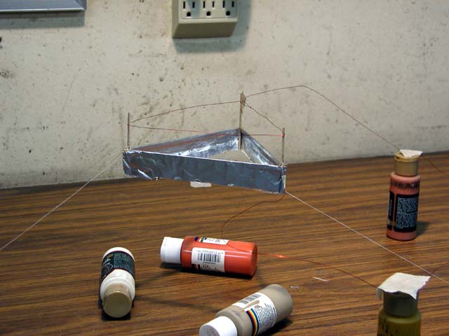 )
)
-
Title: Re: EM Drive Developments - related to space flight applications - Thread 3
Post by: SeeShells on 07/30/2015 12:46 PM -
<a href="http://forum.nasaspaceflight.com/index.php?topic=37642.msg1411286#msg1411286">Quote from: deltaMass on 07/30/2015 07:30 AM</a>
Shawyer has it all backwards. The easiest application of all is mild thrust in space - say, station keeping around LEO. That's the low hanging fruit - literally. Next easiest depends on N/W. It's either free energy forever (there might be a small market for that, who knows?) or lifting one's own weight off the ground. But if you can float, you can get to LEO. At LEO and above, you can do all three.
No one has showed a working EMDrive in a vacuum that has decent thrust. The best I've seen is about 10% of the thrust in a air test.
He has just made a public fool of himself. It's a shame, but there it is.
What this might say is he (RS) still hasn't quite figured out why it works and his theories are built on possible incorrect assumptions. (Air=More to push on inside the cavity violates CoM unless you can get outside of the cavity). Dr. White's theory of virtual particles is the only one I can think of right now that gets momentum from inside (creating VPs) to the outside but lacks a good explanation of explaining air/no air test results. Back to ground zero so far.
The air/no air is to me a huge Data flag and still the 800 pound gorilla in the room and I don't blame RS for not wanting to wrestle with it -
Title: Re: EM Drive Developments - related to space flight applications - Thread 3
Post by: deltaMass on 07/30/2015 12:57 PM -
Outgassing? That doesn't hold up because there's likely to be more of that in vacuum - less vapour pressure.
Anyway, as has been pointed out, the "can't do space because there's no air" argument doesn't hold up. You just put the drive in a pressurised gas box and/or let it push from the inside of the vehicle.
And no, none of this makes any sense to me either.
So what's all this "space qualified" stuff? Not needed. -
Title: Re: EM Drive Developments - related to space flight applications - Thread 3
Post by: SeeShells on 07/30/2015 01:08 PM -
<a href="http://forum.nasaspaceflight.com/index.php?topic=37642.msg1411230#msg1411230">Quote from: lmbfan on 07/30/2015 04:56 AM</a>
This may help<a href="http://forum.nasaspaceflight.com/index.php?topic=37642.msg1411216#msg1411216">Quote from: aero on 07/30/2015 02:39 AM</a>Here is an example from meep-discuss that uses a square loop antenna. The example problem doesn't work but I think that was a different problem with his control file. Using ( 2 pi ) * something instead of ( 0 + 2 pi i ) * something. He should have been using a complex multiplier, that is, if I'm recalling the right / problem answer.
This is the same example that I uploaded yesterday morning, but that is 10 pages up thread, so here it is again.
I don't know much about loop antenna. This file makes a giant 2-D source (24 units X 24 units, infinitely thin) and a square metal loop 2.928 X .7 units (center line), the "wire" width is .2, height of .1 units. The loop is called a "scatterer" and is not generated by default. Does any of that sound right for a loop antenna?
If I (or someone else) were to make a square loop antenna somehow, how would we know if it was a loop? What fields would we look at and what would they look like? Quickly testing different ideas can be painful if I use the truncated cone geometry/steps with long calculation times.
http://www.silabs.com/Support%20Documents/TechnicalDocs/AN639.pdf -
Title: Re: EM Drive Developments - related to space flight applications - Thread 3
Post by: Rodal on 07/30/2015 01:12 PM -
<a href="http://forum.nasaspaceflight.com/index.php?topic=37642.msg1411338#msg1411338">Quote from: deltaMass on 07/30/2015 12:57 PM</a>
...
Conservation of momentum precludes that
Anyway, as has been pointed out, the "can't do space because there's no air" argument doesn't hold up. You just put the drive in a pressurised gas box and/or let it push from the inside of the vehicle.
...
Neither can you use an air-breathing jet engine in space by just putting it "in a pressurised gas box and/or let it push from the inside of the vehicle." -
Title: Re: EM Drive Developments - related to space flight applications - Thread 3
Post by: deltaMass on 07/30/2015 01:15 PM -
Conservation of momentum precludes the whole thing.
But it's propellantless. So inside or outside, it's all the same.
Or does it have a local topology detector? -
Title: Re: EM Drive Developments - related to space flight applications - Thread 3
Post by: Rodal on 07/30/2015 01:18 PM -
When we heard about Tajmar's title "side effects..." we hoped that his team had made measurements of the environment outside the EM Drive to see whether indeed nothing is being ejected, no electromagnetic fields, no distortions of the environment.
Unfortunately he didn't make any such measurements... -
Title: Re: EM Drive Developments - related to space flight applications - Thread 3
Post by: deltaMass on 07/30/2015 01:21 PM -
<a href="http://forum.nasaspaceflight.com/index.php?topic=37642.msg1411348#msg1411348">Quote from: Rodal on 07/30/2015 01:18 PM</a>
When we heard about Tajmar's title "side effects..." we hoped that his team had made measurements of the environment outside the EM Drive to see whether indeed nothing is being ejected, no electromagnetic fields, no distortions of the environment.
Why would you expect a propellantless drive to eject propellant?
Unfortunately he didn't make any such measurements... -
Title: Re: EM Drive Developments - related to space flight applications - Thread 3
Post by: deltaMass on 07/30/2015 01:27 PM -
Here's a thought experiment about inside versus outside.
Model the drive as a cylinder of fixed shape. Imagine it touching a flat, deformable plane of finite extent.
To get the drive inside, we simply deform the plane around the drive into a bigger cylinder and let it make endcaps to seal itself shut with the drive inside.
Now unroll the plane back to flat, and deform it the other way, so now it's curving away from the drive. We end up with two touching cylinders.
Why would these operations make any difference to a drive that emits no exhaust of any kind? -
Title: Re: EM Drive Developments - related to space flight applications - Thread 3
Post by: martinc on 07/30/2015 01:28 PM -
>>Dr. White's theory of virtual particles is the only one I can think of right now that gets momentum from inside
>>(creating VPs) to the outside but lacks a good explanation of explaining air/no air test results. Back to ground zero so
>>far.
this isn't quite true, there is the possibility of a warp field as claimed to be detected by the laser interferometer results
but whether a small warp field or spacial distortion with a concave shape could produce the measured thrust is beyond me to tell. i think the warp effect should be included in the possibilities at this stage, it's no more outlandish that the quantum soup theory and actually has some evidence. i don't understand why no-one is talking about this
-
Title: Re: EM Drive Developments - related to space flight applications - Thread 3
Post by: leomillert on 07/30/2015 01:28 PM -
<a href="http://forum.nasaspaceflight.com/index.php?topic=37642.msg1411328#msg1411328">Quote from: TheTraveller on 07/30/2015 12:04 PM</a><a href="http://forum.nasaspaceflight.com/index.php?topic=37642.msg1411325#msg1411325">Quote from: deltaMass on 07/30/2015 11:46 AM</a>
It would be a game-changer nevertheless if a floater could be built, even if it only worked in air. Needless to say, I don't believe it can because of the ridiculous numbers being bandied about. I also note that interstellar travel is largely an airless endeavour. ::)
I would suggest the Wright brothers would agree will you if you told them of the engineering stats for an A380. They would look at a modern jet engine with their mouths wide open, totally in disbelief.
In reality the difference between the Wright Flyer and the A380 is just engineering hours and $.
Will be no difference with EMDrive development as N/kW climb higher and higher.
Wright brothers?
I think you mean Santos-Dumont 8)
Wright Flyer?
I think you mean 14-bis 8) -
Title: Re: EM Drive Developments - related to space flight applications - Thread 3
Post by: deltaMass on 07/30/2015 01:29 PM -
<a href="http://forum.nasaspaceflight.com/index.php?topic=37642.msg1411351#msg1411351">Quote from: Rodal on 07/30/2015 01:24 PM</a>
The only one claiming "propellant-less" in that absolutist way is Shawyer. Everybody else (McCulloch, White, etc.) no matter how unusual their theories, claims an interaction with the outside
Not exactly. They claim an interaction with spacetime, which pervades everything. And so again, inside and outside are no different. -
Title: Re: EM Drive Developments - related to space flight applications - Thread 3
Post by: rfmwguy on 07/30/2015 01:30 PM -
Think we could use an RS time out. As with Cannae, what they will do is far less useful than what is being done in the short term. The distraction of future business plans cannot help this thread, which unless I miss the intent, is to study Spaceflight applications of an EM driven device.
I'm sure there are aeronautical forums that would benefit from RS's plans. Here? Not so much.
Pardon the mini-rant. -
Title: Re: EM Drive Developments - related to space flight applications - Thread 3
Post by: TheTraveller on 07/30/2015 01:35 PM -
<a href="http://forum.nasaspaceflight.com/index.php?topic=37642.msg1411329#msg1411329">Quote from: deltaMass on 07/30/2015 12:05 PM</a><a href="http://forum.nasaspaceflight.com/index.php?topic=37642.msg1411326#msg1411326">Quote from: TheTraveller on 07/30/2015 11:57 AM</a>
It would seem SPR has added another business model, as a contract end product EMDrive enabled builder, to it's traditional EMDrive IP licensor business model.
Ah yes. And how's that been working out for SPR - "traditionally", I mean?
Forgive me for saying so, but I am not noticing all these EmDrive licenced products zigging and zagging around in my little universe. Could that be because I should get out more?
All I heard is that Boeing took a look and now disavows it completely. Is that what you mean by "traditional"?
Don't know about the others but my EMDrive will soon be on a rotary turntable accelerating from 0 rpm to 120 rpm. The Rf amp power consumed versus real forward power versus real reflected power versus 3 axis acceleration versus velocity versus KE versus cavity pressure versus 6 x cavity temperature will be very interesting reading.
Wonder what Boeing will say then? BTW when EW asked Boeing to borrow their Flight Thruster they said No. Strange that if it didn't work? Was told Boeing still receives all the SPR updates that it sends out to their other IP licensees.
As to the licensees, Roger and I are in discussion about me setting up a EMDrive company ("something Prometheus something" sounds appropriate) and becoming a SPR licensee. Should be fun, exciting and profitable if just to sell complete EMDrive systems with a rotary test rig to 1,000s of uni, college, gov and corp customers that just have to see this working in the flesh and before their eyes. -
Title: Re: EM Drive Developments - related to space flight applications - Thread 3
Post by: Rodal on 07/30/2015 01:44 PM -
<a href="http://forum.nasaspaceflight.com/index.php?topic=37642.msg1411359#msg1411359">Quote from: TheTraveller on 07/30/2015 01:35 PM</a>
...Don't know about the others but my EMDrive will soon be on a rotary turntable accelerating from 0 rpm to 120 rpm. .. Roger and I are in discussion about me setting up a EMDrive company ("something Prometheus something" sounds appropriate) and becoming a SPR licensee...
When?
Soon is when ? -
Title: Re: EM Drive Developments - related to space flight applications - Thread 3
Post by: DrBagelBites on 07/30/2015 01:55 PM -
<a href="http://forum.nasaspaceflight.com/index.php?topic=37642.msg1411359#msg1411359">Quote from: TheTraveller on 07/30/2015 01:35 PM</a><a href="http://forum.nasaspaceflight.com/index.php?topic=37642.msg1411329#msg1411329">Quote from: deltaMass on 07/30/2015 12:05 PM</a><a href="http://forum.nasaspaceflight.com/index.php?topic=37642.msg1411326#msg1411326">Quote from: TheTraveller on 07/30/2015 11:57 AM</a>
It would seem SPR has added another business model, as a contract end product EMDrive enabled builder, to it's traditional EMDrive IP licensor business model.
Ah yes. And how's that been working out for SPR - "traditionally", I mean?
Forgive me for saying so, but I am not noticing all these EmDrive licenced products zigging and zagging around in my little universe. Could that be because I should get out more?
All I heard is that Boeing took a look and now disavows it completely. Is that what you mean by "traditional"?
Don't know about the others but my EMDrive will soon be on a rotary turntable accelerating from 0 rpm to 120 rpm. The Rf amp power consumed versus real forward power versus real reflected power versus 3 axis acceleration versus velocity versus KE versus cavity pressure versus 6 x cavity temperature will be very interesting reading.
Wonder what Boeing will say then? BTW when EW asked Boeing to borrow their Flight Thruster they said No. Strange that if it didn't work? Was told Boeing still receives all the SPR updates that it sends out to their other IP licensees.
As to the licensees, Roger and I are in discussion about me setting up a EMDrive company ("something Prometheus something" sounds appropriate) and becoming a SPR licensee. Should be fun, exciting and profitable if just to sell complete EMDrive systems with a rotary test rig to 1,000s of uni, college, gov and corp customers that just have to see this working in the flesh and before their eyes.
I'll preface this with the fact that I think you have done great work between the spreadsheet as well as helping towards theory of how this magical device seems to work. So, thank you on that front.
However, this does not overlook the fact that almost on a daily basis you seem to have more and more promises of results, conclusions, and now a company which will sell thousands of drives.
I just want to see one, Traveller.
As they say, talk is cheap.
This is going to be the only time I'm going to mention this. I am rooting for you. Honestly, I am. I just want to see results, not promises.
-I -
Title: Re: EM Drive Developments - related to space flight applications - Thread 3
Post by: WarpTech on 07/30/2015 02:01 PM -
<a href="http://forum.nasaspaceflight.com/index.php?topic=37642.msg1411351#msg1411351">Quote from: Rodal on 07/30/2015 01:24 PM</a>
The only one claiming "propellant-less" in that absolutist way is Shawyer. Everybody else (McCulloch, White, etc.) no matter how unusual their theories, claims an interaction with the outside
Their claims are unfounded. ALL of the equations, Shawyer, McCulloch, @Notsosureofit, and my own, all are the same "rocket" equation. The only difference is how we choose to define group and phase velocity "inside" the frustum. Shawyer's equation is no more wrong or right than anyone elses, IMO. If we use Zeng & Fan's impedance graph to give us our v/c^2 value, then one might consider that "definitive" for a cone.
In all cases. Momentum is conserved without ejecting reaction mass because the momentum inside is non-linear. The force pushing it forward is larger than the momentum striking the big end plate. The problem is, without using GR or PV to describe a frequency dependent metric, (and even then) not too many folks are going to believe this until it actually lifts-off the ground.
It is not a Newtonian machine. Expecting it to obey Newton's laws, which are invalidated under these conditions by GR, is a mistake IMO.
Todd
-
Title: Re: EM Drive Developments - related to space flight applications - Thread 3
Post by: SeeShells on 07/30/2015 02:08 PM -
<a href="http://forum.nasaspaceflight.com/index.php?topic=37642.msg1411349#msg1411349">Quote from: deltaMass on 07/30/2015 01:21 PM</a>
It's virtually massless mass with Virtual Particles??? ;)<a href="http://forum.nasaspaceflight.com/index.php?topic=37642.msg1411348#msg1411348">Quote from: Rodal on 07/30/2015 01:18 PM</a>When we heard about Tajmar's title "side effects..." we hoped that his team had made measurements of the environment outside the EM Drive to see whether indeed nothing is being ejected, no electromagnetic fields, no distortions of the environment.
Why would you expect a propellantless drive to eject propellant?
Unfortunately he didn't make any such measurements... -
Title: Re: EM Drive Developments - related to space flight applications - Thread 3
Post by: wallofwolfstreet on 07/30/2015 02:11 PM -
<a href="http://forum.nasaspaceflight.com/index.php?topic=37642.msg1411335#msg1411335">Quote from: SeeShells on 07/30/2015 12:46 PM</a><a href="http://forum.nasaspaceflight.com/index.php?topic=37642.msg1411286#msg1411286">Quote from: deltaMass on 07/30/2015 07:30 AM</a>
Shawyer has it all backwards. The easiest application of all is mild thrust in space - say, station keeping around LEO. That's the low hanging fruit - literally. Next easiest depends on N/W. It's either free energy forever (there might be a small market for that, who knows?) or lifting one's own weight off the ground. But if you can float, you can get to LEO. At LEO and above, you can do all three.
No one has showed a working EMDrive in a vacuum that has decent thrust. The best I've seen is about 10% of the thrust in a air test.
He has just made a public fool of himself. It's a shame, but there it is.
What this might say is he (RS) still hasn't quite figured out why it works and his theories are built on possible incorrect assumptions. (Air=More to push on inside the cavity violates CoM unless you can get outside of the cavity). Dr. White's theory of virtual particles is the only one I can think of right now that gets momentum from inside (creating VPs) to the outside but lacks a good explanation of explaining air/no air test results. Back to ground zero so far.
The air/no air is to me a huge Data flag and still the 800 pound gorilla in the room and I don't blame RS for not wanting to wrestle with it
We now have two separate sets of experiments that confirm that thrust decreases significantly in air, and yet we still see the numbers for Yang and Shawyer (4 N/kW of 1 N/kW) bandied around. With the knowledge that thrust drops in air (but by an inconsistent/indeterminate amount), aren't we forced to essentially ignore any numerical results that come from either Yang or Shawyer? We know they are less, but how much less is impossible to tell.
Any comment that extrapolates thrust results, or linearity of results wrt to Q, etc, using Yang and Shawyers results, is ignoring the experimental proof from two labs that thrust drops in vacuum. At the very least, from what Shell has said with the best being 10%, we have to throw away an order of magnitude, meaning the "best" thrust to power achieved so far was actually 0.4 N/kW, if that. -
Title: Re: EM Drive Developments - related to space flight applications - Thread 3
Post by: rfmwguy on 07/30/2015 02:11 PM -
Back on track - Frustum, funnel, vortices and my initial theory.
While building and thinking (dangerous combination), a theory has been brewing that is not ready for peer review, but is ready for my pals here at NSF. Nature often leads to answers. Growing up in the tornado belt has lead me to think about the known forces within a funnel cloud that touches the earth. A frustum is a portion of that funnel.
Swirling electromagnetic waves, as with air, could create suction in the direction of the narrow end of the vortex. Thus, I've been reluctant to quantify the force as "thrust". Visualizing what occurs in a non-static frustum lead me to explore some papers on a electromagnetic vortices .
Be aware, there are 4th dimensional properties going on here and its not for the faint of heart.
Here is one of those papers: http://arxiv.org/ftp/arxiv/papers/1008/1008.3994.pdf
"From the above it is possible to conclude: the state and evolution of the electro-magnetic field in a macroscopic approximation to the selected reference frame is clearly described by four-dimensional vector, which includes potential and solenoidal components and satisfies four-dimensional Dalamber equation."
My emphasis Solenoidal, aka ratchet.
Meepers will no doubt have issues with 4th dimensional properties as well as non-steady state EM waves in a Rotational propogation...just what fires naturally out of a magnetron's radome.
There you have it. Its where I'll be spending my theory time. Comments and critiques welcomed.
p.s. Yes, I know, a Z axis rotation needs to be measured along the longitudinal axis. To date, no one has tried this. -
Title: Re: EM Drive Developments - related to space flight applications - Thread 3
Post by: Star One on 07/30/2015 02:12 PM -
<a href="http://forum.nasaspaceflight.com/index.php?topic=37642.msg1411357#msg1411357">Quote from: rfmwguy on 07/30/2015 01:30 PM</a>
Think we could use an RS time out. As with Cannae, what they will do is far less useful than what is being done in the short term. The distraction of future business plans cannot help this thread, which unless I miss the intent, is to study Spaceflight applications of an EM driven device.
I'm sure there are aeronautical forums that would benefit from RS's plans. Here? Not so much.
Pardon the mini-rant.
I would argue that with a truly EM device (if there is ever such a thing) there would eventually be no difference as the vehicle would be able operate in both environments. Taking itself from the ground to space. -
Title: Re: EM Drive Developments - related to space flight applications - Thread 3
Post by: TheTraveller on 07/30/2015 02:17 PM -
<a href="http://forum.nasaspaceflight.com/index.php?topic=37642.msg1411365#msg1411365">Quote from: DrBagelBites on 07/30/2015 01:55 PM</a><a href="http://forum.nasaspaceflight.com/index.php?topic=37642.msg1411359#msg1411359">Quote from: TheTraveller on 07/30/2015 01:35 PM</a><a href="http://forum.nasaspaceflight.com/index.php?topic=37642.msg1411329#msg1411329">Quote from: deltaMass on 07/30/2015 12:05 PM</a><a href="http://forum.nasaspaceflight.com/index.php?topic=37642.msg1411326#msg1411326">Quote from: TheTraveller on 07/30/2015 11:57 AM</a>
It would seem SPR has added another business model, as a contract end product EMDrive enabled builder, to it's traditional EMDrive IP licensor business model.
Ah yes. And how's that been working out for SPR - "traditionally", I mean?
Forgive me for saying so, but I am not noticing all these EmDrive licenced products zigging and zagging around in my little universe. Could that be because I should get out more?
All I heard is that Boeing took a look and now disavows it completely. Is that what you mean by "traditional"?
Don't know about the others but my EMDrive will soon be on a rotary turntable accelerating from 0 rpm to 120 rpm. The Rf amp power consumed versus real forward power versus real reflected power versus 3 axis acceleration versus velocity versus KE versus cavity pressure versus 6 x cavity temperature will be very interesting reading.
Wonder what Boeing will say then? BTW when EW asked Boeing to borrow their Flight Thruster they said No. Strange that if it didn't work? Was told Boeing still receives all the SPR updates that it sends out to their other IP licensees.
As to the licensees, Roger and I are in discussion about me setting up a EMDrive company ("something Prometheus something" sounds appropriate) and becoming a SPR licensee. Should be fun, exciting and profitable if just to sell complete EMDrive systems with a rotary test rig to 1,000s of uni, college, gov and corp customers that just have to see this working in the flesh and before their eyes.
I'll preface this with the fact that I think you have done great work between the spreadsheet as well as helping towards theory of how this magical device seems to work. So, thank you on that front.
However, this does not overlook the fact that almost on a daily basis you seem to have more and more promises of results, conclusions, and now a company which will sell thousands of drives.
I just want to see one, Traveller.
As they say, talk is cheap.
This is going to be the only time I'm going to mention this. I am rooting for you. Honestly, I am. I just want to see results, not promises.
-I
My talk is not cheap. I've allocated $20k to get this project done.
My 2nd surgery is over. Only 1.5 hours under the robot versus 4.5 hours last time. Was told the margin results are good but still show show some cancer was missed. Now being told will start daily radiation treatment for 6 weeks in about 1 1/2 month as they want to 1st monitor in which direction my PSA is moving. Was told the radiation should not stop me working in my workshop.
Should start doing real hands on work in about 1 1/2 month, when the rad treatment starts. My friend is arranging for the 1st prototype to be build in China and to arrive here in the same time as I start the rad treatment. So that will help shorten the time. Give me 6 weeks to finish the Raspberry and PC software. Have the rotary table components. Amp should be here in a few weeks, so everything is currently scheduled to be coming together in 6 weeks.
Mid Sept should start posting photos of the build. -
Title: Re: EM Drive Developments - related to space flight applications - Thread 3
Post by: Rodal on 07/30/2015 02:21 PM -
<a href="http://forum.nasaspaceflight.com/index.php?topic=37642.msg1411377#msg1411377">Quote from: TheTraveller on 07/30/2015 02:17 PM</a>
...
My talk is not cheap. I've allocated $20k to get this project done.
My 2nd surgery is over. Only 1.5 hours under the robot versus 4.5 hours last time. Was told the margin results are good but still show show some cancer was missed. Now being told will start daily radiation treatment for 6 weeks in about 1 1/2 month as they want to 1st monitor in which direction my PSA is moving. Was told the radiation should not stop me working in my workshop.
Should start doing real hands on work in about 1 1/2 month, when the rad treatment starts. My friend is arranging for the 1st prototype to be build in China and to arrive here in the same time as I start the rad treatment. So that will help shorten the time. Give me 6 weeks to finish the Raspberry and PC software. Have the rotary table components. Amp should be here in a few weeks, so everything is currently scheduled to be coming together in 6 weeks.
Mid Sept should start posting photos of the build.
We are all praying for a quick recovery and that all your wishes come true -
Title: Re: EM Drive Developments - related to space flight applications - Thread 3
Post by: wallofwolfstreet on 07/30/2015 02:22 PM -
<a href="http://forum.nasaspaceflight.com/index.php?topic=37642.msg1411374#msg1411374">Quote from: Rodal on 07/30/2015 02:14 PM</a><a href="http://forum.nasaspaceflight.com/index.php?topic=37642.msg1411370#msg1411370">Quote from: wallofwolfstreet on 07/30/2015 02:11 PM</a>
...We now have two separate sets of experiments that confirm that thrust decreases significantly in air, and yet we still see the numbers for Yang and Shawyer (4 N/kW of 1 N/kW) bandied around. With the knowledge that thrust drops in air (but by an inconsistent/indeterminate amount), aren't we forced to essentially ignore any numerical results that come from either Yang or Shawyer? We know they are less, but how much less is impossible to tell.
Any comment that extrapolates thrust results, or linearity of results wrt to Q, etc, using Yang and Shawyers results, is ignoring the experimental proof from two labs that thrust drops in vacuum. At the very least, from what Shell has said with the best being 10%, we have to throw away an order of magnitude, meaning the "best" thrust to power achieved so far was actually 0.4 N/kW, if that.
No, see: http://emdrive.wiki/Experimental_Results
Best reported thrust/InputPower in vacuum is 0.001 N/kW
Your number is 400 times larger
4 N/kW is 4,000 times larger
Yeah, I took the best result Yang reported (4 N/kW) and took Shell's reported 10% decrease in vacuum, to report a sort of "vacuum adjusted" best thrust to power ratio of 0.4 N/kW (in the best case scenario of only losing 90% of thrust in a vacuum, as per Shell).
But you're right in that my "vacuum adjusted" methodology isn't winning any experimental honesty awards, and the only honest thing to do is to throw out Yang and Shawyer's results completely (at least their numerical results) and only focus on results that come from vacuum.Quote from: SeeShellsNo one has showed a working EMDrive in a vacuum that has decent thrust. The best I've seen is about 10% of the thrust in a air test.
-
Title: Re: EM Drive Developments - related to space flight applications - Thread 3
Post by: TheTraveller on 07/30/2015 02:23 PM -
<a href="http://forum.nasaspaceflight.com/index.php?topic=37642.msg1411374#msg1411374">Quote from: Rodal on 07/30/2015 02:14 PM</a><a href="http://forum.nasaspaceflight.com/index.php?topic=37642.msg1411370#msg1411370">Quote from: wallofwolfstreet on 07/30/2015 02:11 PM</a>
...We now have two separate sets of experiments that confirm that thrust decreases significantly in air, and yet we still see the numbers for Yang and Shawyer (4 N/kW of 1 N/kW) bandied around. With the knowledge that thrust drops in air (but by an inconsistent/indeterminate amount), aren't we forced to essentially ignore any numerical results that come from either Yang or Shawyer? We know they are less, but how much less is impossible to tell.
Any comment that extrapolates thrust results, or linearity of results wrt to Q, etc, using Yang and Shawyers results, is ignoring the experimental proof from two labs that thrust drops in vacuum. At the very least, from what Shell has said with the best being 10%, we have to throw away an order of magnitude, meaning the "best" thrust to power achieved so far was actually 0.4 N/kW, if that.
No, see: http://emdrive.wiki/Experimental_Results
Best reported thrust/InputPower in vacuum is 0.001 N/kW
Your number is 400 times larger
4 N/kW is 4,000 times larger
The Tajmar vacuum results were at a Q of 20 in a oxidised cavity. It is not correct to quote Specific Force numbers without quoting the Q and if the cavity contained a dielectric or not.
It would be very interesting to measure, record and post the atmo and vacuum Q of a cavity based on a S11 return loss scan.
Why has such a simple thing never been done or has it? Anybody know? -
Title: Re: EM Drive Developments - related to space flight applications - Thread 3
Post by: TheTraveller on 07/30/2015 02:26 PM - Have confirmed the EW dielectric copper frustum does generate Force big end to small end. The latest Shawyer summary is incorrect. Have informed Shawyer.
-
Title: Re: EM Drive Developments - related to space flight applications - Thread 3
Post by: DrBagelBites on 07/30/2015 02:27 PM -
<a href="http://forum.nasaspaceflight.com/index.php?topic=37642.msg1411377#msg1411377">Quote from: TheTraveller on 07/30/2015 02:17 PM</a>
...
My talk is not cheap. I've allocated $20k to get this project done.
My 2nd surgery is over. Only 1.5 hours under the robot versus 4.5 hours last time. Was told the margin results are good but still show show some cancer was missed. Now being told will start daily radiation treatment for 6 weeks in about 1 1/2 month as they want to 1st monitor in which direction my PSA is moving. Was told the radiation should not stop me working in my workshop.
Should start doing real hands on work in about 1 1/2 month, when the rad treatment starts. My friend is arranging for the 1st prototype to be build in China and to arrive here in the same time as I start the rad treatment. So that will help shorten the time. Give me 6 weeks to finish the Raspberry and PC software. Have the rotary table components. Amp should be here in a few weeks, so everything is currently scheduled to be coming together in 6 weeks.
Mid Sept should start posting photos of the build.
Get better, we need you.
I am excited to see what you have in store.
-I -
Title: Re: EM Drive Developments - related to space flight applications - Thread 3
Post by: TheTraveller on 07/30/2015 02:30 PM -
<a href="http://forum.nasaspaceflight.com/index.php?topic=37642.msg1411380#msg1411380">Quote from: wallofwolfstreet on 07/30/2015 02:22 PM</a><a href="http://forum.nasaspaceflight.com/index.php?topic=37642.msg1411374#msg1411374">Quote from: Rodal on 07/30/2015 02:14 PM</a><a href="http://forum.nasaspaceflight.com/index.php?topic=37642.msg1411370#msg1411370">Quote from: wallofwolfstreet on 07/30/2015 02:11 PM</a>
...We now have two separate sets of experiments that confirm that thrust decreases significantly in air, and yet we still see the numbers for Yang and Shawyer (4 N/kW of 1 N/kW) bandied around. With the knowledge that thrust drops in air (but by an inconsistent/indeterminate amount), aren't we forced to essentially ignore any numerical results that come from either Yang or Shawyer? We know they are less, but how much less is impossible to tell.
Any comment that extrapolates thrust results, or linearity of results wrt to Q, etc, using Yang and Shawyers results, is ignoring the experimental proof from two labs that thrust drops in vacuum. At the very least, from what Shell has said with the best being 10%, we have to throw away an order of magnitude, meaning the "best" thrust to power achieved so far was actually 0.4 N/kW, if that.
No, see: http://emdrive.wiki/Experimental_Results
Best reported thrust/InputPower in vacuum is 0.001 N/kW
Your number is 400 times larger
4 N/kW is 4,000 times larger
Yeah, I took the best result Yang reported (4 N/kW) and took Shell's reported 10% decrease in vacuum, to report a sort of "vacuum adjusted" best thrust to power ratio of 0.4 N/kW (in the best case scenario of only losing 90% of thrust in a vacuum, as per Shell).
But you're right in that my "vacuum adjusted" methodology isn't winning any experimental honesty awards, and the only honest thing to do is to throw out Yang and Shawyer's results completely (at least their numerical results) and only focus on results that come from vacuum.Quote from: SeeShellsNo one has showed a working EMDrive in a vacuum that has decent thrust. The best I've seen is about 10% of the thrust in a air test.
I suggest we need to wait to see what the latest EW vacuum data shows.
In my opinion it is the Tajmar vacuum data that needs to be thrown out as it was a comedy of multiple measurement errors. -
Title: Re: EM Drive Developments - related to space flight applications - Thread 3
Post by: WarpTech on 07/30/2015 02:33 PM -
<a href="http://forum.nasaspaceflight.com/index.php?topic=37642.msg1411368#msg1411368">Quote from: Rodal on 07/30/2015 02:06 PM</a><a href="http://forum.nasaspaceflight.com/index.php?topic=37642.msg1411367#msg1411367">Quote from: WarpTech on 07/30/2015 02:01 PM</a>
...In all cases. Momentum is conserved without ejecting reaction mass because the momentum inside is non-linear. The force pushing it forward is larger than the momentum striking the big end plate. The problem is, without using GR or PV to describe a frequency dependent metric, (and even then) not too many folks are going to believe this until it actually lifts-off the ground.
So that means that you think that this "force pushing it forward is larger than the momentum striking the big end plate" must be acting against a fixed background, that there is a preferred frame.
It is not a Newtonian machine. Expecting it to obey Newton's laws, which are invalidated under these conditions by GR, is a mistake IMO.
Todd
Why? I do not follow your logic. There are 2 frames of reference only. The metal and the field. What I believe is happening is "squeezed" light. GR and the PV Model operate through the Uncertainty principle relationships,
delta_p * delta_x = h/2
If you squeeze delta_x by confining it inside a tight cavity near the apex, then the momentum is necessarily larger in that state. So this equation is different at each end of the cavity, depending on the diameters. How is this related to GR and the PV Model? Simple,
delta_p*sqrt(K) * delta_x/sqrt(K) = h/2
When the refractive index, K = sqrt(-g11/g00) > 1, this is precisely what happens.
Todd
-
Title: Re: EM Drive Developments - related to space flight applications - Thread 3
Post by: Rodal on 07/30/2015 02:40 PM -
<a href="http://forum.nasaspaceflight.com/index.php?topic=37642.msg1411388#msg1411388">Quote from: WarpTech on 07/30/2015 02:33 PM</a>
...
I don't see an equation for conservation of momentum above. Neither did I see a force balance diagram for the statement " The force pushing it forward is larger than the momentum striking the big end plate."
Why? I do not follow your logic. There are 2 frames of reference only. The metal and the field. What I believe is happening is "squeezed" light. GR and the PV Model operate through the Uncertainty principle relationships,
delta_p * delta_x = h/2
If you squeeze delta_x by confining it inside a tight cavity near the apex, then the momentum is necessarily larger in that state. So this equation is different at each end of the cavity, depending on the diameters. How is this related to GR and the PV Model? Simple,
delta_p*sqrt(K) * delta_x/sqrt(K) = h/2
When the refractive index, K = sqrt(-g11/g00) > 1, this is precisely what happens.
Todd -
Title: Re: EM Drive Developments - related to space flight applications - Thread 3
Post by: Flyby on 07/30/2015 02:42 PM -
There is really no point in fabricating 1000N/kW projections and VTOL spacecrafts if you can not even produce 1N of force...
Show the data of a device producing 1N and then we can slowly start extrapolating towards the future.
But until now we don't even know if it works...
It has been said a thousand times already inhere : if you want credibility, then start with a modest , but clear force.
Producing wild, highly speculative and outlandish claims and extrapolating towards floating vehicles actually works contra-productive and drives your credibility into the ground like a bunkerbuster... -
Title: Re: EM Drive Developments - related to space flight applications - Thread 3
Post by: aceshigh on 07/30/2015 03:04 PM -
<a href="http://forum.nasaspaceflight.com/index.php?topic=37642.msg1411351#msg1411351">Quote from: Rodal on 07/30/2015 01:24 PM</a>
The only one claiming "propellant-less" in that absolutist way is Shawyer. Everybody else (McCulloch, White, etc.) no matter how unusual their theories, claims an interaction with the outside
true, but it´s quite different to claim an interaction with something that doesn´t care about the engine/ship walls, in other words, the engine push "it" but "it" doesn´t interact with the the rest of the ship... like virtual particles in White's Theory or "the rest of the mass of the universe", in Mach Effect Theory...
... and pushing air... which in that case, EM Drive is not a propellantless propulsion, but just a propeller-less air engine. -
Title: Re: EM Drive Developments - related to space flight applications - Thread 3
Post by: SeeShells on 07/30/2015 03:08 PM -
<a href="http://forum.nasaspaceflight.com/index.php?topic=37642.msg1411384#msg1411384">Quote from: TheTraveller on 07/30/2015 02:26 PM</a>
Have confirmed the EW dielectric copper frustum does generate Force big end to small end. The latest Shawyer summary is incorrect. Have informed Shawyer.
Good! I mentioned a bazillion pages ago it didn't make any sense.
Shell -
Title: Re: EM Drive Developments - related to space flight applications - Thread 3
Post by: SeeShells on 07/30/2015 03:14 PM -
<a href="http://forum.nasaspaceflight.com/index.php?topic=37642.msg1411386#msg1411386">Quote from: TheTraveller on 07/30/2015 02:30 PM</a>
There is no bad data and even though the test was fraught with issues there is enough in it ti glean useful data. the Thrust differential saw was about 10% in the vacuum and that's a good guess.<a href="http://forum.nasaspaceflight.com/index.php?topic=37642.msg1411380#msg1411380">Quote from: wallofwolfstreet on 07/30/2015 02:22 PM</a><a href="http://forum.nasaspaceflight.com/index.php?topic=37642.msg1411374#msg1411374">Quote from: Rodal on 07/30/2015 02:14 PM</a><a href="http://forum.nasaspaceflight.com/index.php?topic=37642.msg1411370#msg1411370">Quote from: wallofwolfstreet on 07/30/2015 02:11 PM</a>...We now have two separate sets of experiments that confirm that thrust decreases significantly in air, and yet we still see the numbers for Yang and Shawyer (4 N/kW of 1 N/kW) bandied around. With the knowledge that thrust drops in air (but by an inconsistent/indeterminate amount), aren't we forced to essentially ignore any numerical results that come from either Yang or Shawyer? We know they are less, but how much less is impossible to tell.
Any comment that extrapolates thrust results, or linearity of results wrt to Q, etc, using Yang and Shawyers results, is ignoring the experimental proof from two labs that thrust drops in vacuum. At the very least, from what Shell has said with the best being 10%, we have to throw away an order of magnitude, meaning the "best" thrust to power achieved so far was actually 0.4 N/kW, if that.
No, see: http://emdrive.wiki/Experimental_Results
Best reported thrust/InputPower in vacuum is 0.001 N/kW
Your number is 400 times larger
4 N/kW is 4,000 times larger
Yeah, I took the best result Yang reported (4 N/kW) and took Shell's reported 10% decrease in vacuum, to report a sort of "vacuum adjusted" best thrust to power ratio of 0.4 N/kW (in the best case scenario of only losing 90% of thrust in a vacuum, as per Shell).
But you're right in that my "vacuum adjusted" methodology isn't winning any experimental honesty awards, and the only honest thing to do is to throw out Yang and Shawyer's results completely (at least their numerical results) and only focus on results that come from vacuum.Quote from: SeeShellsNo one has showed a working EMDrive in a vacuum that has decent thrust. The best I've seen is about 10% of the thrust in a air test.
I suggest we need to wait to see what the latest EW vacuum data shows.
In my opinion it is the Tajmar vacuum data that needs to be thrown out as it was a comedy of multiple measurement errors. -
Title: Re: EM Drive Developments - related to space flight applications - Thread 3
Post by: SeeShells on 07/30/2015 03:21 PM -
<a href="http://forum.nasaspaceflight.com/index.php?topic=37642.msg1411354#msg1411354">Quote from: martinc on 07/30/2015 01:28 PM</a>
>>Dr. White's theory of virtual particles is the only one I can think of right now that gets momentum from inside
What the tests showed it that the laser was delayed going through a simple RF resonant cavity, in air. Test it in vacuum then I'll be more convinced of a real effect.
>>(creating VPs) to the outside but lacks a good explanation of explaining air/no air test results. Back to ground zero so
>>far.
this isn't quite true, there is the possibility of a warp field as claimed to be detected by the laser interferometer results
but whether a small warp field or spacial distortion with a concave shape could produce the measured thrust is beyond me to tell. i think the warp effect should be included in the possibilities at this stage, it's no more outlandish that the quantum soup theory and actually has some evidence. i don't understand why no-one is talking about this
Shell -
Title: Re: EM Drive Developments - related to space flight applications - Thread 3
Post by: SeeShells on 07/30/2015 03:43 PM -
<a href="http://forum.nasaspaceflight.com/index.php?topic=37642.msg1411371#msg1411371">Quote from: rfmwguy on 07/30/2015 02:11 PM</a>
Back on track - Frustum, funnel, vortices and my initial theory.
Oh I think it needs to be investigated, I gleaned the same thought sitting in the hot tub months ago swirling the water seeing vortexes form. One reason I started researching helical antennas and when aero is done with his current runs we should see if he could do a 1/4 wave shifted Dipole in the large end simulating a rotating wave pattern.
While building and thinking (dangerous combination), a theory has been brewing that is not ready for peer review, but is ready for my pals here at NSF. Nature often leads to answers. Growing up in the tornado belt has lead me to think about the known forces within a funnel cloud that touches the earth. A frustum is a portion of that funnel.
Swirling electromagnetic waves, as with air, could create suction in the direction of the narrow end of the vortex. Thus, I've been reluctant to quantify the force as "thrust". Visualizing what occurs in a non-static frustum lead me to explore some papers on a electromagnetic vortices .
Be aware, there are 4th dimensional properties going on here and its not for the faint of heart.
Here is one of those papers: http://arxiv.org/ftp/arxiv/papers/1008/1008.3994.pdf
"From the above it is possible to conclude: the state and evolution of the electro-magnetic field in a macroscopic approximation to the selected reference frame is clearly described by four-dimensional vector, which includes potential and solenoidal components and satisfies four-dimensional Dalamber equation."
My emphasis Solenoidal, aka ratchet.
Meepers will no doubt have issues with 4th dimensional properties as well as non-steady state EM waves in a Rotational propogation...just what fires naturally out of a magnetron's radome.
There you have it. Its where I'll be spending my theory time. Comments and critiques welcomed.
p.s. Yes, I know, a Z axis rotation needs to be measured along the longitudinal axis. To date, no one has tried this.
Dr. rodal, what does this look like to you???
Figure 2.
Projection of Poynting vector direction (equation (3.2)) from a circularly polarized dipole, in the plane Embedded Image, showing swirl near the dipole axis and divergence far away.
Ref...
http://rspa.royalsocietypublishing.org/content/467/2133/2500
I think it's a great idea RFMWGUY!
Shell
-
Title: Re: EM Drive Developments - related to space flight applications - Thread 3
Post by: rfmwguy on 07/30/2015 03:59 PM -
<a href="http://forum.nasaspaceflight.com/index.php?topic=37642.msg1411410#msg1411410">Quote from: Rodal on 07/30/2015 03:47 PM</a>
The paper I referenced invokes 4th dimensional physics. It is from this realm that a Solenoidal, or ratchet effect occurs:<a href="http://forum.nasaspaceflight.com/index.php?topic=37642.msg1411408#msg1411408">Quote from: SeeShells on 07/30/2015 03:43 PM</a>...Dr. rodal, what does this look like to you???
Since you asked, here is my answer: I don't see how these ideas address the main question:
Figure 2.
Projection of Poynting vector direction (equation (3.2)) from a circularly polarized dipole, in the plane Embedded Image, showing swirl near the dipole axis and divergence far away.
Ref...
http://rspa.royalsocietypublishing.org/content/467/2133/2500
I think it's a great idea RFMWGUY!
Shell
* Conservation of Momentum and balance of forces
If they do address it, and I missed it, I would appreciate knowing how they address conservation of momentum and balance of forces
"From the above it is possible to conclude: the state and evolution of the electro-magnetic field in a macroscopic approximation to the selected reference frame is clearly described by four-dimensional vector, which includes potential and solenoidal components and satisfies four-dimensional Dalamber equation. No problems with system of equations’ certainty at such approach arise." -
Title: Re: EM Drive Developments - related to space flight applications - Thread 3
Post by: SeeShells on 07/30/2015 04:00 PM -
<a href="http://forum.nasaspaceflight.com/index.php?topic=37642.msg1411410#msg1411410">Quote from: Rodal on 07/30/2015 03:47 PM</a>
I didn't ask. :)<a href="http://forum.nasaspaceflight.com/index.php?topic=37642.msg1411408#msg1411408">Quote from: SeeShells on 07/30/2015 03:43 PM</a>
Since you asked, here is my answer: I don't see how these ideas address the main question:<a href="http://forum.nasaspaceflight.com/index.php?topic=37642.msg1411371#msg1411371">Quote from: rfmwguy on 07/30/2015 02:11 PM</a>Back on track - Frustum, funnel, vortices and my initial theory.
Oh I think it needs to be investigated, I gleaned the same thought sitting in the hot tub months ago swirling the water seeing vortexes form. One reason I started researching helical antennas and when aero is done with his current runs we should see if he could do a 1/4 wave shifted Dipole in the large end simulating a rotating wave pattern.
Dr. rodal, what does this look like to you???
Figure 2.
Projection of Poynting vector direction (equation (3.2)) from a circularly polarized dipole, in the plane Embedded Image, showing swirl near the dipole axis and divergence far away.
Ref...
http://rspa.royalsocietypublishing.org/content/467/2133/2500
I think it's a great idea RFMWGUY!
Shell
* Conservation of Momentum and balance of forces
If they do address it, and I missed it, I would appreciate knowing how they address conservation of momentum and balance of forces
I just think it's an good idea to see if using a helical rotating wave we could keep the modes from switching polarities inside the frustum, increasing poynting vectors thereby the stress. And if I'm seeing this wrong just know I'm still learning.
-
Title: Re: EM Drive Developments - related to space flight applications - Thread 3
Post by: WarpTech on 07/30/2015 04:31 PM -
<a href="http://forum.nasaspaceflight.com/index.php?topic=37642.msg1411410#msg1411410">Quote from: Rodal on 07/30/2015 03:47 PM</a><a href="http://forum.nasaspaceflight.com/index.php?topic=37642.msg1411408#msg1411408">Quote from: SeeShells on 07/30/2015 03:43 PM</a>
...Dr. rodal, what does this look like to you???
Since you asked, here is my answer: I don't see how these ideas address the main question:
Figure 2.
Projection of Poynting vector direction (equation (3.2)) from a circularly polarized dipole, in the plane Embedded Image, showing swirl near the dipole axis and divergence far away.
Ref...
http://rspa.royalsocietypublishing.org/content/467/2133/2500
I think it's a great idea RFMWGUY!
Shell
* Conservation of Momentum and balance of forces
If they do address it, and I missed it, I would appreciate knowing how they address conservation of momentum and balance of forces
I think it is not that you missed it. I feel it is that you don't believe it. The group velocity, phase velocity and the speed of light, are not the same at both ends of the cavity. The momentum carried by EM waves depends on the refractive index and the phase velocity. It is not "free space" inside the cavity. Light is being squeezed at the small end and expands toward the big end. In doing so, there is a force created by this gradient that is not symmetrical because dp/dt is not symmetrical. Nothing has to escape for this to be true, it only needs to be dissipated by doing work to thrust the frustum. It is GR, it is geometry, it is Maxwell's equations in curved space-time, acting over a narrow bandwidth near the cut-off.
That is what all 4 equations are saying. How each of us interpreted the geometry and it's effects on these velocities is different, but we all agree that this is how momentum is conserved. Space-time is being curved at this frequency, which per the PV Model is "identical" to a variable refractive index. Until you "accept this", you will continue to expect CoM to be violated, because there is NO OTHER explanation. Puthoff & Davis have done experiments with squeezed light, in an attempt to create exotic matter.
http://www.earthtech.org/publications/davis_STAIF_conference_1.pdf
Squeezed Light: http://arxiv.org/abs/1401.4118
E. Davis might actually stop knocking the EM Drive if he understood what I'm talking about. It is right up his alley!
Todd
-
Title: Re: EM Drive Developments - related to space flight applications - Thread 3
Post by: Rodal on 07/30/2015 04:42 PM -
<a href="http://forum.nasaspaceflight.com/index.php?topic=37642.msg1411425#msg1411425">Quote from: WarpTech on 07/30/2015 04:31 PM</a>
Yes, you are correct. It is that I don't believe it.<a href="http://forum.nasaspaceflight.com/index.php?topic=37642.msg1411410#msg1411410">Quote from: Rodal on 07/30/2015 03:47 PM</a><a href="http://forum.nasaspaceflight.com/index.php?topic=37642.msg1411408#msg1411408">Quote from: SeeShells on 07/30/2015 03:43 PM</a>...Dr. rodal, what does this look like to you???
Since you asked, here is my answer: I don't see how these ideas address the main question:
Figure 2.
Projection of Poynting vector direction (equation (3.2)) from a circularly polarized dipole, in the plane Embedded Image, showing swirl near the dipole axis and divergence far away.
Ref...
http://rspa.royalsocietypublishing.org/content/467/2133/2500
I think it's a great idea RFMWGUY!
Shell
* Conservation of Momentum and balance of forces
If they do address it, and I missed it, I would appreciate knowing how they address conservation of momentum and balance of forces
I think it is not that you missed it. I feel it is that you don't believe it. The group velocity, phase velocity and the speed of light, are not the same at both ends of the cavity. The momentum carried by EM waves depends on the refractive index and the phase velocity. It is not "free space" inside the cavity. Light is being squeezed at the small end and expands toward the big end. In doing so, there is a force created by this gradient that is not symmetrical because dp/dt is not symmetrical. Nothing has to escape for this to be true, it only needs to be dissipated by doing work to thrust the frustum. It is GR, it is geometry, it is Maxwell's equations in curved space-time, acting over a narrow bandwidth near the cut-off.
That is what all 4 equations are saying. How each of us interpreted the geometry and it's effects on these velocities is different, but we all agree that this is how momentum is conserved. Space-time is being curved at this frequency, which per the PV Model is "identical" to a variable refractive index. Until you "accept this", you will continue to expect CoM to be violated, because there is NO OTHER explanation. Puthoff & Davis have done experiments with squeezed light, in an attempt to create exotic matter.
http://www.earthtech.org/publications/davis_STAIF_conference_1.pdf
Squeezed Light: http://arxiv.org/abs/1401.4118
E. Davis might actually stop knocking the EM Drive if he understood what I'm talking about. It is right up his alley!
Todd
I have written a program with Wolfram Mathematica, and for Yang/Shell (which is much closer to a cylinder and much further from the cone vertex) I get a net force (taking into account all stresses) to be practically zero. Nada. Zilch.
But for NSF-1701 geometry (which has a small base much closer to the vertex), I'm getting a net force pointing from the big base towards the small base, and the major component is coming from the copper conical lateral surface. I'm trying to make sense out of this, because as you say, I don't believe it.
In General Relativity momentum is part of the energy-momentum tensor, which transforms as a covariant quantity, not as an invariant. Hence it is difficult to have intuition about it.
So here is my question: can you think of another phenomenon in Nature where something will accelerate only due to internal electromagnetic fields without anything ejecting to the outside? -
Title: Re: EM Drive Developments - related to space flight applications - Thread 3
Post by: mittelhauser on 07/30/2015 04:50 PM -
<a href="http://forum.nasaspaceflight.com/index.php?topic=37642.msg1411359#msg1411359">Quote from: TheTraveller on 07/30/2015 01:35 PM</a>
Don't know about the others but my EMDrive will soon be on a rotary turntable accelerating from 0 rpm to 120 rpm.
I propose we rename "The Traveller" as "Nostradamus" since he believes that he knows the future. Nothing like going into an experiment knowing the results. Makes life so much easier, eh?
-Jon -
Title: Re: EM Drive Developments - related to space flight applications - Thread 3
Post by: Moe Grills on 07/30/2015 04:51 PM -
Hmmm....EM Drive sounds a lot like the claims of anomalist theorists (I'm being charitable) who speculate that so-called 'flying saucers' (no proof they exist) are supposedly propelled by microwaves.
But back to the issue of a genuine EM Drive. Rodal and Seeshells are now arguing in circles when the only way to settle the issue is?...Is for some (eccentric perhaps) millionaire or billionaire to provide funds to build (at least) a small-scale 'working' prototype to be sent into LEO to see if it works; and if it works, to see if it has any real advantage over VASIMR, or
even an ordinary ion rocket-motor. -
Title: Re: EM Drive Developments - related to space flight applications - Thread 3
Post by: lmbfan on 07/30/2015 05:14 PM -
<a href="http://forum.nasaspaceflight.com/index.php?topic=37642.msg1411342#msg1411342">Quote from: SeeShells on 07/30/2015 01:08 PM</a><a href="http://forum.nasaspaceflight.com/index.php?topic=37642.msg1411230#msg1411230">Quote from: lmbfan on 07/30/2015 04:56 AM</a>
I don't know much about loop antenna. This file makes a giant 2-D source (24 units X 24 units, infinitely thin) and a square metal loop 2.928 X .7 units (center line), the "wire" width is .2, height of .1 units. The loop is called a "scatterer" and is not generated by default. Does any of that sound right for a loop antenna?
This may help
If I (or someone else) were to make a square loop antenna somehow, how would we know if it was a loop? What fields would we look at and what would they look like? Quickly testing different ideas can be painful if I use the truncated cone geometry/steps with long calculation times.
http://www.silabs.com/Support%20Documents/TechnicalDocs/AN639.pdf
I read that when you posted it before (thanks, BTW, it was a good read) - that's the "much" of "I don't know much." :) The source of EM radiation is the square loop from what I understand. In the meep file, the source is a giant square, radiating towards the square loop. That doesn't sound to me like the right approach, but I really don't know. I also don't really know what the EM radiation should look like, if I did, I could compare it to the meep output and see if it matches. -
Title: Re: EM Drive Developments - related to space flight applications - Thread 3
Post by: SeeShells on 07/30/2015 05:20 PM -
<a href="http://forum.nasaspaceflight.com/index.php?topic=37642.msg1411430#msg1411430">Quote from: Rodal on 07/30/2015 04:42 PM</a><a href="http://forum.nasaspaceflight.com/index.php?topic=37642.msg1411425#msg1411425">Quote from: WarpTech on 07/30/2015 04:31 PM</a>
Yes, you are correct. It is that I don't believe it.<a href="http://forum.nasaspaceflight.com/index.php?topic=37642.msg1411410#msg1411410">Quote from: Rodal on 07/30/2015 03:47 PM</a><a href="http://forum.nasaspaceflight.com/index.php?topic=37642.msg1411408#msg1411408">Quote from: SeeShells on 07/30/2015 03:43 PM</a>...Dr. rodal, what does this look like to you???
Figure 2.
Projection of Poynting vector direction (equation (3.2)) from a circularly polarized dipole, in the plane Embedded Image, showing swirl near the dipole axis and divergence far away.
Ref...
http://rspa.royalsocietypublishing.org/content/467/2133/2500
I think it's a great idea RFMWGUY!
Shell
I have written a program with Wolfram Mathematica, and for Yang/Shell (which is much closer to a cylinder and much further from the cone vertex) I get a net force (taking into account all stresses) to be practically zero. Nada. Zilch.
But for NSF-1701 geometry (which has a small base much closer to the vertex), I'm getting a net force pointing from the big base towards the small base, and the major component is coming from the copper conical lateral surface. I'm trying to make sense out of this, because as you say, I don't believe it.
Momentum is conserved in General Relativity.
So here is my question: can you think of another phenomenon in Nature where something will accelerate only due to internal electromagnetic fields without anything ejecting to the outside?
Interestingly enough Doc it doesn't agree with the data published about thrusts. Is the data from the Yang tests totally bogus? Or we don't have the matter of the RF injection correct yet?
I'd be wondering what your stress / poynting vector analysis is really showing? As of now it is only showing a asymetrical differential of stress levels from one end vs the other. What are you looking for your asymmetrical stress figures to do I guess would be the question?
Right now I can take a enclosed can of air, put a air pump in it blowing at one end and the can sits still, but the pressure is higher at one end vs the other. If your saying that the increased stress in one end compresses and acts like a gravity induced gradient at that end and that causes the can to "squirt" along in it's own micro gravity well trying to equalize itself than that's a gravity warp drive.
shell -
Title: Re: EM Drive Developments - related to space flight applications - Thread 3
Post by: RonM on 07/30/2015 05:34 PM -
<a href="http://forum.nasaspaceflight.com/index.php?topic=37642.msg1411393#msg1411393">Quote from: aceshigh on 07/30/2015 03:04 PM</a><a href="http://forum.nasaspaceflight.com/index.php?topic=37642.msg1411351#msg1411351">Quote from: Rodal on 07/30/2015 01:24 PM</a>
The only one claiming "propellant-less" in that absolutist way is Shawyer. Everybody else (McCulloch, White, etc.) no matter how unusual their theories, claims an interaction with the outside
true, but it´s quite different to claim an interaction with something that doesn´t care about the engine/ship walls, in other words, the engine push "it" but "it" doesn´t interact with the the rest of the ship... like virtual particles in White's Theory or "the rest of the mass of the universe", in Mach Effect Theory...
... and pushing air... which in that case, EM Drive is not a propellantless propulsion, but just a propeller-less air engine.
A propeller-less air engine would be great for drones and helicopters, but no so much for spaceflight.
Anyway, I still don't get these astronomical Q values required for EM drives. In real world engineering, aren't the highest practical Q values in the thousands? Even if the theory did work, how could someone build a device that needed Q several orders of magnitude higher? -
Title: Re: EM Drive Developments - related to space flight applications - Thread 3
Post by: Rodal on 07/30/2015 05:47 PM -
<a href="http://forum.nasaspaceflight.com/index.php?topic=37642.msg1411450#msg1411450">Quote from: SeeShells on 07/30/2015 05:20 PM</a>
...
Interestingly enough Doc it doesn't agree with the data published about thrusts. Is the data from the Yang tests totally bogus? Or we don't have the matter of the RF injection correct yet?
I'd be wondering what your stress / poynting vector analysis is really showing? As of now it is only showing a asymetrical differential of stress levels from one end vs the other. What are you looking for your asymmetrical stress figures to do I guess would be the question?
Right now I can take a enclosed can of air, put a air pump in it blowing at one end and the can sits still, but the pressure is higher at one end vs the other. If your saying that the increased stress in one end compresses and acts like a gravity induced gradient at that end and that causes the can to "squirt" along in it's own micro gravity well trying to equalize itself than that's a gravity warp drive.
shell
These are my views on the subject, submitted for whatever little (or nothing :) ) they may be worth.
I submit them now, since you still have time to change the geometry of what you are going to test, and you may want to consider the following points in selecting your geometry.
<<Interestingly enough Doc it doesn't agree with the data published about thrusts. Is the data from the Yang tests totally bogus?>>
1) My statement above that the net force is zero for Yang/Shell is based on a completely different program using the energy-momentum covariant tensor in General Relativity. This program is NOT the program that processes the Meep output to come up with the stress tensor and forces. Not based on the Meep runs
2) The Yang-Shell geometry should not be assumed to be the geometry used by Yang in her tests
I should know, since I was the one that calculated the Yang/Shell geometry as the best estimate of her dimensions based on her early theoretical paper, and then placed those dimensions in the EM Drive wiki (explaining where they came from). Those dimensions were a best effort at inferring what the geometry was in one of her earlier papers:
a) Yang has several papers, the geometry for which Yang/Shell is based on is from a different paper where she reports the highest forces reported. The assumption that the geometry applies to both is just an assumption.
b) Yang does not explicitly give all the dimensions of her frustum. Tajmar gave the dimensions for his EM Drive and it turns out that they were off by a factor of 2. It is quite possible that something was lost in translation and the dimensions of her frustrum are different. The geometry in her drawings looks quite different than the geometry assumed in Yang/Shell. Her drawings show shorter length and a much larger cone angle than the cone angle in Yang/Shell.
c) IMO I think that conducting experiments based on the Yang/Shell geometry is more risky because:
c1) The Yang/Shell geometry was not provided by Yang. Better to use a geometry provided by one of the researchers. For example the geometry provided by NASA, which we know 100% as to being the true geometry being tested.
c2) The Yang/Shell geometry is the closest to a cylinder, having the smallest cone-angle and the largest distance between the small base and the apex of the cone. I would use a geometry having the small base much closer to the apex: the NASA geometry or the Shawyer Demonstrator
c3) the Meep runs and my separate runs show the NSF-1701 geometry as more sensitive to test than the Yang/Shell geometry. The Meep runs show NSF-1701 to be much more sensitive to antenna placement: very different behavior of NSF-1701, force orientation when antenna is placed at one end vs the other end. My separate computations of Yang/Shell show it to be very close to a cylinder in its behavior, self-balanced force distribution.
c4) Based on the following formulas, the Yang/Shell geometry should be the one producing lowest thrust because:
c4A) Marco Frasca General Relativity derivation: the closest to the vertex the better. Yang/Shell is the geometry furthest away from vertex of the cone
c4B) Todd "WarpTech" Zang and Fan paper: critical parameter is kr. Yang/Shell has highest kr, which is worse, according to the theory
c4C) McCulloch and Notsosureofit thrust is highly dependent on the difference between the radii of the bases. Yang/Shell is the closest to a cylinder: should generate the least thrust.
<<I'd be wondering what your stress / poynting vector analysis is really showing? As of now it is only showing a asymetrical differential of stress levels from one end vs the other. What are you looking for your asymmetrical stress figures to do I guess would be the question? >>
The stress analysis based on the Meep runs is completely independent of the Poynting vector analysis. The stress analysis is not at all based on the Poynting vector.
What is more intuitive to look at are the forces calculated and displayed. The forces are the integral of the normal stress over the cross-sectional areas. Forces is what people talk about when discussing the EM Drive. It is most important to understand what the forces are, how they behave vs. time and how they confirm or nullify the very simplified theories that are being thrown around.
<<Right now I can take a enclosed can of air, put a air pump in it blowing at one end and the can sits still, but the pressure is higher at one end vs the other>>
The air pressure should not be higher at one end than the other (at least in steady state, which I expect to be rapidly reached). The equilibirum pressure should be uniformly distributed inside, no matter what the shape. PV = nRT. I don't understand the thought-experiment as to why the air pressure varies on the inner surface of the air can.
I can show that if one has uniform pressure inside an EM Drive, the normal stress (which is the same thing as pressure) being constant on the inner surfaces, translates to a balanced zero net force. This is NOT what the Maxwell's equations solutions show. The electromagnetic fields do NOT result in a uniform pressure on the inside.
IMHO based on the analysis, and as discussed above the NSF-1701 geometry is the one I would test because it has the same diameters as the NASA frustum and the one tested by Iulian Berca, and because the Meep analysis shows it to be more sensitive, while the Yang/Shell geometry is unknown whether it is representative of any EM Drive tested by Yang, and the computer results shows it to be much less sensitive, and its geometry is much closer to a cylinder, and has the small base very distant from the vertex:
http://emdrive.wiki/Experimental_Results
r1 (distance from small base to vertex of the cone)
Yang/Shell 0.6953 m
NASA Eagleworks 0.3111 m (similar to NSF-1701 and to the one of Iulian Berca)
Shawyer Demo 0.2260 m
Since rfmwguy is testing a geometry close to NASA, to be complementary, and since we don't quite know the Yang geometry, but we seem to have a better fix on the Shawyer geometry (from TheTraveller's communication with Shawyer) I would probably choose Shawyer's Demonstrator as the geometry, based on present information, IMHO. :)
SeeShell, I think you have a fabulous testing set-up and testing approach, that's why I spent this time in giving you this lengthy opinion. -
Title: Re: EM Drive Developments - related to space flight applications - Thread 3
Post by: aero on 07/30/2015 06:04 PM -
@SeeShells
I can't get h5topng to color the dielectric plug so that it shows in the same image with the antenna and the frustum border. But there is one there and you can see that the copper border doesn't connect on either side of the plug so the hole is all the way through the copper. I expect that the field images may indicate the existence of the dielectric plug, and HDFveiw shows it nicely, but not the antenna - so - see the attached. -
Title: Re: EM Drive Developments - related to space flight applications - Thread 3
Post by: Ricvil on 07/30/2015 06:04 PM -
<a href="http://forum.nasaspaceflight.com/index.php?topic=37642.msg1411430#msg1411430">Quote from: Rodal on 07/30/2015 04:42 PM</a><a href="http://forum.nasaspaceflight.com/index.php?topic=37642.msg1411425#msg1411425">Quote from: WarpTech on 07/30/2015 04:31 PM</a>
Yes, you are correct. It is that I don't believe it.<a href="http://forum.nasaspaceflight.com/index.php?topic=37642.msg1411410#msg1411410">Quote from: Rodal on 07/30/2015 03:47 PM</a><a href="http://forum.nasaspaceflight.com/index.php?topic=37642.msg1411408#msg1411408">Quote from: SeeShells on 07/30/2015 03:43 PM</a>...Dr. rodal, what does this look like to you???
Since you asked, here is my answer: I don't see how these ideas address the main question:
Figure 2.
Projection of Poynting vector direction (equation (3.2)) from a circularly polarized dipole, in the plane Embedded Image, showing swirl near the dipole axis and divergence far away.
Ref...
http://rspa.royalsocietypublishing.org/content/467/2133/2500
I think it's a great idea RFMWGUY!
Shell
* Conservation of Momentum and balance of forces
If they do address it, and I missed it, I would appreciate knowing how they address conservation of momentum and balance of forces
I think it is not that you missed it. I feel it is that you don't believe it. The group velocity, phase velocity and the speed of light, are not the same at both ends of the cavity. The momentum carried by EM waves depends on the refractive index and the phase velocity. It is not "free space" inside the cavity. Light is being squeezed at the small end and expands toward the big end. In doing so, there is a force created by this gradient that is not symmetrical because dp/dt is not symmetrical. Nothing has to escape for this to be true, it only needs to be dissipated by doing work to thrust the frustum. It is GR, it is geometry, it is Maxwell's equations in curved space-time, acting over a narrow bandwidth near the cut-off.
That is what all 4 equations are saying. How each of us interpreted the geometry and it's effects on these velocities is different, but we all agree that this is how momentum is conserved. Space-time is being curved at this frequency, which per the PV Model is "identical" to a variable refractive index. Until you "accept this", you will continue to expect CoM to be violated, because there is NO OTHER explanation. Puthoff & Davis have done experiments with squeezed light, in an attempt to create exotic matter.
http://www.earthtech.org/publications/davis_STAIF_conference_1.pdf
Squeezed Light: http://arxiv.org/abs/1401.4118
E. Davis might actually stop knocking the EM Drive if he understood what I'm talking about. It is right up his alley!
Todd
I have written a program with Wolfram Mathematica, and for Yang/Shell (which is much closer to a cylinder and much further from the cone vertex) I get a net force (taking into account all stresses) to be practically zero. Nada. Zilch.
But for NSF-1701 geometry (which has a small base much closer to the vertex), I'm getting a net force pointing from the big base towards the small base, and the major component is coming from the copper conical lateral surface. I'm trying to make sense out of this, because as you say, I don't believe it.
In General Relativity momentum is part of the energy-momentum tensor, which transforms as a covariant quantity, not as an invariant. Hence it is difficult to have intuition about it.
So here is my question: can you think of another phenomenon in Nature where something will accelerate only due to internal electromagnetic fields without anything ejecting to the outside?
Dr Rodal
The fields you are using comes from Meep, right?
You're already calculated the force on the antenna?
The antenna ( a dipole ) is metallic and has a scattering cross section bigger than it's physical dimensions.
In a real physical setup, the antenna is fixed to structure of the cavity and not floating inside it.
Verify the force on the antenna because the force on it must be accounted for the evaluation of total net force of the system. -
Title: Re: EM Drive Developments - related to space flight applications - Thread 3
Post by: BL on 07/30/2015 06:05 PM -
Re rfmwguy Post #5685
“Ps to dm...is dark matter floobie dust?”
I am certainly not qualified to critique ‘dark matter/dark energy’ from a scientific perspective.
What bothers me about it is that it is merely one example, in a variety of ‘scientific’ fields, in which the universe is not behaving according to established theory and, rather than adjusting the theory to fit observations the universe is adjusted to conform to established theory. In this case, it required that 95+% of the universe consist of ‘stuff’ for which the only evidence of its existence is the requirement that the universe conform to EXISTING theory.
Meanwhile, Dr. McCulloch has a theory, which I am equally unqualified to critique, which he claims explains observations without the requirement of unobservable, undetectable ‘stuff’. He is dismissed as a ‘kook’ and his theory is not even given cursory consideration. Why? Because his theory conflicts with ‘established theory’.
Is dark matter real or not? Is Dr. McCulloch’s theory right or wrong? Haven’t the foggiest. I do know though that rejecting new theories because they are in conflict with old theories, even to the point in the case of DM/DE of inventing an undetectable 95% of the universe to force the universe to conform to theory, seems to me to be a singularly unpromising method of ‘advancing science’.
In my case that goes a long way toward explaining why I am rooting against ‘established science’ in the case of the EmDrive. I am an aficionado of manned space travel, but unless EmDrive or something functionally equivalent is real, we ain’t goin’ nowhere and we ain’t gonna do nothin’ when we get there. So I HOPE that it is real and that one or more of the DIY’ers demonstrate measurable, repeatable thrust after accounting for experimental artifacts. If not, maybe the NEXT 'fringe effort' WILL work.
-
Title: Re: EM Drive Developments - related to space flight applications - Thread 3
Post by: WarpTech on 07/30/2015 06:39 PM -
<a href="http://forum.nasaspaceflight.com/index.php?topic=37642.msg1411430#msg1411430">Quote from: Rodal on 07/30/2015 04:42 PM</a><a href="http://forum.nasaspaceflight.com/index.php?topic=37642.msg1411425#msg1411425">Quote from: WarpTech on 07/30/2015 04:31 PM</a>
Yes, you are correct. It is that I don't believe it.<a href="http://forum.nasaspaceflight.com/index.php?topic=37642.msg1411410#msg1411410">Quote from: Rodal on 07/30/2015 03:47 PM</a><a href="http://forum.nasaspaceflight.com/index.php?topic=37642.msg1411408#msg1411408">Quote from: SeeShells on 07/30/2015 03:43 PM</a>...Dr. rodal, what does this look like to you???
Since you asked, here is my answer: I don't see how these ideas address the main question:
Figure 2.
Projection of Poynting vector direction (equation (3.2)) from a circularly polarized dipole, in the plane Embedded Image, showing swirl near the dipole axis and divergence far away.
Ref...
http://rspa.royalsocietypublishing.org/content/467/2133/2500
I think it's a great idea RFMWGUY!
Shell
* Conservation of Momentum and balance of forces
If they do address it, and I missed it, I would appreciate knowing how they address conservation of momentum and balance of forces
I think it is not that you missed it. I feel it is that you don't believe it. The group velocity, phase velocity and the speed of light, are not the same at both ends of the cavity. The momentum carried by EM waves depends on the refractive index and the phase velocity. It is not "free space" inside the cavity. Light is being squeezed at the small end and expands toward the big end. In doing so, there is a force created by this gradient that is not symmetrical because dp/dt is not symmetrical. Nothing has to escape for this to be true, it only needs to be dissipated by doing work to thrust the frustum. It is GR, it is geometry, it is Maxwell's equations in curved space-time, acting over a narrow bandwidth near the cut-off.
That is what all 4 equations are saying. How each of us interpreted the geometry and it's effects on these velocities is different, but we all agree that this is how momentum is conserved. Space-time is being curved at this frequency, which per the PV Model is "identical" to a variable refractive index. Until you "accept this", you will continue to expect CoM to be violated, because there is NO OTHER explanation. Puthoff & Davis have done experiments with squeezed light, in an attempt to create exotic matter.
http://www.earthtech.org/publications/davis_STAIF_conference_1.pdf
Squeezed Light: http://arxiv.org/abs/1401.4118
E. Davis might actually stop knocking the EM Drive if he understood what I'm talking about. It is right up his alley!
Todd
I have written a program with Wolfram Mathematica, and for Yang/Shell (which is much closer to a cylinder and much further from the cone vertex) I get a net force (taking into account all stresses) to be practically zero. Nada. Zilch.
But for NSF-1701 geometry (which has a small base much closer to the vertex), I'm getting a net force pointing from the big base towards the small base, and the major component is coming from the copper conical lateral surface. I'm trying to make sense out of this, because as you say, I don't believe it.
In General Relativity momentum is part of the energy-momentum tensor, which transforms as a covariant quantity, not as an invariant. Hence it is difficult to have intuition about it.
So here is my question: can you think of another phenomenon in Nature where something will accelerate only due to internal electromagnetic fields without anything ejecting to the outside?
The force acting on the conical surface is exactly what you should get. It has very little to do with what is striking the end plates and everything to do with the tapered walls causing the EM waves to expand and contract along the gradient.
Yes I can, Gravity. It is also a gradient. It does not exchange photons or gravitons with the Earth to "fall". Space-time (ZPF) drives the harmonic oscillation of the particle. It doesn't radiate to "fall" it simply shifts frequency due to the shift in equilibrium between the driving force and the damping force. This is represented by Gravitational Time Dilation. Which is precisely what is happening to the EM waves inside the frustum, frequency shift causes a change in momentum, which results in thrust.
Literally, it is a frequency dependent gravitational field in a can. I'm sorry you don't believe it, but that is what it is.
Todd
-
Title: Re: EM Drive Developments - related to space flight applications - Thread 3
Post by: Prunesquallor on 07/30/2015 06:41 PM -
<a href="http://forum.nasaspaceflight.com/index.php?topic=37642.msg1411438#msg1411438">Quote from: Moe Grills on 07/30/2015 04:51 PM</a>
Hmmm....EM Drive sounds a lot like the claims of anomalist theorists (I'm being charitable) who speculate that so-called 'flying saucers' (no proof they exist) are supposedly propelled by microwaves.
But back to the issue of a genuine EM Drive. Rodal and Seeshells are now arguing in circles when the only way to settle the issue is?...Is for some (eccentric perhaps) millionaire or billionaire to provide funds to build (at least) a small-scale 'working' prototype to be sent into LEO to see if it works; and if it works, to see if it has any real advantage over VASIMR, or
even an ordinary ion rocket-motor.
I know I've said this before, but if folks believe LEO is some pristine environment that will remove any unknowns that might affect performance, I suggest considering solar particle events, orbital drag, gravity gradients, atomic oxygen, geomagnetism, thermal cycling, radiation pressure, gravitational harmonics, spacecraft outgassing and avionics EMI. Yes, you CAN do experiments like Gravity Probe B, but they ain't easy. -
Title: Re: EM Drive Developments - related to space flight applications - Thread 3
Post by: wallofwolfstreet on 07/30/2015 06:45 PM -
<a href="http://forum.nasaspaceflight.com/index.php?topic=37642.msg1411475#msg1411475">Quote from: BL on 07/30/2015 06:05 PM</a>
What bothers me about it is that it is merely one example, in a variety of ‘scientific’ fields, in which the universe is not behaving according to established theory and, rather than adjusting the theory to fit observations the universe is adjusted to conform to established theory. In this case, it required that 95+% of the universe consist of ‘stuff’ for which the only evidence of its existence is the requirement that the universe conform to EXISTING theory.
This is a gross mischaracterization of dark matter and dark energy. If you think that the only reason the vast majority of professional scientists involved in building the theoretical and experimental basis of dark matter and dark energy is because they need it to hold on to existing theory, then you're wrong. I strongly advise you to devote some time to researching these topics.QuoteMeanwhile, Dr. McCulloch has a theory, which I am equally unqualified to critique, which he claims explains observations without the requirement of unobservable, undetectable ‘stuff’. He is dismissed as a ‘kook’ and his theory is not even given cursory consideration. Why? Because his theory conflicts with ‘established theory’.
Why is it that whenever someone has a theory that isn't fondled by the mainstream, the immediate accusation is that it's because the mainstream doesn't like having "established theory" contradicted? Occam's razor: the reason no one takes McCulloch's theory seriously, is because it makes no sense. McCulloch is one individual, who has his doctorate in oceanography, not physics, who supports MiHsC. Can you point to literally anyone else in the physics community, fringe or mainstream, professional or not, who supports MiHsC? If not, why?QuoteI do know though that rejecting new theories because they are in conflict with old theories, even to the point in the case of DM/DE of inventing an undetectable 95% of the universe to force the universe to conform to theory, seems to me to be a singularly unpromising method of ‘advancing science’.
You realize you are essentially accusing the tens of thousands of active researchers in cosmology that work on dark matter and dark energy on a daily basis of being sub par scientists, because you, a person who just admitted to not being qualified to critique it from a scientific perspective, don't personally like it?QuoteIn my case that goes a long way toward explaining why I am rooting against ‘established science’ in the case of the EmDrive. I am an aficionado of manned space travel, but unless EmDrive or something functionally equivalent is real, we ain’t goin’ nowhere and we ain’t gonna do nothin’ when we get there. So I HOPE that it is real and that one or more of the DIY’ers demonstrate measurable, repeatable thrust after accounting for experimental artifacts. If not, maybe the NEXT 'fringe effort' WILL work.
Well at least that's an honest way of putting it. You don't necessarily see the evidence of the emdrive as being strong, you just wish it were true because it would be gratifying to see all those stuffy mainstream scientists be wrong and it would be really cool to travel the solar system.QuoteI am certainly not qualified to critique ‘dark matter/dark energy’ from a scientific perspective.
What other perspective matters? Critiquing a scientific theory from outside a scientific perspective is like saying you think the Mona Lisa is an artistically poor painting because Leonardo da Vinci had a bad hair cut. -
Title: EM Drive Developments - related to space flight applications - Thread 3
Post by: Star One on 07/30/2015 06:52 PM -
<a href="http://forum.nasaspaceflight.com/index.php?topic=37642.msg1411492#msg1411492">Quote from: wallofwolfstreet on 07/30/2015 06:45 PM</a><a href="http://forum.nasaspaceflight.com/index.php?topic=37642.msg1411475#msg1411475">Quote from: BL on 07/30/2015 06:05 PM</a>
What bothers me about it is that it is merely one example, in a variety of ‘scientific’ fields, in which the universe is not behaving according to established theory and, rather than adjusting the theory to fit observations the universe is adjusted to conform to established theory. In this case, it required that 95+% of the universe consist of ‘stuff’ for which the only evidence of its existence is the requirement that the universe conform to EXISTING theory.
This is a gross mischaracterization of dark matter and dark energy. If you think that the only reason the vast majority of professional scientists involved in building the theoretical and experimental basis of dark matter and dark energy is because they need it to hold on to existing theory, then you're wrong. I strongly advise you to devote some time to researching these topics.QuoteMeanwhile, Dr. McCulloch has a theory, which I am equally unqualified to critique, which he claims explains observations without the requirement of unobservable, undetectable ‘stuff’. He is dismissed as a ‘kook’ and his theory is not even given cursory consideration. Why? Because his theory conflicts with ‘established theory’.
Why is it that whenever someone has a theory that isn't fondled by the mainstream, the immediate accusation is that it's because the mainstream doesn't like having "established theory" contradicted? Occam's razor: the reason no one takes McCulloch's theory seriously, is because it makes no sense. McCulloch is one individual, who has his doctorate in oceanography, not physics, who supports MiHsC. Can you point to literally anyone else in the physics community, fringe or mainstream, professional or not, who supports MiHsC? If not, why?QuoteI do know though that rejecting new theories because they are in conflict with old theories, even to the point in the case of DM/DE of inventing an undetectable 95% of the universe to force the universe to conform to theory, seems to me to be a singularly unpromising method of ‘advancing science’.
You realize you are essentially accusing the tens of thousands of active researchers in cosmology that work on dark matter and dark energy on a daily basis of being sub par scientists, because you, a person who just admitted to not being qualified to critique it from a scientific perspective, don't personally like it?QuoteIn my case that goes a long way toward explaining why I am rooting against ‘established science’ in the case of the EmDrive. I am an aficionado of manned space travel, but unless EmDrive or something functionally equivalent is real, we ain’t goin’ nowhere and we ain’t gonna do nothin’ when we get there. So I HOPE that it is real and that one or more of the DIY’ers demonstrate measurable, repeatable thrust after accounting for experimental artifacts. If not, maybe the NEXT 'fringe effort' WILL work.
Well at least that's an honest way of putting it. You don't necessarily see the evidence of the emdrive as being strong, you just wish it were true because it would be gratifying to see all those stuffy mainstream scientists be wrong and it would be really cool to travel the solar system.QuoteI am certainly not qualified to critique ‘dark matter/dark energy’ from a scientific perspective.
What other perspective matters? Critiquing a scientific theory from outside a scientific perspective is like saying you think the Mona Lisa is an artistically poor painting because Leonardo da Vinci had a bad hair cut.
There are an increasing number of scientists who are having doubts about the whole concept of Dark Matter/Energy. But I suppose you will not accept that because it doesn't fit in with scientific orthodoxy. In my view one of the greatest impediments to scientific advance is cleaving too closely to orthodoxy without adopting any kind of critical questioning.
I was pleased too see for example that Pluto appears to be defying the orthodoxy of what was expected of it. Scientific observation & experimentation will always trump theory made without any practical backing. -
Title: Re: EM Drive Developments - related to space flight applications - Thread 3
Post by: rfmwguy on 07/30/2015 06:56 PM -
<a href="http://forum.nasaspaceflight.com/index.php?topic=37642.msg1411475#msg1411475">Quote from: BL on 07/30/2015 06:05 PM</a>
Re rfmwguy Post #5685
I understand your position well. I also believe in CoM and CoE but I feel its both arrogant and misguided to assume we know everything. You will find those claiming the drive is "#$^&" like a Caltech professor did recently are very protective of the existing "body of knowledge" of physics as THEY understand it. Unfortunately for them, this creates a magnet for those who can't wait to prove them wrong. Seems they're just asking for it.
“Ps to dm...is dark matter floobie dust?”
I am certainly not qualified to critique ‘dark matter/dark energy’ from a scientific perspective.
What bothers me about it is that it is merely one example, in a variety of ‘scientific’ fields, in which the universe is not behaving according to established theory and, rather than adjusting the theory to fit observations the universe is adjusted to conform to established theory. In this case, it required that 95+% of the universe consist of ‘stuff’ for which the only evidence of its existence is the requirement that the universe conform to EXISTING theory.
Meanwhile, Dr. McCulloch has a theory, which I am equally unqualified to critique, which he claims explains observations without the requirement of unobservable, undetectable ‘stuff’. He is dismissed as a ‘kook’ and his theory is not even given cursory consideration. Why? Because his theory conflicts with ‘established theory’.
Is dark matter real or not? Is Dr. McCulloch’s theory right or wrong? Haven’t the foggiest. I do know though that rejecting new theories because they are in conflict with old theories, even to the point in the case of DM/DE of inventing an undetectable 95% of the universe to force the universe to conform to theory, seems to me to be a singularly unpromising method of ‘advancing science’.
In my case that goes a long way toward explaining why I am rooting against ‘established science’ in the case of the EmDrive. I am an aficionado of manned space travel, but unless EmDrive or something functionally equivalent is real, we ain’t goin’ nowhere and we ain’t gonna do nothin’ when we get there. So I HOPE that it is real and that one or more of the DIY’ers demonstrate measurable, repeatable thrust after accounting for experimental artifacts. If not, maybe the NEXT 'fringe effort' WILL work.
Our friend deltamass here invented the term Floobie Dust, which just sounds cool to me. As a friendly skeptic of emdrive, I asked him if dark matter was indeed floobie dust. It is all in good fun. ;) -
Title: Re: EM Drive Developments - related to space flight applications - Thread 3
Post by: wallofwolfstreet on 07/30/2015 07:03 PM -
<a href="http://forum.nasaspaceflight.com/index.php?topic=37642.msg1411496#msg1411496">Quote from: Star One on 07/30/2015 06:52 PM</a>
There are an increasing number of scientists who are having doubts about the whole concept of Dark Matter/Energy. But I suppose you will not accept that because it doesn't fit in with scientific orthodoxy. In my view one of the greatest impediments to scientific advance is cleaving too closely to orthodoxy without adopting any kind of critical questioning.
I was pleased to see for example that Pluto appears to be defying the orthodoxy of what was expected of it. Scientific observation & experimentation will always trump theory made without any practical backing.
Haha, like whom? Where is the list of scientists abandoning dark matter and energy? Can you name any of these mystery scientists?QuoteBut I suppose you will not accept that because it doesn't fit in with scientific orthodoxy.
I won't accept that people are having doubts? Doubts are completely natural, I'd be surprised if people didn't have them. -
Title: Re: EM Drive Developments - related to space flight applications - Thread 3
Post by: phaseshift on 07/30/2015 07:21 PM -
I am delighted to see WarpDrive and rfmwguy present theories for the EM-Drive's thrust that warp space, especially interesting is that rfmwguy's uses a 4th spatial dimension. In my opinion this is the only way forward if the EM-Drive is real. Along the same lines I wanted to post some thinking I’ve been doing about the EM-Drive in the hopes of creating a spark in anyone that can take it and make a roaring fire out of it. Please forgive my writing style, I can only rewrite this so many times before I grow too much older. :)
Let’s keep in mind that ‘SciFi Science’ is another name for ‘magic’ and that magic is another name for a 'sufficiently advanced technology' - and yes that was penned by a Science Fiction writer so I’m not sure how valid it is ;)
It appears to me that the EM-Drive is a miniature Alcubierre Drive, and here’s why:
1. Any solution to the EM-Drive, as I see it, will require space to be warped. Without warping space CoM and CoE will be violated - we can’t have that - and thus my excitement about Todd’s and rfmwguy's theories, though I don’t think Todd has gone far enough and I haven’t digested rfmwguy's theory adequately to comment on it,
2. The warping of spacetime needs to be positively curved at one end (the small end), and negatively curved at the large end. Just having a gravitational gradient between the end plates isn’t enough (it might be, but probably not). This gravitational gradient does not produce thrust, it is a magnifying lens. Keep in mind that Eagleworks may have measured a negative curvature of space inside the frustum using a laser and interferometer,
3. The warping of space will magnify any thrust that is present - Dr. White showed how and why this is the case. Note how both the Alcubierre Drive and the EM-Drive require a push to get them going. A push that is provided by conventional physics that is then magnified by ‘unconventional' physics. With the current EM-Drive this push might be outgassing or thermal effects or a number of other things and possibly the reason it currently works less well in a vacuum,
4. So how is the gravitational gradient produced in the EM-Drive? It appears to me that it is not the endplates themselves that are doing it, rather, it is the corners where the endplates meet the side walls of the frustum that thrust first begins to appear - sort of. The differently sized endplates are there for two reasons - 1) to contain the EM field and build up a sufficient Q, 2) create the corner angles. Regards to # 2, it is possible that a Casimir effect is present in the acute angles of the large end - creating a negative curvature of space in a toroidal shape about the large end (just like an Alcubierre Drive). As Todd’s theory proposes there is a positive mass delta at the small end plate - no Casimir effect is produced as the angle is obtuse. How is this Casimir effect achieved? - I don’t know, but perhaps evanescent waves are responsible. There have been discussions about the evanescent waves present in the corners earlier in the forum. Yes, there is some hand waving in this part :)
Recall that an Alcubierre drive does not produce thrust, it warps space, and has to be given a push - this is the main reason I'm trying to connect the two drive types. The warped space magnifies the push and is how the drive appears to produce far more thrust (from a conventional perspective) than it would from converting input energy directly into movement.
Several people have pointed out how the EM-Drive violates CoM and CoE,&nbnbsp; certainly I have, and I have also said that any solution must be ‘outside’ of conventional physics and that space must be warped in order to achieve thrust (that’s my position and I’m sticking with it). When space is warped the device no longer violates CoM or CoE - you can’t extract free energy from it though you might think so. Anyone inside the area of warped space would look around and see that everything is ‘normal’. Their reference frame is the inside of the warp bubble - just as it looks perfectly normal to someone near a blackhole where time is slowed 90% (for example). There is no free energy extraction possible from the outside of the warp bubble either. From the outside of the bubble it would (at least in the mind’s eye) appear that there is lots of free energy to be extracted, but try it and you will find that you won't be able to extract it. From an external observer’s reference the free energy is inside the bubble and to reach it you will have to expend an equal amount of energy as you will end up extracting. Just like an Alcubierre drive does not violate Einstein’s 'nothing goes faster than light' law the EM-Drive does not violate CoM or CoE for the very same reasons - the laws are by-passed by warping space. So for those that present equations that show the EM-Drive going over Unity upon reaching certain speeds I’ll respond with ‘yes, your equations are correct, but the EM-Drive gets around this because space is warped locally”.
Something to consider about #3 above. If the EM-Drive requires a push to get it going, and spacetime is magnifying the thrust - instead of trying to reduce extraneous thrust - increase it. Yes, this moves the EM-Drive away from a propellantless device, but so what, if the conventional thrust can be magnified many many times I’ll take it over a propellantless drive that doesn’t move any day. A spacecraft based on the Alcubierre Drive is also not propellantless.
Randall/Sundrum could still play a role here - if it’s not the Casimir effect it could be warping of space due to some form of EM interactions, in the acute corners, with a very small 4th spatial dimension that moves the mass of the EM-Drive farther from the Plank/Gravity Brane - however, that would not produce a negative curvature - but would reduce the apparent mass and possibly producing enough of a gravitational gradient to magnify thrust.
Scott
-
Title: Re: EM Drive Developments - related to space flight applications - Thread 3
Post by: X_RaY on 07/30/2015 07:54 PM -
<a href="http://forum.nasaspaceflight.com/index.php?topic=37642.msg1411194#msg1411194">Quote from: Rodal on 07/30/2015 12:33 AM</a><a href="http://forum.nasaspaceflight.com/index.php?topic=37642.msg1410718#msg1410718">Quote from: X_RaY on 07/28/2015 07:09 PM</a><a href="http://forum.nasaspaceflight.com/index.php?topic=37642.msg1410701#msg1410701">Quote from: SeeShells on 07/28/2015 06:39 PM</a>
Can you repost a link to your setup please?<a href="http://forum.nasaspaceflight.com/index.php?topic=37642.msg1410684#msg1410684">Quote from: X_RaY on 07/28/2015 06:10 PM</a>@Rodal
1.Thanks for verification (picture Tajmar device yesterday @4,556GHz).
My calculation was verry close :)
2. impressing picture of the fractal antennas... like that
But for what is that good in the frustrum? This type of antenna will be use to get large bandwide, for multiband mobilephones for example. We don't need large BW.
What is need is ~constand impedance match in the possible drift BW if a high Q is recommend like discussed before?
3.
"3) We also verified that one cannot excite Transverse Electric (TE) modes with a dipole antenna, regardless of orientation or placement in the truncated cone, the mode excited by a dipole antenna is a Transverse Magnetic (TM) mode."
At the center it doesn't work.
I remember that is possible to get TE resonance with a simple dipole:
(rfmwguy posted something similar / plans for his frustrum...)
It's most simple for TE01p. At this mode there are currents in Phi vector inside the metallic endplate, the strongest at the radius who the besselfunktion is maximal.
Place a dipole at this radius close to the plate, E-field vector in Phi direction(tangetial to the radius).
The result will be the correct mode if the cone has the correct length to catch that eigenfrequence.
Something similar is possible at the sidewall, one have to activate currents in the right direction for the mode in the wall..
of course one need a full 3D model
very interesting posts today too much to read all after long day full of work :-[
Very nice post X_Ray. I was thinking of potentially using a 1/10 wave loop (like the square one I posted as it could be modeled) to excite a TE mode center in either center plate. The bandwidth should be around 20-30 mhz. Thoughts?
Also won't a loop on the side wall excite either mode depending on orientation?
Would love your feedback.
Shell
garbage wording.
I'm a little tired today, don't wanna search...
I think up to a quater wavelength will work like you want without bigger problems.
couple the end of the loop direct to the copper( matching capacitor will also work between loops end and copper).
Dipoles very close to the wall will work also.
Picture:
In general,pace the antenna in one of the positions like in the sketch.
Yang/Shell natural frequency = 2.456 GHz for TE012 (compared to 2.494 GHz for TM113)
using
epsilon0 = 8.854187817*10^(-12)
mu0 = 0.999991(*copper*)*4*Pi*10^-7)
resistivity = 1.678*10^(-8)(*pure copper*)
Theoretical Q = 68,705 for TE012 (compared to Q = 45,039. for TM113)
same material properties: TE012 has significantly higher Q than TM113
Difference in Q is due entirely to the electromagnetic field distribution
for other materials or impure copper scale Q by the Square Root of the ratio of the actual resistivity to 1.678*10^(-8)
I attach below:
1) TE012 Yang/Shell Contour Plot of Electric Field in Azimuthal (Circumferential) direction in the flat plane with trapezium boundaries
2) TE012 Yang/Shell Magnetic Vector Field in the flat plane with trapezium boundaries
3) TE012 Yang/Shell Electric Vector Field in the circular cross-section at spherical radius r=0.88 m
4) TE012 Yang/Shell Magnetic Vector Field in the circular cross-section at spherical radius r=0.88 m
CONCLUSIONS:
1) based on the actual magnitude and directions of the electromagnetic fields in the TE012 mode it does not look that easy to excite TE012 using a dipole antenna.
2) it looks like it would be much easier to excite TE012 by using a loop antenna (it could be a square loop)
It is equal which kind of antenna will be used. ExH means there are both components forming the field. If you like use a loop :)
The activation of the field depends on the antenna, its direction and the location inside the frustum.
I have derived the theta_max Radius for the H field(TE01) of SeeShells end plates (with the help of my old dokuments).
Hope i got no mistakes with the math, please correct me if i does.
Its just effective half the way between center and max_radius. -
Title: Re: EM Drive Developments - related to space flight applications - Thread 3
Post by: LasJayhawk on 07/30/2015 07:57 PM -
<a href="http://forum.nasaspaceflight.com/index.php?topic=37642.msg1411430#msg1411430">Quote from: Rodal on 07/30/2015 04:42 PM</a>
So here is my question: can you think of another phenomenon in Nature where something will accelerate only due to internal electromagnetic fields without anything ejecting to the outside?
Well I just let go of a magnet and if flew through the air, until it came to rest against a piece of iron on the wall. Pretty sure it didn't eject anything. :)
Has anyone looked to see what kind of magnetic field is surrounding this thing? Nothing fancy, maybe how close a Boy Scout compass needs to be before it deflects?
I have considered that this is just a goofy electromagnet, and is trying to move towards the nearest piece of steel (nails in the wall, etc) -
Title: Re: EM Drive Developments - related to space flight applications - Thread 3
Post by: Rodal on 07/30/2015 08:06 PM -
<a href="http://forum.nasaspaceflight.com/index.php?topic=37642.msg1411522#msg1411522">Quote from: LasJayhawk on 07/30/2015 07:57 PM</a><a href="http://forum.nasaspaceflight.com/index.php?topic=37642.msg1411430#msg1411430">Quote from: Rodal on 07/30/2015 04:42 PM</a>
So here is my question: can you think of another phenomenon in Nature where something will accelerate only due to internal electromagnetic fields without anything ejecting to the outside?
Well I just let go of a magnet and if flew through the air, until it came to rest against a piece of iron on the wall. Pretty sure it didn't eject anything. :)
Has anyone looked to see what kind of magnetic field is surrounding this thing? Nothing fancy, maybe how close a Boy Scout compass needs to be before it deflects?
I have considered that this is just a goofy electromagnet, and is trying to move towards the nearest piece of steel (nails in the wall, etc)
Yes it did. If your magnet attached itself to the iron wall, it was because the magnetic field of your magnet was unimpeded between the iron on the wall and the magnet.
Look at this image (you can do this by placing tiny iron fragments to display the magnetic field lines) to see the reality of what is "ejected" from the poles of a magnet:
( )
)
Take a gander at the boundary conditions of the electromagnetic fields inside the microwave copper enclosure .
Quite different from the experiment that you postulate.
The magnetic fields become eddy currents in the copper and that energy dissipates into heat, which was measured by NASA Eagleworks and correlates 100% with the theoretical prediction based on classical physics. -
Title: Re: EM Drive Developments - related to space flight applications - Thread 3
Post by: Josave on 07/30/2015 08:06 PM -
The latest results obtained by Matin Tajmar agrees very well with MiHsc theory of Dr. McCulloch
Below is the table you can see in his blog. T1 is the Tajmar EmDrive model:
Expt Q Power Freq. wb ws L Observed MiHsC Predicted
(Watts) (GHz) (cm) (cm) (cm) (milliNewtons)
---------------------------------------------------------------------------------------------------
S a 5900 850 2.45 16 12.750 15.6 16 3.84
S b 45000 1000 2.45 28 12.890 34.5 80-214 148
C a 1.1e7 10.5 1.047 22 20 3.0 9 7.34
J 1 32000 1000 2.45 28 12.89 34.5 214 106
J 2 50000 1000 2.45 28 12.89 34.5 315 165
B a 7320 16.9 1.933 27.94 15.88 22.86 0.09 0.23
B b 18100 16.7 1.937 " " " 0.05 0.57
B c 22000 2.6 1.88 " " " 0.06 0.11
B v 6730 50 1.937 " " " 0.03 0.64
T 1 20.3 700 1.44 5.41 3.85 6.86 0.02 0.019
---------------------------------------------------------------------------------------------
More details in his blog entry of 13-feb-2015. I think his theory deserves more studying, after reading his book, MiHsC seems very plausible and there is nothing of esoteric physics involved, everything is explained in terms of Casimir effect.... -
Title: Re: EM Drive Developments - related to space flight applications - Thread 3
Post by: Rodal on 07/30/2015 08:10 PM -
<a href="http://forum.nasaspaceflight.com/index.php?topic=37642.msg1411526#msg1411526">Quote from: Josave on 07/30/2015 08:06 PM</a>
The latest results obtained by Matin Tajmar agrees very well with MiHsc theory of Dr. McCulloch
But so does Tajmar's results correlate with Shawyer's prediction, for that test, as Tajmar himself points out.
Below is the table you can see in his blog. T1 is the Tajmar EmDrive model:
Expt Q Power Freq. wb ws L Observed MiHsC Predicted
(Watts) (GHz) (cm) (cm) (cm) (milliNewtons)
---------------------------------------------------------------------------------------------------
S a 5900 850 2.45 16 12.750 15.6 16 3.84
S b 45000 1000 2.45 28 12.890 34.5 80-214 148
C a 1.1e7 10.5 1.047 22 20 3.0 9 7.34
J 1 32000 1000 2.45 28 12.89 34.5 214 106
J 2 50000 1000 2.45 28 12.89 34.5 315 165
B a 7320 16.9 1.933 27.94 15.88 22.86 0.09 0.23
B b 18100 16.7 1.937 " " " 0.05 0.57
B c 22000 2.6 1.88 " " " 0.06 0.11
B v 6730 50 1.937 " " " 0.03 0.64
T 1 20.3 700 1.44 5.41 3.85 6.86 0.02 0.019
---------------------------------------------------------------------------------------------
More details in his blog entry of 13-feb-2015. I think his theory deserves more studying, after reading his book, MiHsC seems very plausible and there is nothing of esoteric physics involved, everything is explained in terms of Casimir effect....
And McCulloch's prediction is using the wrong geometry, which is off by a factor of 2, as first shown by X-Ray.
But what about the all-important experiment in vacuum ? Is the experiment in vacuum in McCulloch's table?
And what happens if you compare McCulloch's formula with the best estimates of geometry as shown here: http://emdrive.wiki/Experimental_Results for other tests, including NASAs test in vacuum ?
Some of them are very far off. And there is no basis on which to say that McCulloch's prediction overall is any better than Notsosureofit's or Shawyer's,
Notsosureofit's takes into account the mode shape, the other formulas do not. That's one important thing going for Notsosureofit's formula...
///////////
As to more studying of McCulloch's theory, not sure what we can do here, we look forward to McCulloch leading that effort, by applying his theory, for example:
1) Providing quantitative analysis to explain the much lower results in vacuum found by NASA and Tajmar than in air
2) Explaining what is the "acceleration" (and corresponding inertia modification) of photons inside the EM Drive. What is accelerated? If photon travels at c, nothing is accelerated. Is he using the group velocity? the phase velocity? why?
3) Back of the envelope calculations of this photon "acceleration" using McCulloch's method appear to falls short of the acceleration required for Unruh radiation, how is this explained ?
4) What experimental evidence is there for Unruh radiation around an EM Drive and what can researchers do to test whether this Unruh radiation is real? -
Title: Re: EM Drive Developments - related to space flight applications - Thread 3
Post by: Tron on 07/30/2015 08:21 PM -
<a href="http://forum.nasaspaceflight.com/index.php?topic=37642.msg1411529#msg1411529">Quote from: Rodal on 07/30/2015 08:10 PM</a>
And McCulloch's prediction is using the wrong geometry, which is off by a factor of 2, as first shown by X-Ray
To be fair, and not defending anyone here, if you examine McCulloch's formula you'll realize that it depends on the shape of the resonant chamber and not the size. -
Title: Re: EM Drive Developments - related to space flight applications - Thread 3
Post by: Rodal on 07/30/2015 08:28 PM -
<a href="http://forum.nasaspaceflight.com/index.php?topic=37642.msg1411533#msg1411533">Quote from: Tron on 07/30/2015 08:21 PM</a><a href="http://forum.nasaspaceflight.com/index.php?topic=37642.msg1411529#msg1411529">Quote from: Rodal on 07/30/2015 08:10 PM</a>
And McCulloch's prediction is using the wrong geometry, which is off by a factor of 2, as first shown by X-Ray
To be fair, and not defending anyone here, if you examine McCulloch's formula you'll realize that it depends on the shape of the resonant chamber and not the size.
He had several equations. One of them depended on the ratio of the length to the diameters, so in that case the factor of 2 would not affect it, you are correct.
However another formula did NOT depend on length as the scaling parameter. See: http://physicsfromtheedge.blogspot.co.uk/2014/10/mihsc-vs-emdrive-updated-table.html for the two fomulae:
F = PQ/f * ((1/w_big)-(1/w_small)) MiHsC1
F = PQ L/c * ((1/w_big)-(1/w_small)) MiHsC2 (I believe this is the one in his paper)
The first formula, MIHsC1 is very much affected by a factor of 2 in the dimensions !
Then he had this formula:
F = -PQ/c * (|sin(pi*w_small/L)|-|sin(pi*w_big/L)|) MiHsC3
He also had a 3 D formula which was different from his first formula:
F = 6PQL/c * ( 1/(L+4wb) - 1/(L+4ws) ) MiHsC4
So that's at least four different McCulloch formulae.
Has McCulloch settled on one formula? Could you provide a link to which formula is the one that he settled on?
______
EDITED to add the four formulae -
Title: Re: EM Drive Developments - related to space flight applications - Thread 3
Post by: X_RaY on 07/30/2015 08:29 PM -
<a href="http://forum.nasaspaceflight.com/index.php?topic=37642.msg1411533#msg1411533">Quote from: Tron on 07/30/2015 08:21 PM</a>
Thats why it is a little bit freaky to me opinion. That can only be true for modes with p value equal to zero, and only if the diameter fits frequency. The angle alone tells nothing. again IMHO<a href="http://forum.nasaspaceflight.com/index.php?topic=37642.msg1411529#msg1411529">Quote from: Rodal on 07/30/2015 08:10 PM</a>
And McCulloch's prediction is using the wrong geometry, which is off by a factor of 2, as first shown by X-Ray
To be fair, and not defending anyone here, if you examine McCulloch's formula you'll realize that it depends on the shape of the resonant chamber and not the size. -
Title: Re: EM Drive Developments - related to space flight applications - Thread 3
Post by: Star One on 07/30/2015 08:30 PM -
<a href="http://forum.nasaspaceflight.com/index.php?topic=37642.msg1411504#msg1411504">Quote from: wallofwolfstreet on 07/30/2015 07:03 PM</a><a href="http://forum.nasaspaceflight.com/index.php?topic=37642.msg1411496#msg1411496">Quote from: Star One on 07/30/2015 06:52 PM</a>
There are an increasing number of scientists who are having doubts about the whole concept of Dark Matter/Energy. But I suppose you will not accept that because it doesn't fit in with scientific orthodoxy. In my view one of the greatest impediments to scientific advance is cleaving too closely to orthodoxy without adopting any kind of critical questioning.
I was pleased to see for example that Pluto appears to be defying the orthodoxy of what was expected of it. Scientific observation & experimentation will always trump theory made without any practical backing.
Haha, like whom? Where is the list of scientists abandoning dark matter and energy? Can you name any of these mystery scientists?QuoteBut I suppose you will not accept that because it doesn't fit in with scientific orthodoxy.
I won't accept that people are having doubts? Doubts are completely natural, I'd be surprised if people didn't have them.
You were quite happy to lecture a poster on here about doing further research. So I'll turn that around and suggest if you want to know the people with alternatives to dark matter theory that you do some research on the matter. -
Title: Re: EM Drive Developments - related to space flight applications - Thread 3
Post by: Tron on 07/30/2015 08:35 PM -
<a href="http://forum.nasaspaceflight.com/index.php?topic=37642.msg1411535#msg1411535">Quote from: Rodal on 07/30/2015 08:28 PM</a><a href="http://forum.nasaspaceflight.com/index.php?topic=37642.msg1411533#msg1411533">Quote from: Tron on 07/30/2015 08:21 PM</a><a href="http://forum.nasaspaceflight.com/index.php?topic=37642.msg1411529#msg1411529">Quote from: Rodal on 07/30/2015 08:10 PM</a>
And McCulloch's prediction is using the wrong geometry, which is off by a factor of 2, as first shown by X-Ray
To be fair, and not defending anyone here, if you examine McCulloch's formula you'll realize that it depends on the shape of the resonant chamber and not the size.
He had several equations. One of them depended on the ratio of the length to the diameters, so in that case the factor of 2 would not affect it, you are correct. However another formula used the wavelength as the scaling parameter. He also had a 3 D formula which was different from his first formula. Has McCulloch settled on one formula? Could you provide a link to which formula is the one that he settled on?
I was only familiar with the 3d one here:
http://physicsfromtheedge.blogspot.co.uk/2015/02/mihsc-vs-emdrive-data-3d.html
which is F = 6PQL/c * ( 1/(L+4wb) - 1/(L+4ws) ) Obviously, putting the L inside the parenthesis makes it an adimensional factor that can go from 0 to -1. (I'm surprised he didn't do it himself and called it the "Cavity form efficiency" or somesuch) -
Title: Re: EM Drive Developments - related to space flight applications - Thread 3
Post by: wallofwolfstreet on 07/30/2015 08:39 PM -
<a href="http://forum.nasaspaceflight.com/index.php?topic=37642.msg1411537#msg1411537">Quote from: Star One on 07/30/2015 08:30 PM</a>
You were quite happy to lecture a poster on here about doing further research. So I'll turn that around and suggest if you want to know the people with alternatives to dark matter theory that you do some research on the matter.
It's not my job to justify your statements for you.
If you feel their is some exodus of scientists away from dark matter or dark energy, prove it. I'm not going on some wild goose chase to learn about some fact I couldn't care less about. As a "fringe" man yourself (and I don't mean that in a disparaging way, just that you are interested in alternative theories), you know how many people believe a theory has no impact on whether or not it's true. I know this likewise, and soQuoteThere are an increasing number of scientists who are having doubts about the whole concept of Dark Matter/Energy.
is irrelevant.
But I figured I'd ask to see if you could rustle up the source you got that from, or if you just made it up on the spot. -
Title: Re: EM Drive Developments - related to space flight applications - Thread 3
Post by: Tron on 07/30/2015 08:42 PM -
<a href="http://forum.nasaspaceflight.com/index.php?topic=37642.msg1411536#msg1411536">Quote from: X_RaY on 07/30/2015 08:29 PM</a>
Thats why it is a little bit freaky to me opinion. That can only be true for modes with p value equal to zero, and only if the diameter fits frequency. The angle alone tells nothing. again IMHO
Well, the formula also contains Q and if you derive it from the cavity's size ultimately it will contain the length. But if you're supplied with a Q and the dimension then the formula works even if all the dimensions are cut by the same factor.
Ultimately it doesn't matter IMHO because it predicts the thrust should start immediately after turning the magnetron, it should be proportional to the power and it should end as soon the magnetron is turned off. Since none of those are true, so either the results come from experimental error and they are useless, or they disprove the theory. Time to go back to lurking. -
Title: Re: EM Drive Developments - related to space flight applications - Thread 3
Post by: zellerium on 07/30/2015 08:44 PM -
A bit off topic, but interesting...
Yesterday, we cut off the delivery waveguide on two of our microwaves and found that it dramatically improved our quality and s11 from our initial design (antenna inserted directly into the cylinder).
One of the waveguides came with a small piece of what feels like cardboard, but looks like it has a metallic paint or something. We haven’t been able to figure out what it is, but today we figured out it definitely influences our resonance. Its dimensions are 4 by 2 by .015 inches.
This came out of a Hamilton Beach HB-P90D23AL-DJ microwave oven.
Does anyone know what it is?
-
Title: Re: EM Drive Developments - related to space flight applications - Thread 3
Post by: flux_capacitor on 07/30/2015 08:53 PM -
@zellerium: the "cardboard-like square part" is a thin piece made of mica which covers the end of the waveguide in a microwave oven. Mica (as well as white Teflon) is indeed transparent to microwaves. It lets the EM waves pass through it but protects the food from being impregnated by some undesirable substance that may be emitted from the magnetron cavity, like oil or metallic particles.
This is a thought to EmDrive DIYers: maybe it is a good idea to insert a Teflon or Mica sheet in the waveguide to protect the interior of the cavity from those substances, in the same manner as food is protected in the oven. -
Title: Re: EM Drive Developments - related to space flight applications - Thread 3
Post by: rfmwguy on 07/30/2015 08:53 PM -
<a href="http://forum.nasaspaceflight.com/index.php?topic=37642.msg1411545#msg1411545">Quote from: zellerium on 07/30/2015 08:44 PM</a>
A bit off topic, but interesting...
If it covers the waveguide, I assume it is acting as an attenuator, limiting radiation into the oven. Perhaps they began to use a higher power magnetron that the microwave was not rated for.
Yesterday, we cut off the delivery waveguide on two of our microwaves and found that it dramatically improved our quality and s11 from our initial design (antenna inserted directly into the cylinder).
One of the waveguides came with a small piece of what feels like cardboard, but looks like it has a metallic paint or something. We haven’t been able to figure out what it is, but today we figured out it definitely influences our resonance. Its dimensions are 4 by 2 by .015 inches.
This came out of a Hamilton Beach HB-P90D23AL-DJ microwave oven.
Does anyone know what it is? -
Title: Re: EM Drive Developments - related to space flight applications - Thread 3
Post by: X_RaY on 07/30/2015 08:57 PM -
<a href="http://forum.nasaspaceflight.com/index.php?topic=37642.msg1411543#msg1411543">Quote from: Tron on 07/30/2015 08:42 PM</a>
I have to agree in at this point. From that viewpoint it's true, Q depends on the dimensions. Undersized dimensions leads to Q-->0 and no thrust at all.<a href="http://forum.nasaspaceflight.com/index.php?topic=37642.msg1411536#msg1411536">Quote from: X_RaY on 07/30/2015 08:29 PM</a>
Thats why it is a little bit freaky to me opinion. That can only be true for modes with p value equal to zero, and only if the diameter fits frequency. The angle alone tells nothing. again IMHO
Well, the formula also contains Q and if you derive it from the cavity's size ultimately it will contain the length. But if you're supplied with a Q and the dimension then the formula works even if all the dimensions are cut by the same factor.
Ultimately it doesn't matter IMHO because it predicts the thrust should start immediately after turning the magnetron, it should be proportional to the power and it should end as soon the magnetron is turned off. Since none of those are true, so either the results come from experimental error and they are useless, or they disprove the theory. Time to go back to lurking.
And you are right again, we need much more experimental data to confirm. futurewise i hope we will see who is right and whats the matching model.
Nobel winks to the one who's right ;) ::) -
Title: Re: EM Drive Developments - related to space flight applications - Thread 3
Post by: qraal on 07/30/2015 09:29 PM -
On Dark Matter and Dark Energy, as a watcher of astrophysics for the last ~25 years I know for a fact that multiple theories exist as to their natures. Everything from geometry, topology, higher-dimensions, neutrino physics, exotic bosons and so forth have ALL been proposed and discussed. There are multiple Modified Gravity theories out there, such as Milgrom's MOND, Moffat's MoG, and others, like McCulloch's.
The problem with any comprehensive theory is getting all the data points to marry up. This is not an easy thing because no researcher can be aware of ALL the relevant observations.
So enough name-calling. Look around for a theory and come up with an observational test. Multitudes of Dark Matter theories have been cast aside due to the latest Planck and Supernova data. Think up a new test and do some science. -
Title: Re: EM Drive Developments - related to space flight applications - Thread 3
Post by: SeeShells on 07/30/2015 09:34 PM -
<a href="http://forum.nasaspaceflight.com/index.php?topic=37642.msg1411462#msg1411462">Quote from: Rodal on 07/30/2015 05:47 PM</a>
Dr. Rodal, Thank you for taking the time to detail out the what and why of the Yang model and to explain what your stress calculations are made of I was never sure as there are so many .<a href="http://forum.nasaspaceflight.com/index.php?topic=37642.msg1411450#msg1411450">Quote from: SeeShells on 07/30/2015 05:20 PM</a>...
Interestingly enough Doc it doesn't agree with the data published about thrusts. Is the data from the Yang tests totally bogus? Or we don't have the matter of the RF injection correct yet?
I'd be wondering what your stress / poynting vector analysis is really showing? As of now it is only showing a asymetrical differential of stress levels from one end vs the other. What are you looking for your asymmetrical stress figures to do I guess would be the question?
Right now I can take a enclosed can of air, put a air pump in it blowing at one end and the can sits still, but the pressure is higher at one end vs the other. If your saying that the increased stress in one end compresses and acts like a gravity induced gradient at that end and that causes the can to "squirt" along in it's own micro gravity well trying to equalize itself than that's a gravity warp drive.
shell
These are my views on the subject, submitted for whatever little (or nothing :) ) they may be worth.
I submit them now, since you still have time to change the geometry of what you are going to test, and you may want to consider the following points in selecting your geometry.
<<Interestingly enough Doc it doesn't agree with the data published about thrusts. Is the data from the Yang tests totally bogus?>>
1) My statement above that the net force is zero for Yang/Shell is based on a completely different program using the energy-momentum covariant tensor in General Relativity. This program is NOT the program that processes the Meep output to come up with the stress tensor and forces. Not based on the Meep runs
2) The Yang-Shell geometry should not be assumed to be the geometry used by Yang in her tests
I should know, since I was the one that calculated the Yang/Shell geometry as the best estimate of her dimensions based on her early theoretical paper, and then placed those dimensions in the EM Drive wiki (explaining where they came from). Those dimensions were a best effort at inferring what the geometry was in one of her earlier papers:
a) Yang has several papers, the geometry for which Yang/Shell is based on is from a different paper where she reports the highest forces reported. The assumption that the geometry applies to both is just an assumption.
b) Yang does not explicitly give all the dimensions of her frustum. Tajmar gave the dimensions for his EM Drive and it turns out that they were off by a factor of 2. It is quite possible that something was lost in translation and the dimensions of her frustrum are different. The geometry in her drawings looks quite different than the geometry assumed in Yang/Shell. Her drawings show shorter length and a much larger cone angle than the cone angle in Yang/Shell.
c) IMO I think that conducting experiments based on the Yang/Shell geometry is more risky because:
c1) The Yang/Shell geometry was not provided by Yang. Better to use a geometry provided by one of the researchers. For example the geometry provided by NASA, which we know 100% as to being the true geometry being tested.
c2) The Yang/Shell geometry is the closest to a cylinder, having the smallest cone-angle and the largest distance between the small base and the apex of the cone. I would use a geometry having the small base much closer to the apex: the NASA geometry or the Shawyer Demonstrator
c3) the Meep runs and my separate runs show the NSF-1701 geometry as more sensitive to test than the Yang/Shell geometry. The Meep runs show NSF-1701 to be much more sensitive to antenna placement: very different behavior of NSF-1701, force orientation when antenna is placed at one end vs the other end. My separate computations of Yang/Shell show it to be very close to a cylinder in its behavior, self-balanced force distribution.
c4) Based on the following formulas, the Yang/Shell geometry should be the one producing lowest thrust because:
c4A) Marco Frasca General Relativity derivation: the closest to the vertex the better. Yang/Shell is the geometry furthest away from vertex of the cone
c4B) Todd "WarpTech" Zang and Fan paper: critical parameter is kr. Yang/Shell has highest kr, which is worse, according to the theory
c4C) McCulloch and Notsosureofit thrust is highly dependent on the difference between the radii of the bases. Yang/Shell is the closest to a cylinder: should generate the least thrust.
<<I'd be wondering what your stress / poynting vector analysis is really showing? As of now it is only showing a asymetrical differential of stress levels from one end vs the other. What are you looking for your asymmetrical stress figures to do I guess would be the question? >>
The stress analysis based on the Meep runs is completely independent of the Poynting vector analysis. The stress analysis is not at all based on the Poynting vector.
What is more intuitive to look at are the forces calculated and displayed. The forces are the integral of the normal stress over the cross-sectional areas. Forces is what people talk about when discussing the EM Drive. It is most important to understand what the forces are, how they behave vs. time and how they confirm or nullify the very simplified theories that are being thrown around.
<<Right now I can take a enclosed can of air, put a air pump in it blowing at one end and the can sits still, but the pressure is higher at one end vs the other>>
The air pressure should not be higher at one end than the other (at least in steady state, which I expect to be rapidly reached). The equilibirum pressure should be uniformly distributed inside, no matter what the shape. PV = nRT. I don't understand the thought-experiment as to why the air pressure varies on the inner surface of the air can.
I can show that if one has uniform pressure inside an EM Drive, the normal stress (which is the same thing as pressure) being constant on the inner surfaces, translates to a balanced zero net force. This is NOT what the Maxwell's equations solutions show. The electromagnetic fields do NOT result in a uniform pressure on the inside.
IMHO based on the analysis, and as discussed above the NSF-1701 geometry is the one I would test because it has the same diameters as the NASA frustum and the one tested by Iulian Berca, and because the Meep analysis shows it to be more sensitive, while the Yang/Shell geometry is unknown whether it is representative of any EM Drive tested by Yang, and the computer results shows it to be much less sensitive, and its geometry is much closer to a cylinder, and has the small base very distant from the vertex.
Since rfmwguy is testing a geometry close to NASA, to be complementary, and since we don't quite know the Yang geometry, but we seem to have a better fix on the Shawyer geometry (from TheTraveller's communication with Shawyer) I would probably choose Shawyer's Demonstrator as the geometry, based on present information, IMHO. :)
SeeShell, I think you have a fabulous testing set-up and testing approach, that's why I spent this time in giving you this lengthy opinion.
Gravitational stress-energy tensor
Electromagnetic stress-energy tensor
Acceleration stress-energy tensor
Pressure stress-energy tensor
Post-Marital Stress Field
As to the dimensions of the Yang model I would agree on some points, but behind it I have a theory I need to follow through with that I've never mentioned here and it's one reason it really is a split cavity and that idea goes back when I first joined and in some tests done by EagleWorks. The things I can get from Yang's (6 degree sidewall) is a very high Q, the variable geometry of the Hexagonal endplates, and the ability to support different smaller plates along the cavity exciting different modes wins over the quest for the all mighty thrust. Don't forget I'm for the data and there is no bad data.
I've put a lot of effort to build a test stand that is not cavity specific and will have the ability to test more than one design. This isn't (for me) a one night stand hanging a cavity on the shower curtain rod to test for maximum thrust.
I realize you have a idea of what you think is causing directional thrust and may be working on a paper or two and that gives me hope. I have a lot of respect for your deep knowledge of how things work and how you (others here too) can simply spew out formula's on the fly simply amazes me. It takes me a while to digest and decode all of it sometimes.
I've got company again so I'll fill this in some more later. Thanks again.
shell
ERROR!
Fixed
BBL -
Title: Re: EM Drive Developments - related to space flight applications - Thread 3
Post by: Josave on 07/30/2015 09:53 PM -
<a href="http://forum.nasaspaceflight.com/index.php?topic=37642.msg1411529#msg1411529">Quote from: Rodal on 07/30/2015 08:10 PM</a>
2) Explaining what is the "acceleration" (and corresponding inertia modification) of photons inside the EM Drive. What is accelerated? If photon travels at c, nothing is accelerated. Is he using the group velocity? the phase velocity? why?
To help in this question it deserves a look the Gerald Kaiser work "Electromagnetic inertia, reactive energy and energy flow velocity" http://iopscience.iop.org/1751-8121/44/34/345206/ and subsequent works by others easy to track in Thomson Reuters WoS.
The key is to look at the process of reflection itself, giving rise to a non trivial field configurations, as Kaiser pointed out in his 1994 book about electromagnetic wavelets. At that time he suggested applications of his wavelets to radar and scattering.
Maybe a good starting point to face EM Drive challenge is to characterize a cavity by irradiating it with wavelets instead of sinusoidal waves...
But there is no way to transmit wavelets, unless using a extremely wideband linear amplifier and antenna (fractal antenna?). Well some tentative of building these amplifiers do exist: http://ieeexplore.ieee.org/xpl/articleDetails.jsp?arnumber=6851224 . Although not viable to manage high power due to low efficiency, can be a good starting point to create an arbitrary field distribution regardless of cavity shape and size and study more on electromagnetic inertia and ultimately test the Kaiser and McCulloch theories.
-
Title: Re: EM Drive Developments - related to space flight applications - Thread 3
Post by: Devilstower on 07/30/2015 09:55 PM -
Wouldn't any theory of EM drive that involves a fourth spatial dimension — one that's not infinitesimal – necessarily place us in ultrahyperbolic spacetime? Which I've always thought was a rather bad spot for physical constructs dependent on consistent laws. That was always my understanding going back to Klein. No extra spatial dimensions for you! Not unless those dimensions are bound in a compact manifold making them about as easy to access as other parts of the multiverse.
But hey, I've got my own heresies. I'm still a fan of the idea that dark matter is just probabilistic gravity leakage across branes rather than some invisible stuff in own universe. It notonly seems neater that way, it blows open fun doors in information theory.
(Note: this from a guy whose degrees are biology and geology. No one should allow this post to sway their physics opinions one Planck length.)
-
Title: Re: EM Drive Developments - related to space flight applications - Thread 3
Post by: deltaMass on 07/30/2015 10:09 PM -
Somebody asked if anyone could cite a device that accelerates propellantlessly, and of course the answer was given (to precis and generalise the answer) that an external field often does the trick. Let me riff off that observation in the context of the Lorentz force.
The scalar expression (I won't bother with cool vector notation because it's Thursday) is simply
F = B*I*L
where F=force (N), B=magnetic field (T), I=current (A), L=conductor length (m).
We use the right-hand rule to deduce the direction of F given (B, I along L). For max effect, B is at right angles to I,L (it's a cross-product I L^B).
So that's all just a backgrounder for interested neophytes, and very cursory.
It can be easily shown that, for any closed system of conductors looping current in an external B-field, the net Lorentz force in any direction is identically zero. Were that not the case, I hazard a guess that our current transportation tech would look very different (and doubtless much cooler). But alas 'tis not thus.
Not one single EmDrive experiment to date is fully self-contained. There are wires entering and exiting the apparatus in all cases. So when you draw your virtual "force integration box" around such apparatuses, you will get a net force (however large or small) because the current source at the other end of those wires isn't in your box. This is standard physics and should come as no surprise. It is also why any EmDrive you test should be fully boxed, should run on batteries inside that box, and have no trailing wires outside that box. Yes, I'm a broken record ::)
Let's run a sample calculation for order-of-magnitude purposes.
The Earth's field is on order 5*10-5 T
Let's peg the sort of forces being reported as on order 50 uN = 5*10-5 N
If this force is all due to the experimental artifact of a Lorentz force, then
F/B = I*L = 1 Amp-metre
That's not a lot, is it, considering the sort of dimensions and currents we're talking about re. EmDrives?
And it's easy to ask that this figure be a lot lower when the value of B is jacked up to represent an ambient magnetic field due to other current-carrying conductors in the vicinity. So we see that
It's quite easy to get Lorentz forces comparable to the measured thrusts.
Cannae is the oddball here. Fetta's simulator, an expensive professional piece of kit (whose name currently escapes me) calculates a net Lorentz force inside his cavity that is non-zero. This is a rather mysterious result, since we are talking about a closed system of currents. Last I checked, he didn't understand it, the simulator bods didn't understand it, and I for sure don't understand it.
It might be instructive for the MEEPers to take a look at this domain of behaviour.
Lastly, I have not studied how the Lorentz force transforms under SR and GR. I will leave that as an open question.
-
Title: Re: EM Drive Developments - related to space flight applications - Thread 3
Post by: QuantumG on 07/30/2015 10:11 PM -
Combined with a setup that encourages ratcheting, just about any force will do.
-
Title: Re: EM Drive Developments - related to space flight applications - Thread 3
Post by: deltaMass on 07/30/2015 10:13 PM -
<a href="http://forum.nasaspaceflight.com/index.php?topic=37642.msg1411556#msg1411556">Quote from: Rodal on 07/30/2015 09:43 PM</a>
Post-Marital Stress Field is my favorite :)
Tell me about it!
that would be a great title for a paper :) -
Title: Re: EM Drive Developments - related to space flight applications - Thread 3
Post by: martinc on 07/30/2015 10:22 PM -
don't know if this is of interest/help
contains pictures of particle accelerator rf cavities.. they're very round
also interesting comment about ion's injected into it.. looks like the author's friend is quite knowledgable would be nice to see him write a follow up as his info is now quite out of date..
http://arstechnica.com/science/2014/08/dont-buy-stock-in-impossible-space-drives-just-yet/
martin -
Title: Re: EM Drive Developments - related to space flight applications - Thread 3
Post by: phaseshift on 07/30/2015 10:24 PM -
<a href="http://forum.nasaspaceflight.com/index.php?topic=37642.msg1411560#msg1411560">Quote from: Devilstower on 07/30/2015 09:55 PM</a>
Wouldn't any theory of EM drive that involves a fourth spatial dimension — one that's not infinitesimal – necessarily place us in ultrahyperbolic spacetime? Which I've always thought was a rather bad spot for physical constructs dependent on consistent laws. That was always my understanding going back to Klein. No extra spatial dimensions for you! Not unless those dimensions are bound in a compact manifold making them about as easy to access as other parts of the multiverse.
But hey, I've got my own heresies. I'm still a fan of the idea that dark matter is just probabilistic gravity leakage across branes rather than some invisible stuff in own universe. It notonly seems neater that way, it blows open fun doors in information theory.
(Note: this from a guy whose degrees are biology and geology. No one should allow this post to sway their physics opinions one Planck length.)
Read up on the Randall/Sundrum theory that places a short finite length dimension between our brane and a gravity brane, attempting to explain why gravity is so relatively weak. -
Title: Re: EM Drive Developments - related to space flight applications - Thread 3
Post by: wallofwolfstreet on 07/30/2015 10:37 PM -
<a href="http://forum.nasaspaceflight.com/index.php?topic=37642.msg1411561#msg1411561">Quote from: deltaMass on 07/30/2015 10:09 PM</a>
Somebody asked if anyone could cite a device that accelerates propellantlessly, and of course the answer was given (to precis and generalise the answer) that an external field often does the trick. Let me riff off that observation in the context of the Lorentz force.
The scalar expression (I won't bother with cool vector notation because it's Thursday) is simply
F = B*I*L
where F=force (N), B=magnetic field (T), I=current (A), L=conductor length (m).
We use the right-hand rule to deduce the direction of F given (B, I along L). For max effect, B is at right angles to I,L (it's a cross-product I L^B).
So that's all just a backgrounder for interested neophytes, and very cursory.
It can be easily shown that, for any closed system of conductors looping current in an external B-field, the net Lorentz force in any direction is identically zero. Were that not the case, I hazard a guess that our current transportation tech would look very different (and doubtless much cooler). But alas 'tis not thus.
Not one single EmDrive experiment to date is fully self-contained. There are wires entering and exiting the apparatus in all cases. So when you draw your virtual "force integration box" around such apparatuses, you will get a net force (however large or small) because the current source at the other end of those wires isn't in your box. This is standard physics and should come as no surprise. It is also why any EmDrive you test should be fully boxed, should run on batteries inside that box, and have no trailing wires outside that box. Yes, I'm a broken record ::)
Let's run a sample calculation for order-of-magnitude purposes.
The Earth's field is on order 5*10-5 T
Let's peg the sort of forces being reported as on order 50 uN = 5*10-5 N
If this force is all due to the experimental artifact of a Lorentz force, then
F/B = I*L = 1 Amp-metre
That's not a lot, is it, considering the sort of dimensions and currents we're talking about re. EmDrives?
And it's easy to ask that this figure be a lot lower when the value of B is jacked up to represent an ambient magnetic field due to other current-carrying conductors in the vicinity. So we see that
It's quite easy to get Lorentz forces comparable to the measured thrusts.
Cannae is the oddball here. Fetta's simulator, an expensive professional piece of kit (whose name currently escapes me) calculates a net Lorentz force inside his cavity that is non-zero. This is a rather mysterious result, since we are talking about a closed system of currents. Last I checked, he didn't understand it, the simulator bods didn't understand it, and I for sure don't understand it.
It might be instructive for the MEEPers to take a look at this domain of behaviour.
Lastly, I have not studied how the Lorentz force transforms under SR and GR. I will leave that as an open question.
There is a common experiment to illustrate this principle. All you need is:
a battery
two lengths copper wire
salt
water
some floaty bits (optional)
Dissolve the salt in the water. Connect one length of the copper wire to one of the batteries electrodes and place it in the water. Do the same with the other length of the copper wire and other electrode, so that both ends of the wires immersed in the water are a short distance apart. If you sprinkle those floaty bits in the water between the copper wires, you'll notice they all move in the same direction. If you have a big battery and make a loop with your wire, you can even see the water move without any aid. This is because the lorentz force acting on the ions in the salt water (the ions have velocity from being propelled by the battery and interact with the magnetic field from the rest of the circuit) drive them all in the same direction, and the ions transfer momentum to the surrounding water molecules. It's basically a poor man's electromagnetic pump (https://en.wikipedia.org/wiki/Electromagnetic_pump).
Point is, the lorentz force on a free moving portion of an electric circuit (such as the ions in the water, or the wires on an emdrive measuring apparatus) is none trivial, and can be seen with the naked eye. -
Title: Re: EM Drive Developments - related to space flight applications - Thread 3
Post by: TheTraveller on 07/30/2015 10:47 PM -
Quote from: deltaMass
It is also why any EmDrive you test should be fully boxed, should run on batteries inside that box, and have no trailing wires outside that box. Yes, I'm a broken record ;)
Fully agree.
Plus be tested on a rotary test rig as static testing can't deliver accelerative data.
Yes, I'm also a broken record :) -
Title: Re: EM Drive Developments - related to space flight applications - Thread 3
Post by: Rodal on 07/30/2015 11:01 PM -
Continuing from this post:
http://forum.nasaspaceflight.com/index.php?topic=37642.msg1411085#msg1411085
aero re-run, at my request, NSF-1701 with the antenna at the small base, to confirm whether the previous results posted here:
http://forum.nasaspaceflight.com/index.php?topic=37642.msg1406062#msg1406062
(which are so at odds with the Yang/Shell results with the antenna at either end and with the NSF-1701 with the antenna at the big end) were correct.
I confirm that the previous results (http://forum.nasaspaceflight.com/index.php?topic=37642.msg1406062#msg1406062) were correct.
In order to save bandwidth, I am not posting the stresses at the small and the big base (although the new results contain a few more time slices). However I am posting here the:
EM DRIVE FORCE vs. TIME
Because this new run contains longer amount of information through time (3 extra times slices).
Antenna perpendicular to longitudinal direction placed near the Small Base for NSF-1701
Compare with
http://forum.nasaspaceflight.com/index.php?topic=37642.msg1411071#msg1411071
which are the results for the antenna at the Big Base of NSF-1701
The results shown here (NSF-1701 with antenna near the small end) are the only Meep runs that show a force directed from the small base to the big base. All the other Meep results (NSF-1701 with antenna at big end and Yang/Shell regardless of antenna placement) show a force in the opposite direction, from big end to small end.
It will be exciting to see the NSF-1701 experiment run with the antenna at either end. These computer runs show that the behavior of NSF-1701 is fundamentally different from Yang/Shell as NSF-1701 force changes direction according to antenna placement.
Regardless of how one interprets this, one thing is clear:
NSF-1701 (the NASA and the Iulian Berca geometry) has a completely different stress (and force) distribution according to where one places the antenna.Quote from: aerNSF-1701 - 245x261x261
This is the final summary output from the log file.
run 0 finished at t = 13.054 (6527 timesteps)
Total number of slices 14, the last 14 of 32 full cycles, or periods at 0.1 period intervals. That is, at 30.7, 30.8 and so forth to 32.0 periods of the drive center frequency.
Number of time steps, 6527 and total meep time = 13.054 time units.Quote from: aeroSame antenna, 58 mm in the y direction, Ez excitation.
(set! antlongx 0) ; direction vector of dipole antenna SI units
(set! antlongy 0.058) ; = 58 mm
(set! antlongz 0) -
Title: Re: EM Drive Developments - related to space flight applications - Thread 3
Post by: RonM on 07/30/2015 11:22 PM -
<a href="http://forum.nasaspaceflight.com/index.php?topic=37642.msg1411565#msg1411565">Quote from: phaseshift on 07/30/2015 10:24 PM</a><a href="http://forum.nasaspaceflight.com/index.php?topic=37642.msg1411560#msg1411560">Quote from: Devilstower on 07/30/2015 09:55 PM</a>
Wouldn't any theory of EM drive that involves a fourth spatial dimension — one that's not infinitesimal – necessarily place us in ultrahyperbolic spacetime? Which I've always thought was a rather bad spot for physical constructs dependent on consistent laws. That was always my understanding going back to Klein. No extra spatial dimensions for you! Not unless those dimensions are bound in a compact manifold making them about as easy to access as other parts of the multiverse.
But hey, I've got my own heresies. I'm still a fan of the idea that dark matter is just probabilistic gravity leakage across branes rather than some invisible stuff in own universe. It notonly seems neater that way, it blows open fun doors in information theory.
(Note: this from a guy whose degrees are biology and geology. No one should allow this post to sway their physics opinions one Planck length.)
Read up on the Randall/Sundrum theory that places a short finite length dimension between our brane and a gravity brane, attempting to explain why gravity is so relatively weak.
Ah, string theory, or M theory if you prefer. Eloquent math, but less experimental evidence than EM drives.
Sorry, but until proponents of string theory can come up with some experiments that can be done to confirm their predictions, string theory is more philosophy than science. -
Title: Re: EM Drive Developments - related to space flight applications - Thread 3
Post by: deltaMass on 07/30/2015 11:22 PM -
@Rodal:
Clearly your net force over time has a DC component, which means a time-averaged measurement would return a nonzero reading. Thus a suggestion: plot the time average instead, cycle by cycle. That's a useful distillation of your data.
Oh, and make sure us non-MEEPers can read off Newtons and seconds! -
Title: Re: EM Drive Developments - related to space flight applications - Thread 3
Post by: Rodal on 07/30/2015 11:38 PM -
<a href="http://forum.nasaspaceflight.com/index.php?topic=37642.msg1411580#msg1411580">Quote from: deltaMass on 07/30/2015 11:22 PM</a>
@Rodal:
What specific method would you prefer to do that?
Clearly your net force over time has a DC component, which means a time-averaged measurement would return a nonzero reading. Thus a suggestion: plot the time average instead, cycle by cycle. That's a useful distillation of your data.
Using a moving average would imply a time lag of one cycle. Would you plot the moving average showing that full time lag? Would you center it (so the time lag would be 1/2 a cycle)?
Non-parametric, and other averages are possibilities but they all imply arbitrary conditions at the ends.<a href="http://forum.nasaspaceflight.com/index.php?topic=37642.msg1411580#msg1411580">Quote from: deltaMass on 07/30/2015 11:22 PM</a>
Oh, and make sure us non-MEEPers can read off Newtons and seconds!
The vertical axis is in Newtons already (for a power input of 43 watts if I recall correctly). It could also be plotted as Newtons/Watt. Is that what you would prefer?
-
Title: Re: EM Drive Developments - related to space flight applications - Thread 3
Post by: Prunesquallor on 07/31/2015 12:03 AM -
<a href="http://forum.nasaspaceflight.com/index.php?topic=37642.msg1411565#msg1411565">Quote from: phaseshift on 07/30/2015 10:24 PM</a><a href="http://forum.nasaspaceflight.com/index.php?topic=37642.msg1411560#msg1411560">Quote from: Devilstower on 07/30/2015 09:55 PM</a>
Wouldn't any theory of EM drive that involves a fourth spatial dimension — one that's not infinitesimal – necessarily place us in ultrahyperbolic spacetime? Which I've always thought was a rather bad spot for physical constructs dependent on consistent laws. That was always my understanding going back to Klein. No extra spatial dimensions for you! Not unless those dimensions are bound in a compact manifold making them about as easy to access as other parts of the multiverse.
But hey, I've got my own heresies. I'm still a fan of the idea that dark matter is just probabilistic gravity leakage across branes rather than some invisible stuff in own universe. It notonly seems neater that way, it blows open fun doors in information theory.
(Note: this from a guy whose degrees are biology and geology. No one should allow this post to sway their physics opinions one Planck length.)
Read up on the Randall/Sundrum theory that places a short finite length dimension between our brane and a gravity brane, attempting to explain why gravity is so relatively weak.
I seem to recall Randall had proposed some CERN experiments to watch for momentum being transferred to/from extra dimensions. Does anyone know if those are still on the books? -
Title: Re: EM Drive Developments - related to space flight applications - Thread 3
Post by: deltaMass on 07/31/2015 12:04 AM -
@Rodal:
N/W vertically is good. As for the preferred averaging window, clearly it must be two Pi radians in length or an integer multiple thereof. The phase offset will only make a second order difference.
I assume what you're plotting at the moment is a highly-zoomed snapshot of initial transient behaviour, and that if we zoomed right out we'd see this time averaged apparent thrust average plus and minus to zero and settle to zero asymptotically as time->infinity. -
Title: Re: EM Drive Developments - related to space flight applications - Thread 3
Post by: deltaMass on 07/31/2015 12:18 AM -
Remember Lifters? They drove the woo community nutso with excitement until it was discovered they worked on an ion wind principle. But this didn't prevent every crackpot theorist with internet access chiming in with their pet theories. What is interesting is how these folks responded after it was discovered that the Emperor had no clothes. They didn't. They just walked away, silently, trailing their tattered mathematics behind them.
Now, if you have a theory that definitively predicts EmDrive thrust, and it is later shown that no such thrust exists because all measurements are experimental artifacts, what are you going to say about your theory, now clearly wrong? What suddenly changed to make it wrong? - nothing changed in the mathematics! Will we see any post hoc explanations? Will theories be publicly abandoned? Usually this is never the case.
In an ideal world, the faulty assumptions are isolated, identified and discussed.
-
Title: Re: EM Drive Developments - related to space flight applications - Thread 3
Post by: SeeShells on 07/31/2015 12:19 AM -
<a href="http://forum.nasaspaceflight.com/index.php?topic=37642.msg1411484#msg1411484">Quote from: sghill on 07/30/2015 06:31 PM</a><a href="http://forum.nasaspaceflight.com/index.php?topic=37642.msg1411450#msg1411450">Quote from: SeeShells on 07/30/2015 05:20 PM</a>
Right now I can take a enclosed can of air, put a air pump in it blowing at one end and the can sits still, but the pressure is higher at one end vs the other. If your saying that the increased stress in one end compresses and acts like a gravity induced gradient at that end and that causes the can to "squirt" along in it's own micro gravity well trying to equalize itself then that's a gravity warp drive.
shell
Which is a hypothesis that's been covered several times in these threads....
Back on for a bit. That is why I brought it up again. In the case of a closed cavity using air, it simply cannot disappear into another form or change it's normal mater attributes so as to not be effected buy the pressure differentials in the cavity. Well I could block off one end and pump it up but when the barrier is removed it will equalize.
Here is a thought.
Now I do it with cavitating EM waves in a asymetrical cavity creating at one end high stress and wave pressures (because of the Q of the cavity) and the waves will then decay (because of the shape and nature of the cavity) into evanescent waves imparting their extraordinary spin and momentum into the walls of the cavity (and surrounding air) but it's unlike pressurized air, that imparted of spin and momentum of an evanescent decay cannot return and if I understand the equations well enough it's not all converted into heat.
Just a hot tub thought.
Shell -
Title: Re: EM Drive Developments - related to space flight applications - Thread 3
Post by: Rodal on 07/31/2015 12:29 AM -
<a href="http://forum.nasaspaceflight.com/index.php?topic=37642.msg1411588#msg1411588">Quote from: deltaMass on 07/31/2015 12:04 AM</a>
...
Remember that the force obtained from Meep and post-processed by Wolfram Mathematica as plotted is the net of the forces at the big and the small base. Shawyer is quoted as saying that there is no force on the lateral inner surfaces of the cone because the wave is spherical. This is clearly not the case. Actually the force on the lateral surface is even larger than the forces at the bases. Todd Desiato is 100% correct about this. I have verified this with a separate code I wrote that does not rely on Meep.
I assume what you're plotting at the moment is a highly-zoomed snapshot of initial transient behaviour, and that if we zoomed right out we'd see this time averaged apparent thrust average plus and minus to zero and settle to zero asymptotically as time->infinity.
Unfortunately I only have the csv files from Meep at the ends. I would need hundreds of Meep files to calculate the lateral forces from Meep, which is not manageable at the moment.
So at the moment I am examining the results from my own code (that consider all the forces including the side forces).
The great value of this communal effort using Meep is that although the net force just showing the forces from the ends does not take into account the lateral force, it does show different force distributions between different cases. It shows a big difference between the NSF-1701 NASA/Iulian Berca geometry and the what may be (or may not be, we have no idea) the Yang geometry, which is also the geometry that SeeShells is planning to run.
It also shows the difference in stress and force distribution with placement of the antenna.
It is also great to have independent confirmation from Meep to what I see in my different code, and if I see a difference, then that's something for me to explore.
As to the balance of the forces, as I said I am running a different code, and examining how the forces are balanced. In the case of the Yang/Shell geometry (which is very close to a cylinder) they appear to be trivially balanced: the forces are balanced between the different components in the copper, and that's it, like in a cylinder. For NSF-1701 they don't appear to be trivially balanced and they involve other things as pointed by Todd, Ricvl and others.
I completely disagree with those that claim that there is nothing to be learned from solving Maxwell's equations for a truncated cone and calculating the stresses. On the contrary, the solution is not trivial. Even Greg Egan (who only calculated the energy density) showed that the stress distribution is non-trivial.
One thing I admit I'm not seeing from these simulations is the huge amplification factor that is claimed from Q, the forces are lower than from a photon rocket, just like Marco Frasca found out.
So, Todd is in the right track about worrying about where is the amplification coming from ? is it an artifact? or is it produced by something that goes beyond Maxwell's equations? -
Title: Re: EM Drive Developments - related to space flight applications - Thread 3
Post by: RonM on 07/31/2015 12:31 AM -
<a href="http://forum.nasaspaceflight.com/index.php?topic=37642.msg1411587#msg1411587">Quote from: Prunesquallor on 07/31/2015 12:03 AM</a><a href="http://forum.nasaspaceflight.com/index.php?topic=37642.msg1411565#msg1411565">Quote from: phaseshift on 07/30/2015 10:24 PM</a><a href="http://forum.nasaspaceflight.com/index.php?topic=37642.msg1411560#msg1411560">Quote from: Devilstower on 07/30/2015 09:55 PM</a>
Wouldn't any theory of EM drive that involves a fourth spatial dimension — one that's not infinitesimal – necessarily place us in ultrahyperbolic spacetime? Which I've always thought was a rather bad spot for physical constructs dependent on consistent laws. That was always my understanding going back to Klein. No extra spatial dimensions for you! Not unless those dimensions are bound in a compact manifold making them about as easy to access as other parts of the multiverse.
But hey, I've got my own heresies. I'm still a fan of the idea that dark matter is just probabilistic gravity leakage across branes rather than some invisible stuff in own universe. It notonly seems neater that way, it blows open fun doors in information theory.
(Note: this from a guy whose degrees are biology and geology. No one should allow this post to sway their physics opinions one Planck length.)
Read up on the Randall/Sundrum theory that places a short finite length dimension between our brane and a gravity brane, attempting to explain why gravity is so relatively weak.
I seem to recall Randall had proposed some CERN experiments to watch for momentum being transferred to/from extra dimensions. Does anyone know if those are still on the books?
There is an event a CERN next week to discuss the issue and other implications of string theory.
https://indico.cern.ch/event/365702/ (https://indico.cern.ch/event/365702/)
Researchers will be able to try to find any evidence of extra dimensions in the LHC runs.
I hope they find something, but Nature may not cooperate. It would be a shame if string theory and super symmetry are incorrect. Decades of work has gone into them, but that doesn't mean they are correct. -
Title: Re: EM Drive Developments - related to space flight applications - Thread 3
Post by: deltaMass on 07/31/2015 12:33 AM -
<a href="http://forum.nasaspaceflight.com/index.php?topic=37642.msg1411588#msg1411588">Quote from: deltaMass on 07/31/2015 12:04 AM</a>
I assume what you're plotting at the moment is a highly-zoomed snapshot of initial transient behaviour, and that if we zoomed right out we'd see this time averaged apparent thrust average plus and minus to zero and settle to zero asymptotically as time->infinity.
@Rodal:
Can you address this time window speculation of mine please?
And yes, I do understand that since you're not including sidewall forces, then you will get an apparent net force directed big end forward. -
Title: Re: EM Drive Developments - related to space flight applications - Thread 3
Post by: Rodal on 07/31/2015 12:53 AM -
<a href="http://forum.nasaspaceflight.com/index.php?topic=37642.msg1411597#msg1411597">Quote from: deltaMass on 07/31/2015 12:33 AM</a><a href="http://forum.nasaspaceflight.com/index.php?topic=37642.msg1411588#msg1411588">Quote from: deltaMass on 07/31/2015 12:04 AM</a>
I assume what you're plotting at the moment is a highly-zoomed snapshot of initial transient behaviour, and that if we zoomed right out we'd see this time averaged apparent thrust average plus and minus to zero and settle to zero asymptotically as time->infinity.
@Rodal:
Can you address this time window speculation of mine please?
And yes, I do understand that since you're not including sidewall forces, then you will get an apparent net force directed big end forward.
You are seeing the last 14 time slices of a total of 320 time slices of transient behavior representing (from what I recall) 0.013 microseconds since RF feed ON. -
Title: Re: EM Drive Developments - related to space flight applications - Thread 3
Post by: deltaMass on 07/31/2015 01:00 AM - A "time slice" in seconds is what?
-
Title: Re: EM Drive Developments - related to space flight applications - Thread 3
Post by: Rodal on 07/31/2015 01:09 AM -
<a href="http://forum.nasaspaceflight.com/index.php?topic=37642.msg1411603#msg1411603">Quote from: deltaMass on 07/31/2015 01:00 AM</a>
A "time slice" in seconds is what?
4.0822*10^(-11) seconds/TimeSlice
Each solid circle in the time plots is a TimeSlice
Going from memory here. The info can be ascertained from previous messages. Time consuming to retrieve it. -
Title: Re: EM Drive Developments - related to space flight applications - Thread 3
Post by: Rodal on 07/31/2015 01:17 AM -
<a href="http://forum.nasaspaceflight.com/index.php?topic=37642.msg1411592#msg1411592">Quote from: deltaMass on 07/31/2015 12:18 AM</a>
Remember Lifters? They drove the woo community nutso with excitement until it was discovered they worked on an ion wind principle. But this didn't prevent every crackpot theorist with internet access chiming in with their pet theories. What is interesting is how these folks responded after it was discovered that the Emperor had no clothes. They didn't. They just walked away, silently, trailing their tattered mathematics behind them.
Now, if you have a theory that definitively predicts EmDrive thrust, and it is later shown that no such thrust exists because all measurements are experimental artifacts, what are you going to say about your theory, now clearly wrong? What suddenly changed to make it wrong? - nothing changed in the mathematics! Will we see any post hoc explanations? Will theories be publicly abandoned? Usually this is never the case.
In an ideal world, the faulty assumptions are isolated, identified and discussed.
You don't need to go to fringe science for that. Physics is littered with mathematical theories proven wrong. Most mathematical theories are eventually proven wrong or if they survive, they only do so as approximations (Newtonian mechanics being a very useful approximation to the ultimate reality).
You don't even need to go to mathematical theories.
When Quasars were first found one of the earliest theories is that it was extraterrestrial intelligence communications. CTA-102 was catalogued in the early 1960s by the California Institute of Technology [where Sean Carroll teaches], and proposed, in 1963, by N. S. Kardashev in the scientifically conservative Astronomical Journal of the USSR as evidence of a Type Two or Type Three Kardashev civilization. A worldwide sensation followed a TASS agency announcement that Gennady Sholomitskii of the Sternberg State Astronomical Institute, following up Kardashev's idea, had found CTA-102 to be the beacon of a "supercivilization". -
Title: Re: EM Drive Developments - related to space flight applications - Thread 3
Post by: QuantumG on 07/31/2015 01:18 AM -
<a href="http://forum.nasaspaceflight.com/index.php?topic=37642.msg1411606#msg1411606">Quote from: Rodal on 07/31/2015 01:17 AM</a>
When Quasars were first found one of the earliest theories is that it was extraterrestrial intelligence communications.
.. and for all we know they still are.
-
Title: Re: EM Drive Developments - related to space flight applications - Thread 3
Post by: Prunesquallor on 07/31/2015 01:38 AM -
<a href="http://forum.nasaspaceflight.com/index.php?topic=37642.msg1411606#msg1411606">Quote from: Rodal on 07/31/2015 01:17 AM</a><a href="http://forum.nasaspaceflight.com/index.php?topic=37642.msg1411592#msg1411592">Quote from: deltaMass on 07/31/2015 12:18 AM</a>
Remember Lifters? They drove the woo community nutso with excitement until it was discovered they worked on an ion wind principle. But this didn't prevent every crackpot theorist with internet access chiming in with their pet theories. What is interesting is how these folks responded after it was discovered that the Emperor had no clothes. They didn't. They just walked away, silently, trailing their tattered mathematics behind them.
Now, if you have a theory that definitively predicts EmDrive thrust, and it is later shown that no such thrust exists because all measurements are experimental artifacts, what are you going to say about your theory, now clearly wrong? What suddenly changed to make it wrong? - nothing changed in the mathematics! Will we see any post hoc explanations? Will theories be publicly abandoned? Usually this is never the case.
In an ideal world, the faulty assumptions are isolated, identified and discussed.
You don't need to go to fringe science for that. Physics is littered with mathematical theories proven wrong. Most mathematical theories are eventually proven wrong or if they survive, they only do so as approximations (Newtonian mechanics being a very useful approximation to the ultimate reality).
You don't even need to go to mathematical theories.
When Quasars were first found one of the earliest theories is that it was extraterrestrial intelligence communications. CTA-102 was catalogued in the early 1960s by the California Institute of Technology [where Sean Carroll teaches], and proposed, in 1963, by N. S. Kardashev in the scientifically conservative Astronomical Journal of the USSR as evidence of a Type Two or Type Three Kardashev civilization. A worldwide sensation followed a TASS agency announcement that Gennady Sholomitskii of the Sternberg State Astronomical Institute, following up Kardashev's idea, had found CTA-102 to be the beacon of a "supercivilization".
Given that NASA is going to demonstrate using pulsars as navigation beacons, strangely prescient. -
Title: Re: EM Drive Developments - related to space flight applications - Thread 3
Post by: deltaMass on 07/31/2015 02:06 AM - @Rodal. OK ~40 ps/timeslice. 2.45 GHz period = 408 ps. So 10 ts/period - probably precisely. It needs to be precise i.e. an integer number of timeslices per period.
-
Title: Re: EM Drive Developments - related to space flight applications - Thread 3
Post by: Rodal on 07/31/2015 02:15 AM -
<a href="http://forum.nasaspaceflight.com/index.php?topic=37642.msg1411617#msg1411617">Quote from: deltaMass on 07/31/2015 02:06 AM</a>
@Rodal. OK ~40 ps/timeslice. 2.45 GHz period = 408 ps. So 10 ts/period - probably precisely. It needs to be precise i.e. an integer number of timeslices per period.
Your logic is correct. The assumption that the frequency is precisely 2.45 GHz is incorrect. -
Title: Re: EM Drive Developments - related to space flight applications - Thread 3
Post by: TheTraveller on 07/31/2015 02:19 AM -
Interesting calcs digging through the data of Prof Yang.
When her team redid the measurements from the dip in their Force curve, as I reported earlier, they adjusted their data to show a 4N/kW result.
http://forum.nasaspaceflight.com/index.php?topic=37642.msg1406672#msg1406672
The cavity they used had a measured Q of 1,531 because it needed a wide bandwidth to try to swallow all their magnetrons output. Adjusting the 4N/kW value to a cavity with a Q of 117,500 (their latest design) the Specific Force would grow to 307N/kW. Playing with the cavity Df to get it to 0.95 and still having the 117.500 unloaded Q would maybe boost it another 50%.
Then ripping out all cryo cooling, reducing tank sizes, leaving only what is needed to drive the fuel cells, TWTAs & EMDrives, reducing the frame to a non space, non ablative entry airframe, no wings nor tail, the Spaceplane's, now a wingless Drone, mass would probably drop at least 50% to say 5t which would need 50,000N to lift off. Would require 163kW of Rf at 307N/kW, so the existing fuel cells and TWTAs could power the 5t drone.
Which suggests it may indeed be possible to build a non superconducting EMDrive powered 5t drone, based on the work already done for the Spaceplane and using the latest Prof Yang high Q cavity design being feed with a narrow band Rf signal that auto tracks cavity resonance changes.
As the 5t gross takeoff mass includes 1t of cargo mass, it would not be that hard to put a pilot, a few paxs and cargo in that airframe as the LOx and LH2 tanks will be reduced very significantly as no cryo cooling will be required.
Yes I know it is just speculation but the numbers do stack up and numbers that stack up make an engineer's gut happy to say, Yes it may be doable with enough engineering hours and funds.
BTW I'm starting to think the Tajmar experiment was meant to provide Shawyer with a low point Q value to add to his Q versus Specific Force chart. -
Title: Re: EM Drive Developments - related to space flight applications - Thread 3
Post by: aero on 07/31/2015 02:28 AM -
@SeeShells -
https://drive.google.com/folderview?id=0B1XizxEfB23tfms4ZElWR0FXbzZ2a0E0aFkyNE1CTUF0NEwyOUU5amY3aG5BVUw3TldfN0E&usp=sharing (https://drive.google.com/folderview?id=0B1XizxEfB23tfms4ZElWR0FXbzZ2a0E0aFkyNE1CTUF0NEwyOUU5amY3aG5BVUw3TldfN0E&usp=sharing)
Sorry, I'm going to need to run it again, this time using a larger lattice with absorbing boundary layers. And figure out how to organize the image files. Putting them all in one big folder doesn't work as you can see.
However, this data could be considered to represent the frustum operating in a very small perfect metal box. Energy leaks out through the antenna co-ax connection and bounces all over the place. (kind of like EW testing at ambient with the chamber door closed, only smaller.) I need to absorb the energy before it bounces off the edges of the lattice in order to represent an open test facility. Of course in the real world, your cavity will have other gaps, even if very small, but aren't you planning an open air test?
As for data organization, what do you suggest? I have made cuts across the x axis at the big end and small end, and center cuts across the y and z axis for each of 14 time slices and 6 EM field components. I'm inclined to think that 24 folders would be best, each folder containing 14 time slices of one of 6 EM field components for one of the 4 cuts.
These are the same cuts that I make for Dr. Rodal's use, and upload in a single file, but of course csv files are not very visual. -
Title: Re: EM Drive Developments - related to space flight applications - Thread 3
Post by: aero on 07/31/2015 02:34 AM -
<a href="http://forum.nasaspaceflight.com/index.php?topic=37642.msg1411622#msg1411622">Quote from: Rodal on 07/31/2015 02:15 AM</a><a href="http://forum.nasaspaceflight.com/index.php?topic=37642.msg1411617#msg1411617">Quote from: deltaMass on 07/31/2015 02:06 AM</a>
@Rodal. OK ~40 ps/timeslice. 2.45 GHz period = 408 ps. So 10 ts/period - probably precisely. It needs to be precise i.e. an integer number of timeslices per period.
Your logic is correct. The assumption that the frequency is precisely 2.45 GHz is incorrect.
The excitation drive center frequency is precisely 2.45 GHz and that is used in making the time slices. The Gaussian noise bandwidth is 0.025 * 2.45 GHz so the cavity is free to resonate where it will. -
Title: Re: EM Drive Developments - related to space flight applications - Thread 3
Post by: rfmwguy on 07/31/2015 03:11 AM - Random thought alert - I respect dead scientists, its just that I expect live ones to take it to the next level ;)
-
Title: Re: EM Drive Developments - related to space flight applications - Thread 3
Post by: SeeShells on 07/31/2015 03:21 AM -
<a href="http://forum.nasaspaceflight.com/index.php?topic=37642.msg1411625#msg1411625">Quote from: aero on 07/31/2015 02:28 AM</a>
@SeeShells -
I was afraid of the RF mess that putting the antenna through a hole and not sealing it off would cause and I dislike the asymmetrical mishmash of modes half generated. I think it would be wise to wait until we can get a square loop antenna to put in instead of eating up your computer time. Thanks for the work, it it as always greatly appreciated.
https://drive.google.com/folderview?id=0B1XizxEfB23tfms4ZElWR0FXbzZ2a0E0aFkyNE1CTUF0NEwyOUU5amY3aG5BVUw3TldfN0E&usp=sharing (https://drive.google.com/folderview?id=0B1XizxEfB23tfms4ZElWR0FXbzZ2a0E0aFkyNE1CTUF0NEwyOUU5amY3aG5BVUw3TldfN0E&usp=sharing)
Sorry, I'm going to need to run it again, this time using a larger lattice with absorbing boundary layers. And figure out how to organize the image files. Putting them all in one big folder doesn't work as you can see.
However, this data could be considered to represent the frustum operating in a very small perfect metal box. Energy leaks out through the antenna co-ax connection and bounces all over the place. (kind of like EW testing at ambient with the chamber door closed, only smaller.) I need to absorb the energy before it bounces off the edges of the lattice in order to represent an open test facility. Of course in the real world, your cavity will have other gaps, even if very small, but aren't you planning an open air test?
As for data organization, what do you suggest? I have made cuts across the x axis at the big end and small end, and center cuts across the y and z axis for each of 14 time slices and 6 EM field components. I'm inclined to think that 24 folders would be best, each folder containing 14 time slices of one of 6 EM field components for one of the 4 cuts.
These are the same cuts that I make for Dr. Rodal's use, and upload in a single file, but of course csv files are not very visual.
Shell -
Title: Re: EM Drive Developments - related to space flight applications - Thread 3
Post by: A_M_Swallow on 07/31/2015 03:30 AM -
<a href="http://forum.nasaspaceflight.com/index.php?topic=37642.msg1411624#msg1411624">Quote from: TheTraveller on 07/31/2015 02:19 AM</a>
Interesting calcs digging through the data of Prof Yang.
When her team redid the measurements from the dip in their Force curve, as I reported earlier, they adjusted their data to show a 4N/kW result.
http://forum.nasaspaceflight.com/index.php?topic=37642.msg1406672#msg1406672
The cavity they used had a measured Q of 1,531 because it needed a wide bandwidth to try to swallow all their magnetrons output. Adjusting the 4N/kW value to a cavity with a Q of 117,500 (their latest design) the Specific Force would grow to 307N/kW. Playing with the cavity Df to get it to 0.95 and still having the 117.500 unloaded Q would maybe boost it another 50%.
Then ripping out all cryo cooling, reducing tank sizes, leaving only what is needed to drive the fuel cells, TWTAs & EMDrives, reducing the frame to a non space, non ablative entry airframe, no wings nor tail, the Spaceplane's, now a wingless Drone, mass would probably drop at least 50% to say 5t which would need 50,000N to lift off. Would require 163kW of Rf at 307N/kW, so the existing fuel cells and TWTAs could power the 5t drone.
Which suggests it may indeed be possible to build a non superconducting EMDrive powered 5t drone, based on the work already done for the Spaceplane and using the latest Prof Yang high Q cavity design being feed with a narrow band Rf signal that auto tracks cavity resonance changes.
As the 5t gross takeoff mass includes 1t of cargo mass, it would not be that hard to put a pilot, a few paxs and cargo in that airframe as the LOx and LH2 tanks will be reduced very significantly as no cryo cooling will be required.
Yes I know it is just speculation but the numbers do stack up and numbers that stack up make an engineer's gut happy to say, Yes it may be doable with enough engineering hours and funds.
BTW I'm starting to think the Tajmar experiment was meant to provide Shawyer with a low point Q value to add to his Q versus Specific Force chart.
Aircraft engines are very noisy. Even if you cannot see a reconnaissance drone you just have to hear it to shoot it down. If the EMDrive is quiet it would be permit a major increase in audio stealth. -
Title: Re: EM Drive Developments - related to space flight applications - Thread 3
Post by: mwvp on 07/31/2015 03:52 AM -
<a href="http://forum.nasaspaceflight.com/index.php?topic=37642.msg1411629#msg1411629">Quote from: rfmwguy on 07/31/2015 03:11 AM</a>
Random thought alert - I respect dead scientists, its just that I expect live ones to take it to the next level ;)
"Science advances one funeral at a time." - Max Planck
Alas, for the good 'ol days, when gentlemen of Planck's caliber settled matters at kinetically at 10 paces. ;D -
Title: Re: EM Drive Developments - related to space flight applications - Thread 3
Post by: mwvp on 07/31/2015 03:58 AM -
<a href="http://forum.nasaspaceflight.com/index.php?topic=37642.msg1411559#msg1411559">Quote from: Josave on 07/30/2015 09:53 PM</a>
To help in this question it deserves a look the Gerald Kaiser work "Electromagnetic inertia, reactive energy and energy flow velocity" http://iopscience.iop.org/1751-8121/44/34/345206/ and subsequent works by others easy to track in Thomson Reuters WoS.
...
Maybe a good starting point to face EM Drive challenge is to characterize a cavity by irradiating it with wavelets instead of sinusoidal waves...
But there is no way to transmit wavelets, unless using a extremely wideband linear amplifier and antenna (fractal antenna?).
Very interesting papers by Kaiser. Very timely post. Thanks! -
Title: Re: EM Drive Developments - related to space flight applications - Thread 3
Post by: mwvp on 07/31/2015 04:11 AM -
<a href="http://forum.nasaspaceflight.com/index.php?topic=37642.msg1411371#msg1411371">Quote from: rfmwguy on 07/30/2015 02:11 PM</a>
...
Swirling electromagnetic waves, as with air, could create suction in the direction of the narrow end of the vortex. Thus, I've been reluctant to quantify the force as "thrust". Visualizing what occurs in a non-static frustum lead me to explore some papers on a electromagnetic vortices .
Be aware, there are 4th dimensional properties going on here and its not for the faint of heart.
Here is one of those papers: http://arxiv.org/ftp/arxiv/papers/1008/1008.3994.pdf
Meepers will no doubt have issues with 4th dimensional properties as well as non-steady state EM waves in a Rotational propogation...just what fires naturally out of a magnetron's radome.
There you have it. Its where I'll be spending my theory time. Comments and critiques welcomed.
p.s. Yes, I know, a Z axis rotation needs to be measured along the longitudinal axis. To date, no one has tried this.
It's probably a good thing I read through the paper and looked up some of its references, before I came across further references to scalar waves, Tesla, Bearden. At least none about free energy and Keely-net.
Nevertheless, one does find references to such in qm, and the fine structure constant uses high-order terms also, which is necessary to describe atomic matters, where electrons don't radiate away momentum and spiral in. Something does seem to be missing with the Heaviside's dumbing-down of Maxwell's quaternions if atomic phenomena are to be explained electromagnetically.
One of the references used quaternions. Meep handles dispersive dielectrics, but not dispersive magnetics. Does it apply scalar potentials? Probably not
Thanks for the post. Gives me something to think about, and a reason to come back. Good luck with your build! -
Title: Re: EM Drive Developments - related to space flight applications - Thread 3
Post by: TheTraveller on 07/31/2015 04:16 AM -
<a href="http://forum.nasaspaceflight.com/index.php?topic=37642.msg1411639#msg1411639">Quote from: mwvp on 07/31/2015 03:58 AM</a><a href="http://forum.nasaspaceflight.com/index.php?topic=37642.msg1411559#msg1411559">Quote from: Josave on 07/30/2015 09:53 PM</a>
To help in this question it deserves a look the Gerald Kaiser work "Electromagnetic inertia, reactive energy and energy flow velocity" http://iopscience.iop.org/1751-8121/44/34/345206/ and subsequent works by others easy to track in Thomson Reuters WoS.
...
Maybe a good starting point to face EM Drive challenge is to characterize a cavity by irradiating it with wavelets instead of sinusoidal waves...
But there is no way to transmit wavelets, unless using a extremely wideband linear amplifier and antenna (fractal antenna?).
Very interesting papers by Kaiser. Very timely post. Thanks!
Open access download here:
http://arxiv.org/pdf/1105.4834.pdf -
Title: Re: EM Drive Developments - related to space flight applications - Thread 3
Post by: deltaMass on 07/31/2015 04:21 AM -
<a href="http://forum.nasaspaceflight.com/index.php?topic=37642.msg1411629#msg1411629">Quote from: rfmwguy on 07/31/2015 03:11 AM</a>
Random thought alert - I respect dead scientists, its just that I expect live ones to take it to the next level ;)
Me too! I pay my taxes dammit! -
Title: Re: EM Drive Developments - related to space flight applications - Thread 3
Post by: deltaMass on 07/31/2015 04:31 AM -
<a href="http://forum.nasaspaceflight.com/index.php?topic=37642.msg1411632#msg1411632">Quote from: A_M_Swallow on 07/31/2015 03:30 AM</a>
Aircraft engines are very noisy. Even if you cannot see a reconnaissance drone you just have to hear it to shoot it down. If the EMDrive is quiet it would be permit a major increase in audio stealth.
Yabut the massive helium balloons are a dead giveaway 8) -
Title: Re: EM Drive Developments - related to space flight applications - Thread 3
Post by: TheTraveller on 07/31/2015 04:48 AM -
<a href="http://forum.nasaspaceflight.com/index.php?topic=37642.msg1411646#msg1411646">Quote from: deltaMass on 07/31/2015 04:31 AM</a><a href="http://forum.nasaspaceflight.com/index.php?topic=37642.msg1411632#msg1411632">Quote from: A_M_Swallow on 07/31/2015 03:30 AM</a>
Aircraft engines are very noisy. Even if you cannot see a reconnaissance drone you just have to hear it to shoot it down. If the EMDrive is quiet it would be permit a major increase in audio stealth.
Yabut the massive helium balloons are a dead giveaway 8)
For sure to be sure ;) -
Title: Re: EM Drive Developments - related to space flight applications - Thread 3
Post by: A_M_Swallow on 07/31/2015 05:59 AM -
<a href="http://forum.nasaspaceflight.com/index.php?topic=37642.msg1411646#msg1411646">Quote from: deltaMass on 07/31/2015 04:31 AM</a><a href="http://forum.nasaspaceflight.com/index.php?topic=37642.msg1411632#msg1411632">Quote from: A_M_Swallow on 07/31/2015 03:30 AM</a>
Aircraft engines are very noisy. Even if you cannot see a reconnaissance drone you just have to hear it to shoot it down. If the EMDrive is quiet it would be permit a major increase in audio stealth.
Yabut the massive helium balloons are a dead giveaway 8)
Hopefully an EMDrive receiving power via fuel cells is smaller than the helium balloons. -
Title: Re: EM Drive Developments - related to space flight applications - Thread 3
Post by: SteveD on 07/31/2015 06:14 AM - Just thought I'd note that large magnetrons (10kw/ 9.4 Ghz) for Marine radars are available on Alibaba. ( (http://www.alibaba.com/product-detail/MSF1425B-MSF-1425B-MSF1425-B-NEW_111310069.html?spm=a2700.7724857.35.1.tYB13c (http://www.alibaba.com/product-detail/MSF1425B-MSF-1425B-MSF1425-B-NEW_111310069.html?spm=a2700.7724857.35.1.tYB13c) and http://www.njr.com/products/micro/pdf/MSF1425B.pdf (http://www.njr.com/products/micro/pdf/MSF1425B.pdf)). Not sure of their applicability. Seemed like a rare part that some folks around here might be interested in.
-
Title: Re: EM Drive Developments - related to space flight applications - Thread 3
Post by: Rodal on 07/31/2015 06:16 AM -
<a href="http://forum.nasaspaceflight.com/index.php?topic=37642.msg1411624#msg1411624">Quote from: TheTraveller on 07/31/2015 02:19 AM</a>
Interesting calcs digging through the data of Prof Yang.....The cavity they used had a measured Q of 1,531 because it needed a wide bandwidth to try to swallow all their magnetrons output. Adjusting the 4N/kW value to a cavity with a Q of 117,500 (their latest design) the Specific Force would grow to 307N/kW. Playing with the cavity Df to get it to 0.95 and still having the 117.500 unloaded Q would maybe boost it another 50%....
What is your best estimate of the dimensions of the resonant truncated cone cavity Prof. Yang used to obtain her largest reported thrust and thrust/InputPower ?
Big Base Diameter =
Small Base Diameter =
Length (measured perpendicular to the bases) = -
Title: Re: EM Drive Developments - related to space flight applications - Thread 3
Post by: TheTraveller on 07/31/2015 06:52 AM -
<a href="http://forum.nasaspaceflight.com/index.php?topic=37642.msg1411661#msg1411661">Quote from: Rodal on 07/31/2015 06:16 AM</a><a href="http://forum.nasaspaceflight.com/index.php?topic=37642.msg1411624#msg1411624">Quote from: TheTraveller on 07/31/2015 02:19 AM</a>
Interesting calcs digging through the data of Prof Yang.....The cavity they used had a measured Q of 1,531 because it needed a wide bandwidth to try to swallow all their magnetrons output. Adjusting the 4N/kW value to a cavity with a Q of 117,500 (their latest design) the Specific Force would grow to 307N/kW. Playing with the cavity Df to get it to 0.95 and still having the 117.500 unloaded Q would maybe boost it another 50%....
What is your best estimate of the dimensions of the resonant truncated cone cavity Prof. Yang used to obtain her largest reported thrust and thrust/InputPower ?
Big Base Diameter =
Small Base Diameter =
Length (measured perpendicular to the bases) =
Never tried to work out the dimensions. Prof Yang is like Shawyer and doesn't give away the frustum dimensions. Shawyer does gives more dimensions, Q and Df details than Prof Yang but still not enough to pin down his 3 frustum internal dimensions.
Are there any photos of Prof Yang's frustums? Did once read there was a photo posted to NSF but could never find it. Would be good to pin down the circa 2010 frustum dimensions.
Will see what I can come up with. -
Title: Re: EM Drive Developments - related to space flight applications - Thread 3
Post by: deltaMass on 07/31/2015 06:55 AM -
@TheTraveller:
Do you have an estimate of the thrust and power you plan to use?
Oh, the power is 100W I think from that amp you showed. -
Title: Re: EM Drive Developments - related to space flight applications - Thread 3
Post by: OttO on 07/31/2015 06:56 AM -
For DIY would it be practical to do a form in machinable Wax:
http://www.machinablewax.com/technical.php
and plate it with copper (chemical).
After that either you melt the wax or keep it (If I remember the refraction index of wax for microwaves is quite interesting.)
-
Title: Re: EM Drive Developments - related to space flight applications - Thread 3
Post by: TheTraveller on 07/31/2015 07:15 AM -
<a href="http://forum.nasaspaceflight.com/index.php?topic=37642.msg1411666#msg1411666">Quote from: deltaMass on 07/31/2015 06:55 AM</a>
@TheTraveller:
Do you have an estimate of the thrust and power you plan to use?
Oh, the power is 100W I think from that amp you showed.
Based on the Shawyer Force equation, with a Df of 0.925, a Q of 50k, TE013 and 100W, Force goal is 30mNs. If I can tweak the cavity to 100k, using constant diameter cylindrical short sections and flat end plates, would expect 60mNs.
But with the Prof Yang details I dug out, it may be a lot higher with my 2nd dual tunable flat end plate build as attached.
Have done a few drawing changes on the prototype frustum to allow the short cylindrical sections to be added or removed as desire. Also plan to experiment with a non extended cavity and flat versus spherical end plates to measure Q change and Force generated to see if Force does scale with Q.
I plan to try to answer a lot of questions. -
Title: Re: EM Drive Developments - related to space flight applications - Thread 3
Post by: OttO on 07/31/2015 08:27 AM -
Em drive = transient damping effects + Q and Patm dependant + Delta Tfrustum dependant
= various fields coupling + near field momentum transfer + IR photon rocket
:)
-
Title: Re: EM Drive Developments - related to space flight applications - Thread 3
Post by: OttO on 07/31/2015 08:52 AM -
Quantum spin Hall effect of light
http://arxiv.org/abs/1502.03319
"The corresponding spin-momentum locking originates solely from the basic properties of evanescent waves in Maxwell equations, and can be observed at any interface with the vacuum supporting surface or guided waves.
In particular,surface plasmon-polaritons at a metal-vacuum interface exhibit features similar.......
This offers robust angular-momentum-to-direction coupling in various surface waves as well as
important analogies and generalizations involving quantum and classical wave theories." -
Title: Re: EM Drive Developments - related to space flight applications - Thread 3
Post by: TheTraveller on 07/31/2015 08:57 AM -
For some time I had been concerned about the placement of the TE mode excitation antenna inside the tapered waveguide with it's spherical wave fronts that may be very difficult to couple the antenna to without introducing significant phase distortion in the spherical standing waves.
With my latest frustum design I believe I have found a way to both use a flat end plate for the big end and do a conventional excitation antenna design and placement.
The idea is to add a 1/2 lambda g (constant diameter waveguide guide wavelength) length cylindrical copper section that matches the diameter of the big end. The antenna is then positioned 1/4 lambda g away from the big end flat plate with the dipole antenna being 1/4 lambda 0 (external freq wavelength) long. This is very conventional microwave stuff.
This constant diameter cylindrical section should also convert the spherical wavefronts inside the tapered waveguide into planar wave fronts in the constant diameter section and allow high Q, low phase distortion bounces off the big end flat plate. The small end may be spherical or it may use the latest Prof Yang small cylindrical setback with a flat plate.
BTW the EM wave bouncing off this big end flat plate will be travelling at the group velocity of the constant diameter cylindrical waveguide as determined by it's cutoff planar wavelength. No doubt about it.
Idea attached. Comments most welcome. -
Title: Re: EM Drive Developments - related to space flight applications - Thread 3
Post by: martinc on 07/31/2015 10:04 AM -
slightly off topic? but very curious...
'Ohtsuki and Ofuruton[46][47] described producing “plasma fireballs” by microwave interference within an air-filled cylindrical cavity fed by a rectangular waveguide using a 2.45 GHz, 5 kW (maximum power) microwave oscillator'
'Many modern experiments involve using a microwave oven to produce small rising glowing balls, often referred to as plasma balls. Experiments by Eli Jerby and Vladimir Dikhtyar in Israel revealed that microwave plasma balls are made up of nanoparticles with an average radius of 25 nm. The Israeli team demonstrated the phenomenon with copper, salts, water and carbon'
these all rely on some source material.. although copper is off course the fustrum material?!
ps... if you're not too upset or offended by the 'hitler/downfall' meme i found this hilarious. just when you think that meme has gotten old..
http://captiongenerator.com/48295/Hitler-Reacts-to-current-EmDrive-Situation
-
Title: Re: EM Drive Developments - related to space flight applications - Thread 3
Post by: Flyby on 07/31/2015 10:08 AM -
<a href="http://forum.nasaspaceflight.com/index.php?topic=37642.msg1411665#msg1411665">Quote from: TheTraveller on 07/31/2015 06:52 AM</a>
As I've started on building a guesstimate top-view of the complete Yang setup(cavity+waveguide), with the little info i could gather, i can confirm the lack of consistency in her drawings.
Never tried to work out the dimensions. Prof Yang is like Shawyer and doesn't give away the frustum dimensions. Shawyer does gives more dimensions, Q and Df details than Prof Yang but still not enough to pin down his 3 frustum internal dimensions.
Although they appear to look as accurate engineering drawings, the different drawings do not match very well as far as their dimensions go.
That lack of consistency of the different drawings let me conclude that they are not accurate engineering drawings, but more schematic/principle drawings dressed up as accurate drawings.
No surprise actually, if you want to keep some secrets close to the chest...
So yes, it is highly unlikely we're looking at the accurate dimensions of dr. Yang's device... -
Title: Re: EM Drive Developments - related to space flight applications - Thread 3
Post by: TheTraveller on 07/31/2015 11:03 AM -
<a href="http://forum.nasaspaceflight.com/index.php?topic=37642.msg1411693#msg1411693">Quote from: Flyby on 07/31/2015 10:08 AM</a><a href="http://forum.nasaspaceflight.com/index.php?topic=37642.msg1411665#msg1411665">Quote from: TheTraveller on 07/31/2015 06:52 AM</a>
As I've started on building a guesstimate top-view of the complete Yang setup(cavity+waveguide), with the little info i could gather, i can confirm the lack of consistency in her drawings.
Never tried to work out the dimensions. Prof Yang is like Shawyer and doesn't give away the frustum dimensions. Shawyer does gives more dimensions, Q and Df details than Prof Yang but still not enough to pin down his 3 frustum internal dimensions.
Although they appear to look as accurate engineering drawings, the different drawings do not match very well as far as their dimensions go.
That lack of consistency of the different drawings let me conclude that they are not accurate engineering drawings, but more schematic/principle drawings dressed up as accurate drawings.
No surprise actually, if you want to keep some secrets close to the chest...
So yes, it is highly unlikely we're looking at the accurate dimensions of dr. Yang's device...
We share the same opinion.
There is a LOT of EMDrive "Secret Squirrel Secret Sauce" IP that is never disclosed or misquoted to confuse. Here I offer as example the incorrect Tajmar cavity dimensions. I suggest the recent Tajmar and other experimenters misinformation doesn't stop there. -
Title: Re: EM Drive Developments - related to space flight applications - Thread 3
Post by: TheTraveller on 07/31/2015 11:54 AM -
As of July 2014 the Tesla battery is rated at 245Wh/kg.
200kWh would then mass out at 816kg. Add 100kg for EMDrives and 200kg for a simple frame. Total cargo less mass 1.1t. At 300N/kw = 36kWr of Rf and at 85% e to Rf = 43kWe of electrical power. Approx 4.6hr float time.
Assuming 300N/kW is doable non cryo, an EMDrive and Lithium powered skeleton frame floater drone is possible. -
Title: Re: EM Drive Developments - related to space flight applications - Thread 3
Post by: rfmwguy on 07/31/2015 12:01 PM -
Simple einstein questions. electromagnetic photons traveling at the speed of light, have therefore gained mass...
1) where are they borrowing mass from?
2) can they exist in a sublight or superluminal state?
3) is dark matter sublight photons waiting to be excited to c?
Rusty physics minds want to know ;) -
Title: EM Drive Developments - related to space flight applications - Thread 3
Post by: Star One on 07/31/2015 12:24 PM -
<a href="http://forum.nasaspaceflight.com/index.php?topic=37642.msg1411542#msg1411542">Quote from: wallofwolfstreet on 07/30/2015 08:39 PM</a><a href="http://forum.nasaspaceflight.com/index.php?topic=37642.msg1411537#msg1411537">Quote from: Star One on 07/30/2015 08:30 PM</a>
You were quite happy to lecture a poster on here about doing further research. So I'll turn that around and suggest if you want to know the people with alternatives to dark matter theory that you do some research on the matter.
It's not my job to justify your statements for you.
If you feel their is some exodus of scientists away from dark matter or dark energy, prove it. I'm not going on some wild goose chase to learn about some fact I couldn't care less about. As a "fringe" man yourself (and I don't mean that in a disparaging way, just that you are interested in alternative theories), you know how many people believe a theory has no impact on whether or not it's true. I know this likewise, and soQuoteThere are an increasing number of scientists who are having doubts about the whole concept of Dark Matter/Energy.
is irrelevant.
But I figured I'd ask to see if you could rustle up the source you got that from, or if you just made it up on the spot.
Such sources are easy to find should you have the mind to look.
Study finds possible alternative explanation for dark energy
Here's the article.
http://m.phys.org/news/2014-12-alternative-explanation-dark-energy.html
Here's the paper.
http://journals.plos.org/plosone/article?id=10.1371/journal.pone.0115550
Here's one relating to Dark Matter.
It’s crunch time for dark matter if WIMPs don’t show
https://www.newscientist.com/article/mg22229712.600-its-crunch-time-for-dark-matter-if-wimps-dont-show -
Title: Re: EM Drive Developments - related to space flight applications - Thread 3
Post by: SeeShells on 07/31/2015 12:51 PM -
<a href="http://forum.nasaspaceflight.com/index.php?topic=37642.msg1411630#msg1411630">Quote from: SeeShells on 07/31/2015 03:21 AM</a>
I laid in bed thinking about the confused jumble of images until I realized at 3AM they were not jumbles they were run different this time. 8 meep time slices if the different views of the frustum. If you browser displays only 5 across or any number other than 8 it's hard to see the patterns. I re-sized my browser to display a row of 8 and the sequences appeared in nice columns. Looks better, but still a lot of artifacts from leakage I suspect. The various mode generations looks interesting, I see 4 at least.<a href="http://forum.nasaspaceflight.com/index.php?topic=37642.msg1411625#msg1411625">Quote from: aero on 07/31/2015 02:28 AM</a>@SeeShells -
I was afraid of the RF mess that putting the antenna through a hole and not sealing it off would cause and I dislike the asymmetrical mishmash of modes half generated. I think it would be wise to wait until we can get a square loop antenna to put in instead of eating up your computer time. Thanks for the work, it it as always greatly appreciated.
https://drive.google.com/folderview?id=0B1XizxEfB23tfms4ZElWR0FXbzZ2a0E0aFkyNE1CTUF0NEwyOUU5amY3aG5BVUw3TldfN0E&usp=sharing (https://drive.google.com/folderview?id=0B1XizxEfB23tfms4ZElWR0FXbzZ2a0E0aFkyNE1CTUF0NEwyOUU5amY3aG5BVUw3TldfN0E&usp=sharing)
Sorry, I'm going to need to run it again, this time using a larger lattice with absorbing boundary layers. And figure out how to organize the image files. Putting them all in one big folder doesn't work as you can see.
However, this data could be considered to represent the frustum operating in a very small perfect metal box. Energy leaks out through the antenna co-ax connection and bounces all over the place. (kind of like EW testing at ambient with the chamber door closed, only smaller.) I need to absorb the energy before it bounces off the edges of the lattice in order to represent an open test facility. Of course in the real world, your cavity will have other gaps, even if very small, but aren't you planning an open air test?
As for data organization, what do you suggest? I have made cuts across the x axis at the big end and small end, and center cuts across the y and z axis for each of 14 time slices and 6 EM field components. I'm inclined to think that 24 folders would be best, each folder containing 14 time slices of one of 6 EM field components for one of the 4 cuts.
These are the same cuts that I make for Dr. Rodal's use, and upload in a single file, but of course csv files are not very visual.
Shell
Thanks Aero it was more the way the images were change in the layouts that caught me off guard.
Shell -
Title: Re: EM Drive Developments - related to space flight applications - Thread 3
Post by: martinc on 07/31/2015 12:52 PM - i know this is getting off topic, but I Love that theory by Edward Kipreos.. it's so neat. not that i understand it beyond a vague level of comprehension. it's never sat right with me the universe's expansion should be accellerating.. it just seems disturbing on some level .. and he's only modifying things slightly..
-
Title: Re: EM Drive Developments - related to space flight applications - Thread 3
Post by: Rodal on 07/31/2015 01:02 PM -
Kipreos, a molecular geneticist whose lab works on cell cycle regulation. Don't think this is better than the Lambda-CDM-model https://en.wikipedia.org/wiki/Lambda-CDM_model
The universe has been expanding since the Big Bang. During inflation, it expanded much more. Why fight the concept of some expansion now when there was much more expansion during the inflation period? (at the cost of a preferred frame, as posited by Kipreos)
( )
)
-
Title: Re: EM Drive Developments - related to space flight applications - Thread 3
Post by: deltaMass on 07/31/2015 01:15 PM -
<a href="http://forum.nasaspaceflight.com/index.php?topic=37642.msg1411711#msg1411711">Quote from: TheTraveller on 07/31/2015 11:54 AM</a>
Assuming 300N/kW
That's your problem, right there. -
Title: Re: EM Drive Developments - related to space flight applications - Thread 3
Post by: SeeShells on 07/31/2015 01:18 PM -
TT (or any other comments welcome), since you posted your idea of a TE preconditioning idea here is mine I've been thinking of for a few days but haven't had time to flesh it out but you can get the idea.
Shell -
Title: Re: EM Drive Developments - related to space flight applications - Thread 3
Post by: wallofwolfstreet on 07/31/2015 01:24 PM -
<a href="http://forum.nasaspaceflight.com/index.php?topic=37642.msg1411714#msg1411714">Quote from: Star One on 07/31/2015 12:24 PM</a><a href="http://forum.nasaspaceflight.com/index.php?topic=37642.msg1411542#msg1411542">Quote from: wallofwolfstreet on 07/30/2015 08:39 PM</a><a href="http://forum.nasaspaceflight.com/index.php?topic=37642.msg1411537#msg1411537">Quote from: Star One on 07/30/2015 08:30 PM</a>
You were quite happy to lecture a poster on here about doing further research. So I'll turn that around and suggest if you want to know the people with alternatives to dark matter theory that you do some research on the matter.
It's not my job to justify your statements for you.
If you feel their is some exodus of scientists away from dark matter or dark energy, prove it. I'm not going on some wild goose chase to learn about some fact I couldn't care less about. As a "fringe" man yourself (and I don't mean that in a disparaging way, just that you are interested in alternative theories), you know how many people believe a theory has no impact on whether or not it's true. I know this likewise, and soQuoteThere are an increasing number of scientists who are having doubts about the whole concept of Dark Matter/Energy.
is irrelevant.
But I figured I'd ask to see if you could rustle up the source you got that from, or if you just made it up on the spot.
Such sources are easy to find should you have the mind to look.
Study finds possible alternative explanation for dark energy
Here's the article.
http://m.phys.org/news/2014-12-alternative-explanation-dark-energy.html
Here's the paper.
http://journals.plos.org/plosone/article?id=10.1371/journal.pone.0115550
Here's one relating to Dark Matter.
It’s crunch time for dark matter if WIMPs don’t show
https://www.newscientist.com/article/mg22229712.600-its-crunch-time-for-dark-matter-if-wimps-dont-show
C'mon. That wasn't an answer to my question and you know it. I know alternative explanations are out there. You can just read the wikipedia page for a brief introduction, simple as that.
You wrote:QuoteThere are an increasing number of scientists who are having doubts about the whole concept of Dark Matter/Energy.
Citing alternative theories doesn't justify that statement. You need to show a source that demonstrates more and more scientists are abandoning dark matter and energy for alternative theories, not just that alternative theories exist, which is self evident. -
Title: Re: EM Drive Developments - related to space flight applications - Thread 3
Post by: rfmwguy on 07/31/2015 01:36 PM -
<a href="http://forum.nasaspaceflight.com/index.php?topic=37642.msg1411732#msg1411732">Quote from: wallofwolfstreet on 07/31/2015 01:24 PM</a>
For conservation of E & M folks, Dark Matter disappearing from theory is like saying Newton was a fraud, imo.<a href="http://forum.nasaspaceflight.com/index.php?topic=37642.msg1411714#msg1411714">Quote from: Star One on 07/31/2015 12:24 PM</a><a href="http://forum.nasaspaceflight.com/index.php?topic=37642.msg1411542#msg1411542">Quote from: wallofwolfstreet on 07/30/2015 08:39 PM</a><a href="http://forum.nasaspaceflight.com/index.php?topic=37642.msg1411537#msg1411537">Quote from: Star One on 07/30/2015 08:30 PM</a>You were quite happy to lecture a poster on here about doing further research. So I'll turn that around and suggest if you want to know the people with alternatives to dark matter theory that you do some research on the matter.
It's not my job to justify your statements for you.
If you feel their is some exodus of scientists away from dark matter or dark energy, prove it. I'm not going on some wild goose chase to learn about some fact I couldn't care less about. As a "fringe" man yourself (and I don't mean that in a disparaging way, just that you are interested in alternative theories), you know how many people believe a theory has no impact on whether or not it's true. I know this likewise, and soQuoteThere are an increasing number of scientists who are having doubts about the whole concept of Dark Matter/Energy.
is irrelevant.
But I figured I'd ask to see if you could rustle up the source you got that from, or if you just made it up on the spot.
Such sources are easy to find should you have the mind to look.
Study finds possible alternative explanation for dark energy
Here's the article.
http://m.phys.org/news/2014-12-alternative-explanation-dark-energy.html
Here's the paper.
http://journals.plos.org/plosone/article?id=10.1371/journal.pone.0115550
Here's one relating to Dark Matter.
It’s crunch time for dark matter if WIMPs don’t show
https://www.newscientist.com/article/mg22229712.600-its-crunch-time-for-dark-matter-if-wimps-dont-show
C'mon. That wasn't an answer to my question and you know it. I know alternative explanations are out there. You can just read the wikipedia page for a brief introduction, simple as that.
You wrote:QuoteThere are an increasing number of scientists who are having doubts about the whole concept of Dark Matter/Energy.
Citing alternative theories doesn't justify that statement. You need to show a source that demonstrates more and more scientists are abandoning dark matter and energy for alternative theories, not just that alternative theories exist, which is self evident.
The balancing force to gravity is labeled dark matter to explain the imbalance of forces.
I might suggest that a belief in dark matter is no more controversial than a belief in propellantless forces. Both involve unseen "magic". And both should be given their day in court.
So I will say it Wolfy, if propellantless EM force is real, it could easily be a bridge to GUT. Perhaps thats why many are watching this very closely.
It is good to challenge, not to disuade...think there's a lot more to gain that deep space exploration if it turns out to be the real thing. -
Title: Re: EM Drive Developments - related to space flight applications - Thread 3
Post by: TheTraveller on 07/31/2015 01:40 PM -
<a href="http://forum.nasaspaceflight.com/index.php?topic=37642.msg1411730#msg1411730">Quote from: SeeShells on 07/31/2015 01:18 PM</a>
TT (or any other comments welcome), since you posted your idea of a TE preconditioning idea here is mine I've been thinking of for a few days but haven't had time to flesh it out but you can get the idea.
Shell
Shell,
Yes I understand your drawing. Will think about it.
Mu idea is 100% traditional microwave 101 circular waveguide TE01 mode excitation tech. -
Title: Re: EM Drive Developments - related to space flight applications - Thread 3
Post by: rfmwguy on 07/31/2015 01:42 PM -
I tried this yesterday, but failed miserably...here is the google+ page where you can see all my videos:
https://plus.google.com/102151053813184986030/videos
-
Title: Re: EM Drive Developments - related to space flight applications - Thread 3
Post by: Rodal on 07/31/2015 01:46 PM -
<a href="http://forum.nasaspaceflight.com/index.php?topic=37642.msg1411736#msg1411736">Quote from: rfmwguy on 07/31/2015 01:42 PM</a>
I tried this yesterday, but failed miserably...here is the google+ page where you can see all my videos:
https://plus.google.com/102151053813184986030/videos
When ?, what is the latest estimated date for the first experiment measuring thrust?
Where is going to be the RF feed located during the first experiment? (big base or small base?)
-
Title: Re: EM Drive Developments - related to space flight applications - Thread 3
Post by: TheTraveller on 07/31/2015 01:48 PM -
<a href="http://forum.nasaspaceflight.com/index.php?topic=37642.msg1411728#msg1411728">Quote from: deltaMass on 07/31/2015 01:15 PM</a><a href="http://forum.nasaspaceflight.com/index.php?topic=37642.msg1411711#msg1411711">Quote from: TheTraveller on 07/31/2015 11:54 AM</a>
Assuming 300N/kW
That's your problem, right there.
Maybe, maybe not. Time will tell.
At least I laid out the pathway from 4N/kW to 307N/kW. If Prof Yang's measured 4N/kW and Q = 1,531 for that 2010 wideband frustum is correct and the latest 2013 narrow band frustum design = Q of 117,500 and Specific Force scales with Q and Df, then 307N/kW is doable.
So far, based on 8 data points, Specific Force seems to scale with Q. -
Title: Re: EM Drive Developments - related to space flight applications - Thread 3
Post by: Rodal on 07/31/2015 01:52 PM -
<a href="http://forum.nasaspaceflight.com/index.php?topic=37642.msg1411744#msg1411744">Quote from: TheTraveller on 07/31/2015 01:48 PM</a><a href="http://forum.nasaspaceflight.com/index.php?topic=37642.msg1411728#msg1411728">Quote from: deltaMass on 07/31/2015 01:15 PM</a><a href="http://forum.nasaspaceflight.com/index.php?topic=37642.msg1411711#msg1411711">Quote from: TheTraveller on 07/31/2015 11:54 AM</a>
Assuming 300N/kW
That's your problem, right there.
Maybe, maybe not. Time will tell.
At least I laid out the pathway from 4N/kW to 307N/kW. If Prof Yang's measured 4N/kW and Q = 1,531 for that 2010 wideband frustum is correct and the latest 2013 narrow band frustum design = Q of 117,500 and Specific Force scales with Q and Df, then 307N/kW is doable.
So far, based on 8 data points, Specific Force seems to scale with Q.
Actually the log-log curve of specific force vs Q shows a very big drop-off (taking into account that most everything looks linear when plotted with log-log) at Q approaching Q=100,000=10^5
Maybe the result of the difficulties associated with superconductivity and the extremely narrow band associated with Q's in the ten million data point (Q=10^7)
I can see why TT is not going for superconductivity. Seems like somewhat below Q=100,000 is the sweet spot
(http://forum.nasaspaceflight.com/384x373xindex.php,qaction=dlattach,3Btopic=37642.0,3Battach=1051660,3Bimage.pagespeed.ic.1Mo1UwstpE.webp) -
Title: Re: EM Drive Developments - related to space flight applications - Thread 3
Post by: TheTraveller on 07/31/2015 01:59 PM -
<a href="http://forum.nasaspaceflight.com/index.php?topic=37642.msg1411746#msg1411746">Quote from: Rodal on 07/31/2015 01:52 PM</a>
...
Not plotted is the Prof Yang 4N/kW result with a Q of 1,531.
Sort of blows the chart apart. -
Title: Re: EM Drive Developments - related to space flight applications - Thread 3
Post by: X_RaY on 07/31/2015 02:05 PM -
<a href="http://forum.nasaspaceflight.com/index.php?topic=37642.msg1411725#msg1411725">Quote from: Rodal on 07/31/2015 01:02 PM</a>
Kipreos, a molecular geneticist whose lab works on cell cycle regulation.&nbnbsp; Don't think this is better than the Lambda-CDM-model https://en.wikipedia.org/wiki/Lambda-CDM_model
http://forum.nasaspaceflight.com/index.php?topic=37642.msg1404523#msg1404523
The universe has been expanding since the Big Bang. During inflation, it expanded much more. Why fight the concept of some expansion now when there was much more expansion during the inflation period? (at the cost of a preferred frame, as by Kipreos)
()
Why is vacuum Energie ^120 times to big? ??? -
Title: Re: EM Drive Developments - related to space flight applications - Thread 3
Post by: Rodal on 07/31/2015 02:08 PM -
<a href="http://forum.nasaspaceflight.com/index.php?topic=37642.msg1411755#msg1411755">Quote from: X_RaY on 07/31/2015 02:05 PM</a>
...
Because of the mathematical singularities associated with Quantum Mechanics, and the inability up to now to come up with a unified theory of Quantum Gravity. So, I take the ^120 problem as a symptom of the fact that we don't yet have a satisfactory theory of Quantum Gravity. I would rather rely on the astronomical measurements pointing towards the value of the cosmological constant than relying on Quantum Mechanics calculations for the vacuum energy. I would not rely on Quantum Mechanics calculations of the vacuum energy until we have a theory of Quantum Gravity. We were able to explain inflation without a theory of Quantum Gravity.
http://forum.nasaspaceflight.com/index.php?topic=37642.msg1404523#msg1404523
Why is vacuum Energie ^120 times to big? ??? -
Title: Re: EM Drive Developments - related to space flight applications - Thread 3
Post by: Flyby on 07/31/2015 02:20 PM -
<a href="http://forum.nasaspaceflight.com/index.php?topic=37642.msg1411744#msg1411744">Quote from: TheTraveller on 07/31/2015 01:48 PM</a><a href="http://forum.nasaspaceflight.com/index.php?topic=37642.msg1411728#msg1411728">Quote from: deltaMass on 07/31/2015 01:15 PM</a><a href="http://forum.nasaspaceflight.com/index.php?topic=37642.msg1411711#msg1411711">Quote from: TheTraveller on 07/31/2015 11:54 AM</a>
Assuming 300N/kW
That's your problem, right there.
Maybe, maybe not. Time will tell.
At least I laid out the pathway from 4N/kW to 307N/kW. If Prof Yang's measured 4N/kW and Q = 1,531 for that 2010 wideband frustum is correct and the latest 2013 narrow band frustum design = Q of 117,500 and Specific Force scales with Q and Df, then 307N/kW is doable.
So far, based on 8 data points, Specific Force seems to scale with Q.
It is deceptive to use the efficiency parameter (N/kW) when you see on Yang's graph's that when you increase power you end up with a way lower efficiency (720mN/2.5kW).
What this shows that the thermal impact has a far bigger impact then you assume and that with an increased Q you're massing up gigantic power intensities in the resonance patterns.
With needed Q's in the order of 10^10 i really doubt if cooled nitrogen will be able to keep the frustum walls cooled...
IIRC, Shawyer talked about 17MW of stored energy in the cavity, by only using "700W to 1kW-ish" microwave generators and with a Q of barely 50k....
Agreed, i'm no specialist in the matter, but it looks to me a near impossible engineering challenge, to pack all that in a minimal configuration, with a low enough weight to power ratio, so it can fly...
IF the EMdrive ever turns out to be something (no hard evidence till today), it will be usable for orbit positioning, interplanetary travel and maybe interstellar probes...but terrestrial liftoff vehicles ? nah...
The thermal degeneration on the Q is only going to grow the more power you put into it...at certain point, even supercooled liquids wont be enough to handle the thermal issues....
In all honesty, I had it with all those paper calculations and cloud castles...
I want to SEE results/data first now, before we continue talking about what could be possible...
Let's first generate clear evidence that an EMdrive actually produces a force output...because at this moment there are barely some "indication", let alone evidence it works...
Let's stop talking about the 300N/kW devices and start with building a WORKING setup that generates 0.5N/kW... -
Title: Re: EM Drive Developments - related to space flight applications - Thread 3
Post by: wallofwolfstreet on 07/31/2015 02:29 PM -
<a href="http://forum.nasaspaceflight.com/index.php?topic=37642.msg1411733#msg1411733">Quote from: rfmwguy on 07/31/2015 01:36 PM</a>
For conservation of E & M folks, Dark Matter disappearing from theory is like saying Newton was a fraud, imo.
The balancing force to gravity is labeled dark matter to explain the imbalance of forces.
I'm not sure how that follows. Maybe you meant dark energy there, because it is "repulsive" while familiar mass-energy is attractive? Dark matter behaves just like regular matter gravitationally.
What imbalance of forces are you referring to specifically here? There is no imbalance of forces in gravity from a Newton's 3rd law perspective. -
Title: Re: EM Drive Developments - related to space flight applications - Thread 3
Post by: SeeShells on 07/31/2015 02:29 PM -
<a href="http://forum.nasaspaceflight.com/index.php?topic=37642.msg1411735#msg1411735">Quote from: TheTraveller on 07/31/2015 01:40 PM</a><a href="http://forum.nasaspaceflight.com/index.php?topic=37642.msg1411730#msg1411730">Quote from: SeeShells on 07/31/2015 01:18 PM</a>
TT (or any other comments welcome), since you posted your idea of a TE preconditioning idea here is mine I've been thinking of for a few days but haven't had time to flesh it out but you can get the idea.
Yes it is basic 101.
Shell
Shell,
Yes I understand your drawing. Will think about it.
Mu idea is 100% traditional microwave 101 circular waveguide TE01 mode excitation tech. -
Title: Re: EM Drive Developments - related to space flight applications - Thread 3
Post by: wallofwolfstreet on 07/31/2015 02:32 PM -
<a href="http://forum.nasaspaceflight.com/index.php?topic=37642.msg1411765#msg1411765">Quote from: Flyby on 07/31/2015 02:20 PM</a>
It is deceptive to use the efficiency parameter (N/kW) when you see on Yang's graph's that when you increase power you end up with a way lower efficiency (720mN/2.5kW).
What this shows that the thermal impact has a far bigger impact then you assume and that with and increased Q you're massing up gigantic power intensities in the resonance patterns.
With needed Q's in the order of 10^10 i really doubt if cooled nitrogen will be able to keep the frustum walls cooled...
IIRC, Shawyer talked about 17MW of stored energy in the cavity, by only using "700W to 1kW-ish" microwave generators and with a Q of barely 50k....
Agreed, i'm no specialist in the matter, but it looks to me a near impossible engineering challenge, to pack all that in a minimal configuration, with a low enough weight to power ratio, so it can fly...
IF the EMdrive ever turns out to be something (no hard evidence till today), it will be usable for orbit positioning, interplanetary travel and maybe interstellar probes...but terrestrial liftoff vehicles ? nah...
The thermal degeneration on the Q is only going to grow the more power you put into it...at certain point, even supercooled liquids wont be enough to handle the thermal issues....
Just adding on to this, does anyone have any idea (@rfmqguy in particular) what the highest Q ever obtained by an electromagnetic resonator (whether a cavity or circuit) is? Ie. in the actual physical world, what is the best Q ever obtained? -
Title: Re: EM Drive Developments - related to space flight applications - Thread 3
Post by: TheTraveller on 07/31/2015 02:37 PM -
<a href="http://forum.nasaspaceflight.com/index.php?topic=37642.msg1411765#msg1411765">Quote from: Flyby on 07/31/2015 02:20 PM</a><a href="http://forum.nasaspaceflight.com/index.php?topic=37642.msg1411744#msg1411744">Quote from: TheTraveller on 07/31/2015 01:48 PM</a><a href="http://forum.nasaspaceflight.com/index.php?topic=37642.msg1411728#msg1411728">Quote from: deltaMass on 07/31/2015 01:15 PM</a><a href="http://forum.nasaspaceflight.com/index.php?topic=37642.msg1411711#msg1411711">Quote from: TheTraveller on 07/31/2015 11:54 AM</a>
Assuming 300N/kW
That's your problem, right there.
Maybe, maybe not. Time will tell.
At least I laid out the pathway from 4N/kW to 307N/kW. If Prof Yang's measured 4N/kW and Q = 1,531 for that 2010 wideband frustum is correct and the latest 2013 narrow band frustum design = Q of 117,500 and Specific Force scales with Q and Df, then 307N/kW is doable.
So far, based on 8 data points, Specific Force seems to scale with Q.
It is deceptive to use the efficiency parameter (N/kW) when you see on Yang's graph's that when you increase power you end up with a way lower efficiency (720mN/2.5kW).
What this shows that the thermal impact has a far bigger impact then you assume and that with and increased Q you're massing up gigantic power intensities in the resonance patterns.
With needed Q's in the order of 10^10 i really doubt if cooled nitrogen will be able to keep the frustum walls cooled...
IIRC, Shawyer talked about 17MW of stored energy in the cavity, by only using "700W to 1kW-ish" microwave generators and with a Q of barely 50k....
Agreed, i'm no specialist in the matter, but it looks to me a near impossible engineering challenge, to pack all that in a minimal configuration, with a low enough weight to power ratio, so it can fly...
IF the EMdrive ever turns out to be something (no hard evidence till today), it will be usable for orbit positioning, interplanetary travel and maybe interstellar probes...but terrestrial liftoff vehicles ? nah...
The thermal degeneration on the Q is only going to grow the more power you put into it...at certain point, even supercooled liquids wont be enough to handle the thermal issues....
Prof Yangs data showed the cavity input bandwidth was much narrower than the magnetron output bandwidth. Without spectrum matching each measurement point, as they did for the corrected dip data, there is no way to know how much of the magnetron's energy actually ended up inside the cavity.
Look at the attached 6 examples to see now narrow is the cavity input bandwidth (lower left box in each of the 6 graphs) versus the massively wider magnetron output bandwidth.
I'm sure Prof Yang does know the true power that was inside the cavity at each measurement point (as she did in the 6 examples) but decided to use the total magnetron output for the graphs. She is thus reporting much lower Force per input power than the real values.
Probably not wanting anybody to get excited about 4N/kW values at a Q of 1,531. -
Title: Re: EM Drive Developments - related to space flight applications - Thread 3
Post by: Rodal on 07/31/2015 02:38 PM -
<a href="http://forum.nasaspaceflight.com/index.php?topic=37642.msg1411771#msg1411771">Quote from: wallofwolfstreet on 07/31/2015 02:32 PM</a><a href="http://forum.nasaspaceflight.com/index.php?topic=37642.msg1411765#msg1411765">Quote from: Flyby on 07/31/2015 02:20 PM</a>
It is deceptive to use the efficiency parameter (N/kW) when you see on Yang's graph's that when you increase power you end up with a way lower efficiency (720mN/2.5kW).
What this shows that the thermal impact has a far bigger impact then you assume and that with and increased Q you're massing up gigantic power intensities in the resonance patterns.
With needed Q's in the order of 10^10 i really doubt if cooled nitrogen will be able to keep the frustum walls cooled...
IIRC, Shawyer talked about 17MW of stored energy in the cavity, by only using "700W to 1kW-ish" microwave generators and with a Q of barely 50k....
Agreed, i'm no specialist in the matter, but it looks to me a near impossible engineering challenge, to pack all that in a minimal configuration, with a low enough weight to power ratio, so it can fly...
IF the EMdrive ever turns out to be something (no hard evidence till today), it will be usable for orbit positioning, interplanetary travel and maybe interstellar probes...but terrestrial liftoff vehicles ? nah...
The thermal degeneration on the Q is only going to grow the more power you put into it...at certain point, even supercooled liquids wont be enough to handle the thermal issues....
Just adding on to this, does anyone have any idea (@rfmqguy in particular) what the highest Q ever obtained by an electromagnetic resonator (whether a cavity or circuit) is? Ie. in the actual physical world, what is the best Q ever obtained?
10^10 to 10^11 for superconducting single cell cavities
in the chart below Qo is the Intrinsic Q -
Title: Re: EM Drive Developments - related to space flight applications - Thread 3
Post by: wallofwolfstreet on 07/31/2015 02:42 PM - Awesome, I guess we know that the high Q's needed have at least been obtained before
-
Title: Re: EM Drive Developments - related to space flight applications - Thread 3
Post by: deltaMass on 07/31/2015 02:43 PM -
@TT:
There's a video of Shawyer's device slowly rotating (you've posted it many times; you know the one). There's also a graph of power and thrust over time (you've also posted many times).
Are you sure that they go together?
Reason I ask is that the speed looks about constant - there is little discernable acceleration at all. -
Title: Re: EM Drive Developments - related to space flight applications - Thread 3
Post by: flux_capacitor on 07/31/2015 02:54 PM -
I asked Martin Tajmar directly by email about cavity dimensions that would be off by a factor 2, and he replied confirming the numbers were indeed internal radii instead of diameters.
He added he already uploaded a revised manuscript altogether with some other typo corrections and some additional clarifications at the AIAA website, but revisions from the conference will appear only after 21st of August.
For now, the updated paper (http://tu-dresden.de/die_tu_dresden/fakultaeten/fakultaet_maschinenwesen/ilr/rfs/forschung/folder.2007-08-21.5231434330/ag_raumfahrtantriebe/JPC%20-%20Direct%20Thrust%20Measurements%20of%20an%20EM%20Drive%20and%20Evaluation%20of%20Possible%20Side-Effects.pdf) is online on the UD-Dresden website.
In the updated paper the height is still confirmed to be 68.6 mm:Quote from: Martin TajmarOur final tapered cavity design had an internal top radius of 38.5 mm, a bottom radius of 54.1 mm and a height of 68.6 mm
So:
- internal big diameter = 0.1082 m
- internal small diameter = 0.077 m
- height = 0.00686 m
To @Rodal, @TheTraveller and others: can you try to find resonances and modes with your COMSOL and spreadsheets programs with those dimensions? -
Title: Re: EM Drive Developments - related to space flight applications - Thread 3
Post by: rfmwguy on 07/31/2015 02:55 PM -
<a href="http://forum.nasaspaceflight.com/index.php?topic=37642.msg1411740#msg1411740">Quote from: Rodal on 07/31/2015 01:46 PM</a>
Patience grasshopper... ;)<a href="http://forum.nasaspaceflight.com/index.php?topic=37642.msg1411736#msg1411736">Quote from: rfmwguy on 07/31/2015 01:42 PM</a>I tried this yesterday, but failed miserably...here is the google+ page where you can see all my videos:
https://plus.google.com/102151053813184986030/videos
When ?, what is the latest estimated date for the first experiment measuring thrust?
Where is going to be the RF feed located during the first experiment? (big base or small base?)
Power insertion is 1/4 wave from side, longitudinally aligned with axis on small base.
More power testing tonight or tomorrow. I will do this repeatedly until I'm convinced magnetron match is good and there are no signs of degradation or arcing in the frustum. Goal is 90 deg C magnetron stability. Yes, I will attempt 5 minutes at full power.
Once I am satisfied with this config, its on the fulcrum. First with wired power leads. Mainly because Galinstan is so expensive and I'll need 3 small cups of it. Perhaps if I begged the interwebs, I could get donations and make it sooner ;)
Long story short, I estimate about 10 days for first thrust test, similar to Julian's without wet contacts. -
Title: Re: EM Drive Developments - related to space flight applications - Thread 3
Post by: Rodal on 07/31/2015 02:56 PM -
<a href="http://forum.nasaspaceflight.com/index.php?topic=37642.msg1411785#msg1411785">Quote from: flux_capacitor on 07/31/2015 02:54 PM</a>
I asked Martin Tajmar directly by email about cavity dimensions that would be off by a factor 2, and he replied confirming the numbers were indeed radii instead of diameters.
That height (68.6mm) does not result in resonance at 2.44 GHz. Did you discuss the height with him as well?
He added he already uploaded a revised manuscript altogether with some other typo corrections and some additional clarifications at the AIAA website, but revisions from the conference will appear only after 21st of August.
For now, the updated paper (http://tu-dresden.de/die_tu_dresden/fakultaeten/fakultaet_maschinenwesen/ilr/rfs/forschung/folder.2007-08-21.5231434330/ag_raumfahrtantriebe/JPC%20-%20Direct%20Thrust%20Measurements%20of%20an%20EM%20Drive%20and%20Evaluation%20of%20Possible%20Side-Effects.pdf) is online on the UD-Dresden website.
In the updated paper the height is still confirmed to be 68.6 mm. -
Title: Re: EM Drive Developments - related to space flight applications - Thread 3
Post by: Rodal on 07/31/2015 02:57 PM -
<a href="http://forum.nasaspaceflight.com/index.php?topic=37642.msg1411780#msg1411780">Quote from: wallofwolfstreet on 07/31/2015 02:42 PM</a>
Awesome, I guess we know that the high Q's needed have at least been obtained before
Electropolishing required to eliminate multipaction:
the reason for electropolishing to eliminate surface defects and work well with high Q has nothing to do with the wavelength, etc., of course. The reason for electropolishing is to eliminate multipaction problem
Multipaction is the problem associated with resonant cavities that the NASA guy had mentioned as the possible source of the anomalous thrust of the EM Drive.
Multipaction is a phenomenon in which an electromagnetic field causes a free electron to impact a surface, resulting in the surface emitting one or more secondary electrons. If the surface geometry and electromagnetic fields are appropriately arranged, the secondary electrons can then be accelerated and again impact a surface in the bounding geometry. If the net number of secondary electrons participating in multipactor is non-decreasing, then the process can repeat indefinitely.
Norbert Holtkamp, ORNL - SNS
Seminar at MIT
http://filburt.mit.edu/cast/seminars/20050615holtkamp.pdf -
Title: Re: EM Drive Developments - related to space flight applications - Thread 3
Post by: flux_capacitor on 07/31/2015 03:01 PM -
<a href="http://forum.nasaspaceflight.com/index.php?topic=37642.msg1411787#msg1411787">Quote from: Rodal on 07/31/2015 02:56 PM</a><a href="http://forum.nasaspaceflight.com/index.php?topic=37642.msg1411785#msg1411785">Quote from: flux_capacitor on 07/31/2015 02:54 PM</a>
I asked Martin Tajmar directly by email about cavity dimensions that would be off by a factor 2, and he replied confirming the numbers were indeed radii instead of diameters.
That height (68.6mm) does not result in resonance at 2.44 GHz. Did you discuss the height with him as well?
He added he already uploaded a revised manuscript altogether with some other typo corrections and some additional clarifications at the AIAA website, but revisions from the conference will appear only after 21st of August.
For now, the updated paper (http://tu-dresden.de/die_tu_dresden/fakultaeten/fakultaet_maschinenwesen/ilr/rfs/forschung/folder.2007-08-21.5231434330/ag_raumfahrtantriebe/JPC%20-%20Direct%20Thrust%20Measurements%20of%20an%20EM%20Drive%20and%20Evaluation%20of%20Possible%20Side-Effects.pdf) is online on the UD-Dresden website.
In the updated paper the height is still confirmed to be 68.6 mm.
I know. I will ask him in return if this value of 68.6 mm is the external height, or the internal maximal height, and what is exactly the final internal height at resonance after the tuning screw was fixed. -
Title: Re: EM Drive Developments - related to space flight applications - Thread 3
Post by: WarpTech on 07/31/2015 03:05 PM -
<a href="http://forum.nasaspaceflight.com/index.php?topic=37642.msg1411759#msg1411759">Quote from: Rodal on 07/31/2015 02:08 PM</a><a href="http://forum.nasaspaceflight.com/index.php?topic=37642.msg1411755#msg1411755">Quote from: X_RaY on 07/31/2015 02:05 PM</a>
...
Because of the mathematical singularities associated with Quantum Mechanics, and the inability up to now to come up with a unified theory of Quantum Gravity. So, I take the ^120 problem as a symptom of the fact that we don't yet have a satisfactory theory of Quantum Gravity. I would rather rely on the astronomical measurements pointing towards the value of the cosmological constant than relying on Quantum Mechanics calculations for the vacuum energy. I would not rely on Quantum Mechanics calculations of the vacuum energy until we have a theory of Quantum Gravity. We were able to explain inflation without a theory of Quantum Gravity.
http://forum.nasaspaceflight.com/index.php?topic=37642.msg1404523#msg1404523
Why is vacuum Energie ^120 times to big? ???
I have a working model of QG that works very well, matches GR and QED and explains inflation. It's all in my warp drive paper, which I am STILL waiting on JBIS to review, since January. The 120 orders of magnitude problem is a problem with our understanding of how the ZPF works. It doesn't gravitate, it is the field inside protons that inflates them to the size they are in our local spacetime. All mater is in equilibrium with this field, that is why it doesn't gravitate. So that problem is a non-issue in my QG. It is only in the Classical sense that matter is immutable where it becomes an issue.
Todd -
Title: Re: EM Drive Developments - related to space flight applications - Thread 3
Post by: Rodal on 07/31/2015 03:16 PM -
<a href="http://forum.nasaspaceflight.com/index.php?topic=37642.msg1411790#msg1411790">Quote from: flux_capacitor on 07/31/2015 03:01 PM</a><a href="http://forum.nasaspaceflight.com/index.php?topic=37642.msg1411787#msg1411787">Quote from: Rodal on 07/31/2015 02:56 PM</a><a href="http://forum.nasaspaceflight.com/index.php?topic=37642.msg1411785#msg1411785">Quote from: flux_capacitor on 07/31/2015 02:54 PM</a>
I asked Martin Tajmar directly by email about cavity dimensions that would be off by a factor 2, and he replied confirming the numbers were indeed radii instead of diameters.
That height (68.6mm) does not result in resonance at 2.44 GHz. Did you discuss the height with him as well?
He added he already uploaded a revised manuscript altogether with some other typo corrections and some additional clarifications at the AIAA website, but revisions from the conference will appear only after 21st of August.
For now, the updated paper (http://tu-dresden.de/die_tu_dresden/fakultaeten/fakultaet_maschinenwesen/ilr/rfs/forschung/folder.2007-08-21.5231434330/ag_raumfahrtantriebe/JPC%20-%20Direct%20Thrust%20Measurements%20of%20an%20EM%20Drive%20and%20Evaluation%20of%20Possible%20Side-Effects.pdf) is online on the UD-Dresden website.
In the updated paper the height is still confirmed to be 68.6 mm.
I know. I will ask him in return if this value of 68.6 mm is the external height, or the internal maximal height, and what is exactly the final internal height at resonance after the tuning screw was fixed.QuoteTo @Rodal, @TheTraveller and others: can you try to find resonances and modes with your COMSOL and spreadsheets programs with those dimensions?
Already answered in my previous posts showing the fields and the resonance results. A height close to the big diameter 0.10 m is needed to resonate at 2.44 GHz. Lower heights means higher resonant frequency
Besides, as mentioned multiple times by WarpTech and TheTraveller, the waveguide canNOT attach to the cavity with the 68.6 mm height !
Wish that when the wrong dimensions were pointed out to Tajmar he would have asked people at this lab to do a thorough job at double checking ALL numbers and not just the radii ...
Sigh ... -
Title: Re: EM Drive Developments - related to space flight applications - Thread 3
Post by: rfmwguy on 07/31/2015 03:25 PM -
<a href="http://forum.nasaspaceflight.com/index.php?topic=37642.msg1411771#msg1411771">Quote from: wallofwolfstreet on 07/31/2015 02:32 PM</a>
Good question wolfy, air cavities can exceed 10,000 with silver and gold plating and tight tolerances. But this is measuring Q in the classic center resonance/3dB bandwidth and NOT return loss; i.e. forward power. IOW a 2 port measurement.<a href="http://forum.nasaspaceflight.com/index.php?topic=37642.msg1411765#msg1411765">Quote from: Flyby on 07/31/2015 02:20 PM</a>It is deceptive to use the efficiency parameter (N/kW) when you see on Yang's graph's that when you increase power you end up with a way lower efficiency (720mN/2.5kW).
What this shows that the thermal impact has a far bigger impact then you assume and that with and increased Q you're massing up gigantic power intensities in the resonance patterns.
With needed Q's in the order of 10^10 i really doubt if cooled nitrogen will be able to keep the frustum walls cooled...
IIRC, Shawyer talked about 17MW of stored energy in the cavity, by only using "700W to 1kW-ish" microwave generators and with a Q of barely 50k....
Agreed, i'm no specialist in the matter, but it looks to me a near impossible engineering challenge, to pack all that in a minimal configuration, with a low enough weight to power ratio, so it can fly...
IF the EMdrive ever turns out to be something (no hard evidence till today), it will be usable for orbit positioning, interplanetary travel and maybe interstellar probes...but terrestrial liftoff vehicles ? nah...
The thermal degeneration on the Q is only going to grow the more power you put into it...at certain point, even supercooled liquids wont be enough to handle the thermal issues....
Just adding on to this, does anyone have any idea (@rfmqguy in particular) what the highest Q ever obtained by an electromagnetic resonator (whether a cavity or circuit) is? Ie. in the actual physical world, what is the best Q ever obtained?
These frustums are being tested with a single port, like an antenna, and they are calculating 3dB below either zero insertion, relative 3dB (to insertion loss) or in the case of China, 3dB above center return loss notch (that of course gives ridiculous Q).
So, guess I'll stick with around 10K in a classic 2 port configuration. All else is a foreign language to my way of testing. -
Title: Re: EM Drive Developments - related to space flight applications - Thread 3
Post by: deltaMass on 07/31/2015 03:44 PM - So TT is deluding himself when he quotes 6-figure Q values from Yang because they are unrealistic (and wrong).
-
Title: Re: EM Drive Developments - related to space flight applications - Thread 3
Post by: rfmwguy on 07/31/2015 03:45 PM -
<a href="http://forum.nasaspaceflight.com/index.php?topic=37642.msg1411768#msg1411768">Quote from: wallofwolfstreet on 07/31/2015 02:29 PM</a>
Sloppily saying gravity is the only know force without a repulsive condition, thus an imbalance in the big scheme of things.<a href="http://forum.nasaspaceflight.com/index.php?topic=37642.msg1411733#msg1411733">Quote from: rfmwguy on 07/31/2015 01:36 PM</a>For conservation of E & M folks, Dark Matter disappearing from theory is like saying Newton was a fraud, imo.
The balancing force to gravity is labeled dark matter to explain the imbalance of forces.
I'm not sure how that follows. Maybe you meant dark energy there, because it is "repulsive" while familiar mass-energy is attractive? Dark matter behaves just like regular matter gravitationally.
What imbalance of forces are you referring to specifically here? There is no imbalance of forces in gravity from a Newton's 3rd law perspective. -
Title: Re: EM Drive Developments - related to space flight applications - Thread 3
Post by: rfmwguy on 07/31/2015 03:54 PM -
<a href="http://forum.nasaspaceflight.com/index.php?topic=37642.msg1411808#msg1411808">Quote from: deltaMass on 07/31/2015 03:44 PM</a>
So TT is deluding himself when he quotes 6-figure Q values from Yang because they are unrealistic (and wrong).
I would think so. Superconductivity can jack up Qs for sure, but 100K Qs, measured in the classic sense, are...uhhh...posturing if you want my honest opinion.
Think of it as horsepower in the cavity world. The bigger the better, right? Over the top pronouncements get attention. When anyone claims super high Qs, its all relative to they test methodology they are using in the real world.
Way to solve the problem? Have them take it to: http://www.bsigroup.com or similar authority. I visitem them with a CE product test in a previous life. These guys can certify RF and Microwave performance to a T. -
Title: Re: EM Drive Developments - related to space flight applications - Thread 3
Post by: deltaMass on 07/31/2015 03:56 PM -
<a href="http://forum.nasaspaceflight.com/index.php?topic=37642.msg1411809#msg1411809">Quote from: rfmwguy on 07/31/2015 03:45 PM</a>
There is some indication of balance that the mainstream currently espouses - the inflaton and dark energy. Both act in an anti-gravitic sort of way. But as you probably know, the inflaton ran out of gas very quickly, and dark energy is yet to truly come into its own. So yes, gravity wins for now.<a href="http://forum.nasaspaceflight.com/index.php?topic=37642.msg1411768#msg1411768">Quote from: wallofwolfstreet on 07/31/2015 02:29 PM</a>
Sloppily saying gravity is the only know force without a repulsive condition, thus an imbalance in the big scheme of things.<a href="http://forum.nasaspaceflight.com/index.php?topic=37642.msg1411733#msg1411733">Quote from: rfmwguy on 07/31/2015 01:36 PM</a>For conservation of E & M folks, Dark Matter disappearing from theory is like saying Newton was a fraud, imo.
The balancing force to gravity is labeled dark matter to explain the imbalance of forces.
I'm not sure how that follows. Maybe you meant dark energy there, because it is "repulsive" while familiar mass-energy is attractive? Dark matter behaves just like regular matter gravitationally.
What imbalance of forces are you referring to specifically here? There is no imbalance of forces in gravity from a Newton's 3rd law perspective. -
Title: Re: EM Drive Developments - related to space flight applications - Thread 3
Post by: WarpTech on 07/31/2015 03:58 PM -
<a href="http://forum.nasaspaceflight.com/index.php?topic=37642.msg1411809#msg1411809">Quote from: rfmwguy on 07/31/2015 03:45 PM</a><a href="http://forum.nasaspaceflight.com/index.php?topic=37642.msg1411768#msg1411768">Quote from: wallofwolfstreet on 07/31/2015 02:29 PM</a>
Sloppily saying gravity is the only know force without a repulsive condition, thus an imbalance in the big scheme of things.<a href="http://forum.nasaspaceflight.com/index.php?topic=37642.msg1411733#msg1411733">Quote from: rfmwguy on 07/31/2015 01:36 PM</a>For conservation of E & M folks, Dark Matter disappearing from theory is like saying Newton was a fraud, imo.
The balancing force to gravity is labeled dark matter to explain the imbalance of forces.
I'm not sure how that follows. Maybe you meant dark energy there, because it is "repulsive" while familiar mass-energy is attractive? Dark matter behaves just like regular matter gravitationally.
What imbalance of forces are you referring to specifically here? There is no imbalance of forces in gravity from a Newton's 3rd law perspective.
Haven't you heard of Exotic Matter? It represents repulsive gravity and causes inflation. The ZPF is the driving force, setting the scale of protons and sub-atomic particles which are in equilibrium with it. Where the ZPF power is decreasing, we have gravity and gravitational length contraction and time dilation as matter deflates. Where the ZPF is increasing (think, going up-hill) the opposite is true. The ZPF is gaining power and matter is inflated in the process of lifting it. (The opposite of length contraction and time dilation.)
Exotic Matter, is simply normal matter immersed in a more powerful ZPF. The ZPF increases the energy stored but it also inflates the volume of that matter, such that the equilibrium energy density is lower than it would be in a less powerful ZPF, or in a gravity well. It is the ZPF that is responsible for gravity, it doesn't gravitate, it inflates.
Todd
-
Title: Re: EM Drive Developments - related to space flight applications - Thread 3
Post by: SeeShells on 07/31/2015 04:00 PM -
Dr. Rodal,
I'm reviewing all my collected data this morning sorting and categorizing. I can't locate the data sets for the cavity dimensions on the Rodal-complete ez data set we ran on June 23?
https://drive.google.com/folderview?id=0B1XizxEfB23tfjVmb1RiZXpaajd6WGpGQmpSWDkxRlV3cG10TEJmWVVEbTd2U0t4MC1aa1E&usp=sharing
Thanks,
Shell -
Title: Re: EM Drive Developments - related to space flight applications - Thread 3
Post by: rfmwguy on 07/31/2015 04:01 PM -
<a href="http://forum.nasaspaceflight.com/index.php?topic=37642.msg1411819#msg1411819">Quote from: deltaMass on 07/31/2015 03:56 PM</a>
Yep, this conundrum has to be resolved...whats wrong with these scientist-type guys? C'mon lets get-er-done! 8)<a href="http://forum.nasaspaceflight.com/index.php?topic=37642.msg1411809#msg1411809">Quote from: rfmwguy on 07/31/2015 03:45 PM</a>
There is some indication of balance that the mainstream currently espouses - the inflaton and dark energy. Both act in an anti-gravitic sort of way. But as you probably know, the inflaton ran out of gas very quickly, and dark energy is yet to truly come into its own. So yes, gravity wins for now.<a href="http://forum.nasaspaceflight.com/index.php?topic=37642.msg1411768#msg1411768">Quote from: wallofwolfstreet on 07/31/2015 02:29 PM</a>
Sloppily saying gravity is the only know force without a repulsive condition, thus an imbalance in the big scheme of things.<a href="http://forum.nasaspaceflight.com/index.php?topic=37642.msg1411733#msg1411733">Quote from: rfmwguy on 07/31/2015 01:36 PM</a>For conservation of E & M folks, Dark Matter disappearing from theory is like saying Newton was a fraud, imo.
The balancing force to gravity is labeled dark matter to explain the imbalance of forces.
I'm not sure how that follows. Maybe you meant dark energy there, because it is "repulsive" while familiar mass-energy is attractive? Dark matter behaves just like regular matter gravitationally.
What imbalance of forces are you referring to specifically here? There is no imbalance of forces in gravity from a Newton's 3rd law perspective. -
Title: Re: EM Drive Developments - related to space flight applications - Thread 3
Post by: rfmwguy on 07/31/2015 04:04 PM -
<a href="http://forum.nasaspaceflight.com/index.php?topic=37642.msg1411821#msg1411821">Quote from: WarpTech on 07/31/2015 03:58 PM</a>
Yep, exotic/dark matter and other theories. When it is eventually proven, so leads the way to GUT...at least thats my guess.<a href="http://forum.nasaspaceflight.com/index.php?topic=37642.msg1411809#msg1411809">Quote from: rfmwguy on 07/31/2015 03:45 PM</a><a href="http://forum.nasaspaceflight.com/index.php?topic=37642.msg1411768#msg1411768">Quote from: wallofwolfstreet on 07/31/2015 02:29 PM</a>
Sloppily saying gravity is the only know force without a repulsive condition, thus an imbalance in the big scheme of things.<a href="http://forum.nasaspaceflight.com/index.php?topic=37642.msg1411733#msg1411733">Quote from: rfmwguy on 07/31/2015 01:36 PM</a>For conservation of E & M folks, Dark Matter disappearing from theory is like saying Newton was a fraud, imo.
The balancing force to gravity is labeled dark matter to explain the imbalance of forces.
I'm not sure how that follows. Maybe you meant dark energy there, because it is "repulsive" while familiar mass-energy is attractive? Dark matter behaves just like regular matter gravitationally.
What imbalance of forces are you referring to specifically here? There is no imbalance of forces in gravity from a Newton's 3rd law perspective.
Haven't you heard of Exotic Matter? It represents repulsive gravity and causes inflation. The ZPF is the driving force, setting the scale of protons and sub-atomic particles which are in equilibrium with it. Where the ZPF power is decreasing, we have gravity and gravitational length contraction and time dilation as matter deflates. Where the ZPF is increasing (think, going up-hill) the opposite is true. The ZPF is gaining power and matter is inflated in the process of lifting it. (The opposite of length contraction and time dilation.)
Exotic Matter, is simply normal matter immersed in a more powerful ZPF. The ZPF increases the energy stored but it also inflates the volume of that matter, such that the equilibrium energy density is lower than it would be in a less powerful ZPF, or in a gravity well. It is the ZPF that is responsible for gravity, it doesn't gravitate, it inflates.
Todd -
Title: Re: EM Drive Developments - related to space flight applications - Thread 3
Post by: flux_capacitor on 07/31/2015 04:11 PM -
<a href="http://forum.nasaspaceflight.com/index.php?topic=37642.msg1411821#msg1411821">Quote from: WarpTech on 07/31/2015 03:58 PM</a>
Exotic Matter, is simply normal matter immersed in a more powerful ZPF. The ZPF increases the energy stored but it also inflates the volume of that matter, such that the equilibrium energy density is lower than it would be in a less powerful ZPF, or in a gravity well. It is the ZPF that is responsible for gravity, it doesn't gravitate, it inflates.
Todd
I also like Woodward's hypothesis of exposing the negative bare mass of the electron in the ADM model, being the exotic matter, described chapters 7 and 8 in his book (http://www.amazon.com/Making-Starships-Stargates-Interstellar-Transport/dp/1461456223/ref=la_B0096T9VXI_1_1). -
Title: Re: EM Drive Developments - related to space flight applications - Thread 3
Post by: SeeShells on 07/31/2015 04:16 PM -
<a href="http://forum.nasaspaceflight.com/index.php?topic=37642.msg1411827#msg1411827">Quote from: rfmwguy on 07/31/2015 04:04 PM</a>
Taking a break from sorting and filing and getting all the data ducks in a row.<a href="http://forum.nasaspaceflight.com/index.php?topic=37642.msg1411821#msg1411821">Quote from: WarpTech on 07/31/2015 03:58 PM</a>
Yep, exotic/dark matter and other theories. When it is eventually proven, so leads the way to GUT...at least thats my guess.<a href="http://forum.nasaspaceflight.com/index.php?topic=37642.msg1411809#msg1411809">Quote from: rfmwguy on 07/31/2015 03:45 PM</a><a href="http://forum.nasaspaceflight.com/index.php?topic=37642.msg1411768#msg1411768">Quote from: wallofwolfstreet on 07/31/2015 02:29 PM</a>
Sloppily saying gravity is the only know force without a repulsive condition, thus an imbalance in the big scheme of things.<a href="http://forum.nasaspaceflight.com/index.php?topic=37642.msg1411733#msg1411733">Quote from: rfmwguy on 07/31/2015 01:36 PM</a>For conservation of E & M folks, Dark Matter disappearing from theory is like saying Newton was a fraud, imo.
The balancing force to gravity is labeled dark matter to explain the imbalance of forces.
I'm not sure how that follows. Maybe you meant dark energy there, because it is "repulsive" while familiar mass-energy is attractive? Dark matter behaves just like regular matter gravitationally.
What imbalance of forces are you referring to specifically here? There is no imbalance of forces in gravity from a Newton's 3rd law perspective.
Haven't you heard of Exotic Matter? It represents repulsive gravity and causes inflation. The ZPF is the driving force, setting the scale of protons and sub-atomic particles which are in equilibrium with it. Where the ZPF power is decreasing, we have gravity and gravitational length contraction and time dilation as matter deflates. Where the ZPF is increasing (think, going up-hill) the opposite is true. The ZPF is gaining power and matter is inflated in the process of lifting it. (The opposite of length contraction and time dilation.)
Exotic Matter, is simply normal matter immersed in a more powerful ZPF. The ZPF increases the energy stored but it also inflates the volume of that matter, such that the equilibrium energy density is lower than it would be in a less powerful ZPF, or in a gravity well. It is the ZPF that is responsible for gravity, it doesn't gravitate, it inflates.
Todd
It does my heart good we know what 5% of the universe is made of and how it works, oops we don't quite yet. :D We seem to have a long way to go yet.
-
Title: Re: EM Drive Developments - related to space flight applications - Thread 3
Post by: deltaMass on 07/31/2015 04:21 PM - I'll just say this straight out: Yang's 1 to 4 Newtons of force couldn't be thermal, surely? She is reporting forces so strong you would feel it push on your hand. So...is there any corroboration for this claim? Has anyone actually been to her lab and witnessed this first hand?
-
Title: Re: EM Drive Developments - related to space flight applications - Thread 3
Post by: flux_capacitor on 07/31/2015 04:24 PM -
<a href="http://forum.nasaspaceflight.com/index.php?topic=37642.msg1411795#msg1411795">Quote from: Rodal on 07/31/2015 03:16 PM</a>
Besides, as mentioned multiple times by WarpTech and TheTraveller, the waveguide canNOT attach to the cavity with the 68.6 mm height !
Wish that when the wrong dimensions were pointed out to Tajmar he would have asked people at this lab to do a thorough job at double checking ALL numbers and not just the radii ...
Sigh ...
I'm sorry for not being able to keep up with the incredible speed of the thread during the past few days.
Martin Tajmar just confirmed the internal end plates of his EmDrive are curved (spherical ends) and not flat! He can't confirm the real height because the guy who made the real cavity measurements is currently in holiday so we'd have to wait for the return from the summer holidays to ask this very important question on the real length.Quote from: Martin TajmarIt was the internal height – but our two surfaces were curved (like in Shawyer’s patent). We also modified it a bit during the tuning process – do the real actual height may be a bit different. My student went on holiday and I’m also on holiday starting next week.
I answered the cavity provided cannot neither physically hold the large WR340 waveguide (there isn't the minimum space for it) nor achieve any resonance and told him I will come back later after the summer for that important question to ask to his student. -
Title: Re: EM Drive Developments - related to space flight applications - Thread 3
Post by: deltaMass on 07/31/2015 04:26 PM - For some reason I find this funny...
-
Title: Re: EM Drive Developments - related to space flight applications - Thread 3
Post by: Rodal on 07/31/2015 04:34 PM -
<a href="http://forum.nasaspaceflight.com/index.php?topic=37642.msg1411835#msg1411835">Quote from: flux_capacitor on 07/31/2015 04:24 PM</a><a href="http://forum.nasaspaceflight.com/index.php?topic=37642.msg1411795#msg1411795">Quote from: Rodal on 07/31/2015 03:16 PM</a>
Besides, as mentioned multiple times by WarpTech and TheTraveller, the waveguide canNOT attach to the cavity with the 68.6 mm height !
Wish that when the wrong dimensions were pointed out to Tajmar he would have asked people at this lab to do a thorough job at double checking ALL numbers and not just the radii ...
Sigh ...
I'm sorry for not being able to keep up with the incredible speed of the thread during the past few days.
Martin Tajmar just confirmed the internal end plates of his EmDrive are curved (spherical ends) and not flat! He can't confirm the real height because the guy who made the real cavity measurements is currently in holiday so we'd have to wait for the return from the summer holidays to ask this very important question on the real length.Quote from: Martin TajmarIt was the internal height – but our two surfaces were curved (like in Shawyer’s patent). We also modified it a bit during the tuning process – do the real actual height may be a bit different. My student went on holiday and I’m also on holiday starting next week.
I answered the cavity provided cannot neither physically hold the large WR340 waveguide (there isn't the minimum space for it) nor achieve any resonance and told him I will come back later after the summer for that important question to ask to his student.
I can model the spherical ends exactly and spherical ends don't justify that small height to resonate at 2.45GHz
All of this gives me the impression:
1) Tajmar is managing lofts of research projects. Not hands-on involved in the details of the EM Drive project. He has to wait for somebody to come back from holiday to simply answer what the height of the EM Drive is? How about going to the lab with a ruler ? The Professor at MIT that chaired my Ph.D. thesis had a whole lab with many students and post-Docs, experimental labs, and courses to teach. He would have gone and double checked the dimensions himself. We are talking about a factor of almost 2 here. Sigh
2) His remarks about buying the microwave oven and the cooking oil were in jest. I doubt he had the time to do that personally. Maybe the guy that is on vacation was the one that bought the cooking oil.
3) Tajmar not involved in numerical modeling or mathematical modeling of cavities. He doesn't quite know what the frequency should be with different heights or ends. What student run the COMSOL FEA model? how about asking him/her?
-
Title: Re: EM Drive Developments - related to space flight applications - Thread 3
Post by: deltaMass on 07/31/2015 04:37 PM -
I seem to be operating in Blurt Mode today. Here's another blurt:
If they can take an espresso machine to ISS, why not an EmDrive for microgee testing? -
Title: Re: EM Drive Developments - related to space flight applications - Thread 3
Post by: TheTraveller on 07/31/2015 04:38 PM -
<a href="http://forum.nasaspaceflight.com/index.php?topic=37642.msg1411781#msg1411781">Quote from: deltaMass on 07/31/2015 02:43 PM</a>
@TT:
There's a video of Shawyer's device slowly rotating (you've posted it many times; you know the one). There's also a graph of power and thrust over time (you've also posted many times).
Are you sure that they go together?
Reason I ask is that the speed looks about constant - there is little discernable acceleration at all.
Use the YouTube video. Run it at 1/4 speed. Record the video seconds between the pointer hitting each mark. Can use freeze frame to do this.
You can also import the video from www.emdrive.com and use a video software package to determine the time between the pointer hitting each mark.
I measured the time between each of the 15 marks and the middle 0.5 estimated marks on the table and got the attached velocity curve. This is not the entire acceleration period, just the pointer moving right over the 15 marks on the table. -
Title: Re: EM Drive Developments - related to space flight applications - Thread 3
Post by: deltaMass on 07/31/2015 04:41 PM -
Thank you! That is great info.
Hang on - is that a plot of position or of velocity (vertical y axis)?
Time on the x axis, right? -
Title: Re: EM Drive Developments - related to space flight applications - Thread 3
Post by: LasJayhawk on 07/31/2015 04:48 PM -
<a href="http://forum.nasaspaceflight.com/index.php?topic=37642.msg1411847#msg1411847">Quote from: deltaMass on 07/31/2015 04:37 PM</a>
I seem to be operating in Blurt Mode today. Here's another blurt:
If they can take an espresso machine to ISS, why not an EmDrive for microgee testing?
Don't think NASA would go for it. But a moonshine still and a microwave might fly. :)
I'm thinking about having a copper frustrum made up, and as it turns out, moonshiners are quite good at making them at a reasonable price.
http://www.coppermoonshinestills.com/index.html -
Title: Re: EM Drive Developments - related to space flight applications - Thread 3
Post by: SeeShells on 07/31/2015 04:52 PM -
<a href="http://forum.nasaspaceflight.com/index.php?topic=37642.msg1411851#msg1411851">Quote from: Rodal on 07/31/2015 04:43 PM</a>
Ok, we were just starting to get things organized about that time, no surprise. We'll wait to see if sero has some info.<a href="http://forum.nasaspaceflight.com/index.php?topic=37642.msg1411824#msg1411824">Quote from: SeeShells on 07/31/2015 04:00 PM</a>Dr. Rodal,
I'm reviewing all my collected data this morning sorting and categorizing. I can't locate the data sets for the cavity dimensions on the Rodal-complete ez data set we ran on June 23?
https://drive.google.com/folderview?id=0B1XizxEfB23tfjVmb1RiZXpaajd6WGpGQmpSWDkxRlV3cG10TEJmWVVEbTd2U0t4MC1aa1E&usp=sharing
Thanks,
Shell
Hi Shell,
there is no folder with that name in my Google Drive. I cannot find what the root folder for that folder is from that link. I would need to see what the root folders are to make sense of what this folder contains.
We need aero to interpret what this folder is. I found a different folder titled Dr.Rodal.... etc. but contains different files.
Thanks,
Shell -
Title: Re: EM Drive Developments - related to space flight applications - Thread 3
Post by: X_RaY on 07/31/2015 04:55 PM -
<a href="http://forum.nasaspaceflight.com/index.php?topic=37642.msg1411546#msg1411546">Quote from: flux_capacitor on 07/30/2015 08:53 PM</a>
@zellerium: the "cardboard-like square part" is a thin piece made of mica which covers the end of the waveguide in a microwave oven. Mica (as well as white Teflon) is indeed transparent to microwaves. It lets the EM waves pass through it but protects the food from being impregnated by some undesirable substance that may be emitted from the magnetron cavity, like oil or metallic particles.
This is a thought to EmDrive DIYers: maybe it is a good idea to insert a Teflon or Mica sheet in the waveguide to protect the interior of the cavity from those substances, in the same manner as food is protected in the oven.
@Rodal, flux capacitor and all other experts:
I was thinking about the glimmer plate inside the microwave cooking oven and MW sputtering technique. Without such a plate how many metal ions would enter the cavity? Is it possible that the ions (with high velocity a.k. relativistic mass times rest mass) cause the trust while the EM-field inside the cavity give them preferred direction to a single end plate?
@flux capacitor
Thanks for surprising to Tajmar. ;D
Here one can see how important the peer review process really is! -
Title: Re: EM Drive Developments - related to space flight applications - Thread 3
Post by: TheTraveller on 07/31/2015 04:55 PM -
<a href="http://forum.nasaspaceflight.com/index.php?topic=37642.msg1411816#msg1411816">Quote from: rfmwguy on 07/31/2015 03:54 PM</a>
Think of it as horsepower in the cavity world. The bigger the better, right? Over the top pronouncements get attention. When anyone claims super high Qs, its all relative to they test methodology they are using in the real world.
I thought we had settled how Q was measured.
To be very clear, the Chinese, EW, Shawyer and myself are taking unloaded 1 port S11 -3db off the peak return loss dB bandwidths. That is the way the Q is measured for these cavities. It may not be how you would measure the loaded Q but it is the way Q is measured in EMDrives. Shawyers Force equation uses S11 1 port return loss dB driven unloaded Q.
Attached is an example of a 1 port S11 return loss Q measurement Paul March posted on NSF. The cavity did not have a dielectric. Clearly Qs of 50k are possible with a plain hand made copper frustum with flat end plates. Curve the end plates and the Q will go higher. Machine the cavity to 0.05mm accuracy and the Q will go higher. Highly polish all the interior surfaces and the Q will go higher. -
Title: Re: EM Drive Developments - related to space flight applications - Thread 3
Post by: TheTraveller on 07/31/2015 05:01 PM -
<a href="http://forum.nasaspaceflight.com/index.php?topic=37642.msg1411806#msg1411806">Quote from: rfmwguy on 07/31/2015 03:25 PM</a><a href="http://forum.nasaspaceflight.com/index.php?topic=37642.msg1411771#msg1411771">Quote from: wallofwolfstreet on 07/31/2015 02:32 PM</a>
Good question wolfy, air cavities can exceed 10,000 with silver and gold plating and tight tolerances. But this is measuring Q in the classic center resonance/3dB bandwidth and NOT return loss; i.e. forward power. IOW a 2 port measurement.<a href="http://forum.nasaspaceflight.com/index.php?topic=37642.msg1411765#msg1411765">Quote from: Flyby on 07/31/2015 02:20 PM</a>It is deceptive to use the efficiency parameter (N/kW) when you see on Yang's graph's that when you increase power you end up with a way lower efficiency (720mN/2.5kW).
What this shows that the thermal impact has a far bigger impact then you assume and that with and increased Q you're massing up gigantic power intensities in the resonance patterns.
With needed Q's in the order of 10^10 i really doubt if cooled nitrogen will be able to keep the frustum walls cooled...
IIRC, Shawyer talked about 17MW of stored energy in the cavity, by only using "700W to 1kW-ish" microwave generators and with a Q of barely 50k....
Agreed, i'm no specialist in the matter, but it looks to me a near impossible engineering challenge, to pack all that in a minimal configuration, with a low enough weight to power ratio, so it can fly...
IF the EMdrive ever turns out to be something (no hard evidence till today), it will be usable for orbit positioning, interplanetary travel and maybe interstellar probes...but terrestrial liftoff vehicles ? nah...
The thermal degeneration on the Q is only going to grow the more power you put into it...at certain point, even supercooled liquids wont be enough to handle the thermal issues....
Just adding on to this, does anyone have any idea (@rfmqguy in particular) what the highest Q ever obtained by an electromagnetic resonator (whether a cavity or circuit) is? Ie. in the actual physical world, what is the best Q ever obtained?
These frustums are being tested with a single port, like an antenna, and they are calculating 3dB below either zero insertion, relative 3dB (to insertion loss) or in the case of China, 3dB above center return loss notch (that of course gives ridiculous Q).
So, guess I'll stick with around 10K in a classic 2 port configuration. All else is a foreign language to my way of testing.
In the EmDrive world, cavity Q is measured as unloaded, being 1 port S11 -3db off the max return loss dB. Shawyers Force equation also uses unloaded Q.
I didn't make the rules. EMDrive unloaded Q is measured as described above. Doing it any other way will not tie in with how Shawyer, EW, the Chinese and others measure Q. -
Title: Re: EM Drive Developments - related to space flight applications - Thread 3
Post by: TheTraveller on 07/31/2015 05:06 PM -
<a href="http://forum.nasaspaceflight.com/index.php?topic=37642.msg1411788#msg1411788">Quote from: Rodal on 07/31/2015 02:57 PM</a>
Electropolishing required to eliminate multipaction:
Electropolishing is GOOD. Have real world experience with the process.
I plan to have one of my frustums silver electropolished then gold flashed to stop the silver tarnishing. Might now have one copper electropolished as well to compare against highly polished copper. -
Title: Re: EM Drive Developments - related to space flight applications - Thread 3
Post by: TheTraveller on 07/31/2015 05:12 PM -
<a href="http://forum.nasaspaceflight.com/index.php?topic=37642.msg1411785#msg1411785">Quote from: flux_capacitor on 07/31/2015 02:54 PM</a>
I asked Martin Tajmar directly by email about cavity dimensions that would be off by a factor 2, and he replied confirming the numbers were indeed internal radii instead of diameters.
He added he already uploaded a revised manuscript altogether with some other typo corrections and some additional clarifications at the AIAA website, but revisions from the conference will appear only after 21st of August.
For now, the updated paper (http://tu-dresden.de/die_tu_dresden/fakultaeten/fakultaet_maschinenwesen/ilr/rfs/forschung/folder.2007-08-21.5231434330/ag_raumfahrtantriebe/JPC%20-%20Direct%20Thrust%20Measurements%20of%20an%20EM%20Drive%20and%20Evaluation%20of%20Possible%20Side-Effects.pdf) is online on the UD-Dresden website.
In the updated paper the height is still confirmed to be 68.6 mm:Quote from: Martin TajmarOur final tapered cavity design had an internal top radius of 38.5 mm, a bottom radius of 54.1 mm and a height of 68.6 mm
So:
- internal big diameter = 0.1082 m
- internal small diameter = 0.077 m
- height = 0.00686 m
To @Rodal, @TheTraveller and others: can you try to find resonances and modes with your COMSOL and spreadsheets programs with those dimensions?
No resonance found using those revised numbers. -
Title: Re: EM Drive Developments - related to space flight applications - Thread 3
Post by: TheTraveller on 07/31/2015 05:14 PM -
<a href="http://forum.nasaspaceflight.com/index.php?topic=37642.msg1411781#msg1411781">Quote from: deltaMass on 07/31/2015 02:43 PM</a>
@TT:
There's a video of Shawyer's device slowly rotating (you've posted it many times; you know the one). There's also a graph of power and thrust over time (you've also posted many times).
Are you sure that they go together?
Reason I ask is that the speed looks about constant - there is little discernable acceleration at all.
You need to stop frame and measure the time between the marks. Here is the 1st part of the acceleration as the pointer passed over the 15 marks to the right. -
Title: Re: EM Drive Developments - related to space flight applications - Thread 3
Post by: X_RaY on 07/31/2015 05:17 PM -
<a href="http://forum.nasaspaceflight.com/index.php?topic=37642.msg1411860#msg1411860">Quote from: TheTraveller on 07/31/2015 04:55 PM</a>
"Unloaded" is relative, the port (for S11) measurement have already a 50 Ohm impedance, its design to be almost free of reflections... ???<a href="http://forum.nasaspaceflight.com/index.php?topic=37642.msg1411816#msg1411816">Quote from: rfmwguy on 07/31/2015 03:54 PM</a>Think of it as horsepower in the cavity world. The bigger the better, right? Over the top pronouncements get attention. When anyone claims super high Qs, its all relative to they test methodology they are using in the real world.
I thought we had settled how Q was measured.
To be very clear, the Chinese, EW, Shawyer and myself are taking unloaded 1 port S11 -3db off the peak return loss dB bandwidths. That is the way the Q is measured for these cavities. It may not be how you would measure the loaded Q but it is the way Q is measured in EMDrives. Shawyers Force equation uses S11 1 port return loss dB driven unloaded Q.
Attached is an example of a 1 port S11 return loss Q measurement Paul March posted on NSF. The cavity did not have a dielectric. Clearly Qs of 50k are possible with a plain hand made copper frustum with flat end plates. Curve the end plates and the Q will go higher. Machine the cavity to 0.05mm accuracy and the Q will go higher. Highly polish all the interior surfaces and the Q will go higher.
But i don't know if there's a better way to discover the Q, actually no i think
german file with explanations how to do
http://www-elsa.physik.uni-bonn.de/Lehrveranstaltungen/FP-E106/E106-Erlaeuterungen.pdf -
Title: Re: EM Drive Developments - related to space flight applications - Thread 3
Post by: Rodal on 07/31/2015 05:20 PM -
<a href="http://forum.nasaspaceflight.com/index.php?topic=37642.msg1411856#msg1411856">Quote from: SeeShells on 07/31/2015 04:52 PM</a><a href="http://forum.nasaspaceflight.com/index.php?topic=37642.msg1411851#msg1411851">Quote from: Rodal on 07/31/2015 04:43 PM</a>
Ok, we were just starting to get things organized about that time, no surprise. We'll wait to see if sero has some info.<a href="http://forum.nasaspaceflight.com/index.php?topic=37642.msg1411824#msg1411824">Quote from: SeeShells on 07/31/2015 04:00 PM</a>Dr. Rodal,
I'm reviewing all my collected data this morning sorting and categorizing. I can't locate the data sets for the cavity dimensions on the Rodal-complete ez data set we ran on June 23?
https://drive.google.com/folderview?id=0B1XizxEfB23tfjVmb1RiZXpaajd6WGpGQmpSWDkxRlV3cG10TEJmWVVEbTd2U0t4MC1aa1E&usp=sharing
Thanks,
Shell
Hi Shell,
there is no folder with that name in my Google Drive. I cannot find what the root folder for that folder is from that link. I would need to see what the root folders are to make sense of what this folder contains.
We need aero to interpret what this folder is. I found a different folder titled Dr.Rodal.... etc. but contains different files.
Thanks,
Shell
Shell, I took a look inside these folders. They are all images. They are not csv files. Hence this folder is nothing I ever analyzed.
From looking at the images, it looks like a very extended cone, extending it so that the small base is close to the apex and much smaller than usual. I think that aero might have titled the folder "Rodal" not because he intended for me to analyze it (which I couldn't: there are no csv files) but because of my paper (attached below) on how cut-off doesn't apply to tapered cavities, (not my theory, something that is known by people involved in microwave cavities for dozens of years).
As I showed in my paper, the resonant frequency goes down as one extends the cone, so it should resonate at a lower frequency than 2.45 GHz in the same mode. -
Title: Re: EM Drive Developments - related to space flight applications - Thread 3
Post by: X_RaY on 07/31/2015 05:22 PM -
<a href="http://forum.nasaspaceflight.com/index.php?topic=37642.msg1411868#msg1411868">Quote from: TheTraveller on 07/31/2015 05:12 PM</a>
http://forum.nasaspaceflight.com/index.php?topic=37642.msg1410218#msg1410218 ;)<a href="http://forum.nasaspaceflight.com/index.php?topic=37642.msg1411785#msg1411785">Quote from: flux_capacitor on 07/31/2015 02:54 PM</a>I asked Martin Tajmar directly by email about cavity dimensions that would be off by a factor 2, and he replied confirming the numbers were indeed internal radii instead of diameters.
He added he already uploaded a revised manuscript altogether with some other typo corrections and some additional clarifications at the AIAA website, but revisions from the conference will appear only after 21st of August.
For now, the updated paper (http://tu-dresden.de/die_tu_dresden/fakultaeten/fakultaet_maschinenwesen/ilr/rfs/forschung/folder.2007-08-21.5231434330/ag_raumfahrtantriebe/JPC%20-%20Direct%20Thrust%20Measurements%20of%20an%20EM%20Drive%20and%20Evaluation%20of%20Possible%20Side-Effects.pdf) is online on the UD-Dresden website.
In the updated paper the height is still confirmed to be 68.6 mm:Quote from: Martin TajmarOur final tapered cavity design had an internal top radius of 38.5 mm, a bottom radius of 54.1 mm and a height of 68.6 mm
So:
- internal big diameter = 0.1082 m
- internal small diameter = 0.077 m
- height = 0.00686 m
To @Rodal, @TheTraveller and others: can you try to find resonances and modes with your COMSOL and spreadsheets programs with those dimensions?
No resonance found using those revised numbers. -
Title: Re: EM Drive Developments - related to space flight applications - Thread 3
Post by: TheTraveller on 07/31/2015 05:24 PM -
<a href="http://forum.nasaspaceflight.com/index.php?topic=37642.msg1411808#msg1411808">Quote from: deltaMass on 07/31/2015 03:44 PM</a>
So TT is deluding himself when he quotes 6-figure Q values from Yang because they are unrealistic (and wrong).
I know what I'm doing and I'm not deluding myself. 100K unloaded S11 1 port return loss measured Q is obtainable. This is now Q is measured in the EMDrive world. Shawyers Force equation uses unloaded Q so it has to be measured as 1 port S11 -3dB off the peak return loss dB value.
S21 2 port loaded Q is not measured as EMDrive cavities are not 2 port devices. EM energy is not stored and then moved on in a EMDrive cavity. There is 1 port and that is how the energy gets inside. So yes the EMDrive cavity is like an antenna except it doesn't emit EM wave radiation. Likewise it is like a 2 port cavity as EM wave energy is inputted, except it doesn't have a 2nd output port and the output is Force. -
Title: Re: EM Drive Developments - related to space flight applications - Thread 3
Post by: TheTraveller on 07/31/2015 05:27 PM -
<a href="http://forum.nasaspaceflight.com/index.php?topic=37642.msg1411873#msg1411873">Quote from: X_RaY on 07/31/2015 05:22 PM</a><a href="http://forum.nasaspaceflight.com/index.php?topic=37642.msg1411868#msg1411868">Quote from: TheTraveller on 07/31/2015 05:12 PM</a>
http://forum.nasaspaceflight.com/index.php?topic=37642.msg1410218#msg1410218 ;)<a href="http://forum.nasaspaceflight.com/index.php?topic=37642.msg1411785#msg1411785">Quote from: flux_capacitor on 07/31/2015 02:54 PM</a>I asked Martin Tajmar directly by email about cavity dimensions that would be off by a factor 2, and he replied confirming the numbers were indeed internal radii instead of diameters.
He added he already uploaded a revised manuscript altogether with some other typo corrections and some additional clarifications at the AIAA website, but revisions from the conference will appear only after 21st of August.
For now, the updated paper (http://tu-dresden.de/die_tu_dresden/fakultaeten/fakultaet_maschinenwesen/ilr/rfs/forschung/folder.2007-08-21.5231434330/ag_raumfahrtantriebe/JPC%20-%20Direct%20Thrust%20Measurements%20of%20an%20EM%20Drive%20and%20Evaluation%20of%20Possible%20Side-Effects.pdf) is online on the UD-Dresden website.
In the updated paper the height is still confirmed to be 68.6 mm:Quote from: Martin TajmarOur final tapered cavity design had an internal top radius of 38.5 mm, a bottom radius of 54.1 mm and a height of 68.6 mm
So:
- internal big diameter = 0.1082 m
- internal small diameter = 0.077 m
- height = 0.00686 m
To @Rodal, @TheTraveller and others: can you try to find resonances and modes with your COMSOL and spreadsheets programs with those dimensions?
No resonance found using those revised numbers.
The length/height I used was twice what was quoted. The cavity at 68.6mm is way too short to resonant at 2.45GHz.
I suggest Tajmar needs some help that knows what they are doing. -
Title: Re: EM Drive Developments - related to space flight applications - Thread 3
Post by: TheTraveller on 07/31/2015 05:30 PM -
<a href="http://forum.nasaspaceflight.com/index.php?topic=37642.msg1411871#msg1411871">Quote from: X_RaY on 07/31/2015 05:17 PM</a><a href="http://forum.nasaspaceflight.com/index.php?topic=37642.msg1411860#msg1411860">Quote from: TheTraveller on 07/31/2015 04:55 PM</a>
"Unloaded" is relative, the port (for S11) measurement have already a 50 Ohm impedance, its design to be almost free of reflections... ???<a href="http://forum.nasaspaceflight.com/index.php?topic=37642.msg1411816#msg1411816">Quote from: rfmwguy on 07/31/2015 03:54 PM</a>Think of it as horsepower in the cavity world. The bigger the better, right? Over the top pronouncements get attention. When anyone claims super high Qs, its all relative to they test methodology they are using in the real world.
I thought we had settled how Q was measured.
To be very clear, the Chinese, EW, Shawyer and myself are taking unloaded 1 port S11 -3db off the peak return loss dB bandwidths. That is the way the Q is measured for these cavities. It may not be how you would measure the loaded Q but it is the way Q is measured in EMDrives. Shawyers Force equation uses S11 1 port return loss dB driven unloaded Q.
Attached is an example of a 1 port S11 return loss Q measurement Paul March posted on NSF. The cavity did not have a dielectric. Clearly Qs of 50k are possible with a plain hand made copper frustum with flat end plates. Curve the end plates and the Q will go higher. Machine the cavity to 0.05mm accuracy and the Q will go higher. Highly polish all the interior surfaces and the Q will go higher.
But i don't know if there's a better way to discover the Q, actually no i think
german file with explanations how to do
http://www-elsa.physik.uni-bonn.de/Lehrveranstaltungen/FP-E106/E106-Erlaeuterungen.pdf
The defacto way to measure unloaded Q in the EMDrive world is via 1 port S11 -3db off the peak return loss dBs.
Like it or not, it is the way the measurement is done. -
Title: Re: EM Drive Developments - related to space flight applications - Thread 3
Post by: X_RaY on 07/31/2015 05:34 PM -
<a href="http://forum.nasaspaceflight.com/index.php?topic=37642.msg1411878#msg1411878">Quote from: TheTraveller on 07/31/2015 05:30 PM</a>
I am with you at this point :)<a href="http://forum.nasaspaceflight.com/index.php?topic=37642.msg1411871#msg1411871">Quote from: X_RaY on 07/31/2015 05:17 PM</a><a href="http://forum.nasaspaceflight.com/index.php?topic=37642.msg1411860#msg1411860">Quote from: TheTraveller on 07/31/2015 04:55 PM</a>
"Unloaded" is relative, the port (for S11) measurement have already a 50 Ohm impedance, its design to be almost free of reflections... ???<a href="http://forum.nasaspaceflight.com/index.php?topic=37642.msg1411816#msg1411816">Quote from: rfmwguy on 07/31/2015 03:54 PM</a>Think of it as horsepower in the cavity world. The bigger the better, right? Over the top pronouncements get attention. When anyone claims super high Qs, its all relative to they test methodology they are using in the real world.
I thought we had settled how Q was measured.
To be very clear, the Chinese, EW, Shawyer and myself are taking unloaded 1 port S11 -3db off the peak return loss dB bandwidths. That is the way the Q is measured for these cavities. It may not be how you would measure the loaded Q but it is the way Q is measured in EMDrives. Shawyers Force equation uses S11 1 port return loss dB driven unloaded Q.
Attached is an example of a 1 port S11 return loss Q measurement Paul March posted on NSF. The cavity did not have a dielectric. Clearly Qs of 50k are possible with a plain hand made copper frustum with flat end plates. Curve the end plates and the Q will go higher. Machine the cavity to 0.05mm accuracy and the Q will go higher. Highly polish all the interior surfaces and the Q will go higher.
But i don't know if there's a better way to discover the Q, actually no i think
german file with explanations how to do
http://www-elsa.physik.uni-bonn.de/Lehrveranstaltungen/FP-E106/E106-Erlaeuterungen.pdf
The defacto way to measure unloaded Q in the EMDrive world is via 1 port S11 -3db off the peak return loss dBs.
Like it or not, it is the way the measurement is done.
like i've said
"But i don't know if there's a better way to discover the Q, actually no i think " -
Title: Re: EM Drive Developments - related to space flight applications - Thread 3
Post by: X_RaY on 07/31/2015 05:39 PM -
<a href="http://forum.nasaspaceflight.com/index.php?topic=37642.msg1411877#msg1411877">Quote from: TheTraveller on 07/31/2015 05:27 PM</a>
to make it short, Yes ;D<a href="http://forum.nasaspaceflight.com/index.php?topic=37642.msg1411873#msg1411873">Quote from: X_RaY on 07/31/2015 05:22 PM</a><a href="http://forum.nasaspaceflight.com/index.php?topic=37642.msg1411868#msg1411868">Quote from: TheTraveller on 07/31/2015 05:12 PM</a>
http://forum.nasaspaceflight.com/index.php?topic=37642.msg1410218#msg1410218 ;)<a href="http://forum.nasaspaceflight.com/index.php?topic=37642.msg1411785#msg1411785">Quote from: flux_capacitor on 07/31/2015 02:54 PM</a>I asked Martin Tajmar directly by email about cavity dimensions that would be off by a factor 2, and he replied confirming the numbers were indeed internal radii instead of diameters.
He added he already uploaded a revised manuscript altogether with some other typo corrections and some additional clarifications at the AIAA website, but revisions from the conference will appear only after 21st of August.
For now, the updated paper (http://tu-dresden.de/die_tu_dresden/fakultaeten/fakultaet_maschinenwesen/ilr/rfs/forschung/folder.2007-08-21.5231434330/ag_raumfahrtantriebe/JPC%20-%20Direct%20Thrust%20Measurements%20of%20an%20EM%20Drive%20and%20Evaluation%20of%20Possible%20Side-Effects.pdf) is online on the UD-Dresden website.
In the updated paper the height is still confirmed to be 68.6 mm:Quote from: Martin TajmarOur final tapered cavity design had an internal top radius of 38.5 mm, a bottom radius of 54.1 mm and a height of 68.6 mm
So:
- internal big diameter = 0.1082 m
- internal small diameter = 0.077 m
- height = 0.00686 m
To @Rodal, @TheTraveller and others: can you try to find resonances and modes with your COMSOL and spreadsheets programs with those dimensions?
No resonance found using those revised numbers.
The length/height I used was twice what was quoted. The cavity at 68.6mm is way too short to resonant at 2.45GHz.
I suggest Tajmar needs some help that knows what they are doing.
he could ask us -
Title: Re: EM Drive Developments - related to space flight applications - Thread 3
Post by: TheTraveller on 07/31/2015 05:42 PM -
<a href="http://forum.nasaspaceflight.com/index.php?topic=37642.msg1411880#msg1411880">Quote from: X_RaY on 07/31/2015 05:34 PM</a>
I am with you at this point :)
like i've said
"But i don't know if there's a better way to discover the Q, actually no i think "
Prof Yang has an equation to calc unloaded Q but I have never been able to get it working. It is in the 2010 paper attached.QuoteThe quality factor of this resonator under no load can be calculated by the following equation:
Qu=∫|H|2dv/h/2∫|nxH|2ds+tgd∫|H|2dv = (14)
Where tg is the electric loss within the cavity, n is the normal vector of the wall, s is the cavity surface area, v is the volume of the cavity.
If anyone else can get it to work, please share how you worked it out. -
Title: Re: EM Drive Developments - related to space flight applications - Thread 3
Post by: X_RaY on 07/31/2015 05:49 PM -
<a href="http://forum.nasaspaceflight.com/index.php?topic=37642.msg1411884#msg1411884">Quote from: TheTraveller on 07/31/2015 05:42 PM</a>
what is "tgd"? :o<a href="http://forum.nasaspaceflight.com/index.php?topic=37642.msg1411880#msg1411880">Quote from: X_RaY on 07/31/2015 05:34 PM</a>I am with you at this point :)
like i've said
"But i don't know if there's a better way to discover the Q, actually no i think "
Prof Yang has an equation to calc unloaded Q but I have never been able to get it working. It is in the 2010 paper attached.QuoteThe quality factor of this resonator under no load can be calculated by the following equation:
Qu=∫|H|2dv/h/2∫|nxH|2ds+tgd∫|H|2dv = (14)
Where tg is the electric loss within the cavity, n is the normal vector of the wall, s is the cavity surface area, v is the volume of the cavity.
If anyone else can get it to work, please share how you worked it out.
couldn't find a definition in the paper -
Title: Re: EM Drive Developments - related to space flight applications - Thread 3
Post by: TheTraveller on 07/31/2015 05:55 PM -
<a href="http://forum.nasaspaceflight.com/index.php?topic=37642.msg1411888#msg1411888">Quote from: X_RaY on 07/31/2015 05:49 PM</a>
tg is defined. Equation attached.<a href="http://forum.nasaspaceflight.com/index.php?topic=37642.msg1411884#msg1411884">Quote from: TheTraveller on 07/31/2015 05:42 PM</a>
what is "tgd"? :o<a href="http://forum.nasaspaceflight.com/index.php?topic=37642.msg1411880#msg1411880">Quote from: X_RaY on 07/31/2015 05:34 PM</a>I am with you at this point :)
like i've said
"But i don't know if there's a better way to discover the Q, actually no i think "
Prof Yang has an equation to calc unloaded Q but I have never been able to get it working. It is in the 2010 paper attached.QuoteThe quality factor of this resonator under no load can be calculated by the following equation:
Qu=∫|H|2dv/h/2∫|nxH|2ds+tgd∫|H|2dv = (14)
Where tg is the electric loss within the cavity, n is the normal vector of the wall, s is the cavity surface area, v is the volume of the cavity.
If anyone else can get it to work, please share how you worked it out.
couldn't find a definition in the paper
Would be really good to get this working as then we can see the Q change as the length and end plate diameters change. So can tune the cavity dimensions for both high Df and high Q. Magic. -
Title: Re: EM Drive Developments - related to space flight applications - Thread 3
Post by: Rodal on 07/31/2015 06:09 PM -
<a href="http://forum.nasaspaceflight.com/index.php?topic=37642.msg1411894#msg1411894">Quote from: TheTraveller on 07/31/2015 05:55 PM</a><a href="http://forum.nasaspaceflight.com/index.php?topic=37642.msg1411888#msg1411888">Quote from: X_RaY on 07/31/2015 05:49 PM</a>
tg is defined. Equation attached.<a href="http://forum.nasaspaceflight.com/index.php?topic=37642.msg1411884#msg1411884">Quote from: TheTraveller on 07/31/2015 05:42 PM</a>
what is "tgd"? :o<a href="http://forum.nasaspaceflight.com/index.php?topic=37642.msg1411880#msg1411880">Quote from: X_RaY on 07/31/2015 05:34 PM</a>I am with you at this point :)
like i've said
"But i don't know if there's a better way to discover the Q, actually no i think "
Prof Yang has an equation to calc unloaded Q but I have never been able to get it working. It is in the 2010 paper attached.QuoteThe quality factor of this resonator under no load can be calculated by the following equation:
Qu=∫|H|2dv/h/2∫|nxH|2ds+tgd∫|H|2dv = (14)
Where tg is the electric loss within the cavity, n is the normal vector of the wall, s is the cavity surface area, v is the volume of the cavity.
If anyone else can get it to work, please share how you worked it out.
couldn't find a definition in the paper
Would be really good to get this working as then we can see the Q change as the length and end plate diameters change. So can tune the cavity dimensions for both high Df and high Q. Magic.
The tg term (tg is the "electric loss within the cavity") is not included in the classic electromagnetic theory of resonant cavities since for standing waves the energy is such that when B is max, E is zero, and vice versa, the energy goes from B to E to B for standing waves. For standing waves all you need to consider is B and the surface losses (eddy currents) due to B.
The inclusion of the term tg is due to her implication that the fields inside the cavity are not standing waves. She doesn't clarify why except to ask readers to consider ions inside the cavity.
She NEVER gives an explicit equation for tg, she just gives the words "electric loss within the cavity"
And what is the "d" after tg ? the other d's are differentials. It cannot be a differential here otherwise it would negate the integral that follows it. Is that "d" a typo?
(http://forum.nasaspaceflight.com/xindex.php,qaction=dlattach,3Btopic=37642.0,3Battach=1052116,3Bimage.pagespeed.ic.76fc9QtkGr.webp)
The term including tg doesn't make sense to me. If tg is due to electric losses it should belong in the denominator, with the losses, it should not be added !
Which means that she is probably missing a parenthesis, and the tg term should be added to the denominator of the previous term:
Qu=∫(|H|^2) dv/(2 h∫(|nxH|^2) ds+tgd ∫(|H|^2) dv )
This was published in the Journal of her own University in Xibei "Journal of Northwestern Polytechnical University Vol 28 No 6 Dec 2010". This journal has zero impact factor - an academic measure of quotations for peer reviewed journals-. Yes, zero, I am not exaggerating , see: https://www.researchgate.net/journal/1000-2758_Xibei_Gongye_Daxue_Xuebao_Journal_of_Northwestern_Polytechnical_University
Then this becomes the standard equation to calculate Q, the equation present in Wikipedia:
()
It is what I used to calculate Q as well. -
Title: Re: EM Drive Developments - related to space flight applications - Thread 3
Post by: Devilstower on 07/31/2015 06:20 PM -
The idea that someone might put their hand on Yang's device and "feel it push" put me in mind of a story from many years ago—the Dean Drive.
In the 1950s, well-known science fiction author and editor John W. Campbell claimed to have encountered a "reactionless drive" created by a man named Dean.
"In particular, Campbell said he had seen this thing sit on a bathroom scale; it weighed, say, nine pounds when it was at rest. When it was turned on -- by plugging in an ordinary quarter-inch electric drill that was incorporated into the gadget -- gears turned, weights whirled, and the scale indicated a weight of perhaps 8.5 pounds! This is an impressive thrust; if you could apply continuously that much thrust (1/18 g!) in free fall you would be able to colonize the solar system. The Dean Drive would be the key to space travel even if it never produced enough thrust to actually lift itself."
The device was later shown to aerospace engineer and author, G. Harry Stine, who swore he felt it push against his hand.
However, Dean was very secretive about his device. He purposely fudged diagrams given to others, even taking out patents that didn't resemble the device he demonstrated. After he died, the device was never found. I've read accounts from Campbell, Stine and Pournelle, and much of their experience with Dean comes to mind when I look at Shawyer.
But I often find myself remembering what Stine said. "I felt it push."
http://www.jerrypournelle.com/science/dean.html
-
Title: Re: EM Drive Developments - related to space flight applications - Thread 3
Post by: TheTraveller on 07/31/2015 06:45 PM -
<a href="http://forum.nasaspaceflight.com/index.php?topic=37642.msg1411905#msg1411905">Quote from: Devilstower on 07/31/2015 06:20 PM</a>
The idea that someone might put their hand on Yang's device and "feel it push" put me in mind of a story from many years ago—the Dean Drive.
In the 1950s, well-known science fiction author and editor John W. Campbell claimed to have encountered a "reactionless drive" created by a man named Dean.
"In particular, Campbell said he had seen this thing sit on a bathroom scale; it weighed, say, nine pounds when it was at rest. When it was turned on -- by plugging in an ordinary quarter-inch electric drill that was incorporated into the gadget -- gears turned, weights whirled, and the scale indicated a weight of perhaps 8.5 pounds! This is an impressive thrust; if you could apply continuously that much thrust (1/18 g!) in free fall you would be able to colonize the solar system. The Dean Drive would be the key to space travel even if it never produced enough thrust to actually lift itself."
The device was later shown to aerospace engineer and author, G. Harry Stine, who swore he felt it push against his hand.
However, Dean was very secretive about his device. He purposely fudged diagrams given to others, even taking out patents that didn't resemble the device he demonstrated. After he died, the device was never found. I've read accounts from Campbell, Stine and Pournelle, and much of their experience with Dean comes to mind when I look at Shawyer.
But I often find myself remembering what Stine said. "I felt it push."
http://www.jerrypournelle.com/science/dean.html
Once saw a video of a Dean Drive machine hanging from chains from the apex of a tripod stand. It remained stationary as it pulled a load across the floor, toward itself. Think it was on a US tv show called the Dave Garroway Show? Have searched but never found the video. Yes I know how it works by stiction but that demo I saw was hard to explain by stiction as the mass it was drawing toward itself was much bigger than the Dean Drive machine.
BTW one of my goals with the EMDrive is to "Feel It Push" against my hand. -
Title: Re: EM Drive Developments - related to space flight applications - Thread 3
Post by: X_RaY on 07/31/2015 06:50 PM -
<a href="http://forum.nasaspaceflight.com/index.php?topic=37642.msg1411899#msg1411899">Quote from: Rodal on 07/31/2015 06:09 PM</a>
May be the change of the tg if the dimensions are changed so not tgd but dtg?<a href="http://forum.nasaspaceflight.com/index.php?topic=37642.msg1411894#msg1411894">Quote from: TheTraveller on 07/31/2015 05:55 PM</a><a href="http://forum.nasaspaceflight.com/index.php?topic=37642.msg1411888#msg1411888">Quote from: X_RaY on 07/31/2015 05:49 PM</a>
tg is defined. Equation attached.<a href="http://forum.nasaspaceflight.com/index.php?topic=37642.msg1411884#msg1411884">Quote from: TheTraveller on 07/31/2015 05:42 PM</a>
what is "tgd"? :o<a href="http://forum.nasaspaceflight.com/index.php?topic=37642.msg1411880#msg1411880">Quote from: X_RaY on 07/31/2015 05:34 PM</a>I am with you at this point :)
like i've said
"But i don't know if there's a better way to discover the Q, actually no i think "
Prof Yang has an equation to calc unloaded Q but I have never been able to get it working. It is in the 2010 paper attached.QuoteThe quality factor of this resonator under no load can be calculated by the following equation:
Qu=∫|H|2dv/h/2∫|nxH|2ds+tgd∫|H|2dv = (14)
Where tg is the electric loss within the cavity, n is the normal vector of the wall, s is the cavity surface area, v is the volume of the cavity.
If anyone else can get it to work, please share how you worked it out.
couldn't find a definition in the paper
Would be really good to get this working as then we can see the Q change as the length and end plate diameters change. So can tune the cavity dimensions for both high Df and high Q. Magic.
The tg term (tg is the "electric loss within the cavity") is not included in the classic electromagnetic theory of resonant cavities since for standing waves the energy is such that when B is max, E is zero, and vice versa, the energy goes from B to E to B for standing waves. For standing waves all you need to consider is B and the surface losses (eddy currents) due to B.
The inclusion of the term tg is due to her implication that the fields inside the cavity are not standing waves. She doesn't clarify why except to ask readers to consider ions inside the cavity.
She NEVER gives an explicit equation for tg, she just gives the words "electric loss within the cavity"
And what is the "d" after tg ? the other d's are differentials. It cannot be a differential here otherwise it would negate the integral that follows it. Is that "d" a typo?
(http://forum.nasaspaceflight.com/xindex.php,qaction=dlattach,3Btopic=37642.0,3Battach=1052116,3Bimage.pagespeed.ic.76fc9QtkGr.webp)
The term including tg doesn't make sense to me. If tg is due to electric losses it should belong in the denominator, with the losses, it should not be added !
Which means that she is probably missing a parenthesis, and the tg term should be added to the denominator of the previous term:
Qu=∫(|H|^2) dv/(2 h∫(|nxH|^2) ds+tgd ∫(|H|^2) dv )
This shows a very sloppy paper and very poor "peer review"
Then this becomes the standard equation to calculate Q, the equation present in Wikipedia:
()
It is what I used to calculate Q as well.
Don't know if this make much more sense jet...
Would be the loss over the surface or volume integral -
Title: Re: EM Drive Developments - related to space flight applications - Thread 3
Post by: Rodal on 07/31/2015 06:58 PM -
<a href="http://forum.nasaspaceflight.com/index.php?topic=37642.msg1411915#msg1411915">Quote from: X_RaY on 07/31/2015 06:50 PM</a>
...
May be the change of the tg if the dimensions are changed so not tgd but dtg?
Don't know if this make much more sense jet...
Would be the loss over the surface or volume integral
No, the translation in the Roger Shawyer EM Drive page butchered this equation.
The equation shown by TheTraveller
(http://forum.nasaspaceflight.com/xindex.php,qaction=dlattach,3Btopic=37642.0,3Battach=1052116,3Bimage.pagespeed.ic.76fc9QtkGr.webp)
is incorrect: it is not Yang's equation
I attach the correct equation from the original in Chinese.
The tg term is additive to the denominator, as I thought. The "d" is not a d, it is a delta
In the Chinese paper she clearly states that h is the skin depth, so she clearly forgot to include the angular frequency omega in her equation - poor peer review -
In the Chinese paper she clearly states that tgDelta is the dielectric loss in the cavity. tgdelta means: tangent delta, the loss tangent of the dielectric material !!! In the terrible translation not only they butchered the equation but they incorrectly translated this as the electric losses within the cavity!!! it is the dielectric loss, NOT the electric loss. This is very important, it is the first time I see a mention of dielectric in Yang's paper, implying that she used dielectrics, at least initially in 2010
Her equation in Chinese makes perfect sense !!!
Take a gander
it is the standard equation to calculate Q, the equation present in Wikipedia:
()
-
Title: Re: EM Drive Developments - related to space flight applications - Thread 3
Post by: rfmwguy on 07/31/2015 06:58 PM -
<a href="http://forum.nasaspaceflight.com/index.php?topic=37642.msg1411878#msg1411878">Quote from: TheTraveller on 07/31/2015 05:30 PM</a>
Its an invented technique that any RF engineer will say is nonconformal. An EM drive is an RF device and should be tested with integrity as opposed to unconventional methodology. IOW this is specsmanship. In legitimate RF systems, Qs of 100K+ will be viewed as nonsensical to the engineering community.<a href="http://forum.nasaspaceflight.com/index.php?topic=37642.msg1411871#msg1411871">Quote from: X_RaY on 07/31/2015 05:17 PM</a><a href="http://forum.nasaspaceflight.com/index.php?topic=37642.msg1411860#msg1411860">Quote from: TheTraveller on 07/31/2015 04:55 PM</a>
"Unloaded" is relative, the port (for S11) measurement have already a 50 Ohm impedance, its design to be almost free of reflections... ???<a href="http://forum.nasaspaceflight.com/index.php?topic=37642.msg1411816#msg1411816">Quote from: rfmwguy on 07/31/2015 03:54 PM</a>Think of it as horsepower in the cavity world. The bigger the better, right? Over the top pronouncements get attention. When anyone claims super high Qs, its all relative to they test methodology they are using in the real world.
I thought we had settled how Q was measured.
To be very clear, the Chinese, EW, Shawyer and myself are taking unloaded 1 port S11 -3db off the peak return loss dB bandwidths. That is the way the Q is measured for these cavities. It may not be how you would measure the loaded Q but it is the way Q is measured in EMDrives. Shawyers Force equation uses S11 1 port return loss dB driven unloaded Q.
Attached is an example of a 1 port S11 return loss Q measurement Paul March posted on NSF. The cavity did not have a dielectric. Clearly Qs of 50k are possible with a plain hand made copper frustum with flat end plates. Curve the end plates and the Q will go higher. Machine the cavity to 0.05mm accuracy and the Q will go higher. Highly polish all the interior surfaces and the Q will go higher.
But i don't know if there's a better way to discover the Q, actually no i think
german file with explanations how to do
http://www-elsa.physik.uni-bonn.de/Lehrveranstaltungen/FP-E106/E106-Erlaeuterungen.pdf
The defacto way to measure unloaded Q in the EMDrive world is via 1 port S11 -3db off the peak return loss dBs.
Like it or not, it is the way the measurement is done.
Therefore, it is settled, Shawyer and Yang are likely using unconventional methodology to define Q and should consult with the British Standards Institute or other reputable body to resolve their specification claims. -
Title: Re: EM Drive Developments - related to space flight applications - Thread 3
Post by: BusterSky on 07/31/2015 07:03 PM -
Stumbled upon some news about this sort of propulsion recently. Sounds revolutionary but is it serious ?
I have seen scores of BS articles claiming world changing discoveries over the past years and I would like to know if I can follow this or if I have to put it in the trash can ( I am not an expert in the field ). -
Title: Re: EM Drive Developments - related to space flight applications - Thread 3
Post by: birchoff on 07/31/2015 07:07 PM -
<a href="http://forum.nasaspaceflight.com/index.php?topic=37642.msg1411923#msg1411923">Quote from: rfmwguy on 07/31/2015 06:58 PM</a><a href="http://forum.nasaspaceflight.com/index.php?topic=37642.msg1411878#msg1411878">Quote from: TheTraveller on 07/31/2015 05:30 PM</a>
Its an invented technique that any RF engineer will say is nonconformal. An EM drive is an RF device and should be tested with integrity as opposed to unconventional methodology. IOW this is specsmanship. In legitimate RF systems, Qs of 100K+ will be viewed as nonsensical to the engineering community.<a href="http://forum.nasaspaceflight.com/index.php?topic=37642.msg1411871#msg1411871">Quote from: X_RaY on 07/31/2015 05:17 PM</a><a href="http://forum.nasaspaceflight.com/index.php?topic=37642.msg1411860#msg1411860">Quote from: TheTraveller on 07/31/2015 04:55 PM</a>
"Unloaded" is relative, the port (for S11) measurement have already a 50 Ohm impedance, its design to be almost free of reflections... ???<a href="http://forum.nasaspaceflight.com/index.php?topic=37642.msg1411816#msg1411816">Quote from: rfmwguy on 07/31/2015 03:54 PM</a>Think of it as horsepower in the cavity world. The bigger the better, right? Over the top pronouncements get attention. When anyone claims super high Qs, its all relative to they test methodology they are using in the real world.
I thought we had settled how Q was measured.
To be very clear, the Chinese, EW, Shawyer and myself are taking unloaded 1 port S11 -3db off the peak return loss dB bandwidths. That is the way the Q is measured for these cavities. It may not be how you would measure the loaded Q but it is the way Q is measured in EMDrives. Shawyers Force equation uses S11 1 port return loss dB driven unloaded Q.
Attached is an example of a 1 port S11 return loss Q measurement Paul March posted on NSF. The cavity did not have a dielectric. Clearly Qs of 50k are possible with a plain hand made copper frustum with flat end plates. Curve the end plates and the Q will go higher. Machine the cavity to 0.05mm accuracy and the Q will go higher. Highly polish all the interior surfaces and the Q will go higher.
But i don't know if there's a better way to discover the Q, actually no i think
german file with explanations how to do
http://www-elsa.physik.uni-bonn.de/Lehrveranstaltungen/FP-E106/E106-Erlaeuterungen.pdf
The defacto way to measure unloaded Q in the EMDrive world is via 1 port S11 -3db off the peak return loss dBs.
Like it or not, it is the way the measurement is done.
Therefore, it is settled, Shawyer and Yang are likely using unconventional methodology to define Q and should consult with the British Standards Institute or other reputable body to resolve their specification claims.
Hmmm, If Shawyer and Yang are using non standard methodology to figure out Q. What does this non standard methodology tell us. For example is there a difference in result between the Shawyer methodology and the standard methodology? If so, with what parameters does the Q result begin to diverge? What is the implication of this divergence?
Also, and most interestingly. Why has Shawyer and Yang opted for this non standard methodology? -
Title: Re: EM Drive Developments - related to space flight applications - Thread 3
Post by: TheTraveller on 07/31/2015 07:10 PM -
<a href="http://forum.nasaspaceflight.com/index.php?topic=37642.msg1411923#msg1411923">Quote from: rfmwguy on 07/31/2015 06:58 PM</a><a href="http://forum.nasaspaceflight.com/index.php?topic=37642.msg1411878#msg1411878">Quote from: TheTraveller on 07/31/2015 05:30 PM</a>
Its an invented technique that any RF engineer with say is nonconformal. An EM drive is an RF device and should be tested with integrity as opposed to unconventional methodology. IOW this is specsmanship. In legitimate RF systems, Qs of 100K+ will be viewed as nonsensical to the engineering community.<a href="http://forum.nasaspaceflight.com/index.php?topic=37642.msg1411871#msg1411871">Quote from: X_RaY on 07/31/2015 05:17 PM</a><a href="http://forum.nasaspaceflight.com/index.php?topic=37642.msg1411860#msg1411860">Quote from: TheTraveller on 07/31/2015 04:55 PM</a>
"Unloaded" is relative, the port (for S11) measurement have already a 50 Ohm impedance, its design to be almost free of reflections... ???<a href="http://forum.nasaspaceflight.com/index.php?topic=37642.msg1411816#msg1411816">Quote from: rfmwguy on 07/31/2015 03:54 PM</a>Think of it as horsepower in the cavity world. The bigger the better, right? Over the top pronouncements get attention. When anyone claims super high Qs, its all relative to they test methodology they are using in the real world.
I thought we had settled how Q was measured.
To be very clear, the Chinese, EW, Shawyer and myself are taking unloaded 1 port S11 -3db off the peak return loss dB bandwidths. That is the way the Q is measured for these cavities. It may not be how you would measure the loaded Q but it is the way Q is measured in EMDrives. Shawyers Force equation uses S11 1 port return loss dB driven unloaded Q.
Attached is an example of a 1 port S11 return loss Q measurement Paul March posted on NSF. The cavity did not have a dielectric. Clearly Qs of 50k are possible with a plain hand made copper frustum with flat end plates. Curve the end plates and the Q will go higher. Machine the cavity to 0.05mm accuracy and the Q will go higher. Highly polish all the interior surfaces and the Q will go higher.
But i don't know if there's a better way to discover the Q, actually no i think
german file with explanations how to do
http://www-elsa.physik.uni-bonn.de/Lehrveranstaltungen/FP-E106/E106-Erlaeuterungen.pdf
The defacto way to measure unloaded Q in the EMDrive world is via 1 port S11 -3db off the peak return loss dBs.
Like it or not, it is the way the measurement is done.
Therefore, it is settled, Shawyer and Yang are likely using unconventional methodology to define Q and should consult with the British Standards Institute or other reputable body to resolve their specification claims.
This is not a 2 port cavity. Normally there is only one hole in the cavity and the cavity is tested like it is an antenna. Probably because it only has 1 port / hole.
I didn't create the unloaded Q return loss measurement system. I just understand how the measurement is done to get the unloaded Q that Shawyer uses in his Force equation. Tajmar, Shawyer, EWs, Prof Yang and myself all use this method.
Also plan to freq track my 1 port cavity by measuring the reflected power versus forward power, which can be turned into VSWR and return loss. It may not be the conventional way but it will work. -
Title: Re: EM Drive Developments - related to space flight applications - Thread 3
Post by: CraigPichach on 07/31/2015 07:10 PM -
More thoughts on getting an experiment that actually provides some useful information and order of magnitude above background.. do we really need to fire the magnetron for 120 seconds if we go to higher power? (i.e. if we get a pulsed magnetron at 1MW, fire it for mili-seconds at resonance (TM010)) we should see something; correct?). This ironically is easier to cool and implement than 100kW for 2 minutes.
Also is there any thought to modelling resonance with ANSYS HFFS vs. COMSOL? Anyone on here any good at ANSYS HFFS? -
Title: Re: EM Drive Developments - related to space flight applications - Thread 3
Post by: Rodal on 07/31/2015 07:15 PM -
<a href="http://forum.nasaspaceflight.com/index.php?topic=37642.msg1411932#msg1411932">Quote from: CraigPichach on 07/31/2015 07:10 PM</a>
More thoughts on getting an experiment that actually provides some useful information and order of magnitude above background.. do we really need to fire the magnetron for 120 seconds if we go to higher power? (i.e. if we get a pulsed magnetron at 1MW, fire it for mili-seconds at resonance (TM010)) we should see something; correct?). This ironically is easier to cool and implement than 100kW for 2 minutes.
Also is there any thought to modelling resonance with ANSYS HFFS vs. COMSOL? Anyone on here any good at ANSYS HFFS?
I am good with ANSYS. Don't see the need to use ANSYS to model resonance when there is an exact solution available for resonance. -
Title: Re: EM Drive Developments - related to space flight applications - Thread 3
Post by: CraigPichach on 07/31/2015 07:20 PM - Is there an exact solution for 915MHz though? Are you able to calculate dimensions for a copper frustrum?
-
Title: Re: EM Drive Developments - related to space flight applications - Thread 3
Post by: TheTraveller on 07/31/2015 07:26 PM -
<a href="http://forum.nasaspaceflight.com/index.php?topic=37642.msg1411928#msg1411928">Quote from: birchoff on 07/31/2015 07:07 PM</a>
Hmmm, If Shawyer and Yang are using non standard methodology to figure out Q. What does this non standard methodology tell us. For example is there a difference in result between the Shawyer methodology and the standard methodology? If so, with what parameters does the Q result begin to diverge? What is the implication of this divergence?
Also, and most interestingly. Why has Shawyer and Yang opted for this non standard methodology?
Doing S11 return loss measurements to determine unloaded Q on a 1 port resonant system is NOT non standard. This method is the standard way to measure EMDrive cavities unloaded Q. As used by EWs, Shawyer, Prof Yang, Tajmar and myself.
What others are talking about is doing 2 port loaded Q measurements using S21 methodology. No one in the EMDrive world is interested in loaded Q values or doing 2 port (2 holes in the cavity) S21 measurements.
Here is a paper describing how to do unloaded Q measurements using S11. It is not correct to say using S11 to measure unloaded Q on a 1 port cavity is non standard.
2 documents attached to support that opinion. -
Title: EM Drive Developments - related to space flight applications - Thread 3
Post by: Star One on 07/31/2015 07:32 PM -
<a href="http://forum.nasaspaceflight.com/index.php?topic=37642.msg1411732#msg1411732">Quote from: wallofwolfstreet on 07/31/2015 01:24 PM</a><a href="http://forum.nasaspaceflight.com/index.php?topic=37642.msg1411714#msg1411714">Quote from: Star One on 07/31/2015 12:24 PM</a><a href="http://forum.nasaspaceflight.com/index.php?topic=37642.msg1411542#msg1411542">Quote from: wallofwolfstreet on 07/30/2015 08:39 PM</a><a href="http://forum.nasaspaceflight.com/index.php?topic=37642.msg1411537#msg1411537">Quote from: Star One on 07/30/2015 08:30 PM</a>
You were quite happy to lecture a poster on here about doing further research. So I'll turn that around and suggest if you want to know the people with alternatives to dark matter theory that you do some research on the matter.
It's not my job to justify your statements for you.
If you feel their is some exodus of scientists away from dark matter or dark energy, prove it. I'm not going on some wild goose chase to learn about some fact I couldn't care less about. As a "fringe" man yourself (and I don't mean that in a disparaging way, just that you are interested in alternative theories), you know how many people believe a theory has no impact on whether or not it's true. I know this likewise, and soQuoteThere are an increasing number of scientists who are having doubts about the whole concept of Dark Matter/Energy.
is irrelevant.
But I figured I'd ask to see if you could rustle up the source you got that from, or if you just made it up on the spot.
Such sources are easy to find should you have the mind to look.
Study finds possible alternative explanation for dark energy
Here's the article.
http://m.phys.org/news/2014-12-alternative-explanation-dark-energy.html
Here's the paper.
http://journals.plos.org/plosone/article?id=10.1371/journal.pone.0115550
Here's one relating to Dark Matter.
It’s crunch time for dark matter if WIMPs don’t show
https://www.newscientist.com/article/mg22229712.600-its-crunch-time-for-dark-matter-if-wimps-dont-show
C'mon. That wasn't an answer to my question and you know it. I know alternative explanations are out there. You can just read the wikipedia page for a brief introduction, simple as that.
You wrote:QuoteThere are an increasing number of scientists who are having doubts about the whole concept of Dark Matter/Energy.
Citing alternative theories doesn't justify that statement. You need to show a source that demonstrates more and more scientists are abandoning dark matter and energy for alternative theories, not just that alternative theories exist, which is self evident.
As your going to shift the goal posts on this and because I don't want to derail this thread any further that's all your going to get. We are clearly not going to agree on this so I'm not going to keep taking the thread off topic just to debate unrelated topics with you. -
Title: Re: EM Drive Developments - related to space flight applications - Thread 3
Post by: Rodal on 07/31/2015 07:35 PM -
<a href="http://forum.nasaspaceflight.com/index.php?topic=37642.msg1411941#msg1411941">Quote from: CraigPichach on 07/31/2015 07:20 PM</a>
Is there an exact solution for 915MHz though? Are you able to calculate dimensions for a copper frustrum?
yes
PS: when referring to "resonance (TM010)" I presume you are referring to the degenerate mode that roughly corresponds to TM010 in a cylinder, as strictly speaking there is no TM010 in a truncated cone since p=0 means constant field in the longitudinal direction and there is no mode in a truncated cone that has constant field in the longitudinal direction. -
Title: Re: EM Drive Developments - related to space flight applications - Thread 3
Post by: zen-in on 07/31/2015 07:42 PM -
<a href="http://forum.nasaspaceflight.com/index.php?topic=37642.msg1411847#msg1411847">Quote from: deltaMass on 07/31/2015 04:37 PM</a>
I seem to be operating in Blurt Mode today. Here's another blurt:
If they can take an espresso machine to ISS, why not an EmDrive for microgee testing?
No doubt the expresso machine had to pass a complete battery of tests to certify it as spaceflight hardware. An EM-Drive would fail the emi tests for starters. Maybe a new improved expresso machine could be designed that used a magnetron to heat the beans and could double as a clandestine EM-Drive test. -
Title: Re: EM Drive Developments - related to space flight applications - Thread 3
Post by: X_RaY on 07/31/2015 07:46 PM -
<a href="http://forum.nasaspaceflight.com/index.php?topic=37642.msg1411858#msg1411858">Quote from: X_RaY on 07/31/2015 04:55 PM</a><a href="http://forum.nasaspaceflight.com/index.php?topic=37642.msg1411546#msg1411546">Quote from: flux_capacitor on 07/30/2015 08:53 PM</a>
@zellerium: the "cardboard-like square part" is a thin piece made of mica which covers the end of the waveguide in a microwave oven. Mica (as well as white Teflon) is indeed transparent to microwaves. It lets the EM waves pass through it but protects the food from being impregnated by some undesirable substance that may be emitted from the magnetron cavity, like oil or metallic particles.
This is a thought to EmDrive DIYers: maybe it is a good idea to insert a Teflon or Mica sheet in the waveguide to protect the interior of the cavity from those substances, in the same manner as food is protected in the oven.
@Rodal, flux capacitor and all other experts:
I was thinking about the glimmer plate inside the microwave cooking oven and MW sputtering technique. Without such a plate how many metal ions would enter the cavity? Is it possible that the ions (with high velocity a.k. relativistic mass times rest mass) cause the trust while the EM-field inside the cavity give them preferred direction to a single(? or unsymmetrical ion impact) end plate?
@flux capacitor
Thanks for surprising to Tajmar. ;D
Here one can see how important the peer review process really is!
Is there really no one with ideas about (blue text) ? ??? -
Title: Re: EM Drive Developments - related to space flight applications - Thread 3
Post by: SeeShells on 07/31/2015 07:47 PM -
<a href="http://forum.nasaspaceflight.com/index.php?topic=37642.msg1411872#msg1411872">Quote from: Rodal on 07/31/2015 05:20 PM</a>
Sure it will resonate at some lower frequency because of the traveled distance. What is interesting is the modes it makes and watching the waves decay into Evanescent decay I'd assume. I was wondering if a CSV file was around for this.<a href="http://forum.nasaspaceflight.com/index.php?topic=37642.msg1411856#msg1411856">Quote from: SeeShells on 07/31/2015 04:52 PM</a><a href="http://forum.nasaspaceflight.com/index.php?topic=37642.msg1411851#msg1411851">Quote from: Rodal on 07/31/2015 04:43 PM</a>
Ok, we were just starting to get things organized about that time, no surprise. We'll wait to see if sero has some info.<a href="http://forum.nasaspaceflight.com/index.php?topic=37642.msg1411824#msg1411824">Quote from: SeeShells on 07/31/2015 04:00 PM</a>Dr. Rodal,
I'm reviewing all my collected data this morning sorting and categorizing. I can't locate the data sets for the cavity dimensions on the Rodal-complete ez data set we ran on June 23?
https://drive.google.com/folderview?id=0B1XizxEfB23tfjVmb1RiZXpaajd6WGpGQmpSWDkxRlV3cG10TEJmWVVEbTd2U0t4MC1aa1E&usp=sharing
Thanks,
Shell
Hi Shell,
there is no folder with that name in my Google Drive. I cannot find what the root folder for that folder is from that link. I would need to see what the root folders are to make sense of what this folder contains.
We need aero to interpret what this folder is. I found a different folder titled Dr.Rodal.... etc. but contains different files.
Thanks,
Shell
Shell, I took a look inside these folders. They are all images. They are not csv files. Hence this folder is nothing I ever analyzed.
From looking at the images, it looks like a very extended cone, extending it so that the small base is close to the apex and much smaller than usual. I think that aero might have titled the folder "Rodal" not because he intended for me to analyze it (which I couldn't: there are no csv files) but because of my paper (attached below) on how cut-off doesn't apply to tapered cavities, (not my theory, something that is known by people involved in microwave cavities for dozens of years).
As I showed in my paper, the resonant frequency goes down as one extends the cone, so it should resonate at a lower frequency than 2.45 GHz in the same mode.
Interesting chart observation on the TE013 mode.
Shell
-
Title: Re: EM Drive Developments - related to space flight applications - Thread 3
Post by: rfmwguy on 07/31/2015 07:48 PM -
<a href="http://forum.nasaspaceflight.com/index.php?topic=37642.msg1411945#msg1411945">Quote from: TheTraveller on 07/31/2015 07:26 PM</a>
You are not understanding me Mr T. The methodology EM Drive people are using is not the norm. Yet, they had placed sample ports in the device to make a standardized 2-port measurement. The fact they did not use the second port is indicative of a desire to uniquely define their Q...thousands of times the normal range of measurement.<a href="http://forum.nasaspaceflight.com/index.php?topic=37642.msg1411928#msg1411928">Quote from: birchoff on 07/31/2015 07:07 PM</a>Hmmm, If Shawyer and Yang are using non standard methodology to figure out Q. What does this non standard methodology tell us. For example is there a difference in result between the Shawyer methodology and the standard methodology? If so, with what parameters does the Q result begin to diverge? What is the implication of this divergence?
Also, and most interestingly. Why has Shawyer and Yang opted for this non standard methodology?
Doing S11 return loss measurements to determine unloaded Q on a 1 port resonant system is NOT non standard. This method is the standard way to measure EMDrive cavities unloaded Q. As used by EWs, Shawyer, Prof Yang, Tajmar and myself.
What others are talking about is doing 2 port loaded Q measurements using S21 methodology. No one in the EMDrive world is interested in loaded Q values or doing 2 port (2 holes in the cavity) S21 measurements.
Here is a paper describing how to do unloaded Q measurements using S11. It is not correct to say using S11 to measure unloaded Q on a 1 port cavity is non standard.
2 documents attached to support that opinion.
There is no justification in EM drive Q measurements 3dB above best return loss. Again, any RF engineer will scoff at this "invented" measurement technique.
Since I am scoffing at this myself, I am committed to a 2 port Q measurement on my build as the RF industry would accept...those not using conventional methodogy are advertising their design weakness, IMO. -
Title: Re: EM Drive Developments - related to space flight applications - Thread 3
Post by: Rodal on 07/31/2015 07:49 PM -
<a href="http://forum.nasaspaceflight.com/index.php?topic=37642.msg1411955#msg1411955">Quote from: X_RaY on 07/31/2015 07:46 PM</a><a href="http://forum.nasaspaceflight.com/index.php?topic=37642.msg1411858#msg1411858">Quote from: X_RaY on 07/31/2015 04:55 PM</a><a href="http://forum.nasaspaceflight.com/index.php?topic=37642.msg1411546#msg1411546">Quote from: flux_capacitor on 07/30/2015 08:53 PM</a>
@zellerium: the "cardboard-like square part" is a thin piece made of mica which covers the end of the waveguide in a microwave oven. Mica (as well as white Teflon) is indeed transparent to microwaves. It lets the EM waves pass through it but protects the food from being impregnated by some undesirable substance that may be emitted from the magnetron cavity, like oil or metallic particles.
This is a thought to EmDrive DIYers: maybe it is a good idea to insert a Teflon or Mica sheet in the waveguide to protect the interior of the cavity from those substances, in the same manner as food is protected in the oven.
@Rodal, flux capacitor and all other experts:
I was thinking about the glimmer plate inside the microwave cooking oven and MW sputtering technique. Without such a plate how many metal ions would enter the cavity? Is it possible that the ions (with high velocity a.k. relativistic mass times rest mass) cause the trust while the EM-field inside the cavity give them preferred direction to a single end plate?
@flux capacitor
Thanks for surprising to Tajmar. ;D
Here one can see how important the peer review process really is!
Is there really no one with ideas about (blue text) ? ???
Yes, I had an idea, which was to "like" your post, which meant that I agree with you that this is another possible source of thrust. :) -
Title: Re: EM Drive Developments - related to space flight applications - Thread 3
Post by: Rodal on 07/31/2015 07:53 PM -
<a href="http://forum.nasaspaceflight.com/index.php?topic=37642.msg1411956#msg1411956">Quote from: SeeShells on 07/31/2015 07:47 PM</a>
...
Sure it will resonate at some lower frequency because of the traveled distance. What is interesting is the modes it makes and watching the waves decay into Evanescent decay I'd assume. I was wondering if a CSV file was around for this.
Interesting chart observation on the TE013 mode.
Shell
1) No there are NO csv files to analyze for that case. I am 100% sure of that. Aero would have to run it again, and would have to excite it at a lower frequency than 2.45 GHz to take into account the slightly lower natural frequency for the same mode.
2) Looking at my table, the frequency is lowered only a little with the extension towards the apex, for the same mode, and after a given amount it practically does not change much as one extends it. This is due to the fact that in a tapered cavity the mode does not travel a longer distance once it reaches a transition zone: it stops travelling altogether in the section that is close to the small base, which becomes purely evanescent.
3) Note that in the aero runs he did NOT excite the mode that becomes purely evanescent near the small base. Instead he excited a higher mode with higher p. This was due to the fact that he did not lower the frequency perhaps or perhaps was due to antenna placement.
4) Now that I have found out that Yang in her 2010 paper in Chinese (not in the butchered translation) explicitly mentions the dielectric losses inside her cavity, this means to me that Yang may have used a dielectric for her experiments in 2010. Why include an equation for dielectric losses lowering the Q if Yang did not use a dielectric inside her cavity?
http://forum.nasaspaceflight.com/index.php?topic=37642.msg1411922#msg1411922
A dielectric lowers the natural frequency. Therefore the Yang/Shell geometry will be a WRONG model of Yang's geometry if Yang used a dielectric, because the Yang/Shell geometry was calculated on the basis that there was no dielectric inside her cavity.
5) Thus, more discussion is needed: did Yang use a dielectric for her experiments ? -
Title: Re: EM Drive Developments - related to space flight applications - Thread 3
Post by: Flyby on 07/31/2015 07:58 PM -
<a href="http://forum.nasaspaceflight.com/index.php?topic=37642.msg1411778#msg1411778">Quote from: Rodal on 07/31/2015 02:38 PM</a>
That was indeed why I was referring to 10^10 Q.. ;)
10^10 to 10^11 for superconducting single cell cavities
in the chart below Qo is the Intrinsic Q
http://forum.nasaspaceflight.com/index.php?action=dlattach;topic=37642.0;attach=1051668;image
now, is there any way to translate the E and B field values into Watts?
or maybe do the inverse: determine the intensity of the E and B fields in a frustum (with a given watt).
The purpose would be to get an understanding how the energy intensity in the frustum compares to the Niobium resonators found at CERN... and eventually verify the apparent fantastic claims against some sense of realism...
I would like to understand what kinda power has been put in to achieve 86.5MV/m....
The referencing to those niobium resonators has been often made in the past months to validate the use of extreme high Q's in paper calculations, so it would be nice to really investigate if that really makes sense at all, from an engineering point of view.
Sadly, my calculus in physics is kinda... euh... lacking.. ???
I've been reading that niobium is used in particle accelerators because it loses its electrical resistance at -264C°. I suppose that's ideal for creating massive E and B fields.
IIRC, that's still below liquid hydrogen (-252C°), the cooling liquid Shawyer plans on using.
If he plans on using niobium EMdrives to achieve the extremely large forces, he should be using liquid helium instead (-269C°), but then ofc, the concept or reusing liquid hydrogen for generating electricity in his VTOL vehicles does not make that much sense anymore.... -
Title: Re: EM Drive Developments - related to space flight applications - Thread 3
Post by: X_RaY on 07/31/2015 07:59 PM -
<a href="http://forum.nasaspaceflight.com/index.php?topic=37642.msg1411959#msg1411959">Quote from: Rodal on 07/31/2015 07:49 PM</a>
I know about your like :)<a href="http://forum.nasaspaceflight.com/index.php?topic=37642.msg1411955#msg1411955">Quote from: X_RaY on 07/31/2015 07:46 PM</a><a href="http://forum.nasaspaceflight.com/index.php?topic=37642.msg1411858#msg1411858">Quote from: X_RaY on 07/31/2015 04:55 PM</a><a href="http://forum.nasaspaceflight.com/index.php?topic=37642.msg1411546#msg1411546">Quote from: flux_capacitor on 07/30/2015 08:53 PM</a>@zellerium: the "cardboard-like square part" is a thin piece made of mica which covers the end of the waveguide in a microwave oven. Mica (as well as white Teflon) is indeed transparent to microwaves. It lets the EM waves pass through it but protects the food from being impregnated by some undesirable substance that may be emitted from the magnetron cavity, like oil or metallic particles.
This is a thought to EmDrive DIYers: maybe it is a good idea to insert a Teflon or Mica sheet in the waveguide to protect the interior of the cavity from those substances, in the same manner as food is protected in the oven.
@Rodal, flux capacitor and all other experts:
I was thinking about the glimmer plate inside the microwave cooking oven and MW sputtering technique. Without such a plate how many metal ions would enter the cavity? Is it possible that the ions (with high velocity a.k. relativistic mass times rest mass) cause the trust while the EM-field inside the cavity give them preferred direction to a single end plate?
@flux capacitor
Thanks for surprising to Tajmar. ;D
Here one can see how important the peer review process really is!
Is there really no one with ideas about (blue text) ? ???
Yes, I had an idea, which was to "like" your post, which meant that I agree with you that this is another possible source of thrust. :)
But the magnitude of this effect is not really clear for me at the moment, how many mass(particles/s will be emit) using a standard magnetron? That's what i ask for.
Maybe it's a little less or it's not? And with regard to thrust after 'Power off' in several experiments, i am not sure about the relevance. -
Title: Re: EM Drive Developments - related to space flight applications - Thread 3
Post by: WarpTech on 07/31/2015 08:12 PM -
<a href="http://forum.nasaspaceflight.com/index.php?topic=37642.msg1411945#msg1411945">Quote from: TheTraveller on 07/31/2015 07:26 PM</a><a href="http://forum.nasaspaceflight.com/index.php?topic=37642.msg1411928#msg1411928">Quote from: birchoff on 07/31/2015 07:07 PM</a>
Hmmm, If Shawyer and Yang are using non standard methodology to figure out Q. What does this non standard methodology tell us. For example is there a difference in result between the Shawyer methodology and the standard methodology? If so, with what parameters does the Q result begin to diverge? What is the implication of this divergence?
Also, and most interestingly. Why has Shawyer and Yang opted for this non standard methodology?
Doing S11 return loss measurements to determine unloaded Q on a 1 port resonant system is NOT non standard. This method is the standard way to measure EMDrive cavities unloaded Q. As used by EWs, Shawyer, Prof Yang, Tajmar and myself.
What others are talking about is doing 2 port loaded Q measurements using S21 methodology. No one in the EMDrive world is interested in loaded Q values or doing 2 port (2 holes in the cavity) S21 measurements.
Here is a paper describing how to do unloaded Q measurements using S11. It is not correct to say using S11 to measure unloaded Q on a 1 port cavity is non standard.
2 documents attached to support that opinion.
Hmmm.. this is an interesting paper. The power delivered to the load, PL implies that in a tapered waveguide where w0 is a variable. More power is being delivered to the end of the frustum where w ~ w0, and less power will be delivered to the end where these frequencies have a larger difference. So if the frequency is tuned to match the small end, then more power will be delivered to this end, and less will be delivered to the big end. The difference must either be stored energy, thrust or lost as heat.
Todd
-
Title: Re: EM Drive Developments - related to space flight applications - Thread 3
Post by: Rodal on 07/31/2015 08:36 PM -
<a href="http://forum.nasaspaceflight.com/index.php?topic=37642.msg1410955#msg1410955">Quote from: TheTraveller on 07/29/2015 12:11 PM</a>
Shawyer has updated his device Force generation and direction summary to include the Tajmar results as attached.
That makes 8 devices, tested in 4 countries and 5 labs.
Another error that Shawyer has in that chart (besides the direction of the force in NASA's experiments) is the specific force for Yang's experiments. Shawyer has only 0.288 N/kW for Yang. Yang reported 1 N/kW. You now say that it was really 4 N/kW. Regardless, why is Shawyer reporting only 0.288 N/kW which makes it look like Yang's experiments have lower specific force than Shawyer's Flight Thruster ? (it looks like the peer reviewers for Shawyer's paper missed all of this ...)
(http://forum.nasaspaceflight.com/xindex.php,qaction=dlattach,3Btopic=37642.0,3Battach=1050719,3Bimage.pagespeed.ic.Uq54kPxn5u.webp) -
Title: Re: EM Drive Developments - related to space flight applications - Thread 3
Post by: flux_capacitor on 07/31/2015 10:27 PM -
<a href="http://forum.nasaspaceflight.com/index.php?topic=37642.msg1411974#msg1411974">Quote from: Rodal on 07/31/2015 08:36 PM</a>
Another error that Shawyer has in that chart (besides the direction of the force in NASA's experiments) is the specific force for Yang's experiments. Shawyer has only 0.288 N/kW for Yang. Yang reported 1 N/kW. You now say that it was really 4 N/kW. Regardless, why is Shawyer reporting only 0.288 N/kW and making Yang's experiments to have lower specific force than Shawyer's Flight Thruster ? (it looks like the peer reviewers for Shawyer's paper missed all of this ...)
Explanation:
Specific thrust to power ratio is given for a specific thrust measured at a specific input power, which does not vary linearly a priori (but this last statement is not true, as explained below).
288 N/kW is Yang's specific thrust measured for the maximum force recorded (720 mN) at the maximum power she used (2.5 kW).
1 N/kW is a contrario the maximum mean specific thrust Yang recorded at an input power of 300 W, where she measured a thrust of 310 then 270 mN (2013 Yang paper (https://en.wikipedia.org/wiki/RF_resonant_cavity_thruster), page 7 and 8).
But after she corrected the dip in the thrust versus power curve due to the magnetron to cavity bandwidth mismatch (see same paper, page 8) we can indeed calculate an average specific thrust comprised between 2 and 4 N/kW (and even an -erroneous?- 14N/kW for the first recorded value):
( )
)
As Yang concludes, this relation shows that the EM thrust monotonously increases with the practical power augmentation.
EDIT: This was already pointed out by TheTraveller (http://forum.nasaspaceflight.com/index.php?topic=37642.msg1406672#msg1406672) several days ago. -
Title: Re: EM Drive Developments - related to space flight applications - Thread 3
Post by: Rodal on 07/31/2015 11:06 PM -
<a href="http://forum.nasaspaceflight.com/index.php?topic=37642.msg1412011#msg1412011">Quote from: flux_capacitor on 07/31/2015 10:27 PM</a><a href="http://forum.nasaspaceflight.com/index.php?topic=37642.msg1411974#msg1411974">Quote from: Rodal on 07/31/2015 08:36 PM</a>
Another error that Shawyer has in that chart (besides the direction of the force in NASA's experiments) is the specific force for Yang's experiments. Shawyer has only 0.288 N/kW for Yang. Yang reported 1 N/kW. You now say that it was really 4 N/kW. Regardless, why is Shawyer reporting only 0.288 N/kW and making Yang's experiments to have lower specific force than Shawyer's Flight Thruster ? (it looks like the peer reviewers for Shawyer's paper missed all of this ...)
Explanation:
Specific thrust to power ratio is given for a specific thrust measured at a specific input power, which does not vary linearly a priori (but this last statement is not true, as explained below).
288 N/kW is Yang's specific thrust measured for the maximum force recorded (720 mN) at the maximum power she used (2.5 kW).
1 N/kW is a contrario the maximum mean specific thrust Yang recorded at an input power of 300 W, where she measured a thrust of 310 then 270 mN (2013 Yang paper (https://en.wikipedia.org/wiki/RF_resonant_cavity_thruster), page 7 and 8).
But after she corrected the dip in the thrust versus power curve due to the magnetron to cavity bandwidth mismatch (see same paper, page 8) we can indeed calculate an average specific thrust comprised between 2 and 4 N/kW (and even an -erroneous?- 14N/kW for the first recorded value):
()
As Yang concludes, this relation shows that the EM thrust monotonously increases with the practical power augmentation.
EDIT: This was already pointed out by TheTraveller (http://forum.nasaspaceflight.com/index.php?topic=37642.msg1406672#msg1406672) several days ago.
Yes, but apples should be compared to apples. Why does Shawyer use in the chart a figure for Yang at a much higher thrust than the one achieved by the Flight Thruster. It doesn't make sense. What would make sense is to compare the specific forces for the same thrust, or to compare the highest specific force, or some other fair comparison, but not to make the present arbitrary comparison. Shawyer should report something like "Mean Specific Thrust" or "Highest Specific Thrust" etc.
The present comparison is making the Shawyer Flight Thruster look better than Yang's which is not accurate as Yang reported the highest thrust, and the highest specific thrust than any other EM Drive, including the Flight Thruster. -
Title: Re: EM Drive Developments - related to space flight applications - Thread 3
Post by: deltaMass on 07/31/2015 11:39 PM -
As a practical matter, the figure of interest is N/W where the power is the input power. If you have a fancy-schmancy (sorry, intelligently engineered) way of getting a high percentage of that thrudge to actually enter the cavity and bounce around in there, more power to you. But it's the raw input power that counts.
It also allows me to go on and on and on about conservation 8) -
Title: Re: EM Drive Developments - related to space flight applications - Thread 3
Post by: deltaMass on 07/31/2015 11:43 PM -
<a href="http://forum.nasaspaceflight.com/index.php?topic=37642.msg1411974#msg1411974">Quote from: Rodal on 07/31/2015 08:36 PM</a>
I thought it had already been established that his paper was not truly peer-reviewed. If you are allowed to present at the conference, then you are allowed to publish. The commentator (qraal or similar?) mentioned the parlous state of the papers in general.<a href="http://forum.nasaspaceflight.com/index.php?topic=37642.msg1410955#msg1410955">Quote from: TheTraveller on 07/29/2015 12:11 PM</a>Shawyer has updated his device Force generation and direction summary to include the Tajmar results as attached.
That makes 8 devices, tested in 4 countries and 5 labs.
Another error that Shawyer has in that chart (besides the direction of the force in NASA's experiments) is the specific force for Yang's experiments. Shawyer has only 0.288 N/kW for Yang. Yang reported 1 N/kW. You now say that it was really 4 N/kW. Regardless, why is Shawyer reporting only 0.288 N/kW which makes it look like Yang's experiments have lower specific force than Shawyer's Flight Thruster ? (it looks like the peer reviewers for Shawyer's paper missed all of this ...) -
Title: Re: EM Drive Developments - related to space flight applications - Thread 3
Post by: rfmwguy on 07/31/2015 11:47 PM -
Long article on emdrive...worth a read, bit of a debunker smackdown:
http://www.science20.com/robert_inventor/suggestion_the_em_drive_is_getting_the_appropriate_level_of_attention_from_the_science_community-156719 -
Title: Re: EM Drive Developments - related to space flight applications - Thread 3
Post by: deltaMass on 07/31/2015 11:49 PM -
<a href="http://forum.nasaspaceflight.com/index.php?topic=37642.msg1411963#msg1411963">Quote from: Flyby on 07/31/2015 07:58 PM</a>
now, is there any way to translate the E and B field values into Watts?
The only way I know is to take the well-known formula for the energy density of the field, which is based on the square of the RMS field values, multiply that by the cavity volume, and multiply once again by the frequency. However, this doesn't seem to mean much physically, since the energy density is a continuously changing function of both time and space within the cavity. I have no idea in that case how the volume term would be handled. It sounds like you're back to a "sim" to chop it all up into cells and then add everything up at the end.
or maybe do the inverse: determine the intensity of the E and B fields in a frustum (with a given watt). -
Title: Re: EM Drive Developments - related to space flight applications - Thread 3
Post by: Bob Woods on 07/31/2015 11:52 PM -
A note to you ALL: Thank you, thank you VERY much.
As I boy I dreamed of physics and spaceflight and read all I could. I went to college with dreams of a life in physics, but changed course as the Vietnam War moved my focus to politics and government, which is where I spent my career.
I never lost my love of science, followed it all my life, and found this site/forum in the spring when a friend referred me.
I can't follow the math, but the concepts you folks are formulating, debating, pontificating and wandering in are actually pretty clear. To me, following these threads brings an excitement that I yearned for as a boy, but did not attain.
Right or wrong, your discussions and jousting show the ability of human kind. The development and application of the scientific method is clearly, to me, the finest singular achievement of the human race; the fundamental tenet that makes ongoing discovery possible.
Keep it up. There IS new physics out there. You folks discover it every few years, and watching this online collaboration is opening up new avenues of thought and insight in real time.
I am sure you'll figure out whether the EM drive is real or not. If not, move on to the next possibility. I'm getting old and I'd still like see Einstein an Hawking proved wrong about FTL travel. -
Title: Re: EM Drive Developments - related to space flight applications - Thread 3
Post by: deltaMass on 07/31/2015 11:55 PM -
A comment on simulations from elsewhere.
Tagline: BEWARE!
E/M simulators are notorious for generating funny results. The usual culprits:
Meshing issues.
Quantization errors.
Indeed. I said it before, but it might bear repeating: I got a gain on Steorn's configuration using Comsol, of the same magnitude that they claimed, with the mesh to the max that the PC could handle. However, rotating the entire config by 5 degrees (whatever) and re-running gave a loss. As the laws of physics are rotationally symmetric, this showed that the result couldn't be trusted. -
Title: Re: EM Drive Developments - related to space flight applications - Thread 3
Post by: deltaMass on 07/31/2015 11:58 PM -
<a href="http://forum.nasaspaceflight.com/index.php?topic=37642.msg1411953#msg1411953">Quote from: zen-in on 07/31/2015 07:42 PM</a>
;D<a href="http://forum.nasaspaceflight.com/index.php?topic=37642.msg1411847#msg1411847">Quote from: deltaMass on 07/31/2015 04:37 PM</a>I seem to be operating in Blurt Mode today. Here's another blurt:
If they can take an espresso machine to ISS, why not an EmDrive for microgee testing?
No doubt the expresso machine had to pass a complete battery of tests to certify it as spaceflight hardware. An EM-Drive would fail the emi tests for starters. Maybe a new improved expresso machine could be designed that used a magnetron to heat the beans and could double as a clandestine EM-Drive test.
How about the Vomit Comet? Is 30 seconds time enough to positively identify a turkey?
ETA Don't they already have a microwave oven aboard ISS to heat their food and drink? -
Title: Re: EM Drive Developments - related to space flight applications - Thread 3
Post by: Rodal on 08/01/2015 12:06 AM -
<a href="http://forum.nasaspaceflight.com/index.php?topic=37642.msg1412044#msg1412044">Quote from: deltaMass on 07/31/2015 11:55 PM</a>
A comment on simulations from elsewhere. Tagline: BEWARE! ...
Well, there is a huge difference, dare I say, between someone that was awarded S.B., S.M. and Ph.D. degrees from MIT all involving numerical analysis by Finite Difference and Finite Element methods, theory and experiments, has won awards, author of several such computer programs and has been involved in R&D for NASA, DoD, and multinational private companies and what you are discussing . Just saying :) -
Title: Re: EM Drive Developments - related to space flight applications - Thread 3
Post by: deltaMass on 08/01/2015 12:09 AM -
<a href="http://forum.nasaspaceflight.com/index.php?topic=37642.msg1412047#msg1412047">Quote from: Rodal on 08/01/2015 12:06 AM</a>
Unfortunately (or fortunately, depending) you personally were not involved in the Cannae simulations, which was what this was about (sorry for not having indicated the context). Perhaps there's a way for you to get involved in that process?<a href="http://forum.nasaspaceflight.com/index.php?topic=37642.msg1412044#msg1412044">Quote from: deltaMass on 07/31/2015 11:55 PM</a>A comment on simulations from elsewhere.
Well, there is a huge difference, dare I say, between someone that was awarded S.B., S.M. and Ph.D. degrees from MIT all involving numerical analysis by Finite Difference and Finite Element methods, theory and experiments, has won awards, author of several such computer programs and has been involved in R&D for NASA, DoD, and multinational private companies and what you are implying. Tagline: BEWARE of what you are comparing. Just saying :)
Tagline: BEWARE!
...
This all started following my remarks about Lorentz force and Cannae in particular -
Title: Re: EM Drive Developments - related to space flight applications - Thread 3
Post by: BL on 08/01/2015 12:12 AM -
Postulating that Shawyer is right when he says that EmDrives will produce thrust proportional to drive power and Q, those predicting wonderful things when thrusters with Q’s in the 1e9 range become available may want to curb their enthusiasm a bit.
Consider Shawyer’s latest: an eight cavity thruster in a 10 ton vehicle, operating at 915 MHz, with the drive power being cycled to each cavity every 220 ms. I. e., each cavity has to produce enough thrust to lift the vehicle, but it only has to do it for 27.5 ms every 220 ms. Shawyer says that he is adding piezoelectric compensation to change the cavity size by up to 22 microns to account for Doppler shift. I suspect that Doppler shift will be the least of his problems.
A Q of 1e9 @ 915 MHz implies a bandwidth of slightly less than 1 Hz. Does anyone think that a cavity sized for resonance at 915 MHz being hit with with 10 ton impulses every 220 ms with a duty cycle of 12.5% will be mechanically stable to better than 1e9, never mind the Doppler compensation? What will happen to a precision oscillator mounted on a platform that is being hammered with 10 ton 4.5 Hz impulses at 8 different locations? Do you think that it will be mechanically stable enough to keep all of its energy in a less than 1 Hz bandwidth while the 8 thruster engine is running?
Even really good precision signal sources begin to resemble ‘dirty ol’ magnetrons’ when looking at their spectral content in sub-hz bandwidths around the carrier. And that is without being subject to any mechanical vibration, such as could be expected on a spacecraft being subjected to 10 ton impulses at a 4.5 Hz rate at eight different locations.
Even if Shawyer is right and one of our DIY’ers report confirmed thrust from their frustum, it will be awhile before we will see 10 ton spacecraft wafting into the stratosphere, lifted by superconducting EmDrive thrusters.
-
Title: Re: EM Drive Developments - related to space flight applications - Thread 3
Post by: Rodal on 08/01/2015 12:15 AM -
<a href="http://forum.nasaspaceflight.com/index.php?topic=37642.msg1412049#msg1412049">Quote from: deltaMass on 08/01/2015 12:09 AM</a>
Your warning is a good one. A powerful computer program is a loaded gun: you better be an expert on how to use them for your own and others safety. Particularly when used to make predictions.<a href="http://forum.nasaspaceflight.com/index.php?topic=37642.msg1412047#msg1412047">Quote from: Rodal on 08/01/2015 12:06 AM</a>
Unfortunately (or fortunately, depending) you personally were not involved in the Cannae simulations, which was what this was about (sorry for not having indicated the context). Perhaps there's a way for you to get involved in that process?<a href="http://forum.nasaspaceflight.com/index.php?topic=37642.msg1412044#msg1412044">Quote from: deltaMass on 07/31/2015 11:55 PM</a>A comment on simulations from elsewhere.
Well, there is a huge difference, dare I say, between someone that was awarded S.B., S.M. and Ph.D. degrees from MIT all involving numerical analysis by Finite Difference and Finite Element methods, theory and experiments, has won awards, author of several such computer programs and has been involved in R&D for NASA, DoD, and multinational private companies and what you are implying. Tagline: BEWARE of what you are comparing. Just saying :)
Tagline: BEWARE!
...
As an example: the issue with the foam impact on the Space Shuttle. I was dismayed to hear how NASA handled the foam impact problem on the Shuttle's wing edge and how Managers were discounting it as an issue, all based on really bad engineering analysis of the foam impact problem.
-
Title: Re: EM Drive Developments - related to space flight applications - Thread 3
Post by: deltaMass on 08/01/2015 12:20 AM -
<a href="http://forum.nasaspaceflight.com/index.php?topic=37642.msg1411849#msg1411849">Quote from: TheTraveller on 07/31/2015 04:38 PM</a>
@TT:<a href="http://forum.nasaspaceflight.com/index.php?topic=37642.msg1411781#msg1411781">Quote from: deltaMass on 07/31/2015 02:43 PM</a>@TT:
There's a video of Shawyer's device slowly rotating (you've posted it many times; you know the one). There's also a graph of power and thrust over time (you've also posted many times).
Are you sure that they go together?
Reason I ask is that the speed looks about constant - there is little discernable acceleration at all.
Use the YouTube video. Run it at 1/4 speed. Record the video seconds between the pointer hitting each mark. Can use freeze frame to do this.
You can also import the video from www.emdrive.com and use a video software package to determine the time between the pointer hitting each mark.
I measured the time between each of the 15 marks and the middle 0.5 estimated marks on the table and got the attached velocity curve. This is not the entire acceleration period, just the pointer moving right over the 15 marks on the table.
Once more with feeling: please indicate the semantics (position, velocity, time, etc.) of each axis and the units (m/s, sec, etc) used for those semantics.
I am trying to make sense of your graph but don't know what I'm looking at. -
Title: Re: EM Drive Developments - related to space flight applications - Thread 3
Post by: aero on 08/01/2015 12:29 AM -
@SeeShells and @Rodal,
The data you are referring to was something I generated after reading a post/paper by Dr. Rodal in which he discussed extending the Brady frustum, using the same big end diameter and the same taper angle, but extending until the small end diameter equalled 25% of the big end diameter. The views posted are for the start of the cavity, power on until some cycles later. We remarked at the time about the changing range of the signal causing color changes, but no one realized that I had discovered the first step in inventing the "flashy light thingee" used by the Men in Black.
I have used time today to re-run that model generating what has become rather standard upload data, both csv files and png views, here:
https://drive.google.com/folderview?id=0B1XizxEfB23tfkZVbi1MY2RQZmVkeEVHUmVfQkc3UEdlVkdOVXZENmFYbmg4czJUd1lqcDg&usp=sharing (https://drive.google.com/folderview?id=0B1XizxEfB23tfkZVbi1MY2RQZmVkeEVHUmVfQkc3UEdlVkdOVXZENmFYbmg4czJUd1lqcDg&usp=sharing)
Read the data request file, where I blamed Rodal for asking for the data. I copied some data from my meep run log into the file giving basic cavity and run information. I did not use run logs back in mid June but it is the same model so today's run log data should be the same as was ran back in June. I don't recall where the 2.14 GHz center drive frequency number came from, perhaps it was Harminv.
In any case, I hope this data tells us something, and Dr. Rodal, the complete set of 14 time slice csv files are there so you now have the data to calculate stresses. I'd be interested in seeing the result. Looks to me like zero force on the small end, but appearances can be deceiving. -
Title: Re: EM Drive Developments - related to space flight applications - Thread 3
Post by: Rodal on 08/01/2015 12:41 AM -
<a href="http://forum.nasaspaceflight.com/index.php?topic=37642.msg1412057#msg1412057">Quote from: aero on 08/01/2015 12:29 AM</a>
@SeeShells and @Rodal,
The data you are referring to was something I generated after reading a post/paper by Dr. Rodal in which he discussed extending the Brady frustum, using the same big end diameter and the same taper angle, but extending until the small end diameter equalled 25% of the big end diameter. The views posted are for the start of the cavity, power on until some cycles later. We remarked at the time about the changing range of the signal causing color changes, but no one realized that I had discovered the first step in inventing the "flashy light thingee" used by the Men in Black.
I have used time today to re-run that model generating what has become rather standard upload data, both csv files and png views, here:
https://drive.google.com/folderview?id=0B1XizxEfB23tfkZVbi1MY2RQZmVkeEVHUmVfQkc3UEdlVkdOVXZENmFYbmg4czJUd1lqcDg&usp=sharing (https://drive.google.com/folderview?id=0B1XizxEfB23tfkZVbi1MY2RQZmVkeEVHUmVfQkc3UEdlVkdOVXZENmFYbmg4czJUd1lqcDg&usp=sharing)
Read the data request file, where I blamed Rodal for asking for the data. I copied some data from my meep run log into the file giving basic cavity and run information. I did not use run logs back in mid June but it is the same model so today's run log data should be the same as was ran back in June. I don't recall where the 2.14 GHz center drive frequency number came from, perhaps it was Harminv.
In any case, I hope this data tells us something, and Dr. Rodal, the complete set of 14 time slice csv files are there so you now have the data to calculate stresses. I'd be interested in seeing the result. Looks to me like zero force on the small end, but appearances can be deceiving.
Where is the antenna (dipole?) located what orientation and how big is it?
Big diameter = meters
Small Diameter = meters
Location of Big base = row and column
Location of Small base = row and column
Total Meep run time =
Total Number of Time Slices =
Total Number of Finite Difference time steps =
Thanks -
Title: Re: EM Drive Developments - related to space flight applications - Thread 3
Post by: frobnicat on 08/01/2015 12:51 AM -
<a href="http://forum.nasaspaceflight.com/index.php?topic=37642.msg1411964#msg1411964">Quote from: X_RaY on 07/31/2015 07:59 PM</a><a href="http://forum.nasaspaceflight.com/index.php?topic=37642.msg1411959#msg1411959">Quote from: Rodal on 07/31/2015 07:49 PM</a>
I know about your like :)<a href="http://forum.nasaspaceflight.com/index.php?topic=37642.msg1411955#msg1411955">Quote from: X_RaY on 07/31/2015 07:46 PM</a><a href="http://forum.nasaspaceflight.com/index.php?topic=37642.msg1411858#msg1411858">Quote from: X_RaY on 07/31/2015 04:55 PM</a><a href="http://forum.nasaspaceflight.com/index.php?topic=37642.msg1411546#msg1411546">Quote from: flux_capacitor on 07/30/2015 08:53 PM</a>@zellerium: the "cardboard-like square part" is a thin piece made of mica which covers the end of the waveguide in a microwave oven. Mica (as well as white Teflon) is indeed transparent to microwaves. It lets the EM waves pass through it but protects the food from being impregnated by some undesirable substance that may be emitted from the magnetron cavity, like oil or metallic particles.
This is a thought to EmDrive DIYers: maybe it is a good idea to insert a Teflon or Mica sheet in the waveguide to protect the interior of the cavity from those substances, in the same manner as food is protected in the oven.
@Rodal, flux capacitor and all other experts:
I was thinking about the glimmer plate inside the microwave cooking oven and MW sputtering technique. Without such a plate how many metal ions would enter the cavity? Is it possible that the ions (with high velocity a.k. relativistic mass times rest mass) cause the trust while the EM-field inside the cavity give them preferred direction to a single end plate?
@flux capacitor
Thanks for surprising to Tajmar. ;D
Here one can see how important the peer review process really is!
Is there really no one with ideas about (blue text) ? ???
Yes, I had an idea, which was to "like" your post, which meant that I agree with you that this is another possible source of thrust. :)
But the magnitude of this effect is not really clear for me at the moment, how many mass(particles/s will be emit) using a standard magnetron? That's what i ask for.
Maybe it's a little less or it's not? And with regard to thrust after 'Power off' in several experiments, i am not sure about the relevance.
I disagree with this as a possibility for reported thrust results, not that much on magnitude arguments but because, again, this is a closed device : a given significant thrust (say 20µN) can be obtained either by a "high" mass flow at low velocity ( 2g/s*.01m/s=20µN ) or by a low mass flow at high velocity typical of MW sputtering ( 20µg/s*1km/s=20µN ). 20µg/s for 100s = 2mg, about .2mm3 worth of removed material at copper density. I must say I don't know exactly how much energetic and where (what material) would be accidentally sputtered by a magnetron, let's say it could go to a few hundreds of eV, velocities above 5km/s, removed material could stay below .1mm3 for some amount of time while still thrusting at 20µg/s (notice that microwave oven magnetrons operated at nominal conditions don't wear near that fast, but they are not supposed to be driving a high Q cavity...).
So maybe stretching numbers a little bit, a sputtering magnetron could possibly thrust for many minutes without noticing wear or significantly altered performances. But, back to the comparison high flow low velocity vs low flow high velocity : both can impart same thrust, but this is assuming the "exhaust" is not yet interacting with the limits of the rigid closed system as a whole, since we are exhausting inside a box that is attached to the thruster ! For high velocity this occurs too soon.
Let's take such a reaction thruster attached to (and exhausting reaction mass into) a box of 1m span. With 20µg/s mass flow 1km/s we do record an apparent net thrust overall (system wide) of 20µN but only for 1ms. Then, assuming constant flow, this net thrust goes to 0 exactly : we are still sputtering and eroding material but the momentum gained at emission is exactly compensated by the opposite momentum lost at the wall where exhaust ends its course. Obviously trying to cheat by playing around with reorientations of path, magnetic mirrors and such, is futile (as any change of path of exhaust must recoil on what is causing the change of path, whatever the mean). Then when the process of emission stops, we would observe an apparent net thrust overall of -20µN (opposite direction as for the power on) for 1ms again.
On the other hand, if a magician decided to play a trick, it could be relatively straightforward to send a flow of 2g/s at .01m/s (say, by pumping some fluid), that could impart an apparent net thrust (as observed from the outside) of 20µN during 100s. This apparent thrust would be perfectly well behaved, it could accelerate the system if the system is free to accelerate, it could push against a spring and maintain a force while being static. This is Newtonian propellantless thrust in all its glory. But this is only momentum hidden by a container : after 100s, the box will pay back by thrusting -20µN for 100s. Spatial extent 1m, secretly transferred mass 200g (offset of CoM will remain unnoticed if box weighs a few kgs). Advice to the magician : 1 minute of demonstration, then say that if it can thrust for 1 minute then surely it could also thrust for years on (only a matter of engineering and $). Make sure the device is no longer on the scale after 1 minute of demo, put it back in an IP box.
-
Title: Re: EM Drive Developments - related to space flight applications - Thread 3
Post by: aero on 08/01/2015 12:53 AM -
<a href="http://forum.nasaspaceflight.com/index.php?topic=37642.msg1412059#msg1412059">Quote from: Rodal on 08/01/2015 12:41 AM</a><a href="http://forum.nasaspaceflight.com/index.php?topic=37642.msg1412057#msg1412057">Quote from: aero on 08/01/2015 12:29 AM</a>
@SeeShells and @Rodal,
The data you are referring to was something I generated after reading a post/paper by Dr. Rodal in which he discussed extending the Brady frustum, using the same big end diameter and the same taper angle, but extending until the small end diameter equalled 25% of the big end diameter. The views posted are for the start of the cavity, power on until some cycles later. We remarked at the time about the changing range of the signal causing color changes, but no one realized that I had discovered the first step in inventing the "flashy light thingee" used by the Men in Black.
I have used time today to re-run that model generating what has become rather standard upload data, both csv files and png views, here:
https://drive.google.com/folderview?id=0B1XizxEfB23tfkZVbi1MY2RQZmVkeEVHUmVfQkc3UEdlVkdOVXZENmFYbmg4czJUd1lqcDg&usp=sharing (https://drive.google.com/folderview?id=0B1XizxEfB23tfkZVbi1MY2RQZmVkeEVHUmVfQkc3UEdlVkdOVXZENmFYbmg4czJUd1lqcDg&usp=sharing)
Read the data request file, where I blamed Rodal for asking for the data. I copied some data from my meep run log into the file giving basic cavity and run information. I did not use run logs back in mid June but it is the same model so today's run log data should be the same as was ran back in June. I don't recall where the 2.14 GHz center drive frequency number came from, perhaps it was Harminv.
In any case, I hope this data tells us something, and Dr. Rodal, the complete set of 14 time slice csv files are there so you now have the data to calculate stresses. I'd be interested in seeing the result. Looks to me like zero force on the small end, but appearances can be deceiving.
Where is the antenna (dipole?) located what orientation and how big is it?
Big diameter = meters
Small Diameter = meters
Location of Big base = row and column
Location of Small base = row and column
Total Meep run time =
Total Number of Time Slices =
Total Number of Finite Difference time steps =
Thanks
Did you not get access to this folder?
https://drive.google.com/folderview?id=0B1XizxEfB23tfkZVbi1MY2RQZmVkeEVHUmVfQkc3UEdlVkdOVXZENmFYbmg4czJUd1lqcDg&usp=sharing (https://drive.google.com/folderview?id=0B1XizxEfB23tfkZVbi1MY2RQZmVkeEVHUmVfQkc3UEdlVkdOVXZENmFYbmg4czJUd1lqcDg&usp=sharing)
The image shows the general location of the antenna, near the big end side wall laterally oriented. The text file includes the specific location as well as the other information you requested. You can double click on the text file to open it or you can download it and read it with your own text editor. Or if you want, I can post it here, if fact, I will. It is attached. But do try to look at the uploaded text file, because if you can't read it then something is not working right and needs to be fixed. -
Title: Re: EM Drive Developments - related to space flight applications - Thread 3
Post by: martinc on 08/01/2015 01:14 AM -
on some more reading your were right, we can't just modify newtonian or einsteins theories or at least, how these two have been combined into the "current working theory" consensus. then there'ss quantum mechanics and string theory. the scientific way is to keep with the tried and true way of working with data. relativity has been working for 100 years and used on gps to account for space/time warp of earth on the clocks :)
regarding dark matter and expansion: these are results of the early experiments i saw a sky map of dark matter from japan today. i don't know how they did it. the only other i saw was gamma ray of the whole milky way but this was a sky map around individual galaxies
i am thinking that maybe dark matter is anti-matter and we somehow orbit each other without interacting. but i've read people say these are two different things. (which complicates things further in my mind as another category of matter to figure out)
or maybe dark matter is pure gravity and that's why we can't see it
any change to relatvitiy has to match all experiments data as good as einsteins and be given in equations
i love listening to physics lectures and being mesmerised by the physics and the language of the tensors and the equations that are the most baffling. this is not algebra or statistics but some sort of geometrical formula to space/time.
i think its way too soon to make big changes cause which one do you pick? there's tons of competing and completly different theories and new ones come out all the time. i wonder if quantum mechanics is facing similar situation i want to get into that later after focusing on just relativity. that and electromagnetism is pretty amazing stuff
we know the universe is a strange place and full of complete suprises at times. . in early age of electricity and radio and experiment tech, in this environment some dude called einstine took a huge leap forward with conceptual stuff that actually works and matches the data from every experiment like gravity probe b and all the latest experiments. the heaviest lectures i found pulled up einsteins equations by far the most often and quite a bit of banter and questions with loads of challenges and rebuttals.
so albert is still kicking butt. any new theory will be some refinement of relativity maybe with quantum mechanics string theory is another quite possible one or both together
there's all sort of things predicted in relativity like black holes that we later found (another win) and worm holes probably will be next to be discovered - i was just thinking, maybe black holes are all linked via wormholes and form a network. if this was gravitational, probably pulling the matter back to a central location. these wormholes probably have mass. simply too much material inside not to warp the space around them
in that case could dark matter simply be gravity? knowing einstein this network will not be in our reference frame and probably receding in time also so we can't go looking for it. i'm gonna see what theories are out there on wormholes. the em drive sure is bringing a lot of people into physics
-
Title: Re: EM Drive Developments - related to space flight applications - Thread 3
Post by: Rodal on 08/01/2015 01:26 AM -
<a href="http://forum.nasaspaceflight.com/index.php?topic=37642.msg1412061#msg1412061">Quote from: frobnicat on 08/01/2015 12:51 AM</a>
...I disagree with this as a possibility for reported thrust results, not that much on magnitude arguments but because, again, this is a closed device ...
And how do you know that this is such a hermetically closed device ???
In the first thread we were discussing the possibility of warm air being exhausted as a jet. You conducted calculations. What has happened as of late that you are so convinced now that this is a hermetically closed device that we cannot consider this as an exhaust???
-
Title: Re: EM Drive Developments - related to space flight applications - Thread 3
Post by: frobnicat on 08/01/2015 01:33 AM -
<a href="http://forum.nasaspaceflight.com/index.php?topic=37642.msg1411845#msg1411845">Quote from: Rodal on 07/31/2015 04:34 PM</a>
...
2) His remarks about buying the microwave oven and the cooking oil were in jest. I doubt he had the time to do that personally. Maybe the guy that is on vacation was the one that bought the cooking oil.
...
Isn't putting cooking oil in an experiment involving vacuum asking for troubles ? I mean, it likely is not low vapour pressure (like would be vacuum pump oil), has high water content...
-
Title: Re: EM Drive Developments - related to space flight applications - Thread 3
Post by: Rodal on 08/01/2015 01:42 AM -
<a href="http://forum.nasaspaceflight.com/index.php?topic=37642.msg1412069#msg1412069">Quote from: frobnicat on 08/01/2015 01:33 AM</a>
Isn't purposely testing an EM Drive with a Q lower than 50 and with a huge bloody hole from a huge bloody waveguide asymmetrically placed on one side also asking for trouble ? It is par for the course...<a href="http://forum.nasaspaceflight.com/index.php?topic=37642.msg1411845#msg1411845">Quote from: Rodal on 07/31/2015 04:34 PM</a>...
2) His remarks about buying the microwave oven and the cooking oil were in jest. I doubt he had the time to do that personally. Maybe the guy that is on vacation was the one that bought the cooking oil.
...
Isn't putting cooking oil in an experiment involving vacuum asking for troubles ? I mean, it likely is not low vapour pressure (like would be vacuum pump oil), has high water content... -
Title: Re: EM Drive Developments - related to space flight applications - Thread 3
Post by: rfmwguy on 08/01/2015 01:44 AM -
NSF-1701 2nd static thermal test is done:
https://youtu.be/hAejcKgIHqg -
Title: Re: EM Drive Developments - related to space flight applications - Thread 3
Post by: deltaMass on 08/01/2015 02:01 AM - After seeing that vid I'm adding another artifact candidate - steam jet.
-
Title: Re: EM Drive Developments - related to space flight applications - Thread 3
Post by: rfmwguy on 08/01/2015 02:09 AM -
<a href="http://forum.nasaspaceflight.com/index.php?topic=37642.msg1412074#msg1412074">Quote from: deltaMass on 08/01/2015 02:01 AM</a>
After seeing that vid I'm adding another artifact candidate - steam jet.
I agree, that's why I want to do a lot of thermal testing of hotspots. The machine screw head was way hotter than surrounding metal. I suspect some rf leakage between copper clad end plates. Simple fix I'll mess with over the weekend. Thermal issues need to be addressed well ahead of torsion or balance testing imho. -
Title: Re: EM Drive Developments - related to space flight applications - Thread 3
Post by: frobnicat on 08/01/2015 02:17 AM -
<a href="http://forum.nasaspaceflight.com/index.php?topic=37642.msg1412068#msg1412068">Quote from: Rodal on 08/01/2015 01:26 AM</a><a href="http://forum.nasaspaceflight.com/index.php?topic=37642.msg1412061#msg1412061">Quote from: frobnicat on 08/01/2015 12:51 AM</a>
...I disagree with this as a possibility for reported thrust results, not that much on magnitude arguments but because, again, this is a closed device ...
And how do you know that this is such a hermetically closed device ???
In the first thread we were discussing the possibility of warm air being exhausted as a jet. You conducted calculations. What has happened as of late that you are so convinced now that this is a hermetically closed device that we cannot discuss this exhaust???
Basically the idea (sorry if I misunderstood) is we could have a kind of ion gun shooting its exhaust from the magnetron to within the cavity. Granted those cavities (used so far) may not be hermetically closed, but they are clearly not wide open somewhere, so unless there is a mechanism that would specifically drive the ions through a tiny opening to the outside (where they can play their role of fully thrusting exhaust, by saying farewell to the rigid system), those ions would, for their immense majority, just crash on the walls.
So, my argument is : within the hypothesis that there is no mechanism that would specifically drive/funnel the ions through a tiny opening to the outside, and let them escape at their high velocity, momentum gained at emission is lost at impact, and at high velocities there is not enough time between emission and impact to record pseudo thrust (transfer of mass within the system) for significant duration after power on.
There is no question that cavities under discussion are rarely hermetically closed (especially those that are involved in experiments in vacuum) and that any leaking material will record as thrust. Basically what I was saying is that it is not sufficient to have a high specific impulse thrusting mechanism within the box to explain the results as action/reaction (while still having erosion/wear low enough to go unnoticed). Do you really think that MW sputtering that might occur in the magnetron could specifically be the cause for a significant flow of still high velocity ballistic ions after leaving through cracks ? Maybe I sounded a bit more definitive than I should, but that seems a bit of a stretch, almost like we had a two stage ion thruster by accident. Check my numbers but I think that at less than 1km/s ejection speed outside the system, mass is eroded too fast to go unnoticed, if thrust of a few 10s of µN for 100s of seconds is to be obtained by eroding material.
-
Title: Re: EM Drive Developments - related to space flight applications - Thread 3
Post by: WarpTech on 08/01/2015 02:22 AM -
<a href="http://forum.nasaspaceflight.com/index.php?topic=37642.msg1412059#msg1412059">Quote from: Rodal on 08/01/2015 12:41 AM</a><a href="http://forum.nasaspaceflight.com/index.php?topic=37642.msg1412057#msg1412057">Quote from: aero on 08/01/2015 12:29 AM</a>
@SeeShells and @Rodal,
The data you are referring to was something I generated after reading a post/paper by Dr. Rodal in which he discussed extending the Brady frustum, using the same big end diameter and the same taper angle, but extending until the small end diameter equalled 25% of the big end diameter. The views posted are for the start of the cavity, power on until some cycles later. We remarked at the time about the changing range of the signal causing color changes, but no one realized that I had discovered the first step in inventing the "flashy light thingee" used by the Men in Black.
I have used time today to re-run that model generating what has become rather standard upload data, both csv files and png views, here:
https://drive.google.com/folderview?id=0B1XizxEfB23tfkZVbi1MY2RQZmVkeEVHUmVfQkc3UEdlVkdOVXZENmFYbmg4czJUd1lqcDg&usp=sharing (https://drive.google.com/folderview?id=0B1XizxEfB23tfkZVbi1MY2RQZmVkeEVHUmVfQkc3UEdlVkdOVXZENmFYbmg4czJUd1lqcDg&usp=sharing)
Read the data request file, where I blamed Rodal for asking for the data. I copied some data from my meep run log into the file giving basic cavity and run information. I did not use run logs back in mid June but it is the same model so today's run log data should be the same as was ran back in June. I don't recall where the 2.14 GHz center drive frequency number came from, perhaps it was Harminv.
In any case, I hope this data tells us something, and Dr. Rodal, the complete set of 14 time slice csv files are there so you now have the data to calculate stresses. I'd be interested in seeing the result. Looks to me like zero force on the small end, but appearances can be deceiving.
Where is the antenna (dipole?) located what orientation and how big is it?
Big diameter = meters
Small Diameter = meters
Location of Big base = row and column
Location of Small base = row and column
Total Meep run time =
Total Number of Time Slices =
Total Number of Finite Difference time steps =
Thanks
@Rodal,
When you analyze this data. Is there "any" difference in the frequency between the big end and the small end? Amplitude is one thing, but in order for any of these thrust equations to work, there needs to be a shift in the frequency at which it oscillates between the axis and the tapered walls.
I've been thinking, another way to power these things may be with a spark-gap, rather than a magnetron. With a spark gap, the natural resonant frequency should occur automatically, due to the impulse response. Wouldn't it? It can also deliver a lot of power without this VSWR crap that can destroy the amplifier.
Hey! I'm not an mw engineer. I do power electronics. Spark gaps, transformers and Megawatts is how I roll!
Todd
-
Title: Re: EM Drive Developments - related to space flight applications - Thread 3
Post by: Devilstower on 08/01/2015 02:33 AM -
@rfmwguy since it appears you can't run continuously for a prolonged period without reaching a critical heat regime, what's the plan?
Are you going to implement a cooling system so you can run continuously, or used a reduced power level that involves the magnetron cycling off and on? If the later, how would you untangle the ramp-up, ramp-down seen in previous experiments from the magnetron cycles? It would see, to be difficult under those circumstances to have a very clean relationship between system on/off and measured thrust. -
Title: Re: EM Drive Developments - related to space flight applications - Thread 3
Post by: WarpTech on 08/01/2015 02:44 AM -
<a href="http://forum.nasaspaceflight.com/index.php?topic=37642.msg1412080#msg1412080">Quote from: rfmwguy on 08/01/2015 02:09 AM</a><a href="http://forum.nasaspaceflight.com/index.php?topic=37642.msg1412074#msg1412074">Quote from: deltaMass on 08/01/2015 02:01 AM</a>
After seeing that vid I'm adding another artifact candidate - steam jet.
I agree, that's why I want to do a lot of thermal testing of hotspots. The machine screw head was way hotter than surrounding metal. I suspect some rf leakage between copper clad end plates. Simple fix I'll mess with over the weekend. Thermal issues need to be addressed well ahead of torsion or balance testing imho.
Use a heatsink that has radial fins, so orientation doesn't matter. As it is now, the fins are in the wrong direction. The fins are flat with the openings on the sides. The opening should be up and down, so convention will cool it, pulling cool air in from the bottom. The airflow is blocked.
Granted, this will never work in a vacuum chamber without liquid cooling or a very large mass to dump heat into.
Todd
-
Title: Re: EM Drive Developments - related to space flight applications - Thread 3
Post by: aero on 08/01/2015 03:23 AM -
Just a random thought @rfmwguy.
I know you don't want to blow air over the fins, but would you be able to calibrate the force balance if you used your wife's vacuum sweeper hose to suck air across them? Maybe a longer hose so it exhausted outside? Maybe an inlet of some sort to channel the moving air to minimize stray air currents?
Maybe a liquid cooling loop. ;D
The lag in the temperature readings after turn-off seemed to indicate that the center of the magnetron got much hotter than the fins where you were measuring temperature. -
Title: Re: EM Drive Developments - related to space flight applications - Thread 3
Post by: deltaMass on 08/01/2015 03:31 AM -
Actually I got the impression from the vid that the heat capacity of the magnetron is quite low - it lost heat very rapidly after turn off. Oddly perhaps, the same could not be said of the frustum.
Or perhaps these observations are due to vid editing messing with the observed timeline? -
Title: Re: EM Drive Developments - related to space flight applications - Thread 3
Post by: TheTraveller on 08/01/2015 03:33 AM -
<a href="http://forum.nasaspaceflight.com/index.php?topic=37642.msg1412070#msg1412070">Quote from: Rodal on 08/01/2015 01:42 AM</a><a href="http://forum.nasaspaceflight.com/index.php?topic=37642.msg1412069#msg1412069">Quote from: frobnicat on 08/01/2015 01:33 AM</a>
Isn't purposely testing an EM Drive with a Q lower than 50 and with a huge bloody hole from a huge bloody waveguide asymmetrically placed on one side also asking for trouble ? It is par for the course...<a href="http://forum.nasaspaceflight.com/index.php?topic=37642.msg1411845#msg1411845">Quote from: Rodal on 07/31/2015 04:34 PM</a>...
2) His remarks about buying the microwave oven and the cooking oil were in jest. I doubt he had the time to do that personally. Maybe the guy that is on vacation was the one that bought the cooking oil.
...
Isn't putting cooking oil in an experiment involving vacuum asking for troubles ? I mean, it likely is not low vapour pressure (like would be vacuum pump oil), has high water content...
Totally agree. Then putting a 200C magnetron INSIDE a sealed enclosure with a 50 Q EMDrive is just asking for a measurement disaster. When Shawyer did his sealed enclosure testing the magnetron was OUTSIDE the enclosure so he did not have to deal with such a massive heat source inside his enclosure. -
Title: Re: EM Drive Developments - related to space flight applications - Thread 3
Post by: Silversheep2011 on 08/01/2015 03:37 AM -
rfmwguy.
I'm thinking replace the magnetron [see attachment below looks the same] with a RF transistor as used here
http://www.zdnet.com/article/freescales-radio-frequency-oven-the-end-of-the-microwave/
maybe it runs with less heat loss?
and runs cleaner r.f. waves
http://www.freescale.com/webapp/video_vault/videoSummary.sp?code=RF-SAGE-VIDEO
see 2.37 -
Title: Re: EM Drive Developments - related to space flight applications - Thread 3
Post by: TheTraveller on 08/01/2015 03:47 AM -
<a href="http://forum.nasaspaceflight.com/index.php?topic=37642.msg1412027#msg1412027">Quote from: Rodal on 07/31/2015 11:06 PM</a><a href="http://forum.nasaspaceflight.com/index.php?topic=37642.msg1412011#msg1412011">Quote from: flux_capacitor on 07/31/2015 10:27 PM</a><a href="http://forum.nasaspaceflight.com/index.php?topic=37642.msg1411974#msg1411974">Quote from: Rodal on 07/31/2015 08:36 PM</a>
Another error that Shawyer has in that chart (besides the direction of the force in NASA's experiments) is the specific force for Yang's experiments. Shawyer has only 0.288 N/kW for Yang. Yang reported 1 N/kW. You now say that it was really 4 N/kW. Regardless, why is Shawyer reporting only 0.288 N/kW and making Yang's experiments to have lower specific force than Shawyer's Flight Thruster ? (it looks like the peer reviewers for Shawyer's paper missed all of this ...)
Explanation:
Specific thrust to power ratio is given for a specific thrust measured at a specific input power, which does not vary linearly a priori (but this last statement is not true, as explained below).
288 N/kW is Yang's specific thrust measured for the maximum force recorded (720 mN) at the maximum power she used (2.5 kW).
1 N/kW is a contrario the maximum mean specific thrust Yang recorded at an input power of 300 W, where she measured a thrust of 310 then 270 mN (2013 Yang paper (https://en.wikipedia.org/wiki/RF_resonant_cavity_thruster), page 7 and 8).
But after she corrected the dip in the thrust versus power curve due to the magnetron to cavity bandwidth mismatch (see same paper, page 8) we can indeed calculate an average specific thrust comprised between 2 and 4 N/kW (and even an -erroneous?- 14N/kW for the first recorded value):
()
As Yang concludes, this relation shows that the EM thrust monotonously increases with the practical power augmentation.
EDIT: This was already pointed out by TheTraveller (http://forum.nasaspaceflight.com/index.php?topic=37642.msg1406672#msg1406672) several days ago.
Yes, but apples should be compared to apples. Why does Shawyer use in the chart a figure for Yang at a much higher thrust than the one achieved by the Flight Thruster. It doesn't make sense. What would make sense is to compare the specific forces for the same thrust, or to compare the highest specific force, or some other fair comparison, but not to make the present arbitrary comparison. Shawyer should report something like "Mean Specific Thrust" or "Highest Specific Thrust" etc.
The present comparison is making the Shawyer Flight Thruster look better than Yang's which is not accurate as Yang reported the highest thrust, and the highest specific thrust than any other EM Drive, including the Flight Thruster.
Why?
I suggest there is a lot of protecting IP and not revealing the true Specific Force numbers going on.
As one example, if one takes the Flight Thruster numbers and works them backward, the Q was well over 100k despite the reported Q being 50,000. I mean what the neck it had spherical end plates? The earlier Demonstrator with flat end plates achieved a reported Q of 45,000. So go figure.
-
Title: Re: EM Drive Developments - related to space flight applications - Thread 3
Post by: TheTraveller on 08/01/2015 03:58 AM -
<a href="http://forum.nasaspaceflight.com/index.php?topic=37642.msg1411968#msg1411968">Quote from: WarpTech on 07/31/2015 08:12 PM</a><a href="http://forum.nasaspaceflight.com/index.php?topic=37642.msg1411945#msg1411945">Quote from: TheTraveller on 07/31/2015 07:26 PM</a><a href="http://forum.nasaspaceflight.com/index.php?topic=37642.msg1411928#msg1411928">Quote from: birchoff on 07/31/2015 07:07 PM</a>
Hmmm, If Shawyer and Yang are using non standard methodology to figure out Q. What does this non standard methodology tell us. For example is there a difference in result between the Shawyer methodology and the standard methodology? If so, with what parameters does the Q result begin to diverge? What is the implication of this divergence?
Also, and most interestingly. Why has Shawyer and Yang opted for this non standard methodology?
Doing S11 return loss measurements to determine unloaded Q on a 1 port resonant system is NOT non standard. This method is the standard way to measure EMDrive cavities unloaded Q. As used by EWs, Shawyer, Prof Yang, Tajmar and myself.
What others are talking about is doing 2 port loaded Q measurements using S21 methodology. No one in the EMDrive world is interested in loaded Q values or doing 2 port (2 holes in the cavity) S21 measurements.
Here is a paper describing how to do unloaded Q measurements using S11. It is not correct to say using S11 to measure unloaded Q on a 1 port cavity is non standard.
2 documents attached to support that opinion.
Hmmm.. this is an interesting paper. The power delivered to the load, PL implies that in a tapered waveguide where w0 is a variable. More power is being delivered to the end of the frustum where w ~ w0, and less power will be delivered to the end where these frequencies have a larger difference. So if the frequency is tuned to match the small end, then more power will be delivered to this end, and less will be delivered to the big end. The difference must either be stored energy, thrust or lost as heat.
Todd
Using return loss / VSWR to tune to the best frequency, you are tuning to the entire load as what you want is to get the min reflected power and the most absorbed forward power inside the cavity. As for data collection knowing the real forward power will also allow you to correctly calc Specific Force as you will know how much power the cavity has absorbed, instead of using raw power output as is done in the magnetron case.
This means that even if the inside atmo becomes vacuum and the resonance frequency changes (as I suspect it will), the ideal Rf frequency will always be found as VSWR or reflected power versus forward power or return loss is king to freq track a EMDrive cavity.
Of course if using a magnetron, you have no control over the frequency and no ability to track and adjust for either cavity resonance changes nor magnetron frequency changes with magnetron temperature changes. -
Title: Re: EM Drive Developments - related to space flight applications - Thread 3
Post by: TheTraveller on 08/01/2015 04:07 AM -
<a href="http://forum.nasaspaceflight.com/index.php?topic=37642.msg1411961#msg1411961">Quote from: Rodal on 07/31/2015 07:53 PM</a><a href="http://forum.nasaspaceflight.com/index.php?topic=37642.msg1411956#msg1411956">Quote from: SeeShells on 07/31/2015 07:47 PM</a>
...
Sure it will resonate at some lower frequency because of the traveled distance. What is interesting is the modes it makes and watching the waves decay into Evanescent decay I'd assume. I was wondering if a CSV file was around for this.
Interesting chart observation on the TE013 mode.
Shell
1) No there are NO csv files to analyze for that case. I am 100% sure of that. Aero would have to run it again, and would have to excite it at a lower frequency than 2.45 GHz to take into account the slightly lower natural frequency for the same mode.
2) Looking at my table, the frequency is lowered only a little with the extension towards the apex, for the same mode, and after a given amount it practically does not change much as one extends it. This is due to the fact that in a tapered cavity the mode does not travel a longer distance once it reaches a transition zone: it stops travelling altogether in the section that is close to the small base, which becomes purely evanescent.
3) Note that in the aero runs he did NOT excite the mode that becomes purely evanescent near the small base. Instead he excited a higher mode with higher p. This was due to the fact that he did not lower the frequency perhaps or perhaps was due to antenna placement.
4) Now that I have found out that Yang in her 2010 paper in Chinese (not in the butchered translation) explicitly mentions the dielectric losses inside her cavity, this means to me that Yang may have used a dielectric for her experiments in 2010. Why include an equation for dielectric losses lowering the Q if Yang did not use a dielectric inside her cavity?
http://forum.nasaspaceflight.com/index.php?topic=37642.msg1411922#msg1411922
A dielectric lowers the natural frequency. Therefore the Yang/Shell geometry will be a WRONG model of Yang's geometry if Yang used a dielectric, because the Yang/Shell geometry was calculated on the basis that there was no dielectric inside her cavity.
5) Thus, more discussion is needed: did Yang use a dielectric for her experiments ?
Prof Yang, according to Shawyer did not use a dielectric. She never mentions a dielectric. So it seems no dielectric was used by Prof Yang. -
Title: Re: EM Drive Developments - related to space flight applications - Thread 3
Post by: WarpTech on 08/01/2015 04:09 AM -
<a href="http://forum.nasaspaceflight.com/index.php?topic=37642.msg1411945#msg1411945">Quote from: TheTraveller on 07/31/2015 07:26 PM</a><a href="http://forum.nasaspaceflight.com/index.php?topic=37642.msg1411928#msg1411928">Quote from: birchoff on 07/31/2015 07:07 PM</a>
Hmmm, If Shawyer and Yang are using non standard methodology to figure out Q. What does this non standard methodology tell us. For example is there a difference in result between the Shawyer methodology and the standard methodology? If so, with what parameters does the Q result begin to diverge? What is the implication of this divergence?
Also, and most interestingly. Why has Shawyer and Yang opted for this non standard methodology?
Doing S11 return loss measurements to determine unloaded Q on a 1 port resonant system is NOT non standard. This method is the standard way to measure EMDrive cavities unloaded Q. As used by EWs, Shawyer, Prof Yang, Tajmar and myself.
What others are talking about is doing 2 port loaded Q measurements using S21 methodology. No one in the EMDrive world is interested in loaded Q values or doing 2 port (2 holes in the cavity) S21 measurements.
Here is a paper describing how to do unloaded Q measurements using S11. It is not correct to say using S11 to measure unloaded Q on a 1 port cavity is non standard.
2 documents attached to support that opinion.
Has anyone else looked at this yet? UnloadedQmeasurement.pdf from TT's post above. They give an equation for PL, which is the power delivered to the load. I'm referring to the first and second occurrence, where it is shown power by Ohm's Law, I^2 R and they derive power exactly, in terms of the impedance function Z. (Pity they didn't use equation numbers.)
Anyway, PL is maximum at resonance, when w=w0. When it is not at resonance, energy is stored as reactive power, out of phase with the current. Either current lags voltage or vise versa. It is easily shown that the current has a variable drift velocity on a cone. In other words, as I said about Zeng and Fan, there is a Power Factor that is less than 1 and approaches 1 at the small end. When there is a power factor less than 1, not all of the power does work. Some of it just circulates.
So this is new. At a constant frequency w, the big end has a cut-off far from w, while the small end has a cut-off at w. The power factors are different because there is a phase shift between E and H. When the energy is at the small end, Then the power factor is close to 1, the Watts (Real power that can do work) is maximized. At the big end, there is a power factor < 1, so there is stored energy as VARS and less energy as Watts, which means less power to do work. This is exactly what the phase diagrams (Beta/kr) show in Zeng and Fan.
So in any of these equations where F ~ P/v, the P term is in Watts, not VA and therefore the power is as asymmetrical as the force! Their equation for PL, precisely shows that the power depends on the dimensions of the waveguide, on L & C as w0.
(So does gravity BTW.)
Todd
-
Title: Re: EM Drive Developments - related to space flight applications - Thread 3
Post by: TheTraveller on 08/01/2015 04:16 AM -
<a href="http://forum.nasaspaceflight.com/index.php?topic=37642.msg1411957#msg1411957">Quote from: rfmwguy on 07/31/2015 07:48 PM</a><a href="http://forum.nasaspaceflight.com/index.php?topic=37642.msg1411945#msg1411945">Quote from: TheTraveller on 07/31/2015 07:26 PM</a>
You are not understanding me Mr T. The methodology EM Drive people are using is not the norm. Yet, they had placed sample ports in the device to make a standardized 2-port measurement. The fact they did not use the second port is indicative of a desire to uniquely define their Q...thousands of times the normal range of measurement.<a href="http://forum.nasaspaceflight.com/index.php?topic=37642.msg1411928#msg1411928">Quote from: birchoff on 07/31/2015 07:07 PM</a>Hmmm, If Shawyer and Yang are using non standard methodology to figure out Q. What does this non standard methodology tell us. For example is there a difference in result between the Shawyer methodology and the standard methodology? If so, with what parameters does the Q result begin to diverge? What is the implication of this divergence?
Also, and most interestingly. Why has Shawyer and Yang opted for this non standard methodology?
Doing S11 return loss measurements to determine unloaded Q on a 1 port resonant system is NOT non standard. This method is the standard way to measure EMDrive cavities unloaded Q. As used by EWs, Shawyer, Prof Yang, Tajmar and myself.
What others are talking about is doing 2 port loaded Q measurements using S21 methodology. No one in the EMDrive world is interested in loaded Q values or doing 2 port (2 holes in the cavity) S21 measurements.
Here is a paper describing how to do unloaded Q measurements using S11. It is not correct to say using S11 to measure unloaded Q on a 1 port cavity is non standard.
2 documents attached to support that opinion.
There is no justification in EM drive Q measurements 3dB above best return loss. Again, any RF engineer will scoff at this "invented" measurement technique.
Since I am scoffing at this myself, I am committed to a 2 port Q measurement on my build as the RF industry would accept...those not using conventional methodogy are advertising their design weakness, IMO.
EMDrive Force generating is based, in part on unloaded cavity Q, measured as 3bd down from the peak S11 return loss. If you wish to engage in doing predictions of the Force your cavity may be able to generate, then you need to measure the unloaded cavity Q as per how the other experimenters do it and now the predictive Force equations require it to be done. -
Title: Re: EM Drive Developments - related to space flight applications - Thread 3
Post by: deltaMass on 08/01/2015 04:33 AM - I'm sure there's a conversion equation between real Q and "weird Q". It will involve geometrical terms probably.
-
Title: Re: EM Drive Developments - related to space flight applications - Thread 3
Post by: TheTraveller on 08/01/2015 04:43 AM -
<a href="http://forum.nasaspaceflight.com/index.php?topic=37642.msg1412102#msg1412102">Quote from: deltaMass on 08/01/2015 04:33 AM</a>
I'm sure there's a conversion equation between real Q and "weird Q". It will involve geometrical terms probably.
There are 3 types of Q that I know of:
1) unloaded (used in EMDrive Force equations)
2) loaded
3) external
as attached.
Unloaded Q, measured via S11 return loss at the -3dB points is not "Weird" Q. It may not be how some choose to measure it but it is valid as I have shown in the papers I posted and this attachment.
Time to move on. -
Title: Re: EM Drive Developments - related to space flight applications - Thread 3
Post by: WarpTech on 08/01/2015 04:44 AM -
<a href="http://forum.nasaspaceflight.com/index.php?topic=37642.msg1412090#msg1412090">Quote from: Silversheep2011 on 08/01/2015 03:37 AM</a>
rfmwguy.
I'm thinking replace the magnetron [see attachment below looks the same] with a RF transistor as used here
http://www.zdnet.com/article/freescales-radio-frequency-oven-the-end-of-the-microwave/
maybe it runs with less heat loss?
and runs cleaner r.f. waves
http://www.freescale.com/webapp/video_vault/videoSummary.sp?code=RF-SAGE-VIDEO
see 2.37
They still require a heat sink. 3.7 deg. C/Watt is a lot of heat. These are also only good for about 200 to 400 mW per transistor, if you've got a good heat sink. If you want to get back up to 400W, you will need to parallel about a dozen of them on a well designed PC board, that is thermally conductive to the heatsink. At these frequencies, I have no idea how you would do that, or what proper design criteria are necessary for a microwave amplifier of sufficient power.
Todd
-
Title: Re: EM Drive Developments - related to space flight applications - Thread 3
Post by: SteveD on 08/01/2015 04:56 AM -
<a href="http://forum.nasaspaceflight.com/index.php?topic=37642.msg1412105#msg1412105">Quote from: WarpTech on 08/01/2015 04:44 AM</a><a href="http://forum.nasaspaceflight.com/index.php?topic=37642.msg1412090#msg1412090">Quote from: Silversheep2011 on 08/01/2015 03:37 AM</a>
rfmwguy.
I'm thinking replace the magnetron [see attachment below looks the same] with a RF transistor as used here
http://www.zdnet.com/article/freescales-radio-frequency-oven-the-end-of-the-microwave/
maybe it runs with less heat loss?
and runs cleaner r.f. waves
http://www.freescale.com/webapp/video_vault/videoSummary.sp?code=RF-SAGE-VIDEO
see 2.37
They still require a heat sink. 3.7 deg. C/Watt is a lot of heat. These are also only good for about 200 to 400 mW per transistor, if you've got a good heat sink. If you want to get back up to 400W, you will need to parallel about a dozen of them on a well designed PC board, that is thermally conductive to the heatsink. At these frequencies, I have no idea how you would do that, or what proper design criteria are necessary for a microwave amplifier of sufficient power.
Todd
With X-Band HAM radio being at 10 Ghz some of the HAM guys might have addressed a problem similar enough to be useful. -
Title: Re: EM Drive Developments - related to space flight applications - Thread 3
Post by: deltaMass on 08/01/2015 05:14 AM -
<a href="http://forum.nasaspaceflight.com/index.php?topic=37642.msg1412105#msg1412105">Quote from: WarpTech on 08/01/2015 04:44 AM</a>
I take issue with your use of the arithmetic division operator.<a href="http://forum.nasaspaceflight.com/index.php?topic=37642.msg1412090#msg1412090">Quote from: Silversheep2011 on 08/01/2015 03:37 AM</a>rfmwguy.
I'm thinking replace the magnetron [see attachment below looks the same] with a RF transistor as used here
http://www.zdnet.com/article/freescales-radio-frequency-oven-the-end-of-the-microwave/
maybe it runs with less heat loss?
and runs cleaner r.f. waves
http://www.freescale.com/webapp/video_vault/videoSummary.sp?code=RF-SAGE-VIDEO
see 2.37
They still require a heat sink. 3.7 deg. C/Watt is a lot of heat. These are also only good for about 200 to 400 mW per transistor, if you've got a good heat sink. If you want to get back up to 400W, you will need to parallel about a dozen of them on a well designed PC board, that is thermally conductive to the heatsink. At these frequencies, I have no idea how you would do that, or what proper design criteria are necessary for a microwave amplifier of sufficient power.
Todd -
Title: Re: EM Drive Developments - related to space flight applications - Thread 3
Post by: WarpTech on 08/01/2015 05:42 AM -
<a href="http://forum.nasaspaceflight.com/index.php?topic=37642.msg1412108#msg1412108">Quote from: deltaMass on 08/01/2015 05:14 AM</a><a href="http://forum.nasaspaceflight.com/index.php?topic=37642.msg1412105#msg1412105">Quote from: WarpTech on 08/01/2015 04:44 AM</a>
I take issue with your use of the arithmetic division operator.<a href="http://forum.nasaspaceflight.com/index.php?topic=37642.msg1412090#msg1412090">Quote from: Silversheep2011 on 08/01/2015 03:37 AM</a>rfmwguy.
I'm thinking replace the magnetron [see attachment below looks the same] with a RF transistor as used here
http://www.zdnet.com/article/freescales-radio-frequency-oven-the-end-of-the-microwave/
maybe it runs with less heat loss?
and runs cleaner r.f. waves
http://www.freescale.com/webapp/video_vault/videoSummary.sp?code=RF-SAGE-VIDEO
see 2.37
They still require a heat sink. 3.7 deg. C/Watt is a lot of heat. These are also only good for about 200 to 400 mW per transistor, if you've got a good heat sink. If you want to get back up to 400W, you will need to parallel about a dozen of them on a well designed PC board, that is thermally conductive to the heatsink. At these frequencies, I have no idea how you would do that, or what proper design criteria are necessary for a microwave amplifier of sufficient power.
Todd
Nick picking again... oC/W. -
Title: Re: EM Drive Developments - related to space flight applications - Thread 3
Post by: TheTraveller on 08/01/2015 05:50 AM -
A thought experiment to show guide wavelength, group velocity and end plate reflected Force is different on each end plate of an EMDrive.
Please consider the attached where we have a tapered waveguide and 2 constant diameter circular waveguides at each end.
The smaller waveguide has inside a 1/2 wave at it's waveguides guide wavelength as determined by the cutoff wavelength at the TE01 excitation mode.
Likewise the larger constant diameter circular waveguide has inside a 1/2 wave at it's waveguides guide wavelength as determined by the cutoff wavelength at the TE01 excitation mode.
The Force on each flat end plate will be determined by the waves group velocity as set by the constant diameter waveguides cutoff wavelength at TE01 excitation mode.
While some here may deny any change in guide wavelength or group velocity inside the tapered waveguide section, in this setup it is very clear there will be a differential Force generated between the 2 end plates because the guide wavelength (group velocity) at each end plate is different.
I suggest this setup demonstrates there will be a differential Force generated on a non extended tapered waveguide's end plates as Shawyer and Prof Yang claim to happen.
-
Title: Re: EM Drive Developments - related to space flight applications - Thread 3
Post by: deltaMass on 08/01/2015 05:54 AM -
<a href="http://forum.nasaspaceflight.com/index.php?topic=37642.msg1412111#msg1412111">Quote from: WarpTech on 08/01/2015 05:42 AM</a>
Not that - that you say you need "about a dozen" 400 mW transistors to get 400 Watts.<a href="http://forum.nasaspaceflight.com/index.php?topic=37642.msg1412108#msg1412108">Quote from: deltaMass on 08/01/2015 05:14 AM</a><a href="http://forum.nasaspaceflight.com/index.php?topic=37642.msg1412105#msg1412105">Quote from: WarpTech on 08/01/2015 04:44 AM</a>
I take issue with your use of the arithmetic division operator.<a href="http://forum.nasaspaceflight.com/index.php?topic=37642.msg1412090#msg1412090">Quote from: Silversheep2011 on 08/01/2015 03:37 AM</a>rfmwguy.
I'm thinking replace the magnetron [see attachment below looks the same] with a RF transistor as used here
http://www.zdnet.com/article/freescales-radio-frequency-oven-the-end-of-the-microwave/
maybe it runs with less heat loss?
and runs cleaner r.f. waves
http://www.freescale.com/webapp/video_vault/videoSummary.sp?code=RF-SAGE-VIDEO
see 2.37
They still require a heat sink. 3.7 deg. C/Watt is a lot of heat. These are also only good for about 200 to 400 mW per transistor, if you've got a good heat sink. If you want to get back up to 400W, you will need to parallel about a dozen of them on a well designed PC board, that is thermally conductive to the heatsink. At these frequencies, I have no idea how you would do that, or what proper design criteria are necessary for a microwave amplifier of sufficient power.
Todd
Nick picking again... oC/W. -
Title: Re: EM Drive Developments - related to space flight applications - Thread 3
Post by: SteveD on 08/01/2015 06:09 AM - The embedded video did not load. Probably not going to be able to get a look until I get back from vacation. On heat issues two things come to mind. 1. You could always call around and seem if you could rent/borrow and industrial freezer (one of the ones you can walk inside) for a day. Might help if we're talking about temps around 100C. 2. Some of the water/fluid cooling kits designed for computer equipment might have bearing (see Newegg) though I'm sure you're already aware of them.
-
Title: Re: EM Drive Developments - related to space flight applications - Thread 3
Post by: Rodal on 08/01/2015 07:05 AM -
<a href="http://forum.nasaspaceflight.com/index.php?topic=37642.msg1412096#msg1412096">Quote from: TheTraveller on 08/01/2015 04:07 AM</a>
... She never mentions a dielectric. So it seems no dielectric was used by Prof Yang.
Wrong. Yang explicitly mentions a dielectric in her original 2010 paper in Chinese.
Perhaps you did not read this post: http://forum.nasaspaceflight.com/index.php?topic=37642.msg1411922#msg1411922, so I will make these points again one by one, and be more direct this time as to where you make mistakes:
1) The equation you posted for Q is wrong, it is not the equation that Yang used. The equation you posted for Q does not make any sense. It never appears in Yang's original 2010 paper in Chinese.
2) You posted an equation for Q that instead came from a very bad translation in Shawyer's website instead of coming from her original 2010 paper in Chinese.
3) The original paper in Chinese by Yang has the correct equation for Q.
4) In the original paper in Chinese by Yang she uses tnδ instead of tnd. tnδ means tangent delta (loss tangent) which is the material property for a dielectric loss, which reduces the Q.
5) In the original 2010 paper in Chinese by Yang she explicitly writes: "dielectric losses" instead of the badly translated "electric losses" that appears in the bad translation
I don't know whether Yang did use or did not use dielectrics in any of her experiments, but what is undeniable from reading her 2010 paper in Chinese (*) is that Yang clearly mentions dielectric losses explicitly and furthermore she goes further: she uses an equation for Q that takes into account dielectric losses.
_______________
(*) instead of the very bad translation that appears in Roger Shawyer's website, that you used to refer to her Q expression -
Title: Re: EM Drive Developments - related to space flight applications - Thread 3
Post by: TheTraveller on 08/01/2015 07:22 AM -
<a href="http://forum.nasaspaceflight.com/index.php?topic=37642.msg1412118#msg1412118">Quote from: Rodal on 08/01/2015 07:05 AM</a><a href="http://forum.nasaspaceflight.com/index.php?topic=37642.msg1412096#msg1412096">Quote from: TheTraveller on 08/01/2015 04:07 AM</a>
... She never mentions a dielectric. So it seems no dielectric was used by Prof Yang.
Wrong. Yang explicitly mentions a dielectric in her original 2010 paper in Chinese.
Perhaps you did not read this post: http://forum.nasaspaceflight.com/index.php?topic=37642.msg1411922#msg1411922, so I will make these points again one by one, and be more direct this time as to where you make mistakes:
1) The equation you posted for Q is wrong, it is not the equation that Yang used. The equation you posted for Q does not make any sense. It never appears in Yang's original 2010 paper in Chinese.
2) You posted an equation for Q that instead came from a very bad translation in Shawyer's website instead of coming from her original 2010 paper in Chinese.
3) The original paper in Chinese by Yang has the correct equation for Q.
4) In the original paper in Chinese by Yang she uses tnδ and instead of tnd. tnδ means tangent delta (loss tangent) which is the material property for a dielectric loss, which reduces the Q.
5) In the original 2010 paper in Chinese by Yang she explicitly writes: "dielectric losses" instead of the badly translated "electric losses" that appears in the bad translation
I don't know whether Yang did use or did not use dielectrics in any of her experiments, but what is undeniable from reading her 2010 paper in Chinese is that she clearly mentions dielectric losses explicitly and furthermore she goes further: she uses an equation for Q that takes into account dielectric losses. Why would Yang use an equation for Q that takes into account dielectric losses if she never used dielectrics or planned to use dielectric inserts?
Stop nit picking. I posted the equation from the translated paper. If is wrong, so be it. A point to you for discovering the bad translation. End of story.
As for the use or not of a dielectric, please point to one statement from Prof Yang that she used a dielectric in the frustum used to record the Forces generated?
Just maybe Prof Yang did, in the early stages, test with a dielectric but then confirmed Shawyer was correct and discarded it for the rest of her tests.
Shawyer did say that both he and Prof Yang discarded using dielectrics a long time ago. Which would suggest Prof Yang may have done testing with and without dielectrics and came to the same conclusion as Shawyer that they reduced generated Force.
Really don't know where you are going here? -
Title: Re: EM Drive Developments - related to space flight applications - Thread 3
Post by: Rodal on 08/01/2015 07:33 AM -
This is the statement:
腔体内充填的电介质损耗
in:
Applying Method of Reference 2 to Effectively Calculating Performance of Microwave Radiation Thruster
Yang Juan,Yang Le,Zhu Yu,Ma Nan
Journal of Northwestern Polytechnical University, Dec. 2010, V01.28 No.6, page 810
___________________________________
PS: I'm glad that the NSF forum accepts Chinese characters! That makes this answer simple. Awesome. :) -
Title: Re: EM Drive Developments - related to space flight applications - Thread 3
Post by: TheTraveller on 08/01/2015 07:38 AM -
Doing impedance matching
All frustums need to be impedance matched to the Rf source. Doesn't matter if the Rf source is Magnetron or Rf amp.
Typical way to do that is with a 2 or 3 stub tuner.
Here is the 3 stub coax tuner I will be using between my Rf amp and the frustum.
Waveguide mounted 2 and 3 stub tuners are also available. Of course to use them your magnetron needs to couple Rf energy to the frustum via a waveguide.
I have no idea how to impedance match a direct coupled magnetron and frustum. Anybody know how to do this?
As far as I can find out, only Iulian used a direct couple and his data is highly questionable.
Shawyer in his 1st Experimental EMDrive, 2nd Demonstrator EMDrive and Tajmar's EMDrive used a waveguide between the frustum and the magnetron. I know in the Demonstrator waveguide there was a 2 stub impedance matching setup. I assume there was that capability in the Experimental and Tajmar EMDrives.
So DIY EMDrive builders you need to design in a way to tune the impedance match between your frustum and the Rf source. -
Title: Re: EM Drive Developments - related to space flight applications - Thread 3
Post by: TheTraveller on 08/01/2015 07:42 AM -
<a href="http://forum.nasaspaceflight.com/index.php?topic=37642.msg1412122#msg1412122">Quote from: Rodal on 08/01/2015 07:33 AM</a>
This is the statement:
腔体内充填的电介质损耗
in:
Applying Method of Reference 2 to Effectively Calculating Performance of Microwave Radiation Thruster
Yang Juan,Yang Le,Zhu Yu,Ma Nan
Journal of Northwestern Polytechnical University, Dec. 2010, V01.28 No.6, page 810
___________________________________
PS: I'm glad that the NSF forum accepts Chinese characters! That makes this answer simple. Awesome. :)
Please stop picking at the edges.
The translation is "Dielectric loss cavity filling".
The question I asked you was, Where is it stated the frustum used to measure the Force generated, as reported by Prof Yang, had a dielectric inside? So far you have not answered that question. -
Title: Re: EM Drive Developments - related to space flight applications - Thread 3
Post by: arc on 08/01/2015 08:36 AM -
<a href="http://forum.nasaspaceflight.com/index.php?topic=37642.msg1411182#msg1411182">Quote from: SeeShells on 07/29/2015 11:46 PM</a><a href="http://forum.nasaspaceflight.com/index.php?topic=37642.msg1411179#msg1411179">Quote from: SeeShells on 07/29/2015 11:42 PM</a>
I had a friend ask me today if it was even worth it, you know exploring the solar system because we had probes sent to all the planets and not much more needed to be done. The money could be spent here on earth feeding the hungry masses.<a href="http://forum.nasaspaceflight.com/index.php?topic=37642.msg1411174#msg1411174">Quote from: deltaMass on 07/29/2015 11:32 PM</a>If I knew that...I'd have better answers!
And if we knew more we would have a GUT down pat. ;)
I sent him this.
http://www.space.com/30074-trillion-dollar-asteroid-2011-uw158-earth-flyby.html
perhaps just one of these....
( )
)
-
Title: Re: EM Drive Developments - related to space flight applications - Thread 3
Post by: deltaMass on 08/01/2015 09:13 AM - The main thing I'd like to know about Yang is whether anybody can verify her experimental data at her facility. Neutral parties, I mean.
-
Title: Re: EM Drive Developments - related to space flight applications - Thread 3
Post by: Silversheep2011 on 08/01/2015 09:20 AM -
<a href="http://forum.nasaspaceflight.com/index.php?topic=37642.msg1412113#msg1412113">Quote from: deltaMass on 08/01/2015 05:54 AM</a><a href="http://forum.nasaspaceflight.com/index.php?topic=37642.msg1412111#msg1412111">Quote from: WarpTech on 08/01/2015 05:42 AM</a>
Not that - that you say you need "about a dozen" 400 mW transistors to get 400 Watts.<a href="http://forum.nasaspaceflight.com/index.php?topic=37642.msg1412108#msg1412108">Quote from: deltaMass on 08/01/2015 05:14 AM</a><a href="http://forum.nasaspaceflight.com/index.php?topic=37642.msg1412105#msg1412105">Quote from: WarpTech on 08/01/2015 04:44 AM</a>
I take issue with your use of the arithmetic division operator.<a href="http://forum.nasaspaceflight.com/index.php?topic=37642.msg1412090#msg1412090">Quote from: Silversheep2011 on 08/01/2015 03:37 AM</a>rfmwguy.
I'm thinking replace the magnetron [see attachment below looks the same] with a RF transistor as used here
http://www.zdnet.com/article/freescales-radio-frequency-oven-the-end-of-the-microwave/
maybe it runs with less heat loss?
and runs cleaner r.f. waves
http://www.freescale.com/webapp/video_vault/videoSummary.sp?code=RF-SAGE-VIDEO
see 2.37
They still require a heat sink. 3.7 deg. C/Watt is a lot of heat. These are also only good for about 200 to 400 mW per transistor, if you've got a good heat sink. If you want to get back up to 400W, you will need to parallel about a dozen of them on a well designed PC board, that is thermally conductive to the heatsink. At these frequencies, I have no idea how you would do that, or what proper design criteria are necessary for a microwave amplifier of sufficient power.
Todd
Nick picking again... oC/W.
Mr "deltamass" you might like this quote from
said Mark Murphy, director of marketing, RF power product line, NXP Semiconductors. “Over the last 10 years, engineers exploring the ways to harness RF energy have had to be content using brute force magnetrons with extremely limited or next to no control – with absolute power level the only parameter they could adjust for industrial, scientific and medical applications. With our new dedicated 2.45-GHz ISM portfolio, we’re providing solid-state RF power transistors that have been optimized for this important frequency band,
said Mark Murphy, director of marketing, RF power product line, NXP Semiconductors. “Over the last 10 years, engineers exploring the ways to harness RF energy have had to be content using brute force magnetrons with extremely limited or next to no control – with absolute power level the only parameter they could adjust for industrial, scientific and medical applications. With our new dedicated 2.45-GHz ISM portfolio, we’re providing solid-state RF power transistors that have been optimized for this important frequency band,
It might mean that this offers extra "tunabilty " that our noble experimenter's maybe are needing...
I also think you made a "good" comment further back about eliminating 'steam' as a possible error source needing to be eliminated during experimentation.
1 part liquid H²O can expand up to 1000 parts H²O steam is what I was taught...
could be lurking in many hidden sources.
could be helpful in explain a few anomalies
http://www.nxp.com/news/press-releases/2013/06/is-solid-state-rf-the-next-energy-source.html
also enjoy the little video link at bottom LH of that page.
Me I want those EM 'sparkplugs' in my car 0:45
or how about adapting that plasma light to a plasma drive!
0:58 -
Title: Re: EM Drive Developments - related to space flight applications - Thread 3
Post by: X_RaY on 08/01/2015 09:49 AM -
<a href="http://forum.nasaspaceflight.com/index.php?topic=37642.msg1412057#msg1412057">Quote from: aero on 08/01/2015 12:29 AM</a>
@SeeShells and @Rodal,
Nice run and a wonderful example of how the antenna works
The data you are referring to was something I generated after reading a post/paper by Dr. Rodal in which he discussed extending the Brady frustum, using the same big end diameter and the same taper angle, but extending until the small end diameter equalled 25% of the big end diameter. The views posted are for the start of the cavity, power on until some cycles later. We remarked at the time about the changing range of the signal causing color changes, but no one realized that I had discovered the first step in inventing the "flashy light thingee" used by the Men in Black.
I have used time today to re-run that model generating what has become rather standard upload data, both csv files and png views, here
:
https://drive.google.com/folderview?id=0B1XizxEfB23tfkZVbi1MY2RQZmVkeEVHUmVfQkc3UEdlVkdOVXZENmFYbmg4czJUd1lqcDg&usp=sharing (https://drive.google.com/folderview?id=0B1XizxEfB23tfkZVbi1MY2RQZmVkeEVHUmVfQkc3UEdlVkdOVXZENmFYbmg4czJUd1lqcDg&usp=sharing)
Read the data request file, where I blamed Rodal for asking for the data. I copied some data from my meep run log into the file giving basic cavity and run information. I did not use run logs back in mid June but it is the same model so today's run log data should be the same as was ran back in June. I don't recall where the 2.14 GHz center drive frequency number came from, perhaps it was Harminv.
In any case, I hope this data tells us something, and Dr. Rodal, the complete set of 14 time slice csv files are there so you now have the data to calculate stresses. I'd be interested in seeing the result. Looks to me like zero force on the small end, but appearances can be deceiving. -
Title: Re: EM Drive Developments - related to space flight applications - Thread 3
Post by: X_RaY on 08/01/2015 11:47 AM -
<a href="http://forum.nasaspaceflight.com/index.php?topic=37642.msg1412122#msg1412122">Quote from: Rodal on 08/01/2015 07:33 AM</a>
This is the statement:
LOL ;D good point
腔体内充填的电介质损耗
in:
Applying Method of Reference 2 to Effectively Calculating Performance of Microwave Radiation Thruster
Yang Juan,Yang Le,Zhu Yu,Ma Nan
Journal of Northwestern Polytechnical University, Dec. 2010, V01.28 No.6, page 810
___________________________________
PS: I'm glad that the NSF forum accepts Chinese characters! That makes this answer simple. Awesome. :)
Google translation: 腔体内充填的电介质损耗=Dielectric loss cavity filling -
Title: Re: EM Drive Developments - related to space flight applications - Thread 3
Post by: rfmwguy on 08/01/2015 12:09 PM -
<a href="http://forum.nasaspaceflight.com/index.php?topic=37642.msg1412085#msg1412085">Quote from: Devilstower on 08/01/2015 02:33 AM</a>
@rfmwguy since it appears you can't run continuously for a prolonged period without reaching a critical heat regime, what's the plan?
I suspect radiation "pooling" is the result of the one machine screw getting overheated. I'll address that with some tighter shielding. Regarding the core temp of the mag, I will relocate the injection point to see if I can achieve lower temp. The higher core temp may indicate standing wave matching issues. We'll see. Thanks for the comments.
Are you going to implement a cooling system so you can run continuously, or used a reduced power level that involves the magnetron cycling off and on? If the later, how would you untangle the ramp-up, ramp-down seen in previous experiments from the magnetron cycles? It would see, to be difficult under those circumstances to have a very clean relationship between system on/off and measured thrust. -
Title: Re: EM Drive Developments - related to space flight applications - Thread 3
Post by: rfmwguy on 08/01/2015 12:11 PM -
<a href="http://forum.nasaspaceflight.com/index.php?topic=37642.msg1412086#msg1412086">Quote from: WarpTech on 08/01/2015 02:44 AM</a>
Good eye warpy, the fins are aligned horizontally. I could get a couple of microprocessor heat sinks and put on the sides...aligning the fins vertically. Thanks!<a href="http://forum.nasaspaceflight.com/index.php?topic=37642.msg1412080#msg1412080">Quote from: rfmwguy on 08/01/2015 02:09 AM</a><a href="http://forum.nasaspaceflight.com/index.php?topic=37642.msg1412074#msg1412074">Quote from: deltaMass on 08/01/2015 02:01 AM</a>After seeing that vid I'm adding another artifact candidate - steam jet.
I agree, that's why I want to do a lot of thermal testing of hotspots. The machine screw head was way hotter than surrounding metal. I suspect some rf leakage between copper clad end plates. Simple fix I'll mess with over the weekend. Thermal issues need to be addressed well ahead of torsion or balance testing imho.
Use a heatsink that has radial fins, so orientation doesn't matter. As it is now, the fins are in the wrong direction. The fins are flat with the openings on the sides. The opening should be up and down, so convention will cool it, pulling cool air in from the bottom. The airflow is blocked.
Granted, this will never work in a vacuum chamber without liquid cooling or a very large mass to dump heat into.
Todd -
Title: Re: EM Drive Developments - related to space flight applications - Thread 3
Post by: rfmwguy on 08/01/2015 12:14 PM -
<a href="http://forum.nasaspaceflight.com/index.php?topic=37642.msg1412087#msg1412087">Quote from: aero on 08/01/2015 03:23 AM</a>
Just a random thought @rfmwguy.
Yes, the core (tube) is reflective and not as easy to get a good reading with the IR gun. Nope, no sloshing coolant for me. I'll do my best to have passive cooling so as not to introduce any more variables. As I noticed, this thing has to be thermally managed better to avoid thermal currents.
I know you don't want to blow air over the fins, but would you be able to calibrate the force balance if you used your wife's vacuum sweeper hose to suck air across them? Maybe a longer hose so it exhausted outside? Maybe an inlet of some sort to channel the moving air to minimize stray air currents?
Maybe a liquid cooling loop. ;D
The lag in the temperature readings after turn-off seemed to indicate that the center of the magnetron got much hotter than the fins where you were measuring temperature. -
Title: Re: EM Drive Developments - related to space flight applications - Thread 3
Post by: rfmwguy on 08/01/2015 12:15 PM -
<a href="http://forum.nasaspaceflight.com/index.php?topic=37642.msg1412088#msg1412088">Quote from: deltaMass on 08/01/2015 03:31 AM</a>
Actually I got the impression from the vid that the heat capacity of the magnetron is quite low - it lost heat very rapidly after turn off. Oddly perhaps, the same could not be said of the frustum.
It was about 1 minute clipped out as I took the cam off the tripod. Next time, I'll just let it run...you are correct, that is the best way.
Or perhaps these observations are due to vid editing messing with the observed timeline? -
Title: Re: EM Drive Developments - related to space flight applications - Thread 3
Post by: rfmwguy on 08/01/2015 12:17 PM -
<a href="http://forum.nasaspaceflight.com/index.php?topic=37642.msg1412090#msg1412090">Quote from: Silversheep2011 on 08/01/2015 03:37 AM</a>
rfmwguy.
Thanks, its all about the money...which I try to conserve while my wife puts up with my weird interests ;)
I'm thinking replace the magnetron [see attachment below looks the same] with a RF transistor as used here
http://www.zdnet.com/article/freescales-radio-frequency-oven-the-end-of-the-microwave/
maybe it runs with less heat loss?
and runs cleaner r.f. waves
http://www.freescale.com/webapp/video_vault/videoSummary.sp?code=RF-SAGE-VIDEO
see 2.37 -
Title: Re: EM Drive Developments - related to space flight applications - Thread 3
Post by: X_RaY on 08/01/2015 01:04 PM -
<a href="http://forum.nasaspaceflight.com/index.php?topic=37642.msg1412124#msg1412124">Quote from: TheTraveller on 08/01/2015 07:38 AM</a>
Doing impedance matching
You can do this by using stubs/bolts directly into the frustum(near the antenna for example), but well you have to measure for while tuning.
All frustums need to be impedance matched to the Rf source. Doesn't matter if the Rf source is Magnetron or Rf amp.
Typical way to do that is with a 2 or 3 stub tuner.
Here is the 3 stub coax tuner I will be using between my Rf amp and the frustum.
Waveguide mounted 2 and 3 stub tuners are also available. Of course to use them your magnetron needs to couple Rf energy to the frustum via a waveguide.
I have no idea how to impedance match a direct coupled magnetron and frustum. Anybody know how to do this?
As far as I can find out, only Iulian used a direct couple and his data is highly questionable.
Shawyer in his 1st Experimental EMDrive, 2nd Demonstrator EMDrive and Tajmar's EMDrive used a waveguide between the frustum and the magnetron. I know in the Demonstrator waveguide there was a 2 stub impedance matching setup. I assume there was that capability in the Experimental and Tajmar EMDrives.
So DIY EMDrive builders you need to design in a way to tune the impedance match between your frustum and the Rf source.
Picture form: http://home.comcast.net/~nwilson343/transitions.html -
Title: Re: EM Drive Developments - related to space flight applications - Thread 3
Post by: flux_capacitor on 08/01/2015 01:30 PM -
<a href="http://forum.nasaspaceflight.com/index.php?topic=37642.msg1410193#msg1410193">Quote from: Rodal on 07/27/2015 06:07 PM</a>
{snip}
I continue on this internal height of 68.6 mm according to Tajmar, being non-resonant.
One thing for sure: the height cannot be twice the height as noted in the paper, as some suggested. It is not the same "error of a factor two" as the diameters in the first paper being actually radii. Evidence below. On the left, height of 68.6 mm. On the right, height of 68.6 x 2 = 137.2 mm.
( )
)
For comparison, picture of Tajmar's cavity:
( )
)
The "twice height" is clearly an absurd ratio and we can rule that out.
Keep in mind the diagram above is based on internal dimensions and the external aspect of the cavity cannot be the same because :
- copper walls have a thickness of 3 mm according to the updated paper (http://tu-dresden.de/die_tu_dresden/fakultaeten/fakultaet_maschinenwesen/ilr/rfs/forschung/folder.2007-08-21.5231434330/ag_raumfahrtantriebe/JPC%20-%20Direct%20Thrust%20Measurements%20of%20an%20EM%20Drive%20and%20Evaluation%20of%20Possible%20Side-Effects.pdf).
- the end plates are spherical
- and most importantly, the external shape of the cavity is apparently higher because the small end plate is axially recessed within, via the tuning screw.
For this reason the external height is in reality longer.
Then, let's play with the WR340 waveguide. We know it's "too large to fit" Tajmar's length of 68.6 mm.
Mechanical drawing of a WR340 waveguide flange cross section:
( )
)
Internal waveguide length = 86,36 mm.
So the slope side of the cavity could not have a length below this value.
In the picture of Tajmar's cavity above, we can observe the side of the internal waveguide (the custom part that is hard soldered to the cavity using silver) extends among almost all the wall length of the cavity, if we take into account the spherical upper end plate is recessed downwards so the real internal height is shorter than the object we're looking at from the outside.
So I modeled a WR340 waveguide in SketchUp and played a bit with it. Then one thing surprised me:
When we lift the small end from the initial value of 68.6 mm upper, to the value of 86.6 mm, the side entrance of the WR340 waveguide (86,36 mm) now fits the cavity length. What a coincidence!
Well, could the height of 68.6 mm be a typo inverting two numbers and the author really wanted to write 86.6 mm?
@Rodal, to prove/disprove this hypothesis, can you try to find if a resonance at any mode exists with those numbers:
- big end diameter = 0.1082 m
- small end diameter = 0.077 m
- internal height = 0.0866 m
with spherical ends?
Maybe this is totally wrong, but it would be cool if it matched ;) -
Title: Re: EM Drive Developments - related to space flight applications - Thread 3
Post by: Rodal on 08/01/2015 01:33 PM -
<a href="http://forum.nasaspaceflight.com/index.php?topic=37642.msg1412057#msg1412057">Quote from: aero on 08/01/2015 12:29 AM</a>
@SeeShells and @Rodal,
The data you are referring to was something I generated after reading a post/paper by Dr. Rodal in which he discussed extending the Brady frustum, using the same big end diameter and the same taper angle, but extending until the small end diameter equalled 25% of the big end diameter. The views posted are for the start of the cavity, power on until some cycles later. We remarked at the time about the changing range of the signal causing color changes, but no one realized that I had discovered the first step in inventing the "flashy light thingee" used by the Men in Black.
I have used time today to re-run that model generating what has become rather standard upload data, both csv files and png views, here:
https://drive.google.com/folderview?id=0B1XizxEfB23tfkZVbi1MY2RQZmVkeEVHUmVfQkc3UEdlVkdOVXZENmFYbmg4czJUd1lqcDg&usp=sharing (https://drive.google.com/folderview?id=0B1XizxEfB23tfkZVbi1MY2RQZmVkeEVHUmVfQkc3UEdlVkdOVXZENmFYbmg4czJUd1lqcDg&usp=sharing)
Read the data request file, where I blamed Rodal for asking for the data. I copied some data from my meep run log into the file giving basic cavity and run information. I did not use run logs back in mid June but it is the same model so today's run log data should be the same as was ran back in June. I don't recall where the 2.14 GHz center drive frequency number came from, perhaps it was Harminv.
In any case, I hope this data tells us something, and Dr. Rodal, the complete set of 14 time slice csv files are there so you now have the data to calculate stresses. I'd be interested in seeing the result. Looks to me like zero force on the small end, but appearances can be deceiving.
A brief heads up on this run (NASA Brady et.al. geometry extended to near the apex of the cone):
1) Non-symmetric placement of antenna, very offset from middle
2) Amplitude of response is very low: not a good resonance. It shows fractal numerical artifacts due to very low amplitude.
3) Forces at both ends are very low. Stress distribution at big end very low and very asymmetric. Force at small end close to zero. This is something important we have learnt from this: extending the cone can eliminate the force at the small end.
Suggestion: may need to run again, at an excitation frequency for which we know (from other calculations) that there is a good resonant response and with an antenna located on the axis axi-symmetry.
If run again, it may be better to do it based on Yang/Shell geometry extended to near the apex of the cone, to model the geometry she intends to test. -
Title: Re: EM Drive Developments - related to space flight applications - Thread 3
Post by: SeeShells on 08/01/2015 01:37 PM -
<a href="http://forum.nasaspaceflight.com/index.php?topic=37642.msg1412141#msg1412141">Quote from: deltaMass on 08/01/2015 09:13 AM</a>
The main thing I'd like to know about Yang is whether anybody can verify her experimental data at her facility. Neutral parties, I mean.
I'd love to be the proverbial fly on the wall, my luck I'd buzz to close to the giant bug zapper called a frustum.
I'm hoping that the frustum I'm putting together matches the best guess of the group here. Nobody has taken the bull by the horns to try to at least validate their claims by building something close to their design. I honestly believe it needs to be addressed and I'm trying to do so as best as I can. So criticism is welcome.
TT did you ever run Yang's model in your spreadsheet as reported in the Wiki site? What did you see, inquiring minds want to know.
Shell -
Title: Re: EM Drive Developments - related to space flight applications - Thread 3
Post by: rfmwguy on 08/01/2015 01:38 PM -
<a href="http://forum.nasaspaceflight.com/index.php?topic=37642.msg1412181#msg1412181">Quote from: Rodal on 08/01/2015 01:33 PM</a>
I have almost the same insertion geometry as them except have a monopole rather than a loop. I think my temp tests are confirming a bad match at this locale. Will know more this weekend.<a href="http://forum.nasaspaceflight.com/index.php?topic=37642.msg1412057#msg1412057">Quote from: aero on 08/01/2015 12:29 AM</a>@SeeShells and @Rodal,
The data you are referring to was something I generated after reading a post/paper by Dr. Rodal in which he discussed extending the Brady frustum, using the same big end diameter and the same taper angle, but extending until the small end diameter equalled 25% of the big end diameter. The views posted are for the start of the cavity, power on until some cycles later. We remarked at the time about the changing range of the signal causing color changes, but no one realized that I had discovered the first step in inventing the "flashy light thingee" used by the Men in Black.
I have used time today to re-run that model generating what has become rather standard upload data, both csv files and png views, here:
https://drive.google.com/folderview?id=0B1XizxEfB23tfkZVbi1MY2RQZmVkeEVHUmVfQkc3UEdlVkdOVXZENmFYbmg4czJUd1lqcDg&usp=sharing (https://drive.google.com/folderview?id=0B1XizxEfB23tfkZVbi1MY2RQZmVkeEVHUmVfQkc3UEdlVkdOVXZENmFYbmg4czJUd1lqcDg&usp=sharing)
Read the data request file, where I blamed Rodal for asking for the data. I copied some data from my meep run log into the file giving basic cavity and run information. I did not use run logs back in mid June but it is the same model so today's run log data should be the same as was ran back in June. I don't recall where the 2.14 GHz center drive frequency number came from, perhaps it was Harminv.
In any case, I hope this data tells us something, and Dr. Rodal, the complete set of 14 time slice csv files are there so you now have the data to calculate stresses. I'd be interested in seeing the result. Looks to me like zero force on the small end, but appearances can be deceiving.
A short heads up on this run (NASA Brady et.al. geometry extended to near the apex of the cone):
1) Non-symmetric placement of antenna, very offset from middle
2) Amplitude of response is very low: not a good resonance. It shows fractal numerical artifacts due to very low amplitude.
3) Forces at both ends are very low. Force at small end close to zero. Stress distribution at big end very low and very asymmetric.
Suggestion: may need to run again, at an excitation frequency for which we know (from other calculations) that there is a good resonant response and with an antenna located on the axis axi-symmetry.
If run again, it may be better to do it based on Yang/Shell geometry extended to near the apex of the cone, to model the geometry she intends to test. -
Title: Re: EM Drive Developments - related to space flight applications - Thread 3
Post by: SeeShells on 08/01/2015 02:06 PM -
<a href="http://forum.nasaspaceflight.com/index.php?topic=37642.msg1412181#msg1412181">Quote from: Rodal on 08/01/2015 01:33 PM</a>
Thank you, it would be quite nice to see that run.<a href="http://forum.nasaspaceflight.com/index.php?topic=37642.msg1412057#msg1412057">Quote from: aero on 08/01/2015 12:29 AM</a>@SeeShells and @Rodal,
The data you are referring to was something I generated after reading a post/paper by Dr. Rodal in which he discussed extending the Brady frustum, using the same big end diameter and the same taper angle, but extending until the small end diameter equalled 25% of the big end diameter. The views posted are for the start of the cavity, power on until some cycles later. We remarked at the time about the changing range of the signal causing color changes, but no one realized that I had discovered the first step in inventing the "flashy light thingee" used by the Men in Black.
I have used time today to re-run that model generating what has become rather standard upload data, both csv files and png views, here:
https://drive.google.com/folderview?id=0B1XizxEfB23tfkZVbi1MY2RQZmVkeEVHUmVfQkc3UEdlVkdOVXZENmFYbmg4czJUd1lqcDg&usp=sharing (https://drive.google.com/folderview?id=0B1XizxEfB23tfkZVbi1MY2RQZmVkeEVHUmVfQkc3UEdlVkdOVXZENmFYbmg4czJUd1lqcDg&usp=sharing)
Read the data request file, where I blamed Rodal for asking for the data. I copied some data from my meep run log into the file giving basic cavity and run information. I did not use run logs back in mid June but it is the same model so today's run log data should be the same as was ran back in June. I don't recall where the 2.14 GHz center drive frequency number came from, perhaps it was Harminv.
In any case, I hope this data tells us something, and Dr. Rodal, the complete set of 14 time slice csv files are there so you now have the data to calculate stresses. I'd be interested in seeing the result. Looks to me like zero force on the small end, but appearances can be deceiving.
A short heads up on this run (NASA Brady et.al. geometry extended to near the apex of the cone):
1) Non-symmetric placement of antenna, very offset from middle
2) Amplitude of response is very low: not a good resonance. It shows fractal numerical artifacts due to very low amplitude.
3) Forces at both ends are very low. Force at small end close to zero. Stress distribution at big end very low and very asymmetric.
Suggestion: may need to run again, at an excitation frequency for which we know (from other calculations) that there is a good resonant response and with an antenna located on the axis axi-symmetry.
If run again, it may be better to do it based on Yang/Shell geometry extended to near the apex of the cone, to model the geometry she intends to test.
Shell -
Title: Re: EM Drive Developments - related to space flight applications - Thread 3
Post by: TheTraveller on 08/01/2015 02:20 PM -
<a href="http://forum.nasaspaceflight.com/index.php?topic=37642.msg1412175#msg1412175">Quote from: X_RaY on 08/01/2015 01:04 PM</a>
You can do this by using stubs/bolts directly into the frustum (near the antenna for example), but well you have to measure for while tuning.
I went for the external 3 stub coax tuner because I don't want anything inside the frustum messing with the phase relationship between the waves, the end plates and the excitation antenna. Plus it would be a guess where they should be best placed and I'm trying to minimise unknowns / guessing. -
Title: Re: EM Drive Developments - related to space flight applications - Thread 3
Post by: TheTraveller on 08/01/2015 02:23 PM -
<a href="http://forum.nasaspaceflight.com/index.php?topic=37642.msg1412182#msg1412182">Quote from: SeeShells on 08/01/2015 01:37 PM</a>
TT did you ever run Yang's model in your spreadsheet as reported in the Wiki site? What did you see, inquiring minds want to know.
Shell
Must have missed that.
Simple to do. What are the dimensions, freq and mode? Or should just I use the dimensions and report on what I find? -
Title: Re: EM Drive Developments - related to space flight applications - Thread 3
Post by: Rodal on 08/01/2015 02:23 PM -
<a href="http://forum.nasaspaceflight.com/index.php?topic=37642.msg1412182#msg1412182">Quote from: SeeShells on 08/01/2015 01:37 PM</a><a href="http://forum.nasaspaceflight.com/index.php?topic=37642.msg1412141#msg1412141">Quote from: deltaMass on 08/01/2015 09:13 AM</a>
The main thing I'd like to know about Yang is whether anybody can verify her experimental data at her facility. Neutral parties, I mean.
I'd love to be the proverbial fly on the wall, my luck I'd buzz to close to the giant bug zapper called a frustum.
I'm hoping that the frustum I'm putting together matches the best guess of the group here. Nobody has taken the bull by the horns to try to at least validate their claims by building something close to their design. I honestly believe it needs to be addressed and I'm trying to do so as best as I can. So criticism is welcome.
TT did you ever run Yang's model in your spreadsheet as reported in the Wiki site? What did you see, inquiring minds want to know.
Shell
Shell,
Using your Computer Aided Drawing program to assess the following figure: https://forum.nasaspaceflight.com/index.php?action=dlattach;topic=37642.0;attach=1051616,
what
1) Cone half angle (angle between lateral side and perpendicular to base)
2) Ratio of internal Big Base diameter to internal Small Base diameter
3) Ratio of internal Big Base diameter to internal Length perpendicular to bases
do you get ?
This would be helpful to better estimate dimensions. -
Title: Re: EM Drive Developments - related to space flight applications - Thread 3
Post by: glennfish on 08/01/2015 02:42 PM -
<a href="http://forum.nasaspaceflight.com/index.php?topic=37642.msg1412061#msg1412061">Quote from: frobnicat on 08/01/2015 12:51 AM</a><a href="http://forum.nasaspaceflight.com/index.php?topic=37642.msg1411964#msg1411964">Quote from: X_RaY on 07/31/2015 07:59 PM</a><a href="http://forum.nasaspaceflight.com/index.php?topic=37642.msg1411959#msg1411959">Quote from: Rodal on 07/31/2015 07:49 PM</a>
I know about your like :)<a href="http://forum.nasaspaceflight.com/index.php?topic=37642.msg1411955#msg1411955">Quote from: X_RaY on 07/31/2015 07:46 PM</a><a href="http://forum.nasaspaceflight.com/index.php?topic=37642.msg1411858#msg1411858">Quote from: X_RaY on 07/31/2015 04:55 PM</a><a href="http://forum.nasaspaceflight.com/index.php?topic=37642.msg1411546#msg1411546">Quote from: flux_capacitor on 07/30/2015 08:53 PM</a>@zellerium: the "cardboard-like square part" is a thin piece made of mica which covers the end of the waveguide in a microwave oven. Mica (as well as white Teflon) is indeed transparent to microwaves. It lets the EM waves pass through it but protects the food from being impregnated by some undesirable substance that may be emitted from the magnetron cavity, like oil or metallic particles.
This is a thought to EmDrive DIYers: maybe it is a good idea to insert a Teflon or Mica sheet in the waveguide to protect the interior of the cavity from those substances, in the same manner as food is protected in the oven.
@Rodal, flux capacitor and all other experts:
I was thinking about the glimmer plate inside the microwave cooking oven and MW sputtering technique. Without such a plate how many metal ions would enter the cavity? Is it possible that the ions (with high velocity a.k. relativistic mass times rest mass) cause the trust while the EM-field inside the cavity give them preferred direction to a single end plate?
@flux capacitor
Thanks for surprising to Tajmar. ;D
Here one can see how important the peer review process really is!
Is there really no one with ideas about (blue text) ? ???
Yes, I had an idea, which was to "like" your post, which meant that I agree with you that this is another possible source of thrust. :)
But the magnitude of this effect is not really clear for me at the moment, how many mass(particles/s will be emit) using a standard magnetron? That's what i ask for.
Maybe it's a little less or it's not? And with regard to thrust after 'Power off' in several experiments, i am not sure about the relevance.
I disagree with this as a possibility for reported thrust results, not that much on magnitude arguments but because, again, this is a closed device : a given significant thrust (say 20µN) can be obtained either by a "high" mass flow at low velocity ( 2g/s*.01m/s=20µN ) or by a low mass flow at high velocity typical of MW sputtering ( 20µg/s*1km/s=20µN ). 20µg/s for 100s = 2mg, about .2mm3 worth of removed material at copper density. I must say I don't know exactly how much energetic and where (what material) would be accidentally sputtered by a magnetron, let's say it could go to a few hundreds of eV, velocities above 5km/s, removed material could stay below .1mm3 for some amount of time while still thrusting at 20µg/s (notice that microwave oven magnetrons operated at nominal conditions don't wear near that fast, but they are not supposed to be driving a high Q cavity...).
So maybe stretching numbers a little bit, a sputtering magnetron could possibly thrust for many minutes without noticing wear or significantly altered performances. But, back to the comparison high flow low velocity vs low flow high velocity : both can impart same thrust, but this is assuming the "exhaust" is not yet interacting with the limits of the rigid closed system as a whole, since we are exhausting inside a box that is attached to the thruster ! For high velocity this occurs too soon.
Let's take such a reaction thruster attached to (and exhausting reaction mass into) a box of 1m span. With 20µg/s mass flow 1km/s we do record an apparent net thrust overall (system wide) of 20µN but only for 1ms. Then, assuming constant flow, this net thrust goes to 0 exactly : we are still sputtering and eroding material but the momentum gained at emission is exactly compensated by the opposite momentum lost at the wall where exhaust ends its course. Obviously trying to cheat by playing around with reorientations of path, magnetic mirrors and such, is futile (as any change of path of exhaust must recoil on what is causing the change of path, whatever the mean). Then when the process of emission stops, we would observe an apparent net thrust overall of -20µN (opposite direction as for the power on) for 1ms again.
On the other hand, if a magician decided to play a trick, it could be relatively straightforward to send a flow of 2g/s at .01m/s (say, by pumping some fluid), that could impart an apparent net thrust (as observed from the outside) of 20µN during 100s. This apparent thrust would be perfectly well behaved, it could accelerate the system if the system is free to accelerate, it could push against a spring and maintain a force while being static. This is Newtonian propellantless thrust in all its glory. But this is only momentum hidden by a container : after 100s, the box will pay back by thrusting -20µN for 100s. Spatial extent 1m, secretly transferred mass 200g (offset of CoM will remain unnoticed if box weighs a few kgs). Advice to the magician : 1 minute of demonstration, then say that if it can thrust for 1 minute then surely it could also thrust for years on (only a matter of engineering and $). Make sure the device is no longer on the scale after 1 minute of demo, put it back in an IP box.
In an earlier message, I suggested that oxidation would differentially change the weight of a heated cone. What I couldn't figure out is how there would be enough oxygen in a partial vacuum to have enough mass exchange to be measured.
The sputtering thought got me thinking about the kinetics of oxydation, which is definitely happening in Tajmar's experiment.
It turns out that you can generate force vectors during oxidation, and there are several studies of designing objects that move as a direct result of redox reactions.
see: http://rspa.royalsocietypublishing.org/content/467/2130/1645
The narrow end of the cone would have a lower rate of oxidation than the broad end, simply from the differences in surface area, and there would be a definite force because of that difference. The forces would increase as the temperature of the device increases.
Microwaves might or might not increase the redox rate, but probably would contribute to oxidation with any ambient water in the system. -
Title: Re: EM Drive Developments - related to space flight applications - Thread 3
Post by: Flyby on 08/01/2015 02:43 PM -
<a href="http://forum.nasaspaceflight.com/index.php?topic=37642.msg1412197#msg1412197">Quote from: Rodal on 08/01/2015 02:23 PM</a>
what
1) Cone half angle (angle between lateral side and perpendicular to base)
2) Ratio of internal Big Base diameter to internal Small Base diameter
3) Ratio of internal Big Base diameter to internal Length perpendicular to bases
do you get ?
This would be helpful to better estimate dimensions.
I thought I uploaded this a while ago, or did I forget? ???
not sure if I understand your questions correctly, but...
As I'm not sure about the actual measurements, the drawing is made with proportional dimensions, with the internal height set to 100%
1) 74.56°
2) 100/ 67 (separately rescaled big diameter to 100% to find the % of small diameter)
3) 115.4 / 100
If you find it more convenient to have another dimension as 100% base value, please say so... it's only a few clicks away..
-
Title: Re: EM Drive Developments - related to space flight applications - Thread 3
Post by: X_RaY on 08/01/2015 02:45 PM -
<a href="http://forum.nasaspaceflight.com/index.php?topic=37642.msg1412183#msg1412183">Quote from: rfmwguy on 08/01/2015 01:38 PM</a>
The example was for TE01p and a dipole with different orientation. As far as i know you want to use TM212 correct? And you use a Monopole antenna direction from the magnetron. This is a complete different Situation.<a href="http://forum.nasaspaceflight.com/index.php?topic=37642.msg1412181#msg1412181">Quote from: Rodal on 08/01/2015 01:33 PM</a>
I have almost the same insertion geometry as them except have a monopole rather than a loop. I think my temp tests are confirming a bad match at this locale. Will know more this weekend.<a href="http://forum.nasaspaceflight.com/index.php?topic=37642.msg1412057#msg1412057">Quote from: aero on 08/01/2015 12:29 AM</a>@SeeShells and @Rodal,
The data you are referring to was something I generated after reading a post/paper by Dr. Rodal in which he discussed extending the Brady frustum, using the same big end diameter and the same taper angle, but extending until the small end diameter equalled 25% of the big end diameter. The views posted are for the start of the cavity, power on until some cycles later. We remarked at the time about the changing range of the signal causing color changes, but no one realized that I had discovered the first step in inventing the "flashy light thingee" used by the Men in Black.
I have used time today to re-run that model generating what has become rather standard upload data, both csv files and png views, here:
https://drive.google.com/folderview?id=0B1XizxEfB23tfkZVbi1MY2RQZmVkeEVHUmVfQkc3UEdlVkdOVXZENmFYbmg4czJUd1lqcDg&usp=sharing (https://drive.google.com/folderview?id=0B1XizxEfB23tfkZVbi1MY2RQZmVkeEVHUmVfQkc3UEdlVkdOVXZENmFYbmg4czJUd1lqcDg&usp=sharing)
Read the data request file, where I blamed Rodal for asking for the data. I copied some data from my meep run log into the file giving basic cavity and run information. I did not use run logs back in mid June but it is the same model so today's run log data should be the same as was ran back in June. I don't recall where the 2.14 GHz center drive frequency number came from, perhaps it was Harminv.
In any case, I hope this data tells us something, and Dr. Rodal, the complete set of 14 time slice csv files are there so you now have the data to calculate stresses. I'd be interested in seeing the result. Looks to me like zero force on the small end, but appearances can be deceiving.
A short heads up on this run (NASA Brady et.al. geometry extended to near the apex of the cone):
1) Non-symmetric placement of antenna, very offset from middle
2) Amplitude of response is very low: not a good resonance. It shows fractal numerical artifacts due to very low amplitude.
3) Forces at both ends are very low. Force at small end close to zero. Stress distribution at big end very low and very asymmetric.
Suggestion: may need to run again, at an excitation frequency for which we know (from other calculations) that there is a good resonant response and with an antenna located on the axis axi-symmetry.
If run again, it may be better to do it based on Yang/Shell geometry extended to near the apex of the cone, to model the geometry she intends to test.
But IMHO your penetration point and the orientation of the antenna is a good choice!
You use an unloaded cavity. If you dont put food in your MW oven, the magnetron will also heats up, thats why people dont do that. The device can be broken caused by overheating the magnetron.
BTW got found an interesting link
https://www.cst.com/Applications/Article/Magnetron-And-Microwave-Oven-Design-To-Solve-Wi-Fi-Interference-Issues -
Title: Re: EM Drive Developments - related to space flight applications - Thread 3
Post by: X_RaY on 08/01/2015 02:58 PM -
<a href="http://forum.nasaspaceflight.com/index.php?topic=37642.msg1412195#msg1412195">Quote from: TheTraveller on 08/01/2015 02:20 PM</a>
You asked for possibilities. That was one ;) but with regard to the thrust measurements i can unterstand that you dont want to it this way<a href="http://forum.nasaspaceflight.com/index.php?topic=37642.msg1412175#msg1412175">Quote from: X_RaY on 08/01/2015 01:04 PM</a>You can do this by using stubs/bolts directly into the frustum (near the antenna for example), but well you have to measure for while tuning.
I went for the external 3 stub coax tuner because I don't want anything inside the frustum messing with the phase relationship between the waves, the end plates and the excitation antenna. Plus it would be a guess where they should be best placed and I'm trying to minimise unknowns / guessing. -
Title: Re: EM Drive Developments - related to space flight applications - Thread 3
Post by: rfmwguy on 08/01/2015 02:58 PM -
<a href="http://forum.nasaspaceflight.com/index.php?topic=37642.msg1412202#msg1412202">Quote from: X_RaY on 08/01/2015 02:45 PM</a>
Wonderful article, thanks. Take note of their Q values, a little less that 2000. Another validation for reputable numbers below 10,000.<a href="http://forum.nasaspaceflight.com/index.php?topic=37642.msg1412183#msg1412183">Quote from: rfmwguy on 08/01/2015 01:38 PM</a>
The example was for TE01p and a dipole with different orientation. As far as i know you want to use TM212 correct? And you use a Monopole antenna direction from the magnetron. This is a complete different Situation.<a href="http://forum.nasaspaceflight.com/index.php?topic=37642.msg1412181#msg1412181">Quote from: Rodal on 08/01/2015 01:33 PM</a>
I have almost the same insertion geometry as them except have a monopole rather than a loop. I think my temp tests are confirming a bad match at this locale. Will know more this weekend.<a href="http://forum.nasaspaceflight.com/index.php?topic=37642.msg1412057#msg1412057">Quote from: aero on 08/01/2015 12:29 AM</a>@SeeShells and @Rodal,
The data you are referring to was something I generated after reading a post/paper by Dr. Rodal in which he discussed extending the Brady frustum, using the same big end diameter and the same taper angle, but extending until the small end diameter equalled 25% of the big end diameter. The views posted are for the start of the cavity, power on until some cycles later. We remarked at the time about the changing range of the signal causing color changes, but no one realized that I had discovered the first step in inventing the "flashy light thingee" used by the Men in Black.
I have used time today to re-run that model generating what has become rather standard upload data, both csv files and png views, here:
https://drive.google.com/folderview?id=0B1XizxEfB23tfkZVbi1MY2RQZmVkeEVHUmVfQkc3UEdlVkdOVXZENmFYbmg4czJUd1lqcDg&usp=sharing (https://drive.google.com/folderview?id=0B1XizxEfB23tfkZVbi1MY2RQZmVkeEVHUmVfQkc3UEdlVkdOVXZENmFYbmg4czJUd1lqcDg&usp=sharing)
Read the data request file, where I blamed Rodal for asking for the data. I copied some data from my meep run log into the file giving basic cavity and run information. I did not use run logs back in mid June but it is the same model so today's run log data should be the same as was ran back in June. I don't recall where the 2.14 GHz center drive frequency number came from, perhaps it was Harminv.
In any case, I hope this data tells us something, and Dr. Rodal, the complete set of 14 time slice csv files are there so you now have the data to calculate stresses. I'd be interested in seeing the result. Looks to me like zero force on the small end, but appearances can be deceiving.
A short heads up on this run (NASA Brady et.al. geometry extended to near the apex of the cone):
1) Non-symmetric placement of antenna, very offset from middle
2) Amplitude of response is very low: not a good resonance. It shows fractal numerical artifacts due to very low amplitude.
3) Forces at both ends are very low. Force at small end close to zero. Stress distribution at big end very low and very asymmetric.
Suggestion: may need to run again, at an excitation frequency for which we know (from other calculations) that there is a good resonant response and with an antenna located on the axis axi-symmetry.
If run again, it may be better to do it based on Yang/Shell geometry extended to near the apex of the cone, to model the geometry she intends to test.
But IMHO your penetration point and the orientation of the antenna is a good choice!
You use an unloaded cavity. If you dont put food in your MW oven, the magnetron will also heats up, thats why people dont do that. The device can be broken caused by overheating the magnetron.
BTW got found an interesting link
https://www.cst.com/Applications/Article/Magnetron-And-Microwave-Oven-Design-To-Solve-Wi-Fi-Interference-Issues
Their gif movie demonstrates the circular buildup of energy within the magnetronm which I've seen before. This "spraying" of radiation continues to the radome (monopole antenna):
-
Title: Re: EM Drive Developments - related to space flight applications - Thread 3
Post by: SeeShells on 08/01/2015 03:00 PM -
<a href="http://forum.nasaspaceflight.com/index.php?topic=37642.msg1412196#msg1412196">Quote from: TheTraveller on 08/01/2015 02:23 PM</a>
Details are on the wiki site. http://emdrive.wiki/Experimental_Results Start with them and see what you get with your spreadsheet.<a href="http://forum.nasaspaceflight.com/index.php?topic=37642.msg1412182#msg1412182">Quote from: SeeShells on 08/01/2015 01:37 PM</a>TT did you ever run Yang's model in your spreadsheet as reported in the Wiki site? What did you see, inquiring minds want to know.
Shell
Must have missed that.
Simple to do. What are the dimensions, freq and mode? Or should just I use the dimensions and report on what I find? -
Title: Re: EM Drive Developments - related to space flight applications - Thread 3
Post by: SeeShells on 08/01/2015 03:01 PM -
<a href="http://forum.nasaspaceflight.com/index.php?topic=37642.msg1412197#msg1412197">Quote from: Rodal on 08/01/2015 02:23 PM</a>
Sure give be a bit.<a href="http://forum.nasaspaceflight.com/index.php?topic=37642.msg1412182#msg1412182">Quote from: SeeShells on 08/01/2015 01:37 PM</a><a href="http://forum.nasaspaceflight.com/index.php?topic=37642.msg1412141#msg1412141">Quote from: deltaMass on 08/01/2015 09:13 AM</a>The main thing I'd like to know about Yang is whether anybody can verify her experimental data at her facility. Neutral parties, I mean.
I'd love to be the proverbial fly on the wall, my luck I'd buzz to close to the giant bug zapper called a frustum.
I'm hoping that the frustum I'm putting together matches the best guess of the group here. Nobody has taken the bull by the horns to try to at least validate their claims by building something close to their design. I honestly believe it needs to be addressed and I'm trying to do so as best as I can. So criticism is welcome.
TT did you ever run Yang's model in your spreadsheet as reported in the Wiki site? What did you see, inquiring minds want to know.
Shell
Shell,
Using your Computer Aided Drawing program to assess the following figure: https://forum.nasaspaceflight.com/index.php?action=dlattach;topic=37642.0;attach=1051616,
what
1) Cone half angle (angle between lateral side and perpendicular to base)
2) Ratio of internal Big Base diameter to internal Small Base diameter
3) Ratio of internal Big Base diameter to internal Length perpendicular to bases
do you get ?
This would be helpful to better estimate dimensions. -
Title: Re: EM Drive Developments - related to space flight applications - Thread 3
Post by: aero on 08/01/2015 03:04 PM -
The antenna modelled in the meep simulation was not a very good approximation to the real thing. The location was correct but it was a dipole antenna. I quote from a private communication from Paul received back in April.Quote
Steve: The current loop antenna in the copper frustum has a 14mm OD and is made from #20 AWG magnet wire soldered to an SMA bulkhead connector. This assembly is then rotated to maximize the S11 return loss for a given resonant frequency while using an RG-142 SMA-to-SMA coaxial cable run, which is typically 2.0 feet long. Location is on the frustum sidewall 1.35 inch up from the interior flat surface of the large OD end of the frustum.
A proper model of a loop antenna would seem to be a reasonable next step but I would not know how to rotate it to maximize the S11 return loss. -
Title: Re: EM Drive Developments - related to space flight applications - Thread 3
Post by: flux_capacitor on 08/01/2015 03:13 PM -
<a href="http://forum.nasaspaceflight.com/index.php?topic=37642.msg1412199#msg1412199">Quote from: Flyby on 08/01/2015 02:43 PM</a>
As I'm not sure about the actual measurements, the drawing is made with proportional dimensions, with the internal height set to 100%
1) 74.56°
2) 100/ 67 (separately rescaled big diameter to 100% to find the % of small diameter)
3) 115.4 / 100
If you find it more convenient to have another dimension as 100% base value, please say so... it's only a few clicks away..
Your drawing does not fit the data in the EM drive wiki (http://emdrive.wiki/Experimental_Results), where Yang's frustum has the following dimensions:
- cavity length (m): 0.24
- big diameter (m): 0.201
- small diameter (m): 0.1492
In particular, the big end is smaller than the height, not larger. -
Title: Re: EM Drive Developments - related to space flight applications - Thread 3
Post by: Rodal on 08/01/2015 03:13 PM -
<a href="http://forum.nasaspaceflight.com/index.php?topic=37642.msg1412199#msg1412199">Quote from: Flyby on 08/01/2015 02:43 PM</a>
Yes, this was intended as an exercise for people to realize on their own, using the Socratic method, that the dimensions of the cone in the EM Drive are completely incompatible with the implied dimensions in Yang's drawing:<a href="http://forum.nasaspaceflight.com/index.php?topic=37642.msg1412197#msg1412197">Quote from: Rodal on 08/01/2015 02:23 PM</a>what
1) Cone half angle (angle between lateral side and perpendicular to base)
2) Ratio of internal Big Base diameter to internal Small Base diameter
3) Ratio of internal Big Base diameter to internal Length perpendicular to bases
do you get ?
This would be helpful to better estimate dimensions.
I thought I uploaded this a while ago, or did I forget? ???
not sure if I understand your questions correctly, but...
As I'm not sure about the actual measurements, the drawing is made with proportional dimensions, with the internal height set to 100%
1) 74.56°
2) 100/ 67 (separately rescaled big diameter to 100% to find the % of small diameter)
3) 115.4 / 100
If you find it more convenient to have another dimension as 100% base value, please say so... it's only a few clicks away..
(The cone half angle is the angle between the lateral and the perpendicular to the base, not the angle between the lateral and the base)
Cone half-angle as per your drawing = 90° - 74.56°
= 15.44°
Cone half-angle in Yang/Shell = 6.159° (see http://emdrive.wiki/Experimental_Results)
Cone half-angle NASA = 14.78° (see http://emdrive.wiki/Experimental_Results)
Thus we show that the cone-half angle in Yang's drawing is close to NASA's cone half-angle. We also show that the cone-half angle in Yang/Shell (http://emdrive.wiki/Experimental_Results) is less than 40% of the cone half-angle in Yang's drawing.
The cone half-angle in Yang/Shell (the geometry for Yang in the EM Drive wiki) is close to a cylinder, it is very far away from the geometrical dimensions shown in Yang's drawings.
A cylinder has a cone half-angle equal zero.
-
Title: Re: EM Drive Developments - related to space flight applications - Thread 3
Post by: rfmwguy on 08/01/2015 03:19 PM -
<a href="http://forum.nasaspaceflight.com/index.php?topic=37642.msg1412211#msg1412211">Quote from: aero on 08/01/2015 03:04 PM</a>
The antenna modelled in the meep simulation was not a very good approximation to the real thing. The location was correct but it was a dipole antenna. I quote from a private communication from Paul received back in April.
QuoteSteve: The current loop antenna in the copper frustum has a 14mm OD and is made from #20 AWG magnet wire soldered to an SMA bulkhead connector. This assembly is then rotated to maximize the S11 return loss for a given resonant frequency while using an RG-142 SMA-to-SMA coaxial cable run, which is typically 2.0 feet long. Location is on the frustum sidewall 1.35 inch up from the interior flat surface of the large OD end of the frustum.
A proper model of a loop antenna would seem to be a reasonable next step but I would not know how to rotate it to maximize the S11 return loss.
Shell - A loop antenna radiates maximally along its horizontal axis, therefore its match will be dependent on the ralationship to the closest ground plane. Typically the best rl will be perpendicular to the mounting ground plane. -
Title: Re: EM Drive Developments - related to space flight applications - Thread 3
Post by: Rodal on 08/01/2015 03:20 PM -
<a href="http://forum.nasaspaceflight.com/index.php?topic=37642.msg1412212#msg1412212">Quote from: flux_capacitor on 08/01/2015 03:13 PM</a><a href="http://forum.nasaspaceflight.com/index.php?topic=37642.msg1412199#msg1412199">Quote from: Flyby on 08/01/2015 02:43 PM</a>
As I'm not sure about the actual measurements, the drawing is made with proportional dimensions, with the internal height set to 100%
1) 74.56°
2) 100/ 67 (separately rescaled big diameter to 100% to find the % of small diameter)
3) 115.4 / 100
If you find it more convenient to have another dimension as 100% base value, please say so... it's only a few clicks away..
Your drawing does not fit the data in the EM drive wiki (http://emdrive.wiki/Experimental_Results), where Yang's frustum has the following dimensions:
- cavity length (m): 0.24
- big diameter (m): 0.201
- small diameter (m): 0.1492
In particular, the big end is smaller than the height, not larger.
That's the point I have been trying to make for several pages: the dimensions in the EM Drive wiki are incompatible with this Yang drawing (: https://forum.nasaspaceflight.com/index.php?action=dlattach;topic=37642.0;attach=1051616,
). Completely incompatible. It is not just a little bit off. It is completely different. Take a look at Yang's drawing: does it look like a cylinder?
I strongly doubt that Yang's geometry is close to a cylinder, particularly if she didn't use dielectric inserts. It does not make any sense that her cone half-angle would have been only 6 degrees.
Her drawing shows this.
The Meep runs shows this.
My computer runs shows this.
The only similitude is that the geometry in the EM Drive wiki gives TE012 at 2.45 GHz
That's not enough. I can also give a perfect cylinder geometry with TE012 at 2.45 GHz, that doesn't mean that Yang's experiment was conducted on a cylinder.
-
Title: Re: EM Drive Developments - related to space flight applications - Thread 3
Post by: WarpTech on 08/01/2015 03:26 PM -
<a href="http://forum.nasaspaceflight.com/index.php?topic=37642.msg1412113#msg1412113">Quote from: deltaMass on 08/01/2015 05:54 AM</a><a href="http://forum.nasaspaceflight.com/index.php?topic=37642.msg1412111#msg1412111">Quote from: WarpTech on 08/01/2015 05:42 AM</a>
Not that - that you say you need "about a dozen" 400 mW transistors to get 400 Watts.<a href="http://forum.nasaspaceflight.com/index.php?topic=37642.msg1412108#msg1412108">Quote from: deltaMass on 08/01/2015 05:14 AM</a><a href="http://forum.nasaspaceflight.com/index.php?topic=37642.msg1412105#msg1412105">Quote from: WarpTech on 08/01/2015 04:44 AM</a>
I take issue with your use of the arithmetic division operator.<a href="http://forum.nasaspaceflight.com/index.php?topic=37642.msg1412090#msg1412090">Quote from: Silversheep2011 on 08/01/2015 03:37 AM</a>rfmwguy.
I'm thinking replace the magnetron [see attachment below looks the same] with a RF transistor as used here
http://www.zdnet.com/article/freescales-radio-frequency-oven-the-end-of-the-microwave/
maybe it runs with less heat loss?
and runs cleaner r.f. waves
http://www.freescale.com/webapp/video_vault/videoSummary.sp?code=RF-SAGE-VIDEO
see 2.37
They still require a heat sink. 3.7 deg. C/Watt is a lot of heat. These are also only good for about 200 to 400 mW per transistor, if you've got a good heat sink. If you want to get back up to 400W, you will need to parallel about a dozen of them on a well designed PC board, that is thermally conductive to the heatsink. At these frequencies, I have no idea how you would do that, or what proper design criteria are necessary for a microwave amplifier of sufficient power.
Todd
Nick picking again... oC/W.
Oops! 4W each, not 400mW. Off by a decimal. It was a long day.
Todd
-
Title: Re: EM Drive Developments - related to space flight applications - Thread 3
Post by: flux_capacitor on 08/01/2015 03:32 PM -
<a href="http://forum.nasaspaceflight.com/index.php?topic=37642.msg1412217#msg1412217">Quote from: Rodal on 08/01/2015 03:20 PM</a>
That's the point I have been trying to make for several pages: the dimensions in the EM Drive wiki are incompatible with this Yang drawing (: https://forum.nasaspaceflight.com/index.php?action=dlattach;topic=37642.0;attach=1051616,
). Completely incompatible. It is not just a little bit off. It is completely different. Take a look at Yang's drawing: does it look like a cylinder?
I strongly doubt that Yang's geometry is close to a cylinder, particularly if she didn't use dielectric inserts. It does not make any sense that her cone half-angle would have been only 6 degrees.
Her drawing shows this.
The Meep runs shows this.
My computer runs shows this.
The only similitude is that the geometry in the EM Drive wiki gives TE012 at 2.45 GHz
That's not enough. I can also give a perfect cylinder geometry with TE012 at 2.45 GHz, that doesn't mean that Yang's experiment was conducted on a cylinder.
Evidently. But what is the source of those dimensions on the wiki page (http://emdrive.wiki/Experimental_Results)? I already asked several months ago and you answered (https://forum.nasaspaceflight.com/index.php?topic=37642.msg1389061#msg1389061) they are all over the original Yang 2010 paper (http://www.emdrive.com/NWPU2010paper.pdf). I may be stupid but I only find the (various) cavity lengths she tried at different modes, and not the big end nor the small end dimensions???
EDIT: I see she calculates the end diameters from the cavity length and the cut-off frequency, and shows a diagram (figure 3). But she doesn't provides the results so who calculated those diameters on the wiki?
From the translated paper (http://www.emdrive.com/NWPU2010translation.pdf):Quote from: Juan YANGWith the three main modes of cylinder waveguide, TE011, TE012, TE111, using finite element to calculated the distribution of electromagnetic field of the conical resonators under the four modes TE011, TE012, TE111 and TM011 with frequency near 2.45GHz. To select the conical resonator diameters, first follow the cylinder resonator operation mode in Figure 3 to select cylinder diameter and height in single mode, that diameter is the conical cavity average diameter, select the diameter of the Small-End as the waveguide cut-off diameter, the diameter of the large end can be obtained according to average diameter. Perform the finite element numerical simulate the distribution of microwave electromagnetic field in resonant for the cavity. Repeat adjusting the Small and Large ends diameters D1, D2 and height H1 of cavity within a limit, to obtain the distribution of the electromagnetic field.
( )
)
Figure 3 -
Title: Re: EM Drive Developments - related to space flight applications - Thread 3
Post by: Flyby on 08/01/2015 03:39 PM -
<a href="http://forum.nasaspaceflight.com/index.php?topic=37642.msg1412212#msg1412212">Quote from: flux_capacitor on 08/01/2015 03:13 PM</a>
Your drawing does not fit the data in the EM drive wiki (http://emdrive.wiki/Experimental_Results), where Yang's frustum has the following dimensions:
- cavity length (m): 0.24
- big diameter (m): 0.201
- small diameter (m): 0.1492
In particular, the big end is smaller than the height, not larger.
I'm aware of that, but I do not know where these values were obtained from, and the question was to get the proportions of the drawing (and not of the Wiki dimensions), while being well aware that they are probably not correct.
But neither can we be sure about the wiki dimensions...
I have no clue at all what are the correct dimensions, so it's poking in the dark, hoping we might get something that can lead us further... -
Title: Re: EM Drive Developments - related to space flight applications - Thread 3
Post by: Rodal on 08/01/2015 03:53 PM -
<a href="http://forum.nasaspaceflight.com/index.php?topic=37642.msg1412222#msg1412222">Quote from: flux_capacitor on 08/01/2015 03:32 PM</a><a href="http://forum.nasaspaceflight.com/index.php?topic=37642.msg1412217#msg1412217">Quote from: Rodal on 08/01/2015 03:20 PM</a>
That's the point I have been trying to make for several pages: the dimensions in the EM Drive wiki are incompatible with this Yang drawing (: https://forum.nasaspaceflight.com/index.php?action=dlattach;topic=37642.0;attach=1051616,
). Completely incompatible. It is not just a little bit off. It is completely different. Take a look at Yang's drawing: does it look like a cylinder?
I strongly doubt that Yang's geometry is close to a cylinder, particularly if she didn't use dielectric inserts. It does not make any sense that her cone half-angle would have been only 6 degrees.
Her drawing shows this.
The Meep runs shows this.
My computer runs shows this.
The only similitude is that the geometry in the EM Drive wiki gives TE012 at 2.45 GHz
That's not enough. I can also give a perfect cylinder geometry with TE012 at 2.45 GHz, that doesn't mean that Yang's experiment was conducted on a cylinder.
Evidently. But what is the source of those dimensions on the wiki page (http://emdrive.wiki/Experimental_Results)? I already asked several months ago and you answered they are all over the original Yang 2010 paper (http://www.emdrive.com/NWPU2010paper.pdf). I may be stupid but I only find the (various) cavity lengths she tried at different modes, and not the big end nor the small end dimensions???
EDIT: I see she calculates the end diameters from the cavity length and the cut-off frequency, and shows a diagram (table 3). But she doesn't provides the results so who calculated those diameters on the wiki?Quote from: Juan YANGWith the three main modes of cylinder waveguide, TE011, TE012, TE111, using finite element to calculated the distribution of electromagnetic field of the conical resonators under the four modes TE011, TE012, TE111 and TM011 with frequency near 2.45GHz. To select the conical resonator diameters, first follow the cylinder resonator operation mode in Figure 3 to select cylinder diameter and
height in single mode, that diameter is the conical cavity average diameter, select the diameter of the Small-End as the waveguide cut-off diameter, the diameter of the large end can be obtained according to average diameter. Perform the finite element numerical simulate the distribution of microwave electromagnetic field in resonant for the cavity. Repeat adjusting the Small and Large ends diameters D1, D2 and height H1 of cavity within a limit, to obtain the distribution of the electromagnetic field.
As I pointed out several pages ago, and frequently I am the one that is the source of those dimensions. I carefully explained some time ago how the dimensions were obtained, carefully going through her paper and using her tables, and finally verifying that the dimensions give TE012.
As far as I know, nobody else attempted to obtain dimensions from her tables.
Also, as I have been pointing out through several pages, based on her drawings, based on the Meep analysis, and based on my independent computer analysis, something is completely off in those dimensions. Maybe there is a typo in her paper, maybe there is a misinterpretation of a variable in her tables, something is off by a factor of 2. Nothing strange about that, as I pointed out Tajmar's dimensions were off by a factor of 2 and he has confirmed this.
At this point in time it is kind of a funny situation: I am the one that went through the trouble to calculate the dimensions that are in the Wiki and I am also the one that has been arguing for the last several pages that the angle in the Wiki must be off at least by a factor of 2, and therefore the Yang dimensions in the wiki canNOT be representative.
It doesn't matter if TheTraveller confirms that the dimensions in the Wiki give TE012 at near 2.45 GHz. That proves nothing. I calculated them that way. I can also calculate a perfect cylinder with TE012 at 2.45 GHz that doesn't mean that she used a cylinder. -
Title: Re: EM Drive Developments - related to space flight applications - Thread 3
Post by: WarpTech on 08/01/2015 03:54 PM -
<a href="http://forum.nasaspaceflight.com/index.php?topic=37642.msg1412217#msg1412217">Quote from: Rodal on 08/01/2015 03:20 PM</a><a href="http://forum.nasaspaceflight.com/index.php?topic=37642.msg1412212#msg1412212">Quote from: flux_capacitor on 08/01/2015 03:13 PM</a><a href="http://forum.nasaspaceflight.com/index.php?topic=37642.msg1412199#msg1412199">Quote from: Flyby on 08/01/2015 02:43 PM</a>
As I'm not sure about the actual measurements, the drawing is made with proportional dimensions, with the internal height set to 100%
1) 74.56°
2) 100/ 67 (separately rescaled big diameter to 100% to find the % of small diameter)
3) 115.4 / 100
If you find it more convenient to have another dimension as 100% base value, please say so... it's only a few clicks away..
Your drawing does not fit the data in the EM drive wiki (http://emdrive.wiki/Experimental_Results), where Yang's frustum has the following dimensions:
- cavity length (m): 0.24
- big diameter (m): 0.201
- small diameter (m): 0.1492
In particular, the big end is smaller than the height, not larger.
That's the point I have been trying to make for several pages: the dimensions in the EM Drive wiki are incompatible with this Yang drawing (: https://forum.nasaspaceflight.com/index.php?action=dlattach;topic=37642.0;attach=1051616,
). Completely incompatible. It is not just a little bit off. It is completely different. Take a look at Yang's drawing: does it look like a cylinder?
I strongly doubt that Yang's geometry is close to a cylinder, particularly if she didn't use dielectric inserts. It does not make any sense that her cone half-angle would have been only 6 degrees.
Her drawing shows this.
The Meep runs shows this.
My computer runs shows this.
The only similitude is that the geometry in the EM Drive wiki gives TE012 at 2.45 GHz
That's not enough. I can also give a perfect cylinder geometry with TE012 at 2.45 GHz, that doesn't mean that Yang's experiment was conducted on a cylinder.
However, with the longer cylinder-like frustum, her half-angle is so small that extrapolating from the Impedance diagrams on Zeng and Fan, the part of the impedance curve and slope that cylinder is working on is about the same as it is for the other designs with more angle and shorter length. In other words, although her k*r value is in the 30's, the relative impedance shift is in the same ball park as the shorter designs with a larger angle. It may be that having less angle allows it to reach a much higher Q, like a cylinder but the shift in Z is still there to produce thrust.
@TT, if you look at the impedance graphs in Zeng and Fan, you can estimate what the impedance is as the distance k*r from the apex of the cone. That should eliminate the guessing.
Todd
-
Title: Re: EM Drive Developments - related to space flight applications - Thread 3
Post by: Flyby on 08/01/2015 03:55 PM -
<a href="http://forum.nasaspaceflight.com/index.php?topic=37642.msg1412213#msg1412213">Quote from: Rodal on 08/01/2015 03:13 PM</a>
(The cone half angle is the angle between the lateral and the perpendicular to the base, not the angle between the lateral and the base)
Well, I do not have a scientific/mathematical background, nor is English my first or even my second language.
If you combine the 2, maybe you'll understand it is not always so easy for me to grasp what you mean...
I'm just not used to decipher mathematical definitions for rather simple things... ;)
No offense taken tough... everybody has his own work environment and the specific language that comes with it...
I'm actually learning a lot from following these discussions...
@Warptech<a href="http://forum.nasaspaceflight.com/index.php?topic=37642.msg1412229#msg1412229">Quote from: WarpTech on 08/01/2015 03:54 PM</a>
However, with the longer cylinder-like frustum, her half-angle is so small that extrapolating from the Impedance diagrams on Zeng and Fan, the part of the impedance curve and slope that cylinder is working on is about the same as it is for the other designs with more angle and shorter length. In other words, although her k*r value is in the 30's, the relative impedance shift is in the same ball park as the shorter designs with a larger angle. It may be that having less angle allows it to reach a much higher Q, like a cylinder but the shift in Z is still there to produce thrust.
Todd
A while ago TT mentioned the cylindrical top and bottom parts (14.4% and 16.6%).
He believed it to be Yang's way to enhance the Q of the cavity. Fact is that we have a combined shape here, where the real internal frustum shape is only 69% (100-14.4-16.6) of the total length and a cylindrical shape with an internal length of 100%
However, I'll leave it to you guys to figure out how you need to calculate that. That's way out of my knowledge zone...
-
Title: Re: EM Drive Developments - related to space flight applications - Thread 3
Post by: Rodal on 08/01/2015 04:00 PM -
<a href="http://forum.nasaspaceflight.com/index.php?topic=37642.msg1412229#msg1412229">Quote from: WarpTech on 08/01/2015 03:54 PM</a>
...
However, with the longer cylinder-like frustum, her half-angle is so small that extrapolating from the Impedance diagrams on Zeng and Fan, the part of the impedance curve and slope that cylinder is working on is about the same as it is for the other designs with more angle and shorter length. In other words, although her k*r value is in the 30's, the relative impedance shift is in the same ball park as the shorter designs with a larger angle. It may be that having less angle allows it to reach a much higher Q, like a cylinder but the shift in Z is still there to produce thrust.
@TT, if you look at the impedance graphs in Zeng and Fan, you can estimate what the impedance is as the distance k*r from the apex of the cone. That should eliminate the guessing.
Todd
Yes hundreds of pages ago, this Yang geometry was deemed plausible. Now hundreds of pages later and with weeks of further analysis this Yang geometry does NOT make sense. We already discussed with you and I thought we had settled that the most important parameter is k r. k r for Yang Shell is ridiculous: it is much further from the apex than any other EM Drive.
I am also the one that bothered to calculate the spherical radii r1 and r2 and the cone angles for all the EM Drives int the Wiki
Take a gander at r1 (the smaller spherical radius) for all the EM Drives in the wiki and compare them. The one for Yang is off the charts, much further away from the apex.
-
Title: Re: EM Drive Developments - related to space flight applications - Thread 3
Post by: ThereIWas3 on 08/01/2015 04:05 PM - I notice that Shawyer used a larger half-angle than any of the other experimenters, and also has the most experience doing this. I wonder why people do not, as a starting point, attempt to exactly replicate his experiments.
-
Title: Re: EM Drive Developments - related to space flight applications - Thread 3
Post by: Rodal on 08/01/2015 04:07 PM -
<a href="http://forum.nasaspaceflight.com/index.php?topic=37642.msg1412233#msg1412233">Quote from: ThereIWas3 on 08/01/2015 04:05 PM</a>
I notice that Shawyer used a larger half-angle than any of the other experimenters, and also has the most experience doing this. I wonder why people do not, as a starting point, attempt to exactly replicate his experiments.
You got it. Not just that, but also notice that Shawyer has been increasing the cone angle as time goes by. For his superconducting design the cone half angle is much greater.
That's why I bothered to calculate the cone half-angle and the spherical radii and put that information in the wiki.
The answer to your question is:
1) Shawyer never gave complete information on his geometrical dimensions.
2) It is very hard work to estimate these dimensions. It is very hard work to estimate Yang's dimensions, Shawyer's dimensions.
3) The only one that gave accurate internal dimensions was Paul March from NASA. (Tajmar gave wrong dimensions, the others no complete information on their dimensions). Iulian Berca and Mulletron replicated the exact dimension of NASA. Rfmwguy exactly replicates the diameters of NASA with a small change in length to be able to resonate at 2.45GHz -
Title: Re: EM Drive Developments - related to space flight applications - Thread 3
Post by: WarpTech on 08/01/2015 04:13 PM -
<a href="http://forum.nasaspaceflight.com/index.php?topic=37642.msg1412231#msg1412231">Quote from: Rodal on 08/01/2015 04:00 PM</a><a href="http://forum.nasaspaceflight.com/index.php?topic=37642.msg1412229#msg1412229">Quote from: WarpTech on 08/01/2015 03:54 PM</a>
...
However, with the longer cylinder-like frustum, her half-angle is so small that extrapolating from the Impedance diagrams on Zeng and Fan, the part of the impedance curve and slope that cylinder is working on is about the same as it is for the other designs with more angle and shorter length. In other words, although her k*r value is in the 30's, the relative impedance shift is in the same ball park as the shorter designs with a larger angle. It may be that having less angle allows it to reach a much higher Q, like a cylinder but the shift in Z is still there to produce thrust.
@TT, if you look at the impedance graphs in Zeng and Fan, you can estimate what the impedance is as the distance k*r from the apex of the cone. That should eliminate the guessing.
Todd
Yes hundreds of pages ago, this Yang geometry was deemed plausible. Now hundreds of pages later and with weeks of further analysis this Yang geometry does NOT make sense. We already discussed with you and I thought we had settled that the most important parameter is k r. k r for Yang Shell is ridiculous: it is much further from the apex than any other EM Drive.
I am also the one that bothered to calculate the spherical radii r1 and r2 and the cone angles for all the EM Drives int the Wiki
Take a gander at r1 (the smaller spherical radius) for all the EM Drives in the wiki and compare them. The one for Yang is off the charts, much further away from the apex.
Yes, it is much farther from the apex of the cone, but the half-angle is much smaller too, so the difference of impedance along the curve on Zeng and Fan puts it in the "same" ball park of delta-Z (change in impedance), that the other designs have. It makes sense to me. I do not see those dimensions as unreasonable.
Todd -
Title: Re: EM Drive Developments - related to space flight applications - Thread 3
Post by: rfmwguy on 08/01/2015 04:15 PM -
NSF-1701 random thoughts on thermal management. As someone else pointed out, and empty microwave oven will cause a magnetron to overheat. This will also apply with a frustum. Can't help but think that Yang adressed the issue correctly with a circulator on the waveguide, which redirects reflected energy into a load.
Another option seemed to be EW using a dielectric, and I propose it was a non-conductive "heat sink" as opposed to an electrical match (whether they realized it or not).
So, off for some more testing this weekend. I'll make a tear-down and inspection video next. -
Title: Re: EM Drive Developments - related to space flight applications - Thread 3
Post by: Rodal on 08/01/2015 04:16 PM -
<a href="http://forum.nasaspaceflight.com/index.php?topic=37642.msg1412235#msg1412235">Quote from: WarpTech on 08/01/2015 04:13 PM</a><a href="http://forum.nasaspaceflight.com/index.php?topic=37642.msg1412231#msg1412231">Quote from: Rodal on 08/01/2015 04:00 PM</a><a href="http://forum.nasaspaceflight.com/index.php?topic=37642.msg1412229#msg1412229">Quote from: WarpTech on 08/01/2015 03:54 PM</a>
...
However, with the longer cylinder-like frustum, her half-angle is so small that extrapolating from the Impedance diagrams on Zeng and Fan, the part of the impedance curve and slope that cylinder is working on is about the same as it is for the other designs with more angle and shorter length. In other words, although her k*r value is in the 30's, the relative impedance shift is in the same ball park as the shorter designs with a larger angle. It may be that having less angle allows it to reach a much higher Q, like a cylinder but the shift in Z is still there to produce thrust.
@TT, if you look at the impedance graphs in Zeng and Fan, you can estimate what the impedance is as the distance k*r from the apex of the cone. That should eliminate the guessing.
Todd
Yes hundreds of pages ago, this Yang geometry was deemed plausible. Now hundreds of pages later and with weeks of further analysis this Yang geometry does NOT make sense. We already discussed with you and I thought we had settled that the most important parameter is k r. k r for Yang Shell is ridiculous: it is much further from the apex than any other EM Drive.
I am also the one that bothered to calculate the spherical radii r1 and r2 and the cone angles for all the EM Drives int the Wiki
Take a gander at r1 (the smaller spherical radius) for all the EM Drives in the wiki and compare them. The one for Yang is off the charts, much further away from the apex.
Yes, it is much farther from the apex of the cone, but the half-angle is much smaller too, so the difference of impedance along the curve on Zeng and Fan puts it in the "same" ball park of delta-Z (change in impedance), that the other designs have. It makes sense to me. I do not see those dimensions as unreasonable.
Todd
Good. As SeeShells goes ahead with her Yang/Shell experiment we will see whether anybody is right, my analysis shows that the EM Drive Wiki dimensions I came up with for Yang are unreasonable.
That's what great about experiments: it is where rubber hits the road :)
That's what experiments are for: test different hypothesis and measure what Mother Nature says. -
Title: Re: EM Drive Developments - related to space flight applications - Thread 3
Post by: Flyby on 08/01/2015 04:30 PM -
In Yang's original 2010 Chinese document the dimensions of the frustum are given by H1, D1(large base) and D2 small base. However, i could not find any matching numbers in the document.
On top of that, the drawing in that document differs from the more detailed drawing (the one with the waveguide) that it has no top/bottom cylindrical parts.
Below i did a large base matching between the 2 drawings... they clearly do not line up...
ps.
Come to think about it: would it be meaningful to have all the know drawings and "guesstimates" into one color-coded drawing, so that proportions of all the designs can be viewed simultaneously? -
Title: Re: EM Drive Developments - related to space flight applications - Thread 3
Post by: Devilstower on 08/01/2015 04:33 PM - @rfmwguy I wonder how the heat sink for a current generation Intel cpu might work? The kits are ubiquitous, come with thermal paste, and look to be about the right size for your magnetron.
-
Title: Re: EM Drive Developments - related to space flight applications - Thread 3
Post by: SeeShells on 08/01/2015 04:35 PM -
<a href="http://forum.nasaspaceflight.com/index.php?topic=37642.msg1412197#msg1412197">Quote from: Rodal on 08/01/2015 02:23 PM</a>
Not quite sure where you would like to measure ratios but the cone angle is 15 degrees from the centerline.<a href="http://forum.nasaspaceflight.com/index.php?topic=37642.msg1412182#msg1412182">Quote from: SeeShells on 08/01/2015 01:37 PM</a><a href="http://forum.nasaspaceflight.com/index.php?topic=37642.msg1412141#msg1412141">Quote from: deltaMass on 08/01/2015 09:13 AM</a>The main thing I'd like to know about Yang is whether anybody can verify her experimental data at her facility. Neutral parties, I mean.
I'd love to be the proverbial fly on the wall, my luck I'd buzz to close to the giant bug zapper called a frustum.
I'm hoping that the frustum I'm putting together matches the best guess of the group here. Nobody has taken the bull by the horns to try to at least validate their claims by building something close to their design. I honestly believe it needs to be addressed and I'm trying to do so as best as I can. So criticism is welcome.
TT did you ever run Yang's model in your spreadsheet as reported in the Wiki site? What did you see, inquiring minds want to know.
Shell
Shell,
Using your Computer Aided Drawing program to assess the following figure: https://forum.nasaspaceflight.com/index.php?action=dlattach;topic=37642.0;attach=1051616,
what
1) Cone half angle (angle between lateral side and perpendicular to base)
2) Ratio of internal Big Base diameter to internal Small Base diameter
3) Ratio of internal Big Base diameter to internal Length perpendicular to bases
do you get ?
This would be helpful to better estimate dimensions.
I used 2.45 GHz to calculate the width of the waveguide at .12247 mm
Scaled the rest of the drawing to the same dim.
Looks like the ratio small end to big end is 1:1.5
Not sure where you would like to take the ratios on length and big end small end but I've left the dims in for you to choose.
-
Title: Re: EM Drive Developments - related to space flight applications - Thread 3
Post by: Rodal on 08/01/2015 04:48 PM -
<a href="http://forum.nasaspaceflight.com/index.php?topic=37642.msg1412243#msg1412243">Quote from: SeeShells on 08/01/2015 04:35 PM</a><a href="http://forum.nasaspaceflight.com/index.php?topic=37642.msg1412197#msg1412197">Quote from: Rodal on 08/01/2015 02:23 PM</a>
Not quite sure where you would like to measure ratios but the cone angle is 15 degrees from the centerline.<a href="http://forum.nasaspaceflight.com/index.php?topic=37642.msg1412182#msg1412182">Quote from: SeeShells on 08/01/2015 01:37 PM</a><a href="http://forum.nasaspaceflight.com/index.php?topic=37642.msg1412141#msg1412141">Quote from: deltaMass on 08/01/2015 09:13 AM</a>The main thing I'd like to know about Yang is whether anybody can verify her experimental data at her facility. Neutral parties, I mean.
I'd love to be the proverbial fly on the wall, my luck I'd buzz to close to the giant bug zapper called a frustum.
I'm hoping that the frustum I'm putting together matches the best guess of the group here. Nobody has taken the bull by the horns to try to at least validate their claims by building something close to their design. I honestly believe it needs to be addressed and I'm trying to do so as best as I can. So criticism is welcome.
TT did you ever run Yang's model in your spreadsheet as reported in the Wiki site? What did you see, inquiring minds want to know.
Shell
Shell,
Using your Computer Aided Drawing program to assess the following figure: https://forum.nasaspaceflight.com/index.php?action=dlattach;topic=37642.0;attach=1051616,
what
1) Cone half angle (angle between lateral side and perpendicular to base)
2) Ratio of internal Big Base diameter to internal Small Base diameter
3) Ratio of internal Big Base diameter to internal Length perpendicular to bases
do you get ?
This would be helpful to better estimate dimensions.
I used 2.45 GHz to calculate the width of the waveguide at .12247 mm
Scaled the rest of the drawing to the same dim.
Looks like the ratio small end to big end is 1:1.5
Not sure where you would like to take the ratios on length and big end small end but I've left the dims in for you to choose.
The important thing is that you also calculate cone half angle to be 15 degrees, in complete agreement with the others.
This is more than twice the cone half angle in the Wiki (that I came up with and I think are unreasonable)
-
Title: Re: EM Drive Developments - related to space flight applications - Thread 3
Post by: flux_capacitor on 08/01/2015 04:50 PM -
<a href="http://forum.nasaspaceflight.com/index.php?topic=37642.msg1412243#msg1412243">Quote from: SeeShells on 08/01/2015 04:35 PM</a>
I used 2.45 GHz to calculate the width of the waveguide at .12247 mm
Scaled the rest of the drawing to the same dim.
2.45 GHz microwaves do have a wavelength of 12.2 cm. However waveguides don't need to get that large to work. A WR340 waveguide (used by Tajmar for his magnetron) has a cross-section of 86.36 x 43.18 mm. This is the smallest standard waveguide we can use with microwave oven magnetrons. The size below is the WR-284 waveguide (72.136 x 34.036 mm) but it doesn't work below 2.60 GHz.
The half-cone angle of 15° is not affected of course. But I suggest we try also with the waveguide set at 86.36 mm. -
Title: Re: EM Drive Developments - related to space flight applications - Thread 3
Post by: Rodal on 08/01/2015 04:50 PM -
<a href="http://forum.nasaspaceflight.com/index.php?topic=37642.msg1412239#msg1412239">Quote from: Flyby on 08/01/2015 04:30 PM</a>
In Yang's original 2010 Chinese document the dimensions of the frustum are given by H1, D1(large base) and D2 small base. However, i could not find any matching numbers in the document.
On top of that, the drawing in that document differs from the more detailed drawing (the one with the waveguide) that it has no top/bottom cylindrical parts.
Below i did a large base matching between the 2 drawings... they clearly do not line up...
ps.
Come to think about it: would it be meaningful to have all the know drawings and "guesstimates" into one color-coded drawing, so that proportions of all the designs can be viewed simultaneously?
The difference between the two geometries is completely negligible compared to the difference between the geometry in the EM Drive wiki
Compared to the geometry in the EM Drive wiki, the two drawings you show line up excellent !
(http://forum.nasaspaceflight.com/xindex.php,qaction=dlattach,3Btopic=37642.0,3Battach=1052586,3Bimage.pagespeed.ic.QkUdPLWZ7a.webp)
Could you please superpose the geometry of the EM Drive Wiki ( http://emdrive.wiki/Experimental_Results ), which has a cone half angle of 6 degrees to make that clear ?
If you do that you will see how utterly different is the geometry in the EM Drive wiki for Yang, and that the estimate in the EM Drive Wiki is unreasonable. -
Title: Re: EM Drive Developments - related to space flight applications - Thread 3
Post by: Flyby on 08/01/2015 05:07 PM -
<a href="http://forum.nasaspaceflight.com/index.php?topic=37642.msg1412247#msg1412247">Quote from: Rodal on 08/01/2015 04:50 PM</a>
The difference between the two geometries is completely negligible compared to the difference between the geometry in the EM Drive wiki
Compared to the geometry in the EM Drive wiki, the two drawings you show line up excellent !
(http://forum.nasaspaceflight.com/xindex.php,qaction=dlattach,3Btopic=37642.0,3Battach=1052586,3Bimage.pagespeed.ic.QkUdPLWZ7a.webp)
Could you please superpose the geometry of the EM Drive Wiki ( http://emdrive.wiki/Experimental_Results ), which has a cone half angle of 6 degrees to make that clear ?
If you do that you will see how utterly different is the geometry in the EM Drive wiki for Yang, and that the estimate in the EM Drive Wiki is unreasonable.
Blue outline is the Wiki version of Yang...
As you said... it's way off..
Could it be that the composite shape of a cylinder and frustum, like we see in the more "technical" drawing, altered the data in such a way that reverse calculation gives a length value that is way off?
-
Title: Re: EM Drive Developments - related to space flight applications - Thread 3
Post by: Rodal on 08/01/2015 05:14 PM -
<a href="http://forum.nasaspaceflight.com/index.php?topic=37642.msg1412251#msg1412251">Quote from: Flyby on 08/01/2015 05:07 PM</a><a href="http://forum.nasaspaceflight.com/index.php?topic=37642.msg1412247#msg1412247">Quote from: Rodal on 08/01/2015 04:50 PM</a>
The difference between the two geometries is completely negligible compared to the difference between the geometry in the EM Drive wiki
Compared to the geometry in the EM Drive wiki, the two drawings you show line up excellent !
(http://forum.nasaspaceflight.com/xindex.php,qaction=dlattach,3Btopic=37642.0,3Battach=1052591,3Bimage.pagespeed.ic.izWlQdUm4_.webp)
Could you please superpose the geometry of the EM Drive Wiki ( http://emdrive.wiki/Experimental_Results ), which has a cone half angle of 6 degrees to make that clear ?
If you do that you will see how utterly different is the geometry in the EM Drive wiki for Yang, and that the estimate in the EM Drive Wiki is unreasonable.
Blue outline is the Wiki version of Yang...
As you said... it's way off..
Could it be that the composite shape of a cylinder and frustum, like we see in the more "technical" drawing, altered the data in such a way that reverse calculation gives a value that is way off?
As I thought: EXCELLENT agreement between all the Yang drawigns
Wiki Yang geometry is way off. Yang/Shell is NOT a good model of Yang's dimensions
No. I am the one and only one person that came up with the dimensions that are in the Wiki EM Drive wiki. I know how I came up with those dimensions. Either my interpretation of the tables or something else in her paper is off or she has a mistake in her paper. Something is OFF by a huge amount.
There is NO basis on which to pretend that the dimensions in the EM Drive wiki represent Yang's geometry on the contrary. All the evidence is to the contrary
To start with, the all important cone half-angle is around 15 degrees instead of 6 degrees.
Yang's angle is close to NASA.
I look forward to Shell's test with a cone half-angle of only 6 degrees to prove this :)
Experiments have a way to settle things...
To make it simple:
Geometry close to a cylinder ===> bad
Geometry close to Shawyer and NASA ===> good
-
Title: Re: EM Drive Developments - related to space flight applications - Thread 3
Post by: SeeShells on 08/01/2015 05:17 PM -
<a href="http://forum.nasaspaceflight.com/index.php?topic=37642.msg1412246#msg1412246">Quote from: flux_capacitor on 08/01/2015 04:50 PM</a>
I did the numbers for 2.45 GHz and then to seek agreement went to http://www.pasternack.com/t-calculator-wavelength.aspx?gclid=CNaLoaS9hccCFQ2OaQod9GMB1w<a href="http://forum.nasaspaceflight.com/index.php?topic=37642.msg1412243#msg1412243">Quote from: SeeShells on 08/01/2015 04:35 PM</a>I used 2.45 GHz to calculate the width of the waveguide at .12247 mm
Scaled the rest of the drawing to the same dim.
2.45 GHz microwaves do have a wavelength of 12.2 cm. However waveguides don't need to get that large to work. A WR340 waveguide (used by Tajmar for his magnetron) has a cross-section of 86.36 x 43.18 mm. This is the smallest standard waveguide we can use with microwave oven magnetrons. The size below is the WR-284 waveguide (72.136 x 34.036 mm) but it doesn't work below 2.60 GHz.
The half-cone angle of 15° is not affected of course. But I suggest we try also with the waveguide set at 86.36 mm.
and compared values, they agreed . Mostly this figure was to get ratios but I can see where you're coming from in resetting the waveguide distance. Can do.
Shell -
Title: Re: EM Drive Developments - related to space flight applications - Thread 3
Post by: Flyby on 08/01/2015 05:20 PM -
In Yang's 2014 papers there is a mentioning of a wave coupling window, for which we do have accurate dimensions.
L1 =43.34mm
L2 = 31.78mm
I know nothing about waveguides but is it logical that it is higher then it is large?
Because, just judging on the positions of the drilled holes (for bolting) of that window and comparing that to the shape and positioning of the 2 adjustment screws, that coupling window should be turned 90° and consequently, swapping the height/width dimensions...
It might help to get the dimensions of the waveguide from another angle then calculus? -
Title: Re: EM Drive Developments - related to space flight applications - Thread 3
Post by: flux_capacitor on 08/01/2015 05:29 PM - I think you have it, Flyby! :)
-
Title: Re: EM Drive Developments - related to space flight applications - Thread 3
Post by: Rodal on 08/01/2015 05:33 PM -
Great Internet collaboration!
We are getting there ! -
Title: Re: EM Drive Developments - related to space flight applications - Thread 3
Post by: WarpTech on 08/01/2015 05:41 PM -
<a href="http://forum.nasaspaceflight.com/index.php?topic=37642.msg1412253#msg1412253">Quote from: Rodal on 08/01/2015 05:14 PM</a><a href="http://forum.nasaspaceflight.com/index.php?topic=37642.msg1412251#msg1412251">Quote from: Flyby on 08/01/2015 05:07 PM</a><a href="http://forum.nasaspaceflight.com/index.php?topic=37642.msg1412247#msg1412247">Quote from: Rodal on 08/01/2015 04:50 PM</a>
The difference between the two geometries is completely negligible compared to the difference between the geometry in the EM Drive wiki
Compared to the geometry in the EM Drive wiki, the two drawings you show line up excellent !
(http://forum.nasaspaceflight.com/xindex.php,qaction=dlattach,3Btopic=37642.0,3Battach=1052591,3Bimage.pagespeed.ic.izWlQdUm4_.webp)
Could you please superpose the geometry of the EM Drive Wiki ( http://emdrive.wiki/Experimental_Results ), which has a cone half angle of 6 degrees to make that clear ?
If you do that you will see how utterly different is the geometry in the EM Drive wiki for Yang, and that the estimate in the EM Drive Wiki is unreasonable.
Blue outline is the Wiki version of Yang...
As you said... it's way off..
Could it be that the composite shape of a cylinder and frustum, like we see in the more "technical" drawing, altered the data in such a way that reverse calculation gives a value that is way off?
As I thought: EXCELLENT agreement between all the Yang drawigns
Wiki Yang geometry is way off. Yang/Shell is NOT a good model of Yang's dimensions
No. I am the one and only one person that came up with the dimensions that are in the Wiki EM Drive wiki. I know how I came up with those dimensions. Either my interpretation of the tables or something else in her paper is off or she has a mistake in her paper. Something is OFF by a huge amount.
There is NO basis on which to pretend that the dimensions in the EM Drive wiki represent Yang's geometry on the contrary. All the evidence is to the contrary
To start with, the all important cone half-angle is around 15 degrees instead of 6 degrees.
Yang's angle is close to NASA.
I look forward to Shell's test with a cone half-angle of only 6 degrees to prove this :)
Experiments have a way to settle things...
To make it simple:
Geometry close to a cylinder ===> bad
Geometry close to Shawyer and NASA ===> good
So, what are the "NEW" dimensions of the Juan Yang cavity? I will update my spreadsheet.
Thanks.
Todd
-
Title: Re: EM Drive Developments - related to space flight applications - Thread 3
Post by: flux_capacitor on 08/01/2015 05:49 PM - Here is attached a high definition clean version of Yang's 2014 cavity drawing, so we can start guessing the correct dimensions and ratios from the length L of the coupling window (with the value of L1 or L2 provided by Flyby).
-
Title: Re: EM Drive Developments - related to space flight applications - Thread 3
Post by: Rodal on 08/01/2015 05:51 PM -
<a href="http://forum.nasaspaceflight.com/index.php?topic=37642.msg1412251#msg1412251">Quote from: Flyby on 08/01/2015 05:07 PM</a><a href="http://forum.nasaspaceflight.com/index.php?topic=37642.msg1412247#msg1412247">Quote from: Rodal on 08/01/2015 04:50 PM</a>
The difference between the two geometries is completely negligible compared to the difference between the geometry in the EM Drive wiki
Compared to the geometry in the EM Drive wiki, the two drawings you show line up excellent !
(http://forum.nasaspaceflight.com/xindex.php,qaction=dlattach,3Btopic=37642.0,3Battach=1052591,3Bimage.pagespeed.ic.izWlQdUm4_.webp)
Could you please superpose the geometry of the EM Drive Wiki ( http://emdrive.wiki/Experimental_Results ), which has a cone half angle of 6 degrees to make that clear ?
If you do that you will see how utterly different is the geometry in the EM Drive wiki for Yang, and that the estimate in the EM Drive Wiki is unreasonable.
Blue outline is the Wiki version of Yang...
As you said... it's way off..
Could it be that the composite shape of a cylinder and frustum, like we see in the more "technical" drawing, altered the data in such a way that reverse calculation gives a length value that is way off?
The only dimension given by Yang in her paper is the Length (also called height) measured perpendicular to the bases. It is 0.240 meters.
Look at page 811, Table 1 http://www.emdrive.com/NWPU2010paper.pdf
Hence it would be best if you superpose all the images so that they all have the same length: 0.240 meters
Then one has to use this image:
()
knowing that
1) L=24 cm
2) f = 2.45 GHz
3) D = (Dbig + Dsmall)/2
4) TE012 line should be used
-
Title: Re: EM Drive Developments - related to space flight applications - Thread 3
Post by: WarpTech on 08/01/2015 05:55 PM -
@Notsosureofit,
EDIT: Never mind. I answered my own dumb question. I shouldn't post before I finish my coffee. :( The bandwidth used for Q is not the same, but f is. Therefore, it results in;
acceleration g = (c2/L)*(delta_f/f), where
delta_f = (2pi/f)*(fs2 - fb2)
Q = f/delta_b (b for bandwidth)
N*T = (P/2pi*L*f)*(delta_f/delta_b)
This implies a lower frequency, large delta_f/L implies a short length, wide half-angle. Small delta_b implies narrow bandwidth. So a wide stubby frustum with both a smaller small end and a larger big end? Using a narrow band RF amplifier rather than a Magnetron. Just as @TT and Shawyer have said.
Thank you.
Todd -
Title: Re: EM Drive Developments - related to space flight applications - Thread 3
Post by: SeeShells on 08/01/2015 06:00 PM -
<a href="http://forum.nasaspaceflight.com/index.php?topic=37642.msg1412253#msg1412253">Quote from: Rodal on 08/01/2015 05:14 PM</a><a href="http://forum.nasaspaceflight.com/index.php?topic=37642.msg1412251#msg1412251">Quote from: Flyby on 08/01/2015 05:07 PM</a><a href="http://forum.nasaspaceflight.com/index.php?topic=37642.msg1412247#msg1412247">Quote from: Rodal on 08/01/2015 04:50 PM</a>
The difference between the two geometries is completely negligible compared to the difference between the geometry in the EM Drive wiki
Compared to the geometry in the EM Drive wiki, the two drawings you show line up excellent !
(http://forum.nasaspaceflight.com/xindex.php,qaction=dlattach,3Btopic=37642.0,3Battach=1052586,3Bimage.pagespeed.ic.QkUdPLWZ7a.webp)
Could you please superpose the geometry of the EM Drive Wiki ( http://emdrive.wiki/Experimental_Results ), which has a cone half angle of 6 degrees to make that clear ?
If you do that you will see how utterly different is the geometry in the EM Drive wiki for Yang, and that the estimate in the EM Drive Wiki is unreasonable.
Blue outline is the Wiki version of Yang...
As you said... it's way off..
Could it be that the composite shape of a cylinder and frustum, like we see in the more "technical" drawing, altered the data in such a way that reverse calculation gives a value that is way off?
No. I am the one and only one person that came up with the dimensions that are in the Wiki EM Drive wiki. I know how I came up with those dimensions. Either my interpretation of the tables or something else in her paper is off or she has a mistake in her paper. Something is OFF by a huge amount.
There is NO basis on which to pretend that the dimensions in the EM Drive wiki represent Yang's geometry on the contrary. All the evidence is to the contrary
To start with, the all important cone half-angle is around 15 degrees instead of 6 degrees.
Yang's angle is close to NASA.
I look forward to Shell's test with a cone half-angle of only 6 degrees to prove this :)
Experiments have a way to settle things...
To make it simple:
Geometry close to a cylinder ===> bad
Geometry close to Shawyer and NASA ===> good
I'm not looking to stir up the pot-ty here with this and the design will probably end up with something like RS's to quell everyone's fears. Currently I have vested time into the building of the yang design from the info I tried to glean from their publications (tough indeed) and came close to what Dr. Rodel posted on Wiki. I have more faith in his Wolfram calculations than my pen and paper. It would be a shame to just throw it into the trash without testing a couple ideas I have... beyond the Yang 6 degree model as we see in wiki.
One if them is I know I can get a higher Q from the design and second I would like to test out the longer frustum, looking at the small plate/large plate ratio 1:1.5 (or easier ~1/2) the large diameter by sliding another smaller plate up the cavity. (need the numbers I'll get them)
I would like to ask Dr. Rodal what does it look like when I slide the small plate forward to get close to the 50% size of the larger plate (keeping resonance of the cavity and for those here trying to understand too). If I set the large end on the floor and look down from the top of the cavity I'll see the same end relationships as in the current Yang and close to the current RS designs, right? But it will be longer. So I was interested in decreasing the diameter of the small endplate from the Wiki model and increasing the distance while remaining resonate. That's why I was jazzed to think I could see the meep model evaluation.
With this design I found out I could generate and test higher Q, I could test a longer cavity length, I could test for evanescent waves that maybe imparting thrust through the sidewalls of the perforated cavity and I could use different inserts for cavity length even insert dielectrics. I can even insert probes in to the top of the cavity past the small endplate to test for evanescent waves leaking through the endplates.
Interesting enough everyone should know me by now that seldom do I do something that I cannot kill two birds with one stone. This is a testbed and if it flops with little thrust and the data I get agrees with the calculations on frustum operational dimensionality we are doing, then I'll be happy, as there is no bad data.
I very much need to get out into the shop and saw and claw and glue and screw some fixtures! BBL
Shell -
Title: Re: EM Drive Developments - related to space flight applications - Thread 3
Post by: SeeShells on 08/01/2015 06:10 PM -
<a href="http://forum.nasaspaceflight.com/index.php?topic=37642.msg1412259#msg1412259">Quote from: Rodal on 08/01/2015 05:33 PM</a>
Great Internet collaboration!
We are getting there !
yayaya WHHOR WOOT WOOT.
I need to go get some work done... guys quit writing stuff I just have to read. ;)
Shell -
Title: Re: EM Drive Developments - related to space flight applications - Thread 3
Post by: flux_capacitor on 08/01/2015 06:16 PM -
<a href="http://forum.nasaspaceflight.com/index.php?topic=37642.msg1412267#msg1412267">Quote from: Rodal on 08/01/2015 05:51 PM</a>
knowing that
1) L=24 cm
Hem… taking the longer length L1 = 43.34 mm for the coupling window, according to latest Yang's drawing I get a cavity internal height of 14.87 cm :( The size of the coupling window may be wrong.
However if I follow my first idea of setting the waveguide height as the length of a WR340 waveguide used vertically as in Tajmar's experiment (86.36 mm) I get a cavity length = 22.35 cm, much closer to the 2010 data of 24 cm. -
Title: Re: EM Drive Developments - related to space flight applications - Thread 3
Post by: Rodal on 08/01/2015 06:20 PM -
<a href="http://forum.nasaspaceflight.com/index.php?topic=37642.msg1412273#msg1412273">Quote from: flux_capacitor on 08/01/2015 06:16 PM</a><a href="http://forum.nasaspaceflight.com/index.php?topic=37642.msg1412267#msg1412267">Quote from: Rodal on 08/01/2015 05:51 PM</a>
knowing that
1) L=24 cm
Hem… taking the longer length L1 = 43.34 mm for the coupling window, according to latest Yang's drawing I get a cavity internal height of 14,87 cm :( The size of the coupling window may be wrong.
She has two lengths for TE012 in page 811, Table 1 http://www.emdrive.com/NWPU2010paper.pdf.
24 cm is the longer length, associated with a slightly higher Q and frequency
she also has a length of 17.5 cm . This length of 17.5 cm agrees better with the 14,87 cm
However in her Table 2 this shorter length is associated with a much lower thrust level and much lower measured Q -
Title: Re: EM Drive Developments - related to space flight applications - Thread 3
Post by: deltaMass on 08/01/2015 06:20 PM -
<a href="http://forum.nasaspaceflight.com/index.php?topic=37642.msg1412170#msg1412170">Quote from: rfmwguy on 08/01/2015 12:15 PM</a>
Aha. OK so it lost heat in a "normal" way, good. But I understand your motives for editing. All you have to do is caption and/or voiceover how much time you spliced out. That keeps us all honest.<a href="http://forum.nasaspaceflight.com/index.php?topic=37642.msg1412088#msg1412088">Quote from: deltaMass on 08/01/2015 03:31 AM</a>Actually I got the impression from the vid that the heat capacity of the magnetron is quite low - it lost heat very rapidly after turn off. Oddly perhaps, the same could not be said of the frustum.
It was about 1 minute clipped out as I took the cam off the tripod. Next time, I'll just let it run...you are correct, that is the best way.
Or perhaps these observations are due to vid editing messing with the observed timeline? -
Title: Re: EM Drive Developments - related to space flight applications - Thread 3
Post by: Mulletron on 08/01/2015 06:43 PM -
Only caught up to page 293. Eagleworks and Prof. Tajmar show the importance of atmo in/around the cavity. Thrust in vacuum is greatly diminished it has been shown (I have my ideas...see previous posts...and so do you as I've read enthusiastically), but to know what's up for sure, we need an airtight cavity. An airtight cavity has been suggested before and I second that.
Has anyone looked into non reciprocal interactions? Newton's third law is known to be N/A in certain circumstances (electrodynamics is one) but Noether still holds.
We need to look at the air inside the cavity.
What happens when action reaction symmetry is broken within an electromagnetic field to charged particle system? Does the universe step in to balance the books?
The way I see it is, even with different group velocities at each end, no configuration of internal stress will result in a net thrust. But we're seeing thrust.
Edit: 293
-
Title: Re: EM Drive Developments - related to space flight applications - Thread 3
Post by: deltaMass on 08/01/2015 07:09 PM -
<a href="http://forum.nasaspaceflight.com/index.php?topic=37642.msg1412220#msg1412220">Quote from: WarpTech on 08/01/2015 03:26 PM</a>
Still a long day I think? 400/4 is not equal to 1 dozen ???<a href="http://forum.nasaspaceflight.com/index.php?topic=37642.msg1412113#msg1412113">Quote from: deltaMass on 08/01/2015 05:54 AM</a><a href="http://forum.nasaspaceflight.com/index.php?topic=37642.msg1412111#msg1412111">Quote from: WarpTech on 08/01/2015 05:42 AM</a>
Not that - that you say you need "about a dozen" 400 mW transistors to get 400 Watts.<a href="http://forum.nasaspaceflight.com/index.php?topic=37642.msg1412108#msg1412108">Quote from: deltaMass on 08/01/2015 05:14 AM</a><a href="http://forum.nasaspaceflight.com/index.php?topic=37642.msg1412105#msg1412105">Quote from: WarpTech on 08/01/2015 04:44 AM</a>
I take issue with your use of the arithmetic division operator.<a href="http://forum.nasaspaceflight.com/index.php?topic=37642.msg1412090#msg1412090">Quote from: Silversheep2011 on 08/01/2015 03:37 AM</a>rfmwguy.
I'm thinking replace the magnetron [see attachment below looks the same] with a RF transistor as used here
http://www.zdnet.com/article/freescales-radio-frequency-oven-the-end-of-the-microwave/
maybe it runs with less heat loss?
and runs cleaner r.f. waves
http://www.freescale.com/webapp/video_vault/videoSummary.sp?code=RF-SAGE-VIDEO
see 2.37
They still require a heat sink. 3.7 deg. C/Watt is a lot of heat. These are also only good for about 200 to 400 mW per transistor, if you've got a good heat sink. If you want to get back up to 400W, you will need to parallel about a dozen of them on a well designed PC board, that is thermally conductive to the heatsink. At these frequencies, I have no idea how you would do that, or what proper design criteria are necessary for a microwave amplifier of sufficient power.
Todd
Nick picking again... oC/W.
Oops! 4W each, not 400mW. Off by a decimal. It was a long day.
Todd -
Title: Re: EM Drive Developments - related to space flight applications - Thread 3
Post by: WarpTech on 08/01/2015 07:12 PM -
<a href="http://forum.nasaspaceflight.com/index.php?topic=37642.msg1412274#msg1412274">Quote from: Rodal on 08/01/2015 06:20 PM</a><a href="http://forum.nasaspaceflight.com/index.php?topic=37642.msg1412273#msg1412273">Quote from: flux_capacitor on 08/01/2015 06:16 PM</a><a href="http://forum.nasaspaceflight.com/index.php?topic=37642.msg1412267#msg1412267">Quote from: Rodal on 08/01/2015 05:51 PM</a>
knowing that
1) L=24 cm
Hem… taking the longer length L1 = 43.34 mm for the coupling window, according to latest Yang's drawing I get a cavity internal height of 14,87 cm :( The size of the coupling window may be wrong.
She has two lengths for TE012 in page 811, Table 1 http://www.emdrive.com/NWPU2010paper.pdf.
24 cm is the longer length, associated with a slightly higher Q and frequency
she also has a length of 17.5 cm . This length of 17.5 cm agrees better with the 14,87 cm
However in her Table 2 this shorter length is associated with a much lower thrust level and much lower measured Q
Since she has the cylindrical sections at each end, there are 2 lengths. One is plate to plate, and the other is the length of the tapered section. It kind of messes with the equations in the theories because the relationship of k*r from the apex is no longer where the small end plate is located along the taper.
Todd
-
Title: Re: EM Drive Developments - related to space flight applications - Thread 3
Post by: X_RaY on 08/01/2015 07:25 PM -
<a href="http://forum.nasaspaceflight.com/index.php?topic=37642.msg1412236#msg1412236">Quote from: rfmwguy on 08/01/2015 04:15 PM</a>
NSF-1701 random thoughts on thermal management. As someone else pointed out, and empty microwave oven will cause a magnetron to overheat. This will also apply with a frustum. Can't help but think that Yang adressed the issue correctly with a circulator on the waveguide, which redirects reflected energy into a load.
1. either, use an external tuner to get impedance match
Another option seemed to be EW using a dielectric, and I propose it was a non-conductive "heat sink" as opposed to an electrical match (whether they realized it or not).
So, off for some more testing this weekend. I'll make a tear-down and inspection video next.
2. or, use blots near your penetration point to get impedance match
3. or use a circulator and a load AND be sure you got impedance match (see 1.& 2.)
If you use only a circulator+load without impedance match between antenna and frustum, there will be a huge reflection at your antenna and the energy will flow direct into the load.
4. only the Source without matching impedance will also produce reflection, it travels back to the generator, this will cause much more heat.
it's not important if there is over coupling or uncoupling both leads to reflections.
The key is a useful way to measure the S11 and/or S21 while tuning process with the magnetron antenna feed.
You get almost all the energy into the cavity if there is a good impedance and not reflections.
BTW: "With knowledge of the coupling factor the unloaded quality Q_0 can be calculated from the measured loaded Q" see picture 1 (Q=Q_0/{1+K})
most impotrant: pictures 2 and 3
Last picture: high Q_eff vs low Q_eff for different coupling factors (1/Q_eff=1/Q_int+1/Q_ext)
-
Title: Re: EM Drive Developments - related to space flight applications - Thread 3
Post by: WarpTech on 08/01/2015 07:32 PM -
<a href="http://forum.nasaspaceflight.com/index.php?topic=37642.msg1412287#msg1412287">Quote from: deltaMass on 08/01/2015 07:09 PM</a><a href="http://forum.nasaspaceflight.com/index.php?topic=37642.msg1412220#msg1412220">Quote from: WarpTech on 08/01/2015 03:26 PM</a>
Still a long day I think? 400/4 is not equal to 1 dozen ???<a href="http://forum.nasaspaceflight.com/index.php?topic=37642.msg1412113#msg1412113">Quote from: deltaMass on 08/01/2015 05:54 AM</a><a href="http://forum.nasaspaceflight.com/index.php?topic=37642.msg1412111#msg1412111">Quote from: WarpTech on 08/01/2015 05:42 AM</a>
Not that - that you say you need "about a dozen" 400 mW transistors to get 400 Watts.<a href="http://forum.nasaspaceflight.com/index.php?topic=37642.msg1412108#msg1412108">Quote from: deltaMass on 08/01/2015 05:14 AM</a><a href="http://forum.nasaspaceflight.com/index.php?topic=37642.msg1412105#msg1412105">Quote from: WarpTech on 08/01/2015 04:44 AM</a>
I take issue with your use of the arithmetic division operator.<a href="http://forum.nasaspaceflight.com/index.php?topic=37642.msg1412090#msg1412090">Quote from: Silversheep2011 on 08/01/2015 03:37 AM</a>rfmwguy.
I'm thinking replace the magnetron [see attachment below looks the same] with a RF transistor as used here
http://www.zdnet.com/article/freescales-radio-frequency-oven-the-end-of-the-microwave/
maybe it runs with less heat loss?
and runs cleaner r.f. waves
http://www.freescale.com/webapp/video_vault/videoSummary.sp?code=RF-SAGE-VIDEO
see 2.37
They still require a heat sink. 3.7 deg. C/Watt is a lot of heat. These are also only good for about 200 to 400 mW per transistor, if you've got a good heat sink. If you want to get back up to 400W, you will need to parallel about a dozen of them on a well designed PC board, that is thermally conductive to the heatsink. At these frequencies, I have no idea how you would do that, or what proper design criteria are necessary for a microwave amplifier of sufficient power.
Todd
Nick picking again... oC/W.
Oops! 4W each, not 400mW. Off by a decimal. It was a long day.
Todd
A long week, a concert and I really need a vacation! :(
-
Title: Re: EM Drive Developments - related to space flight applications - Thread 3
Post by: Flyby on 08/01/2015 07:32 PM -
<a href="http://forum.nasaspaceflight.com/index.php?topic=37642.msg1412267#msg1412267">Quote from: Rodal on 08/01/2015 05:51 PM</a>
The only dimension given by Yang in her paper is the Length (also called height) measured perpendicular to the bases. It is 0.240 meters.
Look at page 811, Table 1 http://www.emdrive.com/NWPU2010paper.pdf
Hence it would be best if you superpose all the images so that they all have the same length: 0.240 meters
Then one has to use this image:
()
knowing that
1) L=24 cm
2) f = 2.45 GHz
3) D = (Dbig + Dsmall)/2
4) TE012 line should be used
I will update the drawing(s) tonight to match the total height of 240mm, but I got visitors for dinner... so it might take a bit... patience.. ;) -
Title: Re: EM Drive Developments - related to space flight applications - Thread 3
Post by: Flyby on 08/01/2015 07:35 PM -
<a href="http://forum.nasaspaceflight.com/index.php?topic=37642.msg1412266#msg1412266">Quote from: flux_capacitor on 08/01/2015 05:49 PM</a>
Here is attached a high definition clean version of Yang's 2014 cavity drawing, so we can start guessing the correct dimensions and ratios from the length L of the coupling window (with the value of L1 or L2 provided by Flyby).
I tried that already 14 days ago, just before i went on holidays, when I started on building the top-view cross section of the Yang device...
There is a problem with the drawings not matching : the wall thickness of the longitudinal cut through the waveguide does not match the cross section, so I have to make a choice :
either have the exterior dimensions match up or have the interior match up.
Interior dimensions is suppose, no?
----back to the dinner table---ttyl -
Title: Re: EM Drive Developments - related to space flight applications - Thread 3
Post by: Rodal on 08/01/2015 08:39 PM -
<a href="http://forum.nasaspaceflight.com/index.php?topic=37642.msg1412267#msg1412267">Quote from: Rodal on 08/01/2015 05:51 PM</a><a href="http://forum.nasaspaceflight.com/index.php?topic=37642.msg1412251#msg1412251">Quote from: Flyby on 08/01/2015 05:07 PM</a><a href="http://forum.nasaspaceflight.com/index.php?topic=37642.msg1412247#msg1412247">Quote from: Rodal on 08/01/2015 04:50 PM</a>
The difference between the two geometries is completely negligible compared to the difference between the geometry in the EM Drive wiki
Compared to the geometry in the EM Drive wiki, the two drawings you show line up excellent !
(http://forum.nasaspaceflight.com/xindex.php,qaction=dlattach,3Btopic=37642.0,3Battach=1052591,3Bimage.pagespeed.ic.izWlQdUm4_.webp)
Could you please superpose the geometry of the EM Drive Wiki ( http://emdrive.wiki/Experimental_Results ), which has a cone half angle of 6 degrees to make that clear ?
If you do that you will see how utterly different is the geometry in the EM Drive wiki for Yang, and that the estimate in the EM Drive Wiki is unreasonable.
Blue outline is the Wiki version of Yang...
As you said... it's way off..
Could it be that the composite shape of a cylinder and frustum, like we see in the more "technical" drawing, altered the data in such a way that reverse calculation gives a length value that is way off?
The only dimension given by Yang in her paper is the Length (also called height) measured perpendicular to the bases. It is 0.240 meters.
Look at page 811, Table 1 http://www.emdrive.com/NWPU2010paper.pdf
Hence it would be best if you superpose all the images so that they all have the same length: 0.240 meters
Then one has to use this image:
()
knowing that
1) L=24 cm
2) f = 2.45 GHz
3) D = (Dbig + Dsmall)/2
4) TE012 line should be used
OK, using the above and
Cone half-angle = 15 degrees
I proceed as follows:
TE012 Equation (from Yang's graph): y = 13.5 + 8.5 x
where
y = ((f D) ^2)*10^(-20)
x = (D/L)^2
replacing
L=24 cm
f=2.45*10^9 Hz
and solving the quadratic equation for D, I get
D=17.26915 cm
and since
(Db - Ds)/2 = (24 cm)* tan (15 degrees)
and
(Db + Ds)/2 =D = 17.26915 cm
and solving these coupled equations for Db and Ds, we finally get
Db = 23.69993 cm ~ 23.70 cm
Ds = 10.83836 cm ~ 10.84 cm
L = 24 cm
Need to calculate whether these numbers give a natural frequency for TE012 of 2.45 GHz
if not, need to modify the diameters in order to get TE012 @ 2.45 GHz
The main imprecision comes from the coefficients of the equation y = 13.5 + 8.5 x
Obviously, there is a whole family of solutions that satisfy the equation for TE012 in Yang's graph, for different values of the cone angle. The larger the cone angle, the more different are the values of Db and Ds, all we know is their average D.
-
Title: Re: EM Drive Developments - related to space flight applications - Thread 3
Post by: WarpTech on 08/01/2015 09:20 PM -
<a href="http://forum.nasaspaceflight.com/index.php?topic=37642.msg1412312#msg1412312">Quote from: Rodal on 08/01/2015 08:39 PM</a>
OK, using the above and
Cone half-angle = 15 degrees
I proceed as follows:
TE012 Equation (from Yang's graph): y = 13.5 + 8.5 x
where
y = ((f D) ^2)*10^(-20)
x = (D/L)^2
replacing
L=24 cm
f=2.45*10^9 Hz
and solving the quadratic equation for D, I get
D=17.26915 cm
and since
(Db - Ds)/2 = (24 cm)* tan (15 degrees)
and
(Db + Ds)/2 =D = 17.26915 cm
and solving these coupled equations for Db and Ds, we finally get
Db = 23.69993 cm ~ 23.70 cm
Ds = 10.83836 cm ~ 10.84 cm
L = 24 cm
Need to calculate whether these numbers give a natural frequency for TE012 of 2.45 GHz
if not, need to modify the diameters in order to get TE012 @ 2.45 GHz
The main imprecision comes from the coefficients of the equation y = 13.5 + 8.5 x
Obviously, there is a whole family of solutions that satisfy the equation for TE012 in Yang's graph, for different values of the cone angle. The larger the cone angle, the more different are the values of Db and Ds, all we know is their average D.
With these values, Yang went from the largest k*r values to the smallest, and is now utilizing a much larger differential position along the impedance curve.
Todd -
Title: Re: EM Drive Developments - related to space flight applications - Thread 3
Post by: SeeShells on 08/01/2015 09:46 PM -
<a href="http://forum.nasaspaceflight.com/index.php?topic=37642.msg1412236#msg1412236">Quote from: rfmwguy on 08/01/2015 04:15 PM</a>
NSF-1701 random thoughts on thermal management. As someone else pointed out, and empty microwave oven will cause a magnetron to overheat. This will also apply with a frustum. Can't help but think that Yang adressed the issue correctly with a circulator on the waveguide, which redirects reflected energy into a load.
Sharp observation!
Another option seemed to be EW using a dielectric, and I propose it was a non-conductive "heat sink" as opposed to an electrical match (whether they realized it or not).
So, off for some more testing this weekend. I'll make a tear-down and inspection video next.
It's like the potato in the microwave. You know the potato heats from evanescent waves... That's a lot of energy after the waveform collapses into it. Just saying.
Back to sawdust and glue! (psst a cold effervescent beverage too)
Shell -
Title: Re: EM Drive Developments - related to space flight applications - Thread 3
Post by: SeeShells on 08/01/2015 09:51 PM -
<a href="http://forum.nasaspaceflight.com/index.php?topic=37642.msg1412318#msg1412318">Quote from: WarpTech on 08/01/2015 09:20 PM</a><a href="http://forum.nasaspaceflight.com/index.php?topic=37642.msg1412312#msg1412312">Quote from: Rodal on 08/01/2015 08:39 PM</a>
OK, using the above and
Cone half-angle = 15 degrees
I proceed as follows:
TE012 Equation (from Yang's graph): y = 13.5 + 8.5 x
where
y = ((f D) ^2)*10^(-20)
x = (D/L)^2
replacing
L=24 cm
f=2.45*10^9 Hz
and solving the quadratic equation for D, I get
D=17.26915 cm
and since
(Db - Ds)/2 = (24 cm)* tan (15 degrees)
and
(Db + Ds)/2 =D = 17.26915 cm
and solving these coupled equations for Db and Ds, we finally get
Db = 23.69993 cm ~ 23.70 cm
Ds = 10.83836 cm ~ 10.84 cm
L = 24 cm
Need to calculate whether these numbers give a natural frequency for TE012 of 2.45 GHz
if not, need to modify the diameters in order to get TE012 @ 2.45 GHz
The main imprecision comes from the coefficients of the equation y = 13.5 + 8.5 x
Obviously, there is a whole family of solutions that satisfy the equation for TE012 in Yang's graph, for different values of the cone angle. The larger the cone angle, the more different are the values of Db and Ds, all we know is their average D.
With these values, Yang went from the largest k*r values to the smallest, and is now utilizing a much larger differential position along the impedance curve.
Todd
Interesting. The small plate is getting close to 50% of the large. I need to calculate out for my Yang-Shell model where would I be in L with a 6 degree angle...
That's for later now out to sawdust and a effervescence cold something.
Shell -
Title: Re: EM Drive Developments - related to space flight applications - Thread 3
Post by: Flyby on 08/01/2015 10:09 PM -
Here is the composite drawing all rescaled to 240mm.
magenta : cavity according the technical drawing frustum+waveguide
green : cavity according 2010 papers schematic drawing
blue : wiki cavity dimensions
I'll now try to match up the wave coupling window (in both directions) and see if that agrees with flux_capacitator. -
Title: Re: EM Drive Developments - related to space flight applications - Thread 3
Post by: WarpTech on 08/01/2015 10:09 PM -
<a href="http://forum.nasaspaceflight.com/index.php?topic=37642.msg1412330#msg1412330">Quote from: SeeShells on 08/01/2015 09:51 PM</a><a href="http://forum.nasaspaceflight.com/index.php?topic=37642.msg1412318#msg1412318">Quote from: WarpTech on 08/01/2015 09:20 PM</a><a href="http://forum.nasaspaceflight.com/index.php?topic=37642.msg1412312#msg1412312">Quote from: Rodal on 08/01/2015 08:39 PM</a>
OK, using the above and
Cone half-angle = 15 degrees
I proceed as follows:
TE012 Equation (from Yang's graph): y = 13.5 + 8.5 x
where
y = ((f D) ^2)*10^(-20)
x = (D/L)^2
replacing
L=24 cm
f=2.45*10^9 Hz
and solving the quadratic equation for D, I get
D=17.26915 cm
and since
(Db - Ds)/2 = (24 cm)* tan (15 degrees)
and
(Db + Ds)/2 =D = 17.26915 cm
and solving these coupled equations for Db and Ds, we finally get
Db = 23.69993 cm ~ 23.70 cm
Ds = 10.83836 cm ~ 10.84 cm
L = 24 cm
Need to calculate whether these numbers give a natural frequency for TE012 of 2.45 GHz
if not, need to modify the diameters in order to get TE012 @ 2.45 GHz
The main imprecision comes from the coefficients of the equation y = 13.5 + 8.5 x
Obviously, there is a whole family of solutions that satisfy the equation for TE012 in Yang's graph, for different values of the cone angle. The larger the cone angle, the more different are the values of Db and Ds, all we know is their average D.
With these values, Yang went from the largest k*r values to the smallest, and is now utilizing a much larger differential position along the impedance curve.
Todd
Interesting. The small plate is getting close to 50% of the large. I need to calculate out for my Yang-Shell model where would I be in L with a 6 degree angle...
That's for later now out to sawdust and a effervescence cold something.
Shell
Per Zeng & Fan's impedance graph, you would need the small end to have a k*r in the low 20's to have the nearly the same impedance differential.
Todd -
Title: Re: EM Drive Developments - related to space flight applications - Thread 3
Post by: Flyby on 08/01/2015 10:17 PM -
<a href="http://forum.nasaspaceflight.com/index.php?topic=37642.msg1412312#msg1412312">Quote from: Rodal on 08/01/2015 08:39 PM</a>
.....
and solving these coupled equations for Db and Ds, we finally get
Db = 23.69993 cm ~ 23.70 cm
Ds = 10.83836 cm ~ 10.84 cm
L = 24 cm
Not sure where it goes wrong, but I'm getting way different numbers when I scale to 240mm height...
eighter the drawings or the calcs are wrong.... or both :-[
Db = 276.9mm
Ds = 185.5mm
-
Title: Re: EM Drive Developments - related to space flight applications - Thread 3
Post by: Rodal on 08/01/2015 10:20 PM -
<a href="http://forum.nasaspaceflight.com/index.php?topic=37642.msg1412312#msg1412312">Quote from: Rodal on 08/01/2015 08:39 PM</a>
After a 5 mile run, I'm ready to put this to bed.<a href="http://forum.nasaspaceflight.com/index.php?topic=37642.msg1412267#msg1412267">Quote from: Rodal on 08/01/2015 05:51 PM</a><a href="http://forum.nasaspaceflight.com/index.php?topic=37642.msg1412251#msg1412251">Quote from: Flyby on 08/01/2015 05:07 PM</a><a href="http://forum.nasaspaceflight.com/index.php?topic=37642.msg1412247#msg1412247">Quote from: Rodal on 08/01/2015 04:50 PM</a>
The difference between the two geometries is completely negligible compared to the difference between the geometry in the EM Drive wiki
Compared to the geometry in the EM Drive wiki, the two drawings you show line up excellent !
(http://forum.nasaspaceflight.com/xindex.php,qaction=dlattach,3Btopic=37642.0,3Battach=1052591,3Bimage.pagespeed.ic.izWlQdUm4_.webp)
Could you please superpose the geometry of the EM Drive Wiki ( http://emdrive.wiki/Experimental_Results ), which has a cone half angle of 6 degrees to make that clear ?
If you do that you will see how utterly different is the geometry in the EM Drive wiki for Yang, and that the estimate in the EM Drive Wiki is unreasonable.
Blue outline is the Wiki version of Yang...
As you said... it's way off..
Could it be that the composite shape of a cylinder and frustum, like we see in the more "technical" drawing, altered the data in such a way that reverse calculation gives a length value that is way off?
The only dimension given by Yang in her paper is the Length (also called height) measured perpendicular to the bases. It is 0.240 meters.
Look at page 811, Table 1 http://www.emdrive.com/NWPU2010paper.pdf
Hence it would be best if you superpose all the images so that they all have the same length: 0.240 meters
Then one has to use this image:
()
knowing that
1) L=24 cm
2) f = 2.45 GHz
3) D = (Dbig + Dsmall)/2
4) TE012 line should be used
OK, using the above and
Cone half-angle = 15 degrees
I proceed as follows:
TE012 Equation (from Yang's graph): y = 13.5 + 8.5 x
where
y = ((f D) ^2)*10^(-20)
x = (D/L)^2
replacing
L=24 cm
f=2.45*10^9 Hz
and solving the quadratic equation for D, I get
D=17.26915 cm
and since
(Db - Ds)/2 = (24 cm)* tan (15 degrees)
and
(Db + Ds)/2 =D = 17.26915 cm
and solving these coupled equations for Db and Ds, we finally get
Db = 23.69993 cm ~ 23.70 cm
Ds = 10.83836 cm ~ 10.84 cm
L = 24 cm
Need to calculate whether these numbers give a natural frequency for TE012 of 2.45 GHz
if not, need to modify the diameters in order to get TE012 @ 2.45 GHz
The main imprecision comes from the coefficients of the equation y = 13.5 + 8.5 x
Obviously, there is a whole family of solutions that satisfy the equation for TE012 in Yang's graph, for different values of the cone angle. The larger the cone angle, the more different are the values of Db and Ds, all we know is their average D.
We proceed as follows:
We adopt the Cone half-angle value from Flyby 15.44 degrees, which is the Median of the three values obtained (15 degrees from SeeShells and the two values from Flyby 15.44 and 18.27 degrees)
Cone Half-Angle = 15.44
therefore the constraint is
Db - Ds = 2 (24 cm) Tan(15.44) = 13. 25746 cm
and vary Db and Ds subject to this constraint to get 2.45 GHz for TE012 from the exact solution
doing so, we get:
Db = 0.247 m
Ds = 0.114425 m
L = 0.24 m
r1= 0.211022 m
r2= 0.455515 m
Cone half-angle = 15.44 degrees
these numbers represent only a small change from the previous numbers, which gives some level of encouragement, as the previous numbers were obtained from Yang's chart, just eyeballing it, without performing any frequency calculation
Notice that these diameters for Yang are close to the diameters of Shawyer's Flight Thruster, the only difference with Flight Thruster is that Yang has a greater length to enable resonating at TE012 for Yang at 2.45GHz instead of TE013 for Flight Thruster at 3.85GHz. Recall that at the time that Yang embarked on her project, the Flight Thruster was the latest and highest effective force design by Shawyer. The longer length of Yang being motivated perhaps by the need to resonate at 2.45 GHz instead of 3.85 GHz.
We adopt these numbers as the official Yang geometry and we correct the previous numbers I had entered in the EM Drive Wiki accordingly without further ado.
***A cone half-angle of 6 degrees does not make any sense to me for an EM Drive, it is like a cylinder ===> bad***
-
Title: Re: EM Drive Developments - related to space flight applications - Thread 3
Post by: Rodal on 08/01/2015 10:35 PM -
<a href="http://forum.nasaspaceflight.com/index.php?topic=37642.msg1412318#msg1412318">Quote from: WarpTech on 08/01/2015 09:20 PM</a>
...With these values, Yang went from the largest k*r values to the smallest, and is now utilizing a much larger differential position along the impedance curve.
Todd
Which is very good my friend because k r rules the waves ! :)
This agrees with my computations
This agrees with all the formulae: McCulloch, Notsosureofit: the larger the difference between the diameters the better -
Title: Re: EM Drive Developments - related to space flight applications - Thread 3
Post by: Flyby on 08/01/2015 10:38 PM -
<a href="http://forum.nasaspaceflight.com/index.php?topic=37642.msg1412273#msg1412273">Quote from: flux_capacitor on 08/01/2015 06:16 PM</a><a href="http://forum.nasaspaceflight.com/index.php?topic=37642.msg1412267#msg1412267">Quote from: Rodal on 08/01/2015 05:51 PM</a>
knowing that
1) L=24 cm
Hem… taking the longer length L1 = 43.34 mm for the coupling window, according to latest Yang's drawing I get a cavity internal height of 14.87 cm :( The size of the coupling window may be wrong.
However if I follow my first idea of setting the waveguide height as the length of a WR340 waveguide used vertically as in Tajmar's experiment (86.36 mm) I get a cavity length = 22.35 cm, much closer to the 2010 data of 24 cm.
I can confirm that the drawings do not match in their wave coupling window size. I'm getting 147mm height instead of 240mm...
This is probably because that "wave coupling window" drawing is parametrically, so the chances of having it matching with the other drawing were slim to start with.
I'll try another with the total height, see if that gets anywhere.. -
Title: Re: EM Drive Developments - related to space flight applications - Thread 3
Post by: WarpTech on 08/01/2015 10:49 PM -
<a href="http://forum.nasaspaceflight.com/index.php?topic=37642.msg1412342#msg1412342">Quote from: Rodal on 08/01/2015 10:35 PM</a><a href="http://forum.nasaspaceflight.com/index.php?topic=37642.msg1412318#msg1412318">Quote from: WarpTech on 08/01/2015 09:20 PM</a>
...With these values, Yang went from the largest k*r values to the smallest, and is now utilizing a much larger differential position along the impedance curve.
Todd
Which is very good my friend because k r rules the waves ! :)
This agrees with my computations
This agrees with all the formulae: McCulloch, Notsosureofit: the larger the difference between the diameters the better
Updated: Her's is still the smallest k*r but only slightly smaller now. I also updated the Tajmar size, and it is "closer" now too.
Todd
-
Title: Re: EM Drive Developments - related to space flight applications - Thread 3
Post by: Flyby on 08/01/2015 10:50 PM -
<a href="http://forum.nasaspaceflight.com/index.php?topic=37642.msg1412339#msg1412339">Quote from: Rodal on 08/01/2015 10:20 PM</a>
.........
and vary Db and Ds subject to this constraint to get 2.45 GHz for TE012 from the exact solution
doing so, we get:
Db = 0.247 cm
Ds = 0.114425 cm
L = 0.24 cm
r1= 0.211022 m
r2= 0.455515 m
Cone half-angle = 15.44 degrees
these numbers represent only a small change from the previous numbers, which gives some level of encouragement, as the previous numbers were obtained from Yang's chart, just eyeballing it, without performing any frequency calculation
Notice that these diameters for Yang are close to the diameters of Shawyer's Flight Thruster, the only difference with Flight Thruster is that Yang has a greater length to enable resonating at TE012 for Yang at 2.45GHz instead of TE013 for Flight Thruster at 3.85GHz. Recall that at the time that Yang embarked on her project, the Flight Thruster was the latest and highest effective force design by Shawyer. The longer length of Yang being motivated perhaps by the need to resonate at 2.45 GHz instead of 3.85 GHz.
We adopt these numbers as the official Yang geometry and we correct the previous numbers I had entered in the EM Drive Wiki accordingly without further ado.
Well, the problem i got now is that on 1 side you use the angle from the drawing as being correct, but when I scale the drawing to match the height, my Db and Ds are seriously different that what you have calculated....
So...You seem to have an agreement on your calculations and a disagreement with the drawings you based your initial calculus parameters on....doesn't that sound a bit ... odd?
I'm not comfortable with that.... either the drawing matches the calculated values or it doesn't... -
Title: Re: EM Drive Developments - related to space flight applications - Thread 3
Post by: Rodal on 08/01/2015 10:55 PM -
<a href="http://forum.nasaspaceflight.com/index.php?topic=37642.msg1412346#msg1412346">Quote from: Flyby on 08/01/2015 10:50 PM</a><a href="http://forum.nasaspaceflight.com/index.php?topic=37642.msg1412339#msg1412339">Quote from: Rodal on 08/01/2015 10:20 PM</a>
.........
and vary Db and Ds subject to this constraint to get 2.45 GHz for TE012 from the exact solution
doing so, we get:
Db = 0.247 cm
Ds = 0.114425 cm
L = 0.24 cm
r1= 0.211022 m
r2= 0.455515 m
Cone half-angle = 15.44 degrees
these numbers represent only a small change from the previous numbers, which gives some level of encouragement, as the previous numbers were obtained from Yang's chart, just eyeballing it, without performing any frequency calculation
Notice that these diameters for Yang are close to the diameters of Shawyer's Flight Thruster, the only difference with Flight Thruster is that Yang has a greater length to enable resonating at TE012 for Yang at 2.45GHz instead of TE013 for Flight Thruster at 3.85GHz. Recall that at the time that Yang embarked on her project, the Flight Thruster was the latest and highest effective force design by Shawyer. The longer length of Yang being motivated perhaps by the need to resonate at 2.45 GHz instead of 3.85 GHz.
We adopt these numbers as the official Yang geometry and we correct the previous numbers I had entered in the EM Drive Wiki accordingly without further ado.
Well, the problem i got now is that on 1 side you use the angle from the drawing as being correct, but when I scale the drawing to match the height, my Db and Ds are seriously different that what you have calculated....
So...You seem to have an agreement on your calculations and a disagreement with the drawings you based your initial calculus parameters on....doesn't that sound a bit ... odd?
I'm not comfortable with that.... either the drawing matches the calculated values or it doesn't...
I am extremely comfortable with these dimensions from many constraints, too numerous to explain at the moment.
There are many constraints to satisfy. Satisfying natural frequency at 2.45 GHz is non-negotiable, so is TE012, so is to be near the plot she has for frequency vs D/L, and so is L=24 cm.
A cone with the dimensions you have from the Yang drawing cannot resonate at 2.45 GHz at TE012
As in the movie: something's got to give :)
The most important geometrical constraint from the drawing is the cone half angle. The others you mention are second order and not as important.
If it is any comfort to you remember that you thought that Yang's drawings were schematic. There are more important things to base the dimensions on that this drawing. The most important thing to get from her schematic drawings is the cone-half angle.
-
Title: Re: EM Drive Developments - related to space flight applications - Thread 3
Post by: Rodal on 08/01/2015 11:03 PM -
<a href="http://forum.nasaspaceflight.com/index.php?topic=37642.msg1412345#msg1412345">Quote from: WarpTech on 08/01/2015 10:49 PM</a><a href="http://forum.nasaspaceflight.com/index.php?topic=37642.msg1412342#msg1412342">Quote from: Rodal on 08/01/2015 10:35 PM</a><a href="http://forum.nasaspaceflight.com/index.php?topic=37642.msg1412318#msg1412318">Quote from: WarpTech on 08/01/2015 09:20 PM</a>
...With these values, Yang went from the largest k*r values to the smallest, and is now utilizing a much larger differential position along the impedance curve.
Todd
Which is very good my friend because k r rules the waves ! :)
This agrees with my computations
This agrees with all the formulae: McCulloch, Notsosureofit: the larger the difference between the diameters the better
Updated: Her's is still the smallest k*r but only slightly smaller now. I also updated the Tajmar size, and it is "closer" now too.
Todd
Yang k * r is very, very close to Shawyer's Demo
As TheTraveller said that Yang was following Shawyer, this makes me much more comfortable. It did not make any sense to me that Yang out of the blue would have a geometry resembling a cylinder instead of Shawyer's Demo and Flight Thruster -
Title: Re: EM Drive Developments - related to space flight applications - Thread 3
Post by: Flyby on 08/01/2015 11:08 PM -
<a href="http://forum.nasaspaceflight.com/index.php?topic=37642.msg1412348#msg1412348">Quote from: Rodal on 08/01/2015 10:55 PM</a>
I am extremely comfortable with these dimensions from many constraints, too numerous to explain at the moment.
There are many constraints to satisfy. Satisfying natural frequency at 2.45 GHz is non-negotiable, so is TE012, so is to be near the plot she has for frequency vs D/L, and so is L=24 cm.
A cone with the dimensions you have from the Yang drawing cannot resonate at 2.45 GHz at TE012
As in the movie: something's got to give :)
The most important geometrical constraint from the drawing is the cone half angle. The others you mention are second order and not as important.
If it is any comfort to you remember that you thought that Yang's drawings were schematic. There are more important things to base the dimensions on that this drawing. The most important thing to get from her schematic drawings is the cone-half angle.
I'm not arguing your calculated results, but if you take the cone-half angle from the drawing to base your calculations on, then the the big and small bases should also match you calculations.
The angle is tied to the dimensions of the big and small angle in relation to the height.
How can the angle be correct (for the given height) and not to the big and small bases?
After all, all i did is just rescale to the given height...
Let me add your new results into a new drawing, so we can see better....
brb -
Title: Re: EM Drive Developments - related to space flight applications - Thread 3
Post by: Rodal on 08/01/2015 11:09 PM -
<a href="http://forum.nasaspaceflight.com/index.php?topic=37642.msg1412352#msg1412352">Quote from: Flyby on 08/01/2015 11:08 PM</a><a href="http://forum.nasaspaceflight.com/index.php?topic=37642.msg1412348#msg1412348">Quote from: Rodal on 08/01/2015 10:55 PM</a>
I am extremely comfortable with these dimensions from many constraints, too numerous to explain at the moment.
There are many constraints to satisfy. Satisfying natural frequency at 2.45 GHz is non-negotiable, so is TE012, so is to be near the plot she has for frequency vs D/L, and so is L=24 cm.
A cone with the dimensions you have from the Yang drawing cannot resonate at 2.45 GHz at TE012
As in the movie: something's got to give :)
The most important geometrical constraint from the drawing is the cone half angle. The others you mention are second order and not as important.
If it is any comfort to you remember that you thought that Yang's drawings were schematic. There are more important things to base the dimensions on that this drawing. The most important thing to get from her schematic drawings is the cone-half angle.
I'm not arguing your calculated results, but if you take the cone-half angle from the drawing to base your calculations on, then the the big and small bases should also match you calculations.
The angle is tied to the dimensions of the big and small angle in relation to the height.
How can the angle be correct (for the given height) and not to the big and small bases?
After all, all i did is just rescale to the given height...
Let me add your new results into a new drawing, so we can see better....
brb
Look at it this way: plot Yang/Shell dimensions vs. these new dimensions and show us which one is closer to Yang's schematic drawing: no contest !!!
and the proof of the pudding will be Yang/Shell test, let's see what thrust she gets from a cone angle of only 6 degrees
______
<<I'm not arguing your calculated results, but if you take the cone-half angle from the drawing to base your calculations on, then the the big and small bases should also match you calculations.>>
I strongly disagree:
The cone half-angle is an invariant under internal length-adjustment
The small and the big bases and the length will vary with reentrant ends, and they will vary with length adjustment -
Title: Re: EM Drive Developments - related to space flight applications - Thread 3
Post by: RotoSequence on 08/01/2015 11:23 PM -
<a href="http://forum.nasaspaceflight.com/index.php?topic=37642.msg1412342#msg1412342">Quote from: Rodal on 08/01/2015 10:35 PM</a><a href="http://forum.nasaspaceflight.com/index.php?topic=37642.msg1412318#msg1412318">Quote from: WarpTech on 08/01/2015 09:20 PM</a>
...With these values, Yang went from the largest k*r values to the smallest, and is now utilizing a much larger differential position along the impedance curve.
Todd
Which is very good my friend because k r rules the waves ! :)
This agrees with my computations
This agrees with all the formulae: McCulloch, Notsosureofit: the larger the difference between the diameters the better
What stops one from wanting to take this statement to its maximum (probably wholly illogical) extreme?
( )
)
-
Title: Re: EM Drive Developments - related to space flight applications - Thread 3
Post by: Flyby on 08/01/2015 11:26 PM -
I think I found out what's going on here...
magenta : original technical drawing
red : newly calculated YANG values
yellow : abstracted frustum that does not take the top/bottom cylindrical shapes into count.
Note how, conveniently, that this yellow cone-half angle almost resembles the magenta cone-half angle.
I suspect that your calculations do not take those top/bottom edges into account...
I do not have enough insight in the matter to understand if those are important or not.
added:
I've changed the drawing to add dimensions to the red/yellow design -
Title: Re: EM Drive Developments - related to space flight applications - Thread 3
Post by: Rodal on 08/01/2015 11:27 PM -
<a href="http://forum.nasaspaceflight.com/index.php?topic=37642.msg1412354#msg1412354">Quote from: RotoSequence on 08/01/2015 11:23 PM</a>
I have no idea what that represents. Please explain and elaborate for those of us on a different wavelength<a href="http://forum.nasaspaceflight.com/index.php?topic=37642.msg1412342#msg1412342">Quote from: Rodal on 08/01/2015 10:35 PM</a><a href="http://forum.nasaspaceflight.com/index.php?topic=37642.msg1412318#msg1412318">Quote from: WarpTech on 08/01/2015 09:20 PM</a>...With these values, Yang went from the largest k*r values to the smallest, and is now utilizing a much larger differential position along the impedance curve.
Todd
Which is very good my friend because k r rules the waves ! :)
This agrees with my computations
This agrees with all the formulae: McCulloch, Notsosureofit: the larger the difference between the diameters the better
What stops one from wanting to take this statement to its maximum (probably wholly illogical) extreme?
()
Is that a cone ending at an apex?
I don't know what the slit represents -
Title: Re: EM Drive Developments - related to space flight applications - Thread 3
Post by: Rodal on 08/01/2015 11:29 PM -
<a href="http://forum.nasaspaceflight.com/index.php?topic=37642.msg1412356#msg1412356">Quote from: Flyby on 08/01/2015 11:26 PM</a>
I think I found out what's going on here...
magenta : original technical drawing
red : newly calculated YANG values
yellow : abstracted frustum that does not take the top/bottom cylindrical shapes into count.
Note how, conveniently, that this yellow cone-half angle almost resembles the magenta cone-half angle.
I suspect that your calculations do not take those top/bottom edges into account...
I do not have enough insight in the matter to understand if those are important or not.
No, of course that I don't take those cylindrical corners into account. What matters is the cone half-angle
On purpose I don't take those into account.
The cylindrical extensions make the geometry into an irregular geometry and they break the spherical waves. -
Title: Re: EM Drive Developments - related to space flight applications - Thread 3
Post by: flux_capacitor on 08/01/2015 11:30 PM -
<a href="http://forum.nasaspaceflight.com/index.php?topic=37642.msg1412353#msg1412353">Quote from: Rodal on 08/01/2015 11:09 PM</a><a href="http://forum.nasaspaceflight.com/index.php?topic=37642.msg1412352#msg1412352">Quote from: Flyby on 08/01/2015 11:08 PM</a><a href="http://forum.nasaspaceflight.com/index.php?topic=37642.msg1412348#msg1412348">Quote from: Rodal on 08/01/2015 10:55 PM</a>
I am extremely comfortable with these dimensions from many constraints, too numerous to explain at the moment.
There are many constraints to satisfy. Satisfying natural frequency at 2.45 GHz is non-negotiable, so is TE012, so is to be near the plot she has for frequency vs D/L, and so is L=24 cm.
A cone with the dimensions you have from the Yang drawing cannot resonate at 2.45 GHz at TE012
As in the movie: something's got to give :)
The most important geometrical constraint from the drawing is the cone half angle. The others you mention are second order and not as important.
If it is any comfort to you remember that you thought that Yang's drawings were schematic. There are more important things to base the dimensions on that this drawing. The most important thing to get from her schematic drawings is the cone-half angle.
I'm not arguing your calculated results, but if you take the cone-half angle from the drawing to base your calculations on, then the the big and small bases should also match you calculations.
The angle is tied to the dimensions of the big and small angle in relation to the height.
How can the angle be correct (for the given height) and not to the big and small bases?
After all, all i did is just rescale to the given height...
Let me add your new results into a new drawing, so we can see better....
brb
Look at it this way: plot Yang/Shell dimensions vs. these new dimensions and show us which one is closer to Yang's schematic drawing: no contest !!!
and the proof of the pudding will be Yang/Shell test, let's see what thrust she gets from a cone angle of only 6 degrees
______
<<I'm not arguing your calculated results, but if you take the cone-half angle from the drawing to base your calculations on, then the the big and small bases should also match you calculations.>>
I strongly disagree:
The cone half-angle is an invariant under internal length-adjustment
The small and the big bases and the length will vary with reentrant ends, and they will vary with length adjustment
The issue is that newest Yang's drawings include two cylindrical parts at each end. If the internal length is considered to be 24 cm in all cases, then the half-cone angle is not the same with or without those cylindrical waveguides.
Below, on the left: Yang's frustum per Rodal's dimensions, with a half cone angle of 15.44°
One the right, the same frustum but with cylindrical extents. The half-cone angle is then above 21° for the same maximum internal length of 24 cm. -
Title: Re: EM Drive Developments - related to space flight applications - Thread 3
Post by: Flyby on 08/01/2015 11:36 PM -
actually, look at my new drawing...
Dr Rodal's version of the new YANG cavity is in yellow and has a cone half angle is 15.45° (where the initial magenta design had 15.44°). No idea if it is pure luck or if there is a correlation.... -
Title: Re: EM Drive Developments - related to space flight applications - Thread 3
Post by: Rodal on 08/01/2015 11:38 PM -
<a href="http://forum.nasaspaceflight.com/index.php?topic=37642.msg1412365#msg1412365">Quote from: Flyby on 08/01/2015 11:36 PM</a>
actually, look at my new drawing...
Dr Rodal's version of the new YANG cavity is in yellow and has a cone half angle is 15.45° (where the initial magenta design had 15.44°). No idea if it is pure luck or if there is a correlation....
Excellent
Thanks for the outstanding job :) -
Title: Re: EM Drive Developments - related to space flight applications - Thread 3
Post by: Flyby on 08/01/2015 11:42 PM -
<a href="http://forum.nasaspaceflight.com/index.php?topic=37642.msg1412358#msg1412358">Quote from: Rodal on 08/01/2015 11:29 PM</a>
No, of course that I don't take those cylindrical corners into account. What matters is the cone half-angle
On purpose I don't take those into account.
The cylindrical extensions make the geometry into an irregular geometry and they break the spherical waves.
Then, if I get this right, you do not agree with TT that these top/bottom edges are specifically designed to increase the Q of the cavity?
Or is it just a technical simplification of the required calculations to get a faster result ?<a href="http://forum.nasaspaceflight.com/index.php?topic=37642.msg1412367#msg1412367">Quote from: Rodal on 08/01/2015 11:38 PM</a>Excellent
Thanks for the outstanding job :)
euh.. come to think about it...
of course there is a correlation with the old angle... that's how you got the Db and Ds in the first place...
/Face palm... circular reasoning... :-[ -
Title: Re: EM Drive Developments - related to space flight applications - Thread 3
Post by: WarpTech on 08/01/2015 11:51 PM -
<a href="http://forum.nasaspaceflight.com/index.php?topic=37642.msg1412268#msg1412268">Quote from: WarpTech on 08/01/2015 05:55 PM</a>
@Notsosureofit,
EDIT: Never mind. I answered my own dumb question. I shouldn't post before I finish my coffee. :( The bandwidth used for Q is not the same, but f is. Therefore, it results in;
acceleration g = (c2/L)*(delta_f/f), where
delta_f = (2pi/f)*(fs2 - fb2)
Q = f/delta_b (b for bandwidth)
N*T = (P/2pi*L*f)*(delta_f/delta_b)
This implies a lower frequency, large delta_f/L implies a short length, wide half-angle. Small delta_b implies narrow bandwidth. So a wide stubby frustum with both a smaller small end and a larger big end? Using a narrow band RF amplifier rather than a Magnetron. Just as @TT and Shawyer have said.
Thank you.
Todd
This should make what I'm saying a little clearer. Using @Notsosureofit's theory. From this, we can see how the design of the frustum could be maximized for thrust. What puzzles me is why we are working in microwaves when the equation clearly shows that lower frequency is better. :)
Todd -
Title: Re: EM Drive Developments - related to space flight applications - Thread 3
Post by: RotoSequence on 08/01/2015 11:52 PM -
<a href="http://forum.nasaspaceflight.com/index.php?topic=37642.msg1412357#msg1412357">Quote from: Rodal on 08/01/2015 11:27 PM</a>
I have no idea what that represents. Please explain and elaborate for those of us on a different wavelength
When the topic drifted towards increasing or decreasing cone-angles to maximize the difference in areas between small and large bases, my thoughts drifted to the Shawyer type geometries with hemispherical ends:
( )
)
Which, when grown to maximize the difference between the small end and large end, leads me to a large base that approximates a sphere with a truncated cone subtracted from it:
( )
)
I'm not going to be surprised if I'm simply not groking something fundamental that makes this train of thought a bit hair-brained. :-[ -
Title: Re: EM Drive Developments - related to space flight applications - Thread 3
Post by: Rodal on 08/02/2015 12:01 AM -
<a href="http://forum.nasaspaceflight.com/index.php?topic=37642.msg1412371#msg1412371">Quote from: RotoSequence on 08/01/2015 11:52 PM</a><a href="http://forum.nasaspaceflight.com/index.php?topic=37642.msg1412357#msg1412357">Quote from: Rodal on 08/01/2015 11:27 PM</a>
I have no idea what that represents. Please explain and elaborate for those of us on a different wavelength
When the topic drifted towards increasing or decreasing cone-angles to maximize the difference in areas between small and large bases, my thoughts drifted to the Shawyer type geometries with hemispherical ends:
()
Which, when grown to maximize the difference between the small end and large end, leads me to a large base that approximates a sphere with a truncated cone subtracted from it:
()
I'm not going to be surprised if I'm simply not groking something fundamental that makes this train of thought a bit hair-brained. :-[
I don't see right away how to closed-form analyze that geometry (or to imagine what it looks like in 3D)
but thanks for bringing out of the box thinking in the best tradition of American ingenuity :) -
Title: Re: EM Drive Developments - related to space flight applications - Thread 3
Post by: leomillert on 08/02/2015 12:19 AM -
Quote
I don't see right away how to closed-form analyze that geometry (or to imagine what it looks like in 3D)
but thanks for bringing out of the box thinking in the best tradition of American ingenuity :)
If I understand it correctly, the 3D solid would be a sphere with a void in the format of a cone with rounded tip, which ends at the center of the sphere.
@RotoSequence correct me if I'm wrong.
-
Title: Re: EM Drive Developments - related to space flight applications - Thread 3
Post by: RotoSequence on 08/02/2015 12:24 AM -
<a href="http://forum.nasaspaceflight.com/index.php?topic=37642.msg1412382#msg1412382">Quote from: leomillert on 08/02/2015 12:19 AM</a>Quote
I don't see right away how to closed-form analyze that geometry (or to imagine what it looks like in 3D)
but thanks for bringing out of the box thinking in the best tradition of American ingenuity :)
If I understand it correctly, the 3D solid would be a sphere with a void in the format of a cone with rounded tip, which ends at the center of the sphere.
@RotoSequence correct me if I'm wrong.
You are correct. :)
Half of the sphere:
( )
)
-
Title: Re: EM Drive Developments - related to space flight applications - Thread 3
Post by: SeeShells on 08/02/2015 12:28 AM -
<a href="http://forum.nasaspaceflight.com/index.php?topic=37642.msg1412382#msg1412382">Quote from: leomillert on 08/02/2015 12:19 AM</a>
I think you're quite right. Take that 2D and round it out pull the plug out of it like a frustum and bingo. I see it too so if it's wrong there are two crazies on here...QuoteI don't see right away how to closed-form analyze that geometry (or to imagine what it looks like in 3D)
but thanks for bringing out of the box thinking in the best tradition of American ingenuity :)
If I understand it correctly, the 3D solid would be a sphere with a void in the format of a cone with rounded tip, which ends at the center of the sphere.
@RotoSequence correct me if I'm wrong. -
Title: Re: EM Drive Developments - related to space flight applications - Thread 3
Post by: Rodal on 08/02/2015 12:31 AM -
The Yang/Shell dimensions with cone half angle at 6 degrees had TM113 and TE012 both resonate at near 2.45 GHz.
This geometry (now officially entered into the World Book Of Paranormal EM Drive Phenomena) resonates with TE012 at 2.45 GHz but the TM11 modes are further apart:
TM112= 2.23227 GHz
TM113= 2.64095 GHz
So aero will have to model it in Meep with a loop antenna or we have no resonance at 2.45 GHz -
Title: Re: EM Drive Developments - related to space flight applications - Thread 3
Post by: Rodal on 08/02/2015 12:35 AM -
<a href="http://forum.nasaspaceflight.com/index.php?topic=37642.msg1412386#msg1412386">Quote from: SeeShells on 08/02/2015 12:28 AM</a><a href="http://forum.nasaspaceflight.com/index.php?topic=37642.msg1412382#msg1412382">Quote from: leomillert on 08/02/2015 12:19 AM</a>
I think you're quite right. Take that 2D and round it out pull the plug out of it like a frustum and bingo. I see it too so if it's wrong there are two crazies on here...QuoteI don't see right away how to closed-form analyze that geometry (or to imagine what it looks like in 3D)
but thanks for bringing out of the box thinking in the best tradition of American ingenuity :)
If I understand it correctly, the 3D solid would be a sphere with a void in the format of a cone with rounded tip, which ends at the center of the sphere.
@RotoSequence correct me if I'm wrong.
YEs, I see the 3D shape all right. I dont't see what waves will be resonating inside it though...
To have spherical waves resonate inside it, the entrant shape should be a pointy cone with a pointy vertex, as in radars.
It should be a sphere with a pointy cone cut-out into it. -
Title: Re: EM Drive Developments - related to space flight applications - Thread 3
Post by: SeeShells on 08/02/2015 12:38 AM -
Are we over with the calculations on the Yang frustum? I should have caught it Dr. Rodal but my low IQ pen with a lower IQ driving it missed it.
So I'm going to be making bad data look good. ;)
Shell -
Title: Re: EM Drive Developments - related to space flight applications - Thread 3
Post by: leomillert on 08/02/2015 12:39 AM -
If I understand correctly, because cut-off doesn't apply to tapered cavities, the small bases' diameter can be as small as desired.
If we take RotoSequence's idea of the solid with Rodal's adjustment, that would mean an sphere with as little void as possible (in the form of a cone of pointy tip).
Does this sound plausible?
-
Title: Re: EM Drive Developments - related to space flight applications - Thread 3
Post by: A_M_Swallow on 08/02/2015 12:45 AM -
<a href="http://forum.nasaspaceflight.com/index.php?topic=37642.msg1412370#msg1412370">Quote from: WarpTech on 08/01/2015 11:51 PM</a>
This should make what I'm saying a little clearer. Using @Notsosureofit's theory. From this, we can see how the design of the frustum could be maximized for thrust. What puzzles me is why we are working in microwaves when the equation clearly shows that lower frequency is better. :)
Todd
Change one thing at a time. This started with (a) microwaves, (b) microwave ovens as a cheap source and (c) no underlying theory. -
Title: Re: EM Drive Developments - related to space flight applications - Thread 3
Post by: leomillert on 08/02/2015 12:48 AM -
<a href="http://forum.nasaspaceflight.com/index.php?topic=37642.msg1412396#msg1412396">Quote from: Rodal on 08/02/2015 12:46 AM</a><a href="http://forum.nasaspaceflight.com/index.php?topic=37642.msg1412393#msg1412393">Quote from: leomillert on 08/02/2015 12:39 AM</a>
If I understand correctly, because cut-off doesn't apply to tapered cavities, the small bases' diameter can be as small as desired.
No problem with that. A radar geometry are two cones on the same axis of axisymmetry with their pointy cones touching each other, one cone pointing up and the other cone pointing down. Spherical waves emanate from the common tip.
If we take RotoSequence's idea of the solid with Rodal's adjustment, that would mean an sphere with as little void as possible (in the form of a cone of pointy tip).
Does this sound plausible?
This would be just the asymmetrical form with just one pointy cone and spherical waves coming out from the tip.
Sounds like we just got a new design on the table :) -
Title: Re: EM Drive Developments - related to space flight applications - Thread 3
Post by: Rodal on 08/02/2015 12:52 AM -
It is just the hollow spherical female part of the hollow male spherical cone:
( )
)
Any area on a sphere which is equal in area to the square of its radius, when observed from its center, subtends precisely one steradian -
Title: Re: EM Drive Developments - related to space flight applications - Thread 3
Post by: WarpTech on 08/02/2015 01:02 AM -
<a href="http://forum.nasaspaceflight.com/index.php?topic=37642.msg1412393#msg1412393">Quote from: leomillert on 08/02/2015 12:39 AM</a>
If I understand correctly, because cut-off doesn't apply to tapered cavities, the small bases' diameter can be as small as desired.
If we take RotoSequence's idea of the solid with Rodal's adjustment, that would mean an sphere with as little void as possible (in the form of a cone of pointy tip).
Does this sound plausible?
Not to me. He started this thinking it was taking what I said to the extreme, but I think he went beyond that. I don't even recognize it anymore. :-/ Incremental changes guys! Let's not stray too far from what we're focusing on.
Todd -
Title: Re: EM Drive Developments - related to space flight applications - Thread 3
Post by: Rodal on 08/02/2015 01:05 AM -
<a href="http://forum.nasaspaceflight.com/index.php?topic=37642.msg1412404#msg1412404">Quote from: WarpTech on 08/02/2015 01:02 AM</a>
Don't you like ice cream cones?<a href="http://forum.nasaspaceflight.com/index.php?topic=37642.msg1412393#msg1412393">Quote from: leomillert on 08/02/2015 12:39 AM</a>If I understand correctly, because cut-off doesn't apply to tapered cavities, the small bases' diameter can be as small as desired.
If we take RotoSequence's idea of the solid with Rodal's adjustment, that would mean an sphere with as little void as possible (in the form of a cone of pointy tip).
Does this sound plausible?
Not to me. He started this thinking it was taking what I said to the extreme, but I think he went beyond that. I don't even recognize it anymore. :-/ Incremental changes guys! Let's not stray too far from what we're focusing on.
Todd -
Title: Re: EM Drive Developments - related to space flight applications - Thread 3
Post by: SeeShells on 08/02/2015 01:07 AM -
<a href="http://forum.nasaspaceflight.com/index.php?topic=37642.msg1412388#msg1412388">Quote from: Rodal on 08/02/2015 12:31 AM</a>
The Yang/Shell dimensions with cone half angle at 6 degrees had TM113 and TE012 both resonate at near 2.45 GHz.
Go ahead make me feel bad Jose', I'm about ready to take a brick to the first frustum I'm so frustrumed. :)
This geometry (now officially entered into the World Book Of Paranormal EM Drive Phenomena) resonates with TE012 at 2.45 GHz but the TM11 modes are further apart:
TM112= 2.23227 GHz
TM113= 2.64095 GHz
So aero will have to model it in Meep with a loop antenna or we have no resonance at 2.45 GHz -
Title: Re: EM Drive Developments - related to space flight applications - Thread 3
Post by: WarpTech on 08/02/2015 01:09 AM -
<a href="http://forum.nasaspaceflight.com/index.php?topic=37642.msg1412395#msg1412395">Quote from: A_M_Swallow on 08/02/2015 12:45 AM</a><a href="http://forum.nasaspaceflight.com/index.php?topic=37642.msg1412370#msg1412370">Quote from: WarpTech on 08/01/2015 11:51 PM</a>
This should make what I'm saying a little clearer. Using @Notsosureofit's theory. From this, we can see how the design of the frustum could be maximized for thrust. What puzzles me is why we are working in microwaves when the equation clearly shows that lower frequency is better. :)
Todd
Change one thing at a time. This started with (a) microwaves, (b) microwave ovens as a cheap source and (c) no underlying theory.
Thanks, I think I've narrowed down the theory candidates over the past week. Plotting what would be the phase velocity in what I posted above, it appears there is a significant boost in thrust-to-power ratio if we allow the small end to be much smaller than the big end, like 1/10th the size. Basically, thrust depends almost entirely on the side wall force, not the small end. We want to maximize force on the walls, like @Rodal's plot below. It also seems, operating at around 100MHz, is not an unmanageable model either.
Todd
-
Title: Re: EM Drive Developments - related to space flight applications - Thread 3
Post by: Rodal on 08/02/2015 01:12 AM -
<a href="http://forum.nasaspaceflight.com/index.php?topic=37642.msg1412406#msg1412406">Quote from: SeeShells on 08/02/2015 01:07 AM</a>
Just as long as you don't throw the brick at me :)<a href="http://forum.nasaspaceflight.com/index.php?topic=37642.msg1412388#msg1412388">Quote from: Rodal on 08/02/2015 12:31 AM</a>The Yang/Shell dimensions with cone half angle at 6 degrees had TM113 and TE012 both resonate at near 2.45 GHz.
Go ahead make me feel bad Jose', I'm about ready to take a brick to the first frustum I'm so frustrumed. :)
This geometry (now officially entered into the World Book Of Paranormal EM Drive Phenomena) resonates with TE012 at 2.45 GHz but the TM11 modes are further apart:
TM112= 2.23227 GHz
TM113= 2.64095 GHz
So aero will have to model it in Meep with a loop antenna or we have no resonance at 2.45 GHz -
Title: Re: EM Drive Developments - related to space flight applications - Thread 3
Post by: deltaMass on 08/02/2015 01:16 AM -
I for one welcome our insectoid overlords -
Title: Re: EM Drive Developments - related to space flight applications - Thread 3
Post by: WarpTech on 08/02/2015 01:20 AM -
<a href="http://forum.nasaspaceflight.com/index.php?topic=37642.msg1412411#msg1412411">Quote from: Rodal on 08/02/2015 01:12 AM</a><a href="http://forum.nasaspaceflight.com/index.php?topic=37642.msg1412406#msg1412406">Quote from: SeeShells on 08/02/2015 01:07 AM</a>
Just as long as you don't throw the brick at me :)<a href="http://forum.nasaspaceflight.com/index.php?topic=37642.msg1412388#msg1412388">Quote from: Rodal on 08/02/2015 12:31 AM</a>The Yang/Shell dimensions with cone half angle at 6 degrees had TM113 and TE012 both resonate at near 2.45 GHz.
Go ahead make me feel bad Jose', I'm about ready to take a brick to the first frustum I'm so frustrumed. :)
This geometry (now officially entered into the World Book Of Paranormal EM Drive Phenomena) resonates with TE012 at 2.45 GHz but the TM11 modes are further apart:
TM112= 2.23227 GHz
TM113= 2.64095 GHz
So aero will have to model it in Meep with a loop antenna or we have no resonance at 2.45 GHz
Like I said, I don't build anything until I understand what it is I'm building. I don't wing-it, I'm a tinker-er. I'll build a prototype of something I can predict and then tinker with it until it works or I understand why it doesn't. Although, I must admit it's a lot easier simulating a printed circuit board than it is building mechanical models. Don't get too frustrated Shell, it's a journey.
Todd
-
Title: Re: EM Drive Developments - related to space flight applications - Thread 3
Post by: Rodal on 08/02/2015 01:25 AM -
<a href="http://forum.nasaspaceflight.com/index.php?topic=37642.msg1412414#msg1412414">Quote from: deltaMass on 08/02/2015 01:16 AM</a>
(
I for one welcome our insectoid overlords )
)
-
Title: Re: EM Drive Developments - related to space flight applications - Thread 3
Post by: SeeShells on 08/02/2015 01:25 AM -
<a href="http://forum.nasaspaceflight.com/index.php?topic=37642.msg1412411#msg1412411">Quote from: Rodal on 08/02/2015 01:12 AM</a>
Well it's just another brick on the wall. I'd have to strap a EMDrive to it to get it that far anyway. :)<a href="http://forum.nasaspaceflight.com/index.php?topic=37642.msg1412406#msg1412406">Quote from: SeeShells on 08/02/2015 01:07 AM</a>
Just as long as you don't throw the brick at me :)<a href="http://forum.nasaspaceflight.com/index.php?topic=37642.msg1412388#msg1412388">Quote from: Rodal on 08/02/2015 12:31 AM</a>The Yang/Shell dimensions with cone half angle at 6 degrees had TM113 and TE012 both resonate at near 2.45 GHz.
Go ahead make me feel bad Jose', I'm about ready to take a brick to the first frustum I'm so frustrumed. :)
This geometry (now officially entered into the World Book Of Paranormal EM Drive Phenomena) resonates with TE012 at 2.45 GHz but the TM11 modes are further apart:
TM112= 2.23227 GHz
TM113= 2.64095 GHz
So aero will have to model it in Meep with a loop antenna or we have no resonance at 2.45 GHz
Make it better, give me a number for resonance close to 2.45GHz extending the small plate out down the frustum about 50% of the size of the large plate. My confidence is a little rattled and my pen went on strike. :) -
Title: Re: EM Drive Developments - related to space flight applications - Thread 3
Post by: deltaMass on 08/02/2015 01:32 AM - When I looked at the design equations, I reckoned that the big/small diameter ratio should be as big as possible, which means maximising the half-angle. No idea if this has any effect.
-
Title: Re: EM Drive Developments - related to space flight applications - Thread 3
Post by: SeeShells on 08/02/2015 01:33 AM -
<a href="http://forum.nasaspaceflight.com/index.php?topic=37642.msg1412415#msg1412415">Quote from: WarpTech on 08/02/2015 01:20 AM</a>
Microwave cavities are not my forte, I can design a heck of a test rig but the old math is taking so much longer than it did the first time. sigh.<a href="http://forum.nasaspaceflight.com/index.php?topic=37642.msg1412411#msg1412411">Quote from: Rodal on 08/02/2015 01:12 AM</a><a href="http://forum.nasaspaceflight.com/index.php?topic=37642.msg1412406#msg1412406">Quote from: SeeShells on 08/02/2015 01:07 AM</a>
Just as long as you don't throw the brick at me :)<a href="http://forum.nasaspaceflight.com/index.php?topic=37642.msg1412388#msg1412388">Quote from: Rodal on 08/02/2015 12:31 AM</a>The Yang/Shell dimensions with cone half angle at 6 degrees had TM113 and TE012 both resonate at near 2.45 GHz.
Go ahead make me feel bad Jose', I'm about ready to take a brick to the first frustum I'm so frustrumed. :)
This geometry (now officially entered into the World Book Of Paranormal EM Drive Phenomena) resonates with TE012 at 2.45 GHz but the TM11 modes are further apart:
TM112= 2.23227 GHz
TM113= 2.64095 GHz
So aero will have to model it in Meep with a loop antenna or we have no resonance at 2.45 GHz
Like I said, I don't build anything until I understand what it is I'm building. I don't wing-it, I'm a tinker-er. I'll build a prototype of something I can predict and then tinker with it until it works or I understand why it doesn't. Although, I must admit it's a lot easier simulating a printed circuit board than it is building mechanical models. Don't get too frustrated Shell, it's a journey.
Todd
Thanks...
Shell -
Title: Re: EM Drive Developments - related to space flight applications - Thread 3
Post by: WarpTech on 08/02/2015 01:48 AM -
<a href="http://forum.nasaspaceflight.com/index.php?topic=37642.msg1412420#msg1412420">Quote from: deltaMass on 08/02/2015 01:32 AM</a>
When I looked at the design equations, I reckoned that the big/small diameter ratio should be as big as possible, which means maximising the half-angle. No idea if this has any effect.
True, but if you look at the impedance plots from Z&F, there is very little room along k*r to operate on a slope for any angle over 15 deg, (pi/12). More than that and it starts to look like a flat plate. IMO, Shell's 6 deg frustum is probably not a bad design if she can get the k*r at the small end around 18 and the k*r at the big end around 30.
Todd
-
Title: Re: EM Drive Developments - related to space flight applications - Thread 3
Post by: Rodal on 08/02/2015 02:01 AM -
<a href="http://forum.nasaspaceflight.com/index.php?topic=37642.msg1412423#msg1412423">Quote from: WarpTech on 08/02/2015 01:48 AM</a>
Shawyer and McCulloch both have (for different reasons) a constraint on length: the length cannot be too long. Independently, that's what the calculations show. If you have a cone with a low angle (6 degrees) and you extend it, you end up with a large region near the small base that is just sitting there not resonating. It becomes useless volume. Like you said: you want to get to the point where the force at the small base is zero.<a href="http://forum.nasaspaceflight.com/index.php?topic=37642.msg1412420#msg1412420">Quote from: deltaMass on 08/02/2015 01:32 AM</a>When I looked at the design equations, I reckoned that the big/small diameter ratio should be as big as possible, which means maximising the half-angle. No idea if this has any effect.
True, but if you look at the impedance plots from Z&F, there is very little room along k*r to operate on a slope for any angle over 15 deg, (pi/12). More than that and it starts to look like a flat plate. IMO, Shell's 6 deg frustum is probably not a bad design if she can get the k*r at the small end around 18 and the k*r at the big end around 30.
Todd
But hold it, at that point, not much further, any further is wasted.
Too low angle == bad. If not extended, looks like a cylinder. If extended to the apex, it is an extremely long cone with a large portion of the volume sitting there doing nothing good: no Q resonance near the apex. Modes persist but they become evanescent way before reaching the small base. So the ending portion just sits there doing no good.
Here is the insectoid overlord again. The useful part are the eyes and the brain. The resonance takes place there. Too long a pointy chin (too much purple) is wasted volume:
(http://forum.nasaspaceflight.com/391x400xindex.php,qaction=dlattach,3Btopic=37642.0,3Battach=1052629,3Bimage.pagespeed.ic.O0jCbq_eM5.webp)
-
Title: Re: EM Drive Developments - related to space flight applications - Thread 3
Post by: WarpTech on 08/02/2015 02:05 AM -
<a href="http://forum.nasaspaceflight.com/index.php?topic=37642.msg1412425#msg1412425">Quote from: Rodal on 08/02/2015 02:01 AM</a><a href="http://forum.nasaspaceflight.com/index.php?topic=37642.msg1412423#msg1412423">Quote from: WarpTech on 08/02/2015 01:48 AM</a>
Shawyer and McCulloch both have (for different reasons) a constraint on length: the length cannot be too long. Independently, that's what the calculations show. If you have a cone with a low angle (6 degrees) and you extend it, you end up with a large region near the small base that is just sitting there not resonating. It becomes useless volume. Like you said: you want to get to the point where the force at the small base is zero, not much further, any further is wasted.<a href="http://forum.nasaspaceflight.com/index.php?topic=37642.msg1412420#msg1412420">Quote from: deltaMass on 08/02/2015 01:32 AM</a>When I looked at the design equations, I reckoned that the big/small diameter ratio should be as big as possible, which means maximising the half-angle. No idea if this has any effect.
True, but if you look at the impedance plots from Z&F, there is very little room along k*r to operate on a slope for any angle over 15 deg, (pi/12). More than that and it starts to look like a flat plate. IMO, Shell's 6 deg frustum is probably not a bad design if she can get the k*r at the small end around 18 and the k*r at the big end around 30.
Todd
Too low angle == bad. If not extended, looks like a cylinder. If extended to the apex, it is an extremely long cone with a large portion of the volume sitting there doing nothing good: no Q resonance near the apex. Modes persist but they become evanescent way before reaching the small base. So the ending portion just sits there doing no good.
Understood, so at Shell's cone angle what is the shortest section that can be made to resonate at 2.45GHz? And how small does the small end need to be, such that nothing reaches the small end?
Todd
-
Title: Re: EM Drive Developments - related to space flight applications - Thread 3
Post by: rfmwguy on 08/02/2015 02:07 AM -
NSF-1701 3rd static temp test video. I learned the IR gun is not useful at 3 feet. Also the quick drop of temp when mag cycles off is false reading. Regardless, saw some interesting arcing at full power at 1 minute duration. Frustum itself remained at low temp. Mag went to about 160°C.
https://youtu.be/cEIinPFO6gE -
Title: Re: EM Drive Developments - related to space flight applications - Thread 3
Post by: Rodal on 08/02/2015 02:09 AM -
<a href="http://forum.nasaspaceflight.com/index.php?topic=37642.msg1412427#msg1412427">Quote from: WarpTech on 08/02/2015 02:05 AM</a>
Too tired to calculate that now. In the coming days...<a href="http://forum.nasaspaceflight.com/index.php?topic=37642.msg1412425#msg1412425">Quote from: Rodal on 08/02/2015 02:01 AM</a><a href="http://forum.nasaspaceflight.com/index.php?topic=37642.msg1412423#msg1412423">Quote from: WarpTech on 08/02/2015 01:48 AM</a>
Shawyer and McCulloch both have (for different reasons) a constraint on length: the length cannot be too long. Independently, that's what the calculations show. If you have a cone with a low angle (6 degrees) and you extend it, you end up with a large region near the small base that is just sitting there not resonating. It becomes useless volume. Like you said: you want to get to the point where the force at the small base is zero, not much further, any further is wasted.<a href="http://forum.nasaspaceflight.com/index.php?topic=37642.msg1412420#msg1412420">Quote from: deltaMass on 08/02/2015 01:32 AM</a>When I looked at the design equations, I reckoned that the big/small diameter ratio should be as big as possible, which means maximising the half-angle. No idea if this has any effect.
True, but if you look at the impedance plots from Z&F, there is very little room along k*r to operate on a slope for any angle over 15 deg, (pi/12). More than that and it starts to look like a flat plate. IMO, Shell's 6 deg frustum is probably not a bad design if she can get the k*r at the small end around 18 and the k*r at the big end around 30.
Todd
Too low angle == bad. If not extended, looks like a cylinder. If extended to the apex, it is an extremely long cone with a large portion of the volume sitting there doing nothing good: no Q resonance near the apex. Modes persist but they become evanescent way before reaching the small base. So the ending portion just sits there doing no good.
Understood, so at Shell's cone angle what is the shortest section that can be made to resonate at 2.45GHz? And how small does the small end need to be, such that nothing reaches the small end?
Todd
All machines occupied with $$$ paying work -
Title: Re: EM Drive Developments - related to space flight applications - Thread 3
Post by: rfmwguy on 08/02/2015 02:23 AM -
<a href="http://forum.nasaspaceflight.com/index.php?topic=37642.msg1412421#msg1412421">Quote from: SeeShells on 08/02/2015 01:33 AM</a>
Shell, I went thru what u are, ideas abound, so just pick one and run with it. There is lots to learn beyond frustum dimensional issues. Go with ur gut and git er done. frustum dimensions are a very small part of the experiment...don't let it mess up the bigger pic, thermal, electrical and test stand management. frustums can change, I'm sure mine will.<a href="http://forum.nasaspaceflight.com/index.php?topic=37642.msg1412415#msg1412415">Quote from: WarpTech on 08/02/2015 01:20 AM</a>
Microwave cavities are not my forte, I can design a heck of a test rig but the old math is taking so much longer than it did the first time. sigh.<a href="http://forum.nasaspaceflight.com/index.php?topic=37642.msg1412411#msg1412411">Quote from: Rodal on 08/02/2015 01:12 AM</a><a href="http://forum.nasaspaceflight.com/index.php?topic=37642.msg1412406#msg1412406">Quote from: SeeShells on 08/02/2015 01:07 AM</a>
Just as long as you don't throw the brick at me :)<a href="http://forum.nasaspaceflight.com/index.php?topic=37642.msg1412388#msg1412388">Quote from: Rodal on 08/02/2015 12:31 AM</a>The Yang/Shell dimensions with cone half angle at 6 degrees had TM113 and TE012 both resonate at near 2.45 GHz.
Go ahead make me feel bad Jose', I'm about ready to take a brick to the first frustum I'm so frustrumed. :)
This geometry (now officially entered into the World Book Of Paranormal EM Drive Phenomena) resonates with TE012 at 2.45 GHz but the TM11 modes are further apart:
TM112= 2.23227 GHz
TM113= 2.64095 GHz
So aero will have to model it in Meep with a loop antenna or we have no resonance at 2.45 GHz
Like I said, I don't build anything until I understand what it is I'm building. I don't wing-it, I'm a tinker-er. I'll build a prototype of something I can predict and then tinker with it until it works or I understand why it doesn't. Although, I must admit it's a lot easier simulating a printed circuit board than it is building mechanical models. Don't get too frustrated Shell, it's a journey.
Todd
Thanks...
Shell -
Title: Re: EM Drive Developments - related to space flight applications - Thread 3
Post by: aero on 08/02/2015 02:42 AM -
I made what I hope is a loop antenna out of 20 gauge perfect metal wire. The loop outside diameter is 14 mm, and 20 gauge wire diameter is 0.814 mm.
I proceeded by making a hollow cylinder 14 mm diameter, with 0.814 mm thick sidewalls and 0.814 mm long. I then cut a section 0.814 mm long from the cylindar side. I placed a current source across this gap 1.628 mm long.
I placed this “thing” in the center of the lattice with absorbing boundary layers on all 6 sides and excited it with an ez current source at 1.93 GHz. The lattice is 1.8 wavelengths on a side and the boundary layer is 0.5 wavelengths thick.
I made a meep run and made images of all 3 field views of all 6 EM field components.
Only I don't know what the field pattern should look like. Do the images look like they were generated by a loop antenna?
Views are here as is my control file (its also attached):
https://drive.google.com/folderview?id=0B1XizxEfB23tfk9TOE9HV29EeGJDQkVucm9RY2Fxb3RxaGI0RDFuMzh6MXhoSWN2aU9Lanc&usp=sharing (https://drive.google.com/folderview?id=0B1XizxEfB23tfk9TOE9HV29EeGJDQkVucm9RY2Fxb3RxaGI0RDFuMzh6MXhoSWN2aU9Lanc&usp=sharing) -
Title: Re: EM Drive Developments - related to space flight applications - Thread 3
Post by: Rodal on 08/02/2015 02:58 AM -
<a href="http://forum.nasaspaceflight.com/index.php?topic=37642.msg1412434#msg1412434">Quote from: aero on 08/02/2015 02:42 AM</a>
I made what I hope is a loop antenna out of 20 gauge perfect metal wire. The loop outside diameter is 14 mm, and 20 gauge wire diameter is 0.814 mm.
I proceeded by making a hollow cylinder 14 mm diameter, with 0.814 mm thick sidewalls and 0.814 mm long. I then cut a section 0.814 mm long from the cylindar side. I placed a current source across this gap 1.628 mm long.
I placed this “thing” in the center of the lattice with absorbing boundary layers on all 6 sides and excited it with an ez current source at 1.93 GHz. The lattice is 1.8 wavelengths on a side and the boundary layer is 0.5 wavelengths thick.
I made a meep run and made images of all 3 field views of all 6 EM field components.
Only I don't know what the field pattern should look like. Do the images look like they were generated by a loop antenna?
Views are here as is my control file (its also attached):
https://drive.google.com/folderview?id=0B1XizxEfB23tfk9TOE9HV29EeGJDQkVucm9RY2Fxb3RxaGI0RDFuMzh6MXhoSWN2aU9Lanc&usp=sharing (https://drive.google.com/folderview?id=0B1XizxEfB23tfk9TOE9HV29EeGJDQkVucm9RY2Fxb3RxaGI0RDFuMzh6MXhoSWN2aU9Lanc&usp=sharing)
Sorry I cannot give you any feedback without examining all the usual csv files because to understand the mode shapes I need to have access to numerical data. The Meep image output do not have numerical data associated with the contour levels, and color contours get repeated and hence not way for me to understand what is going on. -
Title: Re: EM Drive Developments - related to space flight applications - Thread 3
Post by: aero on 08/02/2015 03:07 AM -
<a href="http://forum.nasaspaceflight.com/index.php?topic=37642.msg1412437#msg1412437">Quote from: Rodal on 08/02/2015 02:58 AM</a><a href="http://forum.nasaspaceflight.com/index.php?topic=37642.msg1412434#msg1412434">Quote from: aero on 08/02/2015 02:42 AM</a>
I made what I hope is a loop antenna out of 20 gauge perfect metal wire. The loop outside diameter is 14 mm, and 20 gauge wire diameter is 0.814 mm.
I proceeded by making a hollow cylinder 14 mm diameter, with 0.814 mm thick sidewalls and 0.814 mm long. I then cut a section 0.814 mm long from the cylindar side. I placed a current source across this gap 1.628 mm long.
I placed this “thing” in the center of the lattice with absorbing boundary layers on all 6 sides and excited it with an ez current source at 1.93 GHz. The lattice is 1.8 wavelengths on a side and the boundary layer is 0.5 wavelengths thick.
I made a meep run and made images of all 3 field views of all 6 EM field components.
Only I don't know what the field pattern should look like. Do the images look like they were generated by a loop antenna?
Views are here as is my control file (its also attached):
https://drive.google.com/folderview?id=0B1XizxEfB23tfk9TOE9HV29EeGJDQkVucm9RY2Fxb3RxaGI0RDFuMzh6MXhoSWN2aU9Lanc&usp=sharing (https://drive.google.com/folderview?id=0B1XizxEfB23tfk9TOE9HV29EeGJDQkVucm9RY2Fxb3RxaGI0RDFuMzh6MXhoSWN2aU9Lanc&usp=sharing)
Sorry I cannot give you any feedback without examining all the usual csv files because to understand the mode shapes I need to have access to numerical data. The Meep image output do not have numerical data associated with the contour levels, and color contours get repeated and hence not way for me to understand what is going on.
Well, I copied the EW antenna geometry so I could put it into the Brady model, but before I do that I was hoping for some little confirmation or guidance from the forum. I'll give it some time. -
Title: Re: EM Drive Developments - related to space flight applications - Thread 3
Post by: LasJayhawk on 08/02/2015 03:12 AM - Aero, back in the late 60's I would have paid good money for some of those as posters. Groovy Man. :)
-
Title: Re: EM Drive Developments - related to space flight applications - Thread 3
Post by: SeeShells on 08/02/2015 03:28 AM -
<a href="http://forum.nasaspaceflight.com/index.php?topic=37642.msg1412440#msg1412440">Quote from: aero on 08/02/2015 03:07 AM</a>
http://www.ws6x.com/ant_calc.htm<a href="http://forum.nasaspaceflight.com/index.php?topic=37642.msg1412437#msg1412437">Quote from: Rodal on 08/02/2015 02:58 AM</a><a href="http://forum.nasaspaceflight.com/index.php?topic=37642.msg1412434#msg1412434">Quote from: aero on 08/02/2015 02:42 AM</a>I made what I hope is a loop antenna out of 20 gauge perfect metal wire. The loop outside diameter is 14 mm, and 20 gauge wire diameter is 0.814 mm.
I proceeded by making a hollow cylinder 14 mm diameter, with 0.814 mm thick sidewalls and 0.814 mm long. I then cut a section 0.814 mm long from the cylindar side. I placed a current source across this gap 1.628 mm long.
I placed this “thing” in the center of the lattice with absorbing boundary layers on all 6 sides and excited it with an ez current source at 1.93 GHz. The lattice is 1.8 wavelengths on a side and the boundary layer is 0.5 wavelengths thick.
I made a meep run and made images of all 3 field views of all 6 EM field components.
Only I don't know what the field pattern should look like. Do the images look like they were generated by a loop antenna?
Views are here as is my control file (its also attached):
https://drive.google.com/folderview?id=0B1XizxEfB23tfk9TOE9HV29EeGJDQkVucm9RY2Fxb3RxaGI0RDFuMzh6MXhoSWN2aU9Lanc&usp=sharing (https://drive.google.com/folderview?id=0B1XizxEfB23tfk9TOE9HV29EeGJDQkVucm9RY2Fxb3RxaGI0RDFuMzh6MXhoSWN2aU9Lanc&usp=sharing)
Sorry I cannot give you any feedback without examining all the usual csv files because to understand the mode shapes I need to have access to numerical data. The Meep image output do not have numerical data associated with the contour levels, and color contours get repeated and hence not way for me to understand what is going on.
Well, I copied the EW antenna geometry so I could put it into the Brady model, but before I do that I was hoping for some little confirmation or guidance from the forum. I'll give it some time.
Good source for dims and your radiation patterns look a little different. Should look more like a donut. Great idea of slicing a cylinder to get a loop.
Little frazzeled out myself. Nice work aero! -
Title: Re: EM Drive Developments - related to space flight applications - Thread 3
Post by: SteveD on 08/02/2015 05:05 AM -
Pardon me but if the long end of an optimal frustrum is twice the size of the short end then doesn't that imply that the the inverse square law dictates the optimal design of the frustrum?
-
Title: Re: EM Drive Developments - related to space flight applications - Thread 3
Post by: SteveD on 08/02/2015 05:19 AM -
<a href="http://forum.nasaspaceflight.com/index.php?topic=37642.msg1412425#msg1412425">Quote from: Rodal on 08/02/2015 02:01 AM</a>
Shawyer and McCulloch both have (for different reasons) a constraint on length: the length cannot be too long. Independently, that's what the calculations show. If you have a cone with a low angle (6 degrees) and you extend it, you end up with a large region near the small base that is just sitting there not resonating. It becomes useless volume. Like you said: you want to get to the point where the force at the small base is zero.
But hold it, at that point, not much further, any further is wasted.
Too low angle == bad. If not extended, looks like a cylinder. If extended to the apex, it is an extremely long cone with a large portion of the volume sitting there doing nothing good: no Q resonance near the apex. Modes persist but they become evanescent way before reaching the small base. So the ending portion just sits there doing no good.
Here is the insectoid overlord again. The useful part are the eyes and the brain. The resonance takes place there. Too long a pointy chin (too much purple) is wasted volume:
(http://forum.nasaspaceflight.com/391x400xindex.php,qaction=dlattach,3Btopic=37642.0,3Battach=1052629,3Bimage.pagespeed.ic.O0jCbq_eM5.webp)
I'm not sure it's wasted volume. Lets say all of this involves some type of weekly interactive particle that can only interact with areas in resonance. Having one end not in resonance might increase thrust by creating an area of the frustrum where the particles cannot interact with normal matter. (Implying that the rectangular frustrum with the superconductor might work by somehow creating conditions where our mystery particle can only interact with one end of the frustrum). Or to put it another way, if you already have a frustrum already it might be worth testing, but expect a high probability of things not working. -
Title: Re: EM Drive Developments - related to space flight applications - Thread 3
Post by: SteveD on 08/02/2015 05:23 AM -
<a href="http://forum.nasaspaceflight.com/index.php?topic=37642.msg1412429#msg1412429">Quote from: rfmwguy on 08/02/2015 02:07 AM</a>
NSF-1701 3rd static temp test video. I learned the IR gun is not useful at 3 feet. Also the quick drop of temp when mag cycles off is false reading. Regardless, saw some interesting arcing at full power at 1 minute duration. Frustum itself remained at low temp. Mag went to about 160°C.
Digital cameras can be modified to record in the IR spectrum. http://www.lifepixel.com/ (http://www.lifepixel.com/) IR is normally filtered out so that you can't go peaking under peoples clothes. -
Title: Re: EM Drive Developments - related to space flight applications - Thread 3
Post by: deltaMass on 08/02/2015 06:53 AM -
weekly interactive particle
you can't go peaking under peoples clothes.
Sometimes poor spelling is an advantage 8)
-
Title: Re: EM Drive Developments - related to space flight applications - Thread 3
Post by: TheTraveller on 08/02/2015 07:44 AM -
<a href="http://forum.nasaspaceflight.com/index.php?topic=37642.msg1412212#msg1412212">Quote from: flux_capacitor on 08/01/2015 03:13 PM</a>
Yang's frustum has the following dimensions:
- cavity length (m): 0.24
- big diameter (m): 0.201
- small diameter (m): 0.1492
In particular, the big end is smaller than the height, not larger.
There is no resonance I can find for those dimensions at 2.45GHz. Can get TE012 resonance at 2.51GHz.
Shawyer's frustum design rules are:
1) Small end to be as small as possible to have cutoff just below it's guide wavelength. For TE01 mode and 2.45GHz the min small in diameter, in air, is 148.7m diameter. As you can see the Prof Yang small end diameter at 149.2mm is 0.5mm bigger than the minimum. That gives the frustum a bit of breathing room if the external freq needs to increase for tracking or a wide magnetron output bandwidth.
2) Big end to be a big as possible.
3) Length to be determined by desired external frequency and mode so to fit the desired 1/2 effective tapered cavity guide wavelengths in the cavity.
Effective guide wavelength and Df changes as you alter big dia, small dia and external frequency. To do this effectively and interactively you need to either use my spreadsheet or develop such a tool yourself.
-
Title: Re: EM Drive Developments - related to space flight applications - Thread 3
Post by: TheTraveller on 08/02/2015 07:50 AM -
<a href="http://forum.nasaspaceflight.com/index.php?topic=37642.msg1412450#msg1412450">Quote from: SteveD on 08/02/2015 05:05 AM</a>
Pardon me but if the long end of an optimal frustrum is twice the size of the short end then doesn't that imply that the the inverse square law dictates the optimal design of the frustrum?
Shawyer's Df dictates the big to small end ratios. Design for 1.0.
Best I can get in a doable design is Df = 0.925. Is a big ass 400mm dia big end with a 148.7mm small end and a length of 267.5mm. Spherical end plates. Gives TE013 resonance at 2.45GHz -
Title: Re: EM Drive Developments - related to space flight applications - Thread 3
Post by: deltaMass on 08/02/2015 08:27 AM -
@The Traveller: For the 3rd time, can you tell me the meaning of the y and x axes here, and the units used
-
Title: Re: EM Drive Developments - related to space flight applications - Thread 3
Post by: deltaMass on 08/02/2015 08:44 AM -
<a href="http://forum.nasaspaceflight.com/index.php?topic=37642.msg1412471#msg1412471">Quote from: TheTraveller on 08/02/2015 08:40 AM</a>
Please confirm:<a href="http://forum.nasaspaceflight.com/index.php?topic=37642.msg1412469#msg1412469">Quote from: deltaMass on 08/02/2015 08:27 AM</a>@The Traveller: For the 3rd time, can you tell me the meaning of the y and x axes here, and the units used
Apologised, didn't see the other requests.
The bottom x axis are the 0.5 units of the black marks on the table the pointer moved over. To gen more data points I estimated when the pointer was midway between the major black marks. The upper y axis are seconds as I frame by frame stepped the video.
the vertical (y) axis is time in seconds? (so max about 120 secs)
the horizontal (x) axis is distance in tick marks? (so max about 31 marks) -
Title: Re: EM Drive Developments - related to space flight applications - Thread 3
Post by: Flyby on 08/02/2015 08:51 AM -
Hmmmm.. can I throw a brick? ???
Been thinking about the findings of yesterday, while there is still something that is bothering me...
What is nice to see is that dr. Rodal's calculations do also match the graphical recreation i've made of the obtained results. So that confirms for me that the way to calculate the dimensions is most likely a correct one.
What keeps bothering me is the starting values as the calculations do not take the top/bottom cylindrical parts of the cavity into calculation. Consequently, the half cone angle obtained from the drawing is not the one that is calculated.
So.. I've adapted the YANG drawing further to match the calculation method better. What's needed is the angle going from top to bottom, without consideration of cylindrical parts.
I've redone the drawing and added the new half cone angle : 10.8°
I do not know if the good doctor would like to check the new angle and see if that would match better or worse ? -
Title: Re: EM Drive Developments - related to space flight applications - Thread 3
Post by: TheTraveller on 08/02/2015 09:09 AM -
<a href="http://forum.nasaspaceflight.com/index.php?topic=37642.msg1412472#msg1412472">Quote from: deltaMass on 08/02/2015 08:44 AM</a><a href="http://forum.nasaspaceflight.com/index.php?topic=37642.msg1412471#msg1412471">Quote from: TheTraveller on 08/02/2015 08:40 AM</a>
Please confirm:<a href="http://forum.nasaspaceflight.com/index.php?topic=37642.msg1412469#msg1412469">Quote from: deltaMass on 08/02/2015 08:27 AM</a>@The Traveller: For the 3rd time, can you tell me the meaning of the y and x axes here, and the units used
Apologised, didn't see the other requests.
The bottom x axis are the 0.5 units of the black marks on the table the pointer moved over. To gen more data points I estimated when the pointer was midway between the major black marks. The upper y axis are seconds as I frame by frame stepped the video.
the vertical (y) axis is time in seconds? (so max about 120 secs)
the horizontal (x) axis is distance in tick marks? (so max about 31 marks)
My bad incorrect quote. Went back and checked the calcs. Have edited the post. -
Title: Re: EM Drive Developments - related to space flight applications - Thread 3
Post by: TheTraveller on 08/02/2015 09:19 AM -
<a href="http://forum.nasaspaceflight.com/index.php?topic=37642.msg1412472#msg1412472">Quote from: deltaMass on 08/02/2015 08:44 AM</a><a href="http://forum.nasaspaceflight.com/index.php?topic=37642.msg1412471#msg1412471">Quote from: TheTraveller on 08/02/2015 08:40 AM</a>
Please confirm:<a href="http://forum.nasaspaceflight.com/index.php?topic=37642.msg1412469#msg1412469">Quote from: deltaMass on 08/02/2015 08:27 AM</a>@The Traveller: For the 3rd time, can you tell me the meaning of the y and x axes here, and the units used
Apologised, didn't see the other requests.
The bottom x axis are the 0.5 units of the black marks on the table the pointer moved over. To gen more data points I estimated when the pointer was midway between the major black marks. The upper y axis are seconds as I frame by frame stepped the video.
the vertical (y) axis is time in seconds? (so max about 120 secs)
the horizontal (x) axis is distance in tick marks? (so max about 31 marks)
I need to review that chart. Did it when was almost asleep and after a big pain pill. Will do so tomorrow and do the whole sequence as having an early night. Have deleted my earlier reply as it is probably not correct. -
Title: Re: EM Drive Developments - related to space flight applications - Thread 3
Post by: deltaMass on 08/02/2015 09:22 AM -
<a href="http://forum.nasaspaceflight.com/index.php?topic=37642.msg1412475#msg1412475">Quote from: TheTraveller on 08/02/2015 09:09 AM</a>
Thanks. It looks vaguely like v = k*x^n where n~=2 maybe. Interesting.<a href="http://forum.nasaspaceflight.com/index.php?topic=37642.msg1412472#msg1412472">Quote from: deltaMass on 08/02/2015 08:44 AM</a><a href="http://forum.nasaspaceflight.com/index.php?topic=37642.msg1412471#msg1412471">Quote from: TheTraveller on 08/02/2015 08:40 AM</a>
Please confirm:<a href="http://forum.nasaspaceflight.com/index.php?topic=37642.msg1412469#msg1412469">Quote from: deltaMass on 08/02/2015 08:27 AM</a>@The Traveller: For the 3rd time, can you tell me the meaning of the y and x axes here, and the units used
Apologised, didn't see the other requests.
The bottom x axis are the 0.5 units of the black marks on the table the pointer moved over. To gen more data points I estimated when the pointer was midway between the major black marks. The upper y axis are seconds as I frame by frame stepped the video.
the vertical (y) axis is time in seconds? (so max about 120 secs)
the horizontal (x) axis is distance in tick marks? (so max about 31 marks)
My bad incorrect quote. Went back and checked the calcs. Have edited the post.
Could you please attach the data file from which you construct the graph (Excel is fine)? -
Title: Re: EM Drive Developments - related to space flight applications - Thread 3
Post by: deltaMass on 08/02/2015 09:38 AM -
<a href="http://forum.nasaspaceflight.com/index.php?topic=37642.msg1412476#msg1412476">Quote from: TheTraveller on 08/02/2015 09:19 AM</a>
Thank you. You are welcome to send the raw data anytime<a href="http://forum.nasaspaceflight.com/index.php?topic=37642.msg1412472#msg1412472">Quote from: deltaMass on 08/02/2015 08:44 AM</a><a href="http://forum.nasaspaceflight.com/index.php?topic=37642.msg1412471#msg1412471">Quote from: TheTraveller on 08/02/2015 08:40 AM</a>
Please confirm:<a href="http://forum.nasaspaceflight.com/index.php?topic=37642.msg1412469#msg1412469">Quote from: deltaMass on 08/02/2015 08:27 AM</a>@The Traveller: For the 3rd time, can you tell me the meaning of the y and x axes here, and the units used
Apologised, didn't see the other requests.
The bottom x axis are the 0.5 units of the black marks on the table the pointer moved over. To gen more data points I estimated when the pointer was midway between the major black marks. The upper y axis are seconds as I frame by frame stepped the video.
the vertical (y) axis is time in seconds? (so max about 120 secs)
the horizontal (x) axis is distance in tick marks? (so max about 31 marks)
I need to review that chart. Did it when was almost asleep and after a big pain pill. Will do so tomorrow and do the whole sequence as having an early night. Have deleted my earlier reply as it is probably not correct. -
Title: Re: EM Drive Developments - related to space flight applications - Thread 3
Post by: flux_capacitor on 08/02/2015 10:18 AM -
<a href="http://forum.nasaspaceflight.com/index.php?topic=37642.msg1412465#msg1412465">Quote from: TheTraveller on 08/02/2015 07:44 AM</a><a href="http://forum.nasaspaceflight.com/index.php?topic=37642.msg1412212#msg1412212">Quote from: flux_capacitor on 08/01/2015 03:13 PM</a>
Yang's frustum has the following dimensions:
- cavity length (m): 0.24
- big diameter (m): 0.201
- small diameter (m): 0.1492
In particular, the big end is smaller than the height, not larger.
There is no resonance I can find for those dimensions at 2.45GHz. Can get TE012 resonance at 2.51GHz
They were surely wrong dimensions, based on the assumption Yang's drawings had the correct proportions. But what is your analysis of Rodal's revised numbers for Yang's frustum having TE012 resonance at 2.45 GHz:<a href="http://forum.nasaspaceflight.com/index.php?topic=37642.msg1412339#msg1412339">Quote from: Rodal on 08/01/2015 10:20 PM</a>Db = 0.247 m
Ds = 0.114425 m
L = 0.24 m
r1= 0.211022 m
r2= 0.455515 m
Cone half-angle = 15.44 degrees
According to you, the cutoff dimension, just below the guide wavelength for TE01 mode at 2.45GHz = 148.7 mm
But Rodal's small end for Yang's frustum is now at 114.42 mm.
Your advice? -
Title: Re: EM Drive Developments - related to space flight applications - Thread 3
Post by: rfmwguy on 08/02/2015 12:26 PM -
<a href="http://forum.nasaspaceflight.com/index.php?topic=37642.msg1412454#msg1412454">Quote from: SteveD on 08/02/2015 05:23 AM</a>
Way cool...oh how I wish I had real funding ;)<a href="http://forum.nasaspaceflight.com/index.php?topic=37642.msg1412429#msg1412429">Quote from: rfmwguy on 08/02/2015 02:07 AM</a>NSF-1701 3rd static temp test video. I learned the IR gun is not useful at 3 feet. Also the quick drop of temp when mag cycles off is false reading. Regardless, saw some interesting arcing at full power at 1 minute duration. Frustum itself remained at low temp. Mag went to about 160°C.
Digital cameras can be modified to record in the IR spectrum. http://www.lifepixel.com/ (http://www.lifepixel.com/) IR is normally filtered out so that you can't go peaking under peoples clothes. -
Title: Re: EM Drive Developments - related to space flight applications - Thread 3
Post by: Rodal on 08/02/2015 12:42 PM -
<a href="http://forum.nasaspaceflight.com/index.php?topic=37642.msg1412473#msg1412473">Quote from: Flyby on 08/02/2015 08:51 AM</a>
Hmmmm.. can I throw a brick? ???
Been thinking about the findings of yesterday, while there is still something that is bothering me...
What is nice to see is that dr. Rodal's calculations do also match the graphical recreation i've made of the obtained results. So that confirms for me that the way to calculate the dimensions is most likely a correct one.
What keeps bothering me is the starting values as the calculations do not take the top/bottom cylindrical parts of the cavity into calculation. Consequently, the half cone angle obtained from the drawing is not the one that is calculated.
So.. I've adapted the YANG drawing further to match the calculation method better. What's needed is the angle going from top to bottom, without consideration of cylindrical parts.
I've redone the drawing and added the new half cone angle : 10.8°
I do not know if the good doctor would like to check the new angle and see if that would match better or worse ?
0) Given L=24 cm and f=2.45 GHz from Yang's paper, we are at liberty to choose only one additional parameter to ascertain Yang's dimensions: for example, the small diameter (obtained from the cut-off condition), or the cone half-angle, or the ratio D/L. Only one parameter, that's it. To consider more than one parameter, we have to drop L=24 cm as a condition. (We are not going to drop f=2.45 GHz, are we?)
1) I obtained the previous estimates for Yang's dimensions assuming the cut-off condition for the small diameter at 2.45 GHz. That set the dimension of the small diameter. Everything else flowed from there.
2) Since setting the small diameter for Yang to be governed by the cut-off condition resulted in a cone half angle of 6 degrees which is ridiculously small, we decided to drop the cut-off condition and adopt as the parameter the cone half-angle. The cone half-angle is a much more important variable in the solution of the problem. The cut-off condition does not apply to tapered cavities (this has been well known in the peer-reviewed resonant cavity literature for several decades). The cone half-angle was determined to be 15 degrees both by you and Shell independently. The cone half-angle is a most important boundary condition for the physical problem. You cannot substitute it with an average cone half-angle (10.8 degrees) based on the distorted ends. That goes against the physics of the problem. Modifying the ends are much less important than the sides for this problem. This can be shown mathematically. Those modifications at the ends make the geometry not longer a truncated cone. One has to respect what is conical in the geometry: the angle between the conical sides and the axis of axi-symmetry of the cone.
3) From the drawings one cannot obtain dimensions, one can only obtain dimensionless ratios. That's why I had asked for the angle and the ratios. Shell answered that determining the ratios was arbitrary because of the end condition not being a truncated cone. She is correct. Now, if you want, we can proceed as follows:
a) cone half-angle = 15 degrees
b) determine the ratio of the average diameter to the length: D/L = (Db/L +Ds/L)/2 and use this ratio D/L to obtain the dimensions from Yang's paper (which is posed in terms of D/L). Doing so means to drop L=24 cm (given by Yang's paper) as a reliable number and considering D/L to be more robust than L=24 cm
So, do you think that you can provide the ratio D/L = (Db/L +Ds/L)/2 with more confidence than our reliance on Yang providing L=24 cm, and do you think that we should substitute L=24 cm with this ratio D/L? and then I can proceed to determine the dimensions based on the cone half angle = 15 degrees and this ratio D/L ?
If so, what is your robust estimate of the ratio D/L = (Db/L +Ds/L)/2 ?
Db = diameter of the big base
Ds = diameter of the small base
L = distance between bases measured perpendicular to both bases -
Title: Re: EM Drive Developments - related to space flight applications - Thread 3
Post by: leomillert on 08/02/2015 12:48 PM -
<a href="http://forum.nasaspaceflight.com/index.php?topic=37642.msg1412465#msg1412465">Quote from: TheTraveller on 08/02/2015 07:44 AM</a>
Shawyer's frustum design rules are:
1) Small end to be as small as possible to have cutoff just below it's guide wavelength. For TE01 mode and 2.45GHz the min small in diameter, in air, is 148.7m diameter. As you can see the Prof Yang small end diameter at 149.2mm is 0.5mm bigger than the minimum. That gives the frustum a bit of breathing room if the external freq needs to increase for tracking or a wide magnetron output bandwidth.
Yes, that is Shawyer's rule.
But it makes no sense.
It has been known for over 2 decades that
"Due to the absence of sharp cut-off frequencies ..., the interior of the frustum can support nontrivial field amplitudes, even in regions of relatively small electrical cross section"
Electromagnetic plane wave excitation of an open-ended conducting frustum, IEEE TRANSACTIONS ON ANTENNAS AND PROPAGATION, VOL. 42, NO. 5, MAY 1994. 699
I also have attached Doctor Rodal's report on the matter that should make your mind once and for all, as it is made obvious that truncated cones show an absence of sharp cut-off frequencies and that continuing the cone beyond the small diameter at which cut-off would occur (according to the cylindrical formula with is inapplicable to the cone) leads to significantly higher amplitudes of the electromagnetic fields.
To everyone reading this, don't take Shawyer's rules as actual rules. Take them with a pinch of salt and research before trusting what he says.
This particular rule, which is nonsensical, has hindered development, because people wouldn't test lower small diameters (which are good) just because Shawyer claimed without any basis that it wouldn't work.
-
Title: Re: EM Drive Developments - related to space flight applications - Thread 3
Post by: rfmwguy on 08/02/2015 12:51 PM -
<a href="http://forum.nasaspaceflight.com/index.php?topic=37642.msg1412462#msg1412462">Quote from: deltaMass on 08/02/2015 06:53 AM</a>
weekly interactive particle
Nuthing gits bye you DM, I need to keep watching my Pees and Qs with u around ;)
you can't go peaking under peoples clothes.
Sometimes poor spelling is an advantage 8) -
Title: Re: EM Drive Developments - related to space flight applications - Thread 3
Post by: Rodal on 08/02/2015 01:02 PM -
<a href="http://forum.nasaspaceflight.com/index.php?topic=37642.msg1412480#msg1412480">Quote from: flux_capacitor on 08/02/2015 10:18 AM</a><a href="http://forum.nasaspaceflight.com/index.php?topic=37642.msg1412465#msg1412465">Quote from: TheTraveller on 08/02/2015 07:44 AM</a><a href="http://forum.nasaspaceflight.com/index.php?topic=37642.msg1412212#msg1412212">Quote from: flux_capacitor on 08/01/2015 03:13 PM</a>
Yang's frustum has the following dimensions:
- cavity length (m): 0.24
- big diameter (m): 0.201
- small diameter (m): 0.1492
In particular, the big end is smaller than the height, not larger.
There is no resonance I can find for those dimensions at 2.45GHz. Can get TE012 resonance at 2.51GHz
They were surely wrong dimensions, based on the assumption Yang's drawings had the correct proportions. ..
No, they were the dimensions that I had correctly based on the assumption that the small diameter for Yang was obtained based on the cut-off condition for the small end. And TheTraveller's calculation actually confirms it:
<<There is no resonance I can find for those dimensions at 2.45GHz. Can get TE012 resonance at 2.51GHz>>
The 2% difference between 2.45 GHz and 2.51 GHz is completely and utterly negligible compared to the other differences we are talking about: compared to the difference between 6 degrees and 15 degrees for the cone half-angle or compared to the uncertainties in having to eyeball the dimensionless ratio equations from Yang's chart.
On top of that, the result TE012 resonance at 2.51GHz is obtained by TheTraveller from an Excel spreadsheet using very simplified ad-hoc approximate formulas that do not respect the boundary conditions of the problem while the solution for TE012 2.45GHz resonance uses Wolfram Mathematica to solve the exact solution to the problem using Legendre Associated Functions and Spherical Bessel functions.
Taking into account the above considerations, the 2% different ad-hoc TE012 resonance at 2.51GHz means a complete agreement with the dimensions provided, because the 2% difference is completely within bounds.
___________________________________________
The issue at hand (determination of Yang's geometry) has to do with whether L=24cm provided by Yang in her paper is correct, and if so, whether the other (one and only one available to choose) parameter to consider should be the small diameter (based on cut-off), or the cone half-angle (determined from drawings), or some other parameter like D/L (determined from drawings), etc.
One cannot obtain dimensions from Yang's schematic drawings, one can only obtain dimensionless ratios: angles and ratios, that's it.
For L=24 cm and f=2.45 GHz, you cannot satisfy both that the diameter of the small base be above cut-off for an open waveguide AND satisfy the cone half-angle from Yang's drawings . They are in violent conflict with each other. Something got's to give.
This has to be clearly understood: we have mathematical relations to satisfy here, they are mathematical constraints. You cannot satisfy all the dimensionless ratios from Yang's drawings and simultaneously satisfy the cut-off condition at the small end and simultaneously satisfy L=24 cm and simultaneously satisfy the D/L vs frequency relation. -
Title: Re: EM Drive Developments - related to space flight applications - Thread 3
Post by: Silversheep2011 on 08/02/2015 01:35 PM -
For the Labs with the Big money!
I enjoyed this paper on the direction where our microwave technology is going these days.
and found it easy enough to read for us 'Joe normal' types to see some of the important things going on in the thread and why some of those interrelationships like cavity shape and multi antenna are so important.
Seems it could offer better control of space and control of frequency, phase, power and feedback shaping.
start by look at first figure on second page and see the variation going on with the same machine, with 3x 30 second blasts - I would be worried about validation aspects long term when this looks over the 10% mark.
P.S. I have no connection to this company, this is for information and discussion only.
[edit note: figure is on second page] -
Title: Re: EM Drive Developments - related to space flight applications - Thread 3
Post by: TheTraveller on 08/02/2015 02:24 PM -
<a href="http://forum.nasaspaceflight.com/index.php?topic=37642.msg1412505#msg1412505">Quote from: leomillert on 08/02/2015 12:48 PM</a><a href="http://forum.nasaspaceflight.com/index.php?topic=37642.msg1412465#msg1412465">Quote from: TheTraveller on 08/02/2015 07:44 AM</a>
Shawyer's frustum design rules are:
1) Small end to be as small as possible to have cutoff just below it's guide wavelength. For TE01 mode and 2.45GHz the min small in diameter, in air, is 148.7m diameter. As you can see the Prof Yang small end diameter at 149.2mm is 0.5mm bigger than the minimum. That gives the frustum a bit of breathing room if the external freq needs to increase for tracking or a wide magnetron output bandwidth.
Yes, that is Shawyer's rule.
But it makes no sense.
It has been known for over 2 decades that
"Due to the absence of sharp cut-off frequencies ..., the interior of the frustum can support nontrivial field amplitudes, even in regions of relatively small electrical cross section"
Electromagnetic plane wave excitation of an open-ended conducting frustum, IEEE TRANSACTIONS ON ANTENNAS AND PROPAGATION, VOL. 42, NO. 5, MAY 1994. 699
I also have attached Doctor Rodal's report on the matter that should make your mind once and for all, as it is made obvious that truncated cones show an absence of sharp cut-off frequencies and that continuing the cone beyond the small diameter at which cut-off would occur (according to the cylindrical formula with is inapplicable to the cone) leads to significantly higher amplitudes of the electromagnetic fields.
To everyone reading this, don't take Shawyer's rules as actual rules. Take them with a pinch of salt and research before trusting what he says.
This particular rule, which is nonsensical, has hindered development, because people wouldn't test lower small diameters (which are good) just because Shawyer claimed without any basis that it wouldn't work.
Shawyers claim is not without basis, it is based on microwave industry experience. A waveguide operated below cutoff will not propagate an EM wave.
If the small end operates below cutoff there is no EM wave to bounce off the small end, then the big end, then the small end, then the big end, etc.
But please yourself and ignore microwave industry practice, Shawyer & Prof Yang. -
Title: Re: EM Drive Developments - related to space flight applications - Thread 3
Post by: TheTraveller on 08/02/2015 02:32 PM -
<a href="http://forum.nasaspaceflight.com/index.php?topic=37642.msg1412480#msg1412480">Quote from: flux_capacitor on 08/02/2015 10:18 AM</a><a href="http://forum.nasaspaceflight.com/index.php?topic=37642.msg1412465#msg1412465">Quote from: TheTraveller on 08/02/2015 07:44 AM</a><a href="http://forum.nasaspaceflight.com/index.php?topic=37642.msg1412212#msg1412212">Quote from: flux_capacitor on 08/01/2015 03:13 PM</a>
Yang's frustum has the following dimensions:
- cavity length (m): 0.24
- big diameter (m): 0.201
- small diameter (m): 0.1492
In particular, the big end is smaller than the height, not larger.
There is no resonance I can find for those dimensions at 2.45GHz. Can get TE012 resonance at 2.51GHz
They were surely wrong dimensions, based on the assumption Yang�#039;s drawings had the correct proportions. But what is your analysis of Rodal's revised numbers for Yang's frustum having TE012 resonance at 2.45 GHz:<a href="http://forum.nasaspaceflight.com/index.php?topic=37642.msg1412339#msg1412339">Quote from: Rodal on 08/01/2015 10:20 PM</a>Db = 0.247 m
Ds = 0.114425 m
L = 0.24 m
r1= 0.211022 m
r2= 0.455515 m
Cone half-angle = 15.44 degrees
According to you, the cutoff dimension, just below the guide wavelength for TE01 mode at 2.45GHz = 148.7 mm
But Rodal's small end for Yang's frustum is now at 114.42 mm.
Your advice?
At TE012 and 2.45GHz the small end diameter I gave was the smallest that will allow operation just above cutoff. Anything smaller will not, according to what the SPR method predicts, work. -
Title: Re: EM Drive Developments - related to space flight applications - Thread 3
Post by: Rodal on 08/02/2015 02:50 PM -
<a href="http://forum.nasaspaceflight.com/index.php?topic=37642.msg1412523#msg1412523">Quote from: TheTraveller on 08/02/2015 02:24 PM</a>
...
Prof. Yang starts her papers by first briefly discussing Shawyer's theory and conjectures (just like Tajmar) does.
But please yourself and ignore microwave industry practice, Shawyer & Prof Yang.
This brief introduction to Shawyer's theory is standard academic practice. It should not be confused by Yang adopting Shawyer's theory, which she clearly does not. Then she goes to her own formulation. Yang's own formulation is different from Shawyer: Yang uses a Finite Element Analysis Formulation to calculate the Stress Tensor and hence the thrust force. Look at the equations she uses in her Finite Element Analysis: they are not Shawyer's equations. Shawyer never calculates the stress tensor like Yang does.
Shawyer claims that there are no stresses, no pressure and no force on the lateral conical sides. Yang does all the opposite: she calculates the stresses and forces on the lateral conical sides and shows that these forces are quite considerable. Here is an image from Yang showing the pressure on the conical lateral sides, that Shawyer ignores:
(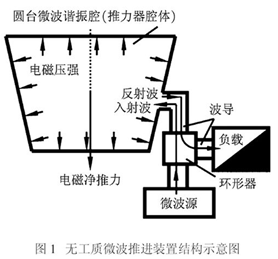 )
)
Let's give credit to Yang where it is due: Yang developed her own formulation and her own different experimental set-up and different EM Drive design. She is not a copy-cat of Shawyer. She has a different formulation than Shawyer, and she reported much higher thrust forces and specific forces (force per InputPower) than Shawyer.
Objective readers: make up your own mind on this: read Yang's formulation and see the difference. -
Title: Re: EM Drive Developments - related to space flight applications - Thread 3
Post by: SeeShells on 08/02/2015 02:57 PM -
<a href="http://forum.nasaspaceflight.com/index.php?topic=37642.msg1412510#msg1412510">Quote from: Rodal on 08/02/2015 01:02 PM</a><a href="http://forum.nasaspaceflight.com/index.php?topic=37642.msg1412480#msg1412480">Quote from: flux_capacitor on 08/02/2015 10:18 AM</a><a href="http://forum.nasaspaceflight.com/index.php?topic=37642.msg1412465#msg1412465">Quote from: TheTraveller on 08/02/2015 07:44 AM</a><a href="http://forum.nasaspaceflight.com/index.php?topic=37642.msg1412212#msg1412212">Quote from: flux_capacitor on 08/01/2015 03:13 PM</a>
Yang's frustum has the following dimensions:
- cavity length (m): 0.24
- big diameter (m): 0.201
- small diameter (m): 0.1492
In particular, the big end is smaller than the height, not larger.
There is no resonance I can find for those dimensions at 2.45GHz. Can get TE012 resonance at 2.51GHz
They were surely wrong dimensions, based on the assumption Yang's drawings had the correct proportions. ..
No, they were the dimensions that I had correctly based on the assumption that the small diameter for Yang was obtained based on the cut-off condition for the small end. And TheTraveller's calculation actually confirms it:
<<There is no resonance I can find for those dimensions at 2.45GHz. Can get TE012 resonance at 2.51GHz>>
The 2% difference between 2.45 GHz and 2.51 GHz is completely and utterly negligible compared to the other differences we are talking about: compared to the difference between 6 degrees and 15 degrees for the cone half-angle or compared to the uncertainties in having to eyeball the dimensionless ratio equations from Yang's chart.
On top of that, the result TE012 resonance at 2.51GHz is obtained by TheTraveller from an Excel spreadsheet using very simplified ad-hoc approximate formulas that do not respect the boundary conditions of the problem while the solution for TE012 2.45GHz resonance uses Wolfram Mathematica to solve the exact solution to the problem using Legendre Associated Functions and Spherical Bessel functions.
Taking into account the above considerations, the 2% different ad-hoc TE012 resonance at 2.51GHz means a complete agreement with the dimensions provided, because the 2% difference is completely within bounds.
___________________________________________
The issue at hand (determination of Yang's geometry) has to do with whether L=24cm provided by Yang in her paper is correct, and if so, whether the other (one and only one available to choose) parameter to consider should be the small diameter (based on cut-off), or the cone half-angle (determined from drawings), or some other parameter like D/L (determined from drawings), etc.
One cannot obtain dimensions from Yang's schematic drawings, one can only obtain dimensionless ratios: angles and ratios, that's it.
For L=24 cm and f=2.45 GHz, you cannot satisfy both that the diameter of the small base be above cut-off for an open waveguide AND satisfy the cone half-angle from Yang's drawings . They are in violent conflict with each other. Something got's to give.
This has to be clearly understood: we have mathematical relations to satisfy here, they are mathematical constraints. You cannot satisfy all the dimensionless ratios from Yang's drawings and simultaneously satisfy the cut-off condition at the small end and simultaneously satisfy L=24 cm and simultaneously satisfy the D/L vs frequency relation.
I'd like to insert one other thing here as well, having been in the middle of this as one of the builders. First I understand the why of your calculations and how you arrived at them.
Numbers don't lie, but liars and the deceiving will number. That said I think we need to at least make sure that the cone angle for Yang's frustum is correct, better than just taking it off of Yang's drawings which have been proven to be not quite accurate. How do we know that the drawing wasn't modified to fit the page ie: shortening or lengthening the image changing the cone angle? How can we even know who drew this and in what program? PCPaint? The answer is, we truly cant. That throw the angles and ratios under question as well.
Unless you are aware of a designed numerical conditions and guides that promotes this anonymously vague thing called thrust (don't think any here are) we still are poking the bear in the dark. How can I design something to optimize thrust when we don't even know what causes it and then throw in the misleading facts and figures from other builders and we have a real corundum on our hands. (ack, Shell runs screaming into the woods here) Numbers don't lie, but confusion in reported numbers or intentional misreporting of them makes for bad designing.
I'm not going to throw bricks or mash up my frustum with it but I have much to do in the building of the test stand and I'm gonna sortta float for awhile seeing if better numbers come forth.
Shell
-
Title: Re: EM Drive Developments - related to space flight applications - Thread 3
Post by: Rodal on 08/02/2015 03:02 PM -
<a href="http://forum.nasaspaceflight.com/index.php?topic=37642.msg1412533#msg1412533">Quote from: SeeShells on 08/02/2015 02:57 PM</a>
...
1) Concerning estimation of Yang's dimensions:
I'd like to insert one other thing here as well, having been in the middle of this as one of the builders. First I understand the why of your calculations and how you arrived at them.
Numbers don't lie, but liars and the deceiving will number. That said I think we need to at least make sure that the cone angle for Yang's frustum is correct, better than just taking it off of Yang's drawings which have been proven to be not quite accurate. How do we know that the drawing wasn't modified to fit the page ie: shortening or lengthening the image changing the cone angle? How can we even know who drew this and in what program? PCPaint? The answer is, we truly cant. That throw the angles and ratios under question as well.
Unless you are aware of a designed numerical conditions and guides that promotes this anonymously vague thing called thrust (don't think any here are) we still are poking the bear in the dark. How can I design something to optimize thrust when we don't even know what causes it and then throw in the misleading facts and figures from other builders and we have a real corundum on our hands. (ack, Shell runs screaming into the woods here) Numbers don't lie, but confusion in reported numbers or intentional misreporting of them makes for bad designing.
I'm not going to throw bricks or mash up my frustum with it but I have much to do in the building of the test stand and I'm gonna sortta float for awhile seeing if better numbers come forth.
Shell
Everybody is welcome to come up with their own estimates for Yang's dimensions. So far, to my recollection, I'm the only one that estimated Yang's dimensions, with two different and clearly stated assumptions: A) assuming the cut-off condition for the small diameter and alternatively B) assuming the angle from the drawings to be approximately correct.
To all readers disagreeing: what is your estimate for Yang's dimensions and what is it based on?
Let's compare different estimates and the basis for calculating the different estimates.
_____
2) Concerning experiments:
The formulas (Shawyer, McCulloch, Notsosureofit), as well as the Meep results and my computations show that the results based on an approximately cylindrical frustum with 6 degree cone angle are going to be inferior to one with a larger cone angle.
Concerning the experiments, I very much look forward to have experiments with a frustum having only 6 degree cone half-angle to compare with the experiments with frustum having higher cone angles.
An experiment will really clear this. Just like Tajmar's experiment with a Q=50 clarified the relationship to Q.
Prior to Tajmar's experiment with Q=50 many people would have expected that Q=50 would result in much lower thrust, but nobody had conducted such experiment. Now we know. Ditto for a frustum with 6 degree cone angle, which is very close to a cylinder. Actually, one might also consider an experiment (without a dielectric) with a cylinder (cone angle=0) and measure the thrust. Conduct an experiment with cone angle =0 (a cylinder), one with cone angle = 6 degrees, and one with cone angle =15 degrees. That will establish the cone angle dependence. That's what experiments are for. -
Title: Re: EM Drive Developments - related to space flight applications - Thread 3
Post by: SeeShells on 08/02/2015 03:09 PM -
<a href="http://forum.nasaspaceflight.com/index.php?topic=37642.msg1412523#msg1412523">Quote from: TheTraveller on 08/02/2015 02:24 PM</a><a href="http://forum.nasaspaceflight.com/index.php?topic=37642.msg1412505#msg1412505">Quote from: leomillert on 08/02/2015 12:48 PM</a><a href="http://forum.nasaspaceflight.com/index.php?topic=37642.msg1412465#msg1412465">Quote from: TheTraveller on 08/02/2015 07:44 AM</a>
Shawyers claim is not without basis, it is based on microwave industry experience. A waveguide operated below cutoff will not propagate an EM wave.
If the small end operates below cutoff there is no EM wave to bounce off the small end, then the big end, then the small end, then the big end, etc.
But please yourself and ignore microwave industry practice, Shawyer & Prof Yang.
But... what if I don't want to propagate just a EM wave? Evanescent waves are a prime contender in this frustum blender.
Shell -
Title: Re: EM Drive Developments - related to space flight applications - Thread 3
Post by: SeeShells on 08/02/2015 03:14 PM -
We are so working in the dark here and I've found evidence we have been trumped by one of the greats already.
BTW he (Tusla) is running about 21.69 degrees cone angle. -
Title: Re: EM Drive Developments - related to space flight applications - Thread 3
Post by: SeeShells on 08/02/2015 03:23 PM -
<a href="http://forum.nasaspaceflight.com/index.php?topic=37642.msg1412535#msg1412535">Quote from: Rodal on 08/02/2015 03:02 PM</a>
I even printed off pictures after changing them to line drawings in software and took my handy dandy protractor to measure and I was all over the place in differences in the pictures and the drawings. The best I could come up with was was disagreeing angles.<a href="http://forum.nasaspaceflight.com/index.php?topic=37642.msg1412533#msg1412533">Quote from: SeeShells on 08/02/2015 02:57 PM</a>...
1) Concerning estimation of Yang's dimensions:
Shell
Everybody is welcome to come up with their own estimates for Yang's dimensions. So far, to my recollection, I'm the only one that estimated Yang's dimensions, with two different and clearly stated assumptions: A) assuming the cut-off condition for the small diameter and alternatively B) assuming the angle from the drawings to be approximately correct.
To all readers disagreeing: what is your estimate for Yang's dimensions and what is it based on?
Let's compare different estimates and the basis for calculating the different estimates.
_____
2) Concerning experiments:
The formulas (Shawyer, McCulloch, Notsosureofit), as well as the Meep results and my computations show that the results based on an approximately cylindrical frustum with 6 degree cone angle are going to be inferior to one with a larger cone angle.
Concerning the experiments, I very much look forward to have experiments with a frustum having only 6 degree cone half-angle to compare with the experiments with frustum having higher cone angles.
An experiment will really clear this. Just like Tajmar's experiment with a Q=50 clarified the relationship to Q.
I did go the old fashioned route with pen and paper.
Shell -
Title: Re: EM Drive Developments - related to space flight applications - Thread 3
Post by: Rodal on 08/02/2015 03:30 PM -
<a href="http://forum.nasaspaceflight.com/index.php?topic=37642.msg1412540#msg1412540">Quote from: SeeShells on 08/02/2015 03:23 PM</a>
...I even printed off pictures after changing them to line drawings in software and took my handy dandy protractor to measure and I was all over the place in differences in the pictures and the drawings. The best I could come up with was was disagreeing angles.
I did go the old fashioned route with pen and paper.
Shell
How much "all over the place"? Did you get an angle of only 6 degrees from any of those pictures?
Neither Flyby nor FluxCapacitor or me report an angle of 6 degrees from any of Yang's pictures.
Blue is the cavity with 6 degrees: (it looks practically like a cylinder, compared to the other two):
(https://forum.nasaspaceflight.com/index.php?action=dlattach;topic=37642.0;attach=1052614;image)
()
-
Title: Re: EM Drive Developments - related to space flight applications - Thread 3
Post by: SeeShells on 08/02/2015 03:49 PM -
<a href="http://forum.nasaspaceflight.com/index.php?topic=37642.msg1412542#msg1412542">Quote from: Rodal on 08/02/2015 03:30 PM</a>
Nope not a one. So i picked a dimensionality that came from calculations (yours and me following them and I didn't catch the booboo either and that's on me) and reported high thrusts and built it. I was wrong and you were wrong, it happens. So I'm left with some of my original plans of testing this design and modifying it some to test out some other ideas. No bad data Jose'. It could be a good test run to iron out all of the test bed issues and fine tune all of it.<a href="http://forum.nasaspaceflight.com/index.php?topic=37642.msg1412540#msg1412540">Quote from: SeeShells on 08/02/2015 03:23 PM</a>...I even printed off pictures after changing them to line drawings in software and took my handy dandy protractor to measure and I was all over the place in differences in the pictures and the drawings. The best I could come up with was was disagreeing angles.
I did go the old fashioned route with pen and paper.
Shell
How much "all over the place"? Did you get an angle of only 6 degrees from any of those pictures?
Neither Flyby nor FluxCapacitor or me report an angle of 6 degrees from any of Yang's pictures.
Blue is the cavity with 6 degrees: (it looks practically like a cylinder, compared to the other two):
(https://forum.nasaspaceflight.com/index.php?action=dlattach;topic=37642.0;attach=1052614;image)
If I get crappy thrust we can just add the data to the charts filling them out. I have a $200 piece of O2 free copper that I ordered that will be my next build drawing on what I see here and what comes out of the test of the Yang-Shell and I believe that will be better for testing.
shell -
Title: Re: EM Drive Developments - related to space flight applications - Thread 3
Post by: SeeShells on 08/02/2015 04:16 PM -
<a href="http://forum.nasaspaceflight.com/index.php?topic=37642.msg1412533#msg1412533">Quote from: SeeShells on 08/02/2015 02:57 PM</a><a href="http://forum.nasaspaceflight.com/index.php?topic=37642.msg1412510#msg1412510">Quote from: Rodal on 08/02/2015 01:02 PM</a><a href="http://forum.nasaspaceflight.com/index.php?topic=37642.msg1412480#msg1412480">Quote from: flux_capacitor on 08/02/2015 10:18 AM</a><a href="http://forum.nasaspaceflight.com/index.php?topic=37642.msg1412465#msg1412465">Quote from: TheTraveller on 08/02/2015 07:44 AM</a><a href="http://forum.nasaspaceflight.com/index.php?topic=37642.msg1412212#msg1412212">Quote from: flux_capacitor on 08/01/2015 03:13 PM</a>
Yang's frustum has the following dimensions:
- cavity length (m): 0.24
- big diameter (m): 0.201
- small diameter (m): 0.1492
In particular, the big end is smaller than the height, not larger.
There is no resonance I can find for those dimensions at 2.45GHz. Can get TE012 resonance at 2.51GHz
They were surely wrong dimensions, based on the assumption Yang's drawings had the correct proportions. ..
No, they were the dimensions that I had correctly based on the assumption that the small diameter for Yang was obtained based on the cut-off condition for the small end. And TheTraveller's calculation actually confirms it:
<<There is no resonance I can find for those dimensions at 2.45GHz. Can get TE012 resonance at 2.51GHz>>
The 2% difference between 2.45 GHz and 2.51 GHz is completely and utterly negligible compared to the other differences we are talking about: compared to the difference between 6 degrees and 15 degrees for the cone half-angle or compared to the uncertainties in having to eyeball the dimensionless ratio equations from Yang's chart.
On top of that, the result TE012 resonance at 2.51GHz is obtained by TheTraveller from an Excel spreadsheet using very simplified ad-hoc approximate formulas that do not respect the boundary conditions of the problem while the solution for TE012 2.45GHz resonance uses Wolfram Mathematica to solve the exact solution to the problem using Legendre Associated Functions and Spherical Bessel functions.
Taking into account the above considerations, the 2% different ad-hoc TE012 resonance at 2.51GHz means a complete agreement with the dimensions provided, because the 2% difference is completely within bounds.
___________________________________________
The issue at hand (determination of Yang's geometry) has to do with whether L=24cm provided by Yang in her paper is correct, and if so, whether the other (one and only one available to choose) parameter to consider should be the small diameter (based on cut-off), or the cone half-angle (determined from drawings), or some other parameter like D/L (determined from drawings), etc.
One cannot obtain dimensions from Yang's schematic drawings, one can only obtain dimensionless ratios: angles and ratios, that's it.
For L=24 cm and f=2.45 GHz, you cannot satisfy both that the diameter of the small base be above cut-off for an open waveguide AND satisfy the cone half-angle from Yang's drawings . They are in violent conflict with each other. Something got's to give.
This has to be clearly understood: we have mathematical relations to satisfy here, they are mathematical constraints. You cannot satisfy all the dimensionless ratios from Yang's drawings and simultaneously satisfy the cut-off condition at the small end and simultaneously satisfy L=24 cm and simultaneously satisfy the D/L vs frequency relation.
I'd like to insert one other thing here as well, having been in the middle of this as one of the builders. First I understand the why of your calculations and how you arrived at them.
Numbers don't lie, but liars and the deceiving will number. That said I think we need to at least make sure that the cone angle for Yang's frustum is correct, better than just taking it off of Yang's drawings which have been proven to be not quite accurate. How do we know that the drawing wasn't modified to fit the page ie: shortening or lengthening the image changing the cone angle? How can we even know who drew this and in what program? PCPaint? The answer is, we truly cant. That throw the angles and ratios under question as well.
Unless you are aware of a designed numerical conditions and guides that promotes this anonymously vague thing called thrust (don't think any here are) we still are poking the bear in the dark. How can I design something to optimize thrust when we don't even know what causes it and then throw in the misleading facts and figures from other builders and we have a real corundum on our hands. (ack, Shell runs screaming into the woods here) Numbers don't lie, but confusion in reported numbers or intentional misreporting of them makes for bad designing.
I'm not going to throw bricks or mash up my frustum with it but I have much to do in the building of the test stand and I'm gonna sortta float for awhile seeing if better numbers come forth.
Shell
BTW I am going to be using a messy magnetron.
http://imgur.com/uL7VRi9
-
Title: Re: EM Drive Developments - related to space flight applications - Thread 3
Post by: Flyby on 08/02/2015 04:17 PM -
Shell,
I think your narrow angled frustum is an ideal case to test Todd's theory, needing a long narrow shape.
If it works better then all the rest, then we've all learned what direction to take for better results...
If it doesn't, it might indicate that Shawyer's path might yield better results.
So, whatever the outcome, your findings and data will bring an important contribution...
I too still have mixed feelings about the accuracy of Yang's frustrum+waveguide "technical drawing".
Some aspects make it read as a genuine technical illustration, where other aspects turn it "make believe" technical drawing that in essence hold no true dimensioning, scaling or proportion...
If only there was more consistency in the drawings and they had measurements on them... sigh... :'(
-
Title: Re: EM Drive Developments - related to space flight applications - Thread 3
Post by: SeeShells on 08/02/2015 04:25 PM -
<a href="http://forum.nasaspaceflight.com/index.php?topic=37642.msg1412550#msg1412550">Quote from: Flyby on 08/02/2015 04:17 PM</a>
Shell,
Thanks.
I think your narrow angled frustum is an ideal case to test Todd's theory, needing a long narrow shape.
If it works better then all the rest, then we've all learned what direction to take for better results...
If it doesn't, it might indicate that Shawyer's path might yield better results.
So, whatever the outcome, your findings and data will bring an important contribution...
I too still have mixed feelings about the accuracy of Yang's frustrum+waveguide "technical drawing".
Some aspects make it read as a genuine technical illustration, where other aspects turn it "make believe" technical drawing that in essence hold no true dimensioning, scaling or proportion...
If only there was more consistency in the drawings and they had measurements on them... sigh... :'(
Sure make it hard poking that bear in the dark doesn't it? Todd's thoughts were seriously taken in consideration in this design and I dearly hope I can get him some well deserved data to plug into his theories.
When I fell onto this design I went oh my I can test this and this and this in one frustum I really guess it hasn't changed too much. So it's good and no brick. ;)
Shell -
Title: Re: EM Drive Developments - related to space flight applications - Thread 3
Post by: Flyby on 08/02/2015 05:35 PM -
Well, i have no clear view on the current status of Todd's ideas are, as they tend to evolve rather quickly, but I'm sure that at certain stage it was mentioned in one of his posts...
I do think it is very helpful to tailor the DIY projects according some of the theories that float around, as these tests might help to prove or disprove an idea/theory.
The faster we're clearing this forest of theories and ideas, the better it will be.. no? -
Title: Re: EM Drive Developments - related to space flight applications - Thread 3
Post by: WarpTech on 08/02/2015 06:01 PM -
<a href="http://forum.nasaspaceflight.com/index.php?topic=37642.msg1412550#msg1412550">Quote from: Flyby on 08/02/2015 04:17 PM</a>
Shell,
I think your narrow angled frustum is an ideal case to test Todd's theory, needing a long narrow shape.
If it works better then all the rest, then we've all learned what direction to take for better results...
If it doesn't, it might indicate that Shawyer's path might yield better results.
So, whatever the outcome, your findings and data will bring an important contribution...
I too still have mixed feelings about the accuracy of Yang's frustrum+waveguide "technical drawing".
Some aspects make it read as a genuine technical illustration, where other aspects turn it "make believe" technical drawing that in essence hold no true dimensioning, scaling or proportion...
If only there was more consistency in the drawings and they had measurements on them... sigh... :'(
To be clear, even in my theory the prediction is that a shorter length with wider angle will give more thrust "forward". However, there are just as large, if not larger forces acting on the side walls when it is long and narrow and evanescent waves are decaying into the small end. The difference is that the force vector is not directed as much toward the front and is more like a cylinder.
In any case, I end up with Length in the denominator when comparing relative phase velocities, or I end up with sin(theta) in the numerator when comparing electromagnetic pressures on the surfaces. Either way, more angle results in more thrust. Too much angle and it starts to look like a pillbox and is too symmetrical, IMO.
On the other hand, the impedance plots from Z&F show that the impedance is scalable wrt. k*r and has higher differentials at lower cone angles. So, I do not see offhand why it would not work if the k*r value is scaled accordingly, to oscillate along the same impedance gradient. Maybe the right k value will not resonate there?
Just so everyone knows, I currently have 3 different models I'm trying to reconcile. Multiple examples in the paper should drive the point home:
1. I have a model similar to @Notsosureofit's equation, but using Z&F Impedance plots for the velocity terms, that are very similar to the Reissner-Nordstrom metric potential.
2. I have a DC coaxial model for TM DC mode, where the cone has a copper central axis. From there I've calculated the magnetic pressures and if the large end is closed and current flows around the complete loop, (a 1 turn inductor), then the force sums to zero. However, if the big end is open, or no current flows through it, then the forces are not balanced and magnetic flux escapes out the big end. Provided there is enough leakage that doesn't couple back to the incoming power wires, there should be "some" thrust.
3. I have a DC cone model for TE DC mode, where the cone is open ended. Circulating current around the small circumference will be "pushed" to the big end as the magnetic flux expands and forces itself out the back. This one is interesting because the conical conductor rotates the EM momentum vector, p = q*A 90 degrees until it is parallel with the cone and exerts a thrust. Like pushing out magnetic doughnuts (toroids).
Then I have all the other theories that I'm trying to compare to and reconcile against. There are definitely ways to generate thrust, however generating thrust better than a photon rocket can only happen when both the group velocity AND the phase velocity are BOTH slower than light in free space. That's the tricky part that is not textbook microwave physics.
Todd
-
Title: Re: EM Drive Developments - related to space flight applications - Thread 3
Post by: SeeShells on 08/02/2015 06:27 PM -
<a href="http://forum.nasaspaceflight.com/index.php?topic=37642.msg1412572#msg1412572">Quote from: Flyby on 08/02/2015 05:35 PM</a>
Well, i have no clear view on the current status of Todd's ideas are, as they tend to evolve rather quickly, but I'm sure that at certain stage it was mentioned in one of his posts...
Todd, when I get to the point where I can test some thoughts you we should exchange notes.
I do think it is very helpful to tailor the DIY projects according some of the theories that float around, as these tests might help to prove or disprove an idea/theory.
The faster we're clearing this forest of theories and ideas, the better it will be.. no?
Thanks for the summaries it's much clearer now.
Shell
>>>Back to the lab Igor! -
Title: Re: EM Drive Developments - related to space flight applications - Thread 3
Post by: Flyby on 08/02/2015 06:35 PM - hop.... another misunderstanding out the window...
-
Title: Re: EM Drive Developments - related to space flight applications - Thread 3
Post by: X_RaY on 08/02/2015 07:03 PM -
<a href="http://forum.nasaspaceflight.com/index.php?topic=37642.msg1412339#msg1412339">Quote from: Rodal on 08/01/2015 10:20 PM</a><a href="http://forum.nasaspaceflight.com/index.php?topic=37642.msg1412312#msg1412312">Quote from: Rodal on 08/01/2015 08:39 PM</a>
After a 5 mile run, I'm ready to put this to bed.<a href="http://forum.nasaspaceflight.com/index.php?topic=37642.msg1412267#msg1412267">Quote from: Rodal on 08/01/2015 05:51 PM</a><a href="http://forum.nasaspaceflight.com/index.php?topic=37642.msg1412251#msg1412251">Quote from: Flyby on 08/01/2015 05:07 PM</a><a href="http://forum.nasaspaceflight.com/index.php?topic=37642.msg1412247#msg1412247">Quote from: Rodal on 08/01/2015 04:50 PM</a>
The difference between the two geometries is completely negligible compared to the difference between the geometry in the EM Drive wiki
Compared to the geometry in the EM Drive wiki, the two drawings you show line up excellent !
(http://forum.nasaspaceflight.com/xindex.php,qaction=dlattach,3Btopic=37642.0,3Battach=1052591,3Bimage.pagespeed.ic.izWlQdUm4_.webp)
Could you please superpose the geometry of the EM Drive Wiki ( http://emdrive.wiki/Experimental_Results ), which has a cone half angle of 6 degrees to make that clear ?
If you do that you will see how utterly different is the geometry in the EM Drive wiki for Yang, and that the estimate in the EM Drive Wiki is unreasonable.
Blue outline is the Wiki version of Yang...
As you said... it's way off..
Could it be that the composite shape of a cylinder and frustum, like we see in the more "technical" drawing, altered the data in such a way that reverse calculation gives a length value that is way off?
The only dimension given by Yang in her paper is the Length (also called height) measured perpendicular to the bases. It is 0.240 meters.
Look at page 811, Table 1 http://www.emdrive.com/NWPU2010paper.pdf
Hence it would be best if you superpose all the images so that they all have the same length: 0.240 meters
Then one has to use this image:
()
knowing that
1) L=24 cm
2) f = 2.45 GHz
3) D = (Dbig + Dsmall)/2
4) TE012 line should be used
OK, using the above and
Cone half-angle = 15 degrees
I proceed as follows:
TE012 Equation (from Yang's graph): y = 13.5 + 8.5 x
where
y = ((f D) ^2)*10^(-20)
x = (D/L)^2
replacing
L=24 cm
f=2.45*10^9 Hz
and solving the quadratic equation for D, I get
D=17.26915 cm
and since
(Db - Ds)/2 = (24 cm)* tan (15 degrees)
and
(Db + Ds)/2 =D = 17.26915 cm
and solving these coupled equations for Db and Ds, we finally get
Db = 23.69993 cm ~ 23.70 cm
Ds = 10.83836 cm ~ 10.84 cm
L = 24 cm
Need to calculate whether these numbers give a natural frequency for TE012 of 2.45 GHz
if not, need to modify the diameters in order to get TE012 @ 2.45 GHz
The main imprecision comes from the coefficients of the equation y = 13.5 + 8.5 x
Obviously, there is a whole family of solutions that satisfy the equation for TE012 in Yang's graph, for different values of the cone angle. The larger the cone angle, the more different are the values of Db and Ds, all we know is their average D.
We proceed as follows:
We adopt the Cone half-angle value from Flyby 15.44 degrees, which is the Median of the three values obtained (15 degrees from SeeShells and the two values from Flyby 15.44 and 18.27 degrees)
Cone Half-Angle = 15.44
therefore the constraint is
Db - Ds = 2 (24 cm) Tan(15.44) = 13. 25746 cm
and vary Db and Ds subject to this constraint to get 2.45 GHz for TE012 from the exact solution
doing so, we get:
Db = 0.247 m
Ds = 0.114425 m
L = 0.24 m
r1= 0.211022 m
r2= 0.455515 m
Cone half-angle = 15.44 degrees
these numbers represent only a small change from the previous numbers, which gives some level of encouragement, as the previous numbers were obtained from Yang's chart, just eyeballing it, without performing any frequency calculation
Notice that these diameters for Yang are close to the diameters of Shawyer's Flight Thruster, the only difference with Flight Thruster is that Yang has a greater length to enable resonating at TE012 for Yang at 2.45GHz instead of TE013 for Flight Thruster at 3.85GHz. Recall that at the time that Yang embarked on her project, the Flight Thruster was the latest and highest effective force design by Shawyer. The longer length of Yang being motivated perhaps by the need to resonate at 2.45 GHz instead of 3.85 GHz.
We adopt these numbers as the official Yang geometry and we correct the previous numbers I had entered in the EM Drive Wiki accordingly without further ado.
***A cone half-angle of 6 degrees does not make any sense to me for an EM Drive, it is like a cylinder ===> bad***
Did ever someone ask for the dimensions (for verification) personally?
yangjuan@nwpu.edu.cn
It isn't helpful to poke in the dark, IMHO
PS: I am not the one who want to do ;) -
Title: Re: EM Drive Developments - related to space flight applications - Thread 3
Post by: Rodal on 08/02/2015 07:53 PM -
<a href="http://forum.nasaspaceflight.com/index.php?topic=37642.msg1412544#msg1412544">Quote from: SeeShells on 08/02/2015 03:49 PM</a>
...So i picked a dimensionality that came from calculations (yours and me following them and I didn't catch the booboo either and that's on me) and reported high thrusts and built it. I was wrong and you were wrong, it happens. ...
Nope. There was no "booboo" and there was not something "wrong" in my previous selection of dimensions for Yang. Those dimensions are the correct dimensions if one assumes that Yang selected her small diameter to be at the waveguide cut-off frequency, following Shawyer's prescription.<a href="http://forum.nasaspaceflight.com/index.php?topic=37642.msg1412480#msg1412480">Quote from: flux_capacitor on 08/02/2015 10:18 AM</a>...
<a href="http://forum.nasaspaceflight.com/index.php?topic=37642.msg1412212#msg1412212">Quote from: flux_capacitor on 08/01/2015 03:13 PM</a>Yang's frustum has the following dimensions:
...the cutoff dimension, just below the guide wavelength for TE01 mode at 2.45GHz = 148.7 mm..
- cavity length (m): 0.24
- big diameter (m): 0.201
- small diameter (m): 0.1492
...
Proof that I selected those Yang's dimensions based on the assumption that she followed Shawyer's prescription for the small diameter to be at the cut-off frequency:
Known input:
Mode Shape: TE012
Frequency: 2.45 GHz
Table of Bessel zeros and Bessel Derivative zeros: http://wwwal.kuicr.kyoto-u.ac.jp/www/accelerator/a4/besselroot.htmlx
____________________________________________________
Proof:
Equation for cut-off diameter:
Ds = (X'01 *c)/(Pi*frequency)
=(3.83170597020751*299792458 m/s)/(Pi*2.45*10^9 1/s)
=0.1492 m
QED. Thus the cut-off diameter for TE012 at 2.45GHz is exactly 0.1492 m and that's where the previous dimensions I selected came from.
____________________________________________________
____________________________________________________
The dimensions for Yang's EM Drive that I have placed now in the Wiki are based instead on the cone half-angle in Yang's drawings. There is only free parameter one can choose: for example that she chose Ds based on the cut-off frequency, or that the cone half-angle is known. One free-parameter. That's it. The cone half-angle in her drawings is in conflict with the assumption that her small diameter was chosen based on cut-off frequencies. The present dimensions based on the cone half-angle in her drawings are in agreement with:
1) similar cone-half angles as NASA and Shawyer
2) in much closer agreement with the formulas from Shawyer. McCulloch and Notsosureofit for thrust
I see no violence in the fact that Yang may not be ascribing to Shawyer's prescription for a cut-off based on waveguides. The reason I see no violence is based on the fact that Yang does NOT use Shawyer's theory. Yang used a Finite Element Program to calculate the stresses in the EM Drive, and therefore calculate the forces. It makes perfect sense to me that when she calculated the stresses (and therefore the resonance of the electromagnetic fields) she was cognizant of the fact (obvious to anyone performing a FEA solution) that there is no such thing as a sharp cut-off frequency, and thus she was free to choose a smaller diameter for the small base.
Those insisting on a sharp cut-off frequency do so at their peril: since such an assumption may preclude them from achieving higher thrust and higher thrust/InputPower. -
Title: Re: EM Drive Developments - related to space flight applications - Thread 3
Post by: X_RaY on 08/02/2015 08:08 PM -
<a href="http://forum.nasaspaceflight.com/index.php?topic=37642.msg1412602#msg1412602">Quote from: Rodal on 08/02/2015 07:53 PM</a>
How sure are you about the 0.240m length?<a href="http://forum.nasaspaceflight.com/index.php?topic=37642.msg1412544#msg1412544">Quote from: SeeShells on 08/02/2015 03:49 PM</a>...So i picked a dimensionality that came from calculations (yours and me following them and I didn't catch the booboo either and that's on me) and reported high thrusts and built it. I was wrong and you were wrong, it happens. ...
Nope. There was no "booboo" and there was not something "wrong" in my previous selection of dimensions for Yang. Those dimensions are the correct dimensions if one assumes that Yang selected her small diameter to be at the waveguide cut-off frequency, following Shawyer's prescription.<a href="http://forum.nasaspaceflight.com/index.php?topic=37642.msg1412480#msg1412480">Quote from: flux_capacitor on 08/02/2015 10:18 AM</a>...
<a href="http://forum.nasaspaceflight.com/index.php?topic=37642.msg1412212#msg1412212">Quote from: flux_capacitor on 08/01/2015 03:13 PM</a>Yang's frustum has the following dimensions:
...the cutoff dimension, just below the guide wavelength for TE01 mode at 2.45GHz = 148.7 mm..
- cavity length (m): 0.24
- big diameter (m): 0.201
- small diameter (m): 0.1492
...
Proof that I selected those Yang's dimensions based on the assumption that she followed Shawyer's prescription for the small diameter to be at the cut-off frequency:
Known input:
Mode Shape: TE012
Frequency: 2.45 GHz
Table of Bessel zeros: http://wwwal.kuicr.kyoto-u.ac.jp/www/accelerator/a4/besselroot.htmlx
____________________________________________________
Proof:
Equation for cut-off diameter:
Ds = (X'01 *c)/(Pi*frequency)
=(3.83170597020751*299792458 m/s)/(Pi*2.45*10^9 1/s)
=0.1492 m
QED. Thus the cut-off diameter for TE012 at 2.45GHz is exactly 0.1492 m and that's where the previous dimensions I selected came from.
____________________________________________________
____________________________________________________
The dimensions for Yang's EM Drive that I have placed now in the Wiki are based instead on the cone half-angle in Yang's drawings. There is only free parameter one can choose: for example that she chose Ds based on the cut-off frequency, or that the cone half-angle is known. One free-parameter. That's it. The cone half-angle in her drawings is in conflict with the assumption that her small diameter was chosen based on cut-off frequencies. The present dimensions based on the cone half-angle in her drawings are in agreement with:
1) similar cone-half angles as NASA and Shawyer
2) in much closer agreement with the formulas from Shawyer. McCulloch and Notsosureofit for thrust
If you think that's it we have all together :)
-
Title: Re: EM Drive Developments - related to space flight applications - Thread 3
Post by: flux_capacitor on 08/02/2015 08:13 PM -
<a href="http://forum.nasaspaceflight.com/index.php?topic=37642.msg1412605#msg1412605">Quote from: X_RaY on 08/02/2015 08:08 PM</a>
How sure are you about the 0.240m length?
See table 1 in the Yang 2010 paper (http://www.emdrive.com/NWPU2010translation.pdf).
If you think that's it we have all together :) -
Title: Re: EM Drive Developments - related to space flight applications - Thread 3
Post by: Rodal on 08/02/2015 08:14 PM -
<a href="http://forum.nasaspaceflight.com/index.php?topic=37642.msg1412605#msg1412605">Quote from: X_RaY on 08/02/2015 08:08 PM</a>
...
240 mm is the length that Prof. Yang explicitly gives for her EM Drive at TE012 at 2.45 Ghz in page 811, Table 1, of her paper (in Chinese)
How sure are you about the 0.240m length?
If you think that's it we have all together :)
无工质微波推进的推力转换机理与性能计算分析
杨 涓,杨 乐,朱 雨,马 楠
2010年t2月 第28卷第6期
西北工业大学学报
Journal of Northwestern Polytechnical University
Dec. 2010 V01.28 No.6
http://www.emdrive.com/NWPU2010paper.pdf -
Title: Re: EM Drive Developments - related to space flight applications - Thread 3
Post by: X_RaY on 08/02/2015 08:16 PM -
<a href="http://forum.nasaspaceflight.com/index.php?topic=37642.msg1412602#msg1412602">Quote from: Rodal on 08/02/2015 07:53 PM</a><a href="http://forum.nasaspaceflight.com/index.php?topic=37642.msg1412544#msg1412544">Quote from: SeeShells on 08/02/2015 03:49 PM</a>
...So i picked a dimensionality that came from calculations (yours and me following them and I didn't catch the booboo either and that's on me) and reported high thrusts and built it. I was wrong and you were wrong, it happens. ...
Nope. There was no "booboo" and there was not something "wrong" in my previous selection of dimensions for Yang. Those dimensions are the correct dimensions if one assumes that Yang selected her small diameter to be at the waveguide cut-off frequency, following Shawyer's prescription.<a href="http://forum.nasaspaceflight.com/index.php?topic=37642.msg1412480#msg1412480">Quote from: flux_capacitor on 08/02/2015 10:18 AM</a>...
<a href="http://forum.nasaspaceflight.com/index.php?topic=37642.msg1412212#msg1412212">Quote from: flux_capacitor on 08/01/2015 03:13 PM</a>Yang's frustum has the following dimensions:
...the cutoff dimension, just below the guide wavelength for TE01 mode at 2.45GHz = 148.7 mm..
- cavity length (m): 0.24
- big diameter (m): 0.201
- small diameter (m): 0.1492
...
Proof that I selected those Yang's dimensions based on the assumption that she followed Shawyer's prescription for the small diameter to be at the cut-off frequency:
Known input:
Mode Shape: TE012
Frequency: 2.45 GHz
Table of Bessel zeros: http://wwwal.kuicr.kyoto-u.ac.jp/www/accelerator/a4/besselroot.htmlx
____________________________________________________
Proof:
Equation for cut-off diameter:
Ds = (X'01 *c)/(Pi*frequency)
=(3.83170597020751*299792458 m/s)/(Pi*2.45*10^9 1/s)
=0.1492 m
QED. Thus the cut-off diameter for TE012 at 2.45GHz is exactly 0.1492 m and that's where the previous dimensions I selected came from.
____________________________________________________
____________________________________________________
The dimensions for Yang's EM Drive that I have placed now in the Wiki are based instead on the cone half-angle in Yang's drawings. There is only free parameter one can choose: for example that she chose Ds based on the cut-off frequency, or that the cone half-angle is known. One free-parameter. That's it. The cone half-angle in her drawings is in conflict with the assumption that her small diameter was chosen based on cut-off frequencies. The present dimensions based on the cone half-angle in her drawings are in agreement with:
1) similar cone-half angles as NASA and Shawyer
2) in much closer agreement with the formulas from Shawyer. McCulloch and Notsosureofit for thrust
SD=0.1492m
BD=0.200m
L=0.240m
f_res(TE012)=~2,4537GHz
angle=6,041deg
with SD 0.15m i get 2,4490GHz
angle=5,946deg
-
Title: Re: EM Drive Developments - related to space flight applications - Thread 3
Post by: Rodal on 08/02/2015 08:18 PM -
<a href="http://forum.nasaspaceflight.com/index.php?topic=37642.msg1412596#msg1412596">Quote from: X_RaY on 08/02/2015 07:03 PM</a>
...
Did ever someone ask for the dimensions (for verification) personally?
yangjuan@nwpu.edu.cn
It isn't helpful to poke in the dark, IMHO
PS: I am not the one who want to do ;)
Several people have asked (Ref: NSF threads 1 and 2). No answers have been reported. Ever.
It has been reported Prof. Yang told a Scientific News reporter that "publicity about her EM Drive research is most unwelcome"
-
Title: Re: EM Drive Developments - related to space flight applications - Thread 3
Post by: Rodal on 08/02/2015 08:22 PM -
<a href="http://forum.nasaspaceflight.com/index.php?topic=37642.msg1412609#msg1412609">Quote from: X_RaY on 08/02/2015 08:16 PM</a>
...
If you think that's it we have all together :)
SD=0.1492m
BD=0.200m
L=0.240m
f_res(TE012)=~2,4537GHz
angle=6,041deg
with SD 0.15m i get 2,4490GHz
angle=5,946deg
Thank you. Confirmed:
1) There was no "booboo"
2) Your computer program agrees quite well with my computer program (once again). TheTraveller's program is only off by 2%, a difference which I consider to be an utterly negligible difference when we are talking about much larger differences here. The calculations by TheTraveller are quite acceptable for engineering purposes. -
Title: Re: EM Drive Developments - related to space flight applications - Thread 3
Post by: X_RaY on 08/02/2015 08:30 PM -
<a href="http://forum.nasaspaceflight.com/index.php?topic=37642.msg1412611#msg1412611">Quote from: Rodal on 08/02/2015 08:18 PM</a>
no answer? >:( bad scientist* :(<a href="http://forum.nasaspaceflight.com/index.php?topic=37642.msg1412596#msg1412596">Quote from: X_RaY on 08/02/2015 07:03 PM</a>...
Did ever someone ask for the dimensions (for verification) personally?
yangjuan@nwpu.edu.cn
It isn't helpful to poke in the dark, IMHO
PS: I am not the one who want to do ;)
Several people have asked (Ref: NSF threads 1 and 2). No answers have been reported. Ever.
It has been reported Prof. Yang told a Scientific News reporter that "publicity about her EM Drive research is most unwelcome"
*don't know, how much the cn government got hands over their scientific results -
Title: Re: EM Drive Developments - related to space flight applications - Thread 3
Post by: Rodal on 08/02/2015 08:33 PM -
<a href="http://forum.nasaspaceflight.com/index.php?topic=37642.msg1412617#msg1412617">Quote from: X_RaY on 08/02/2015 08:30 PM</a><a href="http://forum.nasaspaceflight.com/index.php?topic=37642.msg1412611#msg1412611">Quote from: Rodal on 08/02/2015 08:18 PM</a>
no answer? >:( bad scientist :(<a href="http://forum.nasaspaceflight.com/index.php?topic=37642.msg1412596#msg1412596">Quote from: X_RaY on 08/02/2015 07:03 PM</a>...
Did ever someone ask for the dimensions (for verification) personally?
yangjuan@nwpu.edu.cn
It isn't helpful to poke in the dark, IMHO
PS: I am not the one who want to do ;)
Several people have asked (Ref: NSF threads 1 and 2). No answers have been reported. Ever.
It has been reported Prof. Yang told a Scientific News reporter that "publicity about her EM Drive research is most unwelcome"
There is always hope. Maybe SeeShells can contact her. -
Title: Re: EM Drive Developments - related to space flight applications - Thread 3
Post by: flux_capacitor on 08/02/2015 08:33 PM -
<a href="http://forum.nasaspaceflight.com/index.php?topic=37642.msg1412617#msg1412617">Quote from: X_RaY on 08/02/2015 08:30 PM</a><a href="http://forum.nasaspaceflight.com/index.php?topic=37642.msg1412611#msg1412611">Quote from: Rodal on 08/02/2015 08:18 PM</a>
no answer? >:( bad scientist :(<a href="http://forum.nasaspaceflight.com/index.php?topic=37642.msg1412596#msg1412596">Quote from: X_RaY on 08/02/2015 07:03 PM</a>...
Did ever someone ask for the dimensions (for verification) personally?
yangjuan@nwpu.edu.cn
It isn't helpful to poke in the dark, IMHO
PS: I am not the one who want to do ;)
Several people have asked (Ref: NSF threads 1 and 2). No answers have been reported. Ever.
It has been reported Prof. Yang told a Scientific News reporter that "publicity about her EM Drive research is most unwelcome"
She doesn't do what she wants, this is China. So take into account politics and human rights. Moreover NWPU is also a military school. So add geopolitics and defense purpose. -
Title: Re: EM Drive Developments - related to space flight applications - Thread 3
Post by: X_RaY on 08/02/2015 08:40 PM -
<a href="http://forum.nasaspaceflight.com/index.php?topic=37642.msg1412619#msg1412619">Quote from: flux_capacitor on 08/02/2015 08:33 PM</a>
Yes i've edit my post while you're typing ;)<a href="http://forum.nasaspaceflight.com/index.php?topic=37642.msg1412617#msg1412617">Quote from: X_RaY on 08/02/2015 08:30 PM</a><a href="http://forum.nasaspaceflight.com/index.php?topic=37642.msg1412611#msg1412611">Quote from: Rodal on 08/02/2015 08:18 PM</a>
no answer? >:( bad scientist :(<a href="http://forum.nasaspaceflight.com/index.php?topic=37642.msg1412596#msg1412596">Quote from: X_RaY on 08/02/2015 07:03 PM</a>...
Did ever someone ask for the dimensions (for verification) personally?
yangjuan@nwpu.edu.cn
It isn't helpful to poke in the dark, IMHO
PS: I am not the one who want to do ;)
Several people have asked (Ref: NSF threads 1 and 2). No answers have been reported. Ever.
It has been reported Prof. Yang told a Scientific News reporter that "publicity about her EM Drive research is most unwelcome"
She doesn't do what she wants, this is China. So take into account politics and human rights. Moreover NWPU is also a military school. So add geopolitics and defense purpose. -
Title: Re: EM Drive Developments - related to space flight applications - Thread 3
Post by: SeeShells on 08/02/2015 08:46 PM -
<a href="http://forum.nasaspaceflight.com/index.php?topic=37642.msg1412618#msg1412618">Quote from: Rodal on 08/02/2015 08:33 PM</a>
Nada nothing...digital silence from that end.<a href="http://forum.nasaspaceflight.com/index.php?topic=37642.msg1412617#msg1412617">Quote from: X_RaY on 08/02/2015 08:30 PM</a><a href="http://forum.nasaspaceflight.com/index.php?topic=37642.msg1412611#msg1412611">Quote from: Rodal on 08/02/2015 08:18 PM</a>
no answer? >:( bad scientist :(<a href="http://forum.nasaspaceflight.com/index.php?topic=37642.msg1412596#msg1412596">Quote from: X_RaY on 08/02/2015 07:03 PM</a>...
Did ever someone ask for the dimensions (for verification) personally?
yangjuan@nwpu.edu.cn
It isn't helpful to poke in the dark, IMHO
PS: I am not the one who want to do ;)
Several people have asked (Ref: NSF threads 1 and 2). No answers have been reported. Ever.
It has been reported Prof. Yang told a Scientific News reporter that "publicity about her EM Drive research is most unwelcome"
There is always hope. Maybe SeeShells can contact her. -
Title: Re: EM Drive Developments - related to space flight applications - Thread 3
Post by: WarpTech on 08/02/2015 08:53 PM -
<a href="http://forum.nasaspaceflight.com/index.php?topic=37642.msg1412602#msg1412602">Quote from: Rodal on 08/02/2015 07:53 PM</a>
...It makes perfect sense to me that when she calculated the stresses (and therefore the resonance of the electromagnetic fields) she was cognizant of the fact (obvious to anyone performing a FEA solution) that there is no such thing as a sharp cut-off frequency, and thus she was free to choose a smaller diameter for the small base...
Given that there is no sharp cut-off. If we have a frustum that is too small at the small end and too big at the big end. What determines the resonance? Is there any mode that would resonate without interacting with either end?
Todd
-
Title: Re: EM Drive Developments - related to space flight applications - Thread 3
Post by: X_RaY on 08/02/2015 08:54 PM -
<a href="http://forum.nasaspaceflight.com/index.php?topic=37642.msg1412625#msg1412625">Quote from: SeeShells on 08/02/2015 08:46 PM</a>
Interesting but not good, don't know why they publish the mail address...<a href="http://forum.nasaspaceflight.com/index.php?topic=37642.msg1412618#msg1412618">Quote from: Rodal on 08/02/2015 08:33 PM</a>
Nada nothing...digital silence from that end.<a href="http://forum.nasaspaceflight.com/index.php?topic=37642.msg1412617#msg1412617">Quote from: X_RaY on 08/02/2015 08:30 PM</a><a href="http://forum.nasaspaceflight.com/index.php?topic=37642.msg1412611#msg1412611">Quote from: Rodal on 08/02/2015 08:18 PM</a>
no answer? >:( bad scientist :(<a href="http://forum.nasaspaceflight.com/index.php?topic=37642.msg1412596#msg1412596">Quote from: X_RaY on 08/02/2015 07:03 PM</a>...
Did ever someone ask for the dimensions (for verification) personally?
yangjuan@nwpu.edu.cn
It isn't helpful to poke in the dark, IMHO
PS: I am not the one who want to do ;)
Several people have asked (Ref: NSF threads 1 and 2). No answers have been reported. Ever.
It has been reported Prof. Yang told a Scientific News reporter that "publicity about her EM Drive research is most unwelcome"
There is always hope. Maybe SeeShells can contact her.
We have to believe owen math i think.
I am curious about the results with your geometrie. :) -
Title: Re: EM Drive Developments - related to space flight applications - Thread 3
Post by: X_RaY on 08/02/2015 08:59 PM -
<a href="http://forum.nasaspaceflight.com/index.php?topic=37642.msg1412626#msg1412626">Quote from: WarpTech on 08/02/2015 08:53 PM</a>
Did you notice Dr. Rodal's document? There is still resonance, the side walls do the job of the endplates (topologically) ....<a href="http://forum.nasaspaceflight.com/index.php?topic=37642.msg1412602#msg1412602">Quote from: Rodal on 08/02/2015 07:53 PM</a>...It makes perfect sense to me that when she calculated the stresses (and therefore the resonance of the electromagnetic fields) she was cognizant of the fact (obvious to anyone performing a FEA solution) that there is no such thing as a sharp cut-off frequency, and thus she was free to choose a smaller diameter for the small base...
Given that there is no sharp cut-off. If we have a frustum that is too small at the small end and too big at the big end. What determines the resonance? Is there any mode that would resonate without interacting with either end?
Todd
Sorry, i'm sure you did :) -
Title: Re: EM Drive Developments - related to space flight applications - Thread 3
Post by: Rodal on 08/02/2015 09:31 PM -
<a href="http://forum.nasaspaceflight.com/index.php?topic=37642.msg1412626#msg1412626">Quote from: WarpTech on 08/02/2015 08:53 PM</a><a href="http://forum.nasaspaceflight.com/index.php?topic=37642.msg1412602#msg1412602">Quote from: Rodal on 08/02/2015 07:53 PM</a>
...It makes perfect sense to me that when she calculated the stresses (and therefore the resonance of the electromagnetic fields) she was cognizant of the fact (obvious to anyone performing a FEA solution) that there is no such thing as a sharp cut-off frequency, and thus she was free to choose a smaller diameter for the small base...
Given that there is no sharp cut-off. If we have a frustum that is too small at the small end and too big at the big end. What determines the resonance? Is there any mode that would resonate without interacting with either end?
Todd
Yes resonance definitely plays a role. As explained in my post about the insectoid overlord. Take a look at the Q formula. In the numerator you have the integral over the volume of B square. In the denominator you have the integral over the surface. To maximize Q you want to maximize the numerator and minimize the denominator. -
Title: Re: EM Drive Developments - related to space flight applications - Thread 3
Post by: SteveD on 08/02/2015 09:54 PM -
<a href="http://forum.nasaspaceflight.com/index.php?topic=37642.msg1412462#msg1412462">Quote from: deltaMass on 08/02/2015 06:53 AM</a>
weekly interactive particle
you can't go peaking under peoples clothes.
Sometimes poor spelling is an advantage 8)
Sorry, I was posting from a tablet late at night. The "keyboard" doesn't always pick up every keystroke and then the auto-correct tries to be "helpful." -
Title: Re: EM Drive Developments - related to space flight applications - Thread 3
Post by: seggybop on 08/02/2015 10:32 PM - Did those attempting to contact Yang do so in legit non-Google translated Chinese? If not, I can try sending a message that might be more intelligible / likely to be acknowledged. Or even if it's been attempted already, sending an additional request for info might not hurt.
-
Title: Re: EM Drive Developments - related to space flight applications - Thread 3
Post by: Rodal on 08/02/2015 10:38 PM -
<a href="http://forum.nasaspaceflight.com/index.php?topic=37642.msg1412644#msg1412644">Quote from: seggybop on 08/02/2015 10:32 PM</a>
Did those attempting to contact Yang do so in legit non-Google translated Chinese? If not, I can try sending a message that might be more intelligible / likely to be acknowledged. Or even if it's been attempted already, sending an additional request for info might not hurt.
Sure, by all means. Try asking her what are the dimensions of the EM Drive she tested to get the highest force and force/InputPower ever reported:
very simple question:
Big Base Diameter = m
Small Base Diameter = m
Length (measured perpendicular to the bases) = m -
Title: Re: EM Drive Developments - related to space flight applications - Thread 3
Post by: flux_capacitor on 08/02/2015 10:42 PM -
@seggybop: Do you speak and read Chinese?
If so, can you translate in English the left-side column in the attached table? -
Title: Re: EM Drive Developments - related to space flight applications - Thread 3
Post by: flux_capacitor on 08/02/2015 10:52 PM -
I don't trust Yang's drawings. I think they have incorrect proportions. So I don't trust results defined from a ratio in those drawings, including the half-cone angle.
For those reasons I tried to learn from Yang's 2010 paper (http://www.emdrive.com/NWPU2010translation.pdf) how she calculates the dimensions of a resonating frustum from a chosen frequency and mode. In the following I summarize my understanding of the translation, and my attempt to find some dimensions.
METHOD
1. She starts from a cylinder waveguide.
2. She uses finite element method to calculate the distribution of EM fields in a cavity, for a chosen mode and near a chosen frequency. For example: TE012 around 2.45 GHz.
3. She sets a cylindrical diameter D and a cavity length L according to the mode she wants to use. This can be done according to the figure 3 in her 2010 paper. I add a modified version of that figure attached below, extended and with a grid added for precision. WARNING: If we want a half-cone angle that does not approaches 0 (cylinder) we must have Ds << D << Db
We get what I decided to call the YANG NUMBER Yn on the y axis.
Yn = (f × D)2 × 10-20
where f is the frequency in Hz, and D the cylindrical diameter in cm.
4. This cylindrical diameter D is also the "average diameter" of the frustum. It is NOT the diameter of the small or big end.
5. Set the the small end diameter Ds as the cylindrical waveguide cut-off diameter. So for TE012 at 2.45 GHz:
Ds = 14.92 cm
6. The big end diameter Db then follows from the average diameter D and the small diameter Ds.
Since
D = (Db + Ds)/2
Then
Db = 2×D - Ds
7. She performs again a finite element numerical simulation for the distribution of the EM field. And she repeats adjusting through small steps the small end Ds, big end Db, cavity length L, until she finds the correct resonance. -
Title: Re: EM Drive Developments - related to space flight applications - Thread 3
Post by: flux_capacitor on 08/02/2015 10:52 PM -
And here are my attempts to calculate some dimensions according to Yang's method set in my previous message; at first with a high cone angle, then fixing L = 24 cm from starts which gives the already noted low cone angle.
1ST EXAMPLE
Many possibilities to make a frustum according to these laws. At first I chose to set Db at twice the value of Ds, the later being the cut-off diameter. So:
Ds = 14.92 cm
Db = 29.84 cm
Hence the average diameter D is:
D = 22.38 cm
I calculate the Yang number Yn :
Yn = (f × D)2 × 10-20
Yn = 30-20 cm/s
With this value of Yn on the y axis, we found the corresponding value on the x axis following the TE012 straight line on the graph:
(D/L)2 = 2
Hence
L = 15.825 cm
In this case, half-cone angle = 25.2°
Playing with those numbers, I can't confirm this frustum resonates at TE012 and 2.45 GHz as I don't have access to finite element software.
2ND EXAMPLE WITH L = 24 CM
It is worth noting that when I start from elsewhere, fixing both the small end at cutoff diameter Ds = 14.92 cm and the cavity length L = 24 cm from start,
Then following the same process I finally get:
Yn = 18
Db = 19.71 cm
D = 17.317 cm
Hence as Db is not very different than Ds and the cavity length is quite long, it becomes almost a cylinder as noted before by Rodal.
But is it wrong? Yang's translated notes (typos corrected):Quote from: Juan YANGThe mode TE012 which has smallest Large-End has the largest thrust, so has the highest quality factor and thrust. Mode TM011 thruster has the worst performance. As the Large-End of the cavity increases, the height of cavity reduce, cavity volume and wall surface area also reduced, leading to low quality factor and producing less thrust.
So she seems to confirm that a longer cavity with the big end as small as possible, thus with a very low cone-angle, the frustum being almost cylindrical, has a higher Q and higher thrust… -
Title: Re: EM Drive Developments - related to space flight applications - Thread 3
Post by: flux_capacitor on 08/02/2015 11:22 PM -
<a href="http://forum.nasaspaceflight.com/index.php?topic=37642.msg1412651#msg1412651">Quote from: Rodal on 08/02/2015 11:16 PM</a>
The last case you calculated has a cone half-angle of only 5.70 degrees: practically a cylinder.
Not only I don't trust, I think, based on calculations, that these geometries that are close to a cylinder will result in lower (if any thrust). I find comfort with the fact that my calculations agree with Shaywer, who has used much larger cone angles and actually has been increasing the cone half-angle in his EM Drive. His latest design is over 30 degrees as I recall. NASA and everybody else has used much larger cone angles than 6 degrees as well.
The formulas of McCulloch, Shawyer and Notsosureofit all show that a cone half-angle of only 6 degrees is very ineffective. The Meep runs post-processed with Wolfram Mathematica also show the poor performance of the 6 degree almost a cylinder geometry. I much trust these formulas and the geometries used by Shawyer and NASA, and much more trust the drawings of Yang than any result from her 2010 publication hinting at an angle of 6 degrees.
I don't think that Yang obtained the highest thrust and thrust/InputPower using a cone with a half angle of only 6 degrees.
If SeeShells tests a cone at 6 degrees we will learn the truth from her test results...
Yang may have done a typo in her formula, but not in what she explains. And she clearly claims the smallest the big end and the longest the cavity, the higher the thrust. This perplexes me too.
This Chinese trips leads us to a dead-end for now. I agree we have to wait for Shell's experimental results. -
Title: Re: EM Drive Developments - related to space flight applications - Thread 3
Post by: Rodal on 08/03/2015 12:02 AM -
<a href="http://forum.nasaspaceflight.com/index.php?topic=37642.msg1412648#msg1412648">Quote from: flux_capacitor on 08/02/2015 10:52 PM</a>
...
So she seems to confirm that a longer cavity with the big end as small as possible, thus with a very low cone-angle, the frustum being almost cylindrical, has a higher Q and higher thrust…
In the above message the lines in Yang's graph have been extrapolated to (D/L)^2 =2 for the case with half-cone angle = 25.2°
The maximum value in Yang's graph for (D/L)^2 is approximately 1. Thus the extrapolation in the above message is at a range that is twice the displayed range.
It is usually not a good idea to extrapolate. If extrapolation is warranted, the author (Yang) would have better served the readers by providing the equations. Usually when plots are given like this the assumption is that interpolation is warranted within the displayed range, and that extrapolation is not warranted.
1) It is dangerous to extrapolate because the behavior may be approximately linear in the range displayed in the graph but nonlinear outside the displayed range. Yang plots these lines without displaying marks for the cases she calculated by Finite Element Analysis. That is not good scholarship on Yang's part. In this forum where I have performed fits for fitted data I have shown where the calculated numbers are by marking them with big circles. Since Yang has not displayed the points she calculated we have no idea whether she calculated just two points and joined them with a line. In other words, we don't know whether the behavior is nonlinear even within interpolation. For a cylinder, the behavior is indeed describable by a square (D/L)^2 on the horizontal axis and a square (f D) on the y axis, as shown by the following equation if one multiplies both sides of the equation by R^2.
( )
)
Not for a truncated cone. Hence the displayed lines must be for approximately cylindrical geometries, the displayed lines are valid for cases where the frequency of a truncated cone can be calculated as the frequency of a cylinder having a diameter equal to the average of the big base and the small base diameters.
2) Yang plotted the mode shape lines, presumably in the range where she used them. (D/L)^2 =2 is outside the range she used by a large margin: twice as much. By convention, any case needing extrapolation is a case she did not consider. Therefore it stands to reason that the case extrapolated (half-cone angle = 25.2°) is not a valid geometry for Yang's drive.
Note: in both of my analysis of Yang's geometry (the 6 degree case and the 15 degree case) I interpolated within the ranges given by Yang. -
Title: Re: EM Drive Developments - related to space flight applications - Thread 3
Post by: rfmwguy on 08/03/2015 12:35 AM -
NSF-1701 update...the boring static thermal tests are near complete. Teardown today exposed arc point. It was bottom copper clad to a small solder peak on frustum screen. Shaved it off and put screen mesh across Db. Also added a heatsink to side of magnetron. Long story short, I will do one more thermal test just to be sure. Then comes the galinstan cups and electrodes.
I'm about 2 weeks from the first fulcrum test, which I will live stream. Let's get this party started... -
Title: Re: EM Drive Developments - related to space flight applications - Thread 3
Post by: Rodal on 08/03/2015 12:47 AM -
Another thing I learned from this Yang exercise:
Yang is NOT following Shawyer:
1) If Yang's geometry is the 6 degree geometry, Yang is following an almost cylindrical geometry in complete contradiction with Shawyer who has been increasing the cone angle (presently using cone half angle ~30 degrees for his superconducting design) and whose Design Factor formula gets better Design Factor for increasing difference between small and large diameter. (Yang's geometry at 6 degrees has minimal difference between the diameters). Therefore Yang is ignoring Shawyer's prescriptions.
The following quotation from Yang is in complete contradiction to Shawyer, Yang is ignoring Shawyer's prescriptions:Quote from: Juan YANGThe mode TE012 which has smallest Large-End has the largest thrust, so has the highest quality factor and thrust. Mode TM011 thruster has the worst performance. As the Large-End of the cavity increases, the height of cavity reduce, cavity volume and wall surface area also reduced, leading to low quality factor and producing less thrust.
2) If Yang's geometry is the 15 degree geometry (or higher cone half angle) then the diameter of the small base is below waveguide cut-off and therefore Yang is ignoring Shawyer's prescriptions.
Either way, it is clear that Yang is ignoring Shawyer's prescriptions, of one form or another. -
Title: Re: EM Drive Developments - related to space flight applications - Thread 3
Post by: SeeShells on 08/03/2015 12:50 AM -
<a href="http://forum.nasaspaceflight.com/index.php?topic=37642.msg1412613#msg1412613">Quote from: Rodal on 08/02/2015 08:22 PM</a>
I went over my pen and paper calculations again and it does work out. I feel better in a way.<a href="http://forum.nasaspaceflight.com/index.php?topic=37642.msg1412609#msg1412609">Quote from: X_RaY on 08/02/2015 08:16 PM</a>...
If you think that's it we have all together :)
SD=0.1492m
BD=0.200m
L=0.240m
f_res(TE012)=~2,4537GHz
angle=6,041deg
with SD 0.15m i get 2,4490GHz
angle=5,946deg
Thank you. Confirmed:
1) There was no "booboo"
2) Your computer program agrees quite well with my computer program (once again). TheTraveller's program is only off by 2%, a difference which I consider to be an utterly negligible difference when we are talking about much larger differences here. The calculations by TheTraveller are quite acceptable for engineering purposes.
Shell -
Title: Re: EM Drive Developments - related to space flight applications - Thread 3
Post by: Silversheep2011 on 08/03/2015 01:08 AM -
<a href="http://forum.nasaspaceflight.com/index.php?topic=37642.msg1412644#msg1412644">Quote from: seggybop on 08/02/2015 10:32 PM</a>
Did those attempting to contact Yang do so in legit non-Google translated Chinese? If not, I can try sending a message that might be more intelligible / likely to be acknowledged. Or even if it's been attempted already, sending an additional request for info might not hurt.
from wikipedia
https://en.wikipedia.org/wiki/RF_resonant_cavity_thruster
Chinese Northwestern Polytechnical University (NWPU)[edit]
The editor of Wired magazine who covered these experimental results reported that he received comments from the Chinese researchers stating "the publicity was very unwelcome, especially any suggestion that there might be a military application"[6] and that Yang told him that "she is not able to discuss her work until more results are published".[5]
-
Title: Re: EM Drive Developments - related to space flight applications - Thread 3
Post by: seggybop on 08/03/2015 01:57 AM -
<a href="http://forum.nasaspaceflight.com/index.php?topic=37642.msg1412646#msg1412646">Quote from: flux_capacitor on 08/02/2015 10:42 PM</a>
@seggybop: Do you speak and read Chinese?
If so, can you translate in English the left-side column in the attached table?
Not too well, but I've got someone here who does. Unfortunately we don't know the exact technical equivalents, but here you go:Quote模态 mode
频率 frequency
腔体 cavity
耦合高度 coupling height
计算值 calculated Q value
计算推力 calculated thrust
实验值 experimental Q value
实验推力 experimental thrust
Q值修正系数 Q correction factor
推力理修正系数 thrust correction factor
修正值 revised Q
修正推力 revised thrust<a href="http://forum.nasaspaceflight.com/index.php?topic=37642.msg1412645#msg1412645">Quote from: Rodal on 08/02/2015 10:38 PM</a>Sure, by all means. Try asking her what are the dimensions of the EM Drive she tested to get the highest force and force/InputPower ever reported:
very simple question:
Big Base Diameter = m
Small Base Diameter = m
Length (measured perpendicular to the bases) = m
sent. -
Title: Re: EM Drive Developments - related to space flight applications - Thread 3
Post by: Rodal on 08/03/2015 02:07 AM -
<a href="http://forum.nasaspaceflight.com/index.php?topic=37642.msg1412673#msg1412673">Quote from: seggybop on 08/03/2015 01:57 AM</a><a href="http://forum.nasaspaceflight.com/index.php?topic=37642.msg1412646#msg1412646">Quote from: flux_capacitor on 08/02/2015 10:42 PM</a>
@seggybop: Do you speak and read Chinese?
If so, can you translate in English the left-side column in the attached table?
Not too well, but I've got someone here who does. Unfortunately we don't know the exact technical equivalents, but here you go:Quote模态 mode
频率 frequency
腔体 cavity
耦合高度 coupling height
计算值 calculated Q value
计算推力 calculated thrust
实验值 experimental Q value
实验推力 experimental thrust
Q值修正系数 Q correction factor
推力理修正系数 thrust correction factor
修正值 revised Q
修正推力 revised thrust<a href="http://forum.nasaspaceflight.com/index.php?topic=37642.msg1412645#msg1412645">Quote from: Rodal on 08/02/2015 10:38 PM</a>Sure, by all means. Try asking her what are the dimensions of the EM Drive she tested to get the highest force and force/InputPower ever reported:
very simple question:
Big Base Diameter = m
Small Base Diameter = m
Length (measured perpendicular to the bases) = m
sent.
Thank you. That shows that the coupling height used for Yang in 2010 was only 40 mm
and that the experimental Q value was Q=50,000 vs calculated Q =53,036
(http://forum.nasaspaceflight.com/xindex.php,qaction=dlattach,3Btopic=37642.0,3Battach=1052814,3Bimage.pagespeed.ic.KePAI13Wgj.webp) -
Title: Re: EM Drive Developments - related to space flight applications - Thread 3
Post by: dumbo on 08/03/2015 03:12 AM -
Do we still need confirmation from Yang Juan? If so (and considering she apparently does not answer emails), it might be worth giving her a call. As per http://hangtian.nwpu.edu.cn/info/1549/7982.htm her phone number is +86 (0)29-88492421
Do we have any native Chinese speakers here? -
Title: Re: EM Drive Developments - related to space flight applications - Thread 3
Post by: rfcavity on 08/03/2015 03:13 AM - I'd be careful messaging her too much. At that kind of university all of her mails and communications are undoubtedly monitored. One or two messages is enough. If she gets a bunch she might end up getting questioned in a police station.
-
Title: Re: EM Drive Developments - related to space flight applications - Thread 3
Post by: rfcavity on 08/03/2015 03:22 AM - Consider it from the opposite point of view, as well. If some researcher at the Naval Research Lab working on some experimental propulsion one day got 20 emails from China, some in Chinese, some in poorly formed English, asking about the details of his one paper he published but left out some details (probably to protect confidentiality), would he ever respond? No, and he'd probably get a few meetings with his superiors about it. In China that kind of meeting might go negative a little quickly...
-
Title: Re: EM Drive Developments - related to space flight applications - Thread 3
Post by: aero on 08/03/2015 03:33 AM -
Now all we need is for some enterprising member to insert this into this.
模态 mode
频率 frequency
腔体 cavity
耦合高度 coupling height
计算值 calculated Q value
计算推力 calculated thrust
实验值 experimental Q value
实验推力 experimental thrust
Q值修正系数 Q correction factor
推力理修正系数 thrust correction factor
修正值 revised Q
修正推力 revised thrust
and we'll all be able to read it. -
Title: Re: EM Drive Developments - related to space flight applications - Thread 3
Post by: not_a_physicist on 08/03/2015 03:34 AM -
TheTraveller's post that graphed Shawyer's turnable velocity ( http://forum.nasaspaceflight.com/index.php?topic=37642.msg1411849#msg1411849 ) made me curious to see how that lined up with the "power off" event in the video ( http://www.emdrive.com/fullDMtest188.mpg ). Attached are my results.
To try to be consistent with TheTraveller's data, each 'rotation tick' is half of each line-separated segment on the turntable. There will be a small amount of drift from switching between one of the little black rods rotating around to another. The point's location on the time axis will also jitter a little, since I was only recording times with second resolution. -
Title: Re: EM Drive Developments - related to space flight applications - Thread 3
Post by: TheTraveller on 08/03/2015 03:35 AM -
<a href="http://forum.nasaspaceflight.com/index.php?topic=37642.msg1412602#msg1412602">Quote from: Rodal on 08/02/2015 07:53 PM</a>
=(3.83170597020751*299792458 m/s)/(Pi*2.45*10^9 1/s)
That value of c used above is for vac and not air.
I use a refractive index of air at STP = 1.000277, giving at c in air of 299,709,438 m/s. Is this the air c value you use in your other calcs or are they also vac c based?
Suggest it would be good for us to use the same air c value. It your air c value is different to the air c value I use, would like to understand how your air c value was derived.
-
Title: Re: EM Drive Developments - related to space flight applications - Thread 3
Post by: kwertyops on 08/03/2015 03:49 AM -
<a href="http://forum.nasaspaceflight.com/index.php?topic=37642.msg1412688#msg1412688">Quote from: aero on 08/03/2015 03:33 AM</a>
Now all we need is for some enterprising member to insert this into this.
...
and we'll all be able to read it. -
Title: Re: EM Drive Developments - related to space flight applications - Thread 3
Post by: TheTraveller on 08/03/2015 03:54 AM -
<a href="http://forum.nasaspaceflight.com/index.php?topic=37642.msg1412688#msg1412688">Quote from: aero on 08/03/2015 03:33 AM</a>
Now all we need is for some enterprising member to insert this into this.
模态 mode
频率 frequency
腔体 cavity
耦合高度 coupling height
计算值 calculated Q value
计算推力 calculated thrust
实验值 experimental Q value
实验推力 experimental thrust
Q值修正系数 Q correction factor
推力理修正系数 thrust correction factor
修正值 revised Q
修正推力 revised thrust
and we'll all be able to read it.
Problem with that table is the measured S11 return loss Q of 1,531 was for the real frustum that was used to measure the reported Forces. It needed to be that low so the frustum bandwidth could accept 50% of the magnetrons output bandwidth.
Next question is why did Prof Yang use total magnetron power output instead of the reduced real frustum input power? She knew the frustum's 1,531 Q would only accept 50% of the power. All I can see is she wanted to report lower than actuality Specific Forces.
With a Q of 50,000, almost nothing of the magnetrons power would have made it inside the frustum. Would have been like trying to thread a very fine needle with a piece of rope and only getting one fine thread to fit through.
I suggest that table has very little to do with the frustum Prof Yang used to measure the Force generated.
BTW how does one turn a narrow bandwidth frustum with a Q of 50,000 into one that has a wide bandwidth Q of 1,531? What engineering trick of the frustum dimensions can one use to lower the Q from 50,000 to 1,531?
My guess is you need a bloody big waveguide entrance hole in the side wall of the frustum, with massively increases frustum losses and drops Q into the toilet. But then how did Shawyer get a Q of 45,000 with his waveguide feed Demonstrator EMDrive?
There is is much microwave black magic going on here. -
Title: Re: EM Drive Developments - related to space flight applications - Thread 3
Post by: WarpTech on 08/03/2015 04:21 AM -
<a href="http://forum.nasaspaceflight.com/index.php?topic=37642.msg1412692#msg1412692">Quote from: TheTraveller on 08/03/2015 03:54 AM</a><a href="http://forum.nasaspaceflight.com/index.php?topic=37642.msg1412688#msg1412688">Quote from: aero on 08/03/2015 03:33 AM</a>
Now all we need is for some enterprising member to insert this into this.
模态 mode
频率 frequency
腔体 cavity
耦合高度 coupling height
计算值 calculated Q value
计算推力 calculated thrust
实验值 experimental Q value
实验推力 experimental thrust
Q值修正系数 Q correction factor
推力理修正系数 thrust correction factor
修正值 revised Q
修正推力 revised thrust
and we'll all be able to read it.
Problem with that table is the measured S11 return loss Q of 1,531 was for the real frustum that was used to measure the reported Forces. It needed to be that low so the frustum bandwidth could accept 50% of the magnetrons output bandwidth.
Next question is why did Prof Yang use total magnetron power output instead of the reduced real frustum input power? She knew the frustum's 1,531 Q would only accept 50% of the power. All I can see is she wanted to report lower than actuality Specific Forces.
With a Q of 50,000, almost nothing of the magnetrons power would have made it inside the frustum. Would have been like trying to thread a very fine needle with a piece of rope and only getting one fine thread to fit through.
I suggest that table has very little to do with the frustum Prof Yang used to measure the Force generated.
BTW how does one turn a narrow bandwidth frustum with a Q of 50,000 into one that has a wide bandwidth Q of 1,531? What engineering trick of the frustum dimensions can one use to lower the Q from 50,000 to 1,531?
Probably with a very small coupling height, to filter out the low frequency with her waveguide, and then dump the reflected high frequency waves into an external resistor. What remains in the cavity should be the resonant frequency, with some distortion. No? I'm no expert on this, but it looks like she's using a bandpass filter to tune it.
I think the point here, that was well made today by @Rodal is that, to maximize Q, one must maximize the ratio of volume/surface area. The optimal shape (aside from Aerogels) would be a sphere. After that, a cylinder with spherical ends. After that, a tapered cylinder with spherical ends? The more cylindrical it is, the higher the Q.
Also, per Zeng & Fan's Table 1. The eigenvalues lmn for the spherical waves are much larger at smaller cone angle. In all of the cylindrical theories, the Xmn values multiply the thrust. If the same is true for the lmn values, then for TE01 we have an eigenvalue of 28.7754 for the Z&F cone at pi/24, and only 3.83 for the cylinder approximation.
My opinion at the moment is, Shawyer, McCulloch, @Notsosureofit and myself, who have used cylindrical approximations to simplify the problem, are all the same equation. Each one of us is expressing a different "opinion" on how the physics of a frustrum cavity should behave and what the resulting group and phase velocities should be. Z&F on the other hand, have given us the physics of a tapered waveguide. The problem is Hankel Functions are complicated! Maybe I should do a gofundme, to get help to buy Mathematica or something, but instead I am relying on their graphs and charts and trying to plot the design equations instead of formulating them.
Todd
-
Title: Re: EM Drive Developments - related to space flight applications - Thread 3
Post by: WarpTech on 08/03/2015 04:57 AM -
<a href="http://forum.nasaspaceflight.com/index.php?topic=37642.msg1412663#msg1412663">Quote from: SeeShells on 08/03/2015 12:50 AM</a><a href="http://forum.nasaspaceflight.com/index.php?topic=37642.msg1412613#msg1412613">Quote from: Rodal on 08/02/2015 08:22 PM</a>
I went over my pen and paper calculations again and it does work out. I feel better in a way.<a href="http://forum.nasaspaceflight.com/index.php?topic=37642.msg1412609#msg1412609">Quote from: X_RaY on 08/02/2015 08:16 PM</a>...
If you think that's it we have all together :)
SD=0.1492m
BD=0.200m
L=0.240m
f_res(TE012)=~2,4537GHz
angle=6,041deg
with SD 0.15m i get 2,4490GHz
angle=5,946deg
Thank you. Confirmed:
1) There was no "booboo"
2) Your computer program agrees quite well with my computer program (once again). TheTraveller's program is only off by 2%, a difference which I consider to be an utterly negligible difference when we are talking about much larger differences here. The calculations by TheTraveller are quite acceptable for engineering purposes.
Shell
Shell,
Despite what Shawyer's equation and all the rest of our theories using cylinders describe, I still think the small cone angle is better but I can't back it up with theory yet. I see why it looks "obvious" that thrust would be increased with shorter length and a larger angle. But like you, I have a gut instinct that is telling me there is more to it than that.
Zeng & Fan do define a cut-off for the tapered waveguide. They say thatQuoteThere is no well-defined cutoff wavelength but rather a cutoff radius ( Rc). All modes have a cutoff when β=0 . However, it is interesting to note that the magnitude of the cutoff radius is related to the wavelength and the cone half-angle. At about k*r = 10 , for example, the TE11 reaches cutoff inside the tapered hollow waveguide with cone half-angle θ0 = pi/24 .
If you look at the graphs for alpha and beta, the TE modes have a relatively sharp cut-off value of k*r and just end there. On the other hand, the TM modes get reflected. I think this means that the TE modes have a better impedance match with the small end, where the TM mode cannot transfer all of it's energy, the TE mode can.
Todd -
Title: Re: EM Drive Developments - related to space flight applications - Thread 3
Post by: TheTraveller on 08/03/2015 05:21 AM -
Atmo and Vac c effects on frustum resonance frequency
Some time ago I did a few calcs, using my spreadsheet, to understand what the effect of using c in atmo and c in vac would have on frustum resonance. This assumes the inside of the frustum was operating in either STP atmo or vac. What I found was interesting:
1) Resonance with STP atmo inside the frustum: 2.450000GHz (c = 299,709,438 m/s)
2) Resonance with vac inside the frustum: 2.450680GHz (c = 299,792,458 m/s)
The difference was the vac resonance was 680kHz higher. So what I hear you ask?
Well assuming the frustum had a Q of 50,000, it's bandwidth would be 49kHz or +- 24.5kHz to each side.
Which would mean a nicely working in atmo, 50,000 Q frustum, being driven by a fixed 2.45GHz external frequency, WOULD NOT generate any significant Force if operated internally at vacuum.
Why?
The 2.45GHz driving freq would be outside the now vac frustum's input bandwidth of +- 24.5kHz at a vac resonant freq of 2.450680GHz.
This finding may help to explain why vac operated frustums experience a very large reduction in Force generation versus operation in atmo. Which is one of the reasons my frustum design is sealed and will maintain a constant 1/2 atmo pressure N2 internal environment when operated in atmo or vac.
-
Title: Re: EM Drive Developments - related to space flight applications - Thread 3
Post by: A_M_Swallow on 08/03/2015 05:55 AM -
<a href="http://forum.nasaspaceflight.com/index.php?topic=37642.msg1412698#msg1412698">Quote from: TheTraveller on 08/03/2015 05:21 AM</a>
Atmo and Vac c effects on frustum resonance frequency
Some time ago I did a few calcs, using my spreadsheet, to understand what the effect of using c in atmo and c in vac would have on frustum resonance. This assumes the inside of the frustum was operating in either STP atmo or vac. What I found was interesting:
1) Resonance in STP atmo: 2.450000GHz (c = 299,709,438 m/s)
2) Resonance in vac: 2.450680GHz (c = 299,792,458 m/s)
The difference was the vac resonance was 680kHz higher. So what I hear you ask?
Well assuming the frustum had a Q of 50,000, it's bandwidth would be 49kHz or +- 24.5kHz to each side.
Which would mean a nicely working in atmo, 50,000 Q frustum, being driven by a fixed 2.45GHz external frequency, WOULD NOT generate any significant Force if placed in a vacuum.
Why?
The 2.45GHz driving freq would be outside the now vac frustum's input bandwidth of +- 24.5kHz at a vac resonant freq of 2.450680GHz.
This finding may help to explain why vac operated frustums experience a very large reduction in Force generation versus operation in atmo. Which is one of the reasons my frustum design is sealed and will maintain a constant 1/2 atmo pressure N2 internal environment when operated in atmo or vac.
Consequently for use in the field the EM drives either have to be kept in an artificial atmosphere so the manufacture can control the speed of light c or the magnetron needs to change its frequency to track the resonate frequency of the frustum. The tracking needs to be performed with high accuracy since the bandwidth is very small, less than +/- 24.5kHz at 2.45GHz. -
Title: Re: EM Drive Developments - related to space flight applications - Thread 3
Post by: TheTraveller on 08/03/2015 06:03 AM -
<a href="http://forum.nasaspaceflight.com/index.php?topic=37642.msg1412700#msg1412700">Quote from: A_M_Swallow on 08/03/2015 05:55 AM</a><a href="http://forum.nasaspaceflight.com/index.php?topic=37642.msg1412698#msg1412698">Quote from: TheTraveller on 08/03/2015 05:21 AM</a>
Atmo and Vac c effects on frustum resonance frequency
Some time ago I did a few calcs, using my spreadsheet, to understand what the effect of using c in atmo and c in vac would have on frustum resonance. This assumes the inside of the frustum was operating in either STP atmo or vac. What I found was interesting:
1) Resonance in STP atmo: 2.450000GHz (c = 299,709,438 m/s)
2) Resonance in vac: 2.450680GHz (c = 299,792,458 m/s)
The difference was the vac resonance was 680kHz higher. So what I hear you ask?
Well assuming the frustum had a Q of 50,000, it's bandwidth would be 49kHz or +- 24.5kHz to each side.
Which would mean a nicely working in atmo, 50,000 Q frustum, being driven by a fixed 2.45GHz external frequency, WOULD NOT generate any significant Force if placed in a vacuum.
Why?
The 2.45GHz driving freq would be outside the now vac frustum's input bandwidth of +- 24.5kHz at a vac resonant freq of 2.450680GHz.
This finding may help to explain why vac operated frustums experience a very large reduction in Force generation versus operation in atmo. Which is one of the reasons my frustum design is sealed and will maintain a constant 1/2 atmo pressure N2 internal environment when operated in atmo or vac.
Consequently for use in the field the EM drives either have to be kept in an artificial atmosphere so the manufacture can control the speed of light c or the magnetron needs to change its frequency to track the resonate frequency of the frustum. The tracking needs to be performed with high accuracy since the bandwidth is very small, less than +/- 24.5kHz at 2.45GHz.
Yup. For sure. Even more critical when using a Q in excess of 100k as then the -3dB bandwidth drops to <= +-12kHz.
Best way to track the frustum's resonance frequency is to monitor and auto adjust the freq to obtain the lowest reflected Rf power or the lowest VSWR or the highest S11 return loss dB. Which is what I'm designing my system to do. No need for a 2nd port. The frustum's reflected Rf power tells it all.
BTW good thing my control system can step the frequency in +-1kHz steps and hopefully main freq +-4kHz of ideal real time peak resonant value. Nice. -
Title: Re: EM Drive Developments - related to space flight applications - Thread 3
Post by: demofsky on 08/03/2015 06:09 AM -
<a href="http://forum.nasaspaceflight.com/index.php?topic=37642.msg1412700#msg1412700">Quote from: A_M_Swallow on 08/03/2015 05:55 AM</a>
(Emphasis mine.)<a href="http://forum.nasaspaceflight.com/index.php?topic=37642.msg1412698#msg1412698">Quote from: TheTraveller on 08/03/2015 05:21 AM</a>Atmo and Vac c effects on frustum resonance frequency
Some time ago I did a few calcs, using my spreadsheet, to understand what the effect of using c in atmo and c in vac would have on frustum resonance. This assumes the inside of the frustum was operating in either STP atmo or vac. What I found was interesting:
1) Resonance in STP atmo: 2.450000GHz (c = 299,709,438 m/s)
2) Resonance in vac: 2.450680GHz (c = 299,792,458 m/s)
The difference was the vac resonance was 680kHz higher. So what I hear you ask?
Well assuming the frustum had a Q of 50,000, it's bandwidth would be 49kHz or +- 24.5kHz to each side.
Which would mean a nicely working in atmo, 50,000 Q frustum, being driven by a fixed 2.45GHz external frequency, WOULD NOT generate any significant Force if placed in a vacuum.
Why?
The 2.45GHz driving freq would be outside the now vac frustum's input bandwidth of +- 24.5kHz at a vac resonant freq of 2.450680GHz.
This finding may help to explain why vac operated frustums experience a very large reduction in Force generation versus operation in atmo. Which is one of the reasons my frustum design is sealed and will maintain a constant 1/2 atmo pressure N2 internal environment when operated in atmo or vac.
Consequently for use in the field the EM drives either have to be kept in an artificial atmosphere so the manufacture can control the speed of light c or the magnetron needs to change its frequency to track the resonate frequency of the frustum. The tracking needs to be performed with high accuracy since the bandwidth is very small, less than +/- 24.5kHz at 2.45GHz.
Just to add to this Yang - as Rodal has pointed out many times - mentioned that ionized gas had to be considered as part of understanding EM drives.
However, there has never been any mention by Shawyer or Yang of specific gases. TheTraveller is planning to use N2 for corrosion control. Shell has discussed Sulphur Hexafloride for controlling arcing. Rodal has pointed out that Ammonia gas was used in the first masers. Finally, water molecules resonate around 2.45 GHz so humid air may have an effect. -
Title: Re: EM Drive Developments - related to space flight applications - Thread 3
Post by: TheTraveller on 08/03/2015 06:13 AM -
<a href="http://forum.nasaspaceflight.com/index.php?topic=37642.msg1412702#msg1412702">Quote from: demofsky on 08/03/2015 06:09 AM</a><a href="http://forum.nasaspaceflight.com/index.php?topic=37642.msg1412700#msg1412700">Quote from: A_M_Swallow on 08/03/2015 05:55 AM</a>
(Emphasis mine.)<a href="http://forum.nasaspaceflight.com/index.php?topic=37642.msg1412698#msg1412698">Quote from: TheTraveller on 08/03/2015 05:21 AM</a>Atmo and Vac c effects on frustum resonance frequency
Some time ago I did a few calcs, using my spreadsheet, to understand what the effect of using c in atmo and c in vac would have on frustum resonance. This assumes the inside of the frustum was operating in either STP atmo or vac. What I found was interesting:
1) Resonance in STP atmo: 2.450000GHz (c = 299,709,438 m/s)
2) Resonance in vac: 2.450680GHz (c = 299,792,458 m/s)
The difference was the vac resonance was 680kHz higher. So what I hear you ask?
Well assuming the frustum had a Q of 50,000, it's bandwidth would be 49kHz or +- 24.5kHz to each side.
Which would mean a nicely working in atmo, 50,000 Q frustum, being driven by a fixed 2.45GHz external frequency, WOULD NOT generate any significant Force if placed in a vacuum.
Why?
The 2.45GHz driving freq would be outside the now vac frustum's input bandwidth of +- 24.5kHz at a vac resonant freq of 2.450680GHz.
This finding may help to explain why vac operated frustums experience a very large reduction in Force generation versus operation in atmo. Which is one of the reasons my frustum design is sealed and will maintain a constant 1/2 atmo pressure N2 internal environment when operated in atmo or vac.
Consequently for use in the field the EM drives either have to be kept in an artificial atmosphere so the manufacture can control the speed of light c or the magnetron needs to change its frequency to track the resonate frequency of the frustum. The tracking needs to be performed with high accuracy since the bandwidth is very small, less than +/- 24.5kHz at 2.45GHz.
Just to add to this Yang - as Rodal has pointed out many times - mentioned that ionized gas had to be considered as part of understanding EM drives.
However, there has never been any mention by Shawyer or Yang of specific gases. TheTraveller is planning to use N2 for corrosion control. Shell has discussed Sulphur Hexafloride for controlling arcing. Rodal has pointed out that Ammonia gas was used in the first masers. Finally, water molecules resonate around 2.45 GHz so humid air may have an effect.
I'm using N2, at 1/2 atmo pressure, to stop oxidation of the highly polished OFC (oxygen free copper) interior surfaces of my frustum. When you are designing to achieve a frustum Q of well over 100k, every little bit helps. -
Title: Re: EM Drive Developments - related to space flight applications - Thread 3
Post by: A_M_Swallow on 08/03/2015 06:16 AM -
Well done.
The density of air changes as EM Drives rises above sea level. LEO is not a pure vacuum, the air pressure is just extremely low. Other planets, including Mars, have atmospheres. The amount of water vapour and pollutants varies hourly. These will cause the frustum's resonate frequency to change in flight. -
Title: Re: EM Drive Developments - related to space flight applications - Thread 3
Post by: TheTraveller on 08/03/2015 06:25 AM -
<a href="http://forum.nasaspaceflight.com/index.php?topic=37642.msg1412704#msg1412704">Quote from: A_M_Swallow on 08/03/2015 06:16 AM</a>
Well done.
The density of air changes as EM Drives rises above sea level. LEO is not a pure vacuum, the air pressure is just extremely low. Other planets, including Mars, have atmospheres. The amount of water vapour and pollutants varies hourly. These will cause the frustum's resonate frequency to change in flight.
Not if the frustum is sealed.
Simple reliability engineering. Eliminate as many variables as possible to get the most consistent short and long term operational characteristics.
Those you can't eliminate, develop real time compensation systems to adjust for and minimise their effects on short and long term operational characteristics. -
Title: Re: EM Drive Developments - related to space flight applications - Thread 3
Post by: TheTraveller on 08/03/2015 06:33 AM -
The SPR Ltd / EMDrive website www.emdrive.com has an update:Quote
July 2015
A peer reviewed version of the IAC 2014 conference paper is given here: http://authors.elsevier.com/a/1RQaGLWHFbB5c
The link includes a 5 minute audio/slide presentation, updated to include the latest test data from the University of Dresden in Germany. -
Title: Re: EM Drive Developments - related to space flight applications - Thread 3
Post by: TheTraveller on 08/03/2015 07:15 AM -
Team SPR has clever people working on the superconducting EMDrive.
In the latest patent application it is revealed the SC EMDrive is only driven for 0.2 of the 1st TC as attached.
In reference to the total amount of power that must flow into a TC driven device to fully charge it, the power input at 0.2 of the 1st TC is almost nothing as attached.
This means the Rf energy does not spend much time bouncing from end plate to end plate and inducing thermal heating effects on the walls of the SC frustum. Instead the input Rf energy is quickly converted into kinetic.
Seems pulsing the Rf energy input for 0.2 of 1 frustum TC may be something worthwhile to investigate further. -
Title: Re: EM Drive Developments - related to space flight applications - Thread 3
Post by: demofsky on 08/03/2015 07:51 AM -
<a href="http://forum.nasaspaceflight.com/index.php?topic=37642.msg1412712#msg1412712">Quote from: TheTraveller on 08/03/2015 07:15 AM</a>
Team SPR has clever people working on the superconducting EMDrive.
In the latest patent application it is revealed the SC EMDrive is only driven for 0.2 of the 1st TC as attached.
In reference to the total amount of power that must flow into a TC driven device to fully charge it, the power input at 0.2 of the 1st TC is almost nothing as attached.
This means the Rf energy does not spend much time bouncing from end plate to end plate and inducing thermal heating effects on the walls of the SC frustum. Instead the input Rf energy is quickly converted into kinetic.
Seems pulsing the Rf energy input for 0.2 of 1 frustum TC maybe something to investigate further.
Hm. Very interesting. Todd and others have speculated that the duty cycle of the oven magnetrons many be an important factor. This confirms it in a way. That said, like the bandwidth of these oven magnetrons, the duty cycle is not at all precise like the approach outlined here...
Edit: Typo. -
Title: Re: EM Drive Developments - related to space flight applications - Thread 3
Post by: arc on 08/03/2015 08:18 AM -
<a href="http://forum.nasaspaceflight.com/index.php?topic=37642.msg1412370#msg1412370">Quote from: WarpTech on 08/01/2015 11:51 PM</a><a href="http://forum.nasaspaceflight.com/index.php?topic=37642.msg1412268#msg1412268">Quote from: WarpTech on 08/01/2015 05:55 PM</a>
@Notsosureofit,
EDIT: Never mind. I answered my own dumb question. I shouldn't post before I finish my coffee. :( The bandwidth used for Q is not the same, but f is. Therefore, it results in;
acceleration g = (c2/L)*(delta_f/f), where
delta_f = (2pi/f)*(fs2 - fb2)
Q = f/delta_b (b for bandwidth)
N*T = (P/2pi*L*f)*(delta_f/delta_b)
This implies a lower frequency, large delta_f/L implies a short length, wide half-angle. Small delta_b implies narrow bandwidth. So a wide stubby frustum with both a smaller small end and a larger big end? Using a narrow band RF amplifier rather than a Magnetron. Just as @TT and Shawyer have said.
Thank you.
Todd
This should make what I'm saying a little clearer. Using @Notsosureofit's theory. From this, we can see how the design of the frustum could be maximized for thrust. What puzzles me is why we are working in microwaves when the equation clearly shows that lower frequency is better. :)
Todd
Correct
Shawyers heavy_lift model is designed around the 915Mhz unit, 220msec cyclic burst mode but only active for 1/8th of the time slot. Also advantageous for cooling.
The deep space model is designed around 500Mhz. Its all tradeoff's between thrust and cooling
Todd, I think this is where your original concept of "energy pumping" will start to come into play and find its correct place.
( )
)
-
Title: Re: EM Drive Developments - related to space flight applications - Thread 3
Post by: TheTraveller on 08/03/2015 09:14 AM -
Internal dimensions for my 1st EMDrive build.
The as built unit will have end flanges that allow different end plates to be bolted on and for extensions to be bolted on. -
Title: Re: EM Drive Developments - related to space flight applications - Thread 3
Post by: Flyby on 08/03/2015 10:16 AM -
TT,
I see you're opting for spherical end plates, how are you going to make the end plates?
shape hammering or CNC milling from a larger block of copper/aluminum?
Aluminum end plates might be easier to get and cheaper to mill, no? -
Title: Re: EM Drive Developments - related to space flight applications - Thread 3
Post by: TheTraveller on 08/03/2015 10:35 AM -
<a href="http://forum.nasaspaceflight.com/index.php?topic=37642.msg1412727#msg1412727">Quote from: Flyby on 08/03/2015 10:16 AM</a>
TT,
I see you're opting for spherical end plates, how are you going to make the end plates?
shape hammering or CNC milling from a larger block of copper/aluminum?
Aluminum end plates might be easier to get and cheaper to mill, no?
They will be spin formed using a mandrel, if necessary machined to +- 0.05 mm of the desired radii and then highly polished.
https://www.youtube.com/watch?v=um-biLfru-c
The frustum side walls will also be spin formed around a mandrel and the ends machined to be at a right angle to the frustum axis.
Fabrication work is being done in China, arranged by a friend who does a lot of manufacturing and sourcing business in China. He has his own QA people in his China office to ensure what I get shipped is what I ordered and paid for.
If you have any doubts about the ability of copper to be spun, watch this:
https://www.youtube.com/watch?v=F6lINFzdtCA -
Title: Re: EM Drive Developments - related to space flight applications - Thread 3
Post by: Flyby on 08/03/2015 10:49 AM -
Spin forming.... interesting.. had not seen that one yet, but as i see, it needs a pre-made template form to pull the sheet on...
Unless you plan for mass production, isn't that an expensive way to produce a prototype? -
Title: Re: EM Drive Developments - related to space flight applications - Thread 3
Post by: TheTraveller on 08/03/2015 11:00 AM -
<a href="http://forum.nasaspaceflight.com/index.php?topic=37642.msg1412742#msg1412742">Quote from: Flyby on 08/03/2015 10:49 AM</a>
Spin forming.... interesting.. had not seen that one yet, but as i see, it needs a pre-made template form to pull the sheet on...
Unless you plan for mass production, isn't that an expensive way to produce a prototype?
The template is called a mandrel. Can be made on a lathe from hard wood or high density plastic or aluminium. Not expensive unlike injection tooling. Mandrel tooling costs, in China, are low cost as metal spinners do this all the time to get spinning business.
I intend to make many dozen EMDrives, so reproducibility is important.
One advantage in spin forming the side wall section is there is no small end to big end joint. Just smooth side walls which I believe will add just a bit to a higher Q as there is no silver soldered joint to increase losses. -
Title: Re: EM Drive Developments - related to space flight applications - Thread 3
Post by: demofsky on 08/03/2015 11:26 AM - One nice thing about spin forming is that Todds trombone shaped fustrums can also be built with this technique.
-
Title: Re: EM Drive Developments - related to space flight applications - Thread 3
Post by: SeeShells on 08/03/2015 11:34 AM -
FYI Yang's Sidewalls in degrees.
Shell -
Title: Re: EM Drive Developments - related to space flight applications - Thread 3
Post by: Rodal on 08/03/2015 11:49 AM -
<a href="http://forum.nasaspaceflight.com/index.php?topic=37642.msg1412747#msg1412747">Quote from: SeeShells on 08/03/2015 11:34 AM</a>
FYI Yang's Sidewalls in degrees.
(http://forum.nasaspaceflight.com/xindex.php,qaction=dlattach,3Btopic=37642.0,3Battach=1052857,3Bimage.pagespeed.ic.iKgEczawsq.webp)
Shell
Median = 14.97 degrees
Mean = 16.5257 degrees
Max = 25.48 degrees
Min = 11.45 degrees
Skewness = 0.667531
Kurtosis = 1.91077
It is a very skewed distribution, hence the Median is a better measure of central tendency. The Mean and Standard Deviation are inappropriate to use because it is not a symmetric distribution.
This confirms that 15 degrees is the best estimate for the cone half-angle used by Yang, in agreement with prior analysis.
There is absolutely no basis in any of her drawings for a cone half-angle of 6 degrees -
Title: Re: EM Drive Developments - related to space flight applications - Thread 3
Post by: TheTraveller on 08/03/2015 11:50 AM -
<a href="http://forum.nasaspaceflight.com/index.php?topic=37642.msg1412747#msg1412747">Quote from: SeeShells on 08/03/2015 11:34 AM</a>
FYI Yang's Sidewalls in degrees.
Shell
Which says Prof Yang is keeping the actual operational frustum dimensions very close to her chest.
I believe there is a real world optimised and measured high 117,500 Q narrow band frustum design, another with the measured wideband Q of 1,531 that was used for the magnetron Force generation tests and a lot of theoretical ones that have been sort of revealed in her papers. No real dimensional details, other than the measured Q of the high and low Q frustums has been released. -
Title: Re: EM Drive Developments - related to space flight applications - Thread 3
Post by: TheTraveller on 08/03/2015 11:53 AM -
<a href="http://forum.nasaspaceflight.com/index.php?topic=37642.msg1412749#msg1412749">Quote from: Rodal on 08/03/2015 11:49 AM</a><a href="http://forum.nasaspaceflight.com/index.php?topic=37642.msg1412747#msg1412747">Quote from: SeeShells on 08/03/2015 11:34 AM</a>
FYI Yang's Sidewalls in degrees.
Shell
Median = 14.97
Mean = 16.5257
Max = 25.48
Min = 11.45
Skewness = 0.667531
Kurtosis = 1.91077
It is a very skewed distribution, hence the Median is a better measure of central tendency. This confirms that 15 degrees is the best estimate for the cone half-angle used by Yang, in agreement with my prior analysis
Those drawing are just for reference. They are not representative of actual frustum builds. We have no photographs and no real frustum dimensions. And thus Prof Yang apparently protects Chinese state secrets. -
Title: Re: EM Drive Developments - related to space flight applications - Thread 3
Post by: Rodal on 08/03/2015 12:04 PM -
<a href="http://forum.nasaspaceflight.com/index.php?topic=37642.msg1412751#msg1412751">Quote from: TheTraveller on 08/03/2015 11:53 AM</a><a href="http://forum.nasaspaceflight.com/index.php?topic=37642.msg1412749#msg1412749">Quote from: Rodal on 08/03/2015 11:49 AM</a><a href="http://forum.nasaspaceflight.com/index.php?topic=37642.msg1412747#msg1412747">Quote from: SeeShells on 08/03/2015 11:34 AM</a>
FYI Yang's Sidewalls in degrees.
Shell
Median = 14.97
Mean = 16.5257
Max = 25.48
Min = 11.45
Skewness = 0.667531
Kurtosis = 1.91077
It is a very skewed distribution, hence the Median is a better measure of central tendency. This confirms that 15 degrees is the best estimate for the cone half-angle used by Yang, in agreement with my prior analysis
Those drawing are just for reference. They are not representative of actual frustum builds. We have no photographs and no real frustum dimensions. And thus Prof Yang apparently protects Chinese state secrets.
Yeah, let's just ignore all those drawings and let's use VooDoo to come up with a Yang geometry, because the drawings don't agree with pre-conceived notions. Let's don't believe our eyes :)
Who are you going to believe, me or your lying eyes?
(http://forum.nasaspaceflight.com/xindex.php,qaction=dlattach,3Btopic=37642.0,3Battach=1052857,3Bimage.pagespeed.ic.iKgEczawsq.webp)
-
Title: Re: EM Drive Developments - related to space flight applications - Thread 3
Post by: SeeShells on 08/03/2015 12:05 PM -
<a href="http://forum.nasaspaceflight.com/index.php?topic=37642.msg1412751#msg1412751">Quote from: TheTraveller on 08/03/2015 11:53 AM</a>
It is all we have other than calculations and looking at other builds and their successes or failures. So many variables abound in the reporting of real tests the best we can do is a good guesstimate and rely on numerical calculations.<a href="http://forum.nasaspaceflight.com/index.php?topic=37642.msg1412749#msg1412749">Quote from: Rodal on 08/03/2015 11:49 AM</a><a href="http://forum.nasaspaceflight.com/index.php?topic=37642.msg1412747#msg1412747">Quote from: SeeShells on 08/03/2015 11:34 AM</a>FYI Yang's Sidewalls in degrees.
Shell
Median = 14.97
Mean = 16.5257
Max = 25.48
Min = 11.45
Skewness = 0.667531
Kurtosis = 1.91077
It is a very skewed distribution, hence the Median is a better measure of central tendency. This confirms that 15 degrees is the best estimate for the cone half-angle used by Yang, in agreement with my prior analysis
Those drawing are just for reference. They are not representative of actual frustum builds. We have no photographs and no real frustum dimensions. And thus Prof Yang apparently protects Chinese state secrets. -
Title: Re: EM Drive Developments - related to space flight applications - Thread 3
Post by: Rodal on 08/03/2015 12:15 PM -
So we have 7 drawings from the author's in the author's previously ballyhooed "peer-reviewed papers".
The smallest angle in any of these drawings is practically TWICE as much as 6 degrees, the median is 15 degrees and the max is 25 degrees. Yet we are going to ignore all these drawings in peer-reviewed journals?
The drawings are part of a big master conspiracy?
The peer-reviewers are part of a master conspiracy or they just did not realize that the drawings did not match the text?
Since we are at it, why not just say that Yang used a cylinder for her experiments?
Or perhaps she used a big sphere, that's it, since it is all part of a big conspiracy... -
Title: Re: EM Drive Developments - related to space flight applications - Thread 3
Post by: SeeShells on 08/03/2015 12:17 PM -
<a href="http://forum.nasaspaceflight.com/index.php?topic=37642.msg1412753#msg1412753">Quote from: Rodal on 08/03/2015 12:04 PM</a>
Who do voodoo, you do?<a href="http://forum.nasaspaceflight.com/index.php?topic=37642.msg1412751#msg1412751">Quote from: TheTraveller on 08/03/2015 11:53 AM</a><a href="http://forum.nasaspaceflight.com/index.php?topic=37642.msg1412749#msg1412749">Quote from: Rodal on 08/03/2015 11:49 AM</a><a href="http://forum.nasaspaceflight.com/index.php?topic=37642.msg1412747#msg1412747">Quote from: SeeShells on 08/03/2015 11:34 AM</a>FYI Yang's Sidewalls in degrees.
Shell
Median = 14.97
Mean = 16.5257
Max = 25.48
Min = 11.45
Skewness = 0.667531
Kurtosis = 1.91077
It is a very skewed distribution, hence the Median is a better measure of central tendency. This confirms that 15 degrees is the best estimate for the cone half-angle used by Yang, in agreement with my prior analysis
Those drawing are just for reference. They are not representative of actual frustum builds. We have no photographs and no real frustum dimensions. And thus Prof Yang apparently protects Chinese state secrets.
Yeah, let's just ignore all those drawings and let's use VooDoo to come up with a Yang geometry, because the drawings don't agree with pre-conceived notions. Let's don't believe our eyes :)
Dr. Rodal,
Considering all the theories out there as to the why this produces thrust I would say it would take a internal action like your calculated and increased stress values to accomplish it. I guess it's one of the few things that make sense.
What I find interesting is it seems the stress values are located big end or small end and little shows up in the sidewalls which is what the current theory of Yang's proposes as to thrust. I find it interesting that we see little or no enhanced stress on the side wall which if we did would tend to go hand and hand with their theories.
Coffee thoughts this morning.
Shell -
Title: Re: EM Drive Developments - related to space flight applications - Thread 3
Post by: SeeShells on 08/03/2015 12:25 PM -
<a href="http://forum.nasaspaceflight.com/index.php?topic=37642.msg1412755#msg1412755">Quote from: Rodal on 08/03/2015 12:15 PM</a>
So we have 7 drawings from the author's in the author's previously ballyhooed "peer-reviewed papers".
You know for sure what she used? She could have used a box for all we know. Peer reviewed or not. A real picture would be better not by much.
The smallest angle in any of these drawings is practically TWICE as much as 6 degrees, the median is 15 degrees and the max is 25 degrees. Yet we are going to ignore all these drawings in peer-reviewed journals?
The drawings are part of a big master conspiracy?
The peer-reviewers are part of a master conspiracy or they just did not realize that the drawings did not match the text?
Since we are at it, why not just say that Yang used a cylinder for her experiments?
I find this interesting as well. Every open test that could be verified with real time video and EW as well has showed very low thrusts and here we have the Chinese and RS claiming outrageous thrusts. Why is that? Wouldn't that fact alone lead you to question not only thrusts but configurations and other important data... peer reviewed hmmm. -
Title: Re: EM Drive Developments - related to space flight applications - Thread 3
Post by: Rodal on 08/03/2015 12:39 PM -
<a href="http://forum.nasaspaceflight.com/index.php?topic=37642.msg1412756#msg1412756">Quote from: SeeShells on 08/03/2015 12:17 PM</a>
...
You are completely wrong in the above statement. The calculation of stress shows that the stresses on the sidewalls are most significant. I discussed in previous posts, and Todd understood it, as he actually said that's what he expected.
What I find interesting is it seems the stress values are located big end or small end and little shows up in the sidewalls which is what the current theory of Yang's proposes as to thrust. I find it interesting that we see little or no enhanced stress on the side wall which if we did would tend to go hand and hand with their theories. ....
Shell -
Title: Re: EM Drive Developments - related to space flight applications - Thread 3
Post by: Flyby on 08/03/2015 12:39 PM -
<a href="http://forum.nasaspaceflight.com/index.php?topic=37642.msg1412749#msg1412749">Quote from: Rodal on 08/03/2015 11:49 AM</a>
....
This confirms that 15 degrees is the best estimate for the cone half-angle used by Yang, in agreement with my prior analysis.
There is absolutely no basis in any of her drawings for a cone half-angle of 6 degrees
Pffff... common, how can you use distribution calculations? As if the drawings are random but meaningful data? They are not.
These drawings are produced on purpose, mostly as schematic illustrations. Performing a statistical analysis on drawings to obtain "meaningful" data is really a first for me... :o
However, to me, this type of analyzing looks like a severe case of "calculitis" : an irresistible urge to (over) analyze and look for patterns where there are in fact none...
Might as well perform a statistical analysis on cartoons for facial recognition, while we're at it.... ::)
If you want correct data obtained from from drawings then these drawing need to be engineering grade and include measurements.
If the drawings do not include measurements, then they are illustrations that need to bring an idea across.
The only thing you get out of these, statistically spoken, is the average angle that the illustrator(s) perceive to be best looking to tell the story, iow the perceptional, most pleasing angle to bring the idea or concept across.
Assuming there is a correlation with the real device based on a few illustrations is just few bridges too far...
The only way to obtain the correct angle is either by calculus or by engineering drawings. Performing statistical distribution diagrams , medians , etc is all pointless in this case. Let alone see it as a validation of previous assumptions.
overkill... really... -
Title: Re: EM Drive Developments - related to space flight applications - Thread 3
Post by: SeeShells on 08/03/2015 12:43 PM -
<a href="http://forum.nasaspaceflight.com/index.php?topic=37642.msg1412762#msg1412762">Quote from: Rodal on 08/03/2015 12:32 PM</a><a href="http://forum.nasaspaceflight.com/index.php?topic=37642.msg1412760#msg1412760">Quote from: SeeShells on 08/03/2015 12:25 PM</a><a href="http://forum.nasaspaceflight.com/index.php?topic=37642.msg1412755#msg1412755">Quote from: Rodal on 08/03/2015 12:15 PM</a>
So we have 7 drawings from the author's in the author's previously ballyhooed "peer-reviewed papers".
You know for sure what she used? She could have used a box for all we know. Peer reviewed or not. A real picture would be better not by much.
The smallest angle in any of these drawings is practically TWICE as much as 6 degrees, the median is 15 degrees and the max is 25 degrees. Yet we are going to ignore all these drawings in peer-reviewed journals?
The drawings are part of a big master conspiracy?
The peer-reviewers are part of a master conspiracy or they just did not realize that the drawings did not match the text?
Since we are at it, why not just say that Yang used a cylinder for her experiments?
I find this interesting as well. Every open test that could be verified with real time video and EW as well has showed very low thrusts and here we have the Chinese and RS claiming outrageous thrusts. Why is that? Wouldn't that fact alone lead you to question not only thrusts but configurations and other important data... peer reviewed hmmm.
Of course it leads me to question everything that Yang reported. But the alternatives are either to disregard what she reported or to take into consideration all her drawings, but not to throw all her drawings to the garbage and substitute for her drawings pre-conceived notions. Either I believe nothing she reported or I take into consideration her drawings. It does not make any sense whatsoever to disregard all her drawings and substitute them with an estimate of 6 degrees based on a single paper she published in 2010 dealing mainly with her Finite Element formulation prior to her large thrust measurement papers
Not only her's but we need question with a jaundiced eye all unverifiable reports extraordinary in nature. That said I believe they are gems of information buried in many of these extraordinary reports. Like I've said many times there is no bad data, the problem is distinguishing the good data.
I'm tired of beating this 6 degree angle with a brick. It's done, so called water under the bridge. I'll test it and throw a few variables at it and when I'm done it can become another brick in the wall. -
Title: Re: EM Drive Developments - related to space flight applications - Thread 3
Post by: Rodal on 08/03/2015 12:49 PM -
<a href="http://forum.nasaspaceflight.com/index.php?topic=37642.msg1412764#msg1412764">Quote from: Flyby on 08/03/2015 12:39 PM</a>
...The only way to obtain the correct angle is either by calculus or by engineering drawings. Performing statistical distribution diagrams , medians , etc is all pointless in this case....
Thanks, we look forward to your use of Calculus to elucidate this problem and further teaching us about statistical methods -
Title: Re: EM Drive Developments - related to space flight applications - Thread 3
Post by: SeeShells on 08/03/2015 12:52 PM -
<a href="http://forum.nasaspaceflight.com/index.php?topic=37642.msg1412763#msg1412763">Quote from: Rodal on 08/03/2015 12:39 PM</a>
Are those the images you showed for the large end around the outer diameter? I have a point here to follow through with and got your attention.<a href="http://forum.nasaspaceflight.com/index.php?topic=37642.msg1412756#msg1412756">Quote from: SeeShells on 08/03/2015 12:17 PM</a>...
You are completely wrong in the above statement. The calculation of stress shows that the stresses on the sidewalls are most significant. I discussed in previous posts, and Todd understood it, as he actually said that's what he expected.
What I find interesting is it seems the stress values are located big end or small end and little shows up in the sidewalls which is what the current theory of Yang's proposes as to thrust....
Shell
You showed a very strong stress on the center and outside flange of the large end with a very sharp cutoff where the flange meets the sidewalls. I found that very hard to see that that stress didn't show any propagation to the sidewalls. Did you just calculate for the endplates? Why?
Shell -
Title: Re: EM Drive Developments - related to space flight applications - Thread 3
Post by: Rodal on 08/03/2015 12:59 PM -
<a href="http://forum.nasaspaceflight.com/index.php?topic=37642.msg1412767#msg1412767">Quote from: SeeShells on 08/03/2015 12:52 PM</a><a href="http://forum.nasaspaceflight.com/index.php?topic=37642.msg1412763#msg1412763">Quote from: Rodal on 08/03/2015 12:39 PM</a>
Are those the images you showed for the large end around the outer diameter? I have a point here to follow through with and got your attention.<a href="http://forum.nasaspaceflight.com/index.php?topic=37642.msg1412756#msg1412756">Quote from: SeeShells on 08/03/2015 12:17 PM</a>...
You are completely wrong in the above statement. The calculation of stress shows that the stresses on the sidewalls are most significant. I discussed in previous posts, and Todd understood it, as he actually said that's what he expected.
What I find interesting is it seems the stress values are located big end or small end and little shows up in the sidewalls which is what the current theory of Yang's proposes as to thrust....
Shell
You showed a very strong stress on the center and outside flange of the large end with a very sharp cutoff where the flange meets the sidewalls. I found that very hard to see that that stress didn't show any propagation to the sidewalls. Did you just calculate for the endplates? Why?
Shell
Wrong. Please refer to the prior posts, where it is stated a number of times that that is post-processing of Meep data using Wolfram Mathematica. As aero understands, I can only post-process data that aero produces. He did not send me the over 200 files necessary to calculate the stresses on the side conical walls, only the data for the big and small ends.
I have calculated the stresses on the side walls with a different program I wrote in Mathematica and I have verified that the stresses on the side walls are most significant. I have pointed out how Shawyer is wrong in neglecting the stresses on the side walls.
Aero sends me the information for the big and small ends, and that's what I post-process.
If aero sends me no data I cannot post-process non-existing data.
The statement << stress didn't show any propagation to the sidewalls.>> is incorrect. High stresses at boundaries are shown and they satisfy the mode shape boundary conditions, for example:
(http://forum.nasaspaceflight.com/index.php?action=dlattach;topic=37642.0;attach=1042945;image) -
Title: Re: EM Drive Developments - related to space flight applications - Thread 3
Post by: TheTraveller on 08/03/2015 01:06 PM -
The closest we have to 6 frustum verified data points is when Shawyer took my 3 Flight Thruster internal dimensions estimations, put them through the SPR in-house software and produced the Df and resonant frequency at TE013 being:
Frustum big diameter m: 0.2314m (my data)
Frustum small diameter: 0.1257m (my data)
Frustum centre length: 0.1386m (my data)
Mode: TE013 (my data)
Resonance: 3.9003 GHz (SPR data based on the above)
Df: 0.634 (SPR data based on the above)
With Shawyer we have multiple photographs of 4 EMDrives and the test rigs, a video of the Demonstrator EMDrive accelerating on a rotary test table, willing to corro via email, continual updates on SPR progress, a web site with experimental data and many papers with the last being peer reviewed.
Yet most here reject him like he has the plague. Go figure? -
Title: Re: EM Drive Developments - related to space flight applications - Thread 3
Post by: Rodal on 08/03/2015 01:09 PM -
<a href="http://forum.nasaspaceflight.com/index.php?topic=37642.msg1412769#msg1412769">Quote from: TheTraveller on 08/03/2015 01:06 PM</a>
The closest we have to 6 frustum verified data points is when Shawyer took my 3 Flight Thruster internal dimensions estimations, put them through the SPR in-house software and produced the Df and resonant frequency at TE013 being:
Incorrect. In a prior post I had given the advice that if I were to select another geometry to compare with NASA's (used by Rfmwguy and Iulian Berca and Mulletron in their experiments) I strongly advised to use Shawyer's EM Drives as we know their geometry much better than Yang's, I repeat, emphatically, that advise again in this message
Frustum big diameter m: 0.2314m
Frustum small diameter: 0.1257m
Frustum centre length: 0.1386m
Resonance: 3.9003 GHz
Mode: TE013
Df: 0.634
With Shawyer we have multiple photographs of 4 EMDrives and the test rigs, a video of the Demonstrator EMDrive accelerating on a rotary test table, willing to corro via email, continual updates on SPR progress, a web site with experimental data and many papers with the last being peer reviewed.
Yet most here reject him like he has the plague. Go figure?
This is actually what I have been arguing for in the last dozen of pages.
And to repeat once again: I advice against using 6 degree cone half-angles that go against everything that Shawyer and NASA have been testing. And that go against all the published formulas: Shawyer, McCulloch and Notsosureofit. -
Title: Re: EM Drive Developments - related to space flight applications - Thread 3
Post by: rfmwguy on 08/03/2015 01:09 PM -
Busy with my build, but have reviewed many pages of posts, languishing over Yang's dimensions. These peeps are even more dark than EW has been. Face it, knowing how CN values other's IP, there's no way a military college will disclose anything. Best to move on IMHO. Take your best shot and not ruminate.
Have a question for NSFers here, since it looks like NSF-1701 will be OK at 100% power cycle for 1 minute, I now need to plan on the first real test run. Here's my thought for fulcrum force measurement (Ds down).
30% power cycle (setting) for 5 minutes.
I am guessing this will maintain adequate thermal management plus cycle ON for a decent repetitive rate. With an oil dampener, I will need to allow for resettling time before the next pulse occurs. Comments welcomed. -
Title: Re: EM Drive Developments - related to space flight applications - Thread 3
Post by: TheTraveller on 08/03/2015 01:13 PM -
<a href="http://forum.nasaspaceflight.com/index.php?topic=37642.msg1412770#msg1412770">Quote from: Rodal on 08/03/2015 01:09 PM</a>
This is actually what I have been arguing for in the last dozen of pages.
BTW what resonance and Q do you get for my Flight Thruster estimated dimensions?
Frustum big diameter m: 0.2314m
Frustum small diameter: 0.1257m
Frustum centre length: 0.1386m
Mode: TE013
-
Title: Re: EM Drive Developments - related to space flight applications - Thread 3
Post by: Rodal on 08/03/2015 01:15 PM -
<a href="http://forum.nasaspaceflight.com/index.php?topic=37642.msg1412774#msg1412774">Quote from: TheTraveller on 08/03/2015 01:13 PM</a><a href="http://forum.nasaspaceflight.com/index.php?topic=37642.msg1412770#msg1412770">Quote from: Rodal on 08/03/2015 01:09 PM</a>
This is actually what I have been arguing for in the last dozen of pages.
BTW what resonance and Q do you get for those dimensions?
Frustum big diameter m: 0.2314m
Frustum small diameter: 0.1257m
Frustum centre length: 0.1386m
Mode: TE013
I have 3 computers busy running $$$ paying statistical work. Won't be able to calculate that today, perhaps tonight?. (I only have 2 Mathematica licenses and both are running several hour long programs at the moment). Mathematica does not allow you to run more simultaneous processes than the number of Mathematica licenses you have. -
Title: Re: EM Drive Developments - related to space flight applications - Thread 3
Post by: SeeShells on 08/03/2015 01:32 PM -
<a href="http://forum.nasaspaceflight.com/index.php?topic=37642.msg1412768#msg1412768">Quote from: Rodal on 08/03/2015 12:59 PM</a>
Not seeing the sidewall angle is because it's just a thin slice through the frustum showing stress in XY<a href="http://forum.nasaspaceflight.com/index.php?topic=37642.msg1412767#msg1412767">Quote from: SeeShells on 08/03/2015 12:52 PM</a><a href="http://forum.nasaspaceflight.com/index.php?topic=37642.msg1412763#msg1412763">Quote from: Rodal on 08/03/2015 12:39 PM</a>
Are those the images you showed for the large end around the outer diameter? I have a point here to follow through with and got your attention.<a href="http://forum.nasaspaceflight.com/index.php?topic=37642.msg1412756#msg1412756">Quote from: SeeShells on 08/03/2015 12:17 PM</a>...
You are completely wrong in the above statement. The calculation of stress shows that the stresses on the sidewalls are most significant. I discussed in previous posts, and Todd understood it, as he actually said that's what he expected.
What I find interesting is it seems the stress values are located big end or small end and little shows up in the sidewalls which is what the current theory of Yang's proposes as to thrust....
Shell
You showed a very strong stress on the center and outside flange of the large end with a very sharp cutoff where the flange meets the sidewalls. I found that very hard to see that that stress didn't show any propagation to the sidewalls. Did you just calculate for the endplates? Why?
Shell
Wrong. Please refer to the prior posts, where it is stated a number of times that that is post-processing of Meep data using Wolfram Mathematica. As aero understands, I can only post-process data that aero produces. He did not send me the over 200 files necessary to calculate the stresses on the side conical walls, only the data for the big and small ends.
I have calculated the stresses on the side walls with a different program I wrote in Mathematica and I have verified that the stresses on the side walls are most significant. I have pointed out how Shawyer is wrong in neglecting the stresses on the side walls.
Aero sends me the information for the big and small ends, and that's what I post-process.
If aero sends me no data I cannot post-process non-existing data.
The statement << stress didn't show any propagation to the sidewalls.>> is incorrect. High stresses at boundaries are shown and they satisfy the mode shape boundary conditions, for example:
(http://forum.nasaspaceflight.com/index.php?action=dlattach;topic=37642.0;attach=1042945;image)
Here is where I'm going.
How could you show the stress, big end to small end by taking a point on the outside wall where the large plate connects to the side wall and project along that wall (z axis) to a point on the small plate.
Drew a quick pic to show you what I mean. What I'm looking for here is a traveling stress value over a X amount of time to see how the Stress propagates down the sidewalls.
Can you do this?
-
Title: Re: EM Drive Developments - related to space flight applications - Thread 3
Post by: Rodal on 08/03/2015 01:37 PM -
<a href="http://forum.nasaspaceflight.com/index.php?topic=37642.msg1412778#msg1412778">Quote from: SeeShells on 08/03/2015 01:32 PM</a>
...
Yes, I have done this with my program. Cannot be done with Meep at the moment, if you want to know why PM aero, he will tell ya. You are tired of the 6 degree? I'm tired of explaining why. It has to do with Meep not with me.
Not seeing the sidewall angle is because it's just a thin slice through the frustum showing stress in XY
Here is where I'm going.
How could you show the stress, big end to small end by taking a point on the outside wall where the large plate connects to the side wall and project along that wall (z axis) to a point on the small plate.
Drew a quick pic to show you what I mean. What I'm looking for here is a traveling stress value over a X amount of time to see how the Stress propagates down the sidewalls.
Can you do this?
If you want to have an idea of what the force looks like on the lateral walls take a gander at Greg Egan:
(see the difference between TE and TM modes ;) -what difference do you see between TE and TM ? - )
Your drawing of side forces on conical walls is very wrong for TE modes
your using of z axis for the longitudinal is in disagreement with the aero-chosen Meep axis which is the x axis, this is important in discussing Meep results Use of different axes conventions leads to confusion.
http://gregegan.customer.netspace.net.au/SCIENCE/Cavity/Cavity.html
()
( )
)
-
Title: Re: EM Drive Developments - related to space flight applications - Thread 3
Post by: SeeShells on 08/03/2015 01:46 PM -
<a href="http://forum.nasaspaceflight.com/index.php?topic=37642.msg1412780#msg1412780">Quote from: Rodal on 08/03/2015 01:37 PM</a>
The TE modes are a better way to add stress into the frustum walls and one of the reasons I picked a TE mode.<a href="http://forum.nasaspaceflight.com/index.php?topic=37642.msg1412778#msg1412778">Quote from: SeeShells on 08/03/2015 01:32 PM</a>...
Yes, I have done this with my program. Cannot be done with Meep at the moment, if you want to know why PM aero, he will tell ya. You are tired of the 6 degree? I'm tired of explaining why. It has to do with Meep not with me.
Not seeing the sidewall angle is because it's just a thin slice through the frustum showing stress in XY
Here is where I'm going.
How could you show the stress, big end to small end by taking a point on the outside wall where the large plate connects to the side wall and project along that wall (z axis) to a point on the small plate.
Drew a quick pic to show you what I mean. What I'm looking for here is a traveling stress value over a X amount of time to see how the Stress propagates down the sidewalls.
Can you do this?
If you want to have an idea of what the force looks like on the lateral walls take a gander at Greg Egan:
(see the difference between TE and TM modes ;) -what difference do you see between TE and TM ? - )
Your drawing of side forces on conical walls is very wrong for TE modes
http://gregegan.customer.netspace.net.au/SCIENCE/Cavity/Cavity.html
()
() -
Title: Re: EM Drive Developments - related to space flight applications - Thread 3
Post by: Rodal on 08/03/2015 01:48 PM -
<a href="http://forum.nasaspaceflight.com/index.php?topic=37642.msg1412785#msg1412785">Quote from: SeeShells on 08/03/2015 01:46 PM</a>
...
This bears emphasizing: there has NOT been a single Meep computer run (csv file for sure, and I don't recall seeing any images for TE mode excitation either) for Yang/Shell exciting the frustum in a TE (transverse electric) mode.
The TE modes are a better way to add stress into the frustum walls and one of the reasons I picked a TE mode. -
Title: Re: EM Drive Developments - related to space flight applications - Thread 3
Post by: Flyby on 08/03/2015 02:08 PM -
<a href="http://forum.nasaspaceflight.com/index.php?topic=37642.msg1412766#msg1412766">Quote from: Rodal on 08/03/2015 12:49 PM</a>
No need to be edgy about it, dr Rodal...<a href="http://forum.nasaspaceflight.com/index.php?topic=37642.msg1412764#msg1412764">Quote from: Flyby on 08/03/2015 12:39 PM</a>...The only way to obtain the correct angle is either by calculus or by engineering drawings. Performing statistical distribution diagrams , medians , etc is all pointless in this case....
Thanks, we look forward to your use of Calculus to elucidate this problem and further teaching us about statistical methods
My English is good enough to recognize sarcasm...
As research and maths are part of your professional environment, you obviously are considerably more skilled in those things then me. It is not my world, it's yours.
That is why I also do not engage in your - be slightly snidy perhaps - requests to fill in the data and provide mathematical/statistical method.
However, handling architectural and engineering drawings, making illustrations and communicating with clients and ponder about perception, that is my world, since well over 30years.
Visual communication is part of what i do on a daily basis, just as - I assume? - juggling with formula's and data analysis is what you do on a daily basis.
Consequently, my contribution to this forum is limited to visual information, so if there is data to be obtained from the provided photographs or drawings, I'll gladly assist in analyzing/reconstructing.
I have a great respect for your abilities and the lead you're taking in this topic(s), but I would appreciate you stop belittling some of us.
I do not comment on how correct or incorrect your formula's are or the mathematical methods you use to obtain your results. I do not challenge your math abilities and insights and do not venture on terrains i know little of.
I'm actually learning a lot from you and others like Todd.
But neither do I not ask you to make engineering drawings and 3d models, so why do you insist that I "provide calculus to elucidate the problem". You know damn well i can't...
I'm too old for these type of games...
But as far as visual perception, drawings, design intend and communication goes... that's my playground.
You do with your results what you want, but my 30 year experience with drawings tells me you went overboard with the average angle calculation....
With this from my chest and as I'm not a vindictive person, I'll gladly continue to provide assistance if you need it.... Let's wipe the board clean and start over... ;)
-
Title: Re: EM Drive Developments - related to space flight applications - Thread 3
Post by: Rodal on 08/03/2015 02:09 PM -
<a href="http://forum.nasaspaceflight.com/index.php?topic=37642.msg1412790#msg1412790">Quote from: Flyby on 08/03/2015 02:08 PM</a>
... Let's wipe the board clean and start over... ;)
OK, :) same here
( )
)
-
Title: Re: EM Drive Developments - related to space flight applications - Thread 3
Post by: SeeShells on 08/03/2015 02:45 PM -
<a href="http://forum.nasaspaceflight.com/index.php?topic=37642.msg1412786#msg1412786">Quote from: Rodal on 08/03/2015 01:48 PM</a>
I'm not sure what to do with this Jose. What do you expect me to do? I pretty much know what I'm going to see with this 6 degree frustum and like I said a few pages ago it is a start.<a href="http://forum.nasaspaceflight.com/index.php?topic=37642.msg1412785#msg1412785">Quote from: SeeShells on 08/03/2015 01:46 PM</a>...
This bears emphasizing: there has NOT been a single Meep computer run (csv file for sure, and I don't recall seeing any images for TE mode excitation either) for Yang/Shell exciting the frustum in a TE (transverse electric) mode. Not even one. Nada. Zilch.
The TE modes are a better way to add stress into the frustum walls and one of the reasons I picked a TE mode.
So if your intent is to get me so upset that I leave this forum by beating this dead horse into the ground, continue on this thread and I'll oblige you.
I have the other side of the build to finish so I'm off to the shop.
Shell
-
Title: Re: EM Drive Developments - related to space flight applications - Thread 3
Post by: Flyby on 08/03/2015 03:29 PM -
straight from the press :
The baby-EMdrive team is going for a new build, this time a 3dprinted adjustable cavity...
https://hackaday.io/project/5596-em-drive/log/22027-3d-printed-tuneable-cavity
( )
)
As I have a 3dprinting business myself, I do foresee problems with the surface finish due to the layering.
From what I know, the (european) machine park of Shapeways does not include a combined 3dprint/cnc machine, known for their nice surface finish. They'll need to do something about that or they'll have an extreme low Q.
I wish them all the best with the second experiment, but I fear that they making it hard on themselves : by making it 10x smaller, they also make it 10x more vulnerable to material imperfections. Hopefully they can compensate a bit with the adjustable small end.
also, any1 has an idea to why they added a longitudinal slit/opening ? a position adjustable Rf feed? -
Title: Re: EM Drive Developments - related to space flight applications - Thread 3
Post by: D_Dom on 08/03/2015 03:40 PM -
I am guessing the media will be non-conductive which seems to indicate the cavity will be electroplated after build/polish? Considering your business Flyby what would you charge for this part?
From the link; https://hackaday.io/project/5596-em-drive/log/22027-3d-printed-tuneable-cavity
"a sliding rail for the custom RF board. It will make it possible to position the antenna freely inside the cavity, and it will make it easier replicable"
It seems the opening is an adjustable RF feed slot, not sure if the dimensions are similar to their previous build?!? -
Title: Re: EM Drive Developments - related to space flight applications - Thread 3
Post by: Flyby on 08/03/2015 03:55 PM -
I doubt it will be in a non-metal material. All those materials, except ceramics, have very low melting points.
so it has to be in a metal...
Titanium would be excluded, as I know from colleagues that it prices around 50euro/cm³....expensive to build solid welled objects in... ???
I don't think Alumide would be a good idea. Although it contains a high amount of alu particles, it still is a plastic, sensitive to temperature.
My best guess would be they'll be using 3dprinted brass or steel. These are still affordable materials...
but this closeup shows to why I have questions about the surface finish:
( )
)
notice the layering on the surface, even after polishing...
You need a very specialized (read expensive) metal 3dprinter to achieve smooth surfaces that can compare to cnc milling. In fact , the best industry results are obtained with a combo machine that first 3dprints and does a second cnc milling pass, before printing a new layer.
added.
come to think about it, the baby EMdrive team uses a very low powered device. So, yes, maybe a metal plated plastic model might work as very little heat will be produced (unlike the 1kW microwave generators)...
hmmm... to reduce the layering, they should use Shapeways Objet 3dprinter, those have layer accuracies of 16µm, barely visible with the eye...
I'm not sure if these type of plastic materials can be copper plated...
To smooth out the surface it should be really heavy plated.
I know certain stereo-lithography resins can be easily copper plated, but those need to be hand polished first before they're send off to the copper plating. Some of the highly specialized dental or jewelry stereo-lithograph go down to even 5µm layer thickness, but the downsize is their small printable size.
As you see.. many options... :) -
Title: Re: EM Drive Developments - related to space flight applications - Thread 3
Post by: Donosauro on 08/03/2015 04:13 PM -
<a href="http://forum.nasaspaceflight.com/index.php?topic=37642.msg1412811#msg1412811">Quote from: Flyby on 08/03/2015 03:55 PM</a>
I doubt it will be in a non-metal material. All those materials, except ceramics, have very low melting points.
so it has to be in a metal...
Titanium would be excluded, as I know from colleagues that it prices around 50euro/cm³....expensive to build solid welled objects in... ???
http://www.amazon.com/One-Pound-999-Fine-Titanium/dp/B007RFTC7I shows a one-pound bar of .999
fine titanium selling for less than $50, which is much less than 50 euros per cubic centimeter. Did you mean platinum? -
Title: Re: EM Drive Developments - related to space flight applications - Thread 3
Post by: RonM on 08/03/2015 04:13 PM -
<a href="http://forum.nasaspaceflight.com/index.php?topic=37642.msg1412800#msg1412800">Quote from: SeeShells on 08/03/2015 02:45 PM</a><a href="http://forum.nasaspaceflight.com/index.php?topic=37642.msg1412786#msg1412786">Quote from: Rodal on 08/03/2015 01:48 PM</a>
I'm not sure what to do with this Jose. What do you expect me to do? I pretty much know what I'm going to see with this 6 degree frustum and like I said a few pages ago it is a start.<a href="http://forum.nasaspaceflight.com/index.php?topic=37642.msg1412785#msg1412785">Quote from: SeeShells on 08/03/2015 01:46 PM</a>...
This bears emphasizing: there has NOT been a single Meep computer run (csv file for sure, and I don't recall seeing any images for TE mode excitation either) for Yang/Shell exciting the frustum in a TE (transverse electric) mode. Not even one. Nada. Zilch.
The TE modes are a better way to add stress into the frustum walls and one of the reasons I picked a TE mode.
So if your intent is to get me so upset that I leave this forum by beating this dead horse into the ground, continue on this thread and I'll oblige you.
I have the other side of the build to finish so I'm off to the shop.
Shell
Don't let the theorists get you down. No one knows what is going on or even if there is anything going on. They can run all the simulations they want, but we won't know the truth until we have data. Proving or disproving EM drives is in the hands of people like you who can actually build and conduct experiments. Run your EM drive design and see what happens. -
Title: Re: EM Drive Developments - related to space flight applications - Thread 3
Post by: DaCunha on 08/03/2015 04:21 PM -
<a href="http://forum.nasaspaceflight.com/index.php?topic=37642.msg1412800#msg1412800">Quote from: SeeShells on 08/03/2015 02:45 PM</a><a href="http://forum.nasaspaceflight.com/index.php?topic=37642.msg1412786#msg1412786">Quote from: Rodal on 08/03/2015 01:48 PM</a>
I'm not sure what to do with this Jose. What do you expect me to do? I pretty much know what I'm going to see with this 6 degree frustum and like I said a few pages ago it is a start.<a href="http://forum.nasaspaceflight.com/index.php?topic=37642.msg1412785#msg1412785">Quote from: SeeShells on 08/03/2015 01:46 PM</a>...
This bears emphasizing: there has NOT been a single Meep computer run (csv file for sure, and I don't recall seeing any images for TE mode excitation either) for Yang/Shell exciting the frustum in a TE (transverse electric) mode. Not even one. Nada. Zilch.
The TE modes are a better way to add stress into the frustum walls and one of the reasons I picked a TE mode.
So if your intent is to get me so upset that I leave this forum by beating this dead horse into the ground, continue on this thread and I'll oblige you.
I have the other side of the build to finish so I'm off to the shop.
Shell
I smell a tensed atmosphere. This is why I am saying that simulation and optimization work should be the next point but not the present. You will not arrive at a consensus at this moment, because there is no real way to say who is right or wrong (although I am also more convinced by the theory that TE excitation is not possible).
Regardless of optimization, one should try to rebuild a frustrum with the same dimensions and material parameters as Shawyer's original drive (or use EW parameters) and find someone who has the means to let a high power microwave input > 100 kW inside the frustrum. I am not saying this is an "elegant" way but this is all not about elegance, we have to demonstrate undeniable experimental fact.
Because measurements of µN or mN will not help us either. We need a visible effect to convince the scientific community and we have to convince the scientific community if we want the situation to change.
I think we should concentrate on this. Who could have the means and could be willing to do this? How can we contact this person/organization?
Let us think and find a way -
Title: Re: EM Drive Developments - related to space flight applications - Thread 3
Post by: Flyby on 08/03/2015 04:29 PM -
<a href="http://forum.nasaspaceflight.com/index.php?topic=37642.msg1412817#msg1412817">Quote from: Donosauro on 08/03/2015 04:13 PM</a>
As I do not own a metal 3dprinter, I asked a specialized local firm here for a quote, to see if titanium would be an alternative to (old fashion) bronze casting for an architectural model for blind people.<a href="http://forum.nasaspaceflight.com/index.php?topic=37642.msg1412811#msg1412811">Quote from: Flyby on 08/03/2015 03:55 PM</a>I doubt it will be in a non-metal material. All those materials, except ceramics, have very low melting points.
so it has to be in a metal...
Titanium would be excluded, as I know from colleagues that it prices around 50euro/cm³....expensive to build solid welled objects in... ???
http://www.amazon.com/One-Pound-999-Fine-Titanium/dp/B007RFTC7I shows a one-pound bar of .999
fine titanium selling for less than $50, which is much less than 50 euros per cubic centimeter. Did you mean platinum?
48€/cm³ was the price i got, which - sadly - landed the 3dprint on par with traditional bronze casting.
In 3dprinting, you pay for a lot more then just the raw materials...
Until recently (some new lowcost kickstarter programs), these specialized industrial grade 3dprinters easily go 300k-800k euro, if not more... and that's why you actually pay that much...
-
Title: Re: EM Drive Developments - related to space flight applications - Thread 3
Post by: Rodal on 08/03/2015 04:34 PM -
<a href="http://forum.nasaspaceflight.com/index.php?topic=37642.msg1412819#msg1412819">Quote from: DaCunha on 08/03/2015 04:21 PM</a>
... I am also more convinced by the theory that TE excitation is not possible...
The only reason why the TE mode has not been excited in the Meep software models run by aero is because aero has run Meep models using dipole antennas, as aero has explained, because he did not have a software means ready to simulate a loop antenna in Meep. TE modes are more readily excited with a loop antenna, rather than a dipole antenna. X-Ray has suggested how to excite a TE mode with a dipole antenna but it requires to be done at a precise location and orientation which depends on the geometry and the precise mode shape (TE012, etc.).
Theoretically there is no problem in exciting TE012 in the Yang/Shell actual fustrum geometry if suitable means are used. NASA has reported practical problems exciting TE012 in their NASA report (http://www.libertariannews.org/wp-content/uploads/2014/07/AnomalousThrustProductionFromanRFTestDevice-BradyEtAl.pdf ).Quote from: Brady et alPrior to the TM211 evaluations, COMSOL® analysis indicated that the TE012 was an effective thrust generation mode for the tapered cavity thruster being evaluated, so this mode was explored early in the evaluation process. Figure 22 shows a test run at the TE012 mode with an operating frequency of 1880.4 MHz. The measured quality factor was ~22,000, with a COMSOL prediction of 21,817. The measured power applied to the test article was measured to be 2.6 watts, and the (net) measured thrust was 55.4 micronewtons. With an input power of 2.6 watts, correcting for the quality factor, the predicted thrust is 50 micronewtons. However, since the TE012 mode had numerous other RF modes in very close proximity, it was impractical to repeatedly operate the system in this mode, so the decision was made to evaluate the TM211 modes instead
Shawyer and TheTraveller report that Shawyer has excited TE012 and TE013 in Shawyer's EM Drives and so has Yang reported exciting the TE012 mode. -
Title: Re: EM Drive Developments - related to space flight applications - Thread 3
Post by: TheTraveller on 08/03/2015 04:42 PM -
<a href="http://forum.nasaspaceflight.com/index.php?topic=37642.msg1412819#msg1412819">Quote from: DaCunha on 08/03/2015 04:21 PM</a>
I smell a tensed atmosphere. This is why I am saying that simulation and optimization work should be the next point but not the present. You will not arrive at a consensus at this moment, because there is no real way to say who is right or wrong (although I am also more convinced by the theory that TE excitation is not possible).
Regardless of optimization, one should try to rebuild a frustrum with the same dimensions and material parameters as Shawyer's original drive (or use EW parameters) and find someone who has the means to let a high power microwave input > 100 kW inside the frustrum. I am not saying this is an "elegant" way but this is all not about elegance, we have to demonstrate undeniable experimental fact.
Because measurements of µN or mN will not help us either. We need a visible effect to convince the scientific community and we have to convince the scientific community if we want the situation to change.
I think we should concentrate on this. Who could have the means and could be willing to do this? How can we contact this person/organization?
Let us think and find a way
Got that all in hand.
Just realised my small end is a bit too tight, should give it a bit of headroom and use 150mm.
I expect my cordless and battery powered 100W EMDrive and rotary test rig to accelerate from 0 rpm to at least 120 rpm, with heaps of data being recorded and streamed live over the internet.
Will be almost impossible to deny the results, unless someone chooses to believes it is all a very elaborate trick. -
Title: Re: EM Drive Developments - related to space flight applications - Thread 3
Post by: TheTraveller on 08/03/2015 04:52 PM -
<a href="http://forum.nasaspaceflight.com/index.php?topic=37642.msg1412821#msg1412821">Quote from: Rodal on 08/03/2015 04:34 PM</a><a href="http://forum.nasaspaceflight.com/index.php?topic=37642.msg1412819#msg1412819">Quote from: DaCunha on 08/03/2015 04:21 PM</a>
... I am also more convinced by the theory that TE excitation is not possible...
The only reason why the TE mode has not been excited in the Meep software models run by aero is because aero has run Meep models using dipole antennas, as aero has explained, because he did not have a software means ready to simulate a loop antenna in Meep. TE modes are more readily excited with a loop antenna, rather than a dipole antenna. X-Ray has suggested how to excite a TE mode with a dipole antenna but it requires to be done at a precise location and orientation which depends on the geometry.
Theoretically there is no problem in exciting TE012 in the Yang/Shell actual fustrum geometry if suitable means are used. NASA has reported practical problems exciting TE012 in their NASA report (http://www.libertariannews.org/wp-content/uploads/2014/07/AnomalousThrustProductionFromanRFTestDevice-BradyEtAl.pdf ).Quote from: Brady et alPrior to the TM211 evaluations, COMSOL® analysis indicated that the TE012 was an effective thrust generation mode for the tapered cavity thruster being evaluated, so this mode was explored early in the evaluation process. Figure 22 shows a test run at the TE012 mode with an operating frequency of 1880.4 MHz. The measured quality factor was ~22,000, with a COMSOL prediction of 21,817. The measured power applied to the test article was measured to be 2.6 watts, and the (net) measured thrust was 55.4 micronewtons. With an input power of 2.6 watts, correcting for the quality factor, the predicted thrust is 50 micronewtons. However, since the TE012 mode had numerous other RF modes in very close proximity, it was impractical to repeatedly operate the system in this mode, so the decision was made to evaluate the TM211 modes instead
Shawyer and TheTraveller report that Shawyer has excited TE012 and TE013 in Shawyer's EM Drives and so has Yang reported exciting the TE012 mode.
In a cylindrical waveguide, with planar wave fronts, it is simple to excite TE01 mode using a straight 1/4 lambda0 (external wavelength) stub antenna placed 1/4 lambdag (internal TE01 mode guide wavelength) away from an end plate. -
Title: Re: EM Drive Developments - related to space flight applications - Thread 3
Post by: X_RaY on 08/03/2015 05:10 PM -
<a href="http://forum.nasaspaceflight.com/index.php?topic=37642.msg1412825#msg1412825">Quote from: TheTraveller on 08/03/2015 04:52 PM</a>
Sorry, but that's wrong. Based on your drawing you want to excite the TE11.<a href="http://forum.nasaspaceflight.com/index.php?topic=37642.msg1412821#msg1412821">Quote from: Rodal on 08/03/2015 04:34 PM</a><a href="http://forum.nasaspaceflight.com/index.php?topic=37642.msg1412819#msg1412819">Quote from: DaCunha on 08/03/2015 04:21 PM</a>... I am also more convinced by the theory that TE excitation is not possible...
The only reason why the TE mode has not been excited in the Meep software models run by aero is because aero has run Meep models using dipole antennas, as aero has explained, because he did not have a software means ready to simulate a loop antenna in Meep. TE modes are more readily excited with a loop antenna, rather than a dipole antenna. X-Ray has suggested how to excite a TE mode with a dipole antenna but it requires to be done at a precise location and orientation which depends on the geometry.
Theoretically there is no problem in exciting TE012 in the Yang/Shell actual fustrum geometry if suitable means are used. NASA has reported practical problems exciting TE012 in their NASA report (http://www.libertariannews.org/wp-content/uploads/2014/07/AnomalousThrustProductionFromanRFTestDevice-BradyEtAl.pdf ).Quote from: Brady et alPrior to the TM211 evaluations, COMSOL® analysis indicated that the TE012 was an effective thrust generation mode for the tapered cavity thruster being evaluated, so this mode was explored early in the evaluation process. Figure 22 shows a test run at the TE012 mode with an operating frequency of 1880.4 MHz. The measured quality factor was ~22,000, with a COMSOL prediction of 21,817. The measured power applied to the test article was measured to be 2.6 watts, and the (net) measured thrust was 55.4 micronewtons. With an input power of 2.6 watts, correcting for the quality factor, the predicted thrust is 50 micronewtons. However, since the TE012 mode had numerous other RF modes in very close proximity, it was impractical to repeatedly operate the system in this mode, so the decision was made to evaluate the TM211 modes instead
Shawyer and TheTraveller report that Shawyer has excited TE012 and TE013 in Shawyer's EM Drives and so has Yang reported exciting the TE012 mode.
In a cylindrical waveguide, with planar wave fronts, it is simple to excite TE01 mode using a straight 1/4 lambda0 (external wavelength) stub antenna placed 1/4 lambdag (internal TE01 mode guide wavelength) away from an end plate.
EDIT:
I don't like to tell wrong things. ::) To make it clear, it is possible to excite the TE01 with the stub, but the coupling factor would be extremely worse.
Its like, you would use triangle tires on your car ;) -
Title: Re: EM Drive Developments - related to space flight applications - Thread 3
Post by: X_RaY on 08/03/2015 05:31 PM -
The NASA and others would do it this way for example*.
YES its a loop in the right direction and at that position instead of a monopole ---> TE01
*and of course there are other possibilities :)
-
Title: Re: EM Drive Developments - related to space flight applications - Thread 3
Post by: Mulletron on 08/03/2015 05:46 PM -
Just want to make sure I am reading Tajmar's paper correctly here.
His testing in hard vacuum only used the magnetic damper and did not feature the oil damper.
Right?
For curiosity's sake, is it even possible to use an oil damper in vacuum? Would the oil boil off and coat everything? What would be a suitable fluid?
-
Title: Re: EM Drive Developments - related to space flight applications - Thread 3
Post by: Flyby on 08/03/2015 06:04 PM -
<a href="http://forum.nasaspaceflight.com/index.php?topic=37642.msg1412824#msg1412824">Quote from: TheTraveller on 08/03/2015 04:42 PM</a>
....
I expect my cordless and battery powered 100W EMDrive and rotary test rig to accelerate from 0 rpm to at least 120 rpm, with heaps of data being recorded and streamed live over the internet.
Will be almost impossible to deny the results, unless someone chooses to believes it is all a very elaborate trick.
Keep in mind that your setup will have to convince the skeptics that claim you're rotation is due to vibration.
So you'll need to be able to have everything switched on , yet not load the cavity and another option that does load the cavity. If the loaded cavity produces circular motion and the unloaded cavity does not, then you have your path to immortality... ;) but not sooner...
maybe build a deflector+absorption chamber that can absorb of the waves? ??? -
Title: Re: EM Drive Developments - related to space flight applications - Thread 3
Post by: TheTraveller on 08/03/2015 06:08 PM -
<a href="http://forum.nasaspaceflight.com/index.php?topic=37642.msg1412841#msg1412841">Quote from: Mulletron on 08/03/2015 05:46 PM</a>
Just want to make sure I am reading Tajmar's paper correctly here.
His testing in hard vacuum only used the magnetic damper and did not feature the oil damper.
Right?
For curiosity's sake, is it even possible to use an oil damper in vacuum? Would the oil boil off and coat everything? What would be a suitable fluid?
Magnetic damper was not used in the last test run. Oil damper was used. -
Title: Re: EM Drive Developments - related to space flight applications - Thread 3
Post by: deltaMass on 08/03/2015 06:14 PM -
<a href="http://forum.nasaspaceflight.com/index.php?topic=37642.msg1412775#msg1412775">Quote from: Rodal on 08/03/2015 01:15 PM</a>
I have 3 computers busy running $$$ paying statistical work. Won't be able to calculate that today, perhaps tonight?. (I only have 2 Mathematica licenses and both are running several hour long programs at the moment). Mathematica does not allow you to run more simultaneous processes than the number of Mathematica licenses you have.
Interesting - and I know Mathematica allows GPU acceleration. Are you availing yourself of that with a GPU (and if not, why not)? -
Title: Re: EM Drive Developments - related to space flight applications - Thread 3
Post by: Rodal on 08/03/2015 06:25 PM -
<a href="http://forum.nasaspaceflight.com/index.php?topic=37642.msg1412853#msg1412853">Quote from: deltaMass on 08/03/2015 06:14 PM</a>
...Interesting - and I know Mathematica allows GPU acceleration. Are you availing yourself of that with a GPU (and if not, why not)?
Although I have NVIDIA processors. I am not using CUDALink for these programs because my assessment (after listening to CUDA Wolfram seminars) was that it would not help much for what I'm doing. I would indeed spend the time writing the CUDA link modules if I would be using image processing algorithms or standard discrete Fourier transforms, for example. My assessment maybe outdated: I looked at this more than 1 year ago.
-
Title: Re: EM Drive Developments - related to space flight applications - Thread 3
Post by: deltaMass on 08/03/2015 06:26 PM -
<a href="http://forum.nasaspaceflight.com/index.php?topic=37642.msg1412848#msg1412848">Quote from: Flyby on 08/03/2015 06:04 PM</a>
Well-devised control experiments are key to successful verification. So here's a suggestion in very rough and qualitative form.<a href="http://forum.nasaspaceflight.com/index.php?topic=37642.msg1412824#msg1412824">Quote from: TheTraveller on 08/03/2015 04:42 PM</a>....
I expect my cordless and battery powered 100W EMDrive and rotary test rig to accelerate from 0 rpm to at least 120 rpm, with heaps of data being recorded and streamed live over the internet.
Will be almost impossible to deny the results, unless someone chooses to believes it is all a very elaborate trick.
Keep in mind that your setup will have to convince the skeptics that claim you're rotation is due to vibration.
So you'll need to be able to have everything switched on , yet not load the cavity and another option that does load the cavity. If the loaded cavity produces circular motion and the unloaded cavity does not, then you have your path to immortality... ;) but not sooner...
maybe build a deflector+absorption chamber that can absorb of the waves? ???
Since you plan building a self-contained rotator (which IMO is by far the best demonstration option), you are going to need something to balance the cavity in a diametrically opposite position on the rotor. So I suggest that the balancer be a dummy load. Same moment of inertia as the cavity, same complex impedance at the same frequency. In this way you can switch between dummy and cavity at will. -
Title: Re: EM Drive Developments - related to space flight applications - Thread 3
Post by: TheTraveller on 08/03/2015 06:27 PM -
<a href="http://forum.nasaspaceflight.com/index.php?topic=37642.msg1412830#msg1412830">Quote from: X_RaY on 08/03/2015 05:10 PM</a><a href="http://forum.nasaspaceflight.com/index.php?topic=37642.msg1412825#msg1412825">Quote from: TheTraveller on 08/03/2015 04:52 PM</a>
Sorry, but that's wrong. Based on your drawing you want to excite the TE11.<a href="http://forum.nasaspaceflight.com/index.php?topic=37642.msg1412821#msg1412821">Quote from: Rodal on 08/03/2015 04:34 PM</a><a href="http://forum.nasaspaceflight.com/index.php?topic=37642.msg1412819#msg1412819">Quote from: DaCunha on 08/03/2015 04:21 PM</a>... I am also more convinced by the theory that TE excitation is not possible...
The only reason why the TE mode has not been excited in the Meep software models run by aero is because aero has run Meep models using dipole antennas, as aero has explained, because he did not have a software means ready to simulate a loop antenna in Meep. TE modes are more readily excited with a loop antenna, rather than a dipole antenna. X-Ray has suggested how to excite a TE mode with a dipole antenna but it requires to be done at a precise location and orientation which depends on the geometry.
Theoretically there is no problem in exciting TE012 in the Yang/Shell actual fustrum geometry if suitable means are used. NASA has reported practical problems exciting TE012 in their NASA report (http://www.libertariannews.org/wp-content/uploads/2014/07/AnomalousThrustProductionFromanRFTestDevice-BradyEtAl.pdf ).Quote from: Brady et alPrior to the TM211 evaluations, COMSOL® analysis indicated that the TE012 was an effective thrust generation mode for the tapered cavity thruster being evaluated, so this mode was explored early in the evaluation process. Figure 22 shows a test run at the TE012 mode with an operating frequency of 1880.4 MHz. The measured quality factor was ~22,000, with a COMSOL prediction of 21,817. The measured power applied to the test article was measured to be 2.6 watts, and the (net) measured thrust was 55.4 micronewtons. With an input power of 2.6 watts, correcting for the quality factor, the predicted thrust is 50 micronewtons. However, since the TE012 mode had numerous other RF modes in very close proximity, it was impractical to repeatedly operate the system in this mode, so the decision was made to evaluate the TM211 modes instead
Shawyer and TheTraveller report that Shawyer has excited TE012 and TE013 in Shawyer's EM Drives and so has Yang reported exciting the TE012 mode.
In a cylindrical waveguide, with planar wave fronts, it is simple to excite TE01 mode using a straight 1/4 lambda0 (external wavelength) stub antenna placed 1/4 lambdag (internal TE01 mode guide wavelength) away from an end plate.
TE01 and TE11 have very different guide wavelengths and thus different back plate to antenna spacing. As the external frequency is not changed, the 1/4 wave stud antenna length stays the same.
As an example for a waveguide of 200mm dia to be excited at TE01 at 2.45Ghz, the guide wavelength would be 0.1837m and for TE11 the guide wavelength would be 0.1310m. In each case the back plate to the antenna spacing would be 25% of the appropriate guide wavelength, so the excitation of the 2 modes requires a considerable difference in the antenna to the back plate spacing.
-
Title: Re: EM Drive Developments - related to space flight applications - Thread 3
Post by: rfmwguy on 08/03/2015 06:28 PM -
<a href="http://forum.nasaspaceflight.com/index.php?topic=37642.msg1412841#msg1412841">Quote from: Mulletron on 08/03/2015 05:46 PM</a>
Just want to make sure I am reading Tajmar's paper correctly here.
I'd vote for Beer. Its reclaimable and environmental-friendly :o
His testing in hard vacuum only used the magnetic damper and did not feature the oil damper.
Right?
For curiosity's sake, is it even possible to use an oil damper in vacuum? Would the oil boil off and coat everything? What would be a suitable fluid? -
Title: Re: EM Drive Developments - related to space flight applications - Thread 3
Post by: TheTraveller on 08/03/2015 06:42 PM -
<a href="http://forum.nasaspaceflight.com/index.php?topic=37642.msg1412859#msg1412859">Quote from: deltaMass on 08/03/2015 06:26 PM</a><a href="http://forum.nasaspaceflight.com/index.php?topic=37642.msg1412848#msg1412848">Quote from: Flyby on 08/03/2015 06:04 PM</a>
Well-devised control experiments are key to successful verification. So here's a suggestion in very rough and qualitative form.<a href="http://forum.nasaspaceflight.com/index.php?topic=37642.msg1412824#msg1412824">Quote from: TheTraveller on 08/03/2015 04:42 PM</a>....
I expect my cordless and battery powered 100W EMDrive and rotary test rig to accelerate from 0 rpm to at least 120 rpm, with heaps of data being recorded and streamed live over the internet.
Will be almost impossible to deny the results, unless someone chooses to believes it is all a very elaborate trick.
Keep in mind that your setup will have to convince the skeptics that claim you're rotation is due to vibration.
So you'll need to be able to have everything switched on , yet not load the cavity and another option that does load the cavity. If the loaded cavity produces circular motion and the unloaded cavity does not, then you have your path to immortality... ;) but not sooner...
maybe build a deflector+absorption chamber that can absorb of the waves? ???
Since you plan building a self-contained rotator (which IMO is by far the best demonstration option), you are going to need something to balance the cavity in a diametrically opposite position on the rotor. So I suggest that the balancer be a dummy load. Same moment of inertia as the cavity, same complex impedance at the same frequency. In this way you can switch between dummy and cavity at will.
There are 4 x 12V 6AH SLA batteries on the table, plus the 100W Rf amp. More than enough to balance the frustum. All items mass centre will be on the same radii from the centre of rotation so the moment of inertial is easy to calculate.
Have not considered a dummy load is necessary as the goal is to accelerate the table from 0 RPM to 120 RPM. Internal frustum pressure will also be monitored and recorded, so no claims of hot N2 jets will pass muster. -
Title: Re: EM Drive Developments - related to space flight applications - Thread 3
Post by: Donosauro on 08/03/2015 06:44 PM -
<a href="http://forum.nasaspaceflight.com/index.php?topic=37642.msg1412820#msg1412820">Quote from: Flyby on 08/03/2015 04:29 PM</a><a href="http://forum.nasaspaceflight.com/index.php?topic=37642.msg1412817#msg1412817">Quote from: Donosauro on 08/03/2015 04:13 PM</a>
As I do not own a metal 3dprinter, I asked a specialized local firm here for a quote, to see if titanium would be an alternative to (old fashion) bronze casting for an architectural model for blind people.<a href="http://forum.nasaspaceflight.com/index.php?topic=37642.msg1412811#msg1412811">Quote from: Flyby on 08/03/2015 03:55 PM</a>I doubt it will be in a non-metal material. All those materials, except ceramics, have very low melting points.
so it has to be in a metal...
Titanium would be excluded, as I know from colleagues that it prices around 50euro/cm³....expensive to build solid welled objects in... ???
http://www.amazon.com/One-Pound-999-Fine-Titanium/dp/B007RFTC7I shows a one-pound bar of .999
fine titanium selling for less than $50, which is much less than 50 euros per cubic centimeter. Did you mean platinum?
48€/cm³ was the price i got, which - sadly - landed the 3dprint on par with traditional bronze casting.
In 3dprinting, you pay for a lot more then just the raw materials...
Until recently (some new lowcost kickstarter programs), these specialized industrial grade 3dprinters easily go 300k-800k euro, if not more... and that's why you actually pay that much...
Oops! I didn't catch that the part was to be printed.... That's what I get for not reading more of the thread! -
Title: Re: EM Drive Developments - related to space flight applications - Thread 3
Post by: TheTraveller on 08/03/2015 06:45 PM -
<a href="http://forum.nasaspaceflight.com/index.php?topic=37642.msg1412862#msg1412862">Quote from: rfmwguy on 08/03/2015 06:28 PM</a><a href="http://forum.nasaspaceflight.com/index.php?topic=37642.msg1412841#msg1412841">Quote from: Mulletron on 08/03/2015 05:46 PM</a>
Just want to make sure I am reading Tajmar's paper correctly here.
I'd vote for Beer. Its reclaimable and environmental-friendly :o
His testing in hard vacuum only used the magnetic damper and did not feature the oil damper.
Right?
For curiosity's sake, is it even possible to use an oil damper in vacuum? Would the oil boil off and coat everything? What would be a suitable fluid?
Beer is good and consumable. Better yet don't waste it as a damper. Consume it while discussing how best to damp.
As for me I would have very tightly twisted the maggie power leads, keep the magnetic dampers and drank the beer. -
Title: Re: EM Drive Developments - related to space flight applications - Thread 3
Post by: flux_capacitor on 08/03/2015 06:46 PM -
Back from the Dresden front! Martin Tajmar sent me an email today where he says he measured the internal height of his frustum. It seems he went to the lab to measure it himself before his student came back from holidays ;)Quote from: Martin Tajmar
I measured it: the internal height is 72.8 mm (after adjustment for better resonance). Between the Cavity and the waveguide we used an adapter. The measures are all correct. We simulated it in COMSOL and also Shawyer with his calculation program assured us that the dimensions we used were correct.
So the official internal dimensions from Tajmar are now:
Db = 108.2 mm
Ds = 77 mm
Height = 72.8 mm
Can you guys verify this cavity resonates in your frustumator software? :)
EDIT: A WR340 waveguide measures 86.36 x 43.18 mm so Tajmar used a coupling adapter reducing the waveguide. -
Title: Re: EM Drive Developments - related to space flight applications - Thread 3
Post by: X_RaY on 08/03/2015 06:47 PM -
<a href="http://forum.nasaspaceflight.com/index.php?topic=37642.msg1412861#msg1412861">Quote from: TheTraveller on 08/03/2015 06:27 PM</a>
I have edit the post.<a href="http://forum.nasaspaceflight.com/index.php?topic=37642.msg1412830#msg1412830">Quote from: X_RaY on 08/03/2015 05:10 PM</a><a href="http://forum.nasaspaceflight.com/index.php?topic=37642.msg1412825#msg1412825">Quote from: TheTraveller on 08/03/2015 04:52 PM</a>
Sorry, but that's wrong. Based on your drawing you want to excite the TE11.<a href="http://forum.nasaspaceflight.com/index.php?topic=37642.msg1412821#msg1412821">Quote from: Rodal on 08/03/2015 04:34 PM</a><a href="http://forum.nasaspaceflight.com/index.php?topic=37642.msg1412819#msg1412819">Quote from: DaCunha on 08/03/2015 04:21 PM</a>... I am also more convinced by the theory that TE excitation is not possible...
The only reason why the TE mode has not been excited in the Meep software models run by aero is because aero has run Meep models using dipole antennas, as aero has explained, because he did not have a software means ready to simulate a loop antenna in Meep. TE modes are more readily excited with a loop antenna, rather than a dipole antenna. X-Ray has suggested how to excite a TE mode with a dipole antenna but it requires to be done at a precise location and orientation which depends on the geometry.
Theoretically there is no problem in exciting TE012 in the Yang/Shell actual fustrum geometry if suitable means are used. NASA has reported practical problems exciting TE012 in their NASA report (http://www.libertariannews.org/wp-content/uploads/2014/07/AnomalousThrustProductionFromanRFTestDevice-BradyEtAl.pdf ).Quote from: Brady et alPrior to the TM211 evaluations, COMSOL® analysis indicated that the TE012 was an effective thrust generation mode for the tapered cavity thruster being evaluated, so this mode was explored early in the evaluation process. Figure 22 shows a test run at the TE012 mode with an operating frequency of 1880.4 MHz. The measured quality factor was ~22,000, with a COMSOL prediction of 21,817. The measured power applied to the test article was measured to be 2.6 watts, and the (net) measured thrust was 55.4 micronewtons. With an input power of 2.6 watts, correcting for the quality factor, the predicted thrust is 50 micronewtons. However, since the TE012 mode had numerous other RF modes in very close proximity, it was impractical to repeatedly operate the system in this mode, so the decision was made to evaluate the TM211 modes instead
Shawyer and TheTraveller report that Shawyer has excited TE012 and TE013 in Shawyer's EM Drives and so has Yang reported exciting the TE012 mode.
In a cylindrical waveguide, with planar wave fronts, it is simple to excite TE01 mode using a straight 1/4 lambda0 (external wavelength) stub antenna placed 1/4 lambdag (internal TE01 mode guide wavelength) away from an end plate.
TE01 and TE11 have very different guide wavelengths and thus different back plate to antenna spacing. As the external frequency is not changed, the 1/4 wave stud antenna length stays the same.
As an example for a waveguide of 200mm dia to be excited at TE01 at 2.45Ghz, the guide wavelength would be 0.1837m and for TE11 the guide wavelength would be 0.1310m. In each case the back plate to the antenna spacing would be 25% of the appropriate guide wavelength, so the excitation of the 2 modes requires a considerable difference in the antenna to the back plate spacing.
http://forum.nasaspaceflight.com/index.php?topic=37642.msg1412830#msg1412830 -
Title: Re: EM Drive Developments - related to space flight applications - Thread 3
Post by: TheTraveller on 08/03/2015 06:48 PM -
<a href="http://forum.nasaspaceflight.com/index.php?topic=37642.msg1412837#msg1412837">Quote from: X_RaY on 08/03/2015 05:31 PM</a>
The NASA and others would do it this way for example*.
YES its a loop in the right direction and at that position instead of a monopole ---> TE01
*and of course there are other possibilities :)
EW use a side wall mounted loop antenna about 1.5 inches from the base to excite, I think it was, TM211 mode. -
Title: Re: EM Drive Developments - related to space flight applications - Thread 3
Post by: X_RaY on 08/03/2015 07:04 PM -
<a href="http://forum.nasaspaceflight.com/index.php?topic=37642.msg1412871#msg1412871">Quote from: TheTraveller on 08/03/2015 06:48 PM</a><a href="http://forum.nasaspaceflight.com/index.php?topic=37642.msg1412837#msg1412837">Quote from: X_RaY on 08/03/2015 05:31 PM</a>
The NASA and others would do it this way for example*.
YES its a loop in the right direction and at that position instead of a monopole ---> TE01
*and of course there are other possibilities :)
EW use a side wall mounted loop antenna about 1.5 inches from the base to excite, I think it was, TM211 mode.
Again it will work, it's a question of the coupling factor (and how much energy you can put into the cavity).
I search for good solutions for such problems for over 10 years now. I do it with a well known Prof. of µW engineering. I know what i am saying, believe it or not. If you like to do so, do it and measure and dont forget to post the results. OK?! I have no problem with that, its your turn
I am here to do good science only. Nothing else :) (don't like to "nitpicking"quot; you!) -
Title: Re: EM Drive Developments - related to space flight applications - Thread 3
Post by: TheTraveller on 08/03/2015 07:18 PM -
<a href="http://forum.nasaspaceflight.com/index.php?topic=37642.msg1412876#msg1412876">Quote from: X_RaY on 08/03/2015 07:04 PM</a>
I search for good solutions for such problems for over 10 years now. I do it with a well known Prof. of µW engineering. I know what i am saying, believe it or not. If you like to do so, do it and measure and dont forget to post the results. OK?! I have no problem with that, its your turn
Can you please explain what bad and good coupling are in reference to an antenna design exciting a desired mode in a waveguide or resonant cavity?
The examples I have used are from microwave tech books. Are they incorrect or are there better ways and if so why are the better ways better? -
Title: Re: EM Drive Developments - related to space flight applications - Thread 3
Post by: X_RaY on 08/03/2015 07:30 PM -
<a href="http://forum.nasaspaceflight.com/index.php?topic=37642.msg1412878#msg1412878">Quote from: TheTraveller on 08/03/2015 07:18 PM</a>
OK. Give me a specific problem. Which mode do you like to excite?<a href="http://forum.nasaspaceflight.com/index.php?topic=37642.msg1412876#msg1412876">Quote from: X_RaY on 08/03/2015 07:04 PM</a>I search for good solutions for such problems for over 10 years now. I do it with a well known Prof. of µW engineering. I know what i am saying, believe it or not. If you like to do so, do it and measure and dont forget to post the results. OK?! I have no problem with that, its your turn
Can you please explain what bad and good coupling are in reference to an antenna design exciting a desired mode in a waveguide or resonant cavity?
The examples I have used are from microwave tech books. Are they incorrect or are there better ways and if so why are the better ways better?
PS:These books are really helpful, also helpful is to have experience.
Theory is right most time, but to bring special solutions into practice is a different thing.
If you have a resonator with some antenna, put it onto a VNA and you will se what happens. First one have to think about the problem, look into the books, think about again and try an experiment based on your thinking result. Than make corrections. If you dont get good results, go back thinking, calculate and try an updated experiment again and again and again.. thats the way how scientists do it. It needs time but it works
There are so much things caused that an experiment fails, even the math is correct (good news: most time it is) change only one detail and do it again and so forth -
Title: Re: EM Drive Developments - related to space flight applications - Thread 3
Post by: TheTraveller on 08/03/2015 07:49 PM -
<a href="http://forum.nasaspaceflight.com/index.php?topic=37642.msg1412881#msg1412881">Quote from: X_RaY on 08/03/2015 07:30 PM</a><a href="http://forum.nasaspaceflight.com/index.php?topic=37642.msg1412878#msg1412878">Quote from: TheTraveller on 08/03/2015 07:18 PM</a>
OK. Give me a specific problem. Which mode do you like to excite?<a href="http://forum.nasaspaceflight.com/index.php?topic=37642.msg1412876#msg1412876">Quote from: X_RaY on 08/03/2015 07:04 PM</a>I search for good solutions for such problems for over 10 years now. I do it with a well known Prof. of µW engineering. I know what i am saying, believe it or not. If you like to do so, do it and measure and dont forget to post the results. OK?! I have no problem with that, its your turn
Can you please explain what bad and good coupling are in reference to an antenna design exciting a desired mode in a waveguide or resonant cavity?
The examples I have used are from microwave tech books. Are they incorrect or are there better ways and if so why are the better ways better?
PS:These books are really helpful, also helpful is to have experience.
Theory is right most time, but to bring special solutions into practice is a different thing.
Lets start simple and excite TE01 in a 200mm diameter circular waveguide using 2.45GHz (121.9mm wavelength) as the external drive frequency.
I get 164.0mm as the cutoff wavelength and 182.2mm as the guide wavelength. To excite I would place the 30.5mm long stub antenna (1/4 wavelength of the external frequency) at a right angle to the side wall length axis and 45.6mm away from an end plate (1/4 of the guide wavelength).
Is there a better way?
-
Title: Re: EM Drive Developments - related to space flight applications - Thread 3
Post by: deltaMass on 08/03/2015 07:58 PM -
<a href="http://forum.nasaspaceflight.com/index.php?topic=37642.msg1412689#msg1412689">Quote from: not_a_physicist on 08/03/2015 03:34 AM</a>
TheTraveller's post that graphed Shawyer's turnable velocity ( http://forum.nasaspaceflight.com/index.php?topic=37642.msg1411849#msg1411849 ) made me curious to see how that lined up with the "power off" event in the video ( http://www.emdrive.com/fullDMtest188.mpg ). Attached are my results.
The plot is POSITION vs. TIME.
To try to be consistent with TheTraveller's data, each 'rotation tick' is half of each line-separated segment on the turntable. There will be a small amount of drift from switching between one of the little black rods rotating around to another. The point's location on the time axis will also jitter a little, since I was only recording times with second resolution.
Here's some post-processing for velocity and acceleration. It could benefit from a better filter algorithm. But you get a rough idea. It doesn't make a lot of sense, does it? -
Title: Re: EM Drive Developments - related to space flight applications - Thread 3
Post by: TheTraveller on 08/03/2015 08:05 PM -
<a href="http://forum.nasaspaceflight.com/index.php?topic=37642.msg1412890#msg1412890">Quote from: deltaMass on 08/03/2015 07:58 PM</a><a href="http://forum.nasaspaceflight.com/index.php?topic=37642.msg1412689#msg1412689">Quote from: not_a_physicist on 08/03/2015 03:34 AM</a>
TheTraveller's post that graphed Shawyer's turnable velocity ( http://forum.nasaspaceflight.com/index.php?topic=37642.msg1411849#msg1411849 ) made me curious to see how that lined up with the "power off" event in the video ( http://www.emdrive.com/fullDMtest188.mpg ). Attached are my results.
The plot is POSITION vs. TIME.
To try to be consistent with TheTraveller's data, each 'rotation tick' is half of each line-separated segment on the turntable. There will be a small amount of drift from switching between one of the little black rods rotating around to another. The point's location on the time axis will also jitter a little, since I was only recording times with second resolution.
Here's some post-processing for velocity and acceleration. It could benefit from a better filter algorithm. But you get a rough idea. It doesn't make a lot of sense, does it?
It is what it is.
Will get much better data in around 2 months as my build should start in 6 weeks. -
Title: Re: EM Drive Developments - related to space flight applications - Thread 3
Post by: deltaMass on 08/03/2015 08:08 PM -
<a href="http://forum.nasaspaceflight.com/index.php?topic=37642.msg1412893#msg1412893">Quote from: TheTraveller on 08/03/2015 08:05 PM</a>
It is what it is.
Good grief, man. Is that the best you can come up with?
It is, after all, a Stone Tablet of data handed down by your Guru.
Or do you recommend we do science by ignoring the data that doesn't fit our preconceptions? -
Title: Re: EM Drive Developments - related to space flight applications - Thread 3
Post by: TheTraveller on 08/03/2015 08:17 PM -
<a href="http://forum.nasaspaceflight.com/index.php?topic=37642.msg1412894#msg1412894">Quote from: deltaMass on 08/03/2015 08:08 PM</a><a href="http://forum.nasaspaceflight.com/index.php?topic=37642.msg1412893#msg1412893">Quote from: TheTraveller on 08/03/2015 08:05 PM</a>
It is what it is.
Good grief, man. Is that the best you can come up with?
It is, after all, a Stone Tablet of data handed down by your Guru.
Or do you recommend we do science by ignoring the data that doesn't fit our preconceptions?
Does that include ignoring Shawyer's and Prof Yang's Force measurement data because you don't believe the group velocity is different at each end and therefore their data is rubbish and can't be trusted?
The rotary table data is what it is. Data is data. Looking at the time versus distance Blue curve it is clear the table was initially accelerating and then stopped accelerating when the power was removed.
BTW POSITION is DISTANCE. So the Dark Blue original plot is Distance moved (y) versus Time to do the move (x).
Just looked at how you massaged the Excel data to get those crap looking curves. Why did you do that? Did you think no one would look at your Excel spreadsheet? -
Title: Re: EM Drive Developments - related to space flight applications - Thread 3
Post by: rfmwguy on 08/03/2015 08:32 PM -
There is growing evidence (I think) that TM is the critical mode and not TE. While I'm not trying to throw stones, it is the direction I am going with my theory.
http://processmodeling.org/theory/physics/kinetic.htm
<snip>
"The conclusion - The kinetic energy of the electron is identical to its magnetic energy."
<snip>
"6. General conclusion. - Kinetic energies are electromagnetic energies
Kinetic energies can, in certain conditions, be restructured (converted) into tangible particles and vice versa, tangible particle can be restructured into field ones, i.e. into kinetic energy.
Kinetic energy is conveyed from one object to another in the form of electromagnetic waves (photons)." -
Title: Re: EM Drive Developments - related to space flight applications - Thread 3
Post by: Blaine on 08/03/2015 08:33 PM -
<a href="http://forum.nasaspaceflight.com/index.php?topic=37642.msg1412897#msg1412897">Quote from: TheTraveller on 08/03/2015 08:17 PM</a><a href="http://forum.nasaspaceflight.com/index.php?topic=37642.msg1412894#msg1412894">Quote from: deltaMass on 08/03/2015 08:08 PM</a><a href="http://forum.nasaspaceflight.com/index.php?topic=37642.msg1412893#msg1412893">Quote from: TheTraveller on 08/03/2015 08:05 PM</a>
It is what it is.
Good grief, man. Is that the best you can come up with?
It is, after all, a Stone Tablet of data handed down by your Guru.
Or do you recommend we do science by ignoring the data that doesn't fit our preconceptions?
Does that include ignoring Shawyer's and Prof Yang's Force measurement data because you don't believe the group velocity is different at each end and therefore their data is rubbish and can't be trusted?
The rotary table data is what it is. Data is data. Looking at the time versus distance Blue curve it is clear the table was initially accelerating and then stopped accelerating when the power was removed.
BTW POSITION is DISTANCE. So the Dark Blue original plot is Distance moved (y) versus Time to do the move (x).
For the love of the EmDrive dude, please think... -
Title: Re: EM Drive Developments - related to space flight applications - Thread 3
Post by: deltaMass on 08/03/2015 08:37 PM -
I'd be pleased to read interpretations from someone capable of analysing the data.
In the interim, I'm pondering using a Savitzky-Golay filter or something simpler perhaps.
The raw data consists actually of a sequence t(x), where the x-values increment. What's required is a robust way to generate x(t). Suggestions welcome.
Best would be a way to do it inside Excel. -
Title: Re: EM Drive Developments - related to space flight applications - Thread 3
Post by: TheTraveller on 08/03/2015 08:38 PM -
<a href="http://forum.nasaspaceflight.com/index.php?topic=37642.msg1412903#msg1412903">Quote from: rfmwguy on 08/03/2015 08:32 PM</a>
There is growing evidence (I think) that TM is the critical mode and not TE. While I'm not trying to throw stones, it is the direction I am going with my theory.
http://processmodeling.org/theory/physics/kinetic.htm
<snip>
"The conclusion - The kinetic energy of the electron is identical to its magnetic energy."
<snip>
"6. General conclusion. - Kinetic energies are electromagnetic energies
Kinetic energies can, in certain conditions, be restructured (converted) into tangible particles and vice versa, tangible particle can be restructured into field ones, i.e. into kinetic energy.
Kinetic energy is conveyed from one object to another in the form of electromagnetic waves (photons)."
Both Shawyer and Prof Yang say TE mode delivers more Force. -
Title: Re: EM Drive Developments - related to space flight applications - Thread 3
Post by: deltaMass on 08/03/2015 08:44 PM -
<a href="http://forum.nasaspaceflight.com/index.php?topic=37642.msg1412897#msg1412897">Quote from: TheTraveller on 08/03/2015 08:17 PM</a>
I am quite tired of your aggressive, truculent tone. You come off like a teenager with an inferiority complex. Please cease and desist. It is unutterably tiresome how you flip into aggressive mode at the drop of a hat.<a href="http://forum.nasaspaceflight.com/index.php?topic=37642.msg1412894#msg1412894">Quote from: deltaMass on 08/03/2015 08:08 PM</a><a href="http://forum.nasaspaceflight.com/index.php?topic=37642.msg1412893#msg1412893">Quote from: TheTraveller on 08/03/2015 08:05 PM</a>It is what it is.
Good grief, man. Is that the best you can come up with?
It is, after all, a Stone Tablet of data handed down by your Guru.
Or do you recommend we do science by ignoring the data that doesn't fit our preconceptions?
Does that include ignoring Shawyer's and Prof Yang's Force measurement data because you don't believe the group velocity is different at each end and therefore their data is rubbish and can't be trusted?
The rotary table data is what it is. Data is data. Looking at the time versus distance Blue curve it is clear the table was initially accelerating and then stopped accelerating when the power was removed.
BTW POSITION is DISTANCE. So the Dark Blue original plot is Distance moved (y) versus Time to do the move (x).
Just looked at how you massaged the Excel data to get those crap looking curves. Why did you do that? Did you think no one would look at your Excel spreadsheet?
I already made it clear that this was very rough. I already made it clear that the filtering needs improvement. What you see as "massaging" is actually crude low-pass filtering. -
Title: Re: EM Drive Developments - related to space flight applications - Thread 3
Post by: X_RaY on 08/03/2015 08:50 PM -
<a href="http://forum.nasaspaceflight.com/index.php?topic=37642.msg1412885#msg1412885">Quote from: TheTraveller on 08/03/2015 07:49 PM</a>
OK first with BD and SD equal to 200mm the wavelength iside the waveguide is: 2*91,906mm=183,812mm(lambda) at 2,45 GHz<a href="http://forum.nasaspaceflight.com/index.php?topic=37642.msg1412881#msg1412881">Quote from: X_RaY on 08/03/2015 07:30 PM</a><a href="http://forum.nasaspaceflight.com/index.php?topic=37642.msg1412878#msg1412878">Quote from: TheTraveller on 08/03/2015 07:18 PM</a>
OK. Give me a specific problem. Which mode do you like to excite?<a href="http://forum.nasaspaceflight.com/index.php?topic=37642.msg1412876#msg1412876">Quote from: X_RaY on 08/03/2015 07:04 PM</a>I search for good solutions for such problems for over 10 years now. I do it with a well known Prof. of µW engineering. I know what i am saying, believe it or not. If you like to do so, do it and measure and dont forget to post the results. OK?! I have no problem with that, its your turn
Can you please explain what bad and good coupling are in reference to an antenna design exciting a desired mode in a waveguide or resonant cavity?
The examples I have used are from microwave tech books. Are they incorrect or are there better ways and if so why are the better ways better?
PS:These books are really helpful, also helpful is to have experience.
Theory is right most time, but to bring special solutions into practice is a different thing.
Lets start simple and excite TE01 in a 200mm diameter circular waveguide using 2.45GHz (121.9mm wavelength) as the external drive frequency.
I get 164.0mm as the cutoff wavelength and 182.2mm as the guide wavelength. To excite I would place the 30.5mm long stub antenna (1/4 wavelength of the external frequency) at a right angle to the side wall length axis and 45.6mm away from an end plate (1/4 of the guide wavelength).
Is there a better way?
not 182.2mm (no problem with that difference).
There are some possibilities:
1) use a bended stub antenna in direction of the E field (goes around the center)
2) use a waveguide coupling like tajmar
3) use a set of dipoles near one of the end plates
4) or a loop like in the NASA cone
5) waveguide slot/iris in the endplate (works like a single dipole)
All of that will work as well and i think almost better than the stub in your drawing.
Test it with a VNA. If it isn't work (only one options) i will take my hat. -
Title: Re: EM Drive Developments - related to space flight applications - Thread 3
Post by: TheTraveller on 08/03/2015 08:59 PM -
<a href="http://forum.nasaspaceflight.com/index.php?topic=37642.msg1412910#msg1412910">Quote from: deltaMass on 08/03/2015 08:44 PM</a><a href="http://forum.nasaspaceflight.com/index.php?topic=37642.msg1412897#msg1412897">Quote from: TheTraveller on 08/03/2015 08:17 PM</a>
I am quite tired of your aggressive, truculent tone. You come off like a teenager with an inferiority complex. Please cease and desist. It is unutterably tiresome how you flip into aggressive mode at the drop of a hat.<a href="http://forum.nasaspaceflight.com/index.php?topic=37642.msg1412894#msg1412894">Quote from: deltaMass on 08/03/2015 08:08 PM</a><a href="http://forum.nasaspaceflight.com/index.php?topic=37642.msg1412893#msg1412893">Quote from: TheTraveller on 08/03/2015 08:05 PM</a>It is what it is.
Good grief, man. Is that the best you can come up with?
It is, after all, a Stone Tablet of data handed down by your Guru.
Or do you recommend we do science by ignoring the data that doesn't fit our preconceptions?
Does that include ignoring Shawyer's and Prof Yang's Force measurement data because you don't believe the group velocity is different at each end and therefore their data is rubbish and can't be trusted?
The rotary table data is what it is. Data is data. Looking at the time versus distance Blue curve it is clear the table was initially accelerating and then stopped accelerating when the power was removed.
BTW POSITION is DISTANCE. So the Dark Blue original plot is Distance moved (y) versus Time to do the move (x).
Just looked at how you massaged the Excel data to get those crap looking curves. Why did you do that? Did you think no one would look at your Excel spreadsheet?
I already made it clear that this was very rough. I already made it clear that the filtering needs improvement. What you see as "massaging" is actually crude low-pass filtering.
Could say the same thing about your clearly incorrect theory of the group velocity not altering at each end or energy moving in a waveguide at phase velocity, so on and so on. Despite me showing you that you are wrong, you still believe that you are correct as otherwise your disbelief system of the EMDrive being real and Shawyers test data being real will start to fall apart.
Now you start again, trying to prove your theory that the rotary table never accelerated is correct and to do so you start massaging data to show no acceleration occurred.
Here is the reported test summary data. The EMDrive moved a 100kg mass a distance of 1.85m, with a max power on final velocity of 2cm/sec, after 80 sec of acceleration. -
Title: Re: EM Drive Developments - related to space flight applications - Thread 3
Post by: TheTraveller on 08/03/2015 09:09 PM -
<a href="http://forum.nasaspaceflight.com/index.php?topic=37642.msg1412912#msg1412912">Quote from: X_RaY on 08/03/2015 08:50 PM</a><a href="http://forum.nasaspaceflight.com/index.php?topic=37642.msg1412885#msg1412885">Quote from: TheTraveller on 08/03/2015 07:49 PM</a>
OK first with BD and SD equal to 200mm the wavelength inside the waveguide is: 2*91,906mm=183,812mm(lambda) at 2,45 GHz<a href="http://forum.nasaspaceflight.com/index.php?topic=37642.msg1412881#msg1412881">Quote from: X_RaY on 08/03/2015 07:30 PM</a><a href="http://forum.nasaspaceflight.com/index.php?topic=37642.msg1412878#msg1412878">Quote from: TheTraveller on 08/03/2015 07:18 PM</a>
OK. Give me a specific problem. Which mode do you like to excite?<a href="http://forum.nasaspaceflight.com/index.php?topic=37642.msg1412876#msg1412876">Quote from: X_RaY on 08/03/2015 07:04 PM</a>I search for good solutions for such problems for over 10 years now. I do it with a well known Prof. of µW engineering. I know what i am saying, believe it or not. If you like to do so, do it and measure and dont forget to post the results. OK?! I have no problem with that, its your turn
Can you please explain what bad and good coupling are in reference to an antenna design exciting a desired mode in a waveguide or resonant cavity?
The examples I have used are from microwave tech books. Are they incorrect or are there better ways and if so why are the better ways better?
PS:These books are really helpful, also helpful is to have experience.
Theory is right most time, but to bring special solutions into practice is a different thing.
Lets start simple and excite TE01 in a 200mm diameter circular waveguide using 2.45GHz (121.9mm wavelength) as the external drive frequency.
I get 164.0mm as the cutoff wavelength and 182.2mm as the guide wavelength. To excite I would place the 30.5mm long stub antenna (1/4 wavelength of the external frequency) at a right angle to the side wall length axis and 45.6mm away from an end plate (1/4 of the guide wavelength).
Is there a better way?
not 182.2mm (no problem with that difference).
There are some possibilities:
1) use a bended stub antenna in direction of the E field (goes around the center)
2) use a waveguide coupling like tajmar
3) use a set of dipoles near one of the end plates
4) a loop like in the NASA cone
All of that will work as well and i think almost better than the stub in your drawing.
Test it with a VNA. If it isn't work (only one options) i will take my hat.
Ok understand your point. Interesting. Especially the curved antenna to follow the transverse E field.
BTW what equation did you use to get the guide wavelength? Did you use c in atmo of vac?
Now how about exciting this in TE013? -
Title: Re: EM Drive Developments - related to space flight applications - Thread 3
Post by: WarpTech on 08/03/2015 09:10 PM -
<a href="http://forum.nasaspaceflight.com/index.php?topic=37642.msg1412890#msg1412890">Quote from: deltaMass on 08/03/2015 07:58 PM</a><a href="http://forum.nasaspaceflight.com/index.php?topic=37642.msg1412689#msg1412689">Quote from: not_a_physicist on 08/03/2015 03:34 AM</a>
TheTraveller's post that graphed Shawyer's turnable velocity ( http://forum.nasaspaceflight.com/index.php?topic=37642.msg1411849#msg1411849 ) made me curious to see how that lined up with the "power off" event in the video ( http://www.emdrive.com/fullDMtest188.mpg ). Attached are my results.
The plot is POSITION vs. TIME.
To try to be consistent with TheTraveller's data, each 'rotation tick' is half of each line-separated segment on the turntable. There will be a small amount of drift from switching between one of the little black rods rotating around to another. The point's location on the time axis will also jitter a little, since I was only recording times with second resolution.
Here's some post-processing for velocity and acceleration. It could benefit from a better filter algorithm. But you get a rough idea. It doesn't make a lot of sense, does it?
Looks about right to me. Acceleration stops when the power is turned off, the velocity "slowly" decreases from there due to friction. Since there is very little friction, it keeps moving at nearly the same speed for quite a while but the acceleration stops when it's supposed to.
Todd
-
Title: Re: EM Drive Developments - related to space flight applications - Thread 3
Post by: demofsky on 08/03/2015 09:11 PM -
Wow! Is everyone crabby today!!! :o
Actually, I have been waiting for this. It has been my personal experience that, when dealing a very complex knowledge domain, that just before anyone "Groks" that domain they start to get really quite crabby. It is like a rite of passage it seems - growth pains! :)
Edit: Clarification.
-
Title: Re: EM Drive Developments - related to space flight applications - Thread 3
Post by: WarpTech on 08/03/2015 09:15 PM -
<a href="http://forum.nasaspaceflight.com/index.php?topic=37642.msg1412909#msg1412909">Quote from: TheTraveller on 08/03/2015 08:38 PM</a><a href="http://forum.nasaspaceflight.com/index.php?topic=37642.msg1412903#msg1412903">Quote from: rfmwguy on 08/03/2015 08:32 PM</a>
There is growing evidence (I think) that TM is the critical mode and not TE. While I'm not trying to throw stones, it is the direction I am going with my theory.
http://processmodeling.org/theory/physics/kinetic.htm
<snip>
"The conclusion - The kinetic energy of the electron is identical to its magnetic energy."
<snip>
"6. General conclusion. - Kinetic energies are electromagnetic energies
Kinetic energies can, in certain conditions, be restructured (converted) into tangible particles and vice versa, tangible particle can be restructured into field ones, i.e. into kinetic energy.
Kinetic energy is conveyed from one object to another in the form of electromagnetic waves (photons)."
Both Shawyer and Prof Yang say TE mode delivers more Force.
Me too, based on Zeng & Fan's Beta plots.
Todd -
Title: Re: EM Drive Developments - related to space flight applications - Thread 3
Post by: deltaMass on 08/03/2015 09:24 PM -
<a href="http://forum.nasaspaceflight.com/index.php?topic=37642.msg1412917#msg1412917">Quote from: WarpTech on 08/03/2015 09:10 PM</a>
You don't see the velocity continuing to increase after power is turned off?<a href="http://forum.nasaspaceflight.com/index.php?topic=37642.msg1412890#msg1412890">Quote from: deltaMass on 08/03/2015 07:58 PM</a><a href="http://forum.nasaspaceflight.com/index.php?topic=37642.msg1412689#msg1412689">Quote from: not_a_physicist on 08/03/2015 03:34 AM</a>TheTraveller's post that graphed Shawyer's turnable velocity ( http://forum.nasaspaceflight.com/index.php?topic=37642.msg1411849#msg1411849 ) made me curious to see how that lined up with the "power off" event in the video ( http://www.emdrive.com/fullDMtest188.mpg ). Attached are my results.
The plot is POSITION vs. TIME.
To try to be consistent with TheTraveller's data, each 'rotation tick' is half of each line-separated segment on the turntable. There will be a small amount of drift from switching between one of the little black rods rotating around to another. The point's location on the time axis will also jitter a little, since I was only recording times with second resolution.
Here's some post-processing for velocity and acceleration. It could benefit from a better filter algorithm. But you get a rough idea. It doesn't make a lot of sense, does it?
Looks about right to me. Acceleration stops when the power is turned off, the velocity "slowly" decreases from there due to friction. Since there is very little friction, it keeps moving at nearly the same speed for quite a while but the acceleration stops when it's supposed to.
Todd
Perhaps a fan kicked on in one of those pieces of equipment on the table...but not that any of that is published. -
Title: Re: EM Drive Developments - related to space flight applications - Thread 3
Post by: X_RaY on 08/03/2015 09:31 PM -
<a href="http://forum.nasaspaceflight.com/index.php?topic=37642.msg1412916#msg1412916">Quote from: TheTraveller on 08/03/2015 09:09 PM</a>
c in vacuum, but flat end plates may be thats why there is a difference in our calculations :)<a href="http://forum.nasaspaceflight.com/index.php?topic=37642.msg1412912#msg1412912">Quote from: X_RaY on 08/03/2015 08:50 PM</a><a href="http://forum.nasaspaceflight.com/index.php?topic=37642.msg1412885#msg1412885">Quote from: TheTraveller on 08/03/2015 07:49 PM</a>
OK first with BD and SD equal to 200mm the wavelength inside the waveguide is: 2*91,906mm=183,812mm(lambda) at 2,45 GHz<a href="http://forum.nasaspaceflight.com/index.php?topic=37642.msg1412881#msg1412881">Quote from: X_RaY on 08/03/2015 07:30 PM</a><a href="http://forum.nasaspaceflight.com/index.php?topic=37642.msg1412878#msg1412878">Quote from: TheTraveller on 08/03/2015 07:18 PM</a>
OK. Give me a specific problem. Which mode do you like to excite?<a href="http://forum.nasaspaceflight.com/index.php?topic=37642.msg1412876#msg1412876">Quote from: X_RaY on 08/03/2015 07:04 PM</a>I search for good solutions for such problems for over 10 years now. I do it with a well known Prof. of µW engineering. I know what i am saying, believe it or not. If you like to do so, do it and measure and dont forget to post the results. OK?! I have no problem with that, its your turn
Can you please explain what bad and good coupling are in reference to an antenna design exciting a desired mode in a waveguide or resonant cavity?
The examples I have used are from microwave tech books. Are they incorrect or are there better ways and if so why are the better ways better?
PS:These books are really helpful, also helpful is to have experience.
Theory is right most time, but to bring special solutions into practice is a different thing.
Lets start simple and excite TE01 in a 200mm diameter circular waveguide using 2.45GHz (121.9mm wavelength) as the external drive frequency.
I get 164.0mm as the cutoff wavelength and 182.2mm as the guide wavelength. To excite I would place the 30.5mm long stub antenna (1/4 wavelength of the external frequency) at a right angle to the side wall length axis and 45.6mm away from an end plate (1/4 of the guide wavelength).
Is there a better way?
not 182.2mm (no problem with that difference).
There are some possibilities:
1) use a bended stub antenna in direction of the E field (goes around the center)
2) use a waveguide coupling like tajmar
3) use a set of dipoles near one of the end plates
4) a loop like in the NASA cone
All of that will work as well and i think almost better than the stub in your drawing.
Test it with a VNA. If it isn't work (only one options) i will take my hat.
Ok understand your point. Interesting. Especially the curved antenna to follow the transverse E field.
BTW what equation did you use to get the guide wavelength? Did you use c in atmo of vac?
Now how about exciting this in TE013?
With BD=SD=200 L=lambda/2 i get 5,2233GHz (TE011)
For TE013 its the same game for the end plates, no difference. At the side walls the matching point is all lambda/2.
-
Title: Re: EM Drive Developments - related to space flight applications - Thread 3
Post by: Rodal on 08/03/2015 09:38 PM -
<a href="http://forum.nasaspaceflight.com/index.php?topic=37642.msg1412903#msg1412903">Quote from: rfmwguy on 08/03/2015 08:32 PM</a>
There is growing evidence (I think) that TM is the critical mode and not TE. While I'm not trying to throw stones, it is the direction I am going with my theory.
http://processmodeling.org/theory/physics/kinetic.htm
<snip>
"The conclusion - The kinetic energy of the electron is identical to its magnetic energy."
<snip>
"6. General conclusion. - Kinetic energies are electromagnetic energies
Kinetic energies can, in certain conditions, be restructured (converted) into tangible particles and vice versa, tangible particle can be restructured into field ones, i.e. into kinetic energy.
Kinetic energy is conveyed from one object to another in the form of electromagnetic waves (photons)."
You are correct. NASA agrees with you: March made it clear in previous threads. NASA measured no thrust whatsoever when resonating at mode TE012 without a dielectric. Their computer modeling shows that TM modes are better. Lastly, NASA is the only research organization up to this date that has clearly measured the resonance mode shape. Shawyer and Yang never reported on any measurements showing that the operating mode shape was the mode they thought it was. Only NASA verified the mode shape with a thermal camera.
I hope that TheTraveller and others use a thermal camera to verify the mode shape of operation of the EM Drive under operation. -
Title: Re: EM Drive Developments - related to space flight applications - Thread 3
Post by: deltaMass on 08/03/2015 09:43 PM -
<a href="http://forum.nasaspaceflight.com/index.php?topic=37642.msg1412924#msg1412924">Quote from: deltaMass on 08/03/2015 09:24 PM</a>
Here's Shawyer's own data from the 2008 paper when the turntable was demonstrated seven years ago!!. My crude version below. Both show velocity increasing after power is removed. Thermal? Fans? Floobie Dust?<a href="http://forum.nasaspaceflight.com/index.php?topic=37642.msg1412917#msg1412917">Quote from: WarpTech on 08/03/2015 09:10 PM</a>
You don't see the velocity continuing to increase after power is turned off?<a href="http://forum.nasaspaceflight.com/index.php?topic=37642.msg1412890#msg1412890">Quote from: deltaMass on 08/03/2015 07:58 PM</a><a href="http://forum.nasaspaceflight.com/index.php?topic=37642.msg1412689#msg1412689">Quote from: not_a_physicist on 08/03/2015 03:34 AM</a>TheTraveller's post that graphed Shawyer's turnable velocity ( http://forum.nasaspaceflight.com/index.php?topic=37642.msg1411849#msg1411849 ) made me curious to see how that lined up with the "power off" event in the video ( http://www.emdrive.com/fullDMtest188.mpg ). Attached are my results.
The plot is POSITION vs. TIME.
To try to be consistent with TheTraveller's data, each 'rotation tick' is half of each line-separated segment on the turntable. There will be a small amount of drift from switching between one of the little black rods rotating around to another. The point's location on the time axis will also jitter a little, since I was only recording times with second resolution.
Here's some post-processing for velocity and acceleration. It could benefit from a better filter algorithm. But you get a rough idea. It doesn't make a lot of sense, does it?
Looks about right to me. Acceleration stops when the power is turned off, the velocity "slowly" decreases from there due to friction. Since there is very little friction, it keeps moving at nearly the same speed for quite a while but the acceleration stops when it's supposed to.
Todd
Perhaps a fan kicked on in one of those pieces of equipment on the table...but not that any of that is published. -
Title: Re: EM Drive Developments - related to space flight applications - Thread 3
Post by: Rodal on 08/03/2015 09:48 PM -
<a href="http://forum.nasaspaceflight.com/index.php?topic=37642.msg1412935#msg1412935">Quote from: deltaMass on 08/03/2015 09:43 PM</a><a href="http://forum.nasaspaceflight.com/index.php?topic=37642.msg1412924#msg1412924">Quote from: deltaMass on 08/03/2015 09:24 PM</a>
Here's Shawyer's own data from the 2008 paper when the turntable was demonstrated seven years ago!!. My crude version below. Both show velocity increasing after power is removed. Thermal? Fans? Floobie Dust?<a href="http://forum.nasaspaceflight.com/index.php?topic=37642.msg1412917#msg1412917">Quote from: WarpTech on 08/03/2015 09:10 PM</a>
You don't see the velocity continuing to increase after power is turned off?<a href="http://forum.nasaspaceflight.com/index.php?topic=37642.msg1412890#msg1412890">Quote from: deltaMass on 08/03/2015 07:58 PM</a><a href="http://forum.nasaspaceflight.com/index.php?topic=37642.msg1412689#msg1412689">Quote from: not_a_physicist on 08/03/2015 03:34 AM</a>TheTraveller's post that graphed Shawyer's turnable velocity ( http://forum.nasaspaceflight.com/index.php?topic=37642.msg1411849#msg1411849 ) made me curious to see how that lined up with the "power off" event in the video ( http://www.emdrive.com/fullDMtest188.mpg ). Attached are my results.
The plot is POSITION vs. TIME.
To try to be consistent with TheTraveller's data, each 'rotation tick' is half of each line-separated segment on the turntable. There will be a small amount of drift from switching between one of the little black rods rotating around to another. The point's location on the time axis will also jitter a little, since I was only recording times with second resolution.
Here's some post-processing for velocity and acceleration. It could benefit from a better filter algorithm. But you get a rough idea. It doesn't make a lot of sense, does it?
Looks about right to me. Acceleration stops when the power is turned off, the velocity "slowly" decreases from there due to friction. Since there is very little friction, it keeps moving at nearly the same speed for quite a while but the acceleration stops when it's supposed to.
Todd
Perhaps a fan kicked on in one of those pieces of equipment on the table...but not that any of that is published.
Excellent analysis and undeniable conclusions on your part.
Perhaps there is much greater degree of latitude with which people that have been in this thread for a while are willing to look at EM Drive data, and that's the reason for some responses.
Look at it this way: when EM Drive thust results between different experimenters differ by ORDERS OF MAGNITUDE (not just a few percent) , and since people have seen such huge variations in data, then people are willing to forgive time delays of seconds, or even really anomalous response like the velocity increasing after power is turned off. Our human tolerance on deviations is highly dependent on what we are accustomed to see. Some time ago one poster was asking for 4 sigma experimental results. Ha Ha. That will be the day 4 sigma for the EM Drive.
There are a number of anomalous time delays associated with EM Drive experiments that are very difficult to reconcile with electromagnetism. -
Title: Re: EM Drive Developments - related to space flight applications - Thread 3
Post by: TheTraveller on 08/03/2015 09:49 PM -
<a href="http://forum.nasaspaceflight.com/index.php?topic=37642.msg1412934#msg1412934">Quote from: Rodal on 08/03/2015 09:38 PM</a><a href="http://forum.nasaspaceflight.com/index.php?topic=37642.msg1412903#msg1412903">Quote from: rfmwguy on 08/03/2015 08:32 PM</a>
There is growing evidence (I think) that TM is the critical mode and not TE. While I'm not trying to throw stones, it is the direction I am going with my theory.
http://processmodeling.org/theory/physics/kinetic.htm
<snip>
"The conclusion - The kinetic energy of the electron is identical to its magnetic energy."
<snip>
"6. General conclusion. - Kinetic energies are electromagnetic energies
Kinetic energies can, in certain conditions, be restructured (converted) into tangible particles and vice versa, tangible particle can be restructured into field ones, i.e. into kinetic energy.
Kinetic energy is conveyed from one object to another in the form of electromagnetic waves (photons)."
You are correct. NASA agrees with you: March made it clear in previous threads. NASA measured no thrust whatsoever when resonating at mode TE012 without a dielectric. Their computer modeling shows that TM modes are better. Lastly, NASA is the only research organization up to this date that has clearly measured the resonance mode shape. Shawyer and Yang never reported on any measurements showing that the operating mode shape was the mode they thought it was. Only NASA verified the mode shape with a thermal camera.
I hope that TheTraveller and others use a thermal camera to verify the mode shape of operation of the EM Drive under operation.
NASA uses TM mode as they need a axial electric field to excite their dielectric. When Shawyer used dielectrics he also excited in TM mode but how that he no longer uses dielectrics, TE013 is his mode of choice. Why? Because as Prof Yang found and reported, the H field being axial imparts more momentum transfer than does an axial E field.
As for the EW null Force in TE mode without a dielectric, we both know there is no resonance in any mode for their copper frustum at 2.45GHz. So it is not that TE mode doesn't produce Force, just no resonance, no Force. -
Title: Re: EM Drive Developments - related to space flight applications - Thread 3
Post by: TheTraveller on 08/03/2015 09:52 PM -
<a href="http://forum.nasaspaceflight.com/index.php?topic=37642.msg1412935#msg1412935">Quote from: deltaMass on 08/03/2015 09:43 PM</a><a href="http://forum.nasaspaceflight.com/index.php?topic=37642.msg1412924#msg1412924">Quote from: deltaMass on 08/03/2015 09:24 PM</a>
Here's Shawyer's own data from the 2008 paper when the turntable was demonstrated seven years ago!!. My crude version below. Both show velocity increasing after power is removed. Thermal? Fans? Floobie Dust?<a href="http://forum.nasaspaceflight.com/index.php?topic=37642.msg1412917#msg1412917">Quote from: WarpTech on 08/03/2015 09:10 PM</a>
You don't see the velocity continuing to increase after power is turned off?<a href="http://forum.nasaspaceflight.com/index.php?topic=37642.msg1412890#msg1412890">Quote from: deltaMass on 08/03/2015 07:58 PM</a><a href="http://forum.nasaspaceflight.com/index.php?topic=37642.msg1412689#msg1412689">Quote from: not_a_physicist on 08/03/2015 03:34 AM</a>TheTraveller's post that graphed Shawyer's turnable velocity ( http://forum.nasaspaceflight.com/index.php?topic=37642.msg1411849#msg1411849 ) made me curious to see how that lined up with the "power off" event in the video ( http://www.emdrive.com/fullDMtest188.mpg ). Attached are my results.
The plot is POSITION vs. TIME.
To try to be consistent with TheTraveller's data, each 'rotation tick' is half of each line-separated segment on the turntable. There will be a small amount of drift from switching between one of the little black rods rotating around to another. The point's location on the time axis will also jitter a little, since I was only recording times with second resolution.
Here's some post-processing for velocity and acceleration. It could benefit from a better filter algorithm. But you get a rough idea. It doesn't make a lot of sense, does it?
Looks about right to me. Acceleration stops when the power is turned off, the velocity "slowly" decreases from there due to friction. Since there is very little friction, it keeps moving at nearly the same speed for quite a while but the acceleration stops when it's supposed to.
Todd
Perhaps a fan kicked on in one of those pieces of equipment on the table...but not that any of that is published.
You will not give it up will you? Shawyer has explained why that happened. You know what he reported yet refused to quote it above. So why hide what you know he said?
Please note when power was on there was acceleration and when power was turned off there was no acceleration. -
Title: Re: EM Drive Developments - related to space flight applications - Thread 3
Post by: Flyby on 08/03/2015 09:53 PM -
<a href="http://forum.nasaspaceflight.com/index.php?topic=37642.msg1412918#msg1412918">Quote from: demofsky on 08/03/2015 09:11 PM</a>
Wow! Is everyone crabby today!!! :o
Actually, I have been waiting for this. It has been my personal experience that, when dealing a very complex knowledge domain, that just before anyone "Groks" that domain they start to get really quite crabby. It is like a rite of passage it seems - growth pains! :)
Nah, most of us ran out of coffee this morning.. that's why.... ;) -
Title: Re: EM Drive Developments - related to space flight applications - Thread 3
Post by: Rodal on 08/03/2015 09:56 PM -
<a href="http://forum.nasaspaceflight.com/index.php?topic=37642.msg1412938#msg1412938">Quote from: TheTraveller on 08/03/2015 09:49 PM</a>
...
NASA uses TM mode as they need a axial electric field to excite their dielectric. When Shawyer used dielectrics he also excited in TM mode ...
I fully agree,<a href="http://forum.nasaspaceflight.com/index.php?topic=37642.msg1412938#msg1412938">Quote from: TheTraveller on 08/03/2015 09:49 PM</a>...As for the EW null Force in TE mode without a dielectric, we both know there is no resonance in any mode for their copper frustum at 2.45GHz. So it is not that TE mode doesn't produce Force, just no resonance, no Force.
Please go back and re-check your notes: without a dielctric they tested TE012 mode at 2.168 GHz, not 2.45 GHz.
This is very close to both the NASA COMSOL FEA prediction for TE012 and to my prediction (I think I calculated around 2.2 GHz from memory).
Your Excel spreadsheet may predict a higher frequency (I recall you predicted 2.3 GHz) but usually your Excel spreadsheet predicts natural frequencies higher than my calculations, depending on the mode shape.
If you are performing an integration, do you have the means to increase the number of integration points by a multiplying factor of 100 and see what difference it makes in your predicted results? -
Title: Re: EM Drive Developments - related to space flight applications - Thread 3
Post by: deltaMass on 08/03/2015 10:01 PM -
<a href="http://forum.nasaspaceflight.com/index.php?topic=37642.msg1412940#msg1412940">Quote from: TheTraveller on 08/03/2015 09:52 PM</a>
Rubbish. Look at the data. From the paper:<a href="http://forum.nasaspaceflight.com/index.php?topic=37642.msg1412935#msg1412935">Quote from: deltaMass on 08/03/2015 09:43 PM</a>
Please note when power was on there was acceleration and when power was turned off there was no acceleration.<a href="http://forum.nasaspaceflight.com/index.php?topic=37642.msg1412924#msg1412924">Quote from: deltaMass on 08/03/2015 09:24 PM</a>
Here's Shawyer's own data from the 2008 paper when the turntable was demonstrated seven years ago!!. My crude version below. Both show velocity increasing after power is removed. Thermal? Fans? Floobie Dust?<a href="http://forum.nasaspaceflight.com/index.php?topic=37642.msg1412917#msg1412917">Quote from: WarpTech on 08/03/2015 09:10 PM</a>
You don't see the velocity continuing to increase after power is turned off?<a href="http://forum.nasaspaceflight.com/index.php?topic=37642.msg1412890#msg1412890">Quote from: deltaMass on 08/03/2015 07:58 PM</a><a href="http://forum.nasaspaceflight.com/index.php?topic=37642.msg1412689#msg1412689">Quote from: not_a_physicist on 08/03/2015 03:34 AM</a>TheTraveller's post that graphed Shawyer's turnable velocity ( http://forum.nasaspaceflight.com/index.php?topic=37642.msg1411849#msg1411849 ) made me curious to see how that lined up with the "power off" event in the video ( http://www.emdrive.com/fullDMtest188.mpg ). Attached are my results.
The plot is POSITION vs. TIME.
To try to be consistent with TheTraveller's data, each 'rotation tick' is half of each line-separated segment on the turntable. There will be a small amount of drift from switching between one of the little black rods rotating around to another. The point's location on the time axis will also jitter a little, since I was only recording times with second resolution.
Here's some post-processing for velocity and acceleration. It could benefit from a better filter algorithm. But you get a rough idea. It doesn't make a lot of sense, does it?
Looks about right to me. Acceleration stops when the power is turned off, the velocity "slowly" decreases from there due to friction. Since there is very little friction, it keeps moving at nearly the same speed for quite a while but the acceleration stops when it's supposed to.
Todd
Perhaps a fan kicked on in one of those pieces of equipment on the table...but not that any of that is published.
When the power is turned off, at 210 secs, there is a coast period as the slosh effects of 5kg of coolant maintain a reduced acceleration. This is followed by the deceleration due to the friction torque
Slosh. Ah yes.
-
Title: Re: EM Drive Developments - related to space flight applications - Thread 3
Post by: TheTraveller on 08/03/2015 10:02 PM -
<a href="http://forum.nasaspaceflight.com/index.php?topic=37642.msg1412937#msg1412937">Quote from: Rodal on 08/03/2015 09:48 PM</a><a href="http://forum.nasaspaceflight.com/index.php?topic=37642.msg1412935#msg1412935">Quote from: deltaMass on 08/03/2015 09:43 PM</a><a href="http://forum.nasaspaceflight.com/index.php?topic=37642.msg1412924#msg1412924">Quote from: deltaMass on 08/03/2015 09:24 PM</a>
Here's Shawyer's own data from the 2008 paper when the turntable was demonstrated seven years ago!!. My crude version below. Both show velocity increasing after power is removed. Thermal? Fans? Floobie Dust?<a href="http://forum.nasaspaceflight.com/index.php?topic=37642.msg1412917#msg1412917">Quote from: WarpTech on 08/03/2015 09:10 PM</a>
You don't see the velocity continuing to increase after power is turned off?<a href="http://forum.nasaspaceflight.com/index.php?topic=37642.msg1412890#msg1412890">Quote from: deltaMass on 08/03/2015 07:58 PM</a><a href="http://forum.nasaspaceflight.com/index.php?topic=37642.msg1412689#msg1412689">Quote from: not_a_physicist on 08/03/2015 03:34 AM</a>TheTraveller's post that graphed Shawyer's turnable velocity ( http://forum.nasaspaceflight.com/index.php?topic=37642.msg1411849#msg1411849 ) made me curious to see how that lined up with the "power off" event in the video ( http://www.emdrive.com/fullDMtest188.mpg ). Attached are my results.
The plot is POSITION vs. TIME.
To try to be consistent with TheTraveller's data, each 'rotation tick' is half of each line-separated segment on the turntable. There will be a small amount of drift from switching between one of the little black rods rotating around to another. The point's location on the time axis will also jitter a little, since I was only recording times with second resolution.
Here's some post-processing for velocity and acceleration. It could benefit from a better filter algorithm. But you get a rough idea. It doesn't make a lot of sense, does it?
Looks about right to me. Acceleration stops when the power is turned off, the velocity "slowly" decreases from there due to friction. Since there is very little friction, it keeps moving at nearly the same speed for quite a while but the acceleration stops when it's supposed to.
Todd
Perhaps a fan kicked on in one of those pieces of equipment on the table...but not that any of that is published.
Excellent analysis and undeniable conclusions on your part.
Perhaps there is much greater degree of latitude with which people that have been in this thread for a while are willing to look at EM Drive data, and that's the reason for some responses.
Look at it this way: when EM Drive thust results between different experimenters differ by ORDERS OF MAGNITUDE (not just a few percent) , and people have seen such huge variations in data, then people are willing to forgive time delays of seconds, or even really anomalous response like the velocity increasing after power is turned off.
There are a number of anomalous time delays associated with EM Drive experiments that are very difficult to reconcile with electromagnetism.
You also know what Shawyer said caused that event, yet did not quote it. Selective use of data to make a point?
Trust me I will really enjoy watching quite a few of you, in a few months, eat your hats as you try to climb out of the holes you have dug for yourselves.
BTW a friend has helped me to fine tune my frustum dimensions so it will operate extremely well at 2.45GHz, excited in TE013 mode via a coax excited antenna. Am I confident? 100%. Better get those hats ready guys.
-
Title: Re: EM Drive Developments - related to space flight applications - Thread 3
Post by: TheTraveller on 08/03/2015 10:04 PM -
<a href="http://forum.nasaspaceflight.com/index.php?topic=37642.msg1412944#msg1412944">Quote from: deltaMass on 08/03/2015 10:01 PM</a><a href="http://forum.nasaspaceflight.com/index.php?topic=37642.msg1412940#msg1412940">Quote from: TheTraveller on 08/03/2015 09:52 PM</a>
Rubbish. Look at the data. From the paper:<a href="http://forum.nasaspaceflight.com/index.php?topic=37642.msg1412935#msg1412935">Quote from: deltaMass on 08/03/2015 09:43 PM</a>
Please note when power was on there was acceleration and when power was turned off there was no acceleration.<a href="http://forum.nasaspaceflight.com/index.php?topic=37642.msg1412924#msg1412924">Quote from: deltaMass on 08/03/2015 09:24 PM</a>
Here's Shawyer's own data from the 2008 paper when the turntable was demonstrated seven years ago!!. My crude version below. Both show velocity increasing after power is removed. Thermal? Fans? Floobie Dust?<a href="http://forum.nasaspaceflight.com/index.php?topic=37642.msg1412917#msg1412917">Quote from: WarpTech on 08/03/2015 09:10 PM</a>
You don't see the velocity continuing to increase after power is turned off?<a href="http://forum.nasaspaceflight.com/index.php?topic=37642.msg1412890#msg1412890">Quote from: deltaMass on 08/03/2015 07:58 PM</a><a href="http://forum.nasaspaceflight.com/index.php?topic=37642.msg1412689#msg1412689">Quote from: not_a_physicist on 08/03/2015 03:34 AM</a>TheTraveller's post that graphed Shawyer's turnable velocity ( http://forum.nasaspaceflight.com/index.php?topic=37642.msg1411849#msg1411849 ) made me curious to see how that lined up with the "power off" event in the video ( http://www.emdrive.com/fullDMtest188.mpg ). Attached are my results.
The plot is POSITION vs. TIME.
To try to be consistent with TheTraveller's data, each 'rotation tick' is half of each line-separated segment on the turntable. There will be a small amount of drift from switching between one of the little black rods rotating around to another. The point's location on the time axis will also jitter a little, since I was only recording times with second resolution.
Here's some post-processing for velocity and acceleration. It could benefit from a better filter algorithm. But you get a rough idea. It doesn't make a lot of sense, does it?
Looks about right to me. Acceleration stops when the power is turned off, the velocity "slowly" decreases from there due to friction. Since there is very little friction, it keeps moving at nearly the same speed for quite a while but the acceleration stops when it's supposed to.
Todd
Perhaps a fan kicked on in one of those pieces of equipment on the table...but not that any of that is published.
When the power is turned off, at 210 secs, there is a coast period as the slosh effects of 5kg of coolant maintain a reduced acceleration. This is followed by the deceleration due to the friction torque
Slosh. Ah yes.
The only rubbish is the spin you put on the data.
I will really enjoy watching you eat your hat as you climb out of the pit you have dug for yourself. -
Title: Re: EM Drive Developments - related to space flight applications - Thread 3
Post by: deltaMass on 08/03/2015 10:06 PM -
I've become a big fan of the slosh propellantless drive.
Seriously, in seven whole years this is the best data available?
You'd think at least the slosh would be fixed.
And the fans.
And all the extra weight.
And curves showing position against time for different all-up masses.
And...and....ah nebbermind -
Title: Re: EM Drive Developments - related to space flight applications - Thread 3
Post by: Rodal on 08/03/2015 10:10 PM -
<a href="http://forum.nasaspaceflight.com/index.php?topic=37642.msg1412945#msg1412945">Quote from: TheTraveller on 08/03/2015 10:02 PM</a>
...
Come on. Why would you think that I would recall what Shawyer may have said or didn't say?
You also know what Shawyer said caused that event, ...
Many other things to entertain my mind with...
I recall my children as they were growing up, how much fun I had when I was in school, loving faces.
What Shawyer said... not so much :)
-
Title: Re: EM Drive Developments - related to space flight applications - Thread 3
Post by: TheTraveller on 08/03/2015 10:14 PM -
<a href="http://forum.nasaspaceflight.com/index.php?topic=37642.msg1412943#msg1412943">Quote from: Rodal on 08/03/2015 09:56 PM</a><a href="http://forum.nasaspaceflight.com/index.php?topic=37642.msg1412938#msg1412938">Quote from: TheTraveller on 08/03/2015 09:49 PM</a>
...
NASA uses TM mode as they need a axial electric field to excite their dielectric. When Shawyer used dielectrics he also excited in TM mode ...
I fully agree,<a href="http://forum.nasaspaceflight.com/index.php?topic=37642.msg1412938#msg1412938">Quote from: TheTraveller on 08/03/2015 09:49 PM</a>...As for the EW null Force in TE mode without a dielectric, we both know there is no resonance in any mode for their copper frustum at 2.45GHz. So it is not that TE mode doesn't produce Force, just no resonance, no Force.
Please go back and re-check your notes: without a dielctric they tested TE012 mode at 2.168 GHz, not 2.45 GHz.
This is very close to both the NASA COMSOL FEA prediction for TE012 and to my prediction (I think I calculated around 2.2 GHz from memory).
Your Excel spreadsheet may predict a higher frequency (I recall you predicted 2.3 GHz) but usually your Excel spreadsheet predicts natural frequencies higher than my calculations, depending on the mode shape.
If you are performing an integration, do you have the means to increase the number of integration points by a multiplying factor of 100 and see what difference it makes in your predicted results?
I use 10,000 points in a Trapezoid based numerical integration analysis model.
Just rechecked 16 modes for the EW frustum at 2.45GHz. No resonance. At 2.168GHz there is a weak resonance in TM013 mode. -
Title: Re: EM Drive Developments - related to space flight applications - Thread 3
Post by: rfmwguy on 08/03/2015 10:15 PM -
<a href="http://forum.nasaspaceflight.com/index.php?topic=37642.msg1412909#msg1412909">Quote from: TheTraveller on 08/03/2015 08:38 PM</a>
I am aware of that Mr. T. I just happen to respectfully disagree and am pursuing a TM theory. Why? In the simple course of nature, I've not seen electricity, by itself, move anything. I cannot say that about magnetism.<a href="http://forum.nasaspaceflight.com/index.php?topic=37642.msg1412903#msg1412903">Quote from: rfmwguy on 08/03/2015 08:32 PM</a>There is growing evidence (I think) that TM is the critical mode and not TE. While I'm not trying to throw stones, it is the direction I am going with my theory.
http://processmodeling.org/theory/physics/kinetic.htm
<snip>
"The conclusion - The kinetic energy of the electron is identical to its magnetic energy."
<snip>
"6. General conclusion. - Kinetic energies are electromagnetic energies
Kinetic energies can, in certain conditions, be restructured (converted) into tangible particles and vice versa, tangible particle can be restructured into field ones, i.e. into kinetic energy.
Kinetic energy is conveyed from one object to another in the form of electromagnetic waves (photons)."
Both Shawyer and Prof Yang say TE mode delivers more Force.
Too simple? Perhaps, but nature gives us the clues if we just follow her. I am also not trying to convince or dissuade or argue with anyone else. I find it extremely...uhhhh...distasteful and counterproductive. -
Title: Re: EM Drive Developments - related to space flight applications - Thread 3
Post by: TheTraveller on 08/03/2015 10:18 PM -
<a href="http://forum.nasaspaceflight.com/index.php?topic=37642.msg1412950#msg1412950">Quote from: rfmwguy on 08/03/2015 10:15 PM</a><a href="http://forum.nasaspaceflight.com/index.php?topic=37642.msg1412909#msg1412909">Quote from: TheTraveller on 08/03/2015 08:38 PM</a>
I am aware of that Mr. T. I just happen to respectfully disagree and am pursuing a TM theory. Why? In the simple course of nature, I've not seen electricity, by itself, move anything. I cannot say that about magnetism.<a href="http://forum.nasaspaceflight.com/index.php?topic=37642.msg1412903#msg1412903">Quote from: rfmwguy on 08/03/2015 08:32 PM</a>There is growing evidence (I think) that TM is the critical mode and not TE. While I'm not trying to throw stones, it is the direction I am going with my theory.
http://processmodeling.org/theory/physics/kinetic.htm
<snip>
"The conclusion - The kinetic energy of the electron is identical to its magnetic energy."
<snip>
"6. General conclusion. - Kinetic energies are electromagnetic energies
Kinetic energies can, in certain conditions, be restructured (converted) into tangible particles and vice versa, tangible particle can be restructured into field ones, i.e. into kinetic energy.
Kinetic energy is conveyed from one object to another in the form of electromagnetic waves (photons)."
Both Shawyer and Prof Yang say TE mode delivers more Force.
Too simple? Perhaps, but nature gives us the clues if we just follow her. I am also not trying to convince or dissuade or argue with anyone else. I find it extremely...uhhhh...distasteful and counterproductive.
To get a magnetic (H) field banging strongly against those end plates, you need your cavity to be excited in TE mode. -
Title: Re: EM Drive Developments - related to space flight applications - Thread 3
Post by: deltaMass on 08/03/2015 10:21 PM -
About Slosh.
We have only Shawyer's word for it. It couldn't possibly be an artifact, could it? When fluid under constant acceleration suddenly has the acceleration removed, there tends to be an impulse as the fluid hits "the front end" and rebounds. The motion of any following fluid is effectively cancelled by the rebounding fluid. You will only get acceleration when there's a force, and you will only get force from slosh when the initial leading edge hits the front wall. But what the data shows is a constant force being applied after power is removed for about one full minute. How the hell can that be "slosh"? Slosh is an impulsive force, not a sustained one. -
Title: Re: EM Drive Developments - related to space flight applications - Thread 3
Post by: Rodal on 08/03/2015 10:22 PM -
<a href="http://forum.nasaspaceflight.com/index.php?topic=37642.msg1412950#msg1412950">Quote from: rfmwguy on 08/03/2015 10:15 PM</a>
...I am also not trying to convince or dissuade or argue with anyone else. I find it extremely...uhhhh...distasteful and counterproductive.
For business my favorite partners are people that can strongly disagree with me, have different points of view and not be afraid to tell me so. I really appreciate their disagreements as they have saved me from making bad trades. Same for engineering projects and starting business ventures. -
Title: Re: EM Drive Developments - related to space flight applications - Thread 3
Post by: TheTraveller on 08/03/2015 10:25 PM -
<a href="http://forum.nasaspaceflight.com/index.php?topic=37642.msg1412952#msg1412952">Quote from: Rodal on 08/03/2015 10:18 PM</a><a href="http://forum.nasaspaceflight.com/index.php?topic=37642.msg1412949#msg1412949">Quote from: TheTraveller on 08/03/2015 10:14 PM</a>
...
Does that mean that you can only calculate what happens at a given exact frequency?
I use 10,000 points in a Trapezoid based numerical integration analysis model.
Just rechecked 16 modes for the EW frustum at 2.45GHz. No resonance. At 2.168GHz there is a weak resonance in TM013 mode.
Can you instead calculate at what frequency you get TE012 mode to resonate for NASA's geometry?
Yes by using the Excel Goal Seek function. The value for TE012 resonance is ~2.3075GHz. -
Title: Re: EM Drive Developments - related to space flight applications - Thread 3
Post by: deltaMass on 08/03/2015 10:25 PM - I have seen the light. I believe that we can go to the stars on the power of Slosh. 8)
-
Title: Re: EM Drive Developments - related to space flight applications - Thread 3
Post by: Rodal on 08/03/2015 10:27 PM -
<a href="http://forum.nasaspaceflight.com/index.php?topic=37642.msg1412957#msg1412957">Quote from: TheTraveller on 08/03/2015 10:25 PM</a>
Hey I recalled that right on the money !!!<a href="http://forum.nasaspaceflight.com/index.php?topic=37642.msg1412952#msg1412952">Quote from: Rodal on 08/03/2015 10:18 PM</a><a href="http://forum.nasaspaceflight.com/index.php?topic=37642.msg1412949#msg1412949">Quote from: TheTraveller on 08/03/2015 10:14 PM</a>...
Does that mean that you can only calculate what happens at a given exact frequency?
I use 10,000 points in a Trapezoid based numerical integration analysis model.
Just rechecked 16 modes for the EW frustum at 2.45GHz. No resonance. At 2.168GHz there is a weak resonance in TM013 mode.
Can you instead calculate at what frequency you get TE012 mode to resonate for NASA's geometry?
Yes by using the Excel Goal Seek function. The value for TE012 resonance is ~2.3075GHz.
That's a NEGLIGIBLE difference (only 6%) with 2.17 GHz well within experimental and numerical error.
-
Title: Re: EM Drive Developments - related to space flight applications - Thread 3
Post by: Flyby on 08/03/2015 10:39 PM -
<a href="http://forum.nasaspaceflight.com/index.php?topic=37642.msg1412955#msg1412955">Quote from: deltaMass on 08/03/2015 10:21 PM</a>
About Slosh.
We have only Shawyer's word for it. It couldn't possibly be an artifact, could it? When fluid under constant acceleration suddenly has the acceleration removed, there tends to be an impulse as the fluid hits "the front end" and rebounds. The motion of any following fluid is effectively cancelled by the rebounding fluid. You will only get acceleration when there's a force, and you will only get force from slosh when the initial leading edge hits the front wall. But what the data shows is a constant force being applied after power is removed for about one full minute. How the hell can that be "slosh"? Slosh is an impulsive force, not a sustained one.
On top of that, a good functioning water cooling system should not produce a "slosh" as the complete tubing is filled with cooling liquid. At best you can get some momentum transfer in corners/bended tubes, but as soon as you stop the pump, the speed of the water drops, hence the kinetic energy of the fluid and so will the momentum transfer and ultimately the acceleration it could/should/would(?) cause.
Nah, I'm not a hydro-mechanical engineer, but I've build some PC water cooling systems before...It helps to understand...
I agree with DM that the prolonged acceleration after power cut is .. well, lets call it .. very strange...
Any other possibilities , beyond a slosh effect that could explain it?
A thermal gas/air jet (from a leak) isn't a candidate either, because the moment you cut the power , internal temperature go down and so would the pressure, hence the acceleration... -
Title: Re: EM Drive Developments - related to space flight applications - Thread 3
Post by: deltaMass on 08/03/2015 10:45 PM -
Here's some more Slosh
http://nextbigfuture.com/2015/08/emdrive-paper-and-what-original.html
-
Title: Re: EM Drive Developments - related to space flight applications - Thread 3
Post by: Rodal on 08/03/2015 10:50 PM -
<a href="http://forum.nasaspaceflight.com/index.php?topic=37642.msg1412953#msg1412953">Quote from: TheTraveller on 08/03/2015 10:18 PM</a>
But when you compare the electromagnetic energy of a TM mode with the magnetic field banging on the side conical walls, vs. the electromagnetic energy the smaller magnetic axial field (surrounded by the TE field) in a TE mode banging on the end plates: NO CONTEST.<a href="http://forum.nasaspaceflight.com/index.php?topic=37642.msg1412950#msg1412950">Quote from: rfmwguy on 08/03/2015 10:15 PM</a><a href="http://forum.nasaspaceflight.com/index.php?topic=37642.msg1412909#msg1412909">Quote from: TheTraveller on 08/03/2015 08:38 PM</a>
I am aware of that Mr. T. I just happen to respectfully disagree and am pursuing a TM theory. Why? In the simple course of nature, I've not seen electricity, by itself, move anything. I cannot say that about magnetism.<a href="http://forum.nasaspaceflight.com/index.php?topic=37642.msg1412903#msg1412903">Quote from: rfmwguy on 08/03/2015 08:32 PM</a>There is growing evidence (I think) that TM is the critical mode and not TE. While I'm not trying to throw stones, it is the direction I am going with my theory.
http://processmodeling.org/theory/physics/kinetic.htm
<snip>
"The conclusion - The kinetic energy of the electron is identical to its magnetic energy."
<snip>
"6. General conclusion. - Kinetic energies are electromagnetic energies
Kinetic energies can, in certain conditions, be restructured (converted) into tangible particles and vice versa, tangible particle can be restructured into field ones, i.e. into kinetic energy.
Kinetic energy is conveyed from one object to another in the form of electromagnetic waves (photons)."
Both Shawyer and Prof Yang say TE mode delivers more Force.
Too simple? Perhaps, but nature gives us the clues if we just follow her. I am also not trying to convince or dissuade or argue with anyone else. I find it extremely...uhhhh...distasteful and counterproductive.
To get a magnetic (H) field banging strongly against those end plates, you need your cavity to be excited in TE mode.
Game set and match for the TM mode...
TE modes have higher Q than TM modes. That's the bargain, and the reason why Shawyer and Yang prefer the TE modes
TE modes: higher Q
TM modes: magnetic pressure acting on side conical surface
-
Title: Re: EM Drive Developments - related to space flight applications - Thread 3
Post by: WarpTech on 08/03/2015 10:58 PM -
<a href="http://forum.nasaspaceflight.com/index.php?topic=37642.msg1412935#msg1412935">Quote from: deltaMass on 08/03/2015 09:43 PM</a>
If the vertical axis is position, and the horizontal is time, then this looks like a fairly "constant" velocity slope to me, from nearly the moment that the power is turned off. I'm not analyzing your spreadsheet, just the slope on the graph provided.<a href="http://forum.nasaspaceflight.com/index.php?topic=37642.msg1412924#msg1412924">Quote from: deltaMass on 08/03/2015 09:24 PM</a>
Here's Shawyer's own data from the 2008 paper when the turntable was demonstrated seven years ago!!. My crude version below. Both show velocity increasing after power is removed. Thermal? Fans? Floobie Dust?<a href="http://forum.nasaspaceflight.com/index.php?topic=37642.msg1412917#msg1412917">Quote from: WarpTech on 08/03/2015 09:10 PM</a>Looks about right to me. Acceleration stops when the power is turned off, the velocity "slowly" decreases from there due to friction. Since there is very little friction, it keeps moving at nearly the same speed for quite a while but the acceleration stops when it's supposed to.
You don't see the velocity continuing to increase after power is turned off?
Todd
Perhaps a fan kicked on in one of those pieces of equipment on the table...but not that any of that is published.
Todd
-
Title: Re: EM Drive Developments - related to space flight applications - Thread 3
Post by: TheTraveller on 08/03/2015 11:01 PM -
<a href="http://forum.nasaspaceflight.com/index.php?topic=37642.msg1412962#msg1412962">Quote from: Flyby on 08/03/2015 10:39 PM</a><a href="http://forum.nasaspaceflight.com/index.php?topic=37642.msg1412955#msg1412955">Quote from: deltaMass on 08/03/2015 10:21 PM</a>
About Slosh.
We have only Shawyer's word for it. It couldn't possibly be an artifact, could it? When fluid under constant acceleration suddenly has the acceleration removed, there tends to be an impulse as the fluid hits "the front end" and rebounds. The motion of any following fluid is effectively cancelled by the rebounding fluid. You will only get acceleration when there's a force, and you will only get force from slosh when the initial leading edge hits the front wall. But what the data shows is a constant force being applied after power is removed for about one full minute. How the hell can that be "slosh"? Slosh is an impulsive force, not a sustained one.
On top of that, a good functioning water cooling system should not produce a "slosh" as the complete tubing is filled with cooling liquid. At best you can get some momentum transfer in corners/bended tubes, but as soon as you stop the pump, the speed of the water drops, hence the kinetic energy of the fluid and so will the momentum transfer and ultimately the acceleration it could/should/would(?) cause.
Nah, I'm not a hydro-mechanical engineer, but I've build some PC water cooling systems before...It helps to understand...
I agree with DM that the prolonged acceleration after power cut is .. well, lets call it .. very strange...
Any other possibilities , beyond a slosh effect that could explain it?
A thermal gas/air jet (from a leak) isn't a candidate either, because the moment you cut the power , internal temperature go down and so would the pressure, hence the acceleration...
From the notes:QuoteThe rotary air bearing supports a total load of 100kg, with a friction
torque resulting in a calibrated resistance force of 8.2 gm at the engine
centre of thrust. Calibration runs to determine the friction torque are
carried out prior to each dynamic test run. These use a standard weight
to provide the calibration force along the thrust axis.
So there was a 8.2g breaking force, as measured at the frustum centre line, applied to the rotary table and the EMDrive produced 96mN (9.8g) of Force from 334W of Rf. Which means the table was accelerated by 1.6g of net Force.
The cooling system may have tried to produced some movement during the power on but as long as it remained under 8.2g of effective Force, the table would not move. I do note there was a blip on the Velocity curve at the start that may have been caused by the circulatory system.
I do agree there is a whole range of unknowns surrounding a large mass of circulatory hot fluid and vertical heat discharge fans cooling the reflected microwave power radiators. -
Title: Re: EM Drive Developments - related to space flight applications - Thread 3
Post by: WarpTech on 08/03/2015 11:07 PM -
<a href="http://forum.nasaspaceflight.com/index.php?topic=37642.msg1412950#msg1412950">Quote from: rfmwguy on 08/03/2015 10:15 PM</a><a href="http://forum.nasaspaceflight.com/index.php?topic=37642.msg1412909#msg1412909">Quote from: TheTraveller on 08/03/2015 08:38 PM</a>
I am aware of that Mr. T. I just happen to respectfully disagree and am pursuing a TM theory. Why? In the simple course of nature, I've not seen electricity, by itself, move anything. I cannot say that about magnetism.<a href="http://forum.nasaspaceflight.com/index.php?topic=37642.msg1412903#msg1412903">Quote from: rfmwguy on 08/03/2015 08:32 PM</a>There is growing evidence (I think) that TM is the critical mode and not TE. While I'm not trying to throw stones, it is the direction I am going with my theory.
http://processmodeling.org/theory/physics/kinetic.htm
<snip>
"The conclusion - The kinetic energy of the electron is identical to its magnetic energy."
<snip>
"6. General conclusion. - Kinetic energies are electromagnetic energies
Kinetic energies can, in certain conditions, be restructured (converted) into tangible particles and vice versa, tangible particle can be restructured into field ones, i.e. into kinetic energy.
Kinetic energy is conveyed from one object to another in the form of electromagnetic waves (photons)."
Both Shawyer and Prof Yang say TE mode delivers more Force.
Too simple? Perhaps, but nature gives us the clues if we just follow her. I am also not trying to convince or dissuade or argue with anyone else. I find it extremely...uhhhh...distasteful and counterproductive.
And yet, Maxwell's equations tell us that it is the electric field that "does the work" J*E.
Todd
-
Title: Re: EM Drive Developments - related to space flight applications - Thread 3
Post by: flux_capacitor on 08/03/2015 11:07 PM -
Based on TT latest frustum plan (http://forum.nasaspaceflight.com/index.php?topic=37642.msg1412916#msg1412916), I wondered what would happen if the spherical ends were maximized while the lateral wall was minimized, like in the following drawing.
Could such a cavity resonate ?
-
Title: Re: EM Drive Developments - related to space flight applications - Thread 3
Post by: TheTraveller on 08/03/2015 11:08 PM -
<a href="http://forum.nasaspaceflight.com/index.php?topic=37642.msg1412964#msg1412964">Quote from: Rodal on 08/03/2015 10:50 PM</a><a href="http://forum.nasaspaceflight.com/index.php?topic=37642.msg1412953#msg1412953">Quote from: TheTraveller on 08/03/2015 10:18 PM</a>
But when you compare the electromagnetic energy of a TM mode with the magnetic field banging on the side conical walls, vs. the electromagnetic energy the smaller magnetic axial field (surrounded by the TE field) in a TE mode banging on the end plates: NO CONTEST.<a href="http://forum.nasaspaceflight.com/index.php?topic=37642.msg1412950#msg1412950">Quote from: rfmwguy on 08/03/2015 10:15 PM</a><a href="http://forum.nasaspaceflight.com/index.php?topic=37642.msg1412909#msg1412909">Quote from: TheTraveller on 08/03/2015 08:38 PM</a>
I am aware of that Mr. T. I just happen to respectfully disagree and am pursuing a TM theory. Why? In the simple course of nature, I've not seen electricity, by itself, move anything. I cannot say that about magnetism.<a href="http://forum.nasaspaceflight.com/index.php?topic=37642.msg1412903#msg1412903">Quote from: rfmwguy on 08/03/2015 08:32 PM</a>There is growing evidence (I think) that TM is the critical mode and not TE. While I'm not trying to throw stones, it is the direction I am going with my theory.
http://processmodeling.org/theory/physics/kinetic.htm
<snip>
"The conclusion - The kinetic energy of the electron is identical to its magnetic energy."
<snip>
"6. General conclusion. - Kinetic energies are electromagnetic energies
Kinetic energies can, in certain conditions, be restructured (converted) into tangible particles and vice versa, tangible particle can be restructured into field ones, i.e. into kinetic energy.
Kinetic energy is conveyed from one object to another in the form of electromagnetic waves (photons)."
Both Shawyer and Prof Yang say TE mode delivers more Force.
Too simple? Perhaps, but nature gives us the clues if we just follow her. I am also not trying to convince or dissuade or argue with anyone else. I find it extremely...uhhhh...distasteful and counterproductive.
To get a magnetic (H) field banging strongly against those end plates, you need your cavity to be excited in TE mode.
Game set and match for the TM mode...
TE modes have higher Q than TM modes. That's the bargain, and the reason why Shawyer and Yang prefer the TE modes
TE modes: higher Q
TM modes: magnetic pressure acting on side conical surface
Inside a tapered waveguide, the EM wave fronts are spherical as if radiated from the frustum vertex and as such are at 90 deg to the side walls, so no side wall Forces are generated. -
Title: Re: EM Drive Developments - related to space flight applications - Thread 3
Post by: TheTraveller on 08/03/2015 11:12 PM -
<a href="http://forum.nasaspaceflight.com/index.php?topic=37642.msg1412971#msg1412971">Quote from: flux_capacitor on 08/03/2015 11:07 PM</a>
Based on TT latest frustum plan (http://forum.nasaspaceflight.com/index.php?topic=37642.msg1412916#msg1412916), I wondered what would happen if the spherical ends were maximized while the lateral wall was minimized, like in the following drawing.
Could such a cavity resonate ?
Would resonate but the Force vectors would point from all the big end points to the vertex.
There are no wall losses in a tapered waveguide with spherical waves inside, so the wall loss issue is not there. -
Title: Re: EM Drive Developments - related to space flight applications - Thread 3
Post by: Rodal on 08/03/2015 11:13 PM -
<a href="http://forum.nasaspaceflight.com/index.php?topic=37642.msg1412973#msg1412973">Quote from: TheTraveller on 08/03/2015 11:08 PM</a>
...
Inside a tapered waveguide, the EM wave fronts are spherical as if radiated from the frustum vertex and as such are at 90 deg to the side walls, so no side wall Forces are generated.
Care to compute the forces on the side walls yourself based on spherical waves? I have.
Electromagnetic textbooks predict there will be large side forces on the conical walls. See for example the classic Morse and Feshbach (they were great Professors by the way)
()
()
http://gregegan.customer.netspace.net.au/SCIENCE/Cavity/Cavity.html -
Title: Re: EM Drive Developments - related to space flight applications - Thread 3
Post by: WarpTech on 08/03/2015 11:15 PM -
<a href="http://forum.nasaspaceflight.com/index.php?topic=37642.msg1412973#msg1412973">Quote from: TheTraveller on 08/03/2015 11:08 PM</a><a href="http://forum.nasaspaceflight.com/index.php?topic=37642.msg1412964#msg1412964">Quote from: Rodal on 08/03/2015 10:50 PM</a><a href="http://forum.nasaspaceflight.com/index.php?topic=37642.msg1412953#msg1412953">Quote from: TheTraveller on 08/03/2015 10:18 PM</a>
But when you compare the electromagnetic energy of a TM mode with the magnetic field banging on the side conical walls, vs. the electromagnetic energy the smaller magnetic axial field (surrounded by the TE field) in a TE mode banging on the end plates: NO CONTEST.<a href="http://forum.nasaspaceflight.com/index.php?topic=37642.msg1412950#msg1412950">Quote from: rfmwguy on 08/03/2015 10:15 PM</a><a href="http://forum.nasaspaceflight.com/index.php?topic=37642.msg1412909#msg1412909">Quote from: TheTraveller on 08/03/2015 08:38 PM</a>
I am aware of that Mr. T. I just happen to respectfully disagree and am pursuing a TM theory. Why? In the simple course of nature, I've not seen electricity, by itself, move anything. I cannot say that about magnetism.<a href="http://forum.nasaspaceflight.com/index.php?topic=37642.msg1412903#msg1412903">Quote from: rfmwguy on 08/03/2015 08:32 PM</a>There is growing evidence (I think) that TM is the critical mode and not TE. While I'm not trying to throw stones, it is the direction I am going with my theory.
http://processmodeling.org/theory/physics/kinetic.htm
<snip>
"The conclusion - The kinetic energy of the electron is identical to its magnetic energy."
<snip>
"6. General conclusion. - Kinetic energies are electromagnetic energies
Kinetic energies can, in certain conditions, be restructured (converted) into tangible particles and vice versa, tangible particle can be restructured into field ones, i.e. into kinetic energy.
Kinetic energy is conveyed from one object to another in the form of electromagnetic waves (photons)."
Both Shawyer and Prof Yang say TE mode delivers more Force.
Too simple? Perhaps, but nature gives us the clues if we just follow her. I am also not trying to convince or dissuade or argue with anyone else. I find it extremely...uhhhh...distasteful and counterproductive.
To get a magnetic (H) field banging strongly against those end plates, you need your cavity to be excited in TE mode.
Game set and match for the TM mode...
TE modes have higher Q than TM modes. That's the bargain, and the reason why Shawyer and Yang prefer the TE modes
TE modes: higher Q
TM modes: magnetic pressure acting on side conical surface
Inside a tapered waveguide, the EM wave fronts are spherical as if radiated from the frustum vertex and as such are at 90 deg to the side walls, so no side wall Forces are generated.
That is a false conclusion. There are strong forces exerted at 90 deg to the side walls. As the wave fronts expand, they push back on the walls.
Todd
-
Title: Re: EM Drive Developments - related to space flight applications - Thread 3
Post by: Rodal on 08/03/2015 11:20 PM -
<a href="http://forum.nasaspaceflight.com/index.php?topic=37642.msg1412974#msg1412974">Quote from: TheTraveller on 08/03/2015 11:12 PM</a><a href="http://forum.nasaspaceflight.com/index.php?topic=37642.msg1412971#msg1412971">Quote from: flux_capacitor on 08/03/2015 11:07 PM</a>
Based on TT latest frustum plan (http://forum.nasaspaceflight.com/index.php?topic=37642.msg1412916#msg1412916), I wondered what would happen if the spherical ends were maximized while the lateral wall was minimized, like in the following drawing.
Could such a cavity resonate ?
Would resonate but the Force vectors would point from all the big end points to the vertex.
There are no wall losses in a tapered waveguide with spherical waves inside, so the wall loss issue is not there.
Flux Capacitor design is similar to Shawyer's superconducting design
(http://forum.nasaspaceflight.com/xindex.php,qaction=dlattach,3Btopic=37642.0,3Battach=1052970,3Bimage.pagespeed.ic.l_tAx9LOcQ.webp)
(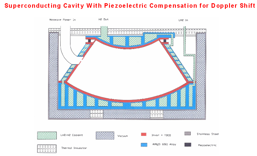 )
)
-
Title: Re: EM Drive Developments - related to space flight applications - Thread 3
Post by: flux_capacitor on 08/03/2015 11:22 PM -
<a href="http://forum.nasaspaceflight.com/index.php?topic=37642.msg1412970#msg1412970">Quote from: WarpTech on 08/03/2015 11:07 PM</a><a href="http://forum.nasaspaceflight.com/index.php?topic=37642.msg1412950#msg1412950">Quote from: rfmwguy on 08/03/2015 10:15 PM</a><a href="http://forum.nasaspaceflight.com/index.php?topic=37642.msg1412909#msg1412909">Quote from: TheTraveller on 08/03/2015 08:38 PM</a>
I am aware of that Mr. T. I just happen to respectfully disagree and am pursuing a TM theory. Why? In the simple course of nature, I've not seen electricity, by itself, move anything. I cannot say that about magnetism.<a href="http://forum.nasaspaceflight.com/index.php?topic=37642.msg1412903#msg1412903">Quote from: rfmwguy on 08/03/2015 08:32 PM</a>There is growing evidence (I think) that TM is the critical mode and not TE. While I'm not trying to throw stones, it is the direction I am going with my theory.
http://processmodeling.org/theory/physics/kinetic.htm
<snip>
"The conclusion - The kinetic energy of the electron is identical to its magnetic energy."
<snip>
"6. General conclusion. - Kinetic energies are electromagnetic energies
Kinetic energies can, in certain conditions, be restructured (converted) into tangible particles and vice versa, tangible particle can be restructured into field ones, i.e. into kinetic energy.
Kinetic energy is conveyed from one object to another in the form of electromagnetic waves (photons)."
Both Shawyer and Prof Yang say TE mode delivers more Force.
Too simple? Perhaps, but nature gives us the clues if we just follow her. I am also not trying to convince or dissuade or argue with anyone else. I find it extremely...uhhhh...distasteful and counterproductive.
And yet, Maxwell's equations tell us that it is the electric field that "does the work" J*E.
Todd
I'd also add that when a free moving charged particle enters a magnetic field, it is deviated. But no kinetic energy is added to the particle by the magnetic field.
When the same charged particle enters an electric field, it is on the other hand accelerated by the E-field.
This is incidentally the basis on MHD accelerators: a crossed E-field and B-field produce the Lorentz force, which acts on all charged particles, accelerating them in the same direction. The B-field modifies the trajectory of each particle but it is the E-field which imparts momentum to the particles. Their combination gives a force in a preferred direction which acts macroscopically on the working fluid. -
Title: Re: EM Drive Developments - related to space flight applications - Thread 3
Post by: TheTraveller on 08/03/2015 11:24 PM -
<a href="http://forum.nasaspaceflight.com/index.php?topic=37642.msg1412976#msg1412976">Quote from: WarpTech on 08/03/2015 11:15 PM</a>
That is a false conclusion. There are strong forces exerted at 90 deg to the side walls. As the wave fronts expand, they push back on the walls.
Todd
Would seem the peer reviews have accepted there are no side wall Forces in this cavity design. -
Title: Re: EM Drive Developments - related to space flight applications - Thread 3
Post by: Rodal on 08/03/2015 11:31 PM -
<a href="http://forum.nasaspaceflight.com/index.php?topic=37642.msg1412980#msg1412980">Quote from: TheTraveller on 08/03/2015 11:24 PM</a>
I looked at the Editorial peer review board for Acta Astronautica and I found that their emphasis and expertise was not on Electromagnetic Theory. It is not the fault of Acta Astronautica. their emphasis is instead stated to be:<a href="http://forum.nasaspaceflight.com/index.php?topic=37642.msg1412976#msg1412976">Quote from: WarpTech on 08/03/2015 11:15 PM</a>That is a false conclusion. There are strong forces exerted at 90 deg to the side walls. As the wave fronts expand, they push back on the walls.
Todd
Would seem the peer reviews have accepted there are no side wall Forces in this cavity design.
The peaceful scientific exploration of space,
Its exploitation for human welfare and progress
Conception, design, development and operation of space-borne and Earth-based systems
Papers reviewed for publication at Acta Astronautica are reviewed on that basis. -
Title: Re: EM Drive Developments - related to space flight applications - Thread 3
Post by: deltaMass on 08/03/2015 11:35 PM -
<a href="http://forum.nasaspaceflight.com/index.php?topic=37642.msg1412966#msg1412966">Quote from: WarpTech on 08/03/2015 10:58 PM</a>
Thanks, and a good fit. But it's not the full story. I'm a bit slow today (probably last night's beer with the boys) but finally got it. Will publish as soon as I have the data tidied up.<a href="http://forum.nasaspaceflight.com/index.php?topic=37642.msg1412935#msg1412935">Quote from: deltaMass on 08/03/2015 09:43 PM</a>
If the vertical axis is position, and the horizontal is time, then this looks like a fairly "constant" velocity slope to me, from nearly the moment that the power is turned off. I'm not analyzing your spreadsheet, just the slope on the graph provided.<a href="http://forum.nasaspaceflight.com/index.php?topic=37642.msg1412924#msg1412924">Quote from: deltaMass on 08/03/2015 09:24 PM</a>
Here's Shawyer's own data from the 2008 paper when the turntable was demonstrated seven years ago!!. My crude version below. Both show velocity increasing after power is removed. Thermal? Fans? Floobie Dust?<a href="http://forum.nasaspaceflight.com/index.php?topic=37642.msg1412917#msg1412917">Quote from: WarpTech on 08/03/2015 09:10 PM</a>Looks about right to me. Acceleration stops when the power is turned off, the velocity "slowly" decreases from there due to friction. Since there is very little friction, it keeps moving at nearly the same speed for quite a while but the acceleration stops when it's supposed to.
You don't see the velocity continuing to increase after power is turned off?
Todd
Perhaps a fan kicked on in one of those pieces of equipment on the table...but not that any of that is published.
Todd -
Title: Re: EM Drive Developments - related to space flight applications - Thread 3
Post by: WarpTech on 08/04/2015 12:18 AM -
<a href="http://forum.nasaspaceflight.com/index.php?topic=37642.msg1412980#msg1412980">Quote from: TheTraveller on 08/03/2015 11:24 PM</a><a href="http://forum.nasaspaceflight.com/index.php?topic=37642.msg1412976#msg1412976">Quote from: WarpTech on 08/03/2015 11:15 PM</a>
That is a false conclusion. There are strong forces exerted at 90 deg to the side walls. As the wave fronts expand, they push back on the walls.
Todd
Would seem the peer reviews have accepted there are no side wall Forces in this cavity design.
I think this mistake comes from assuming a "ray vector" approach, which is commonly used in waveguide physics. If you assume the ray vector emits from the apex and reflects off the spherical surface, the vector is always parallel to the walls. Then you would conclude that the wave does not touch the side walls, and you would be wrong.
When the E field makes a 90 deg angle to the cone wall, it is exerting "Maximum" force, not zero. The component of E that is parallel to the wall is zero, due to the boundary conditions. So the entire assumption of a ray vector falls apart when you analyze the fields and the boundary conditions. The ray is parallel to the wall, which means the fields E and H are perpendicular to the wall. As the wave expands, it exerts a strong Lorentz force on the walls when the wavelength is close to the lateral cut-off diameter.
Sorry TT, I have seen worse errors published in peer reviewed journals. Peer review does not guarantee it is correct and in this case, I can assure you with 100% confidence, that it is not.
Todd -
Title: Re: EM Drive Developments - related to space flight applications - Thread 3
Post by: aero on 08/04/2015 12:41 AM -
I have uploaded anther try at generating a TE mode in Shell's frustum model.
https://drive.google.com/folderview?id=0B1XizxEfB23tflFzUEREeWtJMVZucl9nOWtGaGUtUzlkdnczSkthYVVNVDU4UGNMZ29iRm8&usp=sharing (https://drive.google.com/folderview?id=0B1XizxEfB23tflFzUEREeWtJMVZucl9nOWtGaGUtUzlkdnczSkthYVVNVDU4UGNMZ29iRm8&usp=sharing)
I uploaded a "standard" data set including all .png view files and all csv files including big and small end cuts and y and z cuts. If this data set doesn't show a TE resonant mode, then the problem is likely in my choice of coordinate systems being different than standard conventions. I am assuming of course that meep uses standard conventions internally - seems a safe assumption.
aero -
Title: Re: EM Drive Developments - related to space flight applications - Thread 3
Post by: rfmwguy on 08/04/2015 01:08 AM -
<a href="http://forum.nasaspaceflight.com/index.php?topic=37642.msg1412984#msg1412984">Quote from: deltaMass on 08/03/2015 11:35 PM</a>
Have to admit DM, am impressed with your willingness to help...lots of skeptics just throw stones, you seem to have broken the mold...well done...cheers 8)<a href="http://forum.nasaspaceflight.com/index.php?topic=37642.msg1412966#msg1412966">Quote from: WarpTech on 08/03/2015 10:58 PM</a>
Thanks, and a good fit. But it's not the full story. I'm a bit slow today (probably last night's beer with the boys) but finally got it. Will publish as soon as I have the data tidied up.<a href="http://forum.nasaspaceflight.com/index.php?topic=37642.msg1412935#msg1412935">Quote from: deltaMass on 08/03/2015 09:43 PM</a>
If the vertical axis is position, and the horizontal is time, then this looks like a fairly "constant" velocity slope to me, from nearly the moment that the power is turned off. I'm not analyzing your spreadsheet, just the slope on the graph provided.<a href="http://forum.nasaspaceflight.com/index.php?topic=37642.msg1412924#msg1412924">Quote from: deltaMass on 08/03/2015 09:24 PM</a>
Here's Shawyer's own data from the 2008 paper when the turntable was demonstrated seven years ago!!. My crude version below. Both show velocity increasing after power is removed. Thermal? Fans? Floobie Dust?<a href="http://forum.nasaspaceflight.com/index.php?topic=37642.msg1412917#msg1412917">Quote from: WarpTech on 08/03/2015 09:10 PM</a>Looks about right to me. Acceleration stops when the power is turned off, the velocity "slowly" decreases from there due to friction. Since there is very little friction, it keeps moving at nearly the same speed for quite a while but the acceleration stops when it's supposed to.
You don't see the velocity continuing to increase after power is turned off?
Todd
Perhaps a fan kicked on in one of those pieces of equipment on the table...but not that any of that is published.
Todd -
Title: Re: EM Drive Developments - related to space flight applications - Thread 3
Post by: deltaMass on 08/04/2015 01:33 AM -
<a href="http://forum.nasaspaceflight.com/index.php?topic=37642.msg1413011#msg1413011">Quote from: rfmwguy on 08/04/2015 01:08 AM</a>
You haven't seen me eat the crow yet. Last night's beer has not been kind. But the data will be interesting nonetheless - stay tuned. I need one order better fitting polynomial, and it means a complete redo...<a href="http://forum.nasaspaceflight.com/index.php?topic=37642.msg1412984#msg1412984">Quote from: deltaMass on 08/03/2015 11:35 PM</a>
Have to admit DM, am impressed with your willingness to help...lots of skeptics just throw stones, you seem to have broken the mold...well done...cheers 8)<a href="http://forum.nasaspaceflight.com/index.php?topic=37642.msg1412966#msg1412966">Quote from: WarpTech on 08/03/2015 10:58 PM</a>
Thanks, and a good fit. But it's not the full story. I'm a bit slow today (probably last night's beer with the boys) but finally got it. Will publish as soon as I have the data tidied up.<a href="http://forum.nasaspaceflight.com/index.php?topic=37642.msg1412935#msg1412935">Quote from: deltaMass on 08/03/2015 09:43 PM</a>
If the vertical axis is position, and the horizontal is time, then this looks like a fairly "constant" velocity slope to me, from nearly the moment that the power is turned off. I'm not analyzing your spreadsheet, just the slope on the graph provided.<a href="http://forum.nasaspaceflight.com/index.php?topic=37642.msg1412924#msg1412924">Quote from: deltaMass on 08/03/2015 09:24 PM</a>
Here's Shawyer's own data from the 2008 paper when the turntable was demonstrated seven years ago!!. My crude version below. Both show velocity increasing after power is removed. Thermal? Fans? Floobie Dust?<a href="http://forum.nasaspaceflight.com/index.php?topic=37642.msg1412917#msg1412917">Quote from: WarpTech on 08/03/2015 09:10 PM</a>Looks about right to me. Acceleration stops when the power is turned off, the velocity "slowly" decreases from there due to friction. Since there is very little friction, it keeps moving at nearly the same speed for quite a while but the acceleration stops when it's supposed to.
You don't see the velocity continuing to increase after power is turned off?
Todd
Perhaps a fan kicked on in one of those pieces of equipment on the table...but not that any of that is published.
Todd -
Title: Re: EM Drive Developments - related to space flight applications - Thread 3
Post by: Silversheep2011 on 08/04/2015 05:16 AM -
So while the experimenters are all making their first models.
What comes next?
Maybe get on with some EmDrive debugging and tunning?
I spent the last two days [As have been home with flu from work]
And clean up a 2014 Paper by Yang from this is from a Public Domain sourced document.
Found here.
http://wulixb.iphy.ac.cn/CN/article/downloadArticleFile.do?attachType=PDF&id=60316
This is different from 2010 and 2012 papers.
And have attempted to convert it from Chinese to English via the goggle translator and the occasion bit of writer’s licence.
Please note: I’m not a translator, so please no slagging off about grammer being wrong or alike. And in fact encourage anyone the thread who is a proper translator with a proper qualification in translating ‘Chinese to English’ to give it a go!
I have tidied it up with the goal to make it somewhat more readable. Changes you see marked in ‘Red’, Seems to help make it readable.
Warning: You still may need to read some sentences twice to get the full meaning. as I didn’t wish to make too much in the way of changes to original document and miss the meanings
At this stage it’s more of a ‘hey… look this is what in here!”
And sorry-- no dimensions,
I think it carries several deep insights that could be helpful
For example:
- What that rectangular waveguide window does [now I know].
-Importance of really ‘narrow band’ tunning.
- Why an EC solid-state feedback loop is important.
-Weird Feedback loop issues.
- Heating effects and monitoring suggestions that in turn related to volume convex distortions at the frustum
-
Title: Re: EM Drive Developments - related to space flight applications - Thread 3
Post by: TheTraveller on 08/04/2015 07:41 AM -
<a href="http://forum.nasaspaceflight.com/index.php?topic=37642.msg1412996#msg1412996">Quote from: WarpTech on 08/04/2015 12:18 AM</a><a href="http://forum.nasaspaceflight.com/index.php?topic=37642.msg1412980#msg1412980">Quote from: TheTraveller on 08/03/2015 11:24 PM</a><a href="http://forum.nasaspaceflight.com/index.php?topic=37642.msg1412976#msg1412976">Quote from: WarpTech on 08/03/2015 11:15 PM</a>
That is a false conclusion. There are strong forces exerted at 90 deg to the side walls. As the wave fronts expand, they push back on the walls.
Todd
Would seem the peer reviews have accepted there are no side wall Forces in this cavity design.
I think this mistake comes from assuming a "ray vector" approach, which is commonly used in waveguide physics. If you assume the ray vector emits from the apex and reflects off the spherical surface, the vector is always parallel to the walls. Then you would conclude that the wave does not touch the side walls, and you would be wrong.
When the E field makes a 90 deg angle to the cone wall, it is exerting "Maximum" force, not zero. The component of E that is parallel to the wall is zero, due to the boundary conditions. So the entire assumption of a ray vector falls apart when you analyze the fields and the boundary conditions. The ray is parallel to the wall, which means the fields E and H are perpendicular to the wall. As the wave expands, it exerts a strong Lorentz force on the walls when the wavelength is close to the lateral cut-off diameter.
Sorry TT, I have seen worse errors published in peer reviewed journals. Peer review does not guarantee it is correct and in this case, I can assure you with 100% confidence, that it is not.
Todd
When an EM wave is traveling orthogonal to a surface, the cosine loss of the radiation pressure equation is maxed and there is no radiation pressure produced on the surface by the passing EM wave. Don't believe it? Try to get thrust from a solar sail oriented so the surface is orthogonal to the sun's EM waves.
https://en.wikipedia.org/wiki/Radiation_pressure -
Title: Re: EM Drive Developments - related to space flight applications - Thread 3
Post by: TheTraveller on 08/04/2015 08:13 AM -
<a href="http://forum.nasaspaceflight.com/index.php?topic=37642.msg1413015#msg1413015">Quote from: Rodal on 08/04/2015 01:24 AM</a><a href="http://forum.nasaspaceflight.com/index.php?topic=37642.msg1412769#msg1412769">Quote from: TheTraveller on 08/03/2015 01:06 PM</a>
... SPR in-house software and produced the Df and resonant frequency at TE013 being:
Frustum big diameter m: 0.2314m (my data)
Frustum small diameter: 0.1257m (my data)
Frustum centre length: 0.1386m (my data)
Mode: TE013 (my data)
Resonance: 3.9003 GHz (SPR data based on the above)
Df: 0.634 (SPR data based on the above)...<a href="http://forum.nasaspaceflight.com/index.php?topic=37642.msg1412774#msg1412774">Quote from: TheTraveller on 08/03/2015 01:13 PM</a>...BTW what resonance and Q do you get for my Flight Thruster estimated dimensions?...
Frustum big diameter : 0.2314 m
Frustum small diameter: 0.1257 m
Frustum length: 0.1386 m
Mode Shape; TE013
air index of refraction at STP = 1.000277
cVacuum = 299792458 (*meter/s*)
epsilon0 = 8.854187817*10^(-12)
mu0 = 0.999991(*copper*)*4*Pi*10^(-7)
resistivity = 1.678*10^(-8)(*copper*);
Frequency (GHz) Q
Flat Ends 3.812 less than 72,800 (flat ends approximated by equivalent spherical sections)
Spherical Ends 3.687 74,052 (exact solution)
Q's are for a perfect geometry and based on pure copper resistivity = 1.678*10^(-8)
for other purities of copper or other materials, scale the Q by the square root of the inverse resistivity ratio
Q's for flat ends should be lower than 72,800 because of degradation losses of spherical waves on flat ends is not exactly modeled.
Thanks for doing that. Most appreciated.
Both the SPR and my spreadsheet, assuming spherical end, predicts 3.9003GHz as the TE103 resonance for those estimated Flight Thruster internal dimensions. Roger did not disclose the Q and my spreadsheet is not yet doing Q so there I have nothing to compare.
You may wish to model my build dimensions as here I was told the Q was 88k and resonance was 2.4505GHz, which agrees with my models resonance calc. -
Title: Re: EM Drive Developments - related to space flight applications - Thread 3
Post by: SeeShells on 08/04/2015 08:27 AM -
<a href="http://forum.nasaspaceflight.com/index.php?topic=37642.msg1413064#msg1413064">Quote from: TheTraveller on 08/04/2015 07:41 AM</a>
Tapered cavity of a fiber optic wave.<a href="http://forum.nasaspaceflight.com/index.php?topic=37642.msg1412996#msg1412996">Quote from: WarpTech on 08/04/2015 12:18 AM</a><a href="http://forum.nasaspaceflight.com/index.php?topic=37642.msg1412980#msg1412980">Quote from: TheTraveller on 08/03/2015 11:24 PM</a><a href="http://forum.nasaspaceflight.com/index.php?topic=37642.msg1412976#msg1412976">Quote from: WarpTech on 08/03/2015 11:15 PM</a>That is a false conclusion. There are strong forces exerted at 90 deg to the side walls. As the wave fronts expand, they push back on the walls.
Todd
Would seem the peer reviews have accepted there are no side wall Forces in this cavity design.
I think this mistake comes from assuming a "ray vector" approach, which is commonly used in waveguide physics. If you assume the ray vector emits from the apex and reflects off the spherical surface, the vector is always parallel to the walls. Then you would conclude that the wave does not touch the side walls, and you would be wrong.
When the E field makes a 90 deg angle to the cone wall, it is exerting "Maximum" force, not zero. The component of E that is parallel to the wall is zero, due to the boundary conditions. So the entire assumption of a ray vector falls apart when you analyze the fields and the boundary conditions. The ray is parallel to the wall, which means the fields E and H are perpendicular to the wall. As the wave expands, it exerts a strong Lorentz force on the walls when the wavelength is close to the lateral cut-off diameter.
Sorry TT, I have seen worse errors published in peer reviewed journals. Peer review does not guarantee it is correct and in this case, I can assure you with 100% confidence, that it is not.
Todd
When an EM wave is traveling orthogonal to a surface, the cosine loss of the radiation pressure equation is maxed and there is no radiation pressure produced on the surface by the passing EM wave. Don't believe it? Try to get thrust from a solar sail oriented so the surface is orthogonal to the sun's EM waves.
https://en.wikipedia.org/wiki/Radiation_pressure
https://www.youtube.com/watch?v=mGUGXtc9B0A -
Title: Re: EM Drive Developments - related to space flight applications - Thread 3
Post by: TheTraveller on 08/04/2015 08:42 AM -
<a href="http://forum.nasaspaceflight.com/index.php?topic=37642.msg1413069#msg1413069">Quote from: SeeShells on 08/04/2015 08:27 AM</a><a href="http://forum.nasaspaceflight.com/index.php?topic=37642.msg1413064#msg1413064">Quote from: TheTraveller on 08/04/2015 07:41 AM</a>
Tapered cavity of a fiber optic wave.<a href="http://forum.nasaspaceflight.com/index.php?topic=37642.msg1412996#msg1412996">Quote from: WarpTech on 08/04/2015 12:18 AM</a><a href="http://forum.nasaspaceflight.com/index.php?topic=37642.msg1412980#msg1412980">Quote from: TheTraveller on 08/03/2015 11:24 PM</a><a href="http://forum.nasaspaceflight.com/index.php?topic=37642.msg1412976#msg1412976">Quote from: WarpTech on 08/03/2015 11:15 PM</a>That is a false conclusion. There are strong forces exerted at 90 deg to the side walls. As the wave fronts expand, they push back on the walls.
Todd
Would seem the peer reviews have accepted there are no side wall Forces in this cavity design.
I think this mistake comes from assuming a "ray vector" approach, which is commonly used in waveguide physics. If you assume the ray vector emits from the apex and reflects off the spherical surface, the vector is always parallel to the walls. Then you would conclude that the wave does not touch the side walls, and you would be wrong.
When the E field makes a 90 deg angle to the cone wall, it is exerting "Maximum" force, not zero. The component of E that is parallel to the wall is zero, due to the boundary conditions. So the entire assumption of a ray vector falls apart when you analyze the fields and the boundary conditions. The ray is parallel to the wall, which means the fields E and H are perpendicular to the wall. As the wave expands, it exerts a strong Lorentz force on the walls when the wavelength is close to the lateral cut-off diameter.
Sorry TT, I have seen worse errors published in peer reviewed journals. Peer review does not guarantee it is correct and in this case, I can assure you with 100% confidence, that it is not.
Todd
When an EM wave is traveling orthogonal to a surface, the cosine loss of the radiation pressure equation is maxed and there is no radiation pressure produced on the surface by the passing EM wave. Don't believe it? Try to get thrust from a solar sail oriented so the surface is orthogonal to the sun's EM waves.
https://en.wikipedia.org/wiki/Radiation_pressure
https://www.youtube.com/watch?v=mGUGXtc9B0A
An interesting effect for sure.
My point was what Todd was claiming files in the face of how radiation pressure works, which is there will be no radiation pressure on a surface, from a EM wave, that is orthogonal to a reflecting surface, which is what Shawyer claims and was backed up by the peer reviewers. -
Title: Re: EM Drive Developments - related to space flight applications - Thread 3
Post by: flux_capacitor on 08/04/2015 09:01 AM -
<a href="http://forum.nasaspaceflight.com/index.php?topic=37642.msg1413067#msg1413067">Quote from: TheTraveller on 08/04/2015 08:13 AM</a>
You may wish to model my build dimensions as here I was told the Q was 88k and resonance was 2.4505GHz, which agrees with my models resonance calc.
(clic on the link above to see the picture)
TT, is there a reason your cut-off diameter is 148.7 mm instead of the established value of 149.2 mm at 2.45 GHz? Speed of light in air instead of vacuum?
Rodal claims there is no sharp cut-off below the cut-off diameter in a truncated cone cavity, that modes continue, in some degraded way. But if we build a frustum with a small end just below cut-off, how will this affect the Q-factor? Does it degrades too?
What is Warptech advice about the best setting for the small end: just below, just exactly or just above the cylindrical-equivalent cut-off diameter?
If I recalled correctly, at some point you wanted to give more room to your small end, increasing it to 150 mm. What's your decision?
About the difference of c in vacuum and in air, and the gas you will use: somemone on Reddit was concerned about using nitrogen in your cavity, because N2 could maybe "oxidize" the copper forming copper nitride (Cu3N). So you would be more secure filling your sealed frustum with a noble gas such as argon. But what is the speed of light in Ar at 0.5 atm ? -
Title: Re: EM Drive Developments - related to space flight applications - Thread 3
Post by: Flyby on 08/04/2015 09:19 AM -
<a href="http://forum.nasaspaceflight.com/index.php?topic=37642.msg1413064#msg1413064">Quote from: TheTraveller on 08/04/2015 07:41 AM</a>
When an EM wave is traveling orthogonal to a surface, the cosine loss of the radiation pressure equation is maxed and there is no radiation pressure produced on the surface by the passing EM wave. Don't believe it? Try to get thrust from a solar sail oriented so the surface is orthogonal to the sun's EM waves.
https://en.wikipedia.org/wiki/Radiation_pressure
The question is whether the (presumed) force in an EMdrive originates from radiation pressure, or whether there is another effect into play.
I do not think you can explain the EMdrive with radiation pressure. Several knowledgeable people inhere already demonstrated that the forces exceed the normal photonic force expectations.
Something else is at play here...
Consequently, i don't think it is fitting to argue about radiation pressure...
I sooo wish that somebody could actually confirm that an EMdrive produces a force, so i can drop the "supposedly" or "assumed" in front of the word "force"...
-
Title: Re: EM Drive Developments - related to space flight applications - Thread 3
Post by: TheTraveller on 08/04/2015 09:35 AM -
<a href="http://forum.nasaspaceflight.com/index.php?topic=37642.msg1413071#msg1413071">Quote from: flux_capacitor on 08/04/2015 09:01 AM</a><a href="http://forum.nasaspaceflight.com/index.php?topic=37642.msg1413067#msg1413067">Quote from: TheTraveller on 08/04/2015 08:13 AM</a>
You may wish to model my build dimensions as here I was told the Q was 88k and resonance was 2.4505GHz, which agrees with my models resonance calc.
(clic on the link above to see the picture)
TT, is there a reason your cut-off diameter is 148.7 mm instead of the established value of 149.2 mm at 2.45 GHz? Speed of light in air instead of vacuum?
Rodal claims there is no sharp cut-off below the cut-off diameter in a truncated cone cavity, that modes continue, in some degraded way. But if we build a frustum with a small end just below cut-off, how will this affect the Q-factor? Does it degrades too?
What is Warptech advice about the best setting for the small end: just below, just exactly or just above the cylindrical-equivalent cut-off diameter?
If I recalled correctly, at some point you wanted to give more room to your small end, increasing it to 150 mm. What's your decision?
About the difference of c in vacuum and in air, and the gas you will use: somemone on Reddit was concerned about using nitrogen in your cavity, because N2 could maybe "oxidize" the copper forming copper nitride (Cu3N). So you would be more secure filling your sealed frustum with a noble gas such as argon. But what is the speed of light in Ar at 0.5 atm ?
My error.
There is a slight difference between my model and that of SPR, being 0.37% in length resonance. Df is spot on to 5 decimal places. When I cross check data I get from them I apply a compensation factor. Forgot to back it out when doing the frustum design. 149.2 is the correct cutoff dia at TE01 and 2.45GHz.
Working on a modified design that will allow a 2.3GHz bottom end, so to allow for manufacturing tolerances exceeding 0.05mm.
Dimensions are:
Frustum big diameter : 400.0mm
Frustum small diameter: 159.0mm
Frustum centre length: 240.7mm
Using the above dimensions, the 2.45GHz Df drops from 0.925 to 0.857, so a slight drop in Force generation is predicted. At Shawyer's calculated Q of 88k, my 100W of Rf should produce around 50mN (5g) of Force.
As Demonstrator rotary table test produced 1.8g of net Force, driving a 100kg mass, my table should accelerate much quicker as there should be 2.8 times more Force, driving 20% of the mass or about 13.9 times greater acceleration.
Based on Shawyer's advise, there is no usable resonance nor Force generation if the small end is at or below cutoff. So doesn't matter if it drops off sharp or slow, don't go there. -
Title: Re: EM Drive Developments - related to space flight applications - Thread 3
Post by: TheTraveller on 08/04/2015 09:53 AM -
Demonstrator EMDrive rotary test acceleration calcs:
Known:
Distance moved: 1.85m
Powered on time: 80 sec
Start velocity: 0.0cm/s
Final powered on velocity: 2cm/s
Acceleration = 0.000289 m/s^2 being distance/(time^2)
Acceleration = 0.000250 m/s^2 being (Vfinal - Vstart)/time
Close enough for me.
From that the expected acceleration for my EMDrive and test rig would be approx
0.00348 m/s^2 or
0.354 milli-g. -
Title: Re: EM Drive Developments - related to space flight applications - Thread 3
Post by: TheTraveller on 08/04/2015 09:59 AM -
<a href="http://forum.nasaspaceflight.com/index.php?topic=37642.msg1413073#msg1413073">Quote from: Flyby on 08/04/2015 09:19 AM</a><a href="http://forum.nasaspaceflight.com/index.php?topic=37642.msg1413064#msg1413064">Quote from: TheTraveller on 08/04/2015 07:41 AM</a>
When an EM wave is traveling orthogonal to a surface, the cosine loss of the radiation pressure equation is maxed and there is no radiation pressure produced on the surface by the passing EM wave. Don't believe it? Try to get thrust from a solar sail oriented so the surface is orthogonal to the sun's EM waves.
https://en.wikipedia.org/wiki/Radiation_pressure
The question is whether the (presumed) force in an EMdrive originates from radiation pressure, or whether there is another effect into play.
I do not think you can explain the EMdrive with radiation pressure. Several knowledgeable people inhere already demonstrated that the forces exceed the normal photonic force expectations.
Something else is at play here...
Consequently, i don't think it is fitting to argue about radiation pressure...
I sooo wish that somebody could actually confirm that an EMdrive produces a force, so i can drop the "supposedly" or "assumed" in front of the word "force"...
The UK gov, in funding the Demonstrator and rotary test rig, set up an expert panel that confirmed Shawyer (has been stated this happened in the UK Parliament). Links were given in this Forum.
Prof Yang also confirmed Shawyer.
Eagleworks atmo tests confirmed them both.
What more do you want? -
Title: Re: EM Drive Developments - related to space flight applications - Thread 3
Post by: Rodal on 08/04/2015 11:45 AM -
<a href="http://forum.nasaspaceflight.com/index.php?topic=37642.msg1413071#msg1413071">Quote from: flux_capacitor on 08/04/2015 09:01 AM</a>
...Rodal claims there is no sharp cut-off below the cut-off diameter in a truncated cone cavity,
The fact that there is not sharp cut-off for tapered waveguides is not a claim invented by me or something that is going to win me any prices among people in the know, it is something that is already known in the literature for quite some time. It is as if somebody claims that the Earth is flat, and I say, no the Earth is not flat, and it has been known for quite some time that the Earth is not flat. Please take a look at the peer-reviewed references I provided as well as the fact that any finite element computer program (ANSYS, COMSOL, etc.) can readily verify the fact that there is no sharp cut-off in a tapered waveguide.<a href="http://forum.nasaspaceflight.com/index.php?topic=37642.msg1413071#msg1413071">Quote from: flux_capacitor on 08/04/2015 09:01 AM</a>... that modes continue, in some degraded way. But if we build a frustum with a small end just below cut-off, how will this affect the Q-factor? Does it degrades too? ...
If you build a frustum with the small end below cut-off (it doesn't need to be "just below cut-off" as the modes persist way beyond it) it can resonate in a number of modes, for example it can resonate in a mode with higher p (where p is the longitudinal quantum mode number).
The answer to this question:
QUESTION: if we build a frustum with a small end below cut-off and we excite it at the somewhat lower frequency at which the mode shape that would have been cut-off in a perfect cylindrical waveguide still resonates in the frustum how will this affect the Q-factor? Does the Q degrade? ...
is:
ANSWER: yes, of course that the Q will degrade in that case. As I have shown, in such a frustum the region near the small base would be empty of standing waves, and instead contain evanescent waves hence that portion of the volume is wasted for Q resonance purposes. As Q is the ratio of the volumetric to the surface integral of the square of the magnetic field, it follows that any such wasted volume devoid of standing waves results in a lower Q.
But again, if you build such a frustum, it is most likely to resonate at a higher p mode which will fill the entire frustum with standing waves -and hence have higher Q-, so the excitation of the mode shape discussed above cannot be taken for granted: it has to be excited at the correct frequency. -
Title: Re: EM Drive Developments - related to space flight applications - Thread 3
Post by: rfmwguy on 08/04/2015 12:01 PM -
<a href="http://forum.nasaspaceflight.com/index.php?topic=37642.msg1413073#msg1413073">Quote from: Flyby on 08/04/2015 09:19 AM</a>
Here's where my theory is headed, slowly I might add...fluid dynamics - translation to particle dynamics needed:<a href="http://forum.nasaspaceflight.com/index.php?topic=37642.msg1413064#msg1413064">Quote from: TheTraveller on 08/04/2015 07:41 AM</a>When an EM wave is traveling orthogonal to a surface, the cosine loss of the radiation pressure equation is maxed and there is no radiation pressure produced on the surface by the passing EM wave. Don't believe it? Try to get thrust from a solar sail oriented so the surface is orthogonal to the sun's EM waves.
https://en.wikipedia.org/wiki/Radiation_pressure
The question is whether the (presumed) force in an EMdrive originates from radiation pressure, or whether there is another effect into play.
I do not think you can explain the EMdrive with radiation pressure. Several knowledgeable people inhere already demonstrated that the forces exceed the normal photonic force expectations.
Something else is at play here...
Consequently, i don't think it is fitting to argue about radiation pressure...
I sooo wish that somebody could actually confirm that an EMdrive produces a force, so i can drop the "supposedly" or "assumed" in front of the word "force"...
Suppose we model a fluid vortex with photonic energy. IOW, imagine the frustum is spinning photons creating a centralized low pressure core of TM. COE/COM would require this to be filled from somewhere.
So I envision the engine, not as a thruster but a "puller" to use plain english.
In fluid dynamics particle speed and energy peak as u move down the vortex, or frustum. Since photons have little "fluid" resistance, speed is unlimited...except for C...where strange things happen...theoretical increase in mass....question is from where?
Mass inflow to the vortex should come from the small end because that's the way it works in nature...I know, I lived in tornado alley most my life. Some energy is lost in heat along the frustum.
So I went even further out on a limb, plain english and before I started translating fluid dynamics to particle dynamic for a vortex. Weird, huh?
If anyone wants to follow me down the rabbit hole with this strange conjecture, I welcome any help I can get as I'm still in my test mode :) -
Title: Re: EM Drive Developments - related to space flight applications - Thread 3
Post by: Flyby on 08/04/2015 12:14 PM -
<a href="http://forum.nasaspaceflight.com/index.php?topic=37642.msg1413077#msg1413077">Quote from: TheTraveller on 08/04/2015 09:59 AM</a>
The UK gov, in funding the Demonstrator and rotary test rig, set up an expert panel that confirmed Shawyer (has been stated this happened in the UK Parliament). Links were given in this Forum.
Prof Yang also confirmed Shawyer.
Eagleworks atmo tests confirmed them both.
What more do you want?
hmmm... the same thing that about 90% of the people on this forum want: a clear and unchallenged force signal, that is not hidden in a lot of measurement noise and that can be checked and verified by others.
I do agree with you that Shawyer's tests look convincing, but it is still too much based upon perception...
In our legal system there is a nice description that perfectly characterizes the current situation on the EMdrive :
There is a difference between "an indication of evidence" and "pure evidence".
As i see it, we're currently still in the "indication of evidence" phase....
We need irrefutable proof it is working. Period.
Several more testers need to produce identical/similar or better results like Shawyer's experiment.
Claims on paper have little meaning if they cant be matched with real world experiments (like you're doing).
It is not that I do not want to believe it works, but "believing" is not really a scientific attitude, is it? -
Title: Re: EM Drive Developments - related to space flight applications - Thread 3
Post by: Flyby on 08/04/2015 12:34 PM -
<a href="http://forum.nasaspaceflight.com/index.php?topic=37642.msg1413091#msg1413091">Quote from: rfmwguy on 08/04/2015 12:01 PM</a>
If anyone wants to follow me down the rabbit hole with this strange conjecture, I welcome any help I can get as I'm still in my test mode :)
I do like to follow your line of thought , as i got some of my own weird ideas also... ;)
My problem is that I do not have the proper training in this type speculations as my science background is seriously lacking there, compared to some people here who made a professional career out of it...
The last thing I want to venture into is pseudo science, so I usually refrain from going public with silly ideas... 8)
ah...It is a consequence of a decision i made 30 years ago, where I had to choose between nuclear engineer or architect as path in life. I choose the last option, but my interest in nuclear astrophysics never really left me. I can not keep up with high level discussions and the needed level of math they require, but I do keep trying to understand and follow what's being said.
No regrets doh... just a curiosity what life would have been if i had taken a different path...
-
Title: Re: EM Drive Developments - related to space flight applications - Thread 3
Post by: Slyver on 08/04/2015 12:54 PM -
Quote
The UK gov, in funding the Demonstrator and rotary test rig, set up an expert panel that confirmed Shawyer (has been stated this happened in the UK Parliament). Links were given in this Forum.
Prof Yang also confirmed Shawyer.
Eagleworks atmo tests confirmed them both.
What more do you want?
I want a hermetically sealed, EM shielded, thermally preloaded box, with a self containted EMdrive/RF source/power supply inside it, on a rotating arm whose bearing stiction has been tested and proven to be several orders of magnitude below any observed effect. I want there to be an angular acceleration of the system, which slows to a constant velocity exactly as expected by air resistance.
I then want the entire device (box, arm, drive, and air internal to the box) to be put in a reasonable vacuum and there to be no meaningful difference (at least agreement in the order of magnitude) between measurements taken in either environment.
(We don't know that air (internal, external (or both)) does not play a meaningful (not artifactual) part of the system (for whatever of the myriad reasons it might), and there are measurements that suggest the possibility that it does. This should be tested.)
Finally, I want to be able to find no flaws in the experimental setup within the order of magnitude of the measured forces; something I can not say about ANY experiment done so far. I also want every person who looks at it (with a reasonably open mind) to be just as comfortable with the results as myself. -
Title: Re: EM Drive Developments - related to space flight applications - Thread 3
Post by: Rodal on 08/04/2015 01:07 PM -
<a href="http://forum.nasaspaceflight.com/index.php?topic=37642.msg1413067#msg1413067">Quote from: TheTraveller on 08/04/2015 08:13 AM</a>
I just saw your drawing.<a href="http://forum.nasaspaceflight.com/index.php?topic=37642.msg1413015#msg1413015">Quote from: Rodal on 08/04/2015 01:24 AM</a><a href="http://forum.nasaspaceflight.com/index.php?topic=37642.msg1412769#msg1412769">Quote from: TheTraveller on 08/03/2015 01:06 PM</a>... SPR in-house software and produced the Df and resonant frequency at TE013 being:
Frustum big diameter m: 0.2314m (my data)
Frustum small diameter: 0.1257m (my data)
Frustum centre length: 0.1386m (my data)
Mode: TE013 (my data)
Resonance: 3.9003 GHz (SPR data based on the above)
Df: 0.634 (SPR data based on the above)...<a href="http://forum.nasaspaceflight.com/index.php?topic=37642.msg1412774#msg1412774">Quote from: TheTraveller on 08/03/2015 01:13 PM</a>...BTW what resonance and Q do you get for my Flight Thruster estimated dimensions?...
Frustum big diameter : 0.2314 m
Frustum small diameter: 0.1257 m
Frustum length: 0.1386 m
Mode Shape; TE013
air index of refraction at STP = 1.000277
cVacuum = 299792458 (*meter/s*)
epsilon0 = 8.854187817*10^(-12)
mu0 = 0.999991(*copper*)*4*Pi*10^(-7)
resistivity = 1.678*10^(-8)(*copper*);
Frequency (GHz) Q
Flat Ends 3.812 less than 72,800 (flat ends approximated by equivalent spherical sections)
Spherical Ends 3.687 74,052 (exact solution)
Q's are for a perfect geometry and based on pure copper resistivity = 1.678*10^(-8)
for other purities of copper or other materials, scale the Q by the square root of the inverse resistivity ratio
Q's for flat ends should be lower than 72,800 because of degradation losses of spherical waves on flat ends is not exactly modeled.
Thanks for doing that. Most appreciated.
Both the SPR and my spreadsheet, assuming spherical end, predicts 3.9003GHz as the TE103 resonance for those estimated Flight Thruster internal dimensions. Roger did not disclose the Q and my spreadsheet is not yet doing Q so there I have nothing to compare.
You may wish to model my build dimensions as here I was told the Q was 88k and resonance was 2.4505GHz, which agrees with my models resonance calc.
(http://forum.nasaspaceflight.com/xindex.php,qaction=dlattach,3Btopic=37642.0,3Battach=1053014,3Bimage.pagespeed.ic.xiv0BscJ75.webp)
Your definition of truncated cone length is different than mine.
We have been comparing apples to oranges.
I have been defining the length as the distance measured perpendicular between the plane surfaces defined by the diameters. (That is a consistent mathematical definition with the use of diameters).
You in turn have a drawing where you define the length as the difference between the spherical radii: your "length" is the length between the spherical surfaces, not between the plane surfaces of the diameters).
Your "length" is the lateral length of the spherical truncated cone: the difference between the spherical radii r2 - r1
That is a different definition of length ! They are not the same. Actually the difference makes a difference in frequencies of the order we are discussing.
That's comparing apples and oranges.
We are calculating frequencies based on different geometrical dimensions.
The natural frequency comparison for the spherical end case is moot, as it is predicated on different dimensions !
If I calculate the natural frequency based on your definition of length, I will get a higher natural frequency closer to 3.9 GHz -
Title: Re: EM Drive Developments - related to space flight applications - Thread 3
Post by: SeeShells on 08/04/2015 01:16 PM -
<a href="http://forum.nasaspaceflight.com/index.php?topic=37642.msg1413070#msg1413070">Quote from: TheTraveller on 08/04/2015 08:42 AM</a><a href="http://forum.nasaspaceflight.com/index.php?topic=37642.msg1413069#msg1413069">Quote from: SeeShells on 08/04/2015 08:27 AM</a><a href="http://forum.nasaspaceflight.com/index.php?topic=37642.msg1413064#msg1413064">Quote from: TheTraveller on 08/04/2015 07:41 AM</a>
Tapered cavity of a fiber optic wave.<a href="http://forum.nasaspaceflight.com/index.php?topic=37642.msg1412996#msg1412996">Quote from: WarpTech on 08/04/2015 12:18 AM</a><a href="http://forum.nasaspaceflight.com/index.php?topic=37642.msg1412980#msg1412980">Quote from: TheTraveller on 08/03/2015 11:24 PM</a><a href="http://forum.nasaspaceflight.com/index.php?topic=37642.msg1412976#msg1412976">Quote from: WarpTech on 08/03/2015 11:15 PM</a>That is a false conclusion. There are strong forces exerted at 90 deg to the side walls. As the wave fronts expand, they push back on the walls.
Todd
Would seem the peer reviews have accepted there are no side wall Forces in this cavity design.
I think this mistake comes from assuming a "ray vector" approach, which is commonly used in waveguide physics. If you assume the ray vector emits from the apex and reflects off the spherical surface, the vector is always parallel to the walls. Then you would conclude that the wave does not touch the side walls, and you would be wrong.
When the E field makes a 90 deg angle to the cone wall, it is exerting "Maximum" force, not zero. The component of E that is parallel to the wall is zero, due to the boundary conditions. So the entire assumption of a ray vector falls apart when you analyze the fields and the boundary conditions. The ray is parallel to the wall, which means the fields E and H are perpendicular to the wall. As the wave expands, it exerts a strong Lorentz force on the walls when the wavelength is close to the lateral cut-off diameter.
Sorry TT, I have seen worse errors published in peer reviewed journals. Peer review does not guarantee it is correct and in this case, I can assure you with 100% confidence, that it is not.
Todd
When an EM wave is traveling orthogonal to a surface, the cosine loss of the radiation pressure equation is maxed and there is no radiation pressure produced on the surface by the passing EM wave. Don't believe it? Try to get thrust from a solar sail oriented so the surface is orthogonal to the sun's EM waves.
https://en.wikipedia.org/wiki/Radiation_pressure
https://www.youtube.com/watch?v=mGUGXtc9B0A
An interesting effect for sure.
My point was what Todd was claiming files in the face of how radiation pressure works, which is there will be no radiation pressure on a surface, from a EM wave, that is orthogonal to a reflecting surface, which is what Shawyer claims and was backed up by the peer reviewers.
It's not in any uncertain terms just an interesting effect TT or a sideshow parlor trick.
Here we see in a tapered waveguide of fiber optic the light traveling down the optic fiber. The waves decaying into the side walls making evanescent waves imparting their spin and momentum through the walls moving large cells. This is an order above the simple pressures that light induces on a light sail. I could not shine a bright light on a cell and move it like this.
In this video a Evanescent wave is created traveling along the sidewalls of the fiber optic, created from the angle of incident reflection and the decay because it is a tapered fiber. Maxwell's equations don't account for this effect. It requires quantum tunneling and the Schrödinger wave-function representing particle motion normal to the boundary.
What I find very interesting is microwaves reflecting from the sidewalls of the frustum are also creating and transferring within the frustum walls this extraordinary spin and momentum from the decaying wave functions that's not covered by Maxwell's theorems.
For you to say there aren't any forces within the sidewalls from the microwaves is incorrect.
REF and Quote... https://en.wikipedia.org/wiki/Evanescent_wave
Shell -
Title: Re: EM Drive Developments - related to space flight applications - Thread 3
Post by: Slyver on 08/04/2015 01:47 PM -
@SeeShells
I don’t know if you are still having doubts about your current frustum design. If I don’t read for a couple days it takes me a week to catch up, so your feelings may have completely changed since I last read about your frustrations.
Regardless, I would like for you to know, I for one am very excited to see your experimental results exactly as they have been outlined. Your current frustum design may give us valuable information. One can not know until the experiment has been run and the data collected and analyzed what the optimal configuration is for an unknown effect, regardless of simulations (that may very well be leaving out the most important variables). Your set up allows for different antenna designs/placements and different cavity lengths with a solid testing platform eliminating (or reducing below noise level) most air thermal effects* and external EM coupling.
After the first series of tests, you can then run another (otherwise identical) test group on a similar frustum, changing only the cone half angle. The experience gained from building the first should make building a second a breeze. I expect data from all these different experiments should give EXCELLENT information to help narrow the focus of theory efforts. Who knows, your smaller cone angle could give the largest thrust. Wouldn’t that be a kick.
*We don’t know what effect air may have. Perforation may be deleterious to the “real” effect (if it exists).
-
Title: Re: EM Drive Developments - related to space flight applications - Thread 3
Post by: Rodal on 08/04/2015 01:48 PM -
<a href="http://forum.nasaspaceflight.com/index.php?topic=37642.msg1413070#msg1413070">Quote from: TheTraveller on 08/04/2015 08:42 AM</a>
...
You are failing to distinguish between the physical problem of a confined wave and a free wave.
An interesting effect for sure.
My point was what Todd was claiming files in the face of how radiation pressure works, which is there will be no radiation pressure on a surface, from a EM wave, that is orthogonal to a reflecting surface, which is what Shawyer claims and was backed up by the peer reviewers.
To fix your ideas: think of the difference between fluid flow inside a venturi pipe (you clearly have pressure on the inner surfaces of the pipe) and the flow of a water jet tangent to a rigid surface, with the other surface of the fluid jet having a free surface (the free surface of the fluid jet is unconfined, and therefore its pressure is not higher than ambient pressure).
The problem of radiation pressure of a free wave orthogonal to a surface ("solar sail") and tangent to the surface is different from the problem at hand. You have to analyze the problem mathematically and solve the boundary conditions of the problem: you have a photon gas inside the frustum. The inner surfaces of the frustrum confine the electromagnetic fields inside the frustum hence there is pressure against all internal surfaces.
-
Title: Re: EM Drive Developments - related to space flight applications - Thread 3
Post by: SeeShells on 08/04/2015 02:06 PM -
<a href="http://forum.nasaspaceflight.com/index.php?topic=37642.msg1413105#msg1413105">Quote from: Slyver on 08/04/2015 01:47 PM</a>
@SeaShells
I will run it as a testbed setup and publish the figures. It is the start of serious testing and yes other shapes and forms and configurations of EMDrives will also be tested. The data needs to be filled in from the bottom to the top on one test stand that can do both pressure and acceleration over time.
I don’t know if you are still having doubts about your current frustum design. If I don’t read for a couple days it takes me a week to catch up, so your feelings may have completely changed since I last read about your frustrations.
Regardless, I would like for you to know, I for one am very excited to see your experimental results exactly as they have been outlined. Your current frustum design may give us valuable information. One can not know until the experiment has been run and the data collected and analyzed what the optimal configuration is for an unknown effect, regardless of simulations (that may very well be leaving out the most important variables). Your set up allows for different antenna designs/placements and different cavity lengths with a solid testing platform eliminating (or reducing below noise level) most air thermal effects* and external EM coupling.
After the first series of tests, you can then run another (otherwise identical) test group on a similar frustum, changing only the cone half angle. The experience gained from building the first should make building a second a breeze. I expect data from all these different experiments should give EXCELLENT information to help narrow the focus of theory efforts. Who knows, your smaller cone angle could give the largest thrust. Wouldn’t that be a kick.
*We don’t know what effect air may have. Perforation may be deleterious to the “real” effect (if it exists).
I'm getting my other O2 free copper sheet today... yea...
Updated: 08/04/2015 9:48 A.M. Eastern Time
On Vehicle for Delivery Today
Scheduled Delivery:
Tuesday, 08/04/2015, By End of Day
Just got a Dell laptop that I sniped on Ebay for a "ridiculous" price and found out the charger doesn't work but had enough charge to see it does work. Have another charger on order and when it gets here I'll multi-partition it with Win8, Ubuntu and Windows XP, want to try running http://www.petr-lorenz.com/emgine/ and it doesn't run on win7 and above. plus several others that just run on Ubuntu.
Shell -
Title: Re: EM Drive Developments - related to space flight applications - Thread 3
Post by: SeeShells on 08/04/2015 02:18 PM -
<a href="http://forum.nasaspaceflight.com/index.php?topic=37642.msg1413107#msg1413107">Quote from: Rodal on 08/04/2015 01:48 PM</a>
You lost me here. Where do you see a fluid carrying pipe? It's a tapered fiber optic with a light source traveling through it set in a medium with cells.<a href="http://forum.nasaspaceflight.com/index.php?topic=37642.msg1413070#msg1413070">Quote from: TheTraveller on 08/04/2015 08:42 AM</a>...
You are failing to distinguish between the physical problem of a confined wave and a free wave.
An interesting effect for sure.
My point was what Todd was claiming files in the face of how radiation pressure works, which is there will be no radiation pressure on a surface, from a EM wave, that is orthogonal to a reflecting surface, which is what Shawyer claims and was backed up by the peer reviewers.
To fix your ideas: think of the difference between fluid flow inside a venturi pipe (you clearly have pressure on the inner surfaces of the pipe) and the flow of a water jet tangent to a rigid surface, with the other surface of the fluid jet having a free surface.
The problem of radiation pressure of a free wave orthogonal to a surface ("solar sail") and tangent to the surface is different from the problem at hand. You have to analyze the problem mathematically and solve the boundary conditions of the problem: you have a photon gas inside the frustum.
A photon gas... yes and a EM wave... yes. The electromagnetic wave is made up from lots of photons. Wave-particle duality of photons applies to electrons as well.
All these fifty years of conscious brooding have brought me no nearer to the answer to the
question, 'What are light quanta?' Nowadays every Tom, Dick and Harry thinks he knows it,
but he is mistaken. (Albert Einstein, 1954)
-
Title: Re: EM Drive Developments - related to space flight applications - Thread 3
Post by: daj24 on 08/04/2015 02:23 PM - Did anyone see the "Candorville" comic strip for today? An EM drive reference.
-
Title: Re: EM Drive Developments - related to space flight applications - Thread 3
Post by: SeeShells on 08/04/2015 02:24 PM -
<a href="http://forum.nasaspaceflight.com/index.php?topic=37642.msg1413107#msg1413107">Quote from: Rodal on 08/04/2015 01:48 PM</a>
On the confined wave as in creating a high Q mode within the frustum. In every sim I've seen the modes shift internally and decay, that decay is into a evanescent wave.<a href="http://forum.nasaspaceflight.com/index.php?topic=37642.msg1413070#msg1413070">Quote from: TheTraveller on 08/04/2015 08:42 AM</a>...
You are failing to distinguish between the physical problem of a confined wave and a free wave.
An interesting effect for sure.
My point was what Todd was claiming files in the face of how radiation pressure works, which is there will be no radiation pressure on a surface, from a EM wave, that is orthogonal to a reflecting surface, which is what Shawyer claims and was backed up by the peer reviewers.
To fix your ideas: think of the difference between fluid flow inside a venturi pipe (you clearly have pressure on the inner surfaces of the pipe) and the flow of a water jet tangent to a rigid surface, with the other surface of the fluid jet having a free surface (the free surface of the fluid jet is unconfined, and therefore its pressure is not higher than ambient pressure).
The problem of radiation pressure of a free wave orthogonal to a surface ("solar sail") and tangent to the surface is different from the problem at hand. You have to analyze the problem mathematically and solve the boundary conditions of the problem: you have a photon gas inside the frustum. The inner surfaces of the frustrum confine the electromagnetic fields inside the frustum hence there is pressure against all internal surfaces.
Is this not true? -
Title: Re: EM Drive Developments - related to space flight applications - Thread 3
Post by: Rodal on 08/04/2015 02:49 PM - A gas is a compressible fluid and as such describable by fluid dynamics, just a different constitutive law. Different fluids have different constitutive laws.
-
Title: Re: EM Drive Developments - related to space flight applications - Thread 3
Post by: rfmwguy on 08/04/2015 03:12 PM -
Thermal tests done including 5 minute run at 30% power, which is what I'll use for fulcrum test. What I learned: Matching into frustum is good, magnetron ran at temperatures well below 200°C. Still had minor arcing, corrected it with full teardown and replacement of Db with mesh only, no copper clad. IOW, frustum is now all mesh except for Ds where magnetron is mounted. There was no arcing on Ds throughout any thermal testing. Plasma focused on Db, interestingly enough diagonally across from radome, not directly across axially.
Here's the video, time to do yard work, oh joy:
https://youtu.be/sOdV12MN85w -
Title: Re: EM Drive Developments - related to space flight applications - Thread 3
Post by: SeeShells on 08/04/2015 03:17 PM -
<a href="http://forum.nasaspaceflight.com/index.php?topic=37642.msg1413128#msg1413128">Quote from: Rodal on 08/04/2015 02:49 PM</a>
A gas is a compressible fluid and as such describable by fluid dynamics, just a different constitutive law. Different fluids have different constitutive laws.
True.
What this video shows is light waves consisting of photons traveling as waves down a long conical fiber optic cable (right to left) that causes them to frequency shift as they loose resonance and then decay into traveling evanescent waves outside of the fiber optic walls. These evanescent waves carry momentum and spin components that are orthogonal to the direction of wave propagation. Those components of momentum and spin outside of the walls of the fiber optic cable effect the fluid inducing movement along the length of the optic cable.
I have a conical frustum analogous to the tapered fiber optic that induces the same actions in the frustum. The collapsing modes and waves decay into evanescents just like the fiber optic. My question would be what happens to that spin and momentum of that high Q wave as it collapses into the end or sidewalls of the cavity? Mediums are different but it's still photons and waves. -
Title: Re: EM Drive Developments - related to space flight applications - Thread 3
Post by: TheTraveller on 08/04/2015 03:41 PM -
<a href="http://forum.nasaspaceflight.com/index.php?topic=37642.msg1413100#msg1413100">Quote from: SeeShells on 08/04/2015 01:16 PM</a>
REF and Quote... https://en.wikipedia.org/wiki/Evanescent_wave
Shell
Inside a solid copper EMDrive, designed to follow Shawyer's dimensional recommendations, there are no Evanescent waves as the small end operates above cutoff.
This is not to say do not experiment with creating internal frustum dimensional, mode and external frequency situations that will create internal Evanescent waves at the small end.
What the SPR advise says is that in their experience, operation of the small end at or below cutoff and creating Evanescent waves will result in no significant resonance and no significant Force generation.
Your mileage may vary. -
Title: Re: EM Drive Developments - related to space flight applications - Thread 3
Post by: SeeShells on 08/04/2015 03:44 PM -
<a href="http://forum.nasaspaceflight.com/index.php?topic=37642.msg1413139#msg1413139">Quote from: rfmwguy on 08/04/2015 03:12 PM</a>
Thermal tests done including 5 minute run at 30% power, which is what I'll use for fulcrum test. What I learned: Matching into frustum is good, magnetron ran at temperatures well below 200°C. Still had minor arcing, corrected it with full teardown and replacement of Db with mesh only, no copper clad. IOW, frustum is now all mesh except for Ds where magnetron is mounted. There was no arcing on Ds throughout any thermal testing. Plasma focused on Db, interestingly enough diagonally across from radome, not directly across axially.
Great test! I noticed as your cavity heated up the arcing diminished. Do you think it was due to the magnetron stabilizing? Your cavity pretty much negates thermal expansion with the screen (nice idea).
Here's the video, time to do yard work, oh joy:
https://youtu.be/sOdV12MN85w
I just want to hear you sing "Never, Never Gonna Give Ya Up" by Barry White. Nice voice for narrating.
Shell -
Title: Re: EM Drive Developments - related to space flight applications - Thread 3
Post by: TheTraveller on 08/04/2015 03:49 PM -
<a href="http://forum.nasaspaceflight.com/index.php?topic=37642.msg1413099#msg1413099">Quote from: Rodal on 08/04/2015 01:07 PM</a>
We are calculating frequencies based on different geometrical dimensions.
There is only 1 definition of length in a resonant frustum.
That is the physical distance between the big and small end plates that will fit X number of 1/2 spherical waves at the effective frustum guide wavelength.
Anything else is not resonance. -
Title: Re: EM Drive Developments - related to space flight applications - Thread 3
Post by: SeeShells on 08/04/2015 03:50 PM -
<a href="http://forum.nasaspaceflight.com/index.php?topic=37642.msg1413148#msg1413148">Quote from: TheTraveller on 08/04/2015 03:41 PM</a>
Interesting TT because the tapered cavity induces by its shape wave and mode decay. https://en.wikipedia.org/wiki/Evanescent_wave#/media/File:Electron_density_wave_-_plasmon_excitations.png<a href="http://forum.nasaspaceflight.com/index.php?topic=37642.msg1413100#msg1413100">Quote from: SeeShells on 08/04/2015 01:16 PM</a>REF and Quote... https://en.wikipedia.org/wiki/Evanescent_wave
Shell
Inside a solid copper EMDrive, designed to follow Shawyer's dimensional recommendations, there are no Evanescent waves as the small end operates above cutoff.
This is not to say do not experiment with creating internal frustum dimensional, mode and external frequency situations that will create internal Evanescent waves at the small end.
What the SPR advise says is that in their experience, operation of the small end at or below cutoff and creating Evanescent waves will result in no significant resonance and no significant Force generation.
Your mileage may vary.
The traveling and mode decay are evanescent waves.
-
Title: Re: EM Drive Developments - related to space flight applications - Thread 3
Post by: TheTraveller on 08/04/2015 03:56 PM -
<a href="http://forum.nasaspaceflight.com/index.php?topic=37642.msg1413151#msg1413151">Quote from: SeeShells on 08/04/2015 03:50 PM</a><a href="http://forum.nasaspaceflight.com/index.php?topic=37642.msg1413148#msg1413148">Quote from: TheTraveller on 08/04/2015 03:41 PM</a>
Interesting TT because the tapered cavity induces by its shape wave and mode decay. https://en.wikipedia.org/wiki/Evanescent_wave#/media/File:Electron_density_wave_-_plasmon_excitations.png<a href="http://forum.nasaspaceflight.com/index.php?topic=37642.msg1413100#msg1413100">Quote from: SeeShells on 08/04/2015 01:16 PM</a>REF and Quote... https://en.wikipedia.org/wiki/Evanescent_wave
Shell
Inside a solid copper EMDrive, designed to follow Shawyer's dimensional recommendations, there are no Evanescent waves as the small end operates above cutoff.
This is not to say do not experiment with creating internal frustum dimensional, mode and external frequency situations that will create internal Evanescent waves at the small end.
What the SPR advise says is that in their experience, operation of the small end at or below cutoff and creating Evanescent waves will result in no significant resonance and no significant Force generation.
Your mileage may vary.
The traveling and mode decay are evanescent waves.
There are no dielectrics inside a SPR frustum. Nor are there any Evanescent (dying) waves inside a SPR frustum. If there were such energy loss waves inside the frustum, they would quickly kill Q as they would add to wall eddy current losses.
Maybe explain how it would be possible to get a frustum Q of 50k and higher if there were Evanescent waves inside the frustum?
To be quite honest, I suggest there is a lot of beat up here about mode and mode shape. If you excite in ANY TE mode, ALL the H field energy is moving back and forth between the end plates. The coloured pictures are nice but I fail to see how they can or will influence Force generation.
Don't see mode mentioned in:
F = (2 P Q Df) / c.
Do you?
I do see that that different TE modes may be easier to excite than others and easier to couple an antenna to while generating very low phase distortion between the resonant wave and the excitation antenna. -
Title: Re: EM Drive Developments - related to space flight applications - Thread 3
Post by: RonM on 08/04/2015 04:02 PM -
<a href="http://forum.nasaspaceflight.com/index.php?topic=37642.msg1413139#msg1413139">Quote from: rfmwguy on 08/04/2015 03:12 PM</a>
Thermal tests done including 5 minute run at 30% power, which is what I'll use for fulcrum test. What I learned: Matching into frustum is good, magnetron ran at temperatures well below 200°C. Still had minor arcing, corrected it with full teardown and replacement of Db with mesh only, no copper clad. IOW, frustum is now all mesh except for Ds where magnetron is mounted. There was no arcing on Ds throughout any thermal testing. Plasma focused on Db, interestingly enough diagonally across from radome, not directly across axially.
Here's the video, time to do yard work, oh joy:
https://youtu.be/sOdV12MN85w
Looks good.
One thing that bothered me was the rapid changes in temperature measured by the IR thermometer when the magnetron was running. Could there be interference causing issues with the thermometer? As you said, "It's not an accurate way to measure the temperature."
Get a good old fashioned mechanical grill thermometer and mount it directly to the heat sink. Here's a link to one I found to show what I'm talking about.
http://www.centralrestaurant.com/Grill-Thermometer---2-in-Dial-Stainless-Steel-c177p12987.html?st-t=google_shopping&vt-k=&vt-pti=98375234695&gclid=CLfKp_Xgj8cCFUMjgQodAZoAKA (http://www.centralrestaurant.com/Grill-Thermometer---2-in-Dial-Stainless-Steel-c177p12987.html?st-t=google_shopping&vt-k=&vt-pti=98375234695&gclid=CLfKp_Xgj8cCFUMjgQodAZoAKA)
You may want to look around for what you need. That's just the first one I found doing a search.
Take a look at the dial, it's NSF certified! :) -
Title: Re: EM Drive Developments - related to space flight applications - Thread 3
Post by: Notsosureofit on 08/04/2015 04:21 PM -
FYI
http://arxiv.org/pdf/1507.05828.pdf
http://arXiv.org/pdf/1311.1095.pdf
-
Title: Re: EM Drive Developments - related to space flight applications - Thread 3
Post by: TheTraveller on 08/04/2015 04:23 PM -
Frustum design Mark 2.
Minimal operational frequency: 2.3GHz
Operational frequency: 2.45GHz
Df: 0.857
Design: Q 88k
Predicted Force generation at 100W: 50 mN (5g)
Specific Force: 0.5N/kW
Special thanks to Roger Shawyer (SPR Ltd) and to NSF Forum members for guidance and support. -
Title: Re: EM Drive Developments - related to space flight applications - Thread 3
Post by: TheTraveller on 08/04/2015 04:26 PM -
<a href="http://forum.nasaspaceflight.com/index.php?topic=37642.msg1413160#msg1413160">Quote from: Notsosureofit on 08/04/2015 04:21 PM</a>
FYI
http://arxiv.org/pdf/1507.05828.pdf
http://arXive.org/pdf/1311.1095.pdf
2nd link is dead -
Title: Re: EM Drive Developments - related to space flight applications - Thread 3
Post by: SeeShells on 08/04/2015 04:30 PM -
<a href="http://forum.nasaspaceflight.com/index.php?topic=37642.msg1413163#msg1413163">Quote from: TheTraveller on 08/04/2015 04:26 PM</a>
http://arxiv.org/pdf/1311.1095.pdf<a href="http://forum.nasaspaceflight.com/index.php?topic=37642.msg1413160#msg1413160">Quote from: Notsosureofit on 08/04/2015 04:21 PM</a>FYI
http://arxiv.org/pdf/1507.05828.pdf
http://arXive.org/pdf/1311.1095.pdf
2nd link is dead
try
-
Title: Re: EM Drive Developments - related to space flight applications - Thread 3
Post by: TheTraveller on 08/04/2015 04:40 PM -
<a href="http://forum.nasaspaceflight.com/index.php?topic=37642.msg1413166#msg1413166">Quote from: Rodal on 08/04/2015 04:30 PM</a>
I won't waste my time in calculating the exact number based on your definition of length since from your answer it is evident that you don't care, and I have better things to do.
If I didn't care I would not have taken the time to explain what length means to frustum resonance.
My resonance, at TE013, for the Mark 2 frustum design as below is 2.45GHz and not 3.9GHz.
-
Title: Re: EM Drive Developments - related to space flight applications - Thread 3
Post by: aero on 08/04/2015 04:52 PM -
<a href="http://forum.nasaspaceflight.com/index.php?topic=37642.msg1413142#msg1413142">Quote from: SeeShells on 08/04/2015 03:17 PM</a><a href="http://forum.nasaspaceflight.com/index.php?topic=37642.msg1413128#msg1413128">Quote from: Rodal on 08/04/2015 02:49 PM</a>
A gas is a compressible fluid and as such describable by fluid dynamics, just a different constitutive law. Different fluids have different constitutive laws.
True.
What this video shows is light waves consisting of photons traveling as waves down a long conical fiber optic cable (right to left) that causes them to frequency shift as they loose resonance and then decay into traveling evanescent waves outside of the fiber optic walls. These evanescent waves carry momentum and spin components that are orthogonal to the direction of wave propagation. Those components of momentum and spin outside of the walls of the fiber optic cable effect the fluid inducing movement along the length of the optic cable.
I have a conical frustum analogous to the tapered fiber optic that induces the same actions in the frustum. The collapsing modes and waves decay into evanescents just like the fiber optic. My question would be what happens to that spin and momentum of that high Q wave as it collapses into the end or sidewalls of the cavity? Mediums are different but it's still photons and waves.
Oh - So if you bundle a bunch of them together and run them in air at the right frequency, then the evanescent waves will push the air molecules along - toward which end? And if you run them in vacuum they will push the photons along? -
Title: Re: EM Drive Developments - related to space flight applications - Thread 3
Post by: TheTraveller on 08/04/2015 05:00 PM -
<a href="http://forum.nasaspaceflight.com/index.php?topic=37642.msg1413175#msg1413175">Quote from: Rodal on 08/04/2015 04:48 PM</a><a href="http://forum.nasaspaceflight.com/index.php?topic=37642.msg1413170#msg1413170">Quote from: TheTraveller on 08/04/2015 04:40 PM</a>
I deleted the post with the calculations since they were based on an incorrect length. I wish I could take the time back that I wasted in those calculations and posting them.<a href="http://forum.nasaspaceflight.com/index.php?topic=37642.msg1413166#msg1413166">Quote from: Rodal on 08/04/2015 04:30 PM</a>I won't waste my time in calculating the exact number based on your definition of length since from your answer it is evident that you don't care, and I have better things to do.
If I didn't care I would not have taken the time to explain what length means to frustum resonance.
My resonance, at TE013, for the Mark 2 frustum design as below is 2.45GHz and not 3.9GHz.
Good luck with your design at whatever frequency you decide to make it (at one point 3.9Ghz then it was 2.45GHz, then it was 1.9Ghz because of BlueTooth and now is back to 2.45 GHz ?, it doesn't matter to me :) )
The 1.9GHz was for a possible verification at Eagleworks. If I have a reliable EMDrive and Eagleworks wish to test it, will send my entire system, including Rf amp and control system, so no need to make my EMDrive compatible with their Rf system.
The 3.9GHz was for the Flight Thruster estimated dimensions.
I do appreciate your efforts. At least now we are talking the same length. -
Title: Re: EM Drive Developments - related to space flight applications - Thread 3
Post by: Rodal on 08/04/2015 05:07 PM -
Which, by the way is an issue when defining the dimensions for Tajmar since he also uses spherical ends. What "length" did he measure ? Unless Tajmar provides a drawing for the dimensions he gave, particularly what he means by "length", it is also subject to misinterpretation. This is much more of an issue for spherical ends than for flat ends. To be technical about it, when people use spherical ends, they should ONLY give the following dimensions:
small spherical radius of curvature = r1
big spherical radius of curvature = r2
cone half-angle = theta
Nothing else. Giving "lengths" for spherical ended EM Drive is subject to misinterpretation. The radii of curvature of the spherical ends should be given, rather than assumed. That is standard convention for engineering drawings when giving curved surfaces. Spherical ends are fabricated on the basis of knowledge of their radii of curvature and not based on extraneous calculations to derive the radii of curvature.
When r1, r2, and theta are given, nothing else is needed.
It is standard convention for engineering drawings never to give superfluous dimensional data. -
Title: Re: EM Drive Developments - related to space flight applications - Thread 3
Post by: ElizabethGreene on 08/04/2015 05:10 PM -
Note to experimentalists:
For safety, run an EM detector around the outside of your emdrive while its powered up. Either through shoddy construction(likely) or some as yet unknown (to me) phenomenon, my resonator is leaking radiation from the small end. Based on the fall-off as a function of distance I believe it is evanescent. I have spectrum analyzer on order; when it arrives I'll have a better idea of what it is.
<lurk /> -
Title: Re: EM Drive Developments - related to space flight applications - Thread 3
Post by: Rodal on 08/04/2015 05:11 PM -
<a href="http://forum.nasaspaceflight.com/index.php?topic=37642.msg1413187#msg1413187">Quote from: ElizabethGreene on 08/04/2015 05:10 PM</a>
Note to experimentalists:
For safety, run an EM detector around the outside of your emdrive while its powered up. Either through shoddy construction(likely) or some as yet unknown (to me) phenomenon, my resonator is leaking radiation from the small end. Based on the fall-off as a function of distance I believe it is evanescent. I have spectrum analyzer on order; when it arrives I'll have a better idea of what it is.
<lurk />
Elizabeth, this is very important news, as many of us have suspected that the EM Drive is NOT a closed system and that "thrust" may be explainable by what is leaking.
Looking forward to what you measure :) -
Title: Re: EM Drive Developments - related to space flight applications - Thread 3
Post by: TheTraveller on 08/04/2015 05:13 PM -
<a href="http://forum.nasaspaceflight.com/index.php?topic=37642.msg1413187#msg1413187">Quote from: ElizabethGreene on 08/04/2015 05:10 PM</a>
Note to experimentalists:
For safety, run an EM detector around the outside of your emdrive while its powered up. Either through shoddy construction(likely) or some as yet unknown (to me) phenomenon, my resonator is leaking radiation from the small end. Based on the fall-off as a function of distance I believe it is evanescent. I have spectrum analyzer on order; when it arrives I'll have a better idea of what it is.
<lurk />
Good advise.
Please share your dimensions, frequency and excitation mode as then I'll run a set of number for you.
How do you know you have resonance?
Are you using a magnetron or narrow band Rf amp?
What wattage?
Thanks for your reply and good luck. -
Title: Re: EM Drive Developments - related to space flight applications - Thread 3
Post by: SeeShells on 08/04/2015 05:22 PM -
<a href="http://forum.nasaspaceflight.com/index.php?topic=37642.msg1413180#msg1413180">Quote from: aero on 08/04/2015 04:52 PM</a>
Honestly aero I'm not sure what's going to happen or quite how or what they will interact with inside or outside the cavity or if it's actions within the cavity itself. All I know is that it seems to be a red flag that in many ways makes more sense than some other theories. Who knows aero it may dovetail into one of those theories. I think it would be negligent on my part as a builder to not look at this effect.<a href="http://forum.nasaspaceflight.com/index.php?topic=37642.msg1413142#msg1413142">Quote from: SeeShells on 08/04/2015 03:17 PM</a><a href="http://forum.nasaspaceflight.com/index.php?topic=37642.msg1413128#msg1413128">Quote from: Rodal on 08/04/2015 02:49 PM</a>A gas is a compressible fluid and as such describable by fluid dynamics, just a different constitutive law. Different fluids have different constitutive laws.
True.
What this video shows is light waves consisting of photons traveling as waves down a long conical fiber optic cable (right to left) that causes them to frequency shift as they loose resonance and then decay into traveling evanescent waves outside of the fiber optic walls. These evanescent waves carry momentum and spin components that are orthogonal to the direction of wave propagation. Those components of momentum and spin outside of the walls of the fiber optic cable effect the fluid inducing movement along the length of the optic cable.
I have a conical frustum analogous to the tapered fiber optic that induces the same actions in the frustum. The collapsing modes and waves decay into evanescents just like the fiber optic. My question would be what happens to that spin and momentum of that high Q wave as it collapses into the end or sidewalls of the cavity? Mediums are different but it's still photons and waves.
Oh - So if you bundle a bunch of them together and run them in air at the right frequency, then the evanescent waves will push the air molecules along - toward which end? And if you run them in vacuum they will push the photons along?
It's interesting in the video the cells move towards the large end which means its thrust direction is just like a frustum's. -
Title: Re: EM Drive Developments - related to space flight applications - Thread 3
Post by: SeeShells on 08/04/2015 05:26 PM -
<a href="http://forum.nasaspaceflight.com/index.php?topic=37642.msg1413190#msg1413190">Quote from: TheTraveller on 08/04/2015 05:13 PM</a>
All I ask is for you to be safe. If you would like I'll fed-ex my little USB SA overnight as long as you return it when you get yours.<a href="http://forum.nasaspaceflight.com/index.php?topic=37642.msg1413187#msg1413187">Quote from: ElizabethGreene on 08/04/2015 05:10 PM</a>Note to experimentalists:
For safety, run an EM detector around the outside of your emdrive while its powered up. Either through shoddy construction(likely) or some as yet unknown (to me) phenomenon, my resonator is leaking radiation from the small end. Based on the fall-off as a function of distance I believe it is evanescent. I have spectrum analyzer on order; when it arrives I'll have a better idea of what it is.
<lurk />
Good advise.
Please share your dimensions, frequency and excitation mode as then I'll run a set of number for you.
How do you know you have resonance?
Are you using a magnetron or narrow band Rf amp?
What wattage?
Thanks for your reply and good luck.
Shell -
Title: Re: EM Drive Developments - related to space flight applications - Thread 3
Post by: LasJayhawk on 08/04/2015 05:38 PM -
An inexpensive microwave leak detector might be a good thing to have
http://www.amazon.com/dp/B0027AIL7A/ref=cm_sw_r_tw_dp_PFpWvb1A9M115ia -
Title: Re: EM Drive Developments - related to space flight applications - Thread 3
Post by: Rodal on 08/04/2015 05:42 PM -
Inexpensive Microwave Leakage Detectors - Are They Worth It? (A Performance Evaluation Report)
Journal of Microwave Power and Electromagnetic Energy, 46 (3), 2012, pp. 128-138.
Robert F. Schiffmann
RF Schiffmann Associates, Inc. 149 West 88th Street New York, NY 10024, USA
Rupert Steiner
Gigatherm AG, Postfach Halten 120 CH-9035 Grub AR Switzerland
Received: July 10, 2012
Accepted: September 8, 2012
<<Due largely to the misinformation spread by the blogosphere, many consumers are
worried they may be harmed by the radiation leaking from microwave ovens. As a result,
many have been purchasing and using inexpensive microwave oven leakage detectors. Several
microwave engineers have tested some of these and found them to be inaccurate, often giving
false-high or false-low readings. In our study, we examined a number of these selling for USD
79.95 and less, by comparison to professional equipment.>>
<<CONCLUSIONS
Some of the inexpensive instruments
show far too low readings, which may be
a serious safety problem: too low readings
make users feel safe even while standing in
front of a leaky oven.
Some of the inexpensive instruments
show far too high readings, which is a serious
image problem for microwave industry: too
high readings make users think that nearly
every microwave oven is dangerous even
though they are not.
Some of the inexpensive instruments
show readings strongly dependent on how
the sensor tip of the instrument is held or
rotated along its axis, which is a serious
image problem for microwave industry:
such dependencies make users lose their
confidence in microwave ovens and
measurement equipment in general. >>
http://www.jmpee.org/jmpee_site/Vol_46(3)/JMPEE46-3-128Shiffmann.pdf
Note: This manuscript is a full peer-reviewed
manuscript version of a conference
proceeding presented at 46th IMPI Annual
International Symposium in Las Vegas, NV,
June 20-22, 2012 -
Title: Re: EM Drive Developments - related to space flight applications - Thread 3
Post by: ElizabethGreene on 08/04/2015 06:03 PM -
Quote
All I ask is for you to be safe. If you would like I'll fed-ex my little USB SA overnight as long as you return it when you get yours.
Shell
Thank you for the offer. I'm safe. I found this when my safety meter http://amzn.to/1P4p6pP (http://amzn.to/1P4p6pP) _inside_ the faraday cage triggered.
Answering the other questions:
I'm still in the play-to-find-out-what-I-don't-know-phase. This test was to make sure I had the electronics on the magnetron working properly. It was in my 0.2a cavity that didn't have resonance near 2.45e9. I will happily beg for assistance and share when I get my 101 stuff worked out.
Here's another bit for experimenters. If you pry the bottom cover off your magnetron you'll see a couple of ferrite cored coils. Those are the feed for the filament [the heater] that sources the electrons in the magnetron. If you're following the "Make a magnetron a low noise RF source" paper, that's the bit where you cut the power after it warms up. You don't have to disassemble any of the vacuum sealed bits of the tube. -
Title: Re: EM Drive Developments - related to space flight applications - Thread 3
Post by: ElizabethGreene on 08/04/2015 06:07 PM -
<a href="http://forum.nasaspaceflight.com/index.php?topic=37642.msg1413202#msg1413202">Quote from: Rodal on 08/04/2015 05:42 PM</a>
Inexpensive Microwave Leakage Detectors - Are They Worth It? (A Performance Evaluation Report)
Journal of Microwave Power and Electromagnetic Energy, 46 (3), 2012, pp. 128-138.
Very nice. I have Instrument #3, and will take it with a large grain of salt in the future. -
Title: Re: EM Drive Developments - related to space flight applications - Thread 3
Post by: SeeShells on 08/04/2015 06:21 PM -
<a href="http://forum.nasaspaceflight.com/index.php?topic=37642.msg1413189#msg1413189">Quote from: Rodal on 08/04/2015 05:11 PM</a>
Just as long as she stays safe Jose, that's the most important thing. Everytime the plasma would arc in rfmwguy's I'd mentally cringe, even though I know he know what he is doing.<a href="http://forum.nasaspaceflight.com/index.php?topic=37642.msg1413187#msg1413187">Quote from: ElizabethGreene on 08/04/2015 05:10 PM</a>Note to experimentalists:
For safety, run an EM detector around the outside of your emdrive while its powered up. Either through shoddy construction(likely) or some as yet unknown (to me) phenomenon, my resonator is leaking radiation from the small end. Based on the fall-off as a function of distance I believe it is evanescent. I have spectrum analyzer on order; when it arrives I'll have a better idea of what it is.
<lurk />
Elizabeth, this is very important news, as many of us have suspected that the EM Drive is NOT a closed system and that "thrust" may be explainable by what is leaking.
Looking forward to what you measure :)
Interesting she thinks it's evanescent wave actions because of the decay. I'm excited to be honest.
Shell -
Title: Re: EM Drive Developments - related to space flight applications - Thread 3
Post by: A_M_Swallow on 08/04/2015 06:22 PM -
<a href="http://forum.nasaspaceflight.com/index.php?topic=37642.msg1412409#msg1412409">Quote from: WarpTech on 08/02/2015 01:09 AM</a>
Thanks, I think I've narrowed down the theory candidates over the past week. Plotting what would be the phase velocity in what I posted above, it appears there is a significant boost in thrust-to-power ratio if we allow the small end to be much smaller than the big end, like 1/10th the size. Basically, thrust depends almost entirely on the side wall force, not the small end. We want to maximize force on the walls, like @Rodal's plot below. It also seems, operating at around 100MHz, is not an unmanageable model either.
Todd
100MHz is a nice frequency range to deal with but it is bang in the middle of the UK's civilian FM radio range (87.5 - 108MHz). Anyone using a leaky Faraday cage with a kW magnetron in that frequency range will probably receive legally enforceable complaints about interference.
Does around 100MHz mean the resonate frequency of the frustum in the EM Drive can be designed to be say 110MHz or 120MHz or 200MHz or 75MHz?
It is currently early August 2015, so the FCC, Ofcom (UK) and overseas regulators can still give 'suggestions' for a suitable frequency range before new thrust frustums are made. They will have to allow for air at 1 atmosphere, low pressure nitrogen and the vacuum of space when choosing a range.
Anyone can ask a regulator for advice but to be taken seriously a formal request to reserve a frequency range for spacecraft thrusters probably has to come from an authority such as NASA. If the government delays too long all the EM Drives will say "Made in China" and use a frequency chosen by the Chinese Government. -
Title: Re: EM Drive Developments - related to space flight applications - Thread 3
Post by: X_RaY on 08/04/2015 06:26 PM -
<a href="http://forum.nasaspaceflight.com/index.php?topic=37642.msg1413187#msg1413187">Quote from: ElizabethGreene on 08/04/2015 05:10 PM</a>
Note to experimentalists:
You can use copper adhesive tape to easy fix any leakage :)
For safety, run an EM detector around the outside of your emdrive while its powered up. Either through shoddy construction(likely) or some as yet unknown (to me) phenomenon, my resonator is leaking radiation from the small end. Based on the fall-off as a function of distance I believe it is evanescent. I have spectrum analyzer on order; when it arrives I'll have a better idea of what it is.
<lurk />
http://www.iccfl.com/index.php?cPath=135_184&osCsid=ur8g03ipgtkkdh6src34otdh84
-
Title: Re: EM Drive Developments - related to space flight applications - Thread 3
Post by: rfmwguy on 08/04/2015 06:28 PM -
<a href="http://forum.nasaspaceflight.com/index.php?topic=37642.msg1413156#msg1413156">Quote from: RonM on 08/04/2015 04:02 PM</a>
Great idea Ron, yep the ir gun is not the way to go, a good ol' mechanical one should work fine. Thanks!<a href="http://forum.nasaspaceflight.com/index.php?topic=37642.msg1413139#msg1413139">Quote from: rfmwguy on 08/04/2015 03:12 PM</a>Thermal tests done including 5 minute run at 30% power, which is what I'll use for fulcrum test. What I learned: Matching into frustum is good, magnetron ran at temperatures well below 200°C. Still had minor arcing, corrected it with full teardown and replacement of Db with mesh only, no copper clad. IOW, frustum is now all mesh except for Ds where magnetron is mounted. There was no arcing on Ds throughout any thermal testing. Plasma focused on Db, interestingly enough diagonally across from radome, not directly across axially.
Here's the video, time to do yard work, oh joy:
https://youtu.be/sOdV12MN85w
Looks good.
One thing that bothered me was the rapid changes in temperature measured by the IR thermometer when the magnetron was running. Could there be interference causing issues with the thermometer? As you said, "It's not an accurate way to measure the temperature."
Get a good old fashioned mechanical grill thermometer and mount it directly to the heat sink. Here's a link to one I found to show what I'm talking about.
http://www.centralrestaurant.com/Grill-Thermometer---2-in-Dial-Stainless-Steel-c177p12987.html?st-t=google_shopping&vt-k=&vt-pti=98375234695&gclid=CLfKp_Xgj8cCFUMjgQodAZoAKA (http://www.centralrestaurant.com/Grill-Thermometer---2-in-Dial-Stainless-Steel-c177p12987.html?st-t=google_shopping&vt-k=&vt-pti=98375234695&gclid=CLfKp_Xgj8cCFUMjgQodAZoAKA)
You may want to look around for what you need. That's just the first one I found doing a search.
Take a look at the dial, it's NSF certified! :) -
Title: Re: EM Drive Developments - related to space flight applications - Thread 3
Post by: WarpTech on 08/04/2015 06:29 PM -
<a href="http://forum.nasaspaceflight.com/index.php?topic=37642.msg1413189#msg1413189">Quote from: Rodal on 08/04/2015 05:11 PM</a><a href="http://forum.nasaspaceflight.com/index.php?topic=37642.msg1413187#msg1413187">Quote from: ElizabethGreene on 08/04/2015 05:10 PM</a>
Note to experimentalists:
For safety, run an EM detector around the outside of your emdrive while its powered up. Either through shoddy construction(likely) or some as yet unknown (to me) phenomenon, my resonator is leaking radiation from the small end. Based on the fall-off as a function of distance I believe it is evanescent. I have spectrum analyzer on order; when it arrives I'll have a better idea of what it is.
<lurk />
Elizabeth, this is very important news, as many of us have suspected that the EM Drive is NOT a closed system and that "thrust" may be explainable by what is leaking.
Looking forward to what you measure :)
How is thrust greater than a photon rocket explained by leaking photons?
Todd
-
Title: Re: EM Drive Developments - related to space flight applications - Thread 3
Post by: rfmwguy on 08/04/2015 06:32 PM -
<a href="http://forum.nasaspaceflight.com/index.php?topic=37642.msg1413216#msg1413216">Quote from: X_RaY on 08/04/2015 06:26 PM</a>
This is great stuff. Got my copper tape with conductive adhesive froM Mcmaster carr. Their warehouse is 15 minutes from my house...cool.<a href="http://forum.nasaspaceflight.com/index.php?topic=37642.msg1413187#msg1413187">Quote from: ElizabethGreene on 08/04/2015 05:10 PM</a>Note to experimentalists:
You can use copper adhesive tape to easy fix any leakage :)
For safety, run an EM detector around the outside of your emdrive while its powered up. Either through shoddy construction(likely) or some as yet unknown (to me) phenomenon, my resonator is leaking radiation from the small end. Based on the fall-off as a function of distance I believe it is evanescent. I have spectrum analyzer on order; when it arrives I'll have a better idea of what it is.
<lurk />
http://www.iccfl.com/index.php?cPath=135_184&osCsid=ur8g03ipgtkkdh6src34otdh84 -
Title: Re: EM Drive Developments - related to space flight applications - Thread 3
Post by: Rodal on 08/04/2015 06:32 PM -
<a href="http://forum.nasaspaceflight.com/index.php?topic=37642.msg1412769#msg1412769">Quote from: TheTraveller on 08/03/2015 01:06 PM</a>
... SPR in-house software and produced the Df and resonant frequency at TE013 being:
Frustum big diameter m: 0.2314m (my data)
Frustum small diameter: 0.1257m (my data)
Frustum centre length: 0.1386m (my data)
Mode: TE013 (my data)
Resonance: 3.9003 GHz (SPR data based on the above)
Df: 0.634 (SPR data based on the above)...<a href="http://forum.nasaspaceflight.com/index.php?topic=37642.msg1412774#msg1412774">Quote from: TheTraveller on 08/03/2015 01:13 PM</a>...BTW what resonance and Q do you get for my Flight Thruster estimated dimensions?...
Dimensions as defined as in this drawing
(http://forum.nasaspaceflight.com/xindex.php,qaction=dlattach,3Btopic=37642.0,3Battach=1053093,3Bimage.pagespeed.ic.JjoJDt-cSs.webp)
but with these numbers instead:
Frustum big diameter : 0.2314 m (for both flat and spherical ends)
Frustum small diameter : 0.1257 m (for both flat and spherical ends)
Length perpendicular to bases : 0.1386 m (for flat ends)
Difference between spherical radii= r2 - r1: 0.1386 m (for spherical ends)
r1 = 0.16483 m (for spherical ends)
r2 = 0.30343 m (for spherical ends)
Notice different geometries for the flat end and the spherical end case due to the different definitions of length (TheTraveller uses as "length" for the spherical end case the difference between the spherical radii)
Cone half-angle = 22.415 degrees (for spherical ends)
Cone half-angle = 20.873 degrees (for flat ends)
Mode Shape; TE013
air index of refraction at STP = 1.000277
cVacuum = 299792458 (*meter/s*)
epsilon0 = 8.854187817*10^(-12)
mu0 = 0.999991(*copper*)*4*Pi*10^(-7)
resistivity = 1.678*10^(-8)(*copper*);
Again, this is a comparison for a cone half-angle = 22.415 degrees (for spherical ends) with a cone half-angle = 20.873 degrees (for flat ends)
Frequency (GHz) Q
Flat Ends 3.812 less than 72,800 (flat ends approximated by equivalent spherical sections)
Spherical Ends 3.860 71,687 (exact solution)
That is a difference of only 1% between TheTraveller's and Shawyer's number (3.90 GHz) and the exact solution (3.86 GHz) for spherical ends.
Q's are for a perfect geometry and based on pure copper resistivity = 1.678*10^(-8)
for other purities of copper or other materials, scale the Q by the square root of the inverse resistivity ratio
Q's for flat ends should be lower than 72,800 because of degradation losses of spherical waves on flat ends is not exactly modeled.
My prior post compared the geometries of flat ends and spherical ends having the same cone half-angle, in which case the spherical end case has lower natural frequency and higher Q. This comparison is for different geometries (different cone half-angles between the flat end and the spherical end case).
When comparing cones having the same cone half-angle: 20.873 degrees (both for flat ends and spherical ends), and the diameters previously given: big diameter : 0.2314 m and small diameter : 0.1257 m, we have:
Frequency (GHz) Q
Flat Ends 3.812 less than 72,800 (flat ends approximated by equivalent spherical sections)
Spherical Ends 3.688 74,052 (exact solution)
-
Title: Re: EM Drive Developments - related to space flight applications - Thread 3
Post by: RotoSequence on 08/04/2015 06:33 PM -
<a href="http://forum.nasaspaceflight.com/index.php?topic=37642.msg1413218#msg1413218">Quote from: WarpTech on 08/04/2015 06:29 PM</a>
How is thrust greater than a photon rocket explained by leaking photons?
Todd
If I recall correctly, evanescent wave leakage doesn't involve proper/typical photons, but come from "virtual" particles instead. -
Title: Re: EM Drive Developments - related to space flight applications - Thread 3
Post by: X_RaY on 08/04/2015 06:35 PM -
<a href="http://forum.nasaspaceflight.com/index.php?topic=37642.msg1413220#msg1413220">Quote from: rfmwguy on 08/04/2015 06:32 PM</a>
Yes it works fine :)<a href="http://forum.nasaspaceflight.com/index.php?topic=37642.msg1413216#msg1413216">Quote from: X_RaY on 08/04/2015 06:26 PM</a>
This is great stuff. Got my copper tape with conductive adhesive froM Mcmaster carr. Their warehouse is 15 minutes from my house...cool.<a href="http://forum.nasaspaceflight.com/index.php?topic=37642.msg1413187#msg1413187">Quote from: ElizabethGreene on 08/04/2015 05:10 PM</a>Note to experimentalists:
You can use copper adhesive tape to easy fix any leakage :)
For safety, run an EM detector around the outside of your emdrive while its powered up. Either through shoddy construction(likely) or some as yet unknown (to me) phenomenon, my resonator is leaking radiation from the small end. Based on the fall-off as a function of distance I believe it is evanescent. I have spectrum analyzer on order; when it arrives I'll have a better idea of what it is.
<lurk />
http://www.iccfl.com/index.php?cPath=135_184&osCsid=ur8g03ipgtkkdh6src34otdh84
Did you use the thermal sensor of the µW oven it selves (thermal overheat protection)?
In your first video* it was already inside the chassis and not fixed to the magnetron. Would be interesting to see when that thing is shutting down the power or the temperature is ok...
* frustum with magnetron, not the general setup for the force measurement -
Title: Re: EM Drive Developments - related to space flight applications - Thread 3
Post by: rfmwguy on 08/04/2015 06:46 PM -
<a href="http://forum.nasaspaceflight.com/index.php?topic=37642.msg1413149#msg1413149">Quote from: SeeShells on 08/04/2015 03:44 PM</a>
Thanks shell...coworkers used to tell me I should be on radio in PM with a talk show called Dr Love...snicker.<a href="http://forum.nasaspaceflight.com/index.php?topic=37642.msg1413139#msg1413139">Quote from: rfmwguy on 08/04/2015 03:12 PM</a>Thermal tests done including 5 minute run at 30% power, which is what I'll use for fulcrum test. What I learned: Matching into frustum is good, magnetron ran at temperatures well below 200°C. Still had minor arcing, corrected it with full teardown and replacement of Db with mesh only, no copper clad. IOW, frustum is now all mesh except for Ds where magnetron is mounted. There was no arcing on Ds throughout any thermal testing. Plasma focused on Db, interestingly enough diagonally across from radome, not directly across axially.
Great test! I noticed as your cavity heated up the arcing diminished. Do you think it was due to the magnetron stabilizing? Your cavity pretty much negates thermal expansion with the screen (nice idea).
Here's the video, time to do yard work, oh joy:
https://youtu.be/sOdV12MN85w
I just want to hear you sing "Never, Never Gonna Give Ya Up" by Barry White. Nice voice for narrating.
Shell
I am glad I used mesh, another hi power test I didn't record had no arcing on Db mesh-only surface. Also, the wood underneath it was cool to touch, meaning the mesh stopped most of the energy.
The arcing was nowhere near contact points, it was on copper clad in 2 or 3 spots abt 3 cm from edge...in the open. Have to think about it some more. No real reason for it except the copper might have been thin or oxidized, basically a high resistance point...not sure yet. Regardless, it was wasting energy.
I'm starting to agree with doc, its not a closed system. Whatever is happening, if anything, involves the environment outside the frustum. I'm not sure a hermetically sealed frustum is any big advantage...might be a disadvantage. -
Title: Re: EM Drive Developments - related to space flight applications - Thread 3
Post by: X_RaY on 08/04/2015 06:53 PM -
This is something esoteric to smile a little bit today
http://www.amazon.com/Underwear-Briefs-Anti-Radiation-Protection-8900614L/dp/B007A6YWKG
;D ;D ;D
LOL -
Title: Re: EM Drive Developments - related to space flight applications - Thread 3
Post by: rfmwguy on 08/04/2015 06:53 PM -
<a href="http://forum.nasaspaceflight.com/index.php?topic=37642.msg1413190#msg1413190">Quote from: TheTraveller on 08/04/2015 05:13 PM</a>
I dunno mr t, haven't seen any pics or videos, so elizabeth might be working on a virtual frustum ;)<a href="http://forum.nasaspaceflight.com/index.php?topic=37642.msg1413187#msg1413187">Quote from: ElizabethGreene on 08/04/2015 05:10 PM</a>Note to experimentalists:
For safety, run an EM detector around the outside of your emdrive while its powered up. Either through shoddy construction(likely) or some as yet unknown (to me) phenomenon, my resonator is leaking radiation from the small end. Based on the fall-off as a function of distance I believe it is evanescent. I have spectrum analyzer on order; when it arrives I'll have a better idea of what it is.
<lurk />
Good advise.
Please share your dimensions, frequency and excitation mode as then I'll run a set of number for you.
How do you know you have resonance?
Are you using a magnetron or narrow band Rf amp?
What wattage?
Thanks for your reply and good luck. -
Title: Re: EM Drive Developments - related to space flight applications - Thread 3
Post by: rfmwguy on 08/04/2015 07:19 PM -
<a href="http://forum.nasaspaceflight.com/index.php?topic=37642.msg1413225#msg1413225">Quote from: X_RaY on 08/04/2015 06:35 PM</a>
The thermal switch is 160°C and would have been close to tripping on my setup. Yes, the mag power injection is closer to nasa than spr and julian. Ew had a loop antenna in almost the same locale.<a href="http://forum.nasaspaceflight.com/index.php?topic=37642.msg1413220#msg1413220">Quote from: rfmwguy on 08/04/2015 06:32 PM</a>
Yes it works fine :)<a href="http://forum.nasaspaceflight.com/index.php?topic=37642.msg1413216#msg1413216">Quote from: X_RaY on 08/04/2015 06:26 PM</a>
This is great stuff. Got my copper tape with conductive adhesive froM Mcmaster carr. Their warehouse is 15 minutes from my house...cool.<a href="http://forum.nasaspaceflight.com/index.php?topic=37642.msg1413187#msg1413187">Quote from: ElizabethGreene on 08/04/2015 05:10 PM</a>Note to experimentalists:
You can use copper adhesive tape to easy fix any leakage :)
For safety, run an EM detector around the outside of your emdrive while its powered up. Either through shoddy construction(likely) or some as yet unknown (to me) phenomenon, my resonator is leaking radiation from the small end. Based on the fall-off as a function of distance I believe it is evanescent. I have spectrum analyzer on order; when it arrives I'll have a better idea of what it is.
<lurk />
http://www.iccfl.com/index.php?cPath=135_184&osCsid=ur8g03ipgtkkdh6src34otdh84
Did you use the thermal sensor of the µW oven it selves (thermal overheat protection)?
In your first video* it was already inside the chassis and not fixed to the magnetron. Would be interesting to see when that thing is shutting down the power or the temperature is ok...
* frustum with magnetron, not the general setup for the force measurement -
Title: Re: EM Drive Developments - related to space flight applications - Thread 3
Post by: zen-in on 08/04/2015 07:34 PM -
<a href="http://forum.nasaspaceflight.com/index.php?topic=37642.msg1413213#msg1413213">Quote from: A_M_Swallow on 08/04/2015 06:22 PM</a><a href="http://forum.nasaspaceflight.com/index.php?topic=37642.msg1412409#msg1412409">Quote from: WarpTech on 08/02/2015 01:09 AM</a>
...
100MHz is a nice frequency range to deal with but it is bang in the middle of the UK's civilian FM radio range (87.5 - 108MHz). Anyone using a leaky Faraday cage with a kW magnetron in that frequency range will probably receive legally enforceable complaints about interference.
Does around 100MHz mean the resonate frequency of the frustum in the EM Drive can be designed to be say 110MHz or 120MHz or 200MHz or 75MHz?
It is currently early August 2015, so the FCC, Ofcom (UK) and overseas regulators can still give 'suggestions' for a suitable frequency range before new thrust frustums are made. They will have to allow for air at 1 atmosphere, low pressure nitrogen and the vacuum of space when choosing a range.
Anyone can ask a regulator for advice but to be taken seriously a formal request to reserve a frequency range for spacecraft thrusters probably has to come from an authority such as NASA. If the government delays too long all the EM Drives will say "Made in China" and use a frequency chosen by the Chinese Government.
All EM-Drive experiments that use more than 20 Watts CW and that are not done inside a shielded room violate FCC laws in the US. It doesn't matter what the frequency is; although some frequencies may be under the management of the NTIA instead of the FCC. All it takes is for someone to detect the high power interference from an EM-Drive experiment, locate the source by triangulation, and then report their observations to the FCC. Enforcement can result in hefty fines. Other countries have similar spectrum management laws. Experimenters tend to believe the microwave oven frequencies are free for them to use because all ovens leak some radiation anyway. The problem is once you remove a magnetron from an oven that is a non-conforming use; something the FCC, if there is an enforcement action, will take a dim view of. The wide range of emissions interferes with Part 15 devices and scientific work including SETI, radio astronomy, and NASA deep space satellites.
It has become obvious to me the EM-drive is bogus science. I don't believe anything Mr. Shawyer claims. The Eagleworks project just got less and less "thrust". Yang doesn't want to discuss the research she did. Maybe the Chinese authorities see a benefit in using it for a misinformation campaign, akin to the USAF UFO hoax of the 50's. So I don't think it is worth polluting RF spectrum anymore with this pointless activity.
-
Title: Re: EM Drive Developments - related to space flight applications - Thread 3
Post by: CW on 08/04/2015 07:56 PM -
I try following this forum daily, but frankly: too many posts! :) In case this was not posted yet, the Germans are at it again. This time with 3D printed cavity:
https://hackaday.io/project/5596-em-drive/log/22027-3d-printed-tuneable-cavity
Gesundheit! -
Title: Re: EM Drive Developments - related to space flight applications - Thread 3
Post by: flux_capacitor on 08/04/2015 08:14 PM -
When cavities become larger and with a higher cone angle and shorter length, the spherical ends also become non negligible. This is obvious but I showed this graphically in a previous post (http://forum.nasaspaceflight.com/index.php?topic=37642.msg1412971#msg1412971).
Thorough this topic we always calculate the "cutoff diameter" along the diameter d (in green in the pic below) as for a cylindrical waveguide or frustum cavity with flat ends (@Rodal I know there is no such thing as a "sharp cut-off" in a frustum cavity as shown in the scientific literature you pointed out, yet we need this "cylindrical-equivalent cut-off diameter" to calculate the small end length).
But in the following picture, the wave fronts are spherical and bounce between spherical end plates. Those ends are quite large. Are we sure the "cutoff diameter" should not be calculated as the arc length (in red) instead of the diameter d (in green)?
-
Title: Re: EM Drive Developments - related to space flight applications - Thread 3
Post by: sghill on 08/04/2015 08:19 PM -
There was talk earlier today about oxidizing effects inside the cavity contributing to thrust readings. Why not make the frustum out of aluminum or coat a copper frustum with easily obtainable chrome?
Also, Mulletron had this quote from Thread 2 back in May that I think got missed by many of the newcomers, so I thought I'd post it here after reading Zen-in's post a second ago:
"Want to make sure it isn't forgotten that:
Shawyer said to use narrow band source for cavity with shaped ends.
Wideband is for cavity with flat ends.
Thus, Eagleworks is using the wrong type of signal source.
Can't say we didn't tell them." -
Title: Re: EM Drive Developments - related to space flight applications - Thread 3
Post by: X_RaY on 08/04/2015 08:20 PM -
<a href="http://forum.nasaspaceflight.com/index.php?topic=37642.msg1413256#msg1413256">Quote from: zen-in on 08/04/2015 07:34 PM</a>
In principle you are right with this rules(I know about the maximum permissible value, very low power levels :-\ ) but for any outstanding with a µW-meter it looks like a defect microwave oven and it's difficult to measure from far away ;) ;D<a href="http://forum.nasaspaceflight.com/index.php?topic=37642.msg1413213#msg1413213">Quote from: A_M_Swallow on 08/04/2015 06:22 PM</a><a href="http://forum.nasaspaceflight.com/index.php?topic=37642.msg1412409#msg1412409">Quote from: WarpTech on 08/02/2015 01:09 AM</a>
...
100MHz is a nice frequency range to deal with but it is bang in the middle of the UK's civilian FM radio range (87.5 - 108MHz). Anyone using a leaky Faraday cage with a kW magnetron in that frequency range will probably receive legally enforceable complaints about interference.
Does around 100MHz mean the resonate frequency of the frustum in the EM Drive can be designed to be say 110MHz or 120MHz or 200MHz or 75MHz?
It is currently early August 2015, so the FCC, Ofcom (UK) and overseas regulators can still give 'suggestions' for a suitable frequency range before new thrust frustums are made. They will have to allow for air at 1 atmosphere, low pressure nitrogen and the vacuum of space when choosing a range.
Anyone can ask a regulator for advice but to be taken seriously a formal request to reserve a frequency range for spacecraft thrusters probably has to come from an authority such as NASA. If the government delays too long all the EM Drives will say "Made in China" and use a frequency chosen by the Chinese Government.
All EM-Drive experiments that use more than 20 Watts CW and that are not done inside a shielded room violate FCC laws in the US. It doesn't matter what the frequency is; although some frequencies may be under the management of the NTIA instead of the FCC. All it takes is for someone to detect the high power interference from an EM-Drive experiment, locate the source by triangulation, and then report their observations to the FCC. Enforcement can result in hefty fines. Other countries have similar spectrum management laws. Experimenters tend to believe the microwave oven frequencies are free for them to use because all ovens leak some radiation anyway. The problem is once you remove a magnetron from an oven that is a non-conforming use; something the FCC, if there is an enforcement action, will take a dim view of. The wide range of emissions interferes with Part 15 devices and scientific work including SETI, radio astronomy, and NASA deep space satellites.
It has become obvious to me the EM-drive is bogus science. I don't believe anything Mr. Shawyer claims. The Eagleworks project just got less and less "thrust". Yang doesn't want to discuss the research she did. Maybe the Chinese authorities see a benefit in using it for a misinformation campaign, akin to the USAF UFO hoax of the 50's. So I don't think it is worth polluting RF spectrum anymore with this pointless activity.
This thread is much more interesting to locate these people, but who want that?
Its just science and most members here, know what they are doing (hope for). :)
search for "magnetron" on Youtube, there are some people who are crazy, not here..
The more important point is to sensibilize the people to be careful with the µW and use a good shielding -
Title: Re: EM Drive Developments - related to space flight applications - Thread 3
Post by: deltaMass on 08/04/2015 08:48 PM -
<a href="http://forum.nasaspaceflight.com/index.php?topic=37642.msg1413160#msg1413160">Quote from: Notsosureofit on 08/04/2015 04:21 PM</a>
FYI
Very interesting and another reason to get into space - quantum computers (wherever they and their dogs are) work better in space. On the down side, the kind of experiment required would seem beyond the capabilities of the ISS. Singing Bowie tunes isn't going to cut it.
http://arxiv.org/pdf/1507.05828.pdf
http://arXiv.org/pdf/1311.1095.pdf -
Title: Re: EM Drive Developments - related to space flight applications - Thread 3
Post by: deltaMass on 08/04/2015 08:55 PM -
<a href="http://forum.nasaspaceflight.com/index.php?topic=37642.msg1413220#msg1413220">Quote from: rfmwguy on 08/04/2015 06:32 PM</a>
Ha! Let me guess - it's the reason you bought the house :D<a href="http://forum.nasaspaceflight.com/index.php?topic=37642.msg1413216#msg1413216">Quote from: X_RaY on 08/04/2015 06:26 PM</a>
This is great stuff. Got my copper tape with conductive adhesive froM Mcmaster carr. Their warehouse is 15 minutes from my house...cool.<a href="http://forum.nasaspaceflight.com/index.php?topic=37642.msg1413187#msg1413187">Quote from: ElizabethGreene on 08/04/2015 05:10 PM</a>Note to experimentalists:
You can use copper adhesive tape to easy fix any leakage :)
For safety, run an EM detector around the outside of your emdrive while its powered up. Either through shoddy construction(likely) or some as yet unknown (to me) phenomenon, my resonator is leaking radiation from the small end. Based on the fall-off as a function of distance I believe it is evanescent. I have spectrum analyzer on order; when it arrives I'll have a better idea of what it is.
<lurk />
http://www.iccfl.com/index.php?cPath=135_184&osCsid=ur8g03ipgtkkdh6src34otdh84 -
Title: Re: EM Drive Developments - related to space flight applications - Thread 3
Post by: Rodal on 08/04/2015 09:49 PM -
<a href="http://forum.nasaspaceflight.com/index.php?topic=37642.msg1413269#msg1413269">Quote from: flux_capacitor on 08/04/2015 08:14 PM</a>
When cavities become larger and with a higher cone angle and shorter length, the spherical ends also become non negligible. This is obvious but I showed this graphically in a previous post (http://forum.nasaspaceflight.com/index.php?topic=37642.msg1412971#msg1412971).
Thorough this topic we always calculate the "cutoff diameter" along the diameter d (in green in the pic below) as for a cylindrical waveguide or frustum cavity with flat ends (@Rodal I know there is no such thing as a "sharp cut-off" in a frustum cavity as shown in the scientific literature you pointed out, yet we need this "cylindrical-equivalent cut-off diameter" to calculate the small end length).
But in the following picture, the wave fronts are spherical and bounce between spherical end plates. Those ends are quite large. Are we sure the "cutoff diameter" should not be calculated as the arc length (in red) instead of the diameter d (in green)?
By all means it should be calculated by the arc length, for consistency sake. But there is nothing consistent about modeling a closed cavity as an open waveguide, so this is par for the course of the lack of consistency. There is nothing consistent in the so called "thrust" measurements either, that differ by several orders of magnitude between different researchers.
So it is understandable that when reported thrusts differ by orders of magnitude, and when the position alone of the EM Drive produces different results by a large percentage, or that the thrust drops by orders of magnitude in vacuum, that there is inconsistency regarding these "rules".
-
Title: Re: EM Drive Developments - related to space flight applications - Thread 3
Post by: rfmwguy on 08/04/2015 09:50 PM -
<a href="http://forum.nasaspaceflight.com/index.php?topic=37642.msg1413288#msg1413288">Quote from: deltaMass on 08/04/2015 08:55 PM</a>
Just lucky...I had sworn off electronics several years ago, built computers, ham repeaters, direction finding equipment, hifi speakers, amps, etc...kinda missed the smell of a hot soldering iron ;)<a href="http://forum.nasaspaceflight.com/index.php?topic=37642.msg1413220#msg1413220">Quote from: rfmwguy on 08/04/2015 06:32 PM</a>
Ha! Let me guess - it's the reason you bought the house :D<a href="http://forum.nasaspaceflight.com/index.php?topic=37642.msg1413216#msg1413216">Quote from: X_RaY on 08/04/2015 06:26 PM</a>
This is great stuff. Got my copper tape with conductive adhesive froM Mcmaster carr. Their warehouse is 15 minutes from my house...cool.<a href="http://forum.nasaspaceflight.com/index.php?topic=37642.msg1413187#msg1413187">Quote from: ElizabethGreene on 08/04/2015 05:10 PM</a>Note to experimentalists:
You can use copper adhesive tape to easy fix any leakage :)
For safety, run an EM detector around the outside of your emdrive while its powered up. Either through shoddy construction(likely) or some as yet unknown (to me) phenomenon, my resonator is leaking radiation from the small end. Based on the fall-off as a function of distance I believe it is evanescent. I have spectrum analyzer on order; when it arrives I'll have a better idea of what it is.
<lurk />
http://www.iccfl.com/index.php?cPath=135_184&osCsid=ur8g03ipgtkkdh6src34otdh84 -
Title: Re: EM Drive Developments - related to space flight applications - Thread 3
Post by: CraigPichach on 08/04/2015 09:55 PM - In the NASA thrust data they seem to take seconds before seeing "thrust" on their Q-Thruster frustrums... any thoughts as to why the delay? Shouldn't this be occurring as soon as resonance is reached in an order of microseconds? Does it take them that long to reach resonance? Any thoughts?
-
Title: Re: EM Drive Developments - related to space flight applications - Thread 3
Post by: SeeShells on 08/04/2015 10:08 PM -
<a href="http://forum.nasaspaceflight.com/index.php?topic=37642.msg1413232#msg1413232">Quote from: rfmwguy on 08/04/2015 06:46 PM</a>
We will hopefully see the difference on the merits of a open or closed system when you get your frustum to the fulcrum for testing thrust. I've been tooting the evanescent horn for months now, maybe we can get some data. Exciting times!<a href="http://forum.nasaspaceflight.com/index.php?topic=37642.msg1413149#msg1413149">Quote from: SeeShells on 08/04/2015 03:44 PM</a>
Thanks shell...coworkers used to tell me I should be on radio in PM with a talk show called Dr Love...snicker.<a href="http://forum.nasaspaceflight.com/index.php?topic=37642.msg1413139#msg1413139">Quote from: rfmwguy on 08/04/2015 03:12 PM</a>
Great test! I noticed as your cavity heated up the arcing diminished. Do you think it was due to the magnetron stabilizing? Your cavity pretty much negates thermal expansion with the screen (nice idea).
I just want to hear you sing "Never, Never Gonna Give Ya Up" by Barry White. Nice voice for narrating.
Shell
I am glad I used mesh, another hi power test I didn't record had no arcing on Db mesh-only surface. Also, the wood underneath it was cool to touch, meaning the mesh stopped most of the energy.
The arcing was nowhere near contact points, it was on copper clad in 2 or 3 spots abt 3 cm from edge...in the open. Have to think about it some more. No real reason for it except the copper might have been thin or oxidized, basically a high resistance point...not sure yet. Regardless, it was wasting energy.
I'm starting to agree with doc, its not a closed system. Whatever is happening, if anything, involves the environment outside the frustum. I'm not sure a hermetically sealed frustum is any big advantage...might be a disadvantage.
It meant also the Db reflected the wave, maintaining a resonance and a Q, otherwise you heat it up. A good test!!! And my heartfelt congratulations.
Shell
-
Title: Re: EM Drive Developments - related to space flight applications - Thread 3
Post by: flux_capacitor on 08/04/2015 10:17 PM -
<a href="http://forum.nasaspaceflight.com/index.php?topic=37642.msg1413305#msg1413305">Quote from: CraigPichach on 08/04/2015 09:55 PM</a>
In the NASA thrust data they seem to take seconds before seeing "thrust" on their Q-Thruster frustrums... any thoughts as to why the delay? Shouldn't this be occurring as soon as resonance is reached in an order of microseconds? Does it take them that long to reach resonance? Any thoughts?
To my knowledge (I may be wrong) Eagleworks didn't experience any significant delay after applying power and before measuring thrust. They used a solid-state RF amp that was already tuned for the matching resonant frequency of the cavity. See data available in the original paper (http://www.libertariannews.org/wp-content/uploads/2014/07/AnomalousThrustProductionFromanRFTestDevice-BradyEtAl.pdf), especially:
Figure 22. TE012 test data, quality factor of 22000, applied power of 2.6 watts, net average thrust of 55.4 micronewtons.
attached below. See "RF ON" in red applied for 30 seconds, with a thrust signature appearing when RF was switched on, and disappearing when switched off.
However I wonder what is the ~70µN quick peak during a few seconds before the "net thrust" of ~60µN.
You may mistake NASA's data with Shawyer's, who reported (http://emdrive.com/dynamictests.html), using a magnetron:Quote from: Roger ShawyerThe engine only starts to accelerate when the magnetron frequency locks to the resonant frequency of the thruster, following an initial warm up period.
I suspect the "warm up period" includes the fine tuning of the moveable small end plate through a stepper-motor, seeking for the correct resonant frequency. -
Title: Re: EM Drive Developments - related to space flight applications - Thread 3
Post by: SeeShells on 08/04/2015 10:22 PM -
<a href="http://forum.nasaspaceflight.com/index.php?topic=37642.msg1413271#msg1413271">Quote from: sghill on 08/04/2015 08:19 PM</a>
There was talk earlier today about oxidizing effects inside the cavity contributing to thrust readings. Why not make the frustum out of aluminum or coat a copper frustum with easily obtainable chrome?
Or this...
Also, Mulletron had this quote from Thread 2 back in May that I think got missed by many of the newcomers, so I thought I'd post it here after reading Zen-in's post a second ago:
"Want to make sure it isn't forgotten that:
Shawyer said to use narrow band source for cavity with shaped ends.
Wideband is for cavity with flat ends.
Thus, Eagleworks is using the wrong type of signal source.
Can't say we didn't tell them."
http://www.caswellplating.com/electroplating-anodizing/plug-n-plate-brush-plating-kits.html?p=1 -
Title: Re: EM Drive Developments - related to space flight applications - Thread 3
Post by: SeeShells on 08/04/2015 11:00 PM -
<a href="http://forum.nasaspaceflight.com/index.php?topic=37642.msg1413302#msg1413302">Quote from: Rodal on 08/04/2015 09:49 PM</a>
When I first joined I wondered why the cavity wasn't shaped like this?<a href="http://forum.nasaspaceflight.com/index.php?topic=37642.msg1413269#msg1413269">Quote from: flux_capacitor on 08/04/2015 08:14 PM</a>When cavities become larger and with a higher cone angle and shorter length, the spherical ends also become non negligible. This is obvious but I showed this graphically in a previous post (http://forum.nasaspaceflight.com/index.php?topic=37642.msg1412971#msg1412971).
Thorough this topic we always calculate the "cutoff diameter" along the diameter d (in green in the pic below) as for a cylindrical waveguide or frustum cavity with flat ends (@Rodal I know there is no such thing as a "sharp cut-off" in a frustum cavity as shown in the scientific literature you pointed out, yet we need this "cylindrical-equivalent cut-off diameter" to calculate the small end length).
But in the following picture, the wave fronts are spherical and bounce between spherical end plates. Those ends are quite large. Are we sure the "cutoff diameter" should not be calculated as the arc length (in red) instead of the diameter d (in green)?
By all means it should be calculated by the arc length, for consistency sake. But there is nothing consistent about modeling a closed cavity as an open waveguide, so this is par for the course of the lack of consistency. There is nothing consistent in the so called "thrust" measurements either, that differ by several orders of magnitude between different researchers.
So it is understandable that when reported thrusts differ by orders of magnitude, and when the position alone of the EM Drive produces different results by a large percentage, or that the thrust drops by orders of magnitude in vacuum, that there is inconsistency regarding these "rules".
Added:
When our distance ancestors started to hit rock on rocks I wonder how many rock they smashed together to finally arrive at the process of chipping flint? Somethings change and somethings don't.
Shell
Added: Would anyone like to comment why this would not work, it still intrigues me. It is drawn within the internal radius of a circle.
-
Title: Re: EM Drive Developments - related to space flight applications - Thread 3
Post by: SeeShells on 08/04/2015 11:13 PM -
<a href="http://forum.nasaspaceflight.com/index.php?topic=37642.msg1413304#msg1413304">Quote from: rfmwguy on 08/04/2015 09:50 PM</a><a href="http://forum.nasaspaceflight.com/index.php?topic=37642.msg1413288#msg1413288">Quote from: deltaMass on 08/04/2015 08:55 PM</a>
Just lucky...I had sworn off electronics several years ago, built computers, ham repeaters, direction finding equipment, hifi speakers, amps, etc...kinda missed the smell of a hot soldering iron ;)<a href="http://forum.nasaspaceflight.com/index.php?topic=37642.msg1413220#msg1413220">Quote from: rfmwguy on 08/04/2015 06:32 PM</a>
Ha! Let me guess - it's the reason you bought the house :D<a href="http://forum.nasaspaceflight.com/index.php?topic=37642.msg1413216#msg1413216">Quote from: X_RaY on 08/04/2015 06:26 PM</a><a href="http://forum.nasaspaceflight.com/index.php?topic=37642.msg1413187#msg1413187">Quote from: ElizabethGreene on 08/04/2015 05:10 PM</a><lurk />
Me too. I always had a workshop and in the last few years all those toys have gathered dust. I didn't know until I started this project how much I missed it. I should have never hung up that soldering iron.
Got this beautiful sheet of copper in from
https://www.onlinemetals.com/merchant.cfm?pid=15244&step=4&showunits=inches&id=966&top_cat=87
Took me a 1/2 hour to unbox it. ;) @ .032 thick it will make a great frustum.
Shell
-
Title: Re: EM Drive Developments - related to space flight applications - Thread 3
Post by: rfmwguy on 08/05/2015 12:08 AM -
<a href="http://forum.nasaspaceflight.com/index.php?topic=37642.msg1413325#msg1413325">Quote from: SeeShells on 08/04/2015 11:13 PM</a>
Looks like nice metal. The copper clad pcbs really tarnish quickly. Guess I've always known that, just forgot.<a href="http://forum.nasaspaceflight.com/index.php?topic=37642.msg1413304#msg1413304">Quote from: rfmwguy on 08/04/2015 09:50 PM</a><a href="http://forum.nasaspaceflight.com/index.php?topic=37642.msg1413288#msg1413288">Quote from: deltaMass on 08/04/2015 08:55 PM</a>
Just lucky...I had sworn off electronics several years ago, built computers, ham repeaters, direction finding equipment, hifi speakers, amps, etc...kinda missed the smell of a hot soldering iron ;)<a href="http://forum.nasaspaceflight.com/index.php?topic=37642.msg1413220#msg1413220">Quote from: rfmwguy on 08/04/2015 06:32 PM</a>
Ha! Let me guess - it's the reason you bought the house :D<a href="http://forum.nasaspaceflight.com/index.php?topic=37642.msg1413216#msg1413216">Quote from: X_RaY on 08/04/2015 06:26 PM</a><a href="http://forum.nasaspaceflight.com/index.php?topic=37642.msg1413187#msg1413187">Quote from: ElizabethGreene on 08/04/2015 05:10 PM</a><lurk />
Me too. I always had a workshop and in the last few years all those toys have gathered dust. I didn't know until I started this project how much I missed it. I should have never hung up that soldering iron.
Got this beautiful sheet of copper in from
https://www.onlinemetals.com/merchant.cfm?pid=15244&step=4&showunits=inches&id=966&top_cat=87
Took me a 1/2 hour to unbox it. ;) @ .032 thick it will make a great frustum.
Shell
Its great therapy working on this project. today so much is plug and play, its taken a lot of fun out of electronics. Remember heathkit? Can u imagine someone building a radio from a kit nowadays? Lost art I think.
Another thing is surface mount components and ICs rather than discrete components... not as easy to work with...however, this project is scratch built and haven't had to use tweezers and a magnifying glass once! ;) -
Title: Re: EM Drive Developments - related to space flight applications - Thread 3
Post by: tchernik on 08/05/2015 12:24 AM -
<a href="http://forum.nasaspaceflight.com/index.php?topic=37642.msg1413165#msg1413165">Quote from: SeeShells on 08/04/2015 04:30 PM</a><a href="http://forum.nasaspaceflight.com/index.php?topic=37642.msg1413163#msg1413163">Quote from: TheTraveller on 08/04/2015 04:26 PM</a>
http://arxiv.org/pdf/1311.1095.pdf<a href="http://forum.nasaspaceflight.com/index.php?topic=37642.msg1413160#msg1413160">Quote from: Notsosureofit on 08/04/2015 04:21 PM</a>FYI
http://arxiv.org/pdf/1507.05828.pdf
http://arXive.org/pdf/1311.1095.pdf
2nd link is dead
try
That's a remarkable paper.
At least it gives credence to the idea that quantum computers and maybe many more quantum systems would work better (or at all) only in space.
But the more tantalizing hints are about macroscopic effects. Could we see more quantum weirdness at our scale up there far from a gravity well?
And if so, how far?
Sorry for the deviation from the topic. -
Title: Re: EM Drive Developments - related to space flight applications - Thread 3
Post by: A_M_Swallow on 08/05/2015 12:49 AM -
<a href="http://forum.nasaspaceflight.com/index.php?topic=37642.msg1413256#msg1413256">Quote from: zen-in on 08/04/2015 07:34 PM</a>
{snip}
It has become obvious to me the EM-drive is bogus science. I don't believe anything Mr. Shawyer claims. The Eagleworks project just got less and less "thrust". Yang doesn't want to discuss the research she did. Maybe the Chinese authorities see a benefit in using it for a misinformation campaign, akin to the USAF UFO hoax of the 50's. So I don't think it is worth polluting RF spectrum anymore with this pointless activity.
Something is causing this box to move.
https://www.youtube.com/watch?v=5P3pzbEnwuA (https://www.youtube.com/watch?v=5P3pzbEnwuA) -
Title: Re: EM Drive Developments - related to space flight applications - Thread 3
Post by: SeeShells on 08/05/2015 12:51 AM -
<a href="http://forum.nasaspaceflight.com/index.php?topic=37642.msg1413332#msg1413332">Quote from: rfmwguy on 08/05/2015 12:08 AM</a><a href="http://forum.nasaspaceflight.com/index.php?topic=37642.msg1413325#msg1413325">Quote from: SeeShells on 08/04/2015 11:13 PM</a>
Looks like nice metal. The copper clad pcbs really tarnish quickly. Guess I've always known that, just forgot.<a href="http://forum.nasaspaceflight.com/index.php?topic=37642.msg1413304#msg1413304">Quote from: rfmwguy on 08/04/2015 09:50 PM</a>
https://www.onlinemetals.com/merchant.cfm?pid=15244&step=4&showunits=inches&id=966&top_cat=87<a href="http://forum.nasaspaceflight.com/index.php?topic=37642.msg1413288#msg1413288">Quote from: deltaMass on 08/04/2015 08:55 PM</a><a href="http://forum.nasaspaceflight.com/index.php?topic=37642.msg1413220#msg1413220">Quote from: rfmwguy on 08/04/2015 06:32 PM</a>
Ha! Let me guess - it's the reason you bought the house :D<a href="http://forum.nasaspaceflight.com/index.php?topic=37642.msg1413216#msg1413216">Quote from: X_RaY on 08/04/2015 06:26 PM</a><a href="http://forum.nasaspaceflight.com/index.php?topic=37642.msg1413187#msg1413187">Quote from: ElizabethGreene on 08/04/2015 05:10 PM</a><lurk />
Shell
Its great therapy working on this project. today so much is plug and play, its taken a lot of fun out of electronics. Remember heathkit? Can u imagine someone building a radio from a kit nowadays? Lost art I think.
Another thing is surface mount components and ICs rather than discrete components... not as easy to work with...however, this project is scratch built and haven't had to use tweezers and a magnifying glass once! ;)
Ha, I started out soldering thick wires onto the bottoms of tubes and it just got smaller and smaller and my eyes weaker. lol
Other than I'm flabbergasted at a SA that fits in the palm on my hand going from 0-3GHz. This is truly a great hands on build. Sawing, Screwing, gluing, hammering, working with and bending metal, to finesse thrust out of a unknown process. Things have changed over the years but some things we learned with burning little fingers on the soldering iron are still handy.
-
Title: Re: EM Drive Developments - related to space flight applications - Thread 3
Post by: frobnicat on 08/05/2015 12:58 AM -
<a href="http://forum.nasaspaceflight.com/index.php?topic=37642.msg1412841#msg1412841">Quote from: Mulletron on 08/03/2015 05:46 PM</a>
Just want to make sure I am reading Tajmar's paper correctly here.
His testing in hard vacuum only used the magnetic damper and did not feature the oil damper.
Right?
For curiosity's sake, is it even possible to use an oil damper in vacuum? Would the oil boil off and coat everything? What would be a suitable fluid?
It is not explicit if, after identifying interactions with the magnetic damping, in vacuum, later test were done with oil damping still in vacuum. I thought all later tests were in vacuum, why I asked if cooking oil was suitable (http://forum.nasaspaceflight.com/index.php?topic=37642.msg1412069#msg1412069) (as Tajmar mentioned at the conference that cooking oil were used) but now I doubt so. Thank you for bringing this as a point of clarification to ask Tajmar and/or his team, as maybe a lot of people like me are reading the last set of experiments with oil damping as the best in terms of removal of potential spurious signals, but this is no longer the case if they were in air.
I was thinking cooking oil isn't suitable, but as far as food industry interest goes (not hard vacuum), the reported vapor pressure are 0 at ambient temperatures... must be a little bit above that though. There certainly exist fluids suitable to use in hard vacuum like the oils for vacuum pumps (diffusion pumps), for instance (http://santolubes.com/products/santovac/index.html). It's not like we are doing surface chemistry (?). Probably more knowledgeable people here can confirm.
-
Title: Re: EM Drive Developments - related to space flight applications - Thread 3
Post by: aero on 08/05/2015 01:05 AM -
I made significant changes to the Yang-Shell model for this run. That is, I changed the axis of rotation to correspond to the "z" coordinate axis. (It had previously been "x.") This was for consistency with conventional physics notation where z is the longitudinal axis of a waveguide, so the EM field components Ez and Hz are in the longitudinal direction. This is important because as I read on meep-discuss (Steven G.) TE = Ex Ey Hz. With my previous x longitudinal coordinate, the conventional Hz direction would have been Hx and so there was a liklyhood that the EM field components were being confused.
In any case, I changed coordinates, excited the cavity with a TE source (Ex EY Hz) using 3 co-located and oriented antennas, and am still in the process of evaluating, but this data set (the first) is quite interesting to look at.
You can help with this - What should the placement and direction of the 3 antennas really be? Trying to excite totally different field components, I think they should certainly be oriented in different directions and likely located in different places.
I uploaded the data here:
https://drive.google.com/folderview?id=0B1XizxEfB23tfktkSTVyMDhrWW83ektlcjdJS1lxa1RJMG5zUmxjaHVId0NFZmVrdElLX2s&usp=sharing (https://drive.google.com/folderview?id=0B1XizxEfB23tfktkSTVyMDhrWW83ektlcjdJS1lxa1RJMG5zUmxjaHVId0NFZmVrdElLX2s&usp=sharing)
Note that the end fields (z-views) appear to rotate clockwise one revolution per cycle. By comparing these views with the views uploaded yesterday,
https://drive.google.com/folderview?id=0B1XizxEfB23tflFzUEREeWtJMVZucl9nOWtGaGUtUzlkdnczSkthYVVNVDU4UGNMZ29iRm8&usp=sharing (https://drive.google.com/folderview?id=0B1XizxEfB23tflFzUEREeWtJMVZucl9nOWtGaGUtUzlkdnczSkthYVVNVDU4UGNMZ29iRm8&usp=sharing)
You can see that the change in coordinate systems made a difference. (same 3 antennas/sources, same cavity, different coordinate convention.) -
Title: Re: EM Drive Developments - related to space flight applications - Thread 3
Post by: Quintaglio on 08/05/2015 01:08 AM -
A theory to the EM Drive Thrust
When you shine light or thrust from any of the electromagnetic wavelength the object you are hitting will move in the opposite direction and the force applied will bounce off. But when two wavelenghts of different amplitude collide they cancel each other out
The reason the Em Drive has a net thrust in one direction is because when the electromagnetic wave reaches the wide end there is a greater likelihood of the waves being canceled out, equating in a net thrust at the smaller end.
It would be simpler to just have a copper plate and bounce the wavelenghts off this. -
Title: Re: EM Drive Developments - related to space flight applications - Thread 3
Post by: SeeShells on 08/05/2015 01:17 AM -
<a href="http://forum.nasaspaceflight.com/index.php?topic=37642.msg1413343#msg1413343">Quote from: aero on 08/05/2015 01:05 AM</a>
I made significant changes to the Yang-Shell model for this run. That is, I changed the axis of rotation to correspond to the "z" coordinate axis. (It had previously been "x.") This was for consistency with conventional physics notation where z is the longitudinal axis of a waveguide, so the EM field components Ez and Hz are in the longitudinal direction. This is important because as I read on meep-discuss (Steven G.) TE = Ex Ey Hz. With my previous x longitudinal coordinate, the conventional Hz direction would have been Hx and so there was a liklyhood that the EM field components were being confused.
Interesting indeed.
In any case, I changed coordinates, excited the cavity with a TE source (Ex EY Hz) using 3 co-located and oriented antennas, and am still in the process of evaluating, but this data set (the first) is quite interesting to look at.
You can help with this - What should the placement and direction of the 3 antennas really be? Trying to excite totally different field components, I think they should certainly be oriented in different directions and likely located in different places.
I uploaded the data here:
https://drive.google.com/folderview?id=0B1XizxEfB23tfktkSTVyMDhrWW83ektlcjdJS1lxa1RJMG5zUmxjaHVId0NFZmVrdElLX2s&usp=sharing (https://drive.google.com/folderview?id=0B1XizxEfB23tfktkSTVyMDhrWW83ektlcjdJS1lxa1RJMG5zUmxjaHVId0NFZmVrdElLX2s&usp=sharing)
Note that the end fields (z-views) appear to rotate clockwise one revolution per cycle. By comparing these views with the views uploaded yesterday,
https://drive.google.com/folderview?id=0B1XizxEfB23tflFzUEREeWtJMVZucl9nOWtGaGUtUzlkdnczSkthYVVNVDU4UGNMZ29iRm8&usp=sharing (https://drive.google.com/folderview?id=0B1XizxEfB23tflFzUEREeWtJMVZucl9nOWtGaGUtUzlkdnczSkthYVVNVDU4UGNMZ29iRm8&usp=sharing)
You can see that the change in coordinate systems made a difference. (same 3 antennas/sources, same cavity, different coordinate convention.)
I would put the three antennas in the bottom equal distance from each other to keep the single antenna from pushing the modes around which could cause a decrease in effective Q.
Any more thoughts? Love to hear them.
Shell -
Title: Re: EM Drive Developments - related to space flight applications - Thread 3
Post by: SeeShells on 08/05/2015 01:19 AM -
<a href="http://forum.nasaspaceflight.com/index.php?topic=37642.msg1413332#msg1413332">Quote from: rfmwguy on 08/05/2015 12:08 AM</a>
At this point in the process we are doing something that's as old as humanity and one of the finer gifts we have. When we learned to hit a rock on another rock and think, damn this is a sharp rock! I'll do it again, it doesn't work and he mashed his fingers! Do it again, with a different rock. Do it thousands of times, mash the heck out of fingers... and finally through the process of elimination and generations of mashed fingers our ancestors figured out a way to make fire and sharp flint and slice steaks for their BBQ grills.<a href="http://forum.nasaspaceflight.com/index.php?topic=37642.msg1413325#msg1413325">Quote from: SeeShells on 08/04/2015 11:13 PM</a>
Looks like nice metal. The copper clad pcbs really tarnish quickly. Guess I've always known that, just forgot.<a href="http://forum.nasaspaceflight.com/index.php?topic=37642.msg1413304#msg1413304">Quote from: rfmwguy on 08/04/2015 09:50 PM</a><a href="http://forum.nasaspaceflight.com/index.php?topic=37642.msg1413288#msg1413288">Quote from: deltaMass on 08/04/2015 08:55 PM</a>
Just lucky...I had sworn off electronics several years ago, built computers, ham repeaters, direction finding equipment, hifi speakers, amps, etc...kinda missed the smell of a hot soldering iron ;)<a href="http://forum.nasaspaceflight.com/index.php?topic=37642.msg1413220#msg1413220">Quote from: rfmwguy on 08/04/2015 06:32 PM</a>
Ha! Let me guess - it's the reason you bought the house :D<a href="http://forum.nasaspaceflight.com/index.php?topic=37642.msg1413216#msg1413216">Quote from: X_RaY on 08/04/2015 06:26 PM</a><a href="http://forum.nasaspaceflight.com/index.php?topic=37642.msg1413187#msg1413187">Quote from: ElizabethGreene on 08/04/2015 05:10 PM</a><lurk />
Me too. I always had a workshop and in the last few years all those toys have gathered dust. I didn't know until I started this project how much I missed it. I should have never hung up that soldering iron.
Got this beautiful sheet of copper in from
https://www.onlinemetals.com/merchant.cfm?pid=15244&step=4&showunits=inches&id=966&top_cat=87
Took me a 1/2 hour to unbox it. ;) @ .032 thick it will make a great frustum.
Shell
Its great therapy working on this project. today so much is plug and play, its taken a lot of fun out of electronics. Remember heathkit? Can u imagine someone building a radio from a kit nowadays? Lost art I think.
Another thing is surface mount components and ICs rather than discrete components... not as easy to work with...however, this project is scratch built and haven't had to use tweezers and a magnifying glass once! ;)
It took us a long time but I think we have gotten better at it, that process of elimination and that is where we are now, mashing fingers. -
Title: Re: EM Drive Developments - related to space flight applications - Thread 3
Post by: rfmwguy on 08/05/2015 01:26 AM -
<a href="http://forum.nasaspaceflight.com/index.php?topic=37642.msg1413343#msg1413343">Quote from: aero on 08/05/2015 01:05 AM</a>
I made significant changes to the Yang-Shell model for this run. That is, I changed the axis of rotation to correspond to the "z" coordinate axis. (It had previously been "x.") This was for consistency with conventional physics notation where z is the longitudinal axis of a waveguide, so the EM field components Ez and Hz are in the longitudinal direction. This is important because as I read on meep-discuss (Steven G.) TE = Ex Ey Hz. With my previous x longitudinal coordinate, the conventional Hz direction would have been Hx and so there was a liklyhood that the EM field components were being confused.
You got my attention with z axis rotation. Are Ds and Db rotations in sync or is Ds faster?
In any case, I changed coordinates, excited the cavity with a TE source (Ex EY Hz) using 3 co-located and oriented antennas, and am still in the process of evaluating, but this data set (the first) is quite interesting to look at.
You can help with this - What should the placement and direction of the 3 antennas really be? Trying to excite totally different field components, I think they should certainly be oriented in different directions and likely located in different places.
I uploaded the data here:
https://drive.google.com/folderview?id=0B1XizxEfB23tfktkSTVyMDhrWW83ektlcjdJS1lxa1RJMG5zUmxjaHVId0NFZmVrdElLX2s&usp=sharing (https://drive.google.com/folderview?id=0B1XizxEfB23tfktkSTVyMDhrWW83ektlcjdJS1lxa1RJMG5zUmxjaHVId0NFZmVrdElLX2s&usp=sharing)
Note that the end fields (z-views) appear to rotate clockwise one revolution per cycle. By comparing these views with the views uploaded yesterday,
https://drive.google.com/folderview?id=0B1XizxEfB23tflFzUEREeWtJMVZucl9nOWtGaGUtUzlkdnczSkthYVVNVDU4UGNMZ29iRm8&usp=sharing (https://drive.google.com/folderview?id=0B1XizxEfB23tflFzUEREeWtJMVZucl9nOWtGaGUtUzlkdnczSkthYVVNVDU4UGNMZ29iRm8&usp=sharing)
You can see that the change in coordinate systems made a difference. (same 3 antennas/sources, same cavity, different coordinate convention.) -
Title: Re: EM Drive Developments - related to space flight applications - Thread 3
Post by: aero on 08/05/2015 01:28 AM -
<a href="http://forum.nasaspaceflight.com/index.php?topic=37642.msg1413347#msg1413347">Quote from: rfmwguy on 08/05/2015 01:26 AM</a><a href="http://forum.nasaspaceflight.com/index.php?topic=37642.msg1413343#msg1413343">Quote from: aero on 08/05/2015 01:05 AM</a>
I made significant changes to the Yang-Shell model for this run. That is, I changed the axis of rotation to correspond to the "z" coordinate axis. (It had previously been "x.") This was for consistency with conventional physics notation where z is the longitudinal axis of a waveguide, so the EM field components Ez and Hz are in the longitudinal direction. This is important because as I read on meep-discuss (Steven G.) TE = Ex Ey Hz. With my previous x longitudinal coordinate, the conventional Hz direction would have been Hx and so there was a liklyhood that the EM field components were being confused.
You got my attention with z axis rotation. Are Ds and Db rotations in sync or is Ds faster?
In any case, I changed coordinates, excited the cavity with a TE source (Ex EY Hz) using 3 co-located and oriented antennas, and am still in the process of evaluating, but this data set (the first) is quite interesting to look at.
You can help with this - What should the placement and direction of the 3 antennas really be? Trying to excite totally different field components, I think they should certainly be oriented in different directions and likely located in different places.
I uploaded the data here:
https://drive.google.com/folderview?id=0B1XizxEfB23tfktkSTVyMDhrWW83ektlcjdJS1lxa1RJMG5zUmxjaHVId0NFZmVrdElLX2s&usp=sharing (https://drive.google.com/folderview?id=0B1XizxEfB23tfktkSTVyMDhrWW83ektlcjdJS1lxa1RJMG5zUmxjaHVId0NFZmVrdElLX2s&usp=sharing)
Note that the end fields (z-views) appear to rotate clockwise one revolution per cycle. By comparing these views with the views uploaded yesterday,
https://drive.google.com/folderview?id=0B1XizxEfB23tflFzUEREeWtJMVZucl9nOWtGaGUtUzlkdnczSkthYVVNVDU4UGNMZ29iRm8&usp=sharing (https://drive.google.com/folderview?id=0B1XizxEfB23tflFzUEREeWtJMVZucl9nOWtGaGUtUzlkdnczSkthYVVNVDU4UGNMZ29iRm8&usp=sharing)
You can see that the change in coordinate systems made a difference. (same 3 antennas/sources, same cavity, different coordinate convention.)
I didn't check, need a movie. I'm thinking along the lines of Orbital Angular Momentum, attached. -
Title: Re: EM Drive Developments - related to space flight applications - Thread 3
Post by: A_M_Swallow on 08/05/2015 01:33 AM -
<a href="http://forum.nasaspaceflight.com/index.php?topic=37642.msg1413256#msg1413256">Quote from: zen-in on 08/04/2015 07:34 PM</a><a href="http://forum.nasaspaceflight.com/index.php?topic=37642.msg1413213#msg1413213">Quote from: A_M_Swallow on 08/04/2015 06:22 PM</a><a href="http://forum.nasaspaceflight.com/index.php?topic=37642.msg1412409#msg1412409">Quote from: WarpTech on 08/02/2015 01:09 AM</a>
...
100MHz is a nice frequency range to deal with but it is bang in the middle of the UK's civilian FM radio range (87.5 - 108MHz). Anyone using a leaky Faraday cage with a kW magnetron in that frequency range will probably receive legally enforceable complaints about interference.
Does around 100MHz mean the resonate frequency of the frustum in the EM Drive can be designed to be say 110MHz or 120MHz or 200MHz or 75MHz?
It is currently early August 2015, so the FCC, Ofcom (UK) and overseas regulators can still give 'suggestions' for a suitable frequency range before new thrust frustums are made. They will have to allow for air at 1 atmosphere, low pressure nitrogen and the vacuum of space when choosing a range.
Anyone can ask a regulator for advice but to be taken seriously a formal request to reserve a frequency range for spacecraft thrusters probably has to come from an authority such as NASA. If the government delays too long all the EM Drives will say "Made in China" and use a frequency chosen by the Chinese Government.
All EM-Drive experiments that use more than 20 Watts CW and that are not done inside a shielded room violate FCC laws in the US. It doesn't matter what the frequency is; although some frequencies may be under the management of the NTIA instead of the FCC. All it takes is for someone to detect the high power interference from an EM-Drive experiment, locate the source by triangulation, and then report their observations to the FCC. Enforcement can result in hefty fines. Other countries have similar spectrum management laws. Experimenters tend to believe the microwave oven frequencies are free for them to use because all ovens leak some radiation anyway. The problem is once you remove a magnetron from an oven that is a non-conforming use; something the FCC, if there is an enforcement action, will take a dim view of. The wide range of emissions interferes with Part 15 devices and scientific work including SETI, radio astronomy, and NASA deep space satellites.
{snip}
Time to have some fun doing things like pinning kitchen aluminium foil to hardboard and hanging it on the walls, ceiling and floor. Earth well.
The legal problems come when we make machines that drive along the floor or fly. -
Title: Re: EM Drive Developments - related to space flight applications - Thread 3
Post by: deltaMass on 08/05/2015 01:44 AM -
Slosh fits the data for Shawyer's turntable experiment.
There is a steadily increasing force during power ON (or a constant force, to within experimental error). At power OFF, there is a brief coast time and then a velocity jump. This is consistent with a slosh impulse. After this new velocity is established, it coasts at constant speed until friction begins to decelerate the apparatus to a halt.
I fitted the data using a least-squares fit on piecewise polynomials of position. In time order, the first 2 polynomials were cubics, the third linear, and the 4th again cubic. I matched the velocities between the 1st and 2nd polynomials as an extra fit constraint. Since it's clear by inspection that the 3rd region is constant velocity, at higher velocity than the 2nd region, matching velocities between 2nd and 3rd regions was problematic, so I did not enforce this constraint. I did match velocities between the 3rd and 4th regions. -
Title: Re: EM Drive Developments - related to space flight applications - Thread 3
Post by: ElizabethGreene on 08/05/2015 01:49 AM -
I've stumbled across a bit of difficulty.
Mr. Shawyer's theory paper cites Cullin, p3, Equation 15 indicates that the force from radiation pressure is proportional to guide wavelength.
Jones, p361 Table 1 that the force is in proportion to the phase velocity index of refraction, not the group velocity index.
Q: Is there an obvious reason why dielectric materials would behave differently from waveguides in this regard?
Thanks.
Shawyer's theory Paper
http://www.emdrive.com/theorypaper9-4.pdf (http://www.emdrive.com/theorypaper9-4.pdf)
The Measurement of Optical Radiation Pressure in Dispersive Media
R. V. Jones and B. Leslie
Proceedings of the Royal Society of London. Series A, Mathematical and Physical Sciences
Vol. 360, No. 1702 (Apr. 4, 1978), pp. 347-363
http://www.jstor.org/stable/79586 (http://www.jstor.org/stable/79586)
Absolute Power Measurement at Microwave Frequencies
A.L. Cullen
1951, Journal unknown.
https://dl.dropboxusercontent.com/u/3621645/1951%20Cullen%20Power%20at%20MW%20Frequencies%2011-09-1951.pdf
(https://dl.dropboxusercontent.com/u/3621645/1951%20Cullen%20Power%20at%20MW%20Frequencies%2011-09-1951.pdf) -
Title: Re: EM Drive Developments - related to space flight applications - Thread 3
Post by: deltaMass on 08/05/2015 01:52 AM -
Elizabeth - the ideas in here may help
http://physics.stackexchange.com/questions/190018/does-radiation-force-depend-on-group-velocity-or-on-phase-velocity -
Title: Re: EM Drive Developments - related to space flight applications - Thread 3
Post by: rfmwguy on 08/05/2015 01:58 AM -
<a href="http://forum.nasaspaceflight.com/index.php?topic=37642.msg1413348#msg1413348">Quote from: aero on 08/05/2015 01:28 AM</a>
I believe the frustum may compress and accelerate rotation at Ds compared to Db.<a href="http://forum.nasaspaceflight.com/index.php?topic=37642.msg1413347#msg1413347">Quote from: rfmwguy on 08/05/2015 01:26 AM</a><a href="http://forum.nasaspaceflight.com/index.php?topic=37642.msg1413343#msg1413343">Quote from: aero on 08/05/2015 01:05 AM</a>I made significant changes to the Yang-Shell model for this run. That is, I changed the axis of rotation to correspond to the "z" coordinate axis. (It had previously been "x.") This was for consistency with conventional physics notation where z is the longitudinal axis of a waveguide, so the EM field components Ez and Hz are in the longitudinal direction. This is important because as I read on meep-discuss (Steven G.) TE = Ex Ey Hz. With my previous x longitudinal coordinate, the conventional Hz direction would have been Hx and so there was a liklyhood that the EM field components were being confused.
You got my attention with z axis rotation. Are Ds and Db rotations in sync or is Ds faster?
In any case, I changed coordinates, excited the cavity with a TE source (Ex EY Hz) using 3 co-located and oriented antennas, and am still in the process of evaluating, but this data set (the first) is quite interesting to look at.
You can help with this - What should the placement and direction of the 3 antennas really be? Trying to excite totally different field components, I think they should certainly be oriented in different directions and likely located in different places.
I uploaded the data here:
https://drive.google.com/folderview?id=0B1XizxEfB23tfktkSTVyMDhrWW83ektlcjdJS1lxa1RJMG5zUmxjaHVId0NFZmVrdElLX2s&usp=sharing (https://drive.google.com/folderview?id=0B1XizxEfB23tfktkSTVyMDhrWW83ektlcjdJS1lxa1RJMG5zUmxjaHVId0NFZmVrdElLX2s&usp=sharing)
Note that the end fields (z-views) appear to rotate clockwise one revolution per cycle. By comparing these views with the views uploaded yesterday,
https://drive.google.com/folderview?id=0B1XizxEfB23tflFzUEREeWtJMVZucl9nOWtGaGUtUzlkdnczSkthYVVNVDU4UGNMZ29iRm8&usp=sharing (https://drive.google.com/folderview?id=0B1XizxEfB23tflFzUEREeWtJMVZucl9nOWtGaGUtUzlkdnczSkthYVVNVDU4UGNMZ29iRm8&usp=sharing)
You can see that the change in coordinate systems made a difference. (same 3 antennas/sources, same cavity, different coordinate convention.)
I didn't check, need a movie. I'm thinking along the lines of Orbital Angular Momentum, attached. -
Title: Re: EM Drive Developments - related to space flight applications - Thread 3
Post by: aero on 08/05/2015 02:04 AM -
<a href="http://forum.nasaspaceflight.com/index.php?topic=37642.msg1413355#msg1413355">Quote from: rfmwguy on 08/05/2015 01:58 AM</a><a href="http://forum.nasaspaceflight.com/index.php?topic=37642.msg1413348#msg1413348">Quote from: aero on 08/05/2015 01:28 AM</a>
I believe the frustum may compress and accelerate rotation at Ds compared to Db.<a href="http://forum.nasaspaceflight.com/index.php?topic=37642.msg1413347#msg1413347">Quote from: rfmwguy on 08/05/2015 01:26 AM</a><a href="http://forum.nasaspaceflight.com/index.php?topic=37642.msg1413343#msg1413343">Quote from: aero on 08/05/2015 01:05 AM</a>I made significant changes to the Yang-Shell model for this run. That is, I changed the axis of rotation to correspond to the "z" coordinate axis. (It had previously been "x.") This was for consistency with conventional physics notation where z is the longitudinal axis of a waveguide, so the EM field components Ez and Hz are in the longitudinal direction. This is important because as I read on meep-discuss (Steven G.) TE = Ex Ey Hz. With my previous x longitudinal coordinate, the conventional Hz direction would have been Hx and so there was a liklyhood that the EM field components were being confused.
You got my attention with z axis rotation. Are Ds and Db rotations in sync or is Ds faster?
In any case, I changed coordinates, excited the cavity with a TE source (Ex EY Hz) using 3 co-located and oriented antennas, and am still in the process of evaluating, but this data set (the first) is quite interesting to look at.
You can help with this - What should the placement and direction of the 3 antennas really be? Trying to excite totally different field components, I think they should certainly be oriented in different directions and likely located in different places.
I uploaded the data here:
https://drive.google.com/folderview?id=0B1XizxEfB23tfktkSTVyMDhrWW83ektlcjdJS1lxa1RJMG5zUmxjaHVId0NFZmVrdElLX2s&usp=sharing (https://drive.google.com/folderview?id=0B1XizxEfB23tfktkSTVyMDhrWW83ektlcjdJS1lxa1RJMG5zUmxjaHVId0NFZmVrdElLX2s&usp=sharing)
Note that the end fields (z-views) appear to rotate clockwise one revolution per cycle. By comparing these views with the views uploaded yesterday,
https://drive.google.com/folderview?id=0B1XizxEfB23tflFzUEREeWtJMVZucl9nOWtGaGUtUzlkdnczSkthYVVNVDU4UGNMZ29iRm8&usp=sharing (https://drive.google.com/folderview?id=0B1XizxEfB23tflFzUEREeWtJMVZucl9nOWtGaGUtUzlkdnczSkthYVVNVDU4UGNMZ29iRm8&usp=sharing)
You can see that the change in coordinate systems made a difference. (same 3 antennas/sources, same cavity, different coordinate convention.)
I didn't check, need a movie. I'm thinking along the lines of Orbital Angular Momentum, attached.
I could imagine that happening. A movie would be good but two windows, showing the still images side by side might show the effect, if it shows in this data. -
Title: Re: EM Drive Developments - related to space flight applications - Thread 3
Post by: ElizabethGreene on 08/05/2015 02:06 AM -
<a href="http://forum.nasaspaceflight.com/index.php?topic=37642.msg1413344#msg1413344">Quote from: Quintaglio on 08/05/2015 01:08 AM</a>
A theory to the EM Drive Thrust
When you shine light or thrust from any of the electromagnetic wavelength the object you are hitting will move in the opposite direction and the force applied will bounce off. But when two wavelenghts of different amplitude collide they cancel each other out
The reason the Em Drive has a net thrust in one direction is because when the electromagnetic wave reaches the wide end there is a greater likelihood of the waves being canceled out, equating in a net thrust at the smaller end.
It would be simpler to just have a copper plate and bounce the wavelenghts off this.
Pieces:
1. Two intersecting waves of the same frequency may add or subtract their total amplitudes, depending on if the waves are in phase or not. If the Frequencies are not the same, they will combine to create a new "beat frequency" wave that is lower than both.
Explanation of Beat Frequencies
https://youtu.be/pnfZjGIyKVw
Demo at ~6:00
2. The remarkable bit about Mr. Shawyer's claims are the magnitude of the forces. 1,000 watts of sunlight striking a square meter of earth produce a force on the order of 10^-6 newtons. The most powerful emdrives are claimed to produce 4 newtons for this same amount of power. That would be difficult to explain if large portions of energy were cancelling in the cavity.
(I am not a physicist, and both of the above statements have a high probability of being wrong or worse -not even wrong https://en.wikipedia.org/wiki/Not_even_wrong (https://en.wikipedia.org/wiki/Not_even_wrong)-. If that's the case, DeltaMass will point out my childish errors and I thank him in advance for it.) -
Title: Re: EM Drive Developments - related to space flight applications - Thread 3
Post by: deltaMass on 08/05/2015 02:28 AM - At the risk of sounding like a broken record (if you're too young for vinyl records, it means the needle gets stuck in the same groove and repeats the same sound forever, like the last track on Sergeant Pepper, which you may also not know), there exists no theory to which I subscribe which can satisfactorily explain EmDrive thrust being orders of magnitude greater than the equivalent photon rocket thrust, for the same power input. That is not to imply that EmDrive has no thrust (i.e. that EmDrive thrust measurements are simply experimental artifacts), and nor is it to imply that a new theory will be found to explain the thrust. As matters stand, EmDrive is a highly irritating carbuncle on the derriere of physics.
-
Title: Re: EM Drive Developments - related to space flight applications - Thread 3
Post by: foghorn on 08/05/2015 02:33 AM -
Question, is there any more information (paper, slides, video, anything) regarding the quantum vacuum plasma simulation image that was posted with the April 29, 2015 article? Yes I found http://forum.nasaspaceflight.com/index.php?topic=37438.0 but I wonder if the actual video or more info is out there.
edit: Found some more info here, Paul March's (username Star-Drive) post: https://forum.nasaspaceflight.com/index.php?topic=36313.1620 -
Title: Re: EM Drive Developments - related to space flight applications - Thread 3
Post by: SeeShells on 08/05/2015 02:53 AM -
HxLarge
HxSmall
-
Title: Re: EM Drive Developments - related to space flight applications - Thread 3
Post by: zen-in on 08/05/2015 02:56 AM -
<a href="http://forum.nasaspaceflight.com/index.php?topic=37642.msg1413339#msg1413339">Quote from: A_M_Swallow on 08/05/2015 12:49 AM</a><a href="http://forum.nasaspaceflight.com/index.php?topic=37642.msg1413256#msg1413256">Quote from: zen-in on 08/04/2015 07:34 PM</a>
{snip}
It has become obvious to me the EM-drive is bogus science. I don't believe anything Mr. Shawyer claims. The Eagleworks project just got less and less "thrust". Yang doesn't want to discuss the research she did. Maybe the Chinese authorities see a benefit in using it for a misinformation campaign, akin to the USAF UFO hoax of the 50's. So I don't think it is worth polluting RF spectrum anymore with this pointless activity.
Something is causing this box to move.
https://www.youtube.com/watch?v=5P3pzbEnwuA (https://www.youtube.com/watch?v=5P3pzbEnwuA)
It's anyone's guess what is happening there. There are fans, fluid pumps, kiloWatts of DC power, and hundreds of Watts of RF power. That video is from 2006, 9 years ago. Since then no one has independently researched the device to rule out obvious mundane reasons. Show me a paper by a competent scientist who has been allowed to examine this contraption. Someone who has been given unfettered access to examine it. I suspect the engineers at Boeing were given this opportunity after signing an NDA. History is full of this kind of stuff. Do a Google search for John Ernst Worrell Keely. Very similar situation except 120 years previous to this hoax. Or how about Josef Papp? He made the news in 1966 with the claim of a 300 MPH midget submarine that was built a few miles from where I lived at the time. I knew people who believed his wild claims. There are many who claim fantastic discoveries. These individuals all operated the same way: extravagant claims, tightly controlled demonstrations, many disenchanted investors, and gobblydygook theory of operation. The EM-Drive is just a rebranded perpetual motion machine.
http://www.hisutton.com/300mph%20home-build%20Supercavitating%20midget%20submarine.html -
Title: Re: EM Drive Developments - related to space flight applications - Thread 3
Post by: WarpTech on 08/05/2015 04:38 AM -
<a href="http://forum.nasaspaceflight.com/index.php?topic=37642.msg1413353#msg1413353">Quote from: ElizabethGreene on 08/05/2015 01:49 AM</a>
I've stumbled across a bit of difficulty.
Mr. Shawyer's theory paper cites Cullin, p3, Equation 15 indicates that the force from radiation pressure is proportional to guide wavelength.
Jones, p361 Table 1 that the force is in proportion to the phase velocity index of refraction, not the group velocity index.
Q: Is there an obvious reason why dielectric materials would behave differently from waveguides in this regard?
Thanks.
Shawyer's theory Paper
http://www.emdrive.com/theorypaper9-4.pdf (http://www.emdrive.com/theorypaper9-4.pdf)
The Measurement of Optical Radiation Pressure in Dispersive Media
R. V. Jones and B. Leslie
Proceedings of the Royal Society of London. Series A, Mathematical and Physical Sciences
Vol. 360, No. 1702 (Apr. 4, 1978), pp. 347-363
http://www.jstor.org/stable/79586 (http://www.jstor.org/stable/79586)
Absolute Power Measurement at Microwave Frequencies
A.L. Cullen
1951, Journal unknown.
https://dl.dropboxusercontent.com/u/3621645/1951%20Cullen%20Power%20at%20MW%20Frequencies%2011-09-1951.pdf
(https://dl.dropboxusercontent.com/u/3621645/1951%20Cullen%20Power%20at%20MW%20Frequencies%2011-09-1951.pdf)
It isn't different. When you plug in the formula for guide wavelength into Cullen's equation, you get 1/v-phase.
Todd -
Title: Re: EM Drive Developments - related to space flight applications - Thread 3
Post by: aero on 08/05/2015 04:50 AM -
<a href="http://forum.nasaspaceflight.com/index.php?topic=37642.msg1413371#msg1413371">Quote from: SeeShells on 08/05/2015 02:53 AM</a>
HxLarge
HxSmall
Shell, I didn't realize they were both gifs. When I click the big one to enlarge it makes me cross-eyed. -
Title: Re: EM Drive Developments - related to space flight applications - Thread 3
Post by: SeeShells on 08/05/2015 04:57 AM -
<a href="http://forum.nasaspaceflight.com/index.php?topic=37642.msg1413388#msg1413388">Quote from: aero on 08/05/2015 04:50 AM</a>
It does tend to make you think of Tie Die T shirts.<a href="http://forum.nasaspaceflight.com/index.php?topic=37642.msg1413371#msg1413371">Quote from: SeeShells on 08/05/2015 02:53 AM</a>HxLarge
HxSmall
Shell, I didn't realize they were both gifs. When I click the big one to enlarge it makes me cross-eyed. -
Title: Re: EM Drive Developments - related to space flight applications - Thread 3
Post by: WarpTech on 08/05/2015 05:18 AM -
<a href="http://forum.nasaspaceflight.com/index.php?topic=37642.msg1413388#msg1413388">Quote from: aero on 08/05/2015 04:50 AM</a><a href="http://forum.nasaspaceflight.com/index.php?topic=37642.msg1413371#msg1413371">Quote from: SeeShells on 08/05/2015 02:53 AM</a>
HxLarge
HxSmall
Shell, I didn't realize they were both gifs. When I click the big one to enlarge it makes me cross-eyed.
Looks like random bouncing. I don't really see any standing wave pattern to it. The antenna is offset from the middle? In that configuration, you may need to run the simulation longer to develop a standing wave that has more amplitude than the antenna. Once the Q factor takes over in the cavity, the antenna should be a smaller contribution. Since we are looking at such a short slice, and during the turn-on transient, I think what we see has more to do with the antenna than the cavity resonance, IMO.
Todd -
Title: Re: EM Drive Developments - related to space flight applications - Thread 3
Post by: meberbs on 08/05/2015 05:22 AM -
<a href="http://forum.nasaspaceflight.com/index.php?topic=37642.msg1413353#msg1413353">Quote from: ElizabethGreene on 08/05/2015 01:49 AM</a>
I've stumbled across a bit of difficulty.
Mr. Shawyer's theory paper cites Cullin, p3, Equation 15 indicates that the force from radiation pressure is proportional to guide wavelength.
Jones, p361 Table 1 that the force is in proportion to the phase velocity index of refraction, not the group velocity index.
Q: Is there an obvious reason why dielectric materials would behave differently from waveguides in this regard?
DeltaMass already had a good link that explains that phase velocity is the correct answer. Waveguides are a bit different, so guide wavelength tends to be what equations are written in terms of. I would like to point out that Shawyer's paper is not a good place to go for explanations of the EM drive. There are many places in the paper where his physics is wrong (and sometimes not even wrong).
He tries to use existing theories to explain the thrust, but standard physics calculations when done correctly would yield no thrust. Either new physics is needed to explain it, or (more likely in my opinion) the thrust is some type of experimental artifact (e.g. thermal expansion).<a href="http://forum.nasaspaceflight.com/index.php?topic=37642.msg1413358#msg1413358">Quote from: ElizabethGreene on 08/05/2015 02:06 AM</a><a href="http://forum.nasaspaceflight.com/index.php?topic=37642.msg1413344#msg1413344">Quote from: Quintaglio on 08/05/2015 01:08 AM</a>A theory to the EM Drive Thrust
When you shine light or thrust from any of the electromagnetic wavelength the object you are hitting will move in the opposite direction and the force applied will bounce off. But when two wavelenghts of different amplitude collide they cancel each other out
The reason the Em Drive has a net thrust in one direction is because when the electromagnetic wave reaches the wide end there is a greater likelihood of the waves being canceled out, equating in a net thrust at the smaller end.
It would be simpler to just have a copper plate and bounce the wavelenghts off this.
Pieces:
1. Two intersecting waves of the same frequency may add or subtract their total amplitudes, depending on if the waves are in phase or not. If the Frequencies are not the same, they will combine to create a new "beat frequency" wave that is lower than both.
Your explanation of beat frequency is correct. I will add that the frequency everywhere in the cavity is the same, so the reflections of waves traveling in opposite directions will create a standing wave pattern. I am not sure if that is relevant to Quintaglio's theory, since I don't understand what he is trying to say, especially with statements such as "the force applied will bounce off". My guess for that one is that he means to say photons bounce off.
-
Title: Re: EM Drive Developments - related to space flight applications - Thread 3
Post by: ThinkerX on 08/05/2015 06:47 AM -
Perhaps one of our intrepid DIY types here will be able to duplicate the experiment, minus most of the artefact producing bells and whistles.
Something else I have been meaning to ask you: David Bae's photon recycling laser system - the one requiring two spacecraft that amplifies photonic power 5000 times. To me, despite being accepted as legit, it seems like
the static version could be twisted by a real clever engineer type into a free energy device (power output 5000 times greater than input). A CoE violation. You agree?
Also, if the EM Drive is somehow doing something similar, would that still constitute a violation of CoE? -
Title: Re: EM Drive Developments - related to space flight applications - Thread 3
Post by: deltaMass on 08/05/2015 06:59 AM -
I'll be the first to point out that the folks here have probably had quite enough of me discussing CoE and over-unity. But to Bae...
I had the same thought. The situation is indeed similar. He is asking us to believe that thrust is proportional to the number of bounces, which is directly related to the Q. So he also has a P*Q factor in his thrust equation. And the obvious question is: how can it be that a cavity which is being pumped steady-state with input power P can yield a force that depends on P*Q? How can that be sustainable for seconds and minutes? It appears that one's extracting more than goes in.
I confess to being uncertain about this. I saw his experiment where he got thrust that was indeed 2*P*Q/c. The saving grace might well be that photon mirrors only become efficient as the mirror velocity with respect to the light source approaches c. By this logic, he is only sipping at each beam, and despite the fact that multiple reflections are simultaneously in play (which intensifies the beam of course) he is only taking a small fraction out of each individual beam.
But that's an unsatisfactory explanation too, because one could engineer around it. Probably only a mathematical argument could settle it for me. -
Title: Re: EM Drive Developments - related to space flight applications - Thread 3
Post by: TheTraveller on 08/05/2015 08:55 AM -
During the cordless and totally self contained rotary table EMDrive experiments, the following data will be monitored, data logged and streamed live.
Force generated - calculated
Angular velocity - measured
Angular acceleration - calculated & measured
Forward Rf power - measured
Reflected Rf power - measured
VSWR - calculated
Frequency - measured
Rf amp power consumed - measured
Internal frustum pressure - measured
End plate, side wall and ambient temperature - measured
Any comments on something else to monitor? -
Title: Re: EM Drive Developments - related to space flight applications - Thread 3
Post by: flux_capacitor on 08/05/2015 09:20 AM -
<a href="http://forum.nasaspaceflight.com/index.php?topic=37642.msg1413417#msg1413417">Quote from: TheTraveller on 08/05/2015 08:55 AM</a>
Any comments on something else to monitor?
Filming both end plates with an IR camera to show mode shapes? -
Title: Re: EM Drive Developments - related to space flight applications - Thread 3
Post by: Carl G on 08/05/2015 09:39 AM -
A reminder. You need to quote members properly. It's very simple and avoids misquotes and no way of finding the original quote otherwise. It's a forum rule.
A good example:<a href="http://forum.nasaspaceflight.com/index.php?topic=37642.msg1413420#msg1413420">Quote from: flux_capacitor on 08/05/2015 09:20 AM</a><a href="http://forum.nasaspaceflight.com/index.php?topic=37642.msg1413417#msg1413417">Quote from: TheTraveller on 08/05/2015 08:55 AM</a>Any comments on something else to monitor?
Filming both end plates with an IR camera to show mode shapes?
A bad example:QuoteAny comments on something else to monitor?
Thanks. -
Title: Re: EM Drive Developments - related to space flight applications - Thread 3
Post by: Silversheep2011 on 08/05/2015 10:22 AM -
<a href="http://forum.nasaspaceflight.com/index.php?topic=37642.msg1413417#msg1413417">Quote from: TheTraveller on 08/05/2015 08:55 AM</a>
During the cordless and totally self contained rotary table EMDrive experiments, the following data will be monitored, data logged and streamed live.
Force generated - calculated
Angular velocity - measured
Angular acceleration - calculated & measured
Forward Rf power - measured
Reflected Rf power - measured
VSWR - calculated
Frequency - measured
Rf amp power consumed - measured
Internal frustum pressure - measured
End plate, side wall and ambient temperature - measured
Any comments on something else to monitor?
If I'm reading Yang's 2014 paper: to quote about 1/2 way through: "When using a work chamber, heat loss makes the skin produce heat deep cavity deformation within the fixed lower {limits?} bolt of thermal expansion and that the wall is outwardly convex; this volume change however is very small."
So another one to look for thermal distortion effects on the copper plates particularly perhaps the large flat end plate to causing it to "bow out convex" it may be relevant in making slight volume changes.
I'm not sure if you can measure with device powered on.
but anyway picking a few set 'reference points' and coming back exactly to those points with a a set of feeler gauges with a steel ruler might do it.
note: it maybe that it takes several heating and cooling cycles to see "if" the effect exists [Hot skin on inside, cold skin on outside] for an analogy: Go look at your 'used' frypan in the kitchen and note the way its now has a warped flat surface compared to new.
so makes sense to get a baseline now.
then again it may not be significant... who knows....?
-
Title: Re: EM Drive Developments - related to space flight applications - Thread 3
Post by: TheTraveller on 08/05/2015 10:25 AM -
<a href="http://forum.nasaspaceflight.com/index.php?topic=37642.msg1413420#msg1413420">Quote from: flux_capacitor on 08/05/2015 09:20 AM</a><a href="http://forum.nasaspaceflight.com/index.php?topic=37642.msg1413417#msg1413417">Quote from: TheTraveller on 08/05/2015 08:55 AM</a>
Any comments on something else to monitor?
Filming both end plates with an IR camera to show mode shapes?
Thanks for the comment.
Mode shapes?
I expect the spherical waves will bounce off the matched spherical end plates with very little phase distortion. Ie the whole end plate should get uniformly hot.
As the end plates are 2mm thick oxygen free copper, if there were any localised heating, it might be hard to spot.
Will consider how to do this. -
Title: Re: EM Drive Developments - related to space flight applications - Thread 3
Post by: SeeShells on 08/05/2015 10:26 AM -
<a href="http://forum.nasaspaceflight.com/index.php?topic=37642.msg1413417#msg1413417">Quote from: TheTraveller on 08/05/2015 08:55 AM</a>
During the cordless and totally self contained rotary table EMDrive experiments, the following data will be monitored, data logged and streamed live.
Time
Force generated - calculated
Angular velocity - measured
Angular acceleration - calculated & measured
Forward Rf power - measured
Reflected Rf power - measured
VSWR - calculated
Frequency - measured
Rf amp power consumed - measured
Internal frustum pressure - measured
End plate, side wall and ambient temperature - measured
Any comments on something else to monitor?
Date
Local Magnetic Field
Apx location
Temperature
Humidity
A compass close by to view
Vibration
Digital Stop Watch
Heavy Power Devices locally ie: Transformers
Any High Voltage Power Lines
Turn off Any Fluorescent Lights or if needed screen in Faraday cage (transformer inside)
About all I can think of after the first sip cup of coffee.
Shell -
Title: Re: EM Drive Developments - related to space flight applications - Thread 3
Post by: Rodal on 08/05/2015 10:39 AM -
<a href="http://forum.nasaspaceflight.com/index.php?topic=37642.msg1413393#msg1413393">Quote from: WarpTech on 08/05/2015 05:18 AM</a><a href="http://forum.nasaspaceflight.com/index.php?topic=37642.msg1413388#msg1413388">Quote from: aero on 08/05/2015 04:50 AM</a><a href="http://forum.nasaspaceflight.com/index.php?topic=37642.msg1413371#msg1413371">Quote from: SeeShells on 08/05/2015 02:53 AM</a>
HxLarge
HxSmall
Shell, I didn't realize they were both gifs. When I click the big one to enlarge it makes me cross-eyed.
Looks like random bouncing. I don't really see any standing wave pattern to it. The antenna is offset from the middle? In that configuration, you may need to run the simulation longer to develop a standing wave that has more amplitude than the antenna. Once the Q factor takes over in the cavity, the antenna should be a smaller contribution. Since we are looking at such a short slice, and during the turn-on transient, I think what we see has more to do with the antenna than the cavity resonance, IMO.
Todd
Todd: you are 100% correct concerning this pattern. Ditto for the previous run. I examined the csv files and arrived at the same conclusion.
The previous runs with the dipole antenna in the middle had established clear TM11 standing wave modes. The last two runs are fluctuating, asymmetric fluctuations due to the antenna being very asymetrically placed.
Placing the antenna in an asymmetric location in the Meep model (rather than centrally symmetrically located), rather than exciting a TE mode ends up producing very asymmetric fields and a lack of resonance The Q is thousands of times lower. There are no standing waves being formed.
1) No conclusions should be ever be drawn without looking at the NUMERICAL MAGNITUDE of the response. Runs should not be compared without taking into account that the electric and magnetic fields numerical magnitude patterns are much smaller than others.
2) Anything looking fractal or contour plots that are not smooth indicated noise and very low magnitude.
3) The Meep output for Q should be taken into account. Q of millions (previous runs) means that the resistivity is way too low in the model. Q's of thousands with the same model (when it should be millions, due to the unphysically low resisitvity) means lack of resonance. The physical reality should not be confused with the numerical model. The present numerical model gives a Q of millions (which is unphysical) when there is resonance,because the Drude model constants being used are tantamount to a superconducting cavity. If the same Drude model (which is tantamount to superconductivity due to its effective very low resistivity) gives a Q of thousands it means that the cavity is not in resonance, since the Q is thousands of times lower than what it should be. If people are uncomfortable with Q of millions, this can be addressed by changing the Drude model variables so that the resistivity is increased such that the Q becomes realistic.
Another observation: there has not been a single excitation of a TE mode in any MEEP run for Yang/Shell up to now.
Further exploration is required in order to find out how to excite TE modes using Meep.
Asymmetric location of the antenna just results in very asymmetric fields being excited.
-
Title: Re: EM Drive Developments - related to space flight applications - Thread 3
Post by: TheTraveller on 08/05/2015 10:48 AM -
<a href="http://forum.nasaspaceflight.com/index.php?topic=37642.msg1413428#msg1413428">Quote from: SeeShells on 08/05/2015 10:26 AM</a><a href="http://forum.nasaspaceflight.com/index.php?topic=37642.msg1413417#msg1413417">Quote from: TheTraveller on 08/05/2015 08:55 AM</a>
During the cordless and totally self contained rotary table EMDrive experiments, the following data will be monitored, data logged and streamed live.
Time
Force generated - calculated
Angular velocity - measured
Angular acceleration - calculated & measured
Forward Rf power - measured
Reflected Rf power - measured
VSWR - calculated
Frequency - measured
Rf amp power consumed - measured
Internal frustum pressure - measured
End plate, side wall and ambient temperature - measured
Any comments on something else to monitor?
Date
Local Magnetic Field
Apx location
Temperature
Humidity
A compass close by to view
Vibration
Digital Stop Watch
Heavy Power Devices locally ie: Transformers
Any High Voltage Power Lines
Turn off Any Fluorescent Lights or if needed screen in Faraday cage (transformer inside)
About all I can think of after the first sip cup of coffee.
Shell
All the data will be logged every 10ms, (100 samples per second) with a microsecond resolution date and time clock.
Ambient temp is recorded.
Digital clock and live data will be part of the video stream.
Will add humidity even though the frustum is sealed and the pressure is monitored and logged. So no hot N2 jets.
Frustum is inside a Faraday Cage as is the RF amp. Raspberry 2B control system & Rf gen will be inside a cast metal box. All electrical leads will be shielded.
1st streamed run will be done in my workshop. If all goes well, the next streamed tests will be done at a local Uni's physics dept lab. We are in discussions for them to do a test and measurement run and write a paper for peer review on the results. Of course they need to see it working and have the data to analyse. -
Title: Re: EM Drive Developments - related to space flight applications - Thread 3
Post by: TheTraveller on 08/05/2015 10:56 AM -
<a href="http://forum.nasaspaceflight.com/index.php?topic=37642.msg1413426#msg1413426">Quote from: Silversheep2011 on 08/05/2015 10:22 AM</a><a href="http://forum.nasaspaceflight.com/index.php?topic=37642.msg1413417#msg1413417">Quote from: TheTraveller on 08/05/2015 08:55 AM</a>
During the cordless and totally self contained rotary table EMDrive experiments, the following data will be monitored, data logged and streamed live.
Force generated - calculated
Angular velocity - measured
Angular acceleration - calculated & measured
Forward Rf power - measured
Reflected Rf power - measured
VSWR - calculated
Frequency - measured
Rf amp power consumed - measured
Internal frustum pressure - measured
End plate, side wall and ambient temperature - measured
Any comments on something else to monitor?
If I'm reading Yang's 2014 paper: to quote about 1/2 way through: "When using a work chamber, heat loss makes the skin produce heat deep cavity deformation within the fixed lower {limits?} bolt of thermal expansion and that the wall is outwardly convex; this volume change however is very small."
So another one to look for thermal distortion effects on the copper plates particularly perhaps the large flat end plate to causing it to "bow out convex" it may be relevant in making slight volume changes.
I'm not sure if you can measure with device powered on.
but anyway picking a few set 'reference points' and coming back exactly to those points with a a set of feeler gauges with a steel ruler might do it.
note: it maybe that it takes several heating and cooling cycles to see "if" the effect exists [Hot skin on inside, cold skin on outside] for an analogy: Go look at your 'used' frypan in the kitchen and note the way its now has a warped flat surface compared to new.
so makes sense to get a baseline now.
then again it may not be significant... who knows....?
The freq tracking system will auto compensate for heating effects altering frustum resonance and the 2mm thick oxygen free copper end and wall thickness will distribute any localised heating very quickly. Input power is only 100w MAX and so don't expect much thermal dimensional changes.
Input power is totally programme controlled. From 79mWs to 100Ws in 1dBM steps. Will only use the power level that is required to get the rotary test rig to accelerate from 0 rpm to 120 rpm in a reasonable time. Stressing the Rf amp and the Frustum at max power is not on the agenda. -
Title: Re: EM Drive Developments - related to space flight applications - Thread 3
Post by: TheTraveller on 08/05/2015 11:02 AM -
<a href="http://forum.nasaspaceflight.com/index.php?topic=37642.msg1413375#msg1413375">Quote from: zen-in on 08/05/2015 02:56 AM</a>
...The EM-Drive is just a rebranded perpetual motion machine...
Will enjoy watching you eat those words.
Have a folder of other such NSF quotes that will be posted after my test data is in. -
Title: Re: EM Drive Developments - related to space flight applications - Thread 3
Post by: TheTraveller on 08/05/2015 11:09 AM -
<a href="http://forum.nasaspaceflight.com/index.php?topic=37642.msg1413353#msg1413353">Quote from: ElizabethGreene on 08/05/2015 01:49 AM</a>
I've stumbled across a bit of difficulty.
Mr. Shawyer's theory paper cites Cullin, p3, Equation 15 indicates that the force from radiation pressure is proportional to guide wavelength.
Jones, p361 Table 1 that the force is in proportion to the phase velocity index of refraction, not the group velocity index.
Q: Is there an obvious reason why dielectric materials would behave differently from waveguides in this regard?
Thanks.
Shawyer's theory Paper
http://www.emdrive.com/theorypaper9-4.pdf (http://www.emdrive.com/theorypaper9-4.pdf)
The Measurement of Optical Radiation Pressure in Dispersive Media
R. V. Jones and B. Leslie
Proceedings of the Royal Society of London. Series A, Mathematical and Physical Sciences
Vol. 360, No. 1702 (Apr. 4, 1978), pp. 347-363
http://www.jstor.org/stable/79586 (http://www.jstor.org/stable/79586)
Absolute Power Measurement at Microwave Frequencies
A.L. Cullen
1951, Journal unknown.
https://dl.dropboxusercontent.com/u/3621645/1951%20Cullen%20Power%20at%20MW%20Frequencies%2011-09-1951.pdf
(https://dl.dropboxusercontent.com/u/3621645/1951%20Cullen%20Power%20at%20MW%20Frequencies%2011-09-1951.pdf)
Inside a waveguide, nothing travels at phase velocity as it is above c. Information, energy and momentum travel at group velocity:
http://www.microwaves101.com/encyclopedias/waveguide-mathematics#velocity
Cullen, Shawyer and Prof Yang are correct, as attached, to use the guide wavelength inside their waveguides (other side of the same coin as group velocity) to calc the end plate reflected Force generation.
-
Title: Re: EM Drive Developments - related to space flight applications - Thread 3
Post by: A_M_Swallow on 08/05/2015 11:16 AM -
<a href="http://forum.nasaspaceflight.com/index.php?topic=37642.msg1413417#msg1413417">Quote from: TheTraveller on 08/05/2015 08:55 AM</a>
{snip}
Any comments on something else to monitor?
Microwave leakage
Air currents
The Faraday cage should stop any microwaves but we are looking for something acting as propellant.
A large moving object will move the air around but there may be an unexpected wind. Wind tunnels traditionally used paper streamers. -
Title: Re: EM Drive Developments - related to space flight applications - Thread 3
Post by: SeeShells on 08/05/2015 11:21 AM -
<a href="http://forum.nasaspaceflight.com/index.php?topic=37642.msg1413432#msg1413432">Quote from: Rodal on 08/05/2015 10:39 AM</a>
Not quite random bouncing there is a rotational pattern in the direction upwards from the antenna, the EM field ofthe antenna is pushing the modes around the cavity. Q will suffer as modes deform.<a href="http://forum.nasaspaceflight.com/index.php?topic=37642.msg1413393#msg1413393">Quote from: WarpTech on 08/05/2015 05:18 AM</a><a href="http://forum.nasaspaceflight.com/index.php?topic=37642.msg1413388#msg1413388">Quote from: aero on 08/05/2015 04:50 AM</a><a href="http://forum.nasaspaceflight.com/index.php?topic=37642.msg1413371#msg1413371">Quote from: SeeShells on 08/05/2015 02:53 AM</a>HxLarge
HxSmall
Shell, I didn't realize they were both gifs. When I click the big one to enlarge it makes me cross-eyed.
Looks like random bouncing. I don't really see any standing wave pattern to it. The antenna is offset from the middle? In that configuration, you may need to run the simulation longer to develop a standing wave that has more amplitude than the antenna. Once the Q factor takes over in the cavity, the antenna should be a smaller contribution. Since we are looking at such a short slice, and during the turn-on transient, I think what we see has more to do with the antenna than the cavity resonance, IMO.
Todd
Todd: you are 100% correct concerning this pattern. Ditto for the previous run. I examined the csv files and arrived at the same conclusion.
The previous runs with the dipole antenna in the middle had established clear TM11 standing wave modes. The last two runs are fluctuating, asymmetric fluctuations due to the antenna being very asymetrically placed.
Placing the antenna in an asymmetric location in the Meep model (rather than centrally symmetrically located), rather than exciting a TE mode ends up producing very asymmetric fields and a lack of resonance The Q is thousands of times lower. There are no standing waves being formed.
1) No conclusions should be ever be drawn without looking at the NUMERICAL MAGNITUDE of the response. Runs should not be compared without taking into account that the electric and magnetic fields numerical magnitude patterns are much smaller than others.
2) Anything looking fractal or contour plots that are not smooth indicated noise and very low magnitude.
3) The Meep output for Q should be taken into account. Q of millions (previous runs) means that the resistivity is way too low in the model. Q's of thousands with the same model (when it should be millions, due to the unphysically low resisitvity) means lack of resonance. The physical reality should not be confused with the numerical model. The present numerical model gives a Q of millions (which is unphysical) when there is resonance,because the Drude model constants being used are tantamount to a superconducting cavity. If the same Drude model (which is tantamount to superconductivity due to its effective very low resistivity) gives a Q of thousands it means that the cavity is not in resonance, since the Q is thousands of times lower than what it should be. If people are uncomfortable with Q of millions, this can be addressed by changing the Drude model variables so that the resistivity is increased such that the Q becomes realistic.
Another observation: there has not been a single excitation of a TE mode in any MEEP run for Yang/Shell up to now.
Further exploration is required in order to find out how to excite TE modes using Meep.
Asymmetric location of the antenna just results in very asymmetric fields being excited.
I asked aero to add 2 other antennas on the same plane equidistant around the large plate similar to TT's 3 antennas he is proposing in his frustum. That will should prevent mode shifting and increase Q as well as maintain stable mode shapes.
Shell -
Title: Re: EM Drive Developments - related to space flight applications - Thread 3
Post by: TheTraveller on 08/05/2015 11:26 AM -
<a href="http://forum.nasaspaceflight.com/index.php?topic=37642.msg1413441#msg1413441">Quote from: A_M_Swallow on 08/05/2015 11:16 AM</a><a href="http://forum.nasaspaceflight.com/index.php?topic=37642.msg1413417#msg1413417">Quote from: TheTraveller on 08/05/2015 08:55 AM</a>
{snip}
Any comments on something else to monitor?
Microwave leakage
Air currents
The Faraday cage should stop any microwaves but we are looking for something acting as propellant.
A large moving object will move the air around but there may be an unexpected wind. Wind tunnels traditionally used paper streamers.
The rotary table will have a transparent plastic side wall surround ring so as to minimise atmo resistance and make atmo resistance as constant as possible.
Good idea. Will place several paper streamers around the table.
The frustum will be totally sealed (both Rf and atmo wise) and operate inside a Faraday Cage as well as a perspex box. External design as the SRP Flight Thruster. Will do microwave leak scan around the frustum end plates, antenna connector and side wall mounted air value and pressure sensor.
Expect the internal frustum pressure, at the end of a run, to be the same as it started. Thus no internal frustum heated N2 escaped to form a hot N2 jet. -
Title: Re: EM Drive Developments - related to space flight applications - Thread 3
Post by: TheTraveller on 08/05/2015 11:32 AM -
<a href="http://forum.nasaspaceflight.com/index.php?topic=37642.msg1413442#msg1413442">Quote from: SeeShells on 08/05/2015 11:21 AM</a>
I asked aero to add 2 other antennas on the same plane equidistant around the large plate similar to TT's 3 antennas he is proposing in his frustum. That will should prevent mode shifting and increase Q as well as maintain stable mode shapes.
Shell
Good to see you start to understand the enemy is phase distortion between the antenna and the EM waves. Normally antenna designers don't need to handle / design for the antenna's Rf being reflected back and dealing with the out of phase result. Here we have Rf being reflected from both ends back to the antenna and needing to keep the antenna in phase alignment to both waves. -
Title: Re: EM Drive Developments - related to space flight applications - Thread 3
Post by: rfmwguy on 08/05/2015 11:56 AM -
<a href="http://forum.nasaspaceflight.com/index.php?topic=37642.msg1413371#msg1413371">Quote from: SeeShells on 08/05/2015 02:53 AM</a>
HxLarge
Nice animation shell, would u be able to estimate the Z axis rotational velocity Db to Ds? Assuming they are the same time slice, etc...
HxSmall -
Title: Re: EM Drive Developments - related to space flight applications - Thread 3
Post by: Prunesquallor on 08/05/2015 12:03 PM -
<a href="http://forum.nasaspaceflight.com/index.php?topic=37642.msg1413417#msg1413417">Quote from: TheTraveller on 08/05/2015 08:55 AM</a>
During the cordless and totally self contained rotary table EMDrive experiments, the following data will be monitored, data logged and streamed live.
Force generated - calculated
Angular velocity - measured
Angular acceleration - calculated & measured
Forward Rf power - measured
Reflected Rf power - measured
VSWR - calculated
Frequency - measured
Rf amp power consumed - measured
Internal frustum pressure - measured
End plate, side wall and ambient temperature - measured
Any comments on something else to monitor?
Not a measurement per se, but I assume your force calculations will rely on the turntable moment of inertia. Mass and placement of all turntable components should be made available.
Thanks. -
Title: Re: EM Drive Developments - related to space flight applications - Thread 3
Post by: SeeShells on 08/05/2015 12:08 PM -
<a href="http://forum.nasaspaceflight.com/index.php?topic=37642.msg1413448#msg1413448">Quote from: TheTraveller on 08/05/2015 11:32 AM</a>
You're so very right.<a href="http://forum.nasaspaceflight.com/index.php?topic=37642.msg1413442#msg1413442">Quote from: SeeShells on 08/05/2015 11:21 AM</a>I asked aero to add 2 other antennas on the same plane equidistant around the large plate similar to TT's 3 antennas he is proposing in his frustum. That will should prevent mode shifting and increase Q as well as maintain stable mode shapes.
Shell
Good to see you start to understand the enemy is phase distortion between the antenna and the EM waves. Normally antenna designers don't need to handle / design for the antenna's Rf being reflected back and dealing with the out of phase result. Here we have Rf being reflected from both ends back to the antenna and needing to keep the antenna in phase alignment to both waves.
I wanted to see it myself and verify it with one antenna and even if aero's and IMBFAN's design would produce anything. EagleWorks did the same thing with one antenna in the sidewall and I'm quite sure they ended up distorting modes and decreasing Q.
Watching the animations I was reminded of my 7 grade science class where the teacher took a tuning fork and touched it to a bowl of semi jelled jello, you could see the standing waves and as he tried different tuning forks the patterns would change, funny I still see that analogy.
Shell -
Title: Re: EM Drive Developments - related to space flight applications - Thread 3
Post by: A_M_Swallow on 08/05/2015 12:14 PM -
<a href="http://forum.nasaspaceflight.com/index.php?topic=37642.msg1413456#msg1413456">Quote from: Prunesquallor on 08/05/2015 12:03 PM</a>
Not a measurement per se, but I assume your force calculations will rely on the turntable moment of inertia. Mass and placement of all turntable components should be made available.
Thanks.
Alternatively use a different source to supply a know force, by measuring the acceleration the moment of inertia can be calculated. -
Title: Re: EM Drive Developments - related to space flight applications - Thread 3
Post by: Silversheep2011 on 08/05/2015 12:16 PM -
<a href="http://forum.nasaspaceflight.com/index.php?topic=37642.msg1413445#msg1413445">Quote from: TheTraveller on 08/05/2015 11:26 AM</a><a href="http://forum.nasaspaceflight.com/index.php?topic=37642.msg1413441#msg1413441">Quote from: A_M_Swallow on 08/05/2015 11:16 AM</a><a href="http://forum.nasaspaceflight.com/index.php?topic=37642.msg1413417#msg1413417">Quote from: TheTraveller on 08/05/2015 08:55 AM</a>
{snip}
Any comments on something else to monitor?
Microwave leakage
Air currents
The Faraday cage should stop any microwaves but we are looking for something acting as propellant.
A large moving object will move the air around but there may be an unexpected wind. Wind tunnels traditionally used paper streamers.
The rotary table will have a transparent plastic side wall surround ring so as to minimise atmo resistance and make atmo resistance as constant as possible.
Good idea. Will place several paper streamers around the table.
The frustum will be totally sealed (both Rf and atmo wise) and operate inside a Faraday Cage as well as a perspex box. External design as the SRP Flight Thruster. Will do microwave leak scan around the frustum end plates, antenna connector and side wall mounted air value and pressure sensor.
Expect the internal frustum pressure, at the end of a run, to be the same as it started. Thus no internal frustum heated N2 escaped to form a hot N2 jet.
I did an enclosed test Ø1200 x800 high with a model RC helicopter a few years ago at home. Looking for turbulence effects. And found that while streamer's or tufted out wool 7" long works out as being o.k. It wasn't that good at low speed movements. more like suited at about the 0.5mtr/sec and above.
I think you might want to consider with your tuffs or streamers also add in some smoke 'whiffs' for really slow movement stuff.
-here's a link to get you 'thinking'.
http://www.chimneyballoonusa.com/blog/2009/09/compare-and-review-of-smoke-pencils-and-smoke-puffer-sticks-for-air-testing.html
P.S. The Traveller- I'm looking forward to the results, whatever they are!
-
Title: Re: EM Drive Developments - related to space flight applications - Thread 3
Post by: TheTraveller on 08/05/2015 12:21 PM -
<a href="http://forum.nasaspaceflight.com/index.php?topic=37642.msg1413456#msg1413456">Quote from: Prunesquallor on 08/05/2015 12:03 PM</a><a href="http://forum.nasaspaceflight.com/index.php?topic=37642.msg1413417#msg1413417">Quote from: TheTraveller on 08/05/2015 08:55 AM</a>
During the cordless and totally self contained rotary table EMDrive experiments, the following data will be monitored, data logged and streamed live.
Force generated - calculated
Angular velocity - measured
Angular acceleration - calculated & measured
Forward Rf power - measured
Reflected Rf power - measured
VSWR - calculated
Frequency - measured
Rf amp power consumed - measured
Internal frustum pressure - measured
End plate, side wall and ambient temperature - measured
Any comments on something else to monitor?
Not a measurement per se, but I assume your force calculations will rely on the turntable moment of inertia. Mass and placement of all turntable components should be made available.
Thanks.
The mass centre of all items will be on the same 0.75m radius. Will show the mass of all objects on the table, including the table itself so the resultant Moment of Inertia can be calculated.
The table has a 7,200 pulse per rev (20 pulses per degree of rotation plus 1 pulse pre rev sync) optical track on the bottom outer edge of the table to generate highly accurate real time velocity information. -
Title: Re: EM Drive Developments - related to space flight applications - Thread 3
Post by: TheTraveller on 08/05/2015 12:23 PM -
<a href="http://forum.nasaspaceflight.com/index.php?topic=37642.msg1413460#msg1413460">Quote from: SeeShells on 08/05/2015 12:08 PM</a>
Watching the animations I was reminded of my 7 grade science class where the teacher took a tuning fork and touched it to a bowl of semi jelled jello, you could see the standing waves and as he tried different tuning forks the patterns would change, funny I still see that analogy.
Shell
Good engineers are VERY visual creatures. -
Title: Re: EM Drive Developments - related to space flight applications - Thread 3
Post by: OttO on 08/05/2015 12:24 PM -
For SeeShells:
I think I foound in the article below the track of an old silverback... :)
Universal spin-momentum locking of evanescent waves
http://arxiv.org/abs/1504.06361
We notice the striking fact that this coupling factor of
the chiral emitter into the HE11 mode is direction de-
pendent. -
Title: Re: EM Drive Developments - related to space flight applications - Thread 3
Post by: TheTraveller on 08/05/2015 12:26 PM -
<a href="http://forum.nasaspaceflight.com/index.php?topic=37642.msg1413462#msg1413462">Quote from: Silversheep2011 on 08/05/2015 12:16 PM</a>
I think you might want to consider with your tuffs or streamers also add in some smoke 'whiffs' for really slow movement stuff.
-here's a link to get you 'thinking'.
http://www.chimneyballoonusa.com/blog/2009/09/compare-and-review-of-smoke-pencils-and-smoke-puffer-sticks-for-air-testing.html
P.S. The Traveller- I'm looking forward to the results, whatever they are!
Old sailors trick.
Use 0.25m long pieces of old cassette tape. Very low mass but high surface area.
What I expect to see is air being thrown outward from the rotating table and being drawn up from the floor and down from the roof to make up for the air being thrown outward. -
Title: Re: EM Drive Developments - related to space flight applications - Thread 3
Post by: Rodal on 08/05/2015 12:55 PM -
<a href="http://forum.nasaspaceflight.com/index.php?topic=37642.msg1413439#msg1413439">Quote from: TheTraveller on 08/05/2015 11:09 AM</a>
...
Cullen, Shawyer and Prof Yang are correct, as attached, to use the guide wavelength inside their waveguides (other side of the same coin as group velocity) to calc the end plate reflected Force generation.
Looking at the above-mentioned quotation by Yang you will notice that she mentions this as the introduction to her paper, for historical reasons, and that she does not actually support or much less use this in any of her calculations. It is in section one of her paper, as a historical introduction, where she clearly states that this is what Roger Shawyer maintains and not her theory:
(http://forum.nasaspaceflight.com/xindex.php,qaction=dlattach,3Btopic=37642.0,3Battach=1053191,3Bimage.pagespeed.ic.Ty0ovtLVvf.webp)
"Original idea..." "Roger Shawyer..." got it? It is a historical introduction. Just like a book about the quantum vacuum could start by mentioning the history of the super-rigid aether which was later proven to be wrong.
Get the difference?
Tajmar starts his paper by quoting Shawyer's theory but is more up-front: in Tajmar's paper Tajmar makes it plain to distance himself from Shayer's "theory" calling it controversial ("pushing against itself" :) ):Quote from: TajmarIt must be noted that Shawyers analysis and claims are highly controversial (e.g. Ref. 9) as this would obviously violate the conservation of momentum (pushing against itself) following his theory. Aside from the theoretical concept, most interesting are the experimental claims that have been published to date
Yang is more diplomatic, rather than saying that Shawyer's theory is controversial, she proceeds to develop her own theory: Yang never uses the group velocity in her calculations. Yang uses a Finite Element formulation that dispenses with Shaweyr's theory. Yang effectively throws Shawyer's theory to the dustbin: observe how Shawyer claims that there is no pressure on the sidewalls, while Yang shows that Shawyer is wrong as she calculates the pressure on the sidewalls and shows how important the pressure on the sidewalls is.
So far everybody has distanced themselves from Shaywer's "theory" McCulloch has made it plain, Tajmar also has distanced himself, Yang is more diplomatic. One has to understand Yang's formulation to understand that Yang also distances herself and rejects Shaywer's theory. Yang is subtle: instead of saying how wrong Shawyer is with words, Yang uses equations. One has to read Yang's paper beyond section one, and understand Yang's equations in order to understand how Yang rejects Shawyer's theory.
-
Title: Re: EM Drive Developments - related to space flight applications - Thread 3
Post by: SeeShells on 08/05/2015 01:06 PM -
<a href="http://forum.nasaspaceflight.com/index.php?topic=37642.msg1413454#msg1413454">Quote from: rfmwguy on 08/05/2015 11:56 AM</a><a href="http://forum.nasaspaceflight.com/index.php?topic=37642.msg1413371#msg1413371">Quote from: SeeShells on 08/05/2015 02:53 AM</a>
HxLarge
Nice animation shell, would u be able to estimate the Z axis rotational velocity Db to Ds? Assuming they are the same time slice, etc...
HxSmall
Rough guesstimate looking at the small end hz just to make sure I'm seeing this right.
Looking at the Small end rotational movement (hz.t00.png-hz.t13.png) it looks pretty close to 270 degrees of rotation by following the modes circular pattern start and stop. The displayed run of 14 slices or equals ~20 degree shift per image. For one 360 degree rotation that would be 360/20 or 18 time slice images.
That number is very close to what areo reported of 32 cycles @ 2.45E+009 but he only said he sliced out 1/10 of each cycle from 30.7 to 32 which is only 1.3 cycles.
So it looks like for the duration of 1.3 cycles in the small end the pattern rotated 270 degrees and this doesn't make sense.
Looking at the Center Y it looks like I get a shift every 1/2 cycle which makes more sense @2.45 GHz = 4.0816326530612E-10 / 2 = 2.0408163265306E-10 seconds
Meep data description file.
https://lh3.googleusercontent.com/vHkbiKjDvChfkZ9bGm2Dv8MDCZOw2cx6zhoqL_QGsgk-CtQrXPolxIQa9lOR68vBEo7ngw=s190
Provide the following data uploaded to Google Drive for distribution.
<snip>
Run length - 32 full cycles
Generate files for field components Ex, Ey, Ez, Hx, Hy, Hz
Time slices output for each field component:
every 1/10-th cycle from 30.7 cycles to 32 cycles (end of run)
-
Title: Re: EM Drive Developments - related to space flight applications - Thread 3
Post by: SeeShells on 08/05/2015 01:21 PM -
<a href="http://forum.nasaspaceflight.com/index.php?topic=37642.msg1413465#msg1413465">Quote from: OttO on 08/05/2015 12:24 PM</a>
For SeeShells:
I think I foound in the article below the track of an old silverback... :)
Universal spin-momentum locking of evanescent waves
http://arxiv.org/abs/1504.06361
We notice the striking fact that this coupling factor of
the chiral emitter into the HE11 mode is direction de-
pendent.
That's interesting. I was laying out one one the frustums in cad the other day and I wondered at the time if the Golden ratio had any bearing in the design and pulled my copy of The Golden Ratio by Mario Livio from my book case to re-read. Could be another brick in the wall.
Quote...
This circular TIR condition occurs if and only if the ratio of permittivities of the two dielectric media exceeds the golden ratio.
Thanks,
Shell -
Title: Re: EM Drive Developments - related to space flight applications - Thread 3
Post by: Flyby on 08/05/2015 01:45 PM -
<a href="http://forum.nasaspaceflight.com/index.php?topic=37642.msg1413477#msg1413477">Quote from: SeeShells on 08/05/2015 01:21 PM</a>
That's interesting. I was laying out one one the frustums in cad the other day and I wondered at the time if the Golden ratio had any bearing in the design and pulled my copy of The Golden Ratio by Mario Livio from my book case to re-read. Could be another brick in the wall.
Quote...
This circular TIR condition occurs if and only if the ratio of permittivities of the two dielectric media exceeds the golden ratio.
Funny you say that , Shell, it has crossed my mind also.
As architect student (long ago) , I've encountered the golden ratio many and multiple times. From man-build constructions to beautiful examples in nature.
I do believe the golden ration falls back on a fundamental principle in physics.
It's frequent occurrence in our universe can't be a mere coincidence, nor do i consider it a divine sign...
So...there must be more behind it...
http://www.sciencedaily.com/releases/2010/01/100107143909.htm
A Nobel price for the one that finds it.. ;) -
Title: Re: EM Drive Developments - related to space flight applications - Thread 3
Post by: WarpTech on 08/05/2015 01:51 PM -
<a href="http://forum.nasaspaceflight.com/index.php?topic=37642.msg1413442#msg1413442">Quote from: SeeShells on 08/05/2015 11:21 AM</a><a href="http://forum.nasaspaceflight.com/index.php?topic=37642.msg1413432#msg1413432">Quote from: Rodal on 08/05/2015 10:39 AM</a>
Not quite random bouncing there is a rotational pattern in the direction upwards from the antenna, the EM field ofthe antenna is pushing the modes around the cavity. Q will suffer as modes deform.<a href="http://forum.nasaspaceflight.com/index.php?topic=37642.msg1413393#msg1413393">Quote from: WarpTech on 08/05/2015 05:18 AM</a><a href="http://forum.nasaspaceflight.com/index.php?topic=37642.msg1413388#msg1413388">Quote from: aero on 08/05/2015 04:50 AM</a><a href="http://forum.nasaspaceflight.com/index.php?topic=37642.msg1413371#msg1413371">Quote from: SeeShells on 08/05/2015 02:53 AM</a>HxLarge
HxSmall
Shell, I didn't realize they were both gifs. When I click the big one to enlarge it makes me cross-eyed.
Looks like random bouncing. I don't really see any standing wave pattern to it. The antenna is offset from the middle? In that configuration, you may need to run the simulation longer to develop a standing wave that has more amplitude than the antenna. Once the Q factor takes over in the cavity, the antenna should be a smaller contribution. Since we are looking at such a short slice, and during the turn-on transient, I think what we see has more to do with the antenna than the cavity resonance, IMO.
Todd
Todd: you are 100% correct concerning this pattern. Ditto for the previous run. I examined the csv files and arrived at the same conclusion.
The previous runs with the dipole antenna in the middle had established clear TM11 standing wave modes. The last two runs are fluctuating, asymmetric fluctuations due to the antenna being very asymetrically placed.
Placing the antenna in an asymmetric location in the Meep model (rather than centrally symmetrically located), rather than exciting a TE mode ends up producing very asymmetric fields and a lack of resonance The Q is thousands of times lower. There are no standing waves being formed.
1) No conclusions should be ever be drawn without looking at the NUMERICAL MAGNITUDE of the response. Runs should not be compared without taking into account that the electric and magnetic fields numerical magnitude patterns are much smaller than others.
2) Anything looking fractal or contour plots that are not smooth indicated noise and very low magnitude.
3) The Meep output for Q should be taken into account. Q of millions (previous runs) means that the resistivity is way too low in the model. Q's of thousands with the same model (when it should be millions, due to the unphysically low resisitvity) means lack of resonance. The physical reality should not be confused with the numerical model. The present numerical model gives a Q of millions (which is unphysical) when there is resonance,because the Drude model constants being used are tantamount to a superconducting cavity. If the same Drude model (which is tantamount to superconductivity due to its effective very low resistivity) gives a Q of thousands it means that the cavity is not in resonance, since the Q is thousands of times lower than what it should be. If people are uncomfortable with Q of millions, this can be addressed by changing the Drude model variables so that the resistivity is increased such that the Q becomes realistic.
Another observation: there has not been a single excitation of a TE mode in any MEEP run for Yang/Shell up to now.
Further exploration is required in order to find out how to excite TE modes using Meep.
Asymmetric location of the antenna just results in very asymmetric fields being excited.
I asked aero to add 2 other antennas on the same plane equidistant around the large plate similar to TT's 3 antennas he is proposing in his frustum. That will should prevent mode shifting and increase Q as well as maintain stable mode shapes.
Shell
I doubt it will fix it. The "rotation" looks more like simply reflections bouncing side to side, around a circle. 3 antenna will just have 3 overlapping sets of random reflections. We shall see...
Todd
-
Title: Re: EM Drive Developments - related to space flight applications - Thread 3
Post by: Rodal on 08/05/2015 02:02 PM -
<a href="http://forum.nasaspaceflight.com/index.php?topic=37642.msg1413488#msg1413488">Quote from: WarpTech on 08/05/2015 01:51 PM</a>
...
To solve it, it is necessary to understand the fundamental mode shape one wants to excite: how the amplitude of the mode shape is supposed to vary along the intrinsic spherical coordinate system (certainly not the extrinsic Cartesian coordinate system). The variation is governed by Associated Legendre Functions in the spherical polar angle, Spherical Bessel in the spherical radii, and Harmonic in the spherical azimuthal angle.
I doubt it will fix it. The "rotation" looks more like simply reflections bouncing side to side, around a circle. 3 antenna will just have 3 overlapping sets of random reflections. We shall see...
Todd
The Cartesian system, and anything based on it is unnatural to the physical problem. -
Title: Re: EM Drive Developments - related to space flight applications - Thread 3
Post by: SeeShells on 08/05/2015 02:16 PM -
<a href="http://forum.nasaspaceflight.com/index.php?topic=37642.msg1413486#msg1413486">Quote from: Flyby on 08/05/2015 01:45 PM</a>
Sometimes I feel so so brain dead when I get on here, there are some absolutely incredible sharp people here. But that said I've always loved the golden ratio it is one of the most beautiful numbers I've seen and it seems to permeate everything around us and to have found it in nanoscale symmetry hidden in solid state matter doesn't phase me one bit. So I was fooling around with the ratio 1.61803398875 in the design of the frustum to see what it showed. :) still playing with it.<a href="http://forum.nasaspaceflight.com/index.php?topic=37642.msg1413477#msg1413477">Quote from: SeeShells on 08/05/2015 01:21 PM</a>
That's interesting. I was laying out one one the frustums in cad the other day and I wondered at the time if the Golden ratio had any bearing in the design and pulled my copy of The Golden Ratio by Mario Livio from my book case to re-read. Could be another brick in the wall.
Quote...
This circular TIR condition occurs if and only if the ratio of permittivities of the two dielectric media exceeds the golden ratio.
Funny you say that , Shell, it has crossed my mind also.
As architect student (long ago) , I've encountered the golden ratio many and multiple times. From man-build constructions to beautiful examples in nature.
I do believe the golden ration falls back on a fundamental principle in physics.
It's frequent occurrence in our universe can't be a mere coincidence, nor do i consider it a divine sign...
So...there must be more behind it...
http://www.sciencedaily.com/releases/2010/01/100107143909.htm
A Nobel price for the one that finds it.. ;) -
Title: Re: EM Drive Developments - related to space flight applications - Thread 3
Post by: SeeShells on 08/05/2015 02:31 PM -
<a href="http://forum.nasaspaceflight.com/index.php?topic=37642.msg1413488#msg1413488">Quote from: WarpTech on 08/05/2015 01:51 PM</a>
I realize we are in a area of trying to hold onto a slippery fish of a resonate mode and the tighter we squeeze the easier it is for the fish to slip out. I'm looking forward to seeing the results of the meep run when aero does it. It may be we need to insert the loop halfway between the plates as the radiation pattern from a loop mimics a donut and equal on both sides of the loop and it could trap the modes. Still thinking that through but lets do this first one.<a href="http://forum.nasaspaceflight.com/index.php?topic=37642.msg1413442#msg1413442">Quote from: SeeShells on 08/05/2015 11:21 AM</a><a href="http://forum.nasaspaceflight.com/index.php?topic=37642.msg1413432#msg1413432">Quote from: Rodal on 08/05/2015 10:39 AM</a><a href="http://forum.nasaspaceflight.com/index.php?topic=37642.msg1413393#msg1413393">Quote from: WarpTech on 08/05/2015 05:18 AM</a>
Another observation: there has not been a single excitation of a TE mode in any MEEP run for Yang/Shell up to now.<a href="http://forum.nasaspaceflight.com/index.php?topic=37642.msg1413388#msg1413388">Quote from: aero on 08/05/2015 04:50 AM</a><a href="http://forum.nasaspaceflight.com/index.php?topic=37642.msg1413371#msg1413371">Quote from: SeeShells on 08/05/2015 02:53 AM</a>HxLarge
HxSmall
Further exploration is required in order to find out how to excite TE modes using Meep.
Asymmetric location of the antenna just results in very asymmetric fields being excited.
I doubt it will fix it. The "rotation" looks more like simply reflections bouncing side to side, around a circle. 3 antenna will just have 3 overlapping sets of random reflections. We shall see...
Todd
Shell -
Title: Re: EM Drive Developments - related to space flight applications - Thread 3
Post by: SeeShells on 08/05/2015 02:34 PM -
<a href="http://forum.nasaspaceflight.com/index.php?topic=37642.msg1413490#msg1413490">Quote from: Rodal on 08/05/2015 02:02 PM</a>
Dr. Rodal, I had to read that three times to pack that comment in. Well spoken.<a href="http://forum.nasaspaceflight.com/index.php?topic=37642.msg1413488#msg1413488">Quote from: WarpTech on 08/05/2015 01:51 PM</a>...
To solve it, it is necessary to understand the fundamental mode shape one wants to excite: how the amplitude of the mode shape is supposed to vary along the intrinsic spherical coordinate system (certainly not the extrinsic Cartesian coordinate system). The variation is governed by Associated Legendre Functions in the spherical polar angle, Spherical Bessel in the spherical radii, and Harmonic in the spherical azimuthal angle.
I doubt it will fix it. The "rotation" looks more like simply reflections bouncing side to side, around a circle. 3 antenna will just have 3 overlapping sets of random reflections. We shall see...
Todd
The Cartesian system, and anything based on it is unnatural to the physical problem.
shell -
Title: Re: EM Drive Developments - related to space flight applications - Thread 3
Post by: SeeShells on 08/05/2015 02:54 PM -
Jose',
I'm ready to drop the brick, bury the hatchet and shake hands.
I have a dear friend who is a drummer and she is a phenomenal player and even won a Grammy, but to the band she is simply a knuckle dragging, bongo beating, grunting part of the band. We all know the drummer in a band is as important as any other member.
So I'm a drummer here with a hammer and a soldering iron and 50 years of building things trying to play with this group to make some beautiful music, just don't laugh too much when I drag my knuckles.
Deal?
Shell -
Title: Re: EM Drive Developments - related to space flight applications - Thread 3
Post by: Rodal on 08/05/2015 03:04 PM -
<a href="http://forum.nasaspaceflight.com/index.php?topic=37642.msg1413508#msg1413508">Quote from: SeeShells on 08/05/2015 02:54 PM</a>
Jose',
I'm ready to drop the brick, bury the hatchet and shake hands.
I have a dear friend who is a drummer and she is a phenomenal player and even won a Grammy, but to the band she is simply a knuckle dragging, bongo beating, grunting part of the band. We all know the drummer in a band is as important as any other member.
So I'm a drummer here with a hammer and a soldering iron and 50 years of building things trying to play with this group to make some beautiful music, just don't laugh too much when I drag my knuckles.
Deal?
Shell
Deal :)
I'm on the road ... More later :)
Best regards -
Title: Re: EM Drive Developments - related to space flight applications - Thread 3
Post by: TheTraveller on 08/05/2015 03:05 PM -
<a href="http://forum.nasaspaceflight.com/index.php?topic=37642.msg1413471#msg1413471">Quote from: Rodal on 08/05/2015 12:55 PM</a><a href="http://forum.nasaspaceflight.com/index.php?topic=37642.msg1413439#msg1413439">Quote from: TheTraveller on 08/05/2015 11:09 AM</a>
...
Cullen, Shawyer and Prof Yang are correct, as attached, to use the guide wavelength inside their waveguides (other side of the same coin as group velocity) to calc the end plate reflected Force generation.
Looking at the above-mentioned quotation by Yang you will notice that she mentions this as the introduction to her paper, for historical reasons, and that she does not actually support or much less use this in any of her calculations. It is in section one of her paper, as a historical introduction, where she clearly states that this is what Roger Shawyer maintains and not her theory:
(http://forum.nasaspaceflight.com/xindex.php,qaction=dlattach,3Btopic=37642.0,3Battach=1053191,3Bimage.pagespeed.ic.Ty0ovtLVvf.webp)
"Original idea..." "Roger Shawyer..." got it? It is a historical introduction. Just like a book about the quantum vacuum could start by mentioning the history of the super-rigid aether which was later proven to be wrong.
Get the difference?
Tajmar starts his paper by quoting Shawyer's theory but is more up-front: in Tajmar's paper Tajmar makes it plain to distance himself from Shayer's "theory" calling it controversial ("pushing against itself" :) ):Quote from: TajmarIt must be noted that Shawyers analysis and claims are highly controversial (e.g. Ref. 9) as this would obviously violate the conservation of momentum (pushing against itself) following his theory. Aside from the theoretical concept, most interesting are the experimental claims that have been published to date
Yang is more diplomatic, rather than saying that Shawyer's theory is controversial, she proceeds to develop her own theory: Yang never uses the group velocity in her calculations. Yang uses a Finite Element formulation that dispenses with Shaweyr's theory. Yang effectively throws Shawyer's theory to the dustbin: observe how Shawyer claims that there is no pressure on the sidewalls, while Yang shows that Shawyer is wrong as she calculates the pressure on the sidewalls and shows how important the pressure on the sidewalls is.
So far everybody has distanced themselves from Shaywer's "theory" McCulloch has made it plain, Tajmar also has distanced himself, Yang is more diplomatic. One has to understand Yang's formulation to understand that Yang also distances herself and rejects Shaywer's theory. Yang is subtle: instead of saying how wrong Shawyer is with words, Yang uses equations. One has to read Yang's paper beyond section one, and understand Yang's equations in order to understand how Yang rejects Shawyer's theory.
To be very clear Prof Yang never rejects nor refutes Shawyer's photon based theory. What see did was to explain how the Shawyer EMDrive works using classic electrodynamics.
She said:QuoteIn addition, the microwave thrusters can be explained using the classical electrodynamics theory.
As for Shawyer's use of Cullen 15, I guess you will now try to say either Shawyer or Cullen got it wrong?
In regard to Tajmar rejecting Shawyer, who was it Tajmar thanked for giving him assistance? Strange to reject a theory that just helped you build a frustum that produced Force.
BTW have you figured out how to properly calc resonance when the end plates are spherical and the resonant length is the distance between them? -
Title: Re: EM Drive Developments - related to space flight applications - Thread 3
Post by: Ricvil on 08/05/2015 03:13 PM -
Many symmetry brokens can ocurrs in the tapered cavity.
The position of the antenna inside cavity can broke the circular symmetry.
The loss of metal of cavity and gain of magnetron can broke parity-time symmetry.
I'm no surprised if the fields inside cavity evolves to a bloch oscillation, both longitudinal and circular.
Would be interesting to seek for spatio-temporal oscillations of the center of mass of energy density inside cavity. -
Title: Re: EM Drive Developments - related to space flight applications - Thread 3
Post by: TheTraveller on 08/05/2015 03:22 PM -
<a href="http://forum.nasaspaceflight.com/index.php?topic=37642.msg1413269#msg1413269">Quote from: flux_capacitor on 08/04/2015 08:14 PM</a>
When cavities become larger and with a higher cone angle and shorter length, the spherical ends also become non negligible. This is obvious but I showed this graphically in a previous post (http://forum.nasaspaceflight.com/index.php?topic=37642.msg1412971#msg1412971).
Thorough this topic we always calculate the "cutoff diameter" along the diameter d (in green in the pic below) as for a cylindrical waveguide or frustum cavity with flat ends (@Rodal I know there is no such thing as a "sharp cut-off" in a frustum cavity as shown in the scientific literature you pointed out, yet we need this "cylindrical-equivalent cut-off diameter" to calculate the small end length).
But in the following picture, the wave fronts are spherical and bounce between spherical end plates. Those ends are quite large. Are we sure the "cutoff diameter" should not be calculated as the arc length (in red) instead of the diameter d (in green)?
Shawyer says to use the diameter as the cutoff. -
Title: Re: EM Drive Developments - related to space flight applications - Thread 3
Post by: SeeShells on 08/05/2015 03:50 PM -
<a href="http://forum.nasaspaceflight.com/index.php?topic=37642.msg1413517#msg1413517">Quote from: TheTraveller on 08/05/2015 03:22 PM</a>
Would that still be the case with this design? Or should I split the diff between the two?<a href="http://forum.nasaspaceflight.com/index.php?topic=37642.msg1413269#msg1413269">Quote from: flux_capacitor on 08/04/2015 08:14 PM</a>When cavities become larger and with a higher cone angle and shorter length, the spherical ends also become non negligible. This is obvious but I showed this graphically in a previous post (http://forum.nasaspaceflight.com/index.php?topic=37642.msg1412971#msg1412971).
Thorough this topic we always calculate the "cutoff diameter" along the diameter d (in green in the pic below) as for a cylindrical waveguide or frustum cavity with flat ends (@Rodal I know there is no such thing as a "sharp cut-off" in a frustum cavity as shown in the scientific literature you pointed out, yet we need this "cylindrical-equivalent cut-off diameter" to calculate the small end length).
But in the following picture, the wave fronts are spherical and bounce between spherical end plates. Those ends are quite large. Are we sure the "cutoff diameter" should not be calculated as the arc length (in red) instead of the diameter d (in green)?
Shawyer say to use the diameter as the cutoff.
http://forum.nasaspaceflight.com/index.php?action=dlattach;topic=37642.0;attach=1053151;image
-
Title: Re: EM Drive Developments - related to space flight applications - Thread 3
Post by: TheTraveller on 08/05/2015 03:53 PM -
<a href="http://forum.nasaspaceflight.com/index.php?topic=37642.msg1413525#msg1413525">Quote from: SeeShells on 08/05/2015 03:50 PM</a><a href="http://forum.nasaspaceflight.com/index.php?topic=37642.msg1413517#msg1413517">Quote from: TheTraveller on 08/05/2015 03:22 PM</a>
Would that still be the case with this design? Or should I split the diff between the two?<a href="http://forum.nasaspaceflight.com/index.php?topic=37642.msg1413269#msg1413269">Quote from: flux_capacitor on 08/04/2015 08:14 PM</a>When cavities become larger and with a higher cone angle and shorter length, the spherical ends also become non negligible. This is obvious but I showed this graphically in a previous post (http://forum.nasaspaceflight.com/index.php?topic=37642.msg1412971#msg1412971).
Thorough this topic we always calculate the "cutoff diameter" along the diameter d (in green in the pic below) as for a cylindrical waveguide or frustum cavity with flat ends (@Rodal I know there is no such thing as a "sharp cut-off" in a frustum cavity as shown in the scientific literature you pointed out, yet we need this "cylindrical-equivalent cut-off diameter" to calculate the small end length).
But in the following picture, the wave fronts are spherical and bounce between spherical end plates. Those ends are quite large. Are we sure the "cutoff diameter" should not be calculated as the arc length (in red) instead of the diameter d (in green)?
Shawyer say to use the diameter as the cutoff.
http://forum.nasaspaceflight.com/index.php?action=dlattach;topic=37642.0;attach=1053151;image
That design will introduce massive phase distortion when the spherical wave (concave at the small end) bounces off that concave small end plate. Much worse than a flat plate. -
Title: Re: EM Drive Developments - related to space flight applications - Thread 3
Post by: Blaine on 08/05/2015 03:55 PM - Why is there still talk of cutoff? I thought this forum has carefully been over that there is no real cutt-off for tapered cavities like the EmDrive. So, why are we back to this kind of talk?
-
Title: Re: EM Drive Developments - related to space flight applications - Thread 3
Post by: bprager on 08/05/2015 04:02 PM -
Disclaimer: My field-theoretical skills are decades rusty. But there is a thought that keeps bothering me for a while, that I wonder if I should share it here.
Here we go, even at the risk of totally embarrassing myself:
I was wondering what the importance of resonance is? What does it change in our concept?
I believe there are two aspects:
One is that is allows to add energy continuously that allows building up to a critical point. Like light amplification in a Laser.
That's what I feel we are focussing on, when we discuss resonance here.
But there is another aspect I believe. Resonance shapes a locally stable 4-dimensional "body" of energy. 4-dimensional because we have real and imaginary parts that depend on locality.
(I do remember calculating these field forms back in college and I was always flabbergasted about their weird physical forms.)
Now, when we discuss Conservation of Energy we work under the assumption of a 3-dimensional space.
Hence when we bounce energy in a closed system back and forth, both directions should cancel out. But what happens if we expand that thought to 4 dimensions (add the imaginary part)?
If we could physically shape a frustum complementary to our energy "body" in a way that exposes its surface only in areas of the real part in one direction and the imaginary part in the other direction, should we get a "thrust"?
We would not need new particles. We would only work with complex (real and imaginary) physical concepts we already know.
Is such construct even possible?
-
Title: Re: EM Drive Developments - related to space flight applications - Thread 3
Post by: SeeShells on 08/05/2015 04:08 PM -
<a href="http://forum.nasaspaceflight.com/index.php?topic=37642.msg1413527#msg1413527">Quote from: TheTraveller on 08/05/2015 03:53 PM</a>
Interesting...<a href="http://forum.nasaspaceflight.com/index.php?topic=37642.msg1413525#msg1413525">Quote from: SeeShells on 08/05/2015 03:50 PM</a><a href="http://forum.nasaspaceflight.com/index.php?topic=37642.msg1413517#msg1413517">Quote from: TheTraveller on 08/05/2015 03:22 PM</a>
Would that still be the case with this design? Or should I split the diff between the two?<a href="http://forum.nasaspaceflight.com/index.php?topic=37642.msg1413269#msg1413269">Quote from: flux_capacitor on 08/04/2015 08:14 PM</a>When cavities become larger and with a higher cone angle and shorter length, the spherical ends also become non negligible. This is obvious but I showed this graphically in a previous post (http://forum.nasaspaceflight.com/index.php?topic=37642.msg1412971#msg1412971).
Thorough this topic we always calculate the "cutoff diameter" along the diameter d (in green in the pic below) as for a cylindrical waveguide or frustum cavity with flat ends (@Rodal I know there is no such thing as a "sharp cut-off" in a frustum cavity as shown in the scientific literature you pointed out, yet we need this "cylindrical-equivalent cut-off diameter" to calculate the small end length).
But in the following picture, the wave fronts are spherical and bounce between spherical end plates. Those ends are quite large. Are we sure the "cutoff diameter" should not be calculated as the arc length (in red) instead of the diameter d (in green)?
Shawyer say to use the diameter as the cutoff.
http://forum.nasaspaceflight.com/index.php?action=dlattach;topic=37642.0;attach=1053151;image
That design will introduce massive phase distortion when the spherical wave (concave at the small end) bounces off that concave small end plate. Much worse than a flat plate. -
Title: Re: EM Drive Developments - related to space flight applications - Thread 3
Post by: deltaMass on 08/05/2015 04:27 PM -
<a href="http://forum.nasaspaceflight.com/index.php?topic=37642.msg1413420#msg1413420">Quote from: flux_capacitor on 08/05/2015 09:20 AM</a>
A field meter external to the box to see what kind of leakage, if any, is present. I don't think it's necessary to have that on the rotor if it's easier to sit it at a stationary place.<a href="http://forum.nasaspaceflight.com/index.php?topic=37642.msg1413417#msg1413417">Quote from: TheTraveller on 08/05/2015 08:55 AM</a>Any comments on something else to monitor?
Filming both end plates with an IR camera to show mode shapes?
You might also want to think about control experiments with a dummy load. I already made a comment about that. -
Title: Re: EM Drive Developments - related to space flight applications - Thread 3
Post by: CraigPichach on 08/05/2015 04:45 PM -
Wow, that's a big find - thank you for posting this.
You think that is on the order of less than 20 micro-seconds? Wish could zoom in there.
I thought I read somewhere that there was a delay and some were attributing it to the need for the unit to vibrate though this seems to discount it (and opens up some doors).<a href="http://forum.nasaspaceflight.com/index.php?topic=37642.msg1413311#msg1413311">Quote from: flux_capacitor on 08/04/2015 10:17 PM</a><a href="http://forum.nasaspaceflight.com/index.php?topic=37642.msg1413305#msg1413305">Quote from: CraigPichach on 08/04/2015 09:55 PM</a>In the NASA thrust data they seem to take seconds before seeing "thrust" on their Q-Thruster frustrums... any thoughts as to why the delay? Shouldn't this be occurring as soon as resonance is reached in an order of microseconds? Does it take them that long to reach resonance? Any thoughts?
To my knowledge (I may be wrong) Eagleworks didn't experience any significant delay after applying power and before measuring thrust. They used a solid-state RF amp that was already tuned for the matching resonant frequency of the cavity. See data available in the original paper (http://www.libertariannews.org/wp-content/uploads/2014/07/AnomalousThrustProductionFromanRFTestDevice-BradyEtAl.pdf), especially:
Figure 22. TE012 test data, quality factor of 22000, applied power of 2.6 watts, net average thrust of 55.4 micronewtons.
attached below. See "RF ON" in red applied for 30 seconds, with a thrust signature appearing when RF was switched on, and disappearing when switched off.
However I wonder what is the ~70µN quick peak during a few seconds before the "net thrust" of ~60µN.
You may mistake NASA's data with Shawyer's, who reported (http://emdrive.com/dynamictests.html), using a magnetron:Quote from: Roger ShawyerThe engine only starts to accelerate when the magnetron frequency locks to the resonant frequency of the thruster, following an initial warm up period.
I suspect the "warm up period" includes the fine tuning of the moveable small end plate through a stepper-motor, seeking for the correct resonant frequency. -
Title: Re: EM Drive Developments - related to space flight applications - Thread 3
Post by: deltaMass on 08/05/2015 04:46 PM -
<a href="http://forum.nasaspaceflight.com/index.php?topic=37642.msg1413530#msg1413530">Quote from: bprager on 08/05/2015 04:02 PM</a>
Disclaimer: My field-theoretical skills are decades rusty. But there is a thought that keeps bothering me for a while, that I wonder if I should share it here.
I'm very familiar with imaginary work. It's when you sit in a comfortable chair thinking about the things you have to do 8)
Here we go, even at the risk of totally embarrassing myself:
I was wondering what the importance of resonance is? What does it change in our concept?
I believe there are two aspects:
One is that is allows to add energy continuously that allows building up to a critical point. Like light amplification in a Laser.
That's what I feel we are focussing on, when we discuss resonance here.
But there is another aspect I believe. Resonance shapes a locally stable 4-dimensional "body" of energy. 4-dimensional because we have real and imaginary parts that depend on locality.
(I do remember calculating these field forms back in college and I was always flabbergasted about their weird physical forms.)
Now, when we discuss Conservation of Energy we work under the assumption of a 3-dimensional space.
Hence when we bounce energy in a closed system back and forth, both directions should cancel out. But what happens if we expand that thought to 4 dimensions (add the imaginary part)?
If we could physically shape a frustum complementary to our energy "body" in a way that exposes its surface only in areas of the real part in one direction and the imaginary part in the other direction, should we get a "thrust"?
We would not need new particles. We would only work with complex (real and imaginary) physical concepts we already know.
Is such construct even possible?
https://en.wikipedia.org/wiki/Virtual_work
Bear in mind that the concept of imaginary quantities in electrical theory is merely a construct that makes the calculations easier to use and understand. It actually indicates a phase shift; nothing more. -
Title: Re: EM Drive Developments - related to space flight applications - Thread 3
Post by: aero on 08/05/2015 05:13 PM -
SeeShells has indicated that fields generated using 3 antennas located around the frustum would be interesting. The first natural thought is to separate the antennas by 120 degrees but on second thought, that seems as though it would mix the x and y Electric components. Further, the Magnetic component might not be well excited using a lateral antenna, perhaps a longitudinal antenna would be preferable for the Magnetic component.
In an attempt to shed light on this conumdrum, I made 6 resonance runs with Harminv, one with the antenna excited by each of the 6 EM field components. I did not change or move the antenna in any way. It is still the same antenna and cavity as used in generating the data showing the "Orbital Angular Momentum" posted yesterday. (Note: I don't know that that run showed Orbital Angular Momentum, but it looks like it to me.)
This is the Harminv results showing the Q and the amplitude of the detected resonance for each component.
TE components Ex Ey Hz
Q 31,402 3,358,973 11,631
|amp| 0.1187663886 0.3789006804 0.0618615679
TM components Ez Hx Hy
Q (62,063,123) 65,881,511 (94,789)
|amp| 0.232817953 0.3178146164 0.0868050483
I see from this table that the antenna location/orientation results in strong excitement of the TM mode, but the TE mode is not strongly excited by this antenna with only the Ey field component causing strong resonance. Using 3 different antenna locations/orientations is a natural consideration and it should be straight forward to locate the antennas individually to achieve strong resonance for each individual field component. A difficulty arises in emplimentation.
Each individual antenna will generate it's own field components at the common frequency but it is desired, even necessary that the fields positively reinforce the resonant field in the cavity. That means they must be in phase with the resonant fields. Does that mean that the E field component antennas need to be separated by one wavelength and the H field antenna removed from both by in interger multiple of 1/4 wavelength? No - 1/4, 1-1/4, 2-1/4 ... wavelengths?
Ideally I could run all possible reasonable combinations but the bash shell software needed is beyound me and although this model completes quickly when running resonance, it still takes time to manually do the parameterization. I need a really good guess at the antenna locations to start with. -
Title: Re: EM Drive Developments - related to space flight applications - Thread 3
Post by: rfmwguy on 08/05/2015 05:28 PM -
@deltamass and others - question O-the-Day
CoE and CoM and coriolis effect at luminal velocities (boom!)
Struggling with my theory a bit. Pour water (uncompressable) into a funnel (part of a frustum) and the Z axis velocities at the top (big end) exceed Z axis velocities at the bottom (small end). Right? (in flow and out flow equate)
If wrong, what is the relative speed of the water molecules to each other?
Now, substitute fixed speed photons in place of water molecules in a funnel (frustum). Something has to give.
What gives for CoE and CoM?
p.s. Don't tell me a wormhole opens up ;^) -
Title: Re: EM Drive Developments - related to space flight applications - Thread 3
Post by: CraigPichach on 08/05/2015 05:44 PM -
Hmm, good question (though velocities will be larger at the smaller end as opposed to the larger end) - i.e. incompressible so Volume Flow 1 = Volume Flow 2 and Velocity = Volume Flow / Area. So Velocity1 x Area1 = Velocity 2 x Area 2. Quick check with units m3/s x 1/m2 = m/s. So if Velocity and Volume Flow are the same for photons... (hmm, are photons as mass "incompressible"???). This is for a contained incompressible fluid however, which usually light is not.
Reminds me of Joule-Thomson effect - you take a gas, don't allow heat transfer and throttle it (i.e. drop the pressure and allow it to expand). It's an adiabatic system so the temperature of the gas drops basically to keep that equation equaling zero.. in some cases to cyrogenic temperatures. I see it everyday, I get why they have to, but still don't get physically how the vibration of all those atoms adjust.
Now as RF are the photons acting as a "contained fluid" and velocity is locked? If so, even if compressible, there is still conservation of mass in that case where mass = volume x density so your "photon density as mass" could adjust - and does this impact the "quantum vacuum"??. Or does that create "photon as fluid pressure on the vacuum" (negative mass)? Note that Eagleworks seems convinced that magnetohydrodynamics are in play so ironically I think you are going down the path I think they are on.
That being said, I think someone should do a real experiment an order of magnitude above background to verify this phenomena.<a href="http://forum.nasaspaceflight.com/index.php?topic=37642.msg1413559#msg1413559">Quote from: rfmwguy on 08/05/2015 05:28 PM</a>@deltamass and others - question O-the-Day
CoE and CoM and coriolis effect at luminal velocities (boom!)
Struggling with my theory a bit. Pour water (uncompressable) into a funnel (part of a frustum) and the Z axis velocities at the top (big end) exceed Z axis velocities at the bottom (small end). Right? (in flow and out flow equate)
If wrong, what is the relative speed of the water molecules to each other?
Now, substitute fixed speed photons in place of water molecules in a funnel (frustum). Something has to give.
What gives for CoE and CoM?
p.s. Don't tell me a wormhole opens up ;^) -
Title: Re: EM Drive Developments - related to space flight applications - Thread 3
Post by: jmossman on 08/05/2015 05:48 PM -
<a href="http://forum.nasaspaceflight.com/index.php?topic=37642.msg1413433#msg1413433">Quote from: TheTraveller on 08/05/2015 10:48 AM</a><a href="http://forum.nasaspaceflight.com/index.php?topic=37642.msg1413428#msg1413428">Quote from: SeeShells on 08/05/2015 10:26 AM</a>
...<a href="http://forum.nasaspaceflight.com/index.php?topic=37642.msg1413417#msg1413417">Quote from: TheTraveller on 08/05/2015 08:55 AM</a>During the cordless and totally self contained rotary table EMDrive experiments, the following data will be monitored, data logged and streamed live.
Time
Force generated - calculated
Angular velocity - measured
Angular acceleration - calculated & measured
Forward Rf power - measured
Reflected Rf power - measured
VSWR - calculated
Frequency - measured
Rf amp power consumed - measured
Internal frustum pressure - measured
End plate, side wall and ambient temperature - measured
Any comments on something else to monitor?
Date
Local Magnetic Field
Apx location
Temperature
Humidity
A compass close by to view
Vibration
Digital Stop Watch
Heavy Power Devices locally ie: Transformers
Any High Voltage Power Lines
Turn off Any Fluorescent Lights or if needed screen in Faraday cage (transformer inside)
About all I can think of after the first sip cup of coffee.
Shell<a href="http://forum.nasaspaceflight.com/index.php?topic=37642.msg1413420#msg1413420">Quote from: flux_capacitor on 08/05/2015 09:20 AM</a>Filming both end plates with an IR camera to show mode shapes?
Voltage feeding the RF amp? (may already be part of your V*I "Rf amp power consumed")
Battery voltage?
-
Title: Re: EM Drive Developments - related to space flight applications - Thread 3
Post by: rfmwguy on 08/05/2015 05:59 PM -
<a href="http://forum.nasaspaceflight.com/index.php?topic=37642.msg1413566#msg1413566">Quote from: CraigPichach on 08/05/2015 05:44 PM</a>
Hmm, good question (though velocities will be larger at the smaller end as opposed to the larger end) - i.e. incompressible so Volume Flow 1 = Volume Flow 2 and Velocity = Volume Flow / Area. So Velocity1 x Area1 = Velocity 2 x Area 2. Quick check with units m3/s x 1/m2 = m/s. So if Velocity and Volume Flow are the same for photons... (hmm, are photons as mass "incompressible"???).
This is where my theory is trying to go, but brain cells put up a brick wall. Cannot compress photons, velocity is fixed (or is it?), mass is variable according to einstein as C is approached...(tilt)!
Reminds me of Joule-Thomson effect - you take a gas, don't allow heat transfer and throttle it (i.e. drop the pressure and allow it to expand). It's an adiabatic system so the temperature of the gas drops basically to keep that equation equaling zero.. in some cases to cyrogenic temperatures. I see it everyday, I get why they have to, but still don't get physically how the vibration of all those atoms adjust.<a href="http://forum.nasaspaceflight.com/index.php?topic=37642.msg1413559#msg1413559">Quote from: rfmwguy on 08/05/2015 05:28 PM</a>@deltamass and others - question O-the-Day
CoE and CoM and coriolis effect at luminal velocities (boom!)
Struggling with my theory a bit. Pour water (uncompressable) into a funnel (part of a frustum) and the Z axis velocities at the top (big end) exceed Z axis velocities at the bottom (small end). Right? (in flow and out flow equate)
If wrong, what is the relative speed of the water molecules to each other?
Now, substitute fixed speed photons in place of water molecules in a funnel (frustum). Something has to give.
What gives for CoE and CoM?
p.s. Don't tell me a wormhole opens up ;^)
So, I ponder...thanks for your post. -
Title: Re: EM Drive Developments - related to space flight applications - Thread 3
Post by: CraigPichach on 08/05/2015 06:02 PM -
Was thinking about it.. IF RF in the frustrum enables the photons-as-mass acting as a "contained fluid" and velocity is locked.. there is still conservation of mass (even if zero mass) in that case where mass = volume x density so your "photon density as mass" (vs. photons as energy) could adjust - and does this impact the "quantum vacuum"??. Or does that create "photon as fluid pressure on the vacuum" (negative mass)? Note that Eagleworks seems convinced that magnetohydrodynamics are in play so ironically I think you are going down the path I think they are on.
That being said.. because I think it needs to be done - I think someone should do an experiment an order of magnitude above background to confirm the phenomena is real.<a href="http://forum.nasaspaceflight.com/index.php?topic=37642.msg1413573#msg1413573">Quote from: rfmwguy on 08/05/2015 05:59 PM</a><a href="http://forum.nasaspaceflight.com/index.php?topic=37642.msg1413566#msg1413566">Quote from: CraigPichach on 08/05/2015 05:44 PM</a>Hmm, good question (though velocities will be larger at the smaller end as opposed to the larger end) - i.e. incompressible so Volume Flow 1 = Volume Flow 2 and Velocity = Volume Flow / Area. So Velocity1 x Area1 = Velocity 2 x Area 2. Quick check with units m3/s x 1/m2 = m/s. So if Velocity and Volume Flow are the same for photons... (hmm, are photons as mass "incompressible"???).
This is where my theory is trying to go, but brain cells put up a brick wall. Cannot compress photons, velocity is fixed (or is it?), mass is variable according to einstein as C is approached...(tilt)!
Reminds me of Joule-Thomson effect - you take a gas, don't allow heat transfer and throttle it (i.e. drop the pressure and allow it to expand). It's an adiabatic system so the temperature of the gas drops basically to keep that equation equaling zero.. in some cases to cyrogenic temperatures. I see it everyday, I get why they have to, but still don't get physically how the vibration of all those atoms adjust.<a href="http://forum.nasaspaceflight.com/index.php?topic=37642.msg1413559#msg1413559">Quote from: rfmwguy on 08/05/2015 05:28 PM</a>@deltamass and others - question O-the-Day
CoE and CoM and coriolis effect at luminal velocities (boom!)
Struggling with my theory a bit. Pour water (uncompressable) into a funnel (part of a frustum) and the Z axis velocities at the top (big end) exceed Z axis velocities at the bottom (small end). Right? (in flow and out flow equate)
If wrong, what is the relative speed of the water molecules to each other?
Now, substitute fixed speed photons in place of water molecules in a funnel (frustum). Something has to give.
What gives for CoE and CoM?
p.s. Don't tell me a wormhole opens up ;^)
So, I ponder...thanks for your post. -
Title: Re: EM Drive Developments - related to space flight applications - Thread 3
Post by: teitur on 08/05/2015 06:04 PM - I just watched "Back to the Future 2" and there they travel to october 21, 2015 where there are hoverboards and a lot of flying cars, so you guys still have two and a half months ;D
-
Title: Re: EM Drive Developments - related to space flight applications - Thread 3
Post by: deltaMass on 08/05/2015 06:04 PM -
There have been quite a few attempts to recast basic physics in terms of some sort of vortex theory. Victor Schauberger springs to mind for example. The mathematics is replete with curl operators as expected. As far as I know none of these has succeeded in displacing fundamental mainstream views.
That's not to say that thinking that way is unproductive. Roger Penrose's "twistor" construct has produced many deep and probably useful insights in modern theory. Even Dirac, way back, had his own "spinor". But that's not really a vortex. -
Title: Re: EM Drive Developments - related to space flight applications - Thread 3
Post by: TheTraveller on 08/05/2015 06:10 PM -
<a href="http://forum.nasaspaceflight.com/index.php?topic=37642.msg1413568#msg1413568">Quote from: jmossman on 08/05/2015 05:48 PM</a><a href="http://forum.nasaspaceflight.com/index.php?topic=37642.msg1413433#msg1413433">Quote from: TheTraveller on 08/05/2015 10:48 AM</a><a href="http://forum.nasaspaceflight.com/index.php?topic=37642.msg1413428#msg1413428">Quote from: SeeShells on 08/05/2015 10:26 AM</a>
...<a href="http://forum.nasaspaceflight.com/index.php?topic=37642.msg1413417#msg1413417">Quote from: TheTraveller on 08/05/2015 08:55 AM</a>During the cordless and totally self contained rotary table EMDrive experiments, the following data will be monitored, data logged and streamed live.
Time
Force generated - calculated
Angular velocity - measured
Angular acceleration - calculated & measured
Forward Rf power - measured
Reflected Rf power - measured
VSWR - calculated
Frequency - measured
Rf amp power consumed - measured
Internal frustum pressure - measured
End plate, side wall and ambient temperature - measured
Any comments on something else to monitor?
Date
Local Magnetic Field
Apx location
Temperature
Humidity
A compass close by to view
Vibration
Digital Stop Watch
Heavy Power Devices locally ie: Transformers
Any High Voltage Power Lines
Turn off Any Fluorescent Lights or if needed screen in Faraday cage (transformer inside)
About all I can think of after the first sip cup of coffee.
Shell<a href="http://forum.nasaspaceflight.com/index.php?topic=37642.msg1413420#msg1413420">Quote from: flux_capacitor on 08/05/2015 09:20 AM</a>Filming both end plates with an IR camera to show mode shapes?
Voltage feeding the RF amp? (may already be part of your V*I "Rf amp power consumed")
Battery voltage?
Yes both I and V are monitored and logged.
Rf amp power consumed is then calculated from those monitored values.
Additionally the Rf amp reports (via an analogue output) in real time both Forward and Reflected Power, so I know the real power being pushed into the frustum. Can then compare with battery power consumed. -
Title: Re: EM Drive Developments - related to space flight applications - Thread 3
Post by: rfcavity on 08/05/2015 06:18 PM -
To measure leakage, I would use a field strength meter. I generally use Narda.
http://www.narda-sts.us/products_highfreq_bband.php
These are too expensive to own for personal use, but they can be rented by the month for much more reasonable prices. You can get them NIST calibrated but that's probably overkill for this. -
Title: Re: EM Drive Developments - related to space flight applications - Thread 3
Post by: deltaMass on 08/05/2015 06:20 PM - I just posted about Likes being removed, and my post was removed. Perhaps someone would be polite enough to explain that?
-
Title: Re: EM Drive Developments - related to space flight applications - Thread 3
Post by: AnalogMan on 08/05/2015 06:25 PM -
<a href="http://forum.nasaspaceflight.com/index.php?topic=37642.msg1413590#msg1413590">Quote from: deltaMass on 08/05/2015 06:20 PM</a>
I just posted about Likes being removed, and my post was removed. Perhaps someone would be polite enough to explain that?
See http://forum.nasaspaceflight.com/index.php?topic=32793.msg1413588#msg1413588 (http://forum.nasaspaceflight.com/index.php?topic=32793.msg1413588#msg1413588)
Forum is being tinkered with. -
Title: Re: EM Drive Developments - related to space flight applications - Thread 3
Post by: TheTraveller on 08/05/2015 06:25 PM -
<a href="http://forum.nasaspaceflight.com/index.php?topic=37642.msg1413528#msg1413528">Quote from: Blaine on 08/05/2015 03:55 PM</a>
Why is there still talk of cutoff? I thought this forum has carefully been over that there is no real cut-off for tapered cavities like the EmDrive. So, why are we back to this kind of talk?
That may be nice theory but both Shawyer and Prof Yang talk of cutoff and operating above it.
Shawyer advised me there is no Force generation, no Q and no resonance if the small end operates at or below cutoff. Cutoff as defined via cylindrical waveguide formula, based on diameter, mode and external frequency.
Roger sent me an email, after seeing my frustum design Mark 1 on NSF, advising me my small end was too small. So I redesigned for a lower operational freq of 2.3GHz to ensure the operational 2.45GHz small end diameter was well above cutoff. -
Title: Re: EM Drive Developments - related to space flight applications - Thread 3
Post by: Rodal on 08/05/2015 06:28 PM -
<a href="http://forum.nasaspaceflight.com/index.php?topic=37642.msg1413501#msg1413501">Quote from: SeeShells on 08/05/2015 02:34 PM</a>
:)<a href="http://forum.nasaspaceflight.com/index.php?topic=37642.msg1413490#msg1413490">Quote from: Rodal on 08/05/2015 02:02 PM</a>
Dr. Rodal, I had to read that three times to pack that comment in....<a href="http://forum.nasaspaceflight.com/index.php?topic=37642.msg1413488#msg1413488">Quote from: WarpTech on 08/05/2015 01:51 PM</a>...
To solve it, it is necessary to understand the fundamental mode shape one wants to excite: how the amplitude of the mode shape is supposed to vary along the intrinsic spherical coordinate system (certainly not the extrinsic Cartesian coordinate system). The variation is governed by Associated Legendre Functions in the spherical polar angle, Spherical Bessel in the spherical radii, and Harmonic in the spherical azimuthal angle.
I doubt it will fix it. The "rotation" looks more like simply reflections bouncing side to side, around a circle. 3 antenna will just have 3 overlapping sets of random reflections. We shall see...
Todd
The Cartesian system, and anything based on it is unnatural to the physical problem.
shell
OK, maybe this is better:
It is very difficult to excite a Transverse mode by trying to excite the circumferential field because 1) such attempts result in asymmetries: non-symmetric fields, and 2) The excitation has to be done with a precision as to location, and orientation that is usually impractical. Both of these problems are due to the fact that the transverse circumferential field is at the periphery of the cavity, and that it is difficult to excite a circumferential field with an antenna defined in rectilinear Cartesian axes.
This is what Alesini, from CERN advises:
The best thing is to excite the longitudinal component of the mode shape:
The longitudinal axis is readily aligned with one of the Cartesian axes.
A) For the TM modes, excite the Electric longitudinal component by using a dipole antenna oriented perpendicular to the longitudinal Electric field. Aero was very successful at doing this both with rfmwguy and Yang/Shell by placing a dipole antenna with its center at the axis of axi-symmetry of the truncated cone, perpendicular to the axis, at either end. Please observe in the image below for TM113 in Yang/Shell that the antenna has to be long enough because there is NO electric field along the central axis itself
B) For the TE modes, excite the Magnetic longitudinal component by using a loop antenna oriented such that the magnetic field goes through its loop. Please observe in the image below for TE012 in Yang/Shell that the loop antenna should be positioned on the axis of axi-symmetry because the magnetic field is strongest there. Position the loop where the vector field is strongest (orange-red)
Observe that for TM113, the electric field is strongest near the small base, that is why placing the antenna at the small end was so successful to excite the mode.
Observe that for TE012 the electric field is strongest at some distance from the end.
See attachments
-
Title: Re: EM Drive Developments - related to space flight applications - Thread 3
Post by: TheTraveller on 08/05/2015 06:31 PM -
<a href="http://forum.nasaspaceflight.com/index.php?topic=37642.msg1413587#msg1413587">Quote from: rfcavity on 08/05/2015 06:18 PM</a>
To measure leakage, I would use a field strength meter. I generally use Narda.
http://www.narda-sts.us/products_highfreq_bband.php
These are too expensive to own for personal use, but they can be rented by the month for much more reasonable prices. You can get them NIST calibrated but that's probably overkill for this.
Plan to do spectrum scans at a constant distance from the frustum.
Will be using 3 Faraday Cages. One around the EMDrive. One around the Rf amp. One as a metal box with the control system inside. All wiring will be shielded, with EMI ferrite filters on all the power leads and any long leads, even though they are shielded. -
Title: Re: EM Drive Developments - related to space flight applications - Thread 3
Post by: rfmwguy on 08/05/2015 06:33 PM -
<a href="http://forum.nasaspaceflight.com/index.php?topic=37642.msg1413576#msg1413576">Quote from: deltaMass on 08/05/2015 06:04 PM</a>
There have been quite a few attempts to recast basic physics in terms of some sort of vortex theory. Victor Schauberger springs to mind for example. The mathematics is replete with curl operators as expected. As far as I know none of these has succeeded in displacing fundamental mainstream views.
Thanks for the references to prior stuff. Can't seem to find a lot of links on EM vortices that don't involve Bigfoot or Time Travel :o
That's not to say that thinking that way is unproductive. Roger Penrose's "twistor" construct has produced many deep and probably useful insights in modern theory. Even Dirac, way back, had his own "spinor". But that's not really a vortex.
Best I can determine, there's nothing precluding photons from sinking down the perverbial drain with the exception that gravity has a much weaker impact on a photon that it does a water molecule for your typical vortex. Vortices can be shaped outside of gravity via deflection, so here's where I'm stuck for now. -
Title: Re: EM Drive Developments - related to space flight applications - Thread 3
Post by: deltaMass on 08/05/2015 06:39 PM - It gets messy with GR and light speed because of the whacky coordinate systems that can be chosen - Rindler coordinates come to mind. Even energy conservation gets flakey in GR in certain coordinate systems. My advice - Run Away, Run Away!
-
Title: Re: EM Drive Developments - related to space flight applications - Thread 3
Post by: mwvp on 08/05/2015 07:15 PM -
<a href="http://forum.nasaspaceflight.com/index.php?topic=37642.msg1413559#msg1413559">Quote from: rfmwguy on 08/05/2015 05:28 PM</a>
@deltamass and others - question O-the-Day
CoE and CoM and coriolis effect at luminal velocities (boom!)
Struggling with my theory a bit. Pour water (uncompressable) into a funnel (part of a frustum) and the Z axis velocities at the top (big end) exceed Z axis velocities at the bottom (small end). Right? (in flow and out flow equate)
If wrong, what is the relative speed of the water molecules to each other?
Now, substitute fixed speed photons in place of water molecules in a funnel (frustum). Something has to give.
What gives for CoE and CoM?
p.s. Don't tell me a wormhole opens up ;^)
I have vague memories of rotation and irrotational vortices with radial differentials in velocity, but regarding photons, they are bosons, meaning you can stack as many as you like on top of each other and they don't care (in nonlinear field theory; 4-wave mixing and such notwithstanding).
I'm not sure its proper to speak of "photon gas" in our context. The only other context I've heard of for that term is the x-ray plasma of Teller-Ulam H-bombs, a fusion plasma compressed by x-rays.
But with respect to frustrum, or graded-index photonic media, tapered microstrips, et. the Er and Mu-r of the media results in dispersion, wavelength compression and reaction forces in the media.
You got me started a few days back with that document you referenced, and I found some Konstantin Meyl and some Eric Dollard youtube videos and lit., discussing Tesla scalar waves and vortice electromagnetics and much, much more!
I shall need some industrial-strength, if not weapons-grade hemp-oil to lubricate all that stuff enough to digest.
Please, no more! no more! ::)
-
Title: Re: EM Drive Developments - related to space flight applications - Thread 3
Post by: demofsky on 08/05/2015 07:16 PM -
<a href="http://forum.nasaspaceflight.com/index.php?topic=37642.msg1413575#msg1413575">Quote from: teitur on 08/05/2015 06:04 PM</a>
I just watched "Back to the Future 2" and there they travel to october 21, 2015 where there are hoverboards and a lot of flying cars, so you guys still have two and a half months ;D
Well, they had better hurry. The completion is already here!! :D
https://m.youtube.com/watch?v=ZwSwZ2Y0Ops -
Title: Re: EM Drive Developments - related to space flight applications - Thread 3
Post by: Rodal on 08/05/2015 07:22 PM -
<a href="http://forum.nasaspaceflight.com/index.php?topic=37642.msg1413620#msg1413620">Quote from: mwvp on 08/05/2015 07:15 PM</a>
...I'm not sure its proper to speak of "photon gas" in our context. ...
Teaching the photon gas in introductory physics
Harvey S. Leffa
http://www.cpp.edu/~hsleff/PhotonGasAJP.pdfQuote from: LeffaAn important related point is that photons are everywhere.
That is, because all matter radiates, it is literally impossible
to have a region of space that is free of photons. In this
sense, the photon gas has the distinction of being ubiquitous,
another point that can pique the intellectual curiosity of students. -
Title: Re: EM Drive Developments - related to space flight applications - Thread 3
Post by: rfmwguy on 08/05/2015 07:24 PM -
<a href="http://forum.nasaspaceflight.com/index.php?topic=37642.msg1413620#msg1413620">Quote from: mwvp on 08/05/2015 07:15 PM</a>
lol...Yes, I might need to visit Colorado in the next few days if I can't get past this rabbit hole 8)<a href="http://forum.nasaspaceflight.com/index.php?topic=37642.msg1413559#msg1413559">Quote from: rfmwguy on 08/05/2015 05:28 PM</a>@deltamass and others - question O-the-Day
CoE and CoM and coriolis effect at luminal velocities (boom!)
Struggling with my theory a bit. Pour water (uncompressable) into a funnel (part of a frustum) and the Z axis velocities at the top (big end) exceed Z axis velocities at the bottom (small end). Right? (in flow and out flow equate)
If wrong, what is the relative speed of the water molecules to each other?
Now, substitute fixed speed photons in place of water molecules in a funnel (frustum). Something has to give.
What gives for CoE and CoM?
p.s. Don't tell me a wormhole opens up ;^)
I have vague memories of rotation and irrotational vortices with radial differentials in velocity, but regarding photons, they are bosons, meaning you can stack as many as you like on top of each other and they don't care (in nonlinear field theory; 4-wave mixing and such notwithstanding).
I'm not sure its proper to speak of "photon gas" in our context. The only other context I've heard of for that term is the x-ray plasma of Teller-Ulam H-bombs, a fusion plasma compressed by x-rays.
But with respect to frustrum, or graded-index photonic media, tapered microstrips, et. the Er and Mu-r of the media results in dispersion, wavelength compression and reaction forces in the media.
You got me started a few days back with that document you referenced, and I found some Konstantin Meyl and some Eric Dollard youtube videos and lit., discussing Tesla scalar waves and vortice electromagnetics and much, much more!
I shall need some industrial-strength, if not weapons-grade hemp-oil to lubricate all that stuff enough to digest.
Please, no more! no more! ::)
Think its the possible reaction force outside the media thats got me hooked on this possibility. Hey if spooky action at a distance is ok, then so is spooky action of a frustum on a fulcrum is fine too...ha! -
Title: Re: EM Drive Developments - related to space flight applications - Thread 3
Post by: X_RaY on 08/05/2015 07:34 PM -
<a href="http://forum.nasaspaceflight.com/index.php?topic=37642.msg1413624#msg1413624">Quote from: Rodal on 08/05/2015 07:22 PM</a>
http://forum.nasaspaceflight.com/index.php?topic=37642.msg1382616#msg1382616<a href="http://forum.nasaspaceflight.com/index.php?topic=37642.msg1413620#msg1413620">Quote from: mwvp on 08/05/2015 07:15 PM</a>...I'm not sure its proper to speak of "photon gas" in our context. ...
Teaching the photon gas in introductory physics
Harvey S. Leffa
http://www.cpp.edu/~hsleff/PhotonGasAJP.pdfQuote from: LeffaAn important related point is that photons are everywhere.
That is, because all matter radiates, it is literally impossible
to have a region of space that is free of photons. In this
sense, the photon gas has the distinction of being ubiquitous,
another point that can pique the intellectual curiosity of students.
note point 2
have to study your gerat pdf link rodal :) -
Title: Re: EM Drive Developments - related to space flight applications - Thread 3
Post by: mwvp on 08/05/2015 07:43 PM -
<a href="http://forum.nasaspaceflight.com/index.php?topic=37642.msg1413624#msg1413624">Quote from: Rodal on 08/05/2015 07:22 PM</a><a href="http://forum.nasaspaceflight.com/index.php?topic=37642.msg1413620#msg1413620">Quote from: mwvp on 08/05/2015 07:15 PM</a>
...I'm not sure its proper to speak of "photon gas" in our context. ...
Teaching the photon gas in introductory physics
Harvey S. Leffa
http://www.cpp.edu/~hsleff/PhotonGasAJP.pdf
Thanks, I'll have a look a bit later, got to run now. I appreciate new perspectives on physics, keeps me challenging my preconceptions.
WRT that great paper you wrote with the very interesting amplitude vs. frequency plots, if my conjecture about dynamic instability/negative inertial resistance and zero static thrust is correct (the "Sagnac ratchet", the sharper the phase-slope at "cut-off" the better (at low-acceleration) since the doppler-induced selective sideband filtering will be more effective. Using a double-tuned configuration, with a circulator to dissipate the lower sideband faster should be more effective.
I got my system up finally, and after I finish a couple months of old emails I can start using Meep! -
Title: Re: EM Drive Developments - related to space flight applications - Thread 3
Post by: Rodal on 08/05/2015 07:45 PM -
<a href="http://forum.nasaspaceflight.com/index.php?topic=37642.msg1413629#msg1413629">Quote from: X_RaY on 08/05/2015 07:34 PM</a><a href="http://forum.nasaspaceflight.com/index.php?topic=37642.msg1413624#msg1413624">Quote from: Rodal on 08/05/2015 07:22 PM</a>
http://forum.nasaspaceflight.com/index.php?topic=37642.msg1382616#msg1382616<a href="http://forum.nasaspaceflight.com/index.php?topic=37642.msg1413620#msg1413620">Quote from: mwvp on 08/05/2015 07:15 PM</a>...I'm not sure its proper to speak of "photon gas" in our context. ...
Teaching the photon gas in introductory physics
Harvey S. Leffa
http://www.cpp.edu/~hsleff/PhotonGasAJP.pdfQuote from: LeffaAn important related point is that photons are everywhere.
That is, because all matter radiates, it is literally impossible
to have a region of space that is free of photons. In this
sense, the photon gas has the distinction of being ubiquitous,
another point that can pique the intellectual curiosity of students.
note point 2
have to study your gerat pdf link rodal :)
Excellent! Thank you for reminding me of that post -
Title: Re: EM Drive Developments - related to space flight applications - Thread 3
Post by: mwvp on 08/05/2015 07:50 PM -
<a href="http://forum.nasaspaceflight.com/index.php?topic=37642.msg1413626#msg1413626">Quote from: rfmwguy on 08/05/2015 07:24 PM</a>
lol...Yes, I might need to visit Colorado in the next few days if I can't get past this rabbit hole 8)
Think its the possible reaction force outside the media thats got me hooked on this possibility. Hey if spooky action at a distance is ok, then so is spooky action of a frustum on a fulcrum is fine too...ha!
Forgot to mention, volume 3 of the MIT Rad Lab series mentions thermally stabilizing magnetrons by heating, yes, heating them.
I shouldn't speak despairingly of Dollard or Meyl. Both had some interesting, (even factual!, ok, well mostly factual perhaps) things to say, and I learned a few things. Especially liked Dollard's history of electrical engineering. Tried to find something last night about Steinmetz' analysis methods for power transmission, nothing on wikipedia. Seems like Laplace transforms? -
Title: Re: EM Drive Developments - related to space flight applications - Thread 3
Post by: X_RaY on 08/05/2015 08:12 PM -
<a href="http://forum.nasaspaceflight.com/index.php?topic=37642.msg1413635#msg1413635">Quote from: Rodal on 08/05/2015 07:45 PM</a>
The paper do not offers that ad hoc but what do you think about the following?<a href="http://forum.nasaspaceflight.com/index.php?topic=37642.msg1413629#msg1413629">Quote from: X_RaY on 08/05/2015 07:34 PM</a><a href="http://forum.nasaspaceflight.com/index.php?topic=37642.msg1413624#msg1413624">Quote from: Rodal on 08/05/2015 07:22 PM</a>
http://forum.nasaspaceflight.com/index.php?topic=37642.msg1382616#msg1382616<a href="http://forum.nasaspaceflight.com/index.php?topic=37642.msg1413620#msg1413620">Quote from: mwvp on 08/05/2015 07:15 PM</a>...I'm not sure its proper to speak of "photon gas" in our context. ...
Teaching the photon gas in introductory physics
Harvey S. Leffa
http://www.cpp.edu/~hsleff/PhotonGasAJP.pdfQuote from: LeffaAn important related point is that photons are everywhere.
That is, because all matter radiates, it is literally impossible
to have a region of space that is free of photons. In this
sense, the photon gas has the distinction of being ubiquitous,
another point that can pique the intellectual curiosity of students.
note point 2
have to study your gerat pdf link rodal :)
Excellent! Thank you for reminding me of that post
Can S increase in direction of one cavity end because the photon gas heats up based on the lower volume and decrease in the other direction (The cavity is large in relationship to the wavelength!)?
On the other hand, a hotter side absorb and emit photons faster ???(I am thinking about the NASA thermal pictures)
I am not sure jet, may be i need a little bit help to clarify :-[ -
Title: Re: EM Drive Developments - related to space flight applications - Thread 3
Post by: deltaMass on 08/05/2015 08:20 PM -
Imagine a rigid container divided internally into two compartments. One side contains high pressure gas and the other side contains vacuum.
Does it move?
No, eppur si no muove!
I hope this helps with your "photon gas" musings. -
Title: Re: EM Drive Developments - related to space flight applications - Thread 3
Post by: Rodal on 08/05/2015 08:22 PM -
<a href="http://forum.nasaspaceflight.com/index.php?topic=37642.msg1413649#msg1413649">Quote from: X_RaY on 08/05/2015 08:12 PM</a>
...
I have thought of multiple ways that unequal forces can be exerted from the inside, the roadblock is how can the center of mass self-accelerate unless something leaves the EM Drive. Conservation of momentum dictates that any such forces will be reacted somehow in order to keep the center of mass in a fixed position. I do not know of a single thing in the Universe that its center of mass can self-accelerate by internal actions without the action of an external field or something being ejected.
The paper do not offers that ad hoc but what do you think about the following?
Can S increase in direction of the small end because the photon gas heats up based on the lower volume and decrease in direction of the big end?
On the other hand, a hotter side absorb and emit photons faster ???
I am not sure jet, may be i need a little bit help to clarify :-[
As an excellent Astrophysicist recently told me: if there would be anything in the Universe capable of self-acceleration chances are we would have already observed such phenomenon by now. -
Title: Re: EM Drive Developments - related to space flight applications - Thread 3
Post by: deltaMass on 08/05/2015 08:27 PM -
Actually, a self-accelerating system does exist in theory, and it operates in the absence of any external fields, and it exhausts nothing.
Can anyone guess? (it's more fun this way) -
Title: Re: EM Drive Developments - related to space flight applications - Thread 3
Post by: Rodal on 08/05/2015 08:29 PM -
<a href="http://forum.nasaspaceflight.com/index.php?topic=37642.msg1413655#msg1413655">Quote from: deltaMass on 08/05/2015 08:27 PM</a>
Actually, a self-accelerating system does exist in theory, and it operates in the absence of any external fields, and it exhausts nothing.
Bondi came up with one, but I'll bet we will never see it. Besides it involves a kind of mass that has never been experimentally observed.
Can anyone guess? (it's more fun this way)
Rev. Mod. Phys. 29, 423 – Published 1 July 1957 -
Title: Re: EM Drive Developments - related to space flight applications - Thread 3
Post by: deltaMass on 08/05/2015 08:34 PM -
Well done. The system consists of an object of negative mass next to an object of ordinary, positive mass.
Another way to do this would be if you could vary mass without incurring any local back-reaction, as Woodward proposes. In this case, the algorithm is "push heavy, pull light".
-
Title: Re: EM Drive Developments - related to space flight applications - Thread 3
Post by: CraigPichach on 08/05/2015 08:34 PM -
Ok fine.. I'll dance (though I think it is foolish without an experimental results above background). I don't think you should be thinking of it as gravity flowing down the drain - I'd think more fluid (gas) throttling down a pipe but with same mass flow; but where the velocities can't change. I think the question is does the frustrum RF enable you to treat the entire unit as filled with "photon gas" that then acts as a fluid in which case conservation of mass is now in place (mass = zero). Unlike a pipe however you can't change velocities that the only variable changing then is the density and you can stack as many photons as you like to cause an extreme imbalance. Do you then end up creating "photon gas pressure" that disturbs the "quantum vacuum" (i.e. just like when you throttle a JT value you end up cooling the surroundings by dropping pressure within pipe - in this case do you end up disturbing the surroundings ("pushing photons?") to keep mass = zero in your fluid). I assume someone is thinking like this at Eagleworks as I've seen lots of presentations where magnetrohydrodynamics is argued is at play (i.e. they are dealing with a "fluid") and it is interacting with the quantum vacuum. <a href="http://forum.nasaspaceflight.com/index.php?topic=37642.msg1413604#msg1413604">Quote from: rfmwguy on 08/05/2015 06:33 PM</a><a href="http://forum.nasaspaceflight.com/index.php?topic=37642.msg1413576#msg1413576">Quote from: deltaMass on 08/05/2015 06:04 PM</a>
There have been quite a few attempts to recast basic physics in terms of some sort of vortex theory. Victor Schauberger springs to mind for example. The mathematics is replete with curl operators as expected. As far as I know none of these has succeeded in displacing fundamental mainstream views.
Thanks for the references to prior stuff. Can't seem to find a lot of links on EM vortices that don't involve Bigfoot or Time Travel :o
That's not to say that thinking that way is unproductive. Roger Penrose's "twistor" construct has produced many deep and probably useful insights in modern theory. Even Dirac, way back, had his own "spinor". But that's not really a vortex.
Best I can determine, there's nothing precluding photons from sinking down the perverbial drain with the exception that gravity has a much weaker impact on a photon that it does a water molecule for your typical vortex. Vortices can be shaped outside of gravity via deflection, so here's where I'm stuck for now. -
Title: Re: EM Drive Developments - related to space flight applications - Thread 3
Post by: deltaMass on 08/05/2015 08:42 PM -
Indeed, one can actually build a self-accelerating system. But it has limited utility because of its limited lifetime. It works like this.
Take a railroad car and inside place another smaller car or "puck". The puck starts out full of sand, but continually leaks sand straight out the bottom via a slit, contactlessly. The puck bounces between the two walls of the cart, elastically. You give the system an initial push and you'll see it self-accelerate until the sand is all gone.
That's because it always hits the forward wall with more momentum than it will hit the back wall -
Title: Re: EM Drive Developments - related to space flight applications - Thread 3
Post by: WarpTech on 08/05/2015 08:42 PM -
<a href="http://forum.nasaspaceflight.com/index.php?topic=37642.msg1413621#msg1413621">Quote from: demofsky on 08/05/2015 07:16 PM</a><a href="http://forum.nasaspaceflight.com/index.php?topic=37642.msg1413575#msg1413575">Quote from: teitur on 08/05/2015 06:04 PM</a>
I just watched "Back to the Future 2" and there they travel to october 21, 2015 where there are hoverboards and a lot of flying cars, so you guys still have two and a half months ;D
Well, they had better hurry. The completion is already here!! :D
<snip>
It needs a track!
https://www.youtube.com/watch?v=q_BYvUlDviM
Todd
-
Title: Re: EM Drive Developments - related to space flight applications - Thread 3
Post by: SeeShells on 08/05/2015 08:48 PM -
<a href="http://forum.nasaspaceflight.com/index.php?topic=37642.msg1413599#msg1413599">Quote from: Rodal on 08/05/2015 06:28 PM</a><a href="http://forum.nasaspaceflight.com/index.php?topic=37642.msg1413501#msg1413501">Quote from: SeeShells on 08/05/2015 02:34 PM</a>
:)<a href="http://forum.nasaspaceflight.com/index.php?topic=37642.msg1413490#msg1413490">Quote from: Rodal on 08/05/2015 02:02 PM</a>
Dr. Rodal, I had to read that three times to pack that comment in....<a href="http://forum.nasaspaceflight.com/index.php?topic=37642.msg1413488#msg1413488">Quote from: WarpTech on 08/05/2015 01:51 PM</a>...
To solve it, it is necessary to understand the fundamental mode shape one wants to excite: how the amplitude of the mode shape is supposed to vary along the intrinsic spherical coordinate system (certainly not the extrinsic Cartesian coordinate system). The variation is governed by Associated Legendre Functions in the spherical polar angle, Spherical Bessel in the spherical radii, and Harmonic in the spherical azimuthal angle.
I doubt it will fix it. The "rotation" looks more like simply reflections bouncing side to side, around a circle. 3 antenna will just have 3 overlapping sets of random reflections. We shall see...
Todd
The Cartesian system, and anything based on it is unnatural to the physical problem.
shell
OK, maybe this is better:
It is very difficult to excite a Transverse mode by trying to excite the circumferential field because 1) such attempts result in asymmetries: non-symmetric fields, and 2) The excitation has to be done with a precision as to location, and orientation that is usually impractical. Both of these problems are due to the fact that the transverse circumferential field is at the periphery of the cavity, and that it is difficult to excite a circumferential field with an antenna defined in rectilinear Cartesian axes.
This is what Alesini, from CERN advises:
The best thing is to excite the longitudinal component of the mode shape:
The longitudinal axis is readily aligned with one of the Cartesian axes.
A) For the TM modes, excite the Electric longitudinal component by using a dipole antenna oriented perpendicular to the longitudinal Electric field. Aero was very successful at doing this both with rfmwguy and Yang/Shell by placing a dipole antenna with its center at the axis of axi-symmetry of the truncated cone, perpendicular to the axis, at either end. Please observe in the image below for TM113 in Yang/Shell that the antenna has to be long enough because there is NO electric field along the central axis itself
B) For the TE modes, excite the Magnetic longitudinal component by using a loop antenna oriented such that the magnetic field goes through its loop. Please observe in the image below for TE012 in Yang/Shell that the loop antenna should be positioned on the axis of axi-symmetry because the magnetic field is strongest there. Position the loop where the vector field is strongest (orange-red)
Observe that for TM113, the electric field is strongest near the small base, that is why placing the antenna at the small end was so successful to excite the mode.
Observe that for TE012 the electric field is strongest at some distance from the end.
See attachments
I was all over the place trying to figure out what was going on with the "Square Loop" that I thought aero used in this latest presentation of meep off the sidewall. That's why I said a thank you to aero and imbfan a page or so ago for getting the square loop going. Now I know it was the snub monopole this makes more sense.
Shell
Shell -
Title: Re: EM Drive Developments - related to space flight applications - Thread 3
Post by: CraigPichach on 08/05/2015 08:54 PM -
I'm pretty sure this is why Eagleworks actually started to look into the EMDrive/Q-thruster, not for prop-less thrust but so they can warp space with the negative mass (and I think I saw some results showing that they think it is doing so). They seem to love the Alcubierre drive concept... though why not finish an impulse drive before building a fancy warp drive, eh??? <a href="http://forum.nasaspaceflight.com/index.php?topic=37642.msg1413660#msg1413660">Quote from: deltaMass on 08/05/2015 08:34 PM</a>
Well done. The system consists of an object of negative mass next to an object of ordinary, positive mass.
Another way to do this would be if you could vary mass without incurring any local back-reaction, as Woodward proposes. In this case, the algorithm is "push heavy, pull light". -
Title: Re: EM Drive Developments - related to space flight applications - Thread 3
Post by: deltaMass on 08/05/2015 09:09 PM - Woodward's equations predict a deltaMass (hi!) value given various parameters. If this value is greater than the rest mass of the thing, a naive prediction is that you get negative mass, albeit transiently every cycle.
-
Title: Re: EM Drive Developments - related to space flight applications - Thread 3
Post by: CraigPichach on 08/05/2015 09:14 PM -
Does the copper frustrum really segregate "photon gas" pressure though??
Natural gas going down a pipeline dropping from 20bar to 1bar will have a piece of metal segregating it from the air around it HOWEVER in order to keep specific enthalpy constant it will cool down and in turn basically freeze the pipe and the environment (i.e. mass is segregated but energy is not) to the point frost will form on the pipeline (i.e. the system isn't just what's inside the pipe). You then are manipulating mass outside the pipeline; water vapor is condensing as ice on the pipeline; hot air will move towards the cold air cooled by the pipe, etc.
Can you take the same concept (delta enthalpy = zero with a throttled fluid) and apply it to mass (mass = zero with a throttled photon gas fluid where velocity cannot change) and then have it where if on one side of the copper frustrum you have "high photon gas pressure" that outside the frustrum you rearrange "photon gas"that the overall system (i.e. the area around the copper frustrum) ends up arranging to have on average a "photon gas density"... and would this rearrange the quantum vacuum in such a way that your shooting out the vacuum from the back ("vacuum photon gas?" moving away from a high pressure zone to a low pressure zone) and pushing the frustrum forward. The Cashmir effect is real, so we know that the "vacuum photon gas" can generate a force.
99.99999% chance nothing is happening though but I think this might be what is happening if the EM-Effect/Q-Thruster phenomena is real... maybe something worth simulating if one can achieve experimental results above background noise.<a href="http://forum.nasaspaceflight.com/index.php?topic=37642.msg1413653#msg1413653">Quote from: deltaMass on 08/05/2015 08:20 PM</a>Imagine a rigid container divided internally into two compartments. One side contains high pressure gas and the other side contains vacuum.
Does it move?
No, eppur si no muove!
I hope this helps with your "photon gas" musings. -
Title: Re: EM Drive Developments - related to space flight applications - Thread 3
Post by: Rodal on 08/05/2015 09:49 PM -
<a href="http://forum.nasaspaceflight.com/index.php?topic=37642.msg1413665#msg1413665">Quote from: SeeShells on 08/05/2015 08:48 PM</a>
...
1) I forgot to put the Q value in the TE012 image (which is twice as high as the Q for TM113). I updated the image in the post (http://forum.nasaspaceflight.com/index.php?topic=37642.msg1413599#msg1413599) with the one that has the Q value.
I was all over the place trying to figure out what was going on with the "Square Loop" that I thought aero used in this latest presentation of meep off the sidewall. That's why I said a thank you to aero and imbfan a page or so ago for getting the square loop going. Now I know it was the snub monopole this makes more sense.
Shell
Shell
2) aero tells me that he has been working on loop running loop antennas with Meed, and he is trying some runs as I write this.
3) One thing we have learned from this is that the problems that NASA Eagleworks had with running the TE012 mode (which had resulted in the highest specific force according to their report) may have been due to the same problems we see with Meep: it is difficult to excite the TE mode with an offset snub antenna. The problem NASA had not being able to get thrust with TE012 at 2.2 GHz without a dielectric may have been due to this...
-
Title: Re: EM Drive Developments - related to space flight applications - Thread 3
Post by: WarpTech on 08/05/2015 09:52 PM -
<a href="http://forum.nasaspaceflight.com/index.php?topic=37642.msg1413660#msg1413660">Quote from: deltaMass on 08/05/2015 08:34 PM</a>
Well done. The system consists of an object of negative mass next to an object of ordinary, positive mass.
Another way to do this would be if you could vary mass without incurring any local back-reaction, as Woodward proposes. In this case, the algorithm is "push heavy, pull light".
An object of negative mass is equivalent to an inflating ZPF and an object with with positive mass is equivalent to a contracting ZPF. :) That's the warp drive!
Todd
-
Title: Re: EM Drive Developments - related to space flight applications - Thread 3
Post by: deltaMass on 08/05/2015 09:55 PM - In my theory, one is a blue penguin and one is a red penguin. Coincidence? I think not! 8)
-
Title: Re: EM Drive Developments - related to space flight applications - Thread 3
Post by: Josave on 08/05/2015 09:56 PM -
<a href="http://forum.nasaspaceflight.com/index.php?topic=37642.msg1413530#msg1413530">Quote from: bprager on 08/05/2015 04:02 PM</a>
But there is another aspect I believe. Resonance shapes a locally stable 4-dimensional "body" of energy. 4-dimensional because we have real and imaginary parts that depend on locality.
(I do remember calculating these field forms back in college and I was always flabbergasted about their weird physical forms.)
Now, when we discuss Conservation of Energy we work under the assumption of a 3-dimensional space.
Hence when we bounce energy in a closed system back and forth, both directions should cancel out. But what happens if we expand that thought to 4 dimensions (add the imaginary part)?
If we could physically shape a frustum complementary to our energy "body" in a way that exposes its surface only in areas of the real part in one direction and the imaginary part in the other direction, should we get a "thrust"?
We would not need new particles. We would only work with complex (real and imaginary) physical concepts we already know.
Is such construct even possible?
To help in this question I recall Dr. Gerald Kaiser work "Electromagnetic inertia, reactive energy and energy flow velocity" http://arxiv.org/pdf/1105.4834.pdf and also this one :"Physical wavelets and their sources: Real physics in complex spacetime" http://arxiv.org/abs/math-ph/0303027 in which Kaiser uses the imaginary part as reactive energy or orientation in space-time.
To me, the first Kaiser paper (as a tool) together with McCulloch MiHsC theory (as very well armed model as I can say after second reading of his book http://www.amazon.com/Physics-Edge-Cosmological-Model-Inertia/dp/9814596256) is the clue to maybe create non trivial fields configurations that, let's say "disentangle" the trivial plane wave solution to Maxwell equation leaving behind inertia at rest.
I copy this stunning statement from Kaiser paper: "If |S(x)| < U(x), then the energy flow at x does not carry away all of the energy, leaving positive rest (reactive) energy and inertia densities at x". being S(x) the energy density and U(x) the energy current (Poynting vector)".
Returning to the McCulloch model, it can be used to create a number of Casimir modes in the big end of the cavity frustum larger than the modes in the small end of the cavity. But to do this some non linearity must be introduced (Kaiser notes in his seminal 1994 book that reflection in a curved surface of his electromagnetic wavelets can lead to this, McCulloch proposes the acceleration due to the reflection process itself...)
So, summarizing, working in resonance is only needed to hold a big amount of energy in the cavity, but to notice possible MiHsC effects maybe we need to introduce some kind of non linearity in the reflection process, allowing the EM field to present other non trivial configurations... -
Title: Re: EM Drive Developments - related to space flight applications - Thread 3
Post by: deltaMass on 08/05/2015 10:02 PM - When an author proposes a radical new theory, it's incumbent upon him to propose experiments that are able to differentiate the predictions of his theory from canon.
-
Title: Re: EM Drive Developments - related to space flight applications - Thread 3
Post by: CraigPichach on 08/05/2015 10:03 PM -
"Resonance shapes a locally stable 4-dimensional "body" of energy."
I'd go a step further - instead of just a "body" does it make a stable "fluid of photons" within - i.e. have you created conditions where photons even in a vacuum are "flowing" under an applied stress (where photons from one end of the cavity are impacting photons on the other end of the cavity as a result of photon density)? Or to make it sound cool and quantum physics like - "have you created a fluid out of the quantum vacuum?". -
Title: Re: EM Drive Developments - related to space flight applications - Thread 3
Post by: SeeShells on 08/05/2015 10:11 PM -
Just looking at the Mode TE012 inset into my model. Slight diff in side angle but expected that.
Shell
https://youtu.be/LwpVdX4JhkA -
Title: Re: EM Drive Developments - related to space flight applications - Thread 3
Post by: deltaMass on 08/05/2015 10:46 PM - It will at the very least make an attractive pendant if miniaturised ;)
-
Title: Re: EM Drive Developments - related to space flight applications - Thread 3
Post by: Rodal on 08/05/2015 11:02 PM -
<a href="http://forum.nasaspaceflight.com/index.php?topic=37642.msg1413488#msg1413488">Quote from: WarpTech on 08/05/2015 01:51 PM</a>
...
Here I present the Poynting vector field for the final 14 time slices. It would be fun if somebody makes this into a movie
I doubt it will fix it. The "rotation" looks more like simply reflections bouncing side to side, around a circle. 3 antenna will just have 3 overlapping sets of random reflections. We shall see...
Todd
The truncated cone Yang/Shell is shown with the small base at the top and the big base at the bottom
As Todd said, energy is bouncing from side to side, and as Shell said it is also rotating, but it is interesting how it is concentrated mostly towards the small end. -
Title: Re: EM Drive Developments - related to space flight applications - Thread 3
Post by: SeeShells on 08/05/2015 11:11 PM -
<a href="http://forum.nasaspaceflight.com/index.php?topic=37642.msg1413712#msg1413712">Quote from: Rodal on 08/05/2015 11:02 PM</a>
My neighbor found out my mom passed away and ask me over for Steak and Maine lobster. I'm not turning it down! BBL and I'll do the gif movie of the poynting pointing.<a href="http://forum.nasaspaceflight.com/index.php?topic=37642.msg1413488#msg1413488">Quote from: WarpTech on 08/05/2015 01:51 PM</a>...
Here I present the Poynting vector field for the final 14 time slices. It would be fun if somebody makes this into a movie
I doubt it will fix it. The "rotation" looks more like simply reflections bouncing side to side, around a circle. 3 antenna will just have 3 overlapping sets of random reflections. We shall see...
Todd
The truncated cone Yang/Shell is shown with the small base at the top and the big base at the bottom
Shell -
Title: Re: EM Drive Developments - related to space flight applications - Thread 3
Post by: TheUberOverLord on 08/06/2015 01:44 AM -
Food for thought or just plain "Too wild and crazy" for consideration as being in the mix for possible EM Drive theory?
Especially when dealing with things like the Quantum field theory and the Casimir effect (https://en.wikipedia.org/wiki/Casimir_effect)
The mystery of particle generations (http://www.symmetrymagazine.org/article/august-2015/the-mystery-of-particle-generations)
While I personally have not seen any facts which back this up. I assume that the Casimir effect can take place without the need of using a vacuum using normal ranges of atmospheric pressures. Maybe others here can state if that's a yes or no? If not, why not?
Edit: Typo
Don -
Title: Re: EM Drive Developments - related to space flight applications - Thread 3
Post by: SeeShells on 08/06/2015 02:12 AM -
Different kind of Poynting for Shell Yang TE012 snub ant lower right Db
Shell -
Title: Re: EM Drive Developments - related to space flight applications - Thread 3
Post by: ElizabethGreene on 08/06/2015 03:14 AM -
<a href="http://forum.nasaspaceflight.com/index.php?topic=37642.msg1413733#msg1413733">Quote from: TheUberOverLord on 08/06/2015 01:44 AM</a>
I assume that the Casimir effect can take place without the need of using a vacuum using normal ranges of atmospheric pressures.
I believe you can. The shims in a set of automobile feeler gauges http://amzn.to/1K4yy85 (http://amzn.to/1K4yy85) will glue together with a surprising degree of force if you degrease them first.
I understand that machinists have problems with flats sticking to surface plates from this effect
-
Title: Re: EM Drive Developments - related to space flight applications - Thread 3
Post by: rfcavity on 08/06/2015 03:43 AM - What mesh grid size are you guys using for those meep sims? It seems like more of a stepped cylinder than a tapered cavity, or is that intended?
-
Title: Re: EM Drive Developments - related to space flight applications - Thread 3
Post by: SeeShells on 08/06/2015 03:59 AM -
<a href="http://forum.nasaspaceflight.com/index.php?topic=37642.msg1413745#msg1413745">Quote from: rfcavity on 08/06/2015 03:43 AM</a>
What mesh grid size are you guys using for those meep sims? It seems like more of a stepped cylinder than a tapered cavity, or is that intended?
Originally intended to be like the Yang but calculations we took from come of the drawings we're not quite right. So we are running a frustum with a 6 degree from centerline, with a snub antenna @2.45 GHz in the bottom section on the sidewall we are trying to activate a TE012 mode. -
Title: Re: EM Drive Developments - related to space flight applications - Thread 3
Post by: aero on 08/06/2015 04:13 AM -
<a href="http://forum.nasaspaceflight.com/index.php?topic=37642.msg1413745#msg1413745">Quote from: rfcavity on 08/06/2015 03:43 AM</a>
What mesh grid size are you guys using for those meep sims? It seems like more of a stepped cylinder than a tapered cavity, or is that intended?
The lattice is 0.2747255683428571 meters long, that includes the length of the cavity and boundaries. Resolution is 250, so the grid is 0.274/250 meters/pixel ~ 1.1 mm/cell. The image resolution is probably not that dense making it appear more granular than it is. -
Title: Re: EM Drive Developments - related to space flight applications - Thread 3
Post by: lmbfan on 08/06/2015 04:51 AM -
There's almost certainly a much, much better way to do this, but here's a basic perforated cube. Only the +/- x and +/- y walls have holes, the top and bottom plates are solid, but this should be good enough for illustration purposes. The walls are ~2" X 1" X 1", holes are 1/16" diameter on a 3/16" spacing. Angle of +/- y walls are 6.159 degrees from horizontal. All these values are variable. If you increase or decrease the size of the walls, you'll need to put more or less values into the hacky kludges that I used to loop. If anyone can figure out how to add a second loop, the program can be made many lines shorter. Using a range() type function for the kludges would be commendable too. I tried, but looping in Guile is... not very intuitive. Give me python, or even C/C++/Java any day.
This is just the geometry. I tried popping this into Aero's meep file, but the pictures didn't look right. Hopefully someone who understands what they are doing with EM sources can get this going with a proper source for Shell's needs. -
Title: Re: EM Drive Developments - related to space flight applications - Thread 3
Post by: meberbs on 08/06/2015 06:13 AM -
<a href="http://forum.nasaspaceflight.com/index.php?topic=37642.msg1413412#msg1413412">Quote from: deltaMass on 08/05/2015 06:59 AM</a>
I'll be the first to point out that the folks here have probably had quite enough of me discussing CoE and over-unity. But to Bae...
I had the same thought. The situation is indeed similar. He is asking us to believe that thrust is proportional to the number of bounces, which is directly related to the Q. So he also has a P*Q factor in his thrust equation. And the obvious question is: how can it be that a cavity which is being pumped steady-state with input power P can yield a force that depends on P*Q? How can that be sustainable for seconds and minutes? It appears that one's extracting more than goes in.
I confess to being uncertain about this. I saw his experiment where he got thrust that was indeed 2*P*Q/c. The saving grace might well be that photon mirrors only become efficient as the mirror velocity with respect to the light source approaches c. By this logic, he is only sipping at each beam, and despite the fact that multiple reflections are simultaneously in play (which intensifies the beam of course) he is only taking a small fraction out of each individual beam.
But that's an unsatisfactory explanation too, because one could engineer around it. Probably only a mathematical argument could settle it for me.
I haven't seen any documentation on Bae's design, but it sounds like you are talking about a situation where a laser is reflecting between a spacecraft and a mirror presumably located on a more massive object (such as the moon). I have thought about that type of system before, and eventually figured out how it can be consistent with conservation laws. The key is that when a photon reflects off something twice the photon's momentum is transferred, but this only corresponds to a tiny fraction of the photon's energy. This means the photon is barely redshifted and can continue transferring nearly the same momentum each time until: the mirror accelerates enough to cause large redshift, the photon is absorbed by a mirror which converts the energy to heat rather than directed kinetic energy, or the photon misses the reflector.
Since I was curious about the conservation of energy for a single reflection at 0 velocity (when normally equations give 0 doppler shift), I worked out the expected doppler shift. This was based off conservation of momentum and energy, keeping around terms that are normally neglected in doppler shift, since the momentum transfer to objects is negligible in most applications.
the result is:
v2/v1 = sqrt(a^2 + 4*a +1)-a-1, where a=m*c^2/(h*v1)
where v2 is the new frequency, v1 is the starting frequency, m is the mass of the mirror that the photon reflects off, h and c are the usual constants.
To get an idea of how little energy is transferred in this case, for a photon at 3 GHz, and a mirror mass of only 1e-35 kg, the ratio is 0.999997. Any actual physical mirror with reasonable mass would result in an immeasurably small doppler shift even for much higher frequencies. Repeated reflection just means you get to convert more of the photons energy into the desired form (kinetic energy of your craft) before the rest gets lost in some way.
On a more EM drive related note, photon drive amplification from reflections against test chamber walls was one of my first guesses at possible sources of the EM drive thrust.
-
Title: Re: EM Drive Developments - related to space flight applications - Thread 3
Post by: deltaMass on 08/06/2015 06:56 AM -
<a href="http://forum.nasaspaceflight.com/index.php?topic=37642.msg1413749#msg1413749">Quote from: aero on 08/06/2015 04:13 AM</a>
Oh please.<a href="http://forum.nasaspaceflight.com/index.php?topic=37642.msg1413745#msg1413745">Quote from: rfcavity on 08/06/2015 03:43 AM</a>What mesh grid size are you guys using for those meep sims? It seems like more of a stepped cylinder than a tapered cavity, or is that intended?
The lattice is 0.2747255683428571 meters long -
Title: Re: EM Drive Developments - related to space flight applications - Thread 3
Post by: deltaMass on 08/06/2015 07:01 AM -
<a href="http://forum.nasaspaceflight.com/index.php?topic=37642.msg1413761#msg1413761">Quote from: meberbs on 08/06/2015 06:13 AM</a>
Bravo. That's exactly what I'm pointing at, and you expressed it very well.<a href="http://forum.nasaspaceflight.com/index.php?topic=37642.msg1413412#msg1413412">Quote from: deltaMass on 08/05/2015 06:59 AM</a>I'll be the first to point out that the folks here have probably had quite enough of me discussing CoE and over-unity. But to Bae...
I had the same thought. The situation is indeed similar. He is asking us to believe that thrust is proportional to the number of bounces, which is directly related to the Q. So he also has a P*Q factor in his thrust equation. And the obvious question is: how can it be that a cavity which is being pumped steady-state with input power P can yield a force that depends on P*Q? How can that be sustainable for seconds and minutes? It appears that one's extracting more than goes in.
I confess to being uncertain about this. I saw his experiment where he got thrust that was indeed 2*P*Q/c. The saving grace might well be that photon mirrors only become efficient as the mirror velocity with respect to the light source approaches c. By this logic, he is only sipping at each beam, and despite the fact that multiple reflections are simultaneously in play (which intensifies the beam of course) he is only taking a small fraction out of each individual beam.
But that's an unsatisfactory explanation too, because one could engineer around it. Probably only a mathematical argument could settle it for me.
I haven't seen any documentation on Bae's design, but it sounds like you are talking about a situation where a laser is reflecting between a spacecraft and a mirror presumably located on a more massive object (such as the moon). I have thought about that type of system before, and eventually figured out how it can be consistent with conservation laws. The key is that when a photon reflects off something twice the photon's momentum is transferred, but this only corresponds to a tiny fraction of the photon's energy. This means the photon is barely redshifted and can continue transferring nearly the same momentum each time until: the mirror accelerates enough to cause large redshift, the photon is absorbed by a mirror which converts the energy to heat rather than directed kinetic energy, or the photon misses the reflector.
Since I was curious about the conservation of energy for a single reflection at 0 velocity (when normally equations give 0 doppler shift), I worked out the expected doppler shift. This was based off conservation of momentum and energy, keeping around terms that are normally neglected in doppler shift, since the momentum transfer to objects is negligible in most applications.
the result is:
v2/v1 = sqrt(a^2 + 4*a +1)-a-1, where a=m*c^2/(h*v1)
where v2 is the new frequency, v1 is the starting frequency, m is the mass of the mirror that the photon reflects off, h and c are the usual constants.
To get an idea of how little energy is transferred in this case, for a photon at 3 GHz, and a mirror mass of only 1e-35 kg, the ratio is 0.999997. Any actual physical mirror with reasonable mass would result in an immeasurably small doppler shift even for much higher frequencies. Repeated reflection just means you get to convert more of the photons energy into the desired form (kinetic energy of your craft) before the rest gets lost in some way.
On a more EM drive related note, photon drive amplification from reflections against test chamber walls was one of my first guesses at possible sources of the EM drive thrust.
Now, things start to get interesting when we start considering beamers for interstellar flights. Now Doppler under SR comes in and the maths isn't as simple as you might have imagined:
http://physics.stackexchange.com/questions/162512/relativistic-beamed-photon-propulsion -
Title: Re: EM Drive Developments - related to space flight applications - Thread 3
Post by: TheTraveller on 08/06/2015 07:28 AM -
<a href="http://forum.nasaspaceflight.com/index.php?topic=37642.msg1413761#msg1413761">Quote from: meberbs on 08/06/2015 06:13 AM</a>
...The key is that when a photon reflects off something twice the photon's momentum is transferred, but this only corresponds to a tiny fraction of the photon's energy. This means the photon is barely redshifted and can continue transferring nearly the same momentum each time until: the mirror accelerates enough to cause large redshift, the photon is absorbed by a mirror which converts the energy to heat rather than directed kinetic energy, or the photon misses the reflector.
Since I was curious about the conservation of energy for a single reflection at 0 velocity (when normally equations give 0 doppler shift), I worked out the expected doppler shift. This was based off conservation of momentum and energy, keeping around terms that are normally neglected in doppler shift, since the momentum transfer to objects is negligible in most applications.
the result is:
v2/v1 = sqrt(a^2 + 4*a +1)-a-1, where a=m*c^2/(h*v1)
where v2 is the new frequency, v1 is the starting frequency, m is the mass of the mirror that the photon reflects off, h and c are the usual constants.
To get an idea of how little energy is transferred in this case, for a photon at 3 GHz, and a mirror mass of only 1e-35 kg, the ratio is 0.999997. Any actual physical mirror with reasonable mass would result in an immeasurably small doppler shift even for much higher frequencies.
Repeated reflection just means you get to convert more of the photons energy into the desired form (kinetic energy of your craft) before the rest gets lost in some way. bolding added
On a more EM drive related note, photon drive amplification from reflections against test chamber walls was one of my first guesses at possible sources of the EM drive thrust.
Nice work.
Clearly explains why EMDrive generated Force scales with Q and why a high Q EMDrive can deliver much more Force than can a photon rocket.
In an EMDrive ....... Q Rules -
Title: Re: EM Drive Developments - related to space flight applications - Thread 3
Post by: deltaMass on 08/06/2015 08:11 AM -
<a href="http://forum.nasaspaceflight.com/index.php?topic=37642.msg1413761#msg1413761">Quote from: meberbs on 08/06/2015 06:13 AM</a>
v2/v1 = sqrt(a^2 + 4*a +1)-a-1, where a=m*c^2/(h*v1)
The formula is fine when a=0, because then v2/v1=0 as expected.
where v2 is the new frequency, v1 is the starting frequency, m is the mass of the mirror that the photon reflects off, h and c are the usual constants.
But when a >1 (the macroscopic case we have here), v2/v1 >1 also, which seems to make no sense. -
Title: Re: EM Drive Developments - related to space flight applications - Thread 3
Post by: rfmwguy on 08/06/2015 12:02 PM -
Interesting article linked by our reddit pals:
https://hacked.com/emgate-wars-continue-publication-peer-reviewed-emdrive-paper/
Imo, their emdrive thread is getting much better with more serious pro and con discussions like nsf. Congrats to them an us here for serious but fun discussions which (usually) rise above typical public forums loaded with Qs of less than 50 (insert l where it belongs)..
-
Title: Re: EM Drive Developments - related to space flight applications - Thread 3
Post by: Star One on 08/06/2015 12:09 PM - Indeed interesting article. It seems as if the EM drive is now getting a marginally better response in articles like this. Unfortunately it will probably see years of so called wars until a conclusion appears one way or the other.
-
Title: Re: EM Drive Developments - related to space flight applications - Thread 3
Post by: SeeShells on 08/06/2015 12:19 PM -
<a href="http://forum.nasaspaceflight.com/index.php?topic=37642.msg1413767#msg1413767">Quote from: deltaMass on 08/06/2015 06:56 AM</a>
Simply "A Drive By Pasting". :)<a href="http://forum.nasaspaceflight.com/index.php?topic=37642.msg1413749#msg1413749">Quote from: aero on 08/06/2015 04:13 AM</a>
Oh please.<a href="http://forum.nasaspaceflight.com/index.php?topic=37642.msg1413745#msg1413745">Quote from: rfcavity on 08/06/2015 03:43 AM</a>What mesh grid size are you guys using for those meep sims? It seems like more of a stepped cylinder than a tapered cavity, or is that intended?
The lattice is 0.2747255683428571 meters long -
Title: Re: EM Drive Developments - related to space flight applications - Thread 3
Post by: SeeShells on 08/06/2015 12:23 PM -
<a href="http://forum.nasaspaceflight.com/index.php?topic=37642.msg1413804#msg1413804">Quote from: Star One on 08/06/2015 12:09 PM</a>
Indeed interesting article. It seems as if the EM drive is now getting a marginally better response in articles like this. Unfortunately it will probably see years of so called wars until a conclusion appears one way or the other.
Even if someone makes a EM Drive and flies it up the tailpipes of other theories it will be controversial, it will take years to settle down. Nature of the beast.
Shell -
Title: Re: EM Drive Developments - related to space flight applications - Thread 3
Post by: SeeShells on 08/06/2015 12:37 PM -
It's funny how evening with a burnt piece of meat, some shellfish, good company, frothy efference (cold of course) can make someone right with the world again.
Today I'm presure washing down the section of the shop clearing it out from dust and all the gunk that collects from years of just being a storage area and putting up air dampeners (plastic sheets dropped from the ceiling) in preparation to start setting up the test rig. I wish I still had my clean room ~1600 sq ft to do this in, but we'll make do with this and make it as clean and quiet (EM) and vibration free as I can. I even had to rebuild my old pressure washer, so may little things to do. ;) But I'm having fun!!!
Shell -
Title: Re: EM Drive Developments - related to space flight applications - Thread 3
Post by: rfmwguy on 08/06/2015 01:03 PM -
<a href="http://forum.nasaspaceflight.com/index.php?topic=37642.msg1413809#msg1413809">Quote from: SeeShells on 08/06/2015 12:23 PM</a>
Its a small step forward, at least a challenge to the status quo to defend their belief systems. It certainly can bring out the best and worst in people...interesting, fersure.<a href="http://forum.nasaspaceflight.com/index.php?topic=37642.msg1413804#msg1413804">Quote from: Star One on 08/06/2015 12:09 PM</a>Indeed interesting article. It seems as if the EM drive is now getting a marginally better response in articles like this. Unfortunately it will probably see years of so called wars until a conclusion appears one way or the other.
Even if someone makes a EM Drive and flies it up the tailpipes of other theories it will be controversial, it will take years to settle down. Nature of the beast.
Shell -
Title: Re: EM Drive Developments - related to space flight applications - Thread 3
Post by: ventsyv on 08/06/2015 01:11 PM -
Hello. I've been following the EM drive developments in the last few months and I tried reading through the hundreds of posts on this forum, but found them confusing due to the multiple long running conversations and high SNR.
Can someone summarize the current state of affairs (including the physics)?
As far as I understand it, there have been 3 independent studies that have measured small amounts of thrust. Some of the tests were in atmosphere, some were in hard vacuum and all measured thrust above the error threshold of the instruments.
The latest test also added insulation to try to eliminate thermal and electromagnetic(?) interference.
The theory that seem go get the most traction is that the drive pushes against the quantum vacuum even though the mainstream theory says you should not be able to push against it.
I'm a bit confused about the direction of the thrust that was measured. My understanding is that thrust was measure in the opposite direction of where it was expected and the latest test measured thrust in the orthogonal direction after the power was switched off? Can someone elaborate on this?
Also, what power ranges have been tested and is there a model that can predict the thrust output?
Greatly appreciated. -
Title: Re: EM Drive Developments - related to space flight applications - Thread 3
Post by: Josave on 08/06/2015 01:46 PM -
Hello,
This is an updated place for the information flowing in this forum:
http://emdrive.wiki/Main_Page
-
Title: Re: EM Drive Developments - related to space flight applications - Thread 3
Post by: ventsyv on 08/06/2015 01:53 PM - Great! Thanks!
-
Title: Re: EM Drive Developments - related to space flight applications - Thread 3
Post by: OttO on 08/06/2015 02:30 PM -
I stumbled on this:
Detection of the extraordinary transverse pressure in optical fields
http://metaconferences.org/ocs/public/conferences/9/pdf/3204.pdf
"We predict theoretically and measure experimentally extraordinary transverse force, which appears in inhomogeneous optical fields. In contrast to the known radiation-pressure and gradient optical forces, this weak force is orthogonal to both the momentum (wave vector) and intensity gradient in the field. Moreover, this transverse force crucially depends on the spin (circular polarization) of light" -
Title: Re: EM Drive Developments - related to space flight applications - Thread 3
Post by: meberbs on 08/06/2015 02:34 PM -
<a href="http://forum.nasaspaceflight.com/index.php?topic=37642.msg1413771#msg1413771">Quote from: TheTraveller on 08/06/2015 07:28 AM</a>
Nice work.
Clearly explains why EMDrive generated Force scales with Q and why a high Q EMDrive can deliver much more Force than can a photon rocket.
In an EMDrive ....... Q Rules
Note that most of the post was referring to an open system where only one mirror is attached to the vehicle. If this explains EM drive thrust, the Q factor that matters would be between the device and the chamber walls. Still, assuming there is some new physics behind the EM drive, similar calculations would probably apply.<a href="http://forum.nasaspaceflight.com/index.php?topic=37642.msg1413775#msg1413775">Quote from: deltaMass on 08/06/2015 08:11 AM</a><a href="http://forum.nasaspaceflight.com/index.php?topic=37642.msg1413761#msg1413761">Quote from: meberbs on 08/06/2015 06:13 AM</a>v2/v1 = sqrt(a^2 + 4*a +1)-a-1, where a=m*c^2/(h*v1)
The formula is fine when a=0, because then v2/v1=0 as expected.
where v2 is the new frequency, v1 is the starting frequency, m is the mass of the mirror that the photon reflects off, h and c are the usual constants.
But when a >1 (the macroscopic case we have here), v2/v1 >1 also, which seems to make no sense.
I think you are filling in some numbers wrong. v2/v1 = 0 when a=0 means that the photon is absorbed, transferring all of its energy to the mirror. This limit comes from either the m-> 0, for a massless mirror, or v1-> inf for a photon with infinite frequency.
The example I used before had a as about 450,000 and gave 0.999997 as a result: http://www.wolframalpha.com/input/?i=sqrt%28+a^2+%2B+4*a+%2B+1%29+-a-1%2C+a+%3D+1e-35*9e16%2F+%286.626e-34*3e9+%29 (http://www.wolframalpha.com/input/?i=sqrt%28+a^2+%2B+4*a+%2B+1%29+-a-1%2C+a+%3D+1e-35*9e16%2F+%286.626e-34*3e9+%29)
My ability to take limits correctly seems non-existent this morning, but the limit as a-> inf should be 1, and the function is monotonic for a >0, meaning that for a> 0 it will always be between 0 and 1. This can be seen on the graph here: http://www.wolframalpha.com/input/?i=sqrt%28+a^2+%2B+4*a+%2B+1%29+-a-1 (http://www.wolframalpha.com/input/?i=sqrt%28+a^2+%2B+4*a+%2B+1%29+-a-1)
*If the links don't work right for you, try pasting them directly or seeing if you got a message about cross site scripting. When I click on the links, firefox deletes all of the + and - and () from the equation. -
Title: Re: EM Drive Developments - related to space flight applications - Thread 3
Post by: Fugudaddy on 08/06/2015 02:36 PM -
<a href="http://forum.nasaspaceflight.com/index.php?topic=37642.msg1413467#msg1413467">Quote from: TheTraveller on 08/05/2015 12:26 PM</a>
Old sailors trick.
Use 0.25m long pieces of old cassette tape. Very low mass but high surface area.
What I expect to see is air being thrown outward from the rotating table and being drawn up from the floor and down from the roof to make up for the air being thrown outward.
Wouldn't those potentially respond magnetically as well as via air currents? Of course, any plastic type material like that will respond to electrical/static buildup (think old-fashioned christmas-tree icicles) so may not be giving the sort of result you want if you're looking for just air currents.
-
Title: Re: EM Drive Developments - related to space flight applications - Thread 3
Post by: Rodal on 08/06/2015 02:53 PM -
<a href="http://forum.nasaspaceflight.com/index.php?topic=37642.msg1413834#msg1413834">Quote from: meberbs on 08/06/2015 02:34 PM</a><a href="http://forum.nasaspaceflight.com/index.php?topic=37642.msg1413771#msg1413771">Quote from: TheTraveller on 08/06/2015 07:28 AM</a>
Nice work.
Clearly explains why EMDrive generated Force scales with Q and why a high Q EMDrive can deliver much more Force than can a photon rocket.
In an EMDrive ....... Q Rules
Note that most of the post was referring to an open system where only one mirror is attached to the vehicle. If this explains EM drive thrust, the Q factor that matters would be between the device and the chamber walls. Still, assuming there is some new physics behind the EM drive, similar calculations would probably apply.<a href="http://forum.nasaspaceflight.com/index.php?topic=37642.msg1413775#msg1413775">Quote from: deltaMass on 08/06/2015 08:11 AM</a><a href="http://forum.nasaspaceflight.com/index.php?topic=37642.msg1413761#msg1413761">Quote from: meberbs on 08/06/2015 06:13 AM</a>v2/v1 = sqrt(a^2 + 4*a +1)-a-1, where a=m*c^2/(h*v1)
The formula is fine when a=0, because then v2/v1=0 as expected.
where v2 is the new frequency, v1 is the starting frequency, m is the mass of the mirror that the photon reflects off, h and c are the usual constants.
But when a >1 (the macroscopic case we have here), v2/v1 >1 also, which seems to make no sense.
I think you are filling in some numbers wrong. v2/v1 = 0 when a=0 means that the photon is absorbed, transferring all of its energy to the mirror. This limit comes from either the m-> 0, for a massless mirror, or v1-> inf for a photon with infinite frequency.
The example I used before had a as about 450,000 and gave 0.999997 as a result: http://www.wolframalpha.com/input/?i=sqrt%28+a^2+%2B+4*a+%2B+1%29+-a-1%2C+a+%3D+1e-35*9e16%2F+%286.626e-34*3e9+%29 (http://www.wolframalpha.com/input/?i=sqrt%28+a^2+%2B+4*a+%2B+1%29+-a-1%2C+a+%3D+1e-35*9e16%2F+%286.626e-34*3e9+%29)
My ability to take limits correctly seems non-existent this morning, but the limit as a-> inf should be 1, and the function is monotonic for a >0, meaning that for a> 0 it will always be between 0 and 1. This can be seen on the graph here: http://www.wolframalpha.com/input/?i=sqrt%28+a^2+%2B+4*a+%2B+1%29+-a-1 (http://www.wolframalpha.com/input/?i=sqrt%28+a^2+%2B+4*a+%2B+1%29+-a-1)
*If the links don't work right for you, try pasting them directly or seeing if you got a message about cross site scripting. When I click on the links, firefox deletes all of the + and - and () from the equation.
Meberbs is correct, v2 approaches v1 as a goes to Infinity.
v2 never reaches v1 for finite values of a:
Limit[Sqrt[a^2 + 4*a + 1] - a - 1, a -> Infinity] = 1
N[Limit[Sqrt[a^2 + 4*a + 1] - a - 1, a -> 1000]] = 0.998503
N[Limit[Sqrt[a^2 + 4*a + 1] - a - 1, a -> 100]] = 0.985293
N[Limit[Sqrt[a^2 + 4*a + 1] - a - 1, a -> 10]] = 0.874342
N[Limit[Sqrt[a^2 + 4*a + 1] - a - 1, a -> 2]] = 0.605551
N[Limit[Sqrt[a^2 + 4*a + 1] - a - 1, a -> 1]] = 0.44949
Limit[Sqrt[a^2 + 4*a + 1] - a - 1, a -> 0] = 0 -
Title: Re: EM Drive Developments - related to space flight applications - Thread 3
Post by: OttO on 08/06/2015 03:11 PM -
<a href="http://forum.nasaspaceflight.com/index.php?topic=37642.msg1413833#msg1413833">Quote from: OttO on 08/06/2015 02:30 PM</a>
Could this be in action in our case?
Detection of the extraordinary transverse pressure in optical fields
http://metaconferences.org/ocs/public/conferences/9/pdf/3204.pdf
If the waves are polarized in the cavity this pressure should induce a force toward the small base, no?
Transient yes but it could be a factor while we inflate the pressure tank (I like this image :) )
-
Title: Re: EM Drive Developments - related to space flight applications - Thread 3
Post by: TheTraveller on 08/06/2015 03:41 PM -
<a href="http://forum.nasaspaceflight.com/index.php?topic=37642.msg1413834#msg1413834">Quote from: meberbs on 08/06/2015 02:34 PM</a>
Note that most of the post was referring to an open system where only one mirror is attached to the vehicle. If this explains EM drive thrust, the Q factor that matters would be between the device and the chamber walls. Still, assuming there is some new physics behind the EM drive, similar calculations would probably apply.
Open, closed doesn't really matter.
What you showed, on a per bounce example, is the energy lost to a bounced EMwave, the degraded photon with a very slight red shift, is VERY small and that doing multiple bounces increases the Force as there is more than ample energy available in the bounced EM wave to support MANY bounces.
Which is what both Shawyer and Prof Yang have been saying for years.
EMDrive generated Specific Force scales with Q as attached. -
Title: Re: EM Drive Developments - related to space flight applications - Thread 3
Post by: TheTraveller on 08/06/2015 03:42 PM -
<a href="http://forum.nasaspaceflight.com/index.php?topic=37642.msg1413835#msg1413835">Quote from: Fugudaddy on 08/06/2015 02:36 PM</a><a href="http://forum.nasaspaceflight.com/index.php?topic=37642.msg1413467#msg1413467">Quote from: TheTraveller on 08/05/2015 12:26 PM</a>
Old sailors trick.
Use 0.25m long pieces of old cassette tape. Very low mass but high surface area.
What I expect to see is air being thrown outward from the rotating table and being drawn up from the floor and down from the roof to make up for the air being thrown outward.
Wouldn't those potentially respond magnetically as well as via air currents? Of course, any plastic type material like that will respond to electrical/static buildup (think old-fashioned christmas-tree icicles) so may not be giving the sort of result you want if you're looking for just air currents.
Will have Smoke Sticks to allow air flow to be seen. -
Title: Re: EM Drive Developments - related to space flight applications - Thread 3
Post by: TheTraveller on 08/06/2015 04:00 PM -
<a href="http://forum.nasaspaceflight.com/index.php?topic=37642.msg1413865#msg1413865">Quote from: zellerium on 08/06/2015 03:48 PM</a>
Has anyone heard of the experiments performed by David Pares?
http://www.paresspacewarpresearch.org/index.htm
Looks like he is measuring forces from a fractal tripole array. I haven't scrutinized his pages very thoroughly yet, but at first glance his numbers seem 'too good to be true'.
But maybe an asymmetric warp bubble could be responsible for all EM Drive forces observed?
https://forum.nasaspaceflight.com/index.php?topic=36313.msg1362403#msg1362403
Since when did Eagleworks have 100W of Rf to fill a frustum with? -
Title: Re: EM Drive Developments - related to space flight applications - Thread 3
Post by: zellerium on 08/06/2015 04:08 PM -
<a href="http://forum.nasaspaceflight.com/index.php?topic=37642.msg1413873#msg1413873">Quote from: TheTraveller on 08/06/2015 04:00 PM</a>
Since when did Eagleworks have 100W of Rf to fill a frustum with?
I found this picture on a google image search. Didn't notice the power level. Perhaps it is just a simulation?
I was simply relating the two field geometries, wondering if there is anything to Pares' experiments. -
Title: Re: EM Drive Developments - related to space flight applications - Thread 3
Post by: deltaMass on 08/06/2015 04:17 PM -
<a href="http://forum.nasaspaceflight.com/index.php?topic=37642.msg1413834#msg1413834">Quote from: meberbs on 08/06/2015 02:34 PM</a>
Oops. I'd convinced myself yesterday that v2/v1 could exceed 1 by an inspection argument, but I'm going to have to fire the inspector. I now agree it cannot exceed 1. wolframalpha worked fine.<a href="http://forum.nasaspaceflight.com/index.php?topic=37642.msg1413775#msg1413775">Quote from: deltaMass on 08/06/2015 08:11 AM</a><a href="http://forum.nasaspaceflight.com/index.php?topic=37642.msg1413761#msg1413761">Quote from: meberbs on 08/06/2015 06:13 AM</a>v2/v1 = sqrt(a^2 + 4*a +1)-a-1, where a=m*c^2/(h*v1)
The formula is fine when a=0, because then v2/v1=0 as expected.
where v2 is the new frequency, v1 is the starting frequency, m is the mass of the mirror that the photon reflects off, h and c are the usual constants.
But when a >1 (the macroscopic case we have here), v2/v1 >1 also, which seems to make no sense.
I think you are filling in some numbers wrong. v2/v1 = 0 when a=0 means that the photon is absorbed, transferring all of its energy to the mirror. This limit comes from either the m-> 0, for a massless mirror, or v1-> inf for a photon with infinite frequency.
The example I used before had a as about 450,000 and gave 0.999997 as a result: http://www.wolframalpha.com/input/?i=sqrt%28+a^2+%2B+4*a+%2B+1%29+-a-1%2C+a+%3D+1e-35*9e16%2F+%286.626e-34*3e9+%29 (http://www.wolframalpha.com/input/?i=sqrt%28+a^2+%2B+4*a+%2B+1%29+-a-1%2C+a+%3D+1e-35*9e16%2F+%286.626e-34*3e9+%29)
My ability to take limits correctly seems non-existent this morning, but the limit as a-> inf should be 1, and the function is monotonic for a >0, meaning that for a> 0 it will always be between 0 and 1. This can be seen on the graph here: http://www.wolframalpha.com/input/?i=sqrt%28+a^2+%2B+4*a+%2B+1%29+-a-1 (http://www.wolframalpha.com/input/?i=sqrt%28+a^2+%2B+4*a+%2B+1%29+-a-1)
*If the links don't work right for you, try pasting them directly or seeing if you got a message about cross site scripting. When I click on the links, firefox deletes all of the + and - and () from the equation. -
Title: Re: EM Drive Developments - related to space flight applications - Thread 3
Post by: SteveD on 08/06/2015 05:03 PM -
<a href="http://forum.nasaspaceflight.com/index.php?topic=37642.msg1413809#msg1413809">Quote from: SeeShells on 08/06/2015 12:23 PM</a><a href="http://forum.nasaspaceflight.com/index.php?topic=37642.msg1413804#msg1413804">Quote from: Star One on 08/06/2015 12:09 PM</a>
Indeed interesting article. It seems as if the EM drive is now getting a marginally better response in articles like this. Unfortunately it will probably see years of so called wars until a conclusion appears one way or the other.
Even if someone makes a EM Drive and flies it up the tailpipes of other theories it will be controversial, it will take years to settle down. Nature of the beast.
Shell
Well it looks like venture capital funds got involved with SPR and Cannae before the publication of the first peer reviewed paper. At this rate somebody will be powering a homebuilt aircraft with an EMdrive while the academic community is still debating if the results are worthy of publication. That said, would like to see clear thrust before concluding that something is actually happening. -
Title: Re: EM Drive Developments - related to space flight applications - Thread 3
Post by: rfmwguy on 08/06/2015 05:12 PM -
<a href="http://forum.nasaspaceflight.com/index.php?topic=37642.msg1413876#msg1413876">Quote from: zellerium on 08/06/2015 04:08 PM</a>
I've read local newspaper and saw local TV reports...blue sky promotional material, no peer papers, not connected with any EM drive people that I know of.<a href="http://forum.nasaspaceflight.com/index.php?topic=37642.msg1413873#msg1413873">Quote from: TheTraveller on 08/06/2015 04:00 PM</a>
Since when did Eagleworks have 100W of Rf to fill a frustum with?
I found this picture on a google image search. Didn't notice the power level. Perhaps it is just a simulation?
I was simply relating the two field geometries, wondering if there is anything to Pares' experiments. -
Title: Re: EM Drive Developments - related to space flight applications - Thread 3
Post by: aero on 08/06/2015 05:56 PM -
<a href="http://forum.nasaspaceflight.com/index.php?topic=37642.msg1413767#msg1413767">Quote from: deltaMass on 08/06/2015 06:56 AM</a><a href="http://forum.nasaspaceflight.com/index.php?topic=37642.msg1413749#msg1413749">Quote from: aero on 08/06/2015 04:13 AM</a>
Oh please.<a href="http://forum.nasaspaceflight.com/index.php?topic=37642.msg1413745#msg1413745">Quote from: rfcavity on 08/06/2015 03:43 AM</a>What mesh grid size are you guys using for those meep sims? It seems like more of a stepped cylinder than a tapered cavity, or is that intended?
The lattice is 0.2747255683428571 meters long
To 16 significant digits. -
Title: Re: EM Drive Developments - related to space flight applications - Thread 3
Post by: deltaMass on 08/06/2015 06:09 PM -
<a href="http://forum.nasaspaceflight.com/index.php?topic=37642.msg1413915#msg1413915">Quote from: aero on 08/06/2015 05:56 PM</a>
Which in this context means down to roughly one millionth the diameter of an atom. So again - perleez!<a href="http://forum.nasaspaceflight.com/index.php?topic=37642.msg1413767#msg1413767">Quote from: deltaMass on 08/06/2015 06:56 AM</a><a href="http://forum.nasaspaceflight.com/index.php?topic=37642.msg1413749#msg1413749">Quote from: aero on 08/06/2015 04:13 AM</a>
Oh please.<a href="http://forum.nasaspaceflight.com/index.php?topic=37642.msg1413745#msg1413745">Quote from: rfcavity on 08/06/2015 03:43 AM</a>What mesh grid size are you guys using for those meep sims? It seems like more of a stepped cylinder than a tapered cavity, or is that intended?
The lattice is 0.2747255683428571 meters long
To 16 significant digits. -
Title: Re: EM Drive Developments - related to space flight applications - Thread 3
Post by: aero on 08/06/2015 06:19 PM -
<a href="http://forum.nasaspaceflight.com/index.php?topic=37642.msg1413916#msg1413916">Quote from: deltaMass on 08/06/2015 06:09 PM</a><a href="http://forum.nasaspaceflight.com/index.php?topic=37642.msg1413915#msg1413915">Quote from: aero on 08/06/2015 05:56 PM</a>
Which in this context means down to roughly one millionth the diameter of an atom. So again - perleez!<a href="http://forum.nasaspaceflight.com/index.php?topic=37642.msg1413767#msg1413767">Quote from: deltaMass on 08/06/2015 06:56 AM</a><a href="http://forum.nasaspaceflight.com/index.php?topic=37642.msg1413749#msg1413749">Quote from: aero on 08/06/2015 04:13 AM</a>
Oh please.<a href="http://forum.nasaspaceflight.com/index.php?topic=37642.msg1413745#msg1413745">Quote from: rfcavity on 08/06/2015 03:43 AM</a>What mesh grid size are you guys using for those meep sims? It seems like more of a stepped cylinder than a tapered cavity, or is that intended?
The lattice is 0.2747255683428571 meters long
To 16 significant digits.
Don't know what your problem is - that number is internally calculated based on input to the model. It was in response to a question about the internal dimensions of the numerical lattice, not the physical model. The model is input significant to 2 decimal places in length, but the lattice dimensions are calculated internally and are significant to the resolution of the machine.
Do you really want to debate this point? -
Title: Re: EM Drive Developments - related to space flight applications - Thread 3
Post by: deltaMass on 08/06/2015 06:29 PM - I understand. I am pointing out that the number you're quoting has dubious physical significance. The last 6 digits - at least - have no effect on anything real. . That's beyond debate, so I have no problem stating these facts.
-
Title: Re: EM Drive Developments - related to space flight applications - Thread 3
Post by: Rodal on 08/06/2015 06:34 PM -
May be due to:
1) Unfamiliarity with numerical solution schemes that require double precision (and sometimes higher precision) to eliminate numerical instability in conditionally stable schemes like the central difference time-domain scheme used in Meep (of course this has nothing to do with the physical problem).
and/or
2) a warning that the input to the program (material constants, dimensions, etc.) are only known to a a much smaller precision, usually 2 or 3 digits.
People unfamiliar with #1 may think this is an issue of #2.
However, the use of 16 digits is most likely due to the convenience of copying and pasting the whole calculated number rather than having to spend time getting rid of extra digits.
Forbearance is asked of readers, for the same reason that we don't demand attention to detail in spelling, in the interest of fast communication.
-
Title: Re: EM Drive Developments - related to space flight applications - Thread 3
Post by: deltaMass on 08/06/2015 06:39 PM -
About cavity energy.
When an optimal impedance match is achieved between the RF source and its load (the cavity), all the forward power gets dissipated in the cavity walls as real ohmic heat. Thus maximum heating corresponds to maximum energy within the cavity, the condition that is being sought. Notionally then it would be possible to keep the impedance match optimal over temperature changes by simply monitoring the cavity temperature (I'm assuming that the mode does not switch). The latency of thermal feedback is slower than a 1-port or 2-port VSWR measurement, it's true, but it should nevertheless work well. And it can be made contactless.
Because there's no free lunch, a perfectly matched high-Q cavity and a perfectly matched low-Q cavity will dissipate exactly the same amount of power in ohmic heating for the same input power. At least, that's the theory. -
Title: Re: EM Drive Developments - related to space flight applications - Thread 3
Post by: Rodal on 08/06/2015 06:44 PM -
<a href="http://forum.nasaspaceflight.com/index.php?topic=37642.msg1413926#msg1413926">Quote from: deltaMass on 08/06/2015 06:39 PM</a>
About cavity energy.
When an optimal impedance match is achieved between the RF source and its load (the cavity), all the forward power gets dissipated in the cavity walls as real ohmic heat. Thus maximum heating corresponds to maximum energy within the cavity, the condition that is being sought. Notionally then it would be possible to keep the impedance match optimal over temperature changes by simply monitoring the cavity temperature (I'm assuming that the mode does not switch). The latency of thermal feedback is slower than a 1-port or 2-port VSWR measurement, it's true, but it should nevertheless work well. And it can be made contactless.
Because there's no free lunch, a perfectly matched high-Q cavity and a perfectly matched low-Q cavity will dissipate exactly the same amount of power in ohmic heating for the same input power. At least, that's the theory.
What you stated is true. Please elaborate further as to why you think that
<<The latency of thermal feedback is slower than a 1-port or 2-port VSWR measurement, it's true, but it should nevertheless work well.>>
why do you think that it should work well given the much slower thermal response ? would be nice to elaborate on your reasoning, thanks
There seems to be some assumption of reasonable behavior such that thermal latency will not be a problem...
While the assumption of reasonable behavior applies to other known systems, the EM Drive output (non-repeatable, different by orders of magnitude between researchers) seems to not abide by that assumption -
Title: Re: EM Drive Developments - related to space flight applications - Thread 3
Post by: RotoSequence on 08/06/2015 06:49 PM -
<a href="http://forum.nasaspaceflight.com/index.php?topic=37642.msg1413923#msg1413923">Quote from: deltaMass on 08/06/2015 06:29 PM</a>
I understand. I am pointing out that the number you're quoting has dubious physical significance. The last 6 digits - at least - have no effect on anything real. . That's beyond debate, so I have no problem stating these facts.
You're being pedantic about significant digits in a numerical simulation for no apparent purpose but undermining its credibility, when it really doesn't matter. -
Title: Re: EM Drive Developments - related to space flight applications - Thread 3
Post by: deltaMass on 08/06/2015 06:53 PM -
@Rodal: Well, because the specific heat of copper isn't zero, it takes a finite time to incur a given temperature rise for a given power input. And when there's an impedance mismatch, the dissipated power will fall and so the corresponding temperature changes will be less than in the matched condition.
On the other hand, measurable mismatch changes are sensed at the ports with response times on order roughly the cavity dimensions divided by the speed of light. This is far faster than measurable temperature changes.
However, if the EmDrive is actually generating thrust, the statement about the equivalence of high- and low-Q dissipation may not be true. That's really the reason I'm pointing this out. -
Title: Re: EM Drive Developments - related to space flight applications - Thread 3
Post by: Rodal on 08/06/2015 06:57 PM -
<a href="http://forum.nasaspaceflight.com/index.php?topic=37642.msg1413931#msg1413931">Quote from: deltaMass on 08/06/2015 06:53 PM</a>
@Rodal: Well, because the specific heat of copper isn't zero, it takes a finite time to incur a given temperature rise for a given power input. And when there's an impedance mismatch, the dissipated power will fall and so the corresponding temperature changes will be less than in the matched condition.
On the other hand, measurable mismatch changes are sensed at the ports with response times on order roughly the cavity dimensions divided by the speed of light. This is far faster than measurable temperature changes.
However, if the EmDrive is actually generating thrust, the statement about the equivalence of high- and low-Q dissipation may not be true. That's really the reason I'm pointing this out.
There seems to be some assumption of reasonably monotonic behavior such that thermal latency will not be a problem...
While the assumption of reasonable behavior applies to other known systems, the EM Drive output (non-repeatable, different by orders of magnitude between researchers) seems to not abide by that assumption
For example, the issue of vibrations of unknown magnitude and frequency being required to "engage" the drive, etc... -
Title: Re: EM Drive Developments - related to space flight applications - Thread 3
Post by: deltaMass on 08/06/2015 07:03 PM -
I take that vibration stuff in the same spirit as I take the rest of Shawyer's "physics". :(
But you wanted me to say that, I believe. Decent setup, though 8) -
Title: Re: EM Drive Developments - related to space flight applications - Thread 3
Post by: SeeShells on 08/06/2015 07:03 PM -
<a href="http://forum.nasaspaceflight.com/index.php?topic=37642.msg1413915#msg1413915">Quote from: aero on 08/06/2015 05:56 PM</a>
Size is relative. ;)<a href="http://forum.nasaspaceflight.com/index.php?topic=37642.msg1413767#msg1413767">Quote from: deltaMass on 08/06/2015 06:56 AM</a><a href="http://forum.nasaspaceflight.com/index.php?topic=37642.msg1413749#msg1413749">Quote from: aero on 08/06/2015 04:13 AM</a>
Oh please.<a href="http://forum.nasaspaceflight.com/index.php?topic=37642.msg1413745#msg1413745">Quote from: rfcavity on 08/06/2015 03:43 AM</a>What mesh grid size are you guys using for those meep sims? It seems like more of a stepped cylinder than a tapered cavity, or is that intended?
The lattice is 0.2747255683428571 meters long
To 16 significant digits. -
Title: Re: EM Drive Developments - related to space flight applications - Thread 3
Post by: bprager on 08/06/2015 07:05 PM -
<a href="http://forum.nasaspaceflight.com/index.php?topic=37642.msg1413930#msg1413930">Quote from: RotoSequence on 08/06/2015 06:49 PM</a>
Please bear in mind, when one does iterations with float numbers, a seemingly ridiculous accuracy can actually matter. Since float operations are limited in accuracy, each iteration, will result in more inaccurate numbers. Bottom line: It will add up and might actually be significant at the end.<a href="http://forum.nasaspaceflight.com/index.php?topic=37642.msg1413923#msg1413923">Quote from: deltaMass on 08/06/2015 06:29 PM</a>I understand. I am pointing out that the number you're quoting has dubious physical significance. The last 6 digits - at least - have no effect on anything real. . That's beyond debate, so I have no problem stating these facts.
You're being pedantic about significant digits in a numerical simulation for no apparent purpose but undermining its credibility, when it really doesn't matter.
-
Title: Re: EM Drive Developments - related to space flight applications - Thread 3
Post by: deltaMass on 08/06/2015 07:07 PM -
<a href="http://forum.nasaspaceflight.com/index.php?topic=37642.msg1413936#msg1413936">Quote from: bprager on 08/06/2015 07:05 PM</a>
Based on that sterling observation, I withdraw my objection to this seemingly ridiculous accuracy.<a href="http://forum.nasaspaceflight.com/index.php?topic=37642.msg1413930#msg1413930">Quote from: RotoSequence on 08/06/2015 06:49 PM</a>
Please bear in mind, when one does iterations with float numbers, a seemingly ridiculous accuracy can actually matter. Since float operations are limited in accuracy, each iteration, will result in more inaccurate numbers. Bottom line: It will add up and might actually be significant at the end.<a href="http://forum.nasaspaceflight.com/index.php?topic=37642.msg1413923#msg1413923">Quote from: deltaMass on 08/06/2015 06:29 PM</a>I understand. I am pointing out that the number you're quoting has dubious physical significance. The last 6 digits - at least - have no effect on anything real. . That's beyond debate, so I have no problem stating these facts.
You're being pedantic about significant digits in a numerical simulation for no apparent purpose but undermining its credibility, when it really doesn't matter. -
Title: Re: EM Drive Developments - related to space flight applications - Thread 3
Post by: SeeShells on 08/06/2015 07:11 PM -
As I'm sitting here soaking wet I'm thinking what in the heck am I doing... lmao. The line broke on my 2100 psi industrial power washer from the wand... PANDEMONIUM insued! I couldn't get close to the power washer to shut it off as it was like a Buster Keaton skit with it flailing around spraying everything in water and soap (have a container to suck up soap). Sigh. Ran into the house about 150 foot away and shut it off squishing all the way.
I guess I need another hose. Fun times at the Egor Shop of Horrors.
BBL after I dry myself off .
So how's your day going?
Shell
-
Title: Re: EM Drive Developments - related to space flight applications - Thread 3
Post by: deltaMass on 08/06/2015 07:18 PM - I recommend a dive into the hot tub to remind yourself that water is your friend 8)
-
Title: Re: EM Drive Developments - related to space flight applications - Thread 3
Post by: ElizabethGreene on 08/06/2015 07:22 PM -
<a href="http://forum.nasaspaceflight.com/index.php?topic=37642.msg1413771#msg1413771">Quote from: TheTraveller on 08/06/2015 07:28 AM</a><a href="http://forum.nasaspaceflight.com/index.php?topic=37642.msg1413761#msg1413761">Quote from: meberbs on 08/06/2015 06:13 AM</a>
...The key is that when a photon reflects off something twice the photon's momentum is transferred, but this only corresponds to a tiny fraction of the photon's energy. This means the photon is barely redshifted and can continue transferring nearly the same momentum each time until: the mirror accelerates enough to cause large redshift, the photon is absorbed by a mirror which converts the energy to heat rather than directed kinetic energy, or the photon misses the reflector.
Since I was curious about the conservation of energy for a single reflection at 0 velocity (when normally equations give 0 doppler shift), I worked out the expected doppler shift. This was based off conservation of momentum and energy, keeping around terms that are normally neglected in doppler shift, since the momentum transfer to objects is negligible in most applications.
The result is:
v2/v1 = sqrt(a^2 + 4*a +1)-a-1, where a=m*c^2/(h*v1)
where v2 is the new frequency, v1 is the starting frequency, m is the mass of the mirror that the photon reflects off, h and c are the usual constants.
To get an idea of how little energy is transferred in this case, for a photon at 3 GHz, and a mirror mass of only 1e-35 kg, the ratio is 0.999997. Any actual physical mirror with reasonable mass would result in an immeasurably small doppler shift even for much higher frequencies.
Repeated reflection just means you get to convert more of the photons energy into the desired form (kinetic energy of your craft) before the rest gets lost in some way. bolding added
On a more EM drive related note, photon drive amplification from reflections against test chamber walls was one of my first guesses at possible sources of the EM drive thrust.
Nice work.
Clearly explains why EMDrive generated Force scales with Q and why a high Q EMDrive can deliver much more Force than can a photon rocket.
In an EMDrive ....... Q Rules
Q is only half of the story. Mr. Shawyer's force equation translates to Q times input power times (small diameter force per watt minus large diameter force per watt).
Theoretically you can increase the small diameter force per watt exponentially by approaching the cut-off size of the equivalent waveguide.
I played with the numbers yesterday for F=2P/Vg -> F=2*P*Sqrt(1-(c/(2*(a+x)*f))^2) and found ...
for 2a = lambda, f =2.45e9, P=1
Note: 10e-9 refers to the calculator version of e. i.e. 2*10e-9 = 2*10^-9x F x>=lambda/2 2/C 6.6e-9 10e-2 1.3e-8 10e-3 3.73e-8 10e-6 1.16e-6 10e-9 3.6e-4
By carefully controlling the wide dimension of the reflector you can increase the resultant force by 4 orders of magnitude.
Caution:I haven't sanity or double checked these numbers.
Submicrometer (10e-6) precision is likely impossible to recognize in a physical system. Thermal distortion = flooby dust interference. It also seems pointless if you are using a wideband Rf source.
... so that would be a nifty way to add a couple of orders of magnitude of thrust to your flashlight+skateboard photon rocket.
Disclaiming again, I probably broke the math. -
Title: Re: EM Drive Developments - related to space flight applications - Thread 3
Post by: Rodal on 08/06/2015 07:24 PM -
<a href="http://forum.nasaspaceflight.com/index.php?topic=37642.msg1413939#msg1413939">Quote from: SeeShells on 08/06/2015 07:11 PM</a>
As I'm sitting here soaking wet I'm thinking what in the heck am I doing... lmao. The line broke on my 2100 psi industrial power washer from the wand... PANDEMONIUM insued! I couldn't get close to the power washer to shut it off as it was like a Buster Keaton skit with it flailing around spraying everything in water and soap (have a container to suck up soap). Sigh. Ran into the house about 150 foot away and shut it off squishing all the way.
I guess I need another hose. Fun times at the Egor Shop of Horrors.
BBL after I dry myself off ..
So how's your day going?
Shell
Please be careful, as we are all worried about your safety. It would be nice to have somebody helping you in case something goes wrong: for example you could have slipped on the wet floor etc. Please don't work alone. Safety first. :) -
Title: Re: EM Drive Developments - related to space flight applications - Thread 3
Post by: deltaMass on 08/06/2015 07:27 PM -
I've been going over the figures here again
http://emdrive.wiki/Experimental_Results
Yang is ahead of the pack by a very decent margin on both thrust and specific thrust (N/W).
Consider:
- Yang is at a Chinese establishment with ties to the military.
- Yang does not respond to questions about her experiment.
- It does not seem unreasonable to imagine that disinformation is at work here.
- A perfect conspiratorial excuse for any such data is "military secrecy".
So I'll just state flat out that I don't give Yang's results any credence.
I also know that nobody here can prove me wrong unless they reproduce her results. -
Title: Re: EM Drive Developments - related to space flight applications - Thread 3
Post by: aero on 08/06/2015 07:28 PM -
<a href="http://forum.nasaspaceflight.com/index.php?topic=37642.msg1413939#msg1413939">Quote from: SeeShells on 08/06/2015 07:11 PM</a>
As I'm sitting here soaking wet I'm thinking what in the heck am I doing... lmao. The line broke on my 2100 psi industrial power washer from the wand... PANDEMONIUM insued! I couldn't get close to the power washer to shut it off as it was like a Buster Keaton skit with it flailing around spraying everything in water and soap (have a container to suck up soap). Sigh. Ran into the house about 150 foot away and shut it off squishing all the way.
I guess I need another hose. Fun times at the Egor Shop of Horrors.
BBL after I dry myself off .
So how's your day going?
Shell
Well, I'm happy for you that your experimental setup wasn't further along. I hope you didn't manage to destroy anything of significance? -
Title: Re: EM Drive Developments - related to space flight applications - Thread 3
Post by: Rodal on 08/06/2015 07:30 PM -
<a href="http://forum.nasaspaceflight.com/index.php?topic=37642.msg1413942#msg1413942">Quote from: ElizabethGreene on 08/06/2015 07:22 PM</a><a href="http://forum.nasaspaceflight.com/index.php?topic=37642.msg1413771#msg1413771">Quote from: TheTraveller on 08/06/2015 07:28 AM</a>
...In an EMDrive ....... Q Rules[/b]
Q is only half of the story. Mr. Shawyer's force equation translates to Q times input power times (small diameter force per watt minus large diameter force per watt).
Theoretically you can increase the small diameter force per watt exponentially by approaching the cut-off size of the equivalent waveguide.
I played with the numbers yesterday for F=2P/Vg -> F=2*P*Sqrt(1-(c/(2*(a+x)*f))^2) and found ...
for 2a = lambda, f =2.45e9, P=1
Note: 10e-9 refers to the calculator version of e. i.e. 2*10e-9 = 2*10^-9x F x>=lambda/2 2/C 6.6e-9 10e-2 1.3e-8 10e-3 3.73e-8 10e-6 1.16e-6 10e-9 3.6e-4
By carefully controlling the wide dimension of the reflector you can increase the resultant force by 4 orders of magnitude.
Caution:I haven't sanity or double checked these numbers.
Submicrometer (10e-6) precision is likely impossible to recognize in a physical system. Thermal distortion = flooby dust interference. It also seems pointless if you are using a wideband Rf source.
... so that would be a nifty way to add a couple of orders of magnitude of thrust to your flashlight+skateboard photon rocket.
Disclaiming again, I probably broke the math.
I doubt that even a devout follower of Shawyer like TheTraveller really believes the cut-off prescription to the point that it applies to that level of accuracy. I think that it is just an engineering prescription due to the fact that after cut-off the mode persists in the wider section of the cavity but not as much in the extended section, so that the extended section is wasted for Q resonance purposes. It is part of Shawyer's "cooking instructions" it should not be seen as a scientific prescription but as a cooking recipe, which is not meant to apply that precisely. -
Title: Re: EM Drive Developments - related to space flight applications - Thread 3
Post by: SeeShells on 08/06/2015 07:31 PM -
<a href="http://forum.nasaspaceflight.com/index.php?topic=37642.msg1413943#msg1413943">Quote from: Rodal on 08/06/2015 07:24 PM</a><a href="http://forum.nasaspaceflight.com/index.php?topic=37642.msg1413939#msg1413939">Quote from: SeeShells on 08/06/2015 07:11 PM</a>
As I'm sitting here soaking wet I'm thinking what in the heck am I doing... lmao. The line broke on my 2100 psi industrial power washer from the wand... PANDEMONIUM insued! I couldn't get close to the power washer to shut it off as it was like a Buster Keaton skit with it flailing around spraying everything in water and soap (have a container to suck up soap). Sigh. Ran into the house about 150 foot away and shut it off squishing all the way.
I guess I need another hose. Fun times at the Egor Shop of Horrors.
BBL after I dry myself off ..
So how's your day going?
Shell
Please be careful, as we are all worried about your safety. It would be nice to have somebody helping you in case something goes wrong: for example you could have slipped on the wet floor etc. Please don't work alone. Safety first. :)
Ya ya ya I hear ya. I would have had help if the person helping would have gotten up off the floor from a uncontrollable fit of laughing.
Thanks for the concern and I try to be very careful all the time.
Shell -
Title: Re: EM Drive Developments - related to space flight applications - Thread 3
Post by: SeeShells on 08/06/2015 07:33 PM -
<a href="http://forum.nasaspaceflight.com/index.php?topic=37642.msg1413945#msg1413945">Quote from: aero on 08/06/2015 07:28 PM</a>
No, I was lucky, I'd cleared out the area before so just walls and floors... and soap.<a href="http://forum.nasaspaceflight.com/index.php?topic=37642.msg1413939#msg1413939">Quote from: SeeShells on 08/06/2015 07:11 PM</a>As I'm sitting here soaking wet I'm thinking what in the heck am I doing... lmao. The line broke on my 2100 psi industrial power washer from the wand... PANDEMONIUM insued! I couldn't get close to the power washer to shut it off as it was like a Buster Keaton skit with it flailing around spraying everything in water and soap (have a container to suck up soap). Sigh. Ran into the house about 150 foot away and shut it off squishing all the way.
I guess I need another hose. Fun times at the Egor Shop of Horrors.
BBL after I dry myself off .
So how's your day going?
Shell
Well, I'm happy for you that your experimental setup wasn't further along. I hope you didn't manage to destroy anything of significance?
Thanks Aero,
Shell -
Title: Re: EM Drive Developments - related to space flight applications - Thread 3
Post by: SeeShells on 08/06/2015 07:36 PM -
Ok, going to go clean up the mess. I'll be back later.
Shell -
Title: Re: EM Drive Developments - related to space flight applications - Thread 3
Post by: Rodal on 08/06/2015 07:37 PM -
<a href="http://forum.nasaspaceflight.com/index.php?topic=37642.msg1413944#msg1413944">Quote from: deltaMass on 08/06/2015 07:27 PM</a>
I've been going over the figures here again
http://emdrive.wiki/Experimental_Results
Yang is ahead of the pack by a very decent margin on both thrust and specific thrust (N/W).
Consider:
- Yang is at a Chinese establishment with ties to the military.
- Yang does not respond to questions about her experiment.
- It does not seem unreasonable to imagine that disinformation is at work here.
- A perfect conspiratorial excuse for any such data is "military secrecy".
So I'll just state flat out that I don't give Yang's results any credence.
I also know that nobody here can prove me wrong unless they reproduce her results.
So that means that you give Shawyer the most credence is that right? as you say that he has the coolest experimental setup? ;) -
Title: Re: EM Drive Developments - related to space flight applications - Thread 3
Post by: jmossman on 08/06/2015 08:13 PM -
<a href="http://forum.nasaspaceflight.com/index.php?topic=37642.msg1413932#msg1413932">Quote from: Rodal on 08/06/2015 06:57 PM</a><a href="http://forum.nasaspaceflight.com/index.php?topic=37642.msg1413931#msg1413931">Quote from: deltaMass on 08/06/2015 06:53 PM</a>
@Rodal: Well, because the specific heat of copper isn't zero, it takes a finite time to incur a given temperature rise for a given power input. And when there's an impedance mismatch, the dissipated power will fall and so the corresponding temperature changes will be less than in the matched condition.
On the other hand, measurable mismatch changes are sensed at the ports with response times on order roughly the cavity dimensions divided by the speed of light. This is far faster than measurable temperature changes.
However, if the EmDrive is actually generating thrust, the statement about the equivalence of high- and low-Q dissipation may not be true. That's really the reason I'm pointing this out.
There seems to be some assumption of reasonably monotonic behavior such that thermal latency will not be a problem...
While the assumption of reasonable behavior applies to other known systems, the EM Drive output (non-repeatable, different by orders of magnitude between researchers) seems to not abide by that assumption
For example, the issue of vibrations of unknown magnitude and frequency being required to "engage" the drive, etc...
As a real-world example, fine-grained CPU power management (i.e. fast decisions) has moved away from using thermal diodes since their response time is too slow. (fast decisions need microsecond responses vs 10's or 100's of milliseconds from thermal diodes) Since the EM drive cavity charge/discharge times are on the order of microseconds, I'm rather doubtful that the thermal data would be useful in a true control loop feedback for any EM drive experiment.
However, perhaps the temperature might be useful to post-process and evaluate how much power was actually received/dissipated by the copper in the frustum during an experimental run. (i.e. temperature = integration of ohmic losses over time) Unfortunately, the possible effects of heating moisture within the frustum along with any number of other variables will introduce noise into the temperature reading (cooling from turbulent air around exterior of frustum, humidity at moment of test, etc).
Still worth a look to see how well frustum temperature correlates with impedance matching... but as an input into a real-time EM drive feedback loop, I'd put my money on VSWR measurement as being far more useful. -
Title: Re: EM Drive Developments - related to space flight applications - Thread 3
Post by: deltaMass on 08/06/2015 08:36 PM -
<a href="http://forum.nasaspaceflight.com/index.php?topic=37642.msg1413951#msg1413951">Quote from: Rodal on 08/06/2015 07:37 PM</a>
Your turn :D<a href="http://forum.nasaspaceflight.com/index.php?topic=37642.msg1413944#msg1413944">Quote from: deltaMass on 08/06/2015 07:27 PM</a>I've been going over the figures here again
http://emdrive.wiki/Experimental_Results
Yang is ahead of the pack by a very decent margin on both thrust and specific thrust (N/W).
Consider:
- Yang is at a Chinese establishment with ties to the military.
- Yang does not respond to questions about her experiment.
- It does not seem unreasonable to imagine that disinformation is at work here.
- A perfect conspiratorial excuse for any such data is "military secrecy".
So I'll just state flat out that I don't give Yang's results any credence.
I also know that nobody here can prove me wrong unless they reproduce her results.
So that means that you give Shawyer the most credence is that right? as you say that he has the coolest experimental setup? ;) -
Title: Re: EM Drive Developments - related to space flight applications - Thread 3
Post by: WarpTech on 08/06/2015 09:13 PM -
<a href="http://forum.nasaspaceflight.com/index.php?topic=37642.msg1413942#msg1413942">Quote from: ElizabethGreene on 08/06/2015 07:22 PM</a>
...
I played with the numbers yesterday for F=2P/Vg -> F=2*P*Sqrt(1-(c/(2*(a+x)*f))^2) and found ...
...
Disclaiming again, I probably broke the math.
The equation would be F = (Vg/c^2)*P = P/Vp. IF you use standard waveguide physics that is. In the case of the EM Drive, this may be, F = (Vg*K/c^2)*P, where K is a function TBD by experiment.
Todd
-
Title: Re: EM Drive Developments - related to space flight applications - Thread 3
Post by: SeeShells on 08/06/2015 09:30 PM -
<a href="http://forum.nasaspaceflight.com/index.php?topic=37642.msg1413926#msg1413926">Quote from: deltaMass on 08/06/2015 06:39 PM</a>
About cavity energy.
I would agree with you if we had a perfect resonator.
When an optimal impedance match is achieved between the RF source and its load (the cavity), all the forward power gets dissipated in the cavity walls as real ohmic heat. Thus maximum heating corresponds to maximum energy within the cavity, the condition that is being sought. Notionally then it would be possible to keep the impedance match optimal over temperature changes by simply monitoring the cavity temperature (I'm assuming that the mode does not switch). The latency of thermal feedback is slower than a 1-port or 2-port VSWR measurement, it's true, but it should nevertheless work well. And it can be made contactless.
Because there's no free lunch, a perfectly matched high-Q cavity and a perfectly matched low-Q cavity will dissipate exactly the same amount of power in ohmic heating for the same input power. At least, that's the theory.
What we have is a condition internally in the cavity whenever it's met, with the Q rising to a point to overcome a tipping point, is a decay and the modes shifting into a collapse then to be regenerated again. I've see this in every simulation that's been done, some are faster than others (like the one we just did) and some are slower.
I know there has been talk of the Q being the largest denominator but it's not the whole equation. It would seem that a good buildup of a mode and the collapse into evanescent decay is one of the keys. That supports some theories. Shawyer's layout.
If you believe that a high Q is the denominator than the cavity I just did with Q's in the 10's of millions would be a key and support other theories. Todd and Rodal's (little of me kicking too) decaying into evanescence.
We are at the testing phase of those two thoughts of operation and I think require three different cavities to test. That's where I'm at.
Also you have several other theories that can be tested notsosureofit's and Unrah radiation.
Just remember in meep with perfect walls that don't shift and chage Q we have seen mode shifting and decay.
Tired and time for a nappie.
bbl
shell
Take a look at RFMWGUY's current test. -
Title: Re: EM Drive Developments - related to space flight applications - Thread 3
Post by: Rodal on 08/06/2015 09:51 PM -
<a href="http://forum.nasaspaceflight.com/index.php?topic=37642.msg1413663#msg1413663">Quote from: deltaMass on 08/05/2015 08:42 PM</a>
Indeed, one can actually build a self-accelerating system. But it has limited utility because of its limited lifetime. It works like this.
Take a railroad car and inside place another smaller car or "puck". The puck starts out full of sand, but continually leaks sand straight out the bottom via a slit, contactlessly. The puck bounces between the two walls of the cart, elastically. You give the system an initial push and you'll see it self-accelerate until the sand is all gone.
That's because it always hits the forward wall with more momentum than it will hit the back wall
Here you have three brothers that were granted an actual US patent for <<process produces vertical motion and relies only on the aether.>> Ha ha. Proof that the US Patent Office continues to grant patents for concepts that violate Physics:
http://www.google.com/patents/US7900874#v=onepage&q&f=false
Device to move an object back and forth
US 7900874 B2
Publication number US7900874 B2
Publication type Grant
Application number US 12/009,852
Publication date Mar 8, 2011
Filing date Jan 22, 2008
Priority date Jan 22, 2008
ABSTRACT
Disclosed herein are two separate processes that do not require a propellant and do not produce an equal and opposite reaction against any external form of matter in the Local Inertial Reference Frame and do not violate Newton's Laws in the Universal Reference Frame. The first process produces horizontal motion, relies on the earth's gravitational field as an external force, and has been successfully tested. The second process produces vertical motion and relies only on the aether. It has been successfully tested considering the effect of the earth's gravity. Due to the law of conservation of angular momentum, the first process is normally considered not possible, but with the proper use of an external field (for example, gravity) and the phenomenon of precession, it becomes possible. A clear distinction is made between a simple rotor and a gyroscope which is a far more complex device.
Of course you also have the patents by Dean:
System for converting rotary motion into unidirectional motion
US 2886976 A
http://www.google.com/patents/US2886976?dq=2886976
Variable oscillator system
US 3182517 A
http://www.google.com/patents/US3182517?dq=N.L.+Dean -
Title: Re: EM Drive Developments - related to space flight applications - Thread 3
Post by: deltaMass on 08/06/2015 10:02 PM - I'm considering coming out of retirement and applying for a job at the new patent office they've just opened up here in San Jose. The only other one is the main one in Washington DC. Quite frankly, it seems they could do with some guidance.
-
Title: Re: EM Drive Developments - related to space flight applications - Thread 3
Post by: ElizabethGreene on 08/06/2015 10:10 PM -
<a href="http://forum.nasaspaceflight.com/index.php?topic=37642.msg1413964#msg1413964">Quote from: WarpTech on 08/06/2015 09:13 PM</a><a href="http://forum.nasaspaceflight.com/index.php?topic=37642.msg1413942#msg1413942">Quote from: ElizabethGreene on 08/06/2015 07:22 PM</a>
...
I played with the numbers yesterday for F=2P/Vg -> F=2*P*Sqrt(1-(c/(2*(a+x)*f))^2) and found ...
...
Disclaiming again, I probably broke the math.
The equation would be F = (Vg/c^2)*P = P/Vp. IF you use standard waveguide physics that is. In the case of the EM Drive, this may be, F = (Vg*K/c^2)*P, where K is a function TBD by experiment.
Todd
If F=P/Vp is correct for traditional physics, then Mr. Shawyer's theory falls apart. Specifically, as the size of the waveguide decreases Vp increases. An increase in Vp decreases F. That would make the force on the little end --smaller-- than the force on the big end.
Is that right?
-
Title: Re: EM Drive Developments - related to space flight applications - Thread 3
Post by: Rodal on 08/06/2015 10:18 PM -
<a href="http://forum.nasaspaceflight.com/index.php?topic=37642.msg1413977#msg1413977">Quote from: ElizabethGreene on 08/06/2015 10:10 PM</a><a href="http://forum.nasaspaceflight.com/index.php?topic=37642.msg1413964#msg1413964">Quote from: WarpTech on 08/06/2015 09:13 PM</a><a href="http://forum.nasaspaceflight.com/index.php?topic=37642.msg1413942#msg1413942">Quote from: ElizabethGreene on 08/06/2015 07:22 PM</a>
...
I played with the numbers yesterday for F=2P/Vg -> F=2*P*Sqrt(1-(c/(2*(a+x)*f))^2) and found ...
...
Disclaiming again, I probably broke the math.
The equation would be F = (Vg/c^2)*P = P/Vp. IF you use standard waveguide physics that is. In the case of the EM Drive, this may be, F = (Vg*K/c^2)*P, where K is a function TBD by experiment.
Todd
If F=P/Vp is correct for traditional physics, then Mr. Shawyer's theory falls apart. Specifically, as the size of the waveguide decreases Vp increases. An increase in Vp decreases F. That would make the force on the little end --smaller-- than the force on the big end.
Is that right?
Your thinking is correct. Recall that according to Shawyer, the force is larger on the Big End (he calls the net force on the Big End, the thrust although according to him there is nothing coming out, hence nothing thrusting, -which is a contradiction-), so he would probably answer right on, that what you just explained supports his theory.
[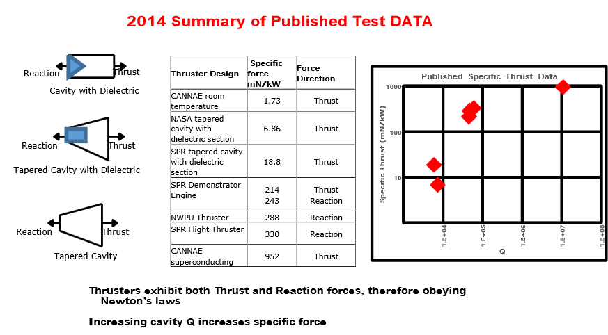
As to how you can reconcile that the force being larger on the Big End results in motion towards the Small End (or to a larger force being measured at the Small End as measured by NASA), then you get into more of this Shawyer's "theory". Here: http://www.emdrive.com/EmDriveForceMeasurement.pdf he goes into a mumbo jumbo of action-reaction and Newton's third law that nobody in academia can follow.
So, you are better off taking Shawyer as a cook giving you a recipe. What matters is the recipe, the chef doesn't necessarily know the Physics or the Chemistry that make the recipe taste well (although if you press him for an explanation he may give you one that is probably not scientifically correct), but, he may know (from experience) what recipes are the ones that make the best dessert. :) -
Title: Re: EM Drive Developments - related to space flight applications - Thread 3
Post by: CraigPichach on 08/06/2015 10:38 PM -
You think if you achieve cavity resonance (charge/discharge) in microseconds (say less than 20microseconds) that you would see the EM-Drive/Q-thruster thrust phenomena in microseconds? <a href="http://forum.nasaspaceflight.com/index.php?topic=37642.msg1413955#msg1413955">Quote from: jmossman on 08/06/2015 08:13 PM</a><a href="http://forum.nasaspaceflight.com/index.php?topic=37642.msg1413932#msg1413932">Quote from: Rodal on 08/06/2015 06:57 PM</a><a href="http://forum.nasaspaceflight.com/index.php?topic=37642.msg1413931#msg1413931">Quote from: deltaMass on 08/06/2015 06:53 PM</a>
@Rodal: Well, because the specific heat of copper isn't zero, it takes a finite time to incur a given temperature rise for a given power input. And when there's an impedance mismatch, the dissipated power will fall and so the corresponding temperature changes will be less than in the matched condition.
On the other hand, measurable mismatch changes are sensed at the ports with response times on order roughly the cavity dimensions divided by the speed of light. This is far faster than measurable temperature changes.
However, if the EmDrive is actually generating thrust, the statement about the equivalence of high- and low-Q dissipation may not be true. That's really the reason I'm pointing this out.
There seems to be some assumption of reasonably monotonic behavior such that thermal latency will not be a problem...
While the assumption of reasonable behavior applies to other known systems, the EM Drive output (non-repeatable, different by orders of magnitude between researchers) seems to not abide by that assumption
For example, the issue of vibrations of unknown magnitude and frequency being required to "engage" the drive, etc...
As a real-world example, fine-grained CPU power management (i.e. fast decisions) has moved away from using thermal diodes since their response time is too slow. (fast decisions need microsecond responses vs 10's or 100's of milliseconds from thermal diodes) Since the EM drive cavity charge/discharge times are on the order of microseconds, I'm rather doubtful that the thermal data would be useful in a true control loop feedback for any EM drive experiment.
However, perhaps the temperature might be useful to post-process and evaluate how much power was actually received/dissipated by the copper in the frustum during an experimental run. (i.e. temperature = integration of ohmic losses over time) Unfortunately, the possible effects of heating moisture within the frustum along with any number of other variables will introduce noise into the temperature reading (cooling from turbulent air around exterior of frustum, humidity at moment of test, etc).
Still worth a look to see how well frustum temperature correlates with impedance matching... but as an input into a real-time EM drive feedback loop, I'd put my money on VSWR measurement as being far more useful. -
Title: Re: EM Drive Developments - related to space flight applications - Thread 3
Post by: flux_capacitor on 08/06/2015 10:40 PM -
<a href="http://forum.nasaspaceflight.com/index.php?topic=37642.msg1413978#msg1413978">Quote from: Rodal on 08/06/2015 10:18 PM</a>
As to how you can reconcile that the force being larger on the Big End results in motion towards the Small End
That's why I prefer McCulloch's theory: according to MiHsC, as they travel towards the big end, photons gain momentum. When they bounce back towards the small end, they loose momentum. So to obey CoM, the cavity has to move from the big end towards the small end. -
Title: Re: EM Drive Developments - related to space flight applications - Thread 3
Post by: flux_capacitor on 08/06/2015 10:58 PM -
I tried to model TheTraveller's EmDrive Mark 2 in 3D, which was a bit difficult since the only dimensions TT provided were end diameters Ds and Db and the length (Rb - Rs)*
Ds = 159 mm
Db = 400 mm
Rb-Rs = 240.7 mm
Moreover the dimensions in his original drawing (https://forum.nasaspaceflight.com/index.php?topic=37642.msg1413170#msg1413170) are not proportionally on scale, maybe due to a phenomenon known as the Yang Effect ;)
But with trial & error I finally found his "magical proportions": Mr. T inscribed his spherical cone (cone + spherical base) within a cube! Hence:
Rs = Ds = 159 mm
Rb = Db = 400 mm
half-cone angle = 30°
@TheTraveller: Very clever! The more I look at your design, the more I like it.
@Rodal: can you please measure mode and resonant frequency with COMSOL for such a cavity? This is important because this cavity will be monolithically fixed (no tunable small end).
@SeeShells: It should please you in your quest for those kinds of mathematical relations, following your love with the golden ratio :)
* Big and small radius from the cone apex -
Title: Re: EM Drive Developments - related to space flight applications - Thread 3
Post by: CraigPichach on 08/06/2015 11:16 PM -
I like that explaination too however if this is photon momentum related (or even relativistic mass conservation) than why all the talk of issues of non-results without vibrations of unknown magnitude and frequency being required to "engage" the drive? Shouldn't the EM-Drive/Q-Thruster thrust effect than be essentially instantaneous then given it would occur at the speed of light (or are the vibrations required to fluidize the photons?)? Or do you think it just takes time for true resonance to be established? Or is that just a function of the low power magnetrons and slow circuits being used?<a href="http://forum.nasaspaceflight.com/index.php?topic=37642.msg1413981#msg1413981">Quote from: flux_capacitor on 08/06/2015 10:40 PM</a><a href="http://forum.nasaspaceflight.com/index.php?topic=37642.msg1413978#msg1413978">Quote from: Rodal on 08/06/2015 10:18 PM</a>
As to how you can reconcile that the force being larger on the Big End results in motion towards the Small End
That's why I prefer McCulloch's theory: according to MiHsC, as they travel towards the big end, photons gain momentum. When they bounce back towards the small end, they loose momentum. So to obey CoM, the cavity has to move from the big end towards the small end. -
Title: Re: EM Drive Developments - related to space flight applications - Thread 3
Post by: rfmwguy on 08/06/2015 11:20 PM - No promises, but tomorrow night, I'm going to test out my live cam setup. If I do, I'll make it a live chat session with some of you who might be around. I'll give you the link and time if I get things together.
-
Title: Re: EM Drive Developments - related to space flight applications - Thread 3
Post by: Rodal on 08/06/2015 11:33 PM -
<a href="http://forum.nasaspaceflight.com/index.php?topic=37642.msg1413985#msg1413985">Quote from: flux_capacitor on 08/06/2015 10:58 PM</a>
I tried to model TheTraveller's EmDrive Mark 2 in 3D, which was a bit difficult since the only dimensions TT provided were end diameters Ds and Db and the length (Rb - Rs)*
Ds = 159 mm
Db = 400 mm
Rb-Rs = 240.7 mm
Moreover the dimensions in his original drawing (https://forum.nasaspaceflight.com/index.php?topic=37642.msg1413170#msg1413170) are not proportionally on scale, maybe due to a phenomenon known as the Yang Effect ;)
But with trial & error I finally found his "magical proportions": Mr. T inscribed his spherical cone (cone + spherical base) within a cube! Hence:
Rs = Ds = 159 mm
Rb = Db = 400 mm
half-cone angle = 30°
@TheTraveller: Very clever! The more I look at your design, the more I like it.
@Rodal: can you please measure mode and resonant frequency with COMSOL for such a cavity? This is important because this cavity will be monolithically fixed (no tunable small end).
@SeeShells: It should please you in your quest for those kinds of mathematical relations, following your love with the golden ratio :)
* Big and small radius from the cone apex
This is really Shawyer's prescription for his superconducting design: spherical ends, 30 degree cone half-angle, spherical radii= diameters, etc. -
Title: Re: EM Drive Developments - related to space flight applications - Thread 3
Post by: lmbfan on 08/06/2015 11:43 PM -
<a href="http://forum.nasaspaceflight.com/index.php?topic=37642.msg1413985#msg1413985">Quote from: flux_capacitor on 08/06/2015 10:58 PM</a>
I tried to model TheTraveller's EmDrive Mark 2 in 3D, which was a bit difficult since the only dimensions TT provided were end diameters Ds and Db and the length (Rb - Rs)*
Ds = 159 mm
Db = 400 mm
Rb-Rs = 240.7 mm
Rs = Ds = 159 mm
Rb = Db = 400 mm
half-cone angle = 30°
I get slightly different dimensions, on the order of tenths of a millimeter. Which brings up the question, how tight are the tolerances on the manufacturing process, and exactly how tight they need to be to get good results? -
Title: Re: EM Drive Developments - related to space flight applications - Thread 3
Post by: frobnicat on 08/07/2015 12:29 AM -
<a href="http://forum.nasaspaceflight.com/index.php?topic=37642.msg1413412#msg1413412">Quote from: deltaMass on 08/05/2015 06:59 AM</a>
I'll be the first to point out that the folks here have probably had quite enough of me discussing CoE and over-unity. But to Bae...
I had the same thought. The situation is indeed similar. He is asking us to believe that thrust is proportional to the number of bounces, which is directly related to the Q. So he also has a P*Q factor in his thrust equation. And the obvious question is: how can it be that a cavity which is being pumped steady-state with input power P can yield a force that depends on P*Q? How can that be sustainable for seconds and minutes? It appears that one's extracting more than goes in.
I confess to being uncertain about this. I saw his experiment where he got thrust that was indeed 2*P*Q/c. The saving grace might well be that photon mirrors only become efficient as the mirror velocity with respect to the light source approaches c. By this logic, he is only sipping at each beam, and despite the fact that multiple reflections are simultaneously in play (which intensifies the beam of course) he is only taking a small fraction out of each individual beam.
But that's an unsatisfactory explanation too, because one could engineer around it. Probably only a mathematical argument could settle it for me.
I can't have enough of you discussing CoE deltaMass. Had only a shallow peek on answers (by meberbs and other contributor) that ensued that request, so maybe the following remark is not relevant...
After all the discussions about Q, some aspects of Q are still unclear (at least to me, so probably also for some other readers). I found this formula about Q for optical resonator :
( )Quote from: http://www.rp-photonics.com/q_factor.html
The Q factor of a resonator depends on the optical frequency ν0 (nu0), the fractional power loss l per round trip, and the round-trip time Trt. (assuming that l << 1)
My (perhaps crude and wrong impression) was that the "boosting factor" for radiation pressure between two mirrors, compared to that F=2*P/c for one perfect mirror with single hit per incoming photon (photon sailing) was that it would be proportional to 1/l (inverse of loss, roughly "the number of bounces") but agnostic of Trt, that is the distance between mirrors. Here assuming 0 relative velocity between mirrors.
The formula can be restated as Q=4π*(d/λ)*1/l with d distance between mirrors and λ wavelength (please check, I'm in bad mood with factors today)
Following this definition, given mirrors of fixed quality (say 99% reflection) Q can be pumped arbitrarily high simply by having mirrors at huge distance (relative to wavelength), notwithstanding difficulties of lateral losses due to diffraction at longer distances.Quote from: http://www.rp-photonics.com/q_factor.htmlFor a resonator consisting of two mirrors with air (or vacuum) in between, the Q factor rises as the resonator length is increased, because this decreases the energy loss per optical cycle. However, extremely high Q values (see below) are often achieved not by using very long resonators, but rather by strongly reducing the losses per round trip.
Contrary to the "often case" indicated in this excerpt, for long range beamed force as chased by BAE, we would have long resonator indeed. For instance the calculator on linked page yields Q of nearly 1012 for IR at 1µm, round trip time of 10000ns (1.5 km, not much distance to ask in space) and 2% round trip loss.
Would that mean it is possible to have a force a trillion time that of a photon sail (at given power) ? For instance, 600 kg force between 99% reflectance mirrors 1.5 km apart, for 1W ?? Somehow the formula must be F=some_constant_factor_around_1*(1/l)*P/c, not 2*P*Q/c, at least if their definition of Q depends on distance. Intuitively, one would expect a force from the "average number of round trips per photon" times 2P/c, the amount of energy buffered in between being irrelevant (for a constant regime). Is it possible to clarify that (before tackling moving mirrors at constant velocity, then accelerating...) ?
Add : This Q=4π*(d/λ)*1/l could indicate that the apparent Q dependence in EMdrive results might in fact be a dependence on (1/l), since d/λ hasn't been varied a lot in the experiments (I know we are not talking of a 1D problem with just two mirrors with the EMdrive, but still...)
-
Title: Re: EM Drive Developments - related to space flight applications - Thread 3
Post by: SeeShells on 08/07/2015 01:03 AM -
<a href="http://forum.nasaspaceflight.com/index.php?topic=37642.msg1413995#msg1413995">Quote from: lmbfan on 08/06/2015 11:43 PM</a><a href="http://forum.nasaspaceflight.com/index.php?topic=37642.msg1413985#msg1413985">Quote from: flux_capacitor on 08/06/2015 10:58 PM</a>
I tried to model TheTraveller's EmDrive Mark 2 in 3D, which was a bit difficult since the only dimensions TT provided were end diameters Ds and Db and the length (Rb - Rs)*
Ds = 159 mm
Db = 400 mm
Rb-Rs = 240.7 mm
Rs = Ds = 159 mm
Rb = Db = 400 mm
half-cone angle = 30°
I get slightly different dimensions, on the order of tenths of a millimeter. Which brings up the question, how tight are the tolerances on the manufacturing process, and exactly how tight they need to be to get good results?
Less than a thickness of a piece of paper puts it into perspective.
Sorry can't stay.. company.
Shell -
Title: Re: EM Drive Developments - related to space flight applications - Thread 3
Post by: jmossman on 08/07/2015 01:15 AM -
<a href="http://forum.nasaspaceflight.com/index.php?topic=37642.msg1413980#msg1413980">Quote from: CraigPichach on 08/06/2015 10:38 PM</a>
You think if you achieve cavity resonance (charge/discharge) in microseconds (say less than 20microseconds) that you would see the EM-Drive/Q-thruster thrust phenomena in microseconds?
Definitely a loaded question, but I'll take a swing:
If the "phenomena" is real, and the RF energy being injected has been properly "matched" to the EM drive, then yes, I would expect the "phenomena" to manifest within microseconds.
However, just like Phase-Lock-Loops (PLL) within CPU's need time to lock/stabilize their internal clock frequency, I would envision some delay/latency for an EM drive control loop to find the appropriate "match" to start producing a noticeable "phenomena" signature. Designs utilizing wide-band RF magnetrons might be the exception; time will tell.
How to best "match"/couple the RF energy to the frustum is an interesting question, and several theories have been postulated. The concept of evanescent waves, frequency limits based upon geometry, Q factor, the excited mode, vanilla impedance matching from RF amp to antenna to frustum... the list is only likely to grow. -
Title: Re: EM Drive Developments - related to space flight applications - Thread 3
Post by: WarpTech on 08/07/2015 01:51 AM -
<a href="http://forum.nasaspaceflight.com/index.php?topic=37642.msg1413981#msg1413981">Quote from: flux_capacitor on 08/06/2015 10:40 PM</a><a href="http://forum.nasaspaceflight.com/index.php?topic=37642.msg1413978#msg1413978">Quote from: Rodal on 08/06/2015 10:18 PM</a>
As to how you can reconcile that the force being larger on the Big End results in motion towards the Small End
That's why I prefer McCulloch's theory: according to MiHsC, as they travel towards the big end, photons gain momentum. When they bounce back towards the small end, they loose momentum. So to obey CoM, the cavity has to move from the big end towards the small end.
That's what I'm finding too. I've been busy lately and going through my notes for this paper, and I realized I've said some things that were confused and backwards, regarding which way the momentum of the wave changes.
As the wave moves from the small end toward the big end it expands, but it's wavelength is getting shorter because the phase velocity is getting slower. So the momentum of the wave is increasing when moving from the small end toward the big end. Therefore, to conserve momentum, the frustum must move the other way. It feels the force that moves it in direction toward the small end. This is thrust, just like a rocket.
When the wave reflects from the big end, the amount of momentum it transfers depends on the impedance match and the angle of reflection. If the impedance doesn't match exactly, or the angle of reflection is not perpendicular, then the force will vary too. Don't ask me for the equations please, I don't have them quite right yet. So this is just hand waving, based on my understanding.
When the wave is traveling toward the small end, its momentum is decreasing and therefore, to conserve momentum the frustum must again feel a force in the "forward" direction, like a sail on a boat. This is due to the gradient, which is unique to the cone geometry. According to Zeng & Fan's paper, if the phase constant Beta goes to zero, there is a perfect impedance match and all the power and momentum is attenuated into the frustum with no reflection.
So regardless if the wave is traveling forward or backwards inside, the frustum will be pushed "forward" toward the small end. The only component that is in the other direction, opposing this thrust is the reflection from the big end. From what I've seen in the meep models, the wave is not perpendicular to the big end. The angle of reflection produces a glancing blow. Anything that reduces the momentum transferred to the big end plate, results in thrust forward.
Todd
-
Title: Re: EM Drive Developments - related to space flight applications - Thread 3
Post by: WarpTech on 08/07/2015 02:19 AM -
<a href="http://forum.nasaspaceflight.com/index.php?topic=37642.msg1413977#msg1413977">Quote from: ElizabethGreene on 08/06/2015 10:10 PM</a><a href="http://forum.nasaspaceflight.com/index.php?topic=37642.msg1413964#msg1413964">Quote from: WarpTech on 08/06/2015 09:13 PM</a><a href="http://forum.nasaspaceflight.com/index.php?topic=37642.msg1413942#msg1413942">Quote from: ElizabethGreene on 08/06/2015 07:22 PM</a>
...
I played with the numbers yesterday for F=2P/Vg -> F=2*P*Sqrt(1-(c/(2*(a+x)*f))^2) and found ...
...
Disclaiming again, I probably broke the math.
The equation would be F = (Vg/c^2)*P = P/Vp. IF you use standard waveguide physics that is. In the case of the EM Drive, this may be, F = (Vg*K/c^2)*P, where K is a function TBD by experiment.
Todd
If F=P/Vp is correct for traditional physics, then Mr. Shawyer's theory falls apart. Specifically, as the size of the waveguide decreases Vp increases. An increase in Vp decreases F. That would make the force on the little end --smaller-- than the force on the big end.
Is that right?
Pretty much... It is that the momentum of an EM wave depends on the phase velocity and Planck's constant. It is the phase velocity, Vp = w/k that give us the momentum per photon, p=h*k. So if Vp is increasing, p is decreasing, and if Vp is decreasing, p is increasing. Either way, the force on the frustum is in the same direction in order to conserve momentum. The momentum is "forward rectified" by the gradient. It is only the reflection at the big end that is opposing this force. Anything that reduces the force on the big end, will result in forward thrust.
In order for the big end to 100% cancel these forces, the force on the big end would have to be larger than the force at the small end. Definitely not smaller. If it is smaller by hook or by crook, or by leakage or heat, then the frustum will feel a thrust forward.
The real question is still, how does it get thrust greater than a photon rocket? I see 3 possibilities:
1. A group velocity that is faster than light in free space.
2. A phase velocity that is slower than light in free space.
3. A means to change the speed of light such that Vg*Vp = (c/K)2, in which case the group velocity could be faster than light in a frustum, but slower than light in free space and result in an amplified ratio;
Vg/c2 -> K*Vg/c2, where K > 1
This way, nothing ever exceeds c in free space, but it reduces both the phase velocity and the group velocity to be much less than c. It is consistent with the PV Model of gravity. I just don't know how to derive it yet. I have 2 key pieces to the puzzle. Squeezed light behaves this way, and what Zeng and Fan show for an impedance curve looks almost exactly like a Reissner Nordstrom "charged" metric refractive index. Somehow, this all seems to make sense to me, but not well enough to write down the correct equations.
Todd
-
Title: Re: EM Drive Developments - related to space flight applications - Thread 3
Post by: Rodal on 08/07/2015 02:47 AM -
<a href="http://forum.nasaspaceflight.com/index.php?topic=37642.msg1413995#msg1413995">Quote from: lmbfan on 08/06/2015 11:43 PM</a><a href="http://forum.nasaspaceflight.com/index.php?topic=37642.msg1413985#msg1413985">Quote from: flux_capacitor on 08/06/2015 10:58 PM</a>
I tried to model TheTraveller's EmDrive Mark 2 in 3D, which was a bit difficult since the only dimensions TT provided were end diameters Ds and Db and the length (Rb - Rs)*
Ds = 159 mm
Db = 400 mm
Rb-Rs = 240.7 mm
Rs = Ds = 159 mm
Rb = Db = 400 mm
half-cone angle = 30°
I get slightly different dimensions, on the order of tenths of a millimeter. Which brings up the question, how tight are the tolerances on the manufacturing process, and exactly how tight they need to be to get good results?
Flux-Capacitor is correct that:
Db = 2 r2 Sin [(30/180) Pi] = 2 r2 Sin [Pi/6]= 2 r1 (1/2) = r2 exactly
Ds = 2 r1 Sin [(30/180) Pi] = 2 r1 Sin [Pi/6]= 2 r1 (1/2) = r1 exactly
An angle of 30 degrees results in Db = r2 and Ds = r1 exactly (to infinite precision) because Sin[30 degrees] =1/2 exactly, regardless of the value of Db and Ds.
But TheTraveller did NOT give an angle of 30 degrees. Instead TheTraveller defined the difference between the spherical radii=r2-r1, and TheTraveller defined them such that the angle is NOT 30 degrees
lmbfan is correct that the numbers given by TheTraveller do NOT agree with this exactly
The reason is that
r2 - r1 = 0.4 - 0.159 = 0.241 exactly
but TheTraveller instead gave the incorrect value of
r2 - r1 = 0.2407 m (which is weird, since those extra digits of 0.7 mm are unnecessary and end up screwing up the values for r1, r2 and theta, while just giving 0.241 gives an exact 30 degrees)
This value is incompatible with 30 degrees. That's where the problem comes from.
This value gives:
r1 = (r2 -r1)/(Db/Ds - 1) = 0.2407 /(0.400/0.159 - 1)
= 0.158802 m
r2 = (r2 -r1)/(1 - Ds/Db ) = 0.2407 /(1 - 0.159/0.400)
= 0.399502 m
theta = ArcSin[Db/(2 r2) ]= 30.0412 degrees
So, again
r2 - r1 = 0.2407 is only valid for 30.0412 degrees
For theta = 30 degrees one must have r2 - r1 = 0.241m
//////////////////////////////////////////
Any way, whether using 30 degrees or 30.0412 degrees this geometry is going to resonate at TE012 at a lower natural frequency than the 2.45 GHz TheTraveller calculated.
The inaccuracy of TheTraveller and Shawyer's code is more evident for this case because of the higher cone angle 30 degrees (compared with other EM Drives that range from 15 degrees to 20 degrees), and therefore the more inaccurate their approximate formulas.
It has a very high theoretical Q though, close to 100,000 much higher than the Fligh Thruster
Flux Capacitor:
I don't use COMSOL for these calculations. I prefer to use the exact solution because... it is exact, while numerical solutions are approximate. -
Title: Re: EM Drive Developments - related to space flight applications - Thread 3
Post by: ElizabethGreene on 08/07/2015 04:33 AM -
<a href="http://forum.nasaspaceflight.com/index.php?topic=37642.msg1413978#msg1413978">Quote from: Rodal on 08/06/2015 10:18 PM</a><a href="http://forum.nasaspaceflight.com/index.php?topic=37642.msg1413977#msg1413977">Quote from: ElizabethGreene on 08/06/2015 10:10 PM</a><a href="http://forum.nasaspaceflight.com/index.php?topic=37642.msg1413964#msg1413964">Quote from: WarpTech on 08/06/2015 09:13 PM</a><a href="http://forum.nasaspaceflight.com/index.php?topic=37642.msg1413942#msg1413942">Quote from: ElizabethGreene on 08/06/2015 07:22 PM</a>
...
I played with the numbers yesterday for F=2P/Vg -> F=2*P*Sqrt(1-(c/(2*(a+x)*f))^2) and found ...
...
Disclaiming again, I probably broke the math.
The equation would be F = (Vg/c^2)*P = P/Vp.
<snipp>
If F=P/Vp is correct for traditional physics, then Mr. Shawyer's theory falls apart. Specifically, as the size of the waveguide decreases Vp increases. An increase in Vp decreases F. That would make the force on the little end --smaller-- than the force on the big end.
Is that right?
Your thinking is correct. <snip>
Thank you both for the kind replies. I looked back in my notebook from yesterday and I did manage to derive 2P/Vp (the expanded form) on my first attempt, but I wrote "that can't be right" next to it and swapped in Vg. I"ll be more careful in the future.
Closing the loop:
My math regarding fine tuning the small end dimensions for maximum thrust was wrong.
The corrected equation is F=2P/V_p. Playing with the numbers for this reveals approximately a 2 order of magnitude decrease in the small end force for small end sizes of 10 microns above the calculated non-tapered waveguide cutoff.
These results do not explain -at all- why the device appears to thrust in the wrong direction in the Boeing video.
I'll look at side forces next. -
Title: Re: EM Drive Developments - related to space flight applications - Thread 3
Post by: deltaMass on 08/07/2015 05:11 AM -
The 3D integration of all photonic forces over the entire internal surface area, averaged over one complete cycle, is zero. That's Maxwell.
The 3D integration of all Lorentz forces over the entire internal surface area, averaged over one complete cycle, is zero. That's Maxwell too.
So if it moves, you have chosen to reject Maxwell.
And when it moves, you have a further set of choices: reject Noether or reject Einstein.
Pretty heady company, if you ask me.
I hope you know what you're doing, whoever you are.
-
Title: Re: EM Drive Developments - related to space flight applications - Thread 3
Post by: tleach on 08/07/2015 05:15 AM -
<a href="http://forum.nasaspaceflight.com/index.php?topic=37642.msg1413981#msg1413981">Quote from: flux_capacitor on 08/06/2015 10:40 PM</a><a href="http://forum.nasaspaceflight.com/index.php?topic=37642.msg1413978#msg1413978">Quote from: Rodal on 08/06/2015 10:18 PM</a>
As to how you can reconcile that the force being larger on the Big End results in motion towards the Small End
That's why I prefer McCulloch's theory: according to MiHsC, as they travel towards the big end, photons gain momentum. When they bounce back towards the small end, they loose momentum. So to obey CoM, the cavity has to move from the big end towards the small end.
So I had a little extra time today and I actually took a look at McCulloch's equations. I don't know much about equations, but what I did realize was that they were actually pretty simple. "I could probably program this into a spreadsheet," I thought aloud. He's only using the frustum dimensions (big end, small end and length), the power, and the Q (which he defines on his blog as the "number of bounces of a typical photon inside the cavity").
So, I tried (see attached .xls). I'm not entirely certain that I translated things correctly, but I'm sure someone here can point out my errors...
I included drive specs I was playing around with (we'll see if I can talk my wife into letting me do a build) as well as some specs and Df I stole from TheTraveller's spreadsheet. There are also specs, predicted force and observed force for 2 of Shawyer's drives (I got those numbers from McCulloch's blog) and Tajmar's drive (again, the specifications came from McCulloch's blog).
Would a spreadsheet like this (only with several more of the various theories/equations programed in) be useful to have over on the wiki? I think it could be helpful for the builders to plug their specifications in and get back several different thrust predictions, each based on a different theory.
EDIT: http://physicsfromtheedge.blogspot.co.uk/2015/02/mihsc-vs-emdrive-data-3d.html
Original
F = PQL/c * (1/wb - 1/ws)
3D
F = 6PQL/c * ( 1/(L+4wb) - 1/(L+4ws) ) -
Title: Re: EM Drive Developments - related to space flight applications - Thread 3
Post by: lmbfan on 08/07/2015 05:26 AM -
<a href="http://forum.nasaspaceflight.com/index.php?topic=37642.msg1414015#msg1414015">Quote from: Rodal on Today at 02:47 AM</a>
r2 - r1 = 0.4 - 0.159 = 0.241 exactly
This agrees with my analysis. The horizontal dimension should be 241 mm, or the small end should be 159.3 mm. If the manufacturing tolerance is greater than a few tenths, it doesn't matter too much, hence my question. If, on the other hand, the tolerance is less than that (which is not uncommon for precision components), it does matter. I know that many microwave devices require tolerances on the order of .001", which works out to ~.03 mm, but this is a novel application, and my experience is less useful. -
Title: Re: EM Drive Developments - related to space flight applications - Thread 3
Post by: ElizabethGreene on 08/07/2015 06:26 AM -
<a href="http://forum.nasaspaceflight.com/index.php?topic=37642.msg1414023#msg1414023">Quote from: deltaMass on Today at 05:11 AM</a>
So if it moves, you have chosen to reject Maxwell.
And when it moves, you have a further set of choices: reject Noether or reject Einstein.
Pretty heady company, if you ask me.
I choose to reject none at this point. Instead I will, following your example, read the papers critically (and slowly). Part of that means, to the limited extent my pidgin math allows, playing with numbers to see what pops out the other side.
It hasn't been unproductive. Two days of spare cpu cycles noodling with small end parameters taught me that Mr. S's equations do not describe the observed behavior. That was worth the time invested. Much better than watching reruns of Law & Order. -
Title: Re: EM Drive Developments - related to space flight applications - Thread 3
Post by: ThinkerX on 08/07/2015 06:40 AM -
Quote
The 3D integration of all photonic forces over the entire internal surface area, averaged over one complete cycle, is zero. That's Maxwell.
The 3D integration of all Lorentz forces over the entire internal surface area, averaged over one complete cycle, is zero. That's Maxwell too.
So if it moves, you have chosen to reject Maxwell.
And when it moves, you have a further set of choices: reject Noether or reject Einstein.
Pretty heady company, if you ask me.
I hope you know what you're doing, whoever you are.
Key word in this to me is 'averaged.'
Lately, the thought has crossed my mind more than once that maybe something about this device breaks or twists the averages somehow. There are such things as loaded dice. And coins do land on edge now and again. Maybe the EM Drive represents one such?
-
Title: Re: EM Drive Developments - related to space flight applications - Thread 3
Post by: TheTraveller on 08/07/2015 07:20 AM -
<a href="http://forum.nasaspaceflight.com/index.php?topic=37642.msg1414015#msg1414015">Quote from: Rodal on Today at 02:47 AM</a>
The inaccuracy of TheTraveller and Shawyer's code is more evident for this case because of the higher cone angle 30 degrees (compared with other EM Drives that range from 15 degrees to 20 degrees), and therefore the more inaccurate their approximate formulas.
Thanks for the good laugh.
You who have no working EMDrives created with your exact solution, derate Shawyer's solution where he has shown 3 working EMDrives and in the case of my estimated Flight Thruster dimensions, produced the quoted resonance at 3.9003GHz, which says my estimated length was 0.6mm too short for resonance at 3.85GHz.
The reality is you have no real idea if your numbers are correct or not, but continually push them as if they represent reality, which as your resonance is so far off the Shawyer solution says they are no correct. Not even close.
BTW how often does your private and not for publication exact solution vary? -
Title: Re: EM Drive Developments - related to space flight applications - Thread 3
Post by: TheTraveller on 08/07/2015 07:29 AM -
<a href="http://forum.nasaspaceflight.com/index.php?topic=37642.msg1414011#msg1414011">Quote from: WarpTech on Today at 02:19 AM</a><a href="http://forum.nasaspaceflight.com/index.php?topic=37642.msg1413977#msg1413977">Quote from: ElizabethGreene on 08/06/2015 10:10 PM</a><a href="http://forum.nasaspaceflight.com/index.php?topic=37642.msg1413964#msg1413964">Quote from: WarpTech on 08/06/2015 09:13 PM</a><a href="http://forum.nasaspaceflight.com/index.php?topic=37642.msg1413942#msg1413942">Quote from: ElizabethGreene on 08/06/2015 07:22 PM</a>
...
I played with the numbers yesterday for F=2P/Vg -> F=2*P*Sqrt(1-(c/(2*(a+x)*f))^2) and found ...
...
Disclaiming again, I probably broke the math.
The equation would be F = (Vg/c^2)*P = P/Vp. IF you use standard waveguide physics that is. In the case of the EM Drive, this may be, F = (Vg*K/c^2)*P, where K is a function TBD by experiment.
Todd
If F=P/Vp is correct for traditional physics, then Mr. Shawyer's theory falls apart. Specifically, as the size of the waveguide decreases Vp increases. An increase in Vp decreases F. That would make the force on the little end --smaller-- than the force on the big end.
Is that right?
Pretty much... It is that the momentum of an EM wave depends on the phase velocity and Planck's constant. It is the phase velocity, Vp = w/k that give us the momentum per photon, p=h*k. So if Vp is increasing, p is decreasing, and if Vp is decreasing, p is increasing. Either way, the force on the frustum is in the same direction in order to conserve momentum. The momentum is "forward rectified" by the gradient. It is only the reflection at the big end that is opposing this force. Anything that reduces the force on the big end, will result in forward thrust.
In order for the big end to 100% cancel these forces, the force on the big end would have to be larger than the force at the small end. Definitely not smaller. If it is smaller by hook or by crook, or by leakage or heat, then the frustum will feel a thrust forward.
The real question is still, how does it get thrust greater than a photon rocket? I see 3 possibilities:
1. A group velocity that is faster than light in free space.
2. A phase velocity that is slower than light in free space.
3. A means to change the speed of light such that Vg*Vp = (c/K)2, in which case the group velocity could be faster than light in a frustum, but slower than light in free space and result in an amplified ratio;
Vg/c2 -> K*Vg/c2, where K > 1
This way, nothing ever exceeds c in free space, but it reduces both the phase velocity and the group velocity to be much less than c. It is consistent with the PV Model of gravity. I just don't know how to derive it yet. I have 2 key pieces to the puzzle. Squeezed light behaves this way, and what Zeng and Fan show for an impedance curve looks almost exactly like a Reissner Nordstrom "charged" metric refractive index. Somehow, this all seems to make sense to me, but not well enough to write down the correct equations.
Todd
Why do you and others keep referring to phase velocity inside a waveguide as it is above c. Inside a waveguide energy moves at group velocity, which is determined from the guide wavelength, which is determined from the cutoff wavelength. The momentum in the wave varies as the guide wavelength varies, longer at the small end and shorter at the big end.
http://www.microwaves101.com/encyclopedias/waveguide-mathematics#velocity
Cullen 15, attached, is based on this and proved that it is correct, so please stop talking above phase velocity inside a waveguide as it is above c and nothing travels above c.
-
Title: Re: EM Drive Developments - related to space flight applications - Thread 3
Post by: deltaMass on 08/07/2015 07:32 AM -
<a href="http://forum.nasaspaceflight.com/index.php?topic=37642.msg1414037#msg1414037">Quote from: ThinkerX on Today at 06:40 AM</a>
I think I understand your comment, but if what you suggest were to be true, then one cycle of RF energy from time t0 to t1 would be in some way different to another cycle from t1 to t2. That does seem rather unlikely, absent an explanatory mechanism, don't you think?Quote
The 3D integration of all photonic forces over the entire internal surface area, averaged over one complete cycle, is zero. That's Maxwell.
The 3D integration of all Lorentz forces over the entire internal surface area, averaged over one complete cycle, is zero. That's Maxwell too.
So if it moves, you have chosen to reject Maxwell.
And when it moves, you have a further set of choices: reject Noether or reject Einstein.
Pretty heady company, if you ask me.
I hope you know what you're doing, whoever you are.
Key word in this to me is 'averaged.'
Lately, the thought has crossed my mind more than once that maybe something about this device breaks or twists the averages somehow. There are such things as loaded dice. And coins do land on edge now and again. Maybe the EM Drive represents one such? -
Title: Re: EM Drive Developments - related to space flight applications - Thread 3
Post by: TheTraveller on 08/07/2015 07:37 AM -
<a href="http://forum.nasaspaceflight.com/index.php?topic=37642.msg1414009#msg1414009">Quote from: WarpTech on Today at 01:51 AM</a>
As the wave moves from the small end toward the big end it expands, but it's wavelength is getting shorter because the phase velocity is getting slower. So the momentum of the wave is increasing when moving from the small end toward the big end. Therefore, to conserve momentum, the frustum must move the other way. It feels the force that moves it in direction toward the small end. This is thrust, just like a rocket.
When the wave reflects from the big end, the amount of momentum it transfers depends on the impedance match and the angle of reflection. If the impedance doesn't match exactly, or the angle of reflection is not perpendicular, then the force will vary too. Don't ask me for the equations please, I don't have them quite right yet. So this is just hand waving, based on my understanding.
When the wave is traveling toward the small end, its momentum is decreasing and therefore, to conserve momentum the frustum must again feel a force in the "forward" direction, like a sail on a boat. This is due to the gradient, which is unique to the cone geometry. According to Zeng & Fan's paper, if the phase constant Beta goes to zero, there is a perfect impedance match and all the power and momentum is attenuated into the frustum with no reflection.
So regardless if the wave is traveling forward or backwards inside, the frustum will be pushed "forward" toward the small end. The only component that is in the other direction, opposing this thrust is the reflection from the big end. From what I've seen in the meep models, the wave is not perpendicular to the big end. The angle of reflection produces a glancing blow. Anything that reduces the momentum transferred to the big end plate, results in thrust forward.
Todd
Nicely explained, except it is group velocity and not phase velocity. Additionally the group velocity is faster at the big end and slower at the small end.
The bad bounce introduces phase distortion into the wave and is why spherical end plates are so important. -
Title: Re: EM Drive Developments - related to space flight applications - Thread 3
Post by: flux_capacitor on 08/07/2015 08:21 AM -
<a href="http://forum.nasaspaceflight.com/index.php?topic=37642.msg1414015#msg1414015">Quote from: Rodal on Today at 02:47 AM</a>
Any way, whether using 30 degrees or 30.0412 degrees this geometry is going to resonate at TE012 at a lower natural frequency than the 2.45 GHz TheTraveller calculated.
So what do your exact solutions give for each value of the possible angles we found (30° and 30.0412°) for TE012 and TE013? Are they really different with such a slight difference?
I think TheTraveller may have accounted for that lower natural frequency, as he also noted on his drawing: "Min operational frequency 2.3 GHz". -
Title: Re: EM Drive Developments - related to space flight applications - Thread 3
Post by: TheTraveller on 08/07/2015 08:53 AM -
<a href="http://forum.nasaspaceflight.com/index.php?topic=37642.msg1414045#msg1414045">Quote from: flux_capacitor on Today at 08:21 AM</a><a href="http://forum.nasaspaceflight.com/index.php?topic=37642.msg1414015#msg1414015">Quote from: Rodal on Today at 02:47 AM</a>
Any way, whether using 30 degrees or 30.0412 degrees this geometry is going to resonate at TE012 at a lower natural frequency than the 2.45 GHz TheTraveller calculated.
So what do your exact solutions give for each value of the possible angles we found (30° and 30.0412°) for TE012 and TE013? Are they really different with such a slight difference?
I think TheTraveller may have accounted for that lower natural frequency, as he also noted on his drawing: "Min operational frequency 2.3 GHz".
I redesigned the frustum to have a lower operational freq of 2.30GHz, which increased the small end diameter and altered the length so as to give me good headroom when operating at 2.45GHz and to allow wider manufacturing tolerance.
Screenshot of my design spreadsheet is attached.
As you can see the TE013 frustum length is 0.05mm too short where length is defined as per the attached. -
Title: Re: EM Drive Developments - related to space flight applications - Thread 3
Post by: Mulletron on 08/07/2015 09:08 AM -
It doesn't matter if there is a more momentum at one vs the other. This theory of operation will not result in the frustum moving because....
The small end and the large end are physically connected, so the total momentum is ZERO.
This mechanism of action is a no go. It is just like pushing your car from the inside.
Now that I've poopood theories which rely on the above (more momentum transfer to one end plate vs the other), I'll offer a down to earth idea, which is similar and may be equally abysmal, but doesn't rely on electromagnetic vacuum field fluctuations as I'm accustomed to doing.
So we know that friction is a non conservative force. I'd rather shake a stick at the friction from the air against the cavity walls while it is circulating within the cavity. I can see this happening as long as thermal equilibrium hasn't been achieved. Is it useful? I don't know.
This should be super easy to test. A simple heat sink or water jacket attached to the frustum would make or break thrust with this mechanism. I think any mechanical engineer could blow this idea up quite easily too.
I don't have much confidence in the internal air friction idea yet, but I'm forced to look at more mundane explanations than momentum from the QV, which I believe is happening but isn't the dominant force here. -
Title: Re: EM Drive Developments - related to space flight applications - Thread 3
Post by: TheTraveller on 08/07/2015 09:24 AM -
<a href="http://forum.nasaspaceflight.com/index.php?topic=37642.msg1414049#msg1414049">Quote from: Mulletron on Today at 09:08 AM</a>
It doesn't matter if there is a more momentum at one vs the other. This theory of operation will not result in the frustum moving because....
The small end and the large end are physically connected, so the total momentum is ZERO.
This mechanism of action is a no go. It is just like pushing your car from the inside.
This is not like pushing your car from the inside. This is about the EM wave gaining and losing momentum inside the tapered waveguide and how that momentum gain and loss affects the frustum.
As the EM wave moves from the small end to the big end, the EM waves momentum increases as the wavelength shortens and the group velocity increases. In needs to balance that momentum increase by pushing the frustum the other way, ie toward the small end.
When the EM wave moves big end to small end, it needs to dump EM wave momentum because the EM wave's momentum is decreasing as the wavelength increases and the group velocity decreases. The dumped momentum pushes the frustum toward the small end.
The bounce at the small end adds to the big to small end momentum gain but offset by the small to big end bounce momentum gain at the big end.
Shawyer has already said the end plate forces versus the frustum forces, from just the bounce action will not results in any external Force being generated.
-
Title: Re: EM Drive Developments - related to space flight applications - Thread 3
Post by: deltaMass on 08/07/2015 10:09 AM -
Oh, I see. That was supposed to be physics.
Carry on. -
Title: Re: EM Drive Developments - related to space flight applications - Thread 3
Post by: TheTraveller on 08/07/2015 10:26 AM -
<a href="http://forum.nasaspaceflight.com/index.php?topic=37642.msg1414052#msg1414052">Quote from: deltaMass on Today at 10:09 AM</a>
Oh, I see. That was supposed to be physics.
Carry on.
So as the EM wave moves from the small to the big end end and the momentum in the EM wave increases, there is no effect on the frustum?
Likewise as the EM wave moves big end to small end and the momentum in the EM wave decreases, there is no effect on the frustum?
Yup then according to you, momentum changes in the EM wave just happen totally isolated from the real world and without any corresponding momentum changes in the frustum.
Nice physics you believe in there.
Oh yes I see, you believe the energy / momentum inside the tapered waveguide (frustum) moves at superluminal above c phase velocity and the group velocity / guide wavelength doesn't change as the EM wave moves from one end of the frustum to the other, so there is no momentum change in the EM wave.
What shall we call this? Denier physics? -
Title: Re: EM Drive Developments - related to space flight applications - Thread 3
Post by: deltaMass on 08/07/2015 10:48 AM - I'm unfamiliar with the term. Was it supposed to be French?
-
Title: Re: EM Drive Developments - related to space flight applications - Thread 3
Post by: Mulletron on 08/07/2015 10:54 AM -
This is useful for those still arguing over group vs phase velocity.
http://www-math.mit.edu/~stevenj/papers/PovinelliIb04.pdf
Slow-light enhancement of radiation pressure
in an omnidirectional-reflector waveguide. -
Title: Re: EM Drive Developments - related to space flight applications - Thread 3
Post by: deltaMass on 08/07/2015 11:24 AM -
<a href="http://forum.nasaspaceflight.com/index.php?topic=37642.msg1414061#msg1414061">Quote from: Mulletron on Today at 10:54 AM</a>
This is useful for those still arguing over group vs phase velocity.
What does this paper confirm for you?
http://www-math.mit.edu/~stevenj/papers/PovinelliIb04.pdf
Slow-light enhancement of radiation pressure
in an omnidirectional-reflector waveguide. -
Title: Re: EM Drive Developments - related to space flight applications - Thread 3
Post by: OttO on 08/07/2015 11:29 AM -
<a href="http://forum.nasaspaceflight.com/index.php?topic=37642.msg1414049#msg1414049">Quote from: Mulletron on Today at 09:08 AM</a>
It doesn't matter if there is a more momentum at one vs the other. This theory of operation will not result in the frustum moving because....
The small end and the large end are physically connected, so the total momentum is ZERO.
Yep, but if like me you fear that it is only a fan then near field radiative momentum could be an explanation.
In a way it would be a new kind of ... lifter ;) -
Title: Re: EM Drive Developments - related to space flight applications - Thread 3
Post by: Mulletron on 08/07/2015 11:58 AM -
<a href="http://forum.nasaspaceflight.com/index.php?topic=37642.msg1414066#msg1414066">Quote from: deltaMass on Today at 11:24 AM</a><a href="http://forum.nasaspaceflight.com/index.php?topic=37642.msg1414061#msg1414061">Quote from: Mulletron on Today at 10:54 AM</a>
This is useful for those still arguing over group vs phase velocity.
What does this paper confirm for you?
http://www-math.mit.edu/~stevenj/papers/PovinelliIb04.pdf
Slow-light enhancement of radiation pressure
in an omnidirectional-reflector waveguide.
Two things:
1) Every time someone mentions "phase velocity" within a waveguide, a cute bunny gets it.
2) Using TE01X modes as the model, the radiation pressure per unit area is greatest at the small end where Vg is slowest (not the other way around).
@ElizabethGreene mentioned #2 a few days ago here, but for different reasons:
http://forum.nasaspaceflight.com/index.php?topic=37642.msg1407704#msg1407704
-
Title: Re: EM Drive Developments - related to space flight applications - Thread 3
Post by: Rodal on 08/07/2015 12:08 PM -
<a href="http://forum.nasaspaceflight.com/index.php?topic=37642.msg1414045#msg1414045">Quote from: flux_capacitor on Today at 08:21 AM</a>
Given his announced commercial (licensing) relationship with Shawyer and unwillingness to consider anything that deviates from what is prescribed by Shawyer, it has become apparent that it is a waste of my time to spend any further time discussing anything related to TheTraveller.<a href="http://forum.nasaspaceflight.com/index.php?topic=37642.msg1414015#msg1414015">Quote from: Rodal on Today at 02:47 AM</a>Any way, whether using 30 degrees or 30.0412 degrees this geometry is going to resonate at TE012 at a lower natural frequency than the 2.45 GHz TheTraveller calculated.
So what do your exact solutions give for each value of the possible angles we found (30° and 30.0412°) for TE012 and TE013? Are they really different with such a slight difference?
I think TheTraveller may have accounted for that lower natural frequency, as he also noted on his drawing: "Min operational frequency 2.3 GHz".
I have also arrived at the conclusion that I cannot trust any experimental claims that TheTraveller may present.
I look forward to the experiments of rfmwguy and SeeShells and hopefully to any further news from NASA Eagleworks and Tajmar.
-
Title: Re: EM Drive Developments - related to space flight applications - Thread 3
Post by: TheTraveller on 08/07/2015 12:18 PM -
<a href="http://forum.nasaspaceflight.com/index.php?topic=37642.msg1414070#msg1414070">Quote from: Mulletron on Today at 11:58 AM</a>
2) Using TE01X modes as the model, the radiation pressure per unit area is greatest at the small end where Vg is slowest (not the other way around).
At the small end, the guide wavelength is the longest, the group velocity is the slowest and the radiation pressure is the smallest. Power per end plate area is the same at each end plate.
As example see the attached, which is from my latest frustum design. -
Title: Re: EM Drive Developments - related to space flight applications - Thread 3
Post by: TheTraveller on 08/07/2015 12:22 PM -
<a href="http://forum.nasaspaceflight.com/index.php?topic=37642.msg1414071#msg1414071">Quote from: Rodal on Today at 12:08 PM</a>
I have also arrived at the conclusion that I cannot trust any experimental claims that TheTraveller may present.
Seems the way you handle being shown you are incorrect is to stick your head in the sand?
Good luck with that. -
Title: Re: EM Drive Developments - related to space flight applications - Thread 3
Post by: Mulletron on 08/07/2015 12:30 PM -
<a href="http://forum.nasaspaceflight.com/index.php?topic=37642.msg1414072#msg1414072">Quote from: TheTraveller on Today at 12:18 PM</a><a href="http://forum.nasaspaceflight.com/index.php?topic=37642.msg1414070#msg1414070">Quote from: Mulletron on Today at 11:58 AM</a>
2) Using TE01X modes as the model, the radiation pressure per unit area is greatest at the small end where Vg is slowest (not the other way around).
At the small end, the guide wavelength is the longest, the group velocity is the slowest and the radiation pressure is the smallest. Power per end plate area is the same at each end plate.
As example see the attached, which is from my latest frustum design.
Shawyer has been wrong before. At least others think so. Is it possible he has it backwards? -
Title: Re: EM Drive Developments - related to space flight applications - Thread 3
Post by: TheTraveller on 08/07/2015 12:38 PM -
<a href="http://forum.nasaspaceflight.com/index.php?topic=37642.msg1414075#msg1414075">Quote from: Mulletron on Today at 12:30 PM</a><a href="http://forum.nasaspaceflight.com/index.php?topic=37642.msg1414072#msg1414072">Quote from: TheTraveller on Today at 12:18 PM</a><a href="http://forum.nasaspaceflight.com/index.php?topic=37642.msg1414070#msg1414070">Quote from: Mulletron on Today at 11:58 AM</a>
2) Using TE01X modes as the model, the radiation pressure per unit area is greatest at the small end where Vg is slowest (not the other way around).
At the small end, the guide wavelength is the longest, the group velocity is the slowest and the radiation pressure is the smallest. Power per end plate area is the same at each end plate.
As example see the attached, which is from my latest frustum design.
Shawyer has been wrong before. At least others think so. Is it possible he has it backwards?
Backward?
That data is based on microwave industry equations and Cullen 15 for the radiation pressure on the end plate bounce Force / momentum transfer per bounce. -
Title: Re: EM Drive Developments - related to space flight applications - Thread 3
Post by: rfmwguy on 08/07/2015 01:14 PM -
<a href="http://forum.nasaspaceflight.com/index.php?topic=37642.msg1414071#msg1414071">Quote from: Rodal on Today at 12:08 PM</a>
Doc,<a href="http://forum.nasaspaceflight.com/index.php?topic=37642.msg1414045#msg1414045">Quote from: flux_capacitor on Today at 08:21 AM</a>
Given his announced commercial (licensing) relationship with Shawyer and unwillingness to consider anything that deviates from what is prescribed by Shawyer, it has become apparent that it is a waste of my time to spend any further time discussing anything related to TheTraveller.<a href="http://forum.nasaspaceflight.com/index.php?topic=37642.msg1414015#msg1414015">Quote from: Rodal on Today at 02:47 AM</a>Any way, whether using 30 degrees or 30.0412 degrees this geometry is going to resonate at TE012 at a lower natural frequency than the 2.45 GHz TheTraveller calculated.
So what do your exact solutions give for each value of the possible angles we found (30° and 30.0412°) for TE012 and TE013? Are they really different with such a slight difference?
I think TheTraveller may have accounted for that lower natural frequency, as he also noted on his drawing: "Min operational frequency 2.3 GHz".
I have also arrived at the conclusion that I cannot trust any experimental claims that TheTraveller may present.
I look forward to the experiments of rfmwguy and SeeShells and hopefully to any further news from NASA Eagleworks and Tajmar.
Guess Mr T is either Shawyer himself or has developed an unshakeable belief system based on nothing other than what he has learned from afar. Repetition of SPR data is not helpful, imo, most of us have seen the same charts and pics ad nauseum. I would go so far as to suggest mod intervention to limit excessive bandwidth taken by these attachments.
Here's the bottom line: Its interesting enough to experiment with and there is no entity out there that has convinced me enough to believe in it just by their words or videos. If one believes someone without exception, that person should not theorize, experiment or even post here...whats the point other than trying to elicit group think.
<end micro-rant>
NSF-1700 update - cam test and live chat tonight if all goes well. Frustum has Db of a spherical mesh only. Will have it on cam for a close, higher quality video. That way, you can see all the build imperfections ;) -
Title: Re: EM Drive Developments - related to space flight applications - Thread 3
Post by: Flyby on 08/07/2015 01:23 PM -
<a href="http://forum.nasaspaceflight.com/index.php?topic=37642.msg1414071#msg1414071">Quote from: Rodal on Today at 12:08 PM</a>
Given his announced commercial (licensing) relationship with Shawyer and unwillingness to consider anything that deviates from what is prescribed by Shawyer, it has become apparent that it is a waste of my time to spend any further time discussing anything related to TheTraveller.
I have also arrived at the conclusion that I cannot trust any experimental claims that TheTraveller may present.
I look forward to the experiments of rfmwguy and SeeShells and hopefully to any further news from NASA Eagleworks and Tajmar.
I'm not here to defend TT, but I find that a regretful attitude.... :(
Whatever experiment TT does, due to his great similarity with what Shawyer did in the past, it will help to assess if Shawyer's experiments hold any value or not.
At least, in contrast with Shawyer, TT promised total transparency on his approach. That will make it much easier to follow the experiment and draw conclusions from it.
So, in that respect TT's experiment remains valuable, regardless of the huge clash of opinion you both have...
I'm looking forward to ALL the experiments, not just a few of them...
Even from the baby EMdrive, we could draw some conclusions that can be useful for future experiments.
I don't see the point to start bickering over experiments that have not taken place yet...?
Good experiments, bad experiments, failures.. you need it all to make progress when you're into uncharted territory... -
Title: Re: EM Drive Developments - related to space flight applications - Thread 3
Post by: WarpTech on 08/07/2015 01:43 PM -
<a href="http://forum.nasaspaceflight.com/index.php?topic=37642.msg1414041#msg1414041">Quote from: TheTraveller on Today at 07:29 AM</a><a href="http://forum.nasaspaceflight.com/index.php?topic=37642.msg1414011#msg1414011">Quote from: WarpTech on Today at 02:19 AM</a><a href="http://forum.nasaspaceflight.com/index.php?topic=37642.msg1413977#msg1413977">Quote from: ElizabethGreene on 08/06/2015 10:10 PM</a><a href="http://forum.nasaspaceflight.com/index.php?topic=37642.msg1413964#msg1413964">Quote from: WarpTech on 08/06/2015 09:13 PM</a><a href="http://forum.nasaspaceflight.com/index.php?topic=37642.msg1413942#msg1413942">Quote from: ElizabethGreene on 08/06/2015 07:22 PM</a>
...
I played with the numbers yesterday for F=2P/Vg -> F=2*P*Sqrt(1-(c/(2*(a+x)*f))^2) and found ...
...
Disclaiming again, I probably broke the math.
The equation would be F = (Vg/c^2)*P = P/Vp. IF you use standard waveguide physics that is. In the case of the EM Drive, this may be, F = (Vg*K/c^2)*P, where K is a function TBD by experiment.
Todd
If F=P/Vp is correct for traditional physics, then Mr. Shawyer's theory falls apart. Specifically, as the size of the waveguide decreases Vp increases. An increase in Vp decreases F. That would make the force on the little end --smaller-- than the force on the big end.
Is that right?
Pretty much... It is that the momentum of an EM wave depends on the phase velocity and Planck's constant. It is the phase velocity, Vp = w/k that give us the momentum per photon, p=h*k. So if Vp is increasing, p is decreasing, and if Vp is decreasing, p is increasing. Either way, the force on the frustum is in the same direction in order to conserve momentum. The momentum is "forward rectified" by the gradient. It is only the reflection at the big end that is opposing this force. Anything that reduces the force on the big end, will result in forward thrust.
In order for the big end to 100% cancel these forces, the force on the big end would have to be larger than the force at the small end. Definitely not smaller. If it is smaller by hook or by crook, or by leakage or heat, then the frustum will feel a thrust forward.
The real question is still, how does it get thrust greater than a photon rocket? I see 3 possibilities:
1. A group velocity that is faster than light in free space.
2. A phase velocity that is slower than light in free space.
3. A means to change the speed of light such that Vg*Vp = (c/K)2, in which case the group velocity could be faster than light in a frustum, but slower than light in free space and result in an amplified ratio;
Vg/c2 -> K*Vg/c2, where K > 1
This way, nothing ever exceeds c in free space, but it reduces both the phase velocity and the group velocity to be much less than c. It is consistent with the PV Model of gravity. I just don't know how to derive it yet. I have 2 key pieces to the puzzle. Squeezed light behaves this way, and what Zeng and Fan show for an impedance curve looks almost exactly like a Reissner Nordstrom "charged" metric refractive index. Somehow, this all seems to make sense to me, but not well enough to write down the correct equations.
Todd
Why do you and others keep referring to phase velocity inside a waveguide as it is above c. Inside a waveguide energy moves at group velocity, which is determined from the guide wavelength, which is determined from the cutoff wavelength. The momentum in the wave varies as the guide wavelength varies, longer at the small end and shorter at the big end.
http://www.microwaves101.com/encyclopedias/waveguide-mathematics#velocity
Cullen 15, attached, is based on this and proved that it is correct, so please stop talking above phase velocity inside a waveguide as it is above c and nothing travels above c.
Lambda/lambda_g*c = 1/Vp Mr. T. It is "You" who prefer to use the term Guide Wavelength. I prefer to use the term Phase Velocity. The resulting equation is identical. It is a matter of preference, not mathematics.
F = 2*P/Vp = 2*P*lambda/lambda_g*c
Call it what you like, but phase velocity is what it "is".
Todd
-
Title: Re: EM Drive Developments - related to space flight applications - Thread 3
Post by: Mulletron on 08/07/2015 02:04 PM -
It doesn't matter anyway what the radiation pressure is at either end. Even if there are unbalanced forces at each end, internal to the frustum, it isn't going to move.
This is central to why everyone (mostly celebrity scientists and the media) is saying this thing violates COM.
I recommend we get rid of any theory that features unbalanced forces at the large/small end and focus on what we recently learned from @Aero and @Rodal that there is a net (and increasing) Poynting vector*.
* http://forum.nasaspaceflight.com/index.php?topic=37642.msg1401370#msg1401370
-
Title: Re: EM Drive Developments - related to space flight applications - Thread 3
Post by: Rodal on 08/07/2015 02:19 PM -
<a href="http://forum.nasaspaceflight.com/index.php?topic=37642.msg1414092#msg1414092">Quote from: Mulletron on Today at 02:04 PM</a>
It doesn't matter anyway what the radiation pressure is at either end. Even if there are unbalanced forces at each end, internal to the frustum, it isn't going to move.
We have a great opportunity to understand what is going on in the near future because we have two very trustworthy people working on independent objective tests (rfmwguy and SeeShells). It is a very unusual opportunity because (just as we did for a while with Paul March at NASA) both rfmwguy and SeeShells are active in this thread. Their approach to testing is unbiased and objective. Unlike what happened with NASA we are under no threat of the communication being interrupted, and unlike what happened with Iulian they are active in the thread and we are under no threat of rfmwguy or SeeShells suddenly stopping their experiments.
This is central to why everyone (mostly celebrity scientists and the media) is saying this thing violates COM.
I recommend we get rid of any theory that features unbalanced forces at the large/small end and focus on what we recently learned from @Aero and @Rodal that there is a net (and increasing) Poynting vector.
PS: coincidentally, I had also been looking to friction as well. To be explicit: related to the boundary conditions between air and the frustum and between the electromagnetic field and the frustum.
-
Title: Re: EM Drive Developments - related to space flight applications - Thread 3
Post by: TheTraveller on 08/07/2015 02:24 PM -
<a href="http://forum.nasaspaceflight.com/index.php?topic=37642.msg1414087#msg1414087">Quote from: WarpTech on Today at 01:43 PM</a>
Lambda/lambda_g*c = 1/Vp Mr. T. It is "You" who prefer to use the term Guide Wavelength. I prefer to use the term Phase Velocity. The resulting equation is identical. It is a matter of preference, not mathematics.
F = 2*P/Vp = 2*P*lambda/lambda_g*c
Call it what you like, but phase velocity is what it "is".
Todd
Energy in a waveguide moves at group velocity, which is slower than c. By microwave industry convention, phase velocity in a waveguide is the above c and imaginary.
http://www.microwaves101.com/encyclopedias/waveguide-mathematics#velocity
The 2 are related by group velocity x phase velocity = c2
So the term for energy transport inside a waveguide is group velocity and not phase velocity. Guide wavelength is the other side of the same coin. So inside a waveguide the guide wavelength is what it is and the group velocity is the velocity the guide wavelength and energy moves at. -
Title: Re: EM Drive Developments - related to space flight applications - Thread 3
Post by: Mulletron on 08/07/2015 02:31 PM -
<a href="http://forum.nasaspaceflight.com/index.php?topic=37642.msg1414095#msg1414095">Quote from: Rodal on Today at 02:19 PM</a><a href="http://forum.nasaspaceflight.com/index.php?topic=37642.msg1414092#msg1414092">Quote from: Mulletron on Today at 02:04 PM</a>
It doesn't matter anyway what the radiation pressure is at either end. Even if there are unbalanced forces at each end, internal to the frustum, it isn't going to move.
We have a great opportunity to understand what is going on in the near future because we have two very trustworthy people working on independent objective tests (rfmwguy and SeeShells). It is a very unusual opportunity because (just as we did for a while with Paul March at NASA) both rfmwguy and SeeShells are active in this thread. Their approach to testing is unbiased and objective. Unlike what happened with NASA we are under no threat of the communication being interrupted, and unlike what happened with Iulian they are active in the thread and we are under no threat of rfmwguy or SeeShells suddenly stopping their experiments.
This is central to why everyone (mostly celebrity scientists and the media) is saying this thing violates COM.
I recommend we get rid of any theory that features unbalanced forces at the large/small end and focus on what we recently learned from @Aero and @Rodal that there is a net (and increasing) Poynting vector.
PS: coincidentally, I had also been looking to friction as well. To be explicit: related to the boundary conditions between air and the frustum and between the electromagnetic field and the frustum.
Yeah true. I have a frustum too and about a thousand dollars invested so far on everything, but there for a while I got so burned out on this that I had to take a break. That combined with all the "anti West" comments from Shawyer in the media, I simply ran out of _'s.
I'm slowly getting back in the game again. I really need to find a cheap USB signal generator.
@TT. I really need you to question everything here. I don't want to see you loose cred by being viewed as a fanboy and not a scientist. Find the truth on your own, don't let the truth be revealed to you.
I mean, if EMdrive does in fact work, then Shawyer is a hero and deserves credit for it. But there is likely a reason this thing has been stagnant for so long, he could have gotten things wrong too. -
Title: Re: EM Drive Developments - related to space flight applications - Thread 3
Post by: TheTraveller on 08/07/2015 02:34 PM -
<a href="http://forum.nasaspaceflight.com/index.php?topic=37642.msg1414092#msg1414092">Quote from: Mulletron on Today at 02:04 PM</a>
It doesn't matter anyway what the radiation pressure is at either end. Even if there are unbalanced forces at each end, internal to the frustum, it isn't going to move.
This is central to why everyone (mostly celebrity scientists and the media) is saying this thing violates COM.
I recommend we get rid of any theory that features unbalanced forces at the large/small end and focus on what we recently learned from @Aero and @Rodal that there is a net (and increasing) Poynting vector*.
* http://forum.nasaspaceflight.com/index.php?topic=37642.msg1401370#msg1401370
The momentum loss to the internal EM wave is balanced by the momentum gained by the external frustum, so CofM is maintained. Why is that hard to understand? It is a balanced momentum transfer.
Inside the frustum there are 4 momentum reactions:
1) Small end plate bounce of the longer EM wavelength with smaller momentum and smaller opposite but equal Force on the Frustum toward the big end.
2) Large end plate bounce of the shorter EM wavelength with larger momentum and larger opposite but equal Force on the frustum toward the small end.
3) Momentum EM wave gain as the EM wave propagates small end to big end with an opposite but equal momentum Force on the frustum toward the small end. (rocket like effect)
4) Momentum Em wave loss as the EM wave propagates big end to small end with a Force on the frustum toward the small end. (downwind sail like effect)
Shawyer has shown cases 1 and 2 balance out and do not generate any external Force as attached.
What cases 1 and 2 do is to set up the conditions for cases 3 and 4 to exist and transfer EM wave momentum to the frustum.
The lost internal EM wave momentum is balanced by the external frustum's gained momentum, so CofM is conserved as both Shawyer and Prof Yang claimed.
-
Title: Re: EM Drive Developments - related to space flight applications - Thread 3
Post by: TheTraveller on 08/07/2015 02:54 PM -
<a href="http://forum.nasaspaceflight.com/index.php?topic=37642.msg1414102#msg1414102">Quote from: Mulletron on Today at 02:31 PM</a><a href="http://forum.nasaspaceflight.com/index.php?topic=37642.msg1414095#msg1414095">Quote from: Rodal on Today at 02:19 PM</a><a href="http://forum.nasaspaceflight.com/index.php?topic=37642.msg1414092#msg1414092">Quote from: Mulletron on Today at 02:04 PM</a>
It doesn't matter anyway what the radiation pressure is at either end. Even if there are unbalanced forces at each end, internal to the frustum, it isn't going to move.
We have a great opportunity to understand what is going on in the near future because we have two very trustworthy people working on independent objective tests (rfmwguy and SeeShells). It is a very unusual opportunity because (just as we did for a while with Paul March at NASA) both rfmwguy and SeeShells are active in this thread. Their approach to testing is unbiased and objective. Unlike what happened with NASA we are under no threat of the communication being interrupted, and unlike what happened with Iulian they are active in the thread and we are under no threat of rfmwguy or SeeShells suddenly stopping their experiments.
This is central to why everyone (mostly celebrity scientists and the media) is saying this thing violates COM.
I recommend we get rid of any theory that features unbalanced forces at the large/small end and focus on what we recently learned from @Aero and @Rodal that there is a net (and increasing) Poynting vector.
PS: coincidentally, I had also been looking to friction as well. To be explicit: related to the boundary conditions between air and the frustum and between the electromagnetic field and the frustum.
Yeah true. I have a frustum too and about a thousand dollars invested so far on everything, but there for a while I got so burned out on this that I had to take a break. That combined with all the "anti West" comments from Shawyer in the media, I simply ran out of _'s.
I'm slowly getting back in the game again. I really need to find a cheap USB signal generator.
@TT. I really need you to question everything here. I don't want to see you loose cred by being viewed as a fanboy and not a scientist. Find the truth on your own, don't let the truth be revealed to you.
I mean, if EMdrive does in fact work, then Shawyer is a hero and deserves credit for it. But there is likely a reason this thing has been stagnant for so long, he could have gotten things wrong too.
I'm no fan boy. Was an EMDrive agnostic then did my research. I followed the data and put together my own spreadsheet to predict various elements of EMDrive data and see how it matched the experimental data. What I saw convinced me I was seeing the results of a real device with real operational characteristics.
This is no different to what happened to Ponds and Fleishman. Even today with 100s of replications and peer reviewed papers, Cold Fusion is still called junk science by established science, despite this 2009 tally of research papers:
http://lenr-canr.org/acrobat/RothwellJtallyofcol.pdf
We how have 6 EMDrive peer reviewed papers, positive published results from Shawyer, Prof Yang, Eagleworks & Prof Tajmar yet still it is denied the EMDrive can work as claimed. Why? Just maybe some have dug a very deep hole for themselves.
All that is really happening is Shawyer has discovered a way to convert some internal EM wave momentum into external frustum momentum, yet for most believing that is possible is a "bridge too far", even though the momentum lost to the EM wave is exactly the momentum gained by the frustum. -
Title: Re: EM Drive Developments - related to space flight applications - Thread 3
Post by: SeeShells on 08/07/2015 03:19 PM -
Theories. They abound and we're at what? Close to a dozen right now? the way I see it each and every one has its good points and bad and if you're here to discover the truth you can't strap yourself to just one. You might be eating your hat.
I have my favorite but that cannot and will not detract or bias me in finding the why. The only real data that is true is mother natures and she trumps and belittles us all, she wrote the book we can barely read.
I've been quite surprised by the simulations in meep and even though meep has it's limits it's enough to allow me to setup several testing criteria to test for different data. One is if this was a normal waveguide or resonant chamber you would expect a stable mode generation and a clean traveling wave locked into Q or traveling down the wave guide. This hasn't been the case. Because of the frustum's variable geometry I see in just a short run for a few cycles in meep mode changes and decays up and down the frustum.
Can anyone explain to me when I see a mode shift in the meep time slices the time it seems to happen... it's within the meep data sample rate. The modes shift from top to bottom or side to side and if actions within the cavity still obey basic laws how can I see a full mode shift top to bottom in less than 1 ns (from sample rate to sample rate which is 1/10th of a cycle?) Light and most actions travels about ~11 inches in 1 ns. I'm so trying to gork opps grok this. I guess I need someone to give me a primmer.
Shell -
Title: Re: EM Drive Developments - related to space flight applications - Thread 3
Post by: Rodal on 08/07/2015 03:31 PM -
<a href="http://forum.nasaspaceflight.com/index.php?topic=37642.msg1414115#msg1414115">Quote from: SeeShells on Today at 03:19 PM</a>
Theories. They abound and we're at what? Close to a dozen right now? the way I see it each and every one has its good points and bad and if you're here to discover the truth you can't strap yourself to just one. You might be eating your hat.
I have my favorite but that cannot and will not detract or bias me in finding the why. The only real data that is true is mother natures and she trumps and belittles us all, she wrote the book we can barely read.
I've been quite surprised by the simulations in meep and even though meep has it's limits it's enough to allow me to setup several testing criteria to test for different data. One is if this was a normal waveguide or resonant chamber you would expect a stable mode generation and a clean traveling wave locked into Q or traveling down the wave guide. This hasn't been the case. Because of the frustum's variable geometry I see in just a short run for a few cycles in meep mode changes and decays up and down the frustum.
Can anyone explain to me when I see a mode shift in the meep time slices the time it seems to happen... it's within the meep data sample rate. The modes shift from top to bottom or side to side and if actions within the cavity still obey basic laws how can I see a full mode shift top to bottom in less than 1 ns (from sample rate to sample rate which is 1/10th of a cycle?) Light and most actions travels about ~11 inches in 1 ns. I'm so trying to gork opps grok this. I guess I need someone to give me a primmer.
Shell
Same thing happens in dynamic structural response, for example in earthquake analysis or the dynamic response of a rocket during lift-off https://en.wikipedia.org/wiki/Structural_dynamics#Modal_participation_factor.
Think of the response of a structure to an earhtquake, or the dynamic response of a rocket during the initial lift-off.
( )
)
The whole concept of "modal response" analysis is a simplification to real response that involves a variety of modes. For linear response one can describe a so called mode participation factor.
The difference between Meep and a closed-form solution is that Meep is NOT conducting a modal response. Actually there are no explicit things as "evanescent waves", "travelling waves" or "standing waves", "group velocity" or "phase velocity" in Meep's solution method. All there is in Meep are fields vs time. The meaning of the the response has to be analyzed and is not obvious. Meep is solving Maxwell's equations using the finite difference method. To put the solution in terms familiar like "modes" for example requires achieving something approaching steady state that has not been achieved in the very short-time response being analyzed (less than 0.01 microseconds as I recall).
The Meep solution so far should be interpreted as a transient response, not as a steady-state response. -
Title: Re: EM Drive Developments - related to space flight applications - Thread 3
Post by: Flyby on 08/07/2015 03:36 PM -
<a href="http://forum.nasaspaceflight.com/index.php?topic=37642.msg1414108#msg1414108">Quote from: TheTraveller on Today at 02:54 PM</a>
Let's tune down the overly optimistic tone a bit to see the things as they are...
We how have 6 EMDrive peer reviewed papers, positive published results from Shawyer, Prof Yang, Eagleworks & Prof Tajmar yet still it is denied the EMDrive can work as claimed. Why? Just maybe some have dug a very deep hole for themselves.
All that is really happening is Shawyer has discovered a way to convert some internal EM wave momentum into external frustum momentum, yet for most believing that is possible is a "bridge too far", even though the momentum lost to the EM wave is exactly the momentum gained by the frustum.
Shawyer has produced the most "perceptible " evidence of a working EMdrive so far. By this I mean that he really build a functional demonstrator. However, there is - litterly- more then the eye can see and perception can be deceptive. The lack of controlled environment and the rather limited data available leaves a lot of questions unanswered, to a point it is not hard to question the validity of the test, for hardcore scientists. Us, laymen, may be easily impressed, but these guys are not....
Yang has the unfortunate situation to be Chinese, and as a consequence is suffering from Western view biased position as being "unreliable"... Personally, I see no reason to doubt Dr Yang competence or her equipment. Although she provides more test data then we got from Shawyer, it is highly probable her research caught the interest of the military, which limits her ability to speak. It needs a jump of faith to believe her data as we know almost nothing about the environmental setup of the experiment. We don't even have the right dimensions. And that's really basic info, needed to evaluate whether her test hold truth. No wonder people doubt the results...
EagleWorks tests had a problem to rise far enough above the measurement noise to be conclusive.
Their tests showed promise but did not provide rock solid material. They have decided to increase power on a new test setup, one that was scheduled for begin july.... We're 1 month further down the road, with zero information.
Prof Tajmar could neither confirm , nor deny whether an EMdrive works and promised to continue the work.
If you add all this together, I would concluded that there are interesting indications that an EMdrive might work, but the margin of error and doubt is still way too big to be conclusively positive.
After all these years, it is still a "maybe"...
Perception is a powerful persuader, so Shawyer's video of the rotating table, makes me really want to believe, but as several clever people inhere already demonstrated, the rotating force may also be attributed to other influences. And as long that is not cleared up, our rationality must prevail our perception... -
Title: Re: EM Drive Developments - related to space flight applications - Thread 3
Post by: deltaMass on 08/07/2015 03:52 PM - It would be nice to get status updates from the other DIYers listed on the wiki who don't regularly check in here. There are 13 in all. 4 post here, Iulian is gone for good (I think), which leaves 8 not accounted for.
-
Title: Re: EM Drive Developments - related to space flight applications - Thread 3
Post by: SeeShells on 08/07/2015 03:53 PM -
<a href="http://forum.nasaspaceflight.com/index.php?topic=37642.msg1414117#msg1414117">Quote from: Rodal on Today at 03:31 PM</a>
Thanks! That makes so much more sense. Hate it when something doesn't make sense.<a href="http://forum.nasaspaceflight.com/index.php?topic=37642.msg1414115#msg1414115">Quote from: SeeShells on Today at 03:19 PM</a>
Theories. They abound and we're at what? Close to a dozen right now? the way I see it each and every one has its good points and bad and if you're here to discover the truth you can't strap yourself to just one. You might be eating your hat.
I have my favorite but that cannot and will not detract or bias me in finding the why. The only real data that is true is mother natures and she trumps and belittles us all, she wrote the book we can barely read.
I've been quite surprised by the simulations in meep and even though meep has it's limits it's enough to allow me to setup several testing criteria to test for different data. One is if this was a normal waveguide or resonant chamber you would expect a stable mode generation and a clean traveling wave locked into Q or traveling down the wave guide. This hasn't been the case. Because of the frustum's variable geometry I see in just a short run for a few cycles in meep mode changes and decays up and down the frustum.
Can anyone explain to me when I see a mode shift in the meep time slices the time it seems to happen... it's within the meep data sample rate. The modes shift from top to bottom or side to side and if actions within the cavity still obey basic laws how can I see a full mode shift top to bottom in less than 1 ns (from sample rate to sample rate which is 1/10th of a cycle?) Light and most actions travels about ~11 inches in 1 ns. I'm so trying to gork opps grok this. I guess I need someone to give me a primmer.
Shell
Same thing happens in dynamic structural response, for example in earthquake analysis or the dynamic response of a rocket during lift-off https://en.wikipedia.org/wiki/Structural_dynamics#Modal_participation_factor.
Think of the response of a structure to an earhtquake, or the dynamic response of a rocket during the initial lift-off.
()
The whole concept of "modal response" analysis is a simplification to real response that involves a variety of modes. For linear response one can describe a so called mode participation factor.
The difference between Meep and a closed-form solution is that Meep is NOT conducting a modal response. Actually there are no explicit things as "evanescent waves", "travelling waves" or "standing waves", "group velocity" or "phase velocity" in Meep's solution method. All there is in Meep are fields vs time. The meaning of the the response has to be analyzed and is not obvious. Meep is solving Maxwell's equations using the finite difference method. To put the solution in terms familiar like "modes" for example requires achieving something approaching steady state that has not been achieved in the very short-time response being analyzed (less than 0.01 microseconds as I recall).
The Meep solution so far should be interpreted as a transient response, not as a steady-state response.
Feeling better.
shell -
Title: Re: EM Drive Developments - related to space flight applications - Thread 3
Post by: zero123 on 08/07/2015 03:57 PM -
<a href="http://forum.nasaspaceflight.com/index.php?topic=37642.msg1414083#msg1414083">Quote from: Flyby on Today at 01:23 PM</a>
I'm not here to defend TT, but I find that a regretful attitude.... :(
Whatever experiment TT does, due to his great similarity with what Shawyer did in the past, it will help to assess if Shawyer's experiments hold any value or not.
At least, in contrast with Shawyer, TT promised total transparency on his approach. That will make it much easier to follow the experiment and draw conclusions from it.
So, in that respect TT's experiment remains valuable, regardless of the huge clash of opinion you both have...
I'm looking forward to ALL the experiments, not just a few of them...
Even from the baby EMdrive, we could draw some conclusions that can be useful for future experiments.
I don't see the point to start bickering over experiments that have not taken place yet...?
Good experiments, bad experiments, failures.. you need it all to make progress when you're into uncharted territory...
The thing is, if you read TT's posts carefully it appears that he has already concluded what the outcomes of his experiments will be. This is a very dangerous attitude for an experimenter to have and it is not entirely unreasonable for people to doubt any results even before they come out.
Yes, in principle, data from a well-designed experiment should speak for itself. But in practice, such extreme biases have ways of getting in the way. -
Title: Re: EM Drive Developments - related to space flight applications - Thread 3
Post by: ElizabethGreene on 08/07/2015 04:03 PM -
<a href="http://forum.nasaspaceflight.com/index.php?topic=37642.msg1414076#msg1414076">Quote from: TheTraveller on Today at 12:38 PM</a>
Backward?
That data is based on microwave industry equations and Cullen 15 for the radiation pressure on the end plate bounce Force / momentum transfer per bounce.
The difficulty I have is that by setting f=2.45, P=1, Lambda=c/f, Bigend widest dimension=lambda, smallend widest dimension = lambda/2+0.000001m and plugging that into the Cullin equation I getBigEnd 5.77 x 10⁻⁹ SmallEnd 1.20 x 10⁻¹¹
*Math attached.
The force is bigger on the big end by the Cullin Equation you posted. Try it.
-
Title: Re: EM Drive Developments - related to space flight applications - Thread 3
Post by: lmbfan on 08/07/2015 04:05 PM -
<a href="http://forum.nasaspaceflight.com/index.php?topic=37642.msg1414071#msg1414071">Quote from: Rodal on Today at 12:08 PM</a>
Given his announced commercial (licensing) relationship with Shawyer and unwillingness to consider anything that deviates from what is prescribed by Shawyer, it has become apparent that it is a waste of my time to spend any further time discussing anything related to TheTraveller.
I have also arrived at the conclusion that I cannot trust any experimental claims that TheTraveller may present.
I look forward to the experiments of rfmwguy and SeeShells and hopefully to any further news from NASA Eagleworks and Tajmar.
I know I'm just a bit player in all this, but I have to reluctantly agree with Dr. Rodal here. I sincerely hope that when TheTraveller turns on his device and it doesn't move (which, despite all of this, I think is the most likely outcome), he has the intellectual honesty to report the results accurately and without bias. But the degree of blind and continuing adherence to Shawyer's theories and results, without even entertaining the thought that there may be significant errors in them (or even outright dishonesty), has made it more and more difficult to sustain such hope.
The contemptuous attitude towards any who question Shawyer's theory or try to figure out if and where there were experimental errors in Shawyer's results indicates to me that TheTraveller is responding in a primarily emotional mode, where responses to criticisms should, in my view, be primarily rational. We're all trying to get to the truth here, and responding in such fashion turns this endeavor into an adversarial process, rather than a cooperative one. TheTraveller is not the only one guilty of contemptuous and/or adversarial posts. Reposting the same images over and over again is also not helpful. What is helpful is a thoughtful discourse aimed at resolving whatever misunderstanding has produced the conflicting views. There is only one truth*, after all.
I also sincerely hope that TheTraveller makes available duplicates of his frustums for further testing as he has previously promised. If thrust is indeed present, then no one will have to rely on TheTraveller's reports alone. This, for me, is the saving grace.
*As truth relates to reality. Not trying to get metaphysical here. ;D -
Title: Re: EM Drive Developments - related to space flight applications - Thread 3
Post by: demofsky on 08/07/2015 04:11 PM -
<a href="http://forum.nasaspaceflight.com/index.php?topic=37642.msg1414131#msg1414131">Quote from: zero123 on Today at 03:57 PM</a><a href="http://forum.nasaspaceflight.com/index.php?topic=37642.msg1414083#msg1414083">Quote from: Flyby on Today at 01:23 PM</a>
I'm not here to defend TT, but I find that a regretful attitude.... :(
Whatever experiment TT does, due to his great similarity with what Shawyer did in the past, it will help to assess if Shawyer's experiments hold any value or not.
At least, in contrast with Shawyer, TT promised total transparency on his approach. That will make it much easier to follow the experiment and draw conclusions from it.
So, in that respect TT's experiment remains valuable, regardless of the huge clash of opinion you both have...
I'm looking forward to ALL the experiments, not just a few of them...
Even from the baby EMdrive, we could draw some conclusions that can be useful for future experiments.
I don't see the point to start bickering over experiments that have not taken place yet...?
Good experiments, bad experiments, failures.. you need it all to make progress when you're into uncharted territory...
The thing is, if you read TT's posts carefully it appears that he has already concluded what the outcomes of his experiments will be. This is a very dangerous attitude for an experimenter to have and it is not entirely unreasonable for people to doubt any results even before they come out.
Yes, in principle, data from a well-designed experiment should speak for itself. But in practice, such extreme biases have ways of getting in the way.
I agree with @FlyBy. TT's transparency in this whole dialog is something I do respect. Also, his approach using a control algorithm is very interesting and could be invaluable to other experimenters especially since he promised to share as he has with his spreadsheet. Finally, he has outlined excellent data capture and at the end of the day that is all that matters.
Biases are important in the interpretation of the data. The biases to be careful of are those that are hidden. Everyone knows exactly where TT stands! -
Title: Re: EM Drive Developments - related to space flight applications - Thread 3
Post by: Mulletron on 08/07/2015 04:11 PM -
<a href="http://forum.nasaspaceflight.com/index.php?topic=37642.msg1414095#msg1414095">Quote from: Rodal on Today at 02:19 PM</a><a href="http://forum.nasaspaceflight.com/index.php?topic=37642.msg1414092#msg1414092">Quote from: Mulletron on Today at 02:04 PM</a>
It doesn't matter anyway what the radiation pressure is at either end. Even if there are unbalanced forces at each end, internal to the frustum, it isn't going to move.
We have a great opportunity to understand what is going on in the near future because we have two very trustworthy people working on independent objective tests (rfmwguy and SeeShells). It is a very unusual opportunity because (just as we did for a while with Paul March at NASA) both rfmwguy and SeeShells are active in this thread. Their approach to testing is unbiased and objective. Unlike what happened with NASA we are under no threat of the communication being interrupted, and unlike what happened with Iulian they are active in the thread and we are under no threat of rfmwguy or SeeShells suddenly stopping their experiments.
This is central to why everyone (mostly celebrity scientists and the media) is saying this thing violates COM.
I recommend we get rid of any theory that features unbalanced forces at the large/small end and focus on what we recently learned from @Aero and @Rodal that there is a net (and increasing) Poynting vector.
PS: coincidentally, I had also been looking to friction as well. To be explicit: related to the boundary conditions between air and the frustum and between the electromagnetic field and the frustum.
IRT to the PS part at the bottom of your message. I've been reading around the net that apparently an induced electric field due to a time varying magnetic field is non conservative. But then I ask myself.....so what?
http://www.phy.duke.edu/~lee/P54/Notes/edyn.pdf (page 5) -
Title: Re: EM Drive Developments - related to space flight applications - Thread 3
Post by: Mulletron on 08/07/2015 04:21 PM -
<a href="http://forum.nasaspaceflight.com/index.php?topic=37642.msg1414104#msg1414104">Quote from: TheTraveller on Today at 02:34 PM</a><a href="http://forum.nasaspaceflight.com/index.php?topic=37642.msg1414092#msg1414092">Quote from: Mulletron on Today at 02:04 PM</a>
It doesn't matter anyway what the radiation pressure is at either end. Even if there are unbalanced forces at each end, internal to the frustum, it isn't going to move.
This is central to why everyone (mostly celebrity scientists and the media) is saying this thing violates COM.
I recommend we get rid of any theory that features unbalanced forces at the large/small end and focus on what we recently learned from @Aero and @Rodal that there is a net (and increasing) Poynting vector*.
* http://forum.nasaspaceflight.com/index.php?topic=37642.msg1401370#msg1401370
The momentum loss to the internal EM wave is balanced by the momentum gained by the external frustum, so CofM is maintained. Why is that hard to understand? It is a balanced momentum transfer.
Inside the frustum there are 4 momentum reactions:
1) Small end plate bounce of the longer EM wavelength with smaller momentum and smaller opposite but equal Force on the Frustum toward the big end.
2) Large end plate bounce of the shorter EM wavelength with larger momentum and larger opposite but equal Force on the frustum toward the small end.
3) Momentum EM wave gain as the EM wave propagates small end to big end with an opposite but equal momentum Force on the frustum toward the small end. (rocket like effect)
4) Momentum Em wave loss as the EM wave propagates big end to small end with a Force on the frustum toward the small end. (downwind sail like effect)
Shawyer has shown cases 1 and 2 balance out and do not generate any external Force as attached.
What cases 1 and 2 do is to set up the conditions for cases 3 and 4 to exist and transfer EM wave momentum to the frustum.
The lost internal EM wave momentum is balanced by the external frustum's gained momentum, so CofM is conserved as both Shawyer and Prof Yang claimed.
And what about the backward momentum of the magnetron? The frustum and the magnetron are both rigidly attached to the same structure. If this thing were floating in space inside a ship, it would go nowhere.
"The total momentum of a system remains constant provided that no external forces act on the system."
The "system" is the thruster plus ship and power source. How does Shawyer's theory open up the system? Where is the external force acting on the system? -
Title: Re: EM Drive Developments - related to space flight applications - Thread 3
Post by: ElizabethGreene on 08/07/2015 04:21 PM -
<a href="http://forum.nasaspaceflight.com/index.php?topic=37642.msg1414132#msg1414132">Quote from: ElizabethGreene on Today at 04:03 PM</a>
The difficulty I have is that by setting f=2.45, P=1, Lambda=c/f, Bigend widest dimension=lambda, smallend widest dimension = lambda/2+0.000001m and plugging that into the Cullin equation I get
<snip>...
The force is bigger on the big end by the Cullin Equation you posted. Try it.
Reading my own post makes me see things in a new light.
I've assumed that P is the same on the bigend and the small end. I should not make that assumption.
P is measured in Watts per square meter. Given 1000 Watts in the box, a little end of .3m2 and a big end of 1m2 then a crude approximation is Plittle 1000/.3 = 3000 and Pbig of 1000/1 = 1000.
Then you can end up with F_small > F_big if the small end is far from the equivalent waveguide cutoff and Pbig < Psmall
Aside from Conservation of Momentum, what stupid rookie mistake did I make above? Is Pbig<Psmall realizable in a physical system? -
Title: Re: EM Drive Developments - related to space flight applications - Thread 3
Post by: TheTraveller on 08/07/2015 04:54 PM -
<a href="http://forum.nasaspaceflight.com/index.php?topic=37642.msg1414139#msg1414139">Quote from: Mulletron on Today at 04:21 PM</a><a href="http://forum.nasaspaceflight.com/index.php?topic=37642.msg1414104#msg1414104">Quote from: TheTraveller on Today at 02:34 PM</a><a href="http://forum.nasaspaceflight.com/index.php?topic=37642.msg1414092#msg1414092">Quote from: Mulletron on Today at 02:04 PM</a>
It doesn't matter anyway what the radiation pressure is at either end. Even if there are unbalanced forces at each end, internal to the frustum, it isn't going to move.
This is central to why everyone (mostly celebrity scientists and the media) is saying this thing violates COM.
I recommend we get rid of any theory that features unbalanced forces at the large/small end and focus on what we recently learned from @Aero and @Rodal that there is a net (and increasing) Poynting vector*.
* http://forum.nasaspaceflight.com/index.php?topic=37642.msg1401370#msg1401370
The momentum loss to the internal EM wave is balanced by the momentum gained by the external frustum, so CofM is maintained. Why is that hard to understand? It is a balanced momentum transfer.
Inside the frustum there are 4 momentum reactions:
1) Small end plate bounce of the longer EM wavelength with smaller momentum and smaller opposite but equal Force on the Frustum toward the big end.
2) Large end plate bounce of the shorter EM wavelength with larger momentum and larger opposite but equal Force on the frustum toward the small end.
3) Momentum EM wave gain as the EM wave propagates small end to big end with an opposite but equal momentum Force on the frustum toward the small end. (rocket like effect)
4) Momentum Em wave loss as the EM wave propagates big end to small end with a Force on the frustum toward the small end. (downwind sail like effect)
Shawyer has shown cases 1 and 2 balance out and do not generate any external Force as attached.
What cases 1 and 2 do is to set up the conditions for cases 3 and 4 to exist and transfer EM wave momentum to the frustum.
The lost internal EM wave momentum is balanced by the external frustum's gained momentum, so CofM is conserved as both Shawyer and Prof Yang claimed.
And what about the backward momentum of the magnetron? The frustum and the magnetron are both rigidly attached to the same structure. If this thing were floating in space inside a ship, it would go nowhere.
"The total momentum of a system remains constant provided that no external forces act on the system."
The "system" is the thruster plus ship and power source. How does Shawyer's theory open up the system? Where is the external force acting on the system?
Try it assuming the Rf energy in the frustum comes from a Rf amp via coax to an antenna inside the frustum.
The ultimate source of the momentum (energy in motion) in the EM wave is the power supply, which is outside the frustum. So power supply energy is converted into Force, which accelerates the frustum.
Draw a box around the power supply, Rf amp and the frustum. Inside the box momentum is conserved as the lost EM wave momentum (which is really just energy in motion) becomes gained frustum momentum (energy in motion). Inside the box energy is conserved as the lost power supply energy is gained by the EMDrive as kinetic energy. -
Title: Re: EM Drive Developments - related to space flight applications - Thread 3
Post by: Flyby on 08/07/2015 05:05 PM -
<a href="http://forum.nasaspaceflight.com/index.php?topic=37642.msg1414131#msg1414131">Quote from: zero123 on Today at 03:57 PM</a>
Agreed with you that a to heavily biased opinion may result in "seeing what you want to believe".
The thing is, if you read TT's posts carefully it appears that he has already concluded what the outcomes of his experiments will be. This is a very dangerous attitude for an experimenter to have and it is not entirely unreasonable for people to doubt any results even before they come out.
Yes, in principle, data from a well-designed experiment should speak for itself. But in practice, such extreme biases have ways of getting in the way.
like...canals on mars, anyone?
But in essence we are all biased inhere.
Biased if the EMdrive works or not, biased if this or that theory might be the right one, if this or the other way to calculate is the correct way to do. We all have our preferred opinions on about everything in this world.
We're all guessing here, nobody knows (yet) what is or might be going on. There are no "objective" criteria. It is all subjective or biased interpretation. Objectivity is an illusion and does not exist.
However, what is most important in scientific research is a persons ability to question his own biased opinions. The ability to stand back and overlook it again and again. Doubting yourself and your test results is what makes great science...
Being biased is an essential step in research as it makes you look for something, but you need to have that ability to constantly revert to a previous position. Once you're no longer questioning things, you become tunnel visioned. Dare i say... narrow minded ?
but we're all biased and nothing wrong with that... 8) -
Title: Re: EM Drive Developments - related to space flight applications - Thread 3
Post by: rfmwguy on 08/07/2015 05:08 PM -
I received an interesting pm from a NSF member and I was able to get his permission to show you a link (and username) to a fulcrum idea he whipped together rather quickly...based on my em vortex pondering:
https://drive.google.com/file/d/0B1djIf10X_KKa0JFNUNQSC05YWs/view?usp=sharing
Note this open-sided frustum design would be interesting as direct reflections wouldn't easily travel towards the source. A slotted waveguide feed might be ideal. Sort of looks like Tajmar's design only shallower launch angle into the frustum...a squirrel-cage fan in reverse when you visualize it.
Thanks @failsafe for the idea...think its rather clever despite your "fast draw" ;) Perhaps a new DIYer might want to give this a shot. -
Title: Re: EM Drive Developments - related to space flight applications - Thread 3
Post by: Star One on 08/07/2015 05:09 PM -
I haven't seen this article posted on here yet. This thread gets a mention.
The EM drive energy paradox
http://physicsfromtheedge.blogspot.co.uk/2015/08/the-emdrive-energy-paradox.html?m=1 -
Title: Re: EM Drive Developments - related to space flight applications - Thread 3
Post by: TheTraveller on 08/07/2015 05:15 PM -
<a href="http://forum.nasaspaceflight.com/index.php?topic=37642.msg1414131#msg1414131">Quote from: zero123 on Today at 03:57 PM</a><a href="http://forum.nasaspaceflight.com/index.php?topic=37642.msg1414083#msg1414083">Quote from: Flyby on Today at 01:23 PM</a>
I'm not here to defend TT, but I find that a regretful attitude.... :(
Whatever experiment TT does, due to his great similarity with what Shawyer did in the past, it will help to assess if Shawyer's experiments hold any value or not.
At least, in contrast with Shawyer, TT promised total transparency on his approach. That will make it much easier to follow the experiment and draw conclusions from it.
So, in that respect TT's experiment remains valuable, regardless of the huge clash of opinion you both have...
I'm looking forward to ALL the experiments, not just a few of them...
Even from the baby EMdrive, we could draw some conclusions that can be useful for future experiments.
I don't see the point to start bickering over experiments that have not taken place yet...?
Good experiments, bad experiments, failures.. you need it all to make progress when you're into uncharted territory...
The thing is, if you read TT's posts carefully it appears that he has already concluded what the outcomes of his experiments will be. This is a very dangerous attitude for an experimenter to have and it is not entirely unreasonable for people to doubt any results even before they come out.
Yes, in principle, data from a well-designed experiment should speak for itself. But in practice, such extreme biases have ways of getting in the way.
I have a very clear expectation.
To observe the totally self contained rotary table accelerate from 0 rpm to at least 120 rpm.
The experiment is designed to replicate and verify Shawyer's rotary table experimental data. If the experimental results are different, then so be it.
Anyone watching the live stream will see the results.
Hard to see how any bias will make the table accelerate from 0 rpm to at least 120 rpm?
-
Title: Re: EM Drive Developments - related to space flight applications - Thread 3
Post by: Giovanni DS on 08/07/2015 05:23 PM -
<a href="http://forum.nasaspaceflight.com/index.php?topic=37642.msg1414152#msg1414152">Quote from: TheTraveller on Today at 05:15 PM</a>
Anyone watching the live stream will see the results.
Hi, will you allow spectators to experiment and let them access and inspect the setup?
I am not asking for myself, just to know. -
Title: Re: EM Drive Developments - related to space flight applications - Thread 3
Post by: TheTraveller on 08/07/2015 05:49 PM -
<a href="http://forum.nasaspaceflight.com/index.php?topic=37642.msg1414156#msg1414156">Quote from: Giovanni DS on Today at 05:23 PM</a><a href="http://forum.nasaspaceflight.com/index.php?topic=37642.msg1414152#msg1414152">Quote from: TheTraveller on Today at 05:15 PM</a>
Anyone watching the live stream will see the results.
Hi, will you allow spectators to experiment and let them access and inspect the setup?
I am not asking for myself, just to know.
Sure, no problems. Shall I invite a JP to witness and sign off on the test runs?
Once I have all the bugs worked out, including bugs in the Raspberry 2B (basically 5 modules 1) freq tracking 2) data monitoring 3) data logging and retrieval 4) PC USB interface 5) rotary BlueTooth to PC interface) and PC side software, plan to do the live stream and then do a run at the local uni physics dept. They are very interested in seeing the demo. -
Title: Re: EM Drive Developments - related to space flight applications - Thread 3
Post by: SteveD on 08/07/2015 06:02 PM -
<a href="http://forum.nasaspaceflight.com/index.php?topic=37642.msg1414131#msg1414131">Quote from: zero123 on Today at 03:57 PM</a><a href="http://forum.nasaspaceflight.com/index.php?topic=37642.msg1414083#msg1414083">Quote from: Flyby on Today at 01:23 PM</a>
I'm not here to defend TT, but I find that a regretful attitude.... :(
Whatever experiment TT does, due to his great similarity with what Shawyer did in the past, it will help to assess if Shawyer's experiments hold any value or not.
At least, in contrast with Shawyer, TT promised total transparency on his approach. That will make it much easier to follow the experiment and draw conclusions from it.
So, in that respect TT's experiment remains valuable, regardless of the huge clash of opinion you both have...
I'm looking forward to ALL the experiments, not just a few of them...
Even from the baby EMdrive, we could draw some conclusions that can be useful for future experiments.
I don't see the point to start bickering over experiments that have not taken place yet...?
Good experiments, bad experiments, failures.. you need it all to make progress when you're into uncharted territory...
The thing is, if you read TT's posts carefully it appears that he has already concluded what the outcomes of his experiments will be. This is a very dangerous attitude for an experimenter to have and it is not entirely unreasonable for people to doubt any results even before they come out.
Yes, in principle, data from a well-designed experiment should speak for itself. But in practice, such extreme biases have ways of getting in the way.
Personally, I think he's so sure of the result that I expect, even if the EMDrive is a real thing, that the first test run is going to brick. My Murphy has a tendency to make a point about hubris.
That said, if he can create a repeatable setup then we can move on from "is this doing anything" to "why is this causing an easily observed effect." That transition tends to free up funding and resources. -
Title: Re: EM Drive Developments - related to space flight applications - Thread 3
Post by: Rodal on 08/07/2015 06:21 PM -
END OF EM DRIVE THREAD NUMBER 3
This is probably a good place to end this thread.
Thread 4!
http://forum.nasaspaceflight.com/index.php?topic=38203.0
Farewell Thread 3, and we thank you.
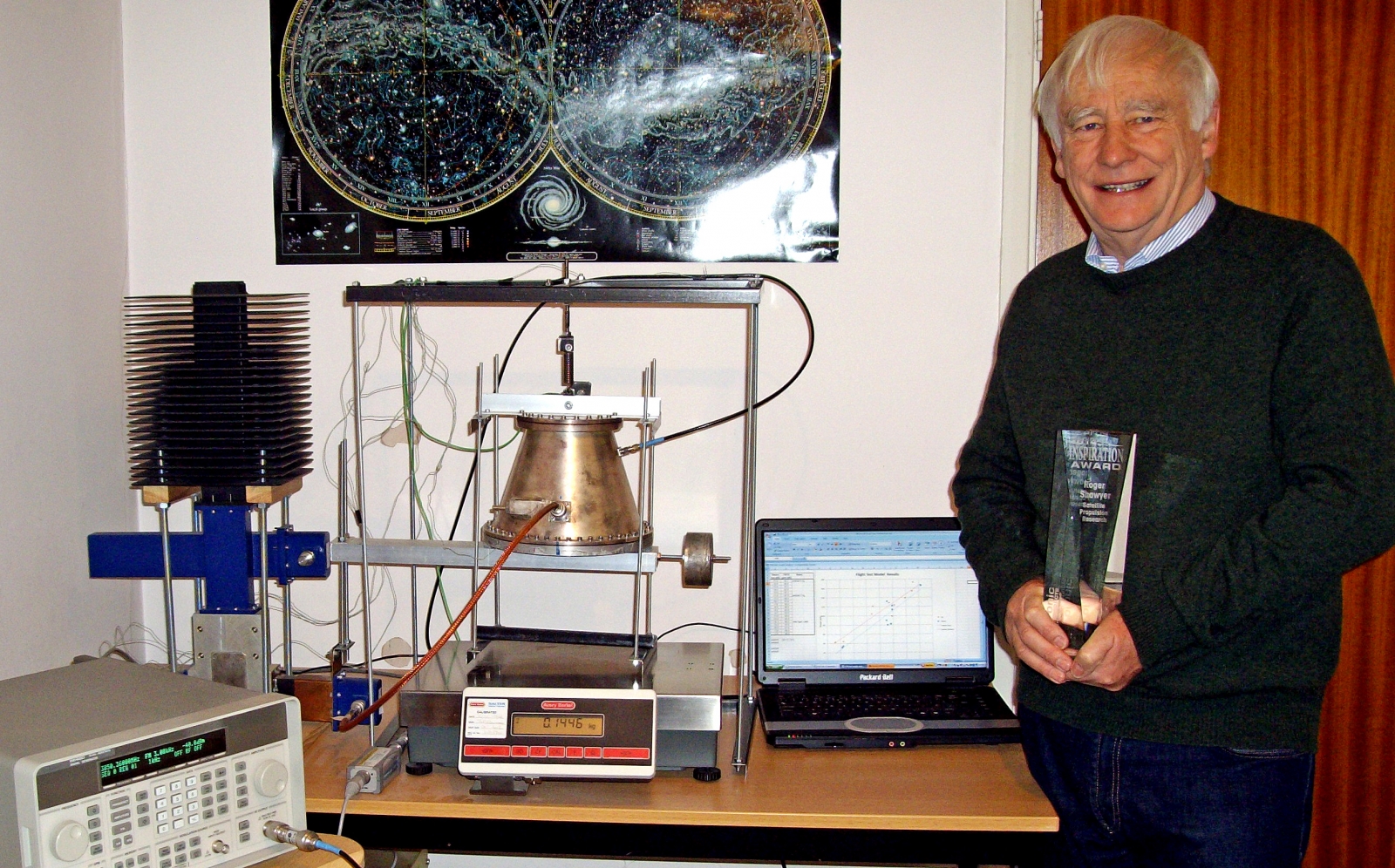
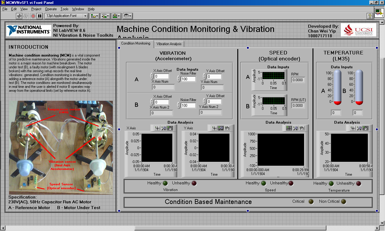
 )
 )